Embed Size (px)
Citation preview

Clemson UniversityTigerPrints
All Dissertations Dissertations
12-2008
HUMAN MICROVASCULATUREFABRICATION USING THERMAL INKJETPRINTING TECHNOLOGYXiaofeng CuiClemson University, [email protected]
Follow this and additional works at: https://tigerprints.clemson.edu/all_dissertations
Part of the Biomedical Engineering and Bioengineering Commons
This Dissertation is brought to you for free and open access by the Dissertations at TigerPrints. It has been accepted for inclusion in All Dissertations byan authorized administrator of TigerPrints. For more information, please contact [email protected].
Recommended CitationCui, Xiaofeng, "HUMAN MICROVASCULATURE FABRICATION USING THERMAL INKJET PRINTING TECHNOLOGY"(2008). All Dissertations. 294.https://tigerprints.clemson.edu/all_dissertations/294

HUMAN MICROVASCULATURE FABRICATION USING THERMAL INKJET PRINTING TECHNOLOGY
A Dissertation Presented to
the Graduate School of Clemson University
In Partial Fulfillment of the Requirements for the Degree
Doctor of Philosophy Bioengineering
by Xiaofeng Cui
December 2008
Accepted by: Dr. Thomas Boland, Committee Chair
Dr. Delphine Dean Dr. Andrew S. Mount Dr. Alexey Vertegel

ABSTRACT
The current tissue engineering paradigm is that successfully engineered thick
tissues must include vasculature. As biological approaches alone such as VGEF have
fallen short of their promises, one may look for an engineering approach to build
microvasculature. With the advent of cell printing, one may be able to build precise
human microvasculature with suitable bio-ink. Human Microvascular Endothelial Cells
(HMVEC) and fibrin were studied as bio-ink for microvasculature construction.
Endothelial cells are the only cells to compose the human capillaries and also the major
cells of blood vessel intima layer. Fibrin has been already widely recognized as tissue
engineering scaffold for vasculature and other cells, including skeleton/smooth muscle
cells and chondrocytes. In our study, we comprehensively studied changes in heat shock
protein expression and cell membrane morphogenesis in printed mammalian cells with
thermal inkjet printers. The heat shock protein expression of the printed cells has minor
difference between the untreated cells and lower than manually heated cells. The cell
membrane of printed cells developed pores which allow small molecules such as
propidium iodide and dextran molecules (up to 70kD) to pass. We then precisely
fabricated micron-sized fibrin channels using a drop-on-demand polymerization. When
printing HMVEC cells in conjunction with the fibrin, we found the cells aligned
themselves inside the channels and proliferated to form confluent linings. The 3D tubular
structure was also found in the printed patterns. We conclude that cell printing
technology can be used for precise cell seeding in tissue engineering fabrication with
minor effect and damages to the printed mammalian cells.
ii

DEDICATION
I dedicate this dissertation to my mom Xinggu Yao, my dad Songchuan Cui, and
my grandmother Dongxian Yang, for their unconditional love and endless support.
谨以此博士论文献给我的母亲姚杏姑,父亲崔松传,和祖母杨冬仙,感谢他
们无条件的爱和无限的支持。
iii

ACKNOWLEDGMENTS
I sincerely appreciate the guidance from my advisor, Dr. Thomas Boland. This
dissertation could not have been successfully finished without his consistent support and
advising.
My committee members, Dr. Delphine Dean, Dr. Andrew S. Mount, and Dr.
Alexey Vertegel, also helped me a lot in both theoretical and experimental ways.
I also would like to acknowledge Dr. Ken Webb for his advice on Western Blot
experiments, Dr. Neeraj Gohad for suggestions on confocal imaging, and Dr. Sahil Jalota
for helps on taking scanning electron microscopy images.
iv

TABLE OF CONTENTS
Page
TITLE PAGE....................................................................................................................i ABSTRACT.....................................................................................................................ii DEDICATION................................................................................................................iii ACKNOWLEDGMENTS ..............................................................................................iv LIST OF TABLES.........................................................................................................vii LIST OF FIGURES ......................................................................................................viii CHAPTER I. LITERATURE REVIEW ..............................................................................1 Introduction of Tissue Engineering .........................................................1 Cardiovascular System and Microvasculature Tissue Engineering...........................................................................14 Cell and Organ Printing .........................................................................27 References..............................................................................................33 II. PROJECT RATIONALE.............................................................................44 Objective One ........................................................................................45 Objective Two........................................................................................47 References..............................................................................................48 III. HEAT SHOCK PROTEIN EXPRESSION AND CELL MEMBRANE DAMAGE INDUCED BY THERMAL INKJET PRINTING OF CHINESE HAMSTER OVARY CELLS ..............................................50 Introduction............................................................................................50 Materials and Methods...........................................................................52 Results....................................................................................................56 Discussion..............................................................................................68 Conclusions............................................................................................71
v

References..............................................................................................72 IV. SIMULTANEOUS DEPOSITION OF HUMAN MICROVASCULAR ENDOTHELIAL CELLS AND BIOMATERIALS FOR HUMAN MICROVASCULATURE FABRICATION USING THERMAL INKJET PRINTING TECHNOLOGY..............................75 Introduction............................................................................................75 Materials and Methods...........................................................................78 Results....................................................................................................83 Discussion..............................................................................................92 Conclusions............................................................................................95 References..............................................................................................96 V. CONCLUSIONS..........................................................................................99
vi

LIST OF TABLES
Table Page 3.1 Quantitative CHO cells printing study of HP DeskJet 500 and HP 51626A ink cartridges........................................................59 3.2 Fluorescent molecules penetrated through damaged cell membrane after cell printing..................................................................65
vii

LIST OF FIGURES
Figure Page 3.1 Thermal inkjet printer printing ability study of various cell concentrations .................................................................................58 3.2 Heat shock protein 70 expression of printed CHO cells..............................61 3.3 Confocal microscopy of printed CHO cells cell membrane pore sizes study using Texas-Red fluorescent dextran ..........................64 3.4 Series confocal microscopy images at z-axis with 1.5µm interval ...................................................................................................66 3.5 Rate of repairing pores developed during printing process by CHO cells..........................................................................................67 4.1 Printed fibrin fibers with grid pattern ..........................................................84 4.2 SEM images of printed fibrin channels .......................................................85 4.3 Printed HMVEC in fibrin channel after 24 hours........................................86 4.4 Printed HMVEC in fibrin channel after 7 days ...........................................87 4.5 Printed HMVEC in fibrin channel after 14 days .........................................88 4.6 Printed HMVEC in fibrin channel after 21 days .........................................88 4.7 Printed microvasculature tube......................................................................89 4.8 Z-series images of printed microvasculature tube .......................................90 4.9 Orthogonal sections display mode of printed microvasculature tube........................................................................................................91 4.10 Integrity study of printed microvasculature for 14 days..............................92
viii

CHAPTER ONE
LITERATURE REVIEW
Introduction of Tissue Engineering
Millions of Americans suffer lost organs and tissues or end-stage organ failure
every year. Although the transplantation of organs like heart, liver, and kidney is a highly
successful therapy for the incurable end-stage diseases, the need for donor organs far
exceeds the supply. There are more than 25% patients for liver or heart transplantation
die while they are still on the waiting list in the United States alone each year (1). Some
new surgical techniques have been developed due to this organ shortage, such as
transplanting whole organs (e.g. kidneys) from living, related donors and splitting adult
organs for transplant (e.g. a part of a liver or a lung from a parent to a child) (2).
However, the problem of donor shortage still remains in spite of the excellent results with
these well developed transplant techniques. This organ donor shortage prompted several
approaches that were proposed to solve this problem: artificial mechanical organs,
xenotransplantation, tissue engineering, and regenerative medicine (3). However, some
artificial organs which are already available to patients showed significantly reduction of
life quality and may have many unwanted side effects. Xenotransplantation sources are
referred as organ donor sources from other species (e.g. pig). The idea of
xenotransplantation becoming suitable in the long term still remains problems (4).
Besides the immunological barrier, there is still great concern about potential spreading
of animal viruses (5). However, tissue engineering completely avoids the risks of
1

immunological responses such as rejections (acute and chronic), as well as viral
infections using autologous cells. This is why tissue engineering has been attracting more
and more attentions since past two decades as a promising solution for this critical organ
donor shortage issue.
Principles of Tissue Engineering
In definition, tissue engineering is an interdisciplinary field that applies the
principles of engineering and the life sciences toward the development of biological
substitutes that restore, maintain, or improve tissue function (6).
There are three general strategies accepted for the creation of new tissues. The
first approach is isolated cells or cell substitutes. This strategy avoids the surgery
complications and allows replacement of only the cells which supply the needed function
and permits manipulation of the cells before infusion. Its potential limitations include
failure of the infused cells to maintain their function in the recipient and immunological
rejection. The second approach is tissue-inducing substance. The success of this strategy
depends on the purification and large-scale production of the appropriate signal
molecules including hormones and growth factors. It also depends on the development of
the methods of delivering these signal molecules to their targets. The third approach is
cell seeding on the porous biomaterial scaffolds. In closed systems, the cells are isolated
from the body by a membrane which allows the nutrients and wastes permeation but
prevents large molecules like antibodies or immune cells from destroying the transplant.
In open systems, cells attached to the matrix scaffolds are implanted and become
2

incorporated into the body. The scaffolds can be natural materials such as collagen or
synthetic polymers. Immunological rejection maybe prevented by immunosuppressive
drugs or by using the autologous cells (7). The third strategy becomes the basic concept
and tradition approach of tissue engineering. It includes a scaffold that provides
architecture for cell seeding which can organize and develop into the desired tissues and
organs in vitro before implantation. The biomaterial scaffolds can provide the initial
biomechanical profile for the seeded cells until they fabricate their own natural
extracellular matrix. During the formation, deposition and organization of the newly
generated tissue matrix, the original scaffold is either degraded or metabolized; finally
leaving a vital organ or tissue that restores, maintains, or improves tissue function (2).
This approach should be distinguished from the guided tissue regeneration which uses
acellular matrices that are repopulated by the host after implantation (6). For vascular
prosthesis, autologous reseeding of a large surface area from the adjacent native tissue is
seen commonly in animals but seems very limited in humans (8). Whether the observed
autologous repopulation of acellular and unseeded matrices can be transferred to humans
still seems highly speculative (9).
Scaffold Materials for Tissue Engineering
The most appealing approach in tissue engineering is utilizing a combination of
patient’s own cells with polymer scaffolds for lost or aged tissues and organs
replacement. The tissue-specific cells are isolated from the patient and harvested in vitro.
By incorporating the harvested cells into the three dimensional polymer scaffolds, the
3

cell-matrix combinations work as the natural extracellular matrices found in the tissues.
The scaffold materials must be biocompatible and are designed to meet both biological
and nutritional needs for the specific cell type involved in the tissue formation. These
biomaterial scaffolds will deliver the incorporated cells to the desired site in the human
body. Not only provide a space for new tissue formation, the scaffolds will also
potentially control the structure and function of the newly engineered tissues (10, 11).
Recently, various types of tissues are being engineered using this approach including
fabricated bladder, skin, cartilage, artery, bone, ligament, and tendon. Several of these
engineered tissues are now at or near clinical applications (12, 17). In addition, a variety
of approaches have been introduced about transferring undifferentiated cells, like stem
cells, into the desired cell phenotype in tissue engineering (18). Almost all tissue
engineering scaffolds are polymer. The polymer mimics many properties of extracellular
matrices found in tissues. Extracellular matrices are comprised of various amino acids
and sugar-based macromolecules. Extracellular matrix brings cells together and controls
the tissue structure, also regulate the function of the cells and allow the diffusion of
nutrients, metabolites and growth factors (19). There are various types of polymers have
been studied and utilized in tissue engineering today (20). The most widely used
synthetic polymers are aliphatic polyesters including poly (glycolic acid) (PGA), poly
(lactic acid) (PLA), and their copolymers (PLGA) (21, 22). PGA was the first synthetic
polymer used for the successful creation of new tissue (23). Although these polymers
have a long history of use in the medical applications and are also considered safe in
many cases by the FDA, the use of these types of polymer scaffolds requires surgical
4

procedures to make large incisions to enable placement of the polymer/cell constructs.
An excellent alternative approach to cell delivery for tissue engineering is the use of
polymers that can be injected into the body. This enables the transplantation of the cells
and polymer scaffolds into patients’ bodies in a minimally invasive matter. Hydrogels
represent an important type of biomaterials in biotechnology and medicine because many
hydrogels have excellent biocompatibility and minimal inflammatory responses,
thrombosis, and tissue damage (24, 25). Hydrogels can also swell large quantities of
water without the dissolution due to the hydrophilic and cross-linked structure. This gives
hydrogels physical characteristics similar to soft tissues. In addition, hydrogels have high
permeability for oxygen, nutrients, and other water-soluble metabolites. Hydrogels have
been found numerous applications in medicine such as contact lens, biosensors, linings
for artificial implants, and drug delivery devices (26, 27). Hydrogels currently used in
tissue engineering are divided into two categories, which are natural and synthetic
polymers.
Hydrogels from Natural Polymers
Collagen and Gelatin
Collagen is a main component of the extracellular matrices of mammalian tissues
including skin, bone, tendon, cartilage, and ligament, and it is the most widely used
tissue-derived natural polymer in tissue engineering. Physically cross-linked collagen
gels offer a limited range of mechanical properties and are thermally reversible. Chemical
cross-linking of collagen using glutaraldehyde (28) or diphenylphosphoryl azide (29) can
5

greatly improve the physical/mechanical properties. But these chemically cross-linked
collagen gels are still short of physical strength, potentially immunogenic, and could be
quite expensive (30). There could also be big variations between different collagen
production batches. However, collagen meets many biological design parameters, since it
is composed of specific combinations of amino acid sequences that are recognized by
cells and degraded by enzymes secreted from the cells, like collagenase. This is why
collagen has been widely used as tissue culture scaffolds or artificial skins due to the
ready attachment of various cell types and the cell-based degradation. Cell attachment on
collagen gel can also be tuned by chemical modification, including incorporation of
fibronectin, chondroitin sulfate, or low level of hyaluronic acid into the collagen matrix
(31). Collagen gels have been utilized for reconstruction of liver (32), skin (33), blood
vessel (34), and small intestine (35).
Gelatin is denatured collagen. It is formed by breaking the natural triple-helix
structure of collagen into single stranded molecules. There are two types of gelatin,
gelatin A and gelatin B. Gelatin A is produced by acidic treatment before thermal
denaturation. Gelatin B is processed by alkaline treatment that causes a high carboxylic
content (36). Gelatin can form gels easily by changing the temperature of the solution. It
is also widely used in tissue engineering applications due to the biocompatibility and ease
of gelation. Gelatin gels can also be used for growth factor delivery to promote
vasculature in the engineered tissue (37). However, gelatin also faces the weakness of the
physical properties and many chemical modifications have been studied to improve the
mechanical properties of gelatin gels (38, 39).
6

Hyaluronate
Hyaluronate is one component of glycosaminoglycan in natural extracellular
matrix and plays an important role in wound healing. Hyaluronate can be covalent cross-
linked into hydrogel using various types of hydrazide derivatives and radical
polymerization of glycidyl methacrylate (40). Hyaluronate can be degraded by
hyaluronidase, which exists in serum and cells (41). Although hyaluronate has been
utilized widely in tissue engineering applications such as artificial skin (42), facial
intradermal implants (43), wound healing (44), and soft tissue augmentation (43), it
requires thorough purification to remove impurities and endotoxins that may potentially
cause diseases or immune responses (45). In addition, hyaluronate gels typically have
lower mechanical properties which cause their limited applications.
Fibrin
Fibrin plays a significant role in natural wound healing. Fibrin gel has been
widely used as sealant and adhesive during surgery. Fibrin can be produced from the
patients’ own blood and used as an autologous scaffold for tissue engineering. Fibrin can
be polymerized using fibrinogen and thrombin solutions at room temperature (46). Fibrin
gels might promote cell migration, proliferation, and matrix synthesis through the
incorporation of the transforming growth factor β and platelet derived growth factors
(47). Fibrin has also been utilized in tissue engineering to engineer tissues with skeletal
muscle cells (48), smooth muscle cells (49), and chondrocytes (50). However, the
7

limitation in mechanical properties prevents their applications. Lots of research has been
going on to increase the mechanical properties of fibrin gels.
Alginate
Alginate is a well-known biomaterial from brown algae. Due to its
biocompatibility, low toxicity, relatively low cost, and simple cross-linking with divalent
cations such as Ca2+, Mg2+, Ba2+, and Sr2+, alginate has been widely used for drug
delivery and tissue engineering scaffolds (51). Alginate can be used as an injectable cell
delivery vehicle (52), wound dressing, dental impression, and immobilization matrix (53,
54). Alginate gel beads have been used for chondrocytes and hepatocytes transplantation
(55).
Despite the advantages, alginate may not be an ideal biomaterial because its
degradation is a process involving the divalent ions loss into the surrounding medium.
This process is uncontrollable and unpredictable. Another potential disadvantage of
alginate gels in tissue engineering is the lack of cellular interaction. Due to the
hydrophilic character, alginate discourages protein adsorption and it is unable to
specifically interact with mammalian cells (56). This is why alginate in tissue engineering
is usually modified with lectin, a carbohydrate specific binding protein, to enhance
ligand-specific binding properties (57). Another modification of alginate is covalently
coupled with an RGD-containing cell adhesion ligand to enhance the cell adhesion. These
alginate modifications provide the adhesion, proliferation, and differentiation of
mammalian cells (58).
8

Agarose
Agarose is not like alginate and it forms thermally reversible gels (59). The
physical properties and pore sizes can be mainly controlled using different agarose
concentrations. Larger pore size and lower mechanical stiffness of the agarose gel at
lower concentrations can enable the cell migration and proliferation (60). Cell adhesion
peptides (CDPGYIGSR) have also been covalently coupled to agarose gel to enhance the
interaction with cells (61).
Chitosan
Chitosan has many biomedical applications due to its biocompatibility, low
toxicity, structural similarity to natural glycosaminoglycans and degradation by
chitosanase and lysozyme (62). The disadvantage of chitosan is easily soluble in the
acidic solution and generally insoluble in neutral conditions and most organic solvents
due to the existence of amino groups and high crystallinity. Numerous derivatives have
been processed to enhance the solubility and processibility of this polymer (63, 64), as
well as the biological functions of chitosan, including enhancement of cellular
interactions. Chitosan forms hydrogels by ionic or chemical cross-linking with
glutaraldehyde (65, 66). Chitosan has also been modified with sugar residues such as
fructose and galactose for hepatocytes culture (67, 68).
9

Hydrogels from Synthetic Polymers
Poly (acrylic acid) and its derivatives
Hydrolytically stable cross-linked poly (2-hydroxyethyl methacrylate) (HEMA) is
one of the most studied synthetic hydrogels. The permeability and hydrophilicity can be
controlled by the crosslinking agents (69). Although poly (HEMA) has many applications
in tissue engineering, it is not degradable in physiological conditions. So dextran-
modified poly (HEMA) gels have been synthesized and reported to be degradable by
enzymes (70).
Poly (N-isopropylacrylamide) (PNIPAAm) exhibits phase transition behavior
above the lower critical solution temperature (LCST) and is attractive for tissue
engineering applications. The LCST of PNIPAAm is about 32 °C and can be adjusted to
match the body temperature (e.g., 37 °C) by copolymerization (71). Therefore the
application of PNIPAAm and its copolymers in tissue engineering is very promising as
people can prepare a mixed cell solution and polymer at room temperature or at a lower
temperature and then inject into the desired site. Then it will form a solid cell/polymer
construct when the gel is warmed to body temperature. The unique temperature-
responsive property of these polymers leads to various biological applications. When
cells are cultured on PNIPAAm, it will be easier to recover intact cell sheets without
damage by simply decreasing the temperature and modulating the hydrophilicity of the
polymer (72). The phase transition property may be ideal for cell delivery since it simply
depends on the temperature change after injected into the body. Limitations of these
10

polymers are nondegradable cross-links, and the monomers and cross-linking molecules
are toxic and carcinogenic (73).
Poly (vinyl alcohol)
Poly (vinyl alcohol) (PVA) can be obtained from poly (vinly acetate) by
alcoholysis, hydrolysis, or aminolysis (74). PVA hydrogels can be formed using repeated
freezing/thawing method (75) or electron beam (76) to avoid the toxicity and leaching
problems of chemical cross-linking agents. Since these gels are not degradable in most
physiological situations, PVA hydrogels are mostly used for long-term or permanent
applications, like artificial articular cartilage (77) and bone-like apatite formation (78).
Polyphosphazene
Polyphosphazene have been used in many biomedical applications due to the
biodegradable property in physiological situations. The degradation rate can be controlled
by changing the side-chain structure instead of the polymer backbone (79).
Polyphosphazene has alternating phosphorus and nitrogen atoms with two side groups
attached to each phosphorus atom. Nonionic and ionic types of hydrogels can be prepared
from polyphosphazenes. Nonionic gels are water-soluble. Ionic hydrogels have been used
in controlled drug delivery due to their ability to respond to environmental changes such
as pH or ionic concentration (80, 81). These polymers are useful for skeletal tissue
regeneration (82).
11

Polypeptides
Since proteins are the major component for the natural matrices of tissues, there is
wide interested in mimicking natural proteins by synthesizing polypeptides. However, to
precisely control the desired amino acids sequence is very difficult and expensive. One
way to bypass this problem is to synthesize genetically engineered polypeptides. People
can transfer DNA templates with predetermined sequences into the genome of bacteria or
yeasts to produce polypeptides with predetermined structure and controlled properties
(83, 84). This method allows people to design and engineer various polypeptides with
different physical/biological properties. Gly-Ala-rich sequence has been incorporated into
the artificial proteins to enable reversible hydrogels according to pH or temperature
change (85). However, this method is not appropriated to produce large amount of
biomaterials economically. And any modification of the hydrogel will require the re-
engineering of the entire genetic system.
Cells Used in Tissue Engineering
Almost all the tissue and organ types in mammals have been investigated by
tissue engineering researchers. Some studies use nonspecific cell types, like fibroblast for
heart valve tissue engineering (86), however, most are focusing on specific cell types for
tissue engineering.
One basic approach to harvest cells is to obtain autologous organ-specific cells by
biopsy. This approach applies to most organ structures, like skin, liver, blood vessels,
bone, heart, bone marrow, and cartilage. But for some tissues or organs, this approach is
12

not applicable. Peripheral vein segments are a suitable cell source for heart valves. And
for neural tissues, the approach to solve this cell-source difficulty is the isolation of stem
cells. Stem cells can proliferate through multiple generations and can potentially
differentiate into various cell types under proper culture conditions (87). Stem cells can
be harvested from either embryonic tissue or adult tissue. Stem cells from embryonic
fetal tissues may raise potential immunological and ethical issues. Recent research has
been focusing on cells derived from autologous bone marrow or circulation stem cells or
progenitor cells. Stem cells are totipotent and have the ability to differentiate into any cell
types by definition (88). Progenitor cells are described as pluripotent since they are more
differentiated than stem cells (89).
The importance to work with stem cells or progenitor cells is to know how to
induce and control the cell to differentiate into the desired cell types. For any cells used
in tissue engineering, it is critical to understand the mechanism of induction and control
the differentiation/proliferation to obtain the functional cells. The other challenges like
isolation and purification of certain cell type to obtain and maintain pure cell types. And
in other hand, like tissue engineering of cardiac myoblasts requires co-culture with
fibroblasts (90).
Current State of Tissue Engineering
Tissue engineering as an important interdisciplinary field in biomedical
engineering has shown tremendous promises in creating biological alternatives for
implants, harvested tissues, and prostheses (91). The basic concept for tissue engineering
13

is isolation of cells from a patient, and expanding the population in cell culture and
seeding onto a biomaterial scaffold. The fabricated tissue engineering structure is then
grafted back into the same patient to function as an introduced replacement tissue. The
first Tissue Engineering sample was found as early as 1933 when Bisceglie implanted
mouse tumor cells encapsulated in a polymer membrane into the abdominal cavity of
chick embryos and showed survival of these cells (92). In 1990s, tissue engineering
developed dramatically and no tissue or organ structures have been excluded from active
research so far. However, only a few tissue engineered products have clinical trials,
including artificial skin, cartilage, and bladders.
The major obstacle in tissue engineering of thick and complex tissue/organ is the
induction of a proper nutrient and oxygen supply as well as waste removal. Although
some avascular tissues, such as heart valve leaflets, can receive the nutrients by diffusion,
the majority of tissues and organs depend on a complex microvascular system. The
critical future challenge of creating such a system still remains unsolved.
Cardiovascular System and Microvasculature Tissue Engineering
Introduction of Cardiovascular System
The cardiovascular system is a transport system that carries blood and lymph to
and from the tissues in the body. The constitutive elements of these fluids include cells,
nutrients, waste products, hormones, and antibodies. Cardiovascular system includes the
heart, the blood, and the blood vessels. A functional cardiovascular system is vital for
survival since the tissues lack oxygen and nutrients, and waste products accumulate
14

without blood circulation. If cardiovascular system doesn’t work well, the cells soon
begin irreversible change, which quickly leads to death.
Blood
Blood is a unique connective tissue and the only fluid tissue in the body. It has
both solid and liquid components. Living blood cells are the formed elements and
suspended in a nonliving fluid matrix called plasma. The collagen and elastic fibers
typical in other connective tissues are absent from blood, but dissolved fibrous proteins
become visible as fibrin strands when blood clotting occurs.
Blood cells include erythrocytes, leukocytes and platelets. Erythrocytes normally
constitute about 45% of the total volume of a blood sample. Leukocytes and platelets
contribute less than 1% of blood volume and plasma makes up most of the remaining
55% of whole blood. Blood is denser than water and about five times more viscous due to
its formed elements. Blood has a pH between 7.35 and 7.45. Blood accounts for
approximately 8% of body weight. Its average volume in healthy adult males (5-6 L) is
somewhat greater than in healthy adult females (4-5 L)
Blood cells originate in red bone marrow from hematopoietic stem cells. Platelets
are from megakaryocytes. Erythrocytes are tiny and about 7.5 µm in diameter. They are
biconcave discs which increase the surface area for gases diffusion. A red blood cell can
readily squeeze through the narrow passages of capillaries because of its shape.
Erythrocytes have hemoglobin which is responsible for the color of the blood as well as
oxygen transportation.
15

Leukocytes protect body against disease. Some types of leukocytes have granular
cytoplasm and make up a group called granulocytes. The others lack cytoplasmic
granules and are called agranulocytes. A typical granulocyte is about twice the size of a
red blood cell. They include neutrophils, eosinophils, and basophils. The nucleus of
neutrophil is lobed and consists of two to five segments connected thin strands of
chromatin. They are also called polymorphonuclear leukocytes. Neutrophils are the first
white blood cells to arrive at an infection site. They phagocytize bacteria, fungi, and
some viruses. Neutrophils account for 54% to 62% of the leukocytes in a typical blood
sample from an adult. The nucleus of eosinophils usually has only two lobes. They
moderate allergic reactions and defend against parasitic worm infestation. Eosinophils
make up 1% to 3% of the total number of circulating leukocytes. Basophils migrate to
damaged tissues where they release histamine to increase permeability of the capillaries
and heparin to inhibit blood clotting. This increases blood flow to injured tissues.
Basophils account for less than 1% of the leukocytes.
Monocytes and lymphocytes form the agranulocyte group of leukocytes.
Monocytes are the largest blood cells. Their nuclei are spherical, kidney-shaped, oval, or
lobed. Monocytes leave the bloodstream and become into macrophages which
phagocytize bacteria, dead cells, and other debris in the tissue. They make up 3% to 9%
of the leukocytes. The major types of lymphocytes are T cells and B cells, both important
in immunity. T cells directly attack microorganisms, tumor cells, and transplanted cells.
B cells produce antibodies, which are proteins that attack foreign molecules.
16

Lymphocytes account for 25% to 33% of the circulating leukocytes and may live for
years.
Platelets are not complete cells. They adhere to exposed ends of injured blood
vessels and any rough surface, particularly to the collagen in connective tissue underlying
the endothelial lining of blood vessels. The shapes of platelets change drastically when
they contact collagen. Platelets adhere to each other to form a platelet plug in the vascular
break.
Heart
The cardiovascular system consists of a pump represented by the heart and blood
vessels, which provide the route by which blood circulates to and from all the parts of the
body. The heart contains four chambers, the right and left atria and right and left
ventricles, through which blood is pumped. Heart valves guard the exits of the chambers,
preventing the backflow of blood. Heart size varies with body size. But an average
adult’s heart is generally about 14 centimeters long and 9 centimeters wide.
The wall of the heart is composed of three distinct layers: an outer epicardium, a
middle myocardium, and an inner endocardium.
Blood that is low in oxygen and high in carbon dioxide enters the right atrium
through the venae cavae and the coronary sinus. As the right atrial wall contracts, the
blood passes through the right atrioventricular orifice and enters the chamber of the right
ventricle. When the right ventricular wall contracts, the tricuspid valve closes the right
atrioventricular orifice, and the blood moves through the pulmonary valve into the
17

pulmonary trunk and its branches, which are pulmonary arteries. From these vessels,
blood enters the capillaries associated with the alveoli (microscopic air sacs) of the lungs.
Gas exchange occurs between the blood in the capillaries and the air in the alveoli. The
freshly oxygenated blood, which is now relatively low in carbon dioxide, returns to the
heart through the pulmonary veins that lead to the lift atrium. The left atrial wall
contracts, and the blood moves through the left atrioventricular orifice and into the
chamber of the left ventricle. When the left ventricular wall contracts, the mitral valve
closes the left atrioventricular orifice, and the blood passes through the aortic valve into
the aorta and its branches.
Blood Vessels
The blood vessels are organs of the cardiovascular system, and they form a closed
circuit of tubes that carries blood from the heart to cells and back again. These vessels
include arteries, arterioles, capillaries, venules, and veins. The arteries and arterioles
conduct blood away from the ventricles of the heart and lead to the capillaries. The
capillaries are sites of change of substances between blood and the body cells, and the
venules and veins return blood from the capillaries to the atria.
Arteries are strong, elastic vessels that are adapted for carrying the blood away
from the heart under high pressure. These vessels subdivide into progressively thinner
tubes and eventually give rise to the finer branched arterioles. The wall of an artery
consists of three distinct layers. The innermost layer, tunica intima, is composed of a
layer of simple squamous epithelium, called endothelium, which rests on a connective
18

tissue membrane that is rich in elastic and collagenous fibers. The endothelial lining of an
artery provides a smooth surface that allows blood cells and platelets to flow through
without being damaged. Additionally, endothelium helps prevent blood clotting by
secreting biochemicals that inhibit platelet aggregation. Endothelium also may help
regulate local blood flow by secreting substances that either dilate or constrict blood
vessels. The middle layer, tunica media, makes up the bulk of the arterial wall. It includes
smooth muscle fibers, which encircle the tube, and a thick layer of elastic connective
tissue. The connective tissue gives the vessel a tough elasticity that enables it to
withstand the force of blood pressure and at the same time, to stretch and accommodate
the sudden increase in blood volume that accompanies ventricular contraction. The outer
layer, tunica adventitia, is thin and consists of loose connective tissue with irregularly
organized elastic and collagenous fibers. This layer attaches the artery to the surrounding
tissues. It also contains vasa vasorum that give rise to capillaries and provide blood to the
more external cells of the artery wall.
Although the walls of the larger arterioles have three layers similar to those of
arteries, the middle and outer layers thin as the arterioles approach the capillaries. The
wall of a very small arteriole consists only of an endothelial lining and some smooth
muscle fibers, surrounded by a small amount of connective tissue. Arterioles, which are
microscopic continuations of arteries, join capillaries. Capillaries are the smallest
diameter blood vessels. They connect the smallest arterioles and the smallest venules.
Capillaries are extensions of the inner linings of arterioles in that their walls are
endothelium, which is a single layer of squamous epithelial cells. These thin walls form
19

the semipermeable layer through which substances in the blood are exchanges for
substances in the tissue fluid surrounding body cells. The higher a tissue’s rate of
metabolism, the denser its capillary networks. Muscle and nerve tissues, which use
abundant oxygen and nutrients, are richly supplied with capillaries. The cartilaginous
tissues, the epidermis, and the cornea, where metabolism is slow, lack capillaries. The
patterns of capillary arrangement also differ in various body parts. Some capillaries pass
directly from arterioles to venules, but others lead to highly branched networks. Such
physical arrangements make it possible for the blood to follow different pathways
through a tissue that are attuned to cellular requirements. Blood flow varies among
tissues. During exercise, blood is directed into the capillary networks of the skeletal
muscles, where the cells require more oxygen and nutrients. At the same time, the blood
bypasses some of the capillary networks in the tissues of the digestive tract, where
demand for blood is less critical. Conversely, when a person is relaxing after a meal,
blood can be shunted from the inactive skeletal muscles into the capillary networks of the
digestive organs. The distribution of blood is mainly regulated by the smooth muscles
that encircle the capillary entrances. The vital function of exchanging gases, nutrients,
and metabolic by-products between the blood and the tissue fluid surrounding body cells
occurs in the capillaries. The biochemicals exchanged move through the capillary walls
by diffusion, filtration, and osmosis. Diffusion is the most important means of transfer.
Blood entering certain capillaries carries high concentrations of oxygen and nutrients,
these substances diffuse through the capillary walls and enter the tissue fluid. Conversely,
the concentrations of carbon dioxide and other wastes are generally greater in the tissues,
20

and such wastes tend to diffuse into the capillary blood. Normally, more fluid leaves the
capillaries than returns to them. Lymphatic vessels collect the excess fluid and return it to
the venous circulation.
Venules are the microscopic vessels that continue from the capillaries and merge
to form veins. The veins, which carry blood back to the atria, follow pathways that
roughly parallel those of the arteries. The walls of veins are similar to those of arteries in
that they are composted of three distinct layers. However, the middle layer of the venous
wall is poorly developed. So veins have thinner walls that contain less smooth muscle
and less elastic tissue than those of comparable arteries, but their lumens have a greater
diameter. Many veins contain flaplike valves, which project inward from their linings.
The valves are pushed closed if the blood begins to back up in a vein. These valves aid in
returning blood to the heart because they are open as long as the flow is toward the heart
but close if it is in the opposite direction.
The blood vessels can be divided into two major pathways. The pulmonary
pathway consists of vessels that carry blood from the heart to the lungs and back to the
heart. The systemic pathway carries blood from the heart to all parts of the body, except
the lungs, and back to the heart again.
Human Endothelial Cells and Angiogenesis
Endothelial cells form the lining of blood vessels and have a remarkable capacity
to adjust their number and arrangement to suit local requirements. Almost all tissues
depend on a blood supply and the blood supply depends on endothelial cells. They create
21

an adaptable life-support system spreading into almost every region of the body.
Endothelial cells extending and remodeling the network of blood vessels makes it
possible for tissue growth and repair. The largest blood vessels are arteries and veins,
which have a thick, tough wall of connective tissue and smooth muscle. The wall is lined
by an exceedingly thin single layer of endothelial cells, separated from the surrounding
outer layers by a basal lamina. The amounts of connective tissue and smooth muscle in
the vessel wall vary according to the vessel’s diameter and function, but the endothelial
lining is always there. In the finest branches of the vascular tree, like capillaries, the walls
consist of nothing but endothelial cells and a basal lamina. Thus endothelial cells line the
entire vascular system, from the heart to the smallest capillary, and control the passage of
materials and the transit of leukocytes into and out of the bloodstream (93).
Throughout the vascular system, endothelial cells have the ability for cell division
and movement. If a part of the wall of the aorta is damaged and denuded of endothelial
cells, neighboring endothelial cells proliferate and migrate in order to cover the exposed
surface. Newly formed endothelial cells will even cover the inner surface of plastic
tubing used by surgeons to replace parts of the damaged blood vessels. Endothelial cells
not only repair the lining of damaged blood vessels, they also create new blood vessels.
They must do this in embryonic tissues to keep pace with growth, to support recurrent
cycles of remodeling and reconstruction, and to repair the damaged adult tissues (94).
New vessels always originate as capillaries, which sprout from existing small
vessels. The process of angiogenesis occurs in response to specific signals. Endothelial
cells will form a new capillary grow out from the side of a capillary or small venule by
22

extending long processes or pseudopodia. The cells at first form a solid sprout, which
then hollows out to form a tube. The process continues until the sprout encounters
another capillary, with which it connects and allowing blood to circulate. Experiments in
culture show that endothelial cells in a medium containing suitable growth factors will
spontaneously form capillary tubes even if they are isolated from all other types of cells.
The first sign of tube formation in culture is the appearance of an elongated vacuole in
cytoplasm. Contiguous cells develop similar vacuoles, and eventually the cells arrange
their vacuoles end to end so that the vacuoles become continuous from cell to cell to form
the capillary channel. Formation of capillary tubes is promoted by basal lamina
components, such as laminin, which the endothelial cells themselves can secrete. The
capillary tubes that develop in a pure culture of endothelial cells do not contain blood,
and nothing travels through them, which indicates that blood flow and pressure are not
required for the formation of a capillary network (95, 96).
Angiogenesis is controlled by growth factors released by the surrounding tissues.
In living animals endothelial cells form new capillaries wherever there is a need for them.
It is thought when cells in tissues are in need of oxygen, they release angiogenic factors
that induce new capillary growth. Similarly, after wounding a burst of capillary growth is
stimulated close to the damaged tissue. Angiogenesis is also important in tumor growth.
The growth of a solid tumor is limited by its blood supply. To grow further, a tumor must
induce the formation of a capillary network that invades the tumor mass. So the invading
endothelial cells must respond to a signal produced by the tissue that requires a blood
supply. The response of the endothelial cells includes at least four components. First, the
23

cells must breach the basal lamina that surrounds an existing blood vessel. Endothelial
cells during angiogenesis have been shown to produce protease, which enable them to
digest their way through the basal lamina of the parent capillary or venule. Second, the
endothelial cells must migrate to the source of the signal. Third, they must proliferate.
Fourth, they must form tubes. There are identified growth factors that can evoke all four
components of the agniogenic response together. The foremost among these factors is
vascular endothelial growth factor (VEGF). This acts selectively on endothelial cells to
stimulate angiogenesis in many different circumstances, and it seems to be the agent by
which some tumors acquire their rich blood supply. Other growth factors like some
members of fibroblast growth factor family also stimulate angiogenesis but at the same
time influence other cell types besides endothelial cells. These growth factors are
released during tissue repair, inflammation, and tissue growth. They are made by various
cell types, including macrophages, mast cells, and fat cells. A number of natural
inhibitors have also been found that can block the formation of new blood vessels.
Angiogenesis seems to be regulated by complex combinations of signals rather than by
one signal alone (97).
Microvasculature Tissue Engineering
Tissue engineering still faces many challenges, including the isolation and
proliferation of appropriate cell types, the arrangement of various cell types into the
correct spatial organization and creation of the optimal microenvironments for growth
and differentiation. To date, the most successful tissue engineering applications are
24
restricted to relatively thin or avascular structures, like skin and cartilage. Those tissues
have relatively low requirements for nutrients and oxygen and can be supported by
diffusion from the host vasculature. Development of an artificial microvasculature is a
critical obstacle to engineer thicker, metabolically demanding organs, such as heart,
kidney, lung and liver. These organs have high metabolic rates and further limit the
maximal thickness of engineered tissues. By building capillary networks within the
engineered tissues can help to transport oxygen and nutrients also to remove the waste
(98). The ability to microvascularize tissue constructs would be a significant step forward
in tissue engineering and regenerative medicine. Tissue-engineered organs rely mainly on
host vasculature for oxygen, nutrients, and waste removal without proper vascularization
(99, 100). When the thickness of engineered tissue exceeds the limit of 100-200 µm, it
must overcome the challenge of creating the functional blood vessels to supply the cells
with oxygen and nutrients and also to remove the waste products from the tissue. Without
an intrinsic capillary network, the maximal thickness of engineered tissue is
approximately 150-200 µm because of oxygen diffusion limitations (101, 102). This is
why microvascularization is so important for engineered tissue constructs before
implantation. Microvascularization in vitro can maintain the cell viability during the
tissue growth, induce the structural organization and promote the angiogenesis after
implantation.
For biomaterial scaffolds, it is a critical challenge of how to use the polymers to
promote the capillary network formation in the fabricated tissues. It is important to
provide the nutrient and oxygen transport to the engineered tissues and also integrate
25

them with the rest of the body (103). One important approach for microvascularizatoin is
to deliver either angiogenic factors or capillary forming cells (e.g., endothelial cells) to
the engineered site using hydrogel. The controlled and sustained release of angiogenic
factors from hydrogels can optimize and promote the localized blood vessel formation.
Various growth factors including vascular endothelial factor (VEGF) (104), epidermal
growth factor (EGF) (105), basic fibroblast growth factor (bFGF) (106), and bone
morphogenetic protein (BMP) (107) could be incorporated into hydrogels depending on
the specific tissue types. Additionally, the delivery of DNA plasmid containing genes
encoding angiogenic proteins may be another solution to increase the vascular network
formation in engineered tissues (108). Co-transplantation of endothelial cells along with
the primary cell type of interest may allow people to rapidly form microvasculature in the
engineered tissues. This is because the endothelial cells will form tube-like structures in
vitro if cultured in an appropriate condition (109).
Another approach is endothelialized microvasculature based on a biodegradable
elastomer. The capillary networks were microfabricated with a biodegradable and
biocompatible elastomer, poly (glycerol sebacate) (PGS). The capillary patterns were
etched onto silicon wafers by standard microelectromechanical systems (MEMS)
techniques. The resulted silicon wafers served as micromolds for the devices. Then the
patterned PGS film was bond to a flat film to create capillary networks that were perfused
with a syringe pump at a physiological flow rate. The devices were endothelialized under
flow conditions, and part of the lumens reached confluence within 14 days of culture
(110).
26

The best studied growth factor for therapeutic angiogenesis is vascular endothelial
growth factor (VEGF). However, VEGF alone is not sufficient to form mature and stable
vasculature (111). In the study of using injection of adenoviral vectors to express VEGF
in normal tissue, the newly formed blood vessels were disorganized, leaky and
hemorrhagic. VEGF may also initiate inflammation by increasing the expression of
adhesion molecules on endothelial cells or the release of chemokines. The newly formed
blood vessels may not be adequate to the tissues’ metabolic need.
Cell and Organ Printing
The traditional tissue engineering approach is using porous biomaterial scaffolds
seeded with isolated autologous cells from the patient, culturing the constructs in
bioreactor, and implanting the resulting cell/biomaterial complex back to the patient.
However, it is a critical challenge to rapidly fabricate tissue and organs with well defined
structures and functions in tissue engineering (112). Engineered tissue constructs require
spatial control over cells in three dimensional spaces to assemble and organize them into
a functional structure (113). The formation of 3D cellular structures requires control of
both cells and scaffold components (114). All the methods currently being investigated
for 3D cellular patterning have the advantages as well as large limitations.
Introduction of Inkjet Printing
Because of the large limitations for the old 3D cell matrix fabrication methods,
researchers have been recently looking at the modified off-the-shelf inkjet printers.
27

Inkjet printing is a non-contact printing technique. By receiving the digital image
or character data from computer, inkjet printers have the ability to reproduce the data
onto substrate (e.g., paper) with tiny ink drops (115). Inkjet printers can drop ink
continuously or drop-on-demand. Drop-on-demand means the ink drops are ejected only
where and when they are required to create the images on the substrate. The ink stream is
broken into equal-sized droplets by applying a piezoelectrically modulated pressure wave
behind the nozzle (116). There are thermal, piezoelectric, and electromagnetic methods
for creating drops. Most inkjet printers are thermal and piezoelectrical printers and the
operating frequencies are about 10 KHz. For thermal inkjet printers, little air bubbles are
created by heating and then collapse to provide the pressure pulse to eject a tiny drop of
ink out of the nozzle. As for piezoelectric inkjet printers, the actuator of polycrystalline
piezoelectric ceramic in each nozzle provides the transient pressure to eject the ink drops
onto the substrate (115).
Similar printing mechanisms are used in both standard Hewlett-Packard and
Canon commercial inkjet printers. Inkjet printing technique was invented in 1979 at HP
laboratories. At the same time, Canon invented their “BubbleJet”. The first inkjet product
appeared on the market in 1984. The inkjet printer has high operating frequency, high
orifice density, integrated power, and interconnect electronics. In thermal inkjet printers,
when a small heating element heats, the expanded air bubble will eject a very small drop
of ink out of the nozzle. The current pulse lasts a few microseconds and raises the plate
temperature as high as 300 °C (117).
28

Inkjet printing technology has also been widely used in electronics and micro-
engineering industries for printing electronic materials and complex integrated circuits
(118). Recently, inkjet technology has been successfully applied into biomedical field,
such as drug screening, genomics, and biosensors (119-121). Although biological
molecules and structures are usually thought to be fragile, DNA molecules have been
directly printed onto glass slides using commercial inkjet printers for fabrication of high-
density DNA microarrays without degradation (122).
Recently, a novel application of inkjet printing is using the commercial available
inkjet printers to print cells and biomaterials in order to fabricate 3D cellular scaffolds
(123). It showed that the standard HP and Canon desktop inkjet printers can be modified
to perform cell printing. Organ printing, defined as computer-aided inkjet based tissue
engineering, has the advantages to construct 3D structures with living biological
elements. An important advantage of this process is the ability to simultaneously deposit
living cells, nutrients, growth factors, therapeutic drugs along with the biomaterial
scaffolds at the right time and location (124). Based on the properties of high-throughput
efficiency, cost-effective, and fully automated, the cell and organ printing has become a
promising approach for tissue engineering.
Cell Printing Using Thermal Inkjet Technology
The Hewlett-Packard Deskjet 500 inkjet printer has the droplet volume of 130 pL.
There are 50 firing nozzles on the printer head and the actual heating occurs during 10-µs
pulse. The energy supplied to the ink during the printing process is transferred into
29

kinetic energy and heating of the ink drop. Mathematical modeling studies indicated that
the bulk drop temperature in the ink rises between 4 and 10 degrees above ambient
during printing. This makes it possible for printing living systems (125). It has been
proved successful to print cell suspensions.
These commercial available inkjet printers can be modified for cell printing (126).
During cell printing, the paper feed sensor mechanism of the printer is adjusted and the
printer is UV sterilized and placed inside a sterile hood. A sterile hydrogel sample was
placed on a stage below the printer head. The ink cartridges are modified and cleaned for
cell suspension. They are rinsed thoroughly using 70% ethanol multiple times for
sterilization. This procedure was proved sufficient sterilization for all the experiments
(125). Quail mesoderm QCE-6 stem cells were printed successfully into specific patterns
on 2 mg/mL collagen hydrogels using modified HP Deskjet 500 with clean and sterilized
HP 51626A ink cartridge. The stem cells were found to proliferate on the collagen gel
surface and to emit green fluorescence because of the GFP expression. This indicated the
live cells. Fewer cells were observed individually at the early stage. After 6 days of
culture, the number of cells increased. And after 12 days, most cells were found. These
evidences indicated that the printed QCE-6 stem cells could maintain their viability and
proliferate on the collagen gel after being printed (127).
By replacing the regular printing ink with the cell suspensions, this can be
considered as bio-ink which could be printed using a commercial thermal inkjet printer.
Because the mammalian cells are very sensitive to heat and mechanical stress, there was
a major concern that the cells could be damaged or killed by the printing process.
30
However, the studies proved that many viable cell types can be delivered using modified
inkjet printers (125).
3-D Printing Using Modified Thermal Inkjet Printers
In order to build 3D biomaterial scaffold, an automatically controlled elevator stage with
z-axis controlled moving platform was designed (127). A round glass cover-slip with 2.5
cm diameter was fixed onto the top of a metallic rod and controlled by a stepper motor.
The motor was powered by a 4 V signal and operated through a series of four toggle
switches. A modified sterile 50 mL or 15 mL sized conical tube was used as chamber to
house the elevator stage. Sterile silicone gel was used for sealant.
For 3D alginate scaffold formation, alginate solution with certain concentration
was filled into the chamber. The crosslink solution was filled into the modified ink
cartridge (128). In this case, 0.25 M CaCl2 was filled into the ink cartridge. It can
promote the cross-linking of the individual alginate chains to form the 3D structure. This
cross-linker was printed layer-by-layer to form the 3D alginate structure. After the cross-
linking occurred on the first layer, the platform was submerged into the uncross-linked
alginate solution for a next layer formation on the previous layer. The procedure was
repeated until the desired structure was achieved. This printing method may apply to
smaller structures since larger one may cause deformation or collapse. Many biomaterial
scaffold structures can be fabricated using this method, such as tubes or branched tubes
(127).
31
Simultaneous Deposition of Biomaterials and Cells
People can use modified thermal inkjet printers to print cells and biomaterials
individually. Simultaneous deposition of endothelial cells and biomaterial scaffold
fabrication can also be achieved using the modified inkjet printers. The idea is to mix the
cells along with the cross-linker in the ink cartridge. When printing the patterns, the
mixed cells can be printed and aligned into the cross-linked biomaterial patterns. The
embedded cells can then attach onto the printed biomaterial pattern and proliferate along
the pattern. Eventually a 2D or 3D cell/biomaterial construct can be fabricated (127).
32

References
(1) Data derived from Health Resources and Services Administration, U.S.
Department of Health and Human Services
(2) Stock UA, Vacanti JP, et al. Tissue engineering: current state and prospects.
Annu. Rev. Med. 2001. 52:443-51
(3) Boland T, Xu Tao, et al. Application of inkjet printing to tissue engineering.
Biotechnol. J. 2006, 1 910-917
(4) Bach FH. Xenotransplantation: problems and prospects. Annu. Rev. Med. 1998
49: 301-10
(5) Mueller NJ, Barth RN, Yamamoto S, Kitamura H, et al. Activation of
cytomegalovirus in pig-to-primate organ xenotransplantation. J. Virol. 2002, 76,
4734-4740
(6) Skalak R, Fox CF, et al. Tissue engineering. Ann. Biomed. Eng. 19, 529 (1991)
(7) Langer R and Vacanti JP. Tissue engineering. Science. 1993, 260, 920-26
(8) Hong-DeWu M, Kouchi Y, Onuki Y, et al. 1995. Effects of differential shear
stress on platelet aggregation, surface thrombosis, and endothelialization of
bilateral carotid-femoral grafts in the dog. J. Vasc. Surg. 22: 382-92
(9) Huynh T, Abraham G, Murray J, et al. 1999. Remodeling of an acellular collagen
graft into a physiologically responsive neovessel. Nat. Biotech. 17(11): 1083-86
(10) Putnam AJ and Mooney DJ. J. Nat. Med. 1996, 2, 824
(11) Marler JJ, Upton J, Langer R, Vacanti JP. Adv. Drug Deliv. Rev. 1998, 33, 165
33

(12) Niklason LE, Gao J, Abbott WM, Hirschi KK, Houser S, Marini R, Langer R.
Science 1999, 284, 489
(13) Oberpenning F, Meng J, Yoo JJ, Atala A. Nat. Biotechnol. 1999, 17, 149
(14) Pomahac B, Svensjo T, Yao F, Brown H, Eriksson E. Crit. Rev. Oral Biol. Med.
1998, 9, 333
(15) Ma PX and Langer RJ. Biomed. Master. Res. 1999, 44, 217
(16) Service RF. Science 2000, 289, 1498
(17) Lin VS, Lee MC, O’Neal S, McKean J, Sung KLP. Tissue Eng. 1999, 5, 443
(18) Heath CA. TIBTECH 2000, 16, 17
(19) Alberts B, Bray D, Lewis J, Raff M, Roberts K, Waston JD. In Molecular
Biology of the Cell; Garland Publishing: New York, 1994, p 971
(20) Kim BS, Mooney DJ, TIBTECH 1998, 16, 224
(21) Harris LD, Kim BS, Mooney DJ. J. Biomed. Mater. Res. 1998, 42, 396
(22) Thomson RC, Mikos AG, Beahm E, Lemon JC, Satterfield WC, Aufdemorate
TB, Miller M. J. Biomaterials 1999, 20, 207
(23) Vacanti JP, Morse MA, Saltzman WM, et al. 1988. Selective cell
transplantation using bioabsorbable artificial polymers as matrices. J. Pediatr.
Surg. 23:3-9
(24) Graham NB. Hydrogels: their future, Part I. Med Device Technol 1998; 9: 18-
22
(25) Graham NB. Hydrogels: their future, Part II. Med Device Technol 1998; 9: 22-5
(26) Peppas NA. Hydrogels in medicine and pharmacy. Florida: CRC Press, 1987
34

(27) Peppas NA, Bures P, et al. Hydrogels in pharmaceutical formulations. Eur J
Pharm Biopharm 2000; 50:27-46
(28) Rault I, Frei V, Herbage D, et al. A. J. Mater. Sci. Mater. Med. 1996, 7, 215
(29) Chevallay B, Abdul-Malak N, Herbage D. J. Biomed. Mater. Res. 1999, 49, 448
(30) Phlapura S, Kohn J. J. Biomater. Appl. 1992, 6, 216
(31) Srivastava S, Gorham SD, Courtney JM. Biomaterials. 1990, 11, 1, 162
(32) Kaufmann PM, Heimrath S, Kim BS, Mooney DJ. Cell Transplant. 1997, 6, 463
(33) Auger FA, Rouabhia M, Goulet F, Berthod F, Moulin V, Germain L. Med. Biol.
Engin. Comput. 1998, 36, 801
(34) Seliktar D, Black RA, Vito RP, Nerem RM. Ann. Biomed. Eng. 2000, 28, 351.
(35) Voytik-Harbin SL, Brightman AO, Waisner BZ, Robinson JP, Lamar CH.
Tissue Eng. 1998, 4, 157
(36) Johns P, Courts A. In The Science and Technology of Gelatin; Ward AG,
Courts A. Eds.; Academic Press: London, 1977; p138
(37) Yamamoto M, Tabata Y, Ikada Y. J. bioact. Compat. Polym. 1999, 14, 474
(38) Kuijpers AJ, Engbers GHM, Feijen J, De Smedt SC, Meyvis TKL, et al. J.
Macromolecules 1999, 32, 3325
(39) Choi YS, Hong SR, Lee YM, Song KW, Park MH, Nam YS. Biomaterials
1999, 20, 409
(40) Inukai M, Jin Y, Yomota C, Yonese M. Chem. Pharm. Bull. 2000, 48, 850
(41) Afify AM, Stern M, Guntenhoner M, Stern R. Arch. Biochem. Biophys. 1993,
305, 434
35

(42) Choi YS, Hong SR, Lee YM, Song KW, Park MH, Nam YS. J. biomed. Mater.
Res. 1999, 48, 631
(43) Duranti F, Salti G, Bovani B, Calandra M, Rosati ML. Dermatol. Surg. 1998,
24, 1317
(44) Radomsky M, Swain L, Aufdemorte T, Fox C, Poser J. J. bone Mineral res.
1996, 11, M667
(45) Liu, LS, Thompson AY, Heidaran MA, Poser JW. Biomaterials. 1999, 20, 1097
(46) Perka C, Spitzer RS, Lindenhayn K, Sittinger M, Schultz O. J. Biomed. Mater.
Res. 2000, 17, 587
(47) Sierra D, Saltz R. Surgical Adhesives and Sealants: Current Technology and
Application; Technomic; Lancaster, 1996
(48) Ye Q, Zund G, Benedikt P, Jockenhoevel S, Sakyama S, Hubell JA, Turina M.
Eur. J. Cardio-Thorac. Surg. 2000, 17, 587
(49) Ikari Y, Fujikawa K, Yee KO, Schwartz SM. J. boil. Chem. 2000, 275, 12799
(50) Meinhart J, Fussenegger M, Hobling W. Ann. Aplast. Surg. 1999, 42, 673
(51) Draget KI, Skjak-Brak G, Smidsrod O. TIBTECH 1990, 8, 71
(52) Atala A, Kim W, Paige KT, Vacanti CA, Retik AB. J. Urol. 1994, 152, 641
(53) Klock G, Pfeffermann A, Ryser C, Grohn P, Kuttler B, Hahn HJ, Zimmermann
U. Biomaterials. 1997, 18, 707
(54) Gombotz WR, Wee SF. Adv. Drug Deliv. Rev. 1998, 31, 267
(55) Gregory KE, Marsden ME, Anderson-MacKenzie J, Bard JB, Bruckner P,
Farjanel J, Robins SP, Hulmes DJ. Exp. Cell Res. 1999, 246, 98
36

(56) Smentana K. Biomaterials 1993, 14, 1046
(57) Sultzbaugh KJ, Speaker TJ. J. Microencapsulation 1996, 13, 363
(58) Rowley JA, Madlambayan G, Mooney DJ. Biomaterials 1999, 20, 45
(59) Wong WH, Mooney DJ. In Synthetic Biodegradable Polymer Scaffolds; A.
Atala, DJ Mooney, RS Langer, JP Vacanti. Eds.; birkhauser: Boston, 1997; p 49
(60) Dillon GP, Yu XJ, Sridharan A, Ranieri JP, Bellamkonda RV. J. Biomater. Sci.
Polym. Ed. 1998, 9, 1049
(61) Borkenhagen M, Clemence JF, Sigrist H, Aebischer P. J. biomed. Mater. Res.
1998, 40, 392
(62) Singh DK, Ray AR. J. Macromol. Sci. Rev. Macromol. Chem. Phys. 2000, C40,
69
(63) Muzzarelli RAA. Carbohydr. Polym. 1983, 3, 53
(64) Kurita K, Kojima T, Nishiyama Y, Shimojoh M. Macromolecules 2000, 33,
4711
(65) Chenite A, Chaput C, Wang D, Selmani A, et al. Biomaterials 2000, 21, 2155
(66) Mi FL, Kuan CY, Shyu SS, Lee ST, Chang SF, Carbohydr. Polym. 2000, 41,
389
(67) Yagi K, Michibayashi N, et al. Biol. Pharm. Bull. 1997, 20, 1290
(68) Yura H, Goto M, Okazaki H, Kobayashi K, Akaike T. J. biomed. Mater. Res.
1995, 29, 1557
(69) Kost J, Langer R. In Hydrogels in Medicine and Pharmacy, Vol. III; CRC Press:
Boca Raton, 1987; p 95
37

(70) Meyvis TKL, De Smedt SC, Demeester J, Hennink W. E. Macromolecules
2000, 21, 464
(71) Heskins M, Guillet JE. J. Macromol. Sci. Chem. Ed. 1968, A2, 1441
(72) Kwon OH, Kikuchi A, Yamato M, Sakurai Y, Okano T. J. biomed. Mater. Res.
2000, 50, 82
(73) Bromberg LV, Ron ES. Adv. Drug Deliv. Rev. 1998, 31, 197
(74) Finch CA. Poly (vinyl alcohol): Properties and Applications; Wiley: London,
1973
(75) Peppas NA, Stauffer SR. J. Controlled Release 1991, 16, 305
(76) Roshii F, Zhanshan Y, Isobe K, Shinozaki K, Makuuchi K. Radiat. Phys. Chem.
1999, 55, 133
(77) Zheng QG, Jiu MX, Xiang HZ. Biomed. Mater. Eng. 1998, 8, 75
(78) Taguchi T, Kishida A, Akashi M. J. Biomater. Sci. Polym. Ed. 1999, 10, 331
(79) Uhrich KE, Cannizzaro SM, Langer R, Shakesheff KM. Chem. Rev. 1999, 99,
3181
(80) Cohen S, bano MC, visscher KB, Chow M, allcock HR, Langer R. J. Am.
Chem. Soc. 1990, 112, 7832
(81) Andrianov AK, Payne LG. Adv. Drug Deliv. Rev. 1998, 31, 185
(82) Laurencin CT, El-Amin SF, Ibim SE, Willoughby DA, Attawia M, Allcock HR,
Ambrosio AA. J. Biomed. Mater. Res. 1996, 30, 133
(83) Cappillo J, Crissman J. Dorman M, Textor G, Marquet M, Ferrari F. Biotechnol.
Prog. 1990, 6, 198
38

(84) O’Brien JP. Trends Polym. Sci. 1993, 8, 228
(85) Petka WA, Harden JL, McGrath KP, Wirtz D, Tirrell DA. Science 1998, 281,
389
(86) Shin-Oka T, Shum-Tim D, Ma P, et al. 1997. Tissue-engineered heart valve
leaflets-Does cell origin affect outcome? Circulation 96 (Suppl. II): II-102-7
(87) Thomson JA, Itskovitz-Eldor J, Shapiro SS. 1998. Embryonic stem cell lines
derived from human blastocyts. Science 252: 1145-47
(88) Quarto R, Muraglia A, Corsi A, et al. 1998. Cultured bone marrow stromal
cells: from bench to the clinic. Tissue Eng. 4:473
(89) Shi Q, Rafii S, Hong-De Wu M, et al. 1998. Evidence for circulating bone
marrow-derived endothelial cells. Blood 92: 362-67
(90) Ai Z, Fischer A, Spray DC, et al. 2000. Wnt-1 regulation of connexin43 in
cardiac myocytes. J. Clin. Invest. 105: 161-71
(91) Mooney DJ and Mikos AG. Growing new organs. Sci. Am. April, 38,1999
(92) Bisceglie V. 1933. Uber die antineoplastische Immunitat; heterologe
Einpflanzung von Tumoren in Huhner-Embryonen. Ztschr. Krebsforsch. 40:
122-40
(93) Campbell, J.H., Campbell, G.R. Endothelial cell influences on vascular smooth
muscle phenotype. Annu. Rev. Physiol. 48:295-306, 1986
(94) Goss, R.J. The physiology of growth, pp. 120-137. New York: Academic press,
1978
39

(95) Folkman, J. What is the evidence that tumors are angiogenesis dependent? J.
Natl. Cancer Inst. 82:4-6, 1990
(96) Kalebic, T., Garbisa, S., Glaser, B., Liotta, L.A. Basement membrane collagen:
degradation by migrating endothelial cells. Science 221:281-283, 1983
(97) Klagsbrun, M., D’Amore, P.A. Regulators of angiogenesis. Annu. Rev. Physiol.
53: 217-239, 1991
(98) Kaazempur-Mofrad, M.R., Weinberg, E.J., Borernstein, J.T., and Vacanti, J.P.
Tissue engineering: Multi-scaled representation of tissue architecture and
function. Complex Systems Science in Biomedicine. New York: Kluwer
Academic-Plenum Publishers, 2004
(99) Langer, R. and Vacanti, J.P. Tissue engineering: The design and fabrication of
living replacement devices for surgical reconstruction and transplantation.
Lancet 354 (Suppl. I), 32, 1999
(100) Langer, R. and Vacanti, J.P. Tissue engineering: The challenges ahead. Sci. Am.
280, 86, 1999
(101) Colton, C. Implantable biohybrid artificial organs. Cell Transplant. 4, 415, 1995
(102) Folkman, J. and Hochberg, M. Self-regulation of growth in three dimensions. J.
Exp. Med. 138, 745, 1973
(103) Thomson RC, Wake MC, Yaszemski MJ, Mikos AG. Adv. Polym. Sci. 1995,
122, 245
(104) Lee KY, Peters MC, Anderson KW, Mooney DJ. Nature 2000, 408,998
(105) Celebi N, Erden N, Gonul B, Koz M. J. Pharm. Pharmacol. 1994, 46, 386
40

(106) Tabata Y, Matsui Y, Ikada Y. J. Controlled Release 1998, 56, 135
(107) Winn Sr, Uludag H, Hollinger JO. Adv. Drug Deliv. Rev. 1998, 31, 303
(108) Shea LD, Smiley E, bonadio J, Mooney DJ. Nat. Biotechnol. 1999, 17, 551
(109) Ingber DE, Folkman J. J. Cell. Biol. 1989, 109, 317
(110) Fidkowski C., Borenstein J., Vacanti JP, Langer R and Wang Y. Endothelialized
microvasculature based on a biodegradable elastomer. Tissue Engineering Vol.
11, Number ½, 2005
(111) Blau HM and Banfi A. Nat. Med. 7, 532-534 (2001)
(112) Tsang VL, Bhatia SN. Three-dimensional tissue fabrication. Adv. Drug Deliver
Rev. 2004; 56 (11): 1635-47
(113) Tan W and Desai TA (2003) Microfluidic patterning of cellular biopolymer
matrices for biomimetic 3D structures. Biomedical Microdevices 5 (3), 235-244
(114) Geissler M and Xia YN. 2004. Patterning: principles and some new
developments. Advanced materials 16 (15), 1249-69
(115) Mohebi MM and Evans JRG. 2002. A drop-on-demand ink-jet printer for
combinatorial libraries and functionally graded ceramics. J. Combinatorial
Chemistry 4 (4), 267-74
(116) Teng WD and Edirisinghe MJ. 1998 Development of continuous direct inkjet
printing of ceramics. British Ceramic Transactions. 97 (4), 169-173
(117) Cao T. et al. 2003. Scaffold design and in vitro study of osteochondral coculture
in a three-dimensional porous polycaprolactone scaffold fabricated by fused
deposition modeling. Tissue Engineering 9, S103-S112
41

(118) Kawase T, et al. 2001. Inkjet printed via-hole interconnections and resistors for
all-polymer transistor circuits. Advanced Materials 13 (21), 1061
(119) Blanchard AP, Et al. 1996. High-density oligonucleotide arrays. Biosensors and
Bioelectronics 11 (6-7), 687-90
(120) Hart AL, et al. 1996. On the use of screen and inkjet printing to produce
amperometric enzyme electrodes for lactate. Biosensors and bioelectronics 11
(3), 263-70
(121) Lemmo AV, et al. 1997. Characterizatoin of an inkjet chemical microdispenser
for combinatorial library synthesis. Analytical Chemistry 69 (4), 543-51
(122) Okamoto T, et al. 2000. Microarray fabrication with covalent attachment of
DNA using Bubble Jet technology. Nature Biotechnology 18 (4), 438-41
(123) Wilson WC and Boland T. 2003. Cell and organ printing 1: Protein and cell
printers. Anatomical Record Part a-Discoveries in Molecular Cellular and
Evolutionary Biology 272A (2), 491-96
(124) Sun W, et al. 2004. Computer-aided tissue engineering: overview, scope and
challenges. Biotechnology and Applied biochemistry 39, 29-47
(125) Xu T, Jin J, Gregory C, Hickman JJ, Boland T. Inkjet printing of viable
mammalian cells. Biomaterials 2005, 26, 93-99
(126) Pardo L, Boland T. A quantitative approach to study structures and orientation
at self-assembled monolayer/fluid interfaces. J. Colloid Interface Sci. 2003, 257,
116-120
42

(127) Boland T, Xu Tao, Damon B, Cui X. Application of inkjet printing to tissue
engineering. Biotechnol. J. 2006, 1 910-917
43

CHAPTER TWO
PROJECT RATIONALE
The traditional approaches in tissue engineering have limitations in precise cell
seeding and penetration to the fabricated biomaterial scaffolds (1). It is also difficult to
fabricate vascularizatoin into thick engineered constructs (2) and assemble multi-cellular
heterogeneous tissue structures (3). The current rapid prototyping techniques, such as
stereolithography (4-7), fused deposition modeling (8-9), and 3D printing® (10-11) are
difficult to apply to tissue engineering because most of them require high temperature
and harsh organic chemical (12), which are unfriendly factors to cells of interest and may
result into apoptosis (13). To address these issues, we have developed thermal inkjet
printing technology for printing cells and biomaterial scaffolds (14-15). It is hypothesized
the modified commercial inkjet printers can simultaneously deliver cells and
biomaterials. The printed endothelail cells will be printed and aligned into the fabricated
biomaterial scaffold channel for human microvasculature fabrication. The printed
endothelial cells will finally proliferate and grow into confluent linings which are the
capillaries. By layer-by-layer inkjet printing technology we can finally fabricate a
capillary tree into the thick engineered tissues, like heart, lung, and livers.
First we are going to explore the feasibility of using the modified thermal inkjet
printers to print living cells and biomaterial scaffolds. This includes the study of the
printing capability of printing mammalian cells using modified thermal inkjet printers;
the possible genetic and morphogenetic changes and damages for the printed cells
44

developed during the thermal printing process. If the cells survive after the printing, how
fast it takes the cells to repair the developed pores. After assuring the safty of printing
process for cell and organ printing, we will continue to use the modified thermal inkjet
printers for human microvasculature fabrication using human microvascular endothelial
cells and appropriate biomaterial scaffolds, like fibrin.
Objective 1
Printing Capacibility Study and Evaluation of the Possible Damages to the
Printed Cells Using Modified Thermal Inkjet Printers
Hypothesis
It was hypothesized commercial thermal inkjet printers could be modified for
precise deliveries of living cells and cell-friendly biomaterial scaffolds into predefined
patterns. The printed cells have high viable rate however there may be cell membrane
pores developed during the printing process. These developed pores may be repaired
shortly after the printing. Cell printing using modified thermal inkjet printers can be
applied not only for tissue engineering, it can also be used for plasmids transfer and
targeted drug delivery to the printed mammalian cells.
Approach
HP Deskjet 500 printers were modified specially for cell and biomaterials
printing. Chinese hamster ovary cells (CHO) were printed for printing capacity study of
45

the modified HP 51626A ink cartridges and the printer. Furthermore, the heat shock
protein 70 expression of the printed CHO cells were examined comparing the heat shock
protein expressions from the manually heated CHO cells and the untreated cells. Possible
developed pores in cell membrane were also studied using fluorescent labeled dextran
molecules with different molecule weight. The cell membrane healing time of the printed
CHO cells were also studied using the same procedure.
Objective 2
Construction and Confocal Evaluation of Human Microvasculature
by Thermal Inkjet Printing Technology
Hypothesis
It was hypothesized that human endothelial cells and biomaterial scaffold can be
simultaneously deposited into specific microvasculature patterns using modified thermal
inkjet printers. The printed endothelial cells would be printed and aligned into the printed
biomaterial scaffold channel and proliferate to align a confluent lining after culturing for
certain time period. The printed endothelial cells were able to show tubulogenesis or
angiogenesis inside the printed biomaterial scaffold which could be confired by laser
scanning confocal microscope.
46

Approach
Human microvascular endothelial cells and fibrin biomaterial scaffold were
printed by the modified thermal inkjet printers. The printed microvasculature was
cultured using MCDB-131 media for 21 days before evaluated by immunostaining and
live/dead assay. The endothelial cells were entrapped in fibrin channel to construct the
designed microvasculature. The fluorescent staining and confocal microscope were
helped to show the tubular structure of the microvasculature. Scanning electron
microscope was also used to study the channel structure of the printed fibrin scaffold and
the surface for cells to attach. The mechanical properties of the printed microvasculature
were also tested for future handling and suturing.
47

References (1) Varghese, D. et al. (2005) Advances in Tissue Engineering: Cell Printing. Journal of
Thoracic and Cardiovascular Surgery In press
(2) Fuchs, J.R. et al. (2001) Tissue engineering: A 21st century solution to surgical
reconstruction. Annals of Thoracic Surgery 72 (2), 577-591
(3) Ringeisen, B.R. et al. (2004) Laser printing of pluripotent embryonal carcinoma cells.
Tissue Engineering 10 (3-4), 483-491
(4) Hutmacher, D.W. et al. (2004) Scaffold-based tissue engineering: rationale for
computer-aided design and solid free-form fabrication systems. Trends in
Biotechnology 22 (7), 354-362
(5) Naumann, A. et al. (2003) Clinical aspects and strategy for biomaterial engineering of
an auricle based on three-dimensional stereolithography. European Archives of Oto-
Rhino-Laryngology 260 (10), 568-575
(6) Sodian, R. et al. (2002) Application of stereolithography for scaffold fabrication for
tissue engineered heart valves. Asaio Journal 48 (1), 12-16
(7) Dhariwala, B. et al. (2004) Rapid prototyping of tissue-engineering constructs, using
photopolymerizable hydrogels and stereolithography. Tissue Engineering 10 (9-10),
1316-1322
(8) Cao, T. et al. (2003) Scaffold design and in vitro study of osteochondral coculture in a
three-dimensional porous polycaprolactone scaffold fabricated by fused deposition
modeling. Tissue Engineering 9, S103-S112
48
(9) Zein, I. et al. (2002) Fused deposition modeling of novel scaffold architectures for
tissue engineering applications. Biomaterials 23 (4), 1169-1185
(10) Pfister, A. et al. (2004) Biofunctional rapid prototyping for tissue-engineering
applications: 3D bioplotting versus 3D printing. Journal of Polymer Science Part a-
Polymer Chemistry 42 (3), 624-638
(11) Lam, C.X.F. et al. (2002) Scaffold development using 3D printing with a starch-
based polymer. Materials Science & Engineering C-Biomimetic and Supramolecular
Systems 20 (1-2), 49-56
(12) Mironov, V. (2003) Printing technology to produce living tissue. Expert Opinion on
Biological Therapy 3 (5), 701-704
(13) Roth, E.A. et al. (2004) Inkjet printing for high-throughput cell patterning.
Biomaterials 25 (17), 3707-3715
(14) Wilson, W.C. and Boland, T. (2003) Cell and organ printing 1: Protein and cell
printers. Anatomical Record Part a-Discoveries in Molecular Cellular and
Evolutionary Biology 272A (2), 491-496
(15) Mironov, V. et al. (2003) Organ printing: computer-aided jet-based 3D tissue
engineering. Trends in Biotechnology 21 (4), 157-161
49

CHAPTER THREE
HEAT SHOCK PROTEIN EXPRESSION AND CELL MEMBRANE DAMAGE
INDUCED BY THERMAL INKJET PRINTING OF CHINESE HAMSTER OVARY
CELLS
Introduction
The traditional approach of tissue engineering is to manually seed cells into
fabricated biomaterial scaffolds for artificial tissue or organ fabrication (1). There has
been growing interest in looking for other approaches for more rapid and precise cell
seeding and biomaterial scaffolds fabrication technologies (2), including cell and organ
printing which was introduced in 1999 showed great promise for improved cell seeding
in tissue engineering applications (3). Drop-on demand cell printing has the advantage to
combine high through-put, digital control and high precision placement (4). There are
thermal, piezoelectric, and electromagnetic methods for creating drops on demand (5);
most inkjet printers employing heat or a mechanical compression. In thermal inkjet
printers, small air bubbles are created by heating that then collapse to provide the
pressure pulse to eject a 10-150 picoliter drop of ink out of the nozzle (6-8). The sizes of
droplets are various according to the applied temperature gradient, frequency of the
current pulse, and the sample viscosity (6-8). As for piezoelectric inkjet printers, the
actuator of polycrystalline piezoelectric ceramic in each nozzle provides the transient
pressure to eject the ink drops onto the substrate (9). Because of the well documented
damages to the cell wall and cell lysis after sonication at 15-25 kHz (10), which is in the
50

range of frequencies employed by piezoelectric inkjets, we focused on the use of thermal
inkjet printers to eject mammalian cells (11-14).
In thermal inkjet printers, the heat used to generate a bubble is maybe of a
concern as many biological molecules denature at temperatures above 37 °C. When cells
are undergoing sudden increased temperature or other kinds of stresses, cells will express
elevated amount of heat shock proteins to protect themselves from the damages (15). This
self-defense mechanism for cells was first reported for drosophila cells in 1974 (16). Heat
shock proteins are a group of proteins which exist in cells under normal conditions but
whose expression will be elevated when the environment changes suddenly (17). Those
protein expressions are triggered by heat shock factor which is a key element during heat
shock response (18). Heat shock proteins, which are named according to their molecular
weight, protect cells by stabilizing other proteins, preventing their denaturation (19) and
can bind to denatured proteins preventing their aggregation (20). In order to quantify the
intensity of heat and stress to the printed mammalian cells during the printing process, we
examined the expression of Heat shock protein 70 (Hsp70), one of the most widely
studied heat shock proteins with a molecular weight of 70 kD (17).
In addition to the Hsp70 expression, we also observed the appropriate cell
concentration for the best printing results, and changes or damages to cell membranes of
the printed cells.
51

Materials and Methods
Materials
Dulbecco’s modified eagle medium (DMEM), fetal bovine serum, penicillin and
streptomycin, sodium bicarbonate, Dulbecco’s phosphate buffered saline solution
(DPBS), trypsin-EDTA, fibronectin were from Sigma Chemicals (St. Louis, MO, USA).
Rat tail Collagen I was from BD Biosciences (San Jose, CA, USA). Live/Dead
Viability/Cytotoxicity Kits for mammalian cells were purchased from Invitrogen
(Carlsbad, CA, USA). Mouse monoclonal antibody to heat shock protein 70 (Hsp70)
were obtained from Abcam Inc (Cambridge, MA, USA). 10X cell lysis buffer,
WesternBreeze chromogenic western blot immunodetection kit, propidium iodide,
dextran Texas Red 3000 MW, dextran Texas Red 10,000 MW, dextran Texas Red 40,000
MW and dextran Texas Red 70,000 MW were from Invitrogen (Carlsbad, CA, USA).
30% Acrylamide/Bis solution, PVDF (polyvinylidene difluoride) membrane, the Mini-
Protean 3 cell, and Trans-Blot electrophoretic transfer cell were acquired from BioRad
(Hercules, CA, USA). The Centra-8R centrifuge was bought from International
Equipment Company (Needham, MA, USA). The microprocessor controlled 280 series
water bath was purchased from Precision Scientific (Winchester, VA, USA) and the Z2
Coulter Counter was obtained from Beckman Coulter, Inc (Fullerton, CA, USA). The HP
DeskJet 500 inkjet printer and 51626A black ink cartridges were manufactured by
Hewlett-Packard Company (Palo Alto, CA, USA), and the LSM 510 confocal laser
scanning microscope was built by Carl Zeiss MicroImaging (Thornwood, NY, USA).
52

Cell Culture and Cell Solutions
A green fluorescent protein (GFP) expressing Chinese hamster ovary (CHO) cell
line kindly provided by Dr. Gabor Forgacs was used for heat shock protein study of
printed mammalian cells(21). CHO cells were cultured with DMEM media and incubated
at 37°C with 5% CO2 for 14 days before passaging. Media was changed every two days.
A cell pellet was collected using centrifugation at 1000rpm for 5 minutes. The
supernatant was aspirated and the cell pellet was resuspended using 1 ml DPBS. The cell
concentration was determined using a Coulter counter and DPBS added to achieve the
desired final concentration between 2x10⁶ and 20x106 cells/ml.
Ink Cartridge and Printing
A new HP 51626A black ink cartridge was used for each cell concentration.
2mg/ml collagen gel was prepared from rat tail collagen 1 using ice cold DPBS and
neutralized with sterile 1N NaOH. Collagen solution was held on ice before use. The
collagen solution was pipetted onto a microscope cover slip using a cold pipette tip which
was then placed in an incubator at 37°C for 30 minutes to allow gelation. Cell
suspensions were pipetted into a cartridge as described elsewhere (22) and the collagen
coated cover slip placed below the cartridge inside a sterile hood. Each of the 50 inkjet
nozzles of the cartridge were fired twice while the printer head was moving across the
cover slip causing 100 drops to be ejected; this was repeated a total of three times for
each cell concentration. The samples were then incubated for 20 minutes before DMEM
media was carefully added onto the samples. Samples were incubated for 12 hours before
53

analysis, to avoid cell proliferation to influence the cell count. The cells were then
imaged by fluorescence microscopy and counted.
Cell Printing and Protein Sample Preparation
In order to study Hsp70 expression of printed CHO cells, 5 samples were
prepared. As positive controls, we used cells that were heated to 43°C for two hours; cells
that were pipetted instead of printed were negative controls. Cells were printed into petri
dishes as described above continuously until a pattern of drop of several mm in diameter
was visible. Cells were diluted with 1 ml DPBS then collected into an Eppendorff tube.
The samples were centrifuged at 1000rpm for 5 minutes and the supernatant aspirated. A
volume of 220 µl DPBS was used to resuspend the cell pellet. Of this suspension, 20 µl
was used for cell counting to determine the cell concentration in the suspension. The
remainder was equally divided into two Eppendorff tubes. Two control samples were
prepared by diluting cell concentrations in DPBS to the identical numbers as the printed
samples. One printed cell sample and one control cell sample were heated to 43 °C for 2
hours in a water bath. One sample containing no cells but DPBS was also prepared.
Following, 10 µl 10X cell lysis buffer was added into all five samples; the samples were
incubated at 37°C for 45 minutes, and then centrifuged at 1000rpm for 5 minutes. Finally,
50 µl protein supernatant of each tube was collected and transferred to a new Eppendorff
tube for Western blot analysis.
54
Heat Shock Protein 70 Expression Analysis
WesternBreeze chromogenic western blot immunodetection kit and mouse
monoclonal antibodies to Hsp70 were used for western blots. First, 18 µl protein solution
from each tube was mixed with 6 µl 4X reducing sample buffer. The mixed protein
samples along with marker were boiled for 5 minutes, added into the wells of
polyacrylamide gel (SDS-PAGE) and assembled in the Mini-Protean 3 cell. A voltage of
100V was used to run the electrophoresis for 150 minutes in ice water. After the
electrophoresis, the SDS-PAGE was taken out and soaked in transfer buffer for 15
minutes before transferred to a sandwich assembly with PVDF membrane. This sandwich
assembly was then inserted into Trans-Blot electrophoretic transfer cell and 30V voltage
was used to transfer protein band from SDS-PAGE to PVDF membrane in a 4°C cold
room overnight. After transfer, the membrane was washed using distilled water for 5
minutes twice to remove gel, transfer buffer components and some weakly bound
proteins. Then the membrane was blocked for 30 minutes on rotary shaker. The primary
antibody solution was made using mouse monoclonal antibody to Hsp70 and blocking
solution at a ratio of 1:5000 following the antibody as per manufacturer’s protocol. The
PVDF membrane was incubated in the primary antibody solution for 1 hour and in the
secondary antibody solution for 30 minutes. The membrane was then incubated with the
chromogenic substrate until purple bands developed on the membrane, before drying on a
clean piece of filter paper in open air.
55

Membrane Permeability Study
We evaluated the effect of printing on the integrity of cell membranes as well.
Texas Red dextran molecules with different molecular weights (3000 D, 10,000 D,
40,000 D, and 70,000 D) were used to stain printed CHO cells in order to assess whether
pores had developed in the cell membrane. Cell suspension for printing was prepared as
mentioned above. Texas red dextran molecules were first dissolved in DPBS at 1mg/ml
stock concentrations. The working solutions to stain the printed cells were diluted 1:1000
from the stock solutions. Microscope cover slips were coated using 10 µg/ml fibronectin
for 2 hours at 37°C. The cells were printed onto the fibronectin coated microscope cover
slips using HP Deskjet 500 thermal inkjet printer as described above. Negative controls
were prepared using cells manually pipetted onto the microscope cover slips. After
incubation at 37 °C for various times ranging from 15 min to 2 hours, dextran solutions
were carefully added to the cover slips. The samples were incubated at darkness for 45
minutes and then carefully washed twice using DPBS. A LSM510 confocal microscope
was used to examine the fluorescent stained cells using appropriate channels for Texas
red and GFP (FITC (cy2) and RHOD (cy3, Texas Red)).
Results
Quantitative Cell Printing Study
This study was conducted to relate cell concentrations in the cartridge to the
number of cells actually printed. As seen in Figure 3.1, as the cell concentration changed
from 2.1x10⁶ to 16.5x10⁶cells/ml, the percentage of drops containing cells varied
56

linearly, peaking at a concentration of 8.2x10⁶cells/ml. At this concentration, we found an
average of 116 cells on the cover slip after firing 100 times, indicating that most the
drops contained one cell, and 15% of the drops contained more than one cell. For
concentrations below 8.2x10⁶cells/ml we observed a linear relationship between the
concentration of cells in the ink and ejected cells. For example at concentration of
4.1x10⁶ only 54% of the drops contained cells. At concentrations above 8.2x10⁶cells/ml
we observed a decrease of cells per drop to 67% at 16.5x10⁶cells/ml.
57

Relation between Cell Concentration and Ejected Cells (n=3)
0
20
40
60
80
100
120
140
2.1 4.1 8.2 16.5Cell Concentration (million cells/ml)
Cel
l Num
bers
(cel
ls)
Figure 3.1: Thermal inkjet printer printing ability study of various cell concentrations
58

Firing frequency 3.6 kHz (23)
Resolution 85 µm (300 dpi) (27) Specification of the Printer
Drop volume 130 pl (23)
Conc. of cell suspension, 106 cells/ml 2.1, 4.1, 8.2, 16.5 Printing Parameters
Number of printed dots 100
Expected Value Printed cellsa 27, 53, 107, 215
Experimental Values Total # of cells printed (n=3) 17, 54, 116, 76 Table 3.1: Quantitative CHO cell printing study of HP DeskJet 500 and HP 51626A ink cartridges (aPrinted cells = Cell concentration x drop volume x number of printed dots).
59

Heat Shock Protein Expression
The cell concentration of printed CHO suspension was 400,000cells/ml. Thus,
there were 80,000 cells total in the 200 µl of collected cell suspension. After the 200 µl
cell suspension was equally divided into two eppendorff tubes, each tube contained
40,000 cells. Figure 3.2 shows the Hsp70 bands of the printed CHO cells and controls.
All samples with cells showed bands at 70 kD indicating heat shock protein was present
for all cells including the untreated CHO cell controls. Manually heated CHO cells had
the strongest Hsp70 protein expression, whether printed of not. Printed CHO cells
showed a somewhat weaker Hsp70 protein expression compared to the manually heated
cells. The intensity of the band was that of untreated cells, indicating marginal over
expression if any of Hsp70 in printed cells.
60
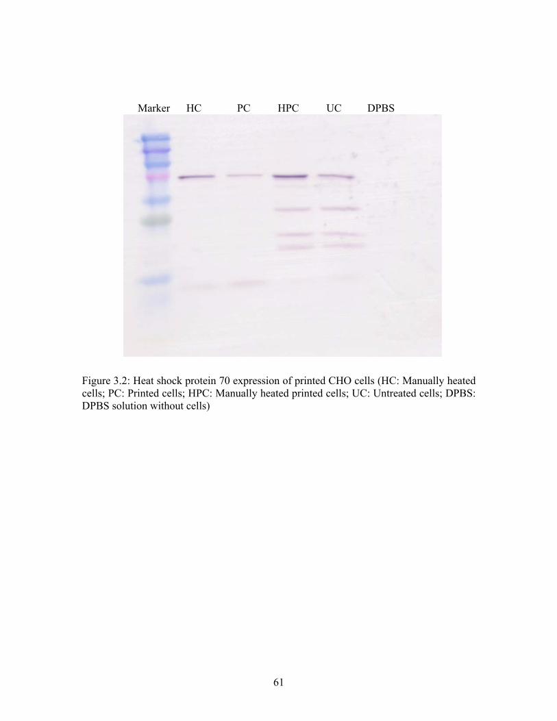
Marker HC PC HPC UC DPBS
Figure 3.2: Heat shock protein 70 expression of printed CHO cells (HC: Manually heated cells; PC: Printed cells; HPC: Manually heated printed cells; UC: Untreated cells; DPBS: DPBS solution without cells)
61

Cell Membrane Permeability of Printed CHO Cells
Figure 3.3 shows cells incubated and stained with dextran molecules 15 min after
printing, we could clearly see the red fluorescence from the Texas red-labeled dyes with
molecular weights up to 40,000. For the printed cells incubated with 70,000 MW dextran
molecules (Figure 3.3D), we did not see significant fluorescence, indicating the limited
penetration of the dye. Control samples showed no significant fluorescence for any
dextran dye employed as shown in Figure 3.3E for the lowest molecular weight dextran
dye (3,000 D). Figure 3.4 showed series images taken at z-axis with 1.5µm interval for
printed cells incubated with Texas Red conjugated dextran molecules of 3000MW. The
transient nature of these pores is shown in Figure 3.5 which shows the evolution of the
approximate pore size with time. We observed, that only 3,000 MW dextran molecules
penetrated the cell if we incubated the cells one hour, thus we estimate the pore size after
60 min to have shrunk to somewhere between the Stokes diameter of 3,000 and 10,000
kD dextran molecules, or approximately 37Å. One hour and a half after the printing, the
size of pores reduced to approximately 22Å. After 2 hours of printing, even PI couldn’t
enter the printed CHO cells. The pores appeared closed or repaired as none of the dyes
penetrated.
62

A
B
C
D
E
63

Figure 3.3: Confocal microscopy of printed CHO cells cell membrane pore sizes study using Texas-Red fluorescent dextran molecular dyes (RHOD cy3 Texas Red channel). (A) Dextran 3,000; (B) Dextran 10,000; (C) Dextran 40,000 (D) Dextran 70,000 (E) Pipetted control sample incubated with Dextran 3,000
64

Time after
Printing PI (16Ǻ)
Dextran
3000 (28Ǻ)
Dextran
10000 (46Ǻ)
Dextran
40000 (90Ǻ)
Dextran
70000
(120Ǻ)
0.25 hour O O O O X
1 hour O O X X X
1.5 hour O X X X X
2 hour X X X X X
Table 3.2: Fluorescent molecules penetrated through damaged cell membrane after cell printing (O: molecules entered the cells; X: molecules didn’t enter the cells).
65

Figure 3.4: Series confocal microscopy images at z-axis with 1.5µm interval showed the fluorescent dextran molecules were inside the cells.
66

Pores Repaired by Cells after Printing
0
20
40
60
80
100
120
0.25 1 1.5 2Time (hours)
Por
e S
izes
(A)
105Ǻ
37Ǻ
22Ǻ
Repaired
Figure 3.5: Rate of repairing pores developed during printing process by CHO cells.
67

Discussion
Quantification
In previous studies, we showed CHO cells can survive the thermal inkjet printing
process with more than 90% viability (13). The focus of this study was to determine the
exact cell numbers printed from different cell concentrations and, thus, optimize the cell
concentration for the bio-ink. Figure 3.1 shows that the cell concentration of
8.2x10⁶cells/ml had the highest amount of cells printed through the printer head. In Table
3.1 some important printing parameters are summarized. The cell concentration that
should result in an average of one cell per drop depends on the drop volume following c
= 1000/Vdrop, where c is the concentration in 106 cells/ml and Vdrop the drop volume in
pL. Thus, a concentration of 7.7x10⁶ cells/ml of ink should assure that each drop contains
one cell. In fact, this is close to our experimental results where a concentration of
8.2x10⁶cells/ml was used and we observed that most drops contained cells with some
drops containing more than one cell. The highest cell concentration which was 16.5 x
106cells/ml also had apparently lower number of cells printed than the 8.2 x 10⁶ cells/ml.
This may be the cells sticking together during the printing. The diameter of the printer
head nozzle is 48 µm and the average diameter of the printed CHO cells were 28 to 30
µm. When two or more cells sticking together, sometimes they could not pass through the
nozzle channel. It also had higher possibility for the cells to be sticking together at high
cell concentration.
68

Heat Shock Protein Expression
When cells are undergoing sudden changes of environment, such as extreme
change of temperature, they express elevated amount of heat shock proteins to protect
other proteins from denaturing (19). The expressed heat shock proteins bind to the other
proteins to protect from disruption of secondary bonds. We wanted to look at the heat
shock protein expression in the printed CHO cells in order to determine if the heat
generated during firing caused an elevated level of HSP which may be an indication of
further potential damage to printed cells. As shown in Figure 3.2, all samples including
the negative controls showed some HSP expression, which has been described in the
literature (17). In fact, every cell expresses HSP, but the amount will be elevated when
the cells are undergoing extreme environment changes. The printed CHO cells had lower
heat shock protein expression than the manually heated CHO cells, and a somewhat
comparable expression to the unprinted controls. Although the modified thermal inkjet
printer had a print frequency of 3.6 kHz, the heating time during the drop ejection process
was as short as 2 microseconds during which 1.3x10⁻⁵ Joules of energy is delivered (23).
If all the energy was used to heat the printed drop, in fact it was not, the temperature of
the drop would increase 24°C1. As the cell printing was executed at room temperature,
the printed cells would be heated to at most 49°C. According to Wang’s work on the
kinetics of Hsp70 expression, the cells wouldn’t respond until at least 1.5 hours at 43°C
and would be expected to have the highest expression when heated continuously for 16
hours at 43°C (24). The drops, however, will cool down to room temperature within
1 Estimated from ∆T = E / (cp * Vdrop); cp – heat capacity of the ink (4.18 JK-1g-1); E – energy supplied by the heating element (1.3x10⁻⁵ J); Vdrop – volume of the drop (1.3 x 10⁻⁷ ml)
69

minutes, thus no elevated HSP levels are observed and we conclude that the printing
process is safe for the cells and the heating time too short for cells to respond via the heat
shock protein mechanism.
Membrane Permeability
The printed CHO cells were studied using dextran molecules with different
molecular weights. A molecule which has been used extensively to estimate the pore
sizes in the cell membranes (25). All the printed CHO cells incubated with dextran
molecules of 3 kD, 10 kD, and 40 kD MW had solid orange fluorescence under
microscope, when the assay was performed shortly after printing. Weak red fluorescence
was also found from the cells incubated with 70 kD dextran molecules (Figure 3.3D).
This may be from the dextran molecules which were attached to the cell membrane.
Another possibility is that the molecules may have been contaminated with lower MW
dextran molecules, as they were not purified after receiving. Still, the fluorescence is
week, which leads us to conclude that the cutoff molecular weight of the pores in the cell
membrane of the printed CHO cells had a range from 40 kD to 70 kD or an average 105Å
pore diameter (26). The series images taken at z-axis of the printed cells stained by Texas
Red conjugated dextran molecules with 3000MW clearly showed the dextran molecules
were inside the cells instead of sticking only outside onto the cell membrane.
The transient nature of the pores has been assumed; given the fact that long term
survival of printed cells has been shown (14). However, we wanted to have a better
understanding of pore sizes dynamics. As Figure 3.4 shows, as soon as 2 hours after
70

printing, virtually no fluorescent molecules were observed penetrating the cells. This was
confirmed by propidium iodide (diameter 16Ǻ) staining the cells, which did not show
significant levels inside the cells.
Conclusions
From the comprehensive study of the heat shock protein expression and cell
membrane morphogenesis, we concluded that the cell printing technology using modified
thermal inkjet printers can be applied for quantitative cell seeding. The low expression of
Hsp70 showed that the cells are not stressed beyond the normal handling, such as
pipetting and centrifuging. During printing, temporary pores opened in the cell membrane
allowing molecules with molecular weight up to 70,000 to pass. This may have
promising applications for plasmid transfer for foreign protein expression and drug
delivery purpose.
71

References
(1) Langer, R. and Vacanti, J. P. (1993) Tissue Engineering, Science 260, 920-926.
(2) Tsang, V. L. and Bhatia, S. N. (2004) Three-dimensional tissue fabrication, Advanced Drug Delivery Reviews 56, 1635-1647.
(3) Mironov, V., Boland, T., Trusk, T., Forgacs, G., and Markwald, R. R. (2003) Organ printing: computer-aided jet-based 3D tissue engineering, Trends in Biotechnology 21, 157-161.
(4) Wilson, W. C. and Boland, T. (2003) Cell and organ printing 1: Protein and cell printers, Anatomical Record Part a-Discoveries in Molecular Cellular and Evolutionary Biology 272A, 491-496.
(5) Beeson R (1998) Thermal (TIJ) or Piezo? Who cares?, in IMI 7th Annual Ink Jet Printing Conference.
(6) Canfield B, Clayton H, and Yeung KWW (1997) US Patent 5673069.
(7) Hock SW, Johnson DA, and Van Veen MA (1996) US Patent 5521622.
(8) Hudson KR, Cowan PB, and Gondek JS (2000) US Patent 6042211.
(9) de Jong, J., de Bruin, G., Reinten, H., van den Berg, M., Wijshoff, H., Versluis, M., and Lohse, D. (2006) Air entrapment in piezo-driven inkjet printheads, Journal of the Acoustical Society of America 120, 1257-1265.
(10) Seetharam R and Sharma SK (1991) Purification and Analysis of Recombinant Proteins, pp 69, Marcel Dekker.
(11) Boland, T., Xu, T., Damon, B., and Cui, X. (2006) Application of inkjet printing to tissue engineering, Biotechnol. J. 1, 910-917.
(12) Roth, E. A., Xu, T., Das, M., Gregory, C., Hickman, J. J., and Boland, T. (2004) Inkjet printing for high-throughput cell patterning, Biomaterials 25, 3707-3715.
(13) Xu, T., Jin, J., Gregory, C., Hickman, J. J., and Boland, T. (2005) Inkjet printing of viable mammalian cells, Biomaterials 26, 93-96.
(14) Xu, T., Gregory, C. A., Molnar, P., Cui, X., Jalota, S., Bhaduri, S. B., and Boland, T. (2006) Viability and electrophysiology of neural cell structures generated by the inkjet printing method, Biomaterials 27, 3580-3588.
72

(15) Christians, E. S., Yan, L. J., and Benjamin, I. J. (2002) Heat shock factor 1 and heat shock proteins: Critical partners in protection against acute cell injury, Crit Care Med. 30, S43-S50.
(16) Tissieres, A., Mitchell, H. K., and Tracy, U. M. (1974) Protein synthesis in salivary glands of Drosophila melanogaster: relation to chromosome puffs, J. Mol. Biol. 84, 389-398.
(17) Schlesinger, M. J. (1990) Heat shock proteins, J. Biol. Chem. 265, 12111-12114.
(18) Cyr, D. M., Langer, T., and Douglas, M. G. (1994) Dnaj-Like Proteins - Molecular Chaperones and Specific Regulators of Hsp70, Trends in Biochemical Sciences 19, 176-181.
(19) Hartl, F. U. and Hayer-Hartl, M. (2002) Protein folding - Molecular chaperones in the cytosol: from nascent chain to folded protein, Science 295, 1852-1858.
(20) Schlesinger MJ, Tissieres A, and Ashburner M (1982) Heat shock proteins: from bacteria to man Cold Spring Harbor Laboratory, Cold Spring Harbor, NY.
(21) Jakab, K., Neagu, A., Mironov, V., Markwald, R. R., and Forgacs, G. (2004) Engineering biological structures of prescribed shape using self-assembling multicellular systems, Proceedings of the National Academy of Sciences of the United States of America 101, 2864-2869.
(22) Xu, T., Petridou, S., Lee, E. H., Roth, E. A., Vyavahare, N. R., Hickman, J. J., and Boland, T. (2004) Construction of high-density bacterial colony arrays and patterns by the ink-jet method, Biotechnology and Bioengineering 85, 29-33.
(23) Buskirk, W. A., Hackleman, D. E., Hall, S. T., Kanarek, P. H., Low, R. N., Trueba, K. E., and Vandepoll, R. R. (1988) Development of A High-Resolution Thermal Inkjet Printhead, Hewlett-Packard Journal 39, 55-61.
(24) Wang, S. H., Diller, K. R., and Aggarwal, S. J. (2003) Kinetics study of endogenous heat shock protein 70 expression, Journal of Biomechanical Engineering-Transactions of the Asme 125, 794-797.
(25) Shattil, S. J., Cunningham, M., Wiedmer, T., Zhao, J., Sims, P. J., and Brass, L. F. (1992) Regulation of Glycoprotein-Iib-Iiia Receptor Function Studied with Platelets Permeabilized by the Pore-Forming Complement Proteins C5B-9, Journal of Biological Chemistry 267, 18424-18431.
73

(26) Gretz, J. E., Norbury, C. C., Anderson, A. O., Proudfoot, A. E. I., and Shaw, S. (2000) Lymph-borne chemokines and other low molecular weight molecules reach high endothelial venules via specialized conduits while a functional barrier limits access to the lymphocyte microenvironments in lymph node cortex, Journal of Experimental Medicine 192, 1425-1439.
(27) Harmon, J. P. and Widder, J. A. (1988) Integrating the Printhead Into the Hp Deskjet Printer, Hewlett-Packard Journal 39, 62-66.
74
CHAPTER FOUR
SIMULTANEOUS DEPOSITION OF HUMAN MICROVASCULAR ENDOTHELIAL
CELLS AND BIOMATERIALS FOR HUMAN MICROVASCULATURE
FABRICATION USING THERMAL INKJET PRINTING TECHNOLOGY
Introduction
From previous study, we confirmed thermal inkjet printing was safe to print
mammalian cells. Now we could continue our human microvasculature fabrication using
human microvascular endothelial cells (HMEC) and appropriate biomaterials using this
technology. The goal of tissue engineering is to solve the organ donor shortage by
fabricating the replacement for the lost or damaged tissues and organs (1). Recently, there
are many successes achieved in tissue engineering. However, these successes are limited
in relatively thin tissue structures, like skin and bladder (2, 3). These engineered tissues
can be supported by the diffusion of nutrients from the host vasculature. However, when
the thickness of the engineered tissue exceeds to 150 to 200 µm, it will surpass the
oxygen diffusion limitation. Then tissue engineers must create functional vasculatures
into the engineered tissues to supply the cells with oxygen and nutrients, also to remove
the waste product from the cells (4). This is an unsolved issue in traditional tissue
engineering so far (5). However, this critical issue could be solved by cell printing
technology which is based on inkjet printing.
Inkjet printing is a non-contact printing technique. Inkjet printers have the ability
to reproduce the data onto substrate with tiny ink drops by receiving data from computers
75

(6). Drop-on-demand means the ink drops are ejected only where and when they are
required to create the images on the substrate. The inkjet printer has high operating
frequency, high orifice density, integrated power, and interconnect electronics. For
thermal inkjet printers, little air bubbles are created by heating and then collapse to
provide the pressure pulse to eject a very small drop of ink out of the nozzle (6). The
current pulse lasts a few microseconds and raises the plate temperature as high as 300 °C
(7). Inkjet printing technology has also been widely used in electronics and micro-
engineering industries for printing electronic materials and complex integrated circuits
(8). Recently, inkjet technology has been successfully applied into biomedical field, such
as drug screening, genomics, and biosensors (9-11). Although biological molecules and
structures are usually thought to be fragile and sensitive, DNA molecules have been
directly printed onto glass slides using commercial inkjet printers for fabrication of high-
density DNA microarrays without degradation (12).
Our lab has successfully developed a novel inkjet printing application using the
commercial available inkjet printers to print cells and biomaterials for 3D cellular
scaffolds (13). We showed that the standard HP and Canon desktop inkjet printers can be
modified to perform cell printing. Organ printing, defined as computer-aided inkjet based
tissue engineering, has the advantages to construct 3D structures with living biological
elements. An important advantage of this process is the ability to simultaneously deposit
living cells, nutrients, growth factors, therapeutic drugs along with biomaterial scaffolds
at the right time and location (14). This technology can also be used for the
microvasculature fabrication using appropriate biomaterials and cells.
76

Fibrin plays a significant role in natural wound healing. Fibrin gel has been
widely used as sealant and adhesive during surgery. Fibrin Glue is used as skin grafts and
tissue engineered skin replacements (15). Fibrin can be produced from the patients’ own
blood and used as an autologous scaffold for tissue engineering (16). Fibrin can be
polymerized using fibrinogen and thrombin solutions at room temperature (17). Fibrin
gels might promote cell migration, proliferation, and matrix synthesis through the
incorporation of the transforming growth factor β and platelet derived growth factors
(18). Fibrin has also been utilized in tissue engineering to engineer tissues with skeletal
muscle cells (19), smooth muscle cells (20), and chondrocytes (21).
Endothelial cells form the whole inner lining of cardiovascular system and have a
remarkable capacity to adjust their number and arrangement to suit local requirements.
Almost all tissues depend on a blood supply and the blood supply depends on endothelial
cells. Endothelial cells are the only cells to form capillaries. They create an adaptable
life-support system spreading into almost every region of the body. Endothelial cells
extending and remodeling the network of blood vessels makes it possible for tissue
growth and repair (angiogenesis) (22).
In our study, a modified Hewlett-Packard Deskjet 500 inkjet printer was used to
simultaneously deposit human microvascular endothelial cells and fibrin to form the
microvasculature. HP Deskjet 500 inkjet printer has the droplet volume of 130 pL for
each drop of ink. There are 50 firing nozzles on the printer head and the actual heating
occurs at 10-µs pulse. The energy supplied during the printing process is transferred into
kinetic energy and heating of the ink drop. Mathematical modeling studies indicated that
77
the bulk drop temperature in the ink rises between 4 and 10 degrees above ambient
during printing. This makes it possible for printing living systems (23). It has been proved
successful to print cell suspensions (24).
Materials and methods
Materials
Human microvascular endothelial cells (HMVEC) were provided by Professor
Peter I. Lelkes at Drexel University. MCDB 131 medium, fetal bovine serum, penicillin
and streptomycin, sodium bicarbonate, L-glutamine, hydrocortisone, human recombinant
epidermal growth factor, heparin, Dulbecco’s phosphate buffered saline solution (DPBS),
trypsin-EDTA, fibrinogen from bovine plasma, thrombin from bovine plasma, bovine
serum albumin (BSA), lectin-fluorescein isothiocyanate conjugate were from Sigma
Chemicals (St. Louis, MO, USA). Live/Dead Viability/Cytotoxicity Kit for mammalian
cells was from Invitrogen (Carlsbad, CA, USA). IEC Centra-8R centrifuge was from
International Equipment Company (Needham, MA, USA). Microprocessor controlled
280 series water bath was from Precision Scientific (Winchester, VA, USA). Glass
microscope cover slips and 35mm tissue culture Petri-dishes were from Fisher Scientific
(Pittsburgh, PA, USA). HP DeskJet 500 inkjet printer and HP 51626A black ink
cartridges were from Hewlett-Packard Company (Palo Alto, CA, USA). Advanced Micro
Osmometer (Model 3300) was from Advanced Instruments, Inc (Norwood, MA, USA).
Zeiss Axiovert S100 UV microscope and Zeiss LSM 510 laser scanning microscope were
from Carl Zeiss (Minneapolis, MN, USA). Electromechanical testing system was from
78

MTS System Corporation (Eden Prairie, MN, USA). Hummer 6.2 sputter coater was
from Anatech Ltd (Hayward, CA, USA). Hitachi S4700N field emission scanning
electron microscope was from Hitachi (Tokyo, Japan).
Thrombin and Fibrinogen Solution Preparation
In order to assure prompt and best polymerization of fibrin gel after printing,
appropriate concentrations of thrombin and fibrinogen solutions were prepared. The
thrombin solution was made using 50 Unit/ml thrombin and 80mM Ca2+ in DPBS. The
concentration of fibrinogen is 60 mg/ml. Thrombin solution was used as ink and
fibrinogen was substrate on a microscope cover slip (bio-paper). After printing, the
printed samples were incubated at 37°C for 5 to 10 minutes until white printed scaffolds
were observed.
Osmolality Study
To assure the minimum deformation (swelling) of the printed fibrin gel in the
culture media, matched osmolality is required for endothelial cells culture media (MCDB
131), thrombin solution, and fibrinogen solution. Serum free MCDB 131 media, 1x PBS,
and distilled water were used to make thrombin and fibrinogen solutions for osmolality
study. The osmolality of different solutions was tested using Advanced Micro
osmometer.
79

Fabrication of Fibrin Channels
HP Deskjet 500 printer and HP 51626A cartridges were modified to
print/fabricate fibrin channels. A grid pattern was used to print fibrin. 50 Unit/ml
thrombin and 80mM Ca2+ in 1x DPBS was used as ink to print onto 60 mg/ml fibrinogen
solution. The printed samples were incubated for 10 to 15 minutes after the printing for
fibrin cross-linking. The printed fibrin fibers were prepared for tensile testing and SEM.
SEM of Printed Fibrin Scaffold
The microstructure of printed fibrin fibers were examined by a scanned electron
microscope. The printed fibers were first dried in 100% ethanol overnight. Then were
critically dried under vacuum and CO2. After that, the dried fibers were cut through in the
middle for the cross section study. The fixed fibers were sputter-coated with a thin layer
of Chromium using the Hummer 6.2 sputter coater in 100 mTorr vacuum argon
environment for a 5 minutes period and 10 mA of current. SEM images were taken using
the Hitachi SEM mentioned above at a 5 kV accelerating voltage.
Mechanical Properties Study of Printed Fibrin
Mechanical properties study of the printed fibrin fibers were tested by stretching
the sample at a constant deformation rate of 5 mm/min at room temperature. The fibers
were gripped on an MTS electromechanical testing system for uni-axial tensile testing.
The original data were achieved and analyzed using the software coming with the MTS
system (TestWorks, MTS System Corporation). The elastic modulus and ultimate tensile
80

strength (UTS) were from the acquired stress-strain data. The elastic modulus was
defined as the slope of the linear part of the stress-strain curve and the highest stress
which caused the fiber to break is the UTS.
Cell culture and Bio-ink Preparation
Human microvascular endothelial cells (HMVEC) were cultured in MCDB 131
media supplemented with FBS, L-glutamine, hydrocortisone, HEGF and heparin. The
culture condition is standard at 37°C with 5% CO2 for 10 days before passaging. Media
was changed every two days. During passaging, cell suspension was centrifuged at
1000rpm for 5 minutes. The supernatant was aspirated and the cell pellet was
resuspended using 1 ml 1X PBS to get the cell suspension. The bio-ink was made by
mixing the same volume of cell suspension and 100 units/ml thrombin with 160 mM Ca2+
in 1x DPBS. The final condition of bio-ink has 1 million cells/ml HMVEC, 50 Unit/ml
thrombin, and 80mM Ca2+ in 1x DPBS.
Fabrication of Microvasculature within Fibrin Channels
The bio-ink mentioned above was added into modified HP 51626A cartridge. 60
mg/ml fibrinogen solution was used to make the bio-paper on a microscope cover slip. A
modified HP Deskjet 500 printer was used to print a 2D grid pattern using the bio-ink
(HMVEC with thrombin/Ca2+) onto the fibrinogen bio-paper. This made the cells
simultaneously deposited along with fibrin channel formation. The printed pattern was
incubated for 20 minutes for the printed cells attaching onto the fibrin channels. This will
81

also allow the printed fibrin channel to crosslink. After that, a few drops of MCDB-131
media was added onto the printed pattern for nutrient and moisture. The patterns were
then cultured at 37°C with 5% CO2 for 21 days. Media was exchanged for every two days
during the culture.
Fluorescent Staining of Printed Microvasculature
Lectin-fluorescein isothiocyanate conjugate (FITC-coupled lectin stain) and
Live/Dead Viability/Cytotoxicity Kit were used to stain the printed fibrin channels and
HMVEC. For FITC-coupled lectin stain, the samples were first blocked using 2% BSA
(blocking solution) for one hour at room temperature. Then the samples were stained
using FITC-coupled lectin staining (20µg/ml in blocking solution) overnight at 37°C with
5% CO2. Samples were then washed using blocking solution twice following 1X PBS for
another two times. Zeiss LSM 510 confocal microscope was used to look at the cells. For
live/dead assay, the staining solution was made by adding 5µl 4mM calcein AM and 20µl
2mM ethidium homodimer-1 into 1x PBS solution. The samples were incubated in the
staining solution for 30 to 45 minutes at room temperature. Zeiss Axiovert S100 UV
microscope was used to look at the samples.
Integrity of Printed Microvasculature
Texas Red conjugated dextran molecules were applied to the printed
microvasculature cultured for 14 days. The samples were incubated at 37°C for 40
82

minutes at darkness. LSM confocal microscope was used to look at the possible dextran
molecules invasion to the cultured microvasculature.
Fluorescent Imaging of Printed Microvasculature
Printed human microvasculature in fibrin channels were cultured for 21 days
before analyzed using Live/Dead viability/cytotoxicity assay. Z-series images with frame
size of 512x512 were taken using Zeiss LSM 510 confocal microscope with the interval
of 5 µm. The series Z-axis fluorescent images were rendered into 3D images using
ImageJ software.
Results
Osmolality of Thrombin and Fibrinogen Solution
The osmolality of thrombin solution of 50 Unit/ml thrombin and 80mM Ca2+ in
1x DPBS is 359 mosM. Fibrinogen solution was made using distilled water and the
osmolality of 60 mg/ml fibrinogen is 341 mosM. After fibrin printed, there were minor
deformations of the fibrin in the HMVEC culture media.
Printed fibrin channels
Figure 4.1 shows the fibrin grid printed using a modified HP Deskjet 500 printer.
The printed fibrin gel kept good shape after the print. Only minor changes of the pattern
were found. The higher magnified images showed channel structures for cell seeding and
microvasculature fabrication.
83

2 mm 50 µm
25 µm
Figure 4.1 Printed fibrin fibers with grid pattern. Light microscopy images of the printed fibrin gel after 20 minutes of print.
Critical dried fibrin gels were studied using Toshiba scanning electron microscope
for the channel structure study. Figure 4.2 (A) showed the cross section of printed fibrin
fiber structure. The higher resolution image (Figure 4.2 (B)) of the printed fibrin surface
showed many nano-sized fibers.
84

A
B
Figure 4.2 Cross section of printed fibrin fiber (A). Nano-sized fiber structure of printed fibrin surface shows friendly for cell to attach (B).
85

Mechanical properties of printed fibrin fibers
Using the MTS electromechanical testing system and the TestWorks software
coming with the system, we had the elastic modulus of 2.9 ± 0.8 MPa and the UTS of 1.7
± 0.5 MPa (n=4). The average diameter of the tested fibrin fibers was 93 µm (n=4).
Microvasculature fabrication of fibrin and HMVEC
Figure 4.3 shows the live/dead assay of the printed HMVEC after 24 hours. The
printed cells aligned a line in the printed fibrin channel. After 7 days, the printed
HMVEC started to proliferate in fibrin grid structure which is shown in Figure 4.4. After
14 days of culture, the printed HMVEC formed a line from the FITC-coupled lectin
staining (Figure 4.5). When the printed HMVEC was cultured for 21 days, the printed
cells aligned themselves and proliferated to form a confluent lining in the fibrin channel
(Figure 4.6).
Figure 4.3 Printed HMVEC in fibrin channel after 24 hours (live/dead assay)
86

A
B
Figure 4.4 Printed HMVEC in fibrin channel after 7 days (live/dead assay). A, B shows different positions in the printed grid pattern.
87

Figure 4.5 Printed HMVEC in fibrin channel after 14 days (FITC-lectin assay)
Figure 4.6 Printed HMVEC in fibrin channel after 21 days (live/dead assay)
88

Channel Structure of Printed Human Microvasculature
Figure 4.7 shows a tube image of the printed human microvasculature. Figure 4.8
shows the Z-series images of the channel. Using free 3D image render software ImageJ, a
channel structure of printed human endothelial cells was found (Figure 4.9).
Figure 4.7 Printed microvasculature tube. Left: Fluorescent image of cells. Right: DIC image of fibrin channel.
89

Figure 4.8 Z-series images of printed microvasculature tube.
90

Figure 4.9 Orthogonal sections display mode of printed microvasculature tube.
91

Integrity of Printed Human Microvasculature
Figure 4.10 (A) shows a printed microvasculature cultured for 14 days. Figure
4.10 (B) shows the fluorescence from Texas Red conjugated dextran molecules with
3000MW which stained the sample.
BA
Figure 4.10 (A) Printed microvasculature cultured for 14 days. (B) Fluorescence image of Texas Red conjugated dextran molecules of 3000MW.
Discussion
Osmolality of Thrombin and Fibrinogen Solution
The osmolality of MCDB-131 culture media was 348 mosM. Osmolality of
thrombin solution of 50 Unit/ml thrombin and 80mM Ca2+ in 1x DPBS is 359 mosM.
Fibrinogen solution was made using distilled water and the osmolality of 60 mg/ml
fibrinogen is 341 mosM. So the thrombin solution of 50 Unit/ml thrombin and 80mM
Ca2+ in 1x DPBS and 60 mg/ml fibrinogen in distilled water have the similar osmolality
which is very close to MCDB-131 media. After the fibrin fibers were printed, there were
also minor changes of the fibrin in the HMVEC culture media. So this can avoid the
distortion and swelling of the printed fibrin fibers.
92

Printed fibrin channel structure
Fibrin was printed into a grid pattern. After 20 minutes of printing, the printed
fibrin patterns were checked using a light microscopy. Only minor deformations of the
pattern were found. The hollow channel structure showed in SEM image of printed fibrin
fiber was promising for cell seeding and microvasculature fabrication. The nano-sized
fibers found in channel surface showed good attachment for cells to attach.
Mechanical properties of printed fibrin fibers
The printed fibrin fiber had elastic modulus of 2.9 ± 0.8 MPa and UTS of 1.7 ±
0.5 MPa (n=4). The average diameter of the tested fibrin fibers is 93 µm (n=4). Using
methods mentioned to estimate the up limit of burst pressure (24), we estimated the burst
pressure of the printed fibrin fiber of 2955mmHg. Comparing with the average burst
pressure of tissue-engineered blood vessels which is 3340 mmHg (25), and the extruded
fibrin fibers with 55-65 µm diameters of UTS of 4.5 MPa by Cornwell and Pins (26), the
mechanical properties of our printed fibrin fibers are very good.
Microvasculature fabrication of fibrin and HMVEC
From figure 4.3, the printed cells aligned very well by the printer and were ready
to proliferate after 24 hours. After 7 days, the printed HMVEC proliferated in the
fabricated fibrin grid channels and were going to connect each other. Two weeks later of
printing, the cells connected together and formed a line. When the printed HMVEC was
cultured for 21 days, the printed cells aligned themselves and proliferated to form a
93

confluent lining in the fibrin channel (Figure 4.6). This shows the successes and
possibility to use the modified thermal inkjet printers and ink cartridge to simultaneously
deposit fibrin and HMVEC for human microvasculature (capillaries) fabrication.
Tubulogenesis Study of Printed Human Microvasculature
During angiogenesis, the proliferated endothelial cells form tubular structure or
capillaries (27). The series images of Z-axis (Figure 4.8) clearly showed the channel
structure of the fabricated microvasculature tube. A 3-D channel was rendered using
ImageJ software. This showed the functionality of the printed human endothelial in the
fabricated fibrin channel. The proliferated endothelial cells aligned inside the fibrin
channel and intended to form a tubular structure. This showed simultaneous deposition of
endothelial cells and fibrin gel using thermal inkjet printing technology can be used for
human microvasculature fabrication.
Integrity Study of Printed Human Microvasculature
It is not necessary for the printed and cultured human microvasculature to be
leaking-proof. However, somewhat integrity is needed for this fabricated structure. Texas
Red conjugated dextran molecules with 3000MW were applied to the printed samples. In
a microvasculature cultured for 14 days, the cells were not confluent yet. We can see
some defects in the structure (Figure 10A). However, the dextran molecules still had
difficulties to get inside the microvasculature. This showed from the obvious red
94

fluorescence difference between the inside and the outside the microvasculature. This
study showed the integrity of the printed microvasculature.
Conclusions
Through the cell printing study of the fibrin gel and HMVEC for
microvasculature fabrication, we concluded that human endothelial cells can be
simultaneously deposited along with the biomaterials (fibrin) for microvasculature
fabrication using the modified thermal inkjet printers. The growth factor (VEGF)
enhanced medium can be used to culture printed cell and biomaterial construct for
promoted microvascularization in vitro. The rendered 3D channel structure through the
Z-series images showed the functionality of the printed human microvasculature. The
endothelial cells tended to form a tube inside the fibrin channel. The fabricated
microvasculature also showed integrity after being cultured for 14 days. The cell/organ
printing technology can be a promising solution for branched 2D/3D human capillary tree
fabrication and organs with complex microvasculature, like lung, liver, and heart.
95

References
(1) Langer R and Vacanti JP. Tissue engineering. Science. 1993, 260, 920-26
(2) Jain RK, Au P, Tam J, D DG and Fukumura D. Engineering vascularized tissue.
Nature Biotechnology 23, 821-823, 2005
(3) Atala A, Bauer S, Soker S, Yoo J, Retik A, Tissue-engineered autologous
bladders for patients needing cystoplasty. The Lancet 2006, Volume 367, Issue
9518, Pages 1214-1246
(4) Levenberg S, Rouwkema J, Macdonald M, Garfein ES, Kohane DS, Darland DC,
Marini R, van Blitterswijk CA, Mulligan RC, D’Amore PA, Langer R.
Engineering vascularized skeletal muscle tissue. Nat Biotechnol 2005;23:879-884
(5) Tsang VL, Bhatia SN. Three-dimensional tissue fabrication. Adv. Drug Deliver
Rev. 2004; 56(11): 1635-47
(6) Mohebi MM and Evans JRG. 2002. A drop-on-demand ink-jet printer for
combinatorial libraries and functionally graded ceramics. J. Combinatorial
Chemistry 4 (4), 267-74
(7) Cao T. et al. 2003. Scaffold design and in vitro study of osteochondral coculture
in a three-dimensional porous polycaprolactone scaffold fabricated by fused
deposition modeling. Tissue Engineering 9, S103-S112
(8) Kawase T, et al. 2001. Inkjet printed via-hole interconnections and resistors for
all-polymer transistor circuits. Advanced Materials 13 (21), 1061
(9) Blanchard AP, Et al. 1996. High-density oligonucleotide arrays. Biosensors and
Bioelectronics 11 (6-7), 687-90
96

(10) Hart AL, et al. 1996. On the use of screen and inkjet printing to produce
amperometric enzyme electrodes for lactate. Biosensors and bioelectronics 11
(3), 263-70
(11) Lemmo AV, et al. 1997. Characterizatoin of an inkjet chemical microdispenser
for combinatorial library synthesis. Analytical Chemistry 69 (4), 543-51
(12) Okamoto T, et al. 2000. Microarray fabrication with covalent attachment of
DNA using Bubble Jet technology. Nature Biotechnology 18 (4), 438-41
(13) Wilson WC and Boland T. 2003. Cell and organ printing 1: Protein and cell
printers. Anatomical Record Part a-Discoveries in Molecular Cellular and
Evolutionary Biology 272A (2), 491-96
(14) Sun W, et al. 2004. Computer-aided tissue engineering: overview, scope and
challenges. Biotechnology and Applied biochemistry 39, 29-47
(15) Currie L, Sharpe JR and Martin R. 2001. The use of fibrin glue in skin grafts
and tissue-engineered skin replacements: a review. Plastic & reconstructive
surgery. 108(6):1713-1726, November 2001
(16) Fussenegger M, et al. 2003. Stabilized autologous fibrin-chondrocyte constructs
for cartilage repair in Vivo. Annals of Plastic Surgery. 51(5):493-498,
November 2003
(17) Perka C, Spitzer RS, Lindenhayn K, Sittinger M, Schultz O. J. Biomed. Mater.
Res. 2000, 17, 587
(18) Sierra D, Saltz R. Surgical Adhesives and Sealants: Current Technology and
Application; Technomic; Lancaster, 1996
97

(19) Ye Q, Zund G, Benedikt P, Jockenhoevel S, Sakyama S, Hubell JA, Turina M.
Eur. J. Cardio-Thorac. Surg. 2000, 17, 587
(20) Ikari Y, Fujikawa K, Yee KO, Schwartz SM. J. boil. Chem. 2000, 275, 12799
(21) Meinhart J, Fussenegger M, Hobling W. Ann. Aplast. Surg. 1999, 42, 673
(22) Goss, R.J. The physiology of growth, pp. 120-137. New York: Academic press,
1978
(23) Xu T, Jin J, Gregory C, Hickman JJ, Boland T. Inkjet printing of viable
mammalian cells. Biomaterials 2005, 26, 93-99
(24) Pardo L, Boland T. A quantitative approach to study structures and orientation
at self-assembled monolayer/fluid interfaces. J. Colloid Interface Sci. 2003, 257,
116-120
(25) Zhu XK, Leis BN. Theoretical and numerical predictions of burst pressure of
pipelines. Transactions of the ASME. November 2007. Vol. 129, 644-652
(26) L’Heureux N, McAllister TN, de la Fuente LM. Tissue-engineered blood vessel
for adult arterial revascularization. N Engl J Med. 357;14, 1451-1453. October
2007
(27) Cornwell KG, Pins GD. Discrete crosslinked fibrin microthread scaffolds for
tissue regeneration. J Biomed Mater Res A. 2007 Jan 31;: 17269139
(28) Folkman, J, Klagsbrun, M: Angiogenetic factors. Science 235: 442-447, 1987
98

CHAPTER FIVE
CONCLUSIONS
Through the comprehensive study of the heat shock protein expression and cell
membrane morphogenesis of the printed mammalian cells, we found minor difference of
the expressed heat shock proteins from the printed cells comparing that from the
untreated cells. The heating time during the printing is too short for the printed cells to
response and initiated the heat shock expression and protection mechanism. The shearing
and stress during the printing delivered to the printed cells did develop pores in the cell
membrane. However, the printed cells still have a survive rate up to 90%. This showed
the pores developed in the cell membrane are not big enough to kill the printed cells.
From the dextran molecules pore size study, the average pore size in the cell membrane
of the just printed cells was 105Ǻ. The pores shrank to 37Ǻ after one hour and were
repaired by cells after just 2 hours of printing. The newly developed pores allowed
molecules with molecular weight up to 70000 to pass. This study showed the cell printing
technology can not only for tissue engineering fabrication, it also has promising
possibilities for plasmid transfer of foreign protein expression and targeted drug delivery
purpose.
After confirmed the cell printing technology was safe for the printed cells, in the
continued study of the fibrin gel and HMVEC for microvasculature fabrication, we
concluded that human endothelial cells can be simultaneously deposited along with the
biomaterials (fibrin) for microvasculature fabrication using the modified thermal inkjet
99

printers. The 3D channel structure rendered from the series Z-axis images showed the
functionality of the printed human microvasculature. The growth factor (VEGF)
enhanced medium can be used to culture printed cell and biomaterial construct for
promoted microvascularization in vitro. The endothelial cells tended to form a tube inside
the fibrin channel. The fabricated microvasculature also showed integrity after being
cultured for 14 days. The cell/organ printing technology can be a promising solution for
engineering tissues with complex microvasculature, such like liver, lung, and heart.
100