Embed Size (px)
Citation preview
�
User Manual
UMHMIBRev 2.0, 06/2007
Human Machine InterfaceHMI 201, 401, 601, 605 & 1205

�
COPYRIGHT NOTICEThis manual is a publication of Brainchild Electronics Co.. Ltd. and is provided for use by its customers only. The contents of the manual are copyrighted by Brainchild Electronics; reproduction in whole or in part, for use other than in support of Brainchild Electronics equipment, is prohibited without the specific written permission from Brainchild Electronics.
SERVICEIf service is required then pack the unit in its original packaging container or, if unavailable, any suitable rigid container. If a substitute container is used, surround the unit with shock absorbing material; damage in shipment is not covered by the warranty. Include a letter with the unit describing the difficulty and Hardware Revision and Software Version. Send to the following address:
Brainchild Electronic.Co.Ltd. 6F, 209, Chung yong Road, Nan Kang Dist, Taipei, Taiwan, R.O.C Tel: +886-2-27861299 Fax: +886-2-27861395 Email: [email protected] All returns will be tested to verify customer claims of noncompliance with the product warranty. Improper return packaging, which makes verification impossible, will void the warranty. If noncompliance is verified and is not due to customer abuse or the other exceptions described with product warranty, Brainchild Electronics will, at its option, repair or replace the Product returned to it, freight prepaid, which fail to comply with the foregoing warranty, provided Brainchild is notified of such noncompliance within the one-year warranty period.
ASSISTANCEThis manual is designed to provide the necessary information for trouble-free installation and operation of your new HMI Series. However, if you need assistance, please call Brainchild Electronic Co. Ltd. at +886-2-27861299 Ext 613 or visit our web site at www. Brainchild.com.tw
MANUAL REVISIONIf you contact us in reference to this manual, please include the following document number Name : User Manual For HMI Document : UMHMIB, 06,2007 Revision : 2.0
Revision Number Document Number Date Description
Rev 1 UM\HMIA 06,2006 20-06-2006 Manual first edition
Rev 2 UM\HMIB 06,2007 20-06-2007 Minor Modification

�
WarrantyCertificate
For New product: This product is warranted against defects in materials and workmanship for a period of 12 months from the date of shipment to Buyer. For Rectified Products: Any product that will be replaced will have Warranty for 6 months or upto Original Product War-ranty period whichever is greater. The warranty is limited to repair or replacement of the defective unit at the option of the manufacturer. This warranty is void if the product has been altered, misused, dismantled, or otherwise abused. ALL OTHER WARRANTIES, EXPRESSED OR IMPLIED, ARE EXCLUDED, INCLUDING BUT NOT LIMITED TO THE IMPLIED WARRANTIES OF MERCHANTABILITY AND FITNESS FOR A PARTICULAR PURPOSE. MAINTENANCE & SERVICE : There are no parts that can be serviced by the user. Service should be performed on a unit substitution basis only. Do not attempt to remove, replace or service any printed circuit board, components or any hardware/software related with display product. If problem within the display product occurs, contact the factory for service information or repair.
IMPORTANT HMI Products are intended to be operator interfaces, to work with PLCs which actually take control actions. It is assumed that the user is well acquainted with the PLC system being used. Never use HMI units to perform emergency STOP applications. It is advised that separate switches be used outside the PLC for ANY emergency Stops.
AnyMechanicalorElectricalModificationtothisUnitwillvoidall Warranties.
�
Contents1.INTRODUCTION.....................................................................................................................................8 1.1Purposeofthismanual 8 1.1.1 HMIBasics 8 1.1.2 HardwareRequirements 9 1.2HMIOverview 10 1.2.1 WhatisaHMI? 10 1.2.2 HowHMIWorks? 11 1.2.3 SpecificationsofHMISeries 15 1.2.� ComparisonBetweenTouchscreenBasedOperatorPanels 162.HARDWARE...........................................................................................................................................................22 2.2 ManagingElectrostaticDischarge 22 2.3 CECompliance 22 2.� EnvironmentalRating 22 2.5 EnvironmentalConsideration 22 2.6 SafetyPrecaution 23 2.7 InstallationInstruction 23 2.8PanelCutoutforHMIModels 2� 2.9 WiringDiagram 26 2.10CommunicationPorts 263.BEFOREYOUBEGIN...........................................................................................................................................27 3.1ConnectingtheHMItoyourComputer 27 3.2 StartingHMIStudioSoftware 28 3.2.1 InstallingHMIStudioSoftware 28 3.2.2 StepsforstartingHMIStudioSoftware 30 3.2.3 UninstallingHMIStudioSoftware 30 3.3 SettingNetworkConfiguration 31�.USINGHMISTUDIOSOFTWARE....................................................................................................................38 �.1HMIStudioMenuStructure 38 �.1.1 FileMenu �0 4.1.2 DefineMenu 41 �.1.3 CommunicateMenu �2 �.1.� UtilitiesMenu �3 4.1.5 HelpMenu 44 �.2CreatingNewApplication �� 4.3CreatingScreens 51 4.3.1 ProtectingHMIApplication 52 4.3.2 ProtectingHMIScreen 53 4.4DataEntryObject 54 4.5DisplayDataObject 54 4.6GlobalAndPowerOnTask 55 4.7GlobalKeys 575.REPRESENTINGDATABYOBJECTSANDWIZARDS.................................................................................58 5.1AlphanumericObjects 58 5.1.1 TextObject 58 5.1.2 DataEntryObject 58 5.1.3 DisplayDataObject 60 5.1.4 Time 63 5.1.5 Date 63
5.1.6AttributesofAlphanumericobjects645.1.7Animationproperties64
5
5.2GraphicWizards 68 5.2.1 Line 69 5.2.2 Rectangle 69 5.2.3 Ellipse 70 5.2.4 RoundedRectangle 70 5.2.5 Bargraph 71 5.2.6 Bitmap 71 5.3Wizards 74 5.3.1 BitButton 75 5.3.2 WordButton 79 5.3.3 BitLamp 82 5.3.4 WordLamp 86 5.3.5 MultipleBargraph 88 5.3.6 AnalogMeter 94 5.3.7 RealTimeTrend 99 5.3.8 NumericKeypad 104 5.3.9 ASCIIKeypad 1076.TASKMANAGEMENT..........................................................................................................................................109 6.1ApplicationTaskList 109 6.2 ScreenTaskList 110 6.3KeyTasklist 112 6.3.1 ForKeypadProducts 113 6.3.2 ForTouchscreenProducts 115 6.�DescriptionofTasks 1167.USINGLANGUAGES............................................................................................................................................135 7.1LanguageConversionUtility 135 7.1.1 SetPCformultiplelanguages 135 7.1.2 ConfiguremultiplelanguagesinHMIStudiosoftware 136 7.2Multi-LanguageTextWizard 137 7.3Exportlanguageconversiontext 138 7.�Workingwithlanguageconversionutility 139
7.5DisplaymultiplelanguagesinHMI 1408.DOWNLOADINGANDUPLOADINGFROMUNIT........................................................................................142 8.1Upload 1�1 8.2Download 1�3 8.3ErrorCatalog 1459.ALARMS..................................................................................................................................................................147 9.1DefineAlarm 147 9.1.1 AlarmDefinition 148 9.1.2 AlarmObject 1�910.TRENDING............................................................................................................................................................150 10.1 RealTimeTrend 150 10.2 DataLogger 155 10.3 HistoricalTrend 15911.LADDERPROGRAMMING..............................................................................................................................165 11.1 PLCLogicBlock 165 11.2 LadderInstructionDetails 166
11.2.1InputInstruction 16711.2.2Transition 16911.2.3OutputInstructions16911.2.�Timers17211.2.5Counters18011.2.6Datacompare18711.2.7Mathoperations19�
6
11.2.8DataMove19911.2.9ShiftInstruction20011.2.10Rotate20311.2.11Logorithm21511.2.12Dataconversion21711.2.13Skipblock21811.2.1�Endblock218. 12.SPECIALFEATURES................................................................................................................................219.12.116PointLinearization 219
12.2 PIDController 222 12.3 HighSpeedTimer 227 12.4 PWMConfiguration 231 12.5 AnalogTotalizer 23413.PRINTING.............................................................................................................................................................237 13.1 PrintingfromHMIunit 237 13.2 PrintingfromHMIstudioSoftware 238 13.3 PrinterPortSetup 2�014.MISCELLANEOUS..............................................................................................................................................241 1�.1 HMIMemoryStatus 2�1 1�.2 FontEditor 2�2 1�.3 AssociateaScreen 2�6 1�.� RealTimeClock 2�7 14.5 OnLineLadderMonitoring 249 14.6 OnLineScreenMonitoring 256 14.7 EthernetSettings 26515.DIAGNOSTICSANDMAINTENANCE............................................................................................................275 15.1 Diagnostics 275 15.1.1EraseKeys 275 15.1.2 Touchscreencalibration 276 15.2 Maintenance 27616.APPENDIX............................................................................................................................................................277 A CommunicationCableDiagrams 277 1 ABMICROLOGICSSERIESTOHMIUNIT(CA-027A-00) 277 2 ABSLCDF1PORTTOHMIUNIT(CA-027B-00) 278 3 AROMATFP0/FPMTOHMIUNIT(CA-015A-00) 279 4 AROMATFP1TOHMIUNIT(CA-015B-00) 280 5 AROMATFP2TOHMIUNIT(CA-015D-00) 281 6 BAUMULLERDRIVE(RS4854-WIRE)TOHMIUNIT(CA-042A-00) 282 7 BAUMULLERDRIVE(RS4842-WIRE)TOHMIUNIT(CA-0042B-00) 283 8 CONTROLTECHNIQUESTOHMIUNIT(CA-100-00) 284 9 DANFOSSDRIVETOHMIUNIT(CA-101-00) 285 10 DELTATOHMIUNIT(CA-044-00) 286 11 FATEKPLCTOHMIUNIT(CA-079A-00) 287 12 GE90SERIESPLCTOHMIUNIT(CA-002-00) 288 13 GE90SERIESSNP-XPLCTOHMIUNIT(CA-106-00) 289 14 IDECMICRO3TOHMIUNIT(CA-025A-00) 290 15 IDECMICROSMARTPLCTOHMIUNIT(CA-025B-00) 291 16 KEYENECKVPLCTOHMIUNIT(CA-018-00) 292 17 KOYODL205PLCTOHMIUNIT(CA-023-00) 293 18 LGMASTERKSERIESPLCTOHMIUNIT(CA-037-00) 294 19 MENTORDRIVEPORTTOHMIUNIT(CA-115A-00) 295 20 MENTORDRIVEPORTTOHMIUNIT(CA-115B-00) 296
7
21 MITUBISHIFXSERIESPLCTOHMIUNIT(CA-0008B-00) 297 22 MITUBISHIFX0PLCTOHMIUNIT(CA-0008A-00) 298 23 OMRONCQMPLCTOHMIUNIT(CA-006B-00) 299 24 OMRONCQM/CPMCMOSPORTTOHMIUNIT(CA-006A-00) 300 25 SIEMENSSTEP7MICRO(S7-200)PLCTOHMIUNIT(CA-029-00) 301 26 SIEMENS-S7300SERIESPLCTOHMIUNIT(CA-029A-00) 302 27 TOSHIBAT1PLCTOHMIUNIT(CA-019A-00) 303 28 TOSHIBAT2PLCTOHMIUNIT(CA-019B-00) 304 29 TOSHIBAT1LINKPORTTOHMIUNIT(CA-046A-00) 305 30 TOSHIBAT2LINKPORTTOHMIUNIT(CA-046B-00) 306 31 TOSHIBAINVERTERSSERIESTOHMIUNIT(CA-050-00) 307 32 UNITELWAY(07/37/57)PLCTOHMIUNIT(CA-26B-00) 308 33 TWIDOPLCTOHMIUNIT(CA-078-00) 309 B PCtoHMICable310
1 RS232InterfaceCablePCtoHMI(CC95-2) 311 C OrderingOptions 311 D ListOfFeatures 312 E ListofSupportedDevices 315

1. INTRODUCTION
�
1.1 Purposeofthismanual
Thank you for purchasing HMI from Brainchild. HMI Series Products are versatile operator interfaces with Microsoft® Windows based configuration Software. This Manual explains the operation of the HMI and how to implement available features using the HMI Studio Software. This manual will help you to install, configure and operate your HMI products.
1.1.1 HMIBasics
Operator Interface Terminals (HMIs) provide much more versatility than traditional mechanical control panels. An HMI allows a plant floor operator to monitor current conditions of a control system and, if necessary, to initiate a change in the operation of the system. HMIs connect to programmable logic controllers (PLCs) typically through the serial commu-nications port. The HMI can be programmed to monitor and/or change current values stored in the data memory of the PLC.
HMIs can have either text or graphics based displays. A text based HMI can display printable text characters but can not print graphics.
Some HMIs use touch screen displays while others use a PCB based keypad. PCB based keypads are best used in applications in which the keypad is likely to become dirty. A touch screen HMI provides much more flexibility than typical PCB based keypad displays. Keys can be created in a touch screen HMI that can be made visible only when needed. The HMIs are available in both text display based HMI and graphics display based HMIs.
What is a Project?
A project is an user created application in HMI Studio Software. A project contains information such as HMI model, Net-work Configuration, Screen information, Task information etc.
What is a Screen?
A screen is a visual representation of objects placed on the HMI screen. Any partially sized window is usually referred to as a popup screen or window. The user can create his customized screen according to his requirements. Popup win-dows can also appear on the HMI display by pressing buttons on the touch screen . The maximum number of screens in an application is only limited by the application memory size. A more in depth discussion on screens is covered in chapter 4.
What is an Object?
An object placed on HMI screen can perform actions such as displaying text messages, writing a value to a PLC register, or displaying an alarm. An object can be classified as a text or graphical object.A text object is used to display the text on the HMI and can also used to perform some action. For example, a data entry object tells the HMI to continuously monitor a PLC register and allows the user to change the value in the register. Some objects can display graphics whose shape depends on the value of a register. These objects may also change the value
1. INTRODUCTION
�
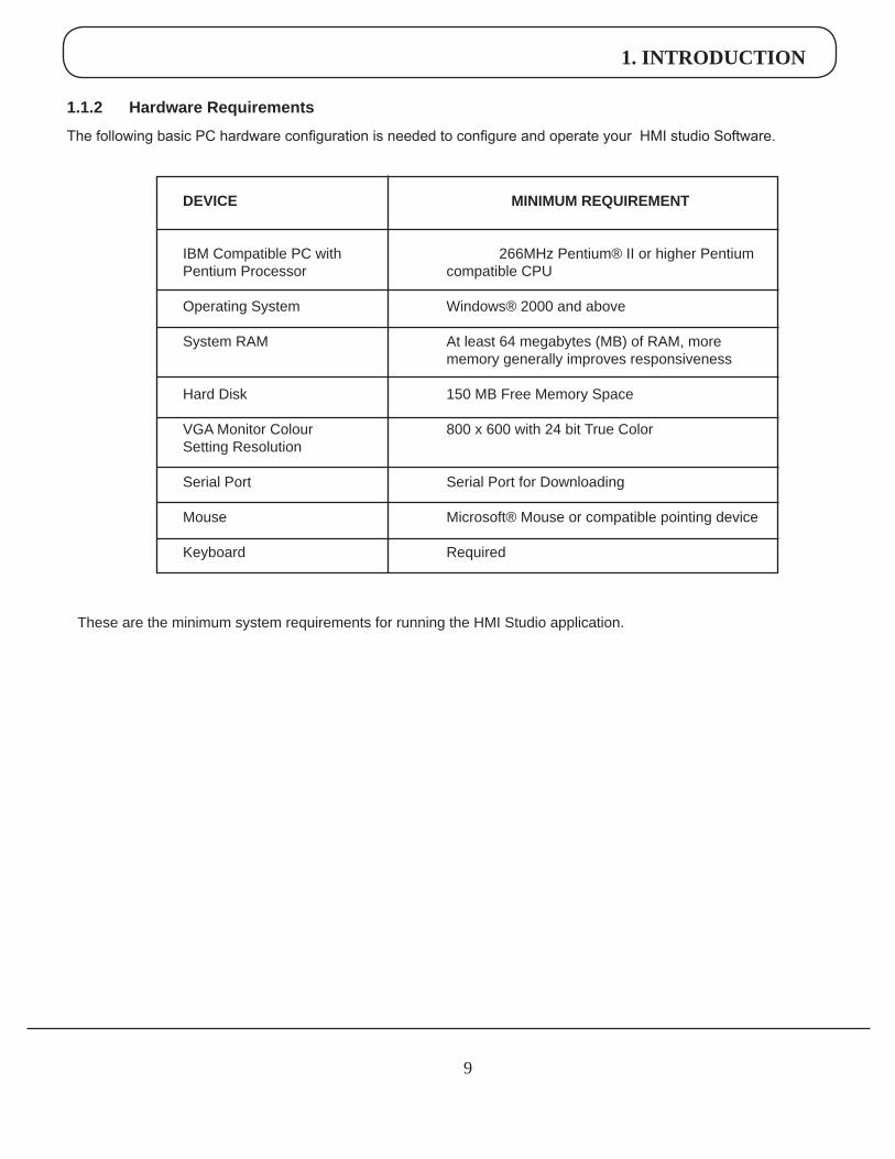
DEVICE MINIMUMREQUIREMENT
IBM Compatible PC with 266MHz Pentium® II or higher Pentium Pentium Processor compatible CPU
Operating System Windows® 2000 and above
System RAM At least 64 megabytes (MB) of RAM, more memory generally improves responsiveness
Hard Disk 150 MB Free Memory Space
VGA Monitor Colour 800 x 600 with 24 bit True Color Setting Resolution
Serial Port Serial Port for Downloading
Mouse Microsoft® Mouse or compatible pointing device
Keyboard Required
These are the minimum system requirements for running the HMI Studio application.
1.1.2 HardwareRequirements
The following basic PC hardware configuration is needed to configure and operate your HMI studio Software.
1. INTRODUCTION
10
1.2 HMIOverview
1.2.1 WhatisaHMI?
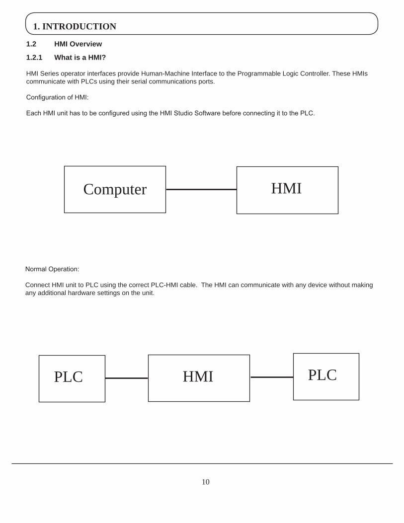
HMI Series operator interfaces provide Human-Machine Interface to the Programmable Logic Controller. These HMIs communicate with PLCs using their serial communications ports.
Configuration of HMI: Each HMI unit has to be configured using the HMI Studio Software before connecting it to the PLC.
Normal Operation: Connect HMI unit to PLC using the correct PLC-HMIcable. The HMI can communicate with any device without making any additional hardware settings on the unit.
Computer HMI
HMIPLC PLC
1. INTRODUCTION
11
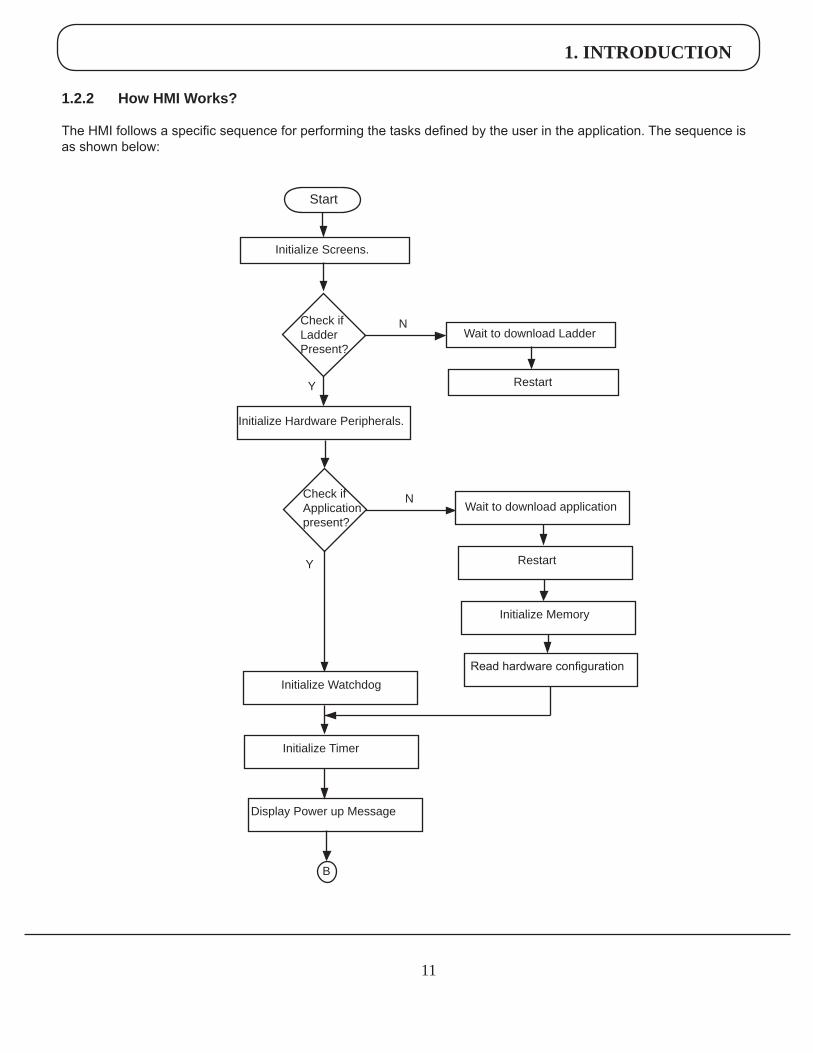
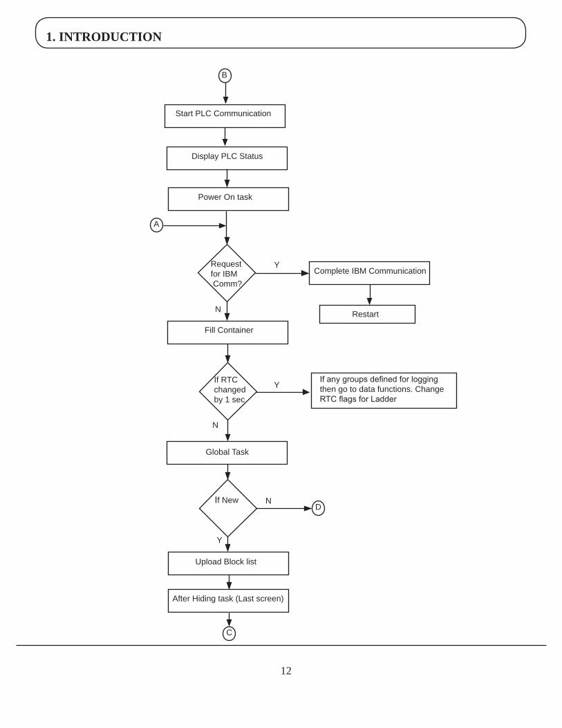
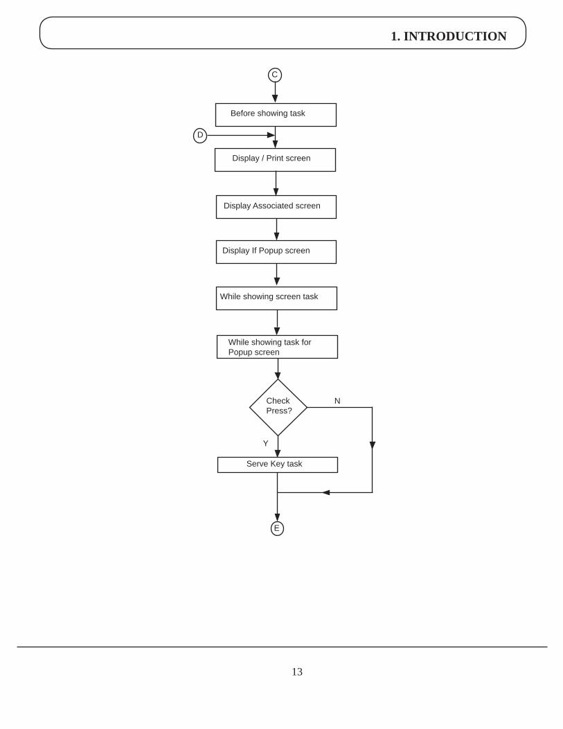
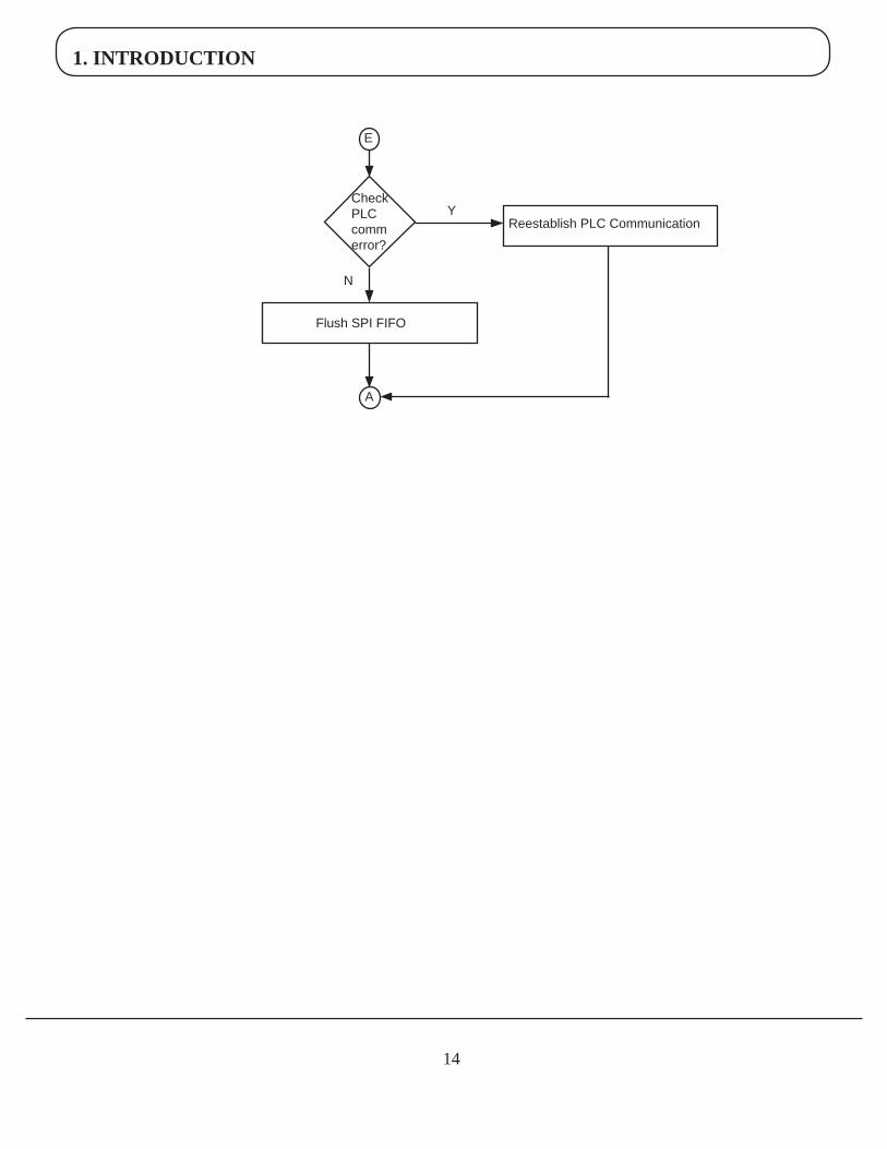
1.2.2 HowHMIWorks?
The HMI follows a specific sequence for performing the tasks defined by the user in the application. The sequence is as shown below:
Start
Check if Application present?
Wait to download application
Restart
N
Initialize Memory
Read hardware configurationInitialize Watchdog
Y
Initialize Timer
Display Power up Message
Check if Ladder Present?
Initialize Screens.
Wait to download LadderN
RestartY
Initialize Hardware Peripherals.
B
1. INTRODUCTION
12
B
Start PLC Communication
Display PLC Status
Power On task
A
Request for IBM Comm?
Y
Restart
Fill Container
N
If RTC changed by 1 sec
Complete IBM Communication
If any groups defined for logging then go to data functions. Change RTC flags for Ladder
Y
Global Task
If New
Upload Block list
Y
After Hiding task (Last screen)
C
D
N
N
1. INTRODUCTION
13
Before showing task
Display / Print screen
C
Display Associated screen
Display If Popup screen
While showing screen task
D
While showing task for Popup screen
Y
NCheck Press?
Serve Key task
E
1. INTRODUCTION
14
E
Check PLC comm error?
Reestablish PLC CommunicationY
Flush SPI FIFO
A
N
1. INTRODUCTION
15
1.2.3 Specifications of HMI Series
HMIseries models are Human Machine Interfaces.
HMImodels need +24VDC power from an external supply.
Models available are as follows:
HMI 201 2” Size, Keypad based HMI 401 4” Size, Touch screen based HMI 601 5.7” Size, Touch screen based, Monochrome HMI 605 5.7” Size, Touch screen based, Color HMI 1205 12.1” Size, Touch screen based, Color All above HMI models have built in ladder functionality.
All above HMI series models have two serial communication ports. They can communicate with two different PLCs simultaneously.
Detailed specifications for each of the above HMI models are given in the following section.
1. INTRODUCTION
16
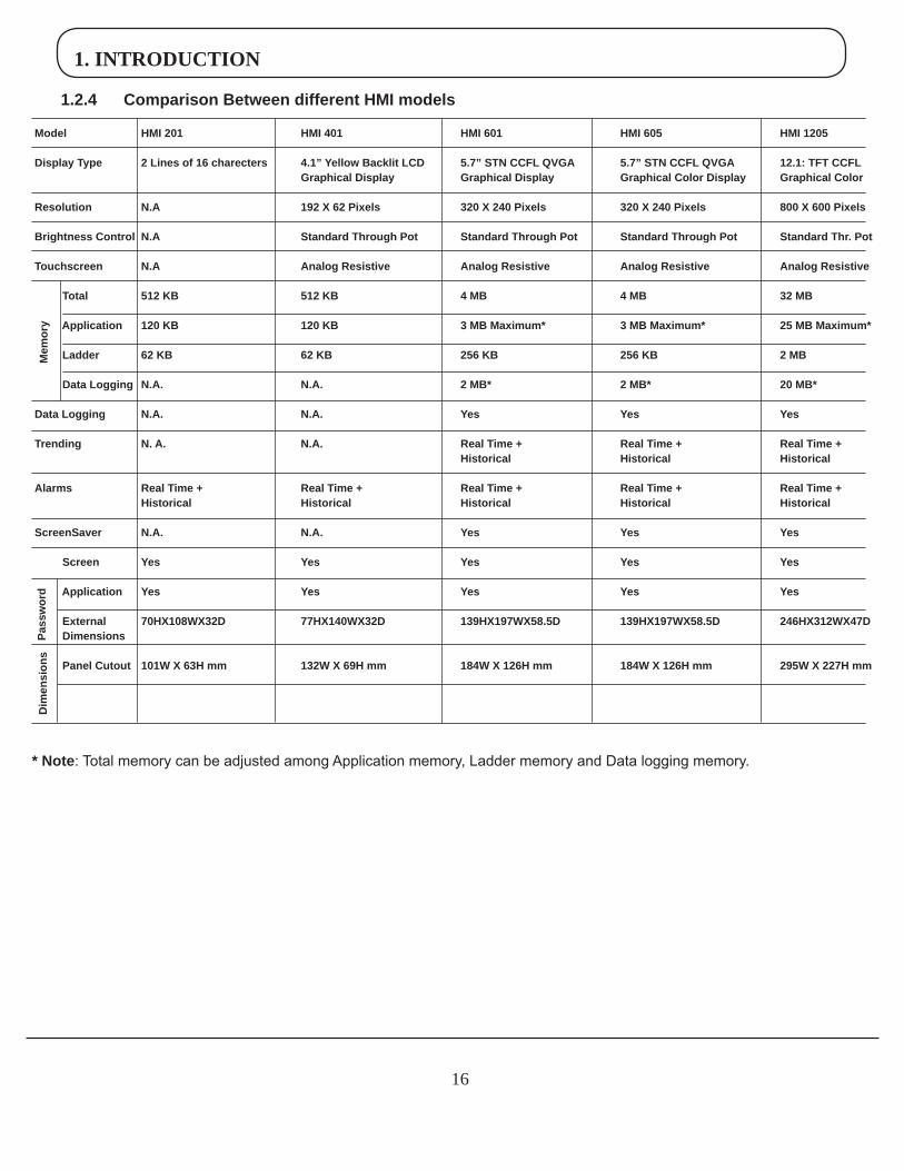
1.2.4 ComparisonBetweendifferentHMImodels
Model HMI201 HMI401 HMI601 HMI605 HMI1205
DisplayType 2Linesof16charecters 4.1”YellowBacklitLCD 5.7”STNCCFLQVGA 5.7”STNCCFLQVGA 12.1:TFTCCFL GraphicalDisplay GraphicalDisplay GraphicalColorDisplay GraphicalColor
Resolution N.A 192X62Pixels 320X240Pixels 320X240Pixels 800X600Pixels
BrightnessControl N.A StandardThroughPot StandardThroughPot StandardThroughPot StandardThr.Pot
Touchscreen N.A AnalogResistive AnalogResistive AnalogResistive AnalogResistive
Total 512KB 512KB 4MB 4MB 32MBApplication 120KB 120KB 3MBMaximum* 3MBMaximum* 25MBMaximum*
Ladder 62KB 62KB 256KB 256KB 2MBDataLogging N.A. N.A. 2MB* 2MB* 20MB*
DataLogging N.A. N.A. Yes Yes Yes
Trending N.A. N.A. RealTime+ RealTime+ RealTime+ Historical Historical Historical
Alarms RealTime+ RealTime+ RealTime+ RealTime+ RealTime+ Historical Historical Historical Historical Historical
ScreenSaver N.A. N.A. Yes Yes Yes
Screen Yes Yes Yes Yes Yes
Application Yes Yes Yes Yes Yes
External 70HX108WX32D 77HX140WX32D 139HX197WX58.5D 139HX197WX58.5D 246HX312WX47DDimensions
PanelCutout 101WX63Hmm 132WX69Hmm 184WX126Hmm 184WX126Hmm 295WX227Hmm
Mem
ory
Dim
ensi
ons
Pass
wor
d
*Note: Total memory can be adjusted among Application memory, Ladder memory and Data logging memory.
1. INTRODUCTION
17
Model HMI201 HMI401 HMI601 HMI605 HMI1205
DisplayType 2Linesof16charecters 4.1”YellowBacklitLCD 5.7”STNCCFLQVGA 5.7”STNCCFLQVGA 12.1:TFTCCFL GraphicalDisplay GraphicalDisplay GraphicalColorDisplay GraphicalColor
Resolution N.A 192X62Pixels 320X240Pixels 320X240Pixels 800X600Pixels
BrightnessControl N.A StandardThroughPot StandardThroughPot StandardThroughPot StandardThr.Pot
Touchscreen N.A AnalogResistive AnalogResistive AnalogResistive AnalogResistive
Total 512KB 512KB 4MB 4MB 32MBApplication 120KB 120KB 3MBMaximum* 3MBMaximum* 25MBMaximum*
Ladder 62KB 62KB 256KB 256KB 2MBDataLogging N.A. N.A. 2MB* 2MB* 20MB*
DataLogging N.A. N.A. Yes Yes Yes
Trending N.A. N.A. RealTime+ RealTime+ RealTime+ Historical Historical Historical
Alarms RealTime+ RealTime+ RealTime+ RealTime+ RealTime+ Historical Historical Historical Historical Historical
ScreenSaver N.A. N.A. Yes Yes Yes
Screen Yes Yes Yes Yes Yes
Application Yes Yes Yes Yes Yes
External 70HX108WX32D 77HX140WX32D 139HX197WX58.5D 139HX197WX58.5D 246HX312WX47DDimensions
PanelCutout 101WX63Hmm 132WX69Hmm 184WX126Hmm 184WX126Hmm 295WX227Hmm
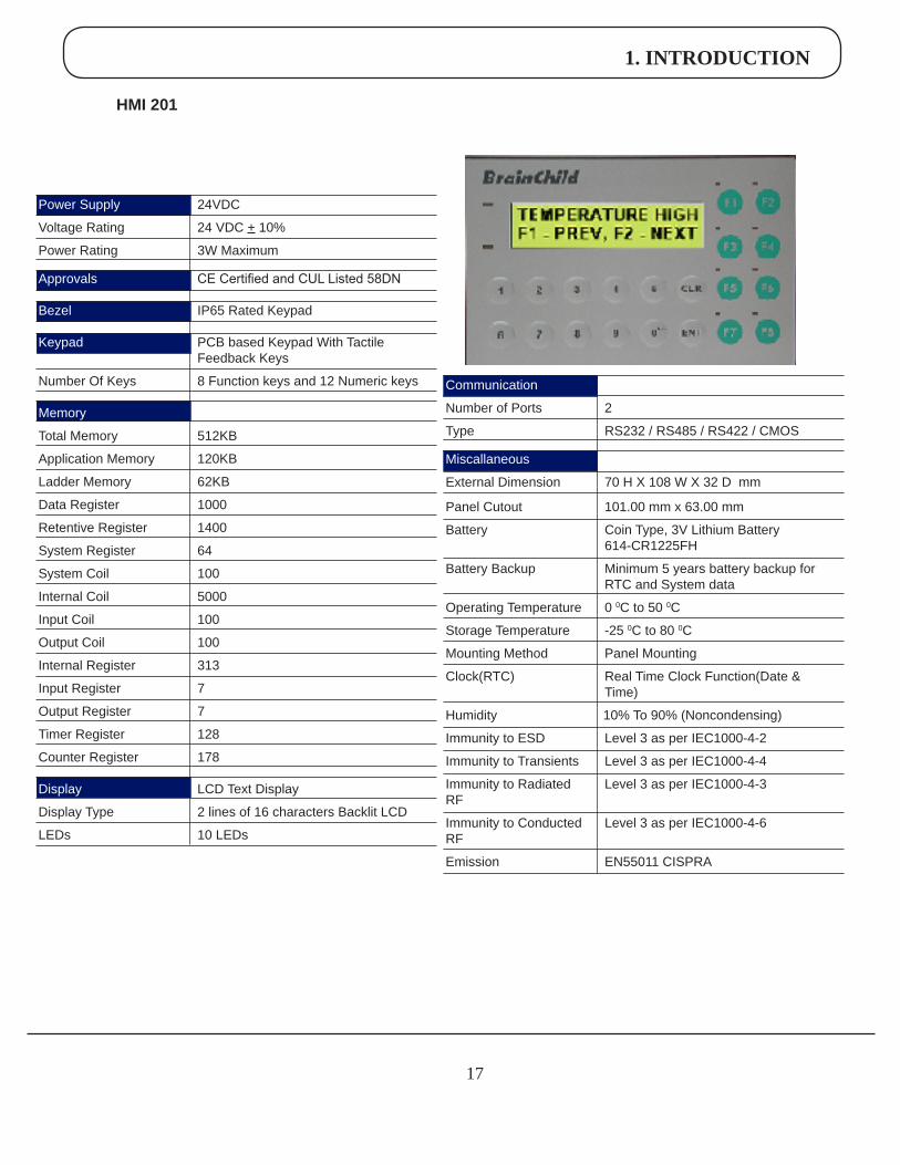
HMI201
Power Supply 24VDC
Voltage Rating 24 VDC + 10%
Power Rating 3W Maximum
Approvals CE Certified and CUL Listed 58DN
Bezel IP65 Rated Keypad
Keypad PCB based Keypad With Tactile Feedback Keys
Number Of Keys 8 Function keys and 12 Numeric keys
Memory
Total Memory 512KB
Application Memory 120KB
Ladder Memory 62KB
Data Register 1000
Retentive Register 1400
System Register 64
System Coil 100
Internal Coil 5000
Input Coil 100
Output Coil 100
Internal Register 313
Input Register 7
Output Register 7
Timer Register 128
Counter Register 178
Display LCD Text Display
Display Type 2 lines of 16 characters Backlit LCD
LEDs 10 LEDs
Communication
Number of Ports 2
Type RS232 / RS485 / RS422 / CMOS
Miscallaneous
External Dimension 70 H X 108 W X 32 D mm
Panel Cutout 101.00 mm x 63.00 mm Battery Coin Type, 3V Lithium Battery 614-CR1225FH
Battery Backup Minimum 5 years battery backup for RTC and System data
Operating Temperature 0 0C to 50 0C
Storage Temperature -25 0C to 80 0C
Mounting Method Panel Mounting
Clock(RTC) Real Time Clock Function(Date & Time)
Humidity 10% To 90% (Noncondensing)
Immunity to ESD Level 3 as per IEC1000-4-2
Immunity to Transients Level 3 as per IEC1000-4-4
Immunity to Radiated Level 3 as per IEC1000-4-3RF
Immunity to Conducted Level 3 as per IEC1000-4-6
RF
Emission EN55011 CISPRA
1. INTRODUCTION
1�
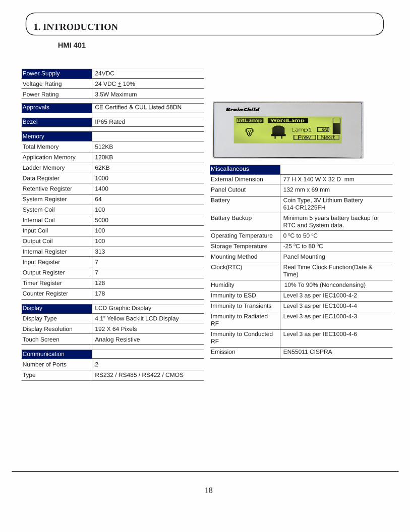
HMI401
Power Supply 24VDC
Voltage Rating 24 VDC + 10%
Power Rating 3.5W Maximum
Approvals CE Certified & CUL Listed 58DN
Bezel IP65 Rated
Memory
Total Memory 512KB
Application Memory 120KB
Ladder Memory 62KB
Data Register 1000
Retentive Register 1400
System Register 64
System Coil 100
Internal Coil 5000
Input Coil 100
Output Coil 100
Internal Register 313
Input Register 7
Output Register 7
Timer Register 128
Counter Register 178
Display LCD Graphic Display
Display Type 4.1” Yellow Backlit LCD Display
Display Resolution 192 X 64 Pixels
Touch Screen Analog Resistive
Communication
Number of Ports 2
Type RS232 / RS485 / RS422 / CMOS
Miscallaneous
External Dimension 77 H X 140 W X 32 D mm
Panel Cutout 132 mm x 69 mm
Battery Coin Type, 3V Lithium Battery 614-CR1225FH
Battery Backup Minimum 5 years battery backup for RTC and System data.
Operating Temperature 0 0C to 50 0C
Storage Temperature -25 0C to 80 0C
Mounting Method Panel Mounting
Clock(RTC) Real Time Clock Function(Date & Time)
Humidity 10% To 90% (Noncondensing)
Immunity to ESD Level 3 as per IEC1000-4-2
Immunity to Transients Level 3 as per IEC1000-4-4
Immunity to Radiated Level 3 as per IEC1000-4-3RF
Immunity to Conducted Level 3 as per IEC1000-4-6
RF
Emission EN55011 CISPRA
1. INTRODUCTION
1�
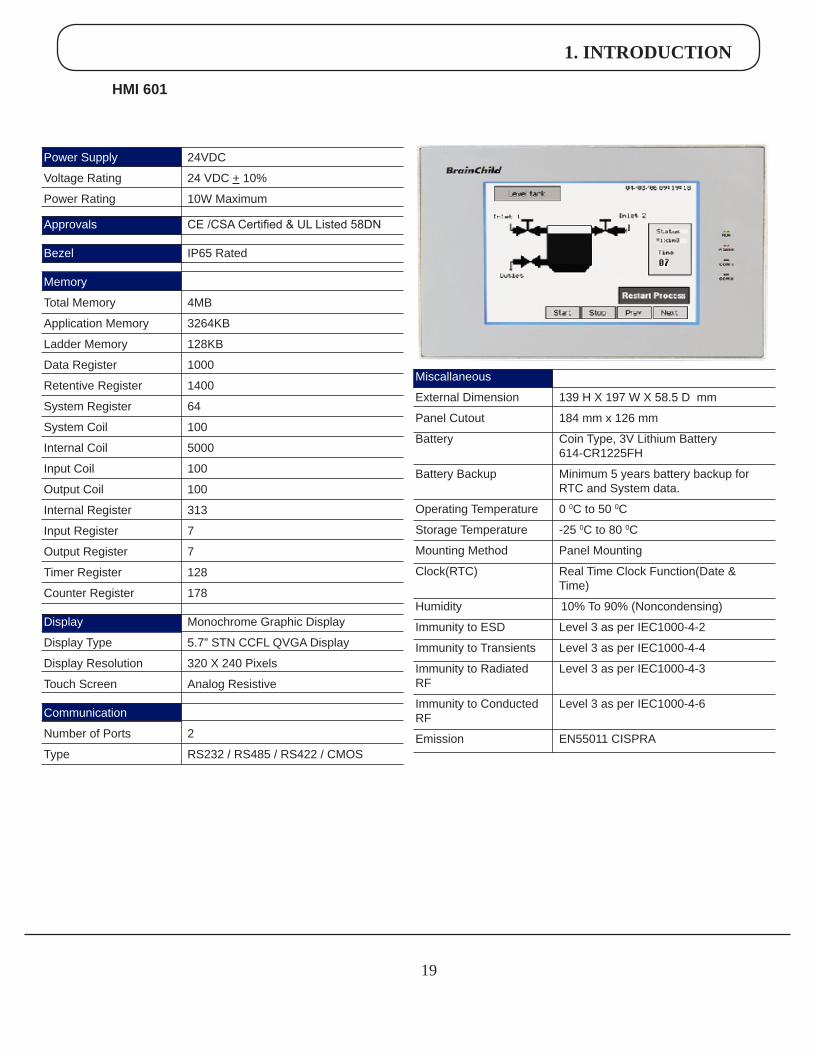
HMI601
Power Supply 24VDC
Voltage Rating 24 VDC + 10%
Power Rating 10W Maximum
Approvals CE /CSA Certified & UL Listed 58DN
Bezel IP65 Rated
Memory
Total Memory 4MB
Application Memory 3264KB
Ladder Memory 128KB
Data Register 1000
Retentive Register 1400
System Register 64
System Coil 100
Internal Coil 5000
Input Coil 100
Output Coil 100
Internal Register 313
Input Register 7
Output Register 7
Timer Register 128
Counter Register 178
Display Monochrome Graphic Display
Display Type 5.7” STN CCFL QVGA Display
Display Resolution 320 X 240 Pixels
Touch Screen Analog Resistive
Communication
Number of Ports 2
Type RS232 / RS485 / RS422 / CMOS
Miscallaneous
External Dimension 139 H X 197 W X 58.5 D mm
Panel Cutout 184 mm x 126 mm
Battery Coin Type, 3V Lithium Battery 614-CR1225FH
Battery Backup Minimum 5 years battery backup for RTC and System data.
Operating Temperature 0 0C to 50 0C
Storage Temperature -25 0C to 80 0C
Mounting Method Panel Mounting
Clock(RTC) Real Time Clock Function(Date & Time)
Humidity 10% To 90% (Noncondensing)
Immunity to ESD Level 3 as per IEC1000-4-2
Immunity to Transients Level 3 as per IEC1000-4-4
Immunity to Radiated Level 3 as per IEC1000-4-3RF
Immunity to Conducted Level 3 as per IEC1000-4-6
RF
Emission EN55011 CISPRA
1. INTRODUCTION
20
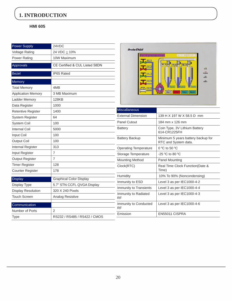
HMI605
Power Supply 24VDC
Voltage Rating 24 VDC + 10%
Power Rating 10W Maximum
Approvals CE Certified & CUL Listed 58DN
Bezel IP65 Rated
Memory
Total Memory 4MB
Application Memory 3 MB Maximum
Ladder Memory 128KB
Data Register 1000
Retentive Register 1400
System Register 64
System Coil 100
Internal Coil 5000
Input Coil 100
Output Coil 100
Internal Register 313
Input Register 7
Output Register 7
Timer Register 128
Counter Register 178
Display Graphical Color Display
Display Type 5.7” STN CCFL QVGA Display
Display Resolution 320 X 240 Pixels
Touch Screen Analog Resistive
Communication
Number of Ports 2
Type RS232 / RS485 / RS422 / CMOS
Miscallaneous
External Dimension 139 H X 197 W X 58.5 D mm
Panel Cutout 184 mm x 126 mm
Battery Coin Type, 3V Lithium Battery 614-CR1225FH
Battery Backup Minimum 5 years battery backup for RTC and System data.
Operating Temperature 0 0C to 50 0C
Storage Temperature -25 0C to 80 0C
Mounting Method Panel Mounting
Clock(RTC) Real Time Clock Function(Date & Time)
Humidity 10% To 90% (Noncondensing)
Immunity to ESD Level 3 as per IEC1000-4-2
Immunity to Transients Level 3 as per IEC1000-4-4
Immunity to Radiated Level 3 as per IEC1000-4-3RF
Immunity to Conducted Level 3 as per IEC1000-4-6
RF
Emission EN55011 CISPRA
1. INTRODUCTION
21
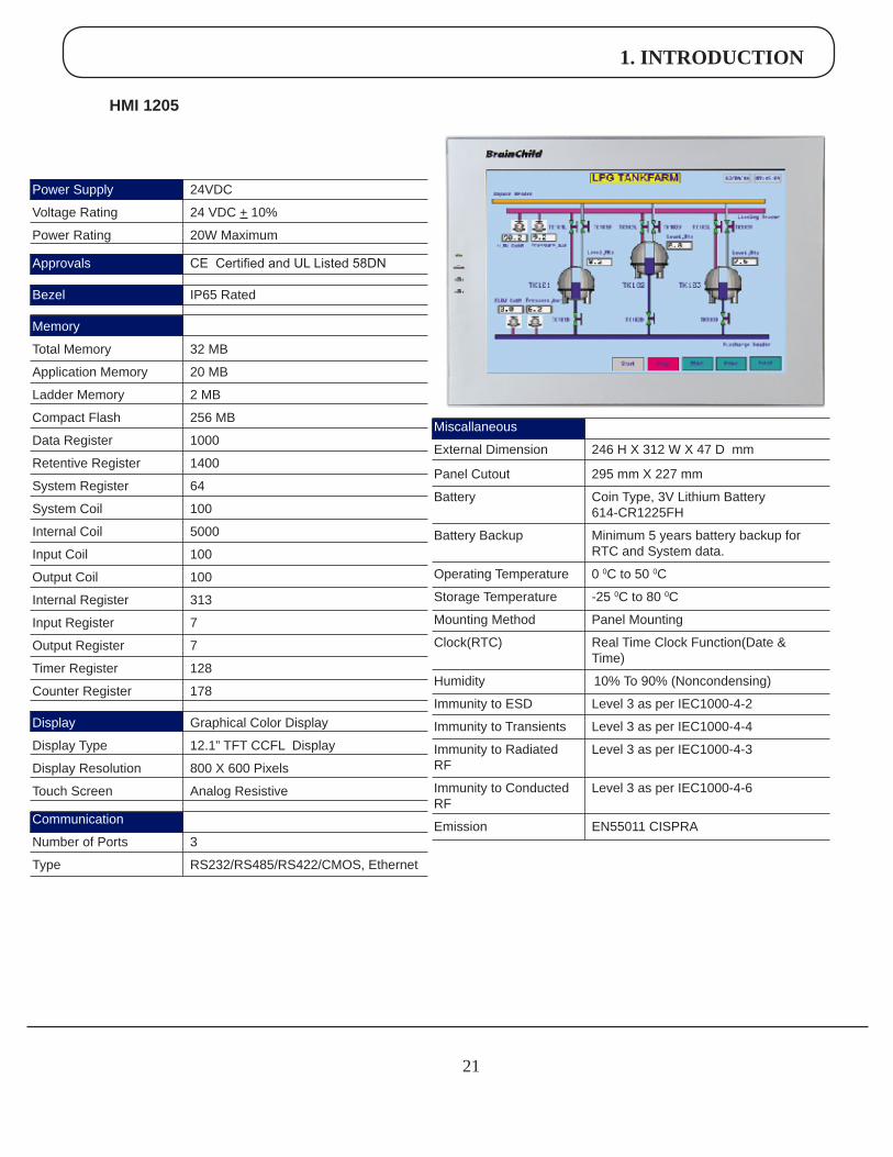
HMI1205
Power Supply 24VDC
Voltage Rating 24 VDC + 10%
Power Rating 20W Maximum
Approvals CE Certified and UL Listed 58DN
Bezel IP65 Rated
Memory
Total Memory 32 MB
Application Memory 20 MB
Ladder Memory 2 MB
Compact Flash 256 MB
Data Register 1000
Retentive Register 1400
System Register 64
System Coil 100
Internal Coil 5000
Input Coil 100
Output Coil 100
Internal Register 313
Input Register 7
Output Register 7
Timer Register 128
Counter Register 178
Display Graphical Color Display
Display Type 12.1” TFT CCFL Display
Display Resolution 800 X 600 Pixels
Touch Screen Analog Resistive
Communication
Number of Ports 3
Type RS232/RS485/RS422/CMOS, Ethernet
Miscallaneous
External Dimension 246 H X 312 W X 47 D mm
Panel Cutout 295 mm X 227 mm
Battery Coin Type, 3V Lithium Battery 614-CR1225FH
Battery Backup Minimum 5 years battery backup for RTC and System data.
Operating Temperature 0 0C to 50 0C
Storage Temperature -25 0C to 80 0C
Mounting Method Panel Mounting
Clock(RTC) Real Time Clock Function(Date & Time)
Humidity 10% To 90% (Noncondensing)
Immunity to ESD Level 3 as per IEC1000-4-2
Immunity to Transients Level 3 as per IEC1000-4-4
Immunity to Radiated Level 3 as per IEC1000-4-3RF
Immunity to Conducted Level 3 as per IEC1000-4-6
RF
Emission EN55011 CISPRA

2. HARDWARE
22
2.1 UnpackingTheUnit
Carefully unpack the HMI. Please read all the instructions and cautions that appear on the shipping container.Check that the container includes the mounting clamps, mounting screws, mounting inserts, gasket, and a silica gel bag. The silica gel bag is enclosed to absorb the moisture in the packing. Brainchild Electronics will not accept responsibility for shortages against the packing list unless notified within 30 days. The unit and its accessories were inspected and tested by Brainchild Electronics before shipment. All equipment should be in good working order. Examine the product carefully and notify the carrier immediately if any shipping damage is evident. You are responsible for claim negotiations with the carrier. Save the shipping container and packing material in case the equipment needs to be stored, returned to Brainchild Electronics, or transported for any reason.
2.2 ManagingElectrostaticDischarge
It is best NOT to remove the rear enclosure of the HMI. When the rear part of the enclosure is removed, the circuitry inside is exposed to possible damage by electrostatic discharge during handling. Minimize the possibility of electrostatic discharge by: • Discharging personal static by grounding yourself prior to handling the HMI.
• Handling the HMI at a static-free grounded workstation.
• Connecting the frame ground ( ) connector of the HMI to a clean earth ground.
• Placing the HMI in an antistatic bag during transport.
2.3 CECompliance
Brainchild Electronics HMI products have been tested to confirm to European CE requirements per Council Direc-tive. The European Union created these requirements to ensure conformity among products traded in those countries. Specifically, Brainchild Electronics products meet or exceed the noise emission and immunity requirements as set in EN55011 (Emission) and IEC1000-4 (Immunity) standards. These HMI products are designed to withstand electrical noise in harsh industrial environment. They also confirm to requirements that limit electrical emission. However this does not guarantee the products will be totally immune from possible malfunction in cases where severe electrical noise occurs. Therefore, we strongly recommend that you follow the guidelines outlined for proper wiring and grounding to ensure the proper operation of the Brainchild HMI products.
2.4 EnvironmentalRating
Brainchild HMI Products are rated for IP 65 as per IEC Standards. This means that when HMI is properly mounted on the enclosure, the front enclosure will provide a degree of protection to the inside panel from the dust and low pressure jets of water from all the directions i.e. protection against ingress of water. The HMI must be installed according to the instructions given.
2.5 EnvironmentalConsideration
Brainchild HMI products are designed to operate at temperature range from 0-500 C. It is intended primarily for indoor installations and may not be suitable for certain outdoor applications. Avoid installing the Brainchild HMI products in environments with severe mechanical vibration or shocks. Do not install the HMI in enclosures with rapid temperature
2. HARDWARE
23
2.6 SafetyPrecaution
Please observe the following precautions when installing the unit. Failure to comply with these restrictions could result in loss of life, serious personal injury, or equipment damage.
Warning:Do not operate the HMI in areas subject to explosion due to flammable gases, vapors, or dusts.
Warning:Do not connect the HMI to an AC power source. You will cause permanent damage to the HMI.
Warning:Do not attempt to use a DC power supply that does not meet HMI power requirements. You may cause malfunction or permanent damage to HMI.
Warning:Do not power the HMI with a DC power supply used for inductive loads or for input circuitry to the programmable logic controller. Severe voltage spikes caused by these devices may damage the HMI.
2.7 InstallationInstruction
The HMI should be mounted on a panel. A sealing gasket and mounting clamps are provided with each HMI unit for proper installation.
EnvironmentalConsiderations:
Make sure that the HMI unit is installed correctly and that the operating limits are followed (see Specifications for HMI ). Do not operate the HMI in areas subject to explosion hazards due to flammable gases, vapors or dusts. HMI should not be installed where fast temperature variations are present. Highly humid areas are also to be avoided. High humidity causes condensation of water in the unit. LocationConsiderations:
Care should be taken when locating equipment behind the HMI to ensure that AC power wiring, PLC output modules, contactors, starters, relays and any other source of electrical interference are located away from the HMI. Particular care should be taken to locate variable speed drives and switching power supplies away from the HMI.
PanelMounting
This section presents the dimensional sketches and panel cutouts for HMI products.(All dimensions are in mm and drawing are not to scale.)
!
!
!
!
2. HARDWARE
24
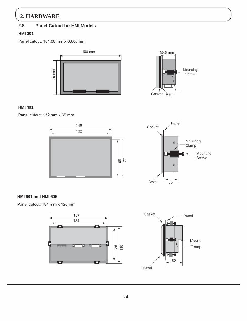
2.8 PanelCutoutforHMIModels
HMI201
Panel cutout: 101.00 mm x 63.00 mm
30.5 mm
Gasket Pan-
MountingScrew
108 mm70
mm
HMI401
Panel cutout: 132 mm x 69 mm
132140
7769
Bezel 35
MountingScrew
PanelGasket
Mounting Clamp
HMI601andHMI605
Panel cutout: 184 mm x 126 mm
197184
139
126
52
Bezel
Gasket Panel
Clamp
Mount
2. HARDWARE
25
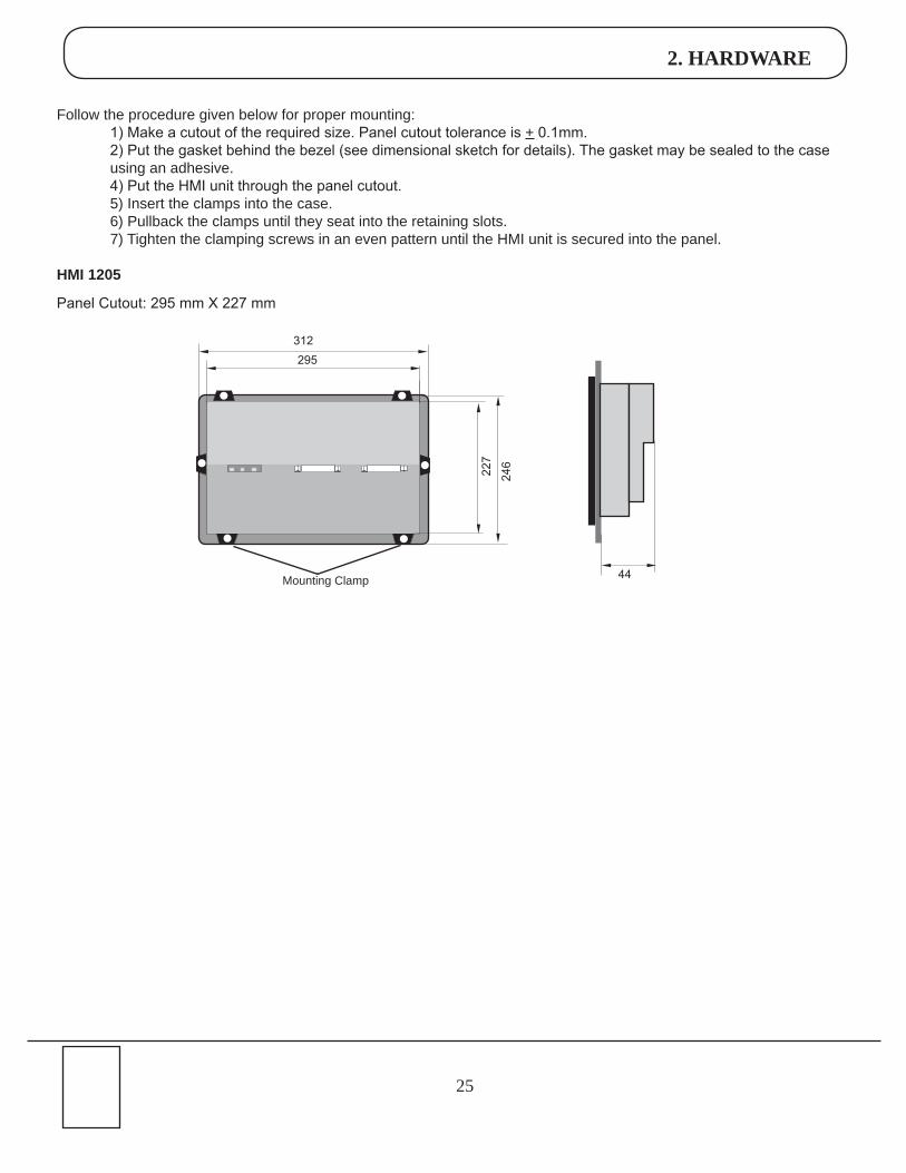
Follow the procedure given below for proper mounting: 1) Make a cutout of the required size. Panel cutout tolerance is + 0.1mm. 2) Put the gasket behind the bezel (see dimensional sketch for details). The gasket may be sealed to the case using an adhesive. 4) Put the HMI unit through the panel cutout. 5) Insert the clamps into the case. 6) Pullback the clamps until they seat into the retaining slots. 7) Tighten the clamping screws in an even pattern until the HMI unit is secured into the panel.
HMI1205
Panel Cutout: 295 mm X 227 mm
44
312
246
Mounting Clamp
295
227
246
2. HARDWARE
26
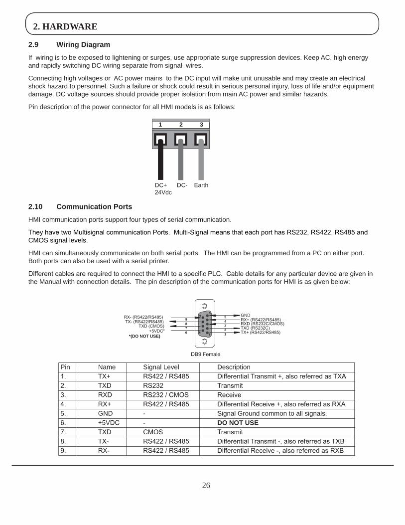
2.9 WiringDiagram
If wiring is to be exposed to lightening or surges, use appropriate surge suppression devices. Keep AC, high energy and rapidly switching DC wiring separate from signal wires.
Connecting high voltages or AC power mains to the DC input will make unit unusable and may create an electrical shock hazard to personnel. Such a failure or shock could result in serious personal injury, loss of life and/or equipment damage. DC voltage sources should provide proper isolation from main AC power and similar hazards.
Pin description of the power connector for all HMI models is as follows:
DC+ DC- Earth24Vdc
1 2 3
2.10 CommunicationPorts
HMI communication ports support four types of serial communication.
They have two Multisignal communication Ports. Multi-Signal means that each port has RS232, RS422, RS485 and CMOS signal levels.
HMI can simultaneously communicate on both serial ports. The HMI can be programmed from a PC on either port. Both ports can also be used with a serial printer.
Different cables are required to connect the HMI to a specific PLC. Cable details for any particular device are given in the Manual with connection details. The pin description of the communication ports for HMI is as given below:
TX- (RS422/RS485)
DB9 Female
1
59
+5VDC**(DONOTUSE)
GNDRX+ (RS422/RS485)RXD (RS232C/CMOS)TXD (RS232C)TX+ (RS422/RS485)
TXD (CMOS)
RX- (RS422/RS485)
6
89
7 2
45
3
16
Pin Name Signal Level Description1. TX+ RS422 / RS485 Differential Transmit +, also referred as TXA2. TXD RS232 Transmit3. RXD RS232 / CMOS Receive4. RX+ RS422 / RS485 Differential Receive +, also referred as RXA5. GND - Signal Ground common to all signals.6. +5VDC - DONOTUSE7. TXD CMOS Transmit8. TX- RS422 / RS485 Differential Transmit -, also referred as TXB9. RX- RS422 / RS485 Differential Receive -, also referred as RXB
3. BEFORE YOU BEGIN
27
3.1 ConnectingtheHMItoyourComputer
•Requirements 1. RS232 interface cable 2. HMI Unit
Cable can be ordered along with HMI or cable can be prepared by the customer as per connection layout explained in chapter no.2
1. Connect the programming cable from computer to HMI. For Ex: COM1 2. Connect a +24VDC power supply to the HMI. 3. Open new project in HMI Studio software. 4. By default, COM1 will be configured for communication with PC. 5. Configure PLC driver in the network configuration, For Ex: COM2. 6. Download the firmware into HMI.
Every PLC will have seperate communication driver. The HMI unit cannot communicate with PLC till the required driver is downloaded. When firmware is downloaded from Computer to HMI, PLC communication driver will also downloaded. Once, COM2 is configured for PLC and download firmware to HMI, then connect PLC to COM2.
3. BEFORE YOU BEGIN
28
3.2 StartingHMIStudioSoftware
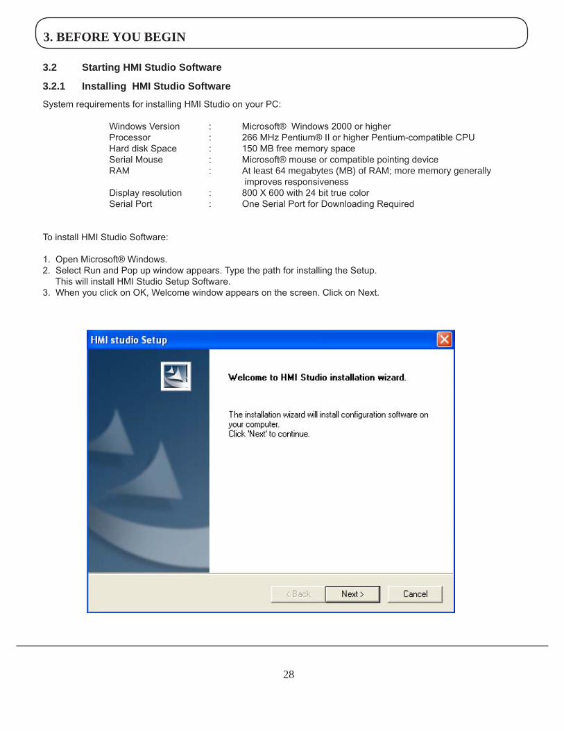
3.2.1 InstallingHMIStudioSoftware
System requirements for installing HMI Studio on your PC:
Windows Version : Microsoft® Windows 2000 or higher Processor : 266 MHz Pentium® II or higher Pentium-compatible CPU Hard disk Space : 150 MB free memory space Serial Mouse : Microsoft® mouse or compatible pointing device RAM : At least 64 megabytes (MB) of RAM; more memory generally improves responsiveness Display resolution : 800 X 600 with 24 bit true color Serial Port : One Serial Port for Downloading Required
To install HMI Studio Software:
1. Open Microsoft® Windows.2. Select Run and Pop up window appears. Type the path for installing the Setup. This will install HMI Studio Setup Software.3. When you click on OK, Welcome window appears on the screen. Click on Next.
3. BEFORE YOU BEGIN
29
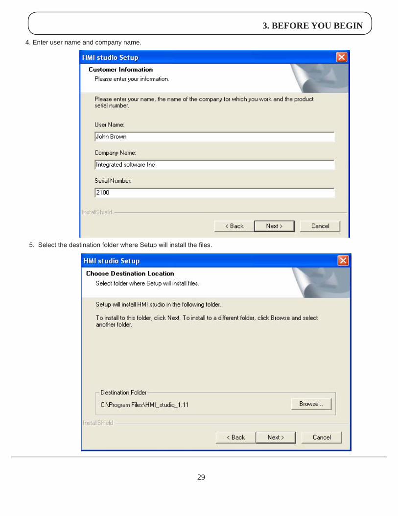
5. Select the destination folder where Setup will install the files.
4. Enter user name and company name.
3. BEFORE YOU BEGIN
30
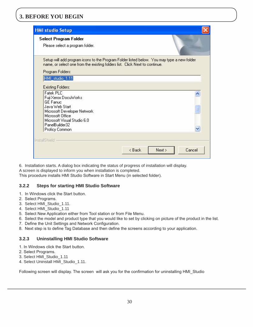
6. Installation starts. A dialog box indicating the status of progress of installation will display.A screen is displayed to inform you when installation is completed.This procedure installs HMI Studio Software in Start Menu (in selected folder).
3.2.2 StepsforstartingHMIStudioSoftware
1. In Windows click the Start button.2. Select Programs.3. Select HMI_Studio_1.11.4. Select HMI_Studio_1.115. Select New Application either from Tool station or from File Menu.6. Select the model and product type that you would like to set by clicking on picture of the product in the list.7. Define the Unit Settings and Network Configuration.8. Next step is to define Tag Database and then define the screens according to your application.
3.2.3 UninstallingHMIStudioSoftware
1. In Windows click the Start button.2. Select Programs.3. Select HMI_Studio_1.114. Select Uninstall HMI_Studio_1.11.
Following screen will display. The screen will ask you for the confirmation for uninstalling HMI_Studio
3. BEFORE YOU BEGIN
31
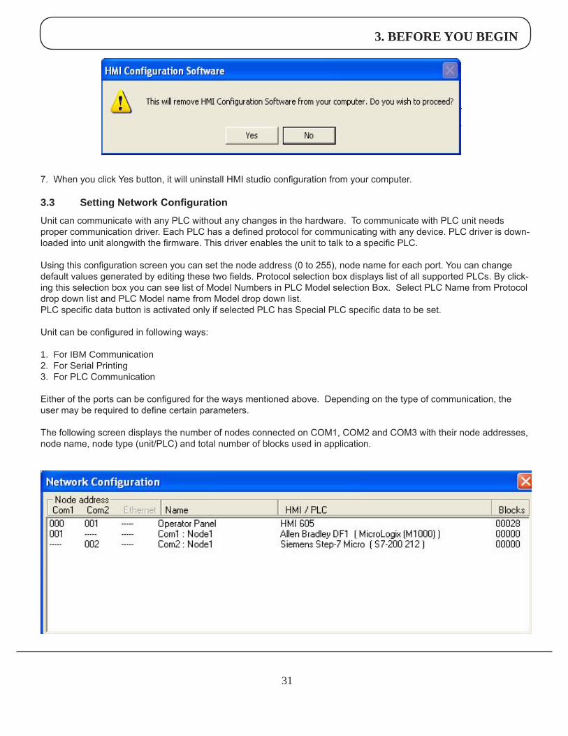
7. When you click Yes button, it will uninstall HMI studio configuration from your computer.
3.3 SettingNetwork Configuration
Unit can communicate with any PLC without any changes in the hardware. To communicate with PLC unit needs proper communication driver. Each PLC has a defined protocol for communicating with any device. PLC driver is down-loaded into unit alongwith the firmware. This driver enables the unit to talk to a specific PLC.
Using this configuration screen you can set the node address (0 to 255), node name for each port. You can change default values generated by editing these two fields. Protocol selection box displays list of all supported PLCs. By click-ing this selection box you can see list of Model Numbers in PLC Model selection Box. Select PLC Name from Protocol drop down list and PLC Model name from Model drop down list.PLC specific data button is activated only if selected PLC has Special PLC specific data to be set.
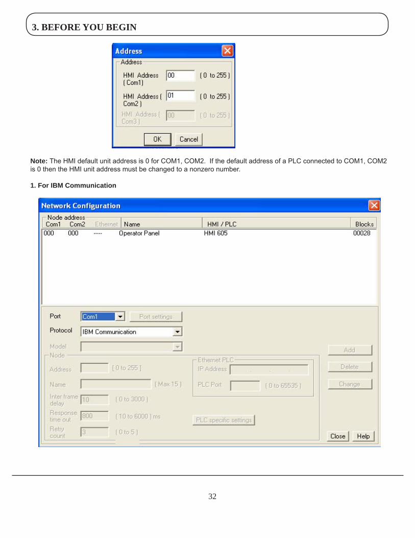
Unit can be configured in following ways:
1. For IBM Communication2. For Serial Printing3. For PLC Communication
Either of the ports can be configured for the ways mentioned above. Depending on the type of communication, the user may be required to define certain parameters.
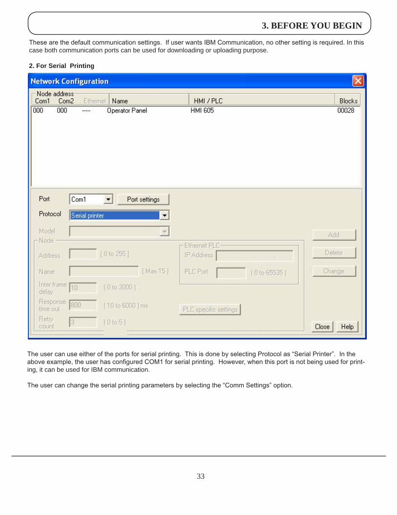
The following screen displays the number of nodes connected on COM1, COM2 and COM3 with their node addresses, node name, node type (unit/PLC) and total number of blocks used in application.
3. BEFORE YOU BEGIN
32
Note:The HMI default unit address is 0 for COM1, COM2. If the default address of a PLC connected to COM1, COM2 is 0 then the HMI unit address must be changed to a nonzero number.
1.ForIBMCommunication
3. BEFORE YOU BEGIN
33
The user can use either of the ports for serial printing. This is done by selecting Protocol as “Serial Printer”. In the above example, the user has configured COM1 for serial printing. However, when this port is not being used for print-ing, it can be used for IBM communication.
The user can change the serial printing parameters by selecting the “Comm Settings” option.
These are the default communication settings. If user wants IBM Communication, no other setting is required. In this case both communication ports can be used for downloading or uploading purpose.
2.ForSerialPrinting
3. BEFORE YOU BEGIN
34
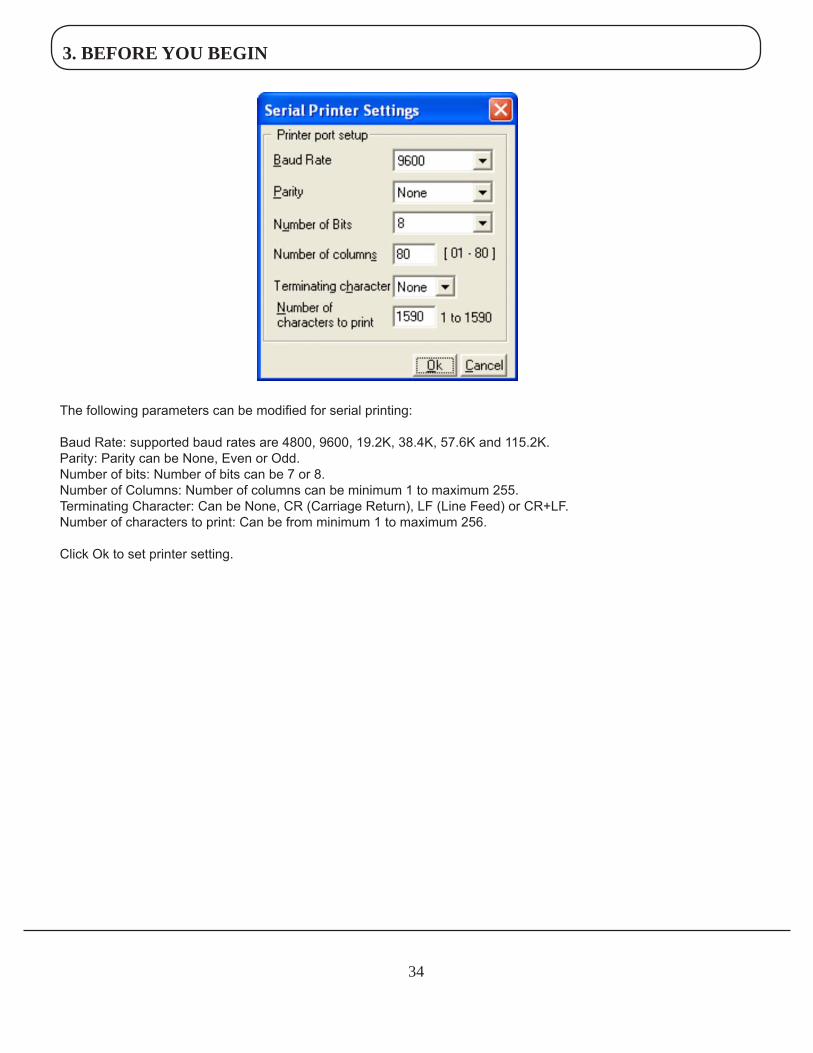
The following parameters can be modified for serial printing:
Baud Rate: supported baud rates are 4800, 9600, 19.2K, 38.4K, 57.6K and 115.2K.Parity: Parity can be None, Even or Odd.Number of bits: Number of bits can be 7 or 8.Number of Columns: Number of columns can be minimum 1 to maximum 255.Terminating Character: Can be None, CR (Carriage Return), LF (Line Feed) or CR+LF.Number of characters to print: Can be from minimum 1 to maximum 256.
Click Ok to set printer setting.
3. BEFORE YOU BEGIN
35
3.ForPLCCommunication
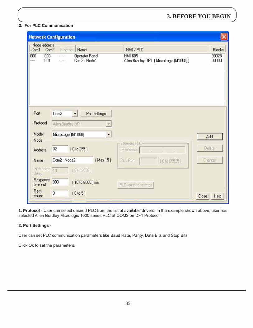
1.Protocol - User can select desired PLC from the list of available drivers. In the example shown above, user has selected Allen Bradley Micrologix 1000 series PLC at COM2 on DF1 Protocol.
2.PortSettings-
User can set PLC communication parameters like Baud Rate, Parity, Data Bits and Stop Bits.
Click Ok to set the parameters.
3. BEFORE YOU BEGIN
36
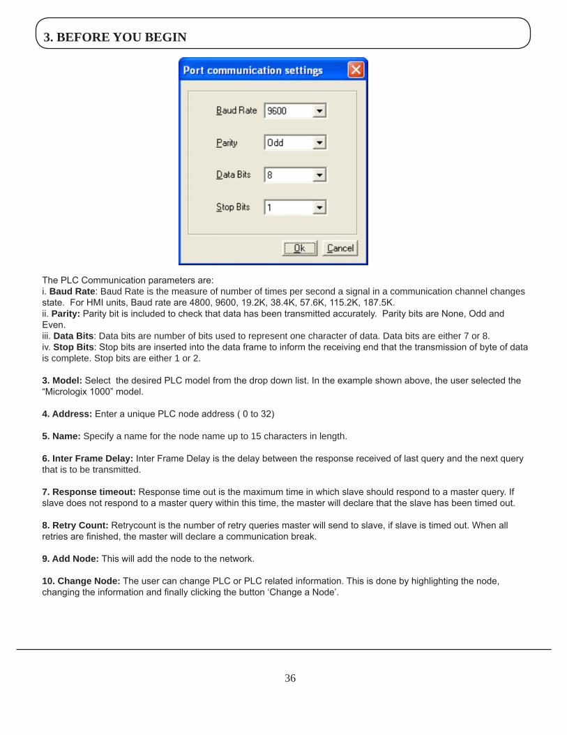
The PLC Communication parameters are:i. BaudRate: Baud Rate is the measure of number of times per second a signal in a communication channel changes state. For HMI units, Baud rate are 4800, 9600, 19.2K, 38.4K, 57.6K, 115.2K, 187.5K. ii. Parity:Parity bit is included to check that data has been transmitted accurately. Parity bits are None, Odd and Even.iii. DataBits: Data bits are number of bits used to represent one character of data. Data bits are either 7 or 8.iv. StopBits: Stop bits are inserted into the data frame to inform the receiving end that the transmission of byte of data is complete. Stop bits are either 1 or 2.
3.Model:Select the desired PLC model from the drop down list. In the example shown above, the user selected the “Micrologix 1000” model.
4.Address:Enter a unique PLC node address ( 0 to 32)
5.Name:Specify a name for the node name up to 15 characters in length.
6.InterFrameDelay: Inter Frame Delay is the delay between the response received of last query and the next query that is to be transmitted.
7.Responsetimeout: Response time out is the maximum time in which slave should respond to a master query. If slave does not respond to a master query within this time, the master will declare that the slave has been timed out.
8.RetryCount: Retrycount is the number of retry queries master will send to slave, if slave is timed out. When all retries are finished, the master will declare a communication break.
9.AddNode:This will add the node to the network.
10.ChangeNode: The user can change PLC or PLC related information. This is done by highlighting the node, changing the information and finally clicking the button ‘Change a Node’.
3. BEFORE YOU BEGIN
37
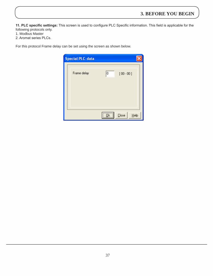
11. PLC specific settings: This screen is used to configure PLC Specific information. This field is applicable for the following protocols only.1. Modbus Master2. Aromat series PLCs.
For this protocol Frame delay can be set using the screen as shown below.
4. USING HMI STUDIO SOFTWARE
38
4.1 HMIStudioMenuStructure
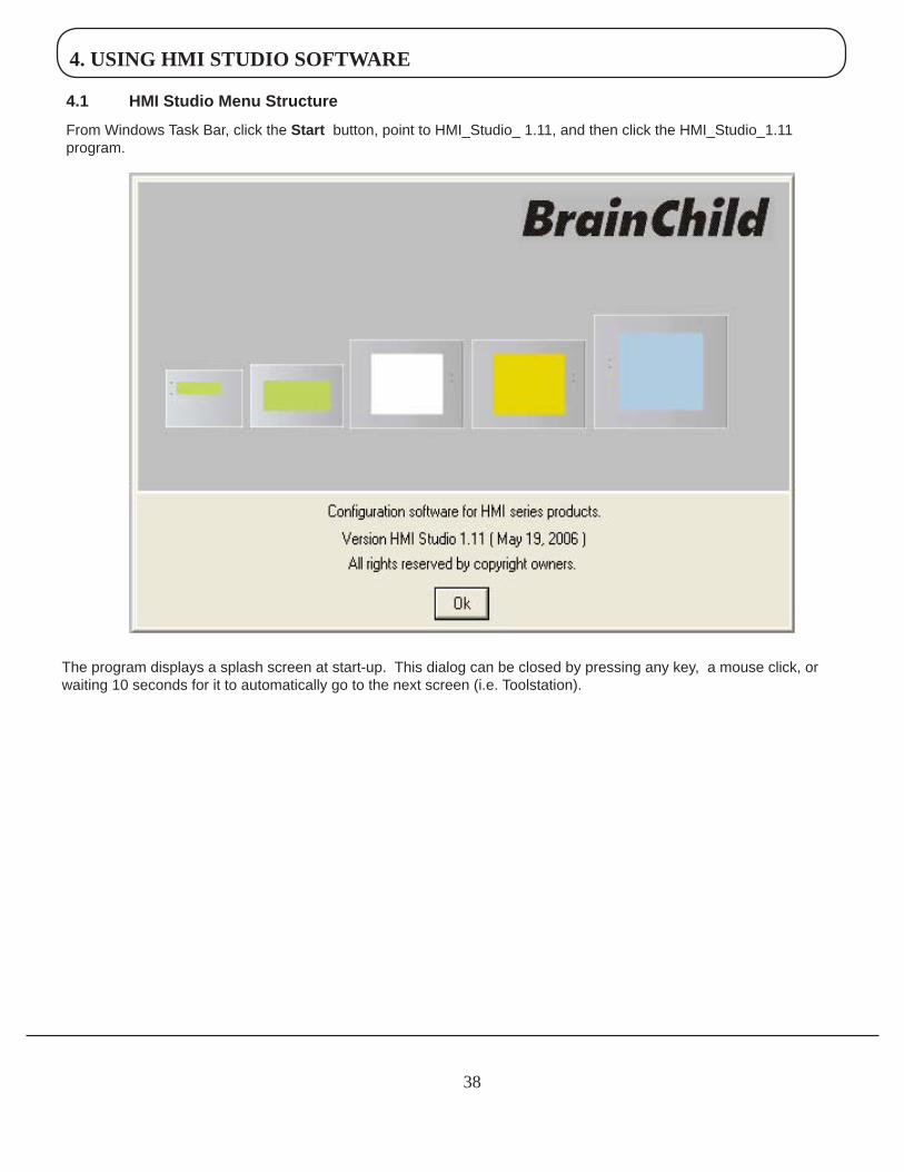
From Windows Task Bar, click theStart button, point to HMI_Studio_ 1.11, and then click the HMI_Studio_1.11 program.
The program displays a splash screen at start-up. This dialog can be closed by pressing any key, a mouse click, or waiting 10 seconds for it to automatically go to the next screen (i.e. Toolstation).
4. USING HMI STUDIO SOFTWARE
39
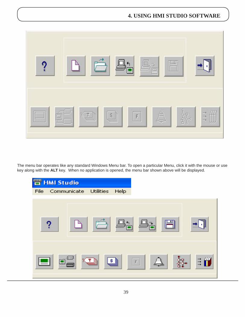
The menu bar operates like any standard Windows Menu bar. To open a particular Menu, click it with the mouse or use key along with the ALT key. When no application is opened, the menu bar shown above will be displayed.
4. USING HMI STUDIO SOFTWARE
40
The Tool-Station consists of icons. When the mouse cursor rests over any icon, a tool-tip is displayed. Click on the icon to select the particular menu.
Now we will study the different Menus in the Menu Bar.
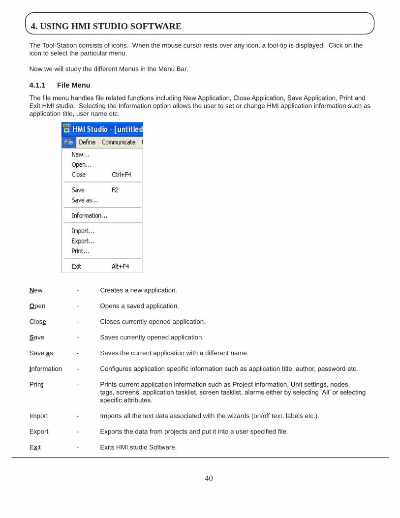
4.1.1 FileMenu
The file menu handles file related functions including New Application, Close Application, Save Application, Print and Exit HMI studio. Selecting the Information option allows the user to set or change HMI application information such as application title, user name etc.
New - Creates a new application.
Open - Opens a saved application.
Close - Closes currently opened application.
Save - Saves currently opened application.
Save as - Saves the current application with a different name.
Information - Configures application specific information such as application title, author, password etc.
Print - Prints current application information such as Project information, Unit settings, nodes, tags, screens, application tasklist, screen tasklist, alarms either by selecting ‘All’ or selecting specific attributes.
Import - Imports all the text data associated with the wizards (on/off text, labels etc.).
Export - Exports the data from projects and put it into a user specified file.
Exit - Exits HMI studio Software.
4. USING HMI STUDIO SOFTWARE
41
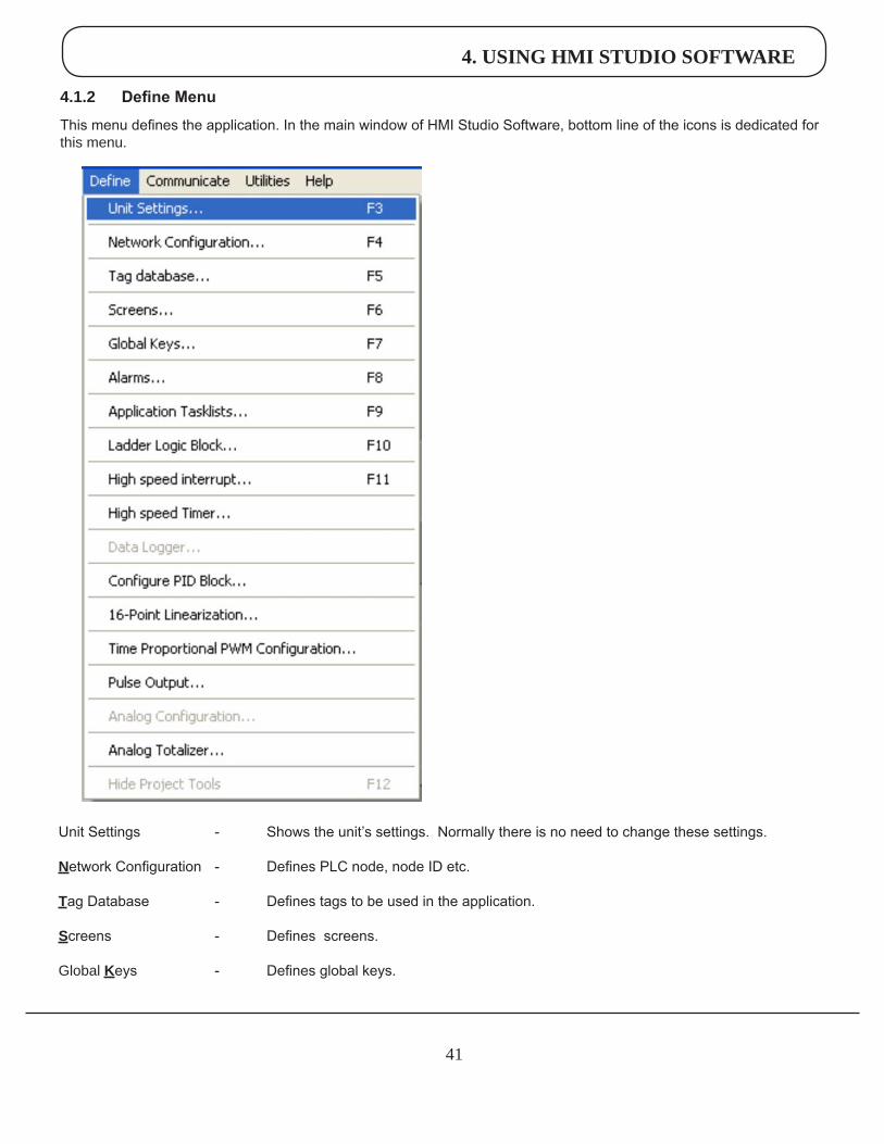
4.1.2 Define Menu
This menu defines the application. In the main window of HMI Studio Software, bottom line of the icons is dedicated for this menu.
Unit Settings - Shows the unit’s settings. Normally there is no need to change these settings.
Network Configuration - Defines PLC node, node ID etc.
Tag Database - Defines tags to be used in the application.
Screens - Defines screens.
Global Keys - Defines global keys.
4. USING HMI STUDIO SOFTWARE
42
Alarms - Defines alarms in the application.
Application Task-List - Defines Power-on and Global Tasklist.
Ladder Logic Block - Used for development of ladder block.
High Speed Interrupt - Used for applications like Rate Measurement, Totalizer.
High Speed Timer - Allows ladder program to be executed in parallel to main program.
Data Logger - Used to record the information about the surrounding environment.
Configure PID Block - Used as feedback controller in process and control applications.
16-Point Linearization - Used to linearize a nonlinear variable.
PWM Configuration - Used to encode analog output to digital signals.
Pulse Output - Used for motion control applications.
Analog Configuration - Used for selection of analog input and output channels.
Analog Totalizer - Used mostly with Flow transmitters which gives analog value proportional to flow of fluid.
Hide Project Tools - When enabled project toolbar is disabled. By default, project toolbar is enabled.
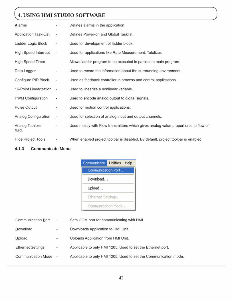
4.1.3 CommunicateMenu
Communication Port - Sets COM port for communicating with HMI
Download - Downloads Application to HMI Unit.
Upload - Uploads Application from HMI Unit.
Ethernet Settings - Applicable to only HMI 1205. Used to set the Ethernet port.
Communication Mode - Applicable to only HMI 1205. Used to set the Communication mode.
4. USING HMI STUDIO SOFTWARE
43
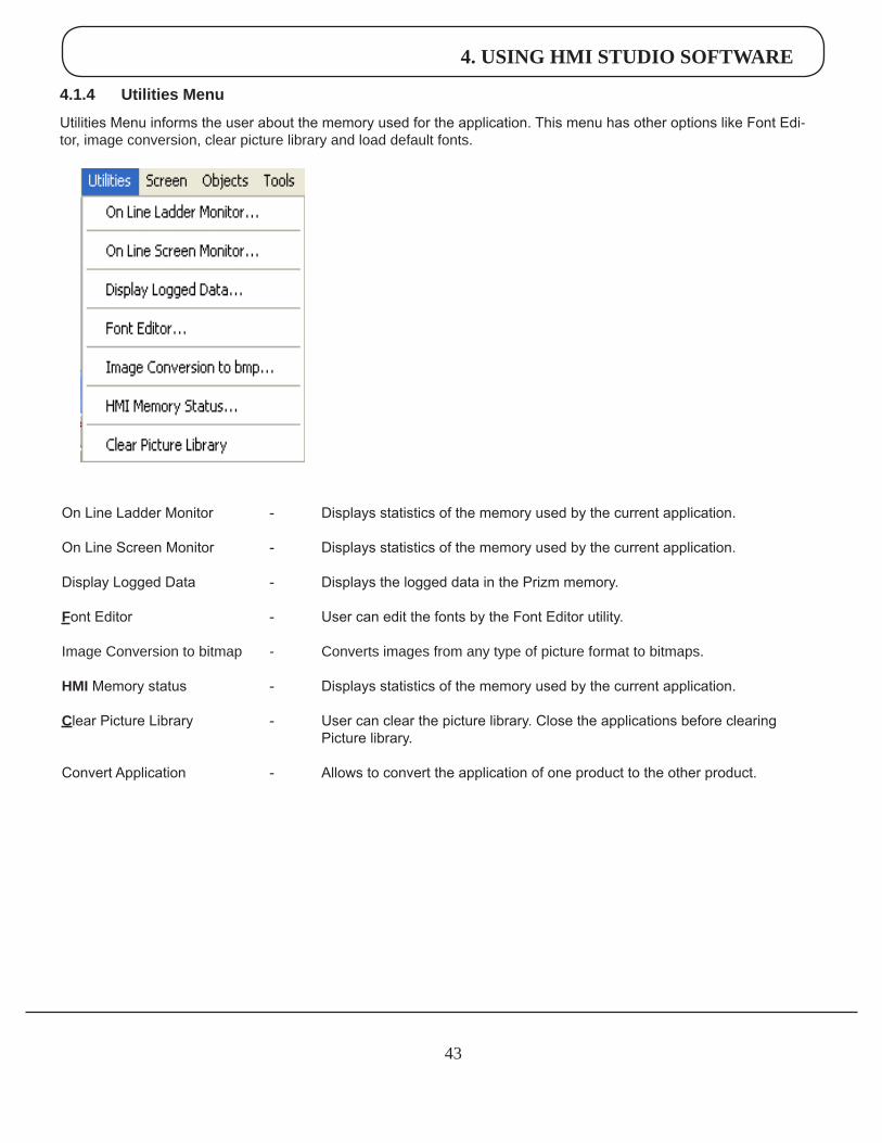
4.1.4 UtilitiesMenu
Utilities Menu informs the user about the memory used for the application. This menu has other options like Font Edi-tor, image conversion, clear picture library and load default fonts.
On Line Ladder Monitor - Displays statistics of the memory used by the current application.
On Line Screen Monitor - Displays statistics of the memory used by the current application.
Display Logged Data - Displays the logged data in the Prizm memory.
Font Editor - User can edit the fonts by the Font Editor utility.
Image Conversion to bitmap - Converts images from any type of picture format to bitmaps.
HMI Memory status - Displays statistics of the memory used by the current application.
Clear Picture Library - User can clear the picture library. Close the applications before clearing Picture library.
Convert Application - Allows to convert the application of one product to the other product.
4. USING HMI STUDIO SOFTWARE
44
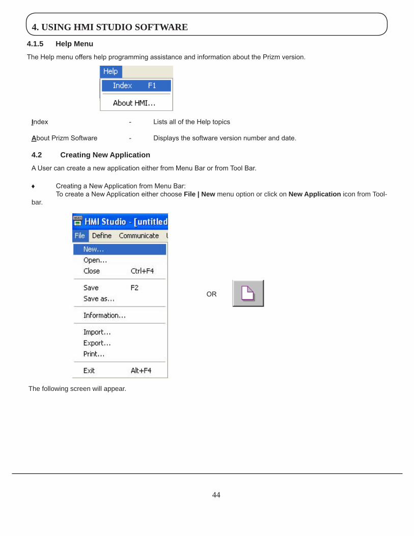
4.1.5 HelpMenu
The Help menu offers help programming assistance and information about the Prizm version.
Index - Lists all of the Help topics
About Prizm Software - Displays the software version number and date.
4.2 CreatingNewApplication
A User can create a new application either from Menu Bar or from Tool Bar.
♦ Creating a New Application from Menu Bar: To create a New Application either choose File|New menu option or click on NewApplication icon from Tool-bar.
The following screen will appear.
OR
4. USING HMI STUDIO SOFTWARE
45
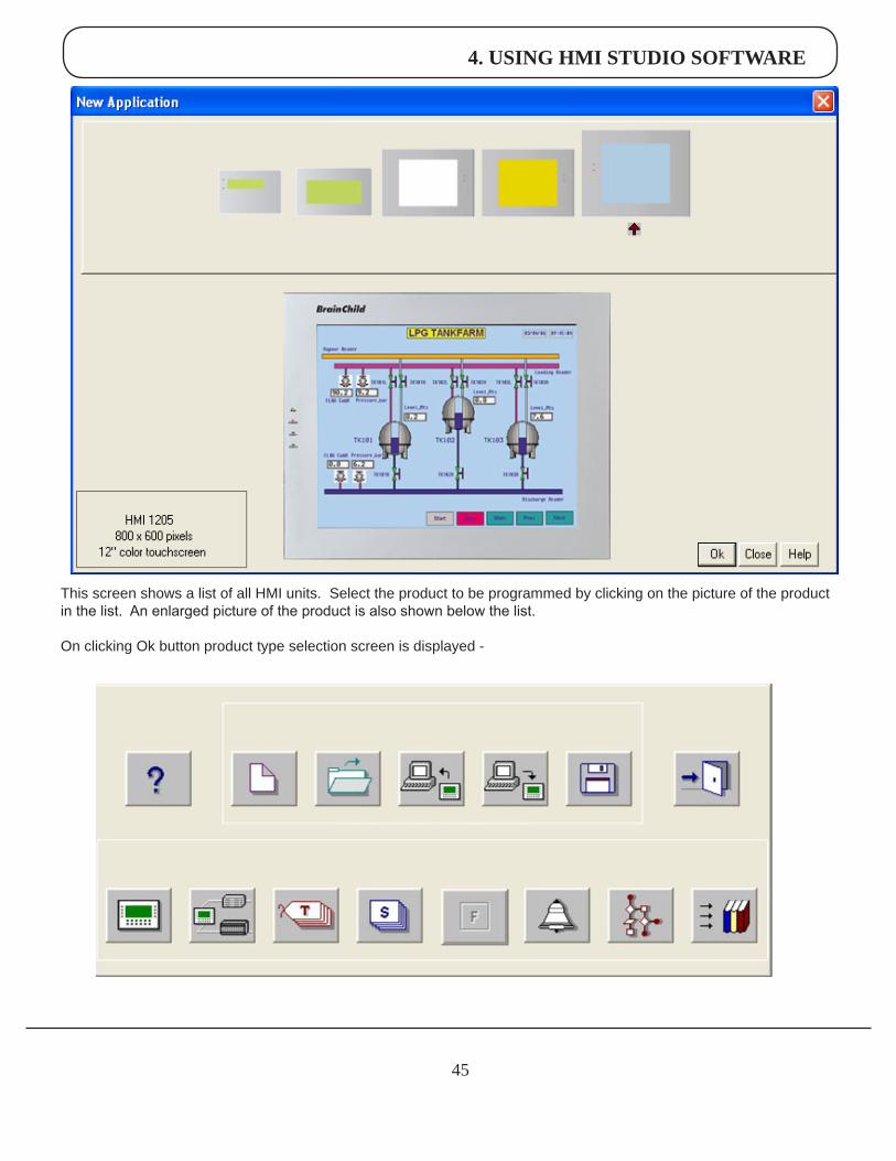
This screen shows a list of all HMI units. Select the product to be programmed by clicking on the picture of the product in the list. An enlarged picture of the product is also shown below the list.
On clicking Ok button product type selection screen is displayed -
4. USING HMI STUDIO SOFTWARE
46
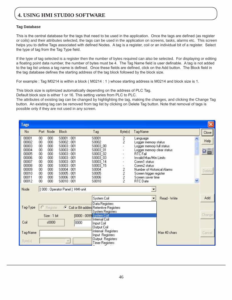
TagDatabase
This is the central database for the tags that need to be used in the application. Once the tags are defined (as register or coils) and their attributes selected, the tags can be used in the application on screens, tasks, alarms etc. This screen helps you to define Tags associated with defined Nodes. A tag is a register, coil or an individual bit of a register. Select the type of tag from the Tag Type field.
If the type of tag selected is a register then the number of bytes required can also be selected. For displaying or editing a floating point data number, the number of bytes must be 4. The Tag Name field is user definable. A tag is not added to the tag list unless a tag name is defined. Once these fields are defined, click on the Add button. The Block field in the tag database defines the starting address of the tag block followed by the block size.
For example : Tag M0214 is within a block ( M0214 : 1 ) whose starting address is M0214 and block size is 1.
This block size is optimized automatically depending on the address of PLC Tag.Default block size is either 1 or 16. This setting varies from PLC to PLC.The attributes of existing tag can be changed by highlighting the tag, making the changes, and clicking the Change Tag button. An existing tag can be removed from tag list by clicking on Delete Tag button. Note that removal of tags is possible only if they are not used in any screen.
4. USING HMI STUDIO SOFTWARE
47
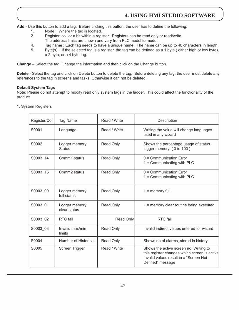
Add - Use this button to add a tag. Before clicking this button, the user has to define the following: 1. Node : Where the tag is located. 2. Register, coil or a bit within a register. Registers can be read only or read/write. The address limits are shown and vary from PLC model to model. 4. Tag name : Each tag needs to have a unique name. The name can be up to 40 characters in length. 5. Byte(s) : If the selected tag is a register, the tag can be defined as a 1 byte ( either high or low byte), a 2 byte, or a 4 byte tag.
Change – Select the tag. Change the information and then click on the Change button.
Delete - Select the tag and click on Delete button to delete the tag. Before deleting any tag, the user must delete any references to the tag in screens and tasks. Otherwise it can not be deleted.
DefaultSystemTagsNote: Please do not attempt to modify read only system tags in the ladder. This could affect the functionality of the product.
1. System Registers
Register/Coil Tag Name Read / Write Description
S0001 Language Read / Write Writing the value will change languages used in any wizard
S0002 Logger memory Read Only Shows the percentage usage of status Status logger memory. ( 0 to 100 )
S0003_14 Comm1 status Read Only 0 = Communication Error 1 = Communicating with PLC
S0003_15 Comm2 status Read Only 0 = Communication Error 1 = Communicating with PLC
S0003_00 Logger memory Read Only 1 = memory full full status
S0003_01 Logger memory Read Only 1 = memory clear routine being executed clear status
S0003_02 RTC fail Read Only RTC fail S0003_03 Invalid max/min Read Only Invalid indirect values entered for wizard limits
S0004 Number of Historical Read Only Shows no of alarms, stored in history
S0005 Screen Trigger Read / Write Shows the active screen no. Writing to this register changes which screen is active. Invalid values result in a “Screen Not Defined” message
4. USING HMI STUDIO SOFTWARE
48
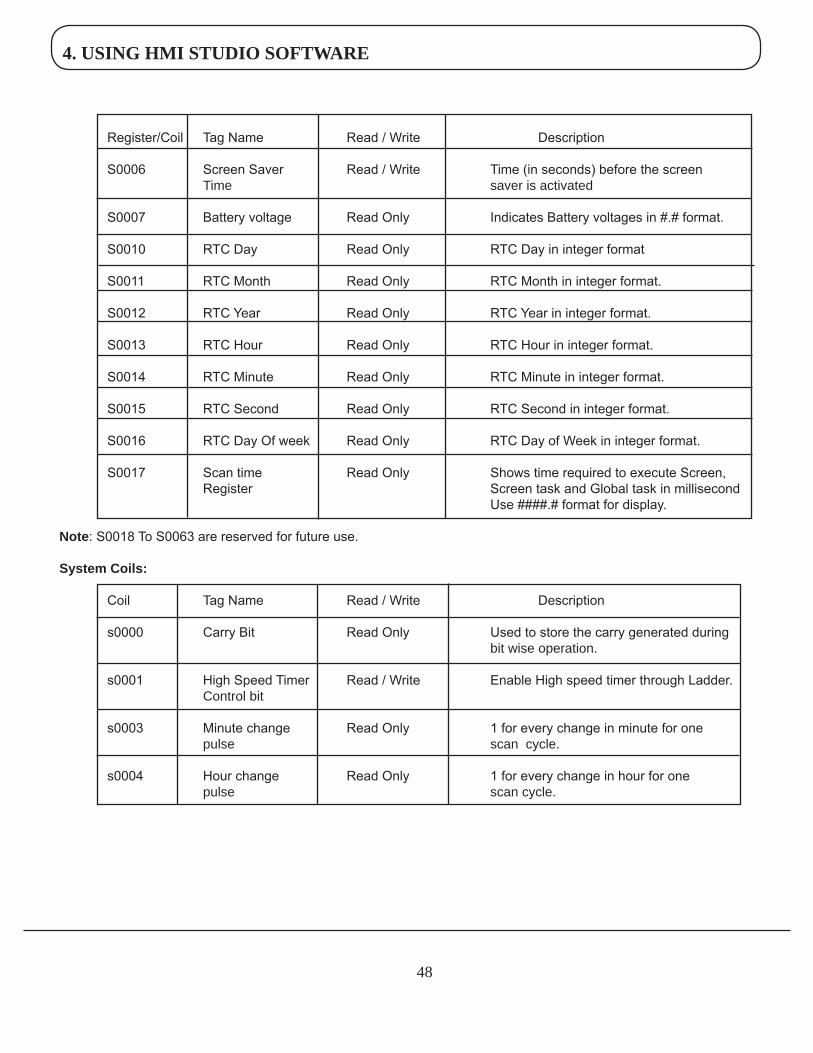
Register/Coil Tag Name Read / Write Description
S0006 Screen Saver Read / Write Time (in seconds) before the screen Time saver is activated
S0007 Battery voltage Read Only Indicates Battery voltages in #.# format.
S0010 RTC Day Read Only RTC Day in integer format
S0011 RTC Month Read Only RTC Month in integer format. S0012 RTC Year Read Only RTC Year in integer format. S0013 RTC Hour Read Only RTC Hour in integer format. S0014 RTC Minute Read Only RTC Minute in integer format. S0015 RTC Second Read Only RTC Second in integer format. S0016 RTC Day Of week Read Only RTC Day of Week in integer format. S0017 Scan time Read Only Shows time required to execute Screen, Register Screen task and Global task in millisecond Use ####.# format for display.
Note: S0018 To S0063 are reserved for future use. SystemCoils:
Coil Tag Name Read / Write Description
s0000 Carry Bit Read Only Used to store the carry generated during bit wise operation. s0001 High Speed Timer Read / Write Enable High speed timer through Ladder. Control bit s0003 Minute change Read Only 1 for every change in minute for one pulse scan cycle. s0004 Hour change Read Only 1 for every change in hour for one pulse scan cycle.
4. USING HMI STUDIO SOFTWARE
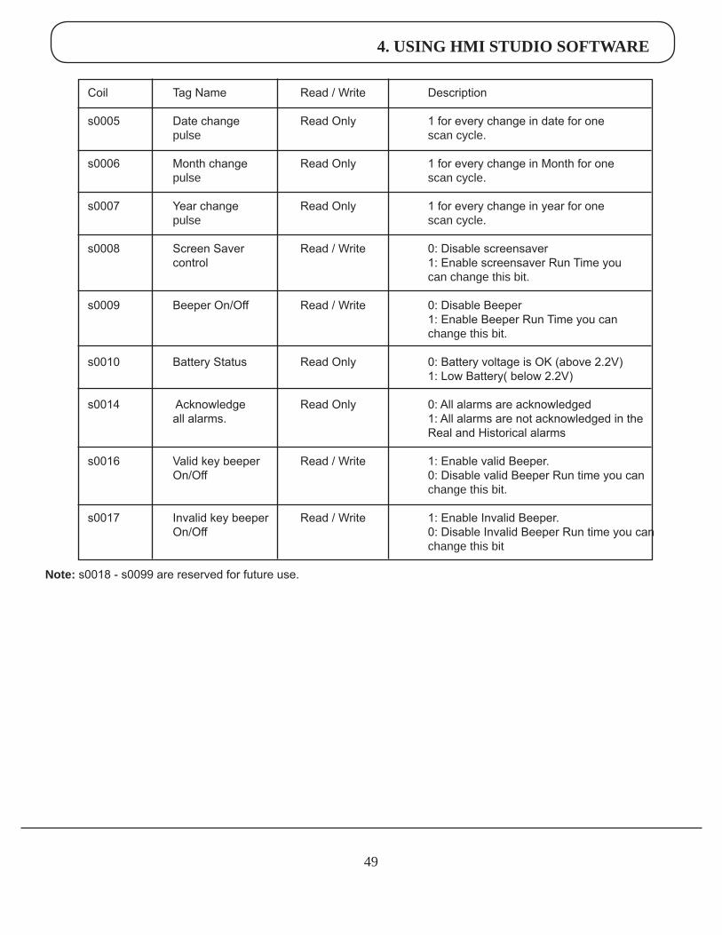
49
Coil Tag Name Read / Write Description s0005 Date change Read Only 1 for every change in date for one pulse scan cycle. s0006 Month change Read Only 1 for every change in Month for one pulse scan cycle.
s0007 Year change Read Only 1 for every change in year for one pulse scan cycle.
s0008 Screen Saver Read / Write 0: Disable screensaver control 1: Enable screensaver Run Time you can change this bit. s0009 Beeper On/Off Read / Write 0: Disable Beeper 1: Enable Beeper Run Time you can change this bit.
s0010 Battery Status Read Only 0: Battery voltage is OK (above 2.2V) 1: Low Battery( below 2.2V)
s0014 Acknowledge Read Only 0: All alarms are acknowledged all alarms. 1: All alarms are not acknowledged in the Real and Historical alarms
s0016 Valid key beeper Read / Write 1: Enable valid Beeper. On/Off 0: Disable valid Beeper Run time you can change this bit.
s0017 Invalid key beeper Read / Write 1: Enable Invalid Beeper. On/Off 0: Disable Invalid Beeper Run time you can change this bit
Note: s0018 - s0099 are reserved for future use.
4. USING HMI STUDIO SOFTWARE
50
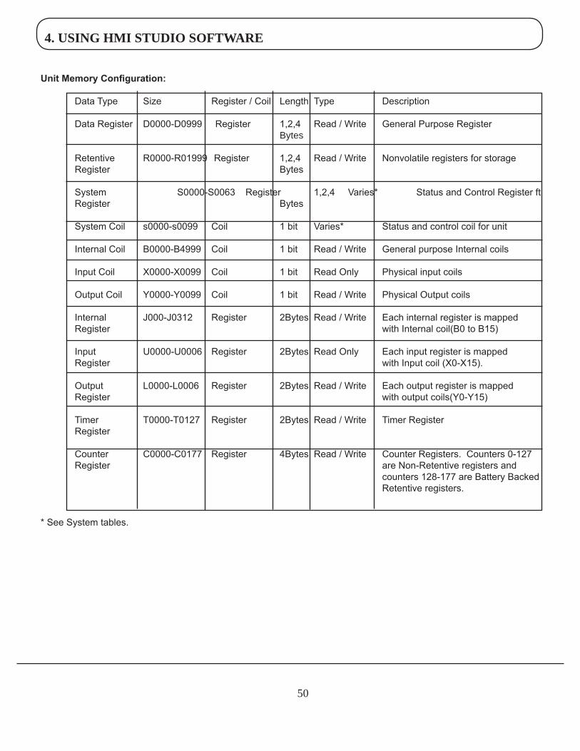
Unit Memory Configuration:
Data Type Size Register / Coil Length Type Description
Data Register D0000-D0999 Register 1,2,4 Read / Write General Purpose Register Bytes Retentive R0000-R01999 Register 1,2,4 Read / Write Nonvolatile registers for storage Register Bytes
System S0000-S0063 Register 1,2,4 Varies* Status and Control Register ft Register Bytes
System Coil s0000-s0099 Coil 1 bit Varies* Status and control coil for unit
Internal Coil B0000-B4999 Coil 1 bit Read / Write General purpose Internal coils Input Coil X0000-X0099 Coil 1 bit Read Only Physical input coils
Output Coil Y0000-Y0099 Coil 1 bit Read / Write Physical Output coils
Internal J000-J0312 Register 2Bytes Read / Write Each internal register is mapped Register with Internal coil(B0 to B15)
Input U0000-U0006 Register 2Bytes Read Only Each input register is mapped Register with Input coil (X0-X15).
Output L0000-L0006 Register 2Bytes Read / Write Each output register is mapped Register with output coils(Y0-Y15)
Timer T0000-T0127 Register 2Bytes Read / Write Timer Register Register Counter C0000-C0177 Register 4Bytes Read / Write Counter Registers. Counters 0-127 Register are Non-Retentive registers and counters 128-177 are Battery Backed Retentive registers.
* See System tables.
4. USING HMI STUDIO SOFTWARE
51
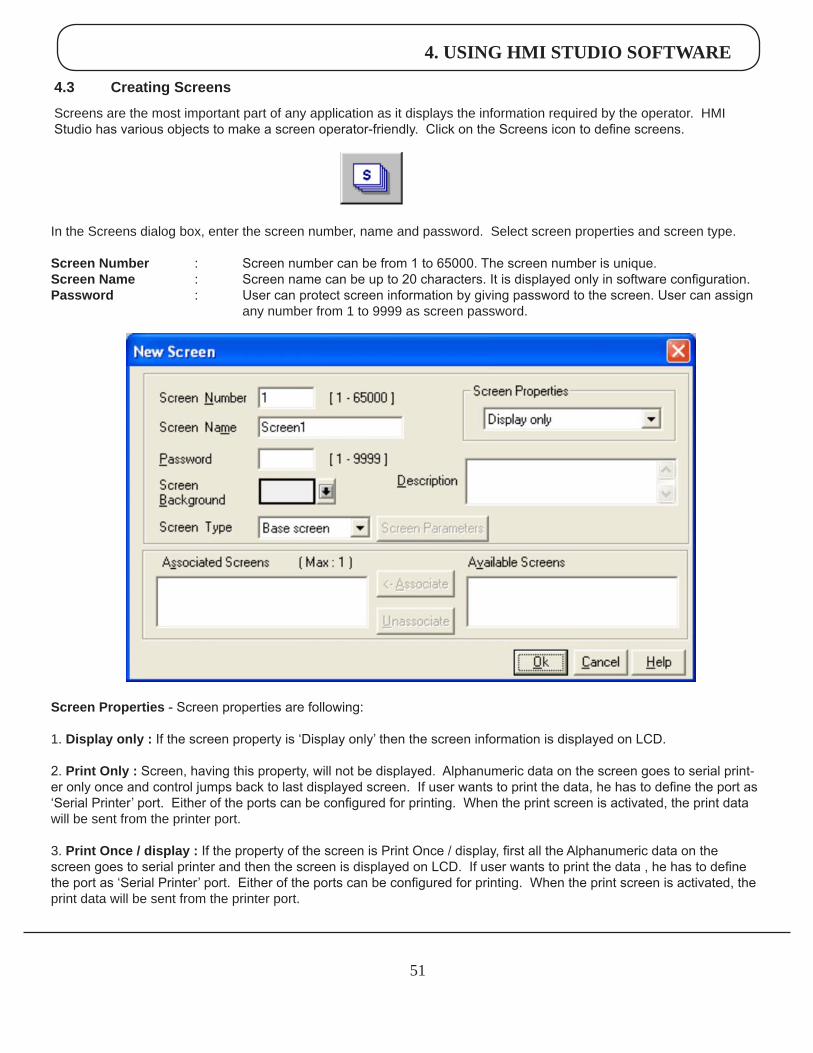
4.3 CreatingScreens
Screens are the most important part of any application as it displays the information required by the operator. HMI Studio has various objects to make a screen operator-friendly. Click on the Screens icon to define screens.
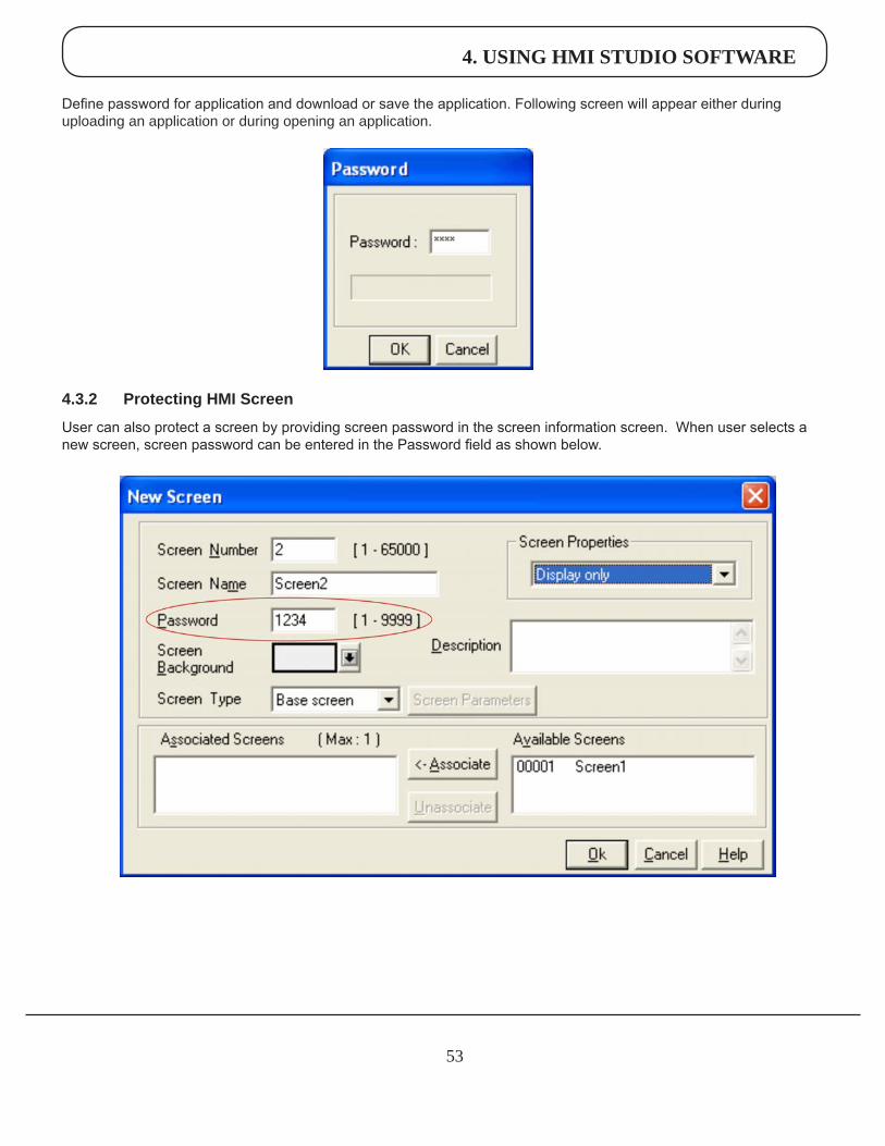
In the Screens dialog box, enter the screen number, name and password. Select screen properties and screen type.
ScreenNumber : Screen number can be from 1 to 65000. The screen number is unique.ScreenName : Screen name can be up to 20 characters. It is displayed only in software configuration.Password : User can protect screen information by giving password to the screen. User can assign any number from 1 to 9999 as screen password.
ScreenProperties - Screen properties are following:
1. Displayonly: If the screen property is ‘Display only’ then the screen information is displayed on LCD.
2. PrintOnly: Screen, having this property, will not be displayed. Alphanumeric data on the screen goes to serial print-er only once and control jumps back to last displayed screen. If user wants to print the data, he has to define the port as ‘Serial Printer’ port. Either of the ports can be configured for printing. When the print screen is activated, the print data will be sent from the printer port.
3. PrintOnce/display: If the property of the screen is Print Once / display, first all the Alphanumeric data on the screen goes to serial printer and then the screen is displayed on LCD. If user wants to print the data , he has to define the port as ‘Serial Printer’ port. Either of the ports can be configured for printing. When the print screen is activated, the print data will be sent from the printer port.
4. USING HMI STUDIO SOFTWARE
52
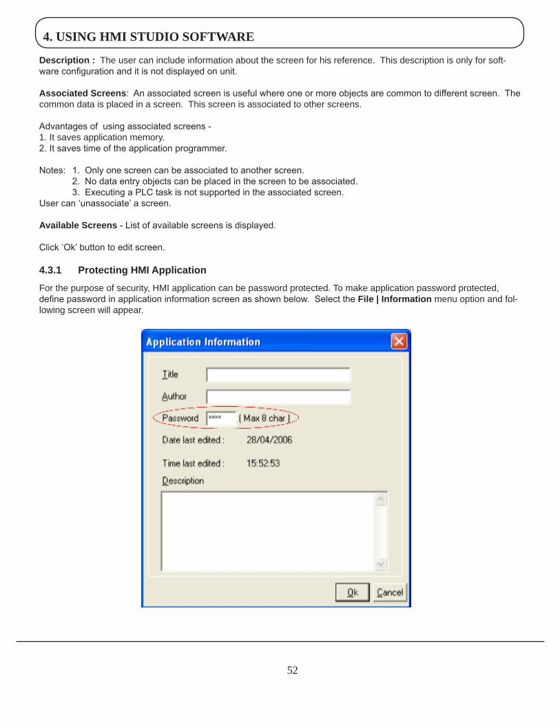
Description: The user can include information about the screen for his reference. This description is only for soft-ware configuration and it is not displayed on unit.
AssociatedScreens: An associated screen is useful where one or more objects are common to different screen. The common data is placed in a screen. This screen is associated to other screens. Advantages of using associated screens -1. It saves application memory.2. It saves time of the application programmer. Notes: 1. Only one screen can be associated to another screen. 2. No data entry objects can be placed in the screen to be associated. 3. Executing a PLC task is not supported in the associated screen. User can ‘unassociate’ a screen.
AvailableScreens - List of available screens is displayed.
Click ‘Ok’ button to edit screen.
4.3.1 ProtectingHMIApplication
For the purpose of security, HMI application can be password protected. To make application password protected, define password in application information screen as shown below. Select the File|Information menu option and fol-lowing screen will appear.
4. USING HMI STUDIO SOFTWARE
53
Define password for application and download or save the application. Following screen will appear either during uploading an application or during opening an application.
4.3.2 ProtectingHMIScreen
User can also protect a screen by providing screen password in the screen information screen. When user selects a new screen, screen password can be entered in the Password field as shown below.
4. USING HMI STUDIO SOFTWARE
54
When user downloads an application and when he opens the screen with password, software will first ask for the password. 4.4 DataEntryObject
Any register or coil from the unit or PLC memory, except Read-only registers and coils, can be edited using the numeric keypad.
Procedure -1. Click on the Data Entry button from objects toolbar.2. The mouse pointer will change to the tool shape. Now place the mouse pointer at desired location and click the left mouse button. The data entry dialog box will appear.
Data Entry objects are explained in detail in chapter 5.
4.5 DisplayDataObject
This object is used to display the contents of the register or coil.Procedure- 1. Click on ‘Display Data’ from objects toolbar. The mouse pointer will change to the tool shape. 2. Now place the mouse pointer at desired location and click the left mouse button. The data entry dialog box will ap-pear.
Display data object is explained in detail in chapter 5.
4. USING HMI STUDIO SOFTWARE
55
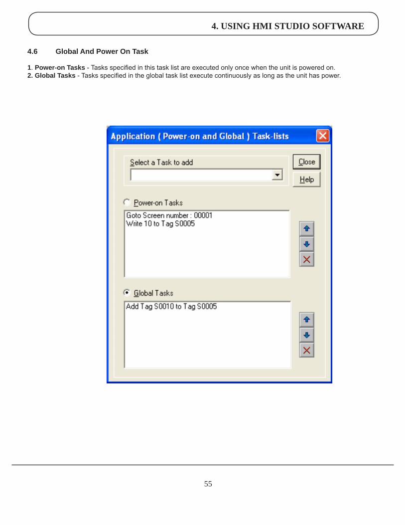
4.6 GlobalAndPowerOnTask
1. Power-onTasks - Tasks specified in this task list are executed only once when the unit is powered on.2. GlobalTasks - Tasks specified in the global task list execute continuously as long as the unit has power.
4. USING HMI STUDIO SOFTWARE
56
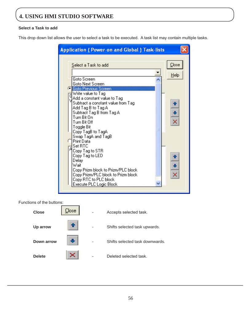
SelectaTasktoadd
This drop down list allows the user to select a task to be executed. A task list may contain multiple tasks.
Functions of the buttons: Close - Accepts selected task.
Uparrow - Shifts selected task upwards.
Downarrow - Shifts selected task downwards.
Delete - Deleted selected task.
4. USING HMI STUDIO SOFTWARE
57
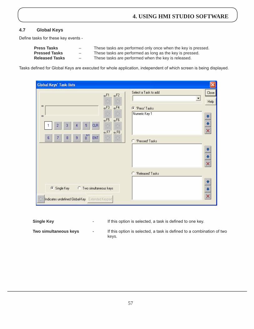
4.7 GlobalKeys
Define tasks for these key events - PressTasks – These tasks are performed only once when the key is pressed. PressedTasks – These tasks are performed as long as the key is pressed. ReleasedTasks – These tasks are performed when the key is released.
Tasks defined for Global Keys are executed for whole application, independent of which screen is being displayed.
SingleKey - If this option is selected, a task is defined to one key.
Twosimultaneouskeys - If this option is selected, a task is defined to a combination of two keys.
5. REPRESENTING DATA BY OBJECTS AND WIZARDS
58
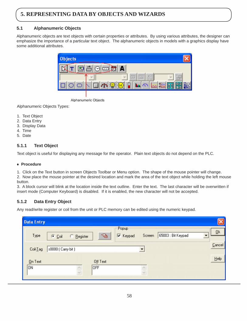
5.1 AlphanumericObjects
Alphanumeric objects are text objects with certain properties or attributes. By using various attributes, the designer can emphasize the importance of a particular text object. The alphanumeric objects in models with a graphics display have some additional attributes.
Alphanumeric Objects Types:
1. Text Object2. Data Entry3. Display Data4. Time5. Date
5.1.1 TextObject
Text object is useful for displaying any message for the operator. Plain text objects do not depend on the PLC.
♦ Procedure
1. Click on the Text button in screen Objects Toolbar or Menu option. The shape of the mouse pointer will change. 2. Now place the mouse pointer at the desired location and mark the area of the text object while holding the left mouse button. 3. A block cursor will blink at the location inside the text outline. Enter the text. The last character will be overwritten if insert mode (Computer Keyboard) is disabled. If it is enabled, the new character will not be accepted.
5.1.2 DataEntryObject
Any read/write register or coil from the unit or PLC memory can be edited using the numeric keypad.
5. REPRESENTING DATA BY OBJECTS AND WIZARDS
59
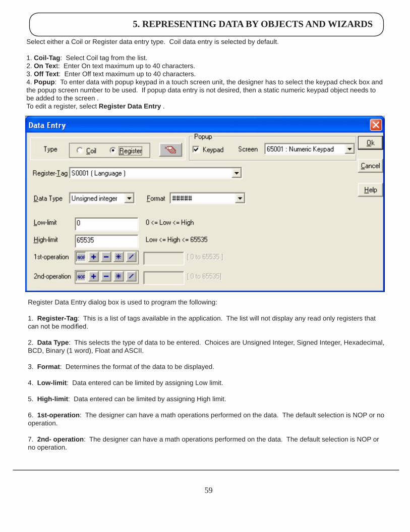
Select either a Coil or Register data entry type. Coil data entry is selected by default.
1. Coil-Tag: Select Coil tag from the list.2. OnText: Enter On text maximum up to 40 characters.3. OffText: Enter Off text maximum up to 40 characters.4.Popup: To enter data with popup keypad in a touch screen unit, the designer has to select the keypad check box and the popup screen number to be used. If popup data entry is not desired, then a static numeric keypad object needs to be added to the screen .To edit a register, select RegisterDataEntry .
Register Data Entry dialog box is used to program the following:
1. Register-Tag: This is a list of tags available in the application. The list will not display any read only registers that can not be modified.
2. DataType: This selects the type of data to be entered. Choices are Unsigned Integer, Signed Integer, Hexadecimal, BCD, Binary (1 word), Float and ASCII.
3. Format: Determines the format of the data to be displayed. 4. Low-limit: Data entered can be limited by assigning Low limit. 5. High-limit: Data entered can be limited by assigning High limit. 6. 1st-operation: The designer can have a math operations performed on the data. The default selection is NOP or no operation. 7. 2nd-operation: The designer can have a math operations performed on the data. The default selection is NOP or no operation.
5. REPRESENTING DATA BY OBJECTS AND WIZARDS
60
8. Popup: To enter data with popup keypad in a touch screen unit, the designer has to select the keypad check box and the popup screen number to use. If popup data entry is not desired, then a static numeric keypad object needs to be added to the screen .
Note: Math operations work only on the unsigned values and yield an unsigned result. For example, if the entry value is 25 and the first operation is to divide by 100, the result stored in the tag is zero.
Click ‘Ok’ button to add the object to the screen.
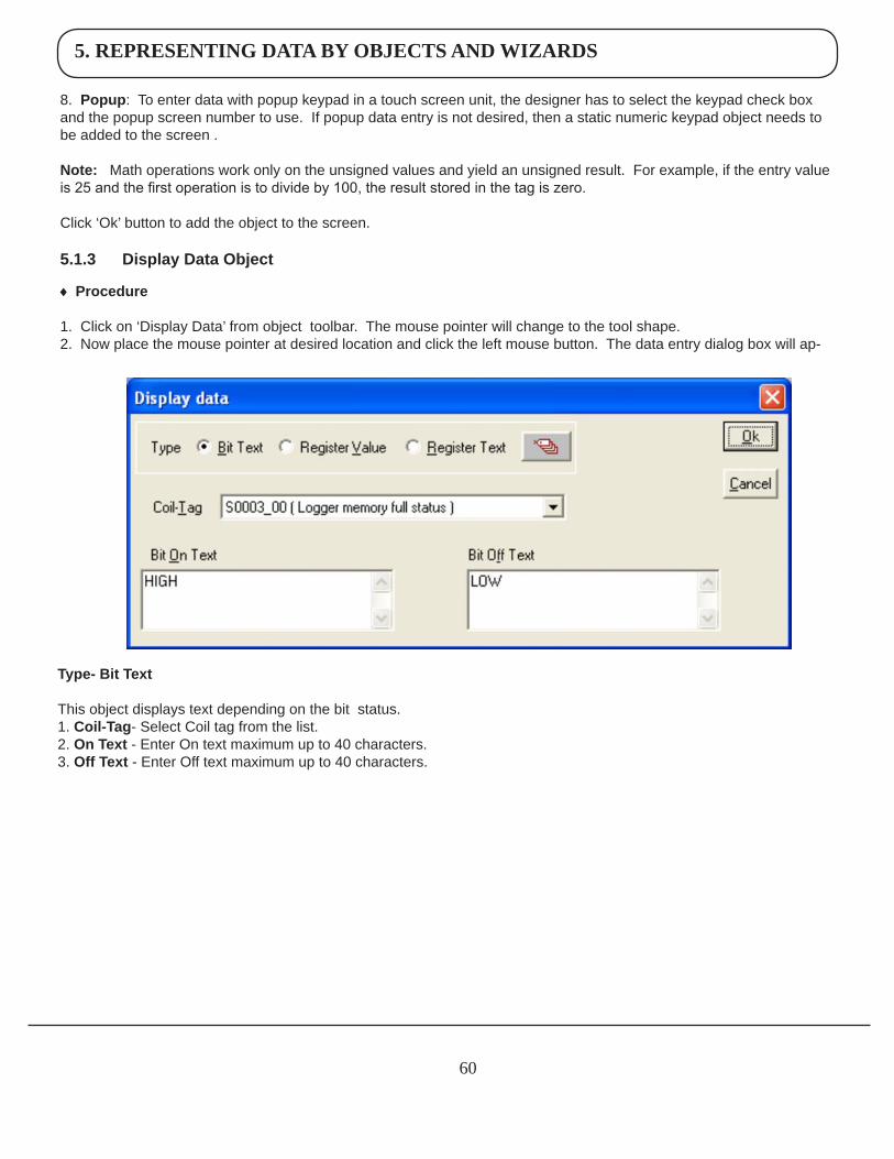
5.1.3 DisplayDataObject
♦ Procedure 1. Click on ‘Display Data’ from object toolbar. The mouse pointer will change to the tool shape. 2. Now place the mouse pointer at desired location and click the left mouse button. The data entry dialog box will ap-
Type-BitText
This object displays text depending on the bit status. 1. Coil-Tag- Select Coil tag from the list. 2. OnText - Enter On text maximum up to 40 characters. 3.OffText - Enter Off text maximum up to 40 characters.
5. REPRESENTING DATA BY OBJECTS AND WIZARDS
61
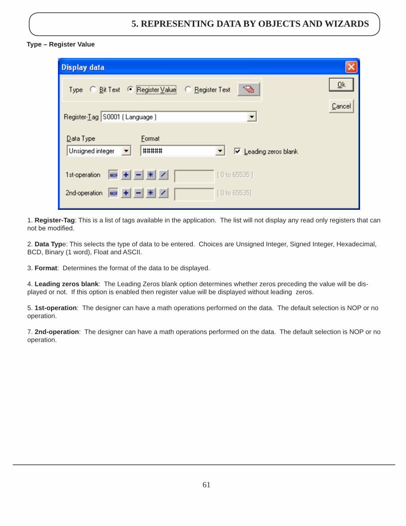
Type–RegisterValue
1. Register-Tag: This is a list of tags available in the application. The list will not display any read only registers that can not be modified.
2.DataType: This selects the type of data to be entered. Choices are Unsigned Integer, Signed Integer, Hexadecimal, BCD, Binary (1 word), Float and ASCII.
3.Format: Determines the format of the data to be displayed.
4. Leadingzerosblank: The Leading Zeros blank option determines whether zeros preceding the value will be dis-played or not. If this option is enabled then register value will be displayed without leading zeros.
5. 1st-operation: The designer can have a math operations performed on the data. The default selection is NOP or no operation.
7. 2nd-operation: The designer can have a math operations performed on the data. The default selection is NOP or no operation.
5. REPRESENTING DATA BY OBJECTS AND WIZARDS
62
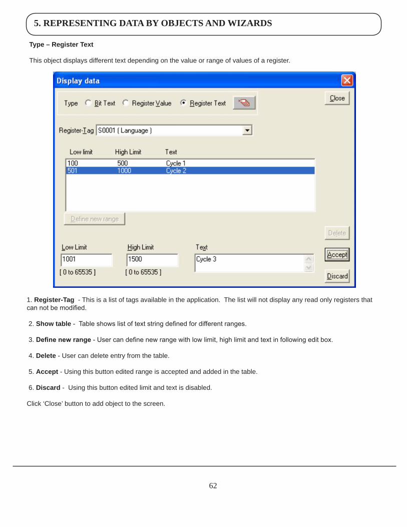
Type–RegisterText
This object displays different text depending on the value or range of values of a register.
1. Register-Tag - This is a list of tags available in the application. The list will not display any read only registers that can not be modified.
2. Showtable - Table shows list of text string defined for different ranges.
3. Define new range - User can define new range with low limit, high limit and text in following edit box.
4. Delete - User can delete entry from the table.
5. Accept - Using this button edited range is accepted and added in the table.
6. Discard - Using this button edited limit and text is disabled.
Click ‘Close’ button to add object to the screen.
5. REPRESENTING DATA BY OBJECTS AND WIZARDS
63
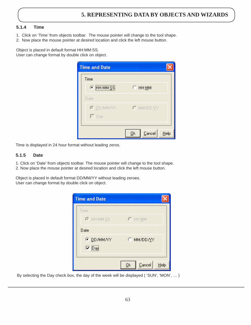
5.1.4 Time
1. Click on ‘Time’ from objects toolbar. The mouse pointer will change to the tool shape. 2. Now place the mouse pointer at desired location and click the left mouse button. Object is placed in default format HH:MM:SS. User can change format by double click on object.
Time is displayed in 24 hour format without leading zeros.
5.1.5 Date
1. Click on ‘Date’ from objects toolbar. The mouse pointer will change to the tool shape. 2. Now place the mouse pointer at desired location and click the left mouse button. Object is placed in default format DD/MM/YY without leading zeroes.User can change format by double click on object.
By selecting the Day check box, the day of the week will be displayed ( ‘SUN’, ‘MON’, … )

5. REPRESENTING DATA BY OBJECTS AND WIZARDS
64
5.1.6AttributesofAlphanumericObjects
FontSize
A text object can have four font sizes: 5x7 Dots, 7x14 Dots, 10x14 Dots and 20x28 Dots. Default font size is 5x7 Dots
TextForeground:
Text foreground can be changed by user. Two options are available: black and white. Default Text Foreground is Black.
TextBackground
The text background can be changed by the designer. The options are black and white. The default text background is white.
Border - Single or Double
Any text object can be highlighted with a single or double border.
UnconditionalFlash
User can assign flashing attribute to any text object. An object can flash at three different speeds: Slow, Medium and Fast. By default no object is assigned the flashing attribute. If flashing is defined, slow flashing is selected by default.
Note: Data Entry objects (Coil and register) do not have flash attribute.
The following attributes are available with a graphic display.
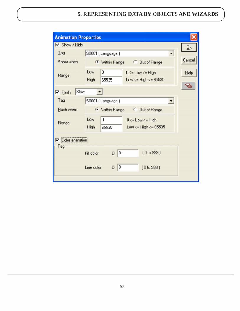
5.1.7AnimationProperties:
All objects can have their appearance changed using the animation property. Changes in the value of the tag associ-ated with the animation property control the tag’s appearance. There are three types of animation properties. They can be used in combination.
1. Show / Hide Animation
2. Flash Animation
3. Color Animation
5. REPRESENTING DATA BY OBJECTS AND WIZARDS
65
5. REPRESENTING DATA BY OBJECTS AND WIZARDS
66
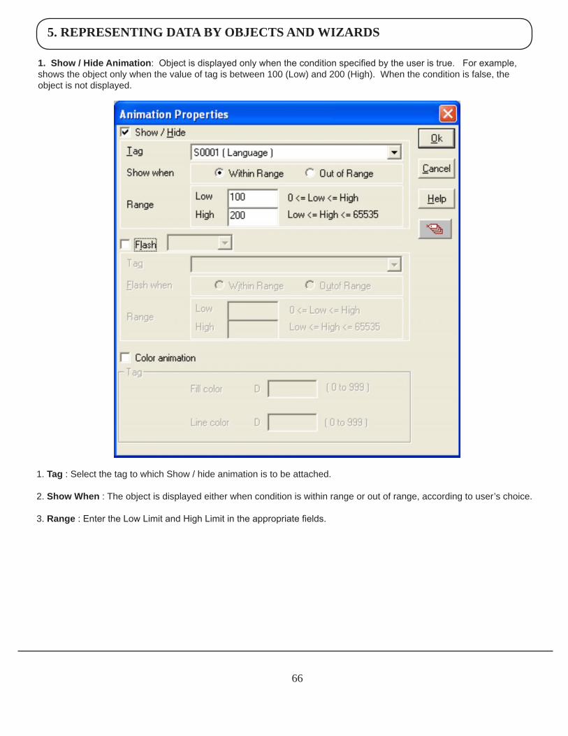
1.Show/HideAnimation: Object is displayed only when the condition specified by the user is true. For example, shows the object only when the value of tag is between 100 (Low) and 200 (High). When the condition is false, the object is not displayed.
1. Tag : Select the tag to which Show / hide animation is to be attached.
2. ShowWhen : The object is displayed either when condition is within range or out of range, according to user’s choice.
3. Range : Enter the Low Limit and High Limit in the appropriate fields.
5. REPRESENTING DATA BY OBJECTS AND WIZARDS
67
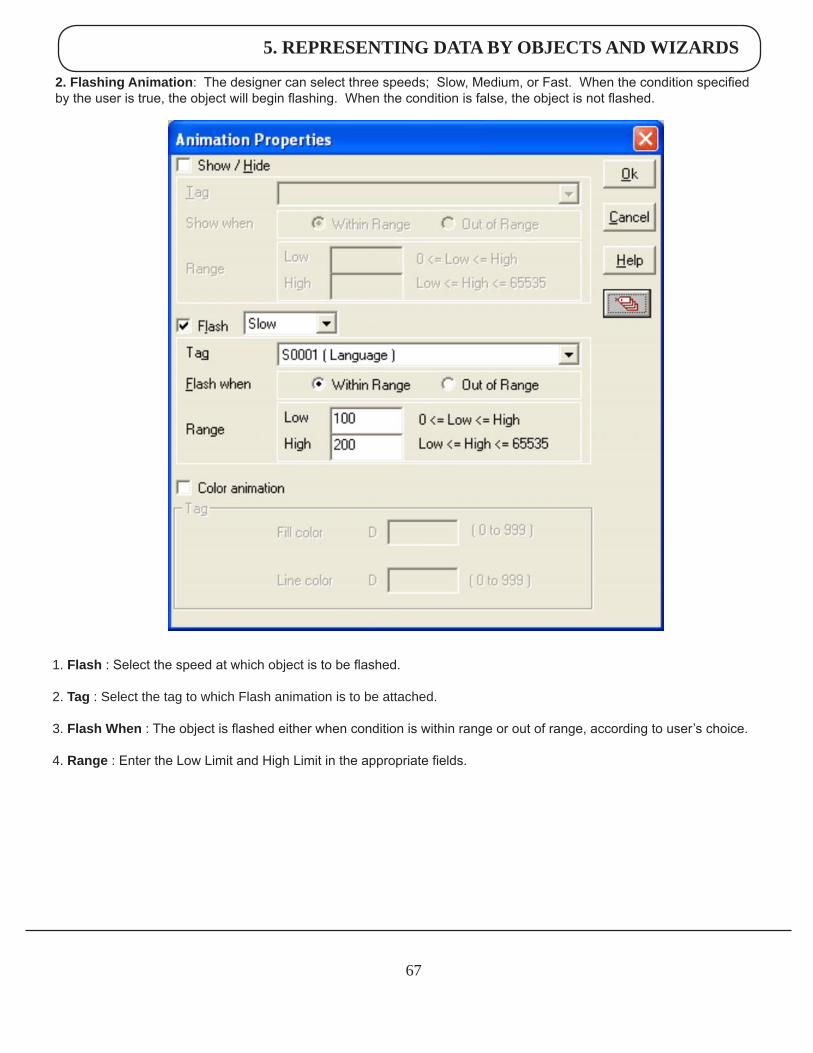
2.FlashingAnimation: The designer can select three speeds; Slow, Medium, or Fast. When the condition specified by the user is true, the object will begin flashing. When the condition is false, the object is not flashed.
1. Flash : Select the speed at which object is to be flashed.
2. Tag : Select the tag to which Flash animation is to be attached.
3. FlashWhen : The object is flashed either when condition is within range or out of range, according to user’s choice.
4. Range : Enter the Low Limit and High Limit in the appropriate fields.
5. REPRESENTING DATA BY OBJECTS AND WIZARDS
68
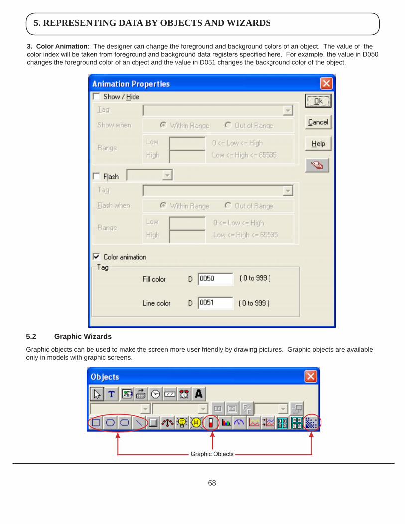
3.ColorAnimation: The designer can change the foreground and background colors of an object. The value of the color index will be taken from foreground and background data registers specified here. For example, the value in D050 changes the foreground color of an object and the value in D051 changes the background color of the object.
5.2 GraphicWizards
Graphic objects can be used to make the screen more user friendly by drawing pictures. Graphic objects are available only in models with graphic screens.
5. REPRESENTING DATA BY OBJECTS AND WIZARDS
69
Following are the Graphical Objects :
1. Line2. Rectangle3. Ellipse4. Rounded Rectangle5. Bargraph6. Bitmap
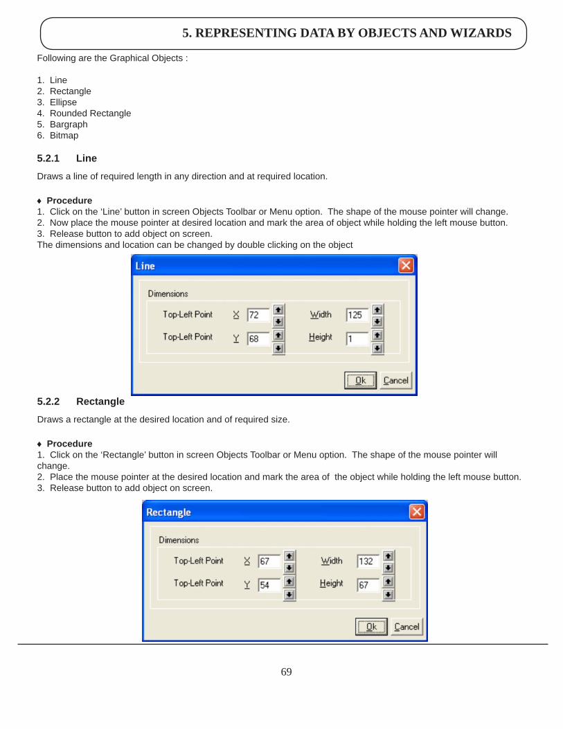
5.2.1 Line
Draws a line of required length in any direction and at required location.
♦ Procedure1. Click on the ‘Line’ button in screen Objects Toolbar or Menu option. The shape of the mouse pointer will change. 2. Now place the mouse pointer at desired location and mark the area of object while holding the left mouse button. 3. Release button to add object on screen.The dimensions and location can be changed by double clicking on the object
5.2.2 Rectangle
Draws a rectangle at the desired location and of required size.
♦ Procedure 1. Click on the ‘Rectangle’ button in screen Objects Toolbar or Menu option. The shape of the mouse pointer will change. 2. Place the mouse pointer at the desired location and mark the area of the object while holding the left mouse button. 3. Release button to add object on screen.
5. REPRESENTING DATA BY OBJECTS AND WIZARDS
70
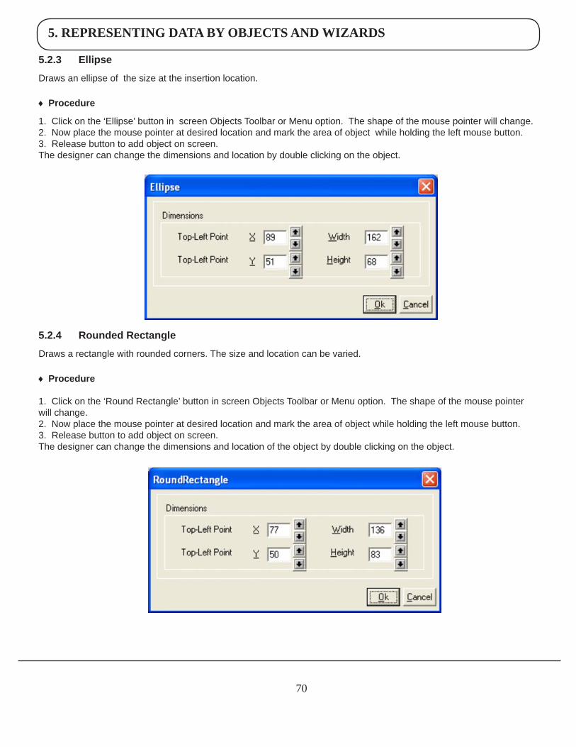
5.2.3 Ellipse
Draws an ellipse of the size at the insertion location.
♦ Procedure
1. Click on the ‘Ellipse’ button in screen Objects Toolbar or Menu option. The shape of the mouse pointer will change. 2. Now place the mouse pointer at desired location and mark the area of object while holding the left mouse button. 3. Release button to add object on screen.The designer can change the dimensions and location by double clicking on the object.
5.2.4 RoundedRectangle
Draws a rectangle with rounded corners. The size and location can be varied.
♦ Procedure 1. Click on the ‘Round Rectangle’ button in screen Objects Toolbar or Menu option. The shape of the mouse pointer will change. 2. Now place the mouse pointer at desired location and mark the area of object while holding the left mouse button. 3. Release button to add object on screen.The designer can change the dimensions and location of the object by double clicking on the object.
5. REPRESENTING DATA BY OBJECTS AND WIZARDS
71
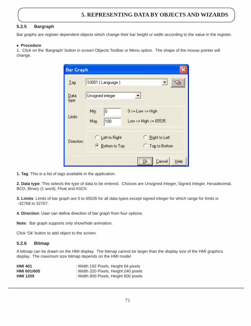
1.Tag: This is a list of tags available in the application.
2.Datatype: This selects the type of data to be entered. Choices are Unsigned Integer, Signed Integer, Hexadecimal, BCD, Binary (1 word), Float and ASCII.
3.Limits: Limits of bar graph are 0 to 65535 for all data types except signed integer for which range for limits is -32768 to 32767.
4.Direction: User can define direction of bar graph from four options.
Note: Bar graph supports only show/hide animation.
Click ‘Ok’ button to add object to the screen.
5.2.6 Bitmap
A bitmap can be drawn on the HMI display. The bitmap cannot be larger than the display size of the HMI graphics display. The maximum size bitmap depends on the HMI model.
HMI401 : Width 192 Pixels, Height 64 pixelsHMI601/605 : Width 320 Pixels, Height 240 pixelsHMI1205 : Width 800 Pixels, Height 600 pixels
5.2.5 Bargraph
Bar graphs are register dependent objects which change their bar height or width according to the value in the register.
♦ Procedure 1. Click on the ‘Bargraph’ button in screen Objects Toolbar or Menu option. The shape of the mouse pointer will change.
5. REPRESENTING DATA BY OBJECTS AND WIZARDS
72
2. Color
Color specification vary from HMI model to model as specified below:
HMI401 : 2 colorHMI601 : 16 colors Gray scalesHMI605/1205 : 256 color
If the image has more colors than the color specification of the HMI display, then the image cannot be used directly. Use Microsoft® Paint or other photo editing software to convert the image to 256 / 16 or 2 colors as per display specifi-cation.
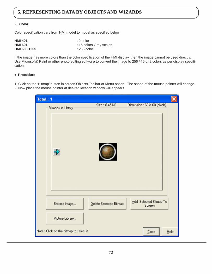
♦ Procedure
1. Click on the ‘Bitmap’ button in screen Objects Toolbar or Menu option. The shape of the mouse pointer will change. 2. Now place the mouse pointer at desired location window will appears.
5. REPRESENTING DATA BY OBJECTS AND WIZARDS
73
This window shows a list of the currently available bitmaps in the bitmap library.
BrowseImage : User can add his own bitmap in the library by browsing the folder.
DeleteSelectedBitmap: User can delete selected bitmap from the library.
AddSelectedBitmapToScreen: This will add selected bitmap on the screen at desired location.
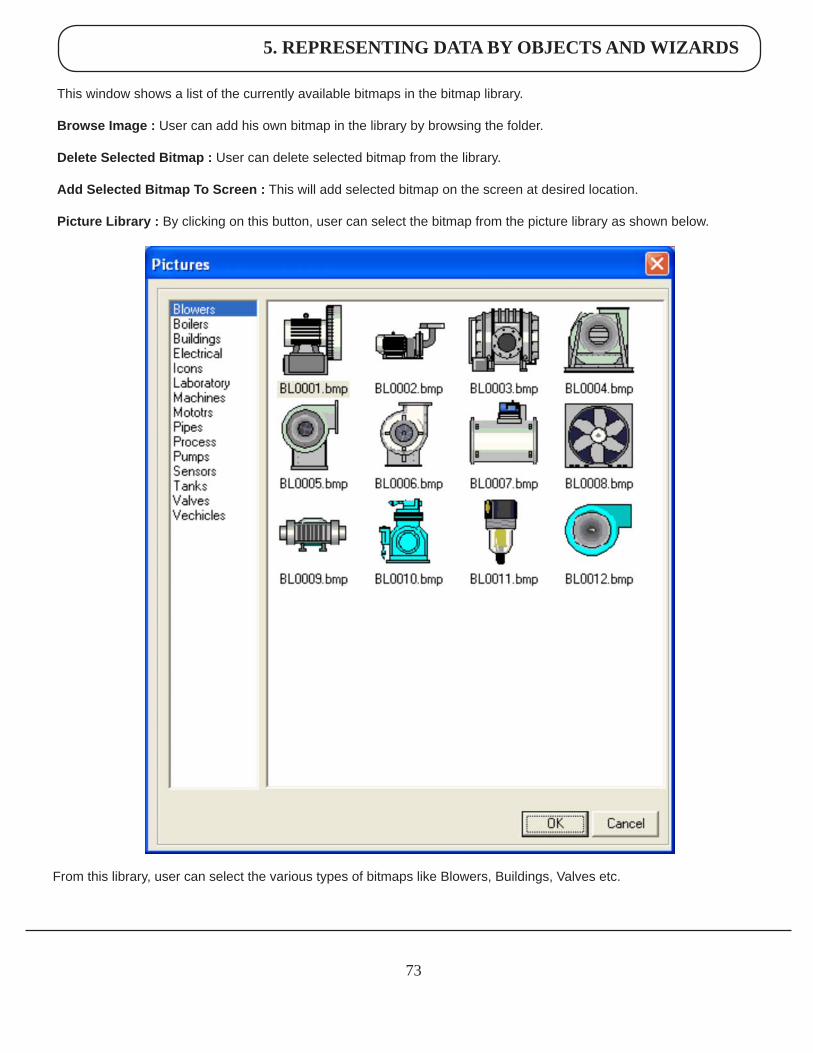
PictureLibrary: By clicking on this button, user can select the bitmap from the picture library as shown below.
From this library, user can select the various types of bitmaps like Blowers, Buildings, Valves etc.
5. REPRESENTING DATA BY OBJECTS AND WIZARDS
74
Graphical Objects have certain properties, referred as Attributes. Attributes are useful for suggesting the importance of the particular object.
Basic Graphic Objects have the following attributes:
PenColor: This attribute defines the pattern for drawing the border. For Black and White Graphic display this can either be black or white.FillColor:This attribute defines the fill color. Any closed object can be filled by the selected color.Flash: All the basic objects can be flashed using this attribute. Flashing can be done at three different speeds: Slow, Medium and Fast.
5.3 Wizards
Various wizards included for use in graphical HMI products are:
1. Button object :
a. Bit Button b. Word Button
2. Lamp Object:
a. Bit Lamp b. Word Lamp
3. Analog Meter
4. Multiple Bargraph
5. Numeric Keypad
6. Trend Display
5. REPRESENTING DATA BY OBJECTS AND WIZARDS
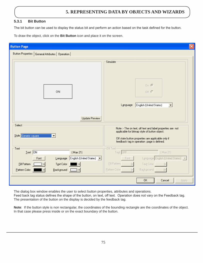
75
The dialog box window enables the user to select button properties, attributes and operations.Feed back tag status defines the shape of the button, on text, off text. Operation does not vary on the Feedback tag. The presentation of the button on the display is decided by the feedback tag. Note: If the button style is non rectangular, the coordinates of the bounding rectangle are the coordinates of the object. In that case please press inside or on the exact boundary of the button.
5.3.1 BitButton
The bit button can be used to display the status bit and perform an action based on the task defined for the button.
To draw the object, click on the BitButton icon and place it on the screen.
5. REPRESENTING DATA BY OBJECTS AND WIZARDS
76
ButtonProperties:
Style A button can have a number of different styles:
1. Generic square 2. Generic circle 3. Generic rounded rectangle 4. Invisible button 5. From Picture Library 6. User defined image
On/OffText A button can also be configured with the following properties:
1. Text: On / Off text, can be up to 21 characters. 2. Font : Select Windows® Font, Font style and Font size. Any font supported in the user’s computer is acceptable. 3. Language : Display the list of languages depending upon the number of languages configured in the unit settings. 4. FillPattern : If the display style is a generic square, circle, or rounded rectangle; then the user can define different types of fill patterns for that style. 5. TextColor : Color of the text. 6. Background Background color of text.
Simulate
The user can simulate the ON and OFF text in various languages as configured in the wizard. These can be previewed in the preview window.
GeneralAttributes
Labelselection Parameters related to the bit button label can be configured if the Label selection is ON. (Check box ‘Label’ is selected). 1. Text : Label text, can be up to 21 characters.2. Font : User can select windows® Font, Font Style and Font size.3. Language : Display the list of languages depending upon number of languages configured in the Unit settings.4. Pattern : User can select different fill patterns for label.5. TextColor : Color of the text.6. Background : Background color of text.7. Labelposition : If the “Top” option is selected, then the label is displayed above the button as shown above. If the “Bottom” option is selected, then the label is shown at the bottom of the button.
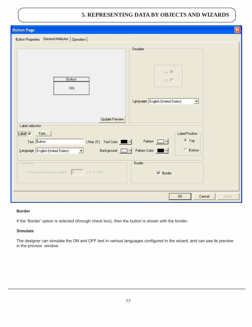
5. REPRESENTING DATA BY OBJECTS AND WIZARDS
77
Border
If the ‘Border’ option is selected (through check box), then the button is shown with the border.
Simulate
The designer can simulate the ON and OFF text in various languages configured in the wizard, and can see its preview in the preview window.
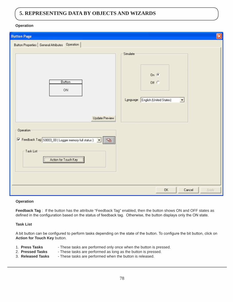
5. REPRESENTING DATA BY OBJECTS AND WIZARDS
78
Operation
Operation
FeedbackTag : If the button has the attribute “Feedback Tag” enabled, then the button shows ON and OFF states as defined in the configuration based on the status of feedback tag. Otherwise, the button displays only the ON state.
TaskList
A bit button can be configured to perform tasks depending on the state of the button. To configure the bit button, click on ActionforTouchKey button.
1. PressTasks - These tasks are performed only once when the button is pressed.2. PressedTasks - These tasks are performed as long as the button is pressed.3. ReleasedTasks - These tasks are performed when the button is released.
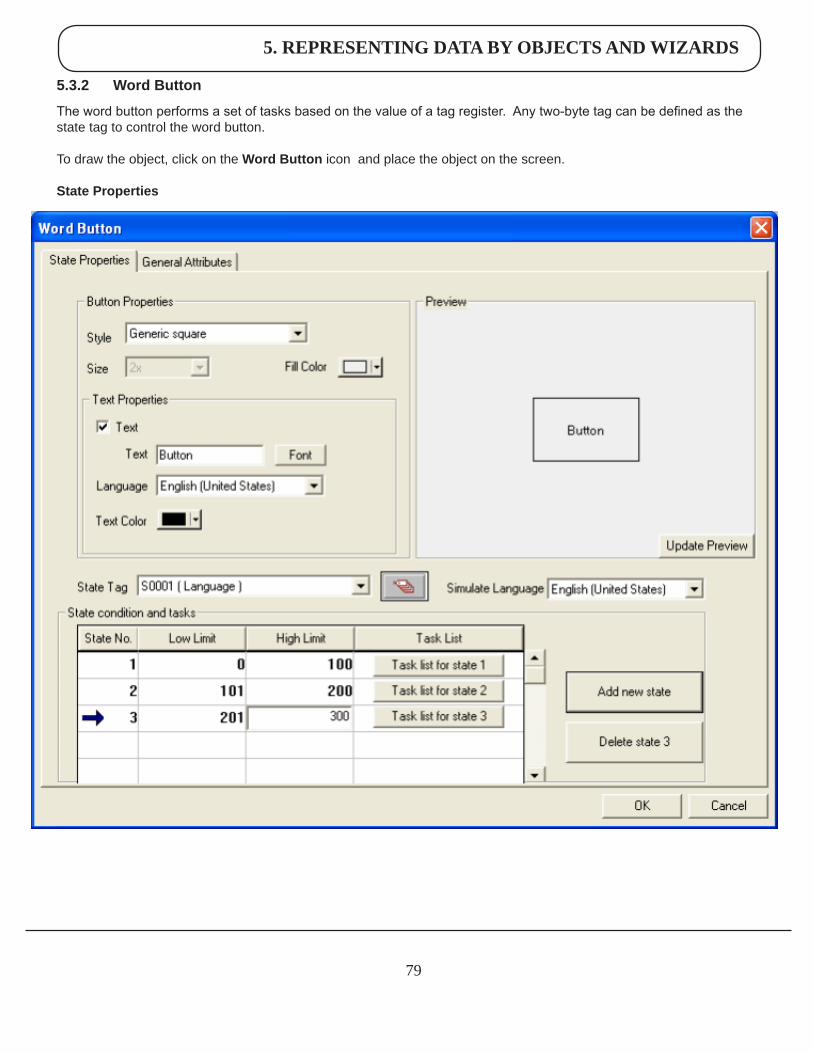
5. REPRESENTING DATA BY OBJECTS AND WIZARDS
79
5.3.2 WordButton
The word button performs a set of tasks based on the value of a tag register. Any two-byte tag can be defined as the state tag to control the word button. To draw the object, click on the WordButton icon and place the object on the screen.
StateProperties
5. REPRESENTING DATA BY OBJECTS AND WIZARDS
80
ButtonProperties
Style
A button can have a number of different display styles:1. Generic square 2. Generic circle 3. Generic rounded rectangle 4. Invisible button 5. From Picture Library 6. User defined image
FillColorFills the color for each state of the button.
SizeIf the style is Check box, Radio button or Toggle switch then user can have button size either 1x or 2x.
TextProperties
The designer can select different text strings for each state if the text option is enabled.
1. Text: Button text maximum upto 20 characters.2. Font : User can select Windows® Font, Font Style and Font size.3. Language : Display the list of languages depending upon number of languages configured in the Unit settings.4. TextColor : User can select the color of the text.5. Background : User can select the background color of text.
StateTag
This tag is used to determine the present state of the word button. This can be either unit tag or PLC tag.
Stateconditionsandtasks
This table gives information about the various states defined by the word button with their corresponding low and high limits and the task list for each range. The user can assign tasks to any of the defined states by clicking on the Task List button for the corresponding state. Up to 32 different states cam be defined.
AddnewstateAdd a new state by clicking this button.
DeletestateDelete an existing state by high lighting it and pressing this button.
SimulateThe designer can simulate various languages configured in the wizard. Previews of each language can be simulated.
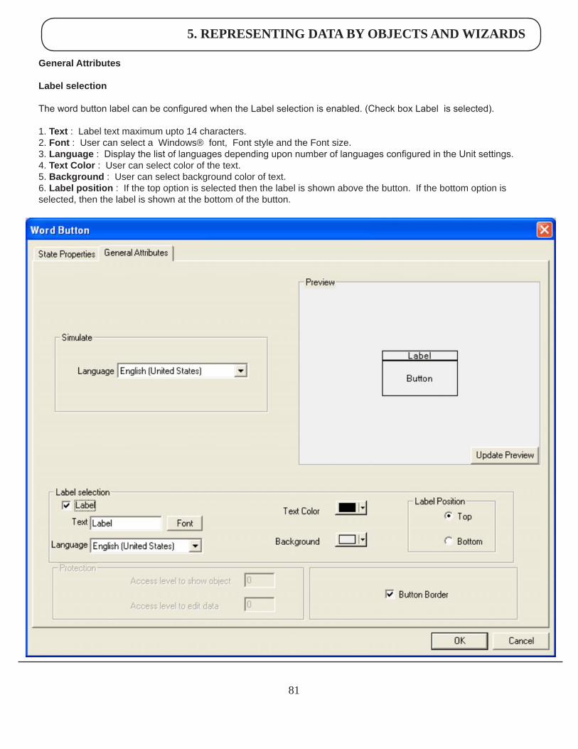
5. REPRESENTING DATA BY OBJECTS AND WIZARDS
81
GeneralAttributes
Labelselection
The word button label can be configured when the Label selection is enabled. (Check box Label is selected).
1. Text : Label text maximum upto 14 characters.2. Font : User can select a Windows® font, Font style and the Font size.3. Language : Display the list of languages depending upon number of languages configured in the Unit settings.4. TextColor : User can select color of the text.5. Background : User can select background color of text.6. Labelposition : If the top option is selected then the label is shown above the button. If the bottom option is selected, then the label is shown at the bottom of the button.
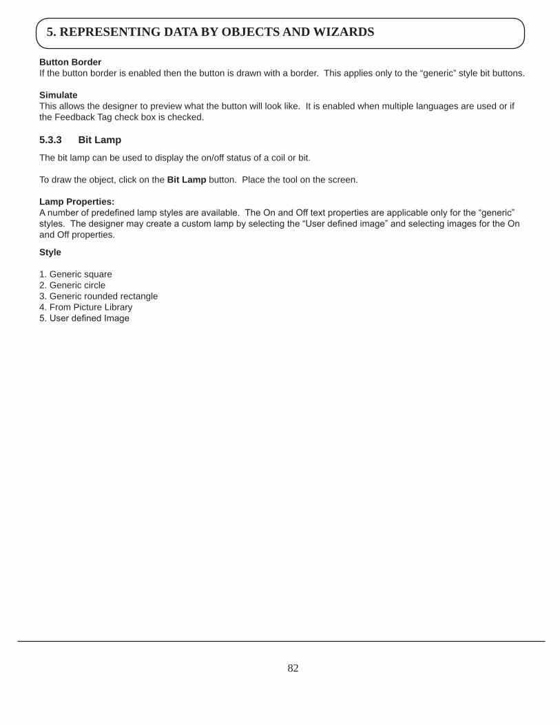
5. REPRESENTING DATA BY OBJECTS AND WIZARDS
82
ButtonBorderIf the button border is enabled then the button is drawn with a border. This applies only to the “generic” style bit buttons.
SimulateThis allows the designer to preview what the button will look like. It is enabled when multiple languages are used or if the Feedback Tag check box is checked.
5.3.3 BitLamp
The bit lamp can be used to display the on/off status of a coil or bit.
To draw the object, click on the BitLamp button. Place the tool on the screen.
LampProperties:A number of predefined lamp styles are available. The On and Off text properties are applicable only for the “generic” styles. The designer may create a custom lamp by selecting the “User defined image” and selecting images for the On and Off properties.
Style
1. Generic square 2. Generic circle 3. Generic rounded rectangle 4. From Picture Library 5. User defined Image
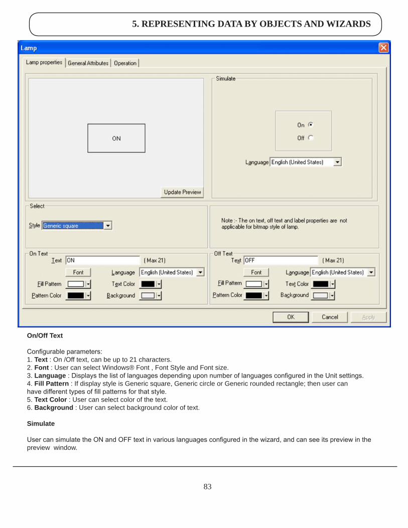
5. REPRESENTING DATA BY OBJECTS AND WIZARDS
83
On/OffText
Configurable parameters:1. Text : On /Off text, can be up to 21 characters.2. Font : User can select Windows® Font , Font Style and Font size.3. Language : Displays the list of languages depending upon number of languages configured in the Unit settings.4. FillPattern : If display style is Generic square, Generic circle or Generic rounded rectangle; then user can have different types of fill patterns for that style.5. TextColor : User can select color of the text.6. Background : User can select background color of text.
Simulate
User can simulate the ON and OFF text in various languages configured in the wizard, and can see its preview in the preview window.
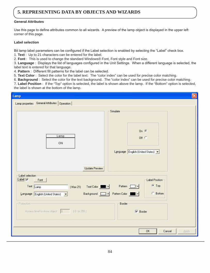
5. REPRESENTING DATA BY OBJECTS AND WIZARDS
84
GeneralAttributes
Use this page to define attributes common to all wizards. A preview of the lamp object is displayed in the upper left corner of this page.
Labelselection
Bit lamp label parameters can be configured if the Label selection is enabled by selecting the “Label” check box.1. Text: Up to 21 characters can be entered for the label.2. Font : This is used to change the standard Windows® Font, Font style and Font size.3. Language : Displays the list of languages configured in the Unit Settings. When a different language is selected, the label text is entered for that language.4. Pattern : Different fill patterns for the label can be selected.5. TextColor : Select the color for the label text. The “color index” can be used for precise color matching.6. Background : Select the color for the text background. The “color index” can be used for precise color matching.7. LabelPosition : If the “Top” option is selected, the label is shown above the lamp. If the “Bottom” option is selected, the label is shown at the bottom of the lamp.
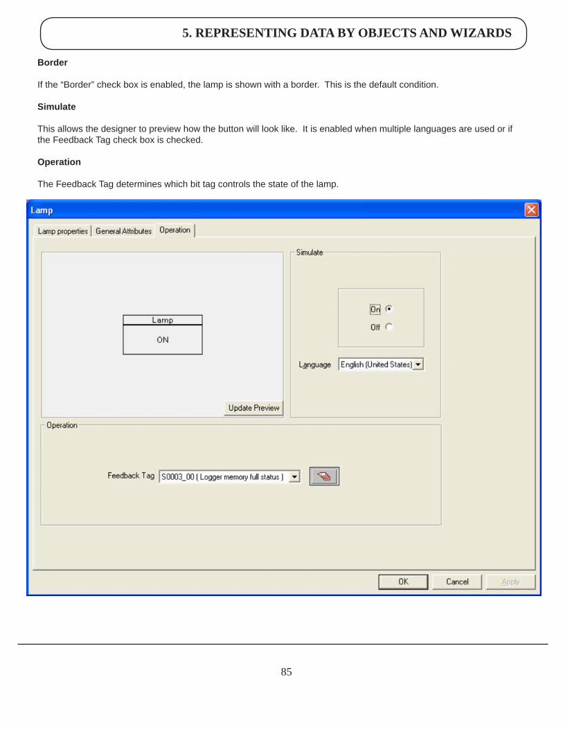
5. REPRESENTING DATA BY OBJECTS AND WIZARDS
85
Border
If the “Border” check box is enabled, the lamp is shown with a border. This is the default condition.
Simulate
This allows the designer to preview how the button will look like. It is enabled when multiple languages are used or if the Feedback Tag check box is checked.
Operation
The Feedback Tag determines which bit tag controls the state of the lamp.
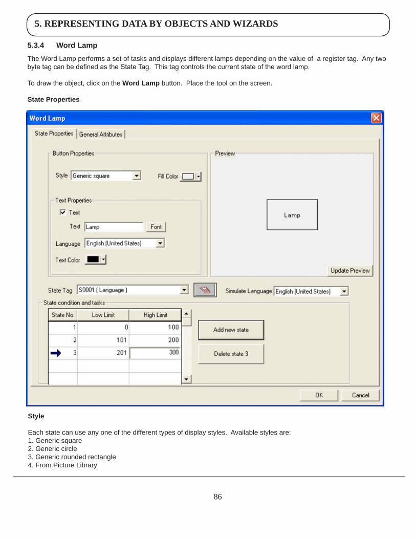
5. REPRESENTING DATA BY OBJECTS AND WIZARDS
86
5.3.4 WordLamp
The Word Lamp performs a set of tasks and displays different lamps depending on the value of a register tag. Any two byte tag can be defined as the State Tag. This tag controls the current state of the word lamp.
To draw the object, click on the WordLamp button. Place the tool on the screen.
StateProperties
Style
Each state can use any one of the different types of display styles. Available styles are:1. Generic square 2. Generic circle 3. Generic rounded rectangle 4. From Picture Library
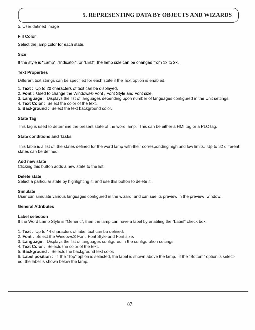
5. REPRESENTING DATA BY OBJECTS AND WIZARDS
87
5. User defined Image
FillColor
Select the lamp color for each state.
Size
If the style is “Lamp”, “Indicator”, or “LED”, the lamp size can be changed from 1x to 2x.
TextProperties
Different text strings can be specified for each state if the Text option is enabled.
1. Text : Up to 20 characters of text can be displayed.2. Font : Used to change the Windows® Font , Font Style and Font size.3. Language : Displays the list of languages depending upon number of languages configured in the Unit settings.4. TextColor : Select the color of the text.5. Background : Select the text background color.
StateTag
This tag is used to determine the present state of the word lamp. This can be either a HMI tag or a PLC tag.
StateconditionsandTasks
This table is a list of the states defined for the word lamp with their corresponding high and low limits. Up to 32 different states can be defined.
AddnewstateClicking this button adds a new state to the list.
DeletestateSelect a particular state by highlighting it, and use this button to delete it.
SimulateUser can simulate various languages configured in the wizard, and can see its preview in the preview window.
GeneralAttributes
LabelselectionIf the Word Lamp Style is “Generic”, then the lamp can have a label by enabling the “Label” check box.
1. Text : Up to 14 characters of label text can be defined.2. Font : Select the Windows® Font, Font Style and Font size.3. Language : Displays the list of languages configured in the configuration settings.4. TextColor : Selects the color of the text.5. Background : Selects the background text color.6. Labelposition : If the “Top” option is selected, the label is shown above the lamp. If the “Bottom” option is select-ed, the label is shown below the lamp.
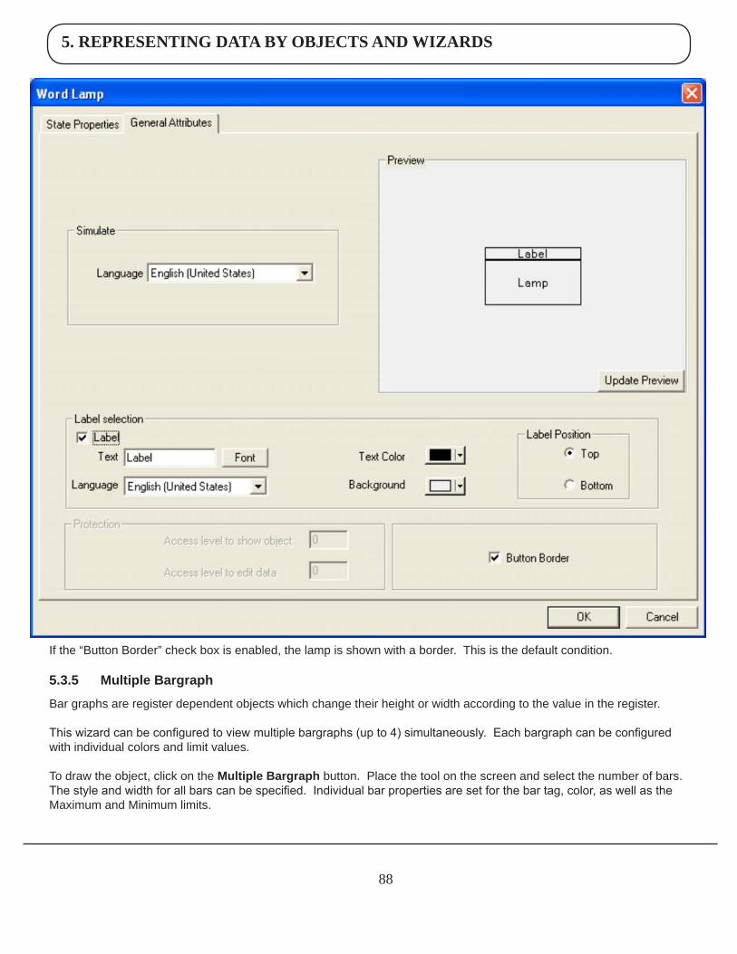
5. REPRESENTING DATA BY OBJECTS AND WIZARDS
88
ButtonBorder
If the “Button Border” check box is enabled, the lamp is shown with a border. This is the default condition.
5.3.5 MultipleBargraph
Bar graphs are register dependent objects which change their height or width according to the value in the register.
This wizard can be configured to view multiple bargraphs (up to 4) simultaneously. Each bargraph can be configured with individual colors and limit values.
To draw the object, click on the MultipleBargraphbutton. Place the tool on the screen and select the number of bars. The style and width for all bars can be specified. Individual bar properties are set for the bar tag, color, as well as the Maximum and Minimum limits.
5. REPRESENTING DATA BY OBJECTS AND WIZARDS
89
Numberofbars Enter or select the number of bars you want in a single wizard. Up to four bargraphs can be defined in a single wizard.
Backgroundcolor This is the background color for the entire bargraph object.
GapwidthThe Gap Width is the space, in pixels, between any two bars. The minimum gap width is 0 pixels. The maximum is 53 pixels.
BarwidthThe designer can specify the bar width, in pixels, for all bars. The minimum gap width is 1 pixel. The maximum is 68 pixels.
BargraphProperties
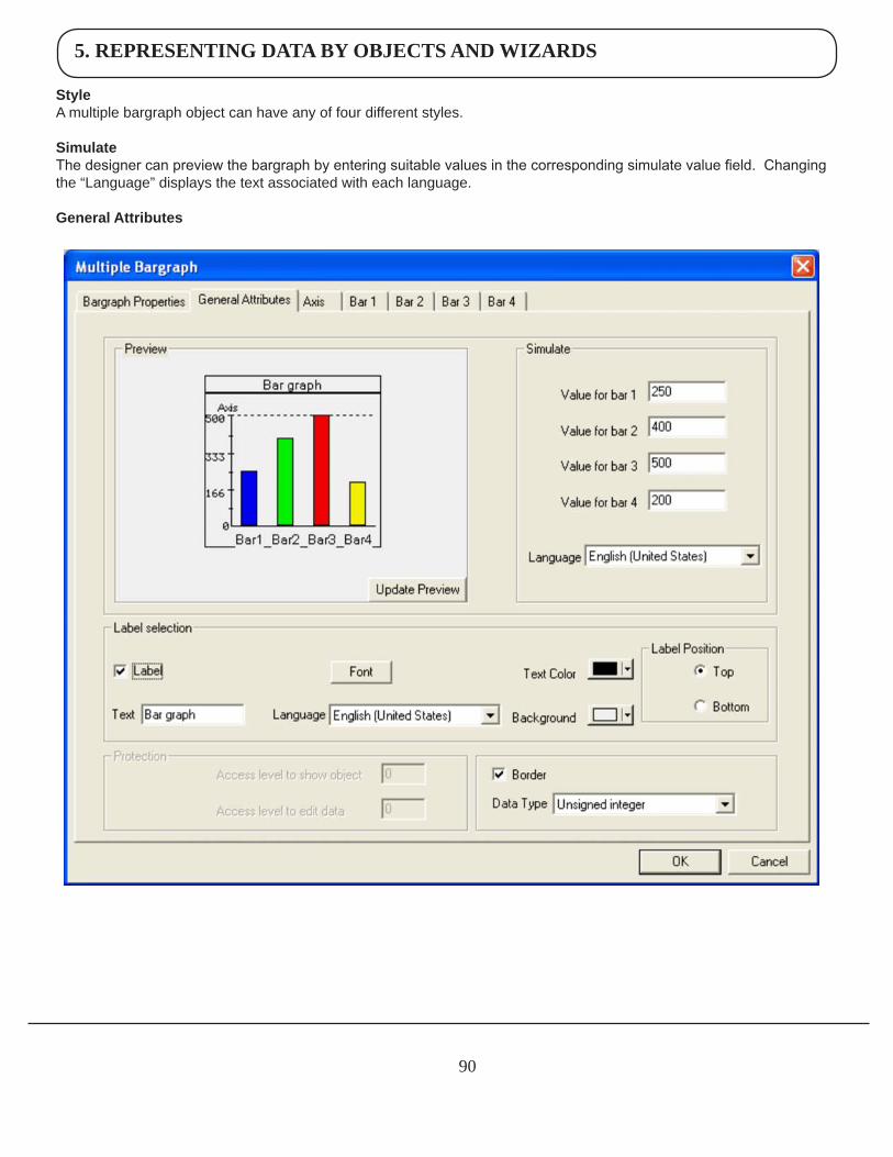
5. REPRESENTING DATA BY OBJECTS AND WIZARDS
90
StyleA multiple bargraph object can have any of four different styles.
Simulate The designer can preview the bargraph by entering suitable values in the corresponding simulate value field. Changing the “Language” displays the text associated with each language.
GeneralAttributes
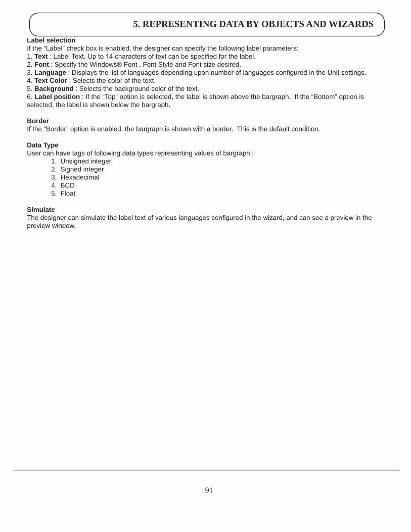
5. REPRESENTING DATA BY OBJECTS AND WIZARDS
91
LabelselectionIf the “Label” check box is enabled, the designer can specify the following label parameters:1. Text : Label Text. Up to 14 characters of text can be specified for the label.2. Font : Specify the Windows® Font , Font Style and Font size desired.3. Language : Displays the list of languages depending upon number of languages configured in the Unit settings.4. TextColor : Selects the color of the text.5. Background : Selects the background color of the text.6. Labelposition : If the “Top” option is selected, the label is shown above the bargraph. If the “Bottom” option is selected, the label is shown below the bargraph.
BorderIf the “Border” option is enabled, the bargraph is shown with a border. This is the default condition.
DataTypeUser can have tags of following data types representing values of bargraph : 1. Unsigned integer 2. Signed integer 3. Hexadecimal 4. BCD 5. Float
SimulateThe designer can simulate the label text of various languages configured in the wizard, and can see a preview in the preview window.
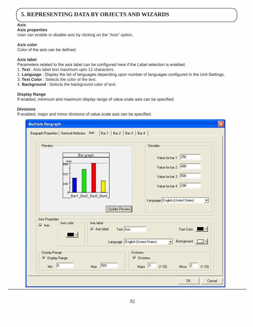
5. REPRESENTING DATA BY OBJECTS AND WIZARDS
92
AxisAxispropertiesUser can enable or disable axis by clicking on the “Axis” option.
Axiscolor Color of the axis can be defined.
Axislabel Parameters related to the axis label can be configured here if the Label selection is enabled. 1. Text : Axis label text maximum upto 12 characters.2. Language : Display the list of languages depending upon number of languages configured in the Unit Settings.3. TextColor : Selects the color of the text.4. Background : Selects the background color of text.
DisplayRangeIf enabled, minimum and maximum display range of value scale axis can be specified.
DivisionsIf enabled, major and minor divisions of value scale axis can be specified.
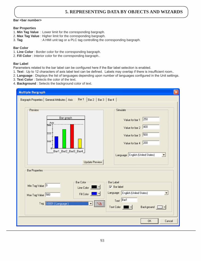
5. REPRESENTING DATA BY OBJECTS AND WIZARDS
93
Bar<barnumber>
BarProperties1. MinTagValue : Lower limit for the corresponding bargraph. 2. MaxTagValue : Higher limit for the corresponding bargraph. 3. Tag : A HMI unit tag or a PLC tag controlling the corresponding bargraph.
BarColor1. LineColor : Border color for the corresponding bargraph. 2. FillColor : Interior color for the corresponding bargraph..
BarLabelParameters related to the bar label can be configured here if the Bar label selection is enabled. 1. Text : Up to 12 characters of axis label text can be defined. Labels may overlap if there is insufficient room.. 2. Language : Displays the list of languages depending upon number of languages configured in the Unit settings.3. TextColor : Selects the color of the text.4. Background : Selects the background color of text.
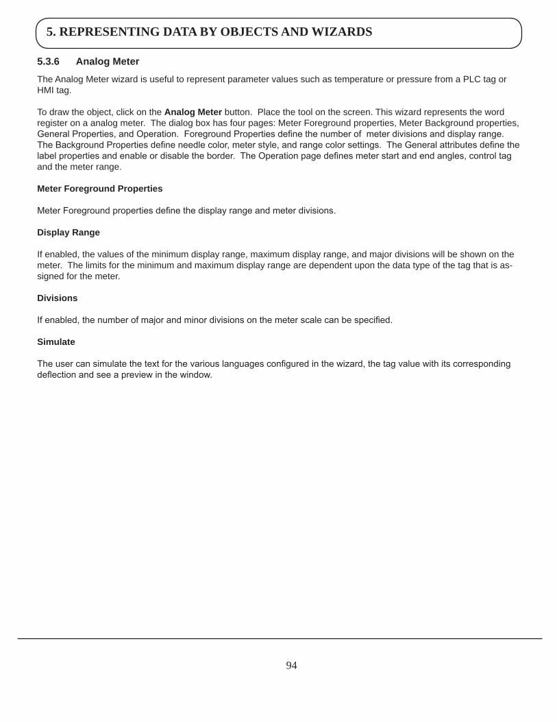
5. REPRESENTING DATA BY OBJECTS AND WIZARDS
94
5.3.6 AnalogMeter
The Analog Meter wizard is useful to represent parameter values such as temperature or pressure from a PLC tag or HMI tag. To draw the object, click on the AnalogMeterbutton. Place the tool on the screen. This wizard represents the word register on a analog meter. The dialog box has four pages: Meter Foreground properties, Meter Background properties, General Properties, and Operation. Foreground Properties define the number of meter divisions and display range. The Background Properties define needle color, meter style, and range color settings. The General attributes define the label properties and enable or disable the border. The Operation page defines meter start and end angles, control tag and the meter range.
MeterForegroundProperties
Meter Foreground properties define the display range and meter divisions.
DisplayRange
If enabled, the values of the minimum display range, maximum display range, and major divisions will be shown on the meter. The limits for the minimum and maximum display range are dependent upon the data type of the tag that is as-signed for the meter.
Divisions
If enabled, the number of major and minor divisions on the meter scale can be specified.
Simulate
The user can simulate the text for the various languages configured in the wizard, the tag value with its corresponding deflection and see a preview in the window.
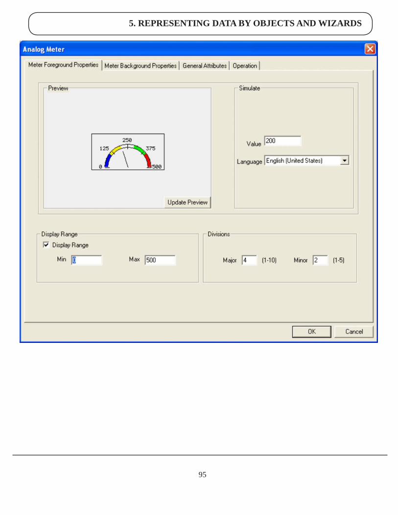
5. REPRESENTING DATA BY OBJECTS AND WIZARDS
95
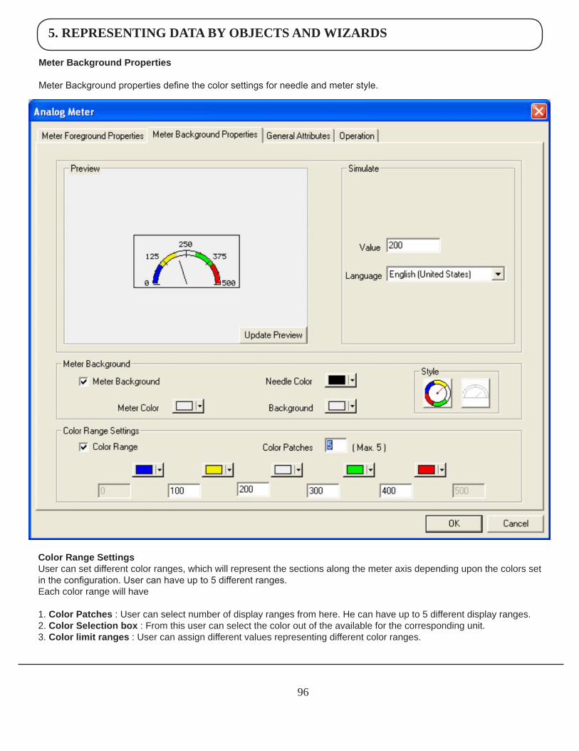
5. REPRESENTING DATA BY OBJECTS AND WIZARDS
96
MeterBackgroundProperties
Meter Background properties define the color settings for needle and meter style.
ColorRangeSettingsUser can set different color ranges, which will represent the sections along the meter axis depending upon the colors set in the configuration. User can have up to 5 different ranges.Each color range will have
1. ColorPatches : User can select number of display ranges from here. He can have up to 5 different display ranges. 2. ColorSelectionbox : From this user can select the color out of the available for the corresponding unit. 3. Colorlimitranges : User can assign different values representing different color ranges.
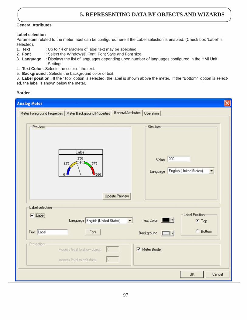
5. REPRESENTING DATA BY OBJECTS AND WIZARDS
97
GeneralAttributes
LabelselectionParameters related to the meter label can be configured here if the Label selection is enabled. (Check box ‘Label’ is selected).1. Text : Up to 14 characters of label text may be specified.2. Font : Select the Windows® Font, Font Style and Font size.3. Language : Displays the list of languages depending upon number of languages configured in the HMI Unit Settings.4. TextColor : Selects the color of the text.5. Background : Selects the background color of text.6. Labelposition : If the “Top” option is selected, the label is shown above the meter. If the “Bottom” option is select-ed, the label is shown below the meter.
Border
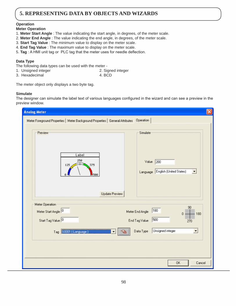
5. REPRESENTING DATA BY OBJECTS AND WIZARDS
98
OperationMeterOperation1. MeterStartAngle : The value indicating the start angle, in degrees, of the meter scale.2. MeterEndAngle : The value indicating the end angle, in degrees, of the meter scale.3. StartTagValue : The minimum value to display on the meter scale.4. EndTagValue : The maximum value to display on the meter scale.5. Tag : A HMI unit tag or PLC tag that the meter uses for needle deflection.
DataTypeThe following data types can be used with the meter -1. Unsigned integer 2. Signed integer 3. Hexadecimal 4. BCD
The meter object only displays a two byte tag.
SimulateThe designer can simulate the label text of various languages configured in the wizard and can see a preview in the preview window.
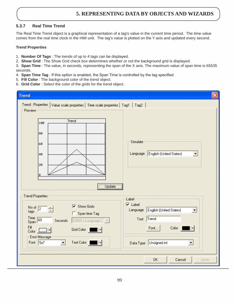
5. REPRESENTING DATA BY OBJECTS AND WIZARDS
99
5.3.7 RealTimeTrend
The Real Time Trend object is a graphical representation of a tag’s value in the current time period. The time value comes from the real time clock in the HMI unit. The tag’s value is plotted on the Y axis and updated every second.
TrendProperties
1. NumberOfTags : The trends of up to 4 tags can be displayed.2. ShowGrid : The Show Grid check box determines whether or not the background grid is displayed.3. SpanTime : The value, in seconds, representing the span of the X axis. The maximum value of span time is 65535 seconds.4. SpanTimeTag : If this option is enabled, the Span Time is controlled by the tag specified.5. FillColor : The background color of the trend object.6. GridColor : Select the color of the grids for the trend object.
5. REPRESENTING DATA BY OBJECTS AND WIZARDS
100
ErrorMessage Many of the trend object’s properties can be determined at run time through the use a tag. If the value of the tag is out of the proper range for the property, an error message will be displayed. The text display properties can be modified. 1. Font : Select the Windows® Font , Font Style and Font size. 2. TextColor : Color of the error message to be displayed.
Label Parameters related to the trend label can be configured here if the Label selection is enabled. (Check box ‘Label’ is selected).1. Text : Label text maximum upto 25 characters.2. Font : Select the Windows® Font , Font Style and Font size.3. Language : Display the list of languages depending upon number of languages configured in the Unit settings.4. Color : Color of the text.
DataType The trend object can have the following data types: 1. Unsigned integer 2. Signed integer 3. Hexadecimal4. BCD5. Float
Only 2 byte tags are supported.
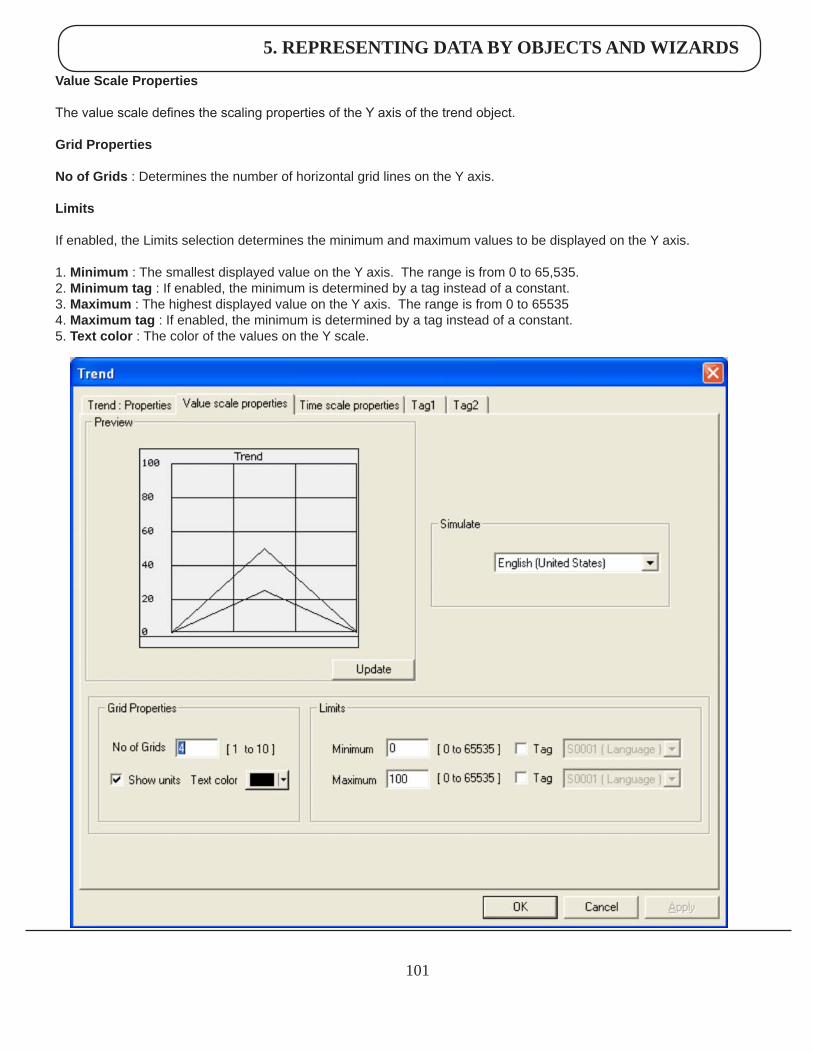
5. REPRESENTING DATA BY OBJECTS AND WIZARDS
101
ValueScaleProperties
The value scale defines the scaling properties of the Y axis of the trend object. GridProperties NoofGrids : Determines the number of horizontal grid lines on the Y axis. Limits
If enabled, the Limits selection determines the minimum and maximum values to be displayed on the Y axis.
1. Minimum : The smallest displayed value on the Y axis. The range is from 0 to 65,535.2. Minimumtag : If enabled, the minimum is determined by a tag instead of a constant.3. Maximum : The highest displayed value on the Y axis. The range is from 0 to 655354. Maximumtag : If enabled, the minimum is determined by a tag instead of a constant.5. Textcolor : The color of the values on the Y scale.
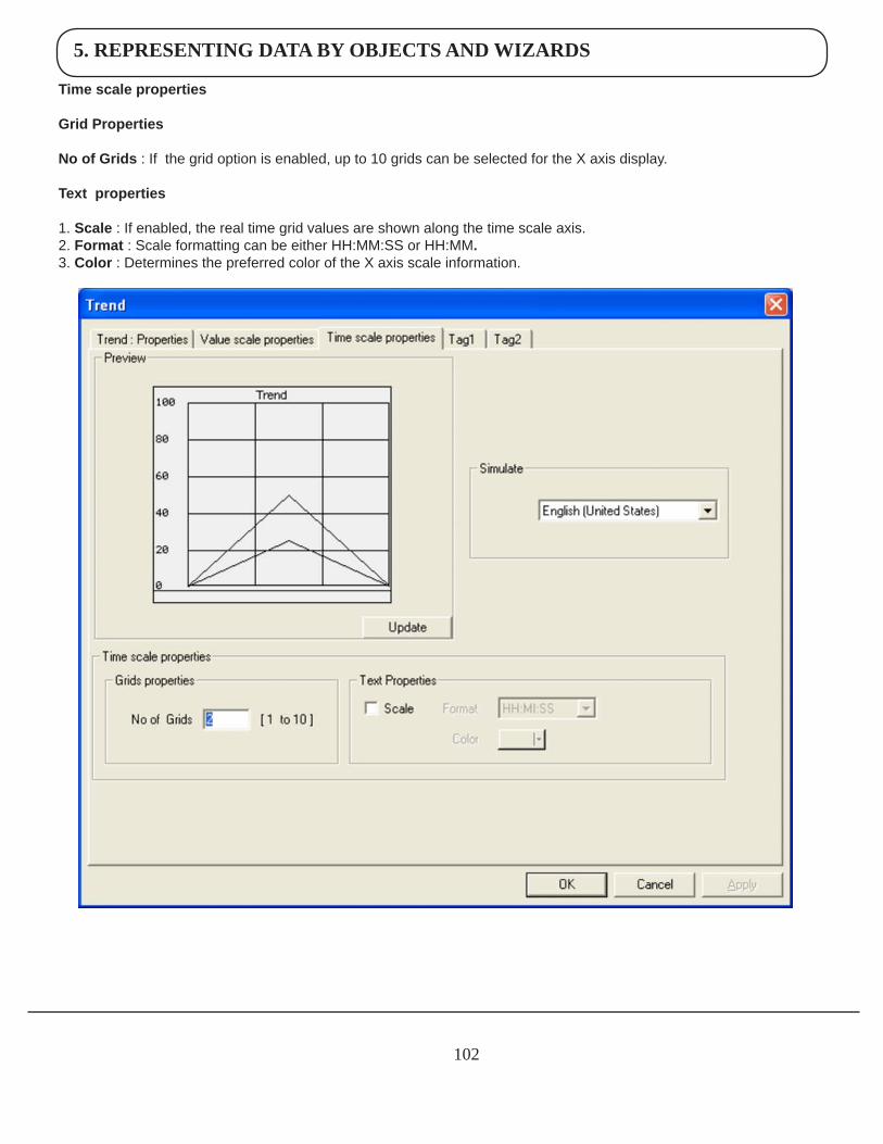
5. REPRESENTING DATA BY OBJECTS AND WIZARDS
102
Timescaleproperties
GridProperties
NoofGrids: If the grid option is enabled, up to 10 grids can be selected for the X axis display.
Textproperties
1. Scale:If enabled, the real time grid values are shown along the time scale axis.2. Format :Scale formatting can be either HH:MM:SS or HH:MM.3. Color:Determines the preferred color of the X axis scale information.
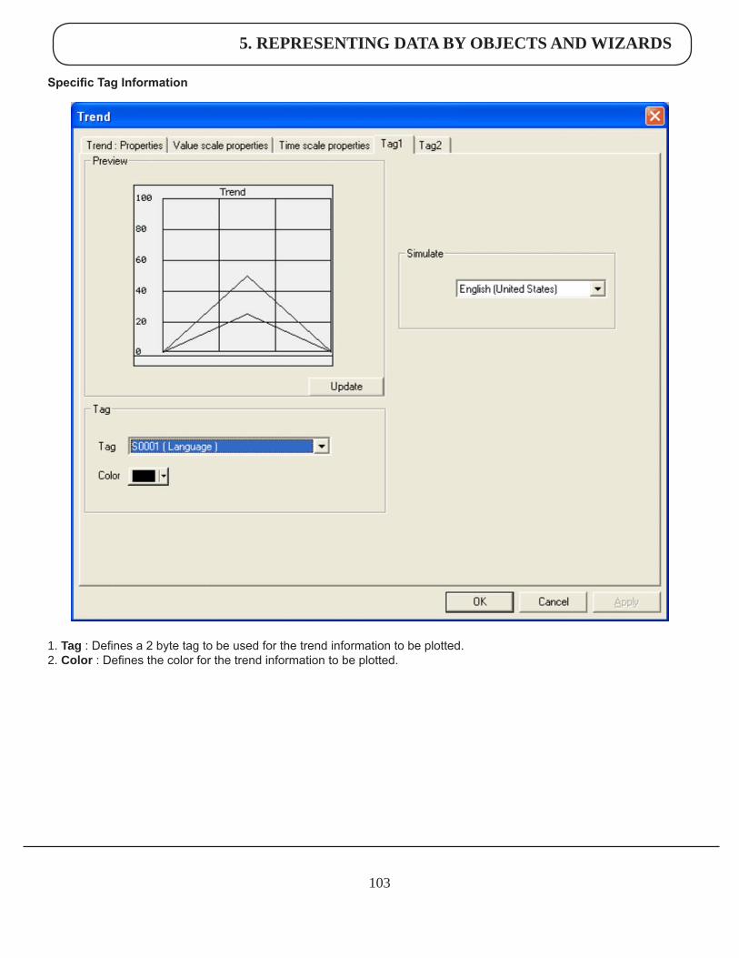
5. REPRESENTING DATA BY OBJECTS AND WIZARDS
103
Specific Tag Information
1. Tag:Defines a 2 byte tag to be used for the trend information to be plotted.2. Color:Defines the color for the trend information to be plotted.
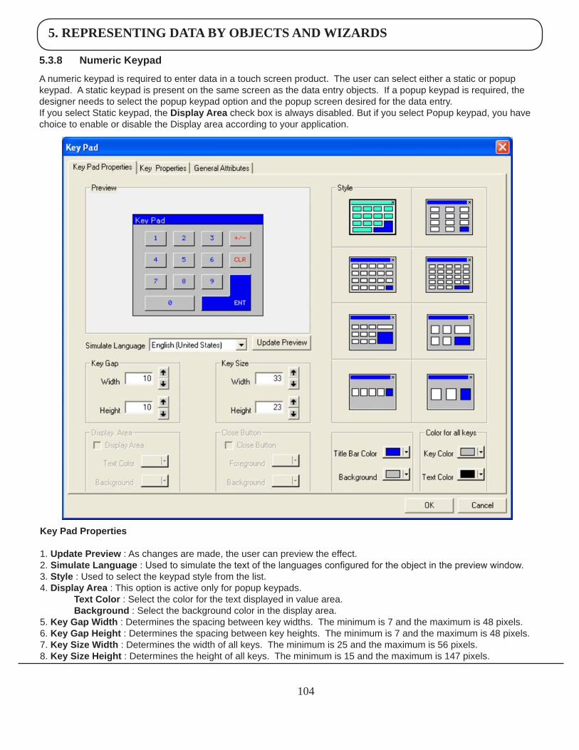
5. REPRESENTING DATA BY OBJECTS AND WIZARDS
104
KeyPadProperties
1. UpdatePreview : As changes are made, the user can preview the effect.2. SimulateLanguage : Used to simulate the text of the languages configured for the object in the preview window.3. Style : Used to select the keypad style from the list.4. DisplayArea : This option is active only for popup keypads. TextColor : Select the color for the text displayed in value area. Background : Select the background color in the display area.5. KeyGapWidth : Determines the spacing between key widths. The minimum is 7 and the maximum is 48 pixels.6. KeyGapHeight : Determines the spacing between key heights. The minimum is 7 and the maximum is 48 pixels.7. KeySizeWidth : Determines the width of all keys. The minimum is 25 and the maximum is 56 pixels.8. KeySizeHeight : Determines the height of all keys. The minimum is 15 and the maximum is 147 pixels.
5.3.8 NumericKeypad
A numeric keypad is required to enter data in a touch screen product. The user can select either a static or popup keypad. A static keypad is present on the same screen as the data entry objects. If a popup keypad is required, the designer needs to select the popup keypad option and the popup screen desired for the data entry. If you select Static keypad, the DisplayArea check box is always disabled. But if you select Popup keypad, you have choice to enable or disable the Display area according to your application.
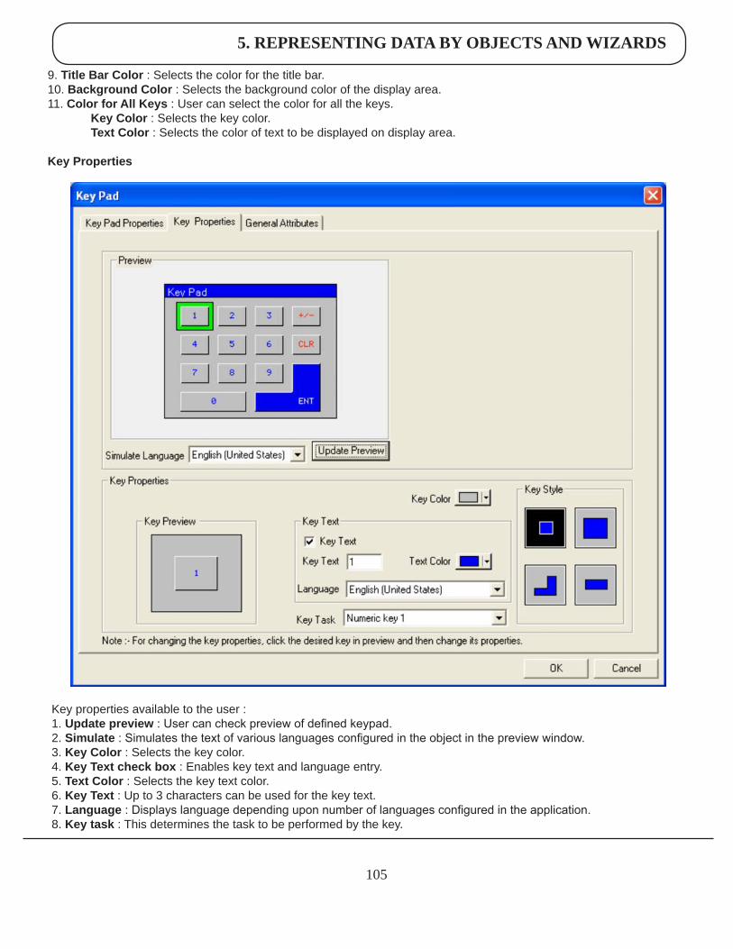
5. REPRESENTING DATA BY OBJECTS AND WIZARDS
105
Key properties available to the user :1. Updatepreview : User can check preview of defined keypad.2. Simulate : Simulates the text of various languages configured in the object in the preview window.3. KeyColor : Selects the key color.4. KeyTextcheckbox : Enables key text and language entry. 5. TextColor : Selects the key text color.6. KeyText : Up to 3 characters can be used for the key text.7. Language : Displays language depending upon number of languages configured in the application.8. Keytask : This determines the task to be performed by the key.
9. TitleBarColor : Selects the color for the title bar.10. BackgroundColor : Selects the background color of the display area.11. ColorforAllKeys : User can select the color for all the keys. KeyColor : Selects the key color. TextColor : Selects the color of text to be displayed on display area.
KeyProperties
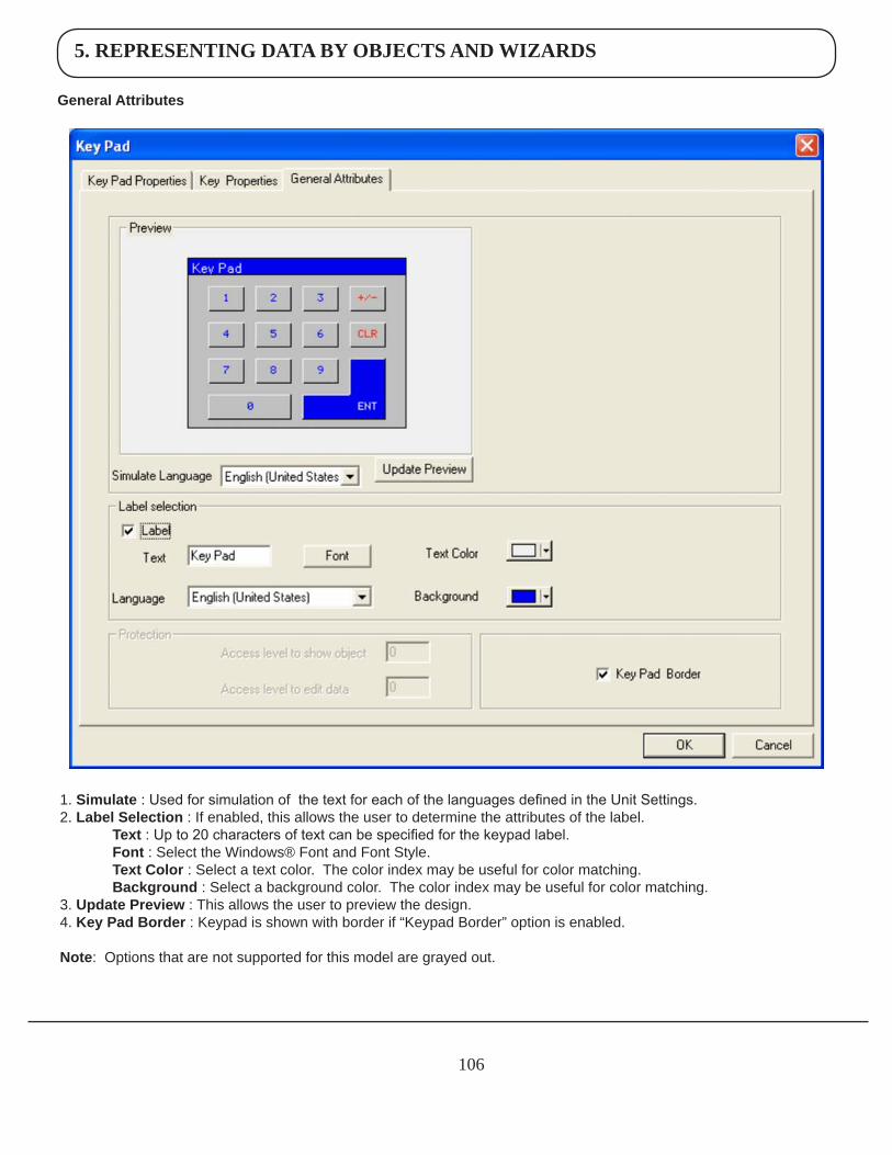
5. REPRESENTING DATA BY OBJECTS AND WIZARDS
106
GeneralAttributes
1. Simulate : Used for simulation of the text for each of the languages defined in the Unit Settings.2. LabelSelection : If enabled, this allows the user to determine the attributes of the label. Text : Up to 20 characters of text can be specified for the keypad label. Font : Select the Windows® Font and Font Style. TextColor : Select a text color. The color index may be useful for color matching. Background : Select a background color. The color index may be useful for color matching.3. UpdatePreview : This allows the user to preview the design. 4. KeyPadBorder : Keypad is shown with border if “Keypad Border” option is enabled.
Note: Options that are not supported for this model are grayed out.
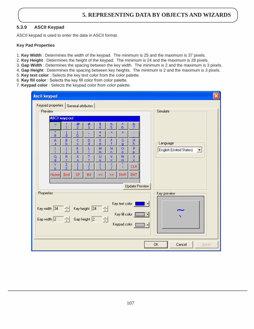
5. REPRESENTING DATA BY OBJECTS AND WIZARDS
107
5.3.9 ASCIIKeypad
ASCII keypad is used to enter the data in ASCII format.
KeyPadProperties
1. KeyWidth : Determines the width of the keypad. The minimum is 25 and the maximum is 37 pixels.2. KeyHeight : Determines the height of the keypad. The minimum is 24 and the maximum is 28 pixels.3. GapWidth : Determines the spacing between the key width. The minimum is 2 and the maximum is 3 pixels.4. GapHeight : Determines the spacing between key heights. The minimum is 2 and the maximum is 3 pixels.5. Keytextcolor : Selects the key text color from the color palette. 6. Key fill color : Selects the key fill color from color palette. 7. Keypadcolor : Selects the keypad color from color palette.
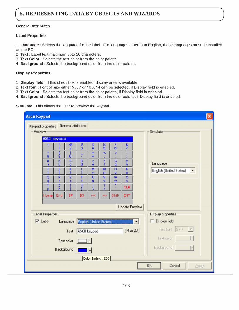
5. REPRESENTING DATA BY OBJECTS AND WIZARDS
108
GeneralAttributes
LabelProperties
1. Language : Selects the language for the label. For languages other than English, those languages must be installed on the PC.2. Text : Label text maximum upto 20 characters.3. TextColor : Selects the test color from the color palette.4. Background : Selects the background color from the color palette.
DisplayProperties
1. Display field : If this check box is enabled, display area is available.2. Textfont : Font of size either 5 X 7 or 10 X 14 can be selected, if Display field is enabled.3.TextColor : Selects the test color from the color palette, if Display field is enabled.4. Background : Selects the background color from the color palette, if Display field is enabled.
Simulate: This allows the user to preview the keypad.
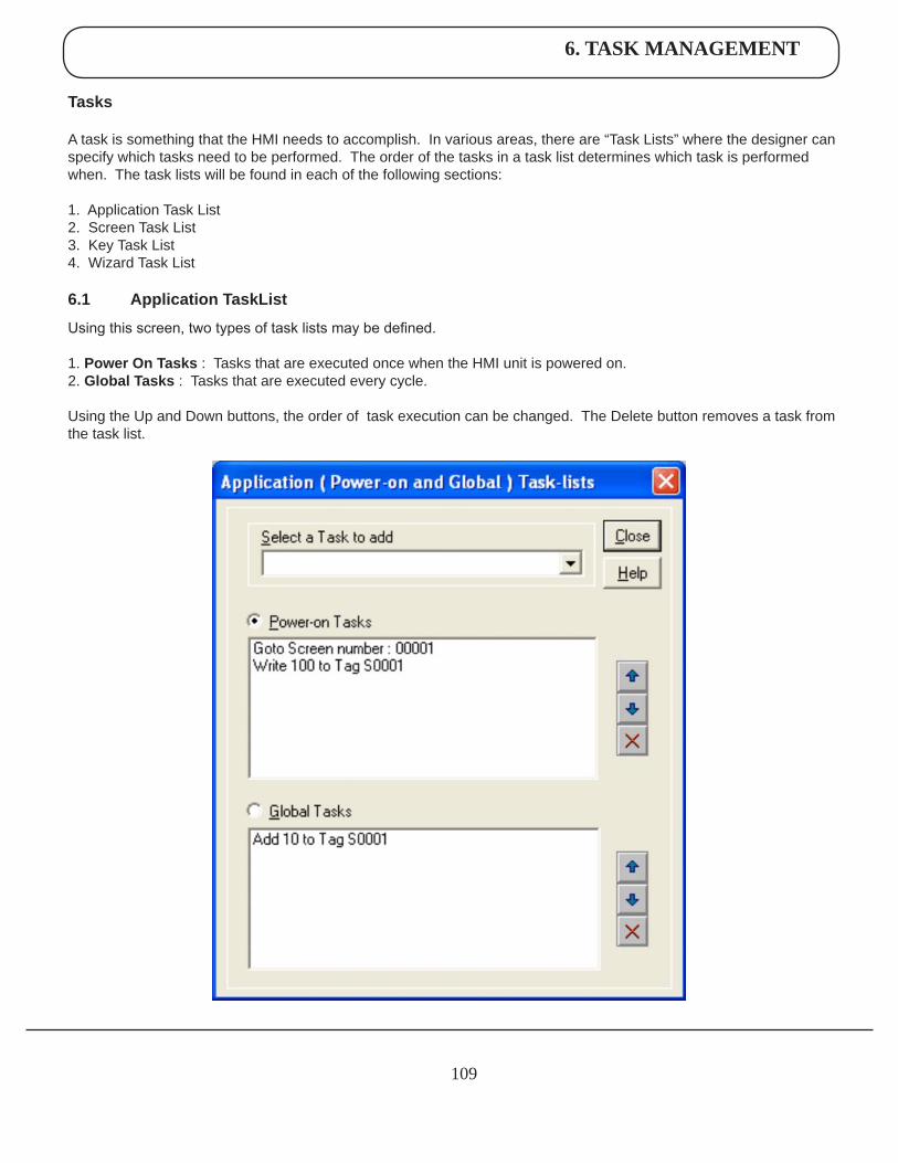
6. TASK MANAGEMENT
109
Tasks
A task is something that the HMI needs to accomplish. In various areas, there are “Task Lists” where the designer can specify which tasks need to be performed. The order of the tasks in a task list determines which task is performed when. The task lists will be found in each of the following sections:
1. Application Task List 2. Screen Task List 3. Key Task List 4. Wizard Task List
6.1 ApplicationTaskList
Using this screen, two types of task lists may be defined.
1. PowerOnTasks: Tasks that are executed once when the HMI unit is powered on. 2. GlobalTasks : Tasks that are executed every cycle.
Using the Up and Down buttons, the order of task execution can be changed. The Delete button removes a task from the task list.
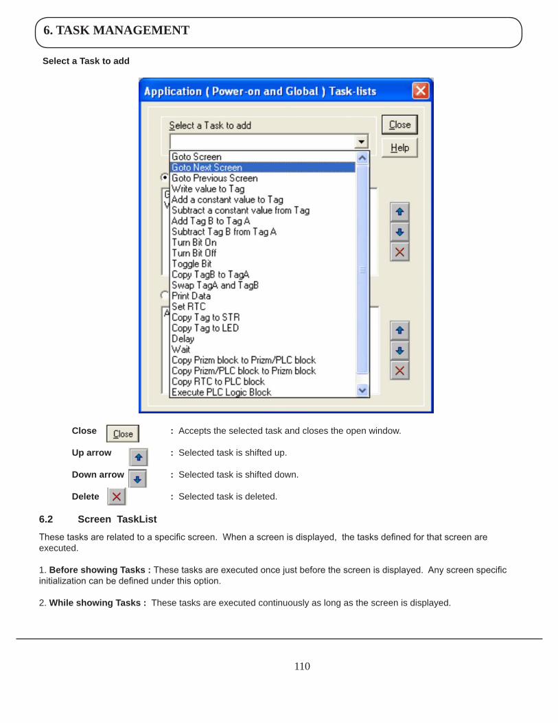
6. TASK MANAGEMENT
110
SelectaTasktoadd
Close :Accepts the selected task and closes the open window.
Uparrow :Selected task is shifted up.
Downarrow :Selected task is shifted down.
Delete :Selected task is deleted.
6.2 ScreenTaskList
These tasks are related to a specific screen. When a screen is displayed, the tasks defined for that screen are executed.
1.BeforeshowingTasks:These tasks are executed once just before the screen is displayed. Any screen specific initialization can be defined under this option.
2.WhileshowingTasks: These tasks are executed continuously as long as the screen is displayed.
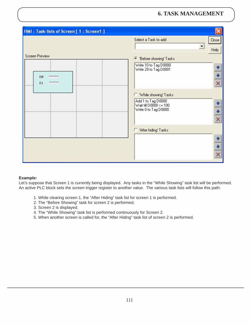
6. TASK MANAGEMENT
111
Example:Let’s suppose that Screen 1 is currently being displayed. Any tasks in the “While Showing” task list will be performed. An active PLC block sets the screen trigger register to another value. The various task lists will follow this path:
1. While clearing screen 1, the “After Hiding” task list for screen 1 is performed. 2. The “Before Showing” task for screen 2 is performed. 3. Screen 2 is displayed. 4. The “While Showing” task list is performed continuously for Screen 2. 5. When another screen is called for, the “After Hiding” task list of screen 2 is performed.
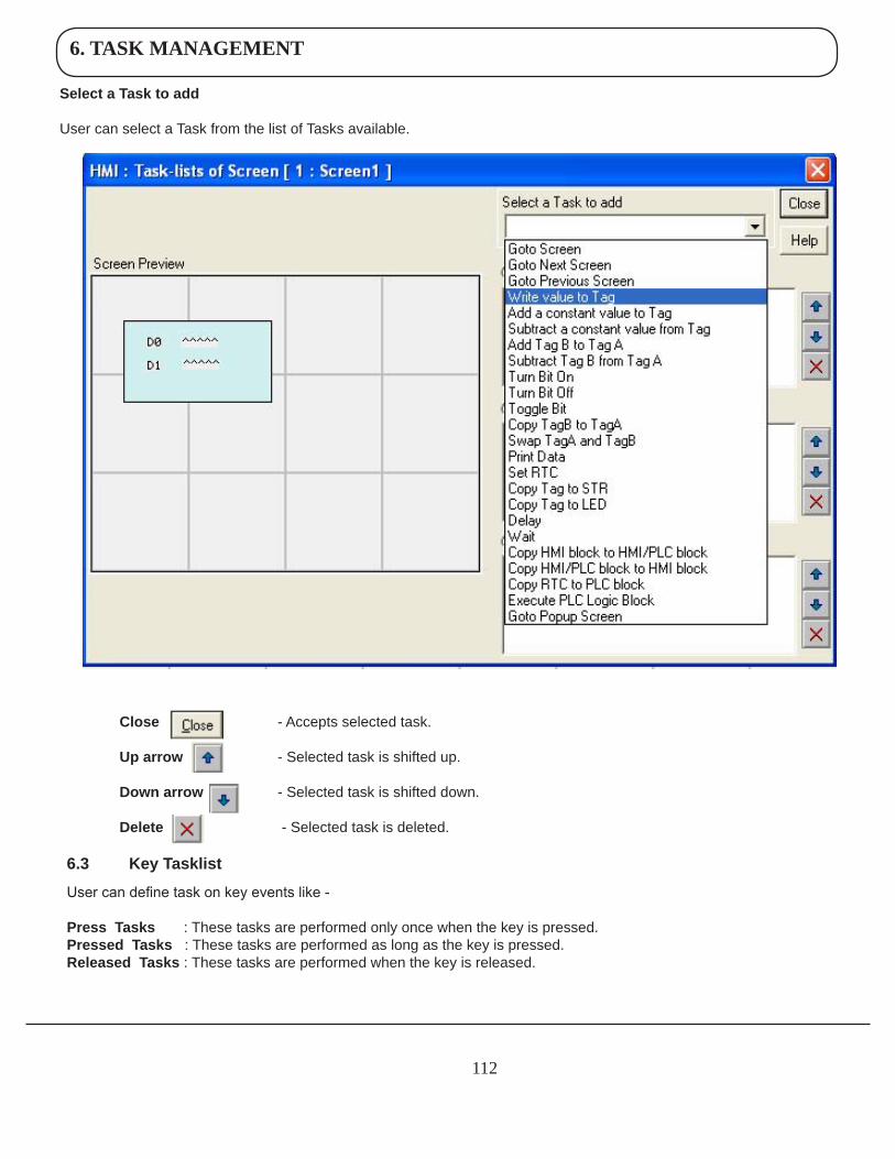
6. TASK MANAGEMENT
112
SelectaTasktoadd
User can select a Task from the list of Tasks available.
Close - Accepts selected task.
Uparrow - Selected task is shifted up.
Downarrow - Selected task is shifted down.
Delete - Selected task is deleted.
6.3 KeyTasklist
User can define task on key events like -
PressTasks: These tasks are performed only once when the key is pressed. PressedTasks : These tasks are performed as long as the key is pressed. ReleasedTasks : These tasks are performed when the key is released.
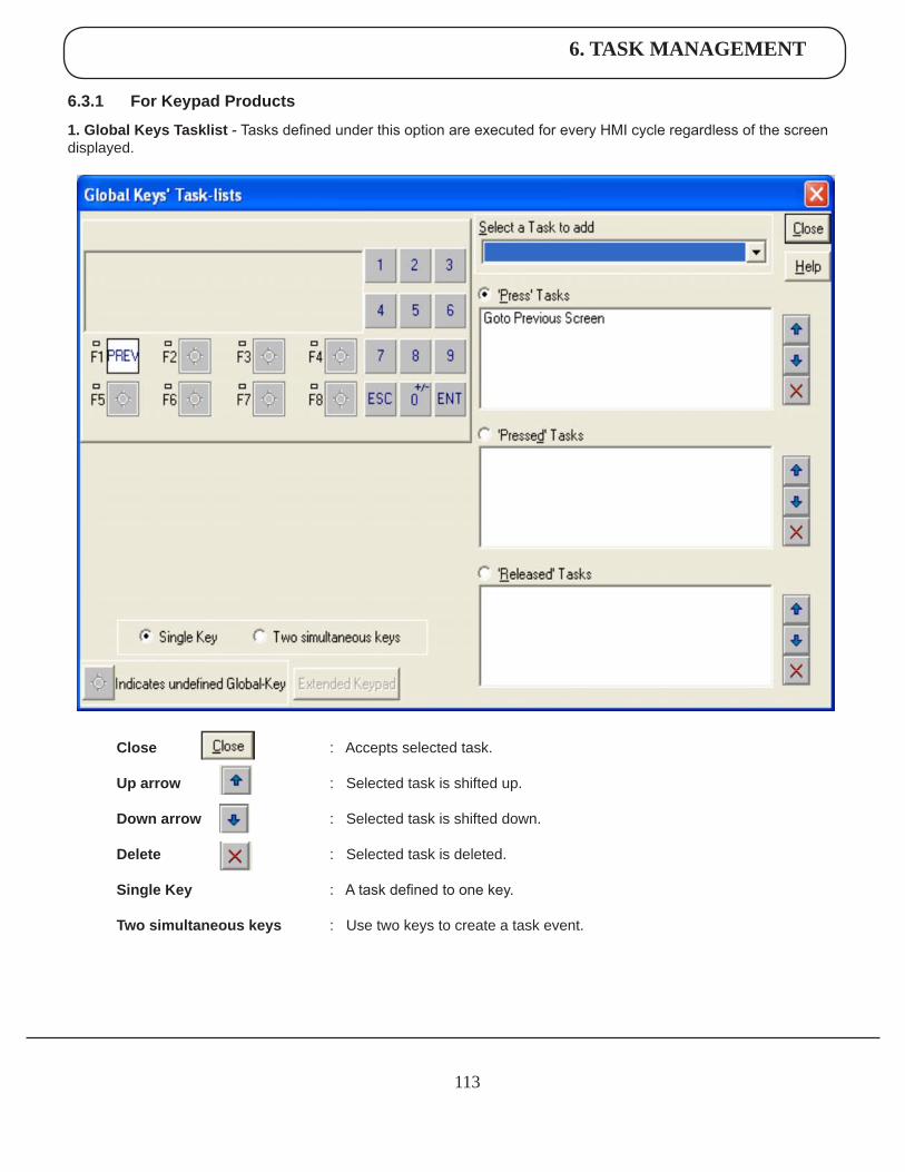
6. TASK MANAGEMENT
113
6.3.1 ForKeypadProducts
1.GlobalKeysTasklist - Tasks defined under this option are executed for every HMI cycle regardless of the screen displayed.
Close : Accepts selected task.
Uparrow : Selected task is shifted up.
Downarrow : Selected task is shifted down.
Delete : Selected task is deleted. SingleKey : A task defined to one key.
Twosimultaneouskeys : Use two keys to create a task event.
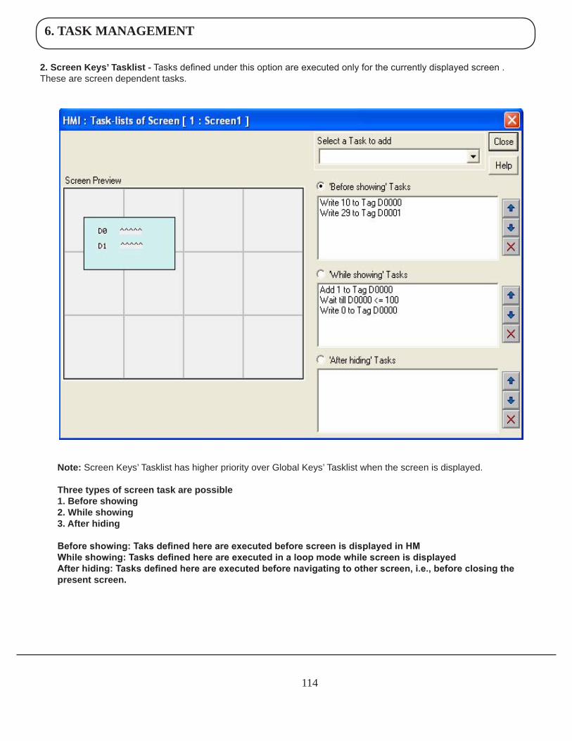
6. TASK MANAGEMENT
114
2.ScreenKeys’Tasklist - Tasks defined under this option are executed only for the currently displayed screen . These are screen dependent tasks.
Note:Screen Keys’ Tasklist has higher priority over Global Keys’ Tasklist when the screen is displayed. Threetypesofscreentaskarepossible 1.Beforeshowing 2.Whileshowing 3.Afterhiding Before showing: Taks defined here are executed before screen is displayed in HM While showing: Tasks defined here are executed in a loop mode while screen is displayed After hiding: Tasks defined here are executed before navigating to other screen, i.e., before closing the presentscreen.
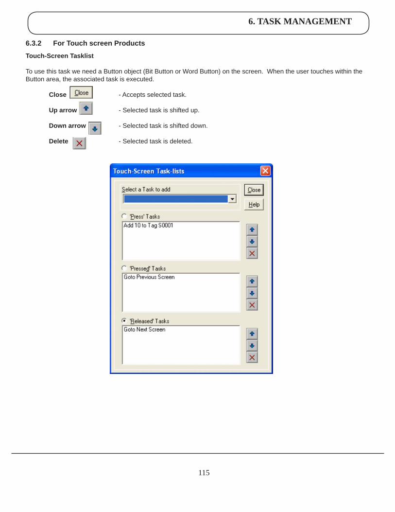
6. TASK MANAGEMENT
115
6.3.2 ForTouchscreenProducts
Touch-ScreenTasklist
To use this task we need a Button object (Bit Button or Word Button) on the screen. When the user touches within the Button area, the associated task is executed.
Close - Accepts selected task.
Uparrow - Selected task is shifted up.
Downarrow - Selected task is shifted down.
Delete - Selected task is deleted.
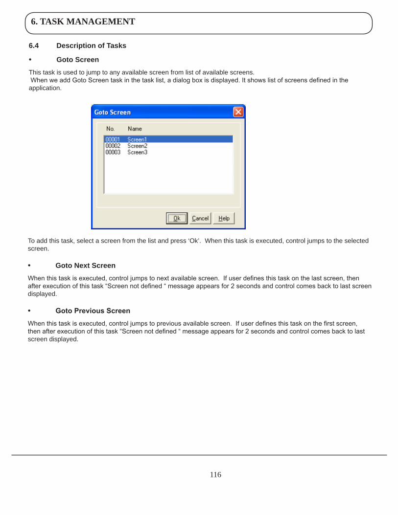
6. TASK MANAGEMENT
116
6.4 DescriptionofTasks
• GotoScreen
This task is used to jump to any available screen from list of available screens. When we add Goto Screen task in the task list, a dialog box is displayed. It shows list of screens defined in the application.
To add this task, select a screen from the list and press ‘Ok’. When this task is executed, control jumps to the selected screen.
• GotoNextScreen
When this task is executed, control jumps to next available screen. If user defines this task on the last screen, then after execution of this task “Screen not defined “ message appears for 2 seconds and control comes back to last screen displayed.
• Goto Previous Screen
When this task is executed, control jumps to previous available screen. If user defines this task on the first screen, then after execution of this task “Screen not defined “ message appears for 2 seconds and control comes back to last screen displayed.
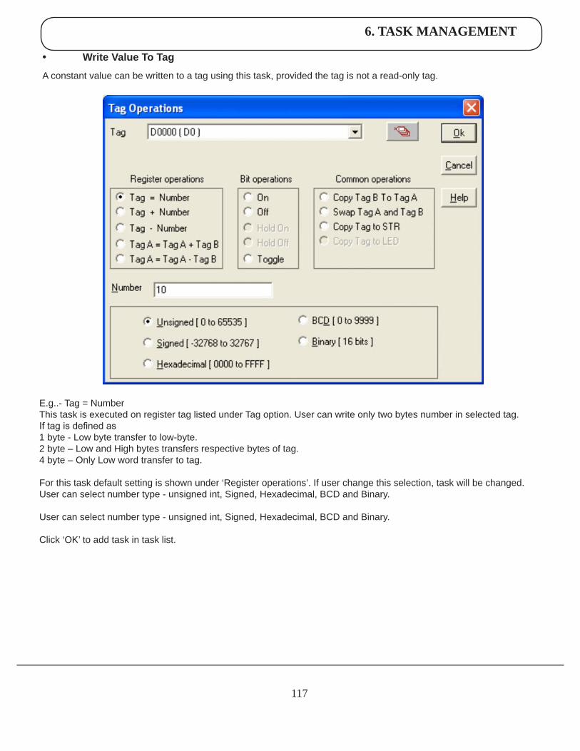
6. TASK MANAGEMENT
117
• WriteValueToTag
A constant value can be written to a tag using this task, provided the tag is not a read-only tag.
E.g..- Tag = NumberThis task is executed on register tag listed under Tag option. User can write only two bytes number in selected tag.If tag is defined as 1 byte - Low byte transfer to low-byte.2 byte – Low and High bytes transfers respective bytes of tag.4 byte – Only Low word transfer to tag.
For this task default setting is shown under ‘Register operations’. If user change this selection, task will be changed.User can select number type - unsigned int, Signed, Hexadecimal, BCD and Binary.
User can select number type - unsigned int, Signed, Hexadecimal, BCD and Binary.
Click ‘OK’ to add task in task list.
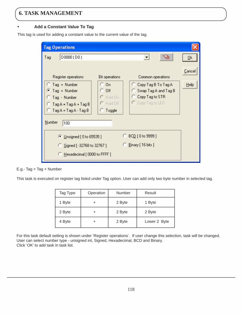
6. TASK MANAGEMENT
118
• AddaConstantValueToTag
This tag is used for adding a constant value to the current value of the tag.
E.g.- Tag = Tag + Number
This task is executed on register tag listed under Tag option. User can add only two byte number in selected tag.
Tag Type Operation Number Result
1 Byte + 2 Byte 1 Byte
2 Byte + 2 Byte 2 Byte
4 Byte + 2 Byte Lower 2 Byte
For this task default setting is shown under ‘Register operations’. If user change this selection, task will be changed. User can select number type - unsigned int, Signed, Hexadecimal, BCD and Binary. Click ‘OK’ to add task in task list.
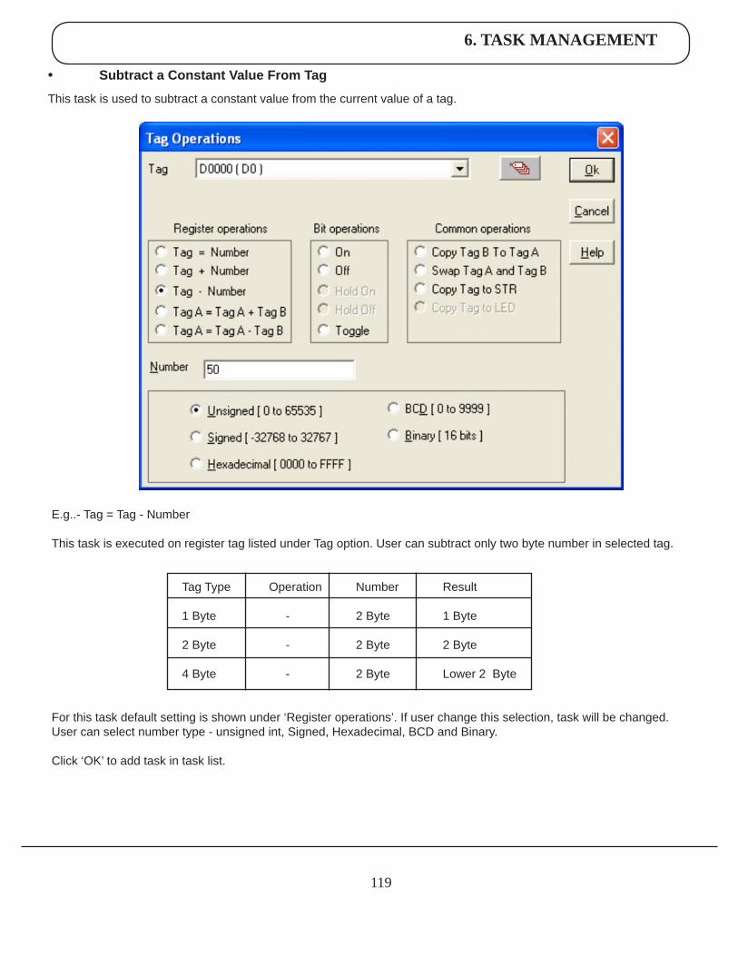
6. TASK MANAGEMENT
119
• SubtractaConstantValueFromTag
This task is used to subtract a constant value from the current value of a tag.
E.g..- Tag = Tag - Number
This task is executed on register tag listed under Tag option. User can subtract only two byte number in selected tag.
Tag Type Operation Number Result
1 Byte - 2 Byte 1 Byte
2 Byte - 2 Byte 2 Byte
4 Byte - 2 Byte Lower 2 Byte
For this task default setting is shown under ‘Register operations’. If user change this selection, task will be changed.User can select number type - unsigned int, Signed, Hexadecimal, BCD and Binary.
Click ‘OK’ to add task in task list.
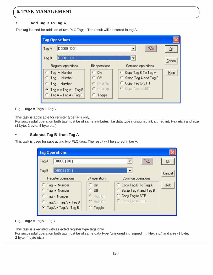
6. TASK MANAGEMENT
120
• AddTagBToTagA
This tag is used for addition of two PLC Tags . The result will be stored in tag A.
E.g..- TagA = TagA + TagB
This task is applicable for register type tags only.For successful operation both tag must be of same attributes like data type ( unsigned int, signed int, Hex etc.) and size (1 byte, 2 byte, 4 byte etc.)
• SubtractTagBfromTagA
This task is used for subtracting two PLC tags. The result will be stored in tag A.
E.g..- TagA = TagA - TagB
This task is executed with selected register type tags only.For successful operation both tag must be of same data type (unsigned int, signed int, Hex etc.) and size (1 byte, 2 byte, 4 byte etc.)
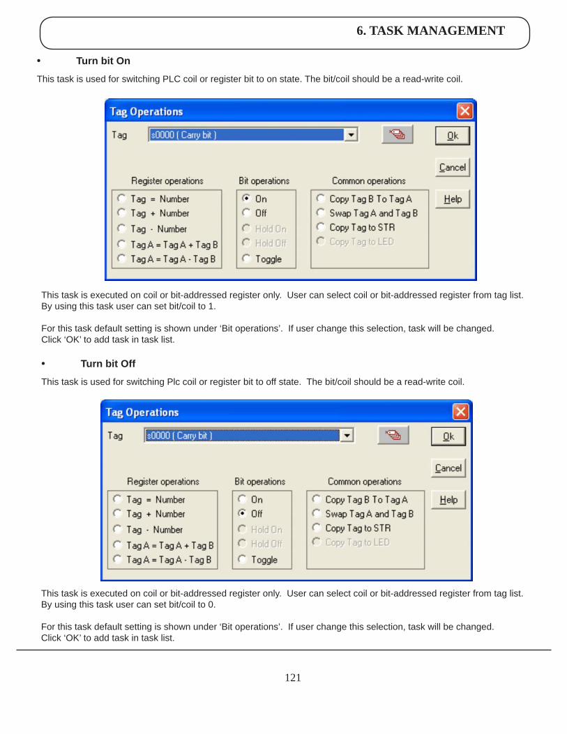
6. TASK MANAGEMENT
121
• TurnbitOn
This task is used for switching PLC coil or register bit to on state. The bit/coil should be a read-write coil.
This task is executed on coil or bit-addressed register only. User can select coil or bit-addressed register from tag list. By using this task user can set bit/coil to 1.
For this task default setting is shown under ‘Bit operations’. If user change this selection, task will be changed. Click ‘OK’ to add task in task list.
• TurnbitOff
This task is used for switching Plc coil or register bit to off state. The bit/coil should be a read-write coil.
This task is executed on coil or bit-addressed register only. User can select coil or bit-addressed register from tag list. By using this task user can set bit/coil to 0.
For this task default setting is shown under ‘Bit operations’. If user change this selection, task will be changed. Click ‘OK’ to add task in task list.
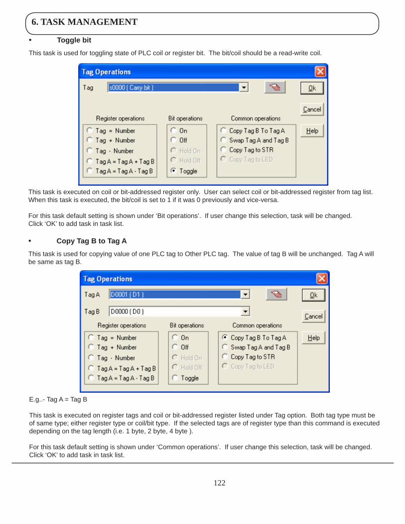
6. TASK MANAGEMENT
122
This task is executed on coil or bit-addressed register only. User can select coil or bit-addressed register from tag list. When this task is executed, the bit/coil is set to 1 if it was 0 previously and vice-versa.
For this task default setting is shown under ‘Bit operations’. If user change this selection, task will be changed. Click ‘OK’ to add task in task list.
• CopyTagBtoTagA
This task is used for copying value of one PLC tag to Other PLC tag. The value of tag B will be unchanged. Tag A will be same as tag B.
E.g..- Tag A = Tag B
This task is executed on register tags and coil or bit-addressed register listed under Tag option. Both tag type must be of same type; either register type or coil/bit type. If the selected tags are of register type than this command is executed depending on the tag length (i.e. 1 byte, 2 byte, 4 byte ).
For this task default setting is shown under ‘Common operations’. If user change this selection, task will be changed.Click ‘OK’ to add task in task list.
• Togglebit
This task is used for toggling state of PLC coil or register bit. The bit/coil should be a read-write coil.
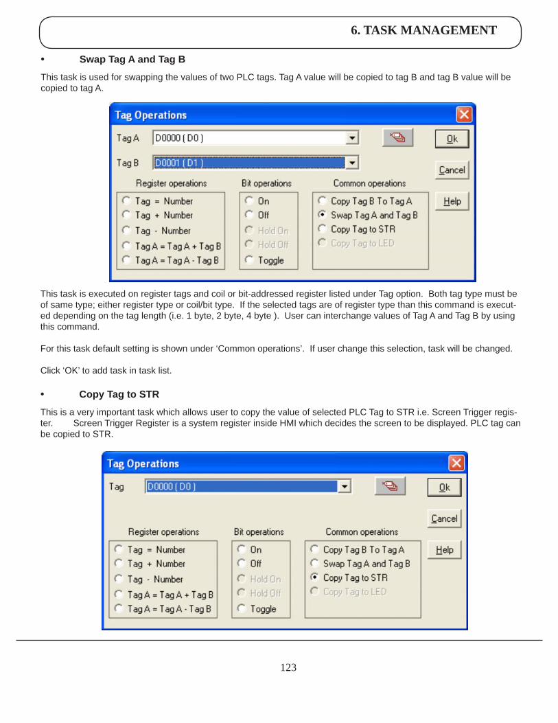
6. TASK MANAGEMENT
123
This task is executed on register tags and coil or bit-addressed register listed under Tag option. Both tag type must be of same type; either register type or coil/bit type. If the selected tags are of register type than this command is execut-ed depending on the tag length (i.e. 1 byte, 2 byte, 4 byte ). User can interchange values of Tag A and Tag B by using this command.
For this task default setting is shown under ‘Common operations’. If user change this selection, task will be changed.
Click ‘OK’ to add task in task list.
• CopyTagtoSTR
This is a very important task which allows user to copy the value of selected PLC Tag to STR i.e. Screen Trigger regis-ter. Screen Trigger Register is a system register inside HMI which decides the screen to be displayed. PLC tag can be copied to STR.
• SwapTagAandTagB
This task is used for swapping the values of two PLC tags. Tag A value will be copied to tag B and tag B value will be copied to tag A.
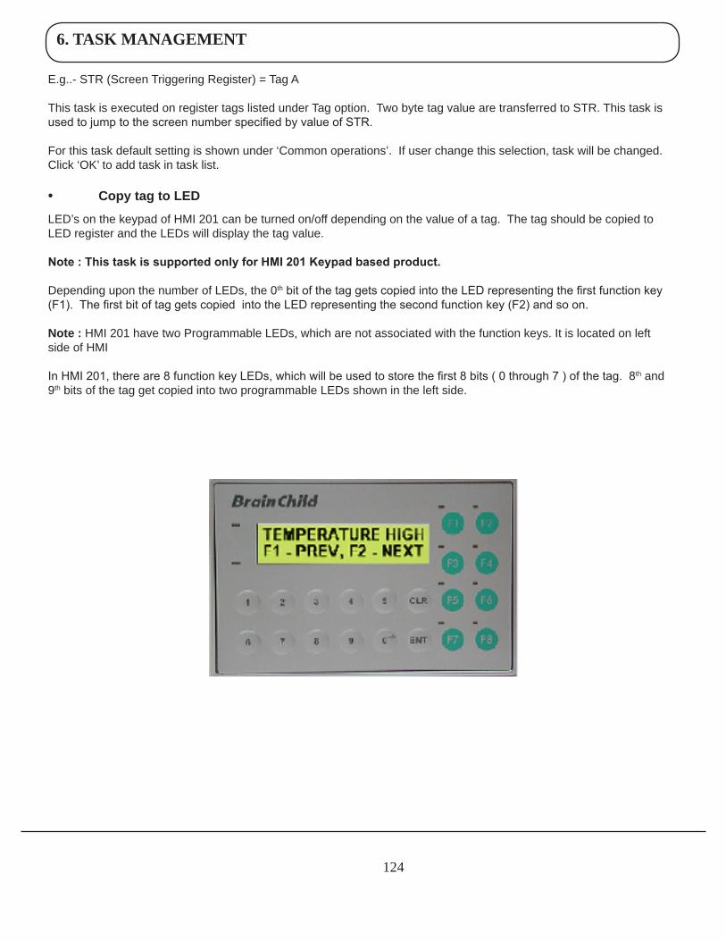
6. TASK MANAGEMENT
124
E.g..- STR (Screen Triggering Register) = Tag A
This task is executed on register tags listed under Tag option. Two byte tag value are transferred to STR. This task is used to jump to the screen number specified by value of STR.
For this task default setting is shown under ‘Common operations’. If user change this selection, task will be changed. Click ‘OK’ to add task in task list.
• CopytagtoLED
LED’s on the keypad of HMI 201 can be turned on/off depending on the value of a tag. The tag should be copied to LED register and the LEDs will display the tag value.
Note : This task is supported only for HMI 201 Keypad based product.
Depending upon the number of LEDs, the 0th bit of the tag gets copied into the LED representing the first function key (F1). The first bit of tag gets copied into the LED representing the second function key (F2) and so on.
Note: HMI 201 have two Programmable LEDs, which are not associated with the function keys. It is located on left side of HMI
In HMI 201, there are 8 function key LEDs, which will be used to store the first 8 bits ( 0 through 7 ) of the tag. 8th and 9th bits of the tag get copied into two programmable LEDs shown in the left side.
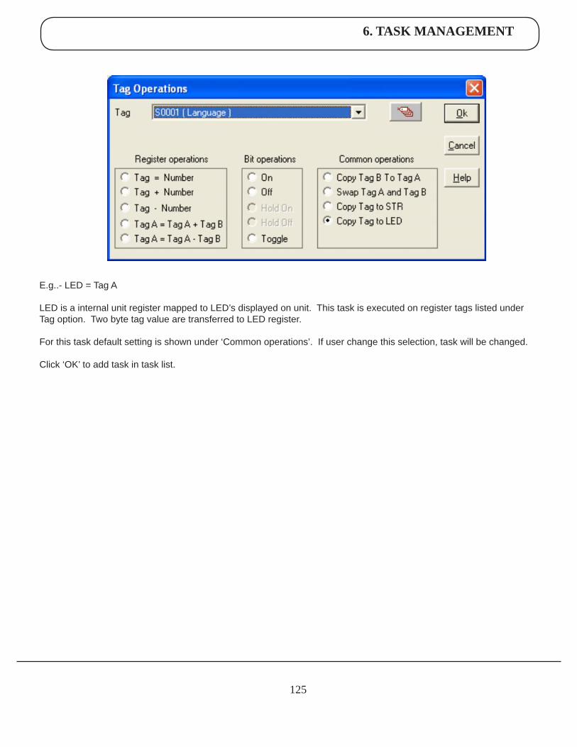
6. TASK MANAGEMENT
125
E.g..- LED = Tag A
LED is a internal unit register mapped to LED’s displayed on unit. This task is executed on register tags listed under Tag option. Two byte tag value are transferred to LED register.
For this task default setting is shown under ‘Common operations’. If user change this selection, task will be changed.
Click ‘OK’ to add task in task list.
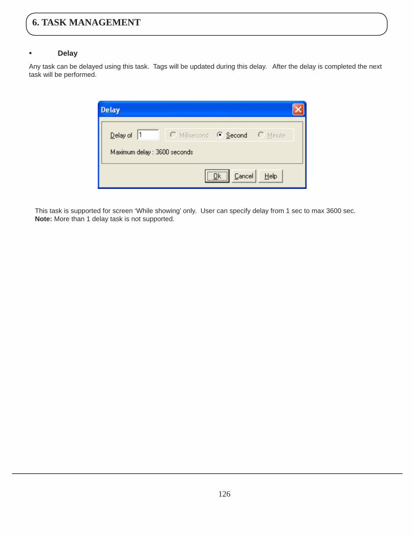
6. TASK MANAGEMENT
126
• Delay
Any task can be delayed using this task. Tags will be updated during this delay. After the delay is completed the next task will be performed.
This task is supported for screen ‘While showing’ only. User can specify delay from 1 sec to max 3600 sec.Note: More than 1 delay task is not supported.
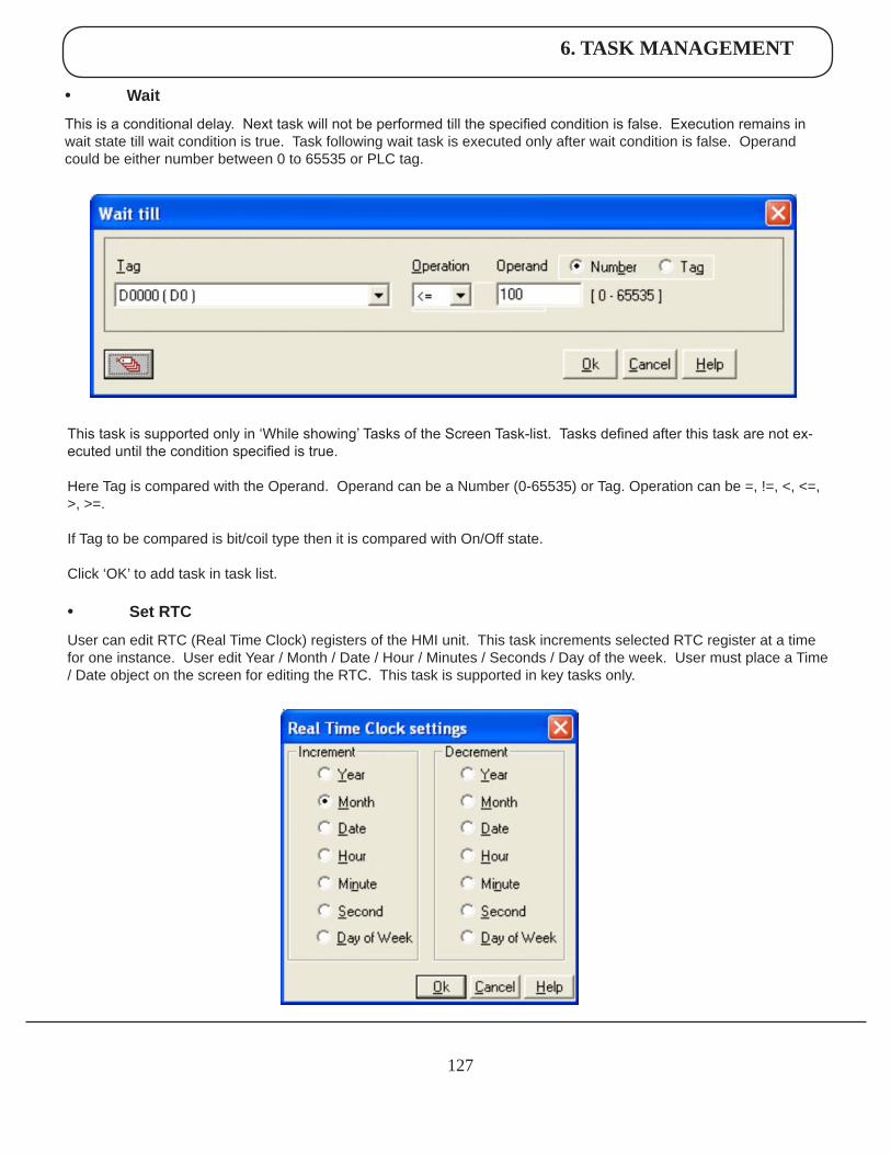
6. TASK MANAGEMENT
127
• Wait
This is a conditional delay. Next task will not be performed till the specified condition is false. Execution remains in wait state till wait condition is true. Task following wait task is executed only after wait condition is false. Operand could be either number between 0 to 65535 or PLC tag.
This task is supported only in ‘While showing’ Tasks of the Screen Task-list. Tasks defined after this task are not ex-ecuted until the condition specified is true.
Here Tag is compared with the Operand. Operand can be a Number (0-65535) or Tag. Operation can be =, !=, <, <=, >, >=.
If Tag to be compared is bit/coil type then it is compared with On/Off state.
Click ‘OK’ to add task in task list.
• SetRTC
User can edit RTC (Real Time Clock) registers of the HMI unit. This task increments selected RTC register at a time for one instance. User edit Year / Month / Date / Hour / Minutes / Seconds / Day of the week. User must place a Time / Date object on the screen for editing the RTC. This task is supported in key tasks only.
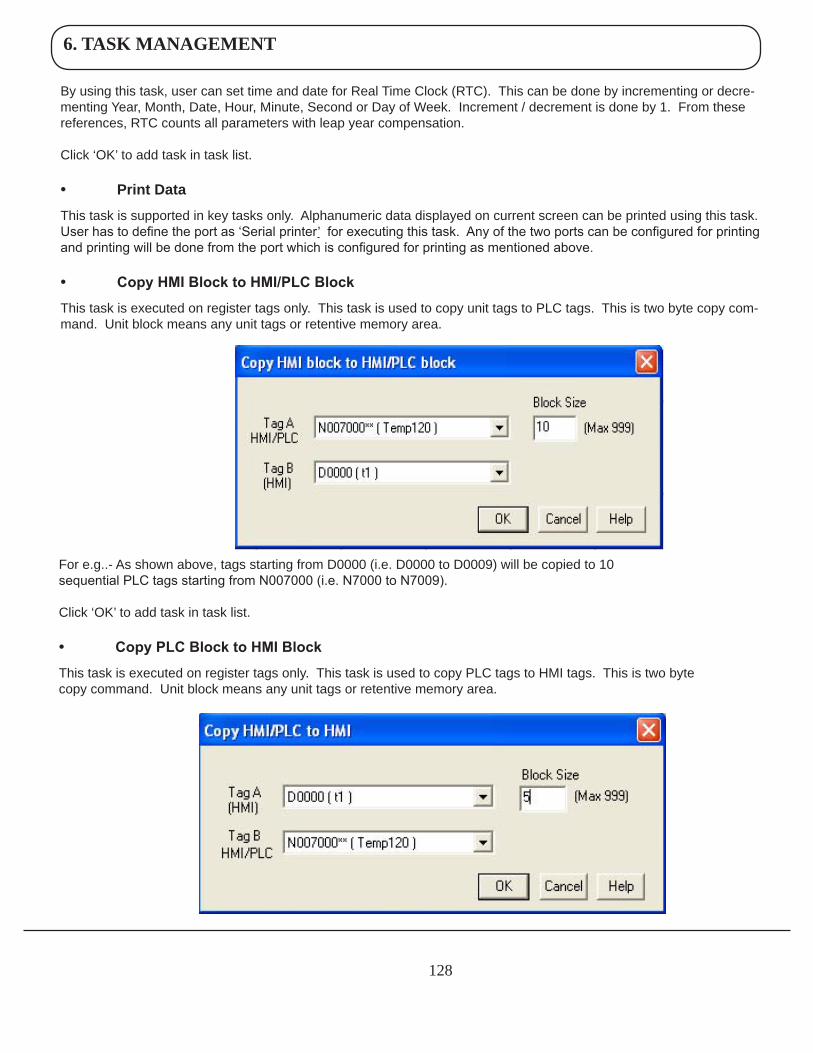
6. TASK MANAGEMENT
128
By using this task, user can set time and date for Real Time Clock (RTC). This can be done by incrementing or decre-menting Year, Month, Date, Hour, Minute, Second or Day of Week. Increment / decrement is done by 1. From these references, RTC counts all parameters with leap year compensation.
Click ‘OK’ to add task in task list.
• PrintData
This task is supported in key tasks only. Alphanumeric data displayed on current screen can be printed using this task. User has to define the port as ‘Serial printer’ for executing this task. Any of the two ports can be configured for printing and printing will be done from the port which is configured for printing as mentioned above.
• Copy HMI Block to HMI/PLC Block
This task is executed on register tags only. This task is used to copy unit tags to PLC tags. This is two byte copy com-mand. Unit block means any unit tags or retentive memory area.
For e.g..- As shown above, tags starting from D0000 (i.e. D0000 to D0009) will be copied to 10 sequential PLC tags starting from N007000 (i.e. N7000 to N7009).
Click ‘OK’ to add task in task list.
• Copy PLC Block to HMI Block
This task is executed on register tags only. This task is used to copy PLC tags to HMI tags. This is two byte copy command. Unit block means any unit tags or retentive memory area.
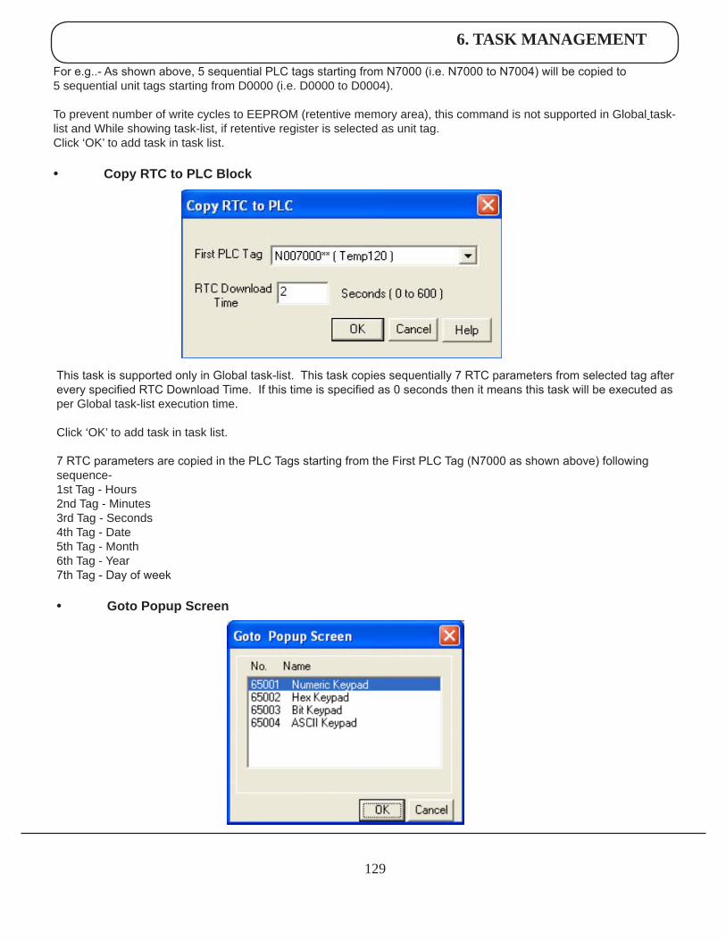
6. TASK MANAGEMENT
129
For e.g..- As shown above, 5 sequential PLC tags starting from N7000 (i.e. N7000 to N7004) will be copied to 5 sequential unit tags starting from D0000 (i.e. D0000 to D0004).
To prevent number of write cycles to EEPROM (retentive memory area), this command is not supported in Global task-list and While showing task-list, if retentive register is selected as unit tag.Click ‘OK’ to add task in task list.
• CopyRTCtoPLCBlock
This task is supported only in Global task-list. This task copies sequentially 7 RTC parameters from selected tag after every specified RTC Download Time. If this time is specified as 0 seconds then it means this task will be executed as per Global task-list execution time.
Click ‘OK’ to add task in task list.
7 RTC parameters are copied in the PLC Tags starting from the First PLC Tag (N7000 as shown above) following sequence-1st Tag - Hours2nd Tag - Minutes3rd Tag - Seconds4th Tag - Date5th Tag - Month6th Tag - Year7th Tag - Day of week
• GotoPopupScreen
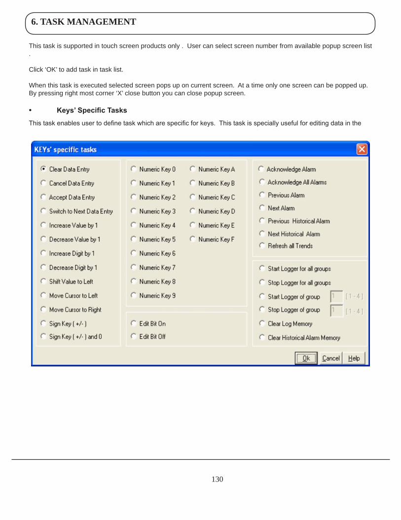
6. TASK MANAGEMENT
130
This task is supported in touch screen products only . User can select screen number from available popup screen list .
Click ‘OK’ to add task in task list.
When this task is executed selected screen pops up on current screen. At a time only one screen can be popped up. By pressing right most corner ‘X’ close button you can close popup screen.
• Keys’ Specific Tasks
This task enables user to define task which are specific for keys. This task is specially useful for editing data in the
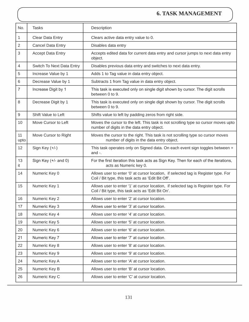
6. TASK MANAGEMENT
131
No. Tasks Description
1 Clear Data Entry Clears active data entry value to 0.
2 Cancel Data Entry Disables data entry
3 Accept Data Entry Accepts edited data for current data entry and cursor jumps to next data entry object.
4 Switch To Next Data Entry Disables previous data entry and switches to next data entry.
5 Increase Value by 1 Adds 1 to Tag value in data entry object.
6 Decrease Value by 1 Subtracts 1 from Tag value in data entry object.
7 Increase Digit by 1 This task is executed only on single digit shown by cursor. The digit scrolls between 0 to 9.
8 Decrease Digit by 1 This task is executed only on single digit shown by cursor. The digit scrolls between 0 to 9.
9 Shift Value to Left Shifts value to left by padding zeros from right side.
10 Move Cursor to Left Moves the cursor to the left. This task is not scrolling type so cursor moves upto number of digits in the data entry object.
11 Move Cursor to Right Moves the cursor to the right. This task is not scrolling type so cursor moves upto number of digits in the data entry object.
12 Sign Key (+/-) This task operates only on Signed data. On each event sign toggles between + and -.
13 Sign Key (+/- and 0) For the first iteration this task acts as Sign Key. Then for each of the iterations, it acts as Numeric key 0.
14 Numeric Key 0 Allows user to enter ‘0’ at cursor location, if selected tag is Register type. For Coil / Bit type, this task acts as ‘Edit Bit Off’.
15 Numeric Key 1 Allows user to enter ‘1’ at cursor location, if selected tag is Register type. For Coil / Bit type, this task acts as ‘Edit Bit On’.
16 Numeric Key 2 Allows user to enter ‘2’ at cursor location.
17 Numeric Key 3 Allows user to enter ‘3’ at cursor location.
18 Numeric Key 4 Allows user to enter ‘4’ at cursor location.
19 Numeric Key 5 Allows user to enter ‘5’ at cursor location.
20 Numeric Key 6 Allows user to enter ‘6’ at cursor location.
21 Numeric Key 7 Allows user to enter ‘7’ at cursor location.
22 Numeric Key 8 Allows user to enter ‘8’ at cursor location.
23 Numeric Key 9 Allows user to enter ‘9’ at cursor location.
24 Numeric Key A Allows user to enter ‘A’ at cursor location.
25 Numeric Key B Allows user to enter ‘B’ at cursor location.
26 Numeric Key C Allows user to enter ‘C’ at cursor location.
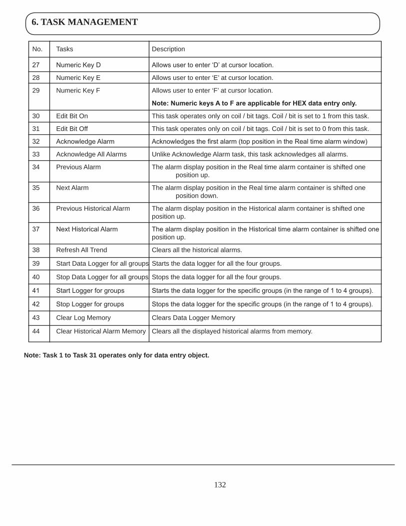
6. TASK MANAGEMENT
132
No. Tasks Description
27 Numeric Key D Allows user to enter ‘D’ at cursor location.
28 Numeric Key E Allows user to enter ‘E’ at cursor location.
29 Numeric Key F Allows user to enter ‘F’ at cursor location.
Note: Numeric keys A to F are applicable for HEX data entry only.
30 Edit Bit On This task operates only on coil / bit tags. Coil / bit is set to 1 from this task.
31 Edit Bit Off This task operates only on coil / bit tags. Coil / bit is set to 0 from this task.
32 Acknowledge Alarm Acknowledges the first alarm (top position in the Real time alarm window)
33 Acknowledge All Alarms Unlike Acknowledge Alarm task, this task acknowledges all alarms.
34 Previous Alarm The alarm display position in the Real time alarm container is shifted one position up.
35 Next Alarm The alarm display position in the Real time alarm container is shifted one position down.
36 Previous Historical Alarm The alarm display position in the Historical alarm container is shifted one position up.
37 Next Historical Alarm The alarm display position in the Historical time alarm container is shifted one position up.
38 Refresh All Trend Clears all the historical alarms.
39 Start Data Logger for all groups Starts the data logger for all the four groups.
40 Stop Data Logger for all groups Stops the data logger for all the four groups.
41 Start Logger for groups Starts the data logger for the specific groups (in the range of 1 to 4 groups).
42 Stop Logger for groups Stops the data logger for the specific groups (in the range of 1 to 4 groups).
43 Clear Log Memory Clears Data Logger Memory
44 Clear Historical Alarm Memory Clears all the displayed historical alarms from memory.
Note:Task1toTask31operatesonlyfordataentryobject.
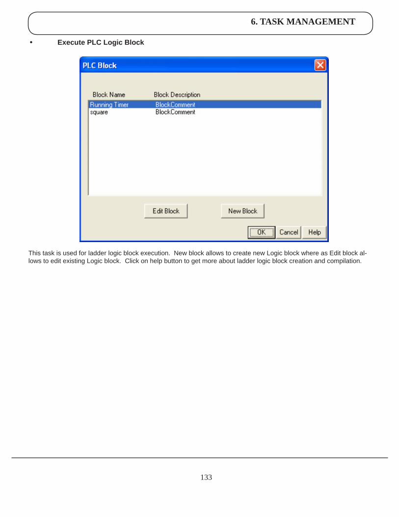
6. TASK MANAGEMENT
133
• ExecutePLCLogicBlock
This task is used for ladder logic block execution. New block allows to create new Logic block where as Edit block al-lows to edit existing Logic block. Click on help button to get more about ladder logic block creation and compilation.
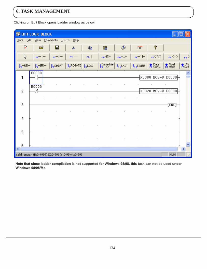
6. TASK MANAGEMENT
134
Clicking on Edit Block opens Ladder window as below.
Note that since ladder compilation is not supported for Windows 95/98, this task can not be used under Windows 95/98/Me.
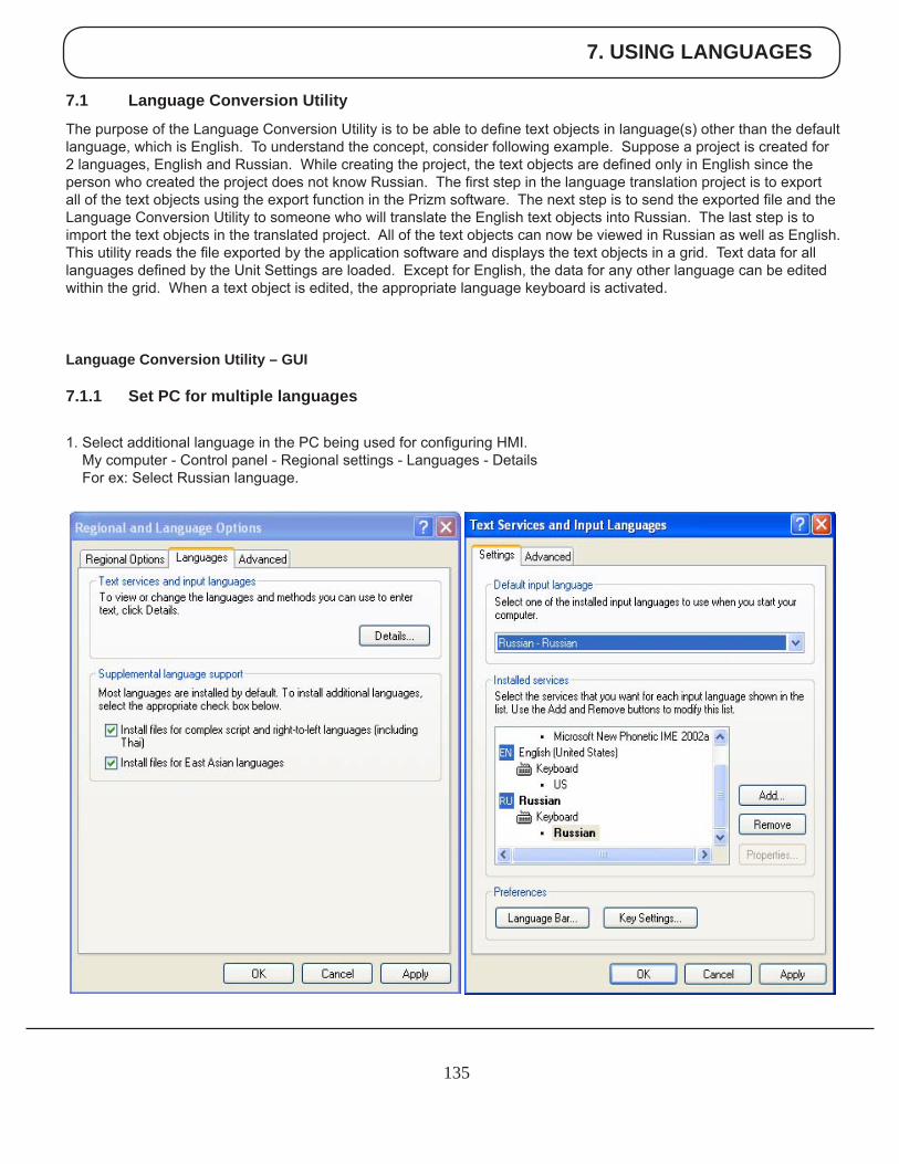
7. USING LANGUAGES
135
7.1 Language Conversion Utility
The purpose of the Language Conversion Utility is to be able to define text objects in language(s) other than the default language, which is English. To understand the concept, consider following example. Suppose a project is created for 2 languages, English and Russian. While creating the project, the text objects are defined only in English since the person who created the project does not know Russian. The first step in the language translation project is to export all of the text objects using the export function in the Prizm software. The next step is to send the exported file and the Language Conversion Utility to someone who will translate the English text objects into Russian. The last step is to import the text objects in the translated project. All of the text objects can now be viewed in Russian as well as English.This utility reads the file exported by the application software and displays the text objects in a grid. Text data for all languages defined by the Unit Settings are loaded. Except for English, the data for any other language can be edited within the grid. When a text object is edited, the appropriate language keyboard is activated.
Language Conversion Utility – GUI
7.1.1 Set PC for multiple languages
1. Select additional language in the PC being used for configuring HMI. My computer - Control panel - Regional settings - Languages - Details For ex: Select Russian language.
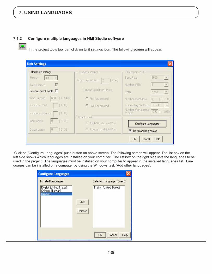
7. USING LANGUAGES
136
7.1.2 ConfiguremultiplelanguagesinHMIStudiosoftware
In the project tools tool bar, click on Unit settings icon. The following screen will appear.
Click on “Configure Languages” push button on above screen. The following screen will appear. The list box on the left side shows which languages are installed on your computer. The list box on the right side lists the languages to be used in the project. The languages must be installed on your computer to appear in the installed languages list. Lan-guages can be installed on a computer by using the Windows task “Add other languages”.
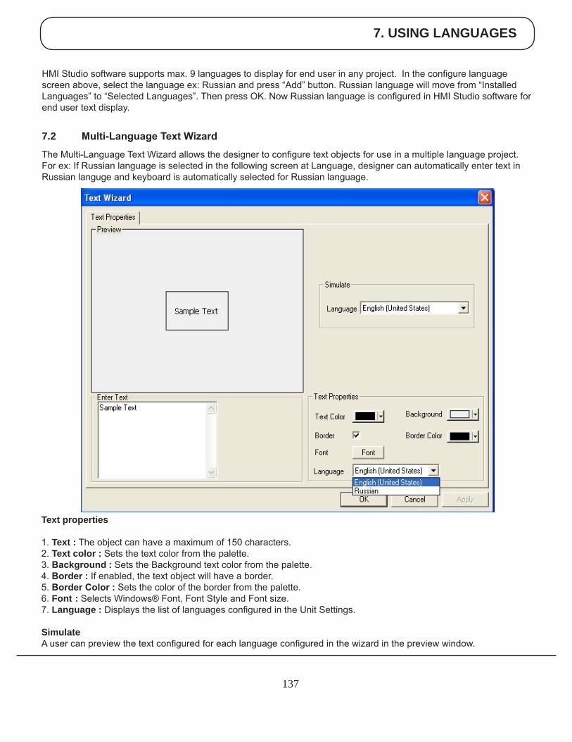
7. USING LANGUAGES
137
HMI Studio software supports max. 9 languages to display for end user in any project. In the configure language screen above, select the language ex: Russian and press “Add” button. Russian language will move from “Installed Languages” to “Selected Languages”. Then press OK. Now Russian language is configured in HMI Studio software for end user text display.
7.2 Multi-LanguageTextWizard
The Multi-Language Text Wizard allows the designer to configure text objects for use in a multiple language project. For ex: If Russian language is selected in the following screen at Language, designer can automatically enter text in Russian languge and keyboard is automatically selected for Russian language.
Text properties
1. Text : The object can have a maximum of 150 characters. 2. Text color : Sets the text color from the palette.3.Background:Sets the Background text color from the palette. 4.Border: If enabled, the text object will have a border.5.BorderColor: Sets the color of the border from the palette. 6. Font : Selects Windows® Font, Font Style and Font size.7. Language : Displays the list of languages configured in the Unit Settings.
SimulateA user can preview the text configured for each language configured in the wizard in the preview window.
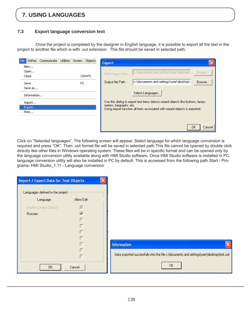
7. USING LANGUAGES
138
7.3 Export language conversion text
Once the project is completed by the designer in English language, it is possible to export all the text in the project to another file which is with .out extension. This file should be saved in selected path.
Click on “Selected languages”, The following screen will appear. Select language for which language conversion is required and press “OK”. Then .out format file will be saved in selected path.This file cannot be opened by double click directly like other files in Windows operating system. These files will be in specific format and can be opened only by the language conversion utility available along with HMI Studio software. Once HMI Studio software is installed in PC, language conversion utility will also be installed in PC by default. This is accessed from the following path Start - Pro-grams- HMI Studio_1.11 - Language conversion
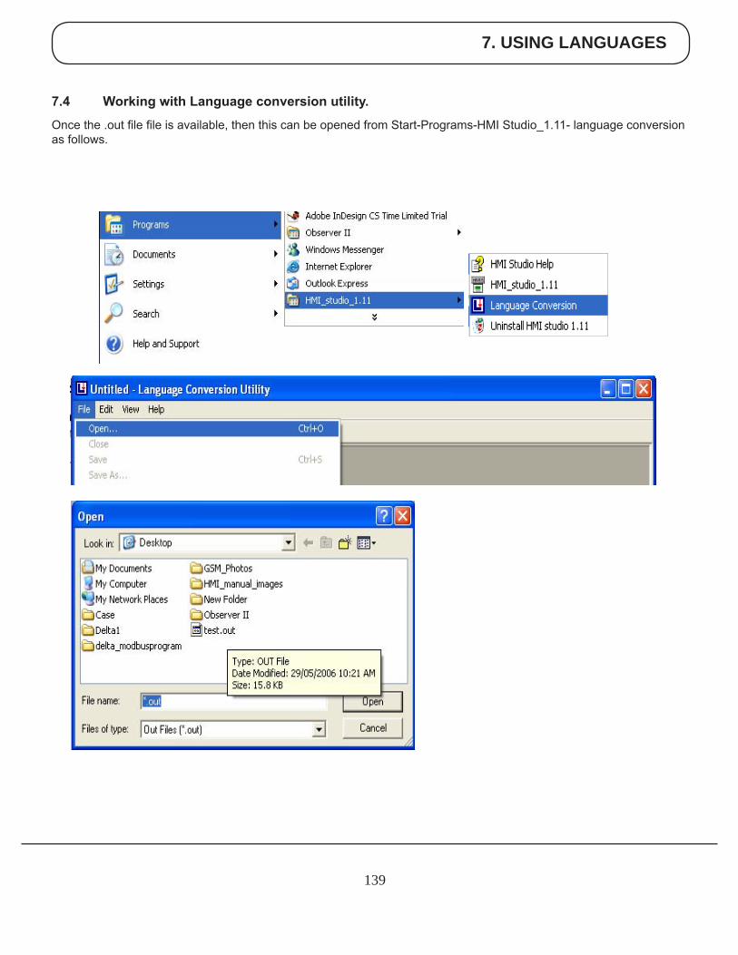
7. USING LANGUAGES
139
7.4 WorkingwithLanguageconversionutility.
Once the .out file file is available, then this can be opened from Start-Programs-HMI Studio_1.11- language conversion as follows.
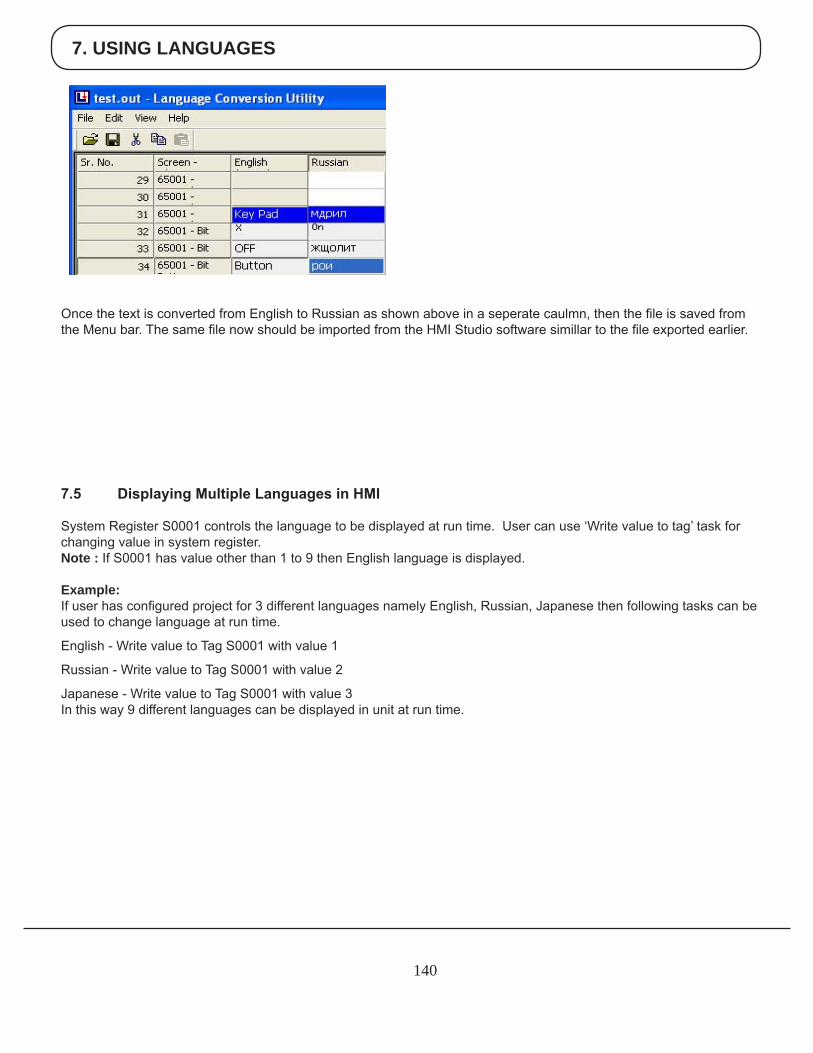
7. USING LANGUAGES
140
Once the text is converted from English to Russian as shown above in a seperate caulmn, then the file is saved from the Menu bar. The same file now should be imported from the HMI Studio software simillar to the file exported earlier.
7.5 DisplayingMultipleLanguagesinHMI
System Register S0001 controls the language to be displayed at run time. User can use ‘Write value to tag’ task forchanging value in system register.Note : If S0001 has value other than 1 to 9 then English language is displayed.
Example:If user has configured project for 3 different languages namely English, Russian, Japanese then following tasks can be used to change language at run time.
English - Write value to Tag S0001 with value 1
Russian - Write value to Tag S0001 with value 2
Japanese - Write value to Tag S0001 with value 3In this way 9 different languages can be displayed in unit at run time.
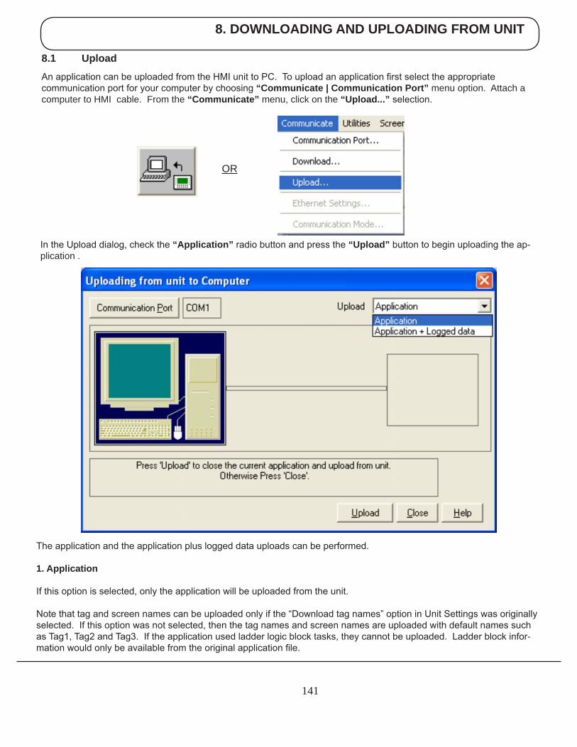
8. DOWNLOADING AND UPLOADING FROM UNIT
141
8.1 Upload
An application can be uploaded from the HMI unit to PC. To upload an application first select the appropriate communication port for your computer by choosing “Communicate | Communication Port” menu option. Attach a computer to HMI cable. From the “Communicate” menu, click on the “Upload...” selection.
OR
In the Upload dialog, check the “Application” radio button and press the “Upload” button to begin uploading the ap-plication .
The application and the application plus logged data uploads can be performed.
1. Application
If this option is selected, only the application will be uploaded from the unit.
Note that tag and screen names can be uploaded only if the “Download tag names” option in Unit Settings was originally selected. If this option was not selected, then the tag names and screen names are uploaded with default names such as Tag1, Tag2 and Tag3. If the application used ladder logic block tasks, they cannot be uploaded. Ladder block infor-mation would only be available from the original application file.
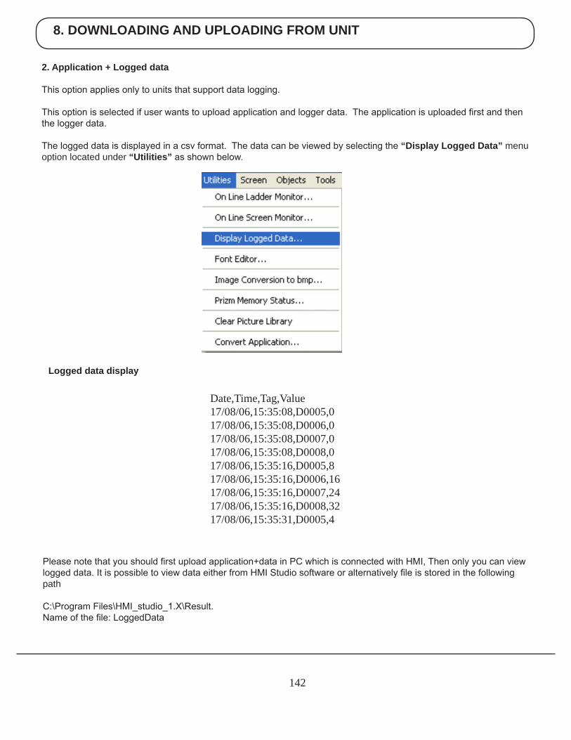
8. DOWNLOADING AND UPLOADING FROM UNIT
142
2. Application + Logged data
This option applies only to units that support data logging.
This option is selected if user wants to upload application and logger data. The application is uploaded first and then the logger data.
The logged data is displayed in a csv format. The data can be viewed by selecting the “Display Logged Data” menu option located under “Utilities” as shown below.
Date,Time,Tag,Value17/08/06,15:35:08,D0005,017/08/06,15:35:08,D0006,017/08/06,15:35:08,D0007,017/08/06,15:35:08,D0008,017/08/06,15:35:16,D0005,817/08/06,15:35:16,D0006,1617/08/06,15:35:16,D0007,2417/08/06,15:35:16,D0008,3217/08/06,15:35:31,D0005,4
Logged data display
Please note that you should first upload application+data in PC which is connected with HMI, Then only you can view logged data. It is possible to view data either from HMI Studio software or alternatively file is stored in the following path
C:\Program Files\HMI_studio_1.X\Result.Name of the file: LoggedData
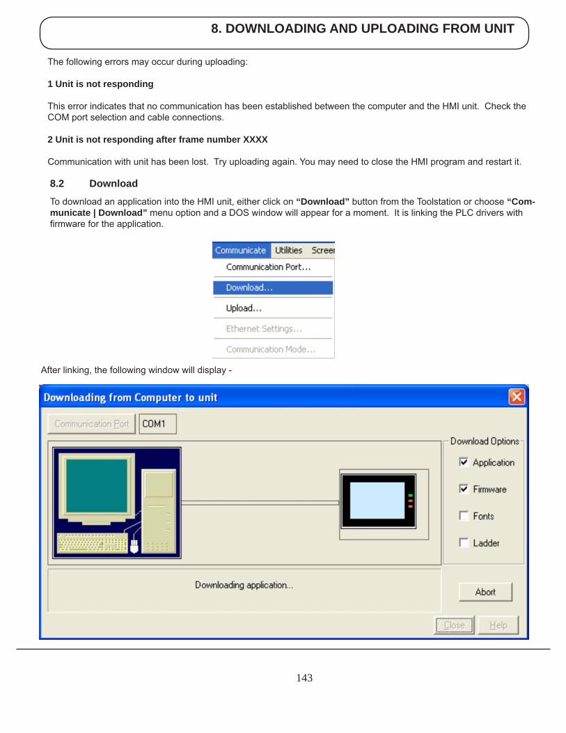
8. DOWNLOADING AND UPLOADING FROM UNIT
143
8.2 Download
To download an application into the HMI unit, either click on “Download” button from the Toolstation or choose “Com-municate | Download” menu option and a DOS window will appear for a moment. It is linking the PLC drivers with firmware for the application.
After linking, the following window will display -
The following errors may occur during uploading:
1 Unit is not responding
This error indicates that no communication has been established between the computer and the HMI unit. Check the COM port selection and cable connections.
2 Unit is not responding after frame number XXXX
Communication with unit has been lost. Try uploading again. You may need to close the HMI program and restart it.
8. DOWNLOADING AND UPLOADING FROM UNIT
144
Communication Port – Used to select which communication port to be used for downloading. By default Com1 is selected. Any changes are stored with the HMI program. Download Options
1. Application Select this option to download the application to the unit.
2. Firmware Firmware needs to be downloaded when:
1. Before downloading the application for the first time. 2. If a new PLC node is either added or deleted in the Network configuration. 3. Upgrading firmware in the unit to newer version. 4. Before downloading applications created in older versions of software.
3. Font Select this option to download fonts to unit. This option needs to be selected if the default fonts have been modified.
4. Ladder Select this option to download ladder blocks to the unit. This option needs to be selected if the ladder logic blocks have been modified.
Download Button - Click this button to start the downloading.
Abort Button - Click on this button to stop the downloading.
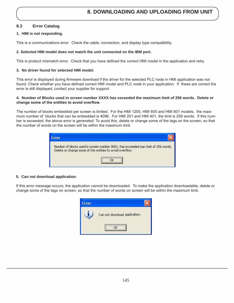
8. DOWNLOADING AND UPLOADING FROM UNIT
145
8.3 Error Catalog
1. HMI is not responding.
This is a communications error. Check the cable, connection, and display type compatibility.
2. Selected HMI model does not match the unit connected on the IBM port.
This is product mismatch error. Check that you have defined the correct HMI model in the application and retry.
3. No driver found for selected HMI model.
This error is displayed during firmware download if the driver for the selected PLC node in HMI application was not found. Check whether you have defined correct HMI model and PLC node in your application. If these are correct the error is still displayed, contact your supplier for support.
4. Number of Blocks used in screen number XXXX has exceeded the maximum limit of 256 words. Delete or change some of the entities to avoid overflow.
The number of blocks embedded per screen is limited. For the HMI 1205, HMI 605 and HMI 601 models, the maxi-mum number of blocks that can be embedded is 4096. For HMI 201 and HMI 401, the limit is 256 words. If this num-ber is exceeded, the above error is generated. To avoid this, delete or change some of the tags on the screen, so that the number of words on the screen will be within the maximum limit.
5. Can not download application.
If this error message occurs, the application cannot be downloaded. To make the application downloadable, delete or change some of the tags on screen, so that the number of words on screen will be within the maximum limit.

8. DOWNLOADING AND UPLOADING FROM UNIT
146
6. The Firmware size has exceeded the limit.
The Firmware size has exceeded the limit. It can be reduced by -
1. Reducing the number of channels configured in 16-point Linearization.2. Reducing the number of blocks configured in PID or Time Proportional PWM.3. Reducing the number of channels configured as High Speed Interrupt or Pulse Output.
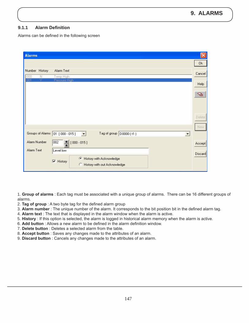
9. ALARMS
147
9.1.1 Alarm Definition
Alarms can be defined in the following screen
1. Group of alarms : Each tag must be associated with a unique group of alarms. There can be 16 different groups of alarms.2. Tag of group : A two byte tag for the defined alarm group3. Alarm number : The unique number of the alarm. It corresponds to the bit position bit in the defined alarm tag.4. Alarm text : The text that is displayed in the alarm window when the alarm is active.5. History : If this option is selected, the alarm is logged in historical alarm memory when the alarm is active.6. Add button : Allows a new alarm to be defined in the alarm definition window.7. Delete button : Deletes a selected alarm from the table.8. Accept button : Saves any changes made to the attributes of an alarm. 9. Discard button : Cancels any changes made to the attributes of an alarm.
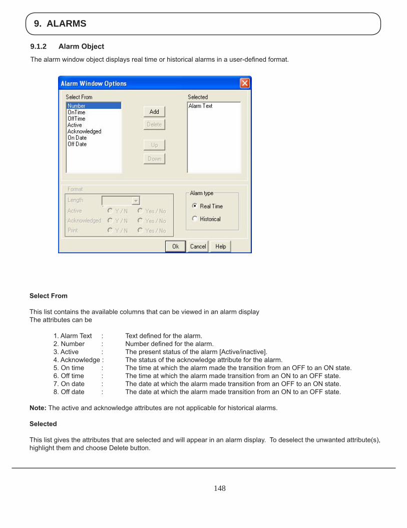
9. ALARMS
148
9.1.2 Alarm Object
The alarm window object displays real time or historical alarms in a user-defined format.
Select From
This list contains the available columns that can be viewed in an alarm displayThe attributes can be
1. Alarm Text : Text defined for the alarm. 2. Number : Number defined for the alarm. 3. Active : The present status of the alarm [Active/inactive]. 4. Acknowledge : The status of the acknowledge attribute for the alarm. 5. On time : The time at which the alarm made the transition from an OFF to an ON state. 6. Off time : The time at which the alarm made transition from an ON to an OFF state. 7. On date : The date at which the alarm made transition from an OFF to an ON state. 8. Off date : The date at which the alarm made transition from an ON to an OFF state.
Note: The active and acknowledge attributes are not applicable for historical alarms.
Selected
This list gives the attributes that are selected and will appear in an alarm display. To deselect the unwanted attribute(s), highlight them and choose Delete button.
9. ALARMS
149
Alarm type
This is the selection, which specifies whether the current alarm window represents the real time or historical alarms.
Note: Historical alarms are Product dependent.
Format
Enter the format for the highlighted attribute from Selected field. For Time attribute, you can select the format as either HH:MM:SS or MM:SS from the combo box.For Alarm Text attribute, you can enter the length in ‘Length’ field.For Active and Acknowledged attributes, you can check the desired radio button.
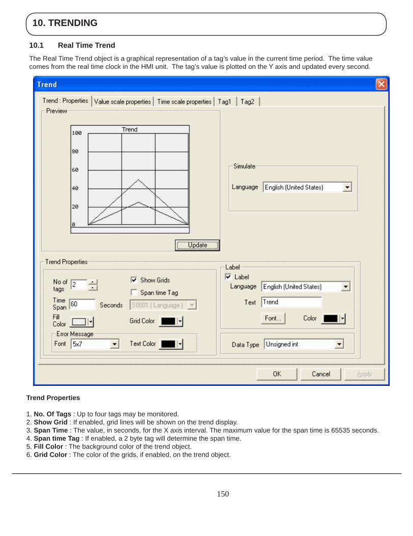
10. TRENDING
150
10.1 Real Time Trend
The Real Time Trend object is a graphical representation of a tag’s value in the current time period. The time value comes from the real time clock in the HMI unit. The tag’s value is plotted on the Y axis and updated every second.
Trend Properties
1. No. Of Tags : Up to four tags may be monitored.2. Show Grid : If enabled, grid lines will be shown on the trend display.3. Span Time : The value, in seconds, for the X axis interval. The maximum value for the span time is 65535 seconds.4. Span time Tag : If enabled, a 2 byte tag will determine the span time.5. Fill Color : The background color of the trend object. 6. Grid Color : The color of the grids, if enabled, on the trend object.
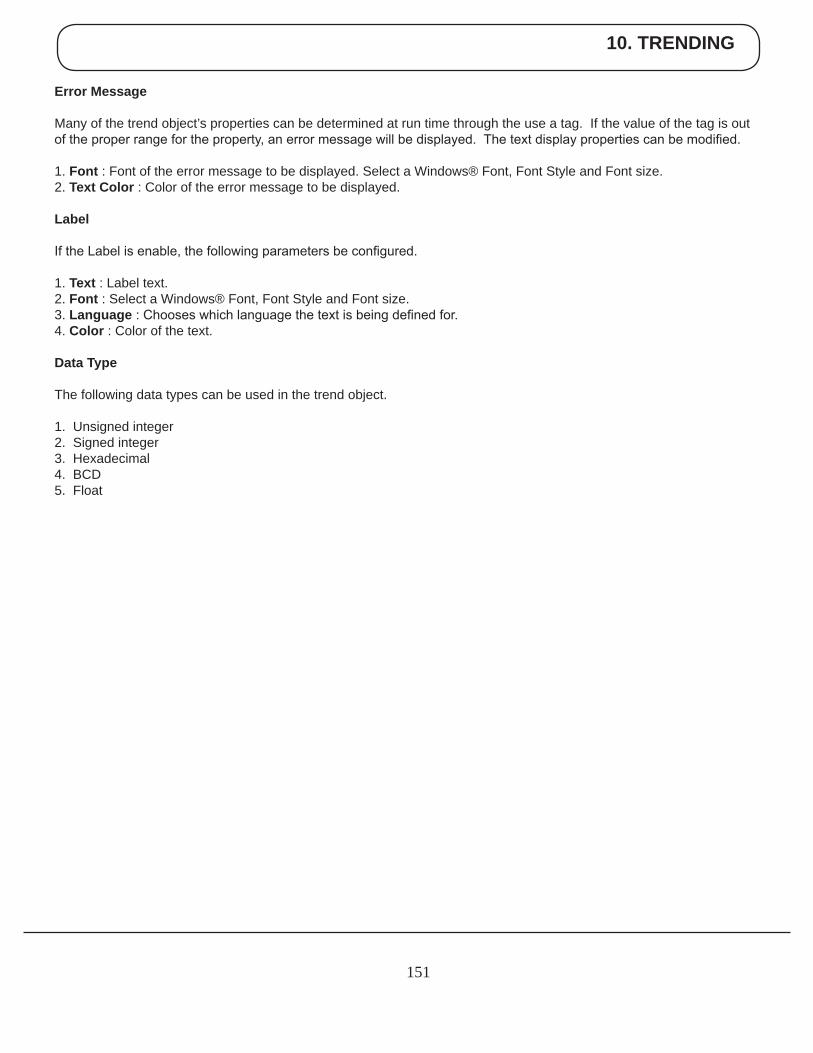
10. TRENDING
151
Error Message
Many of the trend object’s properties can be determined at run time through the use a tag. If the value of the tag is out of the proper range for the property, an error message will be displayed. The text display properties can be modified.
1. Font : Font of the error message to be displayed. Select a Windows® Font, Font Style and Font size. 2. Text Color : Color of the error message to be displayed.
Label
If the Label is enable, the following parameters be configured.
1. Text : Label text.2. Font : Select a Windows® Font, Font Style and Font size.3. Language : Chooses which language the text is being defined for.4. Color : Color of the text.
Data Type
The following data types can be used in the trend object.
1. Unsigned integer2. Signed integer3. Hexadecimal4. BCD5. Float
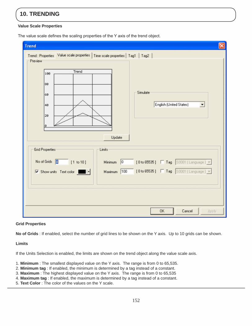
10. TRENDING
152
Grid Properties
No of Grids : If enabled, select the number of grid lines to be shown on the Y axis. Up to 10 grids can be shown.
Limits
If the Units Selection is enabled, the limits are shown on the trend object along the value scale axis.
1. Minimum : The smallest displayed value on the Y axis. The range is from 0 to 65,535.2. Minimum tag : If enabled, the minimum is determined by a tag instead of a constant.3. Maximum : The highest displayed value on the Y axis. The range is from 0 to 65,5354. Maximum tag : If enabled, the maximum is determined by a tag instead of a constant.5. Text Color : The color of the values on the Y scale.
Value Scale Properties
The value scale defines the scaling properties of the Y axis of the trend object.
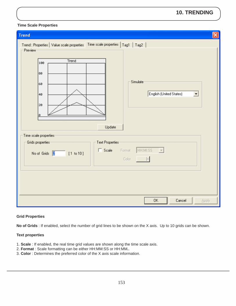
10. TRENDING
153
Time Scale Properties
Grid Properties
No of Grids : If enabled, select the number of grid lines to be shown on the X axis. Up to 10 grids can be shown.
Text properties
1. Scale : If enabled, the real time grid values are shown along the time scale axis. 2. Format : Scale formatting can be either HH:MM:SS or HH:MM..3. Color : Determines the preferred color of the X axis scale information.
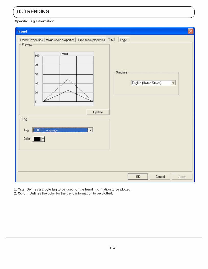
10. TRENDING
154
1. Tag : Defines a 2 byte tag to be used for the trend information to be plotted.2. Color : Defines the color for the trend information to be plotted.
Specific Tag Information
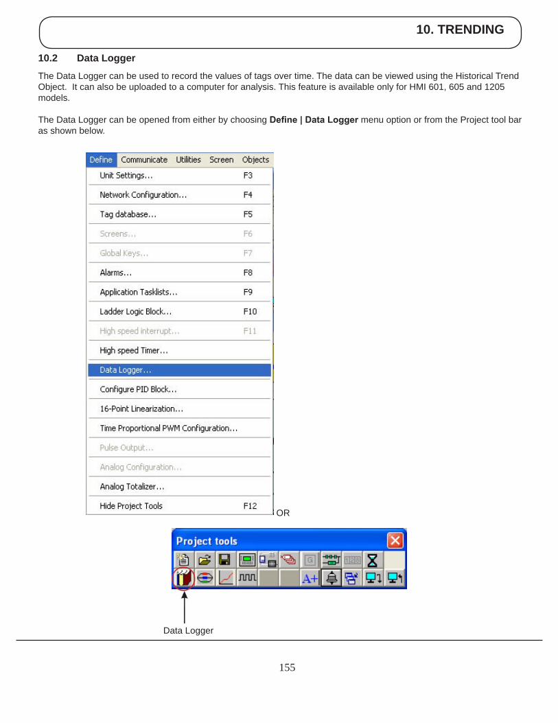
10. TRENDING
155
10.2 Data Logger
The Data Logger can be used to record the values of tags over time. The data can be viewed using the Historical Trend Object. It can also be uploaded to a computer for analysis. This feature is available only for HMI 601, 605 and 1205 models.
The Data Logger can be opened from either by choosing Define | Data Logger menu option or from the Project tool bar as shown below.
OR
Data Logger
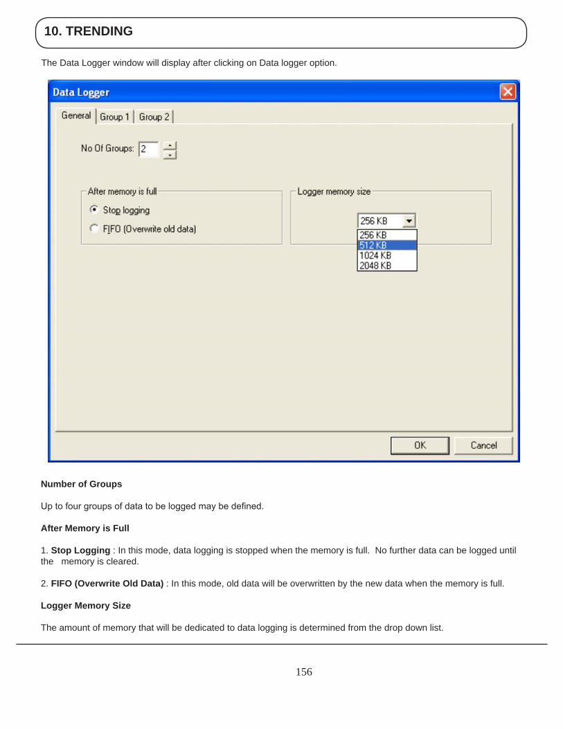
10. TRENDING
156
The Data Logger window will display after clicking on Data logger option.
Number of Groups
Up to four groups of data to be logged may be defined.
After Memory is Full
1. Stop Logging : In this mode, data logging is stopped when the memory is full. No further data can be logged until the memory is cleared.
2. FIFO (Overwrite Old Data) : In this mode, old data will be overwritten by the new data when the memory is full.
Logger Memory Size
The amount of memory that will be dedicated to data logging is determined from the drop down list.
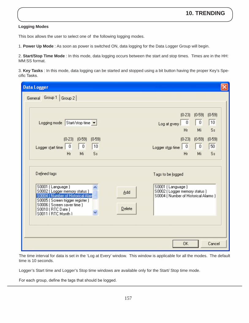
10. TRENDING
157
Logging Modes
This box allows the user to select one of the following logging modes.
1. Power Up Mode : As soon as power is switched ON, data logging for the Data Logger Group will begin.
2. Start/Stop Time Mode : In this mode, data logging occurs between the start and stop times. Times are in the HH:MM:SS format.
3. Key Tasks : In this mode, data logging can be started and stopped using a bit button having the proper Key’s Spe-cific Tasks.
The time interval for data is set in the ‘Log at Every’ window. This window is applicable for all the modes. The default time is 10 seconds.
Logger’s Start time and Logger’s Stop time windows are available only for the Start/ Stop time mode.
For each group, define the tags that should be logged.
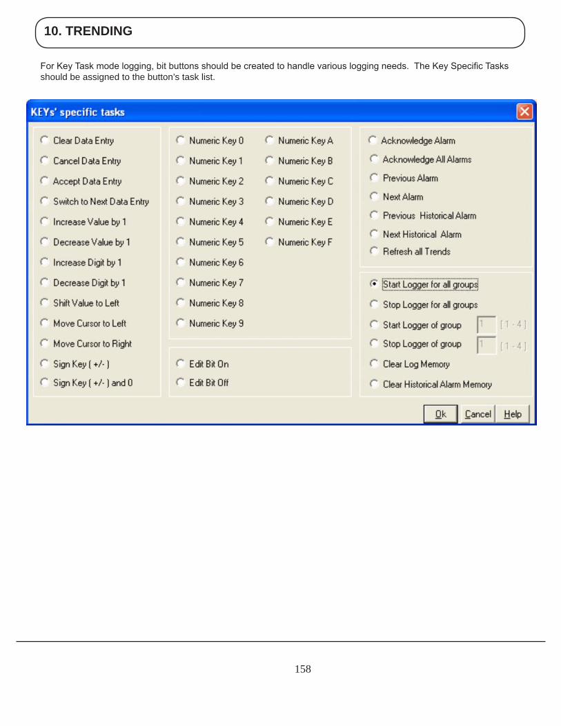
10. TRENDING
158
For Key Task mode logging, bit buttons should be created to handle various logging needs. The Key Specific Tasks should be assigned to the button’s task list.
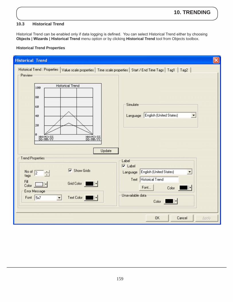
10. TRENDING
159
10.3 Historical Trend
Historical Trend can be enabled only if data logging is defined. You can select Historical Trend either by choosing Objects | Wizards | Historical Trend menu option or by clicking Historical Trend tool from Objects toolbox.
Historical Trend Properties
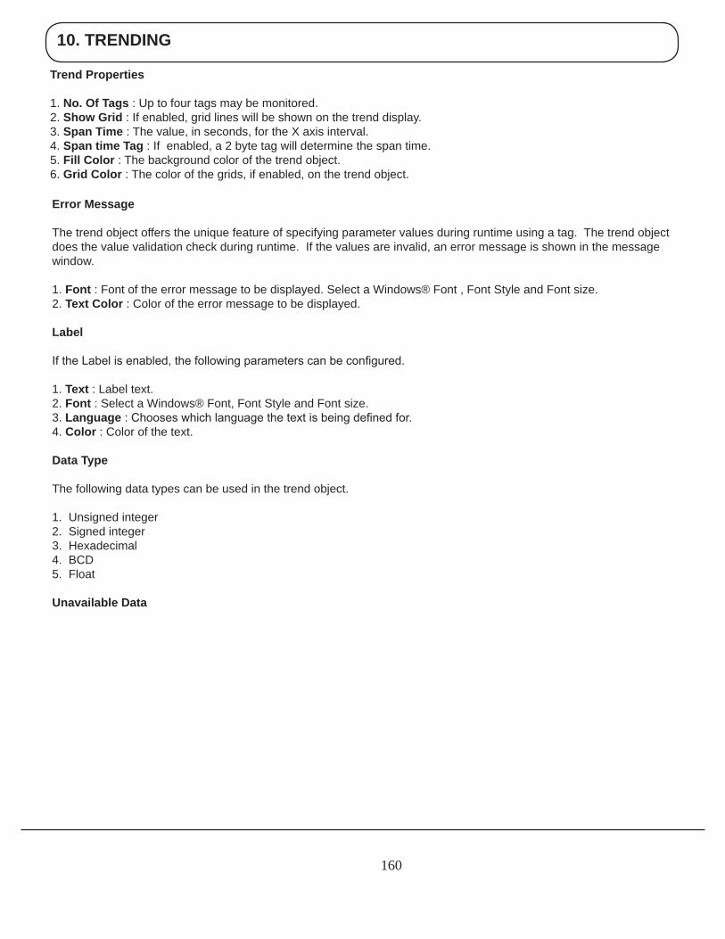
10. TRENDING
160
Trend Properties
1. No. Of Tags : Up to four tags may be monitored.2. Show Grid : If enabled, grid lines will be shown on the trend display.3. Span Time : The value, in seconds, for the X axis interval.4. Span time Tag : If enabled, a 2 byte tag will determine the span time.5. Fill Color : The background color of the trend object. 6. Grid Color : The color of the grids, if enabled, on the trend object.
Error Message
The trend object offers the unique feature of specifying parameter values during runtime using a tag. The trend object does the value validation check during runtime. If the values are invalid, an error message is shown in the message window.
1. Font : Font of the error message to be displayed. Select a Windows® Font , Font Style and Font size. 2. Text Color : Color of the error message to be displayed.
Label
If the Label is enabled, the following parameters can be configured.
1. Text : Label text.2. Font : Select a Windows® Font, Font Style and Font size.3. Language : Chooses which language the text is being defined for.4. Color : Color of the text.
Data Type
The following data types can be used in the trend object.
1. Unsigned integer2. Signed integer3. Hexadecimal4. BCD5. Float
Unavailable Data
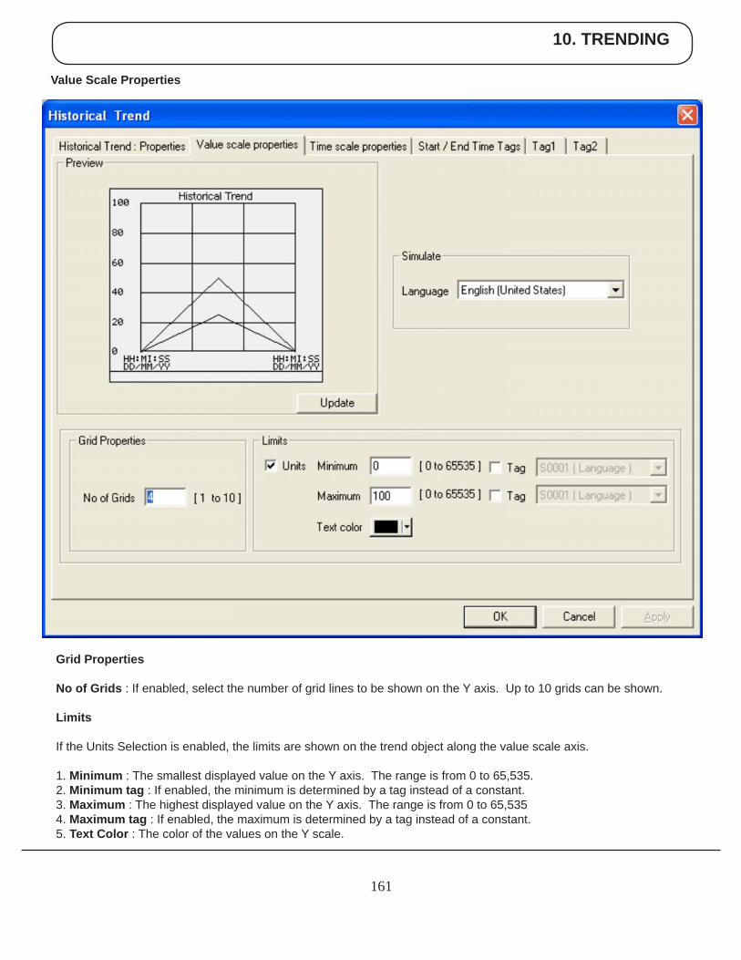
10. TRENDING
161
Value Scale Properties
Grid Properties
No of Grids : If enabled, select the number of grid lines to be shown on the Y axis. Up to 10 grids can be shown.
Limits
If the Units Selection is enabled, the limits are shown on the trend object along the value scale axis.
1. Minimum : The smallest displayed value on the Y axis. The range is from 0 to 65,535.2. Minimum tag : If enabled, the minimum is determined by a tag instead of a constant.3. Maximum : The highest displayed value on the Y axis. The range is from 0 to 65,5354. Maximum tag : If enabled, the maximum is determined by a tag instead of a constant.5. Text Color : The color of the values on the Y scale.
10. TRENDING
162
Time Scale Properties
Grid Properties
No of Grids : If the grid option is enabled, up to 10 grids can be selected for the X axis display.
Text properties
1. Scale : If enabled, the real time grid values are shown along the time scale axis. 2. Format : Scale formatting can be either HH:MM:SS or HH:MM.3. Color : Determines the preferred color of the X axis scale information.
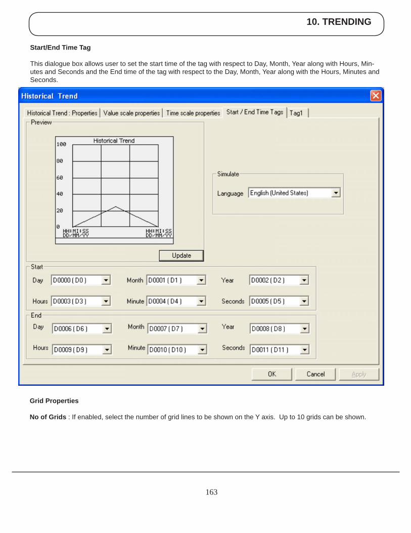
10. TRENDING
163
Start/End Time Tag
This dialogue box allows user to set the start time of the tag with respect to Day, Month, Year along with Hours, Min-utes and Seconds and the End time of the tag with respect to the Day, Month, Year along with the Hours, Minutes and Seconds.
Grid Properties
No of Grids : If enabled, select the number of grid lines to be shown on the Y axis. Up to 10 grids can be shown.
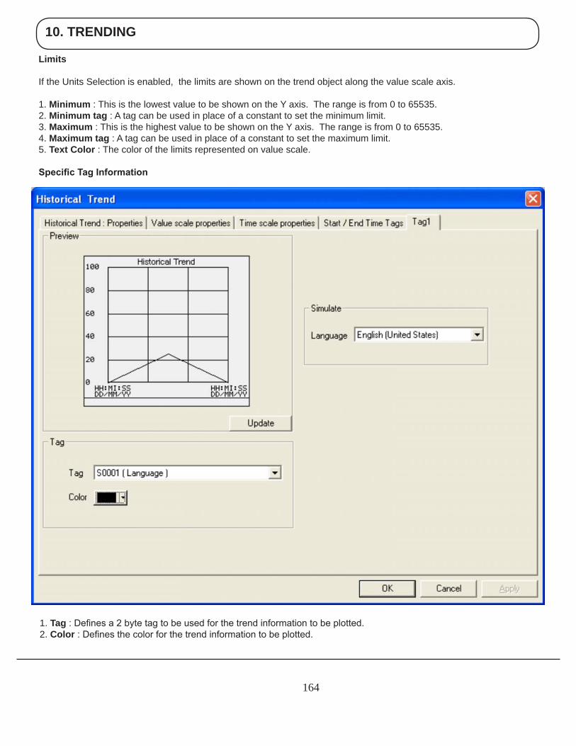
10. TRENDING
164
1. Tag : Defines a 2 byte tag to be used for the trend information to be plotted.2. Color : Defines the color for the trend information to be plotted.
Limits
If the Units Selection is enabled, the limits are shown on the trend object along the value scale axis.
1. Minimum : This is the lowest value to be shown on the Y axis. The range is from 0 to 65535.2. Minimum tag : A tag can be used in place of a constant to set the minimum limit.3. Maximum : This is the highest value to be shown on the Y axis. The range is from 0 to 65535.4. Maximum tag : A tag can be used in place of a constant to set the maximum limit.5. Text Color : The color of the limits represented on value scale.
Specific Tag Information
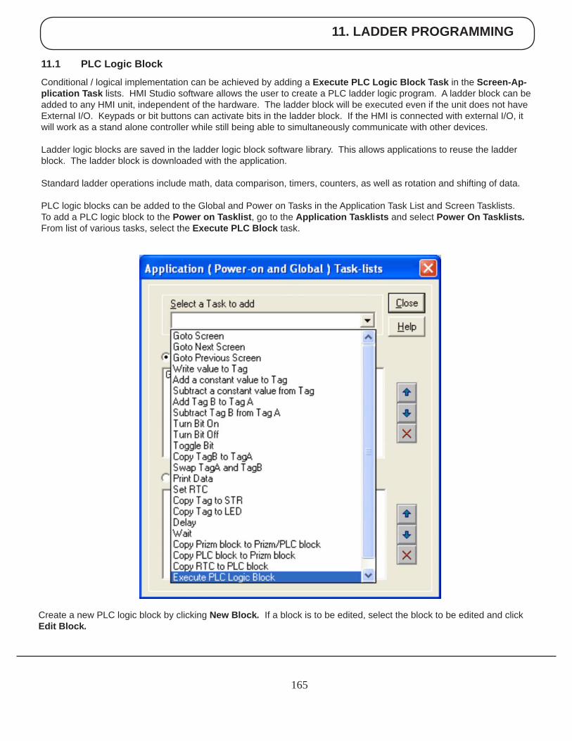
11. LADDER PROGRAMMING
165
11.1 PLC Logic Block
Conditional / logical implementation can be achieved by adding a Execute PLC Logic Block Task in the Screen-Ap-plication Task lists. HMI Studio software allows the user to create a PLC ladder logic program. A ladder block can be added to any HMI unit, independent of the hardware. The ladder block will be executed even if the unit does not have External I/O. Keypads or bit buttons can activate bits in the ladder block. If the HMI is connected with external I/O, it will work as a stand alone controller while still being able to simultaneously communicate with other devices.
Ladder logic blocks are saved in the ladder logic block software library. This allows applications to reuse the ladder block. The ladder block is downloaded with the application.
Standard ladder operations include math, data comparison, timers, counters, as well as rotation and shifting of data.
PLC logic blocks can be added to the Global and Power on Tasks in the Application Task List and Screen Tasklists. To add a PLC logic block to the Power on Tasklist, go to the Application Tasklists and select Power On Tasklists. From list of various tasks, select the Execute PLC Block task.
Create a new PLC logic block by clicking New Block. If a block is to be edited, select the block to be edited and click Edit Block.

11. LADDER PROGRAMMING
166
11.2 Ladder Instruction Details
Types of Instructions used for developing a ladder are:
• Inputs • Outputs • Timer • Data Compare (for Word and Double word) • Math Operation (for Word and double word) • Data Move • Transition • Counters • Shift (for Word and Double word) • Rotate (for Word and Double word) • Logarithmic • Data Conversion • End
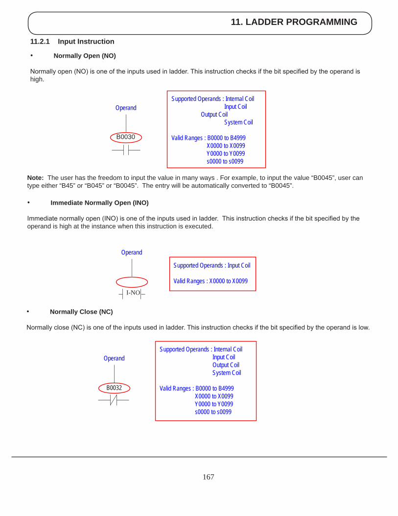
11. LADDER PROGRAMMING
167
11.2.1 Input Instruction
• Normally Open (NO)
Normally open (NO) is one of the inputs used in ladder. This instruction checks if the bit specified by the operand is high.
Note: The user has the freedom to input the value in many ways . For example, to input the value “B0045”, user can type either “B45” or “B045” or “B0045”. The entry will be automatically converted to “B0045”.
• Immediate Normally Open (INO)
Immediate normally open (INO) is one of the inputs used in ladder. This instruction checks if the bit specified by the operand is high at the instance when this instruction is executed.
• Normally Close (NC)
Normally close (NC) is one of the inputs used in ladder. This instruction checks if the bit specified by the operand is low.
Supported Operands : Internal Coil Input Coil Output Coil System Coil
Valid Ranges : B0000 to B4999 X0000 to X0099 Y0000 to Y0099 s0000 to s0099
B0032
Operand
Supported Operands : Input Coil
Valid Ranges : X0000 to X0099
Operand
I-NO
Supported Operands : Internal Coil Input Coil Output Coil System Coil
Valid Ranges : B0000 to B4999 X0000 to X0099 Y0000 to Y0099 s0000 to s0099
B0030
Operand
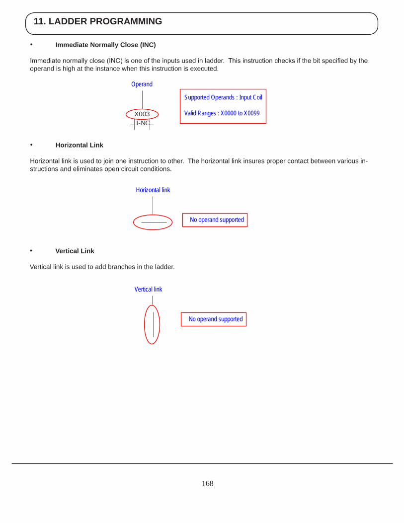
11. LADDER PROGRAMMING
168
• Immediate Normally Close (INC)
Immediate normally close (INC) is one of the inputs used in ladder. This instruction checks if the bit specified by the operand is high at the instance when this instruction is executed.
• Horizontal Link
Horizontal link is used to join one instruction to other. The horizontal link insures proper contact between various in-structions and eliminates open circuit conditions.
• Vertical Link
Vertical link is used to add branches in the ladder.
Supported Operands : Input Coil
Valid Ranges : X0000 to X0099 X003
Operand
I-NC
Horizontal link
No operand supported
Vertical link
No operand supported
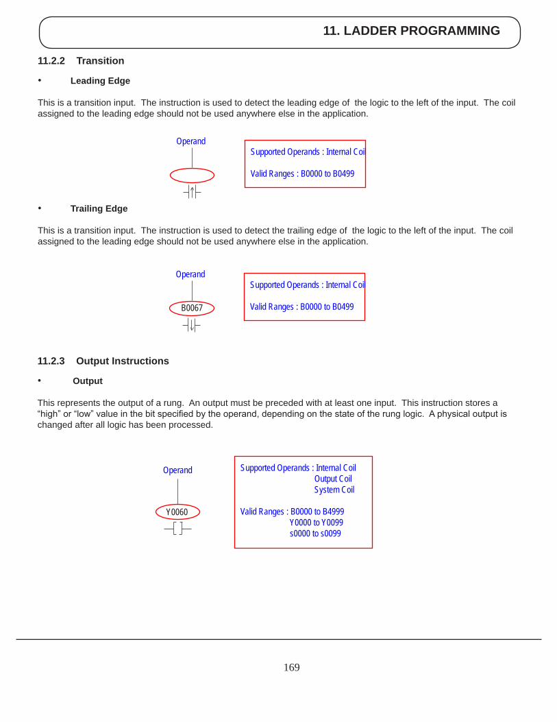
11. LADDER PROGRAMMING
169
11.2.2 Transition
• Leading Edge
This is a transition input. The instruction is used to detect the leading edge of the logic to the left of the input. The coil assigned to the leading edge should not be used anywhere else in the application.
11.2.3 Output Instructions
• Output
This represents the output of a rung. An output must be preceded with at least one input. This instruction stores a “high” or “low” value in the bit specified by the operand, depending on the state of the rung logic. A physical output is changed after all logic has been processed.
Supported Operands : Internal Coil
Valid Ranges : B0000 to B0499 B0067
Operand
Y0060
Operand Supported Operands : Internal Coil Output Coil System Coil
Valid Ranges : B0000 to B4999 Y0000 to Y0099 s0000 to s0099
Supported Operands : Internal Coil
Valid Ranges : B0000 to B0499
Operand
• Trailing Edge
This is a transition input. The instruction is used to detect the trailing edge of the logic to the left of the input. The coil assigned to the leading edge should not be used anywhere else in the application.
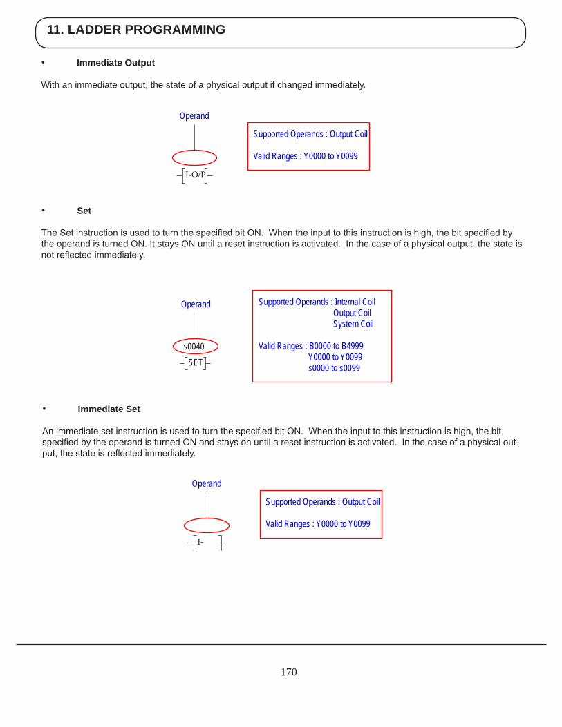
11. LADDER PROGRAMMING
170
• Immediate Output
With an immediate output, the state of a physical output if changed immediately.
• Set
The Set instruction is used to turn the specified bit ON. When the input to this instruction is high, the bit specified by the operand is turned ON. It stays ON until a reset instruction is activated. In the case of a physical output, the state is not reflected immediately.
Supported Operands : Output Coil
Valid Ranges : Y0000 to Y0099
Operand
I-O/P
s0040
Operand Supported Operands : Internal Coil Output Coil System Coil
Valid Ranges : B0000 to B4999 Y0000 to Y0099 s0000 to s0099SET
• Immediate Set
An immediate set instruction is used to turn the specified bit ON. When the input to this instruction is high, the bit specified by the operand is turned ON and stays on until a reset instruction is activated. In the case of a physical out-put, the state is reflected immediately.
Supported Operands : Output Coil
Valid Ranges : Y0000 to Y0099
Operand
I-
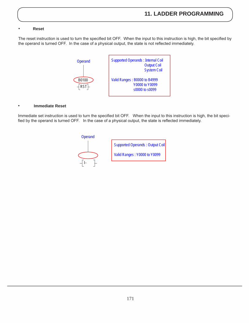
11. LADDER PROGRAMMING
171
• Reset
The reset instruction is used to turn the specified bit OFF. When the input to this instruction is high, the bit specified by the operand is turned OFF. In the case of a physical output, the state is not reflected immediately.
• Immediate Reset
Immediate set instruction is used to turn the specified bit OFF. When the input to this instruction is high, the bit speci-fied by the operand is turned OFF. In the case of a physical output, the state is reflected immediately.
B0100
Operand Supported Operands : Internal Coil Output Coil System Coil
Valid Ranges : B0000 to B4999 Y0000 to Y0099 s0000 to s0099
RST
Supported Operands : Output Coil
Valid Ranges : Y0000 to Y0099
Operand
I-
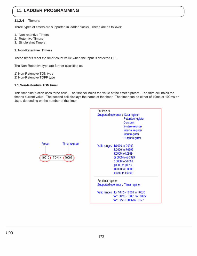
11. LADDER PROGRAMMING
172
11.2.4 Timers
Three types of timers are supported in ladder blocks. These are as follows:
1. Non-retentive Timers2. Retentive Timers3. Single shot Timers
1. Non-Retentive Timers
These timers reset the timer count value when the input is detected OFF.
The Non-Retentive type are further classified as
1) Non-Retentive TON type 2) Non-Retentive TOFF type
1.1 Non-Retentive TON timer
This timer instruction uses three cells. The first cell holds the value of the timer’s preset. The third cell holds the timer’s current value. The second cell displays the name of the timer. The timer can be either of 10ms or 100ms or 1sec, depending on the number of the timer.
U00
For Preset Supported operands : Data register Retentive register Constant System register Internal register Input register Output register
Valid ranges : D0000 to D0999 R0000 to R0999 K0000 to k0999 @0000 to @0999 S0000 to S0063 J0000 to J0312 U0000 to U0006 L0000 to L0006
For timer register Supported operands : Timer register Valid ranges : for 10mS- T0000 to T0030 for 100mS- T0031 to T0095 for 1 sec- T0096 to T0127
K0010 TON-N T0002
Preset Timer register
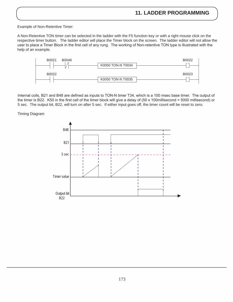
11. LADDER PROGRAMMING
173
Example of Non-Retentive Timer:
A Non-Retentive TON timer can be selected in the ladder with the F5 function key or with a right mouse click on the respective timer button. The ladder editor will place the Timer block on the screen. The ladder editor will not allow the user to place a Timer Block in the first cell of any rung. The working of Non-retentive TON type is illustrated with the help of an example.
Internal coils, B21 and B48 are defined as inputs to TON-N timer T34, which is a 100 msec base timer. The output of the timer is B22. K50 in the first cell of the timer block will give a delay of (50 x 100millisecond = 5000 millisecond) or 5 sec. The output bit, B22, will turn on after 5 sec. If either input goes off, the timer count will be reset to zero.
Timing Diagram
B48
B21
5 sec
Timer value
Output bit B22
K0050 TON-N T0034B0022B0021 B0048
K0050 TON-N T0035B0023B0022
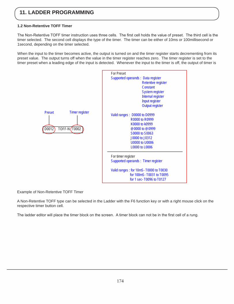
11. LADDER PROGRAMMING
174
1.2 Non-Retentive TOFF Timer
The Non-Retentive TOFF timer instruction uses three cells. The first cell holds the value of preset. The third cell is the timer selected. The second cell displays the type of the timer. The timer can be either of 10ms or 100millisecond or 1second, depending on the timer selected.
When the input to the timer becomes active, the output is turned on and the timer register starts decrementing from its preset value. The output turns off when the value in the timer register reaches zero. The timer register is set to the timer preset when a leading edge of the input is detected. Whenever the input to the timer is off, the output of timer is
Example of Non-Retentive TOFF Timer
A Non-Retentive TOFF type can be selected in the Ladder with the F6 function key or with a right mouse click on the respective timer button cell.
The ladder editor will place the timer block on the screen. A timer block can not be in the first cell of a rung.
For Preset Supported operands : Data register Retentive register Constant System register Internal register Input register Output register
Valid ranges : D0000 to D0999 R0000 to R0999 K0000 to k0999 @0000 to @0999 S0000 to S0063 J0000 to J0312 U0000 to U0006 L0000 to L0006
For timer register Supported operands : Timer register Valid ranges : for 10mS- T0000 to T0030 for 100mS- T0031 to T0095 for 1 sec- T0096 to T0127
D0012 TOFF-N T0002
Preset Timer register
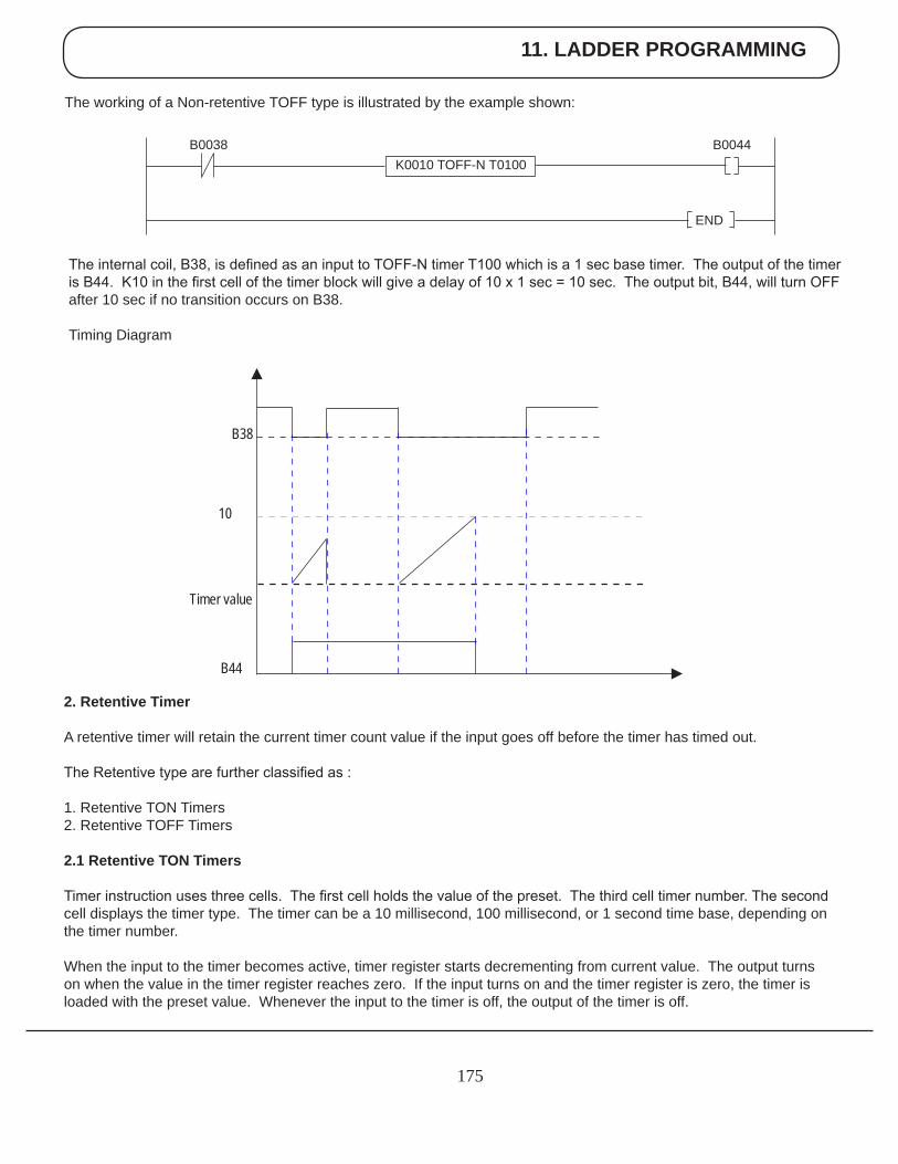
11. LADDER PROGRAMMING
175
The internal coil, B38, is defined as an input to TOFF-N timer T100 which is a 1 sec base timer. The output of the timer is B44. K10 in the first cell of the timer block will give a delay of 10 x 1 sec = 10 sec. The output bit, B44, will turn OFF after 10 sec if no transition occurs on B38.
Timing Diagram
2. Retentive Timer
A retentive timer will retain the current timer count value if the input goes off before the timer has timed out.
The Retentive type are further classified as :
1. Retentive TON Timers2. Retentive TOFF Timers
2.1 Retentive TON Timers
Timer instruction uses three cells. The first cell holds the value of the preset. The third cell timer number. The second cell displays the timer type. The timer can be a 10 millisecond, 100 millisecond, or 1 second time base, depending on the timer number.
When the input to the timer becomes active, timer register starts decrementing from current value. The output turns on when the value in the timer register reaches zero. If the input turns on and the timer register is zero, the timer is loaded with the preset value. Whenever the input to the timer is off, the output of the timer is off.
10
Timer value
B44
B38
The working of a Non-retentive TOFF type is illustrated by the example shown:
K0010 TOFF-N T0100B0044B0038
END
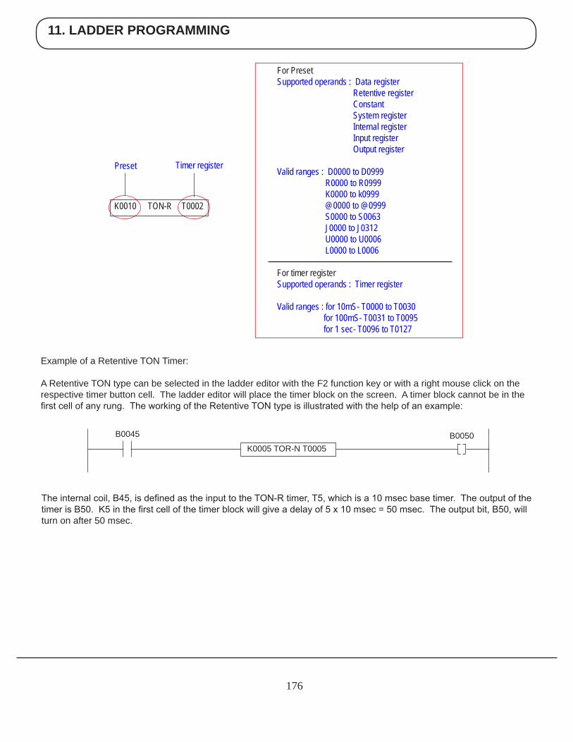
11. LADDER PROGRAMMING
176
Example of a Retentive TON Timer:
A Retentive TON type can be selected in the ladder editor with the F2 function key or with a right mouse click on the respective timer button cell. The ladder editor will place the timer block on the screen. A timer block cannot be in the first cell of any rung. The working of the Retentive TON type is illustrated with the help of an example:
The internal coil, B45, is defined as the input to the TON-R timer, T5, which is a 10 msec base timer. The output of the timer is B50. K5 in the first cell of the timer block will give a delay of 5 x 10 msec = 50 msec. The output bit, B50, will turn on after 50 msec.
For Preset Supported operands : Data register Retentive register Constant System register Internal register Input register Output register
Valid ranges : D0000 to D0999 R0000 to R0999 K0000 to k0999 @0000 to @0999 S0000 to S0063 J0000 to J0312 U0000 to U0006 L0000 to L0006
For timer register Supported operands : Timer register Valid ranges : for 10mS- T0000 to T0030 for 100mS- T0031 to T0095 for 1 sec- T0096 to T0127
K0010 TON-R T0002
Preset Timer register
K0005 TOR-N T0005B0050B0045
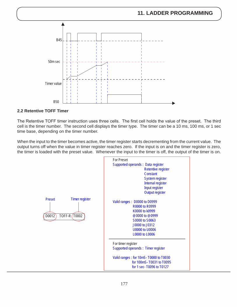
11. LADDER PROGRAMMING
177
2.2 Retentive TOFF Timer
The Retentive TOFF timer instruction uses three cells. The first cell holds the value of the preset. The third cell is the timer number. The second cell displays the timer type. The timer can be a 10 ms, 100 ms, or 1 sec time base, depending on the timer number.
When the input to the timer becomes active, the timer register starts decrementing from the current value. The output turns off when the value in timer register reaches zero. If the input is on and the timer register is zero, the timer is loaded with the preset value. Whenever the input to the timer is off, the output of the timer is on.
50m sec
Timer value
B50
B45
For Preset Supported operands : Data register Retentive register Constant System register Internal register Input register Output register
Valid ranges : D0000 to D0999 R0000 to R0999 K0000 to k0999 @0000 to @0999 S0000 to S0063 J0000 to J0312 U0000 to U0006 L0000 to L0006
For timer register Supported operands : Timer register Valid ranges : for 10mS- T0000 to T0030 for 100mS- T0031 to T0095 for 1 sec- T0096 to T0127
D0012 TOFF-R T0002
Preset Timer register
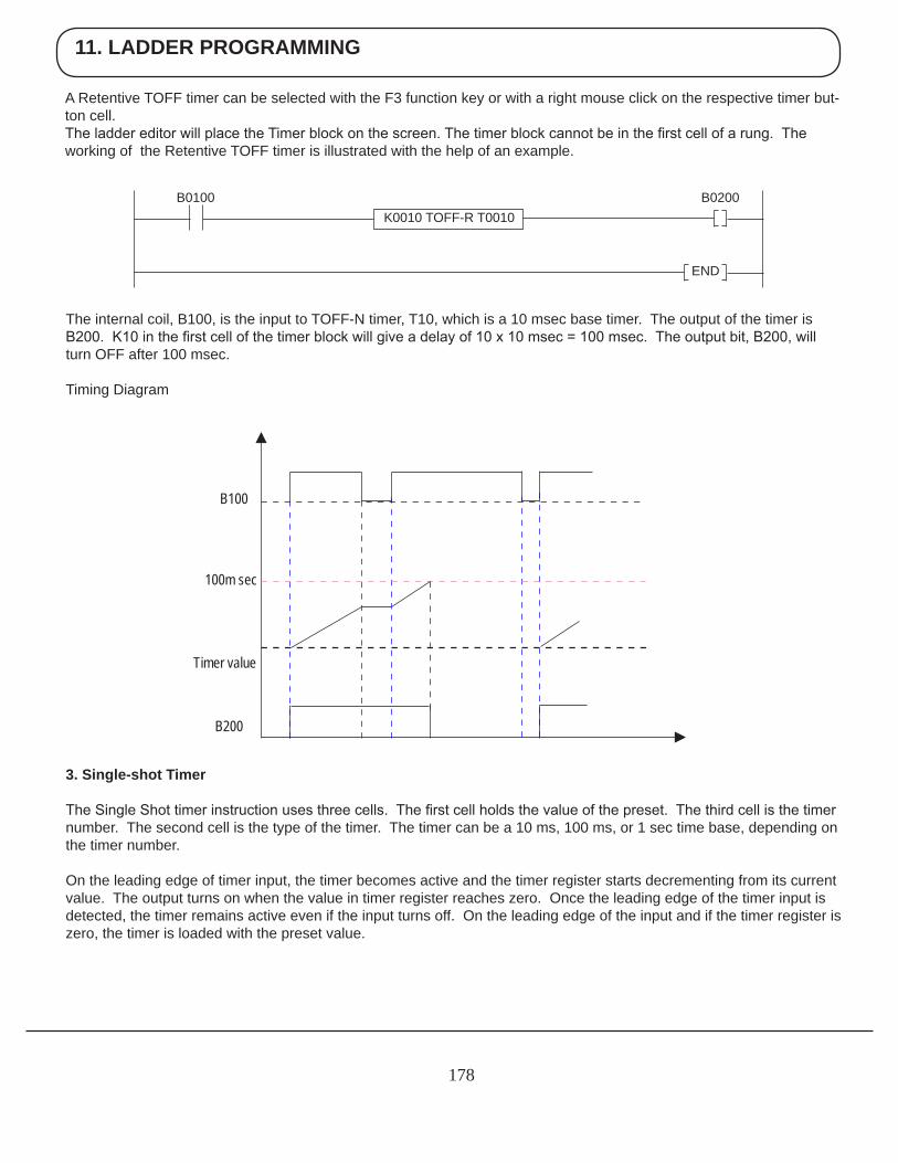
11. LADDER PROGRAMMING
178
A Retentive TOFF timer can be selected with the F3 function key or with a right mouse click on the respective timer but-ton cell. The ladder editor will place the Timer block on the screen. The timer block cannot be in the first cell of a rung. The working of the Retentive TOFF timer is illustrated with the help of an example.
The internal coil, B100, is the input to TOFF-N timer, T10, which is a 10 msec base timer. The output of the timer is B200. K10 in the first cell of the timer block will give a delay of 10 x 10 msec = 100 msec. The output bit, B200, will turn OFF after 100 msec.
Timing Diagram
3. Single-shot Timer
The Single Shot timer instruction uses three cells. The first cell holds the value of the preset. The third cell is the timer number. The second cell is the type of the timer. The timer can be a 10 ms, 100 ms, or 1 sec time base, depending on the timer number.
On the leading edge of timer input, the timer becomes active and the timer register starts decrementing from its current value. The output turns on when the value in timer register reaches zero. Once the leading edge of the timer input is detected, the timer remains active even if the input turns off. On the leading edge of the input and if the timer register is zero, the timer is loaded with the preset value.
100m sec
Timer value
B200
B100
K0010 TOFF-R T0010B0200B0100
END
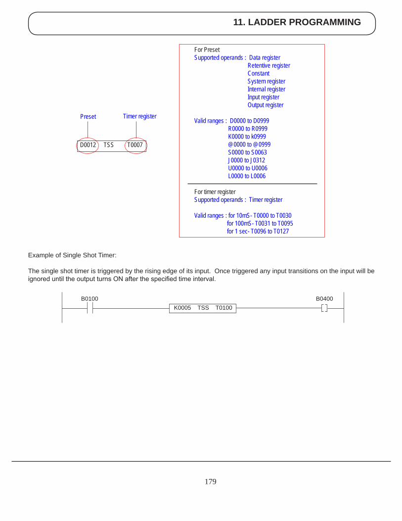
11. LADDER PROGRAMMING
179
Example of Single Shot Timer:
The single shot timer is triggered by the rising edge of its input. Once triggered any input transitions on the input will be ignored until the output turns ON after the specified time interval.
For Preset Supported operands : Data register Retentive register Constant System register Internal register Input register Output register
Valid ranges : D0000 to D0999 R0000 to R0999 K0000 to k0999 @0000 to @0999 S0000 to S0063 J0000 to J0312 U0000 to U0006 L0000 to L0006
For timer register Supported operands : Timer register Valid ranges : for 10mS- T0000 to T0030 for 100mS- T0031 to T0095 for 1 sec- T0096 to T0127
D0012 TSS T0007
Preset Timer register
K0005 TSS T0100B0400B0100
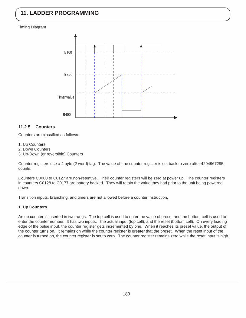
11. LADDER PROGRAMMING
180
Timing Diagram
5 sec
Timer value
B400
B100
11.2.5 Counters
Counters are classified as follows:
1. Up Counters2. Down Counters3. Up-Down (or reversible) Counters
Counter registers use a 4 byte (2 word) tag. The value of the counter register is set back to zero after 4294967295 counts. Counters C0000 to C0127 are non-retentive. Their counter registers will be zero at power up. The counter registers in counters C0128 to C0177 are battery backed. They will retain the value they had prior to the unit being powered down.
Transition inputs, branching, and timers are not allowed before a counter instruction.
1. Up Counters
An up counter is inserted in two rungs. The top cell is used to enter the value of preset and the bottom cell is used to enter the counter number. It has two inputs: the actual input (top cell), and the reset (bottom cell). On every leading edge of the pulse input, the counter register gets incremented by one. When it reaches its preset value, the output of the counter turns on. It remains on while the counter register is greater that the preset. When the reset input of the counter is turned on, the counter register is set to zero. The counter register remains zero while the reset input is high.
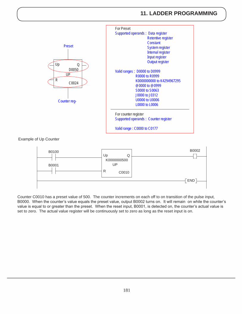
11. LADDER PROGRAMMING
181
Example of Up Counter
Counter C0010 has a preset value of 500. The counter increments on each off to on transition of the pulse input, B0000. When the counter’s value equals the preset value, output B0002 turns on. It will remain on while the counter’s value is equal to or greater than the preset. When the reset input, B0001, is detected on, the counter’s actual value is set to zero. The actual value register will be continuously set to zero as long as the reset input is on.
For Preset Supported operands : Data register Retentive register Constant System register Internal register Input register Output register
Valid ranges : D0000 to D0999 R0000 to R0999 K0000000000 to K4294967295 @0000 to @0999 S0000 to S0063 J0000 to J0312 U0000 to U0006 L0000 to L0006
For counter register Supported operands : Counter register Valid range : C0000 to C0177
Preset
Counter reg-
Up
R
QD0050
UP
C0024
K0000000500
END
Up
R
B0100
B0001
B0002Q
C0010
UP
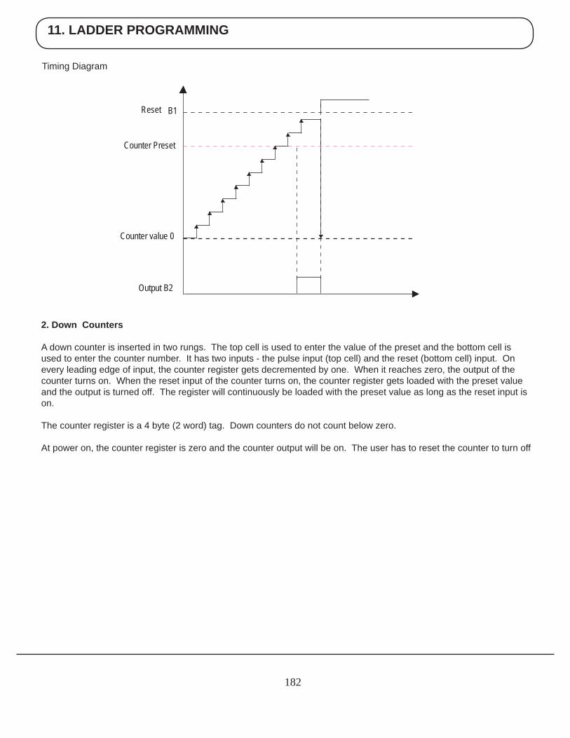
11. LADDER PROGRAMMING
182
Timing Diagram
Counter value 0
Output B2
B1Reset
Counter Preset
2. Down Counters
A down counter is inserted in two rungs. The top cell is used to enter the value of the preset and the bottom cell is used to enter the counter number. It has two inputs - the pulse input (top cell) and the reset (bottom cell) input. On every leading edge of input, the counter register gets decremented by one. When it reaches zero, the output of the counter turns on. When the reset input of the counter turns on, the counter register gets loaded with the preset value and the output is turned off. The register will continuously be loaded with the preset value as long as the reset input is on.
The counter register is a 4 byte (2 word) tag. Down counters do not count below zero.
At power on, the counter register is zero and the counter output will be on. The user has to reset the counter to turn off
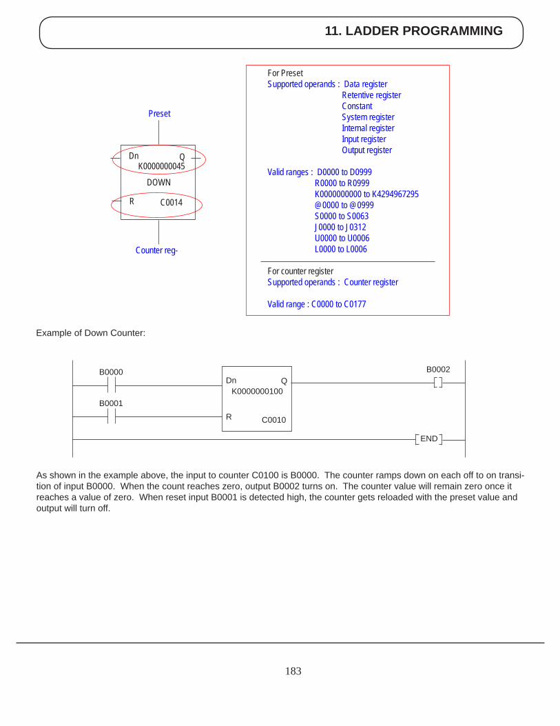
11. LADDER PROGRAMMING
183
Example of Down Counter:
As shown in the example above, the input to counter C0100 is B0000. The counter ramps down on each off to on transi-tion of input B0000. When the count reaches zero, output B0002 turns on. The counter value will remain zero once it reaches a value of zero. When reset input B0001 is detected high, the counter gets reloaded with the preset value and output will turn off.
For Preset Supported operands : Data register Retentive register Constant System register Internal register Input register Output register
Valid ranges : D0000 to D0999 R0000 to R0999 K0000000000 to K4294967295 @0000 to @0999 S0000 to S0063 J0000 to J0312 U0000 to U0006 L0000 to L0006
For counter register Supported operands : Counter register Valid range : C0000 to C0177
Preset
Counter reg-
Dn
R
QK0000000045
DOWN
C0014
K0000000100
END
Dn
R
B0000
B0001
B0002Q
C0010
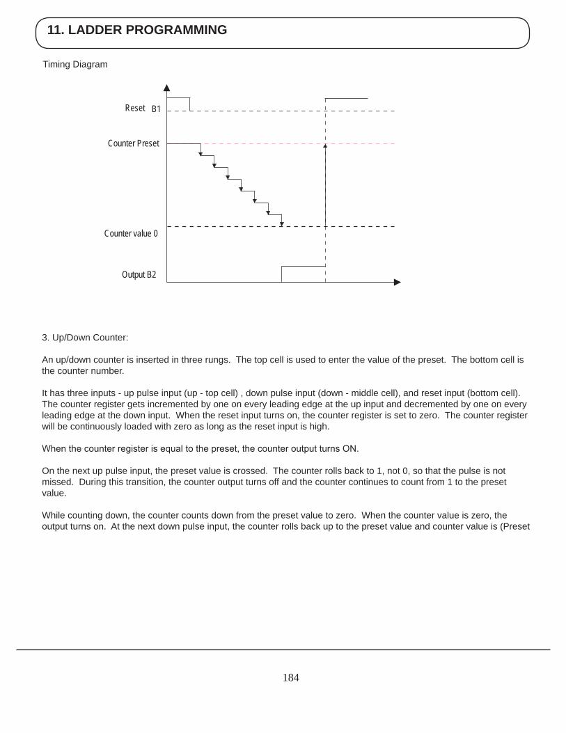
11. LADDER PROGRAMMING
184
Timing Diagram
3. Up/Down Counter:
An up/down counter is inserted in three rungs. The top cell is used to enter the value of the preset. The bottom cell is the counter number.
It has three inputs - up pulse input (up - top cell) , down pulse input (down - middle cell), and reset input (bottom cell). The counter register gets incremented by one on every leading edge at the up input and decremented by one on every leading edge at the down input. When the reset input turns on, the counter register is set to zero. The counter register will be continuously loaded with zero as long as the reset input is high.
When the counter register is equal to the preset, the counter output turns ON.
On the next up pulse input, the preset value is crossed. The counter rolls back to 1, not 0, so that the pulse is not missed. During this transition, the counter output turns off and the counter continues to count from 1 to the preset value.
While counting down, the counter counts down from the preset value to zero. When the counter value is zero, the output turns on. At the next down pulse input, the counter rolls back up to the preset value and counter value is (Preset
Counter value 0
Output B2
B1Reset
Counter Preset
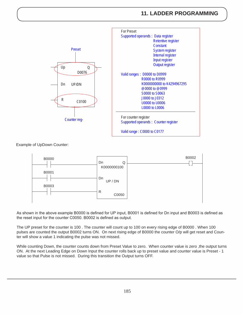
11. LADDER PROGRAMMING
185
As shown in the above example B0000 is defined for UP input, B0001 is defined for Dn input and B0003 is defined as the reset input for the counter C0050. B0002 is defined as output. The UP preset for the counter is 100 . The counter will count up to 100 on every rising edge of B0000 . When 100 pulses are counted the output B0002 turns ON. On next rising edge of B0000 the counter O/p will get reset and Coun-ter will show a value 1 indicating the pulse was not missed. While counting Down, the counter counts down from Preset Value to zero. When counter value is zero ,the output turns ON. At the next Leading Edge on Down Input the counter rolls back up to preset value and counter value is Preset - 1 value so that Pulse is not missed. During this transition the Output turns OFF.
Example of UpDown Counter:
For Preset Supported operands : Data register Retentive register Constant System register Internal register Input register Output register
Valid ranges : D0000 to D0999 R0000 to R0999 K0000000000 to K4294967295 @0000 to @0999 S0000 to S0063 J0000 to J0312 U0000 to U0006 L0000 to L0006
For counter register Supported operands : Counter register Valid range : C0000 to C0177
Up
Dn
QD0076
C0100
Preset
Counter reg-
R
UP/DN
K0000000100Dn
Dn
B0000 B0002Q
C0050
UP / DN
R
B0001
B0003
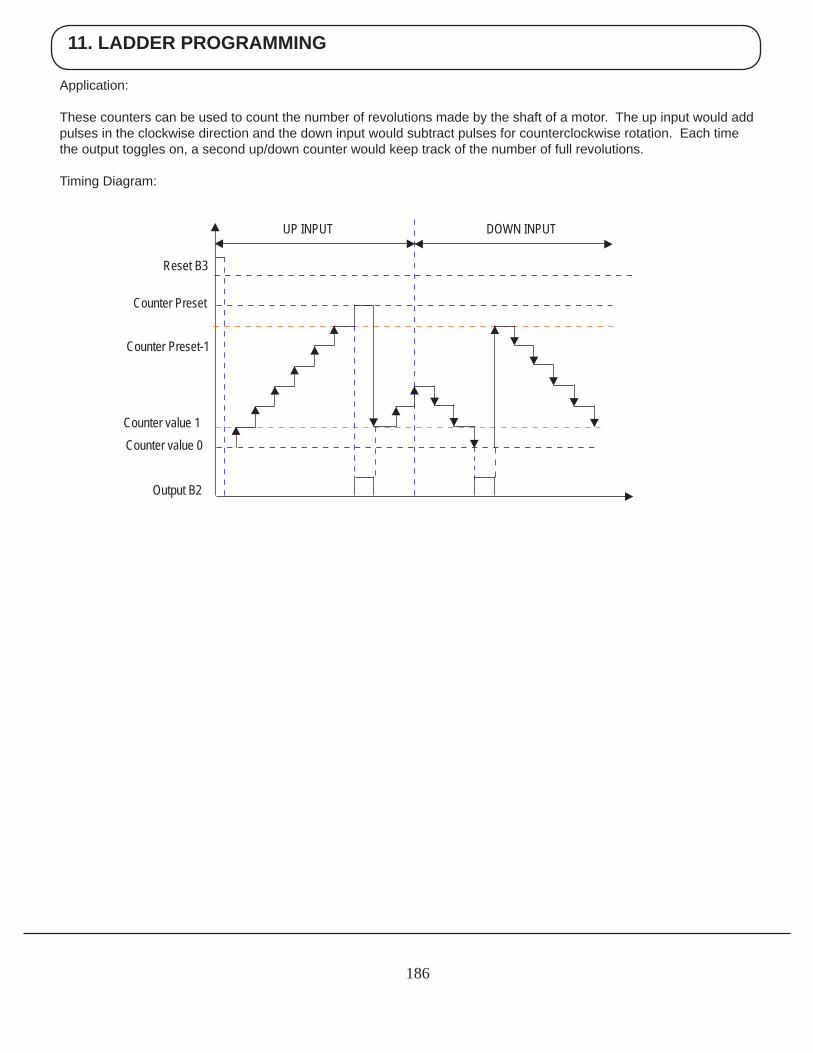
11. LADDER PROGRAMMING
186
Application:
These counters can be used to count the number of revolutions made by the shaft of a motor. The up input would add pulses in the clockwise direction and the down input would subtract pulses for counterclockwise rotation. Each time the output toggles on, a second up/down counter would keep track of the number of full revolutions. Timing Diagram:
UP INPUT DOWN INPUT
Reset B3
Counter Preset
Counter Preset-1
Counter value 1
Output B2
Counter value 0
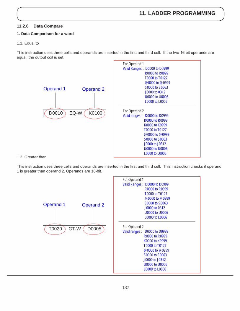
11. LADDER PROGRAMMING
187
1.2. Greater than
This instruction uses three cells and operands are inserted in the first and third cell. This instruction checks if operand 1 is greater than operand 2. Operands are 16-bit.
For Operand 1 Valid Ranges : D0000 to D0999 R0000 to R0999 T0000 to T0127 @0000 to @0999 S0000 to S0063 J0000 to 0312 U0000 to U0006 L0000 to L0006
For Operand 2 Valid ranges : D0000 to D0999 R0000 to R0999 K0000 to K9999 T0000 to T0127 @0000 to @0999 S0000 to S0063 J0000 to J0312 U0000 to U0006 L0000 to L0006
T0020 GT-W D0005
Operand 1 Operand 2
For Operand 1 Valid Ranges : D0000 to D0999 R0000 to R0999 T0000 to T0127 @0000 to @0999 S0000 to S0063 J0000 to 0312 U0000 to U0006 L0000 to L0006
For Operand 2 Valid ranges : D0000 to D0999 R0000 to R0999 K0000 to K9999 T0000 to T0127 @0000 to @0999 S0000 to S0063 J0000 to J0312 U0000 to U0006 L0000 to L0006
D0010 EQ-W K0100
Operand 1 Operand 2
11.2.6 Data Compare
1. Data Comparison for a word
1.1. Equal to
This instruction uses three cells and operands are inserted in the first and third cell. If the two 16 bit operands are equal, the output coil is set.
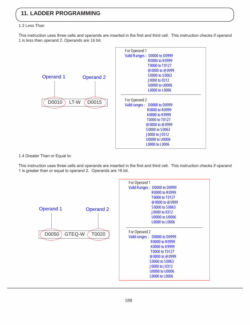
11. LADDER PROGRAMMING
188
1.3 Less Than
This instruction uses three cells and operands are inserted in the first and third cell. This instruction checks if operand 1 is less than operand 2. Operands are 16 bit.
1.4 Greater Than or Equal to:
This instruction uses three cells and operands are inserted in the first and third cell. This instruction checks if operand 1 is greater than or equal to operand 2. Operands are 16 bit.
For Operand 1 Valid Ranges : D0000 to D0999 R0000 to R0999 T0000 to T0127 @0000 to @0999 S0000 to S0063 J0000 to 0312 U0000 to U0006 L0000 to L0006
For Operand 2 Valid ranges : D0000 to D0999 R0000 to R0999 K0000 to K9999 T0000 to T0127 @0000 to @0999 S0000 to S0063 J0000 to J0312 U0000 to U0006 L0000 to L0006
D0010 LT-W D0015
Operand 1 Operand 2
For Operand 1 Valid Ranges : D0000 to D0999 R0000 to R0999 T0000 to T0127 @0000 to @0999 S0000 to S0063 J0000 to 0312 U0000 to U0006 L0000 to L0006
For Operand 2 Valid ranges : D0000 to D0999 R0000 to R0999 K0000 to K9999 T0000 to T0127 @0000 to @0999 S0000 to S0063 J0000 to J0312 U0000 to U0006 L0000 to L0006
D0050 GTEQ-W T0020
Operand 1 Operand 2
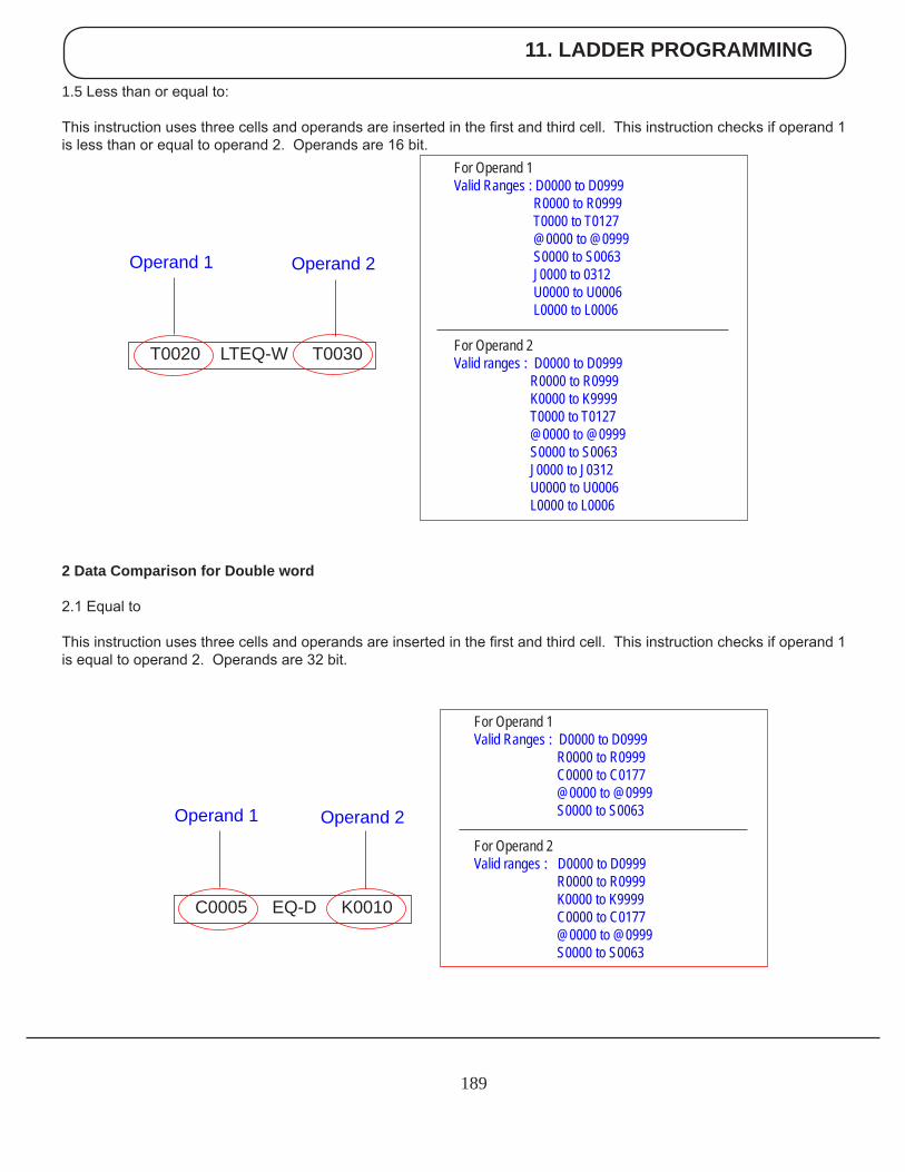
11. LADDER PROGRAMMING
189
1.5 Less than or equal to:
This instruction uses three cells and operands are inserted in the first and third cell. This instruction checks if operand 1 is less than or equal to operand 2. Operands are 16 bit.
2 Data Comparison for Double word
2.1 Equal to
This instruction uses three cells and operands are inserted in the first and third cell. This instruction checks if operand 1 is equal to operand 2. Operands are 32 bit.
For Operand 1 Valid Ranges : D0000 to D0999 R0000 to R0999 C0000 to C0177 @0000 to @0999 S0000 to S0063 For Operand 2 Valid ranges : D0000 to D0999 R0000 to R0999 K0000 to K9999 C0000 to C0177 @0000 to @0999 S0000 to S0063
C0005 EQ-D K0010
Operand 1 Operand 2
For Operand 1 Valid Ranges : D0000 to D0999 R0000 to R0999 T0000 to T0127 @0000 to @0999 S0000 to S0063 J0000 to 0312 U0000 to U0006 L0000 to L0006
For Operand 2 Valid ranges : D0000 to D0999 R0000 to R0999 K0000 to K9999 T0000 to T0127 @0000 to @0999 S0000 to S0063 J0000 to J0312 U0000 to U0006 L0000 to L0006
T0020 LTEQ-W T0030
Operand 1 Operand 2
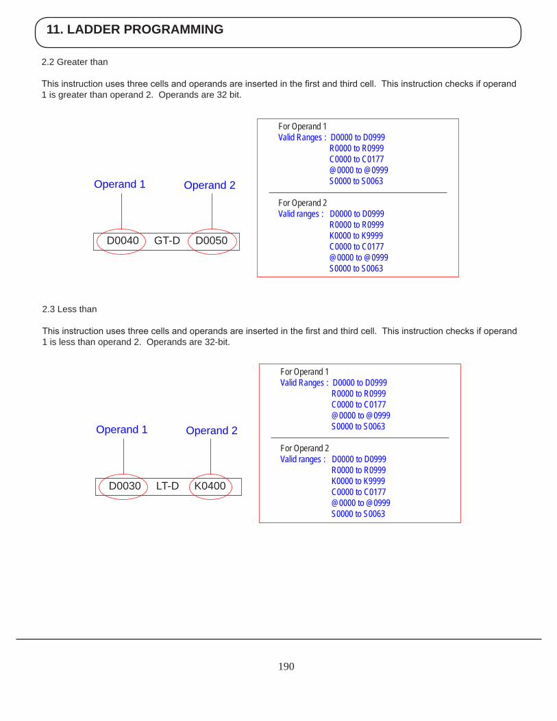
11. LADDER PROGRAMMING
190
2.2 Greater than
This instruction uses three cells and operands are inserted in the first and third cell. This instruction checks if operand 1 is greater than operand 2. Operands are 32 bit.
2.3 Less than
This instruction uses three cells and operands are inserted in the first and third cell. This instruction checks if operand 1 is less than operand 2. Operands are 32-bit.
For Operand 1 Valid Ranges : D0000 to D0999 R0000 to R0999 C0000 to C0177 @0000 to @0999 S0000 to S0063 For Operand 2 Valid ranges : D0000 to D0999 R0000 to R0999 K0000 to K9999 C0000 to C0177 @0000 to @0999 S0000 to S0063
D0040 GT-D D0050
Operand 1 Operand 2
For Operand 1 Valid Ranges : D0000 to D0999 R0000 to R0999 C0000 to C0177 @0000 to @0999 S0000 to S0063 For Operand 2 Valid ranges : D0000 to D0999 R0000 to R0999 K0000 to K9999 C0000 to C0177 @0000 to @0999 S0000 to S0063
D0030 LT-D K0400
Operand 1 Operand 2
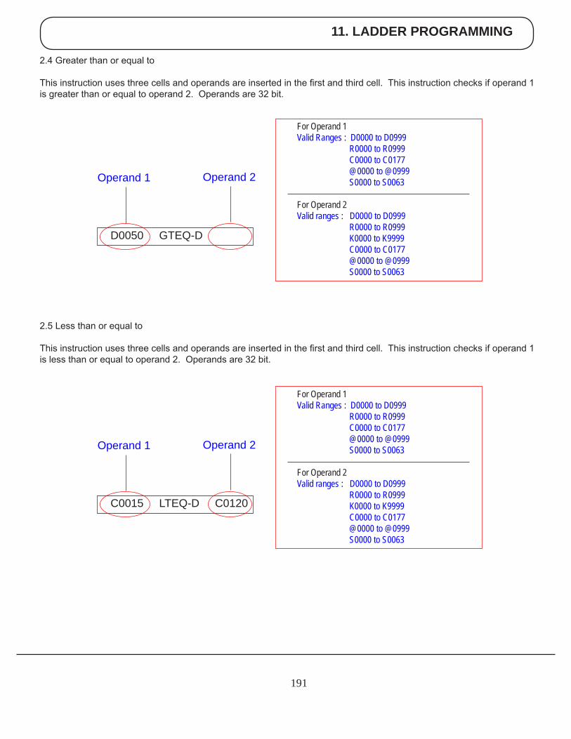
11. LADDER PROGRAMMING
191
2.4 Greater than or equal to
This instruction uses three cells and operands are inserted in the first and third cell. This instruction checks if operand 1 is greater than or equal to operand 2. Operands are 32 bit.
2.5 Less than or equal to
This instruction uses three cells and operands are inserted in the first and third cell. This instruction checks if operand 1 is less than or equal to operand 2. Operands are 32 bit.
For Operand 1 Valid Ranges : D0000 to D0999 R0000 to R0999 C0000 to C0177 @0000 to @0999 S0000 to S0063 For Operand 2 Valid ranges : D0000 to D0999 R0000 to R0999 K0000 to K9999 C0000 to C0177 @0000 to @0999 S0000 to S0063
D0050 GTEQ-D
Operand 1 Operand 2
For Operand 1 Valid Ranges : D0000 to D0999 R0000 to R0999 C0000 to C0177 @0000 to @0999 S0000 to S0063 For Operand 2 Valid ranges : D0000 to D0999 R0000 to R0999 K0000 to K9999 C0000 to C0177 @0000 to @0999 S0000 to S0063
C0015 LTEQ-D C0120
Operand 1 Operand 2
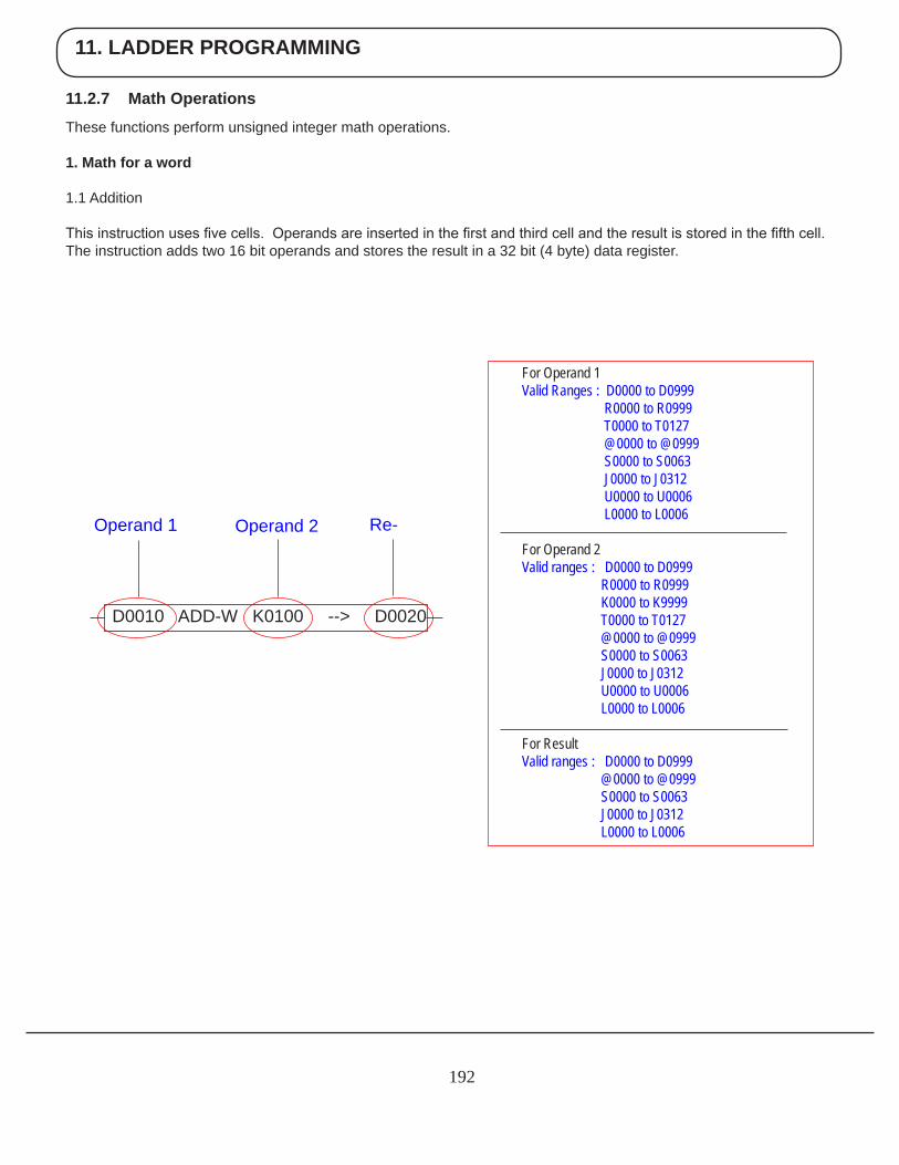
11. LADDER PROGRAMMING
192
11.2.7 Math Operations
These functions perform unsigned integer math operations.
1. Math for a word 1.1 Addition
This instruction uses five cells. Operands are inserted in the first and third cell and the result is stored in the fifth cell. The instruction adds two 16 bit operands and stores the result in a 32 bit (4 byte) data register.
For Operand 1 Valid Ranges : D0000 to D0999 R0000 to R0999 T0000 to T0127 @0000 to @0999 S0000 to S0063 J0000 to J0312 U0000 to U0006 L0000 to L0006
For Operand 2 Valid ranges : D0000 to D0999 R0000 to R0999 K0000 to K9999 T0000 to T0127 @0000 to @0999 S0000 to S0063 J0000 to J0312 U0000 to U0006 L0000 to L0006
For Result Valid ranges : D0000 to D0999 @0000 to @0999 S0000 to S0063 J0000 to J0312 L0000 to L0006
D0010 ADD-W K0100 --> D0020
Operand 1 Operand 2 Re-
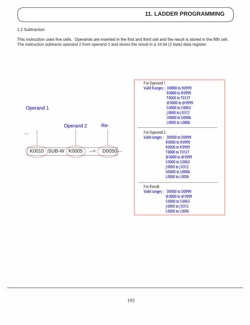
11. LADDER PROGRAMMING
193
Operand 1
1.2 Subtraction
This instruction uses five cells. Operands are inserted in the first and third cell and the result is stored in the fifth cell. The instruction subtracts operand 2 from operand 1 and stores the result in a 16 bit (2 byte) data register.
For Operand 1 Valid Ranges : D0000 to D0999 R0000 to R0999 T0000 to T0127 @0000 to @0999 S0000 to S0063 J0000 to J0312 U0000 to U0006 L0000 to L0006
For Operand 2 Valid ranges : D0000 to D0999 R0000 to R0999 K0000 to K9999 T0000 to T0127 @0000 to @0999 S0000 to S0063 J0000 to J0312 U0000 to U0006 L0000 to L0006
For Result Valid ranges : D0000 to D0999 @0000 to @0999 S0000 to S0063 J0000 to J0312 L0000 to L0006
K0010 SUB-W K0005 --> D0050
Operand 2 Re-

11. LADDER PROGRAMMING
194
1.3 Multiplication:
This instruction uses five cells. Operands are inserted in the first and third cell and the result is stored in the fifth cell. The instruction multiplies two 16 bit operands and stores the result in a 32 bit (4 byte) data register. LSB of the result is stored in the first tag and MSB is stored in second tag.
For Operand 1 Valid Ranges : D0000 to D0999 R0000 to R0999 T0000 to T0127 @0000 to @0999 S0000 to S0063 J0000 to J0312 U0000 to U0006 L0000 to L0006
For Operand 2 Valid ranges : D0000 to D0999 R0000 to R0999 K0000 to K9999 T0000 to T0127 @0000 to @0999 S0000 to S0063 J0000 to J0312 U0000 to U0006 L0000 to L0006
For Result Valid ranges : D0000 to D0999 @0000 to @0999 S0000 to S0063 J0000 to J0312 L0000 to L0006
K0100 MUL-W K0010 --> D0005
Operand 2 Re-
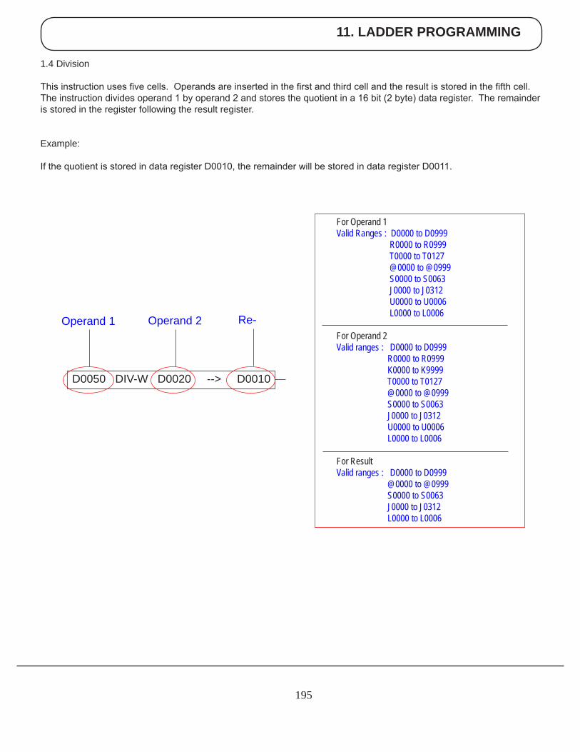
11. LADDER PROGRAMMING
195
1.4 Division
This instruction uses five cells. Operands are inserted in the first and third cell and the result is stored in the fifth cell. The instruction divides operand 1 by operand 2 and stores the quotient in a 16 bit (2 byte) data register. The remainder is stored in the register following the result register.
Example:
If the quotient is stored in data register D0010, the remainder will be stored in data register D0011.
For Operand 1 Valid Ranges : D0000 to D0999 R0000 to R0999 T0000 to T0127 @0000 to @0999 S0000 to S0063 J0000 to J0312 U0000 to U0006 L0000 to L0006
For Operand 2 Valid ranges : D0000 to D0999 R0000 to R0999 K0000 to K9999 T0000 to T0127 @0000 to @0999 S0000 to S0063 J0000 to J0312 U0000 to U0006 L0000 to L0006
For Result Valid ranges : D0000 to D0999 @0000 to @0999 S0000 to S0063 J0000 to J0312 L0000 to L0006
D0050 DIV-W D0020 --> D0010
Re-Operand 2Operand 1
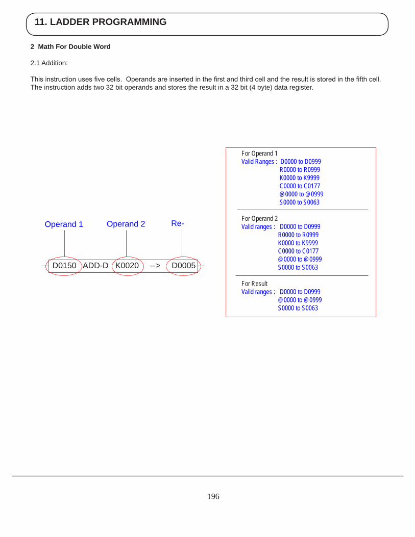
11. LADDER PROGRAMMING
196
2 Math For Double Word
2.1 Addition:
This instruction uses five cells. Operands are inserted in the first and third cell and the result is stored in the fifth cell. The instruction adds two 32 bit operands and stores the result in a 32 bit (4 byte) data register.
For Operand 1 Valid Ranges : D0000 to D0999 R0000 to R0999 K0000 to K9999 C0000 to C0177 @0000 to @0999 S0000 to S0063 For Operand 2 Valid ranges : D0000 to D0999 R0000 to R0999 K0000 to K9999 C0000 to C0177 @0000 to @0999 S0000 to S0063 For Result Valid ranges : D0000 to D0999 @0000 to @0999 S0000 to S0063
D0150 ADD-D K0020 --> D0005
Re-Operand 2Operand 1
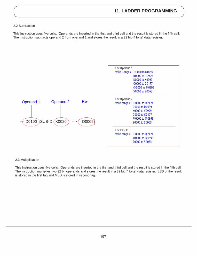
11. LADDER PROGRAMMING
197
2.2 Subtraction
This instruction uses five cells. Operands are inserted in the first and third cell and the result is stored in the fifth cell. The instruction subtracts operand 2 from operand 1 and stores the result in a 32 bit (4 byte) data register.
For Operand 1 Valid Ranges : D0000 to D0999 R0000 to R0999 K0000 to K9999 C0000 to C0177 @0000 to @0999 S0000 to S0063 For Operand 2 Valid ranges : D0000 to D0999 R0000 to R0999 K0000 to K9999 C0000 to C0177 @0000 to @0999 S0000 to S0063 For Result Valid ranges : D0000 to D0999 @0000 to @0999 S0000 to S0063
D0100 SUB-D K0020 --> D0005
Re-Operand 2Operand 1
2.3 Multiplication
This instruction uses five cells. Operands are inserted in the first and third cell and the result is stored in the fifth cell. The instruction multiplies two 32 bit operands and stores the result in a 32 bit (4 byte) data register. LSB of the result is stored in the first tag and MSB is stored in second tag.
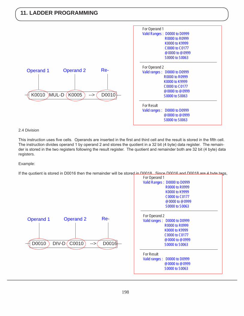
11. LADDER PROGRAMMING
198
2.4 Division
This instruction uses five cells. Operands are inserted in the first and third cell and the result is stored in the fifth cell. The instruction divides operand 1 by operand 2 and stores the quotient in a 32 bit (4 byte) data register. The remain-der is stored in the two registers following the result register. The quotient and remainder both are 32 bit (4 byte) data registers.
Example:
If the quotient is stored in D0016 then the remainder will be stored in D0018. Since D0016 and D0018 are 4 byte tags,
For Operand 1 Valid Ranges : D0000 to D0999 R0000 to R0999 K0000 to K9999 C0000 to C0177 @0000 to @0999 S0000 to S0063 For Operand 2 Valid ranges : D0000 to D0999 R0000 to R0999 K0000 to K9999 C0000 to C0177 @0000 to @0999 S0000 to S0063 For Result Valid ranges : D0000 to D0999 @0000 to @0999 S0000 to S0063
K0010 MUL-D K0005 --> D0010
Re-Operand 2Operand 1
For Operand 1 Valid Ranges : D0000 to D0999 R0000 to R0999 K0000 to K9999 C0000 to C0177 @0000 to @0999 S0000 to S0063 For Operand 2 Valid ranges : D0000 to D0999 R0000 to R0999 K0000 to K9999 C0000 to C0177 @0000 to @0999 S0000 to S0063 For Result Valid ranges : D0000 to D0999 @0000 to @0999 S0000 to S0063
D0010 DIV-D C0010 --> D0016
Re-Operand 2Operand 1
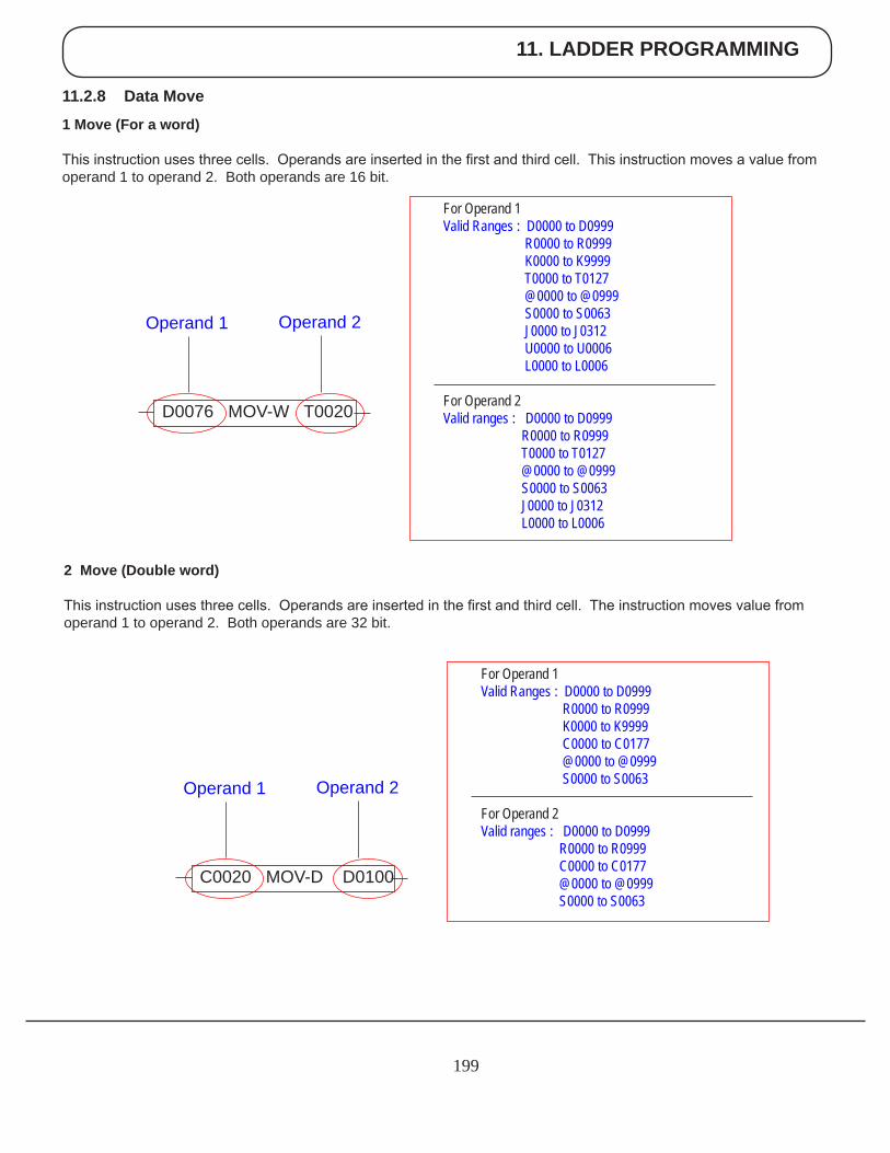
11. LADDER PROGRAMMING
199
11.2.8 Data Move
1 Move (For a word)
This instruction uses three cells. Operands are inserted in the first and third cell. This instruction moves a value from operand 1 to operand 2. Both operands are 16 bit.
2 Move (Double word)
This instruction uses three cells. Operands are inserted in the first and third cell. The instruction moves value from operand 1 to operand 2. Both operands are 32 bit.
For Operand 1 Valid Ranges : D0000 to D0999 R0000 to R0999 K0000 to K9999 T0000 to T0127 @0000 to @0999 S0000 to S0063 J0000 to J0312 U0000 to U0006 L0000 to L0006 For Operand 2 Valid ranges : D0000 to D0999 R0000 to R0999 T0000 to T0127 @0000 to @0999 S0000 to S0063 J0000 to J0312 L0000 to L0006
D0076 MOV-W T0020
Operand 2Operand 1
For Operand 1 Valid Ranges : D0000 to D0999 R0000 to R0999 K0000 to K9999 C0000 to C0177 @0000 to @0999 S0000 to S0063 For Operand 2 Valid ranges : D0000 to D0999 R0000 to R0999 C0000 to C0177 @0000 to @0999 S0000 to S0063
C0020 MOV-D D0100
Operand 2Operand 1
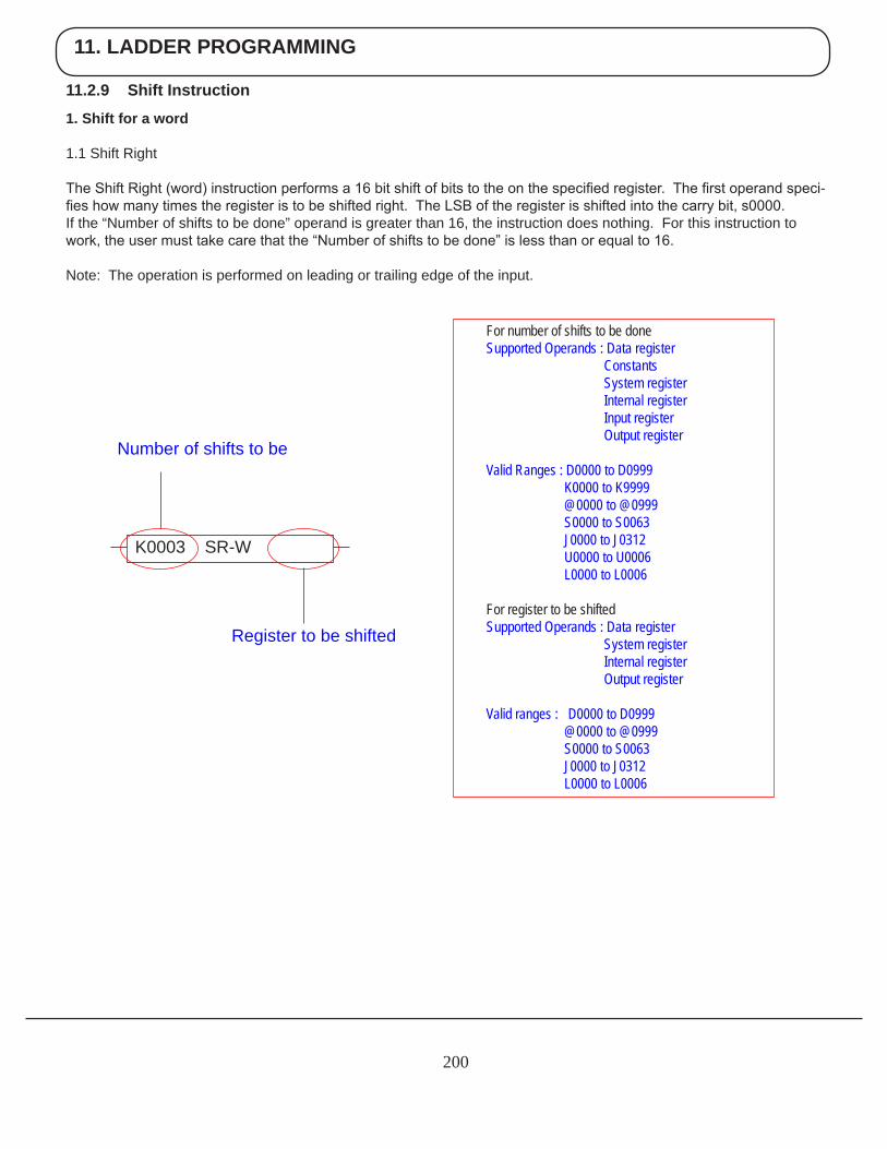
11. LADDER PROGRAMMING
200
For number of shifts to be done Supported Operands : Data register Constants System register Internal register Input register Output register
Valid Ranges : D0000 to D0999 K0000 to K9999 @0000 to @0999 S0000 to S0063 J0000 to J0312 U0000 to U0006 L0000 to L0006
For register to be shifted Supported Operands : Data register System register Internal register Output register
Valid ranges : D0000 to D0999 @0000 to @0999 S0000 to S0063 J0000 to J0312 L0000 to L0006
K0003 SR-W
Number of shifts to be
Register to be shifted
11.2.9 Shift Instruction
1. Shift for a word
1.1 Shift Right
The Shift Right (word) instruction performs a 16 bit shift of bits to the on the specified register. The first operand speci-fies how many times the register is to be shifted right. The LSB of the register is shifted into the carry bit, s0000.If the “Number of shifts to be done” operand is greater than 16, the instruction does nothing. For this instruction to work, the user must take care that the “Number of shifts to be done” is less than or equal to 16.
Note: The operation is performed on leading or trailing edge of the input.
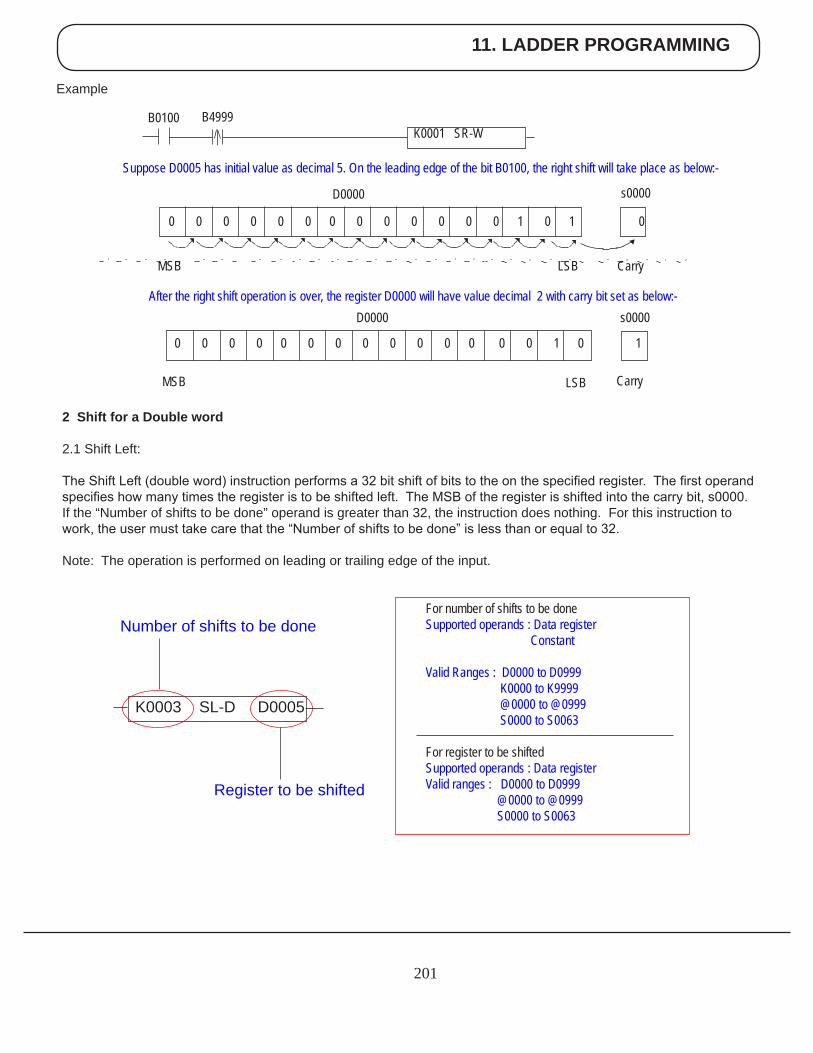
11. LADDER PROGRAMMING
201
Example
2 Shift for a Double word
2.1 Shift Left:
The Shift Left (double word) instruction performs a 32 bit shift of bits to the on the specified register. The first operand specifies how many times the register is to be shifted left. The MSB of the register is shifted into the carry bit, s0000.If the “Number of shifts to be done” operand is greater than 32, the instruction does nothing. For this instruction to work, the user must take care that the “Number of shifts to be done” is less than or equal to 32.
Note: The operation is performed on leading or trailing edge of the input.
For number of shifts to be done Supported operands : Data register Constant
Valid Ranges : D0000 to D0999 K0000 to K9999 @0000 to @0999 S0000 to S0063 For register to be shifted Supported operands : Data register Valid ranges : D0000 to D0999 @0000 to @0999 S0000 to S0063
K0003 SL-D D0005
Register to be shifted
Number of shifts to be done
Suppose D0005 has initial value as decimal 5. On the leading edge of the bit B0100, the right shift will take place as below:-
K0001 SR-W B0100 B4999
0 0 0 0 0 0 0 0 0 0 0 0 0 1 0 1 0
MSB LSB Carry
s0000D0000
After the right shift operation is over, the register D0000 will have value decimal 2 with carry bit set as below:-
0 0 0 0 0 0 0 0 0 0 0 0 0 0 1 0 1
D0000
MSB LSB
s0000
Carry
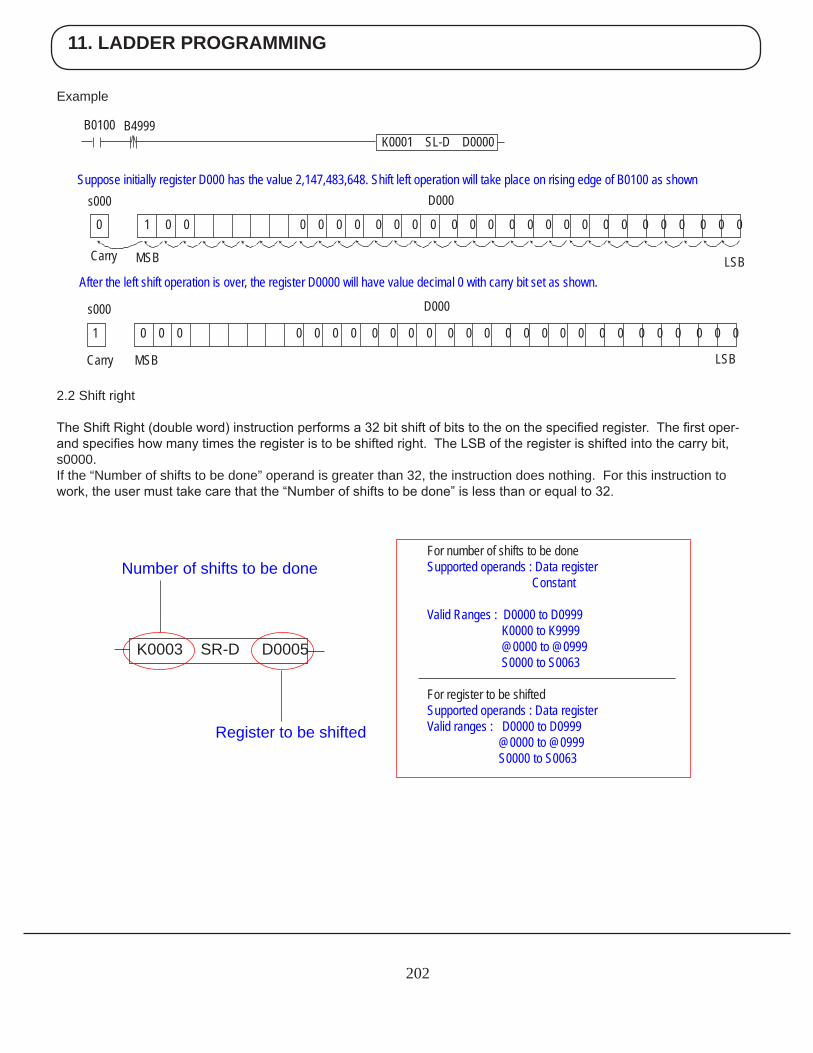
11. LADDER PROGRAMMING
202
Example
2.2 Shift right
The Shift Right (double word) instruction performs a 32 bit shift of bits to the on the specified register. The first oper-and specifies how many times the register is to be shifted right. The LSB of the register is shifted into the carry bit, s0000.If the “Number of shifts to be done” operand is greater than 32, the instruction does nothing. For this instruction to work, the user must take care that the “Number of shifts to be done” is less than or equal to 32.
For number of shifts to be done Supported operands : Data register Constant
Valid Ranges : D0000 to D0999 K0000 to K9999 @0000 to @0999 S0000 to S0063 For register to be shifted Supported operands : Data register Valid ranges : D0000 to D0999 @0000 to @0999 S0000 to S0063
K0003 SR-D D0005
Register to be shifted
Number of shifts to be done
Suppose initially register D000 has the value 2,147,483,648. Shift left operation will take place on rising edge of B0100 as shown
D000
1 0 0 0 0 0 0 0 0 0 0 0 0 0 0 0 0 0 0 0 0 0 0 0 0 0 0 0
s000
Carry MSB LSB
After the left shift operation is over, the register D0000 will have value decimal 0 with carry bit set as shown.
B0100 B4999K0001 SL-D D0000
0 1 0 0 0 0 0 0 0 0 0 0 0 0 0 0 0 0 0 0 0 0 0 0 0 0 0 0
s000
Carry LSBMSB
D000
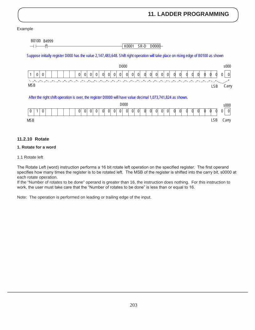
11. LADDER PROGRAMMING
203
Example
B0100 B4999K0001 SR-D D0000
Suppose initially register D000 has the value 2,147,483,648. Shift right operation will take place on rising edge of B0100 as shown
s000
CarryLSBMSB
D000
1 0 0 0 0 0 0 0 0 0 0 0 0 0 0 0 0 0 0 0 0 0 0 0 0 0 0 0 0
After the right shift operation is over, the register D0000 will have value decimal 1,073,741,824 as shown.
s0000 1 0 0 0 0 0 0 0 0 0 0 0 0 0 0 0 0 0 0 0 0 0 0 0 0 0 0 0
D000
CarryLSBMSB
11.2.10 Rotate
1. Rotate for a word
1.1 Rotate left
The Rotate Left (word) instruction performs a 16 bit rotate left operation on the specified register. The first operand specifies how many times the register is to be rotated left. The MSB of the register is shifted into the carry bit, s0000 at each rotate operation.If the “Number of rotates to be done” operand is greater than 16, the instruction does nothing. For this instruction to work, the user must take care that the “Number of rotates to be done” is less than or equal to 16.
Note: The operation is performed on leading or trailing edge of the input.
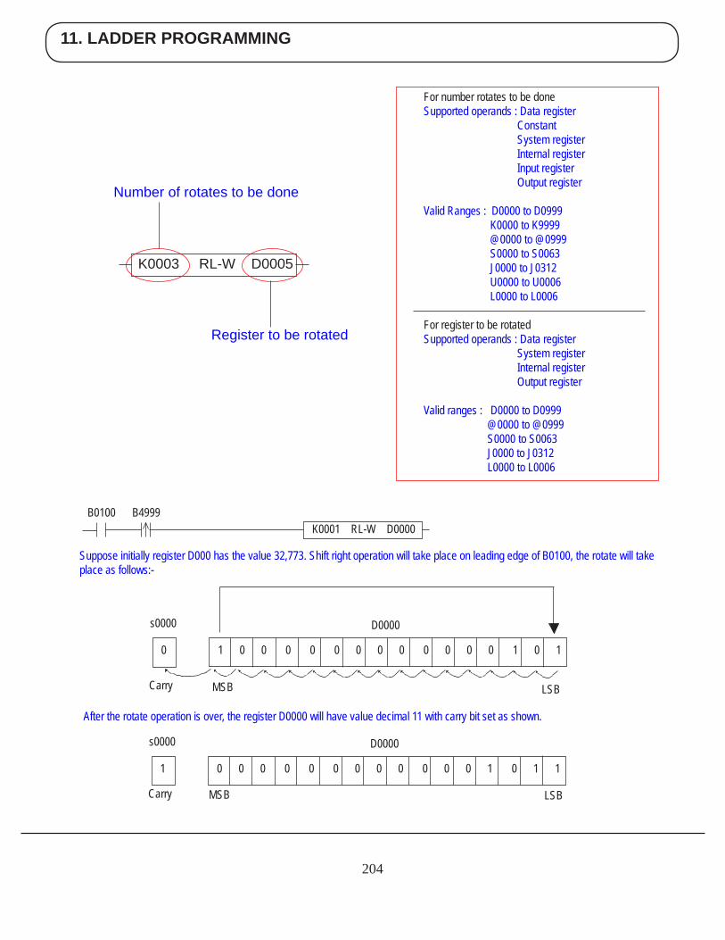
11. LADDER PROGRAMMING
204
For number rotates to be done Supported operands : Data register Constant System register Internal register Input register Output register
Valid Ranges : D0000 to D0999 K0000 to K9999 @0000 to @0999 S0000 to S0063 J0000 to J0312 U0000 to U0006 L0000 to L0006 For register to be rotated Supported operands : Data register System register Internal register Output register
Valid ranges : D0000 to D0999 @0000 to @0999 S0000 to S0063 J0000 to J0312 L0000 to L0006
K0003 RL-W D0005
Register to be rotated
Number of rotates to be done
0 1 0 0 0 0 0 0 0 0 0 0 0 0 1 0 1
s0000 D0000
Carry MSB LSB
B0100 B4999K0001 RL-W D0000
Suppose initially register D000 has the value 32,773. Shift right operation will take place on leading edge of B0100, the rotate will take place as follows:-
After the rotate operation is over, the register D0000 will have value decimal 11 with carry bit set as shown.
1 0 0 0 0 0 0 0 0 0 0 0 0 1 0 1 1
s0000 D0000
Carry MSB LSB
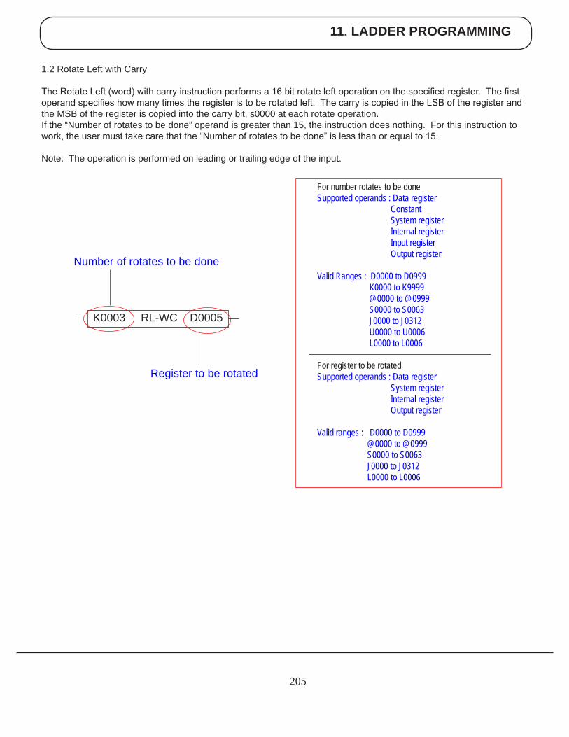
11. LADDER PROGRAMMING
205
1.2 Rotate Left with Carry
The Rotate Left (word) with carry instruction performs a 16 bit rotate left operation on the specified register. The first operand specifies how many times the register is to be rotated left. The carry is copied in the LSB of the register and the MSB of the register is copied into the carry bit, s0000 at each rotate operation.If the “Number of rotates to be done” operand is greater than 15, the instruction does nothing. For this instruction to work, the user must take care that the “Number of rotates to be done” is less than or equal to 15.
Note: The operation is performed on leading or trailing edge of the input.
For number rotates to be done Supported operands : Data register Constant System register Internal register Input register Output register
Valid Ranges : D0000 to D0999 K0000 to K9999 @0000 to @0999 S0000 to S0063 J0000 to J0312 U0000 to U0006 L0000 to L0006 For register to be rotated Supported operands : Data register System register Internal register Output register
Valid ranges : D0000 to D0999 @0000 to @0999 S0000 to S0063 J0000 to J0312 L0000 to L0006
K0003 RL-WC D0005
Register to be rotated
Number of rotates to be done
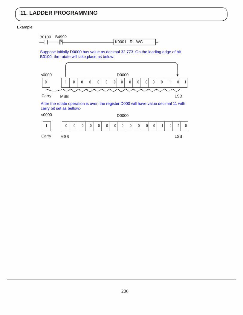
11. LADDER PROGRAMMING
206
Example
B0100 B4999K0001 RL-WC
Suppose initially D0000 has value as decimal 32.773. On the leading edge of bit B0100, the rotate will take place as below:
Carry MSB LSB
After the rotate operation is over, the register D000 will have value decimal 11 withcarry bit set as bellow:-
s0000
s0000
D0000
MSB LSB
D0000
Carry
0 1 0 0 0 0 0 0 0 0 0 0 0 0 1 0 1
1 0 0 0 0 0 0 0 0 0 0 0 0 1 0 1 0
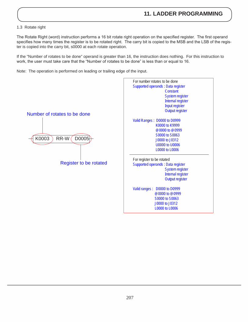
11. LADDER PROGRAMMING
207
1.3 Rotate right
The Rotate Right (word) instruction performs a 16 bit rotate right operation on the specified register. The first operand specifies how many times the register is to be rotated right. The carry bit is copied to the MSB and the LSB of the regis-ter is copied into the carry bit, s0000 at each rotate operation.
If the “Number of rotates to be done” operand is greater than 16, the instruction does nothing. For this instruction to work, the user must take care that the “Number of rotates to be done” is less than or equal to 16.
Note: The operation is performed on leading or trailing edge of the input.
For number rotates to be done Supported operands : Data register Constant System register Internal register Input register Output register
Valid Ranges : D0000 to D0999 K0000 to K9999 @0000 to @0999 S0000 to S0063 J0000 to J0312 U0000 to U0006 L0000 to L0006 For register to be rotated Supported operands : Data register System register Internal register Output register
Valid ranges : D0000 to D0999 @0000 to @0999 S0000 to S0063 J0000 to J0312 L0000 to L0006
K0003 RR-W D0005
Register to be rotated
Number of rotates to be done
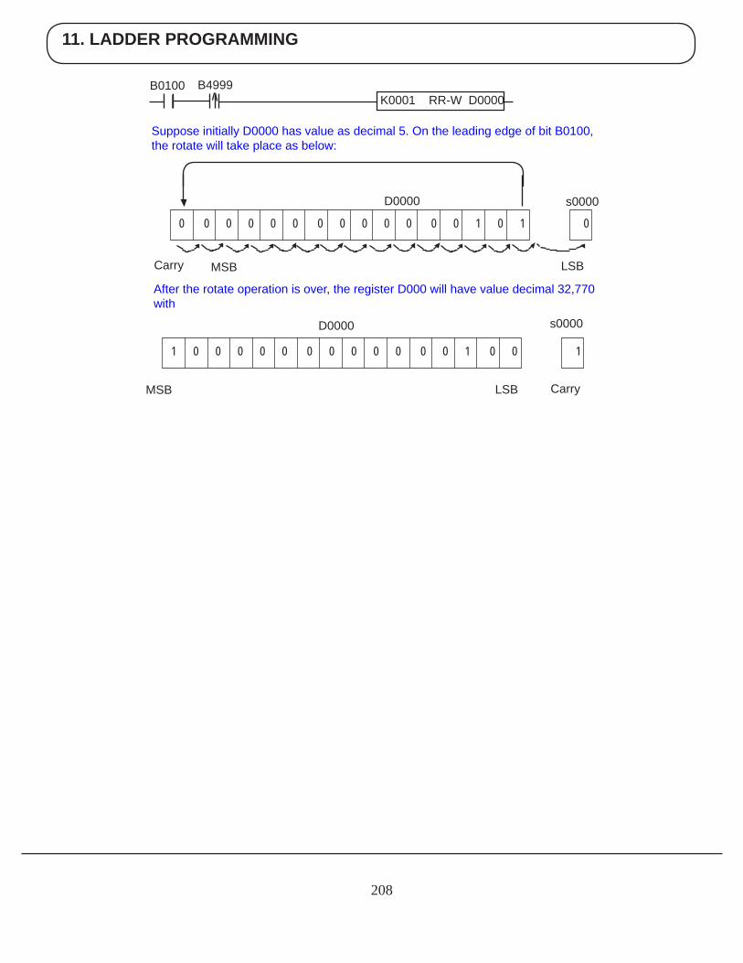
11. LADDER PROGRAMMING
208
B0100 B4999
Suppose initially D0000 has value as decimal 5. On the leading edge of bit B0100, the rotate will take place as below:
After the rotate operation is over, the register D000 will have value decimal 32,770 with
s0000
Carry MSB LSB
D0000
MSB LSB
D0000
K0001 RR-W D0000
s0000
Carry
0 0 0 0 0 0 0 0 0 0 0 0 0 1 0 1 0
1 0 0 0 0 0 0 0 0 0 0 0 0 1 0 0 1
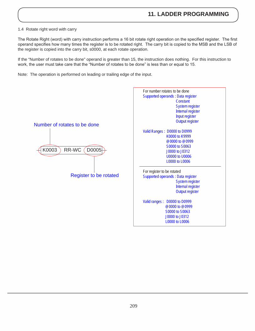
11. LADDER PROGRAMMING
209
For number rotates to be done Supported operands : Data register Constant System register Internal register Input register Output register
Valid Ranges : D0000 to D0999 K0000 to K9999 @0000 to @0999 S0000 to S0063 J0000 to J0312 U0000 to U0006 L0000 to L0006 For register to be rotated Supported operands : Data register System register Internal register Output register
Valid ranges : D0000 to D0999 @0000 to @0999 S0000 to S0063 J0000 to J0312 L0000 to L0006
Register to be rotated
K0003 RR-WC D0005
Number of rotates to be done
1.4 Rotate right word with carry
The Rotate Right (word) with carry instruction performs a 16 bit rotate right operation on the specified register. The first operand specifies how many times the register is to be rotated right. The carry bit is copied to the MSB and the LSB of the register is copied into the carry bit, s0000, at each rotate operation.
If the “Number of rotates to be done” operand is greater than 15, the instruction does nothing. For this instruction to work, the user must take care that the “Number of rotates to be done” is less than or equal to 15.
Note: The operation is performed on leading or trailing edge of the input.
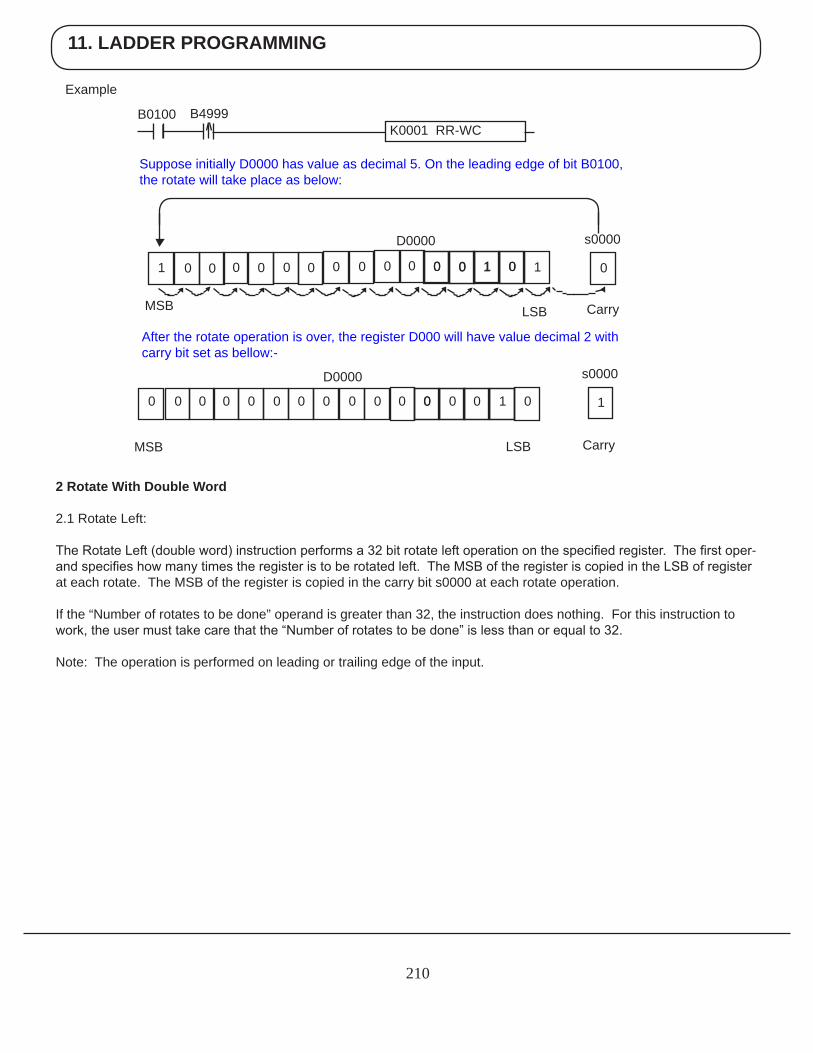
11. LADDER PROGRAMMING
210
Example
2 Rotate With Double Word
2.1 Rotate Left:
The Rotate Left (double word) instruction performs a 32 bit rotate left operation on the specified register. The first oper-and specifies how many times the register is to be rotated left. The MSB of the register is copied in the LSB of register at each rotate. The MSB of the register is copied in the carry bit s0000 at each rotate operation.
If the “Number of rotates to be done” operand is greater than 32, the instruction does nothing. For this instruction to work, the user must take care that the “Number of rotates to be done” is less than or equal to 32.
Note: The operation is performed on leading or trailing edge of the input.
K0001 RR-WC
Suppose initially D0000 has value as decimal 5. On the leading edge of bit B0100, the rotate will take place as below:
LSB
After the rotate operation is over, the register D000 will have value decimal 2 withcarry bit set as bellow:-
LSB
Carry
s0000
00 1 0 10 1 01 00 0000 0 0 0 0 00
s0000
1
Carry
0 0 1 0
MSB
D0000
0 00 0000 0 0 0 0 00
B0100 B4999
MSB
D0000
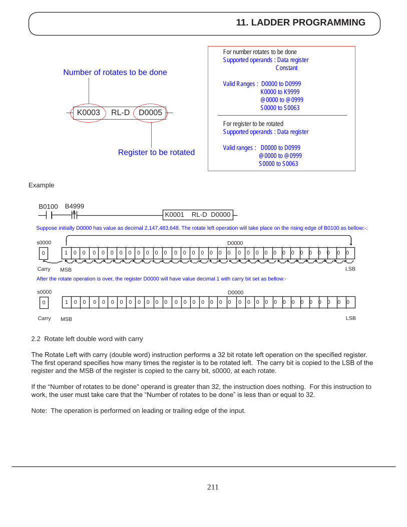
11. LADDER PROGRAMMING
211
Example
2.2 Rotate left double word with carry
The Rotate Left with carry (double word) instruction performs a 32 bit rotate left operation on the specified register. The first operand specifies how many times the register is to be rotated left. The carry bit is copied to the LSB of the register and the MSB of the register is copied to the carry bit, s0000, at each rotate.
If the “Number of rotates to be done” operand is greater than 32, the instruction does nothing. For this instruction to work, the user must take care that the “Number of rotates to be done” is less than or equal to 32.
Note: The operation is performed on leading or trailing edge of the input.
For number rotates to be done Supported operands : Data register Constant Valid Ranges : D0000 to D0999 K0000 to K9999 @0000 to @0999 S0000 to S0063 For register to be rotated Supported operands : Data register Valid ranges : D0000 to D0999 @0000 to @0999 S0000 to S0063
K0003 RL-D D0005
Register to be rotated
Number of rotates to be done
Suppose initially D0000 has value as decimal 2,147,483,648. The rotate left operation will take place on the rising edge of B0100 as bellow:-:
s0000
Carry MSB
D0000
After the rotate operation is over, the register D0000 will have value decimal 1 with carry bit set as bellow:-
0 1 0 0 0 0 0 0 0 0 0 0 0 0 0 0 0 0 0 0 0 0 0 0 0 0 0 0 0 0 0 0 0
LSB
s0000
Carry MSB
D0000
0 1 0 0 0 0 0 0 0 0 0 0 0 0 0 0 0 0 0 0 0 0 0 0 0 0 0 0 0 0 0 0 0
LSB
B0100 B4999K0001 RL-D D0000
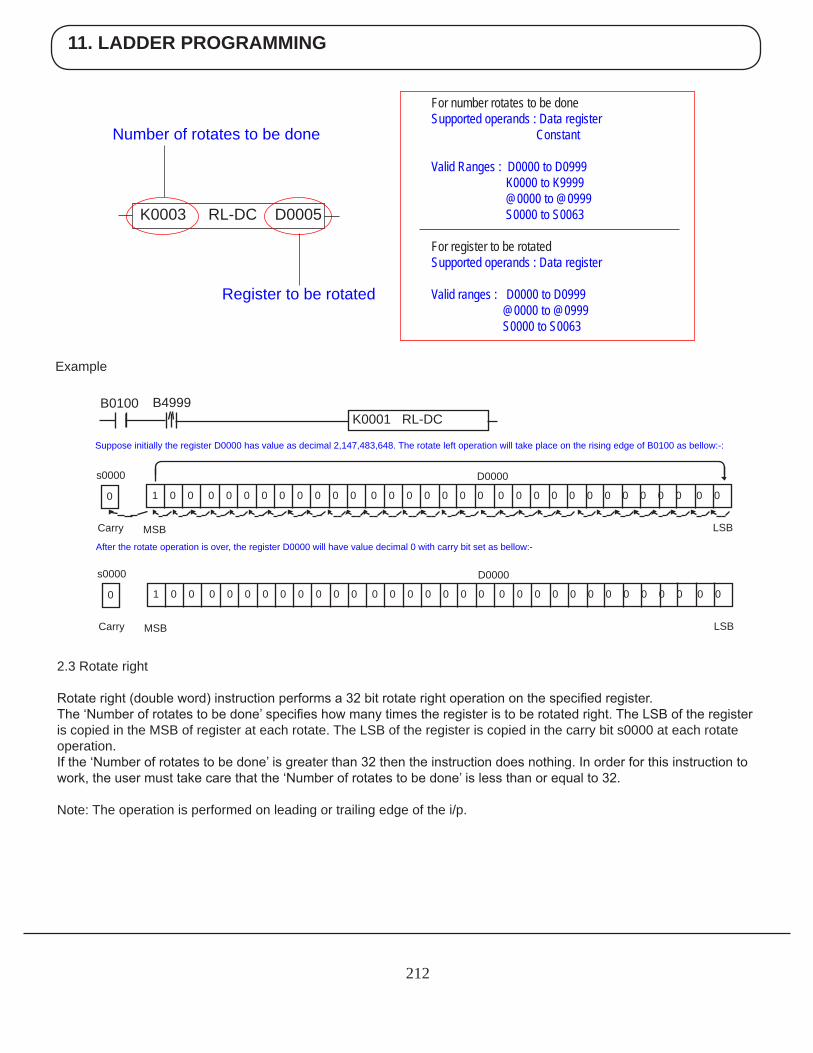
11. LADDER PROGRAMMING
212
Example
2.3 Rotate right
Rotate right (double word) instruction performs a 32 bit rotate right operation on the specified register.The ‘Number of rotates to be done’ specifies how many times the register is to be rotated right. The LSB of the register is copied in the MSB of register at each rotate. The LSB of the register is copied in the carry bit s0000 at each rotate operation.If the ‘Number of rotates to be done’ is greater than 32 then the instruction does nothing. In order for this instruction to work, the user must take care that the ‘Number of rotates to be done’ is less than or equal to 32.
Note: The operation is performed on leading or trailing edge of the i/p.
For number rotates to be done Supported operands : Data register Constant Valid Ranges : D0000 to D0999 K0000 to K9999 @0000 to @0999 S0000 to S0063 For register to be rotated Supported operands : Data register Valid ranges : D0000 to D0999 @0000 to @0999 S0000 to S0063
K0003 RL-DC D0005
Register to be rotated
Number of rotates to be done
Suppose initially the register D0000 has value as decimal 2,147,483,648. The rotate left operation will take place on the rising edge of B0100 as bellow:-:
s0000
Carry MSB
D0000
After the rotate operation is over, the register D0000 will have value decimal 0 with carry bit set as bellow:-
0 1 0 0 0 0 0 0 0 0 0 0 0 0 0 0 0 0 0 0 0 0 0 0 0 0 0 0 0 0 0 0 0
LSB
s0000
Carry MSB
D0000
0 1 0 0 0 0 0 0 0 0 0 0 0 0 0 0 0 0 0 0 0 0 0 0 0 0 0 0 0 0 0 0 0
LSB
B0100 B4999K0001 RL-DC
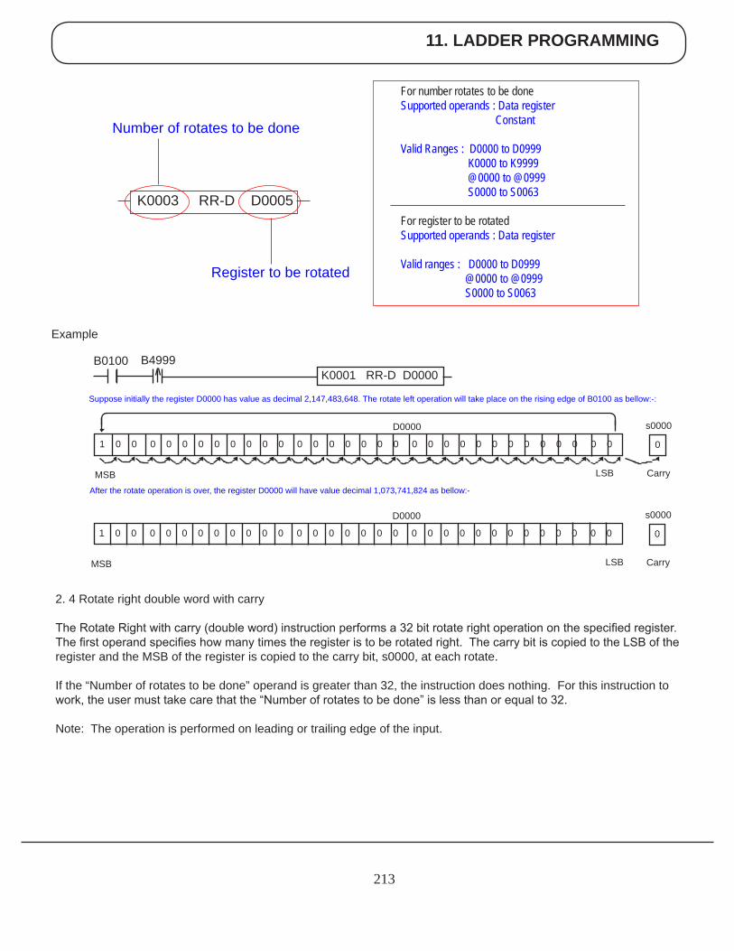
11. LADDER PROGRAMMING
213
Example
2. 4 Rotate right double word with carry
The Rotate Right with carry (double word) instruction performs a 32 bit rotate right operation on the specified register. The first operand specifies how many times the register is to be rotated right. The carry bit is copied to the LSB of the register and the MSB of the register is copied to the carry bit, s0000, at each rotate.
If the “Number of rotates to be done” operand is greater than 32, the instruction does nothing. For this instruction to work, the user must take care that the “Number of rotates to be done” is less than or equal to 32.
Note: The operation is performed on leading or trailing edge of the input.
For number rotates to be done Supported operands : Data register Constant Valid Ranges : D0000 to D0999 K0000 to K9999 @0000 to @0999 S0000 to S0063 For register to be rotated Supported operands : Data register Valid ranges : D0000 to D0999 @0000 to @0999 S0000 to S0063
K0003 RR-D D0005
Register to be rotated
Number of rotates to be done
Suppose initially the register D0000 has value as decimal 2,147,483,648. The rotate left operation will take place on the rising edge of B0100 as bellow:-:
MSBAfter the rotate operation is over, the register D0000 will have value decimal 1,073,741,824 as bellow:-
B0100 B4999K0001 RR-D D0000
s0000
Carry
0
D0000
1 0 0 0 0 0 0 0 0 0 0 0 0 0 0 0 0 0 0 0 0 0 0 0 0 0 0 0 0 0 0 0
LSB
s0000
Carry
0
MSB
D0000
1 0 0 0 0 0 0 0 0 0 0 0 0 0 0 0 0 0 0 0 0 0 0 0 0 0 0 0 0 0 0 0
LSB
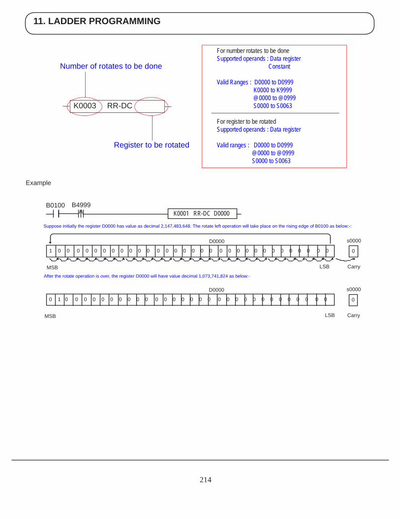
11. LADDER PROGRAMMING
214
Example
For number rotates to be done Supported operands : Data register Constant Valid Ranges : D0000 to D0999 K0000 to K9999 @0000 to @0999 S0000 to S0063 For register to be rotated Supported operands : Data register Valid ranges : D0000 to D0999 @0000 to @0999 S0000 to S0063
K0003 RR-DC
Register to be rotated
Number of rotates to be done
Suppose initially the register D0000 has value as decimal 2,147,483,648. The rotate left operation will take place on the rising edge of B0100 as below:-:
MSBAfter the rotate operation is over, the register D0000 will have value decimal 1,073,741,824 as below:-
B0100 B4999K0001 RR-DC D0000
s0000
Carry
0
D0000
1 0 0 0 0 0 0 0 0 0 0 0 0 0 0 0 0 0 0 0 0 0 0 0 0 0 0 0 0 0 0 0
LSB
s0000
Carry
0
MSB
D0000
0 1 0 0 0 0 0 0 0 0 0 0 0 0 0 0 0 0 0 0 0 0 0 0 0 0 0 0 0 0 0 0
LSB
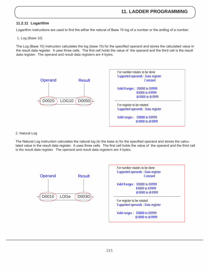
11. LADDER PROGRAMMING
215
11.2.11 Logarithm
Logarithm instructions are used to find the either the natural of Base 10 log of a number or the antilog of a number.
1. Log (Base 10)
The Log (Base 10) instruction calculates the log (base 10) for the specified operand and stores the calculated value in the result data register. It uses three cells. The first cell holds the value of the operand and the third cell is the result data register. The operand and result data registers are 4 bytes.
2. Natural Log
The Natural Log instruction calculates the natural log (to the base e) for the specified operand and stores the calcu-lated value in the result data register. It uses three cells. The first cell holds the value of the operand and the third cell is the result data register. The operand and result data registers are 4 bytes.
For number rotates to be done Supported operands : Data register Constant Valid Ranges : D0000 to D0999 K0000 to K9999 @0000 to @0999 For register to be rotated Supported operands : Data register Valid ranges : D0000 to D0999 @0000 to @0999
D0020 LOG10 D0050
ResultOperand
For number rotates to be done Supported operands : Data register Constant Valid Ranges : D0000 to D0999 K0000 to K9999 @0000 to @0999 For register to be rotated Supported operands : Data register Valid ranges : D0000 to D0999 @0000 to @0999
D0010 LOGe D0030
ResultOperand
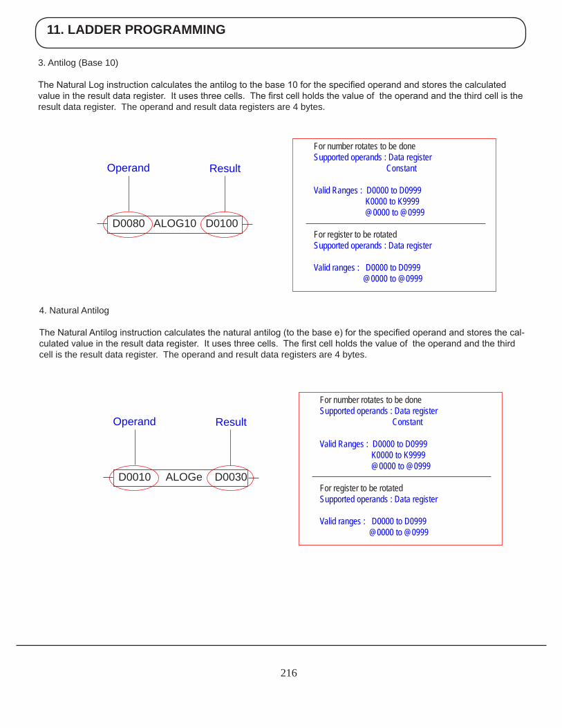
11. LADDER PROGRAMMING
216
3. Antilog (Base 10)
The Natural Log instruction calculates the antilog to the base 10 for the specified operand and stores the calculated value in the result data register. It uses three cells. The first cell holds the value of the operand and the third cell is the result data register. The operand and result data registers are 4 bytes.
4. Natural Antilog
The Natural Antilog instruction calculates the natural antilog (to the base e) for the specified operand and stores the cal-culated value in the result data register. It uses three cells. The first cell holds the value of the operand and the third cell is the result data register. The operand and result data registers are 4 bytes.
For number rotates to be done Supported operands : Data register Constant Valid Ranges : D0000 to D0999 K0000 to K9999 @0000 to @0999 For register to be rotated Supported operands : Data register Valid ranges : D0000 to D0999 @0000 to @0999
D0080 ALOG10 D0100
ResultOperand
For number rotates to be done Supported operands : Data register Constant Valid Ranges : D0000 to D0999 K0000 to K9999 @0000 to @0999 For register to be rotated Supported operands : Data register Valid ranges : D0000 to D0999 @0000 to @0999
D0010 ALOGe D0030
ResultOperand
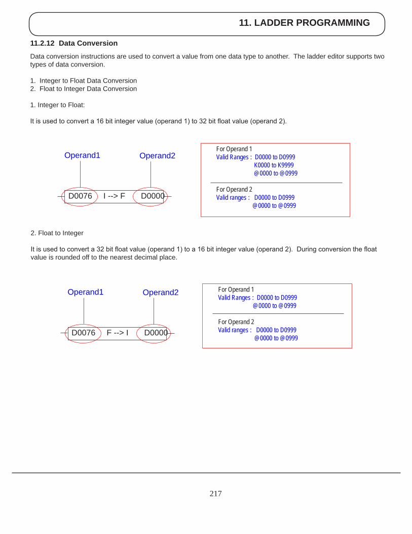
11. LADDER PROGRAMMING
217
11.2.12 Data Conversion
Data conversion instructions are used to convert a value from one data type to another. The ladder editor supports two types of data conversion.
1. Integer to Float Data Conversion2. Float to Integer Data Conversion
1. Integer to Float: It is used to convert a 16 bit integer value (operand 1) to 32 bit float value (operand 2).
2. Float to Integer
It is used to convert a 32 bit float value (operand 1) to a 16 bit integer value (operand 2). During conversion the float value is rounded off to the nearest decimal place.
D0076 I --> F D0000
Operand2Operand1 For Operand 1 Valid Ranges : D0000 to D0999 K0000 to K9999 @0000 to @0999 For Operand 2 Valid ranges : D0000 to D0999 @0000 to @0999
D0076 F --> I D0000
Operand2Operand1 For Operand 1 Valid Ranges : D0000 to D0999 @0000 to @0999 For Operand 2 Valid ranges : D0000 to D0999 @0000 to @0999
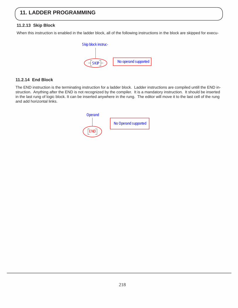
11. LADDER PROGRAMMING
218
11.2.13 Skip Block
When this instruction is enabled in the ladder block, all of the following instructions in the block are skipped for execu-
Skip block instruc-
No operand supportedSKIP
11.2.14 End Block
The END instruction is the terminating instruction for a ladder block. Ladder instructions are compiled untill the END in-struction. Anything after the END is not recognized by the compiler. It is a mandatory instruction. It should be inserted in the last rung of logic block. It can be inserted anywhere in the rung. The editor will move it to the last cell of the rung and add horizontal links.
No Operand supported
Operand
END
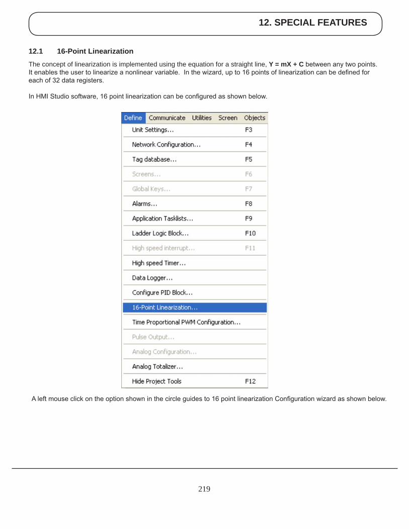
12. SPECIAL FEATURES
219
A left mouse click on the option shown in the circle guides to 16 point linearization Configuration wizard as shown below.
12.1 16-Point Linearization
The concept of linearization is implemented using the equation for a straight line, Y = mX + C between any two points. It enables the user to linearize a nonlinear variable. In the wizard, up to 16 points of linearization can be defined for each of 32 data registers.
In HMI Studio software, 16 point linearization can be configured as shown below.
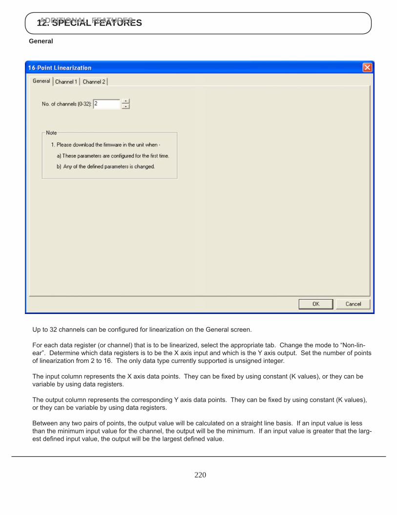
12. SPECIAL FEATURESADDITIONAL FEATURES
220
Up to 32 channels can be configured for linearization on the General screen.
For each data register (or channel) that is to be linearized, select the appropriate tab. Change the mode to “Non-lin-ear”. Determine which data registers is to be the X axis input and which is the Y axis output. Set the number of points of linearization from 2 to 16. The only data type currently supported is unsigned integer.
The input column represents the X axis data points. They can be fixed by using constant (K values), or they can be variable by using data registers.
The output column represents the corresponding Y axis data points. They can be fixed by using constant (K values), or they can be variable by using data registers.
Between any two pairs of points, the output value will be calculated on a straight line basis. If an input value is less than the minimum input value for the channel, the output will be the minimum. If an input value is greater that the larg-est defined input value, the output will be the largest defined value.
General
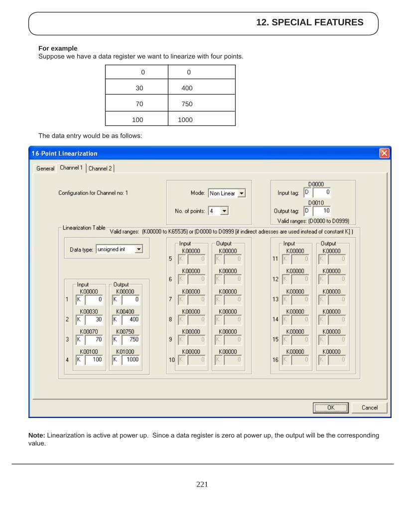
12. SPECIAL FEATURES
221
For exampleSuppose we have a data register we want to linearize with four points.
0 0 30 400 70 750
100 1000
The data entry would be as follows:
Note: Linearization is active at power up. Since a data register is zero at power up, the output will be the corresponding value.
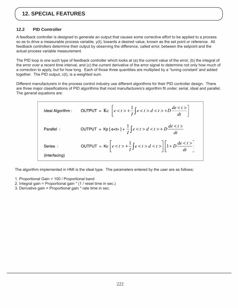
12. SPECIAL FEATURES
222
12.2 PID Controller
A feedback controller is designed to generate an output that causes some corrective effort to be applied to a process so as to drive a measurable process variable, y(t), towards a desired value, known as the set point or reference. All feedback controllers determine their output by observing the difference, called error, between the setpoint and the actual process variable measurement.
The PID loop is one such type of feedback controller which looks at (a) the current value of the error, (b) the integral of the error over a recent time interval, and (c) the current derivative of the error signal to determine not only how much of a correction to apply, but for how long. Each of those three quantities are multiplied by a “tuning constant’ and added together. The PID output, c(t), is a weighted sum.
Different manufacturers in the process control industry use different algorithms for their PID controller design. There are three major classifications of PID algorithms that most manufacturers’s algorithm fit under, serial, ideal and parallel. The general equations are:
The algorithm implemented in HMI is the ideal type. The parameters entered by the user are as follows:
1. Proportional Gain = 100 / Proportional band2. Integral gain = Proportional gain * (1 / reset time in sec.)3. Derivative gain = Proportional gain * rate time in sec.
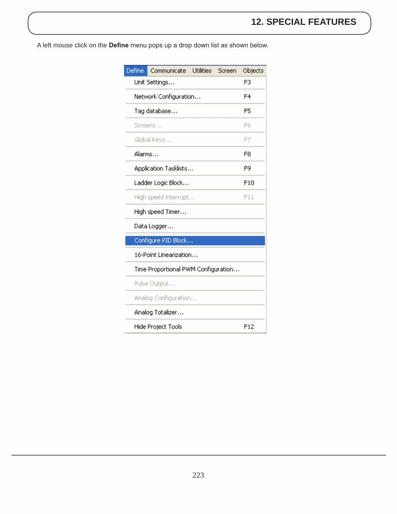
12. SPECIAL FEATURES
223
A left mouse click on the Define menu pops up a drop down list as shown below.
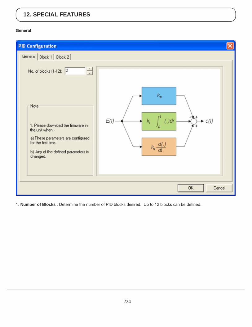
12. SPECIAL FEATURES
224
1. Number of Blocks : Determine the number of PID blocks desired. Up to 12 blocks can be defined.
General
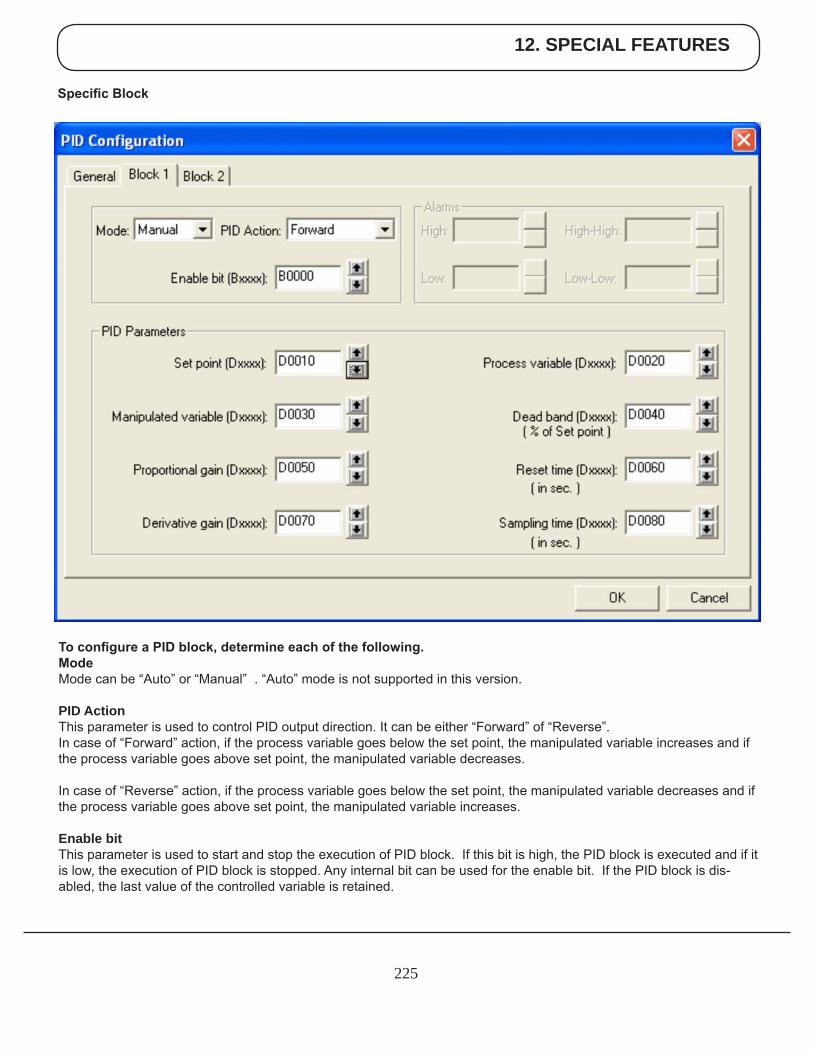
12. SPECIAL FEATURES
225
To configure a PID block, determine each of the following.ModeMode can be “Auto” or “Manual” . “Auto” mode is not supported in this version.
PID ActionThis parameter is used to control PID output direction. It can be either “Forward” of “Reverse”. In case of “Forward” action, if the process variable goes below the set point, the manipulated variable increases and if the process variable goes above set point, the manipulated variable decreases.
In case of “Reverse” action, if the process variable goes below the set point, the manipulated variable decreases and if the process variable goes above set point, the manipulated variable increases.
Enable bitThis parameter is used to start and stop the execution of PID block. If this bit is high, the PID block is executed and if it is low, the execution of PID block is stopped. Any internal bit can be used for the enable bit. If the PID block is dis-abled, the last value of the controlled variable is retained.
Specific Block
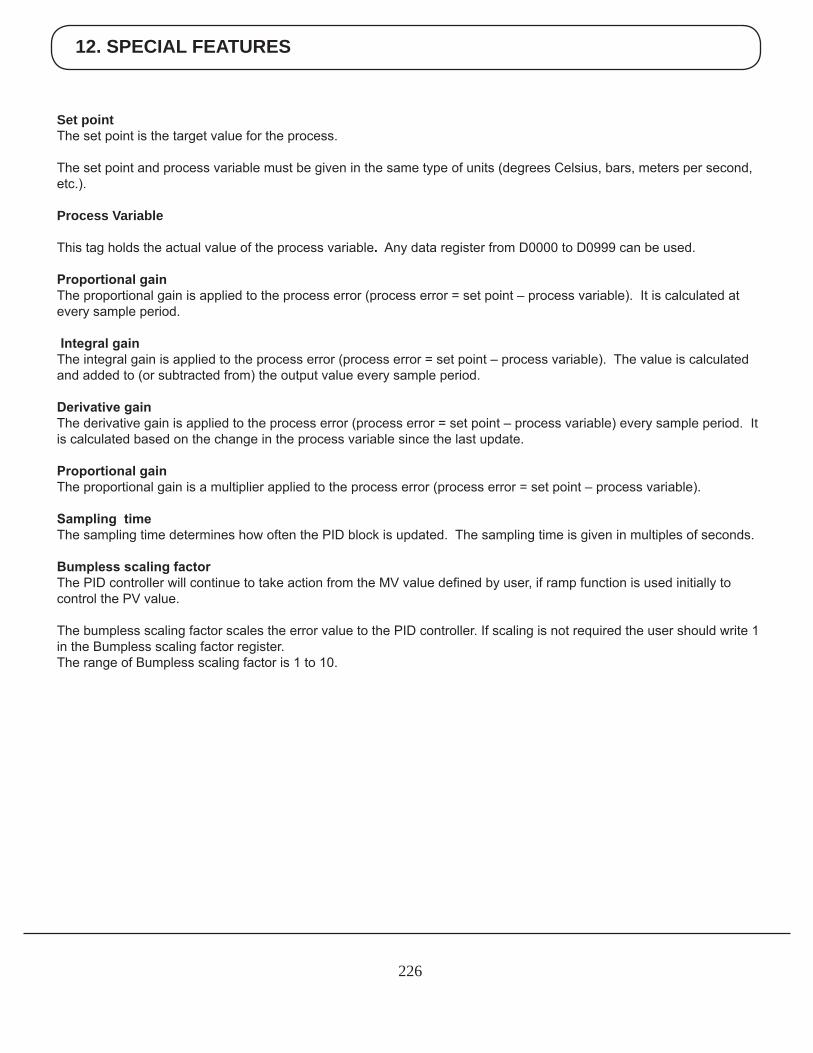
12. SPECIAL FEATURES
226
Set pointThe set point is the target value for the process.
The set point and process variable must be given in the same type of units (degrees Celsius, bars, meters per second, etc.).
Process Variable
This tag holds the actual value of the process variable. Any data register from D0000 to D0999 can be used.
Proportional gainThe proportional gain is applied to the process error (process error = set point – process variable). It is calculated at every sample period.
Integral gainThe integral gain is applied to the process error (process error = set point – process variable). The value is calculated and added to (or subtracted from) the output value every sample period.
Derivative gainThe derivative gain is applied to the process error (process error = set point – process variable) every sample period. It is calculated based on the change in the process variable since the last update.
Proportional gainThe proportional gain is a multiplier applied to the process error (process error = set point – process variable).
Sampling timeThe sampling time determines how often the PID block is updated. The sampling time is given in multiples of seconds.
Bumpless scaling factorThe PID controller will continue to take action from the MV value defined by user, if ramp function is used initially to control the PV value.
The bumpless scaling factor scales the error value to the PID controller. If scaling is not required the user should write 1 in the Bumpless scaling factor register.The range of Bumpless scaling factor is 1 to 10.
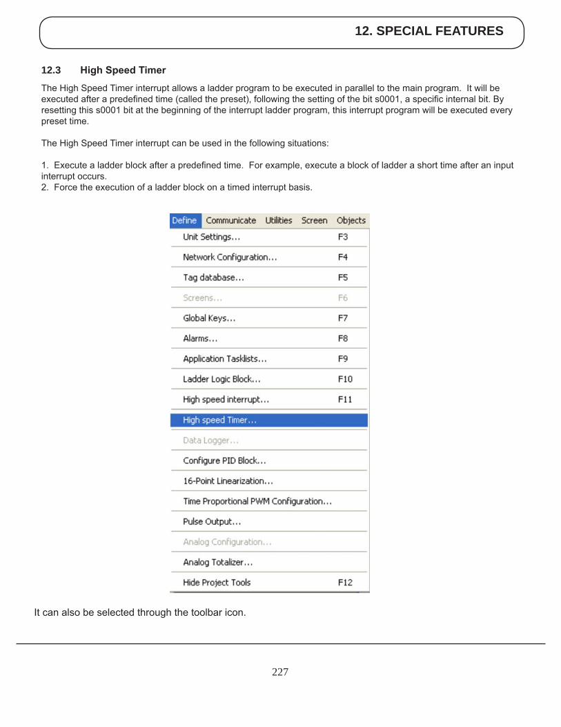
12. SPECIAL FEATURES
227
12.3 High Speed Timer
The High Speed Timer interrupt allows a ladder program to be executed in parallel to the main program. It will be executed after a predefined time (called the preset), following the setting of the bit s0001, a specific internal bit. By resetting this s0001 bit at the beginning of the interrupt ladder program, this interrupt program will be executed every preset time.
The High Speed Timer interrupt can be used in the following situations:
1. Execute a ladder block after a predefined time. For example, execute a block of ladder a short time after an input interrupt occurs.2. Force the execution of a ladder block on a timed interrupt basis.
It can also be selected through the toolbar icon.
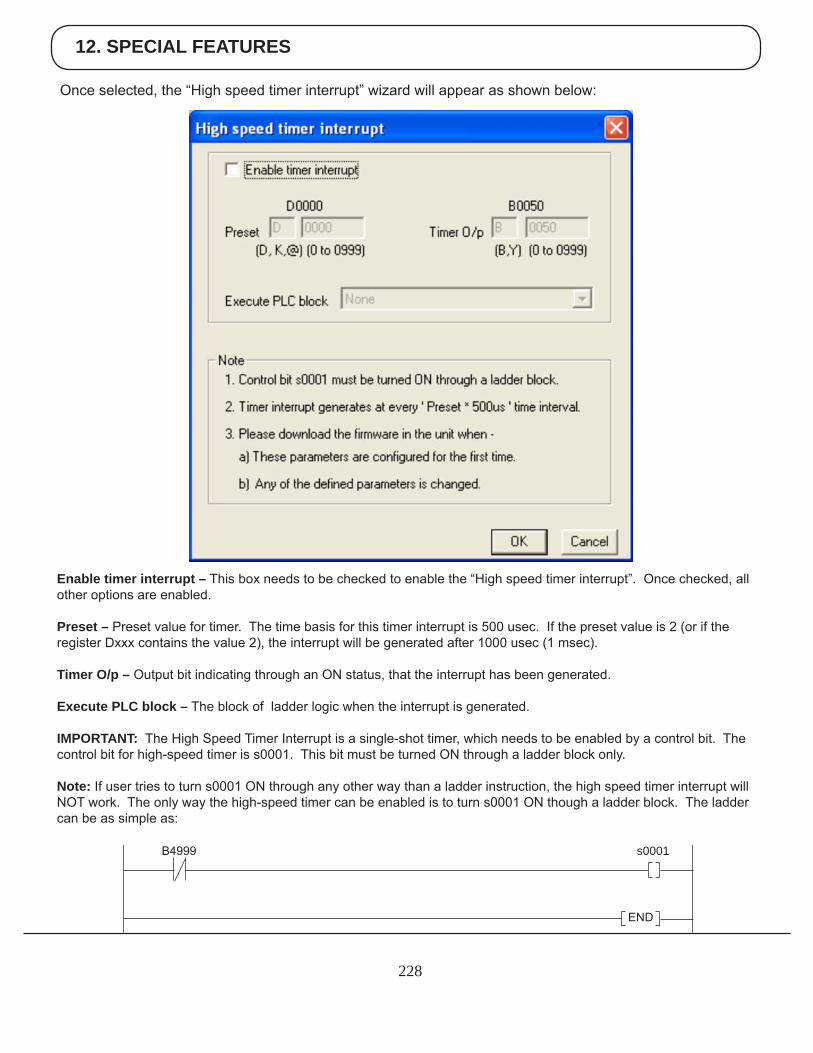
12. SPECIAL FEATURES
228
Enable timer interrupt – This box needs to be checked to enable the “High speed timer interrupt”. Once checked, all other options are enabled.
Preset – Preset value for timer. The time basis for this timer interrupt is 500 usec. If the preset value is 2 (or if the register Dxxx contains the value 2), the interrupt will be generated after 1000 usec (1 msec).
Timer O/p – Output bit indicating through an ON status, that the interrupt has been generated.
Execute PLC block – The block of ladder logic when the interrupt is generated.
IMPORTANT: The High Speed Timer Interrupt is a single-shot timer, which needs to be enabled by a control bit. The control bit for high-speed timer is s0001. This bit must be turned ON through a ladder block only.
Note: If user tries to turn s0001 ON through any other way than a ladder instruction, the high speed timer interrupt will NOT work. The only way the high-speed timer can be enabled is to turn s0001 ON though a ladder block. The ladder can be as simple as:
Once selected, the “High speed timer interrupt” wizard will appear as shown below:
s0001B4999
END
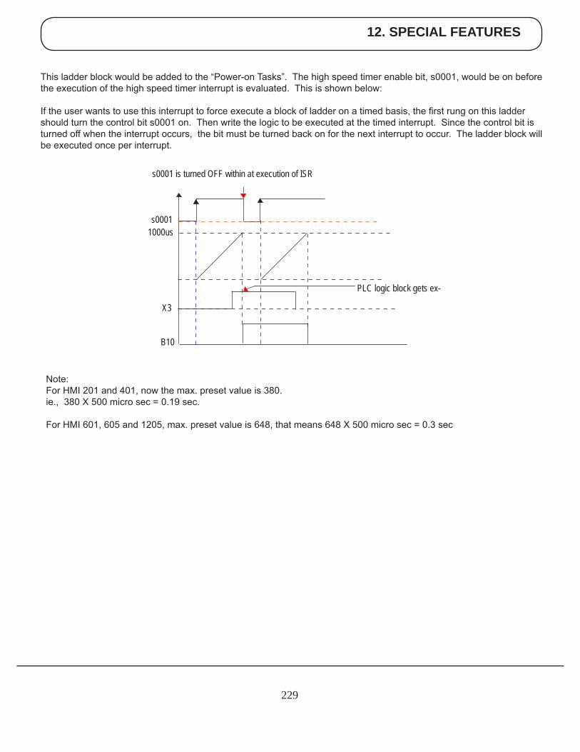
12. SPECIAL FEATURES
229
This ladder block would be added to the “Power-on Tasks”. The high speed timer enable bit, s0001, would be on before the execution of the high speed timer interrupt is evaluated. This is shown below:
If the user wants to use this interrupt to force execute a block of ladder on a timed basis, the first rung on this ladder should turn the control bit s0001 on. Then write the logic to be executed at the timed interrupt. Since the control bit is turned off when the interrupt occurs, the bit must be turned back on for the next interrupt to occur. The ladder block will be executed once per interrupt.
s0001 is turned OFF within at execution of ISR
s00011000us
X3
B10
PLC logic block gets ex-
Note:For HMI 201 and 401, now the max. preset value is 380.ie., 380 X 500 micro sec = 0.19 sec.
For HMI 601, 605 and 1205, max. preset value is 648, that means 648 X 500 micro sec = 0.3 sec
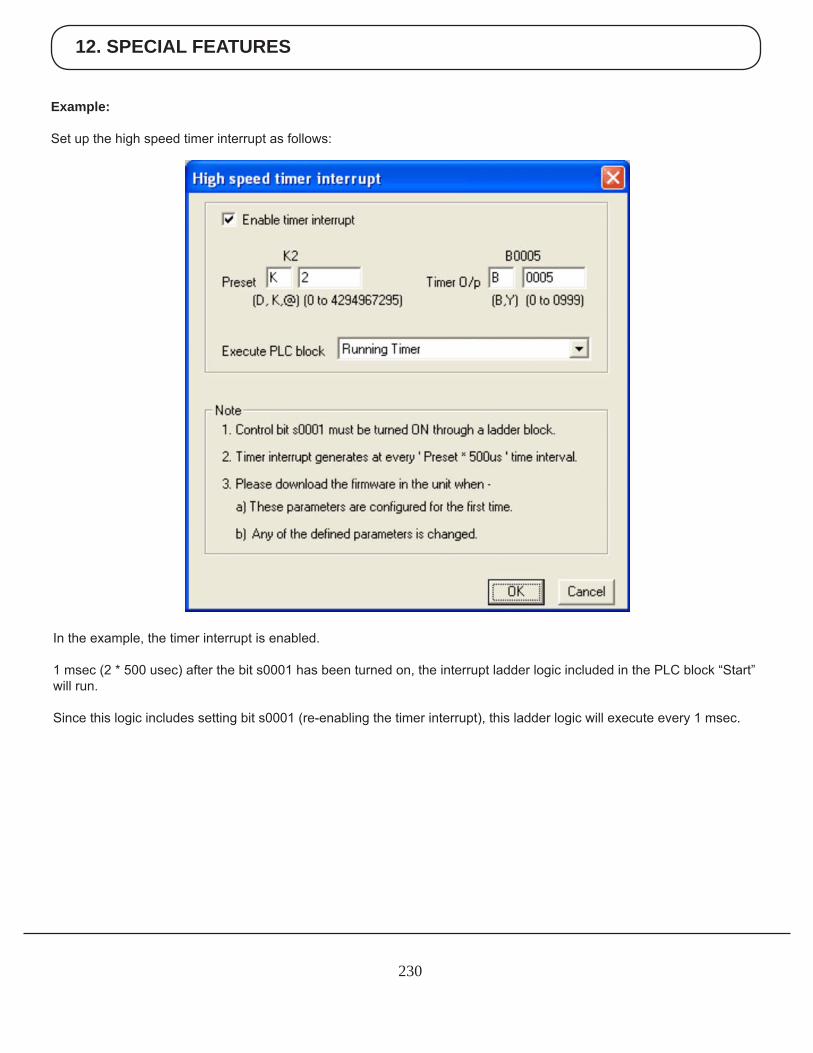
12. SPECIAL FEATURES
230
Example:
Set up the high speed timer interrupt as follows:
In the example, the timer interrupt is enabled.
1 msec (2 * 500 usec) after the bit s0001 has been turned on, the interrupt ladder logic included in the PLC block “Start” will run.
Since this logic includes setting bit s0001 (re-enabling the timer interrupt), this ladder logic will execute every 1 msec.
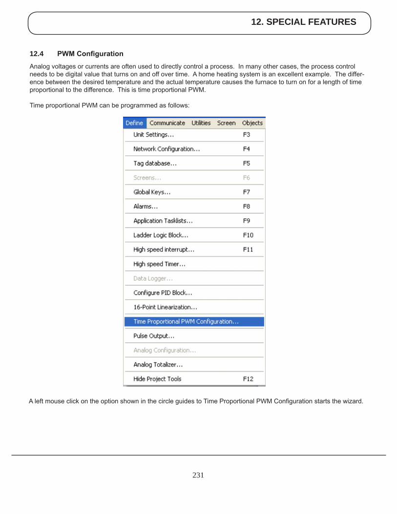
12. SPECIAL FEATURES
231
A left mouse click on the option shown in the circle guides to Time Proportional PWM Configuration starts the wizard.
12.4 PWM Configuration
Analog voltages or currents are often used to directly control a process. In many other cases, the process control needs to be digital value that turns on and off over time. A home heating system is an excellent example. The differ-ence between the desired temperature and the actual temperature causes the furnace to turn on for a length of time proportional to the difference. This is time proportional PWM.
Time proportional PWM can be programmed as follows:
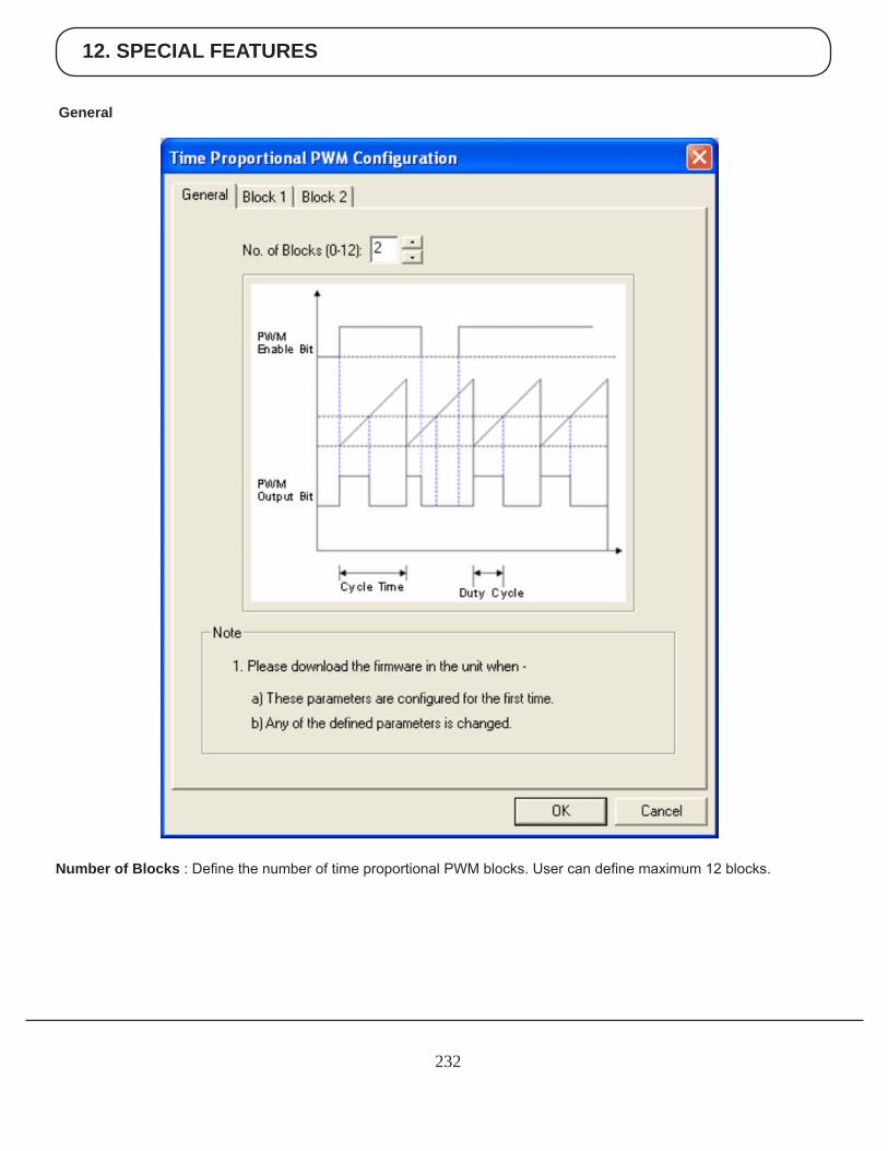
12. SPECIAL FEATURES
232
General
Number of Blocks : Define the number of time proportional PWM blocks. User can define maximum 12 blocks.
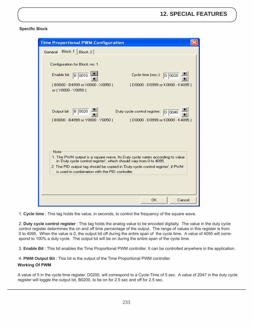
12. SPECIAL FEATURES
233
1. Cycle time : This tag holds the value, in seconds, to control the frequency of the square wave.
2. Duty cycle control register : This tag holds the analog value to be encoded digitally. The value in the duty cycle control register determines the on and off time percentage of the output. The range of values in this register is from 0 to 4095. When the value is 0, the output bit off during the entire span of the cycle time. A value of 4095 will corre-spond to 100% a duty cycle. The output bit will be on during the entire span of the cycle time. 3. Enable Bit : This bit enables the Time Proportional PWM controller. It can be controlled anywhere in the application. 4. PWM Output Bit : This bit is the output of the Time Proportional PWM controller.
Specific Block
Working Of PWM
A value of 5 in the cycle time register, D0200, will correspond to a Cycle-Time of 5 sec. A value of 2047 in the duty cycle register will toggle the output bit, B0200, to be on for 2.5 sec and off for 2.5 sec.
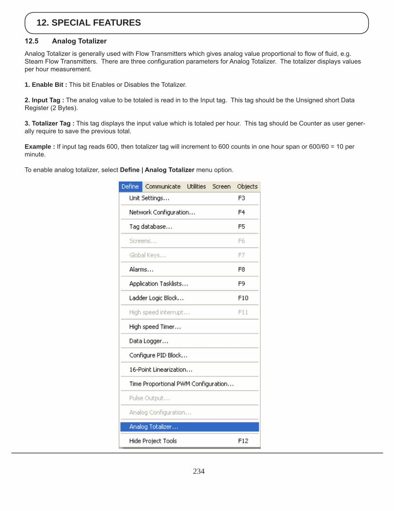
12. SPECIAL FEATURES
234
12.5 Analog Totalizer
Analog Totalizer is generally used with Flow Transmitters which gives analog value proportional to flow of fluid, e.g. Steam Flow Transmitters. There are three configuration parameters for Analog Totalizer. The totalizer displays values per hour measurement.
1. Enable Bit : This bit Enables or Disables the Totalizer.
2. Input Tag : The analog value to be totaled is read in to the Input tag. This tag should be the Unsigned short Data Register (2 Bytes).
3. Totalizer Tag : This tag displays the input value which is totaled per hour. This tag should be Counter as user gener-ally require to save the previous total.
Example : If input tag reads 600, then totalizer tag will increment to 600 counts in one hour span or 600/60 = 10 per minute.
To enable analog totalizer, select Define | Analog Totalizer menu option.
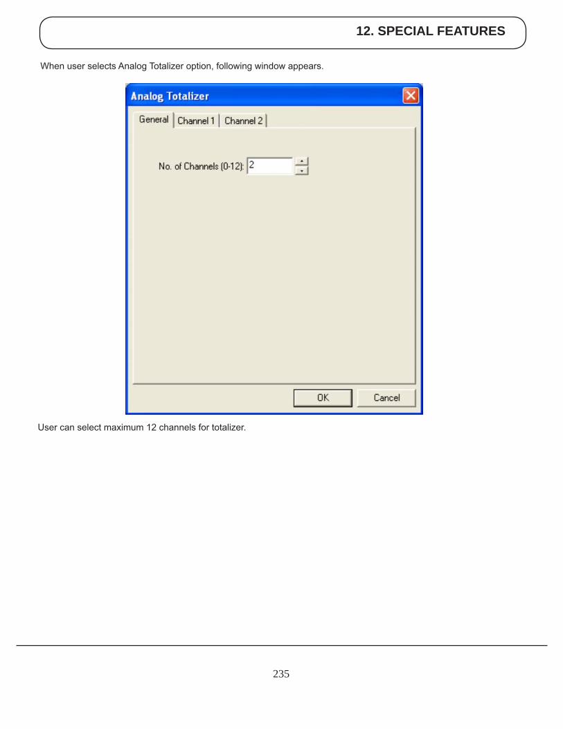
12. SPECIAL FEATURES
235
When user selects Analog Totalizer option, following window appears.
User can select maximum 12 channels for totalizer.
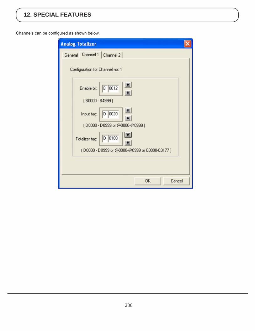
12. SPECIAL FEATURES
236
Channels can be configured as shown below.
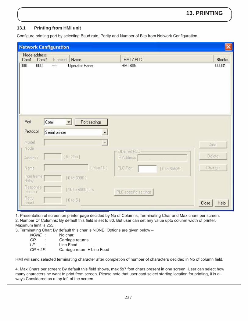
13. PRINTING
237
13.1 Printing from HMI unit
Configure printing port by selecting Baud rate, Parity and Number of Bits from Network Configuration.
1. Presentation of screen on printer page decided by No of Columns, Terminating Char and Max chars per screen. 2. Number Of Columns: By default this field is set to 80. But user can set any value upto column width of printer. Maximum limit is 255. 3. Terminating Char: By default this char is NONE, Options are given below – NONE : No char. CR : Carriage returns. LF : Line Feed. CR+LF: Carriage return + Line Feed
HMI will send selected terminating character after completion of number of characters decided in No of column field.
4. Max Chars per screen: By default this field shows, max 5x7 font chars present in one screen. User can select how many characters he want to print from screen. Please note that user cant select starting location for printing, it is al-ways Considered as a top left of the screen.
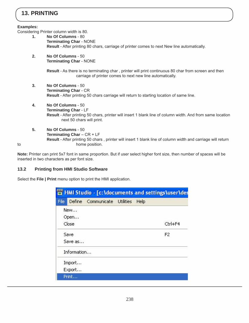
13. PRINTING
238
Examples: Considering Printer column width is 80. 1. No Of Columns - 80 Terminating Char - NONE Result - After printing 80 chars, carriage of printer comes to next New line automatically.
2. No Of Columns - 50 Terminating Char - NONE
Result - As there is no terminating char , printer will print continuous 80 char from screen and then carriage of printer comes to next new line automatically.
3. No Of Columns - 50 Terminating Char - CR Result - After printing 50 chars carriage will return to starting location of same line.
4. No Of Columns - 50 Terminating Char - LF Result - After printing 50 chars, printer will insert 1 blank line of column width. And from same location next 50 chars will print.
5. No Of Columns - 50 Terminating Char – CR + LF Result - After printing 50 chars , printer will insert 1 blank line of column width and carriage will return to home position.
Note: Printer can print 5x7 font in same proportion. But if user select higher font size, then number of spaces will be inserted in two characters as per font size.
13.2 Printing from HMI Studio Software
Select the File | Print menu option to print the HMI application.
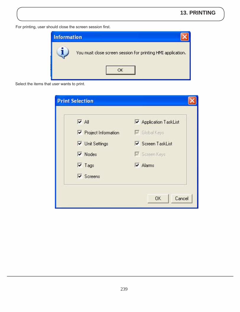
13. PRINTING
239
For printing, user should close the screen session first.
Select the items that user wants to print.
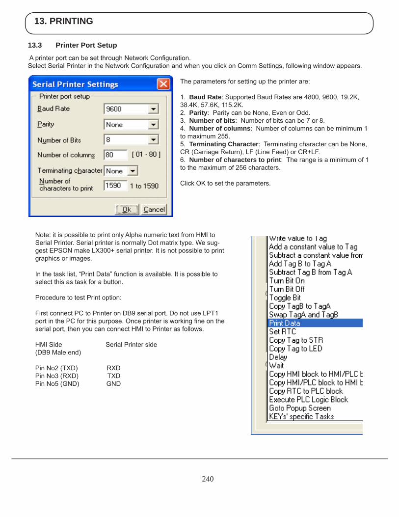
13. PRINTING
240
13.3 Printer Port Setup
A printer port can be set through Network Configuration. Select Serial Printer in the Network Configuration and when you click on Comm Settings, following window appears.
The parameters for setting up the printer are:
1. Baud Rate: Supported Baud Rates are 4800, 9600, 19.2K, 38.4K, 57.6K, 115.2K.2. Parity: Parity can be None, Even or Odd.3. Number of bits: Number of bits can be 7 or 8.4. Number of columns: Number of columns can be minimum 1 to maximum 255.5. Terminating Character: Terminating character can be None, CR (Carriage Return), LF (Line Feed) or CR+LF.6. Number of characters to print: The range is a minimum of 1 to the maximum of 256 characters.
Click OK to set the parameters.
Note: it is possible to print only Alpha numeric text from HMI to Serial Printer. Serial printer is normally Dot matrix type. We sug-gest EPSON make LX300+ serial printer. It is not possible to print graphics or images.
In the task list, “Print Data” function is available. It is possible to select this as task for a button.
Procedure to test Print option:
First connect PC to Printer on DB9 serial port. Do not use LPT1 port in the PC for this purpose. Once printer is working fine on the serial port, then you can connect HMI to Printer as follows.
HMI Side Serial Printer side(DB9 Male end)
Pin No2 (TXD) RXDPin No3 (RXD) TXDPin No5 (GND) GND
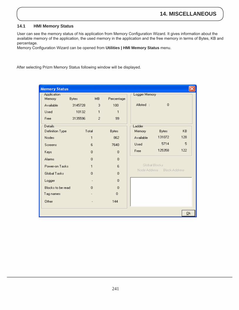
14. MISCELLANEOUS
241
14.1 HMI Memory Status
User can see the memory status of his application from Memory Configuration Wizard. It gives information about the available memory of the application, the used memory in the application and the free memory in terms of Bytes, KB and percentage. Memory Configuration Wizard can be opened from Utilities | HMI Memory Status menu.
After selecting Prizm Memory Status following window will be displayed.
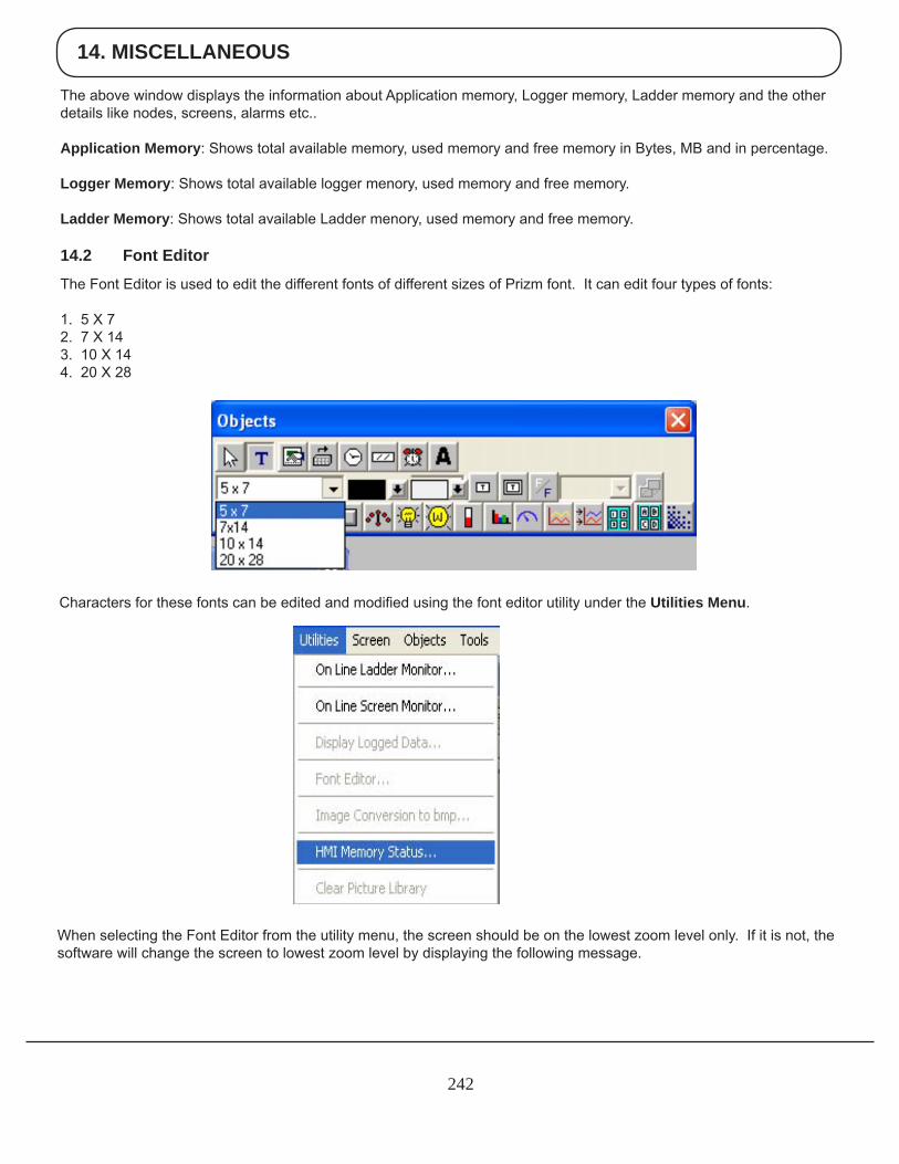
14. MISCELLANEOUS
242
The above window displays the information about Application memory, Logger memory, Ladder memory and the other details like nodes, screens, alarms etc..
Application Memory: Shows total available memory, used memory and free memory in Bytes, MB and in percentage.
Logger Memory: Shows total available logger menory, used memory and free memory.
Ladder Memory: Shows total available Ladder menory, used memory and free memory.
14.2 Font Editor
The Font Editor is used to edit the different fonts of different sizes of Prizm font. It can edit four types of fonts:
1. 5 X 72. 7 X 14 3. 10 X 14 4. 20 X 28
Characters for these fonts can be edited and modified using the font editor utility under the Utilities Menu.
When selecting the Font Editor from the utility menu, the screen should be on the lowest zoom level only. If it is not, the software will change the screen to lowest zoom level by displaying the following message.
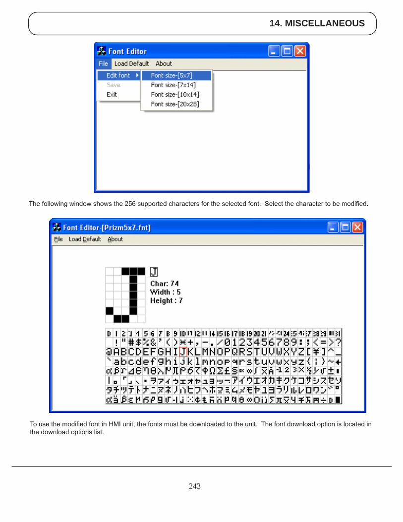
14. MISCELLANEOUS
243
The following window shows the 256 supported characters for the selected font. Select the character to be modified.
To use the modified font in HMI unit, the fonts must be downloaded to the unit. The font download option is located in the download options list.
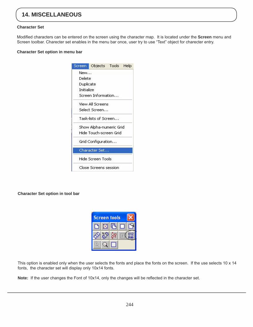
14. MISCELLANEOUS
244
Character Set
Modified characters can be entered on the screen using the character map. It is located under the Screen menu and Screen toolbar. Charecter set enables in the menu bar once, user try to use “Text” object for charecter entry.
Character Set option in menu bar
Character Set option in tool bar
This option is enabled only when the user selects the fonts and place the fonts on the screen. If the use selects 10 x 14 fonts, the character set will display only 10x14 fonts.
Note: If the user changes the Font of 10x14, only the changes will be reflected in the character set.
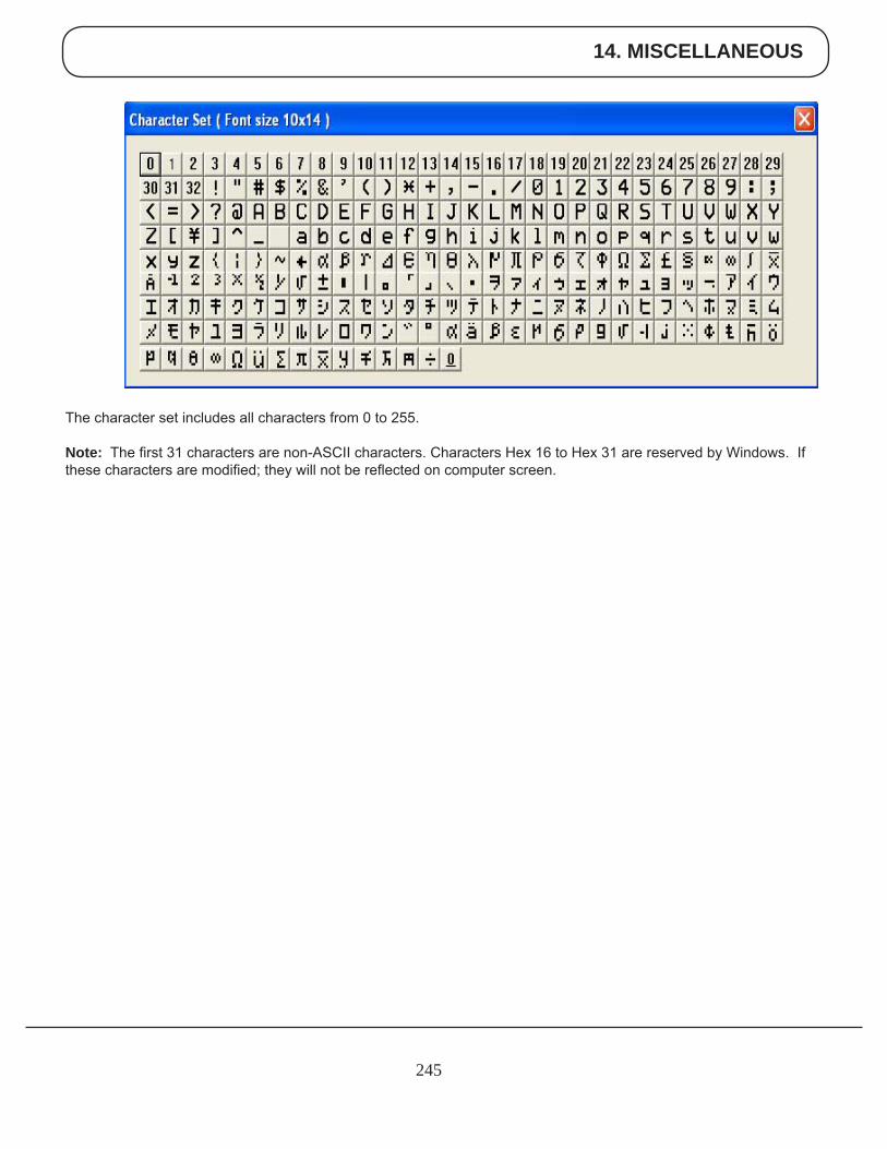
14. MISCELLANEOUS
245
The character set includes all characters from 0 to 255.
Note: The first 31 characters are non-ASCII characters. Characters Hex 16 to Hex 31 are reserved by Windows. If these characters are modified; they will not be reflected on computer screen.
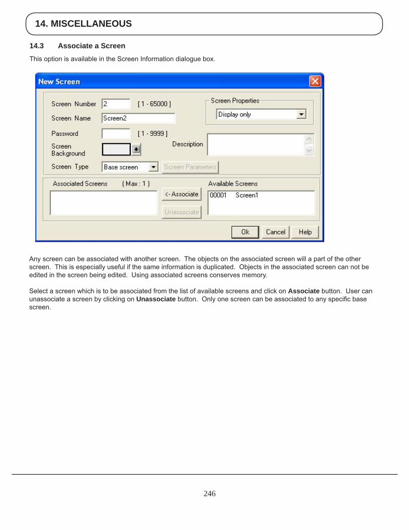
14. MISCELLANEOUS
246
14.3 Associate a Screen
This option is available in the Screen Information dialogue box.
Any screen can be associated with another screen. The objects on the associated screen will a part of the other screen. This is especially useful if the same information is duplicated. Objects in the associated screen can not be edited in the screen being edited. Using associated screens conserves memory.
Select a screen which is to be associated from the list of available screens and click on Associate button. User can unassociate a screen by clicking on Unassociate button. Only one screen can be associated to any specific base screen.
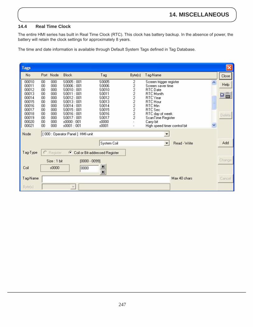
14. MISCELLANEOUS
247
14.4 Real Time Clock
The entire HMI series has built in Real Time Clock (RTC). This clock has battery backup. In the absence of power, the battery will retain the clock settings for approximately 8 years.
The time and date information is available through Default System Tags defined in Tag Database.
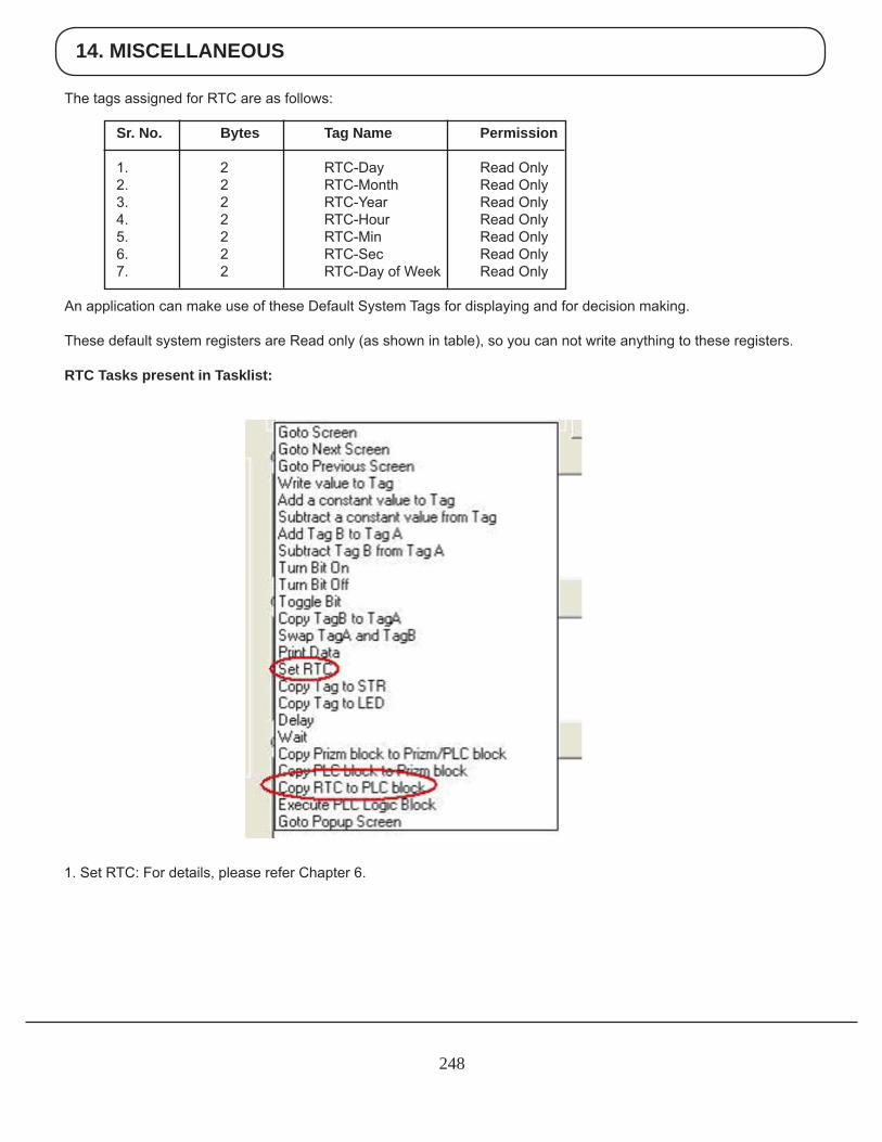
14. MISCELLANEOUS
248
1. Set RTC: For details, please refer Chapter 6.
The tags assigned for RTC are as follows:
Sr. No. Bytes Tag Name Permission 1. 2 RTC-Day Read Only 2. 2 RTC-Month Read Only 3. 2 RTC-Year Read Only 4. 2 RTC-Hour Read Only 5. 2 RTC-Min Read Only 6. 2 RTC-Sec Read Only 7. 2 RTC-Day of Week Read Only
An application can make use of these Default System Tags for displaying and for decision making.
These default system registers are Read only (as shown in table), so you can not write anything to these registers.
RTC Tasks present in Tasklist:
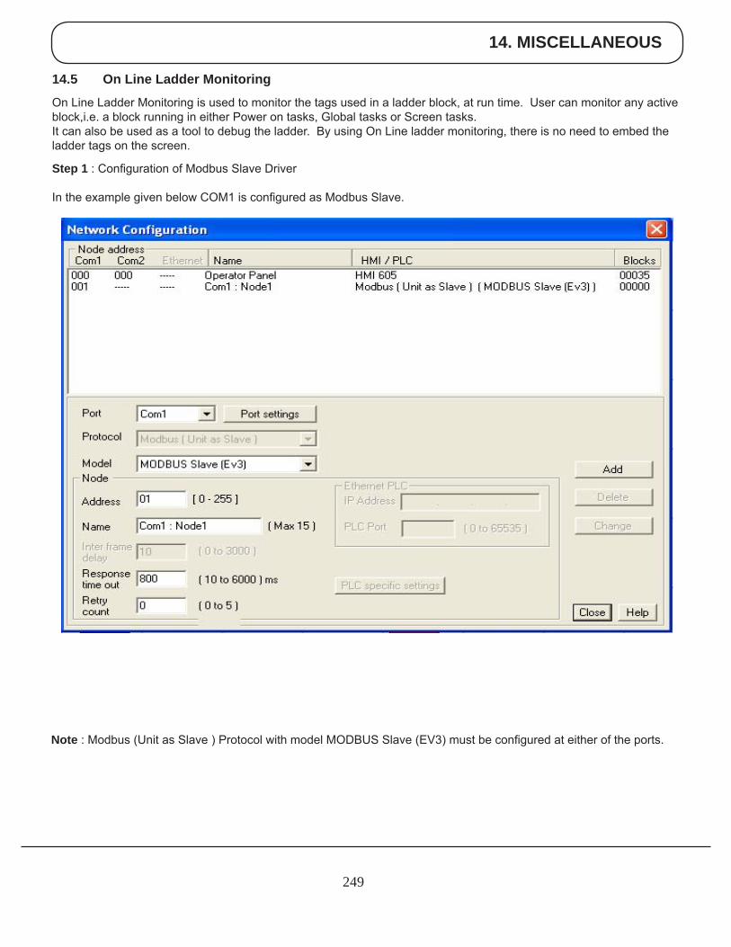
14. MISCELLANEOUS
249
14.5 On Line Ladder Monitoring
On Line Ladder Monitoring is used to monitor the tags used in a ladder block, at run time. User can monitor any active block,i.e. a block running in either Power on tasks, Global tasks or Screen tasks. It can also be used as a tool to debug the ladder. By using On Line ladder monitoring, there is no need to embed the ladder tags on the screen.
Step 1 : Configuration of Modbus Slave Driver
In the example given below COM1 is configured as Modbus Slave.
Note : Modbus (Unit as Slave ) Protocol with model MODBUS Slave (EV3) must be configured at either of the ports.
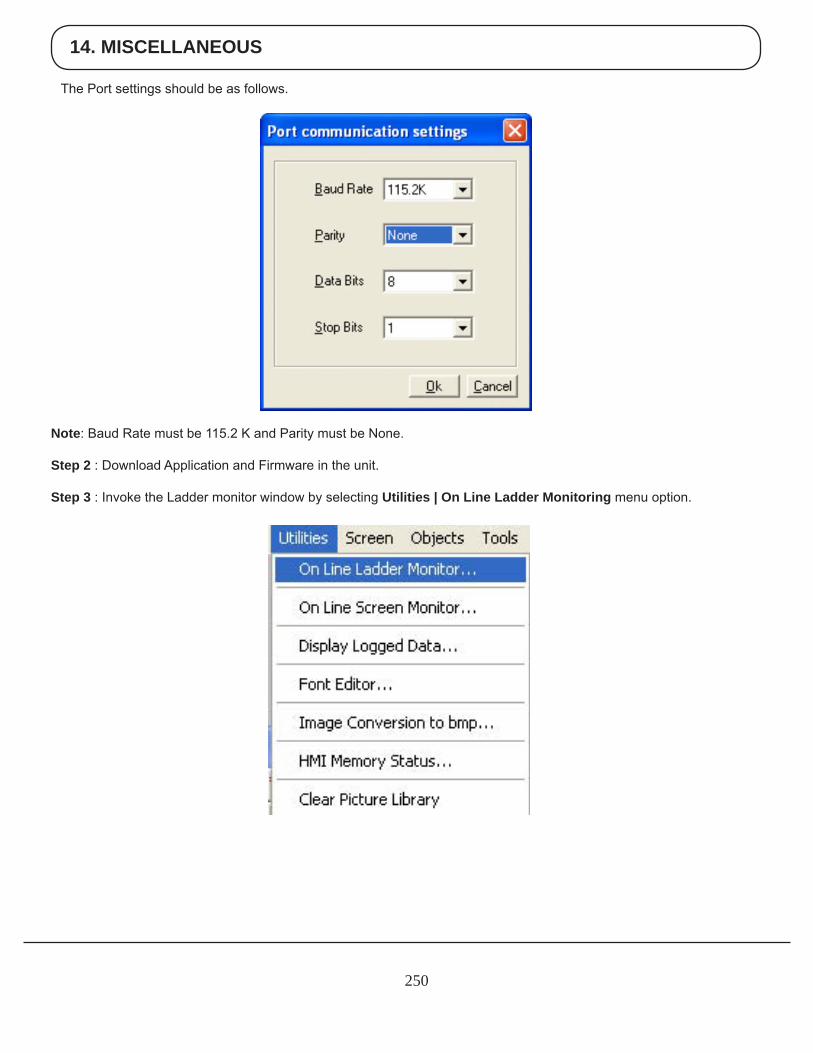
14. MISCELLANEOUS
250
The Port settings should be as follows.
Note: Baud Rate must be 115.2 K and Parity must be None.
Step 2 : Download Application and Firmware in the unit.
Step 3 : Invoke the Ladder monitor window by selecting Utilities | On Line Ladder Monitoring menu option.
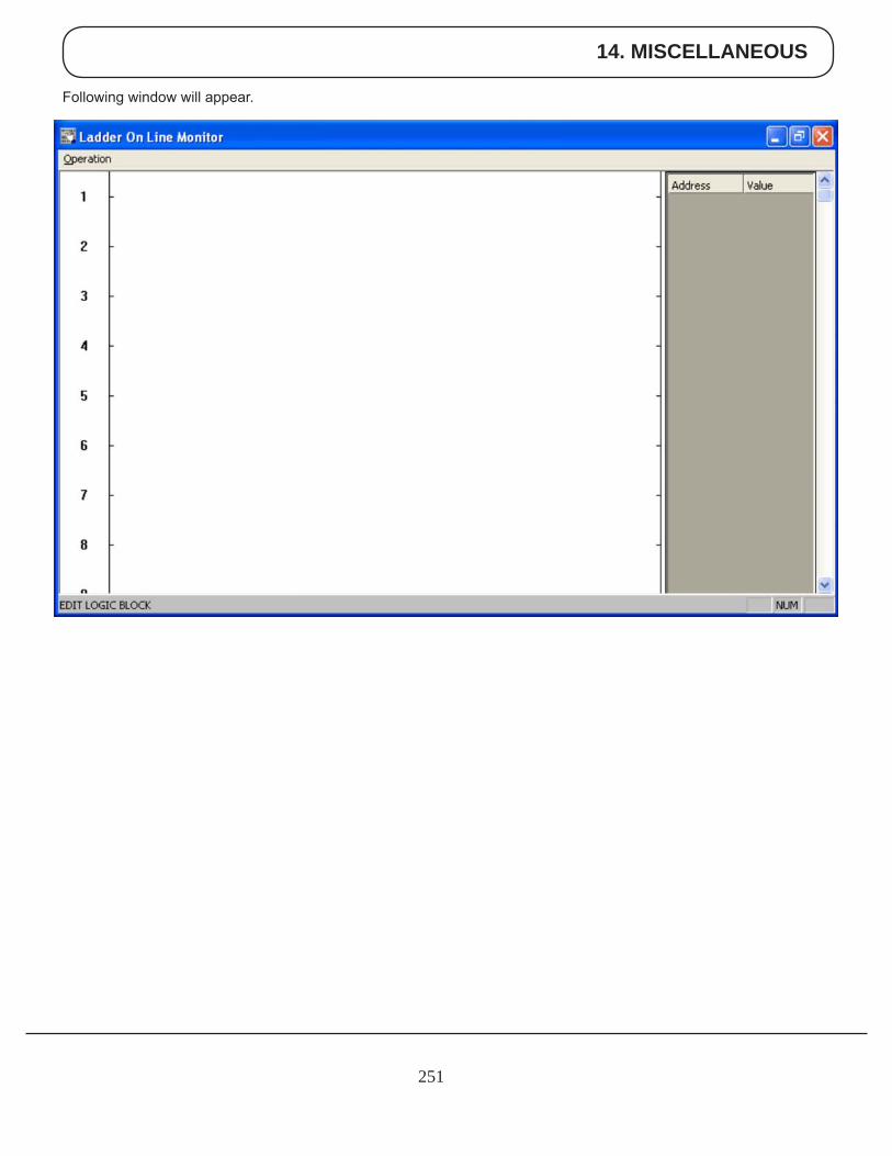
14. MISCELLANEOUS
251
Following window will appear.
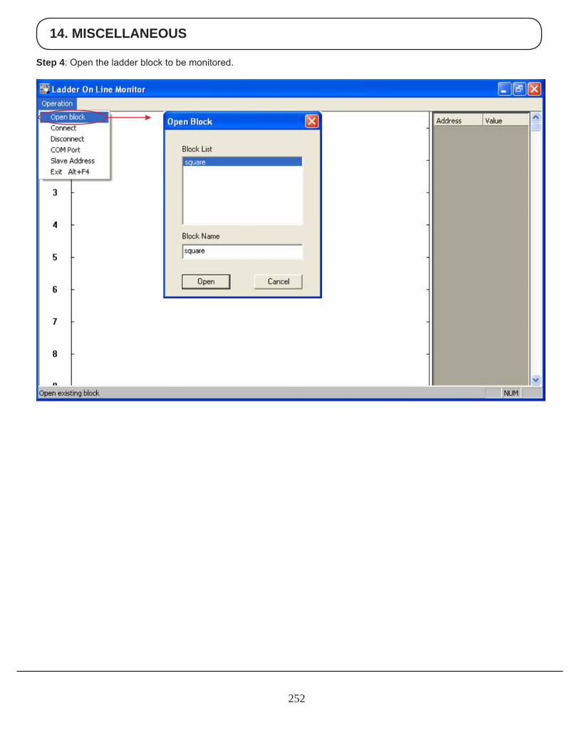
14. MISCELLANEOUS
252
Step 4: Open the ladder block to be monitored.
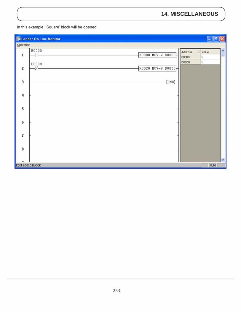
14. MISCELLANEOUS
253
In this example, ‘Square’ block will be opened.
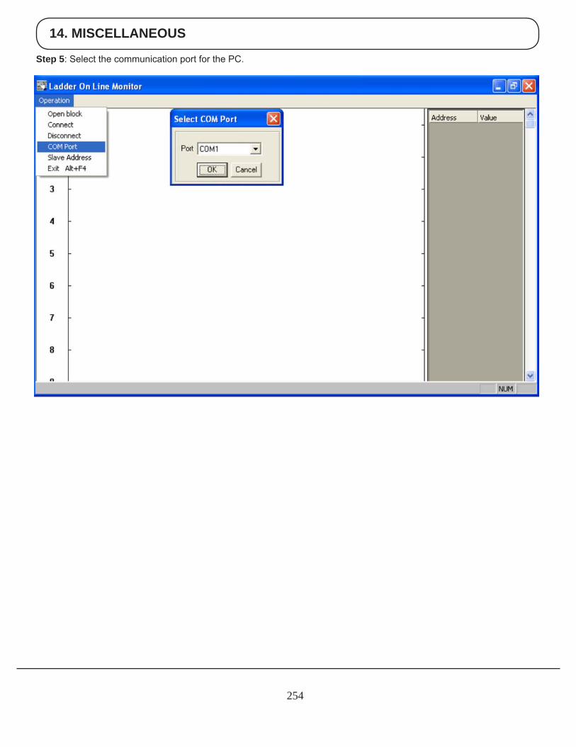
14. MISCELLANEOUS
254
Step 5: Select the communication port for the PC.
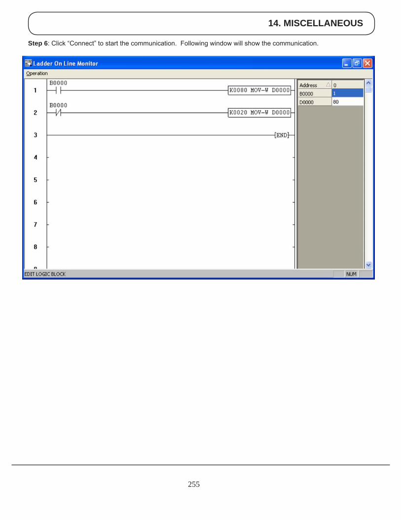
14. MISCELLANEOUS
255
Step 6: Click “Connect” to start the communication. Following window will show the communication.
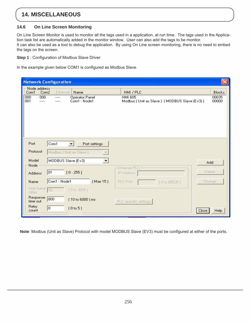
14. MISCELLANEOUS
256
14.6 On Line Screen Monitoring
On Line Screen Monitor is used to monitor all the tags used in a application, at run time. The tags used in the Applica-tion task list are automatically added in the monitor window. User can also add the tags to be monitor.It can also be used as a tool to debug the application. By using On Line screen monitoring, there is no need to embed the tags on the screen.
Step 1 : Configuration of Modbus Slave Driver
In the example given below COM1 is configured as Modbus Slave.
Note: Modbus (Unit as Slave) Protocol with model MODBUS Slave (EV3) must be configured at either of the ports.
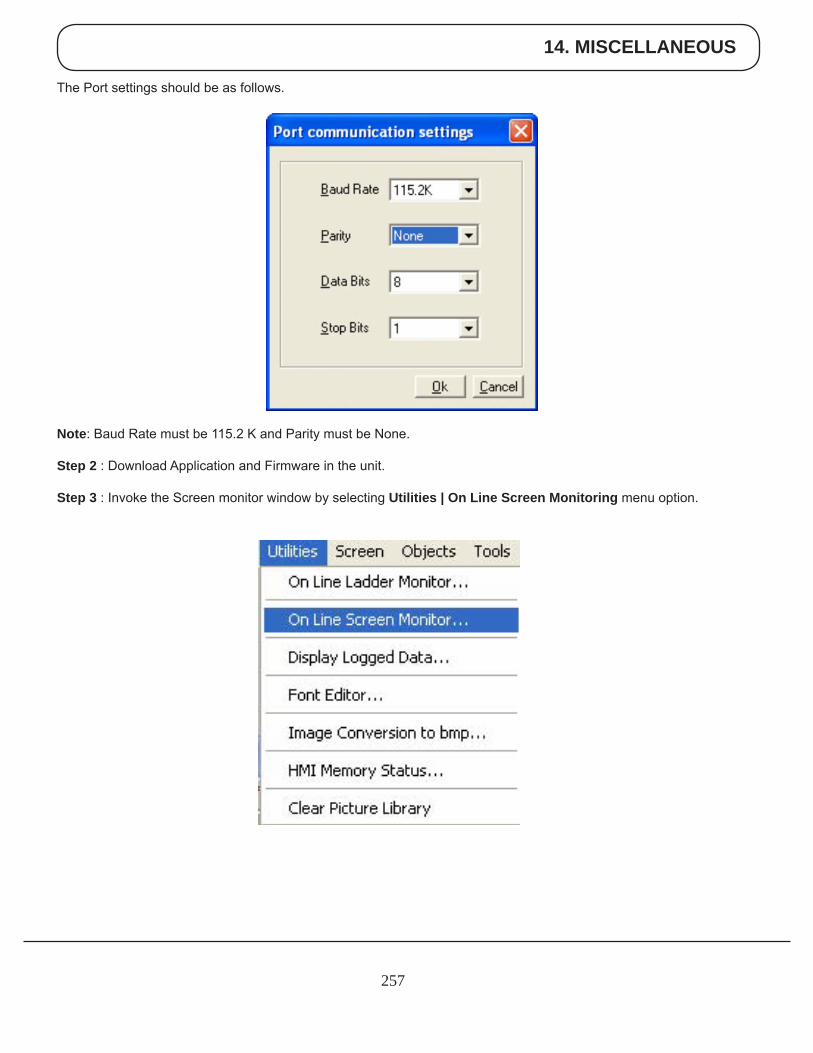
14. MISCELLANEOUS
257
The Port settings should be as follows.
Note: Baud Rate must be 115.2 K and Parity must be None.
Step 2 : Download Application and Firmware in the unit.
Step 3 : Invoke the Screen monitor window by selecting Utilities | On Line Screen Monitoring menu option.
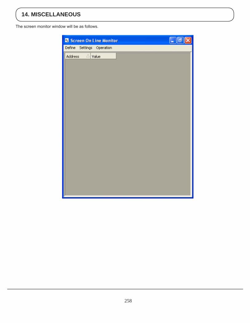
14. MISCELLANEOUS
258
The screen monitor window will be as follows.
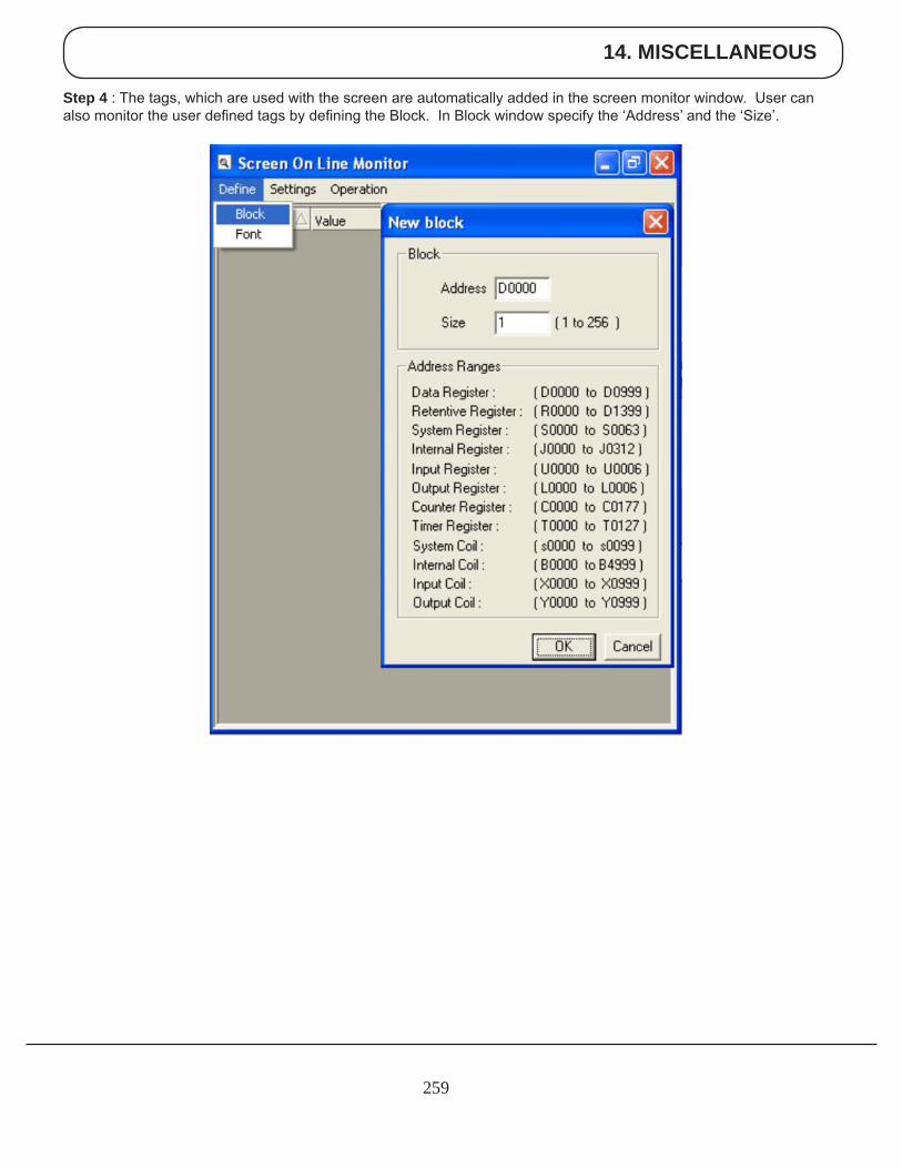
14. MISCELLANEOUS
259
Step 4 : The tags, which are used with the screen are automatically added in the screen monitor window. User can also monitor the user defined tags by defining the Block. In Block window specify the ‘Address’ and the ‘Size’.
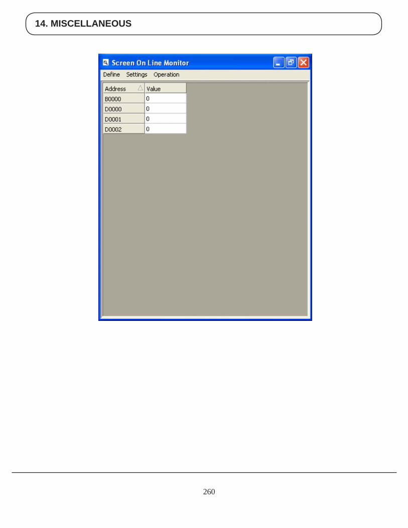
14. MISCELLANEOUS
260
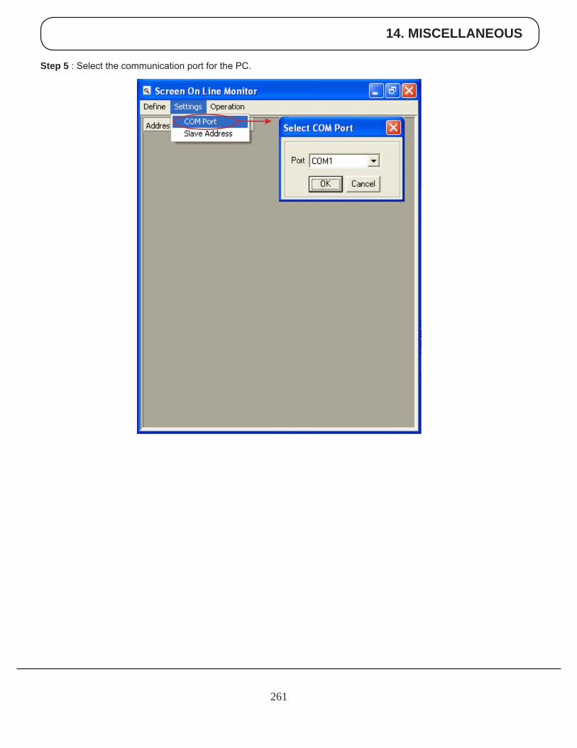
14. MISCELLANEOUS
261
Step 5 : Select the communication port for the PC.
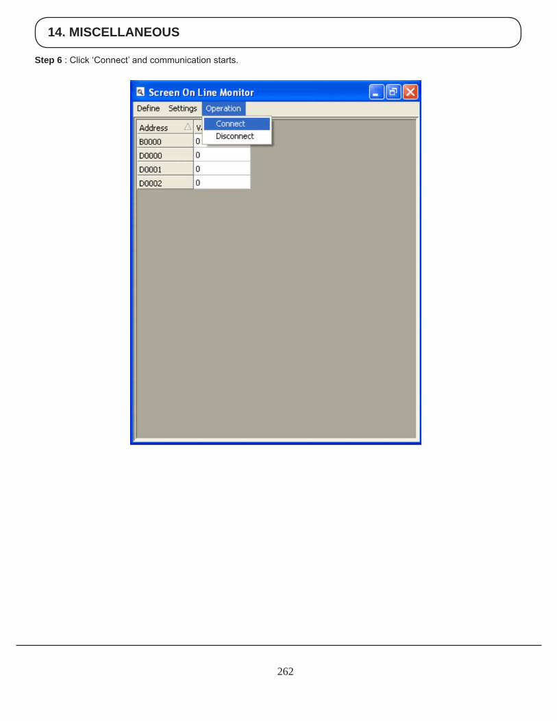
14. MISCELLANEOUS
262
Step 6 : Click ‘Connect’ and communication starts.
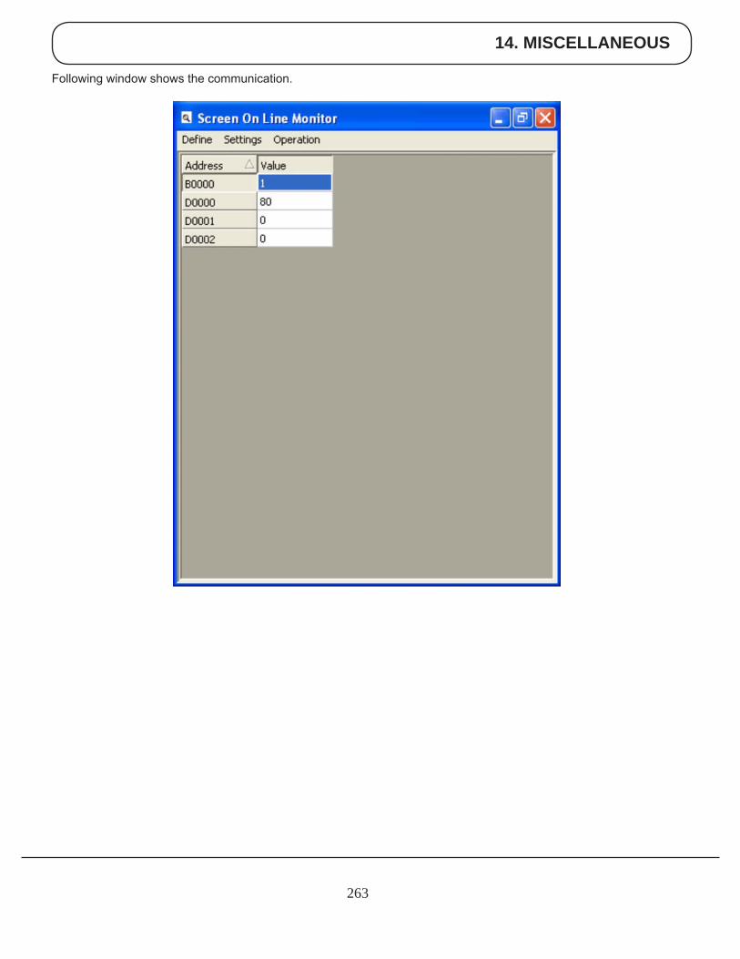
14. MISCELLANEOUS
263
Following window shows the communication.
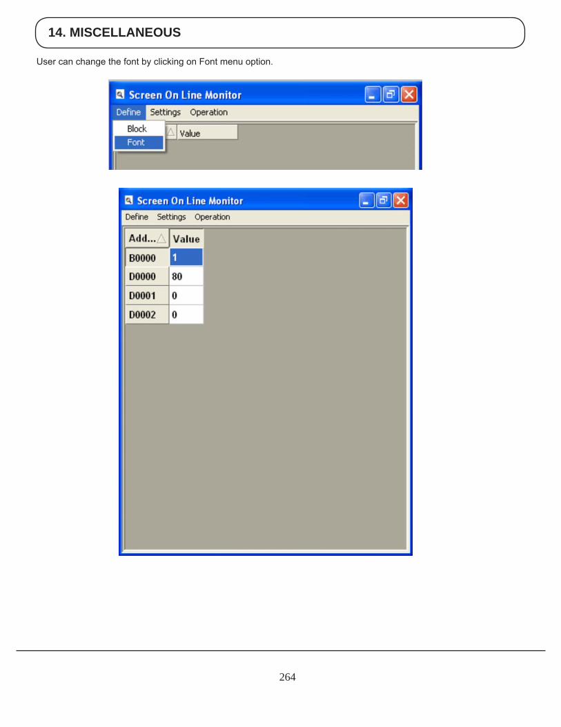
14. MISCELLANEOUS
264
User can change the font by clicking on Font menu option.
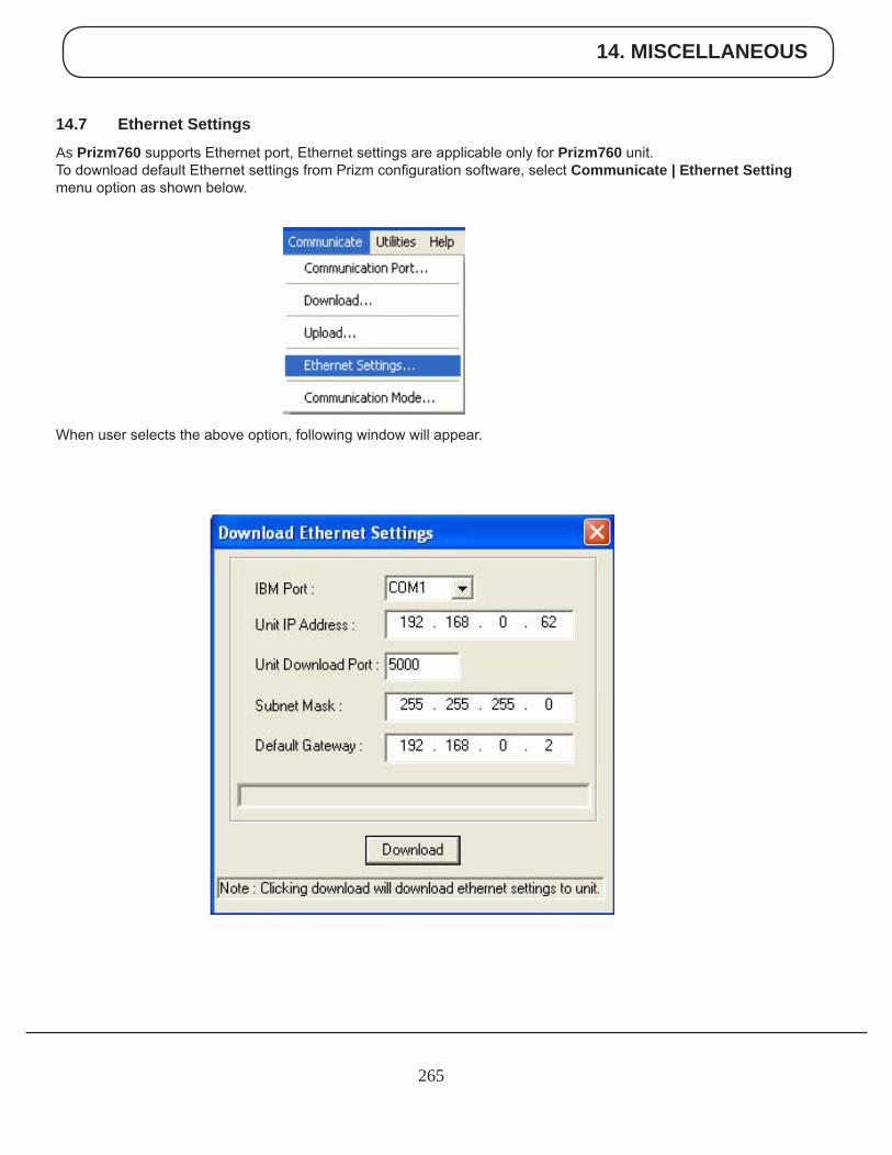
14. MISCELLANEOUS
265
14.7 Ethernet Settings
AsPrizm760 supports Ethernet port, Ethernet settings are applicable only for Prizm760 unit. To download default Ethernet settings from Prizm configuration software, select Communicate | Ethernet Settingmenu option as shown below.
When user selects the above option, following window will appear.
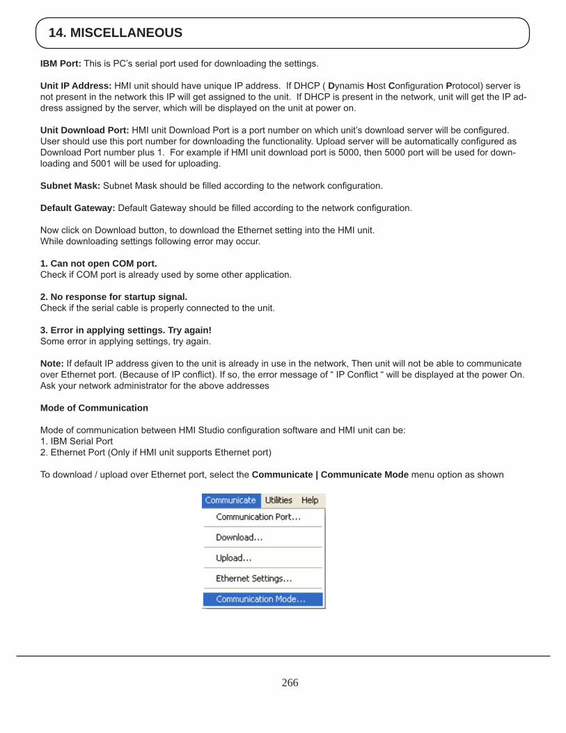
14. MISCELLANEOUS
266
IBM Port: This is PC’s serial port used for downloading the settings.
Unit IP Address: HMI unit should have unique IP address. If DHCP ( DynamisHostConfiguration Protocol) server is not present in the network this IP will get assigned to the unit. If DHCP is present in the network, unit will get the IP ad-dress assigned by the server, which will be displayed on the unit at power on.
Unit Download Port: HMI unit Download Port is a port number on which unit’s download server will be configured. User should use this port number for downloading the functionality. Upload server will be automatically configured as Download Port number plus 1. For example if HMI unit download port is 5000, then 5000 port will be used for down-loading and 5001 will be used for uploading.
Subnet Mask: Subnet Mask should be filled according to the network configuration.
Default Gateway: Default Gateway should be filled according to the network configuration.
Now click on Download button, to download the Ethernet setting into the HMI unit.While downloading settings following error may occur.
1. Can not open COM port. Check if COM port is already used by some other application.
2. No response for startup signal.Check if the serial cable is properly connected to the unit.
3. Error in applying settings. Try again!Some error in applying settings, try again.
Note: If default IP address given to the unit is already in use in the network, Then unit will not be able to communicate over Ethernet port. (Because of IP conflict). If so, the error message of “ IP Conflict “ will be displayed at the power On. Ask your network administrator for the above addresses
Mode of Communication
Mode of communication between HMI Studio configuration software and HMI unit can be:1. IBM Serial Port2. Ethernet Port (Only if HMI unit supports Ethernet port)
To download / upload over Ethernet port, select the Communicate | Communicate Mode menu option as shown
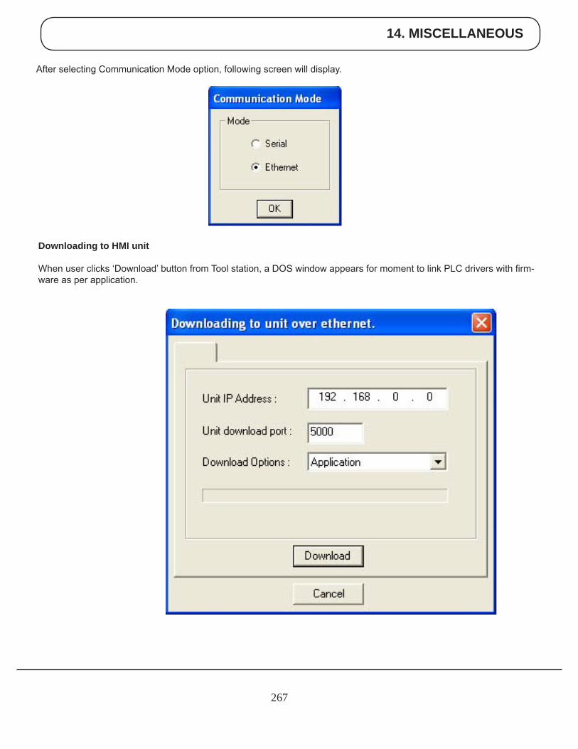
14. MISCELLANEOUS
267
After selecting Communication Mode option, following screen will display.
Downloading to HMI unit
When user clicks ‘Download’ button from Tool station, a DOS window appears for moment to link PLC drivers with firm-ware as per application.
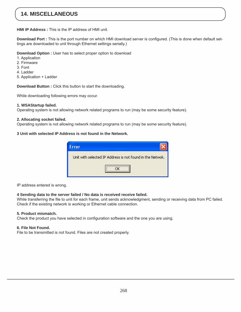
14. MISCELLANEOUS
268
HMI IP Address : This is the IP address of HMI unit.
Download Port : This is the port number on which HMI download server is configured. (This is done when default set-tings are downloaded to unit through Ethernet settings serially.)
Download Option : User has to select proper option to download1. Application2. Firmware3. Font4. Ladder5. Application + Ladder
Download Button : Click this button to start the downloading.
While downloading following errors may occur.
1. WSAStartup failed.Operating system is not allowing network related programs to run (may be some security feature).
2. Allocating socket failed.Operating system is not allowing network related programs to run (may be some security feature).
3 Unit with selected IP Address is not found in the Network.
IP address entered is wrong.
4 Sending data to the server failed / No data is received receive failed.While transferring the file to unit for each frame, unit sends acknowledgment, sending or receiving data from PC failed. Check if the existing network is working or Ethernet cable connection.
5. Product mismatch.Check the product you have selected in configuration software and the one you are using.
6. File Not Found.File to be transmitted is not found. Files are not created properly.
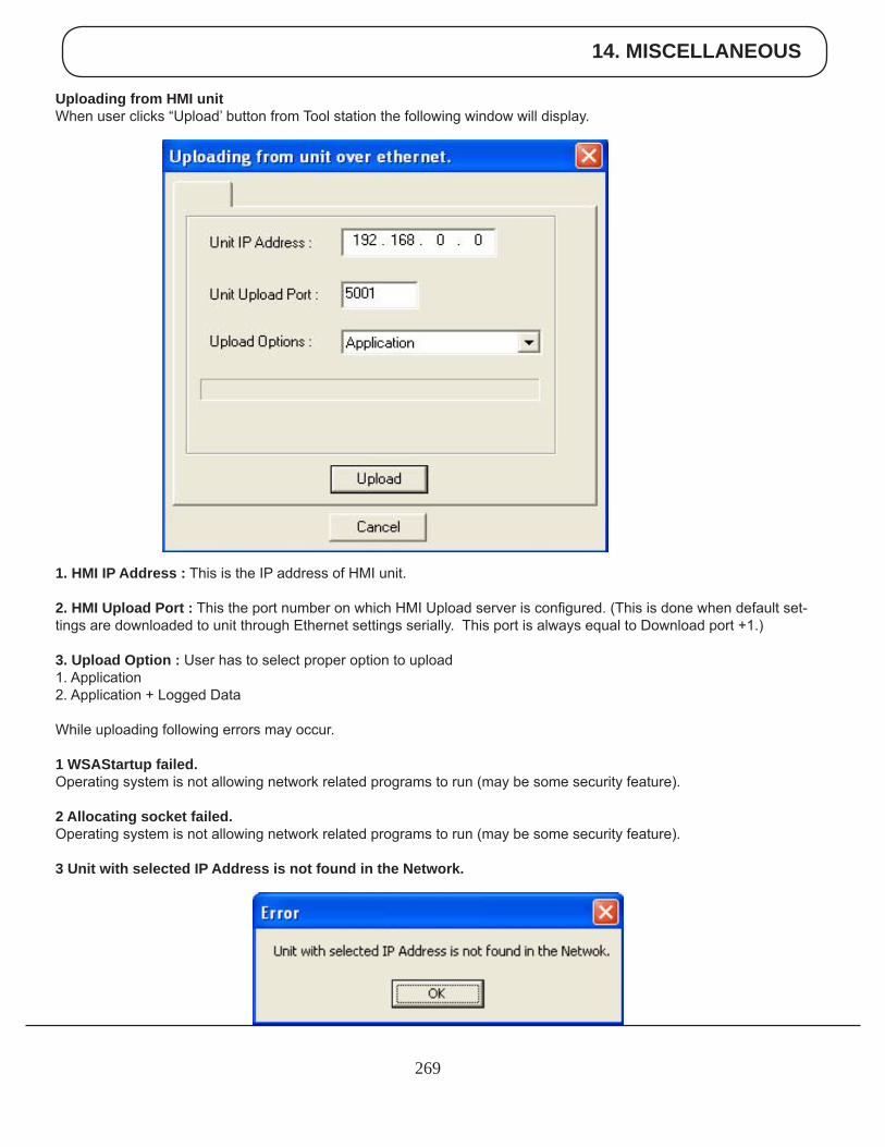
14. MISCELLANEOUS
269
Uploading from HMI unitWhen user clicks “Upload’ button from Tool station the following window will display.
1. HMI IP Address : This is the IP address of HMI unit.
2. HMI Upload Port : This the port number on which HMI Upload server is configured. (This is done when default set-tings are downloaded to unit through Ethernet settings serially. This port is always equal to Download port +1.)
3. Upload Option : User has to select proper option to upload1. Application2. Application + Logged Data
While uploading following errors may occur.
1 WSAStartup failed.Operating system is not allowing network related programs to run (may be some security feature).
2 Allocating socket failed.Operating system is not allowing network related programs to run (may be some security feature).
3 Unit with selected IP Address is not found in the Network.
14. MISCELLANEOUS
270
IP address entered is wrong.
4 Sending data to the server failed / No data is received receive failed.While transferring the file to unit for each frame, unit sends acknowledgment, sending or receiving data from PC failed. Check if the existing network is working or Ethernet cable connection.
5. Product mismatch.Check the product you have selected in configuration software and the one you are using.
6. File Not Found.File to be transmitted is not found. Files are not created properly.
Notes:1. For connecting unit and the PC point to point, use standard Ethernet cross over cable.2. For connecting unit and PC through the switch, use standard Ethernet straight through cable.3. For Point to point communication over Ethernet, PC should be given static IP address.
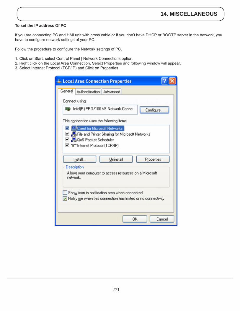
14. MISCELLANEOUS
271
To set the IP address Of PC
If you are connecting PC and HMI unit with cross cable or if you don’t have DHCP or BOOTP server in the network, you have to configure network settings of your PC.
Follow the procedure to configure the Network settings of PC.
1. Click on Start, select Control Panel | Network Connections option.2. Right click on the Local Area Connection. Select Properties and following window will appear.3. Select Internet Protocol (TCP/IP) and Click on Properties
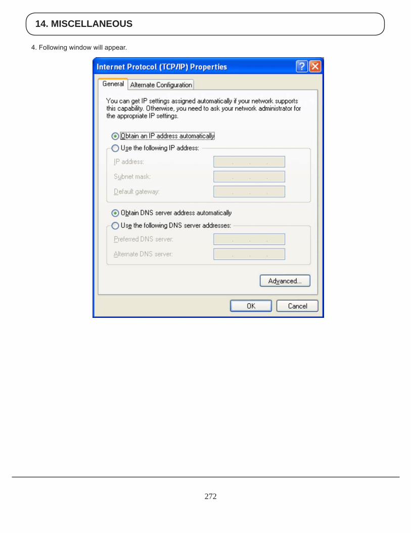
14. MISCELLANEOUS
272
4. Following window will appear.
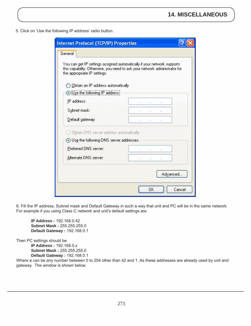
14. MISCELLANEOUS
273
5. Click on ‘Use the following IP address’ radio button.
6. Fill the IP address, Subnet mask and Default Gateway in such a way that unit and PC will be in the same network.For example if you using Class C network and unit’s default settings are
IP Address : 192.168.0.42 Subnet Mask : 255.255.255.0 Default Gateway : 192.168.0.1
Then PC settings should be IP Address : 192.168.0.x Subnet Mask : 255.255.255.0 Default Gateway : 192.168.0.1Where x can be any number between 0 to 254 other than 42 and 1. As these addresses are already used by unit and gateway. The window is shown below.
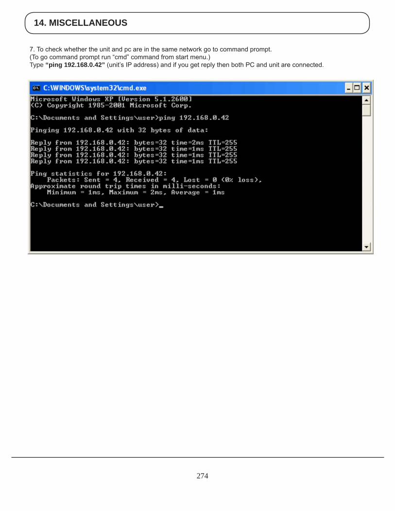
14. MISCELLANEOUS
274
7. To check whether the unit and pc are in the same network go to command prompt.(To go command prompt run “cmd” command from start menu.)Type “ping 192.168.0.42” (unit’s IP address) and if you get reply then both PC and unit are connected.
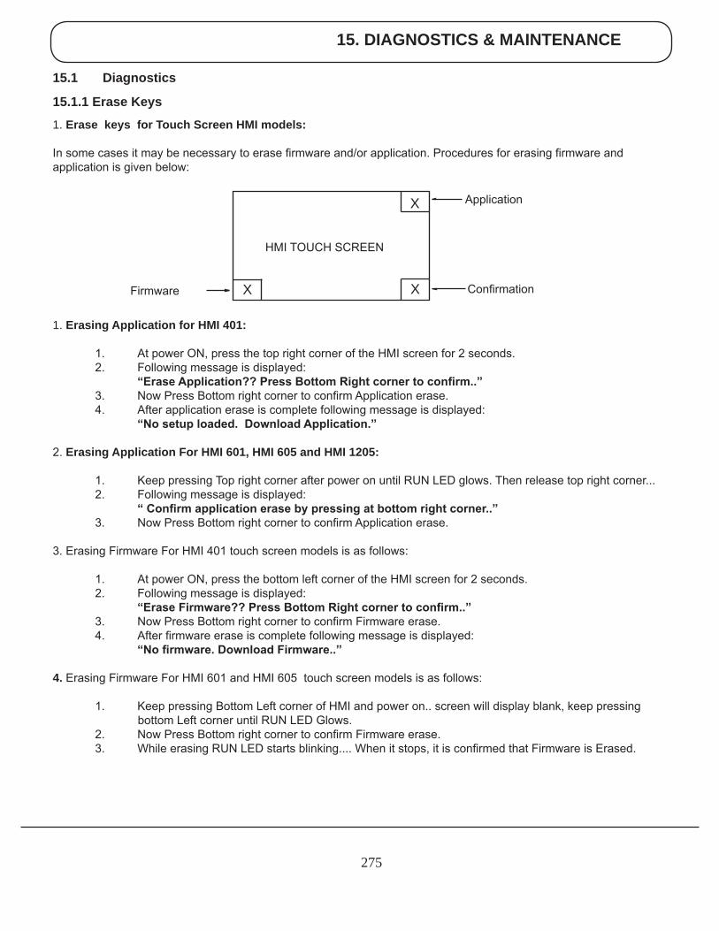
15. DIAGNOSTICS & MAINTENANCE
275
15.1 Diagnostics
15.1.1 Erase Keys
1. Erase keys for Touch Screen HMI models:
In some cases it may be necessary to erase firmware and/or application. Procedures for erasing firmware and application is given below:
1. Erasing Application for HMI 401:
1. At power ON, press the top right corner of the HMI screen for 2 seconds. 2. Following message is displayed: “EraseApplication??PressBottomRightcornertoconfirm..” 3. Now Press Bottom right corner to confirm Application erase. 4. After application erase is complete following message is displayed: “Nosetuploaded.DownloadApplication.”
2. Erasing Application For HMI 601, HMI 605 and HMI 1205:
1. Keep pressing Top right corner after power on until RUN LED glows. Then release top right corner... 2. Following message is displayed: “Confirmapplicationerasebypressingatbottomrightcorner..” 3. Now Press Bottom right corner to confirm Application erase.
3. Erasing Firmware For HMI 401 touch screen models is as follows:
1. At power ON, press the bottom left corner of the HMI screen for 2 seconds. 2. Following message is displayed: “EraseFirmware??PressBottomRightcornertoconfirm..” 3. Now Press Bottom right corner to confirm Firmware erase. 4. After firmware erase is complete following message is displayed: “Nofirmware.DownloadFirmware..”
4. Erasing Firmware For HMI 601 and HMI 605 touch screen models is as follows:
1. Keep pressing Bottom Left corner of HMI and power on.. screen will display blank, keep pressing bottom Left corner until RUN LED Glows. 2. Now Press Bottom right corner to confirm Firmware erase. 3. While erasing RUN LED starts blinking.... When it stops, it is confirmed that Firmware is Erased.
ConfirmationX
X
X
Application
Firmware
HMI TOUCH SCREEN
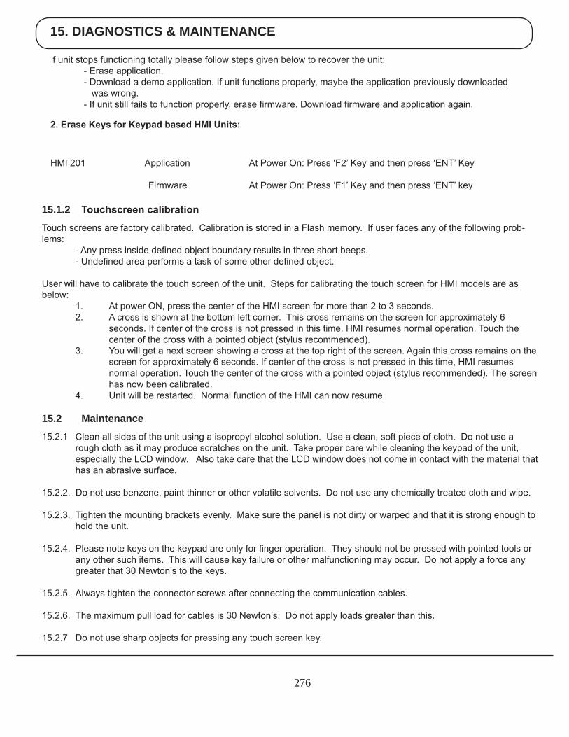
15. DIAGNOSTICS & MAINTENANCE
276
HMI 201 Application At Power On: Press ‘F2’ Key and then press ‘ENT’ Key Firmware At Power On: Press ‘F1’ Key and then press ‘ENT’ key
2.EraseKeysforKeypadbasedHMIUnits:
15.1.2 Touchscreencalibration
Touch screens are factory calibrated. Calibration is stored in a Flash memory. If user faces any of the following prob-lems: - Any press inside defined object boundary results in three short beeps. - Undefined area performs a task of some other defined object.
User will have to calibrate the touch screen of the unit. Steps for calibrating the touch screen for HMI models are as below: 1. At power ON, press the center of the HMI screen for more than 2 to 3 seconds. 2. A cross is shown at the bottom left corner. This cross remains on the screen for approximately 6 seconds. If center of the cross is not pressed in this time, HMI resumes normal operation. Touch the center of the cross with a pointed object (stylus recommended). 3. You will get a next screen showing a cross at the top right of the screen. Again this cross remains on the screen for approximately 6 seconds. If center of the cross is not pressed in this time, HMI resumes normal operation. Touch the center of the cross with a pointed object (stylus recommended). The screen has now been calibrated. 4. Unit will be restarted. Normal function of the HMI can now resume.
15.2 Maintenance
15.2.1 Clean all sides of the unit using a isopropyl alcohol solution. Use a clean, soft piece of cloth. Do not use a rough cloth as it may produce scratches on the unit. Take proper care while cleaning the keypad of the unit, especially the LCD window. Also take care that the LCD window does not come in contact with the material that has an abrasive surface.
15.2.2. Do not use benzene, paint thinner or other volatile solvents. Do not use any chemically treated cloth and wipe.
15.2.3. Tighten the mounting brackets evenly. Make sure the panel is not dirty or warped and that it is strong enough to hold the unit.
15.2.4. Please note keys on the keypad are only for finger operation. They should not be pressed with pointed tools or any other such items. This will cause key failure or other malfunctioning may occur. Do not apply a force any greater that 30 Newton’s to the keys.
15.2.5. Always tighten the connector screws after connecting the communication cables.
15.2.6. The maximum pull load for cables is 30 Newton’s. Do not apply loads greater than this. 15.2.7 Do not use sharp objects for pressing any touch screen key.
f unit stops functioning totally please follow steps given below to recover the unit: - Erase application. - Download a demo application. If unit functions properly, maybe the application previously downloaded was wrong. - If unit still fails to function properly, erase firmware. Download firmware and application again.
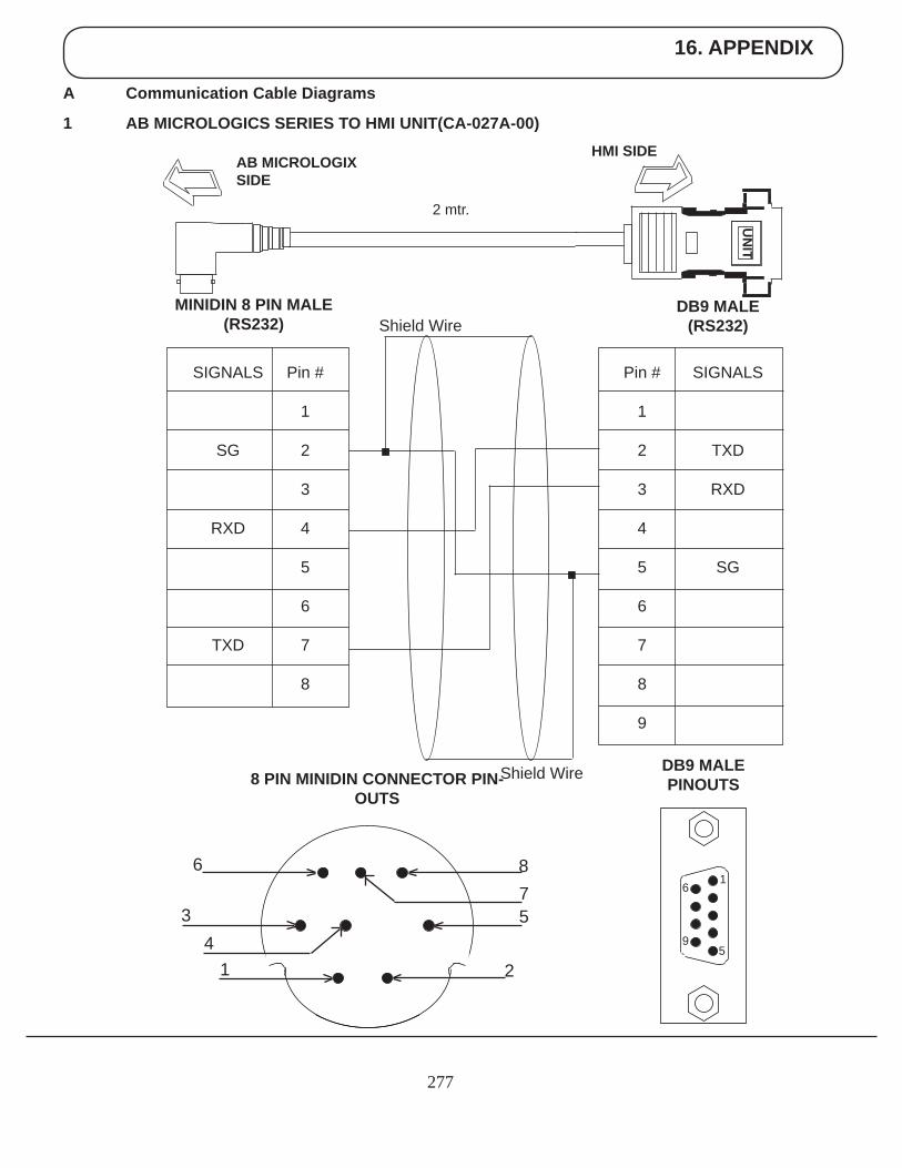
16. APPENDIX
277
A Communication Cable Diagrams
1 AB MICROLOGICS SERIES TO HMI UNIT(CA-027A-00)
UN
ITHMI SIDE
AB MICROLOGIX SIDE
2 mtr.
Pin #
1
2
3
4
5
6
7
8
9
SIGNALS
TXD
RXD
SG
DB9 MALE (RS232)
Pin #
1
2
3
4
5
6
7
8
SIGNALS
SG
RXD
TXD
MINIDIN 8 PIN MALE(RS232)
DB9 MALE PINOUTS8 PIN MINIDIN CONNECTOR PIN-
OUTS
Shield Wire
Shield Wire
6
9
1
5
6
34
1
875
2
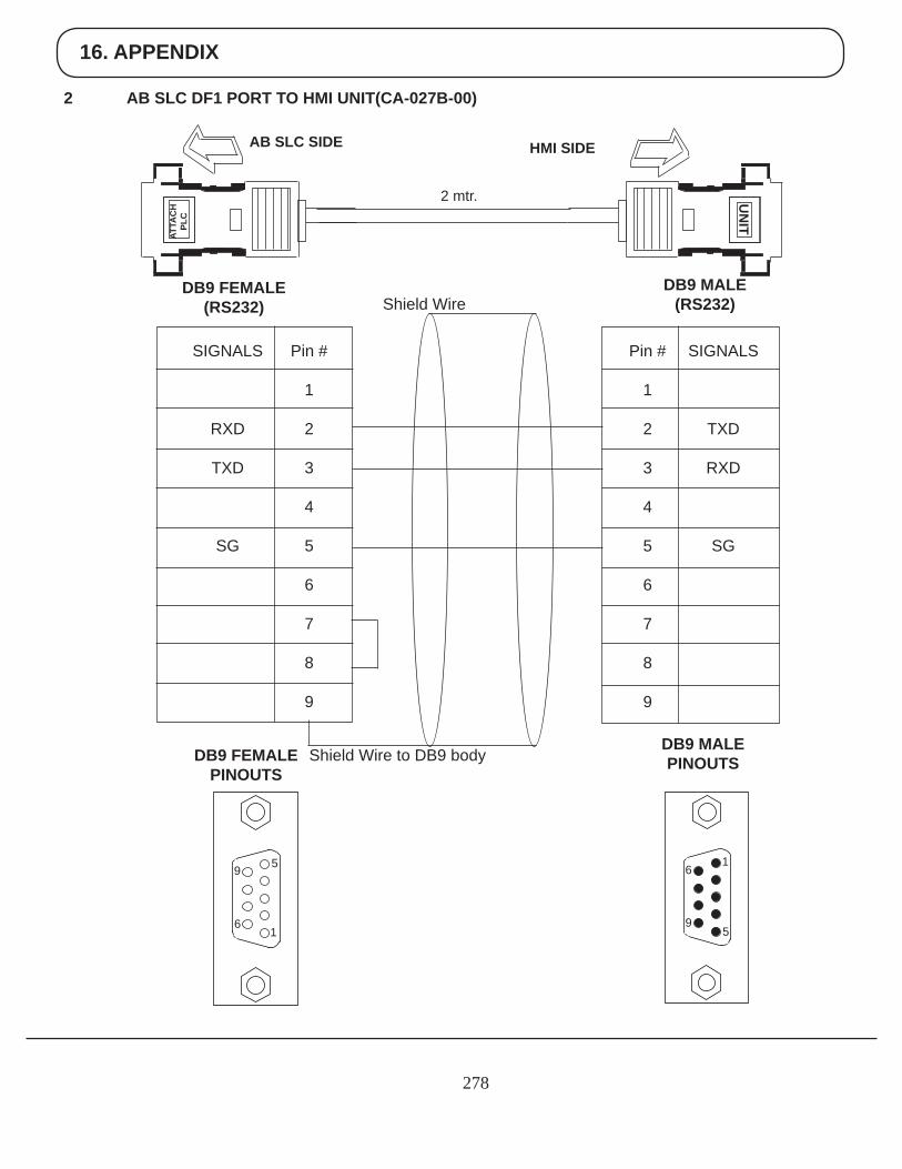
16. APPENDIX
278
2 AB SLC DF1 PORT TO HMI UNIT(CA-027B-00)
UN
ITHMI SIDEAB SLC SIDE
2 mtr.
SIGNALS
TXD
RXD
SG
DB9 MALE (RS232)
DB9 FEMALE(RS232)
DB9 MALE PINOUTSDB9 FEMALE
PINOUTS
6
9
1
5
Shield Wire
Shield Wire to DB9 body
ATTA
CH
PLC
9
6
5
1
Pin #
1
2
3
4
5
6
7
8
9
Pin #
1
2
3
4
5
6
7
8
9
SIGNALS
RXD
TXD
SG
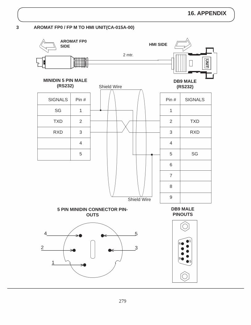
16. APPENDIX
279
3 AROMAT FP0 / FP M TO HMI UNIT(CA-015A-00)
UN
ITHMI SIDE
AROMAT FP0SIDE
2 mtr.
Pin #
1
2
3
4
5
6
7
8
9
SIGNALS
TXD
RXD
SG
DB9 MALE (RS232)
Pin #
1
2
3
4
5
SIGNALS
SG
TXD
RXD
MINIDIN 5 PIN MALE(RS232)
DB9 MALE PINOUTS
5 PIN MINIDIN CONNECTOR PIN-OUTS
Shield Wire
Shield Wire
6
9
1
5
4
2
1
5
3
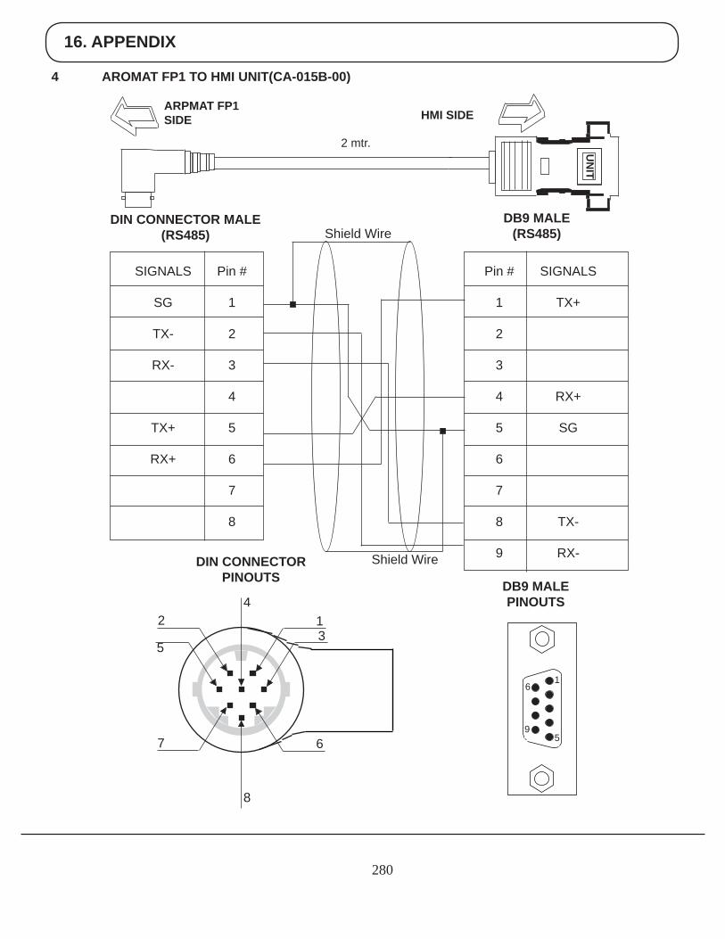
16. APPENDIX
280
4 AROMAT FP1 TO HMI UNIT(CA-015B-00)
UN
IT
HMI SIDEARPMAT FP1SIDE
2 mtr.
Pin #
1
2
3
4
5
6
7
8
9
SIGNALS
TX+
RX+
SG
TX-
RX-
DB9 MALE (RS485)
Pin #
1
2
3
4
5
6
7
8
SIGNALS
SG
TX-
RX-
TX+
RX+
DIN CONNECTOR MALE(RS485)
DB9 MALE PINOUTS
DIN CONNECTORPINOUTS
6
9
1
5
Shield Wire
Shield Wire
42
5
7
8
6
13
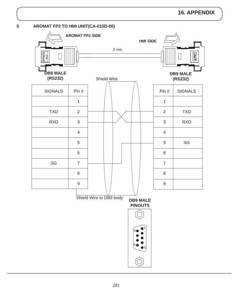
16. APPENDIX
281
5 AROMAT FP2 TO HMI UNIT(CA-015D-00)
UN
ITHMI SIDE
AROMAT FP2 SIDE
2 mtr.
SIGNALS
TXD
RXD
SG
DB9 MALE (RS232)
DB9 MALE(RS232)
DB9 MALE PINOUTS
6
9
1
5
Shield Wire
Shield Wire to DB9 body
ATTA
CH
PLC
Pin #
1
2
3
4
5
6
7
8
9
Pin #
1
2
3
4
5
6
7
8
9
SIGNALS
TXD
RXD
SG
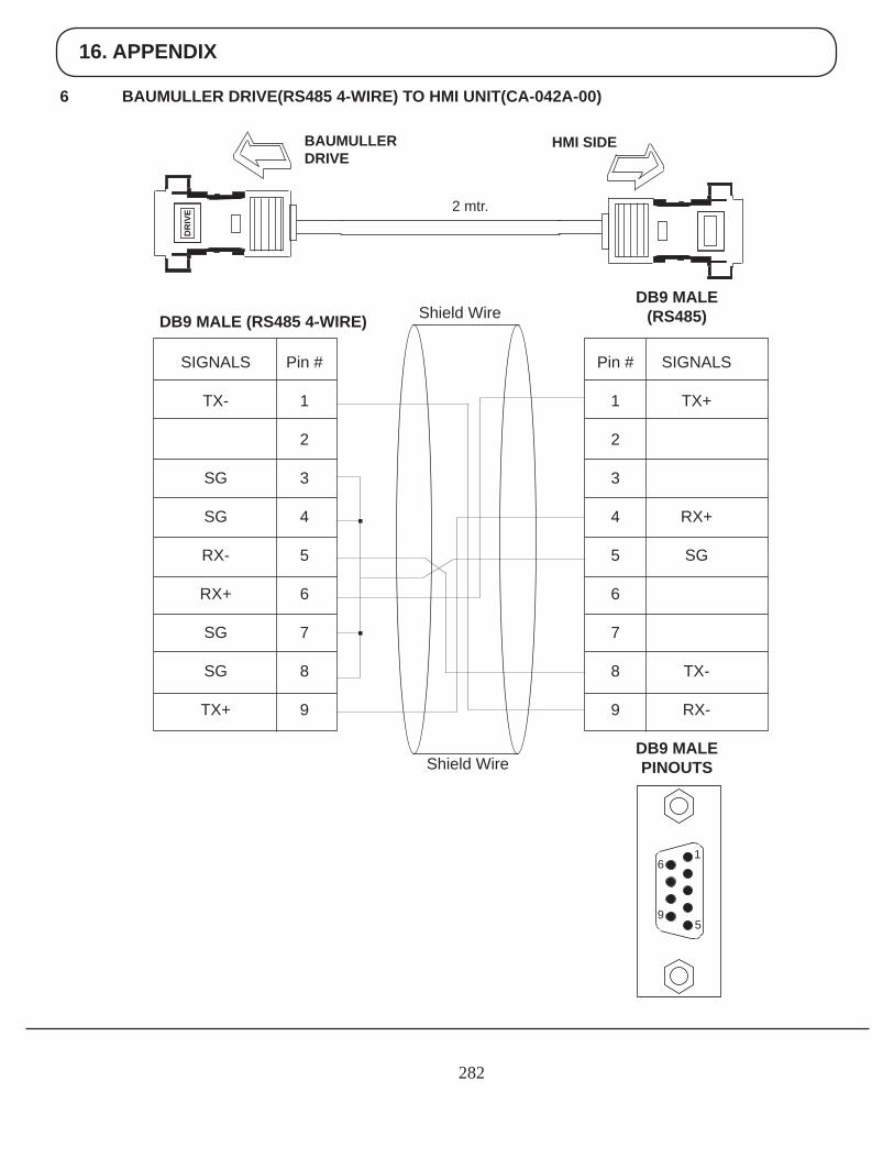
16. APPENDIX
282
6 BAUMULLER DRIVE(RS485 4-WIRE) TO HMI UNIT(CA-042A-00)
HMI SIDEBAUMULLERDRIVE
2 mtr.
SIGNALS
TX+
RX+
SG
TX-
RX-
DB9 MALE (RS485)DB9 MALE (RS485 4-WIRE)
DB9 MALE PINOUTS
6
9
1
5
Shield Wire
Shield Wire
Pin #
1
2
3
4
5
6
7
8
9
DR
IVE
Pin #
1
2
3
4
5
6
7
8
9
SIGNALS
TX-
SG
SG
RX-
RX+
SG
SG
TX+
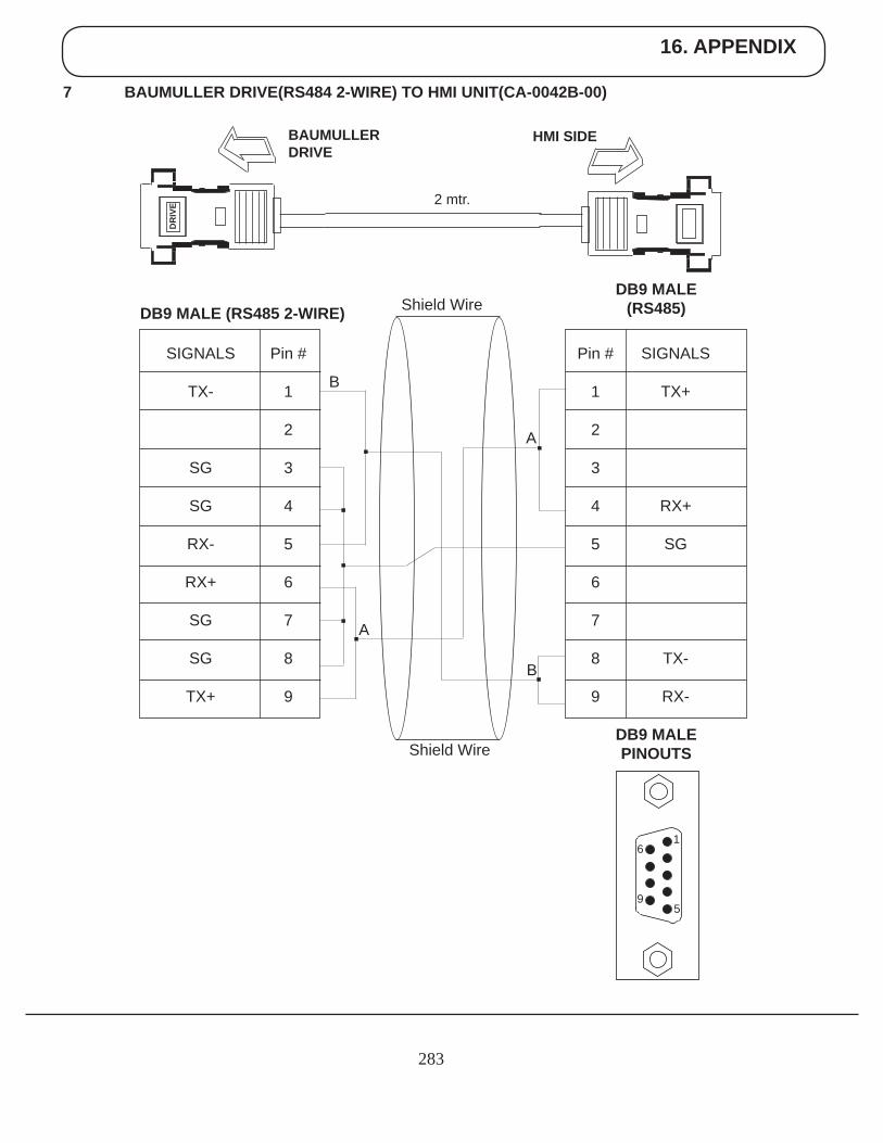
16. APPENDIX
283
7 BAUMULLER DRIVE(RS484 2-WIRE) TO HMI UNIT(CA-0042B-00)
HMI SIDEBAUMULLERDRIVE
2 mtr.
SIGNALS
TX+
RX+
SG
TX-
RX-
DB9 MALE (RS485)DB9 MALE (RS485 2-WIRE)
DB9 MALE PINOUTS
6
9
1
5
Shield Wire
Shield Wire
Pin #
1
2
3
4
5
6
7
8
9
DR
IVE
Pin #
1
2
3
4
5
6
7
8
9
SIGNALS
TX-
SG
SG
RX-
RX+
SG
SG
TX+
B
B
A
A
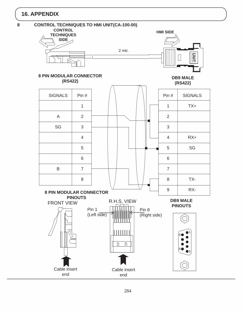
16. APPENDIX
284
8 CONTROL TECHNIQUES TO HMI UNIT(CA-100-00) CONTROL
TECHNIQUESSIDE
UN
IT
HMI SIDE
2 mtr.
Pin #
1
2
3
4
5
6
7
8
9
SIGNALS
TX+
RX+
SG
TX-
RX-
DB9 MALE (RS422)
Pin #
1
2
3
4
5
6
7
8
SIGNALS
A
SG
B
8 PIN MODULAR CONNECTOR (RS422)
DB9 MALE PINOUTS
8 PIN MODULAR CONNECTOR PINOUTS
6
9
1
5
Cable insert end
Cable insert end
Pin 1(Left side)
Pin 8(Right side)
FRONT VIEW R.H.S. VIEW
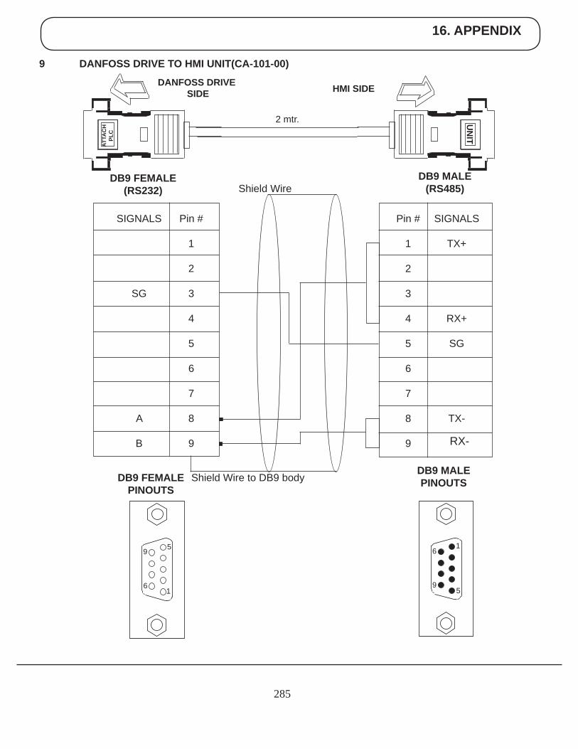
16. APPENDIX
285
9 DANFOSS DRIVE TO HMI UNIT(CA-101-00)
RX-
UN
IT
HMI SIDEDANFOSS DRIVE SIDE
2 mtr.
SIGNALS
TX+
RX+
SG
TX-
DB9 MALE (RS485)
DB9 FEMALE(RS232)
DB9 MALE PINOUTSDB9 FEMALE
PINOUTS
6
9
1
5
Shield Wire
Shield Wire to DB9 body
ATTA
CH
PLC
9
6
5
1
Pin #
1
2
3
4
5
6
7
8
9
Pin #
1
2
3
4
5
6
7
8
9
SIGNALS
SG
A
B
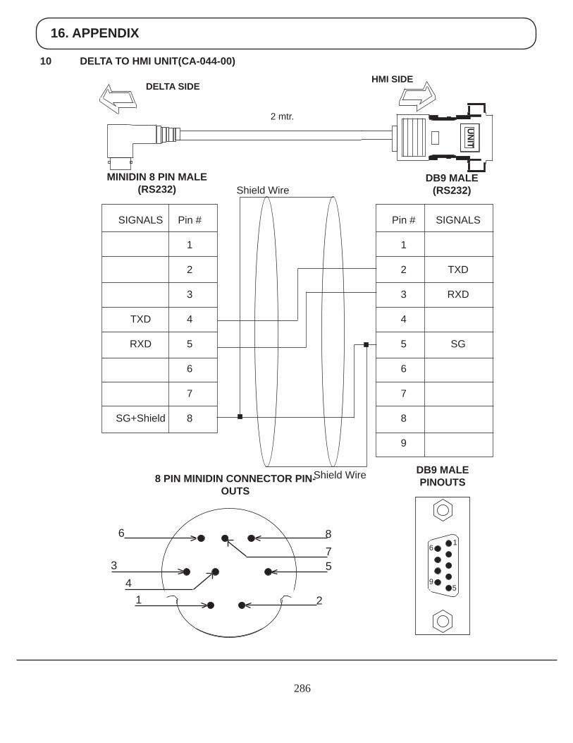
16. APPENDIX
286
10 DELTA TO HMI UNIT(CA-044-00)
UN
IT
HMI SIDEDELTA SIDE
2 mtr.
Pin #
1
2
3
4
5
6
7
8
9
SIGNALS
TXD
RXD
SG
DB9 MALE (RS232)
Pin #
1
2
3
4
5
6
7
8
SIGNALS
TXD
RXD
SG+Shield
MINIDIN 8 PIN MALE(RS232)
DB9 MALE PINOUTS8 PIN MINIDIN CONNECTOR PIN-
OUTS
Shield Wire
Shield Wire
6
9
1
5
6
34
1
875
2
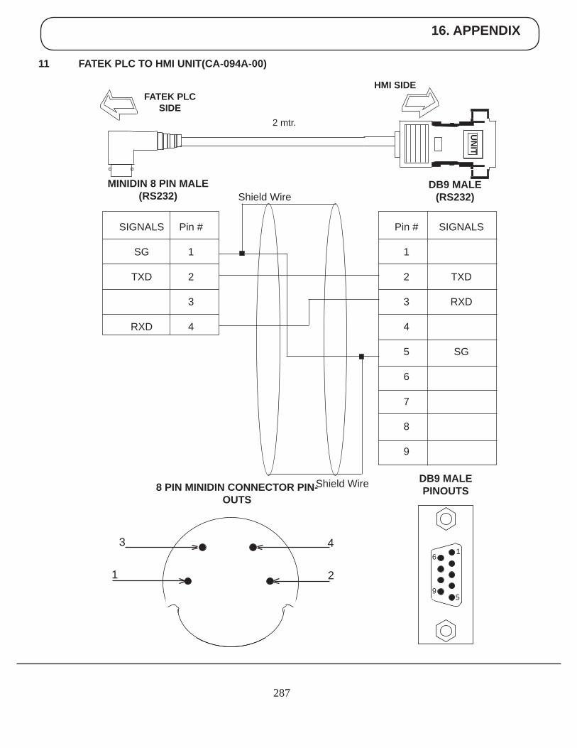
16. APPENDIX
287
11 FATEK PLC TO HMI UNIT(CA-094A-00)
UN
IT
HMI SIDEFATEK PLC
SIDE2 mtr.
Pin #
1
2
3
4
5
6
7
8
9
SIGNALS
TXD
RXD
SG
DB9 MALE (RS232)
Pin #
1
2
3
4
SIGNALS
SG
TXD
RXD
MINIDIN 8 PIN MALE(RS232)
DB9 MALE PINOUTS8 PIN MINIDIN CONNECTOR PIN-
OUTS
Shield Wire
Shield Wire
6
9
1
5
3
1
4
2
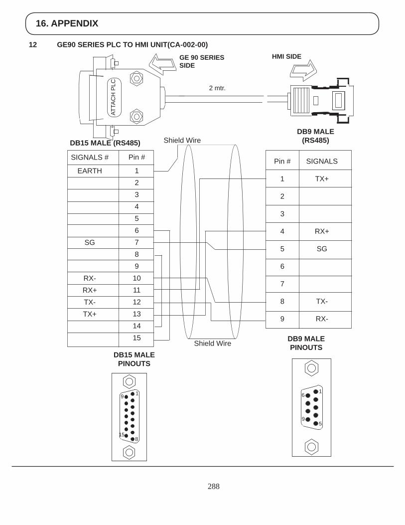
16. APPENDIX
288
12 GE90 SERIES PLC TO HMI UNIT(CA-002-00) HMI SIDEGE 90 SERIES
SIDE
2 mtr.
SIGNALS
TX+
RX+
SG
TX-
RX-
DB9 MALE (RS485)DB15 MALE (RS485)
DB9 MALE PINOUTS
6
9
1
5
Shield Wire
Shield Wire
Pin #
1
2
3
4
5
6
7
8
9
Pin #
123456789
101112131415
SIGNALS #
EARTH
SG
RX-RX+TX-TX+
DB15 MALE PINOUTS
15
9 1
8
ATTA
CH
PLC
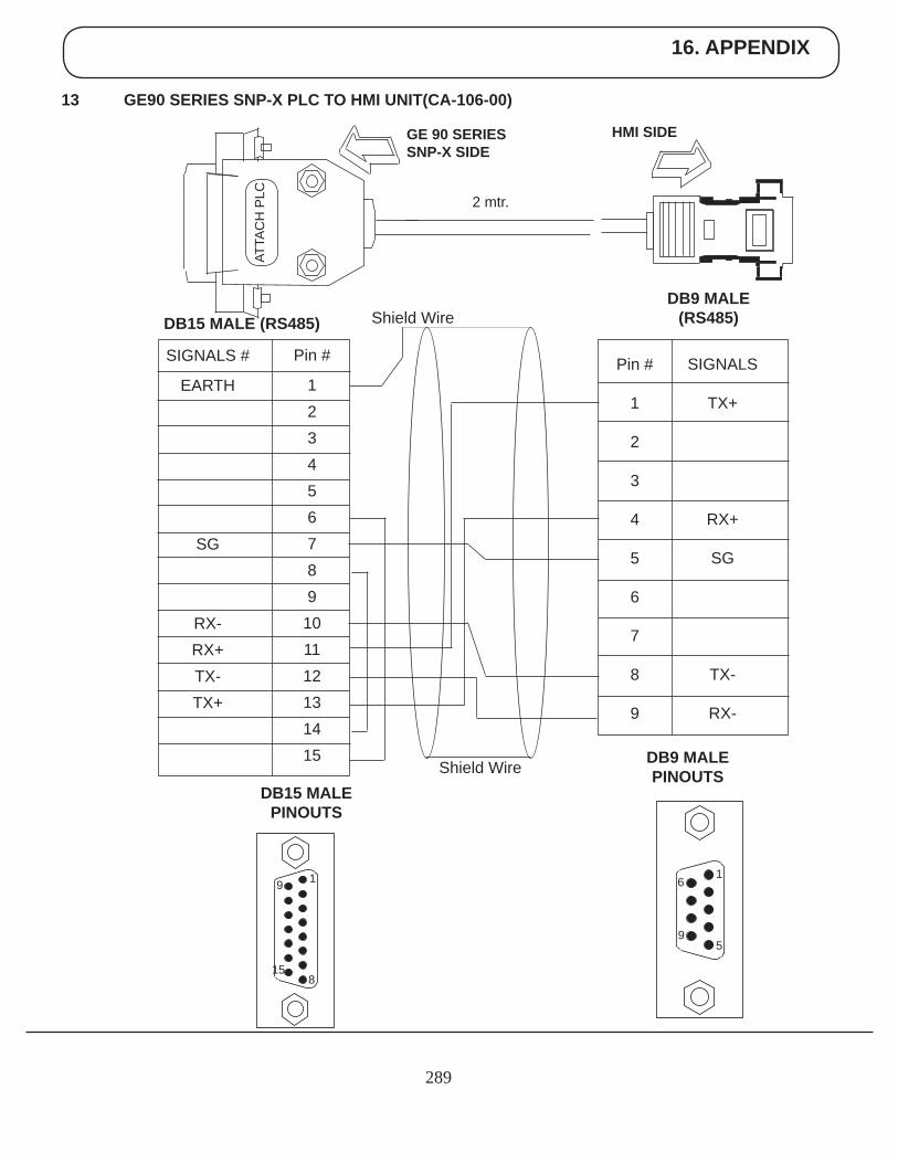
16. APPENDIX
289
13 GE90 SERIES SNP-X PLC TO HMI UNIT(CA-106-00)
HMI SIDEGE 90 SERIESSNP-X SIDE
2 mtr.
SIGNALS
TX+
RX+
SG
TX-
RX-
DB9 MALE (RS485)DB15 MALE (RS485)
DB9 MALE PINOUTS
6
9
1
5
Shield Wire
Shield Wire
Pin #
1
2
3
4
5
6
7
8
9
Pin #
123456789
101112131415
SIGNALS #
EARTH
SG
RX-RX+TX-TX+
DB15 MALE PINOUTS
15
9 1
8
ATTA
CH
PLC
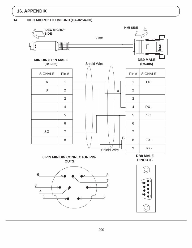
16. APPENDIX
290
14 IDEC MICRO3 TO HMI UNIT(CA-025A-00)
UN
ITHMI SIDE
IDEC MICRO3
SIDE2 mtr.
Pin #
1
2
3
4
5
6
7
8
9
SIGNALS
TX+
RX+
SG
TX-
RX-
DB9 MALE (RS485)
Pin #
1
2
3
4
5
6
7
8
SIGNALS
A
B
SG
MINIDIN 8 PIN MALE(RS232)
DB9 MALE PINOUTS
8 PIN MINIDIN CONNECTOR PIN-OUTS
6
9
1
5
Shield Wire
Shield Wire
A
B
6
34
1
875
2
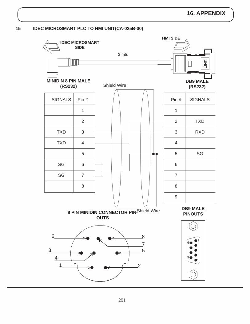
16. APPENDIX
291
15 IDEC MICROSMART PLC TO HMI UNIT(CA-025B-00)
UN
IT
HMI SIDEIDEC MICROSMART
SIDE2 mtr.
Pin #
1
2
3
4
5
6
7
8
9
SIGNALS
TXD
RXD
SG
DB9 MALE (RS232)
Pin #
1
2
3
4
5
6
7
8
SIGNALS
TXD
TXD
SG
SG
MINIDIN 8 PIN MALE(RS232)
DB9 MALE PINOUTS8 PIN MINIDIN CONNECTOR PIN-
OUTS
Shield Wire
Shield Wire
6
9
1
5
6
34
1
875
2
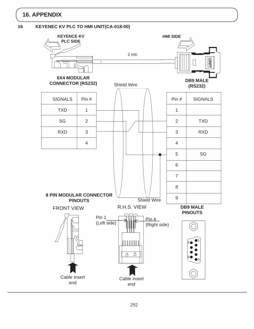
16. APPENDIX
292
16 KEYENEC KV PLC TO HMI UNIT(CA-018-00)
UN
IT
HMI SIDEKEYENCE KV PLC SIDE
2 mtr.
Pin #
1
2
3
4
5
6
7
8
9
SIGNALS
TXD
RXD
SG
DB9 MALE (RS232)
Pin #
1
2
3
4
SIGNALS
TXD
SG
RXD
6X4 MODULARCONNECTOR (RS232)
DB9 MALE PINOUTS
8 PIN MODULAR CONNECTOR PINOUTS
6
9
1
5
Cable insert end
Cable insert end
Pin 1(Left side)
Pin 4(Right side)
FRONT VIEW R.H.S. VIEW
Shield Wire
Shield Wire
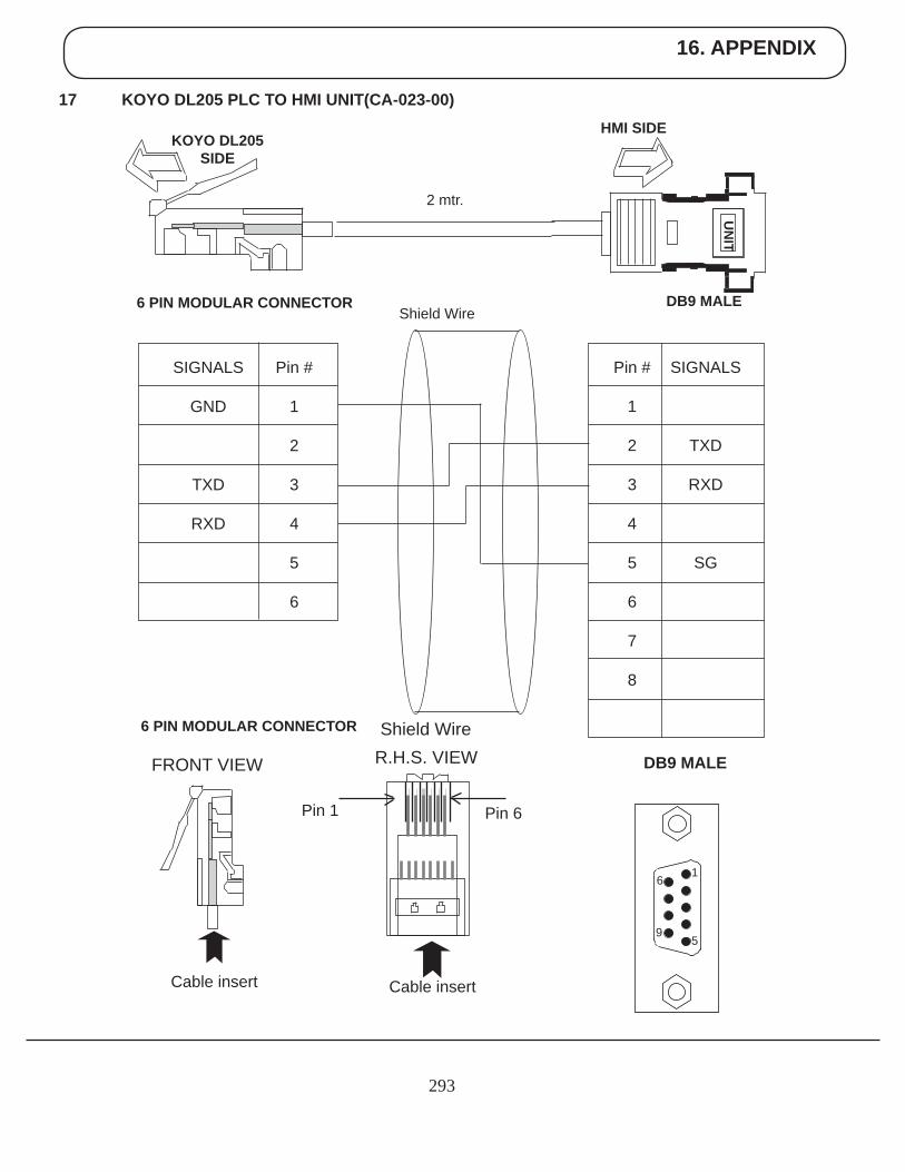
16. APPENDIX
293
17 KOYO DL205 PLC TO HMI UNIT(CA-023-00)
UN
IT
HMI SIDEKOYO DL205
SIDE
2 mtr.
Pin #
1
2
3
4
5
6
7
8
SIGNALS
TXD
RXD
SG
DB9 MALE
Pin #
1
2
3
4
5
6
SIGNALS
GND
TXD
RXD
6 PIN MODULAR CONNECTOR
DB9 MALE
6 PIN MODULAR CONNECTOR
Cable insert Cable insert
Pin 1 Pin 6
FRONT VIEW R.H.S. VIEW
Shield Wire
Shield Wire
6
9
1
5
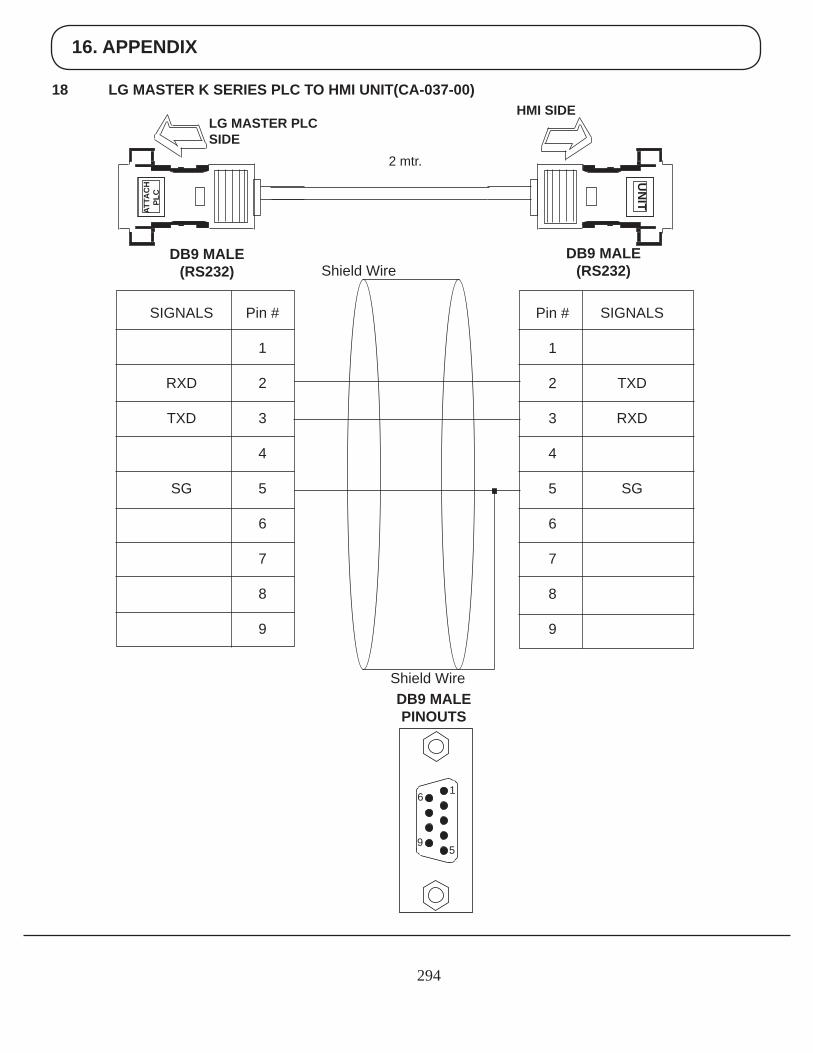
16. APPENDIX
294
18 LG MASTER K SERIES PLC TO HMI UNIT(CA-037-00)
UN
IT
HMI SIDELG MASTER PLCSIDE
2 mtr.
SIGNALS
TXD
RXD
SG
DB9 MALE (RS232)
DB9 MALE(RS232)
DB9 MALE PINOUTS
6
9
1
5
Shield Wire
Shield Wire
ATTA
CH
PLC
Pin #
1
2
3
4
5
6
7
8
9
Pin #
1
2
3
4
5
6
7
8
9
SIGNALS
RXD
TXD
SG
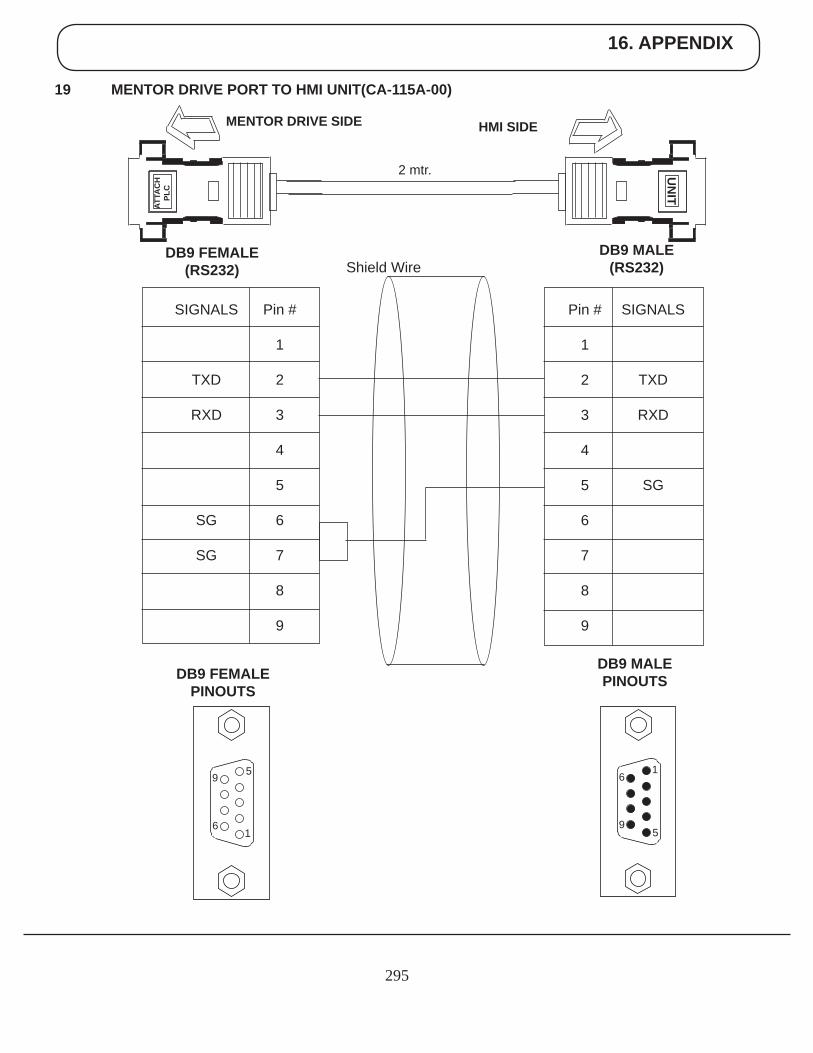
16. APPENDIX
295
19 MENTOR DRIVE PORT TO HMI UNIT(CA-115A-00)
UN
ITHMI SIDEMENTOR DRIVE SIDE
2 mtr.
SIGNALS
TXD
RXD
SG
DB9 MALE (RS232)
DB9 FEMALE(RS232)
DB9 MALE PINOUTSDB9 FEMALE
PINOUTS
6
9
1
5
Shield Wire
ATTA
CH
PLC
9
6
5
1
Pin #
1
2
3
4
5
6
7
8
9
Pin #
1
2
3
4
5
6
7
8
9
SIGNALS
TXD
RXD
SG
SG
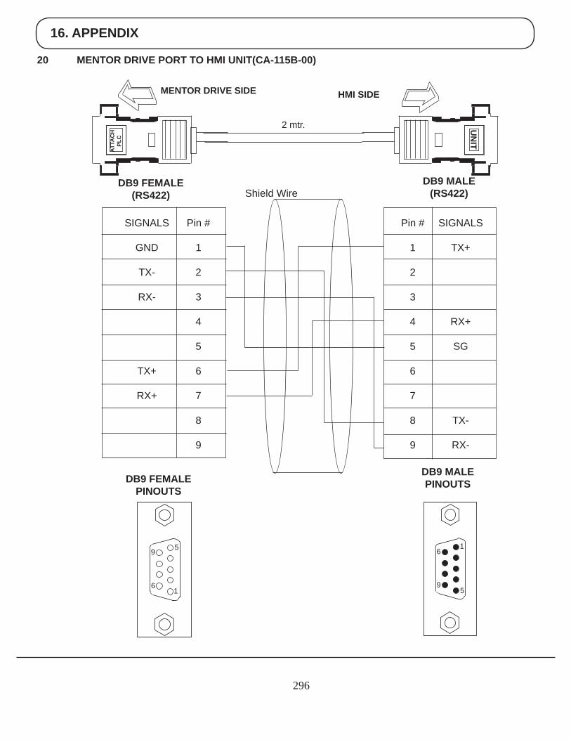
16. APPENDIX
296
20 MENTOR DRIVE PORT TO HMI UNIT(CA-115B-00)
UN
ITHMI SIDEMENTOR DRIVE SIDE
2 mtr.
SIGNALS
TX+
RX+
SG
TX-
RX-
DB9 MALE (RS422)
DB9 FEMALE(RS422)
DB9 MALE PINOUTSDB9 FEMALE
PINOUTS
6
9
1
5
Shield Wire
ATTA
CH
PLC
9
6
5
1
Pin #
1
2
3
4
5
6
7
8
9
Pin #
1
2
3
4
5
6
7
8
9
SIGNALS
GND
TX-
RX-
TX+
RX+
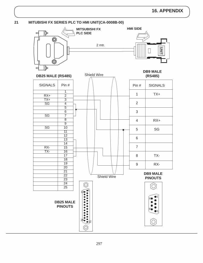
16. APPENDIX
297
21 MITUBISHI FX SERIES PLC TO HMI UNIT(CA-0008B-00)
UN
IT
HMI SIDEMITSUBISHI FXPLC SIDE
2 mtr.
SIGNALS
TX+
RX+
SG
TX-
RX-
DB9 MALE (RS485)DB25 MALE (RS485)
DB9 MALE PINOUTS
Shield Wire
Shield Wire
Pin #
1
2
3
4
5
6
7
8
9
Pin #
123456789
10111213141516171819202122232425
SIGNALS
RX+TX+SG
SG
SG
RX-TX-
DB25 MALE PINOUTS
6
9
1
5
1
12
13
25
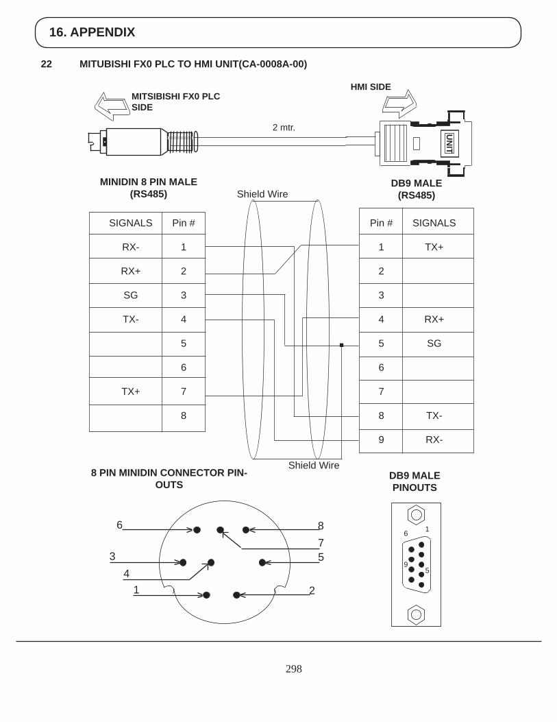
16. APPENDIX
298
22 MITUBISHI FX0 PLC TO HMI UNIT(CA-0008A-00)
UN
IT
HMI SIDEMITSIBISHI FX0 PLCSIDE
2 mtr.
Pin #
1
2
3
4
5
6
7
8
9
SIGNALS
TX+
RX+
SG
TX-
RX-
DB9 MALE (RS485)
Pin #
1
2
3
4
5
6
7
8
SIGNALS
RX-
RX+
SG
TX-
TX+
MINIDIN 8 PIN MALE(RS485)
DB9 MALE PINOUTS
8 PIN MINIDIN CONNECTOR PIN-OUTS
6
9
1
5
Shield Wire
Shield Wire
6
34
1
875
2
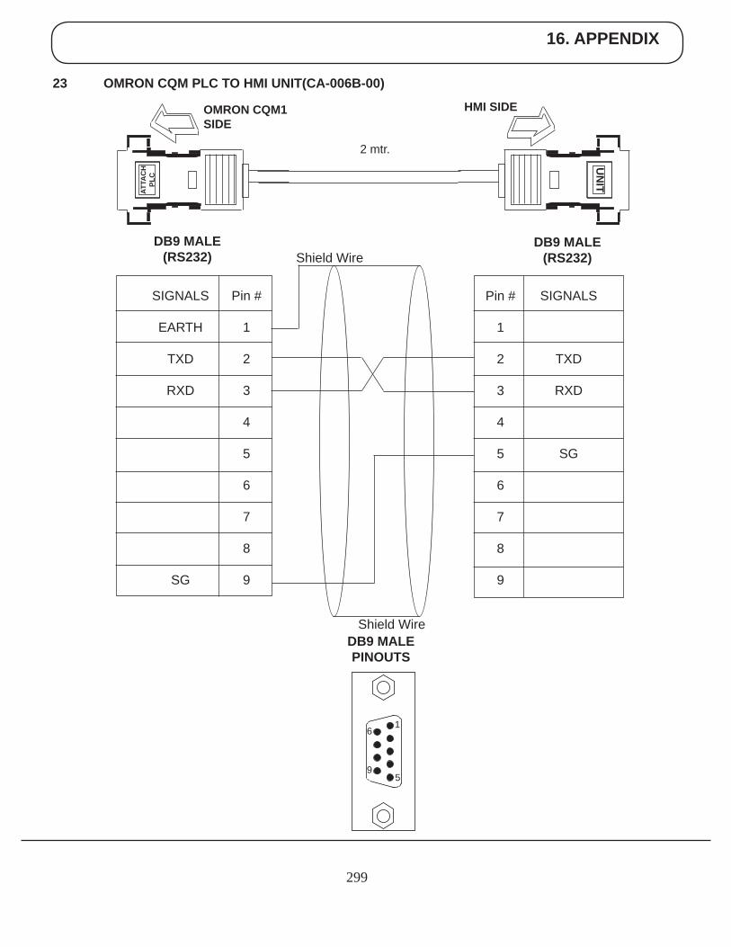
16. APPENDIX
299
23 OMRON CQM PLC TO HMI UNIT(CA-006B-00)
UN
IT
HMI SIDEOMRON CQM1SIDE
2 mtr.
SIGNALS
TXD
RXD
SG
DB9 MALE (RS232)
DB9 MALE(RS232)
DB9 MALE PINOUTS
6
9
1
5
Shield Wire
Shield Wire
ATTA
CH
PLC
Pin #
1
2
3
4
5
6
7
8
9
Pin #
1
2
3
4
5
6
7
8
9
SIGNALS
EARTH
TXD
RXD
SG
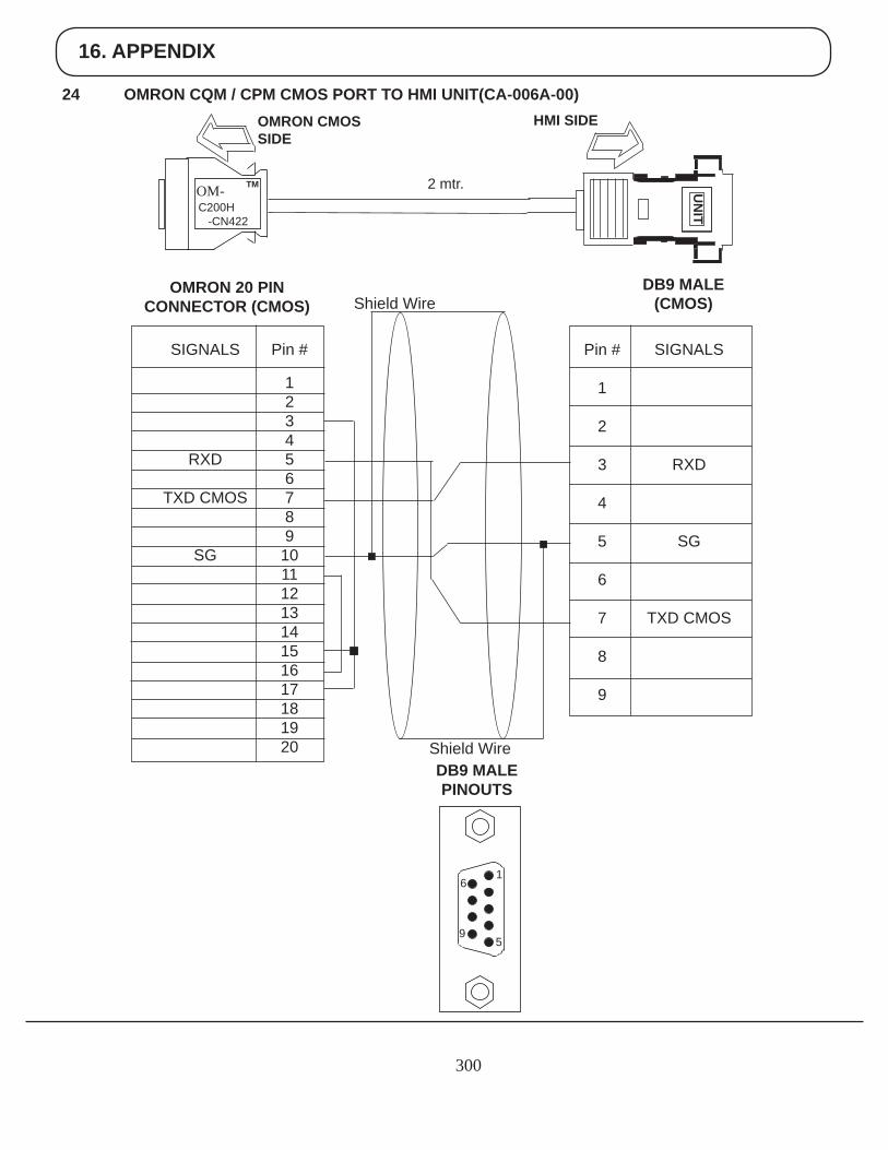
16. APPENDIX
300
24 OMRON CQM / CPM CMOS PORT TO HMI UNIT(CA-006A-00)
UN
IT
HMI SIDEOMRON CMOSSIDE
2 mtr.
SIGNALS
RXD
SG
TXD CMOS
DB9 MALE (CMOS)
OMRON 20 PINCONNECTOR (CMOS)
DB9 MALE PINOUTS
6
9
1
5
Shield Wire
Shield Wire
Pin #
1
2
3
4
5
6
7
8
9
Pin #
123456789
1011121314151617181920
SIGNALS
RXD
TXD CMOS
SG
OM- TM
C200H -CN422
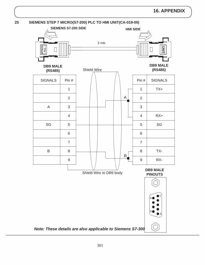
16. APPENDIX
301
25 SIEMENS STEP 7 MICRO(S7-200) PLC TO HMI UNIT(CA-019-00)
UN
IT
HMI SIDESIEMENS S7-200 SIDE
2 mtr.
SIGNALS
TX+
RX+
SG
TX-
RX-
DB9 MALE (RS485)
DB9 MALE(RS485)
DB9 MALE PINOUTS
Shield Wire
Shield Wire to DB9 body
ATTA
CH
PLC
Pin #
1
2
3
4
5
6
7
8
9
Pin #
1
2
3
4
5
6
7
8
9
SIGNALS
A
SG
B
A
B
Note: These details are also applicable to Siemens S7-300
6
9
1
5
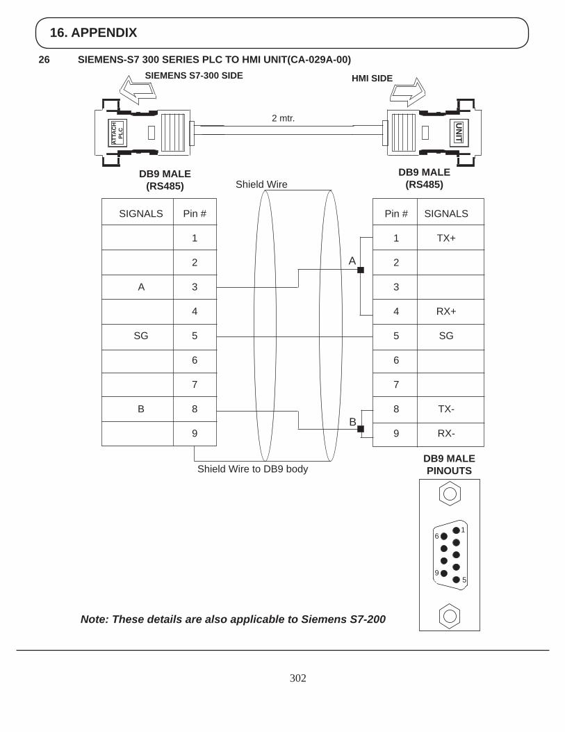
16. APPENDIX
302
26 SIEMENS-S7 300 SERIES PLC TO HMI UNIT(CA-029A-00)
UN
IT
HMI SIDESIEMENS S7-300 SIDE
2 mtr.
SIGNALS
TX+
RX+
SG
TX-
RX-
DB9 MALE (RS485)
DB9 MALE(RS485)
DB9 MALE PINOUTS
Shield Wire
Shield Wire to DB9 body
ATTA
CH
PLC
Pin #
1
2
3
4
5
6
7
8
9
Pin #
1
2
3
4
5
6
7
8
9
SIGNALS
A
SG
B
A
B
Note: These details are also applicable to Siemens S7-200
6
9
1
5
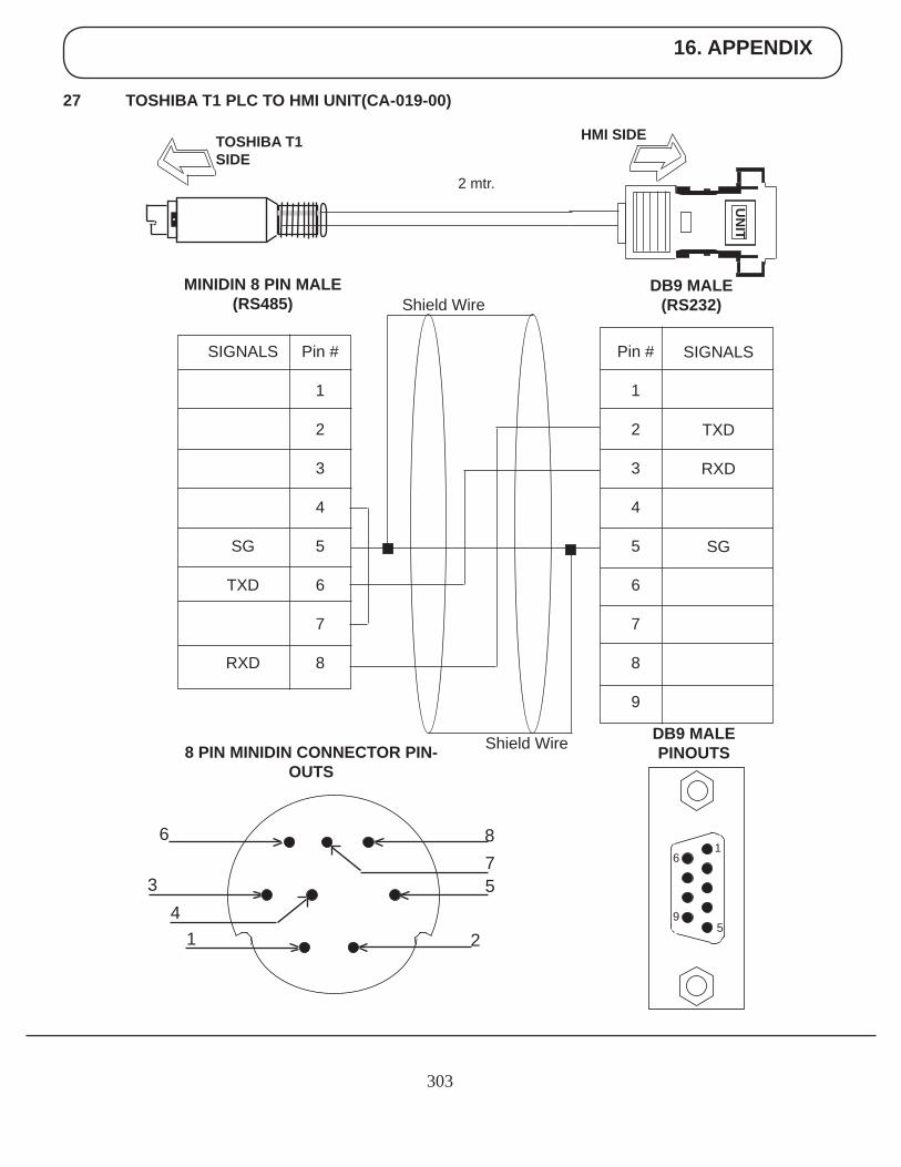
16. APPENDIX
303
27 TOSHIBA T1 PLC TO HMI UNIT(CA-019-00)
UN
IT
HMI SIDETOSHIBA T1SIDE
2 mtr.
Pin #
1
2
3
4
5
6
7
8
9
SIGNALS
TXD
RXD
SG
DB9 MALE (RS232)
Pin #
1
2
3
4
5
6
7
8
SIGNALS
SG
TXD
RXD
MINIDIN 8 PIN MALE(RS485)
DB9 MALE PINOUTS
Shield Wire
Shield Wire8 PIN MINIDIN CONNECTOR PIN-OUTS
6
34
1
875
2
6
9
1
5
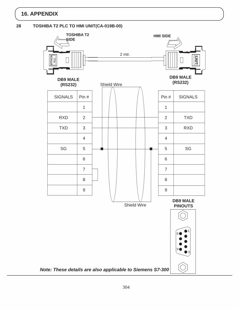
16. APPENDIX
304
28 TOSHIBA T2 PLC TO HMI UNIT(CA-019B-00)
HMI SIDETOSHIBA T2SIDE
2 mtr.
SIGNALS
TXD
RXD
SG
DB9 MALE (RS232)DB9 MALE
(RS232)
DB9 MALE PINOUTS
Shield Wire
Shield Wire
Pin #
1
2
3
4
5
6
7
8
9
Pin #
1
2
3
4
5
6
7
8
9
SIGNALS
RXD
TXD
SG
Note: These details are also applicable to Siemens S7-300
UN
IT
ATTA
CH
PLC
6
9
1
5
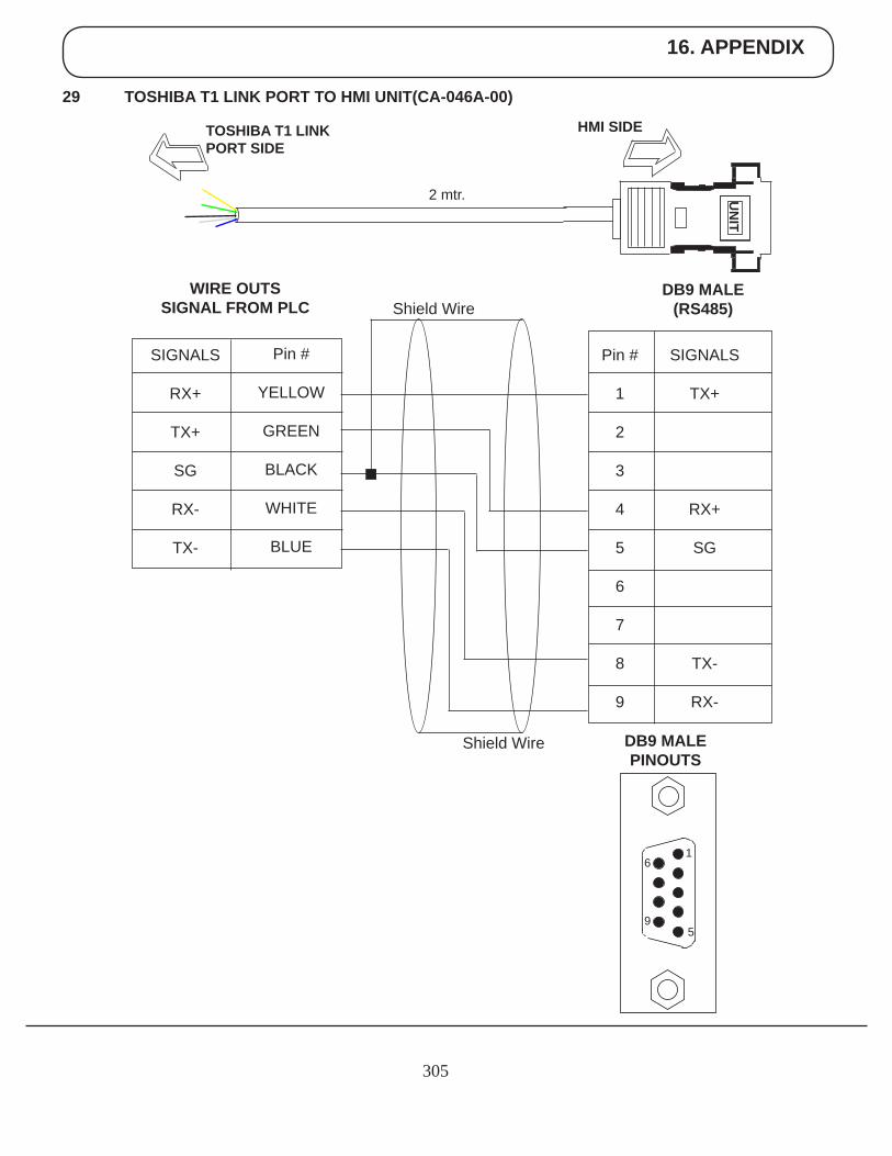
16. APPENDIX
305
29 TOSHIBA T1 LINK PORT TO HMI UNIT(CA-046A-00)
UN
IT
HMI SIDETOSHIBA T1 LINK PORT SIDE
2 mtr.
Pin #
1
2
3
4
5
6
7
8
9
SIGNALS
TX+
RX+
SG
TX-
RX-
DB9 MALE (RS485)
Pin #
YELLOW
GREEN
BLACK
WHITE
BLUE
SIGNALS
RX+
TX+
SG
RX-
TX-
WIRE OUTSSIGNAL FROM PLC
DB9 MALE PINOUTS
Shield Wire
Shield Wire
6
9
1
5
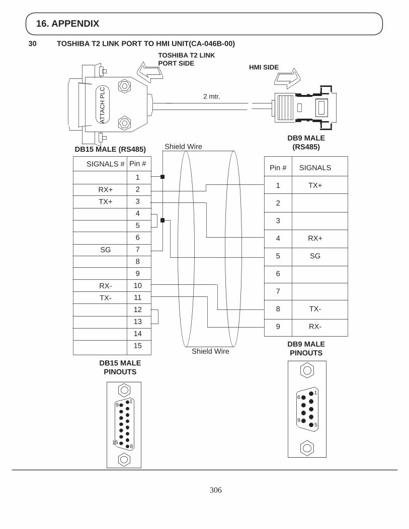
16. APPENDIX
306
30 TOSHIBA T2 LINK PORT TO HMI UNIT(CA-046B-00)
HMI SIDE
TOSHIBA T2 LINK PORT SIDE
2 mtr.
SIGNALS
TX+
RX+
SG
TX-
RX-
DB9 MALE (RS485)DB15 MALE (RS485)
DB9 MALE PINOUTS
6
9
1
5
Shield Wire
Shield Wire
Pin #
1
2
3
4
5
6
7
8
9
ATTA
CH
PLC
Pin #
123456789
101112131415
SIGNALS #
RX+TX+
SG
RX-TX-
DB15 MALE PINOUTS
15
9 1
8
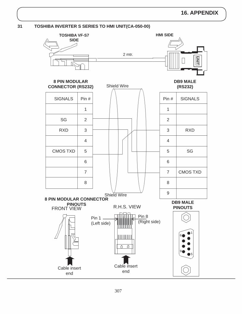
16. APPENDIX
307
31 TOSHIBA INVERTER S SERIES TO HMI UNIT(CA-050-00)
UN
IT
HMI SIDETOSHIBA VF-S7SIDE
2 mtr.
Pin #
1
2
3
4
5
6
7
8
9
SIGNALS
RXD
SG
CMOS TXD
DB9 MALE (RS232)
Pin #
1
2
3
4
5
6
7
8
SIGNALS
SG
RXD
CMOS TXD
8 PIN MODULARCONNECTOR (RS232)
DB9 MALE PINOUTS
8 PIN MODULAR CONNECTOR PINOUTS
6
9
1
5
Cable insert end
Cable insert end
Pin 1(Left side)
Pin 8(Right side)
FRONT VIEW R.H.S. VIEW
Shield Wire
Shield Wire
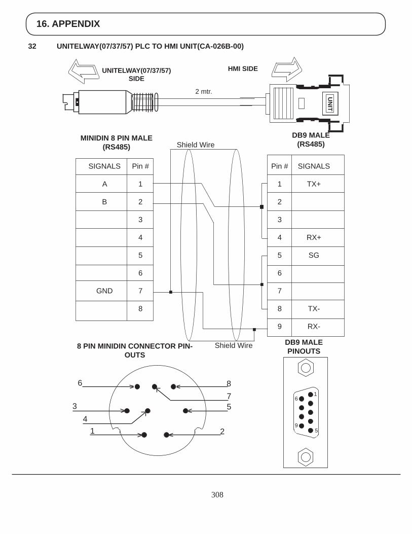
16. APPENDIX
308
32 UNITELWAY(07/37/57) PLC TO HMI UNIT(CA-026B-00)
UN
IT
HMI SIDEUNITELWAY(07/37/57) SIDE
2 mtr.
Pin #
1
2
3
4
5
6
7
8
9
SIGNALS
TX+
RX+
SG
TX-
RX-
DB9 MALE (RS485)
Pin #
1
2
3
4
5
6
7
8
SIGNALS
A
B
GND
MINIDIN 8 PIN MALE(RS485)
DB9 MALE PINOUTS8 PIN MINIDIN CONNECTOR PIN-
OUTS
Shield Wire
Shield Wire
6
34
1
875
2
6
9
1
5
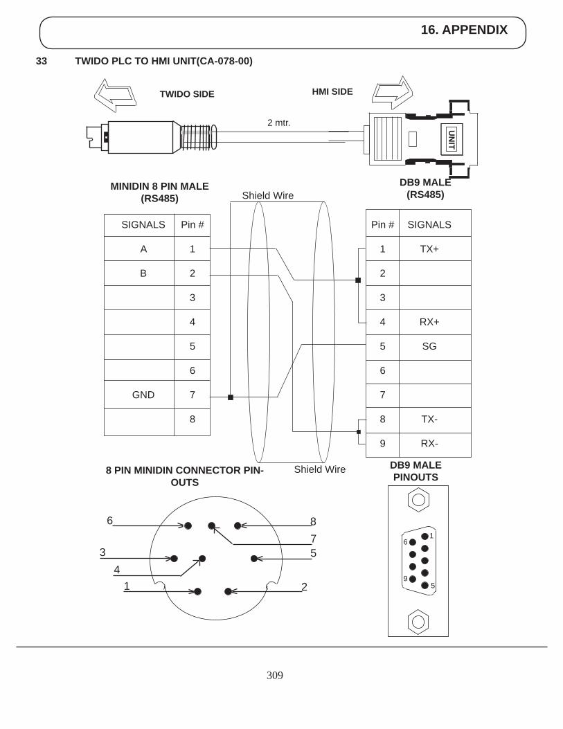
16. APPENDIX
309
33 TWIDO PLC TO HMI UNIT(CA-078-00)
UN
IT
HMI SIDETWIDO SIDE
2 mtr.
Pin #
1
2
3
4
5
6
7
8
9
SIGNALS
TX+
RX+
SG
TX-
RX-
DB9 MALE (RS485)
Pin #
1
2
3
4
5
6
7
8
SIGNALS
A
B
GND
MINIDIN 8 PIN MALE(RS485)
DB9 MALE PINOUTS8 PIN MINIDIN CONNECTOR PIN-
OUTS
Shield Wire
Shield Wire
6
34
1
875
2
6
9
1
5
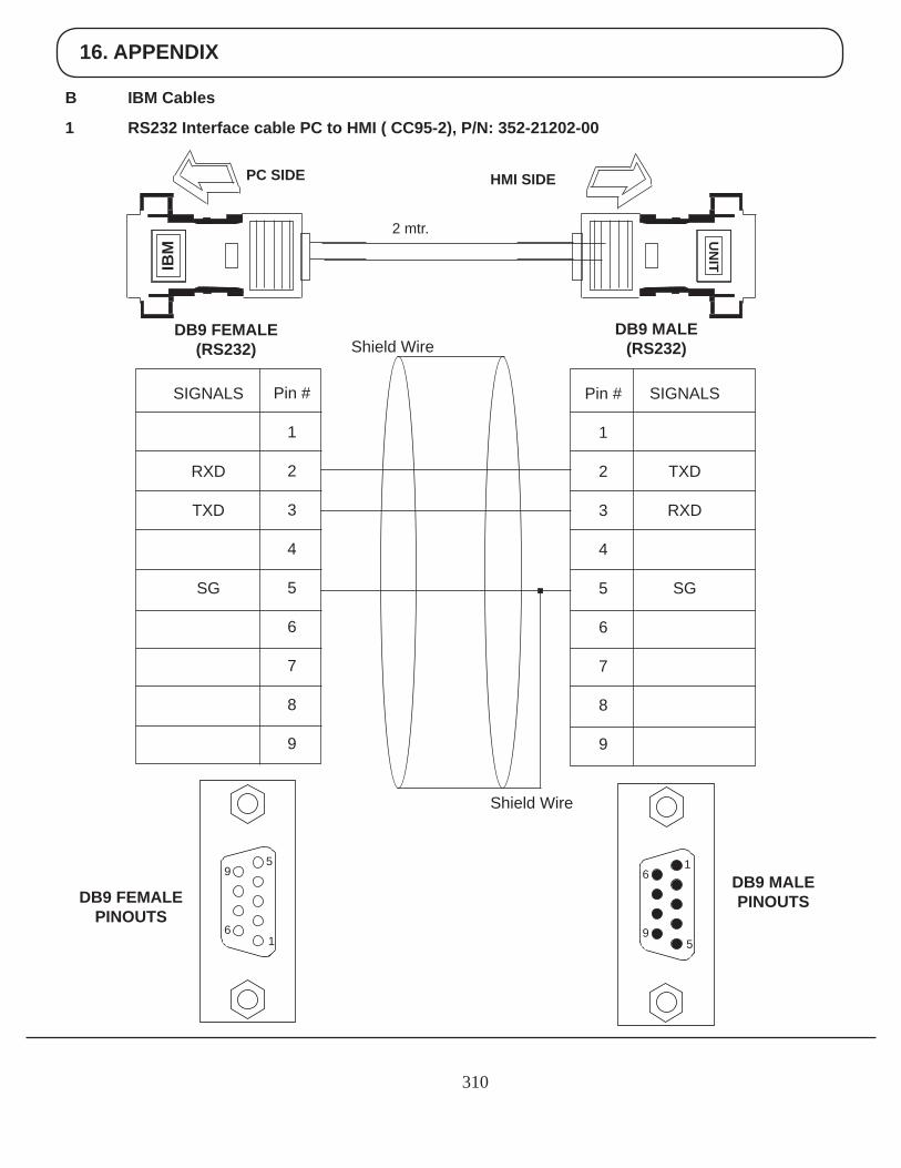
16. APPENDIX
310
B IBM Cables
1 RS232 Interface cable PC to HMI ( CC95-2), P/N: 352-21202-00
2 mtr.
SIGNALS
TXD
RXD
SG
DB9 MALE (RS232)
DB9 FEMALE(RS232)
DB9 MALE PINOUTSDB9 FEMALE
PINOUTS
Shield Wire
Shield Wire
Pin #
1
2
3
4
5
6
7
8
9
Pin #
1
2
3
4
5
6
7
8
9
SIGNALS
RXD
TXD
SG
PC SIDEIB
MU
NIT
HMI SIDE
9
6
5
1
6
9
1
5
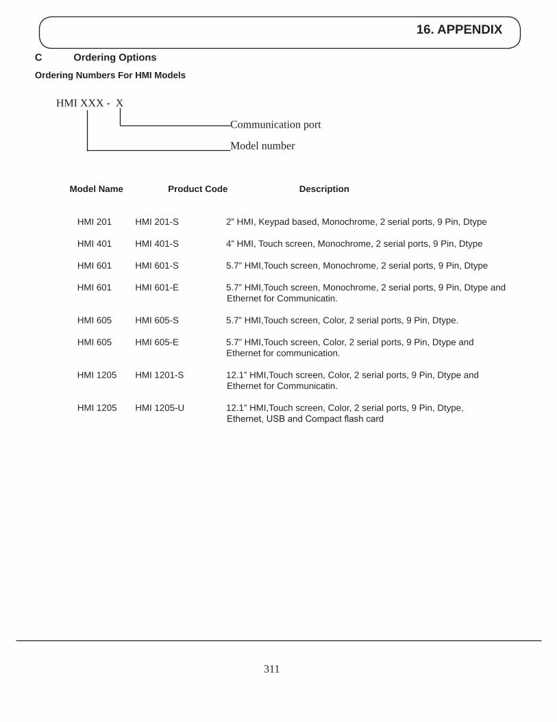
16. APPENDIX
311
C Ordering Options
Ordering Numbers For HMI Models
Model Name Product Code Description
HMI 201 HMI 201-S 2” HMI, Keypad based, Monochrome, 2 serial ports, 9 Pin, Dtype HMI 401 HMI 401-S 4” HMI, Touch screen, Monochrome, 2 serial ports, 9 Pin, Dtype
HMI 601 HMI 601-S 5.7” HMI,Touch screen, Monochrome, 2 serial ports, 9 Pin, Dtype
HMI 601 HMI 601-E 5.7” HMI,Touch screen, Monochrome, 2 serial ports, 9 Pin, Dtype and Ethernet for Communicatin.
HMI 605 HMI 605-S 5.7” HMI,Touch screen, Color, 2 serial ports, 9 Pin, Dtype. HMI 605 HMI 605-E 5.7” HMI,Touch screen, Color, 2 serial ports, 9 Pin, Dtype and Ethernet for communication.
HMI 1205 HMI 1201-S 12.1” HMI,Touch screen, Color, 2 serial ports, 9 Pin, Dtype and Ethernet for Communicatin.
HMI 1205 HMI 1205-U 12.1” HMI,Touch screen, Color, 2 serial ports, 9 Pin, Dtype, Ethernet, USB and Compact flash card
HMI XXX - X
Model number
Communication port
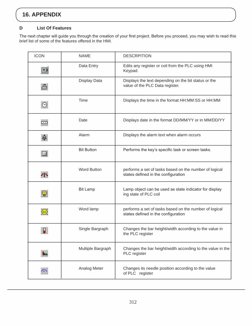
16. APPENDIX
312
D List Of Features
The next chapter will guide you through the creation of your first project. Before you proceed, you may wish to read this brief list of some of the features offered in the HMI.
ICON NAME DESCRPITION
Data Entry Edits any register or coil from the PLC using HMI Keypad. Display Data Displays the text depending on the bit status or the value of the PLC Data register.
Time Displays the time in the format HH:MM:SS or HH:MM
Date Displays date in the format DD/MM/YY or in MM/DD/YY
Alarm Displays the alarm text when alarm occurs
Bit Button Performs the key’s specific task or screen tasks.
Word Button performs a set of tasks based on the number of logical states defined in the configuration
Bit Lamp Lamp object can be used as state indicator for display ing state of PLC coil
Word lamp performs a set of tasks based on the number of logical states defined in the configuration
Single Bargraph Changes the bar height/width according to the value in the PLC register
Multiple Bargraph Changes the bar height/width according to the value in the PLC register
Analog Meter Changes its needle position according to the value of PLC register
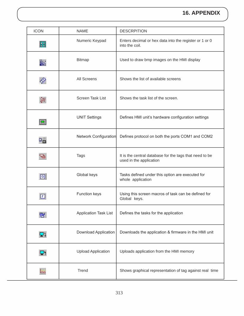
16. APPENDIX
313
ICON NAME DESCRPITION
Numeric Keypad Enters decimal or hex data into the register or 1 or 0 into the coil.
Bitmap Used to draw bmp images on the HMI display
All Screens Shows the list of available screens
Screen Task List Shows the task list of the screen.
UNIT Settings Defines HMI unit’s hardware configuration settings
Network Configuration Defines protocol on both the ports COM1 and COM2
Tags It is the central database for the tags that need to be used in the application
Global keys Tasks defined under this option are executed for whole application
Function keys Using this screen macros of task can be defined for Global keys.
Application Task List Defines the tasks for the application
Download Application Downloads the application & firmware in the HMI unit
Upload Application Uploads application from the HMI memory
Trend Shows graphical representation of tag against real time
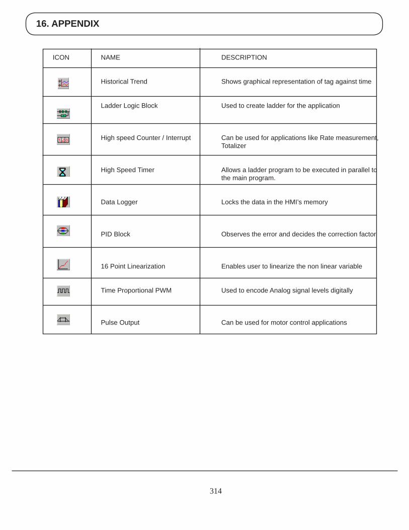
16. APPENDIX
314
ICON NAME DESCRIPTION
Historical Trend Shows graphical representation of tag against time
Ladder Logic Block Used to create ladder for the application
High speed Counter / Interrupt Can be used for applications like Rate measurement, Totalizer
High Speed Timer Allows a ladder program to be executed in parallel to the main program.
Data Logger Locks the data in the HMI’s memory
PID Block Observes the error and decides the correction factor
16 Point Linearization Enables user to linearize the non linear variable
Time Proportional PWM Used to encode Analog signal levels digitally
Pulse Output Can be used for motor control applications
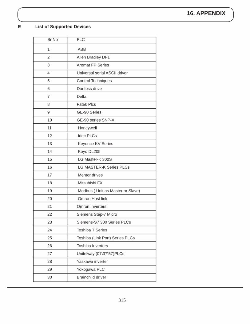
16. APPENDIX
315
E List of Supported Devices
Sr No PLC
1 ABB
2 Allen Bradley DF1
3 Aromat FP Series
4 Universal serial ASCII driver
5 Control Techniques
6 Danfoss drive
7 Delta
8 Fatek Plcs
9 GE-90 Series
10 GE-90 series SNP-X
11 Honeywell
12 Idec PLCs
13 Keyence KV Series
14 Koyo DL205
15 LG Master-K 300S
16 LG MASTER-K Series PLCs
17 Mentor drives
18 Mitsubishi FX
19 Modbus ( Unit as Master or Slave)
20 Omron Host link
21 Omron Inverters
22 Siemens Step-7 Micro
23 Siemens-S7 300 Series PLCs
24 Toshiba T Series
25 Toshiba (Link Port) Series PLCs
26 Toshiba Inverters
27 Unitelway (07\37\57)PLCs
28 Yaskawa inverter
29 Yokogawa PLC
30 Brainchild driver

16. APPENDIX
316
BRAINCHILD ELECTRONIC CO.LTD 6F, No.209, Chung Yang Rd, Nan Kang Dist., Taipei, Taiwan, R.O.C Tel: +886-2-27861299, Fax: +886-2-27861395 Email: [email protected] Website: www.brainchild.com.tw
F Technical Support