Embed Size (px)
Citation preview

Human Centred Design for MaintenanceHazel Courteney
Introduction
Civil aviation is safe but needs to be saferCivil aviation currently enjoys a very high level of safety. However, due to increasingair traffic the standard needs to be further improved to avoid rising numbers ofaccidents. The much quoted Pareto Effect tells us that usually we will receive 80% ofthe benefit from the first 20% of the effort. This means that once a high level of safetyhas been reached, any further gains will cost relatively more effort. That is oursituation today, so our target improvements need to be selected with care.
Human Error is the Leading RiskIt is already accepted that human error is the leading cause of aviation accidents [e.g.CAP 681 study of fatal accidents to large aircraft world-wide]. In fact, almost any riskcould be traced back to human error if decisions in design, training, production,communications or weather forecasting and were to be included as ‘errors’. The CAP681 specifically identifies Maintenance Error as a contributory causal factor in 28 fatalaccidents and in 10 of those it was the primary cause. The role of errors inmaintenance has attracted increasing attention in recent years. It is difficult to obtain acomprehensive picture of risk trends world-wide but UK CAA statistics indicate acontinuing rise in the number of reportable maintenance errors per million flights [seeFig. 1]. Such a rise will be compounded by increasing traffic to make absolutenumbers of errors show an accelerating trend.
0
100
200
300
400
500
600
90/92 91/93 92/94 93/95 94/96 95/97 96/98 97/99 98/00
Fig. 1: Maintenance Error MORs to UK Registered Public Transport Aeroplanes>5700kg mtwa per Million Flights [shown as 3 year moving average]

Aircraft Design affects Likelihood and Consequences of ErrorThere is increasing awareness that the design of an aircraft affects its vulnerability toerror during maintenance. The design will influence how easy it is to do the task, thelikelihood that an error will occur, and the opportunities to detect the error and recoverthe situation before the aircraft returns to service. The design may also determinewhether the error can be identified by the pilots before or during flight, and the finaleffect that it will have on flight safety. The opportunity for the regulatory authority toassess these aspects of the aircraft is during Type Certification [TC] of the basicdesign.
Documentation is ImportantMaintenance manuals may also be viewed as an element of the ‘aircraft’ package. Anaircraft design may be elegant but if the manual does not successfully communicate thetask to the engineer, then the elegance is wasted and the ‘total’ design is poor.Documentation that is unclear leaves the aircraft vulnerable to maintenance error andreduces flight safety. Validation of a maintenance task should be conducted withrepresentative maintenance engineers using the instructions as they would realisticallybe presented, including the realistic degree of cross referencing to other pages orsources, and translation to other languages where appropriate. This aspect may bemissed in processes that evaluate the task using designers themselves, engineers whohave received personal tuition or ‘mannequins’ computer simulations.
Whole Aircraft, not just Flight Deck‘Human Centred Design’ refers to the practice of designing the machine to best suit theneeds of the human user. The human in question might be the pilot, the cabin crew,maintenance engineer, production staff, ground crew, or anyone else who interacts withthe aeroplane or its components. Historically, most of the discussion on these ‘humancentred’ aspects of design have focused on the flight deck interface with the pilot.More recently, the maintenance engineer has begun to receive similar consideration asthe potential importance of errors in maintenance are recognised. ‘Design forMaintenance’ across the whole aircraft is now recognised as a key area of HumanCentred Design. ‘Error resistance’ is one of several considerations in a HumanCentred approach.
What is Good ‘Design for Maintenance’?
What Constitutes a ‘Good’ Design for Maintenance?‘Design for maintenance’ as a concept is neither new nor mysterious. It embraces arange of characteristics, including tasks being error resistant, easy, quick and safe todo, visible and accessible, with space to manoeuvre for the full range of engineersphysical sizes using the appropriate tools, a minimal training requirement, andappropriate supporting material.
CommunicationThe first priority in design for maintenance should be how the task is communicated tothe engineer. This begins with understanding the training baseline that all qualifiedengineers would have and building from there through effective manuals, clearinstructions and convenient data retrieval facilities. The tasks themselves have to befeasible, the procedures applicable and the data correct. Where problems areidentified in service, the communication from the engineer to the manufacturer also

needs to be effective, so that information is corrected and redistributed in a reasonabletimescale. These points may sound like obvious common sense, but consider whetherthey are always achieved by established aircraft manufacturers.
General UsabilitySome manufacturers already have design guidelines to promote good practice. Thisdirects design engineers to ensure that their design can be seen, reached and worked onin an appropriate way. ‘Appropriate’ will include sufficient clearance to turn aspanner without colliding with other components, to conduct manual manipulationwithout getting the hand stuck or skinning knuckles, on a part that can be seen withoutthe necessity for the maintenance engineer to hold a torch with their third hand and havetheir head share a spatial position with an item of metal structure. There may be apolicy to identify the most important tasks and ensure that particular guidelines are metfor these, if not every maintenance task. Such priorities may also dictate which tasks[and associated data] are validated, which must be conducted independently, and whichparts may not be disturbed to access others. If a safety critical part is repeatedlyremoved to allow routine maintenance on another item, then the risks of error in re-assembly, contamination or damage to that component rise considerably. Some of theseconcerns may be identified through the manufacturers Zonal Safety Analysis if it is donewell.
Error Resistant DesignThere may also be error resistant design features. This would ideally include‘designing out’ safety critical tasks. It may also be supported by parts that arephysically impossible to assemble or install incorrectly, cross connection prevented bydifferent part numbers, staggered position of similar parts or by leads that are too shortto stretch to the wrong fastener. Some designs remove the need for inspections, orother tasks, that may risk damaging delicate parts. Small apertures that invite tools todrop through may be avoided or at least a means provided to rescue stray items. Paintfinish may be controlled due to the increased likelihood of flaw detection on shiny[rather than matt] surface finish, and certain colours may be favoured, or restricted toplain monochrome rather than patterned, to aid inspection reliability. Other simpledevices to promote error resistance in design can include items in close proximitydistinguished by colour coding or shaped switch tops, standardisation of displayformats and direction of operation [always ‘clockwise’ to increase quantity] switchesor dials that form a visual pattern when they are all in the correct position, convenientaccess panels, lids attached to chains [making it obvious that they have not beenreplaced], switches that lock, are physically separated or carefully positioned to avoidinadvertent operation, guarding of moving parts, even placards to some extent [although
the use of placards should not proliferate as a ‘sticking plaster’ solution to all risks].
MOR extract: “Loud bang & rapid depressurisation. P1 and cabin crew member lostconsciousness. Emergency descent. Five injuries.
Cargo door cracked......Evidence from the contamination of the cracks and the a/c recordsindicated that the cracks had been in existence some 17 years and not noticed during theembodiment of FAA AD 76-26-02 in Sept81 at 12000 flight cycles and 25000 hrs and theparticularly relevant CAA AAD B737 001-06-89 'Frame and Beam Inspection Modificationand Repair in Nov97 at 34460 flight cycles and 84772 hrs.”

Use of these Principles is VariableManufacturers, even individual designers, may vary tremendously in their use of suchdesign principles. There is no regulatory requirement to do so. This variation arisesfrom at least three sources:
• the extent of their understanding of HCD principles• level of confidence relative to task criticality• competition from other priorities, such as cost, time, weight and space
These will be briefly discussed in turn.
Understanding of HCDDesign engineers are not a homogenous group in terms of their views on errorresistance in design. Some regard the aircraft design as a self contained item thatcannot be held responsible for the actions - or errors - of a human maintenanceengineer. Those individuals feel that if the part they are designing meets the technicalspecification, and the published maintenance procedure is correct, then their task isdone. They may feel no obligation to take preventative measures to deal with possibleerrors that could be made, or to accommodate the end users as they actually are [i.e.human] and not how the designer would like them to be [i.e. errorless]. In the case ofmanuals and procedures, they may believe that if the information they have written isclear to them as they have expressed it, then it must also be clear to someone elseseeing the design for the first time. If not then it is that persons fault for notunderstanding. They may believe that provided that each element of information isfactually true, their job is successfully completed. They may not feel it is theirresponsibility to ensure that information is presented in a way that is not only ‘true’ butis actually intelligible and convenient for the people who will use it. Such an approachwould directly contravene the principles of HCD and Design for Maintenance.Manuals exist to communicate effectively to practising engineers and if they do notachieve that, they have failed.
Confidence Relative to Task CriticalityHCD and error resistant features improve the likelihood of good performance, but -depending on the mechanism chosen - cannot always guarantee it. Colour coding canbe ignored, tasks performed incorrectly in even the best environments, parts that do notfit forced in to position regardless. For example, plates can be designed with one drillhole smaller than the rest to match a single smaller protrusion. This will ‘ensure’ that itcan only be fitted in the correct orientation. Unfortunately, it has been known for theengineers to assume that the hole has been drilled under-size in error andconscientiously re-drill it to match the rest, before fitting the plate backwards. If thesafety assessment cannot entirely rely upon the HCD method to avoid the risk, and othermeasures are needed anyway, some will question the benefit of doing it at all.
Competition from other PrioritiesWithin any design, there will be items where it is easy to introduce an error resistantfeature with little or no penalty, and others where it is not. This may result in animplementation that does include some beneficial features but the policy is inconsistentand unrelated to safety priority. This leaves the possibility of high risk items beingunprotected. It can also be unwise because the existence of some safety features may

lead engineers to a ‘false sense of security’ assuming that the same protection will beuniform across the whole aircraft and that anything that can be fitted must be right.
The Regulators Role
Good Practice Vs Minimum StandardsThe CAA exists to set and enforce minimum baseline standards for aviation safetywithout creating an unduly restrictive environment or burden upon the industry. Thismeans that the regulators role is confined in two important ways:• Safety: the issue must be safety related• Minimum Standards: the standard imposed must be the minimum acceptable, not
the best theoretically achievable.
Safety Related Issues:So far we have discussed some principles that may contribute to ‘good design formaintenance’ and in particular, resistance to error. These are all worthwhile goals.Clearly there are benefits to a design that offers minimal training burden, quickturnarounds and easy, convenient tasks that don’t result in dirty clothes or aching backs.However, whilst it may be universally acknowledged to be ‘a good thing’ this is notnecessarily the business of the regulator. If manufacturers and operators are willing totolerate a higher level of training and maintenance schedule time in order to buyaeroplanes at a lower price, that should not be prohibited unless it is unsafe. If errorscan occur but the result only affects cost, rework or delay, then that is not a safety issue.Whilst good practice is acknowledged, the regulators focus remains on those elementsof HCD that affect flight safety.
Defining a Minimum Standard for HCDIf the only criteria for aircraft design were optimised error resistance, then every partwould be designed with additional features to achieve this, no two parts would beidentical to avoid wrong fitting, every system operation would carry ‘are you sure?’reminders, and the whole aircraft would be colour coded and jobs all inspected intriplicate. Of course, that can never happen. Aircraft also have to be affordable, partshave to fit into a certain space, tasks have to be conducted with limited resources oftime and staff levels, operators push for parts standardisation. The simple advice tomake aircraft design error tolerant is not very useful, because for any given part therewill usually be a trade-off with other priorities such as cost, effort, weight, size, or tasktime. What is necessary is a clear definition of how we should decide which itemsmust have error tolerant features, and for which it is optional.
Error Resistance is the Main ConcernThe main safety related issue in HCD is the inherent error resistance of the design.Having said that, the easier maintenance tasks are to do, the less they are likely to incurerror in the first place. Therefore there may be two parts to effective future regulationof design. The first task would be to effectively define a minimum acceptable level oferror resistance. This could then form part of the design requirements for the aircraft.To support this it would be necessary to identify some methods that the manufacturercould use in order to achieve that goal, and to demonstrate that they have achieved it.These could be in the form of analytical techniques and form part of the compliancedocumentation for the Type Certificate. The development of such techniques will bediscussed later. The second might be the requirement for a documented Design for

Maintenance Policy, that would identify the manufacturers selected principles [such asthose outlined above] and their policy toward validation of maintenance tasks, ‘usertesting’ of the instruction manuals, organisational methods for assuring documentedprocedures, and mechanisms for receiving and correcting incorrect data discovered inservice.
Regulatory Action to DateRegulatory action takes time. This can be frustrating but it is essential that all avenuesare investigated, effects assessed, and relevant parties consulted. Before wordsbecome embedded as binding requirements, it is important to be sure that they are right,and the effects will be beneficial. There is already substantial efforts taking place onregulatory material for HCD aspects of the flight deck, as operated by the pilots.Design for Maintenance has received less attention to date, but that may soon change.UK CAA has already recognised the issues identified above and some proposedregulatory material forwarded to JAA Central as proposed new requirements. Thismaterial is designated JAA P-NPA 25.310 and it has had some preliminary circulationfor comment. The proposal requires for example that:
“It must be shown by analysis, substantiated where necessary by test, that asfar as reasonably practicable all design precautions have been taken toprevent human errors in production, maintenance and operation causingHazardous or Catastrophic effect. Where the potential cannot realistically beeliminated, then the remaining safety critical tasks should be sufficientlyunderstood and the potential for human error mitigated.”
Where industry resistance has been encountered, the main objection has been thatcompliance techniques are not readily available. Although there are various publishedapproaches to the assessment of human error in the system, none appears directlysuitable to the issues as they arise for aircraft certification in consideration of humanerror or design for maintenance in general.
Means of Compliance
Seeking a Mature Means of ComplianceA fully mature means of compliance has not yet been identified. It seems likely that itwould involve systematic analysis of the design to identify the potential safety risksfrom maintenance error and show how they have been addressed. It might also includea manufacturers ‘Design for Maintenance’ manual with ‘good practice’ guidance.However, the existence of guidance may not provide adequate assurance of acceptablesafety in all cases. Therefore a suitable method of analysis is currently beingresearched by UK CAA.
MOR extract: “Nr2 engine contaminated by FOD (screwdriver).
Screwdriver found resting against leading edge of outlet guide vanes in 6 o'clock positionbehind fan blades. Screwdriver removed & engine inspected for damage but none found.Reporter confirms that a/c had flown one sector since recent overnight stop & RC1check at foreign facility.”

Existing HF Analysis MethodsOf course, there are already ‘off the shelf’ analysis techniques that are offered aspotentially suitable for the purpose. Human Reliability Analysis [HRA], Hazard andOperability assessment [HAZOP], and others have been evaluated and considered.Many such methods have some merit, but none of these has been found entirely adequatefor this specialised purpose.
HF Analysis Integrated with Engineering MethodsThe CAA approach endeavours to integrate Human Factors considerations with currentpractice in engineering and design. At present designers conducting the System SafetyAssessment [SSA] use techniques such as fault trees and Failure Modes and EffectsAnalysis [FMEA] to determine whether the design is acceptable in terms of safety andreliability. For technical components, the more severe the consequences of a failure,the more reliable it must be. If it cannot be made more reliable then the system must berevised to reduce the adverse consequences of a failure occurring. Depending on thetask, it may not be possible to make the human ‘component’ more reliable. Trainingwill not eradicate all routine errors in human performance. New techniques toincorporate human error into the evaluation build upon these existing methods,extending them to encompass risk from human error as well as technical failure. This ispreferred to creating a completely separate parallel activity that the design would thenhave to accommodate in addition to technical concerns.
Methods Developed by CAAThe UK CAA has begun to develop procedures for augmentation of traditionalengineering fault trees to include potential maintenance error alongside technical failurerisks [see example produced for CAA by Ray Cherry Associates, Appendix 1 SectionA1]. Once the potential errors that may impact safety are identified in the Fault Tree,then the relevant tasks in which those errors could occur would be subjected to aHuman Hazard Analysis [HHA]. This method was first published to address directoperational tasks [Courteney, 1997, 1998, 1999] and was subsequently developed forapplication to maintenance tasks [Doherty, 1999] see adapted example, Appendix 1Section A2. It is based upon the qualitative FMEA approach but assesses the result ofa human error instead of a technical failure. Opportunities [both for maintenanceengineers and pilots] to detect and recover from the error are considered, as are thepotential hazard level of the consequences, both directly and through dormancy. Forexample, cross connected fire bottles have little immediate effect but in the event of anengine fire the result may be more serious. Having systematically considered theeffects of the error should it occur, the selected means of mitigation is identified. Thismay range from design change, training / procedures or nothing at all, depending uponthe result of the assessment. However, it is made clear that design change is usuallypreferred and that, in the case of risks from routine slips and lapses that training peopleis not acceptable as a claimed means to eradicate error. This method specifically aimsto distinguish between items that must incorporate error resistant features for safetyreasons, and those that can be tolerated without such features at the discretion of themanufacturer. It is intended that the analysis would form part of the aircraftdocumentation to demonstrate compliance with the requirements.
Which Errors are ‘Foreseeable’?

Development of these techniques is more difficult than it might first appear, becausedefining exactly what human errors are ‘foreseeable’ by skilled maintenance personnelis not a simple matter. It is clearly ‘foreseeable’ that even highly competent andexperienced people can make errors in data entry or drop a spanner. However, it is notreasonable to require aircraft manufacturers to design aircraft such that professionalmaintenance engineers can act in an almost random fashion without due care,knowledge or skill. It would be almost impossible to design such a machine andanyway unnecessary with a highly trained, carefully licensed population. So whereshould we draw the line in deciding which errors the manufacturer must identify as‘foreseeable’ and thus be required to make the design resistant to the error occurring?
Defining Foreseeable ErrorsThe approach thus far has been to explicitly identify specific kinds of error that themanufacturer should regard as foreseeable [e.g. crossed connections] and those thatwould be referred to as ‘slips and lapses’ in the literature [e.g. data entry errors], plusany that are known to have occurred in service previously. In order to make progress,this has been accepted although it is probably a conservative set. However, if at leastthese can be accommodated, then this will be a significant improvement withoutintroducing an unnecessary burden to address large numbers of errors that might neverhappen. The ‘set’ as defined above is not adequately addressed in current design andso the requirement would make a step improvement to existing standards. It would alsoprovide an opportunity to gain experience and improve safety with the least effort andexpense by industry. However, it is hoped that in the future this definition of‘foreseeable error’ can be expanded.
Using Numerical ProbabilitiesBefore leaving this subject it is worthwhile to mention the use of numericalprobabilities for human error. It would be massively convenient if the human errors ina fault tree could be assigned a realistic probability value like the other, technicalcomponents in the System Safety Assessment [SSA]. The safety levels could then bemathematically computed and the problem solved. Again, it is unfortunately not sosimple. Realistic probability numbers for human error are notoriously difficult toobtain. The reason is that they are very sensitive to small changes in the design, thetask procedure, in fact almost anything including time of day, temperature, lightinglevels and noise. Such factors can change the error rates from clearly within to faroutside the line of acceptability for certification.
Difficulty of Collecting Probability DataIt could be argued that the actual design proposed could be subjected to experimentaltrials, but to obtain sufficient hours to establish statistical rates of these [actually veryrare] errors in sufficiently representative circumstances [i.e., embedded realistically in
MOR extract: “Fuel imbalance. "Pan" declared. Diversion. Fuel gauges cross-connected. Maintenance error.
Re-balancing procedures & QRH actions had no effect. Subsequent investigationrevealed that flight deck fuel quantity gauges were cross-connected behind instrumentpanel during recent work carried out on a wiper motor that required the instrumentpanel to be removed.”

the task, and in context] for every relevant feature would be a mammoth program.Worse, it would have to wait until the design [and prototype build] was complete, tobegin the data collection necessary for the analysis, to decide whether each feature wasacceptable or had to be changed. Some people have proposed the use of generic‘coarse band’ numbers for human errors in safety assessments in order to at least gainan approximate understanding of the human error risk in the system. That is not such abad thing to do, for overall SSA. It is certainly better than the philosophy by somesystem designers today that the risk from human error is assumed to be less than 10-9
[one in a billion flight hours!] and therefore can be discounted from the safetyassessment.
Motivating Best Design for High Risk ItemsFrom a certification point of view, generic probability bands are only part of asolution. Suppose human errors are always assigned a certain value, let’s say 10-3 perflight hour. There is then nothing to motivate a manufacturer to improve the designsurrounding any task, not even the most vulnerable designs where an error seemsobviously likely. If the Type Certification team will always give the same credit [10-3]to that error risk, then what has the manufacturer to gain by making it less likely by abetter design? Further, it does not allow a Certification Team to reject a design thatcarries a high risk of error in a vulnerable area if it meets the agreed SSA criteria witha 10-3 probability. This is then complicated by the introduction of equally approximatenumbers for the reliability attributed to the detection of the error by the maintenanceengineer, or the intervention of the pilot, and the cross checks provided by the otherpilot. So, although it would be easy to be seduced by the numerical analyses, theircontribution is at best incomplete. They need to be balanced by a motivation for bestergonomic design for highest risk items, as provided by the HHA.
Realistic Human Performance Levels in SSAOne possible way to use numerical probabilities may be to calculate, through the SSA,what the probability of a human error would have to be in order to meet the safetyobjective for its effect. So, if a technical failure were to be classified ‘Major’, itshould not happen more often that 1x10⁻⁵. If this were combined with a human error,[e.g., failed component, plus human does not detect the failure] then the result may bemuch more serious [e.g. it now has to survive take-off again], so the classificationwould have to be amended to accommodate this to, for example, ‘Hazardous’. For ahazardous event the safety objective would be 1x10⁻⁷, so that the ‘implied’ rate ofhuman error to meet that target would be 1x10⁻². This could be seen as a realistic levelof human performance. If however the ‘implied’ level of human performance wouldhave to be 10-6 in order to meet the safety objective, that would be very optimistic.Parts where that was the case might be considered vulnerable to error and selected forimprovement in terms of technical reliability and/or human factors aspects of design, inorder to promote acceptable overall performance. These methods could be combinedwith the use of Fault Trees as described above to identify which maintenance taskswould need to be subjected to the full HHA treatment.
‘Meta’ Human Factors Issues
Assuring a Seamless System

Many problems that are labelled ‘Human Factors Issues’ arise from gaps or mismatchesbetween different areas of the aviation system. In justifying a design as safe andworkable designers may make assumptions about operational circumstance andpractices that may not be a perfect match for reality. Where two areas of the overallaviation system do not match up in this way, there is a ‘gap’ between what designersexpected and what is realistically provided operationally. When such a ‘gap’ arises,there is only one element of the overall industry system that is sufficiently adaptable,flexible and clever to stretch itself and compensate for the gap between areas. Thatelement is the human engineer. When the engineer stretches to bridge the gap he maycome under strain. We may refer to this as a ‘meta’ human factors issue: it arises notfrom the HF aspects of any individual element [ergonomics, good hangar conditions],but from the mismatch between elements. As the London Underground trains have saidon the platform: ‘Mind the Gap’!
Does the Training Assumed Match the Training Provided?It could be that the demands of a design assume a certain depth of knowledge gainedfrom a certain level of training. Yet that depth of training may not be provided foreveryone who might do that task. The ‘gap’ between the expectations of the designerand the training by the operator will be covered by individual engineers being‘stretched’. They will ‘stretch’ by figuring it out, asking others, going in search ofinformation. However, sometimes the stretch required is just too much, or they areoverloaded by this stretching and make errors. These errors are called ‘a humanfactors problem’ because the engineer made an error, but they arise because ofstructural difficulties in the overall system, with gaps between different parts of theprocess.
Is the Time Allowed Realistic?Another potential ‘gap’ might arise between the time allocated for a task and the timethat it might realistically need, given contingencies that arise or problems that could befound. If the operation relies upon a faster turnaround time than can be comfortablyachieved, the engineers will ‘stretch’ to achieve a solution. They may be proud of their‘can do’ attitude and work innovatively to get the aircraft out on time. Unfortunately,their ‘stretched’ performance to bridge the gap between scheduled times and realistictimes may encourage undetected errors.
Engineers May Assume ‘Normal’ ProceduresDesigners may assume that if the instructions on a drawing or in a manual identify acertain technique to be used, then the engineer will read that and the prescribed methodwill be applied. However, it may be that if normal custom and practice is to do thingsa certain way. If this particular component is not obviously different from many othersthat are always treated in that conventional way, it may be unrealistic to assume thatskilled experienced engineers will consult the instructions anew with every new jobthat arrives. Engineers may see a task that [they believe] belongs to a familiar categoryof tasks and proceed accordingly. Therefore in cases where a different technique iscalled up, it may be wise to assess the consequences of the traditional method beingused. A good ‘error resistant’ system would provide clear flags to draw attention toitems that depart from ‘normal’ procedures. A similar argument could apply to theinspection of parts where a small amount of surface damage would be acceptable ontraditional constructions and might be [wrongly] assumed to be equally insignificant onmodern materials. In this case a specific training requirement might be identified.

Adverse Field or Hangar ConditionsIt would not be surprising if designers, located in light, clean and warm offices, did notgive as much attention to real field conditions as engineers might like. They mayconsult JAR-145 and assume that during maintenance the activity will always beconducted within a narrow band of [relatively good] environmental conditions. Thismay not include consideration of manual strength or dexterity in biting cold; inspectionof structures in shadowy illumination, scanning for damage on dust laden metallic orcomposite parts with multi-coloured paint patterns.
Quality of DocumentationThere is ongoing discussion concerning the quality of maintenance documentation.There is a range of potential problems, from accuracy of information, clarity andfeasibility of task descriptions, unworkable tasks that have not been validated,mechanisms to feed back incorrect data to manufacturers and [lack of] confidence in thelikelihood and timescale of corrections. As with the other examples, if there is a gapbetween the quality of instructions needed and those actually supplied, it will be theengineer that has to stretch in order to bridge the gap - with varying degrees of success.
ModificationsAircraft remain in service a long time and may incorporate many modifications overtheir lifetime. This can create a ‘gap’ between standards used for, e.g. the trainingnotes for that Type and the actual standard found on the aircraft. Once again this mustbe bridged by the engineer. The best way to address this may be to create a mechanismthat permanently links the design to the documentation and training such that a change inone necessarily causes a commensurate change in the other.
HF Characteristics of Maintenance EquipmentThe equipment used by maintenance engineers is also beginning to receive attention interms of usability, error tolerance and definition of training needs. This may take alittle longer, but the principles are likely to be very similar to those applied to theaircraft. As with other areas, care must be taken that there is no ‘gap’ between theassumptions made by the design and the real context of use. There is little benefit toapplying colour coding for good ergonomic reasons and easy use if we do not testlicensed engineers for colour blindness - a common condition in male adults.
Supporting Activity
This topic is gaining attention from UK CAA design surveyors engaged in TypeCertification, all of whom receive residential training in HF principles and some attendadditional training specifically for Design for Maintenance. As described above newregulatory material has been proposed and supporting methods are being developed.This year, a research contract is being offered to encourage major constructors to bidfor validation of these methods on full aircraft systems. Continued Airworthinessactivity is ongoing to identify relevant issues from Mandatory Occurrence Reports[MORs] that may call for action on existing aircraft or improve our understanding of theissues. In addition, work in the flight deck area has begun to ask manufacturers todocument any assumptions about maintenance that exceed normal baselines in anOperator Interface Document.

Conclusion
This paper has attempted to outline some of the UK CAA current thinking on Design forMaintenance. The Design approach fully recognises the value of error reporting andmanagement but believes that the aircraft design can also make a strong contribution toreducing the vulnerability of aviation safety to errors during maintenance.
References
Courteney H.Y. & Earthy J.V. , ‘Assessing System Safety To 10-Joker: Accounting forthe Human Operator in Certification and Approval’ Proceedings of the EuropeanSpace Agency Conference 1997
Courteney, H.Y. ‘Assessing System Design For Vulnerability To User Error’,Proceedings of the Electronics Research Association Conference 1999
Courteney, H.Y., ‘Project Requirements: The Silent Dictators’ Proceeding of theConference on Function Allocation, University of Galway 1998
Doherty, S. M., ‘Development of a Human Hazard Analysis Method for CrossedConnection Incidents in Aircraft Maintenance.’ Bournemouth University as an MScDissertation, 1999.

APPENDIX 1 EXAMPLES OF THE HUMAN HAZARD ANALYSIS METHOD
A1. FAULT TREE ANALYSIS
System Description
The sub-system shown in Figure A1 relates to that part of a stall warning system thatprovides the datum setting appropriate to each position of the trailing edge flap. Thesystem does not relate to any particular aircraft but has been constructed to illustrate theproposed methodology.
Figure A1 Part System Schematic of Aircraft Stall Warning System
In order to cater for the change in stall speed, and hence the aircraft speed below whichthe stall warning motors are powered, a mechanical drive from the flap system operatesStall Warning Potentiometers (Pot. A and Pot. B) which provide an input signal to theStall Warning Control Unit (SWCU). Each major section of the flap drive isillustrated by the designators W, X, Y and Z as shown in Figure A1 and Figure A2.Pot. A Stall Warning Potentiometer provides the datum setting, appropriate to each flapposition,to the SWCU in Channel A, and Pot. B to the SWCU in Channel B. The vanesassociated with each SWCU provide signals that are a function of aircraft speed. theSWCU operates a relay when aircraft speed falls below the threshold appropriate tothe flap setting. When the relay operates power is supplied to the associated stallwarning motor. There are two stall warning motors in the system, one in channel Aand the other in Channel B. Only channel B is shown in Figure A1 for reasons ofclarity. In order to achieve the required levels of reliability from the system eitherstall warning motor operating provides a satisfactory aural and tactile warning to bothmembers of the flight crew.
Figure A2 shows the control law for the Stall Warning Control Unit for both flaps 450
and flaps 00 , illustrating the threshold signal for Stall Warning Motor operation.Considering the case when the drive to a potentiometer fails at an angle correspnding tothe flaps 450 position. The Stall Warning Control Unit would would always follow theflaps 450 control law irrespective of flap angle. If aircraft speed were allowed todecay below 1.3 VS0 it would normally result in stall warning motor operation.However, if the SWCU were operating constantly on the flaps 450 control law the stallwarning motor would not operate until the aircraft speed reached 1.3 VS45 , which forthe purposes of this exercise is assumed to be less than the stall speed at flaps 00 , VS0.
SWCUCHANNEL
B
STALL WARNING MOTOR
BUSBAR
CIRCUIT BREAKER
POT A
POT B
RELAY
FLAPDRIVE
SWCUCHANNEL
A
STALL WARNINGPOTENTIOMETERCHANNEL A
Y
Z
X
W
VANE
VANE
STALL WARNINGPOTENTIOMETERCHANNEL B

Figure A2 Graph Showing Relationship between Threshold Signal to Stall WarningControl Unit and Aircraft Speed
THRESHOLDSIGNAL ATFLAPS 0
THRESHOLDSIGNAL ATFLAPS 45
SPEED1.3 VS45 1.3 VS0
THRESHOLDSIGNAL TOSTALL WARNINGCONTROL UNIT
A
B
CONTROL LAWFLAPS 00
CONTROL LAWFLAPS 450
THRESHOLD SIGNALFOR STALLWARNING CONTROLUNIT

Z
W
N
M
Y
Figure A3 Mechanical Drive from Flap to Stall Warning Potentiometers

Explanation of The Fault Tree
The "Top Event" or undesirable System State considered in the Fault Tree is"Approach to the stall with no audible or tactile warning at Flaps 00. The symbologyused in the Fault Tree is as defined in Table A1.
The rectangle identifies an event that results from the combination offault or failure events through the input logic gate.
OR
The 'OR' gate defines a situation whereby the output event will exist ifone or more of the input events exist.
AND
The 'AND' gate describes the logical operation whereby the coexistenceof all input events is required to produce the output event.
The circle describes a primary failure event that requires no furtherdevelopment.
The diamond describes an event that is considered primary in a given faulttree. The possible causes of the event are not developed, because eitherthe event is of insufficient consequence or the necessary information isunavailable.
The double diamond is similar to the normal diamond but is used toindicate a dormant or latent event.
4
4
Triangles are used as transfer symbols. The inverted triangle is usedwhere the sequence of events being transferred to another part of thefault tree is to have one or more different events in the second locationbut is to be identical in function. The upright triangle is used where thesequence of events being transferred to another part of the fault tree is tohave all identical events in both locations.
Table A1 Fault Tree Symbology
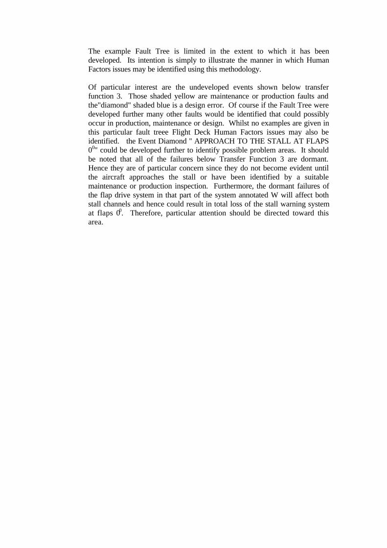
The example Fault Tree is limited in the extent to which it has beendeveloped. Its intention is simply to illustrate the manner in which HumanFactors issues may be identified using this methodology.
Of particular interest are the undeveloped events shown below transferfunction 3. Those shaded yellow are maintenance or production faults andthe"diamond" shaded blue is a design error. Of course if the Fault Tree weredeveloped further many other faults would be identified that could possiblyoccur in production, maintenance or design. Whilst no examples are given inthis particular fault treee Flight Deck Human Factors issues may also beidentified. the Event Diamond " APPROACH TO THE STALL AT FLAPS00" could be developed further to identify possible problem areas. It shouldbe noted that all of the failures below Transfer Function 3 are dormant.Hence they are of particular concern since they do not become evident untilthe aircraft approaches the stall or have been identified by a suitablemaintenance or production inspection. Furthermore, the dormant failures ofthe flap drive system in that part of the system annotated W will affect bothstall channels and hence could result in total loss of the stall warning systemat flaps 00. Therefore, particular attention should be directed toward thisarea.

NOTE: SWCU = STALLWARNING CONTROLUNIT
D
NO AUDIBLE OR TACTILEWARNING AT APPROACH TO
THE STALL AT FLAPS 00B
E
A
C
APPROACH TO THE STALL WITH NO AUDIBLEOR TACTILE WARNING AT FLAPS 00
NO AUDIBLE OR TACTILEWARNING AT APPROACH TO
THE STALL AT FLAPS 00
FROM CHANNEL B
OTHER POSSIBLE SYSTEM STATESNOT CONSIDERED FOR THIS
ANALYSIS
CHANNEL B STALL WARNINGMOTOR DOES NOT OPERATE ATAPPROACH TO THE STALL AT
FLAPS 00
SIMILAR TOCHANNEL B
OTHER POSSIBLE SYSTEM STATESNOT CONSIDERED FOR THIS
ANALYSIS
F
MALFUNCTION OF FLAP DISCRETE FROMFLAP POSITION TRANSMITTER SUCH THATCHANNEL B STALL WARNING MOTOR DOESNOT OPERATE AT APPROACH TO THE STALL
AT FLAPS 00
OTHER POSSIBLE SYSTEM STATESNOT CONSIDERED FOR THIS
ANALYSIS
AND
OR
NO AUDIBLE OR TACTILEWARNING AT APPROACH TO
THE STALL AT FLAPS 00
FROM CHANNEL A
OR
MALFUNCTION OF SIGNAL TORELAY SUCH THAT
CHANNEL B STALL WARNINGMOTOR DOES NOT OPERATE ATAPPROACH TO THE STALL AT
FLAPS 00
OR
1
AND
APPROACH TO THE STALL ATFLAPS 00

OR
1
MALFUNCTION OF FLAP DISCRETE FROMFLAP POSITION TRANSMITTER SUCH THATCHANNEL B STALL WARNING MOTOR DOESNOT OPERATE AT APPROACH TO THE STALL
AT FLAPS 00
OTHER POSSIBLE SYSTEM STATESNOT CONSIDERED FOR THIS
ANALYSIS
F
LOSS OF MECHANICAL INTEGRITY OF DRIVETO FLAP POSITION TRANSMITTER SUCH THAT
CHANNEL B SWCU RECEIVES CONSTANTSIGNAL THAT FLAPS ARE AT 450
OR
G
NON-SYSTEMATIC FAILURES RESULTING INSYSTEM STATE G
SYSTEMATIC FAILURES RESULTING INSYSTEM STATE G
32
H I
HNON-SYSTEMATIC FAILURES RESULTING
IN SYSTEM STATE G
2
OR
OTHER POSSIBLE SYSTEMSTATES NOT CONSIDERED FOR
THIS ANALYSIS
FRACTURE OF LINKAGE Z FRACTURE OF LINKAGE N FRACTURE OF LINKAGE W

Figure A4: Fault Tree Augmented to Identify Possible Risk from Errors inMaintenance, Design and Production. The ‘yellow’ elements relate to possiblemaintenance errors and are used to select the maintenance tasks that would be subjectedto the ‘FMEA’ part of the HHA [see Appendix 2]. For example, tasks may include‘Assemble Linkage Z’, or ‘Lock Nut Y to Correct Torque’ or ‘Fit Split Pin’. Otheritems such as ‘Inadequate Strength of Linkage Z’ may relate instead to vulnerability tohuman error in other areas such as Design activity. This would suggest that items suchas ‘Strength of linkage Z’ identified in this way should receive particular attentionduring design checks and / or production processes.
ISYSTEMATIC FAILURES RESULTING IN
SYSTEM STATE G
3
OR
OTHER POSSIBLE SYSTEMSTATES NOT CONSIDERED FOR
THIS ANALYSIS
IMPROPER ASSEMBLY OFLINKAGE Z
LOCKING NUT Y INCORRECTLYTORQUED NON-FITMENT OF SPLIT PIN M
IMPROPER ASSEMBLY OFLINKAGE W
INADEQUATE STRENGTH OFLINKAGE Z

A2: Example of FMEA Based HHA Conducted on Selected TasksMaintenancetask
DesignVulnerability
Possiblewrong action
FTrequired?
Indication tomaintenance crew if FTnot performed?
Indication to flight crewbefore flight?
Subsequentindication to flightcrew?
Immediate ordirectconsequence
Latentconsequence (withsecond failure)
Comments Mitigationrequired
1. Install fuelgauges
Same partnumbers ongauges andconnectors
Crossconnect wingtank gauges
Yes None None None unless fueltransfer required
MINOR CATASTROPHICWhen combinedwith fuel pumpfailure, it could leadto fuel transfer fromthe empty tank tothe full tank,resulting in fuelimbalance and lossof control
No obviousvisual cluesunless wingtank fuelcontents areconsiderablydifferent
Physicallydifferent partsfor theconnectorsand gaugesTaggingsystem
Same partnumbers ongauges andconnectors
Crossconnect wingtank gaugewith centraltank gauge
Yes None Strange readings onfuel tank gauges incockpit
More apparent if fueltransfer required
MINOR CATASTROPHICWhen combinedwith fuel pumpfailure, it could leadto fuel transfer fromthe empty tank tothe full tank,resulting in fuelimbalance and lossof control
No obviousvisual cluesunless wingtank fuelcontents areconsiderablydifferent
Physicallydifferent partsfor theconnectorsand gaugesTaggingsystem
2. InstallPRSOV / fanair modulatingvalve
Pipe unionssame partnumbersCMM figuremisleading -not inagreementwith text
CrossconnectPRSOV /FAMVpneumaticpipe unions
Yes Pipes can be seenvisually crossed
EICAS warning ormessage
Pneumatic ductpressure excessiveat take-off power
MINOR MAJORPneumatic systemproblems couldresult in highcockpit workload inthe event of asecond failure
Pipes foundtwisted insidepylon
DifferentunionsImprove CMMfigures
3. Installnavigationsystem
Same partnumbers forcableconnectors
Crossconnect co-axial cablesfor VHFcomms andVORnavigation
Yes None None Poor range on VHFcomms andintermittent VORsignal
MINOR MAJORIn the event offailure of thesecondary VOR orVHF commssystem
Located onsame rack
Physicallydifferent parts

Fig. A5. HHA Applied to selected maintenance tasks on the B737 aircraft. Adapted from Doherty (1999).