Embed Size (px)
Citation preview
Hub City HubFlex® Coupling
Certified prints are available upon requestDOWNLOAD AVAILABLE CAD MODELS AT: WWW.HUBCITYINC.COM
Q-1
Q
Hub
Flex® C
oup
ling
EMAIL: [email protected] • www.hubcityinc.com
HubFlex® Features and Advantages Q-2
Green Technology and Sustainability Q-3
Coupling Ordering Nomenclature Q-4
Inserts Q-5
Covers Q-6
Coupling Selection Q-7
Dimensions/Ratings Q-8-9
Bore Sizes and Tolerances Q-10
Torque Ratings Q-11-12
Misalignment Tolerances Q-13
Banded Inserts Q-13
Spacer Hubs and Couplings Q-14-18
Service Factors Q-19-21
Compatibility Chart Q-22
Safety Guidelines Q-23
Quick Selection Guide Q-24
Hub City HubFlex® Coupling
Certified prints are available upon requestDOWNLOAD AVAILABLE CAD MODELS AT: WWW.HUBCITYINC.COM
CALL: (605) 225-0360 • FAX: (605) 225-0567Q-2
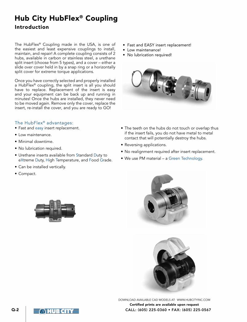
The HubFlex® Coupling made in the USA, is one of the easiest and least expensive couplings to install, maintain, and repair! A complete coupling consists of 2 hubs, available in carbon or stainless steel, a urethane split insert (choose from 5 types), and a cover – either a slide over cover held in by a snap ring or a horizontally split cover for extreme torque applications
Once you have correctly selected and properly installed a HubFlex® coupling, the split insert is all you should have to replace Replacement of the insert is easy and your equipment can be back up and running in minutes! Once the hubs are installed, they never need to be moved again Remove only the cover, replace the insert, re-install the cover, and you are ready to GO!
The HubFlex® advantages:• Fast and easy insert replacement
• Low maintenance
• Minimal downtime
• No lubrication required
• Urethane inserts available from Standard Duty to eXtreme Duty, High Temperature, and Food Grade
• Can be installed vertically
• Compact
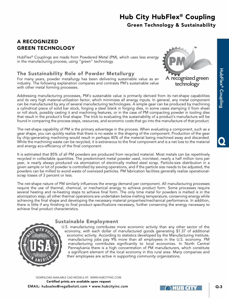
• The teeth on the hubs do not touch or overlap thus if the insert fails, you do not have metal to metal contact that will potentially destroy the hubs
• Reversing applications
• No realignment required after insert replacement
• We use PM material – a Green Technology
• Fast and EASY insert replacement!• Low maintenance!• No lubrication required!
Introduction
Hub City HubFlex® Coupling
Certified prints are available upon requestDOWNLOAD AVAILABLE CAD MODELS AT: WWW.HUBCITYINC.COM
Q-3
Q
Hub
Flex® C
oup
ling
EMAIL: [email protected] • www.hubcityinc.com
Green Technology & Sustainability
A RECOGNIZED GREEN TECHNOLOGY
HubFlex® Couplings are made from Powdered Metal (PM), which uses less energy in the manufacturing process, using “green” technology
The Sustainability Role of Powder MetallurgyFor many years, powder metallurgy has been delivering sustainable value as an industry The following explanation compares and contrasts PM’s sustainable value with other metal forming processes
Addressing manufacturing processes, PM’s sustainable value is primarily derived from its net-shape capabilities and its very high material-utilization factor, which minimizes all energy inputs In general, any metal component can be manufactured by any of several manufacturing technologies A simple gear can be produced by machining a cylindrical piece of solid bar stock, forging a steel blank in forging dies, in some cases stamping it from sheet or roll stock, possibly casting it and machining features, or in the case of PM compacting powder in tooling dies that result in the product’s final shape The trick to evaluating the sustainability of a product’s manufacture will be found in comparing the process steps, resources, and economic costs that go into the manufacture of that product
The net-shape capability of PM is the primary advantage in the process When evaluating a component, such as a gear shape, you can quickly realize that there is no waste in the shaping of the component Production of the gear by chip-generating machining would result in perhaps 40% of the material being machined away and discarded While the machining waste can be recycled, it is extraneous to the final component and is a net loss to the material and energy eco-efficiency of the final component
It is estimated that 85% of all PM powders are produced from recycled material Most metals can be repetitively recycled in collectable quantities The predominant metal powder used, iron/steel, nearly a half million tons per year, is nearly always produced via atomization of electrically melted steel scrap Particle-size distribution in a given sample or lot of powder is controlled by sieving operations, and if the particle size needs to be adjusted, the powders can be milled to avoid waste of oversized particles PM fabrication facilities generally realize operational-scrap losses of 3 percent or less
The net-shape nature of PM similarly influences the energy demand per component All manufacturing processes require the use of thermal, chemical, or mechanical energy to achieve product form Some processes require several heating and re-heating steps to achieve final form The only time metal for powders is melted is in the atomization step; all other thermal operations are undertaken below melting temperature, conserving energy while achieving the final shape and developing the necessary material properties/mechanical performance In addition, there is little if any finishing to final product specifications necessary, further conserving the energy necessary to achieve final product characteristics
Sustainable EmploymentU S manufacturing contributes more economic activity than any other sector of the
economy, with each dollar of manufactured goods generating $1 37 of additional economic activity According to statistics developed by the Manufacturing Institute, manufacturing jobs pay 9% more than all employees in the U S economy PM manufacturing contributes significantly to local economies In North Central Pennsylvania there is a high concentration of PM manufacturers, which constitute a significant element of the local economy in this rural area Many companies and
their employees are active in supporting community organizations
Hub City HubFlex® Coupling
Certified prints are available upon requestDOWNLOAD AVAILABLE CAD MODELS AT: WWW.HUBCITYINC.COM
CALL: (605) 225-0360 • FAX: (605) 225-0567Q-4
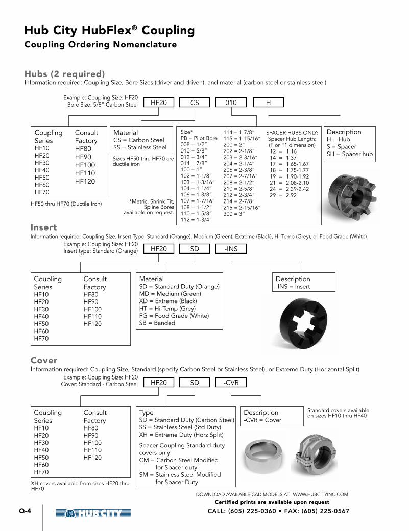
Coupling Ordering Nomenclature
Hubs (2 required)Information required: Coupling Size, Bore Sizes (driver and driven), and material (carbon steel or stainless steel)
InsertInformation required: Coupling Size, Insert Type: Standard (Orange), Medium (Green), Extreme (Black), Hi-Temp (Grey), or Food Grade (White)
CoverInformation required: Coupling Size, Standard (specify Carbon Steel or Stainless Steel), or Extreme Duty (Horizontal Split)
HF20
HF20
HF20
CS
SD
SD
010 H
-CVR
-INS
Example: Coupling Size: HF20Bore Size: 5/8” Carbon Steel
Example: Coupling Size: HF20Insert type: Standard (Orange)
Example: Coupling Size: HF20Cover: Standard - Carbon Steel
Coupling SeriesHF10HF20HF30HF40HF50HF60HF70
Coupling SeriesHF10HF20HF30HF40HF50HF60HF70
Coupling SeriesHF10HF20HF30HF40HF50HF60HF70
MaterialCS = Carbon SteelSS = Stainless Steel
TypeSD = Standard Duty (Carbon Steel)SS = Stainless Steel (Std Duty)XH = Extreme Duty (Horz Split)
Spacer Coupling Standard duty covers only:CM = Carbon Steel Modified for Spacer dutySM = Stainless Steel Modified for Spacer Duty
MaterialSD = Standard Duty (Orange)MD = Medium (Green)XD = Extreme (Black)HT = Hi-Temp (Grey)FG = Food Grade (White)SB = Banded
DescriptionH = HubS = SpacerSH = Spacer hub
Description-CVR = Cover
Description-INS = Insert
Consult FactoryHF80HF90HF100HF110HF120
Consult FactoryHF80HF90HF100HF110HF120
Consult FactoryHF80HF90HF100HF110HF120
114 = 1-7/8”115 = 1-15/16”200 = 2”202 = 2-1/8”203 = 2-3/16”204 = 2-1/4”206 = 2-3/8”207 = 2-7/16”208 = 2-1/2”210 = 2-5/8”212 = 2-3/4”214 = 2-7/8”215 = 2-15/16”300 = 3”
Size*PB = Pilot Bore008 = 1/2”010 = 5/8”012 = 3/4”014 = 7/8”100 = 1”102 = 1-1/8”103 = 1-3/16” 104 = 1-1/4”106 = 1-3/8”107 = 1-7/16”108 = 1-1/2”110 = 1-5/8”112 = 1-3/4”
*Metric, Shrink Fit, Spline Bores
available on request
HF50 thru HF70 (Ductile Iron)
Sizes HF50 thru HF70 are ductile iron
XH covers available from sizes HF20 thru HF70
Standard covers available on sizes HF10 thru HF40
SPACER HUBS ONLY:Spacer Hub Length:(F or F1 dimension)12 = 1 1614 = 1 3717 = 1 65-1 6718 = 1 75-1 7719 = 1 90-1 9221 = 2 08-2 1024 = 2 39-2 4229 = 2 92
Hub City HubFlex® Coupling
Certified prints are available upon requestDOWNLOAD AVAILABLE CAD MODELS AT: WWW.HUBCITYINC.COM
Q-5
Q
Hub
Flex® C
oup
ling
EMAIL: [email protected] • www.hubcityinc.com
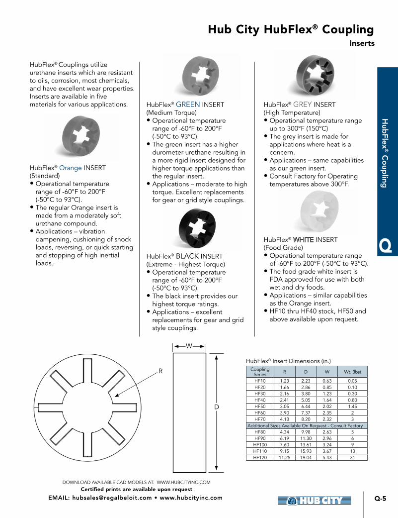
Inserts
HubFlex® Couplings utilize urethane inserts which are resistant to oils, corrosion, most chemicals, and have excellent wear properties Inserts are available in five materials for various applications
HubFlex® Orange INSERT (Standard)• Operational temperature
range of -60°F to 200°F (-50°C to 93°C)
• The regular Orange insert is made from a moderately soft urethane compound
• Applications – vibration dampening, cushioning of shock loads, reversing, or quick starting and stopping of high inertial loads
HubFlex® GREEN INSERT (Medium Torque)• Operational temperature
range of -60°F to 200°F (-50°C to 93°C)
• The green insert has a higher durometer urethane resulting in a more rigid insert designed for higher torque applications than the regular insert
• Applications – moderate to high torque Excellent replacements for gear or grid style couplings
HubFlex® BLACK INSERT (Extreme - Highest Torque)• Operational temperature
range of -60°F to 200°F (-50°C to 93°C)
• The black insert provides our highest torque ratings
• Applications – excellent replacements for gear and grid style couplings
HubFlex® GREY INSERT (High Temperature)• Operational temperature range
up to 300°F (150°C) • The grey insert is made for
applications where heat is a concern
• Applications – same capabilities as our green insert
• Consult Factory for Operating temperatures above 300°F
HubFlex® INSERT (Food Grade)• Operational temperature range
of -60°F to 200°F (-50°C to 93°C) • The food grade white insert is
FDA approved for use with both wet and dry foods
• Applications – similar capabilities as the Orange insert
• HF10 thru HF40 stock, HF50 and above available upon request
HubFlex® Insert Dimensions (in )Coupling
Series R D W Wt (lbs)
HF10 1 23 2 23 0 63 0 05HF20 1 66 2 86 0 85 0 10HF30 2 16 3 80 1 23 0 30HF40 2 41 5 05 1 64 0 80HF50 3 05 6 44 2 02 1 45HF60 3 90 7 37 2 35 2HF70 4 13 8 20 2 32 3
Additional Sizes Available On Request - Consult FactoryHF80 4 34 9 98 2 63 5HF90 6 19 11 30 2 96 6
HF100 7 60 13 61 3 24 9HF110 9 15 15 93 3 67 13HF120 11 25 19 04 5 43 31
R
W
D

Hub City HubFlex® Coupling
Certified prints are available upon requestDOWNLOAD AVAILABLE CAD MODELS AT: WWW.HUBCITYINC.COM
CALL: (605) 225-0360 • FAX: (605) 225-0567Q-6
Covers
HubFlex® Standard CoverDesigned for applications where low torque and/or high speed is present
HubFlex® Standard Cover Dimensions (in )
COVER PART #
(XX=Material)
MAXIMUM RPM* D W WEIGHT
(lbs )
HF10XX-CVR 4000 2 49 0 95 3HF20XX-CVR 4000 3 16 1 35 78HF30XX-CVR 4000 4 21 1 95 2 1HF40XX-CVR 4000 5 48 2 38 3 3
Additional Sizes Available Upon Request - Consult FactoryHF50XX-CVR 4000 7 00 2 96 10 3HF60XX-CVR 4000 8 00 3 27 11 2HF70XX-CVR 3800 8 88 3 50 17 9HF80XX-CVR 3400 10 77 4 05 18
HubFlex® Extreme Duty CoverDesigned for all applications including high or low torque and speed ratings while eliminating axial loading
HubFlex® Extreme Duty Cover Dimensions (in )
COVER PART #
MAXIMUM RPM* W D BOLT SIZE WEIGHT
(lbs )HF20XH-CVR 4000 1 93 3 99 (4) 3/8 nc x 1-1/4 1 1HF30XH-CVR 4000 2 61 5 34 (4) 1/2 nc x 2 2 5HF40XH-CVR 4000 3 02 7 28 (4) 1/2 nc x 1-3/4 5 7HF50XH-CVR 4000 5 96 7 76 (4) 1/2 nc x 2-1/4 10 3HF60XH-CVR 4000 6 17 8 52 (4) 5/8 nc x 2-1/2 11 2HF70XH-CVR 3800 6 54 10 29 (4) 3/4 nc x 3-1/2 17 9
Additional Sizes Available Upon Request - Consult FactoryHF80XH-CVR 3000 7 93 12 05 (4) 3/4 nc x 3-1/2 18
* For applications over 4000 RPM, consult factory
* For applications over 4000 RPM, consult factoryStainless steel hardware provided with all Extreme Duty covers
Hub City HubFlex® Coupling
Certified prints are available upon requestDOWNLOAD AVAILABLE CAD MODELS AT: WWW.HUBCITYINC.COM
Q-7
Q
Hub
Flex® C
oup
ling
EMAIL: [email protected] • www.hubcityinc.com
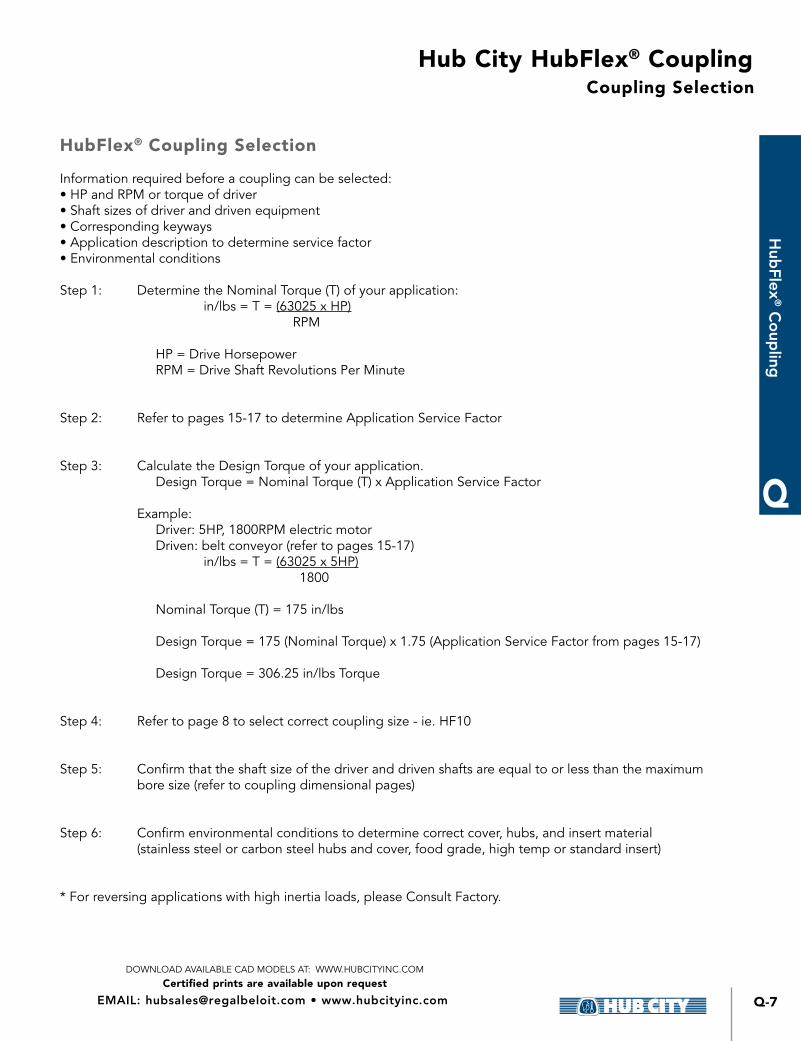
Coupling Selection
HubFlex® Coupling Selection
Information required before a coupling can be selected:• HP and RPM or torque of driver• Shaft sizes of driver and driven equipment• Corresponding keyways• Application description to determine service factor• Environmental conditions
Step 1: Determine the Nominal Torque (T) of your application: in/lbs = T = (63025 x HP) RPM
HP = Drive Horsepower RPM = Drive Shaft Revolutions Per Minute
Step 2: Refer to pages 15-17 to determine Application Service Factor
Step 3: Calculate the Design Torque of your application Design Torque = Nominal Torque (T) x Application Service Factor
Example: Driver: 5HP, 1800RPM electric motor Driven: belt conveyor (refer to pages 15-17) in/lbs = T = (63025 x 5HP) 1800 Nominal Torque (T) = 175 in/lbs
Design Torque = 175 (Nominal Torque) x 1 75 (Application Service Factor from pages 15-17) Design Torque = 306 25 in/lbs Torque
Step 4: Refer to page 8 to select correct coupling size - ie HF10
Step 5: Confirm that the shaft size of the driver and driven shafts are equal to or less than the maximum bore size (refer to coupling dimensional pages)
Step 6: Confirm environmental conditions to determine correct cover, hubs, and insert material (stainless steel or carbon steel hubs and cover, food grade, high temp or standard insert)
* For reversing applications with high inertia loads, please Consult Factory
Hub City HubFlex® Coupling
Certified prints are available upon requestDOWNLOAD AVAILABLE CAD MODELS AT: WWW.HUBCITYINC.COM
CALL: (605) 225-0360 • FAX: (605) 225-0567Q-8
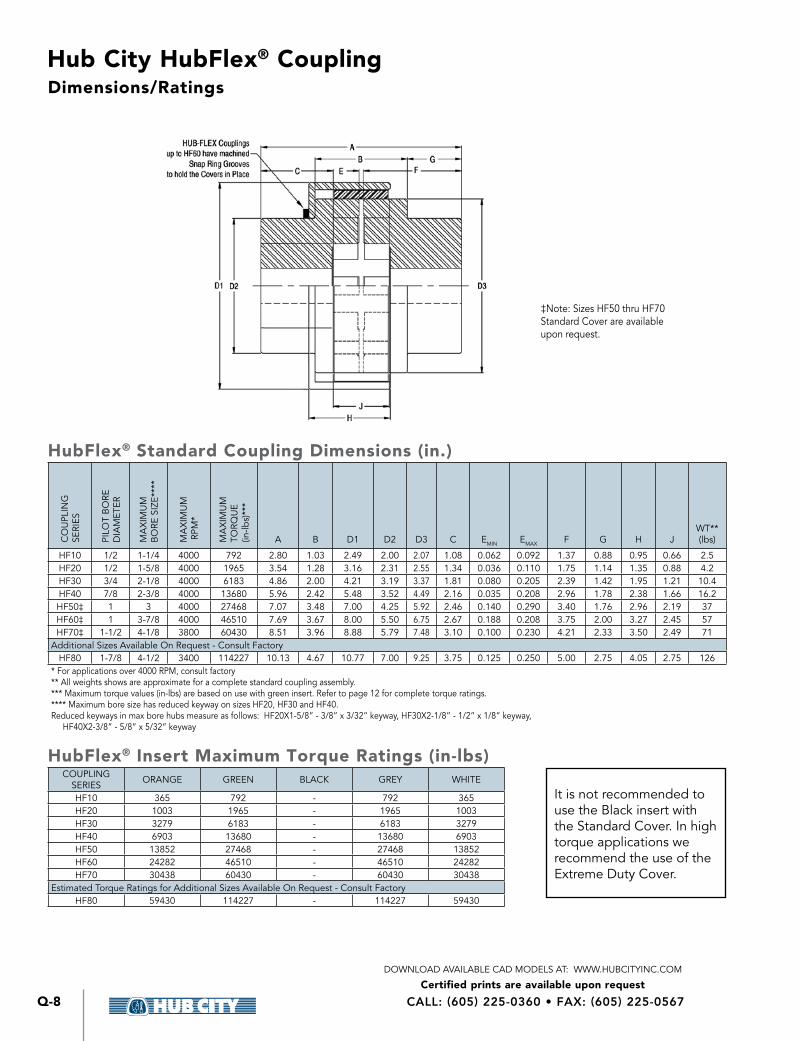
Dimensions/Ratings
HubFlex® Standard Coupling Dimensions (in.)
CO
UPL
ING
SE
RIES
PILO
T B
ORE
D
IAM
ETER
MA
XIM
UM
B
ORE
SIZ
E***
*
MA
XIM
UM
RPM
*
MA
XIM
UM
TO
RQU
E
(in-lb
s)**
*
A B D1 D2 D3 C EMIN EMAX F G H JWT**(lbs)
HF10 1/2 1-1/4 4000 792 2 80 1 03 2 49 2 00 2 07 1 08 0 062 0 092 1 37 0 88 0 95 0 66 2 5HF20 1/2 1-5/8 4000 1965 3 54 1 28 3 16 2 31 2 55 1 34 0 036 0 110 1 75 1 14 1 35 0 88 4 2HF30 3/4 2-1/8 4000 6183 4 86 2 00 4 21 3 19 3 37 1 81 0 080 0 205 2 39 1 42 1 95 1 21 10 4HF40 7/8 2-3/8 4000 13680 5 96 2 42 5 48 3 52 4 49 2 16 0 035 0 208 2 96 1 78 2 38 1 66 16 2HF50‡ 1 3 4000 27468 7 07 3 48 7 00 4 25 5 92 2 46 0 140 0 290 3 40 1 76 2 96 2 19 37HF60‡ 1 3-7/8 4000 46510 7 69 3 67 8 00 5 50 6 75 2 67 0 188 0 208 3 75 2 00 3 27 2 45 57HF70‡ 1-1/2 4-1/8 3800 60430 8 51 3 96 8 88 5 79 7 48 3 10 0 100 0 230 4 21 2 33 3 50 2 49 71
Additional Sizes Available On Request - Consult FactoryHF80 1-7/8 4-1/2 3400 114227 10 13 4 67 10 77 7 00 9 25 3 75 0 125 0 250 5 00 2 75 4 05 2 75 126
* For applications over 4000 RPM, consult factory** All weights shows are approximate for a complete standard coupling assembly *** Maximum torque values (in-lbs) are based on use with green insert Refer to page 12 for complete torque ratings **** Maximum bore size has reduced keyway on sizes HF20, HF30 and HF40 Reduced keyways in max bore hubs measure as follows: HF20X1-5/8” - 3/8” x 3/32” keyway, HF30X2-1/8” - 1/2” x 1/8” keyway, HF40X2-3/8” - 5/8” x 5/32” keyway
HubFlex® Insert Maximum Torque Ratings (in-lbs)COUPLING
SERIES ORANGE GREEN BLACK GREY WHITE
HF10 365 792 - 792 365HF20 1003 1965 - 1965 1003HF30 3279 6183 - 6183 3279HF40 6903 13680 - 13680 6903HF50 13852 27468 - 27468 13852HF60 24282 46510 - 46510 24282HF70 30438 60430 - 60430 30438
Estimated Torque Ratings for Additional Sizes Available On Request - Consult FactoryHF80 59430 114227 - 114227 59430
It is not recommended to use the Black insert with the Standard Cover In high torque applications we recommend the use of the Extreme Duty Cover
‡Note: Sizes HF50 thru HF70 Standard Cover are available upon request
Hub City HubFlex® Coupling
Certified prints are available upon requestDOWNLOAD AVAILABLE CAD MODELS AT: WWW.HUBCITYINC.COM
Q-9
Q
Hub
Flex® C
oup
ling
EMAIL: [email protected] • www.hubcityinc.com
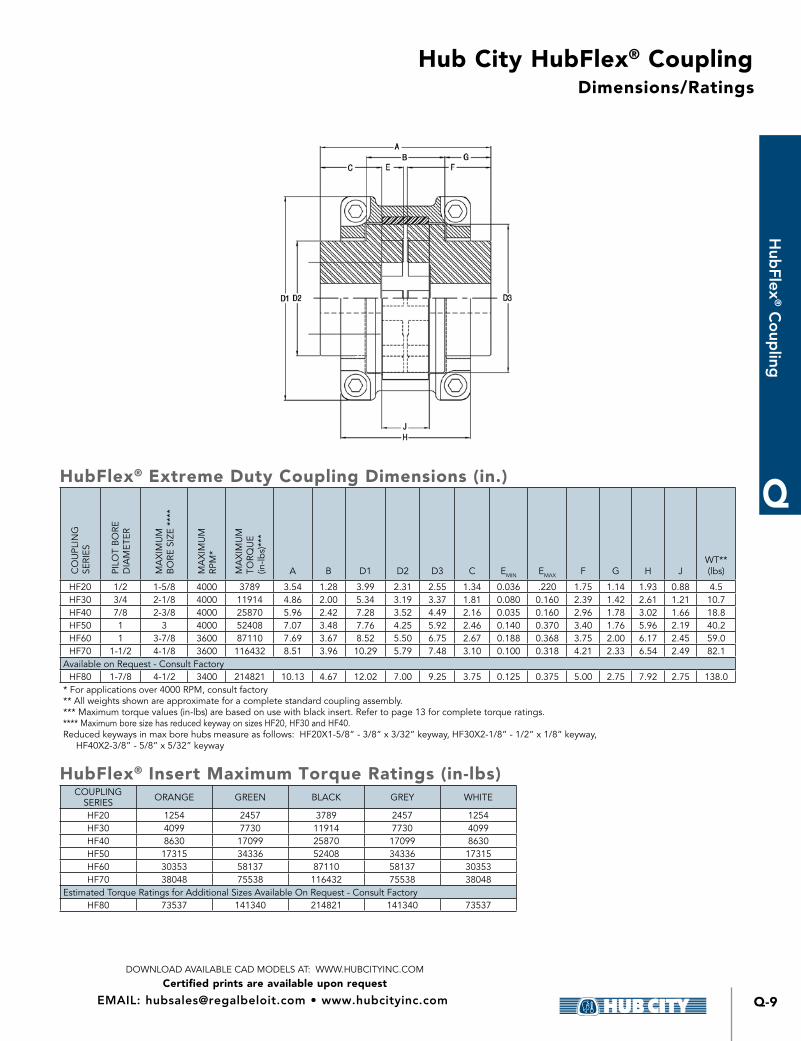
Dimensions/Ratings
HubFlex® Extreme Duty Coupling Dimensions (in.)
CO
UPL
ING
SERI
ES
PILO
T B
ORE
D
IAM
ETER
MA
XIM
UM
B
ORE
SIZ
E **
**
MA
XIM
UM
RPM
*
MA
XIM
UM
TO
RQU
E (in
-lbs)
***
A B D1 D2 D3 C EMIN EMAX F G H JWT** (lbs)
HF20 1/2 1-5/8 4000 3789 3 54 1 28 3 99 2 31 2 55 1 34 0 036 220 1 75 1 14 1 93 0 88 4 5HF30 3/4 2-1/8 4000 11914 4 86 2 00 5 34 3 19 3 37 1 81 0 080 0 160 2 39 1 42 2 61 1 21 10 7HF40 7/8 2-3/8 4000 25870 5 96 2 42 7 28 3 52 4 49 2 16 0 035 0 160 2 96 1 78 3 02 1 66 18 8HF50 1 3 4000 52408 7 07 3 48 7 76 4 25 5 92 2 46 0 140 0 370 3 40 1 76 5 96 2 19 40 2HF60 1 3-7/8 3600 87110 7 69 3 67 8 52 5 50 6 75 2 67 0 188 0 368 3 75 2 00 6 17 2 45 59 0HF70 1-1/2 4-1/8 3600 116432 8 51 3 96 10 29 5 79 7 48 3 10 0 100 0 318 4 21 2 33 6 54 2 49 82 1
Available on Request - Consult FactoryHF80 1-7/8 4-1/2 3400 214821 10 13 4 67 12 02 7 00 9 25 3 75 0 125 0 375 5 00 2 75 7 92 2 75 138 0
* For applications over 4000 RPM, consult factory** All weights shown are approximate for a complete standard coupling assembly *** Maximum torque values (in-lbs) are based on use with black insert Refer to page 13 for complete torque ratings **** Maximum bore size has reduced keyway on sizes HF20, HF30 and HF40 Reduced keyways in max bore hubs measure as follows: HF20X1-5/8” - 3/8” x 3/32” keyway, HF30X2-1/8” - 1/2” x 1/8” keyway, HF40X2-3/8” - 5/8” x 5/32” keyway
HubFlex® Insert Maximum Torque Ratings (in-lbs)COUPLING
SERIES ORANGE GREEN BLACK GREY WHITE
HF20 1254 2457 3789 2457 1254HF30 4099 7730 11914 7730 4099HF40 8630 17099 25870 17099 8630HF50 17315 34336 52408 34336 17315HF60 30353 58137 87110 58137 30353HF70 38048 75538 116432 75538 38048
Estimated Torque Ratings for Additional Sizes Available On Request - Consult FactoryHF80 73537 141340 214821 141340 73537
Hub City HubFlex® Coupling
Certified prints are available upon requestDOWNLOAD AVAILABLE CAD MODELS AT: WWW.HUBCITYINC.COM
CALL: (605) 225-0360 • FAX: (605) 225-0567Q-10
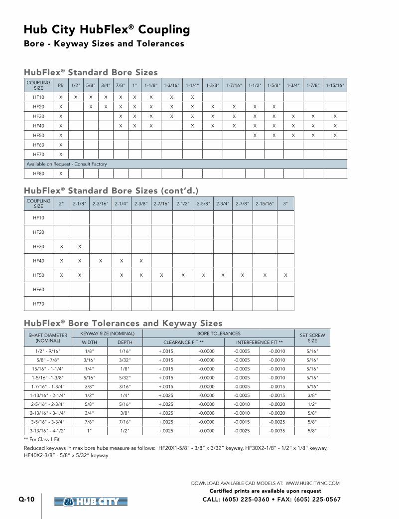
Bore - Keyway Sizes and Tolerances
HubFlex® Standard Bore Sizes COUPLING
SIZE PB 1/2" 5/8" 3/4" 7/8" 1" 1-1/8" 1-3/16" 1-1/4" 1-3/8" 1-7/16" 1-1/2" 1-5/8" 1-3/4" 1-7/8" 1-15/16"
HF10 X X X X X X X X X
HF20 X X X X X X X X X X X X
HF30 X X X X X X X X X X X X X
HF40 X X X X X X X X X X X X
HF50 X X X X X X
HF60 X
HF70 X
Available on Request - Consult Factory
HF80 X
HubFlex® Standard Bore Sizes (cont’d.)COUPLING
SIZE 2" 2-1/8" 2-3/16" 2-1/4" 2-3/8" 2-7/16" 2-1/2" 2-5/8" 2-3/4" 2-7/8" 2-15/16" 3"
HF10
HF20
HF30 X X
HF40 X X X X X
HF50 X X X X X X X X X X X
HF60
HF70
HubFlex® Bore Tolerances and Keyway Sizes SHAFT DIAMETER
(NOMINAL)
KEYWAY SIZE (NOMINAL) BORE TOLERANCES SET SCREW SIZEWIDTH DEPTH CLEARANCE FIT ** INTERFERENCE FIT **
1/2" - 9/16" 1/8" 1/16" + 0015 -0 0000 -0 0005 -0 0010 5/16"
5/8" - 7/8" 3/16" 3/32" + 0015 -0 0000 -0 0005 -0 0010 5/16"
15/16" - 1-1/4" 1/4" 1/8" + 0015 -0 0000 -0 0005 -0 0010 5/16"
1-5/16" -1-3/8" 5/16" 5/32" + 0015 -0 0000 -0 0005 -0 0010 5/16"
1-7/16" - 1-3/4" 3/8" 3/16" + 0015 -0 0000 -0 0005 -0 0015 5/16"
1-13/16" - 2-1/4" 1/2" 1/4" + 0025 -0 0000 -0 0005 -0 0015 3/8"
2-5/16" - 2-3/4" 5/8" 5/16" + 0025 -0 0000 -0 0010 -0 0020 1/2"
2-13/16" - 3-1/4" 3/4" 3/8" + 0025 -0 0000 -0 0010 -0 0020 5/8"
3-5/16" - 3-3/4" 7/8" 7/16" + 0025 -0 0000 -0 0015 -0 0025 5/8"
3-13/16" - 4-1/2" 1" 1/2" + 0025 -0 0000 -0 0025 -0 0035 5/8"
** For Class 1 Fit
Reduced keyways in max bore hubs measure as follows: HF20X1-5/8” - 3/8” x 3/32” keyway, HF30X2-1/8” - 1/2” x 1/8” keyway, HF40X2-3/8” - 5/8” x 5/32” keyway
Hub City HubFlex® Coupling
Certified prints are available upon requestDOWNLOAD AVAILABLE CAD MODELS AT: WWW.HUBCITYINC.COM
Q-11
Q
Hub
Flex® C
oup
ling
EMAIL: [email protected] • www.hubcityinc.com
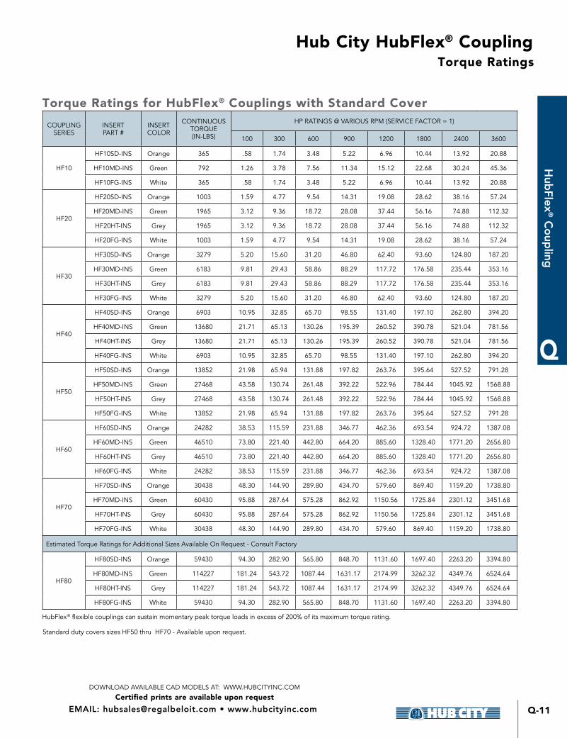
Torque Ratings
Torque Ratings for HubFlex® Couplings with Standard Cover
COUPLING SERIES
INSERT PART #
INSERT COLOR
CONTINUOUS TORQUE (IN-LBS)
HP RATINGS @ VARIOUS RPM (SERVICE FACTOR = 1)
100 300 600 900 1200 1800 2400 3600
HF10
HF10SD-INS Orange 365 58 1 74 3 48 5 22 6 96 10 44 13 92 20 88
HF10MD-INS Green 792 1 26 3 78 7 56 11 34 15 12 22 68 30 24 45 36
HF10FG-INS White 365 58 1 74 3 48 5 22 6 96 10 44 13 92 20 88
HF20
HF20SD-INS Orange 1003 1 59 4 77 9 54 14 31 19 08 28 62 38 16 57 24
HF20MD-INS Green 1965 3 12 9 36 18 72 28 08 37 44 56 16 74 88 112 32
HF20HT-INS Grey 1965 3 12 9 36 18 72 28 08 37 44 56 16 74 88 112 32
HF20FG-INS White 1003 1 59 4 77 9 54 14 31 19 08 28 62 38 16 57 24
HF30
HF30SD-INS Orange 3279 5 20 15 60 31 20 46 80 62 40 93 60 124 80 187 20
HF30MD-INS Green 6183 9 81 29 43 58 86 88 29 117 72 176 58 235 44 353 16
HF30HT-INS Grey 6183 9 81 29 43 58 86 88 29 117 72 176 58 235 44 353 16
HF30FG-INS White 3279 5 20 15 60 31 20 46 80 62 40 93 60 124 80 187 20
HF40
HF40SD-INS Orange 6903 10 95 32 85 65 70 98 55 131 40 197 10 262 80 394 20
HF40MD-INS Green 13680 21 71 65 13 130 26 195 39 260 52 390 78 521 04 781 56
HF40HT-INS Grey 13680 21 71 65 13 130 26 195 39 260 52 390 78 521 04 781 56
HF40FG-INS White 6903 10 95 32 85 65 70 98 55 131 40 197 10 262 80 394 20
HF50
HF50SD-INS Orange 13852 21 98 65 94 131 88 197 82 263 76 395 64 527 52 791 28
HF50MD-INS Green 27468 43 58 130 74 261 48 392 22 522 96 784 44 1045 92 1568 88
HF50HT-INS Grey 27468 43 58 130 74 261 48 392 22 522 96 784 44 1045 92 1568 88
HF50FG-INS White 13852 21 98 65 94 131 88 197 82 263 76 395 64 527 52 791 28
HF60
HF60SD-INS Orange 24282 38 53 115 59 231 88 346 77 462 36 693 54 924 72 1387 08
HF60MD-INS Green 46510 73 80 221 40 442 80 664 20 885 60 1328 40 1771 20 2656 80
HF60HT-INS Grey 46510 73 80 221 40 442 80 664 20 885 60 1328 40 1771 20 2656 80
HF60FG-INS White 24282 38 53 115 59 231 88 346 77 462 36 693 54 924 72 1387 08
HF70
HF70SD-INS Orange 30438 48 30 144 90 289 80 434 70 579 60 869 40 1159 20 1738 80
HF70MD-INS Green 60430 95 88 287 64 575 28 862 92 1150 56 1725 84 2301 12 3451 68
HF70HT-INS Grey 60430 95 88 287 64 575 28 862 92 1150 56 1725 84 2301 12 3451 68
HF70FG-INS White 30438 48 30 144 90 289 80 434 70 579 60 869 40 1159 20 1738 80
Estimated Torque Ratings for Additional Sizes Available On Request - Consult Factory
HF80
HF80SD-INS Orange 59430 94 30 282 90 565 80 848 70 1131 60 1697 40 2263 20 3394 80
HF80MD-INS Green 114227 181 24 543 72 1087 44 1631 17 2174 99 3262 32 4349 76 6524 64
HF80HT-INS Grey 114227 181 24 543 72 1087 44 1631 17 2174 99 3262 32 4349 76 6524 64
HF80FG-INS White 59430 94 30 282 90 565 80 848 70 1131 60 1697 40 2263 20 3394 80
HubFlex® flexible couplings can sustain momentary peak torque loads in excess of 200% of its maximum torque rating
Standard duty covers sizes HF50 thru HF70 - Available upon request
Hub City HubFlex® Coupling
Certified prints are available upon requestDOWNLOAD AVAILABLE CAD MODELS AT: WWW.HUBCITYINC.COM
CALL: (605) 225-0360 • FAX: (605) 225-0567Q-12
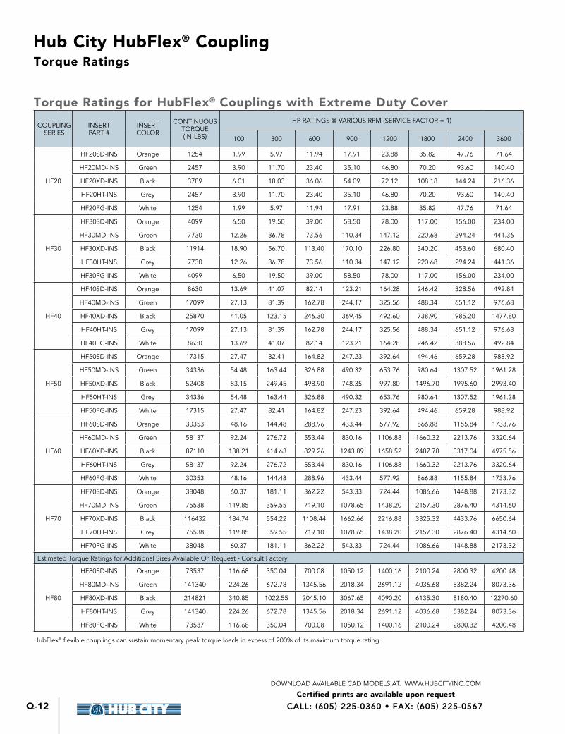
Torque Ratings
Torque Ratings for HubFlex® Couplings with Extreme Duty Cover
COUPLING SERIES
INSERT PART #
INSERT COLOR
CONTINUOUS TORQUE (IN-LBS)
HP RATINGS @ VARIOUS RPM (SERVICE FACTOR = 1)
100 300 600 900 1200 1800 2400 3600
HF20
HF20SD-INS Orange 1254 1 99 5 97 11 94 17 91 23 88 35 82 47 76 71 64
HF20MD-INS Green 2457 3 90 11 70 23 40 35 10 46 80 70 20 93 60 140 40
HF20XD-INS Black 3789 6 01 18 03 36 06 54 09 72 12 108 18 144 24 216 36
HF20HT-INS Grey 2457 3 90 11 70 23 40 35 10 46 80 70 20 93 60 140 40
HF20FG-INS White 1254 1 99 5 97 11 94 17 91 23 88 35 82 47 76 71 64
HF30
HF30SD-INS Orange 4099 6 50 19 50 39 00 58 50 78 00 117 00 156 00 234 00
HF30MD-INS Green 7730 12 26 36 78 73 56 110 34 147 12 220 68 294 24 441 36
HF30XD-INS Black 11914 18 90 56 70 113 40 170 10 226 80 340 20 453 60 680 40
HF30HT-INS Grey 7730 12 26 36 78 73 56 110 34 147 12 220 68 294 24 441 36
HF30FG-INS White 4099 6 50 19 50 39 00 58 50 78 00 117 00 156 00 234 00
HF40
HF40SD-INS Orange 8630 13 69 41 07 82 14 123 21 164 28 246 42 328 56 492 84
HF40MD-INS Green 17099 27 13 81 39 162 78 244 17 325 56 488 34 651 12 976 68
HF40XD-INS Black 25870 41 05 123 15 246 30 369 45 492 60 738 90 985 20 1477 80
HF40HT-INS Grey 17099 27 13 81 39 162 78 244 17 325 56 488 34 651 12 976 68
HF40FG-INS White 8630 13 69 41 07 82 14 123 21 164 28 246 42 388 56 492 84
HF50
HF50SD-INS Orange 17315 27 47 82 41 164 82 247 23 392 64 494 46 659 28 988 92
HF50MD-INS Green 34336 54 48 163 44 326 88 490 32 653 76 980 64 1307 52 1961 28
HF50XD-INS Black 52408 83 15 249 45 498 90 748 35 997 80 1496 70 1995 60 2993 40
HF50HT-INS Grey 34336 54 48 163 44 326 88 490 32 653 76 980 64 1307 52 1961 28
HF50FG-INS White 17315 27 47 82 41 164 82 247 23 392 64 494 46 659 28 988 92
HF60
HF60SD-INS Orange 30353 48 16 144 48 288 96 433 44 577 92 866 88 1155 84 1733 76
HF60MD-INS Green 58137 92 24 276 72 553 44 830 16 1106 88 1660 32 2213 76 3320 64
HF60XD-INS Black 87110 138 21 414 63 829 26 1243 89 1658 52 2487 78 3317 04 4975 56
HF60HT-INS Grey 58137 92 24 276 72 553 44 830 16 1106 88 1660 32 2213 76 3320 64
HF60FG-INS White 30353 48 16 144 48 288 96 433 44 577 92 866 88 1155 84 1733 76
HF70
HF70SD-INS Orange 38048 60 37 181 11 362 22 543 33 724 44 1086 66 1448 88 2173 32
HF70MD-INS Green 75538 119 85 359 55 719 10 1078 65 1438 20 2157 30 2876 40 4314 60
HF70XD-INS Black 116432 184 74 554 22 1108 44 1662 66 2216 88 3325 32 4433 76 6650 64
HF70HT-INS Grey 75538 119 85 359 55 719 10 1078 65 1438 20 2157 30 2876 40 4314 60
HF70FG-INS White 38048 60 37 181 11 362 22 543 33 724 44 1086 66 1448 88 2173 32
Estimated Torque Ratings for Additional Sizes Available On Request - Consult Factory
HF80
HF80SD-INS Orange 73537 116 68 350 04 700 08 1050 12 1400 16 2100 24 2800 32 4200 48
HF80MD-INS Green 141340 224 26 672 78 1345 56 2018 34 2691 12 4036 68 5382 24 8073 36
HF80XD-INS Black 214821 340 85 1022 55 2045 10 3067 65 4090 20 6135 30 8180 40 12270 60
HF80HT-INS Grey 141340 224 26 672 78 1345 56 2018 34 2691 12 4036 68 5382 24 8073 36
HF80FG-INS White 73537 116 68 350 04 700 08 1050 12 1400 16 2100 24 2800 32 4200 48
HubFlex® flexible couplings can sustain momentary peak torque loads in excess of 200% of its maximum torque rating

Hub City HubFlex® Coupling
Certified prints are available upon requestDOWNLOAD AVAILABLE CAD MODELS AT: WWW.HUBCITYINC.COM
Q-13
Q
Hub
Flex® C
oup
ling
EMAIL: [email protected] • www.hubcityinc.com
Misalignment Tolerances
HubFlex® Couplings Misalignment TolerancesCOUPLING
SERIESAXIAL MISALIGNMENT
TOLERANCE (IN )RADIAL MISALIGNMENT TOLERANCE
(IN )ANGULAR MISALIGNMENT
TOLERANCE
HF10 0 078 0 020 2°
HF20 0 116 0 039 2°
HF30 0 116 0 039 2°
HF40 0 116 0 039 2°
HF50 0 156 0 058 2°
HF60 0 175 0 058 1 3°
HF70 0 234 0 058 1 3°
Additional Sizes Available - Consult Factory
HF80 0 234 0 058 1°
HF90 0 234 0 058 1°
HF100 0 312 0 058 1°
HF110 0 312 0 078 1°
HF120 0 312 0 078 1°
HubFlex® Special Banded Inserts *Patent Pending*
COUPLINGSERIES
MAXIMUMRPM
MAXIMUM HP(AT 900 RPM)
MAXIMUMTORQUE(IN-LBS)
R D W WT (LBS)
HF10 3600 2 140 1 23 2 49 0 63 0 10
HF20 3600 10 700 1 66 3 16 0 85 0 20
HF30 3600 30 2100 2 16 4 21 1 23 0 40
Banded inserts are manufactured with an outer ring of high strength urethane and are designed for use in spaces where a cover cannot be accessed or spaces where there is not room for a cover Please note torque limitations
Ideal applications include coupled style C-face motor flanges
Hub City HubFlex® Coupling
Certified prints are available upon requestDOWNLOAD AVAILABLE CAD MODELS AT: WWW.HUBCITYINC.COM
CALL: (605) 225-0360 • FAX: (605) 225-0567Q-14
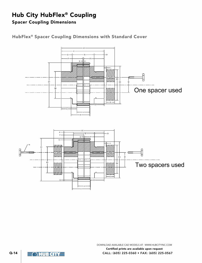
HubFlex® Spacer Coupling Dimensions with Standard Cover
Spacer Coupling Dimensions
Hub City HubFlex® Coupling
Certified prints are available upon requestDOWNLOAD AVAILABLE CAD MODELS AT: WWW.HUBCITYINC.COM
Q-15
Q
Hub
Flex® C
oup
ling
EMAIL: [email protected] • www.hubcityinc.com
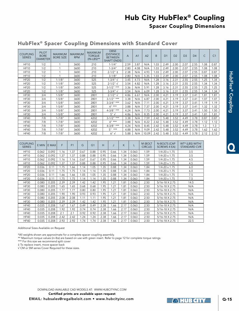
Spacer Coupling Dimensions
COUPLING SERIES
PILOT BORE
DIAMETER
MAXIMUM BORE SIZE
MAXIMUM RPM
MAXIMUM TORQUE (IN-LBS)**
DBSE(DISTANCE BETWEEN
SHAFT ENDS)
A A1 A2 B D1 D2 D3 D4 C C1
HF10 1/2 1 3600 210 1-1/4" 2 59 3 87 N/A 1 03 2 49 2 00 2 07 2 55 1 08 0 87HF10 1/2 1 3600 210 1-3/4" 2 80 4 08 N/A 1 03 2 49 2 00 2 07 2 55 1 08 1 08HF10 1/2 1 3600 210 2-1/2" ‡ 2 38 N/A 4 93 1 03 2 49 2 00 2 07 2 55 0 87 0 87HF10 1/2 1 3600 210 3-1/8" 2 80 N/A 5 35 1 03 2 49 2 00 2 07 2 55 1 08 1 08HF20 1/2 1-1/8" 3600 525 1-3/4" √ 3 45 4 73 N/A 1 28 3 16 2 31 2 55 2 55 1 25 1 34HF20 1/2 1-1/8" 3600 525 2-1/2" √ 3 54 4 82 N/A 1 28 3 16 2 31 2 55 2 55 1 34 1 34HF20 1/2 1-1/8" 3600 525 3-1/2" *** 3 36 N/A 5 91 1 28 3 16 2 31 2 55 2 55 1 25 1 25HF20 1/2 1-1/8" 3600 525 3-3/4” √ 3 54 N/A 6 09 1 28 3 16 2 31 2 55 2 55 1 34 1 34HF30 3/4 1-5/8" 3600 2801 2-1/2" √ 4 86 6 61 N/A 2 00 4 21 3 19 3 37 3 41 1 81 1 81HF30 3/4 1-5/8" 3600 2801 3-1/2" *** 3 38 N/A 6 87 2 00 4 21 3 19 3 37 3 41 1 07 1 07HF30 3/4 1-5/8" 3600 2801 3-3/4" *** 3 62 N/A 7 11 2 00 4 21 3 19 3 37 3 41 1 19 1 19HF30 3/4 1-5/8" 3600 2801 4" *** 3 88 N/A 7 37 2 00 4 21 3 19 3 37 3 41 1 32 1 32HF30 3/4 1-5/8" 3600 2801 4-3/8" *** 4 24 N/A 7 73 2 00 4 21 3 19 3 37 3 41 1 50 1 50HF30 3/4 1-5/8" 3600 2801 5" √ 4 86 N/A 8 35 2 00 4 21 3 19 3 37 3 41 1 81 1 81HF40 7/8 1-7/8" 3600 4202 3-1/2" *** 3 38 N/A 7 59 2 42 5 48 3 52 4 49 3 78 0 87 0 87HF40 7/8 1-7/8" 3600 4202 4" *** 3 88 N/A 8 22 2 42 5 48 3 52 4 49 3 78 1 12 1 12HF40 7/8 1-7/8" 3600 4202 4-3/8" *** 4 24 N/A 8 45 2 42 5 48 3 52 4 49 3 78 1 3 1 3HF40 7/8 1-7/8" 3600 4202 5" *** 4 88 N/A 9 09 2 42 5 48 3 52 4 49 3 78 1 62 1 62HF40 7/8 1-7/8" 3600 4202 6" √ 5 88 N/A 10 09 2 42 5 48 3 52 4 49 3 78 2 12 2 12
COUPLING SERIES E MIN E MAX F F1 G G1 H J K L M (BOLT
CIRCLE)N-BOLTS (CAP SCREWS 4 EA)
WT* (LBS) WITH/ STANDARD CVR
HF10 0 062 0 092 1 16 1 37 0 67 0 88 0 95 0 66 1 34 0 063 1 59 1/4-20 x 1 75 3 5HF10 0 062 0 092 1 37 1 37 0 88 0 88 0 95 0 66 1 34 0 063 1 59 1/4-20 x 1 75 3 5HF10 0 062 0 092 1 16 1 16 0 67 0 67 0 95 0 66 1 34 0 063 1 59 1/4-20 x 1 75 4 5HF10 0 062 0 092 1 37 1 37 0 88 0 88 0 95 0 66 1 34 0 063 1 59 1/4-20 x 1 75 4 5HF20 0 036 0 11 1 75 1 66 1 14 1 05 1 35 0 88 1 34 0 063 1 84 1/4-20 x 1 75 6 0HF20 0 036 0 11 1 75 1 75 1 14 1 14 1 35 0 88 1 34 0 063 1 84 1/4-20 x 1 75 6 0HF20 0 036 0 11 1 66 1 66 1 05 1 05 1 35 0 88 1 34 0 063 1 84 1/4-20 x 1 75 7 5HF20 0 036 0 11 1 75 1 75 1 14 1 14 1 35 0 88 1 34 0 063 1 84 1/4-20 x 1 75 7 5HF30 0 080 0 205 2 39 2 39 1 42 1 42 1 95 1 21 1 81 0 063 2 50 5/16-18 X 2 75 14 5HF30 0 080 0 205 1 65 1 65 0 68 0 68 1 95 1 21 1 81 0 063 2 50 5/16-18 X 2 75 N/AHF30 0 080 0 205 1 77 1 77 0 80 0 80 1 95 1 21 1 81 0 063 2 50 5/16-18 X 2 75 N/AHF30 0 080 0 205 1 90 1 90 0 93 0 93 1 95 1 21 1 81 0 063 2 50 5/16-18 X 2 75 N/AHF30 0 080 0 205 2 08 2 08 1 11 1 11 1 95 1 21 1 81 0 063 2 50 5/16-18 X 2 75 N/AHF30 0 080 0 205 2 39 2 39 1 42 1 42 1 95 1 21 1 81 0 063 2 50 5/16-18 X 2 75 N/AHF40 0 035 0 208 1 67 1 67 0 49 0 49 2 38 1 66 2 17 0 063 2 50 5/16-18 X 2 75 N/AHF40 0 035 0 208 1 92 1 92 0 74 0 74 2 38 1 66 2 17 0 063 2 50 5/16-18 X 2 75 N/AHF40 0 035 0 208 2 1 2 1 0 92 0 92 2 38 1 66 2 17 0 063 2 50 5/16-18 X 2 75 N/AHF40 0 035 0 208 2 42 2 42 1 24 1 24 2 38 1 66 2 17 0 063 2 50 5/16-18 X 2 75 N/AHF40 0 035 0 208 2 92 2 92 1 74 1 74 2 38 1 66 2 17 0 063 2 50 5/16-18 X 2 75 22 5
Additional Sizes Available on Request
*All weights shown are approximate for a complete spacer coupling assembly ** Maximum torque values (in-lbs) are based on use with green insert Refer to page 12 for complete torque ratings *** For this size we recommend split cover‡ To replace insert, move spacer back√ CM or SM series Cover Required for these sizes
HubFlex® Spacer Coupling Dimensions with Standard Cover
Hub City HubFlex® Coupling
Certified prints are available upon requestDOWNLOAD AVAILABLE CAD MODELS AT: WWW.HUBCITYINC.COM
CALL: (605) 225-0360 • FAX: (605) 225-0567Q-16
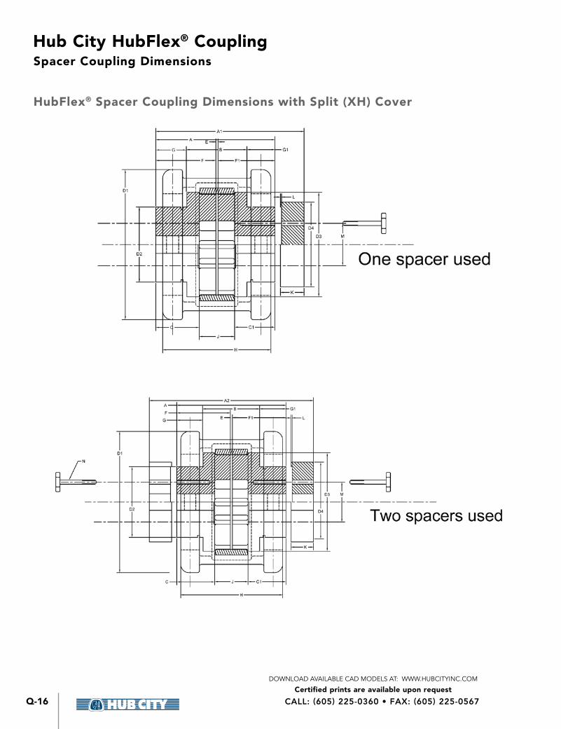
HubFlex® Spacer Coupling Dimensions with Split (XH) Cover
Spacer Coupling Dimensions
Hub City HubFlex® Coupling
Certified prints are available upon requestDOWNLOAD AVAILABLE CAD MODELS AT: WWW.HUBCITYINC.COM
Q-17
Q
Hub
Flex® C
oup
ling
EMAIL: [email protected] • www.hubcityinc.com
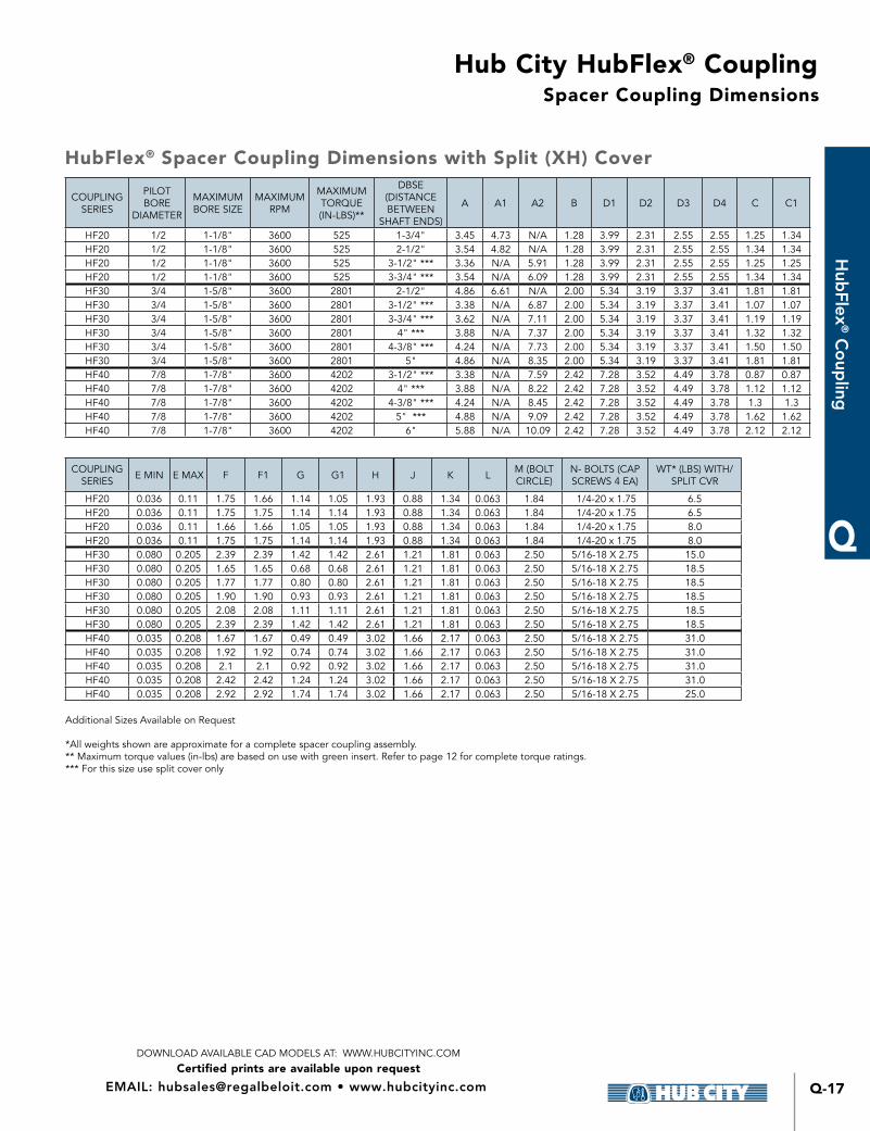
Spacer Coupling Dimensions
COUPLING SERIES
PILOT BORE
DIAMETER
MAXIMUM BORE SIZE
MAXIMUM RPM
MAXIMUM TORQUE (IN-LBS)**
DBSE (DISTANCE BETWEEN
SHAFT ENDS)
A A1 A2 B D1 D2 D3 D4 C C1
HF20 1/2 1-1/8" 3600 525 1-3/4" 3 45 4 73 N/A 1 28 3 99 2 31 2 55 2 55 1 25 1 34HF20 1/2 1-1/8" 3600 525 2-1/2" 3 54 4 82 N/A 1 28 3 99 2 31 2 55 2 55 1 34 1 34HF20 1/2 1-1/8" 3600 525 3-1/2" *** 3 36 N/A 5 91 1 28 3 99 2 31 2 55 2 55 1 25 1 25HF20 1/2 1-1/8" 3600 525 3-3/4" *** 3 54 N/A 6 09 1 28 3 99 2 31 2 55 2 55 1 34 1 34HF30 3/4 1-5/8" 3600 2801 2-1/2" 4 86 6 61 N/A 2 00 5 34 3 19 3 37 3 41 1 81 1 81HF30 3/4 1-5/8" 3600 2801 3-1/2" *** 3 38 N/A 6 87 2 00 5 34 3 19 3 37 3 41 1 07 1 07HF30 3/4 1-5/8" 3600 2801 3-3/4" *** 3 62 N/A 7 11 2 00 5 34 3 19 3 37 3 41 1 19 1 19HF30 3/4 1-5/8" 3600 2801 4" *** 3 88 N/A 7 37 2 00 5 34 3 19 3 37 3 41 1 32 1 32HF30 3/4 1-5/8" 3600 2801 4-3/8" *** 4 24 N/A 7 73 2 00 5 34 3 19 3 37 3 41 1 50 1 50HF30 3/4 1-5/8" 3600 2801 5" 4 86 N/A 8 35 2 00 5 34 3 19 3 37 3 41 1 81 1 81HF40 7/8 1-7/8" 3600 4202 3-1/2" *** 3 38 N/A 7 59 2 42 7 28 3 52 4 49 3 78 0 87 0 87HF40 7/8 1-7/8" 3600 4202 4" *** 3 88 N/A 8 22 2 42 7 28 3 52 4 49 3 78 1 12 1 12HF40 7/8 1-7/8" 3600 4202 4-3/8" *** 4 24 N/A 8 45 2 42 7 28 3 52 4 49 3 78 1 3 1 3HF40 7/8 1-7/8" 3600 4202 5" *** 4 88 N/A 9 09 2 42 7 28 3 52 4 49 3 78 1 62 1 62HF40 7/8 1-7/8" 3600 4202 6" 5 88 N/A 10 09 2 42 7 28 3 52 4 49 3 78 2 12 2 12
COUPLING SERIES E MIN E MAX F F1 G G1 H J K L M (BOLT
CIRCLE)N- BOLTS (CAP SCREWS 4 EA)
WT* (LBS) WITH/ SPLIT CVR
HF20 0 036 0 11 1 75 1 66 1 14 1 05 1 93 0 88 1 34 0 063 1 84 1/4-20 x 1 75 6 5HF20 0 036 0 11 1 75 1 75 1 14 1 14 1 93 0 88 1 34 0 063 1 84 1/4-20 x 1 75 6 5HF20 0 036 0 11 1 66 1 66 1 05 1 05 1 93 0 88 1 34 0 063 1 84 1/4-20 x 1 75 8 0HF20 0 036 0 11 1 75 1 75 1 14 1 14 1 93 0 88 1 34 0 063 1 84 1/4-20 x 1 75 8 0HF30 0 080 0 205 2 39 2 39 1 42 1 42 2 61 1 21 1 81 0 063 2 50 5/16-18 X 2 75 15 0HF30 0 080 0 205 1 65 1 65 0 68 0 68 2 61 1 21 1 81 0 063 2 50 5/16-18 X 2 75 18 5HF30 0 080 0 205 1 77 1 77 0 80 0 80 2 61 1 21 1 81 0 063 2 50 5/16-18 X 2 75 18 5HF30 0 080 0 205 1 90 1 90 0 93 0 93 2 61 1 21 1 81 0 063 2 50 5/16-18 X 2 75 18 5HF30 0 080 0 205 2 08 2 08 1 11 1 11 2 61 1 21 1 81 0 063 2 50 5/16-18 X 2 75 18 5HF30 0 080 0 205 2 39 2 39 1 42 1 42 2 61 1 21 1 81 0 063 2 50 5/16-18 X 2 75 18 5HF40 0 035 0 208 1 67 1 67 0 49 0 49 3 02 1 66 2 17 0 063 2 50 5/16-18 X 2 75 31 0HF40 0 035 0 208 1 92 1 92 0 74 0 74 3 02 1 66 2 17 0 063 2 50 5/16-18 X 2 75 31 0HF40 0 035 0 208 2 1 2 1 0 92 0 92 3 02 1 66 2 17 0 063 2 50 5/16-18 X 2 75 31 0HF40 0 035 0 208 2 42 2 42 1 24 1 24 3 02 1 66 2 17 0 063 2 50 5/16-18 X 2 75 31 0HF40 0 035 0 208 2 92 2 92 1 74 1 74 3 02 1 66 2 17 0 063 2 50 5/16-18 X 2 75 25 0
Additional Sizes Available on Request
*All weights shown are approximate for a complete spacer coupling assembly ** Maximum torque values (in-lbs) are based on use with green insert Refer to page 12 for complete torque ratings *** For this size use split cover only
HubFlex® Spacer Coupling Dimensions with Split (XH) Cover
Hub City HubFlex® Coupling
Certified prints are available upon requestDOWNLOAD AVAILABLE CAD MODELS AT: WWW.HUBCITYINC.COM
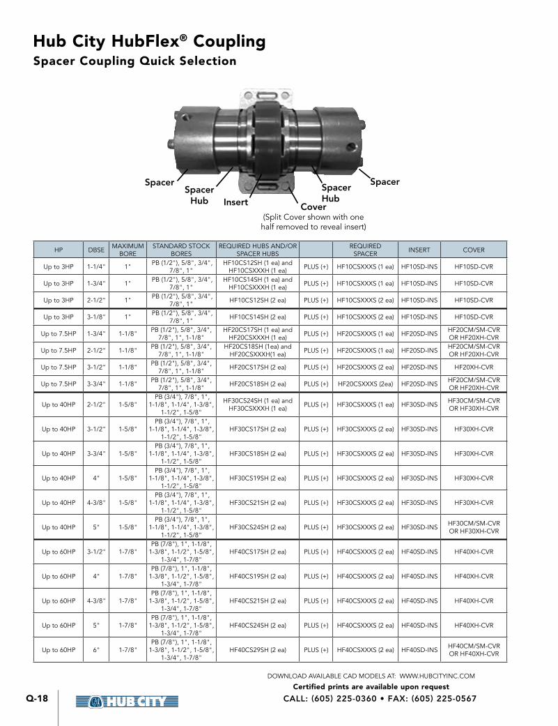
CALL: (605) 225-0360 • FAX: (605) 225-0567Q-18
HP DBSE MAXIMUM BORE
STANDARD STOCK BORES
REQUIRED HUBS AND/OR SPACER HUBS
REQUIRED SPACER INSERT COVER
Up to 3HP 1-1/4" 1" PB (1/2"), 5/8", 3/4", 7/8", 1"
HF10CS12SH (1 ea) and HF10CSXXXH (1 ea) PLUS (+) HF10CSXXXS (1 ea) HF10SD-INS HF10SD-CVR
Up to 3HP 1-3/4" 1" PB (1/2"), 5/8", 3/4", 7/8", 1"
HF10CS14SH (1 ea) and HF10CSXXXH (1 ea) PLUS (+) HF10CSXXXS (1 ea) HF10SD-INS HF10SD-CVR
Up to 3HP 2-1/2" 1" PB (1/2"), 5/8", 3/4", 7/8", 1" HF10CS12SH (2 ea) PLUS (+) HF10CSXXXS (2 ea) HF10SD-INS HF10SD-CVR
Up to 3HP 3-1/8" 1" PB (1/2"), 5/8", 3/4", 7/8", 1" HF10CS14SH (2 ea) PLUS (+) HF10CSXXXS (2 ea) HF10SD-INS HF10SD-CVR
Up to 7 5HP 1-3/4" 1-1/8" PB (1/2"), 5/8", 3/4", 7/8", 1", 1-1/8"
HF20CS17SH (1 ea) and HF20CSXXXH (1 ea) PLUS (+) HF20CSXXXS (1 ea) HF20SD-INS HF20CM/SM-CVR
OR HF20XH-CVR
Up to 7 5HP 2-1/2" 1-1/8" PB (1/2"), 5/8", 3/4", 7/8", 1", 1-1/8"
HF20CS18SH (1ea) and HF20CSXXXH(1 ea) PLUS (+) HF20CSXXXS (1 ea) HF20SD-INS HF20CM/SM-CVR
OR HF20XH-CVR
Up to 7 5HP 3-1/2" 1-1/8" PB (1/2"), 5/8", 3/4", 7/8", 1", 1-1/8" HF20CS17SH (2 ea) PLUS (+) HF20CSXXXS (2 ea) HF20SD-INS HF20XH-CVR
Up to 7 5HP 3-3/4" 1-1/8" PB (1/2"), 5/8", 3/4", 7/8", 1", 1-1/8" HF20CS18SH (2 ea) PLUS (+) HF20CSXXXS (2ea) HF20SD-INS HF20CM/SM-CVR
OR HF20XH-CVR
Up to 40HP 2-1/2" 1-5/8" PB (3/4"), 7/8", 1",
1-1/8", 1-1/4", 1-3/8", 1-1/2", 1-5/8"
HF30CS24SH (1 ea) and HF30CSXXXH (1 ea) PLUS (+) HF30CSXXXS (1 ea) HF30SD-INS HF30CM/SM-CVR
OR HF30XH-CVR
Up to 40HP 3-1/2" 1-5/8" PB (3/4"), 7/8", 1",
1-1/8", 1-1/4", 1-3/8", 1-1/2", 1-5/8"
HF30CS17SH (2 ea) PLUS (+) HF30CSXXXS (2 ea) HF30SD-INS HF30XH-CVR
Up to 40HP 3-3/4" 1-5/8" PB (3/4"), 7/8", 1",
1-1/8", 1-1/4", 1-3/8", 1-1/2", 1-5/8"
HF30CS18SH (2 ea) PLUS (+) HF30CSXXXS (2 ea) HF30SD-INS HF30XH-CVR
Up to 40HP 4" 1-5/8" PB (3/4"), 7/8", 1",
1-1/8", 1-1/4", 1-3/8", 1-1/2", 1-5/8"
HF30CS19SH (2 ea) PLUS (+) HF30CSXXXS (2 ea) HF30SD-INS HF30XH-CVR
Up to 40HP 4-3/8" 1-5/8" PB (3/4"), 7/8", 1",
1-1/8", 1-1/4", 1-3/8", 1-1/2", 1-5/8"
HF30CS21SH (2 ea) PLUS (+) HF30CSXXXS (2 ea) HF30SD-INS HF30XH-CVR
Up to 40HP 5" 1-5/8" PB (3/4"), 7/8", 1",
1-1/8", 1-1/4", 1-3/8", 1-1/2", 1-5/8"
HF30CS24SH (2 ea) PLUS (+) HF30CSXXXS (2 ea) HF30SD-INS HF30CM/SM-CVR OR HF30XH-CVR
Up to 60HP 3-1/2" 1-7/8"PB (7/8"), 1", 1-1/8",
1-3/8", 1-1/2", 1-5/8", 1-3/4", 1-7/8"
HF40CS17SH (2 ea) PLUS (+) HF40CSXXXS (2 ea) HF40SD-INS HF40XH-CVR
Up to 60HP 4" 1-7/8"PB (7/8"), 1", 1-1/8",
1-3/8", 1-1/2", 1-5/8", 1-3/4", 1-7/8"
HF40CS19SH (2 ea) PLUS (+) HF40CSXXXS (2 ea) HF40SD-INS HF40XH-CVR
Up to 60HP 4-3/8" 1-7/8"PB (7/8"), 1", 1-1/8",
1-3/8", 1-1/2", 1-5/8", 1-3/4", 1-7/8"
HF40CS21SH (2 ea) PLUS (+) HF40CSXXXS (2 ea) HF40SD-INS HF40XH-CVR
Up to 60HP 5" 1-7/8"PB (7/8"), 1", 1-1/8",
1-3/8", 1-1/2", 1-5/8", 1-3/4", 1-7/8"
HF40CS24SH (2 ea) PLUS (+) HF40CSXXXS (2 ea) HF40SD-INS HF40XH-CVR
Up to 60HP 6" 1-7/8"PB (7/8"), 1", 1-1/8",
1-3/8", 1-1/2", 1-5/8", 1-3/4", 1-7/8"
HF40CS29SH (2 ea) PLUS (+) HF40CSXXXS (2 ea) HF40SD-INS HF40CM/SM-CVR OR HF40XH-CVR
Spacer Coupling Quick Selection
SpacerSpacer
Hub Insert Cover(Split Cover shown with one half removed to reveal insert)
SpacerHub
Spacer
Hub City HubFlex® Coupling
Certified prints are available upon requestDOWNLOAD AVAILABLE CAD MODELS AT: WWW.HUBCITYINC.COM
Q-19
Q
Hub
Flex® C
oup
ling
EMAIL: [email protected] • www.hubcityinc.com
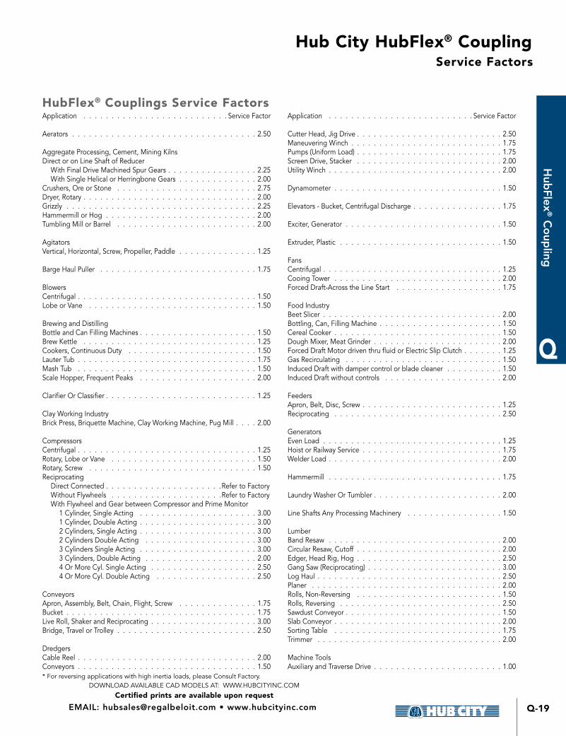
Service Factors
HubFlex® Couplings Service Factors Application Service Factor
Aerators 2 50
Aggregate Processing, Cement, Mining KilnsDirect or on Line Shaft of Reducer With Final Drive Machined Spur Gears 2 25 With Single Helical or Herringbone Gears 2 00Crushers, Ore or Stone 2 75Dryer, Rotary 2 00Grizzly 2 25Hammermill or Hog 2 00Tumbling Mill or Barrel 2 00
AgitatorsVertical, Horizontal, Screw, Propeller, Paddle 1 25
Barge Haul Puller 1 75
BlowersCentrifugal 1 50Lobe or Vane 1 50
Brewing and DistillingBottle and Can Filling Machines 1 50Brew Kettle 1 25Cookers, Continuous Duty 1 50Lauter Tub 1 75Mash Tub 1 50Scale Hopper, Frequent Peaks 2 00
Clarifier Or Classifier 1 25
Clay Working IndustryBrick Press, Briquette Machine, Clay Working Machine, Pug Mill 2 00
CompressorsCentrifugal 1 25Rotary, Lobe or Vane 1 50Rotary, Screw 1 50Reciprocating Direct Connected Refer to Factory Without Flywheels Refer to Factory With Flywheel and Gear between Compressor and Prime Monitor 1 Cylinder, Single Acting 3 00 1 Cylinder, Double Acting 3 00 2 Cylinders, Single Acting 3 00 2 Cylinders Double Acting 3 00 3 Cylinders Single Acting 3 00 3 Cylinders, Double Acting 2 00 4 Or More Cyl Single Acting 2 50 4 Or More Cyl Double Acting 2 50
ConveyorsApron, Assembly, Belt, Chain, Flight, Screw 1 75Bucket 1 75Live Roll, Shaker and Reciprocating 3 00Bridge, Travel or Trolley 2 50
DredgersCable Reel 2 00Conveyors 1 50
Application Service Factor
Cutter Head, Jig Drive 2 50Maneuvering Winch 1 75Pumps (Uniform Load) 1 75Screen Drive, Stacker 2 00Utility Winch 2 00
Dynamometer 1 50
Elevators - Bucket, Centrifugal Discharge 1 75
Exciter, Generator 1 50
Extruder, Plastic 1 50
FansCentrifugal 1 25Cooing Tower 2 00Forced Draft-Across the Line Start 1 75
Food IndustryBeet Slicer 2 00Bottling, Can, Filling Machine 1 50Cereal Cooker 1 50Dough Mixer, Meat Grinder 2 00Forced Draft Motor driven thru fluid or Electric Slip Clutch 1 25Gas Recirculating 1 50Induced Draft with damper control or blade cleaner 1 50Induced Draft without controls 2 00
FeedersApron, Belt, Disc, Screw 1 25Reciprocating 2 50
GeneratorsEven Load 1 25Hoist or Railway Service 1 75Welder Load 2 00
Hammermill 1 75
Laundry Washer Or Tumbler 2 00
Line Shafts Any Processing Machinery 1 50
LumberBand Resaw 2 00Circular Resaw, Cutoff 2 00Edger, Head Rig, Hog 2 50Gang Saw (Reciprocating) 3 00Log Haul 2 50Planer 2 00Rolls, Non-Reversing 1 50Rolls, Reversing 2 50Sawdust Conveyor 1 50Slab Conveyor 2 00Sorting Table 1 75Trimmer 2 00
Machine ToolsAuxiliary and Traverse Drive 1 00
* For reversing applications with high inertia loads, please Consult Factory
Hub City HubFlex® Coupling
Certified prints are available upon requestDOWNLOAD AVAILABLE CAD MODELS AT: WWW.HUBCITYINC.COM
CALL: (605) 225-0360 • FAX: (605) 225-0567Q-20
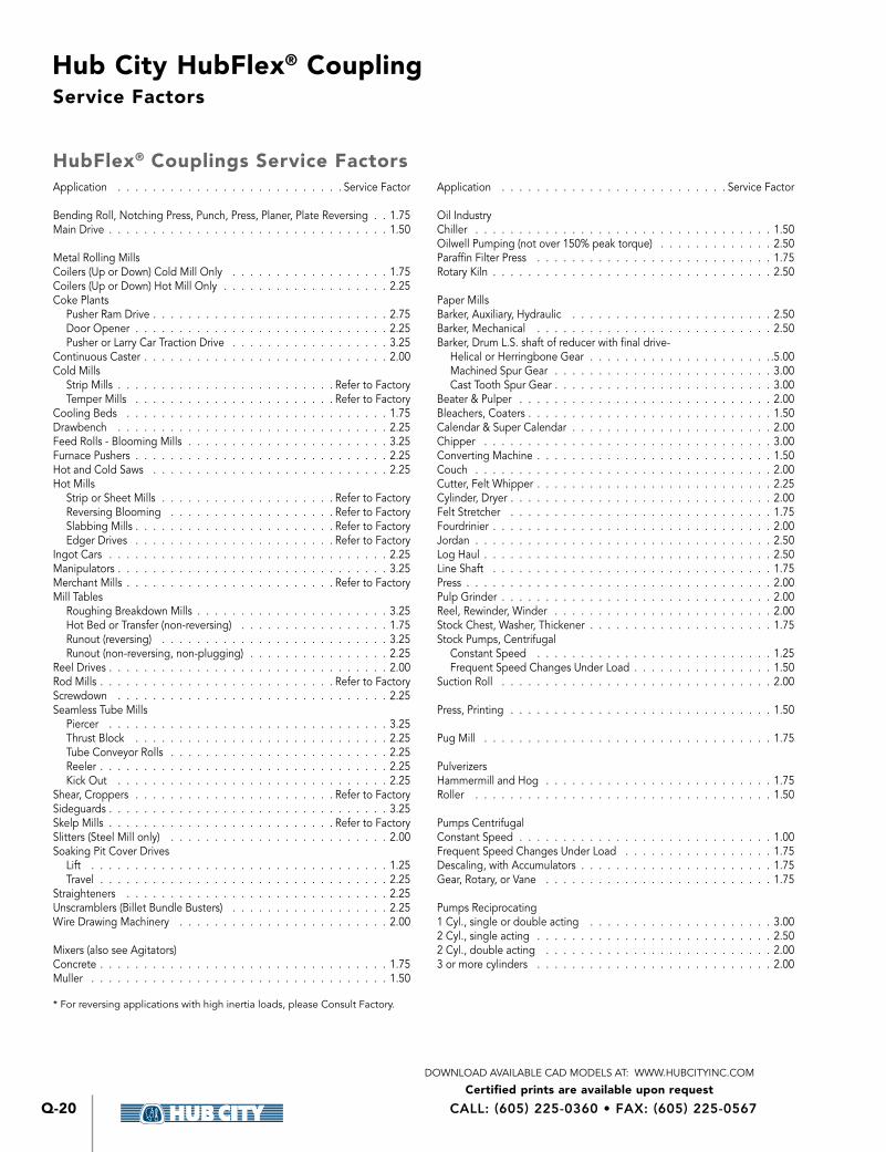
Service Factors
HubFlex® Couplings Service Factors Application Service Factor
Bending Roll, Notching Press, Punch, Press, Planer, Plate Reversing 1 75Main Drive 1 50
Metal Rolling MillsCoilers (Up or Down) Cold Mill Only 1 75Coilers (Up or Down) Hot Mill Only 2 25Coke Plants Pusher Ram Drive 2 75 Door Opener 2 25 Pusher or Larry Car Traction Drive 3 25Continuous Caster 2 00Cold Mills Strip Mills Refer to Factory Temper Mills Refer to FactoryCooling Beds 1 75Drawbench 2 25Feed Rolls - Blooming Mills 3 25Furnace Pushers 2 25Hot and Cold Saws 2 25Hot Mills Strip or Sheet Mills Refer to Factory Reversing Blooming Refer to Factory Slabbing Mills Refer to Factory Edger Drives Refer to FactoryIngot Cars 2 25Manipulators 3 25Merchant Mills Refer to FactoryMill Tables Roughing Breakdown Mills 3 25 Hot Bed or Transfer (non-reversing) 1 75 Runout (reversing) 3 25 Runout (non-reversing, non-plugging) 2 25Reel Drives 2 00Rod Mills Refer to FactoryScrewdown 2 25Seamless Tube Mills Piercer 3 25 Thrust Block 2 25 Tube Conveyor Rolls 2 25 Reeler 2 25 Kick Out 2 25Shear, Croppers Refer to FactorySideguards 3 25Skelp Mills Refer to FactorySlitters (Steel Mill only) 2 00Soaking Pit Cover Drives Lift 1 25 Travel 2 25Straighteners 2 25Unscramblers (Billet Bundle Busters) 2 25Wire Drawing Machinery 2 00
Mixers (also see Agitators)Concrete 1 75Muller 1 50
Application Service Factor
Oil IndustryChiller 1 50Oilwell Pumping (not over 150% peak torque) 2 50Paraffin Filter Press 1 75Rotary Kiln 2 50
Paper MillsBarker, Auxiliary, Hydraulic 2 50Barker, Mechanical 2 50Barker, Drum L S shaft of reducer with final drive- Helical or Herringbone Gear 5 00 Machined Spur Gear 3 00 Cast Tooth Spur Gear 3 00Beater & Pulper 2 00Bleachers, Coaters 1 50Calendar & Super Calendar 2 00Chipper 3 00Converting Machine 1 50Couch 2 00Cutter, Felt Whipper 2 25Cylinder, Dryer 2 00Felt Stretcher 1 75Fourdrinier 2 00Jordan 2 50Log Haul 2 50Line Shaft 1 75Press 2 00Pulp Grinder 2 00Reel, Rewinder, Winder 2 00Stock Chest, Washer, Thickener 1 75Stock Pumps, Centrifugal Constant Speed 1 25 Frequent Speed Changes Under Load 1 50Suction Roll 2 00
Press, Printing 1 50
Pug Mill 1 75
PulverizersHammermill and Hog 1 75Roller 1 50
Pumps CentrifugalConstant Speed 1 00Frequent Speed Changes Under Load 1 75Descaling, with Accumulators 1 75Gear, Rotary, or Vane 1 75
Pumps Reciprocating1 Cyl , single or double acting 3 002 Cyl , single acting 2 502 Cyl , double acting 2 003 or more cylinders 2 00
* For reversing applications with high inertia loads, please Consult Factory

Hub City HubFlex® Coupling
Certified prints are available upon requestDOWNLOAD AVAILABLE CAD MODELS AT: WWW.HUBCITYINC.COM
Q-21
Q
Hub
Flex® C
oup
ling
EMAIL: [email protected] • www.hubcityinc.com
Service Factors
Application Service Factor
Rubber IndustryCalendar 2 25Cracker, Plasticolour 2 50Extruder 2 00Tire & Tube Press Opener (peak torque) 1 50Warming Mill One or two mills in line 2 00 Three or more mills in line 2 50Washer 2 75
ScreensAir Washing 1 50Grizzly 2 50Rotary Coal or Sand 2 00Vibrating 2 50Water 1 50
Sewage Disposal EquipmentBar Screen, Chemical Feeders, Collectors, Dewatering Screen, Grit Collector 1 50Mill Stands, Turbine Driven with all Helical or Herringbone Gears 1 75Electric Drive or Steam Engine Drive with Helical or Herringbone 2 00
Stoker 1 00
Sugar IndustryCone Carrier and Leveler 2 25Cane Knife and Crusher 2 50Mill Stands, Turbine Driver with all helical or Herringbone Gears 1 75Electric Drive or Steam Engine Drive with helical, Herringbone, or Spur Gears with any Prime Mover 2 00
Textile IndustryBatcher 1 50Calendar, Card Machine 1 75Cloth Finishing Machine 1 75Dry Can, Loom 1 75Dyeing Machinery 1 50Knitting Machine Refer to FactoryMangle, Napper, Soaper 1 50Spinner, Tenter Frame, Winder 1 75
Tumbling Barrel 2 00
Winch, Maneuvering - Dredge, Marine 1 50
Windlass 1 50
Engine Service FactorsService Factors for engine drives are those required for applications where good flywheel regulation prevents torque fluctuation greater than 20% For drives where torque fluctuations are greater or where the operation is near a serious critical or torsional vibration, a mass elastic study is necessary
To determine an engine drive service factor, first determine the application service factor for motors Then, use that to find the correct engine service factor in the table below When the application service factor for motors is greater than 2 0 or where 1, 2, or 3 cylinder engines are involved, please contact customer service with complete application details for engineering review
APPLICATION SERVICE FACTOR
ENGINE FACTOR
4 TO 5 CYLINDERS 6+ CYLINDERS
1 00 2 000 1 500
1 25 2 250 1 750
1 50 2 500 2 000
1 75 2 750 2 250
2 00 3 000 2 500
HubFlex® Couplings Service Factors
* For reversing applications with high inertia loads, please Consult Factory
Hub City HubFlex® Coupling
Certified prints are available upon requestDOWNLOAD AVAILABLE CAD MODELS AT: WWW.HUBCITYINC.COM
CALL: (605) 225-0360 • FAX: (605) 225-0567Q-22
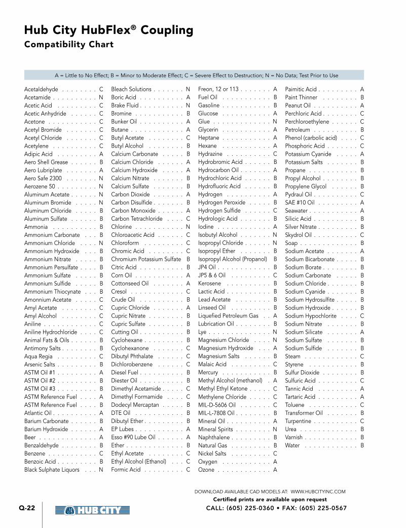
Compatibility Chart
Acetaldehyde CAcetamide NAcetic Acid CAcetic Anhydride CAcetone CAcetyl Bromide CAcetyl Chloride CAcetylene CAdipic Acid AAero Shell Grease BAero Lubriplate AAero Safe 2300 NAerozene 50 NAluminum Acetate NAluminum Bromide NAluminum Chloride BAluminum Sulfate BAmmonia BAmmonium Carbonate BAmmonium Chloride NAmmonium Hydroxide BAmmonium Nitrate BAmmonium Persulfate BAmmonium Sulfate BAmmonium Sulfide BAmmonium Thiocynate BAmonnium Acetate CAmyl Acetate CAmyl Alcohol CAniline CAniline Hydrochloride CAnimal Fats & Oils BAntimony Salts BAqua Regia CArsenic Salts BASTM Oil #1 AASTM Oil #2 BASTM Oil #3 BASTM Reference Fuel AASTM Reference Fuel BAtlantic Oil ABarium Carbonate BBarium Hydroxide ABeer ABenzaldehyde BBenzene CBenzoic Acid BBlack Sulphate Liquors N
Bleach Solutions NBoric Acid ABrake Fluid NBromine BBunker Oil AButane AButyl Acetate CButyl Alcohol BCalcium Carbonate BCalcium Chloride ACalcium Hydroxide ACalcium Nitrate BCalcium Sulfate BCarbon Dioxide ACarbon Disulfide BCarbon Monoxide ACarbon Tetrachloride CChlorine NChloroacetic Acid CChloroform CChromic Acid CChromium Potassium Sulfate BCitric Acid BCorn Oil ACottonseed Oil ACresol CCrude Oil BCupric Chloride ACupric Nitrate BCupric Sulfate BCutting Oil BCyclohexane BCyclohexanone CDibutyl Phthalate CDichlorobenzene CDiesel Fuel BDiester Oil BDimethyl Acetamide CDimethyl Formamide CDodecyl Mercaptan BDTE Oil BDibutyl Ether BEP Lubes AEsso #90 Lube Oil AEther BEthyl Acetate CEthyl Alcohol (Ethanol) CFormic Acid C
Freon, 12 or 113 AFuel Oil BGasoline BGlucose AGlue NGlycerin AHeptane AHexane AHydrazine CHydrobromic Acid BHydrocarbon Oil AHydrochloric Acid BHydrofluoric Acid BHydrogen AHydrogen Peroxide BHydrogen Sulfide CHydrologic Acid BIodine AIsobutyl Alcohol NIsopropyl Chloride NIsopropyl Ether BIsopropyl Alcohol (Propanol) BJP4 Oil BJP5 & 6 Oil CKerosene BLactic Acid BLead Acetate BLinseed Oil BLiquefied Petroleum Gas ALubrication Oil BLye NMagnesium Chloride NMagnesium Hydroxide AMagnesium Salts BMalaic Acid CMercury BMethyl Alcohol (methanol) AMethyl Ethyl Ketone CMethylene Chloride CMIL-D-5606 Oil CMIL-L-7808 Oil BMineral Oil AMineral Spirits NNaphthalene BNatural Gas BNickel Salts COxygen AOzone A
Paimitic Acid APaint Thinner BPeanut Oil APerchloric Acid CPerchloroethylene CPetroleum BPhenol (carbolic acid) CPhosphoric Acid CPotassium Cyanide APotassium Salts BPropane BPropyl Alcohol BPropylene Glycol BPydraul Oil CSAE #10 Oil ASeawater ASilicic Acid BSilver Nitrate BSkydrol Oil CSoap BSodium Acetate ASodium Bicarbonate BSodium Borate BSodium Carbonate BSodium Chloride BSodium Cyanide BSodium Hydrosulfite BSodium Hydroxide BSodium Hypochlorite CSodium Nitrate BSodium Silicate ASodium Sulfate BSodium Sulfide BSteam CStyrene BSulfur Dioxide BSulfuric Acid CTannic Acid ATartaric Acid AToluene CTransformer Oil BTurpentine CUrea BVarnish BWater B
A = Little to No Effect; B = Minor to Moderate Effect; C = Severe Effect to Destruction; N = No Data; Test Prior to Use
Hub City HubFlex® Coupling
Certified prints are available upon requestDOWNLOAD AVAILABLE CAD MODELS AT: WWW.HUBCITYINC.COM
Q-23
Q
Hub
Flex® C
oup
ling
EMAIL: [email protected] • www.hubcityinc.com
Safety Guidelines
When using HubFlex® Couplings, you must follow the installation instructions and take the following precautions Failure to do so may cause the HubFlex® Coupling(s) to break and parts to be thrown with sufficient force to cause severe injury or death
Refer to this catalog for proper selection, sizing, horsepower, torque range, and speed range of HubFlex® Couplings Follow the installation instructions included with the product Do not exceed catalog ratings
During start up and operation of HubFlex® Couplings, avoid sudden shock loads HubFlex® Coupling assembly should operate quietly and smoothly If HubFlex® Coupling assembly vibrates or makes beating sound, shut down immediately, and recheck alignment Shortly after initial operation and periodically thereafter, where applicable, inspect HubFlex® Coupling assembly for: alignment, wear of elastomeric element, and flexing elements for signs of fatigue Do not operate HubFlex® Coupling assembly if alignment is improper, or if elastomeric element is damaged or worn
Do not use any HubFlex® Couplings for elevators, man lifts, or other devices that carry people If the HubFlex® Coupling fails, the lift device could fall resulting in severe injury or death
For all HubFlex® Couplings, you must install suitable guards in accordance with OSHA and American Society of Mechanical Engineers Standards Do not start HubFlex® Coupling before suitable guards are in place Failure to properly guard these products may result in severe injury or death from personnel contacting moving parts or from parts being thrown from assembly in the event the HubFlex® Coupling product fails
If you have any questions, contact your Hub City Sales Representative - www hubcityinc com

Hub City HubFlex® Coupling
Certified prints are available upon requestDOWNLOAD AVAILABLE CAD MODELS AT: WWW.HUBCITYINC.COM
CALL: (605) 225-0360 • FAX: (605) 225-0567Q-24
Quick Selection Guide
Insert FeaturesStandard duty (Orange) Medium Duty (Green) Extreme Duty (Black) High Temp (Gray) Food Grade (White)
Max Temp: 200 F Max Temp: 200 F Max Temp: 200 F Max Temp: 300 F Max Temp: 200 F
Greatest Dampening Lower Dampening Lowest DampeningDampening &
Torque Dampening & Torque
Lowest Torque Higher Torque Highest Torque Same as Green Same as Orange
FDA Approved Material
MAX TORQUE RATING (in. lbs.) With EXTREME DUTY CoverMAX BORE
COUPLING SERIES ORANGE GREEN BLACK HI-TEMP FOOD GRADE
1-5/8" HF20 1254 2457 3789 2457 1254
2-1/8" HF30 4099 7730 11914 7730 4099
2-3/8" HF40 8630 17099 25870 17099 8630
3" HF50 17315 34336 52408 34336 17315
3-7/8" HF60 30353 58137 87110 58137 30353
4-1/8" HF70 38048 75538 116432 75538 38048
Estimated Torque Ratings for Additional Sizes Available Upon Request - Consult Factory
4-1/2" HF80 75000 145000 220000 145000 75000
5-1/2" HF90 105000 204000 310000 204000 105000
7" HF100 175000 345000 550000 345000 175000
8" HF110 300000 565000 870000 565000 300000
11" HF120 NA 1120000 1680000 1120000 NA
MAX TORQUE RATING (in. lbs.) With STANDARD CoverMAX BORE
COUPLING SERIES ORANGE GREEN BLACK HI-TEMP FOOD GRADE
1-1/4" HF10 365 792 792 792 365