Embed Size (px)
Citation preview

Hub Arm Assembly
RTI TECHNOLOGIES, INC.York, PA 17402
800-468-2321 (ext. 259)
Manual P/N 035-80608-00

Table of Contents
1 Introduction . . . . . . . . . . . . . . . . . . . . . . . . . . . . . . . . . . . . 1
2 Safety . . . . . . . . . . . . . . . . . . . . . . . . . . . . . . . . . . . . . . . . 2
3 Material List . . . . . . . . . . . . . . . . . . . . . . . . . . . . . . . . . . . . 3
4 Mounting of Hub & Centering Plate Storage Bracket . . . . 4
5 Component Storage . . . . . . . . . . . . . . . . . . . . . . . . . . . . . 5
6 Mounting the Cranks on the Centering Plate . . . . . . . . . . 6
7 Mounting Centering Plate to the Wheel Hub . . . . . . . . . . . 7
8 Preliminary Runout Compensation Adjustment . . . . . . . . . 8
9 Mounting the Hub Arm . . . . . . . . . . . . . . . . . . . . . . . . . . 10
10 Mounting the Lathe Head . . . . . . . . . . . . . . . . . . . . . . . . 11
11 Attaching the Drive Motor . . . . . . . . . . . . . . . . . . . . . . . . 12
12 Connecting Power . . . . . . . . . . . . . . . . . . . . . . . . . . . . . . 13
13 Final Runout Compensation Adjustment . . . . . . . . . . . . . 14
14 Removing Hub Arm Assembly . . . . . . . . . . . . . . . . . . . . 15
BRC35 Lathe + BRC440 Hub Arm = BRC475
BRC40 + BRC440 Hub Arm = BRC480

Page 1
1 Introduction
Thank you for your purchase of a Lathe and Hub Arm Assembly. Congratulations on yourchoice! The BRC Lathe and Hub Arm Assembly is designed to outperform every othercomparable hub mounted brake lathe in all respects.
The BRC was designed as a completely new product. The special hub adaption methoddesigned by RTI for the BRC is brand new and substantially improved.
The BRC is designed to be easy to use. Once the unit is mounted to the hub it operates inmuch the same way as a typical bench mounted lathe. Mounting the unit on the hub of thevehicle requires the axis of the BRC drive be aligned or compensated to the hub axis of thevehicle. The precision of this alignment or compensation for the BRC or any other hub mountedlathe will determine the rotor run out that is finally achieved.
The time to achieve the necessary compensation or alignment of the BRC is minimal. Lessthan two minutes per wheel to get around 0.002 in. (0.050 mm) of run out and only slightly moretime to achieve “near zero” or less an 0.001 in. (0.025 mm) of run out. The BRC hub plate isattached to the hub of the vehicle by means of 3, 4, 5 or 7 special cranks and thecompensation is achieved by simply lengthening or shortening the length of these cranks usinga dial indicator to determine the correct setting. Minimizing brake rotor run out is an importantaspect of modern brake service. Elimination of pedal pulsation issues on wheels with pre-loaded wheel bearings requires less than 0.001 in. (0.025 mm) of run out. If the wheels do notrun on pre-loaded wheel bearings, run out of 0.002 in. (0.050 mm) is acceptable.
Running the BRC is simple. It has two spindle speeds and a variable feed rate.
The BRC can be used as a “single pass-one cut” machine. However, RTI recommends a “twopass” machining process with a rough “foundation” cut just deep enough to clean up the rotorand an extra fine finish cut, with a depth of only 0.001 to 0.002 in. (0.025 to 0.05 mm) per side,taking full advantage of the special cutting tool design of the BRC This two pass technique willnot remove any more material than necessary, and even though it may take a few minuteslonger, it will result in a more perfect rotor in every respect.
Technical Support800-468-2321 (Extension 259)

Page 2
2 SafetyA. Avoid a major injury because of an unexpected start-up!Be sure that the BRC is not plugged in and supplied with electrical power when the lathe in notoperating. This is particularly important when mounting the unit and performing thecompensation adjustments. In addition, the BRC has an Emergency Stop button on the spindledrive motor.
B. Avoid a major injury from rotating machinery!The BRC has a spindle motor with a great deal of power and torque. Do not wear loose clothingthat could be entangled in the rotating parts. Be sure that long hair is properly secured so thatit can not be entangled in the rotating parts. Do not place any part of your body near therotating parts of the BRC when in operation. Always be aware of the location of the EmergencyStop button so that the lathe can be stopped immediately.
C. Protect your eyes!Small metal chips fly off the rotor during machining. Be sure to wear safety glasses at all timeswhen the BRC is in operation. Use the same safety glasses that are required when grindingmetal.
D. Avoid possible electrical shock or unsafe operation!Like any electrical appliance, never operate the BRC when it is wet, or when you are standingin water. Be sure the receptacle for the electrical plug is a three prong grounded type, that itis the correct voltage for the BRC (110V, 60Hz in the North America), that it is protected by afuse or circuit breaker with the correct rating (15 Amp maximum in North America), and that itis protected with a Ground Fault Circuit Interrupter (GFCI).
E. Avoid all fire hazards!If for any reason the lathe spindle is jammed or locked up and stops suddenly, be sure to turnthe power off and unplug the lathe immediately, before fixing the cause of the problem.
Page 3
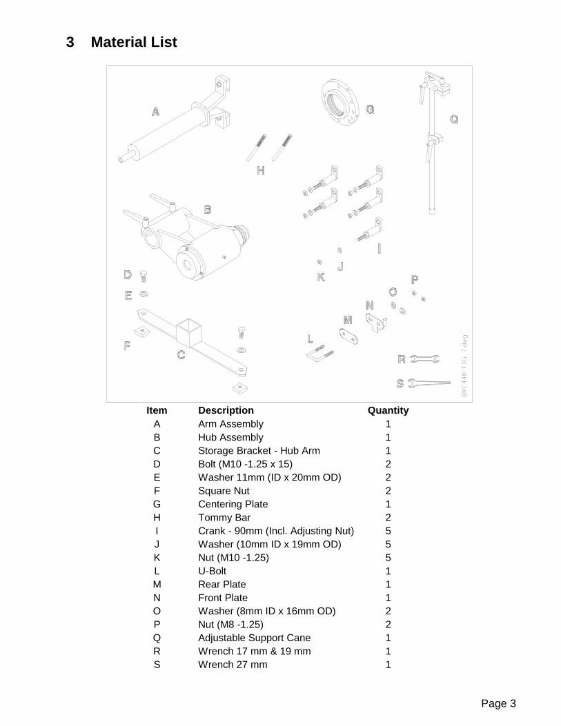
3 Material List
Item Description QuantityA Arm Assembly 1B Hub Assembly 1C Storage Bracket - Hub Arm 1D Bolt (M10 -1.25 x 15) 2E Washer 11mm (ID x 20mm OD) 2F Square Nut 2G Centering Plate 1H Tommy Bar 2I Crank - 90mm (Incl. Adjusting Nut) 5J Washer (10mm ID x 19mm OD) 5K Nut (M10 -1.25) 5L U-Bolt 1M Rear Plate 1N Front Plate 1O Washer (8mm ID x 16mm OD) 2P Nut (M8 -1.25) 2Q Adjustable Support Cane 1R Wrench 17 mm & 19 mm 1S Wrench 27 mm 1

Page 4
4 Mounting of Hub & Centering Plate Storage Brackets
4.1 Place Square Nut (F) inside each leg and mount the Hub ArmStorage Bracket (C) using Bolts and Washers (D-E). Positionthe bracket as shown, noting that the ends are cut to matchthe angle of each leg. Place plastic end cap into end of legs.
4.2 Mount the Centering Plate Bracket (L-M-N-O-P). Positionbracket at the top of the lower column of the Drive Stand. Thehook should face towards the Hub Arm Storage Bracket (C).

Page 5
5 Component Storage
5.1 Store Centering Plate with Cranks on hook (A).
5.2 Store Hub Arm Assembly on bracket (B)
5.3 Store Tommy Bars and extra Cranks in box on bracket (C).

Page 6
6 Mounting the Cranks on the Centering Plate
6.1 A scribe mark (A) is located on each Crank and large nut. Turn the largenut onto the Crank as far as possible, finger tight. The scribe markshould be aligned on the large nut and the barrel of the Crank. Then,loosen the large nut one full turn, once again aligning the scribe marks.Do this on all Cranks.
6.2 Numbers (B) are stamped on the Centering Plate next to the holes formounting the Cranks. Mount four cranks in the holes numbered 4 for afour-lug wheel. Mount five cranks in the holes numbered 5 for a five-lugwheel. Mount three cranks in the holes numbered 3 for a six-lug wheel.
Insert the Cranks into the appropriate holes, install the washers, andsmall nuts. Finger tighten the small nuts.
6.3 Position the legs (C) of all the Cranks so they point in the counter-clockwise direction.

Page 7
7 Mounting Centering Plate to the Wheel Hub
7.1 Place the large holes in the legs of the Cranks over the wheel lugsand install the lug nuts (A) finger tight.
7.2 Tighten the lug nuts to the manufacturer’s recommended wheelinstallation torque.
7.3 Place the Vibration Dampener Rubber Ring (B - supplied with BRCLathe Assembly) around the rotor. Other types of vibrationdampeners can also be used. It is always important to preventvibration which could cause unsatisfactory surface finish whencutting the rotor.

Page 8
8 Preliminary Runout Compensation Adjustment
8.1 Mount a Dial Indicator (A) rigidly on the hub knuckle assembly. The stylus of the DialIndicator must be in contact with surface B as shown. Lightly tap the Dial Indicator toensure the needle returns to the same spot to verify it is mounted securely.
8.2 Rotate the Centering Plate 360 degrees several times while watching the total swingof the Dial Indicator needle. Set the mark (C) on the bezel of the Dial Indicator to theMIDDLE of this total swing as shown.
The goal is now to adjust the large and small nuts (D) on the Cranks so that theTOTAL swing of the needle is 0.004 in. (0.1 mm) or less.

Page 9
8 Preliminary Runout Compensation Adjustment (Continued)
8.3 Rotate the Centering Plate until the Dial Indicator needle is at the largest number ofthe total swing, as shown.
8.4 Nuts on the two cranks are next adjusted to move the needle one-half the distancebetween the present reading and the mark on the bezel.
8.4.1 Slightly turn (1/16 rotation or less) small nut A in direction of arrow.
8.4.2 Tighten large nut B by turning in direction of arrow.
8.4.3 Slightly turn (1/16 rotation) large nut D (not visible) in the direction of arrow.
8.4.4 Tighten small nut C by turning in direction of arrow.
8.5 The needle will have moved towards the mark on the bezel, hopefully about one-halfthe distance from its starting point. Colored bands on the Cranks can be used to keeptrack of position if the Centering Plate must be turned to aid in adjusting the nuts.
8.6 Repeat Steps 8.3 and 8.4 until the TOTAL swing of the needle during a 360 degreerotation of the Centering Plate is 0.004 in. (0.1 mm) or less. Near zero swing will makethe final adjustments, after the lathe is mounted, much easier.
Page 10
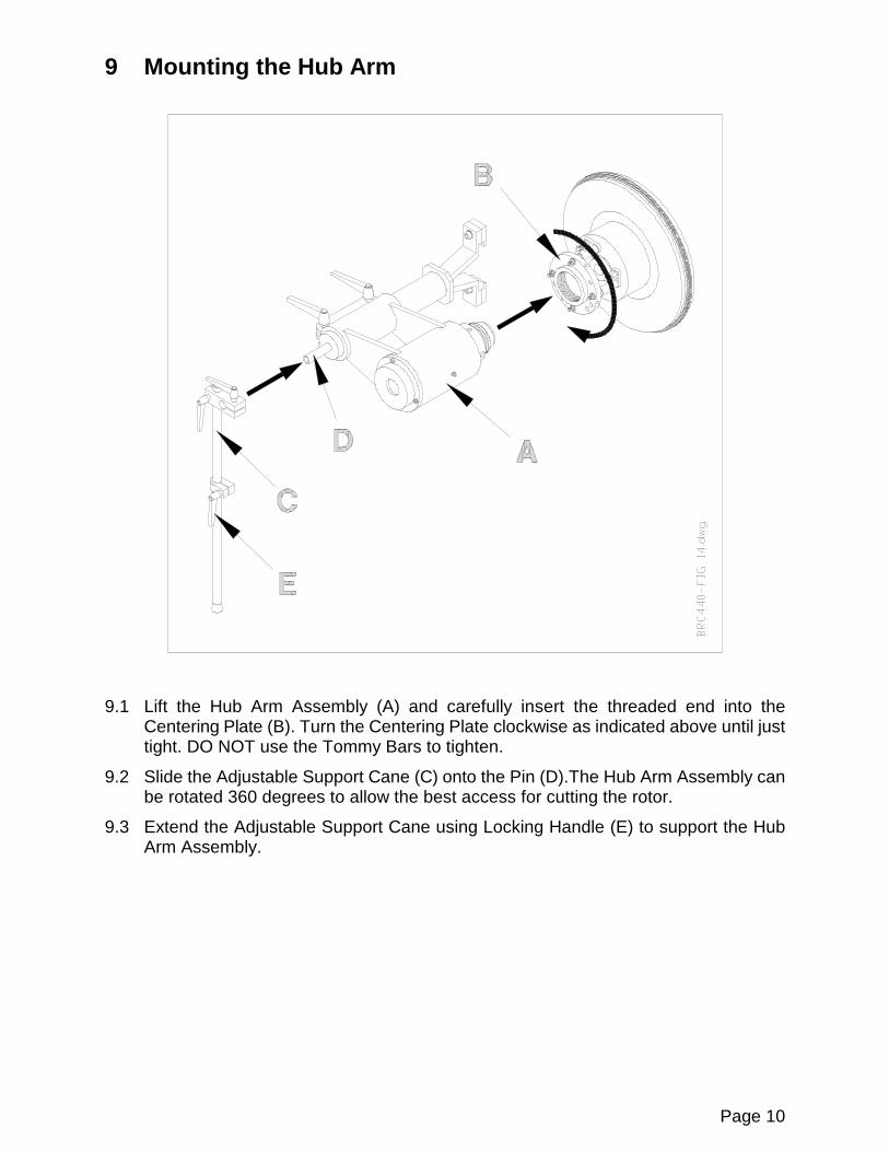
9 Mounting the Hub Arm
9.1 Lift the Hub Arm Assembly (A) and carefully insert the threaded end into theCentering Plate (B). Turn the Centering Plate clockwise as indicated above until justtight. DO NOT use the Tommy Bars to tighten.
9.2 Slide the Adjustable Support Cane (C) onto the Pin (D).The Hub Arm Assembly canbe rotated 360 degrees to allow the best access for cutting the rotor.
9.3 Extend the Adjustable Support Cane using Locking Handle (E) to support the HubArm Assembly.

Page 11
10 Mounting the Lathe Head
10.1 Loosen Socket Hex Bolts (A) and slide the Lathe Head into the slots as shownabove. Finger tighten the Socket Hex Bolts.
10.2 Loosen Locking Handles (C) and slide the Tube (B) to center the Lathe Head on theRotor.
10.3 Continue adjusting the Tube (B) and the Lathe Head until the cutting tips arecentered on the Rotor.
10.4 Check that the Lathe Head is slid in towards the center of the Rotor far enough sothe cutting tips will reach the inner diameter of the rotor surface to be cut.
10.5 Tighten both Socket Hex Bolts (A) and both Locking Handles (C).
Page 12
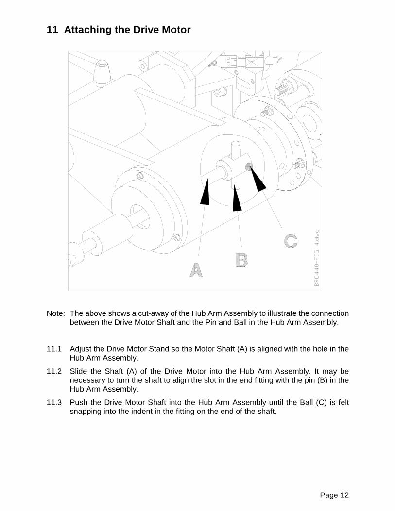
11 Attaching the Drive Motor
Note: The above shows a cut-away of the Hub Arm Assembly to illustrate the connectionbetween the Drive Motor Shaft and the Pin and Ball in the Hub Arm Assembly.
11.1 Adjust the Drive Motor Stand so the Motor Shaft (A) is aligned with the hole in theHub Arm Assembly.
11.2 Slide the Shaft (A) of the Drive Motor into the Hub Arm Assembly. It may benecessary to turn the shaft to align the slot in the end fitting with the pin (B) in theHub Arm Assembly.
11.3 Push the Drive Motor Shaft into the Hub Arm Assembly until the Ball (C) is feltsnapping into the indent in the fitting on the end of the shaft.

Page 13
12 Connecting Power
Note: The above shows the completed set-up of the Hub Arm Assembly, Lathe Head, andDrive Motor.
12.1 Push in the Emergency Stop Button on the Drive Motor Control Box.
12.2 Connect the Power Cord (A) to an appropriately grounded power source.
12.3 Connect the Coiled Cord (B) from the socket on the side of the Drive Motor Controlto the socket on top of the Lathe Head.
Page 14
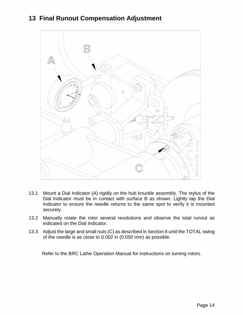
13 Final Runout Compensation Adjustment
13.1 Mount a Dial Indicator (A) rigidly on the hub knuckle assembly. The stylus of theDial Indicator must be in contact with surface B as shown. Lightly tap the DialIndicator to ensure the needle returns to the same spot to verify it is mountedsecurely.
13.2 Manually rotate the rotor several revolutions and observe the total runout asindicated on the Dial Indicator.
13.3 Adjust the large and small nuts (C) as described in Section 8 until the TOTAL swingof the needle is as close to 0.002 in (0.050 mm) as possible.
Refer to the BRC Lathe Operation Manual for instructions on turning rotors.

Page 15
14 Removing Hub Arm Assembly
14.1 Insert Tommy Bars (A) as shown above.
14.2 Rotate Tommy Bars as shown to release Hub Arm Assembly from the CenteringPlate.