Embed Size (px)
Citation preview

HUAWEI UPS5000-A Solution (400-500kVA)
2
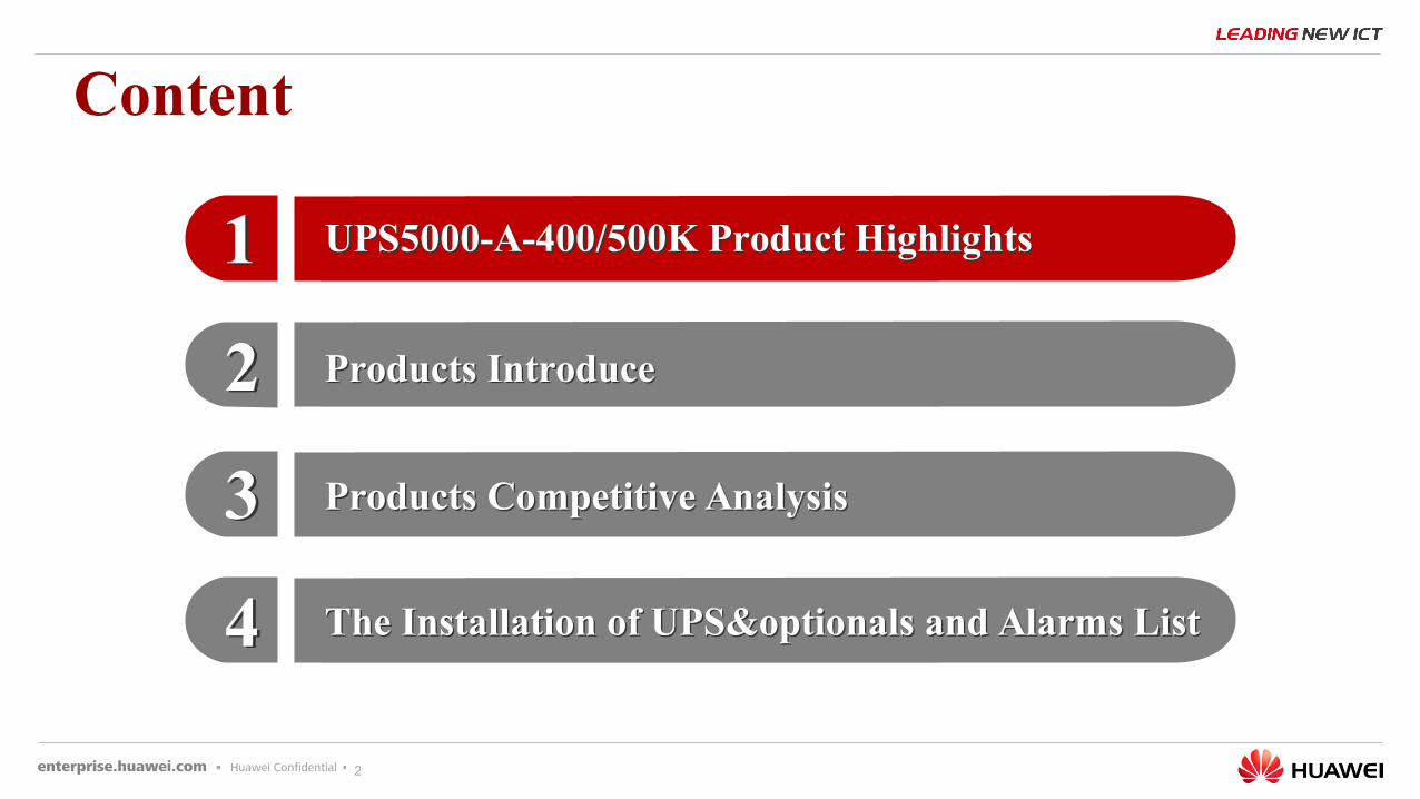
Content
33
11
22
44
Products Competitive AnalysisProducts Competitive Analysis
UPS5000-A-400/500K Product HighlightsUPS5000-A-400/500K Product Highlights
Products IntroduceProducts Introduce
The Installation of UPS&optionals and Alarms ListThe Installation of UPS&optionals and Alarms List
3
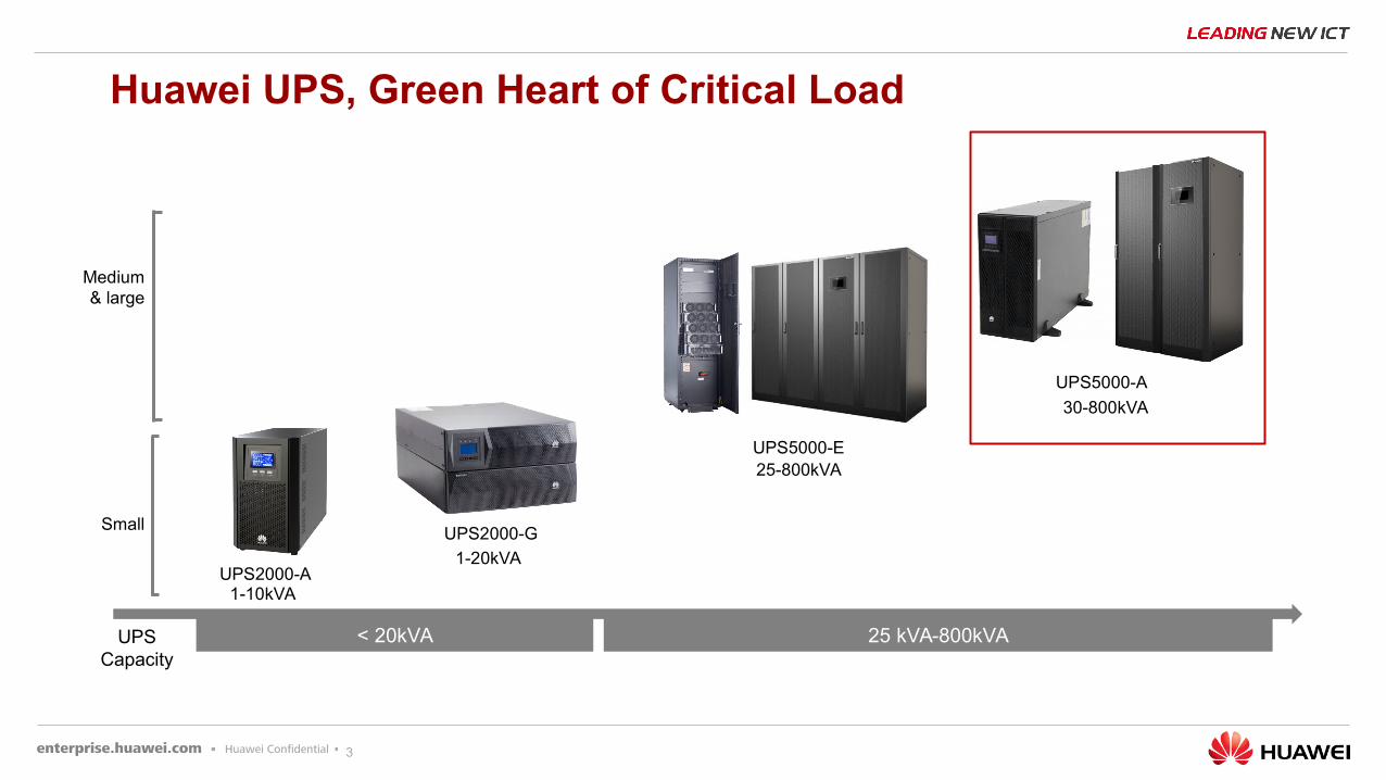
25-800kVA
30-800kVA
1-20kVA
UPS2000-G
UPS5000-E
UPS5000-A
1-10kVA
UPS2000-A
Small
Medium & large
< 20kVA 25 kVA-800kVA
1-10kVA
UPS Capacity
Huawei UPS, Green Heart of Critical Load
4
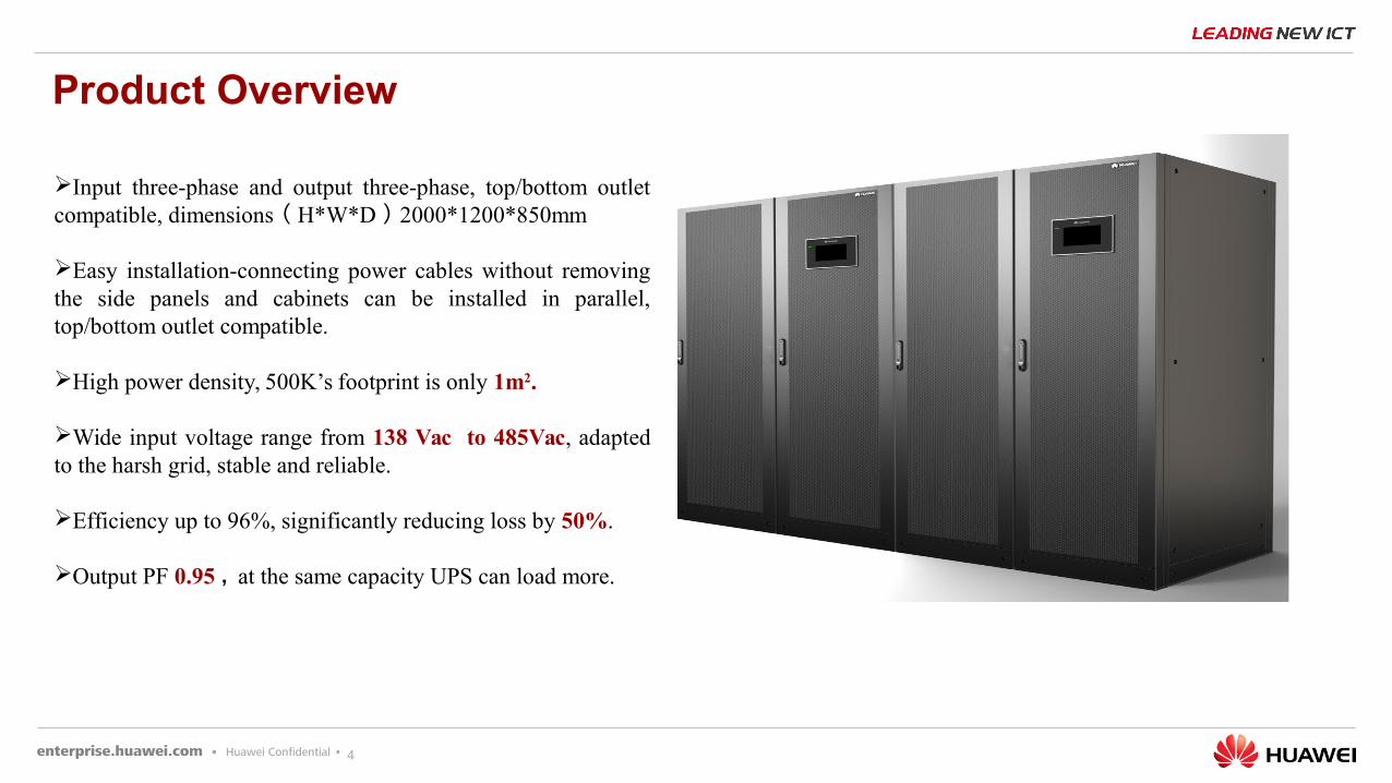
Product Overview
Input three-phase and output three-phase, top/bottom outlet compatible, dimensions ( H*W*D ) 2000*1200*850mm
Easy installation-connecting power cables without removing the side panels and cabinets can be installed in parallel, top/bottom outlet compatible.
High power density, 500K’s footprint is only 1m2.
Wide input voltage range from 138 Vac to 485Vac, adapted to the harsh grid, stable and reliable.
Efficiency up to 96%, significantly reducing loss by 50%.
Output PF 0.95 , at the same capacity UPS can load more.
5
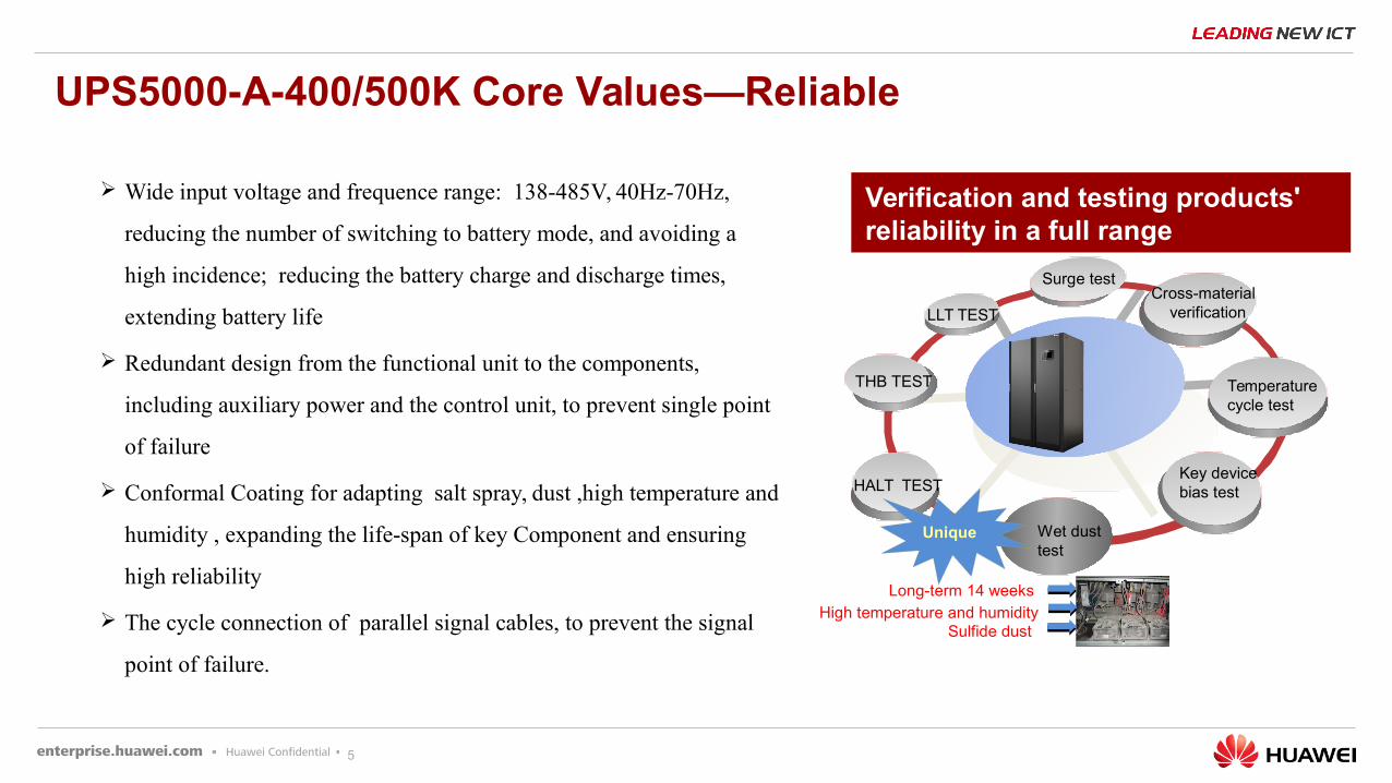
Cross-material verification
HALT TEST
THB TEST
LLT TEST
Wet dust test
Key device bias test
Temperature cycle test
High temperature and humiditySulfide dust
Long-term 14 weeks
Unique
Wide input voltage and frequence range: 138-485V, 40Hz-70Hz,
reducing the number of switching to battery mode, and avoiding a
high incidence; reducing the battery charge and discharge times,
extending battery life
Redundant design from the functional unit to the components,
including auxiliary power and the control unit, to prevent single point
of failure
Conformal Coating for adapting salt spray, dust ,high temperature and
humidity , expanding the life-span of key Component and ensuring
high reliability
The cycle connection of parallel signal cables, to prevent the signal
point of failure.
Verification and testing products' reliability in a full range
UPS5000-A-400/500K Core Values—Reliable
Surge test
6
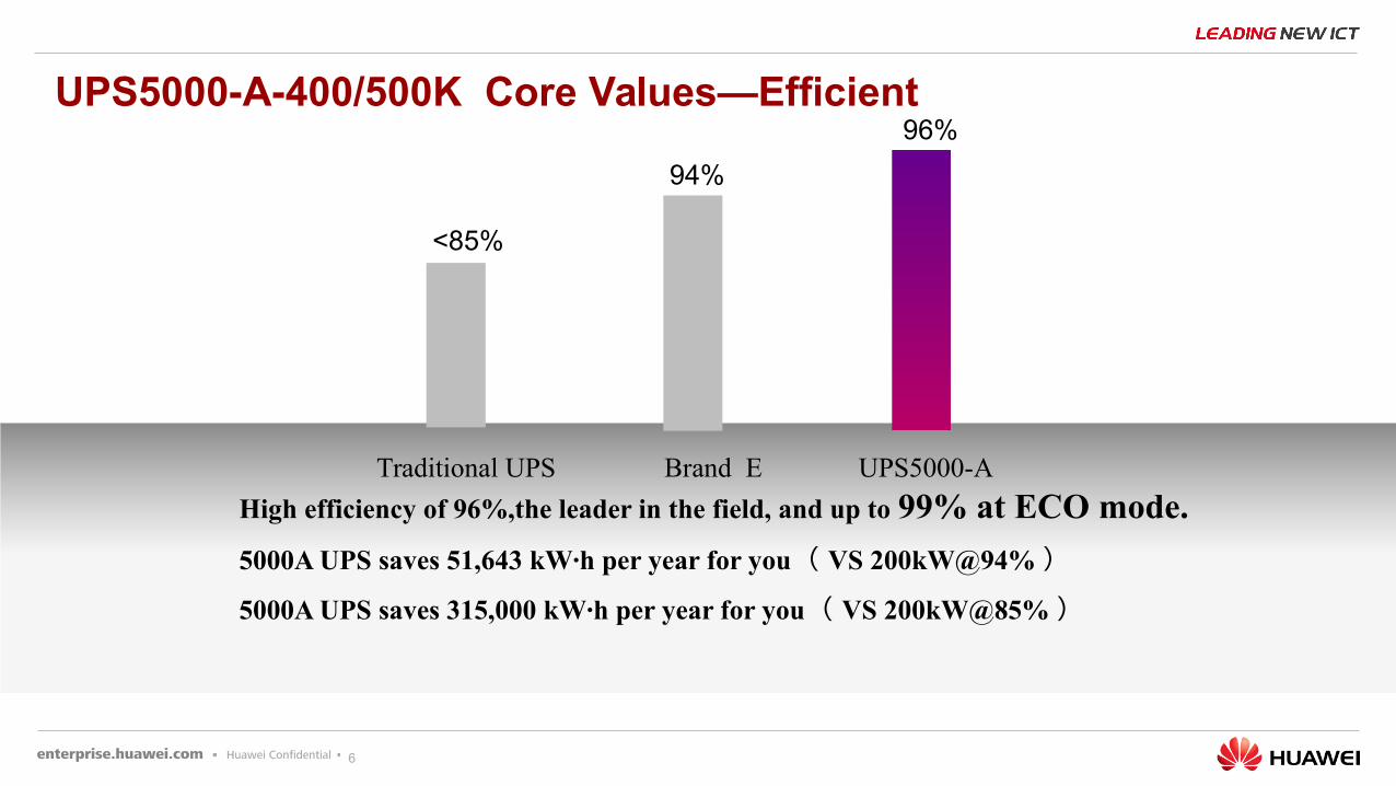
High efficiency of 96%,the leader in the field, and up to 99% at ECO mode.
5000A UPS saves 51,643 kW·h per year for you ( VS 200kW@94% )
5000A UPS saves 315,000 kW·h per year for you ( VS 200kW@85% )
Traditional UPS Brand E UPS5000-A
<85%
94%
96%UPS5000-A-400/500K Core Values—Efficient
7
UPS5000-A-400/500K Core Values—Efficient
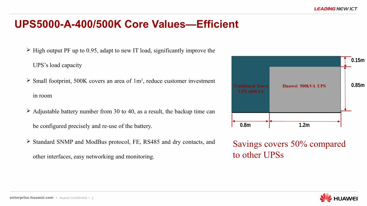
High output PF up to 0.95, adapt to new IT load, significantly improve the
UPS’s load capacity
Small footprint, 500K covers an area of 1m2, reduce customer investment
in room
Adjustable battery number from 30 to 40, as a result, the backup time can
be configured precisely and re-use of the battery.
Standard SNMP and ModBus protocol, FE, RS485 and dry contacts, and
other interfaces, easy networking and monitoring.
1.2m
0.85m
0.8m
0.15m
Huawei 500kVA UPSTraditional Tower UPS 400kVA
Savings covers 50% compared to other UPSs
8
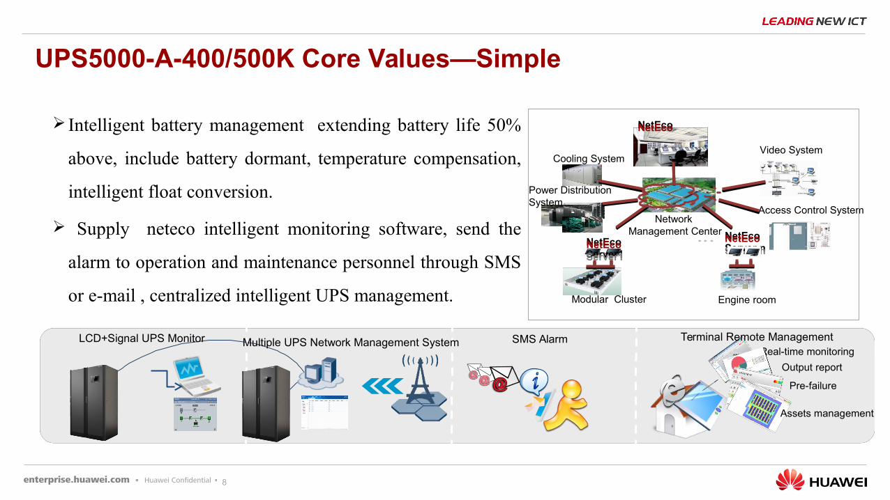
UPS5000-A-400/500K Core Values—Simple
Intelligent battery management extending battery life 50%
above, include battery dormant, temperature compensation,
intelligent float conversion.
Supply neteco intelligent monitoring software, send the
alarm to operation and maintenance personnel through SMS
or e-mail , centralized intelligent UPS management.
Video System
Access Control System
NetEcoNetEco
Network Management Center
Modular Cluster
NetEcoServer nNetEcoServer n
Engine room
Power Distribution System
Cooling System
NetEcoServer1NetEcoServer1
Real-time monitoring
Output report
Pre-failure
Assets management
LCD+Signal UPS Monitor Multiple UPS Network Management System SMS Alarm Terminal Remote Management
网管中
9
33
11
22
44
Content
UPS5000-A-400/500K Product HighlightsUPS5000-A-400/500K Product Highlights
Products Competitive AnalysisProducts Competitive Analysis
Products IntroduceProducts Introduce
The Installation of UPS&optionals and Alarms ListThe Installation of UPS&optionals and Alarms List
10
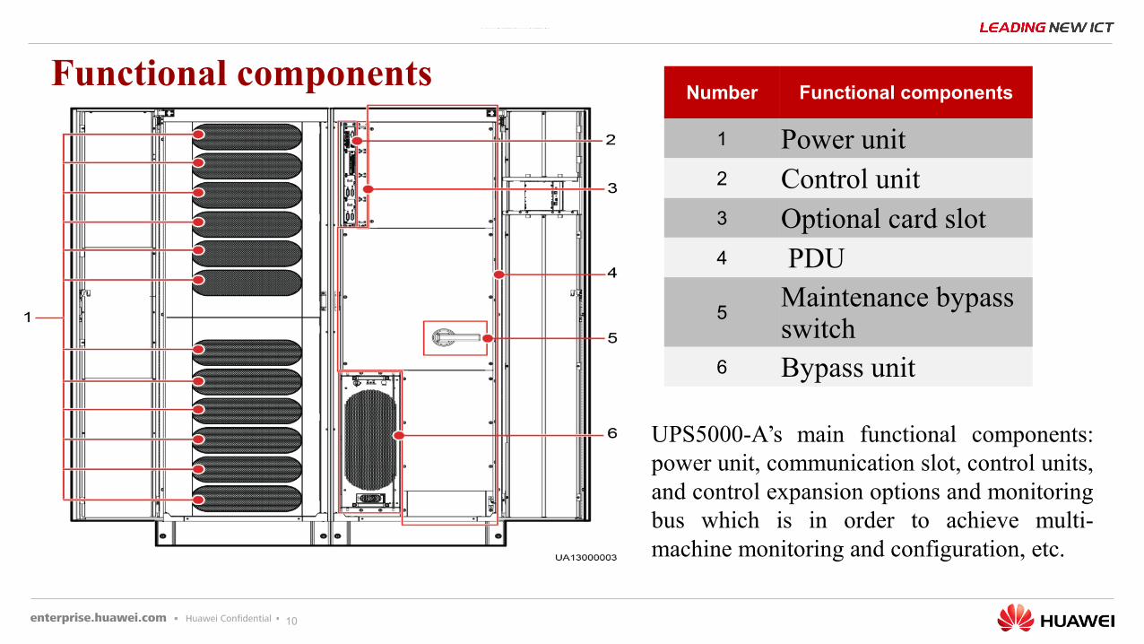
UPS5000-A’s main functional components: power unit, communication slot, control units, and control expansion options and monitoring bus which is in order to achieve multi-machine monitoring and configuration, etc.
Functional componentsNumber Functional components
1 Power unit2 Control unit3 Optional card slot4 PDU
5Maintenance bypass switch
6 Bypass unit
11
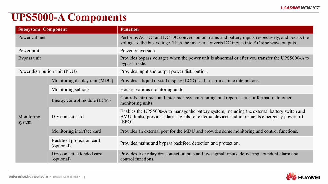
Subsystem Component Function
Power cabinet Performs AC-DC and DC-DC conversion on mains and battery inputs respectively, and boosts the voltage to the bus voltage. Then the inverter converts DC inputs into AC sine wave outputs.
Power unit Power conversion.
Bypass unit Provides bypass voltages when the power unit is abnormal or after you transfer the UPS5000-A to bypass mode.
Power distribution unit (PDU) Provides input and output power distribution.
Monitoring system
Monitoring display unit (MDU) Provides a liquid crystal display (LCD) for human-machine interactions.
Monitoring subrack Houses various monitoring units.
Energy control module (ECM) Controls intra-rack and inter-rack system running, and reports status information to other monitoring units.
Dry contact cardEnables the UPS5000-A to manage the battery system, including the external battery switch and BMU. It also provides alarm signals for external devices and implements emergency power-off (EPO).
Monitoring interface card Provides an external port for the MDU and provides some monitoring and control functions.
Backfeed protection card (optional)
Provides mains and bypass backfeed detection and protection.
Dry contact extended card (optional)
Provides five relay dry contact outputs and five signal inputs, delivering abundant alarm and control functions.
UPS5000-A Components
12
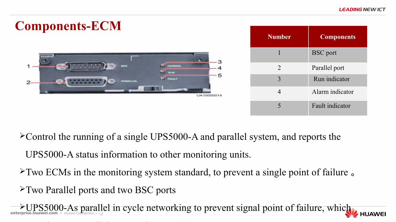
Components-ECM
Control the running of a single UPS5000-A and parallel system, and reports the
UPS5000-A status information to other monitoring units.
Two ECMs in the monitoring system standard, to prevent a single point of failure 。
Two Parallel ports and two BSC ports
UPS5000-As parallel in cycle networking to prevent signal point of failure, which
contains two Parallel ports and two BSC ports.
Number Components
1 BSC port
2 Parallel port
3 Run indicator
4 Alarm indicator
5 Fault indicator
13
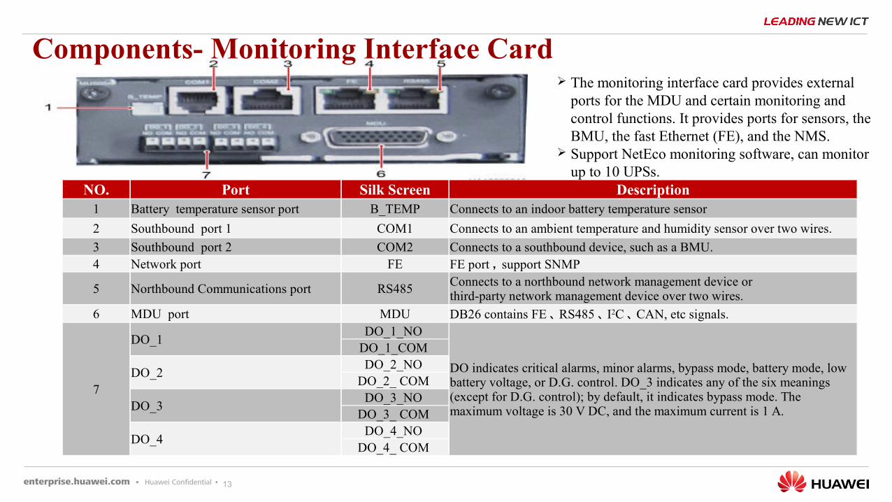
Components- Monitoring Interface Card
NO. Port Silk Screen Description1 Battery temperature sensor port B_TEMP Connects to an indoor battery temperature sensor
2 Southbound port 1 COM1 Connects to an ambient temperature and humidity sensor over two wires.
3 Southbound port 2 COM2 Connects to a southbound device, such as a BMU.4 Network port FE FE port , support SNMP
5 Northbound Communications port RS485Connects to a northbound network management device or third-party network management device over two wires.
6 MDU port MDU DB26 contains FE 、 RS485 、 I2C 、 CAN, etc signals.
7
DO_1DO_1_NO
DO indicates critical alarms, minor alarms, bypass mode, battery mode, low battery voltage, or D.G. control. DO_3 indicates any of the six meanings (except for D.G. control); by default, it indicates bypass mode. The maximum voltage is 30 V DC, and the maximum current is 1 A.
DO_1_COM
DO_2DO_2_NO
DO_2_ COM
DO_3DO_3_NO
DO_3_ COM
DO_4DO_4_NO
DO_4_ COM
The monitoring interface card provides external ports for the MDU and certain monitoring and control functions. It provides ports for sensors, the BMU, the fast Ethernet (FE), and the NMS.
Support NetEco monitoring software, can monitor up to 10 UPSs.
14
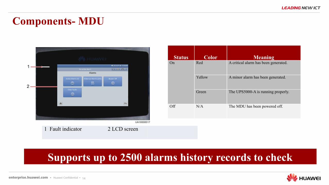
1 Fault indicator 2 LCD screen
Status Color MeaningOn Red A critical alarm has been generated.
Yellow A minor alarm has been generated.
Green The UPS5000-A is running properly.
Off N/A The MDU has been powered off.
Components- MDU
Supports up to 2500 alarms history records to check
15
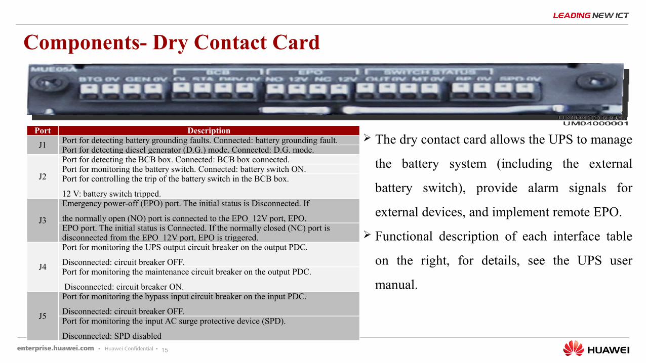
Components- Dry Contact Card
Port Description
J1Port for detecting battery grounding faults. Connected: battery grounding fault.Port for detecting diesel generator (D.G.) mode. Connected: D.G. mode.
J2
Port for detecting the BCB box. Connected: BCB box connected.Port for monitoring the battery switch. Connected: battery switch ON.Port for controlling the trip of the battery switch in the BCB box.
12 V: battery switch tripped.
J3
Emergency power-off (EPO) port. The initial status is Disconnected. If
the normally open (NO) port is connected to the EPO_12V port, EPO.EPO port. The initial status is Connected. If the normally closed (NC) port is disconnected from the EPO_12V port, EPO is triggered.
J4
Port for monitoring the UPS output circuit breaker on the output PDC.
Disconnected: circuit breaker OFF.Port for monitoring the maintenance circuit breaker on the output PDC.
Disconnected: circuit breaker ON.
J5
Port for monitoring the bypass input circuit breaker on the input PDC.
Disconnected: circuit breaker OFF.Port for monitoring the input AC surge protective device (SPD).
Disconnected: SPD disabled
The dry contact card allows the UPS to manage
the battery system (including the external
battery switch), provide alarm signals for
external devices, and implement remote EPO.
Functional description of each interface table
on the right, for details, see the UPS user
manual.
16
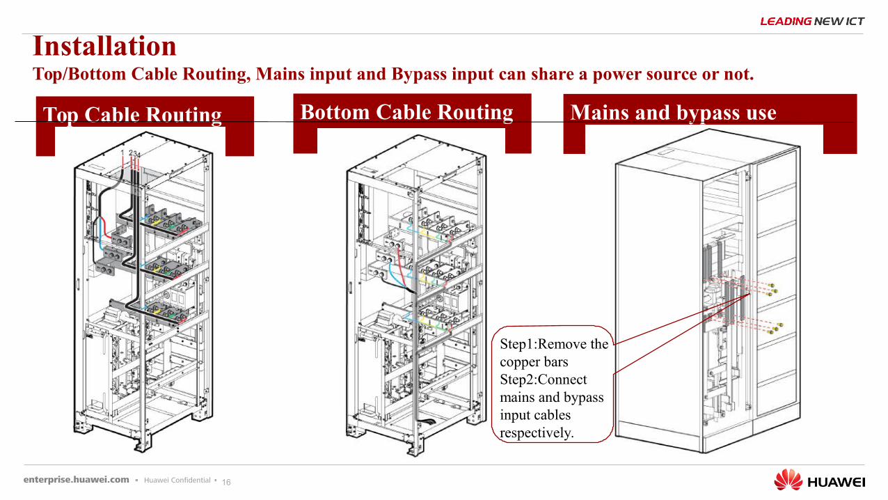
Top Cable Routing diagram
InstallationTop/Bottom Cable Routing, Mains input and Bypass input can share a power source or not.
Bottom Cable Routing diagram
Mains and bypass use different sources
Step1:Remove the copper barsStep2:Connect mains and bypass input cables respectively.
17
33
11
22
44
Products Competitive AnalysisProducts Competitive Analysis
UPS5000-A-400/500K Product HighlightsUPS5000-A-400/500K Product Highlights
Products IntroduceProducts Introduce
The Installation of UPS&optionals and Alarms ListThe Installation of UPS&optionals and Alarms List
Content
18
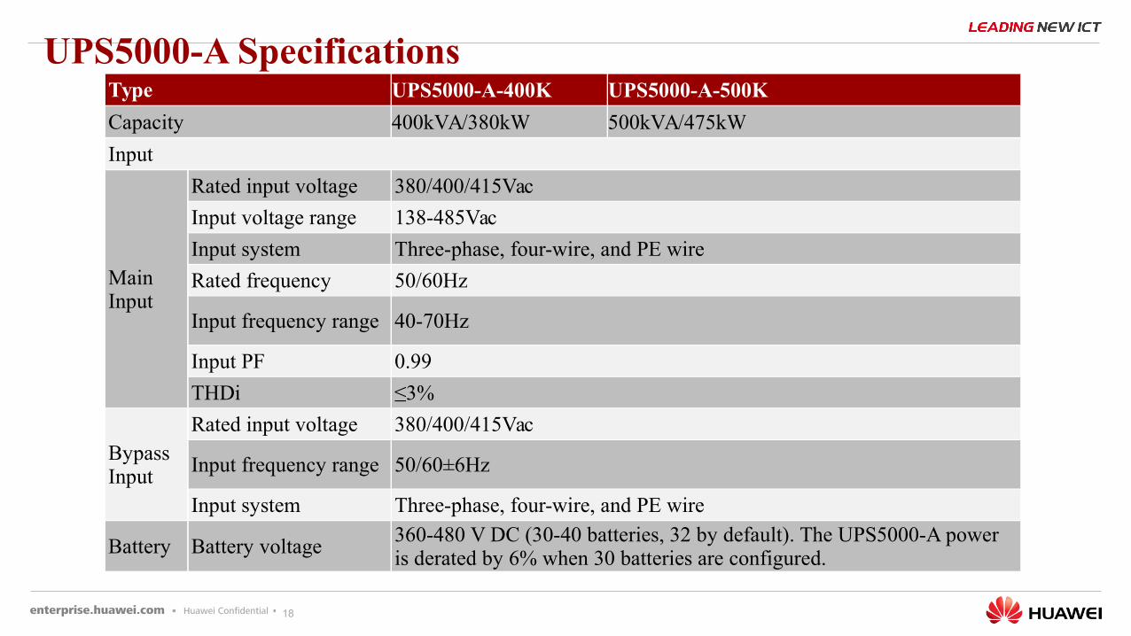
UPS5000-A SpecificationsType UPS5000-A-400K UPS5000-A-500K
Capacity 400kVA/380kW 500kVA/475kW
Input
Main Input
Rated input voltage 380/400/415Vac
Input voltage range 138-485Vac
Input system Three-phase, four-wire, and PE wire
Rated frequency 50/60Hz
Input frequency range 40-70Hz
Input PF 0.99
THDi ≤3%
BypassInput
Rated input voltage 380/400/415Vac
Input frequency range 50/60±6Hz
Input system Three-phase, four-wire, and PE wire
Battery Battery voltage360-480 V DC (30-40 batteries, 32 by default). The UPS5000-A power is derated by 6% when 30 batteries are configured.
19
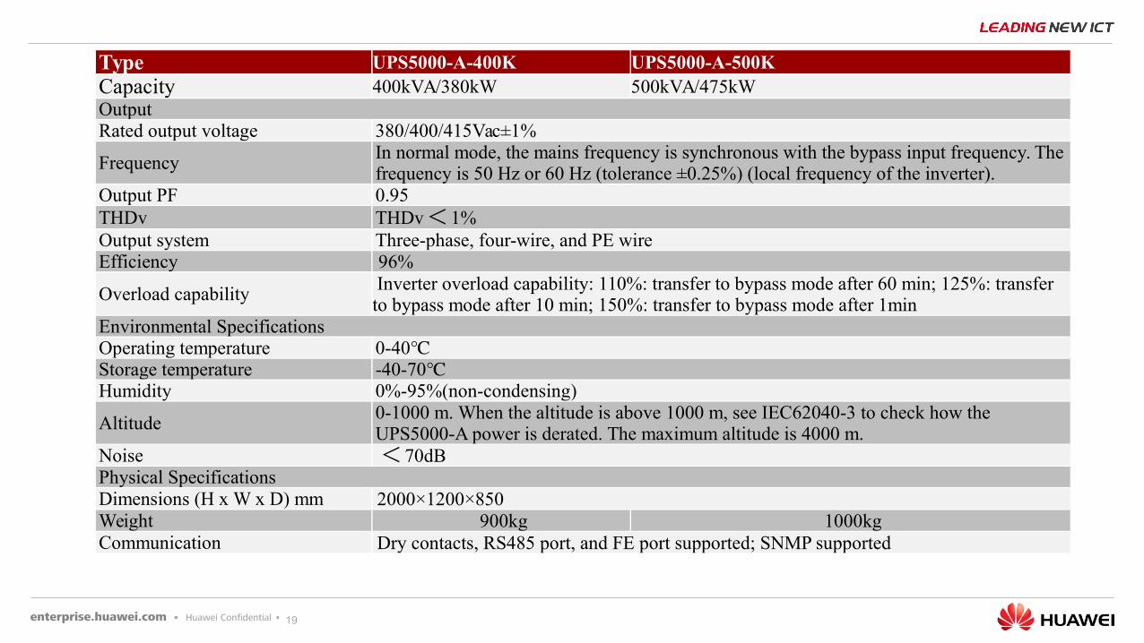
Type UPS5000-A-400K UPS5000-A-500KCapacity 400kVA/380kW 500kVA/475kWOutputRated output voltage 380/400/415Vac±1%
FrequencyIn normal mode, the mains frequency is synchronous with the bypass input frequency. The frequency is 50 Hz or 60 Hz (tolerance ±0.25%) (local frequency of the inverter).
Output PF 0.95THDv THDv< 1%Output system Three-phase, four-wire, and PE wireEfficiency 96%
Overload capability Inverter overload capability: 110%: transfer to bypass mode after 60 min; 125%: transfer to bypass mode after 10 min; 150%: transfer to bypass mode after 1min
Environmental SpecificationsOperating temperature 0-40℃Storage temperature -40-70℃Humidity 0%-95%(non-condensing)
Altitude0-1000 m. When the altitude is above 1000 m, see IEC62040-3 to check how the UPS5000-A power is derated. The maximum altitude is 4000 m.
Noise < 70dBPhysical SpecificationsDimensions (H x W x D) mm 2000×1200×850Weight 900kg 1000kgCommunication Dry contacts, RS485 port, and FE port supported; SNMP supported
20
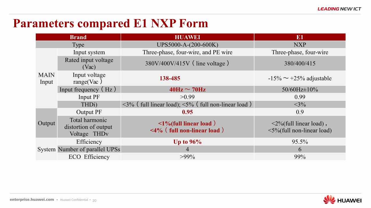
Parameters compared E1 NXP FormBrand HUAWEI E1Type UPS5000-A-(200-600K) NXP
MAINInput
Input system Three-phase, four-wire, and PE wire Three-phase, four-wireRated input voltage
(Vac)380V/400V/415V ( line voltage ) 380/400/415
Input voltage range(Vac ) 138-485 -15%~ +25% adjustable
Input frequency ( Hz ) 40Hz~ 70Hz 50/60Hz±10%Input PF >0.99 0.99THDi) <3% ( full linear load); <5% ( full non-linear load ) <3%
Output
Output PF 0.95 0.9Total harmonic
distortion of output Voltage THDv
<1%(full linear load )<4% ( full non-linear load )
<2%(full linear load) ,<5%(full non-linear load)
SystemEfficiency Up to 96% 95.5%
Number of parallel UPSs 4 6ECO Efficiency >99% 99%
21
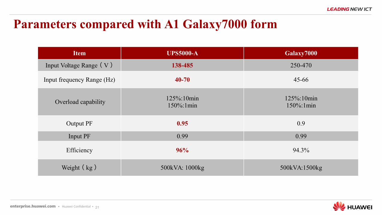
Parameters compared with A1 Galaxy7000 form
Item UPS5000-A Galaxy7000
Input Voltage Range ( V ) 138-485 250-470
Input frequency Range (Hz) 40-70 45-66
Overload capability125%:10min150%:1min
125%:10min150%:1min
Output PF 0.95 0.9
Input PF 0.99 0.99
Efficiency 96% 94.3%
Weight ( kg ) 500kVA: 1000kg 500kVA:1500kg
22
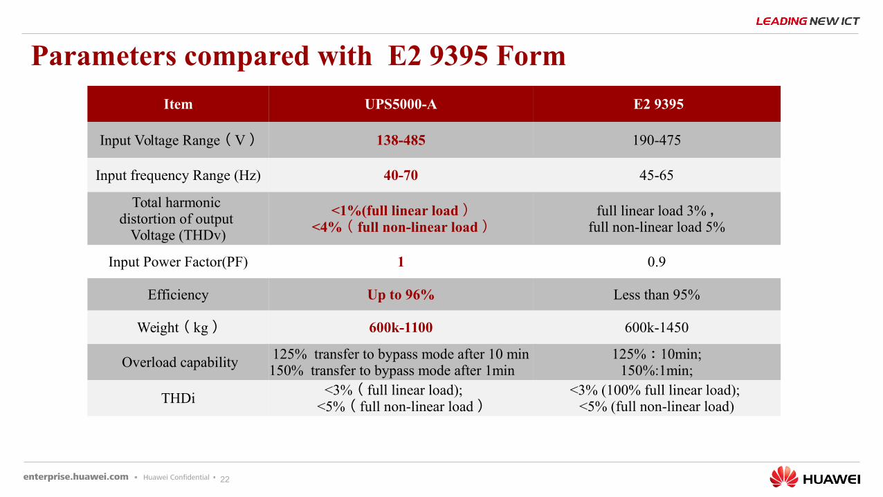
Parameters compared with E2 9395 Form
Item UPS5000-A E2 9395
Input Voltage Range ( V ) 138-485 190-475
Input frequency Range (Hz) 40-70 45-65
Total harmonic distortion of output
Voltage (THDv)
<1%(full linear load )<4% ( full non-linear load )
full linear load 3% ,full non-linear load 5%
Input Power Factor(PF) 1 0.9
Efficiency Up to 96% Less than 95%
Weight ( kg ) 600k-1100 600k-1450
Overload capability125% transfer to bypass mode after 10 min150% transfer to bypass mode after 1min
125% : 10min;150%:1min;
THDi <3% ( full linear load);
<5% ( full non-linear load )<3% (100% full linear load);
<5% (full non-linear load)
23
33
11
22
44
Products Competitive AnalysisProducts Competitive Analysis
UPS5000-A-400/500K Product HighlightsUPS5000-A-400/500K Product Highlights
Products IntroduceProducts Introduce
The Installation of UPS&optionals and Alarms ListThe Installation of UPS&optionals and Alarms List
Content
24
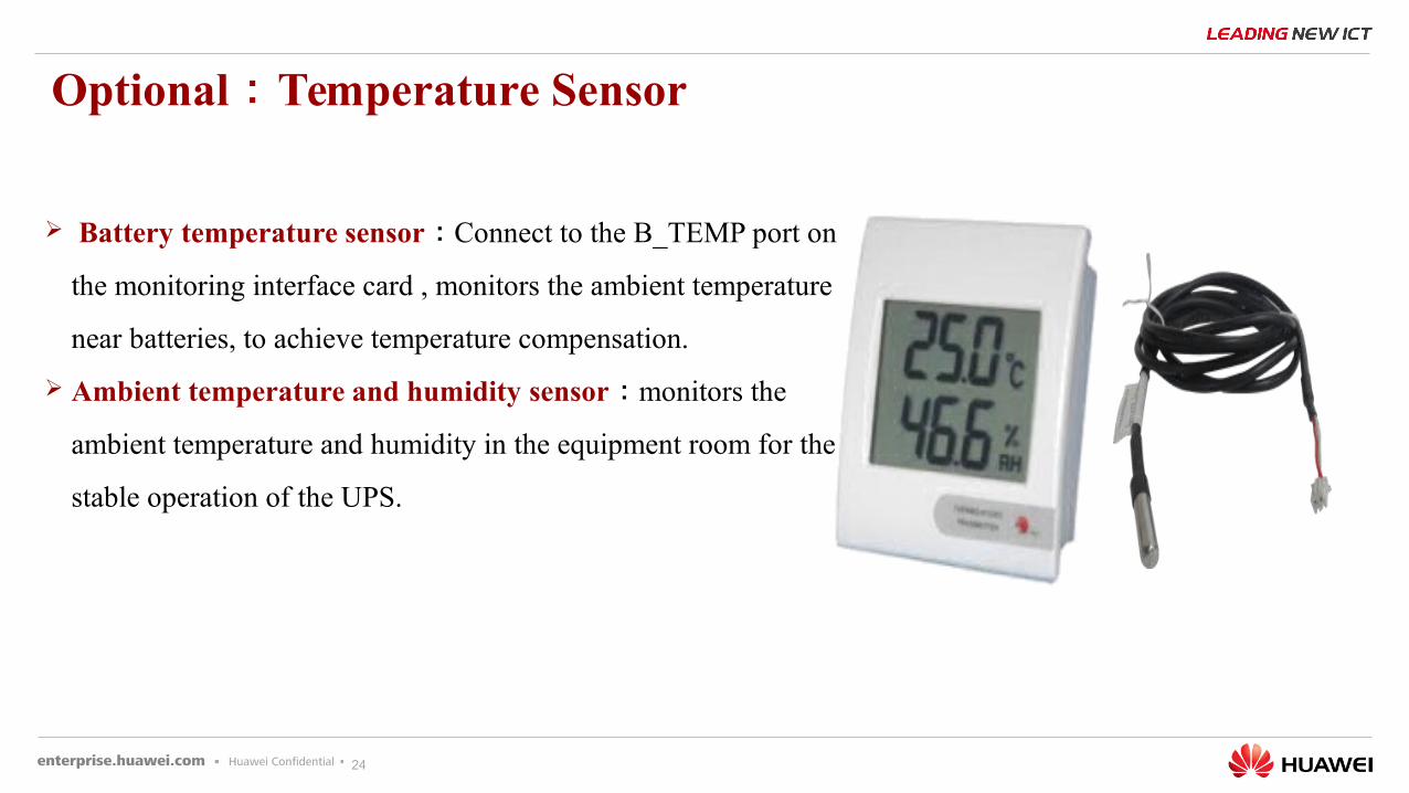
Battery temperature sensor : Connect to the B_TEMP port on
the monitoring interface card , monitors the ambient temperature
near batteries, to achieve temperature compensation.
Ambient temperature and humidity sensor : monitors the
ambient temperature and humidity in the equipment room for the
stable operation of the UPS.
Optional : Temperature Sensor
25
Optional : Dry Contact Extended Card
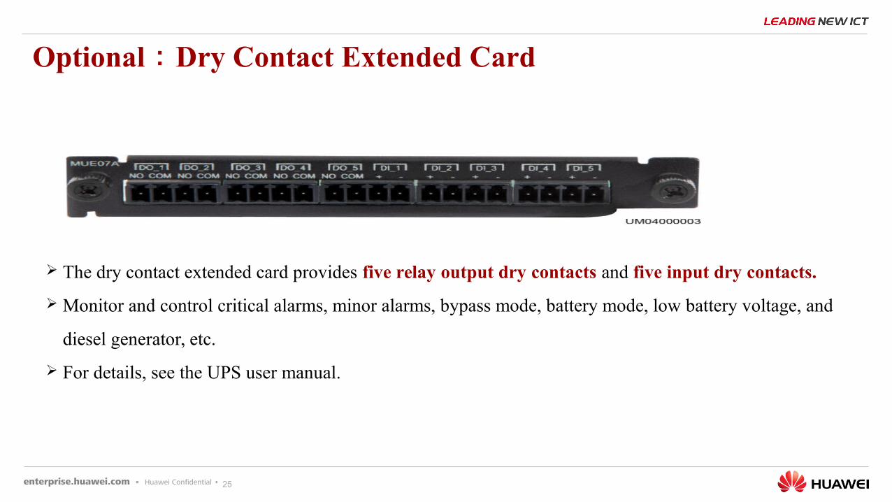
The dry contact extended card provides five relay output dry contacts and five input dry contacts.
Monitor and control critical alarms, minor alarms, bypass mode, battery mode, low battery voltage, and
diesel generator, etc.
For details, see the UPS user manual.
26
Optional : Battery Monitor Unit
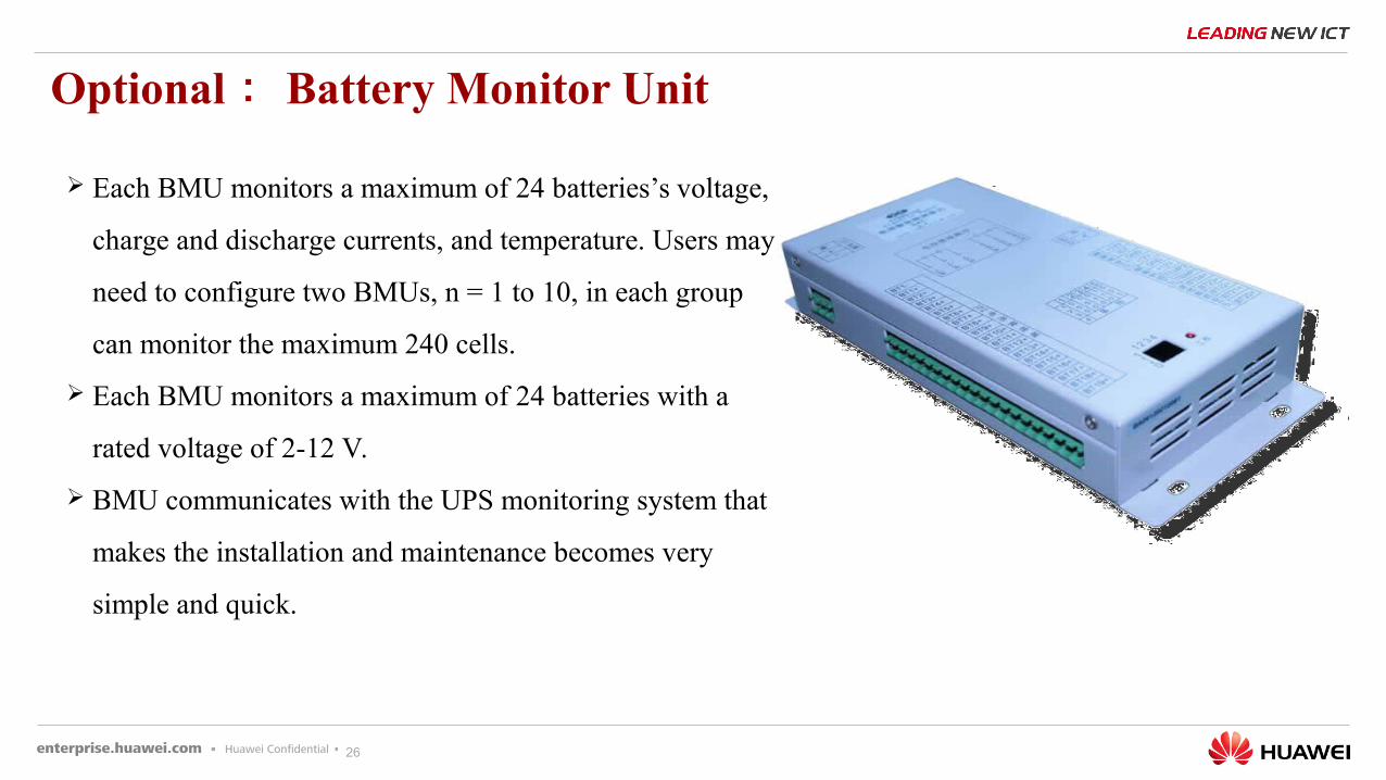
Each BMU monitors a maximum of 24 batteries’s voltage,
charge and discharge currents, and temperature. Users may
need to configure two BMUs, n = 1 to 10, in each group
can monitor the maximum 240 cells.
Each BMU monitors a maximum of 24 batteries with a
rated voltage of 2-12 V.
BMU communicates with the UPS monitoring system that
makes the installation and maintenance becomes very
simple and quick.
27
Optional : Battery Grounding Failure Detector
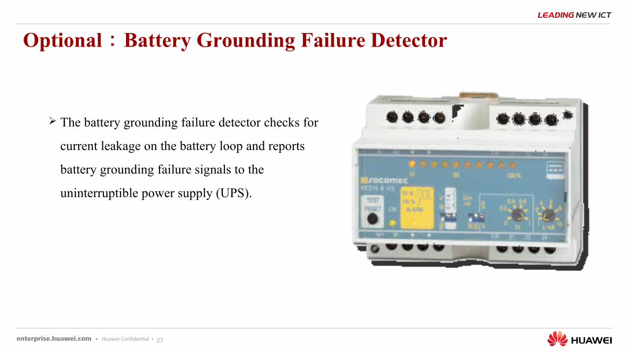
The battery grounding failure detector checks for
current leakage on the battery loop and reports
battery grounding failure signals to the
uninterruptible power supply (UPS).
28
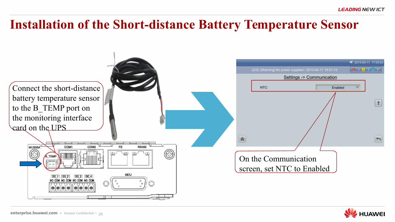
Installation of the Short-distance Battery Temperature Sensor
Connect the short-distance battery temperature sensor to the B_TEMP port on the monitoring interface card on the UPS
On the Communication screen, set NTC to Enabled
29
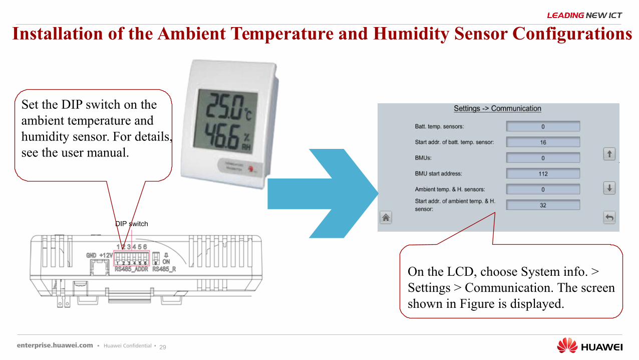
Installation of the Ambient Temperature and Humidity Sensor Configurations
Set the DIP switch on the ambient temperature and humidity sensor. For details, see the user manual.
On the LCD, choose System info. > Settings > Communication. The screen shown in Figure is displayed.
30
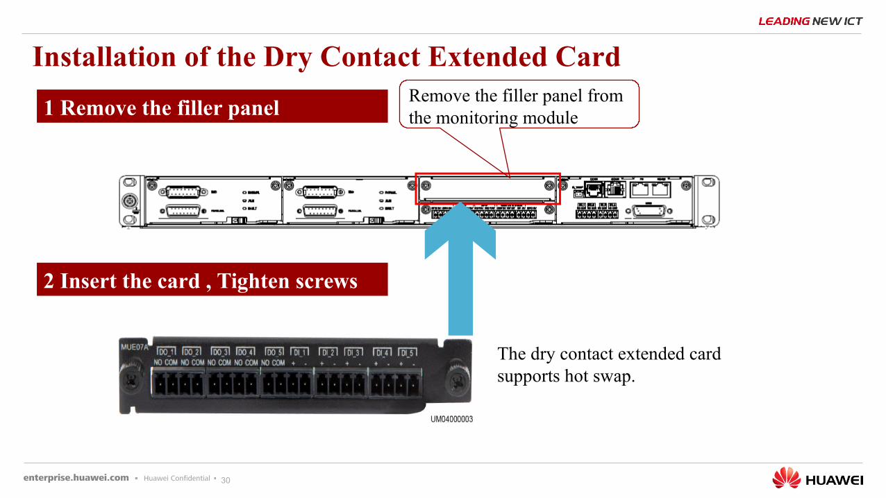
Installation of the Dry Contact Extended CardRemove the filler panel from the monitoring module
The dry contact extended card supports hot swap.
1 Remove the filler panel
2 Insert the card , Tighten screws
31
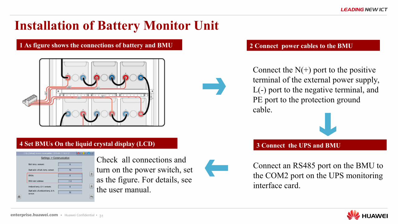
Installation of Battery Monitor Unit1 As figure shows the connections of battery and BMU 2 Connect power cables to the BMU
Connect the N(+) port to the positive terminal of the external power supply, L(-) port to the negative terminal, and PE port to the protection ground cable.
3 Connect the UPS and BMU
Connect an RS485 port on the BMU to the COM2 port on the UPS monitoring interface card.
4 Set BMUs On the liquid crystal display (LCD)
Check all connections and turn on the power switch, set as the figure. For details, see the user manual.
32
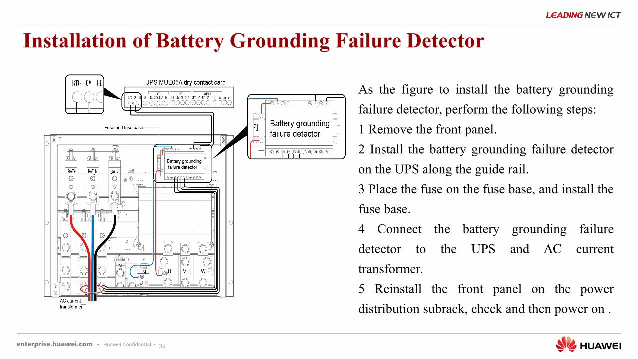
Installation of Battery Grounding Failure Detector
As the figure to install the battery grounding
failure detector, perform the following steps:
1 Remove the front panel.
2 Install the battery grounding failure detector
on the UPS along the guide rail.
3 Place the fuse on the fuse base, and install the
fuse base.
4 Connect the battery grounding failure
detector to the UPS and AC current
transformer.
5 Reinstall the front panel on the power
distribution subrack, check and then power on .
33
Appendix : Alarm List
Alarm List

THANK YOU
Copyright©2016 Huawei Technologies Co., Ltd. All Rights Reserved.The information in this document may contain predictive statements including, without limitation, statements regarding the future financial and operating results, future product portfolio, new technology, etc. There are a number of factors that could cause actual results and developments to differ materially from those expressed or implied in the predictive statements. Therefore, such information is provided for reference purpose only and constitutes neither an offer nor an acceptance. Huawei may change the information at any time without notice.