Embed Size (px)
Citation preview
This paper is a post-print of a paper submitted to and accepted for publication in IET Renewable Power Generation and
is subject to The Institution of Engineering and Technology Copyright. The copy of record is available at IET Digital
Library
1
Hybrid AC/DC hub for integrating onshore wind power and interconnecting onshore and offshore DC networks
Kai Huang1, Wang Xiang1*, Lie Xu1, Yi Wang2 1 Department of Electronic and Electrical Engineering, University of Strathclyde, G1 1XW, Glasgow, UK. 2 State Key Laboratory of Alternate Electrical Power System with Renewable Energy Sources, North China
Electric Power University, Baoding 071003, People's Republic of China * [email protected]
Abstract: A hybrid AC/DC hub is proposed in this paper, where a modular multilevel converter (MMC) and a line-commutated converter (LCC) are paralleled at the AC side to integrate onshore wind power, and connected in series at the DC sides to interconnect two DC networks with different voltages. The hybrid AC/DC hub facilities wind power integration and DC network interconnection with reduced converter ratings and power losses when compared with the ‘conventional’ approach using DC-DC converters. To investigate the design requirement and performance of the hybrid AC/DC hub, power flow analysis is assessed to evaluate the converter power rating requirement. To ride through DC faults at either side of the interconnected DC networks, a coordinated DC fault protection for the hybrid AC/DC hub is proposed and studied. Simulation results in PSCAD/EMTDC verify the feasibility and effectiveness of the proposed control and protection of the hybrid AC/DC hub under power flow change, AC and DC fault conditions.
1. Introduction
Renewable and sustainable energy utilization has been
well acknowledged as one of the most promising solutions to
mitigate the climate crisis. Among various renewable
energies, wind energy is considered the most developed and
mature technology. By the end of 2018, 591 GW wind power
has been installed world widely onshore and offshore [1].
For countries like China, India and USA, onshore wind
power exploitation still plays a leading role with many large
wind farms currently being developed. Transmitting power
generated from large onshore wind farms to load centers over
long distance, line commutated converter based HVDC
(LCC-HVDC) technologies are being used, e.g. in China,
several LCC-HVDC links at ±500 kV and ±800kV have been
commissioned to transmit onshore wind power over 1000km
[2]. In the meantime, many offshore wind farms have been
installed or under construction, e.g. in Europe, modular
multilevel converter based HVDC (MMC-HVDC)
technologies at up to ±320 kV have been used for their grid
connection [3][4].
To improve the transmission efficiency, onshore and
offshore HVDC systems could be connected to existing DC
networks that directly supply load centers. Due to the
different voltage ratings between overhead line HVDC (e.g.
onshore LCC-HVDC) and offshore MMC-HVDC systems,
DC-DC converters are required to interconnect the two
systems. The DC-DC converters can be galvanic isolated or
non-isolated [5][6]. Several isolated topologies of DC-DC
converters have been proposed, such as the modular
multilevel dual-active bridge (DAB) and the inductor-
capacitor-inductor (LCL) based DC-DC converters, both of
which offer independent AC-DC conversion and inherent DC
fault tolerate capability [7][8]. However, they require two
AC/DC conversion stages, resulting in higher converter
power rating and operating power loss.
The non-isolated DC-DC converter without full DC-AC-
DC conversion has been proposed as an efficient alternative.
The MMC based DC autotransformer (DC AUTO) is one of
the most attractive and feasible solutions [9][10]. In a DC
AUTO, part of DC power is transferred through the direct
electrical connection between the interconnected converters,
leading to reduced converter capacity and power losses.
However, to achieve bidirectional fault blocking capability,
the half-bridge submodules should be replaced by full-bridge
or self-blocking counterparts [11], increasing costs and losses.
From the DC AUTO concept, several alternative
unidirectional topologies for specified applications have been
proposed to further minimize the costs and losses [12]
However, they are not suitable for interconnecting DC
networks requiring power reversal operation. Combined with
a three-switch submodule circuit and series-connected
thyristors and diodes, a hybrid non-isolated topology was
proposed for DC network interconnection, which presents
lower capital cost, small footprint and power losses [13].
However, performance during DC fault needs further analysis.
Therefore, a new hybrid AC/DC hub (Hybrid Hub)
configuration consisted of LCC and MMC technologies is
proposed in this paper for integrating onshore wind power
and interconnecting onshore and offshore DC networks. In
the Hybrid Hub, the onshore wind farm is directly connected
to the LCC, and a MMC is connected in series between the
LCC (higher DC voltage side) and DC terminals of the
offshore DC network (lower DC voltage side). The Hybrid
Hub can be implemented in windy areas near the coast, such
as North China and South Scotland. The main contributions
of this paper are as follows:
A Hybrid Hub concept is proposed to interconnect onshore
and offshore DC networks with different voltage levels,
and to integrate onshore wind farms through the AC
terminal. Compared with the ‘conventional’
interconnection approach using DC-DC converters, in the
proposed Hybrid Hub, part of the power from the offshore
DC network can be transmitted to the onshore DC network
directly, therefore, significantly reducing the costs and
power losses of converters.
Detailed fault ride-through strategies for the Hybrid Hub
are investigated. To avoid overcurrent during DC faults on
submarine cable or overhead lines (OHLs), additional
bidirectional thyristors associated with coordinated
This paper is a post-print of a paper submitted to and accepted for publication in IET Renewable Power Generation and is subject to The
Institution of Engineering and Technology Copyright. The copy of record is available at IET Digital Library
2
current based DC fault detection algorithms are proposed
to protect the converters from breakdown during DC faults
on either high voltage or low voltage side.
Comprehensive operating conditions of the
interconnection system are analysed. Besides the normal
operation of transmitting power from the offshore DC
network to the onshore DC network, the power absorbing
scenario of offshore DC network is investigated. It is
found that the Hybrid Hub can provide active power to the
offshore DC network, which enables the black start of
offshore DC network from the onshore DC network.
This paper is organised as follows. Section 2 depicts the
topology and power flow analysis of the Hybrid Hub. Section
3 presents its system layout and control principle. A
comprehensive DC fault protection scheme for the Hybrid
Hub is proposed in Section 4. Simulation validations on
power flow change, DC fault and AC fault responses
(including the study of AC fault ride-through capability) of
the Hybrid Hub are provided in Section 5. Conclusions are
drawn in Section 6.
2. System Topology and Power Flow Analysis
2.1. Envisaged Application Scenario
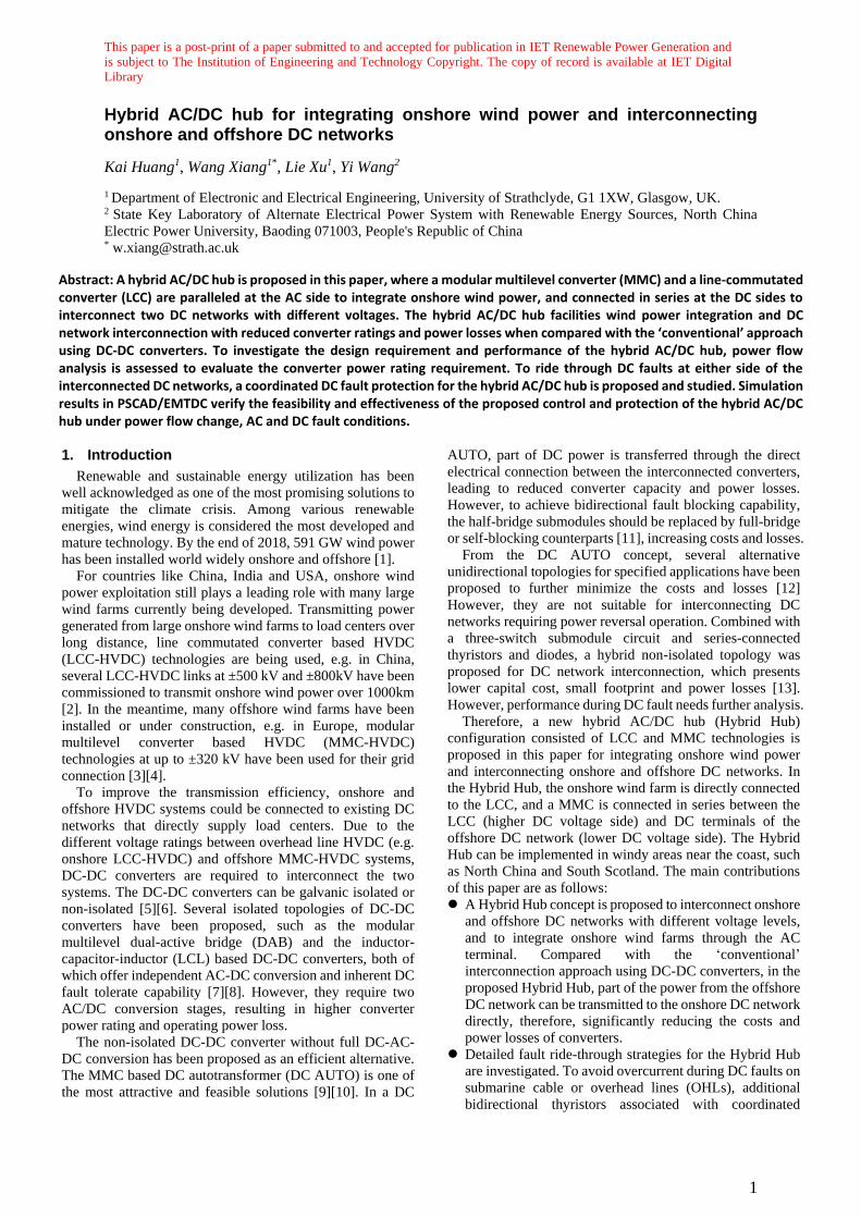
Fig. 1 illustrates an envisaged application scenario to
interconnect onshore and offshore DC networks. An onshore
wind farm is integrated with the local AC grid, where an LCC
is used to transmit the power to the DC network with higher-
voltage (HV) E2. The DC power at the HV side is transmitted
to the load center through long-distance OHLs. The DC
circuit breaker (DCCB) is installed between the LCC and
MMC2 to isolate DC fault. An existing offshore DC network
with a lower-voltage (LV) E1 is connected to the onshore DC
system through submarine cables. Due to the different DC
voltages, a DC-DC converter (shown as the front-to-front
(F2F) type [14]) is required for this interconnection to step up
the voltage from E1 to E2. Alternative DC-DC converter
configurations, e.g. a DC AUTO might be used instead of the
F2F one to reduce converter power rating and power loss.
However, additional submodules should be employed in the
DC AUTO converters to achieve bidirectional DC fault
isolating capability [9].
E2
PLCC
Pdc2
DC-DC Converter
Local GridOHL
DC
CB
Onshore
E1
Pdc1
LCC
CableMMC1 MMC2
PWF
Load
Centre
Offshore
DC network
OWF 1
OWF 2
OWF 3
Offshore
Fig. 1. Mono-polar topology of the envisaged scenario for
DC network interconnection.
2.2. Topology of the Hybrid Hub
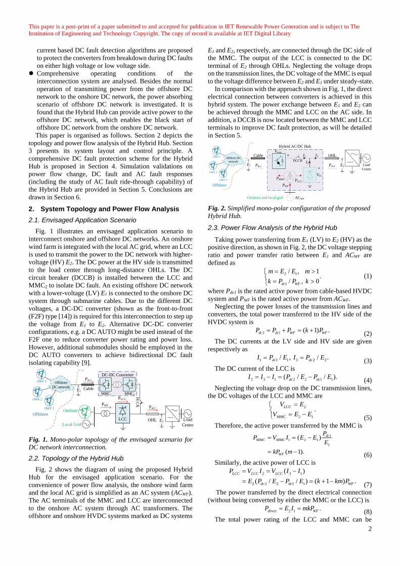
Fig. 2 shows the diagram of using the proposed Hybrid
Hub for the envisaged application scenario. For the
convenience of power flow analysis, the onshore wind farm
and the local AC grid is simplified as an AC system (ACWF).
The AC terminals of the MMC and LCC are interconnected
to the onshore AC system through AC transformers. The
offshore and onshore HVDC systems marked as DC systems
E1 and E2, respectively, are connected through the DC side of
the MMC. The output of the LCC is connected to the DC
terminal of E2 through OHLs. Neglecting the voltage drops
on the transmission lines, the DC voltage of the MMC is equal
to the voltage difference between E2 and E1 under steady-state.
In comparison with the approach shown in Fig. 1, the direct
electrical connection between converters is achieved in this
hybrid system. The power exchange between E1 and E2 can
be achieved through the MMC and LCC on the AC side. In
addition, a DCCB is now located between the MMC and LCC
terminals to improve DC fault protection, as will be detailed
in Section 5.
I3
I2
I1
Pdc1 Pdc2
PWF
ACWF
PMMC PLCC
Hybrid AC/DC Hub
+- OHLCable
DCCB
Vmmc
+
-
Vlcc
E1
Onshore and local grid
E2 Load
Centre
Offshore DC
network
OWF 1
OWF 2
OWF 3
Offshore
Fig. 2. Simplified mono-polar configuration of the proposed
Hybrid Hub.
2.3. Power Flow Analysis of the Hybrid Hub
Taking power transferring from E1 (LV) to E2 (HV) as the
positive direction, as shown in Fig. 2, the DC voltage stepping
ratio and power transfer ratio between E1 and ACWF are
defined as
2 1
1
/ , 1.
/ , 0dc WF
m E E m
k P P k
(1)
where Pdc1 is the rated active power from cable-based HVDC
system and PWF is the rated active power from ACWF.
Neglecting the power losses of the transmission lines and
converters, the total power transferred to the HV side of the
HVDC system is
2 1 ( 1) .dc dc WF WFP P P k P (2)
The DC currents at the LV side and HV side are given
respectively as
1 1 1 3 2 2/ , / .dc dcI P E I P E (3)
The DC current of the LCC is
2 3 1 2 2 1 1( / / ).dc dcI I I P E P E (4)
Neglecting the voltage drop on the DC transmission lines,
the DC voltages of the LCC and MMC are
2
2 1
.LCC
MMC
V E
V E E
(5)
Therefore, the active power transferred by the MMC is
1
1 2 1
1
( )
( 1).
dc
MMC MMC
WF
PP V I E E
E
kP m
(6)
Similarly, the active power of LCC is
2 3 1
2 2 2 1 1
( )
( / / ) ( 1 ) .
LCC LCC LCC
dc dc WF
P V I V I I
E P E P E k km P
(7)
The power transferred by the direct electrical connection
(without being converted by either the MMC or the LCC) is
2 1 .dir t WFecP I mkPE (8)
The total power rating of the LCC and MMC can be
This paper is a post-print of a paper submitted to and accepted for publication in IET Renewable Power Generation and is subject to The
Institution of Engineering and Technology Copyright. The copy of record is available at IET Digital Library
3
obtained by adding (6) and (7) as
_ . h hub LCC MMC WFP P P P (9)
The total power transferred by the MMC and LCC can also
be obtained from a point of view of active power balance. The
active power of ACWF which is equal to PWF, flowing into the
MMC and LCC separately, as shown in Fig. 2.
The total power rating of the ‘conventional’ F2F DC
network interconnection as shown in Fig. 1 is
1
_
2
(2 1) .
con MMC LCC dc WF
WF h hub
P P P P P
k P P (10)
If a F2F DC-DC converter in Fig. 1 is replaced by the DC
AUTO based on [9], the total power rating is
_
2 (1 1/ )
(2 1 2 / ) .
AT WF WF
WF h hub
P kP m P
k k m P P (11)
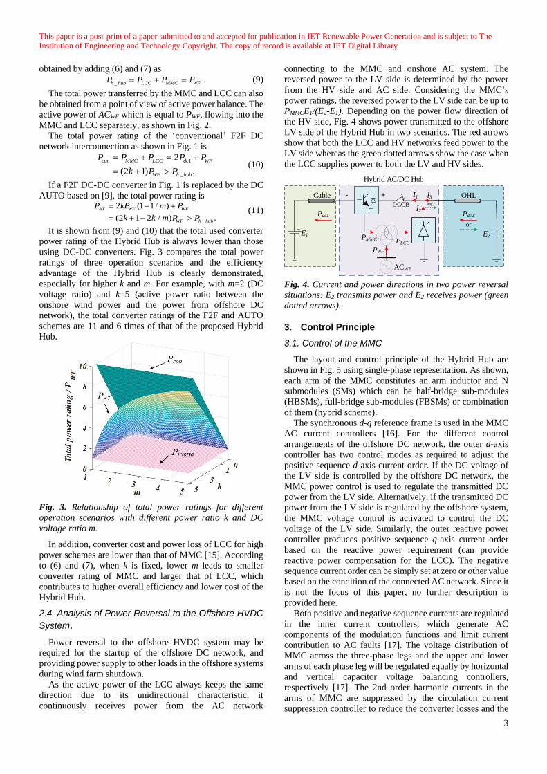
It is shown from (9) and (10) that the total used converter
power rating of the Hybrid Hub is always lower than those
using DC-DC converters. Fig. 3 compares the total power
ratings of three operation scenarios and the efficiency
advantage of the Hybrid Hub is clearly demonstrated,
especially for higher k and m. For example, with m=2 (DC
voltage ratio) and k=5 (active power ratio between the
onshore wind power and the power from offshore DC
network), the total converter ratings of the F2F and AUTO
schemes are 11 and 6 times of that of the proposed Hybrid
Hub.
Fig. 3. Relationship of total power ratings for different
operation scenarios with different power ratio k and DC
voltage ratio m.
In addition, converter cost and power loss of LCC for high
power schemes are lower than that of MMC [15]. According
to (6) and (7), when k is fixed, lower m leads to smaller
converter rating of MMC and larger that of LCC, which
contributes to higher overall efficiency and lower cost of the
Hybrid Hub.
2.4. Analysis of Power Reversal to the Offshore HVDC
System.
Power reversal to the offshore HVDC system may be
required for the startup of the offshore DC network, and
providing power supply to other loads in the offshore systems
during wind farm shutdown.
As the active power of the LCC always keeps the same
direction due to its unidirectional characteristic, it
continuously receives power from the AC network
connecting to the MMC and onshore AC system. The
reversed power to the LV side is determined by the power
from the HV side and AC side. Considering the MMC’s
power ratings, the reversed power to the LV side can be up to
PMMCE1/(E2-E1). Depending on the power flow direction of
the HV side, Fig. 4 shows power transmitted to the offshore
LV side of the Hybrid Hub in two scenarios. The red arrows
show that both the LCC and HV networks feed power to the
LV side whereas the green dotted arrows show the case when
the LCC supplies power to both the LV and HV sides.
I3
I2
I1
E1 E2
Pdc1 Pdc2
PWF
ACWF
PMMC PLCC
Hybrid AC/DC Hub
+- OHLCable
DCCB or
or
Fig. 4. Current and power directions in two power reversal
situations: E2 transmits power and E2 receives power (green
dotted arrows).
3. Control Principle
3.1. Control of the MMC
The layout and control principle of the Hybrid Hub are
shown in Fig. 5 using single-phase representation. As shown,
each arm of the MMC constitutes an arm inductor and N
submodules (SMs) which can be half-bridge sub-modules
(HBSMs), full-bridge sub-modules (FBSMs) or combination
of them (hybrid scheme).
The synchronous d-q reference frame is used in the MMC
AC current controllers [16]. For the different control
arrangements of the offshore DC network, the outer d-axis
controller has two control modes as required to adjust the
positive sequence d-axis current order. If the DC voltage of
the LV side is controlled by the offshore DC network, the
MMC power control is used to regulate the transmitted DC
power from the LV side. Alternatively, if the transmitted DC
power from the LV side is regulated by the offshore system,
the MMC voltage control is activated to control the DC
voltage of the LV side. Similarly, the outer reactive power
controller produces positive sequence q-axis current order
based on the reactive power requirement (can provide
reactive power compensation for the LCC). The negative
sequence current order can be simply set at zero or other value
based on the condition of the connected AC network. Since it
is not the focus of this paper, no further description is
provided here.
Both positive and negative sequence currents are regulated
in the inner current controllers, which generate AC
components of the modulation functions and limit current
contribution to AC faults [17]. The voltage distribution of
MMC across the three-phase legs and the upper and lower
arms of each phase leg will be regulated equally by horizontal
and vertical capacitor voltage balancing controllers,
respectively [17]. The 2nd order harmonic currents in the
arms of MMC are suppressed by the circulation current
suppression controller to reduce the converter losses and the
This paper is a post-print of a paper submitted to and accepted for publication in IET Renewable Power Generation and is subject to The
Institution of Engineering and Technology Copyright. The copy of record is available at IET Digital Library
4
SMs’ capacitor voltage ripples.
Nearest level modulation (NLM) is used for providing gate
signals to each SMs, which can closely fit the output voltage
reference and reduce the switching frequency of the high DC
link voltage [18].
drI
LCCr
LarmLarm
Δ/Y
AC Filters
*
drI
AC Grid
Y/Δ
Y/Y
PCC
MMC (one phase)
1 N 1 N
+E1 +E2
PWF
PLCC
PMMC
Vmmc=E2-E1
VDCOL
1
G
sT
E2
PWF
+
PMMC
*
LCCP
2
1
E–
Idmax
Idmin
*
1dcP1
MMCV
E
*
MMCP
+
–
PMMC
PI
+
–*
MMCV
VMMC
+
– Idmax
Idmin
PI
Reactive power
controller
Positive and
Negative sequence
Current controllerNLM modulation
Vertical and
horizontal capacitor
voltage controllers
Circulating current
Suppression
controller
I*d+
Iqmax Iqmin
I*q+
I*
dq-
Gate signals
PI
3.05(175°)
0.52(30°)
r
π(180°)
+
–
+
drI
–
MIN
MMC Power Control
MMC Voltage Control
or LCC Power Control
Idmax
Idmin
E1
E2
1
G
sT
Fig. 5. System layout and control of the Hybrid Hub.
3.2. Control of the LCC
The rectifier LCC is composed of two six-pulse thyristor
bridges in series with two corresponding transformers to form
a 12-pulse converter configuration. AC filters are used to
absorb AC side harmonics and to supply reactive power to the
converter.
The LCC rectifier station controls the DC current to
regulate the active power whereas the LCC inverter controls
the DC voltage. Using the power direction definition shown
in Fig. 2, the active power order of the LCC is the power
difference between the required power transmission from the
onshore AC system and active power absorbed by the AC side
of the MMC. As shown in Fig. 5, the desired LCC power is then regulated by its DC current I
*
dr using Constant Current
Control (CCC) with Voltage-Dependent Current Order
Limiter (VDCOL). In normal operation, the CCC is working by comparing the measured DC current Idr and I
*
dr to produce
the error signal. A PI controller receives the current signal to
produce the desired firing angle order α to the LCC. The
VDCOL is added as an auxiliary control during fault
conditions. When the DC voltage of LCC drops to a certain
threshold, the DC current will be controlled to be reduced.
The reduced DC current helps to improve DC voltage
recovery and AC system stability as the absorbed reactive
power is reduced [19].
4. DC Fault Protection
4.1. System Behaviour during DC Fault
In the event of a DC fault on either side of the Hybrid Hub,
similar to the DC AUTO, the fault current will feed from the
healthy DC side into the faulty DC side through the MMC
due to its direct electrical connection [9].
If the MMC in the Hybrid Hub is designed to block DC
faults using HBSMs and FBSMs, it has to provide the full HV
side DC voltage in the event of a LV side fault to interrupt the
fault current from the HV side, as shown in Fig. 6 (a).
Similarly, Fig. 6 (b) shows that the MMC has to support the
full LV side DC voltage to interrupt the fault current from the
LV side, in the event of a DC fault on the HV side. The LCC
has no influence during DC fault on either side, as it can
eliminate its DC current by simply increasing the firing angle.
Therefore, additional FBSMs should be inserted into the
MMC depending on the voltage ratio m.
If DCCBs are used to isolate DC faults, the MMC has to
be bypassed and the fault current will flow through the
freewheeling diodes. Thus, a comprehensive DC fault
protection is required to protect the whole system.
Taking into account the voltage stepping ratio level given
in [6], the low stepping ratio is defined to be less than or
around 1.5. Two DC fault protection schemes under high and
low stepping ratios are analysed as follows.
MMC
LCC
E1=0
E2
E2
(a)
(b)
MMC
LCC
E1
E1
E2=0
Fig. 6. Equivalent circuits with MMC blocking during
different DC faults
(a) LV DC side fault, (b) HV DC side fault.
4.2. DC Fault Protection under High Stepping Ratio
If the voltage stepping ratio is relatively high (m≥2), i.e.
This paper is a post-print of a paper submitted to and accepted for publication in IET Renewable Power Generation and is subject to The
Institution of Engineering and Technology Copyright. The copy of record is available at IET Digital Library
5
the voltage rating of MMC is also high, a hybrid MMC that
composes of HBSMs and FBSMs, could be used to interrupt
DC faults on either LV or HV side. Neglecting the voltage
drops across the DC lines, the required capacitor voltages of the MMC and FBSMs in each arm (V
*
arm_MMC and V*
arm_FBSM) to
isolate DC fault, and the DC voltage rating of the MMC in
each arm (Varm_MMC) without DC fault consideration are
expressed as,
* 2 1
_
* 1
_
_ 1
2 2
.2
( -1)
arm MMC
arm FBSM
arm MMC
E mEV
EV
V m E
(12)
In terms of HV side faults, if V*
arm_MMC> V
arm_MMC (i.e. m<2),
additional HBSMs should be inserted into each arm of the
MMC to increase its voltage rating to E1/2 in order to protect
the MMC from submodule overvoltage.
Similarly, additional FBSMs should be inserted into each arm of the MMC if V
*
arm_FBSM> V
arm_MMC (i.e. m<1.5) in the case
of LV side faults. Based on these, the hybrid MMC is not a
good option for DC fault protection if m is small as the
required additional FBSM could lead to extremely high cost.
4.3. DC Fault Protection under Low Stepping Ratio
The Hybrid Hub with a small voltage stepping ratio (m is
less than or around 1.5) will be mainly analysed in this paper
since a small m has been proven to be more efficient and
economical. For DC fault protection, DCCBs will be used and
the MMC is bypassed during DC faults. Thus, the standard
MMC with only HBSMs will be employed in the system.
CB3CB2
ACWF
MMC
LCC
- +Cable
HV
CB1
E2
(a)
LV
E1=0
OHL
Detailed circuit
RCable RCB
LV
E1=0
AC current
DC current
ROHL
E2
(b)
HVULCC
If-MMC
RSC
Rs Ls
AC grid
MMC bypassed
LCC
LV
E1=0E2
(c)
HV
OHLCable
Ls
AC grid
MMC rectifier operation
Detailed circuit
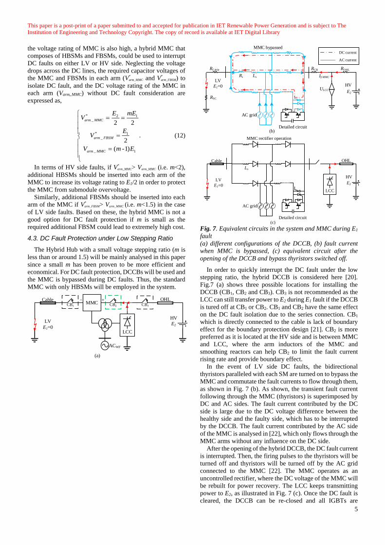
Fig. 7. Equivalent circuits in the system and MMC during E1
fault
(a) different configurations of the DCCB, (b) fault current
when MMC is bypassed, (c) equivalent circuit after the
opening of the DCCB and bypass thyristors switched off.
In order to quickly interrupt the DC fault under the low
stepping ratio, the hybrid DCCB is considered here [20].
Fig.7 (a) shows three possible locations for installing the
DCCB (CB1, CB2 and CB3). CB3 is not recommended as the
LCC can still transfer power to E2 during E1 fault if the DCCB
is tured off at CB1 or CB2. CB1 and CB2 have the same effect
on the DC fault isolation due to the series connection. CB1
which is directly connected to the cable is lack of boundary
effect for the boundary protection design [21]. CB2 is more
preferred as it is located at the HV side and is between MMC
and LCC, where the arm inductors of the MMC and
smoothing reactors can help CB2 to limit the fault current
rising rate and provide boundary effect.
In the event of LV side DC faults, the bidirectional
thyristors paralleled with each SM are turned on to bypass the
MMC and commutate the fault currents to flow through them,
as shown in Fig. 7 (b). As shown, the transient fault current
following through the MMC (thyristors) is superimposed by
DC and AC sides. The fault current contributed by the DC
side is large due to the DC voltage difference between the
healthy side and the faulty side, which has to be interrupted
by the DCCB. The fault current contributed by the AC side
of the MMC is analysed in [22], which only flows through the
MMC arms without any influence on the DC side.
After the opening of the hybrid DCCB, the DC fault current
is interrupted. Then, the firing pulses to the thyristors will be
turned off and thyristors will be turned off by the AC grid
connected to the MMC [22]. The MMC operates as an
uncontrolled rectifier, where the DC voltage of the MMC will
be rebuilt for power recovery. The LCC keeps transmitting
power to E2, as illustrated in Fig. 7 (c). Once the DC fault is
cleared, the DCCB can be re-closed and all IGBTs are
This paper is a post-print of a paper submitted to and accepted for publication in IET Renewable Power Generation and is subject to The
Institution of Engineering and Technology Copyright. The copy of record is available at IET Digital Library
6
deblocked to restart the MMC.
In the event of HV side DC faults, once the fault is
detected, all the thyristors in the MMC and the hybrid DCCB
are turned on. The fault clearance procedure of the MMC is
the same as the one on the LV side, which will not be
repeated. However, different from the LV side DC fault, the
firing angle of LCC is increased similar to DC fault handling
by the rectifier station in a conventional LCC HVDC system
[23].
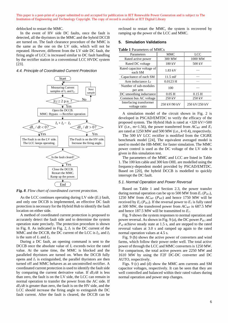
4.4. Principle of Coordinated Current Protection
Fig. 8. Flow chart of coordinated current protection.
As the LCC continues operating during LV side (E1) fault,
and only one DCCB is implemented, an effective DC fault
protection is necessary for the Hybrid Hub to identify the fault
location on either side.
A method of coordinated current protection is proposed to
accurately detect the fault side and to determine the system
operation state precisely. The protection procedure is shown
in Fig. 8. As indicated in Fig. 2, I1 is the DC current of the
MMC and the DCCB, the DC current of the LCC is I2, and I3
is the sum of I1 and I2.
During a DC fault, an opening command is sent to the
DCCB once the absolute value of I1 exceeds twice the rated
value. At the same time, the MMC is blocked and the
paralleled thyristors are turned on. When the DCCB fully
opens and I1 is extinguished, the parallel thyristors are then
turned off and MMC behaves as an uncontrolled rectifier. A
coordinated current protection is used to identify the fault side
by comparing the current derivative value. If dI3/dt is less
than zero, the fault is on the LV side, the LCC can remain in
normal operation to transfer the power from the AC side. If
dI3/dt is greater than zero, the fault is on the HV side, and the
LCC should increase the firing angle to extinguish the DC
fault current. After the fault is cleared, the DCCB can be
reclosed to restart the MMC, the system is recovered by
ramping up the power of the LCC and MMC.
5. Simulation Validations
Table 1 Parameters of MMCs
Parameters MMC LCC
Rated active power 300 MW 1000 MW
Rated DC voltage 180 kV 500 kV
Rated capacitor voltage of
each SM 1.83 kV —
Capacitance of each SM 11.5 mF —
Arm inductance L0 0.0123 H —
Number of sub-modules
per arm 100 —
DC smoothing inductance 0.05 H 0.15 H
Common bus AC voltage 250 kV 250 kV
Interfacing transformer
voltage ratio 250 kV/90 kV 250 kV/250 kV
A simulation model of the circuit shown in Fig. 2 is
developed in PSCAD/EMTDC to verify the efficacy of the
proposed system. The Hybrid Hub is rated at +320 kV/+500
kV (i.e., m=1.56), the power transferred from ACWF and E1
are rated at 1250 MW and 500 MW (i.e., k=0.4), respectively.
The 500 kV LCC rectifier is modified from the CIGRE
benchmark model [24], The equivalent averaged model is
used to model the HB-MMC for faster simulation. The MMC
power control is used as the DC voltage of the LV side is
given in this simulation test.
The parameters of the MMC and LCC are listed in Table
1. The 100 km cable and 300 km OHL are modelled using the
frequency-dependent model provided by PSCAD/EMTDC.
Based on [20], the hybrid DCCB is modelled to quickly
interrupt the DC fault.
5.1. Normal Operation and Power Reversal
Based on Table 1 and Section 2.3, the power transfer
during normal operation can be up to 500 MW from E1 (Pdc1),
1250 MW from ACWF (PWF) and hence 1750 MW will be
received by E2 (Pdc2). If the reversal power to E1 is fully rated
at 500 MW, the transferred power from ACWF is 687.5 MW
and hence 187.5 MW will be transmitted to E1.
Fig. 9 shows the system responses to normal operation and
power reversal. As shown in Fig. 9 (a), the DC power Pdc1 and
Pwf achieve steady state at 1.5 s, and are stepped to the rated
reversal values at 3.0 s and ramped up again to the rated
normal operation values at 4.5 s.
Fig. 9 (b) shows the active power of converters and wind
farms, which follow their power order well. The total active
power of through the LCC and MMC converters is 1250 MW.
For comparison, the total active powers are 2250 MW and
1610 MW by using the F2F DC-DC converter and DC
AUTO, respectively.
Figs. 9 (c) and (d) show the MMC arm currents and SM
capacitor voltages, respectively. It can be seen that they are
well controlled and balanced within their rated values during
normal operation and power step changes.
Measuring Current
samples of I1 and I2.
|I1| 2 p.u. ?
Yes
No
Next
sample
Open the DCCB.
MMC: Bypass Rectifier operation
Yes Yes
The Fault is on the LV side.
The LCC keeps operating.
The Fault is on the HV side.
Increase the firing angle.
Is the fault cleard?
Yes
Close the DCCB.
Restart the MMC.
Ramp up the power.
I1 + I2 = I3
End
Start
3 / 0?dI dt 3 / 0?dI dt
This paper is a post-print of a paper submitted to and accepted for publication in IET Renewable Power Generation and is subject to The
Institution of Engineering and Technology Copyright. The copy of record is available at IET Digital Library
7
a)
Pdc
(MW
)b)
Pa
c (M
W)
c)
i pa (
kA
)d)
Vc
(kV
)
1 1.5 2 2.5 3 3.5 4 4.5 5-500
0
500
1000
1500
2000
1 1.5 2 2.5 3 3.5 4 4.5 5-500
0
500
1000
1500
1 1.5 2 2.5 3 3.5 4 4.5 5-2
-1
0
1
2
1 1.5 2 2.5 3 3.5 4 4.5 51.65
1.75
1.85
1.95
2.05
Time(s)
Time(s)
Time(s)
Time(s)
Pdc1
Pdc2
Pmmc Plcc Pwf
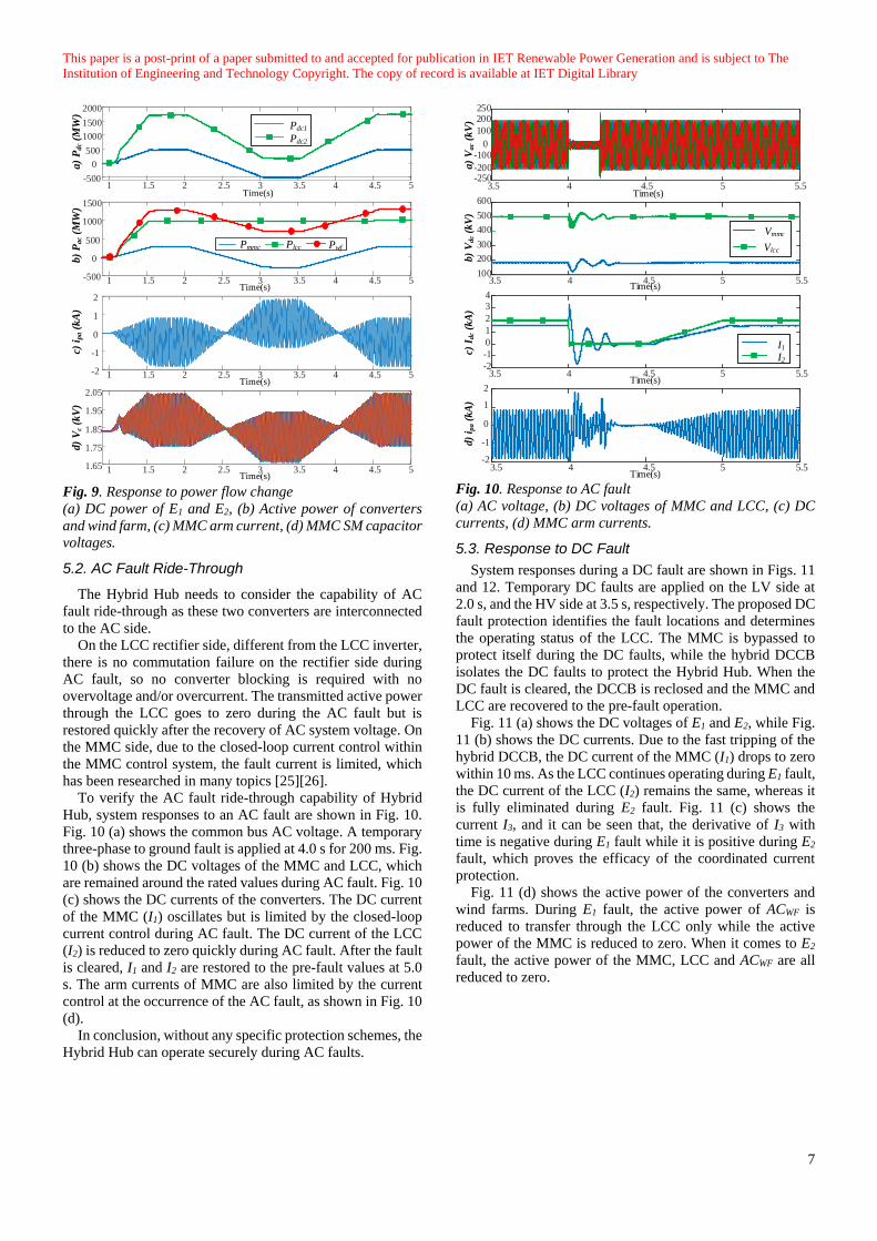
Fig. 9. Response to power flow change
(a) DC power of E1 and E2, (b) Active power of converters
and wind farm, (c) MMC arm current, (d) MMC SM capacitor
voltages.
5.2. AC Fault Ride-Through
The Hybrid Hub needs to consider the capability of AC
fault ride-through as these two converters are interconnected
to the AC side.
On the LCC rectifier side, different from the LCC inverter,
there is no commutation failure on the rectifier side during
AC fault, so no converter blocking is required with no
overvoltage and/or overcurrent. The transmitted active power
through the LCC goes to zero during the AC fault but is
restored quickly after the recovery of AC system voltage. On
the MMC side, due to the closed-loop current control within
the MMC control system, the fault current is limited, which
has been researched in many topics [25][26].
To verify the AC fault ride-through capability of Hybrid
Hub, system responses to an AC fault are shown in Fig. 10.
Fig. 10 (a) shows the common bus AC voltage. A temporary
three-phase to ground fault is applied at 4.0 s for 200 ms. Fig.
10 (b) shows the DC voltages of the MMC and LCC, which
are remained around the rated values during AC fault. Fig. 10
(c) shows the DC currents of the converters. The DC current
of the MMC (I1) oscillates but is limited by the closed-loop
current control during AC fault. The DC current of the LCC
(I2) is reduced to zero quickly during AC fault. After the fault
is cleared, I1 and I2 are restored to the pre-fault values at 5.0
s. The arm currents of MMC are also limited by the current
control at the occurrence of the AC fault, as shown in Fig. 10
(d).
In conclusion, without any specific protection schemes, the
Hybrid Hub can operate securely during AC faults.
3.5 4 4.5 5 5.5
-200
0
200
3.5 4 4.5 5 5.5100
200
300
400
500
600
3.5 4 4.5 5 5.5-2
-1
0
1
2
3
4
3.5 4 4.5 5 5.5-2
-1
0
1
2
250
-250
100
-100
Time(s)
Time(s)
Time(s)
Time(s)a)
Va
c (k
V)
b)
Vd
c (k
V)
c) I
dc
(kA
)d)
i pa (
kA
)
Vmmc
Vlcc
I1
I2
Fig. 10. Response to AC fault
(a) AC voltage, (b) DC voltages of MMC and LCC, (c) DC
currents, (d) MMC arm currents.
5.3. Response to DC Fault
System responses during a DC fault are shown in Figs. 11
and 12. Temporary DC faults are applied on the LV side at
2.0 s, and the HV side at 3.5 s, respectively. The proposed DC
fault protection identifies the fault locations and determines
the operating status of the LCC. The MMC is bypassed to
protect itself during the DC faults, while the hybrid DCCB
isolates the DC faults to protect the Hybrid Hub. When the
DC fault is cleared, the DCCB is reclosed and the MMC and
LCC are recovered to the pre-fault operation.
Fig. 11 (a) shows the DC voltages of E1 and E2, while Fig.
11 (b) shows the DC currents. Due to the fast tripping of the
hybrid DCCB, the DC current of the MMC (I1) drops to zero
within 10 ms. As the LCC continues operating during E1 fault,
the DC current of the LCC (I2) remains the same, whereas it
is fully eliminated during E2 fault. Fig. 11 (c) shows the
current I3, and it can be seen that, the derivative of I3 with
time is negative during E1 fault while it is positive during E2
fault, which proves the efficacy of the coordinated current
protection.
Fig. 11 (d) shows the active power of the converters and
wind farms. During E1 fault, the active power of ACWF is
reduced to transfer through the LCC only while the active
power of the MMC is reduced to zero. When it comes to E2
fault, the active power of the MMC, LCC and ACWF are all
reduced to zero.
This paper is a post-print of a paper submitted to and accepted for publication in IET Renewable Power Generation and is subject to The
Institution of Engineering and Technology Copyright. The copy of record is available at IET Digital Library
8
2 2.5 3 3.5 4 4.5 50
100
200
300
400
500
2 2.5 3 3.5 4 4.5 5-5
-2.5
0
2.5
5
2 2.5 3 3.5 4 4.5 5-101
3
5
7
2 2.5 3 3.5 4 4.5 50
250
500
750
1000
1250
1500
a)
Edc
(kV
)b
) I d
c (k
A)
c) I
3 (
kA
)d
) P
ac
(MW
)
Time(s)
Time(s)
Time(s)
E1
E2
I1
I2
Plcc
Pwf
Pmmc
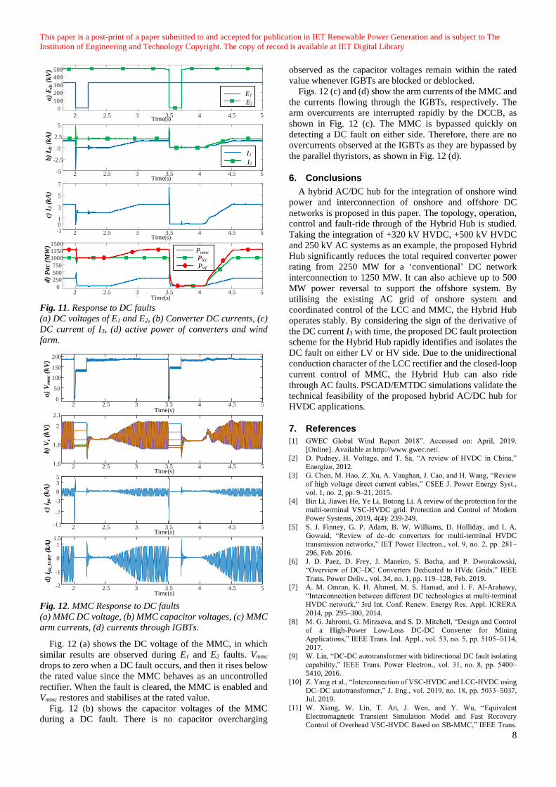
Time(s) Fig. 11. Response to DC faults
(a) DC voltages of E1 and E2, (b) Converter DC currents, (c)
DC current of I3, (d) active power of converters and wind
farm.
Fig. 12. MMC Response to DC faults
(a) MMC DC voltage, (b) MMC capacitor voltages, (c) MMC
arm currents, (d) currents through IGBTs.
Fig. 12 (a) shows the DC voltage of the MMC, in which
similar results are observed during E1 and E2 faults. Vmmc
drops to zero when a DC fault occurs, and then it rises below
the rated value since the MMC behaves as an uncontrolled
rectifier. When the fault is cleared, the MMC is enabled and
Vmmc restores and stabilises at the rated value.
Fig. 12 (b) shows the capacitor voltages of the MMC
during a DC fault. There is no capacitor overcharging
observed as the capacitor voltages remain within the rated
value whenever IGBTs are blocked or deblocked.
Figs. 12 (c) and (d) show the arm currents of the MMC and
the currents flowing through the IGBTs, respectively. The
arm overcurrents are interrupted rapidly by the DCCB, as
shown in Fig. 12 (c). The MMC is bypassed quickly on
detecting a DC fault on either side. Therefore, there are no
overcurrents observed at the IGBTs as they are bypassed by
the parallel thyristors, as shown in Fig. 12 (d).
6. Conclusions
A hybrid AC/DC hub for the integration of onshore wind
power and interconnection of onshore and offshore DC
networks is proposed in this paper. The topology, operation,
control and fault-ride through of the Hybrid Hub is studied.
Taking the integration of +320 kV HVDC, +500 kV HVDC
and 250 kV AC systems as an example, the proposed Hybrid
Hub significantly reduces the total required converter power
rating from 2250 MW for a ‘conventional’ DC network
interconnection to 1250 MW. It can also achieve up to 500
MW power reversal to support the offshore system. By
utilising the existing AC grid of onshore system and
coordinated control of the LCC and MMC, the Hybrid Hub
operates stably. By considering the sign of the derivative of
the DC current I3 with time, the proposed DC fault protection
scheme for the Hybrid Hub rapidly identifies and isolates the
DC fault on either LV or HV side. Due to the unidirectional
conduction character of the LCC rectifier and the closed-loop
current control of MMC, the Hybrid Hub can also ride
through AC faults. PSCAD/EMTDC simulations validate the
technical feasibility of the proposed hybrid AC/DC hub for
HVDC applications.
7. References
[1] GWEC Global Wind Report 2018”. Accessed on: April, 2019.
[Online]. Available at http://www.gwec.net/.
[2] D. Pudney, H. Voltage, and T. Sa, “A review of HVDC in China,”
Energize, 2012.
[3] G. Chen, M. Hao, Z. Xu, A. Vaughan, J. Cao, and H. Wang, “Review
of high voltage direct current cables,” CSEE J. Power Energy Syst.,
vol. 1, no. 2, pp. 9–21, 2015.
[4] Bin Li, Jiawei He, Ye Li, Botong Li. A review of the protection for the
multi-terminal VSC-HVDC grid. Protection and Control of Modern
Power Systems, 2019, 4(4): 239-249.
[5] S. J. Finney, G. P. Adam, B. W. Williams, D. Holliday, and I. A.
Gowaid, “Review of dc–dc converters for multi-terminal HVDC
transmission networks,” IET Power Electron., vol. 9, no. 2, pp. 281–
296, Feb. 2016.
[6] J. D. Paez, D. Frey, J. Maneiro, S. Bacha, and P. Dworakowski,
“Overview of DC–DC Converters Dedicated to HVdc Grids,” IEEE
Trans. Power Deliv., vol. 34, no. 1, pp. 119–128, Feb. 2019.
[7] A. M. Omran, K. H. Ahmed, M. S. Hamad, and I. F. Al-Arabawy,
“Interconnection between different DC technologies at multi-terminal
HVDC network,” 3rd Int. Conf. Renew. Energy Res. Appl. ICRERA
2014, pp. 295–300, 2014.
[8] M. G. Jahromi, G. Mirzaeva, and S. D. Mitchell, “Design and Control
of a High-Power Low-Loss DC-DC Converter for Mining
Applications,” IEEE Trans. Ind. Appl., vol. 53, no. 5, pp. 5105–5114,
2017.
[9] W. Lin, “DC-DC autotransformer with bidirectional DC fault isolating
capability,” IEEE Trans. Power Electron., vol. 31, no. 8, pp. 5400–
5410, 2016.
[10] Z. Yang et al., “Interconnection of VSC-HVDC and LCC-HVDC using
DC–DC autotransformer,” J. Eng., vol. 2019, no. 18, pp. 5033–5037,
Jul. 2019.
[11] W. Xiang, W. Lin, T. An, J. Wen, and Y. Wu, “Equivalent
Electromagnetic Transient Simulation Model and Fast Recovery
Control of Overhead VSC-HVDC Based on SB-MMC,” IEEE Trans.
2 2.5 3 3.5 4 4.5 50
50
100
150
200
2 2.5 3 3.5 4 4.5 51.6
1.8
2
2 2.5 3 3.5 4 4.5 5-11
-7
-3
0
35
2 2.5 3 3.5 4 4.5 5-2
-1
0
11.5
2.1Time(s)
Time(s)
Time(s)
Time(s)
a)
Vm
mc (
kV
)b)
Vc
(kV
)c)
ipa (
kA
)d
) i p
a_IG
BT (
kA
)
This paper is a post-print of a paper submitted to and accepted for publication in IET Renewable Power Generation and is subject to The
Institution of Engineering and Technology Copyright. The copy of record is available at IET Digital Library
9
Power Deliv., vol. 32, no. 2, pp. 778–788, Apr. 2017.
[12] M. Zhou, W. Xiang, W. Zuo, W. Lin, and J. Wen, “A Unidirectional
DC-DC Autotransformer for DC Grid Application,” Energies, vol. 11,
no. 3, p. 530, Mar. 2018.
[13] B. Li, X. Zhao, D. Cheng, S. Zhang, and D. Xu, “Novel Hybrid DC/DC
Converter Topology for HVDC Interconnections,” IEEE Trans. Power
Electron., vol. 34, no. 6, pp. 5131–5146, Jun. 2019.
[14] N. Ahmed, A. Haider, D. Van Hertem, L. Zhang, and H.-P. Nee,
“Prospects and challenges of future HVDC superGrids with modular
multilevel converters,” Proc. Power Electron. Appl., pp. 1–10, 2011.
[15] P. S. Jones and C. C. Davidson, “Calculation of power losses for MMC-
based VSC HVDC stations,” in 2013 15th European Conference on
Power Electronics and Applications (EPE), 2013, no. Mmc, pp. 1–10.
[16] L. Xu, L. Yao, and C. Sasse, “Grid Integration of Large DFIG-Based
Wind Farms Using VSC Transmission,” IEEE Trans. Power Syst., vol.
22, no. 3, pp. 976–984, Aug. 2007.
[17] R. Zeng, L. Xu, L. Yao, and S. J. Finney, “Analysis and Control of
Modular Multilevel Converters under Asymmetric Arm Impedance
Conditions,” IEEE Trans. Ind. Electron., vol. 63, no. 1, pp. 71–81, Jan.
2016.
[18] M. Perez, J. Rodriguez, J. Pontt, and S. Kouro, “Power Distribution in
Hybrid Multi-cell Converter with Nearest Level Modulation,” in 2007
IEEE International Symposium on Industrial Electronics, 2007, pp.
736–741.
[19] X. Yu, J. Yi, N. Wang, Y. Teng, and Q. Huang, “Analysis on Dynamic
Response of LCC-VSC Hybrid HVDC System with AC/DC Faults,” in
2018 IEEE Innovative Smart Grid Technologies - Asia (ISGT Asia),
2018, pp. 323–327.
[20] J. Häfner and B. Jacobson, “Proactive Hybrid HVDC Breakers - A key
innovation for reliable HVDC grids,” Electr. power Syst. Futur. -
Integr. supergrids microgrids Int. Symp. Bol. , Italy, p. 9, 2011.
[21] W. Xiang, S. Yang, L. Xu, J. Zhang, W. Lin, and J. Wen, “A Transient
Voltage-Based DC Fault Line Protection Scheme for MMC-Based DC
Grid Embedding DC Breakers,” IEEE Trans. Power Deliv., vol. 34, no.
1, pp. 334–345, Feb. 2019.
[22] X. Li, Q. Song, W. Liu, H. Rao, S. Xu, and L. Li, “Protection of
nonpermanent faults on DC overhead lines in MMC-based HVDC
systems,” IEEE Trans. Power Deliv., vol. 28, no. 1, pp. 483–490, 2013.
[23] W. Xiang, R. Yang, C. Lin, J. Zhou, J. Wen, and W. Lin, “A Cascaded
Converter Interfacing Long Distance HVDC and Back-to-Back HVDC
Systems,” IEEE J. Emerg. Sel. Top. Power Electron., vol. PP, no. c, pp.
1–1, 2019.
[24] M. Szechtman, T. Wess, and C. V. Thio, “Benchmark model for HVDC
system studies,” IEE Conf. Publ., no. 345, pp. 374–378, 1991.
[25] Y. Zhou, D. Jiang, J. Guo, P. Hu, and Y. Liang, “Analysis and Control
of Modular Multilevel Converters Under Unbalanced Conditions,”
IEEE Trans. Power Deliv., vol. 28, no. 4, pp. 1986–1995, Oct. 2013.
[26] J. W. Moon, J. W. Park, D. W. Kang, and J. M. Kim, “A Control
Method of HVDC-Modular Multilevel Converter Based on Arm
Current under the Unbalanced Voltage Condition,” IEEE Trans. Power
Deliv., vol. 30, no. 2, pp. 529–536, 2015.


![Open-source software for HVDC control and protection...IET ACDC, Manchester, 14–16 Feb. 2017. [7] H. Saad et al., “On Resonances and Harmonics in HVDC-MMC Station Connected to](https://img.pdfslide.us/doc/110x75/5f65601e0898633a515e41d8/open-source-software-for-hvdc-control-and-protection-iet-acdc-manchester-14a16.jpg)