Embed Size (px)
Citation preview
HTS Magnets for Accelerator Applications
K. Hatanaka [email protected]
Research Center for Nuclear Physics
Osaka University
8th International Particle Accelerator Conference Bella Center, Copenhagen, Denmark May 17, 2017
1. Introduction 2. High Temperature Superconducting (HTS) wire 3. Development of HTS magnets at RCNP Models: ECR mirror coil Scanning magnet Superferic dipole magnet with bana-shaped coil Magnets for practical use: UCN polarizer Beam line switching magnet design and performance hysteresis loss of HTS coil 4. Summary
Outline

Motivations to develop HTS magnets Compact system
Beam line, Gantry for particle therapy, Accelerators
Low power consumption system
Advantages over LTS system No liquid helium is required Cooled by conduction to cryo-coolers Operating temperature can be 20 K or higher Cryogenic components become simpler Cooling power of refrigerators is much larger Temperature range for superconductivity is wider AC and pulsed magnets may be possible.
HTS materials
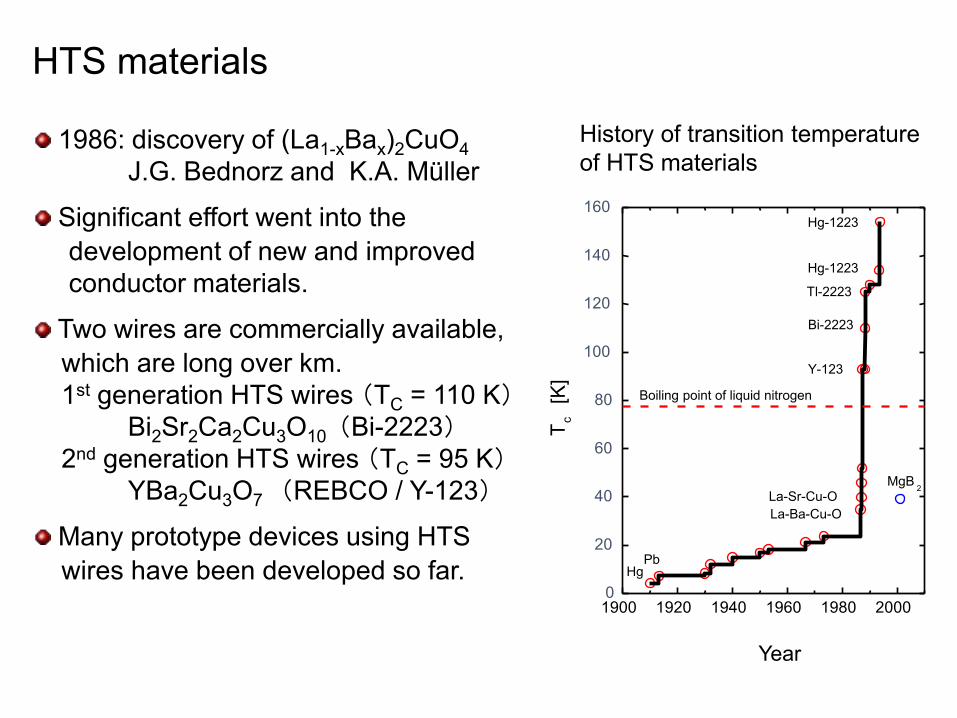
1986: discovery of (La1-xBax)2CuO4 J.G. Bednorz and K.A. Müller
Significant effort went into the development of new and improved conductor materials.
Two wires are commercially available, which are long over km. 1st generation HTS wires (TC = 110 K) Bi2Sr2Ca2Cu3O10 (Bi-2223) 2nd generation HTS wires (TC = 95 K) YBa2Cu3O7 (REBCO / Y-123)
Many prototype devices using HTS wires have been developed so far.
History of transition temperature of HTS materials
1900 1920 1940 1960 1980 2000 0
20
40
60
80
100
120
140
160
Boiling point of liquid nitrogen
MgB 2
Hg-1223
Hg-1223
Tl-2223
Bi-2223
Y-123
La-Sr-Cu-O La-Ba-Cu-O
Pb Hg
T c [K
]
year Year
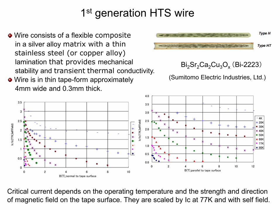
Wire consists of a flexible composite
in a silver alloy matrix with a thin stainless steel (or copper alloy) lamination that provides mechanical stability and transient thermal conductivity.
Wire is in thin tape-form approximately 4mm wide and 0.3mm thick.
1st generation HTS wire
Bi2Sr2Ca2Cu3Ox (Bi-2223) (Sumitomo Electric Industries, Ltd.)
Critical current depends on the operating temperature and the strength and direction of magnetic field on the tape surface. They are scaled by Ic at 77K and with self field.

A scanning magnet
80 mrad deflection
x
y
z
By-coils
Bx-coils
• Scanning magnet consists of two sets of two racetrack-type coils.
• Each coil is built by stacking three double pancakes.
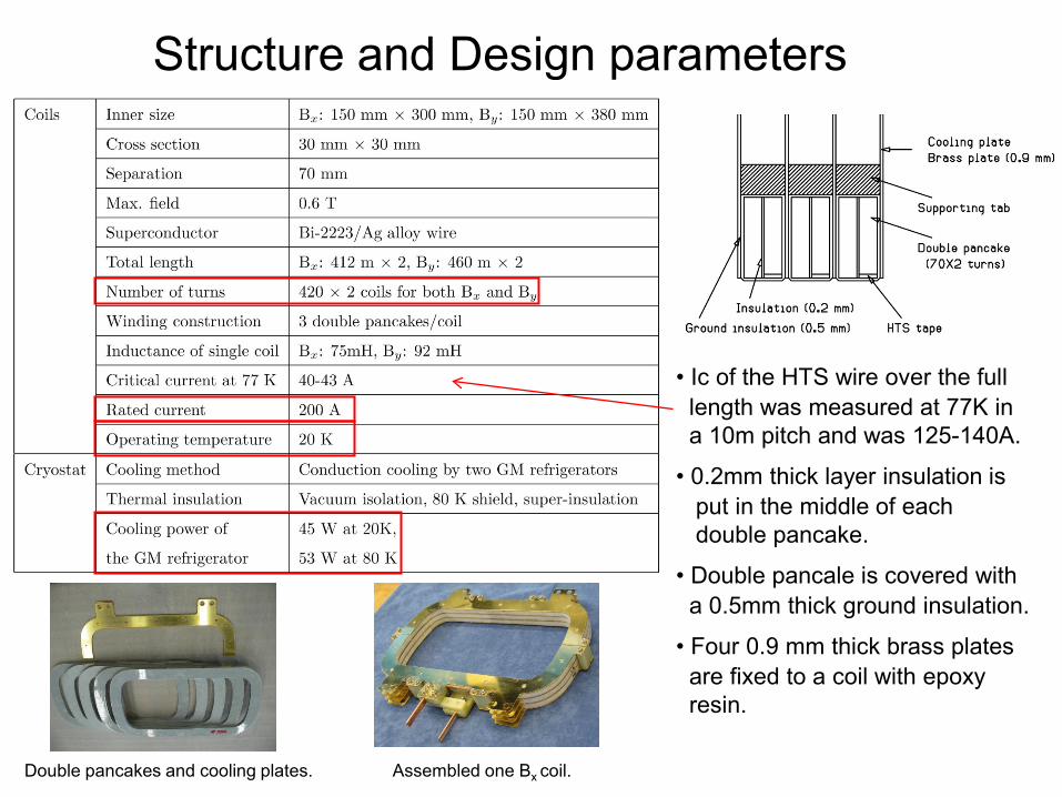
Structure and Design parameters
• Ic of the HTS wire over the full length was measured at 77K in a 10m pitch and was 125-140A.
• 0.2mm thick layer insulation is put in the middle of each double pancake.
• Double pancale is covered with a 0.5mm thick ground insulation.
• Four 0.9 mm thick brass plates are fixed to a coil with epoxy resin.
Double pancakes and cooling plates. Assembled one Bx coil.
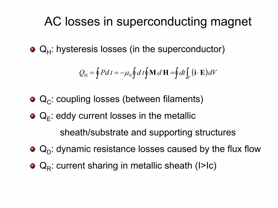
QH: hysteresis losses (in the superconductor)
QC: coupling losses (between filaments)
QE: eddy current losses in the metallic
sheath/substrate and supporting structures
QD: dynamic resistance losses caused by the flux flow
QR: current sharing in metallic sheath (I>Ic)
AC losses in superconducting magnet
( )dVdtdtdtPdQV∫ ∫ ∫∫∫ ⋅=−== EiHM0H µ

AC losses per cycle of HTS conductors
• • • • •
2IQD ∝
43−∝ IQH
2IfQE ⋅∝
2IQR ∝
2IfQC ⋅∝
So far studies have been limited to such simple structures as tapes, cables and simple coils in both experimental and theoretical points of view.

AC losses at 20 K Comparison with calculations
Data
FEM results at 15 Hz
by Brandt et al.,
Normalized at 50 A
Loss per cycle
4.2I∝
2If ⋅∝
Independent on f
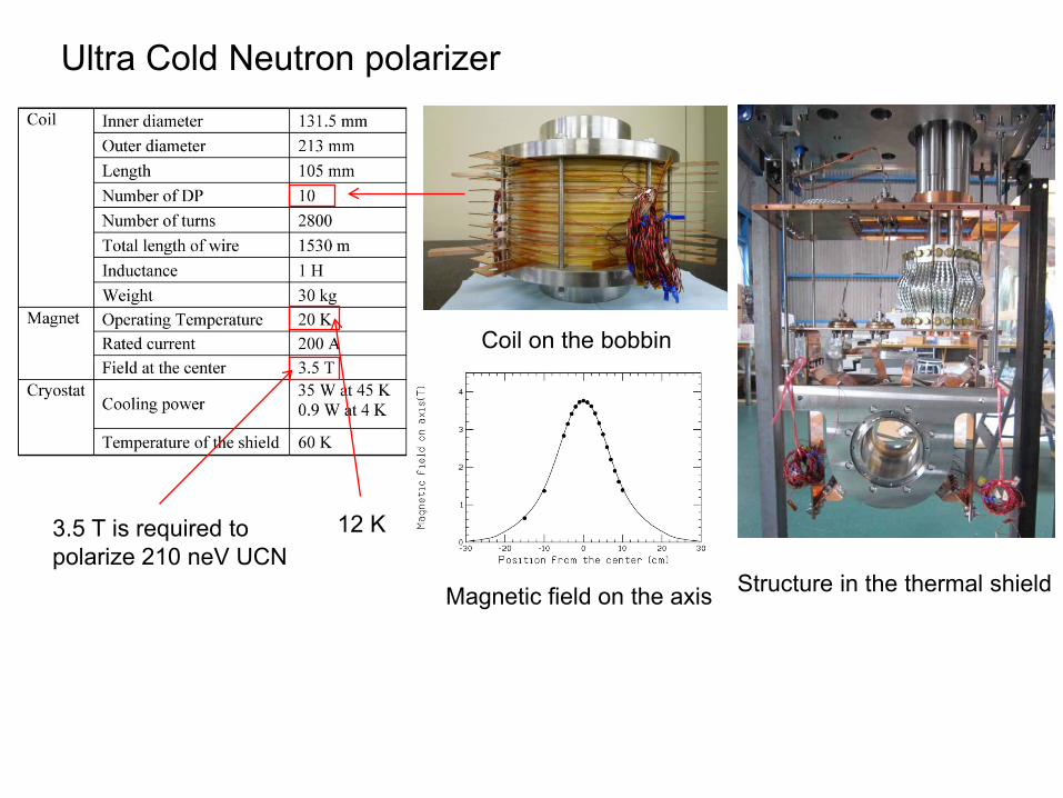
Ultra Cold Neutron polarizer
Coil on the bobbin
3.5 T is required to polarize 210 neV UCN
Magnetic field on the axis
12 K
Structure in the thermal shield
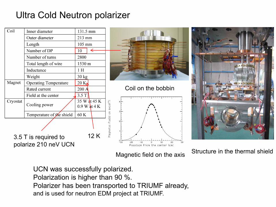
Ultra Cold Neutron polarizer
Coil on the bobbin
3.5 T is required to polarize 210 neV UCN
Magnetic field on the axis
12 K
Structure in the thermal shield
UCN was successfully polarized. Polarization is higher than 90 %. Polarizer has been transported to TRIUMF already, and is used for neutron EDM project at TRIUMF.

Dipole magnet for beamline switching
A-A’ Cross Section
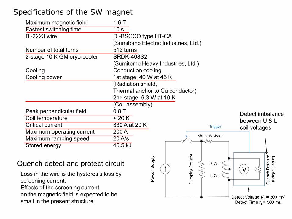
Maximum magnetic field 1.6 T Fastest switching time 10 s Bi-2223 wire DI-BSCCO type HT-CA (Sumitomo Electric Industries, Ltd.) Number of total turns 512 turns 2-stage 10 K GM cryo-cooler SRDK-408S2 (Sumitomo Heavy Industries, Ltd.) Cooling Conduction cooling Cooling power 1st stage: 40 W at 45 K (Radiation shield, Thermal anchor to Cu conductor) 2nd stage: 6.3 W at 10 K (Coil assembly) Peak perpendicular field 0.8 T Coil temperature < 20 K Critical current 330 A at 20 K Maximum operating current 200 A Maximum ramping speed 20 A/s Stored energy 45.5 kJ
Specifications of the SW magnet
Quench detect and protect circuit Loss in the wire is the hysteresis loss by screening current. Effects of the screening current on the magnetic field is expected to be small in the present structure.
Detect imbalance between U & L coil voltages
1.E-10
1.E-09
1.E-08
1.E-07
1.E-06
1 10 100Volta
ge p
er le
ngth
(V/c
m)
Current (A)
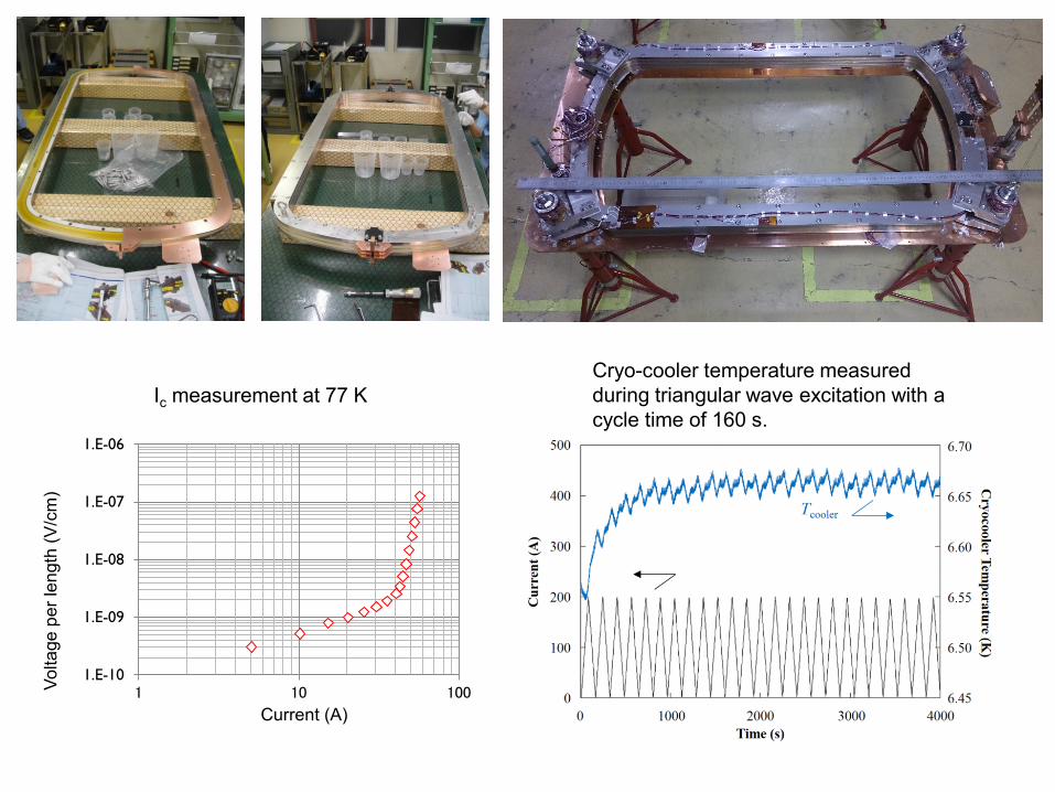
Ic measurement at 77 K Cryo-cooler temperature measured during triangular wave excitation with a cycle time of 160 s.
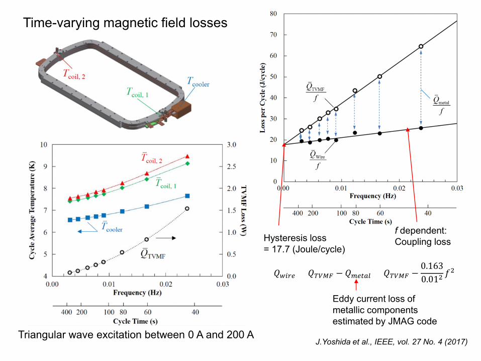
Time-varying magnetic field losses
𝑄𝑄𝑤𝑤𝑤𝑤𝑤𝑤𝑤𝑤 = 𝑄𝑄𝑇𝑇𝑇𝑇𝑇𝑇𝑇𝑇 − 𝑄𝑄𝑚𝑚𝑤𝑤𝑚𝑚𝑚𝑚𝑚𝑚 = 𝑄𝑄𝑇𝑇𝑇𝑇𝑇𝑇𝑇𝑇 −0.1630.012 𝑓𝑓
2
Hysteresis loss = 17.7 (Joule/cycle)
f dependent: Coupling loss
Eddy current loss of metallic components estimated by JMAG code
J.Yoshida et al., IEEE, vol. 27 No. 4 (2017) Triangular wave excitation between 0 A and 200 A

10 90 8 100
160 A 200 A
2
8 94 8 100 Time(s)
160 A
2
Current Current
Time(s)
Pattern operation
Current sweep reversal excitation (Cycling)
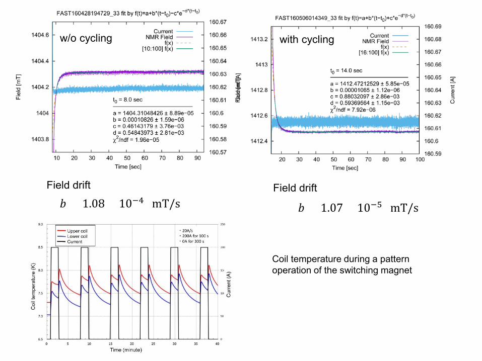
w/o cycling
𝑏𝑏 = 1.08 × 10⁻⁴ (mT/s)
with cycling
𝑏𝑏 = 1.07 × 10⁻⁵ (mT/s)
Coil temperature during a pattern operation of the switching magnet
Field drift Field drift
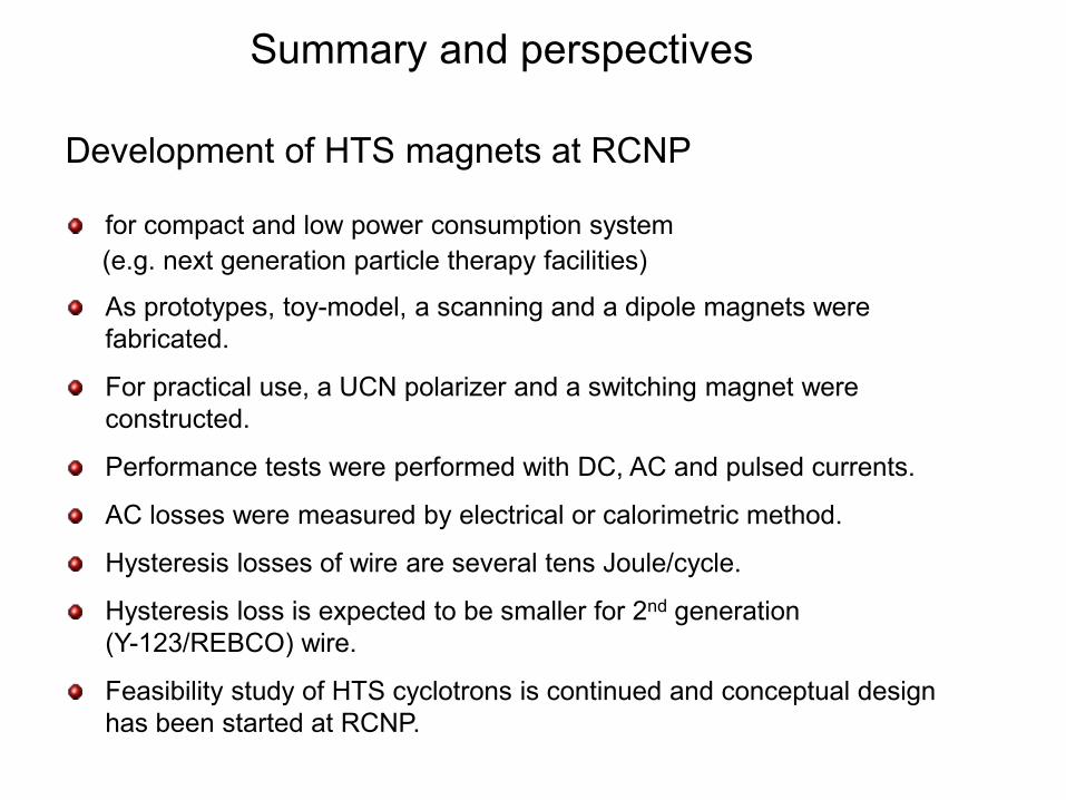
Summary and perspectives
Development of HTS magnets at RCNP
for compact and low power consumption system (e.g. next generation particle therapy facilities)
As prototypes, toy-model, a scanning and a dipole magnets were fabricated.
For practical use, a UCN polarizer and a switching magnet were constructed.
Performance tests were performed with DC, AC and pulsed currents.
AC losses were measured by electrical or calorimetric method.
Hysteresis losses of wire are several tens Joule/cycle.
Hysteresis loss is expected to be smaller for 2nd generation (Y-123/REBCO) wire.
Feasibility study of HTS cyclotrons is continued and conceptual design has been started at RCNP.
Collaborators
RCNP: M. Fukuda, T. Yorita, H. Ueda, J. Nakagawa, N. Izumi, T. Saito, H. Tamura, Y. Yasuda, M. Nakao, K. Kamakura, N. Hamatani, S. Hara
Tohoku U.: Y. Sakemi
Kyushu U.: T. Wakasa
NIRS: K. Noda
KT Science: T. Kawaguchi
SHI: J. Yoshida, T. Morie, A. Hashimoto, H. Mitsubori,
Y. Mikami, K. Watazawa
Thank you for your attention