Embed Size (px)
Citation preview

H604
Solid
Car
bide
Drill
sCo
mbi
natio
nTo
ols
Mod
ular
Dril
lsIn
dexa
ble
Drill
sQP
VDr
ills
Twist
Dril
ls/Ta
ps &
Dies
Coun
terb
orin
gTo
ols
Rota
ting
Borin
gTo
ols
Hole
mak
ing
Tech
Dat
aSp
ecia
l Too
ling/
Adap
ters
Tool
hold
ing
Syste
ms
Inde
x
HTS-C Indexable DrillsTroubleshooting Guide for HTS-C Drills
On lathes:
pilot drill cracking • Verify that the tool is centered correctly.Readjust machine, if necessary.
• Check clamping accuracy (tool and workpiece) for possible improvement.
• Use pilot drill B503 in HSS grade AS3.
inner insert cracking • Use tougher carbide grade.
• Reduce feed by 20%.
• Check clamping accuracy (tool and workpiece) for possible improvement.
outer insert cracking • Use tougher carbide grade and/or stronger insert geometry.
• Reduce feed by 20%.
• When drilling through, reduce feed by 50%.
• Check clamping accuracy (tool and workpiece)for possible improvement.
extensive pilot drill wear • Use coated carbide pilot drill B504 in grade CS3.
• Increase coolant pressure and volume.
• Reduce cutting speed by 20%.
problem solution

H605
Solid
Car
bide
Drill
sCo
mbi
natio
nTo
ols
Mod
ular
Dril
lsIn
dexa
ble
Drill
sQP
VDr
ills
Twist
Dril
ls/Ta
ps &
Dies
Coun
terb
orin
gTo
ols
Rota
ting
Borin
gTo
ols
Hole
mak
ing
Tech
Dat
aSp
ecia
l Too
ling/
Adap
ters
Tool
hold
ing
Syste
ms
Inde
x
On lathes:
excessive insert wear • Use a more wear-resistant carbide grade.
• Increase coolant pressure and volume.
• Reduce cutting speed by 20%.
chip breaking not optimal • Optimize chip control for given application.
• Increase cutting speed by 20%; reduce feed by 20%.
chip evacuation not optimal, • Increase coolant pressure and volume.poor drill hole quality
• Increase cutting speed by 20%.
HTS-C Indexable DrillsTroubleshooting Guide for HTS-C Drills
problem solution

H606
Solid
Car
bide
Drill
sCo
mbi
natio
nTo
ols
Mod
ular
Dril
lsIn
dexa
ble
Drill
sQP
VDr
ills
Twist
Dril
ls/Ta
ps &
Dies
Coun
terb
orin
gTo
ols
Rota
ting
Borin
gTo
ols
Hole
mak
ing
Tech
Dat
aSp
ecia
l Too
ling/
Adap
ters
Tool
hold
ing
Syste
ms
Inde
x
HTS-C Indexable DrillsCutting Forces — KDDH and HTS-C Series Drills
Power: This chart is based on machining experiences using steels with a hardness of 200-250 HB, and on a cutting speed of 350 sfm.
Coolant Application: Efficient cooling of HTS-C drills is ensured byan internal coolant capability.
recommended coolant: emulsion 6-8%
minimum coolant pressure: stationary drill 30 psi
rotating drill 90 psi
catalog number gradeincluded
angleA
primary relief angle
B
chisel angle
C
gash angle
D
web thickness
E
gash depth
F
B504S04000 G13 130° 14° 58° ± 3° 20° ± 2° .0118 - .004 .0196 ± .004
B504S05000 G13 130° 14° 58° ± 3° 20° ± 2° .0114 ± .004 .0224 ± .004
B504S06000 G13 130° 14° 58° ± 3° 20° ± 2° .0129 ± .004 .0129 ± .004
B504S08000 G13 130° 14° 58° ± 3° 20° ± 2° .0196 ± .004 .0338 ± .004
B504S10000 G13 130° 14° 58° ± 3° 20° ± 2° .0267 ± .004 .0452 ± .004
B504S04000 CS3 130° 14° 58° ± 3° 20° ± 2° .0118 - .004 .0196 ± .004
B504S05000 CS3 130° 14° 58° ± 3° 20° ± 2° .0114 ± .004 .0224 ± .004
B504S06000 CS3 130° 14° 58° ± 3° 20° ± 2° .0129 ± .004 .0129 ± .004
B504S08000 CS3 130° 14° 58° ± 3° 20° ± 2° .0196 ± .004 .0338 ± .004
B504S10000 CS3 130° 14° 58° ± 3° 20° ± 2° .0267 ± .004 .0452 ± .004
HTS-C Pilot Drill Repointing Data

H607
Solid
Car
bide
Drill
sCo
mbi
natio
nTo
ols
Mod
ular
Dril
lsIn
dexa
ble
Drill
sQP
VDr
ills
Twist
Dril
ls/Ta
ps &
Dies
Coun
terb
orin
gTo
ols
Rota
ting
Borin
gTo
ols
Hole
mak
ing
Tech
Dat
aSp
ecia
l Too
ling/
Adap
ters
Tool
hold
ing
Syste
ms
Inde
x
HTS Deep-Hole Drilling SystemThe HTS Advantage
The HTS modular drilling system is the most effective deep-holedrilling system of its kind for drilling into solid workpieces. HTSdrills can drill as deep as 8x diameter and greater, while still maintaining accuracy and stability.
This deep hole capability is possible because of the system’sexclusive HSS pilot drill design. By precutting and then remainingconstantly in the cut, the pilot drill provides excellent guiding andcentering of the drill head, even at greater depths.
This type of centering and stability is not possible with conventionaldrills. A standard 2x diameter drill loses 60 percent of its stabilitywhen extended to 3x diameter, and 80 percent of stability ifextended to 4x diameter. Carbide guides and stronger helix anglesmay offer individual solutions for specific applications, but these will always be expensive special tools.
With the modular design of the HTS system, you can constructdifferent drilling combinations from a variety of standard components. Cartridges can be modified to produce specific diameters within the limits of each head and can be replacedquickly with a single mounting screw.
Trigon indexable carbide inserts provide a smooth entry into thecut and are accurately located in fixed pockets. The internalcoolant supply of the HTS system cools the cutting edges andassists chip evacuation. Also, the combination of the short drillinghead with a smaller diameter shaft offers minimum resistance tochip flow, regardless of drilling depths.
Use the guidelines in this technical section to optimize the performance of HTS in your shop.
The HTS coupling features a drive ring and two clamp screws.This design ensures a secure and stable connection between individual components of the modular system.
Application Example – Special Drillmaterial: 1020 steel (ST52/2)
task: holes (ø — 244 mm x 680 mm)
tool: HTS special
cutting speed: 410 sfm (130 m/min)
feed: .007 ipr (0,18 mm/rev)
power consumption: 80 hp
cutting time: 22 min./hole
result: high-production safety, low costs
H608
Solid
Car
bide
Drill
sCo
mbi
natio
nTo
ols
Mod
ular
Dril
lsIn
dexa
ble
Drill
sQP
VDr
ills
Twist
Dril
ls/Ta
ps &
Dies
Coun
terb
orin
gTo
ols
Rota
ting
Borin
gTo
ols
Hole
mak
ing
Tech
Dat
aSp
ecia
l Too
ling/
Adap
ters
Tool
hold
ing
Syste
ms
Inde
x
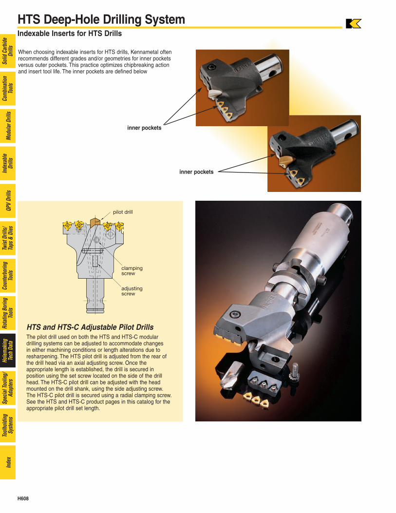
HTS and HTS-C Adjustable Pilot DrillsThe pilot drill used on both the HTS and HTS-C modulardrilling systems can be adjusted to accommodate changes in either machining conditions or length alterations due toresharpening. The HTS pilot drill is adjusted from the rear ofthe drill head via an axial adjusting screw. Once the appropriate length is established, the drill is secured in position using the set screw located on the side of the drillhead. The HTS-C pilot drill can be adjusted with the headmounted on the drill shank, using the side adjusting screw.The HTS-C pilot drill is secured using a radial clamping screw.See the HTS and HTS-C product pages in this catalog for theappropriate pilot drill set length.
HTS Deep-Hole Drilling SystemIndexable Inserts for HTS Drills
When choosing indexable inserts for HTS drills, Kennametal oftenrecommends different grades and/or geometries for inner pocketsversus outer pockets. This practice optimizes chipbreaking actionand insert tool life. The inner pockets are defined below
inner pockets
inner pockets

H609
Solid
Car
bide
Drill
sCo
mbi
natio
nTo
ols
Mod
ular
Dril
lsIn
dexa
ble
Drill
sQP
VDr
ills
Twist
Dril
ls/Ta
ps &
Dies
Coun
terb
orin
gTo
ols
Rota
ting
Borin
gTo
ols
Hole
mak
ing
Tech
Dat
aSp
ecia
l Too
ling/
Adap
ters
Tool
hold
ing
Syste
ms
Inde
x
HTS Deep-Hole Drilling SystemApplication Guidelines — HTS Drills
CAUTION
During through-hole operations, a slug or disc is produced as thetool breaks through the workpiece. When the drill is stationary andthe workpiece is rotating, this slug may be hurled from the chuckby centrifugal force. Provide adequate shielding to protect allbystanders.
*When drilling through, a small shoulder will be produced on breakthrough asthe pilot drill is no longer cutting.
incorrect correct
incorrect correct
incorrect correct
spot drilling For plain/straight surfaces, no spot drilling is required. Spot drilling isrecommended when using HTS at a long L/D ratio, especially for horizontal applications. In this case, the center drill diameter should beconsiderably smaller than the pilot drill diameter.
spot drilling and drilling through* on inclined surfacesSpot drilling on inclined surfaces is not possible. A pre-facing operationis required for spot drilling and drilling through on inclined surfaces.
multi-stage drill holeHTS drills are not recommended for boring operations. First, use theHTS drill to drill a larger diameter hole. Then, use a solid carbideDynapoint drill, KSEM, or HTS-C drill to drill the smaller holes.
drilling of stacked platesNot possible with HTS drills–a final disc forms when the drill breaks through.

H610
Solid
Car
bide
Drill
sCo
mbi
natio
nTo
ols
Mod
ular
Dril
lsIn
dexa
ble
Drill
sQP
VDr
ills
Twist
Dril
ls/Ta
ps &
Dies
Coun
terb
orin
gTo
ols
Rota
ting
Borin
gTo
ols
Hole
mak
ing
Tech
Dat
aSp
ecia
l Too
ling/
Adap
ters
Tool
hold
ing
Syste
ms
Inde
x
HTS Deep-Hole Drilling SystemTroubleshooting Guide for HTS Drills
On lathes:
pilot drill cracking • Verify that the tool is centered correctly. Readjust machine, if necessary.
• Check clamping accuracy (tool and workpiece) for possible runout.
insert cracking • Use tougher carbide grade.
• Check clamping accuracy (tool and workpiece) for possible runout.
excessive insert wear • Use coated pilot drill AS3.
• Increase coolant pressure and volume.
• Reduce speed by 20%.
chip breaking not optimal • Optimize chip control for given application.
• Increase cutting speed by 20%; reduce feed by 20%.
chip evacuation not optimal, • Increase coolant pressure and volume.poor hole quality
• Increase cutting speed by 20%.
problem solution

H611
Solid
Car
bide
Drill
sCo
mbi
natio
nTo
ols
Mod
ular
Dril
lsIn
dexa
ble
Drill
sQP
VDr
ills
Twist
Dril
ls/Ta
ps &
Dies
Coun
terb
orin
gTo
ols
Rota
ting
Borin
gTo
ols
Hole
mak
ing
Tech
Dat
aSp
ecia
l Too
ling/
Adap
ters
Tool
hold
ing
Syste
ms
Inde
x
HTS Deep-Hole Drilling SystemAdjusting the HTS Drill Diameter
The HTS deep-hole drilling system offers a precise method of adjustingthe hole diameter. The cartridges supplied with each HTS system aredesigned to cut the largest diameter in its range.
To adjust the HTS cutting diameter, make a trial cut, calculate theadjustment needed, remove the outer cartridge and grind off one-half of the difference obtained by the calculation of the cut diameter to therequired diameter.
Example: If the standard drill cuts 3.400" and the required diameter is3.350", the difference is .050. Grind .025 from the inner side of theouter cartridge.
Caution must be taken when altering a cartridge. It’s critical that thechamfers are reground on the cartridge. If the chamfers are not ground,the cartridge will not seat properly in the pocket; thus the tool will notcut the correct diameter.
* Change drill diameter by adjusting the outercartridge. The outer cartridge is bolted to the headand can be shortened to drill smaller diameters.
* Shorten at 90° to the contact face “A” and the support face “B”.
* Shortening reduces the effective drill diameter bydouble the length removed.
inner outer
HTS Pilot Drill Repointing Data
catalog number grade
included angle
A
primary relief angle
B
chisel angle
C
width ofprimary
reliefD
gashangle
E
webthickness
F
gash depth
G
gashthickness
H
B510S08000 AS3 118° 8° + 2° 55° ± 3° .0275 ± .004 20° - 2° .0196 ± .004 .0314 ± .004 .0098 ± .002B510S10000 AS3 118° 8° + 2° 55° ± 3° .0314 ± .004 20° - 2° .0236 ± .004 .0393 ± .004 .0118 ± .002B510S15000 AS3 118° 8° + 2° 55° ± 3° .0433 ± .004 20° - 2° .0354 ± .004 .0590 ± .004 .0177 ± .002B510S20000 AS3 118° 8° + 2° 55° ± 3° .0551 ± .004 20° - 2° .0472 ± .004 .0787 ± .004 .0236 ± .002B510S25000 AS3 118° 8° + 2° 55° ± 3° .0629 ± .004 20° - 2° .0590 ± .004 .0984 ± .004 .0291 ± .004B510S30000 AS3 118° 8° + 2° 55° ± 3° .0708 ± .004 20° - 2° .0708 ± .001 .1181 ± .001 .0354 ± .004B510S08000 A30 118° 8° + 2° 55° ± 3° .0275 ± .004B510S10000 A30 118° 8° + 2° 55° ± 3° .0314 ± .004B510S15000 A30 118° 8° + 2° 55° ± 3° .0433 ± .004B510S20000 A30 118° 8° + 2° 55° ± 3° .0551 ± .004B510S25000 A30 118° 8° + 2° 55° ± 3° .0629 ± .004B510S30000 A30 118° 8° + 2° 55° ± 3° .0708 ± .004
AS3 grade A30 grade

H612
Solid
Car
bide
Drill
sCo
mbi
natio
nTo
ols
Mod
ular
Dril
lsIn
dexa
ble
Drill
sQP
VDr
ills
Twist
Dril
ls/Ta
ps &
Dies
Coun
terb
orin
gTo
ols
Rota
ting
Borin
gTo
ols
Hole
mak
ing
Tech
Dat
aSp
ecia
l Too
ling/
Adap
ters
Tool
hold
ing
Syste
ms
Inde
x
HTS Deep-Hole Drilling SystemCutting Forces — HTS Drills
Power: These charts are based on machining experiences usingsteels with a hardness of 200-250 HB, and on a cutting speed of 350 sfm.
Coolant Application: HTS drills must always be applied with coolant lubricant. The higher the coolant rate, the better the drilling performance.