Embed Size (px)
Citation preview

Features 190 to 400V DC Input Range Up to 55W Output Power 22V, 2.5A Rated Output Voltage and Current Internal EMI Filter Magnetically Coupled Feedback 80% Minimum Efficiency 20°C to +165°C continuous with transient up to +175°C 100M @ 500V DC Isolation Under-Voltage Lockout Short Circuit and Overload Protection Output Over Voltage Limiter Adjustable Output Voltage within 10% of nominal Synchronization Input and Output External Inhibit Low Weight, < 70grams
HIGH RELIABILITY DC-DC CONVERTER
HTH27022S
Description The HTH27022S is a single output 55W DC-DC converter designed to operate in extremely high temperature environments such as those encountered in oil exploration. Features include small size, low weight and high tolerance to environmental stresses such as wide wide temperature extremes, severe shock and vibration. All internal components and assembly processes have been selected and developed to ensure reliable performance in the intended operating environments. The converter incorporates a fixed frequency forward topology with magnetic feedback and internal EMI filter. It also includes an external inhibit port and have an adjustable output voltage. It is enclosed in a hermetic 4.0" x 2.15" x 0.40" (3.5"x1.5"x0.40"H excluding mounting tabs and I/O pins) AlSi package and weighs less than 70 grams. The package utilizes rugged ceramic feed-thru, copper-cored pins and is sealed using laser welding. Full environmental screening includes temperature cycling, constant acceleration, fine and gross leak, and burn-in. Please refer to Device Screening table. Variations in electrical specifications and screening to meet custom requirements can be accommodated
1 2016-06-30
PD-97815A
165°C, 270V Input, 55W, 22V, Single Output
Applications Down Hole Exploration Tools
HTH
Circuit Description The HTH27022S converter utilizes an enhanced forward topology with two power switches and resonant reset. The nominal switching frequency is 520 kHz. Electrical isolation and tight output regulation are achieved through the use of a magnetically coupled feedback. Voltage feed-forward with duty factor limiting provides high line rejection and protection against output over voltage due to certain component failures in the internal control loop. This mechanism limits the maximum output voltage to approximately 20% over the nominal regardless of the line voltage with an output load that is 25% of the full rated output power. Output current is limited under load fault conditions to approximately 125% of the rating. An overload condition causes the converter output to behave like a constant current source with the output voltage dropping below nominal. The converter will resume normal operation when the load current is reduced below the current limit point. This protects the converter from both overload and short circuit conditions. The current limit point exhibits a slightly negative temperature coefficient to reduce the possibility of thermal runaway.
An external inhibit port (Pin 4) is provided to control converter operation. The converter’s operation is inhibited when this pin is pulled low. It is designed to be driven by an open collector logic device. The pin may be left open for normal operation and has a nominal open circuit voltage of 4V with respect to the input return (Pin 2). The output voltage of all models can be adjusted using a single external resistor within ±10% of nominal output voltage.

HTH27022S 165°C, 270V Input, 55W, 22V Single Output
2 2016-06-30
Specifications Absolute Maximum Ratings Recommended Operating Conditions Input Voltage range -0.5VDC to +400VDC Input Voltage range 190VDC to 400VDC Output power Internally limited Output power 0 to Max. Rated Lead Temperature +300°C for 10 seconds Operating temperature -20°C to +165°C Operating Case temperature -20°C to +175°C Storage temperature
Storage temperature -55°C to +175°C
-20°C to +165°C
Electrical Performance Characteristics
For Notes to Electrical Performance Characteristics Table, refer to page 4
Parameter Group A Subgroup
Conditions -20°C TC +165°C
VIN = 270V DC ± 5%, CL = 0 unless otherwise specified
Limits
Unit Min Nom Max
Input Voltage 1,2,3 Guaranteed to turn on 190 270 400 V
Output Power (POUT) 1,2,3 VIN = 190, 270, 400 Volts, Note 2 0 55 W
Output Current (IOUT) 1,2,3 VIN = 190, 270, 400 Volts, Note 2 0 2.5 A
Line Regulation (VRLINE) 1,2,3 VIN = 190, 270, 400 Volts, Notes 1, 4
IOUT = 10, 50, 100% Rated Load -120 120 mV
Load Regulation (VRLOAD) 1,2,3 VIN = 190, 270, 400 Volts, Notes 1, 4
IOUT = 10, 50, 100% Rated Load -220 220 mV
Input Current, No Load (IIN) 1,2,3 IOUT = 0. Pin 4 open 15 mA
Input Ripple Current 1,2,3 IOUT = 100% Rated Load, BW=10MHz 100 mAp-p
Input Current Inhibited 1,2,3 Pin 4 shorted to pin 2 5.0 mA
Input Under Voltage Lockout
Turn-on (Input Voltage Rising)
Turn-off (Input Voltage Decreasing)
1,3
2
1,2,3
Min Load, Note 1
160
160
135
180
190
160 V
Output Ripple (VRIP) 1,2,3 VIN = 190, 270, 400 Volts, Notes 1, 3
IOUT = 10%, 100% Rated Load 120 mVp-p
Efficiency (EFF) 1,2,3 IOUT = 100% Rated Load , Note 1 80 84 %
Switching frequency (FS) 1,2,3 Sync. Input (Pin 6) open 470 580 kHz
Synchronization Input Frequency Range Pulse Amplitude, High Pulse Amplitude, Low Pulse Rise Time Pulse Duty Cycle
1,2,3 1,2,3 1,2,3 1,2,3 1,2,3
Notes 1, 12
500 4.0 -0.5
20
600 10 0.8 100 80
kHz V V ns %
Output Voltage (VOUT) 1,2,3 IOUT = 100% rated load Note 1 21.34 22.66 V

HTH27022S 165°C, 270V Input, 55W, 22V Single Output
3 2016-06-30
Electrical Performance Characteristics (continued)
For Notes to Electrical Performance Characteristics Table, refer to page 4
Parameter
Group A Subgroup
Conditions
-20°C TC +165°C VIN = 270V DC ± 5%, CL = 0 unless otherwise specified
Limits
Unit Min
Nom
Max
Enable Input (Inhibit Function) Open Circuit Voltage Drive Current (Sink) Voltage Range
1,2,3 Note 1, 12
3.0 -0.5
5.0 100 50
V A V
Current Limit Point Expressed as a percentage of Full Rated Output Power
1,2,3 VOUT = 90% of Nominal
105
150
%
Power Dissipation, Load Fault (PD) 1,2,3 Short Circuit, Overload Note 7
30 W
Load Transient Response Amplitude Recovery
Amplitude Recovery
4,5,6
4,5,6
Load Step, 50% to/from 100%
Notes 1, 8
Load Step, 10% to/from 50% Notes 1, 8
-1200
-1200
+1200
400
+1200 400
mV µs
mV µs
Line Transient Response Amplitude Recovery 4,5,6
Input Voltage Step, 190V to/from 400V
IOUT = 100% rated load Notes 1, 9, 10
-500
+500 400
mV µs
Turn-on Response Overshoot (VOS) Turn-on Delay (TDLY)
4,5,6
Vin = 190V, 270V, 400V IOUT = 50% rated load
Notes 1, 11
5.0
500 60
mV ms
Capacitive Load (CL)
1
IOUT = 100% rated load No effect on DC performance
Notes 1, 5, 6, 12
1000
µF
Line Rejection 1 MIL-STD-461, CS101 30Hz to 50kHz, Note 1, 12
40 60
dB
Isolation 1 Input to Output or Any Pin to Case except pin 3, test @ 500VDC
100
M
Device Weight
70 g

HTH27022S 165°C, 270V Input, 55W, 22V Single Output
4 2016-06-30
Fig 1. Circuit for Measuring Output Ripple Voltage
Notes for Electrical Performance Characteristics Table 1. Unless otherwise specified, “Rated” load is 55 watts, 2.5 Amps. 2. Parameter verified during line and load regulation tests. 3. Guaranteed for a D.C. to 20 MHz bandwidth. Tested using a 10 kHz to 10 MHz bandwidth. 4. Load is varied for output under test. Regulation relative to output voltage at 50% rated load. 5. Capacitive load may be any value from 0 to the maximum limit without compromising dc performance. 6. A capacitive load in excess of the maximum limit may interfere with the proper operation of the converter’s overload protection, causing erratic behavior during turn-on. 7. Overload power dissipation is defined as the device power dissipation with the load set such that VOUT= 90% of nominal. 8. Load step transition time 10s. 9. Recovery time is measured from initiation of the transient to where VOUT has returned to within ±1% of steady state value. 10. Line step transition time 100s. 11. Turn-on delay time from either a step application of input power or a logic low to a logic high transition on the inhibit pin to the point where VOUT = 90% of nominal. 12. Parameter is tested as part of design characterization or after design changes. Thereafter, parameter shall be guaranteed to the limits specified.
+ Vout
ReturnDUT
RL for IRATED
0.1 µF
50 Coax50
Oscilliscope or Equivalentwith 10 MHz Bandwidth.Multiply readings by 2.
1 µF
50 Termination

HTH27022S 165°C, 270V Input, 55W, 22V Single Output
5 2016-06-30
Fig 2: Efficiency vs Output Current at 25°C with Vin = 190V, 270V and 400V
Fig 3: Efficiency vs Output Current at 165°C with Vin = 190V, 270V and 400V
Typical Efficiency Curves
HTH27022S 165°C, 270V Input, 55W, 22V Single Output
6 2016-06-30
Fig 4: Efficiency vs Temperature, Load = 2.5A with Vin = 190V, 270V and 400V
HTH27022S 165°C, 270V Input, 55W, 22V Single Output
7 2016-06-30
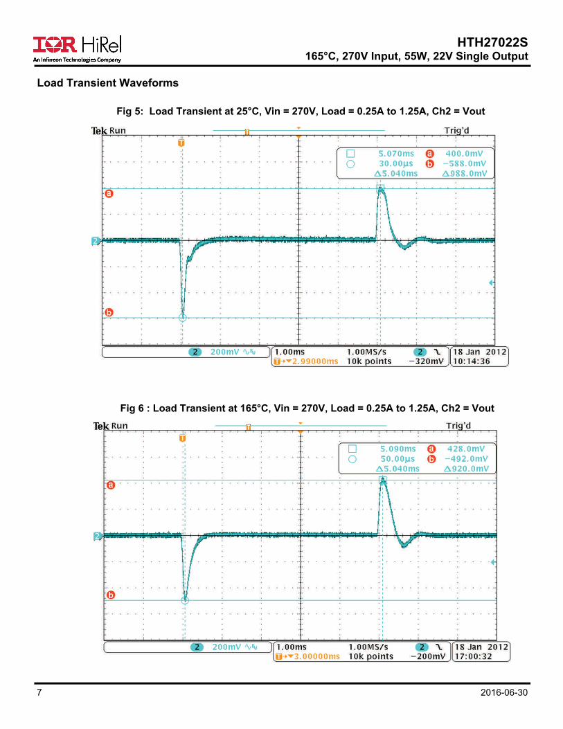
Fig 5: Load Transient at 25°C, Vin = 270V, Load = 0.25A to 1.25A, Ch2 = Vout
Fig 6 : Load Transient at 165°C, Vin = 270V, Load = 0.25A to 1.25A, Ch2 = Vout
Load Transient Waveforms

HTH27022S 165°C, 270V Input, 55W, 22V Single Output
8 2016-06-30
Fig 7: Load Transient at 25°C, Vin = 270V, Load = 1.25A to 2.5A, Ch2 = Vout
Fig 8 : Load Transient at 165°C, Vin = 270V, Load = 1.25A to 2.5A, Ch2 = Vout

HTH27022S 165°C, 270V Input, 55W, 22V Single Output
9 2016-06-30
Technical Notes
Remote Sensing
Connection of the + Sense and - Sense leads at a remotely located load permits compensation for resistive voltage drop between the converter output and the load when they are physically separated by a significant distance. This connection allows regulation at the point of application. To minimize noise pickup that could interfere normal operation of the converter, a twisted pair for remote sensing is highly recommended. When the remote sensing features is not used, the sense leads should be connected to their respective output terminals at the converter.
Notes:
(1) If the +Sense connection is unintentionally broken, the converter has a fail-safe output voltage of Vout + 25mV, where the 25mV is independent of the nominal output voltage. (2) In the event of both the +Sense and -Sense connections being broken, the output will be limited to Vout + 440mV. This 440mV is also essentially constant independent of the nominal output voltage. While operation in this condition is not damaging to the device, not all performance parameters will be met. (3) The +Sense Pin shall be kept from being shorted to the -Sense Pin or the Output Return Pin through a resistance path < 1k, or permanent damages will occur inside the converter.
Inhibiting Converter Output
As an alternative to application and removal of the DC voltage to the input, the user can control the converter output by providing TTL compatible negative logic (LOW active) signal to Inhibit Pin (Pin 4) with respect to the Input Return Pin (Pin 2). The Inhibit Pin is internally pulled “high” so that when not used, an open connection on the Inhibit Pin permits normal converter operation. When its use is desired, a logical “low” on this port will shut the converter down.
Synchronization of Multiple Converters
When operating multiple converters, system requirements often may require operation of the converters at a common frequency. To accommodate this requirement, the converters provide both a synchronization input and output The Sync Input port permits synchronization of a HT converter to any compatible external frequency source operating between 500 kHz and 600 kHz. This input signal should be referenced to the Input Return and has a 10% to 90% duty cycle. Compatibility requires transition times less than 100ns, maximum low level of +0.8V and a minimum high level of +2.0V. The Sync Output of a converter which has been designated as the master oscillator provides a convenient frequency source for this mode of operation. When external synchronization is not required, the Sync In Pin should be left unconnected thereby permitting the converter to operate at its own internally set frequency. The sync output signal is a continuous pulse train factory-set at 520 ± 50 kHz, with a duty cycle of 15 ± 5.0%. This signal is referenced to the Input Return and has been tailored to be compatible with the Sync Input port. Transition times are less than 100ns and the low level output impedance is less than 50. This signal is active when the DC input voltage is within the specified operating range and the converter is not inhibited. This output has adequate drive capability to synchronize at least five additional converters.

HTH27022S 165°C, 270V Input, 55W, 22V Single Output
10 2016-06-30
In addition to permitting close voltage regulation of remotely located loads, the converter has a Vadj Pin allowing the users to trim its output voltage up or down for their applications. The adjustment range is limited to +10% , -20% maximum. The adjustments are intended as a means to “trim” the output to a voltage setting for certain design application, but are not intended to create a variable output converter. The output voltage is done by connecting a resistor with an appropriate value between the Vadj Pin and either +Sense and or -Sense Pins while as shown in Fig. 9 below. The resistance value for a desired output voltage can be determined by formulae described below.
Voltage Trimming Procedure: (1) Nominal Output Voltage with Vadj Pin (Pin 11) Open: 22V (2) Trimming Up Output Voltage by installing a trimming resistor Radj (1/4W, 1%) between the Vadj Pin (Pin 11) and -SENSE Pin (Pin 9): Radj = [ 1950 / [10 * (Vout - 2.5) - 195 ] ] - 50; Radj in k, Vout in Volts Example: To trim Vout up to 24V Radj = [ 1950 / [10 * (24 - 2.5) -195 ] ] - 50 = [ 1950 / 20 ] - 50 = 47.5 (k) Thus, Vout can be trimmed up to 24V by installing a 1/4W, 1%, 47.5k resistor between the Vadj Pin (Pin 11) and the -SENSE Pin (Pin 9). (3) Trimming Down Output Voltage by installing a trimming resistor Radj (1/4W, 1%) between the Vadj Pin (Pin 11) and +SENSE Pin (Pin 10) Radj = [ 780 * (Vout - 2.5) ] / [ 195 - 10 * (Vout - 2.5 ) ] ; Radj in k, Vout in Volts Example: To trim Vout down to 20V Radj = [ 780 * (20 - 2.5) ] / [ 195 - 10 * (20 - 2.5 ) ] = 13650 / 20 = 682.5 (k) Thus, Vout can be trimmed down to 20V by installing a 1/4W, 1% 682.5k resistor between the Vadj Pin (Pin 11) and the +SENSE Pin (Pin 10)
Output Voltage Adjust - For Higher or Lower Output Voltage
Fig 9: Connection for VOUT Adjustment

HTH27022S 165°C, 270V Input, 55W, 22V Single Output
11 2016-06-30
Share Function - Paralleling Converters for Higher Output Current or Reliability Redundancy The converter has a built-in OR-ing diode, rated 300V/10A and connected to the Share Pin as indicated in Fig 10. Multiple converters can be paralleled and configured as shown in Fig 10 for the following purposes: (1) Paralleling for higher output current: Several converters can be paralleled for sharing higher output current demand at the expense of some degradation in the load regulation. (2) N+1 Redundancy for fault tolerance and extra system reliability: When one of the paralleled converters fails with a lower output voltage or short, it will be isolated from the rest of the converters in parallel. The system can continue to function normally. Note: Direct connection of the +Sense Pin to a remote load is not recommended due to potential control loop contention that could interfere the overall sharing stability or loss of fault isolation. Consult factory for additional application specific options.
Mounting Procedure DC-DC converters are constructed with aluminum-silicon (ALSi) controlled expansion alloy benefit from low mass, high thermal conductivity, and CTE match to substrates mounted in them. The one disadvantage over traditional cold rolled steel packages (CRS) however is that the ALSi material is more brittle than the CRS. For this reason, it is important to avoid using a thermal pad or gasket. The DC-DC converter requires 6-32 size screws and #6 flat washers. The minimum recommended mounting surface flatness is 0.002” per inch. The Procedure for mounting the converter is as follows: 1. Check all surfaces for foreign material, burrs, or anything that may interfere with the different parts. 2. Place the converter on the mounting surface and line up with mounting holes. 3. Install screws using appropriate washers and tighten by hand (~ 4 in.oz) in the sequence shown below in the diagram 1. Tighten the screws with appropriate torque driver using a controlled torque of up to 20-24 in.lb in the sequence as shown in the diagram below.
Fig 10: Connection for Share Pin
1
2
3
4

HTH27022S 165°C, 270V Input, 55W, 22V Single Output
12 2016-06-30
Fig 11 . Block Diagram
Input Filter
Bias Supply
1
OutputFilter
CurrentSense
12
7
6
2
4 8
11
Control5 Vfb
Drive
DC Input
Inhibit
InputReturn
SyncInput
SyncOutput
+Output
Output Return
Share Output
Trim
3Case
9 -Sense
10 +SenseError Amp.&
Ref.
Pin Designation Table
Pin # Description Pin # Description
1 DC Input 7 + Output
2 Input Return 8 Output Return
3 Case 9 - Sense
4 Inhibit 10 + Sense
5 Sync. Output 11 Trim
6 Sync. Input 12 Share Output
HTH27022S 165°C, 270V Input, 55W, 22V Single Output
13 2016-06-30
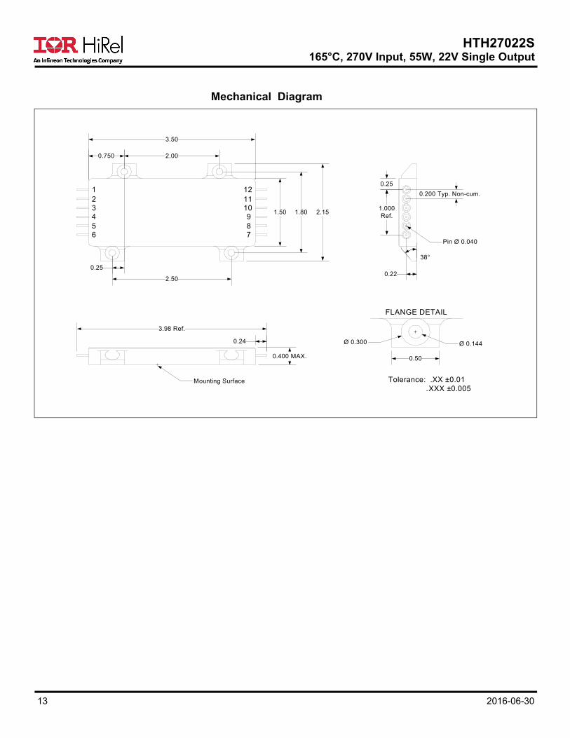
Mechanical Diagram
0.24
0.400 MAX.
3.98 Ref.
Ø 0.144Ø 0.300
0.50
38°
Pin Ø 0.040
0.25
2.00
3.50
2.50
1.50 1.80 2.151.000Ref.
0.25
0.22
0.750
1
65432
12
789
1011
0.200 Typ. Non-cum.
Tolerance: .XX ±0.01 .XXX ±0.005
FLANGE DETAIL
Mounting Surface

HTH27022S 165°C, 270V Input, 55W, 22V Single Output
14 2016-06-30
Device Screening
Notes: Any Engineering Model (EM) build with the “EM” Suffix shall only be form, fit and functional equivalent to its Flight Model (FM) counterpart, and it may not meet the radiation performance. The EM Model shall not be expected comply with MIL-PRF-38534 flight quality/workmanship standards, and configuration control. An EM build may use electrical equivalent commercial grade components. IR HiRel will provide a list of non-compliance items upon request.
Requirement MIL-STD-883
Method Condition
No Suffix (Production
Quality)
/EM suffix (For Engineering
Evaluation)
Internal Visual 2017 - X X
Seal (Laser Weld) 1014 - X X
Fine Leak Test (Unpressurized) - - X X (For info only)
Gross Leak Test (Unpressurized) - - X X
Temperature Cycling 1010 -35°C, +165°C, 10 cycles X Not required
Electrical In accordance with device specification
- X Not required
Constant Acceleration 2001 3000G for 1 minute X Not required
Burn-in 1015 48 hrs @ 165°C X 8 hours @ 165°C
Final Electrical (Group A) In accordance with device specification
- X X
Fine Leak Test 1014 A2 X Not required
Gross Leak Test 1014 C1 X X
External Visual 2009 - X X
IR HiRel Headquarters: 101 N. Sepulveda Blvd., El Segundo, California 90245, USA Tel: (310) 252-7105 IR HiRel Leominster: 205 Crawford St., Leominster, Massachusetts 01453, USA Tel: (978) 534-5776
IR HiRel San Jose: 2520 Junction Avenue, San Jose, California 95134, USA Tel: (408) 434-5000 Data and specifications subject to change without notice.
Part Numbering

HTH27022S 165°C, 270V Input, 55W, 22V Single Output
15 2016-06-30
IMPORTANT NOTICE The information given in this document shall be in no event regarded as guarantee of conditions or characteristic. The data contained herein is a characterization of the component based on internal standards and is intended to demonstrate and provide guidance for typical part performance. It will require further evaluation, qualification and analysis to determine suitability in the application environment to confirm compliance to your system requirements. With respect to any example hints or any typical values stated herein and/or any information regarding the application of the product, Infineon Technologies hereby disclaims any and all warranties and liabilities of any kind including without limitation warranties on non- infringement of intellectual property rights and any third party. In addition, any information given in this document is subject to customer’s compliance with its obligations stated in this document and any applicable legal requirements, norms and standards concerning customer’s product and any use of the product of Infineon Technologies in customer’s applications. The data contained in this document is exclusively intended for technically trained staff. It is the responsibility of any customer’s technical departments to evaluate the suitability of the product for the intended applications and the completeness of the product information given in this document with respect to applications. For further information on the product, technology, delivery terms and conditions and prices, please contact your local sales representative or go to (www.infineon.com/hirel). WARNING Due to technical requirements products may contain dangerous substances. For information on the types in question, please contact your nearest Infineon Technologies office.