Embed Size (px)
Citation preview
- 42 -
Instruction and Operation Manual
HTD-I Water-CooledGalden ® Chiller
NESLAB Manual P/N 000806
Rev. 09/09/97
- 1 -
HTD-I Water-Cooled Galden ® Chiller
PREFACECompliance ............................................................................................ 4Unpacking .............................................................................................. 4Shipping List .......................................................................................... 4After-sale Support .................................................................................. 4
SECTION ISafety
Warnings................................................................................................ 5Material Data Safety Sheets ................................................................... 5
SECTION IIGeneral Information
Description ............................................................................................. 6Specifications ......................................................................................... 6
SECTION IIIInstallation
Site ......................................................................................................... 8Electrical Requirements ......................................................................... 8Plumbing Requirements ......................................................................... 9Fluids ..................................................................................................... 10Filling Requirements .............................................................................. 10
SECTION IVOperation
Start Up .................................................................................................. 11Front Panel Controls .............................................................................. 12Front Panel Gauges ............................................................................... 13Rear Panel Controls ............................................................................... 13Control Display ....................................................................................... 14Indicator Lamps ..................................................................................... 15Failure and Warning Condition Table ..................................................... 18Changing a Value ................................................................................... 20Controller Displays ................................................................................. 20Error Messages...................................................................................... 27
SECTION VSpecial Features
Heater Package ..................................................................................... 30Pump Motor Overload Protector............................................................. 30Compressor Motor Overload Protector .................................................. 30Pressure Relief Valve ............................................................................. 31High Pressure Cutout ............................................................................. 31Low Pressure Cutout .............................................................................. 32High Temperature Cutouts ..................................................................... 32Cabinet High Temperature Cutout ......................................................... 32Electrical Interlocks ................................................................................ 32Tank Relief Valves ................................................................................. 32
- 2 -
High Injector Temperature ..................................................................... 33Phase Voltage Monitor ........................................................................... 33Temperature Control .............................................................................. 33Flow Monitors ......................................................................................... 33Low Level Monitors ................................................................................ 33Temperature Sensor .............................................................................. 33Accessory Connections.......................................................................... 34
SECTION VIMaintenance
Service Contracts ................................................................................... 35Draining.................................................................................................. 35Reservoir Cleaning................................................................................. 36Filter Cartridge Cleaning ........................................................................ 36Preventive Maintenance ......................................................................... 37
SECTION VIITroubleshooting
Troubleshooting ..................................................................................... 38
SECTION VIIISpare Parts List
Critical Spare Parts List .......................................................................... 39Common Spare Parts List ...................................................................... 40
SECTION IXDiagrams
Flow Diagram ......................................................................................... 41Wiring Diagrams .................................................................................... 42
- 3 -
HDT-I Quick Reference GuideDescriptionThe HTD-I Water-Cooled Chiller is designed to provide acontinuous flow of Galden® heat transfer fluid at a constanttemperature and flow rate. The unit consists of 2 water-cooledrefrigeration systems each with a fluid reservoir, fluidrecirculation pump and a microprocessor temperaturecontroller. A 5 kilowatt heater is located in each fluid reservoir.
Specifications
Refer to page 6 for each channel's specifications.
SiteLocate the unit in a laboratory or clean industrial environmentwhere ambient temperatures are inside the range of +68°F to+86°F (+20°C to +30°C). The unit will retain its full ratedcapacity with cooling water temperatures to approximately86°F (30°C). Above 86°F, derate the cooling capacity 1% forevery 1°F above 86°F.
Never place the unit in a location where excessive heat,moisture, orcorrosive materials are present
Electrical RequirementsControlRated Voltage: 208VAC ±10%, 50/60Hz, 1ØRated Current: 5Amps
Electrical RequirementsPowerRated Voltage: 208VAC ±10%, 50/60Hz, 3ØRated Current: 63Amps
Make sure the voltage of the power source meets the specifiedvoltage, ±10%.
The unit construction provides extra protection againstthe risk of electrical shock by grounding appropriate metalparts. It is the user's responsibility to assure that a properground connection is provided to the unit.
Each channel is provided with a 4-conductor line cord forpower and a 3-conductor line cord for control.
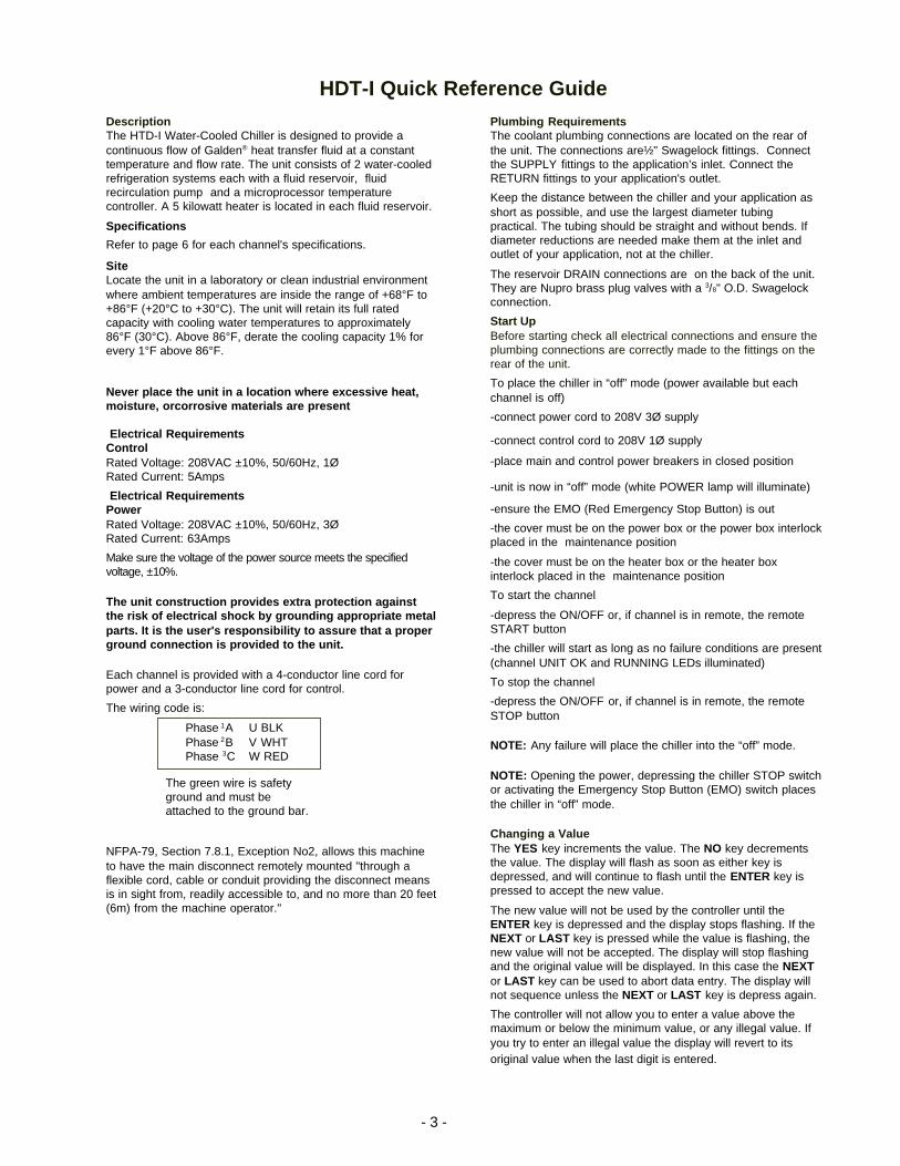
The wiring code is:
Phase 1A U BLKPhase 2B V WHTPhase 3C W RED
NFPA-79, Section 7.8.1, Exception No2, allows this machineto have the main disconnect remotely mounted "through aflexible cord, cable or conduit providing the disconnect meansis in sight from, readily accessible to, and no more than 20 feet(6m) from the machine operator."
Plumbing RequirementsThe coolant plumbing connections are located on the rear ofthe unit. The connections are½" Swagelock fittings. Connectthe SUPPLY fittings to the application’s inlet. Connect theRETURN fittings to your application's outlet.
Keep the distance between the chiller and your application asshort as possible, and use the largest diameter tubingpractical. The tubing should be straight and without bends. Ifdiameter reductions are needed make them at the inlet andoutlet of your application, not at the chiller.
The reservoir DRAIN connections are on the back of the unit.They are Nupro brass plug valves with a 3/8" O.D. Swagelockconnection.
Start UpBefore starting check all electrical connections and ensure theplumbing connections are correctly made to the fittings on therear of the unit.
To place the chiller in “off” mode (power available but eachchannel is off)
-connect power cord to 208V 3Ø supply
-connect control cord to 208V 1Ø supply
-place main and control power breakers in closed position
-unit is now in “off” mode (white POWER lamp will illuminate)
-ensure the EMO (Red Emergency Stop Button) is out
-the cover must be on the power box or the power box interlockplaced in the maintenance position
-the cover must be on the heater box or the heater boxinterlock placed in the maintenance position
To start the channel
-depress the ON/OFF or, if channel is in remote, the remoteSTART button
-the chiller will start as long as no failure conditions are present(channel UNIT OK and RUNNING LEDs illuminated)
To stop the channel
-depress the ON/OFF or, if channel is in remote, the remoteSTOP button
NOTE: Any failure will place the chiller into the “off” mode.
NOTE: Opening the power, depressing the chiller STOP switchor activating the Emergency Stop Button (EMO) switch placesthe chiller in “off” mode.
Changing a ValueThe YES key increments the value. The NO key decrementsthe value. The display will flash as soon as either key isdepressed, and will continue to flash until the ENTER key ispressed to accept the new value.
The new value will not be used by the controller until theENTER key is depressed and the display stops flashing. If theNEXT or LAST key is pressed while the value is flashing, thenew value will not be accepted. The display will stop flashingand the original value will be displayed. In this case the NEXTor LAST key can be used to abort data entry. The display willnot sequence unless the NEXT or LAST key is depress again.
The controller will not allow you to enter a value above themaximum or below the minimum value, or any illegal value. Ifyou try to enter an illegal value the display will revert to itsoriginal value when the last digit is entered.
The green wire is safetyground and must beattached to the ground bar.
- 4 -
Preface
ComplianceProducts tested and found to be in compliance with the requirements definedin the EMC standards defined by 89/336/EEC as well as Low Voltage Direc-tive (LVD) 73/23/EEC can be identified by the CE label on the rear of the unit.This label indicates testing has demonstrated compliance with the followingdirectives:
LVD, 73/23/EEC Complies with UL 3101-1:93
EMC, 89/336/EEC EN 55011, Class A VerificationEN 50082-1:1992IEC 1000-4-2:1995IEC 1000-4-3:1994IEC 1000-4-4:1995
For any additional information refer to the Letter of Compliance that shippedwith the unit (Declaration of Conformity).
UnpackingNOTE: A copy of these instructions is attached to the crate's exterior surface.
Remove the front panel. The panel will serve as a ramp.
Remove the remaining side panels as one piece by unscrewing the lag boltswhich hold the sides to the base.
Mount the ramp to the base and install lag bolts to secure the ramp to the base.
Remove the support and strapping.
Extend the four leveling feet on the chiller and then slowly raise the chillerevenly off the support rails.
Remove the support rails by loosening the lag screws.
Lower the chiller onto the castors and then slowly push the chiller towards theramp.
Reverse these directions to repackage the chiller.
Retain all cartons and packing material until the unit is operated and found tobe in good condition. If the unit shows external or internal damage, or doesnot operate properly, contact the transportation company and file a damageclaim. Under ICC regulations, this is your responsibility.
Shipping ListTEL HTD-I Chiller Test dataExhaust ring with 4 mounting screws System verification checklistControl system power cord Flow DiagramMain power cord Wiring diagrams (3 pages)Declaration of Conformity for CE Mark Operator's manualQA checklist
After-sale Support
NESLAB is committed to customer service both during and after the sale. Ifyou have questions concerning the operation of your unit, contact our SalesDepartment. Before calling, please refer to the serial number label on the rearof the unit to obtain the following information (see Section II, Description for
- 5 -
serial number label location).
Section I Safety
WarningsMake sure you read and understand all instructions and safety precautionslisted in this manual before installing or operating your unit. If you have anyquestions concerning the operation of your unit or the information in thismanual, please contact our Sales Department (see After-sale Support).
Performance of installation, operation, or maintenance proceduresother than those described in this manual may result in a hazardoussituation and may void the manufacturer's warranty.
Transport the unit with care. Sudden jolts or drops can cause damage.
Observe all warning labels.
Never remove warning labels.
Never operate damaged or leaking equipment.
Never operate the unit without fluid in the reservoir.
Always turn off the unit and disconnect the power supply from thepower source before performing any service or maintenance, or beforemoving the unit.
Always empty the reservoir before moving the unit.
Never operate equipment with damaged power cords.
Refer service and repairs to a qualified technician.
In addition to the safety warnings listed above, warnings are posted through-out the manual. Read and follow these important instructions. Failure toobserve these instructions can result in permanent damage to the unit,significant property damage, or personal injury or death.
Material DataSafety Sheets
Galden® HT-200 Ausimont USA, Inc.PO Box 26Thorofare, NJ 08086-0026609-853-8119
LOCTITE® LOCTITE Corporation705 North Mountain RoadNewington, CN 06111203-278-1280
De-Ox Anti-Oxident Ilsco4730 Madison Road
- 6 -
Cincinnati, OH 45227513-871-4000
Section II General Information
DescriptionThe HTD-I Water-Cooled Chiller is designed to provide a continuous flow ofGalden® heat transfer fluid at a constant temperature and flow rate.
The unit consists of 2 water-cooled refrigeration systems, 2 fluid reservoirs, 2fluid recirculation pumps and 2 microprocessor temperature controllers. A 5kilowatt heater is located in each fluid reservoir.
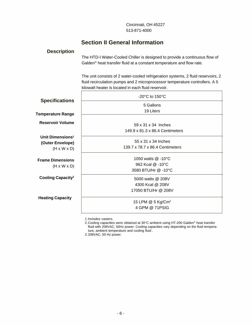
Specifications
Temperature Range
Reservoir Volume
Unit Dimensions 1
(Outer Envelope)(H x W x D)
Frame Dimensions(H x W x D)
Cooling Capacity 2
Heating Capacity
59 x 31 x 34 Inches 149.9 x 81.3 x 86.4 Centimeters
5 Gallons19 Liters
-20°C to 150°C
1050 watts @ -10°C962 Kcal @ -10°C
3580 BTU/Hr @ -10°C
5000 watts @ 208V4300 Kcal @ 208V
17050 BTU/Hr @ 208V
15 LPM @ 5 Kg/Cm2
4 GPM @ 71PSIG
55 x 31 x 34 Inches139.7 x 78.7 x 86.4 Centimeters
1.Includes casters.2.Cooling capacities were obtained at 30°C ambient using HT-200 Galden® heat transfer
fluid with 208VAC, 50Hz power. Cooling capacities vary depending on the fluid tempera-ture, ambient temperature and cooling fluid .
2.208VAC, 50 Hz power.
- 7 -
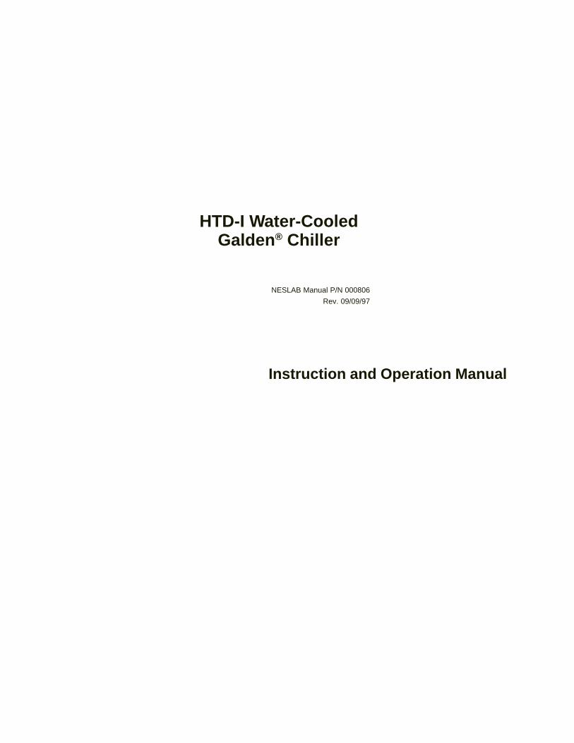
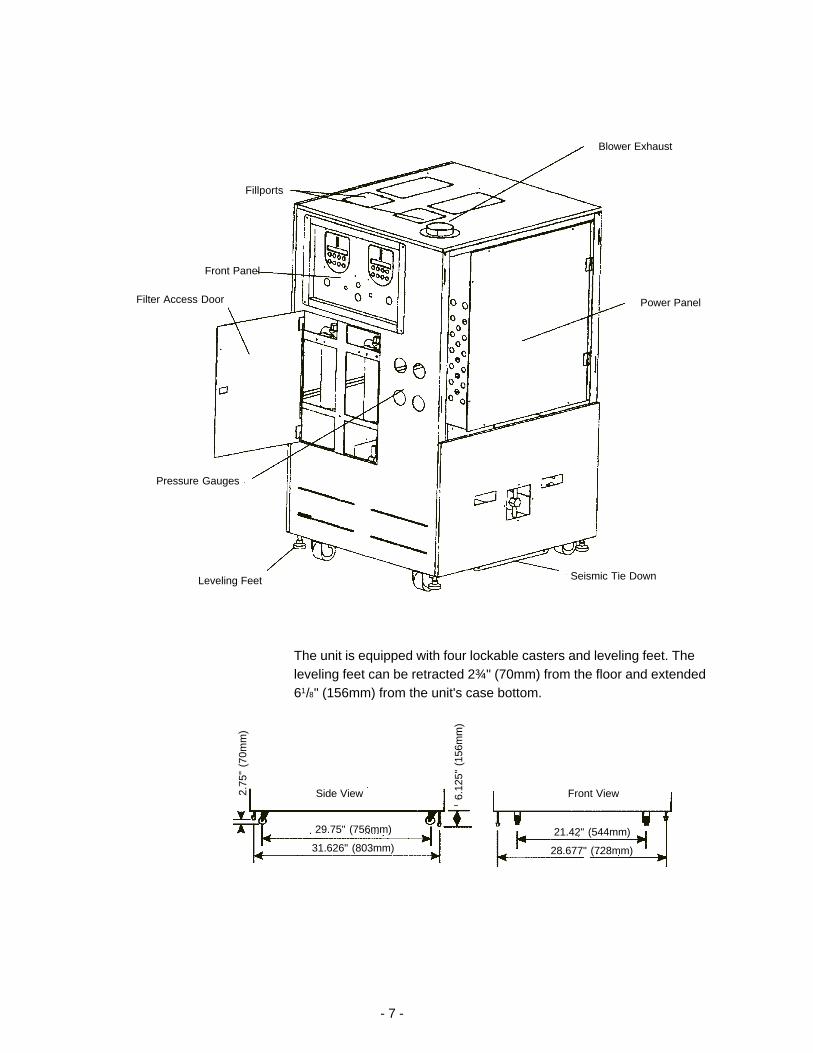
Blower Exhaust
Power Panel
Fillports
Pressure Gauges
Front Panel
Filter Access Door
Leveling Feet Seismic Tie Down
The unit is equipped with four lockable casters and leveling feet. Theleveling feet can be retracted 2¾" (70mm) from the floor and extended61/8" (156mm) from the unit's case bottom.
21.42" (544mm)
28.677" (728mm)
29.75" (756mm)
31.626" (803mm)
6.12
5" (
156m
m)
Front ViewSide View2.75
" (7
0mm
)
- 8 -
Pumping Capacity 3
SiteLocate the unit in a laboratory or clean industrial environment where ambienttemperatures are inside the range of +20°C to +30°C (+68°F to +86°F).
The unit will retain its full rated capacity with cooling water temperatures toapproximately 30°C (86°F). Above 30°C, derate the cooling capacity 1% forevery 0.5°C above 30°C.
Never place the unit in a location where excessive heat, moisture, orcorrosive materials are present .
ElectricalRequirements
The unit construction provides extra protection against the risk ofelectrical shock by grounding appropriate metal parts. It is the user'sresponsibility to assure that a proper ground connection is provided tothe unit.
ControlRated Voltage: 208VAC ±10%, 50/60Hz, 1ØRated Current: 5Amps
PowerRated Voltage: 208VAC ±10%, 50/60Hz, 3ØRated Current: 63Amps
Make sure the voltage of the power source meets the specified voltage ±10%.
The prototype is provided with a 4-conductor line cord for power and a 3-conductor line cord for control.
The wiring code is:
Phase A 208VACPhase B 208VACPhase C 208VAC
NFPA-79, Section 7.8.1, Exception No 2, allows this machine to have themain disconnect remotely mounted "through a flexible cord, cable or conduitproviding the disconnect means is in sight from, readily accessible to, and nomore than 20 feet (6m) from the machine operator."
Section III Installation
The green wire is safety ground and must beattached to the ground bar.
- 9 -
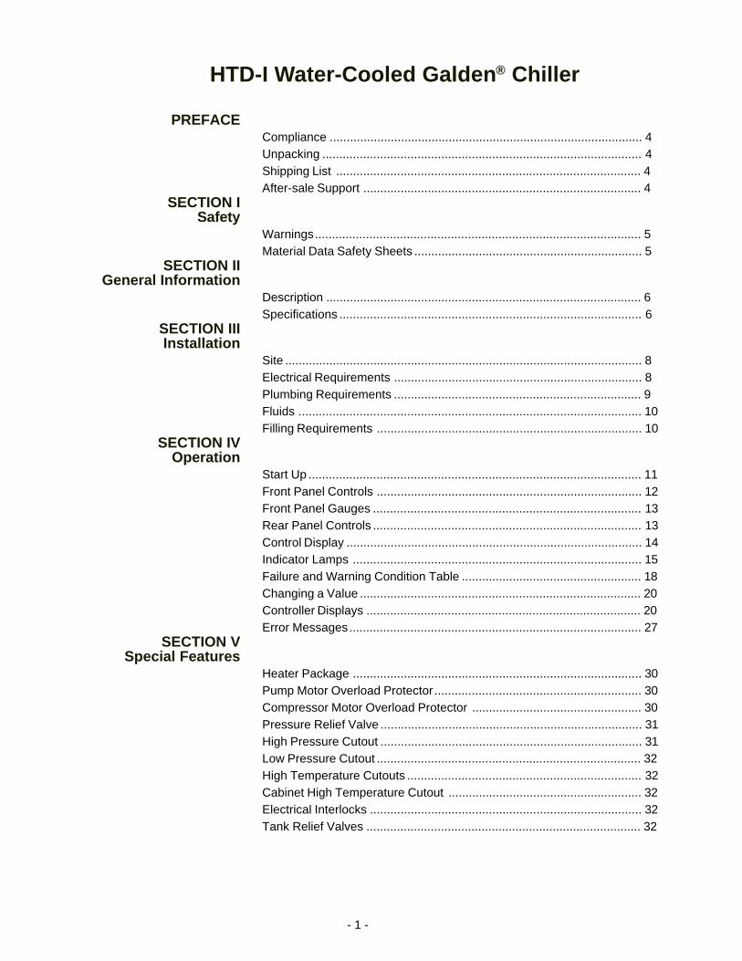
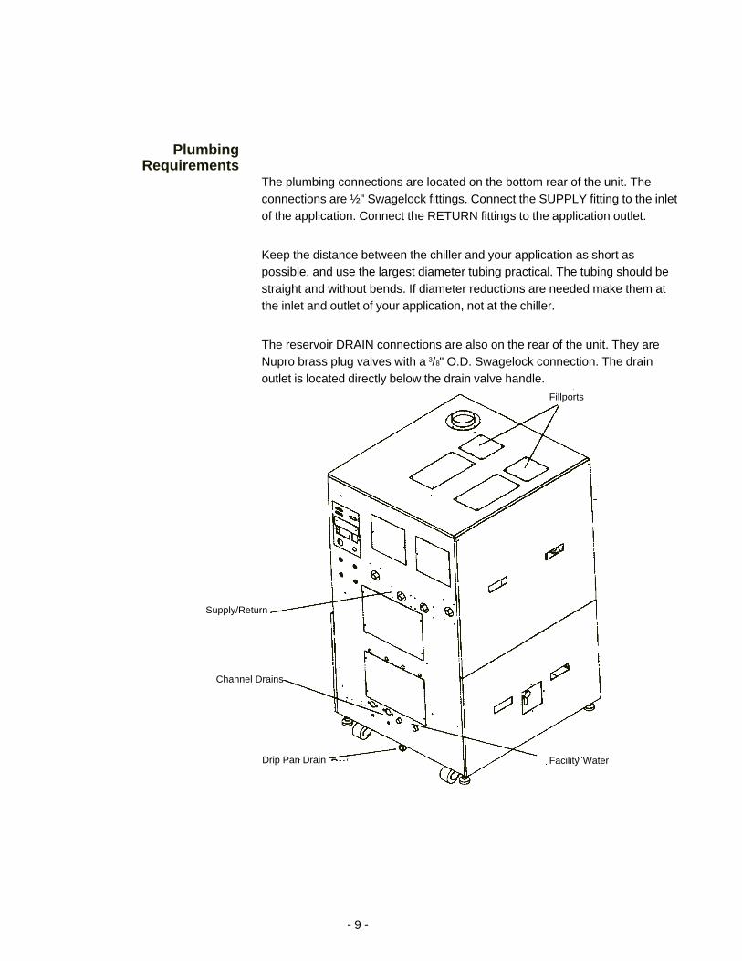
PlumbingRequirements
The plumbing connections are located on the bottom rear of the unit. Theconnections are ½" Swagelock fittings. Connect the SUPPLY fitting to the inletof the application. Connect the RETURN fittings to the application outlet.
Keep the distance between the chiller and your application as short aspossible, and use the largest diameter tubing practical. The tubing should bestraight and without bends. If diameter reductions are needed make them atthe inlet and outlet of your application, not at the chiller.
The reservoir DRAIN connections are also on the rear of the unit. They areNupro brass plug valves with a 3/8" O.D. Swagelock connection. The drainoutlet is located directly below the drain valve handle.
Fillports
Supply/Return
Facility WaterDrip Pan Drain
Channel Drains
- 10 -
FluidsThe unit is designed to use Galden® HT200 or Flourinert 4236 as a heattransfer fluid..
Do not use water as a substitute fluid.
Never use flammable or corrosive fluids with the unit. Do not useautomobile antifreeze. Commercial antifreeze contains silicants that candamage the pump seals and cause leaks. Use of automobile antifreezewill void the manufacturer's warranty.
FillingRequirements
Remove the reservoir access cover and then the filler cap from the top of thereservoir. Using a funnel, carefully fill the reservoir with fluid.
Fill the reservoir until the ADD FLUID LED on the microprocessor extin-guishes.
The amount of recirculating fluid required depends on the total requirementsof the application system. If substantial lengths of recirculating lines are used,add enough fluid to compensate for their volume. The maximum reservoirvolume is 5 gallons (19 liters).
- 11 -
Replace the filler cap and access panel.
Section IV Operation
Start UpBefore starting the unit check all electrical connections and ensure the plumb-ing connections are correctly made to the fittings on the rear of the unit.
To place the chiller in "off" mode (power available but each channel is off)
-connect power cord to 208V 3Ø supply
-connect control cord to 208V 1Ø supply
-place main and control power breakers in closed position
-unit is now in "off" mode (white POWER lamp will illuminate)
-pull out the EMO (Red Emergency Stop Button)
-the cover must be on the power box or the power box interlock placed in themaintenance position
-the cover must be on the heater box or the heater box interlock placed in themaintenance position
To start either channel
-depress the ON/OFF or, if channel is in remote, the remote START button
-the chiller will start as long as no failure conditions are present (channelUNIT OK and RUNNING LEDs illuminated)
To stop either channel
-depress the ON/OFF or, if channel is in remote, the remote STOP button
NOTE: Any failure will place the chiller in the "off" mode.
NOTE: Removing the power or heater box cover, depressing the chillerSTOP switch or activating the Emergency Stop Button (EMO) switch placesthe chiller in "off" mode.
- 12 -
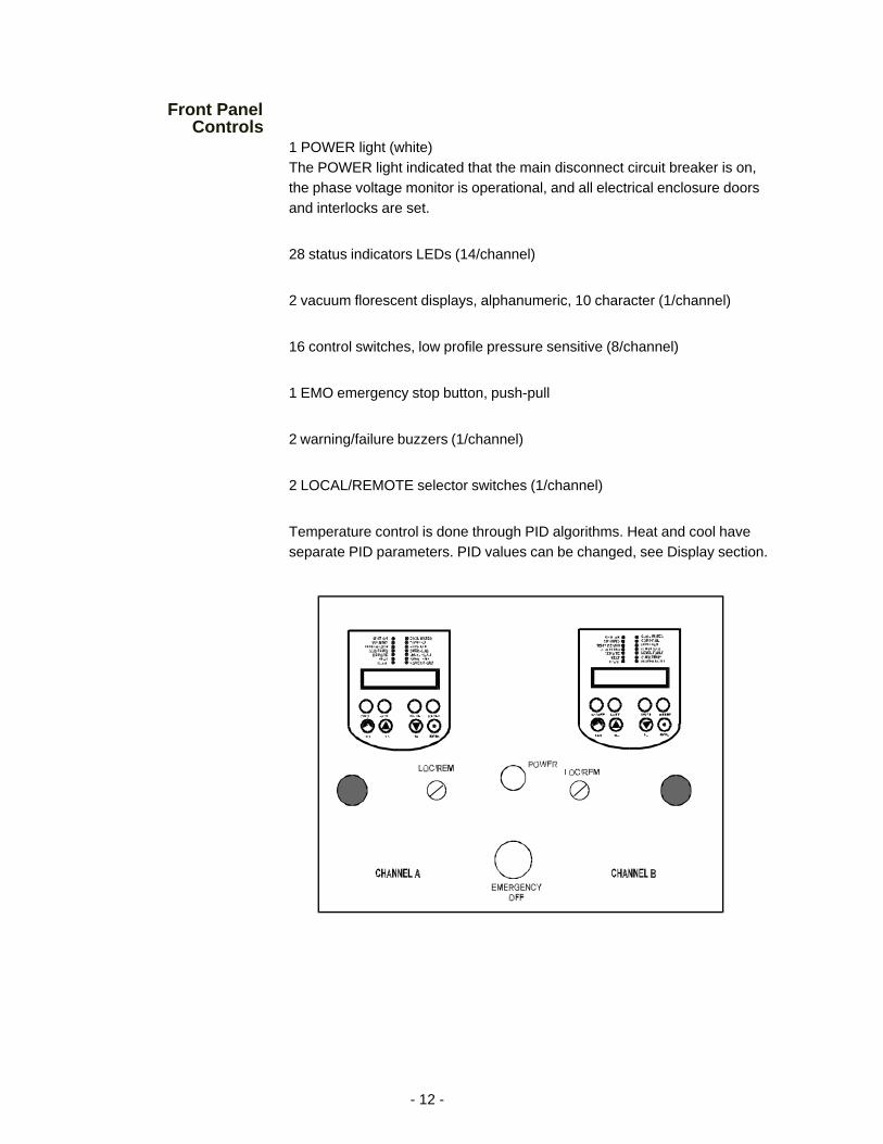
Front PanelControls
1 POWER light (white)The POWER light indicated that the main disconnect circuit breaker is on,the phase voltage monitor is operational, and all electrical enclosure doorsand interlocks are set.
28 status indicators LEDs (14/channel)
2 vacuum florescent displays, alphanumeric, 10 character (1/channel)
16 control switches, low profile pressure sensitive (8/channel)
1 EMO emergency stop button, push-pull
2 warning/failure buzzers (1/channel)
2 LOCAL/REMOTE selector switches (1/channel)
Temperature control is done through PID algorithms. Heat and cool haveseparate PID parameters. PID values can be changed, see Display section.
- 13 -
Front Panel Gauges2 fluid supply pressure gauges. Reads the fluid pressure at each channel outlet.
2 fluid filter inlet pressure gauges. Reads the fluid pressure at each channelfilter inlet.
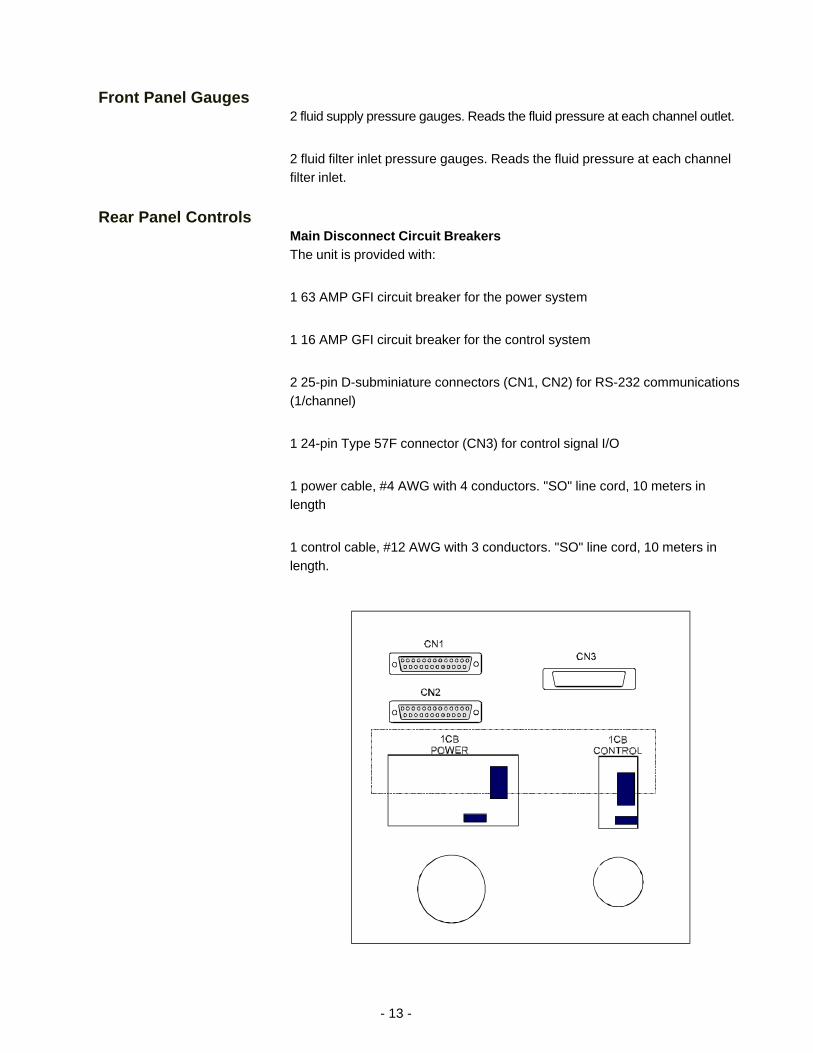
Rear Panel ControlsMain Disconnect Circuit BreakersThe unit is provided with:
1 63 AMP GFI circuit breaker for the power system
1 16 AMP GFI circuit breaker for the control system
2 25-pin D-subminiature connectors (CN1, CN2) for RS-232 communications(1/channel)
1 24-pin Type 57F connector (CN3) for control signal I/O
1 power cable, #4 AWG with 4 conductors. "SO" line cord, 10 meters inlength
1 control cable, #12 AWG with 3 conductors. "SO" line cord, 10 meters inlength.
- 14 -
Controller Keypad
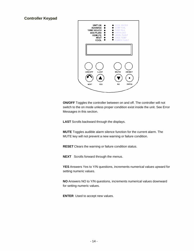
ON/OFF Toggles the controller between on and off. The controller will notswitch to the on mode unless proper condition exist inside the unit. See ErrorMessages in this section.
LAST Scrolls backward through the displays.
MUTE Toggles audible alarm silence function for the current alarm. TheMUTE key will not prevent a new warning or failure condition.
RESET Clears the warning or failure condition status.
NEXT Scrolls forward through the menus.
YES Answers Yes to Y/N questions, increments numerical values upward forsetting numeric values.
NO Answers NO to Y/N questions, increments numerical values downwardfor setting numeric values.
ENTER Used to accept new values.
- 15 -
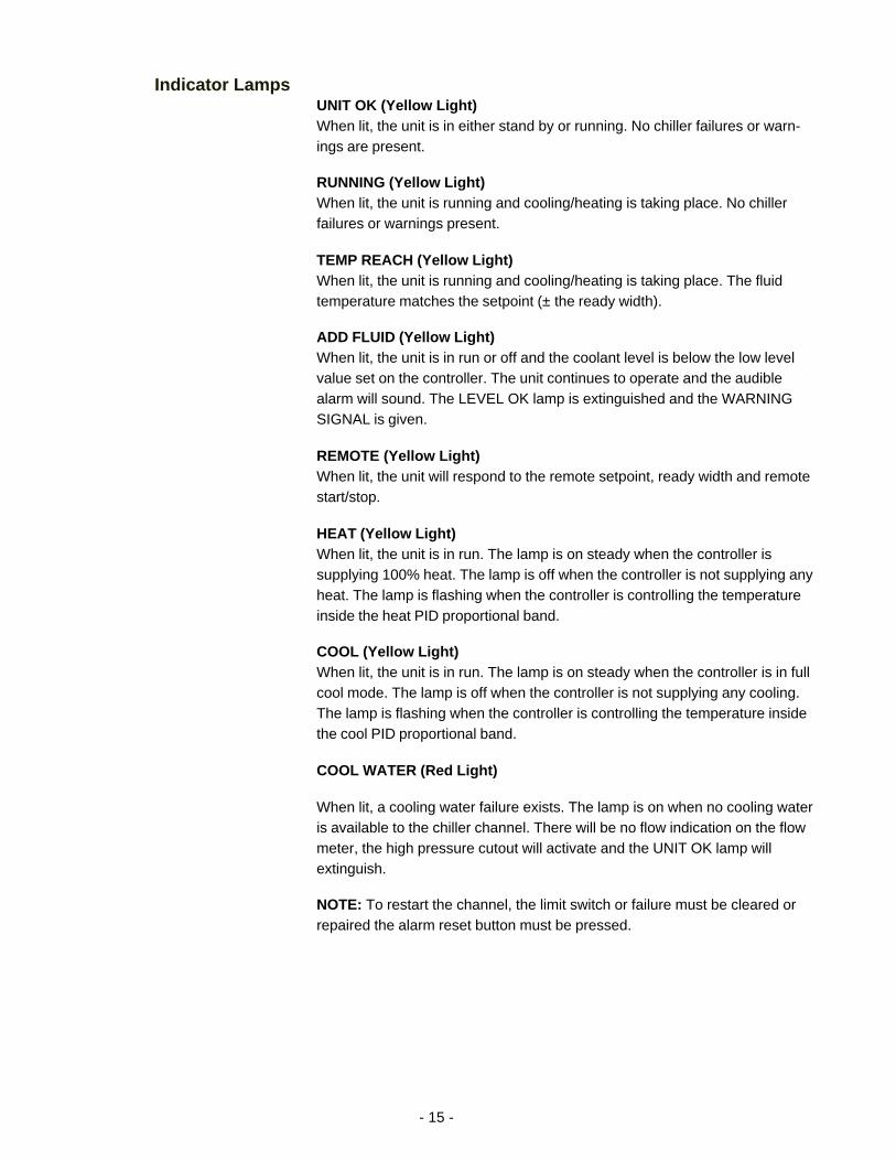
Indicator LampsUNIT OK (Yellow Light)When lit, the unit is in either stand by or running. No chiller failures or warn-ings are present.
RUNNING (Yellow Light)When lit, the unit is running and cooling/heating is taking place. No chillerfailures or warnings present.
TEMP REACH (Yellow Light)When lit, the unit is running and cooling/heating is taking place. The fluidtemperature matches the setpoint (± the ready width).
ADD FLUID (Yellow Light)When lit, the unit is in run or off and the coolant level is below the low levelvalue set on the controller. The unit continues to operate and the audiblealarm will sound. The LEVEL OK lamp is extinguished and the WARNINGSIGNAL is given.
REMOTE (Yellow Light)When lit, the unit will respond to the remote setpoint, ready width and remotestart/stop.
HEAT (Yellow Light)When lit, the unit is in run. The lamp is on steady when the controller issupplying 100% heat. The lamp is off when the controller is not supplying anyheat. The lamp is flashing when the controller is controlling the temperatureinside the heat PID proportional band.
COOL (Yellow Light)When lit, the unit is in run. The lamp is on steady when the controller is in fullcool mode. The lamp is off when the controller is not supplying any cooling.The lamp is flashing when the controller is controlling the temperature insidethe cool PID proportional band.
COOL WATER (Red Light)
When lit, a cooling water failure exists. The lamp is on when no cooling wateris available to the chiller channel. There will be no flow indication on the flowmeter, the high pressure cutout will activate and the UNIT OK lamp willextinguish.
NOTE: To restart the channel, the limit switch or failure must be cleared orrepaired the alarm reset button must be pressed.
- 16 -
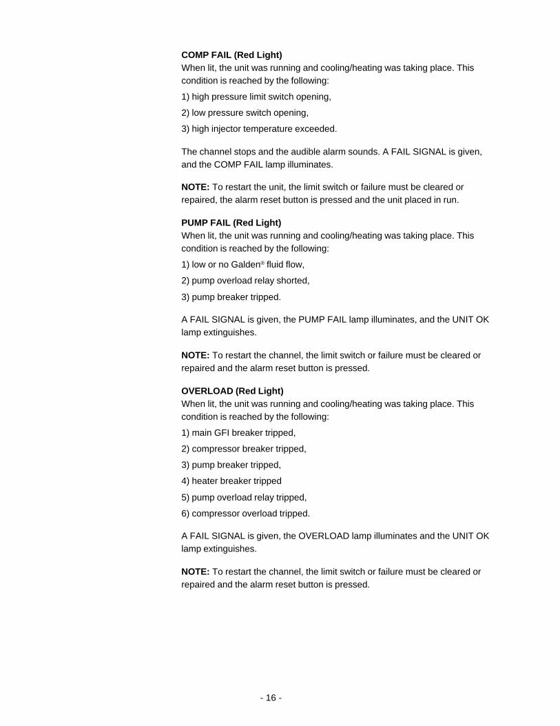
COMP FAIL (Red Light)When lit, the unit was running and cooling/heating was taking place. Thiscondition is reached by the following:
1) high pressure limit switch opening,
2) low pressure switch opening,
3) high injector temperature exceeded.
The channel stops and the audible alarm sounds. A FAIL SIGNAL is given,and the COMP FAIL lamp illuminates.
NOTE: To restart the unit, the limit switch or failure must be cleared orrepaired, the alarm reset button is pressed and the unit placed in run.
PUMP FAIL (Red Light)When lit, the unit was running and cooling/heating was taking place. Thiscondition is reached by the following:
1) low or no Galden® fluid flow,
2) pump overload relay shorted,
3) pump breaker tripped.
A FAIL SIGNAL is given, the PUMP FAIL lamp illuminates, and the UNIT OKlamp extinguishes.
NOTE: To restart the channel, the limit switch or failure must be cleared orrepaired and the alarm reset button is pressed.
OVERLOAD (Red Light)When lit, the unit was running and cooling/heating was taking place. Thiscondition is reached by the following:
1) main GFI breaker tripped,
2) compressor breaker tripped,
3) pump breaker tripped,
4) heater breaker tripped
5) pump overload relay tripped,
6) compressor overload tripped.
A FAIL SIGNAL is given, the OVERLOAD lamp illuminates and the UNIT OKlamp extinguishes.
NOTE: To restart the channel, the limit switch or failure must be cleared orrepaired and the alarm reset button is pressed.
- 17 -
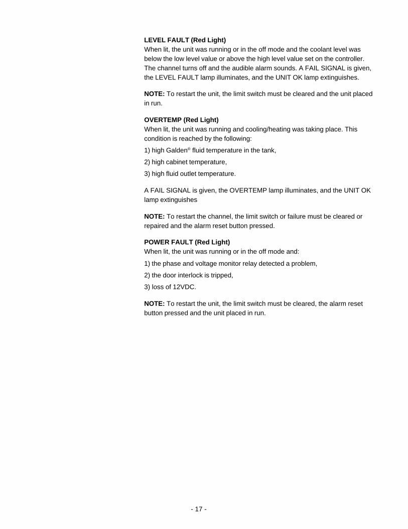
LEVEL FAULT (Red Light)When lit, the unit was running or in the off mode and the coolant level wasbelow the low level value or above the high level value set on the controller.The channel turns off and the audible alarm sounds. A FAIL SIGNAL is given,the LEVEL FAULT lamp illuminates, and the UNIT OK lamp extinguishes.
NOTE: To restart the unit, the limit switch must be cleared and the unit placedin run.
OVERTEMP (Red Light)When lit, the unit was running and cooling/heating was taking place. Thiscondition is reached by the following:
1) high Galden® fluid temperature in the tank,
2) high cabinet temperature,
3) high fluid outlet temperature.
A FAIL SIGNAL is given, the OVERTEMP lamp illuminates, and the UNIT OKlamp extinguishes
NOTE: To restart the channel, the limit switch or failure must be cleared orrepaired and the alarm reset button pressed.
POWER FAULT (Red Light)When lit, the unit was running or in the off mode and:
1) the phase and voltage monitor relay detected a problem,
2) the door interlock is tripped,
3) loss of 12VDC.
NOTE: To restart the unit, the limit switch must be cleared, the alarm resetbutton pressed and the unit placed in run.
- 18 -
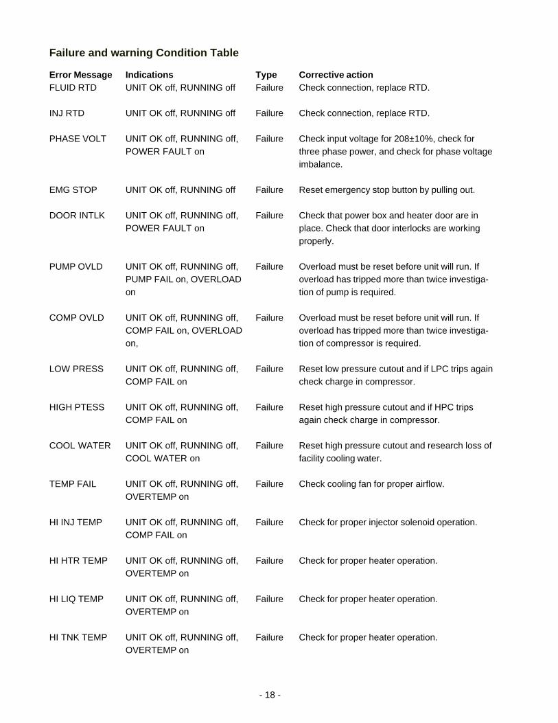
Failure and warning Condition Table
Error MessageFLUID RTD
INJ RTD
PHASE VOLT
EMG STOP
DOOR INTLK
PUMP OVLD
COMP OVLD
LOW PRESS
HIGH PTESS
COOL WATER
TEMP FAIL
HI INJ TEMP
HI HTR TEMP
HI LIQ TEMP
HI TNK TEMP
IndicationsUNIT OK off, RUNNING off
UNIT OK off, RUNNING off
UNIT OK off, RUNNING off,POWER FAULT on
UNIT OK off, RUNNING off
UNIT OK off, RUNNING off,POWER FAULT on
UNIT OK off, RUNNING off,PUMP FAIL on, OVERLOADon
UNIT OK off, RUNNING off,COMP FAIL on, OVERLOADon,
UNIT OK off, RUNNING off,COMP FAIL on
UNIT OK off, RUNNING off,COMP FAIL on
UNIT OK off, RUNNING off,COOL WATER on
UNIT OK off, RUNNING off,OVERTEMP on
UNIT OK off, RUNNING off,COMP FAIL on
UNIT OK off, RUNNING off,OVERTEMP on
UNIT OK off, RUNNING off,OVERTEMP on
UNIT OK off, RUNNING off,OVERTEMP on
TypeFailure
Failure
Failure
Failure
Failure
Failure
Failure
Failure
Failure
Failure
Failure
Failure
Failure
Failure
Failure
Corrective actionCheck connection, replace RTD.
Check connection, replace RTD.
Check input voltage for 208±10%, check forthree phase power, and check for phase voltageimbalance.
Reset emergency stop button by pulling out.
Check that power box and heater door are inplace. Check that door interlocks are workingproperly.
Overload must be reset before unit will run. Ifoverload has tripped more than twice investiga-tion of pump is required.
Overload must be reset before unit will run. Ifoverload has tripped more than twice investiga-tion of compressor is required.
Reset low pressure cutout and if LPC trips againcheck charge in compressor.
Reset high pressure cutout and if HPC tripsagain check charge in compressor.
Reset high pressure cutout and research loss offacility cooling water.
Check cooling fan for proper airflow.
Check for proper injector solenoid operation.
Check for proper heater operation.
Check for proper heater operation.
Check for proper heater operation.
- 19 -
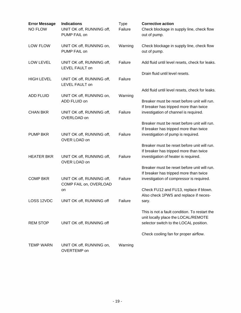
Error MessageNO FLOW
LOW FLOW
LOW LEVEL
HIGH LEVEL
ADD FLUID
CHAN BKR
PUMP BKR
HEATER BKR
COMP BKR
LOSS 12VDC
REM STOP
TEMP WARN
IndicationsUNIT OK off, RUNNING off,PUMP FAIL on
UNIT OK off, RUNNING on,PUMP FAIL on
UNIT OK off, RUNNING off,LEVEL FAULT on
UNIT OK off, RUNNING off,LEVEL FAULT on
UNIT OK off, RUNNING on,ADD FLUID on
UNIT OK off, RUNNING off,OVERLOAD on
UNIT OK off, RUNNING off,OVER LOAD on
UNIT OK off, RUNNING off,OVER LOAD on
UNIT OK off, RUNNING off,COMP FAIL on, OVERLOADon
UNIT OK off, RUNNING off
UNIT OK off, RUNNING off
UNIT OK off, RUNNING on,OVERTEMP on
TypeFailure
Warning
Failure
Failure
Warning
Failure
Failure
Failure
Failure
Failure
Warning
Corrective actionCheck blockage in supply line, check flowout of pump.
Check blockage in supply line, check flowout of pump.
Add fluid until level resets, check for leaks.
Drain fluid until level resets.
Add fluid until level resets, check for leaks.
Breaker must be reset before unit will run.If breaker has tripped more than twiceinvestigation of channel is required.
Breaker must be reset before unit will run.If breaker has tripped more than twiceinvestigation of pump is required.
Breaker must be reset before unit will run.If breaker has tripped more than twiceinvestigation of heater is required.
Breaker must be reset before unit will run.If breaker has tripped more than twiceinvestigation of compressor is required.
Check FU12 and FU13, replace if blown.Also check 1PWS and replace if neces-sary.
This is not a fault condition. To restart theunit locally place the LOCAL/REMOTEselector switch to the LOCAL position.
Check cooling fan for proper airflow.
- 20 -
Changing a ValueThe YES key increments the value. The NO key decrements the value.
The display will flash as soon as either key is depressed, and will continue toflash until the ENTER key is pressed to accept the new value.
The new value will not be used by the controller until the ENTER key isdepressed and the display stops flashing.
If the NEXT key is pressed while the value is flashing, the new value will notbe accepted. The display will stop flashing and the original value will bedisplayed. In this case the NEXT key can be used to abort data entry. Thedisplay will not sequence unless the NEXT key is depress again.
For large values the display can be changed by manipulating the individualdigits. Press the YES key and the NO key at the same time. The mostsignificant digit will start to flash. The YES key increments or the NO keydecrements the digit. Press the ENTER key to accept the digit and to move tothe next most significant digit. Repeat until all digits are entered. Pressing theNEXT key before all digit are entered will abort the procedure and return thedisplay to the original value.
The controller will not allow you to enter a value above the maximum(+150°C) or below the minimum (-20°C). If you try to enter an value outsidethe range, the display will revert to its original value.
Controller DisplaysAn alphanumeric display presents numeric readings of various operatingconditions within the chiller. Display function is selected by pressing theappropriate keys to move through a menu of available information.
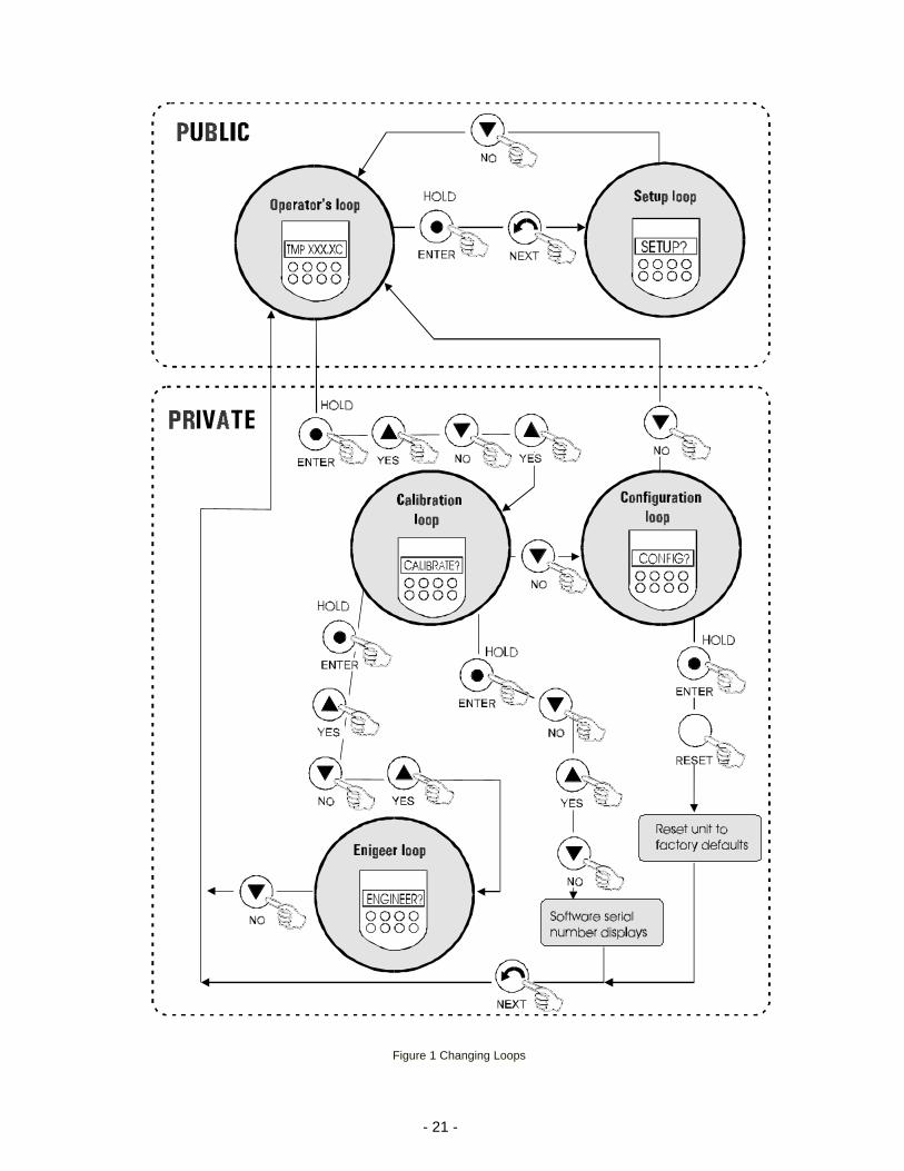
Various controller loops allow you to display and/or alter different parametersof the controller. They can be accessed from the temperature display bypressing and holding the key combinations shown on Figure 1 on the nextpage. Public loops are designed for day-to-day operation, private loopsshould be run by only qualified technicians.
When the controller is first powered up it goes through a short self test andthen enters the Operator’s Loop, displaying the reservoir fluid temperature.
NOTE: Should you desire to return to the temperature display and abort anychanges, keep pressing the NEXT until the display reads SAVE? Press NO.
- 21 -
Figure 1 Changing Loops
- 22 -
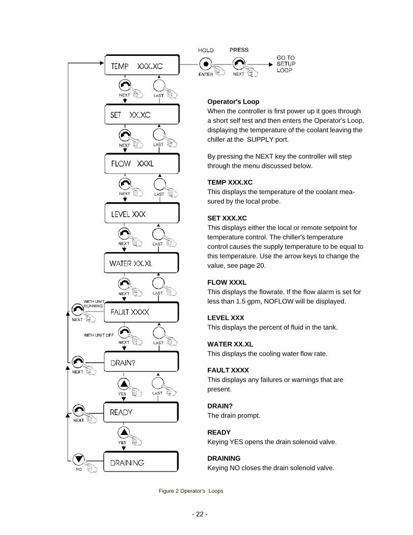
Operator's LoopWhen the controller is first power up it goes througha short self test and then enters the Operator's Loop,displaying the temperature of the coolant leaving thechiller at the SUPPLY port.
By pressing the NEXT key the controller will stepthrough the menu discussed below.
TEMP XXX.XCThis displays the temperature of the coolant mea-sured by the local probe.
SET XXX.XCThis displays either the local or remote setpoint fortemperature control. The chiller's temperaturecontrol causes the supply temperature to be equal tothis temperature. Use the arrow keys to change thevalue, see page 20.
FLOW XXXLThis displays the flowrate. If the flow alarm is set forless than 1.5 gpm, NOFLOW will be displayed.
LEVEL XXXThis displays the percent of fluid in the tank.
WATER XX.XLThis displays the cooling water flow rate.
FAULT XXXXThis displays any failures or warnings that arepresent.
DRAIN?The drain prompt.
READYKeying YES opens the drain solenoid valve.
DRAININGKeying NO closes the drain solenoid valve.
Figure 2 Operator's Loops
- 23 -
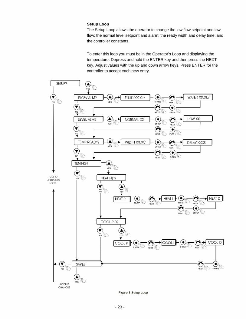
Setup LoopThe Setup Loop allows the operator to change the low flow setpoint and lowflow; the normal level setpoint and alarm; the ready width and delay time; andthe controller constants.
To enter this loop you must be in the Operator's Loop and displaying thetemperature. Depress and hold the ENTER key and then press the NEXTkey. Adjust values with the up and down arrow keys. Press ENTER for thecontroller to accept each new entry.
Figure 3 Setup Loop
- 24 -
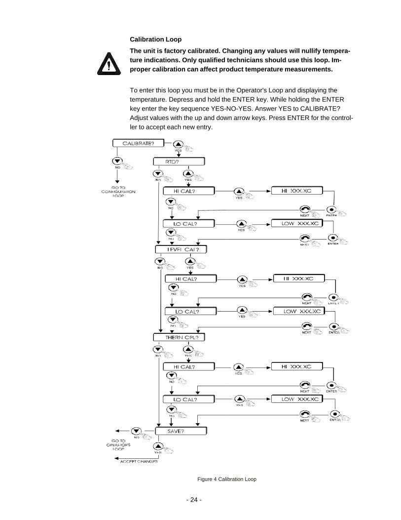
Calibration Loop
The unit is factory calibrated. Changing any values will nullify tempera-ture indications. Only qualified technicians should use this loop. Im-proper calibration can affect product temperature measurements.
To enter this loop you must be in the Operator's Loop and displaying thetemperature. Depress and hold the ENTER key. While holding the ENTERkey enter the key sequence YES-NO-YES. Answer YES to CALIBRATE?Adjust values with the up and down arrow keys. Press ENTER for the control-ler to accept each new entry.
Figure 4 Calibration Loop
- 25 -
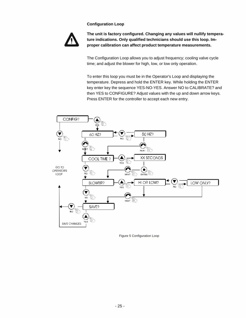
Configuration Loop
The unit is factory configured. Changing any values will nullify tempera-ture indications. Only qualified technicians should use this loop. Im-proper calibration can affect product temperature measurements.
The Configuration Loop allows you to adjust frequency; cooling valve cycletime; and adjust the blower for high, low, or low only operation.
To enter this loop you must be in the Operator's Loop and displaying thetemperature. Depress and hold the ENTER key. While holding the ENTERkey enter key the sequence YES-NO-YES. Answer NO to CALIBRATE? andthen YES to CONFIGURE? Adjust values with the up and down arrow keys.Press ENTER for the controller to accept each new entry.
Figure 5 Configuration Loop
- 26 -
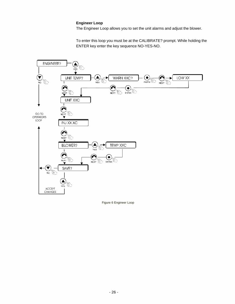
Engineer LoopThe Engineer Loop allows you to set the unit alarms and adjust the blower.
To enter this loop you must be at the CALIBRATE? prompt. While holding theENTER key enter the key sequence NO-YES-NO.
Figure 6 Engineer Loop
- 27 -
Error MessagesError messages are displayed whenever certain conditions are detected.When this occurs the error message will be displayed by alternating the errormessage and the normal display. The keys and menus will perform normally.
All error messages will disappear when the error condition is corrected.
FLUID RTDIndicates the internal temperature probe has failed, i.e. shorted or opened.Upon failure the channel enters the off mode.
PHASE VOLTIndicates the phase voltage monitor relay has detected an incoming powerproblem, i.e., loss of phase, phase voltage imbalance, phase reversal, andlow voltage. Upon failure the channel enters the off mode.
PUMP OVLDIndicates the pump motor overload has tripped. Upon failure the channelenters the off mode.
COMP OVLDIndicates the compressor motor overload has tripped. Upon failure thechannel enters the off mode.
LOW PRESSIndicates the refrigeration system low pressure switch has detected lowpressure. Upon failure the channel enters the off mode. The switch must bemanually reset.
HIGH PRESSIndicates the refrigeration system high pressure switch has detected highpressure. Upon failure the channel enters the off mode. The switch must bemanually reset.
HI HTR TEMIndicates the heater high temperature cutout has detected over temperature.Upon failure the channel enters the off mode.
HI INJ TEMIndicates the refrigeration system high temperature cutout has detected overtemperature. Upon failure the channel enters the off mode.
HI LIQ TEMIndicates the controller sensed a liquid temperature over normal operatingrange. Upon failure the channel enters the off mode.
- 28 -
NO FLOWIndicates the controller sensed a liquid line flow loss, i.e., less than 5.75 LPM.Upon failure the channel enters the off mode.
LOW LEVELIndicates the controller sensed a liquid level in the tank that is below theheater level. Upon failure the channel enters the off mode.
HIGH LEVELIndicates the controller sensed a liquid level in the tank that is above theproper operating level range. Upon failure the channel enters the off mode.
REM STOPWith the channel in the remote mode, indicates the remote stop button isopen.
MAIN BKRIndicates the main breaker has tripped. Upon failure the channel enters theoff mode. The breaker must be manually reset.
CHAN BKRIndicates the channel breaker has tripped. Upon failure each channel entersthe off mode. The breaker must be manually reset.
PUMP BKRIndicates the pump breaker has tripped. Upon failure the channel enters theoff mode. The breaker must be manually reset.
COMP BKRIndicates the compressor breaker has tripped. Upon failure the channelenters the off mode. The breaker must be manually reset.
HEATER BKRIndicates the heater breaker has tripped. Upon failure the channel enters theoff mode. The breaker must be manually reset.
TEMP FAILIndicates the internal thermal couple has detected an over temperaturecondition. Upon failure the channel enters the off mode.
HI TNK TEMIndicates the tank High Temperature Cutout (HTC) has detected an overtemperature condition. Upon failure the channel enters the off mode. TheHTC must be manually reset.
- 29 -
EMOIndicates the EMO button is depressed. Each channel enters the off mode.
DOOR INTLKIndicates a door interlock (heater boxes or power box) is open. Each channelenters the off mode.
LOSS 12VDCIndicates the internal 12 volt power supply has failed. Each channel enters theoff mode.
COOL WATERIndicates no cooling water detected so the high pressure cutout opened. Thechannel enters the off mode.
INJ RTDIndicates the refrigeration system liquid injector temperature sensor hasfailed, i.e., shorted or opened.
LOW FLOWIndicates the controller senses a liquid line flow that is less than a properoperating flow.
ADD FLUIDIndicates the controller senses a tank liquid level that is less than a properoperating level.
TEMP WARMIndicates the internal thermal couple has detected an over temperaturecondition. The fan enters the high mode, if possible.
- 30 -
Section IV Special Features
Heater PackageEach heater package consists of a 5000 watt (@208V, 3Ø) immersion heaterin the unit's fluid reservoir, and a high temperature limit device. The hightemperature limit device disconnects power to the heater if the heater surfacetemperature exceeds a preset limit.
The heater high temperature limit device senses the surface temperature ofthe heater. If the heater temperature becomes too high, the limit device opensa mechanical relay to remove power to the heater and pump.
The heater surface temperature may operate several degrees higher than thereservoir fluid. The limit device is factory set to 200°C.
For personal safety and equipment reliability, do not adjust the hightemperature limit device.
To reset a tripped temperature limit device depress the reset switch on theback of the unit.
NOTE: The microprocessor controller will indicate a fault and must bemanually reset before the unit can be placed in the run mode.
Pump MotorOverload Protector
The unit is equipped with a pump motor overload protector. The overloadprotector prevents the pump motor from damage due to excessive current. Ifan overload occurs, due, for example, to excessive pressure or flow, orexcessive ambient temperatures, the overload protector will shut off the pumpmotor.
NOTE: The microprocessor controller will indicate a fault and must bemanually reset before the unit can be placed in the run mode.
Compressor MotorOverload Protector
The unit is equipped with a compressor motor overload protector. Theoverload protector prevents the compressor motor from damage due toexcessive current. If an overload occurs, due, for example, to excessivepressure, excessive ambient temperatures, or high suction temperatures, theoverload protector will shut off the compressor.
NOTE: The microprocessor controller will indicate a fault and must bemanually reset before the unit can be placed in the run mode.
- 31 -
Pressure Relief ValvesThe pressure relief valve establishes the maximum operating pressure of theunit. If the pressure of the fluid leaving the pump exceeds the valve setting,the relief valve will bypass fluid within the unit to limit the pressure. The valvedoes not determine the system operating pressure; the system operatingpressure is determined by the back pressure of the connected equipment. Ifadjustment seems necessary, consult our service department for assistance.
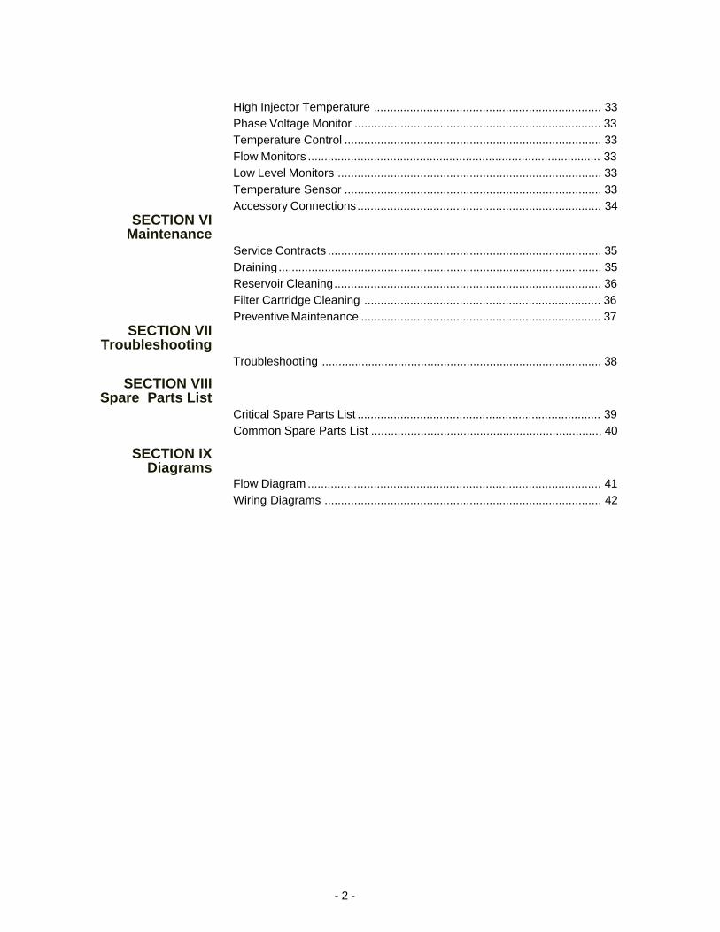
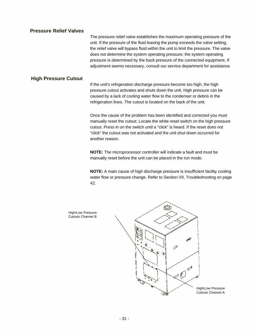
High Pressure CutoutIf the unit's refrigeration discharge pressure become too high, the highpressure cutout activates and shuts down the unit. High pressure can becaused by a lack of cooling water flow to the condenser or debris in therefrigeration lines. The cutout is located on the back of the unit.
Once the cause of the problem has been identified and corrected you mustmanually reset the cutout. Locate the white reset switch on the high pressurecutout. Press in on the switch until a "click" is heard. If the reset does not"click" the cutout was not activated and the unit shut down occurred foranother reason.
NOTE: The microprocessor controller will indicate a fault and must bemanually reset before the unit can be placed in the run mode.
NOTE: A main cause of high discharge pressure is insufficient facility coolingwater flow or pressure change. Refer to Section VII, Troubleshooting on page42.
High/Low PressureCutouts Channel B
High/Low PressureCutouts Channel A
- 32 -
Low Pressure CutoutIf the unit's refrigeration discharge pressure become too low, the low pressurecutout activates and shuts down the unit. The cutout is located on the back ofthe unit.
Once the cause of the problem has been identified and corrected you mustmanually reset the cutout. Locate the white reset switch on the low pressurecutout. Press in on the switch until a "click" is heard. If the reset does not"click" the cutout was not activated and the unit shut down occurred foranother reason.
NOTE: The microprocessor controller will indicate a fault and must bemanually reset before the unit can be placed in the run mode.
High TemperatureCutout
Each channel's tank is equipped with a High Temperature Cutout (HTC).Each HTC is installed on the channel's tank outlet. Should the tank's fluidtemperature become too high, the HTC trips and that channel enters the offmode. The HTC is located on the back of the unit.
Once the cause of the problem has been identified and corrected, you mustmanually reset the HTC.
NOTE: The microprocessor controller will indicate a fault and must bemanually reset before the unit can be placed in the run mode.
Cabinet HighTemperature
The chiller is equipped with a thermal couple that monitors the power boxtemperature. Should the unit's internal temperature become too high (>55°C),Channel A enters the off mode.
NOTE: The microprocessor controller will indicate a fault and must bemanually reset before the unit can be placed in the run mode.
Electrical InterlocksEach heater electrical box and the unit's power box is equipped with mechani-cal interlocks. If any is removed while the chiller is operating, the main chillerpower will be disconnected and each channel will enter the off mode.
NOTE: Each interlock can be pulled out to override normal operation andallow the chiller to operate during servicing.
Tank Relief ValveFor safety reasons each reservoir is equipped with pressure and vacuumrelief valves. Each valve is a Nupro® check valve. The pressure and vacuumvalves are designed to operate at 0.7 kg/cm2 (10PSI) and 0.02 kg/cm2
(0.33PSI) respectively.
- 33 -
High InjectorTemperature
If the unit's refrigeration suction temperature become too high, the highinjector temperature sensor will indicate an over temperature to the controllerand the channel will enter the off mode. High temperature can be caused by adefective liquid injection system.
Once the cause of the problem is identified and corrected the cutout auto-matically resets.
NOTE: The microprocessor controller will indicate a fault and must bemanually reset before the unit can be placed in the run mode.
Phase VoltageMonitor
Power input problems activates the phase voltage monitor and places thechiller in the standby mode. Input problems can be caused by low voltage,loss of phase, phase imbalance, and phase reversal.
Once the cause of the problem is identified and corrected the cutout auto-matically resets.
NOTE: The microprocessor controller will indicate a fault and must bemanually reset before the unit can be placed in the run mode.
Temperature ControlFluid temperature control is achieved by activating a refrigeration system,pump, and a tank heater. PID microprocessor algorithms control both therefrigeration system and the heater.
Flow MonitorsEach recirculating channel is equipped with a flow sensor. The flow sensorconfirms proper flow returning from your application.
Each channel is also equipped with a water flow transducer to help diagnosefacility water flow problems.
Low Level MonitorsThere is an analog level switch in each reservoir. When the fluid level dropsto 50%, the ADD FLUID lamp illuminates and a warning signal is sent to thetool. If the fluid level should drop to 25%, the LEVEL FAULT lamp illuminates.
Temperature SensorA temperature sensor is located in each recirculating process fluid outlet line.Sensor temperature readings are communicated to the tool via theRS-232 communication port.
- 34 -
Accessory ConnectorCN1 RS232Channel A current temperature, output signal target temperature (setpoint),input signal temperature and deviation value input signal.
CN2 RS232Channel B current temperature, output signal target temperature (setpoint),input signal temperature and deviation value input signal.
CN3Pin 1 Ch A Start/Stop
Pin 2 Ch A Remote/Local
Pin 3 Ch A Run (LED)
Pin 4 Ch A ALM1 (LED)
Pin 5 Ch A ALM2 (LED)
Pin 6 Ch B Remote/Local
Pin 7 Ch B Run (LED)
Pin 8 Ch B ALM1 (LED)
Pin 9 Ch B ALM2 (LED)
Pin 10 Cn B Start/Stop
Pin 11 Ch A Stop
Pin 12 EMG SW
Pin 13 12VDC RET
Pin 14 Ch A Common
Pin 15 Ch A Ready (LED)
Pin 16 +12VDC
Pin 17 Ch A Remote/Local (LED)
Pin 18 Ch B Common
Pin 19 Ch B Ready (LED)
Pin 29 +12VDC
Pin 21 Ch B Remote/Local (LED)
Pin 22 12VDC RET
Pin 23 Ch B Stop
Pin 24 EMG SW
Pin 25 Not Used
- 35 -
Section VI Maintenance
For personal safety and equipment reliability, the following proceduresshould only be performed by a qualified technician. Contact our ...Service Department for assistance (see Preface, After-sale Support).
Service Contracts
NESLAB offers on-site Service Contracts that are designed to provide .extended life and minimal down-time for your unit. For more information,contact our Service Department (see Preface, After-sale Support).
DrainingNOTE: The procedure for draining either channel is identical.
Open Channel A or B drain valve located on the rear of the unit.
When the fluid finishes draining close the drain valve. Open the lower rearaccess panel. Locate and open the secondary drain. (The secondary drain islocated just below the opening on the right side for Channel A, left side forChannel B.) The secondary drain removes the last few ounces in the lowerpart of the heat exchanger into the drip pan.
Close the secondary valve when the draining is complete.
Remove the insulation off the bottom of the filter cannister and then removethe cannister's bottom drain plug.
When draining is complete replace the cannister's O-ring, reinstall the plugand insulation.
Use the following procedure to drain the exchanger's lines and completelydrain either channel.
Open Channel A or B drain valve located on the rear of the unit.
After 2 - 3 gallons (8 - 12 liters) have drained, use the channel control systemto manually open the solenoid valve.
The drain option is the seventh display on the main menu. (NOTE: TheDRAIN? display appears only if the channel is off, see Section IV.)
With DRAIN? displayed press YES.
READY will be displayed, press YES to open the valves.
DRAINING will be displayed. When draining is complete press YES to closethe valves. The fluid temperature will be displayed.
Close the drain valve on the rear of the chiller.
- 36 -
When the fluid finishes draining close the drain valve. Open the lower rearaccess panel and locate and open the secondary drain. (The secondary drainis located just below the opening on the right side for Channel A, left side forChannel B.) The secondary drain removes the last few ounces in the lowerpart of the heat exchanger into the drip pan.
Close the secondary valve when the draining is complete.
Remove the insulation off the bottom of the filter cannister and then removethe cannister's bottom drain plug.
When draining is complete replace the cannister's O-ring, reinstall the plugand insulation.
Reservoir CleaningPeriodically inspect the fluid inside the reservoir. If cleaning is necessary,flush the reservoir with a cleaning fluid compatible with the circulating systemand the recirculating fluid.
Filter CartridgeCleaning
If debris is drawn into the system, the filter prevents the material from beingdrawn into the fluid loop.
Check the pressure drop across the filter assembly. If the drop is greater than15 PSI, change or clean the filter cartridge.
Drain the reservoir. The drain for each channel is located on the unit's back.
Drain the fluid from the filter by removing the plug on the sump housing.
Reinstall the plug onto the housing. Unscrew the ring nut from the filter headand slide the sump housing down off the head. Empty the remaining fluidfrom the sump housing and remove the stainless steel filter cartridge.
The stainless steel cartridge can be cleaned by using either ultrasound orrinsing with Galden® or alcohol.
NOTE: If rinsed, ensure the stainless steel filter cartridge is dry beforereinstalling.
Replace the O-ring when the housing is reinstalled.
Reinstall the cannister.
Hand tighten the ring nut and check for leaks.
- 37 -
PreventiveMaintenance
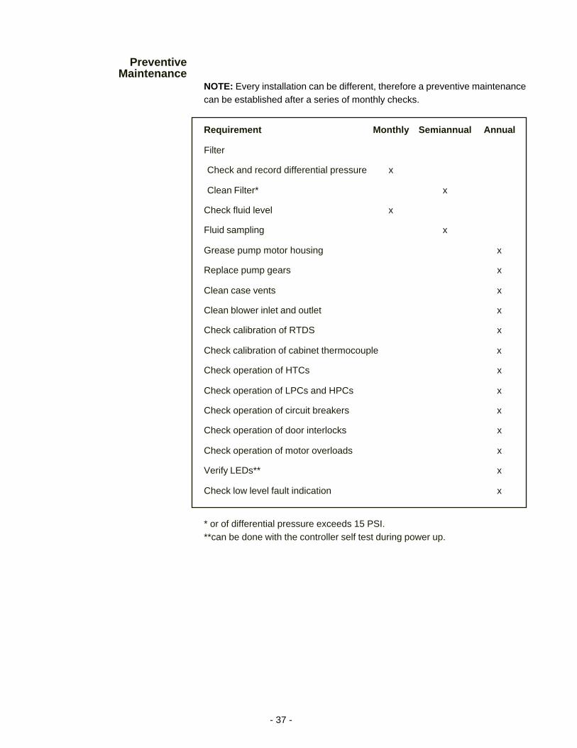
NOTE: Every installation can be different, therefore a preventive maintenancecan be established after a series of monthly checks.
Requirement Monthly Semiannual Annual
Filter
Check and record differential pressure x
Clean Filter* x
Check fluid level x
Fluid sampling x
Grease pump motor housing x
Replace pump gears x
Clean case vents x
Clean blower inlet and outlet x
Check calibration of RTDS x
Check calibration of cabinet thermocouple x
Check operation of HTCs x
Check operation of LPCs and HPCs x
Check operation of circuit breakers x
Check operation of door interlocks x
Check operation of motor overloads x
Verify LEDs** x
Check low level fault indication x
* or of differential pressure exceeds 15 PSI.**can be done with the controller self test during power up.
- 38 -
Section VII Troubleshooting
Main power is not available to unit
-Check main breaker on rear of chiller-Check incoming power supply-Check cable connection in the power box and at your application-Check door interlock on power box-Check door interlock on heater box-Check EMO
Unit fails to enter run mode
-Check microprocessor for fault conditions-See Failure and Warning Condition Table on page 18
Unit will not circulate fluid
-Check tubing between chiller and application-Check pump circuit breaker-Check pump overloads-Check pressure drop across the filter assembly-Check for proper fluid level
Inadequate temperature control
-Check compressor circuit breaker-Check heater circuit breaker-Check temperature probe-Check for fluctuating input power-Check microprocessor for proper calibration-Check for refrigeration system failure
Control system fails to power up
-Check control breaker on the rear of the unit-Check incoming power supply-Check cable connection in the power box and at your application
- 39 -
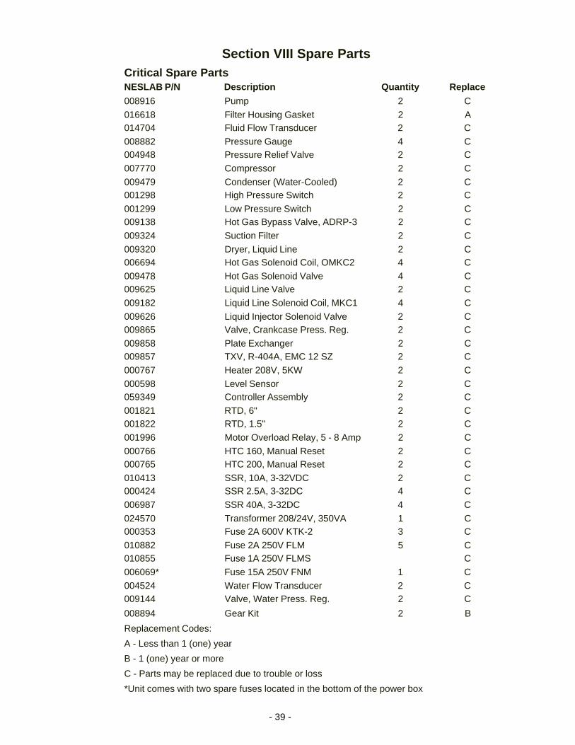
Section VIII Spare PartsCritical Spare PartsNESLAB P/N Description Quantity Replace
008916 Pump 2 C
016618 Filter Housing Gasket 2 A014704 Fluid Flow Transducer 2 C
008882 Pressure Gauge 4 C004948 Pressure Relief Valve 2 C
007770 Compressor 2 C
009479 Condenser (Water-Cooled) 2 C001298 High Pressure Switch 2 C
001299 Low Pressure Switch 2 C009138 Hot Gas Bypass Valve, ADRP-3 2 C
009324 Suction Filter 2 C
009320 Dryer, Liquid Line 2 C006694 Hot Gas Solenoid Coil, OMKC2 4 C
009478 Hot Gas Solenoid Valve 4 C009625 Liquid Line Valve 2 C
009182 Liquid Line Solenoid Coil, MKC1 4 C
009626 Liquid Injector Solenoid Valve 2 C009865 Valve, Crankcase Press. Reg. 2 C
009858 Plate Exchanger 2 C009857 TXV, R-404A, EMC 12 SZ 2 C
000767 Heater 208V, 5KW 2 C
000598 Level Sensor 2 C059349 Controller Assembly 2 C
001821 RTD, 6" 2 C001822 RTD, 1.5" 2 C
001996 Motor Overload Relay, 5 - 8 Amp 2 C
000766 HTC 160, Manual Reset 2 C000765 HTC 200, Manual Reset 2 C
010413 SSR, 10A, 3-32VDC 2 C000424 SSR 2.5A, 3-32DC 4 C
006987 SSR 40A, 3-32DC 4 C
024570 Transformer 208/24V, 350VA 1 C000353 Fuse 2A 600V KTK-2 3 C
010882 Fuse 2A 250V FLM 5 C010855 Fuse 1A 250V FLMS C
006069* Fuse 15A 250V FNM 1 C
004524 Water Flow Transducer 2 C009144 Valve, Water Press. Reg. 2 C
008894 Gear Kit 2 B
Replacement Codes:
A - Less than 1 (one) year
B - 1 (one) year or more
C - Parts may be replaced due to trouble or loss
*Unit comes with two spare fuses located in the bottom of the power box
- 40 -
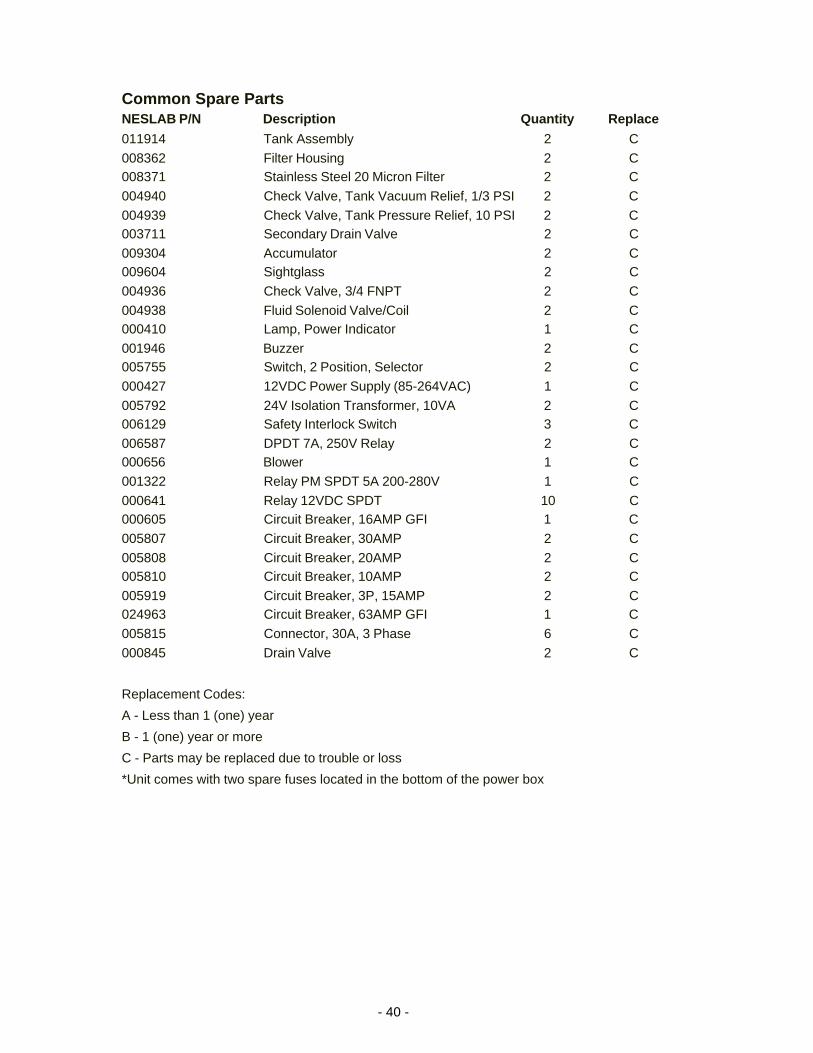
Common Spare PartsNESLAB P/N Description Quantity Replace
011914 Tank Assembly 2 C
008362 Filter Housing 2 C008371 Stainless Steel 20 Micron Filter 2 C
004940 Check Valve, Tank Vacuum Relief, 1/3 PSI 2 C
004939 Check Valve, Tank Pressure Relief, 10 PSI 2 C003711 Secondary Drain Valve 2 C
009304 Accumulator 2 C009604 Sightglass 2 C
004936 Check Valve, 3/4 FNPT 2 C
004938 Fluid Solenoid Valve/Coil 2 C000410 Lamp, Power Indicator 1 C
001946 Buzzer 2 C005755 Switch, 2 Position, Selector 2 C
000427 12VDC Power Supply (85-264VAC) 1 C
005792 24V Isolation Transformer, 10VA 2 C006129 Safety Interlock Switch 3 C
006587 DPDT 7A, 250V Relay 2 C000656 Blower 1 C
001322 Relay PM SPDT 5A 200-280V 1 C
000641 Relay 12VDC SPDT 10 C000605 Circuit Breaker, 16AMP GFI 1 C
005807 Circuit Breaker, 30AMP 2 C
005808 Circuit Breaker, 20AMP 2 C005810 Circuit Breaker, 10AMP 2 C
005919 Circuit Breaker, 3P, 15AMP 2 C024963 Circuit Breaker, 63AMP GFI 1 C
005815 Connector, 30A, 3 Phase 6 C
000845 Drain Valve 2 C
Replacement Codes:
A - Less than 1 (one) year
B - 1 (one) year or more
C - Parts may be replaced due to trouble or loss
*Unit comes with two spare fuses located in the bottom of the power box
- 41 -
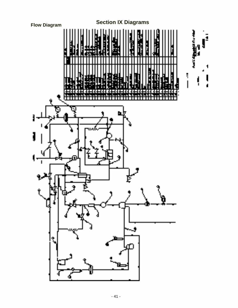
Section IX DiagramsFlow Diagram