Embed Size (px)
Citation preview

HSFC-PRO
Operating Instructions
pco. imaging


Safety Instructions 3
©PCO 2004
Safety Instructions For your own safety and in order to guarantee a safe operation of the camera, please read carefully the following information prior to using the device. • While operating with the camera system please be careful
that the image intensifier is not over exposed. While not using the camera, protect it by using a lens cap. • Never operate the camera at places where water or dust
might penetrate. • Place the camera on a sufficiently stable basis.
Shocks like e.g. dropping the camera onto the floor, might cause serious damage to the device. Please note that the weight of the camera is about 80kg.
• Always unplug the camera before cleaning it. Do not use
cleaning liquids or sprays. Instead, use a dry, soft duster. • Never insert any objects through the device's slots. The ap-
plied voltage inside the camera can cause short-circuits or electrical shocks.
• The slots in the camera housing (bottom and rear panel) are
needed for ventilation. In order to guarantee a proper opera-tion and to prevent overheating of the camera, these slots must always be kept free.
• Make sure that the connecting cable is in good condition and
that the link to the socket does not represent an obstacle. • Detach the camera and contact the customer service in the
following cases:
− When cable or plug are damaged or worn-out. − When water or other liquids have soaked into the device. − When the device is not properly working although you fol-
lowed all instructions of the user's manual. − When the camera fell to the floor or the housing has been
damaged. − When the device shows apparent deviations of normal
operation.
HSFC-PRO


Safety Instructions 5
Safety Instructions for safety use with Image Intensifiers The camera contains a higly sensitive image intensifier, running on voltages of a few kV. To avoid damages or loss of quality, the camera should not be operated with a too high light input. The photocathodes’s lifetime and its loss of sensitivity depends directly on the amount of light impinging on it. A few milisec-onds or even microseconds may be sufficient to damage the photocathode if the light source is powerful enough. The photo-cathode is a thin layer of chemical substances transforming photons in photoelectrons which is eroded every time light strikes it while the photocathode is on. In extreme cases the layer is completely wore off and where it happens a black spot appears. The photocathode is now “blind” and there is no rem-edy. Bright light sources, e.g. lamps or daylight (for example while adjusting or focusing the camera) in a non-gated opera-tion mode can permanently damage the photocathode, even when a monitor does not show any picture (when, for instance the MCP-Gain is set to a minimum). Since the MCP is behind the cathode changing the MCP-Gain does not affect the photocathode. It is a wrong con-clusion to assume lower gain would save the photocath-ode in an overexposed scene. For a safe camera operation we recommend to start with a nearly closed iris (high f-stop, e. g. 22) and short exposure time. If no image is visible or the gain not sufficient to yield an image the exposure time may be carefully increased or the iris opened step by step. If the camera is not in use replace the cap in front of the lens or itensifier. Operational Lifetime Values The halflife of the image intensifier (time taken for a 50% de-crease in sensitivity) is approximately 2000 hours at a light input of 1 mlux. A 10-times higher light input reduces the halflife to approx. 200 hs. This standard value is valid for light inputs of approx. 1 mlux.
Note In the gated mode a linear correspondence of halflife and light input does not apply. In this case substantially higher light inputs are allowed.
©PCO 2004 HSFC-PRO

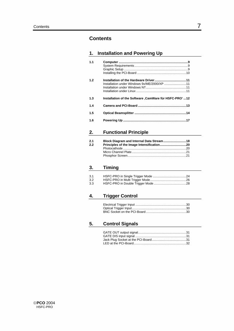
Contents 7
Contents 1. Installation and Powering Up 1.1 Computer ...............................................................................9 System Requirements .............................................................9 Graphic Setup .........................................................................9 Installing the PCI-Board ........................................................10 1.2 Installation of the Hardware Driver....................................11 Installation under Windows 9x/ME/2000/XP .........................11 Installation under Windows NT..............................................11 Installation under Linux .........................................................11 1.3 Installation of the Software ‚CamWare für HSFC-PRO’ ...12 1.4 Camera and PCI-Board .......................................................13 1.5 Optical Beamsplitter ...........................................................14 1.6 Powering Up ........................................................................17
2. Functional Principle 2.1 Block Diagram and Internal Data Stream..........................18 2.2 Principles of the Image Intensification..............................20 Photocathode ........................................................................20 Micro Channel Plate ..............................................................21 Phosphor Screen...................................................................21
3. Timing 3.1 HSFC-PRO in Single Trigger Mode ......................................24 3.2 HSFC-PRO in Multi Trigger Mode.........................................26 3.3 HSFC-PRO in Double Trigger Mode .....................................28 4. Trigger Control Electrical Trigger Input ..........................................................30 Optical Trigger Input..............................................................30 BNC Socket on the PCI-Board ..............................................30
5. Control Signals GATE OUT output signal.......................................................31 GATE DIS input signal ..........................................................31 Jack Plug Socket at the PCI-Board.......................................31 LED at the PCI-Board............................................................32
©PCO 2004 HSFC-PRO

8 Contents
6. Software Application Software CamWare ............................................33 Software Development Kit (SDK) ..........................................33 Drivers ...................................................................................33
7. Servicing, Maintenance and Cleaning Instructions Servicing, Maintenance and Cleaning Instructions ...............34 Cleaning Method for the Optical Part ....................................34 Cleaning Method for the FOL ................................................35
8. Appendix Customer Service..................................................................36 Warranty................................................................................36 CE-Certification .....................................................................36 Dimensions and Weight ........................................................37 System Data..........................................................................38 Operating Instructions HSFC-PRO Version 11/2004 Subject to change without prior notice! Copyright by PCO, 2004
©PCO 2004 HSFC-PRO
1. Installation and Powering Up 9
1. Installation and Powering Up The HSFC-PRO imaging system consists of camera head and four PCI-Boards. To get the system working properly, follow the instructions. 1.1 Computer
System Requirements The PCI-Board should be installed in a computer with following characteristics: • PCI-Bus with PCI-Chip Version 2.1 or higher • Intel Processor, Pentium or AMD • 128 MB RAM • Possible Operating Systems
• Microsoft Windows 95 Version 4.00.950b or higher • Microsoft Windows 98 or 98SE • Windows ME • Microsoft Windows NT 4.0 Workstation • Microsoft Windows 2000 Workstation • Microsoft Windows XP • Linux Kernel 2.2, preferable SuSE 6.3 or newer
In case of working with Linux, please contact PCO.
Graphic Board For best display of images on the monitor we recommend the use of highest performance boards with at least 4MB RAM, preferable with AGP Bus architecture.
Graphic Setup The camera generates 12 Bit (4096 grey levels). For display on the PC Monitor 8 Bit (256 grey levels) respectively 3x8 Bit in true color (16,7 millions colors) are generated. In general, several graphic setups are possible. We recom-mend the setting with 24 or 32 Bit with 16.7 million colors. In the 256-Color-Modus twenty colors are used by Windows for internal purposes. This modus allows to display a maximum of 236 grey levels. Therefore only 7 bit (128 grey levels) are used for black/white display. Some graphic boards use in principle 6 bit for the 256-Color-Modus, i. e. not more than 64 grey levels can be displayed on the monitor.
©PCO 2004 HSFC-PRO

10 1. Installation and Powering Up
Installing the PCI-Board
Caution! Before touching the PCI-Board make sure you have not accu-mulated static charges. A discharge may destroy the sensitive electronics and voids any guarantee. Insert the PCI-Board in a free PCI-slot of your computer and screw the bow onto the PC housing. Make sure the board does not touch any electrical conducting parts (housing, other boards, wires or chillers) It is essential to use a master PCI-slot. Some computers re-quire additional enabling of PCI-slot mastering on BIOS level.
©PCO 2004 HSFC-PRO

1. Installation and Powering Up 11
1.2 Installation of the Hardware Driver You can operate the camera with Windows9x/ME/2000/NT or Linux. Installation under Windows 9x/ME/2000/XP
New-Installation of the hardware driver If you have Windows9x/ME/XP or Windows 2000 installed, the
computer should automatically recognize the new hardware (PCI-Board) and request you to insert a disk with the manufac-turer's drivers. For installation please read the actual information in the re-adme.txt file on the enclosed CD.
Updating the hardware driver For updating an existing driver, please download the newest driver version from the internet under http://www.pco.de. For installation please read the actual information in the re-adme.txt file which will be download automatically with the driver. In case the downloaded drivers are compressed you have to decompress them with a suitable program (e.g. ZIP program). Installation under Windows NT
Installation of the Hardware Driver If you install the camera under Windows NT, you need the rights of the administrator. Please login as administrator. For installation please read the actual information in the re-adme.txt file on the enclosed CD or after downloading from internet. Installation under Linux The Linux driver is on the enclosed CD or can be downloaded from internet under http://www.pco.de. In case the downloaded drivers are compressed you have to decompress them with a suitable program (e.g. ZIP program, TAR program). Detailed instructions for installation you will find in the readme file.
©PCO 2004 HSFC-PRO

12 1. Installation and Powering Up
1.3 Installation of the Software „CamWare for HSFC-PRO“ CamWare for HSFC-PRO is a 32 Bit Windows application. With CamWare all camera parameters can be set. The images can be displayed on the monitor and saved on hard disk. For de-tailed information please see the separate manual ‚CamWare’. You will find the software CamWare for HSFC-PRO on the en-closed CD. The newest version can also be downloaded from the internet under http://www.pco.de.
Installation from CD In case the CD will not start automatically, please start it manu-ally by double click starter.exe. Please select your camera and the software ‘CamWare’:
Installation from Internet Download CamWare from the Internet to a free selected direc-tory. The downloaded file must be decompressed with a suit-able program (e.g. ZIP program) Start the installation with setup.exe. The newest information how to install CamWare can be found in the readme.txt file. To install CamWare under Windows 2000, Windows NT or Windows XP you need administration rights.
Remark After successful installation the computer has to be restarted. The installation program transfers all necessary DLL and OLE files to the respective Windows, checking automatically for ex-isting older versions and replacing them by new ones. Windows’95 carries out all „registry“-entries. If the program is to be deleted from the computer, a proper de-installation is carried out in
START - SETUP - SYSTEM CONTROL - SOFTWARE After successful installation you will have the new directory ‘Digital Camera Toolbox’. CamWare and some additional useful tools will be installed to this directory.
Hotline In case you have problems during installation, call our hotline (see „Customer Service“).
©PCO 2004 HSFC-PRO

1. Installation and Powering Up 13
1.4 Camera and PCI-Board Before Powering Up, make following connections: • Power from Power Supply to Camera • Serial Interface between camera and PCI-Board with en-
closed cables. For the serial data transfer between camera and PCI-Board a fiber optic cable (FOL) is used.
Fiber Optic Link (FOL) Remove the protection caps from the camera and the PCI-Board. Also remove gently the small caps from either end of the cable. Plug in the cable on both devices. Because of the plug shape the cables cannot be mixed up. The plugs should slip in easily. Do not force!
4 PCI-Interface-Boards in the Control Unit (computer)
Caution! Avoid kinking or bending it over a sharp edge (e.g. stepping on it while over a threshold). This will break the core and destroy the cable. Further avoid touching the ends with bare fingers and replace the caps on either the cable or camera / board to pro-tect the sensitive optical surfaces from dust. The small protection caps will be lost easily. Keep the caps on a safe place.
©PCO 2004 HSFC-PRO

14 1. Installation and Powering Up
1.5 Optical Beam Splitter A high performance optical beam splitter is placed between in-put lens and the four intensified cameras. The beam splitter consists of image splitter cubes arranged in the infinite, parallel ray path, generated by a collimator lens at the common optical input. Each image splitter has an output lens coupled to the camera. This way eventual dust or particles on the optical components will not degrade the image quality. The beam splitter’s construction eliminates aberrations due to changes in wavelength, e.g. when placing filters in the optical path. Standard Nikon F–Mount lenses are suited as input objectives. If required, single image beam splitters may be removed from the path so that whole light input is concentrated on a reduced number of channels. There are fine thread screws to adjust the beam splitter cubes. Springs hold the image splitter cubes in its position and secures against shocks. On the next page you can see the adjustment screws of a bean splitter cube.
Remark Only trained personnel should adjust the image beam splitter cubes!
Back focal length change To change the back focal length loosen the counter-ring at the common optical input and turn the tubus in or out, as required. Do not forget to tighten the counter-ring again.
Optical input The optical input may be used either straight or angled. Please note that all four images of an angled input will be mirrored. The software function “mirror” or “flip” reverts the images to the original.
Filter Depending on configuration of your camera, filters may be placed in the optical path either in front of each channel or in front of two channels simultaneously or on the whole input
©PCO 2004 HSFC-PRO

1. Installation and Powering Up 15
Beam splitter cube with adjustment screws Before adjustment the two fixing screws must be loosen.
©PCO 2004 HSFC-PRO

16 1. Installation and Powering Up
Top view of the HSFC-PRO with placing of the four chan-nels.
©PCO 2004 HSFC-PRO

1. Installation and Powering Up 17
1.6 Powering Up Check the following points: • Four PCI-Boards properly mounted? • Camera-Boards connections via FOL properly made? • Power supply connected to camera, to main? • Objective lens mounted? • Protection cap on the lens?
Switch on the computer Switch on the computer but do not start yet the program HSFC-Control
Switch on the camera Switch on the camera by pressing the POWER button on the rear panel of the device. The four dual LEDs will be green, but can also be red for a short time.
Starting CamWare Now start the program „CamWare for HSFC-PRO“ from the
directory Programme – Digital Camera ToolBox. For detailed information to CamWare please see the separate manual ‚CamWare’.
©PCO 2004 HSFC-PRO

18 2. Functional Principle
2. Functional Principle The images, captured by the camera head, will be transferred via a high speed data transfer to the PCI-Board in the com-puter. The data will be saved in the RAM of the computer where the operator can decide what to do with them. With the enclosed software ‚CamWare’ the camera can be con-trolled within the windows environment and the images can be displayed on the monitor. The Recorder function allows you to record image sequences and display them as "movies". The maximum memory space for the recorded images depends solely on the RAM size of your computer. For detailed information to CamWare please see the separate manual ‚CamWare’. 2.1 Block Diagram and Data Stream
Block Diagram The following block diagram shows the structure of the whole system.
Power
Serial Data Transfer12Bit A/D parallel/serial
Converter
Logic Control
Power Unit
Lens Adapter
4 PCI-Interface-Boards
CCDImageIntensifier
TandemLens
CCDImageIntensifier
TandemLens
CCDImageIntensifier
TandemLens
CCDImageIntensifier
TandemLens
ImageIntensifier
BeamSplitter
©PCO 2004 HSFC-PRO

2. Functional Principle 19
Internal Data Stream The PCI-Board gets the 12 Bit data from the camera and trans-fers it via PCI-Bus to a 16 Bit array (of the PC Memory). The higher 4 Bits are set to zero. The 16 Bit data are automatically converted to a 8 Bit array and accessed by the graphic board. Depending on graphic board setup display on the monitor is ef-fected in 8, 24 or 32 Bit.
File Formats The command ‘Export’ stores 16 Bit or 8 Bit data on hard disc in
BMP, TIFF, FITS or B16 format. Display The command ‘Convert Control’ allows to select a discretionary
range between 0 ... 4095 grey levels (12 Bit) which is then dis-played in 256 grey levels (8 Bit) on the PC monitor.
HSFC-PROPC
Monitor
4 PCI-Interface-Boards Graphic Board
PCI-Bus
©PCO 2004 HSFC-PRO

20 2. Functional Principle
2.2 Principles of the Image Intensification Following drawing sketches the function principle of the MCP intensifier.
6kV acceleration voltage
0 ... 900Vgain
-180V/+80Vshutter on/off
light
object
lens
e- e-
light phosphor screen
connected to a high voltage power supply, e.g. HVMCP
photocathode connected to a pulser, e.g. HVP5N, HVP2N
MCP micro channel plate
Light emitted from an object releases photoelectrons at the photocathode. The photoelectrons enter the channels of a mi-cro channel plate (MCP) where they are multiplied producing secondary electrons. Finally the accelerated electrons hit a phosphor screen producing a light emission.
Photocathode The photocathode consists of a thin layer of a material with a low activation energy for electrons and allows a high quantum efficiency down to long wavelength. Choosing the right material and layer thickness the spectral sensitivity can be varied from the near UV to the near infrared. The quantum efficiency (number of photoelectrons to number of photons) of many materials is as high as 10% or even above. By applying a voltage to the photocathode, electrons are either pushed towards the MCP (negative voltage) or hold back in the photocathode (positive voltage). This property of the intensifier makes it particularly suited as an electronic shutter. Not all the voltages of a few KV applied to the intensifier has to be switched for this purpose. A potential difference of 200-250 V at the photocathode is sufficient to achieve a shutter ratio of 1:107. High performance ‘high voltage’ generators achieve gate times of a few nanoseconds. The capacitive load (approx. 100pF) of the photocathode is switched with a rise and fall time of 1-2 ns.
©PCO 2004 HSFC-PRO

2. Functional Principle 21
Caution The image intensifier’s photocathode is the most sensitive com-
ponent of the camera. Its lifetime depends decisively of the photocathode current (photo effect). Setting a high MCP gain spares the photocathode, since a low incident light generates low photocathode current and already produces enough signal to saturate the CCD. The intensifier’s lifetime also depends on the number of expo-sures whether they are single ones or taken with a high imaging frequency.
Micro Channel Plate (MCP) Secondary photoelectron multiplication occurs in the micro channel plate (MCP), made of lead glass and having about 106-107 microscopic channels of typically 6µm diameter and 0.5 mm length. Each channel represents a photomultiplier which dynodes are replaced by a continuous semiconducting surface. Manufactur-ing of such micro channel plates is a rather complex process while the properties of the final device may be widely manipu-lated to yield the desired result. The intensification depends mainly from two parameters, the ratio of the channel’s length to diameter and the applied voltage. The variation of the light in-tensification of the image intensifier is just a result of variation of the applied MCP voltage. For the described type of MCP it ranges from 0 to 104 V.
Phosphor Screen After all the electrons are accelerated towards the phosphor screen by fixed bias voltage of several KV producing a light emmittance. For the choice of the right phosphor the quantum efficiency and the afterglow (decay time) play a part. The decay time may vary from a few nanoseconds to a few seconds, de-pending on the phosphor material. Thus it has to be carefully selected to match the applications preconditions. Mainly the ‘Double Trigger Mode’ which carries out two expo-sures with very short time demands a fast phosphor with a short decay time. Phosphor-decay at the ‚Double Trigger Mode’:
Delay 1
PhosphorOutput
Delay 2 incl.500ns dead time
CCD Integration Image 1
Phosphor DecayExposure 1 Exposure 2
©PCO 2004 HSFC-PRO

22 2. Functional Principle
The CamWare program allows to extend the phosphor integra-tion time by setting an appropriate value in the Camera Control window.
General Properties The whole unit photocathode – MCP phosphor screen is a sealed high vacuum device to prevent an interaction between electrons and gas atoms. In case an electron hits a gas atom an positive ion results which is accelerated towards the photo-cathode. There it produces undesired electrons (ion feed-back). Often image intensifiers do have fiber optic input and output windows to facilitate an optical coupling. The focal plane is transferred from the inside to the outer surface of the window. At very high light inputs MCP channels tend to saturate, reduc-ing dramatically its intensification. Furthermore, a too high light input may produce a local photocathode etching or even de-stroy the whole device. Already too long exposure times at room lighting or short, in-tense laser beams, even reflected ones are sufficient to yield black spots, an irreparably damage. Suited converter (UV, IR) are used to shift the spectral sensitiv-ity. Further, open MCP intensifiers, without photocathode di-rectly coupled to an evacuated experimental setup detect x-rays, electrons or other charged particles.
©PCO 2004 HSFC-PRO

3.Timing 23
3. Timing The info field of Camera Control contains the actual read out time and image repeat frequency (frames per second, fps), de-pending on the chosen setting (ROI, binning).
CCD readout time repetition frequency
(frames per second)
Pulser type The following trigger modi of the HSFC-PRO are different, de-pending of the used pulser HVP3X. pulser type minimum pulse length HVP3X-3 3ns HVP3X-5 5ns HVP3X-20 20ns
If you want to make single exposures, please go on reading on the next page with HSFC-PRO in ‘Single Trigger Mode’ If you want to make multiple exposures, please go on reading on page 26 with HSFC-PRO in ‘Multi Trigger Mode’ If you want to make double exposures, please go on reading on page 28 with HSFC-PRO in ‘Double Trigger Mode’
©PCO 2004 HSFC-PRO

24 3. Timing
3.1 HSFC-PRO in Single Trigger Mode Single Trigger Mode < 20ns ≥ 20ns max. pulse frequency 3,3 KHz 2 MHz resulting minimum delay between two exposures
300µs 500ns
Delay Time 0 ... 1000s Steps see below!
Loops 1 ... 256 The selected delay and exposure time can be repeated up to 256.
Exposure Time x ns ... 1000s (x = depending of the pulser) Steps see below!
Possible settings for delay and exposure times Following there is an overview of the possible settings for delay and exposure times.
50ns
Trigger
1ns steps 5ns steps 20ns steps
20ns steps
1µs steps
1µs steps
0 100ns 1000ms
1000ms
1000s
30ns
10ns steps
See table below
3 100ns 1000s
Delay
Exposure
pulser type fixed exposure times in [ns] HVP3X-3 3 - 10 - 20 - 25 - 30 HVP3X-5 5 - 10 - 20 - 25 - 30 HVP3X-20 5 - 10 - 20 - 25 - 30
©PCO 2004 HSFC-PRO

3.Timing 25
In addition to the selected delay and exposure times there is a system delay time and a pulser delay time. They are defined by the system itself and cannot be changed.
System Delay
Loop 1 ... 256 *
Exposure Time of the CCD
Pulser Delay Delay
Phosphor Decay
Exposure
CCD-Readout
Internal Trigger (auto)External Trigger (external)
System Delaywhen delay and exposure time each <= 100ns: 25ns +/- 0,25nswhen delay or exposure time > 100ns: 25ns +/- 2ns
Readout time of the CCD sensorThe readout time depends of the sensor type(VGA or SuperVGA), of the selected binning andof the ROI (region of interest).The exact readout time can be seen in the Infofield of the Camera Control window.
Phosphor DecayThe phosphor decay time depends of the usedphosphor material. The CCD integration time will be increased by this 'Decay [ms]' time
TimeIntensifier-Timing
CCD-Timing
Pulser DelayHVP3x at < 20ns : 20nsHVP3x at => 20 ns : 60ns
* The Loop function requires an additional internal time of 5 x 64µs (VGA sensor) respect. 5 x 117µs (SuperVGA sensor) for each loop
©PCO 2004 HSFC-PRO

26 3. Timing
3.2 HSFC-PRO in Multi Trigger Mode Multi Trigger Mode < 20ns ≥ 20ns max. pulse frequency
not allowed
2 MHz
resulting delay between two exposures
not allowed
500ns
Delay Time 0 ... 999ms Steps see below!
Exposure Time 20ns ... 999ms) Steps see below!
Loops 1 ... 256 The selected delay and exposure time pairs can be repeated up to 256. Each Loop will be triggered separate. (Trigger auto or external)
Possible settings for delay and exposure times Following there is an overview of the possible settings for delay and exposure times.
Trigger
20ns steps
0 999ms
20ns steps
20ns 999ms
Delay
Exposure
©PCO 2004 HSFC-PRO
3.Timing 27
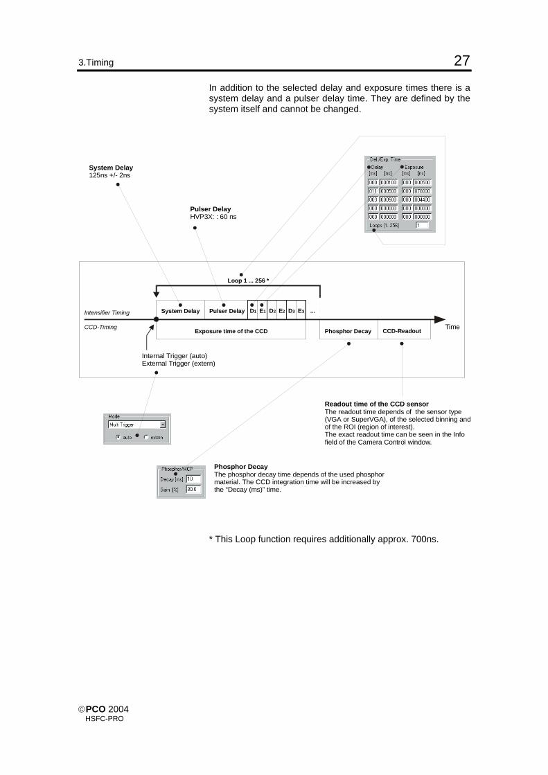
In addition to the selected delay and exposure times there is a system delay and a pulser delay time. They are defined by the system itself and cannot be changed.
System Delay
Loop 1 ... 256 *
Exposure time of the CCD
Pulser Delay D1 E1 D2 E2 D3 E3 ...
Phosphor Decay CCD-Readout
Internal Trigger (auto)External Trigger (extern)
System Delay125ns +/- 2ns
Readout time of the CCD sensorThe readout time depends of the sensor type(VGA or SuperVGA), of the selected binning andof the ROI (region of interest).The exact readout time can be seen in the Infofield of the Camera Control window.
Phosphor DecayThe phosphor decay time depends of the used phosphormaterial. The CCD integration time will be increased by the “Decay (ms)” time.
Time
Intensifier Timing
CCD-Timing
Pulser DelayHVP3X: : 60 ns
* This Loop function requires additionally approx. 700ns.
©PCO 2004 HSFC-PRO

28 3. Timing
3.3 HSFC-PRO in Double Trigger Mode Double Trigger Mode < 20ns ≥ 20ns max. pulse frequency 2 MHz
resulting delay between two expo-sures
not 500ns
min. exposure time allowed 20ns ‘dead time’ between both exposures 500ns
Delay Time 0 ... 10ms Steps see below!
Exposure Time 20ns ... 999ms Steps see below!
Possible settings for delay and exposure times Following there is an overview of the possible settings for delay and exposure times. Trigger
20ns steps
0 10ms
20ns steps
20ns 999ms
Delay
Exposure
©PCO 2004 HSFC-PRO

3.Timing 29
In addition to the selected delay and exposure times there is a system delay and a pulser delay time. They are defined by the system itself and cannot be changed.
Hint The Double Trigger Mode should only be used for short time separation between the two exposures. Otherwise the camera should be operated in the ‘Single Trigger Mode’ or in the ‘Multi Trigger Mode’.
System Delay
Exposure Time Image 1
Exposure TimeImage 2
Pulser Delay
>= 1µs
Del.1Delay2
Exp.1 Incl.. Dead Time Exp.2
CCD-ReadoutImage 1
CCD-ReadoutImage 2Internal Trigger (auto)
External Trigger (extern)
System Delay125ns +/- 2ns
Readout time of the CCD sensorThe readout time depends of the sensor type(VGA or SuperVGA), of the selected binning andof the ROI (region of interest).The exact readout time can be seen in the Infofield of the Camera Control window.
Time
Intensifier Timing
CCD-Timing
Pulser DelayHVP3X: 60ns
2. Exposure
©PCO 2004 HSFC-PRO

30 4. Trigger Control
4. Trigger Control There are two ways of triggering the HSFC-PRO, internally via the HSFC-Control software and externally via the trigger input at the rear panel of the camera. For external triggering, you can select between electrical or op-tical trigger.
Electrical Trigger Input A TTL signal (5V) with rising edge is required. The rise time should be <20ns. Internally the input is connected to ground (GND) with 1kΩ.
Optical Trigger Input A trigger signal has to last for a minimum of 10ns. A light power of 1mW is sufficient.
Trigger LED) At the camera rear panel the red LED in the segment TRIG IN shows an incoming trigger pulse. The dual LEDs at the four fiber optic link inputs show the data transfer at each channel (not trigger signal!).
BNC Socket at the PCI-Board
The BNC Socket at the PCI-Board has no function.
©PCO 2004 HSFC-PRO

5. Control Signals 31
5. Control Signals At the camera rear panel there are two BNC sockets with con-trol signals.
GATE OUT High active TTL-control output. For exposure times >20ns, there is a TTL high active signal at the GATE OUT socket while the photocathode is on. It starts 60ns before the photocathode on-times and ends 60ns before the off-time (pulser delay). For exposure times <20ns the GATE OUT pulse is always 100ns.
GATE DIS Low-active TTL-control input. While the GATE OUT is active (photocathode is on) the on-time can be disabled by a low active TTL signal. Please note that you may activate this control input only for ex-posure times >20ns!
Jack Plug Socket at the PCI-Board The 3.5mm stereo jack plug socket at the PCI-Board has a double function:
TRIG IN
Function 1: BUSY Signal This control output signals if the camera is ready to accept a new trigger signal. While BUSY is active, an external trigger sig-nal will be ignored. The BUSY signal edge depends of the selected trigger input edge of the TRIG IN signal. When the trigger input is falling edge (selected in the CameraControl window), an output signal low means the camera is busy, an output signal high means the cameras is ready to accept a new trigger signal.
BUSYSTORE
Function 2: STORE Signal Control Output (high active) STORE signals the data transfer from the camera to the PCI-Board.
©PCO 2004 HSFC-PRO
32 5. Control Signals
LEDs at the PCI-Board
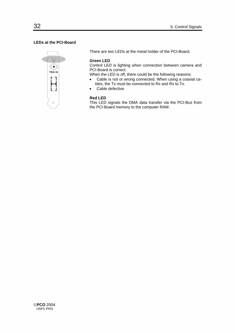
There are two LEDs at the metal holder of the PCI-Board.
TRIG IN
Green LED Control LED is lighting when connection between camera and PCI-Board is correct. When the LED is off, there could be the following reasons: • Cable is not or wrong connected. When using a coaxial ca-
bles, the Tx must be connected to Rx and Rx to Tx. • Cable defective Red LED This LED signals the DMA data transfer via the PCI-Bus from the PCI-Board memory to the computer RAM.
©PCO 2004 HSFC-PRO

6. Software 33
6. Software
Application Software Shipment of the camera system includes the CamWare soft-ware, a complete operation software for the camera allowing to display and to save images. For detailed information to CamWare please see the separate manual ‚CamWare’.
Software Development Kit In case you have written your own software or you wish to in-clude the control software into already existing programs, the camera control may be integrated as DLL file by using our Soft-ware Development Kit (SDK). The following SDK’s with detailed manual are available: • SDK for Windows 9x/ME/2000/NT/XP • SDK for Linux The SDK can be found on the CD or can be downloaded from Internet under http://www.pco.de.
Drivers To work with the camera properly a Twain driver and the follow-ing PCI-Board drivers are available: • PCI-Board driver for Windows 9x/ME/2000/XP • PCI-Board driver for Windows NT • PCI-Board driver for Linux The drivers can be found on the CD or can be downloaded from Internet under http://www.pco.de.
©PCO 2004 HSFC-PRO

34 7. Servicing, Maintenance and Cleaning Instructions
7. Servicing, Maintenance and Cleaning Instructions
Servicing, Maintenance and Cleaning Instructions The camera is maintenance-free. Factory settings make any inspection and servicing superflu-ous. During use the camera should be protected from hard shocks or strong vibrations. Also should the camera be protected from high humidity and temperature shocks. Avoid exposing to sunlight, since it heats up the camera housing unnecessarily and prevents the cooling from reaching its optimum operating temperature. Keep apertures and slots free to allow air to circulate. Objective lens or lens adapter should be screwed in gently. Avoid forcing as it will damage the tread. Use a soft and dry cloth to clean the housing.
Cleaning Method for the Optical Part In principle every cleaning method bears the danger of damag-ing an optical surface. Therefore clean only if it is strictly necessary. As a first step use dry air to blow out dust particles. Avoid strictly to wipe on a dry glass surface. In case dirt cannot be removed by blowing, use special optical cleaning fluids. Adequate fluids for optical surfaces are: pure dehydrogenated alcohol, pure acetone or cleaning fluids avail-able in photo shops. Use a soaked cotton tip and take care to wipe only on glass surfaces, avoiding contact to metal surfaces, e.g. C-Mount thread, otherwise microscopic dirt and metallic chips are released, causing irreparable scratches on the glass surface. Never use aggressive cleaning substances, e.g. benzine, spirit, nitro solvents, etc. commonly found in labs. Such substances may destroy or damage the surface on which they are applied.
Hint The best is to avoid any dirt on optical parts, e.g. by replacing immediately the black protection cap when removing the objec-tive lens. Do not leave the camera’s optical input window open, without lens or protecting cap. Our warranty does not cover damaged optical surfaces caused by improper cleaning methods.
©PCO 2004 HSFC-PRO

7. Servicing, Maintenance and Cleaning Instructions 35
Cleaning Method for the FOL The core of the Fiber Optic Link is a 64µm diameter glass fiber. The connectors and the fiber itself should be cleaned only by dry dust free air. Again, after disconnecting, replace the respective protection caps on either camera and cables immediately.
©PCO 2004 HSFC-PRO

36 8. Appendix
8. Appendix Customer Service Having a problem or a question about matters not handled in these operating Instructions, we recommend to contact us :
... by Telephone 09441/2005-0
... by Fax 09441/2005-20
... by Email [email protected]
... by Post PCO AG Donaupark 11 D-93309 Kelheim Germany For a quicker reply we need following information: • Short description of the problem • Experiment conditions • Settings of delay and exposure time • Used camera control software and version number • Camera serial number • PCI-Board serial number (520 ... or 525 ...) • Operating System • Processor type of your computer • Size of RAM • Type of graphic board • Graphic setup Warranty PCO grants warranty by law for the HSFC-PRO System (cam-era, PCI-Board, FOL, power supply). The warranty period starts on day of delivery ex-factory. In case of defect within the war-ranty period replacement or repair will be made (at PCO’s dis-cretion) free of charge. The device shall be returned on cus-tomer’s expenses to PCO, preferably in the original package. Image intensifiers are subject to the original manufacturer’s warranty conditions PCO is not liable for consequential damages. Before returning the camera, contact PCO via any of the Cus-tomer Services. Pay attention to use a sufficient package if you have to send the camera via mail (keep the original package). The FOL cable connectors and the connectors of the camera and PCI-Board must be protected with the protection caps. Don’t forget to screw the C-Mount protection cap!
Attention Opening of the camera or improper handling (e.g. damage by electrostatic charge, wrong cleaning method) voids the war-ranty. CE Certification SensiCam complies with the requirements of the „EMC Direc-tions of the European Communities (089 / 336 / EWG)“ and therefore bears the CE-Marking.
©PCO 2004 HSFC-PRO

8. Appendix 37
Dimensions and Weight The weight of the camera is between 80 ... 100kg, depending of the equipment. Bottom plate with position of the threads:
©PCO 2004 HSFC-PRO

38 8. Appendix
System Data
Image Intensifier see separate data sheet ‘specification of the image intensifier’
Power and Gating Supply for the Image Intensifier Phosphor Voltage 6 ... 7kV, internally adjusted, ripple ±15mV MCP Voltage 0 ... 900V, externally adjusted, ripple ±15mV Photocathode Voltage on: -180V, off: +80V Gating Module HVP3X In Ultra Fast Gating mode:
min. pulse width: 5ns, optional 3ns, 1.5ns max. pulsing frequency: 3.3kHz In High Rate Gating mode: min. pulse width: 20ns max. pulsing frequency: 2MHz
Optical Coupling (Ultra Speed Tandem Lens) Collimator Lens Rodenstock F2.5/105mm Output Lens F1.0/33mm or F1.5/46mm Quantum Efficiency (typ.) > 22% Vignetting < 3% Resolution > 60 lp/mm Scaling Rates 18mm and VGA sensor 25mm and VGA sensor 25mm and SuperVGA sensor
1:2.17 1:3 1:2.17
CCD Data VGA SuperVGA Sensor Type CCD-Interline Progressive Scan with “lens-on-
chip“ Number of Pixels 640(H) x 480(V) 1280(H) x 1024(V) Pixel Size 9.9µm x 9.9µm 6.7µm x 6.7µm Sensor Format ½“ 2/3“ Scan Area 6.3mm x 4.8mm 8.6mm x 6.9mm Cooling Type 2-stage peltier cooler with forced air cooling CCD Temperature -15°C -12°C Full Well Capacity 35.000 e- 25.000 e-
Scan Rate 12.5 MHz 12.5 MHz Readout Noise @12.5 MHz 13 ... 14 e- 7 ... 8 e-
A/D-Converter 12 Bit @12.5MHz A/D Conversion Factor 7.5 e-/count 5 e-/count Max. Quantum Efficiency monochrome, @ 520nm
≥ 40%
Spectral Response (monochrome) 280 ... 1000nm Average Dark Charge 7) < 0.1 e-/pixel.sec < 0.1 e-/pixel.sec Extinction Ratio 1) 1:2000 1:2000
x) See „Definitions and Measurement Conditions“
©PCO 2004 HSFC-PRO

8. Appendix 39 CCD Data VGA SuperVGA Smear 2) < 0.005% < 0.005% Anti Blooming 3) > 1000 > 1000 CCD Quality grade 0 grade 0 Non-Linearity < 1% < 1% Readout Time (Full Frame) 30 fps 8 fps Binning Horizontal 1...8 Binning Vertical 1...128 Blemishes
Point Defects 4) 0 0 Cluster Defects 5) 0 0 Column Defects 6) 0 0
Warm Pixels 7) typ. # pixels > 100 e- 0 0 # pixels > 5 e- 0 - 2 0 - 2 # pixels > 1 e- 250 - 1000 500 - 2000
Non-Uniformity in darkness 8) typ. 1 count 1 count Non-Uniformity in brightness 9) typ. 0.2% 0.6%
# pixels > 12% 0 0 # pixels 8 ... 12% 0 0 - 2 # pixels 4 ... 8% 0 10 - 50 # pixels 2 ... 4% 0 - 5 n.a.
Optical Input C-Mount with adjustable focus length Dimension Head: 93(W) x 78(H) x 210(L) mm Weight 8 kg Operating Temperature 0...40°C Storage Temperature -20...+70°C Humidity 10...90% non condensing
High Speed Serial Link High Speed Serial Link standard: fiber optic link 10 ... 1500m,
SC connectors PCI-Interface Board Board PCI Local Bus compatible, revision 2.1 Buffer RAM 16 MByte Trigger Input TTL level (rising/falling edge); BNC connector or FOL
Power Supply Power Supply Desktop AC/DC 90...260V / 12V, IEC connector
12V / 4,5A x) See “Definitions and Measurements Conditions”
©PCO 2004 HSFC-PRO

40 8. Appendix Definitions and Measurement Conditions 1) Extinction ratio It is the ratio of “electronic shutter off“ Voff to “electronic shutter on“ Von. It is measured with an exposure time set to 100ns and a pulsed laser diode (20ns) illumination. During exposure window (100ns) light is attenuated by a factor of 1:1000 grey filter, while out of the exposure window filter is removed. Thus: 2) Smear The CCD is set to 40ms exposure time with an uniform illumination to achieve 50% of saturation (V50). Then the electronic shutter is closed (readout clock is stopped, charge drain is performed by the electronic shutter) and the illumination is set to 500 times over exposure. After 40ms the CCD is read out.
E = ⋅VV
off
on
11000
SmVV
Sm= ⋅ ⋅50
1500
100%The measured output signal (VSm) is substituted in the following formula: 3) Anti Blooming The factor of over exposure allowed to avoid blooming in the neighbouring pixels. 4) Point Defect Measured under Conditions A: A point defect is a pixel whose signal deviates by more than 3 counts from the mean value of 48 neighbouring pixels (7x7 array). Measured under Conditions B: A point defect is a pixel whose signal deviates by more than 12 % from the mean value of 48 neighbouring pixels (7x7 array). 5) Cluster Defect Measured under Conditions A. Is a group of 2 ... 6 contiguous defective pixels. 6) Column Defect, Row Defect Measured under Conditions A. Is a group of more than 6 contiguous defective pixels along a single column or row. 7) Warm Pixel / Dark Charge Measured under Conditions C. A pixel is considered a warm pixel, if it has an increased dark charge generation. No test for FastShutter version. 8) Non-Uniformity in darkness, compared to neighbouring pixels Measured under Conditions A. Non-uniformity of a single pixel is the deviation in counts, compared to the mean value of 48 neighbouring pixels (7x7 array). 9) Non-Uniformity in brightness, compared to neighbouring pixels Measured under Conditions A or B. Non-uniformity of a single pixel is the deviation in %, compared to the mean value of 48 neighbouring pixels (7x7 array).
typical deviation d dtyp x
n
. = ∑1
d pp
x xn= − ∑ 481
48
dx = deviation of the tested pixel Px = pixel to test Pn = 48 neighbouring pixels (7x7 array)
with n = 307,200 for VGA (640 x 480 pixels) with n = 1,310,720 for SuperVGA (1280 x 1024
Conditions for measurement For all conditions the operating temperature is -15°C for VGA and -12°C for SuperVGA A : exposure time 40ms Binning H1, V1 256 images averaged dark field conditions
B : exposure time 40ms Binning H1, V1 256 images averaged uniform illumination to yield 75% saturation (about 3,000 counts)
C : exposure time 200 s Binning H1, V1 16 images averaged dark field conditions
©PCO 2004 HSFC-PRO

Dear Customer, We hope this camera will be an always valuable tool for your scientific day in, day out work. Comments, suggestions or any new idea on our system are welcome. We are at your disposal at any time, also after your buying of this camera.
Your PCO Team
pco. imaging
PCO AG Donaupark 11 D-93309 Kelheim fon: +49 (0)9441 2005 0 fax: +49 (0)9441 2005 20 eMail: [email protected]