Embed Size (px)
Citation preview
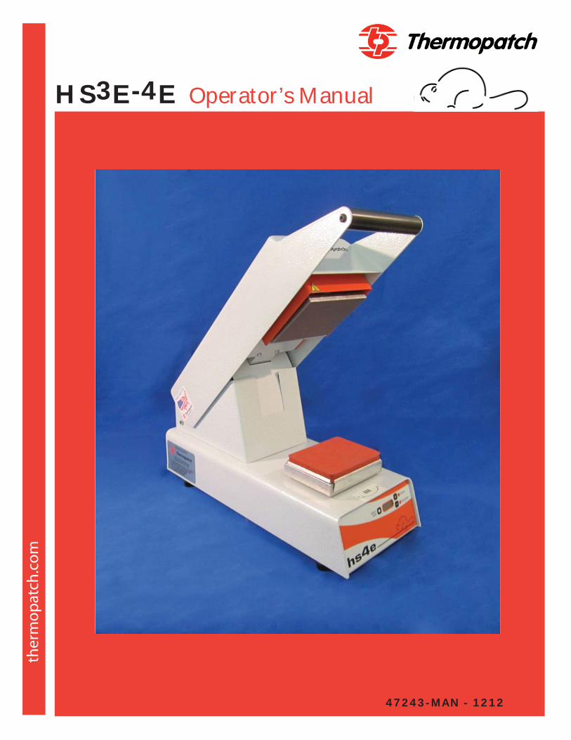
HS3E-4E Operator’s Manual
47243-MAN - 1212

© 2011, Thermopatch, Syracuse, New York. No part of this publication may be reproduced by any means without the prior written permission of Thermopatch, Syracuse, New York. Thermopatch, Thermo-Seal, Alligator, Beaver, Cheetah, Deco-Print, Penguin, TruFlex and the Thermopatch logo are ® trademarks of Thermopatch, Syracuse, New York.
Copyright
Contents1. Introduction
1.1 What Did You Receive? 1.2 Machine Specifications
2. Machine Settings
4. Troubleshooting
6. Drawings and Parts Listings
1.3 Safety Information
5. Maintenance
3. Operating Instructions
1.4 Conditions of Warranty
4.1 Common Problems and Causes 4.2 Temperature Controller Error Codes
1.5 Customer Service 1.6 Setting Up the Machine
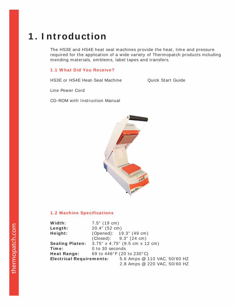
The HS3E and HS4E heat seal machines provide the heat, time and pressure required for the application of a wide variety of Thermopatch products including mending materials, emblems, label tapes and transfers.
1.1 What Did You Receive?
HS3E or HS4E Heat-Seal Machine Quick Start Guide
Line Power Cord
CD-ROM with Instruction Manual
1.2 Machine Specifications
Width: 7.5" (19 cm)Length: 20.4" (52 cm)Height: (Opened): 19.3" (49 cm) (Closed): 9.3" (24 cm)Sealing Platen: 3.75" x 4.75" (9.5 cm x 12 cm)Time: 0 to 30 secondsHeat Range: 69 to 446°F (20 to 230°C)Electrical Requirements: 5.6 Amps @ 110 VAC, 50/60 HZ 2.8 Amps @ 220 VAC, 50/60 HZ
1. Introduction
1.3 Safety Information
The HS3E and HS4E heat seal machines have a Power Saver energy feature. The machine heater element will be de-energized after a preset time and cool down to room temperature. This will occur when the preset “Power Saver Time” has elapsed.
Re-activation of the HS3E or HS4E machine is achieved by lowering the Seal Arm handle of the machine. Once the Seal Arm Handle is lowered into the “Locked” position, the machine will exit the Power Saver Mode. The Heater Element of the machine will become re-energized and increase in temperature to the preset “Power Saver Temperature.” Upon achieving the preset Power Saver Temperature, the Sealing Cycle Timer will begin counting down to zero seconds.
This machine is equipped with a fully grounded 3-wire cord and plug. It must be used only in conjunction with a properly grounded outlet of the correct voltage.
WARNING: THE HEATER ELEMENT CAN CAUSE SKIN BURNS!
1.4 Conditions of Warranty
Thermopatch Corporation, Syracuse, New York (”Seller”) warrants this product to be free from defects in material and workmanship under normal use and service. Any part which proves to be defective in material or workmanship within one year of the date of original purpose for use will be repaired or replaced, at Seller’s option, free of service or labor charges, with a new or functionally operative part. Seller’s liability under the Warranty shall be limited to repairing or replacing at its own factory or through an authorized service distributor or dealer, material which is determined by Seller to have been defective in manufacture and upon which a claim has been made by the original purchaser or user to Seller (or an authorized distributor or dealer) within the warranty period. An authorized officer of Seller will honor claims under this Warranty only upon written approval. Approved return of parts or products will be on a prepaid transportation charges basis only. Claims under this Warranty will be honored only upon Seller’s determination that the claim is covered by this Warranty, and Seller shall incur no obligation under this Warranty prior to such determination. This Warranty does not apply: (1) To any machinery or equipment which has been altered or repaired, except by Seller or its authorized representatives, or (2) to any machinery or equipment which has been subject to misuse, negligence or accident, including, without limitation, use and operation of such machinery or equipment while parts are loose, broken, out of order, or damaged by the elements. Parts replaced under this Warranty are warranted only through the remainder of the original Warranty. Any and all claims for warranty service must include such information as Seller designates, and shall include specifically the serial number of each unit (if appropriate).
The foregoing shall constitute the sole and exclusive remedy of any using purchaser and the sole and exclusive liability of Seller in connection with this product. THIS WARRANTY IS IN LIEU OF ALL OTHER WARRANTIES, EXPRESS, IMPLIED OR STATUTORY, INCLUDING BUT NOT LIMITED TO, ANY WARRANT OF MERCHANTABILITY OR FITNESS AND ALL OTHER OBLIGATIONS OR LIABILITIES OF SELLER, INCLUDING ANY TORT LIABILITY, FOR NEGLIGENT DESIGN OR MANUFACTURE OF THIS PRODUCT, OR OTHERWISE. It is expressly agreed that Buyer shall not be entitled to recover any incidental or consequential damages, as those terms are defined in the Uniform Commercial Code, and that Buyer shall have no right of rejection or of revocation of acceptance of any part or of the goods covered hereby.
1.5 Customer Service
Thermopatch Corporation’s U.S. and International network of Sales Representatives, as well as its internal Customer Service Department, offer their assistance in the development of effective heat-seal mending, marking and identification programs.
Thermopatch markets a complete line of heat-seal and marking machines, as well as a complete line of materials and supplies.
Label Print Machines – Manual, automatic and computer controlled.Marking Machines – High speed permanent imprinting of decorative or informative marks on most woven fabrics.Heat-Seal Machines – Manual, semi-automatic and completely automatic, with high inter-platen pressure to assure excellent adhesion of label tapes and mending materials.Label Tapes – Specially woven 100% cotton and blends with adhesives to match specific processing requirements.
The Deco-Print line of products has been specifically designed to offer alternative solutions to sewn-in labeling and other methods of decorative trimming. An assortment of heat-sealable applications are available including hot paper transfers, screen printed transfers, direct printing, application equipment and supplies and digital printed transfers.
When ordering machine parts, please include the model and serial numbers of your equipment.
United States :
Thermopatch Corporation P.O. Box 8007
Syracuse, New York 13217-8007 Telephone: 315-446-8110 Fax: 315-445-8046 Toll Free: 800-252-6555 (in the US only)
Canada : Thermopatch (Canada) Incorporated
25 Groff Place, Unit No. 5 Kitchener, Ontario N2E 2L6 Telephone: 519-748-5027 Fax: 519-748-1543 Toll Free: 800-265-6416 (in Canada only)
Australia : Thermopatch (Australia) Pty. Ltd. 477 Warrigal Road, Unit No. 9
Moorabbin, Victoria 3189 Telephone: 011-61-3-9532-5722
Fax: 011-61-3-9532-5652
Netherlands : Thermopatch BV P.O. Box 50052 1305 AB Almere Netherlands
Telephone: 011-31-36-549-1111 Fax: 011-31-36-532-0398
Germany : Thermopatch Deutschland Grunteweg 33 26127 Oldenburg Deutschland Telephone: +49 441-380210 Fax: +49 441-3802121 E-mail: [email protected]
France : Thermopatch France 7 Rue Chappe-Z.I. Des Garennes B.P. 1011 Les Mureaux Cedex 78131 France Telephone: 011-33-1-3022-0808
Fax: 011-33-1-3022-1866
Internet Address : http://www.thermopatch.com E-mail Address : [email protected]
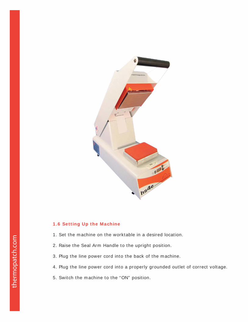
1.6 Setting Up the Machine
1. Set the machine on the worktable in a desired location.
2. Raise the Seal Arm Handle to the upright position.
3. Plug the line power cord into the back of the machine.
4. Plug the line power cord into a properly grounded outlet of correct voltage.
5. Switch the machine to the “ON” position.
During the heat-up phase and when the machine has achieved “Set Temperature,” changes to the machine settings for Set Temperature, Temperature Display in Celsius or Fahrenheit, Sealing Cycle Time, Power Saver Time and Power Saver Temperature can be made.
Changes cannot be made to the settings during an active Sealing Cycle.
LCD Panel FunctionsThe following describes the LCD Display functions:
The Celsius or Fahrenheit LED will light up continuously once the temperature is within range of the setting. Range is +/- 15°F and +/- 7°C.
When not in a sealing cycle, the actual temperature of the Heater Element is displayed.
During the sealing cycle, the LCD will display a countdown of the time in seconds from the preset Sealing Cycle Time.
The machine has been factory preset to:Temperature: 400°F (204°C) Sealing Time: 12 seconds Power Saver Timer: 30 minutesPower Saver Temperature: 302°F (150°C)
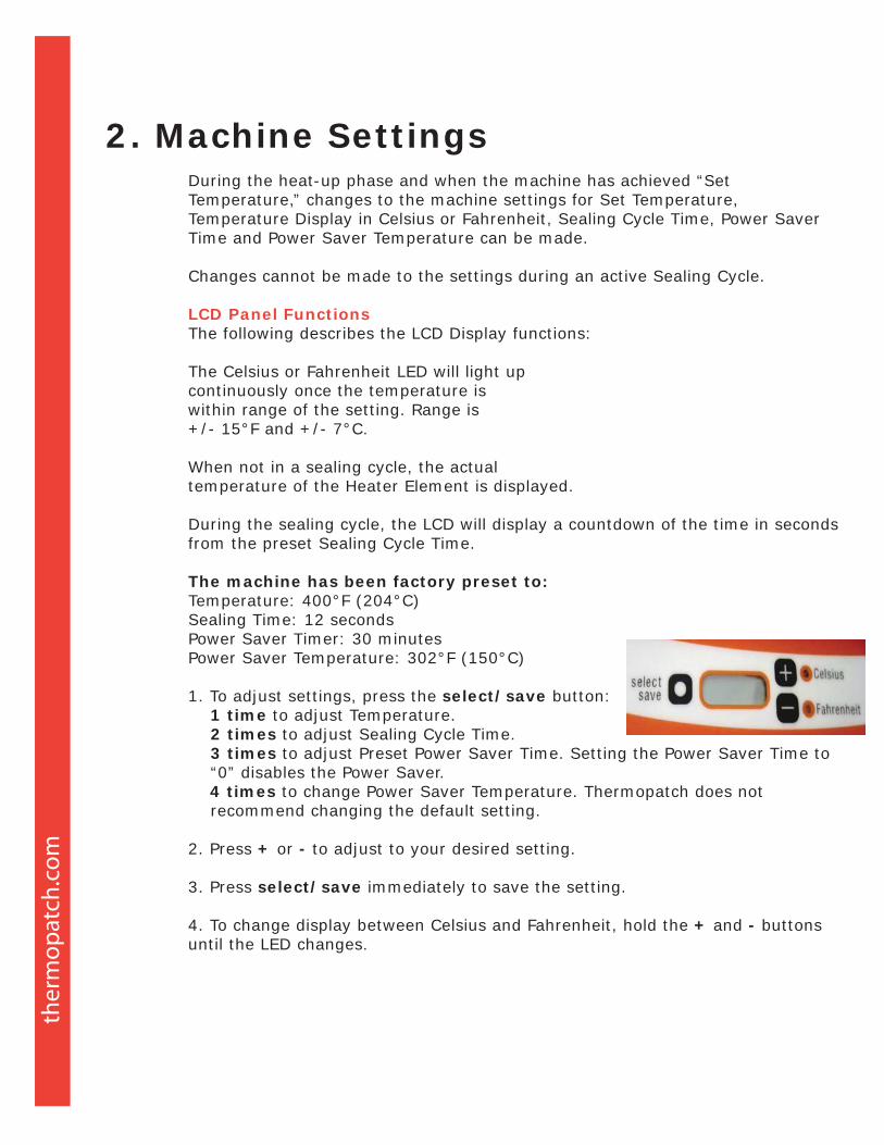
1. To adjust settings, press the select/save button: 1 time to adjust Temperature. 2 times to adjust Sealing Cycle Time. 3 times to adjust Preset Power Saver Time. Setting the Power Saver Time to “0” disables the Power Saver. 4 times to change Power Saver Temperature. Thermopatch does not recommend changing the default setting.
2. Press + or - to adjust to your desired setting.
3. Press select/save immediately to save the setting.
4. To change display between Celsius and Fahrenheit, hold the + and - buttons until the LED changes.
2. Machine Settings
Important: Read this entire section before operating the machine.
1. Set the heat and time settings to your recommended levels. See Control Panel Instructions. Double-check settings have been saved.
2. Individual HS3E and HS4E machines vary slightly. To achieve the optimum pressure setting, adjust the lower platen such that when the Sealing Arm Handle is down, it depresses 1/16th of an inch (1.5mm).
3. Place the garment to be labeled on the sealing platen.
4. Place the repair patch, emblem or label tape adhesive shiny side down (Transfers should be placed ink side down).
5. Lower the Seal Arm Handle to its locked position.
6. At the end of the Sealing Cycle an alarm buzzer will sound. The HS3E Series Machine requires a manual release. The HS4E Series Machine will automatically release.
WARNING: THE HEATER ELEMENT CAN CAUSE SKIN BURNS! HEAT- SEALED MATERIALS ARE VERY HOT. ALL HEAT-SEALED MATERIALS SHOULD BE ALLOWED TO COOL DOWN BEFORE HANDLING.
Pressure adjustment may be necessary. Normally, higher pressures will produce more effective heat seals. However, the use of excess pressure may force adhesive through the fabric, with an unsightly result.
THE DATUM HEIGHT OF THE LOWER SEAL PLATEN IS (4) TURNS UP FROM THE BASE OF THE MACHINE. ANY LESS WILL DAMAGE MACHINE.
A label to indicate the direction in which to turn the Lower Press Platen is mounted directly below the Lower Press Platen. To increase inter-platen pressure, turn the Lower Press Platen counterclockwise. To decrease the inter-platen pressure, turn the Lower Press Platen clockwise.
Caution: Use of excess pressure can cause the HS3E and HS4E machines to become locked in a closed position and difficult to open. Extreme pressure may severely damage your machine and your garment.
Difficulty locking the Seal Arm Handle of the HS3E or HS4E machines in a closed position is an indication of too much inter-platen pressure. To prevent excess pressure when sealing thick garments, turn the Lower Press Platen down.
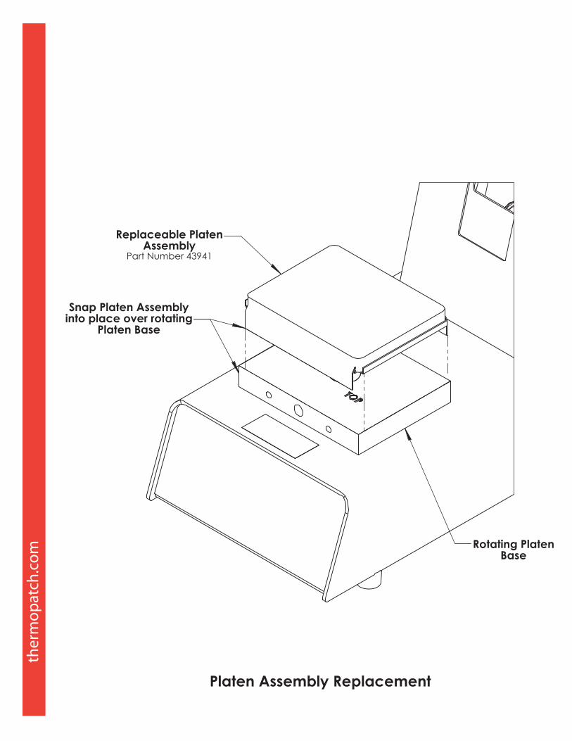
A Lower Press Platen that is worn from use can cause insufficient inter-platen pressure. The Lower Press Platen (P/N 43941) can be replaced.
3. Operating Instructions

4.1 Common Problems and Causes
Head will not come down. The most common causes are: 1. Mechanical binding 2. Broken links 3. Broken link pivot shaft
Head will not lock down. The most common causes are: 1. Sealing platen is adjusted too low 2. Release motor switch out of adjustment (HS4E) 3. Release motor faulty (HS4E) 4. Mechanical binding 5. Worn gears 6. Broken or stretched links 7. Broken link pivot shaft
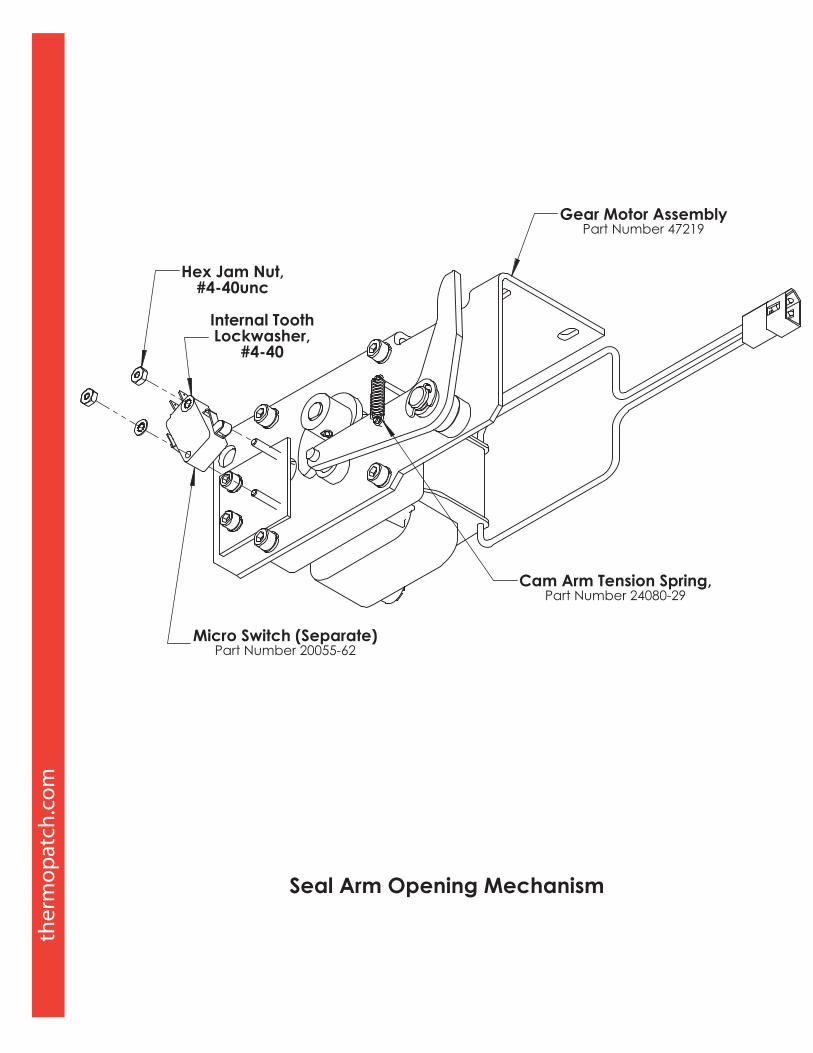
Head will not release (HS4E only). The most common causes are: 1. Incorrect machine setup 2. Sealing platen adjusted too high 3. Release motor microswitch out of adjustment 4. Cam on release motor loose or out of position 5. Faulty release motor switch 6. Broken return spring 7. Broken rod end 8. Faulty start switch 9. Faulty control board 10. Faulty release motor
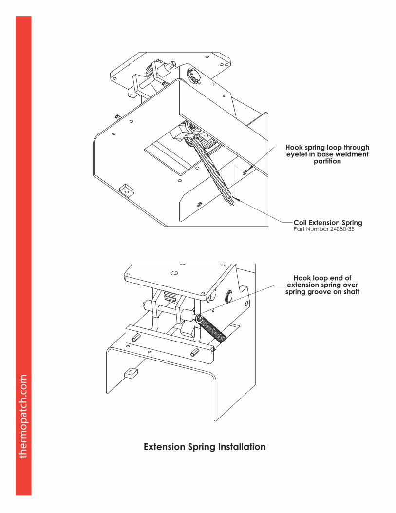
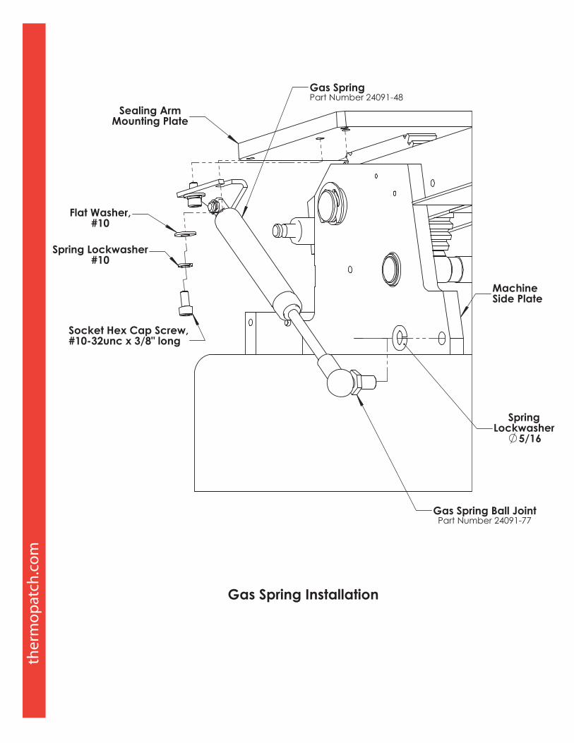
Head will only raise 1-2”. The most common causes are: 1. Broken spring 2. Faulty gas spring
Head will only come up halfway. The most common causes are: 1. Broken rod end 2. Faulty gas spring
Heating problems (No heat or low heat). The most common causes are: 1. Temperature settings incorrect 2. Machine in “Sleep Mode” 3. Faulty temperature sensor 4. Broken wiring to sensor 5. Faulty relay 6. Faulty temperature controller 7. Faulty heater
4. Troubleshooting
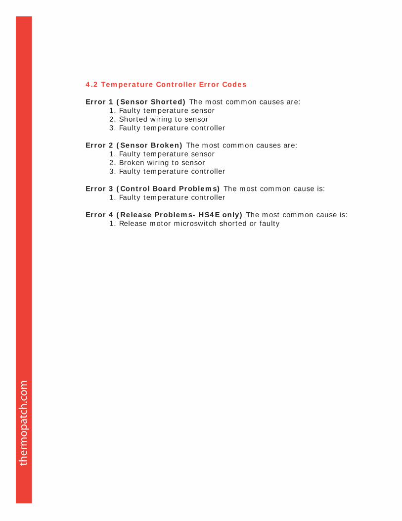
4.2 Temperature Controller Error Codes
Error 1 (Sensor Shorted) The most common causes are: 1. Faulty temperature sensor 2. Shorted wiring to sensor 3. Faulty temperature controller
Error 2 (Sensor Broken) The most common causes are: 1. Faulty temperature sensor 2. Broken wiring to sensor 3. Faulty temperature controller
Error 3 (Control Board Problems) The most common cause is: 1. Faulty temperature controller
Error 4 (Release Problems- HS4E only) The most common cause is: 1. Release motor microswitch shorted or faulty
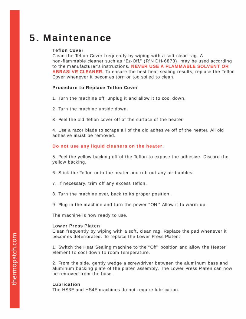
Teflon CoverClean the Teflon Cover frequently by wiping with a soft clean rag. A non-flammable cleaner such as “Ez-Off,” (P/N DH-6873), may be used according to the manufacturer’s instructions. NEVER USE A FLAMMABLE SOLVENT OR ABRASIVE CLEANER. To ensure the best heat-sealing results, replace the Teflon Cover whenever it becomes torn or too soiled to clean.
Procedure to Replace Teflon Cover
1. Turn the machine off, unplug it and allow it to cool down.
2. Turn the machine upside down.
3. Peel the old Teflon cover off of the surface of the heater.
4. Use a razor blade to scrape all of the old adhesive off of the heater. All old adhesive must be removed.
Do not use any liquid cleaners on the heater.
5. Peel the yellow backing off of the Teflon to expose the adhesive. Discard the yellow backing.
6. Stick the Teflon onto the heater and rub out any air bubbles.
7. If necessary, trim off any excess Teflon.
8. Turn the machine over, back to its proper position.
9. Plug in the machine and turn the power “ON.” Allow it to warm up.
The machine is now ready to use.
Lower Press PlatenClean frequently by wiping with a soft, clean rag. Replace the pad whenever it becomes deteriorated. To replace the Lower Press Platen:
1. Switch the Heat Sealing machine to the “Off” position and allow the Heater Element to cool down to room temperature.
2. From the side, gently wedge a screwdriver between the aluminum base and aluminum backing plate of the platen assembly. The Lower Press Platen can now be removed from the base.
LubricationThe HS3E and HS4E machines do not require lubrication.
5. Maintenance

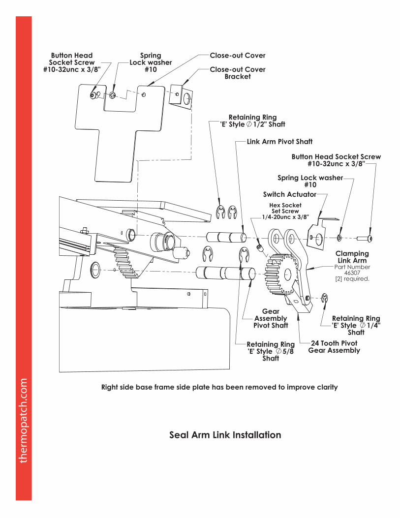
Drawings and Parts ListingOn the following pages, the reader will find technical drawings and corresponding parts listings of the HS3E and HS4E machines. The technical drawing illustrating a particular sub-assembly or area of the machine provides the individual parts for that sub-assembly or area. A complete listing of available parts is provided at the end of this chapter.
The reader will find that the technical drawings and corresponding parts listings are arranged by category. Those categories in order are:
1. Electrical
2. Mechanical
3. Parts listing
N
E
P
E
N
P
Line
Sid
e Chassis Gnd
1 8
GRN/YEL
L1 BLK
L2 WHT
J1
J21 8
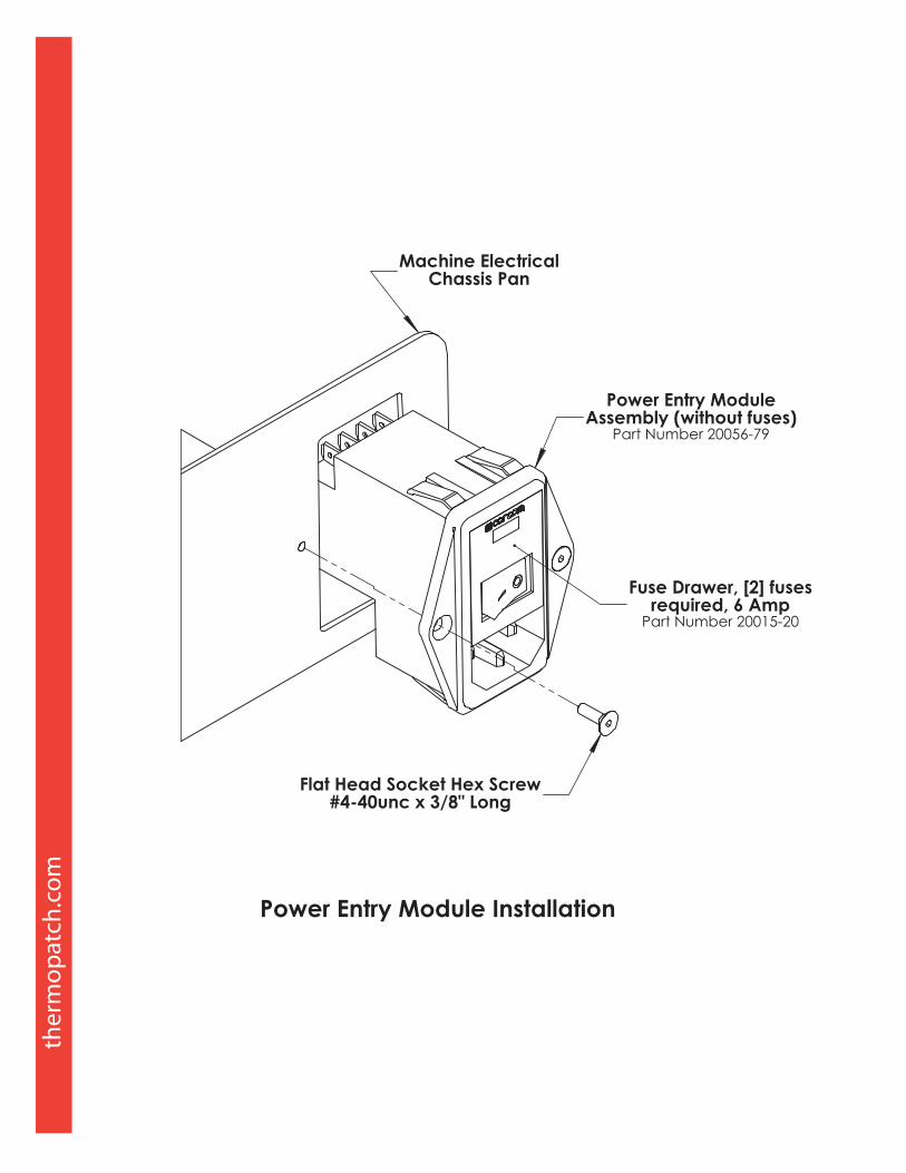
Power Entry ModuleFuses: [2] 6.3 Amp
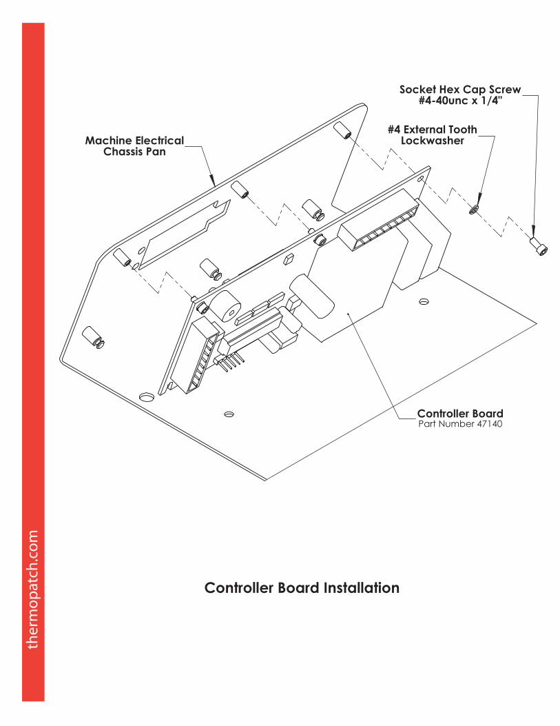
ControllerBoard
+
Solid StateRelay
5 BL
K
2 RE
D1
RED
6 W
HT
5 BLK
6 WHT
L1 WHT
L2 WHT
AC
Inp
ut
HTR
MTR
Wire HarnessPlug
Heater UnitHigh LimitThermostat
GRN
/YEL
Wire HarnessPlug
7 BL
K8
WH
T
7 BLK
8 WHT
7 BL
U
GRN
3 G
RY4
GRY
Seal SwitchLS1 LS2
Motor ControlSwitch
8 BL
U
Wire HarnessPlug
5 YEL
6 YEL RED
YELThermocouple,
Type K
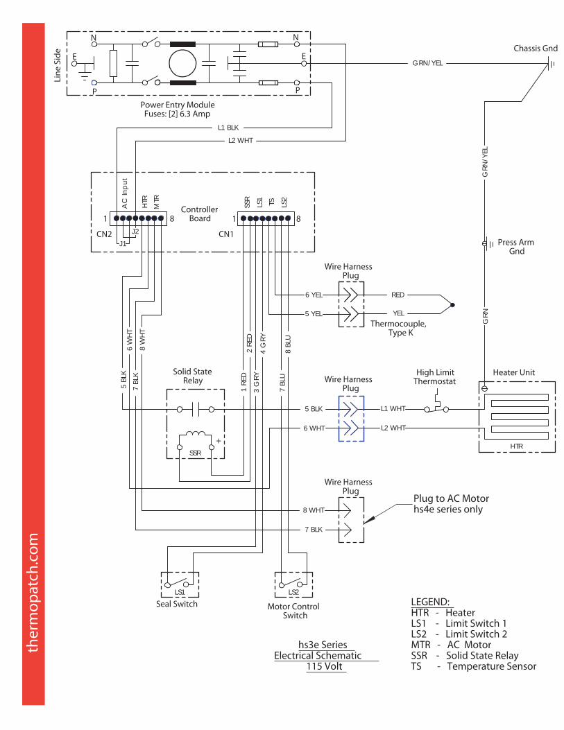
hs3e SeriesElectrical Schematic
115 Volt
CN2 CN1
SSRHTR
Press ArmGnd
LEGEND:HTR - HeaterLS1 - Limit Switch 1LS2 - Limit Switch 2MTR - AC MotorSSR - Solid State RelayTS - Temperature Sensor
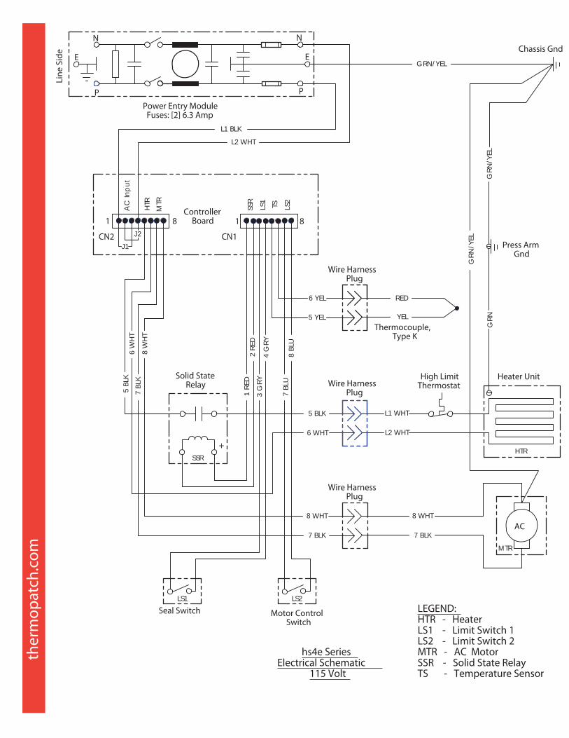
Plug to AC Motorhs4e series only
SSR
LS1 TS LS2
N
E
P
E
N
P
Line
Sid
e Chassis Gnd
1 8
GRN/YEL
L1 BLK
L2 WHT
J1
J21 8
Power Entry ModuleFuses: [2] 6.3 Amp
ControllerBoard
+
Solid StateRelay
5 BL
K
2 RE
D1
RED
6 W
HT
5 BLK
6 WHT
L1 WHT
L2 WHT
AC
Inp
ut
HTR
MTR
Wire HarnessPlug
Heater UnitHigh LimitThermostat
GRN
/YEL
Wire HarnessPlug
7 BL
K8
WH
T
7 BLK
8 WHTAC
GRN
/YEL
7 BLK
8 WHT
7 BL
U
GRN
3 G
RY4
GRY
Seal SwitchLS1 LS2
Motor ControlSwitch
8 BL
U
Wire HarnessPlug
5 YEL
6 YEL RED
YELThermocouple,
Type K
hs4e SeriesElectrical Schematic
115 Volt
CN2 CN1
SSR
MTR
HTR
Press ArmGnd
LEGEND:HTR - HeaterLS1 - Limit Switch 1LS2 - Limit Switch 2MTR - AC MotorSSR - Solid State RelayTS - Temperature Sensor
LS2TSLS1
SSR

HS3E and HS4E Parts Listing
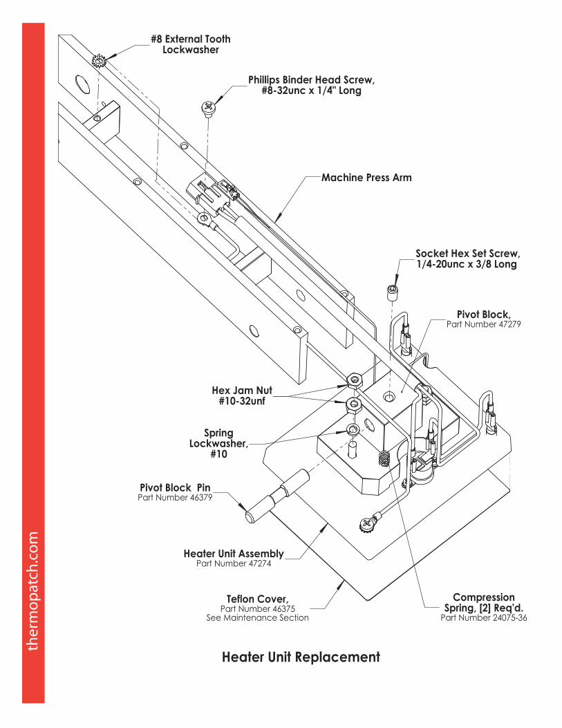
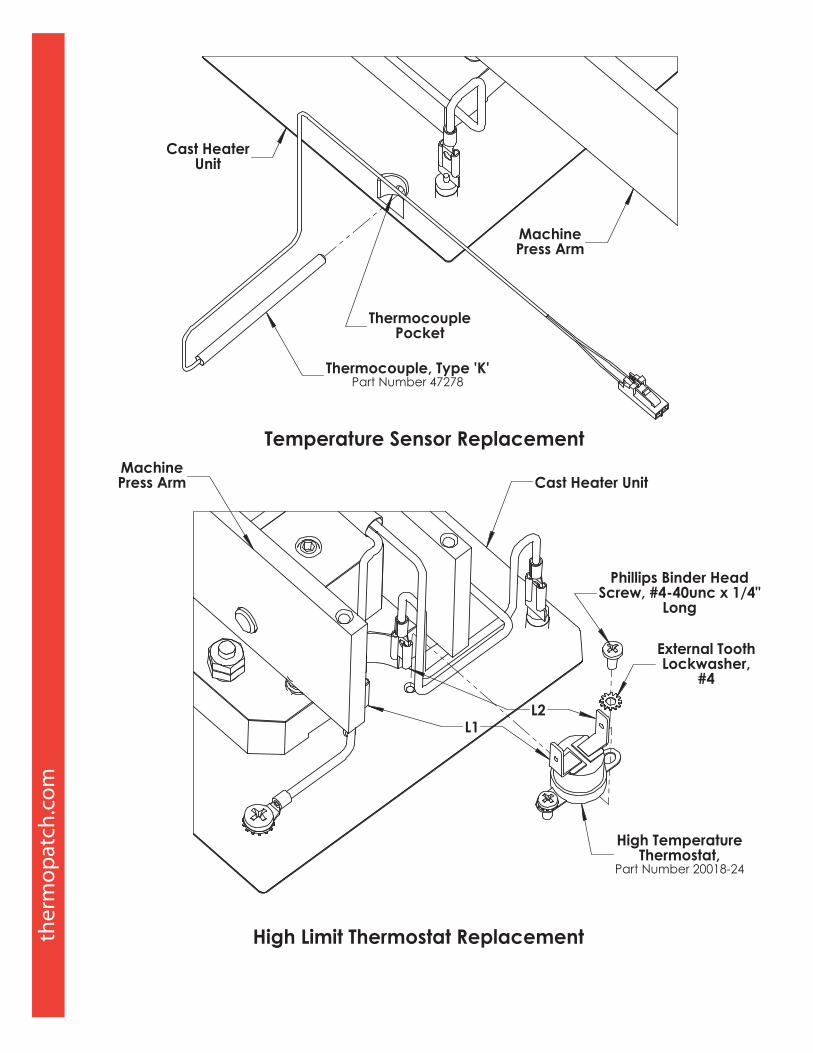
Part # Part Description20015-20 Fuse, 6 amp, 2 required20018-24 High limit thermostat20040-69 Solid State Relay21050-185 Rubber feet, 4 required20080-70 115 volt electric power cord24080-29 Spring, tension; HS4E only, release cam24080-35 Return spring24091-48 Gas spring, without rod end24091-77 Rod end, ball joint, M8 thread43941 Platen Assembly, Lower Sealing46307 Link Clamp (sold in pairs)46325 Gear, Spur, 48 tooth46374 Bracket Assembly, Gas Spring46375 Teflon Cover, Heating Unit, 4” x 5”46493 Gear Assembly, Spur, 24 tooth47140 Controller Board47262 Cover, Front Close out47278 Temperature Sensor Assembly, Type K47280 Detent Disc, Platen Post
Thermopatch Corporate Headquarters USA T +1 315 446-8110 F +1 315 445-8046 [email protected] Thermopatch European Headquarters The Netherlands T +31 36 549 11 11 F +31 36 532 03 98 [email protected] Thermopatch Australia Pty Ltd Australia T +61 395325722 F +386 2 80 55 232 [email protected] Thermopatch Canada Inc Canada T +1 519 748-5027 F +1 519 748-1543 [email protected] Kannegiesser UK Ltd United Kingdom T +44 1539 722122 F +44 1539 721000 [email protected]


![[l5r 4e] Legend of the Five Rings 4E - Imperial Archives](https://img.pdfslide.us/doc/110x75/56d6cb291a28ab30169ca7a1/l5r-4e-legend-of-the-five-rings-4e-imperial-archives.jpg)