Embed Size (px)
Citation preview
Subje
ct t
o M
odifi
cations
Fehringerstrasse 45A-8280 Fürstenfeld
Tel.: +43 (0)3382/53388Fax: +43 (0)3382/53093
FN21826yUID ATU30764704
E-Mail: offi [email protected]: www.osteosynthese.at2
0090507w
r H
S30 S
urg
ical
Tech
niq
ue
FA R
ev05V0 -
ge
Hofer GmbH & Co KG
HS3.0 - HOFER FOREARM SYSTEM
Surgical Technique
WINKELSTABIL - MULTIDIREKTIONAL
HS3.0 - HOFER UNTERARM SYSTEM
Operationsanleitung
ANGLE STABLE - MULTIDIRECTIONAL
InhaltContent
Vorwort SF-ST-1Preface
Verwendungszweck SF-ST-2Purpose
Implantat spezifische Informationen FA-ST-3Implant Specific Information
Indikationen und Kontraindikationen Indications and Contra Indications
Patientenlagerung Position of Patient
Zugänge Approaches
Operationstechnik SF-ST-4Operation Technique
#1 - Platzierung des Implantes Insertion of the Implant
#2 - Temporäre Fixierung Temporary Fixation
#3 - Ausrichtung des Implantates Orienting the Implant
#4 - Schraubenplatzierung Screw Placement
#5 - Entfernung der temporären Fixierung oder Instrumente Removal of temporary Fixations or Instruments
#6 - Wundverschluss Wound Closure
#7 - Postoperative Behandlung Post Operative Treatment
#8 - Implantatentfernung Implant-Removal
Klinische Fälle FA-ST-5Clinical Cases
SF-ST-1
20080215w
r H
S30 S
urg
ical
Tech
niq
ue
Pref
ace
Rev
03V0 -
ge
VorwortPreface
This document provides information about the handling of Hofer implants and instruments.
This operation manual‘s intention shall be considered as an addition and under no circumstances as a substitute to existing literature about surgical methods within trau-matolgy.
The content shall be regarded as a recommendation for a standardized procedure of how to apply the products wi-thout addressing the issues of any further necessary tasks, addtional operative actions and possible extensions of the surgical technique.The actual selection of the most suitable implant and its implantation method has to happen exclusively by the sur-geon based on his education and the individual diagnostic fi ndings.
Please also consider that all illustrations printed here have a purely symbolic character to support the description of the surgical technique and can vary
Furthermore these operation instructions don‘t contain any details on the use of the instruments. Corresponding do-cuments are available as indicated within the section „Ge-neral Instructions“.These are namely:• Instruction manual for instruments: Intra and post ope-
rative handling• Instruction manual for implants (enclosed to each imp-
lant)
Note that it is in the surgeons function to identify and cha-racterize the respective injury and its subsequent treat-ment.
An adequate reduction of the anatomical structures has to be established always!
Dieses Dokument enthält Informationen zur Anwendung von Hofer Implantaten und Instrumenten.
Diese Anleitung soll als eine Ergänzung und unter keinen Umständen als Ersatz zu bestehender Literatur über Ope-rationsmethoden der Orthopädie und Traumatologie be-trachtet werden.
Dieser Inhalt soll als eine Empfehlung für eine standar-disierte Vorgehensweise in der Anwendung der Produkte verstanden werden, ohne auf weitergehende erforderliche Maßnahmen, Zusatzeingriffe und mögliche Erweiterungen der OP-Technik einzugehen.Die tatsächliche Auswahl des erforderlichen bzw. geeig-neten Implantates sowie der Implantationsmethode muß durch den Chirurgen aufgrund seiner Fachkenntnisse und anhand der individuelle Befundkonstellation erfolgen.
Die Abbildungen innerhalb dieses Dokumentes sollen ex-emplarisch die Operationsanleitung bildlich unterstützen. Abweichungen zu diesen Darstellungen können auftreten.
Diese Operationsanleitung enthält keine Angaben über die richtige Handhabung des Instrumentariums. Entspre-chende Unterlagen sind verfügbar in Form von• Gebrauchsanweisung für Instrumente: Intra- & Posto-
perative Handhabung• Gebrauchsanweisung für Implantate (ist jedem Implan-
tat beiliegend)
Bitte nehmen Sie zur Kenntnis, dass die Diagnosestellung sowie Festlegung der Behandlungsstragie einzig beim Chi-rurgen liegt.
Eine adäquate Reposition der Fraktur muss stets ange-strebt werden!
VerwendungszweckPurpose
The HS3.0 Hofer System is a multi directional and angle
stable implant system for small fragments based on the
internal fi xateur principle.
The HS3.0 system is designed to meet epiphyseal, meta-
physeal and intra articular fractures of small bones only.
All Hofer products result out of a joint development of
experienced clinicians and our engineers. This successful
cooperation results in providing products to meet the ana-
tomical and functional requirements of the respective sites
due to their pre-contoured and low profi le design and to
provide an almost unrestricted operative treatment ran-
ging from simple to cominuted fractures.
For more indepth information on the technical capabilities
of this implant system we would like to recommend the
additionally available brochure „Tips & Tricks“.
SF-ST-2
20080215w
r H
S30 S
urg
ical
Tech
niq
ue
Purp
ose
Rev
02V0 -
ge
Das HS3.0 System der Hofer Gmbh & Co KG (HOFER) ist
ein multidirektionales und winkelstabiles Kleinfragment
Implantatesystem basierend auf dem Fixateur intere Prin-
zip.
Das HS3.0 System dient zur Behandlung von epiphysären,
metaphysären und intraartikulären Frakturen kleiner Kno-
chen.
Alle HOFER Produkte resultieren aus einer gemeinsamen
Entwicklung bestehend aus erfahrenen Anwendern und
unseren Ingenieuren. Diese erfolgreiche Kooperation führt
zu Produkten, die die anatomischen und funktionelle Anfor-
derungen der jeweiligen Struktur aufgrund des anatomisch
vorgeformten Low-Profi l Designs sowie der vielfältigen
Versorgungsmöglichkeiten von einfachen bis Trümmerfrak-
turen erfüllen.
Weiterführendere Informationen zu den technischen Mög-
lichkeiten dieses Implantatesystems enthält die Broschüre
„Tips & Tricks“.
- Extra & intra-articular fractures of the distal radius
- Arthrodesis in the carpal region
- Extra & intra-articular fractures of the distal radius
- Arthrodesis in the carpal region
Patient Positioning:
Standard
Approach: Standard
- 11 (Version M1) oder 10 (Version M2) screw placement options for the epiphysial region
- Styloid can be attached to the plate directly- K-Wire holes for temporary fi xation and / or
fracture reduction- Slotted hole for primary fi xation and plate
orientation- All holes accept angle stable or not angle
stable screws- Pre Shaped, re-contouring possible, even
across holes- Low-profi le design, minimal screw head
overlap
- „3-Point-Support“ of the distally located screws
Patient Positioning:
Standard
Approach: Standard
- 9 screw placement options for the epiphysial region
- Styloid can be attached to the plate directly- K-Wire holes for temporary fi xation and / or
fracture reduction- Slotted hole for primary fi xation and plate
orientation- All holes accept angle stable or not angle
stable screws- Pre Shaped, re-contouring possible, even
across holes- Low-profi le design, minimal screw head
overlap
- „3-Point-Support“ of the distally located screws
Compatible to HS3.0 Bone ScrewsDrill Bit Sizes for Cancellous Screw 2,0 mm Cortical Screw 2,5 mm
FA-ST-3.1
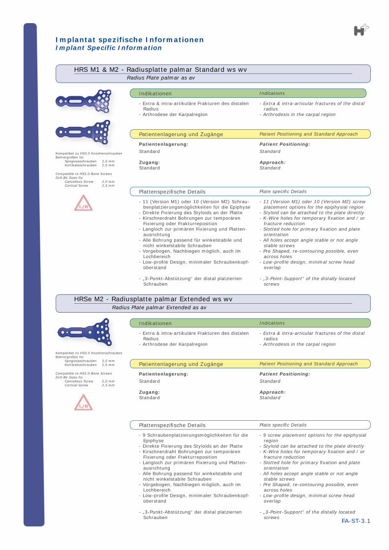
HRS M1 & M2 - Radiusplatte palmar Standard ws wvRadius Plate palmar as av
HRSe M2 - Radiusplatte palmar Extended ws wv Radius Plate palmar Extended as av
Kompatibel zu HS3.0 KnochenschraubenBohrergrößen für Spngiosaschrauben 2,0 mm Kortikalisschrauben 2,5 mm
Compatible to HS3.0 Bone ScrewsDrill Bit Sizes for Cancellous Screw 2,0 mm Cortical Screw 2,5 mm
Kompatibel zu HS3.0 KnochenschraubenBohrergrößen für Spngiosaschrauben 2,0 mm Kortikalisschrauben 2,5 mm
Plattenspezifi sche Details Plate specifi c Details
IndicationsIndikationen
Patient Positioning and Standard ApproachPatientenlagerung und Zugänge
Plattenspezifi sche Details Plate specifi c Details
IndicationsIndikationen
Patient Positioning and Standard ApproachPatientenlagerung und Zugänge
Implantat spezifische InformationenImplant Specific Information
- Extra & intra-artikuläre Frakturen des distalen Radius
- Arthrodese der Karpalregion
Patientenlagerung:
Standard
Zugang: Standard
- 11 (Version M1) oder 10 (Version M2) Schrau-benplatzierungsmöglichkeiten für die Epiphyse
- Direkte Fixierung des Styloids an der Platte- Kirschnerdraht Bohrungen zur temporären
Fixierung oder Frakturreposition- Langloch zur primären Fixierung und Platten-
ausrichtung- Alle Bohrung passend für winkelstabile und
nicht winkelstabile Schrauben- Vorgebogen, Nachbiegen möglich, auch im
Lochbereich- Low-profi le Design, minimaler Schraubenkopf-
überstand
- „3-Punkt-Abstützung“ der distal platzierten Schrauben
- 9 Schraubenplatzierungsmöglichkeiten für die Epiphyse
- Direkte Fixierung des Styloids an der Platte- Kirschnerdraht Bohrungen zur temporären
Fixierung oder Frakturreposition- Langloch zur primären Fixierung und Platten-
ausrichtung- Alle Bohrung passend für winkelstabile und
nicht winkelstabile Schrauben- Vorgebogen, Nachbiegen möglich, auch im
Lochbereich- Low-profi le Design, minimaler Schraubenkopf-
überstand
- „3-Punkt-Abstützung“ der distal platzierten Schrauben
- Extra & intra-artikuläre Frakturen des distalen Radius
- Arthrodese der Karpalregion
Patientenlagerung:
Standard
Zugang: Standard
Kompatibel zu HS3 0 Knochenschraube
- Extra & intra-articular fractures of the distal radius
- Arthrodesis of carpal region
Patient Positioning:
Standard
Approach: Standard
- Styloid can be attached to the plate directly- K-Wire holes for temporary fi xation and / or
fracture reduction- Slotted hole for primary fi xation and plate
orientation- All holes accept angle stable or not angle
stable screws- Pre Shaped, re-contouring possible, even
across holes- Low-profi le design, minimal screw head
overlap
FA-ST-3.2
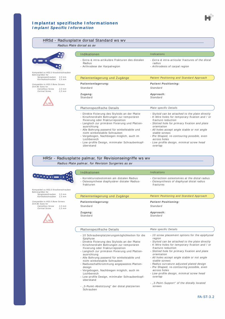
HRSd - Radiusplatte dorsal Standard ws wvRadius Plate dorsal as av
Compatible to HS3.0 Bone ScrewsDrill Bit Sizes for Cancellous Screw 2,0 mm Cortical Screw 2,5 mm
Kompatibel zu HS3.0 KnochenschraubenBohrergrößen für Spngiosaschrauben 2,0 mm Kortikalisschrauben 2,5 mm
Plattenspezifi sche Details Plate specifi c Details
IndicationsIndikationen
Patient Positioning and Standard ApproachPatientenlagerung und Zugänge
Implantat spezifische InformationenImplant Specific Information
- Direkte Fixierung des Styloids an der Platte- Kirschnerdraht Bohrungen zur temporären
Fixierung oder Frakturreposition- Langloch zur primären Fixierung und Platten-
ausrichtung- Alle Bohrung passend für winkelstabile und
nicht winkelstabile Schrauben- Vorgebogen, Nachbiegen möglich, auch im
Lochbereich- Low-profi le Design, minimaler Schraubenkopf-
überstand
- Extra & intra-artikuläre Frakturen des distalen Radius
- Arthrodese der Karpalregion
Patientenlagerung:
Standard
Zugang: Standard
Compatible to HS3.0 Bone ScrewsDrill Bit Sizes for Cancellous Screw 2,0 mm Cortical Screw 2,5 mm
Kompatibel zu HS3.0 KnochenschraubenBohrergrößen für Spngiosaschrauben 2,0 mm Kortikalisschrauben 2,5 mm
Plattenspezifi sche Details Plate specifi c Details
IndicationsIndikationen
Patient Positioning and Standard ApproachPatientenlagerung und Zugänge
HRSr - Radiusplatte palmar, für Revisionseingriffe ws wvRadius Plate palmar, for Revision Surgeries as av
- Correctiion osteotomies at the distal radius- Osteoynthesis of diaphysal distal radius
fractures
Patient Positioning:
Standard
Approach: Standard
- 10 screw placement options for the epiphysial region
- Styloid can be attached to the plate directly- K-Wire holes for temporary fi xation and / or
fracture reduction- Slotted hole for primary fi xation and plate
orientation- All holes accept angle stable or not angle
stable screws- Radius curvature adjusted plated design- Pre Shaped, re-contouring possible, even
across holes- Low-profi le design, minimal screw head
overlap
- „3-Point-Support“ of the distally located screws
- 10 Schraubenplatzierungsmöglichkeiten für die Epiphyse
- Direkte Fixierung des Styloids an der Platte- Kirschnerdraht Bohrungen zur temporären
Fixierung oder Frakturreposition- Langloch zur primären Fixierung und Platten-
ausrichtung- Alle Bohrung passend für winkelstabile und
nicht winkelstabile Schrauben- Radiusschaftkrümmung angepasstes Platten-
design- Vorgebogen, Nachbiegen möglich, auch im
Lochbereich- Low-profi le Design, minimaler Schraubenkopf-
überstand
- „3-Punkt-Abstützung“ der distal platzierten Schrauben
- Korrekturosteotomien am distalen Radius- Osteosynthese diaphysärer distaler Radius-
frakturen
Patientenlagerung:
Standard
Zugang: Standard
FA-ST-3.3
Implantat spezifische InformationenImplant Specific Information
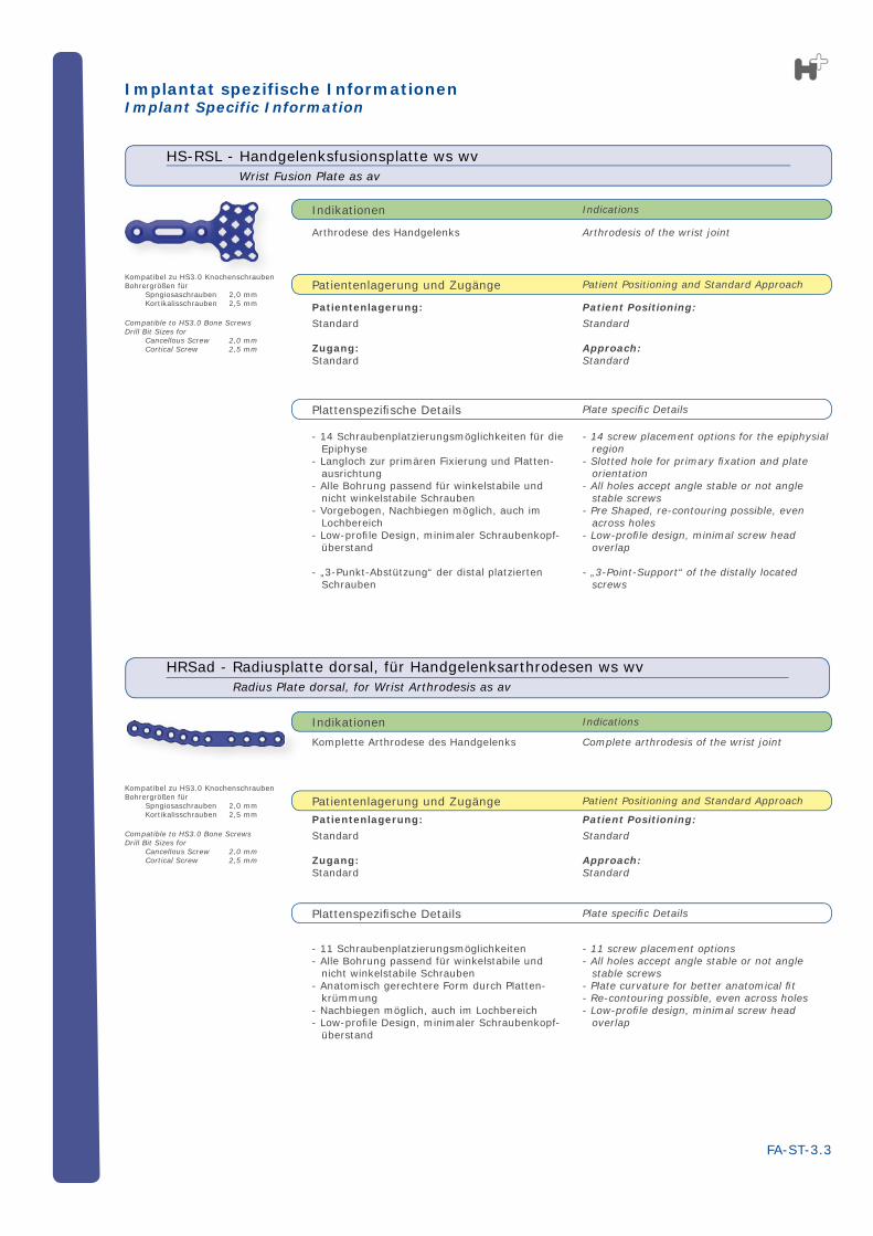
HRSad - Radiusplatte dorsal, für Handgelenksarthrodesen ws wvRadius Plate dorsal, for Wrist Arthrodesis as av
Complete arthrodesis of the wrist joint
Patient Positioning:
Standard
Approach: Standard
- 11 screw placement options- All holes accept angle stable or not angle
stable screws- Plate curvature for better anatomical fi t- Re-contouring possible, even across holes- Low-profi le design, minimal screw head
overlap
- 11 Schraubenplatzierungsmöglichkeiten - Alle Bohrung passend für winkelstabile und
nicht winkelstabile Schrauben- Anatomisch gerechtere Form durch Platten-
krümmung- Nachbiegen möglich, auch im Lochbereich- Low-profi le Design, minimaler Schraubenkopf-
überstand
Komplette Arthrodese des Handgelenks
Patientenlagerung:
Standard
Zugang: Standard
Plattenspezifi sche Details Plate specifi c Details
IndicationsIndikationen
Patient Positioning and Standard ApproachPatientenlagerung und Zugänge
Compatible to HS3.0 Bone ScrewsDrill Bit Sizes for Cancellous Screw 2,0 mm Cortical Screw 2,5 mm
Kompatibel zu HS3.0 KnochenschraubenBohrergrößen für Spngiosaschrauben 2,0 mm Kortikalisschrauben 2,5 mm
Arthrodesis of the wrist joint
Patient Positioning:
Standard
Approach: Standard
- 14 screw placement options for the epiphysial region
- Slotted hole for primary fi xation and plate orientation
- All holes accept angle stable or not angle stable screws
- Pre Shaped, re-contouring possible, even across holes
- Low-profi le design, minimal screw head overlap
- „3-Point-Support“ of the distally located screws
HS-RSL - Handgelenksfusionsplatte ws wvWrist Fusion Plate as av
Compatible to HS3.0 Bone ScrewsDrill Bit Sizes for Cancellous Screw 2,0 mm Cortical Screw 2,5 mm
Kompatibel zu HS3.0 KnochenschraubenBohrergrößen für Spngiosaschrauben 2,0 mm Kortikalisschrauben 2,5 mm
Plattenspezifi sche Details Plate specifi c Details
IndicationsIndikationen
Patient Positioning and Standard ApproachPatientenlagerung und Zugänge
- 14 Schraubenplatzierungsmöglichkeiten für die Epiphyse
- Langloch zur primären Fixierung und Platten-ausrichtung
- Alle Bohrung passend für winkelstabile und nicht winkelstabile Schrauben
- Vorgebogen, Nachbiegen möglich, auch im Lochbereich
- Low-profi le Design, minimaler Schraubenkopf-überstand
- „3-Punkt-Abstützung“ der distal platzierten Schrauben
Arthrodese des Handgelenks
Patientenlagerung:
Standard
Zugang: Standard
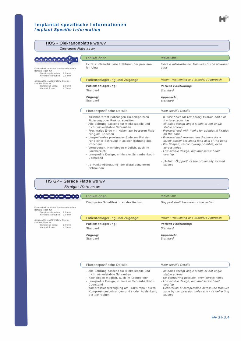
Extra & intra-articular fractures of the proximal ulna
Patient Positioning:
Standard
Approach: Standard
- K-Wire holes for temporary fi xation and / or fracture reduction
- All holes accept angle stable or not angle stable screws
- Proximal end with hooks for additional fi xation on the bone
- Proximal end surrounding the bone for a screw placement along long axis of the bone
- Pre Shaped, re-contouring possible, even across holes
- Low-profi le design, minimal screw head overlap
- „3-Point-Support“ of the proximally located screws
FA-ST-3.4
Olecranon Plate as av
HOS - Olekranonplatte ws wv
Compatible to HS3.0 Bone ScrewsDrill Bit Sizes for Cancellous Screw 2,0 mm Cortical Screw 2,5 mm
Kompatibel zu HS3.0 KnochenschraubenBohrergrößen für Spngiosaschrauben 2,0 mm Kortikalisschrauben 2,5 mm
Plattenspezifi sche Details Plate specifi c Details
IndicationsIndikationen
Patient Positioning and Standard ApproachPatientenlagerung und Zugänge
- Kirschnerdraht Bohrungen zur temporären Fixierung oder Frakturreposition
- Alle Bohrung passend für winkelstabile und nicht winkelstabile Schrauben
- Proximales Ende mit Haken zur besseren Fixie-rung am Knochen
- Umgreifendes proximales Ende zur Platzie-rung einer Schraube in axialer Richtung des Knochens
- Vorgebogen, Nachbiegen möglich, auch im Lochbereich
- Low-profi le Design, minimaler Schraubenkopf-überstand
- „3-Punkt-Abstützung“ der distal platzierten Schrauben
Extra & intraartikuläre Frakturen der proxima-len Ulna
Patientenlagerung:
Standard
Zugang: Standard
Implantat spezifische InformationenImplant Specific Information
HS GP - Gerade Platte ws wvStraight Plate as av
Compatible to HS3.0 Bone ScrewsDrill Bit Sizes for Cancellous Screw 2,0 mm Cortical Screw 2,5 mm
Kompatibel zu HS3.0 KnochenschraubenBohrergrößen für Spngiosaschrauben 2,0 mm Kortikalisschrauben 2,5 mm
Diapysal shaft fractures of the radius
Patient Positioning:
Standard
Approach: Standard
- All holes accept angle stable or not angle stable screws
- Re-contouring possible, even across holes- Low-profi le design, minimal screw head
overlap- Generation of compression across the fracture
zone by compression holes and / or defl ecting screws
Plattenspezifi sche Details Plate specifi c Details
IndicationsIndikationen
Patient Positioning and Standard ApproachPatientenlagerung und Zugänge
- Alle Bohrung passend für winkelstabile und nicht winkelstabile Schrauben
- Nachbiegen möglich, auch im Lochbereich- Low-profi le Design, minimaler Schraubenkopf-
überstand- Kompressionserzeugung am Frakturspalt durch
Kompressionsbohrungen und / oder Auslenkung der Schrauben
Diaphysäre Schaftfrakturen des Radius
Patientenlagerung:
Standard
Zugang: Standard
- Infections or infl ammations (acute, chronical, local)- Derogated vascularization of the respective site- Derogated bone support for proper implant fi xation- Possible or proven material sensitifi ty
- Patient with little to none compliance with respect to the obe-dience of post operative rehabilitation advices
- For further information on patient selection, please refer to the instructions manual for implants.
FA-ST-3.5
Contra IndicationsKontraindikationen
- Infektionen oder Entzündungen (akut, chronisch, lokal)- Verminderte Durchblutung der betroffenen Stelle- Vermindertes Implantatelager- Mögliche oder gegebene Sensibilität gegenüber dem
Material
- Patienten mit geringer oder keiner Compliance in Bezug auf die Einhaltung der postoperativen Rehabilitationsemp-fehlungen
- Weitere Informationen zur Patientenauswahl sind aus der Gebrauchsanweisung für Implantate zu entnehmen
Implantat spezifische InformationenImplant Specific Information
OperationstechnikOperation Technique
IMPROTANT:Preparatory measures for the use of HOFER implants require a preparation as thorough as possible of the operation fi eld. Nearby nerve fi bers and blood ves-sels require a special caution.Primary an adequate reduction of the anatomical structure also must have been carried out before HOFER implants are used
#1 - Insertion of the ImplantAfter reducing and stabilizing the fractured zone the plate can be positioned. For this step no special insertion device is necessary.If necessary, a re-shaping of the plate can be performed. For more details on bending plates please refer to the > instruction manual on applying the bending pliers.
#2 - Temporary FixationTo temporarily fixate the plate, depending on the plate type, K-wire holes or a slotted hole are available. For the former case the K-wires can additionally be used in a „joy-stick“ like fashion to furtherly manipulate the reduction of the respective fragments.For the latter case it is recommended to use a not angle stable screw. For inserting a screw please refer to the pa-ragraph after next.
#3 - Orienting the ImplantThe orientation of the implant is carried out according to the present anatomy.In the case of using the slotted hole: While the screw is not completely tightened the plate can still be moved to obtain the final position for fixation.
#4 - Screw PlacementFor placing angle stable or not angle stable screws the technique is the very same. The number of screws, their insertion site and direction has to happen based on the current situation.Concerning drilling pilot holes for the screws please refer to the > instruction manual on drilling pilot holes.For measuring the pilot hole depth for determining the re-quired screw length a depth gauge is to be used. For more details on hole depth determination please refer to the > instruction manual on applying the depth gauge.For more details on inserting screws please refer to the > instruction manual on picking up screws from the screw rack.> instruction manual on inserting screws.
SF-ST-4.1
WICHTIG:Vorbereitende Maßnahmen für den Einsatz von HO-FER Implantaten erfordern eine sorgfältige Freipä-paration des Operationsfeldes. Besondere Vorsicht erfordern nahe gelegene Nervenbündeln und Blut-gefäße. Primär muss eine adäquate Reposition der anato-mischen Struktur vorgenommen worden sein, bevor HOFER Implantate Verwendung fi nden.
#1 - Platzierung des ImplantatesNach der Reposition und Stabilisierung der Frakturzone kann die Platte aufgelegt werden. Dieser Schritt erfordert kein spezielles Einführinstrument.Falls erforderlich können die Platten nachgebogen werden. Weitere Informationen zu dem Biegeinstrumentarium kön-nen entnommen werden der> Gebrauchsanweisung zur Handhabung der Biegezan-gen.
#2 - Temporäre FixierungEine vorübergehende Fixierung der Platte kann je nach Plattentyp entweder über die Kirschnerdrahtbohrungen oder dem Langloch erfolgen. Im ersteren Fall können die Kirschnerdrähte zusätzlich wie Joysticks verwendet wer-den, falls eine weitere Reposition der Fragmente erforder-lich sein sollte. Für den letzteren Fall wird empfholen, eine nicht winkelstabile Schraube zu verwenden.Hinweise zum Einbringen einer Schraube sind im über-nächsten Abschnitt enthalten.
#3 - Ausrichtung des ImplantatesDie Ausrichtung des Implantates erfolgt entsprechend der vorgefundenen Anatomie.Bei der Verwendung des Langloches: So lange die fixie-rende Schraube noch nicht festgezogen ist, kann die noch bewegliche Platte in die endgültige Lage gebracht werden.
#4 - SchraubenplatzierungDas Einbringen einer winkelstabilen oder nicht winkelsta-bilen Schraube ist gleich. Die Anzahl der Schrauben, deren Lage und Ausrichtung müssen situationsbedingt gewählt werden.Hinweise zum Vorbohren für die Schrauben sind enthalten in der > Gebrauchsanweisung zum Vorbohren.Zur Messung der Bohrlochtiefe und zur Bestimmung der erforderlichen Schraubenlänge ist eine Tiefenmesslehre zu verwendenInformationen zur Bohrlochtiefenmessung sind in der > Gebrauchsanweisung zur Handhabung der Tiefenmess-lehre enthalten.Angaben zum Einschrauben der Schrauben sind enthalten in der
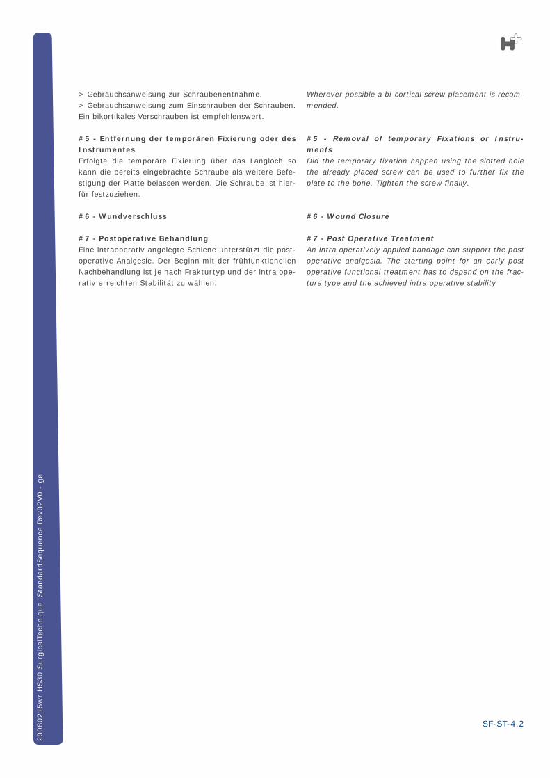
Wherever possible a bi-cortical screw placement is recom-mended.
#5 - Removal of temporary Fixations or Instru-mentsDid the temporary fixation happen using the slotted hole the already placed screw can be used to further fix the plate to the bone. Tighten the screw finally.
#6 - Wound Closure
#7 - Post Operative TreatmentAn intra operatively applied bandage can support the post operative analgesia. The starting point for an early post operative functional treatment has to depend on the frac-ture type and the achieved intra operative stability
SF-ST-4.2
20080215w
r H
S30 S
urg
ical
Tech
niq
ue
Sta
ndar
dSeq
uen
ce R
ev02V0 -
ge
> Gebrauchsanweisung zur Schraubenentnahme.> Gebrauchsanweisung zum Einschrauben der Schrauben.Ein bikortikales Verschrauben ist empfehlenswert.
#5 - Entfernung der temporären Fixierung oder des InstrumentesErfolgte die temporäre Fixierung über das Langloch so kann die bereits eingebrachte Schraube als weitere Befe-stigung der Platte belassen werden. Die Schraube ist hier-für festzuziehen.
#6 - Wundverschluss
#7 - Postoperative BehandlungEine intraoperativ angelegte Schiene unterstützt die post-operative Analgesie. Der Beginn mit der frühfunktionellen Nachbehandlung ist je nach Frakturtyp und der intra ope-rativ erreichten Stabilität zu wählen.
FA-ST-5
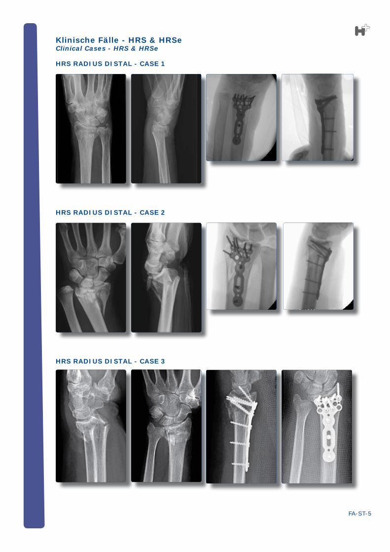
HRS RADIUS DISTAL - CASE 1
HRS RADIUS DISTAL - CASE 2
HRS RADIUS DISTAL - CASE 3
Klinische Fälle - HRS & HRSeClinical Cases - HRS & HRSe


![Biografie Florian Hofer [Deutsch]](https://img.pdfslide.us/doc/110x75/568c3b971a28ab0235aab3bb/biografie-florian-hofer-deutsch.jpg)