Embed Size (px)
Citation preview
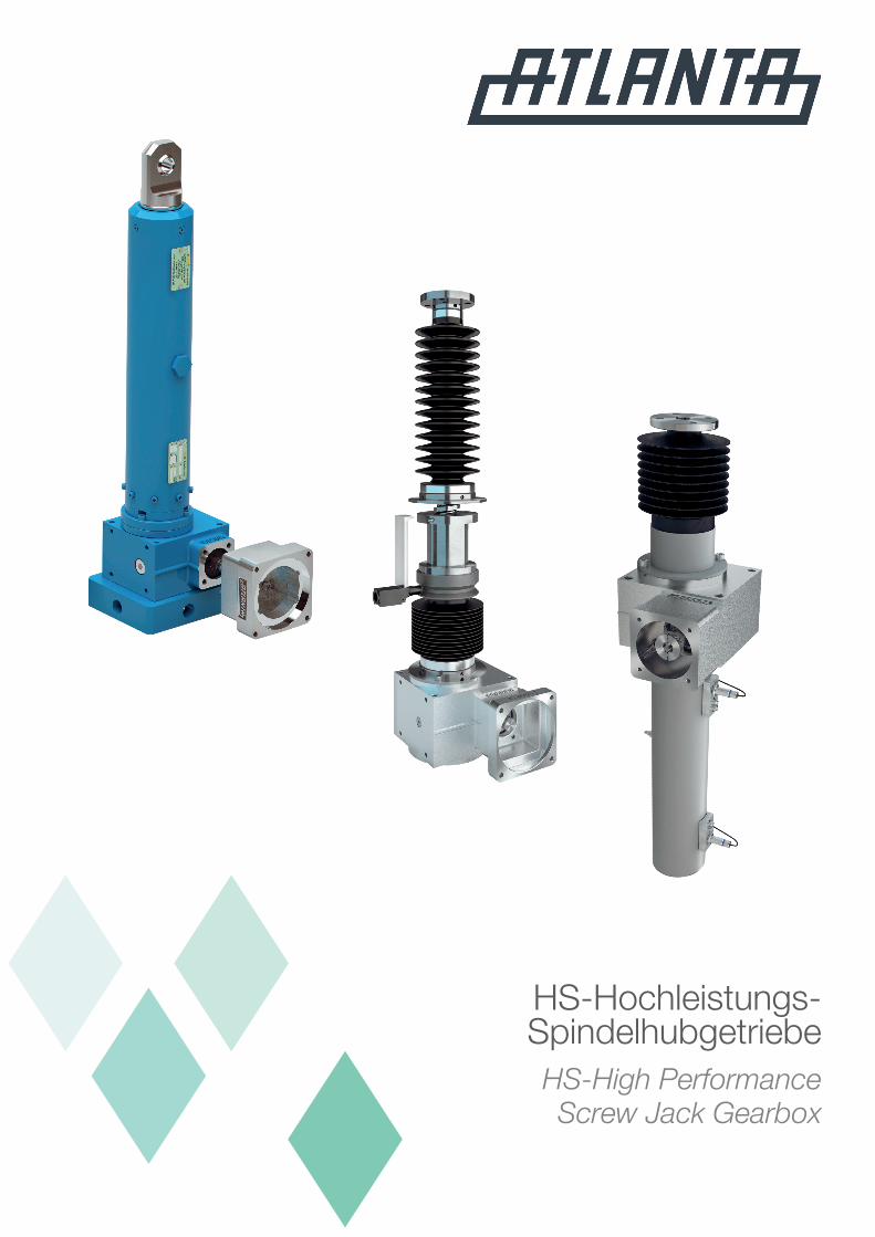
HS-Hochleistungs- SpindelhubgetriebeHS-High Performance Screw Jack Gearbox
2 1/2018
Technische DatenTechnical data
HS high-performance screw-jack gearboxes from ATLANTA make it possible to achieve high feed rates even with heavy loads. Combining power and speed they feature all the advantages of the flexible electro-mechanic drive technology, particularly the exact approach to different positions and an excellent repeat-ability precision.
The construction of the HS screw-jack gearboxes is based on the proved design of the ATLANTA servo worm-gear units. In combination with special ball-screw spindle drives with dynamic load capacities far above standard they enable the realization of low-clearance, dynamic, and long-living lifting drives. Due to their compactness the rotating spindle, non-rotating spindle or lifting cylinder designs can be easily integrated in existing machine concepts.
Because of their precision and robustness the HS high-perfor-mance screw-jack gearboxes as linear drives are the ideal drive concept for all dynamic lifting, lowering, feeding, pressing, tilting, and swiveling motions as well as for similar moving processes and very precise positioning.
Special features are:
– Circumferential backlash basic gear <12 angular minutes– Input speeds up to 5000 min-1
– Linear speed up to 550 mm/s – 50 % higher torque compared to standard gear units – Ball-screw drives with axial play 0.03 mm, possible without
play– Lead accuracy 0.023 mm / 300 mm (tolerance class P5)
HS-Hochleistungs-Spindelhubgetriebe von ATLANTA ermögli-chen hohe Vorschubgeschwindigkeiten auch bei großen Lasten. In Kombination von Kraft und Geschwindigkeit bieten Sie alle Vorteile der Flexibilität elektromechanischer Antriebstechnik, insbesondere das exakte Anfahren verschiedener Positionen mit hoher Wiederholgenauigkeit.
Konstruktiv basiert der Aufbau der HS-Hubgetriebe auf den bewährten Servoschneckengetrieben von ATLANTA, was in Ver-bindung mit speziellen Kugelgewindetrieben mit weit über dem Standard liegenden dynamischen Tragzahlen die Realisierung spielarmer, dynamischer und langlebiger Hubantriebe erlaubt. Die Ausführungen rotierende Spindel, stehende Spindel oder Hubzylinder sind dank Ihrer Kompaktheit leicht in Maschinen-konzepte einzubinden.
HS-Hochleistungs-Spindelhubgetriebe als lineare Bewegungs-antriebe sind mit Ihrer Präzision und Robustheit das passende Antriebskonzept für alle dynamischen Hub-, Senk-, Vorschub-, Druck-, Kipp-, Schwenk- und ähnliche Bewegungsabläufe in Verbindung mit hochpräzisem Positionieren.
Besondere Merkmale sind:
– Verdrehflankenspiel Grundgetriebe <12 Winkelminuten– Eintriebsdrehzahlen bis 5000 min-1
– Verfahrgeschwindigkeit bis 550 mm/s – 50 % höheres Drehmoment gegenüber Standardgetrieben– Kugelgewindetriebe mit Axialspiel 0,03 mm, spielfrei möglich– Steigungsgenauigkeit 0,023 mm / 300 mm (Toleranzklasse
P5)
Nachdruck – auch auszugsweise – ohne unsere Genehmigung ist nicht gestattet. Die Maße und sonstige technische Angaben dieses Kataloges sind freibleibend und für uns völlig unverbindlich. Technische Änderungen in den Maßen und im Umfang unseres Normprogramms sind vorbehalten. Lieferungen erfolgen gemäß unseren Verkaufs- und Lieferbedingungen Ausgabe 15.Duplication – even by way of excerpts – is not allowed without our express permission. Dimensions and any other technical details given in this catalogue are subject to alterations without notice and are completely without obligation on our part. All rights to make technical changes to the dimensions and the range of our standard programme are reserved.
31/2018
Technische DatenTechnical data
Allgemeine Daten General dataSelbsthemmung nein / no Self-locking qualityMax. Einschaltdauer bis / up to 100 %1) Max. duty cycle (last- und zyklusabhängig) (depending on load and cycle)
Getriebeübersetzung 3,0; 6,75 und / and 29 Ratio of gearunitMotoren Drehstrom- und Servomotoren / 3-phase AC- and servomotors MotorsBremse erforderlich ja / yes Brake required
Getriebe HS10 HS25 Gearunit
stehendeSpindel non-rotating spindleKugelgewindetrieb 20x10 20x20 32x10 32x20 Ball screw driveMax. Last beim Verfahren [kN] 9 5 25 252) Max. load during travellingMax. statische Last [kN] 9 9 35 25 Max. static loadMax. Eintriebsdrehzahl [min-1] 5000 5000 Max. input speedMax. Verfahrgeschwindigkeit [mm/s] 275 555 275 555 Max. travelling speedDyn. Tragzahl C [kN] 11,9 11,9 36,6 27,5 Dyn. load capacity C
rotierendeSpindel rotating spindleKugelgewindetrieb 32x10 32x20 40x10 40x20 Ball screw driveMax. Last beim Verfahren [kN] 10 5 25 252) Max. load during travellingMax. statische Last [kN] 18 18 45 45 Max. static loadMax. Eintriebsdrehzahl [min-1] 5000 5000 Max. input speedMax. Verfahrgeschwindigkeit [mm/s] 275 555 275 555 Max. travelling speedDyn. Tragzahl C [kN] 36,6 27,5 92,6 75,2 Dyn. load capacity C
Hubzylinder Lifting cylinderKugelgewindetrieb 25x10 25x20 40x10 40x20 Ball screw driveMax. Last beim Verfahren [kN] 10 5 25 252) Max. load during travellingMax. statische Last [kN] 18 13 45 45 Max. static loadMax. Eintriebsdrehzahl [min-1] 5000 5000 Max. input speedMax. Verfahrgeschwindigkeit [mm/s] 275 555 275 555 Max. travelling speedDyn. Tragzahl C [kN] 19,8 14,9 64,7 75,2 Dyn. load capacity C
Getriebe HS50 HS100 Gearunit
stehendeSpindel non-rotating spindleKugelgewindetrieb 40x10 40x20 50x20 Ball screw driveMax. Last beim Verfahren [kN] 50 503) 1004) Max. load during travellingMax. statische Last [kN] 90 65 160 Max. static loadMax. Eintriebsdrehzahl [min-1] 4000 3000 Max. input speedMax. Verfahrgeschwindigkeit [mm/s] 220 440 330 Max. travelling speedDyn. Tragzahl C [kN] 92,6 75,2 195 Dyn. load capacity C
rotierendeSpindel rotating spindleKugelgewindetrieb 50x20 63x20 63x20 80x20 Ball screw driveMax. Last beim Verfahren [kN] 503) 503) 1004) 1004) Max. load during travellingMax. statische Last [kN] 90 90 180 180 Max. static loadMax. Eintriebsdrehzahl [min-1] 4000 3000 Max. input speedMax. Verfahrgeschwindigkeit [mm/s] 440 440 330 330 Max. travelling speedDyn. Tragzahl C [kN] 160 248 248 359 Dyn. load capacity C
Hubzylinder Lifting cylinderKugelgewindetrieb 50x20 63x20 80x20 Ball screw driveMax. Last beim Verfahren [kN] 503) 1004) 1004) Max. load during travellingMax. statische Last [kN] 90 180 180 Max. static loadMax. Eintriebsdrehzahl [min-1] 4000 3000 Max. input speedMax. Verfahrgeschwindigkeit [mm/s] 440 330 330 Max. travelling speedDyn. Tragzahl C [kN] 160 248 359 Dyn. load capacity C
1) Bei Einschaltdauer über 50% bitten wir um Rücksprache / Duty cycles over 50% upon request. 2) Bei / For i=3 Fmax = 15kN3) Bei / For i=3 Fmax = 30kN4) Bei / For i=3 Fmax = 80kN
4 1/2018
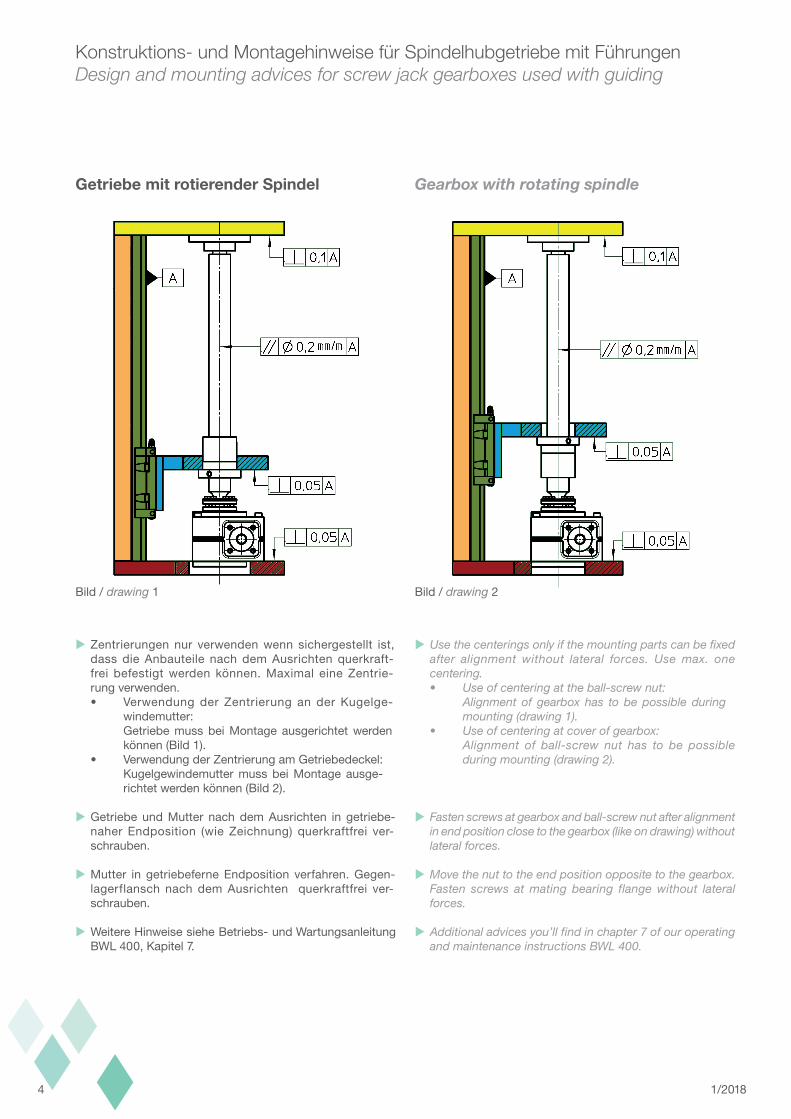
Konstruktions- und Montagehinweise für Spindelhubgetriebe mit FührungenDesign and mounting advices for screw jack gearboxes used with guiding
GetriebemitrotierenderSpindel Gearbox with rotating spindle
Zentrierungen nur verwenden wenn sichergestellt ist, dass die Anbauteile nach dem Ausrichten querkraft- frei befestigt werden können. Maximal eine Zentrie- rung verwenden. • Verwendung der Zentrierung an der Kugelge- windemutter: Getriebe muss bei Montage ausgerichtet werden können (Bild 1). • Verwendung der Zentrierung am Getriebedeckel: Kugelgewindemutter muss bei Montage ausge- richtet werden können (Bild 2).
Getriebe und Mutter nach dem Ausrichten in getriebe- naher Endposition (wie Zeichnung) querkraftfrei ver- schrauben.
Mutter in getriebeferne Endposition verfahren. Gegen- lagerflansch nach dem Ausrichten querkraftfrei ver- schrauben.
Weitere Hinweise siehe Betriebs- und Wartungsanleitung BWL 400, Kapitel 7.
Use the centerings only if the mounting parts can be fixed after alignment without lateral forces. Use max. one centering. • Use of centering at the ball-screw nut: Alignment of gearbox has to be possible during mounting (drawing 1). • Use of centering at cover of gearbox: Alignment of ball-screw nut has to be possible during mounting (drawing 2).
Fasten screws at gearbox and ball-screw nut after alignment in end position close to the gearbox (like on drawing) without lateral forces.
Move the nut to the end position opposite to the gearbox. Fasten screws at mating bearing flange without lateral forces.
Additional advices you’ll find in chapter 7 of our operating and maintenance instructions BWL 400.
Bild / drawing 1 Bild / drawing 2
51/2018
Konstruktions- und Montagehinweise für Spindelhubgetriebe mit FührungenDesign and mounting advices for screw jack gearboxes used with guiding
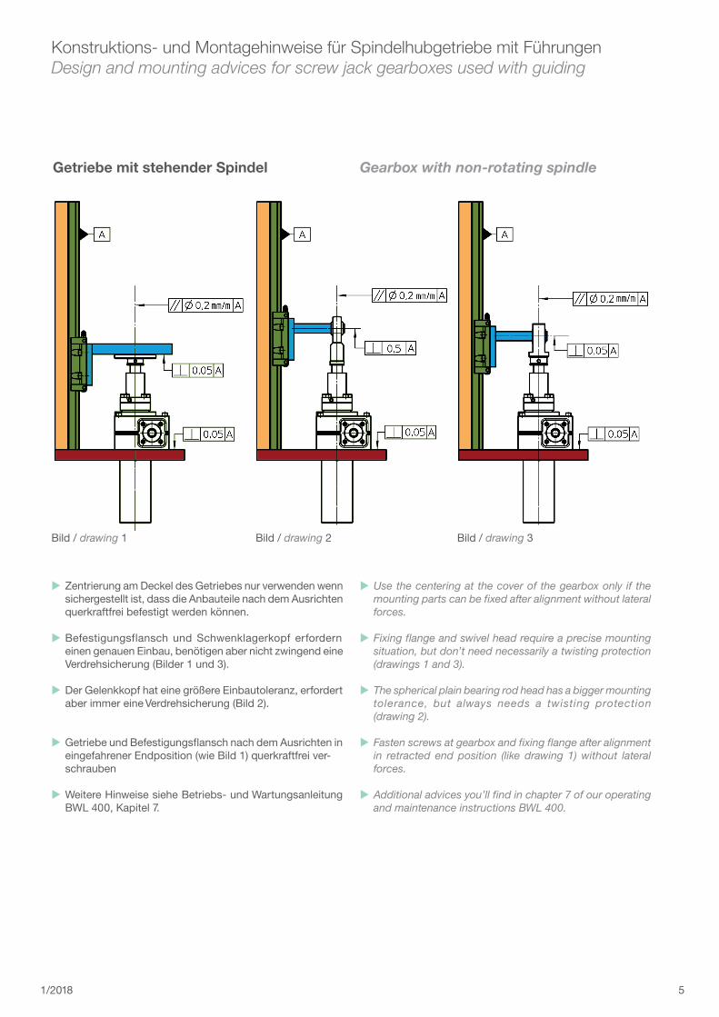
GetriebemitstehenderSpindel Gearbox with non-rotating spindle
Zentrierung am Deckel des Getriebes nur verwenden wenn sichergestellt ist, dass die Anbauteile nach dem Ausrichten querkraftfrei befestigt werden können.
Befestigungsflansch und Schwenklagerkopf erfordern einen genauen Einbau, benötigen aber nicht zwingend eine Verdrehsicherung (Bilder 1 und 3).
Der Gelenkkopf hat eine größere Einbautoleranz, erfordert aber immer eine Verdrehsicherung (Bild 2).
Getriebe und Befestigungsflansch nach dem Ausrichten in eingefahrener Endposition (wie Bild 1) querkraftfrei ver- schrauben
Weitere Hinweise siehe Betriebs- und Wartungsanleitung BWL 400, Kapitel 7.
Use the centering at the cover of the gearbox only if the mounting parts can be fixed after alignment without lateral forces.
Fixing flange and swivel head require a precise mounting situation, but don’t need necessarily a twisting protection (drawings 1 and 3).
The spherical plain bearing rod head has a bigger mounting tolerance, but always needs a twisting protection (drawing 2).
Fasten screws at gearbox and fixing flange after alignment in retracted end position (like drawing 1) without lateral forces.
Additional advices you’ll find in chapter 7 of our operating and maintenance instructions BWL 400.
Bild / drawing 1 Bild / drawing 2 Bild / drawing 3
6 1/2018
Konstruktions- und Montagehinweise für Spindelhubgetriebe mit FührungenDesign and mounting advices for screw jack gearboxes used with guiding
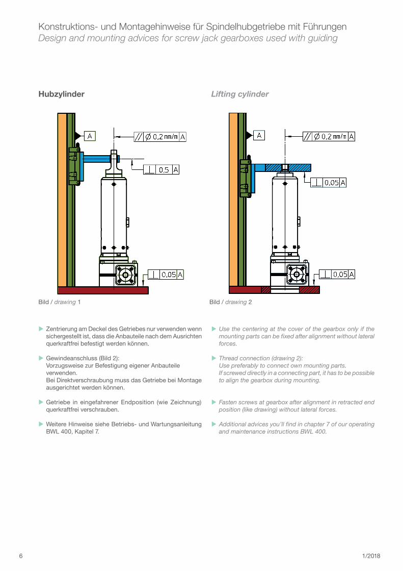
Hubzylinder Lifting cylinder
Zentrierung am Deckel des Getriebes nur verwenden wenn sichergestellt ist, dass die Anbauteile nach dem Ausrichten querkraftfrei befestigt werden können.
Gewindeanschluss (Bild 2): Vorzugsweise zur Befestigung eigener Anbauteile verwenden. Bei Direktverschraubung muss das Getriebe bei Montage ausgerichtet werden können.
Getriebe in eingefahrener Endposition (wie Zeichnung) querkraftfrei verschrauben.
Weitere Hinweise siehe Betriebs- und Wartungsanleitung BWL 400, Kapitel 7.
Use the centering at the cover of the gearbox only if the mounting parts can be fixed after alignment without lateral forces.
Thread connection (drawing 2): Use preferably to connect own mounting parts. If screwed directly in a connecting part, it has to be possible to align the gearbox during mounting.
Fasten screws at gearbox after alignment in retracted end position (like drawing) without lateral forces.
Additional advices you’ll find in chapter 7 of our operating and maintenance instructions BWL 400.
Bild / drawing 1 Bild / drawing 2
71/2018
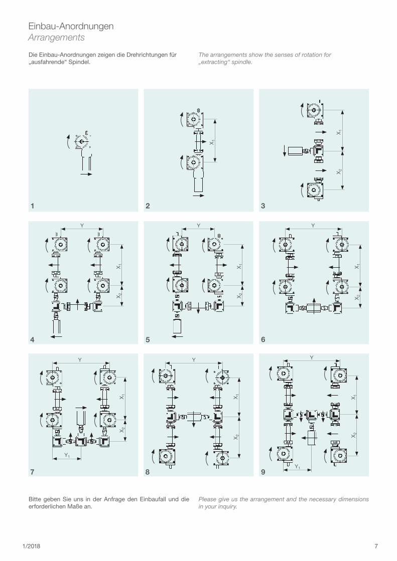
Einbau-AnordnungenArrangements
Die Einbau-Anordnungen zeigen die Drehrichtungen für „ausfahrende“ Spindel.
The arrangements show the senses of rotation for „extracting“ spindle.
Bitte geben Sie uns in der Anfrage den Einbaufall und die erforderlichen Maße an.
Please give us the arrangement and the necessary dimensions in your inquiry.
X1
X1
X2
Y
X1
X2
Y
X1
X2
Y
X1
X2
Y
X1
X2
Y1
Y
X 1X 2
YX 1
X 2
Y1
1 2 3
4 5 6
7 8 9
8 1/2018
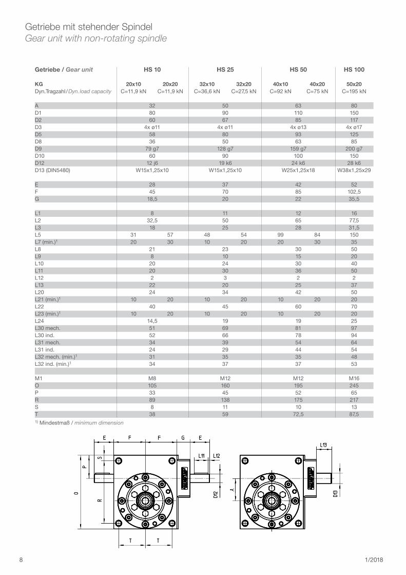
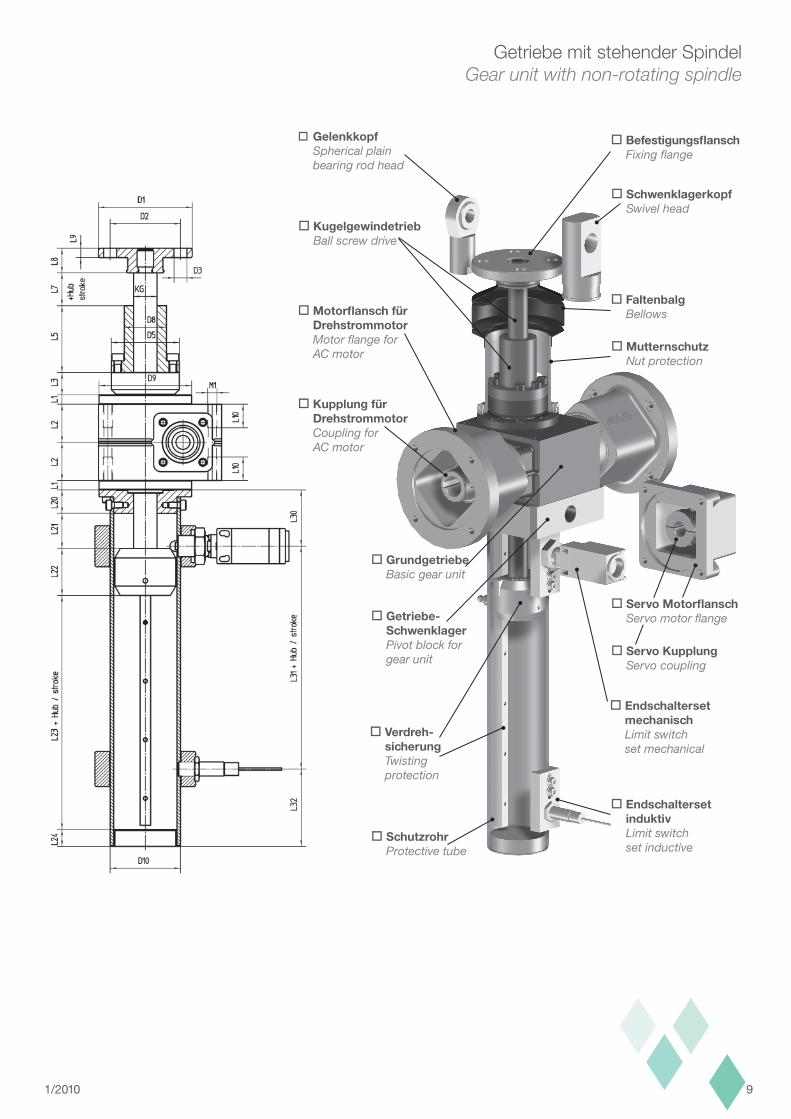
Getriebe mit stehender SpindelGear unit with non-rotating spindle
Getriebe/Gear unit HS10 HS25 HS50 HS100
KG 20x10 20x20 32x10 32x20 40x10 40x20 50x20Dyn. Tragzahl / Dyn. load capacity C=11,9 kN C=11,9 kN C=36,6 kN C=27,5 kN C=92 kN C=75 kN C=195 kN
A 32 50 63 80D1 80 90 110 150D2 60 67 85 117D3 4x ø11 4x ø11 4x ø13 4x ø17D5 58 80 93 125 D8 36 50 63 85D9 79 g7 128 g7 159 g7 200 g7D10 60 90 100 150D12 12 j6 19 k6 24 k6 28 k6D13 (DIN5480) W15x1,25x10 W15x1,25x10 W25x1,25x18 W38x1,25x29
E 28 37 42 52F 45 70 85 102,5G 18,5 20 22 35,5
L1 8 11 12 16L2 32,5 50 65 77,5L3 18 25 28 31,5L5 31 57 48 54 99 84 150L7 (min.)1 20 30 10 20 20 30 35L8 21 23 30 50L9 8 10 15 20L10 20 24 30 40L11 20 30 36 50L12 2 3 2 2L13 22 20 25 37L20 24 34 42 50L21 (min.)1 10 20 10 20 10 20 20L22 40 45 60 70L23 (min.)1 10 20 10 20 10 20 20L24 14,5 19 19 25L30 mech. 51 69 81 97L30 ind. 52 66 78 94L31 mech. 34 39 54 64L31 ind. 24 29 44 54L32 mech. (min.)1 31 35 35 48L32 ind. (min.)1 34 37 37 53
M1 M8 M12 M12 M16O 105 160 195 245P 33 45 52 65R 89 138 175 217S 8 11 10 13T 38 59 72,5 87,51) Mindestmaß / minimum dimension
91/2010
Getriebe mit stehender SpindelGear unit with non-rotating spindle
oGelenkkopf Spherical plain bearing rod head
oKugelgewindetrieb Ball screw drive
oMotorflanschfür Drehstrommotor Motor flange for AC motor
oKupplungfür Drehstrommotor Coupling for AC motor
oGrundgetriebe Basic gear unit
oGetriebe- Schwenklager Pivot block for gear unit
oVerdreh- sicherung Twisting protection
oEndschalterset induktiv Limit switch set inductive
oSchutzrohr Protective tube
oEndschalterset mechanisch Limit switch set mechanical
oServoKupplung Servo coupling
oBefestigungsflansch Fixing flange
oSchwenklagerkopf Swivel head
oFaltenbalg Bellows
oMutternschutz Nut protection
oServoMotorflansch Servo motor flange
10 1/2018
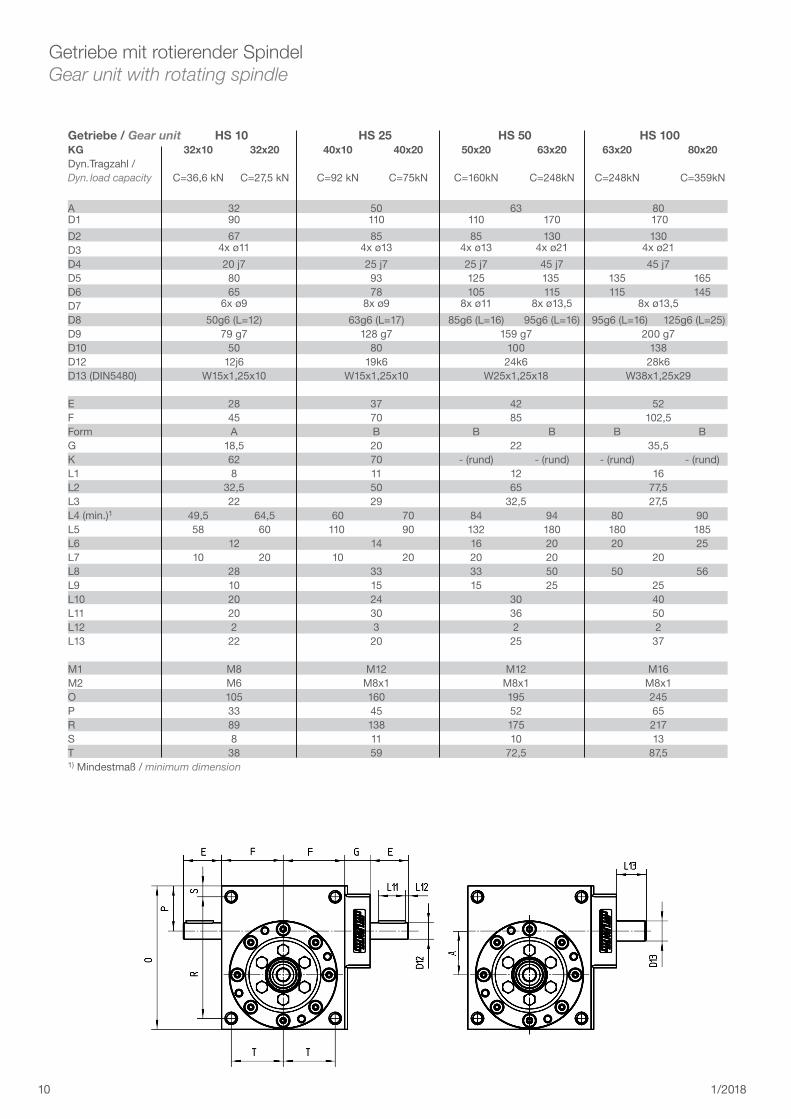
Getriebe mit rotierender SpindelGear unit with rotating spindle
Getriebe/Gear unit HS10 HS25 HS50 HS100KG 32x10 32x20 40x10 40x20 50x20 63x20 63x20 80x20Dyn.Tragzahl /Dyn. load capacity C=36,6 kN C=27,5 kN C=92 kN C=75kN C=160kN C=248kN C=248kN C=359kN
A 32 50 63 80D1 90 110 110 170 170
D2 67 85 85 130 130D3 4x ø11 4x ø13 4x ø13 4x ø21 4x ø21
D4 20 j7 25 j7 25 j7 45 j7 45 j7D5 80 93 125 135 135 165D6 65 78 105 115 115 145 D7 6x ø9 8x ø9 8x ø11 8x ø13,5 8x ø13,5
D8 50g6 (L=12) 63g6 (L=17) 85g6 (L=16) 95g6 (L=16) 95g6 (L=16) 125g6 (L=25)D9 79 g7 128 g7 159 g7 200 g7 D10 50 80 100 138D12 12j6 19k6 24k6 28k6D13 (DIN5480) W15x1,25x10 W15x1,25x10 W25x1,25x18 W38x1,25x29
E 28 37 42 52F 45 70 85 102,5Form A B B B B BG 18,5 20 22 35,5K 62 70 - (rund) - (rund) - (rund) - (rund)L1 8 11 12 16L2 32,5 50 65 77,5L3 22 29 32,5 27,5L4 (min.)1 49,5 64,5 60 70 84 94 80 90L5 58 60 110 90 132 180 180 185L6 12 14 16 20 20 25L7 10 20 10 20 20 20 20L8 28 33 33 50 50 56L9 10 15 15 25 25L10 20 24 30 40L11 20 30 36 50 L12 2 3 2 2L13 22 20 25 37
M1 M8 M12 M12 M16M2 M6 M8x1 M8x1 M8x1 O 105 160 195 245P 33 45 52 65R 89 138 175 217S 8 11 10 13T 38 59 72,5 87,51) Mindestmaß / minimum dimension
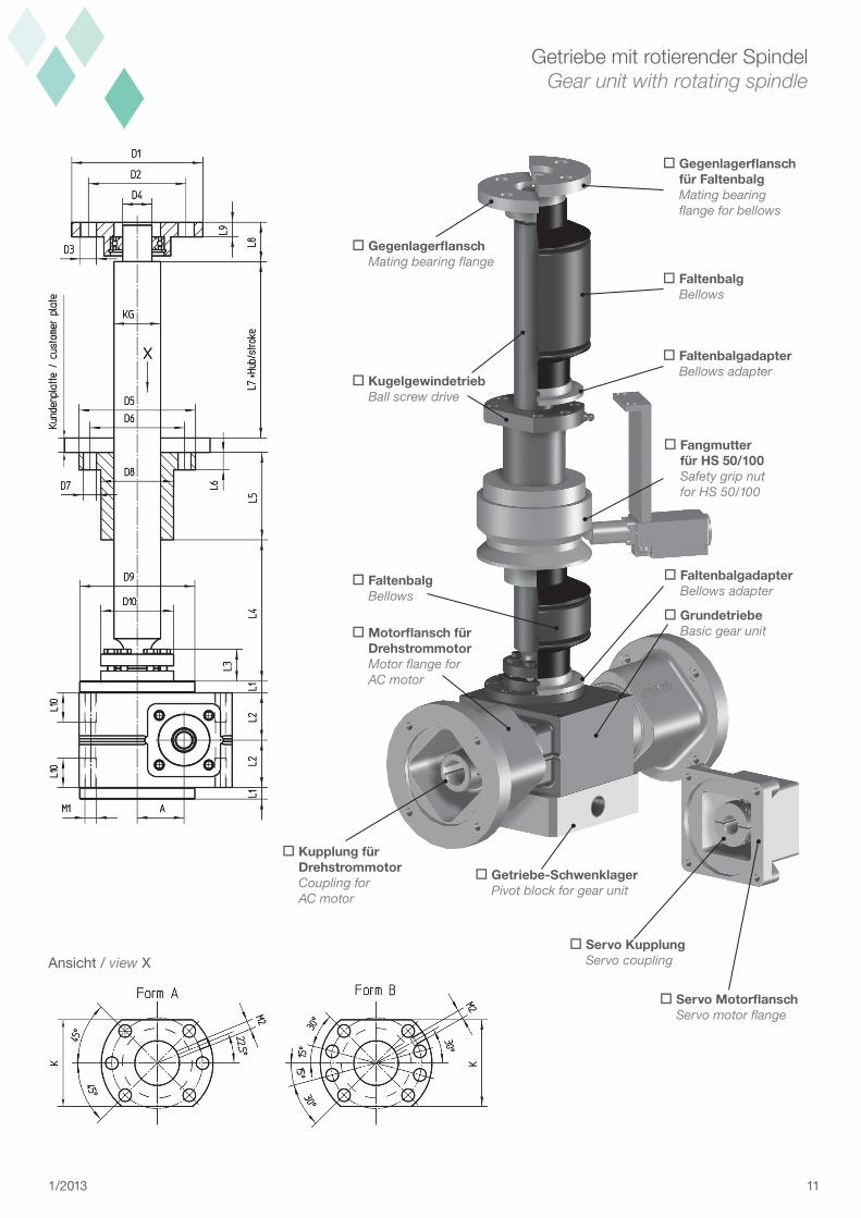
111/2013
oKugelgewindetrieb Ball screw drive
oMotorflanschfür Drehstrommotor Motor flange for AC motor
oKupplungfür Drehstrommotor Coupling for AC motor
oGetriebe-Schwenklager Pivot block for gear unit
oServoKupplung Servo coupling
oGegenlagerflansch Mating bearing flange
oFaltenbalg Bellows
oFaltenbalgadapter Bellows adapter
oServoMotorflansch Servo motor flange
oGegenlagerflansch fürFaltenbalg Mating bearing flange for bellows
oFangmutter fürHS50/100 Safety grip nut for HS 50/100
oGrundetriebe Basic gear unit
oFaltenbalgadapter Bellows adapter
oFaltenbalg Bellows
Getriebe mit rotierender SpindelGear unit with rotating spindle
Ansicht / view X
12 1/2018
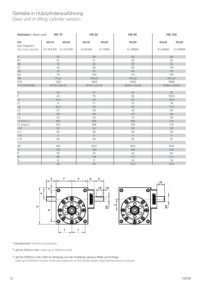
Getriebe in HubzylinderausführungGear unit in lifting cylinder version
1) Mindestmaß / minimum dimension
2) gilt bis 250mm Hub / valid up to 250mm stroke
3) gilt bis 2000mm Hub; Maß ist abhängig von der Hublänge; genaue Maße auf Anfrage valid up to 2000mm stroke; dimension depends on the stroke length; exact demensions on request
Getriebe/Gear unit HS10 HS25 HS50 HS100
KG 25x10 25x20 40x10 40x20 50x20 63x20 80x20Dyn.Tragzahl /Dyn. load capacity C=19,8 kN C=14,9 kN C=65 kN C=75kN C=160kN C=248kN C=359kN
A 32 50 63 80B1 21 31 28 35B2 15 22 22 34D1 45 65 80 120D2 16 25 40 50D3 70 100 110 150D9 79 g7 128 g7 159 g7 200 g7D12 12j6 19k6 24k6 28k6D13 (DIN5480) W15x1,25x10 W15x1,25x10 W25x1,25x18 W38x1,25x29
E 28 37 42 52F 45 70 85 102,5G 18,5 20 22 35,5L1 8 11 12 16L2 32,5 50 65 77,5L3 24 36 45 60L4 30 38 45 55L5 20 20 15 28L7 (min.)1, 2 262 268 360 412L7 (max.)3 612 668 720 772L10 20 24 30 40L11 20 30 36 50L12 2 3 2 2L13 22 20 25 37
M1 M8 M12 M12 M16O 105 160 195 245P 33 45 52 65R 89 138 175 217S 8 11 10 13T 38 59 72,5 87,5
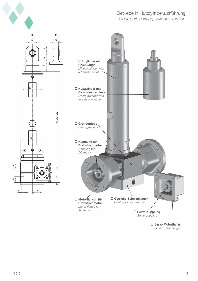
13
oMotorflanschfür Drehstrommotor Motor flange for AC motor
oKupplungfür Drehstrommotor Coupling for AC motor
oServoKupplung Servo coupling
oServoMotorflansch Servo motor flange
oGetriebe-Schwenklager Pivot block for gear unit
oGrundetriebe Basic gear unit
oHubzylindermit Gelenkauge Lifting cylinder with articulated joint
oHubzylindermit Gewindeanschluss Lifting cylinder with thread connection
Getriebe in HubzylinderausführungGear unit in lifting cylinder version
1/2010
14 1/2018
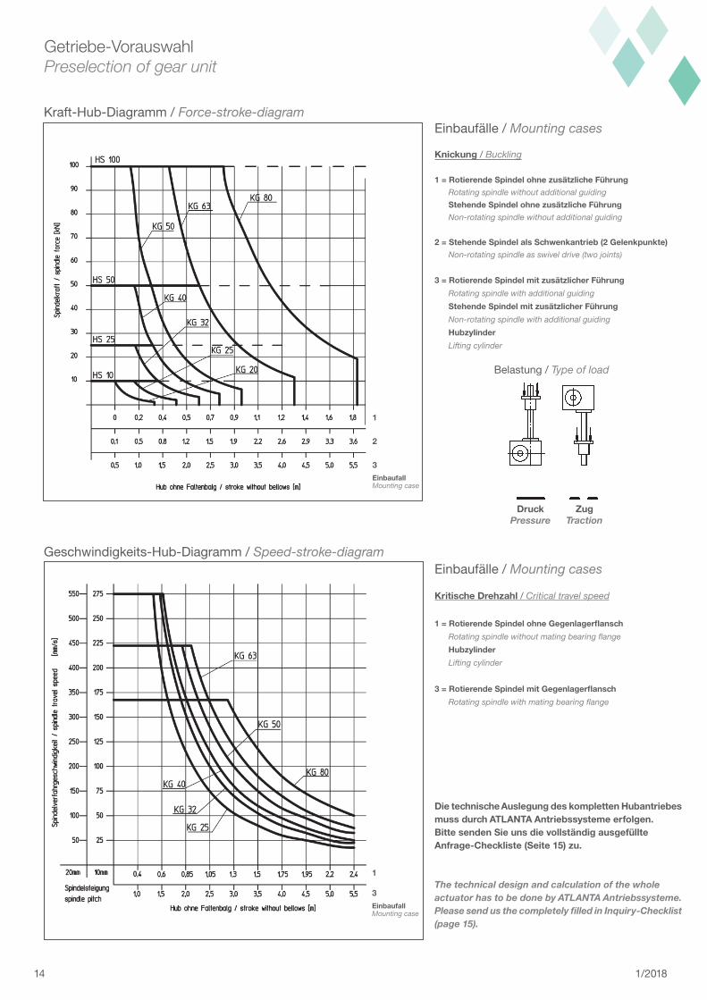
Getriebe-VorauswahlPreselection of gear unit
Kraft-Hub-Diagramm / Force-stroke-diagram
Geschwindigkeits-Hub-Diagramm / Speed-stroke-diagram
1
3EinbaufallMounting case
1
2
3EinbaufallMounting case
Belastung / Type of load
DruckPressure
ZugTraction
Einbaufälle / Mounting cases
KritischeDrehzahl/ Critical travel speed
1=RotierendeSpindelohneGegenlagerflansch Rotating spindle without mating bearing flange
Hubzylinder Lifting cylinder
3=RotierendeSpindelmitGegenlagerflansch Rotating spindle with mating bearing flange
DietechnischeAuslegungdeskomplettenHubantriebesmussdurchATLANTAAntriebssystemeerfolgen.BittesendenSieunsdievollständigausgefüllteAnfrage-Checkliste(Seite15)zu.
The technical design and calculation of the whole actuator has to be done by ATLANTA Antriebssysteme. Please send us the completely filled in Inquiry-Checklist (page 15).
Einbaufälle / Mounting cases
Knickung/ Buckling
1=RotierendeSpindelohnezusätzlicheFührung Rotating spindle without additional guiding StehendeSpindelohnezusätzlicheFührung Non-rotating spindle without additional guiding
2=StehendeSpindelalsSchwenkantrieb(2Gelenkpunkte) Non-rotating spindle as swivel drive (two joints)
3=RotierendeSpindelmitzusätzlicherFührung Rotating spindle with additional guiding
StehendeSpindelmitzusätzlicherFührung Non-rotating spindle with additional guiding
Hubzylinder Lifting cylinder
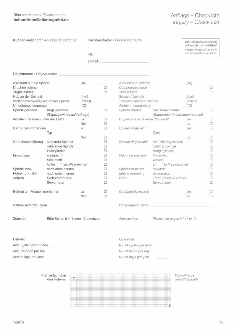
151/2019
Kunden-Anschrift / Address of customer Sachbearbeiter / Person in charge
Tel.
Projektname / Project name
Bitte möglichst vollständig ankreuzen bzw. ausfüllen!
Please check off or fill in as completely as possible.
Axialkraft auf die Spindel [kN]Druckbelastung Zugbelastung Hub an der Spindel [mm]Verfahrgeschwindigkeit an der Spindel [mm/s]Umgebungstemperatur [°C]Spindelgewinde Kugelgewinde (Trapezgewinde auf Anfrage)Arbeiten Personen unter der Last? Ja Nein Führungen vorhanden ja Typ Nein Getriebeausführung stehende Spindel rotierende Spindel Hubzylinder Einbaulage waagrecht Senkrecht Unter ___° zur Waagrechten Spindel bzw. nach oben heraus Kolbenrohr fährt nach unten heraus Antrieb Drehstrommotor Servomotor
Betrieb am Frequenzumrichter Ja Nein
weitere Anforderungen
Zubehör: Bitte Seiten 9 / 11 oder 13 benutzen
F
S
Kraftverlauf über den Hubweg
Flow of force over lifting path
Betrieb:
Anz. Zyklen pro Stunde
Anz. Stunden pro Tag
Anzahl Tage pro Jahr
Anfrage – ChecklisteInquiry – Check List
Operation:
No. of cycles per hour
No. of hours per day
No. of days per year
Axial force of spindle [kN]Compressive force Tensile force Stroke of spindle [mm]Travelling speed at spindle [mm/s]Ambient temperature [°C]Spindle thread Ball-screw thread (Trapezoidal-thread upon request)Do persons work under the load? yes no Guides available? yes Type no Version of gear unit non-rotating spindle rotating spindle lifting cylinder Mounting position horizontal vertical at ___° to the horizontal Spindle or piston upwards tube is extending downwards Drive Three-phase AC motor Servo motor
Operated by inverter yes no
Other requirements
Accessories: Please use pages 9 / 11 or 13
Bitte senden an: /Please sent to: [email protected]
Eigenschaften• Kraftbereich: 5-100 kN• Max. Verfahrgeschwindigkeit: 550 mm/s• Kugelgewindetriebe für hohe Zyklen und Einschalt-
dauern, aber ohne Selbsthemmung.• Hohe Lebensdauern durch Kugelgewindetriebe mit
deutlich über dem Standard liegenden dynamischen Tragzahlen, dadurch mehrfache Lebens dauer.
• Antrieb mit Drehstrom- und Servomotoren• Sowohl mechanische als auch elektrische Synchro-
nisation mehrerer Getriebe möglich.
VorteilegegenüberHydraulik• Hohe Dynamik und sehr genaue Positionierung.• Anfahren verschiedener und veränderlicher Positi-
onen einfach realisierbar. Angefahrene Positionen werden auch nach dem Abschalten sicher gehalten.
• Konstantes Steuerungs- und Regelungsverhalten (keine Viskositätsänderungen) über den gesamten Gebrauchsbereich.
• Minimaler Anschlussaufwand, nur Strom- und Sig-nalleitungen.
• Geringer Wartungs- und Instandhaltungs auf wand.• Keine Umweltbelastung durch Leckagen.
Properties:• Load range: 5-100 kN• Max. travelling speed: 550 mm/s• Ball-screw drives for high number of cycles and high
duty cycles, but without self-locking quality.• High life-time with ball-screw drives with dynamic
load capacities, which are above standard drives. This results in multiple life-time.
• Three-phase AC motors and servomotors are avail-able as standard drives.
• Mechanical or electrical synchronisation of several actuators is possible.
Advantages against hydraulic solutions• High dynamic performance and very precise posi-
tioning.• Different and/or varying positions can be easily ap-
proached. Positions stopped at are permanently held even after shutting off the drive.
• Constant controllability and adjustability (no change in viscosity) during the whole range of use.
• Minimal installation expenditure, only circuit and signalling lines required.
• Low maintenance and repair expenses.• No pollution of the environment due to leakages.
V132 1.0 10.2019 2140610532
AntriebssystemeE.SeidenspinnerGmbH&Co.KGCarl-Benz-Str. 16 D-74321 Bietigheim-Bissingen Tel.: +49 (0) 71 42 / 70 01- 0 Fax: +49 (0) 71 42 / 70 01- 99 E-Mail: [email protected] Web: www.atlantagmbh.de