Embed Size (px)
Citation preview
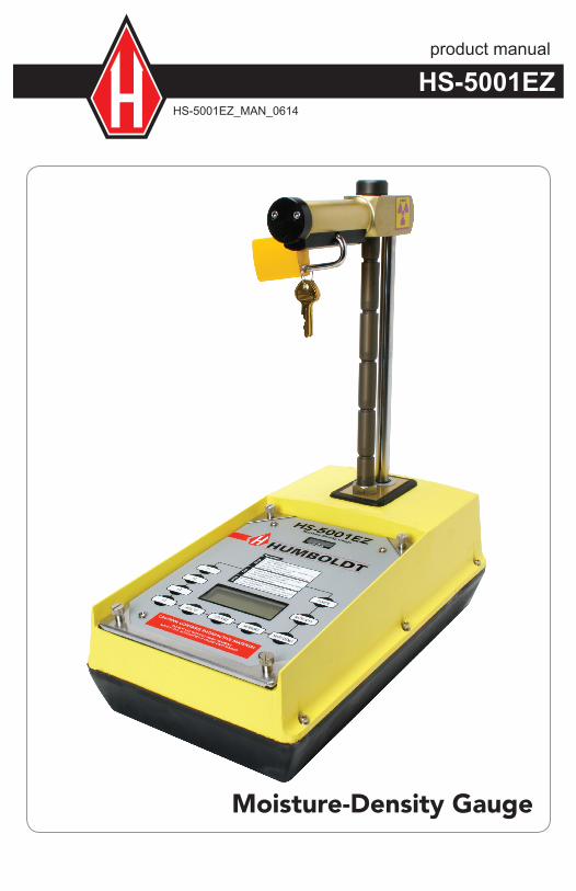
product manual
HS-5001EZ_MAN_0614
HS-5001EZ
Moisture-Density Gauge

COPYRIGHT NOTICE
Copyright (C) HUMBOLDT SCIENTIFIC, INC., 1983-2012All Rights Reserved.
This manual or parts thereof, may not bereproduced in any form without express writtenpermission of HUMBOLDT SCIENTIFIC, INC.
UNPUBLISHED LICENSED PROPRIETARY WORKCopyright (C) HUMBOLDT SCIENTIFIC, INC., 2012
The programmable read only memory integrated circuit package contained in this equipment and covered with a copyright notice label contains pro-prietary and confidential software which is the sole property of HUMBOLDT SCIENTIFIC, INC. It is licensed for use by the original purchaser of this equipment for a period of 99 years. Transfer of the license can be obtained by a request, in writing, from HUMBOLDT SCIENTIFIC, INC.
With the exception of HUMBOLDT Authorized Service Facilities, you may not copy, alter, de-compile, or reverse assemble the software in any fashion except as instructed in this manual. US copyright laws, trademark laws, and trade secrets protect the materials.
Any person(s) and /or organizations that attempt or accomplish the above violation or knowingly aid or abet the violation by supplying equipment or technology will be subject to civil damages and criminal prosecution.
IMPORTANT NOTICEThe information contained herein is supplied without representation or warranty of any kind. Humboldt Scientific, Inc. therefore assumes no responsibility and shall have no liability, consequential or otherwise, of any kind arising from the use of the described equipment or radioactive materials and/or information contained in this manual.
Use of the supplied hammer and drill rod requires driving the rod into compacted soil or other hard materials and may cause damage to the user due to flying particles from the hammer, drill rod or the materials under test. Safety glasses must be utilized for this procedure.
See Section 9 for Equipment Warranty.
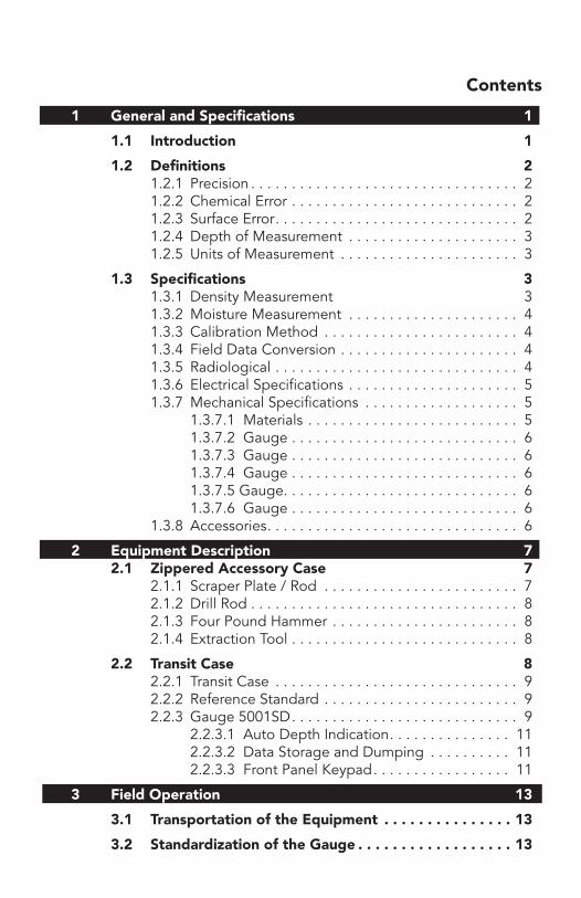
Contents
1 General and Specifications 1
1.1 Introduction 1
1.2 Definitions 2 1.2.1 Precision . . . . . . . . . . . . . . . . . . . . . . . . . . . . . . . . . 2 1.2.2 Chemical Error . . . . . . . . . . . . . . . . . . . . . . . . . . . . 2 1.2.3 Surface Error . . . . . . . . . . . . . . . . . . . . . . . . . . . . . . 2 1.2.4 Depth of Measurement . . . . . . . . . . . . . . . . . . . . . 3 1.2.5 Units of Measurement . . . . . . . . . . . . . . . . . . . . . . 3
1.3 Specifications 3 1.3.1 Density Measurement 3 1.3.2 Moisture Measurement . . . . . . . . . . . . . . . . . . . . . 4 1.3.3 Calibration Method . . . . . . . . . . . . . . . . . . . . . . . . 4 1.3.4 Field Data Conversion . . . . . . . . . . . . . . . . . . . . . . 4 1.3.5 Radiological . . . . . . . . . . . . . . . . . . . . . . . . . . . . . . 4 1.3.6 Electrical Specifications . . . . . . . . . . . . . . . . . . . . . 5 1.3.7 Mechanical Specifications . . . . . . . . . . . . . . . . . . . 5 1.3.7.1 Materials . . . . . . . . . . . . . . . . . . . . . . . . . . 5 1.3.7.2 Gauge . . . . . . . . . . . . . . . . . . . . . . . . . . . . 6 1.3.7.3 Gauge . . . . . . . . . . . . . . . . . . . . . . . . . . . . 6 1.3.7.4 Gauge . . . . . . . . . . . . . . . . . . . . . . . . . . . . 6 1.3.7.5 Gauge . . . . . . . . . . . . . . . . . . . . . . . . . . . . . 6 1.3.7.6 Gauge . . . . . . . . . . . . . . . . . . . . . . . . . . . . 6 1.3.8 Accessories . . . . . . . . . . . . . . . . . . . . . . . . . . . . . . . 6
2 Equipment Description 7 7 2.1 Zippered Accessory Case 7 2.1.1 Scraper Plate / Rod . . . . . . . . . . . . . . . . . . . . . . . . 7 2.1.2 Drill Rod . . . . . . . . . . . . . . . . . . . . . . . . . . . . . . . . . 8 2.1.3 Four Pound Hammer . . . . . . . . . . . . . . . . . . . . . . . 8 2.1.4 Extraction Tool . . . . . . . . . . . . . . . . . . . . . . . . . . . . 8
2.2 Transit Case 8 2.2.1 Transit Case . . . . . . . . . . . . . . . . . . . . . . . . . . . . . . 9 2.2.2 Reference Standard . . . . . . . . . . . . . . . . . . . . . . . . 9 2.2.3 Gauge 5001SD . . . . . . . . . . . . . . . . . . . . . . . . . . . . 9 2.2.3.1 Auto Depth Indication . . . . . . . . . . . . . . . 11 2.2.3.2 Data Storage and Dumping . . . . . . . . . . 11 2.2.3.3 Front Panel Keypad . . . . . . . . . . . . . . . . . 11
3 Field Operation 13
3.1 Transportation of the Equipment . . . . . . . . . . . . . . . 13
3.2 Standardization of the Gauge . . . . . . . . . . . . . . . . . . 13
3.4 Site Selection 19
3.5 Site Preparation 19
3.6 Positioning The Gauge 20
3.7 Taking the Measurement Count 20 3.7.1 Measurement Time Selection . . . . . . . . . . . . . . . . 20 3.7.2 Measurement Type Selection . . . . . . . . . . . . . . . . 21 3.7.2.1 Asphalt Measurements . . . . . . . . . . . . . . 21 3.7.2.2 Asphalt Thin Layer Measurements . . . . . 22 3.7.2.3 Soil Measurements . . . . . . . . . . . . . . . . . 25 3.7.2.4 Soil Measurements in Trenches . . . . . . . . 26
3.8 Processing the Results 27 3.8.1 Compaction Control . . . . . . . . . . . . . . . . . . . . . . . 28 3.8.2 Void Ratio . . . . . . . . . . . . . . . . . . . . . . . . . . . . . . . 28 3.8.3 Percent Air Voids . . . . . . . . . . . . . . . . . . . . . . . . . 28
3.9 Repackaging The Equipment 28
4 Menus 29 4.1 Data Menus 29
4.1.1 View Current Measurement . . . . . . . . . . . . . . . . . 29 4.1.2 Current Standard / Statistical Counts . . . . . . . . . . 29 4.1.3 Projects Setup . . . . . . . . . . . . . . . . . . . . . . . . . . . 30 4.1.3.1 Edit / Store Data . . . . . . . . . . . . . . . . . . . 31 4.1.3.2 View Stored Data . . . . . . . . . . . . . . . . . . 31 4.1.3.3 Print Data Report . . . . . . . . . . . . . . . . . . . 32
4.2 Setup Menus 32 4.2.1 Date Setup . . . . . . . . . . . . . . . . . . . . . . . . . . . . . . 32 4.2.2 Time Setup . . . . . . . . . . . . . . . . . . . . . . . . . . . . . . 33 4.2.3 Units Setup . . . . . . . . . . . . . . . . . . . . . . . . . . . . . . 34 4.2.4 Measurement Modes Setup . . . . . . . . . . . . . . . . . 34 4.2.5 Trench Correction Setup . . . . . . . . . . . . . . . . . . . 35 4.2.6 Targets Setup . . . . . . . . . . . . . . . . . . . . . . . . . . . . 35
4.3 Engineering Menus 35 4.3.1 Calibration . . . . . . . . . . . . . . . . . . . . . . . . . . . . . . 36 4.3.2 Reset Master Guage . . . . . . . . . . . . . . . . . . . . . . . 37 4.3.3 Manufacturer's Information . . . . . . . . . . . . . . . . . 37 4.3.4 Battery & Rod Voltage Information . . . . . . . . . . . 37
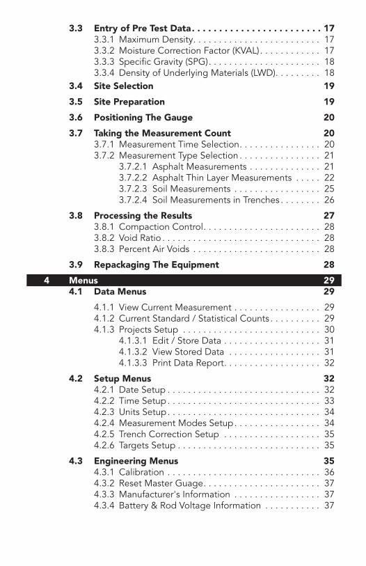
3.3 Entry of Pre Test Data . . . . . . . . . . . . . . . . . . . . . . . . 17 3.3.1 Maximum Density . . . . . . . . . . . . . . . . . . . . . . . . . 17 3.3.2 Moisture Correction Factor (KVAL) . . . . . . . . . . . . 17 3.3.3 Specific Gravity (SPG) . . . . . . . . . . . . . . . . . . . . . . 18 3.3.4 Density of Underlying Materials (LWD) . . . . . . . . . 18
5 Preventive Maintenance 37
5.1 Storage Environment 37
5.2 Exterior Cleaning 38
5.3 Sliding Shield Cavity 38
5.4 Performing A Wipe Test 39
5.5 Statistical Stability Test 40
6 Field Service 41
6.1 Mechanical Disassembly / Assembly 41 6.1.1 Bottom Plate and Shield . . . . . . . . . . . . . . . . . . . 41 6.1.2 Source Rod . . . . . . . . . . . . . . . . . . . . . . . . . . . . . . 41 6.1.3 Indexer and Latch . . . . . . . . . . . . . . . . . . . . . . . . 41 6.1.4 Index Rod . . . . . . . . . . . . . . . . . . . . . . . . . . . . . . . 42 6.1.5 Top Cover . . . . . . . . . . . . . . . . . . . . . . . . . . . . . . 42 6.1.6 Top Post and Seals . . . . . . . . . . . . . . . . . . . . . . . . 42 6.1.7 Base Module . . . . . . . . . . . . . . . . . . . . . . . . . . . . 43
6.2 Battery Replacement 43
6.3 Electronic Modules Adjustment / Replacement 43 6.3.1 Processor Module (200682) . . . . . . . . . . . . . . . . . 43 6.3.2 Base Plane Board (200112) . . . . . . . . . . . . . . . . . 44 6.3.3 High Voltage Power Supply Module (200088) . . . 44 6.3.4 Density Amplifier Module (200087) . . . . . . . . . . . 44 6.3.5 Moisture Amplifier Module (200086) . . . . . . . . . . 45
6.4 Detector Replacement 45
6.5 Parts List 46
6.6 Service Hints 48
6.7 Calibration 49
7 Theory of Operation 49
7.1 Density Measurement by Gamma Radiation 49
7.2 Moisture Measurement by Neutron Radiation 54
7.3 Radiation Statistics 57
8 Radiation Safety 59
8.1 Licensing 59
8.2 Dosimeter 60
8.3 Leak Tests 60
8.4 Transport 60
8.5 Disposal 61
8.6 Reporting of Loss or Incident 61
8.7 Radiation Profile 61
9 Warranty 63
9 Warranty 93

1 General and Specifications
1.1 Introduction
This Density/Moisture Gauge, the HS-5001EZ, is specifically designed to measure the moisture content and density of construction materials. The microprocessor-based units automatically computes these parameters and makes corrections to the measurements.
It uses the attenuation of gamma radiation due to Compton scattering and photoelectric absorption. It is directly related to the electron density of ma-terials as an indication of the mass density of specific materials having a chemical composition approximating the crust of the earth.
The standard factory supplied density calibration is based on a material consisting of 50% limestone and 50% granite as being very close to the average material encountered in engineering construction. This calibration may be altered by the user to best fit other materials, which may have a chemical composition vastly different from the supplied calibration.
The measurement of moisture content is based on the thermalization (slowing down) of fast neutron radiation. It is predominately a function of the hydrogen content of the materials and to a lessor degree, by other low atomic number elements such as carbon and oxygen. The presence of chemical elements such as boron, which may absorb or capture thermal neutrons, will also have some effect on the accuracy. Hydrated minerals such as gypsum or crystals such as mica may cause the largest single error. In general, a material containing hydrogen, which is not removed during an oven dry procedure, as outlined in ASTM D2216 will cause an error in the measurement.
The standard factory supplied moisture calibration is based on a water saturated silica sand standard, which is used to calibrate a working standard. The user, to correct for other materials, may alter the calibration.
THIS INSTRUMENT CONTAINS RADIOACTIVE MATERIALS, WHICH MAY BE HAZARDOUS IF IMPROPERLY USED.
HUMBOLDT recommends that users participate in a radiation safety and applications training program given by competent instructors. Where this is not possible or impractical, users should study the Radiation Safety Manual supplied with this instrument and carefully read this Instruction Manual to become familiar with the safe operation of the instrument.
A Radioactive or By product Material License is required from an Agree-ment State or The US Nuclear Regulatory Commission for possession in the United States. The governments of other countries require a similar license.
1
Proper use of this equipment will have little effect on the total exposure of a typical operator to ionizing radiation. However, a potential danger does exist and any questions regarding this danger should be addressed to the Radiation Safety Officer within the owner's organization or other competent persons.
Any theft or other loss and accidents to the equipment, which may involve the sealed sources of radioactive material, must be immediately reported to the Radiation Safety Officer.
1.2 Definitions
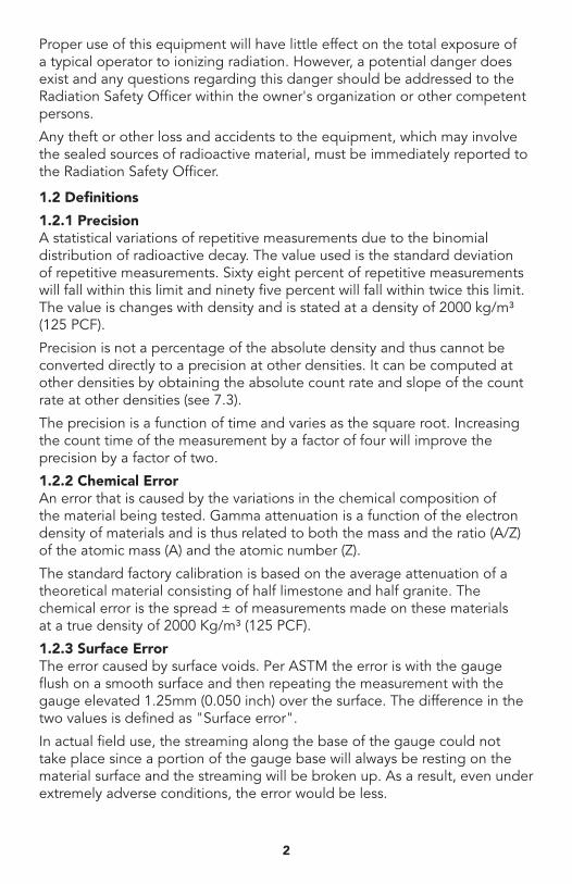
1.2.1 PrecisionA statistical variations of repetitive measurements due to the binomial distribution of radioactive decay. The value used is the standard deviation of repetitive measurements. Sixty eight percent of repetitive measurements will fall within this limit and ninety five percent will fall within twice this limit. The value is changes with density and is stated at a density of 2000 kg/m³ (125 PCF).
Precision is not a percentage of the absolute density and thus cannot be converted directly to a precision at other densities. It can be computed at other densities by obtaining the absolute count rate and slope of the count rate at other densities (see 7.3).
The precision is a function of time and varies as the square root. Increasing the count time of the measurement by a factor of four will improve the precision by a factor of two.
1.2.2 Chemical ErrorAn error that is caused by the variations in the chemical composition of the material being tested. Gamma attenuation is a function of the electron density of materials and is thus related to both the mass and the ratio (A/Z) of the atomic mass (A) and the atomic number (Z).
The standard factory calibration is based on the average attenuation of a theoretical material consisting of half limestone and half granite. The chemical error is the spread ± of measurements made on these materials at a true density of 2000 Kg/m³ (125 PCF).
1.2.3 Surface ErrorThe error caused by surface voids. Per ASTM the error is with the gauge flush on a smooth surface and then repeating the measurement with the gauge elevated 1.25mm (0.050 inch) over the surface. The difference in the two values is defined as "Surface error".
In actual field use, the streaming along the base of the gauge could not take place since a portion of the gauge base will always be resting on the material surface and the streaming will be broken up. As a result, even under extremely adverse conditions, the error would be less.
2
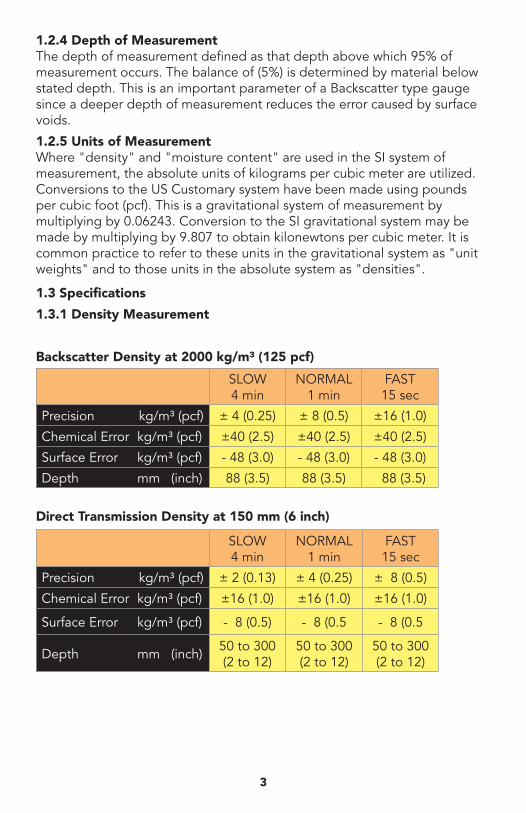
1.2.4 Depth of MeasurementThe depth of measurement defined as that depth above which 95% of measurement occurs. The balance of (5%) is determined by material below stated depth. This is an important parameter of a Backscatter type gauge since a deeper depth of measurement reduces the error caused by surface voids.
1.2.5 Units of MeasurementWhere "density" and "moisture content" are used in the SI system of measurement, the absolute units of kilograms per cubic meter are utilized. Conversions to the US Customary system have been made using pounds per cubic foot (pcf). This is a gravitational system of measurement by multiplying by 0.06243. Conversion to the SI gravitational system may be made by multiplying by 9.807 to obtain kilonewtons per cubic meter. It is common practice to refer to these units in the gravitational system as "unit weights" and to those units in the absolute system as "densities".
1.3 Specifications
1.3.1 Density Measurement
Backscatter Density at 2000 kg/m³ (125 pcf)
Direct Transmission Density at 150 mm (6 inch)
SLOW 4 min
NORMAL 1 min
FAST 15 sec
Precision kg/m³ (pcf) ± 4 (0.25) ± 8 (0.5) ±16 (1.0)
Chemical Error kg/m³ (pcf) ±40 (2.5) ±40 (2.5) ±40 (2.5)
Surface Error kg/m³ (pcf) - 48 (3.0) - 48 (3.0) - 48 (3.0)
Depth mm (inch) 88 (3.5) 88 (3.5) 88 (3.5)
SLOW 4 min
NORMAL 1 min
FAST 15 sec
Precision kg/m³ (pcf) ± 2 (0.13) ± 4 (0.25) ± 8 (0.5)
Chemical Error kg/m³ (pcf) ±16 (1.0) ±16 (1.0) ±16 (1.0)
Surface Error kg/m³ (pcf) - 8 (0.5) - 8 (0.5 - 8 (0.5
Depth mm (inch) 50 to 300 (2 to 12)
50 to 300 (2 to 12)
50 to 300 (2 to 12)
3
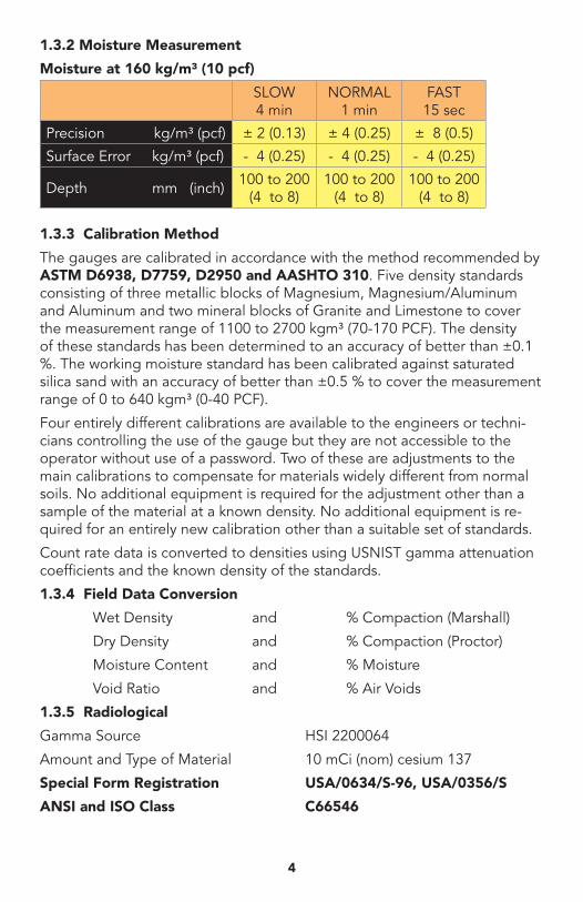
1.3.2 Moisture Measurement
Moisture at 160 kg/m³ (10 pcf)
1.3.3 Calibration Method
The gauges are calibrated in accordance with the method recommended by ASTM D6938, D7759, D2950 and AASHTO 310. Five density standards consisting of three metallic blocks of Magnesium, Magnesium/Aluminum and Aluminum and two mineral blocks of Granite and Limestone to cover the measurement range of 1100 to 2700 kgm³ (70-170 PCF). The density of these standards has been determined to an accuracy of better than ±0.1 %. The working moisture standard has been calibrated against saturated silica sand with an accuracy of better than ±0.5 % to cover the measurement range of 0 to 640 kgm³ (0-40 PCF).
Four entirely different calibrations are available to the engineers or techni-cians controlling the use of the gauge but they are not accessible to the operator without use of a password. Two of these are adjustments to the main calibrations to compensate for materials widely different from normal soils. No additional equipment is required for the adjustment other than a sample of the material at a known density. No additional equipment is re-quired for an entirely new calibration other than a suitable set of standards.
Count rate data is converted to densities using USNIST gamma attenuation coefficients and the known density of the standards.
1.3.4 Field Data Conversion
Wet Density and % Compaction (Marshall)
Dry Density and % Compaction (Proctor)
Moisture Content and % Moisture
Void Ratio and % Air Voids
1.3.5 Radiological
Gamma Source HSI 2200064
Amount and Type of Material 10 mCi (nom) cesium 137
Special Form Registration USA/0634/S-96, USA/0356/S
ANSI and ISO Class C66546
SLOW 4 min
NORMAL 1 min
FAST 15 sec
Precision kg/m³ (pcf) ± 2 (0.13) ± 4 (0.25) ± 8 (0.5)
Surface Error kg/m³ (pcf) - 4 (0.25) - 4 (0.25) - 4 (0.25)
Depth mm (inch) 100 to 200 (4 to 8)
100 to 200 (4 to 8)
100 to 200 (4 to 8)
4
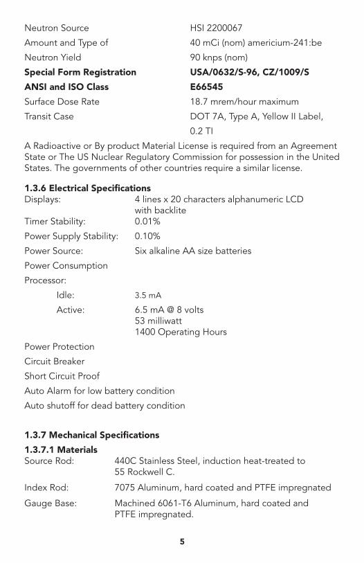
Neutron Source HSI 2200067
Amount and Type of 40 mCi (nom) americium-241:be
Neutron Yield 90 knps (nom)
Special Form Registration USA/0632/S-96, CZ/1009/S
ANSI and ISO Class E66545
Surface Dose Rate 18.7 mrem/hour maximum
Transit Case DOT 7A, Type A, Yellow II Label,
0.2 TI
A Radioactive or By product Material License is required from an Agreement State or The US Nuclear Regulatory Commission for possession in the United States. The governments of other countries require a similar license.
1.3.6 Electrical SpecificationsDisplays: 4 lines x 20 characters alphanumeric LCD with backlite Timer Stability: 0.01%
Power Supply Stability: 0.10%
Power Source: Six alkaline AA size batteries
Power Consumption
Processor:
Idle: 3.5 mA
Active: 6.5 mA @ 8 volts 53 milliwatt 1400 Operating Hours
Power Protection
Circuit Breaker
Short Circuit Proof
Auto Alarm for low battery condition
Auto shutoff for dead battery condition
1.3.7 Mechanical Specifications
1.3.7.1 MaterialsSource Rod: 440C Stainless Steel, induction heat-treated to 55 Rockwell C.
Index Rod: 7075 Aluminum, hard coated and PTFE impregnated
Gauge Base: Machined 6061-T6 Aluminum, hard coated and PTFE impregnated.
5
2
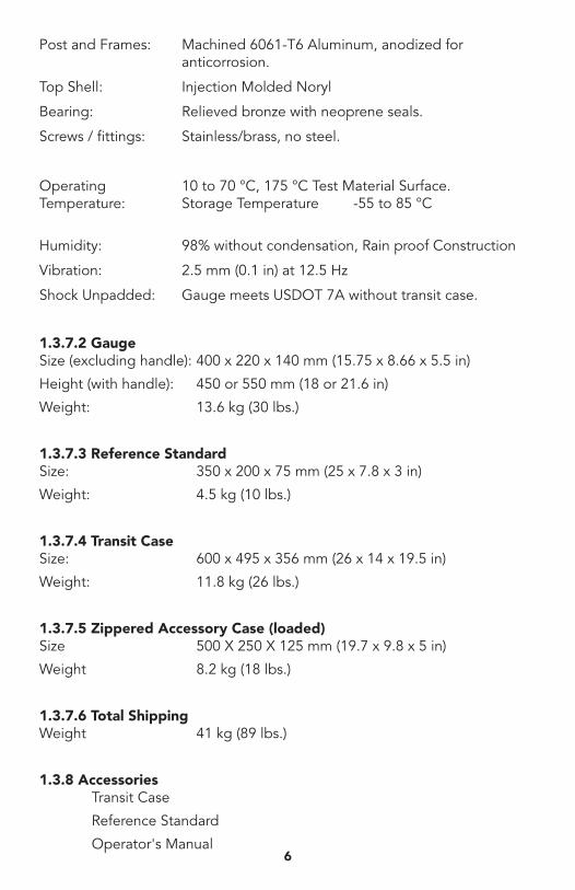
Post and Frames: Machined 6061-T6 Aluminum, anodized for anticorrosion.
Top Shell: Injection Molded Noryl
Bearing: Relieved bronze with neoprene seals.
Screws / fittings: Stainless/brass, no steel.
Operating 10 to 70 °C, 175 °C Test Material Surface. Temperature: Storage Temperature -55 to 85 °C
Humidity: 98% without condensation, Rain proof Construction
Vibration: 2.5 mm (0.1 in) at 12.5 Hz
Shock Unpadded: Gauge meets USDOT 7A without transit case.
1.3.7.2 GaugeSize (excluding handle): 400 x 220 x 140 mm (15.75 x 8.66 x 5.5 in)
Height (with handle): 450 or 550 mm (18 or 21.6 in)
Weight: 13.6 kg (30 lbs.)
1.3.7.3 Reference StandardSize: 350 x 200 x 75 mm (25 x 7.8 x 3 in)
Weight: 4.5 kg (10 lbs.)
1.3.7.4 Transit CaseSize: 600 x 495 x 356 mm (26 x 14 x 19.5 in)
Weight: 11.8 kg (26 lbs.)
1.3.7.5 Zippered Accessory Case (loaded)Size 500 X 250 X 125 mm (19.7 x 9.8 x 5 in)
Weight 8.2 kg (18 lbs.)
1.3.7.6 Total Shipping Weight 41 kg (89 lbs.)
1.3.8 Accessories Transit Case
Reference Standard
Operator's Manual6
Radiation Safety Manual
Source and Case Certification
Wipe Test Materials
Zippered Accessory Case
Rod Guide/Scraper Plate
Drill Rod
Four Pound Hammer
Rod Extraction Tool
2. EQUIPMENT DESCRIPTIONBefore using this equipment, the operator should be thoroughly familiar with the Radiation Safety Manual supplied with the instrument. If possible, a suitable course in the safe use and field application should be attended.
Users who desire knowledge regarding the theory of operation of the equipment should refer to Section 7.0. This information will be helpful in understanding, the limitations of the equipment and how to avoid or work around these limitations.
2.1 Zippered Accessory CaseZippered Accessory Case Containing:
Rod Guide/Scraper Plate Drill Rod Four Pound Hammer Rod Extraction ToolThe accessories may be carried in the transit case or may be carried in a zippered canvas bag. It is convenient to carry and decreases the bulk and weight of the transit case, which contains the Gauge, Reference Standard and Manuals.
2.1.1 Scraper Plate / Rod GuideWhen the gauge is to be used on soil, the Scraper Plate is used to smooth the site to eliminate as many surface voids as possible. Two convenient handles are located so that it may be used to scrape away loose material.
The two handles are also used as a guide when driving the rod into soil or soil aggregates for a direct transmission density measurement. The operator or a helper can stand on the plate to prevent it from shifting while the rod is hammered.
The plate is the same size as the gauge base, and if the rod is used to mark lines around it, then the gauge can then be approximately located over the rod hole before attempting to lower source rod into the hole.
The plate may be used to lightly tamp soil or native fines that may have been used to fill the surface voids. It should not be used with the hammer to pack soil since it may distort the plate and cause erroneous measurements.
7
4
2.1.2 Drill RodThe drill rod is a medium hardness tough steel and has a captive head to allow it to be driven into soil or soil aggregates so that the source can be placed into the material for a direct transmission density measurement. The rod is marked so that the depth can be controlled by reference to the top of the scraper plate handle.Use the rod in stiff clays may require the application of the extraction tool for removal. It must not be driven or moved sideways as this will enlarge the hole or modify the density of the material being tested.
The rod is expendable and must be replaced after extensive or severe use. Repeated hammering of the cap may cause metal chips to break away and the operator and others close by the test site must wear safety glasses.
2.1.3 Four-Pound HammerThe hammer is supplied to drive the rod into soils or soil aggregates and it may be used with the extraction tool to help remove the rod from clay. It is sufficiently heavy for this purpose and a larger hammer is not needed since it could rapidly damage the drill rod.
2.1.4 Extraction ToolThis tool is used to assist the removal of the drill rod if it becomes stuck in clay or granular material. The usual problem is a vacuum, which can exist in the hole when attempting to pull the rod out.
It does not have to be put into place before driving the rod. A slot in the middle is placed on a square, which is cut in the drill rod head. The arms may then be used to rotate the rod and will make it easier to extract by the supplying handles to pull up on the rod. If necessary, the hammer may be lightly topped on the underside of the tool to drive the rod up out of the hole.
2.2 Transit CaseContaining: Gauge Reference Standard Operator's Manual Radiation Safety Manual
Both the gauge and the transit case are supplied with locks and they should be secured when the instrument is not in use or attended.
When stored, the equipment should be placed in a locked room or area, which is dry and maintained at a livable temperature. Storage below 20 °C should be avoided and temperatures above 30 °C for extended periods of time will deplete the batteries at a rapid rate and shorten their useful life.
8
2.2.1 Transit CaseThe transit case is a rotational molded high strength, plastic case and is equipped with a lockable latch. The design and components follow the standard ATA case configuration that is in popular use for air shipment of delicate instruments. It has fitted compartments for the gauge, Reference Standard and accessories along with a storage area for engineering notebooks and manuals.
It has been tested to US DOT 7A Type A requirements and has labels, which meet both International and US requirements, for surface and air cargo shipment.
2.2.2 Reference StandardThe Reference Standard is used to provide a standard count to account for aging of the calibration. Instruments, which use radiation to perform measurements, are subject to decay of the source (2.3% per year for Cs 137) drift of the detectors due to leakage and absorption of quench gas, and long term drift of the electronics. In order to decrease the effect of these errors, the calibration is made as a ratio to a standard measurement. The moisture count is a ratio to a moisture count on the standard and the density count is a ratio to a density count on the standard.
The hydrogen in the reference standard determines the moisture standard count. The density standard count is determined primarily by the shielding material in the base of the gauge and only slightly by the reference standard.
The Reference Standard is serialized to match the gauge and they must not be interchanged between gauges or moisture measurement errors may exist.
2.2.3 Gauge HS-5001EZThe HS-5001EZ-type gauge utilizes an alphanumeric LCD touch screen, state of the art electronic circuits to generate the necessary timing circuit, and power supplies. The processor automatically compensates for the abnormal gamma attenuation coefficient for hydrogen as compared to the values of higher atomic numbered materials found in soils. Using the current standard count it also compensates for the decay of the Cesium source. It also allows the operator to enter a correction factor (KVAL) to compensate for hydrogen found in construction materials, which is not represented by water.
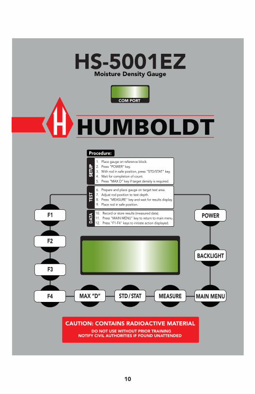
A facsimile of the control panel is shown on next page indicating the positions of the display and keys. The keys are grouped across the bottom for easy access and the display labeled for clarity.
The lettering is embedded in the plastic overlay and is not harmed by water or abrasion. Since there are many functions available, a description of the purpose for each key is necessary.
9
610
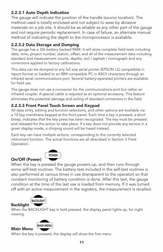
2.2.3.1 Auto Depth IndicationThe gauge will indicate the position of the handle (source location). The method used is totally enclosed and not subject to wear by abrasive materials on a job site. It should be as reliable as any other part of the gauge and not require periodic replacement. In case of failure, an alternate manual method of indicating the depth to the microprocessor is available.
2.2.3.2 Data Storage and DumpingThe gauge has a 32k battery backed RAM. It will store complete field tests including date, time, project number, station, offset, and all of the measurement data including standard and measurement counts, depths, soil / asphalt / nomograph and any corrections applied to factory calibrations.
This data can be dumped to any full size serial printer (EPSON LQ compatible) in report format or loaded to an IBM compatible PC in ASCII characters through an infrared serial communications port. Several battery-operated printers are available for field use.
The gauge does not use a connector for the communications port but rather an infrared coupler. A special cable is required as an optional accessory. This feature eliminates the potential damage and soiling of standard connectors in the field.
2.2.3.3 Front Panel Touch Screen and Keypad All data entry, editing and function selections, and other options are available via a 10 key membrane keypad at the front panel. Each time a key is pressed, a short bleep, indicates that the key press has been recognized. The key must be pressed and released for the action to take place. If a key does not provide any service in a given display mode, a chirping sound will be heard instead.
Each key can have multiple actions, corresponding to the currently selected instrument function. The actual functions are all described in Section 3 Field Operation.
On/Off (Power) When the key is pressed the gauge powers up, and then runs through some self-test routines. The battery test included in the self-test routines is also performed at various times in use (transparent to the operator) so that constant monitoring of battery condition is done. After this test, the gauge condition at the time of the last use is loaded from memory. If it was turned off with an active measurement in the registers, the measurement is recalled.
Backlight When the BACKLIGHT key is held pressed, the display panel lights up, for night viewing.
Main Menu When the key is pressed, the display will show the first menu
11
812
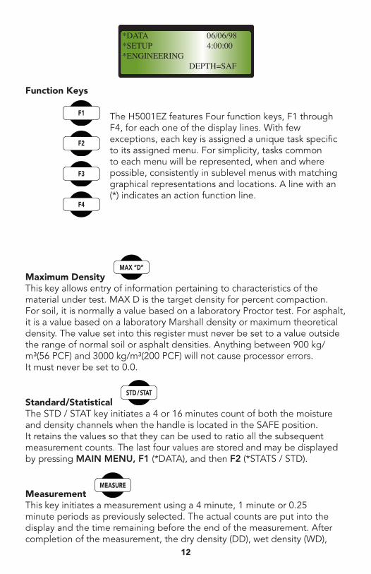
*DATA 06/06/98 *SETUP 4:00:00 *ENGINEERING DEPTH=SAF
Function Keys
The H5001EZ features Four function keys, F1 through F4, for each one of the display lines. With few exceptions, each key is assigned a unique task specific to its assigned menu. For simplicity, tasks common to each menu will be represented, when and where possible, consistently in sublevel menus with matching graphical representations and locations. A line with an (*) indicates an action function line.
Maximum Density This key allows entry of information pertaining to characteristics of the material under test. MAX D is the target density for percent compaction. For soil, it is normally a value based on a laboratory Proctor test. For asphalt, it is a value based on a laboratory Marshall density or maximum theoretical density. The value set into this register must never be set to a value outside the range of normal soil or asphalt densities. Anything between 900 kg/m³(56 PCF) and 3000 kg/m³(200 PCF) will not cause processor errors. It must never be set to 0.0.
Standard/Statistical The STD / STAT key initiates a 4 or 16 minutes count of both the moisture and density channels when the handle is located in the SAFE position. It retains the values so that they can be used to ratio all the subsequent measurement counts. The last four values are stored and may be displayed by pressing MAIN MENU, F1 (*DATA), and then F2 (*STATS / STD).
Measurement This key initiates a measurement using a 4 minute, 1 minute or 0.25 minute periods as previously selected. The actual counts are put into the display and the time remaining before the end of the measurement. After completion of the measurement, the dry density (DD), wet density (WD),
13
moisture (M), percent moisture (%M), percent proctor (%PR) are displayed, if the gauge is in the soil mode. Wet density (WD) or total density, % Marshall (%MA) if in the asphalt mode. Any of the other parameters may be successively obtained by pressing the appropriate key.
3. Field Operation This chapter will describe the proper use of the equipment during the process of making field measurements on soils, soil aggregates, treated bases, or asphaltic concrete. It is assumed that the user has read the previous chapter and understands the functions of the various keys.
The operator should have had training in radiation safety or thoroughly read the RADIATION SAFETY MANUAL supplied with this instrument and understand the basic principles of minimizing his/her exposure.
3.1 Transportation of the Equipment The Gauge and Reference Standard should be transported in its Transit Case, which is designed for this purpose. The gauge lock and the transit case lock should be in place and secured. In case of an accident to the vehicle, the locks prevent unauthorized access to the radioactive material and the case will help protect the equipment from damage. The Zippered Accessory Case will prevent loss of its items and if an automobile is used, it will protect the trunk space.
If transport is made by automobile, the Transit Case and Gauge should be placed in the trunk to keep it as far away from passengers as possible. Van location should be toward the rear and the case secured to prevent shifting. In open trucks, means must be taken to prevent shifting and unauthorized removal.
3.2 Standardization of the Gauge Prior to use of the gauge, a set of STANDARD COUNTS must be taken and used for all of the measurements to be made on a particular day. These counts should be logged for verification of proper operation and provide a history for service if required, Remove the Gauge lock and make certain that the handle is latched in the “SAFE” position. It must be in the top position of the index rod.
Important notice: The Reference Standard and bottom surface of the gauge must be clear of any debris that would prevent the gauge from seating firmly on the Reference Standard. Place the Reference Standard on compacted material, place the gauge on the Reference Standard with the handle end of the Standard away from the operator. The gauge must be seated inside the guide rails along the edges of the Standard, and the back of the gauge up against the handle of the reference standard.
1014
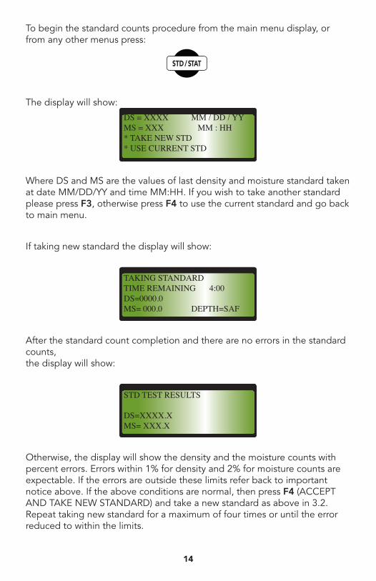
To begin the standard counts procedure from the main menu display, or from any other menus press:
The display will show:
Where DS and MS are the values of last density and moisture standard taken at date MM/DD/YY and time MM:HH. If you wish to take another standard please press F3, otherwise press F4 to use the current standard and go back to main menu.
If taking new standard the display will show:
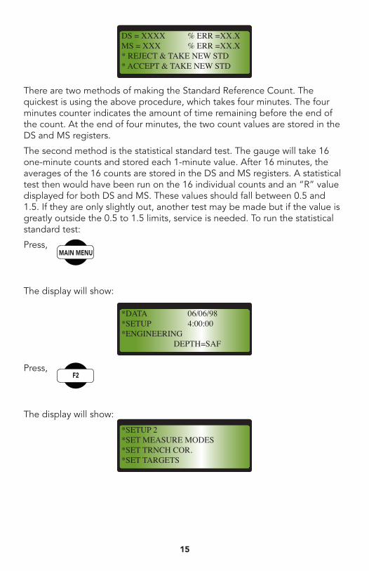
After the standard count completion and there are no errors in the standard counts, the display will show:
Otherwise, the display will show the density and the moisture counts with percent errors. Errors within 1% for density and 2% for moisture counts are expectable. If the errors are outside these limits refer back to important notice above. If the above conditions are normal, then press F4 (ACCEPT AND TAKE NEW STANDARD) and take a new standard as above in 3.2. Repeat taking new standard for a maximum of four times or until the error reduced to within the limits.
DS = XXXX MM / DD / YY MS = XXX MM : HH * TAKE NEW STD * USE CURRENT STD
TAKING STANDARDTIME REMAINING 4:00DS=0000.0MS= 000.0 DEPTH=SAF
STD TEST RESULTS
DS=XXXX.XMS= XXX.X
15
There are two methods of making the Standard Reference Count. The quickest is using the above procedure, which takes four minutes. The four minutes counter indicates the amount of time remaining before the end of the count. At the end of four minutes, the two count values are stored in the DS and MS registers.
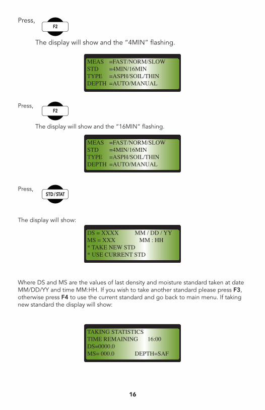
The second method is the statistical standard test. The gauge will take 16 one-minute counts and stored each 1-minute value. After 16 minutes, the averages of the 16 counts are stored in the DS and MS registers. A statistical test then would have been run on the 16 individual counts and an “R” value displayed for both DS and MS. These values should fall between 0.5 and 1.5. If they are only slightly out, another test may be made but if the value is greatly outside the 0.5 to 1.5 limits, service is needed. To run the statistical standard test:
Press,
The display will show:
Press,
The display will show:
*DATA 06/06/98*SETUP 4:00:00*ENGINEERING DEPTH=SAF
DS = XXXX % ERR =XX.XMS = XXX % ERR =XX.X* REJECT & TAKE NEW STD* ACCEPT & TAKE NEW STD
*SETUP 2*SET MEASURE MODES*SET TRNCH COR.*SET TARGETS
16
Press,
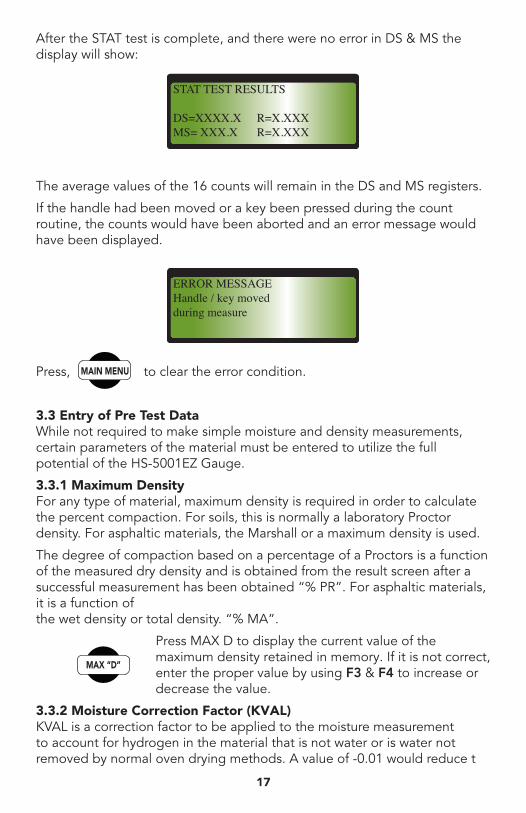
The display will show and the “4MIN” flashing.
Press,
The display will show and the “16MIN” flashing.
Press,
The display will show:
Where DS and MS are the values of last density and moisture standard taken at date MM/DD/YY and time MM:HH. If you wish to take another standard please press F3, otherwise press F4 to use the current standard and go back to main menu. If taking new standard the display will show:
MEAS =FAST/NORM/SLOWSTD =4MIN/16MINTYPE =ASPH/SOIL/THINDEPTH =AUTO/MANUAL
MEAS =FAST/NORM/SLOWSTD =4MIN/16MINTYPE =ASPH/SOIL/THINDEPTH =AUTO/MANUAL
DS = XXXX MM / DD / YY MS = XXX MM : HH * TAKE NEW STD * USE CURRENT STD
TAKING STATISTICSTIME REMAINING 16:00DS=0000.0MS= 000.0 DEPTH=SAF
17
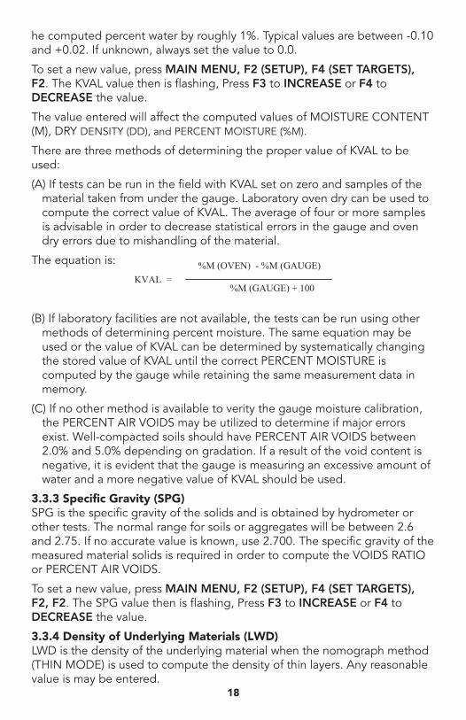
After the STAT test is complete, and there were no error in DS & MS the display will show:
The average values of the 16 counts will remain in the DS and MS registers.
If the handle had been moved or a key been pressed during the count routine, the counts would have been aborted and an error message would have been displayed.
Press, to clear the error condition.
3.3 Entry of Pre Test Data While not required to make simple moisture and density measurements, certain parameters of the material must be entered to utilize the full potential of the HS-5001EZ Gauge.
3.3.1 Maximum Density For any type of material, maximum density is required in order to calculate the percent compaction. For soils, this is normally a laboratory Proctor density. For asphaltic materials, the Marshall or a maximum density is used.
The degree of compaction based on a percentage of a Proctors is a function of the measured dry density and is obtained from the result screen after a successful measurement has been obtained “% PR”. For asphaltic materials, it is a function of the wet density or total density. “% MA”.
Press MAX D to display the current value of the maximum density retained in memory. If it is not correct, enter the proper value by using F3 & F4 to increase or decrease the value.
3.3.2 Moisture Correction Factor (KVAL) KVAL is a correction factor to be applied to the moisture measurement to account for hydrogen in the material that is not water or is water not removed by normal oven drying methods. A value of -0.01 would reduce t
STAT TEST RESULTS
DS=XXXX.X R=X.XXXMS= XXX.X R=X.XXX
ERROR MESSAGEHandle / key movedduring measure
18
he computed percent water by roughly 1%. Typical values are between -0.10 and +0.02. If unknown, always set the value to 0.0.
To set a new value, press MAIN MENU, F2 (SETUP), F4 (SET TARGETS), F2. The KVAL value then is flashing, Press F3 to INCREASE or F4 to DECREASE the value.
The value entered will affect the computed values of MOISTURE CONTENT (M), DRY DENSITY (DD), and PERCENT MOISTURE (%M).
There are three methods of determining the proper value of KVAL to be used:
(A) If tests can be run in the field with KVAL set on zero and samples of the material taken from under the gauge. Laboratory oven dry can be used to compute the correct value of KVAL. The average of four or more samples is advisable in order to decrease statistical errors in the gauge and oven dry errors due to mishandling of the material.
The equation is:
(B) If laboratory facilities are not available, the tests can be run using other methods of determining percent moisture. The same equation may be used or the value of KVAL can be determined by systematically changing the stored value of KVAL until the correct PERCENT MOISTURE is computed by the gauge while retaining the same measurement data in memory.
(C) If no other method is available to verity the gauge moisture calibration, the PERCENT AIR VOIDS may be utilized to determine if major errors exist. Well-compacted soils should have PERCENT AIR VOIDS between 2.0% and 5.0% depending on gradation. If a result of the void content is negative, it is evident that the gauge is measuring an excessive amount of water and a more negative value of KVAL should be used.
3.3.3 Specific Gravity (SPG) SPG is the specific gravity of the solids and is obtained by hydrometer or other tests. The normal range for soils or aggregates will be between 2.6 and 2.75. If no accurate value is known, use 2.700. The specific gravity of the measured material solids is required in order to compute the VOIDS RATIO or PERCENT AIR VOIDS.
To set a new value, press MAIN MENU, F2 (SETUP), F4 (SET TARGETS), F2, F2. The SPG value then is flashing, Press F3 to INCREASE or F4 to DECREASE the value.
3.3.4 Density of Underlying Materials (LWD) LWD is the density of the underlying material when the nomograph method (THIN MODE) is used to compute the density of thin layers. Any reasonable value is may be entered.
19
To set a new value, press MAIN MENU, F2 (SETUP), F4 (SET TARGETS), F1. The LWD value then is flashing, Press F3 to INCREASE or F4 to DECREASE the value.
3.4 Site Selection In general, all measurement should be made as soon as possible after the site has been compacted. This is particularly true for fills and embankments since evaporation may dry out the surface material and lower the average moisture measurement. Any rain prior to the measurements may increase these values unless sufficient time has elapsed to allow surface drying. These conditions may be alleviated by removing surface materials to a depth necessary to eliminate non-homogeneous materials.
For asphaltic concrete emplacements, the testing should ideally be made while the material is being compacted so that additional rolling can be accomplished before the material cools below acceptable compaction temperatures.
The selection of a site to be measured is left to the judgement of the operator or may be defined by prescribed procedures or specifications. A random sampling method is recommended.
An optionally selected site should not be chosen on obvious conditions which may either reject or pass the results It should be representative of the total area to be tested.
3.5 Site Preparation Any site to be measured should be clear of all loose debris before attempting to seat the gauge. After removing the loose material from soils, the area should be leveled using Scraper Plate to provide a flat surface. Any large surface void areas should be filled with native fines even though a direct transmission measurement will be made.
If hard surfaced areas are involved which make the direct transmission method impractical or impossible, then a backscatter measurement will have to be made. In addition, the surface voids must be carefully leveled with mineral filler and lightly compacted with the Scraper Plate to minimize surface errors.
The Scraper Plate is used as a guide for the Drill Rod to facilitate making a vertical hole. Place the Scraper Plate over the desired site and while holding it in place with one foot, drive the rod to a depth at least 50 mm (2 inches) deeper than the measurement depth. The Drill Rod is marked in 50mm (2-inch) increments to aid in judging the depth. Safety Glasses must be worn to prevent eye damage while striking the rod with the hammer.
If the rod cannot be easily removed from the hole, place the Extraction Tool around the rod and engage the flat surfaces at the bottom of the head. Using the tool, rotate and pull on the rod to remove it. If the rod is still difficult to remove, lightly tap on the bottom surface of the Extraction Tool and drive it vertically out of the hole.
1620
If the line is used to make a light mark is drawn around the Scraper Plate while it is placed over the hole, it will be easier to locate the Gauge such that the source rod will extend into the hole without difficulty.
3.6 Positioning the Gauge Carefully place the Gauge over the prepared site. If backscatter is used, seat the Gauge to make it as flush to the surface as possible. If a line was scribed around the site for direct transmission then the base should be centered over the site to ease insertion of the source rod into the hole.
Release the LATCH by pressing the trigger into the handle, push the handle down until the approximate correct position is obtained, the first notch for backscatter or the correct predetermined depth for direct transmission. At the correct depth, release the trigger, and lift the handle just above the notch then push the handle one more time until hearing the “click” as the INDEXER accurately position the source.
If a direct transmission is being used, pull the Gauge toward the control panel end to force the source rod against the side of the prepared hole. This is important since a void could exist between the rod tip and the side of the hole.
3.7 Taking the Measurement Count The measurement can be taken by simply pressing the MEAS key. Most measurements will be made, by using the “NORM” in measure mode, which takes an exact one-minute count. It may be desirable to use the “FAST” or 1/4 minute measure mode if it is necessary to make a quick measurement to avoid conflict with compaction equipment. The measurement precision will be degraded by a factor of two.
Use of the “SLOW” four minute measuring mode will enable the user to improve the precision by a factor of two. This will allow close examination of small density changes such as establishing a roller pattern or attempting to improve compaction efficiency.
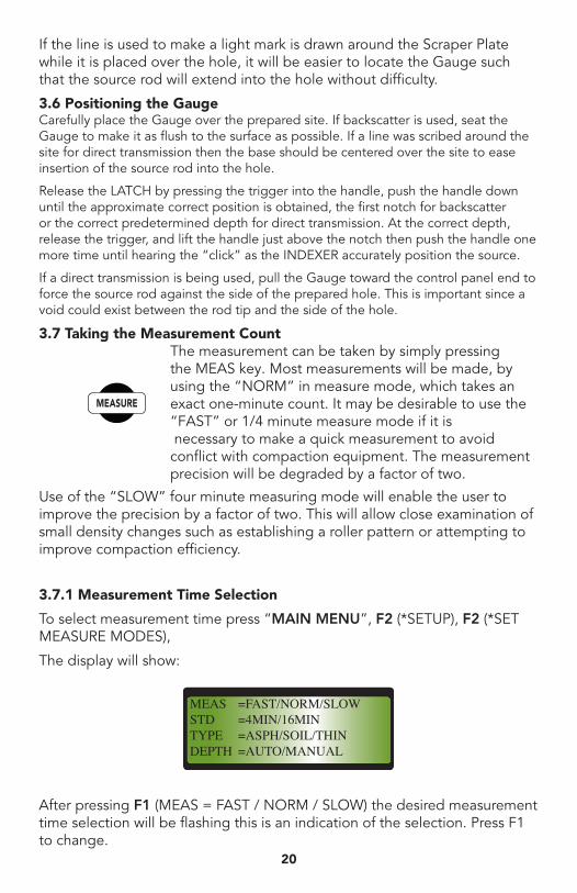
3.7.1 Measurement Time Selection
To select measurement time press “MAIN MENU”, F2 (*SETUP), F2 (*SET MEASURE MODES),
The display will show:
After pressing F1 (MEAS = FAST / NORM / SLOW) the desired measurement time selection will be flashing this is an indication of the selection. Press F1 to change.
MEAS =FAST/NORM/SLOWSTD =4MIN/16MINTYPE =ASPH/SOIL/THINDEPTH =AUTO/MANUAL
21
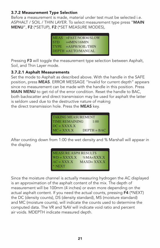
3.7.2 Measurement Type Selection Before a measurement is made, material under test must be selected i.e. ASPHALT / SOIL / THIN LAYER. To select measurement type press “MAIN MENU”, F2 (*SETUP), F2 (*SET MEASURE MODES),
Pressing F3 will toggle the measurement type selection between Asphalt, Soil, and Thin Layer mode.
3.7.2.1 Asphalt Measurements Set the mode to Asphalt as described above. With the handle in the SAFE position, press MEAS. ERROR MESSAGE “Invalid for current depth” appears since no measurement can be made with the handle in this position. Press MAIN MENU to get rid of the error condition. Reset the handle to BAC, both backscatter and direct transmission may be used for asphalt the latter is seldom used due to the destructive nature of making the direct transmission hole. Press the MEAS key.
After counting down from 1:00 the wet density and % Marshall will appear in the display.
Since the moisture channel is actually measuring hydrogen the AC displayed is an approximation of the asphalt content of the mix. The depth of measurement will be 100mm (4 inches) or even more depending on the actual asphalt content. If you need the actual counts, pressing F4 (*NEXT) the DC (density counts), DS (density standard), MS (moisture standard) and MC (moisture counts), will indicate the counts used to determine the computed data. The VR and %AV will indicate void ratio and percent air voids. MDEPTH indicate measured depth.
MEAS =FAST/NORM/SLOWSTD =4MIN/16MINTYPE =ASPH/SOIL/THINDEPTH =AUTO/MANUAL
TAKING MEASUREMENTTIME REMAINING 1:00DC = XXXX.XMC = XXX.X DEPTH = BAC
MEASURE ASPH RESULTSWD = XXXX.X %MA=XXX.XAC = XXX.X MAXD= XXX.X* NEXT
1822
Move the handle back to the SAFE position and note that the display did not change. It is not necessary to leave the source in the measurement position (exposed) while calculations are made. So long as measurement data is present in the active registers the handle position in which the data was taken remains in the display. Clear the data by MAIN MENU and the display will again correctly indicate SAFE. To view the results of the current measurement again from main menu press F1 (*DATA) F1 (*CURRENT MEASUREMENT).
3.7.2.2 Asphalt Thin Layer Measurements There are no currently available true thin-lift gauges of the surface type. They all make one or two measurements at depths greater than the desired thickness and calculate the apparent density of the top layer using the varying depth response of the gauge in the backscatter mode. The major problem with them is that the resultant precision is so poor that the validity of the results is questionable.
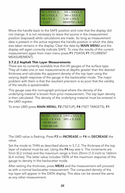
This gauge uses the nomograph principal where the density of the underlying material is known from prior measurement. The top layer density is then calculated. The density of the underlying material must be entered in the LWD register.
To enter LWD press MAIN MENU, F2 (*SETUP), F4 (*SET TARGETS), F1
The LWD value is flashing, Press F3 to INCREASE or F4 to DECREASE the value.
Set the mode to THIN as described above in 3.7.2. The thickness of the top layer of material must be set. Using the F4 key sets it. The increments are 5mm (0.2 inches) and the maximum range is from 25mm (1.0 inch) to 160mm (6.4 inches). The latter value includes 100% of the maximum response of the gauge to density in the backscatter mode.
After setting the thickness, press MEAS and the measurement will proceed as with a normal backscatter measurement. The computed density of the top layer will appear in the DATA display. This data can be stored the same as any other measurement.
DC = XXXX.X DS = XXXX.XMC = XXX.X MS = XXX.XVR = XX.X %AV = XX.X* LAST MDEPTH = BAC
MAXD = XXX.X LWD = XXX.XKVAL = X.XXX SPG = X.XXX* INCREASE* DECREASE
23
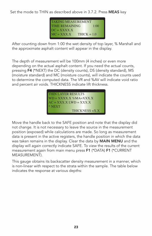
Set the mode to THIN as described above in 3.7.2. Press MEAS key
After counting down from 1:00 the wet density of top layer, % Marshall and the approximate asphalt content will appear in the display.
The depth of measurement will be 100mm (4 inches) or even more depending on the actual asphalt content. If you need the actual counts, pressing F4 (*NEXT) the DC (density counts), DS (density standard), MS (moisture standard) and MC (moisture counts), will indicate the counts used to determine the computed data. The VR and %AV will indicate void ratio and percent air voids. THICKNESS indicate lift thickness.
Move the handle back to the SAFE position and note that the display did not change. It is not necessary to leave the source in the measurement position (exposed) while calculations are made. So long as measurement data is present in the active registers, the handle position in which the data was taken remains in the display. Clear the data by MAIN MENU and the display will again correctly indicate SAFE. To view the results of the current measurement again from main menu press F1 (*DATA) F1 (*CURRENT MEASUREMENT).
This gauge obtains its backscatter density measurement in a manner, which is non-linear with respect to the strata within the sample. The table below indicates the response at various depths:
TAKING MEASUREMENTTIME REMAINING 1:00DC = XXXX.XMC = XXX.X THICK = 1.0
THIN LAYER RESULTSWD = XXXX.X %MA=XXX.XAC = XXX.X LWD = XXX.X* NEXT THICKNESS =X.X
2024
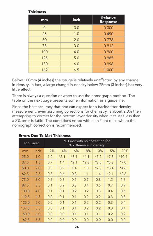
Below 100mm (4 inches) the gauge is relatively unaffected by any change in density. In fact, a large change in density below 75mm (3 inches) has very little effect.
There is always a question of when to use the nomograph method. The table on the next page presents some information as a guideline.
Since the best accuracy that one can expect for a backscatter density measurement, even assuming corrections for chemistry, is about 2.0% then attempting to correct for the bottom layer density when it causes less than a 2% error is futile. The conditions noted within an * are ones where the nomograph correction is recommended.
Top Layer % Error with no correction for % difference in density
mm inch 2% 4% 6% 8% 10% 15% 20%
25.0 1.0 1.0 *2.1 *3.1 *4.1 *5.2 *7.8 *10.4
37.5 1.5 0.7 1.4 *2.1 *2.8 *3.5 *5.3 *7.0
50.0 2.0 0.5 0.9 1.4 1.8 *2.3 *3.4 *4.6
62.5 2.5 0.3 0.6 0.8 1.1 1.4 *2.1 *2.8
75.0 3.0 0.2 0.3 0.5 0.7 0.8 1.2 1.6
87.5 3.5 0.1 0.2 0.3 0.4 0.5 0.7 0.9
100.0 4.0 0.1 0.1 0.2 0.2 0.3 0.4 0.6
112.5 4.5 0.0 0.1 0.1 0.2 0.2 0.3 0.5
125.0 5.0 0.0 0.1 0.1 0.2 0.2 0.3 0.4
137.5 5.5 0.0 0.1 0.1 0.2 0.2 0.3 0.4
150.0 6.0 0.0 0.0 0.1 0.1 0.1 0.2 0.2
162.5 6.5 0.0 0.0 0.0 0.0 0.0 0.0 0.0
Errors Due To Mat Thickness
mm inch Relative Response
0 0.0 0.000
25 1.0 0.490
50 2.0 0.778
75 3.0 0.912
100 4.0 0.960
125 5.0 0.985
150 6.0 0.998
162 6.5 1.000
Thickness
25
While the table may seem confusing it simply states that, for example, one should correct for a mat thickness of 37.5mm (1.5 inches) only when the difference between the top layer and bottom layer densities is 6% or more. If the mat is 50mm (2.0 inches), then use the nomograph when the density difference is 10% or more.
Since a density difference greater than 10% is seldom encountered, one need only be concerned when the mat thickness is 50mm (2.0 inches) or less.
If field procedures involve establishing a passing density using a test strip then only relative densities are important and no corrections are necessary.
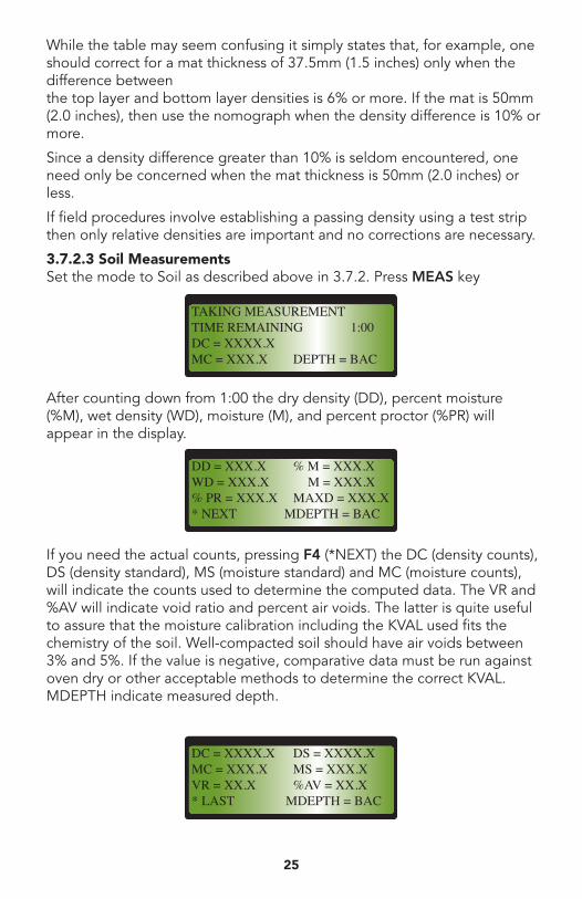
3.7.2.3 Soil Measurements Set the mode to Soil as described above in 3.7.2. Press MEAS key
After counting down from 1:00 the dry density (DD), percent moisture (%M), wet density (WD), moisture (M), and percent proctor (%PR) will appear in the display.
If you need the actual counts, pressing F4 (*NEXT) the DC (density counts), DS (density standard), MS (moisture standard) and MC (moisture counts), will indicate the counts used to determine the computed data. The VR and %AV will indicate void ratio and percent air voids. The latter is quite useful to assure that the moisture calibration including the KVAL used fits the chemistry of the soil. Well-compacted soil should have air voids between 3% and 5%. If the value is negative, comparative data must be run against oven dry or other acceptable methods to determine the correct KVAL. MDEPTH indicate measured depth.
TAKING MEASUREMENTTIME REMAINING 1:00DC = XXXX.XMC = XXX.X DEPTH = BAC
DD = XXX.X % M = XXX.XWD = XXX.X M = XXX.X% PR = XXX.X MAXD = XXX.X* NEXT MDEPTH = BAC
DC = XXXX.X DS = XXXX.XMC = XXX.X MS = XXX.XVR = XX.X %AV = XX.X* LAST MDEPTH = BAC
2226
Move the handle back to the SAFE position and note that the display did not change. It is not necessary to leave the source in the measurement position (exposed) while calculations are made. So long as measurement data is present in the active registers, the handle position in which the data was taken remains in the display. Clear the data by MAIN MENU and the display will again correctly indicate SAFE. To view the results of the current measurement again from main menu press F1 (*DATA) F1 (*CURRENT MEASUREMENT).
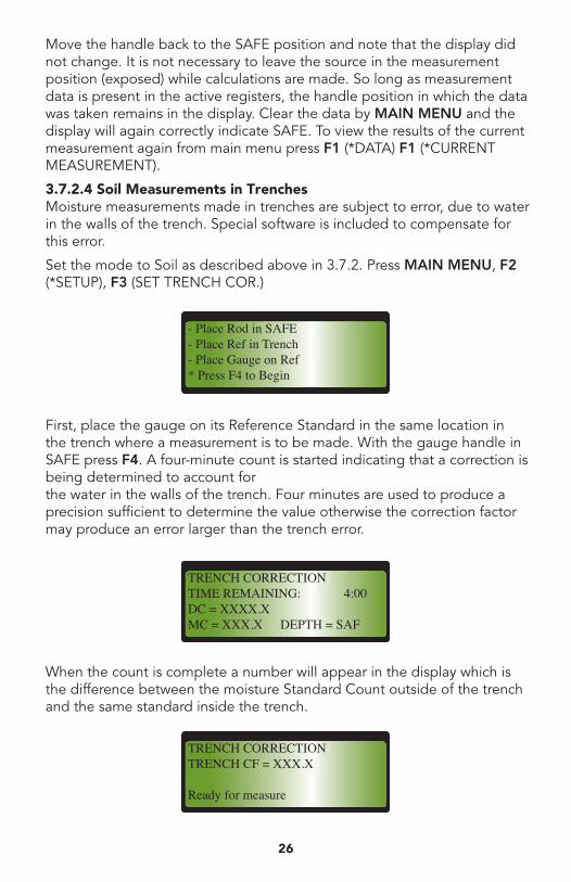
3.7.2.4 Soil Measurements in Trenches Moisture measurements made in trenches are subject to error, due to water in the walls of the trench. Special software is included to compensate for this error.
Set the mode to Soil as described above in 3.7.2. Press MAIN MENU, F2 (*SETUP), F3 (SET TRENCH COR.)
First, place the gauge on its Reference Standard in the same location in the trench where a measurement is to be made. With the gauge handle in SAFE press F4. A four-minute count is started indicating that a correction is being determined to account for the water in the walls of the trench. Four minutes are used to produce a precision sufficient to determine the value otherwise the correction factor may produce an error larger than the trench error.
When the count is complete a number will appear in the display which is the difference between the moisture Standard Count outside of the trench and the same standard inside the trench.
- Place Rod in SAFE- Place Ref in Trench- Place Gauge on Ref* Press F4 to Begin
TRENCH CORRECTIONTIME REMAINING: 4:00DC = XXXX.XMC = XXX.X DEPTH = SAF
TRENCH CORRECTIONTRENCH CF = XXX.X
Ready for measure
27
Remove the gauge from the Reference Standard, place the gauge on the site to be tested (always use direction transmission in a trench) and make an otherwise normal soil measurement. The measurement result has been adjusted to compensate for the water in the wall of the trench.
3.8 Processing The Results The WET DENSITY is obtained using the following equation:
CR = Ae-BD -C
Where: CR = Density Measurement Count divided by Density Standard Count D = Wet Density of the material @ depth X A, B, C = Calibration Constants @ depth X
In addition, the MOISTURE CONTENT is obtained by simply using the following equation:
CR = E + FMWhere: CR = Moisture Measurement Count divided by Moisture Standard Count M = Moisture Content E, F = Calibration Constants
The DRY DENSITY is obtained by subtracting the MOISTURE CONTENT from the WET DENSITY and the PERCENT MOISTURE is obtained by dividing the MOISTURE CONTENT by the DRY DENSITY.
The processor performs the functions, which produce the results without consulting tables, or transferring data to a hand held calculator. This decreases the potential for operator error. The processor also compensates for the attenuation coefficient of hydrogen, which is vastly different from soils.
If the measurement was made on asphaltic concrete only the WET DENSITY has any meaning however, the calculated PERCENT MOISTURE will closely approximate the asphalt content of the mix.
Before actually processing data, the display must indicate the actual depth at which the measurement was made. This is set by using the “F4” key in the manual depth mode or automatically set by the auto-indexing network. The display will only indicate calibrated depths and the value will be in millimeters or inches as preset in the instrument.
The KVAL should have previously been placed into the processor as explained in 3.3.2.
2428
3.8.1 Compaction Control Generally, it is desirable to obtain compaction as a percentage of a maximum density based on a laboratory Proctor density for soils, or as a percentage of the maximum density based on a laboratory Marshall density, or other requirements for asphaltic concrete.
If the desired maximum density has been placed in the D register by using the “MAX D” key as described in 3.2.1, the PERCENT COMPACTION can be by obtained.
% PR = Percentage of the dry density to the maximum soil density.
% MA = Percentage of the wet density to the maximum asphalt density.
3.8.2 Void Ratio By definition, the void ratio (VR) is the ratio of the volume of the void to the volume of the solids. To make this calculation, it is necessary for the processor to know the specific gravity of the solids. There are standard laboratory tests to make this determination. If the true specific gravity is not known, the value of 2.70 may be used to yield approximate void ratios.
The specific gravity may be entered as described in 3.3.3. The “VR” will perform the necessary calculations and display the result in “VR = XXX.X”. No attempt is made to allow for rock corrections since the volume of larger rock is unknown.
Void ratio is an indication of the degree of compaction if the maximum density is not known.
3.8.3 Percent Air Voids This term is defined as volume of air as a percentage of the total volume. The specific gravity of the solids must be known and have been entered as described in 3.3.3. If the calculation is made for asphaltic concrete, the normal PERCENT MOISTURE calculation for soils will have to be adjusted by using “KVAL” to agree with the asphalt content of the mix. The calculation is performed by “% AV” and the results will be displayed in “%AV = XX.XX”.
“% AV” is an indication of the degree of compaction and saturation of the compacted materials. It is also a good indication of the validity of the calibration, particularly moisture, for the specific materials being tested. A negative value for "% AV" indicates that the KVAL needs to be a more negative value. A positive value of more than 5.0% may be caused by incomplete compaction or the need to increase the KVAL in a positive direction (not necessarily a positive number but perhaps less negative one).
3.9 Repackaging the Equipment After use, secure the equipment: First, latch the handle in the "safe" position and install the padlock. After wiping the Gauge and Reference Standard to remove all soil and moisture, place them in the Transit Case and lock the case latch. This double security is provided to prevent unauthorized access to the Instrument and possible injury. Clean the accessories and place them in the Zippered Accessory Case to prevent loss.
29
4 Menus
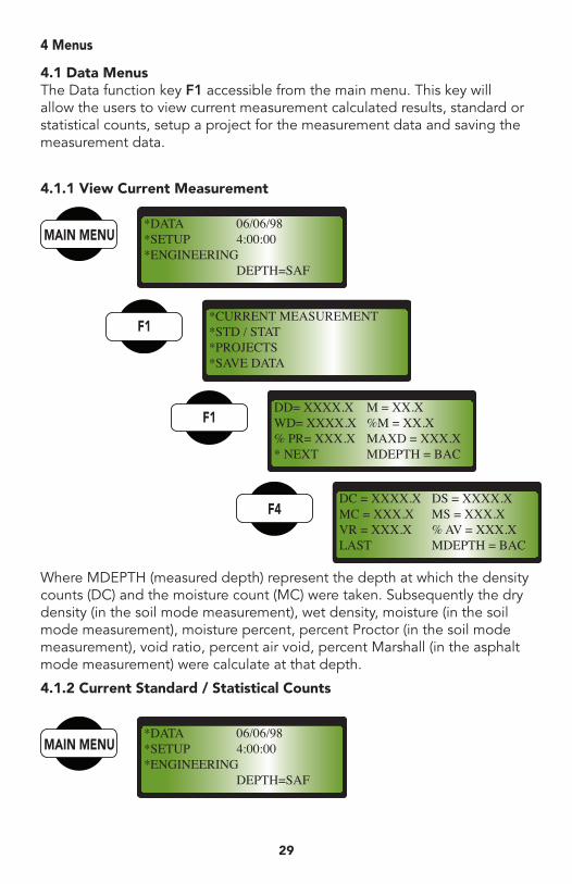
4.1 Data Menus The Data function key F1 accessible from the main menu. This key will allow the users to view current measurement calculated results, standard or statistical counts, setup a project for the measurement data and saving the measurement data.
4.1.1 View Current Measurement
Where MDEPTH (measured depth) represent the depth at which the density counts (DC) and the moisture count (MC) were taken. Subsequently the dry density (in the soil mode measurement), wet density, moisture (in the soil mode measurement), moisture percent, percent Proctor (in the soil mode measurement), void ratio, percent air void, percent Marshall (in the asphalt mode measurement) were calculate at that depth.
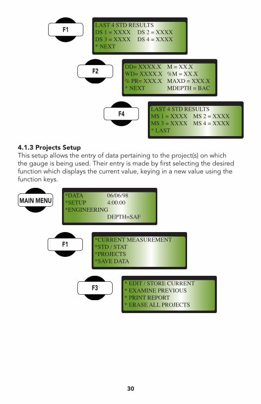
4.1.2 Current Standard / Statistical Counts
*DATA 06/06/98*SETUP 4:00:00*ENGINEERING DEPTH=SAF
*DATA 06/06/98*SETUP 4:00:00*ENGINEERING DEPTH=SAF
*CURRENT MEASUREMENT*STD / STAT*PROJECTS*SAVE DATA
DD= XXXX.X M = XX.XWD= XXXX.X %M = XX.X% PR= XXX.X MAXD = XXX.X* NEXT MDEPTH = BAC
DC = XXXX.X DS = XXXX.XMC = XXX.X MS = XXX.XVR = XXX.X % AV = XXX.XLAST MDEPTH = BAC
2630
LAST 4 STD RESULTSDS 1 = XXXX DS 2 = XXXXDS 3 = XXXX DS 4 = XXXX* NEXT
DD= XXXX.X M = XX.XWD= XXXX.X %M = XX.X% PR= XXX.X MAXD = XXX.X* NEXT MDEPTH = BAC
LAST 4 STD RESULTSMS 1 = XXXX MS 2 = XXXXMS 3 = XXXX MS 4 = XXXX* LAST
4.1.3 Projects Setup This setup allows the entry of data pertaining to the project(s) on which the gauge is being used. Their entry is made by first selecting the desired function which displays the current value, keying in a new value using the function keys.
*DATA 06/06/98*SETUP 4:00:00*ENGINEERING DEPTH=SAF
*CURRENT MEASUREMENT*STD / STAT*PROJECTS*SAVE DATA
* EDIT / STORE CURRENT* EXAMINE PREVIOUS* PRINT REPORT* ERASE ALL PROJECTS
31
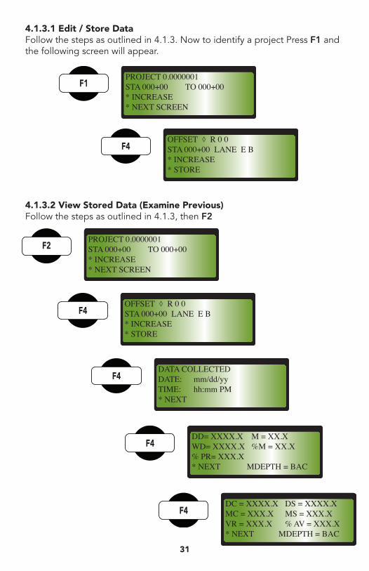
4.1.3.1 Edit / Store Data Follow the steps as outlined in 4.1.3. Now to identify a project Press F1 and the following screen will appear.
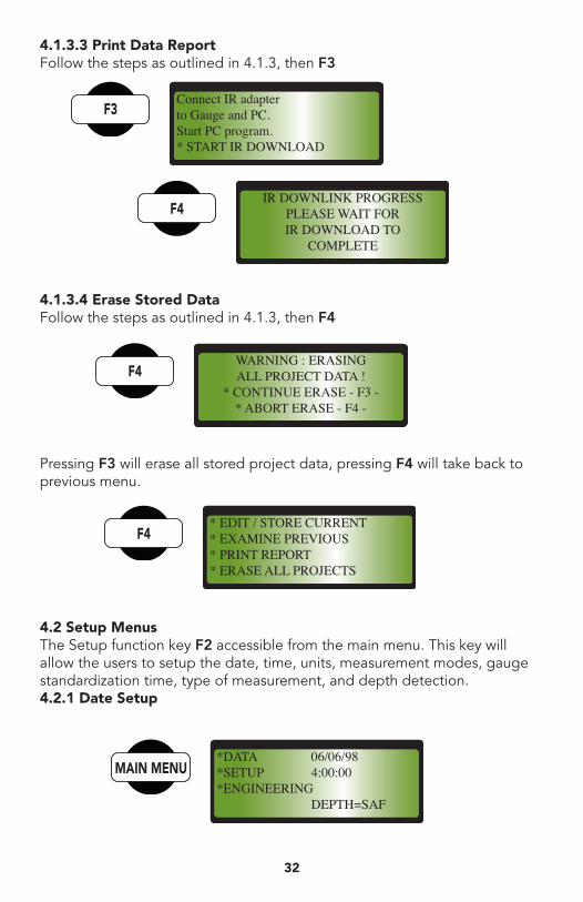
4.1.3.2 View Stored Data (Examine Previous) Follow the steps as outlined in 4.1.3, then F2
PROJECT 0.0000001STA 000+00 TO 000+00* INCREASE* NEXT SCREEN
OFFSET ◊ R 0 0STA 000+00 LANE E B* INCREASE* STORE
PROJECT 0.0000001STA 000+00 TO 000+00* INCREASE* NEXT SCREEN
OFFSET ◊ R 0 0STA 000+00 LANE E B* INCREASE* STORE
DATA COLLECTEDDATE: mm/dd/yyTIME: hh:mm PM* NEXT
DD= XXXX.X M = XX.XWD= XXXX.X %M = XX.X% PR= XXX.X* NEXT MDEPTH = BAC
DC = XXXX.X DS = XXXX.XMC = XXX.X MS = XXX.XVR = XXX.X % AV = XXX.X* NEXT MDEPTH = BAC
2832
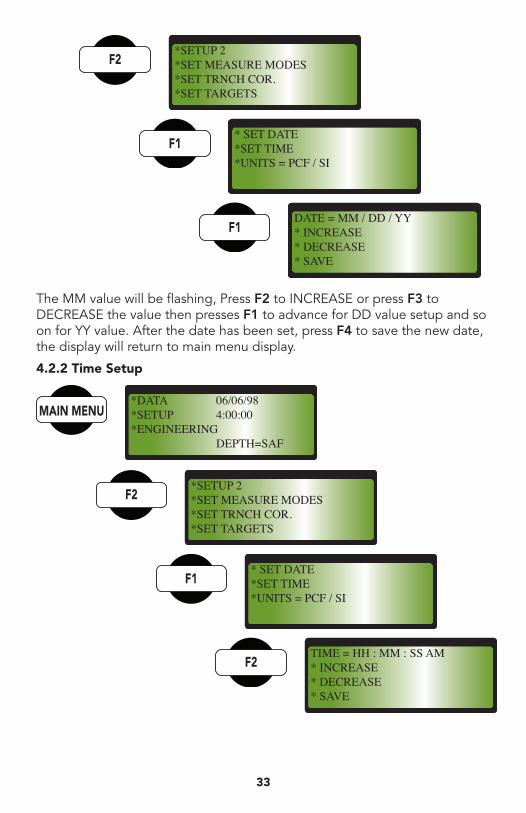
4.1.3.3 Print Data Report Follow the steps as outlined in 4.1.3, then F3
4.1.3.4 Erase Stored Data Follow the steps as outlined in 4.1.3, then F4
Pressing F3 will erase all stored project data, pressing F4 will take back to previous menu.
4.2 Setup Menus The Setup function key F2 accessible from the main menu. This key will allow the users to setup the date, time, units, measurement modes, gauge standardization time, type of measurement, and depth detection.4.2.1 Date Setup
Connect IR adapterto Gauge and PC.Start PC program.* START IR DOWNLOAD
IR DOWNLINK PROGRESSPLEASE WAIT FORIR DOWNLOAD TO
COMPLETE
WARNING : ERASINGALL PROJECT DATA !
* CONTINUE ERASE - F3 -* ABORT ERASE - F4 -
* EDIT / STORE CURRENT* EXAMINE PREVIOUS* PRINT REPORT* ERASE ALL PROJECTS
*DATA 06/06/98*SETUP 4:00:00*ENGINEERING DEPTH=SAF
33
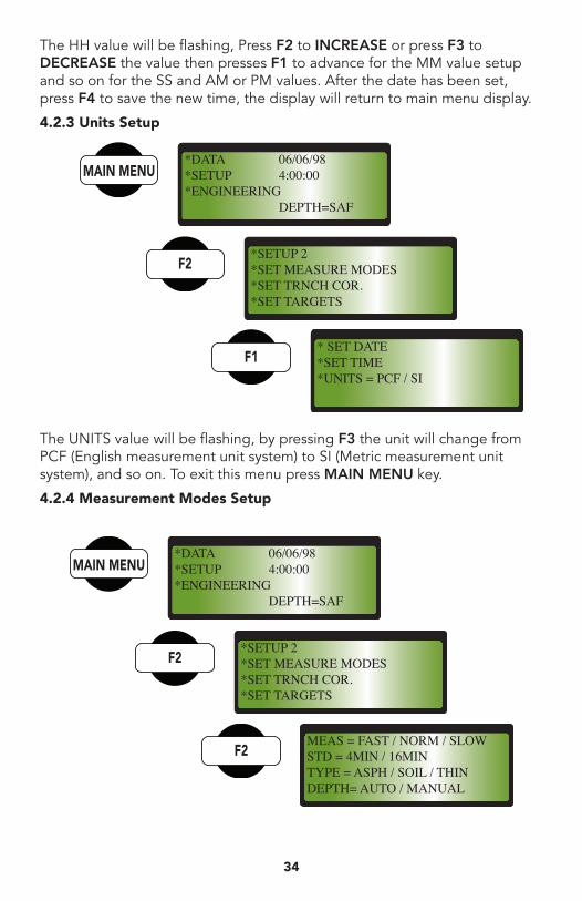
*SETUP 2*SET MEASURE MODES*SET TRNCH COR.*SET TARGETS
* SET DATE*SET TIME*UNITS = PCF / SI
DATE = MM / DD / YY* INCREASE* DECREASE* SAVE
The MM value will be flashing, Press F2 to INCREASE or press F3 to DECREASE the value then presses F1 to advance for DD value setup and so on for YY value. After the date has been set, press F4 to save the new date, the display will return to main menu display.
4.2.2 Time Setup
*DATA 06/06/98*SETUP 4:00:00*ENGINEERING DEPTH=SAF
*SETUP 2*SET MEASURE MODES*SET TRNCH COR.*SET TARGETS
* SET DATE*SET TIME*UNITS = PCF / SI
TIME = HH : MM : SS AM* INCREASE* DECREASE* SAVE
3034
The HH value will be flashing, Press F2 to INCREASE or press F3 to DECREASE the value then presses F1 to advance for the MM value setup and so on for the SS and AM or PM values. After the date has been set, press F4 to save the new time, the display will return to main menu display.
4.2.3 Units Setup
The UNITS value will be flashing, by pressing F3 the unit will change from PCF (English measurement unit system) to SI (Metric measurement unit system), and so on. To exit this menu press MAIN MENU key.
4.2.4 Measurement Modes Setup
*DATA 06/06/98*SETUP 4:00:00*ENGINEERING DEPTH=SAF
*SETUP 2*SET MEASURE MODES*SET TRNCH COR.*SET TARGETS
* SET DATE*SET TIME*UNITS = PCF / SI
*DATA 06/06/98*SETUP 4:00:00*ENGINEERING DEPTH=SAF
*SETUP 2*SET MEASURE MODES*SET TRNCH COR.*SET TARGETS
MEAS = FAST / NORM / SLOWSTD = 4MIN / 16MINTYPE = ASPH / SOIL / THINDEPTH= AUTO / MANUAL
35
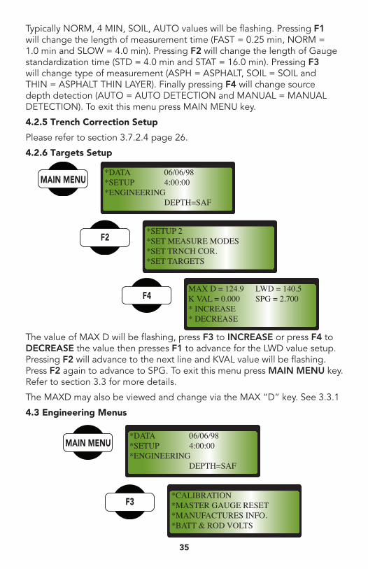
Typically NORM, 4 MIN, SOIL, AUTO values will be flashing. Pressing F1 will change the length of measurement time (FAST = 0.25 min, NORM = 1.0 min and SLOW = 4.0 min). Pressing F2 will change the length of Gauge standardization time (STD = 4.0 min and STAT = 16.0 min). Pressing F3 will change type of measurement (ASPH = ASPHALT, SOIL = SOIL and THIN = ASPHALT THIN LAYER). Finally pressing F4 will change source depth detection (AUTO = AUTO DETECTION and MANUAL = MANUAL DETECTION). To exit this menu press MAIN MENU key.
4.2.5 Trench Correction Setup
Please refer to section 3.7.2.4 page 26.
4.2.6 Targets Setup
The value of MAX D will be flashing, press F3 to INCREASE or press F4 to DECREASE the value then presses F1 to advance for the LWD value setup. Pressing F2 will advance to the next line and KVAL value will be flashing. Press F2 again to advance to SPG. To exit this menu press MAIN MENU key. Refer to section 3.3 for more details.
The MAXD may also be viewed and change via the MAX “D” key. See 3.3.1
4.3 Engineering Menus
*DATA 06/06/98*SETUP 4:00:00*ENGINEERING DEPTH=SAF
*SETUP 2*SET MEASURE MODES*SET TRNCH COR.*SET TARGETS
MAX D = 124.9 LWD = 140.5K VAL = 0.000 SPG = 2.700* INCREASE* DECREASE
*DATA 06/06/98*SETUP 4:00:00*ENGINEERING DEPTH=SAF
*CALIBRATION*MASTER GAUGE RESET*MANUFACTURES INFO.*BATT & ROD VOLTS
36
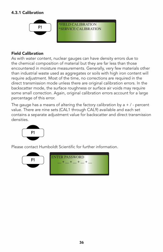
4.3.1 Calibration
Field CalibrationAs with water content, nuclear gauges can have density errors due to the chemical composition of material but they are far less than those encountered in moisture measurements. Generally, very few materials other than industrial waste used as aggregates or soils with high iron content will require adjustment. Most of the time, no corrections are required in the direct transmission mode unless there are original calibration errors. In the backscatter mode, the surface roughness or surface air voids may require some small correction. Again, original calibration errors account for a large percentage of this error.
The gauge has a means of altering the factory calibration by a + / - percent value. There are nine sets (CAL1 through CAL9) available and each set contains a separate adjustment value for backscatter and direct transmission densities.
Please contact Humboldt Scientific for further information.
*FIELD CALIBRATION*SERVICE CALIBRATION
ENTER PASSWORD __ + __ + __ + __ + __
37
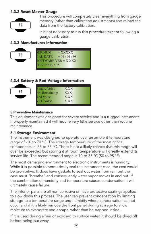
4.3.2 Reset Master Gauge This procedure will completely clear everything from gauge memory (other than calibration adjustments) and reload the data from the factory calibration.
It is not necessary to run this procedure except following a gauge calibration.
4.3.3 Manufactures Information
4.3.4 Battery & Rod Voltage Information
5 Preventive MaintenanceThis equipment was designed for severe service and is a rugged instrument. If properly maintained it will require very little service other than routine maintenance.
5.1 Storage Environment The instrument was designed to operate over an ambient temperature range of -10 to 70 °C. The storage temperature of the most critical components is -55 to 85 °C. There is not a likely chance that this range will over be exceeded but storing it at room temperature will greatly extend its service life. The recommended range is 10 to 35 °C (50 to 95 °F).
The most damaging environment to electronic instruments is humidity. While it is possible to hermetically seal the instrument case, the cost would be prohibitive. It does have gaskets to seal out water from rain but the case must "breathe" and consequently water vapor moves in and out. If the combination of humidity and temperature causes condensation it will ultimately cause failure.
The interior parts are all non-corrosive or have protective coatings applied to slow down this process. The user can prevent condensation by limiting storage to a temperature range and humidity where condensation cannot occur and if it is likely remove the front panel during storage to allow moisture to evaporate and escape rather than be trapped inside.
If it is used during a rain or exposed to surface water, it should be dried off before being put away.
SER NUM = XXXXXCAL DATE = 01 / 01 / 98SOFTWARE VER = X.XXXPH 919 833 3190
Battery Volts: X.XXHrs Remaining: XXXRod Volts: X.XXVCC Volts: X.XX
3438
5.2 Exterior Cleaning The Gauge is going to get soiled during use. While this causes no harm, removing loose material at the end of each working day will prolong the cosmetic appearance.
Occasionally it would help if the exterior were cleaned with an industrial grade detergent and water. Heavy scrubbing may damage the finish on labels but will not harm the other materials.
The source rod and index rod may be sprayed with silicon ok and the excess wiped off with a cloth. The source rod is 440C stainless steel and while no pitting can occur, surface rust may form initially due to iron molecules brought to the surface by heat-treating. Light rubbing with an abrasive will remove it and after several times, it will no longer occur.
Cleaning the top seal around the source rod will aid in preventing soil from working into the bearing, which is located below the seal.
5.3 Sliding Shield Cavity A sliding shield of tungsten covers the gamma source when it is retracted to the “SAFE” condition. After prolonged use, the small amount of soil carried into the cavity with each retraction will accumulate in this cavity. If not periodically cleaned, the abrasion from the soil will increase the force required to push the rod out and could cause jamming of the shield which will result in faulty STANDARD COUNT repeatability. Ultimately the soil will damage the seals between the cavity and the bearing.
The bottom plate, which contains a scraper ring to remove soil from the rod when it is retracted, can be removed by using a hex key to take out the two screws. Lay the Gauge on its side or end with the bottom pointed away from personnel and the rod in the “SAFE” position to prevent exposure from the source. Remove the screws and pull the plate away from the base. The sliding shield is held in place by a spring. Be careful not to let the spring fly off when removing the shield
Clean the parts with a damp cloth and clean the cavity with a stiff brush. Finally spray the parts and cavity with dry silicon spray.
The cavity, and bottom plate are impregnated with Teflon and do not require extensive lubrication. If excessive wear has occurred to the bottom plate and scraper ring, they may need to be replaced.
Push the spring into the hole in the sliding shield and replace it in the cavity with the sloping side towards source and the spring compressed against the end of the cavity. If the sliding shield does not fully close it may be necessary to stretch / replace the spring. Replace the plate and screws being certain that they are tight and the heads of the screws do not extend above the surface of the plate.
39
5.4 Performing a Wipe Test Regulations require that sealed capsules of radioactive materials be tested every six months to assure that they are not leaking. This is to prevent contamination of personnel and other equipment. Absorption of radioactive material into the body is the most severe accident that can occur in use of this equipment and there is little that can be done to remove it. Prevention of the absorption is the only solution.
The materials to perform this test have been supplied with the gauge in kit 5200177 and additional materials may be obtained from Humboldt Scientific Inc. or other venders of these kits.
Ethanol (ethyl alcohol) at 95% purity may be obtained from a local beverage store under the trade name "Everclear". It is preferred but water may be used.
Since the user does not have access to the actual surface of the capsule, the regulations allow the wipe to be made on a surface that is likely to be contaminated by a leaking capsule. There are TWO sources in this Gauge. The gamma source is mounted in the source rod and the most accessible location to wipe is the hole in the case through which the rod extends in normal use. The neutron source is mounted in a cylindrical holder inside the case just behined of the main circuit board.
Most processors of these wipes allow both of these sources to be wiped with the same filter paper since they are able to determine from which source any contamination came. First fill out the form including the Gauge model and serial number, the type of radioactive material (Cs-137 and Am-241:Be) and the gauge serial number (some kits also list the sources serial numbers). Include the owner's name and the address to which the form is to be returned.
Wet the filter paper with the solvent. Remove the front panel and locate the label around the Am-241:Be source holder. Using the tongs, wipe the threads of the allen screw at the top of the holder with the wetted paper. Lay the Gauge on its side with the base away from personnel so that the case provides a shield. Using the tongs to hold the paper, wipe the rim of the hole thoroughly with the wet paper. After wiping a source, do not touch the paper with fingers. Treat it as potentially radioactive material. Place the Gauge in the upright position. Place the filter paper in the plastic envelope and seal it.
Place the plastic envelope and the properly completed form in another envelope and mail it to the processor. The owner and authorities will be notified if the testing indicates a removable activity in excess of 5 nCi (0.005 uCi) which is the legal maximum allowable. An activity in excess of 1.0 nCi will likely result in a request to re-wipe the sources.
3640
5.5 Statistical Stability TestThis test is a simple method of testing the short-term stability of the detectors and electronic counting circuits. The basis for it is explained in section 7.3 covering radiation statistics.
Radioactive decay is a binary process (an atom decays or it does not). The average rate of decay determines the half life (the time for half of the material to disintegrate) of the material. For Cs 137 this is 30.17 years and for Am 241: Be, it is 433 years. The decrease in the average rate of decay for Cs 137 is 2.3% per year and for Am 241: Be is 0.16% per year. Calibrating the Gauge in forms of a ratio eliminates the effect of this change on the measurement.
The short-term fluctuation of binary decay is predictable. The predicted standard deviation is the square root of the average count rate (m):
s = √ m
The Gauge electronics divide the actual events counted in a one-minute period by a factor of 16 before using the number, so the above expression is actually:
√ m
s =
4
This equation can be used to predict the standard deviation of the count rate for a series of measurements. By taking a series of 16 measurements and computing the actual standard deviation, the value obtained can be compared as a ratio to the predicted value thus:
∑ (n – m)² R = 4 √ [ ] m (N-1)
Where: s = Standard deviation of count rate
n = Individual measurement
N = Number of measurement
m = Mean of the measurement
R = Statistical ratio
" STAT" automatically runs this series of measurements and displays the R values for the density and moisture channels. See section 3.2.
41
For: R > 0.6 and < 1.4 Good
R < 0.5 or > 1.5 Bad
Others— Try Again
6 Field ServiceThe HS-5001EZ is designed for reliability and field service is kept to a minimum. Little, if any, test equipment is required and the only tools necessary are:
Hex Key, 1/16 inchHex Key, 1/8 inchHex Key, 9/64 inchHex Key, 3/16 inchPhillips Screwdriver, #1 x 4 inchYour Radioactive Material License must specifically allow removal of the source rod if the rod bearings and seals are to be removed, cleaned or replaced.
6.1 Mechanical Disassembly / Assembly6.1.1 Bottom Plate and ShieldThe Bottom Plate Assembly (200666) is held in place by two flat head hex socket screws (001010). Removing them will allow the plate to pull away and the Sliding Shield (200030) and spring (000816) can be removed for cleaning. The scraper ring (000806) in the plate (200665) can be replaced by removing the retaining ring (000811).
6.1.2 Source RodOther than replacing a set of bearings, it is not necessary to remove the source rod. A suitable shield must be available. REQUIRES AUTHORIZATION FROM REGULATORY AGENCY ON USERS LICENSE
Drop the source rod to the backscatter position. Loosen the two hex setscrew (001007) at the top and unscrew the Lift Cap (200667) and the Auto Lift Bumper (200278) to allow complete removal of the source rod and handle. Hold the rod by the handle with the tip as far as possible from the body and store it in a shielded container with a minimum 25 mm (1 inch) lead wall or in one of the calibration standards at least 3 m (10 ft) from personnel work areas. The rod must not be left unattended and should be replaced in the Gauge shield as soon as practical.
6.1.3 Indexer and LatchThis may be accomplished without removing the source rod from the Gauge. Remove the Lift Cap as described in 6.1.2. Raise the handle off of the index rod and rotate it 90º: Push the rod back into the shield. Remove the two hex setscrew (001034) at the end cap of the handle and slide the complete latch assembly and index pin (200660) out the rear of the handle. These parts are lubricated by the Teflon coating.
3842
6.1.4 Index RodThe Index Rod may be removed without removing the source rod. Remove the lift cap as described in 6.1.2, lift the handle off the Index Rod and rotate it out of the way. MAY REQUIRE FACTORY RE-CALIBRATION.
Loosen the Index Lock Nut (200052) and unscrew the Index Rod (200668. 669, 670 or 671) from the post. When replacing the Index Rod. Latch the handle firmly in the backscatter position and screw the index rod until the tip of the source rod is flush to 0.05 mm (0.002 inch) recessed within the bottom of the Gauge. The rod must not protrude or backscatter measurements in the field could be in error. Tighten the index lock nut (200052)
6.1.5 Top CoverFirst remove the processor (scaler) module (200682) by releasing the four thumbscrews (1001013). Lift the panel out and disconnect the Module Cable (200105) from the base frame assembly.
Remove the six-socket head cap screws (001008) and washers (001030) around the edge of the cover. The cover can be totally removed from the Gauge by placing the handle partially between the backscatter and safe positions and working the cover over it. It will be easier it the Post Grommet (200109) is removed from the hole.
If worn or damaged, the Bottom Gasket (200149) or Panel Gasket (200351) should be replaced
6.1.6 Top Post and SealsThe seals and wipers will wear due to soil abrasion and soil working into them as the source rod is moved up and down. Keeping the bottom cavity clean and lightly lubricating the source rod with silicon grease will help prolong their life.
Caution: the owner’s license must allow source rod removal before this service may be performed. With the source rod removed and safely stored as covered in 6.1.2 and the top cover removed:
Remove the four-socket head cap screws (001009) and lock washers’ (001031) from around the post. The post may be lifted up over the tungsten bio shield.
The Wiper Plate (200031) and Wiper Ring (000803) may be removed from the inside of the post. When replacing them, the wiper goes into the top of the plate such that it cleans the source rod as it moves in an upward direction.
The Top Wiper Cap (200032) may be removed from the Post by removing the two hex socket screws (001007) from the side of the post. Pry up lightly on the Cap. The Wiper Ring (000803) in the cap may be replaced by carefully prying it out of the top.
The two bearing Seals (000805) may be removed by carefully prying them
43
out of the center hole. The seals will be destroyed but be careful not to damage the Source Rod Bearing (200136). When replacing the seals, they must be pushed or lightly tapped in place with a wood or soft metal dowel to prevent damage.
The bearing has recesses for soil to accumulate to prevent binding. Clean the bearing with a solvent and lubricate with silicon grease. Lightly coat all of the seals and wipers with the same grease before reassembling. Reassemble in reverse order.
6.1.7 Base ModuleThere are high voltage capacitors on the circuit board, which may be charged to 900 volts. The current available is low but injury may occur due to the surprise of receiving a severe shock. Discharge them by firstly sliding the circuit breaker at the top of the batteries pack to the off position and secondly pressing and holding the push-button switch at the top of the circuit board for about one second.
Remove the Top Cover as described in 6.1.5. Remove the seven socket head cap screws (001008) and lock washers (001029) around the edge of the module. Carefully lift the Base Module up out of the Gauge Base. The detectors may be replaced if necessary and the parts reassembled.
6.2 Battery ReplacementThe batteries in this Gauge will last a very long time if the Gauge is not stored at a high temperature. The expected service life is 1400 hours. Replacement will be required within one to two weeks after the “LO BAT” symbol appears in the Display while in use.
Replacement batteries should be high quality alkaline AA size cells such as those made by Mallory (DURACELL). Do not replace with manganese zinc cells except in an emergency for a short period of time. They will not last as long and leakage may cause damage to the inside of the Gauge. Remove the screws and lift battery cover. Slip the batteries out of the holders. Replace the cells with the same orientation showing in the battery holders.
6.3 Electronic Modules Adjustment / ReplacementIn order to improve reliability and maintain ease of service, the 5001SD electronics is divided into four modules, which may be individually replaced. Two of them have adjustments, which may need to be set.
6.3.1 Processor Module (200762)This front panel module contains two counting systems, a programmed microprocessor and a display. Field service is impractical other than replacement. It is easily removed by means of four thumbscrews located in the corners. The cable is disconnected from the Base Plane Module by releasing the latches at each end of the connector. Note that the cable, when properly installed, has no twists in it, only a 180° turn.
44
The Factory or Authorized Service Facility may repair or replace the module. No re-calibration is necessary; however, the Gauge calibration is stored in a memory module that must stay with the same Gauge or re-calibration will be necessary.
6.3.2 Base Plane Board (200768)This board, into which all of the small modules are plugged, has no active components, only interconnects between other components. The probability of failure is very low except for physical damage. Should it become necessary to replace it, some soldering is required so either the entire Base Frame must be replaced, or returned, or the entire Gauge returned. No re-calibration is required.
For protection a circuit breaker is above the battery holders which will open up if the main power circuits become shorted. A red indicator is visible when the circuit breaker is closed and applying power to the board.
The base board also has a push-button switch in the upper center of the board which is used to discharge the high voltage before servicing any of these circuits. This button should be pushed and held for about one second before removing or replacing the High Voltage, Density, or Moisture Modules.
The entire frame, including the detectors, is removed by means of the seven screws around the edge of the frame. Do not remove the screws, which attach the Board to the frame.
6.3.3 High Voltage Power Supply Module (200088)This module supplies a highly regulated 900 vdc to the Density and Moisture Amplifier modules and in turn to the detectors. From unit to unit, the voltage may vary ±25 volts but once established, it is very stable.
This voltage can cause a severe shock and before any replacement is attempted, the discharge push-button switch located in the center of the base circuit board must be pushed and held for about one second.
The module is easily replaced by removing the screw located in the middle of the module. When plugging in another one, look and at the pins closely and orient the module pins to the circuit board sockets. If they are aligned the module can be inserted easily. Do not apply force as the pins may be bent or damaged.
The module is not repairable, and must be replaced if defective. The replacement does not affect calibration.
6.3.4 Density Amplifier Module (200087)This module is used to condition varying amplitude pulses from the two gamma detectors to logic level pulses for the counter in the processor module.
There are two adjustments, which control the amplitude of the pulses from
45
each of the detectors. They should be set, using an oscilloscope, to produce average 500 millivolt negative pulses at test point DTP on the base circuit board. This pulse height is not very critical and if the adjustments are set at mid range, and the STAT test indicates stability, the setting is acceptable without the availability of the oscilloscope.
The high voltage can cause a severe shock. Before any replacement is attempted, the discharge push-button switch located in the center of the base circuit board must be pushed and held for about one second.
The module is easily replaced by removing the screw located in the middle of the module. When plugging in another one, look at the pins closely and orient the module pins to the circuit board sockets. If they are aligned, the module can be inserted easily. Do not apply force as the pins may be bent or damaged.
The module is not repairable, and must be replaced if defective.
6.3.5 Moisture Amplifier Module (200086)This module is used to condition varying amplitude pulses from the thermal neutron detector to logic level pulses for the counter in the front panel module.
There is one adjustment, which controls the amplitude of the pulses from the detector. It should be set, using an oscilloscope, to produce average 500 millivolt negative pulses at test point MTP on the base circuit board. This pulse height is not very critical and if the adjustment is set at mid range, and the STAT test indicates stability, the setting is acceptable without the availability of the oscilloscope.
The high voltage can cause a severe shock. Before any replacement is attempted, the discharge push-button switch located in the center of the base circuit board must be pushed and held for about one second.
The module is easily replaced by removing the screw located in the middle of the module. When plugging in another one, look at the pins closely and orient the module pins to the circuit board sockets. If they are aligned the module can be inserted easily. Do not apply force as the pins may be bent or damaged.
The module is not repairable, and must be replaced if defective.
6.4 Detector ReplacementIf total failure of a detector occurs or if adjustments to correct instability problems are not possible, then the detectors require replacement. The procedure is quite simple.
Remove the Base Frame Module as instructed in 6.1.7 after discharging the high voltage. The gamma detector(s) (200035) may be removed by sliding them out of the side of the module. When replacing the gamma detectors, note that a leaf spring is in contact with the shell and needs to be
46
compressed when sliding in the replacement.
The Moisture Amplifier must be removed in order to slide the Neutron Detector (200026) out of the frame. Slide the new detector in place and carefully install the amplifier so the module pins and the detector connector engage. Note: any replacement of the detectors will requires re-calibration.
6.5 Parts ListThis list includes all parts, which may be field replaced.
Tool Set 200112 Zippered Accessory Case 200175 Drill Rod 200130 Scraper Plate/Rod Guide 200127 Rod Extractor Tool 200145 Hammer 000176Transit Case Assembly 200681Reference Standard 200122Gauge Padlock 000177Instruction Manual, HS-5001EZ 200688Radiation Safety Manual 200121Radioactive Source Certificate 200173Wipe Test Materials (Kit) 200177Leak Test Certificates 200174Filter Paper 000175Plastic Bags 000178Forceps 000181Lift Cap 200667 Hex Socket SS Sot Screw, 6 32 x 3/16 (2) 001061Lift Bumper 200278Index Rods 8 X 1 200668 8 X 2 200669 12 X 1 200670 12 X 2 200671Index Lock Nut 200052Handle Assembly 200664 Gauge Handle 200661 Lift Handle 200662 End Cap 200663 Index Pin 200660 Cs Source Label 200091 Roll pin, 0.125 x 0.375 001020Handle Repair Kit 200659Top Cover Assembly 200170 Top Cover 200133 Post Grommet 200109 Bottom Gasket 200149
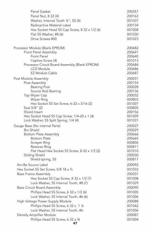
47
Panel Gasket 200351 Panel Nut, 8 32 (4) 200163 Washer, Internal Tooth ¼”, SS (4) 001037 Radioactive Material Label 200134 Hex Socket Head SS Cap Screw, 8 32 x 1/2 (6) 001008 Flat SS Washer, #8 (6) 001030 Drive Screws #00 001023
Processor Module (Blank EPROM) 200682 Front Panel Assembly 200641 Front Panel 200640 Captive Screw (4) 001013 Processor Circuit Board Assembly (Blank EPROM) 200684 LCD Module 200686 EZ Module Cable 200687
Post Module Assembly 200031 Post Assembly 200154 Bearing Post 200028 Source Rod Bearing 200136 Top Wiper Cap 200032 Wiper Ring 000803 Hex Socket SS Set Screw, 6-32 x 3/16 (2) 001007 Seal 5/8” (2) 000805 Shield Insert 200156 Hex Socket Head SS Cap Screw, 1/4-20 x 1 (4) 001009 Lock Washer, SS Split Spring, 1/4 (4) 001031
Gauge Base (No internal Parts) 200027 Bio Shield 200029 Bottom Plate Assembly 200666 Bottom Plate 200665 Scraper Ring 000806 Retainer Ring 000811 Flat Head Hex Socket SS Screw, 8-32 x 1/2 (2) 001010 Sliding Shield 200030 Shield spring, SS 000817
Am:Be Source Label 200092Hex Socket SS Set Screw, 5/8 18 x ½ 001032Base Frame Assembly 200201 Hex Socket SS Cap Screw, 8 32 x 1/2 (7) 001008 Lock Washer, SS Internal Tooth, #8 (7) 001029Base Circuit Board Assembly 200090 Phillips Head SS Screw, 6 32 x 1/2 (6) 001005 Lock Washer, SS Internal Tooth, #6 (6) 001006High Voltage Power Supply Module 200088 Phillips Head SS Screw, 6 32 x 1 ¼ 001042 Lock Washer, SS internal Tooth, #6 001006Density Amplifier Module 200087 Phillips Head SS Screw, 6 32 x ¾ 001004
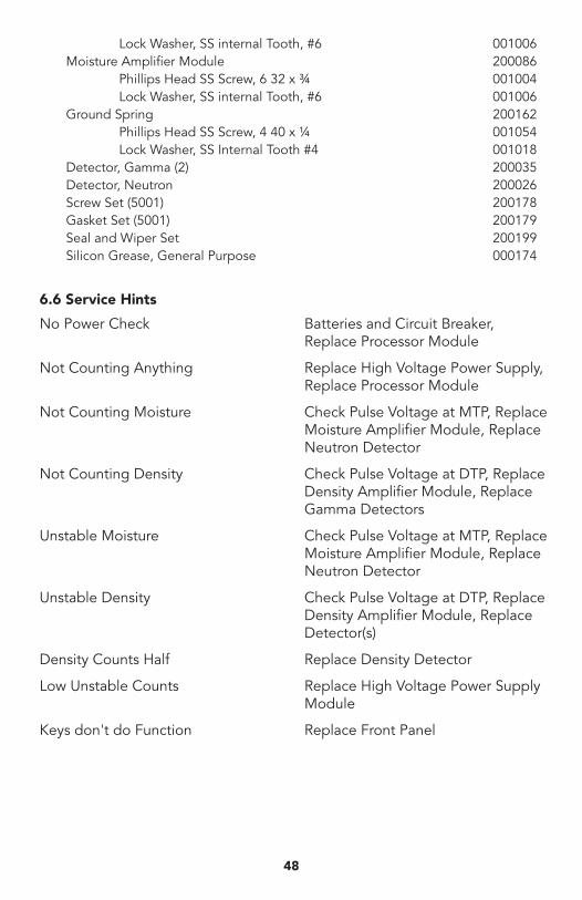
48
Lock Washer, SS internal Tooth, #6 001006Moisture Amplifier Module 200086 Phillips Head SS Screw, 6 32 x ¾ 001004 Lock Washer, SS internal Tooth, #6 001006Ground Spring 200162 Phillips Head SS Screw, 4 40 x ¼ 001054 Lock Washer, SS Internal Tooth #4 001018Detector, Gamma (2) 200035Detector, Neutron 200026Screw Set (5001) 200178Gasket Set (5001) 200179Seal and Wiper Set 200199Silicon Grease, General Purpose 000174
6.6 Service Hints
No Power Check Batteries and Circuit Breaker, Replace Processor Module
Not Counting Anything Replace High Voltage Power Supply, Replace Processor Module
Not Counting Moisture Check Pulse Voltage at MTP, Replace Moisture Amplifier Module, Replace Neutron Detector
Not Counting Density Check Pulse Voltage at DTP, Replace Density Amplifier Module, Replace Gamma Detectors
Unstable Moisture Check Pulse Voltage at MTP, Replace Moisture Amplifier Module, Replace Neutron Detector
Unstable Density Check Pulse Voltage at DTP, Replace Density Amplifier Module, Replace Detector(s)
Density Counts Half Replace Density Detector
Low Unstable Counts Replace High Voltage Power Supply Module
Keys don't do Function Replace Front Panel
49
6.7 Calibration The Calibration of this instrument will be valid for a minimum of one year and probably much longer if reasonable care is taken to prevent the application of heavy shock loads to the Gauge base.
Users are advised to establish a location on a laboratory floor or other reference and measure this location on receipt of the equipment. Periodic measurement of this location will provide a means of verifying the calibration over a long period of time.
Any discrepancy in this measurement or suspected errors in field data will indicate the need for calibration. If the owner does not have facilities to perform the Calibration as covered previously then the equipment should be returned to an Authorized Service Facility or the factory.
7 Theory of OperationThis instrument uses two types of radiation to measure the density and moisture content of materials. The interaction between the radiation and the materials is very different but most of the electronics are compatible with the two functions. Both measurements are indirect in the sense that another parameter of the material is actually measured and the parameter then stated in terms of density and moisture.
The differences between the measured parameters and the desired density and moisture is typically called "composition" or "chemical" error since it does involve the chemical elements or molecules which form the materials.
7.1 Density Measurement by Gamma RadiationGamma radiation is a form of electromagnetic radiation similar to the radio frequencies that carry television signals and rays of visible light. The only difference is one of frequency. At the frequency of gamma radiation, materials exposed to it are ionized and this creates a hazard to living tissue. Gamma and X radiation’s are identical and are only differentiated by their origin. X radiation is emitted when electrons change energy states and gamma is emitted from the nucleus when some types of radioactive decay occur. While one normally thinks of electromagnetic radiation as occurring in continuous waves, at higher frequencies it is more usual to analyze the effects in quanta or points of energy (photons) having zero rest mass.
An isotope of Cesium-137 with a half life of 30.17 years is used in this Gauge to produce gamma radiation. The isotope decays with the emission of a beta particle having a maximum energy of 1.176 MeV and an average of 0.195 MeV. The Cesium-137 is transformed into Barium-137m which has excess energy and decays with a half life of 2.5 minutes to a ground state with the emission of gamma having an energy of 0.662 MeV
The nominal amount of Cesium-137 used is 10 mCi with a rate of decay at 3.7 x 10⁸ disintegration per second. The efficiency of gamma production is 85% so 3.2 x 10⁸ photons are produced per second. The beta particles are absorbed by the capsule wall.
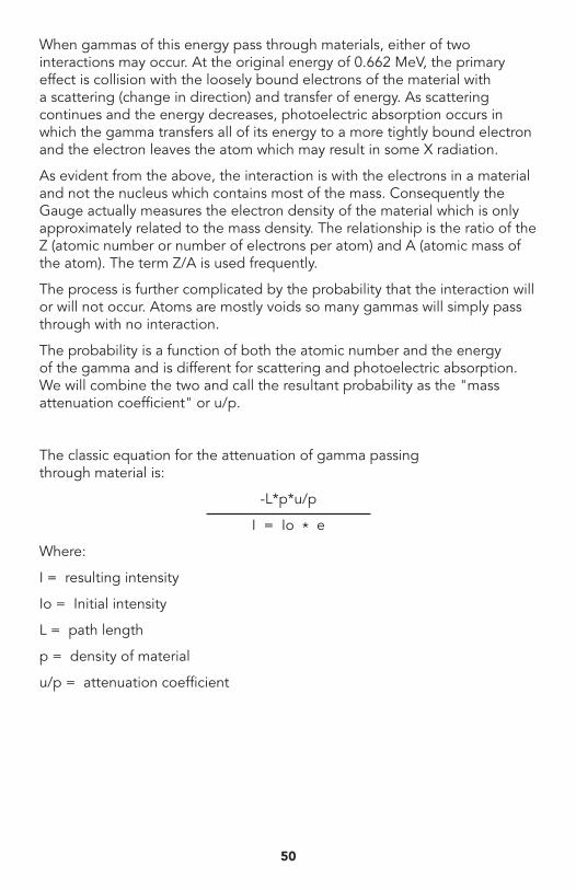
When gammas of this energy pass through materials, either of two interactions may occur. At the original energy of 0.662 MeV, the primary effect is collision with the loosely bound electrons of the material with a scattering (change in direction) and transfer of energy. As scattering continues and the energy decreases, photoelectric absorption occurs in which the gamma transfers all of its energy to a more tightly bound electron and the electron leaves the atom which may result in some X radiation.
As evident from the above, the interaction is with the electrons in a material and not the nucleus which contains most of the mass. Consequently the Gauge actually measures the electron density of the material which is only approximately related to the mass density. The relationship is the ratio of the Z (atomic number or number of electrons per atom) and A (atomic mass of the atom). The term Z/A is used frequently.
The process is further complicated by the probability that the interaction will or will not occur. Atoms are mostly voids so many gammas will simply pass through with no interaction.
The probability is a function of both the atomic number and the energy of the gamma and is different for scattering and photoelectric absorption. We will combine the two and call the resultant probability as the "mass attenuation coefficient" or u/p.
The classic equation for the attenuation of gamma passing through material is:
-L*p*u/p
I = Io * e
Where:
I = resulting intensity
Io = Initial intensity
L = path length
p = density of material
u/p = attenuation coefficient
50
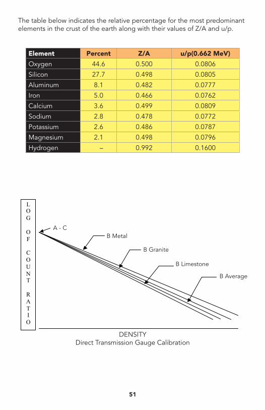
Element Percent Z/A u/p(0.662 MeV)
Oxygen 44.6 0.500 0.0806
Silicon 27.7 0.498 0.0805
Aluminum 8.1 0.482 0.0777
Iron 5.0 0.466 0.0762
Calcium 3.6 0.499 0.0809
Sodium 2.8 0.478 0.0772
Potassium 2.6 0.486 0.0787
Magnesium 2.1 0.498 0.0796
Hydrogen – 0.992 0.1600
51
The table below indicates the relative percentage for the most predominant elements in the crust of the earth along with their values of Z/A and u/p.
DENSITYDirect Transmission Gauge Calibration
L O G
O F
C O U N T
R A T I O
B Average
B Limestone
B Granite
B MetalA - C
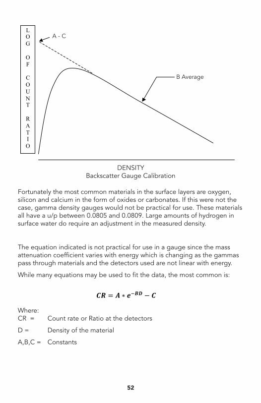
Fortunately the most common materials in the surface layers are oxygen, silicon and calcium in the form of oxides or carbonates. If this were not the case, gamma density gauges would not be practical for use. These materials all have a u/p between 0.0805 and 0.0809. Large amounts of hydrogen in surface water do require an adjustment in the measured density.
The equation indicated is not practical for use in a gauge since the mass attenuation coefficient varies with energy which is changing as the gammas pass through materials and the detectors used are not linear with energy.
While many equations may be used to fit the data, the most common is:
Where: CR = Count rate or Ratio at the detectors
D = Density of the material
A,B,C = Constants
DENSITYBackscatter Gauge Calibration
L O G
O F
C O U N T
R A T I O
B Average
A - C
52
𝑪𝑪𝑪𝑪 = 𝑨𝑨 ∗ 𝒆𝒆!𝑩𝑩𝑩𝑩 − 𝑪𝑪
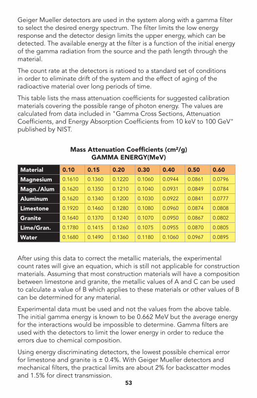
Geiger Mueller detectors are used in the system along with a gamma filter to select the desired energy spectrum. The filter limits the low energy response and the detector design limits the upper energy, which can be detected. The available energy at the filter is a function of the initial energy of the gamma radiation from the source and the path length through the material.
The count rate at the detectors is ratioed to a standard set of conditions in order to eliminate drift of the system and the effect of aging of the radioactive material over long periods of time.
This table lists the mass attenuation coefficients for suggested calibration materials covering the possible range of photon energy. The values are calculated from data included in "Gamma Cross Sections, Attenuation Coefficients, and Energy Absorption Coefficients from 10 keV to 100 GeV" published by NIST.
After using this data to correct the metallic materials, the experimental count rates will give an equation, which is still not applicable for construction materials. Assuming that most construction materials will have a composition between limestone and granite, the metallic values of A and C can be used to calculate a value of B which applies to these materials or other values of B can be determined for any material.
Experimental data must be used and not the values from the above table. The initial gamma energy is known to be 0.662 MeV but the average energy for the interactions would be impossible to determine. Gamma filters are used with the detectors to limit the lower energy in order to reduce the errors due to chemical composition.
Using energy discriminating detectors, the lowest possible chemical error for limestone and granite is ± 0.4%. With Geiger Mueller detectors and mechanical filters, the practical limits are about 2% for backscatter modes and 1.5% for direct transmission.
Material 0.10 0.15 0.20 0.30 0.40 0.50 0.60
Magnesium 0.1610 0.1360 0.1220 0.1060 0.0944 0.0861 0.0796
Magn./Alum 0.1620 0.1350 0.1210 0.1040 0.0931 0.0849 0.0784
Aluminum 0.1620 0.1340 0.1200 0.1030 0.0922 0.0841 0.0777
Limestone 0.1920 0.1460 0.1280 0.1080 0.0960 0.0874 0.0808
Granite 0.1640 0.1370 0.1240 0.1070 0.0950 0.0867 0.0802
Lime/Gran. 0.1780 0.1415 0.1260 0.1075 0.0955 0.0870 0.0805
Water 0.1680 0.1490 0.1360 0.1180 0.1060 0.0967 0.0895
Mass Attenuation Coefficients (cm²/g)GAMMA ENERGY(MeV)
53
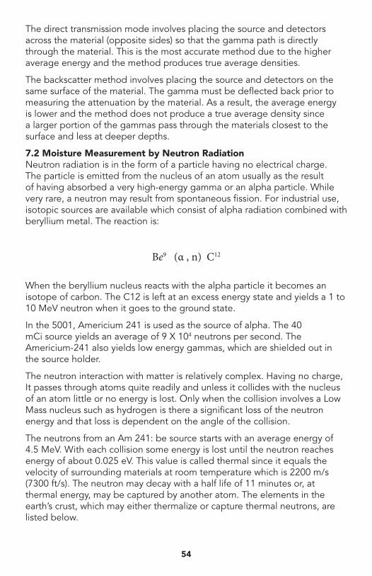
The direct transmission mode involves placing the source and detectors across the material (opposite sides) so that the gamma path is directly through the material. This is the most accurate method due to the higher average energy and the method produces true average densities.
The backscatter method involves placing the source and detectors on the same surface of the material. The gamma must be deflected back prior to measuring the attenuation by the material. As a result, the average energy is lower and the method does not produce a true average density since a larger portion of the gammas pass through the materials closest to the surface and less at deeper depths.
7.2 Moisture Measurement by Neutron RadiationNeutron radiation is in the form of a particle having no electrical charge. The particle is emitted from the nucleus of an atom usually as the result of having absorbed a very high-energy gamma or an alpha particle. While very rare, a neutron may result from spontaneous fission. For industrial use, isotopic sources are available which consist of alpha radiation combined with beryllium metal. The reaction is:
Be9 (α , n) C12
When the beryllium nucleus reacts with the alpha particle it becomes an isotope of carbon. The C12 is left at an excess energy state and yields a 1 to 10 MeV neutron when it goes to the ground state.
In the 5001, Americium 241 is used as the source of alpha. The 40 mCi source yields an average of 9 X 10⁴ neutrons per second. The Americium-241 also yields low energy gammas, which are shielded out in the source holder.
The neutron interaction with matter is relatively complex. Having no charge, It passes through atoms quite readily and unless it collides with the nucleus of an atom little or no energy is lost. Only when the collision involves a Low Mass nucleus such as hydrogen is there a significant loss of the neutron energy and that loss is dependent on the angle of the collision.
The neutrons from an Am 241: be source starts with an average energy of 4.5 MeV. With each collision some energy is lost until the neutron reaches energy of about 0.025 eV. This value is called thermal since it equals the velocity of surrounding materials at room temperature which is 2200 m/s (7300 ft/s). The neutron may decay with a half life of 11 minutes or, at thermal energy, may be captured by another atom. The elements in the earth’s crust, which may either thermalize or capture thermal neutrons, are listed below.
54
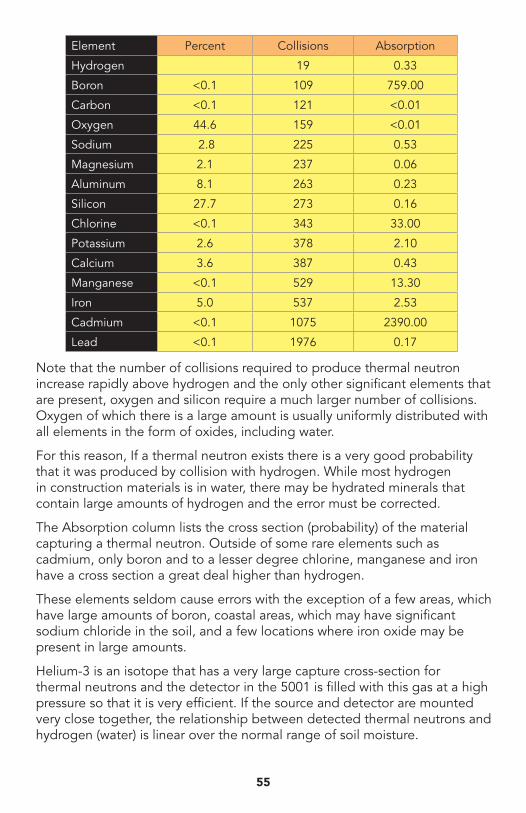
Note that the number of collisions required to produce thermal neutron increase rapidly above hydrogen and the only other significant elements that are present, oxygen and silicon require a much larger number of collisions. Oxygen of which there is a large amount is usually uniformly distributed with all elements in the form of oxides, including water.
For this reason, If a thermal neutron exists there is a very good probability that it was produced by collision with hydrogen. While most hydrogen in construction materials is in water, there may be hydrated minerals that contain large amounts of hydrogen and the error must be corrected.
The Absorption column lists the cross section (probability) of the material capturing a thermal neutron. Outside of some rare elements such as cadmium, only boron and to a lesser degree chlorine, manganese and iron have a cross section a great deal higher than hydrogen.
These elements seldom cause errors with the exception of a few areas, which have large amounts of boron, coastal areas, which may have significant sodium chloride in the soil, and a few locations where iron oxide may be present in large amounts.
Helium-3 is an isotope that has a very large capture cross-section for thermal neutrons and the detector in the 5001 is filled with this gas at a high pressure so that it is very efficient. If the source and detector are mounted very close together, the relationship between detected thermal neutrons and hydrogen (water) is linear over the normal range of soil moisture.
Element Percent Collisions Absorption
Hydrogen 19 0.33
Boron <0.1 109 759.00
Carbon <0.1 121 <0.01
Oxygen 44.6 159 <0.01
Sodium 2.8 225 0.53
Magnesium 2.1 237 0.06
Aluminum 8.1 263 0.23
Silicon 27.7 273 0.16
Chlorine <0.1 343 33.00
Potassium 2.6 378 2.10
Calcium 3.6 387 0.43
Manganese <0.1 529 13.30
Iron 5.0 537 2.53
Cadmium <0.1 1075 2390.00
Lead <0.1 1976 0.17
55
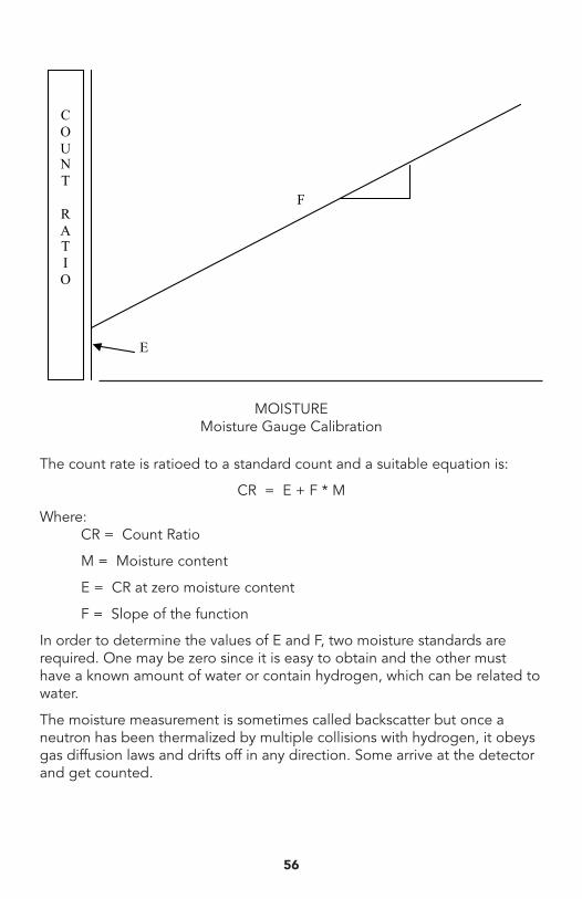
56
MOISTUREMoisture Gauge Calibration
F
E
C O U N T
R A T I O
The count rate is ratioed to a standard count and a suitable equation is:
CR = E + F * M
Where: CR = Count Ratio
M = Moisture content
E = CR at zero moisture content
F = Slope of the function
In order to determine the values of E and F, two moisture standards are required. One may be zero since it is easy to obtain and the other must have a known amount of water or contain hydrogen, which can be related to water.
The moisture measurement is sometimes called backscatter but once a neutron has been thermalized by multiple collisions with hydrogen, it obeys gas diffusion laws and drifts off in any direction. Some arrive at the detector and get counted.
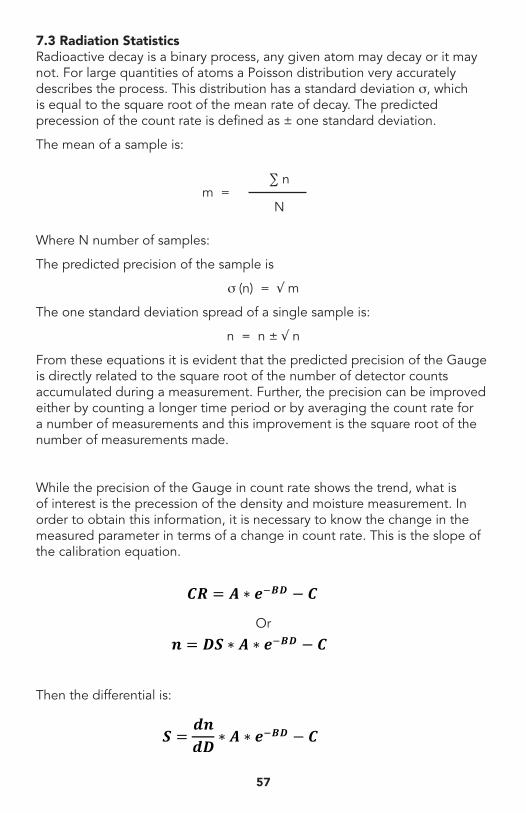
7.3 Radiation StatisticsRadioactive decay is a binary process, any given atom may decay or it may not. For large quantities of atoms a Poisson distribution very accurately describes the process. This distribution has a standard deviation s, which is equal to the square root of the mean rate of decay. The predicted precession of the count rate is defined as ± one standard deviation.
The mean of a sample is:
∑ n
m =
N
Where N number of samples:
The predicted precision of the sample is
s (n) = √ m
The one standard deviation spread of a single sample is:
n = n ± √ n
From these equations it is evident that the predicted precision of the Gauge is directly related to the square root of the number of detector counts accumulated during a measurement. Further, the precision can be improved either by counting a longer time period or by averaging the count rate for a number of measurements and this improvement is the square root of the number of measurements made.
While the precision of the Gauge in count rate shows the trend, what is of interest is the precession of the density and moisture measurement. In order to obtain this information, it is necessary to know the change in the measured parameter in terms of a change in count rate. This is the slope of the calibration equation.
Or
Then the differential is:
57
𝑪𝑪𝑪𝑪 = 𝑨𝑨 ∗ 𝒆𝒆!𝑩𝑩𝑩𝑩 − 𝑪𝑪
𝒏𝒏 = 𝑫𝑫𝑫𝑫 ∗ 𝑨𝑨 ∗ 𝒆𝒆!𝑩𝑩𝑩𝑩 − 𝑪𝑪
𝑺𝑺 =𝒅𝒅𝒅𝒅𝒅𝒅𝒅𝒅 ∗ 𝑨𝑨 ∗ 𝒆𝒆
!𝑩𝑩𝑩𝑩 − 𝑪𝑪
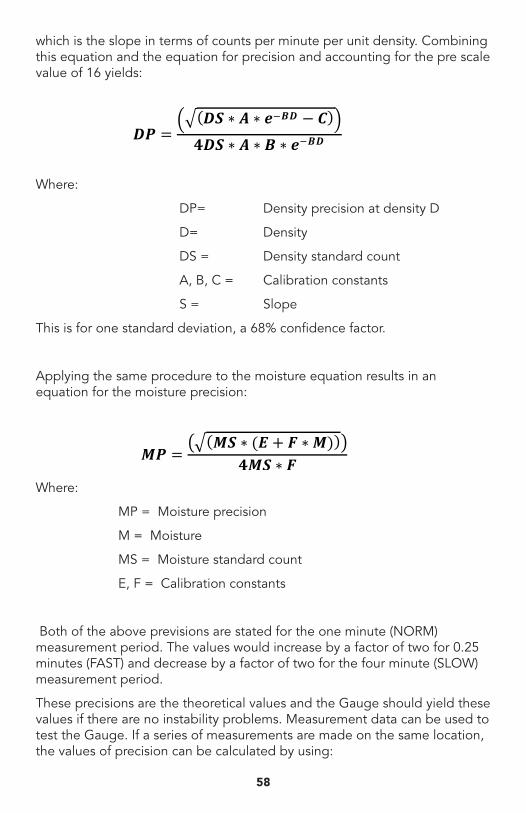
which is the slope in terms of counts per minute per unit density. Combining this equation and the equation for precision and accounting for the pre scale value of 16 yields:
Where:
DP= Density precision at density D
D= Density
DS = Density standard count
A, B, C = Calibration constants
S = Slope
This is for one standard deviation, a 68% confidence factor.
Applying the same procedure to the moisture equation results in an equation for the moisture precision:
Where:
MP = Moisture precision
M = Moisture
MS = Moisture standard count
E, F = Calibration constants
Both of the above previsions are stated for the one minute (NORM) measurement period. The values would increase by a factor of two for 0.25 minutes (FAST) and decrease by a factor of two for the four minute (SLOW) measurement period.
These precisions are the theoretical values and the Gauge should yield these values if there are no instability problems. Measurement data can be used to test the Gauge. If a series of measurements are made on the same location, the values of precision can be calculated by using:
58
𝑫𝑫𝑫𝑫 =𝑫𝑫𝑫𝑫 ∗ 𝑨𝑨 ∗ 𝒆𝒆!𝑩𝑩𝑩𝑩 − 𝑪𝑪𝟒𝟒𝟒𝟒𝟒𝟒 ∗ 𝑨𝑨 ∗ 𝑩𝑩 ∗ 𝒆𝒆!𝑩𝑩𝑩𝑩
𝑴𝑴𝑴𝑴 =𝑴𝑴𝑴𝑴 ∗ (𝑬𝑬+ 𝑭𝑭 ∗𝑴𝑴)
𝟒𝟒𝟒𝟒𝟒𝟒 ∗ 𝑭𝑭
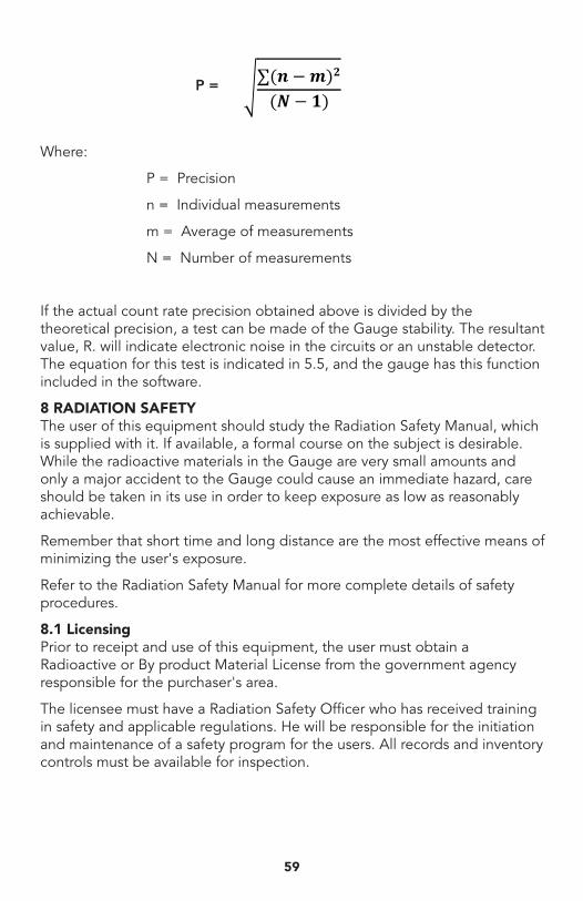
Where:
P = Precision
n = Individual measurements
m = Average of measurements
N = Number of measurements
If the actual count rate precision obtained above is divided by the theoretical precision, a test can be made of the Gauge stability. The resultant value, R. will indicate electronic noise in the circuits or an unstable detector. The equation for this test is indicated in 5.5, and the gauge has this function included in the software.
8 RADIATION SAFETYThe user of this equipment should study the Radiation Safety Manual, which is supplied with it. If available, a formal course on the subject is desirable. While the radioactive materials in the Gauge are very small amounts and only a major accident to the Gauge could cause an immediate hazard, care should be taken in its use in order to keep exposure as low as reasonably achievable.
Remember that short time and long distance are the most effective means of minimizing the user's exposure.
Refer to the Radiation Safety Manual for more complete details of safety procedures.
8.1 LicensingPrior to receipt and use of this equipment, the user must obtain a Radioactive or By product Material License from the government agency responsible for the purchaser's area.
The licensee must have a Radiation Safety Officer who has received training in safety and applicable regulations. He will be responsible for the initiation and maintenance of a safety program for the users. All records and inventory controls must be available for inspection.
59
∑(𝒏𝒏−𝒎𝒎)𝟐𝟐
(𝑵𝑵− 𝟏𝟏) P =
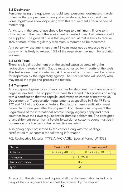
8.2 DosimeterPersonnel using the equipment should wear personnel dosimeters in order to assure that proper care is being taken in storage, transport and use. Some regulations allow dispensing with this requirement after a period of monitoring.
All visitors in the area of use should be kept to a minimum. If long term observance of the use of the equipment is needed then dosimeters should be supplied. The general rule is that any individual that is likely to receive 10% or more of the regulatory maximum is required to be monitored.
Any person whose age is less than 18 years must not be exposed to any dose which is likely to exceed 10% of the regulatory maximum for radiation workers.
8.3 Leak TestsThere is a legal requirement that the sealed capsules containing the radioactive materials in this Gauge must be tested for integrity of the seals. This test is described in detail in 5.4. The record of this test must be retained for inspection by the regulatory agency. The user's license will specify who may make the wipe and process the material.
8.4 TransportAny equipment given to a common carrier for shipment must have a current negative leak test. The shipper must have this record in his possession along with a certification that the capsule, and transport container meet the US Department of Transportation requirements as specified in Title 49 Parts 172 and 173 of the Code of Federal Regulations these certification must be on file for one year after the shipment. For international shipment the Regulations of the international Atomic Energy Agency apply and other countries have their own regulations for domestic shipment. The consignee of any shipment other than a freight forwarder or customs agent must be in possession of a license for the radioactive materials.
A shipping paper presented to the carrier along with the package certification must contain the following information
RQ, Radioactive Material, TYPE A PACKAGE, Special Form, UN3332
A record of the shipment and copies of all the documentation including a copy of the consignee's license must be retained by the shipper.
60
Name Cesium-137 Americium-241
Activity 1.48 GBq (40 mCi) 0.37 GBq (10 mCi)
Category YELLOW II
Transport Index 0.2
Type A
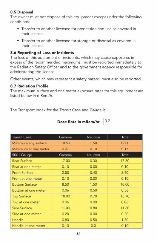
8.5 DisposalThe owner must not dispose of this equipment except under the following conditions:
• Transfer to another licensee for possession and use as covered in their license.
• Transfer to another licensee for storage or disposal as covered in their license.
8.6 Reporting of Loss or IncidentsThe loss of this equipment or incidents, which may cause exposures in excess of the recommended maximums, must be reported immediately to the Radiation Safety Officer and to the government agency responsible for administering the license.
Other events, which may represent a safety hazard, must also be reported.
8.7 Radiation ProfileThe maximum surface and one meter exposure rates for this equipment are listed below in mRem/h.
The Transport Index for the Transit Case and Gauge is:
Dose Rate in mRem/hr
61
0.2
Transit Case Gamma Neutron Total
Maximum any surface 10.50 1.50 12.00
Maximum at one meter 0.07 0.10 0.17
5001 Gauge Gamma Neutron Total
Rear Surface 17.00 0.30 17.30
Rear at one meter 0.10 0.00 0.10
Front Surface 2.50 0.40 2.90
Front at one meter 0.10 0.00 0.10
Bottom Surface 8.50 1.50 10.00
Bottom at one meter 0.06 0.50 0.56
Top Surface 18.00 0.70 18.70
Top at one meter 0.06 0.00 0.06
Side Surface 11.00 0.80 11.80
Side at one meter 0.20 0.00 0.20
Handle 0.80 0.50 1.30
Handle at one meter 0.10 0.0 0.10

North Carolina Protection Section Measurement Dose Rates. Gamma dose rates were measured 08/05/88 using a Ludium Model 14C Survey Meter. Neutron does rates were measured 08/05/88 using an Eberline Model PNR-4 Neutron Rem Counter with a 22.9 cm sphere on the gauge surface, centerline was approximately 11 cm from the surface. 0.0 indicates does rates same as background.
62
9 WARRANTYThe purchase of this equipment includes a limited 12 months warranty against defective material and workmanship. The owner may replace defective parts in the field by prepaid shipment for installation.
Equipment shipped prepaid to the factory will be repaired or replaced at the option of HUMBOLDT and returned prepaid to the customer. This warranty does not apply if the product as determined by HUMBOLDT, is defective because of normal wear or accident or misuse, or as a result of service or modification by other than an Authorized Service Facility.
THIS EQUIPMENT CONTAINS HAZARDOUS RADIOACTIVE MATERIALS AND THE PROPER USE OF THE EQUIPMENT AND PROTECTION OF FACILITIES AND PERSONNEL IS SOLELY THE RESPONSIBILITY OF THE PURCHASER. OWNERS AND USERS ACCEPT RESPONSIBILITY FOR COMPLIANCE WITH LOCAL AND NATIONAL LAWS COVERING THE POSSESSION, USE AND DISPOSAL OF THE MATERIALS.
THERE ARE NO WARRANTIES, EXPRESS OR IMPLIED, INCLUDING WITHOUT LIMITATION ANY IMPLIED WARRANTY OF MERCHANTABILITY OR FITNESS, WHICH EXTENDS BEYOND THIS DESCRIPTION. THIS EXPRESS WARRANTY EXCLUDES COVERAGE OF AND DOES NOT PROVIDE RELIEF FOR INCIDENTAL OR CONSEQUENTIAL DAMAGES OF ANY KIND OR NATURE, INCLUDING BUT NOT LIMITED TO LOSS OF USE, LOSS OF SALES OR INCONVENIENCE. THE EXCLUSIVE REMEDY OF THE PURCHASER IS LIMITED TO REPAIR, RECALIBRATION OR REPLACEMENT OF THE EQUIPMENT AT HUMBOLDT'S OPTION.
Specifications and descriptions are as accurate as possible. HUMBOLDT reserves the right to make changes and improvements in accordance with the latest specifications and design improvements. Upgrading of older equipment to current specifications will be made, where possible, at the expense of the current owner except where HUMBOLDT may elect to make the upgrade at no cost to the owner.
63

64

Humboldt Mfg. Co.2525 Atlantic AvenueRaleigh, NC 27604 U.S.A.
U.S.A. Toll Free: 1.800.537.4183 Voice: 1.919.833.3190
Fax: 1.919.833.5283email: [email protected]