Embed Size (px)
Citation preview
H'rL- ~:::>Yi(A·.t:CS LA!J"'RAI .RY (M, tf'ORio;IA l:•s-IT ;~ E OF T£Chi'IOLOO'I
DEPARTl~T OF THE 1-lA VY
BUREAU OF YARDS AliD DOCKS CONTRACT NQy-12$61
Robert T. Knapp Director
Vito A. Vanoni Aasoci~te Director
Progress Repor~ tor Decemb~r 1949
MODEL STUDIES OF
MOBILE BREAKWAtERS
~oqynamics Laboratories ~draulie Structures Division
of the California In&titute of Tec~Qlogy
Pasadena,. California
Report PJ:•pared by
John H. Carr Project Supervisor

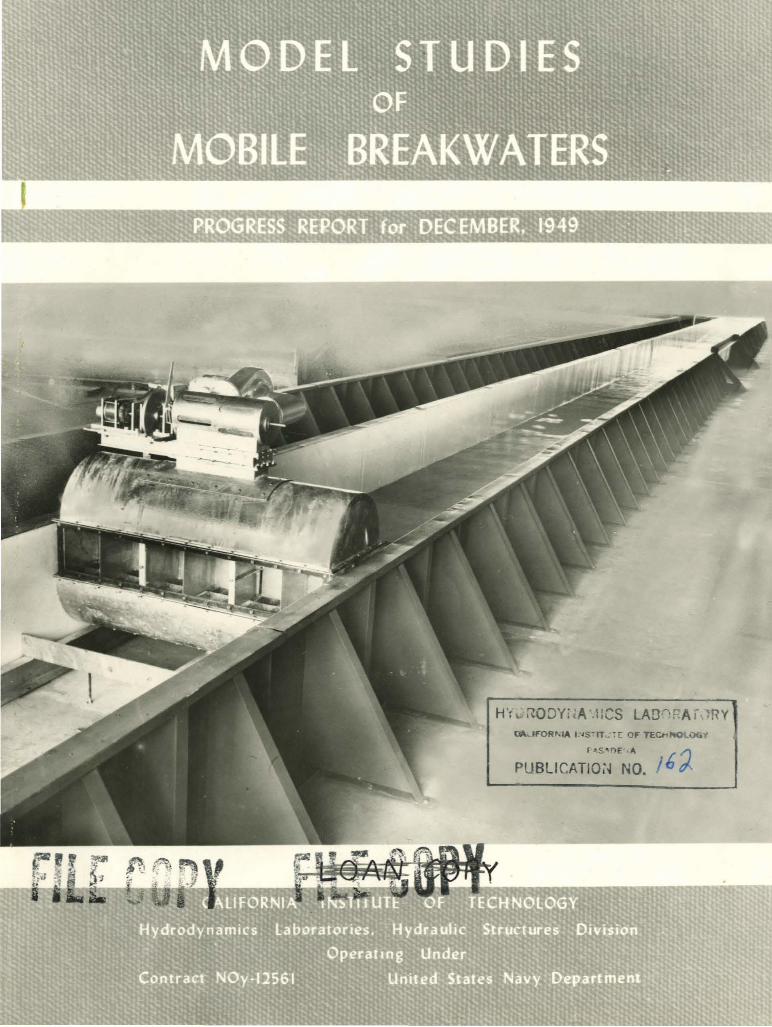
The cover photograph s·haws the 4-toot wi~e by
~30~foot long wave channel at the Azusa Labo~tory.
The wave machine used with ·t his channel is capable
of gener ating wav~s ttp to 4 i nches i n height and
:from 2 to ,;o feet in length. The t ransparent wali
aection is useful for obser ving the particle motion
a·s-acc i ated wi th t he wave trains and t or .obt aining
photographs of wave pr.ofiles ..

Prog~eas R•port for Deo~ber7 1949
Model S,udiee of M9bil& Breakwaters
I . I NTRODUCTIO)l
Two ~eneral p~sical prooeaaea by which wave emer" may be ex~
eluded from a region are wave retlect1oft and wave i nterference at
the seaward bo\mdary or the re~ion. Wave r eflection is the cC~~~aen
basis of opetatien or co~ntid~l br.atwatere, JD4 tor s»eh atruc•
turea is acocmpanied by the developnellt ot lATse to~eet al14 onr•
turni ng m~Dts. Wave interference i a also a. o0111110a oecuztJ"ente
altheugh leas g~rally understood, bei~ r esponsible tor the
charact erietie diffraction effects observed when waves paes through
a ~reakwater gate.
Because of the large toroes developed. a mobile breakwater
des igned to totally reflect incident a~orm waves a~s to be an
impossibility, but there is a good pouibUity t hat subme.rge$1 break•
water s, whi~h •r~ par tially reflecti~ barriers, may be ~es~~ned ,· t
which will provi4e suffic ient proteeti en to be usetul aa; a~pj~o~o•
to for ces small ~nough to permit installation -.JUt ui.ateilance. In
addit1on, it ; everal suoh partially reflective barriers are in~
s t alled i n ser ies, it m~ he possible to t~ke ad.antage ot wave .. '
i nterference to i ncrease greatly t heir net eff ect.
The Laboratory is presently engated. in a s t udy ot ~hia .ayatea
or mobile breakwe.tei"s~ The factors to l;ie il)v-eati~atecl iJlolude:
• 1 ...
(1) Determination of r ef.'!.ec bi-:-·.1 ~ Y.: i'f i cient s 1:>1" e. submerged
barrier as a ·functi on of barrier hei ght and wavo le~th.
(2) D.etel'Jilinat icn of' ref'l eotion ooe.f'ricients or multipl.e
barriers.
(J) Determination of ra~e ot wave le~ths e!'tectiwl y
r~~ed ~Qr fixed barrier spacing.
The determiJJ&'tiQn o£ the 't'~oea eJterted on the etrlolotur .. S.. not
included in this inveetigation.
This program is still in operati9.n at the laboratory; thia
progresa report presents preliminary data whieft will be aucmented
in t he Final Repprt on the Mobil8 Breakwater Investigation, which
is now in preparation.
- 2 -
II.' THE<RY 0:.' Wl~VS RErl-EC'I:r: n:r-~ JS :) JNl'FRFERE~E
A. Wave Reflection
The nature of wave reflection may be conveniently ate.ted in
terms of the equations of the water surface e.a e. function of two
variables, time and distance. Thua, a wave traveli~ in the
x-poaitive direction with amplitude a (wave hei~ht = 2a), lensth L,
and period T, may be represented by the equation:
(1)
If this wave is partially reflected at a poiat x = O, a new wave
of amplitude b and the aame period and le~th aa the ori~inal il
produced, but traTela in the x-~~ative directionr
~ = b sin 2'rr ~ + ~ (2)
The result~ng water surface in the x-negative region ie given by
the summation of the incident and reflected wav~s:
n = n1 + n.z = (a-b) sin 2rr(y - ~) + 2b
t X ein 2Tr T cos 2Tr 't
which is the equati on of a standi~ waTe of amplitude 2b, with
antinode at the barrier ( x 7 o), supertmposed on a progreasiYe
wave of ~plitude (a - b) traveli~ in the ~-pos!tiTe direction.
For the case of tote.l r aflectio:1, a = b, Eq. (;) reduces to the
familiar reS\.llt for this s i;t,t!.'l.t~. ::n; a standir.g wave of ampl itude
twice that of th~ ori~inal inc icent ~ve •
.. 3 -

In the ab~ence of any incidental energy lps$as, the amplitude
of the trans%nitted wave is given by the law of conservation of
energy, and since wave energy is p~oportional to t he ~quare of wave
a%nplitude~ the equation of t he transmitted wave is:
The coefficient of transmi ssion is defined as the ratio of the
traftamitted to inci dent wave amplitud•, or tor the case of no
energy lQss:
p=Jn=~ a a (5)
B. Wave Interferenc~
Wave interference is the process of interact i on of two or more
wave trains. For the specia l case in whi ch we are i nterested, the
two we.ve trains traveling in the same direction with identical wave
l ength, period~ and amplitude, asd wi th phase differenc' p, ~y be
represent~d by:
"1 = a sin 2Tt (~ - T) (6a)
"2 = a sin r (~ -~ + -J {6b)
and t~ resultant becomes:
n = "1 + "2 = a "~ (l+coo ;) •in r ( t --t) + ct J a= sin -1 Jl1.oe ~· (7 )
-4-
Thus the ei'i'ect bi' interi'oreno-:~ is to produc~ a ~w wave of the s ame
length and period, but whos o 81npl.:.:!:·.lb e.~~ -ohei.t• ...... .. . tunot.ion or
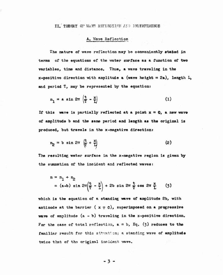
the or i ginal phase differen~e, f• The :ratio of the amplitude of
the resultant and ori~inal wa~s are plotte4 as a £unction oi' • iB
Fig. 1, 11there it ia aeon that for ~ 0, the amplitud• is doubled, 0
or maximum r eintorcemeBt occurs,. aDd for ~ 180 , the amplitude il
zero, or total canoe l lati on oocur• .
The application of t he pPinciplea ~~ wave int&rter ence ia of
grea t importance in the study ot the passage ot wave motion t hrough
so-call ed periodic or lattice etructurea, a a f or example i n the
theory of the transmiss ion or electric wavea t nrough o~ystala ar
filter networks, or i n the present case, the tran~iasiqn ot surface
waves through a series of' subme~ged breakwaters.
Each breakwater in such a series is the source oi' a r eflected
wave train traveling i n the x-negative direction, and if the break-
water spacing a nd wave length are sueh that t hese waves r einforce,
(' = 0), the amplitude oi' the net reflected wave due to N break
waters will be appr oximately N ti~s the amplitude tor one break
water, at least ii' the numbe~ l of breakwaters in t he series is
not to& large and the i ndividual r efl ect ion amplitudes are a small
percentage of the incident wave amplitude, as seems to be the case.
The energy of the net reflected Wt\ve train, hcwever , is propor tiona l
to the square oi' its amplitude, hence the t otal energy abstracted
from t he incident; wave train (thus not present in the transmi tted
wave train) is approximately ~ times the energy re~oved from the
- 5 •
incident wave train hy rma 1-r:H:.bfP.t~~:. '?::-,.._, ::-esult is a rapid in
crease i11 reflective abili·cy f o:::· a. :nodore.te n tunher of "barriers,.
and the possibility of t;.tiliz i ng t>. devi ce in which each unit by
itself is a very weak reflective element, but acting toget her
achieves appreciable net energy reflection.
An important lilnitati on of this technique is that as the number
ot elements are increased, the system becomes increasingly aenaitive
to the requirement t hat the interter~ wave components be exactly
in phase. For water waves, the proper phasing is accomplished by
spacing the barri ers at multiples of one-half wave length. There
fore, for an installation with a fixed spacing between elements,
the range of wave lengths for which appreciable reduction ot tran8-
mitted wave height is obtained narrows as the number of barrier&
is increased.
- 6-
J:II. 3XffiRU.iP.NTAL RE3'VLTS
A. Applicat ion ef t~ Theo!Y to ~he Measuri~ ftoblem
The ex~erimental wor k t o date has been hampered by the diffi-
eulty of ~easuring i mposed wave heights in t he presence of the
atamliDC wave prqcluced by the reflec'ti~ b.arriera, er:nd by the
deoe aait,y of deto~inim« ~he .-ount of oDer~ lost at oaoh barri er
duo '\o turbuleno.e, .azid h~• not appearbt i a the t r anemitted or
r eflected waves. If such energy lo~se$ are minor the problem 1•
more straight f orward, since Eq. (3) , which represents the water
surface between the wave machi ne and tho barriers may be ~itten
in t he form:
n = (a+b) cos 2rr f sin 2rr ~ • (a-b) ~in 2rr t eos ani (8)
The absolute magnitude of '8) , cons ider ed as a f unetioA oft is:
(n) = J a2 +b
2 -+2ab (cos
2 2rr -! - sin
2 2rr ~ ) (9)
L L 2 X~ 2 X"t' 2 X 2 X
Since cos 2rr (~) • sin 2rr (-,;-) = -ooa 2rr L + sin 2Tr L ,
the sum of the squar es of wave amplitude meaauremeats ma.de a quarter ..
wave length apar t i s :
2 2 2 2 n1 + ~ = 2 (a + b )
and since we assUJn8 the amplitude of the trAnsmitted wave to be :
.. 7 -

it is poasible to solve for a, the amplitude ot the tmpoaed wave,
trom three Jneasureaenta ot wave hei~ht, •1
aDd n2
, a qu&rter..W..v•
length apart in the region ahead or the barriera, amd n,• the tr&M
mitted wave height in the protected region behind the barriers.
The transmissio~ wo~ld then be given byt
{10)
It, however, a percentage N or the incident waye energy is lost
by turbulence, ~ ~s given by .J (l-N)a2 -b2, and with_ this additional
variable the problem cannot be solved in this manner. For this case,
it is again convenient to consider t he form ot the equation or the
water surtace given by Eq. {8) :
n = (a+b) cos 2Tr ~ sin 2Tr i - (a .. b) ain 2Tr ~ cQa 2Tr ;
X It is seen that corresponding to poaitioDI where ooa 2Tr L= l,
the equation or the water surface is:
n1
= (a+b) sin 2rr ~ (ll)
and corresponding to position a quarter-wave length a~, where
cos 2Tr ~ = 0 1 sin 2rr f = 1, the equation is :
~ = (aJb) cos 21'T y (12)
Thus by taking a particular case ot the previously described meae
ur.i~ ~ technique, where the measuring elements are not only a
q~rter-wave length apart, but are positioned at poi nts or maximum
and minimum vertical wate~ mot~on we may solve tor a and b d~rectly
-8-
2 .0
g ~ 1.0 0:
00"
0
0 . 9
g .; 0 .8 ~ ~ 0
~ ;g 0.7 il u
0 .6
5 0 . 0
~ ~
""
. 4 5
~
""' ~
-----;;!-.-----· 90 Phose angle
........ ~
"= "" ~
~ . 135
Fig. 1-Effect of interference of two identical wove trains with phose difference II
I
[lemtl'll NO I
283'ohtod of borrotr -~
Element No 2 10.6 ' o,.od ol bor"'' -~------J----JL
Element No 3 100' bthond bortotr ,.,
,'lmpCS'!_d ~""''!_
I -·",0
7 .5 uc. ! TomonQ Lon.t)
Fig.·2 - Oscillograph record of partial reflection of solitary wove
~ ~ ~ i---
- -
- Average of prehmtnory measurements
0 Exact measurements -----
10 15 Ratto: Wave lenQth to water depth
"' tao•
20
Fig. 3 - Effect of wove length on barrier performance for bar rier height of one-half the water depth

l a=- (n + n ) 2 1 2
1 b = 2 (nl - ~)
(13)
, the amplitude of the transmitted wave, is equal to
The determination of the points of maximum and minimum motion
must be a "out-and-try" proposition, and will introduce some in-
accuracy in the results.
B. Experimental Results
Solitary Wave Measurements:
A convenient method for investigating the effect of a single
submerged barrier on shallow-water waves is by the use of a soli
tary wave, which is the archtype of shallow-water waves. The ad
vantage ot this technique ill that the inc i dent, reflected, alld
transmitted waves may be ~easured directly, thus permi~ting an
accurate determination of the effect of barr ier height tor a type
ot wave that approximates the r at her large wave length-to-depth
eonditions typical of harbor locati ons . However, the water particle
motion associated wi th a solitary wave is decidedly different tram
the motion due to a trai n of waves, since tor the solitary wa.e
the particles do not move in closed orbits, but continually advanoe,
hence the quanti tat.ive results of the solitary wave measurements
are not strictly applicable to tbe case of' lODl; wave traina. Tbt
- 9-
qualitative effects or re~tive barrier hei~ht on reflection and
turbulent losses as Observed with solitary waves should, however,
be indicatiw or the trends to be expected with shallow-water
wave trains.
The technique employed consisted or ~eneratin£ solitary wave1
by special manipulation or the laboratory pneumatic wave machine
a.~ one end or the 130-root wave channel and recordi~ the Yertioal
motion or the water surface at points ahead or, and behiDi, the
barrier by means ot the electrical c onductivity wan height measur
i~ elemel!ts described in previous reports. The record from element•
ahead or the barrier show the sequence or iDCident and reflected
waves separated by a time interval equal to twice the distance rrcm
measuring point to barrier divided by the wa.ve nlocity. Fi£. 2
ia a reproduction or a typical oscill0£raph record. The barriers
used were thin vertie•l walls made or 16- ga. sheet metal, reintoroed
at the ed·gea and bottom.
The results or these measurements are shown in Table I. The
turbulent energy loss is here calculated en the basis or the soli
tary wave theory ot BOUSSINESQ(l), in which the wave energy is
propor t i onal to the three-halyes power or the wave height, instead
ot the conventioml AIRY(2 ) . theory tor waye trai:na in which the
energy is proportioMl to the square of the wave hei~t.
(l)Munk, Walter H., THE SOLITARY WAVE TBE<RY AND ITS APPLICATION TO SURF FROBI..EUS. Annals or the New York AoadeJ!l1" ot Sciences, Vol.51, Art. 3. May 1949, pp.}76~.
(2 )tamb, Sir Horace, BIORODYNlMICS DOVER PUBLICATION, New York 1~5 Chapter 9, Art. 230.
.. 10-

TABlE I
Effect of Barrier Height on Transmission of Solitary Waves
l Ratio or I Ratio of I
Ratio of Transmitted Reflected Per Cent of Lmposed Barrier Height Wave Height Wave Heig:.,.t Wave Energy
to to in .l:teflected Lost by to Imposed Imposed Wave Turbulence
Water D4:'pth Wave Height Wave Height
.25 . 95 .oo o.o 7.4 .so . 90 .08 2.3 12.3
.67 .88 .12 4.2 13.5
.83 .75 .26 13.0 22.0
The turbulent energy loss is probably a functi on of the shape
of the reflecting barrier, and these values for very thin walls may
be larger than would be obtained f or prototype structures with re-
latively thic~r sections. The principal conclusion from these
measurements is that the reflected wave accounts for very little
of the energy reduction of the transmitted wave, even tor large
valuea of r elative barrier height. Thus a single barrier appears
to be more of a wave energy dissipati~ than wave reflecting
device.
Preliminary Measurements with Wave Traina:
Some results are available to iDd~ate the effect of a single
barrier on wave trains. These :r:~~ults were obtained with a barri-er
height ot half the water dept~ and with but . a si~le meaauring
element ahead of the barrier. This element thBretor e measured the
incident wave amplitude with a possible error ot plus or minus t ho
r etleoted wave ·amplitud•, a= a ! b. With this limited measuring
- l i -
technique it is not potsible to deter.mine the division of energy
red~etion between the reflect ed waTe and the turbulent lostea .
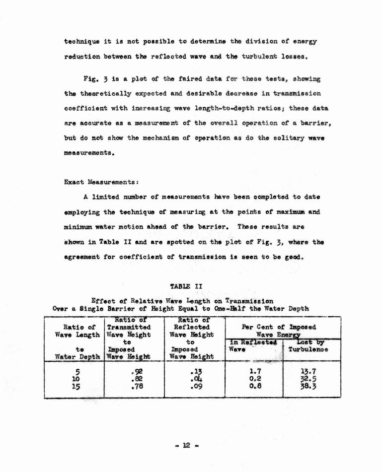
Fig. 3 is a plot of the £aired data f or t hese testt, ahcwins
the theoretically e~eeted and desirable decrease in t r ansmission
coefficient with i~reasing waye length-to-depth r atios ; thes e data
are accur'ate as a meas urement of the overall operation ot a barrier,
but do not show the mechanism of operation as do the solitary wave
me as urementa .
Exact Measurements:
A limited number or measurement& haTe been completed to date
employing the technique or measuriDg at the points ot maximua and
minimum water motion ahead or t~ barrier. These result s are
shown in Table II and are spotted on the plot ot Fig. 3, where the
agreeMent tor coefficient of transmia•ion 1• seen to be geod.
'fABLE II
Etfect ot Relative Waye Length on Transmission Over a linsle Barrier ot Height Equal to ODe-Halt the Water Depth
a 0 0 tio o Ratio ot Transmitted· Reflected
Ylaye X..ngth Wave Height Wan Height to to •
te Imp~ed Imposed ; , Turbuleme Water De th Waye Hei ht Wa'h Bei ht
~
5 . 92 :~ 1.7 13.7 10 .E2 0,2 32·5 15 .78 .09 o.e 38.3
- 12 -
The moat eip11ficant nlue of theae measurements is that they
indicate the rela~iye magnit ude of ener&r r efl ection aDd ener~
41aaipat1on at t he barrier. Althouch the am~ ot ener~ reflected
is small, it is 'believed that s u'baoquent meaaurementa for IINltiple
barl'iora will show that this modo or reduction. or transmi~ted eaarg
can be made significant, at least for a narrow band of wave leDgtha
with a fixed barrier spacing.
'l'he scatter in tho values of the reflected wave heicht is due
to the tact that this quantity is determiaed by the difference or
two larce quantities (aoo Eq.l3}, and thie unfortunately neoeaaar,r
technique ia notorious tor large probable errore. I t is not diffi
cult, hewonr, to <U-aw the conclusion that the refleote4 wan con
tains approximately one per cent ot tho imposed wave enorg-.
- 13 -
IV. C O~~LUSIONS
From theoretical oons iderat iom _ the tollowi~ eoncluaiC)na
are roached:
1. Submersed bPeakwatera otter poasibiliti ea as a mobile break~
water . It may be poss i ble to deai~n l lleh atruoturea so t hat
they are eubjected to but moderate t'~roea while appraoiab}.y
r ec:iuc i~~g imposed wave height-.
2 ,. 'lra~uuaitted wave eura may be redueed by both wan rel'leot.ioa
and eura cliaaipation. If aenral ba!-rier a are &l"raDpd 1a
aeriea, t he amount of wan reflection may be ,reatly inereaeed
f or certain ftluea o£ impo.ed wave len~h.
The experimental program completed to date hA• pr oduced tM
following conclusions:
1. Fer a sin~le barr ier, t he etteot of eneru dissipati on 1a
aueh more important than wave ener~ reflect ion in reduoi~
transmitted wave height• .
2 . The c"Oeft'i ciont ot tranamUaion or a single submerged barrier
decreases with iDCreasi~ wave l engt h-to-depth ratioe, a
des i rable aituati~n.
L For t,ypioal harbor oond1tioaa 1 such aa d= 10, t he coettioi ent
ot ref lection of a s i ngle eubmerged br eakwater with & probable 1
maximum practical height-to-de~!atio of 2
ia appr oximatel y
o. 85, correepoDdiDC to en energ reduction ot near~ 30 por .oeat.
- 14-