Embed Size (px)
Citation preview
Bottle labeling machine
Hrafn Theódór Þorvaldsson
Final thesis for B.Sc. degree in Mechatronic Engineering Technology
Faculty of Electrical and Computer Engineering
School of Engineering and Natural Sciences
University of Iceland
Bottle labeling Machine
Hrafn Theódór Þorvaldsson
24 ECTS thesis submitted in partial fulfillment of a Baccalaureus Scientiarum degree in mechatronic technology
Advisors: Burkni Pálsson
Fida Abu Libdeh
Final thesis for B.Sc. degree in Mechatronic Engineering Technology Faculty of Electrical and Computer Engineering
School of Engineering and Natural Sciences University of Iceland
Reykjanesbær, May 2015
Bottle labeling machine for geoSilica BLMgeo 24 ECTS thesis submitted in partial fulfillment of a Baccalaureus Scientiarum degree in mechatronic technology Copyright © 2015 Hrafn Theódór Þorvaldsson All rights reserved Faculty of Electrical and Computer Engineering School of Engineering and Natural Sciences University of IcelandGrænásbraut 910 235 Reykjanesbær Telephone: 578 4000 Bibliographic information: Hrafn Theódór Þorvaldsson, 2015, Bottle labeling machine, BSc thesis, Keilir Institute of Technology, University of Iceland, pp. 61. Printing: Háskólaprent, Fálkagata, 101 Reykjavík
Reykjanesbær, May 2015

VI
Útdráttur
Þetta verkefni snýr að hönnun og smíði miðavélar fyrir geoSilica sem er sprotafyrirtæki
staðsett í Frumkvöðlasetrinu Eldey á Ásbrú. GeoSilica sérhæfir sig í framleiðslu kísils sem
fæðubótarefnis í formi sviflausnar. Verkefnið er tvíþætt, annars vegar hönnun og smíði á
handvirkri frumgerð og hins vegar sjálfvirkri frumgerð. Miðavélinni er ætlað að auðvelda
ásetningu límiða á flöskur sem eru 300 ml að rúmmáli. Einnig var gert krafa um að hún
væri ódýr og auðveld í notkun.
Abstract
The goal of this project is to design and build a labeling machine for geoSilica which is a
start-up company located in the Eldey entrepreneur center in Ásbrú. GeoSilica specializes
production of silica as a food supplement in form of colloidal silica fluid. The project is
twofold; the design and building of a manual prototype and also an automatic prototype.
The labeling machine is designed to apply labels to bottles which are 300 ml volume; also
it is required to be cost effective and easy to use.
VII
Table of contents
Figures ................................................................................................................................ IX
Tables .................................................................................................................................. XI
Abbreviations .................................................................................................................. XIII
Acknowledgements ........................................................................................................... XV
1 Introduction ..................................................................................................................... 1
2 Requirements .................................................................................................................. 3 2.1 Boundaries ............................................................................................................... 3 2.2 Control system ......................................................................................................... 3 2.3 Motors ..................................................................................................................... 5
2.4 Motor drives ............................................................................................................ 6 2.4.1 The main motor drive..................................................................................... 6
3 Design ............................................................................................................................... 9 3.1 Rollers ................................................................................................................... 10
3.1.1 Interoll modifications ................................................................................... 10
3.2 Side plates.............................................................................................................. 11
3.3 Label roller ............................................................................................................ 12
3.3.1 Roll holder ................................................................................................... 12 3.3.2 Brakes .......................................................................................................... 13
3.4 Peel plate ............................................................................................................... 13 3.4.1 Calcutations.................................................................................................. 13
3.5 Motor and belt assembly ....................................................................................... 14 3.6 Assembled prototype ............................................................................................. 15
4 Planning and Cost ......................................................................................................... 17 4.1 Cost of components ............................................................................................... 17 4.2 Cost of work .......................................................................................................... 18 4.3 Project plan ............................................................................................................ 19
5 Build ............................................................................................................................... 21 5.1 Side Plates ............................................................................................................. 21
5.1.1 Motor and Belt assembly ............................................................................. 22
5.2 Interoll modifications ............................................................................................ 23 5.2.1 3-D printed gearwheel.................................................................................. 23 5.2.2 Gearwheel assembly .................................................................................... 24 5.2.3 Rubber layer ................................................................................................. 24 5.2.4 Lathed plastic bearing holder ....................................................................... 24
5.3 Peel plate ............................................................................................................... 25
VIII
6 Programming ................................................................................................................. 27
7 Testing............................................................................................................................. 29
8 Conclusion ...................................................................................................................... 31 8.1 Future plans ............................................................................................................ 31
9 Discussion ....................................................................................................................... 33
Bibliography ....................................................................................................................... 35
Appendix A ......................................................................................................................... 37
Appendix B .......................................................................................................................... 38
Appendix C ......................................................................................................................... 43
Appendix D ......................................................................................................................... 49
IX
Figures
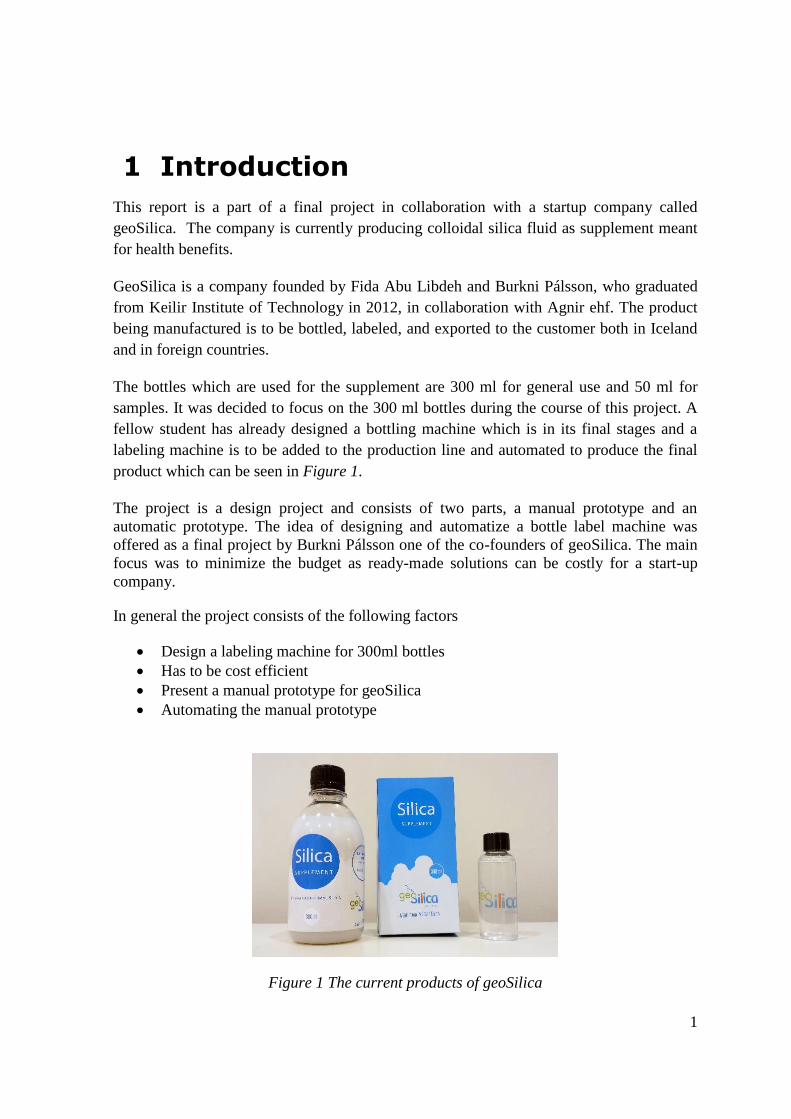
Figure 1 The current products of geoSilica .......................................................................... 1
Figure 2 JVL MST001A stepper motor [2] ............................................................................ 5
Figure 3 Adafruit Motor Shield [4] ....................................................................................... 8
Figure 4 Schematic of the design procedure ......................................................................... 9
Figure 5 Interoll 1100 series gravity rollers [5] ................................................................. 10
Figure 6 Autodesk Inventor illustration of the side plates .................................................. 11
Figure 7 The label roll assembly with no label roll ............................................................ 12
Figure 8 The label roll assembly with label roll ................................................................. 12
Figure 9 The brakes for the label roll ................................................................................. 13
Figure 10 The motor and belt assembly .............................................................................. 14
Figure 11 Top view of the full assembly .............................................................................. 15
Figure 12 A perspective front view of the assembly ............................................................ 15
Figure 13 The back of the machine from a perspective view .............................................. 16
Figure 14 The project plan .................................................................................................. 19
Figure 15 The problematic slots .......................................................................................... 21
Figure 16 Slots needed to remove and refill the label roll .................................................. 22
Figure 17 Motor, gear and belt assembly side view ........................................................... 22
Figure 18 Motor, gear and belt assembly top view ............................................................. 23
Figure 19 The Autodesk Inventor model of the gearwheel .................................................. 23
Figure 20 Lathed plastic bearing holder ............................................................................. 24
Figure 21 The peel plate in the making (to the left) and the completed peel plate with
the slot for the belt (to the right) ....................................................................... 25
Figure 22 The prototype program flowchart ....................................................................... 27
Figure 23 The next stage program flowchart ...................................................................... 28

XI
Tables
Table 1 The candidates of control system ............................................................................. 4
Table 2 The choices of motors ............................................................................................... 5
Table 3 JVL MST001A Specifications [2] ............................................................................. 6
Table 4 Comparison of different motor drives ...................................................................... 7
Table 5 Geckodrive G203V specifications [3] ....................................................................... 8
Table 6 Technical data of the Interoll 1100 series gravity rollers [5] ................................ 10
Table 7 The estimated cost of components .......................................................................... 17
Table 8 The hours spent on the project and cost ................................................................. 18
Table 9 The remaining tasks and cost ................................................................................. 31

XIII
Abbreviations
A Ampere commonly Amp or Amps (SI unit for electric current)
Arduino Einbrettistölva (e. single-board microcontroller,)
CNC Computerized Numerical Control
dwg File format for 2D drawings compatible with software such as AutoCad
Geckodrive A company which produces motor drives http://www.geckodrive.com
gr Grams
KIT Keilir Institute of Technology
Lasermate Software used to communicate to a CNC-Laser
mm Millimeters
PIC Peripheral Interface Controller
PLC Programmable Logic Controler
Plexiglass Poly(methyl methacrylate) PMMA acrylic glass
RPM Rounds per minute
USB Universal Serial Bus

XV
Acknowledgements
I want to thank geoSilica and their staff for their involvement in the project. Next I would
like to thank my family, my fiancée Svanhildur Sigríður Mar and my daughter Elena Mist
Hrafnsdóttir Mar, for their complete support and patience at times. Special thanks go to the
faculty at Keilir Institute of Technology; I want to mention Þorgeir Þorbjarnarsson for his
valuable assistance. Also I want to thank Hakkit for allowing me to use their workspace
and tools. Next I want to thank my uncle Davíð Ásgeirsson for his help and also my friend
and colleague Xabier Þór Tejero Landa. Last but not least I would like thank my instructor
Burkni Pálsson for his support and guidance.

1
1 Introduction
This report is a part of a final project in collaboration with a startup company called
geoSilica. The company is currently producing colloidal silica fluid as supplement meant
for health benefits.
GeoSilica is a company founded by Fida Abu Libdeh and Burkni Pálsson, who graduated
from Keilir Institute of Technology in 2012, in collaboration with Agnir ehf. The product
being manufactured is to be bottled, labeled, and exported to the customer both in Iceland
and in foreign countries.
The bottles which are used for the supplement are 300 ml for general use and 50 ml for
samples. It was decided to focus on the 300 ml bottles during the course of this project. A
fellow student has already designed a bottling machine which is in its final stages and a
labeling machine is to be added to the production line and automated to produce the final
product which can be seen in Figure 1.
The project is a design project and consists of two parts, a manual prototype and an
automatic prototype. The idea of designing and automatize a bottle label machine was
offered as a final project by Burkni Pálsson one of the co-founders of geoSilica. The main
focus was to minimize the budget as ready-made solutions can be costly for a start-up
company.
In general the project consists of the following factors
Design a labeling machine for 300ml bottles
Has to be cost efficient
Present a manual prototype for geoSilica
Automating the manual prototype
Figure 1 The current products of geoSilica

3
2 Requirements
The requirement of the project was to build a machine that could label 300 ml bottles with
65 mm wide labels. As the project proposal suggested, this was to be carried out first
manually and the automatically or at least semi-automatically. The main goals were as
follows:
Lightweight solution
Small and mobile
Cost efficient
The edges of the labels must be even
Reliability
Design according to standards
Low energy usage
Low budget
Those are the main goals of the requirements regarding the design and then later the build
itself.
2.1 Boundaries
The project plan was to build a manual prototype initially and then an automatic version of
the original design. This was to ensure geoSilica had the necessary tools for labeling the
first batch of silica supplement they were producing after the project had started.
The manual version was required to be finished and presented to geoSilica as soon as
possible as they needed it for their batch. Also it was to be hand driven and presented in
the mid-term presentation on the 26th
of March 2015.
The automatic version was expected to be finished during the course of the project or at
least be in its final stages.
The label currently used for the bottles comes on a roll with no spaces between labels this
would make sensing with an infrared emitter and a receiver setup more difficult. The
movement of the bottle would instead be achieved by using either a DC-motor with an
encoder or a stepper motor with a preset amount of steps.
2.2 Control system
The requirements regarding the electronics were mainly that the controller would be
chosen from one of the following solutions: a PIC circuit, an Arduino, a Raspberry Pi, or a
PLC. The main requirement was that it easily acquirable and easy to work with yet
efficient enough for a prototype. The main choices were based on what could be borrowed
and used from the school.
4
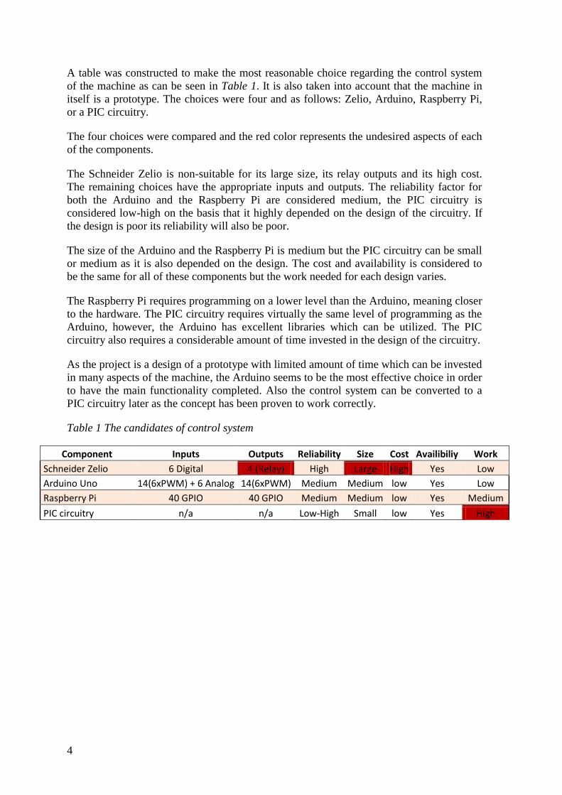
A table was constructed to make the most reasonable choice regarding the control system
of the machine as can be seen in Table 1. It is also taken into account that the machine in
itself is a prototype. The choices were four and as follows: Zelio, Arduino, Raspberry Pi,
or a PIC circuitry.
The four choices were compared and the red color represents the undesired aspects of each
of the components.
The Schneider Zelio is non-suitable for its large size, its relay outputs and its high cost.
The remaining choices have the appropriate inputs and outputs. The reliability factor for
both the Arduino and the Raspberry Pi are considered medium, the PIC circuitry is
considered low-high on the basis that it highly depended on the design of the circuitry. If
the design is poor its reliability will also be poor.
The size of the Arduino and the Raspberry Pi is medium but the PIC circuitry can be small
or medium as it is also depended on the design. The cost and availability is considered to
be the same for all of these components but the work needed for each design varies.
The Raspberry Pi requires programming on a lower level than the Arduino, meaning closer
to the hardware. The PIC circuitry requires virtually the same level of programming as the
Arduino, however, the Arduino has excellent libraries which can be utilized. The PIC
circuitry also requires a considerable amount of time invested in the design of the circuitry.
As the project is a design of a prototype with limited amount of time which can be invested
in many aspects of the machine, the Arduino seems to be the most effective choice in order
to have the main functionality completed. Also the control system can be converted to a
PIC circuitry later as the concept has been proven to work correctly.
Table 1 The candidates of control system
Component Inputs Outputs Reliability Size Cost Availibiliy Work
Schneider Zelio 6 Digital 4 (Relay) High Large High Yes Low
Arduino Uno 14(6xPWM) + 6 Analog 14(6xPWM) Medium Medium low Yes Low
Raspberry Pi 40 GPIO 40 GPIO Medium Medium low Yes Medium
PIC circuitry n/a n/a Low-High Small low Yes High
5
2.3 Motors
The machine requires two separate motors, one for the rotation of the bottle which is, as of
now, referred to as the drive motor, and a second one for gathering the excess adhesive
protective film, which is a waste product of the labels. The motors that could be chosen
from are a DC-motor, a Servo motor or a Stepper motor.
The DC-motor is capable of spinning very fast and controlling the rotations per minute
(RPM) can be troublesome without a voltage control. Also in order to be applied, it has to
be geared. The servo motor is more expensive than both the DC-motor and the Stepper
motor combined, and requires a controller. The Stepper motor is in the same price range as
a DC-motor but does not require a voltage control or any gearing. It is also lighter, uses
less energy, and is precise enough for this application. The conclusion is that a Stepper
motor will be utilized in the project.
Table 2 The choices of motors
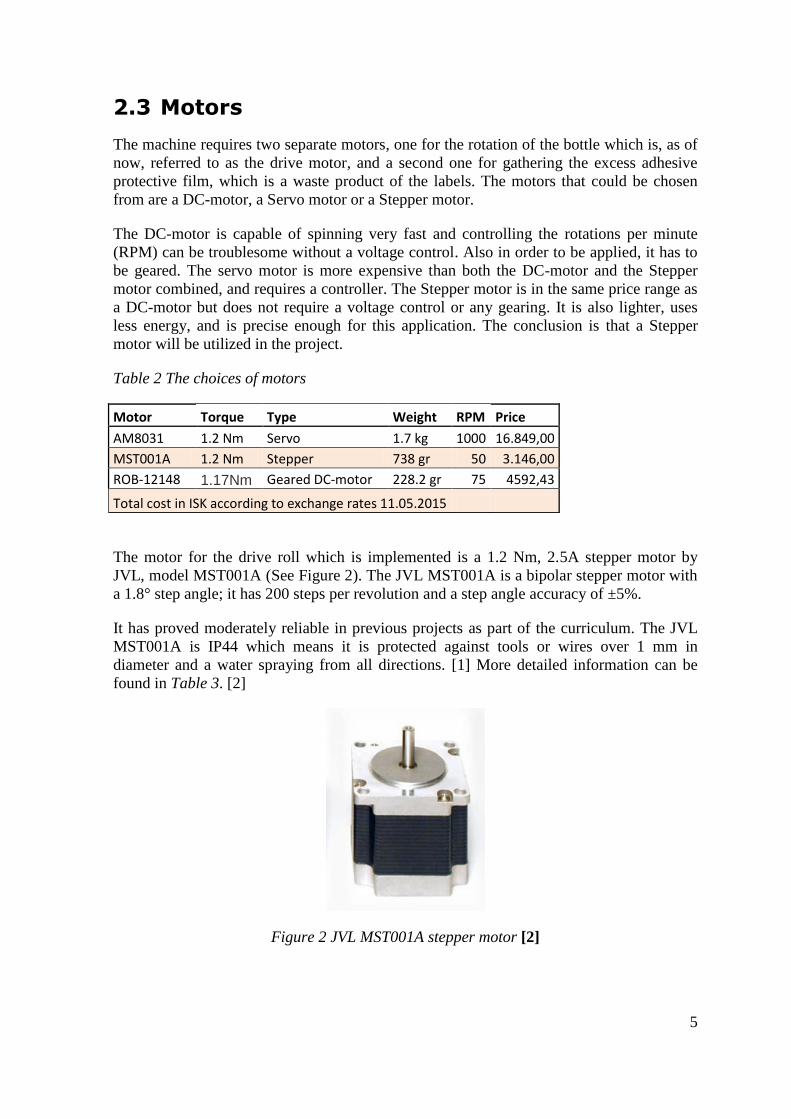
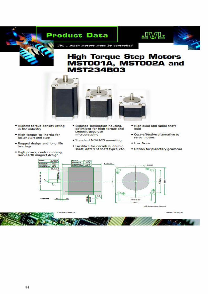
The motor for the drive roll which is implemented is a 1.2 Nm, 2.5A stepper motor by
JVL, model MST001A (See Figure 2). The JVL MST001A is a bipolar stepper motor with
a 1.8° step angle; it has 200 steps per revolution and a step angle accuracy of ±5%.
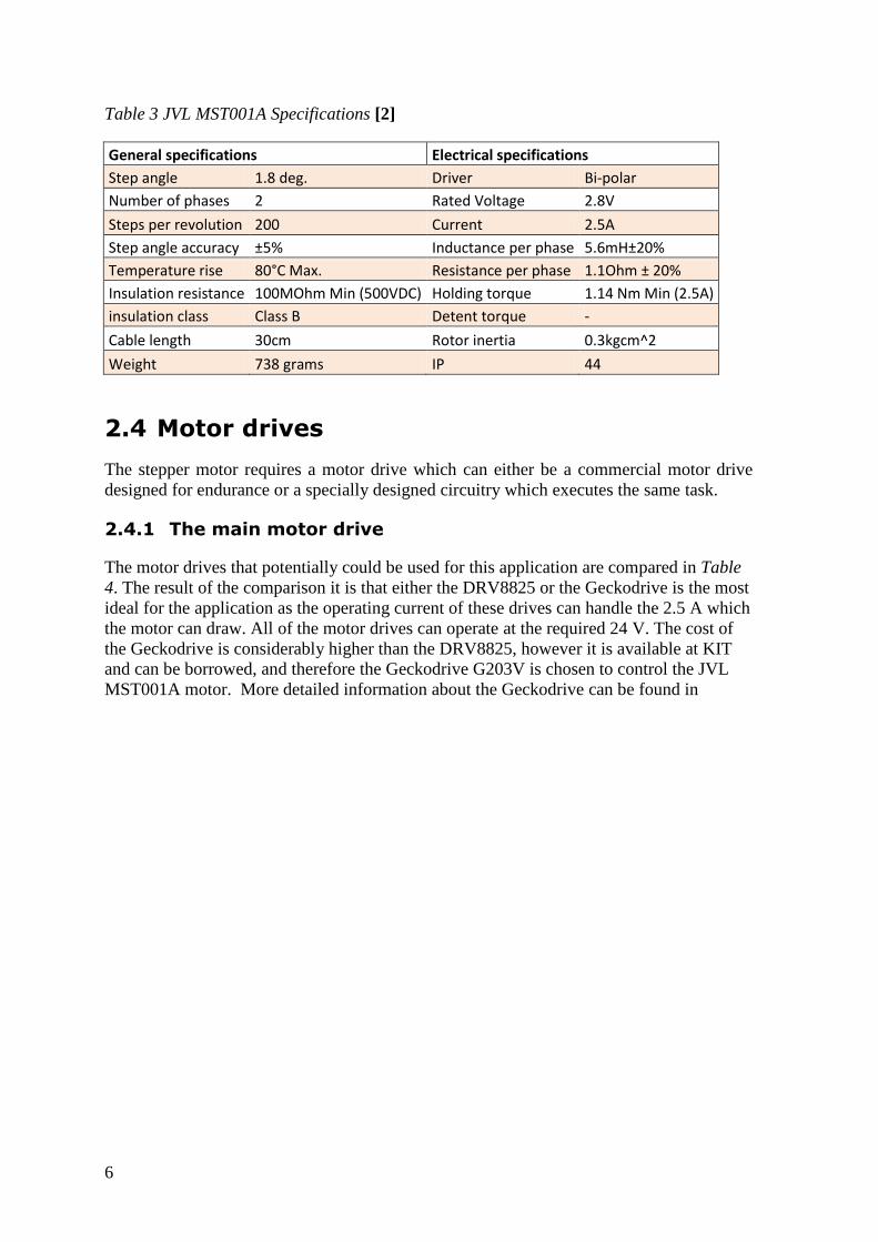
It has proved moderately reliable in previous projects as part of the curriculum. The JVL
MST001A is IP44 which means it is protected against tools or wires over 1 mm in
diameter and a water spraying from all directions. [1] More detailed information can be
found in Table 3. [2]
Figure 2 JVL MST001A stepper motor [2]
Motor Torque Type Weight RPM Price
AM8031 1.2 Nm Servo 1.7 kg 1000 16.849,00
MST001A 1.2 Nm Stepper 738 gr 50 3.146,00
ROB-12148 1.17Nm Geared DC-motor 228.2 gr 75 4592,43
Total cost in ISK according to exchange rates 11.05.2015
6
Table 3 JVL MST001A Specifications [2]
General specifications Electrical specifications
Step angle 1.8 deg. Driver Bi-polar
Number of phases 2 Rated Voltage 2.8V
Steps per revolution 200 Current 2.5A
Step angle accuracy ±5% Inductance per phase 5.6mH±20%
Temperature rise 80°C Max. Resistance per phase 1.1Ohm ± 20%
Insulation resistance 100MOhm Min (500VDC) Holding torque 1.14 Nm Min (2.5A)
insulation class Class B Detent torque -
Cable length 30cm Rotor inertia 0.3kgcm^2
Weight 738 grams IP 44
2.4 Motor drives
The stepper motor requires a motor drive which can either be a commercial motor drive
designed for endurance or a specially designed circuitry which executes the same task.
2.4.1 The main motor drive
The motor drives that potentially could be used for this application are compared in Table
4. The result of the comparison it is that either the DRV8825 or the Geckodrive is the most
ideal for the application as the operating current of these drives can handle the 2.5 A which
the motor can draw. All of the motor drives can operate at the required 24 V. The cost of
the Geckodrive is considerably higher than the DRV8825, however it is available at KIT
and can be borrowed, and therefore the Geckodrive G203V is chosen to control the JVL
MST001A motor. More detailed information about the Geckodrive can be found in
7
Table 5.
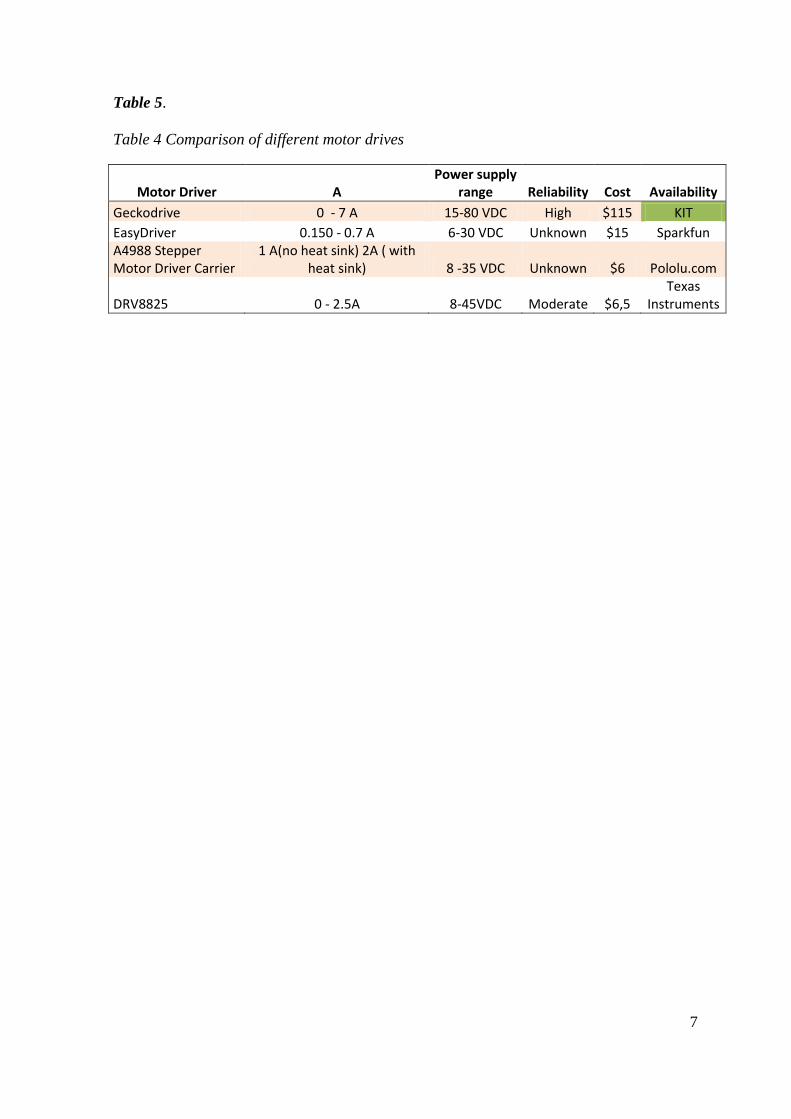
Table 4 Comparison of different motor drives
Motor Driver A Power supply
range Reliability Cost Availability
Geckodrive 0 - 7 A 15-80 VDC High $115 KIT
EasyDriver 0.150 - 0.7 A 6-30 VDC Unknown $15 Sparkfun A4988 Stepper Motor Driver Carrier
1 A(no heat sink) 2A ( with heat sink) 8 -35 VDC Unknown $6 Pololu.com
DRV8825 0 - 2.5A 8-45VDC Moderate $6,5 Texas
Instruments
8
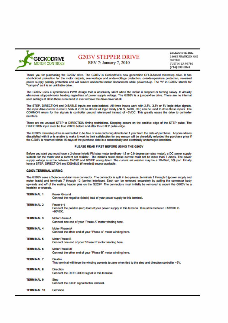
Table 5 Geckodrive G203V specifications [3]
Geckodrive Specifications
Supply Voltage 15 to 80 VDC
Phase Current 0 to 7 Amps
Step Frequency 0 to 333 kHz
Step Pulse “0” Time 2uS min (Step on rising edge)
Step Pulse “1” Time 1uS min
Direction Setup 200nS before step pulse rising edge
200nS hold after step pulse rising edge
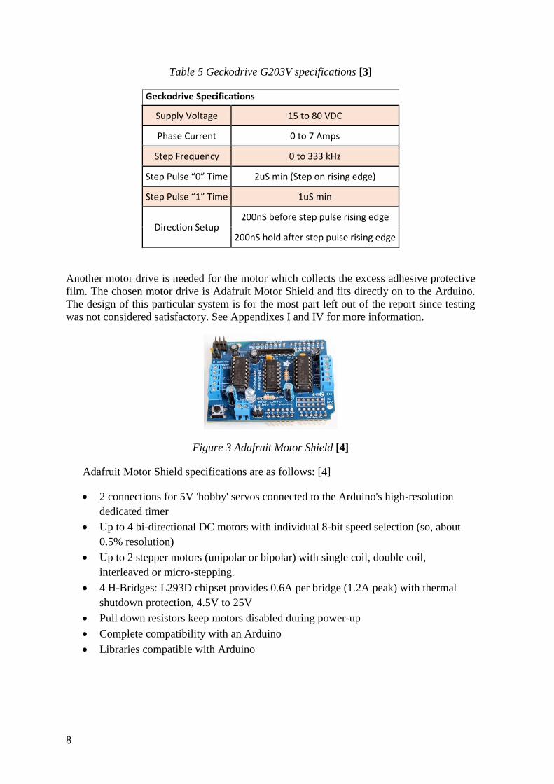
Another motor drive is needed for the motor which collects the excess adhesive protective
film. The chosen motor drive is Adafruit Motor Shield and fits directly on to the Arduino.
The design of this particular system is for the most part left out of the report since testing
was not considered satisfactory. See Appendixes I and IV for more information.
Figure 3 Adafruit Motor Shield [4]
Adafruit Motor Shield specifications are as follows: [4]
2 connections for 5V 'hobby' servos connected to the Arduino's high-resolution
dedicated timer
Up to 4 bi-directional DC motors with individual 8-bit speed selection (so, about
0.5% resolution)
Up to 2 stepper motors (unipolar or bipolar) with single coil, double coil,
interleaved or micro-stepping.
4 H-Bridges: L293D chipset provides 0.6A per bridge (1.2A peak) with thermal
shutdown protection, 4.5V to 25V
Pull down resistors keep motors disabled during power-up
Complete compatibility with an Arduino
Libraries compatible with Arduino
9
3 Design
The design was intended to be a light and cost efficient solution for labeling bottles. Parts
and materials were searched for in the workshop at KIT and included among other:
plexiglass, bolts, motors, and rollers with bearings from Interoll. Other parts were obtained
from the faculty, such as a motor shield and an Arduino. An Adafruit motor shield was
borrowed from a fellow student.
During the course of the design phase several sketches of how the machine could operate
were constructed using Autodesk Inventor, 3D CAD software commonly used for
prototyping and designing.
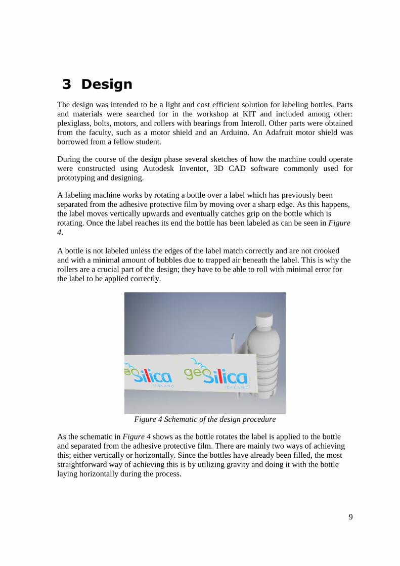
A labeling machine works by rotating a bottle over a label which has previously been
separated from the adhesive protective film by moving over a sharp edge. As this happens,
the label moves vertically upwards and eventually catches grip on the bottle which is
rotating. Once the label reaches its end the bottle has been labeled as can be seen in Figure
4.
A bottle is not labeled unless the edges of the label match correctly and are not crooked
and with a minimal amount of bubbles due to trapped air beneath the label. This is why the
rollers are a crucial part of the design; they have to be able to roll with minimal error for
the label to be applied correctly.
Figure 4 Schematic of the design procedure
As the schematic in Figure 4 shows as the bottle rotates the label is applied to the bottle
and separated from the adhesive protective film. There are mainly two ways of achieving
this; either vertically or horizontally. Since the bottles have already been filled, the most
straightforward way of achieving this is by utilizing gravity and doing it with the bottle
laying horizontally during the process.
10
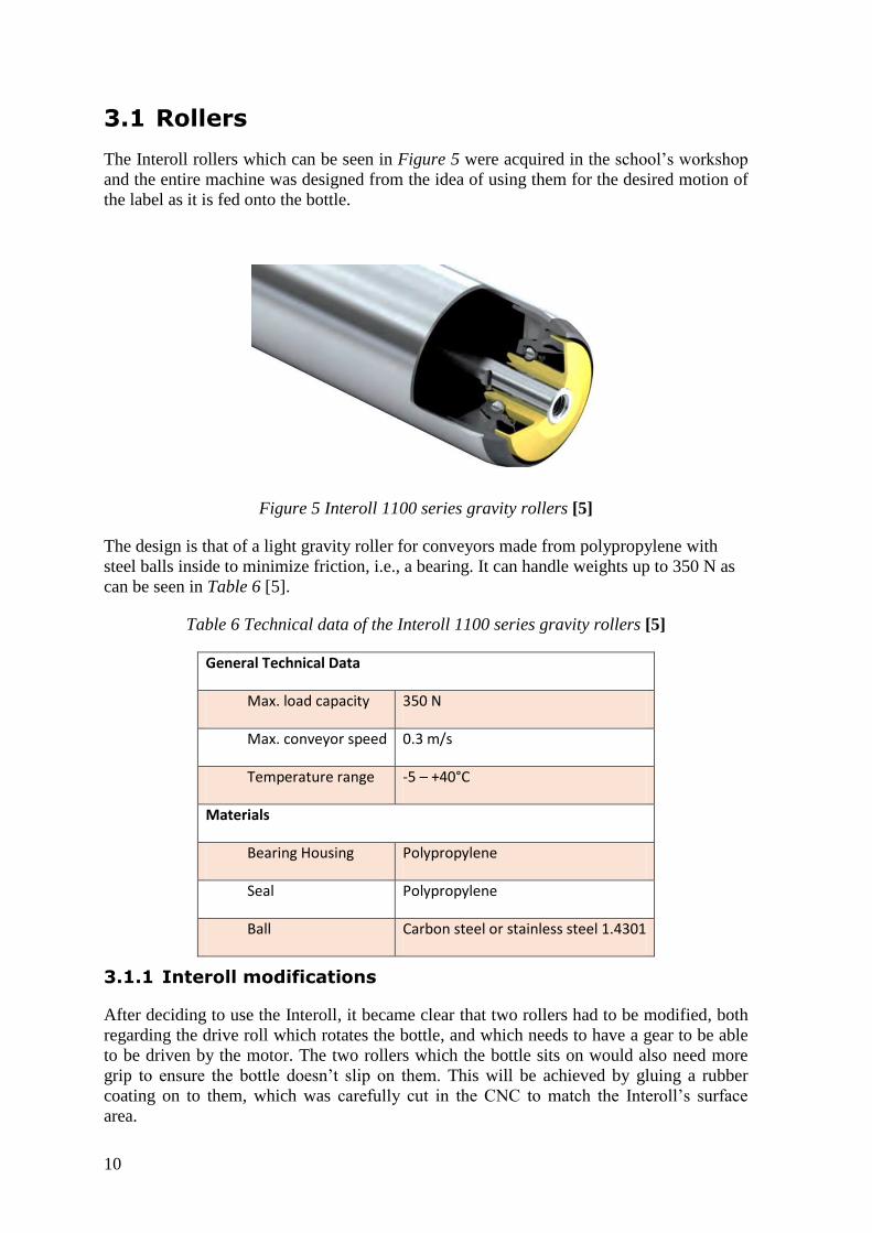
3.1 Rollers
The Interoll rollers which can be seen in Figure 5 were acquired in the school’s workshop
and the entire machine was designed from the idea of using them for the desired motion of
the label as it is fed onto the bottle.
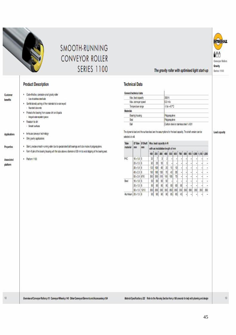
Figure 5 Interoll 1100 series gravity rollers [5]
The design is that of a light gravity roller for conveyors made from polypropylene with
steel balls inside to minimize friction, i.e., a bearing. It can handle weights up to 350 N as
can be seen in Table 6 [5].
Table 6 Technical data of the Interoll 1100 series gravity rollers [5]
General Technical Data
Max. load capacity 350 N
Max. conveyor speed 0.3 m/s
Temperature range -5 – +40°C
Materials
Bearing Housing Polypropylene
Seal Polypropylene
Ball Carbon steel or stainless steel 1.4301
3.1.1 Interoll modifications
After deciding to use the Interoll, it became clear that two rollers had to be modified, both
regarding the drive roll which rotates the bottle, and which needs to have a gear to be able
to be driven by the motor. The two rollers which the bottle sits on would also need more
grip to ensure the bottle doesn’t slip on them. This will be achieved by gluing a rubber
coating on to them, which was carefully cut in the CNC to match the Interoll’s surface
area.
11
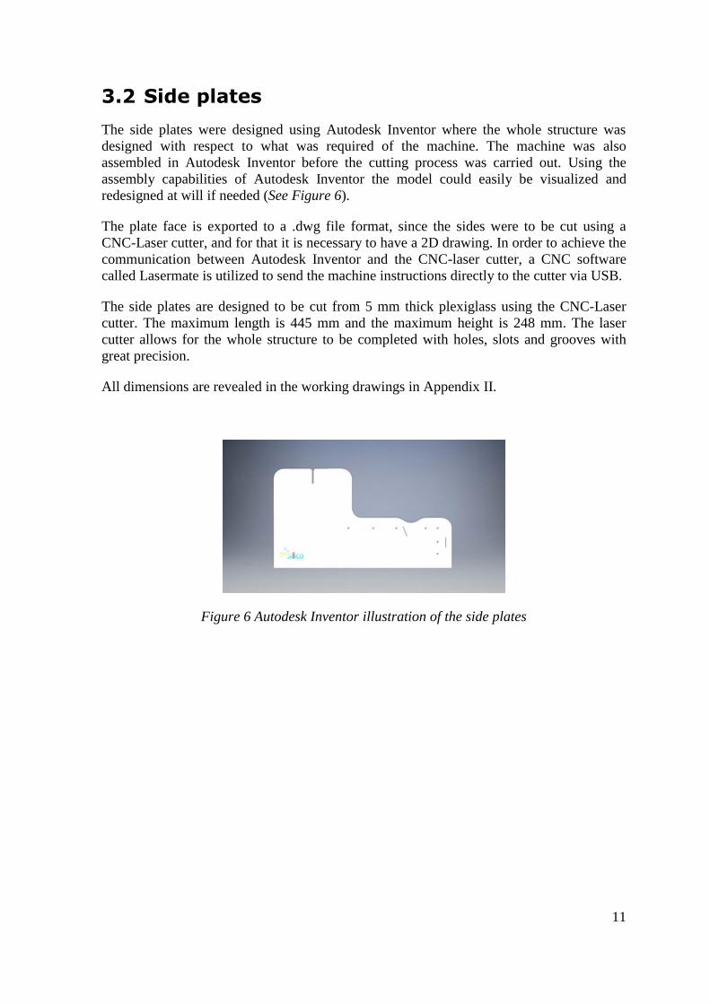
3.2 Side plates
The side plates were designed using Autodesk Inventor where the whole structure was
designed with respect to what was required of the machine. The machine was also
assembled in Autodesk Inventor before the cutting process was carried out. Using the
assembly capabilities of Autodesk Inventor the model could easily be visualized and
redesigned at will if needed (See Figure 6).
The plate face is exported to a .dwg file format, since the sides were to be cut using a
CNC-Laser cutter, and for that it is necessary to have a 2D drawing. In order to achieve the
communication between Autodesk Inventor and the CNC-laser cutter, a CNC software
called Lasermate is utilized to send the machine instructions directly to the cutter via USB.
The side plates are designed to be cut from 5 mm thick plexiglass using the CNC-Laser
cutter. The maximum length is 445 mm and the maximum height is 248 mm. The laser
cutter allows for the whole structure to be completed with holes, slots and grooves with
great precision.
All dimensions are revealed in the working drawings in Appendix II.
Figure 6 Autodesk Inventor illustration of the side plates
12
3.3 Label roller
The Interroll roller which holds the label roll feeds the label from the label roll which is
printed on a 40 mm diameter roll with 500 labels on it. The maximum diameter of the roll
is 120 mm but decreases as labels are applied to the bottles. The design of the sides allows
for rolls of up to a maximum of 200 mm, although it is quite extensive.
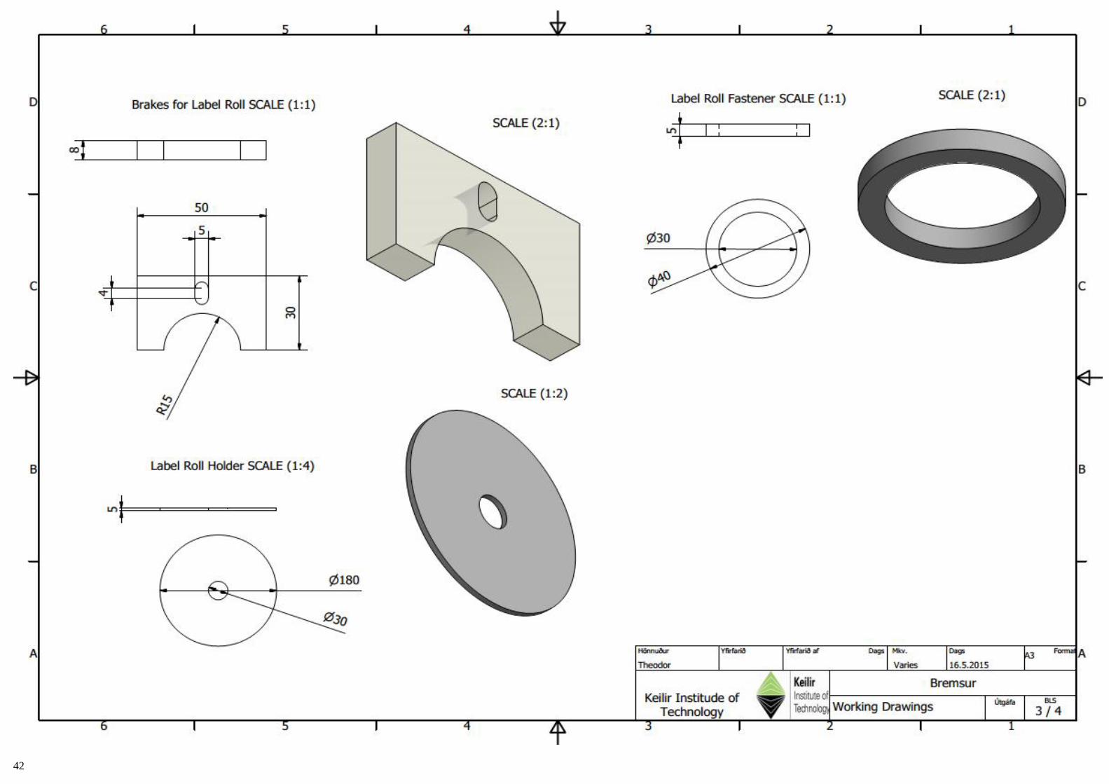
3.3.1 Roll holder
Since the label roll is 40 mm in diameter, it does not fit correctly on to the 30 mm in
diameter Interoll. In order to make sure it stays in place, a few fastening rings were cut
from a 5mm plexiglass with an outer diameter of 40 mm and an inner diameter of 29.95
mm (tight fit).
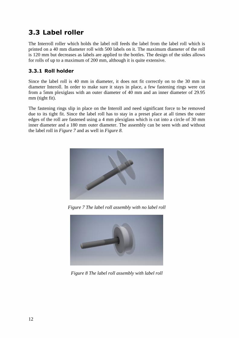
The fastening rings slip in place on the Interoll and need significant force to be removed
due to its tight fit. Since the label roll has to stay in a preset place at all times the outer
edges of the roll are fastened using a 4 mm plexiglass which is cut into a circle of 30 mm
inner diameter and a 180 mm outer diameter. The assembly can be seen with and without
the label roll in Figure 7 and as well in Figure 8.
Figure 7 The label roll assembly with no label roll
Figure 8 The label roll assembly with label roll
13
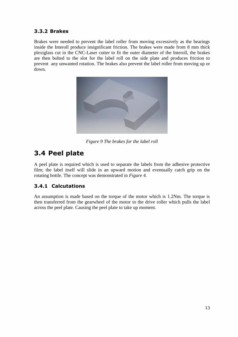
3.3.2 Brakes
Brakes were needed to prevent the label roller from moving excessively as the bearings
inside the Interoll produce insignificant friction. The brakes were made from 8 mm thick
plexiglass cut in the CNC-Laser cutter to fit the outer diameter of the Interoll, the brakes
are then bolted to the slot for the label roll on the side plate and produces friction to
prevent any unwanted rotation. The brakes also prevent the label roller from moving up or
down.
Figure 9 The brakes for the label roll
3.4 Peel plate
A peel plate is required which is used to separate the labels from the adhesive protective
film; the label itself will slide in an upward motion and eventually catch grip on the
rotating bottle. The concept was demonstrated in Figure 4.
3.4.1 Calcutations
An assumption is made based on the torque of the motor which is 1.2Nm. The torque is
then transferred from the gearwheel of the motor to the drive roller which pulls the label
across the peel plate. Causing the peel plate to take up moment.
14
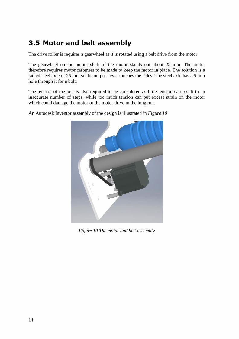
3.5 Motor and belt assembly
The drive roller is requires a gearwheel as it is rotated using a belt drive from the motor.
The gearwheel on the output shaft of the motor stands out about 22 mm. The motor
therefore requires motor fasteners to be made to keep the motor in place. The solution is a
lathed steel axle of 25 mm so the output never touches the sides. The steel axle has a 5 mm
hole through it for a bolt.
The tension of the belt is also required to be considered as little tension can result in an
inaccurate number of steps, while too much tension can put excess strain on the motor
which could damage the motor or the motor drive in the long run.
An Autodesk Inventor assembly of the design is illustrated in Figure 10
Figure 10 The motor and belt assembly
15
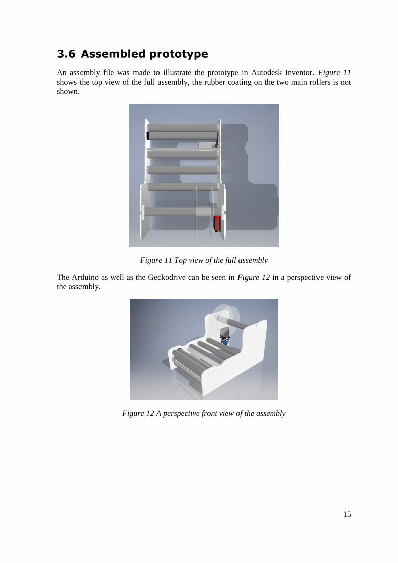
3.6 Assembled prototype
An assembly file was made to illustrate the prototype in Autodesk Inventor. Figure 11
shows the top view of the full assembly, the rubber coating on the two main rollers is not
shown.
Figure 11 Top view of the full assembly
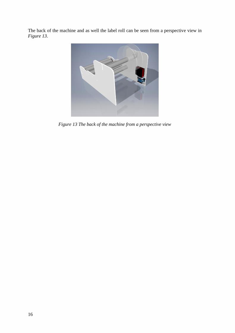
The Arduino as well as the Geckodrive can be seen in Figure 12 in a perspective view of
the assembly.
Figure 12 A perspective front view of the assembly
16
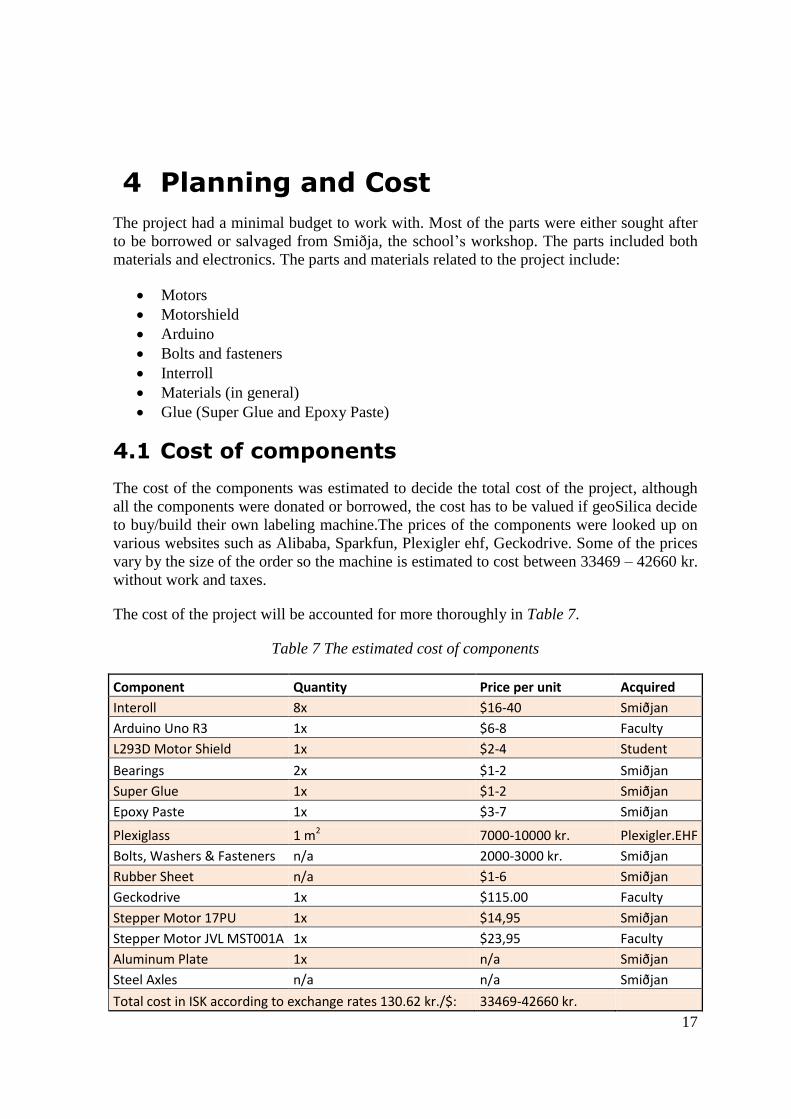
The back of the machine and as well the label roll can be seen from a perspective view in
Figure 13.
Figure 13 The back of the machine from a perspective view
17
4 Planning and Cost
The project had a minimal budget to work with. Most of the parts were either sought after
to be borrowed or salvaged from Smiðja, the school’s workshop. The parts included both
materials and electronics. The parts and materials related to the project include:
Motors
Motorshield
Arduino
Bolts and fasteners
Interroll
Materials (in general)
Glue (Super Glue and Epoxy Paste)
4.1 Cost of components
The cost of the components was estimated to decide the total cost of the project, although
all the components were donated or borrowed, the cost has to be valued if geoSilica decide
to buy/build their own labeling machine.The prices of the components were looked up on
various websites such as Alibaba, Sparkfun, Plexigler ehf, Geckodrive. Some of the prices
vary by the size of the order so the machine is estimated to cost between 33469 – 42660 kr.
without work and taxes.
The cost of the project will be accounted for more thoroughly in Table 7.
Table 7 The estimated cost of components
Component Quantity Price per unit Acquired
Interoll 8x $16-40 Smiðjan
Arduino Uno R3 1x $6-8 Faculty
L293D Motor Shield 1x $2-4 Student
Bearings 2x $1-2 Smiðjan
Super Glue 1x $1-2 Smiðjan
Epoxy Paste 1x $3-7 Smiðjan
Plexiglass 1 m2 7000-10000 kr. Plexigler.EHF
Bolts, Washers & Fasteners n/a 2000-3000 kr. Smiðjan
Rubber Sheet n/a $1-6 Smiðjan
Geckodrive 1x $115.00 Faculty
Stepper Motor 17PU 1x $14,95 Smiðjan
Stepper Motor JVL MST001A 1x $23,95 Faculty
Aluminum Plate 1x n/a Smiðjan
Steel Axles n/a n/a Smiðjan
Total cost in ISK according to exchange rates 130.62 kr./$: 33469-42660 kr.
18
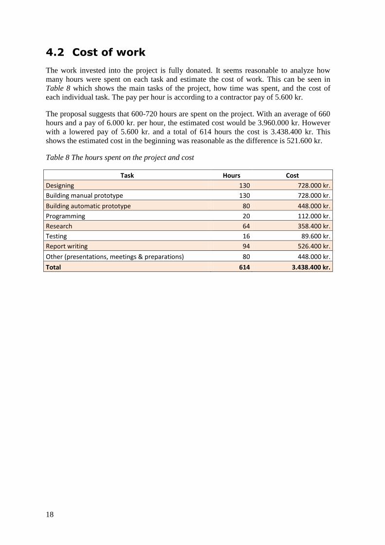
4.2 Cost of work
The work invested into the project is fully donated. It seems reasonable to analyze how
many hours were spent on each task and estimate the cost of work. This can be seen in
Table 8 which shows the main tasks of the project, how time was spent, and the cost of
each individual task. The pay per hour is according to a contractor pay of 5.600 kr.
The proposal suggests that 600-720 hours are spent on the project. With an average of 660
hours and a pay of 6.000 kr. per hour, the estimated cost would be 3.960.000 kr. However
with a lowered pay of 5.600 kr. and a total of 614 hours the cost is 3.438.400 kr. This
shows the estimated cost in the beginning was reasonable as the difference is 521.600 kr.
Table 8 The hours spent on the project and cost
Task Hours Cost
Designing 130 728.000 kr.
Building manual prototype 130 728.000 kr.
Building automatic prototype 80 448.000 kr.
Programming 20 112.000 kr.
Research 64 358.400 kr.
Testing 16 89.600 kr.
Report writing 94 526.400 kr.
Other (presentations, meetings & preparations) 80 448.000 kr.
Total 614 3.438.400 kr.
19
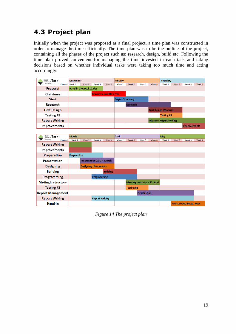
4.3 Project plan
Initially when the project was proposed as a final project, a time plan was constructed in
order to manage the time efficiently. The time plan was to be the outline of the project,
containing all the phases of the project such as: research, design, build etc. Following the
time plan proved convenient for managing the time invested in each task and taking
decisions based on whether individual tasks were taking too much time and acting
accordingly.
Figure 14 The project plan

21
5 Build
The build was carried out in the workshop at Keilir Institute of Technology; however some
parts required a laser-cutter, to which access was granted at Hakkit, the makerspace at
Eldey. Smiðjan, the school’s workshop, had most of the tools and materials needed for
building the mechanical aspect of the machine. Also, most of the materials were scavenged
from there, such as: plexiglass, bolts, motors, axles, etc. Hakkit has the tools required to
laser cut and as well to 3-D print, and in addition it has most of the hand tools needed for
assembling the machine.
5.1 Side Plates
The original design of the prototype was to be built from 25 mm (plastic) which proved to
be very difficult to work with as the CNC-laser cutter was not able to cut through it and the
tools available were not precise enough when handling such material.
Another direction was decided to be taken considering materials for the sides of the
machine and a 5 mm thick plexiglass donated to KIT by Plexigler.ehf was utilized instead.
Considering the fact that the machine is to be used in food production, the white surface
will indicate when cleaning is needed. The plexiglass is also lighter and the manual
prototype weighs less than a kilogram when assembled, making it extremely mobile. In
case the sides are damaged, they are easy to replace by simply cutting a new one in the
laser cutter.
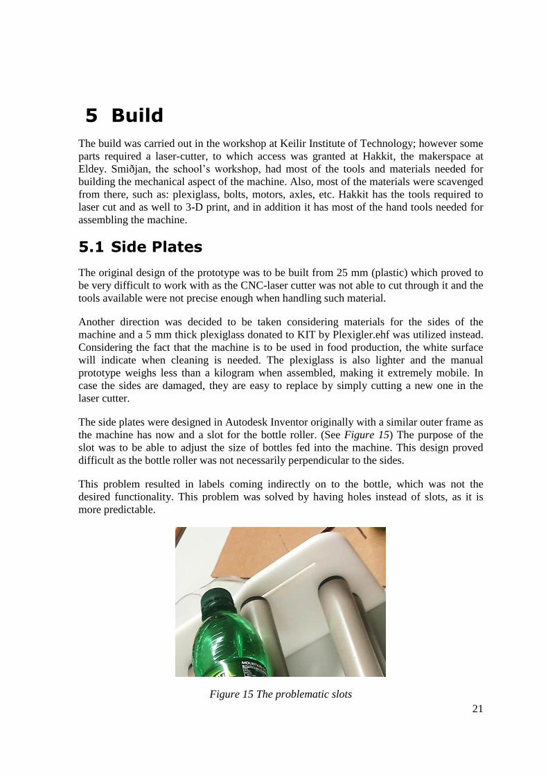
The side plates were designed in Autodesk Inventor originally with a similar outer frame as
the machine has now and a slot for the bottle roller. (See Figure 15) The purpose of the
slot was to be able to adjust the size of bottles fed into the machine. This design proved
difficult as the bottle roller was not necessarily perpendicular to the sides.
This problem resulted in labels coming indirectly on to the bottle, which was not the
desired functionality. This problem was solved by having holes instead of slots, as it is
more predictable.
Figure 15 The problematic slots
22
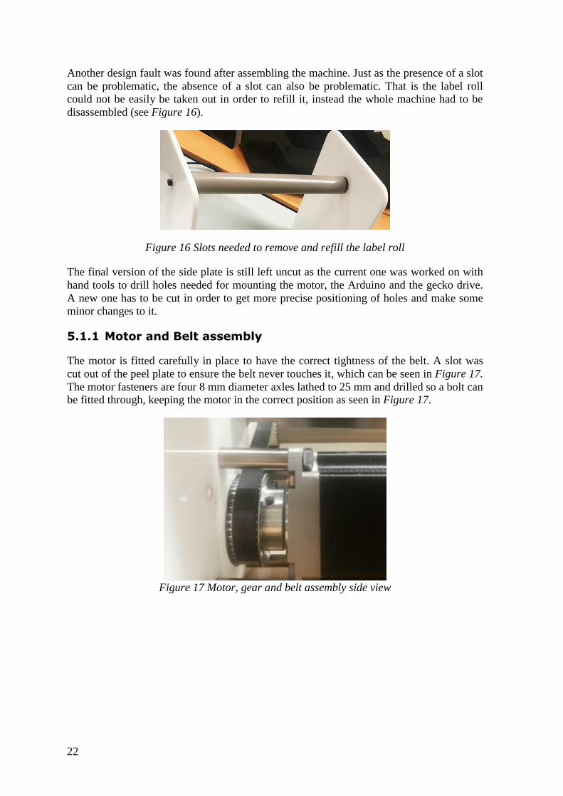
Another design fault was found after assembling the machine. Just as the presence of a slot
can be problematic, the absence of a slot can also be problematic. That is the label roll
could not be easily be taken out in order to refill it, instead the whole machine had to be
disassembled (see Figure 16).
Figure 16 Slots needed to remove and refill the label roll
The final version of the side plate is still left uncut as the current one was worked on with
hand tools to drill holes needed for mounting the motor, the Arduino and the gecko drive.
A new one has to be cut in order to get more precise positioning of holes and make some
minor changes to it.
5.1.1 Motor and Belt assembly
The motor is fitted carefully in place to have the correct tightness of the belt. A slot was
cut out of the peel plate to ensure the belt never touches it, which can be seen in Figure 17.
The motor fasteners are four 8 mm diameter axles lathed to 25 mm and drilled so a bolt can
be fitted through, keeping the motor in the correct position as seen in Figure 17.
Figure 17 Motor, gear and belt assembly side view
23
Figure 18 Motor, gear and belt assembly top view
5.2 Interoll modifications
For the roller which rotates the bottle, one Interoll roller had to be modified to get the
desired results. The motor has to be able to spin the roller which will in turn rotate the
bottle as well. The roller has to have limited amount of uncertainties such as bumps or
incorrect rotation. This can be accomplished by using bearings to make sure the axle
rotates freely and evenly on both ends.
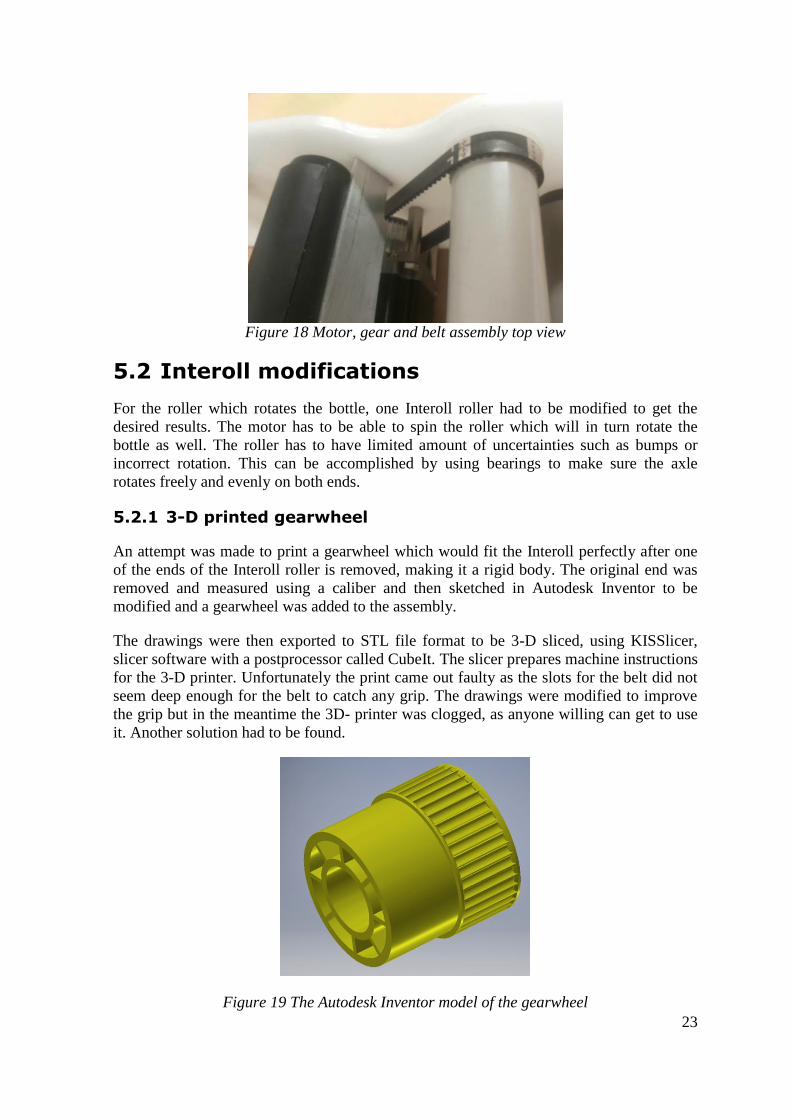
5.2.1 3-D printed gearwheel
An attempt was made to print a gearwheel which would fit the Interoll perfectly after one
of the ends of the Interoll roller is removed, making it a rigid body. The original end was
removed and measured using a caliber and then sketched in Autodesk Inventor to be
modified and a gearwheel was added to the assembly.
The drawings were then exported to STL file format to be 3-D sliced, using KISSlicer,
slicer software with a postprocessor called CubeIt. The slicer prepares machine instructions
for the 3-D printer. Unfortunately the print came out faulty as the slots for the belt did not
seem deep enough for the belt to catch any grip. The drawings were modified to improve
the grip but in the meantime the 3D- printer was clogged, as anyone willing can get to use
it. Another solution had to be found.
Figure 19 The Autodesk Inventor model of the gearwheel
24
5.2.2 Gearwheel assembly
The problem with the 3D-printer was resolved by modifying a gearwheel from an old
printer found in the school’s workshop. This was the only gearwheel which the belt fitted
and of the correct size to fit the end of the Interoll. Since the gearwheel did not have the
fittings that the 3D-printed design would have had, it was decided to glue it to the Interoll
using an epoxy paste.
5.2.3 Rubber layer
In order to ensure a sufficient grip of the rollers which rotate the bottle. A rubber layer is
cut into a rectangle of 94.24 mm x 1100 mm with a laser cutter to match the surface area of
the roller. The rubber coating is then glued to the Interoll. This will ensure that the bottle
rotates correctly and that the coating is a perfect fit.
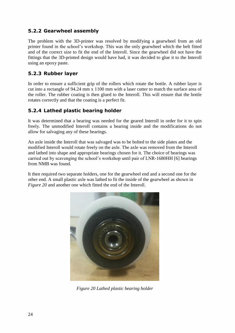
5.2.4 Lathed plastic bearing holder
It was determined that a bearing was needed for the geared Interoll in order for it to spin
freely. The unmodified Interoll contains a bearing inside and the modifications do not
allow for salvaging any of these bearings.
An axle inside the Interoll that was salvaged was to be bolted to the side plates and the
modified Interoll would rotate freely on the axle. The axle was removed from the Interoll
and lathed into shape and appropriate bearings chosen for it. The choice of bearings was
carried out by scavenging the school’s workshop until pair of LNR-1680HH [6] bearings
from NMB was found.
It then required two separate holders, one for the gearwheel end and a second one for the
other end. A small plastic axle was lathed to fit the inside of the gearwheel as shown in
Figure 20 and another one which fitted the end of the Interoll.
Figure 20 Lathed plastic bearing holder
25
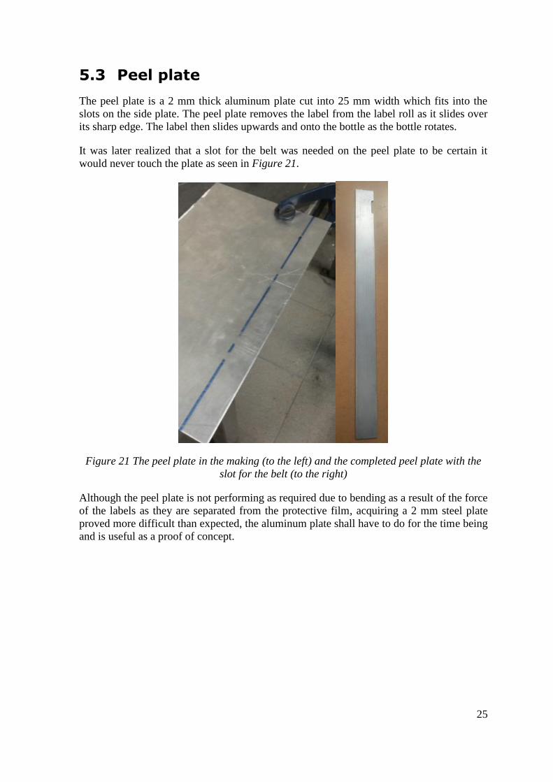
5.3 Peel plate
The peel plate is a 2 mm thick aluminum plate cut into 25 mm width which fits into the
slots on the side plate. The peel plate removes the label from the label roll as it slides over
its sharp edge. The label then slides upwards and onto the bottle as the bottle rotates.
It was later realized that a slot for the belt was needed on the peel plate to be certain it
would never touch the plate as seen in Figure 21.
Figure 21 The peel plate in the making (to the left) and the completed peel plate with the
slot for the belt (to the right)
Although the peel plate is not performing as required due to bending as a result of the force
of the labels as they are separated from the protective film, acquiring a 2 mm steel plate
proved more difficult than expected, the aluminum plate shall have to do for the time being
and is useful as a proof of concept.

27
6 Programming
The programming can be described as the brain of the machine. It‘s logic is simply a few
lines of code in the Arduino‘s memory. In the current state of the project, the program is
not completed; however it is designed to be simple yet efficient enough for a single bottle
fed into the machine at a given time.
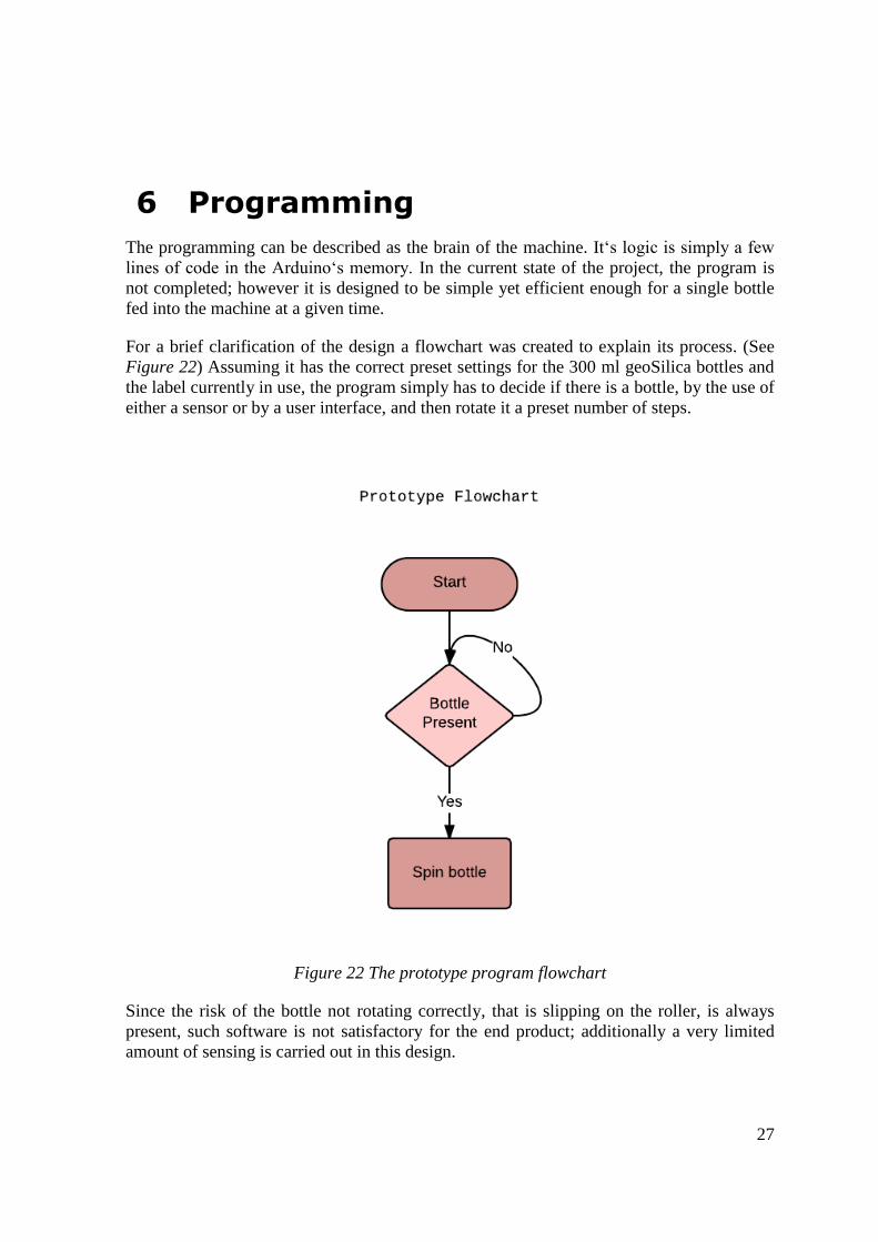
For a brief clarification of the design a flowchart was created to explain its process. (See
Figure 22) Assuming it has the correct preset settings for the 300 ml geoSilica bottles and
the label currently in use, the program simply has to decide if there is a bottle, by the use of
either a sensor or by a user interface, and then rotate it a preset number of steps.
Figure 22 The prototype program flowchart
Since the risk of the bottle not rotating correctly, that is slipping on the roller, is always
present, such software is not satisfactory for the end product; additionally a very limited
amount of sensing is carried out in this design.
28
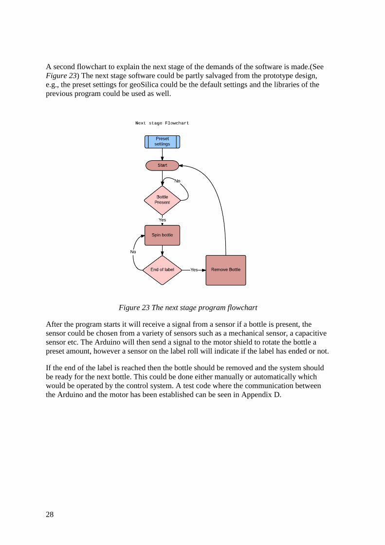
A second flowchart to explain the next stage of the demands of the software is made.(See
Figure 23) The next stage software could be partly salvaged from the prototype design,
e.g., the preset settings for geoSilica could be the default settings and the libraries of the
previous program could be used as well.
Figure 23 The next stage program flowchart
After the program starts it will receive a signal from a sensor if a bottle is present, the
sensor could be chosen from a variety of sensors such as a mechanical sensor, a capacitive
sensor etc. The Arduino will then send a signal to the motor shield to rotate the bottle a
preset amount, however a sensor on the label roll will indicate if the label has ended or not.
If the end of the label is reached then the bottle should be removed and the system should
be ready for the next bottle. This could be done either manually or automatically which
would be operated by the control system. A test code where the communication between
the Arduino and the motor has been established can be seen in Appendix D.
29
7 Testing
Testing the manual version proved considerably important for constructing the automatic
version. It consists of mostly the same parts since it was designed to be easily modifiable
into a semi-automatic or a fully automatic version.
The manual prototype was presented to geoSilica before the making of the automatic
prototype had started. Although it lacked some minor revisions, it seemed to work as
expected. The label was correctly placed onto the bottles most of the time and it was a big
upgrade from doing it by hand as they currently do it.
One flaw in the design was the strength of the peel plate, which was a 2 mm aluminum
plate; the thickness was too small for this material which caused the plate to bend when
subjected to the load of the rolling label. As an effect, it caused the label to be positioned
inaccurately on the bottle. The problem can be revised by adding a 90° bend on the peel
plate which will make the peel plate less susceptible to bending moments. The problem can
also be fixed by replacing the aluminum plate with a steel plate as originally intended.
Since the highest bending moment is concentrated in the middle of the plate [7], the bottle
was placed as close to the side plates as possible and that seemed to lessen the effect. The
problem has yet to be resolved by either replacing the peel plate with a stronger material or
re-designing it altogether.
Further tests are needed for the automatic version since it is not entirely completed.
However the communication between the motor shield, the motor and the Arduino has
been established at this point, so figuring out the correct settings should be an easy exercise
given some amount of time, which unfortunately has been invested into other parts of the
project.

31
8 Conclusion
A functioning manual prototype has been turned in to geoSilica and it can label a minimal
amount of bottles per hour replacing their current way of labeling by hand. The design still
needs some minor tweaks like for example a bottle holder which pushes the bottles down
while it is being labeled to ensure no unforeseen movement occurs, such as bumping or
slipping. The peel plate has to be strengthened or replaced as it seems to bend a bit when
bottles are being labeled near the center of the machine; however its function is adequate
near the side plates.
Time management was a problem during the course of the project which delayed parts that
needn’t to be delayed such as the programming part and the mere finishing touches. This
could be finished within a week given the time.
The labeling machine is a gift for geoSilica since ready-made labeling machines can be
costly for a startup company. The cost of the project was less than estimated initially in the
project proposal, both in terms of components and in terms of work invested in the project.
The automated prototype is currently on track but not fully completed. The tasks left for
the future are listed in the future plans section.
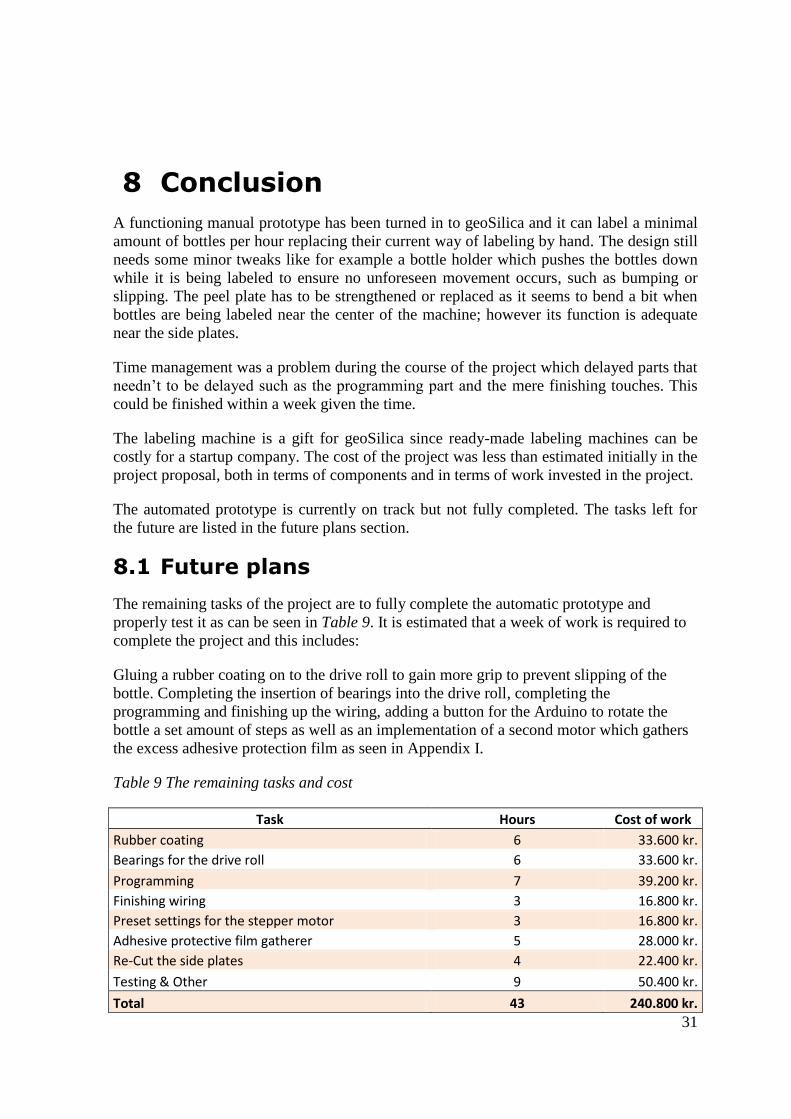
8.1 Future plans
The remaining tasks of the project are to fully complete the automatic prototype and
properly test it as can be seen in Table 9. It is estimated that a week of work is required to
complete the project and this includes:
Gluing a rubber coating on to the drive roll to gain more grip to prevent slipping of the
bottle. Completing the insertion of bearings into the drive roll, completing the
programming and finishing up the wiring, adding a button for the Arduino to rotate the
bottle a set amount of steps as well as an implementation of a second motor which gathers
the excess adhesive protection film as seen in Appendix I.
Table 9 The remaining tasks and cost
Task Hours Cost of work
Rubber coating 6 33.600 kr.
Bearings for the drive roll 6 33.600 kr.
Programming 7 39.200 kr.
Finishing wiring 3 16.800 kr.
Preset settings for the stepper motor 3 16.800 kr.
Adhesive protective film gatherer 5 28.000 kr.
Re-Cut the side plates 4 22.400 kr.
Testing & Other 9 50.400 kr.
Total 43 240.800 kr.

33
9 Discussion
The project developed from an idea and an extensive time plan in the proposal and into a
practically completed prototype. With minimal amount of work left, it is certain that the
machine can be completed in roughly a week. As the time plan in the future plans section
of the report states, this could be a project carried out in a three week course which the
author currently has remaining according to the school’s curriculum.
This three week project could consist of a proposal finishing the remaining tasks of the
project, a report and a defense. This would allow for a fully functional prototype to be
presented to geoSilica.
The time plan of the project held for the most part, however, the project required an
excessive amount of work in a relatively short amount of time. The task of estimating how
much time would actually be spent on the building of the machine proved to be inaccurate.
The building process required three versions of the side plates to be completed and that
delayed the project considerably.
Although some tasks of the project were incomplete, a fully functional manual prototype
was presented at the midterm presentation on the progress of the final project, and will
most likely be used at geoSilica for the time being.
The project went surprisingly well regarding the gathering materials and equipment in
order to complete the prototype and the school’s workshop proved invaluable for the
project as a lot of time was spent scavenging the school’s supplies.
In conclusion the prototype can be completed in a short amount of time and a fully
functional labeling machine can be presented to geoSilica which they urgently need.

35
Bibliography
[1] Hoffman Enclosures Inc., "Standards CE and IEC Classifications," Technical
Information 2003.
[2] JVL Industri Elektronik A/S, "High Torque Step Motors MST0001A, MST002A and
MST234B03," Denmark, 2005.
[3] Geckodrive Motor Controls, "Gecko Drive G203V," Datasheet 2010. [Online].
http://www.geckodrive.com
[4] Adafruit Industries, "Adafruit Motor Shield," 2014.
[5] Interroll, "Smooth-running conveyor roller series 1100," Datasheet.
[6] NMB Minebea, "Ball bearings," Catalogue 2008.
[7] R.C. Hibbeler, Statics and mechanics of materials, Third Edition ed. Singapore:
Prentice Hall, 2011.
[8] www.raspberrypi.org. Raspberry PI 2 Model B. [Online].
https://www.raspberrypi.org/products/raspberry-pi-2-model-b/
[9] Richard Gordon Budynas and Keith J. Nisbett, Shigley's Mechanical Engineering
Design.: McGraw-Hill, 2008.

37
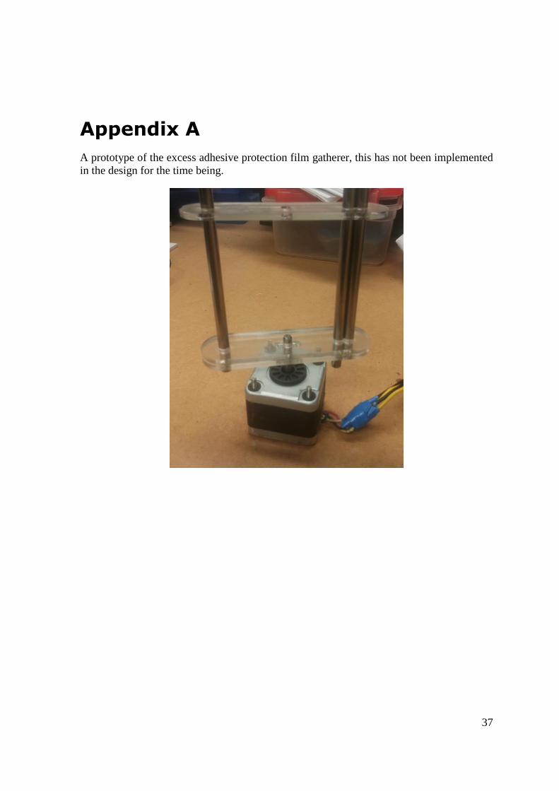
Appendix A
A prototype of the excess adhesive protection film gatherer, this has not been implemented
in the design for the time being.

38
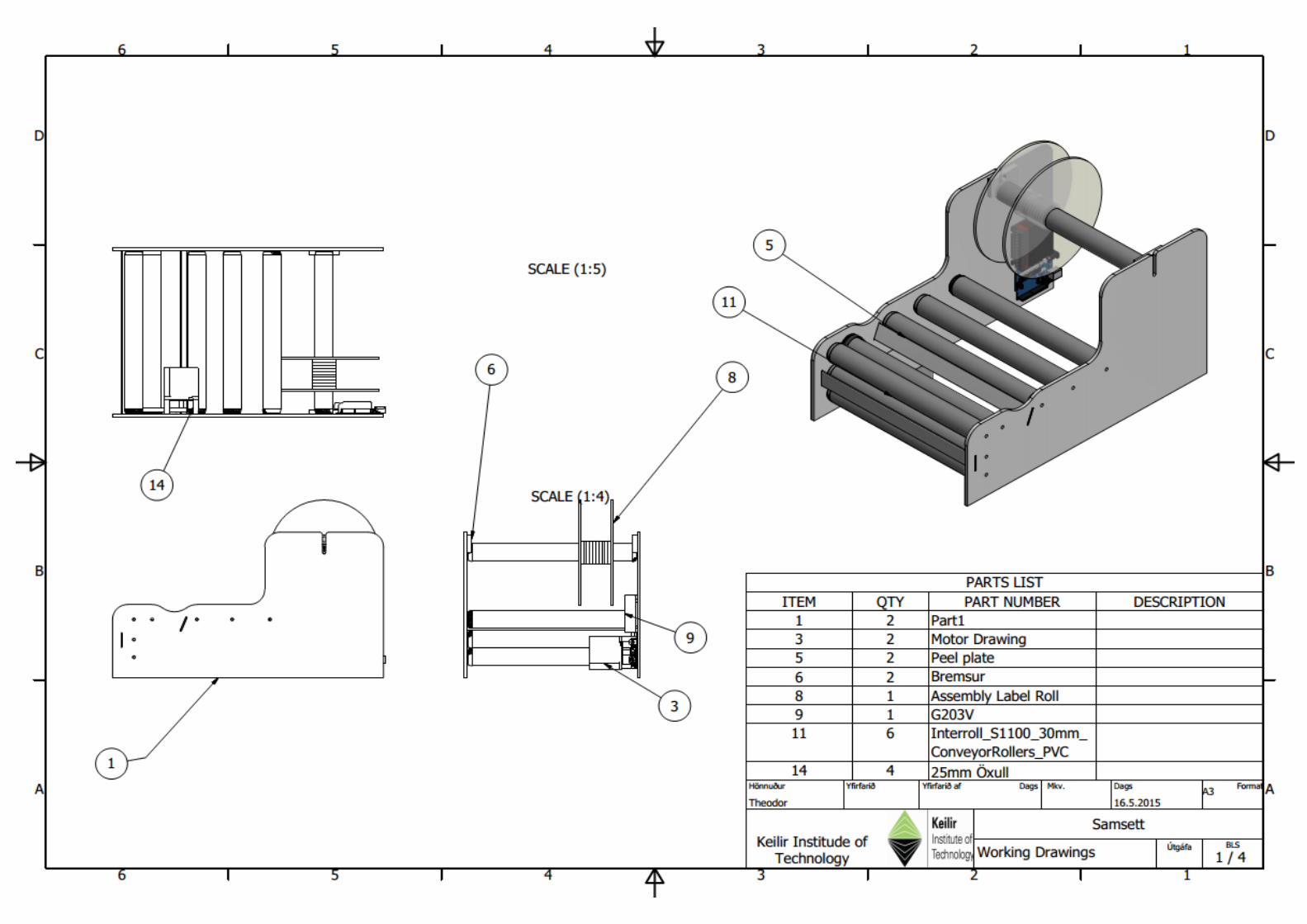
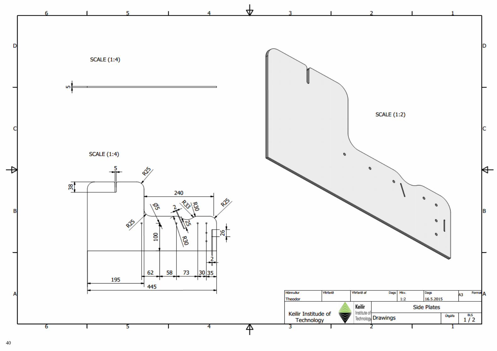
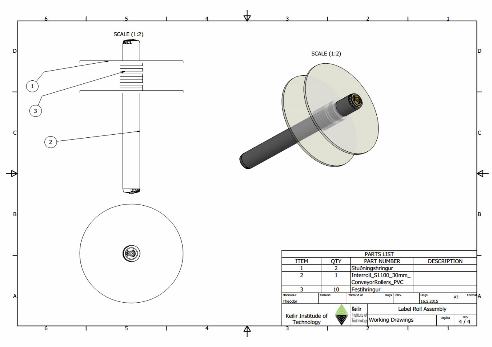
Appendix B
The next four pages are of the size A3 with working drawings of the labeling machine.
39
40
41
42

43
Appendix C
The first page of various datasheets and information used in the project.
44
45
46
47

49
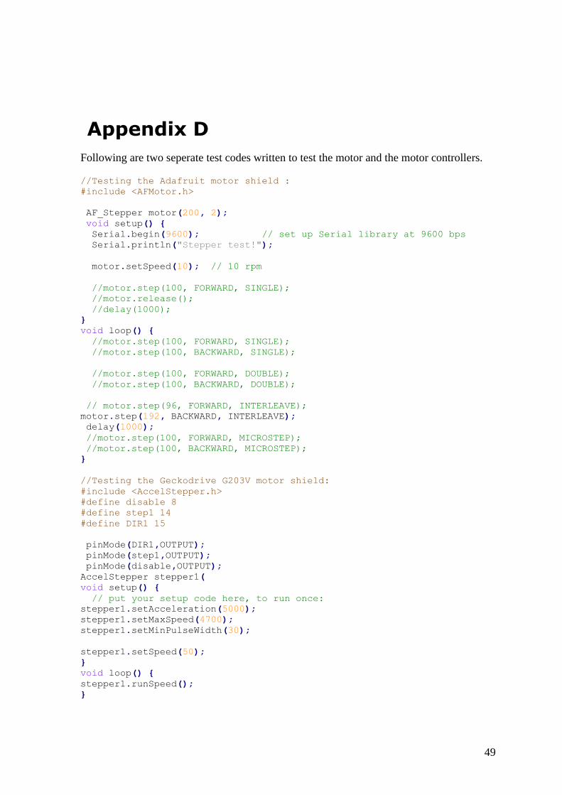
Appendix D
Following are two seperate test codes written to test the motor and the motor controllers.
//Testing the Adafruit motor shield :
#include <AFMotor.h>
AF_Stepper motor(200, 2);
void setup() {
Serial.begin(9600); // set up Serial library at 9600 bps
Serial.println("Stepper test!");
motor.setSpeed(10); // 10 rpm
//motor.step(100, FORWARD, SINGLE);
//motor.release();
//delay(1000);
}
void loop() {
//motor.step(100, FORWARD, SINGLE);
//motor.step(100, BACKWARD, SINGLE);
//motor.step(100, FORWARD, DOUBLE);
//motor.step(100, BACKWARD, DOUBLE);
// motor.step(96, FORWARD, INTERLEAVE);
motor.step(192, BACKWARD, INTERLEAVE);
delay(1000);
//motor.step(100, FORWARD, MICROSTEP);
//motor.step(100, BACKWARD, MICROSTEP);
}
//Testing the Geckodrive G203V motor shield:
#include <AccelStepper.h>
#define disable 8
#define step1 14
#define DIR1 15
pinMode(DIR1,OUTPUT);
pinMode(step1,OUTPUT);
pinMode(disable,OUTPUT);
AccelStepper stepper1(
void setup() {
// put your setup code here, to run once:
stepper1.setAcceleration(5000);
stepper1.setMaxSpeed(4700);
stepper1.setMinPulseWidth(30);
stepper1.setSpeed(50);
}
void loop() {
stepper1.runSpeed();
}