Embed Size (px)
Citation preview
Remote-adjustableRadiator Controller
HR 40 FMounting and Operation

Content
1
ContentOverview 3Mounting 5
Selecting the mounting site 5Mounting the drive unit 5Mounting the operating unit 11Connecting the operating unit and the drive unit 11Inserting batteries into the operating unit 13Setting the date and time 14
Operation 15Display and operating elements at the operating unit 15Changing the setpoint temperature at the adjusting ring 16Changing the operating modes 17Automatic functions 18Emergency operation when the batteries are flat 19Disabling the Roomtronic (child-proofing) 19
Adapting 20Adapting the comfort and economy temperatures 21Adapting the heating and economy periods 22Adaptation at the radiator valve 25
Appendix 27Technical data 27Dimensions and drilling scheme operating unit 28
Content
2
Adapters for the drive unit 29Help with problems 30Glossary 33
Overview
3
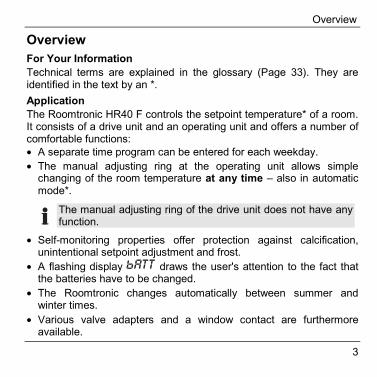
OverviewFor Your InformationTechnical terms are explained in the glossary (Page 33). They areidentified in the text by an *.ApplicationThe Roomtronic HR40 F controls the setpoint temperature* of a room.It consists of a drive unit and an operating unit and offers a number ofcomfortable functions:• A separate time program can be entered for each weekday.• The manual adjusting ring at the operating unit allows simple
changing of the room temperature at any time – also in automaticmode*.
The manual adjusting ring of the drive unit does not have anyfunction.
• Self-monitoring properties offer protection against calcification,unintentional setpoint adjustment and frost.
• A flashing display draws the user's attention to the fact thatthe batteries have to be changed.
• The Roomtronic changes automatically between summer andwinter times.
• Various valve adapters and a window contact are furthermoreavailable.
Overview
4
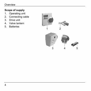
Scope of supply1. Operating unit2. Connecting cable3. Drive unit4. Valve lantern5. Batteries
4 5
1 2
3
Mounting
5
MountingSelecting the mounting site► When selecting the mounting site take into consideration that the
temperature measurement is influenced if the operating unit ismounted on an outer wall or near heat sources.
Mounting the drive unit► Turn the radiator on before mounting. The radiator valve must be
open.
HINT: The correct setting of the valve is best checked with the centralheating switched on. If the valve is correctly mounted, theradiator will become warm.
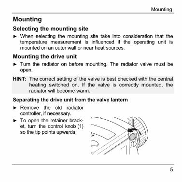
Separating the drive unit from the valve lantern► Remove the old radiator
controller, if necessary.► To open the retainer brack-
et, turn the control knob (1)so the tip points upwards.
�
Mounting
6
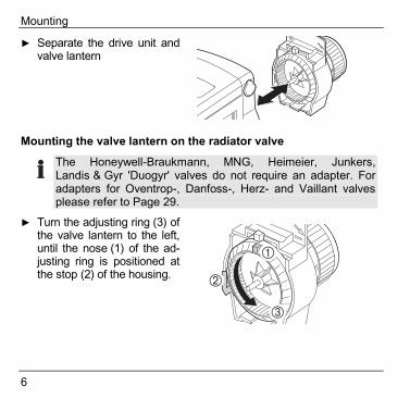
► Separate the drive unit andvalve lantern
Mounting the valve lantern on the radiator valve
The Honeywell-Braukmann, MNG, Heimeier, Junkers,Landis & Gyr 'Duogyr' valves do not require an adapter. Foradapters for Oventrop-, Danfoss-, Herz- and Vaillant valvesplease refer to Page 29.
► Turn the adjusting ring (3) ofthe valve lantern to the left,until the nose (1) of the ad-justing ring is positioned atthe stop (2) of the housing. �
�
�
Mounting
7
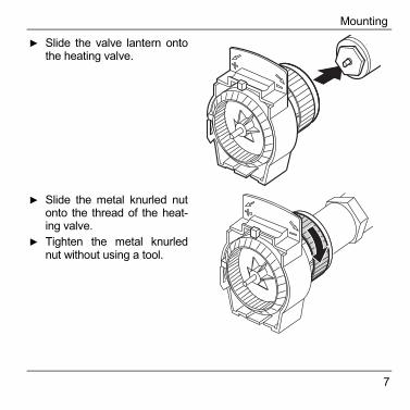
► Slide the valve lantern ontothe heating valve.
► Slide the metal knurled nutonto the thread of the heat-ing valve.
► Tighten the metal knurlednut without using a tool.
Mounting
8
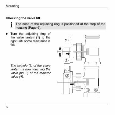
Checking the valve lift
The nose of the adjusting ring is positioned at the stop of thehousing (Page 6).
► Turn the adjusting ring ofthe valve lantern (1) to theright until some resistance isfelt.
�The spindle (2) of the valvelantern is now touching thevalve pin (3) of the radiatorvalve (4).
� �
�
Mounting
9
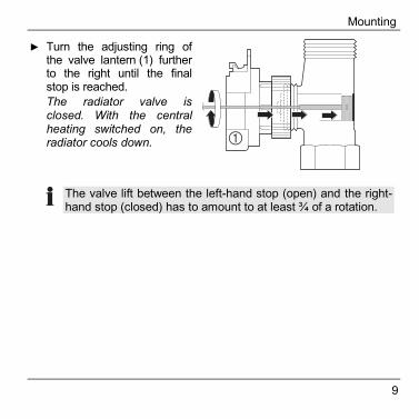
► Turn the adjusting ring ofthe valve lantern (1) furtherto the right until the finalstop is reached.The radiator valve isclosed. With the centralheating switched on, theradiator cools down. �
The valve lift between the left-hand stop (open) and the right-hand stop (closed) has to amount to at least ¾ of a rotation.
Mounting
10
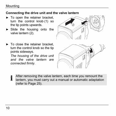
Connecting the drive unit and the valve lantern► To open the retainer bracket,
turn the control knob (1) sothe tip points upwards.
► Slide the housing onto thevalve lantern (2).
► To close the retainer bracket,turn the control knob so the tippoints sideways.The housing of the drive unitand the valve lantern areconnected firmly.
After removing the valve lantern, each time you remount thelantern, you must carry out a manual or automatic adaptation(refer to Page 25).
Mounting
11
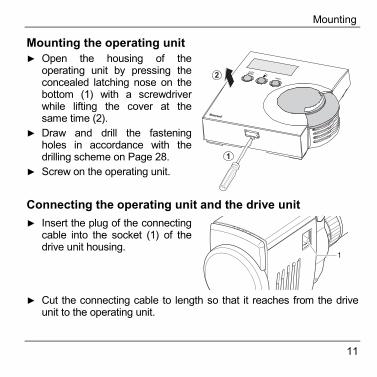
Mounting the operating unit► Open the housing of the
operating unit by pressing theconcealed latching nose on thebottom (1) with a screwdriverwhile lifting the cover at thesame time (2).
► Draw and drill the fasteningholes in accordance with thedrilling scheme on Page 28.
► Screw on the operating unit.
Connecting the operating unit and the drive unit► Insert the plug of the connecting
cable into the socket (1) of thedrive unit housing.
�
► Cut the connecting cable to length so that it reaches from the driveunit to the operating unit.
Mounting
12
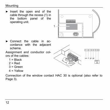
► Insert the open end of thecable through the recess (1) inthe bottom panel of theoperating unit.
► Connect the cable in ac-cordance with the adjacentscheme.
Assignment and conductor col-ors of the cables:
1 = Black2 = Red3 = Green4 = Yellow
Connection of the window contact HAC 30 is optional (also refer toPage 3).
Mounting
13
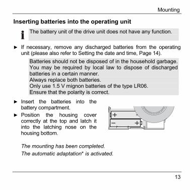
Inserting batteries into the operating unit The battery unit of the drive unit does not have any function.
► If necessary, remove any discharged batteries from the operatingunit (please also refer to Setting the date and time, Page 14).
Batteries should not be disposed of in the household garbage.You may be required by local law to dispose of dischargedbatteries in a certain manner. Always replace both batteries.Only use 1.5 V mignon batteries of the type LR06.Ensure that the polarity is correct.
► Insert the batteries into thebattery compartment.
► Position the housing covercorrectly at the top and latch itinto the latching nose on thehousing bottom.
The mounting has been completed.The automatic adaptation* is activated.
Mounting
14
► Set the date and time once automatic adaptation is complete.
Setting the date and time The date and time must be set when first configuring thecontroller and after each battery change (please also refer toPage 13).
► Keep the button pressed for at least 2 seconds.A four-digit number – the year – flashes in the display.
► Turn the adjusting ring until the current year is displayed.► Press the button.
Two digits flash in the display for the month.► Turn the adjusting ring until the current month is displayed.► Press the button.► Adapt the day, hour and minute by the same method until the current
setpoint temperature is displayed.The date and time are set.
Operation
15
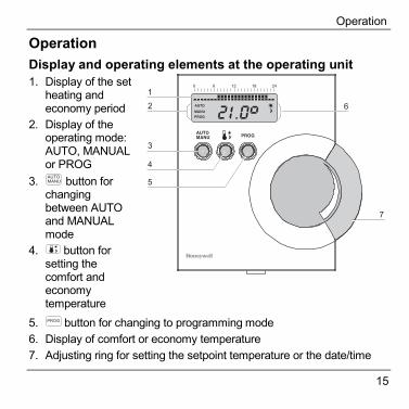
OperationDisplay and operating elements at the operating unit1. Display of the set
heating andeconomy period
2. Display of theoperating mode:AUTO, MANUALor PROG
3. button forchangingbetween AUTOand MANUALmode
4. button forsetting thecomfort andeconomytemperature
�
5. button for changing to programming mode6. Display of comfort or economy temperature7. Adjusting ring for setting the setpoint temperature or the date/time
Operation
16
A rectangle symbolizes one hour of a heating period. Arectangle is displayed above a heating period of half an hour.
The setpoint temperature* at the Roomtronic can be modified asfollows:• Manually at the adjusting ring of the operating unit• By a setpoint modification of the time program at the operating unit
Changing the setpoint temperature at the adjusting ring► Turn the adjusting ring of the operating unit until the desired setpoint
temperature is displayed.Values between 8 °C and 28 °C can be set. The adjusting ring doesnot have a stop.Opening or closing the heating valve completely► Turn the adjusting ring of the operating unit until "OFF" (closed) or
"ON" (opened) is displayed.
Every change in the setpoint temperature remains valid until itis overwritten by the time program in automatic mode.
Operation
17
Changing the operating modesThe Roomtronic disposes of 3 operating modes:• Automatic mode* (AUTO)• Manual mode* (MANU)• Programming mode* (PROG)The automatic mode is the standard mode of the Roomtronic.Temperatures and heating periods are controlled by the time program."AUTO" is displayed.Changing to the manual operating modeChanges to the setpoint temperature can be carried out at theadjusting ring of the operating unit in manual mode. The time programis not active.► Press the button at the operating unit.
"MANU" is displayed.
Changing to the programming modeYou can adjust the time program to your own requirements inprogramming mode. For further information please refer to Chapter"Adapting" from Page 20 onwards.► Press the button at the operating unit.
"PROG" is displayed.
Operation
18
Automatic functionsWindow functionIf you open a window so that the temperature drops strongly, theradiator controller closes the radiator valve in order to save energy.The message is then displayed in the operating unit display.When the temperature rises again the radiator controller returns tonormal operation, however at the latest after 30 minutes. The optionalwindow contact HAC 30 allows you to couple the closing of theheating valve directly to the opening of a window.Protection against limeOnce a week the drive unit opens and closes the radiator valveautomatically and thus protects it against lime deposits. The message
or is then displayed.
Anti-freezeIf the temperature drops below 6 °C, the drive unit opens the heatingvalve until the temperature rises above 8 °C again. The symbol flashes in the display. The anti-freeze function cannot be de-activated.
Operation
19
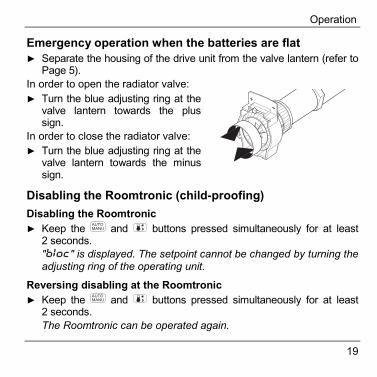
Emergency operation when the batteries are flat► Separate the housing of the drive unit from the valve lantern (refer to
Page 5).In order to open the radiator valve:► Turn the blue adjusting ring at the
valve lantern towards the plussign.
In order to close the radiator valve:► Turn the blue adjusting ring at the
valve lantern towards the minussign.
Disabling the Roomtronic (child-proofing)Disabling the Roomtronic► Keep the and buttons pressed simultaneously for at least
2 seconds." " is displayed. The setpoint cannot be changed by turning theadjusting ring of the operating unit.
Reversing disabling at the Roomtronic► Keep the and buttons pressed simultaneously for at least
2 seconds.The Roomtronic can be operated again.
Adapting
20
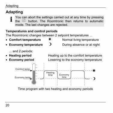
Adapting You can abort the settings carried out at any time by pressingthe button. The Roomtronic then returns to automaticmode. The last changes are rejected.
Temperatures and control periodsThe Roomtronic changes between 2 setpoint temperatures ...• Comfort temperature Normal living temperature• Economy temperature During absence or at night
... and 2 periods:• Heating period Heating up to the comfort temperature• Economy period Lowering to the economy temperature
Time program with two heating and economy periods
Adapting
21
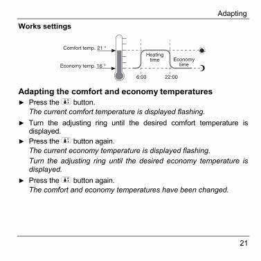
Works settings
Adapting the comfort and economy temperatures► Press the button.
The current comfort temperature is displayed flashing.► Turn the adjusting ring until the desired comfort temperature is
displayed.► Press the button again.
The current economy temperature is displayed flashing.Turn the adjusting ring until the desired economy temperature isdisplayed.
► Press the button again.The comfort and economy temperatures have been changed.
Adapting
22
Adapting the heating and economy periodsYou can set a first heating and economy period and, if required, asecond one for each weekday.
Each heating period must also have an economy periodassigned to it.
HINT: First adapt the heating and economy periods for all theweekdays simultaneously. If necessary, change the heating andeconomy periods of individual days in the next step.Changing the heating and economy periods for all the weekdayssimultaneously► Press the button.
The following text is displayed: ��� .► Press the button again.
The current first heating period is displayed (e.g. 6.00).► Turn the adjusting ring until the desired heating period is displayed.► Press the button again.► Turn the adjusting ring until the desired economy period is displayed.► Press the button again.If you do not want to set a second heating and economy period:► Turn the adjusting ring until is displayed.► Press the button.
Adapting
23
► Turn the adjusting ring until is displayed.► Press the button.
The new heating and economy periods are effective for all theweekdays.
If you want to set a second heating and economy period:► Turn the adjusting ring until the desired second heating period is
displayed.► Press the button again.► Turn the adjusting ring until the desired second economy period is
displayed.► Press the button again.
The second heating and economy periods are effective for all theweekdays.
Changing the heating and economy periods for a single weekday► Press the button.► Turn the adjusting ring until the desired weekday is displayed.The values have the following meaning: 1 Monday, 2 Tuesday, etc.until 7 Sunday.► Press the button.
The desired weekday is selected.► Turn the adjusting ring until the desired first heating period is
displayed.
Adapting
24
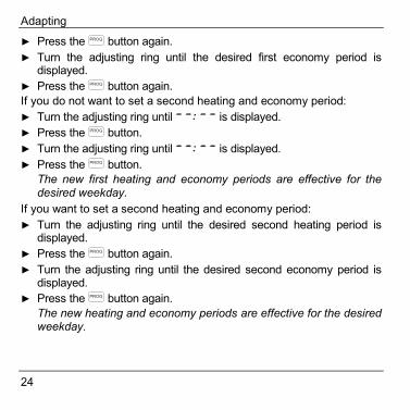
► Press the button again.► Turn the adjusting ring until the desired first economy period is
displayed.► Press the button again.If you do not want to set a second heating and economy period:► Turn the adjusting ring until is displayed.► Press the button.► Turn the adjusting ring until is displayed.► Press the button.
The new first heating and economy periods are effective for thedesired weekday.
If you want to set a second heating and economy period:► Turn the adjusting ring until the desired second heating period is
displayed.► Press the button again.► Turn the adjusting ring until the desired second economy period is
displayed.► Press the button again.
The new heating and economy periods are effective for the desiredweekday.
Adapting
25
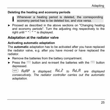
Deleting the heating and economy periods Whenever a heating period is deleted, the correspondingeconomy period has to be deleted too, and vice versa.
► Proceed as described in the above sections on "Changing heatingand economy periods". Turn the adjusting ring respectively to theright until is displayed.
Adaptation at the radiator valveActivating automatic adaptationThe automatic adaptation has to be activated after you have replacedthe radiator valve, e.g. after you have moved or have replaced theradiator.► Remove the batteries from the battery compartment.► Press the button and re-insert the batteries with the button
depressed. is displayed. ���� to ���� are displayed
consecutively. The radiator controller carries out the automaticadaptation.
Adapting
26
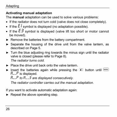
Activating manual adaptationThe manual adaptation can be used to solve various problems:• If the radiator does not turn cold (valve does not close completely).• If the symbol is displayed (no adaptation possible).• If the symbol is displayed (valve lift too short or motor cannot
be moved).► Remove the batteries from the battery compartment.► Separate the housing of the drive unit from the valve lantern, as
described on Page 5.► Turn the blue adjusting ring towards the minus sign until the radiator
valve is closed (please refer to Page 8).The radiator turns cold.
► Place the drive unit back onto the valve lantern.► Insert the batteries again while pressing the button until
is displayed. to are displayed consecutively.
The radiator controller carries out the manual adaptation.
If you want to activate automatic adaptation again:► Repeat the above operating step.

Appendix
27
AppendixTechnical dataOperating range 0 °C ... +40 °C
Mounting Wall mounting
Max. ambient temperature / humidity 0 °C ... 50 °C / 5 % ... 90 % rel.humidity
Max. storage temperature / humidity –20 °C ... +65 °C / 5 % ... 90 % rel.humidity
Voltage supply 2 Mignon batteries LR 06 AA AM3
Degree of protection IP 30 DIN 40 050 / IEC 144
Time program 1 week program, 4 switching pointsper day
Setpoints 1 day and 1 night setpointselectable
Setting precision 0.5 K
Responsiveness 0.15 K
Appendix
28
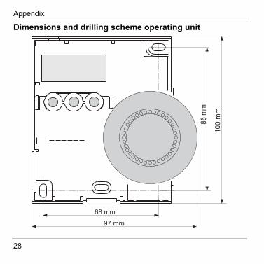
Dimensions and drilling scheme operating unit
Appendix
29
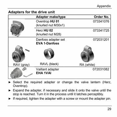
Adapters for the drive unit Adapter make/type Order No.
Oventrop HU 01(knurled nut M30x1)
073341076
Herz HU 02(knurled nut M28)
073341725
Danfoss adapter setEVA 1-Danfoss
072031201
RAV (gray)
RAVL (black)
RA (white)
Vaillant adapter EHA 1VAI
072031082
► Select the required adapter or change the valve lantern (Herz,
Oventrop).► Expand the adapter, if necessary and slide it onto the valve until the
stop is reached. Turn it in the process until it latches perceptibly.► If required, tighten the adapter with a screw or mount the adapter pin.
Appendix
30
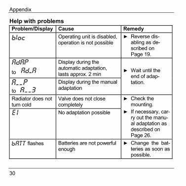
Help with problemsProblem/Display Cause Remedy
Operating unit is disabled,operation is not possible
► Reverse dis-abling as de-scribed onPage 19.
to ����Display during theautomatic adaptation,lasts approx. 2 min
to Display during the manualadaptation
► Wait until theend of adap-tation.
Radiator does notturn cold
Valve does not closecompletelyNo adaptation possible
► Check themounting.
► If necessary, car-ry out the manu-al adaptation asdescribed onPage 26.
flashes Batteries are not powerfulenough
► Change the bat-teries as soon aspossible.
Appendix
31
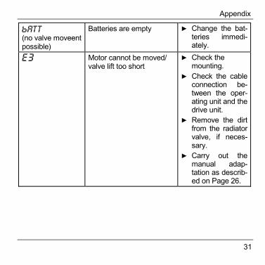
(no valve moveentpossible)
Batteries are empty ► Change the bat-teries immedi-ately.
Motor cannot be moved/valve lift too short
► Check themounting.
► Check the cableconnection be-tween the oper-ating unit and thedrive unit.
► Remove the dirtfrom the radiatorvalve, if neces-sary.
► Carry out themanual adap-tation as describ-ed on Page 26.
Appendix
32
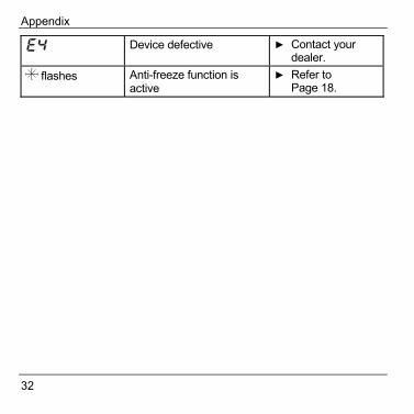
Device defective ► Contact yourdealer.
flashes Anti-freeze function isactive
► Refer toPage 18.

Appendix
33
GlossaryAdaptationThe radiator controller adaptsitself to the lift of the radiatorvalve.Automatic modeStandard operating mode of theoperating unit. The time pro-gram controls the room temper-ature.Comfort temperatureSet temperature which the timeprogram accesses. Refer toeconomy temperature.Economy periodPeriod in which the economytemperature is effective.Economy temperatureSet temperature which the timeprogram accesses. Advisable atnight or during absence. Referto comfort temperature.
Heating periodPeriod in which the comforttemperature is effective.Manual modeNo time program active. Set-point adjustment via adjustingring.Programming modeOperating mode for adaptingthe settings such as the dateand time, heating and economyperiod, etc.Setpoint temperatureThe room temperature which isto be reached.Time programCombination of setpoints andswitching points.
Honeywell AGBöblinger Straße 17D – 71101 SchönaichTel. (++49) (0) 1801 466390www.honeywell.de
This company is certificated to
The right is reserved to make modifications. This document is definitive for theenclosed product and replaces all previous publications.
No. 7157662 EN1H-0183 GE51R0403