Embed Size (px)
Citation preview
- - - - - - - - - - - - - - - - - - - - - - - - - - - - - - - - - - - - - - - - - - - - - - - - - - ▲ INSTRUCTION MANUAL
3601 E. 34th St. Tucson, AZ 85713 USA Tel. +1 520-882-6598 Fax +1 520-882-6599 email: [email protected] Web: http://www.metallographic.com
Please read this instruction manual carefully and follow all installation, operating and safety guidelines.
HR-15C Rockwell Hardness Tester
Equipment Type:
Rockwell Hardness Tester
Model: HR-15C
Electrical Requirements:
110 or 220 Volts (single-phase)
Frequency: 50/60 Hz
Manual Revision Date:
November 25, 2011
- - - - - - - - - - - - - - - - - - - - - - - - - - - - - - - - - - - - - - - - - - - - - - - - - - ▲ INSTRUCTION MANUAL
3601 E. 34th St. Tucson, AZ 85713 USA Tel. +1 520-882-6598 Fax +1 520-882-6599 email: [email protected] Web: http://www.metallographic.com
Please read this instruction manual carefully and follow all installation, operating and safety guidelines.
HR-15C Rockwell Hardness Tester
Contents
PAGE
Warranty ii
1.0 Product Description 1
2.0 Unpacking, Shipping and Installation 3
3.0 Safety Guidelines 15
4.0 Operation 16
5.0 Maintenance 19
6.0 Trouble Shooting 20
7.0 Rockwell Testing Basics 21
8.0 Appendix RS232 Connector 23
i
- - - - - - - - - - - - - - - - - - - - - - - - - - - - - - - - - - - - - - - - - - - - - - - - - - ▲ INSTRUCTION MANUAL
3601 E. 34th St. Tucson, AZ 85713 USA Tel. +1 520-882-6598 Fax +1 520-882-6599 email: [email protected] Web: http://www.metallographic.com
Please read this instruction manual carefully and follow all installation, operating and safety guidelines.
HR-15C Rockwell Hardness Tester
WARRANTY
Terms and Conditions applying to all PACE Technologies Products
1. LIMITED WARRANTY AND DISCLAIMER: PACE Technologies Products are warranted for one year from the purchase date to be free from defects in
material and workmanship under correct use, normal operating conditions, and proper application. PACE
Technologies obligation under this warranty shall be limited to the repair or exchange, at PACE Technologies
option, of any PACE Technologies Product or part which proves to be defective as provided herein. PACE
Technologies reserves the right to either inspect the product at Buyer’s location or require it to be returned to the
factory for inspection. Buyer is responsible for freight to and from factory on all warranty claims. The above
warranty does not extend to goods damaged or subjected to accident, abuse or misuse after release from PACE
Technologies warehouse, nor goods altered or repaired by anyone other than specifically authorized PACE
Technologies representatives. PACE Technologies shall not in any way be responsible for the consequences of
any alteration, modification or misuse unless previously approved in writing by an officer of PACE
Technologies.
PACE TECHNOLOGIES MAKES NO EXPRESS WARRANTIES OTHER THAN THOSE WHICH ARE
SPECIFICALLY DESCRIBED HEREIN. Any description of the goods sold hereunder, including any reference
to Buyer’s specifications and any description in catalogs, circulars and other written material published by
PACE Technologies, is the sole purpose of identifying such goods and shall not create an express warranty that
the goods shall conform to such description.
THIS WARRANTY IS EXPRESSLY IN LIEU OF ALL OTHER WARRANTIES, EXPRESSED OR
IMPLIED. THERE ARE NO IMPLIED WARRANTIES OF MECHANTABILITY OR FITNESS FOR
PARTICULAR PURPOSE. THIS WARRANTY STATES PACE TECHNOLOGIES ENTIRE AND
EXCLUSIVE LIABILITY AND BUYER’S EXCLUSIVE REMEDY FOR ANY CLAIM FOR DAMAGES IN
CONNECTIONS WITH PACE TECHNOLOGIES PRODUCTS. PACE TECHNOLOGIES WILL IN NO
EVENT BE LIABLE FOR INCIDENTAL OR CONSEQUENTIAL DAMAGES WHATSOEVER, NOR FOR
ANY SUM IN EXCESS OF THE PURCHASE PRICE.
2. LIABILITY CAP: PACE Technologies maximum aggregate liability for loss and damage arising under, resulting from or in
connection with the supply or use of the Equipment and Consumables provided under this purchase, or from the
performance or breach of any obligation (s) imposed hereunder, whether such liability arises from any one or
more claims or actions for breach of contract, tort, (including negligence), delayed completion, warranty,
indemnity, strict liability or otherwise, unless otherwise limited by the terms hereof, shall be limited to one
hundred percent (100%) of the purchase price.
3. DELIVERY: Customer assumes and shall bear the risk of all loss or damage to the Products from every cause whatsoever,
whether or not insured, and title to such Products shall pass to Customer upon PACE Technologies delivery of
the Products to the common carrier of Pace Technologies choice, or the carrier specified in writing by Customer,
for shipment to Customer. Any claims for breakage, loss, delay, or damage shall be made to the carrier by the
Customer and Pace Technologies will render customer reasonable assistance in prosecuting such claims.
ii
- - - - - - - - - - - - - - - - - - - - - - - - - - - - - - - - - - - - - - - - - - - - - - - - - - ▲ INSTRUCTION MANUAL
3601 E. 34th St. Tucson, AZ 85713 USA Tel. +1 520-882-6598 Fax +1 520-882-6599 email: [email protected] Web: http://www.metallographic.com
Please read this instruction manual carefully and follow all installation, operating and safety guidelines.
HR-15C Rockwell Hardness Tester
4. ACCEPTANCE: Customer shall inspect the Products promptly upon receipt of delivery. Unless customer objects in writing
within thirty (30) business days thereafter, customer shall be deemed to have accepted the Products. All claims
for damages, errors, or shortage in Products delivered shall be made by Customer in writing within such five
(5) business day period. Failure to make any claim timely shall constitute acceptance of the Products.
5. PAYMENT: Customer agrees to provide timely payment for the Products in accordance with the terms of payment set forth
on the reverse side hereof or in any proposal submitted herewith. If any payment is not paid on or before its
due date, Customer shall pay interest on such late payment from the due date until paid at the lesser of 12% per
annum or the maximum rate allowed by law.
6. DEFAULT:
If Buyer is in default (including, but not limited to, the failure by Buyer to pay all amounts due and payable to
Seller) under the work or purchase order or any other agreement between Buyer and Seller, Buyer’s rights
under the warranty shall be suspended during any period of such default and the original warranty period will
not be extended beyond its original expiration date despite such suspension of warranty rights.
7. MISCELLANEOUS PROVISIONS:
This agreement has been made in and shall be governed by the laws of the State of Arizona. These terms and
conditions and the description of the Products on the reverse side hereof or in any proposal submitted herewith
constitute the entire agreement and understanding of the parties with respect to this sale and supersede all prior
and contemporaneous agreements or understandings, inducements or representations, expressed or implied,
written or oral, between the parties with respect hereto. Any term or provision of this Agreement may be
amended, and any observance of any term of this Agreement may be waived, only by a writing signed by the
party to be bounds. The waiver by a party of any breach shall not be deemed to constitute a waiver of any
other breach. Should suit be brought on this Agreement, the prevailing party shall be entitled to recover its
reasonable attorneys’ fees and other costs of suit including costs and attorneys’ fees incurred on appeal or in
collection of any judgment.
iii
- - - - - - - - - - - - - - - - - - - - - - - - - - - - - - - - - - - - - - - - - - - - - - - - - - ▲ INSTRUCTION MANUAL
3601 E. 34th St. Tucson, AZ 85713 USA Tel. +1 520-882-6598 Fax +1 520-882-6599 email: [email protected] Web: http://www.metallographic.com
Please read this instruction manual carefully and follow all installation, operating and safety guidelines.
HR-15C Rockwell Hardness Tester
1.0 Product Description
1.1 General Description
1
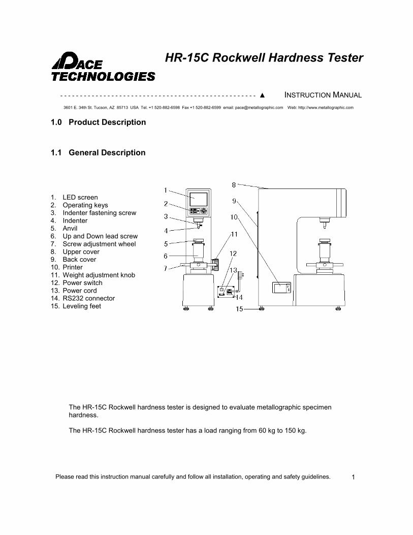
The HR-15C Rockwell hardness tester is designed to evaluate metallographic specimen hardness. The HR-15C Rockwell hardness tester has a load ranging from 60 kg to 150 kg.
1. LED screen 2. Operating keys 3. Indenter fastening screw 4. Indenter 5. Anvil 6. Up and Down lead screw 7. Screw adjustment wheel 8. Upper cover 9. Back cover 10. Printer 11. Weight adjustment knob 12. Power switch 13. Power cord 14. RS232 connector 15. Leveling feet
- - - - - - - - - - - - - - - - - - - - - - - - - - - - - - - - - - - - - - - - - - - - - - - - - - ▲ INSTRUCTION MANUAL
3601 E. 34th St. Tucson, AZ 85713 USA Tel. +1 520-882-6598 Fax +1 520-882-6599 email: [email protected] Web: http://www.metallographic.com
Please read this instruction manual carefully and follow all installation, operating and safety guidelines.
HR-15C Rockwell Hardness Tester
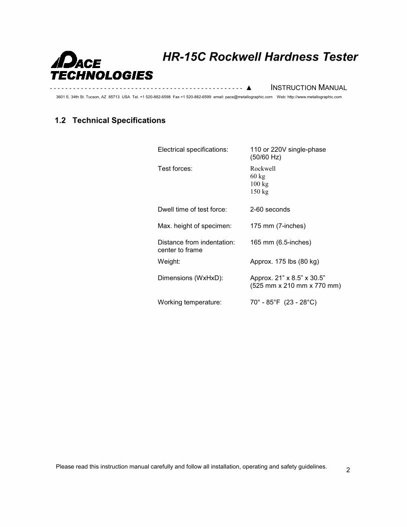
1.2 Technical Specifications
Electrical specifications: 110 or 220V single-phase (50/60 Hz)
Test forces: Rockwell
60 kg
100 kg
150 kg
Dwell time of test force: 2-60 seconds
Max. height of specimen: 175 mm (7-inches)
Distance from indentation: center to frame
165 mm (6.5-inches)
Weight: Approx. 175 lbs (80 kg)
Dimensions (WxHxD): Approx. 21” x 8.5” x 30.5” (525 mm x 210 mm x 770 mm)
Working temperature: 70° - 85°F (23 - 28°C)
2
- - - - - - - - - - - - - - - - - - - - - - - - - - - - - - - - - - - - - - - - - - - - - - - - - - ▲ INSTRUCTION MANUAL
3601 E. 34th St. Tucson, AZ 85713 USA Tel. +1 520-882-6598 Fax +1 520-882-6599 email: [email protected] Web: http://www.metallographic.com
Please read this instruction manual carefully and follow all installation, operating and safety guidelines.
HR-15C Rockwell Hardness Tester
2.0 Unpacking, Shipping and Installation
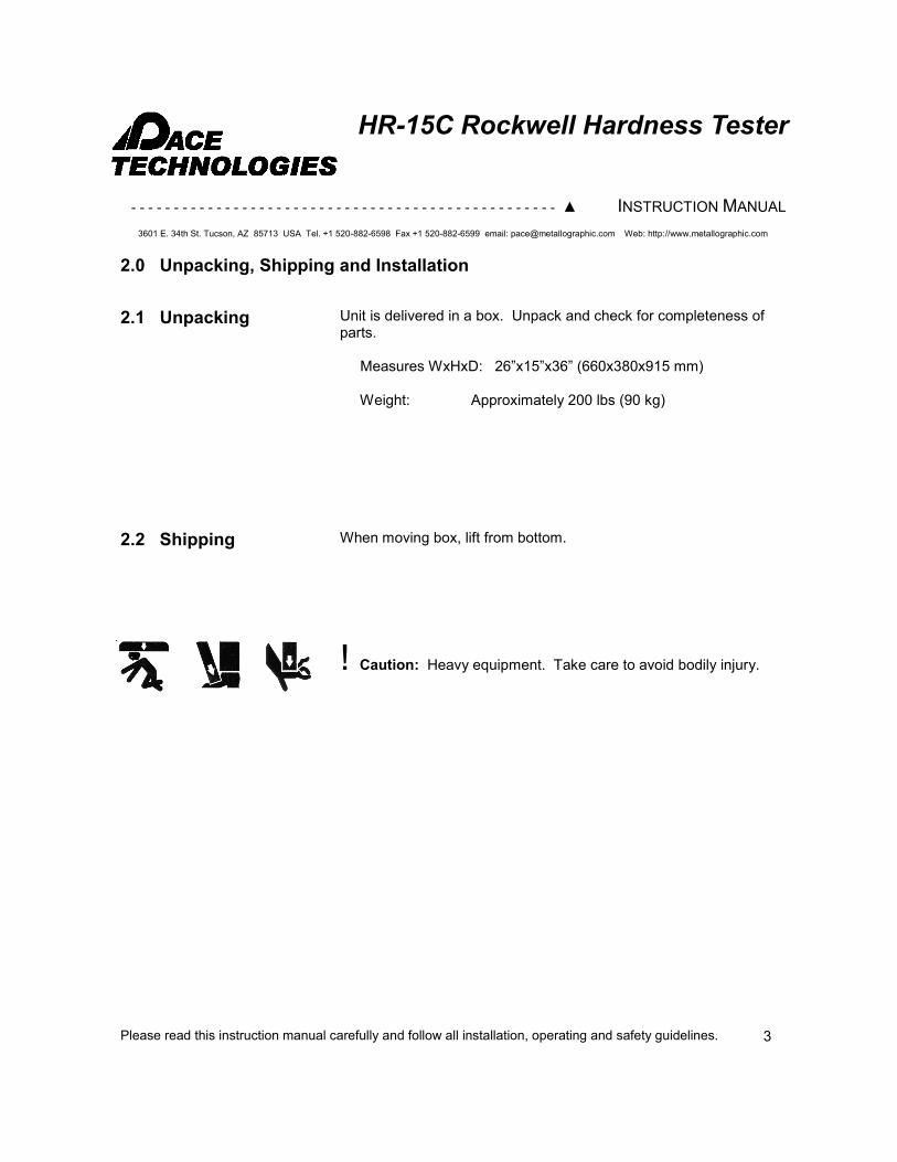
2.1 Unpacking Unit is delivered in a box. Unpack and check for completeness of parts. Measures WxHxD: 26”x15”x36” (660x380x915 mm) Weight: Approximately 200 lbs (90 kg)
2.2 Shipping When moving box, lift from bottom.
! Caution: Heavy equipment. Take care to avoid bodily injury.
3
- - - - - - - - - - - - - - - - - - - - - - - - - - - - - - - - - - - - - - - - - - - - - - - - - - ▲ INSTRUCTION MANUAL
3601 E. 34th St. Tucson, AZ 85713 USA Tel. +1 520-882-6598 Fax +1 520-882-6599 email: [email protected] Web: http://www.metallographic.com
Please read this instruction manual carefully and follow all installation, operating and safety guidelines.
HR-15C Rockwell Hardness Tester
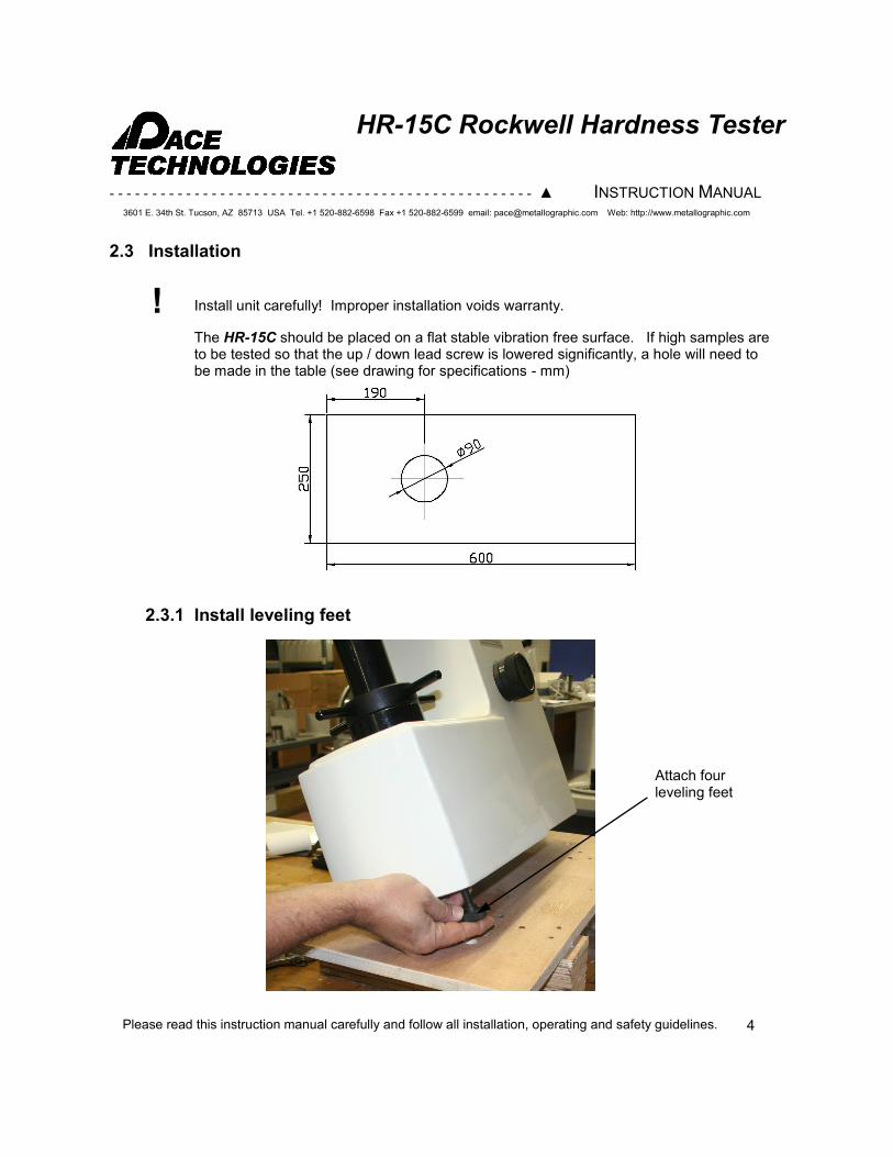
! Install unit carefully! Improper installation voids warranty.
The HR-15C should be placed on a flat stable vibration free surface. If high samples are to be tested so that the up / down lead screw is lowered significantly, a hole will need to be made in the table (see drawing for specifications - mm)
2.3 Installation
Attach four leveling feet
2.3.1 Install leveling feet
4
- - - - - - - - - - - - - - - - - - - - - - - - - - - - - - - - - - - - - - - - - - - - - - - - - - ▲ INSTRUCTION MANUAL
3601 E. 34th St. Tucson, AZ 85713 USA Tel. +1 520-882-6598 Fax +1 520-882-6599 email: [email protected] Web: http://www.metallographic.com
Please read this instruction manual carefully and follow all installation, operating and safety guidelines.
HR-15C Rockwell Hardness Tester
5
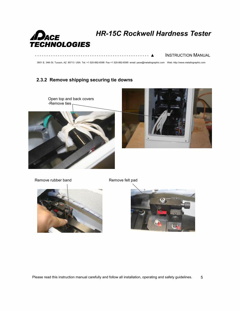
Remove rubber band
Open top and back covers -Remove ties
2.3.2 Remove shipping securing tie downs
Remove felt pad
- - - - - - - - - - - - - - - - - - - - - - - - - - - - - - - - - - - - - - - - - - - - - - - - - - ▲ INSTRUCTION MANUAL
3601 E. 34th St. Tucson, AZ 85713 USA Tel. +1 520-882-6598 Fax +1 520-882-6599 email: [email protected] Web: http://www.metallographic.com
Please read this instruction manual carefully and follow all installation, operating and safety guidelines.
HR-15C Rockwell Hardness Tester
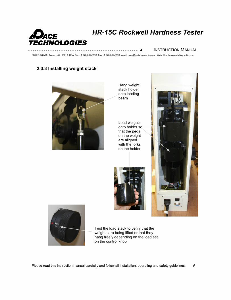
Hang weight stack holder onto loading beam
2.3.3 Installing weight stack
Load weights onto holder so that the pegs on the weight are aligned with the forks on the holder
Test the load stack to verify that the weights are being lifted or that they hang freely depending on the load set on the control knob
6
- - - - - - - - - - - - - - - - - - - - - - - - - - - - - - - - - - - - - - - - - - - - - - - - - - ▲ INSTRUCTION MANUAL
3601 E. 34th St. Tucson, AZ 85713 USA Tel. +1 520-882-6598 Fax +1 520-882-6599 email: [email protected] Web: http://www.metallographic.com
Please read this instruction manual carefully and follow all installation, operating and safety guidelines.
HR-15C Rockwell Hardness Tester
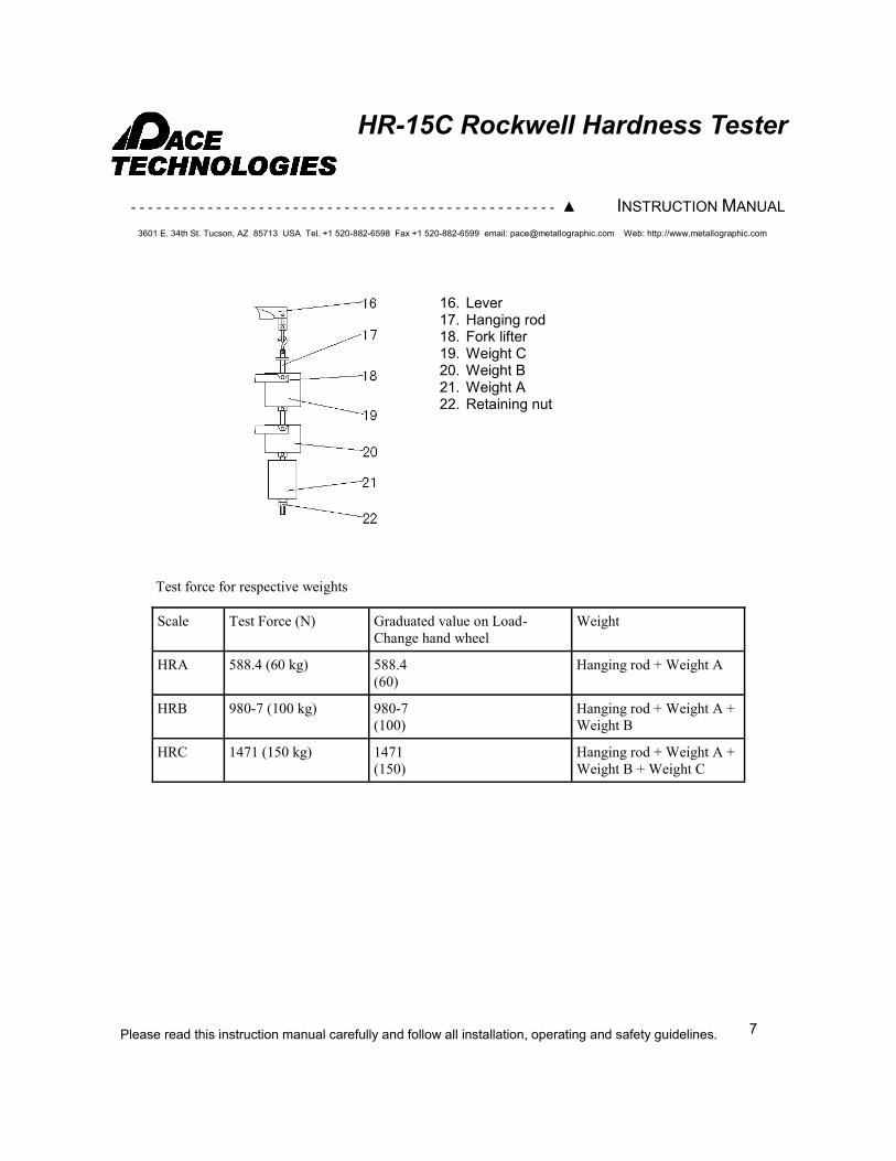
16. Lever 17. Hanging rod 18. Fork lifter 19. Weight C 20. Weight B 21. Weight A 22. Retaining nut
Scale Test Force (N) Graduated value on Load-
Change hand wheel
Weight
HRA 588.4 (60 kg) 588.4
(60)
Hanging rod + Weight A
HRB 980-7 (100 kg) 980-7
(100)
Hanging rod + Weight A +
Weight B
HRC 1471 (150 kg) 1471
(150)
Hanging rod + Weight A +
Weight B + Weight C
Test force for respective weights
7
- - - - - - - - - - - - - - - - - - - - - - - - - - - - - - - - - - - - - - - - - - - - - - - - - - ▲ INSTRUCTION MANUAL
3601 E. 34th St. Tucson, AZ 85713 USA Tel. +1 520-882-6598 Fax +1 520-882-6599 email: [email protected] Web: http://www.metallographic.com
Please read this instruction manual carefully and follow all installation, operating and safety guidelines.
HR-15C Rockwell Hardness Tester
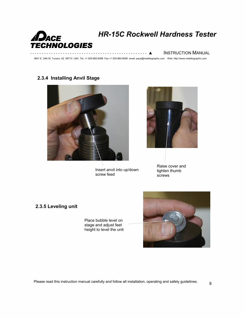
Place bubble level on stage and adjust feet height to level the unit
2.3.4 Installing Anvil Stage
2.3.5 Leveling unit
Insert anvil into up/down screw feed
Raise cover and tighten thumb screws
8
- - - - - - - - - - - - - - - - - - - - - - - - - - - - - - - - - - - - - - - - - - - - - - - - - - ▲ INSTRUCTION MANUAL
3601 E. 34th St. Tucson, AZ 85713 USA Tel. +1 520-882-6598 Fax +1 520-882-6599 email: [email protected] Web: http://www.metallographic.com
Please read this instruction manual carefully and follow all installation, operating and safety guidelines.
HR-15C Rockwell Hardness Tester
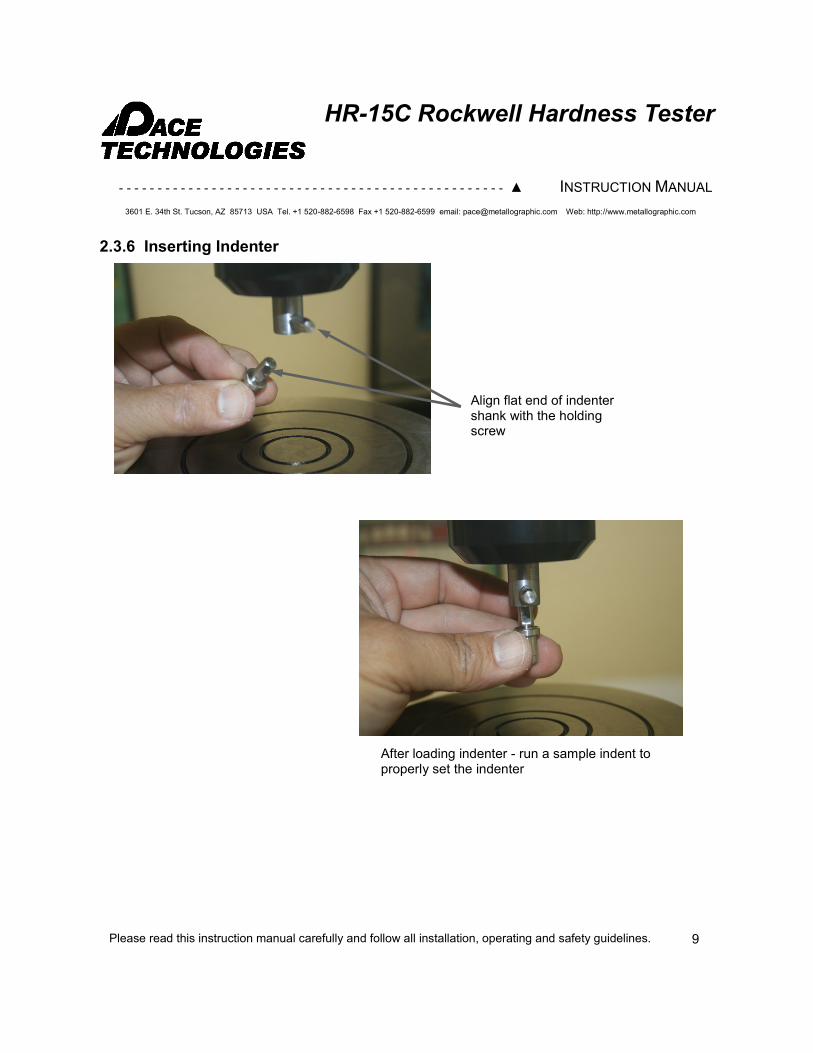
2.3.6 Inserting Indenter
Align flat end of indenter shank with the holding screw
After loading indenter - run a sample indent to properly set the indenter
9
- - - - - - - - - - - - - - - - - - - - - - - - - - - - - - - - - - - - - - - - - - - - - - - - - - ▲ INSTRUCTION MANUAL
3601 E. 34th St. Tucson, AZ 85713 USA Tel. +1 520-882-6598 Fax +1 520-882-6599 email: [email protected] Web: http://www.metallographic.com
Please read this instruction manual carefully and follow all installation, operating and safety guidelines.
HR-15C Rockwell Hardness Tester
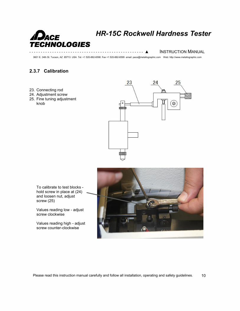
23. Connecting rod 24. Adjustment screw 25. Fine tuning adjustment
knob
2.3.7 Calibration
To calibrate to test blocks - hold screw in place at (24)and loosen nut, adjust screw (25) Values reading low - adjust screw clockwise Values reading high - adjust screw counter-clockwise
10
- - - - - - - - - - - - - - - - - - - - - - - - - - - - - - - - - - - - - - - - - - - - - - - - - - ▲ INSTRUCTION MANUAL
3601 E. 34th St. Tucson, AZ 85713 USA Tel. +1 520-882-6598 Fax +1 520-882-6599 email: [email protected] Web: http://www.metallographic.com
Please read this instruction manual carefully and follow all installation, operating and safety guidelines.
HR-15C Rockwell Hardness Tester
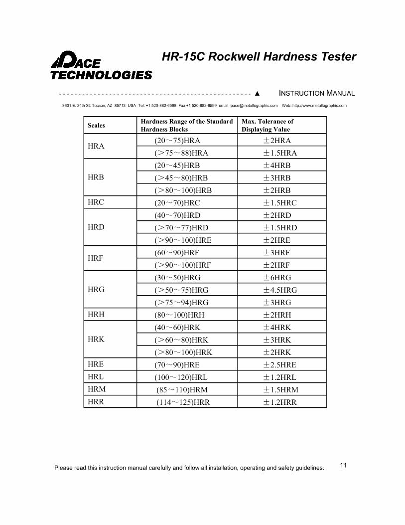
Scales Hardness Range of the Standard
Hardness Blocks
Max. Tolerance of
Displaying Value
HRA (20~75)HRA ±2HRA
(>75~88)HRA ±1.5HRA
HRB
(20~45)HRB ±4HRB
(>45~80)HRB ±3HRB
(>80~100)HRB ±2HRB
HRC (20~70)HRC ±1.5HRC
HRD
(40~70)HRD ±2HRD
(>70~77)HRD ±1.5HRD
(>90~100)HRE ±2HRE
HRF (60~90)HRF ±3HRF
(>90~100)HRF ±2HRF
HRG
(30~50)HRG ±6HRG
(>50~75)HRG ±4.5HRG
(>75~94)HRG ±3HRG
HRH (80~100)HRH ±2HRH
HRK
(40~60)HRK ±4HRK
(>60~80)HRK ±3HRK
(>80~100)HRK ±2HRK
HRE (70~90)HRE ±2.5HRE
HRL (100~120)HRL ±1.2HRL
HRM (85~110)HRM ±1.5HRM
HRR (114~125)HRR ±1.2HRR
11
- - - - - - - - - - - - - - - - - - - - - - - - - - - - - - - - - - - - - - - - - - - - - - - - - - ▲ INSTRUCTION MANUAL
3601 E. 34th St. Tucson, AZ 85713 USA Tel. +1 520-882-6598 Fax +1 520-882-6599 email: [email protected] Web: http://www.metallographic.com
Please read this instruction manual carefully and follow all installation, operating and safety guidelines.
HR-15C Rockwell Hardness Tester
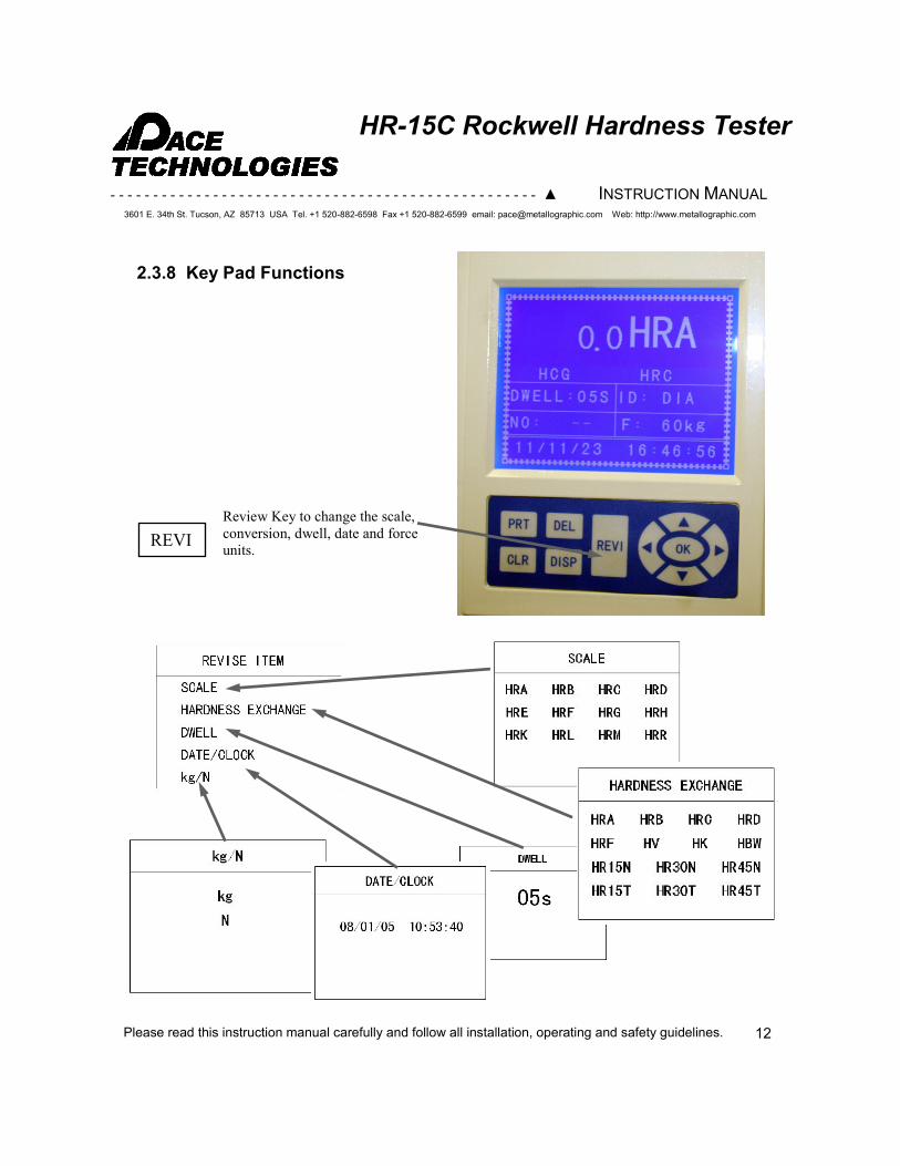
2.3.8 Key Pad Functions
REVI
Review Key to change the scale,
conversion, dwell, date and force
units.
12
- - - - - - - - - - - - - - - - - - - - - - - - - - - - - - - - - - - - - - - - - - - - - - - - - - ▲ INSTRUCTION MANUAL
3601 E. 34th St. Tucson, AZ 85713 USA Tel. +1 520-882-6598 Fax +1 520-882-6599 email: [email protected] Web: http://www.metallographic.com
Please read this instruction manual carefully and follow all installation, operating and safety guidelines.
HR-15C Rockwell Hardness Tester
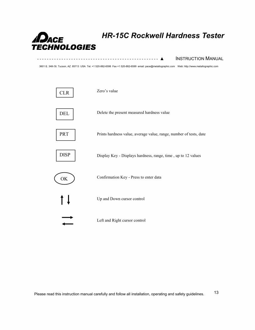
CLR
DEL
PRT
DISP
OK
Zero’s value
Delete the present measured hardness value
Prints hardness value, average value, range, number of tests, date
Display Key - Displays hardness, range, time , up to 12 values
Confirmation Key - Press to enter data
Up and Down cursor control
Left and Right cursor control
13
- - - - - - - - - - - - - - - - - - - - - - - - - - - - - - - - - - - - - - - - - - - - - - - - - - ▲ INSTRUCTION MANUAL
3601 E. 34th St. Tucson, AZ 85713 USA Tel. +1 520-882-6598 Fax +1 520-882-6599 email: [email protected] Web: http://www.metallographic.com
Please read this instruction manual carefully and follow all installation, operating and safety guidelines.
HR-15C Rockwell Hardness Tester
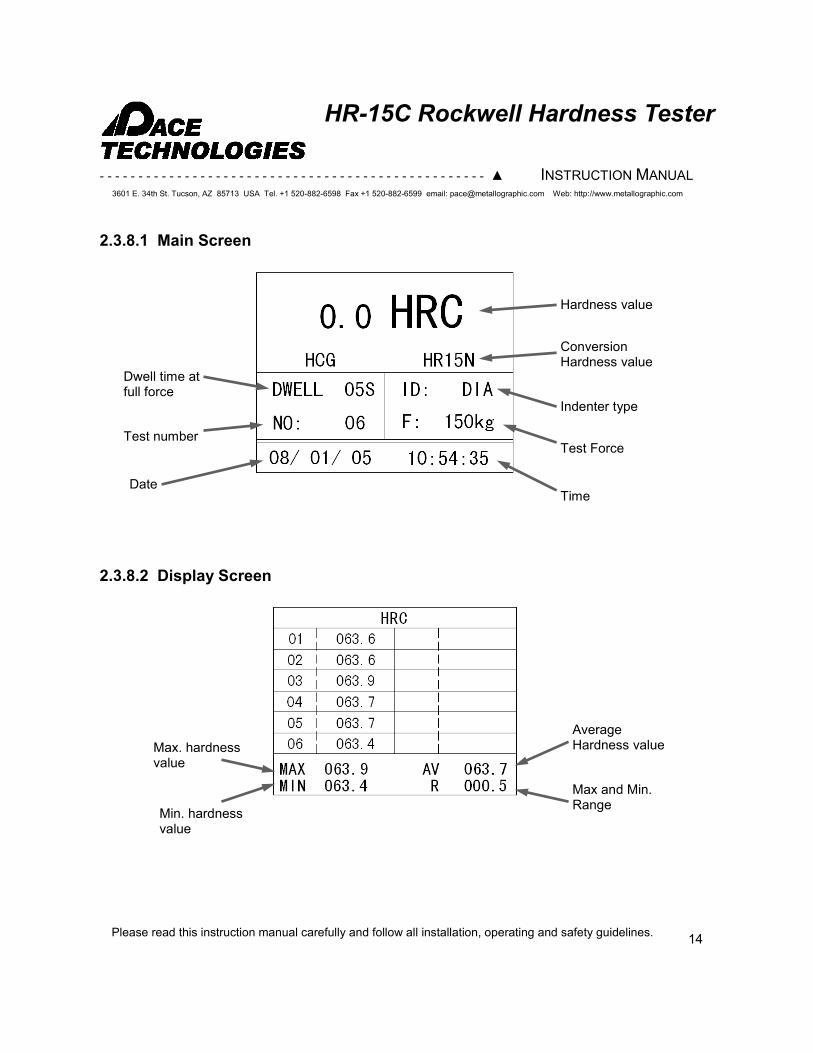
Average Hardness value Max. hardness
value
Min. hardness value
Max and Min. Range
2.3.8.2 Display Screen
Hardness value
Conversion Hardness value
Indenter type
Test Force
Time Date
Test number
Dwell time at full force
2.3.8.1 Main Screen
14
- - - - - - - - - - - - - - - - - - - - - - - - - - - - - - - - - - - - - - - - - - - - - - - - - - ▲ INSTRUCTION MANUAL
3601 E. 34th St. Tucson, AZ 85713 USA Tel. +1 520-882-6598 Fax +1 520-882-6599 email: [email protected] Web: http://www.metallographic.com
Please read this instruction manual carefully and follow all installation, operating and safety guidelines.
HR-15C Rockwell Hardness Tester
3.0 Safety Guidelines
3.1 Warning Sign
! This sign points to special safety features on the machine.
Always follow proper operational guidelines and avoid contact with lubricants and abrasives.
3.3 Emergency Statement
! Operate unit as specified in this manual.
! Disconnect power before opening unit.
! Lower stage to avoid damaging indenter or lens when not in use.
! Cover unit with dust cover when not in use to eliminate dust contamination.
3.2 Safety Precautions
! Careful attention to this instruction manual and the recommended safety guidelines is essential for the safe operation of the HR-15C.
! Proper operator training is required for operation of the HR-15C. Any unauthorized mechanical and electrical change, as well as improper operation, voids all warranty claims. All service issues need to be reported to the manufacturer / supplier.
15
- - - - - - - - - - - - - - - - - - - - - - - - - - - - - - - - - - - - - - - - - - - - - - - - - - ▲ INSTRUCTION MANUAL
3601 E. 34th St. Tucson, AZ 85713 USA Tel. +1 520-882-6598 Fax +1 520-882-6599 email: [email protected] Web: http://www.metallographic.com
Please read this instruction manual carefully and follow all installation, operating and safety guidelines.
HR-15C Rockwell Hardness Tester
4.0 Operation
STEPS FOR HR-15C OPERATION IN BRIEF (Please see explanation of important points on next pages before proceeding)
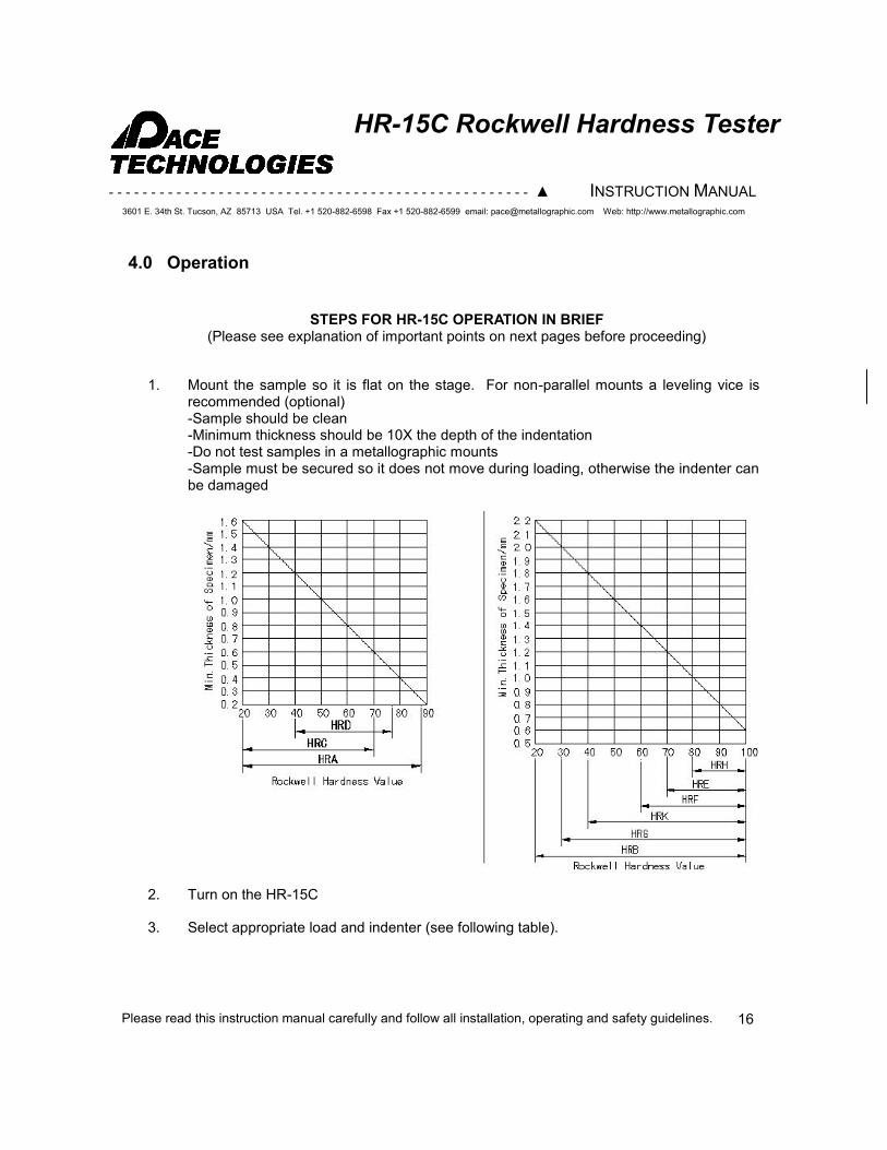
1. Mount the sample so it is flat on the stage. For non-parallel mounts a leveling vice is recommended (optional) -Sample should be clean -Minimum thickness should be 10X the depth of the indentation -Do not test samples in a metallographic mounts -Sample must be secured so it does not move during loading, otherwise the indenter can be damaged
2. Turn on the HR-15C
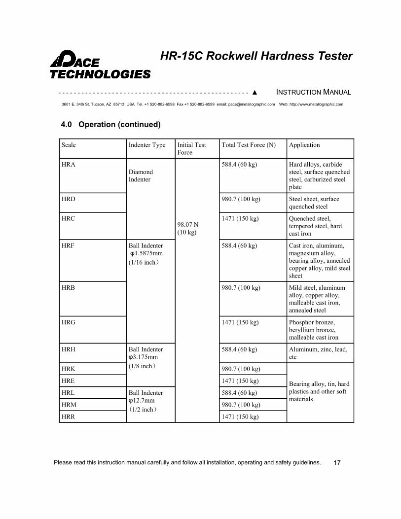
3. Select appropriate load and indenter (see following table).
16
- - - - - - - - - - - - - - - - - - - - - - - - - - - - - - - - - - - - - - - - - - - - - - - - - - ▲ INSTRUCTION MANUAL
3601 E. 34th St. Tucson, AZ 85713 USA Tel. +1 520-882-6598 Fax +1 520-882-6599 email: [email protected] Web: http://www.metallographic.com
Please read this instruction manual carefully and follow all installation, operating and safety guidelines.
HR-15C Rockwell Hardness Tester
Scale Indenter Type Initial Test
Force
Total Test Force (N) Application
HRA
Diamond
Indenter
98.07 N
(10 kg)
588.4 (60 kg) Hard alloys, carbide
steel, surface quenched
steel, carburized steel
plate
HRD 980.7 (100 kg) Steel sheet, surface
quenched steel
HRC 1471 (150 kg) Quenched steel,
tempered steel, hard
cast iron
HRF Ball Indenter
φ1.5875mm
(1/16 inch)
588.4 (60 kg) Cast iron, aluminum,
magnesium alloy,
bearing alloy, annealed
copper alloy, mild steel
sheet
HRB 980.7 (100 kg) Mild steel, aluminum
alloy, copper alloy,
malleable cast iron,
annealed steel
HRG 1471 (150 kg) Phosphor bronze,
beryllium bronze,
malleable cast iron
HRH Ball Indenter
φ3.175mm
(1/8 inch)
588.4 (60 kg) Aluminum, zinc, lead,
etc
HRK 980.7 (100 kg)
Bearing alloy, tin, hard
plastics and other soft
materials
HRE 1471 (150 kg)
HRL Ball Indenter
φ12.7mm
(1/2 inch)
588.4 (60 kg)
HRM 980.7 (100 kg)
HRR 1471 (150 kg)
4.0 Operation (continued)
17
- - - - - - - - - - - - - - - - - - - - - - - - - - - - - - - - - - - - - - - - - - - - - - - - - - ▲ INSTRUCTION MANUAL
3601 E. 34th St. Tucson, AZ 85713 USA Tel. +1 520-882-6598 Fax +1 520-882-6599 email: [email protected] Web: http://www.metallographic.com
Please read this instruction manual carefully and follow all installation, operating and safety guidelines.
HR-15C Rockwell Hardness Tester
PRECAUTIONS Clamp the sample properly on the self-leveling vice. This will make the sample exactly perpendicular to the indenter.
Important : This is very important as a tilted sample can damage the indenter. it is also very important to have a flat specimen. A rounded specimen will have varying height as it moves and can touch and damage the indenter.
Important : Take utmost care to insure that the sample or the leveling vice does not touch the indenter as this may damage the indenter
4.0 Operation (continued)
4. Rotate Hand Wheel clockwise to move sample into indenter -Continue to turn wheel slowly to apply the initial test load (approx. 580-610 hardness on the display). -When the buzzer is sounded allow stop adding the initial load and let the servo motor apply the test force for the preset Dwell time (If the initial load is too fast or over 610 the buzzer will produce a long sound indicating an error in the measurement. For this situation lower the sample and move the sample to a new location and then re-apply the initial test) IMPT: Do not rotate the hand wheel or move the specimen during the operation as this may damage the instrument.
5. Turn rotating wheel counter-clockwise to lower the sample. Move the sample to the second test location. -NOTE: the first measurement is done to set the indenter and is not included in the data
6. To print, remove load or back off sample from indenter and press “PRT” to print the output
18
- - - - - - - - - - - - - - - - - - - - - - - - - - - - - - - - - - - - - - - - - - - - - - - - - - ▲ INSTRUCTION MANUAL
3601 E. 34th St. Tucson, AZ 85713 USA Tel. +1 520-882-6598 Fax +1 520-882-6599 email: [email protected] Web: http://www.metallographic.com
Please read this instruction manual carefully and follow all installation, operating and safety guidelines.
HR-15C Rockwell Hardness Tester
5.0 Maintenance
5.1 Introduction
5.2 Cleaning outside cabinet
The HR-15C requires very minimal maintenance. However, to increase the life of the Rockwell Hardness tester, it is suggested that the unit be covered when not in use.
The cabinet should be cleaned occasionally with a moistened cloth. Do not use any chemicals or cleaning abrasives.
19
- - - - - - - - - - - - - - - - - - - - - - - - - - - - - - - - - - - - - - - - - - - - - - - - - - ▲ INSTRUCTION MANUAL
3601 E. 34th St. Tucson, AZ 85713 USA Tel. +1 520-882-6598 Fax +1 520-882-6599 email: [email protected] Web: http://www.metallographic.com
Please read this instruction manual carefully and follow all installation, operating and safety guidelines.
HR-15C Rockwell Hardness Tester
6.0 Trouble Shooting
20
Phenomenon Possible Causes Method Used
LCD does not
turn on
1. No power
2. The fuse is blown.
1. Check the power cable.
2. Change the fuse.
When the tester is
on, the keys do
not work
The instrument is not in
working state.
When the tester is turned on, wait until
the instrument returns to the working
state.
The Up / Down
Lead Screw is
hard to move
The space between the Up /
Down Lead Screws are
blocked by the thread ends or
dirt
Remove the protecting cover for the
Up / Down Lead Screw and clean the
screw threads
The deviation of
the displaying
hardness value is
too great.
1. The indenter is damaged
2. The Weights are not
installed in order.
3. The tester is not placed in
the horizontal level and the
weights are touching the
inside wall of instrument
body.
4 .The total test force or the
indenter are not correct.
5. The protecting cover of Up/
Down Lead Screw is to high
over the supporting plane of
the Testing Table
1. Change the diamond indenter or the
ball indenter.
2. Install the weights properly
3. Level the tester
4. Choose the appropriate testing force
and indenter
5. Lower the protecting cover and clean
the Up and Down Lead Screw.
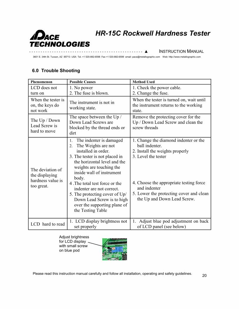
LCD hard to read 1. LCD display brightness not
set properly
1. Adjust blue pod adjustment on back
of LCD panel (see below)
Adjust brightness for LCD display with small screw on blue pod
- - - - - - - - - - - - - - - - - - - - - - - - - - - - - - - - - - - - - - - - - - - - - - - - - - ▲ INSTRUCTION MANUAL
3601 E. 34th St. Tucson, AZ 85713 USA Tel. +1 520-882-6598 Fax +1 520-882-6599 email: [email protected] Web: http://www.metallographic.com
Please read this instruction manual carefully and follow all installation, operating and safety guidelines.
HR-15C Rockwell Hardness Tester
Hardness Testing provides useful information, which can be correlated to tensile strength, wear
resistance, ductility, and other physical characteristics of the material. Hardness testing is therefore
useful for monitoring quality control and for aiding in the materials selection process.
ROCKWELL HARDNESS
Rockwell hardness (HR) is an indentation hardness test that is determined with a spheroconical
penetrator, or hard steel ball, that is forced into the specimen surface. The test is accomplished by
bringing the specimen into contact with the penetrator and allowing the penetrator to be slowly
forced into the specimen surface by a series of weights acting through a system of levers. After the
load is released, a dial pointer or LED screen indicates the hardness number.
Typical Applications:
- Quality control for metal heat treatment
- Materials receiving inspection
- Evaluation of welds in steels and other metal alloys
- Failure analysis
Standard Rockwell testing is at 60, 100 and 150 kg loads and Superfical Rockwell testing is at 15,
30 and 45 kg loads.
BRINELL HARDNESS
To determine a Brinell hardness number (BHN), a 10 mm diameter steel ball is typically used as an
indenter with a 3,000 kgf (29 kN) force. For softer materials, a smaller force is used; for harder
materials, a tungsten carbide ball is used. The BHN can also be converted into the ultimate tensile
strength (UTS), although the relationship is dependent on the material, and therefore is only an
empirically based value.
VICKERS HARDNESS
The Vickers test is often easier to use than other hardness tests since the required calculations are
independent of the size of the indenter, and the indenter can be used for all materials irrespective of
hardness. The Vickers test can be used for all metals and has one of the widest scales among
hardness tests. The unit of hardness given by the test is known as the Vickers Pyramid Number (HV)
or Diamond Pyramid Hardness (DPH).
21
7.0 Hardness Testing Basic
- - - - - - - - - - - - - - - - - - - - - - - - - - - - - - - - - - - - - - - - - - - - - - - - - - ▲ INSTRUCTION MANUAL
3601 E. 34th St. Tucson, AZ 85713 USA Tel. +1 520-882-6598 Fax +1 520-882-6599 email: [email protected] Web: http://www.metallographic.com
Please read this instruction manual carefully and follow all installation, operating and safety guidelines.
HR-15C Rockwell Hardness Tester
MICROHARDNESS
Microhardness testers are both mechanical and optical measuring tools. The indent is
produced by applying a known load to the specimen and then measuring the size of the
appropriate diagonals either optically or with image analysis software.
Microhardness is primarily determined with either a Knoop or Vickers indenter under test
loads in the range of 1 to 2000 gram-force. Microhardness is used to measure the hardness of
specific phases, small particles, and for brittle materials.
Knoop hardness (HK) number is based on the size of the indent that a rhombic-based,
pyramidal diamond indenter produces under a known applied load. The HK number is
calculated by dividing the applied load (kilogram-force) by the projected area of the
indentation (square millimeters).
The Vickers hardness (HV) number is obtained by dividing the applied load in kilogram-force
by the surface area of the indentation. The area of the indentation produced from the Vickers
square-based pyramidal diamond is determined by the mean distance between the two
diagonals of the indentation.
22
- - - - - - - - - - - - - - - - - - - - - - - - - - - - - - - - - - - - - - - - - - - - - - - - - - ▲ INSTRUCTION MANUAL
3601 E. 34th St. Tucson, AZ 85713 USA Tel. +1 520-882-6598 Fax +1 520-882-6599 email: [email protected] Web: http://www.metallographic.com
Please read this instruction manual carefully and follow all installation, operating and safety guidelines.
HR-15C Rockwell Hardness Tester
For Window XP HyperTerminal is already installed. If you are using WIN7 the
program needs to be installed with the CD provided.
Also if your computer has an RS232 port use this port instead of the USB port. If you
do not have an RS232 port you will need to install a conversion driver.
First determine which scenario fits your computer.
A. Window XP with RS232 port (Step 4 only)
B. Windows XP without RS232 port (need to install conversion programs -
PL203_Prolific_DriverInstaller_v10518) (Step 1,2 and 4)
C. Window WIN7 without RS232 port (need to install conversion programs -
PL203_Prolific_DriverInstaller_v10518 and Hyperterm software) (Step 1,2,3)
D. Window WIN7 with RS232 port (need to install Hyperterm) (Step 1 and 3).
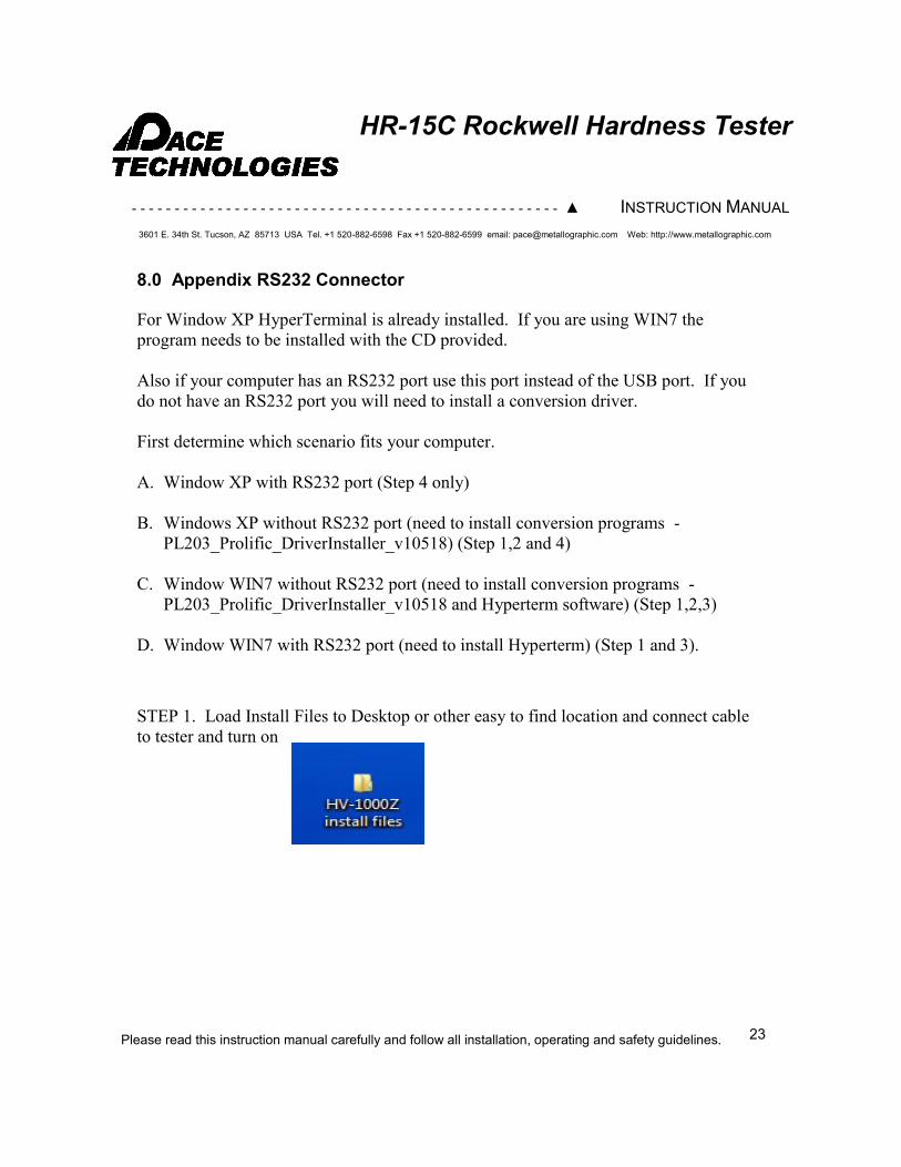
STEP 1. Load Install Files to Desktop or other easy to find location and connect cable
to tester and turn on
8.0 Appendix RS232 Connector
23
- - - - - - - - - - - - - - - - - - - - - - - - - - - - - - - - - - - - - - - - - - - - - - - - - - ▲ INSTRUCTION MANUAL
3601 E. 34th St. Tucson, AZ 85713 USA Tel. +1 520-882-6598 Fax +1 520-882-6599 email: [email protected] Web: http://www.metallographic.com
Please read this instruction manual carefully and follow all installation, operating and safety guidelines.
HR-15C Rockwell Hardness Tester
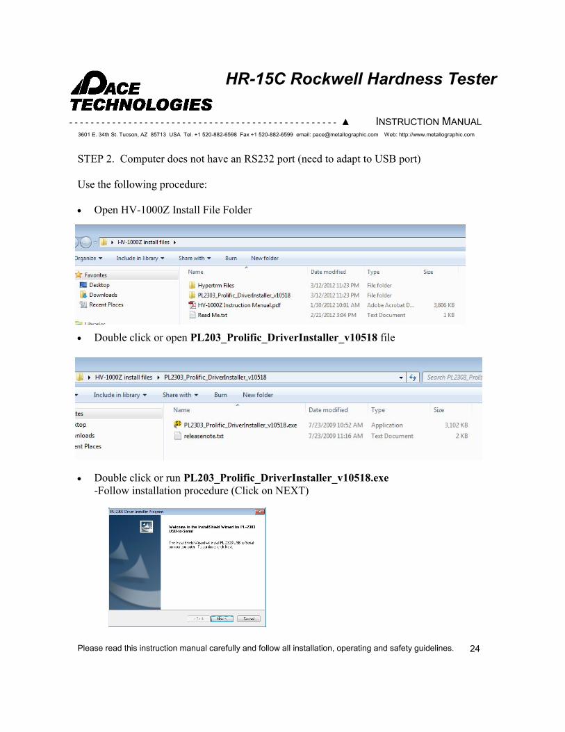
STEP 2. Computer does not have an RS232 port (need to adapt to USB port)
Use the following procedure:
Open HV-1000Z Install File Folder
Double click or open PL203_Prolific_DriverInstaller_v10518 file
Double click or run PL203_Prolific_DriverInstaller_v10518.exe
-Follow installation procedure (Click on NEXT)
24
- - - - - - - - - - - - - - - - - - - - - - - - - - - - - - - - - - - - - - - - - - - - - - - - - - ▲ INSTRUCTION MANUAL
3601 E. 34th St. Tucson, AZ 85713 USA Tel. +1 520-882-6598 Fax +1 520-882-6599 email: [email protected] Web: http://www.metallographic.com
Please read this instruction manual carefully and follow all installation, operating and safety guidelines.
HR-15C Rockwell Hardness Tester
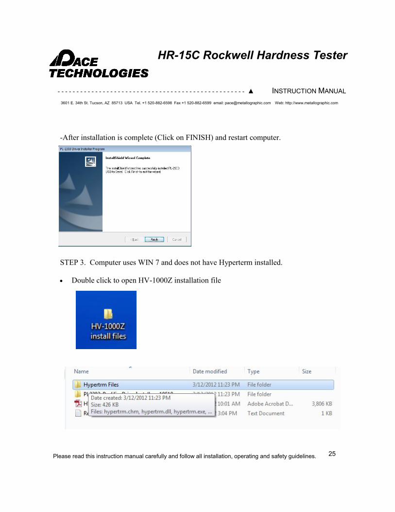
-After installation is complete (Click on FINISH) and restart computer.
STEP 3. Computer uses WIN 7 and does not have Hyperterm installed.
Double click to open HV-1000Z installation file
25
- - - - - - - - - - - - - - - - - - - - - - - - - - - - - - - - - - - - - - - - - - - - - - - - - - ▲ INSTRUCTION MANUAL
3601 E. 34th St. Tucson, AZ 85713 USA Tel. +1 520-882-6598 Fax +1 520-882-6599 email: [email protected] Web: http://www.metallographic.com
Please read this instruction manual carefully and follow all installation, operating and safety guidelines.
HR-15C Rockwell Hardness Tester
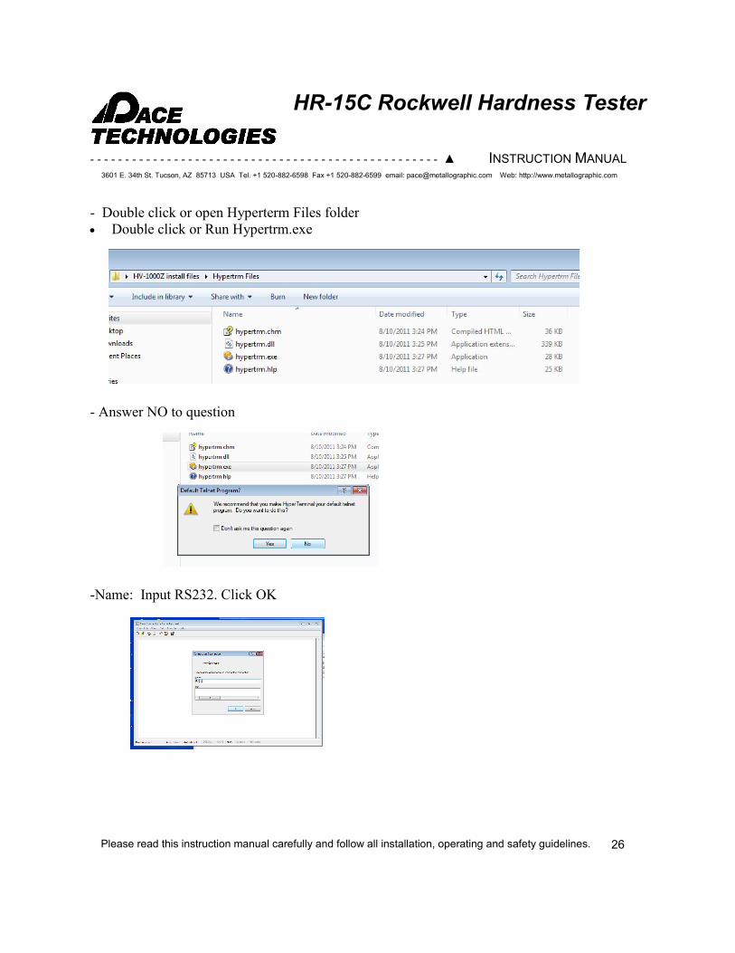
- Double click or open Hyperterm Files folder
Double click or Run Hypertrm.exe
- Answer NO to question
-Name: Input RS232. Click OK
26
- - - - - - - - - - - - - - - - - - - - - - - - - - - - - - - - - - - - - - - - - - - - - - - - - - ▲ INSTRUCTION MANUAL
3601 E. 34th St. Tucson, AZ 85713 USA Tel. +1 520-882-6598 Fax +1 520-882-6599 email: [email protected] Web: http://www.metallographic.com
Please read this instruction manual carefully and follow all installation, operating and safety guidelines.
HR-15C Rockwell Hardness Tester
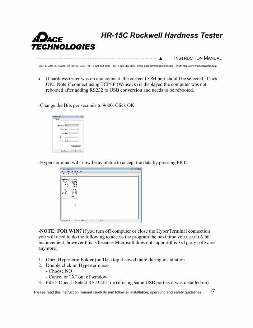
If hardness tester was on and connect the correct COM port should be selected. Click
OK. Note if connect using TCP/IP (Winsock) is displayed the computer was not
rebooted after adding RS232 to USB conversion and needs to be rebooted.
-Change the Bits per seconds to 9600. Click OK
-HyperTerminal will now be available to accept the data by pressing PRT
-NOTE: FOR WIN7 if you turn off computer or close the HyperTerminal connection
you will need to do the following to access the program the next time you use it (A bit
inconvenient, however this is because Microsoft does not support this 3rd party software
anymore).
1. Open Hyperterm Folder (on Desktop if saved there during installation_
2. Double click on Hyperterm.exe
- Choose NO
- Cancel or “X” out of window.
3. File > Open > Select RS232.ht file (if using same USB port as it was installed on)
27
- - - - - - - - - - - - - - - - - - - - - - - - - - - - - - - - - - - - - - - - - - - - - - - - - - ▲ INSTRUCTION MANUAL
3601 E. 34th St. Tucson, AZ 85713 USA Tel. +1 520-882-6598 Fax +1 520-882-6599 email: [email protected] Web: http://www.metallographic.com
Please read this instruction manual carefully and follow all installation, operating and safety guidelines.
HR-15C Rockwell Hardness Tester
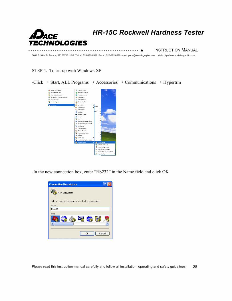
STEP 4. To set-up with Windows XP
-Click → Start, ALL Programs → Accessories → Communications → Hypertrm
-In the new connection box, enter “RS232” in the Name field and click OK
28
- - - - - - - - - - - - - - - - - - - - - - - - - - - - - - - - - - - - - - - - - - - - - - - - - - ▲ INSTRUCTION MANUAL
3601 E. 34th St. Tucson, AZ 85713 USA Tel. +1 520-882-6598 Fax +1 520-882-6599 email: [email protected] Web: http://www.metallographic.com
Please read this instruction manual carefully and follow all installation, operating and safety guidelines.
HR-15C Rockwell Hardness Tester
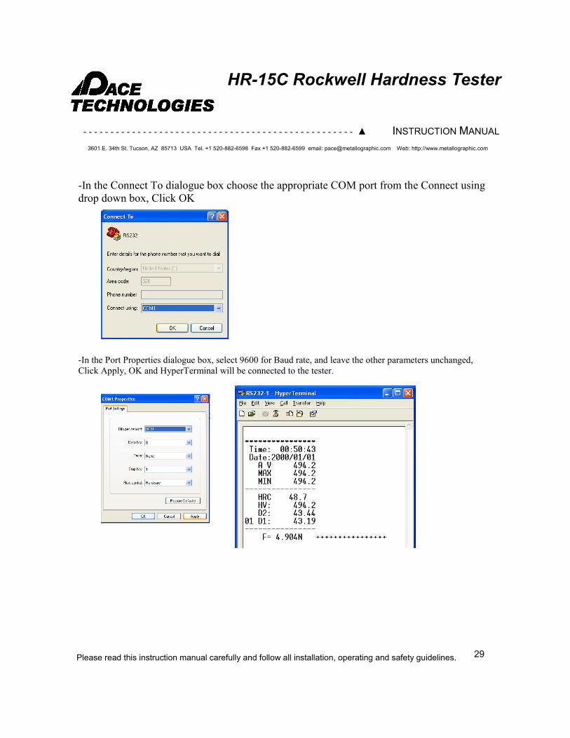
-In the Connect To dialogue box choose the appropriate COM port from the Connect using
drop down box, Click OK
-In the Port Properties dialogue box, select 9600 for Baud rate, and leave the other parameters unchanged,
Click Apply, OK and HyperTerminal will be connected to the tester.
29


![CLOSED AFRICA Imperialism. African Trade [15c-17c]](https://img.pdfslide.us/doc/110x75/56649e2d5503460f94b1d1d1/closed-africa-imperialism-african-trade-15c-17c.jpg)
