Embed Size (px)
Citation preview

INSTALLATION AND OPERATORS MANUAL
TRI-FUEL GENERATOR
HPS12000HE/F
2240-00 2 60706-236
SAVE THESE INSTRUCTIONSThis manual contains important instructions that should be followed during installation and main-tenance of the generator and battery. Read and understand all instructions in the manual before starting and operating the generator set.
USING THE MANUAL
Congratulations on your choice of a Winco genera-tor set. You have selected a high-quality, precision engineered generator set designed and tested to give you years of satisfactory service.
To get the best performance from your new engine generator set, it is important that you carefully read and follow the operating instructions in this manual.
Should you experience a problem please follow the “Troubleshooting Tables” near the end of this manual. The warranty listed in the manual describes what you can expect from WINCO should you need service assistance in the future.
TABLE OF CONTENTS
INTRODUCTION 2BASIC INFORMATION Specifications 2SAFETY INFORMATION 3UNIT CAPABILITIES 4PREPARING THE UNIT Unpacking the Unit 5 LP/NG Installation 6 Fuel Line Sizing 6 Fuel Consumption 7 Fuel Pressure 7 Tank Sizing for LP 8 Changing Fuel Types 8 Battery Installation 9 INITIAL START UP 10 Electric Starting for Gasoline 10 Electric Starting for LP/NG 11 Stopping & Storage 11 Operating Speed 11 CONNECTING THE LOADS 12 Wiring 13ENGINE CARE 14GENERATOR CARE 15TROUBLESHOOTING 16 CONTROL PANEL WIRING DIAGRAM 17 WARRANTY INFORMATION 18
PROPER USE AND INSTALLATIONYou must be sure your new engine generator set is: * Properly serviced before starting. * Operated in a well ventilated area. * Properly exhausted and gases safely dispersed. * Operated only for its designed purposes. * Used only by operators who understand its operation. * Properly maintained.
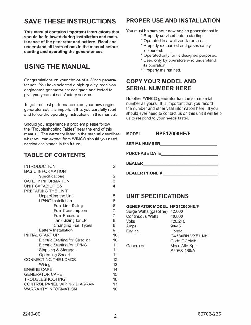
COPY YOUR MODEL AND SERIAL NUMBER HERE No other WINCO generator has the same serial number as yours. It is important that you record the number and other vital information here. If you should ever need to contact us on this unit it will help us to respond to your needs faster.
MODEL HPS12000HE/F
SERIAL NUMBER_________________________
PURCHASE DATE_________________________
DEALER_________________________________
DEALER PHONE # ________________________
UNIT SPECIFICATIONSGENERATOR MODEL HPS12000HE/FSurge Watts (gasoline) 12,000Continuous Watts 10,800Volts 120/240Amps 90/45Engine Honda GX630RH VXE1 NH1 Code GCAMHGenerator Mecc Alte Spa S20FS-160/A

33240 60706-236
SAFETY INFORMATIONThis engine generator set has been designed and manufactured to allow safe, reliable performance. Poor maintenance, improper or careless use can result in potentially deadly hazards; from electrical shock,exhaustgasasphyxiation,orfire.Pleaseread all safety instructions carefully before installa-tion or use. Keep these instructions handy for future reference. Take special note and follow all warnings on the unit labels and in the manuals.
ANSI SAFETY DEFINITIONS*********************************************************** DANGER:DANGER indicates an imminently hazardous situ-ation which, if not avoided, will result in death or serious injury. This signal word is to be limited to the most extreme situations.***********************************************************
***********************************************************WARNING:WARNING indicates a potentially hazardous situ-ation which, if not avoided, could result in death or serious injury.***********************************************************
***********************************************************CAUTION:CAUTION indicates a potentially hazardous situ-ation which, if not avoided, may result in minor or moderate injury. It may also be used to alert against unsafe practices.***********************************************************
1. ELECTRICAL SHOCK The output voltage pres-ent in this equipment can cause fatal electric shock. This equipment must be operated by a responsible person. a. Do not allow anyone to operate the generator without proper instruction. b. Guard against electric shock. c Avoid contact with live terminals or receptacles. d Use extreme care if operating this unit in rain or snow. e. Use only three-pronged grounded receptacles and extension cords. f. Be sure the unit is properly grounded to an external ground rod driven into the earth. 2. FIRE HAZARD Gasoline and other fuels pres-entahazardofpossibleexplosionand/orfire. a. Do not refuel when the engine is running or hot.
b. Keep fuel containers out of reach of children. c. Donotsmokeoruseopenflamenearthe generator set or fuel tank. d. Keepafireextinguishernearbyandknowits proper use. Fire extinguishers rated ABC by NFPA are appropriate. e. Store fuel only in an approved container, and only in a well ventilated area. f. Follow local codes for closeness to combustible material. 3. DEADLY EXHAUST GAS Exhaust fumes from any gasoline engine contain carbon monoxide, an in-visible, odorless and deadly gas that must be mixed with fresh air. a. Operate only in well ventilated areas. b. Never operate indoors including attached garages c. Never operate the unit in such a way as to allow exhaust gases to seep back into closed rooms(i.e.throughwindows,walls,floors).
4. NOISE HAZARD Excessive noise is not only tiring, but continual exposure can lead to loss of hearing. a. Use hearing protection when working around this equipment for long periods of time. b. Keep your neighbors in mind when using this equipment.
5. CLEANLINESS Keep the generator and sur-rounding area clean. a. Remove all grease, ice, snow or materials that create slippery conditions around the unit. b. Remove any rags or other materials that could createapotentialfirehazard. c. Carefully clean up any gas or oil spills before starting the unit.
6. SERVICING EQUIPMENT All service, includ-ing the installation or replacement of service parts, shouldbeperformedonlybyaqualifiedtechnician. a. Use only factory approved repair parts. b. Do not work on this equipment when fatigued. c. Never remove the protective guards, covers, or receptacle panels while the engine is running. d. Use extreme caution when working on electrical components. High output voltage from this equipment can cause serious injury or death. e. Alwaysavoidhotmufflers,exhaustmanifolds, and engine parts. They can cause severe burns instantly. f. The use of the engine-generator set must comply with all national, state, and local codes.
2240-00 4 60706-236
TESTING POLICY Before any generator is shipped from the factory, it is fully checked for performance. The generator is loaded to its full capacity, and the voltage, current and frequency are carefully checked.
Rated output of generator is based on engineering tests of typical units, and is subject to, and limited by, the temperature, altitude, fuel, and other condi-tionsspecifiedbythemanufactureroftheapplicableengines.
INTENDED USES This engine generator set has been designed pri-marily for portable heavy duty commercial use. Both 120 volt and 240 volt receptacles are provided in the control panel to plug in your loads (lights, portable tools, and small appliances). These units are dual wound generators, therefore the 120 volt loads must be equally split with 1/2 of the rated capacity avail-able on each of the two 120 volt circuits.
This portable unit requires large quantities of fresh air for cooling the engine and generator. For safety, long life and adequate performance, these units should never be run in small compartments without positivefreshairflow.
RESTRICTED USESDO NOT remove from the cradle assembly. Re-moval of the generator from the cradle assembly may cause excessive vibration and damage to the engine-generator set.
DO NOT install and operate this generator in a small compartment., i.e. generator compartments of ve-hicles, motor homes or travel trailers. These com-partmentswillnotallowenoughfreeflowoffreshair to reach the engine generator set for cooling and will cause the unit to overheat, damaging both the engine and generator. Small compartments will also develophotspotswherethereisverylittleairflowandmaycauseafire.
PLEASE NOTE There are 3rd party companies making enclosures for generators that have been properly engineered. The use of these 3rd party enclosures is acceptable as long as they have been certifiedandmeetcurrentcode.
DO NOT attempt to operate at 50 cycles. These units are designed and governed to operate at 60 cycles only.
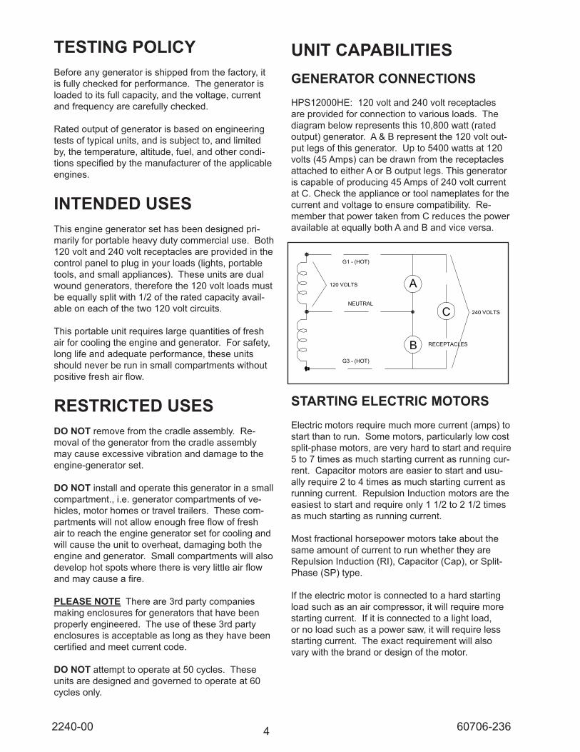
UNIT CAPABILITIESGENERATOR CONNECTIONSHPS12000HE: 120 volt and 240 volt receptacles are provided for connection to various loads. The diagram below represents this 10,800 watt (rated output) generator. A & B represent the 120 volt out-put legs of this generator. Up to 5400 watts at 120 volts (45 Amps) can be drawn from the receptacles attached to either A or B output legs. This generator is capable of producing 45 Amps of 240 volt current at C. Check the appliance or tool nameplates for the current and voltage to ensure compatibility. Re-member that power taken from C reduces the power available at equally both A and B and vice versa.
STARTING ELECTRIC MOTORSElectric motors require much more current (amps) to start than to run. Some motors, particularly low cost split-phase motors, are very hard to start and require 5 to 7 times as much starting current as running cur-rent. Capacitor motors are easier to start and usu-ally require 2 to 4 times as much starting current as running current. Repulsion Induction motors are the easiest to start and require only 1 1/2 to 2 1/2 times as much starting as running current.
Most fractional horsepower motors take about the same amount of current to run whether they are Repulsion Induction (RI), Capacitor (Cap), or Split-Phase (SP) type.
If the electric motor is connected to a hard starting load such as an air compressor, it will require more starting current. If it is connected to a light load, or no load such as a power saw, it will require less starting current. The exact requirement will also vary with the brand or design of the motor.
53240 60706-236
Self-exciting generators respond to severe overload-ing differently than utility power. When overloaded, the engine is not able to supply enough power to bring the electric motor up to operating speed. The generator responds with high initial starting current, but the engine speed drops sharply. The overload may stall the engine. If allowed to operate at very low speeds, the electric motor starting winding will burn out in a short time. The generator winding may also be damaged.
CAUTION: EQUIPMENT DAMAGE
RUNNING THE GENERATOR SET UNDER THESE CONDITIONS MAY RESULT IN DAMAGE TO THE GENERATOR STATOR AS WELL AS THE MOTOR WINDING.
The heavy surge of current required for starting motors is required for only an instant. The genera-tor will not be damaged if it can bring the motor up tospeedinafewsecondsoftime.Ifdifficultyisexperienced in starting motors, turn all other electri-cal loads off and if possible reduce the load on the electric motor.
PREPARING THE UNITUNPACKINGCAUTION: EQUIPMENT DAMAGE
THIS UNIT HAS BEEN SHIPPED WITHOUT OIL. Failure to maintain the engine oil at the proper level will result in serious engine damage.
When you unpack your new engine-generator set be sure to remove all the information sheets and manu-als from the carton.
1. This generator-set was in good order when shipped. Inspect the generator-set promptly after receiving it. If any damage is noted, notify the trans-portation company immediately; request proper pro-ceduresforfilinga“concealeddamage”claim.Titletotheequipmentandresponsibilityforfilingaclaimrests with you when a generator-set is sent F.O.B. shippingpoint.Onlyyoucanlegallyfileaclaim.
2. Before proceeding with the preparations of your new generator-set for operation, take a couple of minutes to ensure the unit you have received is the correctmodelandreviewthespecificationpagesinthis manual to ensure that this unit meets your job requirements.
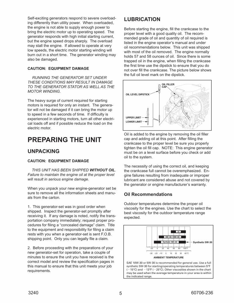
LUBRICATIONBeforestartingtheengine,fillthecrankcasetotheproper level with a good quality oil. The recom-mended grade of oil and quantity of oil required is listed in the engine operator’s manual and under oil recommendations below. This unit was shipped with most of the oil removed. The engine normally holds 57 and 58 ounces of oil. Since there is some trappedoilintheengine,whenfillingthecrankcasethefirsttimeusethedipsticktoensurethatyoudonotoverfillthecrankcase.Thepicturebelowshowsthe full oil level mark on the dipstick.
Oilisaddedtotheenginebyremovingtheoilfillercapandaddingoilatthispoint.Afterfillingthecrankcase to the proper level be sure you properly tightentheoilfillcap.NOTE:Thisenginegeneratormust be on a level surface before you check or add oil to the system. The necessity of using the correct oil, and keeping the crankcase full cannot be overemphasized. En-gine failures resulting from inadequate or improper lubricant are considered abuse and not covered by the generator or engine manufacturer’s warranty. Oil Recommendations
Outdoor temperatures determine the proper oil viscosity for the engines. Use the chart to select the best viscosity for the outdoor temperature range expected.
- - -
ENGLISH
ENGINE OIL
Recommended Oil
Oil Level Check
Oil Change
AMBIENT TEMPERATURE
OIL FILLERCAP
UPPER LIMIT
LOWER LIMIT
OIL LEVEL DIPSTICK
UPPERLIMIT
LOWERLIMIT
SEALING WASHER
DRAIN BOLT
OIL FILLER CAP OIL LEVEL DIPSTICKSynthetic 5W-30
8
Use 4-stroke motor oil that meets or exceeds the requirements forAPI service category SJ or later (or equivalent). Always check theAPI service label on the oil container to be sure it includes theletters SJ or later (or equivalent).
Check the engine oil level with the engine stopped and in a levelposition.
Start the engine and let it idle for 1 or 2 minutes. Stop the engineand wait for 2 or 3 minutes.
Remove the oil level dipstick and wipe it clean.
Fully insert the oil level dipstick, then remove it to check the oillevel.
If the oil level is low, remove the oil filler cap, and fill with therecommended oil to the upper limit mark on the oil level dipstick.
Reinstall the oil level dipstick and oil filler cap.
The Oil Alert system (applicable types) will automatically stop theengine before the oil level falls below the safe limit. However, toavoid the inconvenience of an unexpected shutdown, alwayscheck the engine oil level before startup.
Oil is a major factor affecting performance and service life.Use 4-stroke automotive detergent oil.
Drain the used oil when the engine is warm. Warm oil drainsquickly and completely.
Place a suitable container below the engine to catch the used oil,then remove the oil filler cap, drain bolt and sealing washer.
Allow the used oil to drain completely, then reinstall the drainbolt and new sealing washer, and tighten the drain bolt securely.
Please dispose of used motor oil in a manner that is compatiblewith the environment. We suggest you take used oil in a sealedcontainer to your local recycling center or service station forreclamation. Do not throw it in the trash, pour it on the ground,or pour it down a drain.
Reinstall the oil filler cap and oil level dipstick securely.
The Oil Alert system (applicable types) will automatically stopthe engine before the oil level falls below the safe limit.However, to avoid the inconvenience of an unexpectedshutdown, fill to the upper limit, and check the oil level regularly.
With the engine in a level position, fill with the recommended oilto the upper limit mark on the oil level dipstick.
Running the engine with a low oil level can cause engine damage.This type of damage is not covered by the Distributor’s LimitedWarranty.
Running the engine with a low oil level can cause enginedamage. This type of damage is not covered by the Distributor’sLimited Warranty.
SAE 10W-30 or 5W-30 is recommended for general use. Use a fullsynthetic 5W-30 for starting/operating temperatures between 5°F( 15°C) and 13°F ( 25°C). Other viscosities shown in the chartmay be used when the average temperature in your area is withinthe indicated range.
1.
2.
3.
4.
5.
1.
2.
3.
4.
09/07/07 20:34:57 32Z6L600_008

2240-00 6 60706-236
GASOLINEWhen using gasoline, always use fresh, clean, unleadedfuel.Thisengineiscertifiedtooperateonunleaded gasoline with a minimum octane rating of 87 or higher. Gasoline containing no more than 10% ethanol is acceptable. CAUTION: EQUIPMENT DAMAGE Do not use unapproved gasolines, such as E15 or E85. Do not mix oil in the gasoline. Use of unap-proved fuels will damage the engine components and void the engine warranty. Use of fuels with content of ethanol greater than shown above may cause starting and/or performance problems. Always ensure that the fuel is clean and free of all impurities.
WARNING: FIRE DANGER
Gasoline and its fumes are VERY explosive when proper precautions are not taken.
Never use gasoline that has been stored for an ex-tended period of time as the fuel will lose its volatile properties and you will be left with varnish residue. The varnish like substance will clog the carburetor and will not burn properly. The use of fuel additives, such as STA-BIL, or an equivalent will minimize the formation of fuel gum deposits. If a unit has been out of operation for an extended period of time, it is best to drain old fuel from the engine and replace with fresh fuel before attempting to start. See the engine manual for special instruction for operating this unit at over 5000 feet
LP/NG FUEL INSTALLATIONThe information in this instruction is offered to assist you in providing the proper vapor fuel supply for your engine. This information is only provided to advise you of the engine’s requirements and the decisions you must make. In no case should this information be interpretedtoconflictwithanylocal,stateornationalcode. If in doubt, always follow local codes.
DANGER: FIRE - PERSONAL INJURY -
All fuel lines must be installed by a qualified fuel supplier.
The fuel source should be as close as possible to the outdoor operating location. This will reduce the installation cost of fuel runs. Connect the fuel supply line to the inlet of the fuel demand regulator on the unitusingalocallyapprovedflexiblefuelline(seetable for recommended line size). The pressure supplied to the demand regulator must be FOUR TO SIX OUNCES or 7 to 11 INCHES W.C. (water column). The primary regulator at the fuel supply must be capable of delivering the proper volume of fuel at this pressure.
Have your local fuel supplier install a protected fuel connection at the outside operating location. They should also install a lockable fuel shut off valve at the connectionpoint.Anapprovedflexiblefuellinemustbe installed between the engine generator set and the supply line.
DANGER: FIRE - PERSONAL INJURY -
The LP/NG fuel supply line must always be shut off when the engine is not running. Failure to do so may allow fuel to leak at the unit.
INSTALLING THE FUEL LINE
DANGER: PERSONAL INJURY
Units that are intended to be run unattended MUST have an electric fuel solenoid installed. This solenoid MUST be wired to AUTOMATICALLY turn off the fuel whenever the engine stops.
Unit location will determine the size of fuel line that is required to supply the engine with a constant fuel pressure. Refer to the tables below for fuel line size, and recommended tank size. For distances of 100 feet and over, a two regulator fuel system is recom-mended. This system consisting of a primary 10-15# regulator at the tank and a 6 ounce secondary regula-tor installed about 10 feet from the generator. You need to run a 3/4 inch line or larger from the second-ary regulator to the engine-generator set. When a two (2) regulator fuel system is used, a fuel line size of 3/8 inch is generally adequate for distances up to 300 feet. The line size from the table below applies to the distance from the second regulator to the demand regulator. A positive fuel shut-off device must be installed in the fuel line close to the engine generator set. This manual shut-off valve is require by code even if the 12 volt fuel solenoid kit is installed. This optional 12 volt DC valve is available through your local Winco dealer and can be used to shut the fuel off during normal periods of operation with-out having to shut off the manual valve.
73240 60706-236
The fuel line used to connect the supply line to the demandregulatormustbealocallyapprovedflexiblefuel line. Products used will vary in different regions depending on availability and local codes. Consult with your local fuel supplier to ensure complete com-pliance with ALL codes.
1. Remove the plastic cover plug from the demand regulator.
2.Connecttheflexfuellinetothedemandregulatoror the optional fuel solenoid..
DANGER: PERSONAL INJURY Do not use galvanized pipe in the fuel line runs. The galvanized coating will become eroded and flake off, causing possible obstruction or damage to the regulator or fuel valve. The obstruction could cause an inoperative engine or an explosive fuel leak.
Size of pipe required for generators operating on natural gas/LP gas.
Length of Fuel Line* Fuel Line Size less than 25 feet 3/4 inch black pipe 25 to 100 feet 1 inch black pipe over 100 feet not recommended***allow an additional 3 feet for each standard elbow. Do not use ‘street ells’ (restrictive)** Consult factory for fuel runs over 100 feet.
DANGER! - FIRE - PERSONAL INJURY - Be careful when sealing gas joints. Excessive sealing compound can be drawn into the solenoid, regulator or carburetor causing an engine malfunc-tion or dangerous fuel leak. FUEL CONSUMPTION (Full Load) Gasoline 1.67 Gal/HR LP Vapor 2.2 Gal/HR 200,932 BTU/HR Natural Gas 200 cu ft/hr 200,000 BTU/HR FUEL PRESSURE
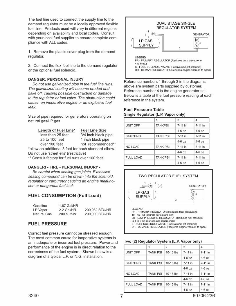
Correct fuel pressure cannot be stressed enough. The most common cause for inoperative systems is an inadequate or incorrect fuel pressure. Power and performance of the engine is in direct relation to the correctness of the fuel system. Shown below is a diagram of a typical L.P. or N.G. installation.
Reference numbers 1 through 3 in the diagrams above are system parts supplied by customer.Reference number 4 is the engine generator set.Below is a table of the fuel pressure reading at each reference in the system.
Fuel Pressure TableSingle Regulator (L.P. Vapor only)
1 3 4
UNIT OFF TANKPSI 7-11 in 7-11 in
4-6 oz 4-6 oz
STARTING TANK PSI 7-11 in 7-11 in
4-6 oz 4-6 oz
NO LOAD TANK PSI 7-11 in 7-11 in
4-6 oz 4-6 oz
FULL LOAD TANK PSI 7-11 in 7-11 in
4-6 oz 4-6 oz
Two (2) Regulator System (L.P. Vapor only) 1 2 3 4
UNIT OFF TANK PSI 10-15 lbs 7-11 in 7-11 in
4-6 oz 4-6 oz
STARTING TANK PSI 10-15 lbs 7-11 in 7-11 in
4-6 oz 4-6 oz
NO LOAD TANK PSI 10-15 lbs 7-11 in 7-11 in
4-6 oz 4-6 oz
FULL LOAD TANK PSI 10-15 lbs 7-11 in 7-11 in
4-6 oz 4-6 oz
2240-00 8 60706-236
Natural Gas 2 3 4UNIT OFF LINE PSI 7-11 in 7-11 in 4-6 oz 4-6 ozSTARTING LINE PSI 7-11 in 7-11 in
4-6 oz 4-6 oz NO LOAD LINE PSI 7-11 in 7-11 in
4-6 oz 4-6 ozFULL LOAD LINE PSI 7-11 in 7-11 in
4-6 oz 4-6 oz
Remember that whichever fuel delivery system or type of vapor fuel used, the fuel pressure at the demand regulator installed on the engine generator must be between 4 and 6 oz. (7-11 inches of water column). Any lower pressure and the unit will starve forfuelunderload.Anyhigherandtheunitwill‘flood’when attempting to start.
LP TANK SIZING
The tank sizes shown below are the smallest recom-mended tank sizes based on the outside temperature. Once above this minimum acceptable size, the size of L.P. tank used will generally depend on how long you wanttheunittorunwithoutrefilling.Keepinmindthe colder it gets the slower L.P. will vaporize. This is the reason for the larger tanks at low temperature. Minimum sizing is not based on running time.
Temp f. 60 deg 30 deg 0 deg -20 deg 150 gal 250 gal 500 gal 1000 gal
CHANGING FUEL TYPES
These engine generator sets are designed to run on three different fuels; gasoline, natural gas or LP vapor. They may be easily changed from one fuel to another.
FROM GASOLINE TO LP/NG
1. With the engine running turn off the gasoline fuel valve.
2. Run the engine until it runs out of fuel.3. Remove the plastic insert from the demand
regulator.4. Installalocallyapprovedflexiblefuelline.5. ConnecttheLP/NGvaporfuellinetotheflex-
ible fuel line. You can’t connect the black iron pipe dir
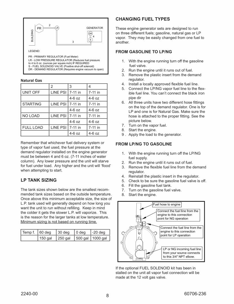
6. Allthreeunitshavetwodifferenthosefittingson the top of the demand regulator. One is for LP and one is for Natural Gas. Make sure the hoseisattachedtotheproperfitting.Seethepicture below.
7. Turn on the vapor fuel.8. Start the engine.9 . Apply the load to the generator.
FROM LP/NG TO GASOLINE
1. With the engine running turn off the LP/NG fuel supply.
2. Run the engine until it runs out of fuel.3. Removetheflexiblefuellinefromthedemand
regulator.4. Reinstall the plastic insert in the regulator. 5. Check to be sure the gasoline fuel valve is off.6. Fill the gasoline fuel tank.7. Turn on the gasoline fuel valve.8. Start the engine.
If the optional FUEL SOLENOID kit has been in stalled on the unit all vapor fuel connection will be made at the 12 volt gas valve.

93240 60706-236
BATTERY INSTALLATIONThis engine generator set is shipped with a battery tie down kit for customer installation. This kit consists of a battery tie down and hardware for installation of the customer supplied battery on the unit. This engine generator set is designed for electric start only, you will need to purchase and install a battery to operate it. .
A 12-volt battery, BCI group U1 rated at 300 CCA or larger is recommended for this electric start engine generator set. Follow the battery manufacturers rec-ommendations for servicing and charging prior to use. Connect the battery to the electric start system using the cables provided.
CAUTION: EQUIPMENT DAMAGE
These electric start engines are NEGATIVE GROUND. Use extreme caution when connecting the battery. Connect the NEGATIVE battery terminal to GROUND. Connecting the positive battery terminal to ground will damage the engines charging circuit.
For your safety always connect the positive battery cabletothe“bat+”terminalfirst.Thenconnectthenegative battery cable to the “bat-” terminal. Make sure all connections are clean and tight. Reverse the sequence when disconnecting, disconnect the nega-tivecablefirst.Theseenginesproduceenoughdirectcurrent to keep a battery charged under normal oper-ating conditions, but were not intended to be used as a battery charger.
WARNING: PERSONAL INJURY
Lead acid batteries produce explosive hydro-gen gas when charging. Keep sparks, flames, and burning cigarettes away from the battery. Ventilate the area when charging or using the battery in an enclosed space. Lead acid batteries contain sulfuric acid, which causes severe burns. If acid contacts eyes, skin or clothing, flush well with water. For con-tact with eyes, get immediate medical attention.
BATTERY CHARGING
Unitsequippedwithelectricstarthaveasmallfly-wheelchargerbuiltintotheengineflywheelassemblyforrechargingthestartingbattery.Thisflywheelcharger generates a small AC current that passes through a diode assembly to produce a DC charg-ing current of about 1 to 3 AMPS. This circuit is not designed to be used as a battery charging circuit to recharge dead batteries.
OIL ALERT SYSTEM
This WINCO generator is equipped with a low oil shutdownsystem.ThisHondaengineusesanfloatswitch mounted inside the engine. If the oil level drops below a certain point the low oil module on the engine will shut it down. This low oil warning system will automatically stop the engine before the oil level reaches a critical danger point. This feature is de-signed to prevent costly repairs and downtime.
CAUTION: EQUIPMENT DAMAGE
Allowing the engine to shutdown repeatedly on low oil level may cause excessive wear which can be cumulative.
STANDARD DOLLY KITAn 4-wheel dolly kit come with this generator. The dolly kit comes with instructions and parts list. After installingthedollykit,filetheinstructionsandpartslist in the back of this manual for future reference.
OPTIONAL FUEL SOLENOID KITAn optional 12 volt DC fuel solenoid kit is available for this generator. This solenoid kit will automatically shut off the fuel supply should the engine stop for any reason will operating preventing fuel leaks. This kit is recommended if you are going to be operating the generator unattended.

2240-00 10 60706-236
INITIAL START UPThe throttle control on these generators is preset and locked to operate at 3600 RPM (nominal) with no load speed set at 3690 RPM. Only a trained service technician should be allowed to adjust this speed setting.
NOTICE: ENGINE START LOCKOUT
This unit will not start if it is low on oil. The lu-bricating oil level must be at the full mark before the engine will start and run.
BASIC OPERATIONThis engine is electric start only. The batteries must be maintained in good condition to prevent hard start-ing or damage to the engine mounted starter.
GASOLINE STARTING 1. Checkoillevel,refillasneeded
2. Turn on the fuel supply. Ref “A” Lever pointing up is on, lever pointing down is off.3. Pull the choke out to the full “closed” position. A warm engine will require less choking than a cold engine.
4. Turn the engine switch to the “on” position
5.. Operating the starter. Rotate the key switch brieflytotheSTARTposition.Thestarterlifeis improved by using shorter starting cycles with time to cool off between cranking cycles. Do not operate the starter more than 5 seconds and wait at least 10 seconds before operating the starter again, Repeat cycle if necessary. 6. When the engine starts, release the key switch, allowing it to return to the “on” position.
7. Gradually push the choke to the open position as the engine warms up..6. The engine should promptly come up to operating speed.CAUTION: EQUIPMENT DAMAGE
Never permit the choke to remain on after the engine has run for a short time. It is not necessary to choke the engine when it is warm. Avoid over-choking.
ENGLISH
STOPPING THE ENGINE
MMIINN..MMIINN..
START
ENGINESWITCH
START
ENGINESWITCH
THROTTLE LEVER
OONN
CHOKE KNOB
OOPPEENNCCLLOOSSEEDD
OONN
OONN
MMIINN..MMIINN..
THROTTLE LEVER
ENGINE SWITCH
OFF
OFF
5
Some engine applications use a remote-mounted throttle controlrather than the engine-mounted throttle lever shown here. Refer tothe instructions provided by the equipment manufacturer.
Turn the engine switch tothe ON position.
Operate the starter.
Turn the engine switch to the STARTposition, and hold it there until theengine starts.
If the engine fails to start within 5seconds, release the engine switch,and wait at least 10 seconds beforeoperating the starter again.
Using the electric starter for more than5 seconds at a time will overheat thestarter motor and can damage it.
When the engine starts, release theengine switch, allowing it to returnto the ON position.
Move the throttle lever away from the MIN. position, about 1/3of the way toward the MAX. position.
Warm up the engine for 2 or 3 minutes.
If the choke knob was pulled to the CLOSED position to start theengine, gradually push it to the OPEN position as the enginewarms up.
To stop the engine in an emergency, simply turn the engine switchto the OFF position. Under normal conditions, use the followingprocedure. Refer to the instructions provided by the equipmentmanufacturer.
Move the throttle lever to the MIN. position.
Some engine applications use a remote-mounted throttlecontrol rather than the engine-mounted throttle lever shownhere.
Turn the engine switch to the OFF position.
If the fuel tank is equipped with a valve, turn the fuel valve to theCLOSED or OFF position.
3.
4.
5.
6.
7.
3.
1.
2.
09/07/07 20:33:44 32Z6L600_005
A

113240 60706-236
LP/NG STARTING 1. Checkoillevel,refillasneeded.2. Turn on the LP/NG fuel supply3. NEVER USE THE CHOKE WHEN OPERATING ON LP/NG.. 4. Turn the engine switch to the “on” position
5.. Operating the starter. Rotate the key switch brieflytotheSTARTposition.Thestarterlifeis improved by using shorter starting cycles with time to cool off between cranking cycles. Do not operate the starter more than 5 seconds and wait at least 10 seconds before operating the starter again, Repeat cycle if necessary. 6. When the engine starts, release the key switch, allowing it to return to the “on” position.
7. The engine should promptly come up to operating speed.
STARTING HINTS
1. Cold weather a. Use the proper oil for the temperature expected. b. Use fresh winter grade fuel. Winter grade gasoline is blended to improve starting. Do not use summer grade gasoline.
2. Hot weather a. Use the proper oil for the temperature expected. b. Use only summer blended gasoline. Using gasoline left over from winter may cause the unit to vapor lock. STOPPING AND STORAGE
1. Move the key switch to the “OFF” position. 2. Turn off the fuel supply valve.3. Before extended storage (over 30 days) certain precautions must be taken to ensure the fuel doesn’t deteriorate and clog the fuel system. Note: The use of a fuel additive, such a STA-BIL or equivalent will minimize the formation of gum depos-its during storage. The additive may be added to gasoline in the engines fuel tank or to gasoline in a storage container. a. Add the fuel stabilizer to the fuel in the tank and run the unit for 2 minutes to circulate the stabilizer throughout the fuel system. b. If you choose to remove the remaining fuel from the fuel tank, it must be drained into an approved container. c. Start the engine and allow it to run until all the fuel in the carburetor and the fuel lines has been used up and the engine stops.
Note: Running the engine to use up the fuel in the lines and carburetor will still leave a small amount of fuel in the carburetor. It is best for extended storage to treat the fuel before draining.
d. While the engine is warm, drain the oil and refillwithfreshoil. e. Clean dirt and chaff from cylinder, cylinder headfins,blowerhousing,screenand mufflerareas. f. Store in a clean and dry area.
OPERATING SPEED
The engine-generator must be run at the correct speed in order to produce the proper electrical volt-age and frequency.CAUTION: EQUIPMENT DAMAGE
The output voltage should be checked to ensure the generator is working properly prior to connecting a load to the generator. Failure to do so could result in damage to equipment plugged into the unit and possible injury to the individual.
ENGLISH
STOPPING THE ENGINE
MMIINN..MMIINN..
START
ENGINESWITCH
START
ENGINESWITCH
THROTTLE LEVER
OONN
CHOKE KNOB
OOPPEENNCCLLOOSSEEDD
OONN
OONN
MMIINN..MMIINN..
THROTTLE LEVER
ENGINE SWITCH
OFF
OFF
5
Some engine applications use a remote-mounted throttle controlrather than the engine-mounted throttle lever shown here. Refer tothe instructions provided by the equipment manufacturer.
Turn the engine switch tothe ON position.
Operate the starter.
Turn the engine switch to the STARTposition, and hold it there until theengine starts.
If the engine fails to start within 5seconds, release the engine switch,and wait at least 10 seconds beforeoperating the starter again.
Using the electric starter for more than5 seconds at a time will overheat thestarter motor and can damage it.
When the engine starts, release theengine switch, allowing it to returnto the ON position.
Move the throttle lever away from the MIN. position, about 1/3of the way toward the MAX. position.
Warm up the engine for 2 or 3 minutes.
If the choke knob was pulled to the CLOSED position to start theengine, gradually push it to the OPEN position as the enginewarms up.
To stop the engine in an emergency, simply turn the engine switchto the OFF position. Under normal conditions, use the followingprocedure. Refer to the instructions provided by the equipmentmanufacturer.
Move the throttle lever to the MIN. position.
Some engine applications use a remote-mounted throttlecontrol rather than the engine-mounted throttle lever shownhere.
Turn the engine switch to the OFF position.
If the fuel tank is equipped with a valve, turn the fuel valve to theCLOSED or OFF position.
3.
4.
5.
6.
7.
3.
1.
2.
09/07/07 20:33:44 32Z6L600_005

2240-00 12 60706-236
All engines have a tendency to slow down when a load is applied. When the electrical load is connected to the generator, the engine is more heavily loaded, and as a result the speed drops slightly. This slight decrease in speed, together with the voltage drop within the generator itself, results in a slightly lower voltage when the generator is loaded to its full capac-ity than when running no load. The slight variation in speed also affects the frequency of the output current. This frequency variation has no appreciable effect in the operation of motors, lights and most ap-pliances. However, electronic equipment and clocks will be affected if correct RPM is not maintained. See Load vs. Output chart.
Although individual units and models vary slightly, the normal voltage and frequency of the engine-genera-tor described in this manual are approximately as follows, under varying loads:
LOAD VS. OUTPUTGenerator
LoadSpeed (RPM)
Frequency (Hz)
Voltage
None 3690 61.5 125VHalf 3600 60.0 120VFull 3510 58.5 115V
The speed of the engine was carefully adjusted at the factory so that the generator produces the proper voltage and frequency. For normal usage, the speed setting should not be changed. If the generator is being run continuously on a very light load, it is often advisable to lower the operating speed slightly. Reference “D” below is the speed adjustment for this engine.
CAUTION: EQUIPMENT DAMAGE SPEED ADJUSTMENTS SHOULD ONLY BE MADE BY A QUALIFIED SERVICE TECH. Whenever making any speed adjustments, check the unit with a voltmeter and a frequency meter or tachometer and be sure the voltage and speed are correct.
Lower voltage may damage both the generator and any load connected to it. Running the engine at ex-cessively high speeds results in high voltage, which maysignificantlyshortenthelifeofappliancesbeingused.Output voltage should be checked periodically to ensure continued proper operation of the generat-ing plant and appliances. If the generator is not equipped with a voltmeter, it can be checked with a portable meter.
CONNECTING THE LOADSAPPLYING THE LOADSAllow the engine to warm up for two or three minutes before applying any load. This will allow the engine to reach normal operating temperature and oil to circu-late throughout the engine. A short warm-up time will permittheenginetoworkmoreefficientlywhentheload is applied and will reduce the wear in the engine, extending its life.
Receptacles have been provided to allow loads to be connected to the generator. The loads should be added one at a time. If a large motor is being started; or multiple motors are being started, they should be started individually and the largest should be started first.
CAUTION: EQUIPMENT OVERLOAD
Keep the generator load within the generator andreceptacle nameplate rating. Overloading may causedamage to the generator and/or the loads .
Most electric tools and appliances will have the volt-age and amperage requirements on their individual nameplates. When in doubt, consult the manufacturer or a local electrician. The nameplate amperage rating for electric motors can be misleading. See “Starting Electric Motors” in Unit Capabilities (page 4).
These engine-generator sets are inherently self regu-lating based on engine speed. The engine governor will automatically adjust itself to the load. No harm to the generator will result if it is operated with no load connected. Proper utilization of the receptacles located on the control panel is necessary to prevent damage to either the receptacles or the generator.
D

133240 60706-236
The generator is a limited source of electrical power, therefore, pay special attention to the receptacle and generator ratings. The nameplate rating can be obtained through a single receptacle as long as the receptacle amperage rating is not exceeded.
GROUNDING
All units must be grounded. Drive a 3/4 or 1” cop-per pipe or rod into the ground close to the engine-generator set. The pipe must penetrate moist earth. Connect an approved ground clamp to the pipe. Run a no. 10 Awg wire from clamp to the generator ground lug on the receptacle panel. Do not connect to a water pipe or to a ground used by a radio system. The engine-generators covered in this manual were designed primarily for portable use. If you are con-necting into a building wiring system that is already grounded using the 14-60 4 wire plug, you do not have to ground the unit. WARNING: PERSONAL DANGER DO NOT OPERATE THIS GENERATOR INDOORS. The unit should be stored in a warm dry location. Dur-ing a power outage, move the unit outdoors to a flat dry location such as a driveway or sidewalk. Never attempt to operate this generator in direct rain or snow. It must be protected during inclement weather.
WIRINGPlug your tools such as drills, saws, blowers, sump pump and other items to be powered directly into the generator receptacles. Before plugging in all the tools and cord sets, recheck the rating of the genera-tor set. Be sure it can handle the intended load and is compatible with the voltage, phase, and current rat-ings. ‘Hard Wiring’ this unit directly into a home or a temporary construction site electrical system is NOT A SIMPLE DO-IT-YOURSELF JOB. For your safety, allwiringmustbedonebyaqualifiedelectricianandconform to the National Electric Code and comply with all state and local codes and regulations. Check with local authorities before proceeding.
WARNING: PERSONAL DANGER
A fully isolated, double pole double throw manual transfer switch must be installed any time a generator is being connected to an existing distribution system. 1. These engine generator sets are designed for portable use. Receptacles are provided on the control panel to permit 120 volt portable appliances and tools to be plugged directly into them. Please
note that the 4-wire 240 volt receptacle on these units are designed to power both 120 or 240 volt loads. The plug for this receptacle can be wired for either 120 volt, 240 volt, or a combination of 120 and 240 volt loads depending on how the plug is wired. A full power 4-wire receptacle (two hot, one ground, and one neutral) has been provided on the control panel for use in temporary power applications requiring 120/240 volt power. Consult a licensed electrician for wiring the TemPower plug and connecting it as temporary service.
To connect these units directly to an un-powered, isolated construction site TemPower panel, have your electrician connect to the control panel using a 120/240 volt, 4-wire plug (14-60P).
2. If the generator set is be connected to an existingdistribution system, a fully isolated manual trans-fer switch must be installed. The transfer switch prevents damage to the generator and other circuit components if main line power is restored while the generator is connected. Installing a transfer switch also permits the use of normal fusing.
3. Many homes and construction sites are wired for at least 60 to 100 Amp entrance service, much greater than the capacity of this portable genera-tor. When installing the generator at these sites, a secondary emergency distribution panel may have to be installed, such as the Emergency Transfer/Service (ET/S) system available through your WINCO dealer. The emergency distribution panel must be installed by a licensed electrician according to all applicable codes. The electrician will move the critical circuits to be powered during the outage to the emergency panel. Keep in mind only a limited amount of amper-age is available from the generator set. Some circuit breakers may still have to be turned off to prevent an overload on the generator during the initial start up. See the nameplate on your generator for the amper-age capabilities of your unit.
CAUTION: EQUIPMENT DAMAGE
Failure to properly limit and balance the load ap-plied to the generator will cause the generator to produce low voltage and may damage the engine generator set. It may also cause severe damage to the loads connected to the generator at that time. Im-proper loading of the generator set constitutes abuse and will not be covered by warranty.

2240-00 14 60706-236
ENGINE CAREIf major engine service or repair is required, contact an authorized engine service center. The manufac-turer of these engines has established an excellent world-wide engine service organization. Engine ser-vice is very likely available from a nearby authorized dealer or distributor. Check the yellow pages of your local telephone directory under “Engines-Gasoline” for the closest engine repair center or ask the dealer from whom you purchased the power plant.
1. Change the oilafterthefirst5hoursofoperationand yearly or 100 hours thereafter under normal op-erating conditions. Change engine oil every 50 hours of operation if the engine is operated under heavy load, or in high ambient temperatures.a. Start the engine and warm it up, stop the engine and remove the spark plug wire to prevent it from accidently being started.
b. Remove oil drain bolt at base of the engine and drain the oil into an approved container.c. Removetheoilfilteranddisposeofitproperly.
d. Beforeyouinstallthenewoilfilter,cleanthefilter mounting base and coat the seal of the new oil filterwillcleanengineoil.e. Installtheoilfilterbyhanduntilthegasket contactstheoilfilteradapter,thentightentheoil filter1/2to3/4turns. f. Replace oil drain bolt making sure the sealing washer is in place..g. Removeoilcapplugandrefillwithnewoil. Refer to the table on page 5 for the proper grade of oil based on your operating temperature. NOTE: This engine requires 57 to 58 ounces of oil ifitiscompletelydrained.Usecautionwhenrefillingthe engine as some residual oil may have remained intheengine.Alwaysusethedipstickwhenfillingtheenginewithoiltopreventoverfilling. h. Replacefillercap.i. Start the engine up and warm it up.j. After warming up the engine, recheck the oil levelandrefillasnecessarytobringittothe proper level. See page 5 for proper oil level.
2. Checking the Oil Level: The oil level must al-ways be checked before the engine is started. Take care to remove any dirt or debris from around the oilfillplugbeforeremoving.Besuretheoillevelismaintained. Fill to the “FULL” mark on the dipstick.
3. Dual Element Air Filter: Clean and/or replace foampre-cleanerandairfilterannuallyorevery100hours. Service more often under dusty conditions. WARNING: EQUIPMENT DAMAGE
Never start or run the engine with the air filter re-moved a. Unsnap the air cleaner cover latches and remove cover
**
**
**
**
**
*
***
-
-
-
ENGLISH
SAFETY PRECAUTIONS
Carbon monoxide poisoning from engine exhaust.
Burns from hot parts.
Injury from moving parts.
MAINTENANCE SCHEDULE
REFUELING
Recommended Fuel
7
Make sure the engine is off before you begin any maintenanceor repairs. To prevent accidental startup, disconnect the sparkplug cap. This will eliminate several potential hazards:
Operate outside, away from open windows or doors.
Let the engine and exhaust system cool before touching.
Do not run the engine unless instructed to do so.
Read the instructions before you begin, and make sure you havethe tools and skills required.
To reduce the possibility of fire or explosion, be careful whenworking around gasoline. Use only a non-flammable solvent,not gasoline, to clean parts. Keep cigarettes, sparks and flamesaway from all fuel related parts.
Remember that an authorized Honda servicing dealer knows yourengine best and is fully equipped to maintain and repair it.
To ensure the best quality and reliability, use only new HondaGenuine parts or their equivalents for repair and replacement.
Service more frequently when used in dusty areas.
These items should be serviced by your Honda servicingdealer, unless you have the proper tools and are mechanicallyproficient. Refer to the Honda shop manual for serviceprocedures.
For commercial use, log hours of operation to determineproper maintenance intervals.
Failure to follow this maintenance schedule could result in non-warrantable failures.
Unleaded gasolineU.S.Except U.S.
Pump octane rating 86 or higherResearch octane rating 91 or higherPump octane rating 86 or higher
This engine is certified to operate on unleaded gasoline with apump octane rating of 86 or higher (a research octane rating of 91or higher).Refuel in a well ventilated area with the engine stopped. If theengine has been running, allow it to cool first. Never refuel theengine inside a building where gasoline fumes may reach flamesor sparks.You may use unleaded gasoline containing no more than 10%ethanol (E10) or 5% methanol by volume. In addition, methanolmust contain cosolvents and corrosion inhibitors. Use of fuelswith content of ethanol or methanol greater than shown abovemay cause starting and/or performance problems. It may alsodamage metal, rubber, and plastic parts of the fuel system. Enginedamage or performance problems that result from using a fuelwith percentages of ethanol or methanol greater than shownabove are not covered under the Warranty.
If your equipment will be used on an infrequent or intermittentbasis, please refer to the fuel section of the STORING YOURENGINE chapter (see page ) for additional informationregarding fuel deterioration.
Spilled fuel is not only a fire hazard, it causes environmentaldamage. Wipe up spills immediately.
Keep gasoline away from appliance pilot lights, barbecues,electric appliances, power tools, etc.
Refuel in a well-ventilated area before starting the engine. If theengine has been running, allow it to cool. Refuel carefully to avoidspilling fuel. It may be necessary to lower the fuel level dependingon operating conditions. After refueling, tighten the fuel tank capsecurely.
Refer to the instructions provided with the equipment powered bythis engine for refuelling.
With the engine stopped and on a level surface, remove the fuelfiller cap and check the fuel level. Refill the tank if the fuel level islow.
Never use stale or contaminated gasoline or an oil/gasolinemixture. Avoid getting dirt or water in the fuel tank.
Fuel can damage paint and some types of plastic. Be careful not tospill fuel when filling your fuel tank. Damage caused by spilledfuel is not covered under the Distributor’s Limited Warranty.
Gasoline is highly flammable and explosive, and youcan be burned or seriously injured when refueling.
Stop the engine and keep heat, sparks, and flameaway.Refuel only outdoors.Wipe up spills immediately.
Replace the paper filter element only.Refer to the Shop Manual.
(1)
(2)
(3)
11REGULAR SERVICE PERIOD (3)
Perform at every
indicated month or
operating hour interval,
whichever comes first.
ITEM
Engine oil
Engine oil filter
Air cleaner
Spark plug
Spark arrester
( )
Idle speed
Valve clearance
Combustion
chamber
Fuel filter
Fuel tube
Check level
Change
Replace
Check
Clean
Replace
Check-adjust
Replace
Clean
Check-adjust
Check-adjust
Clean
Replace
Check
First
Month
or
20 Hrs
Refer
to
Page
8
8
9
9
9
10
11
Every 6
Months
or
100 Hrs
(1)
Every
Year
or
300 Hrs
(2)
(2)
(2)
Every 2
Years
or
500 Hrs
Each
Use
Every 200 Hrs.
After every 1000 Hrs. (2)
Every 2 years (Replace if necessary) (2)
applicable types
09/07/07 20:34:32 32Z6L600_007
ENGLISH
AIR CLEANER
Inspection
Cleaning
OIL FILTER
Change
OIL FILTER
SEAL
FILTER MOUNTING BASE OIL FILTER SOCKET
AIR CLEANER COVER LATCH
AIR CLEANER CASE
PACKING
FOAM FILTERELEMENT
PAPER FILTERELEMENT
AIR CLEANERCOVER
WING NUT
AIR CHAMBER
9
Operating the engine without an air filter, or with a damaged airfilter, will allow dirt to enter the engine, causing rapid engine wear.This type of damage is not covered by the Distributor’s LimitedWarranty.
Remove the air cleaner cover and inspect the filter elements.Clean or replace dirty filter elements. Always replace damagedfilter elements.
Pull the air cleaner cover latch to the unlocked position, andremove the cover.
Remove the paper filter element and foam filter element fromthe air cleaner case.
Inspect both filter elements, and replace them if they aredamaged. Always replace the paper filter element at thescheduled interval (see page ).
A dirty air cleaner will restrict air flow to the carburetor, reducingengine performance. If you operate the engine in very dusty areas,clean the air filter more often than specified in the MAINTENANCESCHEDULE (see page ).
Remove the wing nut from the paper filter element.
Drain the engine oil, and retighten the drain bolt securely.
Remove the oil filter, and drain the oil into a suitable container.Dispose the used oil and filter in a manner compatible with theenvironment.
Use an oil filter socket, rather than a strap wrench, to avoidstriking and damaging the oil pressure switch.
Clean the filter mounting base, and coat the seal of the new oilfilter with clean engine oil.
Use only a Honda Genuine oil filter or a filter of equivalentquality specified for your model. Using the wrong filter, or anon-Honda filter which is not of equivalent quality, may causeengine damage.
Oil filter tightening torque:
Refill the crankcase with the specified amount of therecommended oil (see page ). Reinstall the oil filler cap and oillevel dipstick.
Start the engine, and check for leaks.
Stop the engine, and check the oil level as described on page .If necessary, add oil to bring the oil level to the upper limit markon the oil level dipstick.
Screw on the new oil filter by hand until the seal contacts thefilter mounting base, then use an oil filter socket tool to tightenthe filter an additional 3/4 turn.
12 N·m (1.2 kgf·m , 9 lbf·ft)
Remove the foam filter element from the paper filter element.
1.
2.
3.
4.
5.
7
7
8
8
1.
2.
3.
4.
5.
6.
7.
09/07/07 20:35:22 32Z6L600_009
- - -
ENGLISH
ENGINE OIL
Recommended Oil
Oil Level Check
Oil Change
AMBIENT TEMPERATURE
OIL FILLERCAP
UPPER LIMIT
LOWER LIMIT
OIL LEVEL DIPSTICK
UPPERLIMIT
LOWERLIMIT
SEALING WASHER
DRAIN BOLT
OIL FILLER CAP OIL LEVEL DIPSTICKSynthetic 5W-30
8
Use 4-stroke motor oil that meets or exceeds the requirements forAPI service category SJ or later (or equivalent). Always check theAPI service label on the oil container to be sure it includes theletters SJ or later (or equivalent).
Check the engine oil level with the engine stopped and in a levelposition.
Start the engine and let it idle for 1 or 2 minutes. Stop the engineand wait for 2 or 3 minutes.
Remove the oil level dipstick and wipe it clean.
Fully insert the oil level dipstick, then remove it to check the oillevel.
If the oil level is low, remove the oil filler cap, and fill with therecommended oil to the upper limit mark on the oil level dipstick.
Reinstall the oil level dipstick and oil filler cap.
The Oil Alert system (applicable types) will automatically stop theengine before the oil level falls below the safe limit. However, toavoid the inconvenience of an unexpected shutdown, alwayscheck the engine oil level before startup.
Oil is a major factor affecting performance and service life.Use 4-stroke automotive detergent oil.
Drain the used oil when the engine is warm. Warm oil drainsquickly and completely.
Place a suitable container below the engine to catch the used oil,then remove the oil filler cap, drain bolt and sealing washer.
Allow the used oil to drain completely, then reinstall the drainbolt and new sealing washer, and tighten the drain bolt securely.
Please dispose of used motor oil in a manner that is compatiblewith the environment. We suggest you take used oil in a sealedcontainer to your local recycling center or service station forreclamation. Do not throw it in the trash, pour it on the ground,or pour it down a drain.
Reinstall the oil filler cap and oil level dipstick securely.
The Oil Alert system (applicable types) will automatically stopthe engine before the oil level falls below the safe limit.However, to avoid the inconvenience of an unexpectedshutdown, fill to the upper limit, and check the oil level regularly.
With the engine in a level position, fill with the recommended oilto the upper limit mark on the oil level dipstick.
Running the engine with a low oil level can cause engine damage.This type of damage is not covered by the Distributor’s LimitedWarranty.
Running the engine with a low oil level can cause enginedamage. This type of damage is not covered by the Distributor’sLimited Warranty.
SAE 10W-30 or 5W-30 is recommended for general use. Use a fullsynthetic 5W-30 for starting/operating temperatures between 5°F( 15°C) and 13°F ( 25°C). Other viscosities shown in the chartmay be used when the average temperature in your area is withinthe indicated range.
1.
2.
3.
4.
5.
1.
2.
3.
4.
09/07/07 20:34:57 32Z6L600_008

153240 60706-236
ENGLISH
AIR CLEANER
Inspection
Cleaning
OIL FILTER
Change
OIL FILTER
SEAL
FILTER MOUNTING BASE OIL FILTER SOCKET
AIR CLEANER COVER LATCH
AIR CLEANER CASE
PACKING
FOAM FILTERELEMENT
PAPER FILTERELEMENT
AIR CLEANERCOVER
WING NUT
AIR CHAMBER
9
Operating the engine without an air filter, or with a damaged airfilter, will allow dirt to enter the engine, causing rapid engine wear.This type of damage is not covered by the Distributor’s LimitedWarranty.
Remove the air cleaner cover and inspect the filter elements.Clean or replace dirty filter elements. Always replace damagedfilter elements.
Pull the air cleaner cover latch to the unlocked position, andremove the cover.
Remove the paper filter element and foam filter element fromthe air cleaner case.
Inspect both filter elements, and replace them if they aredamaged. Always replace the paper filter element at thescheduled interval (see page ).
A dirty air cleaner will restrict air flow to the carburetor, reducingengine performance. If you operate the engine in very dusty areas,clean the air filter more often than specified in the MAINTENANCESCHEDULE (see page ).
Remove the wing nut from the paper filter element.
Drain the engine oil, and retighten the drain bolt securely.
Remove the oil filter, and drain the oil into a suitable container.Dispose the used oil and filter in a manner compatible with theenvironment.
Use an oil filter socket, rather than a strap wrench, to avoidstriking and damaging the oil pressure switch.
Clean the filter mounting base, and coat the seal of the new oilfilter with clean engine oil.
Use only a Honda Genuine oil filter or a filter of equivalentquality specified for your model. Using the wrong filter, or anon-Honda filter which is not of equivalent quality, may causeengine damage.
Oil filter tightening torque:
Refill the crankcase with the specified amount of therecommended oil (see page ). Reinstall the oil filler cap and oillevel dipstick.
Start the engine, and check for leaks.
Stop the engine, and check the oil level as described on page .If necessary, add oil to bring the oil level to the upper limit markon the oil level dipstick.
Screw on the new oil filter by hand until the seal contacts thefilter mounting base, then use an oil filter socket tool to tightenthe filter an additional 3/4 turn.
12 N·m (1.2 kgf·m , 9 lbf·ft)
Remove the foam filter element from the paper filter element.
1.
2.
3.
4.
5.
7
7
8
8
1.
2.
3.
4.
5.
6.
7.
09/07/07 20:35:22 32Z6L600_009
b. Remove the wing nut. c. Removethepaperfilterelementandthefoam element from the air cleaner case.d. Removethefoamfilterelementsfromthepaper filterelement.e, Inspectbothfilterelements,andreplacethem if they are damaged. Always replace the paper filterelementatthescheduledinterval. See page 14.f. Toloosendebris,gentlytaptheairfilterona hardsurface.Iftheairfilterisexcessivelydirty replacewithanewfilter.Youcanusepres- surized air (not to exceed 30 psi.) to clean the filter.Alwaysblowthecompressedairfrom inside to the outside. g. Washthefoamfilterelementinliquiddetergent and water. Then allow it to thoroughly air dry. Dipthefoamfilterelementincleanengineoil and squeeze out all the excess before rein stalling it. The engine will smoke when started if too much oil is left in the foam.h. Clean the dirt from the inside of the air cleaner bodyandcover.Reinstalltheairfilterin housing making sure the packing is in place beneaththefilterelement.Tightenthewingnut securely. I Install and secure the cover.
4. Spark Plug: Replace annually or every 300 hours of operation. Always replace spark plugs with the original manufacturers recommendations, and check gap before installing. Spark plug gap is 0.030”. Poor sparkwillalsooccurifsparkplugwiredoesnotfitfirmlyonsparkplug.Ifthishappens,reformtheter-minaltofitfirmlyonsparkplugtip.
5. Carbon Canister: Designed to collect, store, and dispose of fuel vapors created in the fuel tank / fuel system. The canister should last the life of the unit as long as it stays dry.
GENERATOR CAREProper care and maintenance of the generator is necessary to ensure a long trouble free life.
1. Exercising The Generator - The generator should be operated every three to four weeks. It shouldbeoperatedforaperiodoftimesufficienttowarm the unit up and to dry out any moisture that has accumulated in the windings. If left, this moisture can cause corrosion in the winding. Frequent operation of the engine generator set will also ensure that the set is operating properly should it be needed in an emergency.
2. Generator Maintenance - Any major genera-tor service, including the installation or replacement ofparts,shouldbeperformedonlybyaqualifiedelectrical service technician. USE ONLY FACTORY APPROVED REPAIR PARTS.
a. Bearing - The bearing used in these generators is a heavy duty double sealed ball bearing. They require no maintenance or lubrication.b. Receptacles - Quality receptacles have been utilized. If a receptacle should become cracked or otherwise damaged, replace it. Using dam- aged or cracked receptacles can be both dan- gerous to the operator and destructive to the equipment.
CLEANINGRemove dirt and debris with a cloth or brush. DO NOT use high pressure spray to clean either the engine or the generator. This high pressure spray could contaminate the fuel system and the generator components. 1. Keep the air inlet screen on both the engine andgenerator free of any dirt or debris to ensure proper cooling. At least yearly, remove the blower housing on the engine and clean the chaff and dirt out of the enginecoolingfinsandflywheel.Cleanmoreoftenif necessary. Failure to keep these areas clean may cause overheating and permanent damage to the unit.
2. Periodicallycleanmufflerareatoremoveallgrass,dirtandcombustibledebristopreventafire.
3. Onenginemufflersequippedwithsparkarresters,the spark arrester must be removed every 50 hours for cleaning and inspection. Replace if damaged

2240-00 16 60706-236
TROUBLESHOOTING
PROBLEM (SYMPTOMS) POSSIBLE
CAUSES———————————————————————Won’t Start *Low Oil Level. *Fouled spark plug. *Out of fuel. *Start switch in Off position. *Fuel valve turn off. *Pluggedfuelfilter. *Blown fuse in key switch ———————————————————————Voltage too low *Engine speed is too low. *Generator overloaded. *Defective stator. *Defectiverotor(field). *Defective Capacitor.———————————————————————Circuit Breaker *Defective load.Trips *Defective receptacle. *Excessive Load.———————————————————————Voltage too high *Engine speed is too high.———————————————————————Generator *Overloaded.overheating *Insufficientventilation.———————————————————————No output voltage *Short in load (disconnect). *Tripped or defective circuit breaker. *Broken or loose wire. *Defective receptacle. *No residual magnetism (in generator). *Defective stator. *Defectiverotor(field). *Shorted capacitor. *Shorted diodes on rotor. *GFCI Receptacle tripped.———————————————————————
GENERATOR SPECIFICATIONS Generator manufacturer MECC Alte Spa Generator model number S20FS-160A Part number 351836-1 Rotor resistance 6.57 Ohms Stator resistance 0.124 Ohms Cap winding resistance 0.60 Ohms Capacitors 31.5 mF Capacitor part number 300323-112
ENGINE SPECIFICATIONS
Engine manufacturer HONDA Engine model number GX630RH Type VXE1 NH1 Code 653951 Spark plugs ZFR5F (NGK) Airfilter 17210-Z6L-000 Airfilterpre-cleaner 17218-Z6L-000 Oilfilter 15400-RTA-004 Air Filter 16910-Z6L-003 Spark plug gap 0.030 in Intake valve clearance 0.006 - 0.010 in Exhaust valve clearance 0.010 - 0.012 in Oil capacity 57 - 58 oz.

173240 60706-236
CO
NTR
OL
PAN
EL W
IRIN
G D
IAG
RA
M
2240-00 18 60706-236
WINCO, Inc. warrants to the original purchaser for 24 months that goods manufactured or supplied by it will be free from defects in workmanship and material, provided such goods are installed, operated and main-tained in accordance with WINCO’s written instructions.
WINCO, Inc. warrants to the ultimate purchaser and each subsequent purchaser that the evaporative emis-sion control system is designed, built, and equipped so as to conform at the time of original sale to the then current evaporative emission requirements. In addition it is free from defects in materials and workmanship that may keep it from meeting these requirements. This evaporative emission control system is warranted for two years. If an evaporative emission related part on your equipment is defective, the part will be re-paired or replaced by WINCO Inc.
WINCO’s sole liability, and Purchaser’s sole remedy for a failure under this warranty, shall be limited to the repair of the product. At WINCO’s option, material found to be defective in material or workmanship under normal use and service will be repaired or replaced. For warranty service, return the product within 24 months from the date of purchase, transportation charges prepaid, to your nearest WINCO Authorized Service Center or to WINCO Inc. at Le Center, Minnesota.
THERE IS NO OTHER EXPRESS WARRANTY.Totheextentpermittedbylaw,anyandallwarranties,includingthoseofmerchantabilityandfitnessforaparticular purpose, are limited to 24 months from date of purchase. In no event is WINCO liable for inci-dental or consequential damages.
Note: Some states do not allow limitation on the duration of implied warranty and some states do not allow the exclusion or limitation of incidental or consequential damages, so the above limitations may not apply in everyinstance.Thiswarrantygivesyouspecificlegalrightswhichmayvaryfromstatetostate.
WINCO reserves the right to change or improve it products without incurring any obligations to make such changes or improvements on products purchased previously.
EXCLUSIONS:WINCO does not warrant Engines. Engines are covered exclusively by the warranties of their respective manufacturers.
WINCO does not warrant Batteries, or Other Component Parts that are warranted by their respective manufacturers.
WINCO doesnotwarrantmodificationsoralterationswhichwerenotmadebyWINCOInc.
WINCO does not warrant products which have been subjected to misuse and/or negligence or have been involved in an accident.
This warranty does not include travel time, mileage or labor for removal or reinstallation of a WINCO prod-uct from its application.
24 MONTH LIMITED WARRANTY
193240 60706-236
CALIFORNIA EVAPORATIVE EMISSION CONTROLWARRANTY STATEMENT
YOUR WARRANTY RIGHTS AND OBLIGATIONSThe California Air Resources Board is pleased to explain the evaporative emission control system’s warranty on your model 2013 or later generator. In California, new equipment that uses small off-road engines must be designed, built, and equipped to meet the State’s stringent anti-smog standards. WINCO must warrant the evaporative emission control system on your generator for the period listed below provided there has been no abuse, neglect or improper maintenance of your equipment.
Your evaporative emission control system may include parts such as: carburetor, fuel tanks, fuel lines, fuel caps,valves,canisters,filters,vaporhoses,clamps,connectorsandotherassociatedcomponents.
MANUFACTURER’S WARRANTY COVERAGEThe evaporative emission control system is warranted for two years. If any evaporative emission related parts on your equipment are defective, the parts will be repaired or replaced by WINCO.
OWNER’S WARRANTY RESPONSIBILITIES:As the generator owner, you are responsible for performance of the required maintenance listed in your owner’s manuals. WINCO recommends that you retain all receipts covering maintenance on your generator, but WINCO cannot deny warranty solely for lack of receipts.
As the generator owner, you should be aware that WINCO may deny you warranty coverage if your genera-tororaparthasfailedduetoabuse,neglect,orimpropermaintenanceorunapprovedmodifications.
You are responsible for presenting your generator to a WINCO service center as soon as the problem exists. The warranty repairs should be completed in a reasonable amount of time, not to exceed 30 days. If you have a question regarding your warranty coverage, you should contact WINCO at 507-357-6831.

2240-00 20 60706-236
WINCO INC.225 S. CORDOVA AVE.LE CENTER, MN 56057507-357-6821SERVICE DEPT.507-357-6831 www.wincogen.com