Embed Size (px)
Citation preview

HPS® Series 937A ControllerRS-232 / RS-485
OPERATION ANDMAINTENANCE MANUAL


RS-232 / RS-485
HPS® Series 937A ControllerRS-232 / RS-485
November 1999PART #100009182 REV. A1
RS-232 / RS-485
Serial # _ _ _ _ _ _
Please fill in these numbers and have themreadily available when calling for service oradditional information.(The part number can be found on yourpacking slip, and both the part number andserial number are located on the bottom sideof the housing.)
For more information or literature, contact:
MKS Instruments, Inc., HPS® Products, Inc.5330 Sterling DriveBoulder, CO 80301 USA
Phone: 303-449-9861800-345-1967
Fax 303-442-6880
© 1999 by MKS Instruments, Inc., HPS® Products, Inc.Baratron is a registered trademark of MKS Instruments, Inc.,HPS® Products, Inc.
RS-232 / RS-485
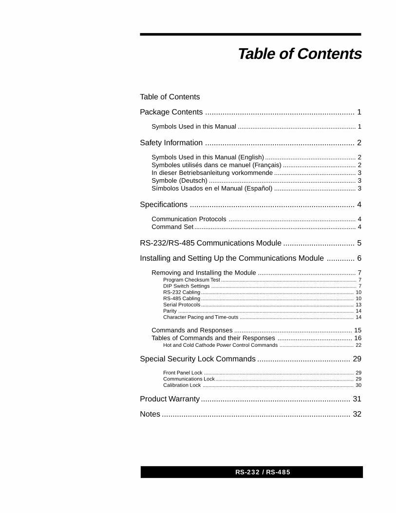
Table of Contents
Table of Contents
Package Contents ..................................................................... 1
Symbols Used in this Manual ................................................................. 1
Safety Information ..................................................................... 2
Symbols Used in this Manual (English) .................................................. 2Symboles utilisés dans ce manuel (Français) ........................................ 2In dieser Betriebsanleitung vorkommende ............................................. 3Symbole (Deutsch) ................................................................................. 3Símbolos Usados en el Manual (Español) ............................................. 3
Specifications ............................................................................ 4
Communication Protocols ...................................................................... 4Command Set ......................................................................................... 4
RS-232/RS-485 Communications Module ................................. 5
Installing and Setting Up the Communications Module ............. 6
Removing and Installing the Module ...................................................... 7Program Checksum Test ............................................................................................... 7DIP Switch Settings ...................................................................................................... 7RS-232 Cabling ........................................................................................................... 10RS-485 Cabling ........................................................................................................... 10Serial Protocols ........................................................................................................... 13Parity ........................................................................................................................... 14Character Pacing and Time-outs ................................................................................ 14
Commands and Responses ................................................................. 15Tables of Commands and their Responses ......................................... 16
Hot and Cold Cathode Power Control Commands .................................................... 22
Special Security Lock Commands ........................................... 29
Front Panel Lock ......................................................................................................... 29Communications Lock ................................................................................................. 29Calibration Lock .......................................................................................................... 30
Product Warranty ..................................................................... 31
Notes ....................................................................................... 32

RS-232 / RS-485
1RS-232 / RS-485
123456789123456789123456789123456789123456789123456789123456789
Before unpacking your RS-232/RS-485 Communications Module for theSeries 929A or 937A System, check all surfaces of the packingmaterial for shipping damage.
Please be sure that your RS-232/RS-485 Optional Communications Modulepackage contains these items:
1 RS-232/RS-485 Communications Module
1 RS-232/RS-485 Communications Module User’s Manual.
If any item is missing from the package, call HPS® ProductsCustomer Service Department at 1-303-449-9861 or 1-800-345-1967.
Inspect the RS-232/RS-485 Communications Module for visible evidence ofdamage. If it has been damaged in shipping, notify the carrier immediately.Keep all shipping materials and packaging for claim verification. Do not returnthe product to HPS Products.
12341234123412341234
12341234123412341234
Symbols Used in this ManualThe first two symbols below, that may be located on your RS-232/RS-485Communications module, Identify critical safety concerns. They are usedthroughout this manual to further define the safety concernsassociated with the product.
The last two symbols identify other information in this manual that is essentialor useful in achieving optimal performance from the Rs-232/Rs-485Communications Module.
CAUTION: Risk of electrical shock.
CAUTION: Refer to manual. Failure to read message couldresult in personal injury or serious damage to theequipment or both.
Failure to read message could result in damageto the equipment.
Calls attention to important procedures,practices, or conditions.
12345678901234567890123456789012345678901234567890123456789012345678901234567890123456789012345678901234567890123456789012345678901234567890123456789012345678901234567890123456789012345678901234567890
1234567890123456789012345678901234567890123456789012345678901234567890123456789012345678901234567890
123456789012345678901234567890123456789012345678901234567890
Package Contents
®
2 937A RS232/RS488 Communications Module2 RS-232 / RS-485
Safety InformationSymbols Used in this Manual (English)Definitions of CAUTION and NOTE messages used throughout the manual.
CAUTION: Risk of electrical shock. ISO 3864, No. B.3.6
CAUTION: Refer to accompanying documents. ISO 3864, No. B.3.1This sign denotes a hazard. It calls attention to a procedure,practice, condition, or the like, which, if not correctly performed oradhered to, could result in injury to personnel.
This sign denotes a hazard. It calls attention to an operatingprocedure, practice, or the like, which, if not correctlyperformed or adhered to, could result in damage to ordestruction of all or part of the product.
This sign denotes important information. It calls attention toa procedure, practice, condition, or the like, which isessential to highlight.
Symboles utilisés dans ce manuel (Français)Définition des indications ATTENTION et REMARQUE utilisées dans ce manuel.
Risque de secousse électrique. ISO 3864, No. B.3.6
Se reporter à la documentation. ISO 3864, No. B.3.1 L’indicationsignale un danger potentiel. Elle est destinée à attirerl’attention sur une procédure, une utilisation, une situation outoute autre chose présentant un risque de blessure en casd’exécution incorrecte ou de non-respect des consignes.
L’indication signale un danger potentiel. Elle est destinée àattirer l’attention sur une procédure, une utilisation, unesituation ou toute autre chose présentant un risqued’endommagement ou de dégât d’une partie ou de la totalitéde l’appareil en cas d’exécution incorrecte ou de non-respectdes consignes.
L’indication REMARQUE signale des informations importantes.Elle est destinée à attirer l’attention sur une procédure, uneutilisation, une situation ou toute autre chose présentant unintérêt particulier.
1234567890123456789012345678901234567890123456789012345678901234567890123456789012345678901234567890
1234567890123456789012345678901234567890123456789012345678901234567890123456789012345678901234567890
1234567890123456789012345678901234567890123456789012345678901234567890123456789012345678901234567890
1234567890123456789012345678901234567890123456789012345678901234567890
1234567890123456789012345678901234567890123456789012345678901234567890123456789012345678901234567890
1234567890123456789012345678901234567890123456789012345678901234567890123456789012345678901234567890
1234567890123456789012345678901234567890123456789012345678901234567890123456789012345678901234567890
1234567890123456789012345678901234567890123456789012345678901234567890
3RS-232 / RS-485
In dieser Betriebsanleitung vorkommende
Symbole (Deutsch)Definition der mit VORSICHT! und HINWEIS überschriebenen Abschnitte indieser Betriebsanleitung
VORSICHT! Stromschlaggefahr! ISO 3864, Nr. B.3.6
VORSICHT! Bitte Begleitdokumente lesen! ISO 3864, Nr. B.3.1Das Symbol VORSICHT! weist auf eine Gefahrenquelle hin. Esmacht auf einen Arbeitsablauf, eine Arbeitsweise, einenZustand oder eine sonstige Gegebenheit aufmerksam, derenunsachgemäße Ausführung bzw. UngenügendeBerücksichtigung zu Körperverletzung führen kann.
Das Symbol VORSICHT! weist auf eine Gefahrenquelle hin. Esmacht auf einen Bedienungsablauf, eine Arbeitsweise oder einesonstige Gegebenheit aufmerksam, deren unsachgemäßeAusführung bzw. Ungenügende Berücksichtigung zu einerBeschädigung oder Zerstörung des Produkts oder von Teilendes Produkts führen kann.
Das Symbol HINWEIS weist auf eine wichtige Mitteilung hin,die auf einen Arbeitsablauf, eine Arbeitsweise, einen Zustandoder eine sonstige Gegebenheit von besonderer Wichtigkeitaufmerksam macht.
Símbolos Usados en el Manual (Español)Definiciones de los mensajes de PRECAUCIÓN y OBSERVACIÓNusados en el manual.
PRECAUCIÓN: Riesgo de descarga eléctrica. ISO 3864, N.° B.3.6
PRECAUCIÓN: Consultar los documentos adjuntos. ISO 3864,N.° B.3.1 Esto símbolo indica un riesgo. Pone de relieve unprocedimiento, práctica, condición, etc., que, de no realizarse uobservarse correctamente, podría causar lesiones a losempleados.
Esto símbolo indica un riesgo. Pone de relieve unprocedimiento, práctica, etc., de tipo operativo que, de norealizarse u observarse correctamente, podría causardesperfectos al instrumento, o llegar incluso a causar sudestrucción total o parcial.
Esto símbolo indica información de importancia. Pone derelieve un procedimiento, práctica, condición, etc., cuyoconocimiento resulta esencial.
1234567890123456789012345678901234567890123456789012345678901234567890123456789012345678901234567890
1234567890123456789012345678901234567890123456789012345678901234567890123456789012345678901234567890
1234567890123456789012345678901234567890123456789012345678901234567890123456789012345678901234567890
1234567890123456789012345678901234567890123456789012345678901234567890
1234567890123456789012345678901234567890123456789012345678901234567890123456789012345678901234567890
1234567890123456789012345678901234567890123456789012345678901234567890123456789012345678901234567890
1234567890123456789012345678901234567890123456789012345678901234567890123456789012345678901234567890
1234567890123456789012345678901234567890123456789012345678901234567890
4 937A RS232/RS488 Communications Module4 RS-232 / RS-485
Communication ProtocolsCable length with RS-232 signals 50 ft (15 m)
Cable length with RS-485 signals 4000 ft (1200 m)May use multidrop (bussed) wiringwith built-in pass-through connector
Serial Bit Rate 2400 to 19200 bps
Character Set Standard ASCII, 0-127
Character Format 8 data bits (MSB=0)1 stop bitEven parity or no parity
Command SetApproximately 50 commands are available
Read pressure on any channel
Read pressure on all channels with one command
Read combination output pressure
Enable or disable hot or cold cathode sensors and hot cathode sensordegas, and determine their status
Perform and check status of user calibration
Set, read, and disable protection, control, and relay set points and hotcathode sensitivity values
Lock or unlock operation of the user calibration functions, all frontpanel functions, or control and setup commands on thecommunication interface.
Change and restore certain effective DIP switch settings within theController. Read the present logical state (i.e. after remote changes)of most DIP switches
Read the state of the set point relays
Read the type of sensors installed
Specifications
1234512345123451234512345
1234512345123451234512345
12345123451234512345
12345123451234512345
1234512345123451234512345
1234512345123451234512345
1234512345123451234512345
1234512345123451234512345
12345123451234512345
12345123451234512345
5RS-232 / RS-485
The RS-232/RS-485 Communications Module is an optional accessory for theHPS® Products 937A vacuum sensor Controllers. It allows the Controller tocommunicate with a host computer via an RS-232 or RS-485 serial interface. Thiscommunication allows all front panel operations to be performed, pressurereadings to be obtained, and some other functions to be performed remotely.Approximately 50 different commands are available.
The two-letter forms of commands used with earlier 929 and 937Controllers are still available.
RS-232/RS-485Communications Module

6 937A RS232/RS488 Communications Module6 RS-232 / RS-485
This section covers switch settings, installation, and wiring of theCommunications Module. In order to install the module correctly, it isnecessary to know the desired serial protocol, bit rate, and (if used) themodule address for RS-485 . To determine the settings desired for thesefactors, see Serial Protocols.
The original 937 controller supports a limited command set. The 937Asupports a larger command set with an enhanced Communications Module.
An old Communications Module (part number 100006040) will not functionproperly in a 937A. It will not recognize any of the modules in the Controller,and the Controller will ignore it, except for a setup error at power on. PressC.C. on to clear this error. Otherwise, the Controller will function normally.These modules cannot be upgraded.
The intermediate version of the Communications Module (part number100007746) is able to support the extended command set if upgraded withnew module software. These modules function either as old or new modules,depending on the software installed in the module. The new software iscontained in an EPROM (part number 100009204). Contact MKS InstrumentsVacuum Products Group for upgrade information.
The new Communications Modules (part number 100009506) are identical tointermediate versions with new software. A new module in an old Controllerwill function the same as an old module with one exception: The new, moreflexible Pn and RZ commands will also work. Refer to the CommunicationsModule User’s Manual for more information on these commands.
EQUIPMENT USE AND MODIFICATION. The instrument must beused as specified by MKS Instruments to ensure safeoperation. Use or modification of this equipment in a mannernot specified by MKS Instruments may impair the protectionprovided by the equipment.
1234567890123456789012345678901234567890123456789012345678901234567890123456789012345678901234567890
Installing and Setting Upthe Communications Module
7RS-232 / RS-485
Removing and Installing the Module
Instrument contains lethal voltages within the enclosure.The power cord must be disconnected before any covers,modules, or cables are removed from the instrument. EVEN WITHTHE POWER SWITCH OFF, DAMAGE OR INJURY MAY OCCUR.
The Controller was designed for easy access to the modules. Use a #1Phillips screwdriver to remove the screws at the top and bottom of themodule. Use a small flat-blade screwdriver to gently pry the module awayfrom the rear frame until it slides freely. Carefully slide the module out; rapidaction can cause damage to the components on the module or the internalconnector. As the module is removed, place it in a static protected container.
There are two banks of DIP switches on the Communications Module. Referto the next section to set those switches before installing the module.
It is very important to place modules in their correct slots. TheCommunications Module must be in the slot labeled “COM”. To insert themodule into the Controller, insert the end with the internal connector betweenthe card guides, so that it slides freely. Gently slide the board towards thefront of the Controller. When the internal connectors meet, carefully push onthe rear panel to make the connection, making sure that the screw holes fitover the threaded inserts. Replace and tighten the two screws with a #1Phillips screwdriver.
Program Checksum Test
The program in the Communications Module performs a checksum self test. Ifthis test finds an error, no communications functions are possible. OtherController functions will operate normally. Contact HPS® Products CustomerService Department to correct this problem.
If this error occurs, the RS-232 TxD output (pin 3 of the upper connector) willchange state nearly every second, to allow easy detection with a voltmeter.This may cause framing errors in an RS-232 host system but will not interferewith communication between RS-485 devices.
DIP Switch Settings
Refer to Serial Protocols for information on choosing the proper protocol.
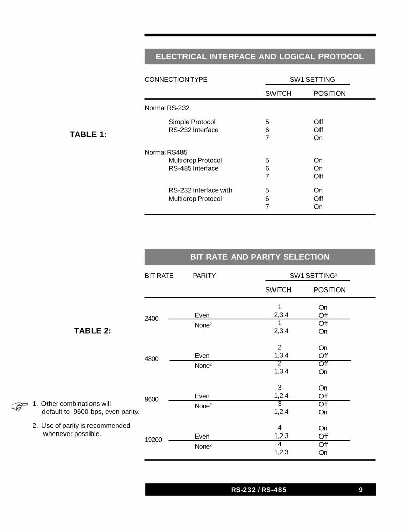
The selection of the desired serial protocol and bit rate is made using theDIP switch bank labeled SW1. Switches 6 and 7 select either the RS-232or the RS-485 electrical interface. Switch 5 selects the simple or multidroplogical protocol. The table Electrical Interface and Logical Protocolshows the allowed configurations.
1234567890123456789012345678901234567890123456789012345678901234567890123456789012345678901234567890

8 937A RS232/RS488 Communications Module8 RS-232 / RS-485
If the multidrop protocol is selected, an address character must also beselected using the DIP switch bank labeled SW3. The switches should be setto the binary code representing an ASCII character which will be theController’s address. ON represents a 0 and OFF represents a 1 bit value. Anyvalue from 0 to 7FH except 24H (“$”, the attention character) may be used forthe address. In some systems, ASCII letters and numbers may be mostconvenient. SW3 is ignored when the simple protocol is selected.
Switches 1-4 of SW1 select the bit rate and parity. The table Bit Rate andParity Selection shows the allowed combinations. Other combinations ofthese four switches default to 9600 bps, even parity. Use of parity isrecommended where possible.
If the simple protocol is used, parity or other charactererrors could result in unexpected operation. This may beavoided by using the multidrop logical protocol with theRS-232 electrical interface. To do this, set CommunicationModule DIP switches 5 and 7 ON and 6 OFF. See SerialProtocols, Parity for more information.
1234567890123456789012345678901234567890123456789012345678901234567890
9RS-232 / RS-485
TABLE 1:
ELECTRICAL INTERFACE AND LOGICAL PROTOCOL
CONNECTION TYPE SW1 SETTING
SWITCH POSITION
Normal RS-232
Simple Protocol 5 OffRS-232 Interface 6 Off
7 On
Normal RS485Multidrop Protocol 5 OnRS-485 Interface 6 On
7 Off
RS-232 Interface with 5 OnMultidrop Protocol 6 Off
7 On
1. Other combinations will default to 9600 bps, even parity.
2. Use of parity is recommended whenever possible.
1234567890123456789012345678901234567890123456789012345678901234567890
BIT RATE PARITY SW1 SETTING1
SWITCH POSITION
TABLE 2:
BIT RATE AND PARITY SELECTION
12,3,4 12,3,4
21,3,4 21,3,4
31,2,4 31,2,4
41,2,3 41,2,3
Even
None2
Even
None2
Even
None2
Even
None2
2400
4800
9600
19200
OnOffOffOn
OnOffOffOn
OnOffOffOn
OnOffOffOn
10 937A RS232/RS488 Communications Module10 RS-232 / RS-485
RS-232 Cabling
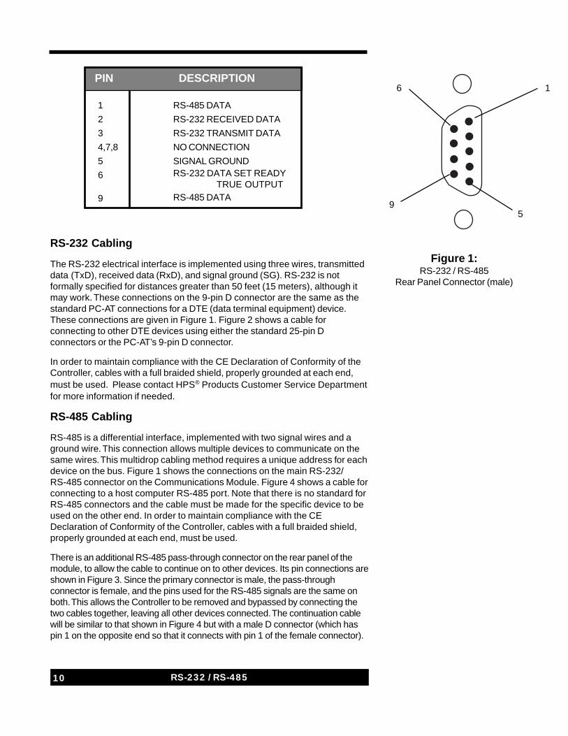
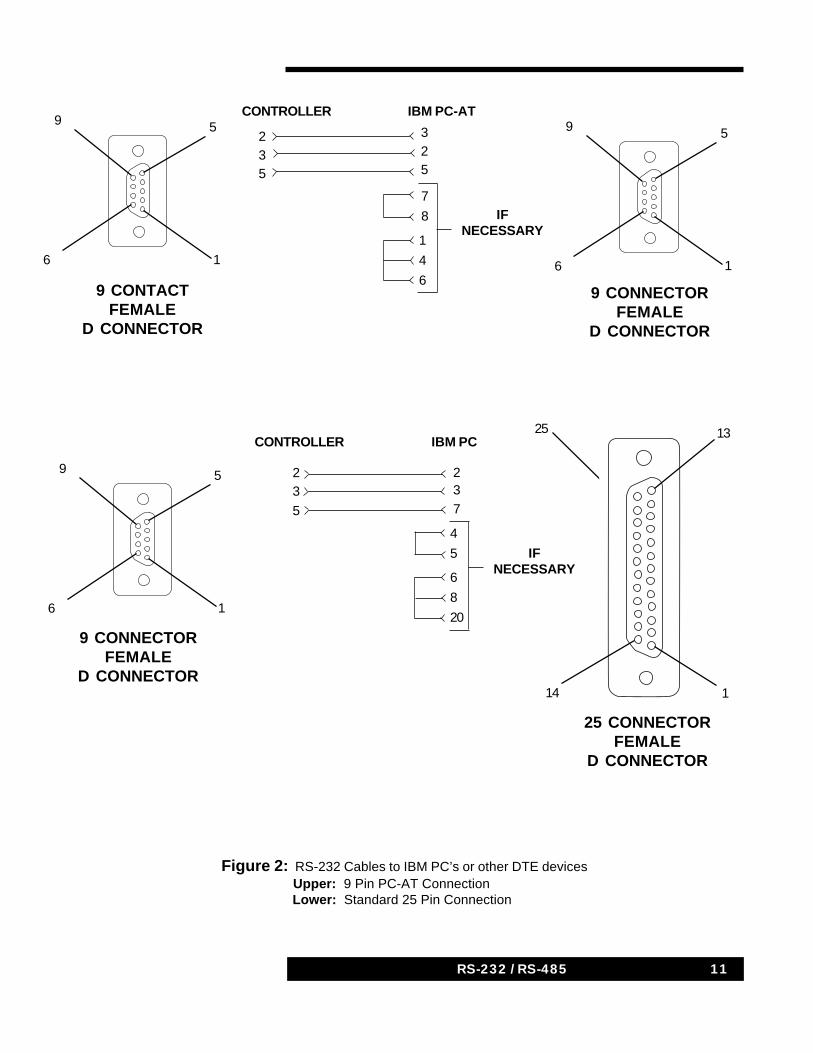
The RS-232 electrical interface is implemented using three wires, transmitteddata (TxD), received data (RxD), and signal ground (SG). RS-232 is notformally specified for distances greater than 50 feet (15 meters), although itmay work. These connections on the 9-pin D connector are the same as thestandard PC-AT connections for a DTE (data terminal equipment) device.These connections are given in Figure 1. Figure 2 shows a cable forconnecting to other DTE devices using either the standard 25-pin Dconnectors or the PC-AT’s 9-pin D connector.
In order to maintain compliance with the CE Declaration of Conformity of theController, cables with a full braided shield, properly grounded at each end,must be used. Please contact HPS® Products Customer Service Departmentfor more information if needed.
RS-485 Cabling
RS-485 is a differential interface, implemented with two signal wires and aground wire. This connection allows multiple devices to communicate on thesame wires. This multidrop cabling method requires a unique address for eachdevice on the bus. Figure 1 shows the connections on the main RS-232/RS-485 connector on the Communications Module. Figure 4 shows a cable forconnecting to a host computer RS-485 port. Note that there is no standard forRS-485 connectors and the cable must be made for the specific device to beused on the other end. In order to maintain compliance with the CEDeclaration of Conformity of the Controller, cables with a full braided shield,properly grounded at each end, must be used.
There is an additional RS-485 pass-through connector on the rear panel of themodule, to allow the cable to continue on to other devices. Its pin connections areshown in Figure 3. Since the primary connector is male, the pass-throughconnector is female, and the pins used for the RS-485 signals are the same onboth. This allows the Controller to be removed and bypassed by connecting thetwo cables together, leaving all other devices connected. The continuation cablewill be similar to that shown in Figure 4 but with a male D connector (which haspin 1 on the opposite end so that it connects with pin 1 of the female connector).
PIN DESCRIPTION
1
2
3
4,7,8
5
6
9
RS-485 DATA
RS-232 RECEIVED DATA
RS-232 TRANSMIT DATA
NO CONNECTION
SIGNAL GROUNDRS-232 DATA SET READY TRUE OUTPUTRS-485 DATA
Figure 1:RS-232 / RS-485
Rear Panel Connector (male)
1
59
6
11RS-232 / RS-485
5
6
9
1
9 CONTACTFEMALE
D CONNECTOR
Figure 2: RS-232 Cables to IBM PC’s or other DTE devices Upper: 9 Pin PC-AT Connection Lower: Standard 25 Pin Connection
7
8
1
4
6
5
6
9
1
9 CONNECTORFEMALE
D CONNECTOR
IFNECESSARY
IBM PC-ATCONTROLLER
235
325
4
5
6
8
20
5
6
9
1
25 CONNECTORFEMALE
D CONNECTOR
IFNECESSARY
13
14
25
1
23
5
237
9 CONNECTORFEMALE
D CONNECTOR
IBM PCCONTROLLER
12 937A RS232/RS488 Communications Module12 RS-232 / RS-485
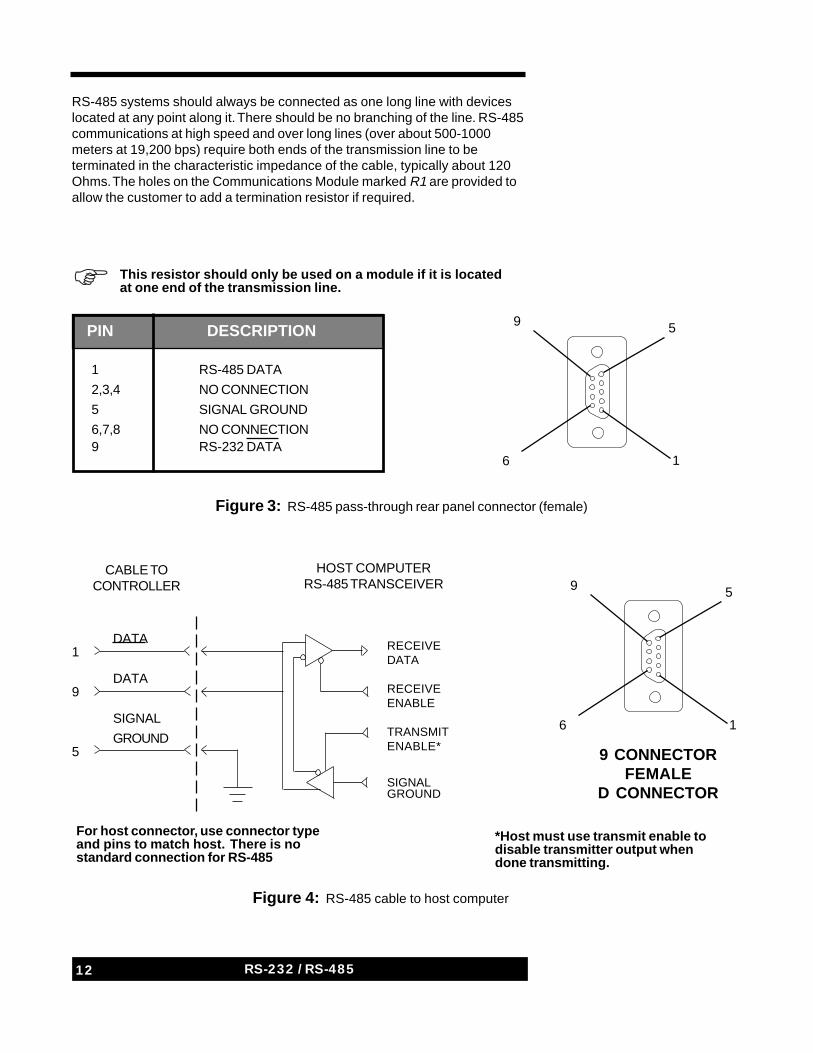
RS-485 systems should always be connected as one long line with deviceslocated at any point along it. There should be no branching of the line. RS-485communications at high speed and over long lines (over about 500-1000meters at 19,200 bps) require both ends of the transmission line to beterminated in the characteristic impedance of the cable, typically about 120Ohms. The holes on the Communications Module marked R1 are provided toallow the customer to add a termination resistor if required.
Figure 3: RS-485 pass-through rear panel connector (female)
Figure 4: RS-485 cable to host computer
For host connector, use connector typeand pins to match host. There is nostandard connection for RS-485
*Host must use transmit enable todisable transmitter output whendone transmitting.
5
6
9
1
9 CONNECTORFEMALE
D CONNECTOR
5
6
9
1
1234567890123456789012345678901234567890123456789012345678901234567890
This resistor should only be used on a module if it is locatedat one end of the transmission line.
RECEIVEDATA
RECEIVEENABLE
TRANSMITENABLE*
SIGNALGROUND
1
9
5
DATA
DATA
SIGNAL
GROUND
CABLE TOCONTROLLER
HOST COMPUTERRS-485 TRANSCEIVER
PIN DESCRIPTION
1
2,3,4
5
6,7,89
RS-485 DATA
NO CONNECTION
SIGNAL GROUND
NO CONNECTIONRS-232 DATA
13RS-232 / RS-485
A Ground wire should be used with RS-485. The maximum line length of 4000feet (1200 meters) may result in various ground problems, and may requirespecial treatment. RS-485 receivers tolerate a ground difference pluscommon-mode noise of up to ±7 V.
An interface card for RS-485 may be purchased for personal computers, or anexternal RS-485 interface converter may be added to an existing RS-232 port.The converter must be a bidirectional, two-wire, half-duplex type. In any case,the RS-485 transmitter must be turned on before each transmission andturned off afterwards. Some converters are controlled by the port’s RTSoutput, while others turn on automatically when data is to be sent, and turn offa period of time after it is finished. The T commands may be needed toaccommodate this delay, up to 8 ms.
Please contact HPS® Products Customer Service Departmentfor more information if needed. Contact B&B Electronics (815-433-5100, www.bb-elec.com) for an application note on RS-485.
Serial Protocols
The serial protocols used by the Communications Module have two majorcomponents, the electrical interface and the logical protocol.
Two electrical interfaces are available, RS-232 and RS-485. These usedifferent signal levels and cables. The RS-232 interface is a point-to-pointconnection, meaning that one set of wires is required between every pair ofdevices that must communicate. A simple protocol, without addresses, maybe used in this case.
RS-485 allows multiple devices to be connected on the same wires to a hostcomputer. This connection requires a multidrop protocol to provide a uniqueaddress for each device on the bus. To announce the arrival of the address,the attention character, “$” (24H), must be the first character of eachcommand sequence, and it must be followed immediately by the selectedaddress character (0 - 7FH, except 24H). The “$” cannot be used in any otherway. The character after the address must be the first character of thecommand name. With the multidrop protocol, the attention and addresscharacters must begin every command. They are not used in the responses,since all responses are assumed to go to the host.
Normally, the simple protocol is used with the RS-232 interface and themultidrop protocol is used with the RS-485 interface. However, the multidropprotocol, combined with parity, gives greater protection from character errors,and it can also be used with RS-232.
If you plan to use the simple protocol, please read the sectionon Parity for more information.
The character data format is 8 data bits, 1 stop bit, and even or no parity. Data isASCII. The most significant data bit must always be zero (0-7FH, no extendedASCII). Rates of 2400, 4800, 9600, or 19200 bits per second may be used.
1234567890123456789012345678901234567890123456789012345678901234567890
1234567890123456789012345678901234567890123456789012345678901234567890
14 937A RS232/RS488 Communications Module14 RS-232 / RS-485
All commands and responses are terminated with a carriage return (<cr>,0DH). Line feed characters (0AH) are ignored at all times. Neither hardware norsoftware handshaking is implemented. Half-duplex mode (no simultaneoustransmitting and receiving) is used, and the host must receive the responsefrom each command before sending the next command.
RS-232 is formally specified for cable lengths of 50 feet (15 m) or less.RS-485 may be used with cables up to 4000 feet (1200 m) long. Very longlines may require termination resistors at each end. See RS-232 Cabling orRS-485 Cabling for information on cabling considerations.
The remainder of this section gives more details on the serial protocols.Installing and Setting Up the Communications Module describes how to setup and connect the Communications Module for the specific protocol desired.
Parity
Parity provides protection against incorrectly received characters. Its use isrecommended where possible. Parity may be disabled in systems that do notallow its use with 8 data bits.
Unless parity is disabled, an even parity bit is sent with each charactertransmitted. The parity bit is also checked for each character received. Aparity error has different effects for simple and multidrop protocols.
If a parity error occurs in any byte sent to the Controller with the multidropprotocol, then the Controller will return to waiting for another command, whichmust start with the attention character and the correct address character. Inorder to avoid bus contention, no parity error message or other response issent back to the host computer. If a parity error occurs, a host computer time-out is required to detect it by the lack of a response.
With the simple protocol, the result is similar. However, the simple protocol doesnot require attention and address characters. Therefore, the remaining portion ofthe command, terminated by a carriage return, may be misinterpreted as adifferent command. Therefore, if the simple protocol is used, parity errors couldresult in unexpected operation. This may be avoided by using the multidropprotocol, even with the RS-232 interface. To do this, set Communication ModuleDIP switches 5 and 7 ON and 6 OFF, and use multidrop attention and addresscharacters with RS-232 wiring and signal levels.
Character Pacing and Time-outs
A serial character consists of a start bit, 8 data bits, a parity bit (if enabled),and a stop bit, a total of 11 bits for each character. The time required totransmit one character as a function of the bit rate is:
2400 bps: 4.58 ms/character
4800 bps: 2.29 ms/character
9600 bps: 1.15 ms/character
19200 bps: 0.57 ms/character
1234512345123451234512345
1234512345123451234512345
1234512345123451234512345
12345123451234512345
15RS-232 / RS-485
The Controller typically requires between 0.5 and 2 ms for processing before aresponse is transmitted. Thus the time between receiving the full read commandand the host computer receiving the full response (up to 10 characters) should bea maximum of 50, 27, 16, and 10 ms for the respective baud rates. These timeestimates include a software processing time of 4 ms. The PZ command, with itslonger response, takes about 40 character times longer.
The response times listed above are for the simple protocol. When using themultidrop protocol, there may be an additional 1, 4, or 8 millisecond softwaredelay after the end of the command, before the response starts. These delays,or no delay, may be selected using the time delay (T) commands. The defaultis 8 milliseconds. These delays may be required to eliminate bus contention ifthe host computer is slow to release the RS-485 bus after sending a command.The Controller releases the line within two bit times after the carriage return atthe end of the response.
The information provided here may be used to calculate a reasonable valuefor a software time-out (i.e. at least 14 ms if 19200 baud and 4ms line releasedelay is used). This time-out is the waiting period used by the host computerto determine that the Controller has failed to respond.
The above times are for read commands only (Px, Cx, FRONT,CAL, RLYx, PROx, GAUGES, etc.). When sending a writecommand to the Controller (for example setting set pointvalues or doing a sensor calibration) processing in theController can take up to 0.5 seconds in some cases. Therefore,a 0.5 second time-out will be required for those commands.
If the time between characters from the host computer to the Controllerexceeds 50 milliseconds, then the Controller will time out and wait for a newcommand, just as if there had been a parity error. To avoid bus contention, theController will not send a response if it times out, and the host computer musttime out to detect this. The same possibility for command misinterpretationexists as for parity errors, as described in Parity.
There is little or no delay between stop and start bits of consecutivecharacters sent from the Communication Module to the host computer, exceptfor an occasional 450 microsecond delay resulting from information transferfrom the Controller to the Communication Module.
Commands and ResponsesThe Controller never initiates communication. It only responds tocommands sent to it.
No information is available for the first five seconds after the Controller poweris turned on. If a “read pressure” command is issued during this period, theresponse will be “NOGAUGE!”
For both logical protocols, the carriage return character (<cr>, 0DH)terminates all commands and responses. Line feeds (0AH) are not required forcommands and are not sent with responses. For multidrop protocol only, theattention character (“$”, 24H) and the selected address character must
1234567890123456789012345678901234567890123456789012345678901234567890
16 937A RS232/RS488 Communications Module16 RS-232 / RS-485
precede all commands. These two characters are not sent with the response,since all responses are presumed to go to the host.
Responses from the Controller (except to the PZ command) consist of up toten ASCII characters, including the carriage return. The PZ response may beup to 45 characters long. Error responses will end with “!”. However, note thatsome conditions may be considered an error by the user’s system but not bythe Controller, or vice versa.
The Communication Module does not maintain independent information aboutthe state of the Controller. When a command changes the state of theController in any way, the following commands and their responses will referto the old state until after the next delivery of information from the Controller.This information is updated every 50 or 100 milliseconds, althoughoccasionally this can be delayed as much as 500 ms.
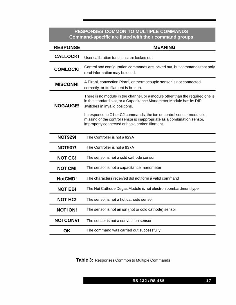
Tables of Commands and their ResponsesThis section contains categorized tables listing all commands, along withtheir particular responses. Responses which are common to multiplecommand groups are listed and defined in the first table. These are mostlyresponses which indicate that a command was executed successfully, isinvalid, or is inconsistent with the current Controller state or configuration.
Commands and their specific responses are grouped by functionalcategories in the following tables. Most tables also contain notes givingfurther information. This manual is not intended to give full descriptions ofController features, but only of how to access them through theCommunications Module. Refer to the Controller User’s Manual forinformation on use of these features.
The sensor modules reside in Controller Slots or CC (937A), A, and B. Thefive sensor channels, HC/CC, A1, A2, B1, B2, are usually identified incommands and responses as channel numbers 1-5. Most modules can besingle or dual channel. Cold Cathode Modules contain only one channel, sothey are in channel numbers 1, 2, and 4. All references to Slot CC apply tothe 937A only. Cold Cathode are abbreviated CC in the tables.
17RS-232 / RS-485
Table 3: Responses Common to Multiple Commands
RESPONSES COMMON TO MULTIPLE COMMANDSCommand-specific are listed with their command groups
RESPONSE
CALLOCK!
COMLOCK!
MISCONN!
NOGAUGE!
NOT929!
NOT937!
NOT CC!
NOT CM!
NotCMD!
NOT EB!
NOT HC!
NOT ION!
NOTCONV!
OK
MEANING
User calibration functions are locked out
Control and configuration commands are locked out, but commands that only
read information may be used.
A Pirani, convection Pirani, or thermocouple sensor is not connected
correctly, or its filament is broken.
There is no module in the channel, or a module other than the required one isin the standard slot, or a Capacitance Manometer Module has its DIPswitches in invalid positions.
In response to C1 or C2 commands, the ion or control sensor module ismissing or the control sensor is inappropriate as a combination sensor,improperly connected or has a broken filament.
The Controller is not a 929A
The Controller is not a 937A
The sensor is not a cold cathode sensor
The sensor is not a capacitance manometer
The characters received did not form a valid command
The Hot Cathode Degas Module is not electron bombardment type
The sensor is not a hot cathode sensor
The sensor is not an ion (hot or cold cathode) sensor
The sensor is not a convection sensor
The command was carried out successfully
18 937A RS232/RS488 Communications Module18 RS-232 / RS-485
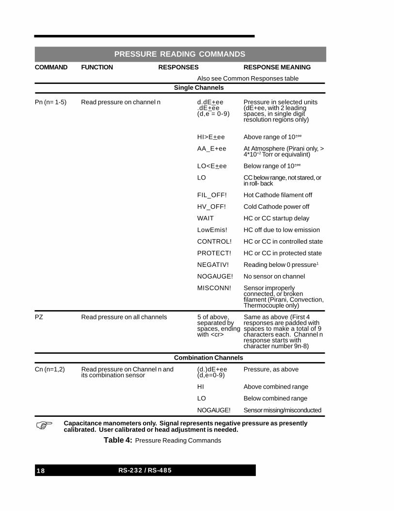
COMMAND FUNCTION RESPONSES RESPONSE MEANING
Also see Common Responses tableSingle Channels
Pn (n= 1-5) Read pressure on channel n d.dE+ee Pressure in selected units.dE+ee (dE+ee, with 2 leading(d,e = 0-9) spaces, in single digit
resolution regions only)
HI>E+ee Above range of 10+ee
AA_E+ee At Atmosphere (Pirani only, >4*10+2 Torr or equivalint)
LO<E+ee Below range of 10+ee
LO CC below range, not stared, orin roll- back
FIL_OFF! Hot Cathode filament off
HV_OFF! Cold Cathode power off
WAIT HC or CC startup delay
LowEmis! HC off due to low emission
CONTROL! HC or CC in controlled state
PROTECT! HC or CC in protected state
NEGATIV! Reading below 0 pressure1
NOGAUGE! No sensor on channel
MISCONN! Sensor improperlyconnected, or brokenfilament (Pirani, Convection,Thermocouple only)
PZ Read pressure on all channels 5 of above, Same as above (First 4separated by responses are padded withspaces, ending spaces to make a total of 9with <cr> characters each. Channel n
response starts withcharacter number 9n-8)
Combination Channels
Cn (n=1,2) Read pressure on Channel n and (d.)dE+ee Pressure, as aboveits combination sensor (d,e=0-9)
HI Above combined range
LO Below combined range
NOGAUGE! Sensor missing/misconducted
Table 4: Pressure Reading Commands
PRESSURE READING COMMANDS
Capacitance manometers only. Signal represents negative pressure as presentlycalibrated. User calibrated or head adjustment is needed.
19RS-232 / RS-485
123456789012345678901234567890123456789012345678901234567890
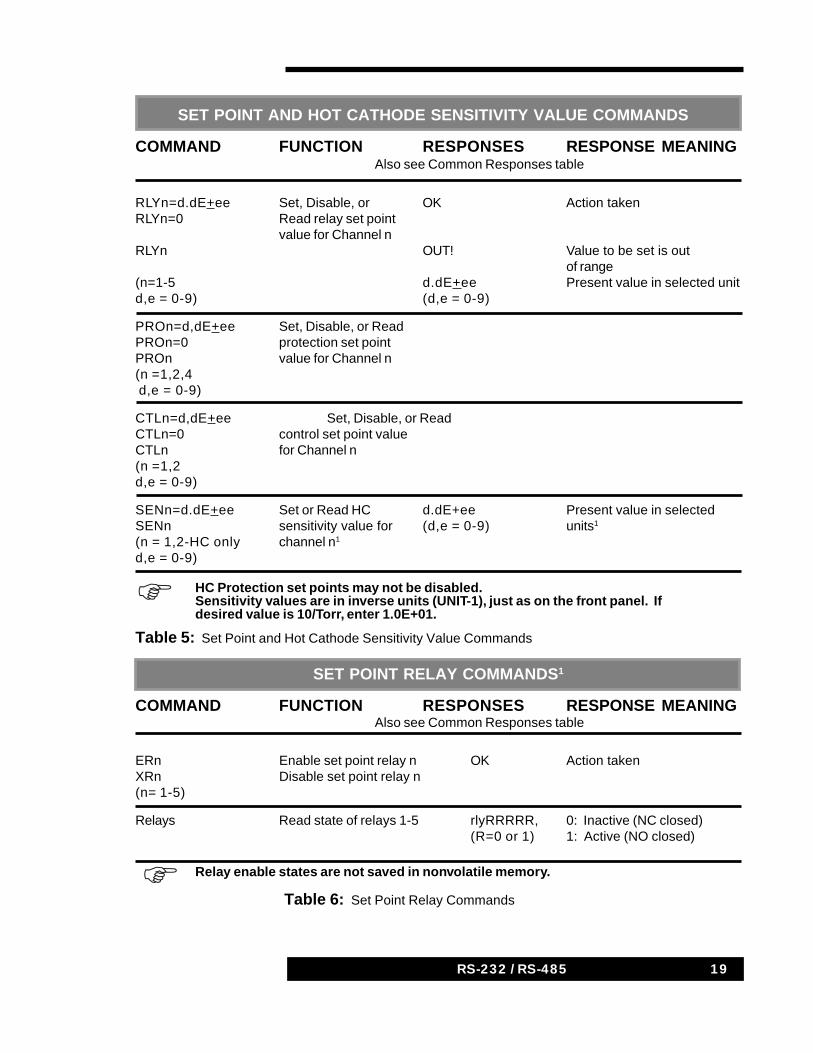
Table 6: Set Point Relay Commands
Table 5: Set Point and Hot Cathode Sensitivity Value Commands
SET POINT AND HOT CATHODE SENSITIVITY VALUE COMMANDS
COMMAND FUNCTION RESPONSES RESPONSE MEANINGAlso see Common Responses table
RLYn=d.dE+ee Set, Disable, or OK Action takenRLYn=0 Read relay set point
value for Channel nRLYn OUT! Value to be set is out
of range(n=1-5 d.dE+ee Present value in selected unitd,e = 0-9) (d,e = 0-9)
PROn=d,dE+ee Set, Disable, or ReadPROn=0 protection set pointPROn value for Channel n(n =1,2,4 d,e = 0-9)
CTLn=d,dE+ee Set, Disable, or ReadCTLn=0 control set point valueCTLn for Channel n(n =1,2d,e = 0-9)
SENn=d.dE+ee Set or Read HC d.dE+ee Present value in selectedSENn sensitivity value for (d,e = 0-9) units1
(n = 1,2-HC only channel n1
d,e = 0-9)
HC Protection set points may not be disabled.Sensitivity values are in inverse units (UNIT-1), just as on the front panel. Ifdesired value is 10/Torr, enter 1.0E+01.
1234567890123456789012345678901234567890123456789012345678901234567890
SET POINT RELAY COMMANDS1
COMMAND FUNCTION RESPONSES RESPONSE MEANINGAlso see Common Responses table
ERn Enable set point relay n OK Action takenXRn Disable set point relay n(n= 1-5)
Relays Read state of relays 1-5 rlyRRRRR, 0: Inactive (NC closed)(R=0 or 1) 1: Active (NO closed)
Relay enable states are not saved in nonvolatile memory.
20 937A RS232/RS488 Communications Module20 RS-232 / RS-485
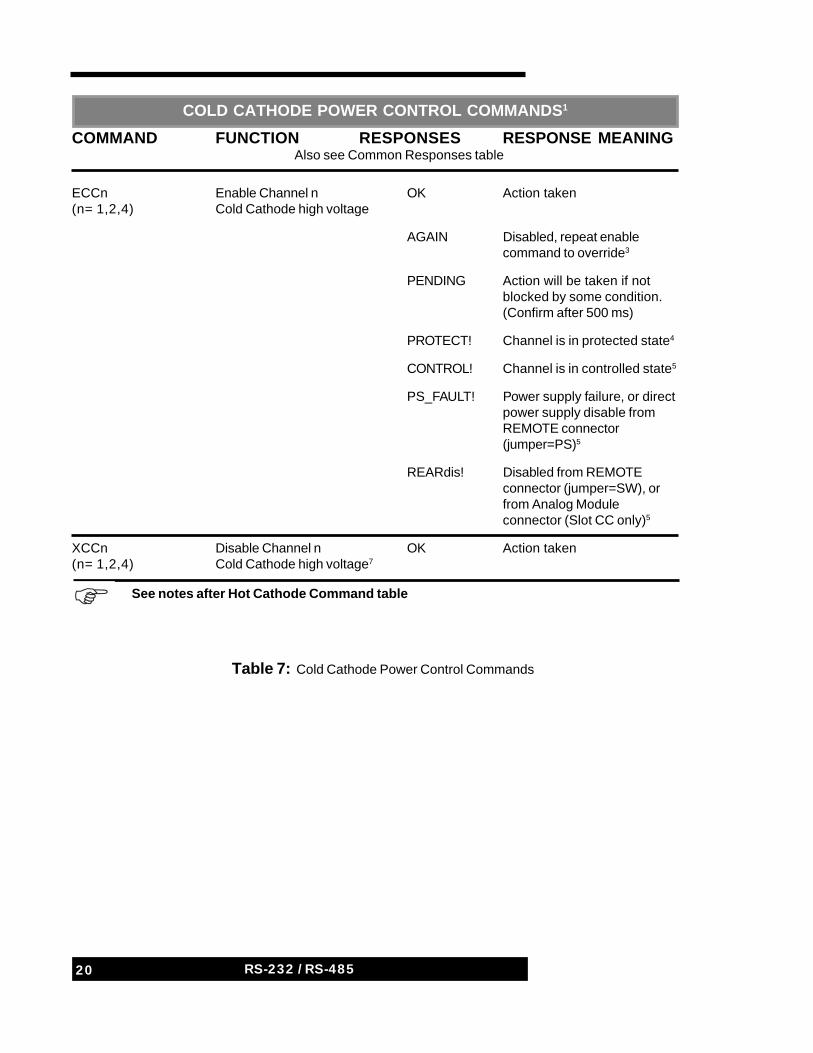
Table 7: Cold Cathode Power Control Commands
COLD CATHODE POWER CONTROL COMMANDS1
COMMAND FUNCTION RESPONSES RESPONSE MEANINGAlso see Common Responses table
ECCn Enable Channel n OK Action taken(n= 1,2,4) Cold Cathode high voltage
AGAIN Disabled, repeat enablecommand to override3
PENDING Action will be taken if notblocked by some condition.(Confirm after 500 ms)
PROTECT! Channel is in protected state4
CONTROL! Channel is in controlled state5
PS_FAULT! Power supply failure, or directpower supply disable fromREMOTE connector(jumper=PS)5
REARdis! Disabled from REMOTEconnector (jumper=SW), orfrom Analog Moduleconnector (Slot CC only)5
XCCn Disable Channel n OK Action taken(n= 1,2,4) Cold Cathode high voltage7
See notes after Hot Cathode Command table1234567890123456789012345678901234567890123456789012345678901234567890
21RS-232 / RS-485
Table 8: Cold Cathode Power Control Commands
1234567890123456789012345678901234567890123456789012345678901234567890
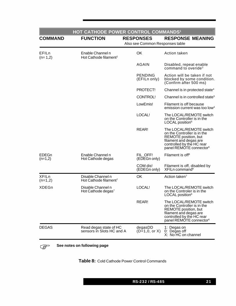
COMMAND FUNCTION RESPONSES RESPONSE MEANINGAlso see Common Responses table
EFILn Enable Channel n OK Action taken(n= 1,2) Hot Cathode filament2
AGAIN Disabled, repeat enablecommand to overide3
PENDING Action will be taken if not(EFILn only) blocked by some condition.
(Confirm after 500 ms)
PROTECT! Channel is in protected state4
CONTROL! Channel is in controlled state5
LowEmis! Filament is off becauseemission current was too low4
LOCAL! The LOCAL/REMOTE switchon the Controller is in theLOCAL position6
REAR! The LOCAL/REMOTE switchon the Controller is in theREMOTE position, butfilament and degas arecontrolled by the HC rearpanel REMOTE connector6
EDEGn Enable Channel n FIL_OFF! Filament is off8
(n=1,2) Hot Cathode degas (EDEGn only)
COM dis! Filament is off, disabled by(EDEGn only) XFILn command8
XFILn Disable Channel n OK Action taken7
(n=1,2) Hot Cathode filament7
XDEGn Disable Channel n LOCAL! The LOCAL/REMOTE switchHot Cathode degas7 on the Controler is in the
LOCAL position6
REAR! The LOCAL/REMOTE switchon the Controller is in theREMOTE position, butfilament and degas arecontrolled by the HC rearpanel REMOTE connector6
DEGAS Read degas state of HC degasDD 1: Degas onsensors in Slots HC and A (D=1,0, or X) 0: Degas off
X: No HC on channel
HOT CATHODE POWER CONTROL COMMANDS1
See notes on following page
22 937A RS232/RS488 Communications Module22 RS-232 / RS-485
Hot and Cold Cathode Power Control Commands
1. Hot and cold cathode enable states are not saved in nonvolatile memory. These sensors are initially off when the Controller power is turned on.
2. WARNING: Verify that the pressure at the hot cathode sensor is below 10-2
Torr before enabling the filament, or it may be damaged. See the 929A Controller User’s Manual section on Hot Cathode Sensor Power Control for more information.
3. Again indicates that the sensor was off due to a cause which can be overridden (initial power-on, the C.C. off button, disabling the control set point while controlled, or some cases of switching between the HC power control sources listed in Note 6). The first enable command provides a needed disable, and responds AGAIN. Repeating the same enable command will enable the selected sensor.
4. These transient disable conditions are latched and require a disable command before an enable command can take effect.
5. These continuing disable conditions cannot be overridden by an enable command. The condition must be eliminated before an enable can take effect.
6. Hot cathode filament and degas can be controlled by one of three input sources. These are:
A. The Controller front panel buttons, selected by the Controller’sLOCAL/REMOTE switch in the LOCAL position,
B. The Hot Cathode Module REMOTE connector, selected by theREMOTE switch position and a connection to the Rear Enableterminal of the REMOTE connector, and
C. The Communications Module, selected by the REMOTE switchposition with no connection to the REMOTE connector. TheCommunications Module cannot change this input sourceselection. These responses indicate that the HC filament anddegas power are controlled by A or B above, and are not affectedby communications commands. The actual state of the filamentor degas may be either on or off.
7. A disable command remains in effect until the corresponding enable command. Other enabling methods cannot override it.
8. Filament must be on before degas can be turned on.
23RS-232 / RS-485
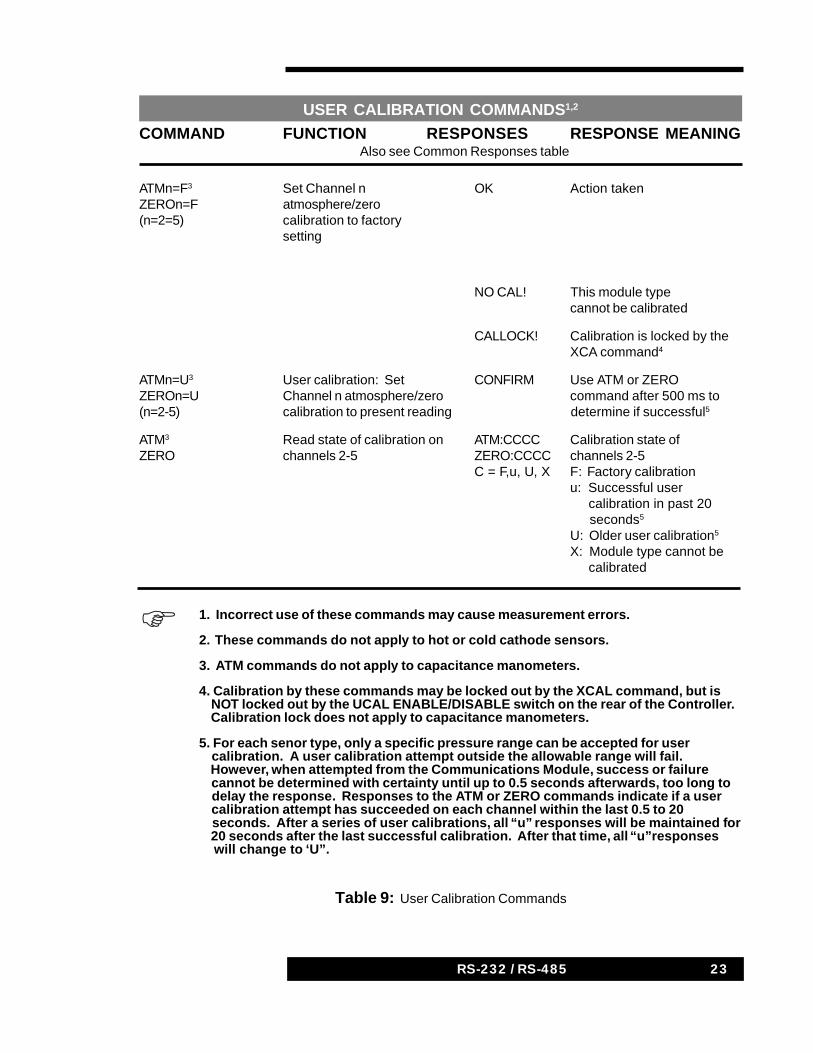
Table 9: User Calibration Commands
COMMAND FUNCTION RESPONSES RESPONSE MEANINGAlso see Common Responses table
ATMn=F3 Set Channel n OK Action takenZEROn=F atmosphere/zero(n=2=5) calibration to factory
setting
NO CAL! This module typecannot be calibrated
CALLOCK! Calibration is locked by theXCA command4
ATMn=U3 User calibration: Set CONFIRM Use ATM or ZEROZEROn=U Channel n atmosphere/zero command after 500 ms to(n=2-5) calibration to present reading determine if successful5
ATM3 Read state of calibration on ATM:CCCC Calibration state ofZERO channels 2-5 ZERO:CCCC channels 2-5
C = F,u, U, X F: Factory calibrationu: Successful user calibration in past 20 seconds5
U: Older user calibration5
X: Module type cannot be calibrated
USER CALIBRATION COMMANDS1,2
1. Incorrect use of these commands may cause measurement errors.
2. These commands do not apply to hot or cold cathode sensors.
3. ATM commands do not apply to capacitance manometers.
4. Calibration by these commands may be locked out by the XCAL command, but is NOT locked out by the UCAL ENABLE/DISABLE switch on the rear of the Controller. Calibration lock does not apply to capacitance manometers.
5. For each senor type, only a specific pressure range can be accepted for user calibration. A user calibration attempt outside the allowable range will fail. However, when attempted from the Communications Module, success or failure cannot be determined with certainty until up to 0.5 seconds afterwards, too long to delay the response. Responses to the ATM or ZERO commands indicate if a user calibration attempt has succeeded on each channel within the last 0.5 to 20 seconds. After a series of user calibrations, all “u” responses will be maintained for 20 seconds after the last successful calibration. After that time, all “u”responses will change to ‘U”.
1234567890123456789012345678901234567890123456789012345678901234567890
24 937A RS232/RS488 Communications Module24 RS-232 / RS-485
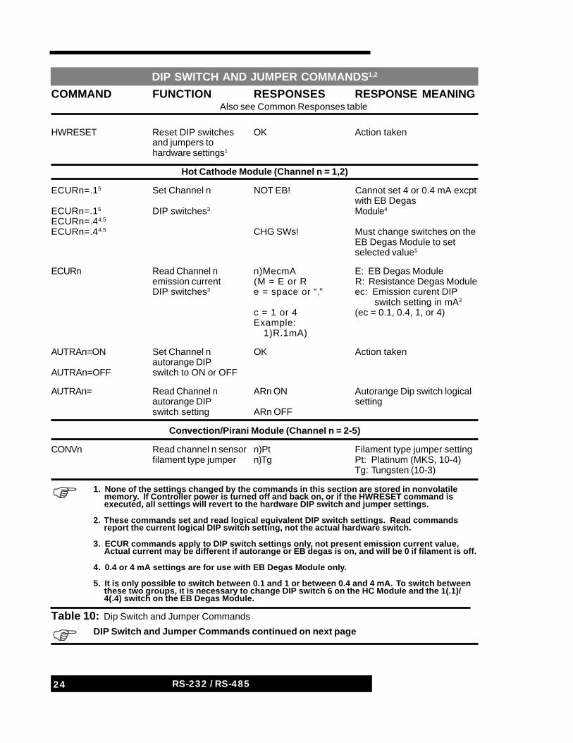
Table 10: Dip Switch and Jumper Commands
COMMAND FUNCTION RESPONSES RESPONSE MEANINGAlso see Common Responses table
HWRESET Reset DIP switches OK Action takenand jumpers tohardware settings1
Hot Cathode Module (Channel n = 1,2)
ECURn=.15 Set Channel n NOT EB! Cannot set 4 or 0.4 mA excptwith EB Degas
ECURn=.15 DIP switches3 Module4
ECURn=.44,5
ECURn=.44,5 CHG SWs! Must change switches on theEB Degas Module to setselected value5
ECURn Read Channel n n)MecmA E: EB Degas Moduleemission current (M = E or R R: Resistance Degas ModuleDIP switches3 e = space or “.” ec: Emission curent DIP
switch setting in mA3
c = 1 or 4 (ec = 0.1, 0.4, 1, or 4)Example: 1)R.1mA)
AUTRAn=ON Set Channel n OK Action takenautorange DIP
AUTRAn=OFF switch to ON or OFF
AUTRAn= Read Channel n ARn ON Autorange Dip switch logicalautorange DIP settingswitch setting ARn OFF
Convection/Pirani Module (Channel n = 2-5)
CONVn Read channel n sensor n)Pt Filament type jumper settingfilament type jumper n)Tg Pt: Platinum (MKS, 10-4)
Tg: Tungsten (10-3)
DIP SWITCH AND JUMPER COMMANDS1,2
1. None of the settings changed by the commands in this section are stored in nonvolatile memory. If Controller power is turned off and back on, or if the HWRESET command is executed, all settings will revert to the hardware DIP switch and jumper settings.
2. These commands set and read logical equivalent DIP switch settings. Read commands report the current logical DIP switch setting, not the actual hardware switch.
3. ECUR commands apply to DIP switch settings only, not present emission current value, Actual current may be different if autorange or EB degas is on, and will be 0 if filament is off.
4. 0.4 or 4 mA settings are for use with EB Degas Module only.
5. It is only possible to switch between 0.1 and 1 or between 0.4 and 4 mA. To switch between these two groups, it is necessary to change DIP switch 6 on the HC Module and the 1(.1)/ 4(.4) switch on the EB Degas Module.
1234567890123456789012345678901234567890123456789012345678901234567890
DIP Switch and Jumper Commands continued on next page1234567890123456789012345678901234567890123456789012345678901234567890
25RS-232 / RS-485
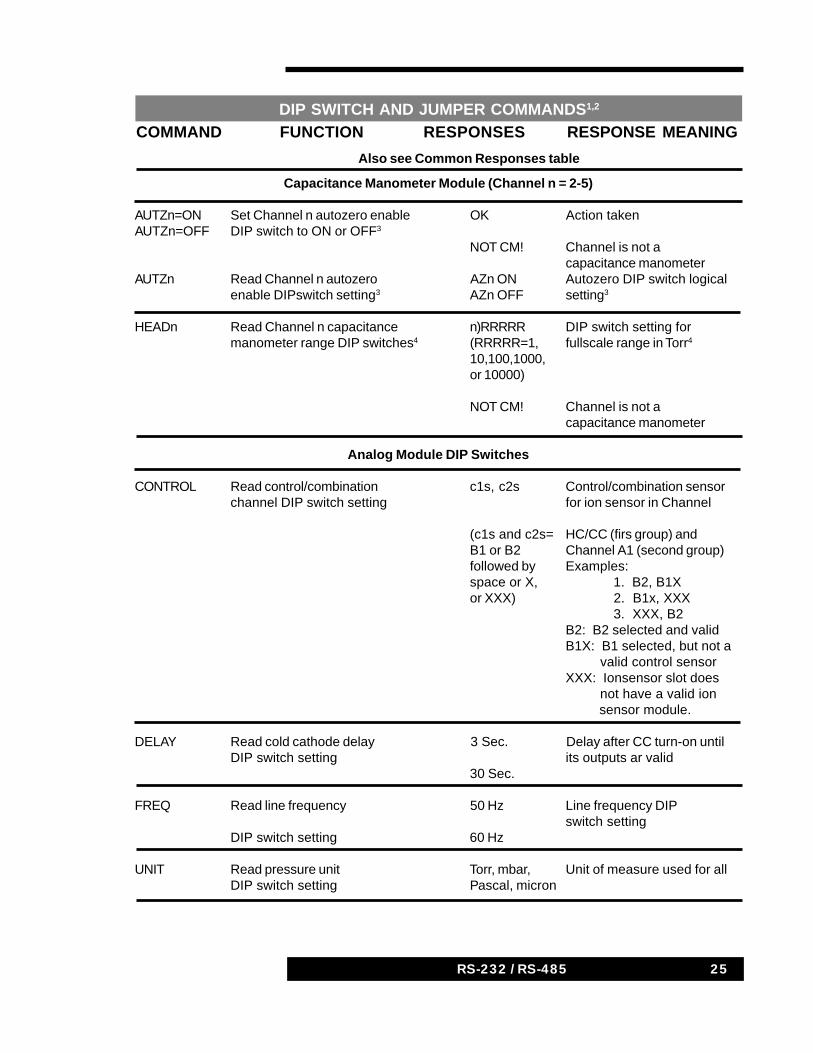
COMMAND FUNCTION RESPONSES RESPONSE MEANING
Also see Common Responses table
DIP SWITCH AND JUMPER COMMANDS1,2
Capacitance Manometer Module (Channel n = 2-5)
AUTZn=ON Set Channel n autozero enable OK Action takenAUTZn=OFF DIP switch to ON or OFF3
NOT CM! Channel is not acapacitance manometer
AUTZn Read Channel n autozero AZn ON Autozero DIP switch logicalenable DIPswitch setting3 AZn OFF setting3
HEADn Read Channel n capacitance n)RRRRR DIP switch setting formanometer range DIP switches4 (RRRRR=1, fullscale range in Torr4
10,100,1000,or 10000)
NOT CM! Channel is not acapacitance manometer
Analog Module DIP Switches
CONTROL Read control/combination c1s, c2s Control/combination sensorchannel DIP switch setting for ion sensor in Channel
(c1s and c2s= HC/CC (firs group) andB1 or B2 Channel A1 (second group)followed by Examples:space or X, 1. B2, B1Xor XXX) 2. B1x, XXX
3. XXX, B2B2: B2 selected and validB1X: B1 selected, but not a valid control sensorXXX: Ionsensor slot does not have a valid ion sensor module.
DELAY Read cold cathode delay 3 Sec. Delay after CC turn-on untilDIP switch setting its outputs ar valid
30 Sec.
FREQ Read line frequency 50 Hz Line frequency DIPswitch setting
DIP switch setting 60 Hz
UNIT Read pressure unit Torr, mbar, Unit of measure used for allDIP switch setting Pascal, micron
26 937A RS232/RS488 Communications Module26 RS-232 / RS-485
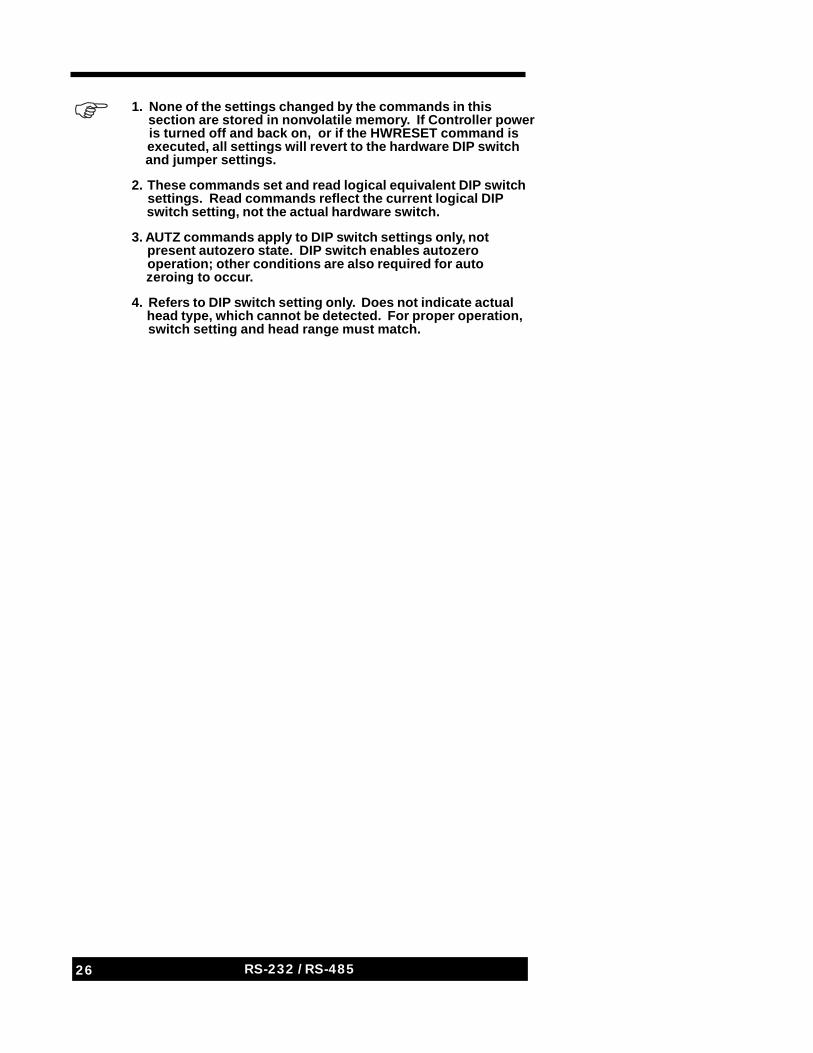
1. None of the settings changed by the commands in this section are stored in nonvolatile memory. If Controller power is turned off and back on, or if the HWRESET command is executed, all settings will revert to the hardware DIP switch and jumper settings.
2. These commands set and read logical equivalent DIP switch settings. Read commands reflect the current logical DIP switch setting, not the actual hardware switch.
3. AUTZ commands apply to DIP switch settings only, not present autozero state. DIP switch enables autozero operation; other conditions are also required for auto zeroing to occur.
4. Refers to DIP switch setting only. Does not indicate actual head type, which cannot be detected. For proper operation, switch setting and head range must match.
123456789012345678901234567890123456789012345678901234567890
27RS-232 / RS-485
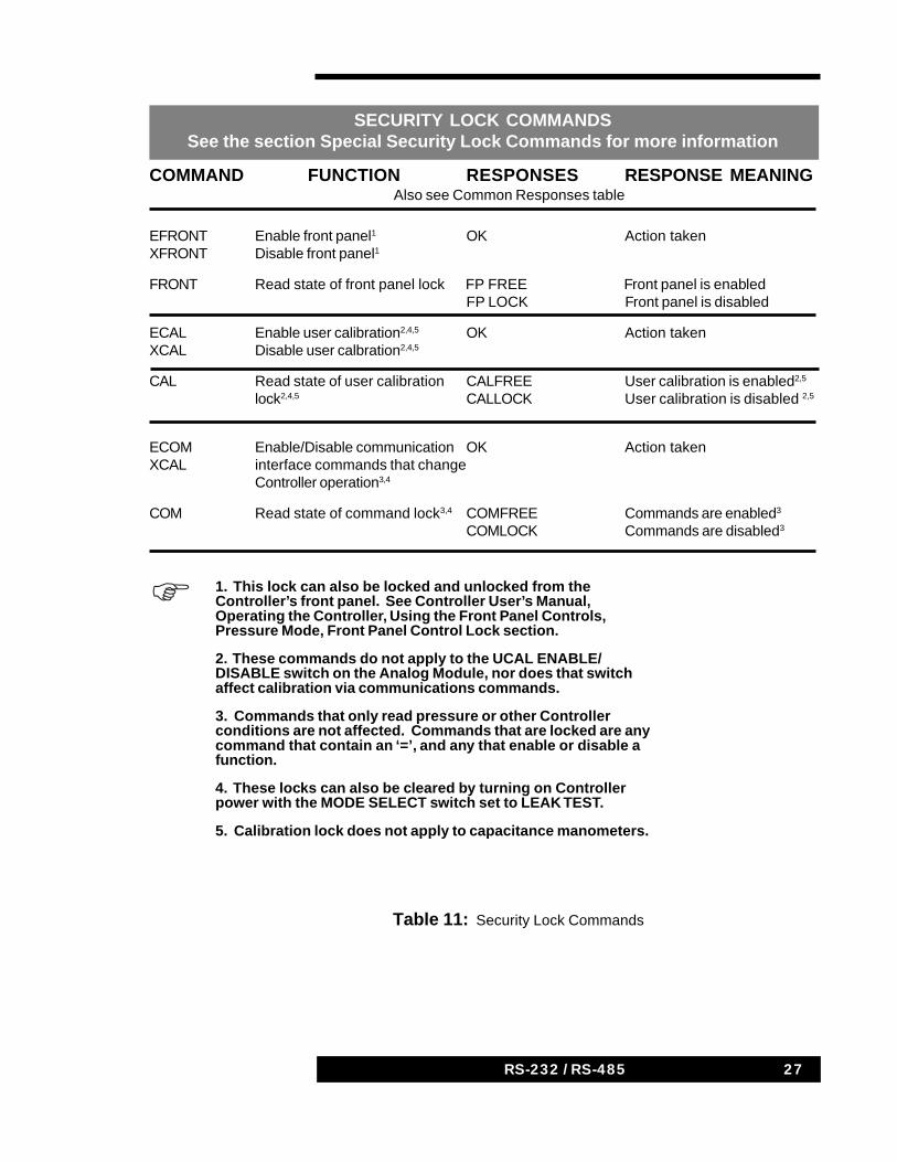
Table 11: Security Lock Commands
COMMAND FUNCTION RESPONSES RESPONSE MEANINGAlso see Common Responses table
EFRONT Enable front panel1 OK Action takenXFRONT Disable front panel1
FRONT Read state of front panel lock FP FREE Front panel is enabledFP LOCK Front panel is disabled
ECAL Enable user calibration2,4,5 OK Action takenXCAL Disable user calbration2,4,5
CAL Read state of user calibration CALFREE User calibration is enabled2,5
lock2,4,5 CALLOCK User calibration is disabled 2,5
ECOM Enable/Disable communication OK Action takenXCAL interface commands that change
Controller operation3,4
COM Read state of command lock3,4 COMFREE Commands are enabled3
COMLOCK Commands are disabled3
SECURITY LOCK COMMANDSSee the section Special Security Lock Commands for more information
1. This lock can also be locked and unlocked from theController’s front panel. See Controller User’s Manual,Operating the Controller, Using the Front Panel Controls,Pressure Mode, Front Panel Control Lock section.
2. These commands do not apply to the UCAL ENABLE/DISABLE switch on the Analog Module, nor does that switchaffect calibration via communications commands.
3. Commands that only read pressure or other Controllerconditions are not affected. Commands that are locked are anycommand that contain an ‘=’, and any that enable or disable afunction.
4. These locks can also be cleared by turning on Controllerpower with the MODE SELECT switch set to LEAK TEST.
5. Calibration lock does not apply to capacitance manometers.
1234567890123456789012345678901234567890123456789012345678901234567890
28 937A RS232/RS488 Communications Module28 RS-232 / RS-485
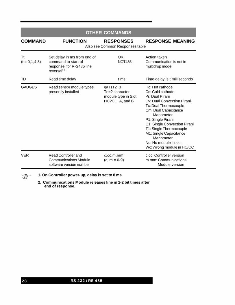
OTHER COMMANDS
COMMAND FUNCTION RESPONSES RESPONSE MEANINGAlso see Common Responses table
Tt Set delay in ms from end of OK Action taken(t = 0,1,4,8) command to start of NOT485! Communication is not in
response, for R-S485 line multidrop modereversal1,2
TD Read time delay t ms Time delay is t milliseconds
GAUGES Read sensor module types gaT1T2T3 Hc: Hot cathodepresently installed Tn=2 character Cc: Cold cathode
module type in Slot Pr: Dual PiraniHC?CC, A, and B Cv: Dual Convection Pirani
Tc: Dual ThermocoupleCm: Dual Capacitance ManometerP1: Single PiraniC1: Single Convection PiraniT1: Single ThermocoupleM1: Single Capacitance ManometerNc: No module in slotWc: Wrong module in HC/CC
VER Read Controller and c.cc,m.mm c.cc: Controller versionCommunications Module (c, m = 0-9) m.mm: Communicationssoftware version number Module version
1. On Controller power-up, delay is set to 8 ms
2. Communications Module releases line in 1-2 bit times after end of response.
1234567890123456789012345678901234567890123456789012345678901234567890
29RS-232 / RS-485
Special Security Lock Commands
There are three groups of commands that are used for locking the operationof certain functions of the 929A and 937A Controllers. Each group containscommands to lock, unlock, and display the lock state of a function. The threefunctions are the front panel controls, operation changes throughCommunication Module commands, and calibration of thermal conductivitysensors. In each case, the state of the lock can also be changed from thefront panel. These commands are given in the table Security LockCommands. This section gives a more complete description of them.
Front Panel Lock
The XFRONT command disables the front panel switches and locks theController in the PRESSURE mode. The EFRONT command enables all frontpanel switches, except possibly the hot cathode filament and degas buttons,which may also be disabled by the REMOTE/LOCAL switch. The FRONTcommand reports the state of the front panel lock. The REMOTE indicator onthe display will be on when either the entire front panel or just the filamentand degas buttons are disabled.
The front panel lock may also be changed from the front panel by thefollowing steps:
1. Rotate the GAUGE SELECT switch to channel B2 (the bottom channel)and the FUNCTION SELECT switch to PRESSURE.
2. Hold the UP button in and press the DOWN button slowly 4 times.
3. In the 937A, the display now reads “not LOC” if the front panel isenabled or “LOC” if the front panel is disabled. In the 929A, the aboveprocedure invokes the setup review function. Press the UP button untilthe display shows one of these two messages. Release the buttons.
4. To change the state of the front panel lock, hold down the DOWNbutton and push the UP button once. Continuing to push the UP buttonwill not continue to toggle between enabled and disabled states.Release the buttons.
5. Push the UP button once to return to normal display after a fewseconds.
Communications Lock
The XCOM command locks out communications commands which changeController operation. For example, commands for enabling and disablingsensors or setting set points are disabled. However, commands which getinformation, such as reading pressure or relay status, function normally. TheECOM command unlocks communications so all commands function
30 937A RS232/RS488 Communications Module30 RS-232 / RS-485
normally. The COM command can be used to determine if communications islocked out. Communications may also be unlocked by turning on Controllerpower while in the LEAK TEST function.
Calibration Lock
The XCAL command locks out calibration of Pirani, convection, andthermocouple (but not capacitance manometer) sensors, both overcommunications and from the front panel. The ECAL command unlocks thecalibration commands. (The switch on the rear panel of the Analog Modulecan still disable calibration from the front panel only.) The CAL command canbe used to determine if calibration is locked out by communications.Calibration lock may also be cleared by turning on Controller power while inthe LEAK TEST function.
31RS-232 / RS-485
Extent of the WarrantyMKS Instruments, Inc., HPS® Products warrants the HPS® Series RS-232 / RS-485 OptionalCommunications Module and its accessories to be free from defects in materials and workmanship for one(1) year from the date of shipment by HPS® or authorized representative to the original purchaser(PURCHASER). Any product or parts of the product repaired or replaced by HPS® under this warranty arewarranted only for the remaining unexpired part of its one (1) year original warranty period. After expirationof the applicable warranty period, the PURCHASER shall be charged HPS®’ current prices for parts andlabor, plus any transportation for any repairs or replacement.ALL EXPRESS AND IMPLIED WARRANTIES, INCLUDING THE IMPLIED WARRANTIES OFMERCHANTABILITY AND FITNESS FOR A PARTICULAR PURPOSE, ARE LIMITED TO THE WARRANTYPERIOD. NO WARRANTIES, EXPRESS OR IMPLIED, WILL APPLY AFTER THIS PERIOD.Warranty ServiceThe obligations of HPS® under this warranty shall be at its option: (1) to repair, replace, or adjust the product sothat it meets applicable product specifications published by HPS® or (2) to refund the purchase price.What Is Not CoveredThe product is subject to above terms only if located in the country of the seller from whom the productwas purchased. The above warranties do not apply to:I. Damages or malfunctions due to failure to provide reasonable and necessary maintenance incoordinatewith HPS® operating instructions.II. Damages or malfunctions due to chemical or electrolytic influences or use of the product in workingenvironments outside the specification.III. Fuses and all expendable items which by their nature or limited lifetime may not function for a year. Ifsuch items fail to give reasonable service for a reasonable period of time within the warranty period of theproduct; they will, at the option of HPS®, be repaired or replaced.IV. Defects or damages caused by modifications and repairs effected by the original PURCHASER or thirdparties not authorized in the manual.Condition of Returned ProductsHPS® will not accept for repair, replacement, or credit any product which is asserted to be defective by thePURCHASER, or any product for which paid or unpaid service is desired, if the product is contaminatedwith potentially corrosive, reactive, harmful, or radioactive materials, gases, or chemicals. When products are used with toxic chemicals, or in an atmosphere that is dangerous to the health ofhumans, or is environmentally unsafe, it is the responsibility of the PURCHASER to have the productcleaned by an independent agency skilled and approved in the handling and cleaning of contaminatedmaterials before the product will be accepted by HPS® for repair and/or replacement. In the course of implementing this policy, HPS® Customer Service Personnel may inquire of thePURCHASER whether the product has been contaminated with or exposed to potentially corrosive,reactive, harmful, or radioactive materials, gases, or chemicals when the PURCHASER requests a returnauthorization. Notwithstanding such inquiries, it is the responsibility of the PURCHASER to ensure that noproducts are returned to HPS® which have been contaminated in the aforementioned manner.Other Rights and RemediesI. These remedies are exclusive. HPS® SHALL NOT BE LIABLE FOR CONSEQUENTIAL DAMAGES, FORANTICIPATED OR LOST PROFITS, INCIDENTAL DAMAGES OR LOSS OF TIME, OR OTHER LOSSESINCURRED BY THE PURCHASER OR BY ANY THIRD PARTY IN CONNECTION WITH THE PRODUCTCOVERED BY THIS WARRANTY, OR OTHERWISE. Some states do not allow exclusion or limitation ofincidental or consequential damage or do not allow the limitation on how long an implied warranty lasts. Ifsuch laws apply, the limitations or exclusions expressed herein may not apply to PURCHASER.II. Unless otherwise explicitly agreed in writing, it is understood that these are the only written warrantiesgiven by HPS®. Any statements made by any persons, including representatives of HPS®, which areinconsistent or in conflict with the terms of the warranty shall not be binding on HPS® unless reduced towriting and approved by an authorized officer of HPS®.III. This warranty gives PURCHASER specific legal rights, and PURCHASER may also have other rightswhich vary from state to state.IV. For HPS® products sold outside of the U.S., contact your MKS representative for warranty informationand service.Warranty PerformanceTo obtain warranty satisfaction, contact the following: MKS Instruments, Inc., HPS® Products, Inc., 5330Sterling Drive, Boulder, CO 80301, USA, at phone number (303) 449-9861. You may be required to presentproof of original purchases
Product Warranty

32 937A RS232/RS488 Communications Module32 RS-232 / RS-485
Notes