Embed Size (px)
Citation preview
The world leader in serving science
Tips and Tricks for HPLC and UHPLC Jan Pettersson Nordics Sales Support Specialist Chromatography Thermo Fisher Scientific, Hägersten/Sweden
2
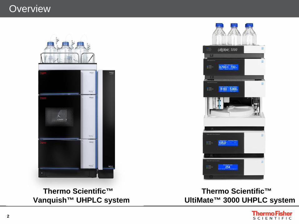
Overview
Thermo Scientific™ Vanquish™ UHPLC system
Thermo Scientific™ UltiMate™ 3000 UHPLC system
3
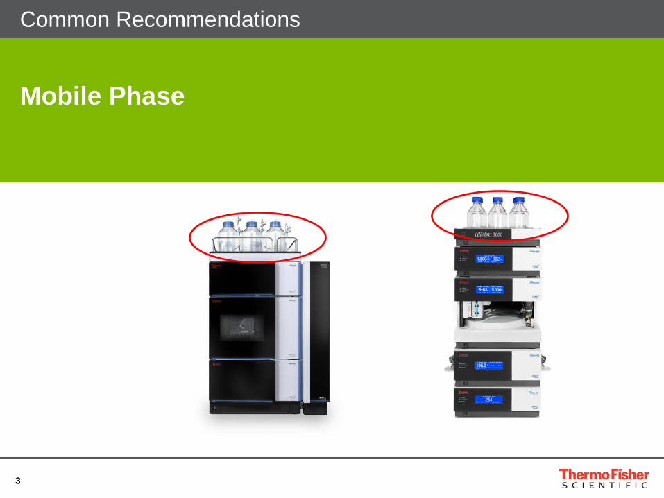
Common Recommendations
Mobile Phase

4
Common Problems: Mobile Phase
• Solvent compatibility • Try to use pre-mixed solvents
• Add 5-10% of organic eluent to the aqueous eluent • Add 5-10% aqueous eluent to the organic eluent • Avoids local crystallization in the pump (with buffers)
• Eluents with salt buffers • Change eluents with salt buffers regularly • Filtrate buffers • Use water with 18,2M Ohm AND <5ppb TOC

5
• Technical note TN140: Solvent quality
• The quality of the eluent is very important to keep the noise as low as possible.
• Make sure that the eluents are good by running them without injection (Sample type "Blank“).
• For MS and Thermo Scientific™ Corona™ charged aerosol detector only use volatile buffers.
Solvent Quality
UV-spectra at 200–250 nm of two methanol samples (both LC/MS grade)
6
Common Recommendations: Mobile Phase
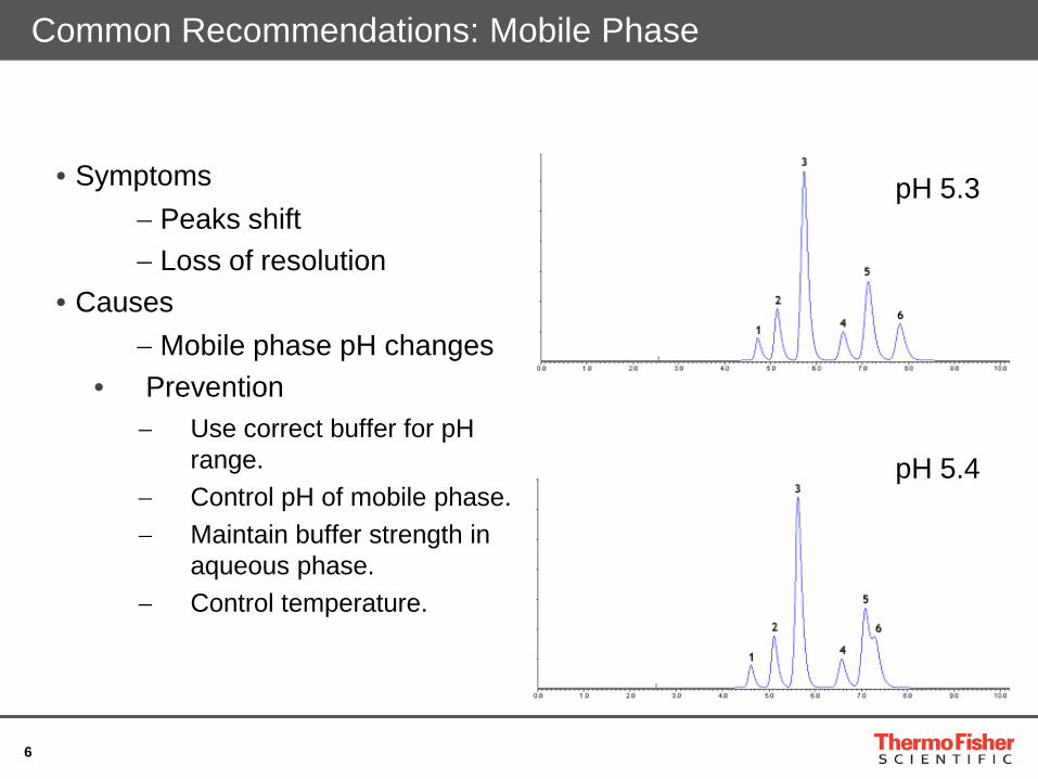
• Symptoms
− Peaks shift − Loss of resolution
• Causes − Mobile phase pH changes
• Prevention − Use correct buffer for pH
range. − Control pH of mobile phase. − Maintain buffer strength in
aqueous phase. − Control temperature.
pH 5.4
pH 5.3
7
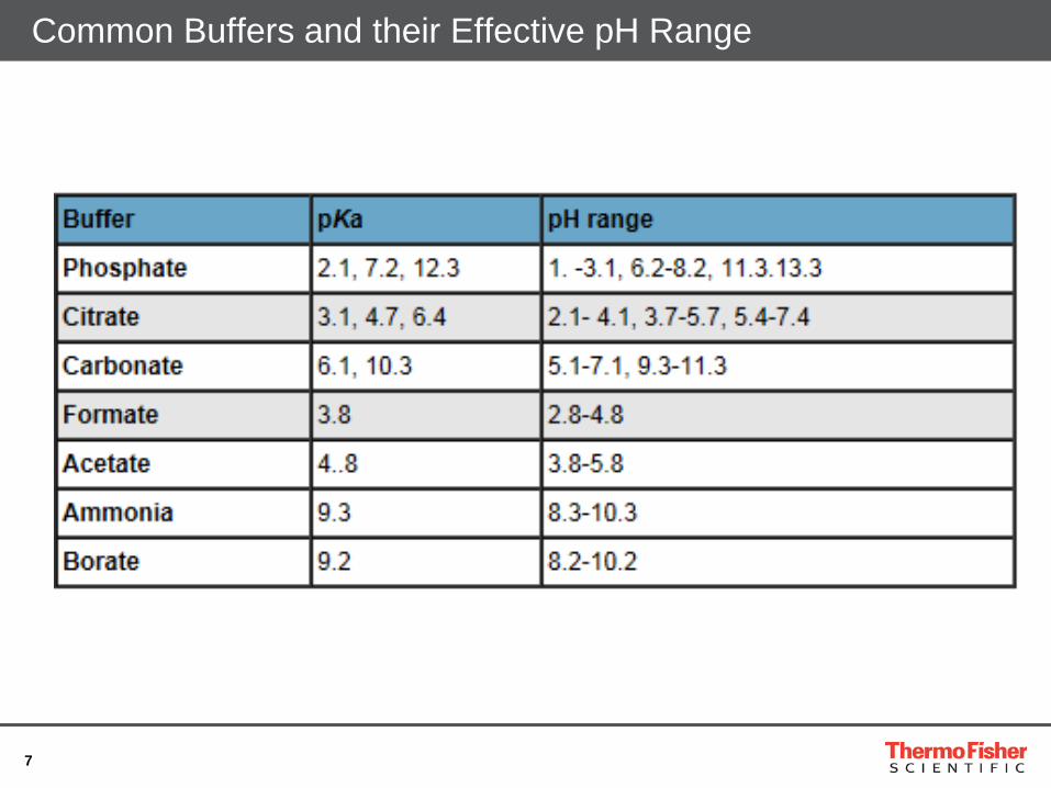
Common Buffers and their Effective pH Range
8
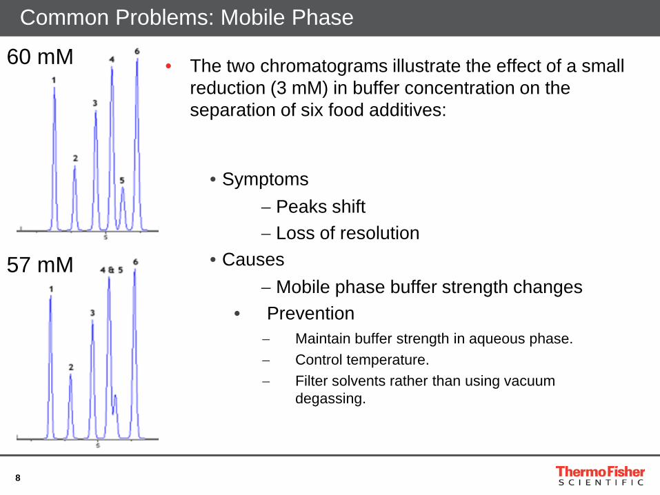
Common Problems: Mobile Phase
• The two chromatograms illustrate the effect of a small reduction (3 mM) in buffer concentration on the separation of six food additives:
• Symptoms − Peaks shift − Loss of resolution
• Causes − Mobile phase buffer strength changes
• Prevention − Maintain buffer strength in aqueous phase. − Control temperature. − Filter solvents rather than using vacuum
degassing.
60 mM
57 mM
9
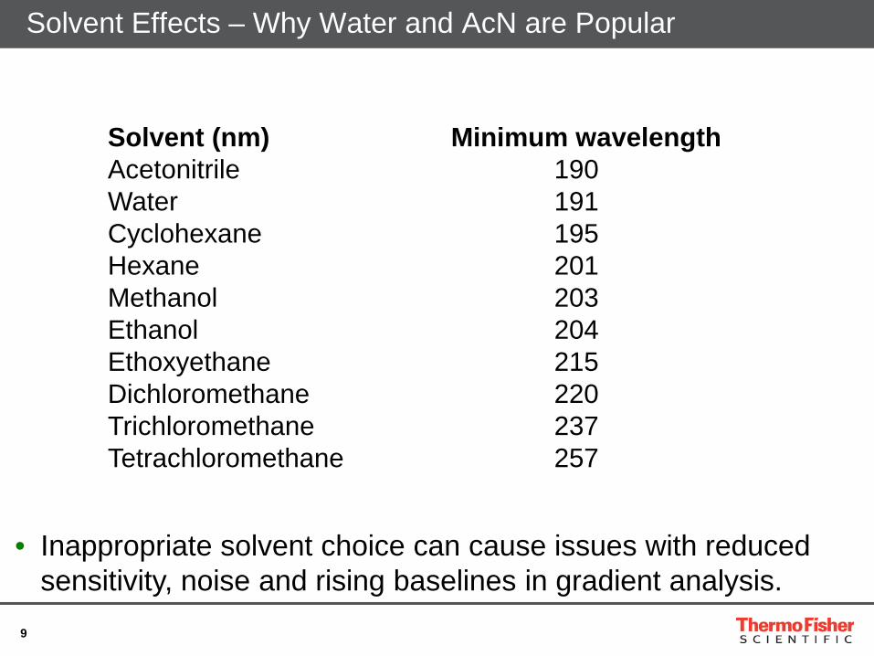
Solvent Effects – Why Water and AcN are Popular
Solvent (nm) Minimum wavelength Acetonitrile 190 Water 191 Cyclohexane 195 Hexane 201 Methanol 203 Ethanol 204 Ethoxyethane 215 Dichloromethane 220 Trichloromethane 237 Tetrachloromethane 257
• Inappropriate solvent choice can cause issues with reduced sensitivity, noise and rising baselines in gradient analysis.
10
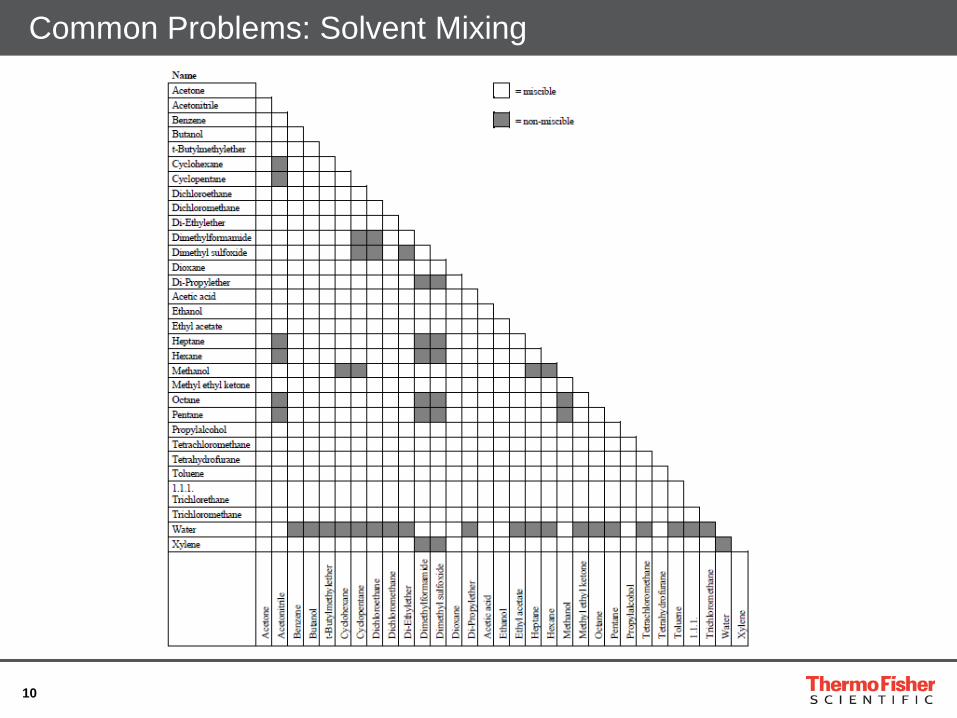
Common Problems: Solvent Mixing
11
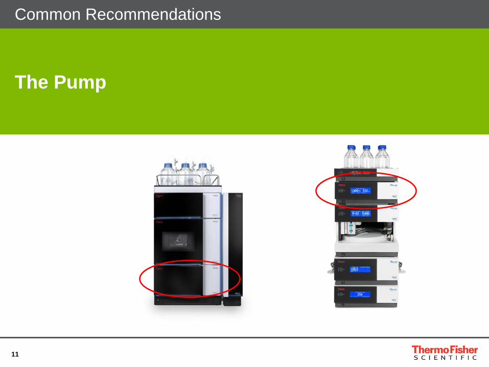
The Pump
Common Recommendations
12
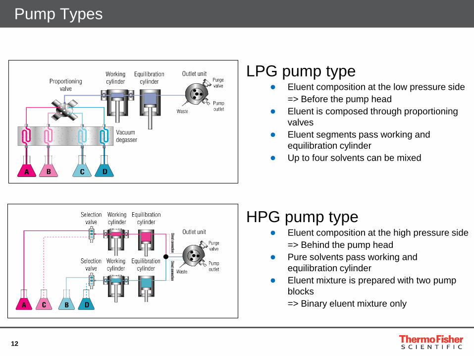
Pump Types
LPG pump type ● Eluent composition at the low pressure side => Before the pump head ● Eluent is composed through proportioning
valves ● Eluent segments pass working and
equilibration cylinder ● Up to four solvents can be mixed
HPG pump type ● Eluent composition at the high pressure side => Behind the pump head ● Pure solvents pass working and
equilibration cylinder ● Eluent mixture is prepared with two pump
blocks => Binary eluent mixture only
13
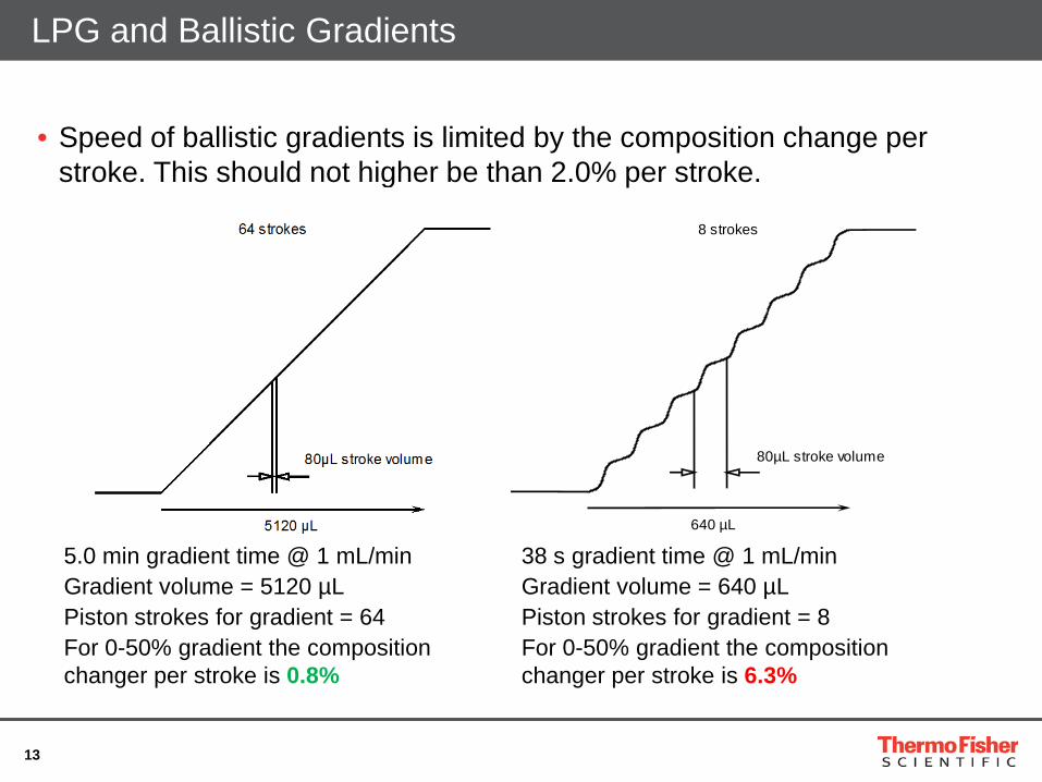
LPG and Ballistic Gradients
• Speed of ballistic gradients is limited by the composition change per stroke. This should not higher be than 2.0% per stroke.
16 strokes 8 strokes
1280 µL 640 µL
80µL stroke volume 80µL stroke volume
5.0 min gradient time @ 1 mL/min Gradient volume = 5120 µL Piston strokes for gradient = 64 For 0-50% gradient the composition changer per stroke is 0.8%
38 s gradient time @ 1 mL/min Gradient volume = 640 µL Piston strokes for gradient = 8 For 0-50% gradient the composition changer per stroke is 6.3%
14
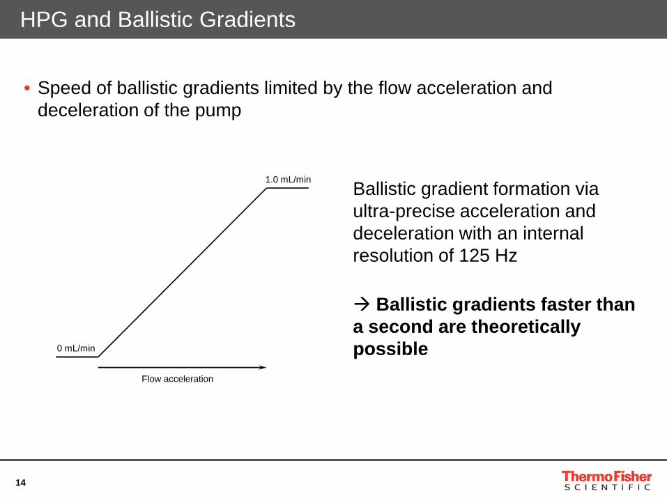
HPG and Ballistic Gradients
• Speed of ballistic gradients limited by the flow acceleration and deceleration of the pump
0 mL/min
Flow acceleration
1.0 mL/min Ballistic gradient formation via ultra-precise acceleration and deceleration with an internal resolution of 125 Hz Ballistic gradients faster than a second are theoretically possible
15
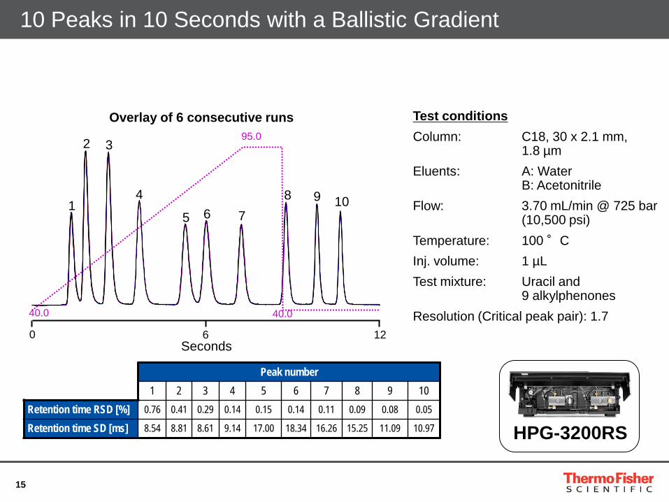
10 Peaks in 10 Seconds with a Ballistic Gradient
Peak number 1 2 3 4 5 6 7 8 9 10
Retention time RSD [%] 0.76 0.41 0.29 0.14 0.15 0.14 0.11 0.09 0.08 0.05
Retention time SD [ms] 8.54 8.81 8.61 9.14 17.00 18.34 16.26 15.25 11.09 10.97
Seconds 0 6 12
95.0
40.0
Overlay of 6 consecutive runs
1
2 3
6 4
5 7 8 9 10
40.0
Test conditions Column: C18, 30 x 2.1 mm, 1.8 µm Eluents: A: Water B: Acetonitrile Flow: 3.70 mL/min @ 725 bar (10,500 psi) Temperature: 100 °C Inj. volume: 1 µL Test mixture: Uracil and 9 alkylphenones Resolution (Critical peak pair): 1.7
HPG-3200RS

16
The Comprehensive SpinFlow Mixer Portfolio
• Range of static mixers suitable from low-GDV LC/MS application to high-sensitive TFA application
Thermo Scientific™ SpinFlow™ technology
17
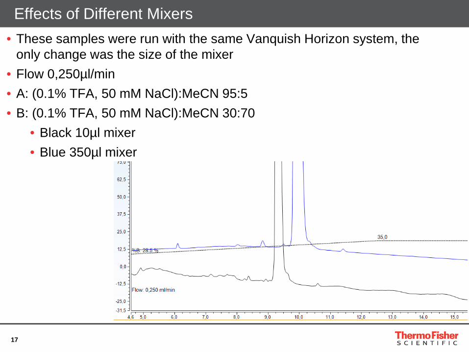
Effects of Different Mixers • These samples were run with the same Vanquish Horizon system, the
only change was the size of the mixer • Flow 0,250µl/min • A: (0.1% TFA, 50 mM NaCl):MeCN 95:5 • B: (0.1% TFA, 50 mM NaCl):MeCN 30:70
• Black 10µl mixer • Blue 350µl mixer
18
Easy Tunable for Optimum Application Performance
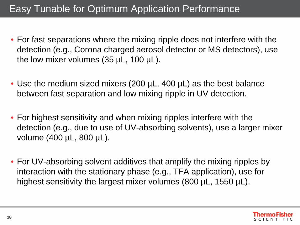
• For fast separations where the mixing ripple does not interfere with the detection (e.g., Corona charged aerosol detector or MS detectors), use the low mixer volumes (35 µL, 100 µL).
• Use the medium sized mixers (200 µL, 400 µL) as the best balance
between fast separation and low mixing ripple in UV detection.
• For highest sensitivity and when mixing ripples interfere with the detection (e.g., due to use of UV-absorbing solvents), use a larger mixer volume (400 µL, 800 µL).
• For UV-absorbing solvent additives that amplify the mixing ripples by
interaction with the stationary phase (e.g., TFA application), use for highest sensitivity the largest mixer volumes (800 µL, 1550 µL).
19
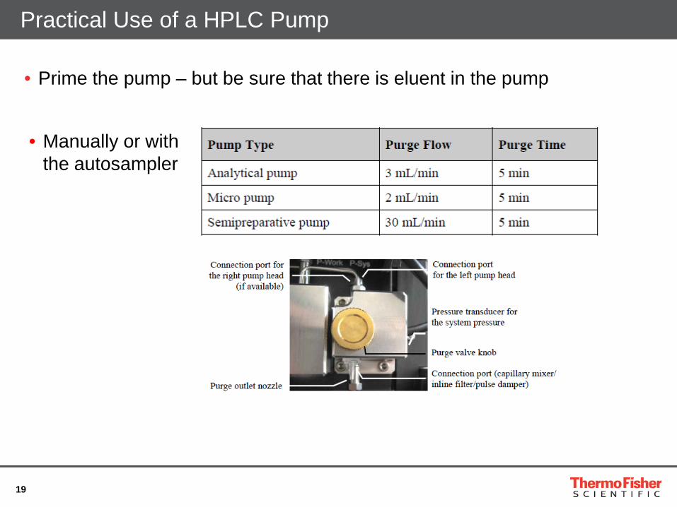
Practical Use of a HPLC Pump
• Manually or with the autosampler
• Prime the pump – but be sure that there is eluent in the pump
20
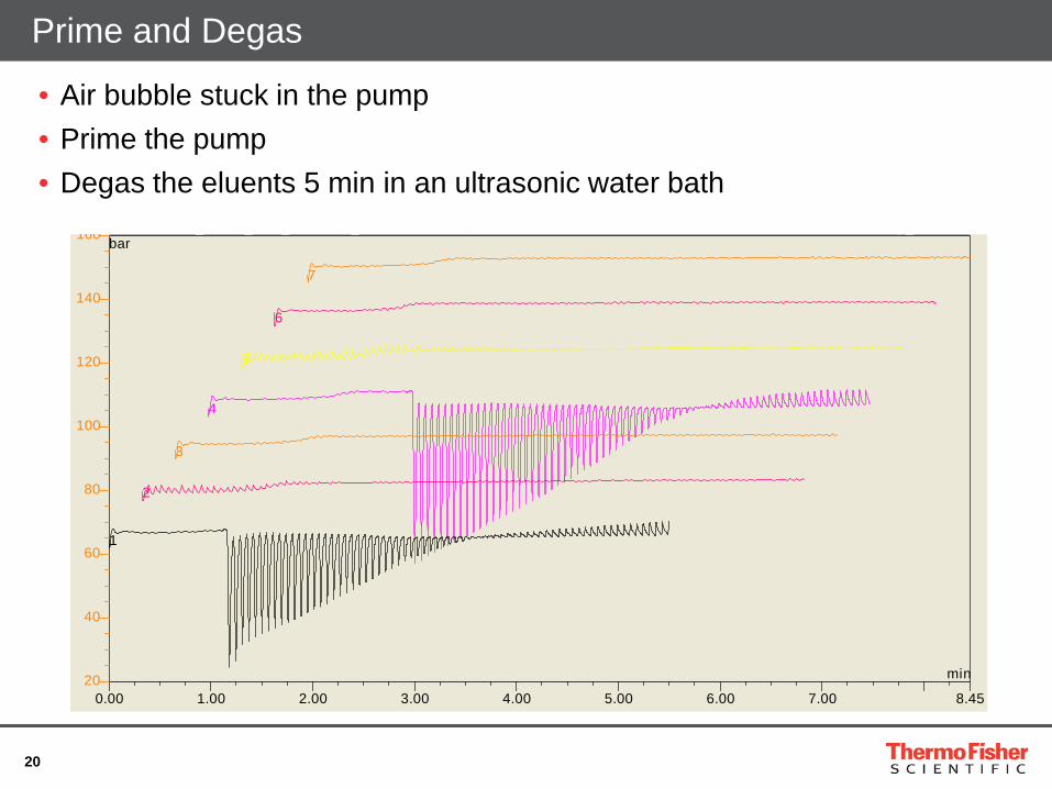
• Air bubble stuck in the pump • Prime the pump • Degas the eluents 5 min in an ultrasonic water bath
Prime and Degas
0.00 1.00 2.00 3.00 4.00 5.00 6.00 7.00 8.4520
40
60
80
100
120
140
160
_ _ _ _ p_
bar
min
7
6
5
4
3
2
1
21
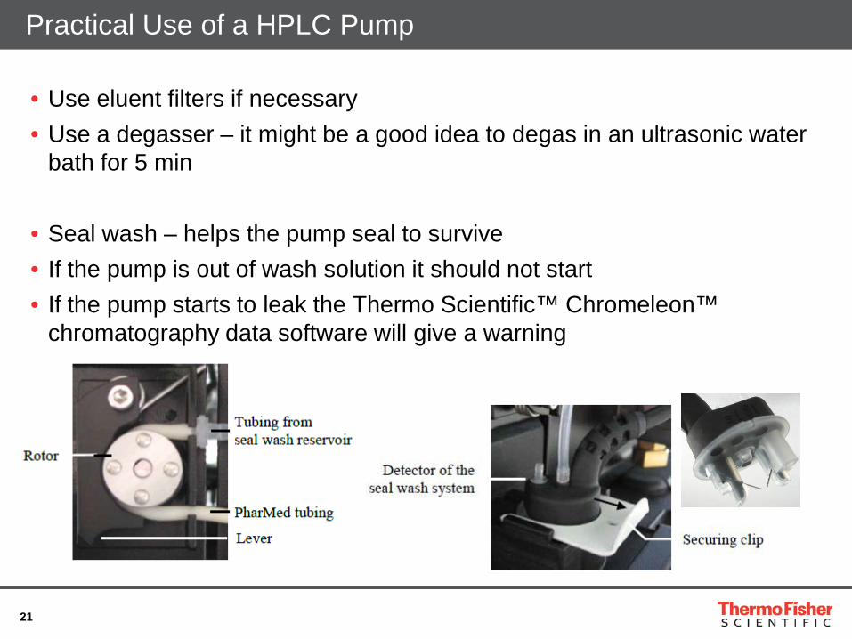
Practical Use of a HPLC Pump
• Use eluent filters if necessary • Use a degasser – it might be a good idea to degas in an ultrasonic water
bath for 5 min • Seal wash – helps the pump seal to survive • If the pump is out of wash solution it should not start • If the pump starts to leak the Thermo Scientific™ Chromeleon™
chromatography data software will give a warning
22
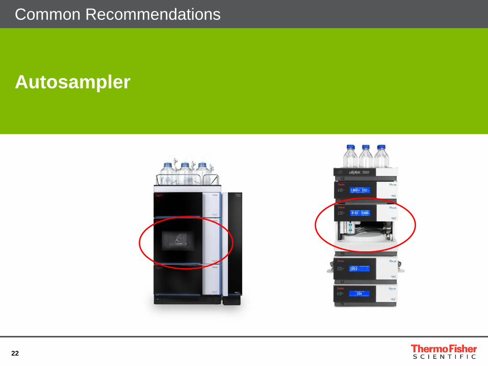
Autosampler
Common Recommendations
23
Autosamplers
• Modern autosamplers should be considered as pipetting robots
• Other than injecting the sample they can:
• Dilute samples
• Do pre-column derivatization
• Spike the samples
24
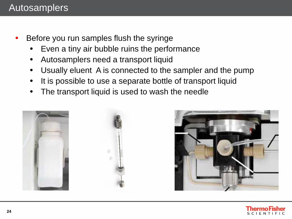
Autosamplers
• Before you run samples flush the syringe • Even a tiny air bubble ruins the performance • Autosamplers need a transport liquid • Usually eluent A is connected to the sampler and the pump • It is possible to use a separate bottle of transport liquid • The transport liquid is used to wash the needle
25
Important Parameters
● DrawSpeed ● Defines the speed at which the sample is drawn by the syringe ● In analytical range (5 - 100 µL) a draw cycle should normally take
3 - 4 seconds. At lower volumes, a draw cycle should take approximately 10 times longer Examples (normal HPLC eluents and samples dissolved in starting eluent)
• => 10 µL injection volume -> Recommended draw speed: 2 - 3 µL/sec • => 2 µL injection volume -> Recommended draw speed: 0.2 - 0.3 µL/sec
● Draw speed has to be adapted in case of samples and eluents with higher viscosity.
● Incorrect setting is frequently responsible for area precision problems.
26
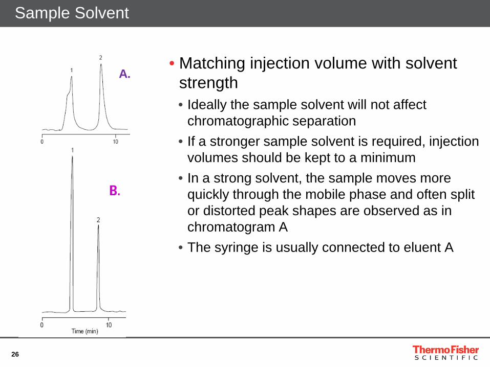
Sample Solvent
• Matching injection volume with solvent strength • Ideally the sample solvent will not affect
chromatographic separation • If a stronger sample solvent is required, injection
volumes should be kept to a minimum • In a strong solvent, the sample moves more
quickly through the mobile phase and often split or distorted peak shapes are observed as in chromatogram A
• The syringe is usually connected to eluent A
A.
27
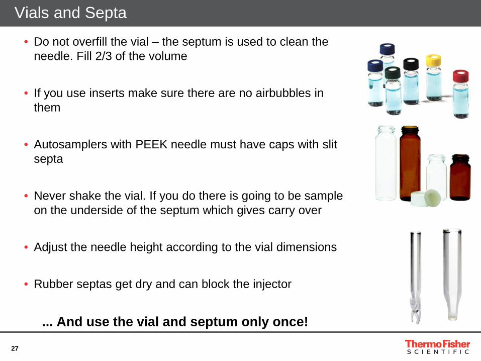
Vials and Septa
• Do not overfill the vial – the septum is used to clean the needle. Fill 2/3 of the volume
• If you use inserts make sure there are no airbubbles in them
• Autosamplers with PEEK needle must have caps with slit septa
• Never shake the vial. If you do there is going to be sample on the underside of the septum which gives carry over
• Adjust the needle height according to the vial dimensions
• Rubber septas get dry and can block the injector
... And use the vial and septum only once!
28
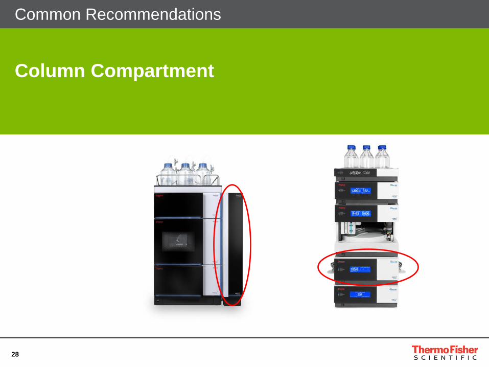
Column Compartment
Common Recommendations
29
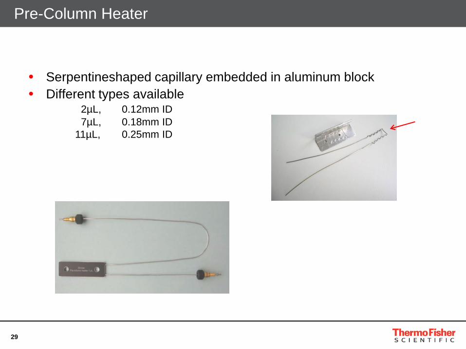
Pre-Column Heater
• Serpentineshaped capillary embedded in aluminum block • Different types available
2µL, 0.12mm ID 7µL, 0.18mm ID 11µL, 0.25mm ID
30
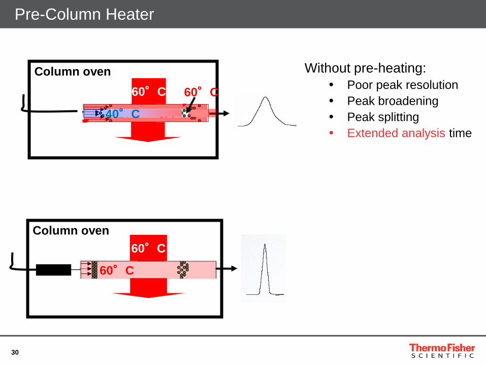
60°C
60°C
60°C Column oven
40°C
60°C
Pre-Column Heater
Column oven
Without pre-heating: • Poor peak resolution • Peak broadening • Peak splitting • Extended analysis time
31
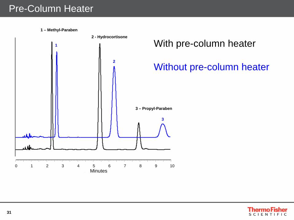
Pre-Column Heater
1 – Methyl-Paraben 2 - Hydrocortisone
3 – Propyl-Paraben
With pre-column heater Without pre-column heater
1
2
3
0 1 2 3 4 5 6 7 8 9 10 Minutes
32
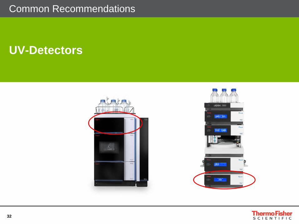
UV-Detectors
Common Recommendations
33
Operating Principle Variable Wavelength Detector (VWD)
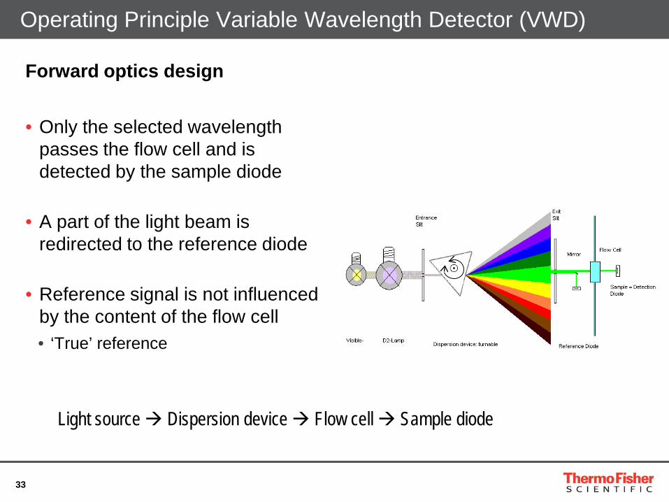
Forward optics design
• Only the selected wavelength passes the flow cell and is detected by the sample diode
• A part of the light beam is redirected to the reference diode
• Reference signal is not influenced by the content of the flow cell • ‘True’ reference
Light source Dispersion device Flow cell Sample diode
34
Recommended Parameters: Reference Wavelength DAD
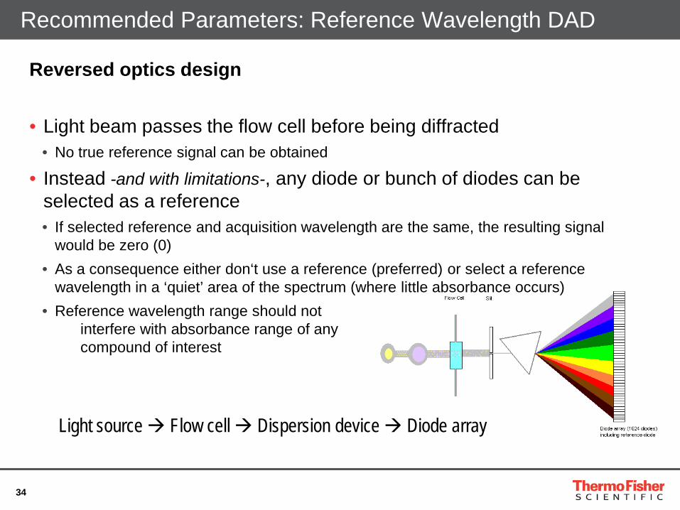
Reversed optics design
• Light beam passes the flow cell before being diffracted • No true reference signal can be obtained
• Instead -and with limitations-, any diode or bunch of diodes can be selected as a reference • If selected reference and acquisition wavelength are the same, the resulting signal
would be zero (0) • As a consequence either don‘t use a reference (preferred) or select a reference
wavelength in a ‘quiet’ area of the spectrum (where little absorbance occurs) • Reference wavelength range should not
interfere with absorbance range of any compound of interest
Light source Flow cell Dispersion device Diode array

35
Flow Cell Volume
• Flow cell volume depends on peak volume • Rule: Flow cell volume should not exceed 10% of the peak volume
Flow cell ok
Peak
Vol
ume
Cell v
olum
e
Flow
Flow cell too big
Micro column peak volumes
Flow cell ok
Micro column peak volumes
Note: Besides lamp age the light intensity is highly dependent on the installed flow cell
Smaller cell volume Less light is passing through the flow cell
36
Diode Array Detector
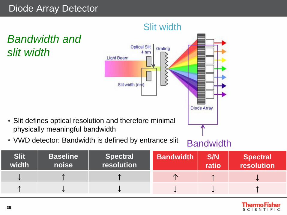
Bandwidth S/N ratio
Spectral resolution
↑ ↑ ↓ ↓ ↓ ↑
Slit width
Baseline noise
Spectral resolution
↓ ↑ ↑ ↑ ↓ ↓
Slit width
Bandwidth
Bandwidth and slit width
• Slit defines optical resolution and therefore minimal physically meaningful bandwidth
• VWD detector: Bandwidth is defined by entrance slit
37
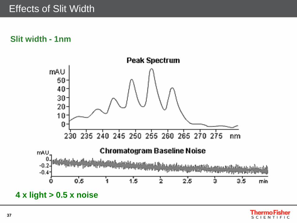
Effects of Slit Width
Slit width - 1nm
4 x light > 0.5 x noise
38
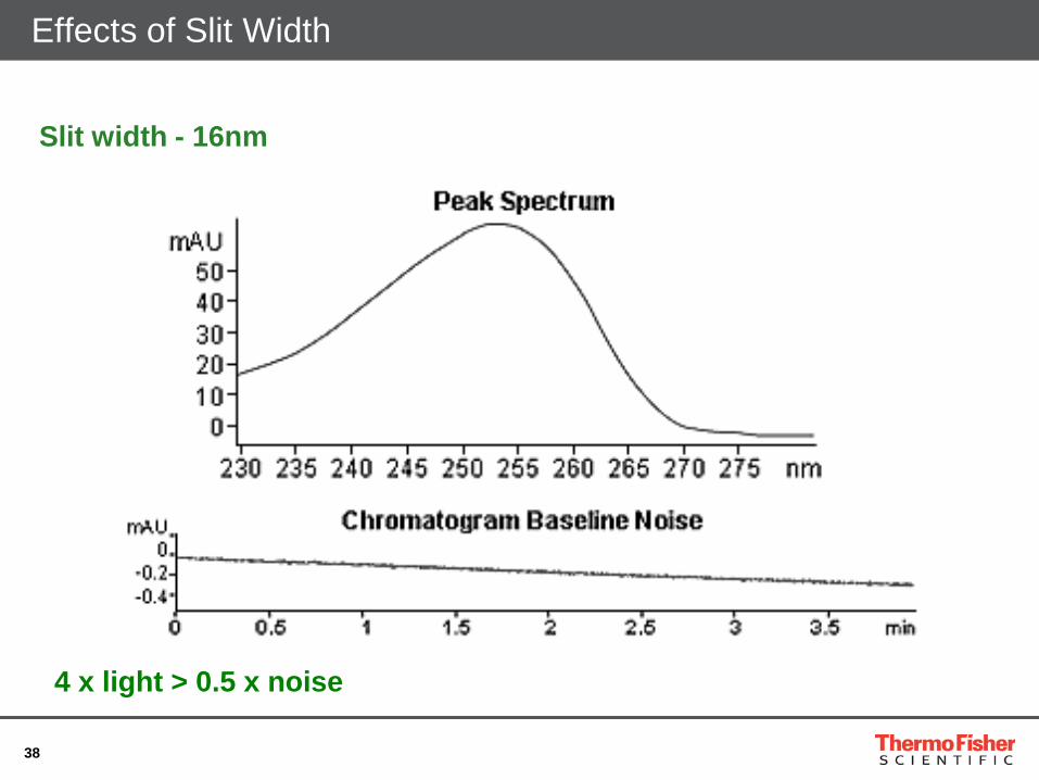
Effects of Slit Width
Slit width - 16nm
4 x light > 0.5 x noise
39
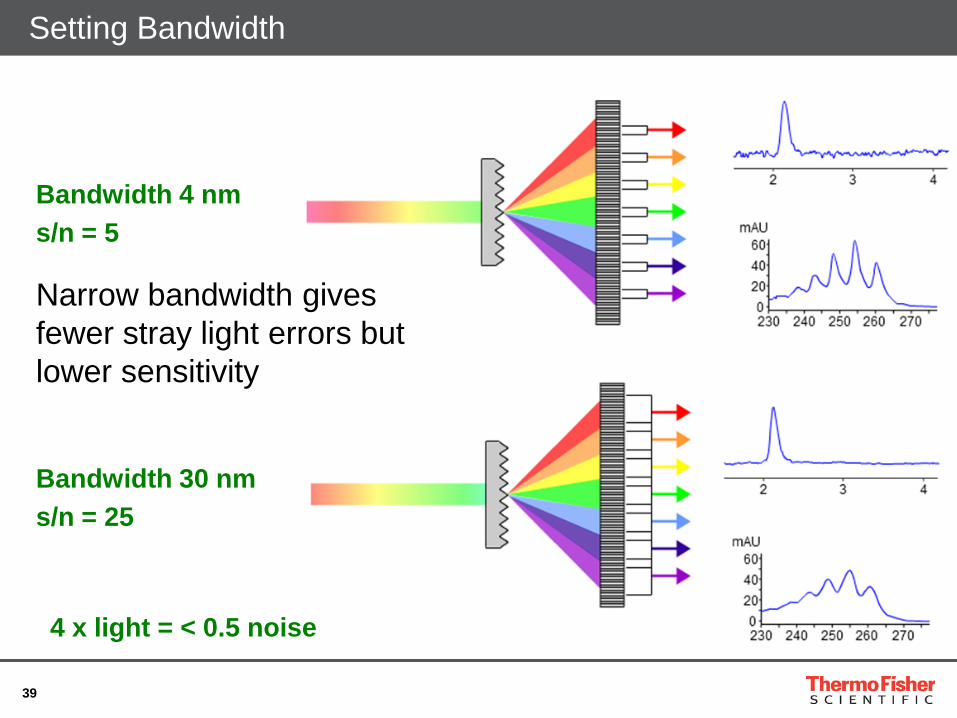
Setting Bandwidth
Bandwidth 4 nm s/n = 5
Bandwidth 30 nm s/n = 25
Narrow bandwidth gives fewer stray light errors but lower sensitivity
4 x light = < 0.5 noise
40
Recommended Parameters: Data Acquisition 250 250
0,100 0,105 0,110 0,115 0,120 0
50
100
150
200
Abs
orba
nce
[mA
U]
t [min] 0,100 0,105 0,110 0,115 0,120 0
50
100
150
200
Data rate: 5 Hz
t [min]
Abs
orba
nce
[mA
U]
Data rate: 100 Hz
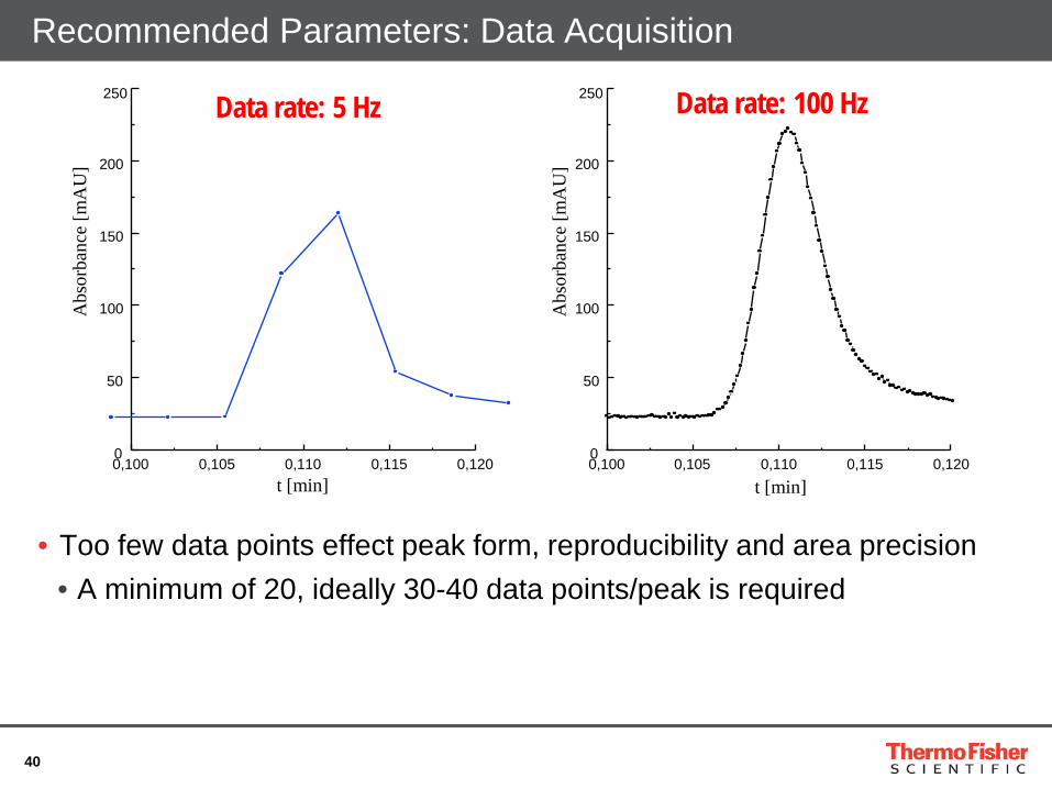
• Too few data points effect peak form, reproducibility and area precision • A minimum of 20, ideally 30-40 data points/peak is required
41
Time Constant
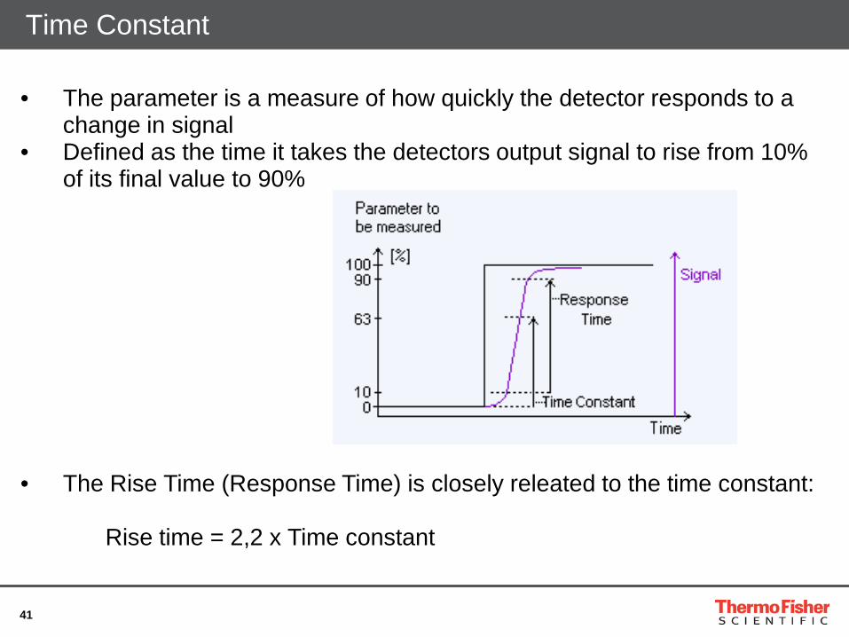
• The Rise Time (Response Time) is closely releated to the time constant:
Rise time = 2,2 x Time constant
• The parameter is a measure of how quickly the detector responds to a change in signal
• Defined as the time it takes the detectors output signal to rise from 10% of its final value to 90%

42
Recommended Parameters: Data Acquisition
• Noise is much more influenced by time constant (TC) than by data collection rate (DCR)
-0,0650
0,0200 1 - Det_Set_Noise #1 DCR fix at 25 Hz and TC varied UV_VIS_1mAU
1
WVL:245 nm
0,0 2,0 4,0 6,0 8,0 10,0 12,0 14,0 16,0 18,0 20,0 22,0 25,0-0,0850
-0,0500
0,0000 2 - Det_Set_Noise #3 TC fix at 0.06 sec. and DCR varied UV_VIS_1mAU
min
2
WVL:245 nm
TC 2.0 s TC 0.2 s TC 0.06 s TC 0.03 s TC 0.01 s
DCR 1 Hz DCR 10 Hz DCR 25 Hz DCR 50 Hz DCR 100 Hz

43
Recommended Parameters: Data Acquisition
• The Program Wizard of Chromeleon has a dedicated step for setting the correct ‘Data Collection Rate’ and ‘Time Constant’
• The internal calculation is based on the peak width at half peak height of the slimmest peak in the chromatogram
44
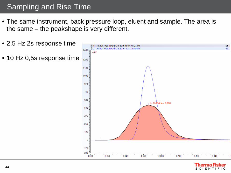
Sampling and Rise Time
• The same instrument, back pressure loop, eluent and sample. The area is the same – the peakshape is very different.
• 2,5 Hz 2s response time
• 10 Hz 0,5s response time
45
THANK YOU!
• Technical Support for Chromatography Columns and Consumables www.thermoscientific.com/chromexpert
• Applications Library Resource www.thermoscientific.com/AppsLab
46
Any questions?
Do you have additional questions or do you want to talk to an expert from Thermo Fisher Scientific? Please send an E-Mail to [email protected] and we will get back to you.