Embed Size (px)
Citation preview
Installation Instructions
HPK-Series Motor Encoder Replacement Kit Catalog Numbers HPK-B1307C-ENC, HPK-B1307E-ENC, HPK-B1308C-ENC, HPK-B1308E-ENC, HPK-B1310C-ENC, HPK-B1609E-ENC, HPK-B1611E-ENC, HPK-B1613C-ENC, HPK-B1613E-ENC, HPK-B1815C-ENC, HPK-B2010C-ENC, HPK-B2010E-ENC, HPK-B2212C-ENC, HPK-B2510C-ENC
About This Publication Each replacement kit is designed for the encoder type and version that is installed on a specific model of an HPK-Series™ motor. Refer to Catalog Number Explanation on page 3 for a chart that defines the motor and encoder combinations.
Use this document if you are responsible for replacing the encoder on an Allen-Bradley® HPK-Series motor. Read all instructions before starting the replacement procedure.
Topic Page
About This Publication 1
Important User Information 2
Catalog Number Explanation 3
Before You Begin 4
Required Parts 5
Replacing Encoders 5
Preparing for Installation 5
Disassemble the Encoder - Original Version 6
Disassemble the Encoder - Later Version 8
Install the Replacement Encoder 10
Additional Resources 11
2 HPK-Series Motor Encoder Replacement Kit
Important User Information
Solid-state equipment has operational characteristics differing from those of electromechanical equipment. Safety Guidelines for the Application, Installation and Maintenance of Solid State Controls (publication SGI-1.1 available from your local Rockwell Automation® sales office or online at http://www.rockwellautomation.com/literature/) describes some important differences between solid-state equipment and hard-wired electromechanical devices. Because of this difference, and also because of the wide variety of uses for solid-state equipment, all persons responsible for applying this equipment must satisfy themselves that each intended application of this equipment is acceptable.
In no event will Rockwell Automation, Inc. be responsible or liable for indirect or consequential damages resulting from the use or application of this equipment.
The examples and diagrams in this manual are included solely for illustrative purposes. Because of the many variables and requirements associated with any particular installation, Rockwell Automation, Inc. cannot assume responsibility or liability for actual use based on the examples and diagrams.
No patent liability is assumed by Rockwell Automation, Inc. with respect to use of information, circuits, equipment, or software described in this manual.
Reproduction of the contents of this manual, in whole or in part, without written permission of Rockwell Automation, Inc., is prohibited.
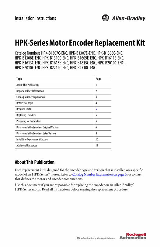
Throughout this manual, when necessary, we use notes to make you aware of safety considerations.
WARNING: Identifies information about practices or circumstances that can cause an explosion in a hazardous environment, which may lead to personal injury or death, property damage, or economic loss.
ATTENTION: Identifies information about practices or circumstances that can lead to personal injury or death, property damage, or economic loss. Attentions help you identify a hazard, avoid a hazard and recognize the consequences.
SHOCK HAZARD: Labels may be on or inside the equipment, for example, a drive or motor, to alert people that dangerous voltage may be present.
BURN HAZARD: Labels may be on or inside the equipment, for example, a drive or motor, to alert people that surfaces may reach dangerous temperatures.
IMPORTANT Identifies information that is critical for successful application and understanding of the product.
Rockwell Automation Publication HPK-IN002C-EN-P - May 2012
HPK-Series Motor Encoder Replacement Kit 3
Catalog Number Explanation
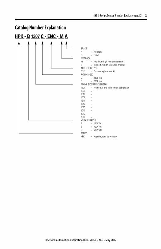
HPK - B 1307 C - ENC - M A
BRAKE A = No brake B = Brake FEEDBACK M = Multi-turn high resolution encoder S = Single-turn high resolution encoder ACCESSORY TYPE ENC = Encoder replacement kit RATED SPEED C = 1500 rpm E = 3000 rpm FRAME SIZE/STACK LENGTH 1307 = Frame size and stack length designation 1308 =1310 =1609 =1611 =1613 =1815 =2010 =2212 =2510 =VOLTAGE RATNG B = 460V AC E = 400V AC G = 750V DC SERIES HPK = Asynchronous servo motor
Rockwell Automation Publication HPK-IN002C-EN-P - May 2012
4 HPK-Series Motor Encoder Replacement Kit
Before You Begin Before unpacking the product, inspect the shipping carton for damage. If damage is visible, immediately contact the shipper and request assistance.; otherwise, proceed with unpacking.
Carefully remove the encoder from its shipping container, and visually inspect it for damage. If the encoder is undamaged, carefully examine the encoder cable and the spring mounting plate for defects.
Keep the original packing material in case you need to return the product for repair or to transport it to another location. Use both the inner and outer packing cartons to provide adequate protection for a unit returned for service.
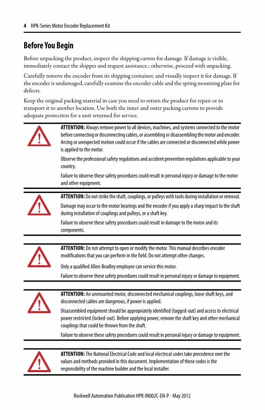
ATTENTION: Always remove power to all devices, machines, and systems connected to the motor before connecting or disconnecting cables, or assembling or disassembling the motor and encoder. Arcing or unexpected motion could occur if the cables are connected or disconnected while power is applied to the motor.
Observe the professional safety regulations and accident prevention regulations applicable to your country.
Failure to observe these safety procedures could result in personal injury or damage to the motor and other equipment.
ATTENTION: Do not strike the shaft, couplings, or pulleys with tools during installation or removal.
Damage may occur to the motor bearings and the encoder if you apply a sharp impact to the shaft during installation of couplings and pulleys, or a shaft key.
Failure to observe these safety procedures could result in damage to the motor and its components.
ATTENTION: Do not attempt to open or modify the motor. This manual describes encoder modifications that you can perform in the field. Do not attempt other changes.
Only a qualified Allen-Bradley employee can service this motor.
Failure to observe these safety procedures could result in personal injury or damage to equipment.
ATTENTION: An unmounted motor, disconnected mechanical couplings, loose shaft keys, and disconnected cables are dangerous, if power is applied.
Disassembled equipment should be appropriately identified (tagged-out) and access to electrical power restricted (locked-out). Before applying power, remove the shaft key and other mechanical couplings that could be thrown from the shaft.
Failure to observe these safety procedures could result in personal injury or damage to equipment.
ATTENTION: The National Electrical Code and local electrical codes take precedence over the values and methods provided in this document. Implementation of these codes is the responsibility of the machine builder and the local installer.
Rockwell Automation Publication HPK-IN002C-EN-P - May 2012
HPK-Series Motor Encoder Replacement Kit 5
Required Parts To install the HPK-Series Motor Encoder Replacement Kit, you should plan to provide the following parts. Where possible, reuse screws and other hardware.
• Fixing screws
• Electrical tape
Replacing Encoders Review these sections to become familiar with the steps before you begin to replace your encoder.
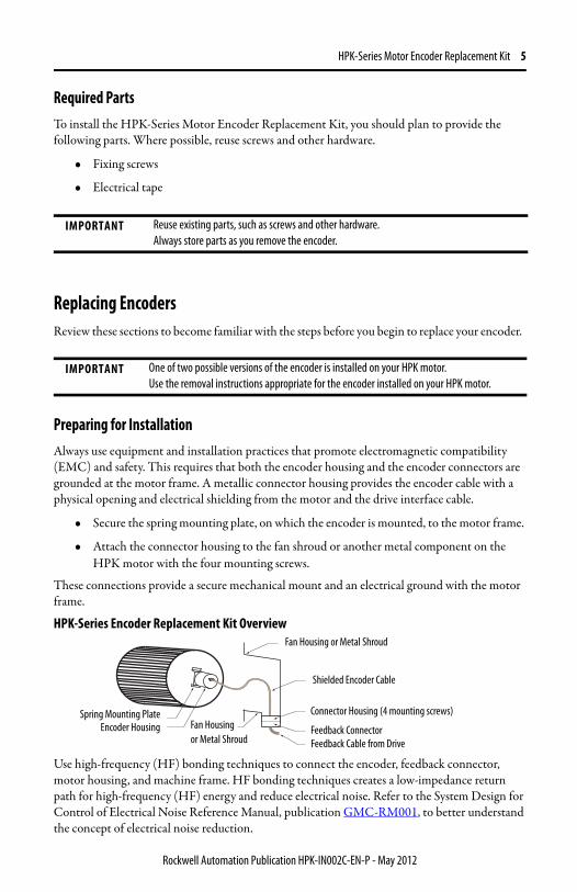
Preparing for Installation Always use equipment and installation practices that promote electromagnetic compatibility (EMC) and safety. This requires that both the encoder housing and the encoder connectors are grounded at the motor frame. A metallic connector housing provides the encoder cable with a physical opening and electrical shielding from the motor and the drive interface cable.
• Secure the spring mounting plate, on which the encoder is mounted, to the motor frame.
• Attach the connector housing to the fan shroud or another metal component on the HPK motor with the four mounting screws.
These connections provide a secure mechanical mount and an electrical ground with the motor frame.
HPK-Series Encoder Replacement Kit Overview
Use high-frequency (HF) bonding techniques to connect the encoder, feedback connector, motor housing, and machine frame. HF bonding techniques creates a low-impedance return path for high-frequency (HF) energy and reduce electrical noise. Refer to the System Design for Control of Electrical Noise Reference Manual, publication GMC-RM001, to better understand the concept of electrical noise reduction.
IMPORTANT Reuse existing parts, such as screws and other hardware. Always store parts as you remove the encoder.
IMPORTANT One of two possible versions of the encoder is installed on your HPK motor. Use the removal instructions appropriate for the encoder installed on your HPK motor.
Fan Housing or Metal Shroud
Shielded Encoder Cable
Connector Housing (4 mounting screws)
Feedback Connector Feedback Cable from Drive
Encoder HousingSpring Mounting Plate
Fan Housing or Metal Shroud
Rockwell Automation Publication HPK-IN002C-EN-P - May 2012
6 HPK-Series Motor Encoder Replacement Kit
Disassemble the Encoder - Original Version
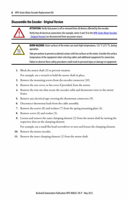
1. Block the motor shaft (3) to prevent rotation.
For example, use a wrench to hold the motor shaft in place.
2. Remove the mounting screws from the encoder connector (10).
3. Remove the rear cover, or fan cover if provided, from the motor.
4. Remove the wire ties that secure the encoder cable and thermostat wires to the motor frame.
5. Remove any electrical tape covering the thermostat connectors (9).
6. Disconnect thermostat leads from the cable assembly.
7. Remove the screws (8) and washers (7) from the spring mounting plate (4).
8. Remove screw (6) and washer (5).
9. Loosen and remove the outer clamping element (2) from the motor shaft by turning the respective slots on the clamping element.
For example, use a small flat head screwdriver to turn and loosen the clamping element.
10. Remove the motor encoder.
11. Remove the inner clamping element (1) from the motor shaft.
ATTENTION: Verify that power is off or removed from all devices affected by the encoder.
Verify that all electrical connections (for example, items 9 and 10 in the HPK-Series Motor Encoder - Original Version) are disconnected from any power source.
BURN HAZARD: Outer surfaces of the motor can reach high temperatures, 125 °C (275 °F), during operation.
Take precautions to prevent accidental contact with hot surfaces on the motor. Consider the surface temperature of the equipment when selecting cables and additional equipment for connection.
Failure to observe these safety procedures could result in personal injury or damage to equipment.
Rockwell Automation Publication HPK-IN002C-EN-P - May 2012
HPK-Series Motor Encoder Replacement Kit 7
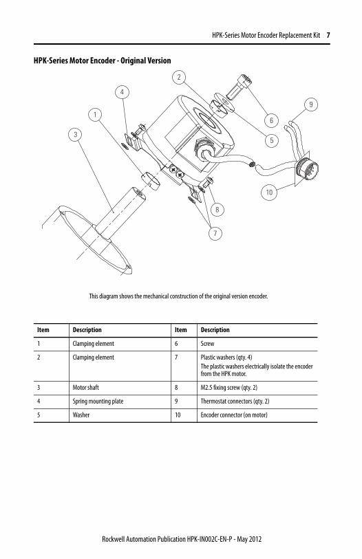
HPK-Series Motor Encoder - Original Version
Item Description Item Description
1 Clamping element 6 Screw
2 Clamping element 7 Plastic washers (qty. 4) The plastic washers electrically isolate the encoder from the HPK motor.
3 Motor shaft 8 M2.5 fixing screw (qty. 2)
4 Spring mounting plate 9 Thermostat connectors (qty. 2)
5 Washer 10 Encoder connector (on motor)
1
4
2
6
5
7
9
8
10
3
This diagram shows the mechanical construction of the original version encoder.
Rockwell Automation Publication HPK-IN002C-EN-P - May 2012
8 HPK-Series Motor Encoder Replacement Kit
Disassemble the Encoder - Later Version
1. Block the motor shaft (3) to prevent rotation.
For example, use a wrench to hold the motor shaft in place.
2. Remove the mounting screws from the encoder connector (10).
3. Remove the rear cover, or fan cover if provided, from the motor.
4. Remove the wire ties that secure the encoder cable and thermostat wires to the motor frame.
5. Remove any electrical tape covering the thermostat connectors (9), and then disconnect the thermostat leads from the thermostat connector.
6. Remove the screws (8) and washers (7) from the spring mounting plate (4).
7. Loosen the shaft clamp screw (6).
8. Remove the motor encoder (1).
9. Remove the plastic shaft sleeve (2) from the motor shaft, if it was not removed with the encoder.
ATTENTION: Verify that power is off or removed from all devices affected by the encoder.
Verify that all electrical connections (for example, items 9 and 10 in the HPK-Series Motor Encoder - Later Version) are disconnected from any power source.
BURN HAZARD: Outer surfaces of the motor can reach high temperatures, 125 °C (275 °F), during operation.
Take precautions to prevent accidental contact with hot surfaces on the motor. Consider the surface temperature of the equipment when selecting cables and additional equipment for connection.
Failure to observe these safety procedures could result in personal injury or damage to equipment.
Rockwell Automation Publication HPK-IN002C-EN-P - May 2012
HPK-Series Motor Encoder Replacement Kit 9
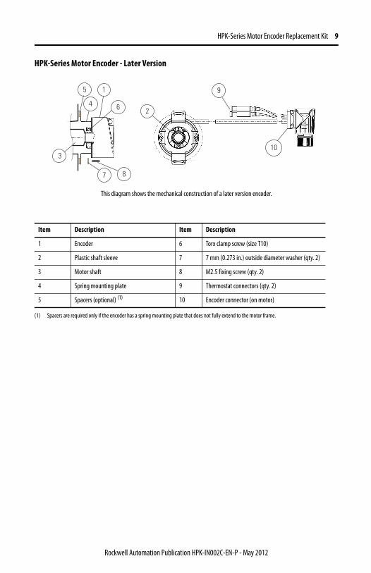
HPK-Series Motor Encoder - Later Version
Item Description Item Description
1 Encoder 6 Torx clamp screw (size T10)
2 Plastic shaft sleeve 7 7 mm (0.273 in.) outside diameter washer (qty. 2)
3 Motor shaft 8 M2.5 fixing screw (qty. 2)
4 Spring mounting plate 9 Thermostat connectors (qty. 2)
5 Spacers (optional) (1)
(1) Spacers are required only if the encoder has a spring mounting plate that does not fully extend to the motor frame.
10 Encoder connector (on motor)
87
3
1
2
10
9
64
5
This diagram shows the mechanical construction of a later version encoder.
Rockwell Automation Publication HPK-IN002C-EN-P - May 2012
10 HPK-Series Motor Encoder Replacement Kit
Install the Replacement Encoder Refer to the HPK-Series Motor Encoder - Later Version diagram on page 9 to identify specific parts of the replacement encoder and their correct position when installed.
1. Verify the encoder replacement kit catalog number corresponds with the motor catalog number listed on the motor nameplate.
2. Check the runout of the motor shaft, approximately 0.50 mm (0.02 in.) from the front of the shaft.
If the runout exceeds 0.003 total indicator runout (TIR), correct it by tapping on the motor shaft with a brass hammer.
3. Verify the plastic shaft sleeve (2) is installed in the encoder shaft (1), with the larger diameter shoulder of the sleeve oriented at the same end of the encoder as the shaft clamp screw (6).
4. Rotate the encoder shaft to an angular position that permits access to the shaft clamp screw (6) when the encoder is installed.
5. Push the encoder (1) fully onto the motor shaft.
The encoder is fully seated when the plastic shaft sleeve (2) is tight against the motor shaft shoulder, but the spring mounting plate is not bent.
6. Tighten the encoder shaft clamp screw (6) to 1.1 ± 0.1 N•m (9.7 ± 0.9 lb•in) with a T10 Torx driver.
7. If a gap exists between the spring mounting plate and the motor frame when the encoder is fully seated on the motor shaft, fill the gap by installing spacer washers (5) or stacked flat washers.
8. Install screws (8) and washers (7) to hold the spring mounting plate (4) on the motor.
After all screws and washers are in place, tighten the screws to 0.28 N•m (2.5 lb•in).
TIP Use a piece of soft wood or a thin rubber pad to protect the motor shaft from physical damage.
ATTENTION: The encoder shaft clamp can break if overtightened.
A broken shaft clamp could cause unexpected motor shaft rotation and corresponding machine motion, due to loss of encoder feedback.
Failure to observe safety procedures could result in personal injury or damage to the motor and other equipment.
IMPORTANT Original version encoders use plastic washers to electrically isolate the encoder from the motor frame at the spring mounting plate. Later version encoders have a plastic shaft sleeve, that electrically isolates the encoder from the motor shaft.
When replacing an original version encoder with a later version encoder, do not use the plastic washers to secure the spring mounting plate to the motor frame. Later version encoders use metal screws (7) and washers (8) to ground the spring mounting plate to the motor frame.
Rockwell Automation Publication HPK-IN002C-EN-P - May 2012
HPK-Series Motor Encoder Replacement Kit 11
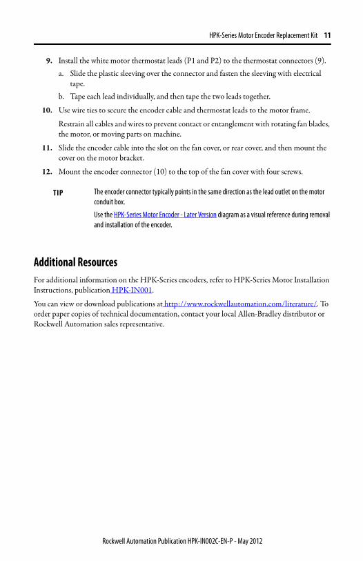
9. Install the white motor thermostat leads (P1 and P2) to the thermostat connectors (9). a. Slide the plastic sleeving over the connector and fasten the sleeving with electrical
tape. b. Tape each lead individually, and then tape the two leads together.
10. Use wire ties to secure the encoder cable and thermostat leads to the motor frame.
Restrain all cables and wires to prevent contact or entanglement with rotating fan blades, the motor, or moving parts on machine.
11. Slide the encoder cable into the slot on the fan cover, or rear cover, and then mount the cover on the motor bracket.
12. Mount the encoder connector (10) to the top of the fan cover with four screws.
Additional ResourcesFor additional information on the HPK-Series encoders, refer to HPK-Series Motor Installation Instructions, publication HPK-IN001.
You can view or download publications at http://www.rockwellautomation.com/literature/. To order paper copies of technical documentation, contact your local Allen-Bradley distributor or Rockwell Automation sales representative.
TIP The encoder connector typically points in the same direction as the lead outlet on the motor conduit box.
Use the HPK-Series Motor Encoder - Later Version diagram as a visual reference during removal and installation of the encoder.
Rockwell Automation Publication HPK-IN002C-EN-P - May 2012
Rockwell Automation Support
Publication HPK-IN002C-EN-P - May 2012 PN-138408
Rockwell Automation provides technical information on the Web to assist you in using its products. At http://www.rockwellautomation.com/support, you can find technical manuals, technical and application notes, sample code and links to software service packs, and a MySupport feature that you can customize to make the best use of these tools. You can also visit our Knowledgebase at http://www.rockwellautomation.com/knowledgebase for FAQs, technical information, support chat and forums, software updates, and to sign up for product notification updates.
For an additional level of technical phone support for installation, configuration and troubleshooting, we offer TechConnectsm support programs. For more information, contact your local distributor or Rockwell Automation representative, or visit http://www.rockwellautomation.com/support/.
Installation AssistanceIf you experience a problem within the first 24 hours of installation, please review the information that's contained in this manual. You can also contact a special Customer Support number for initial help in getting your product up and running.
New Product Satisfaction ReturnRockwell Automation tests all of its products to ensure that they are fully operational when shipped from the manufacturing facility. However, if your product is not functioning and needs to be returned, follow these procedures.
Documentation Feedback Your comments will help us serve your documentation needs better. If you have any suggestions on how to improve this document, complete this form, publication RA-DU002, available at http://www.rockwellautomation.com/literature/.
United States or Canada 1.440.646.3434
Outside United States or Canada
Use the Worldwide Locator at http://www.rockwellautomation.com/support/americas/phone_en.html, or contact your local Rockwell Automation representative.
United StatesContact your distributor. You must provide a Customer Support case number (call the phone number above to obtain one) to your distributor to complete the return process.
Outside United States Please contact your local Rockwell Automation representative for the return procedure.
Allen-Bradley, HPK-Series, Rockwell Automation, Rockwell Software, and TechConnect are trademarks of Rockwell Automation, Inc.
Trademarks not belonging to Rockwell Automation are property of their respective companies.
Rockwell Otomasyon Ticaret A.Ş., Kar Plaza İş Merkezi E Blok Kat:6 34752 İçerenköy, İstanbul, Tel: +90 (216) 5698400
Supersedes Publication HPK-IN002B - November 2008 Copyright © 2012 Rockwell Automation, Inc. All rights reserved. Printed in the U.S.A.


![Fwd: [juizesfree] ENC: Enc: Papagaios do Brasil](https://img.pdfslide.us/doc/110x75/5587e05ed8b42a15638b4725/fwd-juizesfree-enc-enc-papagaios-do-brasil.jpg)