Embed Size (px)
Citation preview

HPE SERVICEGUARD FOR LINUX WITH VMWARE VIRTUAL MACHINES
Technical white paper

Technical white paper
CONTENTS About this paper ............................................................................................................................................................................................................................................................................................................................ 3 Introduction ........................................................................................................................................................................................................................................................................................................................................ 3 Supported storage configuration with VMware virtual machines .................................................................................................................................................................................................... 5 Supported cluster deployment models with VMware virtual machines ...................................................................................................................................................................................... 5
Cluster with VMs only from one host ................................................................................................................................................................................................................................................................... 5 Cluster with one or more VMs each from multiple hosts ................................................................................................................................................................................................................... 6 Cluster with one VM each from multiple hosts ........................................................................................................................................................................................................................................... 6 Clusters with VMs and physical machines ....................................................................................................................................................................................................................................................... 7 Disaster recovery clusters using VMware virtual machines ............................................................................................................................................................................................................ 8
Summary of supported cluster deployment models with various storage configurations ..................................................................................................................................... 12 Configuring a VMware virtual machine .................................................................................................................................................................................................................................................................. 13 Configuration requirements for a Serviceguard cluster with VMware guests .................................................................................................................................................................... 13
Network configurations .................................................................................................................................................................................................................................................................................................. 13 Shared storage configurations for statically linked storage ......................................................................................................................................................................................................... 14 Shared storage configuration steps for dynamically linked storages .................................................................................................................................................................................. 28 Shared storage configuration steps for vVols ........................................................................................................................................................................................................................................... 28 Shared storage configuration using VMDirectPath I/O .................................................................................................................................................................................................................... 28 Shared storage configuration for VMware guest nodes using iSCSI devices ............................................................................................................................................................... 29
Prerequisites for VMware guests used as cluster nodes ....................................................................................................................................................................................................................... 29 VMware Tools ......................................................................................................................................................................................................................................................................................................................... 29 SCSI persistent reservation (sg_persist) ......................................................................................................................................................................................................................................................... 29
Serviceguard support for VMware vMotion ...................................................................................................................................................................................................................................................... 29 Summary of requirements ................................................................................................................................................................................................................................................................................................. 29 Summary of recommendations ..................................................................................................................................................................................................................................................................................... 30 Support information ................................................................................................................................................................................................................................................................................................................ 30 Summary ............................................................................................................................................................................................................................................................................................................................................ 30 References ........................................................................................................................................................................................................................................................................................................................................ 31

Technical white paper Page 3
ABOUT THIS PAPER Virtual machine (VM) technology is a powerful capability that can reduce costs and power usage, while also improving resource utilization. HPE applies virtualization to various aspects of the data center—uniting virtual and physical resources to create an environment suitable for deploying mission-critical applications.
HPE Serviceguard for Linux® is certified for deployment on VMware® VMs created on VMware ESX®/VMware ESXi™ Server running on industry-standard HPE ProLiant and Superdome Flex servers.1 This white paper discusses the various ways a VMware VM can be deployed in a Serviceguard for Linux cluster, Extended Distance Cluster, Metrocluster and a Continentalclusters. The paper describes how you can configure a cluster using VMs from single host and multiple hosts, as well as a combination of VMs and physical machines, to provide high availability (HA) and disaster recovery (DR) for your applications. Reasonable expertise in the installation and configuration of HPE Serviceguard for Linux and ESX/ESXi Server, as well as familiarity with their capabilities and limitations, is assumed.
This white paper provides details on recommended network and storage configurations for VMs used as Serviceguard cluster nodes. In addition, this paper recommends how to eliminate single point of failures and provides pointers to other useful, relevant documents as appropriate.
For the complete list of supported operating systems, certified configurations, ESX/ESXi Server, and storage with the listed version of HPE Serviceguard for Linux release, please refer to the “HPE Serviceguard for Linux Certification Matrix” document at hpe.com/info/linux-Serviceguard-docs.
NOTE Except as noted in this technical white paper, all HPE Serviceguard configuration options documented in the “Managing HPE Serviceguard for Linux manual” are supported for VMware guests, and all the documented requirements apply.
INTRODUCTION VMware VMs are increasingly deployed for server consolidation and flexibility. VM technology allows one physical server to simulate multiple servers, each concurrently running its own OS. In virtual machine technology, the virtualization layer (also known as the hypervisor2) abstracts the physical resources so each instance of an OS appears to have its own NIC, processor, disk, and memory, when in fact they are virtual instances. This abstraction allows you to replace numerous existing physical servers with just one, but at the cost of greater exposure to single point of failure.
HPE Serviceguard for Linux software is designed to protect applications and services from planned and unplanned downtime. By packaging an application or service with its associated resources, and moving that package to other servers as needed, Serviceguard for Linux ensures 24x7 application availability. Packages can be moved automatically when Serviceguard detects a failure in a resource, or manually to perform system maintenance or upgrades. By monitoring the health of each server (node) within a cluster, Serviceguard for Linux can quickly respond to failures such as those that affect processes, memory, LAN media and adapters, disk, operating environments, and more.
HPE Serviceguard for Linux running on VMs provides a significant level of protection. Specifically, it fails over an application when any of a large number of failures occurs, including:
• Application failure
• Failure of any of the components in the underlying network infrastructure that can cause failure of the application network
• Failure of storage
• An OS “hang” or failure of the virtual machine itself
• Failure of the physical machine
1 For the latest details concerning alliances and partnership, visit hpe.com/info/vmware and techlibrary.hpe.com/us/en/enterprise/servers/supportmatrix/vmware.aspx 2 A hypervisor or virtual machine monitor (VMM) is a piece of computer software, firmware, or hardware that creates and runs virtual machines

Technical white paper Page 4
In addition, HPE Serviceguard for Linux provides a framework for integrating custom user-defined monitors, using the generic resource monitoring service.
Beyond increased failure protection, HPE Serviceguard for Linux also offers other advantages, such as:
• Faster failover of monitored applications
• Rolling upgrades, allowing for less planned downtime
– With HPE Serviceguard for Linux, an application (package) can be moved off a virtual machine and restarted on another node in the cluster. The “empty” server can then have its OS or applications upgraded while those applications remain available to users, since they are running on other nodes
• HPE Serviceguard for Linux with the VMware vMotion feature enables you to move an entire running virtual machine from one physical server to another with no downtime. The virtual machine retains its network identity and connections, ensuring a seamless migration process with no perceivable impact to the end user
HPE Serviceguard for Linux, combined with VMware software solutions, can protect your applications, while also optimizing the cost, with no compromises on application availability and reliability.
TABLE 1. Terminologies used in this document
Term Definition
VMware host, host Physical server on which the VMware hypervisor is installed
VM guest, guest VM VMware virtual machine carved out of the hypervisor
Physical machine Physical server configured as a Serviceguard cluster node
NIC Network interface card
Cluster, Serviceguard cluster HPE Serviceguard for Linux cluster
HA High availability
DR Disaster Recovery
OS Operating system
SPOF Single point of failure
NPIV N_Port ID Virtualization
RDM Raw device mapping
vVol(s) VMware Virtual Volume(s)
VMFS Virtual Machine File System/Virtual Disk
SG PKG HPE Serviceguard package
PR SCSI-3 Persistent Reservations
Extended Distance Cluster (XDC) Serviceguard DR solution based on Host based replication
Metrocluster Serviceguard DR solution based on Storage based replication
Continentalcluster Serviceguard DR (Push-Button) recovery solution agnostic to underlying storage replication

Technical white paper Page 5
SUPPORTED STORAGE CONFIGURATION WITH VMWARE VIRTUAL MACHINES
TABLE 2. Snapshot of supported storage configurations with VMware virtual machines
Storage configuration type Description
Statically linked storage In statically linked storage configuration, the disks are configured to all VMs that are part of the cluster as RDMs in physical compatibility mode. Serviceguard node on which the given package is active, places PR for exclusive access of RDM disks to ensure data integrity. This is the only supported storage configuration until Serviceguard A.12.00.30 and will continue to be supported in later versions of Serviceguard.
Dynamically linked storage In dynamically linked storage configuration the disks are accessible to a single VM at a time in the Serviceguard cluster. Serviceguard attaches or detaches a disk based on the operation sequence of the Serviceguard package for exclusive access of the disks. The disks can be of type RDM or Virtual disks (VMFS). This storage configuration is supported from Serviceguard A.12.00.40 or later.
VMware Virtual Volumes (vVols) While using vVols, the vmdk disks are configured to all the VMs that are part of the cluster. Serviceguard node on which the given package is active, places the PR for exclusive access of vVol disks to ensure data integrity. VMware handles the distribution of PR keys to all the available paths on the ESXi host.
This storage configuration is supported from Serviceguard A.12.50.00 or later.
iSCSI In iSCSI storage configuration the devices are exposed to the VMs using software initiator. Serviceguard node on which the given package is active, places PR for exclusive access of the disks presented via iSCSI. If multiple iSCSI paths (for a given LUN) are available at the guest, it is recommended to configure Device Mapper (DM) multipath in the guest.
SUPPORTED CLUSTER DEPLOYMENT MODELS WITH VMWARE VIRTUAL MACHINES Cluster with VMs only from one host In this deployment model, a cluster is formed with VMware guests all of which are carved out of a single host (cluster-in-a-box), as shown in Figure 1. Even though this configuration provides consolidation of resources, it is not an ideal solution. A failure of the host would bring down all the nodes in the cluster thus making the host a single point of failure (SPOF). Hence, the configuration is not recommended.
In this deployment model:
• NPIV enabled storage infrastructure is mandatory with statically linked storage.
• NPIV enabled storage infrastructure is not mandatory with dynamically linked storage and vVols.
• iSCSI devices exposed using software initiator can also be used as shared storage in this model.
FIGURE 1. Cluster-in-a-box
Technical white paper Page 6
Cluster with one or more VMs each from multiple hosts In this deployment model, a cluster can be formed with a collection of VMs that are hosted on multiple hosts and with more than one VM coming from all or some of the hosts as shown in Figure 2.
One must also ensure that the VM nodes are so distributed across the hosts; that the failure of any one of the hosts should not result in more than half of the cluster nodes going down. As shown in Figure 2 the correct distribution would be, two VMs each on two hosts configured as cluster nodes, rather than three VMs from Host1 and one VM from the Host2. In the latter case, the failure of the host with three VM cluster nodes would bring down the entire cluster.
Serviceguard is installed on the VM cluster nodes and it provides high availability to the applications running as packages in these VMs. In case of failures, Serviceguard fails over the application packages to other adoptive cluster nodes.
In this deployment model:
• NPIV enabled storage infrastructure is mandatory with statically linked storage.
• NPIV enabled storage infrastructure is not mandatory with dynamically linked storage and vVols.
• iSCSI devices exposed using software initiator can also be used as shared storage in this model.
FIGURE 2. Cluster with one or more VMs each from multiple hosts
Cluster with one VM each from multiple hosts In this deployment model, a cluster can be formed with multiple guests hosted on multiple hosts, where only one guest from each host is used as a node in a cluster as shown in Figure 3. In other words, one host can have multiple guests all of which can be part of different clusters, but no two guests from the same host can belong to the same cluster.
Serviceguard is installed on the VM cluster nodes and it provides high availability to the applications running as packages in these VMs. In case of failures, Serviceguard fails over the application packages to other adoptive cluster nodes.
In this deployment model:
• NPIV enabled storage infrastructure is not mandatory with statically, dynamically linked storage and vVols.
• iSCSI devices exposed using software initiator can also be used as shared storage in this model.

Technical white paper Page 7
FIGURE 3. Cluster with one VM each from multiple hosts
Clusters with VMs and physical machines In this deployment model, a combination of VMware guests and physical machines can be used as nodes in a Serviceguard cluster, as shown in Figures 4 and 5. Serviceguard is installed on the VMware guests and physical machines, and a cluster is formed among them. Serviceguard provides high availability to the applications running as packages in the VMs and physical machines. In case of failures, Serviceguard fails over the application to other adoptive cluster nodes. The application can be failed over from a VM to a physical machine and vice versa.
As mentioned earlier, the cluster nodes must be equally distributed to ensure that a host does not become a single point of failure (SPOF).
This is a very powerful model where the application can primarily run on the physical machine and in case of failures can fail over to an adoptive VM. Thus enabling users to take advantage of the performance of a physical machine, and at the same time allowing for consolidation of standby resources.
In this deployment model:
• NPIV enabled storage infrastructure is not mandatory with statically linked storage, if no two guests from the same host are part of one cluster (as shown in Figure 4).
• NPIV enabled storage infrastructure is mandatory with statically linked storage, if more than one guest from a given host needs to be used in the same cluster (as shown in Figure 5).
• NPIV enabled storage infrastructure is not mandatory with dynamically linked storage.
• vVols cannot be supported for workloads configured to run on both physical machines and VMs.
• iSCSI devices exposed using software initiator can also be used as shared storage in this model.

Technical white paper Page 8
FIGURE 4. Hybrid cluster—Mix of physical machines and one VM each from multiple hosts as cluster node
Figure 5 shows how you can configure a cluster that combines a collection of VMs that are hosted on single hosts and multiple physical machines. The diagram includes two guests from a host participating in a cluster, which means NPIV is mandatory.
FIGURE 5. Hybrid cluster—Mix of physical machines and one or more VMs each from multiple hosts
Disaster recovery clusters using VMware virtual machines Extended Distance Cluster deployment models VMware guests can also be used as cluster nodes in an Extended Distance Cluster (XDC). You can form an XDC with guests spanning across two different sites.
There are three models of deployment possible when using VMs in a XDC.
In the first model, a cluster is formed with a collection of VMs where each VM cluster node is hosted on a different host as shown in Figure 6. As discussed in section “Cluster with one VM each from multiple hosts” multiple guest from a hosts can all be part of different clusters.
In the second model, a cluster can be formed with a collection of VMs that are hosted on multiple hosts and with more than one VM coming from all or some of the hosts as shown in Figure 7. As discussed in section “Cluster with one or more VMs each from multiple hosts.”
In the third model, a cluster can be formed with physical machines and a collection of VMs that are hosted on single or multiple hosts and where the VMs are deployed as per the two models discussed previously.

Technical white paper Page 9
In XDC deployment model:
• Second XDC deployment model cannot be used with statically linked storage as this mandates the use of NPIV enabled storage infrastructure, which is currently not certified for use in an XDC environment.
• NPIV enabled storage infrastructure is not mandatory with dynamically linked storage and vVols.
• iSCSI devices exposed using software initiator can also be used as shared storage in this model.
• When using iSCSI devices as shared storage, one or more VMs from a host can belong to one XDC.
FIGURE 6. Extended Distance Cluster with one VM each from multiple hosts

Technical white paper Page 10
FIGURE 7. Extended Distance Cluster with more than one VM from a single host
Metrocluster deployment models VMware guests can also be used as cluster nodes in a Metrocluster where the VMs are spanning across two different sites. There are two models of deployment possible when using VMs in a Metrocluster.
In the first model, a cluster is formed with a collection of VMs where each VM cluster node is hosted on a different host as shown in Figure 8. As discussed in section “Cluster with one VM each from multiple hosts” multiple guest from a hosts can all be part of different clusters.
In the second model, a cluster can be formed with a collection of VMs that are hosted on multiple hosts and with more than one VM coming from all or some of the hosts as shown in Figure 9.
In this deployment model:
• NPIV enabled storage infrastructure is not mandatory with statically linked storage, if no two guests from the same host are part of one cluster (as shown in Figure 8).
• NPIV enabled storage infrastructure is mandatory with statically linked storage, if more than one guest from a given host needs to be used in the same cluster (as shown in Figure 9).
• NPIV enabled storage infrastructure is not mandatory with dynamically linked storage.
• vVols are not supported.
• iSCSI devices exposed using software initiator can also be used as shared storage in this model.
A Metrocluster can also have a mix of physical machines and VMs, where the VMs are deployed as per the two models discussed on page 9 and 10.

Technical white paper Page 11
FIGURE 8. Metrocluster with one VM each from multiple hosts
FIGURE 9. Metrocluster with one or more VMs each from multiple hosts

Technical white paper Page 12
NOTE As of writing of this document, VMware NPIV is not certified for use with HPE 3PAR StoreServ arrays. Thus when using HPE 3PAR arrays as shared storage in a Metrocluster, the model described in Figure 8 alone is supported.
For more information about Metrocluster, please see the document entitled, “Understanding and Designing Serviceguard Disaster Recovery Architectures” at hpe.com/info/linux-Serviceguard-docs.
Continentalclusters deployment models VMware VMs can be used as Serviceguard cluster nodes in Continentalclusters. In Continentalclusters, distinct clusters are separated by large distances, with a wide area network (WAN) used to connect them. Continentalclusters are configured using two or more Serviceguard clusters. The individual clusters can be created as per the models described in the previous sections. All the requirements and restriction listed in the previous section for configuration, deployment of a cluster, Metrocluster are all applicable when configuring a cluster and/or array based replication in a Continentalcluster.
In this deployment, the cluster nodes configured to use vVols is not supported.
For more information about Continentalclusters, please refer to the document entitled, “Understanding and Designing Serviceguard Disaster Recovery Architectures” at hpe.com/info/linux-Serviceguard-docs.
FIGURE 10. Continentalclusters with VMs
SUMMARY OF SUPPORTED CLUSTER DEPLOYMENT MODELS WITH VARIOUS STORAGE CONFIGURATIONS An HPE Serviceguard for Linux cluster that includes virtual machines as cluster nodes have multiple deployment model.
Table 3 provides a summary of the supported models with different storage configurations in a Serviceguard cluster. Please refer to the appropriate sections in this document to find out more about each supported model.

Technical white paper Page 13
TABLE 3. Snapshot of supported Serviceguard cluster deployment models with various storage configurations with VMware guests
Supported cluster models Statically linked storage Dynamically linked storage
vVols iSCSI
FC (RDM) FC (RDM + NPIV) FC (NPIV not mandatory)
Cluster with VMs only from one host (Cluster-in-a-box)
Cluster with one or more VMs each from multiple hosts
Cluster with only one VM each from multiple hosts
Cluster with VMs and physical machines
Extended Distance Cluster deployment models
Metrocluster deployment models *
Continentalclusters deployment models *
* With HPE 3PAR as shared storage, NPIV is not yet supported.
CONFIGURING A VMWARE VIRTUAL MACHINE For detailed steps and instructions on how to configure, manage, and administer a virtual machine using VMware ESX/ESXi Server, please refer to the VMware document entitled, “Server Configuration Guide”. The resources allocated to the VMs depend on the requirements of the applications deployed on the VMs, as well as the resources available to the host. For configuration limitations, rules and restrictions, sizing, and capacity planning, please refer to the document entitled, “Configuration Maximums for VMware vSphere® 5.0”.
HPE Serviceguard for Linux places no limits on the number of guests that you can provision on one host. For all provisioning guidelines, please refer to the VMware documentation. For resource planning, please follow the recommendation specified by the OS or application.
CONFIGURATION REQUIREMENTS FOR A SERVICEGUARD CLUSTER WITH VMWARE GUESTS Network configurations To avoid single point of failure, HPE Serviceguard for Linux recommends you deploy a highly available network configuration with redundant heartbeats and data networks. The following section describes how to achieve network redundancy using a VMware NIC teaming configuration.
Use VMware NIC teaming at the host level for all networks used by the applications that run on VMware guests. Do not use NIC teaming at the guest level.
The HPE Serviceguard configuration requires at least two heartbeat links; so if the applications need multiple data networks, you might need to share the logical NICs for data and heartbeats. Practical difficulties might arise when allocating more than a certain number of logical NICs in a virtual machine.3 This number varies, depending on the VMware ESX/ESXi version. For more information, please refer to the document entitled, “Configuration Maximums for VMware vSphere 5.0”.
3 At the time of this writing, vSphere 5 allows up to 10 NICs to be configured per virtual machine

Technical white paper Page 14
Use VMware NIC teaming to avoid single point of failure VMware virtual machines use virtual network interfaces. As HPE Serviceguard does not support channel bonding of virtual NICs, you should use VMware NIC teaming instead.
VMware NIC teaming at the host level provides the same functionality as Linux channel bonding—enabling you to group two or more physical NICs into a single logical network device called a bond.4 After a logical NIC is configured, the virtual machine no longer knows about the underlying physical NICs. Packets sent to the logical NIC are dispatched to one of the physical NICs in the bond interfaces; packets arriving at any of the physical NICs are automatically directed to the appropriate logical interface.
You can configure VMware NIC teaming in load-balancing or fault-tolerant mode. You should use fault-tolerant mode to get the benefit of HA.
When VMware NIC teaming is configured in fault-tolerant mode, and one of the underlying physical NICs fails or its cable is unplugged, ESX/ESXi Server detects the fault condition and automatically moves traffic to another NIC in the bond interfaces. Doing so eliminates any physical NIC as a single point of failure, and makes the overall network connection fault tolerant. This feature requires the beacon monitoring feature (see the “VMware Server™ Configuration Guide”) of both the physical switch and ESX/ESXi Server NIC team to be enabled. (Beacon monitoring allows ESX/ESXi Server to test the links in a bond by sending a packet from one adapter to the other adapters within a virtual switch across the physical links.)
While using VMware NIC teaming, the networking requirements of a Serviceguard cluster might not be met. In such situations, you will see a warning message while applying the cluster configurations.
WARNING Minimum network configuration requirements for the cluster have not been met. Minimum network configuration requirements are:
• Two (2) or more heartbeat networks OR
• One (1) heartbeat network with local switch (HP-UX Only) OR
• One (1) heartbeat network using APA with two (2) trunk members (HP-UX Only) OR
• One (1) heartbeat network using bonding (mode 1) with two (2) slaves (Linux Only)
You can safely ignore the message and continue with the cluster configuration.
Shared storage configurations for statically linked storage HPE Serviceguard for Linux is a high-availability cluster that requires application data to be in shared storage, which is accessible from all adoptive cluster nodes. When using VMware guests as cluster nodes, iSCSI and Fibre Channel devices can be used as shared storage.
Shared storage configuration for VMware guest nodes using Fibre Channel devices You can configure Fibre Channel devices as shared storage using raw device mapping (RDM) or RDM with NPIV.
Shared storage configurations for statically linked storage (RDM) To accommodate scenarios where external physical machines must share block-level data with a virtual machine, ESX/ESXi server allows raw LUNs to be presented to the virtual machine by means of RDM. When using VMware guests as cluster nodes, you must use RDM to configure the FC disk as shared storage.
Creating and exposing a new RDM-mapped disk to a VM To modify the configuration of a virtual machine, you must first power it down. To add a LUN to a virtual machine in RDM mode, invoke the Add Hardware wizard. On a VMware vSphere client,5 right-click the node to which you want to add the disk, and then select Edit Settings to start the wizard.
4 Bonds generated by VMware NIC teaming are different from bonds created by channel bonding 5 In this paper, we used vSphere Client 5.0. The screens might look different on other versions of vSphere

Technical white paper Page 15
FIGURE 11. Start the wizard by selecting Edit Settings
To add the device, click the Add button above the hardware listing, as shown in Figure 12.
FIGURE 12. Select Add from the Hardware list

Technical white paper Page 16
From Add Hardware, select Hard Disk from the Device Type menu.
FIGURE 13. Select Hard Disk
Click the Raw Device Mappings radio button, as shown in Figure 14. If the RDM option is disabled, the system indicates that there is no free LUN available for mapping. If the LUNs are exposed to the ESX/ESXi server, and if the system indicates that no LUNs are available for mapping, you might need to reboot the ESX/ESXi server. Make sure all VMs are powered down when you reboot the ESX/ESXi server.
FIGURE 14. Select Raw Device Mappings

Technical white paper Page 17
Select the Target LUN from the list of available LUNs, as shown in Figure 15.
FIGURE 15. Select Target LUN
Select a Datastore to store the LUN mapping file, as shown in Figure 16.
FIGURE 16. Select a Datastore

Technical white paper Page 18
Next, you need to select the Compatibility Mode. Select Physical, as shown in Figure 17. This option allows the guest OS to access the LUN directly.
FIGURE 17. Selecting the Compatibility Mode
Specifying Advanced Options for the selected virtual disk is the next step. In the screen shown in Figure 18, the drop-down list shows SCSI (1:0), SCSI (1:1), and SCSI (1:15). The first number identifies the SCSI controller, and the second number is the sequence of the LUN or disk. Select a separate SCSI controller, for example SCSI (1:x), for the newly added LUNs. VMware reserves SCSI (0:x) for the non-shared disks and SCSI (1:x) for the shared LUNs.
FIGURE 18. Select Advanced Options

Technical white paper Page 19
Click Finish to verify the selections, as shown in Figure 19.
FIGURE 19. Ready to Complete menu
After you verify your selections, click Finish. This advances you to the Virtual Machine Properties screen, shown in Figure 20. For the newly added hard disk, you can see Physical is selected under Compatibility mode. This selection allows virtual disks to be shared between virtual machines on any server.
FIGURE 20. Virtual Machine Properties

Technical white paper Page 20
For more details on SAN configuration options, please refer to the following document:
• “SAN System Design and Deployment Guide”
If the previous steps are successful, the RDM-mapped disks will be visible in the VMs once they are booted up. To expose the same disk to the other cluster nodes that need to access it, follow the instructions in the section entitled, “Exposing an existing RDM-mapped disk to a VM.” Once the disks are exposed to all cluster nodes, then you can proceed with storage preparation, such as creating virtual groups and disk groups.
Exposing an existing RDM-mapped disk to a VM To expose an existing RDM-mapped disk to a VM, follow these steps:
1. Right-click the VM and click Edit Settings.
2. From Virtual Machine Properties, choose Add from the Hardware list.
3. Select Hard Disk as the Device Type menu from the Add Hardware Wizard, and then click Next.
4. Click the Use an existing virtual disk radio button from the Select Disk menu, and then click Next (as shown in Figure 21).
FIGURE 21. Select Use an existing virtual disk option
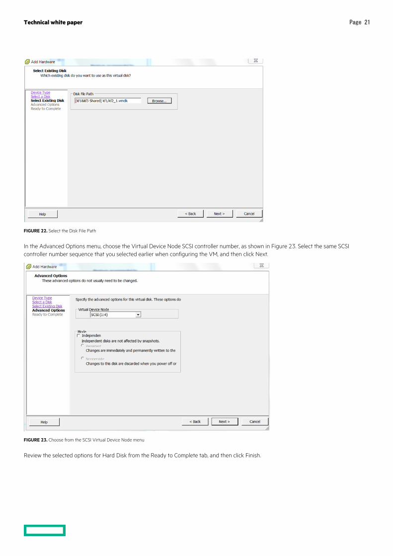
Select the disk file path from the Select Existing Disk menu, and then browse the path from Datastores or copy the vmdk path from the VM hard disk you configured earlier.
Technical white paper Page 21
FIGURE 22. Select the Disk File Path
In the Advanced Options menu, choose the Virtual Device Node SCSI controller number, as shown in Figure 23. Select the same SCSI controller number sequence that you selected earlier when configuring the VM, and then click Next.
FIGURE 23. Choose from the SCSI Virtual Device Node menu
Review the selected options for Hard Disk from the Ready to Complete tab, and then click Finish.

Technical white paper Page 22
FIGURE 24. Ready to Complete menu
From the Virtual Machine Properties tab, verify the virtual device node and vmdk path, and then click OK.
FIGURE 25. Adding RDM in the Virtual Machine Properties menu

Technical white paper Page 23
NOTE If the VMware setup is planned for vMotion, then the NPIV configuration (as explained in the following section) is mandatory. Additional required configuration changes are listed in the section entitled, “Shared storage configuration for vMotion when using statically linked storage and NPIV.”
Shared storage configurations using statically linked storage (RDM and NPIV) When multiple guests from a single host need to be configured as cluster nodes in the same cluster, then you must use Fibre Channel NPIV in addition to RDM. NPIV configuration is mandatory if you plan to use the vMotion feature on guests configured as Serviceguard cluster nodes.
To modify the configuration of a virtual machine, you must first power it down. To configure NPIV to a virtual machine, invoke the Add Hardware wizard. On a vSphere client, right-click the node you need to configure with Fibre Channel NPIV, and then select Edit Settings to start the wizard (see Figure 26).
FIGURE 26. Start the wizard by selecting Edit Settings
Next, select Fibre Channel NPIV in the Options tab under Advanced, as shown in Figure 27.

Technical white paper Page 24
FIGURE 27. Selecting Fibre Channel NPIV
Next, enable the NPIV by deselecting Temporarily Disable NPIV for this virtual machine, clicking the Generate new WWNs radio button, and selecting the Number of WWNs from the drop-down menu as required. Click OK.
FIGURE 28. Enable the Fibre Channel NPIV

Technical white paper Page 25
NPIV is now enabled for the virtual machine. Verify that NPIV is enabled by navigating to Fibre Channel NPIV in the Options tab under Advanced. You should see the Node WWNs and Port WWNs in the WWN Assignments section (as shown in Figure 29).
FIGURE 29. Verify Fibre Channel NPIV
Once the Node and Port WWNs have been generated (as shown in Figure 29), you need to add them to the zoning configuration of the underlying FC infrastructure (SAN switch, storage, etc.). For more information on NPIV configuration with VMware, please refer to the document entitled, “Configuring and Troubleshooting N-Port ID Virtualization.” For information on NPIV zoning configuration, please refer to the appropriate document for your storage infrastructure.
Shared storage configuration for vMotion when using statically linked storage and NPIV If you need to use VMware vMotion with the guests configured as Serviceguard cluster nodes, you must use the following storage configurations on all cluster nodes.
1. Shared disks should be presented to guests in RDM mode with NPIV, as described previously.
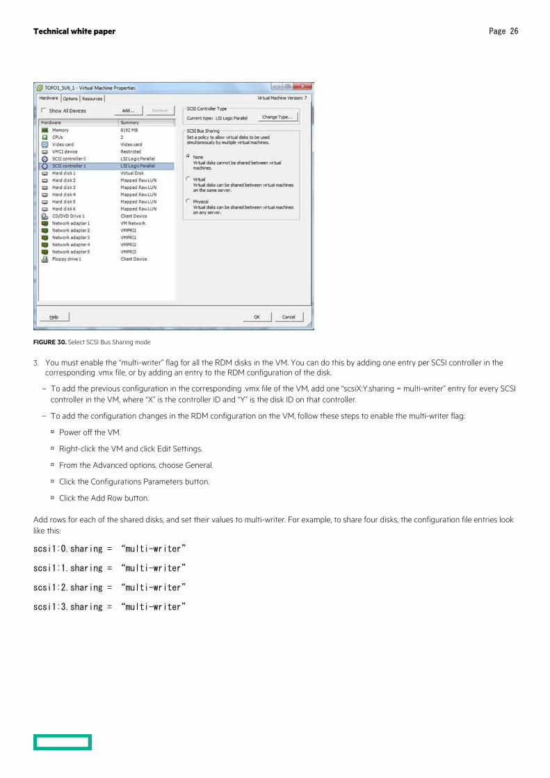
2. SCSI Bus Sharing Mode should be set to none for all RDM disk SCSI controllers.
a. Right-click the VM and click Edit Settings.
b. From the Hardware list, choose SCSI controller <n> (where <n> is the SCSI controller number).
c. Click the None radio button for SCSI Bus Sharing policy, as shown in Figure 30.
Technical white paper Page 26
FIGURE 30. Select SCSI Bus Sharing mode
3. You must enable the “multi-writer” flag for all the RDM disks in the VM. You can do this by adding one entry per SCSI controller in the corresponding .vmx file, or by adding an entry to the RDM configuration of the disk.
– To add the previous configuration in the corresponding .vmx file of the VM, add one “scsiX:Y.sharing = multi-writer” entry for every SCSI controller in the VM, where “X” is the controller ID and “Y” is the disk ID on that controller.
– To add the configuration changes in the RDM configuration on the VM, follow these steps to enable the multi-writer flag:
Power off the VM.
Right-click the VM and click Edit Settings.
From the Advanced options, choose General.
Click the Configurations Parameters button.
Click the Add Row button.
Add rows for each of the shared disks, and set their values to multi-writer. For example, to share four disks, the configuration file entries look like this:
scsi1:0.sharing = “multi-writer”
scsi1:1.sharing = “multi-writer”
scsi1:2.sharing = “multi-writer”
scsi1:3.sharing = “multi-writer”

Technical white paper Page 27
FIGURE 31. Set Configuration Parameters for multi-writer
For more information on the vMotion feature, please refer to the Serviceguard Support for VMware vMotion section of this document.
VMware multipathing when using statically linked storage Serviceguard currently does not support multipathing at host level for statically linked storage configuration. If there are multiple paths available for a LUN, only one path should be active. Rest of the other paths should be disabled as shown in Figure 32.
FIGURE 32. Disable all but one paths for a LUN

Technical white paper Page 28
Shared storage configuration steps for dynamically linked storages • The Virtual machines SCSI controller type must be VMware Paravirtual. For more information refer to section “Add a Paravirtual SCSI
Controller” in VMware vSphere Documentation 5.5 or later.
• The Virtual machines SCSI controller’s SCSI Bus Sharing flag must be configured as “None” which implies that virtual disks cannot be attached to two virtual machines anytime. For more information refer to section “Change the SCSI Bus Sharing Configuration in the vSphere Client” in VMware vSphere Documentation 5.5 or later.
• The datastore must be accessible to all the VMware virtual machine nodes in the cluster. This means the virtual disk must be accessible form all the ESXi hosts on which the cluster virtual machines are configured.
• The vmdk disk can be of type RDM or virtual disk (VMFS).
For more information please refer to “Managing HPE Serviceguard for Linux A.12.00.40,” Section 3.7.5 “Using VMware Virtual Machine File System Disks,” available at hpe.com/info/linux-Serviceguard-docs.
VMware multipathing when using dynamically linked storage Serviceguard supports multipathing at host level for dynamically linked storage configuration. For more information refer to section “Understanding Multipathing and Failover” in VMware vSphere Documentation 5.5 or later.
Shared storage configuration steps for vVols Unlike the SLS and DLS vVols does not require preconfigured storage volumes on the LUNs. vVols are abstracted storage containers which can be accessed as Virtual Volume (vVols) datastore having array native capabilities. Similar to SLS, vVol storage should be configured and available to all the nodes in the cluster.
Configuration steps to support vVols in non-array based replication environments • When setting up the virtual machine, the SCSI controller, used for shared disks, should have the “SCSI bus sharing” field set to physical and
the type should be “VMware Paravirtual”. For more information refer to section “Change the SCSI Bus Sharing Configuration in the vSphere Client” & “Add a Paravirtual SCSI Controller” in VMware vSphere Documentation 6.7 or later.
• The datastore of type “vVol” should be configured. For more information refer to section “Configure Virtual Volumes in the vSphere Storage” in VMware vSphere Product Documentation 6.7 or later.
• The datastore must be accessible to all the VMware virtual machine nodes in the cluster.
• While configuring the vmdk, choose the appropriate vVol “VM storage policy” and set the Hard disk “Sharing” as “Multi-writer”.
• Once the vmdk is configured on one node, for other nodes in the cluster add the configured disk using the option “Existing Hard Disk”.
For more information please refer to section “Using VMware Virtual Machine File System Disks in Managing HPE Serviceguard for Linux A.12.50.00,” available at hpe.com/info/linux-Serviceguard-docs.
VMware multipathing when using vVols Serviceguard supports multipathing at host level for vVols. For more information refer to section “Understanding Multipathing and Failover” in VMware vSphere Documentation 6.7 or later.
Shared storage configuration using VMDirectPath I/O You can also use VMDirectPath I/O to configure shared storage. When using VMDirectPath I/O, you must exclusively assign a host bus adapter (HBA) device on the ESX host to one virtual machine, and then configure the shared storage. This solution is not scalable, as a dedicated HBA port is required for each virtual machine. For more details on VMDirectPath I/O, please refer to the document entitled, “Configuration Examples and Troubleshooting for VMDirectPath”.
NOTE With the VMDirectPath I/O configuration, vMotion and several other features are not supported.

Technical white paper Page 29
Shared storage configuration for VMware guest nodes using iSCSI devices You can use iSCSI devices as shared storage when using VMware guests as Serviceguard cluster nodes.
NOTE Only iSCSI devices exposed using iSCSI software initiator are supported.
Please refer to the appropriate operating system’s “Storage Administration Guide” (in References section) for steps on installing and configuring the software initiator for iSCSI. The VMware vMotion feature is also supported when using iSCSI as shared storage.
PREREQUISITES FOR VMWARE GUESTS USED AS CLUSTER NODES VMware Tools™ VMware recommends you use VMware Tools—a suite of utilities that enhances the performance of the VMs guest operating system. VMware Tools also improve VM management by enabling some important functionality. For more information on the benefits of using VMware Tools and installation instructions, please refer VMware documentation for installation and configuration of VMware Tools. You can find the latest edition of the document at vmware.com/support/ws55/doc/ws_newguest_tools_linux.html.
SCSI persistent reservation (sg_persist) Serviceguard requires the use of persistent reservation (PR) on all cluster nodes in all its cluster configurations while using statically linked storage configuration. The PR functionality is provided by the sg3_utils rpm, which is part of the OS distribution.
While creating modular packages, the PR functionality is provided by the “sg/pr_cntl” module, which was introduced in Serviceguard for Linux A.11.19.00. You must add this module when creating the packages by using the following command:
# cmmakepkg –m sg/all -m sg/pr_cntl <new_pkg.conf>
From Serviceguard A.11.20.20 onward, this is a mandatory module; it is automatically added to the packages. If your existing packages do not include this module, you can add it manually by using the following command:
# cmmakepkg -i <existing_pkg.conf> -m sg/pr_cntl <new_pkg.conf>
If you are using legacy packages, please refer to the white paper entitled, “Migrating packages from legacy to modular style.” You can find this white paper at hpe.com/info/linux-Serviceguard-docs -> White papers.
SERVICEGUARD SUPPORT FOR VMWARE VMOTION The VMware vMotion enables live migration of running virtual machines from one physical server to another with zero downtime ensuring continuous service availability and complete transaction integrity. Serviceguard supports vMotion of cluster nodes. Additionally Serviceguard for Linux A.12.00.50 simplifies manageability by facilitating vMotion of cluster nodes from the Serviceguard Manager GUI with a single click.
For more information on the prerequisites to enable vMotion in a Serviceguard cluster and steps to initiate the same, refer section “Serviceguard support for VMware Migrate (vMotion)” in document “Managing HPE Serviceguard for Linux A.12.00.50 Guide or later” available at hpe.com/info/linux-serviceguard-docs.
SUMMARY OF REQUIREMENTS • Serviceguard requires you to use NIC teaming at the host level to achieve network redundancy for heartbeats and applications.
• When using iSCSI as shared storage, use software initiator to expose the shared LUNs.
• When using statically linked storage:
– Persistent reservation is required for all deployments.
– You must use RDM to attach shared LUNs to VMs. When using FC as shared storage.
– NPIV over RDM is mandatory when multiple VMs from a single host must be configured in the same cluster or when vMotion is used in the cluster.

Technical white paper Page 30
• When using dynamically linked storage:
– Virtual machines SCSI controller type must be VMware Paravirtual.
– Virtual machines SCSI controller’s SCSI Bus Sharing flag must be configured as “None.”
– Ensure that Java is installed on all the cluster nodes.
– For more information about supported Serviceguard version, ESXi host, vCenter Server version, and Java version, refer to the “HPE Serviceguard for Linux Certification Matrix” document at hpe.com/info/linux-Serviceguard-docs.
• When using vVols:
– Persistent reservation is required for all the vVol supported deployments discussed at the beginning of the document.
– Virtual machines SCSI controller, used for shared disks, should have the “SCSI bus sharing” field set to physical and the type should be “VMware Paravirtual”.
– Virtual machines virtual hardware must be version 13 or above.
– The vmdk configured should have appropriate vVol “VM storage policy” and Hard disk “Sharing” should be set to “Multi-writer”.
SUMMARY OF RECOMMENDATIONS • Install VMware guest tools on all VMs, and select the Time Synchronization option.
• Enable beacon monitoring for teamed NICs.
SUPPORT INFORMATION • Co-existence of VMware HA, DRS, and SRM (while using vVols in Serviceguard deployments SRM is not supported) and HPE
Serviceguard for Linux is supported. For more information on this refer section “Using Serviceguard with Virtual Machines" in latest document “Managing HPE Serviceguard for Linux” available at hpe.com/info/linux-serviceguard-docs.
• HPE Serviceguard running on ESX/ESXi Server versions other than those mentioned in the support matrix are not supported.
• vMotion is supported on HPE Serviceguard for Linux clusters with the above-mentioned configuration requirements.
• VMware multipathing is supported on HPE Serviceguard for Linux clusters with dynamically linked storage and while using vVol configuration.
SUMMARY This guide describes best practices for deploying HPE Serviceguard in a typical VMware ESX/ESXi Server environment. This guide is not intended to duplicate the strategies and best practices of other HPE or VMware technical white papers.
The strategies and best practices offered here are presented at a very high level to provide general knowledge. Where appropriate, links are provided for additional documents that offer more detailed information.

Technical white paper
Make the right purchase decision. Contact our presales specialists.
Share now
Get updates
© Copyright 2012–2014, 2016–2017, 2019 Hewlett Packard Enterprise Development LP. The information contained herein is subject to change without notice. The only warranties for Hewlett Packard Enterprise products and services are set forth in the express warranty statements accompanying such products and services. Nothing herein should be construed as constituting an additional warranty. Hewlett Packard Enterprise shall not be liable for technical or editorial errors or omissions contained herein.
Linux is the registered trademark of Linus Torvalds in the U.S. and other countries. Red Hat is a registered trademark of Red Hat, Inc. in the United States and other countries. VMware, VMware vSphere, VMware ESX, VMware ESXi, VMware Server, VMware Tools, and VMware vCenter Server are registered trademarks or trademarks of VMware, Inc. and its subsidiaries in the United States and other jurisdictions. All third-party marks are property of their respective owners.
4AA4-2016ENW, December 2019, Rev. 9
Check if the document is available in the language of your choice.
REFERENCES 1. VMware Server Configuration Guide: vmware.com/pdf/vi3_301_201_server_config.pdf
2. VMware vSphere documentation: vmware.com/support/pubs/vsphere-esxi-vcenter-server-pubs.html
3. VMware vSphere Storage: docs.vmware.com/en/VMware-vSphere/6.7/vsphere-esxi-vcenter-server-672-storage-guide.pdf
4. Configuration maximums for VMware vSphere 5: vmware.com/pdf/vsphere5/r50/vsphere-50-configuration-maximums.pdf
5. VLANs and NIC teaming: vmware.com/files/pdf/virtual_networking_concepts.pdf
6. HPE 3PAR StoreServ Storage and VMware vSphere 6.5 best practices: hpe.com/h20195/v2/Getdocument.aspx?docname=4AA4-3286ENW
7. Configuring and Troubleshooting N-Port ID Virtualization: vmware.com/files/pdf/techpaper/vsp_4_vsp4_41_npivconfig.pdf
8. Configuration Examples and Troubleshooting for VMDirectPath: vmware.com/pdf/vsp_4_vmdirectpath_host.pdf
9. Storage Administration Guide for SUSE 11: suse.com/documentation/sles11/
10. Storage Administration Guide for SUSE 12: suse.com/documentation/sles-12/
11. Storage Administration Guide for SUSE 15: suse.com/documentation/sles-15/
12. Storage Administration Guide for Red Hat® 6 Enterprise Linux: access.redhat.com/documentation/en-us/red_hat_enterprise_linux/6/ -> Storage Administration Guide
13. Storage Administration Guide for Red Hat 7 Enterprise Linux: access.redhat.com/documentation/en-us/red_hat_enterprise_linux/7/ -> Storage Administration Guide
14. Migration of VMs with vMotion: docs.vmware.com/en/VMware-vSphere/6.5/com.vmware.vsphere.vcenterhost.doc/GUID-FE2B516E-7366-4978-B75C-64BF0AC676EB.html
15. Multi-writer flag: kb.vmware.com/selfservice/microsites/search.do?language=en_US&cmd=displayKC&externalId=1034165
16. SAN System Design and Deployment Guide: vmware.com/files/pdf/techpaper/SAN_Design_and_Deployment_Guide.pdf
LEARN MORE AT hpe.com/servers/sglx