Embed Size (px)
Citation preview

HPE FlexNetwork 5510 HI Switch Series MPLS Configuration Guide Part number: 5200-0081b Software version: Release 11xx Document version: 6W102-20171020

© Copyright 2015, 2017 Hewlett Packard Enterprise Development LP
The information contained herein is subject to change without notice. The only warranties for Hewlett Packard Enterprise products and services are set forth in the express warranty statements accompanying such products and services. Nothing herein should be construed as constituting an additional warranty. Hewlett Packard Enterprise shall not be liable for technical or editorial errors or omissions contained herein.
Confidential computer software. Valid license from Hewlett Packard Enterprise required for possession, use, or copying. Consistent with FAR 12.211 and 12.212, Commercial Computer Software, Computer Software Documentation, and Technical Data for Commercial Items are licensed to the U.S. Government under vendor’s standard commercial license.
Links to third-party websites take you outside the Hewlett Packard Enterprise website. Hewlett Packard Enterprise has no control over and is not responsible for information outside the Hewlett Packard Enterprise website.
Acknowledgments
Intel®, Itanium®, Pentium®, Intel Inside®, and the Intel Inside logo are trademarks of Intel Corporation in the United States and other countries.
Microsoft® and Windows® are either registered trademarks or trademarks of Microsoft Corporation in the United States and/or other countries.
Adobe® and Acrobat® are trademarks of Adobe Systems Incorporated.
Java and Oracle are registered trademarks of Oracle and/or its affiliates.
UNIX® is a registered trademark of The Open Group.

i
Contents
Configuring basic MPLS ···································································· 1
Overview ·································································································································· 1 Basic concepts ··················································································································· 1 MPLS network architecture ···································································································· 2 LSP establishment ··············································································································· 3 MPLS forwarding ················································································································· 4 PHP ································································································································· 4 Protocols and standards ······································································································· 5
MPLS configuration task list ········································································································· 5 Enabling MPLS ························································································································· 5 Configuring MPLS MTU ··············································································································· 6 Specifying the label type advertised by egress ················································································· 6 Configuring TTL propagation ········································································································ 7 Enabling sending of MPLS TTL-expired messages ··········································································· 9 Enabling MPLS forwarding statistics ······························································································ 9 Enabling SNMP notifications for MPLS ··························································································· 9 Displaying and maintaining MPLS ······························································································· 10
Configuring a static LSP ·································································· 11
Overview ································································································································ 11 Configuration prerequisites ········································································································ 11 Configuration procedure ············································································································ 11 Displaying static LSPs··············································································································· 12 Static LSP configuration example ································································································ 12
Network requirements ········································································································ 12 Configuration restrictions and guidelines ················································································ 12 Configuration procedure ····································································································· 13 Verifying the configuration ··································································································· 14
Configuring LDP ············································································ 15
Overview ································································································································ 15 Terminology ····················································································································· 15 LDP messages ················································································································· 15 LDP operation ·················································································································· 16 Label distribution and control ······························································································· 17 LDP GR ·························································································································· 19 LDP NSR ························································································································· 20 LDP-IGP synchronization ···································································································· 21 LDP FRR ························································································································· 21 Protocols ························································································································· 22
LDP configuration task list ·········································································································· 22 Enabling LDP ·························································································································· 23
Enabling LDP globally ········································································································ 23 Enabling LDP on an interface ······························································································· 23
Configuring Hello parameters ····································································································· 24 Configuring LDP session parameters ··························································································· 24 Configuring LDP backoff ············································································································ 25 Configuring LDP MD5 authentication ···························································································· 26 Configuring an LSP generation policy ··························································································· 26 Configuring the LDP label distribution control mode ········································································· 27 Configuring a label advertisement policy ······················································································· 27 Configuring a label acceptance policy ··························································································· 28 Configuring LDP loop detection ··································································································· 29 Configuring LDP session protection ····························································································· 30 Configuring LDP GR ················································································································· 31 Configuring LDP NSR ··············································································································· 31 Configuring LDP-IGP synchronization ·························································································· 31
ii
Configuring LDP-OSPF synchronization ················································································· 31 Configuring LDP-ISIS synchronization ··················································································· 32
Configuring LDP FRR ··············································································································· 33 Resetting LDP sessions ············································································································ 33 Enabling SNMP notifications for LDP ··························································································· 33 Displaying and maintaining LDP ·································································································· 34 LDP configuration examples ······································································································· 34
LDP LSP configuration example ··························································································· 34 Label acceptance control configuration example ······································································ 38 Label advertisement control configuration example ··································································· 42 LDP FRR configuration example ··························································································· 47
Configuring MPLS TE ····································································· 51
Overview ································································································································ 51 TE and MPLS TE ·············································································································· 51 MPLS TE basic concepts ···································································································· 51 Static CRLSP establishment ································································································ 51 Dynamic CRLSP establishment ···························································································· 51 Traffic forwarding ·············································································································· 53 Make-before-break ············································································································ 54 Route pinning ··················································································································· 55 Tunnel reoptimization ········································································································· 55 Automatic bandwidth adjustment ·························································································· 55 CRLSP backup ················································································································· 56 FRR ······························································································································· 56 DiffServ-aware TE ············································································································· 57 Bidirectional MPLS TE tunnel ······························································································· 59 Protocols and standards ····································································································· 59
MPLS TE configuration task list ··································································································· 60 Enabling MPLS TE ··················································································································· 61 Configuring a tunnel interface ····································································································· 61 Configuring DS-TE ··················································································································· 61 Configuring an MPLS TE tunnel to use a static CRLSP ···································································· 62 Configuring an MPLS TE tunnel to use a dynamic CRLSP ································································ 63
Configuration task list ········································································································· 63 Configuring MPLS TE attributes for a link ··············································································· 63 Advertising link TE attributes by using IGP TE extension ··························································· 64 Configuring MPLS TE tunnel constraints ················································································ 65 Establishing an MPLS TE tunnel by using RSVP-TE ································································· 67 Controlling CRLSP path selection ························································································· 67 Controlling MPLS TE tunnel setup ························································································ 69
Configuring traffic forwarding ······································································································ 72 Configuring static routing to direct traffic to an MPLS TE tunnel ··················································· 72 Configuring automatic route advertisement to direct traffic to an MPLS TE tunnel ···························· 72
Configuring a bidirectional MPLS TE tunnel ··················································································· 73 Configuring CRLSP backup ········································································································ 74 Configuring MPLS TE FRR ········································································································ 74
Enabling FRR ··················································································································· 75 Configuring a bypass tunnel on the PLR ················································································· 75 Configuring node fault detection ··························································································· 79 Configuring the optimal bypass tunnel selection interval ···························································· 79
Displaying and maintaining MPLS TE ··························································································· 79 MPLS TE configuration examples ································································································ 80
Establishing an MPLS TE tunnel over a static CRLSP ······························································· 80 Establishing an MPLS TE tunnel with RSVP-TE ······································································· 85 Establishing an inter-AS MPLS TE tunnel with RSVP-TE ··························································· 91 Bidirectional MPLS TE tunnel configuration example ································································· 98 CRLSP backup configuration example ················································································· 104 Manual bypass tunnel for FRR configuration example ····························································· 108 Auto FRR configuration example ························································································ 114 IETF DS-TE configuration example ····················································································· 120
Troubleshooting MPLS TE ······································································································· 127

iii
No TE LSA generated ······································································································ 127 Configuring a static CRLSP ···························································· 128
Overview ······························································································································ 128 Configuration procedure ·········································································································· 128 Displaying static CRLSPs ········································································································ 129 Static CRLSP configuration example ·························································································· 129
Network requirements ······································································································ 129 Configuration procedure ··································································································· 130 Verifying the configuration ································································································· 132
Configuring RSVP ········································································ 135
Overview ······························································································································ 135 RSVP messages ············································································································· 135 CRLSP setup procedure ··································································································· 136 RSVP refresh mechanism ································································································· 136 RSVP authentication ········································································································ 137 RSVP GR ······················································································································ 137 Protocols and standards ··································································································· 138
RSVP configuration task list ····································································································· 138 Enabling RSVP ····················································································································· 138 Configuring RSVP refresh ········································································································ 138 Configuring RSVP Srefresh and reliable RSVP message delivery ···················································· 139 Configuring RSVP hello extension ····························································································· 139 Configuring RSVP authentication ······························································································ 140 Specifying a DSCP value for outgoing RSVP packets ···································································· 141 Configuring RSVP GR ············································································································· 142 Enabling BFD for RSVP ·········································································································· 142 Displaying and maintaining RSVP ····························································································· 142 RSVP configuration examples ·································································································· 143
Establishing an MPLS TE tunnel with RSVP-TE ····································································· 143 RSVP GR configuration example ························································································ 147
Configuring tunnel policies ····························································· 150
Overview ······························································································································ 150 Configuring a tunnel policy ······································································································· 150
Configuration guidelines ··································································································· 150 Configuration procedure ··································································································· 151
Displaying tunnel information ···································································································· 152 Tunnel policy configuration examples ························································································· 152
Preferred tunnel configuration example ················································································ 152 Exclusive tunnel configuration example ················································································ 152 Tunnel selection order configuration example ········································································ 153 Preferred tunnel and tunnel selection order configuration example ············································· 153
Configuring MPLS L3VPN ······························································ 155
Overview ······························································································································ 155 Basic MPLS L3VPN architecture ························································································ 155 MPLS L3VPN concepts ···································································································· 155 MPLS L3VPN route advertisement ······················································································ 157 MPLS L3VPN packet forwarding ························································································· 158 MPLS L3VPN networking schemes ····················································································· 159 Inter-AS VPN ·················································································································· 161 Carrier's carrier ··············································································································· 165 Nested VPN ··················································································································· 167 HoVPN ·························································································································· 168 OSPF VPN extension ······································································································· 169 BGP AS number substitution ····························································································· 171 MPLS L3VPN FRR ·········································································································· 172 Protocols and standards ··································································································· 174
MPLS L3VPN configuration task list ··························································································· 174 Configuring basic MPLS L3VPN ································································································ 175

iv
Configuration prerequisites ································································································ 175 Configuring VPN instances ································································································ 175 Configuring routing between a PE and a CE ·········································································· 177 Configuring routing between PEs ························································································ 181 Configuring BGP VPNv4 route control ·················································································· 182
Configuring inter-AS VPN ········································································································ 183 Configuring inter-AS option A ····························································································· 183 Configuring inter-AS option B ····························································································· 184 Configuring inter-AS option C ····························································································· 185
Configuring nested VPN ·········································································································· 188 Configuring HoVPN ················································································································ 189 Configuring an OSPF sham link ································································································ 190
Configuring a loopback interface ························································································· 190 Redistributing the loopback interface route ············································································ 191 Creating a sham link ········································································································ 191
Specifying the VPN label processing mode on the egress PE ·························································· 191 Configuring BGP AS number substitution ···················································································· 192 Configuring MPLS L3VPN FRR ································································································· 192 Enabling SNMP notifications for MPLS L3VPN ············································································· 194 Enabling logging for BGP route flapping ······················································································ 194 Displaying and maintaining MPLS L3VPN ··················································································· 195 MPLS L3VPN configuration examples ························································································ 196
Configuring basic MPLS L3VPN ························································································· 196 Configuring a hub-spoke network ························································································ 202 Configuring MPLS L3VPN inter-AS option A ·········································································· 209 Configuring MPLS L3VPN inter-AS option B ·········································································· 213 Configuring MPLS L3VPN inter-AS option C ········································································· 218 Configuring MPLS L3VPN carrier's carrier ············································································ 225 Configuring nested VPN ··································································································· 233 Configuring HoVPN ········································································································· 242 Configuring an OSPF sham link ·························································································· 249 Configuring BGP AS number substitution ············································································· 253 Configuring MPLS L3VPN FRR through VPNv4 route backup for a VPNv4 route ·························· 257 Configuring MPLS L3VPN FRR through VPNv4 route backup for an IPv4 route ···························· 259 Configuring MPLS L3VPN FRR through IPv4 route backup for a VPNv4 route······························ 261
Configuring IPv6 MPLS L3VPN ······················································· 264
Overview ······························································································································ 264 IPv6 MPLS L3VPN packet forwarding ·················································································· 264 IPv6 MPLS L3VPN routing information advertisement ····························································· 265 IPv6 MPLS L3VPN network schemes and functions ································································ 265 Protocols and standards ··································································································· 265
IPv6 MPLS L3VPN configuration task list ···················································································· 266 Configuring basic IPv6 MPLS L3VPN ························································································· 266
Configuring VPN instances ································································································ 266 Configuring routing between a PE and a CE ·········································································· 268 Configuring routing between PEs ························································································ 274 Configuring BGP VPNv6 route control ·················································································· 274
Configuring inter-AS IPv6 VPN ································································································· 275 Configuring inter-AS IPv6 VPN option A ··············································································· 276 Configuring inter-AS IPv6 VPN option C ··············································································· 276
Configuring an OSPFv3 sham link ····························································································· 277 Configuring a loopback interface ························································································· 277 Redistributing the loopback interface address ········································································ 277 Creating a sham link ········································································································ 278
Enabling logging for BGP route flapping ······················································································ 278 Displaying and maintaining IPv6 MPLS L3VPN ············································································ 278 IPv6 MPLS L3VPN configuration examples ················································································· 280
Configuring IPv6 MPLS L3VPNs ························································································· 280 Configuring IPv6 MPLS L3VPN inter-AS option A ··································································· 286 Configuring IPv6 MPLS L3VPN inter-AS option C ··································································· 291 Configuring IPv6 MPLS L3VPN carrier's carrier······································································ 297

v
Configuring an OSPFv3 sham link ······················································································ 304 Configuring MPLS L2VPN ······························································ 310
Overview ······························································································································ 310 Basic concepts of MPLS L2VPN ························································································· 310 MPLS L2VPN network models ··························································································· 311 PW redundancy ·············································································································· 312 Multi-segment PW ··········································································································· 313 VCCV ··························································································································· 314
MPLS L2VPN configuration task list ··························································································· 315 Enabling L2VPN ···················································································································· 315 Configuring an AC ·················································································································· 316 Configuring a cross-connect ····································································································· 316 Configuring a PW ··················································································································· 317
Configuring a PW class ···································································································· 317 Configuring a static PW ···································································································· 317 Configuring an LDP PW ···································································································· 317 Configuring a BGP PW ····································································································· 318 Configuring a remote CCC connection ················································································· 320
Binding an AC to a cross-connect ······························································································ 320 Configuring PW redundancy ····································································································· 321
Configuring static PW redundancy ······················································································ 321 Configuring LDP PW redundancy ······················································································· 322
Displaying and maintaining MPLS L2VPN ··················································································· 322 MPLS L2VPN configuration examples ························································································ 323
Configuring a static PW ···································································································· 323 Configuring an LDP PW ···································································································· 327 Configuring a BGP PW ····································································································· 331 Configuring a remote CCC connection ················································································· 335 Configuring LDP PW redundancy ······················································································· 338 Configuring an intra-domain multi-segment PW ····································································· 344 Configuring an inter-domain multi-segment PW ····································································· 347
Configuring VPLS ········································································· 355
Overview ······························································································································ 355 Basic VPLS architecture ··································································································· 355 VPLS implementation ······································································································· 356 H-VPLS ························································································································· 358
VPLS configuration task list ······································································································ 360 Enabling L2VPN ···················································································································· 361 Configuring an AC ·················································································································· 361 Configuring a VSI ··················································································································· 362 Configuring a PW ··················································································································· 362
Configuring a PW class ···································································································· 362 Configuring a static PW ···································································································· 362 Configuring an LDP PW ···································································································· 363 Configuring a BGP PW ····································································································· 363 Configuring a BGP auto-discovery LDP PW ·········································································· 365
Binding an AC to a VSI ············································································································ 367 Configuring UPE dual homing ··································································································· 367
Configuring static PW redundancy ······················································································ 368 Configuring LDP PW redundancy ······················································································· 368
Configuring MAC address learning ···························································································· 369 Displaying and maintaining VPLS ······························································································ 369 VPLS configuration examples ··································································································· 370
Static PW configuration example ························································································ 370 LDP PW configuration example ·························································································· 375 BGP PW configuration example ························································································· 377 BGP auto-discovery LDP PW configuration example ······························································· 382 H-VPLS using access configuration example ········································································· 386 H-VPLS UPE dual homing configuration example ··································································· 390

vi
Configuring MPLS OAM ································································ 397
Overview ······························································································································ 397 MPLS ping ····················································································································· 397 MPLS tracert ·················································································································· 397 BFD for MPLS ················································································································ 397 Periodic MPLS tracert ······································································································ 398
Protocols and standards ·········································································································· 398 Configuring MPLS OAM for LSP tunnels ····················································································· 398
Configuring MPLS ping for LSPs ························································································ 398 Configuring MPLS tracert for LSPs ······················································································ 399 Configuring BFD for LSPs ································································································· 399 Configuring periodic MPLS tracert for LSPs ·········································································· 400
Configuring MPLS OAM for MPLS TE tunnels ·············································································· 400 Configuring MPLS OAM for a PW ······························································································ 401
Configuring MPLS ping for a PW ························································································ 401 Configuring BFD for a PW ································································································· 401
Displaying MPLS OAM ············································································································ 405 MPLS OAM configuration examples ··························································································· 405
BFD for LSP configuration example ····················································································· 405 BFD for PW configuration example······················································································ 407
Configuring MCE ·········································································· 413
MPLS L3VPN overview ··········································································································· 413 Basic MPLS L3VPN architecture ························································································ 413 MPLS L3VPN concepts ···································································································· 413
MCE overview ······················································································································· 415 MCE configuration task list ······································································································· 416 Configuring VPN instances ······································································································ 416
Creating a VPN instance ··································································································· 416 Associating a VPN instance with an interface ········································································ 417 Configuring route related attributes for a VPN instance ···························································· 417
Configuring routing on an MCE ································································································· 418 Configuring routing between an MCE and a VPN site ······························································ 418 Configuring routing between an MCE and a PE ····································································· 423
Displaying and maintaining MCE ······························································································· 427 MCE configuration examples ···································································································· 428
Configuring the MCE that uses OSPF to advertise VPN routes to the PE ···································· 428 Configuring the MCE that uses EBGP to advertise VPN routes to the PE ···································· 433
Configuring IPv6 MCE ··································································· 438
Overview ······························································································································ 438 IPv6 MCE configuration task list ································································································ 438 Configuring VPN instances ······································································································ 438
Creating a VPN instance ··································································································· 438 Associating a VPN instance with an interface ········································································ 439 Configuring route related attributes for a VPN instance ···························································· 439
Configuring routing on an MCE ································································································· 440 Configuring routing between an MCE and a VPN site ······························································ 441 Configuring routing between an MCE and a PE ····································································· 445
Displaying and maintaining IPv6 MCE ························································································ 449 IPv6 MCE configuration example ······························································································· 449
Document conventions and icons ···················································· 457
Conventions ························································································································· 457 Network topology icons ··········································································································· 458
Support and other resources ·························································· 459
Accessing Hewlett Packard Enterprise Support ············································································ 459 Accessing updates ················································································································· 459
Websites ······················································································································· 460 Customer self repair ········································································································· 460

vii
Remote support ·············································································································· 460 Documentation feedback ·································································································· 460
Index ························································································· 462

1
Configuring basic MPLS Multiprotocol Label Switching (MPLS) provides connection-oriented label switching over connectionless IP backbone networks. It integrates both the flexibility of IP routing and the simplicity of Layer 2 switching.
In this chapter, the term "interface" refers to a Layer 3 interface. It can be a VLAN interface or a Layer 3 Ethernet interface. Layer 3 Ethernet interfaces refer to the Ethernet interfaces that operate in Layer 3 mode. For information about switching the Ethernet interface operating mode, see Layer 2—LAN Switching Configuration Guide.
Overview MPLS has the following advantages: • High speed and efficiency—MPLS uses short- and fixed-length labels to forward packets,
avoiding complicated routing table lookups. • Multiprotocol support—MPLS resides between the link layer and the network layer. It can
work over various link layer protocols (for example, PPP, ATM, frame relay, and Ethernet) to provide connection-oriented services for various network layer protocols (for example, IPv4, IPv6, and IPX).
• Good scalability—The connection-oriented switching and multilayer label stack features enable MPLS to deliver various extended services, such as VPN, traffic engineering, and QoS.
Basic concepts FEC
MPLS groups packets with the same characteristics (such as packets with the same destination or service class) into a forwarding equivalence class (FEC). Packets of the same FEC are handled in the same way on an MPLS network.
Label A label uniquely identifies an FEC and has local significance.
Figure 1 Format of a label
A label is encapsulated between the Layer 2 header and Layer 3 header of a packet. It is four bytes long and consists of the following fields: • Label—20-bit label value. • TC—3-bit traffic class, used for QoS. It is also called Exp. • S—1-bit bottom of stack flag. A label stack can have multiple labels. The label nearest to the
Layer 2 header is called the top label, and the label nearest to the Layer 3 header is called the bottom label. The S field is set to 1 if the label is the bottom label and set to 0 if not.
• TTL—8-bit time to live field used for routing loop prevention.
TC
0
S
19 22 23 31
Label TTL
Layer 2 header Layer 3 headerLabel Layer 3 data

2
LSR A router that performs MPLS forwarding is a label switching router (LSR).
LSP A label switched path (LSP) is the path along which packets of an FEC travel through an MPLS network.
An LSP is a unidirectional packet forwarding path. Two neighboring LSRs are called the upstream LSR and downstream LSR along the direction of an LSP. In Figure 2, LSR B is the downstream LSR of LSR A, and LSR A is the upstream LSR of LSR B.
Figure 2 Label switched path
LFIB The Label Forwarding Information Base (LFIB) on an MPLS network functions like the Forwarding Information Base (FIB) on an IP network. When an LSR receives a labeled packet, it searches the LFIB to obtain information for forwarding the packet, such as the label operation type, the outgoing label value, and the next hop.
Control plane and forwarding plane An MPLS node consists of a control plane and a forwarding plane. • Control plane—Assigns labels, distributes FEC-label mappings to neighbor LSRs, creates the
LFIB, and establishes and removes LSPs. • Forwarding plane—Forwards packets according to the LFIB.
MPLS network architecture Figure 3 MPLS network architecture
An MPLS network has the following types of LSRs: • Ingress LSR—Ingress LSR of packets. It labels packets entering into the MPLS network.
LSR A
LSR B LSR C
LSR D
LSP
LSPLSP
Ingress LSR LSP Egress LSR
Transit LSR
IP network IP network
MPLS network

3
• Transit LSR—Intermediate LSRs in the MPLS network. The transit LSRs on an LSP forward packets to the egress LSR according to labels.
• Egress LSR—Egress LSR of packets. It removes labels from packets and forwards the packets to their destination networks.
LSP establishment LSPs include static and dynamic LSPs. • Static LSP—To establish a static LSP, you must configure an LFIB entry on each LSR along the
LSP. Establishing static LSPs consumes fewer resources than establishing dynamic LSPs, but static LSPs cannot automatically adapt to network topology changes. Therefore, static LSPs are suitable for small-scale networks with simple, stable topologies.
• Dynamic LSP—Established by a label distribution protocol (also called an MPLS signaling protocol). A label distribution protocol classifies FECs, distributes FEC-label mappings, and establishes and maintains LSPs. Label distribution protocols include protocols designed specifically for label distribution, such as the Label Distribution Protocol (LDP), and protocols extended to support label distribution, such as MP-BGP and RSVP-TE.
In this document, the term "label distribution protocols" refers to all protocols for label distribution. The term "LDP" refers to the RFC 5036 LDP.
A dynamic LSP is established in the following steps: 1. A downstream LSR classifies FECs according to destination addresses. 2. The downstream LSR assigns a label for each FEC, and distributes the FEC-label binding to its
upstream LSR. 3. The upstream LSR establishes an LFIB entry for the FEC according to the binding information.
After all LSRs along the LSP establish an LFIB entry for the FEC, a dynamic LSP is established for the packets of this FEC.
Figure 4 Dynamic LSP establishment
LSR A LSR B LSR DLSR C
LSR E LSR F LSR G
LSR H
Ingress Egress
LSPLabel mapping

4
MPLS forwarding Figure 5 MPLS forwarding
As shown in Figure 5, a packet is forwarded over the MPLS network in the following steps: 1. Router B (the ingress LSR) receives a packet with no label. Then, it performs the following
operations: a. Identifies the FIB entry that matches the destination address of the packet. b. Adds the outgoing label (40, in this example) to the packet. c. Forwards the labeled packet out of the interface VLAN-interface 20 to the next hop LSR
Router C. 2. When receiving the labeled packet, Router C processes the packet as follows:
a. Identifies the LFIB entry that has an incoming label of 40. b. Uses the outgoing label 50 of the entry to replace label 40 in the packet. c. Forwards the labeled packet out of the outgoing interface VLAN-interface 30 to the next hop
LSR Router D. 3. When receiving the labeled packet, Router D (the egress) processes the packet as follows:
a. Identifies the LFIB entry that has an incoming label of 50. b. Removes the label from the packet. c. Forwards the packet out of the outgoing interface VLAN-interface 40 to the next hop LSR
Router E. If the LFIB entry records no outgoing interface or next hop information, Router D performs the following operations: a. Identifies the FIB entry by the IP header. b. Forwards the packet according to the FIB entry.
PHP An egress node must perform two forwarding table lookups to forward a packet: • Two LFIB lookups (if the packet has more than one label).
Router A Router BIngress
Router C Router DEgress
Router E
Router F
IP:10.1.1.1
MPLS network
IP:10.1.1.140 IP:10.1.1.1 50 IP:10.1.1.1
Vlan10 Vlan20 Vlan20 Vlan30 Vlan30 Vlan40
FIB table
LFIB table
LFIB table
NexthopDest Out intOut label10.1.0.0 Vlan2040 Router C
NexthopRouter D
Out intVlan30
Out label50
OperSwap
In label40
NexthopRouter E
Out intVlan40
Out label--
OperPop
In label50
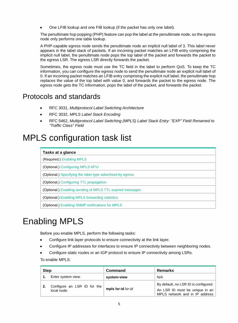
5
• One LFIB lookup and one FIB lookup (if the packet has only one label).
The penultimate hop popping (PHP) feature can pop the label at the penultimate node, so the egress node only performs one table lookup.
A PHP-capable egress node sends the penultimate node an implicit null label of 3. This label never appears in the label stack of packets. If an incoming packet matches an LFIB entry comprising the implicit null label, the penultimate node pops the top label of the packet and forwards the packet to the egress LSR. The egress LSR directly forwards the packet.
Sometimes, the egress node must use the TC field in the label to perform QoS. To keep the TC information, you can configure the egress node to send the penultimate node an explicit null label of 0. If an incoming packet matches an LFIB entry comprising the explicit null label, the penultimate hop replaces the value of the top label with value 0, and forwards the packet to the egress node. The egress node gets the TC information, pops the label of the packet, and forwards the packet.
Protocols and standards • RFC 3031, Multiprotocol Label Switching Architecture • RFC 3032, MPLS Label Stack Encoding • RFC 5462, Multiprotocol Label Switching (MPLS) Label Stack Entry: "EXP" Field Renamed to
"Traffic Class" Field
MPLS configuration task list Tasks at a glance (Required.) Enabling MPLS
(Optional.) Configuring MPLS MTU
(Optional.) Specifying the label type advertised by egress
(Optional.) Configuring TTL propagation
(Optional.) Enabling sending of MPLS TTL-expired messages
(Optional.) Enabling MPLS forwarding statistics
(Optional.) Enabling SNMP notifications for MPLS
Enabling MPLS Before you enable MPLS, perform the following tasks: • Configure link layer protocols to ensure connectivity at the link layer. • Configure IP addresses for interfaces to ensure IP connectivity between neighboring nodes. • Configure static routes or an IGP protocol to ensure IP connectivity among LSRs.
To enable MPLS:
Step Command Remarks 1. Enter system view. system-view N/A
2. Configure an LSR ID for the local node. mpls lsr-id lsr-id
By default, no LSR ID is configured. An LSR ID must be unique in an MPLS network and in IP address

6
Step Command Remarks format. As a best practice, use the IP address of a loopback interface as an LSR ID.
3. Enter the view of the interface that needs to perform MPLS forwarding.
interface interface-type interface-number N/A
4. Enable MPLS for the interface. mpls enable By default, MPLS is disabled on an interface.
Configuring MPLS MTU MPLS inserts the label stack between the link layer header and network layer header of each packet. To make sure the size of MPLS labeled packets is smaller than the MTU of an interface, configure an MPLS MTU on the interface.
MPLS compares each MPLS packet against the interface MPLS MTU. When the packet exceeds the MPLS MTU: • If fragmentation is allowed, MPLS does the following:
a. Removes the label stack from the packet. b. Fragments the IP packet. The length of a fragment is the MPLS MTU minus the length of the
label stack. c. Adds the label stack to each fragment, and forwards the fragments.
• If fragmentation is not allowed, the LSR drops the packet.
To configure an MPLS MTU for an interface:
Step Command Remarks 1. Enter system view. system-view N/A
2. Enter interface view. interface interface-type interface-number N/A
3. Configure an MPLS MTU for the interface. mpls mtu value By default, no MPLS MTU is
configured on an interface.
The following applies when an interface handles MPLS packets: • MPLS packets carrying L2VPN or IPv6 packets are always forwarded by an interface, even if
the length of the MPLS packets exceeds the MPLS MTU of the interface. Whether the forwarding can succeed depends on the actual forwarding capacity of the interface.
• If the MPLS MTU of an interface is greater than the MTU of the interface, data forwarding might fail on the interface.
• If you do not configure the MPLS MTU of an interface, fragmentation of MPLS packets is based on the MTU of the interface without considering MPLS labels. An MPLS fragment might be larger than the interface MTU and be dropped.
Specifying the label type advertised by egress In an MPLS network, an egress can advertise the following types of labels: • Implicit null label with a value of 3. • Explicit null label with a value of 0.

7
• Non-null label. The value range for a non-null label is 16 to 1048575.
For LSPs established by a label distribution protocol, the label advertised by the egress determines how the penultimate hop processes a labeled packet. • If the egress advertises an implicit null label, the penultimate hop directly pops the top label of a
matching packet. • If the egress advertises an explicit null label, the penultimate hop swaps the top label value of a
matching packet with the explicit null label. • If the egress advertises a non-null label (normal label), the penultimate hop swaps the top label
of a matching packet with the specific label assigned by the egress.
Configuration guidelines When you specify the label type advertised by egress, follow these restrictions and guidelines: • If the penultimate hop supports PHP, configure the egress to advertise an implicit null label to
the penultimate hop as a best practice. • If you want to simplify packet forwarding on the egress but keep labels to determine QoS
policies, configure the egress node to advertise an explicit null label to the penultimate hop. • Use non-null labels only in particular scenarios. For example, when OAM is configured on the
egress, the egress can get the OAM function entity status only through non-null labels. • As a penultimate hop, the device accepts the implicit null label, explicit null label, or normal label
advertised by the egress device. • For LDP LSPs, the mpls label advertise command triggers LDP to delete the LSPs
established before the command is executed and re-establishes new LSPs. • For BGP LSPs, the mpls label advertise command takes effect only for the BGP LSPs
established after the command is executed. To apply the new setting to BGP LSPs established before the command is executed, delete the routes corresponding to the BGP LSPs, and then redistribute the routes.
Configuration procedure To specify the type of label that the egress node will advertise to the penultimate hop:
Step Command Remarks 1. Enter system view. system-view N/A
2. Specify the label type advertised by the egress to the penultimate hop.
mpls label advertise { explicit-null | implicit-null | non-null }
By default, an egress advertises an implicit null label to the penultimate hop.
Configuring TTL propagation When TTL propagation is enabled, the ingress node copies the TTL value of an IP packet to the TTL field of the label. Each LSR on the LSP decreases the label TTL value by 1. The LSR that pops the label copies the remaining label TTL value back to the IP TTL of the packet, so the IP TTL value can reflect how many hops the packet has traversed in the MPLS network. The IP tracert facility can show the real path along which the packet has traveled.

8
Figure 6 TTL propagation
When TTL propagation is disabled, the ingress node sets the label TTL to 255. Each LSR on the LSP decreases the label TTL value by 1. The LSR that pops the label does not change the IP TTL value when popping the label. Therefore, the MPLS backbone nodes are invisible to user networks, and the IP tracert facility cannot show the real path in the MPLS network.
Figure 7 Without TTL propagation
Follow these guidelines when you configure TTL propagation: • Enable or disable TTL propagation before you configure MPLS services. If you change the
propagation configuration after the MPLS service configuration, you must reboot the device. • As a best practice, set the same TTL processing mode on all LSRs of an LSP. • To enable TTL propagation for a VPN, you must enable it on all PE devices in the VPN, so that
you can get the same traceroute result (hop count) from those PEs.
To enable TTL propagation:
Step Command Remarks 1. Enter system view. system-view N/A
2. Enable TTL propagation.
mpls ttl propagate { public | vpn }
By default, TTL propagation is enabled only for public-network packets. This command affects only the propagation between IP TTL and label TTL. Within an MPLS network, TTL is always copied between the labels of an MPLS packet.
Ingress EgressLSR D
TTL TTL IP TTL Label TTL
TTL 253 TTL 252 TTL 252 TTL 249 TTL 248
TTL 252 TTL 250
Copy the TTL value
TTL 251
TTL 252
LSR A LSR B LSR C LSR E
TTL 249
TTL 249
Copy the label TTL value to the IP packet and pops the label at the penultimate hop
Ingress EgressLSR D
TTL TTL IP TTL Label TTL
TTL 3 TTL 2 TTL 2 TTL 2 TTL 1
TTL 255 TTL 253TTL 254
TTL 2
LSR A LSR B LSR C LSR E

9
Enabling sending of MPLS TTL-expired messages
This feature enables an LSR to generate an ICMP TTL-expired message upon receiving an MPLS packet with a TTL of 1. If the MPLS packet has only one label, the LSR sends the ICMP TTL-expired message back to the source through IP routing. If the MPLS packet has multiple labels, the LSR sends it along the LSP to the egress node, which then sends the message back to the source.
To enable sending of MPLS TTL-expired messages:
Step Command Remarks 1. Enter system view. system-view N/A
2. Enable sending of MPLS TTL-expired messages. mpls ttl expiration enable By default, this function is
enabled.
Enabling MPLS forwarding statistics MPLS label forwarding forwards a labeled packet based on its incoming label.
Perform this task to enable MPLS label forwarding statistics and set the statistics collection interval. Then, you can use the display mpls lsp verbose command to view MPLS label forwarding statistics.
To enable MPLS label forwarding statistics:
Step Command Remarks 1. Enter system view. system-view N/A
2. Enable MPLS label forwarding statistics for specific LSPs.
mpls statistics { all | [ vpn-instance vpn-instance-name ] { ipv4 ipv4-destination mask-length | ipv6 ipv6-destination prefix-length } | static | te ingress-lsr-id tunnel-id }
By default, MPLS label forwarding statistics is disabled for all LSPs.
3. Set the MPLS label forwarding statistics collection interval.
mpls statistics interval interval By default, the MPLS label forwarding statistics collection interval is not set.
Enabling SNMP notifications for MPLS This feature enables MPLS to generate SNMP notifications. The generated SNMP notifications are sent to the SNMP module.
For more information about SNMP notifications, see Network Management and Monitoring Configuration Guide.
To enable SNMP notifications for MPLS:
Step Command Remarks 1. Enter system view. system-view N/A
2. Enable SNMP notifications for MPLS. snmp-agent trap enable mpls By default, SNMP notifications for
MPLS are enabled.

10
Displaying and maintaining MPLS Execute display commands in any view and reset commands in user view.
Task Command Display MPLS interface information. display mpls interface [ interface-type interface-number ]
Display usage information about MPLS labels. display mpls label { label-value1 [ to label-value2 ] | all }
Display LSP information.
display mpls lsp [ egress | in-label label-value | ingress | outgoing-interface interface-type interface-number | protocol { bgp | ldp | local | rsvp-te | static | static-cr } | transit ] [ vpn-instance vpn-instance-name ] [ ipv4-dest mask-length | ipv6 [ ipv6-dest prefix-length ] ] [ verbose ]
Display MPLS Nexthop Information Base (NIB) information. display mpls nib [ nib-id ]
Display usage information about NIDs. display mpls nid [ nid-value1 [ to nid-value2 ] ]
Display LSP statistics. display mpls lsp statistics
Display MPLS summary information. display mpls summary
Display ILM entries. display mpls forwarding ilm [ label ] [ slot slot-number ]
Display NHLFE entries. display mpls forwarding nhlfe [ nid ] [ slot slot-number ]
Clear MPLS forwarding statistics for the specified LSPs.
reset mpls statistics { all | [ vpn-instance vpn-instance-name ] { ipv4 ipv4-destination mask-length | ipv6 ipv6-destination prefix-length } | static | te ingress-lsr-id tunnel-id }

11
Configuring a static LSP Overview
A static label switched path (LSP) is established by manually specifying the incoming label and outgoing label on each node (ingress, transit, or egress node) of the forwarding path.
Static LSPs consume fewer resources, but they cannot automatically adapt to network topology changes. Therefore, static LSPs are suitable for small and stable networks with simple topologies.
Follow these guidelines to establish a static LSP: • The ingress node performs the following operations:
a. Determines an FEC for a packet according to the destination address. b. Adds the label for that FEC into the packet. c. Forwards the packet to the next hop or out of the outgoing interface. Therefore, on the ingress node, you must specify the outgoing label for the destination address (the FEC) and the next hop or the outgoing interface.
• A transit node swaps the label carried in a received packet with a specific label, and forwards the packet to the next hop or out of the outgoing interface. Therefore, on each transit node, you must specify the incoming label, the outgoing label, and the next hop or the outgoing interface.
• If the penultimate hop popping function is not configured, an egress node pops the incoming label of a packet, and performs label forwarding according to the inner label or IP forwarding. Therefore, on the egress node, you only need to specify the incoming label.
• The outgoing label specified on an LSR must be the same as the incoming label specified on the directly connected downstream LSR.
Configuration prerequisites Before you configure a static LSP, perform the following tasks: • Identify the ingress node, transit nodes, and egress node of the LSP. • Enable MPLS on all interfaces that participate in MPLS forwarding. For more information, see
"Configuring basic MPLS." • Make sure the ingress node has a route to the destination address of the LSP. This is not
required on transit and egress nodes.
Configuration procedure To configure a static LSP:
Step Command Remarks 1. Enter system view. system-view N/A
2. Configure the ingress node of the static LSP.
static-lsp ingress lsp-name destination dest-addr { mask | mask-length } { nexthop next-hop-addr | outgoing-interface interface-type interface-number } out-label out-label
If you specify a next hop for the static LSP, make sure the ingress node has an active route to the specified next hop address.
3. Configure the transit node of the
static-lsp transit lsp-name in-label in-label { nexthop next-hop-addr |
If you specify a next hop for the static LSP, make sure the transit

12
Step Command Remarks static LSP. outgoing-interface interface-type
interface-number } out-label out-label node has an active route to the specified next hop address.
4. Configure the egress node of the static LSP.
static-lsp egress lsp-name in-label in-label
You do not need to configure this command if the outgoing label configured on the penultimate hop of the static LSP is 0 or 3.
Displaying static LSPs Execute display commands in any view.
Task Command Display static LSP information. display mpls static-lsp [ lsp-name lsp-name ]
Static LSP configuration example Network requirements
Switch A, Switch B, and Switch C all support MPLS.
Establish static LSPs between Switch A and Switch C, so that subnets 11.1.1.0/24 and 21.1.1.0/24 can access each other over MPLS.
Figure 8 Network diagram
Configuration restrictions and guidelines • For an LSP, the outgoing label specified on an LSR must be identical with the incoming label
specified on the downstream LSR. • LSPs are unidirectional. You must configure an LSP for each direction of the data forwarding
path. • A route to the destination address of the LSP must be available on the ingress node and the
egress node, but it is not needed on transit nodes. Therefore, you do not need to configure a routing protocol to ensure IP connectivity among all switches.
Loop02.2.2.9/32
Vlan-int320.1.1.1/24
Loop03.3.3.9/32
Loop01.1.1.9/32
Vlan-int210.1.1.1/24
Vlan-int210.1.1.2/24
Vlan-int320.1.1.2/24
Switch A Switch B Switch C
11.1.1.0/24 21.1.1.0/24
Vlan-int411.1.1.1/24
Vlan-int521.1.1.1/24

13
Configuration procedure 1. Create VLANs and configure IP addresses for all interfaces, including the loopback interfaces,
as shown in Figure 8. (Details not shown.) 2. Configure a static route to the destination address of each LSP:
# On Switch A, configure a static route to network 21.1.1.0/24. <SwitchA> system-view
[SwitchA] ip route-static 21.1.1.0 24 10.1.1.2
# On Switch C, configure a static route to network 11.1.1.0/24. <SwitchC> system-view
[SwitchC] ip route-static 11.1.1.0 255.255.255.0 20.1.1.1
3. Configure basic MPLS on the switches: # Configure Switch A. [SwitchA] mpls lsr-id 1.1.1.9
[SwitchA] interface vlan-interface 2
[SwitchA-Vlan-interface2] mpls enable
[SwitchA-Vlan-interface2] quit
# Configure Switch B. [SwitchB] mpls lsr-id 2.2.2.9
[SwitchB] interface vlan-interface 2
[SwitchB-Vlan-interface2] mpls enable
[SwitchB-Vlan-interface2] quit
[SwitchB] interface vlan-interface 3
[SwitchB-Vlan-interface3] mpls enable
[SwitchB-Vlan-interface3] quit
# Configure Switch C. [SwitchC] mpls lsr-id 3.3.3.9
[SwitchC] interface vlan-interface 3
[SwitchC-Vlan-interface3] mpls enable
[SwitchC-Vlan-interface3] quit
4. Configure a static LSP from Switch A to Switch C: # Configure the LSP ingress node, Switch A. [SwitchA] static-lsp ingress AtoC destination 21.1.1.0 24 nexthop 10.1.1.2 out-label 30
# Configure the LSP transit node, Switch B. [SwitchB] static-lsp transit AtoC in-label 30 nexthop 20.1.1.2 out-label 50
# Configure the LSP egress node, Switch C. [SwitchC] static-lsp egress AtoC in-label 50
5. Configure a static LSP from Switch C to Switch A: # Configure the LSP ingress node, Switch C. [SwitchC] static-lsp ingress CtoA destination 11.1.1.0 24 nexthop 20.1.1.1 out-label 40
# Configure the LSP transit node, Switch B. [SwitchB] static-lsp transit CtoA in-label 40 nexthop 10.1.1.1 out-label 70
# Configure the LSP egress node, Switch A. [SwitchA] static-lsp egress CtoA in-label 70

14
Verifying the configuration # Display static LSP information on switches. This example uses Switch A. [SwitchA] display mpls static-lsp
Total: 2
Name FEC In/Out Label Nexthop/Out Interface State
AtoC 21.1.1.0/24 NULL/30 10.1.1.2 Up
CtoA -/- 70/NULL - Up
# Test the connectivity of the LSP from Switch A to Switch C. [SwitchA] ping mpls -a 11.1.1.1 ipv4 21.1.1.0 24
MPLS Ping FEC: 21.1.1.0/24 : 100 data bytes
100 bytes from 20.1.1.2: Sequence=1 time=4 ms
100 bytes from 20.1.1.2: Sequence=2 time=1 ms
100 bytes from 20.1.1.2: Sequence=3 time=1 ms
100 bytes from 20.1.1.2: Sequence=4 time=1 ms
100 bytes from 20.1.1.2: Sequence=5 time=1 ms
--- FEC: 21.1.1.0/24 ping statistics ---
5 packets transmitted, 5 packets received, 0.0% packet loss
round-trip min/avg/max = 1/1/4 ms
# Test the connectivity of the LSP from Switch C to Switch A. [SwitchC] ping mpls -a 21.1.1.1 ipv4 11.1.1.0 24
MPLS Ping FEC: 11.1.1.0/24 : 100 data bytes
100 bytes from 10.1.1.1: Sequence=1 time=5 ms
100 bytes from 10.1.1.1: Sequence=2 time=1 ms
100 bytes from 10.1.1.1: Sequence=3 time=1 ms
100 bytes from 10.1.1.1: Sequence=4 time=1 ms
100 bytes from 10.1.1.1: Sequence=5 time=1 ms
--- FEC: 11.1.1.0/24 ping statistics ---
5 packets transmitted, 5 packets received, 0.0% packet loss
round-trip min/avg/max = 1/1/5 ms

15
Configuring LDP Overview
The Label Distribution Protocol (LDP) dynamically distributes FEC-label mapping information between LSRs to establish LSPs.
Terminology LDP session
Two LSRs establish a TCP-based LDP session to exchange FEC-label mappings.
LDP peer Two LSRs that use LDP to exchange FEC-label mappings are LSR peers.
Label spaces and LDP identifiers Label spaces include the following types: • Per-interface label space—Each interface uses a single, independent label space. Different
interfaces can use the same label values. • Per-platform label space—Each LSR uses a single label space. The device only supports the
per-platform label space.
A six-byte LDP Identifier (LDP ID) identifies a label space on an LSR. It is in the format of <LSR ID>:<label space number>, where: • The LSR ID takes four bytes to identity the LSR. • The label space number takes two bytes to identify a label space within the LSR.
A label space number of 0 indicates that the label space is a per-platform label space. A label space number other than 0 indicates a per-interface label space.
FECs and FEC-label mappings MPLS groups packets with the same characteristics (such as the same destination or service class) into a class, called an "FEC." The packets of the same FEC are handled in the same way on an MPLS network.
LDP can classify FECs by destination IP address and by PW. This document describes FEC classification by destination IP address. For information about FEC classification by PW, see "Configuring MPLS L2VPN" and "Configuring VPLS."
An LSR assigns a label for an FEC and advertises the FEC-label mapping, or FEC-label binding, to its peers in a Label Mapping message.
LDP messages LDP mainly uses the following types of messages: • Discovery messages—Declare and maintain the presence of LSRs, such as Hello messages. • Session messages—Establish, maintain, and terminate sessions between LDP peers, such
as Initialization messages used for parameter negotiation and Keepalive messages used to maintain sessions.
• Advertisement messages—Create, alter, and remove FEC-label mappings, such as Label Mapping messages used to advertise FEC-label mappings.

16
• Notification messages—Provide advisory information and notify errors, such as Notification messages.
LDP uses UDP to transport discovery messages for efficiency, and uses TCP to transport session, advertisement, and notification messages for reliability.
LDP operation LDP operates in the following phases:
Discovering and maintaining LDP peers LDP discovers peers in the following ways: • Basic Discovery—Sends Link Hello messages to multicast address 224.0.0.2 that identifies all
routers on the subnet. All directly-connected LSRs can discover the LSR and establish a hello adjacency.
• Extended Discovery—Sends LDP Targeted Hello messages to a specific IP address. The destination LSR can discover the LSR and establish a hello adjacency. This mechanism is typically used in MPLS L2VPN and VPLS. For more information, see "Configuring MPLS L2VPN," and "Configuring VPLS."
LDP can establish two hello adjacencies with a directly-connected neighbor through both discovery mechanisms. It sends Hello messages at the hello interval to maintain a hello adjacency. If LDP receives no Hello message from a hello adjacency before the hello hold timer expires, it removes the hello adjacency.
Establishing and maintaining LDP sessions LDP establishes a session with a peer in the following steps: 1. Establishes a TCP connection with the neighbor. 2. Negotiates session parameters such as LDP version, label distribution method, and Keepalive
timer, and establishes an LDP session with the neighbor if the negotiation succeeds.
After a session is established, LDP sends LDP PDUs (an LDP PDU carries one or more LDP messages) to maintain the session. If no information is exchanged between the LDP peers within the Keepalive interval, LDP sends Keepalive messages at the Keepalive interval to maintain the session. If LDP receives no LDP PDU from a neighbor before the keepalive hold timer expires, or the last hello adjacency with the neighbor is removed, LDP terminates the session.
LDP can also send a Shutdown message to a neighbor to terminate the LDP session.
Establishing LSPs LDP classifies FECs according to destination IP addresses in IP routing entries, creates FEC-label mappings, and advertises the mappings to LDP peers through LDP sessions. After an LDP peer receives an FEC-label mapping, it uses the received label and the label locally assigned to that FEC to create an LFIB entry for that FEC. When all LSRs (from the Ingress to the Egress) establish an LFIB entry for the FEC, an LSP is established exclusively for the FEC.

17
Figure 9 Dynamically establishing an LSP
Label distribution and control Label advertisement modes
Figure 10 Label advertisement modes
LDP advertises label-FEC mappings in one of the following ways: • Downstream Unsolicited (DU) mode—Distributes FEC-label mappings to the upstream LSR,
without waiting for label requests. The device supports only the DU mode. • Downstream on Demand (DoD) mode—Sends a label request for an FEC to the downstream
LSR. After receiving the label request, the downstream LSR distributes the FEC-label mapping for that FEC to the upstream LSR.
NOTE: A pair of upstream and downstream LSRs must use the same label advertisement mode. Otherwise, the LSP cannot be established.
LSR A LSR B LSR DLSR C
LSR E LSR F LSR G
LSR H
Ingress Egress
LSPLabel mapping
EgressTransit
DU mode
DoD mode
2) Sends a label request for the FEC to the downstream.
3) Distributes a label mapping for the FEC to the upstream upon
receiving the request.
Ingress
1) Unsolicitedly distributes a label mapping for a FEC to the
upstream.2) Unsolicitedly distributes a label mapping for the FEC to the
upstream.
1) Sends a label request for a FEC to the downstream.
4) Distributes a label mapping for the FEC to the upstream upon
receiving the request.

18
Label distribution control LDP controls label distribution in one of the following ways: • Independent label distribution—Distributes an FEC-label mapping to an upstream LSR at
any time. An LSR might distribute a mapping for an FEC to its upstream LSR before it receives a label mapping for that FEC from its downstream LSR. As shown in Figure 11, in DU mode, each LSR distributes a label mapping for an FEC to its upstream LSR whenever it is ready to label-switch the FEC, without waiting for a label mapping for the FEC from its downstream LSR. In DoD mode, an LSR distributes a label mapping for an FEC to its upstream LSR after it receives a label request for the FEC, without waiting for a label mapping for the FEC from its downstream LSR.
Figure 11 Independent label distribution control mode
• Ordered label distribution—Distributes a label mapping for an FEC to its upstream LSR only after it receives a label mapping for that FEC from its downstream LSR unless the local node is the egress node of the FEC. As shown in Figure 10, in DU mode, an LSR distributes a label mapping for an FEC to its upstream LSR only if it receives a label mapping for the FEC from its downstream LSR. In DoD mode, when an LSR (Transit) receives a label request for an FEC from its upstream LSR (Ingress), it continues to send a label request for the FEC to its downstream LSR (Egress). After the transit LSR receives a label mapping for the FEC from the egress LSR, it distributes a label mapping for the FEC to the ingress.
Label retention mode The label retention mode specifies whether an LSR maintains a label mapping for an FEC learned from a neighbor that is not its next hop. • Liberal label retention—Retains a received label mapping for an FEC regardless of whether
the advertising LSR is the next hop of the FEC. This mechanism allows for quicker adaptation to topology changes, but it wastes system resources because LDP has to keep useless labels. The device only supports liberal label retention.
• Conservative label retention—Retains a received label mapping for an FEC only when the advertising LSR is the next hop of the FEC. This mechanism saves label resources, but it cannot quickly adapt to topology changes.
EgressTransit
DU mode
DoD mode 1) Sends a label request for a FEC to the downstream.
2) Distributes a label mapping for the FEC to the upstream upon
receiving the request.
Ingress
Unsolicitedly distributes a label mapping for a FEC to the upstream.
Unsolicitedly distributes a label mapping for a FEC to the upstream.
1) Sends a label request for a FEC to the downstream.
2) Distributes a label mapping for the FEC to the upstream upon
receiving the request.

19
LDP GR LDP GR overview
LDP Graceful Restart (GR) enables an LSR to retain MPLS forwarding entries during an LDP restart, ensuring continuous MPLS forwarding.
Figure 12 LDP GR
As shown in Figure 12, GR defines the following roles: • GR restarter—An LSR that performs GR. It must be GR-capable. • GR helper—A neighbor LSR that helps the GR restarter to complete GR.
The device can act as a GR restarter or a GR helper.
Figure 13 LDP GR operation
As shown in Figure 13, LDP GR works in the following steps: 1. LSRs establish an LDP session. The L flag of the Fault Tolerance TLV in their Initialization
messages is set to 1 to indicate that they support LDP GR. 2. When LDP restarts, the GR restarter starts the MPLS Forwarding State Holding timer, and
marks the MPLS forwarding entries as stale. When the GR helper detects that the LDP session with the GR restarter goes down, it performs the following operations: a. Marks the FEC-label mappings learned from the session as stale.
GR helper
GR helper GR helper
GR restarter
LDP session
LDP session
LDP session
GR restarter GR helper
Send label mappings
Set up an LDP session, and identify that they are LDP GR capable
Protocol restarts
MPLS forwarding state
holding time
Reconnect time
LDP recovery time
Re-establish the LDP session

20
b. Starts the Reconnect timer received from the GR restarter. 3. After LDP completes restart, the GR restarter re-establishes an LDP session with the GR
helper. If the LDP session is not set up before the Reconnect timer expires, the GR helper deletes
the stale FEC-label mappings and the corresponding MPLS forwarding entries. If the LDP session is successfully set up before the Reconnect timer expires, the GR
restarter sends the remaining time of the MPLS Forwarding State Holding timer to the GR helper. The remaining time is sent as the LDP Recovery time.
4. After the LDP session is re-established, the GR helper starts the LDP Recovery timer. 5. The GR restarter and the GR helper exchange label mappings and update their MPLS
forwarding tables. The GR restarter compares each received label mapping against stale MPLS forwarding entries. If a match is found, the restarter deletes the stale mark for the matching entry. Otherwise, it adds a new entry for the label mapping. The GR helper compares each received label mapping against stale FEC-label mappings. If a match is found, the helper deletes the stale mark for the matching mapping. Otherwise, it adds the received FEC-label mapping and a new MPLS forwarding entry for the mapping.
6. When the MPLS Forwarding State Holding timer expires, the GR restarter deletes all stale MPLS forwarding entries.
7. When the LDP Recovery timer expires, the GR helper deletes all stale FEC-label mappings.
LDP NSR LDP nonstop routing (NSR) backs up protocol states and data (including LDP session and LSP information) from the active process to the standby process. When the LDP active process fails, the standby process becomes active and takes over processing seamlessly. The LDP peers are not notified of the LDP interruption. The LDP session stays in Operational state, and the forwarding is not interrupted.
The LDP active process fails when one of the following situations occurs: • The active process restarts. • The IRF member device where the active process resides fails. • The LDP process' position determined by the process placement function is different from the
position where the LDP process is operating.
Choose either LDP NSR or LDP GR to ensure continuous traffic forwarding: • Device requirements
LDP NSR must run on an IRF fabric formed by more than two IRF member devices, and the active and standby processes for LDP reside on different devices.
LDP GR can run on a device that does not form an IRF fabric with other devices. • LDP peer requirements
With LDP NSR, LDP peers of the local device are not notified of any switchover event on the local device. The local device does not require help from a peer to restore the MPLS forwarding information.
With LDP GR, the LDP peer must be able to identify the GR capability flag (in the Initialization message) of the GR restarter. The LDP peer acts as a GR helper to help the GR restarter to restore MPLS forwarding information.

21
LDP-IGP synchronization Basic operating mechanism
LDP establishes LSPs based on the IGP optimal route. If LDP is not synchronized with IGP, MPLS traffic forwarding might be interrupted.
LDP is not synchronized with IGP when one of the following occurs: • A link is up, and IGP advertises and uses this link. However, LDP LSPs on this link have not
been established. • An LDP session on a link is down, and LDP LSPs on the link have been removed. However, IGP
still uses this link. • The Ordered label distribution control mode is used. IGP used the link before the local device
received the label mappings from the downstream LSR to establish LDP LSPs.
After LDP-IGP synchronization is enabled, IGP advertises the actual cost of a link only when LDP convergence on the link is completed. Before LDP convergence is completed, IGP advertises the maximum cost of the link. In this way, the link is visible on the IGP topology, but IGP does not select this link as the optimal route when other links are available. Therefore, the device can avoid discarding MPLS packets when there is not an LDP LSP established on the optimal route.
LDP convergence on a link is completed when all the followings occur: • The local device establishes an LDP session to at least one peer, and the LDP session is
already in Operational state. • The local device has distributed the label mappings to at least one peer.
Notification delay for LDP convergence completion By default, LDP immediately sends a notification to IGP that LDP convergence has completed. However, immediate notifications might cause MPLS traffic forwarding interruptions in one of the following scenarios: • LDP peers use the Ordered label distribution control mode. The device has not received a label
mapping from downstream at the time LDP notifies IGP that LDP convergence has completed. • A large number of label mappings are distributed from downstream. Label advertisement is not
completed when LDP notifies IGP that LDP convergence has completed.
To avoid traffic forwarding interruptions in these scenarios, configure the notification delay. When LDP convergence on a link is completed, LDP waits before notifying IGP.
Notification delay for LDP restart or active/standby switchover When an LDP restart or an active/standby switchover occurs, LDP takes time to converge, and LDP notifies IGP of the LDP-IGP synchronization status as follows: • If a notification delay is not configured, LDP immediately notifies IGP of the current
synchronization states during convergence, and then updates the states after LDP convergence. This could impact IGP processing.
• If a notification delay is configured, LDP notifies IGP of the LDP-IGP synchronization states in bulk when one of the following events occurs: LDP recovers to the state before the restart or switchover. The maximum delay timer expires.
LDP FRR A link or router failure on a path can cause packet loss until LDP completes LSP establishment on the new path. LDP FRR enables fast rerouting to minimize the failover time. LDP FRR bases on IP FRR and is enabled automatically after IP FRR is enabled.

22
You can use one of the following methods to enable IP FRR: • Configure an IGP to automatically calculate a backup next hop. • Configure an IGP to specify a backup next hop by using a routing policy.
Figure 14 Network diagram for LDP FRR
As shown in Figure 14, configure IP FRR on LSR A. The IGP automatically calculates a backup next hop or it specifies a backup next hop through a routing policy. LDP creates a primary LSP and a backup LSP according to the primary route and the backup route calculated by IGP. When the primary LSP operates correctly, it forwards the MPLS packets. When the primary LSP fails, LDP directs packets to the backup LSP.
When packets are forwarded through the backup LSP, IGP calculates the optimal path based on the new network topology. When IGP route convergence occurs, LDP establishes a new LSP according to the optimal path. If a new LSP is not established after IGP route convergence, traffic forwarding might be interrupted. To reduce the traffic interruption time, enable LDP IGP synchronization to work with LDP FRR as a best practice.
Protocols RFC 5036, LDP Specification
LDP configuration task list Tasks at a glance Enable LDP: 1. (Required.) Enabling LDP globally 2. (Required.) Enabling LDP on an interface
(Optional.) Configuring Hello parameters
(Optional.) Configuring LDP session parameters
(Optional.) Configuring LDP backoff
(Optional.) Configuring LDP MD5 authentication
(Optional.) Configuring an LSP generation policy
(Optional.) Configuring the LDP label distribution control mode
(Optional.) Configuring a label advertisement policy
(Optional.) Configuring a label acceptance policy
(Optional.) Configuring LDP loop detection
LSR A
LSR C
LSR B
Primary LSP
Backu
p LSP Backup LSP
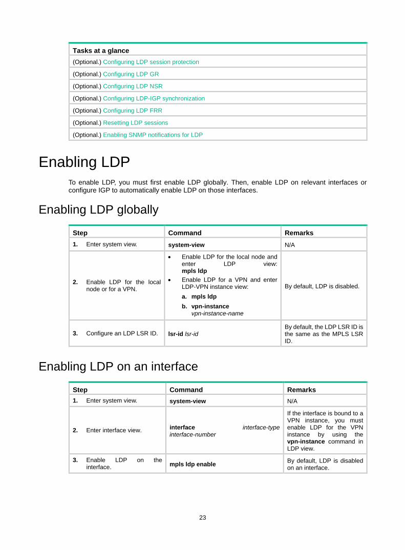
23
Tasks at a glance (Optional.) Configuring LDP session protection
(Optional.) Configuring LDP GR
(Optional.) Configuring LDP NSR
(Optional.) Configuring LDP-IGP synchronization
(Optional.) Configuring LDP FRR
(Optional.) Resetting LDP sessions
(Optional.) Enabling SNMP notifications for LDP
Enabling LDP To enable LDP, you must first enable LDP globally. Then, enable LDP on relevant interfaces or configure IGP to automatically enable LDP on those interfaces.
Enabling LDP globally
Step Command Remarks 1. Enter system view. system-view N/A
2. Enable LDP for the local node or for a VPN.
• Enable LDP for the local node and enter LDP view: mpls ldp
• Enable LDP for a VPN and enter LDP-VPN instance view: a. mpls ldp b. vpn-instance
vpn-instance-name
By default, LDP is disabled.
3. Configure an LDP LSR ID. lsr-id lsr-id By default, the LDP LSR ID is the same as the MPLS LSR ID.
Enabling LDP on an interface
Step Command Remarks 1. Enter system view. system-view N/A
2. Enter interface view. interface interface-type interface-number
If the interface is bound to a VPN instance, you must enable LDP for the VPN instance by using the vpn-instance command in LDP view.
3. Enable LDP on the interface. mpls ldp enable By default, LDP is disabled
on an interface.

24
Configuring Hello parameters Perform this task to configure the following hello timers: • Link Hello hold time and Link Hello interval. • Targeted Hello hold time and Targeted Hello interval for a specific peer.
Configuring Link Hello timers
Step Command Remarks 1. Enter system view. system-view N/A
2. Enter the view of the interface where you want to establish an LDP session.
interface interface-type interface-number N/A
3. Configure the Link Hello hold time.
mpls ldp timer hello-hold timeout
By default, the Link Hello hold time is 15 seconds.
4. Configure the Link Hello interval.
mpls ldp timer hello-interval interval
By default, the Link Hello interval is five seconds.
Configuring Targeted Hello timers for an LDP peer
Step Command Remarks 1. Enter system view. system-view N/A
2. Enter LDP view. mpls ldp N/A
3. Specify an LDP peer and enter LDP peer view. The device will send unsolicited Targeted Hellos to the peer and can respond to the Targeted Hellos sent from the peer.
targeted-peer peer-lsr-id By default, the device does not send Targeted Hellos to or receive Targeted Hellos from any peer.
4. Configure the Targeted Hello hold time.
mpls ldp timer hello-hold timeout
By default, the Targeted Hello hold time is 45 seconds.
5. Configure the Target Hello interval.
mpls ldp timer hello-interval interval
By default, the Targeted Hello interval is 15 seconds.
Configuring LDP session parameters This task configures the following LDP session parameters: • Keepalive hold time and Keepalive interval. • LDP transport address—IP address for establishing TCP connections.
LDP uses Basic Discovery and Extended Discovery mechanisms to discovery LDP peers and establish LDP sessions with them.
When you configure LDP session parameters, follow these guidelines: • The configured LDP transport address must be the IP address of an up interface on the device.
Otherwise, no LDP session can be established. • Make sure the LDP transport addresses of the local and peer LSRs can reach each other.
Otherwise, no TCP connection can be established.

25
Configuring LDP sessions parameters for Basic Discovery mechanism
Step Command Remarks 1. Enter system view. system-view N/A
2. Enter interface view. interface interface-type interface-number N/A
3. Configure the Keepalive hold time.
mpls ldp timer keepalive-hold timeout
By default, the Keepalive hold time is 45 seconds.
4. Configure the Keepalive interval.
mpls ldp timer keepalive-interval interval
By default, the Keepalive interval is 15 seconds.
5. Configure the LDP transport address.
mpls ldp transport-address { ip-address | interface }
By default, the LDP transport address is the LSR ID of the local device if the interface where you want to establish an LDP session belongs to the public network. If the interface belongs to a VPN, the LDP transport address is the primary IP address of the interface. If the interface where you want to establish an LDP session is bound to a VPN instance, the interface with the IP address specified with this command must be bound to the same VPN instance.
Configuring LDP sessions parameters for Extended Discovery mechanism
Step Command Remarks 1. Enter system view. system-view N/A
2. Enter LDP view. mpls ldp N/A
3. Specify an LDP peer and enter LDP peer view. The device will send unsolicited Targeted Hellos to the peer and can respond to Targeted Hellos sent from the targeted peer.
targeted-peer peer-lsr-id By default, the device does not send Targeted Hellos to or receive Targeted Hellos from any peer.
4. Configure the Keepalive hold time.
mpls ldp timer keepalive-hold timeout
By default, the Keepalive hold time is 45 seconds.
5. Configure the Keepalive interval.
mpls ldp timer keepalive-interval interval
By default, the Keepalive interval is 15 seconds.
6. Configure the LDP transport address.
mpls ldp transport-address ip-address
By default, the LDP transport address is the LSR ID of the local device.
Configuring LDP backoff If LDP session parameters (for example, the label advertisement mode) are incompatible, two LDP peers cannot establish a session, and they will keep negotiating with each other.
The LDP backoff mechanism can mitigate this problem by using an initial delay timer and a maximum delay timer. After LDP fails to establish a session with a peer LSR for the first time, LDP does not
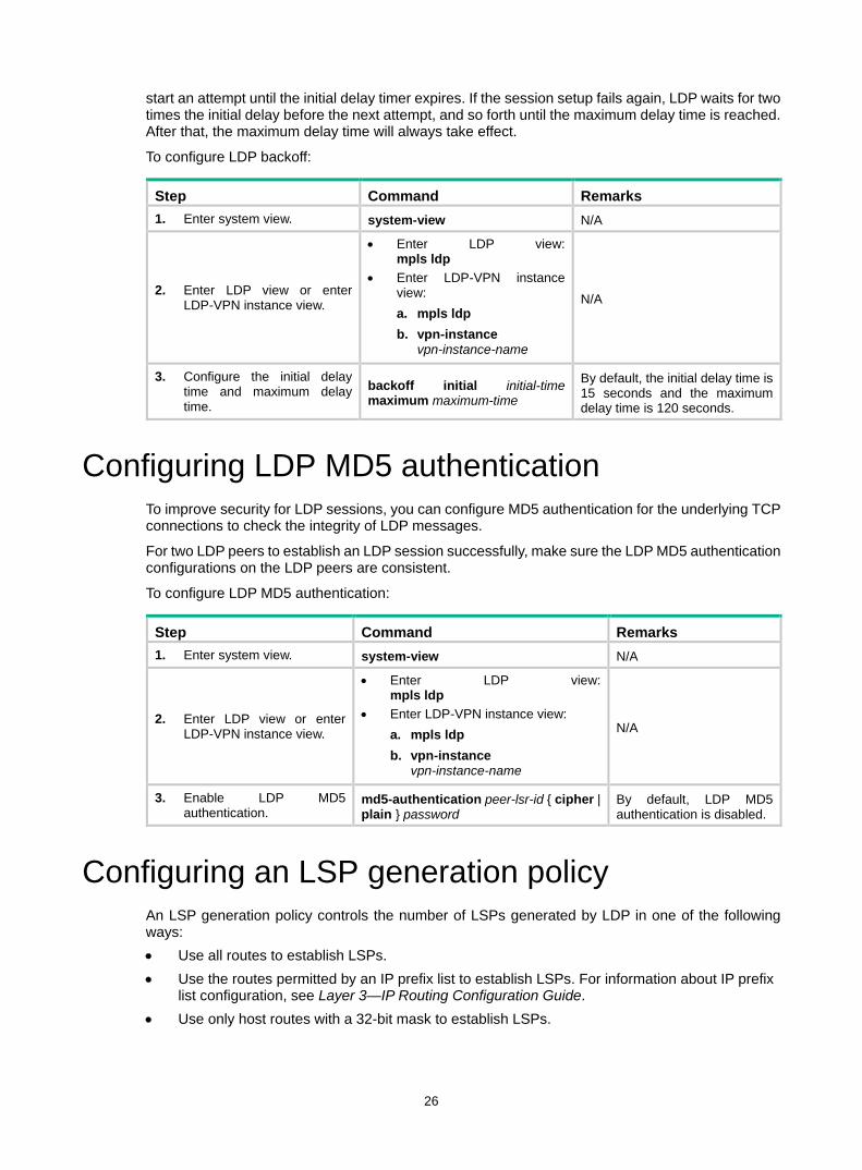
26
start an attempt until the initial delay timer expires. If the session setup fails again, LDP waits for two times the initial delay before the next attempt, and so forth until the maximum delay time is reached. After that, the maximum delay time will always take effect.
To configure LDP backoff:
Step Command Remarks 1. Enter system view. system-view N/A
2. Enter LDP view or enter LDP-VPN instance view.
• Enter LDP view: mpls ldp
• Enter LDP-VPN instance view: a. mpls ldp b. vpn-instance
vpn-instance-name
N/A
3. Configure the initial delay time and maximum delay time.
backoff initial initial-time maximum maximum-time
By default, the initial delay time is 15 seconds and the maximum delay time is 120 seconds.
Configuring LDP MD5 authentication To improve security for LDP sessions, you can configure MD5 authentication for the underlying TCP connections to check the integrity of LDP messages.
For two LDP peers to establish an LDP session successfully, make sure the LDP MD5 authentication configurations on the LDP peers are consistent.
To configure LDP MD5 authentication:
Step Command Remarks 1. Enter system view. system-view N/A
2. Enter LDP view or enter LDP-VPN instance view.
• Enter LDP view: mpls ldp
• Enter LDP-VPN instance view: a. mpls ldp b. vpn-instance
vpn-instance-name
N/A
3. Enable LDP MD5 authentication.
md5-authentication peer-lsr-id { cipher | plain } password
By default, LDP MD5 authentication is disabled.
Configuring an LSP generation policy An LSP generation policy controls the number of LSPs generated by LDP in one of the following ways: • Use all routes to establish LSPs. • Use the routes permitted by an IP prefix list to establish LSPs. For information about IP prefix
list configuration, see Layer 3—IP Routing Configuration Guide. • Use only host routes with a 32-bit mask to establish LSPs.

27
By default, LDP uses only host routes with a 32-bit mask to establish LSPs. The other two methods can result in more LSPs than the default policy. To change the policy, be sure that the system resources and bandwidth resources are sufficient.
To configure an LSP generation policy:
Step Command Remarks 1. Enter system view. system-view N/A
2. Enter LDP view or enter LDP-VPN instance view.
• Enter LDP view: mpls ldp
• Enter LDP-VPN instance view: a. mpls ldp b. vpn-instance
vpn-instance-name
N/A
3. Configure an LSP generation policy.
lsp-trigger { all | prefix-list prefix-list-name }
By default, LDP uses only host routes with a 32-bit mask to establish LSPs.
Configuring the LDP label distribution control mode
Step Command Remarks 1. Enter system view. system-view N/A
2. Enter LDP view or enter LDP-VPN instance view.
• Enter LDP view: mpls ldp
• Enter LDP-VPN instance view: a. mpls ldp b. vpn-instance
vpn-instance-name
N/A
3. Configure the label distribution control mode.
label-distribution { independent | ordered }
By default, the Ordered label distribution mode is used. To apply the new setting to LDP sessions established before the command is configured, you must reset the LDP sessions.
Configuring a label advertisement policy A label advertisement policy uses IP prefix lists to control the FEC-label mappings advertised to peers.
As shown in Figure 15, LSR A advertises label mappings for FECs permitted by IP prefix list B to LSR B and advertises label mappings for FECs permitted by IP prefix list C to LSR C.

28
Figure 15 Label advertisement control diagram
A label advertisement policy on an LSR and a label acceptance policy on its upstream LSR can achieve the same purpose. If downstream LSRs support label advertisement control, use label advertisement policies as a best practice to reduce network load.
Before you configure an LDP label advertisement policy, create an IP prefix list. For information about IP prefix list configuration, see Layer 3—IP Routing Configuration Guide.
To configure a label advertisement policy:
Step Command Remarks 1. Enter system view. system-view N/A
2. Enter LDP view or enter LDP-VPN instance view.
• Enter LDP view: mpls ldp
• Enter LDP-VPN instance view: a. mpls ldp b. vpn-instance
vpn-instance-name
N/A
3. Configure a label advertisement policy.
advertise-label prefix-list prefix-list-name [ peer peer-prefix-list-name ]
By default, LDP advertises all label mappings permitted by the LSP generation policy to all peers.
Configuring a label acceptance policy A label acceptance policy uses an IP prefix list to control the label mappings received from a peer.
As shown in Figure 16, LSR A uses an IP prefix list to filter label mappings from LSR B, and it does not filter label mappings from LSR C.
LSR C
LSR ALSR B
Advert
ise la
bel
mappin
gs pe
rmitte
d
by IP
prefi
x list
C
Advertise label mappings permitted
by IP prefix list B
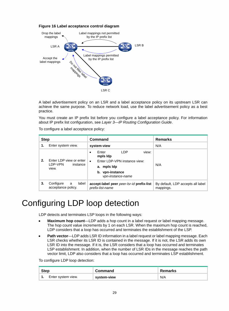
29
Figure 16 Label acceptance control diagram
A label advertisement policy on an LSR and a label acceptance policy on its upstream LSR can achieve the same purpose. To reduce network load, use the label advertisement policy as a best practice.
You must create an IP prefix list before you configure a label acceptance policy. For information about IP prefix list configuration, see Layer 3—IP Routing Configuration Guide.
To configure a label acceptance policy:
Step Command Remarks 1. Enter system view. system-view N/A
2. Enter LDP view or enter LDP-VPN instance view.
• Enter LDP view: mpls ldp
• Enter LDP-VPN instance view: a. mpls ldp b. vpn-instance
vpn-instance-name
N/A
3. Configure a label acceptance policy.
accept-label peer peer-lsr-id prefix-list prefix-list-name
By default, LDP accepts all label mappings.
Configuring LDP loop detection LDP detects and terminates LSP loops in the following ways: • Maximum hop count—LDP adds a hop count in a label request or label mapping message.
The hop count value increments by 1 on each LSR. When the maximum hop count is reached, LDP considers that a loop has occurred and terminates the establishment of the LSP.
• Path vector—LDP adds LSR ID information in a label request or label mapping message. Each LSR checks whether its LSR ID is contained in the message. If it is not, the LSR adds its own LSR ID into the message. If it is, the LSR considers that a loop has occurred and terminates LSP establishment. In addition, when the number of LSR IDs in the message reaches the path vector limit, LDP also considers that a loop has occurred and terminates LSP establishment.
To configure LDP loop detection:
Step Command Remarks 1. Enter system view. system-view N/A
Label mappings permitted by the IP prefix list
LSR A LSR B
Accept the label mappings
Drop the label mappings
Label mappings not permitted by the IP prefix list
LSR C
Do not filter label
mappings

30
Step Command Remarks
2. Enter LDP view or enter LDP-VPN instance view.
• Enter LDP view: mpls ldp
• Enter LDP-VPN instance view: a. mpls ldp b. vpn-instance
vpn-instance-name
N/A
3. Enable loop detection. loop-detect
By default, loop detection is disabled. After loop detection is enabled, the device uses both the maximum hop count and the path vector methods to detect loops.
4. Specify the maximum hop count. maxhops hop-number By default, the maximum hop
count is 32.
5. Specify the path vector limit. pv-limit pv-number By default, the path vector
limit is 32.
NOTE: The LDP loop detection feature is applicable only in networks comprised of devices that do not support TTL mechanism, such as ATM switches. Do not use LDP loop detection on other networks because it only results in extra LDP overhead.
Configuring LDP session protection If two LDP peers have both a direct link and an indirect link in between, you can configure this feature to protect their LDP session when the direct link fails.
LDP establishes both a Link Hello adjacency over the direct link and a Targeted Hello adjacency over the indirect link with the peer. When the direct link fails, LDP deletes the Link Hello adjacency but still maintains the Targeted Hello adjacency. In this way, the LDP session between the two peers is kept available, and the FEC-label mappings based on this session are not deleted. When the direct link recovers, the LDP peers do not need to re-establish the LDP session or re-learn the FEC-label mappings.
When you enable the session protection function, you can also specify the session protection duration. If the Link Hello adjacency does not recover within the duration, LDP deletes the Targeted Hello adjacency and the LDP session. If you do not specify the session protection duration, the two peers will always maintain the LDP session over the Targeted Hello adjacency.
To configure LDP session protection:
Step Command Remarks 1. Enter system view. system-view N/A
2. Enter LDP view. mpls ldp N/A
3. Enable the session protection function.
session protection [ duration time ] [ peer peer-prefix-list-name ]
By default, session protection is disabled.

31
Configuring LDP GR Before you configure LDP GR, enable LDP on the GR restarter and GR helpers.
To configure LDP GR:
Step Command Remarks 1. Enter system view. system-view N/A
2. Enter LDP view. mpls ldp N/A
3. Enable LDP GR. graceful-restart By default, LDP GR is disabled.
4. Configure the Reconnect timer for LDP GR.
graceful-restart timer reconnect reconnect-time
By default, the Reconnect time is 120 seconds.
5. Configure the MPLS Forwarding State Holding timer for LDP GR.
graceful-restart timer forwarding-hold hold-time
By default, the MPLS Forwarding State Holding time is 180 seconds.
Configuring LDP NSR Step Command Remarks 1. Enter system view. system-view N/A
2. Enter LDP view. mpls ldp N/A
3. Enable LDP NSR. non-stop-routing By default, LDP NSR is disabled.
Configuring LDP-IGP synchronization After you enable LDP-IGP synchronization for an OSPF process, OSPF area, or an IS-IS process, LDP-IGP synchronization is enabled on the OSPF process interfaces or the IS-IS process interfaces.
You can execute the mpls ldp igp sync disable command to disable LDP-IGP synchronization on interfaces where LDP-IGP synchronization is not required.
Configuring LDP-OSPF synchronization LDP-IGP synchronization is not supported for an OSPF process and its OSPF areas if the OSPF process belongs to a VPN instance.
To configure LDP-OSPF synchronization for an OSPF process:
Step Command Remarks 1. Enter system view. system-view N/A
2. Enter OSPF view. ospf [ process-id | router-id router-id ] * N/A
3. Enable LDP-OSPF synchronization. mpls ldp sync By default, LDP-OSPF
synchronization is disabled.
4. Return to system view. quit N/A

32
Step Command Remarks
5. Enter interface view. interface interface-type interface-number N/A
6. (Optional.) Disable LDP-IGP synchronization on the interface.
mpls ldp igp sync disable By default, LDP-IGP synchronization is not disabled on an interface.
7. Return to system view. quit N/A
8. Enter LDP view. mpls ldp N/A
9. (Optional.) Set the delay for LDP to notify IGP of the LDP convergence.
igp sync delay time By default, LDP immediately notifies IGP of the LDP convergence completion.
10. (Optional.) Set the maximum delay for LDP to notify IGP of the LDP-IGP synchronization status after an LDP restart or active/standby switchover.
igp sync delay on-restart time
By default, the maximum notification delay is 90 seconds.
To configure LDP-OSPF synchronization for an OSPF area:
Step Command Remarks 1. Enter system view. system-view N/A
2. Enter OSPF view. ospf [ process-id | router-id router-id ] * N/A
3. Enter area view. area area-id N/A
4. Enable LDP-OSPF synchronization. mpls ldp sync By default, LDP-OSPF
synchronization is disabled.
5. Return to system view. quit N/A
6. Enter interface view. interface interface-type interface-number N/A
7. (Optional.) Disable LDP-IGP synchronization on the interface.
mpls ldp igp sync disable By default, LDP-IGP synchronization is not disabled on an interface.
8. Return to system view. quit N/A
9. Enter LDP view. mpls ldp N/A
10. (Optional.) Set the delay for LDP to notify IGP of the LDP convergence.
igp sync delay time By default, LDP immediately notifies IGP of the LDP convergence completion.
11. (Optional.) Set the maximum delay for LDP to notify IGP of the LDP-IGP synchronization status after an LDP restart or active/standby switchover.
igp sync delay on-restart time By default, the maximum notification delay is 90 seconds.
Configuring LDP-ISIS synchronization LDP-IGP synchronization is not supported for an IS-IS process that belongs to a VPN instance.
To configure LDP-ISIS synchronization for an IS-IS process:

33
Step Command Remarks 1. Enter system view. system-view N/A
2. Enter IS-IS view. isis [ process-id ] N/A
3. Enable LDP-ISIS synchronization. mpls ldp sync [ level-1 | level-2 ] By default, LDP-ISIS
synchronization is disabled.
4. Return to system view. quit N/A
5. Enter interface view. interface interface-type interface-number N/A
6. (Optional.) Disable LDP-IGP synchronization on the interface.
mpls ldp igp sync disable By default, LDP-IGP synchronization is not disabled on an interface.
7. Return to system view. quit N/A
8. Enter LDP view. mpls ldp N/A
9. (Optional.) Set the delay for LDP to notify IGP of the LDP convergence completion.
igp sync delay time By default, LDP immediately notifies IGP of the LDP convergence completion.
10. (Optional.) Set the maximum delay for LDP to notify IGP of the LDP-IGP synchronization status after an LDP restart or an active/standby switchover occurs.
igp sync delay on-restart time By default, the maximum notification delay is 90 seconds.
Configuring LDP FRR LDP FRR is based on IP FRR, and is enabled automatically after IP FRR is enabled. For information about configuring IP FRR, see Layer 3—IP Routing Configuration Guide.
Resetting LDP sessions Changes to LDP session parameters take effect only on new LDP sessions. To apply the changes to an existing LDP session, you must reset all LDP sessions by executing the reset mpls ldp command.
Execute the reset mpls ldp command in user view.
Task Command Remarks
Reset LDP sessions. reset mpls ldp [ vpn-instance vpn-instance-name ] [ peer peer-id ]
If you specify the peer keyword, this command resets the LDP session to the specified peer without validating the session parameter changes.
Enabling SNMP notifications for LDP This feature enables generating SNMP notifications for LDP upon LDP session changes, as defined in RFC 3815. The generated SNMP notifications are sent to the SNMP module.
To enable SNMP notifications for LDP:

34
Step Command Remarks 1. Enter system view. system-view N/A
2. Enable SNMP notifications for LDP. snmp-agent trap enable ldp By default, SNMP notifications for
LDP are enabled.
For more information about SNMP notifications, see Network Management and Monitoring Configuration Guide.
Displaying and maintaining LDP Execute display commands in any view.
Task Command
Display LDP discovery information.
display mpls ldp discovery [ vpn-instance vpn-instance-name ] [ interface interface-type interface-number | peer peer-lsr-id | targeted-peer peer-lsr-id ] [ verbose ] [ standby slot slot-number ]
Display LDP FEC-label mapping information.
display mpls ldp fec [ vpn-instance vpn-instance-name ] [ destination-address mask-length | summary ] [ standby slot slot-number ]
Display LDP interface information. display mpls ldp interface [ interface-type interface-number ]
Display LDP-IGP synchronization information.
display mpls ldp igp sync [ interface interface-type interface-number ]
Display LDP LSP information. display mpls ldp lsp [ vpn-instance vpn-instance-name ] [ destination-address mask-length ]
Display LDP running parameters. display mpls ldp parameter [ vpn-instance vpn-instance-name ]
Display LDP peer and session information.
display mpls ldp peer [ vpn-instance vpn-instance-name ] [ peer-lsr-id ] [ verbose ] [ standby slot slot-number ]
Display LDP summary information. display mpls ldp summary [ all | vpn-instance vpn-instance-name ] [ standby slot slot-number ]
LDP configuration examples LDP LSP configuration example Network requirements
Switch A, Switch B, and Switch C all support MPLS.
Configure LDP to establish LSPs between Switch A and Switch C, so subnets 11.1.1.0/24 and 21.1.1.0/24 can reach each other over MPLS.
Configure LDP to establish LSPs only for destinations 1.1.1.9/32, 2.2.2.9/32, 3.3.3.9/32, 11.1.1.0/24, and 21.1.1.0/24 on Switch A, Switch B, and Switch C.

35
Figure 17 Network diagram
Requirements analysis • To ensure that the LSRs establish LSPs automatically, enable LDP on each LSR. • To establish LDP LSPs, configure a routing protocol to ensure IP connectivity between the
LSRs. This example uses OSPF. • To control the number of LSPs, configure an LSP generation policy on each LSR.
Configuration procedure 1. Configure IP addresses and masks for interfaces, including the loopback interfaces, as shown
in Figure 17. (Details not shown.) 2. Configure OSPF on each switch to ensure IP connectivity between them:
# Configure Switch A. <SwitchA> system-view
[SwitchA] ospf
[SwitchA-ospf-1] area 0
[SwitchA-ospf-1-area-0.0.0.0] network 1.1.1.9 0.0.0.0
[SwitchA-ospf-1-area-0.0.0.0] network 10.1.1.0 0.0.0.255
[SwitchA-ospf-1-area-0.0.0.0] network 11.1.1.0 0.0.0.255
[SwitchA-ospf-1-area-0.0.0.0] quit
[SwitchA-ospf-1] quit
# Configure Switch B. <SwitchB> system-view
[SwitchB] ospf
[SwitchB-ospf-1] area 0
[SwitchB-ospf-1-area-0.0.0.0] network 2.2.2.9 0.0.0.0
[SwitchB-ospf-1-area-0.0.0.0] network 10.1.1.0 0.0.0.255
[SwitchB-ospf-1-area-0.0.0.0] network 20.1.1.0 0.0.0.255
[SwitchB-ospf-1-area-0.0.0.0] quit
[SwitchB-ospf-1] quit
# Configure Switch C. <SwitchC> system-view
[SwitchC] ospf
[SwitchC-ospf-1] area 0
[SwitchC-ospf-1-area-0.0.0.0] network 3.3.3.9 0.0.0.0
[SwitchC-ospf-1-area-0.0.0.0] network 20.1.1.0 0.0.0.255
[SwitchC-ospf-1-area-0.0.0.0] network 21.1.1.0 0.0.0.255
[SwitchC-ospf-1-area-0.0.0.0] quit
Loop02.2.2.9/32
Vlan-int320.1.1.1/24
Loop03.3.3.9/32
Loop01.1.1.9/32
Vlan-int210.1.1.1/24
Vlan-int210.1.1.2/24
Vlan-int320.1.1.2/24
Switch A Switch B Switch C
11.1.1.0/24 21.1.1.0/24
Vlan-int411.1.1.1/24
Vlan-int521.1.1.1/24
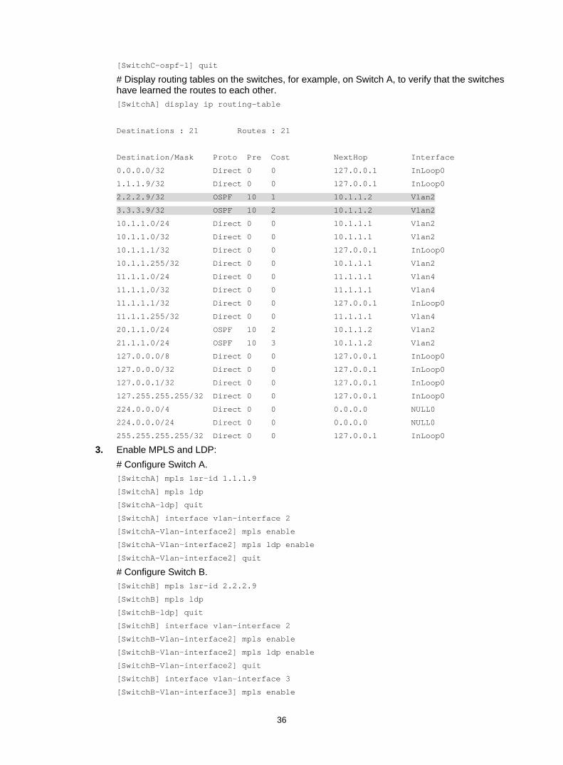
36
[SwitchC-ospf-1] quit
# Display routing tables on the switches, for example, on Switch A, to verify that the switches have learned the routes to each other. [SwitchA] display ip routing-table
Destinations : 21 Routes : 21
Destination/Mask Proto Pre Cost NextHop Interface
0.0.0.0/32 Direct 0 0 127.0.0.1 InLoop0
1.1.1.9/32 Direct 0 0 127.0.0.1 InLoop0
2.2.2.9/32 OSPF 10 1 10.1.1.2 Vlan2
3.3.3.9/32 OSPF 10 2 10.1.1.2 Vlan2
10.1.1.0/24 Direct 0 0 10.1.1.1 Vlan2
10.1.1.0/32 Direct 0 0 10.1.1.1 Vlan2
10.1.1.1/32 Direct 0 0 127.0.0.1 InLoop0
10.1.1.255/32 Direct 0 0 10.1.1.1 Vlan2
11.1.1.0/24 Direct 0 0 11.1.1.1 Vlan4
11.1.1.0/32 Direct 0 0 11.1.1.1 Vlan4
11.1.1.1/32 Direct 0 0 127.0.0.1 InLoop0
11.1.1.255/32 Direct 0 0 11.1.1.1 Vlan4
20.1.1.0/24 OSPF 10 2 10.1.1.2 Vlan2
21.1.1.0/24 OSPF 10 3 10.1.1.2 Vlan2
127.0.0.0/8 Direct 0 0 127.0.0.1 InLoop0
127.0.0.0/32 Direct 0 0 127.0.0.1 InLoop0
127.0.0.1/32 Direct 0 0 127.0.0.1 InLoop0
127.255.255.255/32 Direct 0 0 127.0.0.1 InLoop0
224.0.0.0/4 Direct 0 0 0.0.0.0 NULL0
224.0.0.0/24 Direct 0 0 0.0.0.0 NULL0
255.255.255.255/32 Direct 0 0 127.0.0.1 InLoop0
3. Enable MPLS and LDP: # Configure Switch A. [SwitchA] mpls lsr-id 1.1.1.9
[SwitchA] mpls ldp
[SwitchA-ldp] quit
[SwitchA] interface vlan-interface 2
[SwitchA-Vlan-interface2] mpls enable
[SwitchA-Vlan-interface2] mpls ldp enable
[SwitchA-Vlan-interface2] quit
# Configure Switch B. [SwitchB] mpls lsr-id 2.2.2.9
[SwitchB] mpls ldp
[SwitchB-ldp] quit
[SwitchB] interface vlan-interface 2
[SwitchB-Vlan-interface2] mpls enable
[SwitchB-Vlan-interface2] mpls ldp enable
[SwitchB-Vlan-interface2] quit
[SwitchB] interface vlan-interface 3
[SwitchB-Vlan-interface3] mpls enable
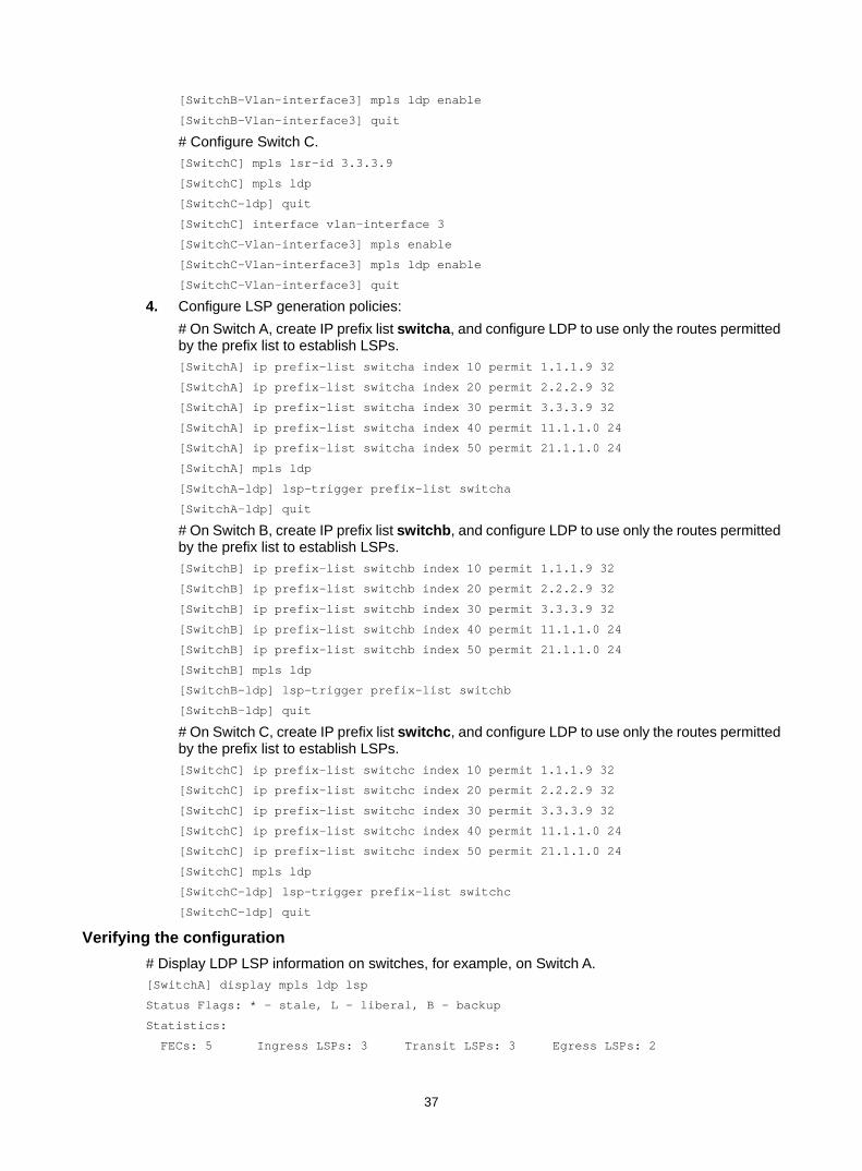
37
[SwitchB-Vlan-interface3] mpls ldp enable
[SwitchB-Vlan-interface3] quit
# Configure Switch C. [SwitchC] mpls lsr-id 3.3.3.9
[SwitchC] mpls ldp
[SwitchC-ldp] quit
[SwitchC] interface vlan-interface 3
[SwitchC-Vlan-interface3] mpls enable
[SwitchC-Vlan-interface3] mpls ldp enable
[SwitchC-Vlan-interface3] quit
4. Configure LSP generation policies: # On Switch A, create IP prefix list switcha, and configure LDP to use only the routes permitted by the prefix list to establish LSPs. [SwitchA] ip prefix-list switcha index 10 permit 1.1.1.9 32
[SwitchA] ip prefix-list switcha index 20 permit 2.2.2.9 32
[SwitchA] ip prefix-list switcha index 30 permit 3.3.3.9 32
[SwitchA] ip prefix-list switcha index 40 permit 11.1.1.0 24
[SwitchA] ip prefix-list switcha index 50 permit 21.1.1.0 24
[SwitchA] mpls ldp
[SwitchA-ldp] lsp-trigger prefix-list switcha
[SwitchA-ldp] quit
# On Switch B, create IP prefix list switchb, and configure LDP to use only the routes permitted by the prefix list to establish LSPs. [SwitchB] ip prefix-list switchb index 10 permit 1.1.1.9 32
[SwitchB] ip prefix-list switchb index 20 permit 2.2.2.9 32
[SwitchB] ip prefix-list switchb index 30 permit 3.3.3.9 32
[SwitchB] ip prefix-list switchb index 40 permit 11.1.1.0 24
[SwitchB] ip prefix-list switchb index 50 permit 21.1.1.0 24
[SwitchB] mpls ldp
[SwitchB-ldp] lsp-trigger prefix-list switchb
[SwitchB-ldp] quit
# On Switch C, create IP prefix list switchc, and configure LDP to use only the routes permitted by the prefix list to establish LSPs. [SwitchC] ip prefix-list switchc index 10 permit 1.1.1.9 32
[SwitchC] ip prefix-list switchc index 20 permit 2.2.2.9 32
[SwitchC] ip prefix-list switchc index 30 permit 3.3.3.9 32
[SwitchC] ip prefix-list switchc index 40 permit 11.1.1.0 24
[SwitchC] ip prefix-list switchc index 50 permit 21.1.1.0 24
[SwitchC] mpls ldp
[SwitchC-ldp] lsp-trigger prefix-list switchc
[SwitchC-ldp] quit
Verifying the configuration # Display LDP LSP information on switches, for example, on Switch A. [SwitchA] display mpls ldp lsp
Status Flags: * - stale, L - liberal, B - backup
Statistics:
FECs: 5 Ingress LSPs: 3 Transit LSPs: 3 Egress LSPs: 2

38
FEC In/Out Label Nexthop OutInterface
1.1.1.9/32 3/-
-/1279(L)
2.2.2.9/32 -/3 10.1.1.2 Vlan-int2
1279/3 10.1.1.2 Vlan-int2
3.3.3.9/32 -/1278 10.1.1.2 Vlan-int2
1278/1278 10.1.1.2 Vlan-int2
11.1.1.0/24 1277/-
-/1277(L)
21.1.1.0/24 -/1276 10.1.1.2 Vlan-int2
1276/1276 10.1.1.2 Vlan-int2
# Test the connectivity of the LDP LSP from Switch A to Switch C. [SwitchA] ping mpls -a 11.1.1.1 ipv4 21.1.1.0 24
MPLS Ping FEC: 21.1.1.0/24 : 100 data bytes
100 bytes from 20.1.1.2: Sequence=1 time=1 ms
100 bytes from 20.1.1.2: Sequence=2 time=1 ms
100 bytes from 20.1.1.2: Sequence=3 time=8 ms
100 bytes from 20.1.1.2: Sequence=4 time=2 ms
100 bytes from 20.1.1.2: Sequence=5 time=1 ms
--- FEC: 21.1.1.0/24 ping statistics ---
5 packets transmitted, 5 packets received, 0.0% packet loss
round-trip min/avg/max = 1/2/8 ms
# Test the connectivity of the LDP LSP from Switch C to Switch A. [SwitchC] ping mpls -a 21.1.1.1 ipv4 11.1.1.0 24
MPLS Ping FEC: 11.1.1.0/24 : 100 data bytes
100 bytes from 10.1.1.1: Sequence=1 time=1 ms
100 bytes from 10.1.1.1: Sequence=2 time=1 ms
100 bytes from 10.1.1.1: Sequence=3 time=1 ms
100 bytes from 10.1.1.1: Sequence=4 time=1 ms
100 bytes from 10.1.1.1: Sequence=5 time=1 ms
--- FEC: 11.1.1.0/24 ping statistics ---
5 packets transmitted, 5 packets received, 0.0% packet loss
round-trip min/avg/max = 1/1/1 ms
Label acceptance control configuration example Network requirements
Two links, Switch A—Switch B—Switch C and Switch A—Switch D—Switch C, exist between subnets 11.1.1.0/24 and 21.1.1.0/24.
Configure LDP to establish LSPs only for routes to subnets 11.1.1.0/24 and 21.1.1.0/24.
Configure LDP to establish LSPs only on the link Switch A—Switch B—Switch C to forward traffic between subnets 11.1.1.0/24 and 21.1.1.0/24.

39
Figure 18 Network diagram
Requirements analysis • To ensure that the LSRs establish LSPs automatically, enable LDP on each LSR. • To establish LDP LSPs, configure a routing protocol to ensure IP connectivity between the
LSRs. This example uses OSPF. • To ensure that LDP establishes LSPs only for the routes 11.1.1.0/24 and 21.1.1.0/24, configure
LSP generation policies on each LSR. • To ensure that LDP establishes LSPs only over the link Switch A—Switch B—Switch C,
configure label acceptance policies as follows: Switch A accepts only the label mapping for FEC 21.1.1.0/24 received from Switch B.
Switch A denies the label mapping for FEC 21.1.1.0/24 received from Switch D. Switch C accepts only the label mapping for FEC 11.1.1.0/24 received from Switch B.
Switch C denies the label mapping for FEC 11.1.1.0/24 received from Switch D.
Configuration procedure 1. Configure IP addresses and masks for interfaces, including the loopback interfaces, as shown
in Figure 18. (Details not shown.) 2. Configure OSPF on each switch to ensure IP connectivity between them. (Details not shown.) 3. Enable MPLS and LDP:
# Configure Switch A. <SwitchA> system-view
[SwitchA] mpls lsr-id 1.1.1.9
[SwitchA] mpls ldp
[SwitchA-ldp] quit
[SwitchA] interface vlan-interface 2
[SwitchA-Vlan-interface2] mpls enable
[SwitchA-Vlan-interface2] mpls ldp enable
[SwitchA-Vlan-interface2] quit
[SwitchA] interface vlan-interface 6
[SwitchA-Vlan-interface6] mpls enable
[SwitchA-Vlan-interface6] mpls ldp enable
[SwitchA-Vlan-interface6] quit
Switch A
Switch B
Switch C
Loop01.1.1.9/32
Loop03.3.3.9/32
Vlan-int210.1.1.1/24
Vlan-int320.1.1.1/24
Vlan-int210.1.1.2/24
Vlan-int320.1.1.2/24
11.1.1.0/24 21.1.1.0/24
Vlan-int411.1.1.1/24
Vlan-int521.1.1.1/24
Switch D
Loop04.4.4.9/32
Loop02.2.2.9/32
Vlan-int630.1.1.1/24
Vlan-int740.1.1.2/24
Vlan-int630.1.1.2/24
Vlan-int740.1.1.1/24

40
# Configure Switch B. <SwitchB> system-view
[SwitchB] mpls lsr-id 2.2.2.9
[SwitchB] mpls ldp
[SwitchB-ldp] quit
[SwitchB] interface vlan-interface 2
[SwitchB-Vlan-interface2] mpls enable
[SwitchB-Vlan-interface2] mpls ldp enable
[SwitchB-Vlan-interface2] quit
[SwitchB] interface vlan-interface 3
[SwitchB-Vlan-interface3] mpls enable
[SwitchB-Vlan-interface3] mpls ldp enable
[SwitchB-Vlan-interface3] quit
# Configure Switch C. <SwitchC> system-view
[SwitchC] mpls lsr-id 3.3.3.9
[SwitchC] mpls ldp
[SwitchC-ldp] quit
[SwitchC] interface vlan-interface 3
[SwitchC-Vlan-interface3] mpls enable
[SwitchC-Vlan-interface3] mpls ldp enable
[SwitchC-Vlan-interface3] quit
[SwitchC] interface vlan-interface 7
[SwitchC-Vlan-interface7] mpls enable
[SwitchC-Vlan-interface7] mpls ldp enable
[SwitchC-Vlan-interface7] quit
# Configure Switch D. <SwitchD> system-view
[SwitchD] mpls lsr-id 4.4.4.9
[SwitchD] mpls ldp
[SwitchD-ldp] quit
[SwitchD] interface vlan-interface 6
[SwitchD-Vlan-interface6] mpls enable
[SwitchD-Vlan-interface6] mpls ldp enable
[SwitchD-Vlan-interface6] quit
[SwitchD] interface vlan-interface 7
[SwitchD-Vlan-interface7] mpls enable
[SwitchD-Vlan-interface7] mpls ldp enable
[SwitchD-Vlan-interface7] quit
4. Configure LSP generation policies: # On Switch A, create IP prefix list switcha, and configure LDP to use only the routes permitted by the prefix list to establish LSPs. [SwitchA] ip prefix-list switcha index 10 permit 11.1.1.0 24
[SwitchA] ip prefix-list switcha index 20 permit 21.1.1.0 24
[SwitchA] mpls ldp
[SwitchA-ldp] lsp-trigger prefix-list switcha
[SwitchA-ldp] quit

41
# On Switch B, create IP prefix list switchb, and configure LDP to use only the routes permitted by the prefix list to establish LSPs. [SwitchB] ip prefix-list switchb index 10 permit 11.1.1.0 24
[SwitchB] ip prefix-list switchb index 20 permit 21.1.1.0 24
[SwitchB] mpls ldp
[SwitchB-ldp] lsp-trigger prefix-list switchb
[SwitchB-ldp] quit
# On Switch C, create IP prefix list switchc, and configure LDP to use only the routes permitted by the prefix list to establish LSPs. [SwitchC] ip prefix-list switchc index 10 permit 11.1.1.0 24
[SwitchC] ip prefix-list switchc index 20 permit 21.1.1.0 24
[SwitchC] mpls ldp
[SwitchC-ldp] lsp-trigger prefix-list switchc
[SwitchC-ldp] quit
# On Switch D, create IP prefix list switchd, and configure LDP to use only the routes permitted by the prefix list to establish LSPs. [SwitchD] ip prefix-list switchd index 10 permit 11.1.1.0 24
[SwitchD] ip prefix-list switchd index 20 permit 21.1.1.0 24
[SwitchD] mpls ldp
[SwitchD-ldp] lsp-trigger prefix-list switchd
[SwitchD-ldp] quit
5. Configure label acceptance policies: # On Switch A, create IP prefix list prefix-from-b to permit subnet 21.1.1.0/24. Switch A uses this list to filter FEC-label mappings received from Switch B. [SwitchA] ip prefix-list prefix-from-b index 10 permit 21.1.1.0 24
# On Switch A, create IP prefix list prefix-from-d to deny subnet 21.1.1.0/24. Switch A uses this list to filter FEC-label mappings received from Switch D. [SwitchA] ip prefix-list prefix-from-d index 10 deny 21.1.1.0 24
# On Switch A, configure label acceptance policies to filter FEC-label mappings received from Switch B and Switch D. [SwitchA] mpls ldp
[SwitchA-ldp] accept-label peer 2.2.2.9 prefix-list prefix-from-b
[SwitchA-ldp] accept-label peer 4.4.4.9 prefix-list prefix-from-d
[SwitchA-ldp] quit
# On Switch C, create IP prefix list prefix-from-b to permit subnet 11.1.1.0/24. Switch C uses this list to filter FEC-label mappings received from Switch B. [SwitchC] ip prefix-list prefix-from-b index 10 permit 11.1.1.0 24
# On Switch C, create IP prefix list prefix-from-d to deny subnet 11.1.1.0/24. Switch A uses this list to filter FEC-label mappings received from Switch D. [SwitchC] ip prefix-list prefix-from-d index 10 deny 11.1.1.0 24
# On Switch C, configure label acceptance policies to filter FEC-label mappings received from Switch B and Switch D. [SwitchC] mpls ldp
[SwitchC-ldp] accept-label peer 2.2.2.9 prefix-list prefix-from-b
[SwitchC-ldp] accept-label peer 4.4.4.9 prefix-list prefix-from-d
[SwitchC-ldp] quit
Verifying the configuration # Display LDP LSP information on switches, for example, on Switch A. [SwitchA] display mpls ldp lsp

42
Status Flags: * - stale, L - liberal, B - backup
Statistics:
FECs: 2 Ingress LSPs: 1 Transit LSPs: 1 Egress LSPs: 1
FEC In/Out Label Nexthop OutInterface
11.1.1.0/24 1277/-
-/1148(L)
21.1.1.0/24 -/1149(L)
-/1276 10.1.1.2 Vlan-int2
1276/1276 10.1.1.2 Vlan-int2
The output shows that the next hop of the LSP for FEC 21.1.1.0/24 is Switch B (10.1.1.2). The LSP has been established over the link Switch A—Switch B—Switch C, not over the link Switch A—Switch D—Switch C.
# Test the connectivity of the LDP LSP from Switch A to Switch C. [SwitchA] ping mpls -a 11.1.1.1 ipv4 21.1.1.0 24
MPLS Ping FEC: 21.1.1.0/24 : 100 data bytes
100 bytes from 20.1.1.2: Sequence=1 time=1 ms
100 bytes from 20.1.1.2: Sequence=2 time=1 ms
100 bytes from 20.1.1.2: Sequence=3 time=8 ms
100 bytes from 20.1.1.2: Sequence=4 time=2 ms
100 bytes from 20.1.1.2: Sequence=5 time=1 ms
--- FEC: 21.1.1.0/24 ping statistics ---
5 packets transmitted, 5 packets received, 0.0% packet loss
round-trip min/avg/max = 1/2/8 ms
# Test the connectivity of the LDP LSP from Switch C to Switch A. [SwitchC] ping mpls -a 21.1.1.1 ipv4 11.1.1.0 24
MPLS Ping FEC: 11.1.1.0/24 : 100 data bytes
100 bytes from 10.1.1.1: Sequence=1 time=1 ms
100 bytes from 10.1.1.1: Sequence=2 time=1 ms
100 bytes from 10.1.1.1: Sequence=3 time=1 ms
100 bytes from 10.1.1.1: Sequence=4 time=1 ms
100 bytes from 10.1.1.1: Sequence=5 time=1 ms
--- FEC: 11.1.1.0/24 ping statistics ---
5 packets transmitted, 5 packets received, 0.0% packet loss
round-trip min/avg/max = 1/1/1 ms
Label advertisement control configuration example Network requirements
Two links, Switch A—Switch B—Switch C and Switch A—Switch D—Switch C, exist between subnets 11.1.1.0/24 and 21.1.1.0/24.
Configure LDP to establish LSPs only for routes to subnets 11.1.1.0/24 and 21.1.1.0/24.
Configure LDP to establish LSPs only on the link Switch A—Switch B—Switch C to forward traffic between subnets 11.1.1.0/24 and 21.1.1.0/24.

43
Figure 19 Network diagram
Requirements analysis • To ensure that the LSRs establish LSPs automatically, enable LDP on each LSR. • To establish LDP LSPs, configure a routing protocol to ensure IP connectivity between the
LSRs. This example uses OSPF. • To ensure that LDP establishes LSPs only for the routes 11.1.1.0/24 and 21.1.1.0/24, configure
LSP generation policies on each LSR. • To ensure that LDP establishes LSPs only over the link Switch A—Switch B—Switch C,
configure label advertisement policies as follows: Switch A advertises only the label mapping for FEC 11.1.1.0/24 to Switch B. Switch C advertises only the label mapping for FEC 21.1.1.0/24 to Switch B. Switch D does not advertise label mapping for FEC 21.1.1.0/24 to Switch A. Switch D does
not advertise label mapping for FEC 11.1.1.0/24 to Switch C.
Configuration procedure 1. Configure IP addresses and masks for interfaces, including the loopback interfaces, as shown
in Figure 19. (Details not shown.) 2. Configure OSPF on each switch to ensure IP connectivity between them. (Details not shown.) 3. Enable MPLS and LDP:
# Configure Switch A. <SwitchA> system-view
[SwitchA] mpls lsr-id 1.1.1.9
[SwitchA] mpls ldp
[SwitchA-ldp] quit
[SwitchA] interface vlan-interface 2
[SwitchA-Vlan-interface2] mpls enable
[SwitchA-Vlan-interface2] mpls ldp enable
[SwitchA-Vlan-interface2] quit
[SwitchA] interface vlan-interface 6
[SwitchA-Vlan-interface6] mpls enable
[SwitchA-Vlan-interface6] mpls ldp enable
[SwitchA-Vlan-interface6] quit
Switch A
Switch B
Switch C
Loop01.1.1.9/32
Loop03.3.3.9/32
Vlan-int210.1.1.1/24
Vlan-int320.1.1.1/24
Vlan-int210.1.1.2/24
Vlan-int320.1.1.2/24
11.1.1.0/24 21.1.1.0/24
Vlan-int411.1.1.1/24
Vlan-int521.1.1.1/24
Switch D
Loop04.4.4.9/32
Loop02.2.2.9/32
Vlan-int630.1.1.1/24
Vlan-int740.1.1.2/24
Vlan-int630.1.1.2/24
Vlan-int740.1.1.1/24

44
# Configure Switch B. <SwitchB> system-view
[SwitchB] mpls lsr-id 2.2.2.9
[SwitchB] mpls ldp
[SwitchB-ldp] quit
[SwitchB] interface vlan-interface 2
[SwitchB-Vlan-interface2] mpls enable
[SwitchB-Vlan-interface2] mpls ldp enable
[SwitchB-Vlan-interface2] quit
[SwitchB] interface vlan-interface 3
[SwitchB-Vlan-interface3] mpls enable
[SwitchB-Vlan-interface3] mpls ldp enable
[SwitchB-Vlan-interface3] quit
# Configure Switch C. <SwitchC> system-view
[SwitchC] mpls lsr-id 3.3.3.9
[SwitchC] mpls ldp
[SwitchC-ldp] quit
[SwitchC] interface vlan-interface 3
[SwitchC-Vlan-interface3] mpls enable
[SwitchC-Vlan-interface3] mpls ldp enable
[SwitchC-Vlan-interface3] quit
[SwitchC] interface vlan-interface 7
[SwitchC-Vlan-interface7] mpls enable
[SwitchC-Vlan-interface7] mpls ldp enable
[SwitchC-Vlan-interface7] quit
# Configure Switch D. <SwitchD> system-view
[SwitchD] mpls lsr-id 4.4.4.9
[SwitchD] mpls ldp
[SwitchD-ldp] quit
[SwitchD] interface vlan-interface 6
[SwitchD-Vlan-interface6] mpls enable
[SwitchD-Vlan-interface6] mpls ldp enable
[SwitchD-Vlan-interface6] quit
[SwitchD] interface vlan-interface 7
[SwitchD-Vlan-interface7] mpls enable
[SwitchD-Vlan-interface7] mpls ldp enable
[SwitchD-Vlan-interface7] quit
4. Configure LSP generation policies: # On Switch A, create IP prefix list switcha, and configure LDP to use only the routes permitted by the prefix list to establish LSPs. [SwitchA] ip prefix-list switcha index 10 permit 11.1.1.0 24
[SwitchA] ip prefix-list switcha index 20 permit 21.1.1.0 24
[SwitchA] mpls ldp
[SwitchA-ldp] lsp-trigger prefix-list switcha
[SwitchA-ldp] quit

45
# On Switch B, create IP prefix list switchb, and configure LDP to use only the routes permitted by the prefix list to establish LSPs. [SwitchB] ip prefix-list switchb index 10 permit 11.1.1.0 24
[SwitchB] ip prefix-list switchb index 20 permit 21.1.1.0 24
[SwitchB] mpls ldp
[SwitchB-ldp] lsp-trigger prefix-list switchb
[SwitchB-ldp] quit
# On Switch C, create IP prefix list switchc, and configure LDP to use only the routes permitted by the prefix list to establish LSPs. [SwitchC] ip prefix-list switchc index 10 permit 11.1.1.0 24
[SwitchC] ip prefix-list switchc index 20 permit 21.1.1.0 24
[SwitchC] mpls ldp
[SwitchC-ldp] lsp-trigger prefix-list switchc
[SwitchC-ldp] quit
# On Switch D, create IP prefix list switchd, and configure LDP to use only the routes permitted by the prefix list to establish LSPs. [SwitchD] ip prefix-list switchd index 10 permit 11.1.1.0 24
[SwitchD] ip prefix-list switchd index 20 permit 21.1.1.0 24
[SwitchD] mpls ldp
[SwitchD-ldp] lsp-trigger prefix-list switchd
[SwitchD-ldp] quit
5. Configure label advertisement policies: # On Switch A, create IP prefix list prefix-to-b to permit subnet 11.1.1.0/24. Switch A uses this list to filter FEC-label mappings advertised to Switch B. [SwitchA] ip prefix-list prefix-to-b index 10 permit 11.1.1.0 24
# On Switch A, create IP prefix list peer-b to permit 2.2.2.9/32. Switch A uses this list to filter peers. [SwitchA] ip prefix-list peer-b index 10 permit 2.2.2.9 32
# On Switch A, configure a label advertisement policy to advertise only the label mapping for FEC 11.1.1.0/24 to Switch B. [SwitchA] mpls ldp
[SwitchA-ldp] advertise-label prefix-list prefix-to-b peer peer-b
[SwitchA-ldp] quit
# On Switch C, create IP prefix list prefix-to-b to permit subnet 21.1.1.0/24. Switch C uses this list to filter FEC-label mappings advertised to Switch B. [SwitchC] ip prefix-list prefix-to-b index 10 permit 21.1.1.0 24
# On Switch C, create IP prefix list peer-b to permit 2.2.2.9/32. Switch C uses this list to filter peers. [SwitchC] ip prefix-list peer-b index 10 permit 2.2.2.9 32
# On Switch C, configure a label advertisement policy to advertise only the label mapping for FEC 21.1.1.0/24 to Switch B. [SwitchC] mpls ldp
[SwitchC-ldp] advertise-label prefix-list prefix-to-b peer peer-b
[SwitchC-ldp] quit
# On Switch D, create IP prefix list prefix-to-a to deny subnet 21.1.1.0/24. Switch D uses this list to filter FEC-label mappings to be advertised to Switch A. [SwitchD] ip prefix-list prefix-to-a index 10 deny 21.1.1.0 24
[SwitchD] ip prefix-list prefix-to-a index 20 permit 0.0.0.0 0 less-equal 32

46
# On Switch D, create IP prefix list peer-a to permit 1.1.1.9/32. Switch D uses this list to filter peers. [SwitchD] ip prefix-list peer-a index 10 permit 1.1.1.9 32
# On Switch D, create IP prefix list prefix-to-c to deny subnet 11.1.1.0/24. Switch D uses this list to filter FEC-label mappings to be advertised to Switch C. [SwitchD] ip prefix-list prefix-to-c index 10 deny 11.1.1.0 24
[SwitchD] ip prefix-list prefix-to-c index 20 permit 0.0.0.0 0 less-equal 32
# On Switch D, create IP prefix list peer-c to permit subnet 3.3.3.9/32. Switch D uses this list to filter peers. [SwitchD] ip prefix-list peer-c index 10 permit 3.3.3.9 32
# On Switch D, configure a label advertisement policy, so Switch D does not advertise label mappings for FEC 21.1.1.0/24 to Switch A, and does not advertise label mappings for FEC 11.1.1.0/24 to Switch C. [SwitchD] mpls ldp
[SwitchD-ldp] advertise-label prefix-list prefix-to-a peer peer-a
[SwitchD-ldp] advertise-label prefix-list prefix-to-c peer peer-c
[SwitchD-ldp] quit
Verifying the configuration # Display LDP LSP information on each switch. [SwitchA] display mpls ldp lsp
Status Flags: * - stale, L - liberal, B - backup
Statistics:
FECs: 2 Ingress LSPs: 1 Transit LSPs: 1 Egress LSPs: 1
FEC In/Out Label Nexthop OutInterface
11.1.1.0/24 1277/-
-/1151(L)
-/1277(L)
21.1.1.0/24 -/1276 10.1.1.2 Vlan-int2
1276/1276 10.1.1.2 Vlan-int2
[SwitchB] display mpls ldp lsp
Status Flags: * - stale, L - liberal, B - backup
Statistics:
FECs: 2 Ingress LSPs: 2 Transit LSPs: 2 Egress LSPs: 0
FEC In/Out Label Nexthop OutInterface
11.1.1.0/24 -/1277 10.1.1.1 Vlan-int2
1277/1277 10.1.1.1 Vlan-int2
21.1.1.0/24 -/1149 20.1.1.2 Vlan-int3
1276/1149 20.1.1.2 Vlan-int3
[SwitchC] display mpls ldp lsp
Status Flags: * - stale, L - liberal, B - backup
Statistics:
FECs: 2 Ingress LSPs: 1 Transit LSPs: 1 Egress LSPs: 1
FEC In/Out Label Nexthop OutInterface
11.1.1.0/24 -/1277 20.1.1.1 Vlan-int3
1148/1277 20.1.1.1 Vlan-int3
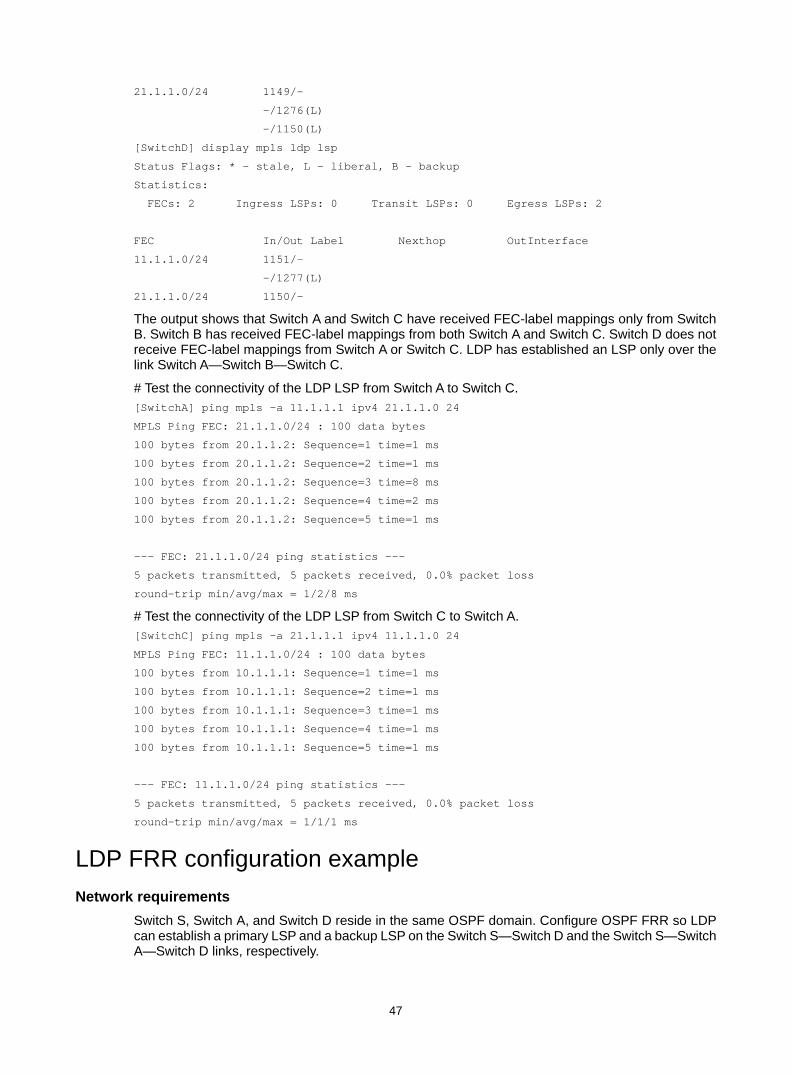
47
21.1.1.0/24 1149/-
-/1276(L)
-/1150(L)
[SwitchD] display mpls ldp lsp
Status Flags: * - stale, L - liberal, B - backup
Statistics:
FECs: 2 Ingress LSPs: 0 Transit LSPs: 0 Egress LSPs: 2
FEC In/Out Label Nexthop OutInterface
11.1.1.0/24 1151/-
-/1277(L)
21.1.1.0/24 1150/-
The output shows that Switch A and Switch C have received FEC-label mappings only from Switch B. Switch B has received FEC-label mappings from both Switch A and Switch C. Switch D does not receive FEC-label mappings from Switch A or Switch C. LDP has established an LSP only over the link Switch A—Switch B—Switch C.
# Test the connectivity of the LDP LSP from Switch A to Switch C. [SwitchA] ping mpls -a 11.1.1.1 ipv4 21.1.1.0 24
MPLS Ping FEC: 21.1.1.0/24 : 100 data bytes
100 bytes from 20.1.1.2: Sequence=1 time=1 ms
100 bytes from 20.1.1.2: Sequence=2 time=1 ms
100 bytes from 20.1.1.2: Sequence=3 time=8 ms
100 bytes from 20.1.1.2: Sequence=4 time=2 ms
100 bytes from 20.1.1.2: Sequence=5 time=1 ms
--- FEC: 21.1.1.0/24 ping statistics ---
5 packets transmitted, 5 packets received, 0.0% packet loss
round-trip min/avg/max = 1/2/8 ms
# Test the connectivity of the LDP LSP from Switch C to Switch A. [SwitchC] ping mpls -a 21.1.1.1 ipv4 11.1.1.0 24
MPLS Ping FEC: 11.1.1.0/24 : 100 data bytes
100 bytes from 10.1.1.1: Sequence=1 time=1 ms
100 bytes from 10.1.1.1: Sequence=2 time=1 ms
100 bytes from 10.1.1.1: Sequence=3 time=1 ms
100 bytes from 10.1.1.1: Sequence=4 time=1 ms
100 bytes from 10.1.1.1: Sequence=5 time=1 ms
--- FEC: 11.1.1.0/24 ping statistics ---
5 packets transmitted, 5 packets received, 0.0% packet loss
round-trip min/avg/max = 1/1/1 ms
LDP FRR configuration example Network requirements
Switch S, Switch A, and Switch D reside in the same OSPF domain. Configure OSPF FRR so LDP can establish a primary LSP and a backup LSP on the Switch S—Switch D and the Switch S—Switch A—Switch D links, respectively.

48
When the primary LSP operates correctly, traffic between subnets 11.1.1.0/24 and 21.1.1.0/24 is forwarded through the LSP.
When the primary LSP fails, traffic between the two subnets can be immediately switched to the backup LSP.
Figure 20 Network diagram
Requirements analysis • To ensure that the LSRs establish LSPs automatically, enable LDP on each LSR. • To establish LDP LSPs, configure a routing protocol to ensure IP connectivity between the
LSRs. This example uses OSPF. • To ensure that LDP establishes LSPs only for the routes 11.1.1.0/24 and 21.1.1.0/24, configure
LSP generation policies on each LSR. • To allow LDP to establish backup LSRs, configure OSPF FRR on Switch S and Switch D.
Configuration procedure 1. Configure IP addresses and masks for interfaces, including the loopback interfaces, as shown
in Figure 20. (Details not shown.) 2. Configure OSPF on each switch to ensure IP connectivity between them. (Details not shown.) 3. Configure OSPF FRR by using one of the following methods:
(Method 1.) Enable OSPF FRR to calculate a backup next hop by using the LFA algorithm: # Configure Switch S. <SwitchS> system-view
[SwitchS] bfd echo-source-ip 10.10.10.10
[SwitchS] ospf 1
[SwitchS-ospf-1] fast-reroute lfa
[SwitchS-ospf-1] quit
# Configure Switch D. <SwitchD> system-view
[SwitchD] bfd echo-source-ip 11.11.11.11
[SwitchD] ospf 1
[SwitchD-ospf-1] fast-reroute lfa
[SwitchD-ospf-1] quit
(Method 2.) Enable OSPF FRR to specify a backup next hop by using a routing policy: # Configure Switch S.
Loop01.1.1.1/32
Switch A
Switch S Switch D
Vlan-int12
12.12.12.1/24
Vlan-int1313.13.13.1/24
Vlan-int1313.13.13.2/24
Vlan-int12
12.12.12.2/24Vlan-int24
24.24.24.2/24Vlan-int24
24.24.24.4/24Loop0
3.3.3.3/32
Primary LSP
Backup LSP
Loop02.2.2.2/32
11.1.1.0/24 21.1.1.0/24

49
<SwitchS> system-view
[SwitchS] bfd echo-source-ip 10.10.10.10
[SwitchS] ip prefix-list abc index 10 permit 21.1.1.0 24
[SwitchS] route-policy frr permit node 10
[SwitchS-route-policy] if-match ip address prefix-list abc
[SwitchS-route-policy] apply fast-reroute backup-interface vlan-interface 12 backup-nexthop 12.12.12.2
[SwitchS-route-policy] quit
[SwitchS] ospf 1
[SwitchS-ospf-1] fast-reroute route-policy frr
[SwitchS-ospf-1] quit
# Configure Switch D. <SwitchD> system-view
[SwitchD] bfd echo-source-ip 10.10.10.10
[SwitchD] ip prefix-list abc index 10 permit 11.1.1.0 24
[SwitchD] route-policy frr permit node 10
[SwitchD-route-policy] if-match ip address prefix-list abc
[SwitchD-route-policy] apply fast-reroute backup-interface vlan-interface 24 backup-nexthop 24.24.24.2
[SwitchD-route-policy] quit
[SwitchD] ospf 1
[SwitchD-ospf-1] fast-reroute route-policy frr
[SwitchD-ospf-1] quit
4. Enable MPLS and LDP: # Configure Switch S. [SwitchS] mpls lsr-id 1.1.1.1
[SwitchS] mpls ldp
[SwitchS-mpls-ldp] quit
[SwitchS] interface vlan-interface 12
[SwitchS-Vlan-interface12] mpls enable
[SwitchS-Vlan-interface12] mpls ldp enable
[SwitchS-Vlan-interface12] quit
[SwitchS] interface vlan-interface 13
[SwitchS-Vlan-interface13] mpls enable
[SwitchS-Vlan-interface13] mpls ldp enable
[SwitchS-Vlan-interface13] quit
# Configure Switch D. [SwitchD] mpls lsr-id 3.3.3.3
[SwitchD] mpls ldp
[SwitchD-mpls-ldp] quit
[SwitchD] interface vlan-interface 13
[SwitchD-Vlan-interface13] mpls enable
[SwitchD-Vlan-interface13] mpls ldp enable
[SwitchD-Vlan-interface13] quit
[SwitchD] interface vlan-interface 24
[SwitchD-Vlan-interface24] mpls enable
[SwitchD-Vlan-interface24] mpls ldp enable
[SwitchD-Vlan-interface24] quit

50
# Configure Switch A. [SwitchA] mpls lsr-id 2.2.2.2
[SwitchA] mpls ldp
[SwitchA-mpls-ldp] quit
[SwitchA] interface vlan-interface 12
[SwitchA-Vlan-interface12] mpls enable
[SwitchA-Vlan-interface12] mpls ldp enable
[SwitchA-Vlan-interface12] quit
[SwitchA] interface vlan-interface 24
[SwitchA-Vlan-interface24] mpls enable
[SwitchA-Vlan-interface24] mpls ldp enable
[SwitchA-Vlan-interface24] quit
5. Configure LSP generation policies so LDP using all static routes and IGP routes to establish LSPs: # Configure Switch S. [SwitchS] mpls ldp
[SwitchS-ldp] lsp-trigger all
[SwitchS-ldp] quit
# Configure Switch D. [SwitchD] mpls ldp
[SwitchD-ldp] lsp-trigger all
[SwitchD-ldp] quit
# Configure Switch A. [SwitchA] mpls ldp
[SwitchA-ldp] lsp-trigger all
[SwitchA-ldp] quit
Verifying the configuration # Verify that primary and backup LSPs have been established on Switch S. [SwitchS] display mpls ldp lsp 21.1.1.0 24
Status Flags: * - stale, L - liberal, B - backup
Statistics:
FECs: 1 Ingress LSPs: 2 Transit LSPs: 2 Egress LSPs: 0
FEC In/Out Label Nexthop OutInterface
21.1.1.0/24 -/3 13.13.13.2 Vlan-int13
2174/3 13.13.13.2 Vlan-int13
-/3(B) 12.12.12.2 Vlan-int12
2174/3(B) 12.12.12.2 Vlan-int12

51
Configuring MPLS TE Overview TE and MPLS TE
Network congestion can degrade the network backbone performance. It might occur when network resources are inadequate or when load distribution is unbalanced. Traffic engineering (TE) is intended to avoid the latter situation where partial congestion might occur because of improper resource allocation.
TE can make the best use of network resources and avoid uneven load distribution by the following: • Real-time monitoring of traffic and traffic load on network elements. • Dynamic tuning of traffic management attributes, routing parameters, and resources
constraints.
MPLS TE combines the MPLS technology and traffic engineering. It reserves resources by establishing LSP tunnels along the specified paths, allowing traffic to bypass congested nodes to achieve appropriate load distribution.
With MPLS TE, a service provider can deploy traffic engineering on the existing MPLS backbone to provide various services and optimize network resources management.
MPLS TE basic concepts • CRLSP—Constraint-based Routed Label Switched Path. To establish a CRLSP, you must
configure routing, and specify constraints, such as the bandwidth and explicit paths. • MPLS TE tunnel—A virtual point-to-point connection from the ingress node to the egress node.
Typically, an MPLS TE tunnel consists of one CRLSP. To deploy CRLSP backup or transmit traffic over multiple paths, you need to establish multiple CRLSPs for one class of traffic. In this case, an MPLS TE tunnel consists of a set of CRLSPs. An MPLS TE tunnel is identified by an MPLS TE tunnel interface on the ingress node. When the outgoing interface of a traffic flow is an MPLS TE tunnel interface, the traffic flow is forwarded through the CRLSP of the MPLS TE tunnel.
Static CRLSP establishment A static CRLSP is established by manually specifying the incoming label, outgoing label, and other constraints on each hop along the path that the traffic travels. Static CRLSPs feature simple configuration, but they cannot automatically adapt to network changes.
For more information about static CRLSPs, see "Configuring a static CRLSP."
Dynamic CRLSP establishment Dynamic CRLSPs are dynamically established as follows: 1. An IGP advertises TE attributes for links. 2. MPLS TE uses the CSPF algorithm to calculate the shortest path to the tunnel destination. The
path must meet constraints such as bandwidth and explicit routing. 3. A label distribution protocol (such as RSVP-TE) advertises labels to establish CRLSPs and
reserve bandwidth resources on each node along the calculated path.

52
Dynamic CRLSPs adapt to network changes and support CRLSP backup and fast reroute, but they require complicated configurations.
Advertising TE attributes MPLS TE uses extended link state IGPs, such as OSPF and IS-IS, to advertise TE attributes for links.
TE attributes include the maximum bandwidth, maximum reservable bandwidth, non-reserved bandwidth for each priority, and the link attribute. The IGP floods TE attributes on the network. Each node collects the TE attributes of all links on all routers within the local area or at the same level to build up a TE database (TEDB).
Calculating paths Based on the TEDB, MPLS TE uses the Constraint-based Shortest Path First (CSPF) algorithm, an improved SPF algorithm, to calculate the shortest, TE constraints-compliant path to the tunnel destination.
CSPF first prunes TE constraints-incompliant links from the TEDB. Then it performs SPF calculation to identify the shortest path (a set of LSR addresses) to an egress. CSPF calculation is usually performed on the ingress node of an MPLS TE tunnel.
TE constraints include the bandwidth, affinity, setup and holding priorities, and explicit path. They are configured on the ingress node of an MPLS TE tunnel. • Bandwidth
Bandwidth constraints specify the class of service and the required bandwidth for the traffic to be forwarded along the MPLS TE tunnel. A link complies with the bandwidth constraints when the reservable bandwidth for the class type is greater than or equal to the bandwidth required by the class type.
• Affinity Affinity determines which links a tunnel can use. The affinity attribute and its mask, and the link attribute are all 32-bit long. A link is available for a tunnel if the link attribute meets the following requirements: The link attribute bits corresponding to the affinity attribute's 1 bits whose mask bits are 1
must have at least one bit set to 1. The link attribute bits corresponding to the affinity attribute's 0 bits whose mask bits are 1
must have no bit set to 1. The link attribute bits corresponding to the 0 bits in the affinity mask are not checked. For example, if the affinity attribute is 0xFFFFFFF0 and its mask is 0x0000FFFF, a link is available for the tunnel when its link attribute bits meet the following requirements: the highest 16 bits each can be 0 or 1 (no requirements), the 17th through 28th bits must have at least one bit whose value is 1, and the lowest four bits must be 0.
• Setup priority and holding priority If MPLS TE cannot find a qualified path for an MPLS TE tunnel, it can remove an existing MPLS TE tunnel and preempt its bandwidth to set up the new MPLS TE tunnel. MPLS TE uses the setup priority and holding priority to make preemption decisions. For a new MPLS TE tunnel to preempt an existing MPLS TE tunnel, the setup priority of the new tunnel must be higher than the holding priority of the existing tunnel. Both setup and holding priorities are in the range of 0 to 7. A smaller value indicates a higher priority. To avoid flapping caused by improper preemptions, the setup priority of a tunnel must not be higher than its holding priority, namely, the setup priority value must be equal to or greater than the holding priority value.
• Explicit path Explicit path specifies the nodes to pass and the nodes to not pass for a tunnel. Explicit paths include the following types:

53
Strict explicit path—Among the nodes that the path must traverse, a node and its previous hop must be connected directly.
Loose explicit path—Among the nodes that the path must traverse, a node and its previous hop can be connected indirectly.
Strict explicit path precisely specifies the path that an MPLS TE tunnel must traverse. Loose explicit path vaguely specifies the path that an MPLS TE tunnel must traverse. Strict explicit path and loose explicit path can be used together to specify that some nodes are directly connected and some nodes have other nodes in between.
Setting up a CRLSP through RSVP-TE After calculating a path by using CSPF, MPLS TE uses a label distribution protocol to set up the CRLSP and reserves resources on each node of the path.
The device supports the label distribution protocol of RSVP-TE for MPLS TE. Resource Reservation Protocol (RSVP) reserves resources on each node along a path. Extended RSVP can support MPLS label distribution and allow resource reservation information to be transmitted with label bindings. This extended RSVP is called RSVP-TE.
For more information about RSVP, see "Configuring RSVP."
Traffic forwarding After an MPLS TE tunnel is established, traffic is not forwarded on the tunnel automatically. You must direct the traffic to the tunnel by using one of the following methods.
Static routing You can direct traffic to an MPLS TE tunnel by creating a static route that reaches the destination through the tunnel interface. This is the easiest way to implement MPLS TE tunnel forwarding. When the traffic to multiple networks is to be forwarded through the MPLS TE tunnel, you must configure multiple static routes, which are complicated to configure and difficult to maintain.
For more information about static routing, see Layer 3—IP Routing Configuration Guide.
Automatic route advertisement You can also configure automatic route advertisement to forward traffic through an MPLS TE tunnel. Automatic route advertisement distributes the MPLS TE tunnel to the IGP (OSPF or IS-IS), so the MPLS TE tunnel can participate in IGP routing calculation. Automatic route advertisement is easy to configure and maintain.
Automatic route advertisement can be implemented by using the following methods: • IGP shortcut—Also known as AutoRoute Announce. It considers the MPLS TE tunnel as a link
that directly connects the tunnel ingress node and the egress node. Only the ingress node uses the MPLS TE tunnel during IGP route calculation.
• Forwarding adjacency—Considers the MPLS TE tunnel as a link that directly connects the tunnel ingress node and the egress node and advertises the link to the network through an IGP, so every node in the network uses the MPLS TE tunnel during IGP route calculation.

54
Figure 21 IGP shortcut and forwarding adjacency diagram
As shown in Figure 21, an MPLS TE tunnel is present from Router D to Router C. IGP shortcut enables only the ingress node Router D to use the MPLS TE tunnel in the IGP route calculation. Router A cannot use this tunnel to reach Router C. With forwarding adjacency enabled, Router A can also know the existence of the MPLS TE tunnel, so it can use this tunnel to transfer traffic to Router C by forwarding the traffic to Router D.
Make-before-break Make-before-break is a mechanism to change an MPLS TE tunnel with minimum data loss and without using extra bandwidth.
In cases of tunnel reoptimization and automatic bandwidth adjustment, traffic forwarding is interrupted if the existing CRLSP is removed before a new CRLSP is established. The make-before-break mechanism makes sure that the existing CRLSP is removed after the new CRLSP is established and the traffic is switched to the new CRLSP. However, this wastes bandwidth resources if some links on the old and new CRLSPs are the same. It is because you need to reserve bandwidth on these links for the old and new CRLSPs separately. The make-before-break mechanism uses the SE resource reservation style to address this problem.
The resource reservation style refers to the style in which RSVP-TE reserves bandwidth resources during CRLSP establishment. The resource reservation style used by an MPLS TE tunnel is determined by the ingress node, and is advertised to other nodes through RSVP.
The device supports the following resource reservation styles: • FF—Fixed-filter, where resources are reserved for individual senders and cannot be shared
among senders on the same session. • SE—Shared-explicit, where resources are reserved for senders on the same session and
shared among them. SE is mainly used for make-before-break.
Router D
Router A
Router B
Router C
Router E
10
20
1010
10
20

55
Figure 22 Diagram for make-before-break
As shown in Figure 22, a CRLSP with 30 M reserved bandwidth has been set up from Router A to Router D through the path Router A—Router B—Router C—Router D.
To increase the reserved bandwidth to 40 M, a new CRLSP must be set up through the path Router A——Router E—Router C—Router D. To achieve this purpose, RSVP-TE needs to reserve 30 M bandwidth for the old CRLSP and 40 M bandwidth for the new CRLSP on the link Router C—Router D, but the link bandwidth is not enough.
Using the make-before-break mechanism, the new CRLSP can share the bandwidth reserved for the old CRLSP. After the new CRLSP is set up, traffic is switched to the new CRLSP without service interruption, and then the old CRLSP is removed.
Route pinning Route pinning enables CRLSPs to always use the original optimal path even if a new optimal route has been learned.
On a network where route changes frequently occur, you can use route pinning to avoid re-establishing CRLSPs upon route changes.
Tunnel reoptimization Tunnel reoptimization allows you to manually or dynamically trigger the ingress node to recalculate a path. If the ingress node recalculates a better path, it creates a new CRLSP, switches traffic from the old CRLSP to the new, and then deletes the old CRLSP.
MPLS TE uses the tunnel reoptimization function to implement dynamic CRLSP optimization. For example, when MPLS TE sets up a tunnel, if a link on the optimal path does not have enough reservable bandwidth, MPLS TE sets up the tunnel on another path. When the link has enough bandwidth, the tunnel optimization function can switch the MPLS TE tunnel to the optimal path.
Automatic bandwidth adjustment Because users cannot estimate accurately how much traffic they need to transmit through a service provider network, the service provider should be able to do the following: • Create MPLS TE tunnels with the bandwidth initially requested by the users. • Automatically tune the bandwidth resources when user traffic increases.
MPLS TE uses the automatic bandwidth adjustment function to meet this requirement. After the automatic bandwidth adjustment is enabled, the device periodically samples the output rate of the tunnel and computes the average output rate within the sampling interval. When the auto bandwidth adjustment frequency timer expires, MPLS TE resizes the tunnel bandwidth to the maximum average output rate sampled during the adjustment time to set up a new CRLSP. If the new CRLSP is set up successfully, MPLS TE switches traffic to the new CRLSP and clears the old CRLSP.
Router A Router B Router C Router D
Router E
30M 60M 60M
60M40M

56
You can use a command to limit the maximum and minimum bandwidth. If the tunnel bandwidth calculated by auto bandwidth adjustment is greater than the maximum bandwidth, MPLS TE uses the maximum bandwidth to set up the new CRLSP. If it is smaller than the minimum bandwidth, MPLS TE uses the minimum bandwidth to set up the new CRLSP.
CRLSP backup CRLSP backup uses a CRLSP to back up a primary CRLSP. When the ingress detects that the primary CRLSP fails, it switches traffic to the backup CRLSP. When the primary CRLSP recovers, the ingress switches traffic back.
CRLSP backup has the following modes: • Hot standby—A backup CRLSP is created immediately after a primary CRLSP is created. • Ordinary—A backup CRLSP is created after the primary CR-LSP fails.
FRR Fast reroute (FRR) protects CRLSPs from link and node failures. FRR can implement 50-millisecond CRLSP failover.
After FRR is enabled for an MPLS TE tunnel, once a link or node fails on the primary CRLSP, FRR reroutes the traffic to a bypass tunnel, and the ingress node attempts to set up a new CRLSP. After the new CRLSP is set up, traffic is forwarded on the new CRLSP.
CRLSP backup provides end-to-end path protection for a CRLSP without time limitation. FRR provides quick but temporary protection for a link or node on a CRLSP.
Basic concepts • Primary CRLSP—Protected CRLSP. • Bypass tunnel—An MPLS TE tunnel used to protect a link or node of the primary CRLSP. • Point of local repair—A PLR is the ingress node of the bypass tunnel. It must be located on
the primary CRLSP but must not be the egress node of the primary CRLSP. • Merge point—An MP is the egress node of the bypass tunnel. It must be located on the primary
CRLSP but must not be the ingress node of the primary CRLSP.
Protection modes FRR provides the following protection modes: • Link protection—The PLR and the MP are connected through a direct link and the primary
CRLSP traverses this link. When the link fails, traffic is switched to the bypass tunnel. As shown in Figure 23, the primary CRLSP is Router A—Router B—Router C—Router D, and the bypass tunnel is Router B—Router F—Router C. This mode is also called next-hop (NHOP) protection.
Figure 23 FRR link protection
Router A Router B Router C Router D
Router F
PLR MP
Primary CRLSPBypass tunnel

57
• Node protection—The PLR and the MP are connected through a device and the primary CRLSP traverses this device. When the device fails, traffic is switched to the bypass tunnel. As shown in Figure 24, the primary CRLSP is Router A—Router B—Router C—Router D—Router E, and the bypass tunnel is Router B—Router F—Router D. Router C is the protected device. This mode is also called next-next-hop (NNHOP) protection.
Figure 24 FRR node protection
DiffServ-aware TE DiffServ is a model that provides differentiated QoS guarantees based on class of service. MPLS TE is a traffic engineering solution that focuses on optimizing network resources allocation.
DiffServ-aware TE (DS-TE) combines DiffServ and TE to optimize network resources allocation on a per-service class basis. DS-TE defines different bandwidth constraints for class types. It maps each traffic class type to the CRLSP that is constraint-compliant for the class type.
The device supports these DS-TE modes: • Prestandard mode—Proprietary DS-TE mode of Hewlett Packard Enterprise. • IETF mode—Complies with RFC 4124, RFC 4125, and RFC 4127.
Basic concepts • CT—Class Type. DS-TE allocates link bandwidth, implements constraint-based routing, and
performs admission control on a per class type basis. A given traffic flow belongs to the same CT on all links.
• BC—Bandwidth Constraint. BC restricts the bandwidth for one or more CTs. • Bandwidth constraint model—Algorithm for implementing bandwidth constraints on different
CTs. A BC model comprises two factors, the maximum number of BCs (MaxBC) and the mappings between BCs and CTs. DS-TE supports two BC models, Russian Dolls Model (RDM) and Maximum Allocation Model (MAM).
• TE class—Defines a CT and a priority. The setup priority or holding priority of an MPLS TE tunnel for a CT must be the same as the priority of the TE class.
The prestandard and IETF modes of DS-TE have the following differences: • The prestandard mode supports two CTs (CT 0 and CT 1), eight priorities, and up to 16 TE
classes. The IETF mode supports four CTs (CT 0 through CT 3), eight priorities, and up to eight TE classes.
• The prestandard mode does not allow you to configure TE classes. The IETF mode allows for TE class configuration.
• The prestandard mode supports only RDM. The IETF mode supports both RDM and MAM. • A device operating in prestandard mode cannot communicate with devices from some vendors.
A device operating in IETF mode can communicate with devices from other vendors.
Router A Router B Router C Router D
Router F
PLR MP
Router E
Primary CRLSPBypass tunnel

58
How DS-TE operates A device takes the following steps to establish an MPLS TE tunnel for a CT: 1. Determines the CT.
A device classifies traffic according to your configuration: When configuring a dynamic MPLS TE tunnel, you can use the mpls te bandwidth
command on the tunnel interface to specify a CT for the traffic to be forwarded by the tunnel. When configuring a static MPLS TE tunnel, you can use the bandwidth keyword to specify
a CT for the traffic to be forwarded along the tunnel. 2. Checks whether bandwidth is enough for the CT.
You can use the mpls te max-reservable-bandwidth command on an interface to configure the bandwidth constraints of the interface. The device determines whether the bandwidth is enough to establish an MPLS TE tunnel for the CT.
The relation between BCs and CTs varies with different BC models:
In RDM model, a BC constrains the total bandwidth of multiple CTs, as shown in Figure 25: • BC 2 is for CT 2. The total bandwidth for CT 2 cannot exceed BC 2. • BC 1 is for CT 2 and CT 1. The total bandwidth for CT 2 and CT 1 cannot exceed BC 1. • BC 0 is for CT 2, CT 1, and CT 0. The total bandwidth for CT 2, CT 1, and CT 0 cannot exceed
BC 0. In this model, BC 0 equals the maximum reservable bandwidth of the link.
In cooperation with priority preemption, the RDM model can also implement bandwidth isolation between CTs. RDM is suitable for networks where traffic is unstable and traffic bursts might occur.
Figure 25 RDM bandwidth constraints model
In MAM model, a BC constrains the bandwidth for only one CT. This ensures bandwidth isolation among CTs no matter whether preemption is used or not. Compared with RDM, MAM is easier to configure. MAM is suitable for networks where traffic of each CT is stable and no traffic bursts occur. Figure 26 shows an example: • BC 0 is for CT 0. The bandwidth occupied by the traffic of CT 0 cannot exceed BC 0. • BC 1 is for CT 1. The bandwidth occupied by the traffic of CT 1 cannot exceed BC 1. • BC 2 is for CT 2. The bandwidth occupied by the traffic of CT 2 cannot exceed BC 2. • The total bandwidth occupied by CT 0, CT 1, and CT 2 cannot exceed the maximum reservable
bandwidth.
CT 2 CT 2+CT 1 CT 2+CT 1+CT 0
BC 2
BC 1
BC 0=Max reservable BW

59
Figure 26 MAM bandwidth constraints model
3. Checks whether the CT and the LSP setup/holding priority match an existing TE class. An MPLS TE tunnel can be established for the CT only when the following conditions are met: Every node along the tunnel has a TE class that matches the CT and the LSP setup priority. Every node along the tunnel has a TE class that matches the CT and the LSP holding
priority.
Bidirectional MPLS TE tunnel MPLS Transport Profile (MPLS-TP) uses bidirectional MPLS TE tunnels to implement 1:1 and 1+1 protection switching and support in-band detection tools and signaling protocols such as OAM and PSC.
A bidirectional MPLS TE tunnel includes a pair of CRLSPs in opposite directions. It can be established in the following modes: • Co-routed mode—Uses the extended RSVP-TE protocol to establish a bidirectional MPLS TE
tunnel. RSVP-TE uses a Path message to advertise the labels assigned by the upstream LSR to the downstream LSR and a Resv message to advertise the labels assigned by the downstream LSR to the upstream LSR. During the delivery of the path message, a CRLSP in one direction is established. During the delivery of the Resv message, a CRLSP in the other direction is established. The CRLSPs of a bidirectional MPLS TE tunnel established in co-routed mode use the same path.
• Associated mode—In this mode, you establish a bidirectional MPLS TE tunnel by binding two unidirectional CRLSPs in opposite directions. The two CRLSPs can be established in different modes and use different paths. For example, one CRLSP is established statically and the other CRLSP is established dynamically by RSVP-TE.
For more information about establishing MPLS TE tunnel through RSVP-TE, the Path message, and the Resv message, see "Configuring RSVP."
Protocols and standards • RFC 2702, Requirements for Traffic Engineering Over MPLS • RFC 3564, Requirements for Support of Differentiated Service-aware MPLS Traffic
Engineering • RFC 4124, Protocol Extensions for Support of Diffserv-aware MPLS Traffic Engineering • RFC 4125, Maximum Allocation Bandwidth Constraints Model for Diffserv-aware MPLS Traffic
Engineering • RFC 4127, Russian Dolls Bandwidth Constraints Model for Diffserv-aware MPLS Traffic
Engineering
CT 2
CT 1
CT 0
BC 0
Max reservable BW
BC 1
BC 2
CT 0 CT 1 CT 2
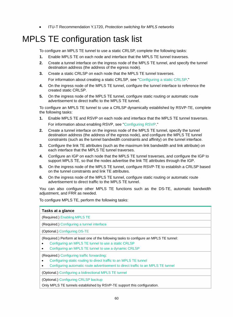
60
• ITU-T Recommendation Y.1720, Protection switching for MPLS networks
MPLS TE configuration task list To configure an MPLS TE tunnel to use a static CRLSP, complete the following tasks: 1. Enable MPLS TE on each node and interface that the MPLS TE tunnel traverses. 2. Create a tunnel interface on the ingress node of the MPLS TE tunnel, and specify the tunnel
destination address (the address of the egress node). 3. Create a static CRLSP on each node that the MPLS TE tunnel traverses.
For information about creating a static CRLSP, see "Configuring a static CRLSP." 4. On the ingress node of the MPLS TE tunnel, configure the tunnel interface to reference the
created static CRLSP. 5. On the ingress node of the MPLS TE tunnel, configure static routing or automatic route
advertisement to direct traffic to the MPLS TE tunnel.
To configure an MPLS TE tunnel to use a CRLSP dynamically established by RSVP-TE, complete the following tasks: 1. Enable MPLS TE and RSVP on each node and interface that the MPLS TE tunnel traverses.
For information about enabling RSVP, see "Configuring RSVP." 2. Create a tunnel interface on the ingress node of the MPLS TE tunnel, specify the tunnel
destination address (the address of the egress node), and configure the MPLS TE tunnel constraints (such as the tunnel bandwidth constraints and affinity) on the tunnel interface.
3. Configure the link TE attributes (such as the maximum link bandwidth and link attribute) on each interface that the MPLS TE tunnel traverses.
4. Configure an IGP on each node that the MPLS TE tunnel traverses, and configure the IGP to support MPLS TE, so that the nodes advertise the link TE attributes through the IGP.
5. On the ingress node of the MPLS TE tunnel, configure RSVP-TE to establish a CRLSP based on the tunnel constraints and link TE attributes.
6. On the ingress node of the MPLS TE tunnel, configure static routing or automatic route advertisement to direct traffic to the MPLS TE tunnel.
You can also configure other MPLS TE functions such as the DS-TE, automatic bandwidth adjustment, and FRR as needed.
To configure MPLS TE, perform the following tasks:
Tasks at a glance (Required.) Enabling MPLS TE
(Required.) Configuring a tunnel interface
(Optional.) Configuring DS-TE
(Required.) Perform at least one of the following tasks to configure an MPLS TE tunnel: • Configuring an MPLS TE tunnel to use a static CRLSP • Configuring an MPLS TE tunnel to use a dynamic CRLSP
(Required.) Configuring traffic forwarding: • Configuring static routing to direct traffic to an MPLS TE tunnel • Configuring automatic route advertisement to direct traffic to an MPLS TE tunnel
(Optional.) Configuring a bidirectional MPLS TE tunnel
(Optional.) Configuring CRLSP backup Only MPLS TE tunnels established by RSVP-TE support this configuration.
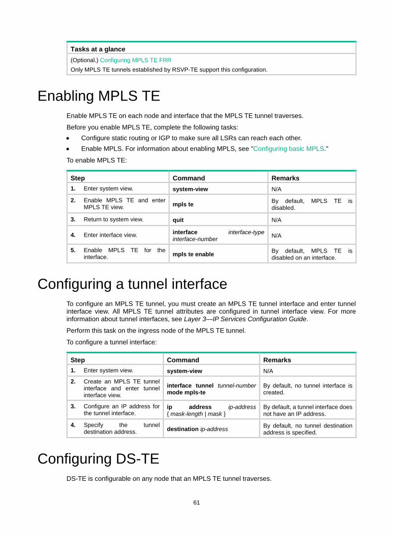
61
Tasks at a glance (Optional.) Configuring MPLS TE FRR Only MPLS TE tunnels established by RSVP-TE support this configuration.
Enabling MPLS TE Enable MPLS TE on each node and interface that the MPLS TE tunnel traverses.
Before you enable MPLS TE, complete the following tasks: • Configure static routing or IGP to make sure all LSRs can reach each other. • Enable MPLS. For information about enabling MPLS, see "Configuring basic MPLS."
To enable MPLS TE:
Step Command Remarks 1. Enter system view. system-view N/A
2. Enable MPLS TE and enter MPLS TE view. mpls te By default, MPLS TE is
disabled.
3. Return to system view. quit N/A
4. Enter interface view. interface interface-type interface-number N/A
5. Enable MPLS TE for the interface. mpls te enable By default, MPLS TE is
disabled on an interface.
Configuring a tunnel interface To configure an MPLS TE tunnel, you must create an MPLS TE tunnel interface and enter tunnel interface view. All MPLS TE tunnel attributes are configured in tunnel interface view. For more information about tunnel interfaces, see Layer 3—IP Services Configuration Guide.
Perform this task on the ingress node of the MPLS TE tunnel.
To configure a tunnel interface:
Step Command Remarks 1. Enter system view. system-view N/A
2. Create an MPLS TE tunnel interface and enter tunnel interface view.
interface tunnel tunnel-number mode mpls-te
By default, no tunnel interface is created.
3. Configure an IP address for the tunnel interface.
ip address ip-address { mask-length | mask }
By default, a tunnel interface does not have an IP address.
4. Specify the tunnel destination address. destination ip-address By default, no tunnel destination
address is specified.
Configuring DS-TE DS-TE is configurable on any node that an MPLS TE tunnel traverses.

62
To configure DS-TE:
Step Command Remarks 1. Enter system view. system-view N/A
2. Enter MPLS TE view. mpls te N/A
3. (Optional.) Configure the DS-TE mode as IETF. ds-te mode ietf By default, the DS-TE mode is
prestandard.
4. (Optional.) Configure the BC model of IETF DS-TE as MAM. ds-te bc-model mam By default, the BC model of IETF
DS-TE is RDM.
5. Configure a TE class. ds-te te-class te-class-index class-type class-type-number priority pri-number
The default TE classes for IETF mode are shown in Table 1. In prestandard mode, you cannot configure TE classes.
Table 1 Default TE classes in IETF mode
TE Class CT Priority 0 0 7
1 1 7
2 2 7
3 3 7
4 0 0
5 1 0
6 2 0
7 3 0
Configuring an MPLS TE tunnel to use a static CRLSP
To configure an MPLS TE tunnel to use a static CRLSP, perform the following tasks: • Establish the static CRLSP. • Specify the MPLS TE tunnel establishment mode as static. • Configure the MPLS TE tunnel to reference the static CRLSP.
Other configurations, such as tunnel constraints and IGP extension, are not needed.
To configure an MPLS TE tunnel to use a static CRLSP:
Step Command Remarks 1. Enter system view. system-view N/A
2. Create a static CRLSP. See "Configuring a static CRLSP." N/A
3. Enter MPLS TE tunnel interface view.
interface tunnel tunnel-number [ mode mpls-te ]
Execute this command on the ingress node.

63
Step Command Remarks 4. Specify the MPLS TE tunnel
establishment mode as static.
mpls te signaling static By default, MPLS TE uses RSVP-TE to establish a tunnel.
5. Apply the static CRLSP to the tunnel interface. mpls te static-cr-lsp lsp-name By default, a tunnel does not
reference any static CRLSP.
Configuring an MPLS TE tunnel to use a dynamic CRLSP
To configure an MPLS TE tunnel to use a CRLSP dynamically established by RSVP-TE, complete the following tasks: • Configure MPLS TE attributes for the links. • Configure IGP TE extension to advertise link TE attributes, so as to generate a TEDB on each
node. • Configure tunnel constraints. • Establish the CRLSP by using the signaling protocol RSVP-TE.
You must configure the IGP TE extension to form a TEDB. Otherwise, the path is created based on IGP routing rather than computed by CSPF.
Configuration task list To establish an MPLS TE tunnel by using a dynamic CRLSP:
Tasks at a glance (Required.) Configuring MPLS TE attributes for a link
(Required.) Advertising link TE attributes by using IGP TE extension
(Required.) Configuring MPLS TE tunnel constraints
(Required.) Establishing an MPLS TE tunnel by using RSVP-TE
(Optional.) Controlling CRLSP path selection
(Optional.) Controlling MPLS TE tunnel setup
Configuring MPLS TE attributes for a link MPLS TE attributes for a link include the maximum link bandwidth, the maximum reservable bandwidth, and the link attribute.
Perform this task on each interface that the MPLS TE tunnel traverses.
To configure the link TE attributes:
Step Command Remarks 1. Enter system view. system-view N/A
2. Enter interface view. interface interface-type interface-number N/A
3. Configure the maximum mpls te max-link-bandwidth By default, the maximum link
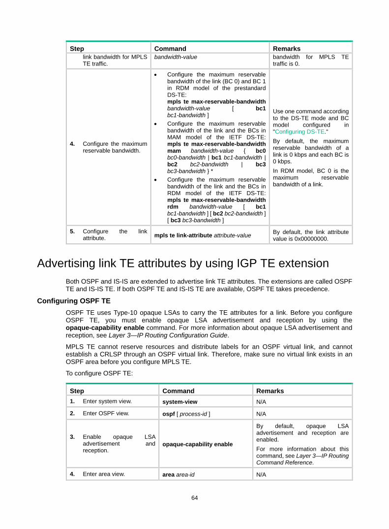
64
Step Command Remarks link bandwidth for MPLS TE traffic.
bandwidth-value bandwidth for MPLS TE traffic is 0.
4. Configure the maximum reservable bandwidth.
• Configure the maximum reservable bandwidth of the link (BC 0) and BC 1 in RDM model of the prestandard DS-TE: mpls te max-reservable-bandwidth bandwidth-value [ bc1 bc1-bandwidth ]
• Configure the maximum reservable bandwidth of the link and the BCs in MAM model of the IETF DS-TE: mpls te max-reservable-bandwidth mam bandwidth-value { bc0 bc0-bandwidth | bc1 bc1-bandwidth | bc2 bc2-bandwidth | bc3 bc3-bandwidth } *
• Configure the maximum reservable bandwidth of the link and the BCs in RDM model of the IETF DS-TE: mpls te max-reservable-bandwidth rdm bandwidth-value [ bc1 bc1-bandwidth ] [ bc2 bc2-bandwidth ] [ bc3 bc3-bandwidth ]
Use one command according to the DS-TE mode and BC model configured in "Configuring DS-TE." By default, the maximum reservable bandwidth of a link is 0 kbps and each BC is 0 kbps. In RDM model, BC 0 is the maximum reservable bandwidth of a link.
5. Configure the link attribute. mpls te link-attribute attribute-value By default, the link attribute
value is 0x00000000.
Advertising link TE attributes by using IGP TE extension Both OSPF and IS-IS are extended to advertise link TE attributes. The extensions are called OSPF TE and IS-IS TE. If both OSPF TE and IS-IS TE are available, OSPF TE takes precedence.
Configuring OSPF TE OSPF TE uses Type-10 opaque LSAs to carry the TE attributes for a link. Before you configure OSPF TE, you must enable opaque LSA advertisement and reception by using the opaque-capability enable command. For more information about opaque LSA advertisement and reception, see Layer 3—IP Routing Configuration Guide.
MPLS TE cannot reserve resources and distribute labels for an OSPF virtual link, and cannot establish a CRLSP through an OSPF virtual link. Therefore, make sure no virtual link exists in an OSPF area before you configure MPLS TE.
To configure OSPF TE:
Step Command Remarks 1. Enter system view. system-view N/A
2. Enter OSPF view. ospf [ process-id ] N/A
3. Enable opaque LSA advertisement and reception.
opaque-capability enable
By default, opaque LSA advertisement and reception are enabled. For more information about this command, see Layer 3—IP Routing Command Reference.
4. Enter area view. area area-id N/A
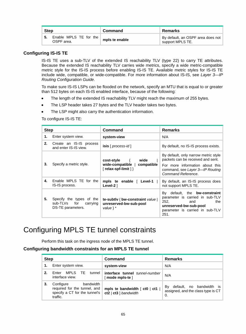
65
Step Command Remarks 5. Enable MPLS TE for the
OSPF area. mpls te enable By default, an OSPF area does not support MPLS TE.
Configuring IS-IS TE IS-IS TE uses a sub-TLV of the extended IS reachability TLV (type 22) to carry TE attributes. Because the extended IS reachability TLV carries wide metrics, specify a wide metric-compatible metric style for the IS-IS process before enabling IS-IS TE. Available metric styles for IS-IS TE include wide, compatible, or wide-compatible. For more information about IS-IS, see Layer 3—IP Routing Configuration Guide.
To make sure IS-IS LSPs can be flooded on the network, specify an MTU that is equal to or greater than 512 bytes on each IS-IS enabled interface, because of the following: • The length of the extended IS reachability TLV might reach the maximum of 255 bytes. • The LSP header takes 27 bytes and the TLV header takes two bytes. • The LSP might also carry the authentication information.
To configure IS-IS TE:
Step Command Remarks 1. Enter system view. system-view N/A
2. Create an IS-IS process and enter IS-IS view. isis [ process-id ] By default, no IS-IS process exists.
3. Specify a metric style. cost-style { wide | wide-compatible | compatible [ relax-spf-limit ] }
By default, only narrow metric style packets can be received and sent. For more information about this command, see Layer 3—IP Routing Command Reference.
4. Enable MPLS TE for the IS-IS process.
mpls te enable [ Level-1 | Level-2 ]
By default, an IS-IS process does not support MPLS TE.
5. Specify the types of the sub-TLVs for carrying DS-TE parameters.
te-subtlv { bw-constraint value | unreserved-bw-sub-pool value } *
By default, the bw-constraint parameter is carried in sub-TLV 252, and the unreserved-bw-sub-pool parameter is carried in sub-TLV 251.
Configuring MPLS TE tunnel constraints Perform this task on the ingress node of the MPLS TE tunnel.
Configuring bandwidth constraints for an MPLS TE tunnel
Step Command Remarks 1. Enter system view. system-view N/A
2. Enter MPLS TE tunnel interface view.
interface tunnel tunnel-number [ mode mpls-te ] N/A
3. Configure bandwidth required for the tunnel, and specify a CT for the tunnel's traffic.
mpls te bandwidth [ ct0 | ct1 | ct2 | ct3 ] bandwidth
By default, no bandwidth is assigned, and the class type is CT 0.

66
Configuring the affinity attribute for an MPLS TE tunnel The associations between the link attribute and the affinity attribute might vary by vendor. To ensure the successful establishment of a tunnel between two devices from different vendors, correctly configure their respective link attribute and affinity attribute.
To configure the affinity attribute for an MPLS TE tunnel:
Step Command Remarks 1. Enter system view. system-view N/A
2. Enter MPLS TE tunnel interface view.
interface tunnel tunnel-number [ mode mpls-te ] N/A
3. Configure an affinity for the MPLS TE tunnel.
mpls te affinity-attribute attribute-value [ mask mask-value ]
By default, the affinity is 0x00000000, and the mask is 0x00000000. The default affinity matches all link attributes.
Configuring a setup priority and a holding priority for an MPLS TE tunnel
Step Command Remarks 1. Enter system view. system-view N/A
2. Enter MPLS TE tunnel interface view.
interface tunnel tunnel-number [ mode mpls-te ] N/A
3. Configure a setup priority and a holding priority for the MPLS TE tunnel.
mpls te priority setup-priority [ hold-priority ]
By default, the setup priority and the holding priority are both 7 for an MPLS TE tunnel.
Configuring an explicit path for an MPLS TE tunnel An explicit path is a set of nodes. The relationship between any two neighboring nodes on an explicit path can be either strict or loose. • Strict—The two nodes must be directly connected. • Loose—The two nodes can have devices in between.
When establishing an MPLS TE tunnel between areas or ASs, you must do the following: • Use a loose explicit path. • Specify the ABR or ASBR as the next hop of the path. • Make sure the tunnel's ingress node and the ABR or ASBR can reach each other.
To configure an explicit path for a MPLS TE tunnel:
Step Command Remarks 1. Enter system view. system-view N/A
2. Create an explicit path and enter its view. explicit-path path-name By default, no explicit path exists
on the device.
3. Enable the explicit path. undo disable By default, an explicit path is enabled.
4. Add or modify a node in the explicit path.
nexthop [ index index-number ] ip-address [ exclude | include [ loose | strict ] ]
By default, an explicit path does not include any node. You can specify the include keyword to have the CRLSP traverse the specified node or the exclude keyword to have the

67
Step Command Remarks CRLSP bypass the specified node.
5. Return to system view. quit N/A
6. Enter MPLS TE tunnel interface view.
interface tunnel tunnel-number [ mode mpls-te ] N/A
7. Configure the MPLS TE tunnel interface to use the explicit path, and specify a preference value for the explicit path.
mpls te path preference value explicit-path path-name [ no-cspf ]
By default, MPLS TE uses the calculated path to establish a CRLSP.
Establishing an MPLS TE tunnel by using RSVP-TE Before you configure this task, you must use the rsvp command and the rsvp enable command to enable RSVP on all nodes and interfaces that the MPLS TE tunnel traverses.
Perform this task on the ingress node of the MPLS TE tunnel.
To configure RSVP-TE to establish an MPLS TE tunnel:
Step Command Remarks 1. Enter system view. system-view N/A
2. Enter MPLS TE tunnel interface view.
interface tunnel tunnel-number [ mode mpls-te ] N/A
3. Configure MPLS TE to use RSVP-TE to establish the tunnel.
mpls te signaling rsvp-te By default, MPLS TE uses RSVP-TE to establish a tunnel.
4. Specify an explicit path for the MPLS TE tunnel, and specify the path preference value.
mpls te path preference value { dynamic | explicit-path path-name } [ no-cspf ]
By default, MPLS TE uses the calculated path to establish a CRLSP.
Controlling CRLSP path selection Before performing the configuration tasks in this section, be aware of each configuration objective and its impact on your device.
MPLS TE uses CSPF to calculate a path according to the TEDB and constraints and sets up the CRLSP through RSVP-TE. MPLS TE provides measures that affect the CSPF calculation. You can use these measures to tune the path selection for CRLSP.
Configuring the metric type for path selection Each MPLS TE link has two metrics: IGP metric and TE metric. By planning the two metrics, you can select different tunnels for different classes of traffic. For example, use the IGP metric to represent a link delay (a smaller IGP metric value indicates a lower link delay), and use the TE metric to represent a link bandwidth value (a smaller TE metric value indicates a bigger link bandwidth value).
You can establish two MPLS TE tunnels: Tunnel 1 for voice traffic and Tunnel 2 for video traffic. Configure Tunnel 1 to use IGP metrics for path selection, and configure Tunnel 2 to use TE metrics for path selection. As a result, the video service (with larger traffic) travels through the path that has larger bandwidth, and the voice traffic travels through the path that has lower delay.
To configure the metric type for tunnel path selection:

68
Step Command Remarks 1. Enter system view. system-view N/A
2. Enter MPLS TE view. mpls te N/A
3. Specify the metric type to use when no metric type is explicitly configured for a tunnel.
path-metric-type { igp | te }
By default, a tunnel uses the TE metric for path selection. Execute this command on the ingress node of an MPLS TE tunnel.
4. Return to system view. quit N/A
5. Enter MPLS TE tunnel interface view.
interface tunnel tunnel-number [ mode mpls-te ] N/A
6. Specify the metric type for path selection.
mpls te path-metric-type { igp | te }
By default, no link metric type is specified and the one specified in MPLS TE view is used. Execute this command on the ingress node of an MPLS TE tunnel.
7. Return to system view. quit N/A
8. Enter interface view. interface interface-type interface-number N/A
9. Assign a TE metric to the link. mpls te metric value
By default, the link uses its IGP metric as the TE metric. This command is available on every interface that the MPLS TE tunnel traverses.
Configuring route pinning When route pinning is enabled, MPLS TE tunnel reoptimization and automatic bandwidth adjustment are not available.
Perform this task on the ingress node of an MPLS TE tunnel.
To configure route pinning:
Step Command Remarks 1. Enter system view. system-view N/A
2. Enter MPLS TE tunnel interface view.
interface tunnel tunnel-number [ mode mpls-te ] N/A
3. Enable route pinning. mpls te route-pinning By default, route pinning is disabled.
Configuring tunnel reoptimization Tunnel reoptimization allows you to manually or dynamically trigger the ingress node to recalculate a path. If the ingress node recalculates a better path, it creates a new CRLSP, switches the traffic from the old CRLSP to the new CRLSP, and then deletes the old CRLSP.
Perform this task on the ingress node of an MPLS TE tunnel.
To configure tunnel reoptimization:

69
Step Command Remarks 1. Enter system view. system-view N/A
2. Enter MPLS TE tunnel interface view.
interface tunnel tunnel-number [ mode mpls-te ] N/A
3. Enable tunnel reoptimization. mpls te reoptimization [ frequency seconds ]
By default, tunnel reoptimization is disabled.
4. Return to user view. return N/A
5. (Optional.) Immediately reoptimize all MPLS TE tunnels that are enabled with the tunnel reoptimization function.
mpls te reoptimization N/A
Configuring TE flooding thresholds and interval When the bandwidth of an MPLS TE link changes, IGP floods the new bandwidth information, so the ingress node can use CSPF to recalculate the path.
To prevent such recalculations from consuming too many resources, you can configure IGP to flood only significant bandwidth changes by setting the following flooding thresholds: • Up threshold—When the percentage of the reservable-bandwidth increase to the maximum
reservable bandwidth reaches the threshold, IGP floods the TE information. • Down threshold—When the percentage of the reservable-bandwidth decrease to the
maximum reservable bandwidth reaches the threshold, IGP floods the TE information.
You can also configure the flooding interval at which bandwidth changes that cannot trigger immediate flooding are flooded.
This task can be performed on all nodes that the MPLS TE tunnel traverses.
To configure TE flooding thresholds and the flooding interval:
Step Command Remarks 1. Enter system view. system-view N/A
2. Enter interface view. interface interface-type interface-number N/A
3. Configure the up/down threshold.
mpls te bandwidth change thresholds { down | up } percent
By default, the up/down threshold is 10% of the link reservable bandwidth.
4. Return to system view. quit N/A
5. Enter MPLS TE view. mpls te N/A
6. Configure the flooding interval.
link-management periodic-flooding timer interval
By default, the flooding interval is 180 seconds.
Controlling MPLS TE tunnel setup Before performing the configuration tasks in this section, be aware of each configuration objective and its impact on your device.
Perform the tasks in this section on the ingress node of the MPLS TE tunnel.

70
Enabling route and label recording Perform this task to record the nodes that an MPLS TE tunnel traverses and the label assigned by each node. The recorded information helps you know about the path used by the MPLS TE tunnel and the label distribution information, and when the tunnel fails, it helps you locate the fault.
To enable route and label recording:
Step Command Remarks 1. Enter system view. system-view N/A
2. Enter MPLS TE tunnel interface view.
interface tunnel tunnel-number [ mode mpls-te ] N/A
3. Record routes or record both routes and labels.
• To record routes: mpls te record-route
• To record both routes and labels: mpls te record-route label
By default, both route recording and label recording are disabled.
Enabling loop detection Enabling loop detection also enables the route recording function, regardless of whether you have configured the mpls te record-route command. Loop detection enables each node of the tunnel to detect whether a loop has occurred according to the recorded route information.
To enable loop detection:
Step Command Remarks 1. Enter system view. system-view N/A
2. Enter MPLS TE tunnel interface view.
interface tunnel tunnel-number [ mode mpls-te ] N/A
3. Enable loop detection. mpls te loop-detection By default, loop detection is disabled.
Configuring tunnel setup retry If the ingress node fails to establish an MPLS TE tunnel, it waits for the retry interval, and then tries to set up the tunnel again. It repeats this process until the tunnel is established or until the number of attempts reaches the maximum. If the tunnel cannot be established when the number of attempts reaches the maximum, the ingress waits for a longer period and then repeats the previous process.
To configure tunnel setup retry:
Step Command Remarks 1. Enter system view. system-view N/A
2. Enter MPLS TE tunnel interface view.
interface tunnel tunnel-number [ mode mpls-te ] N/A
3. Configure maximum number of tunnel setup attempts. mpls te retry times By default, the maximum number
of attempts is 3.
4. Configure the retry interval. mpls te timer retry seconds By default, the retry interval is 2 seconds.

71
Configuring automatic bandwidth adjustment
Step Command Remarks 1. Enter system view. system-view N/A
2. Enter MPLS TE view. mpls te N/A
3. Enable automatic bandwidth adjustment globally, and configure the output rate sampling interval.
auto-bandwidth enable [ sample-interval seconds ]
By default, the global auto bandwidth adjustment is disabled. The sampling interval configured in MPLS TE view applies to all MPLS TE tunnels. The output rates of all MPLS TE tunnels are recorded every sampling interval to calculate the actual average bandwidth of each MPLS TE tunnel in one sampling interval.
4. Enter MPLS TE tunnel interface view.
interface tunnel tunnel-number [ mode mpls-te ] N/A
5. Enable automatic bandwidth adjustment or output rate sampling for the MPLS TE tunnel.
• To enable automatic bandwidth adjustment: mpls te auto-bandwidth adjustment [ frequency seconds ] [ max-bw max-bandwidth | min-bw min-bandwidth ] *
• To enable output rate sampling: mpls te auto-bandwidth collect-bw [ frequency seconds ]
Use either command. By default, automatic bandwidth adjustment and output rate sampling are disabled for an MPLS TE tunnel.
6. Return to user view. return N/A
7. (Optional.) Reset the automatic bandwidth adjustment.
reset mpls te auto-bandwidth-adjustment timers
After this command is executed, the system clears the output rate sampling information and the remaining time to the next bandwidth adjustment to start a new output rate sampling and bandwidth adjustment.
Configuring RSVP resource reservation style
Step Command Remarks 1. Enter system view. system-view N/A
2. Enter MPLS TE tunnel interface view.
interface tunnel tunnel-number [ mode mpls-te ] N/A
3. Configure the resources reservation style for the tunnel.
mpls te resv-style { ff | se }
By default, the resource reservation style is SE. In current MPLS TE applications, tunnels are established usually by using the make-before-break mechanism. As a best practice, use the SE style.

72
Configuring traffic forwarding Perform the tasks in this section on the ingress node of the MPLS TE tunnel.
Configuring static routing to direct traffic to an MPLS TE tunnel
Step Command Remarks 1. Enter system view. system-view N/A
2. Configure a static route to direct traffic to an MPLS TE tunnel.
For information about static routing commands, see Layer 3—IP Routing Command Reference.
By default, no static route exists on the device. The interface specified in this command must be an MPLS TE tunnel interface in load sharing mode.
Configuring automatic route advertisement to direct traffic to an MPLS TE tunnel
You can use either IGP shortcut or forwarding adjacency to implement automatic route advertisement. When you use IGP shortcut, you can specify a metric for the TE tunnel. If you assign an absolute metric, the metric is directly used as the MPLS TE tunnel's metric. If you assign a relative metric, the MPLS TE tunnel's metric is the assigned metric plus the IGP link metric.
Before configuring automatic route advertisement, perform the following tasks: • Enable OSPF or IS-IS on the tunnel interface to advertise the tunnel interface address to OSPF
or IS-IS. • Enable MPLS TE for an OSPF area or an IS-IS process by executing the mpls te enable
command in OSPF area view or IS-IS view.
Follow these restrictions and guidelines when you configure automatic route advertisement: • The destination address of the MPLS TE tunnel can be the LSR ID of the egress node or the
primary IP address of an interface on the egress node. As a best practice, configure the destination address of the MPLS TE tunnel as the LSR ID of the egress node.
• If you configure the tunnel destination address as the primary IP address of an interface on the egress node, you must enable MPLS TE, and configure OSPF or IS-IS on that interface. This makes sure the primary IP address of the interface can be advertised to its peer.
• The route to the tunnel interface address and the route to the tunnel destination must be in the same OSPF area or at the same IS-IS level.
Configuring IGP shortcut
Step Command Remarks 1. Enter system view. system-view N/A
2. Enter MPLS TE tunnel interface view.
interface tunnel tunnel-number [ mode mpls-te ] N/A
3. Enable IGP shortcut. mpls te igp shortcut [ isis | ospf ] By default, IGP shortcut is disabled. If no IGP is specified, both

73
Step Command Remarks OSPF and IS-IS will include the MPLS TE tunnel in route calculation.
4. Assign a metric to the MPLS TE tunnel.
mpls te igp metric { absolute value | relative value }
By default, the metric of an MPLS TE tunnel equals its IGP metric.
Configuring forwarding adjacency To use forwarding adjacency, you must establish two MPLS TE tunnels in opposite directions between two nodes, and configure forwarding adjacency on both the nodes.
To configure forwarding adjacency:
Step Command Remarks 1. Enter system view. system-view N/A
2. Enter MPLS TE tunnel interface view.
interface tunnel tunnel-number [ mode mpls-te ] N/A
3. Enable forwarding adjacency.
mpls te igp advertise [ hold-time value ]
By default, forwarding adjacency is disabled.
Configuring a bidirectional MPLS TE tunnel Before you create a bidirectional MPLS TE tunnel, complete the following tasks: • Disable the PHP function on both ends of the tunnel. • To set up a bidirectional MPLS TE tunnel in co-routed mode, you must specify the signaling
protocol as RSVP-TE, and use the mpls te resv-style command to configure the resources reservation style as FF for the tunnel.
• To set up a bidirectional MPLS TE tunnel in associated mode and use RSVP-TE to set up one CRLSP of the tunnel, you must use the mpls te resv-style command to configure the resources reservation style as FF for the CR-LSP.
To create a bidirectional MPLS TE tunnel, create an MPLS TE tunnel interface on both ends of the tunnel and enable the bidirectional tunnel function on the tunnel interfaces: • For a co-routed bidirectional tunnel, configure one end of the tunnel as the active end and the
other end as the passive end, and specify the reverse CR-LSP at the passive end. • For an associated bidirectional tunnel, specify a reverse CR-LSP at both ends of the tunnel.
To configure the active end of a co-routed bidirectional MPLS TE tunnel:
Step Command Remarks 1. Enter system view. system-view N/A
2. Enter MPLS TE tunnel interface view.
interface tunnel tunnel-number [ mode mpls-te ] N/A
3. Configure a co-routed bidirectional MPLS TE tunnel and specify the local end as the active end of the tunnel.
mpls te bidirectional co-routed active
By default, no bidirectional tunnel is configured, and tunnels established on the tunnel interface are unidirectional MPLS TE tunnels.
To configure the passive end of a co-routed bidirectional MPLS TE tunnel:

74
Step Command Remarks 1. Enter system view. system-view N/A
2. Enter MPLS TE tunnel interface view.
interface tunnel tunnel-number [ mode mpls-te ] N/A
3. Configure a co-routed bidirectional MPLS TE tunnel and specify the local end as the passive end of the tunnel.
mpls te bidirectional co-routed passive reverse-lsp lsr-id ingress-lsr-id tunnel-id tunnel-id
By default, no bidirectional tunnel is configured, and tunnels established on the tunnel interface are unidirectional MPLS TE tunnels.
To configure an associated bidirectional MPLS TE tunnel:
Step Command Remarks 1. Enter system view. system-view N/A
2. Enter MPLS TE tunnel interface view.
interface tunnel tunnel-number [ mode mpls-te ] N/A
3. Configure an associated bidirectional MPLS TE tunnel.
mpls te bidirectional associated reverse-lsp { lsp-name lsp-name | lsr-id ingress-lsr-id tunnel-id tunnel-id } }
By default, no bidirectional tunnel is configured, and tunnels established on the tunnel interface are unidirectional MPLS TE tunnels.
Configuring CRLSP backup CRLSP backup provides end-to-end CRLSP protection. Only MPLS TE tunnels established through RSVP-TE support CRLSP backup.
Perform this task on the ingress node of an MPLS TE tunnel.
To configure CRLSP backup:
Step Command Remarks 1. Enter system view. system-view N/A
2. Enter MPLS TE tunnel interface view.
interface tunnel tunnel-number [ mode mpls-te ] N/A
3. Enable CRLSP backup and specify the backup mode.
mpls te backup { hot-standby | ordinary }
By default, tunnel backup is disabled.
4. Specify a path for the primary CRLSP and set the preference of the path.
mpls te path preference value { dynamic | explicit-path path-name } [ no-cspf ]
By default, MPLS TE uses the dynamically calculated path to set up the primary CRLSP.
5. Specify a path for the backup CRLSP and set the preference of the path.
mpls te backup-path preference value { dynamic | explicit-path path-name } [ no-cspf ]
By default, MPLS TE uses the dynamically calculated path to set up the backup CRLSP.
Configuring MPLS TE FRR MPLS TE FRR provides temporary link or node protection on a CRLSP. When you configure FRR, note the following restrictions and guidelines: • Do not configure both FRR and RSVP authentication on the same interface.

75
• Only MPLS TE tunnels established through RSVP-TE support FRR.
Enabling FRR Perform this task on the ingress node of a primary CRLSP.
To enable FRR:
Step Command Remarks 1. Enter system view. system-view N/A
2. Enter tunnel interface view of the primary CRLSP.
interface tunnel tunnel-number [ mode mpls-te ] N/A
3. Enable FRR. mpls te fast-reroute [ bandwidth ]
By default, FRR is disabled. If you specify the bandwidth keyword, the primary CRLSP must have bandwidth protection.
Configuring a bypass tunnel on the PLR Overview
To configure FRR, you must configure bypass tunnels for primary CRLSPs on the PLR.
To configure bypass tunnels on the PLR, you can use the following methods: • Manually configuring a bypass tunnel on the PLR—Create an MPLS TE tunnel on the PLR,
and configure the tunnel as a bypass tunnel for a primary CRLSP. You need to specify the bandwidth and CT that the bypass tunnel can protect, and bind the bypass tunnel to the egress interface of the primary CRLSP. You can configure up to three bypass tunnels for a primary CRLSP.
• Configuring the PLR to set up bypass tunnels automatically—Configure the automatic bypass tunnel setup function (also referred to as the auto FRR function) on the PLR. The PLR automatically sets up two bypass tunnels for each of its primary CRLSPs: one in link protection mode and the other in node protection mode. Automatically created bypass tunnels can be used to protect any type of CT, but they cannot provide bandwidth protection.
A primary tunnel can have both manually configured and automatically created bypass tunnels. The PLR will select one bypass tunnel to protect the primary CRLSP. The selected bypass tunnel is bound to the primary CRLSP.
Manually created bypass tunnels take precedence over automatically created bypass tunnels. An automatically created bypass tunnel in node protection mode takes precedence over an automatically created bypass tunnel in link protection mode. Among manually created bypass tunnels, the PLR selects the bypass tunnel for protecting the primary CRLSP by following these rules: 1. Selects a bypass tunnel according to the principles, as shown in Table 2. 2. Prefers the bypass tunnel in node protection mode over the one in link protection mode. 3. Prefers the bypass tunnel with a smaller ID over the one with a bigger tunnel ID.

76
Table 2 FRR protection principles
Bandwidth required by primary CRLSP
Primary CRLSP requires bandwidth protection or not
Bypass tunnel providing bandwidth protection
Bypass tunnel providing no bandwidth protection
0
Yes
The primary CRLSP cannot be bound to the bypass tunnel.
The primary CRLSP can be bound to the bypass tunnel if CT 0 or no CT is specified for the bypass tunnel. After binding, the RRO message does not carry the bandwidth protection flag. The bypass tunnel does not provide bandwidth protection for the primary CRLSP, and performs best-effort forwarding for traffic of the primary CRLSP.
No
None-zero Yes
The primary CRLSP can be bound to the bypass tunnel when all the following conditions are met: • The bandwidth that the
bypass tunnel can protect is no less than the bandwidth required by the primary CRLSP.
• There is not a CT specified for the bypass tunnel, or the specified CT is the same as that specified for the primary CRLSP.
After binding, the RRO message carries the bandwidth protection flag, and the bypass tunnel provides bandwidth protection for the primary CRLSP. The primary CRLSP prefers bypass tunnels that provide bandwidth protection over those providing no bandwidth protection.
The primary CRLSP can be bound to the bypass tunnel when one of the following conditions is met: • No CT is specified for the
bypass tunnel. • The specified CT is the same
as that specified for the primary CRLSP.
After binding, the RRO message does not carry the bandwidth protection flag. This bypass tunnel is selected only when no bypass tunnel that provides bandwidth protection can be bound to the primary CRLSP.
Non-zero No
The primary CRLSP can be bound to the bypass tunnel when all the following conditions are met: • The bandwidth that the
bypass tunnel can protect is no less than the bandwidth required by the primary CRLSP.
• No CT that the bypass tunnel can protect is specified, or the specified CT is the same as that of the traffic on the primary CRLSP.
After binding, the RRO message
The primary CRLSP can be bound to the bypass tunnel when one of the following conditions is met: • No CT is specified for the
bypass tunnel. • The specified CT is the same
as that of the traffic on the primary CRLSP.
After binding, the RRO message does not carry the bandwidth protection flag. The primary CRLSP prefers bypass tunnels that does not provide bandwidth protection over those providing bandwidth
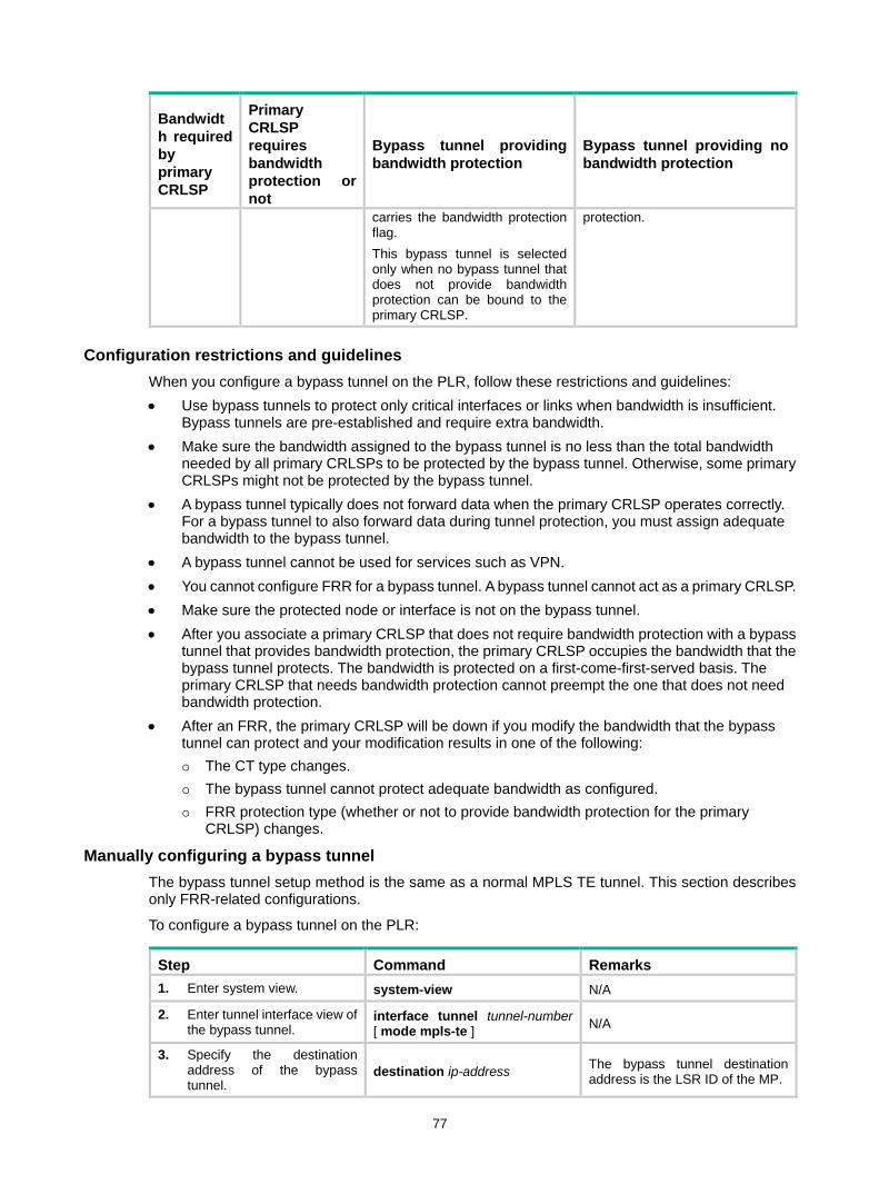
77
Bandwidth required by primary CRLSP
Primary CRLSP requires bandwidth protection or not
Bypass tunnel providing bandwidth protection
Bypass tunnel providing no bandwidth protection
carries the bandwidth protection flag. This bypass tunnel is selected only when no bypass tunnel that does not provide bandwidth protection can be bound to the primary CRLSP.
protection.
Configuration restrictions and guidelines When you configure a bypass tunnel on the PLR, follow these restrictions and guidelines: • Use bypass tunnels to protect only critical interfaces or links when bandwidth is insufficient.
Bypass tunnels are pre-established and require extra bandwidth. • Make sure the bandwidth assigned to the bypass tunnel is no less than the total bandwidth
needed by all primary CRLSPs to be protected by the bypass tunnel. Otherwise, some primary CRLSPs might not be protected by the bypass tunnel.
• A bypass tunnel typically does not forward data when the primary CRLSP operates correctly. For a bypass tunnel to also forward data during tunnel protection, you must assign adequate bandwidth to the bypass tunnel.
• A bypass tunnel cannot be used for services such as VPN. • You cannot configure FRR for a bypass tunnel. A bypass tunnel cannot act as a primary CRLSP. • Make sure the protected node or interface is not on the bypass tunnel. • After you associate a primary CRLSP that does not require bandwidth protection with a bypass
tunnel that provides bandwidth protection, the primary CRLSP occupies the bandwidth that the bypass tunnel protects. The bandwidth is protected on a first-come-first-served basis. The primary CRLSP that needs bandwidth protection cannot preempt the one that does not need bandwidth protection.
• After an FRR, the primary CRLSP will be down if you modify the bandwidth that the bypass tunnel can protect and your modification results in one of the following: The CT type changes. The bypass tunnel cannot protect adequate bandwidth as configured. FRR protection type (whether or not to provide bandwidth protection for the primary
CRLSP) changes.
Manually configuring a bypass tunnel The bypass tunnel setup method is the same as a normal MPLS TE tunnel. This section describes only FRR-related configurations.
To configure a bypass tunnel on the PLR:
Step Command Remarks 1. Enter system view. system-view N/A
2. Enter tunnel interface view of the bypass tunnel.
interface tunnel tunnel-number [ mode mpls-te ] N/A
3. Specify the destination address of the bypass tunnel.
destination ip-address The bypass tunnel destination address is the LSR ID of the MP.

78
Step Command Remarks 4. Configure the bandwidth and
the CT to be protected by the bypass tunnel.
mpls te backup bandwidth [ ct0 | ct1 | ct2 | ct3 ] { bandwidth | un-limited }
By default, the bandwidth and the CT to be protected by the bypass tunnel are not specified.
5. Return to system view. quit N/A
6. Enter interface view of the egress interface of a primary CRLSP.
interface interface-type interface-number N/A
7. Specify a bypass tunnel for the protected interface (the current interface).
mpls te fast-reroute bypass-tunnel tunnel tunnel-number
By default, no bypass tunnel is specified for an interface.
Automatically setting up bypass tunnels With auto FRR, if the PLR is the penultimate node of a primary CRLSP, the PLR does not create a node-protection bypass tunnel for the primary CRLSP.
To configure auto FRR on the PLR:
Step Command Remarks 1. Enter system view. system-view N/A
2. Enter MPLS TE view. mpls te N/A
3. Enable the auto FRR function globally. auto-tunnel backup By default, the auto FRR function
is disabled globally.
4. Specify an interface number range for the automatically created bypass tunnels.
tunnel-number min min-number max max-number
By default, no interface number range is specified, and the PLR cannot set up a bypass tunnel automatically.
5. (Optional.) Configure the PLR to create only link-protection bypass tunnels.
nhop-only
By default, the PLR automatically creates both a link-protection and a node-protection bypass tunnel for each of its primary CRLSPs. Execution of this command deletes all existing node-protection bypass tunnels automatically created for MPLS TE auto FRR.
6. (Optional.) Configure a removal timer for unused bypass tunnels.
timers removal unused seconds By default, a bypass tunnel is removed after it is unused for 3600 seconds.
7. (Optional.) Return to system view. quit N/A
8. (Optional.) Enter interface view.
interface interface-type interface-number N/A
9. (Optional.) Disable the auto FRR function on the interface.
mpls te auto-tunnel backup disable
By default, the auto FRR function is enabled on all RSVP-enabled interfaces after it is enabled globally. Execution of this command deletes all existing bypass tunnels automatically created on the interface for MPLS TE auto FRR.

79
Configuring node fault detection Perform this task to configure the RSVP hello mechanism or BFD on the PLR and the protected node to detect the node faults caused by signaling protocol faults. FRR does not need to use the RSVP hello mechanism or BFD to detect the node faults caused by the link faults between the PLR and the protected node.
You do not need to perform this task for FRR link protection.
To configure node fault detection:
Step Command Remarks 1. Enter system view. system-view N/A
2. Enter interface view of the connecting interface between the PLR and the protected node.
interface interface-type interface-number N/A
3. Configure node fault detection.
• (Method 1) Enable RSVP hello extension on the interface: rsvp hello enable
• (Method 2) Enable BFD on the interface: rsvp bfd enable
By default, RSVP hello extension is disabled, and BFD is not configured. For more information about the rsvp hello enable command and the rsvp bfd enable command, see "Configuring RSVP."
Configuring the optimal bypass tunnel selection interval If you have specified multiple bypass tunnels for a primary CRLSP, MPLS TE selects an optimal bypass tunnel to protect the primary CRLSP. Sometimes, a bypass tunnel might become better than the current optimal bypass tunnel because, for example, the reservable bandwidth changes. Therefore, MPLS TE needs to poll the bypass tunnels periodically to update the optimal bypass tunnel.
Perform this task on the PLR to configure the interval for selecting an optimal bypass tunnel:
Step Command Remarks 1. Enter system view. system-view N/A
2. Enter MPLS TE view. mpls te N/A
3. Configure the interval for selecting an optimal bypass tunnel.
fast-reroute timer interval By default, the interval is 300 seconds.
Displaying and maintaining MPLS TE Execute display commands in any view and reset commands in user view.
Task Command Display information about explicit paths. display explicit-path [ path-name ]
Display link and node information in an IS-IS TEDB.
display isis mpls te advertisement [ [ level-1 | level-2 ] | [ originate-system system-id | local ] | verbose ] * [ process-id ]
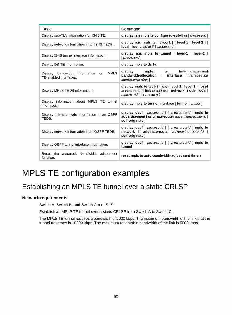
80
Task Command Display sub-TLV information for IS-IS TE. display isis mpls te configured-sub-tlvs [ process-id ]
Display network information in an IS-IS TEDB. display isis mpls te network [ [ level-1 | level-2 ] | local | lsp-id lsp-id ]* [ process-id ]
Display IS-IS tunnel interface information. display isis mpls te tunnel [ level-1 | level-2 ] [ process-id ]
Display DS-TE information. display mpls te ds-te
Display bandwidth information on MPLS TE-enabled interfaces.
display mpls te link-management bandwidth-allocation [ interface interface-type interface-number ]
Display MPLS TEDB information. display mpls te tedb { { isis { level-1 | level-2 } | ospf area area-id } | link ip-address | network | node [ local | mpls-lsr-id ] | summary }
Display information about MPLS TE tunnel interfaces. display mpls te tunnel-interface [ tunnel number ]
Display link and node information in an OSPF TEDB.
display ospf [ process-id ] [ area area-id ] mpls te advertisement [ originate-router advertising-router-id | self-originate ]
Display network information in an OSPF TEDB. display ospf [ process-id ] [ area area-id ] mpls te network [ originate-router advertising-router-id | self-originate ]
Display OSPF tunnel interface information. display ospf [ process-id ] [ area area-id ] mpls te tunnel
Reset the automatic bandwidth adjustment function. reset mpls te auto-bandwidth-adjustment timers
MPLS TE configuration examples Establishing an MPLS TE tunnel over a static CRLSP Network requirements
Switch A, Switch B, and Switch C run IS-IS.
Establish an MPLS TE tunnel over a static CRLSP from Switch A to Switch C.
The MPLS TE tunnel requires a bandwidth of 2000 kbps. The maximum bandwidth of the link that the tunnel traverses is 10000 kbps. The maximum reservable bandwidth of the link is 5000 kbps.

81
Figure 27 Network diagram
Configuration procedure 1. Configure IP addresses and masks for interfaces. (Details not shown.) 2. Configure IS-IS to advertise interface addresses, including the loopback interface address:
# Configure Switch A. <SwitchA> system-view
[SwitchA] isis 1
[SwitchA-isis-1] network-entity 00.0005.0000.0000.0001.00
[SwitchA-isis-1] quit
[SwitchA] interface vlan-interface 1
[SwitchA-Vlan-interface1] isis enable 1
[SwitchA-Vlan-interface1] quit
[SwitchA] interface loopback 0
[SwitchA-LoopBack0] isis enable 1
[SwitchA-LoopBack0] quit
# Configure Switch B. <SwitchB> system-view
[SwitchB] isis 1
[SwitchB-isis-1] network-entity 00.0005.0000.0000.0002.00
[SwitchB-isis-1] quit
[SwitchB] interface vlan-interface 1
[SwitchB-Vlan-interface1] isis enable 1
[SwitchB-Vlan-interface1] quit
[SwitchB] interface vlan-interface 2
[SwitchB-Vlan-interface2] isis enable 1
[SwitchB-Vlan-interface2] quit
[SwitchB] interface loopback 0
[SwitchB-LoopBack0] isis enable 1
[SwitchB-LoopBack0] quit
# Configure Switch C. <SwitchC> system-view
[SwitchC] isis 1
[SwitchC-isis-1] network-entity 00.0005.0000.0000.0003.00
Loop02.2.2.2/32
Vlan-int12.1.1.2/24
Vlan-int23.2.1.1/24
Vlan-int12.1.1.1/24
Vlan-int23.2.1.2/24
Loop01.1.1.1/32
Loop03.3.3.3/32
Switch A Switch C
Switch B

82
[SwitchC-isis-1] quit
[SwitchC] interface vlan-interface 2
[SwitchC-Vlan-interface2] isis enable 1
[SwitchC-Vlan-interface2] quit
[SwitchC] interface loopback 0
[SwitchC-LoopBack0] isis enable 1
[SwitchC-LoopBack0] quit
# Execute the display ip routing-table command on each switch to verify that the switches have learned the routes to one another, including the routes to the loopback interfaces. (Details not shown.)
3. Configure an LSR ID, and enable MPLS and MPLS TE: # Configure Switch A. [SwitchA] mpls lsr-id 1.1.1.1
[SwitchA] mpls te
[SwitchA-te] quit
[SwitchA] interface vlan-interface 1
[SwitchA-Vlan-interface1] mpls enable
[SwitchA-Vlan-interface1] mpls te enable
[SwitchA-Vlan-interface1] quit
# Configure Switch B. [SwitchB] mpls lsr-id 2.2.2.2
[SwitchB] mpls te
[SwitchB-te] quit
[SwitchB] interface vlan-interface 1
[SwitchB-Vlan-interface1] mpls enable
[SwitchB-Vlan-interface1] mpls te enable
[SwitchB-Vlan-interface1] quit
[SwitchB] interface vlan-interface 2
[SwitchB-Vlan-interface2] mpls enable
[SwitchB-Vlan-interface2] mpls te enable
[SwitchB-Vlan-interface2] quit
# Configure Switch C. [SwitchC] mpls lsr-id 3.3.3.3
[SwitchC] mpls te
[SwitchC-te] quit
[SwitchC] interface vlan-interface 2
[SwitchC-Vlan-interface2] mpls enable
[SwitchC-Vlan-interface2] mpls te enable
[SwitchC-Vlan-interface2] quit
4. Configure MPLS TE attributes of links: # Configure the maximum link bandwidth and maximum reservable bandwidth on Switch A. [SwitchA] interface vlan-interface 1
[SwitchA-Vlan-interface1] mpls te max-link-bandwidth 10000
[SwitchA-Vlan-interface1] mpls te max-reservable-bandwidth 5000
[SwitchA-Vlan-interface1] quit
# Configure the maximum link bandwidth and maximum reservable bandwidth on Switch B. [SwitchB] interface vlan-interface 1
[SwitchB-Vlan-interface1] mpls te max-link-bandwidth 10000

83
[SwitchB-Vlan-interface1] mpls te max-reservable-bandwidth 5000
[SwitchB-Vlan-interface1] quit
[SwitchB] interface vlan-interface 2
[SwitchB-Vlan-interface2] mpls te max-link-bandwidth 10000
[SwitchB-Vlan-interface2] mpls te max-reservable-bandwidth 5000
[SwitchB-Vlan-interface2] quit
# Configure the maximum link bandwidth and maximum reservable bandwidth on Switch C. [SwitchC] interface vlan-interface 2
[SwitchC-Vlan-interface2] mpls te max-link-bandwidth 10000
[SwitchC-Vlan-interface2] mpls te max-reservable-bandwidth 5000
[SwitchC-Vlan-interface2] quit
5. Configure an MPLS TE tunnel on Switch A: # Configure MPLS TE tunnel interface Tunnel 0. [SwitchA] interface tunnel 0 mode mpls-te
[SwitchA-Tunnel0] ip address 6.1.1.1 255.255.255.0
# Specify the tunnel destination address as the LSR ID of Switch C. [SwitchA-Tunnel0] destination 3.3.3.3
# Configure MPLS TE to use a static CRLSP to establish the tunnel. [SwitchA-Tunnel0] mpls te signaling static
[SwitchA-Tunnel0] quit
6. Create a static CRLSP: # Configure Switch A as the ingress node of the static CRLSP, and specify the next hop address as 2.1.1.2, outgoing label as 20, and bandwidth for the tunnel as 2000 kbps. [SwitchA] static-cr-lsp ingress static-cr-lsp-1 nexthop 2.1.1.2 out-label 20 bandwidth 2000
# On Switch A, configure tunnel 0 to reference the static CRLSP static-cr-lsp-1. [SwitchA] interface Tunnel0
[SwitchA-Tunnel0] mpls te static-cr-lsp static-cr-lsp-1
[SwitchA-Tunnel0] quit
# Configure Switch B as the transit node of the static CRLSP, and specify the incoming label as 20, next hop address as 3.2.1.2, outgoing label as 30, and bandwidth for the tunnel as 2000 kbps. [SwitchB] static-cr-lsp transit static-cr-lsp-1 in-label 20 nexthop 3.2.1.2 out-label 30 bandwidth 2000
# Configure Switch C as the egress node of the static CRLSP, and specify the incoming label as 30. [SwitchC] static-cr-lsp egress static-cr-lsp-1 in-label 30
7. Configure a static route on Switch A to direct traffic destined for subnet 3.2.1.0/24 to MPLS TE tunnel 0. [SwitchA] ip route-static 3.2.1.2 24 tunnel 0 preference 1
Verifying the configuration # Execute the display interface tunnel command on Switch A. The output shows that the tunnel interface is up. [SwitchA] display interface tunnel
Tunnel0
Current state: UP
Line protocol state: UP
Description: Tunnel0 Interface

84
Bandwidth: 64kbps
Maximum Transmit Unit: 1496
Internet Address is 6.1.1.1/24 Primary
Tunnel source unknown, destination 3.3.3.3
Tunnel TTL 255
Tunnel protocol/transport CR_LSP
Output queue - Urgent queuing: Size/Length/Discards 0/100/0
Output queue - Protocol queuing: Size/Length/Discards 0/500/0
Output queue - FIFO queuing: Size/Length/Discards 0/75/0
Last clearing of counters: Never
Last 300 seconds input rate: 0 bytes/sec, 0 bits/sec, 0 packets/sec
Last 300 seconds output rate: 0 bytes/sec, 0 bits/sec, 0 packets/sec
Input: 0 packets, 0 bytes, 0 drops
Output: 0 packets, 0 bytes, 0 drops
# Execute the display mpls te tunnel-interface command on Switch A to display detailed information about the MPLS TE tunnel. [SwitchA] display mpls te tunnel-interface
Tunnel Name : Tunnel 0
Tunnel State : Up (Main CRLSP up)
Tunnel Attributes :
LSP ID : 1 Tunnel ID : 0
Admin State : Normal
Ingress LSR ID : 1.1.1.1 Egress LSR ID : 3.3.3.3
Signaling : Static Static CRLSP Name : static-cr-lsp-1
Resv Style : -
Tunnel mode : -
Reverse-LSP name : -
Reverse-LSP LSR ID : - Reverse-LSP Tunnel ID: -
Class Type : - Tunnel Bandwidth : -
Reserved Bandwidth : -
Setup Priority : 0 Holding Priority : 0
Affinity Attr/Mask : -/-
Explicit Path : -
Backup Explicit Path : -
Metric Type : TE
Record Route : - Record Label : -
FRR Flag : - Bandwidth Protection : -
Backup Bandwidth Flag: - Backup Bandwidth Type: -
Backup Bandwidth : -
Bypass Tunnel : - Auto Created : -
Route Pinning : -
Retry Limit : 3 Retry Interval : 2 sec
Reoptimization : - Reoptimization Freq : -
Backup Type : - Backup LSP ID : -
Auto Bandwidth : - Auto Bandwidth Freq : -
Min Bandwidth : - Max Bandwidth : -
Collected Bandwidth : -

85
# Execute the display mpls lsp command or the display mpls static-cr-lsp command on each switch to display static CRLSP information. [SwitchA] display mpls lsp
FEC Proto In/Out Label Interface/Out NHLFE
1.1.1.1/0/1 StaticCR -/20 Vlan1
2.1.1.2 Local -/- Vlan1
[SwitchB] display mpls lsp
FEC Proto In/Out Label Interface/Out NHLFE
- StaticCR 20/30 Vlan2
3.2.1.2 Local -/- Vlan2
[SwitchC] display mpls lsp
FEC Proto In/Out Label Interface/Out NHLFE
- StaticCR 30/- -
[SwitchA] display mpls static-cr-lsp
Name LSR Type In/Out Label Out Interface State
static-cr-lsp-1 Ingress Null/20 Vlan1 Up
[SwitchB] display mpls static-cr-lsp
Name LSR Type In/Out Label Out Interface State
static-cr-lsp-1 Transit 20/30 Vlan2 Up
[SwitchC] display mpls static-cr-lsp
Name LSR Type In/Out Label Out Interface State
static-cr-lsp1 Egress 30/Null - Up
# Execute the display ip routing-table command on Switch A. The output shows a static route entry with interface Tunnel 0 as the output interface. (Details not shown.)
Establishing an MPLS TE tunnel with RSVP-TE Network requirements
Switch A, Switch B, Switch C, and Switch D run IS-IS and all of them are Level-2 switches.
Use RSVP-TE to create an MPLS TE tunnel from Switch A to Switch D. The MPLS TE tunnel requires a bandwidth of 2000 kbps.
The maximum bandwidth of the link that the tunnel traverses is 10000 kbps and the maximum reservable bandwidth of the link is 5000 kbps.
Figure 28 Network diagram
Vlan-int1
Vlan-int1Vlan-int2
Vlan-int2
Vlan-int3
Vlan-int3
Loop0 Loop0
Loop0 Loop0
Switch A
Switch B Switch C
Switch D

86
Table 3 Interface and IP address assignment
Device Interface IP address Device Interface IP address Switch A Loop0 1.1.1.9/32 Switch D Loop0 4.4.4.9/32
Vlan-int1 10.1.1.1/24 Vlan-int3 30.1.1.2/24
Switch B Loop0 2.2.2.9/32 Switch C Loop0 3.3.3.9/32
Vlan-int1 10.1.1.2/24 Vlan-int3 30.1.1.1/24
Vlan-int2 20.1.1.1/24 Vlan-int2 20.1.1.2/24
Configuration procedure 1. Configure IP addresses and masks for interfaces. (Details not shown.) 2. Configure IS-IS to advertise interface addresses, including the loopback interface address:
# Configure Switch A. <SwitchA> system-view
[SwitchA] isis 1
[SwitchA-isis-1] network-entity 00.0005.0000.0000.0001.00
[SwitchA-isis-1] quit
[SwitchA] interface vlan-interface 1
[SwitchA-Vlan-interface1] isis enable 1
[SwitchA-Vlan-interface1] isis circuit-level level-2
[SwitchA-Vlan-interface1] quit
[SwitchA] interface loopback 0
[SwitchA-LoopBack0] isis enable 1
[SwitchA-LoopBack0] isis circuit-level level-2
[SwitchA-LoopBack0] quit
# Configure Switch B. <SwitchB> system-view
[SwitchB] isis 1
[SwitchB-isis-1] network-entity 00.0005.0000.0000.0002.00
[SwitchB-isis-1] quit
[SwitchB] interface vlan-interface 1
[SwitchB-Vlan-interface1] isis enable 1
[SwitchB-Vlan-interface1] isis circuit-level level-2
[SwitchB-Vlan-interface1] quit
[SwitchB] interface vlan-interface 2
[SwitchB-Vlan-interface2] isis enable 1
[SwitchB-Vlan-interface2] isis circuit-level level-2
[SwitchB-Vlan-interface2] quit
[SwitchB] interface loopback 0
[SwitchB-LoopBack0] isis enable 1
[SwitchB-LoopBack0] isis circuit-level level-2
[SwitchB-LoopBack0] quit
# Configure Switch C. <SwitchC> system-view
[SwitchC] isis 1
[SwitchC-isis-1] network-entity 00.0005.0000.0000.0003.00
[SwitchC-isis-1] quit
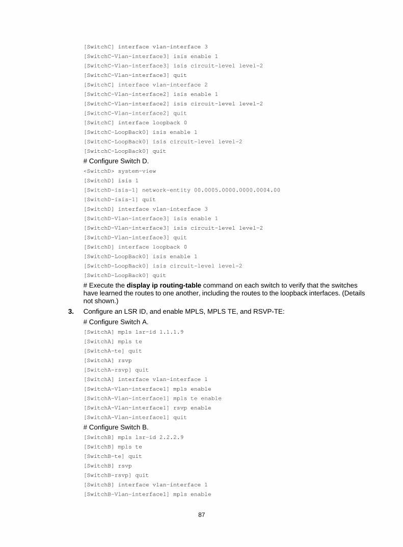
87
[SwitchC] interface vlan-interface 3
[SwitchC-Vlan-interface3] isis enable 1
[SwitchC-Vlan-interface3] isis circuit-level level-2
[SwitchC-Vlan-interface3] quit
[SwitchC] interface vlan-interface 2
[SwitchC-Vlan-interface2] isis enable 1
[SwitchC-Vlan-interface2] isis circuit-level level-2
[SwitchC-Vlan-interface2] quit
[SwitchC] interface loopback 0
[SwitchC-LoopBack0] isis enable 1
[SwitchC-LoopBack0] isis circuit-level level-2
[SwitchC-LoopBack0] quit
# Configure Switch D. <SwitchD> system-view
[SwitchD] isis 1
[SwitchD-isis-1] network-entity 00.0005.0000.0000.0004.00
[SwitchD-isis-1] quit
[SwitchD] interface vlan-interface 3
[SwitchD-Vlan-interface3] isis enable 1
[SwitchD-Vlan-interface3] isis circuit-level level-2
[SwitchD-Vlan-interface3] quit
[SwitchD] interface loopback 0
[SwitchD-LoopBack0] isis enable 1
[SwitchD-LoopBack0] isis circuit-level level-2
[SwitchD-LoopBack0] quit
# Execute the display ip routing-table command on each switch to verify that the switches have learned the routes to one another, including the routes to the loopback interfaces. (Details not shown.)
3. Configure an LSR ID, and enable MPLS, MPLS TE, and RSVP-TE: # Configure Switch A. [SwitchA] mpls lsr-id 1.1.1.9
[SwitchA] mpls te
[SwitchA-te] quit
[SwitchA] rsvp
[SwitchA-rsvp] quit
[SwitchA] interface vlan-interface 1
[SwitchA-Vlan-interface1] mpls enable
[SwitchA-Vlan-interface1] mpls te enable
[SwitchA-Vlan-interface1] rsvp enable
[SwitchA-Vlan-interface1] quit
# Configure Switch B. [SwitchB] mpls lsr-id 2.2.2.9
[SwitchB] mpls te
[SwitchB-te] quit
[SwitchB] rsvp
[SwitchB-rsvp] quit
[SwitchB] interface vlan-interface 1
[SwitchB-Vlan-interface1] mpls enable

88
[SwitchB-Vlan-interface1] mpls te enable
[SwitchB-Vlan-interface1] rsvp enable
[SwitchB-Vlan-interface1] quit
[SwitchB] interface vlan-interface 2
[SwitchB-Vlan-interface2] mpls enable
[SwitchB-Vlan-interface2] mpls te enable
[SwitchB-Vlan-interface2] rsvp enable
[SwitchB-Vlan-interface2] quit
# Configure Switch C. [SwitchC] mpls lsr-id 3.3.3.9
[SwitchC] mpls te
[SwitchC-te] quit
[SwitchC] rsvp
[SwitchC-rsvp] quit
[SwitchC] interface vlan-interface 3
[SwitchC-Vlan-interface3] mpls enable
[SwitchC-Vlan-interface3] mpls te enable
[SwitchC-Vlan-interface3] rsvp enable
[SwitchC-Vlan-interface3] quit
[SwitchC] interface vlan-interface 2
[SwitchC-Vlan-interface2] mpls enable
[SwitchC-Vlan-interface2] mpls te enable
[SwitchC-Vlan-interface2] rsvp enable
[SwitchC-Vlan-interface2] quit
# Configure Switch D. [SwitchD] mpls lsr-id 4.4.4.9
[SwitchD] mpls te
[SwitchD-te] quit
[SwitchD] rsvp
[SwitchD-rsvp] quit
[SwitchD] interface vlan-interface 3
[SwitchD-Vlan-interface3] mpls enable
[SwitchD-Vlan-interface3] mpls te enable
[SwitchD-Vlan-interface3] rsvp enable
[SwitchD-Vlan-interface3] quit
4. Configure IS-IS TE: # Configure Switch A. [SwitchA] isis 1
[SwitchA-isis-1] cost-style wide
[SwitchA-isis-1] mpls te enable level-2
[SwitchA-isis-1] quit
# Configure Switch B. [SwitchB] isis 1
[SwitchB-isis-1] cost-style wide
[SwitchB-isis-1] mpls te enable level-2
[SwitchB-isis-1] quit
# Configure Switch C. [SwitchC] isis 1

89
[SwitchC-isis-1] cost-style wide
[SwitchC-isis-1] mpls te enable level-2
[SwitchC-isis-1] quit
# Configure Switch D. [SwitchD] isis 1
[SwitchD-isis-1] cost-style wide
[SwitchD-isis-1] mpls te enable level-2
[SwitchD-isis-1] quit
5. Configure MPLS TE attributes of links: # Configure the maximum link bandwidth and maximum reservable bandwidth on Switch A. [SwitchA] interface vlan-interface 1
[SwitchA-Vlan-interface1] mpls te max-link-bandwidth 10000
[SwitchA-Vlan-interface1] mpls te max-reservable-bandwidth 5000
[SwitchA-Vlan-interface1] quit
# Configure the maximum link bandwidth and maximum reservable bandwidth on Switch B. [SwitchB] interface vlan-interface 1
[SwitchB-Vlan-interface1] mpls te max-link-bandwidth 10000
[SwitchB-Vlan-interface1] mpls te max-reservable-bandwidth 5000
[SwitchB-Vlan-interface1] quit
[SwitchB] interface vlan-interface 2
[SwitchB-Vlan-interface2] mpls te max-link-bandwidth 10000
[SwitchB-Vlan-interface2] mpls te max-reservable-bandwidth 5000
[SwitchB-Vlan-interface2] quit
# Configure the maximum link bandwidth and maximum reservable bandwidth on Switch C. [SwitchC] interface vlan-interface 3
[SwitchC-Vlan-interface3] mpls te max-link-bandwidth 10000
[SwitchC-Vlan-interface3] mpls te max-reservable-bandwidth 5000
[SwitchC-Vlan-interface3] quit
[SwitchC] interface vlan-interface 2
[SwitchC-Vlan-interface2] mpls te max-link-bandwidth 10000
[SwitchC-Vlan-interface2] mpls te max-reservable-bandwidth 5000
[SwitchC-Vlan-interface2] quit
# Configure the maximum link bandwidth and maximum reservable bandwidth on Switch D. [SwitchD] interface vlan-interface 3
[SwitchD-Vlan-interface3] mpls te max-link-bandwidth 10000
[SwitchD-Vlan-interface3] mpls te max-reservable-bandwidth 5000
[SwitchD-Vlan-interface3] quit
6. Configure an MPLS TE tunnel on Switch A: # Configure MPLS TE tunnel interface Tunnel 1. [SwitchA] interface tunnel 1 mode mpls-te
[SwitchA-Tunnel1] ip address 7.1.1.1 255.255.255.0
# Specify the tunnel destination address as the LSR ID of Switch D. [SwitchA-Tunnel1] destination 4.4.4.9
# Configure MPLS TE to use RSVP-TE to establish the tunnel. [SwitchA-Tunnel1] mpls te signaling rsvp-te
# Assign 2000 kbps bandwidth to the tunnel. [SwitchA-Tunnel1] mpls te bandwidth 2000
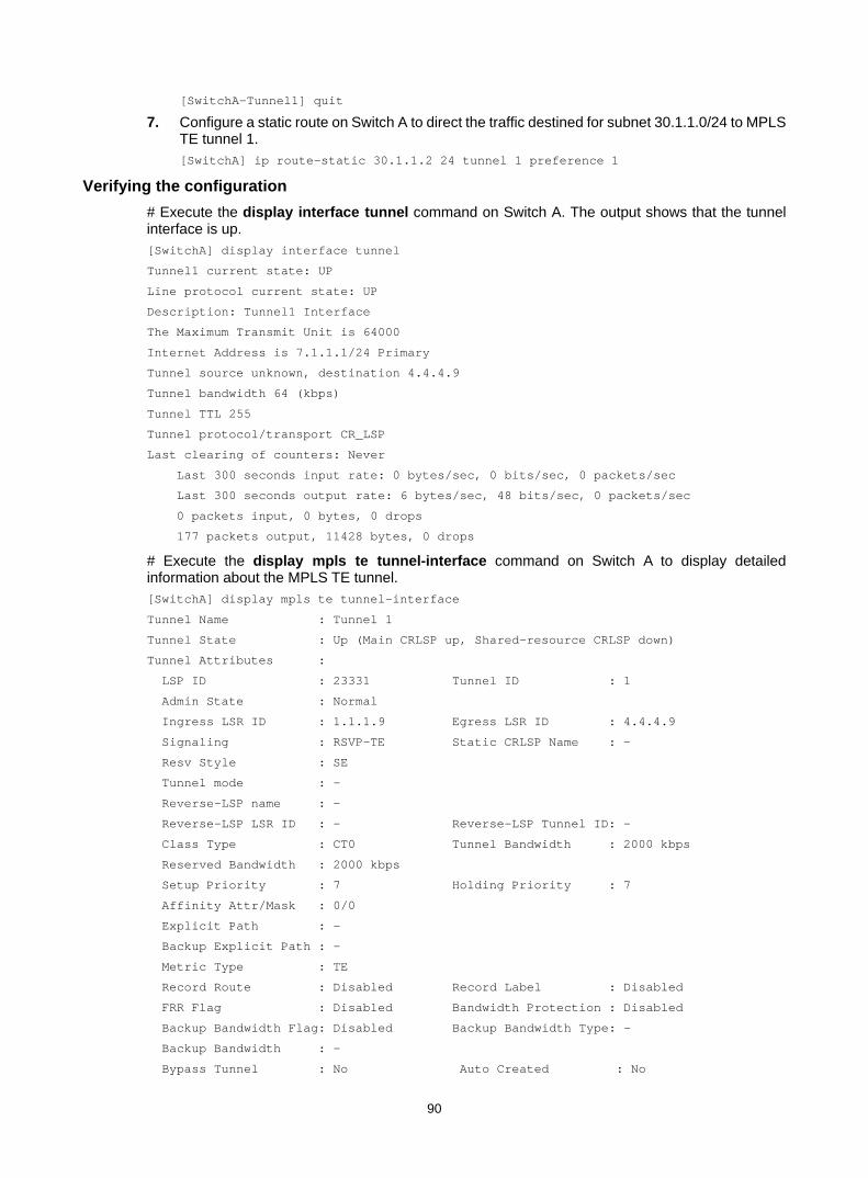
90
[SwitchA-Tunnel1] quit
7. Configure a static route on Switch A to direct the traffic destined for subnet 30.1.1.0/24 to MPLS TE tunnel 1. [SwitchA] ip route-static 30.1.1.2 24 tunnel 1 preference 1
Verifying the configuration # Execute the display interface tunnel command on Switch A. The output shows that the tunnel interface is up. [SwitchA] display interface tunnel
Tunnel1 current state: UP
Line protocol current state: UP
Description: Tunnel1 Interface
The Maximum Transmit Unit is 64000
Internet Address is 7.1.1.1/24 Primary
Tunnel source unknown, destination 4.4.4.9
Tunnel bandwidth 64 (kbps)
Tunnel TTL 255
Tunnel protocol/transport CR_LSP
Last clearing of counters: Never
Last 300 seconds input rate: 0 bytes/sec, 0 bits/sec, 0 packets/sec
Last 300 seconds output rate: 6 bytes/sec, 48 bits/sec, 0 packets/sec
0 packets input, 0 bytes, 0 drops
177 packets output, 11428 bytes, 0 drops
# Execute the display mpls te tunnel-interface command on Switch A to display detailed information about the MPLS TE tunnel. [SwitchA] display mpls te tunnel-interface
Tunnel Name : Tunnel 1
Tunnel State : Up (Main CRLSP up, Shared-resource CRLSP down)
Tunnel Attributes :
LSP ID : 23331 Tunnel ID : 1
Admin State : Normal
Ingress LSR ID : 1.1.1.9 Egress LSR ID : 4.4.4.9
Signaling : RSVP-TE Static CRLSP Name : -
Resv Style : SE
Tunnel mode : -
Reverse-LSP name : -
Reverse-LSP LSR ID : - Reverse-LSP Tunnel ID: -
Class Type : CT0 Tunnel Bandwidth : 2000 kbps
Reserved Bandwidth : 2000 kbps
Setup Priority : 7 Holding Priority : 7
Affinity Attr/Mask : 0/0
Explicit Path : -
Backup Explicit Path : -
Metric Type : TE
Record Route : Disabled Record Label : Disabled
FRR Flag : Disabled Bandwidth Protection : Disabled
Backup Bandwidth Flag: Disabled Backup Bandwidth Type: -
Backup Bandwidth : -
Bypass Tunnel : No Auto Created : No

91
Route Pinning : Disabled
Retry Limit : 10 Retry Interval : 2 sec
Reoptimization : Disabled Reoptimization Freq : -
Backup Type : None Backup LSP ID : -
Auto Bandwidth : Disabled Auto Bandwidth Freq : -
Min Bandwidth : - Max Bandwidth : -
Collected Bandwidth : -
# Execute the display ip routing-table command on Switch A. The output shows a static route entry with interface Tunnel 1 as the output interface. (Details not shown.)
Establishing an inter-AS MPLS TE tunnel with RSVP-TE Network requirements
Switch A and Switch B are in AS 100. Switch C and Switch D are in AS 200. AS 100 and AS 200 use OSPF as the IGP.
Establish an EBGP connection between ASBRs Switch B and Switch C. Redistribute BGP routes into OSPF and OSPF routes into BGP, so that a route is available between AS 100 and AS 200.
Establish an MPLS TE tunnel from Switch A to Switch D. The tunnel requires a bandwidth of 2000 kbps. The maximum bandwidth of the link that the tunnel traverses is 10000 kbps and the maximum reservable bandwidth of the link is 5000 kbps.
Figure 29 Network diagram
Table 4 Interface and IP address assignment
Device Interface IP address Device Interface IP address Switch A Loop0 1.1.1.9/32 Switch D Loop0 4.4.4.9/32
Vlan-int1 10.1.1.1/24 Vlan-int3 30.1.1.2/24
Switch B Loop0 2.2.2.9/32 Switch C Loop0 3.3.3.9/32
Vlan-int1 10.1.1.2/24 Vlan-int3 30.1.1.1/24
Vlan-int2 20.1.1.1/24 Vlan-int2 20.1.1.2/24
Configuration procedure 1. Configure IP addresses and masks for interfaces. (Details not shown.)
MPLS backboneAS 100
MPLS backboneAS 200
Vlan-int1
Vlan-int1Vlan-int2
Vlan-int2
Vlan-int3
Vlan-int3
Loop0 Loop0
Loop0 Loop0
Switch A
Switch B Switch C
Switch D

92
2. Configure OSPF to advertise routes within the ASs, and redistribute the direct and BGP routes into OSPF on Switch B and Switch C: # Configure Switch A. <SwitchA> system-view
[SwitchA] ospf
[SwitchA-ospf-1] area 0
[SwitchA-ospf-1-area-0.0.0.0] network 10.1.1.0 0.0.0.255
[SwitchA-ospf-1-area-0.0.0.0] network 1.1.1.9 0.0.0.0
[SwitchA-ospf-1-area-0.0.0.0] quit
[SwitchA-ospf-1] quit
# Configure Switch B. <SwitchB> system-view
[SwitchB] ospf
[SwitchB-ospf-1] import-route direct
[SwitchB-ospf-1] import-route bgp
[SwitchB-ospf-1] area 0
[SwitchB-ospf-1-area-0.0.0.0] network 10.1.1.0 0.0.0.255
[SwitchB-ospf-1-area-0.0.0.0] network 2.2.2.9 0.0.0.0
[SwitchB-ospf-1-area-0.0.0.0] quit
[SwitchB-ospf-1] quit
# Configure Switch C. <SwitchC> system-view
[SwitchC] ospf
[SwitchC-ospf-1] import-route direct
[SwitchC-ospf-1] import-route bgp
[SwitchC-ospf-1] area 0
[SwitchC-ospf-1-area-0.0.0.0] network 30.1.1.0 0.0.0.255
[SwitchC-ospf-1-area-0.0.0.0] network 3.3.3.9 0.0.0.0
[SwitchC-ospf-1-area-0.0.0.0] quit
[SwitchC-ospf-1] quit
# Configure Switch D. <SwitchD> system-view
[SwitchD] ospf
[SwitchD-ospf-1] area 0
[SwitchD-ospf-1-area-0.0.0.0] network 30.1.1.0 0.0.0.255
[SwitchD-ospf-1-area-0.0.0.0] network 4.4.4.9 0.0.0.0
[SwitchD-ospf-1-area-0.0.0.0] quit
[SwitchD-ospf-1] quit
# Execute the display ip routing-table command on each switch to verify that the switches have learned the routes to one another, including the routes to the loopback interfaces. Take Switch A as an example: [SwitchA] display ip routing-table
Destinations : 6 Routes : 6
Destination/Mask Proto Pre Cost NextHop Interface
1.1.1.9/32 Direct 0 0 127.0.0.1 InLoop0

93
2.2.2.9/32 OSPF 10 1 10.1.1.2 Vlan1
10.1.1.0/24 Direct 0 0 10.1.1.1 Vlan1
10.1.1.1/32 Direct 0 0 127.0.0.1 InLoop0
127.0.0.0/8 Direct 0 0 127.0.0.1 InLoop0
127.0.0.1/32 Direct 0 0 127.0.0.1 InLoop0
3. Configure BGP on Switch B and Switch C to make sure the ASs can communicate with each other: # Configure Switch B. [SwitchB] bgp 100
[SwitchB-bgp] peer 20.1.1.2 as-number 200
[SwitchB-bgp] address-family ipv4 unicast
[SwitchB-bgp-ipv4] peer 20.1.1.2 enable
[SwitchB-bgp-ipv4] import-route ospf
[SwitchB-bgp-ipv4] import-route direct
[SwitchB-bgp-ipv4] quit
[SwitchB-bgp] quit
# Configure Switch C. [SwitchC] bgp 200
[SwitchC-bgp] peer 20.1.1.1 as-number 100
[SwitchC-bgp] address-family ipv4 unicast
[SwitchC-bgp-ipv4] peer 20.1.1.1 enable
[SwitchC-bgp-ipv4] import-route ospf
[SwitchC-bgp-ipv4] import-route direct
[SwitchC-bgp-ipv4] quit
[SwitchC-bgp] quit
# Execute the display ip routing-table command on each switch to verify that the switches have learned AS-external routes. Take Switch A as an example: [SwitchA] display ip routing-table
Destinations : 10 Routes : 10
Destination/Mask Proto Pre Cost NextHop Interface
1.1.1.9/32 Direct 0 0 127.0.0.1 InLoop0
2.2.2.9/32 OSPF 10 1 10.1.1.2 Vlan1
3.3.3.9/32 O_ASE 150 1 10.1.1.2 Vlan1
4.4.4.9/32 O_ASE 150 1 10.1.1.2 Vlan1
10.1.1.0/24 Direct 0 0 10.1.1.1 Vlan1
10.1.1.1/32 Direct 0 0 127.0.0.1 InLoop0
20.1.1.0/24 O_ASE 150 1 10.1.1.2 Vlan1
30.1.1.0/24 O_ASE 150 1 10.1.1.2 Vlan1
127.0.0.0/8 Direct 0 0 127.0.0.1 InLoop0
127.0.0.1/32 Direct 0 0 127.0.0.1 InLoop0
4. Configure an LSR ID, and enable MPLS, MPLS TE, and RSVP-TE: # Configure Switch A. [SwitchA] mpls lsr-id 1.1.1.9
[SwitchA] mpls te
[SwitchA-te] quit

94
[SwitchA] rsvp
[SwitchA-rsvp] quit
[SwitchA] interface vlan-interface 1
[SwitchA-Vlan-interface1] mpls enable
[SwitchA-Vlan-interface1] mpls te enable
[SwitchA-Vlan-interface1] rsvp enable
[SwitchA-Vlan-interface1] quit
# Configure Switch B. [SwitchB] mpls lsr-id 2.2.2.9
[SwitchB] mpls te
[SwitchB-te] quit
[SwitchB] rsvp
[SwitchB-rsvp] quit
[SwitchB] interface vlan-interface 1
[SwitchB-Vlan-interface1] mpls enable
[SwitchB-Vlan-interface1] mpls te enable
[SwitchB-Vlan-interface1] rsvp enable
[SwitchB-Vlan-interface1] quit
[SwitchB] interface vlan-interface 2
[SwitchB-Vlan-interface2] mpls enable
[SwitchB-Vlan-interface2] mpls te enable
[SwitchB-Vlan-interface2] rsvp enable
[SwitchB-Vlan-interface2] quit
# Configure Switch C. [SwitchC] mpls lsr-id 3.3.3.9
[SwitchC] mpls te
[SwitchC-te] quit
[SwitchC] rsvp
[SwitchC-rsvp] quit
[SwitchC] interface vlan-interface 2
[SwitchC-Vlan-interface2] mpls enable
[SwitchC-Vlan-interface2] mpls te enable
[SwitchC-Vlan-interface2] rsvp enable
[SwitchC-Vlan-interface2] quit
[SwitchC] interface vlan-interface 3
[SwitchC-Vlan-interface3] mpls enable
[SwitchC-Vlan-interface3] mpls te enable
[SwitchC-Vlan-interface3] rsvp enable
[SwitchC-Vlan-interface3] quit
# Configure Switch D. [SwitchD] mpls lsr-id 4.4.4.9
[SwitchD] mpls te
[SwitchD-te] quit
[SwitchD] rsvp
[SwitchD-rsvp] quit
[SwitchD] interface vlan-interface 3
[SwitchD-Vlan-interface3] mpls enable
[SwitchD-Vlan-interface3] mpls te enable

95
[SwitchD-Vlan-interface3] rsvp enable
[SwitchD-Vlan-interface3] quit
5. Configure OSPF TE: # Configure Switch A. [SwitchA] ospf
[SwitchA-ospf-1] opaque-capability enable
[SwitchA-ospf-1] area 0
[SwitchA-ospf-1-area-0.0.0.0] mpls te enable
[SwitchA-ospf-1-area-0.0.0.0] quit
[SwitchA-ospf-1] quit
# Configure Switch B. [SwitchB] ospf
[SwitchB-ospf-1] opaque-capability enable
[SwitchB-ospf-1] area 0
[SwitchB-ospf-1-area-0.0.0.0] mpls te enable
[SwitchB-ospf-1-area-0.0.0.0] quit
[SwitchB-ospf-1] quit
# Configure Switch C. [SwitchC] ospf
[SwitchC-ospf-1] opaque-capability enable
[SwitchC-ospf-1] area 0
[SwitchC-ospf-1-area-0.0.0.0] mpls te enable
[SwitchC-ospf-1-area-0.0.0.0] quit
[SwitchC-ospf-1] quit
# Configure Switch D. [SwitchD] ospf
[SwitchD-ospf-1] opaque-capability enable
[SwitchD-ospf-1] area 0
[SwitchD-ospf-1-area-0.0.0.0] mpls te enable
[SwitchD-ospf-1-area-0.0.0.0] quit
[SwitchD-ospf-1] quit
6. Configure an explicit route on Switch A. Specify Switch B and Switch D as loose nodes, and Switch C as a strict node. [SwitchA] explicit-path atod
[SwitchA-explicit-path-atod] nexthop 10.1.1.2 include loose
[SwitchA-explicit-path-atod] nexthop 20.1.1.2 include strict
[SwitchA-explicit-path-atod] nexthop 30.1.1.2 include loose
[SwitchA-explicit-path-atod] quit
7. Configure MPLS TE attributes of links: # Configure the maximum link bandwidth and maximum reservable bandwidth on Switch A. [SwitchA] interface vlan-interface 1
[SwitchA-Vlan-interface1] mpls te max-link-bandwidth 10000
[SwitchA-Vlan-interface1] mpls te max-reservable-bandwidth 5000
[SwitchA-Vlan-interface1] quit
# Configure the maximum link bandwidth and maximum reservable bandwidth on Switch B. [SwitchB] interface vlan-interface 1
[SwitchB-Vlan-interface1] mpls te max-link-bandwidth 10000
[SwitchB-Vlan-interface1] mpls te max-reservable-bandwidth 5000
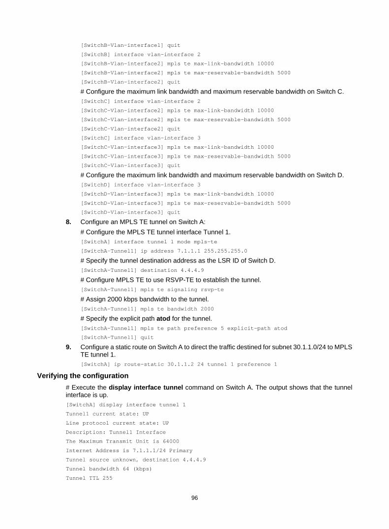
96
[SwitchB-Vlan-interface1] quit
[SwitchB] interface vlan-interface 2
[SwitchB-Vlan-interface2] mpls te max-link-bandwidth 10000
[SwitchB-Vlan-interface2] mpls te max-reservable-bandwidth 5000
[SwitchB-Vlan-interface2] quit
# Configure the maximum link bandwidth and maximum reservable bandwidth on Switch C. [SwitchC] interface vlan-interface 2
[SwitchC-Vlan-interface2] mpls te max-link-bandwidth 10000
[SwitchC-Vlan-interface2] mpls te max-reservable-bandwidth 5000
[SwitchC-Vlan-interface2] quit
[SwitchC] interface vlan-interface 3
[SwitchC-Vlan-interface3] mpls te max-link-bandwidth 10000
[SwitchC-Vlan-interface3] mpls te max-reservable-bandwidth 5000
[SwitchC-Vlan-interface3] quit
# Configure the maximum link bandwidth and maximum reservable bandwidth on Switch D. [SwitchD] interface vlan-interface 3
[SwitchD-Vlan-interface3] mpls te max-link-bandwidth 10000
[SwitchD-Vlan-interface3] mpls te max-reservable-bandwidth 5000
[SwitchD-Vlan-interface3] quit
8. Configure an MPLS TE tunnel on Switch A: # Configure the MPLS TE tunnel interface Tunnel 1. [SwitchA] interface tunnel 1 mode mpls-te
[SwitchA-Tunnel1] ip address 7.1.1.1 255.255.255.0
# Specify the tunnel destination address as the LSR ID of Switch D. [SwitchA-Tunnel1] destination 4.4.4.9
# Configure MPLS TE to use RSVP-TE to establish the tunnel. [SwitchA-Tunnel1] mpls te signaling rsvp-te
# Assign 2000 kbps bandwidth to the tunnel. [SwitchA-Tunnel1] mpls te bandwidth 2000
# Specify the explicit path atod for the tunnel. [SwitchA-Tunnel1] mpls te path preference 5 explicit-path atod
[SwitchA-Tunnel1] quit
9. Configure a static route on Switch A to direct the traffic destined for subnet 30.1.1.0/24 to MPLS TE tunnel 1. [SwitchA] ip route-static 30.1.1.2 24 tunnel 1 preference 1
Verifying the configuration # Execute the display interface tunnel command on Switch A. The output shows that the tunnel interface is up. [SwitchA] display interface tunnel 1
Tunnel1 current state: UP
Line protocol current state: UP
Description: Tunnel1 Interface
The Maximum Transmit Unit is 64000
Internet Address is 7.1.1.1/24 Primary
Tunnel source unknown, destination 4.4.4.9
Tunnel bandwidth 64 (kbps)
Tunnel TTL 255

97
Tunnel protocol/transport CR_LSP
Last clearing of counters: Never
Last 300 seconds input rate: 0 bytes/sec, 0 bits/sec, 0 packets/sec
Last 300 seconds output rate: 0 bytes/sec, 0 bits/sec, 0 packets/sec
0 packets input, 0 bytes, 0 drops
3077 packets output, 197028 bytes, 0 drops
# Execute the display mpls te tunnel-interface command on Switch A to display detailed information about the MPLS TE tunnel. [SwitchA] display mpls te tunnel-interface
Tunnel Name : Tunnel 1
Tunnel State : Up (Main CRLSP up, Shared-resource CRLSP down)
Tunnel Attributes :
LSP ID : 23549 Tunnel ID : 1
Admin State : Normal
Ingress LSR ID : 1.1.1.9 Egress LSR ID : 4.4.4.9
Signaling : RSVP-TE Static CRLSP Name : -
Resv Style : SE
Tunnel mode : -
Reverse-LSP name : -
Reverse-LSP LSR ID : - Reverse-LSP Tunnel ID: -
Class Type : CT0 Tunnel Bandwidth : 2000 kbps
Reserved Bandwidth : 2000 kbps
Setup Priority : 7 Holding Priority : 7
Affinity Attr/Mask : 0/0
Explicit Path : atod
Backup Explicit Path : -
Metric Type : TE
Record Route : Disabled Record Label : Disabled
FRR Flag : Disabled Bandwidth Protection : Disabled
Backup Bandwidth Flag: Disabled Backup Bandwidth Type: -
Backup Bandwidth : -
Bypass Tunnel : No Auto Created : No
Route Pinning : Disabled
Retry Limit : 10 Retry Interval : 2 sec
Reoptimization : Disabled Reoptimization Freq : -
Backup Type : None Backup LSP ID : -
Auto Bandwidth : Disabled Auto Bandwidth Freq : -
Min Bandwidth : - Max Bandwidth : -
Collected Bandwidth : -
# Execute the display ip routing-table command on Switch A. The output shows a static route entry with interface Tunnel1 as the output interface. [SwitchA] display ip routing-table
Destinations : 14 Routes : 14
Destination/Mask Proto Pre Cost NextHop Interface

98
1.1.1.9/32 Direct 0 0 127.0.0.1 InLoop0
2.2.2.9/32 OSPF 10 1 10.1.1.2 Vlan1
3.3.3.9/32 O_ASE 150 1 10.1.1.2 Vlan1
4.4.4.9/32 O_ASE 150 1 10.1.1.2 Vlan1
7.1.1.0/24 Direct 0 0 7.1.1.1 Tun1
7.1.1.1/32 Direct 0 0 127.0.0.1 InLoop0
10.1.1.0/24 Direct 0 0 10.1.1.1 Vlan1
10.1.1.1/32 Direct 0 0 127.0.0.1 InLoop0
20.1.1.0/24 O_ASE 150 1 10.1.1.2 Vlan1
30.1.1.0/24 Static 1 0 7.1.1.1 Tun1
127.0.0.0/8 Direct 0 0 127.0.0.1 InLoop0
127.0.0.1/32 Direct 0 0 127.0.0.1 InLoop0
Bidirectional MPLS TE tunnel configuration example Network requirements
Switch A, Switch B, Switch C, and Switch D all run IS-IS and they are all level-2 switches.
Use RSVP-TE to establish a bidirectional MPLS TE tunnel between Switch A and Switch D.
Figure 30 Network diagram
Table 5 Interface and IP address assignment
Device Interface IP address Device Interface IP address Switch A Loop0 1.1.1.9/32 Switch D Loop0 4.4.4.9/32
Vlan-int1 10.1.1.1/24 Vlan-int3 30.1.1.2/24
Switch B Loop0 2.2.2.9/32 Switch C Loop0 3.3.3.9/32
Vlan-int1 10.1.1.2/24 Vlan-int3 30.1.1.1/24
Vlan-int2 20.1.1.1/24 Vlan-int2 20.1.1.2/24
Configuration procedure 1. Configure IP addresses and masks for interfaces. (Details not shown.) 2. Configure IS-IS to advertise interface addresses, including the loopback interface address.
For more information, see "Establishing an MPLS TE tunnel with RSVP-TE." 3. Configure an LSR ID, and enable MPLS, MPLS TE, and RSVP-TE on each switch. Configure
Switch A and Switch D to assign a non-null label to the penultimate hop:
Vlan-int1
Vlan-int1Vlan-int2
Vlan-int2
Vlan-int3
Vlan-int3
Loop0 Loop0
Loop0 Loop0
Switch A
Switch B Switch C
Switch D

99
# Configure Switch A. <SwitchA> system-view
[SwitchA] mpls lsr-id 1.1.1.9
[SwitchA] mpls label advertise non-null
[SwitchA] mpls te
[SwitchA-te] quit
[SwitchA] rsvp
[SwitchA-rsvp] quit
[SwitchA] interface vlan-interface 1
[SwitchA-Vlan-interface1] mpls enable
[SwitchA-Vlan-interface1] mpls te enable
[SwitchA-Vlan-interface1] rsvp enable
[SwitchA-Vlan-interface1] quit
# Configure Switch B. <SwitchB> system-view
[SwitchB] mpls lsr-id 2.2.2.9
[SwitchB] mpls te
[SwitchB-te] quit
[SwitchB] rsvp
[SwitchB-rsvp] quit
[SwitchB] interface vlan-interface 1
[SwitchB-Vlan-interface1] mpls enable
[SwitchB-Vlan-interface1] mpls te enable
[SwitchB-Vlan-interface1] rsvp enable
[SwitchB-Vlan-interface1] quit
[SwitchB] interface vlan-interface 2
[SwitchB-Vlan-interface2] mpls enable
[SwitchB-Vlan-interface2] mpls te enable
[SwitchB-Vlan-interface2] rsvp enable
[SwitchB-Vlan-interface1] quit
# Configure Switch C. <SwitchC> system-view
[SwitchC] mpls lsr-id 3.3.3.9
[SwitchC] mpls te
[SwitchC-te] quit
[SwitchC] rsvp
[SwitchC-rsvp] quit
[SwitchC] interface vlan-interface 3
[SwitchC-Vlan-interface3] mpls enable
[SwitchC-Vlan-interface3] mpls te enable
[SwitchC-Vlan-interface3] rsvp enable
[SwitchC-Vlan-interface3] quit
[SwitchC] interface vlan-interface 2
[SwitchC-Vlan-interface2] mpls enable
[SwitchC-Vlan-interface2] mpls te enable
[SwitchC-Vlan-interface2] rsvp enable
[SwitchC-Vlan-interface2] quit
# Configure Switch D.

100
<SwitchD> system-view
[SwitchD] mpls lsr-id 4.4.4.9
[SwitchD] mpls label advertise non-null
[SwitchD] mpls te
[SwitchD-te] quit
[SwitchD] rsvp
[SwitchD-rsvp] quit
[SwitchD] interface vlan-interface 3
[SwitchD-Vlan-interface3] mpls enable
[SwitchD-Vlan-interface3] mpls te enable
[SwitchD-Vlan-interface3] rsvp enable
[SwitchD-Vlan-interface3] quit
4. Configure IS-IS TE: # Configure Switch A. [SwitchA] isis 1
[SwitchA-isis-1] cost-style wide
[SwitchA-isis-1] mpls te enable level-2
[SwitchA-isis-1] quit
# Configure Switch B. [SwitchB] isis 1
[SwitchB-isis-1] cost-style wide
[SwitchB-isis-1] mpls te enable level-2
[SwitchB-isis-1] quit
# Configure Switch C. [SwitchC] isis 1
[SwitchC-isis-1] cost-style wide
[SwitchC-isis-1] mpls te enable level-2
[SwitchC-isis-1] quit
# Configure Switch D. [SwitchD] isis 1
[SwitchD-isis-1] cost-style wide
[SwitchD-isis-1] mpls te enable level-2
[SwitchD-isis-1] quit
5. Configure a co-routed bidirectional MPLS TE tunnel: # Configure Switch A as the active end of the co-routed bidirectional tunnel. [SwitchA] interface tunnel 1 mode mpls-te
[SwitchA-Tunnel1] ip address 7.1.1.1 255.255.255.0
[SwitchA-Tunnel1] destination 4.4.4.9
[SwitchA-Tunnel1] mpls te signaling rsvp-te
[SwitchA-Tunnel1] mpls te resv-style ff
[SwitchA-Tunnel1] mpls te bidirectional co-routed active
[SwitchA-Tunnel1] quit
# Configure Switch D as the passive end of the co-routed bidirectional tunnel. [SwitchD] interface tunnel 4 mode mpls-te
[SwitchD-Tunnel4] ip address 8.1.1.1 255.255.255.0
[SwitchD-Tunnel4] destination 1.1.1.9
[SwitchD-Tunnel4] mpls te signaling rsvp-te
[SwitchD-Tunnel4] mpls te resv-style ff

101
[SwitchD-Tunnel4] mpls te bidirectional co-routed passive reverse-lsp lsr-id 1.1.1.9 tunnel-id 1
[SwitchD-Tunnel4] quit
Verifying the configuration # Execute the display interface tunnel command on Switch A. The output shows that the tunnel interface is up. [SwitchA] display interface tunnel
Tunnel1 current state: UP
Line protocol current state: UP
Description: Tunnel1 Interface
The Maximum Transmit Unit is 64000
Internet Address is 7.1.1.1/24 Primary
Tunnel source unknown, destination 4.4.4.9
Tunnel bandwidth 64 (kbps)
Tunnel protocol/transport CR_LSP
Last clearing of counters: Never
Last 300 seconds input rate: 0 bytes/sec, 0 bits/sec, 0 packets/sec
Last 300 seconds output rate: 0 bytes/sec, 0 bits/sec, 0 packets/sec
0 packets input, 0 bytes, 0 drops
0 packets output, 0 bytes, 0 drops
# Execute the display mpls te tunnel-interface command on Switch A to display detailed information about the MPLS TE tunnel. [SwitchA] display mpls te tunnel-interface
Tunnel Name : Tunnel 1
Tunnel State : Up (Main CRLSP up, Reverse CRLSP up)
Tunnel Attributes :
LSP ID : 30478 Tunnel ID : 1
Admin State : Normal
Ingress LSR ID : 1.1.1.9 Egress LSR ID : 4.4.4.9
Signaling : RSVP-TE Static CRLSP Name : -
Resv Style : FF
Tunnel mode : Co-routed, active
Reverse-LSP name : -
Reverse-LSP LSR ID : - Reverse-LSP Tunnel ID: -
Class Type : CT0 Tunnel Bandwidth : 0 kbps
Reserved Bandwidth : 0 kbps
Setup Priority : 7 Holding Priority : 7
Affinity Attr/Mask : 0/0
Explicit Path : -
Backup Explicit Path : -
Metric Type : TE
Record Route : Disabled Record Label : Disabled
FRR Flag : Disabled Bandwidth Protection : Disabled
Backup Bandwidth Flag: Disabled Backup Bandwidth Type: -
Backup Bandwidth : -
Bypass Tunnel : No Auto Created : No
Route Pinning : Disabled
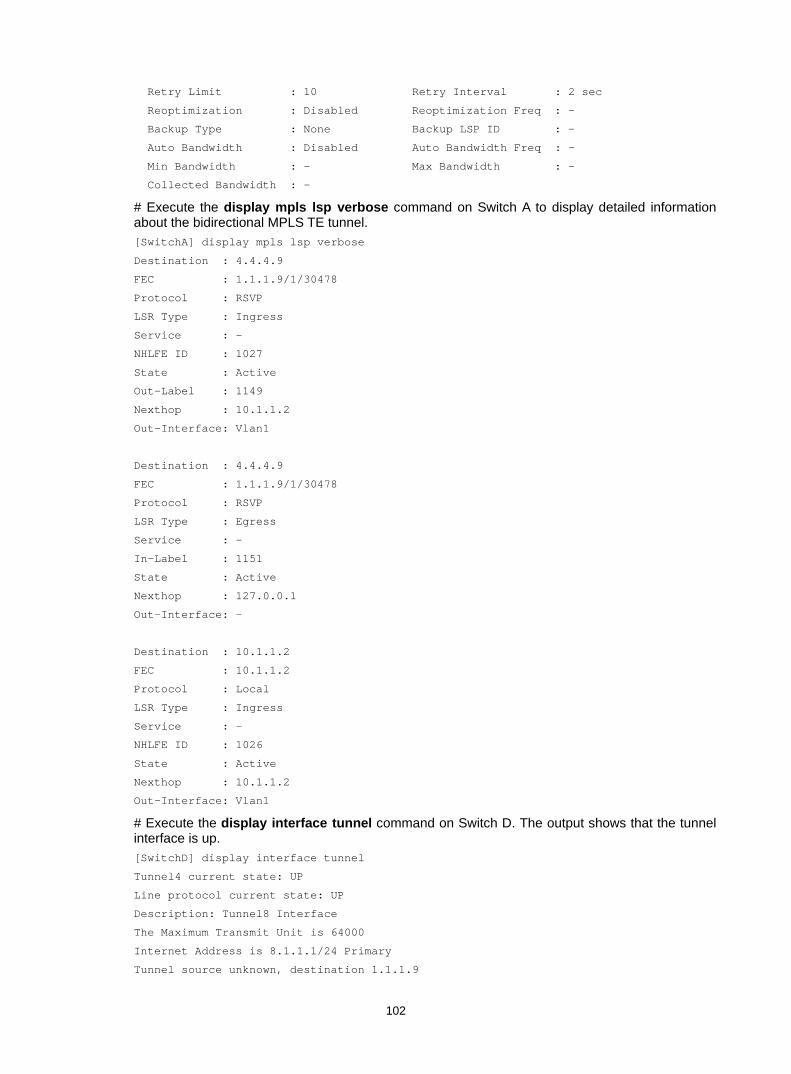
102
Retry Limit : 10 Retry Interval : 2 sec
Reoptimization : Disabled Reoptimization Freq : -
Backup Type : None Backup LSP ID : -
Auto Bandwidth : Disabled Auto Bandwidth Freq : -
Min Bandwidth : - Max Bandwidth : -
Collected Bandwidth : -
# Execute the display mpls lsp verbose command on Switch A to display detailed information about the bidirectional MPLS TE tunnel. [SwitchA] display mpls lsp verbose
Destination : 4.4.4.9
FEC : 1.1.1.9/1/30478
Protocol : RSVP
LSR Type : Ingress
Service : -
NHLFE ID : 1027
State : Active
Out-Label : 1149
Nexthop : 10.1.1.2
Out-Interface: Vlan1
Destination : 4.4.4.9
FEC : 1.1.1.9/1/30478
Protocol : RSVP
LSR Type : Egress
Service : -
In-Label : 1151
State : Active
Nexthop : 127.0.0.1
Out-Interface: -
Destination : 10.1.1.2
FEC : 10.1.1.2
Protocol : Local
LSR Type : Ingress
Service : -
NHLFE ID : 1026
State : Active
Nexthop : 10.1.1.2
Out-Interface: Vlan1
# Execute the display interface tunnel command on Switch D. The output shows that the tunnel interface is up. [SwitchD] display interface tunnel
Tunnel4 current state: UP
Line protocol current state: UP
Description: Tunnel8 Interface
The Maximum Transmit Unit is 64000
Internet Address is 8.1.1.1/24 Primary
Tunnel source unknown, destination 1.1.1.9

103
Tunnel bandwidth 64 (kbps)
Tunnel TTL 255
Tunnel protocol/transport CR_LSP
Last clearing of counters: Never
Last 300 seconds input rate: 0 bytes/sec, 0 bits/sec, 0 packets/sec
Last 300 seconds output rate: 0 bytes/sec, 0 bits/sec, 0 packets/sec
0 packets input, 0 bytes, 0 drops
0 packets output, 0 bytes, 0 drops
# Execute the display mpls te tunnel-interface command on Switch D to display detailed information about the MPLS TE tunnel. [SwitchD] display mpls te tunnel-interface
[SwitchD] display mpls te tunnel-interface
Tunnel Name : Tunnel 4
Tunnel State : Up (Main CRLSP up, Reverse CRLSP up)
Tunnel Attributes :
LSP ID : - Tunnel ID : 8
Admin State : Normal
Ingress LSR ID : - Egress LSR ID : -
Signaling : RSVP-TE Static CRLSP Name : -
Resv Style : FF
Tunnel mode : Co-routed, passive
Reverse-LSP name : -
Reverse-LSP LSR ID : 1.1.1.9 Reverse-LSP Tunnel ID: 1
Class Type : - Tunnel Bandwidth : -
Reserved Bandwidth : -
Setup Priority : - Holding Priority : -
Affinity Attr/Mask : -/-
Explicit Path : -
Backup Explicit Path : -
Metric Type : -
Record Route : - Record Label : -
FRR Flag : - Bandwidth Protection : -
Backup Bandwidth Flag: - Backup Bandwidth Type: -
Backup Bandwidth : -
Bypass Tunnel : - Auto Created : No
Route Pinning : -
Retry Limit : - Retry Interval : -
Reoptimization : - Reoptimization Freq : -
Backup Type : - Backup LSP ID : -
Auto Bandwidth : - Auto Bandwidth Freq : -
Min Bandwidth : - Max Bandwidth : -
Collected Bandwidth : -
# Execute the display mpls lsp verbose command on Switch D to display detailed information about the bidirectional MPLS TE tunnel. [SwitchD] display mpls lsp verbose
Destination : 4.4.4.9
FEC : 1.1.1.9/1/30478
Protocol : RSVP

104
LSR Type : Egress
Service : -
In-Label : 3
State : Active
Nexthop : 127.0.0.1
Out-Interface: -
Destination : 4.4.4.9
FEC : 1.1.1.9/1/30478
Protocol : RSVP
LSR Type : Ingress
Service : -
NHLFE ID : 1025
State : Active
Out-Label : 1150
Nexthop : 30.1.1.1
Out-Interface: Vlan1
Destination : 30.1.1.1
FEC : 30.1.1.1
Protocol : Local
LSR Type : Ingress
Service : -
NHLFE ID : 1024
State : Active
Nexthop : 30.1.1.1
Out-Interface: Vlan1
CRLSP backup configuration example Network requirements
Switch A, Switch B, Switch C, and Switch D run IS-IS.
Use RSVP-TE to establish an MPLS TE tunnel from Switch A to Switch C. Enable CRLSP hot backup for the tunnel to simultaneously establish a primary CRLSP and a backup CRLSP. When the primary CRLSP fails, traffic is switched to the backup CRLSP.

105
Figure 31 Network diagram
Table 6 Interface and IP address assignment
Device Interface IP address Device Interface IP address Switch A Loop0 1.1.1.9/32 Switch D Loop0 4.4.4.9/32
Vlan-int1 10.1.1.1/24 Vlan-int4 30.1.1.2/24
Vlan-int4 30.1.1.1/24 Vlan-int3 40.1.1.1/24
Switch B Loop0 2.2.2.9/32 Switch C Loop0 3.3.3.9/32
Vlan-int1 10.1.1.2/24 Vlan-int2 20.1.1.2/24
Vlan-int2 20.1.1.1/24 Vlan-int3 40.1.1.2/24
Configuration procedure 1. Configure IP addresses and masks for interfaces. (Details not shown.) 2. Configure IS-IS to advertise interface addresses, including the loopback interface address.
(Details not shown.) 3. Configure an LSR ID, and enable MPLS, MPLS TE, and RSVP-TE:
# Configure Switch A. <SwitchA> system-view
[SwitchA] mpls lsr-id 1.1.1.9
[SwitchA] mpls te
[SwitchA-te] quit
[SwitchA] rsvp
[SwitchA-rsvp] quit
[SwitchA] interface vlan-interface 1
[SwitchA-Vlan-interface1] mpls enable
[SwitchA-Vlan-interface1] mpls te enable
[SwitchA-Vlan-interface1] rsvp enable
[SwitchA-Vlan-interface1] quit
[SwitchA] interface vlan-interface 4
[SwitchA-Vlan-interface4] mpls enable
[SwitchA-Vlan-interface4] mpls te enable
Switch ALoop0
Vlan-int1
Switch B Switch C
Switch D
Loop0 Loop0
Vlan-int1 Vlan-int2
Vlan-int2
Vlan-int4 Vlan-int3
Vlan-int4 Vlan-int3
Loop0

106
[SwitchA-Vlan-interface4] rsvp enable
[SwitchA-Vlan-interface4] quit
# Configure Switch B, Switch C, and Switch D in the same way that Switch A is configured. (Details not shown.)
4. Configure an MPLS TE tunnel on Switch A: # Configure the MPLS TE tunnel interface Tunnel 3. [SwitchA] interface tunnel 3 mode mpls-te
[SwitchA-Tunnel3] ip address 9.1.1.1 24
# Specify the tunnel destination address as the LSR ID of Switch C. [SwitchA-Tunnel3] destination 3.3.3.9
# Configure MPLS TE to use RSVP-TE to establish the tunnel. [SwitchA-Tunnel3] mpls te signaling rsvp-te
# Enable CRLSP hot backup for the tunnel. [SwitchA-Tunnel3] mpls te backup hot-standby
[SwitchA-Tunnel3] quit
5. Configure a static route on Switch A to direct the traffic destined for subnet 20.1.1.0/24 to MPLS TE tunnel 3. [SwitchA] ip route-static 20.1.1.2 24 tunnel 3 preference 1
Verifying the configuration # Execute the display interface tunnel command on Switch A. The output shows that the tunnel interface Tunnel 3 is up. [SwitchA] display interface tunnel
Tunnel3 current state: UP
Line protocol current state: UP
Description: Tunnel3 Interface
The Maximum Transmit Unit is 64000
Internet Address is 9.1.1.1/24 Primary
Tunnel source unknown, destination 3.3.3.9
Tunnel bandwidth 64 (kbps)
Tunnel TTL 255
Tunnel protocol/transport CR_LSP
Last clearing of counters: Never
Last 300 seconds input rate: 0 bytes/sec, 0 bits/sec, 0 packets/sec
Last 300 seconds output rate: 1802 bytes/sec, 14416 bits/sec, 0 packets/sec
0 packets input, 0 bytes, 0 drops
351 packets output, 3105652 bytes, 0 drops
# Execute the display mpls lsp command on Switch A. The output shows that two CRLSPs exist on the switch, one with the output interface VLAN-interface 1 and the other with the output interface VLAN-interface 4. [SwitchA] display mpls lsp
FEC Proto In/Out Label Interface/Out NHLFE
1.1.1.9/3/30106 RSVP -/1137 Vlan1
1.1.1.9/3/30107 RSVP -/1150 Vlan4
10.1.1.2 Local -/- Vlan1
30.1.1.2 Local -/- Vlan4
# Execute the display rsvp lsp verbose command on Switch A to display the paths used by the two CRLSPs.

107
[SwitchA] display rsvp lsp verbose
Tunnel name: SwitchA_t3
Destination: 3.3.3.9 Source: 1.1.1.9
Tunnel ID: 3 LSP ID: 30106
LSR type: Ingress Direction: Unidirectional
Setup priority: 7 Holding priority: 7
In-Label: - Out-Label: 1137
In-Interface: - Out-Interface: Vlan1
Nexthop: 10.1.1.2 Exclude-any: 0
Include-Any: 0 Include-all: 0
Mean rate (CIR): 0 kbps Mean burst size (CBS): 1000.00 bytes
Path MTU: 1500 Class type: CT0
RRO number: 6
10.1.1.1/32 Flag: 0x00 (No FRR)
10.1.1.2/32 Flag: 0x00 (No FRR)
2.2.2.9/32 Flag: 0x20 (No FRR/Node-ID)
20.1.1.1/32 Flag: 0x00 (No FRR)
20.1.1.2/32 Flag: 0x00 (No FRR)
3.3.3.9/32 Flag: 0x20 (No FRR/Node-ID)
Fast Reroute protection: None
Tunnel name: Tunnel3
Destination: 3.3.3.9 Source: 1.1.1.9
Tunnel ID: 3 LSP ID: 30107
LSR type: Ingress Direction: Unidirectional
Setup priority: 7 Holding priority: 7
In-Label: - Out-Label: 1150
In-Interface: - Out-Interface: Vlan4
Nexthop: 30.1.1.2 Exclude-any: 0
Include-Any: 0 Include-all: 0
Mean rate (CIR): 0 kbps Mean burst size (CBS): 1000.00 bytes
Path MTU: 1500 Class type: CT0
RRO number: 6
30.1.1.1/32 Flag: 0x00 (No FRR)
30.1.1.2/32 Flag: 0x00 (No FRR)
4.4.4.9/32 Flag: 0x20 (No FRR/Node-ID)
40.1.1.1/32 Flag: 0x00 (No FRR)
40.1.1.2/32 Flag: 0x00 (No FRR)
3.3.3.9/32 Flag: 0x20 (No FRR/Node-ID)
Fast Reroute protection: None
# Tracert the tunnel destination 3.3.3.9. The output shows that the used CRLSP is the one that traverses Switch B. [SwitchA] tracert –a 1.1.1.9 3.3.3.9
traceroute to 3.3.3.9 (3.3.3.9) from 1.1.1.9, 30 hops at most, 40 bytes each pac
ket, press CTRL_C to break
1 10.1.1.2 (10.1.1.2) 1.000 ms 1.000 ms 1.000 ms
2 * * *

108
# Shut down interface VLAN-interface 2 on Switch B, and then tracert the tunnel destination. The output shows that packets are forwarded on the CRLSP that traverses Switch D. [SwitchA] tracert –a 1.1.1.9 3.3.3.9
traceroute to 3.3.3.9 (3.3.3.9) from 9.1.1.1, 30 hops at most, 40 bytes each pac
ket, press CTRL_C to break
1 30.1.1.2 (30.1.1.2) 3.000 ms 7.000 ms 3.000 ms
2 * * *
# Execute the display mpls lsp command on Switch A. The output shows that only one CRLSP exists on the switch. [SwitchA] display mpls lsp
FEC Proto In/Out Label Interface/Out NHLFE
1.1.1.9/3/48984 RSVP -/1150 Vlan4
30.1.1.2 Local -/- Vlan4
# Execute the display ip routing-table command on Switch A. The output shows a static route entry with interface Tunnel 3 as the output interface. (Details not shown.)
Manual bypass tunnel for FRR configuration example Network requirements
On the primary CRLSP Switch A—Switch B—Switch C—Switch D, use FRR to protect the link Switch B—Switch C.
Use RSVP-TE to establish the primary CRLSP and bypass tunnel of the MPLS TE tunnel based on the constraints of the explicit paths. The bypass tunnel uses path Switch B—Switch E—Switch C. Switch B is the PLR and Switch C is the MP.
Configure BFD for RSVP-TE between Switch B and Switch C. When the link between Switch B and Switch C fails, BFD can detect the failure quickly and notify RSVP-TE of the failure, so RSVP-TE can switch traffic to the bypass tunnel.
Figure 32 Network diagram
Table 7 Interface and IP address assignment
Device Interface IP address Device Interface IP address Switch A Loop0 1.1.1.1/32 Switch E Loop0 5.5.5.5/32
Vlan-int1 2.1.1.1/24 Vlan-int4 3.2.1.2/24
Switch B Loop0 2.2.2.2/32 Vlan-int5 3.3.1.1/24
Switch A Switch B Switch C Switch D
Switch E
Vlan-int1
Loop0 Loop0 Loop0 Loop0
Vlan-int1
Vlan-int2
Vlan-int2 Vlan-int3
Vlan-int3Vlan-int4
Vlan-int4
Primary CRLSPBypass tunnel
Vlan-int5
Vlan-int5
Loop0

109
Device Interface IP address Device Interface IP address Vlan-int1 2.1.1.2/24 Switch C Loop0 3.3.3.3/32
Vlan-int2 3.1.1.1/24 Vlan-int3 4.1.1.1/24
Vlan-int4 3.2.1.1/24 Vlan-int2 3.1.1.2/24
Switch D Loop0 4.4.4.4/32 Vlan-int5 3.3.1.2/24
Vlan-int3 4.1.1.2/24
Configuration procedure 1. Configure IP addresses and masks for interfaces. (Details not shown.) 2. Configure IS-IS to advertise interface addresses, including the loopback interface address.
(Details not shown.) 3. Configure an LSR ID, and enable MPLS, MPLS TE, and RSVP-TE on each switch. Enable BFD
for RSVP-TE on Switch B and Switch C: # Configure Switch A. <SwitchA> system-view
[SwitchA] mpls lsr-id 1.1.1.1
[SwitchA] mpls te
[SwitchA-te] quit
[SwitchA] rsvp
[SwitchA-rsvp] quit
[SwitchA] interface vlan-interface 1
[SwitchA-Vlan-interface1] mpls enable
[SwitchA-Vlan-interface1] mpls te enable
[SwitchA-Vlan-interface1] rsvp enable
[SwitchA-Vlan-interface1] quit
# Configure Switch B. <SwitchB> system-view
[SwitchB] mpls lsr-id 2.2.2.2
[SwitchB] mpls te
[SwitchB-te] quit
[SwitchB] rsvp
[SwitchB-rsvp] quit
[SwitchB] interface vlan-interface 1
[SwitchB-Vlan-interface1] mpls enable
[SwitchB-Vlan-interface1] mpls te enable
[SwitchB-Vlan-interface1] rsvp enable
[SwitchB-Vlan-interface1] quit
[SwitchB] interface vlan-interface 2
[SwitchB-Vlan-interface2] mpls enable
[SwitchB-Vlan-interface2] mpls te enable
[SwitchB-Vlan-interface2] rsvp enable
[SwitchB-Vlan-interface2] rsvp bfd enable
[SwitchB-Vlan-interface2] quit
[SwitchB] interface vlan-interface 4
[SwitchB-Vlan-interface4] mpls enable
[SwitchB-Vlan-interface4] mpls te enable

110
[SwitchB-Vlan-interface4] rsvp enable
[SwitchB-Vlan-interface4] quit
# Configure Switch C in the same way that Switch B is configured. Configure Switch D and Switch E in the same way that Switch A is configured. (Details not shown.)
4. Configure an MPLS TE tunnel on Switch A, the ingress node of the primary CRLSP: # Configure an explicit path for the primary CRLSP. [SwitchA] explicit-path pri-path
[SwitchA-explicit-path-pri-path] nexthop 2.1.1.2
[SwitchA-explicit-path-pri-path] nexthop 3.1.1.2
[SwitchA-explicit-path-pri-path] nexthop 4.1.1.2
[SwitchA-explicit-path-pri-path] nexthop 4.4.4.4
[SwitchA-explicit-path-pri-path] quit
# Create MPLS TE tunnel interface Tunnel4 for the primary CRLSP. [SwitchA] interface tunnel 4 mode mpls-te
[SwitchA-Tunnel4] ip address 10.1.1.1 255.255.255.0
# Specify the tunnel destination address as the LSR ID of Switch D. [SwitchA-Tunnel4] destination 4.4.4.4
# Specify the tunnel signaling protocol as RSVP-TE. [SwitchA-Tunnel4] mpls te signaling rsvp-te
# Specify the explicit path to be used as pri-path. [SwitchA-Tunnel4] mpls te path preference 1 explicit-path pri-path
# Enable FRR for the MPLS TE tunnel. [SwitchA-Tunnel4] mpls te fast-reroute
[SwitchA-Tunnel4] quit
# Execute the display interface tunnel command on Switch A. The output shows that the tunnel interface Tunnel4 is up. [SwitchA] display interface tunnel
Tunnel4 current state: UP
Line protocol current state: UP
Description: Tunnel3 Interface
The Maximum Transmit Unit is 64000
Internet Address is 9.1.1.1/24 Primary
Tunnel source unknown, destination 3.3.3.9
Tunnel bandwidth 64 (kbps)
Tunnel TTL 255
Tunnel protocol/transport CR_LSP
Last clearing of counters: Never
Last 300 seconds input rate: 0 bytes/sec, 0 bits/sec, 0 packets/sec
Last 300 seconds output rate: 1911 bytes/sec, 15288 bits/sec, 0 packets/sec
0 packets input, 0 bytes, 0 drops
1526 packets output, 22356852 bytes, 0 drops
# Execute the display mpls te tunnel-interface command on Switch A to display detailed information about the MPLS TE tunnel. [SwitchA] display mpls te tunnel-interface
Tunnel Name : Tunnel 4
Tunnel State : Up (Main CRLSP up, Shared-resource CRLSP down)
Tunnel Attributes :

111
LSP ID : 48960 Tunnel ID : 4
Admin State : Normal
Ingress LSR ID : 1.1.1.1 Egress LSR ID : 3.3.3.3
Signaling : RSVP-TE Static CRLSP Name : -
Resv Style : SE
Tunnel mode : -
Reverse-LSP name : -
Reverse-LSP LSR ID : - Reverse-LSP Tunnel ID: -
Class Type : CT0 Tunnel Bandwidth : 0 kbps
Reserved Bandwidth : 0 kbps
Setup Priority : 7 Holding Priority : 7
Affinity Attr/Mask : 0/0
Explicit Path : pri-path
Backup Explicit Path : -
Metric Type : TE
Record Route : Enabled Record Label : Enabled
FRR Flag : Enabled Bandwidth Protection : Disabled
Backup Bandwidth Flag: Disabled Backup Bandwidth Type: -
Backup Bandwidth : -
Bypass Tunnel : No Auto Created : No
Route Pinning : Disabled
Retry Limit : 10 Retry Interval : 2 sec
Reoptimization : Disabled Reoptimization Freq : -
Backup Type : None Backup LSP ID : -
Auto Bandwidth : Disabled Auto Bandwidth Freq : -
Min Bandwidth : - Max Bandwidth : -
Collected Bandwidth : -
5. Configure a bypass tunnel on Switch B (the PLR): # Configure an explicit path for the bypass tunnel. [SwitchB] explicit-path by-path
[SwitchB-explicit-path-by-path] nexthop 3.2.1.2
[SwitchB-explicit-path-by-path] nexthop 3.3.1.2
[SwitchB-explicit-path-by-path] nexthop 3.3.3.3
[SwitchB-explicit-path-by-path] quit
# Create MPLS TE tunnel interface Tunnel 5 for the bypass tunnel. [SwitchB] interface tunnel 5 mode mpls-te
[SwitchB-Tunnel5] ip address 11.1.1.1 255.255.255.0
# Specify the tunnel destination address as LSR ID of Switch C. [SwitchB-Tunnel5] destination 3.3.3.3
# Specify the tunnel signaling protocol as RSVP-TE. [SwitchB-Tunnel5] mpls te signaling rsvp-te
# Specify the explicit path to be used as by-path. [SwitchB-Tunnel5] mpls te path preference 1 explicit-path by-path
# Configure the bandwidth that the bypass tunnel can protect. [SwitchB-Tunnel5] mpls te backup bandwidth un-limited
[SwitchB-Tunnel5] quit
# Bind the bypass tunnel to the protected interface. [SwitchB] interface vlan-interface 2

112
[SwitchB-Vlan-interface2] mpls te fast-reroute bypass-tunnel tunnel 5
[SwitchB-Vlan-interface2] quit
# Execute the display interface tunnel command on Switch B to verify that the tunnel interface Tunnel 5 is up. (Details not shown.)
6. Configure a static route on Switch A to direct the traffic destined for subnet 4.1.1.0/24 to MPLS TE tunnel 4. [SwitchA] ip route-static 4.1.1.2 24 tunnel 4 preference 1
Verifying the configuration # Execute the display mpls lsp command on each switch. The output shows the LSP entries. Switch B and Switch C each have two CRLSPs. The bypass tunnel backs up the primary CRLSP. [SwitchA] display mpls lsp
FEC Proto In/Out Label Interface/Out NHLFE
1.1.1.1/4/61400 RSVP -/1245 Vlan1
2.1.1.2 Local -/- Vlan1
[SwitchB] display mpls lsp
FEC Proto In/Out Label Interface/Out NHLFE
1.1.1.1/4/614000 RSVP 1245/3 Vlan2
Backup 1245/3 Tun5
2.2.2.2/5/30914 RSVP -/1150 Vlan2
3.2.1.2 Local -/- Vlan4
3.1.1.2 Local -/- Vlan2
[SwitchE] display mpls lsp
FEC Proto In/Out Label Interface/Out NHLFE
2.2.2.2/5/30914 RSVP 1150/3 Vlan5
3.3.1.2 Local -/- Vlan5
# Shut down the protected interface VLAN-interface 2 on the PLR (Switch B). [SwitchB] interface vlan-interface 2
[SwitchB-Vlan-interface2] shutdown
[SwitchB-Vlan-interface2] quit
# Execute the display interface tunnel 4 command on Switch A to display information about the primary CRLSP. The output shows that the tunnel interface is still up. (Details not shown.)
# Execute the display mpls te tunnel-interface command on Switch A to display detailed information about the tunnel interface. [SwitchA] display mpls te tunnel-interface
Tunnel Name : Tunnel 4
Tunnel State : Up (Main CRLSP up, Shared-resource CRLSP being set up)
Tunnel Attributes :
LSP ID : 18753 Tunnel ID : 4
Admin State : Normal
Ingress LSR ID : 1.1.1.1 Egress LSR ID : 3.3.3.3
Signaling : RSVP-TE Static CRLSP Name : -
Resv Style : SE
Tunnel mode : -
Reverse-LSP name : -
Reverse-LSP LSR ID : - Reverse-LSP Tunnel ID: -
Class Type : CT0 Tunnel Bandwidth : 0 kbps
Reserved Bandwidth : 0 kbps
Setup Priority : 7 Holding Priority : 7

113
Affinity Attr/Mask : 0/0
Explicit Path : pri-path
Backup Explicit Path : -
Metric Type : TE
Record Route : Enabled Record Label : Enabled
FRR Flag : Enabled Bandwidth Protection : Disabled
Backup Bandwidth Flag: Disabled Backup Bandwidth Type: -
Backup Bandwidth : -
Bypass Tunnel : No Auto Created : No
Route Pinning : Disabled
Retry Limit : 10 Retry Interval : 2 sec
Reoptimization : Disabled Reoptimization Freq : -
Backup Type : None Backup LSP ID : -
Auto Bandwidth : Disabled Auto Bandwidth Freq : -
Min Bandwidth : - Max Bandwidth : -
Collected Bandwidth : -
NOTE: If you execute the display mpls te tunnel-interface command immediately after an FRR, you can see two CRLSPs in up state. This is because FRR uses the make-before-break mechanism to set up a new LSP, and the old LSP is deleted after the new one has been established for a while.
# Execute the display mpls lsp command on Switch B. The output shows that the bypass tunnel is in use. [SwitchB] display mpls lsp
FEC Proto In/Out Label Interface/Out NHLFE
1.1.1.1/4/61400 RSVP 1136/3 Tun5
2.2.2.2/5/30914 RSVP -/1149 Vlan4
3.2.1.2 Local -/- Vlan4
# On the PLR, configure the interval for selecting an optimal bypass tunnel as 5 seconds. [SwitchB] mpls te
[SwitchB-te] fast-reroute timer 5
[SwitchB-te] quit
# On the PLR, bring up the protected interface VLAN-interface 2. [SwitchB] interface vlan-interface 2
[SwitchB-Vlan-interface2] undo shutdown
# On Switch A, execute the display interface tunnel 4 command to display information about the primary CRLSP. The output shows that the tunnel interface is in up state. (Details not shown.)
# Wait for about 5 seconds, execute the display mpls lsp verbose command on Switch B. The output shows that Tunnel 5 is bound to interface VLAN-interface 2 but not in use. (Details not shown.)
# Execute the display ip routing-table command on Switch A. The output shows a static route entry with interface Tunnel4 as the output interface. (Details not shown.)

114
Auto FRR configuration example Network requirements
Use RSVP-TE to set up a primary CRLSP that explicitly uses path Switch A—Switch B—Switch C—Switch D.
Configure auto FRR on Switch B to automatically set up bypass tunnels for the primary CRLSP.
Configure BFD for RSVP-TE between Switch B and Switch C. When the link between Switch B and Switch C fails, BFD can detect the failure quickly and notify RSVP-TE of the failure, so RSVP-TE can switch traffic to the bypass tunnel.
Figure 33 Network diagram
Table 8 Interface and IP address assignment
Device Interface IP address Device Interface IP address Switch A Loop0 1.1.1.1/32 Switch E Loop0 5.5.5.5/32
Vlan-int1 2.1.1.1/24 Vlan-int4 3.2.1.2/24
Switch B Loop0 2.2.2.2/32 Vlan-int5 3.4.1.1/24
Vlan-int1 2.1.1.2/24 Switch C Loop0 3.3.3.3/32
Vlan-int2 3.1.1.1/24 Vlan-int3 4.1.1.1/24
Vlan-int4 3.2.1.1/24 Vlan-int2 3.1.1.2/24
Vlan-int6 3.3.1.1/24 Vlan-int5 3.4.1.2/24
Switch D Loop0 4.4.4.4/32 Switch F Loop0 6.6.6.6/32
Vlan-int3 4.1.1.2/24 Vlan-int6 3.3.1.2/24
Vlan-int7 4.2.1.2/24 Vlan-int7 4.2.1.1/24
Switch A Switch B Switch C Switch D
Switch E
Vlan-int1
Loop0 Loop0 Loop0 Loop0
Vlan-int1 Vlan-int2
Vlan-int2
Vlan-int3
Vlan-int3
Vlan-int4
Vlan-int4
Primary CRLSPBypass Tunnel
Vlan-int5
Vlan-int5
Loop0
Switch FLoop0
Vlan-int6
Vlan-int6 Vlan-int7
Vlan-int7
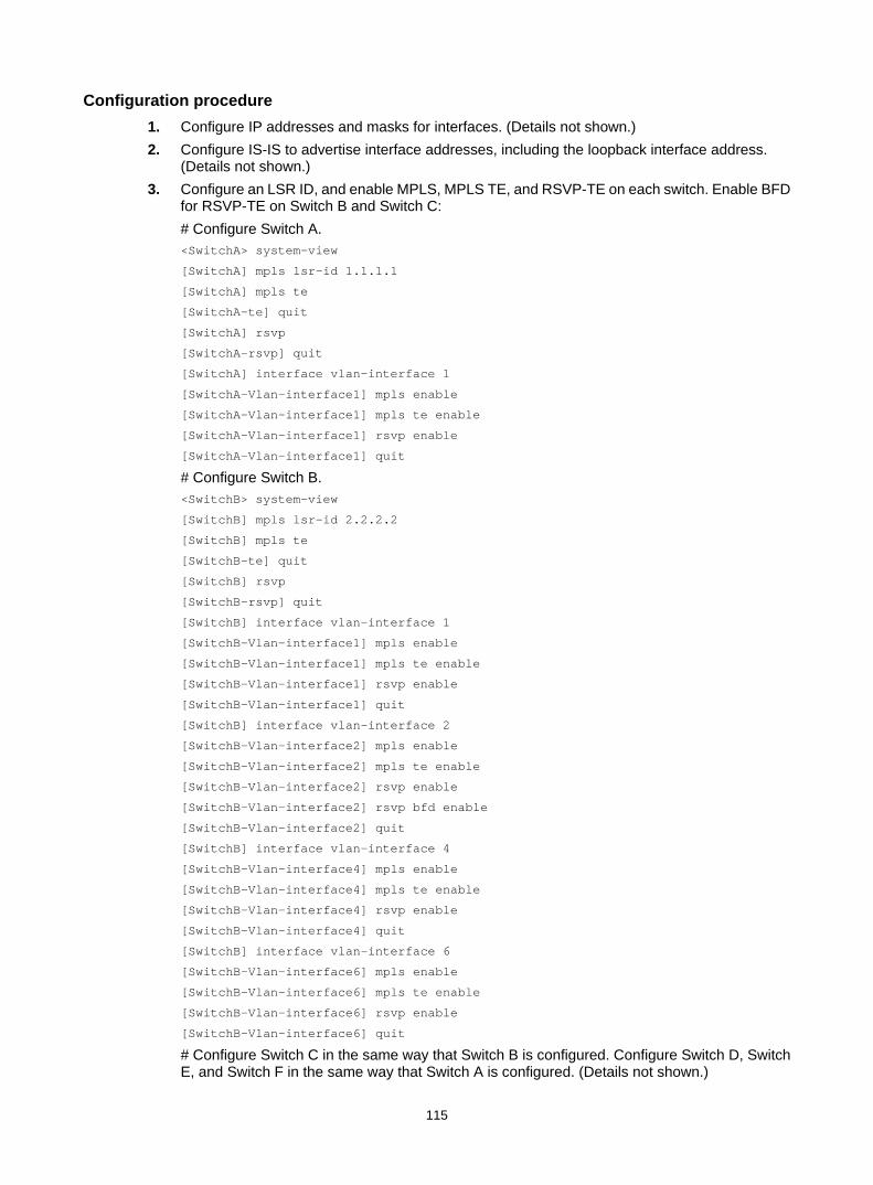
115
Configuration procedure 1. Configure IP addresses and masks for interfaces. (Details not shown.) 2. Configure IS-IS to advertise interface addresses, including the loopback interface address.
(Details not shown.) 3. Configure an LSR ID, and enable MPLS, MPLS TE, and RSVP-TE on each switch. Enable BFD
for RSVP-TE on Switch B and Switch C: # Configure Switch A. <SwitchA> system-view
[SwitchA] mpls lsr-id 1.1.1.1
[SwitchA] mpls te
[SwitchA-te] quit
[SwitchA] rsvp
[SwitchA-rsvp] quit
[SwitchA] interface vlan-interface 1
[SwitchA-Vlan-interface1] mpls enable
[SwitchA-Vlan-interface1] mpls te enable
[SwitchA-Vlan-interface1] rsvp enable
[SwitchA-Vlan-interface1] quit
# Configure Switch B. <SwitchB> system-view
[SwitchB] mpls lsr-id 2.2.2.2
[SwitchB] mpls te
[SwitchB-te] quit
[SwitchB] rsvp
[SwitchB-rsvp] quit
[SwitchB] interface vlan-interface 1
[SwitchB-Vlan-interface1] mpls enable
[SwitchB-Vlan-interface1] mpls te enable
[SwitchB-Vlan-interface1] rsvp enable
[SwitchB-Vlan-interface1] quit
[SwitchB] interface vlan-interface 2
[SwitchB-Vlan-interface2] mpls enable
[SwitchB-Vlan-interface2] mpls te enable
[SwitchB-Vlan-interface2] rsvp enable
[SwitchB-Vlan-interface2] rsvp bfd enable
[SwitchB-Vlan-interface2] quit
[SwitchB] interface vlan-interface 4
[SwitchB-Vlan-interface4] mpls enable
[SwitchB-Vlan-interface4] mpls te enable
[SwitchB-Vlan-interface4] rsvp enable
[SwitchB-Vlan-interface4] quit
[SwitchB] interface vlan-interface 6
[SwitchB-Vlan-interface6] mpls enable
[SwitchB-Vlan-interface6] mpls te enable
[SwitchB-Vlan-interface6] rsvp enable
[SwitchB-Vlan-interface6] quit
# Configure Switch C in the same way that Switch B is configured. Configure Switch D, Switch E, and Switch F in the same way that Switch A is configured. (Details not shown.)

116
4. Configure an MPLS TE tunnel on Switch A, the ingress node of the primary CRLSP: # Configure an explicit path named pri-path for the primary CRLSP. [SwitchA] explicit-path pri-path
[SwitchA-explicit-path-pri-path] nexthop 2.1.1.2
[SwitchA-explicit-path-pri-path] nexthop 3.1.1.2
[SwitchA-explicit-path-pri-path] nexthop 4.1.1.2
[SwitchA-explicit-path-pri-path] nexthop 4.4.4.4
[SwitchA-explicit-path-pri-path] quit
# Configure an MPLS TE tunnel. [SwitchA] interface tunnel 1 mode mpls-te
[SwitchA-Tunnel1] ip address 10.1.1.1 255.255.255.0
# Specify the tunnel destination address as the LSR ID of Switch D. [SwitchA-Tunnel1] destination 4.4.4.4
# Specify the tunnel signaling protocol as RSVP-TE. [SwitchA-Tunnel1] mpls te signaling rsvp-te
# Specify the explicit path as pri-path. [SwitchA-Tunnel1] mpls te path preference 1 explicit-path pri-path
# Enable FRR for the MPLS TE tunnel. [SwitchA-Tunnel1] mpls te fast-reroute
[SwitchA-Tunnel1] quit
# Execute the display interface tunnel command on Switch A. The output shows that the MPLS TE interface Tunnel1 is up. [SwitchA] display interface tunnel
Tunnel1 current state: UP
Line protocol current state: UP
Description: Tunnel1 Interface
The Maximum Transmit Unit is 64000
Internet Address is 10.1.1.1/24 Primary
Tunnel source unknown, destination 4.4.4.4
Tunnel bandwidth 64 (kbps)
Tunnel TTL 255
Tunnel protocol/transport CR_LSP
Last clearing of counters: Never
Last 300 seconds input rate: 0 bytes/sec, 0 bits/sec, 0 packets/sec
Last 300 seconds output rate: 1911 bytes/sec, 15288 bits/sec, 0 packets/sec
0 packets input, 0 bytes, 0 drops
1526 packets output, 22356852 bytes, 0 drops
# Execute the display mpls te tunnel-interface command on Switch A to display detailed information about the MPLS TE tunnel interface. [SwitchA] display mpls te tunnel-interface
Tunnel Name : Tunnel 1
Tunnel State : Up (Main CRLSP up, Shared-resource CRLSP down)
Tunnel Attributes :
LSP ID : 16802 Tunnel ID : 1
Admin State : Normal
Ingress LSR ID : 2.2.2.2 Egress LSR ID : 4.4.4.4
Signaling : RSVP-TE Static CRLSP Name : -
Resv Style : SE

117
Tunnel mode : -
Reverse-LSP name : -
Reverse-LSP LSR ID : - Reverse-LSP Tunnel ID: -
Class Type : CT0 Tunnel Bandwidth : 0 kbps
Reserved Bandwidth : 0 kbps
Setup Priority : 7 Holding Priority : 7
Affinity Attr/Mask : 0/0
Explicit Path : exp1
Backup Explicit Path : -
Metric Type : TE
Record Route : Enabled Record Label : Enabled
FRR Flag : Enabled Bandwidth Protection : Disabled
Backup Bandwidth Flag: Disabled Backup Bandwidth Type: -
Backup Bandwidth : -
Bypass Tunnel : No Auto Created : No
Route Pinning : Disabled
Retry Limit : 3 Retry Interval : 2 sec
Reoptimization : Disabled Reoptimization Freq : -
Backup Type : None Backup LSP ID : -
Auto Bandwidth : Disabled Auto Bandwidth Freq : -
Min Bandwidth : - Max Bandwidth : -
Collected Bandwidth : -
5. Configure auto FRR on Switch B (the PLR): # Enable the automatic bypass tunnel setup function globally. [SwitchB] mpls te
[SwitchB-te] auto-tunnel backup
# Specify interface numbers 50 to 100 for the automatically created bypass tunnels. [SwitchB-te-auto-bk] tunnel-number min 50 max 100
[SwitchB-te-auto-bk] quit
Verifying the configuration # Execute the display interface tunnel brief on Switch B. The output shows that two tunnels have been created automatically. [SwitchB] display interface tunnel brief
Brief information on interface(s) under route mode:
Link: ADM - administratively down; Stby - standby
Protocol: (s) - spoofing
Interface Link Protocol Main IP Description
Tun50 UP UP --
Tun51 UP UP --
# Execute the display mpls te tunnel-interface command on Switch B to display information about Tunnel 50 and Tunnel 51. The output shows that Tunnel 50 and Tunnel 51 are automatically created bypass tunnels. Tunnel 50 is a node-protection bypass tunnel (egress LSR ID is 4.4.4.4, the LSR ID of Switch D). Tunnel 51 is a link-protection bypass tunnel (egress LSR ID is 3.3.3.3, the LSR ID of Switch C). [SwitchB] display mpls te tunnel-interface tunnel 50
Tunnel Name : Tunnel 50
Tunnel State : Up (Main CRLSP up, Shared-resource CRLSP down)
Tunnel Attributes :

118
LSP ID : 16802 Tunnel ID : 50
Admin State : Normal
Ingress LSR ID : 2.2.2.2 Egress LSR ID : 4.4.4.4
Signaling : RSVP-TE Static CRLSP Name : -
Resv Style : SE
Tunnel mode : -
Reverse-LSP name : -
Reverse-LSP LSR ID : - Reverse-LSP Tunnel ID: -
Class Type : CT0 Tunnel Bandwidth : 0 kbps
Reserved Bandwidth : 0 kbps
Setup Priority : 7 Holding Priority : 7
Affinity Attr/Mask : 0/0
Explicit Path : -
Backup Explicit Path : -
Metric Type : TE
Record Route : Enabled Record Label : Disabled
FRR Flag : Disabled Bandwidth Protection : Disabled
Backup Bandwidth Flag: Disabled Backup Bandwidth Type: -
Backup Bandwidth : -
Bypass Tunnel : Yes Auto Created : Yes
Route Pinning : Disabled
Retry Limit : 3 Retry Interval : 2 sec
Reoptimization : Disabled Reoptimization Freq : -
Backup Type : None Backup LSP ID : -
Auto Bandwidth : Disabled Auto Bandwidth Freq : -
Min Bandwidth : - Max Bandwidth : -
Collected Bandwidth : -
[SwitchB] display mpls te tunnel-interface tunnel 51
Tunnel Name : Tunnel 51
Tunnel State : Up (Main CRLSP up, Shared-resource CRLSP down)
Tunnel Attributes :
LSP ID : 16802 Tunnel ID : 51
Admin State : Normal
Ingress LSR ID : 2.2.2.2 Egress LSR ID : 3.3.3.3
Signaling : RSVP-TE Static CRLSP Name : -
Resv Style : SE
Tunnel mode : -
Reverse-LSP name : -
Reverse-LSP LSR ID : - Reverse-LSP Tunnel ID: -
Class Type : CT0 Tunnel Bandwidth : 0 kbps
Reserved Bandwidth : 0 kbps
Setup Priority : 7 Holding Priority : 7
Affinity Attr/Mask : 0/0
Explicit Path : -
Backup Explicit Path : -
Metric Type : TE
Record Route : Enabled Record Label : Disabled
FRR Flag : Disabled Bandwidth Protection : Disabled

119
Backup Bandwidth Flag: Disabled Backup Bandwidth Type: -
Backup Bandwidth : -
Bypass Tunnel : Yes Auto Created : Yes
Route Pinning : Disabled
Retry Limit : 3 Retry Interval : 2 sec
Reoptimization : Disabled Reoptimization Freq : -
Backup Type : None Backup LSP ID : -
Auto Bandwidth : Disabled Auto Bandwidth Freq : -
Min Bandwidth : - Max Bandwidth : -
Collected Bandwidth : -
# Execute the display mpls lsp command on Switch B. The output shows that the current bypass tunnel that protects the primary CRLSP is Tunnel 50. [SwitchB] display mpls lsp
FEC Proto In/Out Label Interface/Out NHLFE
2.2.2.2/51/16802 RSVP -/3 Vlan4
2.2.2.2/1/16802 RSVP -/1151 Vlan2
Backup -/3 Tun50
2.2.2.2/50/16802 RSVP -/3 Vlan6
3.2.1.2 Local -/- Vlan6
3.3.1.2 Local -/- Vlan6
# Execute the display rsvp lsp verbose command on Switch A to display detailed information about MPLS TE tunnel 1, the tunnel for the primary CRLSP. The output shows that Tunnel1 is protected by the bypass tunnel Tunnel 50, and the protected node is 3.1.1.1. [SwitchA] display rsvp lsp tunnel-id 1 verbose
Tunnel name: Tunnel1
Destination: 4.4.4.4 Source: 1.1.1.1
Tunnel ID: 1 LSP ID: 16802
LSR type: Ingress Direction: Unidirectional
Setup priority: 7 Holding priority: 7
In-Label: - Out-Label: 1150
In-Interface: - Out-Interface: Vlan1
Nexthop: 2.1.1.2 Exclude-any: 0
Include-Any: 0 Include-all: 0
Average bitrate: 0 kbps Maximum burst: 1000.00 bytes
Path MTU: 1500 Class type: CT0
RRO number: 12
2.1.1.1/32 Flag: 0x00 (No FRR)
2.1.1.2/32 Flag: 0x00 (No FRR)
1150 Flag: 0x01 (Global label)
2.2.2.2/32 Flag: 0x20 (No FRR/Node-ID)
3.1.1.1/32 Flag: 0x09 (FRR Avail/Node-Prot)
3.1.1.2/32 Flag: 0x00 (No FRR)
1151 Flag: 0x01 (Global label)
3.3.3.3/32 Flag: 0x20 (No FRR/Node-ID)
4.1.1.1/32 Flag: 0x00 (No FRR)
4.1.1.2/32 Flag: 0x00 (No FRR)
3 Flag: 0x01 (Global label)
4.4.4.4/32 Flag: 0x20 (No FRR/Node-ID)
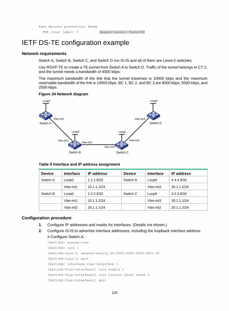
120
Fast Reroute protection: Ready
FRR inner label: 3 Bypass tunnel: Tunnel50
IETF DS-TE configuration example Network requirements
Switch A, Switch B, Switch C, and Switch D run IS-IS and all of them are Level-2 switches.
Use RSVP-TE to create a TE tunnel from Switch A to Switch D. Traffic of the tunnel belongs to CT 2, and the tunnel needs a bandwidth of 4000 kbps.
The maximum bandwidth of the link that the tunnel traverses is 10000 kbps and the maximum reservable bandwidth of the link is 10000 kbps. BC 1, BC 2, and BC 3 are 8000 kbps, 5000 kbps, and 2000 kbps.
Figure 34 Network diagram
Table 9 Interface and IP address assignment
Device Interface IP address Device Interface IP address Switch A Loop0 1.1.1.9/32 Switch D Loop0 4.4.4.9/32
Vlan-int1 10.1.1.1/24 Vlan-int3 30.1.1.2/24
Switch B Loop0 2.2.2.9/32 Switch C Loop0 3.3.3.9/32
Vlan-int1 10.1.1.2/24 Vlan-int3 30.1.1.1/24
Vlan-int2 20.1.1.1/24 Vlan-int2 20.1.1.2/24
Configuration procedure 1. Configure IP addresses and masks for interfaces. (Details not shown.) 2. Configure IS-IS to advertise interface addresses, including the loopback interface address:
# Configure Switch A. <SwitchA> system-view
[SwitchA] isis 1
[SwitchA-isis-1] network-entity 00.0005.0000.0000.0001.00
[SwitchA-isis-1] quit
[SwitchA] interface vlan-interface 1
[SwitchA-Vlan-interface1] isis enable 1
[SwitchA-Vlan-interface1] isis circuit-level level-2
[SwitchA-Vlan-interface1] quit
Vlan-int1
Vlan-int1Vlan-int2
Vlan-int2
Vlan-int3
Vlan-int3
Loop0 Loop0
Loop0 Loop0
Switch A
Switch B Switch C
Switch D

121
[SwitchA] interface loopback 0
[SwitchA-LoopBack0] isis enable 1
[SwitchA-LoopBack0] isis circuit-level level-2
[SwitchA-LoopBack0] quit
# Configure Switch B. <SwitchB> system-view
[SwitchB] isis 1
[SwitchB-isis-1] network-entity 00.0005.0000.0000.0002.00
[SwitchB-isis-1] quit
[SwitchB] interface vlan-interface 1
[SwitchB-Vlan-interface1] isis enable 1
[SwitchB-Vlan-interface1] isis circuit-level level-2
[SwitchB-Vlan-interface1] quit
[SwitchB] interface vlan-interface 2
[SwitchB-Vlan-interface2] isis enable 1
[SwitchB-Vlan-interface2] isis circuit-level level-2
[SwitchB-Vlan-interface2] quit
[SwitchB] interface loopback 0
[SwitchB-LoopBack0] isis enable 1
[SwitchB-LoopBack0] isis circuit-level level-2
[SwitchB-LoopBack0] quit
# Configure Switch C. <SwitchC> system-view
[SwitchC] isis 1
[SwitchC-isis-1] network-entity 00.0005.0000.0000.0003.00
[SwitchC-isis-1] quit
[SwitchC] interface vlan-interface 3
[SwitchC-Vlan-interface3] isis enable 1
[SwitchC-Vlan-interface3] isis circuit-level level-2
[SwitchC-Vlan-interface3] quit
[SwitchC] interface vlan-interface 2
[SwitchC-Vlan-interface2] isis enable 1
[SwitchC-Vlan-interface2] isis circuit-level level-2
[SwitchC-Vlan-interface2] quit
[SwitchC] interface loopback 0
[SwitchC-LoopBack0] isis enable 1
[SwitchC-LoopBack0] isis circuit-level level-2
[SwitchC-LoopBack0] quit
# Configure Switch D. <SwitchD> system-view
[SwitchD] isis 1
[SwitchD-isis-1] network-entity 00.0005.0000.0000.0004.00
[SwitchD-isis-1] quit
[SwitchD] interface vlan-interface 3
[SwitchD-Vlan-interface3] isis enable 1
[SwitchD-Vlan-interface3] isis circuit-level level-2
[SwitchD-Vlan-interface3] quit
[SwitchD] interface loopback 0

122
[SwitchD-LoopBack0] isis enable 1
[SwitchD-LoopBack0] isis circuit-level level-2
[SwitchD-LoopBack0] quit
# Execute the display ip routing-table command on each switch to verify that the switches have learned the routes to one another, including the routes to the loopback interfaces. Take Switch A as an example: [SwitchA] display ip routing-table
Destinations : 10 Routes : 10
Destination/Mask Proto Pre Cost NextHop Interface
1.1.1.9/32 Direct 0 0 127.0.0.1 InLoop0
2.2.2.9/32 ISIS 15 10 10.1.1.2 Vlan1
3.3.3.9/32 ISIS 15 20 10.1.1.2 Vlan1
4.4.4.9/32 ISIS 15 30 10.1.1.2 Vlan1
10.1.1.0/24 Direct 0 0 10.1.1.1 Vlan1
10.1.1.1/32 Direct 0 0 127.0.0.1 InLoop0
20.1.1.0/24 ISIS 15 20 10.1.1.2 Vlan1
30.1.1.0/24 ISIS 15 30 10.1.1.2 Vlan1
127.0.0.0/8 Direct 0 0 127.0.0.1 InLoop0
127.0.0.1/32 Direct 0 0 127.0.0.1 InLoop0
3. Configure an LSR ID, enable MPLS, MPLS TE, and RSVP-TE, and configure the DS-TE mode as IETF: # Configure Switch A. [SwitchA] mpls lsr-id 1.1.1.9
[SwitchA] mpls te
[SwitchA-te] ds-te mode ietf
[SwitchA-te] quit
[SwitchA] rsvp
[SwitchA-rsvp] quit
[SwitchA] interface vlan-interface 1
[SwitchA-Vlan-interface1] mpls enable
[SwitchA-Vlan-interface1] mpls te enable
[SwitchA-Vlan-interface1] rsvp enable
[SwitchA-Vlan-interface1] quit
# Configure Switch B. [SwitchB] mpls lsr-id 2.2.2.9
[SwitchB] mpls te
[SwitchB-te] ds-te mode ietf
[SwitchB-te] quit
[SwitchB] rsvp
[SwitchB-rsvp] quit
[SwitchB] interface vlan-interface 1
[SwitchB-Vlan-interface1] mpls enable
[SwitchB-Vlan-interface1] mpls te enable
[SwitchB-Vlan-interface1] rsvp enable
[SwitchB-Vlan-interface1] quit
[SwitchB] interface vlan-interface 2
[SwitchB-Vlan-interface2] mpls enable
[SwitchB-Vlan-interface2] mpls te enable
[SwitchB-Vlan-interface2] rsvp enable

123
[SwitchB-Vlan-interface2] quit
# Configure Switch C. [SwitchC] mpls lsr-id 3.3.3.9
[SwitchC] mpls te
[SwitchC-te] ds-te mode ietf
[SwitchC-te] quit
[SwitchC] rsvp
[SwitchC-rsvp] quit
[SwitchC] interface vlan-interface 3
[SwitchC-Vlan-interface3] mpls enable
[SwitchC-Vlan-interface3] mpls te enable
[SwitchC-Vlan-interface3] rsvp enable
[SwitchC-Vlan-interface3] quit
[SwitchC] interface vlan-interface 2
[SwitchC-Vlan-interface2] mpls enable
[SwitchC-Vlan-interface2] mpls te enable
[SwitchC-Vlan-interface2] rsvp enable
[SwitchC-Vlan-interface2] quit
# Configure Switch D. [SwitchD] mpls lsr-id 4.4.4.9
[SwitchD] mpls te
[SwitchD-te] ds-te mode ietf
[SwitchD-te] quit
[SwitchD] rsvp
[SwitchD-rsvp] quit
[SwitchD] interface vlan-interface 3
[SwitchD-Vlan-interface3] mpls enable
[SwitchD-Vlan-interface3] mpls te enable
[SwitchD-Vlan-interface3] rsvp enable
[SwitchD-Vlan-interface3] quit
4. Configure IS-IS TE: # Configure Switch A. [SwitchA] isis 1
[SwitchA-isis-1] cost-style wide
[SwitchA-isis-1] mpls te enable level-2
[SwitchA-isis-1] quit
# Configure Switch B. [SwitchB] isis 1
[SwitchB-isis-1] cost-style wide
[SwitchB-isis-1] mpls te enable level-2
[SwitchB-isis-1] quit
# Configure Switch C. [SwitchC] isis 1
[SwitchC-isis-1] cost-style wide
[SwitchC-isis-1] mpls te enable level-2
[SwitchC-isis-1] quit
# Configure Switch D. [SwitchD] isis 1

124
[SwitchD-isis-1] cost-style wide
[SwitchD-isis-1] mpls te enable level-2
[SwitchD-isis-1] quit
5. Configure MPLS TE attributes of links: # Configure the maximum bandwidth, maximum reservable bandwidth, and bandwidth constraints on Switch A. [SwitchA] interface vlan-interface 1
[SwitchA-Vlan-interface1] mpls te max-link-bandwidth 10000
[SwitchA-Vlan-interface1] mpls te max-reservable-bandwidth rdm 10000 bc1 8000 bc2 5000 bc3 2000
[SwitchA-Vlan-interface1] quit
# Configure the maximum bandwidth, maximum reservable bandwidth, and bandwidth constraints on Switch B. [SwitchB] interface vlan-interface 1
[SwitchB-Vlan-interface1] mpls te max-link-bandwidth 10000
[SwitchB-Vlan-interface1] mpls te max-reservable-bandwidth rdm 10000 bc1 8000 bc2 5000 bc3 2000
[SwitchB-Vlan-interface1] quit
[SwitchB] interface vlan-interface 2
[SwitchB-Vlan-interface2] mpls te max-link-bandwidth 10000
[SwitchB-Vlan-interface2] mpls te max-reservable-bandwidth rdm 10000 bc1 8000 bc2 5000 bc3 2000
[SwitchB-Vlan-interface2] quit
# Configure the maximum bandwidth, maximum reservable bandwidth, and bandwidth constraints on Switch C. [SwitchC] interface vlan-interface 3
[SwitchC-Vlan-interface3] mpls te max-link-bandwidth 10000
[SwitchC-Vlan-interface3] mpls te max-reservable-bandwidth rdm 10000 bc1 8000 bc2 5000 bc3 2000
[SwitchC-Vlan-interface3] quit
[SwitchC] interface vlan-interface 2
[SwitchC-Vlan-interface2] mpls te max-link-bandwidth 10000
[SwitchC-Vlan-interface2] mpls te max-reservable-bandwidth rdm 10000 bc1 8000 bc2 5000 bc3 2000
[SwitchC-Vlan-interface2] quit
# Configure the maximum bandwidth, maximum reservable bandwidth, and bandwidth constraints on Switch D. [SwitchD] interface vlan-interface 3
[SwitchD-Vlan-interface3] mpls te max-link-bandwidth 10000
[SwitchD-Vlan-interface3] mpls te max-reservable-bandwidth rdm 10000 bc1 8000 bc2 5000 bc3 2000
[SwitchD-Vlan-interface3] quit
6. Configure an MPLS TE tunnel on Switch A: # Create the MPLS TE tunnel interface Tunnel 1. [SwitchA] interface Tunnel 1 mode mpls-te
[SwitchA-Tunnel1] ip address 7.1.1.1 255.255.255.0
# Specify the tunnel destination address as the LSR ID of Switch D. [SwitchA-Tunnel1] destination 4.4.4.9
# Configure MPLS TE to use RSVP-TE to establish the tunnel.
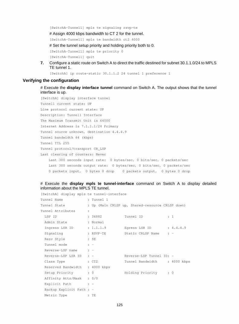
125
[SwitchA-Tunnel1] mpls te signaling rsvp-te
# Assign 4000 kbps bandwidth to CT 2 for the tunnel. [SwitchA-Tunnel1] mpls te bandwidth ct2 4000
# Set the tunnel setup priority and holding priority both to 0. [SwitchA-Tunnel1] mpls te priority 0
[SwitchA-Tunnel1] quit
7. Configure a static route on Switch A to direct the traffic destined for subnet 30.1.1.0/24 to MPLS TE tunnel 1. [SwitchA] ip route-static 30.1.1.2 24 tunnel 1 preference 1
Verifying the configuration # Execute the display interface tunnel command on Switch A. The output shows that the tunnel interface is up. [SwitchA] display interface tunnel
Tunnel1 current state: UP
Line protocol current state: UP
Description: Tunnel1 Interface
The Maximum Transmit Unit is 64000
Internet Address is 7.1.1.1/24 Primary
Tunnel source unknown, destination 4.4.4.9
Tunnel bandwidth 64 (kbps)
Tunnel TTL 255
Tunnel protocol/transport CR_LSP
Last clearing of counters: Never
Last 300 seconds input rate: 0 bytes/sec, 0 bits/sec, 0 packets/sec
Last 300 seconds output rate: 0 bytes/sec, 0 bits/sec, 0 packets/sec
0 packets input, 0 bytes 0 drop 0 packets output, 0 bytes 0 drop
# Execute the display mpls te tunnel-interface command on Switch A to display detailed information about the MPLS TE tunnel. [SwitchA] display mpls te tunnel-interface
Tunnel Name : Tunnel 1
Tunnel State : Up (Main CRLSP up, Shared-resource CRLSP down)
Tunnel Attributes :
LSP ID : 36882 Tunnel ID : 1
Admin State : Normal
Ingress LSR ID : 1.1.1.9 Egress LSR ID : 4.4.4.9
Signaling : RSVP-TE Static CRLSP Name : -
Resv Style : SE
Tunnel mode : -
Reverse-LSP name : -
Reverse-LSP LSR ID : - Reverse-LSP Tunnel ID: -
Class Type : CT2 Tunnel Bandwidth : 4000 kbps
Reserved Bandwidth : 4000 kbps
Setup Priority : 0 Holding Priority : 0
Affinity Attr/Mask : 0/0
Explicit Path : -
Backup Explicit Path : -
Metric Type : TE
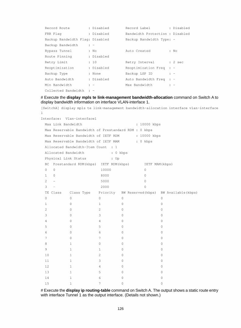
126
Record Route : Disabled Record Label : Disabled
FRR Flag : Disabled Bandwidth Protection : Disabled
Backup Bandwidth Flag: Disabled Backup Bandwidth Type: -
Backup Bandwidth : -
Bypass Tunnel : No Auto Created : No
Route Pinning : Disabled
Retry Limit : 10 Retry Interval : 2 sec
Reoptimization : Disabled Reoptimization Freq : -
Backup Type : None Backup LSP ID : -
Auto Bandwidth : Disabled Auto Bandwidth Freq : -
Min Bandwidth : - Max Bandwidth : -
Collected Bandwidth : -
# Execute the display mpls te link-management bandwidth-allocation command on Switch A to display bandwidth information on interface VLAN-interface 1. [SwitchA] display mpls te link-management bandwidth-allocation interface vlan-interface 1
Interface: Vlan-interface1
Max Link Bandwidth : 10000 kbps
Max Reservable Bandwidth of Prestandard RDM : 0 kbps
Max Reservable Bandwidth of IETF RDM : 10000 kbps
Max Reservable Bandwidth of IETF MAM : 0 kbps
Allocated Bandwidth-Item Count : 1
Allocated Bandwidth : 0 kbps
Physical Link Status : Up
BC Prestandard RDM(kbps) IETF RDM(kbps) IETF MAM(kbps)
0 0 10000 0
1 0 8000 0
2 - 5000 0
3 - 2000 0
TE Class Class Type Priority BW Reserved(kbps) BW Available(kbps)
0 0 0 0 0
1 0 1 0 0
2 0 2 0 0
3 0 3 0 0
4 0 4 0 0
5 0 5 0 0
6 0 6 0 0
7 0 7 0 0
8 1 0 0 0
9 1 1 0 0
10 1 2 0 0
11 1 3 0 0
12 1 4 0 0
13 1 5 0 0
14 1 6 0 0
15 1 7 0 0
# Execute the display ip routing-table command on Switch A. The output shows a static route entry with interface Tunnel 1 as the output interface. (Details not shown.)

127
Troubleshooting MPLS TE No TE LSA generated Symptom
OSPF TE is configured but no TE LSAs can be generated to describe MPLS TE attributes.
Analysis For TE LSAs to be generated, at least one OSPF neighbor must reach FULL state.
Solution 1. To resolve the problem:
a. Use the display current-configuration command to verify that MPLS TE is configured on involved interfaces.
b. Use the debugging ospf mpls-te command to verify that OSPF can receive the TE LINK establishment message.
c. Use the display ospf peer command to verify that OSPF neighbors are established correctly.
2. If the problem persists, contact Hewlett Packard Enterprise Support.

128
Configuring a static CRLSP Overview
A static Constraint-based Routed Label Switched Path (CRLSP) is established by manually specifying CRLSP setup information on the ingress, transit, and egress nodes of the forwarding path. The CRLSP setup information includes the incoming label, outgoing label, and required bandwidth. If the device does not have enough bandwidth resources required by a CRLSP, the CRLSP cannot be established.
Static CRLSPs consume fewer resources, but they cannot automatically adapt to network topology changes. Therefore, static CRLSPs are suitable for small and stable networks with simple topologies.
Follow these guidelines to establish a static CRLSP: • Configure the ingress node as follows:
Specify the outgoing label for the CRLSP, the next hop or the outgoing interface to the next hop, and the required bandwidth.
Create an MPLS TE tunnel interface. Reference the static CRLSP for the tunnel interface. The tunnel interface adds the outgoing label of the static CRLSP to each packet, and forwards the packet to the next hop or out of the outgoing interface.
• A transit node swaps the label carried in a received packet with a specific label. It forwards the packet to the next hop or out of the outgoing interface. You must specify the incoming label, the outgoing label, the next hop or the outgoing interface, and the required bandwidth on each transit node.
• If it is not configured with the penultimate hop popping function, an egress node pops the incoming label of a packet. It performs label forwarding according to the inner label or IP forwarding. You are only required to specify the incoming label on the egress node.
• The outgoing label specified on an LSR must be the same as the incoming label specified on the directly connected downstream LSR.
Configuration procedure Static CRLSPs are special static LSPs. They use the same label space as static LSPs. On a device, a static CRLSP and a static LSP cannot use the same incoming label.
A static CRLSP can be used to forward MPLS TE traffic only after you create an MPLS TE tunnel interface on the ingress node and reference the static CRLSP for the tunnel interface. For more information about MPLS TE, see "Configuring MPLS TE."
Before you configure a static CRLSP, complete the following tasks: • Identify the ingress node, transit nodes, and egress node of the CRLSP. • Enable MPLS on all interfaces that participate in MPLS forwarding. For more information, see
"Configuring basic MPLS." • Enable MPLS TE for each node and interface that the CRLSP traverses. For more information,
see "Configuring MPLS TE."
To configure a static CRLSP:

129
Step Command Remarks 1. Enter system view. system-view N/A
2. Create a static CRLSP.
• Configure the ingress node: static-cr-lsp ingress lsp-name { nexthop next-hop-addr | outgoing-interface interface-type interface-number } out-label out-label-value [ bandwidth [ ct0 | ct1 | ct2 | ct3 ] bandwidth-value ]
• Configure a transit node: static-cr-lsp transit lsp-name in-label in-label-value { nexthop next-hop-addr | outgoing-interface interface-type interface-number } out-label out-label-value [ bandwidth [ ct0 | ct1 | ct2 | ct3 ] bandwidth-value ]
• Configure the egress node: static-cr-lsp egress lsp-name in-label in-label-value
Use one command according to the position of a device on the network. By default, no static CRLSP exists. Do not configure the next hop address as a local public IP address when configuring the static CRLSP on the ingress node or a transit node. You do not need to execute the static-cr-lsp egress command on the egress node if the outgoing label configured on the penultimate hop of the static CRLSP is 0 or 3.
Displaying static CRLSPs Execute display commands in any view.
Task Command Display static CRLSP information. display mpls static-cr-lsp [ lsp-name lsp-name ] [ verbose ]
Static CRLSP configuration example Network requirements
Switch A, Switch B, and Switch C run IS-IS.
Establish an MPLS TE tunnel over a static CRLSP from Switch A to Switch C.

130
Figure 35 Network diagram
Configuration procedure 1. Configure IP addresses and masks for interfaces. (Details not shown.) 2. Configure IS-IS to advertise interface addresses, including the loopback interface address:
# Configure Switch A. <SwitchA> system-view
[SwitchA] isis 1
[SwitchA-isis-1] network-entity 00.0005.0000.0000.0001.00
[SwitchA-isis-1] quit
[SwitchA] interface vlan-interface 1
[SwitchA-Vlan-interface1] isis enable 1
[SwitchA-Vlan-interface1] quit
[SwitchA] interface loopback 0
[SwitchA-LoopBack0] isis enable 1
[SwitchA-LoopBack0] quit
# Configure Switch B. <SwitchB> system-view
[SwitchB] isis 1
[SwitchB-isis-1] network-entity 00.0005.0000.0000.0002.00
[SwitchB-isis-1] quit
[SwitchB] interface vlan-interface 1
[SwitchB-Vlan-interface1] isis enable 1
[SwitchB-Vlan-interface1] quit
[SwitchB] interface vlan-interface 2
[SwitchB-Vlan-interface2] isis enable 1
[SwitchB-Vlan-interface2] quit
[SwitchB] interface loopback 0
[SwitchB-LoopBack0] isis enable 1
[SwitchB-LoopBack0] quit
# Configure Switch C. <SwitchC> system-view
[SwitchC] isis 1
Loop02.2.2.2/32
Vlan-int12.1.1.2/24
Vlan-int23.2.1.1/24
Vlan-int12.1.1.1/24
Vlan-int23.2.1.2/24
Loop01.1.1.1/32
Loop03.3.3.3/32
Switch A Switch C
Switch B

131
[SwitchC-isis-1] network-entity 00.0005.0000.0000.0003.00
[SwitchC-isis-1] quit
[SwitchC] interface vlan-interface 2
[SwitchC-Vlan-interface2] isis enable 1
[SwitchC-Vlan-interface2] quit
[SwitchC] interface loopback 0
[SwitchC-LoopBack0] isis enable 1
[SwitchC-LoopBack0] quit
# Execute the display ip routing-table command on each switch to verify that the switches have learned the routes to one another, including the routes to the loopback interfaces. (Details not shown.)
3. Configure an LSR ID, and enable MPLS and MPLS TE: # Configure Switch A. [SwitchA] mpls lsr-id 1.1.1.1
[SwitchA] mpls te
[SwitchA-te] quit
[SwitchA] interface vlan-interface 1
[SwitchA-Vlan-interface1] mpls enable
[SwitchA-Vlan-interface1] mpls te enable
[SwitchA-Vlan-interface1] quit
# Configure Switch B. [SwitchB] mpls lsr-id 2.2.2.2
[SwitchB] mpls te
[SwitchB-te] quit
[SwitchB] interface vlan-interface 1
[SwitchB-Vlan-interface1] mpls enable
[SwitchB-Vlan-interface1] mpls te enable
[SwitchB-Vlan-interface1] quit
[SwitchB] interface vlan-interface 2
[SwitchB-Vlan-interface2] mpls enable
[SwitchB-Vlan-interface2] mpls te enable
[SwitchB-Vlan-interface2] quit
# Configure Switch C. [SwitchC] mpls lsr-id 3.3.3.3
[SwitchC] mpls te
[SwitchC-te] quit
[SwitchC] interface vlan-interface 2
[SwitchC-Vlan-interface2] mpls enable
[SwitchC-Vlan-interface2] mpls te enable
[SwitchC-Vlan-interface2] quit
4. Configure an MPLS TE tunnel on Switch A: # Configure MPLS TE tunnel interface Tunnel 0. [SwitchA] interface tunnel 0 mode mpls-te
[SwitchA-Tunnel0] ip address 6.1.1.1 255.255.255.0
# Specify the tunnel destination address as the LSR ID of Switch C. [SwitchA-Tunnel0] destination 3.3.3.3
# Configure MPLS TE to use a static CRLSP to establish the tunnel. [SwitchA-Tunnel0] mpls te signaling static

132
[SwitchA-Tunnel0] quit
5. Create a static CRLSP: # Configure Switch A as the ingress node of the static CRLSP, specify the next hop address as 2.1.1.2 and outgoing label as 20. [SwitchA] static-cr-lsp ingress static-cr-lsp-1 nexthop 2.1.1.2 out-label 20
# On Switch A, configure tunnel 0 to reference the static CRLSP static-cr-lsp-1. [SwitchA] interface Tunnel0
[SwitchA-Tunnel0] mpls te static-cr-lsp static-cr-lsp-1
[SwitchA-Tunnel0] quit
# Configure Switch B as the transit node of the static CRLSP, specify the incoming label as 20, the next hop address as 3.2.1.2 and outgoing label as 30. [SwitchB] static-cr-lsp transit static-cr-lsp-1 in-label 20 nexthop 3.2.1.2 out-label 30
# Configure Switch C as the egress node of the static CRLSP, and specify the incoming label as 30. [SwitchC] static-cr-lsp egress static-cr-lsp-1 in-label 30
6. Configure a static route on Switch A to direct traffic destined for subnet 3.2.1.0/24 to MPLS TE tunnel 0. [SwitchA] ip route-static 3.2.1.2 24 tunnel 0 preference 1
Verifying the configuration # Execute the display interface tunnel command on Switch A. The output shows that the tunnel interface is up. [SwitchA] display interface tunnel
Tunnel0
Current state: UP
Line protocol state: UP
Description: Tunnel0 Interface
Bandwidth: 64kbps
Maximum Transmit Unit: 1496
Internet Address is 6.1.1.1/24 Primary
Tunnel source unknown, destination 3.3.3.3
Tunnel TTL 255
Tunnel protocol/transport CR_LSP
Last clearing of counters: Never
Last 300 seconds input rate: 0 bytes/sec, 0 bits/sec, 0 packets/sec
Last 300 seconds output rate: 0 bytes/sec, 0 bits/sec, 0 packets/sec
Input: 0 packets, 0 bytes, 0 drops
Output: 0 packets, 0 bytes, 0 drops
# Execute the display mpls te tunnel-interface command on Switch A to display detailed information about the MPLS TE tunnel. [SwitchA] display mpls te tunnel-interface
Tunnel Name : Tunnel 0
Tunnel State : Up (Main CRLSP up)
Tunnel Attributes :
LSP ID : 1 Tunnel ID : 0
Admin State : Normal
Ingress LSR ID : 1.1.1.1 Egress LSR ID : 3.3.3.3

133
Signaling : Static Static CRLSP Name : static-cr-lsp-1
Resv Style : -
Tunnel mode : -
Reverse-LSP name : -
Reverse-LSP LSR ID : - Reverse-LSP Tunnel ID: -
Class Type : - Tunnel Bandwidth : -
Reserved Bandwidth : -
Setup Priority : 0 Holding Priority : 0
Affinity Attr/Mask : -/-
Explicit Path : -
Backup Explicit Path : -
Metric Type : TE
Record Route : - Record Label : -
FRR Flag : - Backup Bandwidth Flag: -
Backup Bandwidth Type: - Backup Bandwidth : -
Route Pinning : -
Retry Limit : 3 Retry Interval : 2 sec
Reoptimization : - Reoptimization Freq : -
Backup Type : - Backup LSP ID : -
Auto Bandwidth : - Auto Bandwidth Freq : -
Min Bandwidth : - Max Bandwidth : -
Collected Bandwidth : -
# Execute the display mpls lsp command or the display mpls static-cr-lsp command on each switch to display the static CRLSP information. [SwitchA] display mpls lsp
FEC Proto In/Out Label Interface/Out NHLFE
1.1.1.1/0/1 StaticCR -/20 Vlan1
2.1.1.2 Local -/- Vlan1
[SwitchB] display mpls lsp
FEC Proto In/Out Label Interface/Out NHLFE
- StaticCR 20/30 Vlan2
3.2.1.2 Local -/- Vlan2
[SwitchC] display mpls lsp
FEC Proto In/Out Label Interface/Out NHLFE
- StaticCR 30/- -
[SwitchA] display mpls static-cr-lsp
Name LSR Type In/Out Label Out Interface State
static-cr-lsp-1 Ingress Null/20 Vlan1 Up
[SwitchB] display mpls static-cr-lsp
Name LSR Type In/Out Label Out Interface State
static-cr-lsp-1 Transit 20/30 Vlan2 Up
[SwitchC] display mpls static-cr-lsp
Name LSR Type In/Out Label Out Interface State
static-cr-lsp1 Egress 30/Null - Up
# Execute the display ip routing-table command on Switch A. The output shows a static route entry with interface Tunnel 0 as the output interface. [SwitchA] display ip routing-table

134
Destinations : 12 Routes : 12
Destination/Mask Proto Pre Cost NextHop Interface
0.0.0.0/32 Direct 0 0 127.0.0.1 InLoop0
1.1.1.1/32 Direct 0 0 127.0.0.1 InLoop0
2.1.1.0/24 Direct 0 0 2.1.1.1 Vlan1
2.1.1.0/32 Direct 0 0 2.1.1.1 Vlan1
2.1.1.1/32 Direct 0 0 127.0.0.1 InLoop0
2.1.1.255/32 Direct 0 0 2.1.1.1 Vlan1
2.2.2.2/32 IS_L1 15 10 2.1.1.2 Vlan1
3.2.1.0/24 Static 1 0 0.0.0.0 Tun0
3.3.3.3/32 IS_L1 15 20 2.1.1.2 Vlan1
6.1.1.0/24 Direct 0 0 6.1.1.1 Tun0
6.1.1.0/32 Direct 0 0 6.1.1.1 Tun0
6.1.1.1/32 Direct 0 0 127.0.0.1 InLoop0
6.1.1.255/32 Direct 0 0 6.1.1.1 Tun0

135
Configuring RSVP Overview
The Resource Reservation Protocol (RSVP) is a signaling protocol that reserves resources on a network. Extended RSVP supports MPLS label distribution and allows resource reservation information to be transmitted with label bindings. This extended RSVP is called RSVP-TE. RSVP-TE is a label distribution protocol for MPLS TE. It distributes MPLS labels and reserves resources on the nodes of a specific path to establish a CRLSP.
RSVP messages RSVP uses the following types of messages: • Path messages—Sent by the sender downstream along the data transmission path to save
path state information on each node along the path. • Resv messages—Sent by the receiver upstream towards the sender to request resource
reservation and to create and maintain reservation state on each node along the reverse of the data transmission path.
• PathTear messages—Sent downstream by the sender or a transit node to remove the path state and related reservation state on each node along the path.
• ResvTear messages—Sent upstream by the receiver or a transit node to remove the reservation state on each node along the path.
• PathErr messages—Sent upstream by the receiver or a transit node to report Path message processing errors to the sender. They do not affect the state of the nodes along the path.
• ResvErr messages—Sent downstream by the sender or a transit node to notify the downstream nodes that an error has occurred during Resv message processing or that a reservation error has occurred because of preemption.
• ResvConf messages—Sent to the receiver to confirm Resv messages. • Hello messages—Sent between any two directly connected RSVP neighbors to set up and
maintain the neighbor relationship. Hello messages are sent only when the RSVP hello extension has been enabled.
RSVP-TE extends RSVP by adding new objects to Path and Resv messages. In addition to label bindings, these objects also carry routing constraints to support CRLSP and FRR.
New objects added to the Path message include: • LABEL_REQUEST—Requests the downstream node to allocate a label. • EXPLICIT_ROUTE—Carries the path information calculated by the ingress node, making sure
the CRLSP is set up along that path. • RECORD_ROUTE—Records the path that the CRLSP actually traverses and the label
allocated by each node on the path. • SESSION_ATTRIBUTE—Carries the MPLS TE tunnel attributes, such as the setup priority,
holding priority, and affinity.
New objects added to the Resv message include: • LABEL—Advertises the label allocated by the downstream node to the upstream node. • RECORD_ROUTE—Records the path that the CRLSP actually traverses and the label
allocated by each node on the path.

136
CRLSP setup procedure Figure 36 Setting up a CRLSP
As shown in Figure 36, a CRLSP is set up using the following steps: 1. The ingress LSR generates a Path message that carries LABEL_REQUEST, and then forwards
the message along the path calculated by CSPF hop-by-hop towards the egress LSR. 2. After receiving the Path message, the egress LSR generates a Resv message carrying the
reservation information and the LABEL object. It forwards the Resv message to the ingress LSR along the reverse direction of the path that the Path message traveled. The Resv message advertises labels, reserves resources, and creates a reserve state on each LSR it passes, so QoS can be guaranteed for services transmitted on the CRLSP.
3. When the ingress LSR receives the Resv message, the CRLSP is established.
RSVP refresh mechanism Refresh messages
RSVP maintains resource reservation states on a node by periodically sending messages.
The resource reservation states include path states and reservation states. A path state is saved in a path state block (PSB), and a reservation state is saved in a reservation state block (RSB). A PSB is created by a Path message and saves the LABEL_REQUEST object. A RSB is created by a Resv message and saves the LABEL object.
The path states and reservation states are refreshed periodically by Path and Resv messages. A state is removed if no refresh messages for the state are received in a certain interval, and the CRLSP established based on this state is also removed.
The Path and Resv messages for refreshing the resource reservation states are collectively referred to as refresh messages. Refresh messages can also be used to recover from lost RSVP messages.
When multiple RSVP sessions exist on a network, a short refresh interval can cause network degradation, but a long refresh interval cannot meet the requirements of delay sensitive applications. To find an appropriate balance, you can use the summary refresh (Srefresh) and the reliable RSVP message delivery functions.
Srefresh Srefresh is implemented by adding a Message_ID object to a Path or Resv message to uniquely identify the message. To refresh Path and Resv states, RSVP does not need to send standard Path and Resv messages. Instead, it sends an Srefresh message carrying a set of Message_ID objects that identify the Path and Resv states to be refreshed. The Srefresh function reduces the number of refresh messages on the network and speeds up refresh message processing.
Reliable RSVP message delivery An RSVP sender cannot know or retransmit lost RSVP messages. The reliable RSVP message delivery mechanism is designed to ensure reliable transmission.
This mechanism requires the peer device to acknowledge each RSVP message received from the local device. If no acknowledgment is received, the local device retransmits the message.
To implement reliable RSVP message delivery, a node sends an RSVP message that includes a Message_ID object in which the ACK_Desired flag is set. The receiver needs to confirm the delivery
Ingress Egress
Sender Receiver
Path
Path
Resv Resv

137
by sending back a message that includes the Message_ID_ACK object. If the sender does not receive a Message_ID_ACK within the retransmission interval (Rf), it performs the following tasks: • Retransmits the message when Rf expires. • Sets the next transmission interval to (1 + delta) × Rf.
The sender repeats this process until it receives the Message_ID_ACK before the retransmission time expires or it has transmitted the message three times.
RSVP authentication RSVP authentication ensures integrity of RSVP messages, and prevents false resource reservation requests from occupying network resources.
With RSVP authentication, the sender uses the MD5 algorithm and the authentication key to calculate a message digest for an RSVP message, and inserts the message digest to the RSVP message. When the receiver receives the message, it performs the same calculation and compares the result with the message digest. If they match, the receiver accepts the message. Otherwise, it drops the message.
By carrying a sequence number in a message, RSVP authentication can also prevent packet replay attacks. The device records the sequence number of a received RSVP message, and determines whether the subsequent messages are valid according to the recorded sequence number. If the sequence number of a subsequent message is within the valid range, the device accepts the message. Otherwise, it drops the message.
RSVP GR RSVP GR preserves the soft state and label forwarding information when the signaling protocol or control plane fails, so that LSRs can still forward packets according to forwarding entries.
RSVP GR defines the following roles: • GR restarter—Router that gracefully restarts due to a manually configured command or a fault.
It must be GR-capable. • GR helper—Neighbor of the GR restarter. A GR helper maintains the neighbor relationship with
the GR restarter and helps the GR restarter restore its LFIB information. A GR helper must be GR-capable.
The device can act only as a RSVP GR helper.
The RSVP GR function depends on the extended hello capability of RSVP. A GR-capable device advertises its GR capability and relevant time parameters to its neighbors in RSVP hello packets. If a device and all its neighbors have the RSVP GR capability and have exchanged GR parameters, each of them can function as the GR helper of another device.
A GR helper considers that a GR restarter is rebooting when it does not receive hellos or receives erroneous hellos from the restarter in three consecutive hello intervals. When a GR restarter is rebooting, the GR helpers perform the following tasks: • Retain soft state information about the GR restarter. • Continue sending hello packets periodically to the GR restarter until the restart timer expires.
If a GR helper receives a hello message from the GR restarter before the restart timer expires, the recovery timer is started and signaling packet exchange is triggered to restore the original soft state. Otherwise, all RSVP soft state information and forwarding entries relevant to the neighbor are removed. When the recovery timer expires, soft state information and forwarding entries that are not restored are removed.
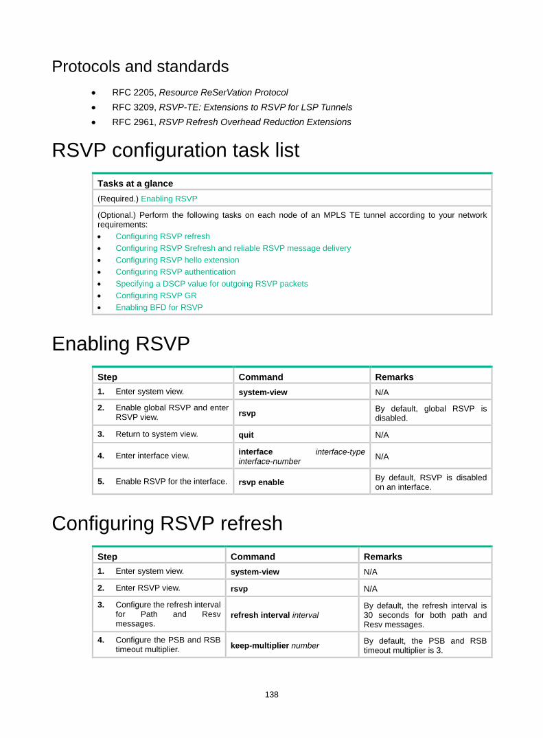
138
Protocols and standards • RFC 2205, Resource ReSerVation Protocol • RFC 3209, RSVP-TE: Extensions to RSVP for LSP Tunnels • RFC 2961, RSVP Refresh Overhead Reduction Extensions
RSVP configuration task list Tasks at a glance (Required.) Enabling RSVP
(Optional.) Perform the following tasks on each node of an MPLS TE tunnel according to your network requirements: • Configuring RSVP refresh • Configuring RSVP Srefresh and reliable RSVP message delivery • Configuring RSVP hello extension • Configuring RSVP authentication • Specifying a DSCP value for outgoing RSVP packets • Configuring RSVP GR • Enabling BFD for RSVP
Enabling RSVP Step Command Remarks 1. Enter system view. system-view N/A
2. Enable global RSVP and enter RSVP view. rsvp By default, global RSVP is
disabled.
3. Return to system view. quit N/A
4. Enter interface view. interface interface-type interface-number N/A
5. Enable RSVP for the interface. rsvp enable By default, RSVP is disabled on an interface.
Configuring RSVP refresh Step Command Remarks 1. Enter system view. system-view N/A
2. Enter RSVP view. rsvp N/A
3. Configure the refresh interval for Path and Resv messages.
refresh interval interval By default, the refresh interval is 30 seconds for both path and Resv messages.
4. Configure the PSB and RSB timeout multiplier. keep-multiplier number By default, the PSB and RSB
timeout multiplier is 3.

139
Configuring RSVP Srefresh and reliable RSVP message delivery
After Srefresh is enabled, RSVP maintains the path and reservation states by sending Srefresh messages rather than standard refresh messages.
To configure Srefresh and reliable RSVP message delivery:
Step Command Remarks 1. Enter system view. system-view N/A
2. Enter interface view. interface interface-type interface-number N/A
3. Enable Srefresh and reliable RSVP message delivery.
rsvp reduction srefresh [ reliability ]
By default, Srefresh and reliable RSVP message delivery are disabled.
4. Configure the retransmission increment value for reliable RSVP message delivery.
rsvp reduction retransmit increment increment-value
By default, the RSVP message retransmission increment is 1. This command takes effect after reliable RSVP message delivery is enabled by using the rsvp reduction srefresh reliability command.
5. Configure the retransmission interval for reliable RSVP message delivery.
rsvp reduction retransmit interval retrans-timer-value
By default, the RSVP message retransmission interval is 500 milliseconds. This command takes effect after reliable RSVP message delivery is enabled by using the rsvp reduction srefresh reliability command.
Configuring RSVP hello extension When RSVP hello extension is enabled on an interface, the device receives and sends hello messages through the interface to detect the neighbor's status.
If the device receives a hello request from the neighbor, the device replies with a hello ACK message. If the device receives no hello request from the neighbor within the interval specified by the hello interval command, the device sends hello requests to the neighbor.
When the number of consecutive lost hellos or erroneous hellos from the neighbor reaches the maximum (specified by the hello lost command), the device determines the neighbor is in fault. If GR is configured, the device serves as a GR helper to help the neighbor to restart. If FRR is configured, the device performs an FRR. For more information about FRR, see "Configuring MPLS TE."
To configure RSVP hello extension:
Step Command Remarks 1. Enter system view. system-view N/A
2. Enter RSVP view. rsvp N/A
3. Configure the maximum hello lost times By default, the maximum number

140
Step Command Remarks number of consecutive lost or erroneous hellos.
is 4.
4. Configure the interval for sending hello requests. hello interval interval By default, hello requests are sent
every 5 seconds.
5. Return to system view. quit N/A
6. Enter interface view. interface interface-type interface-number N/A
7. Enable RSVP hello extension. rsvp hello enable By default, RSVP hello extension
is disabled.
Configuring RSVP authentication RSVP adopts hop-by-hop authentication to prevent fake resource reservation requests from occupying network resources. The interfaces at the two ends of a link must use the same authentication key.
RSVP authentication can be configured in the following views: • RSVP view—Configuration applies to all RSVP security associations. • RSVP neighbor view—Configuration applies only to RSVP security associations with the
specified RSVP neighbor. • Interface view—Configuration applies only to RSVP security associations established on the
current interface.
Configurations in RSVP neighbor view, interface view, and RSVP view are in descending order of priority.
To configure RSVP authentication in RSVP neighbor view:
Step Command Remarks 1. Enter system view. system-view N/A
2. Enter RSVP view. rsvp N/A
3. Create an RSVP authentication neighbor and enter RSVP neighbor view.
peer ip-address By default, the device does not have any RSVP authentication neighbors.
4. Enable RSVP authentication for the RSVP neighbor and specify the authentication key.
authentication key { cipher | plain } auth-key
By default, RSVP authentication is disabled.
5. Enable challenge-response handshake for the RSVP neighbor.
authentication challenge By default, the challenge-response handshake function is disabled.
6. Configure the idle timeout for the RSVP security associations with the RSVP neighbor.
authentication lifetime life-time By default, the idle timeout is 1800 seconds (30 minutes).
7. Specify the maximum number of out-of-sequence RSVP authentication messages that can be received from the RSVP neighbor.
authentication window-size number
By default, only one RSVP authenticated message can be received out of sequence.

141
To configure RSVP authentication in interface view:
Step Command Remarks 1. Enter system view. system-view N/A
2. Enter interface view. interface interface-type interface-number N/A
3. Enable RSVP authentication on the interface and configure the authentication key.
rsvp authentication key { cipher | plain } auth-key
By default, RSVP authentication is disabled. Do not enable both RSVP authentication and FRR on the same interface.
4. Enable challenge-response handshake on the interface. rsvp authentication challenge
By default, the challenge-response handshake function is disabled.
5. Configure the idle timeout for RSVP security associations on the interface.
rsvp authentication lifetime life-time
By default, the idle timeout is 1800 seconds (30 minutes).
6. Specify the maximum number of out-of-sequence RSVP authentication messages that can be received on the interface.
rsvp authentication window-size number
By default, only one RSVP authenticated message can be received out of sequence.
To configure RSVP authentication in RSVP view:
Step Command Remarks 1. Enter system view. system-view N/A
2. Enter RSVP view. rsvp N/A
3. Enable RSVP authentication globally and configure the authentication key.
authentication key { cipher | plain } auth-key
By default, RSVP authentication is disabled.
4. Enable challenge-response handshake globally. authentication challenge
By default, the challenge-response handshake function is disabled.
5. Configure the global idle timeout for RSVP security associations.
authentication lifetime life-time By default, the idle timeout is 1800 seconds (30 minutes).
6. Specify the global RSVP authentication window size—the maximum number of RSVP authenticated messages that can be received out of sequence.
authentication window-size number
By default, only one RSVP authenticated message can be received out of sequence.
Specifying a DSCP value for outgoing RSVP packets
The DSCP value of an IP packet specifies the priority level of the packet and affects the transmission priority of the packet.
To specify a DSCP value for outgoing RSVP packets:
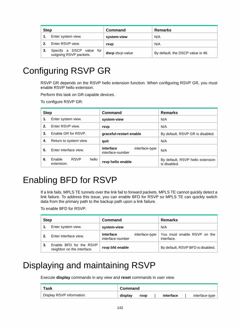
142
Step Command Remarks 1. Enter system view. system-view N/A
2. Enter RSVP view. rsvp N/A
3. Specify a DSCP value for outgoing RSVP packets. dscp dscp-value By default, the DSCP value is 48.
Configuring RSVP GR RSVP GR depends on the RSVP hello extension function. When configuring RSVP GR, you must enable RSVP hello extension.
Perform this task on GR-capable devices.
To configure RSVP GR:
Step Command Remarks 1. Enter system view. system-view N/A
2. Enter RSVP view. rsvp N/A
3. Enable GR for RSVP. graceful-restart enable By default, RSVP GR is disabled.
4. Return to system view. quit N/A
5. Enter interface view. interface interface-type interface-number N/A
6. Enable RSVP hello extension. rsvp hello enable By default, RSVP hello extension
is disabled.
Enabling BFD for RSVP If a link fails, MPLS TE tunnels over the link fail to forward packets. MPLS TE cannot quickly detect a link failure. To address this issue, you can enable BFD for RSVP so MPLS TE can quickly switch data from the primary path to the backup path upon a link failure.
To enable BFD for RSVP:
Step Command Remarks 1. Enter system view. system-view N/A
2. Enter interface view. interface interface-type interface-number
You must enable RSVP on the interface.
3. Enable BFD for the RSVP neighbor on the interface. rsvp bfd enable By default, RSVP BFD is disabled.
Displaying and maintaining RSVP Execute display commands in any view and reset commands in user view.
Task Command Display RSVP information. display rsvp [ interface [ interface-type

143
Task Command interface-number ] ]
Display information about the security associations established with RSVP neighbors.
display rsvp authentication [ from ip-address ] [ to ip-address ] [ verbose ]
Display information about CRLSPs established through RSVP.
display rsvp lsp [ destination ip-address ] [ source ip-address ] [ tunnel-id tunnel-id ] [ lsp-id lsp-id ] [ verbose ]
Display information about RSVP neighbors. display rsvp peer [ interface interface-type interface-number ] [ ip ip-address ] [ verbose ]
Display information about RSVP resource reservation requests sent to upstream devices.
display rsvp request [ destination ip-address ] [ source ip-address ] [ tunnel-id tunnel-id ] [ prev-hop ip-address ] [ verbose ]
Display information about RSVP resource reservation states.
display rsvp reservation [ destination ip-address ] [ source ip-address ] [ tunnel-id tunnel-id ] [ nexthop ip-address ] [ verbose ]
Display information about RSVP path states. display rsvp sender [ destination ip-address ] [ source ip-address ] [ tunnel-id tunnel-id ] [ lsp-id lsp-id ] [ verbose ]
Display RSVP statistics. display rsvp statistics [ interface [ interface-type interface-number ] ]
Clear RSVP security associations. reset rsvp authentication [ from ip-address to ip-address ]
Clear RSVP statistics. reset rsvp statistics [ interface [ interface-type interface-number ]
RSVP configuration examples Establishing an MPLS TE tunnel with RSVP-TE Network requirements
Switch A, Switch B, Switch C, and Switch D run IS-IS.
Use RSVP-TE to create an MPLS TE tunnel from Switch A to Switch D.
Figure 37 Network diagram
Vlan-int1
Vlan-int1Vlan-int2
Vlan-int2
Vlan-int3
Vlan-int3
Loop0 Loop0
Loop0 Loop0
Switch A
Switch B Switch C
Switch D

144
Table 10 Interface and IP address assignment
Device Interface IP address Device Interface IP address Switch A Loop0 1.1.1.9/32 Switch D Loop0 4.4.4.9/32
Vlan-int1 10.1.1.1/24 Vlan-int3 30.1.1.2/24
Switch B Loop0 2.2.2.9/32 Switch C Loop0 3.3.3.9/32
Vlan-int1 10.1.1.2/24 Vlan-int3 30.1.1.1/24
Vlan-int2 20.1.1.1/24 Vlan-int2 20.1.1.2/24
Configuration procedure 1. Configure IP addresses and masks for interfaces. (Details not shown.) 2. Configure IS-IS to advertise interface addresses, including the loopback interface address:
# Configure Switch A. <SwitchA> system-view
[SwitchA] isis 1
[SwitchA-isis-1] network-entity 00.0005.0000.0000.0001.00
[SwitchA-isis-1] quit
[SwitchA] interface vlan-interface 1
[SwitchA-Vlan-interface1] isis enable 1
[SwitchA-Vlan-interface1] quit
[SwitchA] interface loopback 0
[SwitchA-LoopBack0] isis enable 1
[SwitchA-LoopBack0] quit
# Configure Switch B. <SwitchB> system-view
[SwitchB] isis 1
[SwitchB-isis-1] network-entity 00.0005.0000.0000.0002.00
[SwitchB-isis-1] quit
[SwitchB] interface vlan-interface 1
[SwitchB-Vlan-interface1] isis enable 1
[SwitchB-Vlan-interface1] quit
[SwitchB] interface vlan-interface 2
[SwitchB-Vlan-interface2] isis enable 1
[SwitchB-Vlan-interface2] quit
[SwitchB] interface loopback 0
[SwitchB-LoopBack0] isis enable 1
[SwitchB-LoopBack0] quit
# Configure Switch C. <SwitchC> system-view
[SwitchC] isis 1
[SwitchC-isis-1] network-entity 00.0005.0000.0000.0003.00
[SwitchC-isis-1] quit
[SwitchC] interface vlan-interface 3
[SwitchC-Vlan-interface3] isis enable 1
[SwitchC-Vlan-interface3] quit
[SwitchC] interface vlan-interface 2
[SwitchC-Vlan-interface2] isis enable 1

145
[SwitchC-Vlan-interface2] quit
[SwitchC] interface loopback 0
[SwitchC-LoopBack0] isis enable 1
[SwitchC-LoopBack0] quit
# Configure Switch D. <SwitchD> system-view
[SwitchD] isis 1
[SwitchD-isis-1] network-entity 00.0005.0000.0000.0004.00
[SwitchD-isis-1] quit
[SwitchD] interface vlan-interface 3
[SwitchD-Vlan-interface3] isis enable 1
[SwitchD-Vlan-interface3] quit
[SwitchD] interface loopback 0
[SwitchD-LoopBack0] isis enable 1
[SwitchD-LoopBack0] quit
# Execute the display ip routing-table command on each switch to verify that the switches have learned the routes to one another, including the host to the loopback interfaces. (Details not shown.)
3. Configure an LSR ID, and enable MPLS, MPLS TE, and RSVP: # Configure Switch A. [SwitchA] mpls lsr-id 1.1.1.9
[SwitchA] mpls te
[SwitchA-te] quit
[SwitchA] rsvp
[SwitchA-rsvp] quit
[SwitchA] interface vlan-interface 1
[SwitchA-Vlan-interface1] mpls enable
[SwitchA-Vlan-interface1] mpls te enable
[SwitchA-Vlan-interface1] rsvp enable
[SwitchA-Vlan-interface1] quit
# Configure Switch B. [SwitchB] mpls lsr-id 2.2.2.9
[SwitchB] mpls te
[SwitchB-te] quit
[SwitchB] rsvp
[SwitchB-rsvp] quit
[SwitchB] interface vlan-interface 1
[SwitchB-Vlan-interface1] mpls enable
[SwitchB-Vlan-interface1] mpls te enable
[SwitchB-Vlan-interface1] rsvp enable
[SwitchB-Vlan-interface1] quit
[SwitchB] interface vlan-interface 2
[SwitchB-Vlan-interface2] mpls enable
[SwitchB-Vlan-interface2] mpls te enable
[SwitchB-Vlan-interface2] rsvp enable
[SwitchB-Vlan-interface2] quit
# Configure Switch C. [SwitchC] mpls lsr-id 3.3.3.9

146
[SwitchC] mpls te
[SwitchC-te] quit
[SwitchC] rsvp
[SwitchC-rsvp] quit
[SwitchC] interface vlan-interface 3
[SwitchC-Vlan-interface3] mpls enable
[SwitchC-Vlan-interface3] mpls te enable
[SwitchC-Vlan-interface3] rsvp enable
[SwitchC-Vlan-interface3] quit
[SwitchC] interface vlan-interface 2
[SwitchC-Vlan-interface2] mpls enable
[SwitchC-Vlan-interface2] mpls te enable
[SwitchC-Vlan-interface2] rsvp enable
[SwitchC-Vlan-interface2] quit
# Configure Switch D. [SwitchD] mpls lsr-id 4.4.4.9
[SwitchD] mpls te
[SwitchD-te] quit
[SwitchD] rsvp
[SwitchD-rsvp] quit
[SwitchD] interface vlan-interface 3
[SwitchD-Vlan-interface3] mpls enable
[SwitchD-Vlan-interface3] mpls te enable
[SwitchD-Vlan-interface3] rsvp enable
[SwitchD-Vlan-interface3] quit
4. Configure an MPLS TE tunnel on Switch A: # Configure MPLS TE tunnel interface Tunnel 1. [SwitchA] interface tunnel 1 mode mpls-te
[SwitchA-Tunnel1] ip address 7.1.1.1 255.255.255.0
# Specify the tunnel destination address as the LSR ID of Switch D. [SwitchA-Tunnel1] destination 4.4.4.9
# Configure MPLS TE to use RSVP-TE to establish the tunnel. [SwitchA-Tunnel1] mpls te signaling rsvp-te
[SwitchA-Tunnel1] quit
5. Configure a static route on Switch A to direct the traffic destined for subnet 30.1.1.0/24 to the MPLS TE tunnel 1 for forwarding. [SwitchA] ip route-static 30.1.1.2 24 tunnel 1 preference 1
Verifying the configuration # Execute the display interface tunnel command on Switch A. The output shows that the tunnel interface is up. [SwitchA] display interface tunnel
Tunnel1
Current state: UP
Line protocol state: UP
Description: Tunnel1 Interface
Bandwidth: 64kbps
Maximum Transmit Unit: 1496
Internet Address is 7.1.1.1/24 Primary

147
Tunnel source unknown, destination 4.4.4.9
Tunnel TTL 255
Tunnel protocol/transport CR_LSP
Last clearing of counters: Never
Last 300 seconds input rate: 0 bytes/sec, 0 bits/sec, 0 packets/sec
Last 300 seconds output rate: 6 bytes/sec, 48 bits/sec, 0 packets/sec
Input: 0 packets, 0 bytes, 0 drops
Output: 177 packets, 11428 bytes, 0 drops
# Execute the display mpls te tunnel-interface command on Switch A. The output shows detailed information about the MPLS TE tunnel. [SwitchA] display mpls te tunnel-interface
Tunnel Name : Tunnel 1
Tunnel State : Up (Main CRLSP up, Shared-resource CRLSP down)
Tunnel Attributes :
LSP ID : 23331 Tunnel ID : 1
Admin State : Normal
Ingress LSR ID : 1.1.1.9 Egress LSR ID : 4.4.4.9
Signaling : RSVP-TE Static CRLSP Name : -
Resv Style : SE
Tunnel mode : -
Reverse-LSP name : -
Reverse-LSP LSR ID : - Reverse-LSP Tunnel ID: -
Class Type : CT0 Tunnel Bandwidth : 0 kbps
Reserved Bandwidth : 0 kbps
Setup Priority : 7 Holding Priority : 7
Affinity Attr/Mask : 0/0
Explicit Path : -
Backup Explicit Path : -
Metric Type : TE
Record Route : Disabled Record Label : Disabled
FRR Flag : Disabled Backup Bandwidth Flag: Disabled
Backup Bandwidth Type: - Backup Bandwidth : -
Route Pinning : Disabled
Retry Limit : 10 Retry Interval : 2 sec
Reoptimization : Disabled Reoptimization Freq : -
Backup Type : None Backup LSP ID : -
Auto Bandwidth : Disabled Auto Bandwidth Freq : -
Min Bandwidth : - Max Bandwidth : -
Collected Bandwidth : -
# Execute the display ip routing-table command on Switch A to verify that a static route entry with interface Tunnel 1 as the output interface exists. (Details not shown.)
RSVP GR configuration example Network requirements
Switch A, Switch B, and Switch C run IS-IS.
Use RSVP-TE to establish a TE tunnel from Switch A to Switch C.

148
Configure RSVP GR on the switches to ensure continuous forwarding when a switch reboots.
Figure 38 Network diagram
Configuration procedure 1. Configure IP addresses and masks for interfaces. (Details not shown.) 2. Configure IS-IS to advertise interface addresses, including the loopback interface address.
(Details not shown.) 3. Configure an LSR ID, enable MPLS, MPLS TE, RSVP, and RSVP hello extension:
# Configure Switch A. <SwitchA> system-view
[SwitchA] mpls lsr-id 1.1.1.9
[SwitchA] mpls te
[SwitchA-te] quit
[SwitchA] rsvp
[SwitchA-rsvp] quit
[SwitchA] interface vlan-interface 1
[SwitchA-Vlan-interface1] mpls enable
[SwitchA-Vlan-interface1] mpls te enable
[SwitchA-Vlan-interface1] rsvp enable
[SwitchA-Vlan-interface1] rsvp hello enable
[SwitchA-Vlan-interface1] quit
# Configure Switch B. <SwitchB> system-view
[SwitchB] mpls lsr-id 2.2.2.9
[SwitchB] mpls te
[SwitchB-te] quit
[SwitchB] rsvp
[SwitchB-rsvp] quit
[SwitchB-mpls] interface vlan-interface 1
[SwitchB-Vlan-interface1] mpls enable
[SwitchB-Vlan-interface1] mpls te enable
[SwitchB-Vlan-interface1] rsvp enable
[SwitchB-Vlan-interface1] rsvp hello enable
[SwitchB-Vlan-interface1] quit
[SwitchB] interface vlan-interface 2
[SwitchB-Vlan-interface2] mpls enable
[SwitchB-Vlan-interface2] mpls te enable
[SwitchB-Vlan-interface2] rsvp enable
[SwitchB-Vlan-interface2] rsvp hello enable
[SwitchB-Vlan-interface2] quit
# Configure Switch C.
Loop02.2.2.9/32
Vlan-int220.1.1.1/24
Loop03.3.3.9/32
Loop01.1.1.9/32
Vlan-int110.1.1.1/24
Vlan-int110.1.1.2/24
Vlan-int220.1.1.2/24
Switch A Switch B Switch C

149
<SwitchC> system-view
[SwitchC] mpls lsr-id 3.3.3.9
[SwitchC] mpls te
[SwitchC-te] quit
[SwitchC] rsvp
[SwitchC-rsvp] quit
[SwitchC] interface vlan-interface 2
[SwitchC-Vlan-interface2] mpls enable
[SwitchC-Vlan-interface2] mpls te enable
[SwitchC-Vlan-interface2] rsvp enable
[SwitchC-Vlan-interface2] rsvp hello enable
[SwitchC-Vlan-interface2] quit
4. Configure an MPLS TE tunnel. (Details not shown.) 5. Configure RSVP GR:
# Configure Switch A. [SwitchA] rsvp
[SwitchA-rsvp] graceful-restart enable
# Configure Switch B. [SwitchB] rsvp
[SwitchB-rsvp] graceful-restart enable
# Configure Switch C. [SwitchC] rsvp
[SwitchC-rsvp] graceful-restart enable
Verifying the configuration # After a tunnel is established from Switch A and Switch C, execute the following command on Switch A: <SwitchA> display rsvp peer verbose
Peer: 10.1.1.2 Interface: Vlan1
Hello state: Up Hello type: Active
PSB count: 0 RSB count: 1
Src instance: 0x1f08 Dst instance: 0x22
Refresh reduction: Disabled Graceful Restart state: Ready
Peer GR restart time: 120000 ms Peer GR recovery time: 0 ms
The output shows that the neighbor's GR state is Ready.

150
Configuring tunnel policies Overview
Tunnel policies enable a PE to forward traffic for each MPLS VPN over a preferred tunnel or over multiple tunnels. The tunnels supported by MPLS VPN include MPLS LSPs and MPLS TE tunnels.
For more information about MPLS TE, see "Configuring MPLS TE." For more information about MPLS VPNs, see "Configuring MPLS L3VPN," "Configuring MPLS L2VPN," and "Configuring VPLS."
Configuring a tunnel policy Configuration guidelines
Follow these guidelines when you configure a tunnel policy: • To select a preferred tunnel, create a tunnel policy and specify the preferred tunnel with the
preferred-path command. The destination address of the preferred tunnel identifies a peer PE so the PE will forward traffic destined for that peer PE over the preferred tunnel. If you specify multiple preferred tunnels that have the same destination address in a tunnel
policy, only the first configured tunnel takes effect. If the first tunnel is not available, the second tunnel is used, and so forth. No load balancing
will be performed on these tunnels. This method explicitly specifies an MPLS TE tunnel for an MPLS VPN, facilitating traffic planning. As a best practice, use this method.
• To select multiple tunnels for load sharing, create a tunnel policy and specify the tunnel selection order and the number of tunnels by using the select-seq load-balance-number command. A tunnel type closer to the select-seq keyword has a higher priority. For example, the select-seq lsp cr-lsp load-balance-number 3 command gives LSP higher priority. If no LSP is available or the number of LSPs is less than 3, VPN uses CRLSP tunnels. The tunnels selected by this method are not fixed, complicating traffic planning.
If you configure both methods for a tunnel policy, the tunnel policy selects tunnels in the following steps: 1. If the destination address of a preferred tunnel identifies a peer PE, the tunnel policy uses the
preferred tunnel to forward traffic destined for the peer PE without using any other tunnels. 2. If not, the tunnel policy selects tunnels as configured by the select-seq load-balance-number
command.

151
Figure 39 MPLS VPN tunnel selection diagram
As shown in Figure 39, PE 1 and PE 2 have multiple tunnels in between and they are connected to multiple MPLS VPNs. You can control the paths for VPN traffic by using one of the following methods: • Configure multiple tunnel policies, and specify a preferred tunnel for each policy by using the
preferred-path command. Apply these policies to different MPLS VPNs to forward the traffic of each VPN over a specific tunnel.
• Configure one tunnel policy, and use the select-seq load-balance-number command to specify the tunnel selection order and the number of tunnels for load balancing. Apply the tunnel policy to MPLS VPNs to forward the traffic of every VPN over multiple tunnels.
The second method distributes traffic of a single VPN to multiple tunnels. The transmission delays on different tunnels can vary by a large amount. Therefore, the destination device or the upper layer application might take a great time to sequence the packets. As a best practice, do not use the second method.
Configuration procedure To configure a tunnel policy:
Step Command Remarks 1. Enter system view. system-view N/A
2. Create a tunnel policy, and enter tunnel policy view.
tunnel-policy tunnel-policy-name By default, no tunnel policy is configured.
3. Configure tunnel selection methods.
• (Method 1) Specify a preferred tunnel: preferred-path tunnel number
• (Method 2) Configure the tunnel selection order and the number of tunnels for load balancing: select-seq { cr-lsp | lsp } * load-balance-number number
Configure one or both methods. By default, no preferred tunnel is specified. By default, only one tunnel is selected in LSP—CRLSP order.
NOTE: For a VPN to exclusively use a tunnel, you can specify the tunnel as the preferred tunnel in a tunnel policy, and apply the policy only to that VPN.
PE 1 PE 2P 2
P 1
Tunnel 2
Tunnel 1
Tunnel 3
P 3
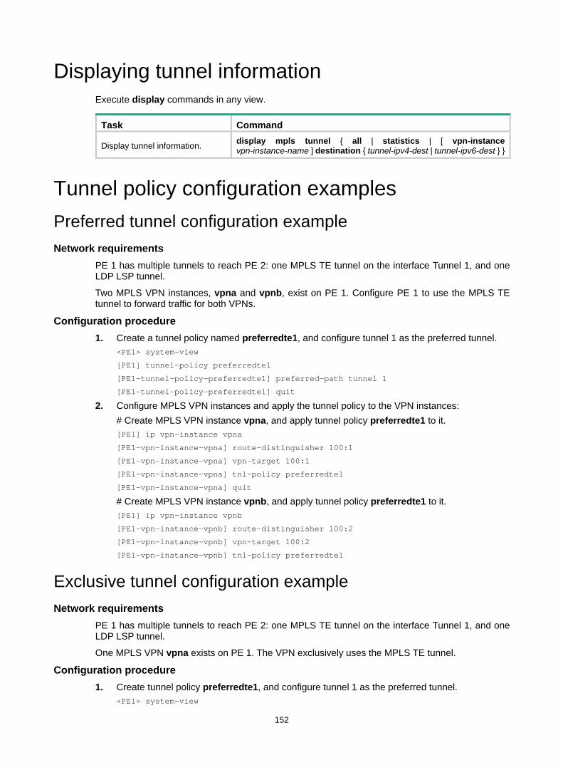
152
Displaying tunnel information Execute display commands in any view.
Task Command
Display tunnel information. display mpls tunnel { all | statistics | [ vpn-instance vpn-instance-name ] destination { tunnel-ipv4-dest | tunnel-ipv6-dest } }
Tunnel policy configuration examples Preferred tunnel configuration example Network requirements
PE 1 has multiple tunnels to reach PE 2: one MPLS TE tunnel on the interface Tunnel 1, and one LDP LSP tunnel.
Two MPLS VPN instances, vpna and vpnb, exist on PE 1. Configure PE 1 to use the MPLS TE tunnel to forward traffic for both VPNs.
Configuration procedure 1. Create a tunnel policy named preferredte1, and configure tunnel 1 as the preferred tunnel.
<PE1> system-view
[PE1] tunnel-policy preferredte1
[PE1-tunnel-policy-preferredte1] preferred-path tunnel 1
[PE1-tunnel-policy-preferredte1] quit
2. Configure MPLS VPN instances and apply the tunnel policy to the VPN instances: # Create MPLS VPN instance vpna, and apply tunnel policy preferredte1 to it. [PE1] ip vpn-instance vpna
[PE1-vpn-instance-vpna] route-distinguisher 100:1
[PE1-vpn-instance-vpna] vpn-target 100:1
[PE1-vpn-instance-vpna] tnl-policy preferredte1
[PE1-vpn-instance-vpna] quit
# Create MPLS VPN instance vpnb, and apply tunnel policy preferredte1 to it. [PE1] ip vpn-instance vpnb
[PE1-vpn-instance-vpnb] route-distinguisher 100:2
[PE1-vpn-instance-vpnb] vpn-target 100:2
[PE1-vpn-instance-vpnb] tnl-policy preferredte1
Exclusive tunnel configuration example Network requirements
PE 1 has multiple tunnels to reach PE 2: one MPLS TE tunnel on the interface Tunnel 1, and one LDP LSP tunnel.
One MPLS VPN vpna exists on PE 1. The VPN exclusively uses the MPLS TE tunnel.
Configuration procedure 1. Create tunnel policy preferredte1, and configure tunnel 1 as the preferred tunnel.
<PE1> system-view

153
[PE1] tunnel-policy preferredte1
[PE1-tunnel-policy-preferredte1] preferred-path tunnel 1
[PE1-tunnel-policy-preferredte1] quit
2. Create MPLS VPN instance vpna, and apply tunnel policy preferredte1 to it. [PE1] ip vpn-instance vpna
[PE1-vpn-instance-vpna] route-distinguisher 100:1
[PE1-vpn-instance-vpna] vpn-target 100:1
[PE1-vpn-instance-vpna] tnl-policy preferredte1
[PE1-vpn-instance-vpna] quit
Tunnel selection order configuration example Network requirements
PE 1 has multiple tunnels to reach PE 2: one MPLS TE tunnel on the interface Tunnel 1, and one LDP LSP tunnel.
Only one MPLS VPN, vpna, exists on PE 1. Select only one tunnel in LDP LSP-MPLS TE order for this VPN.
Configuration procedure # Create tunnel policy seq-lsp-te. <PE1> system-view
[PE1] tunnel-policy seq-lsp-te
# Specify the tunnel selection order and set the number of tunnels for load balancing to 1—no load balancing. [PE1-tunnel-policy-seq-lsp-te] select-seq lsp cr-lsp load-balance-number 1
[PE1-tunnel-policy-seq-lsp-te] quit
# Create MPLS VPN instance vpna, and apply tunnel policy seq-lsp-te to it. [PE1] ip vpn-instance vpna
[PE1-vpn-instance-vpna] route-distinguisher 100:1
[PE1-vpn-instance-vpna] vpn-target 100:1
[PE1-vpn-instance-vpna] tnl-policy seq-lsp-te
Preferred tunnel and tunnel selection order configuration example Network requirements
PE 1 has multiple tunnels to reach PE 2: two MPLS TE tunnels on the interface Tunnel 1 and Tunnel 3, and one LDP LSP tunnel.
PE 1 has multiple MPLS VPN instances: vpna, vpnb, vpnc, vpnd, and vpne. Table 11 shows the tunnel policy that PE 1 uses for each VPN instance.
Table 11 Tunnel policies used for VPN instances
VPN instance Tunnel policy vpna, vpnb Use MPLS TE tunnel Tunnel1 as the preferred tunnel.
vpnc, vpnd Use MPLS TE tunnel Tunnel3 as the preferred tunnel.
vpne Uses one tunnel selected in LDP LSP-MPLS TE order.
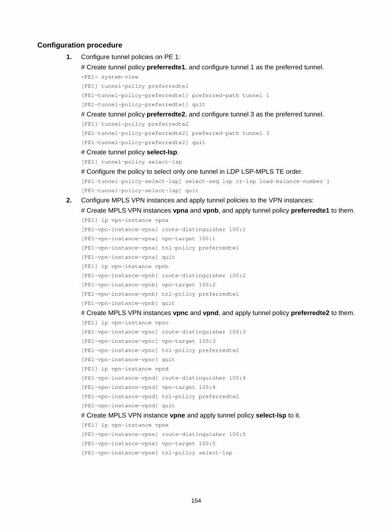
154
Configuration procedure 1. Configure tunnel policies on PE 1:
# Create tunnel policy preferredte1, and configure tunnel 1 as the preferred tunnel. <PE1> system-view
[PE1] tunnel-policy preferredte1
[PE1-tunnel-policy-preferredte1] preferred-path tunnel 1
[PE1-tunnel-policy-preferredte1] quit
# Create tunnel policy preferredte2, and configure tunnel 3 as the preferred tunnel. [PE1] tunnel-policy preferredte2
[PE1-tunnel-policy-preferredte2] preferred-path tunnel 3
[PE1-tunnel-policy-preferredte2] quit
# Create tunnel policy select-lsp. [PE1] tunnel-policy select-lsp
# Configure the policy to select only one tunnel in LDP LSP-MPLS TE order. [PE1-tunnel-policy-select-lsp] select-seq lsp cr-lsp load-balance-number 1
[PE1-tunnel-policy-select-lsp] quit
2. Configure MPLS VPN instances and apply tunnel policies to the VPN instances: # Create MPLS VPN instances vpna and vpnb, and apply tunnel policy preferredte1 to them. [PE1] ip vpn-instance vpna
[PE1-vpn-instance-vpna] route-distinguisher 100:1
[PE1-vpn-instance-vpna] vpn-target 100:1
[PE1-vpn-instance-vpna] tnl-policy preferredte1
[PE1-vpn-instance-vpna] quit
[PE1] ip vpn-instance vpnb
[PE1-vpn-instance-vpnb] route-distinguisher 100:2
[PE1-vpn-instance-vpnb] vpn-target 100:2
[PE1-vpn-instance-vpnb] tnl-policy preferredte1
[PE1-vpn-instance-vpnb] quit
# Create MPLS VPN instances vpnc and vpnd, and apply tunnel policy preferredte2 to them. [PE1] ip vpn-instance vpnc
[PE1-vpn-instance-vpnc] route-distinguisher 100:3
[PE1-vpn-instance-vpnc] vpn-target 100:3
[PE1-vpn-instance-vpnc] tnl-policy preferredte2
[PE1-vpn-instance-vpnc] quit
[PE1] ip vpn-instance vpnd
[PE1-vpn-instance-vpnd] route-distinguisher 100:4
[PE1-vpn-instance-vpnd] vpn-target 100:4
[PE1-vpn-instance-vpnd] tnl-policy preferredte2
[PE1-vpn-instance-vpnd] quit
# Create MPLS VPN instance vpne and apply tunnel policy select-lsp to it. [PE1] ip vpn-instance vpne
[PE1-vpn-instance-vpne] route-distinguisher 100:5
[PE1-vpn-instance-vpne] vpn-target 100:5
[PE1-vpn-instance-vpne] tnl-policy select-lsp

155
Configuring MPLS L3VPN This chapter describes MPLS L3VPN configuration.
Overview MPLS L3VPN is a L3VPN technology used to interconnect geographically dispersed VPN sites. MPLS L3VPN uses BGP to advertise VPN routes and uses MPLS to forward VPN packets over a service provider backbone.
MPLS L3VPN provides flexible networking modes, excellent scalability, and convenient support for MPLS QoS and MPLS TE.
Basic MPLS L3VPN architecture Figure 40 Basic MPLS L3VPN architecture
A basic MPLS L3VPN architecture has the following types of devices: • Customer edge device—A CE device resides on a customer network and has one or more
interfaces directly connected to a service provider network. It does not support VPN or MPLS. • Provider edge device—A PE device resides at the edge of a service provider network and
connects to one or more CEs. All MPLS VPN services are processed on PEs. • Provider device—A P device is a core device on a service provider network. It is not directly
connected to any CE. A P device has only basic MPLS forwarding capability and does not handle VPN routing information.
MPLS L3VPN concepts Site
A site has the following features: • A site is a group of IP systems with IP connectivity that does not rely on any service provider
network.
VPN 1
CE
Site 1
VPN 2
CE
CE
CE
Site 3VPN 2
PE
VPN 1
Site 2
Site 4
PE
PE
P P
P P

156
• The classification of a site depends on the topology relationship of the devices, rather than the geographical positions. However, the devices at a site are, in most cases, adjacent to each other geographically.
• The devices at a site can belong to multiple VPNs, which means that a site can belong to multiple VPNs.
• A site is connected to a provider network through one or more CEs. A site can contain multiple CEs, but a CE can belong to only one site.
Sites connected to the same provider network can be classified into different sets by policies. Only the sites in the same set can access each other through the provider network. Such a set is called a VPN.
VPN instance VPN instances, also called virtual routing and forwarding (VRF) instances, implement route isolation, data independence, and data security for VPNs.
A VPN instance has the following components: • A separate Label Forwarding Information Base (LFIB). • An IP routing table. • Interfaces bound to the VPN instance. • VPN instance administration information, including route distinguishers (RDs), route targets
(RTs), and route filtering policies.
To associate a site with a VPN instance, bind the VPN instance to the PE's interface connected to the site. A site can be associated with only one VPN instance, and different sites can associate with the same VPN instance. A VPN instance contains the VPN membership and routing rules of associated sites.
VPN-IPv4 address Each VPN independently manages its address space. The address spaces of VPNs might overlap. For example, if both VPN 1 and VPN 2 use the addresses on subnet 10.110.10.0/24, address space overlapping occurs.
BGP cannot process overlapping VPN address spaces. For example, if both VPN 1 and VPN 2 use the subnet 10.110.10.0/24 and each advertise a route destined for the subnet, BGP selects only one of them. This results in the loss of the other route.
Multiprotocol BGP (MP-BGP) can solve this problem by advertising VPN-IPv4 addresses (also called VPNv4 addresses).
Figure 41 VPN-IPv4 address structure
As shown in Figure 41, a VPN-IPv4 address consists of 12 bytes. The first eight bytes represent the RD, followed by a four-byte IPv4 prefix. The RD and the IPv4 prefix form a unique VPN-IPv4 prefix.
An RD can be in one of the following formats: • When the Type field is 0, the Administrator subfield occupies two bytes, the Assigned number
subfield occupies four bytes, and the RD format is 16-bit AS number:32-bit user-defined number. For example, 100:1.
• When the Type field is 1, the Administrator subfield occupies four bytes, the Assigned number subfield occupies two bytes, and the RD format is 32-bit IPv4 address:16-bit user-defined number. For example, 172.1.1.1:1.
Type
2 bytes 4 bytes
IPv4 address prefix
6 bytes
Route Distinguisher (8 bytes)
Assigned number subfieldAdministrator subfield

157
• When the Type field is 2, the Administrator subfield occupies four bytes, the Assigned number subfield occupies two bytes, and the RD format is 32-bit AS number:16-bit user-defined number, where the minimum value of the AS number is 65536. For example, 65536:1.
To guarantee global uniqueness for a VPN-IPv4 address, do not set the Administrator subfield to any private AS number or private IP address.
Route target attribute MPLS L3VPN uses route target community attributes to control the advertisement of VPN routing information. A VPN instance on a PE supports the following types of route target attributes: • Export target attribute—A PE sets the export target attribute for VPN-IPv4 routes learned
from directly connected sites before advertising them to other PEs. • Import target attribute—A PE checks the export target attribute of VPN-IPv4 routes received
from other PEs. If the export target attribute matches the import target attribute of a VPN instance, the PE adds the routes to the routing table of the VPN instance.
Route target attributes define which sites can receive VPN-IPv4 routes, and from which sites a PE can receive routes.
Like RDs, route target attributes can be one of the following formats: • 16-bit AS number:32-bit user-defined number. For example, 100:1. • 32-bit IPv4 address:16-bit user-defined number. For example, 172.1.1.1:1. • 32-bit AS number:16-bit user-defined number, where the minimum value of the AS number is
65536. For example, 65536:1.
MP-BGP MP-BGP supports multiple address families, including IPv4 multicast, IPv6 unicast, IPv6 multicast, and VPN-IPv4 address families.
In MPLS L3VPN, MP-BGP advertises VPN-IPv4 routes for VPN sites between PEs.
MPLS L3VPN route advertisement In a basic MPLS L3VPN, CEs and PEs are responsible for advertising VPN routing information. P routers maintain only the routes within the backbone. A PE maintains only routing information for directly connected VPNs, rather than for all VPNs.
VPN routing information is advertised from the local CE to the remote CE by using the following process: 1. From the local CE to the ingress PE:
The CE advertises standard IPv4 routing information to the ingress PE over a static route, RIP route, OSPF route, IS-IS route, EBGP route, or IBGP route.
2. From the ingress PE to the egress PE: The ingress PE does the following: a. Adds RD and route target attributes to these standard IPv4 routes to create VPN-IPv4
routes. b. Saves them to the routing table of the VPN instance created for the CE. c. Advertises the VPN-IPv4 routes to the egress PE through MP-BGP.
3. From the egress PE to the remote CE: After receiving the VPN-IPv4 routes, the egress PE does the following: a. Compares the routes' export target attributes with the local import target attributes. b. Adds the routes to the routing table of the VPN instance if the export and local import target
attributes match each other. c. Restores the VPN-IPv4 routes to the original IPv4 routes.

158
d. Advertises those routes to the connected CE over a static route, RIP route, OSPF route, IS-IS route, EBGP route, or IBGP route.
MPLS L3VPN packet forwarding In a basic MPLS L3VPN (within a single AS), a PE adds the following information into VPN packets: • Outer tag—Identifies the public tunnel from the local PE to the remote PE. The public tunnel
can be an LSP, an MPLS TE tunnel. Based on the outer tag, a VPN packet can be forwarded along the public tunnel to the remote PE. For a GRE public tunnel, the outer tag is the GRE encapsulation. For an LSP or MPLS TE tunnel, the outer tag is an MPLS label.
• Inner label—Identifies the remote VPN site. The remote PE uses the inner label to forward packets to the target VPN site. MP-BGP advertises inner labels for VPN routes among PEs.
Figure 42 VPN packet forwarding
As shown in Figure 42, a VPN packet is forwarded from Site 1 to Site 2 by using the following process: 1. Site 1 sends an IP packet with the destination address 1.1.1.2. CE 1 transmits the packet to PE
1. 2. PE 1 does the following:
a. Finds the matching VPN route based on the inbound interface and destination address of the packet.
b. Labels the packet with both the inner label and the outer tag. c. Forwards the packet to the public tunnel.
3. P devices forward the packet to PE 2 by the outer tag. If the outer tag is an MPLS label, the label is removed from the packet at the penultimate
hop. If the outer tag is GRE encapsulation, PE 2 removes the GRE encapsulation.
4. PE 2 does the following: a. Uses the inner label to find the matching VPN instance to which the destination address of
the packet belongs. b. Looks up the routing table of the VPN instance for the output interface. c. Removes the inner label and forwards the packet out of the interface to CE 2.
5. CE 2 transmits the packet to the destination through IP forwarding.
When two sites of a VPN are connected to the same PE, the PE directly forwards packets between the two sites through the VPN routing table without adding any tag or label.
For more information about GRE, see Layer 3—IP Services Configuration Guide.
CE 1Site 1
PE 1
P P
PE 2
CE 2 Site 2
2.1.1.1/24 1.1.1.2/24
1.1.1.2
1.1.1.2
Inner label
Outer tag
1.1.1.2
Inner label1.1.1.2
MPLS network

159
MPLS L3VPN networking schemes In MPLS L3VPNs, route target attributes are used to control the advertisement and reception of VPN routes between sites. They work independently and can be configured with multiple values to support flexible VPN access control and implement multiple types of VPN networking schemes.
Basic VPN networking scheme In the simplest case, all users in a VPN form a closed user group. They can forward traffic to each other but cannot communicate with any user outside the VPN.
For the basic VPN networking scheme, you must assign a route target to each VPN for identifying the export target attribute and import target attribute of the VPN. Moreover, this route target cannot be used by any other VPNs.
Figure 43 Network diagram for basic VPN networking scheme
As shown in Figure 43, the route target for VPN 1 is 100:1, while that for VPN 2 is 200:1. The two VPN 1 sites can communicate with each other, and the two VPN 2 sites can communicate with each other. However, the VPN 1 sites cannot communicate with the VPN 2 sites.
Hub and spoke networking scheme The hub and spoke networking scheme is suitable for a VPN where all users must communicate with each other through an access control device.
In a hub and spoke network as shown in Figure 44, configure route targets as follows: • On spoke PEs (PEs connected to spoke sites), set the export target to Spoke and the import
target to Hub. • On the hub PE (PE connected to the hub site), use two interfaces that each belong to a different
VPN instance to connect the hub CE. One VPN instance receives routes from spoke PEs and has the import target set to Spoke. The other VPN instance advertises routes to spoke PEs and has the export target set to Hub.
These route targets rules produce the following results: • The hub PE can receive all VPN-IPv4 routes from spoke PEs. • All spoke PEs can receive VPN-IPv4 routes advertised by the hub PE. • The hub PE advertises the routes learned from a spoke PE to the other spoke PEs so the spoke
sites can communicate with each other through the hub site.
CE
CE CE
CE
PE PEP
Site 2
Site 1 Site 3
Site 4
VPN 1
VPN 1
VPN 2
VPN 2
VPN 1:Import: 100:1Export: 100:1
VPN 2:Import: 200:1Export: 200:1
VPN 2:Import: 200:1Export: 200:1
VPN 1:Import: 100:1Export: 100:1

160
• The import target attribute of a spoke PE is different from the export target attribute of any other spoke PE. Therefore, any two spoke PEs cannot directly advertise VPN-IPv4 routes to each other or directly access each other.
Figure 44 Network diagram for hub and spoke network
A route in Site 1 is advertised to Site 2 by using the following process: 1. Spoke-CE 1 advertises a route in Site 1 to Spoke-PE 1. 2. Spoke-PE 1 changes the route to a VPN-IPv4 route and advertises the VPN-IPv4 route to
Hub-PE through MP-BGP. 3. Hub-PE adds the VPN-IPv4 route into the routing table of VPN 1-in, changes it to the original
IPv4 route, and advertises the IPv4 route to Hub-CE. 4. Hub-CE advertises the IPv4 route back to Hub-PE. 5. Hub-PE adds the IPv4 route to the routing table of VPN 1-out, changes it to a VPN-IPv4 route,
and advertises the VPN-IPv4 route to Spoke-PE 2 through MP-BGP. 6. Spoke-PE 2 changes the VPN-IPv4 route to the original IPv4 route, and advertises the IPv4
route to Site 2.
After spoke sites exchange routes through the hub site, they can communicate with each other through the hub site.
Extranet networking scheme The extranet networking scheme allows specific resources in a VPN to be accessed by users not in the VPN.
In this networking scheme, if a VPN instance needs to access a shared site, the export target attribute and the import target attribute of the VPN instance must be contained in the import target attribute and the export target attribute of the VPN instance of the shared site, respectively.
Spoke-CE 2
Hub-PE
Site 2
Site 1
Site 3
VPN 1
VPN 1
VPN 1
VPN 1:Import: HubExport: Spoke VPN 1-out:
Export: Hub
Hub-CE
Spoke-PE 1
Spoke-PE 2VPN 1-in:Import: Spoke
VPN 1:Import: HubExport: Spoke
Spoke-CE 1
Route distributionPacket forwarding

161
Figure 45 Network diagram for extranet networking scheme
As shown in Figure 45, route targets configured on PEs produce the following results: • PE 3 can receive VPN-IPv4 routes from PE 1 and PE 2. • PE 1 and PE 2 can receive VPN-IPv4 routes advertised by PE 3. • Site 1 and Site 3 of VPN 1 can communicate with each other, and Site 2 of VPN 2 and Site 3 of
VPN 1 can communicate with each other. • PE 3 advertises neither the VPN-IPv4 routes received from PE 1 to PE 2 nor the VPN-IPv4
routes received from PE 2 to PE 1 (routes learned from an IBGP neighbor are not advertised to any other IBGP neighbor). Therefore, Site 1 of VPN 1 and Site 2 of VPN 2 cannot communicate with each other.
Inter-AS VPN In an inter-AS VPN networking scenario, multiple sites of a VPN are connected to multiple ISPs in different ASs, or to multiple ASs of an ISP.
The following inter-AS VPN solutions are available: • VRF-to-VRF connections between ASBRs—This solution is also called inter-AS option A. • EBGP redistribution of labeled VPN-IPv4 routes between ASBRs—ASBRs advertise
VPN-IPv4 routes to each other through MP-EBGP. This solution is also called inter-AS option B. • Multihop EBGP redistribution of labeled VPN-IPv4 routes between PE routers—PEs
advertise VPN-IPv4 routes to each other through MP-EBGP. This solution is also called inter-AS option C.
Inter-AS option A In this solution, PEs of two ASs are directly connected, and each PE is also the ASBR of its AS. Each PE treats the other as a CE and advertises unlabeled IPv4 unicast routes through EBGP. The PEs associate a VPN instance with at least one interface.
CE
CE
PE 1
PE 3
Site 2
Site 1
Site 3
VPN 1
VPN 1
VPN 2
VPN 1:Import:100:1Export:100:1
CE
VPN 2:Import:200:1Export:200:1
PE 2VPN 1:Import:100:1,200:1Export:100:1,200:1

162
Figure 46 Network diagram for inter-AS option A
As shown in Figure 46, VPN 1 routes are advertised from CE 1 to CE 3 by using the following process: 1. PE 1 advertises the VPN routes learned from CE 1 to ASBR 1 through MP-IBGP. 2. ASBR 1 does the following:
a. Adds the routes to the routing table of the VPN instance whose import target attribute matches the export target attribute of the routes.
b. Advertises the routes as IPv4 unicast routes to its CE (ASBR 2) through EBGP. 3. ASBR 2 adds the IPv4 unicast routes to the routing table of the VPN instance bound to the
receiving interface, and advertises the routes to PE 3 through MP-IBGP. 4. PE 3 advertises the received routes to CE 3.
Packets forwarded within an AS are VPN packets that carry two labels. Packets forwarded between ASBRs are common IP packets.
Inter-AS option A is easy to carry out because no special configuration is required on the PEs acting as the ASBRs.
However, it has limited scalability because the PEs acting as the ASBRs must manage all the VPN routes and create VPN instances on a per-VPN basis. This leads to excessive VPN-IPv4 routes on the PEs. Associateing a separate interface with each VPN also requires additional system resources.
Inter-AS option B In this solution, two ASBRs use MP-EBGP to exchange VPN-IPv4 routes that they obtain from the PEs in their respective ASs.
VPN 1
CE 1PE 1 PE 3
VPN 1
CE 3
CE 2
VPN 2 VPN 2
PE 2 PE 4
ASBR 1(PE)
ASBR 2(PE)
VPN LSP 1 VPN LSP 2
LSP 1 LSP 2CE 4
IP Forwarding
EBGPAS 100 AS 200

163
Figure 47 Network diagram for inter-AS option B
As shown in Figure 47, VPN 1 routes are advertised from CE 1 to CE 3 by using the following process: 1. PE 1 advertises the VPN routes learned from CE 1 to ASBR 1 through MP-IBGP.
Assume that the inner label assigned by PE 1 to the routes is L1. 2. ASBR 1 advertises the VPN-IPv4 routes to ASBR 2 through MP-IBGP.
Before advertising the routes, ASBR 1 modifies the next hop as its own address, assigns a new inner label (L2) to the routes, and associates L1 with L2.
3. ASBR 2 advertises the VPN-IPv4 routes to PE 3 through MP-IBGP. Before advertising the routes, ASBR 2 modifies the next hop as its own address, assigns a new inner label (L3) to the routes, and associates L2 with L3.
4. PE 3 advertises the received routes to CE 3.
A packet is forwarded from CE 3 to CE 1 by using the following process: 1. PE 3 encapsulates the received packet with two labels, and forwards the encapsulated packet
to ASBR 2. The two labels are the inner label for the VPN (L3) and the outer tag for the public tunnel from PE 3 to ASBR 2.
2. ASBR 2 removes the outer tag, replaces L3 with L2, and forwards the packet to ASBR 1. Packets between ASBR 1 and ASBR 2 carry only one inner label.
3. ASBR 1 replaces L2 with L1, adds the outer tag of the public tunnel from ASBR 1 to PE 1, and forwards the packet to PE 1.
4. PE 1 removes the outer tag and inner label and forwards the packet to CE 1.
In this solution, ASBRs must receive all inter-AS VPN routes. Therefore, ASBRs cannot filter incoming VPN-IPv4 routes by route targets.
Inter-AS option B has better scalability than option A. However, it requires that ASBRs maintain and advertise VPN routes.
Inter-AS option C The inter-AS option A and option B solutions require that the ASBRs maintain and advertise VPN-IPv4 routes. When every AS needs to exchange a great amount of VPN routes, the ASBRs might become bottlenecks, which hinders network extension. Inter-AS option C has better scalability because it makes PEs directly exchange VPN-IPv4 routes.
VPN 1
CE 1PE 1 PE 3
VPN 1
CE 3
CE 2
VPN 2 VPN 2
PE 2 PE 4
ASBR 1(PE)
ASBR 2(PE)
VPN LSP 1 VPN LSP 3
LSP 1 LSP 2CE 4VPN LSP2
MP-EBGP
AS 100 AS 200
MP-IBGP
MP-IBGP
MP-IBGP
MP-IBGP
MPLS backbone MPLS backbone

164
In this solution, PEs exchange VPN-IPv4 routes over a multihop MP-EBGP session. Each PE must have a route to the peer PE and a label for the route so that the inter-AS public tunnel between the PEs can be set up. Inter-AS option C sets up a public tunnel by using the following methods: • A label distribution protocol within the AS, for example, LDP. • Labeled IPv4 unicast route advertisement by ASBRs through BGP.
Labeled IPv4 unicast route advertisement refers to the process of assigning MPLS labels to IPv4 unicast routes and advertising the IPv4 unicast routes and their labels.
Figure 48 Network diagram for inter-AS option C
As shown in Figure 48, VPN 1 routes are advertised from CE 1 to CE 3 by using the following process: 1. PE 1 advertises the VPN routes learned from CE 1 as VPN-IPv4 routes to PE 3 through
multihop MP-EBGP. Assume that the inner label assigned by PE 1 for the routes is Lx.
2. PE 3 advertises the received routes to CE 3.
Setting up an inter-AS public tunnel is difficult in this solution. A public tunnel, for example, the one from PE 3 to PE 1, is set up by using the following process: 1. Within AS 100, the public tunnel from ASBR 1 to PE 1 is set up by using a label distribution
protocol, for example, LDP. Assume that the outgoing label for the public tunnel on ASBR 1 is L1.
2. ASBR 1 advertises labeled IPv4 unicast routes to ASBR 2 through EBGP to set up the public tunnel from ASBR 2 to ASBR 1. ASBR 1 assigns a label (L2) to the route destined for PE 1, and advertises the route and its label (L2) to ASBR 2. The next hop for the route is ASBR 1. The incoming label for the public tunnel on ASBR 1 is L2.
3. ASBR 2 advertises labeled IPv4 unicast routes to PE 3 through IBGP to set up the public tunnel from PE 3 directly to ASBR 2. ASBR 2 assigns a label (L3) to the route destined for PE 1, and advertises the route and its label (L3) to PE 3. The next hop for the route is ASBR 2. The incoming label for the public tunnel on ASBR 2 is L3, and the outgoing label is L2.
4. MPLS packets cannot be forwarded directly from PE 3 to ASBR 2. Therefore, another public tunnel from PE 3 to ASBR 2 is required to be set up hop by hop through a label distribution protocol, for example, LDP. Assume that the outgoing label for the public tunnel on PE 3 is Lv.
VPN 1
CE 1
PE 1 PE 3
VPN 1
CE 3
CE 2
VPN 2 VPN 2
PE 2 PE 4
ASBR 1(PE)
ASBR 2(PE)
VPN LSP CE 4
EBGP
AS 100 AS 200
IBGP
IBGP
IBGP
IBGP
Multi-hop MP-EBGP
Multi-hop MP-EBGP
MPLS backbone MPLS backbone
LSP

165
After route advertisement and public tunnel setup, a packet is forwarded from CE 3 to CE 1 by using the following process: 1. PE 3 performs the following routing table lookups for the packet:
a. Finds a matching route with next hop PE 1 and inner label Lx, and encapsulates the packet with label Lx.
b. Finds the route to PE 1 with next hop ASBR 2 and label L3, and encapsulates the packet with label L3 as the outer label.
c. Finds the route to ASBR 2 with outgoing label Lv, and encapsulates the packet with label Lv as the outmost label.
2. AS 200 transmits the packet to ASBR 2 by the outmost label. 3. ASBR 2 removes the outmost label, replaces L3 with L2, and forwards the packet to ASBR 1. 4. ASBR 1 replaces L2 with L1, and forwards the packet. 5. AS 100 transmits the packet to PE 1 by the outer label. 6. PE 1 removes the outer label, and forwards the packet to CE 1 according to the inner label Lx.
As shown in Figure 49, to improve scalability, you can specify an RR in each AS to exchange VPN-IPv4 routes with PEs in the same AS. The RR in each AS maintains all VPN-IPv4 routes. The RRs in two ASs establish a multihop MP-EBGP session to advertise VPN-IPv4 routes.
Figure 49 Network diagram for inter-AS option C using RRs
Carrier's carrier If a customer of the MPLS L3VPN service provider is also a service provider: • The MPLS L3VPN service provider is called the provider carrier or the Level 1 carrier. • The customer is called the customer carrier or the Level 2 carrier.
This networking model is referred to as carrier's carrier.
The PEs of the Level 2 carrier directly exchange customer networks over a BGP session. The Level 1 carrier only learns the backbone networks of the Level 2 carrier, without learning customer networks.
For packets between customer networks to travel through the Level 1 carrier, the PE of the Level 1 carrier and the CE of the Level 2 carrier must assign labels to the backbone networks of the Level 2 carrier. The CE of the Level 2 carrier is a PE within the Level 2 carrier network.
VPN 1
PE 1 PE 3
VPN 1
CE 3
CE 2VPN 2 VPN 2
PE 4
CE 4
CE 1
AS 100
PE 2
MP-IBGP
MP-IBGP
ASBR 1(PE)RR 1 RR 2
ASBR 2(PE)
IBGP IBGP
EBGP
Multi-hop MP-EBGP
VPN LSP
LSP
AS 200
MP-IBGP
MP-IBGP
MPLS backbone MPLS backbone
Private LSPPublic LSP
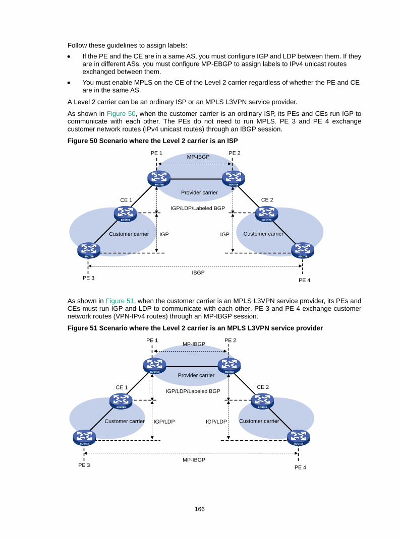
166
Follow these guidelines to assign labels: • If the PE and the CE are in a same AS, you must configure IGP and LDP between them. If they
are in different ASs, you must configure MP-EBGP to assign labels to IPv4 unicast routes exchanged between them.
• You must enable MPLS on the CE of the Level 2 carrier regardless of whether the PE and CE are in the same AS.
A Level 2 carrier can be an ordinary ISP or an MPLS L3VPN service provider.
As shown in Figure 50, when the customer carrier is an ordinary ISP, its PEs and CEs run IGP to communicate with each other. The PEs do not need to run MPLS. PE 3 and PE 4 exchange customer network routes (IPv4 unicast routes) through an IBGP session.
Figure 50 Scenario where the Level 2 carrier is an ISP
As shown in Figure 51, when the customer carrier is an MPLS L3VPN service provider, its PEs and CEs must run IGP and LDP to communicate with each other. PE 3 and PE 4 exchange customer network routes (VPN-IPv4 routes) through an MP-IBGP session.
Figure 51 Scenario where the Level 2 carrier is an MPLS L3VPN service provider
Provider carrier
MP-IBGPPE 1 PE 2
CE 2CE 1
PE 3 PE 4
Customer carrier Customer carrier
IBGP
IGP IGP
IGP/LDP/Labeled BGP
Provider carrier
MP-IBGPPE 1 PE 2
CE 2CE 1
PE 3 PE 4
Customer carrier Customer carrier
MP-IBGP
IGP/LDP IGP/LDP
IGP/LDP/Labeled BGP
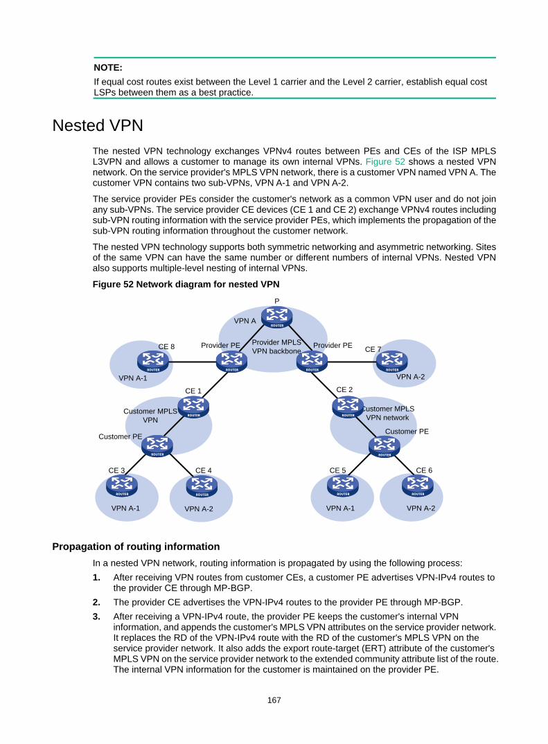
167
NOTE: If equal cost routes exist between the Level 1 carrier and the Level 2 carrier, establish equal cost LSPs between them as a best practice.
Nested VPN The nested VPN technology exchanges VPNv4 routes between PEs and CEs of the ISP MPLS L3VPN and allows a customer to manage its own internal VPNs. Figure 52 shows a nested VPN network. On the service provider's MPLS VPN network, there is a customer VPN named VPN A. The customer VPN contains two sub-VPNs, VPN A-1 and VPN A-2.
The service provider PEs consider the customer's network as a common VPN user and do not join any sub-VPNs. The service provider CE devices (CE 1 and CE 2) exchange VPNv4 routes including sub-VPN routing information with the service provider PEs, which implements the propagation of the sub-VPN routing information throughout the customer network.
The nested VPN technology supports both symmetric networking and asymmetric networking. Sites of the same VPN can have the same number or different numbers of internal VPNs. Nested VPN also supports multiple-level nesting of internal VPNs.
Figure 52 Network diagram for nested VPN
Propagation of routing information In a nested VPN network, routing information is propagated by using the following process: 1. After receiving VPN routes from customer CEs, a customer PE advertises VPN-IPv4 routes to
the provider CE through MP-BGP. 2. The provider CE advertises the VPN-IPv4 routes to the provider PE through MP-BGP. 3. After receiving a VPN-IPv4 route, the provider PE keeps the customer's internal VPN
information, and appends the customer's MPLS VPN attributes on the service provider network. It replaces the RD of the VPN-IPv4 route with the RD of the customer's MPLS VPN on the service provider network. It also adds the export route-target (ERT) attribute of the customer's MPLS VPN on the service provider network to the extended community attribute list of the route. The internal VPN information for the customer is maintained on the provider PE.
Provider PE
CE 3 CE 4
Provider MPLS VPN backbone
P
VPN A-1
VPN A-1 VPN A-2
CE 7Provider PE
VPN A-2
CE 8
Customer MPLS VPN
Customer PE
CE 5 CE 6
VPN A-1 VPN A-2
Customer MPLS VPN network
Customer PE
CE 1 CE 2
VPN A
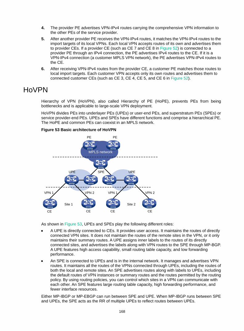
168
4. The provider PE advertises VPN-IPv4 routes carrying the comprehensive VPN information to the other PEs of the service provider.
5. After another provider PE receives the VPN-IPv4 routes, it matches the VPN-IPv4 routes to the import targets of its local VPNs. Each local VPN accepts routes of its own and advertises them to provider CEs. If a provider CE (such as CE 7 and CE 8 in Figure 52) is connected to a provider PE through an IPv4 connection, the PE advertises IPv4 routes to the CE. If it is a VPN-IPv4 connection (a customer MPLS VPN network), the PE advertises VPN-IPv4 routes to the CE.
6. After receiving VPN-IPv4 routes from the provider CE, a customer PE matches those routes to local import targets. Each customer VPN accepts only its own routes and advertises them to connected customer CEs (such as CE 3, CE 4, CE 5, and CE 6 in Figure 52).
HoVPN Hierarchy of VPN (HoVPN), also called Hierarchy of PE (HoPE), prevents PEs from being bottlenecks and is applicable to large-scale VPN deployment.
HoVPN divides PEs into underlayer PEs (UPEs) or user-end PEs, and superstratum PEs (SPEs) or service provider-end PEs. UPEs and SPEs have different functions and comprise a hierarchical PE. The HoPE and common PEs can coexist in an MPLS network.
Figure 53 Basic architecture of HoVPN
As shown in Figure 53, UPEs and SPEs play the following different roles: • A UPE is directly connected to CEs. It provides user access. It maintains the routes of directly
connected VPN sites. It does not maintain the routes of the remote sites in the VPN, or it only maintains their summary routes. A UPE assigns inner labels to the routes of its directly connected sites, and advertises the labels along with VPN routes to the SPE through MP-BGP. A UPE features high access capability, small routing table capacity, and low forwarding performance.
• An SPE is connected to UPEs and is in the internal network. It manages and advertises VPN routes. It maintains all the routes of the VPNs connected through UPEs, including the routes of both the local and remote sites. An SPE advertises routes along with labels to UPEs, including the default routes of VPN instances or summary routes and the routes permitted by the routing policy. By using routing policies, you can control which sites in a VPN can communicate with each other. An SPE features large routing table capacity, high forwarding performance, and fewer interface resources.
Either MP-IBGP or MP-EBGP can run between SPE and UPE. When MP-IBGP runs between SPE and UPEs, the SPE acts as the RR of multiple UPEs to reflect routes between UPEs.
MPLS network
PE PE
SPEUPE UPE
CE CE CE CE
VPN 1 VPN 1VPN 2 VPN 2
Site 1 Site 2
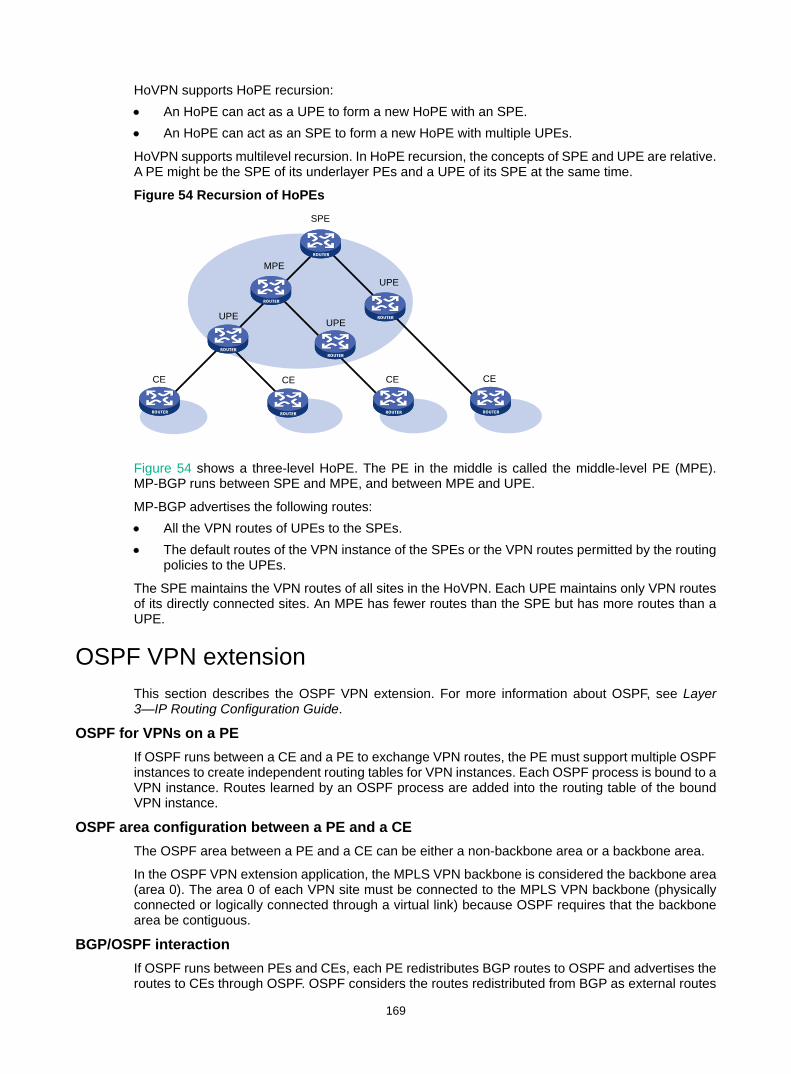
169
HoVPN supports HoPE recursion: • An HoPE can act as a UPE to form a new HoPE with an SPE. • An HoPE can act as an SPE to form a new HoPE with multiple UPEs.
HoVPN supports multilevel recursion. In HoPE recursion, the concepts of SPE and UPE are relative. A PE might be the SPE of its underlayer PEs and a UPE of its SPE at the same time.
Figure 54 Recursion of HoPEs
Figure 54 shows a three-level HoPE. The PE in the middle is called the middle-level PE (MPE). MP-BGP runs between SPE and MPE, and between MPE and UPE.
MP-BGP advertises the following routes: • All the VPN routes of UPEs to the SPEs. • The default routes of the VPN instance of the SPEs or the VPN routes permitted by the routing
policies to the UPEs.
The SPE maintains the VPN routes of all sites in the HoVPN. Each UPE maintains only VPN routes of its directly connected sites. An MPE has fewer routes than the SPE but has more routes than a UPE.
OSPF VPN extension This section describes the OSPF VPN extension. For more information about OSPF, see Layer 3—IP Routing Configuration Guide.
OSPF for VPNs on a PE If OSPF runs between a CE and a PE to exchange VPN routes, the PE must support multiple OSPF instances to create independent routing tables for VPN instances. Each OSPF process is bound to a VPN instance. Routes learned by an OSPF process are added into the routing table of the bound VPN instance.
OSPF area configuration between a PE and a CE The OSPF area between a PE and a CE can be either a non-backbone area or a backbone area.
In the OSPF VPN extension application, the MPLS VPN backbone is considered the backbone area (area 0). The area 0 of each VPN site must be connected to the MPLS VPN backbone (physically connected or logically connected through a virtual link) because OSPF requires that the backbone area be contiguous.
BGP/OSPF interaction If OSPF runs between PEs and CEs, each PE redistributes BGP routes to OSPF and advertises the routes to CEs through OSPF. OSPF considers the routes redistributed from BGP as external routes
SPE
MPE
UPE
UPEUPE
CE CE CE CE

170
but the OSPF routes actually might belong to the same OSPF domain. This problem can be resolved by configuring the same domain ID for sites in an OSPF domain.
Figure 55 Network diagram for BGP/OSPF interaction
As shown in Figure 55, CE 11, CE 21, and CE 22 belong to the same VPN and the same OSPF domain.
Before a domain ID is configured, VPN 1 routes are advertised from CE 11 to CE 21 and CE 22 by using the following process: 1. PE 1 redistributes OSPF routes from CE 11 into BGP, and advertises the VPN routes to PE 2
through BGP. 2. PE 2 redistributes the BGP routes to OSPF, and advertises them to CE 21 and CE 22 in AS
External LSAs (Type 5) or NSSA External LSAs (Type 7).
After a domain ID is configured, VPN 1 routes are advertised from CE 11 to CE 21 and CE 22 by using the following process: 1. PE 1 redistributes OSPF routes into BGP, adds the domain ID to the redistributed BGP VPNv4
routes as a BGP extended community attribute, and advertises the routes to PE 2. 2. PE 2 compares the domain ID in the received routes with the locally configured domain ID. If
they are the same and the received routes are intra-area or inter-area routes, OSPF advertises these routes in Network Summary LSAs (Type 3). Otherwise, OSPF advertises these routes in AS External LSAs (Type 5) or NSSA External LSAs (Type 7).
Routing loop avoidance Figure 56 Network diagram for routing loop avoidance
OSPF Area 1
OSPF Area 2
CE 11
CE 12 CE 22
CE 21
VPN 1
Site 2
VPN 1
Site 3
OSPF Area 0
VPN 1
Site 1
Site 1
OSPF Area 1
VPN 2
MPLS backbone
Site 1
PE 1 PE 2
OSPF Area 1
OSPF Area 2
CE 11
CE 22
CE 21
VPN 1
Site 2
VPN 1
Site 3
OSPF Area 0
VPN 1
Site 1
MPLS backbonePE 1
PE 3
PE 2

171
As shown in Figure 56, Site 1 is connected to two PEs. When a PE advertises VPN routes learned from MP-BGP to Site 1 through OSPF, the routes might be received by the other PE. This results in a routing loop.
OSPF VPN extension uses the following tags to avoid routing loops: • DN bit (for Type 3 LSAs)—When a PE redistributes BGP routes into OSPF and creates Type 3
LSAs, it sets the DN bit for the LSAs. When receiving the Type 3 LSAs advertised by CE 11, the other PE ignores the LSAs whose DN bit is set to avoid routing loops.
• Route tag (for Type 5 or 7 LSAs)—The two PEs use the same route tag. When a PE redistributes BGP routes into OSPF and creates Type 5 or 7 LSAs, it adds the route tag to the LSAs. When receiving the Type 5 or 7 LSAs advertised by CE 11, the other PE compares the route tag in the LSAs against the local route tag. If they are the same, the PE ignores the LSAs to avoid routing loops.
OSPF sham link As shown in Figure 57, two routes exist between site 1 and site 2 of VPN 1: • A route connected through PEs—Inter-area route or external route.
Inter-area route—The route is an inter-area route if the two PEs have the same domain ID configured for the OSPF process of VPN 1.
External route—The route is an external route if the two PEs have no or different domain IDs configured for the OSPF process of VPN 1.
• A route directly connected through CEs—Intra-area route, which is called a backdoor link.
The inter-area route priority is lower than the intra-area route priority. To use the inter-area route, you can establish a sham link between the two PEs to change the inter-area route to an intra-area route. VPN traffic are forwarded over the sham link through metric adjustment.
Figure 57 Network diagram for sham link
A sham link is considered a virtual point-to-point link within a VPN and is advertised in a Type 1 LSA. It is identified by the source IP address and destination IP address that are the local PE address and the remote PE address in the VPN address space. Typically, the source and destination addresses are loopback interface addresses with a 32-bit mask.
To add a route to the destination IP address of a sham link to a VPN instance, the remote PE must advertise the source IP address of the sham link as a VPN-IPv4 address through MP-BGP. To avoid routing loops, a PE does not advertise the sham link's destination address.
BGP AS number substitution BGP detects routing loops by examining AS numbers. If EBGP runs between PE and CE, you must assign different AS numbers to geographically different sites to ensure correct transmission of routing information.
OSPF Area 1
MPLS backbonePE 1 PE 2
Sham-link
Backdoor-link
CE 12 CE 22
VPN 1VPN 1
OSPF Area 1
Site 1 Site 2

172
The BGP AS number substitution function allows physically dispersed CEs to use the same AS number. The function is a BGP outbound policy and affects routes to be advertised.
With the BGP AS number substitution function, when a PE advertises a route to a CE, if an AS number identical to that of the CE exists in the AS_PATH of the route, the PE replaces it with its own AS number.
After you enable the BGP AS number substitution function, the PE performs BGP AS number substitution for all routes and re-advertises them to connected CEs in the peer group.
Figure 58 Application of BGP AS number substitution
As shown in Figure 58, both Site and Site 2 use the AS number 800. AS number substitution is enabled on PE 2 for CE 2. Before advertising updates received from CE 1 to CE 2, PE 2 substitutes its own AS number 100 for the AS number 800. In this way, CE 2 can correctly receive the routing information from CE 1.
However, the AS number substitution function also introduces a routing loop in Site 2 because route updates originated from CE 3 can be advertised back to Site 2 through PE 2 and CE 2. To remove the routing loop, you can configure a routing policy on PE 2 to add the SoO attribute to route updates received from CE 2 and CE 3 so that PE 2 does not advertise route updates from CE 3 to CE 2.
NOTE: The device does not support adding the SoO attribute to routes.
MPLS L3VPN FRR MPLS L3VPN Fast Reroute (FRR) is applicable to a dual-homed scenario, as shown in Figure 59. By using BFD to detect the primary link, FRR enables a PE router to use the backup link when the primary link fails. The PE router then selects a new optimal route, and uses the new optimal route to forward traffic.
MPLS L3VPN FRR supports the following types of backup: • VPNv4 route backup for a VPNv4 route. • VPNv4 route backup for an IPv4 route. • IPv4 route backup for a VPNv4 route.
MPLS backbone
VPNv4_Update: 10.1.0.0/16RD: 100:1AS_PATH: 800
EBGP_Update: 10.1.0.0/16AS_PATH: 100, 100
PE 1 PE 2
CE 3
AS 800Site 2
EBGP_Update: 10.1.0.0/16AS_PATH: 800
AS 800Site 1
AS 100
CE 1
CE 2

173
VPNv4 route backup for a VPNv4 route Figure 59 Network diagram
As show in Figure 59, configure FRR on the ingress node PE 1, and specify the backup next hop for VPN 1 as PE 3. When PE 1 receives a VPNv4 route to CE 2 from both PE 2 and PE 3, it uses the route from PE 2 as the primary link, and the route from PE 3 as the backup link.
Configure BFD for LSPs or MPLS TE tunnels on PE 1 to detect the connectivity of the public tunnel from PE 1 to PE 2. When the tunnel PE 1—PE 2 operates correctly, traffic from CE 1 to CE 2 goes through the path CE 1—PE 1—PE 2—CE 2. When the tunnel fails, the traffic goes through the path CE 1—PE 1—PE 3—CE 2.
In this scenario, PE 1 is responsible for primary link detection and traffic switchover.
For more information about BFD for LSPs or MPLS TE tunnels, see "Configuring MPLS OAM."
VPNv4 route backup for an IPv4 route Figure 60 Network diagram
As shown in Figure 60, configure FRR on the egress node PE 2, and specify the backup next hop for VPN 1 as PE 3. When PE 2 receives an IPv4 route from CE 2 and a VPNv4 route from PE 3 (both routes are destined for VPN 1 connected to CE 2), PE 2 uses the IPv4 route as the primary link, and the VPNv4 route as the backup link.
PE 2 uses echo-mode BFD to detect the connectivity of the link from PE 2 to CE 2. When the link operates correctly, traffic from CE 1 to CE 2 goes through the path CE 1—PE 1—PE 2—CE 2. When the link fails, PE 2 switches traffic to the link PE 2—PE 3—CE 2, and traffic from CE 1 to CE 2 goes through the path CE 1—PE 1—PE 2—PE 3—CE 2. This avoids traffic interruption before route convergence completes (switching to the link CE 1—PE 1—PE 3—CE 2).
In this scenario, PE 2 is responsible for primary link detection and traffic switchover.
CE 2CE 1
VPN 1 VPN 1MPLS backbone
PE 2
PE 1
PE 3
Primary linkBackup link
CE 2CE 1
VPN 1 VPN 1MPLS backbone
PE 2
PE 1
PE 3
Primary linkBackup link

174
IPv4 route backup for a VPNv4 route Figure 61 Network diagram
As shown in Figure 61, configure FRR on the egress node PE 2, and specify the backup next hop for VPN 1 as CE 2. When PE 2 receives an IPv4 route from CE 2 and a VPNv4 route from PE 3 (both routes are destined for VPN 1 connected to CE 2), PE 2 uses the VPNv4 route as the primary link, and the IPv4 route as the backup link.
Configure BFD for LSPs or MPLS TE tunnels on PE 2 to detect the connectivity of the public tunnel from PE 2 to PE 3. When the tunnel operates correctly, traffic from CE 1 to CE 2 goes through the path CE 1—PE 1—PE 2—PE 3—CE 2. When the tunnel fails, the traffic goes through the path CE 1—PE 1—PE 2—CE 2.
In this scenario, PE 2 is responsible for primary link detection and traffic switchover.
Protocols and standards • RFC 3107, Carrying Label Information in BGP-4 • RFC 4360, BGP Extended Communities Attribute • RFC 4364, BGP/MPLS IP Virtual Private Networks (VPNs) • RFC 4577, OSPF as the Provider/Customer Edge Protocol for BGP/MPLS IP Virtual Private
Networks (VPNs)
MPLS L3VPN configuration task list Tasks at a glance (Required.) Configuring basic MPLS L3VPN
(Optional.) Configuring inter-AS VPN
(Optional.) Configuring nested VPN
(Optional.) Configuring HoVPN
(Optional.) Configuring an OSPF sham link
(Optional.) Specifying the VPN label processing mode on the egress PE
(Optional.) Configuring BGP AS number substitution
(Optional.) Configuring MPLS L3VPN FRR
(Optional.) Enabling SNMP notifications for MPLS L3VPN
CE 2CE 1
VPN 1 VPN 1MPLS backbone
PE 2
PE 1
PE 3
Primary linkBackup link

175
Tasks at a glance (Optional.) Enabling logging for BGP route flapping
Configuring basic MPLS L3VPN Tasks at a glance Configuring VPN instances: 1. (Required.) Creating a VPN instance 2. (Required.) Associating a VPN instance with an interface 3. (Optional.) Configuring route related attributes for a VPN instance
(Required.) Configuring routing between a PE and a CE
(Required.) Configuring routing between PEs
(Optional.) Configuring BGP VPNv4 route control
Configuration prerequisites Before you configure basic MPLS L3VPN, complete the following tasks: • Configure an IGP for the MPLS backbone (on the PEs and Ps) to achieve IP connectivity. • Configure basic MPLS for the MPLS backbone. • Configure MPLS LDP for the MPLS backbone so that LDP LSPs can be established.
Configuring VPN instances VPN instances isolate VPN routes from public network routes and routes among VPNs. This feature allows VPN instances to be used in network scenarios besides MPLS L3VPNs.
All VPN instance configurations are performed on PEs.
Creating a VPN instance A VPN instance is a collection of the VPN membership and routing rules of its associated site. A VPN instance might correspond to more than one VPN.
To create and configure a VPN instance:
Step Command Remarks 1. Enter system view. system-view N/A
2. Create a VPN instance and enter VPN instance view.
ip vpn-instance vpn-instance-name
By default, no VPN instance is created.
3. Configure an RD for the VPN instance.
route-distinguisher route-distinguisher
By default, no RD is specified for a VPN instance.
4. (Optional.) Configure a description for the VPN instance.
description text By default, no description is configured for a VPN instance.
5. (Optional.) Configure a VPN ID for the VPN instance. vpn-id vpn-id By default, no VPN ID is
configured for a VPN instance.

176
Associating a VPN instance with an interface After creating and configuring a VPN instance, associate the VPN instance with the interface connected to the CE.
To associate a VPN instance with an interface:
Step Command Remarks 1. Enter system view. system-view N/A
2. Enter interface view. interface interface-type interface-number N/A
3. Associate a VPN instance with the interface.
ip binding vpn-instance vpn-instance-name
By default, an interface is not associated with a VPN instance. The ip binding vpn-instance command deletes the IP address of the current interface. You must re-configure an IP address for the interface after configuring the command.
Configuring route related attributes for a VPN instance
Step Command Remarks 1. Enter system view. system-view N/A
2. Enter VPN instance view or IPv4 VPN view
• Enter VPN instance view: ip vpn-instance vpn-instance-name
• Enter IPv4 VPN view: a. ip vpn-instance
vpn-instance-name b. address-family ipv4
Configurations made in VPN instance view apply to both IPv4 VPN and IPv6 VPN. IPv4 VPN prefers the configurations in IPv4 VPN view over the configurations in VPN instance view.
3. Configure route targets. vpn-target vpn-target&<1-8> [ both | export-extcommunity | import-extcommunity ]
By default, no route targets are configured.
4. Set the maximum number of active routes.
routing-table limit number { warn-threshold | simply-alert }
By default, the number of active routes in a VPN instance is not limited. Setting the maximum number of active routes for a VPN instance can prevent the PE from learning too many routes.
5. Apply an import routing policy. import route-policy route-policy
By default, all routes matching the import target attribute are accepted. The specified routing policy must have been created. For information about routing policies, see Layer 3—IP Routing Configuration Guide.
6. Apply an export routing policy. export route-policy route-policy
By default, routes to be advertised are not filtered. The specified routing policy must have been created. For information about routing

177
Step Command Remarks policies, see Layer 3—IP Routing Configuration Guide.
7. Apply a tunnel policy to the VPN instance. tnl-policy tunnel-policy-name
By default, only one tunnel is selected (no load balancing) in this order: LSP tunnel, GRE tunnel, and CR-LSP tunnel. The specified tunnel policy must have been created. For information about tunnel policies, see "Configuring tunnel policies."
Configuring routing between a PE and a CE You can configure static routing, RIP, OSPF, IS-IS, EBGP, or IBGP between a PE and a CE.
Configuring static routing between a PE and a CE
Step Command Remarks 1. Enter system view. system-view N/A
2. Configure a static route for a VPN instance.
ip route-static vpn-instance s-vpn-instance-name dest-address { mask-length | mask } { interface-type interface-number [ next-hop-address ] |next-hop-address [ public ] [ track track-entry-number ] | vpn-instance d-vpn-instance-name next-hop-address [ track track-entry-number ] } [ permanent ] [ preference preference-value ] [ tag tag-value ] [ description description-text ]
By default, no static route is configured for a VPN instance. Perform this configuration on the PE. On the CE, configure a common static route. For more information about static routing, see Layer 3—IP Routing Configuration Guide.
Configuring RIP between a PE and a CE A RIP process belongs to the public network or a single VPN instance. If you create a RIP process without binding it to a VPN instance, the process belongs to the public network.
To configure RIP between a PE and a CE:
Step Command Remarks 1. Enter system view. system-view N/A
2. Create a RIP process for a VPN instance and enter RIP view.
rip [ process-id ] vpn-instance vpn-instance-name
Perform this configuration on the PE. On the CE, create a common RIP process.
3. Enable RIP on the interface attached to the specified network.
network network-address By default, RIP is disabled on an interface.
Configuring OSPF between a PE and a CE An OSPF process that is bound to a VPN instance does not use the public network router ID configured in system view. Therefore, you must specify a router ID when starting a process or configure an IP address for at least one interface of the VPN instance.
An OSPF process belongs to the public network or a single VPN instance. If you create an OSPF process without binding it to a VPN instance, the process belongs to the public network.

178
To configure OSPF between a PE and a CE:
Step Command Remarks 1. Enter system view. system-view N/A
2. Create an OSPF process for a VPN instance and enter the OSPF view.
ospf [ process-id | router-id router-id | vpn-instance vpn-instance-name ] *
Perform this configuration on the PE. On the CE, create a common OSPF process.
3. (Optional.) Configure an OSPF domain ID.
domain-id domain-id [ secondary ]
The default domain ID is 0. Perform this configuration on the PE. The domain ID is carried in the routes of the OSPF process. When redistributing routes from the OSPF process, BGP adds the domain ID as an extended community attribute into BGP routes. An OSPF process can be configured with only one domain ID. Domain IDs of different OSPF processes can be the same. All OSPF processes of a VPN must be configured with the same domain ID.
4. Configure the type codes of OSPF extended community attributes.
ext-community-type { domain-id type-code1 | router-id type-code2 | route-type type-code3 }
The defaults are as follows: • 0x0005 for Domain ID. • 0x0107 for Router ID. • 0x0306 for Route Type. Perform this configuration on the PE.
5. Create an OSPF area and enter area view. area area-id By default, no OSPF area is
created.
6. Enable OSPF on the interface attached to the specified network in the area.
network ip-address wildcard-mask
By default, an interface neither belongs to any area nor runs OSPF.
Configuring IS-IS between a PE and a CE An IS-IS process belongs to the public network or a single VPN instance. If you create an IS-IS process without binding it to a VPN instance, the process belongs to the public network.
To configure IS-IS between a PE and a CE:
Step Command Remarks 1. Enter system view. system-view N/A
2. Create an IS-IS process for a VPN instance and enter IS-IS view.
isis [ process-id ] vpn-instance vpn-instance-name
Perform this configuration on the PE. On the CE, configure common IS-IS.
3. Configure a network entity title for the IS-IS process. network-entity net By default, no NET is configured.
4. Return to system view. quit N/A
5. Enter interface view. interface interface-type interface-number N/A
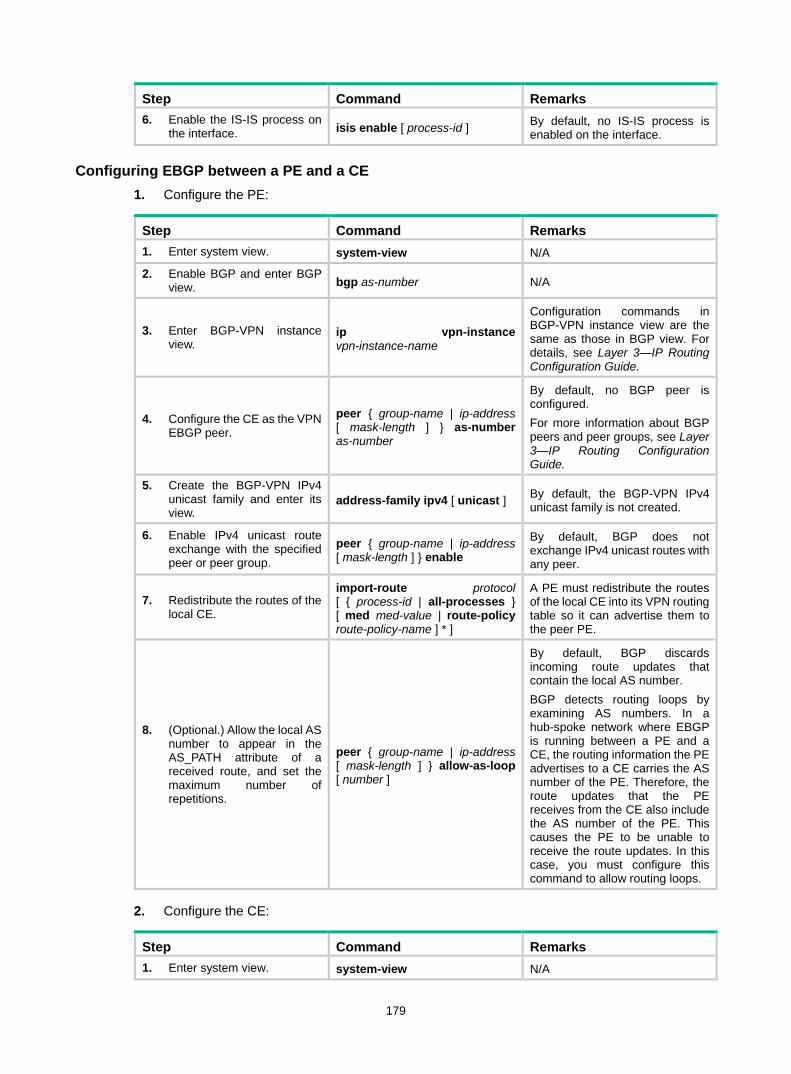
179
Step Command Remarks 6. Enable the IS-IS process on
the interface. isis enable [ process-id ] By default, no IS-IS process is enabled on the interface.
Configuring EBGP between a PE and a CE 1. Configure the PE:
Step Command Remarks 1. Enter system view. system-view N/A
2. Enable BGP and enter BGP view. bgp as-number N/A
3. Enter BGP-VPN instance view.
ip vpn-instance vpn-instance-name
Configuration commands in BGP-VPN instance view are the same as those in BGP view. For details, see Layer 3—IP Routing Configuration Guide.
4. Configure the CE as the VPN EBGP peer.
peer { group-name | ip-address [ mask-length ] } as-number as-number
By default, no BGP peer is configured. For more information about BGP peers and peer groups, see Layer 3—IP Routing Configuration Guide.
5. Create the BGP-VPN IPv4 unicast family and enter its view.
address-family ipv4 [ unicast ] By default, the BGP-VPN IPv4 unicast family is not created.
6. Enable IPv4 unicast route exchange with the specified peer or peer group.
peer { group-name | ip-address [ mask-length ] } enable
By default, BGP does not exchange IPv4 unicast routes with any peer.
7. Redistribute the routes of the local CE.
import-route protocol [ { process-id | all-processes } [ med med-value | route-policy route-policy-name ] * ]
A PE must redistribute the routes of the local CE into its VPN routing table so it can advertise them to the peer PE.
8. (Optional.) Allow the local AS number to appear in the AS_PATH attribute of a received route, and set the maximum number of repetitions.
peer { group-name | ip-address [ mask-length ] } allow-as-loop [ number ]
By default, BGP discards incoming route updates that contain the local AS number. BGP detects routing loops by examining AS numbers. In a hub-spoke network where EBGP is running between a PE and a CE, the routing information the PE advertises to a CE carries the AS number of the PE. Therefore, the route updates that the PE receives from the CE also include the AS number of the PE. This causes the PE to be unable to receive the route updates. In this case, you must configure this command to allow routing loops.
2. Configure the CE:
Step Command Remarks 1. Enter system view. system-view N/A
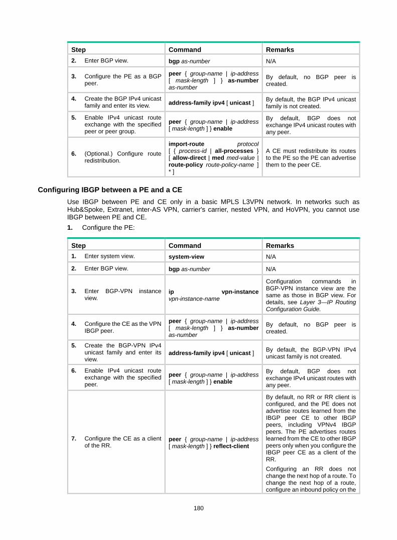
180
Step Command Remarks 2. Enter BGP view. bgp as-number N/A
3. Configure the PE as a BGP peer.
peer { group-name | ip-address [ mask-length ] } as-number as-number
By default, no BGP peer is created.
4. Create the BGP IPv4 unicast family and enter its view. address-family ipv4 [ unicast ] By default, the BGP IPv4 unicast
family is not created.
5. Enable IPv4 unicast route exchange with the specified peer or peer group.
peer { group-name | ip-address [ mask-length ] } enable
By default, BGP does not exchange IPv4 unicast routes with any peer.
6. (Optional.) Configure route redistribution.
import-route protocol [ { process-id | all-processes } [ allow-direct | med med-value | route-policy route-policy-name ] * ]
A CE must redistribute its routes to the PE so the PE can advertise them to the peer CE.
Configuring IBGP between a PE and a CE Use IBGP between PE and CE only in a basic MPLS L3VPN network. In networks such as Hub&Spoke, Extranet, inter-AS VPN, carrier's carrier, nested VPN, and HoVPN, you cannot use IBGP between PE and CE. 1. Configure the PE:
Step Command Remarks 1. Enter system view. system-view N/A
2. Enter BGP view. bgp as-number N/A
3. Enter BGP-VPN instance view.
ip vpn-instance vpn-instance-name
Configuration commands in BGP-VPN instance view are the same as those in BGP view. For details, see Layer 3—IP Routing Configuration Guide.
4. Configure the CE as the VPN IBGP peer.
peer { group-name | ip-address [ mask-length ] } as-number as-number
By default, no BGP peer is created.
5. Create the BGP-VPN IPv4 unicast family and enter its view.
address-family ipv4 [ unicast ] By default, the BGP-VPN IPv4 unicast family is not created.
6. Enable IPv4 unicast route exchange with the specified peer.
peer { group-name | ip-address [ mask-length ] } enable
By default, BGP does not exchange IPv4 unicast routes with any peer.
7. Configure the CE as a client of the RR.
peer { group-name | ip-address [ mask-length ] } reflect-client
By default, no RR or RR client is configured, and the PE does not advertise routes learned from the IBGP peer CE to other IBGP peers, including VPNv4 IBGP peers. The PE advertises routes learned from the CE to other IBGP peers only when you configure the IBGP peer CE as a client of the RR. Configuring an RR does not change the next hop of a route. To change the next hop of a route, configure an inbound policy on the

181
Step Command Remarks receiving side.
8. (Optional.) Enable route reflection between clients. reflect between-clients Route reflection between clients is
enabled by default.
9. (Optional.) Configure the cluster ID for the RR.
reflector cluster-id { cluster-id | ip-address }
By default, the RR uses its own router ID as the cluster ID. If multiple RRs exist in a cluster, use this command to configure the same cluster ID for all RRs in the cluster to avoid routing loops.
2. Configure the CE:
Step Command Remarks 1. Enter system view. system-view N/A
2. Enter BGP view. bgp as-number N/A
3. Configure the PE as an IBGP peer.
peer { group-name | ip-address [ mask-length ] } as-number as-number
By default, no BGP peer is created.
4. Create the BGP IPv4 unicast family and enter its view. address-family ipv4 [ unicast ] By default, the BGP IPv4 unicast
family is not created.
5. Enable IPv4 unicast route exchange with the specified peer or peer group.
peer { group-name | ip-address [ mask-length ] } enable
By default, BGP does not exchange IPv4 unicast routes with any peer.
6. (Optional.) Configure route redistribution.
import-route protocol [ { process-id | all-processes } [ allow-direct | med med-value | route-policy route-policy-name ] * ]
A CE must redistribute its routes to the PE so the PE can advertise them to the peer CE.
Configuring routing between PEs
Step Command Remarks 1. Enter system view. system-view N/A
2. Enter BGP view. bgp as-number N/A
3. Configure the remote PE as a BGP peer.
peer { group-name | ip-address [ mask-length ] } as-number as-number
By default, no BGP peer is created.
4. Specify the source interface for route updates.
peer { group-name | ip-address [ mask-length ] } connect-interface interface-type interface-number
By default, BGP uses the egress interface of the optimal route destined for the peer as the source interface.
5. Create the BGP VPNv4 address family and enter its view.
address-family vpnv4 By default, the BGP VPNv4 address family is not created.
6. Enable BGP VPNv4 route exchange with the specified peer.
peer { group-name | ip-address [ mask-length ] } enable
By default, BGP does not exchange BGP VPNv4 routes with any peer.

182
Configuring BGP VPNv4 route control BGP VPNv4 route control is configured similarly with BGP route control, except that it is configured in BGP VPNv4 address family view. For detailed information about BGP route control, see Layer 3—IP Routing Configuration Guide.
To configure BGP VPNv4 route control:
Step Command Remarks 1. Enter system view. system-view N/A
2. Enter BGP view. bgp as-number N/A
3. Enter BGP VPNv4 address family view. address-family vpnv4 N/A
4. Configure filtering of advertised routes.
filter-policy { acl-number | prefix-list prefix-list-name } export [ protocol process-id ]
By default, BGP does not filter advertised routes.
5. Configure filtering of received routes.
filter-policy { acl-number | prefix-list prefix-list-name } import
By default, BGP does not filter received routes.
6. Advertise community attributes to a peer or peer group.
peer { group-name | ip-address [ mask-length ] } advertise-community
By default, no community attributes are advertised to any peer or peer group.
7. Allow the local AS number to appear in the AS_PATH attribute of routes received from the peer, and set the maximum number of repetitions.
peer { group-name | ip-address [ mask-length ] } allow-as-loop [ number ]
By default, BGP discards route updates that contain the local AS number.
8. Filter routes received from or advertised to a peer or peer group based on an AS_PATH list.
peer { group-name | ip-address [ mask-length ] } as-path-acl as-path-acl-number { export | import }
By default, no AS filtering list is applied to a peer or peer group.
9. Advertise a default VPN route to a peer or peer group.
peer { group-name | ip-address [ mask-length ] } default-route-advertise vpn-instance vpn-instance-name
By default, no default VPN route is advertised to a peer or peer group.
10. Apply an ACL to filter routes received from or advertised to a peer or peer group.
peer { group-name | ip-address [ mask-length ] } filter-policy acl-number { export | import }
By default, no ACL-based filtering is configured.
11. Save all route updates from a peer or peer group.
peer { group-name | ip-address [ mask-length ] } keep-all-routes
By default, BGP does not save route updates from any peer.
12. Specify the router as the next hop of routes sent to a peer or peer group.
peer { group-name | ip-address [ mask-length ] } next-hop-local
By default, the router sets itself as the next hop for routes sent to a peer or peer group.
13. Configure BGP to not change the next hop of routes sent to an EBGP peer or peer group.
peer { group-name | ip-address [ mask-length ] } next-hop-invariable
By default, the router sets itself as the next hop for routes sent to an EBGP peer or peer group. In an inter-AS option C network where an RR is used to advertise VPNv4 routes, configure this command on the RR so the RR does not change the next hop of routes sent to EBGP peers and clients.

183
Step Command Remarks 14. Specify a preferred value for
routes received from a peer or peer group.
peer { group-name | ip-address [ mask-length ] } preferred-value value
By default, the preferred value is 0.
15. Apply a prefix list to filter routes received from or advertised to a peer or peer group.
peer { group-name | ip-address [ mask-length ] } prefix-list prefix-list-name { export | import }
By default, no prefix list based filtering is configured.
16. Configure BGP updates advertised to an EBGP peer or peer group to carry only public AS numbers.
peer { group-name | ip-address [ mask-length ] } public-as-only
By default, BGP route updates advertised to an EBGP peer or peer group can carry both public and private AS numbers.
17. Configure the router as a route reflector and specify a peer or peer group as its client.
peer { group-name | ip-address [ mask-length ] } reflect-client By default, no RR is configured.
18. Specify the maximum number of routes BGP can receive from a peer or peer group.
peer { group-name | ip-address [ mask-length ] } route-limit prefix-number [ { alert-only | discard | reconnect reconnect-time } | percentage-value ] *
By default, the number of routes that BGP can receive from a peer or peer group is not limited.
19. Apply a routing policy to a peer or peer group.
peer { group-name | ip-address [ mask-length ] } route-policy route-policy-name { export | import }
By default, no routing policy is applied to a peer or peer group.
20. Enable route target-based filtering of received VPNv4 routes.
policy vpn-target By default, this feature is enabled.
21. Enable route reflection between clients. reflect between-clients
By default, route reflection between clients is enabled on the RR.
22. Configure a cluster ID for the route reflector.
reflector cluster-id { cluster-id | ip-address }
By default, the RR uses its own router ID as the cluster ID.
23. Configure filtering of reflected routes.
rr-filter extended-community-number
By default, the RR does not filter reflected routes.
Configuring inter-AS VPN If the MPLS backbone spans multiple ASs, you must configure inter-AS VPN.
Configuring inter-AS option A Inter-AS option A applies to scenarios with a few VPNs.
To configure inter-AS option A, create VPN instances on PEs and ASBRs. The VPN instances on PEs are used to allow CEs to access the network. The VPN instances on ASBRs are used to access the peer ASBRs. An ASBR considers the peer ASBR as a CE.
The route targets configured on the PEs must match those configured on the ASBRs in the same AS to make sure VPN routes sent by the PEs (or ASBRs) can be received by the ASBRs (or PEs). Route targets configured on the PEs in different ASs do not have such requirements.
For more information, see "Configuring basic MPLS L3VPN."
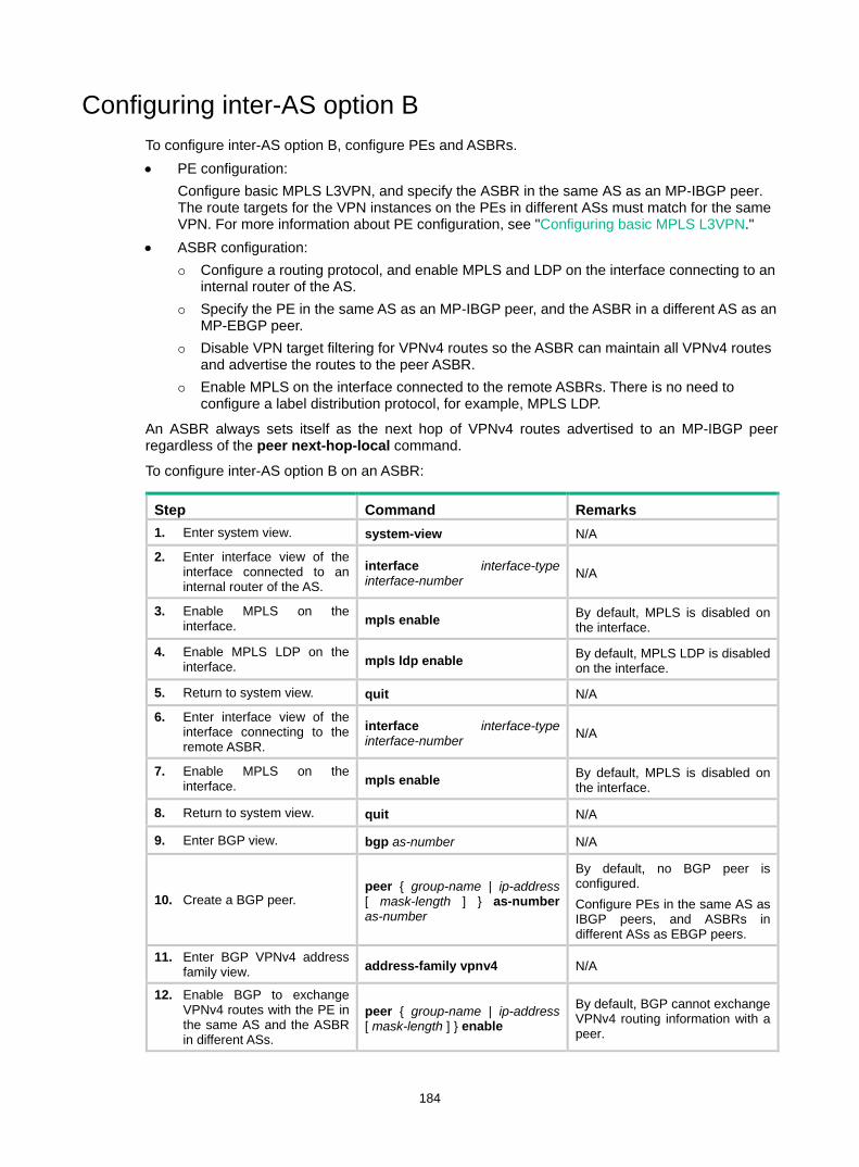
184
Configuring inter-AS option B To configure inter-AS option B, configure PEs and ASBRs. • PE configuration:
Configure basic MPLS L3VPN, and specify the ASBR in the same AS as an MP-IBGP peer. The route targets for the VPN instances on the PEs in different ASs must match for the same VPN. For more information about PE configuration, see "Configuring basic MPLS L3VPN."
• ASBR configuration: Configure a routing protocol, and enable MPLS and LDP on the interface connecting to an
internal router of the AS. Specify the PE in the same AS as an MP-IBGP peer, and the ASBR in a different AS as an
MP-EBGP peer. Disable VPN target filtering for VPNv4 routes so the ASBR can maintain all VPNv4 routes
and advertise the routes to the peer ASBR. Enable MPLS on the interface connected to the remote ASBRs. There is no need to
configure a label distribution protocol, for example, MPLS LDP.
An ASBR always sets itself as the next hop of VPNv4 routes advertised to an MP-IBGP peer regardless of the peer next-hop-local command.
To configure inter-AS option B on an ASBR:
Step Command Remarks 1. Enter system view. system-view N/A
2. Enter interface view of the interface connected to an internal router of the AS.
interface interface-type interface-number N/A
3. Enable MPLS on the interface. mpls enable By default, MPLS is disabled on
the interface.
4. Enable MPLS LDP on the interface. mpls ldp enable By default, MPLS LDP is disabled
on the interface.
5. Return to system view. quit N/A
6. Enter interface view of the interface connecting to the remote ASBR.
interface interface-type interface-number N/A
7. Enable MPLS on the interface. mpls enable By default, MPLS is disabled on
the interface.
8. Return to system view. quit N/A
9. Enter BGP view. bgp as-number N/A
10. Create a BGP peer. peer { group-name | ip-address [ mask-length ] } as-number as-number
By default, no BGP peer is configured. Configure PEs in the same AS as IBGP peers, and ASBRs in different ASs as EBGP peers.
11. Enter BGP VPNv4 address family view. address-family vpnv4 N/A
12. Enable BGP to exchange VPNv4 routes with the PE in the same AS and the ASBR in different ASs.
peer { group-name | ip-address [ mask-length ] } enable
By default, BGP cannot exchange VPNv4 routing information with a peer.
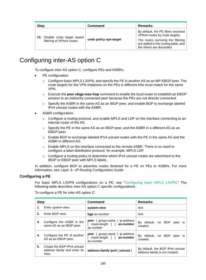
185
Step Command Remarks
13. Disable route target based filtering of VPNv4 routes. undo policy vpn-target
By default, the PE filters received VPNv4 routes by route targets. The routes surviving the filtering are added to the routing table, and the others are discarded.
Configuring inter-AS option C To configure inter-AS option C, configure PEs and ASBRs. • PE configuration:
Configure basic MPLS L3VPN, and specify the PE in another AS as an MP-EBGP peer. The route targets for the VPN instances on the PEs in different ASs must match for the same VPN.
Execute the peer ebgp-max-hop command to enable the local router to establish an EBGP session to an indirectly-connected peer because the PEs are not directly connected.
Specify the ASBR in the same AS as an IBGP peer, and enable BGP to exchange labeled IPv4 unicast routes with the ASBR.
• ASBR configuration: Configure a routing protocol, and enable MPLS and LDP on the interface connecting to an
internal router of the AS. Specify the PE in the same AS as an IBGP peer, and the ASBR in a different AS as an
EBGP peer. Enable BGP to exchange labeled IPv4 unicast routes with the PE in the same AS and the
ASBR in different AS. Enable MPLS on the interface connected to the remote ASBR. There is no need to
configure a label distribution protocol, for example, MPLS LDP. Configure a routing policy to determine which IPv4 unicast routes are advertised to the
IBGP or EBGP peer with MPLS labels.
In addition, configure BGP to advertise routes destined for a PE on PEs or ASBRs. For more information, see Layer 3—IP Routing Configuration Guide.
Configuring a PE For basic MPLS L3VPN configurations on a PE, see "Configuring basic MPLS L3VPN." The following table describes inter-AS option C specific configurations.
To configure a PE for inter-AS option C:
Step Command Remarks 1. Enter system view. system-view N/A
2. Enter BGP view. bgp as-number N/A
3. Configure the ASBR in the same AS as an IBGP peer.
peer { group-name | ip-address [ mask-length ] } as-number as-number
By default, no BGP peer is created.
4. Configure the PE of another AS as an EBGP peer.
peer { group-name | ip-address [ mask-length ] } as-number as-number
By default, no BGP peer is created.
5. Create the BGP IPv4 unicast address family and enter its view.
address-family ipv4 [ unicast ] By default, the BGP IPv4 unicast address family is not created.
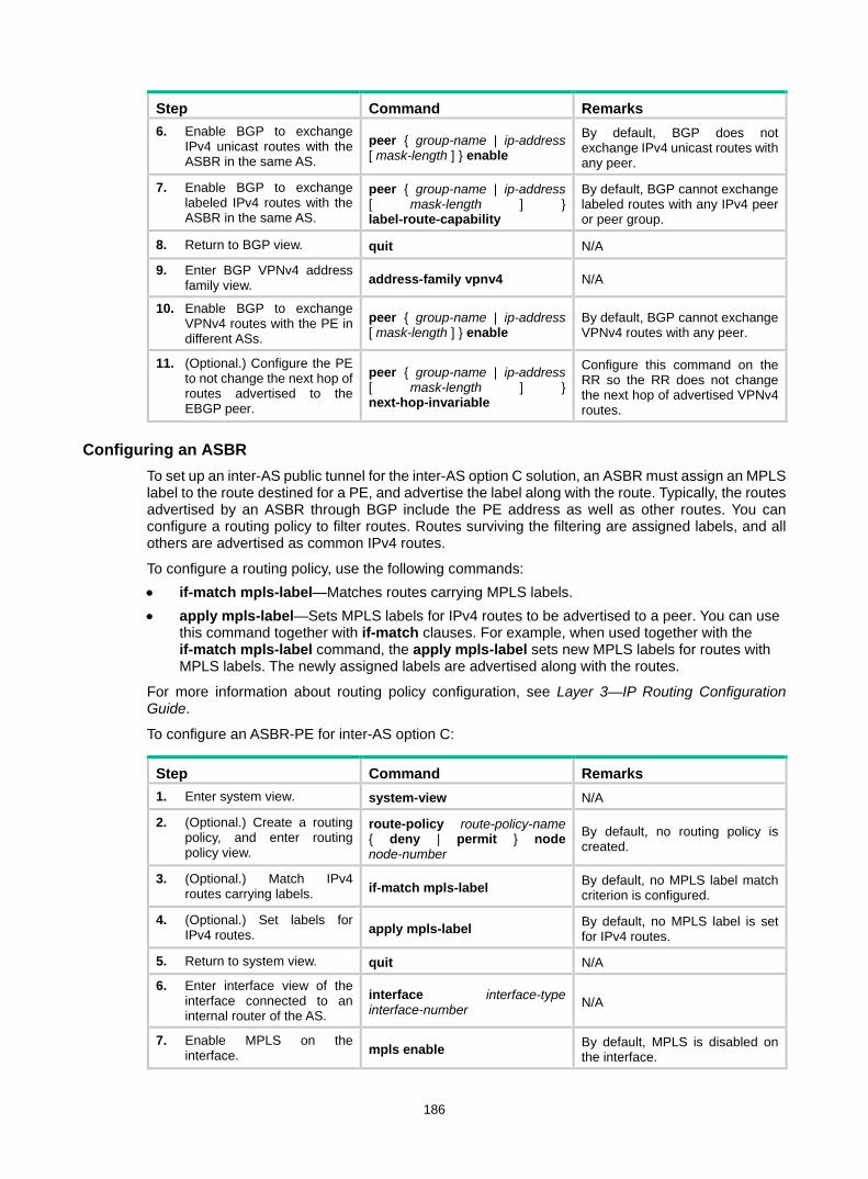
186
Step Command Remarks 6. Enable BGP to exchange
IPv4 unicast routes with the ASBR in the same AS.
peer { group-name | ip-address [ mask-length ] } enable
By default, BGP does not exchange IPv4 unicast routes with any peer.
7. Enable BGP to exchange labeled IPv4 routes with the ASBR in the same AS.
peer { group-name | ip-address [ mask-length ] } label-route-capability
By default, BGP cannot exchange labeled routes with any IPv4 peer or peer group.
8. Return to BGP view. quit N/A
9. Enter BGP VPNv4 address family view. address-family vpnv4 N/A
10. Enable BGP to exchange VPNv4 routes with the PE in different ASs.
peer { group-name | ip-address [ mask-length ] } enable
By default, BGP cannot exchange VPNv4 routes with any peer.
11. (Optional.) Configure the PE to not change the next hop of routes advertised to the EBGP peer.
peer { group-name | ip-address [ mask-length ] } next-hop-invariable
Configure this command on the RR so the RR does not change the next hop of advertised VPNv4 routes.
Configuring an ASBR To set up an inter-AS public tunnel for the inter-AS option C solution, an ASBR must assign an MPLS label to the route destined for a PE, and advertise the label along with the route. Typically, the routes advertised by an ASBR through BGP include the PE address as well as other routes. You can configure a routing policy to filter routes. Routes surviving the filtering are assigned labels, and all others are advertised as common IPv4 routes.
To configure a routing policy, use the following commands: • if-match mpls-label—Matches routes carrying MPLS labels. • apply mpls-label—Sets MPLS labels for IPv4 routes to be advertised to a peer. You can use
this command together with if-match clauses. For example, when used together with the if-match mpls-label command, the apply mpls-label sets new MPLS labels for routes with MPLS labels. The newly assigned labels are advertised along with the routes.
For more information about routing policy configuration, see Layer 3—IP Routing Configuration Guide.
To configure an ASBR-PE for inter-AS option C:
Step Command Remarks 1. Enter system view. system-view N/A
2. (Optional.) Create a routing policy, and enter routing policy view.
route-policy route-policy-name { deny | permit } node node-number
By default, no routing policy is created.
3. (Optional.) Match IPv4 routes carrying labels. if-match mpls-label By default, no MPLS label match
criterion is configured.
4. (Optional.) Set labels for IPv4 routes. apply mpls-label By default, no MPLS label is set
for IPv4 routes.
5. Return to system view. quit N/A
6. Enter interface view of the interface connected to an internal router of the AS.
interface interface-type interface-number N/A
7. Enable MPLS on the interface. mpls enable By default, MPLS is disabled on
the interface.

187
Step Command Remarks 8. Enable MPLS LDP on the
interface. mpls ldp enable By default, MPLS LDP is disabled on the interface.
9. Return to system view. quit N/A
10. Enter interface view of the interface connected to the remote ASBR.
interface interface-type interface-number N/A
11. Enable MPLS on the interface. mpls enable By default, MPLS is disabled on
the interface.
12. Return to system view. quit N/A
13. Enter BGP view. bgp as-number N/A
14. Configure the PE in the same AS as an IBGP peer.
peer { group-name | ip-address [ mask-length ] } as-number as-number
By default, no BGP peer is created.
15. Configure the ASBR in another AS as an EBGP peer.
peer { group-name | ip-address [ mask-length ] } as-number as-number
By default, no BGP peer is created.
16. Create the BGP IPv4 unicast address family and enter its view.
address-family ipv4 [ unicast ] By default, the BGP IPv4 unicast address family is not created.
17. Enable exchange of IPv4 unicast routes with the PE in the same AS and the ASBR in another AS.
peer { group-name | ip-address [ mask-length ] } enable
By default, BGP does not exchange IPv4 unicast routes with any peer.
18. Enable exchange of labeled IPv4 routes with the PE in the same AS and the ASBR in another AS.
peer { group-name | ip-address [ mask-length ] } label-route-capability
By default, BGP cannot advertise labeled routes to any IPv4 peer or peer group.
19. Configure the ASBR-PE to set itself as the next hop of routes advertised to the PE in the local AS.
peer { group-name | ip-address [ mask-length ] } next-hop-local
By default, BGP does not use its address as the next hop of routes advertised to an IBGP peer or peer group.
20. (Optional.) Apply a routing policy to routes incoming from or outgoing to a peer or peer group.
peer { group-name | ip-address [ mask-length ] } route-policy route-policy-name { export | import }
By default, no routing policy is applied.
Configuring a routing policy on an ASBR-PE A routing policy on an ASBR-PE does the following: • Assigns MPLS labels to routes received from the PEs in the local AS before advertising them to
the peer ASBR-PE. • Assigns new MPLS labels to labeled IPv4 routes advertised to PEs in the local AS.
Which IPv4 routes are assigned with MPLS labels depends on the routing policy. Only routes that meet the criteria are assigned with labels. All other routes are still common IPv4 routes.
To configure a routing policy for inter-AS option C on an ASBR-PE:
Step Command Remarks 1. Enter system view. system-view N/A
2. Create a routing policy and enter routing policy view.
route-policy route-policy-name { deny | permit } node
By default, no routing policy is created.

188
Step Command Remarks node-number
3. Match IPv4 routes carrying labels. if-match mpls-label By default, no match criterion is
configured.
4. Set labels for IPv4 routes. apply mpls-label By default, no apply clause is configured.
Configuring nested VPN For a network with many VPNs, nested VPN is a good solution to implement layered management of VPNs and to conceal the deployment of internal VPNs.
To build a nested VPN network, perform the following configurations: • Configurations between customer PE and customer CE—Configure VPN instances on the
customer PE and configure route exchange between customer PE and customer CE. • Configurations between customer PE and provider CE—Configure BGP VPNv4 route
exchange between them. To make sure the provider CE can receive all BGP VPNv4 routes, configure the undo policy vpn-target command on the provider CE to not filter VPNv4 routes by RTs.
• Configurations between provider CE and provider PE—Configure VPN instances and enable nested VPN on the provider PE and configure BGP VPNv4 route exchange between the provider CE and provider PE.
• Configurations between provider PEs—Configure BGP VPNv4 route exchange between them.
Nested VPN allows a customer PE to directly exchange VPNv4 routes with a provider PE, without needing to deploy a provider CE. In this case, the customer PE also acts as the provider CE. Therefore, you must configure provider CE settings on it.
Configurations on the customer CE, customer PE, and provider CE are similar to basic MPLS L3VPN configurations. This task describes the configurations on the provider PE.
When you configure nested VPN, follow these guidelines: • The address spaces of sub-VPNs of a VPN cannot overlap. • Do not assign nested VPN peers addresses that public network peers use. • Nested VPN does not support multihop EBGP. A provider PE and a provider CE must use the
addresses of the directly connected interfaces to establish a neighbor relationship.
To configure nested VPN:
Step Command Remarks 1. Enter system view. system-view N/A
2. Enter BGP view. bgp as-number N/A
3. Enter BGP VPNv4 address family view. address-family vpnv4 N/A
4. Enable nested VPN. nesting-vpn By default, nested VPN is disabled.
5. Return to BGP view. quit N/A
6. Enter BGP-VPN instance view.
ip vpn-instance vpn-instance-name N/A
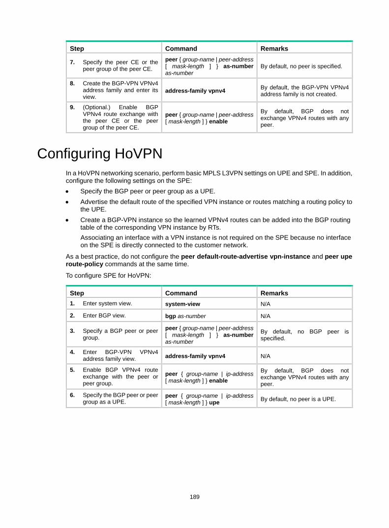
189
Step Command Remarks
7. Specify the peer CE or the peer group of the peer CE.
peer { group-name | peer-address [ mask-length ] } as-number as-number
By default, no peer is specified.
8. Create the BGP-VPN VPNv4 address family and enter its view.
address-family vpnv4 By default, the BGP-VPN VPNv4 address family is not created.
9. (Optional.) Enable BGP VPNv4 route exchange with the peer CE or the peer group of the peer CE.
peer { group-name | peer-address [ mask-length ] } enable
By default, BGP does not exchange VPNv4 routes with any peer.
Configuring HoVPN In a HoVPN networking scenario, perform basic MPLS L3VPN settings on UPE and SPE. In addition, configure the following settings on the SPE: • Specify the BGP peer or peer group as a UPE. • Advertise the default route of the specified VPN instance or routes matching a routing policy to
the UPE. • Create a BGP-VPN instance so the learned VPNv4 routes can be added into the BGP routing
table of the corresponding VPN instance by RTs. Associating an interface with a VPN instance is not required on the SPE because no interface on the SPE is directly connected to the customer network.
As a best practice, do not configure the peer default-route-advertise vpn-instance and peer upe route-policy commands at the same time.
To configure SPE for HoVPN:
Step Command Remarks 1. Enter system view. system-view N/A
2. Enter BGP view. bgp as-number N/A
3. Specify a BGP peer or peer group.
peer { group-name | peer-address [ mask-length ] } as-number as-number
By default, no BGP peer is specified.
4. Enter BGP-VPN VPNv4 address family view. address-family vpnv4 N/A
5. Enable BGP VPNv4 route exchange with the peer or peer group.
peer { group-name | ip-address [ mask-length ] } enable
By default, BGP does not exchange VPNv4 routes with any peer.
6. Specify the BGP peer or peer group as a UPE.
peer { group-name | ip-address [ mask-length ] } upe By default, no peer is a UPE.
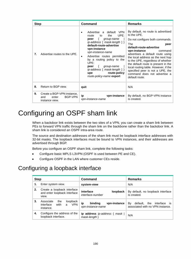
190
Step Command Remarks
7. Advertise routes to the UPE.
• Advertise a default VPN route to the UPE: peer { group-name | ip-address [ mask-length ] } default-route-advertise vpn-instance vpn-instance-name
• Advertise routes permitted by a routing policy to the UPE: peer { group-name | ip-address [ mask-length ] } upe route-policy route-policy-name export
By default, no route is advertised to the UPE. Do not configure both commands. The peer default-route-advertise vpn-instance command advertises a default route using the local address as the next hop to the UPE, regardless of whether the default route is present in the local routing table. However, if the specified peer is not a UPE, the command does not advertise a default route.
8. Return to BGP view. quit N/A
9. Create a BGP-VPN instance, and enter BGP-VPN instance view.
ip vpn-instance vpn-instance-name
By default, no BGP-VPN instance is created.
Configuring an OSPF sham link When a backdoor link exists between the two sites of a VPN, you can create a sham link between PEs to forward VPN traffic through the sham link on the backbone rather than the backdoor link. A sham link is considered an OSPF intra-area route.
The source and destination addresses of the sham link must be loopback interface addresses with 32-bit masks. The loopback interfaces must be bound to VPN instances, and their addresses are advertised through BGP.
Before you configure an OSPF sham link, complete the following tasks: • Configure basic MPLS L3VPN (OSPF is used between PE and CE). • Configure OSPF in the LAN where customer CEs reside.
Configuring a loopback interface
Step Command Remarks 1. Enter system view. system-view N/A
2. Create a loopback interface and enter loopback interface view.
interface loopback interface-number
By default, no loopback interface is created.
3. Associate the loopback interface with a VPN instance.
ip binding vpn-instance vpn-instance-name
By default, the interface is associated with no VPN instance.
4. Configure the address of the loopback interface.
ip address ip-address { mask | mask-length } N/A
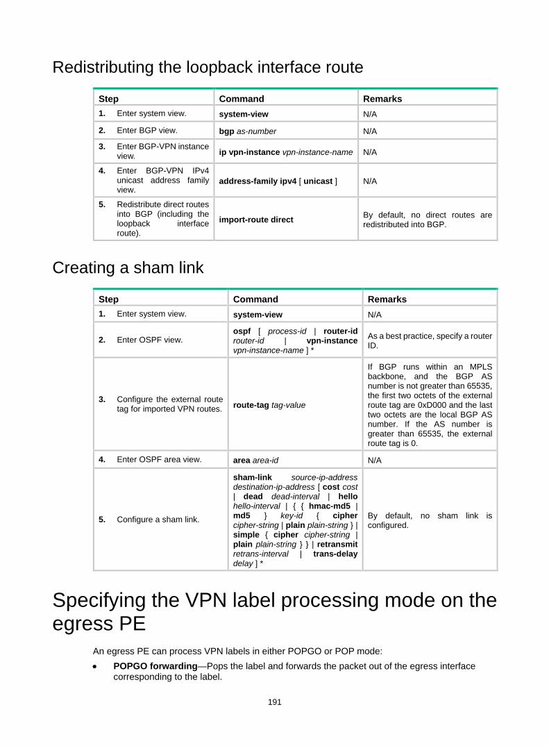
191
Redistributing the loopback interface route
Step Command Remarks 1. Enter system view. system-view N/A
2. Enter BGP view. bgp as-number N/A
3. Enter BGP-VPN instance view. ip vpn-instance vpn-instance-name N/A
4. Enter BGP-VPN IPv4 unicast address family view.
address-family ipv4 [ unicast ] N/A
5. Redistribute direct routes into BGP (including the loopback interface route).
import-route direct By default, no direct routes are redistributed into BGP.
Creating a sham link
Step Command Remarks 1. Enter system view. system-view N/A
2. Enter OSPF view. ospf [ process-id | router-id router-id | vpn-instance vpn-instance-name ] *
As a best practice, specify a router ID.
3. Configure the external route tag for imported VPN routes. route-tag tag-value
If BGP runs within an MPLS backbone, and the BGP AS number is not greater than 65535, the first two octets of the external route tag are 0xD000 and the last two octets are the local BGP AS number. If the AS number is greater than 65535, the external route tag is 0.
4. Enter OSPF area view. area area-id N/A
5. Configure a sham link.
sham-link source-ip-address destination-ip-address [ cost cost | dead dead-interval | hello hello-interval | { { hmac-md5 | md5 } key-id { cipher cipher-string | plain plain-string } | simple { cipher cipher-string | plain plain-string } } | retransmit retrans-interval | trans-delay delay ] *
By default, no sham link is configured.
Specifying the VPN label processing mode on the egress PE
An egress PE can process VPN labels in either POPGO or POP mode: • POPGO forwarding—Pops the label and forwards the packet out of the egress interface
corresponding to the label.

192
• POP forwarding—Pops the label and forwards the packet through the FIB table.
To specify the VPN label processing mode on an egress PE:
Step Command Remarks 1. Enter system view. system-view N/A
2. Enter BGP view. bgp as-number N/A
3. Specify the VPN label processing mode as POPGO forwarding.
vpn popgo The default is POP forwarding.
Configuring BGP AS number substitution When CEs at different sites have the same AS number, configure the BGP AS number substitution function to avoid route loss. If the AS_PATH attribute of a route contains the AS number of the specified CE, the PE replaces the AS number with its own AS number before advertising the route to that CE.
To configure BGP AS number substitution:
Step Command Remarks 1. Enter system view. system-view N/A
2. Enter BGP view. bgp as-number N/A
3. Enter BGP-VPN instance view.
ip vpn-instance vpn-instance-name N/A
4. Configure a BGP peer or peer group.
peer { group-name | ip-address [ mask-length ] } as-number as-number
N/A
5. Enable the BGP AS number substitution function.
peer { group-name | ip-address [ mask-length ] } substitute-as
By default, BGP AS number substitution is disabled. For more information about this command, see Layer 3—IP Routing Command Reference.
Configuring MPLS L3VPN FRR There are two methods to configure MPLS L3VPN FRR: • Method 1—Execute the pic command in BGP-VPN IPv4 unicast address family view. The
device calculates a backup next hop for each BGP route in the VPN instance if there are two or more unequal-cost routes to reach the destination.
• Method 2—Execute the fast-reroute route-policy command in BGP-VPN IPv4 unicast address family view to reference a routing policy in which a backup next hop is specified by using the apply fast-reroute backup-nexthop command. The backup next hop calculated by the device must be the same as the specified backup next hop. Otherwise, the device does not generate a backup next hop for the primary route. You can also configure if-match clauses in the routing policy to identify the routes protected by FRR.
If both methods are configured, Method 2 takes precedence over Method 1.
To configure MPLS L3VPN FRR:

193
Step Command Remarks 1. Enter system view. system-view N/A
2. Enable MPLS BFD. mpls bfd enable
The mpls bfd enable command applies to VPNv4 route backup for a VPNv4 route and IPv4 route backup for a VPNv4 route. For more information about this command, see MPLS Command Reference.
3. Configure the source IP address for BFD echo packets.
bfd echo-source-ip ip-address
The bfd echo-source-ip command is required when echo-mode BFD is used to detect primary route connectivity in VPNv4 route backup for an IPv4 route. For more information about this command, see High Availability Command Reference.
4. Use BFD to test the connectivity of an LSP or MPLS TE tunnel.
• Configure BFD to test the connectivity of the LSP for the specified FEC: mpls bfd dest-addr mask-length [ nexthop nexthop-address [ discriminator local local-id remote remote-id ] ] [ template template-name ]
• Configure BFD to test the connectivity of the MPLS TE tunnel for the tunnel interface: a. interface tunnel number
mode mpls-te b. mpls bfd [ discriminator
local local-id remote remote-id ] [ template template-name ]
c. quit
By default, BFD is not configured to test the connectivity of the LSP or MPLS TE tunnel. This step is required for VPNv4 route backup for a VPNv4 route and IPv4 route backup for a VPNv4 route. Use either command depending on the public tunnel type. For more information about the commands in this step, see MPLS Command Reference.
5. Create a routing policy and enter routing policy view.
route-policy route-policy-name permit node node-number
By default, no routing policy is created. This step is required to enable MPLS L3VPN FRR in Method 2. For more information about this command, see Layer 3—IP Routing Command Reference.
6. Set the backup next hop for FRR.
apply fast-reroute backup-nexthop ip-address
By default, no backup next hop address is set for FRR. This step is required to enable MPLS L3VPN FRR in Method 2. For more information about this command, see Layer 3—IP Routing Command Reference.
7. Return to system view. quit N/A
8. Enter BGP view. bgp as-number N/A
9. (Optional.) Use echo-mode BFD to detect the connectivity to the
primary-path-detect bfd echo By default, ARP is used to detect the connectivity to the next hop. Use this command if necessary in
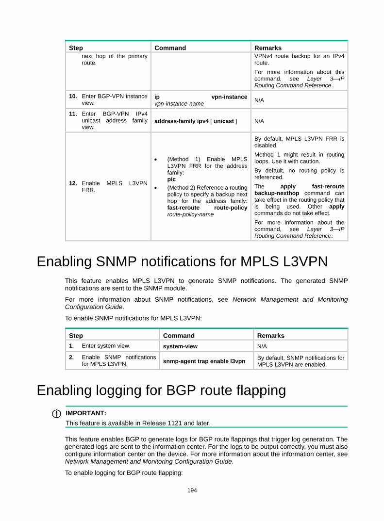
194
Step Command Remarks next hop of the primary route.
VPNv4 route backup for an IPv4 route. For more information about this command, see Layer 3—IP Routing Command Reference.
10. Enter BGP-VPN instance view.
ip vpn-instance vpn-instance-name N/A
11. Enter BGP-VPN IPv4 unicast address family view.
address-family ipv4 [ unicast ] N/A
12. Enable MPLS L3VPN FRR.
• (Method 1) Enable MPLS L3VPN FRR for the address family: pic
• (Method 2) Reference a routing policy to specify a backup next hop for the address family: fast-reroute route-policy route-policy-name
By default, MPLS L3VPN FRR is disabled. Method 1 might result in routing loops. Use it with caution. By default, no routing policy is referenced. The apply fast-reroute backup-nexthop command can take effect in the routing policy that is being used. Other apply commands do not take effect. For more information about the command, see Layer 3—IP Routing Command Reference.
Enabling SNMP notifications for MPLS L3VPN This feature enables MPLS L3VPN to generate SNMP notifications. The generated SNMP notifications are sent to the SNMP module.
For more information about SNMP notifications, see Network Management and Monitoring Configuration Guide.
To enable SNMP notifications for MPLS L3VPN:
Step Command Remarks 1. Enter system view. system-view N/A
2. Enable SNMP notifications for MPLS L3VPN. snmp-agent trap enable l3vpn By default, SNMP notifications for
MPLS L3VPN are enabled.
Enabling logging for BGP route flapping IMPORTANT:
This feature is available in Release 1121 and later.
This feature enables BGP to generate logs for BGP route flappings that trigger log generation. The generated logs are sent to the information center. For the logs to be output correctly, you must also configure information center on the device. For more information about the information center, see Network Management and Monitoring Configuration Guide.
To enable logging for BGP route flapping:

195
Step Command Remarks
1. Enter system view. system-view N/A
2. Enter BGP VPNv4 address family view or BGP-VPN VPNv4 address family view.
• Enter BGP VPNv4 address family view: a. bgp as-number b. address-family vpnv4
• Enter BGP-VPN VPNv4 address family view: a. bgp as-number b. ip vpn-instance
vpn-instance-name c. address-family vpnv4
N/A
3. Enable logging for BGP route flapping.
log-route-flap monitor-time monitor-count [ log-count-limit | route-policy route-policy-name ] *
By default, logging for BGP route flapping is disabled.
Displaying and maintaining MPLS L3VPN You can soft-reset or reset BGP sessions to apply new BGP configurations. A soft reset operation updates BGP routing information without tearing down BGP connections. A reset operation updates BGP routing information by tearing down, and then re-establishing BGP connections. Soft reset requires that BGP peers have route refresh capability.
Execute the following commands in user view to soft reset or reset BGP connections:
Task Command
Soft reset BGP sessions for VPNv4 address family.
refresh bgp { ip-address [ mask-length ] | all | external | group group-name | internal } { export | import } vpnv4 [ vpn-instance vpn-instance-name ]
Reset BGP sessions for VPNv4 address family.
reset bgp { as-number | ip-address [ mask-length ] | all | external | internal | group group-name } vpnv4 [ vpn-instance vpn-instance-name ]
For more information about the refresh bgp vpnv4 and reset bgp vpnv4 commands, see Layer 3—IP Routing Command Reference.
Execute the following commands in any view to display MPLS L3VPN:
Task Command
Display the routing table for a VPN instance.
display ip routing-table vpn-instance vpn-instance-name [ statistics | verbose ] [ standby slot slot-number ]
Display information about a specified or all VPN instances. display ip vpn-instance [ instance-name vpn-instance-name ]
Display the FIB of a VPN instance. display fib vpn-instance vpn-instance-name
Display FIB entries that match the specified destination IP address in the specified VPN instance.
display fib vpn-instance vpn-instance-name ip-address [ mask | mask-length ]
Display BGP VPNv4 peer group information.
display bgp group vpnv4 [ vpn-instance vpn-instance-name ] [ group-name group-name ]

196
Task Command
Display BGP VPNv4 peer information.
display bgp peer vpnv4 [ vpn-instance vpn-instance-name ] [ ip-address mask-length | { ip-address | group-name group-name } log-info | [ [ ip-address ] verbose ] [ standby slot slot-number ] ]
Display BGP VPNv4 routes.
display bgp routing-table vpnv4 [ [ route-distinguisher route-distinguisher ] [ network-address [ { mask | mask-length } [ longest-match ] ] | network-address [ mask | mask-length ] advertise-info | as-path-acl as-path-acl-number | community-list { { basic-community-list-number | comm-list-name } [ whole-match ] | adv-community-list-number } ] | [ vpn-instance vpn-instance-name ] peer ip-address { advertised-routes | received-routes } [ network-address [ mask | mask-length ] | statistics ] | statistics ] [ standby slot slot-number ]
Display incoming labels for BGP IPv4 unicast routes.
display bgp routing-table ipv4 [ unicast ] [ vpn-instance vpn-instance-name ] inlabel
Display outgoing labels for BGP IPv4 unicast routes.
display bgp routing-table ipv4 [ unicast ] [ vpn-instance vpn-instance-name ] outlabel [ standby slot slot-number ]
Display incoming labels for BGP VPNv4 routes. display bgp routing-table vpnv4 inlabel
Display outgoing labels for BGP VPNv4 routes.
display bgp routing-table vpnv4 outlabel [ standby slot slot-number ]
Display BGP VPNv4 address family update group information.
display bgp update-group vpnv4 [ vpn-instance vpn-instance-name ] [ ip-address ]
Display OSPF sham link information.
display ospf [ process-id ] sham-link [ area area-id ] [ standby slot slot-number ]
For more information about the display ip routing-table, display bgp group vpnv4, display bgp peer vpnv4, and display bgp update-group vpnv4 commands, see Layer 3—IP Routing Command Reference.
MPLS L3VPN configuration examples Configuring basic MPLS L3VPN Network requirements
CE 1 and CE 3 belong to VPN 1. CE 2 and CE 4 belong to VPN 2.
VPN 1 uses route target attribute 111:1. VPN 2 uses route target attribute 222:2. Users of different VPNs cannot access each other.
EBGP is used to exchange VPN routing information between CE and PE.
PEs use OSPF to communicate with each other and use MP-IBGP to exchange VPN routing information.

197
Figure 62 Network diagram
Table 12 Interface and IP address assignment
Device Interface IP address Device Interface IP address CE 1 Vlan-int11 10.1.1.1/24 P Loop0 2.2.2.9/32
PE 1 Loop0 1.1.1.9/32 Vlan-int12 172.2.1.1/24
Vlan-int11 10.1.1.2/24 Vlan-int13 172.1.1.2/24
Vlan-int13 172.1.1.1/24 PE 2 Loop0 3.3.3.9/32
Vlan-int12 10.2.1.2/24 Vlan-int12 172.2.1.2/24
CE 2 Vlan-int12 10.2.1.1/24 Vlan-int11 10.3.1.2/24
CE 3 Vlan-int11 10.3.1.1/24 Vlan-int13 10.4.1.2/24
CE 4 Vlan-int13 10.4.1.1/24
Configuration procedure 1. Configure an IGP on the MPLS backbone to ensure IP connectivity within the backbone:
# Configure PE 1. <PE1> system-view
[PE1] interface loopback 0
[PE1-LoopBack0] ip address 1.1.1.9 32
[PE1-LoopBack0] quit
[PE1] interface vlan-interface 13
[PE1-Vlan-interface13] ip address 172.1.1.1 24
[PE1-Vlan-interface13] quit
[PE1] ospf
[PE1-ospf-1] area 0
[PE1-ospf-1-area-0.0.0.0] network 172.1.1.0 0.0.0.255
[PE1-ospf-1-area-0.0.0.0] network 1.1.1.9 0.0.0.0
[PE1-ospf-1-area-0.0.0.0] quit
[PE1-ospf-1] quit
CE 1
Loop0
Loop0 Loop0
PE 1 PE 2
Vlan-int11
Vlan-int11
Vlan-int12
Vlan-int12
Vlan-int12
Vlan-int13
Vlan-int13
Vlan-int11
Vlan-int11
CE 3
CE 2 CE 4
Vlan-int13 Vlan-int12Vlan-int13
VPN 1 VPN 1
VPN 2 VPN 2
MPLS backbone
AS 65410 AS 65430
AS 65420 AS 65440
P

198
# Configure the P device. <P> system-view
[P] interface loopback 0
[P-LoopBack0] ip address 2.2.2.9 32
[P-LoopBack0] quit
[P] interface vlan-interface 13
[P-Vlan-interface13] ip address 172.1.1.2 24
[P- Vlan-interface13] quit
[P] interface vlan-interface 12
[P-Vlan-interface12] ip address 172.2.1.1 24
[P-Vlan-interface12] quit
[P] ospf
[P-ospf-1] area 0
[P-ospf-1-area-0.0.0.0] network 172.1.1.0 0.0.0.255
[P-ospf-1-area-0.0.0.0] network 172.2.1.0 0.0.0.255
[P-ospf-1-area-0.0.0.0] network 2.2.2.9 0.0.0.0
[P-ospf-1-area-0.0.0.0] quit
[P-ospf-1] quit
# Configure PE 2. <PE2> system-view
[PE2] interface loopback 0
[PE2-LoopBack0] ip address 3.3.3.9 32
[PE2-LoopBack0] quit
[PE2] interface vlan-interface 12
[PE2-Vlan-interface12] ip address 172.2.1.2 24
[PE2-Vlan-interface12] quit
[PE2] ospf
[PE2-ospf-1] area 0
[PE2-ospf-1-area-0.0.0.0] network 172.2.1.0 0.0.0.255
[PE2-ospf-1-area-0.0.0.0] network 3.3.3.9 0.0.0.0
[PE2-ospf-1-area-0.0.0.0] quit
[PE2-ospf-1] quit
# Execute the display ospf peer command to verify that OSPF adjacencies in Full state have been established between PE 1, P, and PE 2. Execute the display ip routing-table command to verify that the PEs have learned the routes to the loopback interfaces of each other. (Details not shown.)
2. Configure basic MPLS and MPLS LDP on the MPLS backbone to establish LDP LSPs: # Configure PE 1. [PE1] mpls lsr-id 1.1.1.9
[PE1] mpls ldp
[PE1-ldp] quit
[PE1] interface vlan-interface 13
[PE1-Vlan-interface13] mpls enable
[PE1-Vlan-interface13] mpls ldp enable
[PE1-Vlan-interface13] quit
# Configure the P device. [P] mpls lsr-id 2.2.2.9
[P] mpls ldp
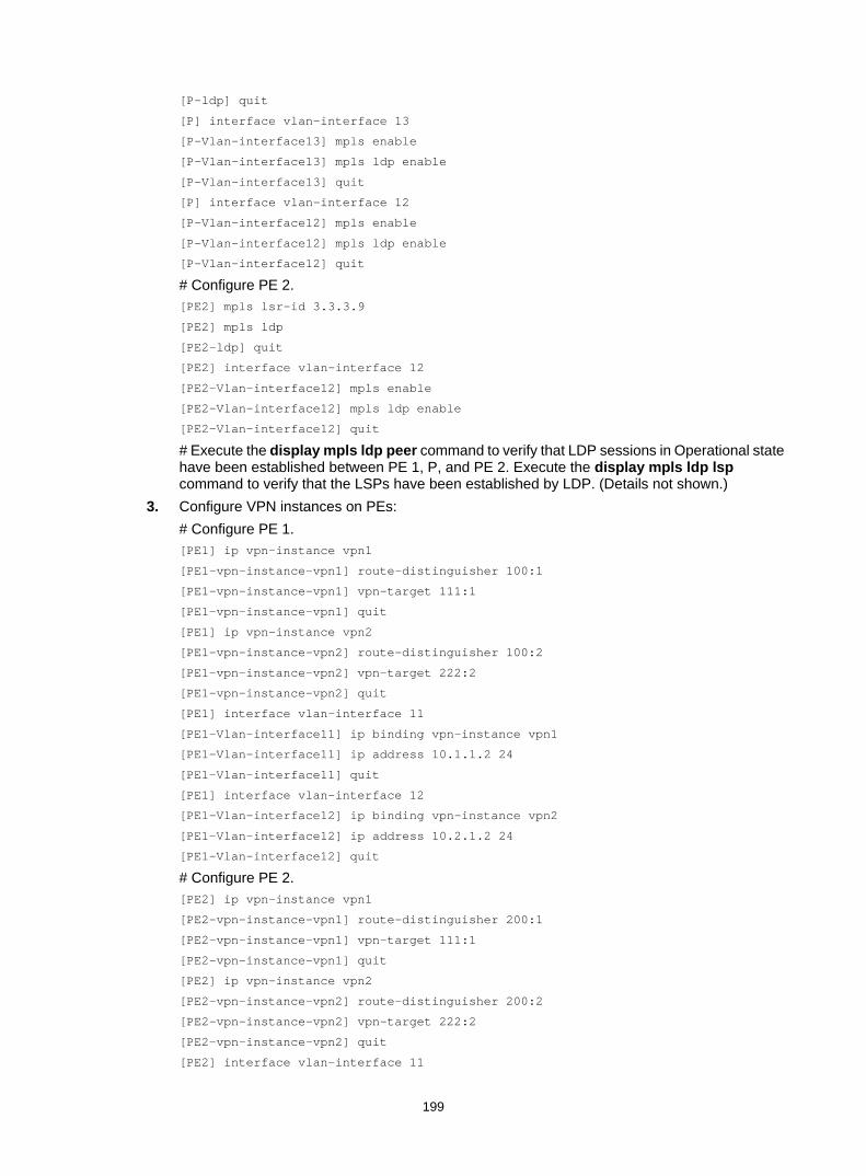
199
[P-ldp] quit
[P] interface vlan-interface 13
[P-Vlan-interface13] mpls enable
[P-Vlan-interface13] mpls ldp enable
[P-Vlan-interface13] quit
[P] interface vlan-interface 12
[P-Vlan-interface12] mpls enable
[P-Vlan-interface12] mpls ldp enable
[P-Vlan-interface12] quit
# Configure PE 2. [PE2] mpls lsr-id 3.3.3.9
[PE2] mpls ldp
[PE2-ldp] quit
[PE2] interface vlan-interface 12
[PE2-Vlan-interface12] mpls enable
[PE2-Vlan-interface12] mpls ldp enable
[PE2-Vlan-interface12] quit
# Execute the display mpls ldp peer command to verify that LDP sessions in Operational state have been established between PE 1, P, and PE 2. Execute the display mpls ldp lsp command to verify that the LSPs have been established by LDP. (Details not shown.)
3. Configure VPN instances on PEs: # Configure PE 1. [PE1] ip vpn-instance vpn1
[PE1-vpn-instance-vpn1] route-distinguisher 100:1
[PE1-vpn-instance-vpn1] vpn-target 111:1
[PE1-vpn-instance-vpn1] quit
[PE1] ip vpn-instance vpn2
[PE1-vpn-instance-vpn2] route-distinguisher 100:2
[PE1-vpn-instance-vpn2] vpn-target 222:2
[PE1-vpn-instance-vpn2] quit
[PE1] interface vlan-interface 11
[PE1-Vlan-interface11] ip binding vpn-instance vpn1
[PE1-Vlan-interface11] ip address 10.1.1.2 24
[PE1-Vlan-interface11] quit
[PE1] interface vlan-interface 12
[PE1-Vlan-interface12] ip binding vpn-instance vpn2
[PE1-Vlan-interface12] ip address 10.2.1.2 24
[PE1-Vlan-interface12] quit
# Configure PE 2. [PE2] ip vpn-instance vpn1
[PE2-vpn-instance-vpn1] route-distinguisher 200:1
[PE2-vpn-instance-vpn1] vpn-target 111:1
[PE2-vpn-instance-vpn1] quit
[PE2] ip vpn-instance vpn2
[PE2-vpn-instance-vpn2] route-distinguisher 200:2
[PE2-vpn-instance-vpn2] vpn-target 222:2
[PE2-vpn-instance-vpn2] quit
[PE2] interface vlan-interface 11
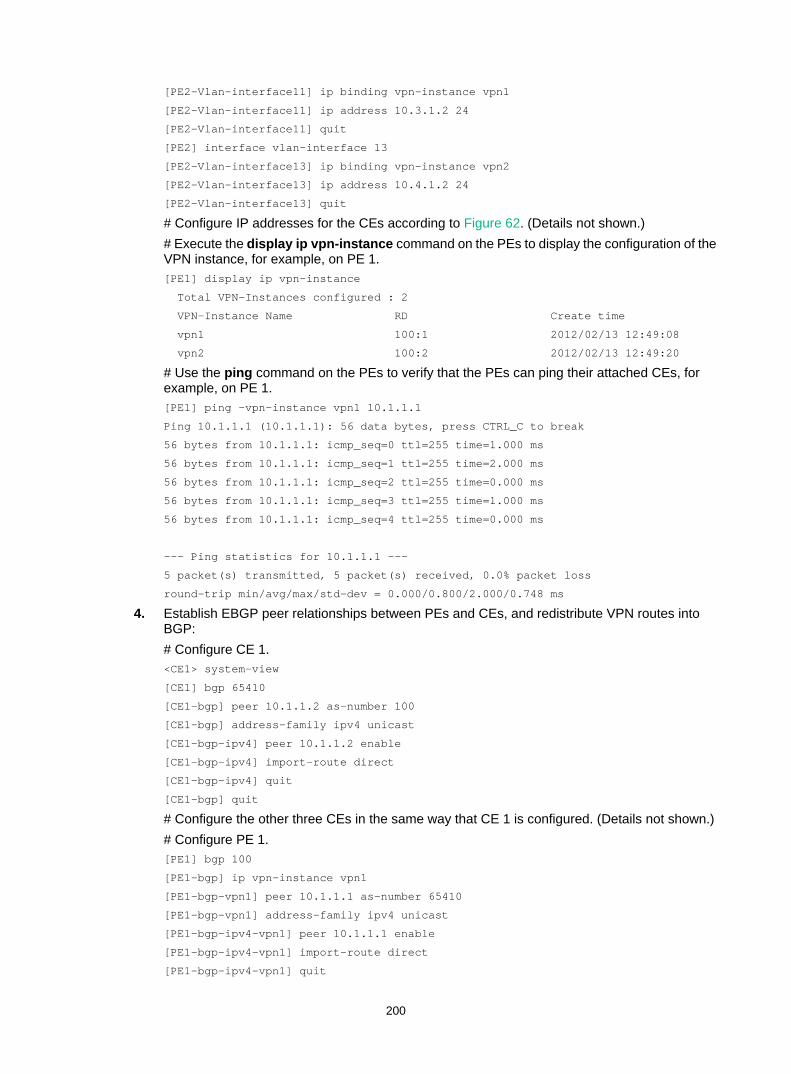
200
[PE2-Vlan-interface11] ip binding vpn-instance vpn1
[PE2-Vlan-interface11] ip address 10.3.1.2 24
[PE2-Vlan-interface11] quit
[PE2] interface vlan-interface 13
[PE2-Vlan-interface13] ip binding vpn-instance vpn2
[PE2-Vlan-interface13] ip address 10.4.1.2 24
[PE2-Vlan-interface13] quit
# Configure IP addresses for the CEs according to Figure 62. (Details not shown.) # Execute the display ip vpn-instance command on the PEs to display the configuration of the VPN instance, for example, on PE 1. [PE1] display ip vpn-instance
Total VPN-Instances configured : 2
VPN-Instance Name RD Create time
vpn1 100:1 2012/02/13 12:49:08
vpn2 100:2 2012/02/13 12:49:20
# Use the ping command on the PEs to verify that the PEs can ping their attached CEs, for example, on PE 1. [PE1] ping -vpn-instance vpn1 10.1.1.1
Ping 10.1.1.1 (10.1.1.1): 56 data bytes, press CTRL_C to break
56 bytes from 10.1.1.1: icmp_seq=0 ttl=255 time=1.000 ms
56 bytes from 10.1.1.1: icmp_seq=1 ttl=255 time=2.000 ms
56 bytes from 10.1.1.1: icmp_seq=2 ttl=255 time=0.000 ms
56 bytes from 10.1.1.1: icmp_seq=3 ttl=255 time=1.000 ms
56 bytes from 10.1.1.1: icmp_seq=4 ttl=255 time=0.000 ms
--- Ping statistics for 10.1.1.1 ---
5 packet(s) transmitted, 5 packet(s) received, 0.0% packet loss
round-trip min/avg/max/std-dev = 0.000/0.800/2.000/0.748 ms
4. Establish EBGP peer relationships between PEs and CEs, and redistribute VPN routes into BGP: # Configure CE 1. <CE1> system-view
[CE1] bgp 65410
[CE1-bgp] peer 10.1.1.2 as-number 100
[CE1-bgp] address-family ipv4 unicast
[CE1-bgp-ipv4] peer 10.1.1.2 enable
[CE1-bgp-ipv4] import-route direct
[CE1-bgp-ipv4] quit
[CE1-bgp] quit
# Configure the other three CEs in the same way that CE 1 is configured. (Details not shown.) # Configure PE 1. [PE1] bgp 100
[PE1-bgp] ip vpn-instance vpn1
[PE1-bgp-vpn1] peer 10.1.1.1 as-number 65410
[PE1-bgp-vpn1] address-family ipv4 unicast
[PE1-bgp-ipv4-vpn1] peer 10.1.1.1 enable
[PE1-bgp-ipv4-vpn1] import-route direct
[PE1-bgp-ipv4-vpn1] quit
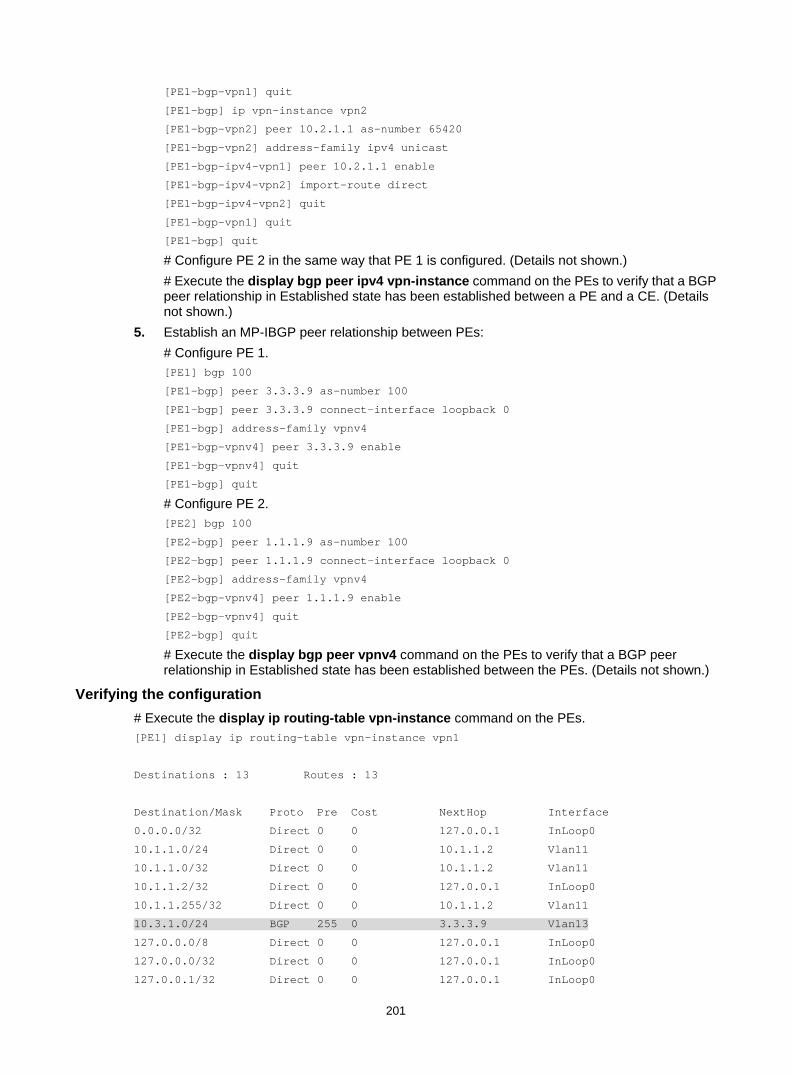
201
[PE1-bgp-vpn1] quit
[PE1-bgp] ip vpn-instance vpn2
[PE1-bgp-vpn2] peer 10.2.1.1 as-number 65420
[PE1-bgp-vpn2] address-family ipv4 unicast
[PE1-bgp-ipv4-vpn1] peer 10.2.1.1 enable
[PE1-bgp-ipv4-vpn2] import-route direct
[PE1-bgp-ipv4-vpn2] quit
[PE1-bgp-vpn1] quit
[PE1-bgp] quit
# Configure PE 2 in the same way that PE 1 is configured. (Details not shown.) # Execute the display bgp peer ipv4 vpn-instance command on the PEs to verify that a BGP peer relationship in Established state has been established between a PE and a CE. (Details not shown.)
5. Establish an MP-IBGP peer relationship between PEs: # Configure PE 1. [PE1] bgp 100
[PE1-bgp] peer 3.3.3.9 as-number 100
[PE1-bgp] peer 3.3.3.9 connect-interface loopback 0
[PE1-bgp] address-family vpnv4
[PE1-bgp-vpnv4] peer 3.3.3.9 enable
[PE1-bgp-vpnv4] quit
[PE1-bgp] quit
# Configure PE 2. [PE2] bgp 100
[PE2-bgp] peer 1.1.1.9 as-number 100
[PE2-bgp] peer 1.1.1.9 connect-interface loopback 0
[PE2-bgp] address-family vpnv4
[PE2-bgp-vpnv4] peer 1.1.1.9 enable
[PE2-bgp-vpnv4] quit
[PE2-bgp] quit
# Execute the display bgp peer vpnv4 command on the PEs to verify that a BGP peer relationship in Established state has been established between the PEs. (Details not shown.)
Verifying the configuration # Execute the display ip routing-table vpn-instance command on the PEs. [PE1] display ip routing-table vpn-instance vpn1
Destinations : 13 Routes : 13
Destination/Mask Proto Pre Cost NextHop Interface
0.0.0.0/32 Direct 0 0 127.0.0.1 InLoop0
10.1.1.0/24 Direct 0 0 10.1.1.2 Vlan11
10.1.1.0/32 Direct 0 0 10.1.1.2 Vlan11
10.1.1.2/32 Direct 0 0 127.0.0.1 InLoop0
10.1.1.255/32 Direct 0 0 10.1.1.2 Vlan11
10.3.1.0/24 BGP 255 0 3.3.3.9 Vlan13
127.0.0.0/8 Direct 0 0 127.0.0.1 InLoop0
127.0.0.0/32 Direct 0 0 127.0.0.1 InLoop0
127.0.0.1/32 Direct 0 0 127.0.0.1 InLoop0
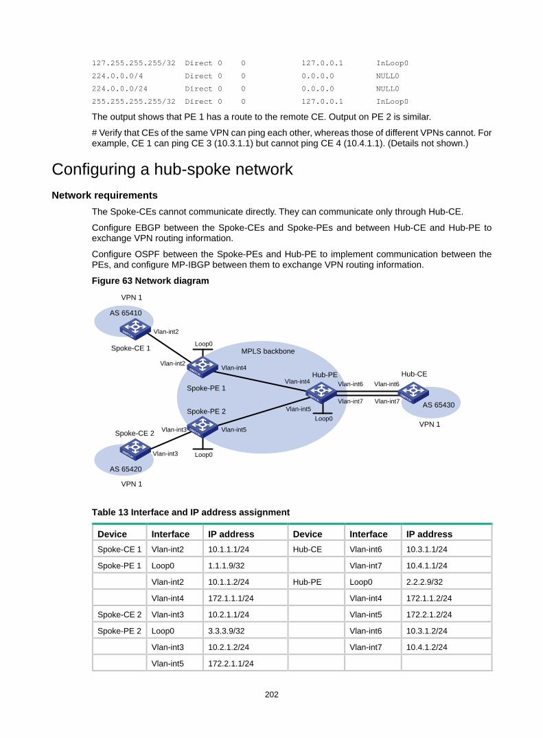
202
127.255.255.255/32 Direct 0 0 127.0.0.1 InLoop0
224.0.0.0/4 Direct 0 0 0.0.0.0 NULL0
224.0.0.0/24 Direct 0 0 0.0.0.0 NULL0
255.255.255.255/32 Direct 0 0 127.0.0.1 InLoop0
The output shows that PE 1 has a route to the remote CE. Output on PE 2 is similar.
# Verify that CEs of the same VPN can ping each other, whereas those of different VPNs cannot. For example, CE 1 can ping CE 3 (10.3.1.1) but cannot ping CE 4 (10.4.1.1). (Details not shown.)
Configuring a hub-spoke network Network requirements
The Spoke-CEs cannot communicate directly. They can communicate only through Hub-CE.
Configure EBGP between the Spoke-CEs and Spoke-PEs and between Hub-CE and Hub-PE to exchange VPN routing information.
Configure OSPF between the Spoke-PEs and Hub-PE to implement communication between the PEs, and configure MP-IBGP between them to exchange VPN routing information.
Figure 63 Network diagram
Table 13 Interface and IP address assignment
Device Interface IP address Device Interface IP address Spoke-CE 1 Vlan-int2 10.1.1.1/24 Hub-CE Vlan-int6 10.3.1.1/24
Spoke-PE 1 Loop0 1.1.1.9/32 Vlan-int7 10.4.1.1/24
Vlan-int2 10.1.1.2/24 Hub-PE Loop0 2.2.2.9/32
Vlan-int4 172.1.1.1/24 Vlan-int4 172.1.1.2/24
Spoke-CE 2 Vlan-int3 10.2.1.1/24 Vlan-int5 172.2.1.2/24
Spoke-PE 2 Loop0 3.3.3.9/32 Vlan-int6 10.3.1.2/24
Vlan-int3 10.2.1.2/24 Vlan-int7 10.4.1.2/24
Vlan-int5 172.2.1.1/24
Spoke-CE 2
Hub-PE
AS 65420
AS 65410
AS 65430
VPN 1
VPN 1
VPN 1
Hub-CE
Spoke-PE 1
Spoke-PE 2
Spoke-CE 1 Loop0
Vlan-int5
Vlan-int7
Vlan-int6 Vlan-int6Vlan-int4
Vlan-int5
Vlan-int4
MPLS backbone
Vlan-int2
Vlan-int3
Vlan-int2
Vlan-int3
Vlan-int7
Loop0
Loop0
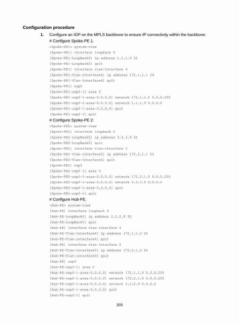
203
Configuration procedure 1. Configure an IGP on the MPLS backbone to ensure IP connectivity within the backbone:
# Configure Spoke-PE 1. <Spoke-PE1> system-view
[Spoke-PE1] interface loopback 0
[Spoke-PE1-LoopBack0] ip address 1.1.1.9 32
[Spoke-PE1-LoopBack0] quit
[Spoke-PE1] interface vlan-interface 4
[Spoke-PE1-Vlan-interface4] ip address 172.1.1.1 24
[Spoke-PE1-Vlan-interface4] quit
[Spoke-PE1] ospf
[Spoke-PE1-ospf-1] area 0
[Spoke-PE1-ospf-1-area-0.0.0.0] network 172.1.1.0 0.0.0.255
[Spoke-PE1-ospf-1-area-0.0.0.0] network 1.1.1.9 0.0.0.0
[Spoke-PE1-ospf-1-area-0.0.0.0] quit
[Spoke-PE1-ospf-1] quit
# Configure Spoke-PE 2. <Spoke-PE2> system-view
[Spoke-PE2] interface loopback 0
[Spoke-PE2-LoopBack0] ip address 3.3.3.9 32
[Spoke-PE2-LoopBack0] quit
[Spoke-PE2] interface vlan-interface 5
[Spoke-PE2-Vlan-interface5] ip address 172.2.1.1 24
[Spoke-PE2-Vlan-interface5] quit
[Spoke-PE2] ospf
[Spoke-PE2-ospf-1] area 0
[Spoke-PE2-ospf-1-area-0.0.0.0] network 172.2.1.0 0.0.0.255
[Spoke-PE2-ospf-1-area-0.0.0.0] network 3.3.3.9 0.0.0.0
[Spoke-PE2-ospf-1-area-0.0.0.0] quit
[Spoke-PE2-ospf-1] quit
# Configure Hub-PE. <Hub-PE> system-view
[Hub-PE] interface loopback 0
[Hub-PE-LoopBack0] ip address 2.2.2.9 32
[Hub-PE-LoopBack0] quit
[Hub-PE] interface vlan-interface 4
[Hub-PE-Vlan-interface4] ip address 172.1.1.2 24
[Hub-PE-Vlan-interface4] quit
[Hub-PE] interface vlan-interface 5
[Hub-PE-Vlan-interface5] ip address 172.2.1.2 24
[Hub-PE-Vlan-interface5] quit
[Hub-PE] ospf
[Hub-PE-ospf-1] area 0
[Hub-PE-ospf-1-area-0.0.0.0] network 172.1.1.0 0.0.0.255
[Hub-PE-ospf-1-area-0.0.0.0] network 172.2.1.0 0.0.0.255
[Hub-PE-ospf-1-area-0.0.0.0] network 2.2.2.9 0.0.0.0
[Hub-PE-ospf-1-area-0.0.0.0] quit
[Hub-PE-ospf-1] quit

204
# Execute the display ospf peer command on the devices to verify that OSPF adjacencies in Full state have been established between Spoke-PE 1, Spoke-PE 2, and Hub-PE. Execute the display ip routing-table command on the devices to verify that the PEs have learned the routes to the loopback interfaces of each other. (Details not shown.)
2. Configure basic MPLS and MPLS LDP on the MPLS backbone to establish LDP LSPs: # Configure Spoke-PE 1. [Spoke-PE1] mpls lsr-id 1.1.1.9
[Spoke-PE1] mpls ldp
[Spoke-PE1-ldp] quit
[Spoke-PE1] interface vlan-interface 4
[Spoke-PE1-Vlan-interface4] mpls enable
[Spoke-PE1-Vlan-interface4] mpls ldp enable
[Spoke-PE1-Vlan-interface4] quit
# Configure Spoke-PE 2. [Spoke-PE2] mpls lsr-id 3.3.3.9
[Spoke-PE2] mpls ldp
[Spoke-PE2-ldp] quit
[Spoke-PE2] interface vlan-interface 5
[Spoke-PE2-Vlan-interface5] mpls enable
[Spoke-PE2-Vlan-interface5] mpls ldp enable
[Spoke-PE2-Vlan-interface5] quit
# Configure Hub-PE. [Hub-PE] mpls lsr-id 2.2.2.9
[Hub-PE] mpls ldp
[Hub-PE-ldp] quit
[Hub-PE] interface vlan-interface 4
[Hub-PE-Vlan-interface4] mpls enable
[Hub-PE-Vlan-interface4] mpls ldp enable
[Hub-PE-Vlan-interface4] quit
[Hub-PE] interface vlan-interface 5
[Hub-PE-Vlan-interface5] mpls enable
[Hub-PE-Vlan-interface5] mpls ldp enable
[Hub-PE-Vlan-interface5] quit
# Execute the display mpls ldp peer command on the devices to verify that LDP sessions in Operational state have been established between Spoke-PE 1, Spoke-PE 2, and Hub-PE. Execute the display mpls ldp lsp command on the devices to verify that the LSPs have been established by LDP. (Details not shown.)
3. Configure VPN instances on the Spoke-PEs and Hub-PE: # Configure Spoke-PE 1. [Spoke-PE1] ip vpn-instance vpn1
[Spoke-PE1-vpn-instance-vpn1] route-distinguisher 100:1
[Spoke-PE1-vpn-instance-vpn1] vpn-target 111:1 import-extcommunity
[Spoke-PE1-vpn-instance-vpn1] vpn-target 222:2 export-extcommunity
[Spoke-PE1-vpn-instance-vpn1] quit
[Spoke-PE1] interface vlan-interface 2
[Spoke-PE1-Vlan-interface2] ip binding vpn-instance vpn1
[Spoke-PE1-Vlan-interface2] ip address 10.1.1.2 24
[Spoke-PE1-Vlan-interface2] quit
# Configure Spoke-PE 2.

205
[Spoke-PE2] ip vpn-instance vpn1
[Spoke-PE2-vpn-instance-vpn1] route-distinguisher 100:2
[Spoke-PE2-vpn-instance-vpn1] vpn-target 111:1 import-extcommunity
[Spoke-PE2-vpn-instance-vpn1] vpn-target 222:2 export-extcommunity
[Spoke-PE2-vpn-instance-vpn1] quit
[Spoke-PE2] interface vlan-interface 3
[Spoke-PE2-Vlan-interface3] ip binding vpn-instance vpn1
[Spoke-PE2-Vlan-interface3] ip address 10.2.1.2 24
[Spoke-PE2-Vlan-interface3] quit
# Configure Hub-PE. [Hub-PE] ip vpn-instance vpn1-in
[Hub-PE-vpn-instance-vpn1-in] route-distinguisher 100:3
[Hub-PE-vpn-instance-vpn1-in] vpn-target 222:2 import-extcommunity
[Hub-PE-vpn-instance-vpn1-in] quit
[Hub-PE] ip vpn-instance vpn1-out
[Hub-PE-vpn-instance-vpn1-out] route-distinguisher 100:4
[Hub-PE-vpn-instance-vpn1-out] vpn-target 111:1 export-extcommunity
[Hub-PE-vpn-instance-vpn1-out] quit
[Hub-PE] interface vlan-interface 6
[Hub-PE-Vlan-interface6] ip binding vpn-instance vpn1-in
[Hub-PE-Vlan-interface6] ip address 10.3.1.2 24
[Hub-PE-Vlan-interface6] quit
[Hub-PE] interface vlan-interface 7
[Hub-PE-Vlan-interface7] ip binding vpn-instance vpn1-out
[Hub-PE-Vlan-interface7] ip address 10.4.1.2 24
[Hub-PE-Vlan-interface7] quit
# Configure IP addresses for the CEs according to Figure 63. (Details not shown.) # Execute the display ip vpn-instance command on the PEs to display the configuration of the VPN instance, for example, on Spoke-PE 1. [Spoke-PE1] display ip vpn-instance
Total VPN-Instances configured : 1
VPN-Instance Name RD Create time
vpn1 100:1 2009/04/08 10:55:07
# Use the ping command on the PEs to verify that the PEs can ping their attached CEs, for example, on Spoke-PE 1. [Spoke-PE1] ping -vpn-instance vpn1 10.1.1.1
Ping 10.1.1.1 (10.1.1.1): 56 data bytes, press CTRL_C to break
56 bytes from 10.1.1.1: icmp_seq=0 ttl=128 time=1.913 ms
56 bytes from 10.1.1.1: icmp_seq=1 ttl=128 time=2.381 ms
56 bytes from 10.1.1.1: icmp_seq=2 ttl=128 time=1.707 ms
56 bytes from 10.1.1.1: icmp_seq=3 ttl=128 time=1.666 ms
56 bytes from 10.1.1.1: icmp_seq=4 ttl=128 time=2.710 ms
--- Ping statistics for 10.1.1.1 ---
5 packet(s) transmitted, 5 packet(s) received, 0.0% packet loss
round-trip min/avg/max/std-dev = 1.666/2.075/2.710/0.406 ms

206
4. Establish EBGP peer relationships between the PEs and CEs, and redistribute VPN routes into BGP: # Configure Spoke-CE 1. <Spoke-CE1> system-view
[Spoke-CE1] bgp 65410
[Spoke-CE1-bgp] peer 10.1.1.2 as-number 100
[Spoke-CE1-bgp] address-family ipv4
[Spoke-CE1-bgp-ipv4] peer 10.1.1.2 enable
[Spoke-CE1-bgp-ipv4] import-route direct
[Spoke-CE1-bgp-ipv4] quit
[Spoke-CE1-bgp] quit
# Configure Spoke-CE 2. <Spoke-CE2> system-view
[Spoke-CE2] bgp 65420
[Spoke-CE2-bgp] peer 10.2.1.2 as-number 100
[Spoke-CE2-bgp] address-family ipv4
[Spoke-CE2-bgp-ipv4] peer 10.2.1.2 enable
[Spoke-CE2-bgp-ipv4] import-route direct
[Spoke-CE2-bgp-ipv4] quit
[Spoke-CE2-bgp] quit
# Configure Hub-CE. <Hub-CE> system-view
[Hub-CE] bgp 65430
[Hub-CE-bgp] peer 10.3.1.2 as-number 100
[Hub-CE-bgp] peer 10.4.1.2 as-number 100
[Hub-CE-bgp] address-family ipv4
[Hub-CE-bgp-ipv4] peer 10.3.1.2 enable
[Hub-CE-bgp-ipv4] peer 10.4.1.2 enable
[Hub-CE-bgp-ipv4] import-route direct
[Hub-CE-bgp-ipv4] quit
[Hub-CE-bgp] quit
# Configure Spoke-PE 1. [Spoke-PE1] bgp 100
[Spoke-PE1-bgp] ip vpn-instance vpn1
[Spoke-PE1-bgp-vpn1] peer 10.1.1.1 as-number 65410
[Spoke-PE1-bgp-vpn1] address-family ipv4
[Spoke-PE1-bgp-ipv4-vpn1] peer 10.1.1.1 enable
[Spoke-PE1-bgp-ipv4-vpn1] import-route direct
[Spoke-PE1-bgp-ipv4-vpn1] quit
[Spoke-PE1-bgp-vpn1] quit
[Spoke-PE1-bgp] quit
# Configure Spoke-PE 2. [Spoke-PE2] bgp 100
[Spoke-PE2-bgp] ip vpn-instance vpn1
[Spoke-PE2-bgp-vpn1] peer 10.2.1.1 as-number 65420
[Spoke-PE2-bgp-vpn1] address-family ipv4
[Spoke-PE2-bgp-ipv4-vpn1] peer 10.2.1.1 enable
[Spoke-PE2-bgp-ipv4-vpn1] import-route direct

207
[Spoke-PE2-bgp-ipv4-vpn1] quit
[Spoke-PE2-bgp-vpn1] quit
[Spoke-PE2-bgp] quit
# Configure Hub-PE. [Hub-PE] bgp 100
[Hub-PE-bgp] ip vpn-instance vpn1-in
[Hub-PE-bgp-vpn1-in] peer 10.3.1.1 as-number 65430
[Hub-PE-bgp-vpn1-in] address-family ipv4
[Hub-PE-bgp-ipv4-vpn1-in] peer 10.3.1.1 enable
[Hub-PE-bgp-ipv4-vpn1-in] import-route direct
[Hub-PE-bgp-ipv4-vpn1-in] quit
[Hub-PE-bgp-vpn1-in] quit
[Hub-PE-bgp] ip vpn-instance vpn1-out
[Hub-PE-bgp-vpn1-out] peer 10.4.1.1 as-number 65430
[Hub-PE-bgp-vpn1-out] address-family ipv4
[Hub-PE-bgp-ipv4-vpn1-out] peer 10.4.1.1 enable
[Hub-PE-bgp-ipv4-vpn1-out] peer 10.4.1.1 allow-as-loop 2
[Hub-PE-bgp-ipv4-vpn1-out] import-route direct
[Hub-PE-bgp-ipv4-vpn1-out] quit
[Hub-PE-bgp-vpn1-out] quit
[Hub-PE-bgp] quit
# Execute the display bgp peer ipv4 vpn-instance command on the PEs to verify that a BGP peer relationship in Established state has been established between a PE and a CE. (Details not shown.)
5. Establish an MP-IBGP peer relationship between the Spoke-PEs and Hub-PE: # Configure Spoke-PE 1. [Spoke-PE1] bgp 100
[Spoke-PE1-bgp] peer 2.2.2.9 as-number 100
[Spoke-PE1-bgp] peer 2.2.2.9 connect-interface loopback 0
[Spoke-PE1-bgp] address-family vpnv4
[Spoke-PE1-bgp-vpnv4] peer 2.2.2.9 enable
[Spoke-PE1-bgp-vpnv4] quit
[Spoke-PE1-bgp] quit
# Configure Spoke-PE 2. [Spoke-PE2] bgp 100
[Spoke-PE2-bgp] peer 2.2.2.9 as-number 100
[Spoke-PE2-bgp] peer 2.2.2.9 connect-interface loopback 0
[Spoke-PE2-bgp] address-family vpnv4
[Spoke-PE2-bgp-vpnv4] peer 2.2.2.9 enable
[Spoke-PE2-bgp-vpnv4] quit
[Spoke-PE2-bgp] quit
# Configure Hub-PE. [Hub-PE] bgp 100
[Hub-PE-bgp] peer 1.1.1.9 as-number 100
[Hub-PE-bgp] peer 1.1.1.9 connect-interface loopback 0
[Hub-PE-bgp] peer 3.3.3.9 as-number 100
[Hub-PE-bgp] peer 3.3.3.9 connect-interface loopback 0
[Hub-PE-bgp] address-family vpnv4

208
[Hub-PE-bgp-vpnv4] peer 1.1.1.9 enable
[Hub-PE-bgp-vpnv4] peer 3.3.3.9 enable
[Hub-PE-bgp-vpnv4] quit
[Hub-PE-bgp] quit
# Execute the display bgp peer vpnv4 command on the PEs to verify that a BGP peer relationship in Established state has been established between the PEs. (Details not shown.)
Verifying the configuration # Execute the display ip routing-table vpn-instance command on the PEs to display the routes to the CEs. This example uses Spoke-PE 1 to verify that the next hop of the route from a Spoke-PE to its connected Spoke-CE is Hub-PE. [Spoke-PE1] display ip routing-table vpn-instance vpn1
Destinations : 15 Routes : 15
Destination/Mask Proto Pre Cost NextHop Interface
0.0.0.0/32 Direct 0 0 127.0.0.1 InLoop0
10.1.1.0/24 Direct 0 0 10.1.1.2 Vlan2
10.1.1.0/32 Direct 0 0 10.1.1.2 Vlan2
10.1.1.2/32 Direct 0 0 127.0.0.1 InLoop0
10.1.1.255/32 Direct 0 0 10.1.1.2 Vlan2
10.2.1.0/24 BGP 255 0 2.2.2.9 Vlan4
10.3.1.0/24 BGP 255 0 2.2.2.9 Vlan4
10.4.1.0/24 BGP 255 0 2.2.2.9 Vlan4
127.0.0.0/8 Direct 0 0 127.0.0.1 InLoop0
127.0.0.0/32 Direct 0 0 127.0.0.1 InLoop0
127.0.0.1/32 Direct 0 0 127.0.0.1 InLoop0
127.255.255.255/32 Direct 0 0 127.0.0.1 InLoop0
224.0.0.0/4 Direct 0 0 0.0.0.0 NULL0
224.0.0.0/24 Direct 0 0 0.0.0.0 NULL0
255.255.255.255/32 Direct 0 0 127.0.0.1 InLoop0
# Verify that Spoke-CE 1 and Spoke-CE 2 can ping each other. The TTL value indicates that traffic from Spoke-CE 1 to Spoke-CE 2 passes six hops (255-250+1) and is forwarded through Hub-CE. This example uses Spoke-CE 1 to verify their connectivity. [Spoke-CE1] ping 10.2.1.1
Ping 10.2.1.1 (10.2.1.1): 56 data bytes, press CTRL_C to break
56 bytes from 10.2.1.1: icmp_seq=0 ttl=250 time=1.000 ms
56 bytes from 10.2.1.1: icmp_seq=1 ttl=250 time=2.000 ms
56 bytes from 10.2.1.1: icmp_seq=2 ttl=250 time=0.000 ms
56 bytes from 10.2.1.1: icmp_seq=3 ttl=250 time=1.000 ms
56 bytes from 10.2.1.1: icmp_seq=4 ttl=250 time=0.000 ms
--- Ping statistics for 10.2.1.1 ---
5 packet(s) transmitted, 5 packet(s) received, 0.0% packet loss
round-trip min/avg/max/std-dev = 0.000/0.800/2.000/0.748 ms

209
Configuring MPLS L3VPN inter-AS option A Network requirements
CE 1 and CE 2 belong to the same VPN. CE 1 accesses the network through PE 1 in AS 100, and CE 2 accesses the network through PE 2 in AS 200.
Configure MPLS L3VPN inter-AS option A, and use the VRF-to-VRF method to manage VPN routes.
Run OSPF on the MPLS backbone in each AS.
Figure 64 Network diagram
Table 14 Interface and IP address assignment
Device Interface IP address Device Interface IP address CE 1 Vlan-int12 10.1.1.1/24 CE 2 Vlan-int12 10.2.1.1/24
PE 1 Loop0 1.1.1.9/32 PE 2 Loop0 4.4.4.9/32
Vlan-int12 10.1.1.2/24 Vlan-int12 10.2.1.2/24
Vlan-int11 172.1.1.2/24 Vlan-int11 162.1.1.2/24
ASBR-PE 1 Loop0 2.2.2.9/32 ASBR-PE 2 Loop0 3.3.3.9/32
Vlan-int11 172.1.1.1/24 Vlan-int11 162.1.1.1/24
Vlan-int12 192.1.1.1/24 Vlan-int12 192.1.1.2/24
Configuration procedure 1. Configure IGP on the MPLS backbone to implement the connectivity in the backbone:
This example uses OSPF. (Details not shown.) # Execute the display ospf peer command to verify that each ASBR-PE has established an OSPF adjacency in Full state with the PE in the same AS, and that PEs and ASBR-PEs in the same AS have learned the routes to the loopback interfaces of each other. Verify that each ASBR-PE and the PE in the same AS can ping each other. (Details not shown.)
2. Configure basic MPLS and MPLS LDP on the MPLS backbone to establish LDP LSPs:
Loop0 Loop0
Loop0 Loop0
Vlan-int12
CE 1 CE 2
AS 65001 AS 65002
PE 1 PE 2
ASBR-PE 2ASBR-PE 1
MPLS backbone MPLS backbone
AS 100 AS 200
Vlan-int12 Vlan-int12
Vlan-int12
Vlan-int11
Vlan-int11
Vlan-int12Vlan-int12
Vlan-int11
Vlan-int11

210
# Configure basic MPLS on PE 1, and enable MPLS LDP on the interface connected to ASBR-PE 1. <PE1> system-view
[PE1] mpls lsr-id 1.1.1.9
[PE1] mpls ldp
[PE1-ldp] quit
[PE1] interface vlan-interface 11
[PE1-Vlan-interface11] mpls enable
[PE1-Vlan-interface11] mpls ldp enable
[PE1-Vlan-interface11] quit
# Configure basic MPLS on ASBR-PE 1, and enable MPLS LDP on the interface connected to PE 1. <ASBR-PE1> system-view
[ASBR-PE1] mpls lsr-id 2.2.2.9
[ASBR-PE1] mpls ldp
[ASBR-PE1-ldp] quit
[ASBR-PE1] interface vlan-interface 11
[ASBR-PE1-Vlan-interface11] mpls enable
[ASBR-PE1-Vlan-interface11] mpls ldp enable
[ASBR-PE1-Vlan-interface11] quit
# Configure basic MPLS on ASBR-PE 2, and enable MPLS LDP on the interface connected to PE 2. <ASBR-PE2> system-view
[ASBR-PE2] mpls lsr-id 3.3.3.9
[ASBR-PE2] mpls ldp
[ASBR-PE2-ldp] quit
[ASBR-PE2] interface vlan-interface 11
[ASBR-PE2-Vlan-interface11] mpls enable
[ASBR-PE2-Vlan-interface11] mpls ldp enable
[ASBR-PE2-Vlan-interface11] quit
# Configure basic MPLS on PE 2, and enable MPLS LDP on the interface connected to ASBR-PE 2. <PE2> system-view
[PE2] mpls lsr-id 4.4.4.9
[PE2] mpls ldp
[PE2-ldp] quit
[PE2] interface vlan-interface 11
[PE2-Vlan-interface11] mpls enable
[PE2-Vlan-interface11] mpls ldp enable
[PE2-Vlan-interface11] quit
# Execute the display mpls ldp peer command on the devices to verify that the session status is Operational, and that each PE and the ASBR-PE in the same AS have established a neighbor relationship. (Details not shown.)
3. Configure VPN instances on PEs: For the same VPN, the route targets for the VPN instance on the PE must match those for the VPN instance on the ASBR-PE in the same AS. This is not required for PEs in different ASs. # Configure CE 1. <CE1> system-view
[CE1] interface vlan-interface 12
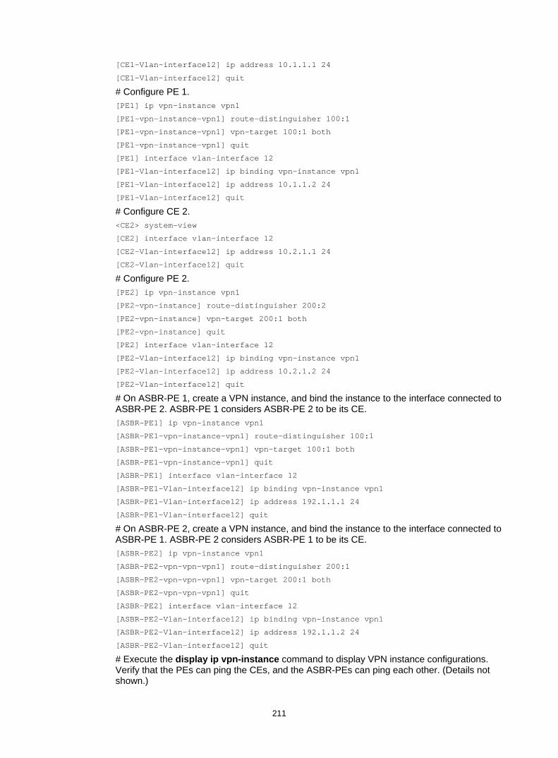
211
[CE1-Vlan-interface12] ip address 10.1.1.1 24
[CE1-Vlan-interface12] quit
# Configure PE 1. [PE1] ip vpn-instance vpn1
[PE1-vpn-instance-vpn1] route-distinguisher 100:1
[PE1-vpn-instance-vpn1] vpn-target 100:1 both
[PE1-vpn-instance-vpn1] quit
[PE1] interface vlan-interface 12
[PE1-Vlan-interface12] ip binding vpn-instance vpn1
[PE1-Vlan-interface12] ip address 10.1.1.2 24
[PE1-Vlan-interface12] quit
# Configure CE 2. <CE2> system-view
[CE2] interface vlan-interface 12
[CE2-Vlan-interface12] ip address 10.2.1.1 24
[CE2-Vlan-interface12] quit
# Configure PE 2. [PE2] ip vpn-instance vpn1
[PE2-vpn-instance] route-distinguisher 200:2
[PE2-vpn-instance] vpn-target 200:1 both
[PE2-vpn-instance] quit
[PE2] interface vlan-interface 12
[PE2-Vlan-interface12] ip binding vpn-instance vpn1
[PE2-Vlan-interface12] ip address 10.2.1.2 24
[PE2-Vlan-interface12] quit
# On ASBR-PE 1, create a VPN instance, and bind the instance to the interface connected to ASBR-PE 2. ASBR-PE 1 considers ASBR-PE 2 to be its CE. [ASBR-PE1] ip vpn-instance vpn1
[ASBR-PE1-vpn-instance-vpn1] route-distinguisher 100:1
[ASBR-PE1-vpn-instance-vpn1] vpn-target 100:1 both
[ASBR-PE1-vpn-instance-vpn1] quit
[ASBR-PE1] interface vlan-interface 12
[ASBR-PE1-Vlan-interface12] ip binding vpn-instance vpn1
[ASBR-PE1-Vlan-interface12] ip address 192.1.1.1 24
[ASBR-PE1-Vlan-interface12] quit
# On ASBR-PE 2, create a VPN instance, and bind the instance to the interface connected to ASBR-PE 1. ASBR-PE 2 considers ASBR-PE 1 to be its CE. [ASBR-PE2] ip vpn-instance vpn1
[ASBR-PE2-vpn-vpn-vpn1] route-distinguisher 200:1
[ASBR-PE2-vpn-vpn-vpn1] vpn-target 200:1 both
[ASBR-PE2-vpn-vpn-vpn1] quit
[ASBR-PE2] interface vlan-interface 12
[ASBR-PE2-Vlan-interface12] ip binding vpn-instance vpn1
[ASBR-PE2-Vlan-interface12] ip address 192.1.1.2 24
[ASBR-PE2-Vlan-interface12] quit
# Execute the display ip vpn-instance command to display VPN instance configurations. Verify that the PEs can ping the CEs, and the ASBR-PEs can ping each other. (Details not shown.)

212
4. Establish EBGP peer relationships between PEs and CEs, and redistribute VPN routes into BGP: # Configure CE 1. [CE1] bgp 65001
[CE1-bgp] peer 10.1.1.2 as-number 100
[CE1-bgp] address-family ipv4 unicast
[CE1-bgp-ipv4] peer 10.1.1.2 enable
[CE1-bgp-ipv4] import-route direct
[CE1-bgp-ipv4] quit
[CE1-bgp] quit
# Configure PE 1. [PE1] bgp 100
[PE1-bgp] ip vpn-instance vpn1
[PE1-bgp-vpn1] peer 10.1.1.1 as-number 65001
[PE1-bgp-vpn1] address-family ipv4 unicast
[PE1-bgp-ipv4-vpn1] peer 10.1.1.1 enable
[PE1-bgp-ipv4-vpn1] quit
[PE1-bgp-vpn1] quit
[PE1-bgp] quit
# Configure CE 2. [CE2] bgp 65002
[CE2-bgp] peer 10.2.1.2 as-number 200
[CE2-bgp] address-family ipv4 unicast
[CE2-bgp-ipv4] peer 10.2.1.2 enable
[CE2-bgp-ipv4] import-route direct
[CE2-bgp-ipv4] quit
[CE2-bgp] quit
# Configure PE 2. [PE2] bgp 200
[PE2-bgp] ip vpn-instance vpn1
[PE2-bgp-vpn1] peer 10.2.1.1 as-number 65002
[PE2-bgp-vpn1] address-family ipv4 unicast
[PE2-bgp-ipv4-vpn1] peer 10.2.1.1 enable
[PE2-bgp-ipv4-vpn1] quit
[PE2-bgp-vpn1] quit
[PE2-bgp] quit
5. Establish an MP-IBGP peer relationship between each PE and the ASBR-PE in the same AS, and an EBGP peer relationship between the ASBR-PEs: # Configure PE 1. [PE1] bgp 100
[PE1-bgp] peer 2.2.2.9 as-number 100
[PE1-bgp] peer 2.2.2.9 connect-interface loopback 0
[PE1-bgp] address-family vpnv4
[PE1-bgp-vpnv4] peer 2.2.2.9 enable
[PE1-bgp-vpnv4] peer 2.2.2.9 next-hop-local
[PE1-bgp-vpnv4] quit
[PE1-bgp] quit
# Configure ASBR-PE 1.

213
[ASBR-PE1] bgp 100
[ASBR-PE1-bgp] ip vpn-instance vpn1
[ASBR-PE1-bgp-vpn1] peer 192.1.1.2 as-number 200
[ASBR-PE1-bgp-vpn1] address-family ipv4 unicast
[ASBR-PE1-bgp-ipv4-vpn1] peer 192.1.1.2 enable
[ASBR-PE1-bgp-ipv4-vpn1] quit
[ASBR-PE1-bgp-vpn1] quit
[ASBR-PE1-bgp] peer 1.1.1.9 as-number 100
[ASBR-PE1-bgp] peer 1.1.1.9 connect-interface loopback 0
[ASBR-PE1-bgp] address-family vpnv4
[ASBR-PE1-bgp-vpnv4] peer 1.1.1.9 enable
[ASBR-PE1-bgp-vpnv4] peer 1.1.1.9 next-hop-local
[ASBR-PE1-bgp-vpnv4] quit
[ASBR-PE1-bgp] quit
# Configure ASBR-PE 2. [ASBR-PE2] bgp 200
[ASBR-PE2-bgp] ip vpn-instance vpn1
[ASBR-PE2-bgp-vpn1] peer 192.1.1.1 as-number 100
[ASBR-PE2-bgp-vpn1] address-family ipv4 unicast
[ASBR-PE2-bgp-ipv4-vpn1] peer 192.1.1.1 enable
[ASBR-PE2-bgp-ipv4-vpn1] quit
[ASBR-PE2-bgp-vpn1] quit
[ASBR-PE2-bgp] peer 4.4.4.9 as-number 200
[ASBR-PE2-bgp] peer 4.4.4.9 connect-interface loopback 0
[ASBR-PE2-bgp] address-family vpnv4
[ASBR-PE2-bgp-vpnv4] peer 4.4.4.9 enable
[ASBR-PE2-bgp-vpnv4] peer 4.4.4.9 next-hop-local
[ASBR-PE2-bgp-vpnv4] quit
[ASBR-PE2-bgp] quit
# Configure PE 2. [PE2] bgp 200
[PE2-bgp] peer 3.3.3.9 as-number 200
[PE2-bgp] peer 3.3.3.9 connect-interface loopback 0
[PE2-bgp] address-family vpnv4
[PE2-bgp-vpnv4] peer 3.3.3.9 enable
[PE2-bgp-vpnv4] peer 3.3.3.9 next-hop-local
[PE2-bgp-vpnv4] quit
[PE2-bgp] quit
Verifying the configuration # Verify that the CEs can learn the interface routes from each other and ping each other. (Details not shown.)
Configuring MPLS L3VPN inter-AS option B Network requirements
Site 1 and Site 2 belong to the same VPN. CE 1 of Site 1 accesses the network through PE 1 in AS 100, and CE 2 of Site 2 accesses the network through PE 2 in AS 600. PEs in the same AS run IS-IS.

214
PE 1 and ASBR-PE 1 exchange VPNv4 routes through MP-IBGP. PE 2 and ASBR-PE 2 exchange VPNv4 routes through MP-IBGP. ASBR-PE 1 and ASBR-PE 2 exchange VPNv4 routes through MP-EBGP.
ASBRs do not perform route target filtering of received VPN-IPv4 routes.
Figure 65 Network diagram
Table 15 Interface and IP address assignment
Device Interface IP address Device Interface IP address PE 1 Loop0 2.2.2.9/32 PE 2 Loop0 5.5.5.9/32
Vlan-int12 30.0.0.1/8 Vlan-int12 20.0.0.1/8
Vlan-int11 1.1.1.2/8 Vlan-int11 9.1.1.2/8
ASBR-PE 1 Loop0 3.3.3.9/32 ASBR-PE 2 Loop0 4.4.4.9/32
Vlan-int11 1.1.1.1/8 Vlan-int11 9.1.1.1/8
Vlan-int12 11.0.0.2/8 Vlan-int12 11.0.0.1/8
Configuration procedure 1. Configure PE 1:
# Configure IS-IS on PE 1. <PE1> system-view
[PE1] isis 1
[PE1-isis-1] network-entity 10.111.111.111.111.00
[PE1-isis-1] quit
# Configure the LSR ID, and enable MPLS and LDP. [PE1] mpls lsr-id 2.2.2.9
[PE1] mpls ldp
[PE1-ldp] quit
# Configure interface VLAN-interface 11, and enable IS-IS, MPLS, and LDP on the interface. [PE1] interface vlan-interface 11
[PE1-Vlan-interface11] ip address 1.1.1.2 255.0.0.0
Loop0 Loop0
Loop0 Loop0
CE 1 CE 2
AS 65001 AS 65002
PE 1 PE 2
ASBR-PE 2ASBR-PE 1
MPLS backbone MPLS backbone
AS 100 AS 600
Vlan-int12 Vlan-int12
Vlan-int11
Vlan-int11
Vlan-int12Vlan-int12
Vlan-int11
Vlan-int11
Site 1 Site 2

215
[PE1-Vlan-interface11] isis enable 1
[PE1-Vlan-interface11] mpls enable
[PE1-Vlan-interface11] mpls ldp enable
[PE1-Vlan-interface11] quit
# Configure interface Loopback 0, and enable IS-IS on it. [PE1] interface loopback 0
[PE1-LoopBack0] ip address 2.2.2.9 32
[PE1-LoopBack0] isis enable 1
[PE1-LoopBack0] quit
# Create VPN instance vpn1, and configure the RD and route target attributes. [PE1] ip vpn-instance vpn1
[PE1-vpn-instance-vpn1] route-distinguisher 11:11
[PE1-vpn-instance-vpn1] vpn-target 1:1 2:2 3:3 import-extcommunity
[PE1-vpn-instance-vpn1] vpn-target 3:3 export-extcommunity
[PE1-vpn-instance-vpn1] quit
# Bind the interface connected to CE 1 to the created VPN instance. [PE1] interface vlan-interface 12
[PE1-Vlan-interface12] ip binding vpn-instance vpn1
[PE1-Vlan-interface12] ip address 30.0.0.1 8
[PE1-Vlan-interface12] quit
# Enable BGP on PE 1. [PE1] bgp 100
# Configure IBGP peer 3.3.3.9 as a VPNv4 peer. [PE1-bgp] peer 3.3.3.9 as-number 100
[PE1-bgp] peer 3.3.3.9 connect-interface loopback 0
[PE1-bgp] address-family vpnv4
[PE1-bgp-vpnv4] peer 3.3.3.9 enable
[PE1-bgp-vpnv4] quit
# Redistribute direct routes to the VPN routing table of vpn1. [PE1-bgp] ip vpn-instance vpn1
[PE1-bgp-vpn1] address-family ipv4 unicast
[PE1-bgp-ipv4-vpn1] import-route direct
[PE1-bgp-ipv4-vpn1] quit
[PE1-bgp-vpn1] quit
[PE1-bgp] quit
2. Configure ASBR-PE 1: # Enable IS-IS on ASBR-PE 1. <ASBR-PE1> system-view
[ASBR-PE1] isis 1
[ASBR-PE1-isis-1] network-entity 10.222.222.222.222.00
[ASBR-PE1-isis-1] quit
# Configure the LSR ID, and enable MPLS and LDP. [ASBR-PE1] mpls lsr-id 3.3.3.9
[ASBR-PE1] mpls ldp
[ASBR-PE1-ldp] quit
# Configure interface VLAN-interface 11, and enable IS-IS, MPLS, and LDP on the interface. [ASBR-PE1] interface vlan-interface11

216
[ASBR-PE1-Vlan-interface11] ip address 1.1.1.1 255.0.0.0
[ASBR-PE1-Vlan-interface11] isis enable 1
[ASBR-PE1-Vlan-interface11] mpls enable
[ASBR-PE1-Vlan-interface11] mpls ldp enable
[ASBR-PE1-Vlan-interface11] quit
# Configure interface VLAN-interface 12, and enable MPLS on it. [ASBR-PE1] interface vlan-interface 12
[ASBR-PE1-Vlan-interface12] ip address 11.0.0.2 255.0.0.0
[ASBR-PE1-Vlan-interface12] mpls enable
[ASBR-PE1-Vlan-interface12] quit
# Configure interface Loopback 0, and enable IS-IS on it. [ASBR-PE1] interface loopback 0
[ASBR-PE1-LoopBack0] ip address 3.3.3.9 32
[ASBR-PE1-LoopBack0] isis enable 1
[ASBR-PE1-LoopBack0] quit
# Enable BGP on ASBR-PE 1. [ASBR-PE1] bgp 100
[ASBR-PE1-bgp] peer 2.2.2.9 as-number 100
[ASBR-PE1-bgp] peer 2.2.2.9 connect-interface loopback 0
[ASBR-PE1-bgp] peer 11.0.0.1 as-number 600
[ASBR-PE1-bgp] peer 11.0.0.1 connect-interface vlan-interface 12
# Disable route target based filtering of received VPNv4 routes. [ASBR-PE1-bgp] address-family vpnv4
[ASBR-PE1-bgp-vpnv4] undo policy vpn-target
# Configure both IBGP peer 2.2.2.0 and EBGP peer 11.0.0.1 as VPNv4 peers. [ASBR-PE1-bgp-vpnv4] peer 11.0.0.1 enable
[ASBR-PE1-bgp-vpnv4] peer 2.2.2.9 enable
[ASBR-PE1-bgp-vpnv4] quit
3. Configure ASBR-PE 2: # Enable IS-IS on ASBR-PE 2. <ASBR-PE2> system-view
[ASBR-PE2] isis 1
[ASBR-PE2-isis-1] network-entity 10.222.222.222.222.00
[ASBR-PE2-isis-1] quit
# Configure the LSR ID, and enable MPLS and LDP. [ASBR-PE2] mpls lsr-id 4.4.4.9
[ASBR-PE2] mpls ldp
[ASBR-PE2-ldp] quit
# Configure interface VLAN-interface 11, and enable IS-IS, MPLS, and LDP on the interface. [ASBR-PE2] interface vlan-interface 11
[ASBR-PE2-Vlan-interface11] ip address 9.1.1.1 255.0.0.0
[ASBR-PE2-Vlan-interface11] isis enable 1
[ASBR-PE2-Vlan-interface11] mpls enable
[ASBR-PE2-Vlan-interface11] mpls ldp enable
[ASBR-PE2-Vlan-interface11] quit
# Configure interface VLAN-interface 12, and enable MPLS on it. [ASBR-PE2] interface vlan-interface 12

217
[ASBR-PE2-Vlan-interface12] ip address 11.0.0.1 255.0.0.0
[ASBR-PE2-Vlan-interface12] mpls enable
[ASBR-PE2-Vlan-interface12] quit
# Configure interface Loopback 0, and enable IS-IS on it. [ASBR-PE2] interface loopback 0
[ASBR-PE2-LoopBack0] ip address 4.4.4.9 32
[ASBR-PE2-LoopBack0] isis enable 1
[ASBR-PE2-LoopBack0] quit
# Enable BGP on ASBR-PE 2. [ASBR-PE2] bgp 600
[ASBR-PE2-bgp] peer 11.0.0.2 as-number 100
[ASBR-PE2-bgp] peer 11.0.0.2 connect-interface vlan-interface 12
[ASBR-PE2-bgp] peer 5.5.5.9 as-number 600
[ASBR-PE2-bgp] peer 5.5.5.9 connect-interface loopback 0
# Disable route target based filtering of received VPNv4 routes. [ASBR-PE2-bgp] address-family vpnv4
[ASBR-PE2-bgp-vpnv4] undo policy vpn-target
# Configure both IBGP peer 5.5.5.9 and EBGP peer 11.0.0.2 as VPNv4 peers. [ASBR-PE2-bgp-vpnv4] peer 11.0.0.2 enable
[ASBR-PE2-bgp-vpnv4] peer 5.5.5.9 enable
[ASBR-PE2-bgp-vpnv4] quit
[ASBR-PE2-bgp] quit
4. Configure PE 2: # Enable IS-IS on PE 2. <PE2> system-view
[PE2] isis 1
[PE2-isis-1] network-entity 10.111.111.111.111.00
[PE2-isis-1] quit
# Configure the LSR ID, and enable MPLS and LDP. [PE2] mpls lsr-id 5.5.5.9
[PE2] mpls ldp
[PE2-ldp] quit
# Configure interface VLAN-interface 11, and enable IS-IS, MPLS, and LDP on the interface. [PE2] interface vlan-interface 11
[PE2-Vlan-interface11] ip address 9.1.1.2 255.0.0.0
[PE2-Vlan-interface11] isis enable 1
[PE2-Vlan-interface11] mpls enable
[PE2-Vlan-interface11] mpls ldp enable
[PE2-Vlan-interface11] quit
# Configure interface Loopback 0, and enable IS-IS on it. [PE2] interface loopback 0
[PE2-LoopBack0] ip address 5.5.5.9 32
[PE2-LoopBack0] isis enable 1
[PE2-LoopBack0] quit
# Create VPN instance vpn1, and configure the RD and route target attributes. [PE2] ip vpn-instance vpn1
[PE2-vpn-instance-vpn1] route-distinguisher 12:12

218
[PE2-vpn-instance-vpn1] vpn-target 1:1 2:2 3:3 import-extcommunity
[PE2-vpn-instance-vpn1] vpn-target 3:3 export-extcommunity
[PE2-vpn-instance-vpn1] quit
# Bind the interface connected with CE 2 to the created VPN instance. [PE2] interface vlan-interface12
[PE2-Vlan-interface12] ip binding vpn-instance vpn1
[PE2-Vlan-interface12] ip address 20.0.0.1 8
[PE2-Vlan-interface12] quit
# Enable BGP on PE 2. [PE2] bgp 600
# Configure IBGP peer 4.4.4.9 as a VPNv4 peer. [PE2-bgp] peer 4.4.4.9 as-number 600
[PE2-bgp] peer 4.4.4.9 connect-interface loopback 0
[PE2-bgp] address-family vpnv4
[PE2-bgp-vpnv4] peer 4.4.4.9 enable
[PE2-bgp-vpnv4] quit
# Redistribute direct routes to the VPN routing table of vpn1. [PE2-bgp] ip vpn-instance vpn1
[PE2-bgp-vpn1] address-family ipv4 unicast
[PE2-bgp-ipv4-vpn1] import-route direct
[PE2-bgp-ipv4-vpn1] quit
[PE2-bgp-vpn1] quit
[PE2-bgp] quit
Verifying the configuration # Verify that PE 1 and PE 2 can ping each other. [PE1] ping -a 30.0.0.1 -vpn-instance vpn1 20.0.0.1
Ping 20.0.0.1 (20.0.0.1) from 30.0.0.1: 56 data bytes, press CTRL_C to break
56 bytes from 20.0.0.1: icmp_seq=0 ttl=255 time=1.208 ms
56 bytes from 20.0.0.1: icmp_seq=1 ttl=255 time=0.867 ms
56 bytes from 20.0.0.1: icmp_seq=2 ttl=255 time=0.551 ms
56 bytes from 20.0.0.1: icmp_seq=3 ttl=255 time=0.566 ms
56 bytes from 20.0.0.1: icmp_seq=4 ttl=255 time=0.570 ms
--- Ping statistics for 20.0.0.1 ---
5 packet(s) transmitted, 5 packet(s) received, 0.0% packet loss
round-trip min/avg/max/std-dev = 0.551/0.752/1.208/0.257 ms
Configuring MPLS L3VPN inter-AS option C Network requirements
Site 1 and Site 2 belong to the same VPN. Site 1 accesses the network through PE 1 in AS 100, and Site 2 accesses the network through PE 2 in AS 600. PEs in the same AS run IS-IS.
PE 1 and ASBR-PE 1 exchange labeled IPv4 routes through IBGP. PE 2 and ASBR-PE 2 exchange labeled IPv4 routes through IBGP. PE 1 and PE 2 exchange VPNv4 routes through MP-EBGP.
ASBR-PE 1 and ASBR-PE 2 use their respective routing policies and label routes received from each other.
ASBR-PE 1 and ASBR-PE 2 use EBGP to exchange labeled IPv4 routes.

219
Figure 66 Network diagram
Table 16 Interface and IP address assignment
Device Interface IP address Device Interface IP address PE 1 Loop0 2.2.2.9/32 PE 2 Loop0 5.5.5.9/32
Vlan-int11 1.1.1.2/8 Vlan-int11 9.1.1.2/8
Vlan-int12 30.0.0.1/24 Vlan-int12 20.0.0.1/24
ASBR-PE 1 Loop0 3.3.3.9/32 ASBR-PE 2 Loop0 4.4.4.9/32
Vlan-int11 1.1.1.1/8 Vlan-int11 9.1.1.1/8
Vlan-int12 11.0.0.2/8 Vlan-int12 11.0.0.1/8
CE 1 Vlan-int12 30.0.0.2/24 CE 2 Vlan-int12 20.0.0.2/24
Configuration procedure 1. Configure CE 1:
# Configure an IP address for VLAN-interface 12. <CE1> system-view
[CE1] interface vlan-interface 12
[CE1-Vlan-interface12] ip address 30.0.0.2 24
[CE1-Vlan-interface12] quit
# Configure 30.0.0.1 as an EBGP peer, and redistribute direct routes. [CE1] bgp 65001
[CE1-bgp] peer 30.0.0.1 as-number 100
[CE1-bgp] address-family ipv4 unicast
[CE1-bgp-ipv4] peer 30.0.0.1 enable
[CE1-bgp-ipv4] import-route direct
[CE1-bgp-ipv4] quit
[CE1-bgp] quit
2. Configure PE 1: # Configure IS-IS on PE 1. <PE1> system-view
PE 1
MPLS backbone MPLS backbone
ASBR-PE 1 ASBR-PE 2
Vlan-int11
Vlan-int11
Vlan-int11
Loop0
Loop0 Loop0
Loop0
PE 2Site 1 Site 2
MP-EBGP
AS 100 AS 600
Vlan-int12 Vlan-int12
Vlan-int11
CE 1 CE 2
Site 1 Site 2
Vlan-int12
Vlan-int12
Vlan-int12
Vlan-int12

220
[PE1] isis 1
[PE1-isis-1] network-entity 10.111.111.111.111.00
[PE1-isis-1] quit
# Configure the LSR ID, and enable MPLS and LDP. [PE1] mpls lsr-id 2.2.2.9
[PE1] mpls ldp
[PE1-ldp] quit
# Configure interface VLAN-interface 11, and enable IS-IS, MPLS, and LDP on the interface. [PE1] interface vlan-interface 11
[PE1-Vlan-interface11] ip address 1.1.1.2 255.0.0.0
[PE1-Vlan-interface11] isis enable 1
[PE1-Vlan-interface11] mpls enable
[PE1-Vlan-interface11] mpls ldp enable
[PE1-Vlan-interface11] quit
# Configure interface Loopback 0, and enable IS-IS on it. [PE1] interface loopback 0
[PE1-LoopBack0] ip address 2.2.2.9 32
[PE1-LoopBack0] isis enable 1
[PE1-LoopBack0] quit
# Create VPN instance vpn1, and configure the RD and route target attributes. [PE1] ip vpn-instance vpn1
[PE1-vpn-instance-vpn1] route-distinguisher 11:11
[PE1-vpn-instance-vpn1] vpn-target 1:1 2:2 3:3 import-extcommunity
[PE1-vpn-instance-vpn1] vpn-target 3:3 export-extcommunity
[PE1-vpn-instance-vpn1] quit
# Associate interface VLAN-interface 12 with VPN instance vpn1, and specify an IP address for the interface. [PE1] interface vlan-interface 12
[PE1-Vlan-interface12] ip binding vpn-instance vpn1
[PE1-Vlan-interface12] ip address 30.0.0.1 24
[PE1-Vlan-interface12] quit
# Enable BGP on PE 1. [PE1] bgp 100
# Enable the capability to advertise labeled routes to IBGP peer 3.3.3.9 and to receive labeled routes from the peer. [PE1-bgp] peer 3.3.3.9 as-number 100
[PE1-bgp] peer 3.3.3.9 connect-interface loopback 0
[PE1-bgp] address-family ipv4 unicast
[PE1-bgp-ipv4] peer 3.3.3.9 enable
[PE1-bgp-ipv4] peer 3.3.3.9 label-route-capability
[PE1-bgp-ipv4] quit
# Configure the maximum hop count from PE 1 to EBGP peer 5.5.5.9 as 10. [PE1-bgp] peer 5.5.5.9 as-number 600
[PE1-bgp] peer 5.5.5.9 connect-interface loopback 0
[PE1-bgp] peer 5.5.5.9 ebgp-max-hop 10
# Configure peer 5.5.5.9 as a VPNv4 peer. [PE1-bgp] address-family vpnv4
[PE1-bgp-vpnv4] peer 5.5.5.9 enable

221
[PE1-bgp-vpnv4] quit
# Configure 30.0.0.2 as an EBGP peer, and redistribute BGP routes to the routing table of vpn1. [PE1-bgp] ip vpn-instance vpn1
[PE1-bgp-vpn1] peer 30.0.0.2 as-number 65001
[PE1-bgp-vpn1] address-family ipv4 unicast
[PE1-bgp-ipv4-vpn1] peer 30.0.0.2 enable
[PE1-bgp-ipv4-vpn1] quit
[PE1-bgp-vpn1] quit
[PE1-bgp] quit
3. Configure ASBR-PE 1: # Enable IS-IS on ASBR-PE 1. <ASBR-PE1> system-view
[ASBR-PE1] isis 1
[ASBR-PE1-isis-1] network-entity 10.222.222.222.222.00
[ASBR-PE1-isis-1] quit
# Configure the LSR ID, and enable MPLS and LDP. [ASBR-PE1] mpls lsr-id 3.3.3.9
[ASBR-PE1] mpls ldp
[ASBR-PE1-ldp] quit
# Configure interface VLAN-interface 11, and enable IS-IS, MPLS, and LDP on the interface. [ASBR-PE1] interface vlan-interface 11
[ASBR-PE1-Vlan-interface11] ip address 1.1.1.1 255.0.0.0
[ASBR-PE1-Vlan-interface11] isis enable 1
[ASBR-PE1-Vlan-interface11] mpls enable
[ASBR-PE1-Vlan-interface11] mpls ldp enable
[ASBR-PE1-Vlan-interface11] quit
# Configure interface VLAN-interface 12, and enable MPLS on it. [ASBR-PE1] interface vlan-interface 12
[ASBR-PE1-Vlan-interface12] ip address 11.0.0.2 255.0.0.0
[ASBR-PE1-Vlan-interface12] mpls enable
[ASBR-PE1-Vlan-interface12] quit
# Configure interface Loopback 0, and enable IS-IS on it. [ASBR-PE1] interface loopback 0
[ASBR-PE1-LoopBack0] ip address 3.3.3.9 32
[ASBR-PE1-LoopBack0] isis enable 1
[ASBR-PE1-LoopBack0] quit
# Create routing policies. [ASBR-PE1] route-policy policy1 permit node 1
[ASBR-PE1-route-policy-policy1-1] apply mpls-label
[ASBR-PE1-route-policy-policy1-1] quit
[ASBR-PE1] route-policy policy2 permit node 1
[ASBR-PE1-route-policy-policy2-1] if-match mpls-label
[ASBR-PE1-route-policy-policy2-1] apply mpls-label
[ASBR-PE1-route-policy-policy2-1] quit
# Enable BGP on ASBR-PE 1, and apply the routing policy policy2 to routes advertised to IBGP peer 2.2.2.9. [ASBR-PE1] bgp 100
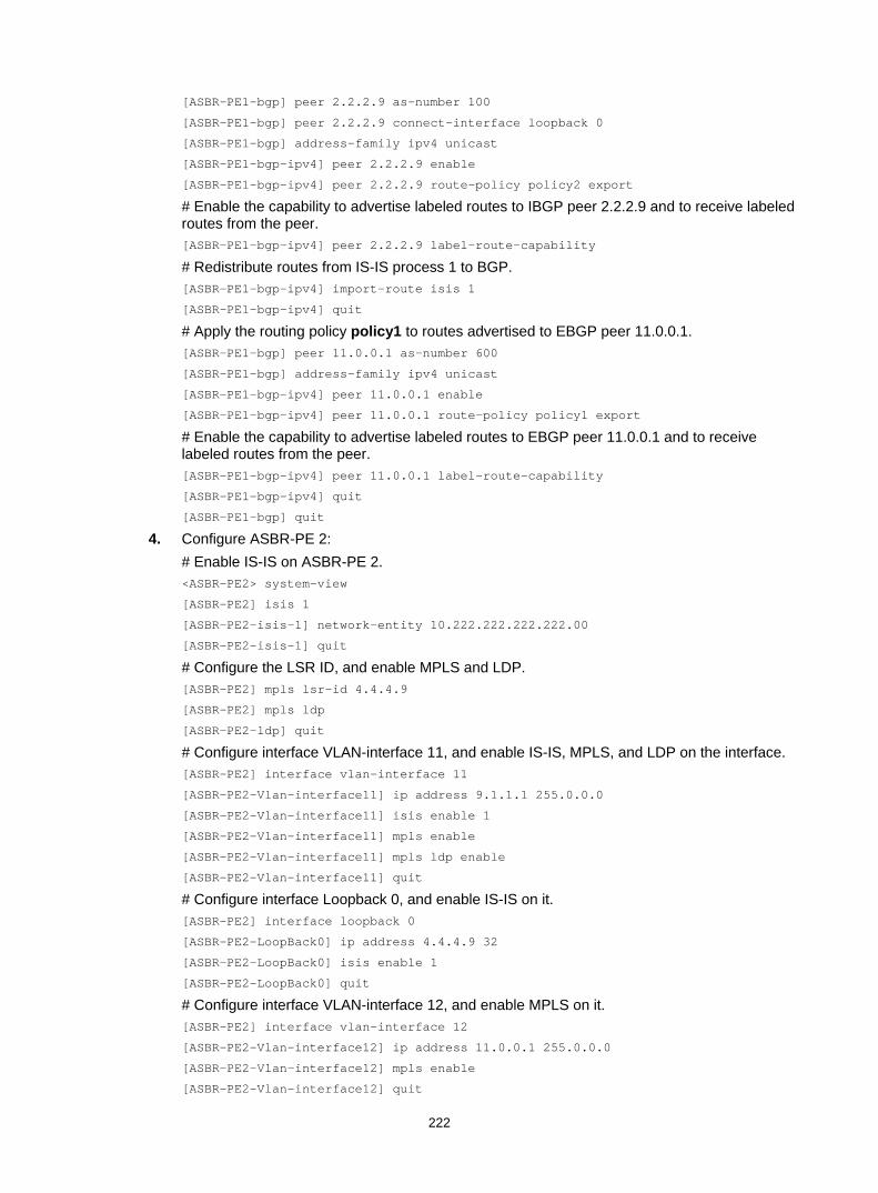
222
[ASBR-PE1-bgp] peer 2.2.2.9 as-number 100
[ASBR-PE1-bgp] peer 2.2.2.9 connect-interface loopback 0
[ASBR-PE1-bgp] address-family ipv4 unicast
[ASBR-PE1-bgp-ipv4] peer 2.2.2.9 enable
[ASBR-PE1-bgp-ipv4] peer 2.2.2.9 route-policy policy2 export
# Enable the capability to advertise labeled routes to IBGP peer 2.2.2.9 and to receive labeled routes from the peer. [ASBR-PE1-bgp-ipv4] peer 2.2.2.9 label-route-capability
# Redistribute routes from IS-IS process 1 to BGP. [ASBR-PE1-bgp-ipv4] import-route isis 1
[ASBR-PE1-bgp-ipv4] quit
# Apply the routing policy policy1 to routes advertised to EBGP peer 11.0.0.1. [ASBR-PE1-bgp] peer 11.0.0.1 as-number 600
[ASBR-PE1-bgp] address-family ipv4 unicast
[ASBR-PE1-bgp-ipv4] peer 11.0.0.1 enable
[ASBR-PE1-bgp-ipv4] peer 11.0.0.1 route-policy policy1 export
# Enable the capability to advertise labeled routes to EBGP peer 11.0.0.1 and to receive labeled routes from the peer. [ASBR-PE1-bgp-ipv4] peer 11.0.0.1 label-route-capability
[ASBR-PE1-bgp-ipv4] quit
[ASBR-PE1-bgp] quit
4. Configure ASBR-PE 2: # Enable IS-IS on ASBR-PE 2. <ASBR-PE2> system-view
[ASBR-PE2] isis 1
[ASBR-PE2-isis-1] network-entity 10.222.222.222.222.00
[ASBR-PE2-isis-1] quit
# Configure the LSR ID, and enable MPLS and LDP. [ASBR-PE2] mpls lsr-id 4.4.4.9
[ASBR-PE2] mpls ldp
[ASBR-PE2-ldp] quit
# Configure interface VLAN-interface 11, and enable IS-IS, MPLS, and LDP on the interface. [ASBR-PE2] interface vlan-interface 11
[ASBR-PE2-Vlan-interface11] ip address 9.1.1.1 255.0.0.0
[ASBR-PE2-Vlan-interface11] isis enable 1
[ASBR-PE2-Vlan-interface11] mpls enable
[ASBR-PE2-Vlan-interface11] mpls ldp enable
[ASBR-PE2-Vlan-interface11] quit
# Configure interface Loopback 0, and enable IS-IS on it. [ASBR-PE2] interface loopback 0
[ASBR-PE2-LoopBack0] ip address 4.4.4.9 32
[ASBR-PE2-LoopBack0] isis enable 1
[ASBR-PE2-LoopBack0] quit
# Configure interface VLAN-interface 12, and enable MPLS on it. [ASBR-PE2] interface vlan-interface 12
[ASBR-PE2-Vlan-interface12] ip address 11.0.0.1 255.0.0.0
[ASBR-PE2-Vlan-interface12] mpls enable
[ASBR-PE2-Vlan-interface12] quit

223
# Create routing policies. [ASBR-PE2] route-policy policy1 permit node 1
[ASBR-PE2-route-policy-policy1-1] apply mpls-label
[ASBR-PE2-route-policy-policy1-1] quit
[ASBR-PE2] route-policy policy2 permit node 1
[ASBR-PE2-route-policy-policy2-1] if-match mpls-label
[ASBR-PE2-route-policy-policy2-1] apply mpls-label
[ASBR-PE2-route-policy-policy2-1] quit
# Enable BGP on ASBR-PE 2, and enable the capability to advertise labeled routes to IBGP peer 5.5.5.9 and to receive labeled routes from the peer. [ASBR-PE2] bgp 600
[ASBR-PE2-bgp] peer 5.5.5.9 as-number 600
[ASBR-PE2-bgp] peer 5.5.5.9 connect-interface loopback 0
[ASBR-PE2-bgp] address-family ipv4 unicast
[ASBR-PE2-bgp-ipv4] peer 5.5.5.9 enable
[ASBR-PE2-bgp-ipv4] peer 5.5.5.9 label-route-capability
# Apply the routing policy policy2 to routes advertised to IBGP peer 5.5.5.9. [ASBR-PE2-bgp-ipv4] peer 5.5.5.9 route-policy policy2 export
# Redistribute routes from IS-IS process 1 into BGP. [ASBR-PE2-bgp-ipv4] import-route isis 1
[ASBR-PE2-bgp-ipv4] quit
# Apply the routing policy policy1 to routes advertised to EBGP peer 11.0.0.2. [ASBR-PE2-bgp] peer 11.0.0.2 as-number 100
[ASBR-PE2-bgp] address-family ipv4 unicast
[ASBR-PE2-bgp-ipv4] peer 11.0.0.2 enable
[ASBR-PE2-bgp-ipv4] peer 11.0.0.2 route-policy policy1 export
# Enable the capability to advertise labeled routes to EBGP peer 11.0.0.2 and to receive labeled routes from the peer. [ASBR-PE2-bgp-ipv4] peer 11.0.0.2 label-route-capability
[ASBR-PE2-bgp-ipv4] quit
[ASBR-PE2-bgp] quit
5. Configure PE 2: # Enable IS-IS on PE 2. <PE2> system-view
[PE2] isis 1
[PE2-isis-1] network-entity 10.111.111.111.111.00
[PE2-isis-1] quit
# Configure the LSR ID, and enable MPLS and LDP. [PE2] mpls lsr-id 5.5.5.9
[PE2] mpls ldp
[PE2-ldp] quit
# Configure interface VLAN-interface 11, and enable IS-IS, MPLS, and LDP on the interface. [PE2] interface vlan-interface 11
[PE2-Vlan-interface11] ip address 9.1.1.2 255.0.0.0
[PE2-Vlan-interface11] isis enable 1
[PE2-Vlan-interface11] mpls enable
[PE2-Vlan-interface11] mpls ldp enable
[PE2-Vlan-interface11] quit

224
# Configure interface Loopback 0, and enable IS-IS on it. [PE2] interface loopback 0
[PE2-LoopBack0] ip address 5.5.5.9 32
[PE2-LoopBack0] isis enable 1
[PE2-LoopBack0] quit
# Create VPN instance vpn1, and configure the RD and route target attributes. [PE2] ip vpn-instance vpn1
[PE2-vpn-instance-vpn1] route-distinguisher 11:11
[PE2-vpn-instance-vpn1] vpn-target 1:1 2:2 3:3 import-extcommunity
[PE2-vpn-instance-vpn1] vpn-target 3:3 export-extcommunity
[PE2-vpn-instance-vpn1] quit
# Associate interface VLAN-interface 12 with VPN instance vpn1, and specify an IP address for the interface. [PE2] interface vlan-interface 12
[PE2-Vlan-interface12] ip binding vpn-instance vpn1
[PE2-Vlan-interface12] ip address 20.0.0.1 24
[PE2-Vlan-interface12] quit
# Enable BGP on PE 2. [PE2] bgp 600
# Enable the capability to advertise labeled routes to IBGP peer 4.4.4.9 and to receive labeled routes from the peer. [PE2-bgp] peer 4.4.4.9 as-number 600
[PE2-bgp] peer 4.4.4.9 connect-interface loopback 0
[PE2-bgp] address-family ipv4 unicast
[PE2-bgp-ipv4] peer 4.4.4.9 enable
[PE2-bgp-ipv4] peer 4.4.4.9 label-route-capability
[PE2-bgp-ipv4] quit
# Configure the maximum hop count from PE 2 to EBGP peer 2.2.2.9 as 10. [PE2-bgp] peer 2.2.2.9 as-number 100
[PE2-bgp] peer 2.2.2.9 connect-interface loopback 0
[PE2-bgp] peer 2.2.2.9 ebgp-max-hop 10
# Configure peer 2.2.2.9 as a VPNv4 peer. [PE2-bgp] address-family vpnv4
[PE2-bgp-vpnv4] peer 2.2.2.9 enable
[PE2-bgp-vpnv4] quit
# Configure 20.0.0.2 as an EBGP peer, and redistribute BGP routes to the routing table of vpn1. [PE2-bgp] ip vpn-instance vpn1
[PE2-bgp-vpn1] peer 20.0.0.2 as-number 65002
[PE2-bgp-vpn1] address-family ipv4 unicast
[PE2-bgp-ipv4-vpn1] peer 20.0.0.2 enable
[PE2-bgp-ipv4-vpn1] quit
[PE2-bgp-vpn1] quit
[PE2-bgp] quit
6. Configure CE 2: # Configure an IP address for VLAN-interface 12. <CE2> system-view
[CE2] interface vlan-interface 12

225
[CE2-Vlan-interface12] ip address 20.0.0.2 24
[CE2-Vlan-interface12] quit
# Configure 20.0.0.1 as an EBGP peer, and redistribute direct routes. [CE2] bgp 65002
[CE2-bgp] peer 20.0.0.1 as-number 600
[CE2-bgp] address-family ipv4 unicast
[CE2-bgp-ipv4] peer 20.0.0.1 enable
[CE2-bgp-ipv4] import-route direct
[CE2-bgp-ipv4] quit
[CE2-bgp] quit
Verifying the configuration # Execute the display ip routing table command on CE 1 and CE 2 to verify that CE 1 and CE 2 have a route to each other. Verify that CE 1 and CE 2 can ping each other. (Details not shown.)
Configuring MPLS L3VPN carrier's carrier Network requirements
Configure carrier's carrier for the scenario shown in Figure 67. In this scenario: • PE 1 and PE 2 are the provider carrier's PE switches. They provide VPN services for the
customer carrier. • CE 1 and CE 2 are the customer carrier's switches. They are connected to the provider carrier's
backbone as CE switches. • PE 3 and PE 4 are the customer carrier's PE switches. They provide MPLS L3VPN services for
the end customers. • CE 3 and CE 4 are customers of the customer carrier.
The key to carrier's carrier deployment is to configure exchange of two kinds of routes: • Exchange of the customer carrier's internal routes on the provider carrier's backbone. • Exchange of the end customers' VPN routes between PE 3 and PE 4, the PEs of the customer
carrier. In this process, an MP-IBGP peer relationship must be established between PE 3 and PE 4.

226
Figure 67 Network diagram
Table 17 Interface and IP address assignment
Device Interface IP address Device Interface IP address CE 3 Vlan-int11 100.1.1.1/24 CE 4 Vlan-int11 120.1.1.1/24
PE 3 Loop0 1.1.1.9/32 PE 4 Loop0 6.6.6.9/32
Vlan-int11 100.1.1.2/24 Vlan-int11 120.1.1.2/24
Vlan-int12 10.1.1.1/24 Vlan-int12 20.1.1.2/24
CE 1 Loop0 2.2.2.9/32 CE 2 Loop0 5.5.5.9/32
Vlan-int12 10.1.1.2/24 Vlan-int11 21.1.1.2/24
Vlan-int11 11.1.1.1/24 Vlan-int12 20.1.1.1/24
PE 1 Loop0 3.3.3.9/32 PE 2 Loop0 4.4.4.9/32
Vlan-int11 11.1.1.2/24 Vlan-int12 30.1.1.2/24
Vlan-int12 30.1.1.1/24 Vlan-int11 21.1.1.1/24
Configuration procedure 1. Configure MPLS L3VPN on the provider carrier backbone. Enable IS-IS as the IGP, enable
LDP between PE 1 and PE 2, and establish an MP-IBGP peer relationship between the PEs: # Configure PE 1. <PE1> system-view
[PE1] interface loopback 0
[PE1-LoopBack0] ip address 3.3.3.9 32
[PE1-LoopBack0] quit
[PE1] mpls lsr-id 3.3.3.9
[PE1] mpls ldp
[PE1-ldp] quit
[PE1] isis 1
[PE1-isis-1] network-entity 10.0000.0000.0000.0004.00
PE 1 PE 2
Provider carrier
Customer carrier
PE 4CE 2CE 1
PE 3
CE 3 CE 4AS 65410 AS 65420
Loop0 Loop0
Loop0Customer carrier
Vlan-int11
Loop0 Loop0
AS 100 AS 100
Vlan-int11
Vlan-int12Vlan-int12
Vlan-int11
Vlan-int11
Vlan-int12Vlan-int12
Vlan-int11
Vlan-int11Vlan-int12
Vlan-int12Vlan-int11
Vlan-int11MP-IBGP

227
[PE1-isis-1] quit
[PE1] interface loopback 0
[PE1-LoopBack0] isis enable 1
[PE1-LoopBack0] quit
[PE1] interface vlan-interface 12
[PE1-Vlan-interface12] ip address 30.1.1.1 24
[PE1-Vlan-interface12] isis enable 1
[PE1-Vlan-interface12] mpls enable
[PE1-Vlan-interface12] mpls ldp enable
[PE1-Vlan-interface12] mpls ldp transport-address interface
[PE1-Vlan-interface12] quit
[PE1] bgp 100
[PE1-bgp] peer 4.4.4.9 as-number 100
[PE1-bgp] peer 4.4.4.9 connect-interface loopback 0
[PE1-bgp] address-family vpnv4
[PE1-bgp-vpnv4] peer 4.4.4.9 enable
[PE1-bgp-vpnv4] quit
[PE1-bgp] quit
# Configure PE 2 in the same way that PE 1 is configured. (Details not shown.) # On PE 1 or PE 2, execute the following commands: Execute the display mpls ldp peer command to verify that an LDP session in Operational
state has been established between PE 1 and PE 2. (Details not shown.) Execute the display bgp peer vpnv4 command to verify that a BGP peer relationship in
Established state has been established between PE 1 and PE 2. (Details not shown.) Execute the display isis peer command to verify that the IS-IS neighbor relationship has
been established between PE 1 and PE 2. (Details not shown.) 2. Configure the customer carrier network. Enable IS-IS as the IGP, and enable LDP between PE
3 and CE 1, and between PE 4 and CE 2: # Configure PE 3. <PE3> system-view
[PE3] interface loopback 0
[PE3-LoopBack0] ip address 1.1.1.9 32
[PE3-LoopBack0] quit
[PE3] mpls lsr-id 1.1.1.9
[PE3] mpls ldp
[PE3-ldp] quit
[PE3] isis 2
[PE3-isis-2] network-entity 10.0000.0000.0000.0001.00
[PE3-isis-2] quit
[PE3] interface loopback 0
[PE3-LoopBack0] isis enable 2
[PE3-LoopBack0] quit
[PE3] interface vlan-interface 12
[PE3-Vlan-interface12] ip address 10.1.1.1 24
[PE3-Vlan-interface12] isis enable 2
[PE3-Vlan-interface12] mpls enable
[PE3-Vlan-interface12] mpls ldp enable
[PE3-Vlan-interface12] mpls ldp transport-address interface

228
[PE3-Vlan-interface12] quit
# Configure CE 1. <CE1> system-view
[CE1] interface loopback 0
[CE1-LoopBack0] ip address 2.2.2.9 32
[CE1-LoopBack0] quit
[CE1] mpls lsr-id 2.2.2.9
[CE1] mpls ldp
[CE1-ldp] quit
[CE1] isis 2
[CE1-isis-2] network-entity 10.0000.0000.0000.0002.00
[CE1-isis-2] quit
[CE1] interface loopback 0
[CE1-LoopBack0] isis enable 2
[CE1-LoopBack0] quit
[CE1] interface vlan-interface 12
[CE1-Vlan-interface12] ip address 10.1.1.2 24
[CE1-Vlan-interface12] isis enable 2
[CE1-Vlan-interface12] mpls enable
[CE1-Vlan-interface12] mpls ldp enable
[CE1-Vlan-interface12] mpls ldp transport-address interface
[CE1-Vlan-interface12] quit
PE 3 and CE 1 can establish an LDP session and IS-IS neighbor relationship between them. # Configure PE 4 and CE 2 in the same way that PE 3 and CE 1 are configured. (Details not shown.)
3. Perform configurations to allow CEs of the customer carrier to access PEs of the provider carrier, and redistribute IS-IS routes to BGP and BGP routes to IS-IS on the PEs: # Configure PE 1. [PE1] ip vpn-instance vpn1
[PE1-vpn-instance-vpn1] route-distinguisher 200:1
[PE1-vpn-instance-vpn1] vpn-target 1:1
[PE1-vpn-instance-vpn1] quit
[PE1] mpls ldp
[PE1-ldp] vpn-instance vpn1
[PE1-ldp-vpn-instance-vpn1] quit
[PE1-ldp] quit
[PE1] isis 2 vpn-instance vpn1
[PE1-isis-2] network-entity 10.0000.0000.0000.0003.00
[PE1-isis-2] import-route bgp
[PE1-isis-2] quit
[PE1] interface vlan-interface 11
[PE1-Vlan-interface11] ip binding vpn-instance vpn1
[PE1-Vlan-interface11] ip address 11.1.1.2 24
[PE1-Vlan-interface11] isis enable 2
[PE1-Vlan-interface11] mpls enable
[PE1-Vlan-interface11] mpls ldp enable
[PE1-Vlan-interface11] mpls ldp transport-address interface
[PE1-Vlan-interface11] quit

229
[PE1] bgp 100
[PE1-bgp] ip vpn-instance vpn1
[PE1-bgp-vpn1] address-family ipv4 unicast
[PE1-bgp-ipv4-vpn1] import isis 2
[PE1-bgp-ipv4-vpn1] quit
[PE1-bgp-vpn1] quit
[PE1-bgp] quit
# Configure CE 1. [CE1] interface vlan-interface 11
[CE1-Vlan-interface11] ip address 11.1.1.1 24
[CE1-Vlan-interface11] isis enable 2
[CE1-Vlan-interface11] mpls enable
[CE1-Vlan-interface11] mpls ldp enable
[CE1-Vlan-interface11] mpls ldp transport-address interface
[CE1-Vlan-interface11] quit
PE 1 and CE 1 can establish an LDP session and an IS-IS neighbor relationship between them. # Configure PE 2 and CE 2 in the same way that PE 1 and CE 1 are configured. (Details not shown.)
4. Perform configuration to connect the CEs of the end customers to the PEs of the customer carrier: # Configure CE 3. <CE3> system-view
[CE3] interface vlan-interface 11
[CE3-Vlan-interface11] ip address 100.1.1.1 24
[CE3-Vlan-interface11] quit
[CE3] bgp 65410
[CE3-bgp] peer 100.1.1.2 as-number 100
[CE3-bgp] address-family ipv4 unicast
[CE3-bgp-ipv4] peer 100.1.1.2 enable
[CE3-bgp-ipv4] import-route direct
[CE3-bgp-ipv4] quit
[CE3-bgp] quit
# Configure PE 3. [PE3] ip vpn-instance vpn1
[PE3-vpn-instance-vpn1] route-distinguisher 100:1
[PE3-vpn-instance-vpn1] vpn-target 1:1
[PE3-vpn-instance-vpn1] quit
[PE3] interface Vlan-interface11
[PE3-Vlan-interface11] ip binding vpn-instance vpn1
[PE3-Vlan-interface11] ip address 100.1.1.2 24
[PE3-Vlan-interface11] quit
[PE3] bgp 100
[PE3-bgp] ip vpn-instance vpn1
[PE3-bgp-vpn1] peer 100.1.1.1 as-number 65410
[PE3-bgp-vpn1] address-family ipv4 unicast
[PE3-bgp-ipv4-vpn1] peer 100.1.1.1 enable
[PE3-bgp-ipv4-vpn1] import-route direct
[PE3-bgp-ipv4-vpn1] quit

230
[PE3-bgp-vpn1] quit
[PE3-bgp] quit
# Configure PE 4 and CE 4 in the same way that PE 3 and CE 3 are configured. (Details not shown.)
5. Configure MP-IBGP peer relationship between the PEs of the customer carrier to exchange the end customers' VPN routes: # Configure PE 3. [PE3] bgp 100
[PE3-bgp] peer 6.6.6.9 as-number 100
[PE3-bgp] peer 6.6.6.9 connect-interface loopback 0
[PE3-bgp] address-family vpnv4
[PE3-bgp-vpnv4] peer 6.6.6.9 enable
[PE3-bgp-vpnv4] quit
[PE3-bgp] quit
# Configure PE 4 in the same way that PE 3 is configured. (Details not shown.)
Verifying the configuration 1. Display the public network routing table and VPN routing table on the provider carrier PEs, for
example, on PE 1: # Verify that the public network routing table contains only routes of the provider carrier network. [PE1] display ip routing-table
Destinations : 14 Routes : 14
Destination/Mask Proto Pre Cost NextHop Interface
0.0.0.0/32 Direct 0 0 127.0.0.1 InLoop0
3.3.3.9/32 Direct 0 0 127.0.0.1 InLoop0
4.4.4.9/32 ISIS 15 10 30.1.1.2 Vlan12
30.1.1.0/24 Direct 0 0 30.1.1.1 Vlan12
30.1.1.0/32 Direct 0 0 30.1.1.1 Vlan12
30.1.1.1/32 Direct 0 0 127.0.0.1 InLoop0
30.1.1.255/32 Direct 0 0 30.1.1.1 Vlan12
127.0.0.0/8 Direct 0 0 127.0.0.1 InLoop0
127.0.0.0/32 Direct 0 0 127.0.0.1 InLoop0
127.0.0.1/32 Direct 0 0 127.0.0.1 InLoop0
127.255.255.255/32 Direct 0 0 127.0.0.1 InLoop0
224.0.0.0/4 Direct 0 0 0.0.0.0 NULL0
224.0.0.0/24 Direct 0 0 0.0.0.0 NULL0
255.255.255.255/32 Direct 0 0 127.0.0.1 InLoop0
# Verify that the VPN routing table contains the internal routes of the customer carrier network, but it does not contain the VPN routes that the customer carrier maintains on the PE. [PE1] display ip routing-table vpn-instance vpn1
Destinations : 18 Routes : 18
Destination/Mask Proto Pre Cost NextHop Interface
0.0.0.0/32 Direct 0 0 127.0.0.1 InLoop0
1.1.1.9/32 ISIS 15 20 11.1.1.1 Vlan11
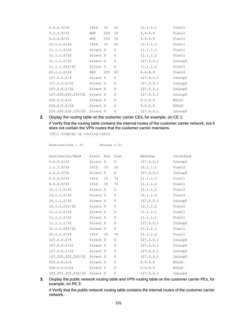
231
2.2.2.9/32 ISIS 15 10 11.1.1.1 Vlan11
5.5.5.9/32 BGP 255 10 4.4.4.9 Vlan12
6.6.6.9/32 BGP 255 20 4.4.4.9 Vlan12
10.1.1.0/24 ISIS 15 20 11.1.1.1 Vlan11
11.1.1.0/24 Direct 0 0 11.1.1.2 Vlan11
11.1.1.0/32 Direct 0 0 11.1.1.2 Vlan11
11.1.1.2/32 Direct 0 0 127.0.0.1 InLoop0
11.1.1.255/32 Direct 0 0 11.1.1.2 Vlan11
20.1.1.0/24 BGP 255 20 4.4.4.9 Vlan12
127.0.0.0/8 Direct 0 0 127.0.0.1 InLoop0
127.0.0.0/32 Direct 0 0 127.0.0.1 InLoop0
127.0.0.1/32 Direct 0 0 127.0.0.1 InLoop0
127.255.255.255/32 Direct 0 0 127.0.0.1 InLoop0
224.0.0.0/4 Direct 0 0 0.0.0.0 NULL0
224.0.0.0/24 Direct 0 0 0.0.0.0 NULL0
255.255.255.255/32 Direct 0 0 127.0.0.1 InLoop0
2. Display the routing table on the customer carrier CEs, for example, on CE 1: # Verify that the routing table contains the internal routes of the customer carrier network, but it does not contain the VPN routes that the customer carrier maintains. [CE1] display ip routing-table
Destinations : 21 Routes : 21
Destination/Mask Proto Pre Cost NextHop Interface
0.0.0.0/32 Direct 0 0 127.0.0.1 InLoop0
1.1.1.9/32 ISIS 15 10 10.1.1.1 Vlan12
2.2.2.9/32 Direct 0 0 127.0.0.1 InLoop0
5.5.5.9/32 ISIS 15 74 11.1.1.2 Vlan11
6.6.6.9/32 ISIS 15 74 11.1.1.2 Vlan11
10.1.1.0/24 Direct 0 0 10.1.1.2 Vlan12
10.1.1.0/32 Direct 0 0 10.1.1.2 Vlan12
10.1.1.2/32 Direct 0 0 127.0.0.1 InLoop0
10.1.1.255/32 Direct 0 0 10.1.1.2 Vlan12
11.1.1.0/24 Direct 0 0 11.1.1.1 Vlan11
11.1.1.0/32 Direct 0 0 11.1.1.1 Vlan11
11.1.1.1/32 Direct 0 0 127.0.0.1 InLoop0
11.1.1.255/32 Direct 0 0 11.1.1.1 Vlan11
20.1.1.0/24 ISIS 15 74 11.1.1.2 Vlan11
127.0.0.0/8 Direct 0 0 127.0.0.1 InLoop0
127.0.0.0/32 Direct 0 0 127.0.0.1 InLoop0
127.0.0.1/32 Direct 0 0 127.0.0.1 InLoop0
127.255.255.255/32 Direct 0 0 127.0.0.1 InLoop0
224.0.0.0/4 Direct 0 0 0.0.0.0 NULL0
224.0.0.0/24 Direct 0 0 0.0.0.0 NULL0
255.255.255.255/32 Direct 0 0 127.0.0.1 InLoop0
3. Display the public network routing table and VPN routing table on the customer carrier PEs, for example, on PE 3: # Verify that the public network routing table contains the internal routes of the customer carrier network.

232
[PE3] display ip routing-table
Destinations : 18 Routes : 18
Destination/Mask Proto Pre Cost NextHop Interface
0.0.0.0/32 Direct 0 0 127.0.0.1 InLoop0
1.1.1.9/32 Direct 0 0 127.0.0.1 InLoop0
2.2.2.9/32 ISIS 15 10 10.1.1.2 Vlan12
5.5.5.9/32 ISIS 15 84 10.1.1.2 Vlan12
6.6.6.9/32 ISIS 15 84 10.1.1.2 Vlan12
10.1.1.0/24 Direct 0 0 10.1.1.1 Vlan12
10.1.1.0/32 Direct 0 0 10.1.1.1 Vlan12
10.1.1.1/32 Direct 0 0 127.0.0.1 InLoop0
10.1.1.255/32 Direct 0 0 10.1.1.1 Vlan12
11.1.1.0/24 ISIS 15 20 10.1.1.2 Vlan12
20.1.1.0/24 ISIS 15 84 10.1.1.2 Vlan12
127.0.0.0/8 Direct 0 0 127.0.0.1 InLoop0
127.0.0.0/32 Direct 0 0 127.0.0.1 InLoop0
127.0.0.1/32 Direct 0 0 127.0.0.1 InLoop0
127.255.255.255/32 Direct 0 0 127.0.0.1 InLoop0
224.0.0.0/4 Direct 0 0 0.0.0.0 NULL0
224.0.0.0/24 Direct 0 0 0.0.0.0 NULL0
255.255.255.255/32 Direct 0 0 127.0.0.1 InLoop0
# Verify that the VPN routing table contains the route to the remote VPN customer. [PE3] display ip routing-table vpn-instance vpn1
Destinations : 13 Routes : 13
Destination/Mask Proto Pre Cost NextHop Interface
0.0.0.0/32 Direct 0 0 127.0.0.1 InLoop0
100.1.1.0/24 Direct 0 0 100.1.1.2 Vlan11
100.1.1.0/32 Direct 0 0 100.1.1.2 Vlan11
100.1.1.2/32 Direct 0 0 127.0.0.1 InLoop0
100.1.1.255/32 Direct 0 0 100.1.1.2 Vlan11
127.0.0.0/8 Direct 0 0 127.0.0.1 InLoop0
127.0.0.0/32 Direct 0 0 127.0.0.1 InLoop0
127.0.0.1/32 Direct 0 0 127.0.0.1 InLoop0
127.255.255.255/32 Direct 0 0 127.0.0.1 InLoop0
120.1.1.0/24 BGP 255 0 6.6.6.9 Vlan12
224.0.0.0/4 Direct 0 0 0.0.0.0 NULL0
224.0.0.0/24 Direct 0 0 0.0.0.0 NULL0
255.255.255.255/32 Direct 0 0 127.0.0.1 InLoop0
4. Verify that PE 3 and PE 4 can ping each other. (Details not shown.) 5. Verify that CE 3 and CE 4 can ping each other. (Details not shown.)

233
Configuring nested VPN Network requirements
The service provider provides nested VPN services for users, as shown in Figure 68. • PE 1 and PE 2 are PE devices on the service provider backbone. Both of them support the
nested VPN function. • CE 1 and CE 2 are connected to the service provider backbone. Both of them support VPNv4
routes. • PE 3 and PE 4 are PE devices of the customer VPN. Both of them support MPLS L3VPN. • CE 3 through CE 6 are CE devices of the sub-VPNs for the customer VPN.
The key of nested VPN configuration is to understand the processing of routes of sub-VPNs on the service provider PEs: • When receiving a VPNv4 route from a CE (CE 1 or CE 2 in this example), a service provider PE
a. Replaces the RD of the VPNv4 route with the RD of the MPLS VPN on the service provider network where the CE resides.
b. Adds the export target attribute of the MPLS VPN on the service provider network to the extended community attribute list.
c. Forwards the VPNv4 route. • To implement exchange of sub-VPN routes between customer PEs and service provider PEs,
MP-EBGP peers must be established between service provider PEs and customer CEs.
Figure 68 Network diagram
Table 18 Interface and IP address assignment
Device Interface IP address Device Interface IP address CE 1 Loop0 2.2.2.9/32 CE 2 Loop0 5.5.5.9/32
Vlan-int2 10.1.1.2/24 Vlan-int1 21.1.1.2/24
Vlan-int1 11.1.1.1/24 Vlan-int2 20.1.1.1/24
CE 3 Vlan-int1 100.1.1.1/24 CE 4 Vlan-int1 120.1.1.1/24
CE 5 Vlan-int3 110.1.1.1/24 CE 6 Vlan-int3 130.1.1.1/24
PE 1
CE 3
AS 65410SUB_VPN 1
PE 2
Customer VPN
PE 3
CE 6
AS 65421SUB_VPN 2
PE 4
Vlan-int2
Carrier VPNCustomer VPN
Loop0 Loop0
Vlan-int1
Loop
0
CE 1 CE 2
Loop0Vlan-int2
Vlan-int2
Vlan-int1
Vlan-int1 Vlan-int3
Vlan-int3
Vlan-int2
Vlan-int2
AS 100
AS 200VPN 1
AS 200VPN 1
Vlan-int2 Vlan-int1
Vlan-int1Vlan-int1
Loop
0
CE 5
AS 65411SUB_VPN 2
Vlan-int3
Vlan-int3
Loop0
CE 4
AS 65420SUB_VPN 1
Vlan-int1
Vlan-int1

234
Device Interface IP address Device Interface IP address PE 1 Loop0 3.3.3.9/32 PE 2 Loop0 4.4.4.9/32
Vlan-int1 11.1.1.2/24 Vlan-int1 21.1.1.1/24
Vlan-int2 30.1.1.1/24 Vlan-int2 30.1.1.2/24
PE 3 Loop0 1.1.1.9/32 PE 4 Loop0 6.6.6.9/32
Vlan-int1 100.1.1.2/24 Vlan-int1 120.1.1.2/24
Vlan-int2 10.1.1.1/24 Vlan-int2 20.1.1.2/24
Vlan-int3 110.1.1.2/24 Vlan-int3 130.1.1.2/24
Configuration procedure 1. Configure MPLS L3VPN on the service provider backbone. Enable IS-IS, enable LDP, and
establish an MP-IBGP peer relationship between PE 1 and PE 2: # Configure PE 1. <PE1> system-view
[PE1] interface loopback 0
[PE1-LoopBack0] ip address 3.3.3.9 32
[PE1-LoopBack0] quit
[PE1] mpls lsr-id 3.3.3.9
[PE1] mpls ldp
[PE1-ldp] quit
[PE1] isis 1
[PE1-isis-1] network-entity 10.0000.0000.0000.0004.00
[PE1-isis-1] quit
[PE1] interface loopback 0
[PE1-LoopBack0] isis enable 1
[PE1-LoopBack0] quit
[PE1] interface vlan-interface 2
[PE1-Vlan-interface2] ip address 30.1.1.1 24
[PE1-Vlan-interface2] isis enable 1
[PE1-Vlan-interface2] mpls enable
[PE1-Vlan-interface2] mpls ldp enable
[PE1-Vlan-interface2] quit
[PE1] bgp 100
[PE1-bgp] peer 4.4.4.9 as-number 100
[PE1-bgp] peer 4.4.4.9 connect-interface loopback 0
[PE1-bgp] address-family vpnv4
[PE1-bgp-vpnv4] peer 4.4.4.9 enable
[PE1-bgp-vpnv4] quit
[PE1-bgp] quit
# Configure PE 2 in the same way that PE 1 is configured. (Details not shown.) # On PE 1 or PE 2, execute the following commands: Execute the display mpls ldp peer command to verify that an LDP session in Operational
state has been established between PE 1 and PE 2. (Details not shown.) Execute the display bgp peer vpnv4 command to verify that a BGP peer relationship in
Established state has been established between PE 1 and PE 2. (Details not shown.)

235
Execute the display isis peer command to verify that the IS-IS neighbor relationship has been established between PE 1 and PE 2. (Details not shown.)
2. Configure the customer VPN. Enable IS-IS, and enable LDP between PE 3 and CE 1, and between PE 4 and CE 2: # Configure PE 3. <PE3> system-view
[PE3] interface loopback 0
[PE3-LoopBack0] ip address 1.1.1.9 32
[PE3-LoopBack0] quit
[PE3] mpls lsr-id 1.1.1.9
[PE3] mpls ldp
[PE3-ldp] quit
[PE3] isis 2
[PE3-isis-2] network-entity 10.0000.0000.0000.0001.00
[PE3-isis-2] quit
[PE3] interface loopback 0
[PE3-LoopBack0] isis enable 2
[PE3-LoopBack0] quit
[PE3] interface vlan-interface 2
[PE3-Vlan-interface2] ip address 10.1.1.1 24
[PE3-Vlan-interface2] isis enable 2
[PE3-Vlan-interface2] mpls enable
[PE3-Vlan-interface2] mpls ldp enable
[PE3-Vlan-interface2] quit
# Configure CE 1. <CE1> system-view
[CE1] interface loopback 0
[CE1-LoopBack0] ip address 2.2.2.9 32
[CE1-LoopBack0] quit
[CE1] mpls lsr-id 2.2.2.9
[CE1] mpls ldp
[CE1-ldp] quit
[CE1] isis 2
[CE1-isis-2] network-entity 10.0000.0000.0000.0002.00
[CE1-isis-2] quit
[CE1] interface loopback 0
[CE1-LoopBack0] isis enable 2
[CE1-LoopBack0] quit
[CE1] interface vlan-interface 2
[CE1-Vlan-interface2] ip address 10.1.1.2 24
[CE1-Vlan-interface2] isis enable 2
[CE1-Vlan-interface2] mpls enable
[CE1-Vlan-interface2] mpls ldp enable
[CE1-Vlan-interface2] quit
An LDP session and an IS-IS neighbor relationship can be established between PE 3 and CE 1. # Configure PE 4 and CE 2 in the same way that PE 3 and CE 1 are configured. (Details not shown.)
3. Connect CE 1 and CE 2 to service provider PEs:

236
# Configure PE 1. [PE1] ip vpn-instance vpn1
[PE1-vpn-instance-vpn1] route-distinguisher 200:1
[PE1-vpn-instance-vpn1] vpn-target 1:1
[PE1-vpn-instance-vpn1] quit
[PE1] interface vlan-interface 1
[PE1-Vlan-interface1] ip binding vpn-instance vpn1
[PE1-Vlan-interface1] ip address 11.1.1.2 24
[PE1-Vlan-interface1] mpls enable
[PE1-Vlan-interface1] quit
[PE1] bgp 100
[PE1-bgp] ip vpn-instance vpn1
[PE1-bgp-vpn1] peer 11.1.1.1 as-number 200
[PE1-bgp-vpn1] address-family ipv4
[PE1-bgp-ipv4-vpn1] peer 11.1.1.1 enable
[PE1-bgp-ipv4-vpn1] quit
[PE1-bgp-vpn1] quit
[PE1-bgp] quit
# Configure CE 1. [CE1] interface vlan-interface 1
[CE1-Vlan-interface1] ip address 11.1.1.1 24
[CE1-Vlan-interface1] mpls enable
[CE1-Vlan-interface1] quit
[CE1] bgp 200
[CE1-bgp] peer 11.1.1.2 as-number 100
[CE1-bgp-vpn1] address-family ipv4
[CE1-bgp-ipv4-vpn1] peer 11.1.1.2 enable
[CE1-bgp-ipv4-vpn1] quit
[CE1-bgp] quit
# Configure PE 2 and CE 2 in the same way that PE 1 and CE 1 are configured. (Details not shown.)
4. Connect sub-VPN CEs to the customer VPN PEs: # Configure CE 3. <CE3> system-view
[CE3] interface vlan-interface 1
[CE3-Vlan-interface1] ip address 100.1.1.1 24
[CE3-Vlan-interface1] quit
[CE3] bgp 65410
[CE3-bgp] peer 100.1.1.2 as-number 200
[CE3-bgp] address-family ipv4 unicast
[CE3-bgp-ipv4] peer 100.1.1.2 enable
[CE3-bgp-ipv4] import-route direct
[CE3-bgp-ipv4] quit
[CE3-bgp] quit
# Configure CE 5. <CE5> system-view
[CE5] interface vlan-interface 3
[CE5-Vlan-interface3] ip address 110.1.1.1 24

237
[CE5-Vlan-interface3] quit
[CE5] bgp 65411
[CE5-bgp] peer 110.1.1.2 as-number 200
[CE5-bgp] address-family ipv4 unicast
[CE5-bgp-ipv4] peer 110.1.1.2 enable
[CE5-bgp-ipv4] import-route direct
[CE5-bgp-ipv4] quit
[CE5-bgp] quit
# Configure PE 3. [PE3] ip vpn-instance SUB_VPN1
[PE3-vpn-instance-SUB_VPN1] route-distinguisher 100:1
[PE3-vpn-instance-SUB_VPN1] vpn-target 2:1
[PE3-vpn-instance-SUB_VPN1] quit
[PE3] interface vlan-interface 1
[PE3-Vlan-interface1] ip binding vpn-instance SUB_VPN1
[PE3-Vlan-interface1] ip address 100.1.1.2 24
[PE3-Vlan-interface1] quit
[PE3] ip vpn-instance SUB_VPN2
[PE3-vpn-instance-SUB_VPN2] route-distinguisher 101:1
[PE3-vpn-instance-SUB_VPN2] vpn-target 2:2
[PE3-vpn-instance-SUB_VPN2] quit
[PE3] interface vlan-interface 3
[PE3-Vlan-interface3] ip binding vpn-instance SUB_VPN2
[PE3-Vlan-interface3] ip address 110.1.1.2 24
[PE3-Vlan-interface3] quit
[PE3] bgp 200
[PE3-bgp] ip vpn-instance SUB_VPN1
[PE3-bgp-SUB_VPN1] peer 100.1.1.1 as-number 65410
[PE3-bgp-SUB_VPN1] address-family ipv4 unicast
[PE3-bgp-ipv4-SUB_VPN1] peer 100.1.1.1 enable
[PE3-bgp-ipv4-SUB_VPN1] import-route direct
[PE3-bgp-ipv4-SUB_VPN1] quit
[PE3-bgp-SUB_VPN1] quit
[PE3-bgp] ip vpn-instance SUB_VPN2
[PE3-bgp-SUB_VPN2] peer 100.1.1.1 as-number 65411
[PE3-bgp-SUB_VPN2] address-family ipv4 unicast
[PE3-bgp-ipv4-SUB_VPN2] peer 110.1.1.1 enable
[PE3-bgp-ipv4-SUB_VPN2] import-route direct
[PE3-bgp-ipv4-SUB_VPN2] quit
[PE3-bgp-SUB_VPN2] quit
[PE3-bgp] quit
# Configure PE 4, CE 4, and CE 6 in the same way that PE 3, CE 3, and CE 5 are configured. (Details not shown.)
5. Establish MP-EBGP peer relationships between service provider PEs and their CEs to exchange user VPNv4 routes: # On PE 1, enable nested VPN and VPNv4 route exchange with CE 1. [PE1] bgp 100
[PE1-bgp] address-family vpnv4

238
[PE1-bgp-vpnv4] nesting-vpn
[PE1-bgp-vpnv4] quit
[PE1-bgp] ip vpn-instance vpn1
[PE1-bgp-vpn1] address-family vpnv4
[PE1-bgp-vpnv4-vpn1] peer 11.1.1.1 enable
[PE1-bgp-vpnv4-vpn1] quit
[PE1-bgp-vpn1] quit
[PE1-bgp] quit
# Enable CE 1 to exchange VPNv4 routes with PE 1. [CE1] bgp 200
[CE1-bgp] address-family vpnv4
[CE1-bgp-vpnv4] peer 11.1.1.2 enable
# Allow the local AS number to appear in the AS-PATH attribute of the routes received. [CE1-bgp-vpnv4] peer 11.1.1.2 allow-as-loop 2
# Disable route target based filtering of received VPNv4 routes. [CE1-bgp-vpnv4] undo policy vpn-target
[CE1-bgp-vpnv4] quit
[CE1-bgp] quit
# Configure PE 2 and CE 2 in the same way that PE 1 and CE 1 are configured. (Details not shown.)
6. Establish MP-IBGP peer relationships between sub-VPN PEs and CEs of the customer VPN to exchange VPNv4 routes of sub-VPNs: # Configure PE 3. [PE3] bgp 200
[PE3-bgp] peer 2.2.2.9 as-number 200
[PE3-bgp] peer 2.2.2.9 connect-interface loopback 0
[PE3-bgp] address-family vpnv4
[PE3-bgp-vpnv4] peer 2.2.2.9 enable
# Allow the local AS number to appear in the AS-PATH attribute of the routes received. [PE3-bgp-vpnv4] peer 2.2.2.9 allow-as-loop 2
[PE3-bgp-vpnv4] quit
[PE3-bgp] quit
# Configure CE 1. [CE1] bgp 200
[CE1-bgp] peer 1.1.1.9 as-number 200
[CE1-bgp] peer 1.1.1.9 connect-interface loopback 0
[CE1-bgp] address-family vpnv4
[CE1-bgp-vpnv4] peer 1.1.1.9 enable
[CE1-bgp-vpnv4] undo policy vpn-target
[CE1-bgp-vpnv4] quit
[CE1-bgp] quit
# Configure PE 4 and CE 2 in the same way that PE 3 and CE 1 are configured. (Details not shown.)
Verifying the configuration 1. Display the public routing table and VPN routing table on the provider PEs, for example, on PE
1: # Verify that the public routing table contains only routes on the service provider network. [PE1] display ip routing-table

239
Destinations : 14 Routes : 14
Destination/Mask Proto Pre Cost NextHop Interface
0.0.0.0/32 Direct 0 0 127.0.0.1 InLoop0
3.3.3.9/32 Direct 0 0 127.0.0.1 InLoop0
4.4.4.9/32 ISIS 15 10 30.1.1.2 Vlan2
30.1.1.0/24 Direct 0 0 30.1.1.1 Vlan2
30.1.1.0/32 Direct 0 0 30.1.1.1 Vlan2
30.1.1.1/32 Direct 0 0 127.0.0.1 InLoop0
30.1.1.255/32 Direct 0 0 30.1.1.1 Vlan2
127.0.0.0/8 Direct 0 0 127.0.0.1 InLoop0
127.0.0.0/32 Direct 0 0 127.0.0.1 InLoop0
127.0.0.1/32 Direct 0 0 127.0.0.1 InLoop0
127.255.255.255/32 Direct 0 0 127.0.0.1 InLoop0
224.0.0.0/4 Direct 0 0 0.0.0.0 NULL0
224.0.0.0/24 Direct 0 0 0.0.0.0 NULL0
255.255.255.255/32 Direct 0 0 127.0.0.1 InLoop0
# Verify that the VPN routing table contains sub-VPN routes. [PE1] display ip routing-table vpn-instance vpn1
Destinations : 16 Routes : 16
Destination/Mask Proto Pre Cost NextHop Interface
0.0.0.0/32 Direct 0 0 127.0.0.1 InLoop0
11.1.1.0/24 Direct 0 0 11.1.1.2 Vlan1
11.1.1.0/32 Direct 0 0 11.1.1.2 Vlan1
11.1.1.2/32 Direct 0 0 127.0.0.1 InLoop0
11.1.1.255/32 Direct 0 0 11.1.1.1 Vlan1
100.1.1.0/24 BGP 255 0 11.1.1.1 NULL0
110.1.1.0/24 BGP 255 0 11.1.1.1 NULL0
120.1.1.0/24 BGP 255 0 4.4.4.9 NULL0
127.0.0.0/8 Direct 0 0 127.0.0.1 InLoop0
127.0.0.0/32 Direct 0 0 127.0.0.1 InLoop0
127.0.0.1/32 Direct 0 0 127.0.0.1 InLoop0
127.255.255.255/32 Direct 0 0 127.0.0.1 InLoop0
130.1.1.0/24 BGP 255 0 4.4.4.9 NULL0
224.0.0.0/4 Direct 0 0 0.0.0.0 NULL0
224.0.0.0/24 Direct 0 0 0.0.0.0 NULL0
255.255.255.255/32 Direct 0 0 127.0.0.1 InLoop0
2. Display the VPNv4 routing table on the provider CEs, for example, on CE 1. # Verify that the VPNv4 routing table on the customer VPN contains internal sub-VPN routes. [CE1] display bgp routing-table vpnv4
BGP Local router ID is 2.2.2.9
Status codes: * - valid, > - best, d - damped, h - history,
s - suppressed, S - Stale, i - internal, e - external
Origin: i - IGP, e - EGP, ? - incomplete

240
Total number of routes from all PEs: 4
Route Distinguisher: 100:1
Total number of routes: 1
Network NextHop MED LocPrf PrefVal Path/Ogn
* > 100.1.1.0/24 1.1.1.9 0 100 0 200 65410?
Route Distinguisher: 101:1
Total number of routes: 1
Network NextHop MED LocPrf PrefVal Path/Ogn
* > 110.1.1.0/24 1.1.1.9 0 100 0 200 65411?
Route Distinguisher: 200:1
Total number of routes: 1
Network NextHop MED LocPrf PrefVal Path/Ogn
* > 120.1.1.0/24 11.1.1.2 0 100 200
65420?
Route Distinguisher: 201:1
Total number of routes: 1
Network NextHop MED LocPrf PrefVal Path/Ogn
* > 130.1.1.0/24 11.1.1.2 0 100 200
65421?
3. Display the VPN routing table on the customer PEs, for example, on PE 3: # Verify that the VPN routing table contains routes sent by the provider PE to the sub-VPN. [PE3] display ip routing-table vpn-instance SUB_VPN1
Destinations : 11 Routes : 11
Destination/Mask Proto Pre Cost NextHop Interface
0.0.0.0/32 Direct 0 0 127.0.0.1 InLoop0
100.1.1.0/24 Direct 0 0 100.1.1.2 Vlan1
100.1.1.2/32 Direct 0 0 127.0.0.1 InLoop0
120.1.1.0/24 BGP 255 0 2.2.2.9 Vlan2
127.0.0.0/8 Direct 0 0 127.0.0.1 InLoop0
127.0.0.0/32 Direct 0 0 127.0.0.1 InLoop0
127.0.0.1/32 Direct 0 0 127.0.0.1 InLoop0
127.255.255.255/32 Direct 0 0 127.0.0.1 InLoop0
224.0.0.0/4 Direct 0 0 0.0.0.0 NULL0
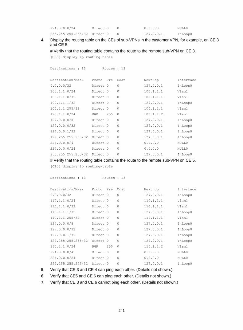
241
224.0.0.0/24 Direct 0 0 0.0.0.0 NULL0
255.255.255.255/32 Direct 0 0 127.0.0.1 InLoop0
4. Display the routing table on the CEs of sub-VPNs in the customer VPN, for example, on CE 3 and CE 5: # Verify that the routing table contains the route to the remote sub-VPN on CE 3. [CE3] display ip routing-table
Destinations : 13 Routes : 13
Destination/Mask Proto Pre Cost NextHop Interface
0.0.0.0/32 Direct 0 0 127.0.0.1 InLoop0
100.1.1.0/24 Direct 0 0 100.1.1.1 Vlan1
100.1.1.0/32 Direct 0 0 100.1.1.1 Vlan1
100.1.1.1/32 Direct 0 0 127.0.0.1 InLoop0
100.1.1.255/32 Direct 0 0 100.1.1.1 Vlan1
120.1.1.0/24 BGP 255 0 100.1.1.2 Vlan1
127.0.0.0/8 Direct 0 0 127.0.0.1 InLoop0
127.0.0.0/32 Direct 0 0 127.0.0.1 InLoop0
127.0.0.1/32 Direct 0 0 127.0.0.1 InLoop0
127.255.255.255/32 Direct 0 0 127.0.0.1 InLoop0
224.0.0.0/4 Direct 0 0 0.0.0.0 NULL0
224.0.0.0/24 Direct 0 0 0.0.0.0 NULL0
255.255.255.255/32 Direct 0 0 127.0.0.1 InLoop0
# Verify that the routing table contains the route to the remote sub-VPN on CE 5. [CE5] display ip routing-table
Destinations : 13 Routes : 13
Destination/Mask Proto Pre Cost NextHop Interface
0.0.0.0/32 Direct 0 0 127.0.0.1 InLoop0
110.1.1.0/24 Direct 0 0 110.1.1.1 Vlan1
110.1.1.0/32 Direct 0 0 110.1.1.1 Vlan1
110.1.1.1/32 Direct 0 0 127.0.0.1 InLoop0
110.1.1.255/32 Direct 0 0 110.1.1.1 Vlan1
127.0.0.0/8 Direct 0 0 127.0.0.1 InLoop0
127.0.0.0/32 Direct 0 0 127.0.0.1 InLoop0
127.0.0.1/32 Direct 0 0 127.0.0.1 InLoop0
127.255.255.255/32 Direct 0 0 127.0.0.1 InLoop0
130.1.1.0/24 BGP 255 0 110.1.1.2 Vlan1
224.0.0.0/4 Direct 0 0 0.0.0.0 NULL0
224.0.0.0/24 Direct 0 0 0.0.0.0 NULL0
255.255.255.255/32 Direct 0 0 127.0.0.1 InLoop0
5. Verify that CE 3 and CE 4 can ping each other. (Details not shown.) 6. Verify that CE5 and CE 6 can ping each other. (Details not shown.) 7. Verify that CE 3 and CE 6 cannot ping each other. (Details not shown.)

242
Configuring HoVPN Network requirements
There are two levels of networks, the backbone and the MPLS VPN networks, as shown in Figure 69. • SPEs act as PEs to allow MPLS VPNs to access the backbone. • UPEs act as PEs of the MPLS VPNs to allow end users to access the VPNs. • Performance requirements for the UPEs are lower than those for the SPEs. • SPEs advertise routes permitted by the routing policies to UPEs, permitting CE 1 and CE 3 in
VPN 1 to communicate with each other, and forbidding CE 2 and CE 4 in VPN 2 from communicating with each other.
Figure 69 Network diagram
Table 19 Interface and IP address assignment
Device Interface IP address Device Interface IP address CE 1 Vlan-int12 10.2.1.1/24 CE 3 Vlan-int12 10.1.1.1/24
CE 2 Vlan-int13 10.4.1.1/24 CE 4 Vlan-int13 10.3.1.1/24
UPE 1 Loop0 1.1.1.9/32 UPE 2 Loop0 4.4.4.9/32
Vlan-int11 172.1.1.1/24 Vlan-int11 172.2.1.1/24
Vlan-int12 10.2.1.2/24 Vlan-int12 10.1.1.2/24
Vlan-int13 10.4.1.2/24 Vlan-int13 10.3.1.2/24
SPE 1 Loop0 2.2.2.9/32 SPE 2 Loop0 3.3.3.9/32
Vlan-int11 172.1.1.2/24 Vlan-int11 172.2.1.2/24
Vlan-int12 180.1.1.1/24 Vlan-int12 180.1.1.2/24
Configuration procedure 1. Configure UPE 1:
# Configure basic MPLS and MPLS LDP to establish LDP LSPs. <UPE1> system-view
[UPE1] interface loopback 0
SPE 1 SPE 2
UPE 1 UPE 2
CE 1 CE 2 CE 3 CE 4
Vlan-int12
Loop0 Loop0
AS 65410 AS 65420 AS 65430 AS 65440
Loop0Loop0
VPN 1 VPN 1VPN 2 VPN 2
AS 100
Vlan-int12Vlan-int11
Vlan-int11
Vlan-int13Vlan-int12
Vlan-int13Vlan-int12Vlan-int12 Vlan-int13
Vlan-int13Vlan-int12
Vlan-int11
Vlan-int11

243
[UPE1-LoopBack0] ip address 1.1.1.9 32
[UPE1-LoopBack0] quit
[UPE1] mpls lsr-id 1.1.1.9
[UPE1] mpls ldp
[UPE1-ldp] quit
[UPE1] interface vlan-interface 11
[UPE1-Vlan-interface11] ip address 172.1.1.1 24
[UPE1-Vlan-interface11] mpls enable
[UPE1-Vlan-interface11] mpls ldp enable
[UPE1-Vlan-interface11] quit
# Configure the IGP protocol (OSPF, in this example). [UPE1] ospf
[UPE1-ospf-1] area 0
[UPE1-ospf-1-area-0.0.0.0] network 172.1.1.0 0.0.0.255
[UPE1-ospf-1-area-0.0.0.0] network 1.1.1.9 0.0.0.0
[UPE1-ospf-1-area-0.0.0.0] quit
[UPE1-ospf-1] quit
# Configure VPN instances vpn1 and vpn2, allowing CE 1 and CE 2 to access UPE 1. [UPE1] ip vpn-instance vpn1
[UPE1-vpn-instance-vpn1] route-distinguisher 100:1
[UPE1-vpn-instance-vpn1] vpn-target 100:1 both
[UPE1-vpn-instance-vpn1] quit
[UPE1] ip vpn-instance vpn2
[UPE1-vpn-instance-vpn2] route-distinguisher 100:2
[UPE1-vpn-instance-vpn2] vpn-target 100:2 both
[UPE1-vpn-instance-vpn2] quit
[UPE1] interface vlan-interface 12
[UPE1-Vlan-interface12] ip binding vpn-instance vpn1
[UPE1-Vlan-interface12] ip address 10.2.1.2 24
[UPE1-Vlan-interface12] quit
[UPE1] interface vlan-interface 13
[UPE1-Vlan-interface13] ip binding vpn-instance vpn2
[UPE1-Vlan-interface13] ip address 10.4.1.2 24
[UPE1-Vlan-interface13] quit
# Establish an MP-IBGP peer relationship with SPE 1. [UPE1] bgp 100
[UPE1-bgp] peer 2.2.2.9 as-number 100
[UPE1-bgp] peer 2.2.2.9 connect-interface loopback 0
[UPE1-bgp] address-family vpnv4
[UPE1-bgp-vpnv4] peer 2.2.2.9 enable
[UPE1-bgp-vpnv4] quit
# Establish an EBGP peer relationship with CE 1, and redistribute VPN routes into BGP. [UPE1-bgp] ip vpn-instance vpn1
[UPE1-bgp-vpn1] peer 10.2.1.1 as-number 65410
[UPE1-bgp-vpn1] address-family ipv4 unicast
[UPE1-bgp-ipv4-vpn1] peer 10.2.1.1 enable
[UPE1-bgp-ipv4-vpn1] import-route direct
[UPE1-bgp-ipv4-vpn1] quit

244
[UPE1-bgp-vpn1] quit
# Establish an EBGP peer relationship with CE 2, and redistribute VPN routes into BGP. [UPE1-bgp] ip vpn-instance vpn2
[UPE1-bgp-vpn2] peer 10.4.1.1 as-number 65420
[UPE1-bgp-vpn2] address-family ipv4 unicast
[UPE1-bgp-ipv4-vpn2] peer 10.4.1.1 enable
[UPE1-bgp-ipv4-vpn2] import-route direct
[UPE1-bgp-ipv4-vpn2] quit
[UPE1-bgp-vpn2] quit
[UPE1-bgp] quit
2. Configure CE 1. <CE1> system-view
[CE1] interface vlan-interface 12
[CE1-Vlan-interface12] ip address 10.2.1.1 255.255.255.0
[CE1-Vlan-interface12] quit
[CE1] bgp 65410
[CE1-bgp] peer 10.2.1.2 as-number 100
[CE1-bgp] address-family ipv4 unicast
[CE1-bgp-ipv4] peer 10.2.1.2 enable
[CE1-bgp-ipv4] import-route direct
[CE1-bgp-ipv4] quit
[CE1-bgp] quit
3. Configure CE 2. <CE2> system-view
[CE2] interface vlan-interface 13
[CE2-Vlan-interface13] ip address 10.4.1.1 255.255.255.0
[CE2-Vlan-interface13] quit
[CE2] bgp 65420
[CE2-bgp] peer 10.4.1.2 as-number 100
[CE2-bgp] address-family ipv4 unicast
[CE2-bgp-ipv4] peer 10.4.1.2 enable
[CE2-bgp-ipv4] import-route direct
[CE2-bgp-ipv4] quit
[CE2-bgp] quit
4. Configure UPE 2: # Configure basic MPLS and MPLS LDP to establish LDP LSPs. <UPE2> system-view
[UPE2] interface loopback 0
[UPE2-Loopback0] ip address 4.4.4.9 32
[UPE2-Loopback0] quit
[UPE2] mpls lsr-id 4.4.4.9
[UPE2] mpls ldp
[UPE2-ldp] quit
[UPE2] interface vlan-interface 11
[UPE2-Vlan-interface11] ip address 172.2.1.1 24
[UPE2-Vlan-interface11] mpls enable
[UPE2-Vlan-interface11] mpls ldp enable
[UPE2-Vlan-interface11] quit

245
# Configure the IGP protocol (OSPF, in this example). [UPE2] ospf
[UPE2-ospf-1] area 0
[UPE2-ospf-1-area-0.0.0.0] network 172.2.1.0 0.0.0.255
[UPE2-ospf-1-area-0.0.0.0] network 4.4.4.9 0.0.0.0
[UPE2-ospf-1-area-0.0.0.0] quit
[UPE2-ospf-1] quit
# Configure VPN instances vpn1 and vpn2, allowing CE 3 and CE 4 to access UPE 2. [UPE2] ip vpn-instance vpn1
[UPE2-vpn-instance-vpn1] route-distinguisher 300:1
[UPE2-vpn-instance-vpn1] vpn-target 100:1 both
[UPE2-vpn-instance-vpn1] quit
[UPE2] ip vpn-instance vpn2
[UPE2-vpn-instance-vpn2] route-distinguisher 400:2
[UPE2-vpn-instance-vpn2] vpn-target 100:2 both
[UPE2-vpn-instance-vpn2] quit
[UPE2] interface vlan-interface 12
[UPE2-Vlan-interface12] ip binding vpn-instance vpn1
[UPE2-Vlan-interface12] ip address 10.1.1.2 24
[UPE2-Vlan-interface12] quit
[UPE2] interface vlan-interface 13
[UPE2-Vlan-interface13] ip binding vpn-instance vpn2
[UPE2-Vlan-interface13] ip address 10.3.1.2 24
[UPE2-Vlan-interface13] quit
# Establish an MP-IBGP peer relationship with SPE 2. [UPE2] bgp 100
[UPE2-bgp] peer 3.3.3.9 as-number 100
[UPE2-bgp] peer 3.3.3.9 connect-interface loopback 0
[UPE2-bgp] address-family vpnv4
[UPE2-bgp-vpnv4] peer 3.3.3.9 enable
[UPE2-bgp-vpnv4] quit
# Establish an EBGP peer relationship with CE 3 and redistribute VPN routes. [UPE2-bgp] ip vpn-instance vpn1
[UPE2-bgp-vpn1] peer 10.1.1.1 as-number 65430
[UPE2-bgp-vpn1] address-family ipv4 unicast
[UPE2-bgp-ipv4-vpn1] peer 10.1.1.1 enable
[UPE2-bgp-ipv4-vpn1] import-route direct
[UPE2-bgp-ipv4-vpn1] quit
[UPE2-bgp-vpn1] quit
# Establish an EBGP peer relationship with CE 4, and redistribute VPN routes into BGP. [UPE2-bgp] ip vpn-instance vpn2
[UPE2-bgp-vpn2] peer 10.3.1.1 as-number 65440
[UPE2-bgp-vpn2] address-family ipv4 unicast
[UPE2-bgp-ipv4-vpn2] peer 10.3.1.1 enable
[UPE2-bgp-ipv4-vpn2] import-route direct
[UPE2-bgp-ipv4-vpn2] quit
[UPE2-bgp-vpn2] quit
[UPE2-bgp] quit
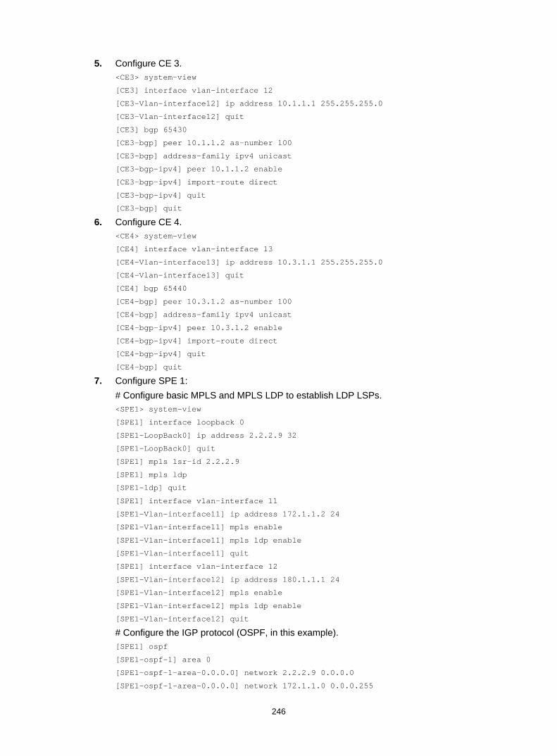
246
5. Configure CE 3. <CE3> system-view
[CE3] interface vlan-interface 12
[CE3-Vlan-interface12] ip address 10.1.1.1 255.255.255.0
[CE3-Vlan-interface12] quit
[CE3] bgp 65430
[CE3-bgp] peer 10.1.1.2 as-number 100
[CE3-bgp] address-family ipv4 unicast
[CE3-bgp-ipv4] peer 10.1.1.2 enable
[CE3-bgp-ipv4] import-route direct
[CE3-bgp-ipv4] quit
[CE3-bgp] quit
6. Configure CE 4. <CE4> system-view
[CE4] interface vlan-interface 13
[CE4-Vlan-interface13] ip address 10.3.1.1 255.255.255.0
[CE4-Vlan-interface13] quit
[CE4] bgp 65440
[CE4-bgp] peer 10.3.1.2 as-number 100
[CE4-bgp] address-family ipv4 unicast
[CE4-bgp-ipv4] peer 10.3.1.2 enable
[CE4-bgp-ipv4] import-route direct
[CE4-bgp-ipv4] quit
[CE4-bgp] quit
7. Configure SPE 1: # Configure basic MPLS and MPLS LDP to establish LDP LSPs. <SPE1> system-view
[SPE1] interface loopback 0
[SPE1-LoopBack0] ip address 2.2.2.9 32
[SPE1-LoopBack0] quit
[SPE1] mpls lsr-id 2.2.2.9
[SPE1] mpls ldp
[SPE1-ldp] quit
[SPE1] interface vlan-interface 11
[SPE1-Vlan-interface11] ip address 172.1.1.2 24
[SPE1-Vlan-interface11] mpls enable
[SPE1-Vlan-interface11] mpls ldp enable
[SPE1-Vlan-interface11] quit
[SPE1] interface vlan-interface 12
[SPE1-Vlan-interface12] ip address 180.1.1.1 24
[SPE1-Vlan-interface12] mpls enable
[SPE1-Vlan-interface12] mpls ldp enable
[SPE1-Vlan-interface12] quit
# Configure the IGP protocol (OSPF, in this example). [SPE1] ospf
[SPE1-ospf-1] area 0
[SPE1-ospf-1-area-0.0.0.0] network 2.2.2.9 0.0.0.0
[SPE1-ospf-1-area-0.0.0.0] network 172.1.1.0 0.0.0.255
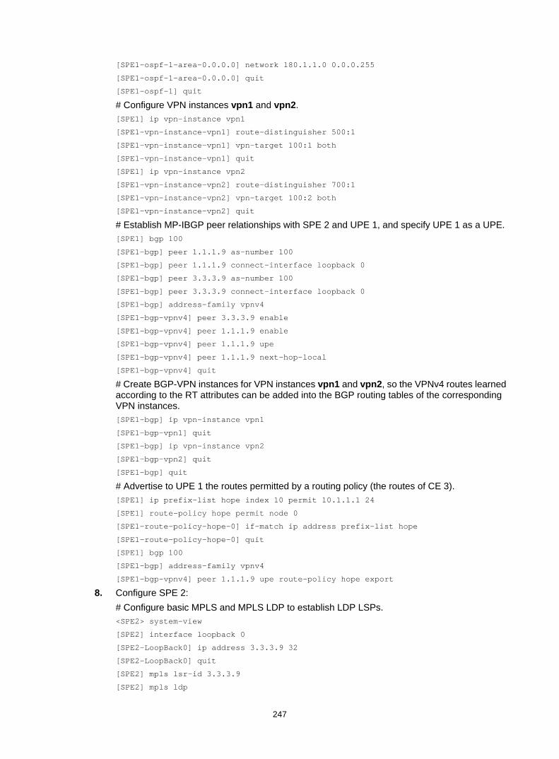
247
[SPE1-ospf-1-area-0.0.0.0] network 180.1.1.0 0.0.0.255
[SPE1-ospf-1-area-0.0.0.0] quit
[SPE1-ospf-1] quit
# Configure VPN instances vpn1 and vpn2. [SPE1] ip vpn-instance vpn1
[SPE1-vpn-instance-vpn1] route-distinguisher 500:1
[SPE1-vpn-instance-vpn1] vpn-target 100:1 both
[SPE1-vpn-instance-vpn1] quit
[SPE1] ip vpn-instance vpn2
[SPE1-vpn-instance-vpn2] route-distinguisher 700:1
[SPE1-vpn-instance-vpn2] vpn-target 100:2 both
[SPE1-vpn-instance-vpn2] quit
# Establish MP-IBGP peer relationships with SPE 2 and UPE 1, and specify UPE 1 as a UPE. [SPE1] bgp 100
[SPE1-bgp] peer 1.1.1.9 as-number 100
[SPE1-bgp] peer 1.1.1.9 connect-interface loopback 0
[SPE1-bgp] peer 3.3.3.9 as-number 100
[SPE1-bgp] peer 3.3.3.9 connect-interface loopback 0
[SPE1-bgp] address-family vpnv4
[SPE1-bgp-vpnv4] peer 3.3.3.9 enable
[SPE1-bgp-vpnv4] peer 1.1.1.9 enable
[SPE1-bgp-vpnv4] peer 1.1.1.9 upe
[SPE1-bgp-vpnv4] peer 1.1.1.9 next-hop-local
[SPE1-bgp-vpnv4] quit
# Create BGP-VPN instances for VPN instances vpn1 and vpn2, so the VPNv4 routes learned according to the RT attributes can be added into the BGP routing tables of the corresponding VPN instances. [SPE1-bgp] ip vpn-instance vpn1
[SPE1-bgp-vpn1] quit
[SPE1-bgp] ip vpn-instance vpn2
[SPE1-bgp-vpn2] quit
[SPE1-bgp] quit
# Advertise to UPE 1 the routes permitted by a routing policy (the routes of CE 3). [SPE1] ip prefix-list hope index 10 permit 10.1.1.1 24
[SPE1] route-policy hope permit node 0
[SPE1-route-policy-hope-0] if-match ip address prefix-list hope
[SPE1-route-policy-hope-0] quit
[SPE1] bgp 100
[SPE1-bgp] address-family vpnv4
[SPE1-bgp-vpnv4] peer 1.1.1.9 upe route-policy hope export
8. Configure SPE 2: # Configure basic MPLS and MPLS LDP to establish LDP LSPs. <SPE2> system-view
[SPE2] interface loopback 0
[SPE2-LoopBack0] ip address 3.3.3.9 32
[SPE2-LoopBack0] quit
[SPE2] mpls lsr-id 3.3.3.9
[SPE2] mpls ldp

248
[SPE2-ldp] quit
[SPE2] interface vlan-interface 12
[SPE2-Vlan-interface12] ip address 180.1.1.2 24
[SPE2-Vlan-interface12] mpls enable
[SPE2-Vlan-interface12] mpls ldp enable
[SPE2-Vlan-interface12] quit
[SPE2] interface vlan-interface 11
[SPE2-Vlan-interface11] ip address 172.2.1.2 24
[SPE2-Vlan-interface11] mpls enable
[SPE2-Vlan-interface11] mpls ldp enable
[SPE2-Vlan-interface11] quit
# Configure the IGP protocol (OSPF, in this example). [SPE2] ospf
[SPE2-ospf-1] area 0
[SPE2-ospf-1-area-0.0.0.0] network 3.3.3.9 0.0.0.0
[SPE2-ospf-1-area-0.0.0.0] network 172.2.1.0 0.0.0.255
[SPE2-ospf-1-area-0.0.0.0] network 180.1.1.0 0.0.0.255
[SPE2-ospf-1-area-0.0.0.0] quit
[SPE2-ospf-1] quit
# Configure VPN instances vpn1 and vpn2. [SPE2] ip vpn-instance vpn1
[SPE2-vpn-instance-vpn1] route-distinguisher 600:1
[SPE2-vpn-instance-vpn1] vpn-target 100:1 both
[SPE2-vpn-instance-vpn1] quit
[SPE2] ip vpn-instance vpn2
[SPE2-vpn-instance-vpn2] route-distinguisher 800:1
[SPE2-vpn-instance-vpn2] vpn-target 100:2 both
[SPE2-vpn-instance-vpn2] quit
# Establish MP-IBGP peer relationships with SPE 1 and UPE 2, and specify UPE 2 as a UPE. [SPE2] bgp 100
[SPE2-bgp] peer 4.4.4.9 as-number 100
[SPE2-bgp] peer 4.4.4.9 connect-interface loopback 0
[SPE2-bgp] peer 2.2.2.9 as-number 100
[SPE2-bgp] peer 2.2.2.9 connect-interface loopback 0
[SPE2-bgp] address-family vpnv4
[SPE2-bgp-vpnv4] peer 2.2.2.9 enable
[SPE2-bgp-vpnv4] peer 4.4.4.9 enable
[SPE2-bgp-vpnv4] peer 4.4.4.9 upe
[SPE2-bgp-vpnv4] peer 4.4.4.9 next-hop-local
[SPE2-bgp-vpnv4] quit
# Create BGP-VPN instances for VPN instances vpn1 and vpn2, so the VPNv4 routes learned according to the RT attributes can be added into the BGP routing tables of the corresponding VPN instances. [SPE2-bgp] ip vpn-instance vpn1
[SPE2-bgp-vpn1] quit
[SPE2-bgp] ip vpn-instance vpn2
[SPE2-bgp-vpn2] quit
[SPE2-bgp] quit

249
# Advertise to UPE 2 the routes permitted by a routing policy (the routes of CE 1). [SPE2] ip prefix-list hope index 10 permit 10.2.1.1 24
[SPE2] route-policy hope permit node 0
[SPE2-route-policy-hope-0] if-match ip address prefix-list hope
[SPE2-route-policy-hope-0] quit
[SPE2] bgp 100
[SPE2-bgp] address-family vpnv4
[SPE2-bgp-vpnv4] peer 4.4.4.9 upe route-policy hope export
Verifying the configuration # Verify that CE 1 and CE3 can learn each other's interface routes and can ping each other. CE 2 and CE 4 cannot learn each other's interface routes and cannot ping each other. (Details not shown.)
Configuring an OSPF sham link Network requirements
As shown in Figure 70, CE 1 and CE 2 belong to VPN 1. Configure an OSPF sham link between PE 1 and PE 2 so traffic between CE 1 and CE 2 is forwarded through the MPLS backbone, instead of the backdoor link.
Figure 70 Network diagram
Table 20 Interface and IP address assignment
Device Interface IP address Device Interface IP address CE 1 Vlan-int11 100.1.1.1/24 CE 2 Vlan-int11 120.1.1.1/24
Vlan-int13 20.1.1.1/24 Vlan-int12 30.1.1.2/24
PE 1 Loop0 1.1.1.9/32 PE 2 Loop0 2.2.2.9/32
Loop1 3.3.3.3/32 Loop1 5.5.5.5/32
Vlan-int11 100.1.1.2/24 Vlan-int11 120.1.1.2/24
Vlan-int12 10.1.1.1/24 Vlan-int12 10.1.1.2/24
Switch A Vlan-int11 20.1.1.2/24
Vlan-int12 30.1.1.1/24
Vlan-int12
Loop0 Loop0
Sham-link
CE 1 Switch A CE 2
PE 2PE 1
Loop1 Loop1
OSPF Area 1
Backdoor link
Vlan-int12 Vlan-int11
Vlan-int11Vlan-int13
Vlan-int11
Vlan-int11
Vlan-int12 Vlan-int12Vlan-int13

250
Configuration procedure 1. Configure OSPF on the customer networks:
Configure conventional OSPF on CE 1, Switch A, and CE 2 to advertise addresses of the interfaces as shown in Figure 70. Execute the display ip routing-table command to verify that CE 1 and CE 2 have learned the route to each other. (Details not shown.)
2. Configure MPLS L3VPN on the backbone: # Configure basic MPLS and MPLS LDP on PE 1 to establish LDP LSPs. <PE1> system-view
[PE1] interface loopback 0
[PE1-LoopBack0] ip address 1.1.1.9 32
[PE1-LoopBack0] quit
[PE1] mpls lsr-id 1.1.1.9
[PE1] mpls ldp
[PE1-ldp] quit
[PE1] interface vlan-interface 12
[PE1-Vlan-interface12] ip address 10.1.1.1 24
[PE1-Vlan-interface12] mpls enable
[PE1-Vlan-interface12] mpls ldp enable
[PE1-Vlan-interface12] quit
# Configure PE 1 to take PE 2 as an MP-IBGP peer. [PE1] bgp 100
[PE1-bgp] peer 2.2.2.9 as-number 100
[PE1-bgp] peer 2.2.2.9 connect-interface loopback 0
[PE1-bgp] address-family vpnv4
[PE1-bgp-vpnv4] peer 2.2.2.9 enable
[PE1-bgp-vpnv4] quit
[PE1-bgp] quit
# Configure OSPF on PE 1. [PE1]ospf 1
[PE1-ospf-1]area 0
[PE1-ospf-1-area-0.0.0.0]network 1.1.1.9 0.0.0.0
[PE1-ospf-1-area-0.0.0.0]network 10.1.1.0 0.0.0.255
[PE1-ospf-1-area-0.0.0.0]quit
[PE1-ospf-1]quit
# Configure basic MPLS and MPLS LDP on PE 2 to establish LDP LSPs. <PE2> system-view
[PE2] interface loopback 0
[PE2-LoopBack0] ip address 2.2.2.9 32
[PE2-LoopBack0] quit
[PE2] mpls lsr-id 2.2.2.9
[PE2] mpls ldp
[PE2-ldp] quit
[PE2] interface vlan-interface 12
[PE2-Vlan-interface12] ip address 10.1.1.2 24
[PE2-Vlan-interface12] mpls enable
[PE2-Vlan-interface12] mpls ldp enable
[PE2-Vlan-interface12] quit
# Configure PE 2 to take PE 1 as an MP-IBGP peer.

251
[PE2] bgp 100
[PE2-bgp] peer 1.1.1.9 as-number 100
[PE2-bgp] peer 1.1.1.9 connect-interface loopback 0
[PE2-bgp] address-family vpnv4
[PE2-bgp-vpnv4] peer 1.1.1.9 enable
[PE2-bgp-vpnv4] quit
[PE2-bgp] quit
# Configure OSPF on PE 2. [PE2]ospf 1
[PE2-ospf-1]area 0
[PE2-ospf-1-area-0.0.0.0]network 2.2.2.9 0.0.0.0
[PE2-ospf-1-area-0.0.0.0]network 10.1.1.0 0.0.0.255
[PE2-ospf-1-area-0.0.0.0]quit
[PE2-ospf-1]quit
3. Configure PEs to allow CE access: # Configure PE 1. [PE1] ip vpn-instance vpn1
[PE1-vpn-instance-vpn1] route-distinguisher 100:1
[PE1-vpn-instance-vpn1] vpn-target 1:1
[PE1-vpn-instance-vpn1] quit
[PE1] interface vlan-interface 11
[PE1-Vlan-interface11] ip binding vpn-instance vpn1
[PE1-Vlan-interface11] ip address 100.1.1.2 24
[PE1-Vlan-interface11] quit
[PE1] ospf 100 vpn-instance vpn1
[PE1-ospf-100] domain-id 10
[PE1-ospf-100] area 1
[PE1-ospf-100-area-0.0.0.1] network 100.1.1.0 0.0.0.255
[PE1-ospf-100-area-0.0.0.1] quit
[PE1-ospf-100] quit
[PE2] bgp 100
[PE1-bgp] ip vpn-instance vpn1
[PE1-bgp-vpn1] address-family ipv4 unicast
[PE1-bgp-ipv4-vpn1] import-route ospf 100
[PE1-bgp-ipv4-vpn1] import-route direct
[PE1-bgp-ipv4-vpn1] quit
[PE1-bgp-vpn1] quit
[PE1-bgp] quit
# Configure PE 2. [PE2] ip vpn-instance vpn1
[PE2-vpn-instance-vpn1] route-distinguisher 100:2
[PE2-vpn-instance-vpn1] vpn-target 1:1
[PE2-vpn-instance-vpn1] quit
[PE2] interface vlan-interface 11
[PE2-Vlan-interface11] ip binding vpn-instance vpn1
[PE2-Vlan-interface11] ip address 120.1.1.2 24
[PE2-Vlan-interface11] quit
[PE2] ospf 100 vpn-instance vpn1

252
[PE2-ospf-100] domain-id 10
[PE2-ospf-100] area 1
[PE2-ospf-100-area-0.0.0.1] network 120.1.1.0 0.0.0.255
[PE2-ospf-100-area-0.0.0.1] quit
[PE2-ospf-100] quit
[PE2] bgp 100
[PE2-bgp] ip vpn-instance vpn1
[PE2-bgp-vpn1] address-family ipv4 unicast
[PE2-bgp-ipv4-vpn1] import-route ospf 100
[PE2-bgp-ipv4-vpn1] import-route direct
[PE2-bgp-ipv4-vpn1] quit
[PE2-bgp-vpn1] quit
[PE2-bgp] quit
# Execute the display ip routing-table vpn-instance command on the PEs to verify that the path to the peer CE is along the OSPF route across the customer networks, instead of the BGP route across the backbone. (Details not shown.)
4. Configure a sham link: # Configure PE 1. [PE1] interface loopback 1
[PE1-LoopBack1] ip binding vpn-instance vpn1
[PE1-LoopBack1] ip address 3.3.3.3 32
[PE1-LoopBack1] quit
[PE1] ospf 100
[PE1-ospf-100] area 1
[PE1-ospf-100-area-0.0.0.1] sham-link 3.3.3.3 5.5.5.5 cost 10
[PE1-ospf-100-area-0.0.0.1] quit
[PE1-ospf-100] quit
# Configure PE 2. [PE2] interface loopback 1
[PE2-LoopBack1] ip binding vpn-instance vpn1
[PE2-LoopBack1] ip address 5.5.5.5 32
[PE2-LoopBack1] quit
[PE2] ospf 100
[PE2-ospf-100] area 1
[PE2-ospf-100-area-0.0.0.1] sham-link 5.5.5.5 3.3.3.3 cost 10
[PE2-ospf-100-area-0.0.0.1] quit
[PE2-ospf-100] quit
Verifying the configuration # Execute the display ip routing-table vpn-instance command on the PEs to verify the following results: (Details not shown.) • The path to the peer CE is now along the BGP route across the backbone. • A route to the sham link destination address is present.
# Execute the display ip routing-table command on the CEs to verify that the next hop of the OSPF route to the peer CE is the VLAN interface 11 connected to the PE. The VPN traffic to the peer is forwarded over the backbone. (Details not shown.)
# Verify that a sham link has been established on PEs, for example, on PE 1. [PE1] display ospf sham-link

253
OSPF Process 100 with Router ID 100.1.1.2
Sham link
Area Neighbor ID Source IP Destination IP State Cost
0.0.0.1 120.1.1.2 3.3.3.3 5.5.5.5 P-2-P 10
# Verify that the peer state is Full on PE 1. [PE1] display ospf sham-link area 1
OSPF Process 100 with Router ID 100.1.1.2
Sham-Link: 3.3.3.3 --> 5.5.5.5
Neighbor ID: 120.1.1.2 State: Full
Area: 0.0.0.1
Cost: 10 State: P-2-P Type: Sham
Timers: Hello 10, Dead 40, Retransmit 5, Transmit Delay 1
Request list: 0 Retransmit list: 0
Configuring BGP AS number substitution Network requirements
As shown in Figure 71, CE 1 and CE 2 belong to VPN 1 and are connected to PE 1 and PE 2, respectively. The two CEs have the same AS number, 600. Configure BGP AS number substitution on the PEs to enable the CEs to communicate with each other.
Figure 71 Network diagram
Table 21 Interface and IP address assignment
Device Interface IP address Device Interface IP address CE 1 Vlan-int11 10.1.1.1/24 P Loop0 2.2.2.9/32
Vlan-int12 100.1.1.1/24 Vlan-int11 30.1.1.1/24
PE 1 Loop0 1.1.1.9/32 Vlan-int12 20.1.1.2/24
Vlan-int11 10.1.1.2/24 PE 2 Loop0 3.3.3.9/32
Loop0
Loop0 Loop0
PE 1 P PE 2
CE 1 CE 2
VPN 1AS 600
VPN 1AS 600
Vlan-int12
MPLS backboneAS 100
Vlan-int12 Vlan-int11
Vlan-int13Vlan-int12
Vlan-int11
Vlan-int12
Vlan-int12
Vlan-int11
Vlan-int11
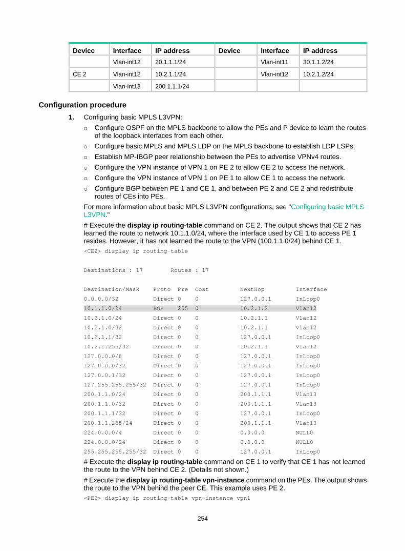
254
Device Interface IP address Device Interface IP address Vlan-int12 20.1.1.1/24 Vlan-int11 30.1.1.2/24
CE 2 Vlan-int12 10.2.1.1/24 Vlan-int12 10.2.1.2/24
Vlan-int13 200.1.1.1/24
Configuration procedure 1. Configuring basic MPLS L3VPN:
Configure OSPF on the MPLS backbone to allow the PEs and P device to learn the routes of the loopback interfaces from each other.
Configure basic MPLS and MPLS LDP on the MPLS backbone to establish LDP LSPs. Establish MP-IBGP peer relationship between the PEs to advertise VPNv4 routes. Configure the VPN instance of VPN 1 on PE 2 to allow CE 2 to access the network. Configure the VPN instance of VPN 1 on PE 1 to allow CE 1 to access the network. Configure BGP between PE 1 and CE 1, and between PE 2 and CE 2 and redistribute
routes of CEs into PEs. For more information about basic MPLS L3VPN configurations, see "Configuring basic MPLS L3VPN." # Execute the display ip routing-table command on CE 2. The output shows that CE 2 has learned the route to network 10.1.1.0/24, where the interface used by CE 1 to access PE 1 resides. However, it has not learned the route to the VPN (100.1.1.0/24) behind CE 1. <CE2> display ip routing-table
Destinations : 17 Routes : 17
Destination/Mask Proto Pre Cost NextHop Interface
0.0.0.0/32 Direct 0 0 127.0.0.1 InLoop0
10.1.1.0/24 BGP 255 0 10.2.1.2 Vlan12
10.2.1.0/24 Direct 0 0 10.2.1.1 Vlan12
10.2.1.0/32 Direct 0 0 10.2.1.1 Vlan12
10.2.1.1/32 Direct 0 0 127.0.0.1 InLoop0
10.2.1.255/32 Direct 0 0 10.2.1.1 Vlan12
127.0.0.0/8 Direct 0 0 127.0.0.1 InLoop0
127.0.0.0/32 Direct 0 0 127.0.0.1 InLoop0
127.0.0.1/32 Direct 0 0 127.0.0.1 InLoop0
127.255.255.255/32 Direct 0 0 127.0.0.1 InLoop0
200.1.1.0/24 Direct 0 0 200.1.1.1 Vlan13
200.1.1.0/32 Direct 0 0 200.1.1.1 Vlan13
200.1.1.1/32 Direct 0 0 127.0.0.1 InLoop0
200.1.1.255/24 Direct 0 0 200.1.1.1 Vlan13
224.0.0.0/4 Direct 0 0 0.0.0.0 NULL0
224.0.0.0/24 Direct 0 0 0.0.0.0 NULL0
255.255.255.255/32 Direct 0 0 127.0.0.1 InLoop0
# Execute the display ip routing-table command on CE 1 to verify that CE 1 has not learned the route to the VPN behind CE 2. (Details not shown.) # Execute the display ip routing-table vpn-instance command on the PEs. The output shows the route to the VPN behind the peer CE. This example uses PE 2. <PE2> display ip routing-table vpn-instance vpn1

255
Destinations : 15 Routes : 15
Destination/Mask Proto Pre Cost NextHop Interface
0.0.0.0/32 Direct 0 0 127.0.0.1 InLoop0
10.1.1.0/24 BGP 255 0 1.1.1.9 Vlan11
10.2.1.0/24 Direct 0 0 10.2.1.2 Vlan12
10.2.1.0/32 Direct 0 0 10.2.1.2 Vlan12
10.2.1.2/32 Direct 0 0 127.0.0.1 InLoop0
10.2.1.255/32 Direct 0 0 10.2.1.2 Vlan12
100.1.1.0/24 BGP 255 0 1.1.1.9 Vlan11
127.0.0.0/8 Direct 0 0 127.0.0.1 InLoop0
127.0.0.0/32 Direct 0 0 127.0.0.1 InLoop0
127.0.0.1/32 Direct 0 0 127.0.0.1 InLoop0
127.255.255.255/32 Direct 0 0 127.0.0.1 InLoop0
200.1.1.0/24 BGP 255 0 10.2.1.1 Vlan12
224.0.0.0/4 Direct 0 0 0.0.0.0 NULL0
224.0.0.0/24 Direct 0 0 0.0.0.0 NULL0
255.255.255.255/32 Direct 0 0 127.0.0.1 InLoop0
# Enable BGP update packet debugging on PE 2. The output shows that PE 2 advertises the route to 100.1.1.1/32, and the AS_PATH is 100 600. <PE2> terminal monitor
<PE2> terminal logging level 7
<PE2> debugging bgp update vpn-instance vpn1 10.2.1.1 ipv4
<PE2> refresh bgp all export ipv4 vpn-instance vpn1
*Jun 13 16:12:52:096 2012 PE2 BGP/7/DEBUG:
BGP.vpn1: Send UPDATE to peer 10.2.1.1 for following destinations:
Origin : Incomplete
AS Path : 100 600
Next Hop : 10.2.1.2
100.1.1.0/24,
# Execute the display bgp routing-table ipv4 peer received-routes command on CE 2 to verify that CE 2 has not received the route to 100.1.1.0/24. <CE2> display bgp routing-table ipv4 peer 10.2.1.2 received-routes
Total number of routes: 2
BGP local router ID is 200.1.1.1
Status codes: * - valid, > - best, d - dampened, h - history,
s - suppressed, S - stale, i - internal, e - external
Origin: i - IGP, e - EGP, ? - incomplete
Network NextHop MED LocPrf PrefVal Path/Ogn
* >e 10.1.1.0/24 10.2.1.2 0 100?
* e 10.2.1.0/24 10.2.1.2 0 0 100?
2. Configure BGP AS number substitution on PE 2. <PE2> system-view

256
[PE2] bgp 100
[PE2-bgp] ip vpn-instance vpn1
[PE2-bgp-vpn1] peer 10.2.1.1 substitute-as
[PE2-bgp-vpn1] address-family ipv4 unicast
[PE2-bgp-ipv4-vpn1] peer 10.2.1.1 enable
[PE2-bgp-ipv4-vpn1] quit
[PE2-bgp-vpn1] quit
[PE2-bgp] quit
Verifying the configuration # The output shows that among the routes advertised by PE 2 to CE 2, the AS_PATH of 100.1.1.0/24 has changed from 100 600 to 100 100. *Jun 13 16:15:59:456 2012 PE2 BGP/7/DEBUG:
BGP.vpn1: Send UPDATE to peer 10.2.1.1 for following destinations:
Origin : Incomplete
AS Path : 100 100
Next Hop : 10.2.1.2
100.1.1.0/24,
# Display again the routing information that CE 2 has received and the routing table. <CE2> display bgp routing-table ipv4 peer 10.2.1.2 received-routes
Total number of routes: 3
BGP local router ID is 200.1.1.1
Status codes: * - valid, > - best, d - dampened, h - history,
s - suppressed, S - stale, i - internal, e - external
Origin: i - IGP, e - EGP, ? - incomplete
Network NextHop MED LocPrf PrefVal Path/Ogn
* >e 10.1.1.0/24 10.2.1.2 0 100?
* e 10.2.1.0/24 10.2.1.2 0 0 100?
* >e 100.1.1.0/24 10.2.1.2 0 100 100?
<CE2> display ip routing-table
Destinations : 18 Routes : 18
Destination/Mask Proto Pre Cost NextHop Interface
0.0.0.0/32 Direct 0 0 127.0.0.1 InLoop0
10.1.1.0/24 BGP 255 0 10.2.1.2 Vlan12
10.2.1.0/24 Direct 0 0 10.2.1.1 Vlan12
10.2.1.0/32 Direct 0 0 10.2.1.1 Vlan12
10.2.1.1/32 Direct 0 0 127.0.0.1 InLoop0
10.2.1.255/32 Direct 0 0 10.2.1.1 Vlan12
100.1.1.0/24 BGP 255 0 10.2.1.2 Vlan12
127.0.0.0/8 Direct 0 0 127.0.0.1 InLoop0
127.0.0.0/32 Direct 0 0 127.0.0.1 InLoop0
127.0.0.1/32 Direct 0 0 127.0.0.1 InLoop0
127.255.255.255/32 Direct 0 0 127.0.0.1 InLoop0

257
200.1.1.0/24 Direct 0 0 200.1.1.1 Vlan13
200.1.1.0/32 Direct 0 0 200.1.1.1 Vlan13
200.1.1.1/32 Direct 0 0 127.0.0.1 InLoop0
200.1.1.255/32 Direct 0 0 200.1.1.1 Vlan13
224.0.0.0/4 Direct 0 0 0.0.0.0 NULL0
224.0.0.0/24 Direct 0 0 0.0.0.0 NULL0
255.255.255.255/32 Direct 0 0 127.0.0.1 InLoop0
# Verify that the VLAN interfaces of CE 1 and CE 2 can ping each other. (Details not shown.)
Configuring MPLS L3VPN FRR through VPNv4 route backup for a VPNv4 route Network requirements
CE 1 and CE 2 belong to VPN 1.
Configure EBGP between CEs and PEs to exchange VPN routes.
Configure OSPF to ensure connectivity between PEs, and configure MP-IBGP to exchange VPNv4 routing information between PEs.
Configure MPLS L3VPN FRR on PE 1 to achieve the following purposes: • When the link PE 1—PE 2 operates correctly, traffic from CE 1 to CE 2 goes through the path
CE 1—PE 1—PE 2—CE 2. • When BFD detects that the LSP between PE 1 and PE 2 fails, traffic from CE 1 to CE 2 goes
through the path CE 1—PE 1—PE 3—CE 2.
Figure 72 Network diagram
Table 22 Interface and IP address assignment
Device Interface IP address Device Interface IP address CE 1 Loop0 5.5.5.5/32 PE 1 Loop0 1.1.1.1/32
Vlan-int10 10.2.1.1/24
Vlan-int10 10.2.1.2/24
PE 2 Loop0 2.2.2.2/32
Vlan-int11 172.1.1.1/24
Vlan-int11 172.1.1.2/24
Vlan-int12 172.2.1.1/24
Vlan-int13 10.1.1.2/24 CE 2 Loop0 4.4.4.4/32
PE 3 Loop0 3.3.3.3/32
Vlan-int13 10.1.1.1/24
CE 2CE 1
VPN 1 VPN 1
MPLS backbone
PE 2
PE 1
PE 3
Vlan-int13
Vlan-int14
Vlan-int13Vlan-int11
Vlan-int14Vlan-int12
Vlan-int11
Vlan-int12
Vlan-int10
Vlan-int10Loop0
Loop0
Loop0
Loop0
Primary linkBackup link
Loop0

258
Device Interface IP address Device Interface IP address
Vlan-int12 172.2.1.3/24
Vlan-int14 10.3.1.1/24
Vlan-int14 10.3.1.2/24
Configuration procedure 1. Configure IP addresses and masks for interfaces as shown in Table 22, and configure BGP and
MPLS L3VPN. (Details not shown.) For more information about configuring basic MPLS L3VPN, see "Configuring basic MPLS L3VPN."
2. Configure MPLS L3VPN FRR on PE 1: # Configure BFD to test the connectivity of the LSP to 2.2.2.2/32. <PE1> system-view
[PE1] mpls bfd enable
[PE1] mpls bfd 2.2.2.2 32
# Create routing policy frr, and specify the backup next hop as 3.3.3.3 for the route to 4.4.4.4/32. [PE1] ip prefix-list abc index 10 permit 4.4.4.4 32
[PE1] route-policy frr permit node 10
[PE1-route-policy] if-match ip address prefix-list abc
[PE1-route-policy] apply fast-reroute backup-nexthop 3.3.3.3
[PE1-route-policy] quit
# Configure FRR for VPN instance vpn1 to reference routing policy frr. [PE1] bgp 100
[PE1-bgp] ip vpn-instance vpn1
[PE1-bgp-vpn1] address-family ipv4 unicast
[PE1-bgp-ipv4-vpn1] fast-reroute route-policy frr
[PE1-bgp-ipv4-vpn1] quit
[PE1-bgp-vpn1] quit
# Specify the preferred value as 100 for BGP VPNv4 routes received from PE 2. This value is greater than the preferred value (0) for routes from PE 3, so PE 1 prefers the routes from PE 2. [PE1-bgp] address-family vpnv4
[PE1-bgp-vpnv4] peer 2.2.2.2 preferred-value 100
[PE1-bgp-vpnv4] quit
[PE1-bgp] quit
3. Enable MPLS BFD on PE 2. <PE2> system-view
[PE2] mpls bfd enable
Verifying the configuration # Display detailed information about the route to 4.4.4.4/32 on PE 1. The output shows the backup next hop for the route. [PE1] display ip routing-table vpn-instance vpn1 4.4.4.4 32 verbose
Summary Count : 1
Destination: 4.4.4.4/32
Protocol: BGP Process ID: 0
SubProtID: 0x1 Age: 00h00m03s

259
Cost: 0 Preference: 255
IpPre: N/A QosLocalID: N/A
Tag: 0 State: Active Adv
OrigTblID: 0x0 OrigVrf: default-vrf
TableID: 0x102 OrigAs: 300
NibID: 0x15000002 LastAs: 300
AttrID: 0x2 Neighbor: 2.2.2.2
Flags: 0x110060 OrigNextHop: 2.2.2.2
Label: 1146 RealNextHop: 172.1.1.2
BkLabel: 1275 BkNextHop: 172.2.1.3
Tunnel ID: Invalid Interface: Vlan-int11
BkTunnel ID: Invalid BkInterface: Vlan-int12
FtnIndex: 0x0
Configuring MPLS L3VPN FRR through VPNv4 route backup for an IPv4 route Network requirements
CE 1 and CE 2 belong to VPN 1.
Configure EBGP between CEs and PEs to exchange VPN routes.
Configure OSPF to ensure connectivity between PEs, and configure MP-IBGP to exchange VPNv4 routing information between PEs.
Configure MPLS L3VPN FRR on PE 2 to achieve the following purposes: • When the link PE 2—CE 2 operates correctly, traffic from CE 1 to CE 2 goes through the path
CE 1—PE 1—PE 2—CE 2. • When BFD detects that the link between PE 2 and CE 2 fails, traffic from CE 1 to CE 2 goes
through the path CE 1—PE 1—PE 2—PE 3—CE 2.
Figure 73 Network diagram
Table 23 Interface and IP address assignment
Device Interface IP address Device Interface IP address CE 1 Loop0 5.5.5.5/32 PE 2 Loop0 2.2.2.2/32
Vlan-int10 10.2.1.1/24
Vlan-int11 172.1.1.2/24
CE 2CE 1
VPN 1 VPN 1
MPLS backbone
PE 2
PE 1
PE 3
Vlan-int13
Vlan-int14
Vlan-int13Vlan-int11
Vlan-int14Vlan-int12
Vlan-int11
Vlan-int12
Vlan-int10
Vlan-int10Loop0
Loop0
Loop0
Loop0
Vlan-int15
Vlan-int15
Loop0
Primary linkBackup link

260
Device Interface IP address Device Interface IP address PE 1 Loop0 1.1.1.1/32
Vlan-int13 10.1.1.2/24
Vlan-int10 10.2.1.2/24
Vlan-int15 172.3.1.2/24
Vlan-int11 172.1.1.1/24 PE 3 Loop0 3.3.3.3/32
Vlan-int12 172.2.1.1/24
Vlan-int12 172.2.1.3/24
CE 2 Loop0 4.4.4.4/32
Vlan-int14 10.3.1.2/24
Vlan-int13 10.1.1.1/24
Vlan-int15 172.3.1.3/24
Vlan-int14 10.3.1.1/24
Configuration procedure 1. Configure IP addresses and masks for interfaces as shown in Table 23, and configure BGP and
MPLS L3VPN. (Details not shown.) For more information about configuring basic MPLS L3VPN, see "Configuring basic MPLS L3VPN."
2. Configure MPLS L3VPN FRR on PE 2: # Configure the source IP address of BFD echo packets as 12.1.1.1. <PE2> system-view
[PE2] bfd echo-source-ip 12.1.1.1
# Create routing policy frr, and specify the backup next hop as 3.3.3.3 for the route to 4.4.4.4/32. [PE2] ip prefix-list abc index 10 permit 4.4.4.4 32
[PE2] route-policy frr permit node 10
[PE2-route-policy] if-match ip address prefix-list abc
[PE2-route-policy] apply fast-reroute backup-nexthop 3.3.3.3
[PE2-route-policy] quit
# Use echo-mode BFD to detect the primary route connectivity. [PE2] bgp 100
[PE2-bgp] primary-path-detect bfd echo
# Configure FRR for VPN instance vpn1 to reference routing policy frr. [PE2-bgp] ip vpn-instance vpn1
[PE2-bgp-vpn1] address-family ipv4 unicast
[PE2-bgp-ipv4-vpn1] fast-reroute route-policy frr
# Specify the preferred value as 200 for BGP routes received from CE 2. This value is greater than the preferred value (0) for routes from PE 3, so PE 2 prefers the routes from CE 2. [PE2-bgp-ipv4-vpn1] peer 10.1.1.1 preferred-value 200
[PE2-bgp-vpn1] quit
[PE2-bgp] quit
Verifying the configuration # Display detailed information about the route to 4.4.4.4/32 on PE 2. The output shows the backup next hop for the route. [PE2] display ip routing-table vpn-instance vpn1 4.4.4.4 32 verbose
Summary Count : 1
Destination: 4.4.4.4/32
Protocol: BGP Process ID: 0

261
SubProtID: 0x2 Age: 01h54m24s
Cost: 0 Preference: 10
IpPre: N/A QosLocalID: N/A
Tag: 0 State: Active Adv
OrigTblID: 0x0 OrigVrf: vpn1
TableID: 0x102 OrigAs: 300
NibID: 0x15000002 LastAs: 300
AttrID: 0x0 Neighbor: 10.1.1.1
Flags: 0x10060 OrigNextHop: 10.1.1.1
Label: NULL RealNextHop: 10.1.1.1
BkLabel: 1275 BkNextHop: 172.3.1.3
Tunnel ID: Invalid Interface: Vlan-int13
BkTunnel ID: 0x409 BkInterface: Vlan-int15
FtnIndex: 0x0
Configuring MPLS L3VPN FRR through IPv4 route backup for a VPNv4 route Network requirements
CE 1 and CE 2 belong to VPN 1.
Configure EBGP between CEs and PEs to exchange VPN routes.
Configure OSPF to ensure connectivity between PEs, and configure MP-IBGP to exchange VPNv4 routing information between PEs.
Configure MPLS L3VPN FRR on PE 2 to achieve the following purposes: • When the link PE 2—PE 3 operates correctly, traffic from CE 1 to CE 2 goes through the path
CE 1—PE 1—PE 2—PE 3—CE 2. • When BFD detects that the link between PE 2 and PE 3 fails, traffic from CE 1 to CE 2 goes
through the path CE 1—PE 1—PE 2—CE 2.
Figure 74 Network diagram
Table 24 Interface and IP address assignment
Device Interface IP address Device Interface IP address CE 1 Loop0 5.5.5.5/32 PE 2 Loop0 2.2.2.2/32
CE 2CE 1
VPN 1 VPN 1
MPLS backbone
PE 2
PE 1
PE 3
Vlan-int13
Vlan-int14
Vlan-int13Vlan-int11
Vlan-int14Vlan-int12
Vlan-int11
Vlan-int12
Vlan-int10
Vlan-int10Loop0
Loop0
Loop0
Loop0
Vlan-int15
Vlan-int15
Loop0
Primary linkBackup link

262
Device Interface IP address Device Interface IP address
Vlan-int10 10.2.1.1/24
Vlan-int11 172.1.1.2/24
PE 1 Loop0 1.1.1.1/32
Vlan-int13 10.1.1.2/24
Vlan-int10 10.2.1.2/24
Vlan-int15 172.3.1.2/24
Vlan-int11 172.1.1.1/24 PE 3 Loop0 3.3.3.3/32
Vlan-int12 172.2.1.1/24
Vlan-int12 172.2.1.3/24
CE 2 Loop0 4.4.4.4/32
Vlan-int14 10.3.1.2/24
Vlan-int13 10.1.1.1/24
Vlan-int15 172.3.1.3/24
Vlan-int14 10.3.1.1/24
Configuration procedure 1. Configure IP addresses and masks for interfaces as shown in Table 24, and configure BGP and
MPLS L3VPN. (Details not shown.) For more information about configuring basic MPLS L3VPN, see "Configuring basic MPLS L3VPN."
2. Configure MPLS L3VPN FRR on PE 2: # Configure BFD to test the connectivity of the LSP to 3.3.3.3/32. <PE2> system-view
[PE2] mpls bfd enable
[PE2] mpls bfd 3.3.3.3 32
# Create routing policy frr, and specify the backup next hop as 10.1.1.1 for the route to 4.4.4.4/32. [PE2] ip prefix-list abc index 10 permit 4.4.4.4 32
[PE2] route-policy frr permit node 10
[PE2-route-policy] if-match ip address prefix-list abc
[PE2-route-policy] apply fast-reroute backup-nexthop 10.1.1.1
[PE2-route-policy] quit
# Configure FRR for VPN instance vpn1 to reference routing policy frr. [PE2] bgp 100
[PE2-bgp] ip vpn-instance vpn1
[PE2-bgp-vpn1] address-family ipv4 unicast
[PE2-bgp-ipv4-vpn1] fast-reroute route-policy frr
[PE2-bgp-ipv4-vpn1] quit
[PE2-bgp-vpn1] quit
# Specify the preferred value as 200 for BGP VPNv4 routes received from PE 3. This value is greater than the preferred value (0) for IPv4 unicast routes from CE 2, so PE 2 prefers the routes from PE 3. [PE2-bgp] address-family vpnv4
[PE2-bgp-vpnv4] peer 3.3.3.3 preferred-value 200
[PE2-bgp-vpnv4] quit
[PE2-bgp] quit
3. Enable MPLS BFD on PE 3. <PE3> system-view
[PE3] mpls bfd enable

263
Verifying the configuration # Display detailed information about the route to 4.4.4.4/32 on PE 2. The output shows the backup next hop for the route. [PE2] display ip routing-table vpn-instance vpn1 4.4.4.4 32 verbose
Summary Count : 1
Destination: 4.4.4.4/32
Protocol: BGP Process ID: 0
SubProtID: 0x1 Age: 00h00m04s
Cost: 0 Preference: 255
IpPre: N/A QosLocalID: N/A
Tag: 0 State: Active Adv
OrigTblID: 0x0 OrigVrf: default-vrf
TableID: 0x102 OrigAs: 300
NibID: 0x15000004 LastAs: 300
AttrID: 0x1 Neighbor: 3.3.3.3
Flags: 0x110060 OrigNextHop: 3.3.3.3
Label: 1275 RealNextHop: 172.3.1.3
BkLabel: NULL BkNextHop: 10.1.1.1
Tunnel ID: 0x409 Interface: Vlan-int15
BkTunnel ID: Invalid BkInterface: Vlan-int13
FtnIndex: 0x0

264
Configuring IPv6 MPLS L3VPN Overview
IPv6 MPLS L3VPN uses BGP to advertise IPv6 VPN routes and uses MPLS to forward IPv6 VPN packets on the service provider backbone.
Figure 75 shows a typical IPv6 MPLS L3VPN model. The service provider backbone in the IPv6 MPLS L3VPN model is an IPv4 network. IPv6 runs inside the VPNs and between CE and PE. Therefore, PEs must support both IPv4 and IPv6. The PE-CE interfaces of a PE run IPv6, and the PE-P interface of a PE runs IPv4.
Figure 75 Network diagram for the IPv6 MPLS L3VPN model
IPv6 MPLS L3VPN packet forwarding Figure 76 IPv6 MPLS L3VPN packet forwarding diagram
As shown in Figure 76, the IPv6 MPLS L3VPN packet forwarding procedure is as follows: 1. The PC at Site 1 sends an IPv6 packet destined for 2001:2::1, the PC at Site 2. CE 1 transmits
the packet to PE 1.
VPN 1
CE
IPv6 Site 1
VPN 2
CE
CE
CE
IPv6 Site 3VPN 2
PE
VPN 1
IPv6 Site 2
IPv6 Site 4
PE
PE
P P
P P
IPv4 network
CE 1Site 1
PE 1
P P
PE 2
CE 2 Site 2
2001:1::1/96
2001:2::1
2001:2::1
Layer2
Layer1
2001:2::1/96
2001:2::1
Layer22001:2::1

265
2. Based on the inbound interface and destination address of the packet, PE 1 finds a matching entry from the routing table of the VPN instance, labels the packet with both a private network label (inner label) and a public network label (outer label), and forwards the packet out.
3. The MPLS backbone transmits the packet to PE 2 by outer label. The outer label is removed from the packet at the penultimate hop.
4. According to the inner label and destination address of the packet, PE 2 searches the routing table of the VPN instance to determine the outbound interface, and then forwards the packet out of the interface to CE 2.
5. CE 2 forwards the packet to the destination by IPv6 forwarding.
IPv6 MPLS L3VPN routing information advertisement The routing information for a local CE is advertised to the remote CE by using the following process: 1. From the local CE to the ingress PE.
The local CE advertises standard IPv6 routing information to the ingress PE over an IPv6 static route, RIPng route, OSPFv3 route, IPv6 IS-IS route, IBGP route, or EBGP route.
2. From the ingress PE to the egress PE. After receiving the standard IPv6 routes from the CE, the ingress PE does the following: a. Adds RDs and route targets to create VPN-IPv6 routes. b. Saves the routes to the routing table of the VPN instance created for the CE. c. Assigns VPN labels for the routes. d. Advertises the VPN-IPv6 routes to the egress PE through MP-BGP. The egress PE does the following: a. Compares the export target attributes of the VPN-IPv6 routes with the import target
attributes that it maintains for the VPN instance. b. Adds the routes to the routing table of the VPN instance if the export and import target
attributes are the same. The PEs use an IGP to ensure the connectivity between them.
3. From the egress PE to the remote peer CE. The egress PE restores the original IPv6 routes and advertises them to the remote CE over an IPv6 static route, RIPng route, OSPFv3 route, IPv6 IS-IS route, EBGP, or IBGP route.
IPv6 MPLS L3VPN network schemes and functions IPv6 MPLS L3VPN supports the following network schemes and functions: • Basic VPN. • Inter-AS VPN option A. • Inter-AS VPN option C. • Carrier's carrier. • OSPFv3 VPN extension. (OSPFv3 Type 3, Type 5, and Type 7 LSAs support the DN bit. By
default, OSPFv3 VPN extension uses the DN bit to avoid routing loops.)
Protocols and standards • RFC 4659, BGP-MPLS IP Virtual Private Network (VPN) Extension for IPv6 VPN • RFC 6565, OSPFv3 as a Provider Edge to Customer Edge (PE-CE) Routing Protocol
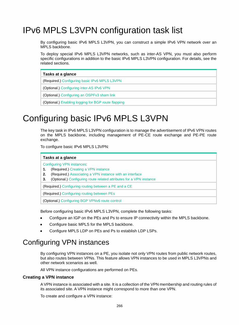
266
IPv6 MPLS L3VPN configuration task list By configuring basic IPv6 MPLS L3VPN, you can construct a simple IPv6 VPN network over an MPLS backbone.
To deploy special IPv6 MPLS L3VPN networks, such as inter-AS VPN, you must also perform specific configurations in addition to the basic IPv6 MPLS L3VPN configuration. For details, see the related sections.
Tasks at a glance (Required.) Configuring basic IPv6 MPLS L3VPN
(Optional.) Configuring inter-AS IPv6 VPN
(Optional.) Configuring an OSPFv3 sham link
(Optional.) Enabling logging for BGP route flapping
Configuring basic IPv6 MPLS L3VPN The key task in IPv6 MPLS L3VPN configuration is to manage the advertisement of IPv6 VPN routes on the MPLS backbone, including management of PE-CE route exchange and PE-PE route exchange.
To configure basic IPv6 MPLS L3VPN:
Tasks at a glance Configuring VPN instances: 1. (Required.) Creating a VPN instance 2. (Required.) Associating a VPN instance with an interface 3. (Optional.) Configuring route related attributes for a VPN instance
(Required.) Configuring routing between a PE and a CE
(Required.) Configuring routing between PEs
(Optional.) Configuring BGP VPNv6 route control
Before configuring basic IPv6 MPLS L3VPN, complete the following tasks: • Configure an IGP on the PEs and Ps to ensure IP connectivity within the MPLS backbone. • Configure basic MPLS for the MPLS backbone. • Configure MPLS LDP on PEs and Ps to establish LDP LSPs.
Configuring VPN instances By configuring VPN instances on a PE, you isolate not only VPN routes from public network routes, but also routes between VPNs. This feature allows VPN instances to be used in MPLS L3VPNs and other network scenarios as well.
All VPN instance configurations are performed on PEs.
Creating a VPN instance A VPN instance is associated with a site. It is a collection of the VPN membership and routing rules of its associated site. A VPN instance might correspond to more than one VPN.
To create and configure a VPN instance:

267
Step Command Remarks 1. Enter system view. system-view N/A
2. Create a VPN instance and enter VPN instance view.
ip vpn-instance vpn-instance-name
By default, no VPN instance is created.
3. Configure an RD for the VPN instance.
route-distinguisher route-distinguisher By default, no RD is specified.
4. (Optional.) Configure a description for the VPN instance.
description text
By default, no description is configured for a VPN instance. The description should contain the VPN instance's related information, such as its relationship with a certain VPN.
5. (Optional.) Configure an ID for the VPN instance. vpn-id vpn-id By default, no ID is configured for
a VPN instance.
Associating a VPN instance with an interface After creating and configuring a VPN instance, associate the VPN instance with the interface connected to the CE.
To associate a VPN instance with an interface:
Step Command Remarks 1. Enter system view. system-view N/A
2. Enter interface view. interface interface-type interface-number N/A
3. Associate a VPN instance with the interface.
ip binding vpn-instance vpn-instance-name
By default, an interface is not associated with a VPN instance. The ip binding vpn-instance command clears the IP address of the interface. Therefore, re-configure an IP address for the interface after configuring this command.
Configuring route related attributes for a VPN instance
Step Command Remarks 1. Enter system view. system-view N/A
2. Enter VPN instance view or IPv6 VPN view.
• Enter VPN instance view: ip vpn-instance vpn-instance-name
• Enter IPv6 VPN view: a. ip vpn-instance
vpn-instance-name b. address-family ipv6
Configurations made in VPN instance view apply to both IPv4 VPN and IPv6 VPN. IPv6 VPN prefers the configurations in IPv6 VPN view over the configurations in VPN instance view.
3. Configure route targets. vpn-target vpn-target&<1-8> [ both | export-extcommunity | import-extcommunity ]
By default, no route targets are configured.
4. Set the maximum number of active routes.
routing-table limit number { warn-threshold | simply-alert }
By default, the number of active routes in a VPN instance is not
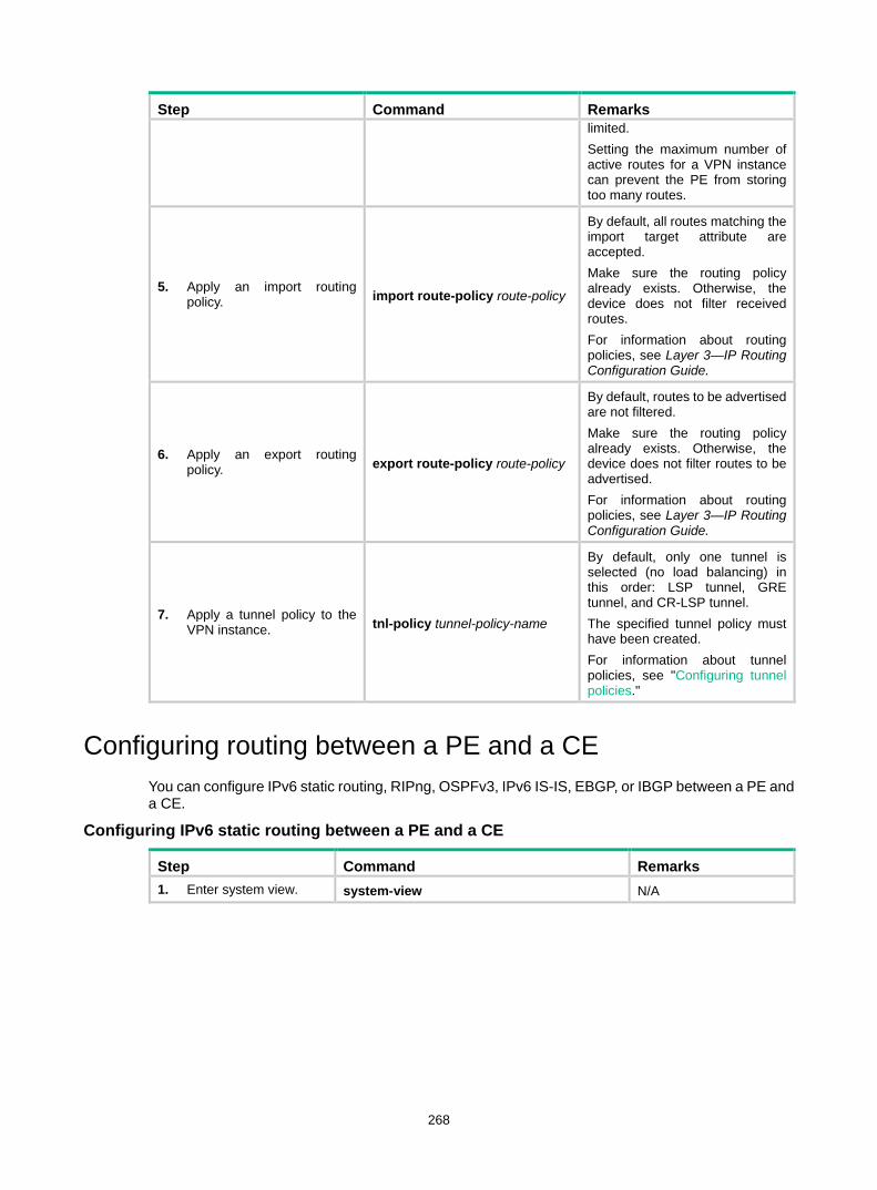
268
Step Command Remarks limited. Setting the maximum number of active routes for a VPN instance can prevent the PE from storing too many routes.
5. Apply an import routing policy. import route-policy route-policy
By default, all routes matching the import target attribute are accepted. Make sure the routing policy already exists. Otherwise, the device does not filter received routes. For information about routing policies, see Layer 3—IP Routing Configuration Guide.
6. Apply an export routing policy. export route-policy route-policy
By default, routes to be advertised are not filtered. Make sure the routing policy already exists. Otherwise, the device does not filter routes to be advertised. For information about routing policies, see Layer 3—IP Routing Configuration Guide.
7. Apply a tunnel policy to the VPN instance. tnl-policy tunnel-policy-name
By default, only one tunnel is selected (no load balancing) in this order: LSP tunnel, GRE tunnel, and CR-LSP tunnel. The specified tunnel policy must have been created. For information about tunnel policies, see "Configuring tunnel policies."
Configuring routing between a PE and a CE You can configure IPv6 static routing, RIPng, OSPFv3, IPv6 IS-IS, EBGP, or IBGP between a PE and a CE.
Configuring IPv6 static routing between a PE and a CE
Step Command Remarks 1. Enter system view. system-view N/A

269
Step Command Remarks
2. Configure an IPv6 static route for a VPN instance.
ipv6 route-static vpn-instance s-vpn-instance-name ipv6-address prefix-length { interface-type interface-number [ next-hop-address ] | nexthop-address [ public ] | vpn-instance d-vpn-instance-name nexthop-address } [ permanent ] [ preference preference-value ] [ tag tag-value ] [ description description-text ]
By default, no IPv6 static route is configured for a VPN instance. Perform this configuration on the PE. On the CE, configure a common IPv6 static route. For more information about IPv6 static routing, see Layer 3—IP Routing Configuration Guide.
Configuring RIPng between a PE and a CE A RIPng process belongs to the public network or a single VPN instance. If you create a RIPng process without binding it to a VPN instance, the process belongs to the public network.
For more information about RIPng, see Layer 3—IP Routing Configuration Guide.
To configure RIPng between a PE and a CE:
Step Command Remarks 1. Enter system view. system-view N/A
2. Create a RIPng process for a VPN instance and enter RIPng view.
ripng [ process-id ] vpn-instance vpn-instance-name
Perform this configuration on the PE. On the CE, create a common RIPng process.
3. Return to system view. quit N/A
4. Enter interface view. interface interface-type interface-number N/A
5. Enable RIPng on the interface. ripng process-id enable By default, RIPng is disabled on
an interface.
Configuring OSPFv3 between a PE and a CE An OSPFv3 process belongs to the public network or a single VPN instance. If you create an OSPF process without binding it to a VPN instance, the process belongs to the public network.
For more information about OSPFv3, see Layer 3—IP Routing Configuration Guide.
To configure OSPFv3 between a PE and a CE:
Step Command Remarks 1. Enter system view. system-view N/A
2. Create an OSPFv3 process for a VPN instance and enter OSPFv3 view.
ospfv3 [ process-id ] vpn-instance vpn-instance-name
Perform this configuration on the PE. On the CE, create a common OSPF process. Deleting a VPN instance also deletes all related OSPFv3 processes.
3. Set the router ID. router-id router-id N/A
4. (Optional.) Configure an OSPFv3 domain ID.
domain-id { domain-id [ secondary ] | null }
The default domain ID is 0. Perform this configuration on the
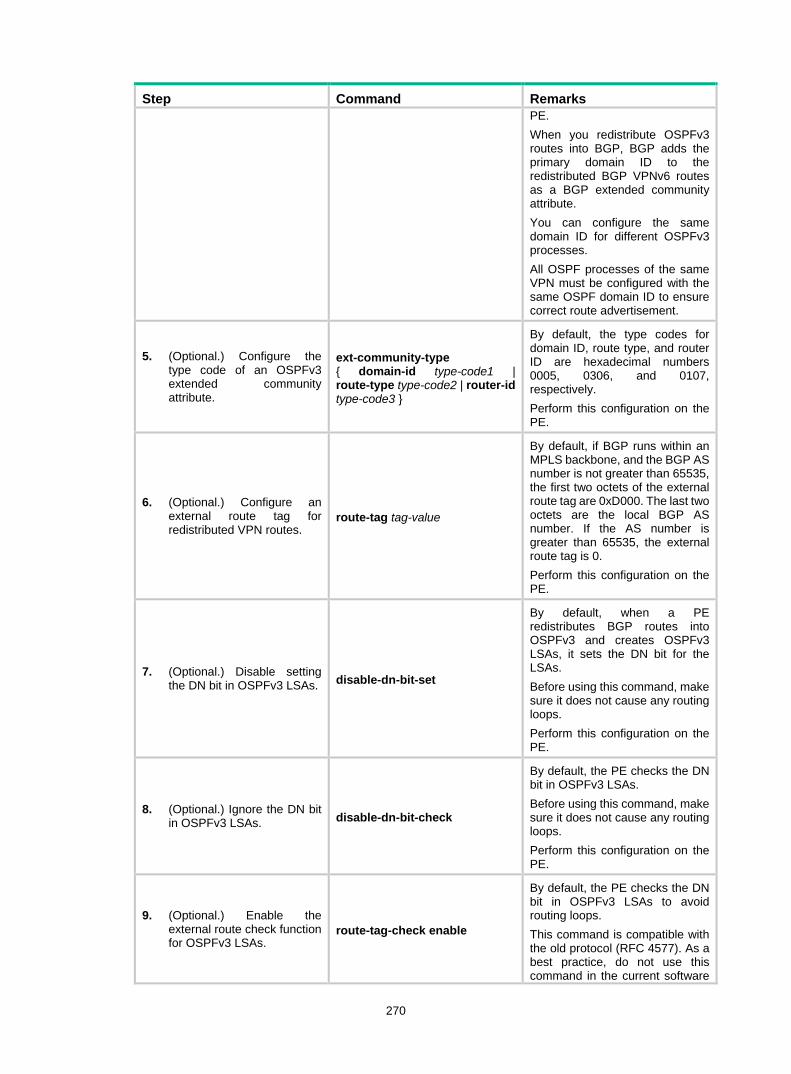
270
Step Command Remarks PE. When you redistribute OSPFv3 routes into BGP, BGP adds the primary domain ID to the redistributed BGP VPNv6 routes as a BGP extended community attribute. You can configure the same domain ID for different OSPFv3 processes. All OSPF processes of the same VPN must be configured with the same OSPF domain ID to ensure correct route advertisement.
5. (Optional.) Configure the type code of an OSPFv3 extended community attribute.
ext-community-type { domain-id type-code1 | route-type type-code2 | router-id type-code3 }
By default, the type codes for domain ID, route type, and router ID are hexadecimal numbers 0005, 0306, and 0107, respectively. Perform this configuration on the PE.
6. (Optional.) Configure an external route tag for redistributed VPN routes.
route-tag tag-value
By default, if BGP runs within an MPLS backbone, and the BGP AS number is not greater than 65535, the first two octets of the external route tag are 0xD000. The last two octets are the local BGP AS number. If the AS number is greater than 65535, the external route tag is 0. Perform this configuration on the PE.
7. (Optional.) Disable setting the DN bit in OSPFv3 LSAs. disable-dn-bit-set
By default, when a PE redistributes BGP routes into OSPFv3 and creates OSPFv3 LSAs, it sets the DN bit for the LSAs. Before using this command, make sure it does not cause any routing loops. Perform this configuration on the PE.
8. (Optional.) Ignore the DN bit in OSPFv3 LSAs. disable-dn-bit-check
By default, the PE checks the DN bit in OSPFv3 LSAs. Before using this command, make sure it does not cause any routing loops. Perform this configuration on the PE.
9. (Optional.) Enable the external route check function for OSPFv3 LSAs.
route-tag-check enable
By default, the PE checks the DN bit in OSPFv3 LSAs to avoid routing loops. This command is compatible with the old protocol (RFC 4577). As a best practice, do not use this command in the current software

271
Step Command Remarks version. Perform this configuration on the PE.
10. Return to system view. quit N/A
11. Enter interface view. interface interface-type interface-number N/A
12. Enable OSPFv3 on the interface.
ospfv3 process-id area area-id [ instance instance-id ]
By default, OSPFv3 is disabled on an interface. Perform this configuration on the PE.
Configuring IPv6 IS-IS between a PE and a CE An IPv6 IS-IS process belongs to the public network or a single VPN instance. If you create an IPv6 IS-IS process without binding it to a VPN instance, the process belongs to the public network.
For more information about IPv6 IS-IS, see Layer 3—IP Routing Configuration Guide.
To configure IPv6 IS-IS between a PE and a CE:
Step Command Remarks 1. Enter system view. system-view N/A
2. Create an IPv6 IS-IS process for a VPN instance and enter IS-IS view.
isis [ process-id ] vpn-instance vpn-instance-name
Perform this configuration on the PE. On the CE, create a common IPv6 IS-IS process.
3. Configure a network entity title for the IS-IS process. network-entity net By default, no NET is configured.
4. Enable IPv6 for the IS-IS process. ipv6 enable IPv6 is disabled by default.
5. Return to system view. quit N/A
6. Enter interface view. interface interface-type interface-number N/A
7. Enable IPv6 for the IS-IS process on the interface. isis ipv6 enable [ process-id ] IPv6 is disabled on an interface by
default.
Configuring EBGP between a PE and a CE 1. Configure the PE:
Step Command Remarks 1. Enter system view. system-view N/A
2. Enable BGP and enter BGP view. bgp as-number N/A
3. Enter BGP-VPN instance view.
ip vpn-instance vpn-instance-name N/A
4. Configure the CE as the VPN EBGP peer.
peer { group-name | ipv6-address [ prefix-length ] } as-number as-number
By default, no BGP peer is configured.
5. Create the BGP-VPN IPv6 unicast address family and enter its view.
address-family ipv6 [ unicast ] By default, the BGP-VPN IPv6 unicast address family is not created.

272
Step Command Remarks Configuration commands in BGP-VPN IPv6 unicast address family view are the same as those in BGP IPv6 unicast address family view. For details, see Layer 3—IP Routing Configuration Guide.
6. Enable IPv6 unicast route exchange with the specified peer or peer group.
peer { group-name | ipv6-address [ prefix-length ] } enable
By default, BGP does not exchange IPv6 unicast routes with any peer.
7. Redistribute the routes of the local CE.
import-route protocol [ process-id [ allow-direct | med med-value | route-policy route-policy-name ] * ]
A PE must redistribute the routes of the local CE into its VPN routing table so that it can advertise them to the peer PE.
8. (Optional.) Configure filtering of advertised routes.
filter-policy { acl6-number | prefix-list ipv6-prefix-name } export [ protocol process-id ]
By default, BGP does not filter advertised routes.
9. (Optional.) Configure filtering of received routes.
filter-policy { acl6-number | prefix-list ipv6-prefix-name } import
By default, the PE does not filter received routes.
2. Configure the CE:
Step Command Remarks 1. Enter system view. system-view N/A
2. Enter BGP view. bgp as-number N/A
3. Configure the PE as an EBGP peer.
peer { group-name | ipv6-address [ prefix-length ] } as-number as-number
By default, no BGP peer is configured.
4. Create the BGP IPv6 unicast address family and enter its view.
address-family ipv6 [ unicast ] By default, the BGP IPv6 unicast address family is not created.
5. Enable IPv6 unicast route exchange with the specified peer or peer group.
peer { group-name | ipv6-address [ prefix-length ] } enable
By default, BGP does not exchange IPv6 unicast routes with any peer.
6. (Optional.) Configure route redistribution.
import-route protocol [ process-id [ allow-direct | med med-value | route-policy route-policy-name ] * ]
A CE must advertise its VPN routes to the connected PE so that the PE can advertise them to the peer CE.
Configuring IBGP between a PE and a CE Use IBGP between PE and CE only in a basic IPv6 MPLS L3VPN network. In networks such as inter-AS VPN and carrier's carrier, you cannot configure IBGP between PE and CE. 1. Configure the PE:
Step Command Remarks 1. Enter system view. system-view N/A
2. Enter BGP view. bgp as-number N/A
3. Enter BGP-VPN instance view.
ip vpn-instance vpn-instance-name
Configuration commands in BGP-VPN instance view are the same as those in BGP view. For

273
Step Command Remarks details, see Layer 3—IP Routing Configuration Guide.
4. Configure the CE as the VPN IBGP peer.
peer { group-name | ipv6-address [ prefix-length ] } as-number as-number
By default, no BGP peer is created.
5. Create the BGP-VPN IPv6 unicast family and enter its view.
address-family ipv6 [ unicast ] By default, the BGP-VPN IPv6 unicast family is not created.
6. Enable IPv6 unicast route exchange with the specified peer.
peer { group-name | ipv6-address [ prefix-length ] } enable
By default, BGP does not exchange IPv6 unicast routes with any peer.
7. Configure the CE as a client of the RR.
peer { group-name | ipv6-address [ prefix-length ] } reflect-client
By default, no RR or RR client is configured, and the PE does not advertise routes learned from the IBGP peer CE to other IBGP peers, including VPNv6 IBGP peers. The PE advertises routes learned from the CE to other IBGP peers only when you configure the IBGP peer CE as a client of the RR. Configuring an RR does not change the next hop of a route. To change the next hop of a route, configure an inbound policy on the receiving side.
8. (Optional.) Enable route reflection between clients. reflect between-clients By default, route reflection
between clients is enabled.
9. (Optional.) Configure the cluster ID for the RR.
reflector cluster-id { cluster-id | ip-address }
By default, the RR uses its own router ID as the cluster ID. If multiple RRs exist in a cluster, use this command to configure the same cluster ID for all RRs in the cluster to avoid routing loops.
2. Configure the CE:
Step Command Remarks 1. Enter system view. system-view N/A
2. Enter BGP view. bgp as-number N/A
3. Configure the PE as an IBGP peer.
peer { group-name | ipv6-address [ prefix-length ] } as-number as-number
By default, no BGP peer is created.
4. Create the BGP IPv6 unicast family and enter its view. address-family ipv6 [ unicast ] By default, the BGP IPv6 unicast
family is not created.
5. Enable IPv6 unicast route exchange with the specified peer or peer group.
peer { group-name | ipv6-address [ prefix-length ] } enable
By default, BGP does not exchange IPv6 unicast routes with any peer.
6. (Optional.) Configure route redistribution.
import-route protocol [ process-id [ allow-direct |med med-value | route-policy route-policy-name ] * ]
A CE must redistribute its routes to the PE so the PE can advertise them to the peer CE.

274
Configuring routing between PEs
Step Command Remarks 1. Enter system view. system-view N/A
2. Enter BGP view. bgp as-number N/A
3. Configure the remote PE as the peer.
peer { group-name | ip-address [ mask-length ] } as-number as-number
By default, no BGP peer is configured.
4. Specify the source interface for route update packets sent to the specified peer.
peer { group-name | ip-address [ mask-length ] } connect-interface interface-type interface-number
By default, BGP uses the outbound interface of the best route destined to the BGP peer as the source interface.
5. Create the BGP VPNv6 address family and enter its view.
address-family vpnv6 By default, the BGP VPNv6 address family is not created.
6. Enable BGP VPNv6 route exchange with the specified peer.
peer { group-name | ip-address [ mask-length ] } enable
By default, BGP does not exchange BGP VPNv6 routes with any peer.
Configuring BGP VPNv6 route control BGP VPNv6 route control is configured similarly with BGP route control, except that it is configured in BGP VPNv6 address family view. For detailed information about BGP route control, see Layer 3—IP Routing Configuration Guide.
To configure BGP VPNv6 route control:
Step Command Remarks 1. Enter system view. system-view N/A
2. Enter BGP view. bgp as-number N/A
3. Enter BGP VPNv6 address family view. address-family vpnv6 N/A
4. Configure filtering of advertised routes.
filter-policy { acl6-number | prefix-list ipv6-prefix-name } export [ protocol process-id ]
By default, the PE does not filter advertised routes.
5. Configure filtering of received routes.
filter-policy { acl6-number | prefix-list ipv6-prefix-name } import
By default, the PE does not filter received routes.
6. Configure ACL-based route filtering for the specified peer or peer group.
peer { group-name | ip-address [ mask-length ] } filter-policy acl6-number { export | import }
By default, no ACL-based route filtering is configured.
7. Configure IPv6 prefix list-based route filtering for the specified peer or peer group.
peer { group-name | ip-address [ mask-length ] } prefix-list ipv6-prefix-name { export | import }
By default, no IPv6 prefix list-based route filtering is configured.
8. Specify a preferred value for routes received from the peer or peer group.
peer { group-name | ip-address [ mask-length ] } preferred-value value
The default preferred value is 0.
9. Configure BGP updates sent to the peer to carry only
peer { group-name | ip-address [ mask-length ] } public-as-only
By default, a BGP update carries both public and private AS

275
Step Command Remarks public AS numbers. numbers.
10. Apply a routing policy to routes advertised to or received from the peer or peer group.
peer { group-name | ip-address [ mask-length ] } route-policy route-policy-name { export | import }
By default, no routing policy is applied for a peer.
11. Enable route target filtering for received BGP VPNv6 routes.
policy vpn-target By default, route target filtering is enabled.
12. Configure the local PE as the route reflector and specify the peer as the client.
peer { group-name | ip-address [ mask-length ] } reflect-client
By default, no route reflector or client is configured.
13. Specify the maximum number of routes BGP can receive from a peer or peer group.
peer { group-name | ip-address [ mask-length ] } route-limit prefix-number [ { alert-only | discard | reconnect reconnect-time } | percentage-value ] *
By default, the number of routes that BGP can receive from a peer or peer group is not limited.
14. Enable route reflection between clients. reflect between-clients By default, route reflection
between clients is enabled.
15. Configure a cluster ID for the route reflector.
reflector cluster-id { cluster-id | ip-address }
By default, an RR uses its own router ID as the cluster ID. If more than one RR exists in a cluster, use this command to configure the same cluster ID for all RRs in the cluster to avoid routing loops.
16. Configure filtering of reflected routes.
rr-filter extended-community-number
By default, an RR does not filter reflected routes. Only IBGP routes whose extended community attribute matches the specified community list are reflected. By configuring different filtering policies on RRs, you can implement load balancing among the RRs.
Configuring inter-AS IPv6 VPN If the MPLS backbone spans multiple ASs, you must configure inter-AS IPv6 VPN.
There are three inter-AS VPN solutions (for more information, see "Configuring MPLS L3VPN"). IPv6 MPLS L3VPN supports only inter-AS VPN option A and option C.
Before configuring inter-AS IPv6 VPN, complete these tasks: • Configure an IGP for the MPLS backbone in each AS to ensure IP connectivity. • Configure basic MPLS for the MPLS backbone of each AS. • Configure MPLS LDP for the MPLS backbones so that LDP LSPs can be established.
The following sections describe inter-AS IPv6 VPN option A and option C. Select one according to your network scenario.

276
Configuring inter-AS IPv6 VPN option A Inter-AS IPv6 VPN option A applies to scenarios where the number of VPNs and that of VPN routes on the PEs are relatively small.
To configure inter-AS IPv6 option A: • Configure basic IPv6 MPLS L3VPN on each AS. • Configure VPN instances on both PEs and ASBR-PEs. The VPN instances on PEs allow CEs
to access the network, and those on ASBR-PEs are for access of the peer ASBR-PEs.
For more configuration information, see "Configuring MPLS L3VPN."
In the inter-AS IPv6 VPN option A solution, for the same IPv6 VPN, the route targets configured on the PEs must match those configured on the ASBR-PEs in the same AS. This makes sure VPN routes sent by the PEs (or ASBR-PEs) can be received by the ASBR-PEs (or PEs). Route targets configured on the PEs in different ASs do not have such requirements.
Configuring inter-AS IPv6 VPN option C To configure inter-AS IPv6 VPN option C, perform proper configurations on PEs and ASBR-PEs, and configure routing policies on the ASBR-PEs.
Configuring the PEs Establish an IBGP peer relationship between a PE and an ASBR-PE in an AS, and an MP-EBGP peer relationship between PEs in different ASs.
The PEs and ASBR-PEs in an AS must be able to exchange labeled routes.
To configure a PE for inter-AS IPv6 VPN option C:
Step Command Remarks 1. Enter system view. system-view N/A
2. Enter BGP view. bgp as-number N/A
3. Configure the ASBR-PE in the same AS as an IBGP peer.
peer { group-name | ip-address [ mask-length ] } as-number as-number
By default, no BGP peer is configured.
4. Configure the PE in another AS as an EBGP peer.
peer { group-name | ip-address [ mask-length ] } as-number as-number
By default, no BGP peer is configured.
5. Enter BGP IPv4 unicast address family view. address-family ipv4 [ unicast ] N/A
6. Enable the PE to exchange BGP IPv4 unicast routes with the ASBR-PE in the same AS.
peer { group-name | ip-address [ mask-length ] } enable
By default, the PE does not exchange BGP IPv4 unicast routes with any peer.
7. Enable the PE to exchange labeled routes with the ASBR-PE in the same AS.
peer { group-name | ip-address [ mask-length ] } label-route-capability
By default, the PE does not advertise labeled routes to any IPv4 peer/peer group.
8. Return to BGP view. quit N/A
9. Enter BGP VPNv6 address family view. address-family vpnv6 N/A
10. Enable the PE to exchange BGP VPNv6 routing information with the EBGP
peer ip-address [ mask-length ] enable
By default, the PE does not exchange labeled routes with any IPv4 peer/peer group.

277
Step Command Remarks peer.
Configuring the ASBR-PEs In the inter-AS IPv6 VPN option C solution, an inter-AS LSP is needed, and the routes advertised between the PEs and ASBRs must carry MPLS label information. The configuration is the same as that in the Inter-AS IPv4 VPN option C solution. For more information, see "Configuring MPLS L3VPN."
Configuring the routing policy A routing policy on an ASBR-PE does the following: • Assigns MPLS labels to routes received from the PEs in the same AS before advertising them
to the peer ASBR-PE. • Assigns new MPLS labels to the labeled routes to be advertised to the PEs in the same AS.
The configuration is the same as that in the Inter-AS IPv4 VPN option C solution. For more information, see "Configuring MPLS L3VPN."
Configuring an OSPFv3 sham link Before you configure an OSPFv3 sham link, configure basic IPv6 MPLS L3VPN (OSPFv3 is used between PE and CE).
Configuring a loopback interface
Step Command Remarks 1. Enter system view. system-view N/A
2. Create a loopback interface and enter loopback interface view.
interface loopback interface-number
By default, no loopback interface is created.
3. Associate the loopback interface with a VPN instance.
ip binding vpn-instance vpn-instance-name
By default, the interface is associated with no VPN instance.
4. Configure an IPv6 address for the loopback interface.
See Layer 3—IP Services Configuration Guide.
By default, no IPv6 address is configured for the loopback interface.
Redistributing the loopback interface address
Step Command Remarks 1. Enter system view. system-view N/A
2. Enter BGP view. bgp as-number N/A
3. Enter BGP-VPN instance view.
ip vpn-instance vpn-instance-name N/A
4. Enter BGP-VPN IPv6 unicast address family view.
address-family ipv6 [ unicast ] N/A

278
Step Command Remarks 5. Redistribute direct routes
into BGP (including the loopback interface address).
import-route direct By default, no direct routes are redistributed into BGP.
Creating a sham link
Step Command Remarks 1. Enter system view. system-view N/A
2. Enter OSPFv3 view. ospfv3 [ process-id | vpn-instance vpn-instance-name ] * N/A
3. Enter OSPFv3 area view. area area-id N/A
4. Configure an OSPFv3 sham link.
sham-link source-ipv6-address destination-ipv6-address [ cost cost | dead dead-interval | hello hello-interval | instance instance-id | ipsec-profile profile-name | retransmit retrans-interval | trans-delay delay ] *
By default, no sham link is configured.
Enabling logging for BGP route flapping IMPORTANT:
This feature is available in Release 1121 and later.
This feature enables BGP to generate logs for BGP route flappings that trigger log generation. The generated logs are sent to the information center. For the logs to be output correctly, you must also configure information center on the device. For more information about the information center, see Network Management and Monitoring Configuration Guide.
To enable logging for BGP route flapping:
Step Command Remarks
1. Enter system view. system-view N/A
2. Enter BGP view. bgp as-number N/A
3. Enter BGP VPNv6 address family view. address-family vpnv6 N/A
4. Enable logging for BGP route flapping.
log-route-flap monitor-time monitor-count [ log-count-limit | route-policy route-policy-name ] *
By default, logging for BGP route flapping is disabled.
Displaying and maintaining IPv6 MPLS L3VPN You can soft-reset or reset BGP sessions to apply new BGP configurations. A soft reset operation updates BGP routing information without tearing down BGP connections. A reset operation updates BGP routing information by tearing down, and then re-establishing BGP connections. Soft reset requires that BGP peers have route refresh capability.

279
Execute the following commands in user view to soft reset or reset BGP connections:
Task Command Soft reset BGP sessions for VPNv6 address family.
refresh bgp { ip-address [ mask-length ] | all | external | group group-name | internal } { export | import } vpnv6
Reset BGP sessions for VPNv6 address family.
reset bgp { as-number | ip-address [ mask-length ] | all | external | internal | group group-name } vpnv6
For more information about the refresh bgp vpnv6 and reset bgp vpnv6 commands, see Layer 3—IP Routing Command Reference.
Execute the following commands in any view to display IPv6 MPLS L3VPN:
Task Command Display the IPv6 routing table for a VPN instance.
display ipv6 routing-table vpn-instance vpn-instance-name [ verbose ]
Display information about a specified VPN instance or all VPN instances.
display ip vpn-instance [ instance-name vpn-instance-name ]
Display IPv6 FIB information for a VPN instance.
display ipv6 fib vpn-instance vpn-instance-name [ ipv6-address [ prefix-length ] ]
Display BGP VPNv6 peer group information. display bgp group vpnv6 [ group-name group-name ]
Display BGP VPNv6 peer information.
display bgp peer vpnv6 [ ip-address mask-length | { ip-address | group-name group-name } log-info | [ [ ip-address ] verbose ] [ standby slot slot-number ] ]
Display BGP VPNv6 routes.
display bgp routing-table vpnv6 [ [ route-distinguisher route-distinguisher ] [ network-address prefix-length [ advertise-info ] | as-path-acl as-path-acl-number | community-list { { basic-community-list-number | comm-list-name } [ whole-match ] | adv-community-list-number } ] | peer ip-address { advertised-routes | received-routes } [ network-address prefix-length | statistics ] | statistics ] [ standby slot slot-number ]
Display incoming labels for all BGP VPNv6 routes. display bgp routing-table vpnv6 inlabel
Display outgoing labels for all BGP VPNv6 routes.
display bgp routing-table vpnv6 outlabel [ standby slot slot-number ]
Display BGP VPNv6 address family update group information. display bgp update-group vpnv6 [ ip-address ]
Display OSPFv3 sham link information. display ospfv3 [ process-id ] [ area area-id ] sham-link [ verbose ]
For more information about the display ipv6 routing-table, display bgp group vpnv6, display bgp peer vpnv6, and display bgp update-group vpnv6 commands, see Layer 3—IP Routing Command Reference.

280
IPv6 MPLS L3VPN configuration examples Configuring IPv6 MPLS L3VPNs Network requirements
CE 1 and CE 3 belong to VPN 1. CE 2 and CE 4 belong to VPN 2.
VPN 1 uses route target attributes 111:1. VPN 2 uses route target attributes 222:2. Users of different VPNs cannot access each other.
Run EBGP between CE and PE switches to exchange VPN routing information.
PEs use OSPF to communicate with each other and use MP-IBGP to exchange VPN routing information.
Figure 77 Network diagram
Table 25 Interface and IP address assignment
Device Interface IP address Device Interface IP address CE 1 Vlan-int11 2001:1::1/96 P Loop0 2.2.2.9/32
PE 1 Loop0 1.1.1.9/32 Vlan-int12 172.2.1.1/24
Vlan-int11 2001:1::2/96 Vlan-int13 172.1.1.2/24
Vlan-int13 172.1.1.1/24 PE 2 Loop0 3.3.3.9/32
Vlan-int12 2001:2::2/96 Vlan-int12 172.2.1.2/24
CE 2 Vlan-int12 2001:2::1/96 Vlan-int11 2001:3::2/96
CE 3 Vlan-int11 2001:3::1/96 Vlan-int13 2001:4::2/96
CE 4 Vlan-int13 2001:4::1/96
Configuration procedure 1. Configure OSPF on the MPLS backbone to ensure IP connectivity among the PEs and the P
switch:
CE 1
Loop0
Loop0 Loop0
PE 1 PE 2
Vlan-int11
Vlan-int11
Vlan-int12
Vlan-int12
Vlan-int12
Vlan-int13
Vlan-int13
Vlan-int11
Vlan-int11
CE 3
CE 2 CE 4
Vlan-int13 Vlan-int12Vlan-int13
VPN 1 VPN 1
VPN 2 VPN 2
MPLS backbone
AS 65410 AS 65430
AS 65420 AS 65440
P

281
# Configure PE 1. <PE1> system-view
[PE1] interface loopback 0
[PE1-LoopBack0] ip address 1.1.1.9 32
[PE1-LoopBack0] quit
[PE1] interface vlan-interface 13
[PE1-Vlan-interface13] ip address 172.1.1.1 24
[PE1- Vlan-interface13] quit
[PE1] ospf
[PE1-ospf-1] area 0
[PE1-ospf-1-area-0.0.0.0] network 172.1.1.0 0.0.0.255
[PE1-ospf-1-area-0.0.0.0] network 1.1.1.9 0.0.0.0
[PE1-ospf-1-area-0.0.0.0] quit
[PE1-ospf-1] quit
# Configure the P switch. <P> system-view
[P] interface loopback 0
[P-LoopBack0] ip address 2.2.2.9 32
[P-LoopBack0] quit
[P] interface vlan-interface 13
[P-Vlan-interface13] ip address 172.1.1.2 24
[P- Vlan-interface13] quit
[P] interface vlan-interface 12
[P-Vlan-interface12] ip address 172.2.1.1 24
[P-Vlan-interface12] quit
[P] ospf
[P-ospf-1] area 0
[P-ospf-1-area-0.0.0.0] network 172.1.1.0 0.0.0.255
[P-ospf-1-area-0.0.0.0] network 172.2.1.0 0.0.0.255
[P-ospf-1-area-0.0.0.0] network 2.2.2.9 0.0.0.0
[P-ospf-1-area-0.0.0.0] quit
[P-ospf-1] quit
# Configure PE 2. <PE2> system-view
[PE2] interface loopback 0
[PE2-LoopBack0] ip address 3.3.3.9 32
[PE2-LoopBack0] quit
[PE2] interface vlan-interface 12
[PE2-Vlan-interface12] ip address 172.2.1.2 24
[PE2-Vlan-interface12] quit
[PE2] ospf
[PE2-ospf-1] area 0
[PE2-ospf-1-area-0.0.0.0] network 172.2.1.0 0.0.0.255
[PE2-ospf-1-area-0.0.0.0] network 3.3.3.9 0.0.0.0
[PE2-ospf-1-area-0.0.0.0] quit
[PE2-ospf-1] quit
# Execute the display ospf peer command to verify that OSPF adjacencies in Full state have been established between PE 1, P, and PE 2. Execute the display ip routing-table command

282
to verify that the PEs have learned the routes to the loopback interfaces of each other. (Details not shown.)
2. Configure basic MPLS and enable MPLS LDP on the MPLS backbone to establish LDP LSPs: # Configure PE 1. [PE1] mpls lsr-id 1.1.1.9
[PE1] mpls ldp
[PE1-ldp] quit
[PE1] interface vlan-interface 13
[PE1-Vlan-interface13] mpls enable
[PE1-Vlan-interface13] mpls ldp enable
[PE1-Vlan-interface13] quit
# Configure the P switch. [P] mpls lsr-id 2.2.2.9
[P] mpls ldp
[P-ldp] quit
[P] interface vlan-interface 13
[P-Vlan-interface13] mpls enable
[P-Vlan-interface13] mpls ldp enable
[P-Vlan-interface13] quit
[P] interface vlan-interface 12
[P-Vlan-interface12] mpls enable
[P-Vlan-interface12] mpls ldp enable
[P-Vlan-interface12] quit
# Configure PE 2. [PE2] mpls lsr-id 3.3.3.9
[PE2] mpls ldp
[PE2-ldp] quit
[PE2] interface vlan-interface 12
[PE2-Vlan-interface12] mpls enable
[PE2-Vlan-interface12] mpls ldp enable
[PE2-Vlan-interface12] quit
# Execute the display mpls ldp peer command to verify that LDP sessions in Operational state have been established between PE 1, P, and PE 2. Execute the display mpls ldp lsp command to verify that the LSPs have been established by LDP. (Details not shown.)
3. Configure VPN instances on the PEs: # Configure PE 1. [PE1] ip vpn-instance vpn1
[PE1-vpn-instance-vpn1] route-distinguisher 100:1
[PE1-vpn-instance-vpn1] vpn-target 111:1
[PE1-vpn-instance-vpn1] quit
[PE1] ip vpn-instance vpn2
[PE1-vpn-instance-vpn2] route-distinguisher 100:2
[PE1-vpn-instance-vpn2] vpn-target 222:2
[PE1-vpn-instance-vpn2] quit
[PE1] interface vlan-interface 11
[PE1-Vlan-interface11] ip binding vpn-instance vpn1
[PE1-Vlan-interface11] ipv6 address 2001:1::2 96
[PE1-Vlan-interface11] quit

283
[PE1] interface vlan-interface 12
[PE1-Vlan-interface12] ip binding vpn-instance vpn2
[PE1-Vlan-interface12] ipv6 address 2001:2::2 96
[PE1-Vlan-interface12] quit
# Configure PE 2. [PE2] ip vpn-instance vpn1
[PE2-vpn-instance-vpn1] route-distinguisher 200:1
[PE2-vpn-instance-vpn1] vpn-target 111:1
[PE2-vpn-instance-vpn1] quit
[PE2] ip vpn-instance vpn2
[PE2-vpn-instance-vpn2] route-distinguisher 200:2
[PE2-vpn-instance-vpn2] vpn-target 222:2
[PE2-vpn-instance-vpn2] quit
[PE2] interface vlan-interface 11
[PE2-Vlan-interface11] ip binding vpn-instance vpn1
[PE2-Vlan-interface11] ipv6 address 2001:3::2 96
[PE2-Vlan-interface11] quit
[PE2] interface vlan-interface 13
[PE2-Vlan-interface13] ip binding vpn-instance vpn2
[PE2-Vlan-interface13] ipv6 address 2001:4::2 96
[PE2-Vlan-interface13] quit
# Configure IP addresses for the CEs according to Figure 77. (Details not shown.) # Execute the display ip vpn-instance command on the PEs to display information about the VPN instances, for example, on PE 1. [PE1] display ip vpn-instance
Total VPN-Instances configured : 2
VPN-Instance Name RD Create time
vpn1 100:1 2012/02/13 12:49:08
vpn2 100:2 2012/02/13 12:49:20
# Use the ping command on the PEs to verify that the PEs can ping their attached CEs, for example, on PE 1. [PE1] ping ipv6 -vpn-instance vpn1 2001:1::1
Ping6(56 bytes) 2001:1::2 --> 2001:1::1, press CTRL_C to break
56 bytes from 2001:1::1, icmp_seq=0 hlim=64 time=9.000 ms
56 bytes from 2001:1::1, icmp_seq=1 hlim=64 time=1.000 ms
56 bytes from 2001:1::1, icmp_seq=2 hlim=64 time=0.000 ms
56 bytes from 2001:1::1, icmp_seq=3 hlim=64 time=0.000 ms
56 bytes from 2001:1::1, icmp_seq=4 hlim=64 time=0.000 ms
--- Ping6 statistics for 2001:1::1 ---
5 packet(s) transmitted, 5 packet(s) received, 0.0% packet loss
round-trip min/avg/max/std-dev = 0.000/2.000/9.000/3.521 ms
4. Establish EBGP peer relationships between the PEs and CEs to exchange VPN routes: # Configure CE 1. <CE1> system-view
[CE1] bgp 65410
[CE1-bgp] peer 2001:1::2 as-number 100
[CE1-bgp] address-family ipv6 unicast

284
[CE1-bgp-ipv6] peer 2001:1::2 enable
[CE1-bgp-ipv6] import-route direct
[CE1-bgp-ipv6] quit
[CE1-bgp] quit
# Configure the other three CEs (CE 2 through CE 4) in the same way that CE 1 is configured. (Details not shown.) # Configure PE 1. [PE1] bgp 100
[PE1-bgp] ip vpn-instance vpn1
[PE1-bgp-vpn1] peer 2001:1::1 as-number 65410
[PE1-bgp-vpn1] address-family ipv6 unicast
[PE1-bgp-ipv6-vpn1] peer 2001:1::1 enable
[PE1-bgp-ipv6-vpn1] import-route direct
[PE1-bgp-ipv6-vpn1] quit
[PE1-bgp-vpn1] quit
[PE1-bgp] ip vpn-instance vpn2
[PE1-bgp-vpn2] peer 2001:2::1 as-number 65420
[PE1-bgp-vpn2] address-family ipv6 unicast
[PE1-bgp-ipv6-vpn2] peer 2001:2::1 enable
[PE1-bgp-ipv6-vpn2] import-route direct
[PE1-bgp-ipv6-vpn2] quit
[PE1-bgp-vpn2] quit
[PE1-bgp] quit
# Configure PE 2 in the same way that PE 1 is configured. (Details not shown.) # Execute the display bgp peer ipv6 vpn-instance command on the PEs to verify that a BGP peer relationship in Established state has been established between a PE and a CE. (Details not shown.)
5. Configure an MP-IBGP peer relationship between the PEs: # Configure PE 1. [PE1] bgp 100
[PE1-bgp] peer 3.3.3.9 as-number 100
[PE1-bgp] peer 3.3.3.9 connect-interface loopback 0
[PE1-bgp] address-family vpnv6
[PE1-bgp-af-vpnv6] peer 3.3.3.9 enable
[PE1-bgp-af-vpnv6] quit
[PE1-bgp] quit
# Configure PE 2. [PE2] bgp 100
[PE2-bgp] peer 1.1.1.9 as-number 100
[PE2-bgp] peer 1.1.1.9 connect-interface loopback 0
[PE2-bgp] address-family vpnv6
[PE2-bgp-af-vpnv6] peer 1.1.1.9 enable
[PE2-bgp-af-vpnv6] quit
[PE2-bgp] quit
# Execute the display bgp peer vpnv6 command on the PEs to verify that a BGP peer relationship in Established state has been established between the PEs. (Details not shown.)
Verifying the configuration # Execute the display ipv6 routing-table vpn-instance command on the PEs.

285
[PE1] display ipv6 routing-table vpn-instance vpn1
Destinations : 6 Routes : 6
Destination: ::1/128 Protocol : Direct
NextHop : ::1 Preference: 0
Interface : InLoop0 Cost : 0
Destination: 2001:1::/96 Protocol : Direct
NextHop : :: Preference: 0
Interface : Vlan11 Cost : 0
Destination: 2001:1::2/128 Protocol : Direct
NextHop : ::1 Preference: 0
Interface : InLoop0 Cost : 0
Destination: 2001:3::/96 Protocol : BGP4+
NextHop : ::FFFF:3.3.3.9 Preference: 255
Interface : Vlan13 Cost : 0
Destination: FE80::/10 Protocol : Direct
NextHop : :: Preference: 0
Interface : NULL0 Cost : 0
Destination: FF00::/8 Protocol : Direct
NextHop : :: Preference: 0
Interface : NULL0 Cost : 0
[PE1] display ipv6 routing-table vpn-instance vpn2
Destinations : 6 Routes : 6
Destination: ::1/128 Protocol : Direct
NextHop : ::1 Preference: 0
Interface : InLoop0 Cost : 0
Destination: 2001:2::/96 Protocol : Direct
NextHop : :: Preference: 0
Interface : Vlan12 Cost : 0
Destination: 2001:2::2/128 Protocol : Direct
NextHop : ::1 Preference: 0
Interface : InLoop0 Cost : 0
Destination: 2001:4::/96 Protocol : BGP4+
NextHop : ::FFFF:3.3.3.9 Preference: 255
Interface : Vlan13 Cost : 0
Destination: FE80::/10 Protocol : Direct

286
NextHop : :: Preference: 0
Interface : NULL0 Cost : 0
Destination: FF00::/8 Protocol : Direct
NextHop : :: Preference: 0
Interface : NULL0 Cost : 0
The output shows that PE 1 has routes to the remote CEs. Output on PE 2 is similar.
# Verify that CEs of the same VPN can ping each other, and CEs of different VPNs cannot ping each other. For example, CE 1 can ping CE 3 (2001:3::1), but cannot ping CE 4 (2001:4::1). (Details not shown.)
Configuring IPv6 MPLS L3VPN inter-AS option A Network requirements
CE 1 and CE 2 belong to the same VPN. CE 1 accesses the network through PE 1 in AS 100, and CE 2 accesses the network through PE 2 in AS 200.
Configure IPv6 MPLS L3VPN inter-AS option A, and use the VRF-to-VRF method to manage VPN routes.
Run OSPF on the MPLS backbone of each AS.
Figure 78 Network diagram
Table 26 Interface and IP address assignment
Device Interface IP address Device Interface IP address CE 1 Vlan-int12 2001:1::1/96 CE 2 Vlan-int12 2001:2::1/96
PE 1 Loop0 1.1.1.9/32 PE 2 Loop0 4.4.4.9/32
Vlan-int12 2001:1::2/96 Vlan-int12 2001:2::2/96
Vlan-int11 172.1.1.2/24 Vlan-int11 162.1.1.2/24
ASBR-PE 1 Loop0 2.2.2.9/32 ASBR-PE 2 Loop0 3.3.3.9/32
Loop0 Loop0
Loop0 Loop0
Vlan-int12
CE 1 CE 2
AS 65001 AS 65002
PE 1 PE 2
ASBR-PE 2ASBR-PE 1
MPLS backbone MPLS backbone
AS 100 AS 200
Vlan-int12 Vlan-int12
Vlan-int12
Vlan-int11
Vlan-int11
Vlan-int12Vlan-int12
Vlan-int11
Vlan-int11

287
Device Interface IP address Device Interface IP address Vlan-int11 172.1.1.1/24 Vlan-int11 162.1.1.1/24
Vlan-int12 2002:1::1/96 Vlan-int12 2002:1::2/96
Configuration procedure 1. Configure an IGP on each MPLS backbone to ensure IP connectivity within the backbone:
This example uses OSPF. (Details not shown.) # Execute the display ospf peer command to verify that each ASBR-PE has established an OSPF adjacency in Full state with the PE in the same AS, and that the PEs and ASBR-PEs in the same AS have learned the routes to the loopback interfaces of each other. Verify that each ASBR-PE and the PE in the same AS can ping each other. (Details not shown.)
2. Configure basic MPLS and enable MPLS LDP on each MPLS backbone to establish LDP LSPs: # Configure basic MPLS on PE 1, and enable MPLS LDP for the interface connected to ASBR-PE 1. <PE1> system-view
[PE1] mpls lsr-id 1.1.1.9
[PE1] mpls ldp
[PE1-ldp] quit
[PE1] interface vlan-interface 11
[PE1-Vlan-interface11] mpls enable
[PE1-Vlan-interface11] mpls ldp enable
[PE1-Vlan-interface11] quit
# Configure basic MPLS on ASBR-PE 1, and enable MPLS LDP for the interface connected to PE 1. <ASBR-PE1> system-view
[ASBR-PE1] mpls lsr-id 2.2.2.9
[ASBR-PE1] mpls ldp
[ASBR-PE1-ldp] quit
[ASBR-PE1] interface vlan-interface 11
[ASBR-PE1-Vlan-interface11] mpls enable
[ASBR-PE1-Vlan-interface11] mpls ldp enable
[ASBR-PE1-Vlan-interface11] quit
# Configure basic MPLS on ASBR-PE 2, and enable MPLS LDP for the interface connected to PE 2. <ASBR-PE2> system-view
[ASBR-PE2] mpls lsr-id 3.3.3.9
[ASBR-PE2] mpls ldp
[ASBR-PE2-ldp] quit
[ASBR-PE2] interface vlan-interface 11
[ASBR-PE2-Vlan-interface11] mpls enable
[ASBR-PE2-Vlan-interface11] mpls ldp enable
[ASBR-PE2-Vlan-interface11] quit
# Configure basic MPLS on PE 2, and enable MPLS LDP for the interface connected to ASBR-PE 2. <PE2> system-view
[PE2] mpls lsr-id 4.4.4.9
[PE2] mpls ldp
[PE2-ldp] quit
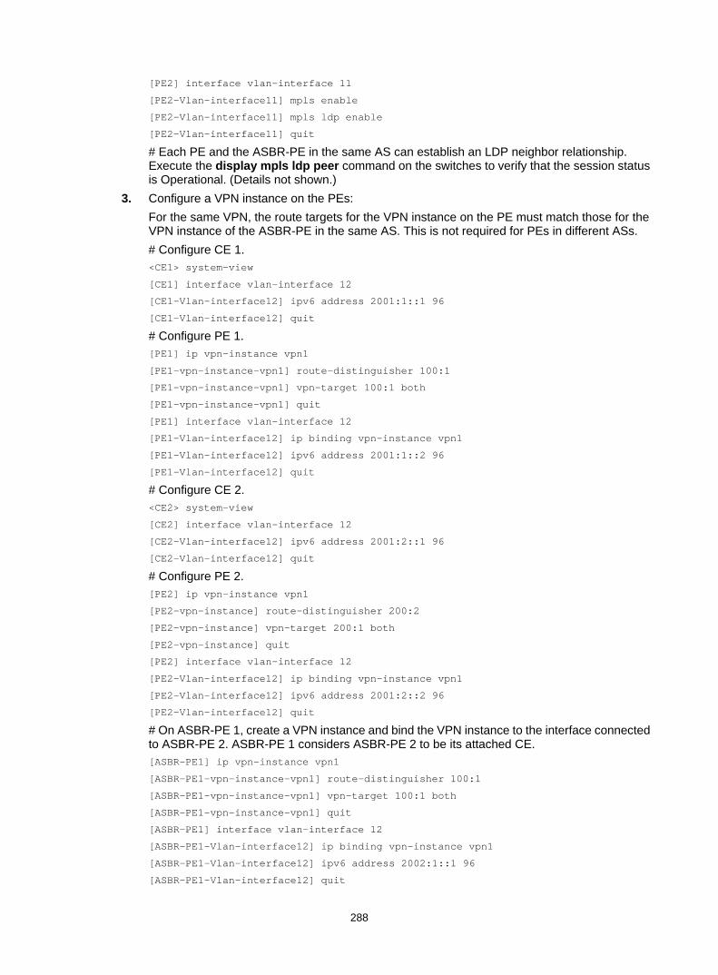
288
[PE2] interface vlan-interface 11
[PE2-Vlan-interface11] mpls enable
[PE2-Vlan-interface11] mpls ldp enable
[PE2-Vlan-interface11] quit
# Each PE and the ASBR-PE in the same AS can establish an LDP neighbor relationship. Execute the display mpls ldp peer command on the switches to verify that the session status is Operational. (Details not shown.)
3. Configure a VPN instance on the PEs: For the same VPN, the route targets for the VPN instance on the PE must match those for the VPN instance of the ASBR-PE in the same AS. This is not required for PEs in different ASs. # Configure CE 1. <CE1> system-view
[CE1] interface vlan-interface 12
[CE1-Vlan-interface12] ipv6 address 2001:1::1 96
[CE1-Vlan-interface12] quit
# Configure PE 1. [PE1] ip vpn-instance vpn1
[PE1-vpn-instance-vpn1] route-distinguisher 100:1
[PE1-vpn-instance-vpn1] vpn-target 100:1 both
[PE1-vpn-instance-vpn1] quit
[PE1] interface vlan-interface 12
[PE1-Vlan-interface12] ip binding vpn-instance vpn1
[PE1-Vlan-interface12] ipv6 address 2001:1::2 96
[PE1-Vlan-interface12] quit
# Configure CE 2. <CE2> system-view
[CE2] interface vlan-interface 12
[CE2-Vlan-interface12] ipv6 address 2001:2::1 96
[CE2-Vlan-interface12] quit
# Configure PE 2. [PE2] ip vpn-instance vpn1
[PE2-vpn-instance] route-distinguisher 200:2
[PE2-vpn-instance] vpn-target 200:1 both
[PE2-vpn-instance] quit
[PE2] interface vlan-interface 12
[PE2-Vlan-interface12] ip binding vpn-instance vpn1
[PE2-Vlan-interface12] ipv6 address 2001:2::2 96
[PE2-Vlan-interface12] quit
# On ASBR-PE 1, create a VPN instance and bind the VPN instance to the interface connected to ASBR-PE 2. ASBR-PE 1 considers ASBR-PE 2 to be its attached CE. [ASBR-PE1] ip vpn-instance vpn1
[ASBR-PE1-vpn-instance-vpn1] route-distinguisher 100:1
[ASBR-PE1-vpn-instance-vpn1] vpn-target 100:1 both
[ASBR-PE1-vpn-instance-vpn1] quit
[ASBR-PE1] interface vlan-interface 12
[ASBR-PE1-Vlan-interface12] ip binding vpn-instance vpn1
[ASBR-PE1-Vlan-interface12] ipv6 address 2002:1::1 96
[ASBR-PE1-Vlan-interface12] quit

289
# On ASBR-PE 2, create a VPN instance and bind the VPN instance to the interface connected to ASBR-PE 1. ASBR-PE 2 considers ASBR-PE 1 to be its attached CE. [ASBR-PE2] ip vpn-instance vpn1
[ASBR-PE2-vpn-vpn-vpn1] route-distinguisher 200:1
[ASBR-PE2-vpn-vpn-vpn1] vpn-target 200:1 both
[ASBR-PE2-vpn-vpn-vpn1] quit
[ASBR-PE2] interface vlan-interface 12
[ASBR-PE2-Vlan-interface12] ip binding vpn-instance vpn1
[ASBR-PE2-Vlan-interface12] ipv6 address 2002:1::2 96
[ASBR-PE2-Vlan-interface12] quit
# Execute the display ip vpn-instance command to display VPN instance configurations. Verify that each PE can ping its attached CE, and ASBR-PE 1 and ASBR-PE 2 can ping each other. (Details not shown.)
4. Establish an EBGP peer relationship between PE and CE switches, and redistribute VPN routes into BGP: # Configure CE 1. [CE1] bgp 65001
[CE1-bgp] peer 2001:1::2 as-number 100
[CE1-bgp] address-family ipv6 unicast
[CE1-bgp-ipv6] peer 2001:1::2 enable
[CE1-bgp-ipv6] import-route direct
[CE1-bgp-ipv6] quit
[CE1-bgp] quit
# Configure PE 1. [PE1] bgp 100
[PE1-bgp] ip vpn-instance vpn1
[PE1-bgp-vpn1] peer 2001:1::1 as-number 65001
[PE1-bgp-vpn1] address-family ipv6 unicast
[PE1-bgp-ipv6-vpn1] peer 2001:1::1 enable
[PE1-bgp-ipv6-vpn1] quit
[PE1-bgp-vpn1] quit
[PE1-bgp] quit
# Configure CE 2. [CE2] bgp 65002
[CE2-bgp] peer 2001:2::2 as-number 200
[CE2-bgp] address-family ipv6
[CE2-bgp-ipv6] peer 2001:2::2 enable
[CE2-bgp-ipv6] import-route direct
[CE2-bgp-ipv6] quit
[CE2-bgp] quit
# Configure PE 2. [PE2] bgp 200
[PE2-bgp] ip vpn-instance vpn1
[PE2-bgp-vpn1] peer 2001:2::1 as-number 65002
[PE2-bgp-vpn1] address-family ipv6 unicast
[PE2-bgp-ipv6-vpn1] peer 2001:2::1 enable
[PE2-bgp-ipv6-vpn1] quit
[PE2-bgp-vpn1] quit
[PE2-bgp] quit

290
5. Establish an IBGP peer relationship between each PE and the ASBR-PE in the same AS, and an EBGP peer relationship between the ASBR-PEs: # Configure PE 1. [PE1] bgp 100
[PE1-bgp] peer 2.2.2.9 as-number 100
[PE1-bgp] peer 2.2.2.9 connect-interface loopback 0
[PE1-bgp] address-family vpnv6
[PE1-bgp-vpnv6] peer 2.2.2.9 enable
[PE1-bgp-vpnv6] quit
[PE1-bgp] quit
# Configure ASBR-PE 1. [ASBR-PE1] bgp 100
[ASBR-PE1-bgp] ip vpn-instance vpn1
[ASBR-PE1-bgp-vpn1] peer 2002:1::2 as-number 200
[ASBR-PE1-bgp-vpn1] address-family ipv6 unicast
[ASBR-PE1-bgp-ipv6-vpn1] peer 2002:1::2 enable
[ASBR-PE1-bgp-ipv6-vpn1] quit
[ASBR-PE1-bgp-vpn1] quit
[ASBR-PE1-bgp] peer 1.1.1.9 as-number 100
[ASBR-PE1-bgp] peer 1.1.1.9 connect-interface loopback 0
[ASBR-PE1-bgp] address-family vpnv6
[ASBR-PE1-bgp-vpnv6] peer 1.1.1.9 enable
[ASBR-PE1-bgp-vpnv6] quit
[ASBR-PE1-bgp] quit
# Configure ASBR-PE 2. [ASBR-PE2] bgp 200
[ASBR-PE2-bgp] ip vpn-instance vpn1
[ASBR-PE2-bgp-vpn1] peer 2002:1::1 as-number 100
[ASBR-PE2-bgp-vpn1] address-family ipv6 unicast
[ASBR-PE2-bgp-ipv6-vpn1] peer 2002:1::1 enable
[ASBR-PE2-bgp-ipv6-vpn1] quit
[ASBR-PE2-bgp-vpn1] quit
[ASBR-PE2-bgp] peer 4.4.4.9 as-number 200
[ASBR-PE2-bgp] peer 4.4.4.9 connect-interface loopback 0
[ASBR-PE2-bgp] address-family vpnv6
[ASBR-PE2-bgp-vpnv6] peer 4.4.4.9 enable
[ASBR-PE2-bgp-vpnv6] quit
[ASBR-PE2-bgp] quit
# Configure PE 2. [PE2] bgp 200
[PE2-bgp] peer 3.3.3.9 as-number 200
[PE2-bgp] peer 3.3.3.9 connect-interface loopback 0
[PE2-bgp] address-family vpnv6
[PE2-bgp-vpnv6] peer 3.3.3.9 enable
[PE2-bgp-vpnv6] quit
[PE2-bgp] quit
Verifying the configuration # Verify that the CEs can learn the route to each other and can ping each other. (Details not shown.)

291
Configuring IPv6 MPLS L3VPN inter-AS option C Network requirements
Site 1 and Site 2 belong to the same VPN. Site 1 accesses the network through PE 1 in AS 100. Site 2 accesses the network through PE 2 in AS 600. PEs in the same AS run IS-IS.
PE 1 and ASBR-PE 1 exchange labeled IPv4 routes by IBGP. PE 2 and ASBR-PE 2 exchange labeled IPv4 routes by IBGP. PE 1 and PE 2 use MP-EBGP to exchange VPNv6 routes.
ASBR-PE 1 and ASBR-PE 2 use their respective routing policies and label the routes received from each other.
ASBR-PE 1 and ASBR-PE 2 use EBGP to exchange labeled IPv4 routes.
Figure 79 Network diagram
Table 27 Interface and IP address assignment
Device Interface IP address Device Interface IP address PE 1 Loop0 2.2.2.9/32 PE 2 Loop0 5.5.5.9/32
Vlan-int11 1.1.1.2/8 Vlan-int11 9.1.1.2/8
Vlan-int12 2001::1/64 Vlan-int12 2002::1/64
ASBR-PE 1 Loop0 3.3.3.9/32 ASBR-PE 2 Loop0 4.4.4.9/32
Vlan-int11 1.1.1.1/8 Vlan-int11 9.1.1.1/8
Vlan-int12 11.0.0.2/8 Vlan-int12 11.0.0.1/8
CE 1 Vlan-int12 2001::2/64 CE 2 Vlan-int12 2002::2/64
Configuration procedure 1. Configure CE 1:
# Configure an IPv6 address for VLAN-interface 12. <CE1> system-view
[CE1] interface vlan-interface 12
[CE1-Vlan-interface12] ip address 2001::2 64
[CE1-Vlan-interface12] quit
PE 1
MPLS backbone MPLS backbone
ASBR-PE 1 ASBR-PE 2
Vlan-int11
Vlan-int11
Vlan-int11
Loop0
Loop0 Loop0
Loop0
PE 2Site 1 Site 2
MP-EBGP
AS 100 AS 600
Vlan-int12 Vlan-int12
Vlan-int11
CE 1 CE 2
Site 1 Site 2
Vlan-int12
Vlan-int12
Vlan-int12
Vlan-int12
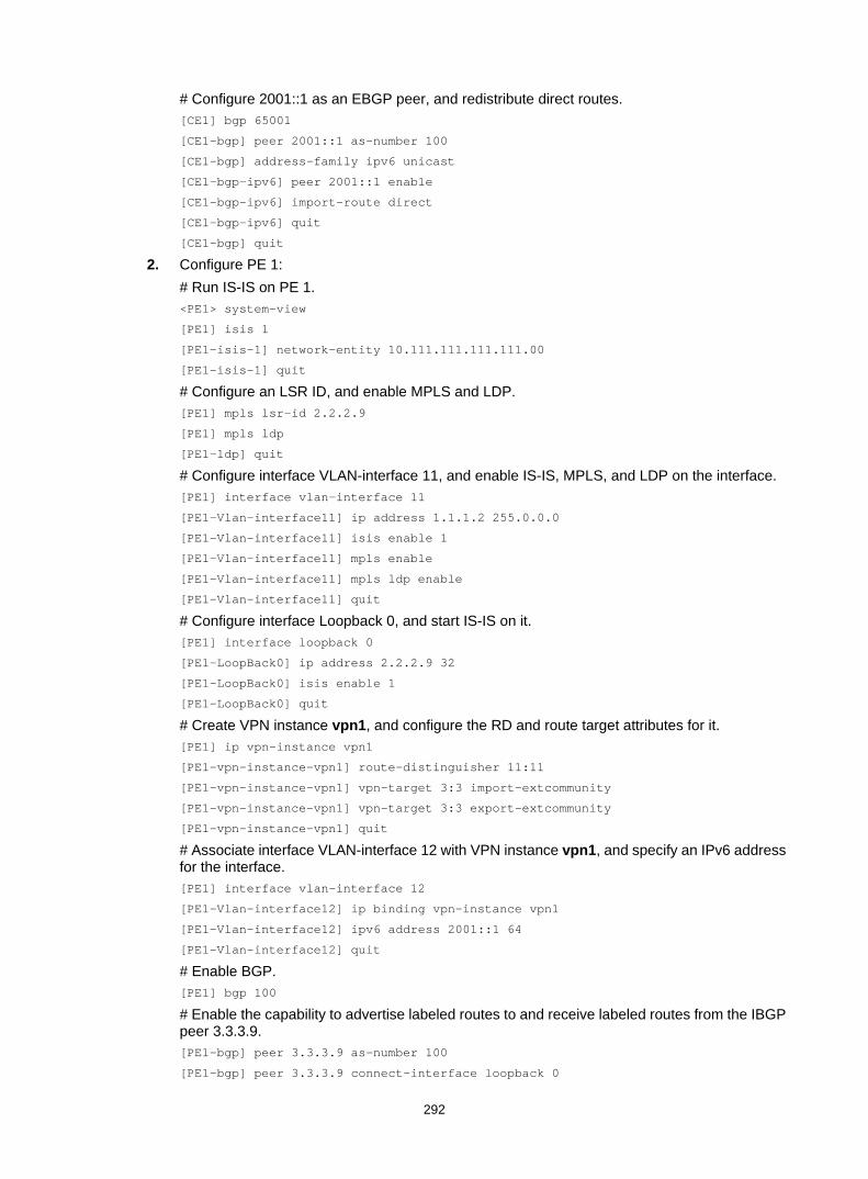
292
# Configure 2001::1 as an EBGP peer, and redistribute direct routes. [CE1] bgp 65001
[CE1-bgp] peer 2001::1 as-number 100
[CE1-bgp] address-family ipv6 unicast
[CE1-bgp-ipv6] peer 2001::1 enable
[CE1-bgp-ipv6] import-route direct
[CE1-bgp-ipv6] quit
[CE1-bgp] quit
2. Configure PE 1: # Run IS-IS on PE 1. <PE1> system-view
[PE1] isis 1
[PE1-isis-1] network-entity 10.111.111.111.111.00
[PE1-isis-1] quit
# Configure an LSR ID, and enable MPLS and LDP. [PE1] mpls lsr-id 2.2.2.9
[PE1] mpls ldp
[PE1-ldp] quit
# Configure interface VLAN-interface 11, and enable IS-IS, MPLS, and LDP on the interface. [PE1] interface vlan-interface 11
[PE1-Vlan-interface11] ip address 1.1.1.2 255.0.0.0
[PE1-Vlan-interface11] isis enable 1
[PE1-Vlan-interface11] mpls enable
[PE1-Vlan-interface11] mpls ldp enable
[PE1-Vlan-interface11] quit
# Configure interface Loopback 0, and start IS-IS on it. [PE1] interface loopback 0
[PE1-LoopBack0] ip address 2.2.2.9 32
[PE1-LoopBack0] isis enable 1
[PE1-LoopBack0] quit
# Create VPN instance vpn1, and configure the RD and route target attributes for it. [PE1] ip vpn-instance vpn1
[PE1-vpn-instance-vpn1] route-distinguisher 11:11
[PE1-vpn-instance-vpn1] vpn-target 3:3 import-extcommunity
[PE1-vpn-instance-vpn1] vpn-target 3:3 export-extcommunity
[PE1-vpn-instance-vpn1] quit
# Associate interface VLAN-interface 12 with VPN instance vpn1, and specify an IPv6 address for the interface. [PE1] interface vlan-interface 12
[PE1-Vlan-interface12] ip binding vpn-instance vpn1
[PE1-Vlan-interface12] ipv6 address 2001::1 64
[PE1-Vlan-interface12] quit
# Enable BGP. [PE1] bgp 100
# Enable the capability to advertise labeled routes to and receive labeled routes from the IBGP peer 3.3.3.9. [PE1-bgp] peer 3.3.3.9 as-number 100
[PE1-bgp] peer 3.3.3.9 connect-interface loopback 0

293
[PE1-bgp] address-family ipv4 unicast
[PE1-bgp-ipv4] peer 3.3.3.9 enable
[PE1-bgp-ipv4] peer 3.3.3.9 label-route-capability
[PE1-bgp-ipv4] quit
# Configure the maximum hop count from PE 1 to EBGP peer 5.5.5.9 as 10. [PE1-bgp] peer 5.5.5.9 as-number 600
[PE1-bgp] peer 5.5.5.9 connect-interface loopback 0
[PE1-bgp] peer 5.5.5.9 ebgp-max-hop 10
# Configure peer 5.5.5.9 as a VPNv6 peer. [PE1-bgp] address-family vpnv6
[PE1-bgp-vpnv6] peer 5.5.5.9 enable
[PE1-bgp-vpnv6] quit
# Configure 2001::2 as an EBGP peer, and redistribute BGP routes to the routing table of vpn1. [PE1-bgp] ip vpn-instance vpn1
[PE1-bgp-vpn1] peer 2001::2 as-number 65001
[PE1-bgp-vpn1] address-family ipv6 unicast
[PE1-bgp-ipv6-vpn1] peer 2001::2 enable
[PE1-bgp-ipv6-vpn1] quit
[PE1-bgp-vpn1] quit
[PE1-bgp] quit
3. Configure ASBR-PE 1: # Start IS-IS on ASBR-PE 1. <ASBR-PE1> system-view
[ASBR-PE1] isis 1
[ASBR-PE1-isis-1] network-entity 10.222.222.222.222.00
[ASBR-PE1-isis-1] quit
# Configure an LSR ID, and enable MPLS and LDP. [ASBR-PE1] mpls lsr-id 3.3.3.9
[ASBR-PE1] mpls ldp
[ASBR-PE1-ldp] quit
# Configure interface VLAN-interface 11, and enable IS-IS, MPLS, and LDP on the interface. [ASBR-PE1] interface vlan-interface 11
[ASBR-PE1-Vlan-interface11] ip address 1.1.1.1 255.0.0.0
[ASBR-PE1-Vlan-interface11] isis enable 1
[ASBR-PE1-Vlan-interface11] mpls enable
[ASBR-PE1-Vlan-interface11] mpls ldp enable
[ASBR-PE1-Vlan-interface11] quit
# Configure interface VLAN-interface 12, and enable MPLS on it. [ASBR-PE1] interface vlan-interface 12
[ASBR-PE1-Vlan-interface12] ip address 11.0.0.2 255.0.0.0
[ASBR-PE1-Vlan-interface12] mpls enable
[ASBR-PE1-Vlan-interface12] quit
# Configure interface Loopback 0, and start IS-IS on it. [ASBR-PE1] interface loopback 0
[ASBR-PE1-LoopBack0] ip address 3.3.3.9 32
[ASBR-PE1-LoopBack0] isis enable 1
[ASBR-PE1-LoopBack0] quit

294
# Create routing policies. [ASBR-PE1] route-policy policy1 permit node 1
[ASBR-PE1-route-policy-policy1-1] apply mpls-label
[ASBR-PE1-route-policy-policy1-1] quit
[ASBR-PE1] route-policy policy2 permit node 1
[ASBR-PE1-route-policy-policy2-1] if-match mpls-label
[ASBR-PE1-route-policy-policy2-1] apply mpls-label
[ASBR-PE1-route-policy-policy2-1] quit
# Start BGP on ASBR-PE 1 and apply routing policy policy2 to routes advertised to IBGP peer 2.2.2.9 [ASBR-PE1] bgp 100
[ASBR-PE1-bgp] peer 2.2.2.9 as-number 100
[ASBR-PE1-bgp] peer 2.2.2.9 connect-interface loopback 0
[ASBR-PE1-bgp] address-family ipv4 unicast
[ASBR-PE1-bgp-ipv4] peer 2.2.2.9 enable
[ASBR-PE1-bgp-ipv4] peer 2.2.2.9 route-policy policy2 export
# Enable the capability to advertise labeled routes to and receive labeled routes from IBGP peer 2.2.2.9. [ASBR-PE1-bgp-ipv4] peer 2.2.2.9 label-route-capability
# Redistribute routes from IS-IS process 1. [ASBR-PE1-bgp-ipv4] import-route isis 1
[ASBR-PE1-bgp-ipv4] quit
# Apply routing policy policy1 to routes advertised to EBGP peer 11.0.0.1. [ASBR-PE1-bgp] peer 11.0.0.1 as-number 600
[ASBR-PE1-bgp] address-family ipv4 unicast
[ASBR-PE1-bgp-ipv4] peer 11.0.0.1 enable
[ASBR-PE1-bgp-ipv4] peer 11.0.0.1 route-policy policy1 export
# Enable the capability to advertise labeled routes to and receive labeled routes from EBGP peer 11.0.0.1. [ASBR-PE1-bgp-ipv4] peer 11.0.0.1 label-route-capability
[ASBR-PE1-bgp-ipv4] quit
[ASBR-PE1-bgp] quit
4. Configure ASBR-PE 2: # Start IS-IS on ASBR-PE 2. <ASBR-PE2> system-view
[ASBR-PE2] isis 1
[ASBR-PE2-isis-1] network-entity 10.333.333.333.333.00
[ASBR-PE2-isis-1] quit
# Configure an LSR ID, and enable MPLS and LDP. [ASBR-PE2] mpls lsr-id 4.4.4.9
[ASBR-PE2] mpls ldp
[ASBR-PE2-ldp] quit
# Configure interface VLAN-interface 11, and enable IS-IS, MPLS, and LDP on the interface. [ASBR-PE2] interface vlan-interface 11
[ASBR-PE2-Vlan-interface11] ip address 9.1.1.1 255.0.0.0
[ASBR-PE2-Vlan-interface11] isis enable 1
[ASBR-PE2-Vlan-interface11] mpls enable
[ASBR-PE2-Vlan-interface11] mpls ldp enable

295
[ASBR-PE2-Vlan-interface11] quit
# Configure interface Loopback 0, and start IS-IS on it. [ASBR-PE2] interface loopback 0
[ASBR-PE2-LoopBack0] ip address 4.4.4.9 32
[ASBR-PE2-LoopBack0] isis enable 1
[ASBR-PE2-LoopBack0] quit
# Configure interface VLAN-interface 12, and enable MPLS on it. [ASBR-PE2] interface vlan-interface 12
[ASBR-PE2-Vlan-interface12] ip address 11.0.0.1 255.0.0.0
[ASBR-PE2-Vlan-interface12] mpls enable
[ASBR-PE2-Vlan-interface12] quit
# Create routing policies. [ASBR-PE2] route-policy policy1 permit node 1
[ASBR-PE2-route-policy-policy1-1] apply mpls-label
[ASBR-PE2-route-policy-policy1-1] quit
[ASBR-PE2] route-policy policy2 permit node 1
[ASBR-PE2-route-policy-policy2-1] if-match mpls-label
[ASBR-PE2-route-policy-policy2-1] apply mpls-label
[ASBR-PE2-route-policy-policy2-1] quit
# Start BGP on ASBR-PE 2, and enable the capability to advertise labeled routes to and receive labeled routes from IBGP peer 5.5.5.9. [ASBR-PE2] bgp 600
[ASBR-PE2-bgp] peer 5.5.5.9 as-number 600
[ASBR-PE2-bgp] peer 5.5.5.9 connect-interface loopback 0
[ASBR-PE2-bgp] address-family ipv4 unicast
[ASBR-PE2-bgp-ipv4] peer 5.5.5.9 enable
[ASBR-PE2-bgp-ipv4] peer 5.5.5.9 label-route-capability
# Apply routing policy policy2 to routes advertised to IBGP peer 5.5.5.9. [ASBR-PE2-bgp-ipv4] peer 5.5.5.9 route-policy policy2 export
# Redistribute routes from IS-IS process 1 [ASBR-PE2-bgp-ipv4] import-route isis 1
[ASBR-PE2-bgp-ipv4] quit
# Apply routing policy policy1 to routes advertised to EBGP peer 11.0.0.2. [ASBR-PE2-bgp] peer 11.0.0.2 as-number 100
[ASBR-PE2-bgp] address-family ipv4 unicast
[ASBR-PE2-bgp-ipv4] peer 11.0.0.2 enable
[ASBR-PE2-bgp-ipv4] peer 11.0.0.2 route-policy policy1 export
# Enable the capability to advertise labeled routes to and receive labeled routes from EBGP peer 11.0.0.2. [ASBR-PE2-bgp-ipv4] peer 11.0.0.2 label-route-capability
[ASBR-PE2-bgp-ipv4] quit
[ASBR-PE2-bgp] quit
5. Configure PE 2: # Enable IS-IS on PE 2. <PE2> system-view
[PE2] isis 1
[PE2-isis-1] network-entity 10.444.444.444.444.00
[PE2-isis-1] quit

296
# Configure an LSR ID, and enable MPLS and LDP. [PE2] mpls lsr-id 5.5.5.9
[PE2] mpls ldp
[PE2-ldp] quit
# Configure interface VLAN-interface 11, and enable IS-IS, MPLS, and LDP on the interface. [PE2] interface vlan-interface 11
[PE2-Vlan-interface11] ip address 9.1.1.2 255.0.0.0
[PE2-Vlan-interface11] isis enable 1
[PE2-Vlan-interface11] mpls enable
[PE2-Vlan-interface11] mpls ldp enable
[PE2-Vlan-interface11] quit
# Configure interface Loopback 0, and start IS-IS on it. [PE2] interface loopback 0
[PE2-LoopBack0] ip address 5.5.5.9 32
[PE2-LoopBack0] isis enable 1
[PE2-LoopBack0] quit
# Create VPN instance vpn1, and configure the RD and route target attributes for it. [PE2] ip vpn-instance vpn1
[PE2-vpn-instance-vpn1] route-distinguisher 11:11
[PE2-vpn-instance-vpn1] vpn-target 3:3 import-extcommunity
[PE2-vpn-instance-vpn1] vpn-target 3:3 export-extcommunity
[PE2-vpn-instance-vpn1] quit
# Associate interface VLAN-interface 12 with VPN instance vpn1, and specify an IPv6 address for the interface. [PE2] interface vlan-interface 12
[PE2-Vlan-interface12] ip binding vpn-instance vpn1
[PE2-Vlan-interface12] ipv6 address 2002::1 64
[PE2-Vlan-interface12] quit
# Enable BGP on PE 2. [PE2] bgp 600
# Configure the capability to advertise labeled routes to IBGP peer 4.4.4.9 and to receive labeled routes from the peer. [PE2-bgp] peer 4.4.4.9 as-number 600
[PE2-bgp] peer 4.4.4.9 connect-interface loopback 0
[PE2-bgp] address-family ipv4 unicast
[PE2-bgp-ipv4] peer 4.4.4.9 enable
[PE2-bgp-ipv4] peer 4.4.4.9 label-route-capability
[PE2-bgp-ipv4] quit
# Configure the maximum hop count from PE 2 to EBGP peer 2.2.2.9 as 10. [PE2-bgp] peer 2.2.2.9 as-number 100
[PE2-bgp] peer 2.2.2.9 connect-interface loopback 0
[PE2-bgp] peer 2.2.2.9 ebgp-max-hop 10
# Configure peer 2.2.2.9 as a VPNv6 peer. [PE2-bgp] address-family vpnv6
[PE2-bgp-vpnv6] peer 2.2.2.9 enable
[PE2-bgp-vpnv6] quit
# Configure 2002::2 as an EBGP peer, and redistribute BGP routes to the routing table of vpn1. [PE2-bgp] ip vpn-instance vpn1

297
[PE2-bgp-vpn1] peer 2002::2 as-number 65002
[PE2-bgp-vpn1] address-family ipv6 unicast
[PE2-bgp-ipv6-vpn1] peer 2002::2 enable
[PE2-bgp-ipv6-vpn1] quit
[PE2-bgp-vpn1] quit
[PE2-bgp] quit
6. Configure CE 2: # Configure an IPv6 address for VLAN-interface 12. <CE2> system-view
[CE2] interface vlan-interface 12
[CE2-Vlan-interface12] ip address 2002::2 64
[CE2-Vlan-interface12] quit
# Configure 2002::1 as an EBGP peer, and redistribute direct routes. [CE2] bgp 65002
[CE2-bgp] peer 2002::1 as-number 600
[CE2-bgp] address-family ipv6 unicast
[CE2-bgp-ipv6] peer 2002::1 enable
[CE2-bgp-ipv6] import-route direct
[CE2-bgp-ipv6] quit
[CE2-bgp] quit
Verifying the configuration # Execute the display ipv6 routing table command on CE 1 and CE 2 to verify that CE 1 and CE 2 have a route to each other. Verify that CE 1 and CE 2 can ping each other. (Details not shown.)
Configuring IPv6 MPLS L3VPN carrier's carrier Network requirements
Configure carrier's carrier for the scenario shown in Figure 80. In this scenario: • PE 1 and PE 2 are the provider carrier's PE switches. They provide VPN services for the
customer carrier. • CE 1 and CE 2 are the customer carrier's switches. They connect to the provider carrier's
backbone as CE switches. • PE 3 and PE 4 are the customer carrier's PE switches. They provide IPv6 MPLS L3VPN
services for end customers. • CE 3 and CE 4 are customers of the customer carrier.
The key to the carrier's carrier deployment is to configure exchange of two kinds of routes: • Exchange of the customer carrier's internal routes on the provider carrier's backbone. • Exchange of the end customers' internal routes between PE 3 and PE 4, the PEs of the
customer carrier. An MP-IBGP peer relationship must be established between PE 3 and PE 4.
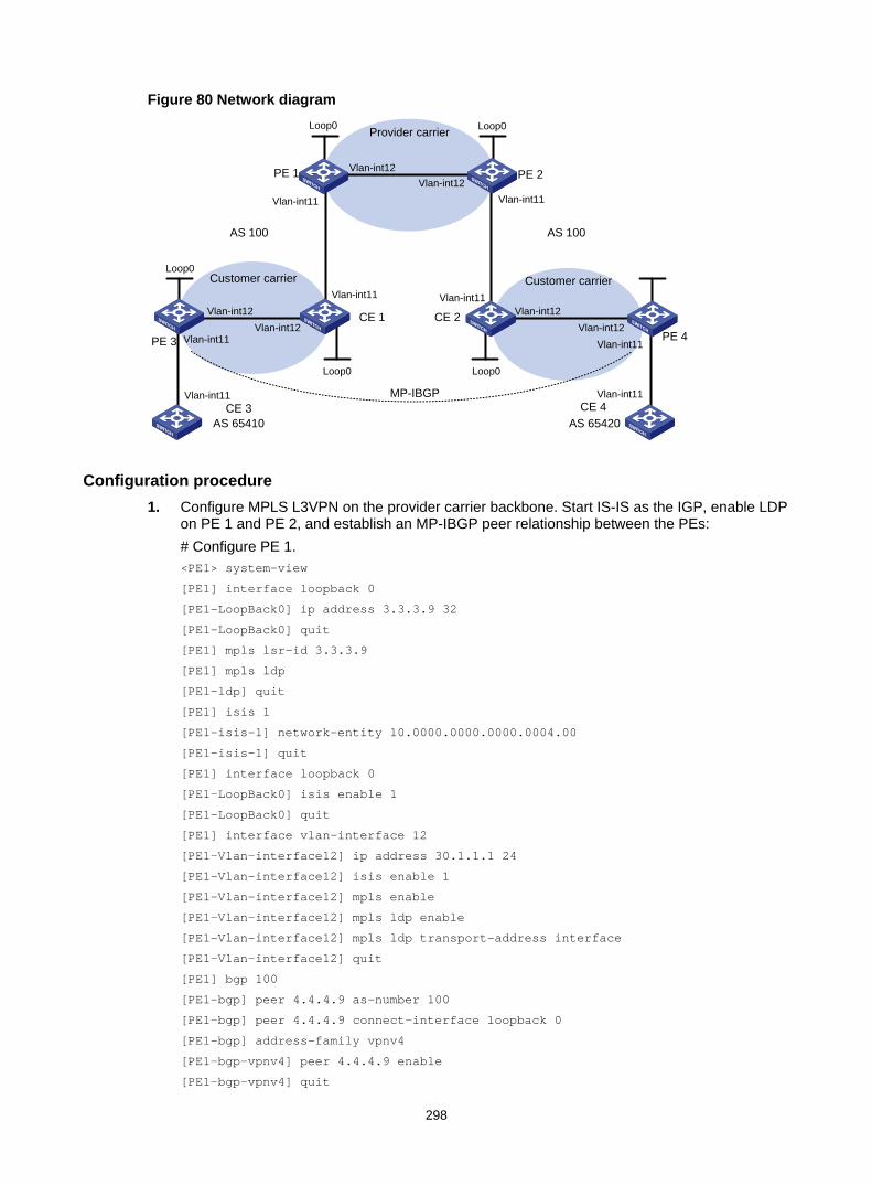
298
Figure 80 Network diagram
Configuration procedure 1. Configure MPLS L3VPN on the provider carrier backbone. Start IS-IS as the IGP, enable LDP
on PE 1 and PE 2, and establish an MP-IBGP peer relationship between the PEs: # Configure PE 1. <PE1> system-view
[PE1] interface loopback 0
[PE1-LoopBack0] ip address 3.3.3.9 32
[PE1-LoopBack0] quit
[PE1] mpls lsr-id 3.3.3.9
[PE1] mpls ldp
[PE1-ldp] quit
[PE1] isis 1
[PE1-isis-1] network-entity 10.0000.0000.0000.0004.00
[PE1-isis-1] quit
[PE1] interface loopback 0
[PE1-LoopBack0] isis enable 1
[PE1-LoopBack0] quit
[PE1] interface vlan-interface 12
[PE1-Vlan-interface12] ip address 30.1.1.1 24
[PE1-Vlan-interface12] isis enable 1
[PE1-Vlan-interface12] mpls enable
[PE1-Vlan-interface12] mpls ldp enable
[PE1-Vlan-interface12] mpls ldp transport-address interface
[PE1-Vlan-interface12] quit
[PE1] bgp 100
[PE1-bgp] peer 4.4.4.9 as-number 100
[PE1-bgp] peer 4.4.4.9 connect-interface loopback 0
[PE1-bgp] address-family vpnv4
[PE1-bgp-vpnv4] peer 4.4.4.9 enable
[PE1-bgp-vpnv4] quit
PE 1 PE 2
Provider carrier
Customer carrier
PE 4CE 2CE 1
PE 3
CE 3 CE 4AS 65410 AS 65420
Loop0 Loop0
Loop0Customer carrier
Vlan-int11
Loop0 Loop0
AS 100 AS 100
Vlan-int11
Vlan-int12Vlan-int12
Vlan-int11
Vlan-int11
Vlan-int12Vlan-int12
Vlan-int11
Vlan-int11Vlan-int12
Vlan-int12Vlan-int11
Vlan-int11MP-IBGP
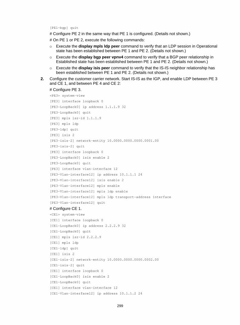
299
[PE1-bgp] quit
# Configure PE 2 in the same way that PE 1 is configured. (Details not shown.) # On PE 1 or PE 2, execute the following commands: Execute the display mpls ldp peer command to verify that an LDP session in Operational
state has been established between PE 1 and PE 2. (Details not shown.) Execute the display bgp peer vpnv4 command to verify that a BGP peer relationship in
Established state has been established between PE 1 and PE 2. (Details not shown.) Execute the display isis peer command to verify that the IS-IS neighbor relationship has
been established between PE 1 and PE 2. (Details not shown.) 2. Configure the customer carrier network. Start IS-IS as the IGP, and enable LDP between PE 3
and CE 1, and between PE 4 and CE 2: # Configure PE 3. <PE3> system-view
[PE3] interface loopback 0
[PE3-LoopBack0] ip address 1.1.1.9 32
[PE3-LoopBack0] quit
[PE3] mpls lsr-id 1.1.1.9
[PE3] mpls ldp
[PE3-ldp] quit
[PE3] isis 2
[PE3-isis-2] network-entity 10.0000.0000.0000.0001.00
[PE3-isis-2] quit
[PE3] interface loopback 0
[PE3-LoopBack0] isis enable 2
[PE3-LoopBack0] quit
[PE3] interface vlan-interface 12
[PE3-Vlan-interface12] ip address 10.1.1.1 24
[PE3-Vlan-interface12] isis enable 2
[PE3-Vlan-interface12] mpls enable
[PE3-Vlan-interface12] mpls ldp enable
[PE3-Vlan-interface12] mpls ldp transport-address interface
[PE3-Vlan-interface12] quit
# Configure CE 1. <CE1> system-view
[CE1] interface loopback 0
[CE1-LoopBack0] ip address 2.2.2.9 32
[CE1-LoopBack0] quit
[CE1] mpls lsr-id 2.2.2.9
[CE1] mpls ldp
[CE1-ldp] quit
[CE1] isis 2
[CE1-isis-2] network-entity 10.0000.0000.0000.0002.00
[CE1-isis-2] quit
[CE1] interface loopback 0
[CE1-LoopBack0] isis enable 2
[CE1-LoopBack0] quit
[CE1] interface vlan-interface 12
[CE1-Vlan-interface12] ip address 10.1.1.2 24

300
[CE1-Vlan-interface12] isis enable 2
[CE1-Vlan-interface12] mpls enable
[CE1-Vlan-interface12] mpls ldp enable
[CE1-Vlan-interface12] mpls ldp transport-address interface
[CE1-Vlan-interface12] quit
PE 3 and CE 1 can establish an LDP session and IS-IS neighbor relationship between them. # Configure PE 4 and CE 2 in the same way that PE 3 and CE 1 are configured. (Details not shown.)
3. Connect the customer carrier to the provider carrier: # Configure PE 1. [PE1] ip vpn-instance vpn1
[PE1-vpn-instance-vpn1] route-distinguisher 200:1
[PE1-vpn-instance-vpn1] vpn-target 1:1
[PE1-vpn-instance-vpn1] quit
[PE1] mpls ldp
[PE1-ldp] vpn-instance vpn1
[PE1-ldp-vpn-instance-vpn1] quit
[PE1-ldp] quit
[PE1] isis 2 vpn-instance vpn1
[PE1-isis-2] network-entity 10.0000.0000.0000.0003.00
[PE1-isis-2] import-route bgp allow-ibgp
[PE1-isis-2] quit
[PE1] interface vlan-interface11
[PE1-Vlan-interface11] ip binding vpn-instance vpn1
[PE1-Vlan-interface11] ip address 11.1.1.2 24
[PE1-Vlan-interface11] isis enable 2
[PE1-Vlan-interface11] mpls enable
[PE1-Vlan-interface11] mpls ldp enable
[PE1-Vlan-interface11] mpls ldp transport-address interface
[PE1-Vlan-interface11] quit
[PE1] bgp 100
[PE1-bgp] ip vpn-instance vpn1
[PE1-bgp-vpn1] address-family ipv4 unicast
[PE1-bgp-ipv4-vpn1] import isis 2
[PE1-bgp-ipv4-vpn1] quit
[PE1-bgp-vpn1] quit
[PE1-bgp] quit
# Configure CE 1. [CE1] interface vlan-interface11
[CE1-Vlan-interface11] ip address 11.1.1.1 24
[CE1-Vlan-interface11] isis enable 2
[CE1-Vlan-interface11] mpls enable
[CE1-Vlan-interface11] mpls ldp enable
[CE1-Vlan-interface11] mpls ldp transport-address interface
[CE1-Vlan-interface11] quit
PE 1 and CE 1 can establish an LDP session and IS-IS neighbor relationship between them. # Configure PE 2 and CE 2 in the same way that PE 1 and CE 1 are configured. (Details not shown.)

301
4. Connect end customers to the customer carrier: # Configure CE 3. <CE3> system-view
[CE3] interface vlan-interface11
[CE3-Vlan-interface11] ipv6 address 2001:1::1 96
[CE3-Vlan-interface11] quit
[CE3] bgp 65410
[CE3-bgp] peer 2001:1::2 as-number 100
[CE3-bgp] address-family ipv6
[CE3-bgp-ipv6] peer 2001:1::2 enable
[CE3-bgp-ipv6] import-route direct
[CE3-bgp-ipv6] quit
[CE3-bgp] quit
# Configure PE 3. [PE3] ip vpn-instance vpn1
[PE3-vpn-instance-vpn1] route-distinguisher 100:1
[PE3-vpn-instance-vpn1] vpn-target 1:1
[PE3-vpn-instance-vpn1] quit
[PE3] interface Vlan-interface11
[PE3-Vlan-interface11] ip binding vpn-instance vpn1
[PE3-Vlan-interface11] ipv6 address 2001:1::2 96
[PE3-Vlan-interface11] quit
[PE3] bgp 100
[PE3-bgp] ip vpn-instance vpn1
[PE3-bgp-vpn1] peer 2001:1::1 as-number 65410
[PE3-bgp-vpn1] address-family ipv6 unicast
[PE3-bgp-ipv6-vpn1] peer 2001:1::1 enable
[PE3-bgp-ipv6-vpn1] import-route direct
[PE3-bgp-ipv6-vpn1] quit
[PE3-bgp-vpn1] quit
[PE3-bgp] quit
# Configure PE 4 and CE 4 in the same way that PE 3 and CE 3 are configured. (Details not shown.)
5. Establish an MP-IBGP peer relationship between PEs of the customer carrier to exchange the VPN routes of the customer carrier's customers: # Configure PE 3. [PE3] bgp 100
[PE3-bgp] peer 6.6.6.9 as-number 100
[PE3-bgp] peer 6.6.6.9 connect-interface loopback 0
[PE3-bgp] address-family vpnv6
[PE3-bgp-vpnv6] peer 6.6.6.9 enable
[PE3-bgp-vpnv6] quit
[PE3-bgp] quit
# Configure PE 3 in the same way that PE 3 is configured. (Details not shown.)
Verifying the configuration 1. Display the public network routing table and VPN routing table on the provider carrier PEs, for
example, on PE 1:

302
# Verify that the public network routing table contains only routes of the provider carrier network. [PE1] display ip routing-table
Destinations : 14 Routes : 14
Destination/Mask Proto Pre Cost NextHop Interface
0.0.0.0/32 Direct 0 0 127.0.0.1 InLoop0
3.3.3.9/32 Direct 0 0 127.0.0.1 InLoop0
4.4.4.9/32 ISIS 15 10 30.1.1.2 Vlan12
30.1.1.0/24 Direct 0 0 30.1.1.1 Vlan12
30.1.1.0/32 Direct 0 0 30.1.1.1 Vlan12
30.1.1.1/32 Direct 0 0 127.0.0.1 InLoop0
30.1.1.255/32 Direct 0 0 30.1.1.1 Vlan12
127.0.0.0/8 Direct 0 0 127.0.0.1 InLoop0
127.0.0.0/32 Direct 0 0 127.0.0.1 InLoop0
127.0.0.1/32 Direct 0 0 127.0.0.1 InLoop0
127.255.255.255/32 Direct 0 0 127.0.0.1 InLoop0
224.0.0.0/4 Direct 0 0 0.0.0.0 NULL0
224.0.0.0/24 Direct 0 0 0.0.0.0 NULL0
255.255.255.255/32 Direct 0 0 127.0.0.1 InLoop0
# Verify that the VPN routing table contains the internal routes of the customer carrier network. [PE1] display ip routing-table vpn-instance vpn1
Destinations : 18 Routes : 18
Destination/Mask Proto Pre Cost NextHop Interface
0.0.0.0/32 Direct 0 0 127.0.0.1 InLoop0
1.1.1.9/32 ISIS 15 20 11.1.1.1 Vlan11
2.2.2.9/32 ISIS 15 10 11.1.1.1 Vlan11
5.5.5.9/32 BGP 255 10 4.4.4.9 Vlan12
6.6.6.9/32 BGP 255 20 4.4.4.9 Vlan12
10.1.1.0/24 ISIS 15 20 11.1.1.1 Vlan11
11.1.1.0/24 Direct 0 0 11.1.1.2 Vlan11
11.1.1.0/32 Direct 0 0 11.1.1.2 Vlan11
11.1.1.2/32 Direct 0 0 127.0.0.1 InLoop0
11.1.1.255/32 Direct 0 0 11.1.1.2 Vlan11
20.1.1.0/24 BGP 255 20 4.4.4.9 Vlan12
127.0.0.0/8 Direct 0 0 127.0.0.1 InLoop0
127.0.0.0/32 Direct 0 0 127.0.0.1 InLoop0
127.0.0.1/32 Direct 0 0 127.0.0.1 InLoop0
127.255.255.255/32 Direct 0 0 127.0.0.1 InLoop0
224.0.0.0/4 Direct 0 0 0.0.0.0 NULL0
224.0.0.0/24 Direct 0 0 0.0.0.0 NULL0
255.255.255.255/32 Direct 0 0 127.0.0.1 InLoop0
2. Verify that the routing table contains the internal routes of the customer carrier network on the customer carrier CEs, for example, on CE 1. [CE1] display ip routing-table
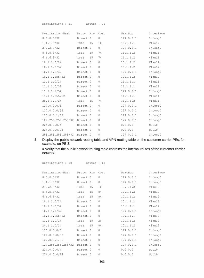
303
Destinations : 21 Routes : 21
Destination/Mask Proto Pre Cost NextHop Interface
0.0.0.0/32 Direct 0 0 127.0.0.1 InLoop0
1.1.1.9/32 ISIS 15 10 10.1.1.1 Vlan12
2.2.2.9/32 Direct 0 0 127.0.0.1 InLoop0
5.5.5.9/32 ISIS 15 74 11.1.1.2 Vlan11
6.6.6.9/32 ISIS 15 74 11.1.1.2 Vlan11
10.1.1.0/24 Direct 0 0 10.1.1.2 Vlan12
10.1.1.0/32 Direct 0 0 10.1.1.2 Vlan12
10.1.1.2/32 Direct 0 0 127.0.0.1 InLoop0
10.1.1.255/32 Direct 0 0 10.1.1.2 Vlan12
11.1.1.0/24 Direct 0 0 11.1.1.1 Vlan11
11.1.1.0/32 Direct 0 0 11.1.1.1 Vlan11
11.1.1.1/32 Direct 0 0 127.0.0.1 InLoop0
11.1.1.255/32 Direct 0 0 11.1.1.1 Vlan11
20.1.1.0/24 ISIS 15 74 11.1.1.2 Vlan11
127.0.0.0/8 Direct 0 0 127.0.0.1 InLoop0
127.0.0.0/32 Direct 0 0 127.0.0.1 InLoop0
127.0.0.1/32 Direct 0 0 127.0.0.1 InLoop0
127.255.255.255/32 Direct 0 0 127.0.0.1 InLoop0
224.0.0.0/4 Direct 0 0 0.0.0.0 NULL0
224.0.0.0/24 Direct 0 0 0.0.0.0 NULL0
255.255.255.255/32 Direct 0 0 127.0.0.1 InLoop0
3. Display the public network routing table and VPN routing table on the customer carrier PEs, for example, on PE 3: # Verify that the public network routing table contains the internal routes of the customer carrier network.
Destinations : 18 Routes : 18
Destination/Mask Proto Pre Cost NextHop Interface
0.0.0.0/32 Direct 0 0 127.0.0.1 InLoop0
1.1.1.9/32 Direct 0 0 127.0.0.1 InLoop0
2.2.2.9/32 ISIS 15 10 10.1.1.2 Vlan12
5.5.5.9/32 ISIS 15 84 10.1.1.2 Vlan12
6.6.6.9/32 ISIS 15 84 10.1.1.2 Vlan12
10.1.1.0/24 Direct 0 0 10.1.1.1 Vlan12
10.1.1.0/32 Direct 0 0 10.1.1.1 Vlan12
10.1.1.1/32 Direct 0 0 127.0.0.1 InLoop0
10.1.1.255/32 Direct 0 0 10.1.1.1 Vlan12
11.1.1.0/24 ISIS 15 20 10.1.1.2 Vlan12
20.1.1.0/24 ISIS 15 84 10.1.1.2 Vlan12
127.0.0.0/8 Direct 0 0 127.0.0.1 InLoop0
127.0.0.0/32 Direct 0 0 127.0.0.1 InLoop0
127.0.0.1/32 Direct 0 0 127.0.0.1 InLoop0
127.255.255.255/32 Direct 0 0 127.0.0.1 InLoop0
224.0.0.0/4 Direct 0 0 0.0.0.0 NULL0
224.0.0.0/24 Direct 0 0 0.0.0.0 NULL0
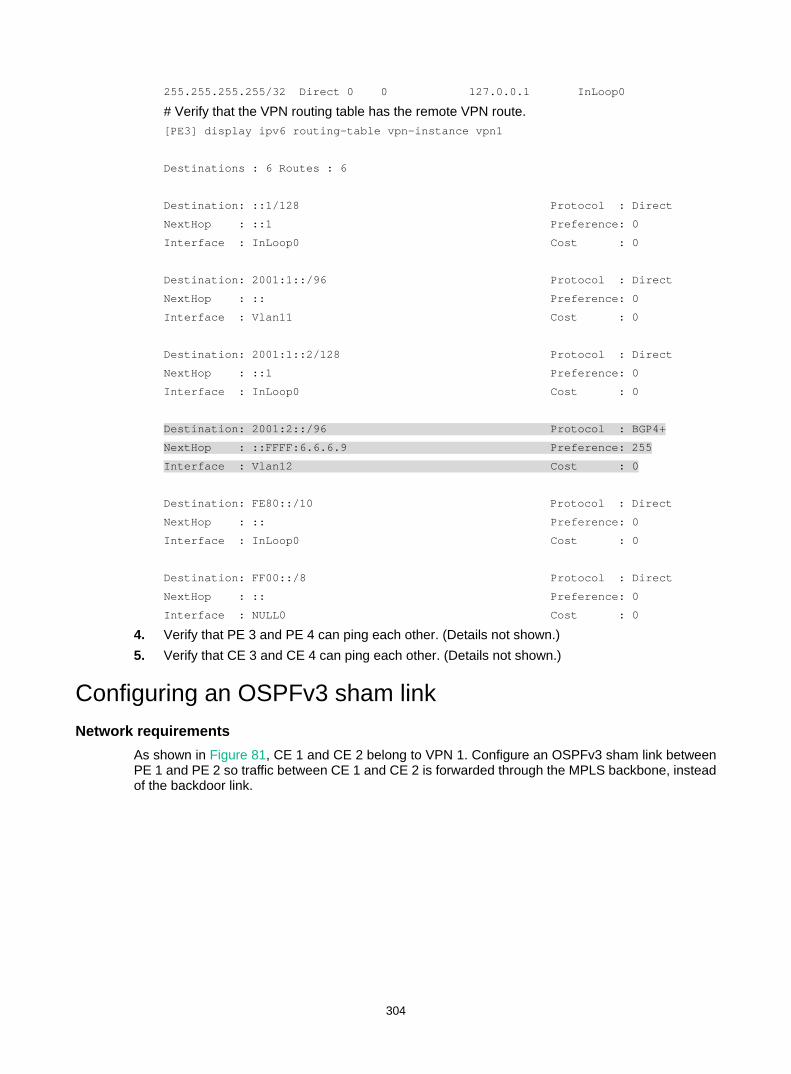
304
255.255.255.255/32 Direct 0 0 127.0.0.1 InLoop0
# Verify that the VPN routing table has the remote VPN route. [PE3] display ipv6 routing-table vpn-instance vpn1
Destinations : 6 Routes : 6
Destination: ::1/128 Protocol : Direct
NextHop : ::1 Preference: 0
Interface : InLoop0 Cost : 0
Destination: 2001:1::/96 Protocol : Direct
NextHop : :: Preference: 0
Interface : Vlan11 Cost : 0
Destination: 2001:1::2/128 Protocol : Direct
NextHop : ::1 Preference: 0
Interface : InLoop0 Cost : 0
Destination: 2001:2::/96 Protocol : BGP4+
NextHop : ::FFFF:6.6.6.9 Preference: 255
Interface : Vlan12 Cost : 0
Destination: FE80::/10 Protocol : Direct
NextHop : :: Preference: 0
Interface : InLoop0 Cost : 0
Destination: FF00::/8 Protocol : Direct
NextHop : :: Preference: 0
Interface : NULL0 Cost : 0
4. Verify that PE 3 and PE 4 can ping each other. (Details not shown.) 5. Verify that CE 3 and CE 4 can ping each other. (Details not shown.)
Configuring an OSPFv3 sham link Network requirements
As shown in Figure 81, CE 1 and CE 2 belong to VPN 1. Configure an OSPFv3 sham link between PE 1 and PE 2 so traffic between CE 1 and CE 2 is forwarded through the MPLS backbone, instead of the backdoor link.

305
Figure 81 Network diagram
Table 28 Interface and IP address assignment
Device Interface IP address Device Interface IP address CE 1 Vlan-int11 100::1/64 CE 2 Vlan-int11 120::1/64
Vlan-int13 20::1/64 Vlan-int12 30::2/64
PE 1 Loop0 1.1.1.9/32 PE 2 Loop0 2.2.2.9/32
Loop1 3::3/128 Loop1 5::5/128
Vlan-int11 100::2/64 Vlan-int11 120::2/64
Vlan-int12 10.1.1.1/24 Vlan-int12 10.1.1.2/24
Switch A Vlan-int11 30::1/64
Vlan-int12 20::2/64
Configuration procedure 1. Configure OSPFv3 on the customer networks.
Configure conventional OSPFv3 on CE 1, Switch A, and CE 2 to advertise subnet addresses of the interfaces as shown in Figure 81. Set the cost value to 2 for both the link between CE 1 and Switch A, and the link between CE 2 and Switch A. Execute the display ipv6 routing-table command to verify that CE 1 and CE 2 have each learned the OSPFv3 route to VLAN-interface 11 of the other. (Details not shown.)
2. Configure IPv6 MPLS L3VPN on the backbone: # Configure basic MPLS and MPLS LDP on PE 1 to establish LDP LSPs. <PE1> system-view
[PE1] interface loopback 0
[PE1-LoopBack0] ip address 1.1.1.9 32
[PE1-LoopBack0] quit
[PE1] mpls lsr-id 1.1.1.9
[PE1] mpls ldp
[PE1-ldp] quit
[PE1] interface vlan-interface 12
[PE1-Vlan-interface12] ip address 10.1.1.1 24
[PE1-Vlan-interface12] mpls enable
Vlan-int12
Loop0 Loop0
Sham-link
CE 1 Switch A CE 2
PE 2PE 1
Loop1 Loop1
OSPFv3 Area 1
Backdoor link
Vlan-int12 Vlan-int11
Vlan-int11Vlan-int13
Vlan-int11
Vlan-int11
Vlan-int12 Vlan-int12Vlan-int13

306
[PE1-Vlan-interface12] mpls ldp enable
[PE1-Vlan-interface12] quit
# Configure PE 1 to take PE 2 as an MP-IBGP peer. [PE1] bgp 100
[PE1-bgp] peer 2.2.2.9 as-number 100
[PE1-bgp] peer 2.2.2.9 connect-interface loopback 0
[PE1-bgp] address-family vpnv6
[PE1-bgp-vpnv6] peer 2.2.2.9 enable
[PE1-bgp-vpnv6] quit
[PE1-bgp] quit
# Configure OSPF on PE 1. [PE1] ospf 1
[PE1-ospf-1] area 0
[PE1-ospf-1-area-0.0.0.0] network 1.1.1.9 0.0.0.0
[PE1-ospf-1-area-0.0.0.0] network 10.1.1.0 0.0.0.255
[PE1-ospf-1-area-0.0.0.0] quit
[PE1-ospf-1] quit
# Configure basic MPLS and MPLS LDP on PE 2 to establish LDP LSPs. <PE2> system-view
[PE2] interface loopback 0
[PE2-LoopBack0] ip address 2.2.2.9 32
[PE2-LoopBack0] quit
[PE2] mpls lsr-id 2.2.2.9
[PE2] mpls ldp
[PE2-ldp] quit
[PE2] interface vlan-interface 12
[PE2-Vlan-interface12] ip address 10.1.1.2 24
[PE2-Vlan-interface12] mpls enable
[PE2-Vlan-interface12] mpls ldp enable
[PE2-Vlan-interface12] quit
# Configure PE 2 to take PE 1 as an MP-IBGP peer. [PE2] bgp 100
[PE2-bgp] peer 1.1.1.9 as-number 100
[PE2-bgp] peer 1.1.1.9 connect-interface loopback 0
[PE2-bgp] address-family vpnv6
[PE2-bgp-vpnv6] peer 1.1.1.9 enable
[PE2-bgp-vpnv6] quit
[PE2-bgp] quit
# Configure OSPF on PE 2. [PE2] ospf 1
[PE2-ospf-1] area 0
[PE2-ospf-1-area-0.0.0.0] network 2.2.2.9 0.0.0.0
[PE2-ospf-1-area-0.0.0.0] network 10.1.1.0 0.0.0.255
[PE2-ospf-1-area-0.0.0.0] quit
[PE2-ospf-1] quit
3. Configure PEs to allow CE access: # Configure PE 1. [PE1] ip vpn-instance vpn1
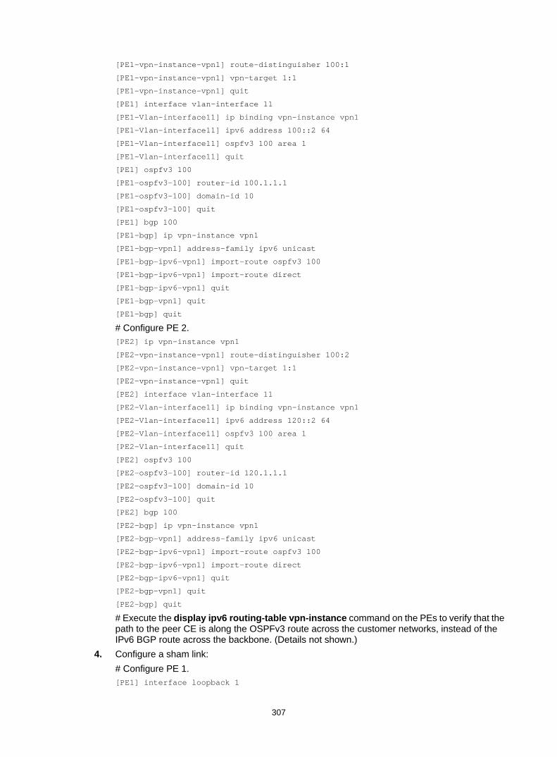
307
[PE1-vpn-instance-vpn1] route-distinguisher 100:1
[PE1-vpn-instance-vpn1] vpn-target 1:1
[PE1-vpn-instance-vpn1] quit
[PE1] interface vlan-interface 11
[PE1-Vlan-interface11] ip binding vpn-instance vpn1
[PE1-Vlan-interface11] ipv6 address 100::2 64
[PE1-Vlan-interface11] ospfv3 100 area 1
[PE1-Vlan-interface11] quit
[PE1] ospfv3 100
[PE1-ospfv3-100] router-id 100.1.1.1
[PE1-ospfv3-100] domain-id 10
[PE1-ospfv3-100] quit
[PE1] bgp 100
[PE1-bgp] ip vpn-instance vpn1
[PE1-bgp-vpn1] address-family ipv6 unicast
[PE1-bgp-ipv6-vpn1] import-route ospfv3 100
[PE1-bgp-ipv6-vpn1] import-route direct
[PE1-bgp-ipv6-vpn1] quit
[PE1-bgp-vpn1] quit
[PE1-bgp] quit
# Configure PE 2. [PE2] ip vpn-instance vpn1
[PE2-vpn-instance-vpn1] route-distinguisher 100:2
[PE2-vpn-instance-vpn1] vpn-target 1:1
[PE2-vpn-instance-vpn1] quit
[PE2] interface vlan-interface 11
[PE2-Vlan-interface11] ip binding vpn-instance vpn1
[PE2-Vlan-interface11] ipv6 address 120::2 64
[PE2-Vlan-interface11] ospfv3 100 area 1
[PE2-Vlan-interface11] quit
[PE2] ospfv3 100
[PE2-ospfv3-100] router-id 120.1.1.1
[PE2-ospfv3-100] domain-id 10
[PE2-ospfv3-100] quit
[PE2] bgp 100
[PE2-bgp] ip vpn-instance vpn1
[PE2-bgp-vpn1] address-family ipv6 unicast
[PE2-bgp-ipv6-vpn1] import-route ospfv3 100
[PE2-bgp-ipv6-vpn1] import-route direct
[PE2-bgp-ipv6-vpn1] quit
[PE2-bgp-vpn1] quit
[PE2-bgp] quit
# Execute the display ipv6 routing-table vpn-instance command on the PEs to verify that the path to the peer CE is along the OSPFv3 route across the customer networks, instead of the IPv6 BGP route across the backbone. (Details not shown.)
4. Configure a sham link: # Configure PE 1. [PE1] interface loopback 1

308
[PE1-LoopBack1] ip binding vpn-instance vpn1
[PE1-LoopBack1] ipv6 address 3::3 128
[PE1-LoopBack1] quit
[PE1] ospfv3 100
[PE1-ospfv3-100] area 1
[PE1-ospfv3-100-area-0.0.0.1] sham-link 3::3 5::5
[PE1-ospfv3-100-area-0.0.0.1] quit
[PE1-ospfv3-100] quit
# Configure PE 2. [PE2] interface loopback 1
[PE2-LoopBack1] ip binding vpn-instance vpn1
[PE2-LoopBack1] ipv6 address 5::5 128
[PE2-LoopBack1] quit
[PE2] ospfv3 100
[PE2-ospfv3-100] area 1
[PE2-ospfv3-100-area-0.0.0.1] sham-link 5::5 3::3
[PE2-ospfv3-100-area-0.0.0.1] quit
[PE2-ospfv3-100] quit
Verifying the configuration # Execute the display ipv6 routing-table vpn-instance command on the PEs to verify the following results (details not shown): • The path to the peer CE is now along the IPv6 BGP route across the backbone. • A route to the sham link destination address exists.
# Execute the display ipv6 routing-table command on the CEs to verify that the next hop of the OSPFv3 route to the peer CE is the VLAN interface connected to the PE. The VPN traffic to the peer is forwarded over the backbone. (Details not shown.)
# Verify that a sham link has been established on PEs, for example, on PE 1. [PE1] display ospfv3 sham-link
OSPFv3 Process 100 with Router ID 100.1.1.1
Sham-link (Area: 0.0.0.1)
Neighbor ID State Instance ID Destination address
120.1.1.1 P-2-P 0 5::5
# Verify that the peer state is Full on PE 1. [PE1] display ospfv3 sham-link verbose
OSPFv3 Process 100 with Router ID 100.1.1.1
Sham-link (Area: 0.0.0.1)
Source : 3::3
Destination : 5::5
Interface ID: 2147483649
Neighbor ID : 120.1.1.1, Neighbor state: Full
Cost: 1 State: P-2-P Type: Sham Instance ID: 0
Timers: Hello 10, Dead 40, Retransmit 5, Transmit delay 1

309
Request list: 0 Retransmit list: 0

310
Configuring MPLS L2VPN MPLS L2VPN provides point-to-point and point-to-multipoint connections. This chapter describes only the MPLS L2VPN technologies that provide point-to-point connections. For information about the MPLS L2VPN technologies that provide point-to-multipoint connections, see "Configuring VPLS."
Overview MPLS L2VPN is an implementation of Pseudo Wire Emulation Edge-to-Edge (PWE3). It offers Layer 2 VPN services over an MPLS or IP backbone. MPLS L2VPN can transparently transmit Layer 2 data for different data link layer protocols, including Ethernet, VLAN, ATM, FR, and PPP.
From a user's perspective, the MPLS or IP backbone is a Layer 2 switched network. For example, when two Ethernet networks are connected through MPLS L2VPN over an MPLS backbone, Ethernet users think they are connected directly through an Ethernet.
Basic concepts of MPLS L2VPN • Customer edge—A CE is a customer device directly connected to the service provider
network. • Provider edge—A PE is a service provider device connected to one or more CEs. It provides
VPN access by mapping and forwarding packets between user networks and public tunnels. • Attachment circuit—An AC is a link between a CE and a PE, such as an FR DLCI, ATM
VPI/VCI, Ethernet interface, VLAN, or PPP connection. • Pseudowire—A PW is a virtual bidirectional connection between two PEs. An MPLS PW
comprises a pair of LSPs in opposite directions. • Public tunnel—A public tunnel is a connection that carries one or more PWs across the MPLS
or IP backbone. It can be an LSP tunnel or an MPLS TE tunnel. • Cross-connect—A cross-connect concatenates two physical or virtual circuits such as ACs
and PWs. It switches packets between the two physical or virtual circuits. Cross-connects include AC to AC cross-connect, AC to PW cross-connect, and PW to PW cross-connect.
• Site ID—A site ID uniquely identifies a site in a VPN. Sites in different VPNs can have the same site ID.
• Route distinguisher—A route distinguisher (RD) is added before a site ID to distinguish the sites that have the same site ID but reside in different VPNs. An RD and a site ID uniquely identify a VPN site.
• Label block—A label block is a set of labels. It includes the following parameters: Label base—The LB specifies the initial label value of the label block. A PE automatically
selects an LB value that cannot be manually modified. Label range—The LR specifies the number of labels that the label block contains. The LB
and LR determine the labels contained in the label block. For example, if the LB is 1000 and the LR is 5, the label block contains labels 1000 through 1004.
Label-block offset—The LO specifies the offset of a label block. If the existing label block becomes insufficient as the VPN sites increase, you can add a new label block to enlarge the label range. A PE uses an LO to identify the position of the new label block. The LO value of a label block is the sum of the LRs of all previously assigned label blocks. For example, if the LR and LO of the first label block are 10 and 0, the LO of the second label block is 10. If the LR of the second label block is 20, the LO of the third label block is 30.
A label block whose LB, LO, and LR are 1000, 10, and 5 is represented as 1000/10/5.

311
Assume that a VPN has 10 sites, and a PE assigns the first label block LB1/0/10 to the VPN. When another 15 sites are added, the PE keeps the first label block and assigns the second label block LB2/10/15 to extend the network. LB1 and LB2 are the initial label values that are randomly selected by the PE.
• Route target—PEs use the BGP route target attribute (also called VPN target attribute) to manage BGP L2VPN information advertisement. PEs support the following types of route target attributes: Export target attribute—When a PE sends L2VPN information to the peer PE in a BGP
update message, it sets the route target attribute in the update message to an export target. L2VPN information includes the site ID, RD, and label block.
Import target attribute—When a PE receives an update message from the peer PE, it checks the route target attribute in the update message. If the route target value matches an import target, the PE accepts the L2VPN information in the update message.
Route target attributes determine from which PEs a PE can receive L2VPN information.
MPLS L2VPN network models As shown in Figure 82, this model connects two CEs through a PW on an MPLS or IP backbone.
Figure 82 MPLS L2VPN network model
To set up an MPLS L2VPN connection: 1. Set up a public tunnel to carry one or more PWs between PEs:
The public tunnel can be an LSP or MPLS TE tunnel. If multiple public tunnels exist between two PEs, you can configure a tunnel policy to control tunnel selection. For more information about tunnel policies, see "Configuring tunnel policies." If a PW is established over an LSP or MPLS TE tunnel, packets on the PW have two labels. The outer label is the public LSP or MPLS TE tunnel label that MPLS uses to forward the packet to the peer PE. The inner label is the PW label that the peer PE uses to forward the packet to the destination CE.
2. Set up a PW to connect customer networks: PWs include static PWs, LDP PWs, BGP PWs, and Circuit Cross Connect (CCC) PWs. To establish a static PW, configure the peer PE address, and the incoming and outgoing PW labels for the PW on the two PEs. Static PWs consume a small amount of resources but have complex configurations. To establish an LDP PW, configure LDP and specify the peer PE address on the two PEs. LDP defines a new FEC type named PW ID FEC for PEs to exchange PW-label bindings. The new FEC type uses a PW ID and a PW data encapsulation type to identify a PW. The PW ID is the ID of the PW between PEs. The PW data encapsulation type specifies the encapsulation type for data transmitted over the PW, such as ATM, FR, Ethernet, or VLAN. PEs advertise the PW label and PW ID FEC in label mapping messages to create a PW. Dynamic PWs have simple configurations but consume more resources than static PWs.
CE 1 CE 2
PE 1 PE 2
Tunnel
PW
ACAC
MPLS or IP backbone
Customer network
Customer network

312
To establish BGP PWs, BGP advertises label block information in an extended BGP update to PEs in the same VPN. Each PE uses the received label block information to calculate outgoing labels and uses its own label block to calculate incoming labels. After two PEs complete label calculation, a BGP PW is established between them. BGP PWs have the following features: Simplified configuration—There is no need to manually specify peer PEs. A PE
automatically find peer PEs after receiving label block information from the peer PEs. Reduced workload—Label block advertisement enables assigning labels for multiple PWs
at one time. To establish a CCC PW, manually specify the incoming and outgoing labels for the CCC PW on the PEs, and create two static LSPs in opposite directions on P devices between PEs. CCC employs only one level of label to transfer packets. The static LSPs on the P devices transfer data only for the CCC PW. They cannot be used by other connections or MPLS L3VPN.
3. Set up an AC between a PE and a CE: Set up an AC by configuring a link layer connection between a PE and a CE. An AC is an Ethernet service instance on a Layer 2 Ethernet interface or Layer 2 aggregate interface. The interface forwards incoming packets that match the Ethernet service instance to the bound PW.
4. Bind the AC to the PW: Bind the Ethernet service instance to the PW, so the PE forwards packets between the AC and the PW.
PW redundancy PW redundancy provides redundant links between PEs so that the customer networks can communicate when the path over one PW fails. As shown in Figure 83, PE 1 establishes two PWs (one primary and one backup). The CEs communicate through the primary PW. When the primary PW fails, PE 1 brings up the backup PW and forwards packets from CE 1 to CE 2 through the backup PW. When CE 2 receives the packets, it updates its MAC address table, so that packets from CE 2 to CE 1 also travel through the backup PW. Only static PWs and LDP PWs support PW redundancy.
Figure 83 PW redundancy
The MPLS L2VPN determines whether the primary PW fails according to the LDP session status or the BFD result. The backup PW is used when one of the following conditions exists: • The public tunnel of the primary PW is deleted, or BFD detects that the public tunnel has failed. • The primary PW is deleted because the LDP session between PEs goes down, or BFD detects
that the primary PW has failed. • A manual PW switchover is performed.
CE 1
PE 3
PE 1
PE 2
CE 2
MPLS or IP backbone
Primary PW
Backup PW

313
Multi-segment PW A multi-segment PW includes multiple concatenated static or LDP PWs. Creating two PWs for a cross-connect on a PE can concatenate the two PWs. Upon receiving a packet from one PW, the PE removes the tunnel ID and PW label of the packet, adds the PW label of the other PW, and forwards the packet over the public tunnel. Only static and LDP PWs can form a multi-segment PW.
As shown in Figure 84, to create a multi-segment PW between PE 1 and PE 4, you can concatenate PW 1 and PW 2 on PE 2, and PW 2 and PW 3 on PE 3.
Figure 84 Multi-segment PW
Multi-segment PWs include intra-domain multi-segment PWs and inter-domain multi-segment PWs.
Intra-domain multi-segment PW An intra-domain multi-segment PW has concatenated PWs within an AS. You can create an intra-domain multi-segment PW between two PEs that have no public tunnel to each other.
As shown in Figure 85, there is no public tunnel between PE 1 and PE 4. There is a public tunnel between PE 1 and PE 2 and a public tunnel between PE 2 and PE 4. To create an intra-domain multi-segment PW between PE 1 and PE 4, you can perform the following operations: 1. Create a PW between PE 1 and PE 2 (PW 1) and a PW between PE 2 and PE 4 (PW 2). 2. Concatenate the two PWs on PE 2.
Intra-domain multi-segment PWs can fully use existing public tunnels to reduce end-to-end public tunnels.
CE 1
PE 1 PE 4
PE 2 PE 3
PW 1 PW
3
CE 2
PW 2
MPLS or IP backbone
PW

314
Figure 85 Intra-domain multi-segment PW
Inter-domain multi-segment PW An inter-domain multi-segment PW has concatenated PWs in different ASs, and is a method for inter-AS option B networking.
As shown in Figure 86, to create an inter-domain multi-segment PW between PE 1 and PE 2 in different ASs, you can perform the following operations: • Concatenate PW 1 and PW 2 on ASBR 1 • Concatenate PW 2 and PW 3 on ASBR 2.
Figure 86 Inter-domain multi-segment PW
VCCV Virtual Circuit Connectivity Verification (VCCV) is an OAM function for L2VPN. It verifies the connectivity of PWs on the data plane. VCCV includes two modes: • Manual mode—Use the ping mpls pw command to manually test the connectivity of a PW. • Auto mode—Configure BFD to automatically test the connectivity of a PW.
For more information about VCCV, see "Configuring MPLS OAM."
CE 1
PE 4
PE 1 PE 2
CE 2
MPLS or IP backbone
PE 3
Tunnel
Tunnel
PW 1
PW 2
PW
CE 1
PE 1 PE 2
ASBR 1 ASBR 2
CE 2
AS 100 AS 200
MPLS or IP backbone MPLS or IP backbone
PW 1 PW
3
PW 2
PW
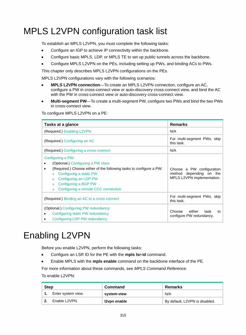
315
MPLS L2VPN configuration task list To establish an MPLS L2VPN, you must complete the following tasks: • Configure an IGP to achieve IP connectivity within the backbone. • Configure basic MPLS, LDP, or MPLS TE to set up public tunnels across the backbone. • Configure MPLS L2VPN on the PEs, including setting up PWs, and binding ACs to PWs.
This chapter only describes MPLS L2VPN configurations on the PEs.
MPLS L2VPN configurations vary with the following scenarios: • MPLS L2VPN connection—To create an MPLS L2VPN connection, configure an AC,
configure a PW in cross-connect view or auto-discovery cross-connect view, and bind the AC with the PW in cross-connect view or auto-discovery cross-connect view.
• Multi-segment PW—To create a multi-segment PW, configure two PWs and bind the two PWs in cross-connect view.
To configure MPLS L2VPN on a PE:
Tasks at a glance Remarks (Required.) Enabling L2VPN N/A
(Required.) Configuring an AC For multi-segment PWs, skip this task.
(Required.) Configuring a cross-connect N/A
Configuring a PW: • (Optional.) Configuring a PW class • (Required.) Choose either of the following tasks to configure a PW:
Configuring a static PW Configuring an LDP PW Configuring a BGP PW Configuring a remote CCC connection
Choose a PW configuration method depending on the MPLS L2VPN implementation.
(Required.) Binding an AC to a cross-connect For multi-segment PWs, skip this task.
(Optional.) Configuring PW redundancy: • Configuring static PW redundancy • Configuring LDP PW redundancy
Choose either task to configure PW redundancy.
Enabling L2VPN Before you enable L2VPN, perform the following tasks: • Configure an LSR ID for the PE with the mpls lsr-id command. • Enable MPLS with the mpls enable command on the backbone interface of the PE.
For more information about these commands, see MPLS Command Reference.
To enable L2VPN:
Step Command Remarks 1. Enter system view. system-view N/A
2. Enable L2VPN. l2vpn enable By default, L2VPN is disabled.
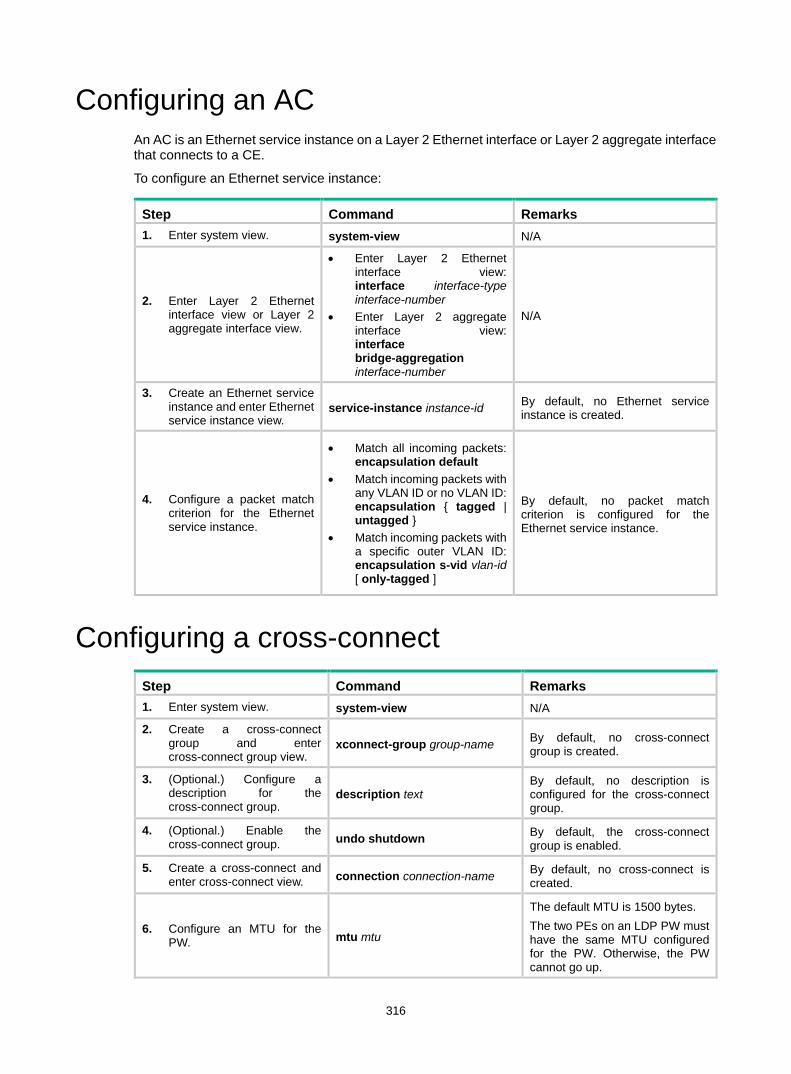
316
Configuring an AC An AC is an Ethernet service instance on a Layer 2 Ethernet interface or Layer 2 aggregate interface that connects to a CE.
To configure an Ethernet service instance:
Step Command Remarks 1. Enter system view. system-view N/A
2. Enter Layer 2 Ethernet interface view or Layer 2 aggregate interface view.
• Enter Layer 2 Ethernet interface view: interface interface-type interface-number
• Enter Layer 2 aggregate interface view: interface bridge-aggregation interface-number
N/A
3. Create an Ethernet service instance and enter Ethernet service instance view.
service-instance instance-id By default, no Ethernet service instance is created.
4. Configure a packet match criterion for the Ethernet service instance.
• Match all incoming packets: encapsulation default
• Match incoming packets with any VLAN ID or no VLAN ID: encapsulation { tagged | untagged }
• Match incoming packets with a specific outer VLAN ID: encapsulation s-vid vlan-id [ only-tagged ]
By default, no packet match criterion is configured for the Ethernet service instance.
Configuring a cross-connect Step Command Remarks 1. Enter system view. system-view N/A
2. Create a cross-connect group and enter cross-connect group view.
xconnect-group group-name By default, no cross-connect group is created.
3. (Optional.) Configure a description for the cross-connect group.
description text By default, no description is configured for the cross-connect group.
4. (Optional.) Enable the cross-connect group. undo shutdown By default, the cross-connect
group is enabled.
5. Create a cross-connect and enter cross-connect view. connection connection-name By default, no cross-connect is
created.
6. Configure an MTU for the PW. mtu mtu
The default MTU is 1500 bytes. The two PEs on an LDP PW must have the same MTU configured for the PW. Otherwise, the PW cannot go up.

317
Configuring a PW Configuring a PW class
You can configure PW attributes such as the PW data encapsulation type and enable control word in a PW class. PWs with the same attributes can use the same PW class.
To configure a PW class:
Step Command Remarks 1. Enter system view. system-view N/A
2. Create a PW class and enter PW class view. pw-class class-name By default, no PW class is
created.
3. (Optional.) Enable control word. control-word enable By default, control word is
disabled.
4. (Optional.) Specify the PW data encapsulation type. pw-type { ethernet | vlan } By default, the PW data
encapsulation type is VLAN.
Configuring a static PW
Step Command Remarks 1. Enter system view. system-view N/A
2. Enter cross-connect group view. xconnect-group group-name N/A
3. Enter cross-connect view. connection connection-name N/A
4. Configure a static PW and enter cross-connect PW view.
peer ip-address pw-id pw-id in-label label-value out-label label-value [ pw-class class-name | tunnel-policy tunnel-policy-name ] *
By default, no static PW is configured.
Configuring an LDP PW Before you configure an LDP PW, enable global and interface MPLS LDP on the PE. For information about MPLS LDP configuration, see "Configuring LDP."
To configure an LDP PW:
Step Command Remarks 1. Enter system view. system-view N/A
2. Enter cross-connect group view. xconnect-group group-name N/A
3. Enter cross-connect view. connection connection-name N/A
4. Configure an LDP PW and enter cross-connect PW view.
peer ip-address pw-id pw-id [ pw-class class-name | tunnel-policy tunnel-policy-name ] *
By default, no LDP PW is configured. After an LDP PW is created, the local PE automatically sends a targeted hello to create an LDP

318
Step Command Remarks session to the peer PE. Then, the PE exchanges the PW ID FEC and PW label mapping with the peer.
Configuring a BGP PW To configure a BGP PW, perform the following configurations on PEs: • Configure BGP to advertise MPLS L2VPN label block information. • Create a BGP PW.
Configuring BGP to advertise MPLS L2VPN label block information
Step Command Remarks 1. Enter system view. system-view N/A
2. Enable BGP and enter BGP view. bgp as-number By default, BGP is not
enabled.
3. Configure the remote PE as a BGP peer.
peer { group-name | ip-address [ mask-length ] } as-number as-number
By default, no BGP peer is configured.
4. Create a BGP L2VPN address family and enter BGP L2VPN address family view.
address-family l2vpn By default, no BGP L2VPN address family is created.
5. Enable BGP to exchange BGP L2VPN information with the specified peer or peer group.
peer { group-name | ip-address [ mask-length ] } enable
By default, BGP cannot exchange BGP L2VPN information with any peer or peer group.
6. Enable BGP to exchange label block information with the specified peer or peer group.
peer { group-name | ip-address [ mask-length ] } signaling [ non-standard ]
By default, BGP can exchange label block information with a BGP L2VPN peer or peer group by using RFC 4761 MP_REACH_NLRI.
7. (Optional.) Permit the local AS number to appear in routes from the specified peer or peer group and specify the appearance times.
peer { group-name | ip-address [ mask-length ] } allow-as-loop [ number ]
By default, the local AS number is not allowed in routes from a peer or peer group.
8. (Optional.) Enable route target-based filtering of incoming BGP L2VPN information.
policy vpn-target By default, route target-based filtering of incoming BGP L2VPN information is enabled.
9. (Optional.) Configure the router as a route reflector and specify a peer or peer group as its client.
peer { group-name | ip-address [ mask-length ] } reflect-client
By default, no route reflector or client is configured.
10. (Optional.) Enable L2VPN information reflection between clients.
reflect between-clients By default, L2VPN information reflection is enabled between clients.
11. (Optional.) Configure the cluster ID of the route reflector.
reflector cluster-id { cluster-id | ip-address }
By default, a route reflector uses its own router ID as the cluster ID.
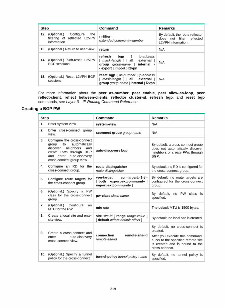
319
Step Command Remarks 12. (Optional.) Configure the
filtering of reflected L2VPN information.
rr-filter extended-community-number
By default, the route reflector does not filter reflected L2VPN information.
13. (Optional.) Return to user view. return N/A
14. (Optional.) Soft-reset L2VPN BGP sessions.
refresh bgp { ip-address [ mask-length ] | all | external | group group-name | internal } { export | import } l2vpn
N/A
15. (Optional.) Reset L2VPN BGP sessions.
reset bgp { as-number | ip-address [ mask-length ] | all | external | group group-name | internal } l2vpn
N/A
For more information about the peer as-number, peer enable, peer allow-as-loop, peer reflect-client, reflect between-clients, reflector cluster-id, refresh bgp, and reset bgp commands, see Layer 3—IP Routing Command Reference.
Creating a BGP PW
Step Command Remarks 1. Enter system view. system-view N/A
2. Enter cross-connect group view. xconnect-group group-name N/A
3. Configure the cross-connect group to automatically discover neighbors and create PWs through BGP and enter auto-discovery cross-connect group view.
auto-discovery bgp
By default, a cross-connect group does not automatically discover neighbors or create PWs through BGP.
4. Configure an RD for the cross-connect group.
route-distinguisher route-distinguisher
By default, no RD is configured for the cross-connect group.
5. Configure route targets for the cross-connect group.
vpn-target vpn-target&<1-8> [ both | export-extcommunity | import-extcommunity ]
By default, no route targets are configured for the cross-connect group.
6. (Optional.) Specify a PW class for the cross-connect group.
pw-class class-name By default, no PW class is specified.
7. (Optional.) Configure an MTU for the PW. mtu mtu The default MTU is 1500 bytes.
8. Create a local site and enter site view.
site site-id [ range range-value ] [ default-offset default-offset ] By default, no local site is created.
9. Create a cross-connect and enter auto-discovery cross-connect view.
connection remote-site-id remote-site-id
By default, no cross-connect is created. After you execute this command, a PW to the specified remote site is created and is bound to the cross-connect.
10. (Optional.) Specify a tunnel policy for the cross-connect. tunnel-policy tunnel-policy-name By default, no tunnel policy is
specified.

320
Configuring a remote CCC connection To configure a remote CCC connection, perform the following configurations on the PE and P devices: • On the two PEs, use the ccc command to specify the incoming and outgoing labels. • On each P device between the two PEs, use the static-lsp transit command to configure a
static LSP for each direction of the CCC connection. For more information about the static-lsp transit command, see MPLS Command References.
Follow these guidelines when you configure a remote CCC connection: • The outgoing label specified on a device must be the same as the incoming label specified on
the next-hop device. • CCC connection settings such as the encapsulation type and control word function must be
consistent on the two PEs. Otherwise, the PEs might fail to forward packets over the CCC connection.
To configure a remote CCC connection:
Step Command Remarks 1. Enter system view. system-view N/A
2. Enter cross-connect group view. xconnect-group group-name N/A
3. Enter cross-connect view. connection connection-name N/A
4. Create a remote CCC connection.
ccc in-label in-label-value out-label out-label-value { nexthop nexthop | out-interface interface-type interface-number } [ pw-class class-name ]
By default, no remote CCC connection is created. Use the out-interface keyword to specify the outgoing interface only on a point-to-point link. On other types of interfaces such as Layer 3 Ethernet interface, VLAN interface, and Layer 3 aggregate interface, you must use the nexthop keyword to specify the IP address of the next hop.
Binding an AC to a cross-connect This task is mutually exclusive with Ethernet link aggregation. If an Ethernet interface has been added to a link aggregation group, you cannot bind an Ethernet service instance on the interface to a cross-connect, and vice versa.
On a Layer 2 Ethernet or Layer 2 aggregate interface, you can create an Ethernet service instance and bind it to a cross-connect. The Ethernet service instance matches packets received on that interface. The matching packets are then forwarded to the bound PW or another AC. An Ethernet service instance can match all packets, tagged packets, or untagged packets.
To bind an Ethernet service instance to a non-BGP cross-connect:
Step Command Remarks 1. Enter system view. system-view N/A
2. Enter cross-connect group view. xconnect-group group-name N/A

321
Step Command Remarks 3. Enter cross-connect view. connection connection-name N/A
4. Bind the Ethernet service instance on the interface to the cross-connect.
ac interface interface-type interface-number service-instance instance-id [ access-mode { ethernet | vlan } ]
By default, no Ethernet service instance is bound to the cross-connect.
To bind an Ethernet service instance to a BGP cross-connect:
Step Command Remarks 1. Enter system view. system-view N/A
2. Enter cross-connect group view. xconnect-group group-name N/A
3. Enter cross-connect group auto-discovery view. auto-discovery bgp N/A
4. Enter site view. site site-id [ range range-value ] [ default-offset default-offset-value ]
N/A
5. Enter auto-discovery cross-connect view.
connection remote-site-id remote-site-id N/A
6. Bind the Ethernet service instance on the interface to the BGP cross-connect.
ac interface interface-type interface-number service-instance instance-id [ access-mode { ethernet | vlan } ]
By default, no Ethernet service instance is bound to the BGP cross-connect.
Configuring PW redundancy This task includes the following configurations: • Create a backup PW for the primary PW. • Specify whether to switch traffic from the backup PW to the primary PW when the primary PW
recovers, and specify the wait time for the switchover. • Manually perform a PW switchover.
Configuring static PW redundancy
Step Command Remarks 1. Enter system view. system-view N/A
2. Enter cross-connect group view. xconnect-group group-name N/A
3. Enter cross-connect view. connection connection-name N/A
4. (Optional.) Specify whether to switch traffic from the backup PW to the primary PW when the primary PW recovers, and specify the wait time for the switchover.
revertive { wtr wtr-time | never } By default, traffic is immediately switched back from the backup PW to the primary PW when the primary PW recovers.

322
Step Command Remarks
5. Enter cross-connect PW view.
peer ip-address pw-id pw-id [ in-label label-value out-label label-value ] [ pw-class class-name | tunnel-policy tunnel-policy-name ] *
N/A
6. Configure a backup cross-connect PW and enter backup cross-connect PW view.
backup-peer ip-address pw-id pw-id in-label label-value out-label label-value [ pw-class class-name | tunnel-policy tunnel-policy-name ] *
By default, no backup PW is configured.
7. Return to user view. return N/A
8. Manually perform a PW switchover.
l2vpn switchover peer ip-address pw-id pw-id N/A
Configuring LDP PW redundancy
Step Command Remarks 1. Enter system view. system-view N/A
2. Enter cross-connect group view. xconnect-group group-name N/A
3. Enter cross-connect view. connection connection-name N/A
4. (Optional.) Specify whether to switch traffic from the backup PW to the primary PW when the primary PW recovers, and specify the wait time for the switchover.
revertive { wtr wtr-time | never } By default, traffic is immediately switched back from the backup PW to the primary PW when the primary PW recovers.
5. Enter cross-connect PW view.
peer ip-address pw-id pw-id [ pw-class class-name | tunnel-policy tunnel-policy-name ] *
N/A
6. Configure a backup LDP PW and enter cross-connect backup PW view.
backup-peer ip-address pw-id pw-id [ pw-class class-name | tunnel-policy tunnel-policy-name ] *
By default, no backup LDP PW is configured.
7. Return to user view. return N/A
8. Manually switch traffic to the backup PW of the specified PW.
l2vpn switchover peer ip-address pw-id pw-id N/A
Displaying and maintaining MPLS L2VPN Execute display commands in any view and reset commands in user view.
Task Command
Display LDP PW label information. display l2vpn ldp [ peer ip-address [ pw-id pw-id ] | xconnect-group group-name ] [ verbose ]
Display cross-connect forwarding display l2vpn forwarding { ac | pw } [ xconnect-group
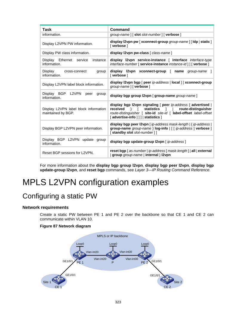
323
Task Command information. group-name ] [ slot slot-number ] [ verbose ]
Display L2VPN PW information. display l2vpn pw [ xconnect-group group-name ] [ ldp | static ] [ verbose ]
Display PW class information. display l2vpn pw-class [ class-name ]
Display Ethernet service instance information.
display l2vpn service-instance [ interface interface-type interface-number [ service-instance instance-id ] ] [ verbose ]
Display cross-connect group information.
display l2vpn xconnect-group [ name group-name ] [ verbose ]
Display L2VPN label block information. display l2vpn bgp [ peer ip-address | local ] [ xconnect-group group-name ] [ verbose ]
Display BGP L2VPN peer group information. display bgp group l2vpn [ group-name group-name ]
Display L2VPN label block information maintained by BGP.
display bgp l2vpn signaling [ peer ip-address { advertised | received } [ statistics ] | route-distinguisher route-distinguisher [ site-id site-id [ label-offset label-offset [ advertise-info ] ] ] | statistics ]
Display BGP L2VPN peer information. display bgp peer l2vpn [ ip-address mask-length | { ip-address | group-name group-name } log-info | [ [ ip-address ] verbose ] [ standby slot slot-number ] ]
Display BGP L2VPN update group information. display bgp update-group l2vpn [ ip-address ]
Reset BGP sessions for L2VPN. reset bgp { as-number | ip-address [ mask-length ] | all | external | group group-name | internal } l2vpn
For more information about the display bgp group l2vpn, display bgp peer l2vpn, display bgp update-group l2vpn, and reset bgp commands, see Layer 3—IP Routing Command Reference.
MPLS L2VPN configuration examples Configuring a static PW Network requirements
Create a static PW between PE 1 and PE 2 over the backbone so that CE 1 and CE 2 can communicate within VLAN 10.
Figure 87 Network diagram
MPLS or IP backbone
CE 1 CE 2
PE 1 PE 2P
Vlan-int20
Vlan-int20
Vlan-int30
Vlan-int30GE1/0/1 GE1/0/1
GE1/0/1 GE1/0/1
Loop0 Loop0 Loop0
Site 1 Site 2
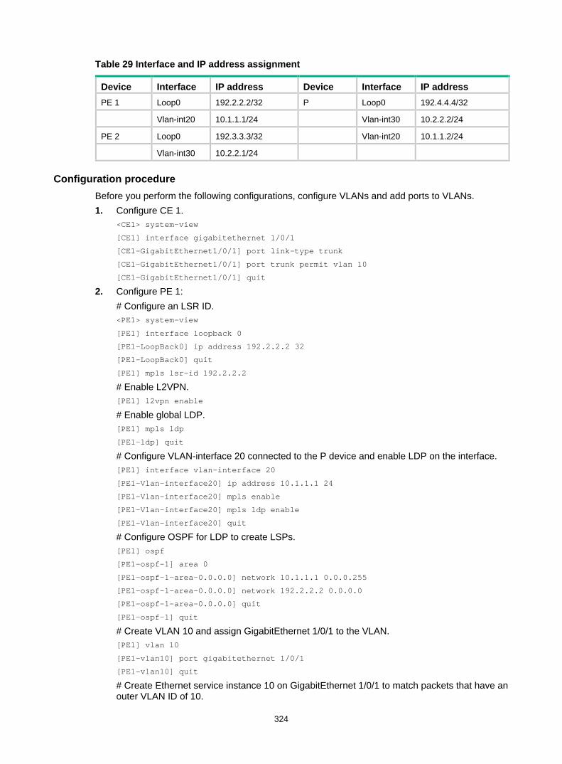
324
Table 29 Interface and IP address assignment
Device Interface IP address Device Interface IP address PE 1 Loop0 192.2.2.2/32 P Loop0 192.4.4.4/32
Vlan-int20 10.1.1.1/24 Vlan-int30 10.2.2.2/24
PE 2 Loop0 192.3.3.3/32 Vlan-int20 10.1.1.2/24
Vlan-int30 10.2.2.1/24
Configuration procedure Before you perform the following configurations, configure VLANs and add ports to VLANs. 1. Configure CE 1.
<CE1> system-view
[CE1] interface gigabitethernet 1/0/1
[CE1-GigabitEthernet1/0/1] port link-type trunk
[CE1-GigabitEthernet1/0/1] port trunk permit vlan 10
[CE1-GigabitEthernet1/0/1] quit
2. Configure PE 1: # Configure an LSR ID. <PE1> system-view
[PE1] interface loopback 0
[PE1-LoopBack0] ip address 192.2.2.2 32
[PE1-LoopBack0] quit
[PE1] mpls lsr-id 192.2.2.2
# Enable L2VPN. [PE1] l2vpn enable
# Enable global LDP. [PE1] mpls ldp
[PE1-ldp] quit
# Configure VLAN-interface 20 connected to the P device and enable LDP on the interface. [PE1] interface vlan-interface 20
[PE1-Vlan-interface20] ip address 10.1.1.1 24
[PE1-Vlan-interface20] mpls enable
[PE1-Vlan-interface20] mpls ldp enable
[PE1-Vlan-interface20] quit
# Configure OSPF for LDP to create LSPs. [PE1] ospf
[PE1-ospf-1] area 0
[PE1-ospf-1-area-0.0.0.0] network 10.1.1.1 0.0.0.255
[PE1-ospf-1-area-0.0.0.0] network 192.2.2.2 0.0.0.0
[PE1-ospf-1-area-0.0.0.0] quit
[PE1-ospf-1] quit
# Create VLAN 10 and assign GigabitEthernet 1/0/1 to the VLAN. [PE1] vlan 10
[PE1-vlan10] port gigabitethernet 1/0/1
[PE1-vlan10] quit
# Create Ethernet service instance 10 on GigabitEthernet 1/0/1 to match packets that have an outer VLAN ID of 10.
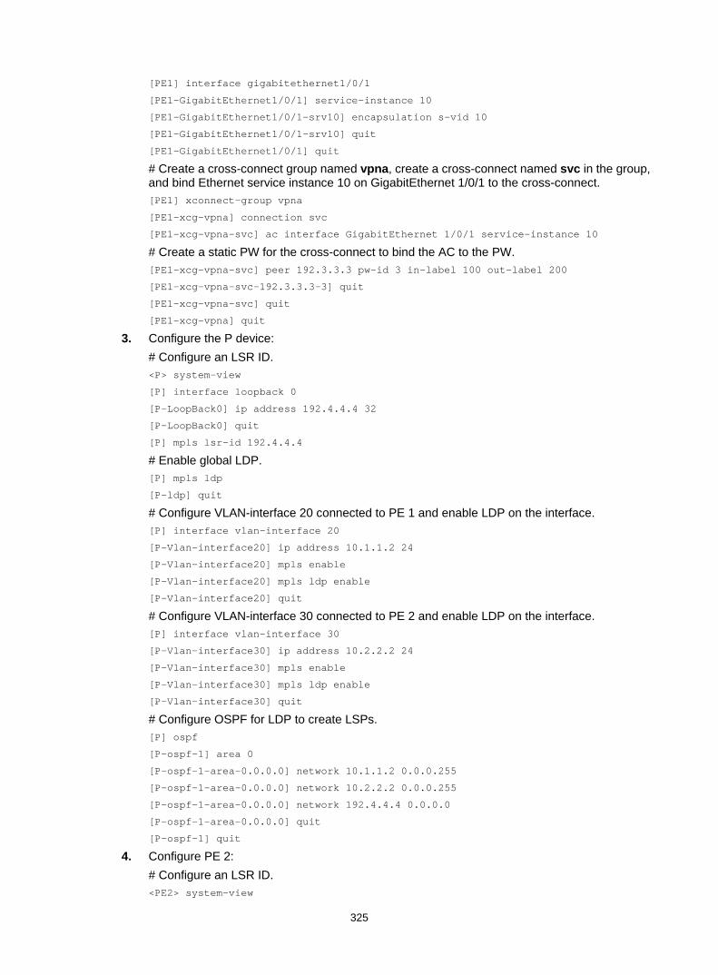
325
[PE1] interface gigabitethernet1/0/1
[PE1-GigabitEthernet1/0/1] service-instance 10
[PE1-GigabitEthernet1/0/1-srv10] encapsulation s-vid 10
[PE1-GigabitEthernet1/0/1-srv10] quit
[PE1-GigabitEthernet1/0/1] quit
# Create a cross-connect group named vpna, create a cross-connect named svc in the group, and bind Ethernet service instance 10 on GigabitEthernet 1/0/1 to the cross-connect. [PE1] xconnect-group vpna
[PE1-xcg-vpna] connection svc
[PE1-xcg-vpna-svc] ac interface GigabitEthernet 1/0/1 service-instance 10
# Create a static PW for the cross-connect to bind the AC to the PW. [PE1-xcg-vpna-svc] peer 192.3.3.3 pw-id 3 in-label 100 out-label 200
[PE1-xcg-vpna-svc-192.3.3.3-3] quit
[PE1-xcg-vpna-svc] quit
[PE1-xcg-vpna] quit
3. Configure the P device: # Configure an LSR ID. <P> system-view
[P] interface loopback 0
[P-LoopBack0] ip address 192.4.4.4 32
[P-LoopBack0] quit
[P] mpls lsr-id 192.4.4.4
# Enable global LDP. [P] mpls ldp
[P-ldp] quit
# Configure VLAN-interface 20 connected to PE 1 and enable LDP on the interface. [P] interface vlan-interface 20
[P-Vlan-interface20] ip address 10.1.1.2 24
[P-Vlan-interface20] mpls enable
[P-Vlan-interface20] mpls ldp enable
[P-Vlan-interface20] quit
# Configure VLAN-interface 30 connected to PE 2 and enable LDP on the interface. [P] interface vlan-interface 30
[P-Vlan-interface30] ip address 10.2.2.2 24
[P-Vlan-interface30] mpls enable
[P-Vlan-interface30] mpls ldp enable
[P-Vlan-interface30] quit
# Configure OSPF for LDP to create LSPs. [P] ospf
[P-ospf-1] area 0
[P-ospf-1-area-0.0.0.0] network 10.1.1.2 0.0.0.255
[P-ospf-1-area-0.0.0.0] network 10.2.2.2 0.0.0.255
[P-ospf-1-area-0.0.0.0] network 192.4.4.4 0.0.0.0
[P-ospf-1-area-0.0.0.0] quit
[P-ospf-1] quit
4. Configure PE 2: # Configure an LSR ID. <PE2> system-view

326
[PE2] interface loopback 0
[PE2-LoopBack0] ip address 192.3.3.3 32
[PE2-LoopBack0] quit
[PE2] mpls lsr-id 192.3.3.3
# Enable L2VPN. [PE2] l2vpn enable
# Enable global LDP. [PE2] mpls ldp
[PE2-ldp] quit
# Configure VLAN-interface 30 connected to the P device and enable LDP on the interface. [PE2] interface vlan-interface 30
[PE2-Vlan-interface30] ip address 10.2.2.1 24
[PE2-Vlan-interface30] mpls enable
[PE2-Vlan-interface30] mpls ldp enable
[PE2-Vlan-interface30] quit
# Configure OSPF for LDP to create LSPs. [PE2] ospf
[PE2-ospf-1] area 0
[PE2-ospf-1-area-0.0.0.0] network 10.2.2.1 0.0.0.255
[PE2-ospf-1-area-0.0.0.0] network 192.3.3.3 0.0.0.0
[PE2-ospf-1-area-0.0.0.0] quit
[PE2-ospf-1] quit
# Create VLAN 10 and assign GigabitEthernet 1/0/1 to the VLAN. [PE2] vlan 10
[PE2-vlan10] port gigabitethernet 1/0/1
[PE2-vlan10] quit
# Create Ethernet service instance 10 on GigabitEthernet 1/0/1 to match packets that have an outer VLAN ID of 10. [PE2] interface gigabitethernet1/0/1
[PE2-GigabitEthernet1/0/1] service-instance 10
[PE2-GigabitEthernet1/0/1-srv10] encapsulation s-vid 10
[PE2-GigabitEthernet1/0/1-srv10] quit
[PE2-GigabitEthernet1/0/1] quit
# Create a cross-connect group named vpna, create a cross-connect named svc in the group, and bind Ethernet service instance 10 on GigabitEthernet 1/0/1 to the cross-connect. [PE2] xconnect-group vpna
[PE2-xcg-vpna] connection svc
[PE2-xcg-vpna-svc] ac interface GigabitEthernet 1/0/1 service-instance 10
# Create a static PW for the cross-connect to bind the AC to the PW. [PE2-xcg-vpna-svc] peer 192.2.2.2 pw-id 3 in-label 200 out-label 100
[PE2-xcg-vpna-svc-192.2.2.2-3] quit
[PE2-xcg-vpna-svc] quit
[PE2-xcg-vpna] quit
5. Configure CE 2. <CE2> system-view
[CE2] interface gigabitethernet 1/0/1
[CE2-GigabitEthernet1/0/1] port link-type trunk
[CE2-GigabitEthernet1/0/1] port trunk permit vlan 10

327
[CE2-GigabitEthernet1/0/1] quit
Verifying the configuration # Display L2VPN PW information on PE 1. The output shows that a static PW has been established. [PE1] display l2vpn pw
Flags: M - main, B - backup, H - hub link, S - spoke link, N - no split horizon
Total number of PWs: 1, 1 up, 0 blocked, 0 down, 0 defect
Xconnect-group Name: vpna
Peer PW ID In/Out Label Proto Flag Link ID State
192.3.3.3 3 100/200 Static M 0 Up
# Display L2VPN PW information on PE 2. The output shows that a static PW has been established. [PE2] display l2vpn pw
Flags: M - main, B - backup, H - hub link, S - spoke link, N - no split horizon
Total number of PWs: 1, 1 up, 0 blocked, 0 down, 0 defect
Xconnect-group Name: vpna
Peer PW ID In/Out Label Proto Flag Link ID State
192.2.2.2 3 200/100 Static M 0 Up
# Verify that CE 1 and CE 2 can ping each other. (Details not shown.)
Configuring an LDP PW Network requirements
Create an LDP PW between PE 1 and PE 2 over the backbone so VLAN 10 on CE 1 can communicate with VLAN 10 on CE 2.
Figure 88 Network diagram
Table 30 Interface and IP address assignment
Device Interface IP address Device Interface IP address PE 1 Loop0 192.2.2.2/32 P Loop0 192.4.4.4/32
Vlan-int20 10.1.1.1/24 Vlan-int20 10.1.1.2/24
PE 2 Loop0 192.3.3.3/32 Vlan-int30 10.2.2.2/24
Vlan-int30 10.2.2.1/24
MPLS or IP backbone
CE 1 CE 2
PE 1 PE 2P
Vlan-int20
Vlan-int20
Vlan-int30
Vlan-int30GE1/0/1 GE1/0/1
GE1/0/1 GE1/0/1
Loop0 Loop0 Loop0
Site 1 Site 2

328
Configuration procedure Before you perform the following configurations, configure VLANs and add ports to VLANs. 1. Configure CE 1.
<CE1> system-view
[CE1] interface gigabitethernet 1/0/1
[CE1-GigabitEthernet1/0/1] port link-type trunk
[CE1-GigabitEthernet1/0/1] port trunk permit vlan 10
[CE1-GigabitEthernet1/0/1] quit
2. Configure PE 1: # Configure an LSR ID. <PE1> system-view
[PE1] interface loopback 0
[PE1-LoopBack0] ip address 192.2.2.2 32
[PE1-LoopBack0] quit
[PE1] mpls lsr-id 192.2.2.2
# Enable L2VPN. [PE1] l2vpn enable
# Enable global LDP. [PE1] mpls ldp
[PE1-ldp] quit
# Configure VLAN-interface 20 connected to the P device and enable LDP on the interface. [PE1] interface vlan-interface 20
[PE1-Vlan-interface20] ip address 10.1.1.1 24
[PE1-Vlan-interface20] mpls enable
[PE1-Vlan-interface20] mpls ldp enable
[PE1-Vlan-interface20] quit
# Configure OSPF for LDP to create LSPs. [PE1] ospf
[PE1-ospf-1] area 0
[PE1-ospf-1-area-0.0.0.0] network 10.1.1.1 0.0.0.255
[PE1-ospf-1-area-0.0.0.0] network 192.2.2.2 0.0.0.0
[PE1-ospf-1-area-0.0.0.0] quit
[PE1-ospf-1] quit
# Create VLAN 10 and assign GigabitEthernet 1/0/1 to the VLAN. [PE1] vlan 10
[PE1-vlan10] port gigabitethernet 1/0/1
[PE1-vlan10] quit
# Create Ethernet service instance 10 on GigabitEthernet 1/0/1 to match packets that have an outer VLAN ID of 10. [PE1] interface gigabitethernet1/0/1
[PE1-GigabitEthernet1/0/1] service-instance 10
[PE1-GigabitEthernet1/0/1-srv10] encapsulation s-vid 10
[PE1-GigabitEthernet1/0/1-srv10] quit
[PE1-GigabitEthernet1/0/1] quit
# Create a cross-connect group named vpna, create a cross-connect named ldp in the group, and bind Ethernet service instance 10 on GigabitEthernet 1/0/1 to the cross-connect. [PE1] xconnect-group vpna

329
[PE1-xcg-vpna] connection ldp
[PE1-xcg-vpna-ldp] ac interface GigabitEthernet 1/0/1 service-instance 10
# Create an LDP PW for the cross-connect to bind the AC to the PW. [PE1-xcg-vpna-ldp] peer 192.3.3.3 pw-id 3
[PE1-xcg-vpna-ldp-192.3.3.3-3] quit
[PE1-xcg-vpna-ldp] quit
[PE1-xcg-vpna] quit
3. Configure the P device: # Configure an LSR ID. <P> system-view
[P] interface loopback 0
[P-LoopBack0] ip address 192.4.4.4 32
[P-LoopBack0] quit
[P] mpls lsr-id 192.4.4.4
# Enable global LDP. [P] mpls ldp
[P-ldp] quit
# Configure VLAN-interface 20 connected to PE 1 and enable LDP on the interface. [P] interface vlan-interface 20
[P-Vlan-interface20] ip address 10.1.1.2 24
[P-Vlan-interface20] mpls enable
[P-Vlan-interface20] mpls ldp enable
[P-Vlan-interface20] quit
# Configure VLAN-interface 30 connected to PE 2 and enable LDP on the interface. [P] interface vlan-interface 30
[P-Vlan-interface30] ip address 10.2.2.2 24
[P-Vlan-interface30] mpls enable
[P-Vlan-interface30] mpls ldp enable
[P-Vlan-interface30] quit
# Configure OSPF for LDP to create LSPs. [P] ospf
[P-ospf-1] area 0
[P-ospf-1-area-0.0.0.0] network 10.1.1.2 0.0.0.255
[P-ospf-1-area-0.0.0.0] network 10.2.2.2 0.0.0.255
[P-ospf-1-area-0.0.0.0] network 192.4.4.4 0.0.0.0
[P-ospf-1-area-0.0.0.0] quit
[P-ospf-1] quit
4. Configure PE 2: # Configure an LSR ID. <PE2> system-view
[PE2] interface loopback 0
[PE2-LoopBack0] ip address 192.3.3.3 32
[PE2-LoopBack0] quit
[PE2] mpls lsr-id 192.3.3.3
# Enable L2VPN. [PE2] l2vpn enable
# Enable global LDP.

330
[PE2] mpls ldp
[PE2-ldp] quit
# Configure VLAN-interface 30 connected to the P device and enable LDP on the interface. [PE2] interface vlan-interface 30
[PE2-Vlan-interface30] ip address 10.2.2.1 24
[PE2-Vlan-interface30] mpls enable
[PE2-Vlan-interface30] mpls ldp enable
[PE2-Vlan-interface30] quit
# Configure OSPF for LDP to create LSPs. [PE2] ospf
[PE2-ospf-1] area 0
[PE2-ospf-1-area-0.0.0.0] network 192.3.3.3 0.0.0.0
[PE2-ospf-1-area-0.0.0.0] network 10.2.2.0 0.0.0.255
[PE2-ospf-1-area-0.0.0.0] quit
[PE2-ospf-1] quit
# Create VLAN 10 and assign GigabitEthernet 1/0/1 to the VLAN. [PE2] vlan 10
[PE2-vlan10] port gigabitethernet 1/0/1
[PE2-vlan10] quit
# Create Ethernet service instance 10 on GigabitEthernet 1/0/1 to match packets that have an outer VLAN ID of 10. [PE2] interface gigabitethernet1/0/1
[PE2-GigabitEthernet1/0/1] service-instance 10
[PE2-GigabitEthernet1/0/1-srv10] encapsulation s-vid 10
[PE2-GigabitEthernet1/0/1-srv10] quit
[PE2-GigabitEthernet1/0/1] quit
# Create a cross-connect group named vpna, create a cross-connect named ldp in the group, and bind Ethernet service instance 10 on GigabitEthernet 1/0/1 to the cross-connect. [PE2] xconnect-group vpna
[PE2-xcg-vpna] connection ldp
[PE2-xcg-vpna-ldp] ac interface GigabitEthernet 1/0/1 service-instance 10
# Create an LDP PW for the cross-connect to bind the AC to the PW. [PE2-xcg-vpna-ldp] peer 192.2.2.2 pw-id 3
[PE2-xcg-vpna-ldp-192.2.2.2-3] quit
[PE2-xcg-vpna-ldp] quit
[PE2-xcg-vpna] quit
5. Configure CE 2. <CE2> system-view
[CE2] interface gigabitethernet 1/0/1
[CE2-GigabitEthernet1/0/1] port link-type trunk
[CE2-GigabitEthernet1/0/1] port trunk permit vlan 10
[CE2-GigabitEthernet1/0/1] quit
Verifying the configuration # Display L2VPN PW information on PE 1. The output shows that an LDP PW has been established. [PE1] display l2vpn pw
Flags: M - main, B - backup, H - hub link, S - spoke link, N - no split horizon
Total number of PWs: 1, 1 up, 0 blocked, 0 down, 0 defect

331
Xconnect-group Name: vpna
Peer PW ID In/Out Label Proto Flag Link ID State
192.3.3.3 3 65679/65679 LDP M 1 Up
# Display L2VPN PW information on PE 2. The output shows that an LDP PW has been established. [PE2] display l2vpn pw
Flags: M - main, B - backup, H - hub link, S - spoke link, N - no split horizon
Total number of PWs: 1, 1 up, 0 blocked, 0 down, 0 defect
Xconnect-group Name: vpna
Peer PW ID In/Out Label Proto Flag Link ID State
192.2.2.2 3 65679/65679 LDP M 1 Up
# Verify that CE 1 and CE 2 can ping each other. (Details not shown.)
Configuring a BGP PW Network requirements
Create a BGP PW between PE 1 and PE 2 so VLAN 10 on CE 1 can communicate with VLAN 10 on CE 2.
Figure 89 Network diagram
Table 31 Interface and IP address assignment
Device Interface IP address Device Interface IP address PE 1 Loop0 192.2.2.2/32 P Loop0 192.4.4.4/32
Vlan-int20 10.1.1.1/24 Vlan-int20 10.1.1.2/24
PE 2 Loop0 192.3.3.3/32 Vlan-int30 10.2.2.2/24
Vlan-int30 10.2.2.1/24
Configuration procedure Before you perform the following configurations, configure VLANs and add ports to VLANs. 1. Configure CE 1.
<CE1> system-view
[CE1] interface gigabitethernet 1/0/1
[CE1-GigabitEthernet1/0/1] port link-type trunk
MPLS or IP backbone
CE 1 CE 2
PE 1 PE 2P
Vlan-int20
Vlan-int20
Vlan-int30
Vlan-int30GE1/0/1 GE1/0/1
GE1/0/1 GE1/0/1
Loop0 Loop0 Loop0
Site 1 Site 2
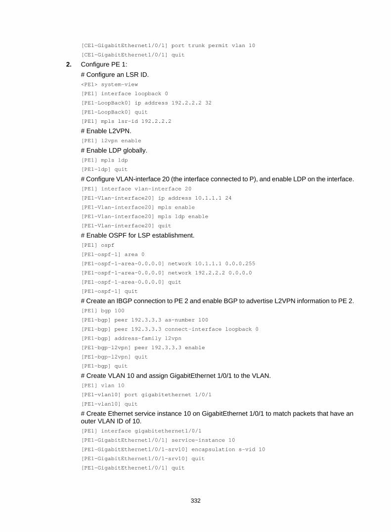
332
[CE1-GigabitEthernet1/0/1] port trunk permit vlan 10
[CE1-GigabitEthernet1/0/1] quit
2. Configure PE 1: # Configure an LSR ID. <PE1> system-view
[PE1] interface loopback 0
[PE1-LoopBack0] ip address 192.2.2.2 32
[PE1-LoopBack0] quit
[PE1] mpls lsr-id 192.2.2.2
# Enable L2VPN. [PE1] l2vpn enable
# Enable LDP globally. [PE1] mpls ldp
[PE1-ldp] quit
# Configure VLAN-interface 20 (the interface connected to P), and enable LDP on the interface. [PE1] interface vlan-interface 20
[PE1-Vlan-interface20] ip address 10.1.1.1 24
[PE1-Vlan-interface20] mpls enable
[PE1-Vlan-interface20] mpls ldp enable
[PE1-Vlan-interface20] quit
# Enable OSPF for LSP establishment. [PE1] ospf
[PE1-ospf-1] area 0
[PE1-ospf-1-area-0.0.0.0] network 10.1.1.1 0.0.0.255
[PE1-ospf-1-area-0.0.0.0] network 192.2.2.2 0.0.0.0
[PE1-ospf-1-area-0.0.0.0] quit
[PE1-ospf-1] quit
# Create an IBGP connection to PE 2 and enable BGP to advertise L2VPN information to PE 2. [PE1] bgp 100
[PE1-bgp] peer 192.3.3.3 as-number 100
[PE1-bgp] peer 192.3.3.3 connect-interface loopback 0
[PE1-bgp] address-family l2vpn
[PE1-bgp-l2vpn] peer 192.3.3.3 enable
[PE1-bgp-l2vpn] quit
[PE1-bgp] quit
# Create VLAN 10 and assign GigabitEthernet 1/0/1 to the VLAN. [PE1] vlan 10
[PE1-vlan10] port gigabitethernet 1/0/1
[PE1-vlan10] quit
# Create Ethernet service instance 10 on GigabitEthernet 1/0/1 to match packets that have an outer VLAN ID of 10. [PE1] interface gigabitethernet1/0/1
[PE1-GigabitEthernet1/0/1] service-instance 10
[PE1-GigabitEthernet1/0/1-srv10] encapsulation s-vid 10
[PE1-GigabitEthernet1/0/1-srv10] quit
[PE1-GigabitEthernet1/0/1] quit
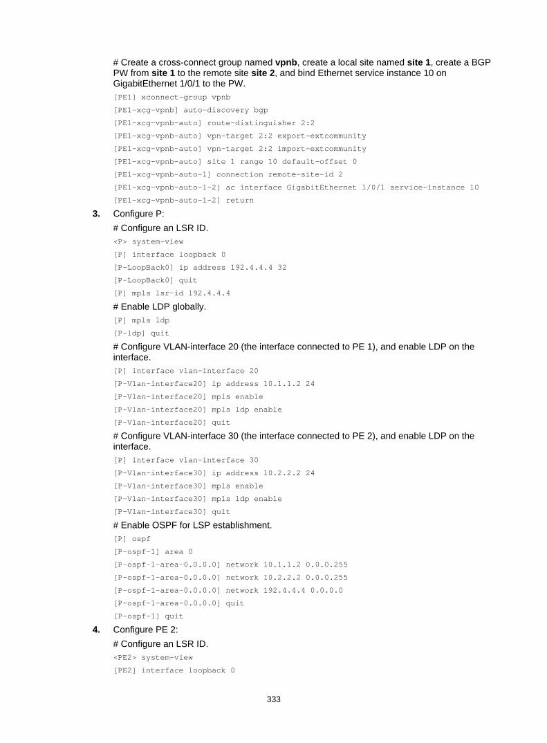
333
# Create a cross-connect group named vpnb, create a local site named site 1, create a BGP PW from site 1 to the remote site site 2, and bind Ethernet service instance 10 on GigabitEthernet 1/0/1 to the PW. [PE1] xconnect-group vpnb
[PE1-xcg-vpnb] auto-discovery bgp
[PE1-xcg-vpnb-auto] route-distinguisher 2:2
[PE1-xcg-vpnb-auto] vpn-target 2:2 export-extcommunity
[PE1-xcg-vpnb-auto] vpn-target 2:2 import-extcommunity
[PE1-xcg-vpnb-auto] site 1 range 10 default-offset 0
[PE1-xcg-vpnb-auto-1] connection remote-site-id 2
[PE1-xcg-vpnb-auto-1-2] ac interface GigabitEthernet 1/0/1 service-instance 10
[PE1-xcg-vpnb-auto-1-2] return
3. Configure P: # Configure an LSR ID. <P> system-view
[P] interface loopback 0
[P-LoopBack0] ip address 192.4.4.4 32
[P-LoopBack0] quit
[P] mpls lsr-id 192.4.4.4
# Enable LDP globally. [P] mpls ldp
[P-ldp] quit
# Configure VLAN-interface 20 (the interface connected to PE 1), and enable LDP on the interface. [P] interface vlan-interface 20
[P-Vlan-interface20] ip address 10.1.1.2 24
[P-Vlan-interface20] mpls enable
[P-Vlan-interface20] mpls ldp enable
[P-Vlan-interface20] quit
# Configure VLAN-interface 30 (the interface connected to PE 2), and enable LDP on the interface. [P] interface vlan-interface 30
[P-Vlan-interface30] ip address 10.2.2.2 24
[P-Vlan-interface30] mpls enable
[P-Vlan-interface30] mpls ldp enable
[P-Vlan-interface30] quit
# Enable OSPF for LSP establishment. [P] ospf
[P-ospf-1] area 0
[P-ospf-1-area-0.0.0.0] network 10.1.1.2 0.0.0.255
[P-ospf-1-area-0.0.0.0] network 10.2.2.2 0.0.0.255
[P-ospf-1-area-0.0.0.0] network 192.4.4.4 0.0.0.0
[P-ospf-1-area-0.0.0.0] quit
[P-ospf-1] quit
4. Configure PE 2: # Configure an LSR ID. <PE2> system-view
[PE2] interface loopback 0

334
[PE2-LoopBack0] ip address 192.3.3.3 32
[PE2-LoopBack0] quit
[PE2] mpls lsr-id 192.3.3.3
# Enable L2VPN. [PE2] l2vpn enable
# Enable LDP globally. [PE2] mpls ldp
[PE2-ldp] quit
# Configure VLAN-interface 30 (the interface connected to P), and enable LDP on the interface. [PE2] interface vlan-interface 30
[PE2-Vlan-interface30] ip address 10.2.2.1 24
[PE2-Vlan-interface30] mpls enable
[PE2-Vlan-interface30] mpls ldp enable
[PE2-Vlan-interface30] quit
# Enable OSPF for LSP establishment. [PE2] ospf
[PE2-ospf-1] area 0
[PE2-ospf-1-area-0.0.0.0] network 192.3.3.3 0.0.0.0
[PE2-ospf-1-area-0.0.0.0] network 10.2.2.0 0.0.0.255
[PE2-ospf-1-area-0.0.0.0] quit
[PE2-ospf-1] quit
# Create an IBGP connection to PE 1, and enable BGP to advertise L2VPN information to PE 1. [PE2] bgp 100
[PE2-bgp] peer 192.2.2.2 as-number 100
[PE2-bgp] peer 192.2.2.2 connect-interface loopback 0
[PE2-bgp] address-family l2vpn
[PE2-bgp-l2vpn] peer 192.2.2.2 enable
[PE2-bgp-l2vpn] quit
[PE2-bgp] quit
# Create VLAN 10 and assign GigabitEthernet 1/0/1 to the VLAN. [PE2] vlan 10
[PE2-vlan10] port gigabitethernet 1/0/1
[PE2-vlan10] quit
# Create Ethernet service instance 10 on GigabitEthernet 1/0/1 to match packets that have an outer VLAN ID of 20. [PE2] interface gigabitethernet1/0/1
[PE2-GigabitEthernet1/0/1] service-instance 10
[PE2-GigabitEthernet1/0/1-srv10]encapsulation s-vid 10
[PE2-GigabitEthernet1/0/1-srv10] quit
[PE2-GigabitEthernet1/0/1] quit
# Create a cross-connect group named vpnb, create a local site named site 2, create a BGP PW from site 2 to the remote site site 1, and bind Ethernet service instance 10 on GigabitEthernet 1/0/1 to the PW. [PE2] xconnect-group vpnb
[PE2-xcg-vpnb] auto-discovery bgp
[PE2-xcg-vpnb-auto] route-distinguisher 2:2
[PE2-xcg-vpnb-auto] vpn-target 2:2 export-extcommunity
[PE2-xcg-vpnb-auto] vpn-target 2:2 import-extcommunity
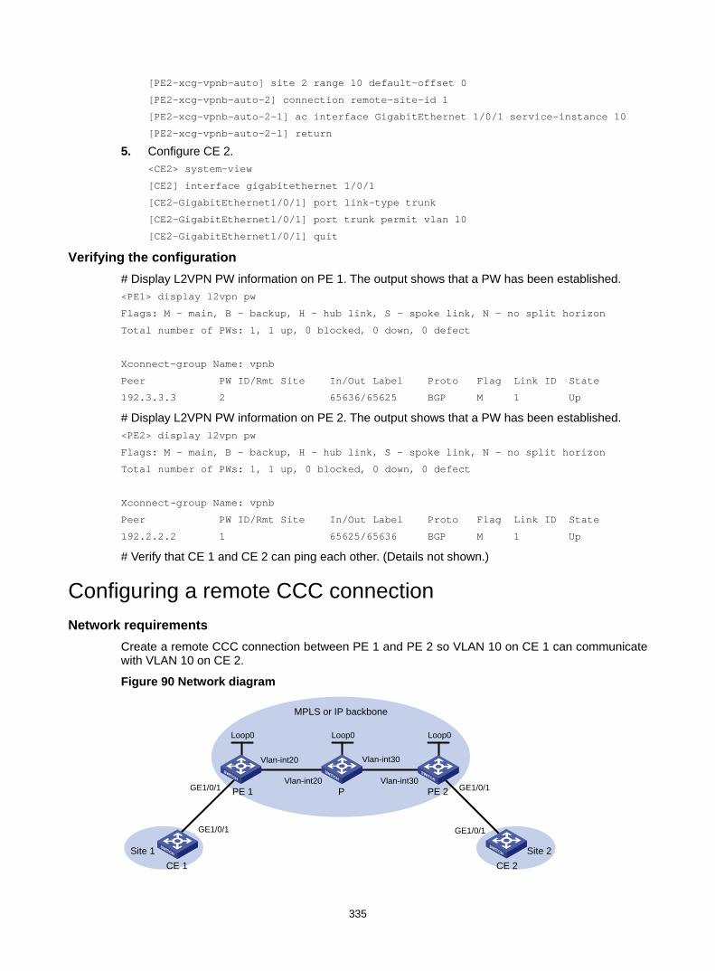
335
[PE2-xcg-vpnb-auto] site 2 range 10 default-offset 0
[PE2-xcg-vpnb-auto-2] connection remote-site-id 1
[PE2-xcg-vpnb-auto-2-1] ac interface GigabitEthernet 1/0/1 service-instance 10
[PE2-xcg-vpnb-auto-2-1] return
5. Configure CE 2. <CE2> system-view
[CE2] interface gigabitethernet 1/0/1
[CE2-GigabitEthernet1/0/1] port link-type trunk
[CE2-GigabitEthernet1/0/1] port trunk permit vlan 10
[CE2-GigabitEthernet1/0/1] quit
Verifying the configuration # Display L2VPN PW information on PE 1. The output shows that a PW has been established. <PE1> display l2vpn pw
Flags: M - main, B - backup, H - hub link, S - spoke link, N - no split horizon
Total number of PWs: 1, 1 up, 0 blocked, 0 down, 0 defect
Xconnect-group Name: vpnb
Peer PW ID/Rmt Site In/Out Label Proto Flag Link ID State
192.3.3.3 2 65636/65625 BGP M 1 Up
# Display L2VPN PW information on PE 2. The output shows that a PW has been established. <PE2> display l2vpn pw
Flags: M - main, B - backup, H - hub link, S - spoke link, N - no split horizon
Total number of PWs: 1, 1 up, 0 blocked, 0 down, 0 defect
Xconnect-group Name: vpnb
Peer PW ID/Rmt Site In/Out Label Proto Flag Link ID State
192.2.2.2 1 65625/65636 BGP M 1 Up
# Verify that CE 1 and CE 2 can ping each other. (Details not shown.)
Configuring a remote CCC connection Network requirements
Create a remote CCC connection between PE 1 and PE 2 so VLAN 10 on CE 1 can communicate with VLAN 10 on CE 2.
Figure 90 Network diagram
MPLS or IP backbone
CE 1 CE 2
PE 1 PE 2P
Vlan-int20
Vlan-int20
Vlan-int30
Vlan-int30GE1/0/1 GE1/0/1
GE1/0/1 GE1/0/1
Loop0 Loop0 Loop0
Site 1 Site 2

336
Table 32 Interface and IP address assignment
Device Interface IP address Device Interface IP address PE 1 Loop0 192.2.2.2/32 P Loop0 192.4.4.4/32
Vlan-int20 10.1.1.1/24 Vlan-int20 10.1.1.2/24
PE 2 Loop0 192.3.3.3/32 Vlan-int30 10.2.2.2/24
Vlan-int30 10.2.2.1/24
Configuration procedure Before you perform the following configurations, configure VLANs and add ports to VLANs. 1. Configure CE 1.
<CE1> system-view
[CE1] interface gigabitethernet 1/0/1
[CE1-GigabitEthernet1/0/1] port link-type trunk
[CE1-GigabitEthernet1/0/1] port trunk permit vlan 10
[CE1-GigabitEthernet1/0/1] quit
2. Configure PE 1: # Configure an LSR ID. <PE1> system-view
[PE1] interface loopback 0
[PE1-LoopBack0] ip address 192.2.2.2 32
[PE1-LoopBack0] quit
[PE1] mpls lsr-id 192.2.2.2
# Enable L2VPN. [PE1] l2vpn enable
# Configure VLAN-interface 20 (the interface connected to P), and enable MPLS on the interface. [PE1] interface vlan-interface 20
[PE1-Vlan-interface20] ip address 10.1.1.1 24
[PE1-Vlan-interface20] mpls enable
[PE1-Vlan-interface20] quit
# Create VLAN 10 and assign GigabitEthernet 1/0/1 to the VLAN. [PE1] vlan 10
[PE1-vlan10] port gigabitethernet 1/0/1
[PE1-vlan10] quit
# Create Ethernet service instance 10 on GigabitEthernet 1/0/1 to match packets that have an outer VLAN ID of 10. [PE1] interface gigabitethernet1/0/1
[PE1-GigabitEthernet1/0/1] service-instance 10
[PE1-GigabitEthernet1/0/1-srv10] encapsulation s-vid 10
[PE1-GigabitEthernet1/0/1-srv10] quit
[PE1-GigabitEthernet1/0/1] quit
# Create a cross-connect group named ccc, create a remote CCC connection that has incoming label 101, outgoing label 201, and next hop 10.1.1.2, and bind Ethernet service instance 10 on GigabitEthernet 1/0/1 to the CCC connection. [PE1] xconnect-group ccc
[PE1-xcg-ccc] connection ccc

337
[PE1-xcg-ccc-ccc] ccc in-label 101 out-label 201 nexthop 10.1.1.2
[PE1-xcg-ccc-ccc] ac interface GigabitEthernet 1/0/1 service-instance 10
[PE1-xcg-ccc-ccc] quit
[PE1-xcg-ccc] quit
3. Configure P: # Configure an LSR ID. <P> system-view
[P] interface loopback 0
[P-LoopBack0] ip address 192.4.4.4 32
[P-LoopBack0] quit
[P] mpls lsr-id 192.4.4.4
# Configure VLAN-interface 20 (the interface connected to PE 1), and enable MPLS on the interface. [P] interface vlan-interface 20
[P-Vlan-interface20] ip address 10.1.1.2 24
[P-Vlan-interface20] mpls enable
[P-Vlan-interface20] quit
# Configure VLAN-interface 30 (the interface connected to PE 2), and enable MPLS on the interface. [P] interface vlan-interface 30
[P-Vlan-interface30] ip address 10.2.2.2 24
[P-Vlan-interface30] mpls enable
[P-Vlan-interface30] quit
# Configure a static LSP to forward packets from PE 1 to PE 2. [P] static-lsp transit pe1-pe2 in-label 201 nexthop 10.2.2.1 out-label 202
# Configure a static LSP to forward packets from PE 2 to PE 1. [P] static-lsp transit pe2-pe1 in-label 102 nexthop 10.1.1.1 out-label 101
4. Configure PE 2: # Configure an LSR ID. <PE2> system-view
[PE2] interface loopback 0
[PE2-LoopBack0] ip address 192.3.3.3 32
[PE2-LoopBack0] quit
[PE2] mpls lsr-id 192.3.3.3
# Enable L2VPN. [PE2] l2vpn enable
# Configure VLAN-interface 30 (the interface connected to P), and enable MPLS on the interface. [PE2] interface vlan-interface 30
[PE2-Vlan-interface30] ip address 10.2.2.1 24
[PE2-Vlan-interface30] mpls enable
[PE2-Vlan-interface30] quit
# Create VLAN 10 and assign GigabitEthernet 1/0/1 to the VLAN. [PE2] vlan 10
[PE2-vlan10] port gigabitethernet 1/0/1
[PE2-vlan10] quit
# Create Ethernet service instance 10 on GigabitEthernet 1/0/1 to match packets that have an outer VLAN ID of 10.

338
[PE2] interface gigabitethernet1/0/1
[PE2-GigabitEthernet1/0/1] service-instance 10
[PE2-GigabitEthernet1/0/1-srv10] encapsulation s-vid 10
[PE2-GigabitEthernet1/0/1-srv10] quit
[PE2-GigabitEthernet1/0/1] quit
# Create a cross-connect group named ccc, create a remote CCC connection that has incoming label 202, outgoing label 102, and next hop 10.2.2.2, and bind Ethernet service instance 10 on GigabitEthernet 1/0/1 to the CCC connection. [PE2] xconnect-group ccc
[PE2-xcg-ccc] connection ccc
[PE2-xcg-ccc-ccc] ccc in-label 202 out-label 102 nexthop 10.2.2.2
[PE2-xcg-ccc-ccc] ac interface GigabitEthernet 1/0/1 service-instance 10
[PE2-xcg-ccc-ccc] quit
[PE2-xcg-ccc] quit
5. Configure CE 2. <CE2> system-view
[CE2] interface gigabitethernet 1/0/1
[CE2-GigabitEthernet1/0/1] port link-type trunk
[CE2-GigabitEthernet1/0/1] port trunk permit vlan 10
[CE2-GigabitEthernet1/0/1] quit
Verifying the configuration # Display L2VPN PW information on PE 1. The output shows that a remote CCC connection (identified by PW ID/Rmt Site "-" and Proto Static) has been established. [PE1] display l2vpn pw
Flags: M - main, B - backup, H - hub link, S - spoke link, N - no split horizon
Total number of PWs: 1, 1 up, 0 blocked, 0 down, 0 defect
Xconnect-group Name: ccc
Peer PW ID/Rmt Site In/Out Label Proto Flag Link ID State
10.1.1.2 - 101/201 Static M 0 Up
# Display L2VPN PW information on PE 2. The output shows that a remote CCC connection has been established. [PE2] display l2vpn pw
Flags: M - main, B - backup, H - hub link, S - spoke link, N - no split horizon
Total number of PWs: 1, 1 up, 0 blocked, 0 down, 0 defect
Xconnect-group Name: ccc
Peer PW ID/Rmt Site In/Out Label Proto Flag Link ID State
10.2.2.2 - 202/102 Static M 0 Up
# Verify that CE 1 and CE 2 can ping each other. (Details not shown.)
Configuring LDP PW redundancy Network requirements
Create two LDP PWs to implement PW redundancy between CE 1 and CE 2. The primary PW goes through PE 1—PE 2. The backup PW goes through PE 1—PE 3. When the primary PW fails, CE 1 and CE 2 communicate through the backup PW.
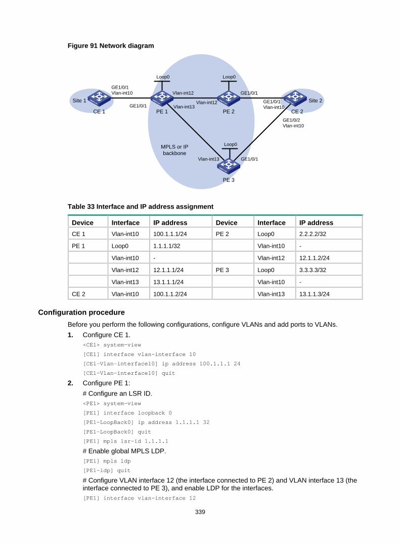
339
Figure 91 Network diagram
Table 33 Interface and IP address assignment
Device Interface IP address Device Interface IP address CE 1 Vlan-int10 100.1.1.1/24 PE 2 Loop0 2.2.2.2/32
PE 1 Loop0 1.1.1.1/32 Vlan-int10 -
Vlan-int10 - Vlan-int12 12.1.1.2/24
Vlan-int12 12.1.1.1/24 PE 3 Loop0 3.3.3.3/32
Vlan-int13 13.1.1.1/24 Vlan-int10 -
CE 2 Vlan-int10 100.1.1.2/24 Vlan-int13 13.1.1.3/24
Configuration procedure Before you perform the following configurations, configure VLANs and add ports to VLANs. 1. Configure CE 1.
<CE1> system-view
[CE1] interface vlan-interface 10
[CE1-Vlan-interface10] ip address 100.1.1.1 24
[CE1-Vlan-interface10] quit
2. Configure PE 1: # Configure an LSR ID. <PE1> system-view
[PE1] interface loopback 0
[PE1-LoopBack0] ip address 1.1.1.1 32
[PE1-LoopBack0] quit
[PE1] mpls lsr-id 1.1.1.1
# Enable global MPLS LDP. [PE1] mpls ldp
[PE1-ldp] quit
# Configure VLAN interface 12 (the interface connected to PE 2) and VLAN interface 13 (the interface connected to PE 3), and enable LDP for the interfaces. [PE1] interface vlan-interface 12
Loop0 Loop0
CE 1 CE 2PE 1 PE 2
Vlan-int12
Vlan-int12
Loop0
PE 3
GE1/0/1
GE1/0/1
Vlan-int13
Vlan-int13
GE1/0/1Vlan-int10
GE1/0/1
MPLS or IP backbone
GE1/0/1Vlan-int10
Site 1 Site 2
GE1/0/2Vlan-int10
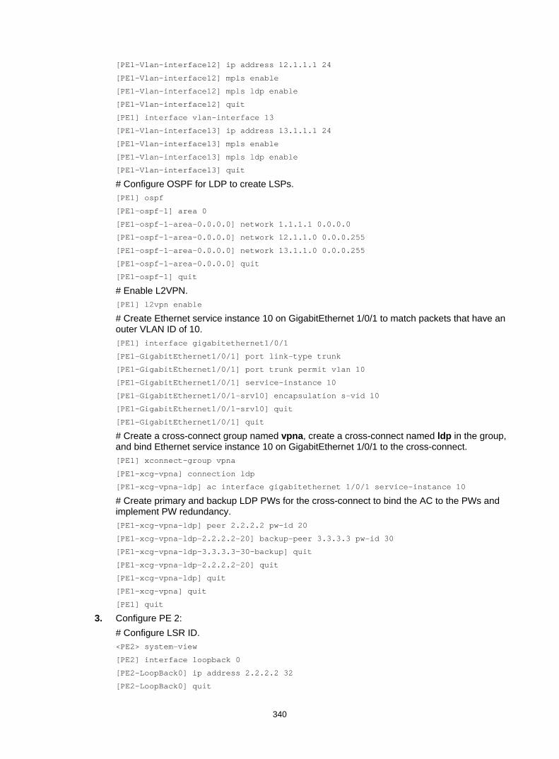
340
[PE1-Vlan-interface12] ip address 12.1.1.1 24
[PE1-Vlan-interface12] mpls enable
[PE1-Vlan-interface12] mpls ldp enable
[PE1-Vlan-interface12] quit
[PE1] interface vlan-interface 13
[PE1-Vlan-interface13] ip address 13.1.1.1 24
[PE1-Vlan-interface13] mpls enable
[PE1-Vlan-interface13] mpls ldp enable
[PE1-Vlan-interface13] quit
# Configure OSPF for LDP to create LSPs. [PE1] ospf
[PE1-ospf-1] area 0
[PE1-ospf-1-area-0.0.0.0] network 1.1.1.1 0.0.0.0
[PE1-ospf-1-area-0.0.0.0] network 12.1.1.0 0.0.0.255
[PE1-ospf-1-area-0.0.0.0] network 13.1.1.0 0.0.0.255
[PE1-ospf-1-area-0.0.0.0] quit
[PE1-ospf-1] quit
# Enable L2VPN. [PE1] l2vpn enable
# Create Ethernet service instance 10 on GigabitEthernet 1/0/1 to match packets that have an outer VLAN ID of 10. [PE1] interface gigabitethernet1/0/1
[PE1-GigabitEthernet1/0/1] port link-type trunk
[PE1-GigabitEthernet1/0/1] port trunk permit vlan 10
[PE1-GigabitEthernet1/0/1] service-instance 10
[PE1-GigabitEthernet1/0/1-srv10] encapsulation s-vid 10
[PE1-GigabitEthernet1/0/1-srv10] quit
[PE1-GigabitEthernet1/0/1] quit
# Create a cross-connect group named vpna, create a cross-connect named ldp in the group, and bind Ethernet service instance 10 on GigabitEthernet 1/0/1 to the cross-connect. [PE1] xconnect-group vpna
[PE1-xcg-vpna] connection ldp
[PE1-xcg-vpna-ldp] ac interface gigabitethernet 1/0/1 service-instance 10
# Create primary and backup LDP PWs for the cross-connect to bind the AC to the PWs and implement PW redundancy. [PE1-xcg-vpna-ldp] peer 2.2.2.2 pw-id 20
[PE1-xcg-vpna-ldp-2.2.2.2-20] backup-peer 3.3.3.3 pw-id 30
[PE1-xcg-vpna-ldp-3.3.3.3-30-backup] quit
[PE1-xcg-vpna-ldp-2.2.2.2-20] quit
[PE1-xcg-vpna-ldp] quit
[PE1-xcg-vpna] quit
[PE1] quit
3. Configure PE 2: # Configure LSR ID. <PE2> system-view
[PE2] interface loopback 0
[PE2-LoopBack0] ip address 2.2.2.2 32
[PE2-LoopBack0] quit
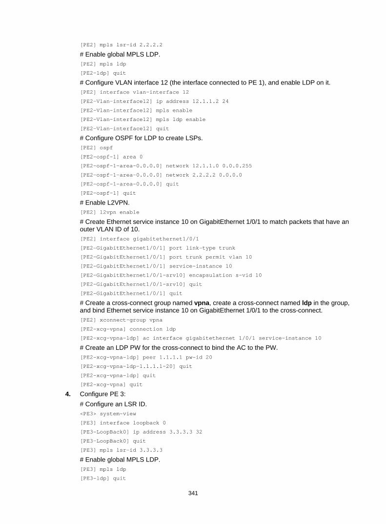
341
[PE2] mpls lsr-id 2.2.2.2
# Enable global MPLS LDP. [PE2] mpls ldp
[PE2-ldp] quit
# Configure VLAN interface 12 (the interface connected to PE 1), and enable LDP on it. [PE2] interface vlan-interface 12
[PE2-Vlan-interface12] ip address 12.1.1.2 24
[PE2-Vlan-interface12] mpls enable
[PE2-Vlan-interface12] mpls ldp enable
[PE2-Vlan-interface12] quit
# Configure OSPF for LDP to create LSPs. [PE2] ospf
[PE2-ospf-1] area 0
[PE2-ospf-1-area-0.0.0.0] network 12.1.1.0 0.0.0.255
[PE2-ospf-1-area-0.0.0.0] network 2.2.2.2 0.0.0.0
[PE2-ospf-1-area-0.0.0.0] quit
[PE2-ospf-1] quit
# Enable L2VPN. [PE2] l2vpn enable
# Create Ethernet service instance 10 on GigabitEthernet 1/0/1 to match packets that have an outer VLAN ID of 10. [PE2] interface gigabitethernet1/0/1
[PE2-GigabitEthernet1/0/1] port link-type trunk
[PE2-GigabitEthernet1/0/1] port trunk permit vlan 10
[PE2-GigabitEthernet1/0/1] service-instance 10
[PE2-GigabitEthernet1/0/1-srv10] encapsulation s-vid 10
[PE2-GigabitEthernet1/0/1-srv10] quit
[PE2-GigabitEthernet1/0/1] quit
# Create a cross-connect group named vpna, create a cross-connect named ldp in the group, and bind Ethernet service instance 10 on GigabitEthernet 1/0/1 to the cross-connect. [PE2] xconnect-group vpna
[PE2-xcg-vpna] connection ldp
[PE2-xcg-vpna-ldp] ac interface gigabitethernet 1/0/1 service-instance 10
# Create an LDP PW for the cross-connect to bind the AC to the PW. [PE2-xcg-vpna-ldp] peer 1.1.1.1 pw-id 20
[PE2-xcg-vpna-ldp-1.1.1.1-20] quit
[PE2-xcg-vpna-ldp] quit
[PE2-xcg-vpna] quit
4. Configure PE 3: # Configure an LSR ID. <PE3> system-view
[PE3] interface loopback 0
[PE3-LoopBack0] ip address 3.3.3.3 32
[PE3-LoopBack0] quit
[PE3] mpls lsr-id 3.3.3.3
# Enable global MPLS LDP. [PE3] mpls ldp
[PE3-ldp] quit
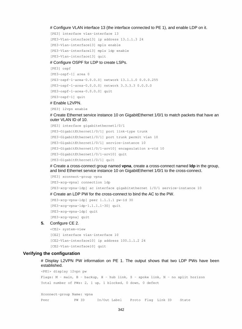
342
# Configure VLAN interface 13 (the interface connected to PE 1), and enable LDP on it. [PE3] interface vlan-interface 13
[PE3-Vlan-interface13] ip address 13.1.1.3 24
[PE3-Vlan-interface13] mpls enable
[PE3-Vlan-interface13] mpls ldp enable
[PE3-Vlan-interface13] quit
# Configure OSPF for LDP to create LSPs. [PE3] ospf
[PE3-ospf-1] area 0
[PE3-ospf-1-area-0.0.0.0] network 13.1.1.0 0.0.0.255
[PE3-ospf-1-area-0.0.0.0] network 3.3.3.3 0.0.0.0
[PE3-ospf-1-area-0.0.0.0] quit
[PE3-ospf-1] quit
# Enable L2VPN. [PE3] l2vpn enable
# Create Ethernet service instance 10 on GigabitEthernet 1/0/1 to match packets that have an outer VLAN ID of 10. [PE3] interface gigabitethernet1/0/1
[PE3-GigabitEthernet1/0/1] port link-type trunk
[PE3-GigabitEthernet1/0/1] port trunk permit vlan 10
[PE3-GigabitEthernet1/0/1] service-instance 10
[PE3-GigabitEthernet1/0/1-srv10] encapsulation s-vid 10
[PE3-GigabitEthernet1/0/1-srv10] quit
[PE3-GigabitEthernet1/0/1] quit
# Create a cross-connect group named vpna, create a cross-connect named ldp in the group, and bind Ethernet service instance 10 on GigabitEthernet 1/0/1 to the cross-connect. [PE3] xconnect-group vpna
[PE3-xcg-vpna] connection ldp
[PE3-xcg-vpna-ldp] ac interface gigabitethernet 1/0/1 service-instance 10
# Create an LDP PW for the cross-connect to bind the AC to the PW. [PE3-xcg-vpna-ldp] peer 1.1.1.1 pw-id 30
[PE3-xcg-vpna-ldp-1.1.1.1-30] quit
[PE3-xcg-vpna-ldp] quit
[PE3-xcg-vpna] quit
5. Configure CE 2. <CE2> system-view
[CE2] interface vlan-interface 10
[CE2-Vlan-interface10] ip address 100.1.1.2 24
[CE2-Vlan-interface10] quit
Verifying the configuration # Display L2VPN PW information on PE 1. The output shows that two LDP PWs have been established. <PE1> display l2vpn pw
Flags: M - main, B - backup, H - hub link, S - spoke link, N - no split horizon
Total number of PWs: 2, 1 up, 1 blocked, 0 down, 0 defect
Xconnect-group Name: vpna
Peer PW ID In/Out Label Proto Flag Link ID State

343
2.2.2.2 20 65651/65779 LDP M 1 Up
3.3.3.3 30 65650/65779 LDP B 1 Blocked
# Display detailed information about the primary and backup PWs on PE 1. <PE1> display l2vpn pw verbose
Xconnect-group Name: vpna
Connection: ldp
Peer: 2.2.2.2 PW ID: 20
Signaling Protocol : LDP
Link ID : 1 PW State : Up
In Label : 65651 Out Label: 65779
Wait to Restore Time: 0 sec
MTU : 1500
PW Attributes : Main
VCCV CC : -
VCCV BFD : -
Tunnel Group ID : 0x1800000260000002
Tunnel NHLFE IDs : 135
Peer: 3.3.3.3 PW ID: 30
Signaling Protocol : LDP
Link ID : 1 PW State : Blocked
In Label : 65650 Out Label: 65779
MTU : 1500
PW Attributes : Backup
VCCV CC : -
VCCV BFD : -
Tunnel Group ID : 0x1800000360000003
Tunnel NHLFE IDs : 137
# Display L2VPN PW information on PE 2. The output shows that an LDP PW has been established. [PE2] display l2vpn pw
Flags: M - main, B - backup, H - hub link, S - spoke link, N - no split horizon
Total number of PWs: 1, 1 up, 0 blocked, 0 down, 0 defect
Xconnect-group Name: vpna
Peer PW ID In/Out Label Proto Flag Link ID State
1.1.1.1 20 65779/65651 LDP M 1 Up
# Display L2VPN PW information on PE 3. The output shows that an LDP PW has been established. [PE3] display l2vpn pw
Flags: M - main, B - backup, H - hub link, S - spoke link, N - no split horizon
Total number of PWs: 1, 1 up, 0 blocked, 0 down, 0 defect
Xconnect-group Name: vpna
Peer PW ID In/Out Label Proto Flag Link ID State
1.1.1.1 30 65779/65650 LDP M 1 Up
# Verify that CE 1 and CE 2 can ping each other. (Details not shown.)
# Manually switch to the backup PW on PE 1. <PE1> l2vpn switchover peer 2.2.2.2 pw-id 20
# Display L2VPN PW information on PE 1. The output shows that the PW switchover is successful.

344
<PE1> display l2vpn pw
Flags: M - main, B - backup, H - hub link, S - spoke link, N - no split horizon
Total number of PWs: 2, 1 up, 1 blocked, 0 down, 0 defect
Xconnect-group Name: vpna
Peer PW ID In/Out Label Proto Flag Link ID State
2.2.2.2 20 65651/65779 LDP M 1 Blocked
3.3.3.3 30 65650/65779 LDP B 1 Up
# Verify that CE 1 and CE 2 can ping each other. (Details not shown.)
Configuring an intra-domain multi-segment PW Network requirements
As shown in Figure 92, there is no public tunnel between PE 1 and PE 2. There is an MPLS TE tunnel between PE 1 and P, and an MPLS TE tunnel between P and PE 2.
Configure a multi-segment PW between PE 1 and PE 2, so CE 1 and CE 2 can communicate over the backbone. The multi-segment PW includes an LDP PW between PE 1 and P, and a static PW between P and PE 2. The two PWs are concatenated on P.
Figure 92 Network diagram
Table 34 Interface and IP address assignment
Device Interface IP address Device Interface IP address CE 1 Vlan-int10 100.1.1.1/24 P Loop0 192.4.4.4/32
PE 1 Loop0 192.2.2.2/32 Vlan-int23 23.1.1.2/24
Vlan-int23 23.1.1.1/24 Vlan-int26 26.2.2.2/24
CE 2 Vlan-int10 100.1.1.2/24 PE 2 Loop0 192.3.3.3/32
Vlan-int26 26.2.2.1/24
Configuration procedure 1. Configure CE 1.
<CE1> system-view
[CE1] vlan 10
[CE1-vlan10] quit
[CE1] interface vlan-interface 10
MPLS backbone
CE 1 CE 2
PE 1 PE 2P
Vlan-int23
Vlan-int23
Vlan-int26
Vlan-int26GE1/0/1 GE1/0/1
GE1/0/1Vlan-int10
GE1/0/1Vlan-int10
Loop0 Loop0 Loop0
Tunnel1 Tunnel2
Site 1 Site 2

345
[CE1-Vlan-interface10] ip address 100.1.1.1 24
[CE1-Vlan-interface10] quit
[CE1] interface gigabitethernet 1/0/1
[CE1-GigabitEthernet1/0/1] port link-type trunk
[CE1-GigabitEthernet1/0/1] port trunk permit vlan 10
[CE1-GigabitEthernet1/0/1] quit
2. Configure PE 1: # Configure an LSR ID. <PE1> system-view
[PE1] interface loopback 0
[PE1-LoopBack0] ip address 192.2.2.2 32
[PE1-LoopBack0] quit
[PE1] mpls lsr-id 192.2.2.2
# Enable L2VPN. [PE1] l2vpn enable
# Configure MPLS TE to establish an MPLS TE tunnel between PE 1 and P. For more information, see "Configuring MPLS TE." # Create VLAN 10 and assign GigabitEthernet 1/0/1 to the VLAN. [PE1] vlan 10
[PE1-vlan10] port gigabitethernet 1/0/1
[PE1-vlan10] quit
# Create Ethernet service instance 1000 on GigabitEthernet 1/0/1 to match packets that have an outer VLAN ID of 10. [PE1] interface gigabitethernet 1/0/1
[PE1-GigabitEthernet1/0/1] service-instance 1000
[PE1-GigabitEthernet1/0/1-srv1000] encapsulation s-vid 10
[PE1-GigabitEthernet1/0/1-srv1000] quit
[PE1-GigabitEthernet1/0/1] quit
# Create a cross-connect group named vpn1, create a cross-connect named ldp in the group, and bind Ethernet service instance 1000 on GigabitEthernet 1/0/1 to the cross-connect. [PE1] xconnect-group vpn1
[PE1-xcg-vpn1] connection ldp
[PE1-xcg-vpn1-ldp] ac interface gigabitethernet1/0/1 service-instance 1000
# Create an LDP PW for the cross-connect to bind the AC to the PW. [PE1-xcg-vpn1-ldp] peer 192.4.4.4 pw-id 1000
[PE1-xcg-vpn1-ldp-192.4.4.4-1000] quit
[PE1-xcg-vpn1-ldp] quit
[PE1-xcg-vpn1] quit
3. Configure P: # Configure an LSR ID. <P> system-view
[P] interface loopback 0
[P-LoopBack0] ip address 192.4.4.4 32
[P-LoopBack0] quit
[P] mpls lsr-id 192.4.4.4
# Enable L2VPN. [P] l2vpn enable

346
# Configure MPLS TE to establish an MPLS TE tunnel between PE 1 and P, and between P and PE 2. For more information, see "Configuring MPLS TE." # Create a cross-connect group named vpn1, create a cross-connect named ldpsvc in the group, and create an LDP PW and a static PW for the cross-connect to form a multi-segment PW that includes the two PWs. [P] xconnect-group vpn1
[P-xcg-vpn1] connection ldpsvc
[P-xcg-vpn1-ldpsvc] peer 192.2.2.2 pw-id 1000
[P-xcg-vpn1-ldpsvc-192.2.2.2-1000] quit
[P-xcg-vpn1-ldpsvc] peer 192.3.3.3 pw-id 1000 in-label 100 out-label 200
[P-xcg-vpn1-ldpsvc-192.3.3.3-1000] quit
[P-xcg-vpn1-ldpsvc] quit
[P-xcg-vpn1] quit
4. Configure PE 2: # Configure an LSR ID. <PE2> system-view
[PE2] interface loopback 0
[PE2-LoopBack0] ip address 192.3.3.3 32
[PE2-LoopBack0] quit
[PE2] mpls lsr-id 192.3.3.3
# Enable L2VPN. [PE2] l2vpn enable
# Configure MPLS TE to establish an MPLS TE tunnel between P and PE 2. For more information, see "Configuring MPLS TE." # Create VLAN 10 and assign GigabitEthernet 1/0/1 to the VLAN. [PE2] vlan 10
[PE2-vlan10] port gigabitethernet 1/0/1
[PE2-vlan10] quit
# Create Ethernet service instance 1000 on GigabitEthernet 1/0/1 to match packets that have an outer VLAN ID of 10. [PE2] interface gigabitethernet1/0/1
[PE2-GigabitEthernet1/0/1] service-instance 1000
[PE2-GigabitEthernet1/0/1-srv1000] encapsulation s-vid 10
[PE2-GigabitEthernet1/0/1-srv1000] quit
[PE2-GigabitEthernet1/0/1] quit
# Create a cross-connect group named vpn1, create a cross-connect named svc in the group, and bind Ethernet service instance 1000 on GigabitEthernet 1/0/1 to the cross-connect. [PE2] xconnect-group vpn1
[PE2-xcg-vpn1] connection svc
[PE2-xcg-vpn1-svc] ac interface gigabitethernet 1/0/1 service-instance 1000
# Create a static PW for the cross-connect to bind the AC to the PW. [PE2-xcg-vpn1-svc] peer 192.4.4.4 pw-id 1000 in-label 200 out-label 100
[PE2-xcg-vpn1-svc-192.4.4.4-1000] quit
[PE2-xcg-vpn1-svc] quit
[PE2-xcg-vpn1] quit
5. Configure CE 2. <CE2> system-view
[CE2] vlan 10

347
[CE2-vlan10] quit
[CE2] interface vlan-interface 10
[CE2-Vlan-interface10] ip address 100.1.1.2 24
[CE2-Vlan-interface10] quit
[CE2] interface gigabitethernet 1/0/1
[CE2-GigabitEthernet1/0/1] port link-type trunk
[CE2-GigabitEthernet1/0/1] port trunk permit vlan 10
[CE2-GigabitEthernet1/0/1] quit
Verifying the configuration # Display L2VPN PW information on P. The output shows that two PWs have been created to form a multi-segment PW. [P] display l2vpn pw
Flags: M - main, B - backup, H - hub link, S - spoke link, N - no split horizon
Total number of PWs: 2, 2 up, 0 blocked, 0 down, 0 defect
Xconnect-group Name: vpn1
Peer PW ID In/Out Label Proto Flag Link ID State
192.2.2.2 1000 65779/65650 LDP M 0 Up
192.3.3.3 1000 100/200 Static M 1 Up
# Display L2VPN PW information on PE 1. The output shows that a PW has been created. [PE1] display l2vpn pw
Flags: M - main, B - backup, H - hub link, S - spoke link, N - no split horizon
Total number of PWs: 1, 1 up, 0 blocked, 0 down, 0 defect
Xconnect-group Name: vpn1
Peer PW ID In/Out Label Proto Flag Link ID State
192.4.4.4 1000 65650/65779 LDP M 1 Up
# Display L2VPN PW information on PE 2. The output shows that a PW has been created. [PE2] display l2vpn pw
Flags: M - main, B - backup, H - hub link, S - spoke link, N - no split horizon
Total number of PWs: 1, 1 up, 0 blocked, 0 down, 0 defect
Xconnect-group Name: vpn1
Peer PW ID In/Out Label Proto Flag Link ID State
192.4.4.4 1000 200/100 Static M 1 Up
# Verify that CE 1 and CE 2 can ping each other. (Details not shown.)
Configuring an inter-domain multi-segment PW Network requirements
PE 1 and ASBR 1 belong to AS 100. PE 2 and ASBR 2 belong to AS 200.
Set up an inter-domain multi-segment PW (a method for inter-AS Option B networking) between PE 1 and PE 2, so CE 1 and CE 2 can communicate over the backbone.
Configure the inter-domain multi-segment PW as follows: • Configure LDP PWs between PE 1 and ASBR 1, and between PE 2 and ASBR 2, and configure
public tunnels through LDP to carry the PWs.

348
• Configure an LDP PW between ASBR 1 and ASBR 2. Advertise labeled IPv4 routes between ASBR 1 and ASBR 2 through BGP, so as to set up the public tunnel to carry the LDP PW.
• Concatenate the two public tunnels on ASBR 1. • Concatenate the two public tunnels on ASBR 2.
Figure 93 Network diagram
Table 35 Interface and IP address assignment
Device Interface IP address Device Interface IP address CE 1 Vlan-int10 100.1.1.1/24 ASBR 1 Loop0 192.2.2.2/32
PE 1 Loop0 192.1.1.1/32 Vlan-int23 23.1.1.2/24
Vlan-int23 23.1.1.1/24 Vlan-int26 26.2.2.2/24
PE 2 Loop0 192.4.4.4/32 ASBR 2 Loop0 192.3.3.3/32
Vlan-int22 22.2.2.1/24 Vlan-int26 26.2.2.3/24
CE 2 Vlan-int10 100.1.1.2/24 Vlan-int22 22.2.2.3/24
Configuration procedure Before you perform the following configurations, configure VLANs and add ports to VLANs. 1. Configure CE 1.
<CE1> system-view
[CE1] vlan 10
[CE1-vlan10] quit
[CE1] interface vlan-interface 10
[CE1-Vlan-interface10] ip address 100.1.1.1 24
[CE1-Vlan-interface10] quit
[CE1] interface gigabitethernet 1/0/1
[CE1-GigabitEthernet1/0/1] port link-type trunk
[CE1-GigabitEthernet1/0/1] port trunk permit vlan 10
[CE1-GigabitEthernet1/0/1] quit
2. Configure PE 1: # Configure an LSR ID. <PE1> system-view
[PE1] interface loopback 0
[PE1-LoopBack0] ip address 192.1.1.1 32
[PE1-LoopBack0] quit
CE 1
PE 1 PE 2ASBR 1 ASBR 2
CE 2
AS 100 AS 200
MPLS or IP backbone
MPLS or IP backbone
GE1/0/1Vlan-int10
GE1/0/1
Vlan-int23
Vlan-int23
GE1/0/1
GE1/0/1Vlan-int10
Vlan-int22
Vlan-int22
Vlan-int26Vlan-int26
Loop0Loop0
Loop0Loop0
Site 1 Site 2

349
[PE1] mpls lsr-id 192.1.1.1
# Enable L2VPN. [PE1] l2vpn enable
# Enable global LDP. [PE1] mpls ldp
[PE1-ldp] quit
# Configure VLAN-interface 23 connected to ASBR 1, and enable LDP on the interface. [PE1] interface vlan-interface 23
[PE1-Vlan-interface23] ip address 23.1.1.1 24
[PE1-Vlan-interface23] mpls enable
[PE1-Vlan-interface23] mpls ldp enable
[PE1-Vlan-interface23] quit
# Configure OSPF for LDP to create LSPs. [PE1] ospf
[PE1-ospf-1] area 0
[PE1-ospf-1-area-0.0.0.0] network 23.1.1.1 0.0.0.255
[PE1-ospf-1-area-0.0.0.0] network 192.1.1.1 0.0.0.0
[PE1-ospf-1-area-0.0.0.0] quit
[PE1-ospf-1] quit
# Create VLAN 10 and assign GigabitEthernet 1/0/1 to the VLAN. [PE1] vlan 10
[PE1-vlan10] port gigabitethernet 1/0/1
[PE1-vlan10] quit
# Create Ethernet service instance 1000 on GigabitEthernet 1/0/1 to match packets that have an outer VLAN ID of 10. [PE1] interface gigabitethernet 1/0/1
[PE1-GigabitEthernet1/0/1] service-instance 1000
[PE1-GigabitEthernet1/0/1-srv1000] encapsulation s-vid 10
[PE1-GigabitEthernet1/0/1-srv1000] quit
[PE1-GigabitEthernet1/0/1] quit
# Create a cross-connect group named vpn1, create a cross-connect named ldp in the group, and bind Ethernet service instance 1000 on GigabitEthernet 1/0/1 to the cross-connect. [PE1] xconnect-group vpn1
[PE1-xcg-vpn1] connection ldp
[PE1-xcg-vpn1-ldp] ac interface gigabitethernet 1/0/1 service-instance 1000
# Create an LDP PW for the cross-connect to bind the AC to the PW. [PE1-xcg-vpn1-ldp] peer 192.2.2.2 pw-id 1000
[PE1-xcg-vpn1-ldp-192.2.2.2-1000] quit
[PE1-xcg-vpn1-ldp] quit
[PE1-xcg-vpn1] quit
3. Configure ASBR 1: # Configure an LSR ID. <ASBR1> system-view
[ASBR1] interface loopback 0
[ASBR1-LoopBack0] ip address 192.2.2.2 32
[ASBR1-LoopBack0] quit
[ASBR1] mpls lsr-id 192.2.2.2
# Enable L2VPN.

350
[ASBR1] l2vpn enable
# Enable global LDP. [ASBR1] mpls ldp
[ASBR1-ldp] quit
# Configure VLAN-interface 23 connected to PE 1, and enable LDP on the interface. [ASBR1] interface vlan-interface 23
[ASBR1-Vlan-interface23] ip address 23.1.1.2 24
[ASBR1-Vlan-interface23] mpls enable
[ASBR1-Vlan-interface23] mpls ldp enable
[ASBR1-Vlan-interface23] quit
# Configure VLAN-interface 26 connected to ASBR 2, and enable MPLS on the interface. [ASBR1] interface vlan-interface 26
[ASBR1-Vlan-interface26] ip address 26.2.2.2 24
[ASBR1-Vlan-interface26] mpls enable
[ASBR1-Vlan-interface26] quit
# Configure OSPF for LDP to create LSPs. [ASBR1] ospf
[ASBR1-ospf-1] area 0
[ASBR1-ospf-1-area-0.0.0.0] network 23.1.1.2 0.0.0.255
[ASBR1-ospf-1-area-0.0.0.0] network 192.2.2.2 0.0.0.0
[ASBR1-ospf-1-area-0.0.0.0] quit
[ASBR1-ospf-1] quit
# Configure BGP to advertise labeled routes on ASBR1. [ASBR1] bgp 100
[ASBR1-bgp] peer 26.2.2.3 as-number 200
[ASBR1-bgp] address-family ipv4 unicast
[ASBR1-bgp-ipv4] import-route direct
[ASBR1-bgp-ipv4] peer 26.2.2.3 enable
[ASBR1-bgp-ipv4] peer 26.2.2.3 route-policy policy1 export
[ASBR1-bgp-ipv4] peer 26.2.2.3 label-route-capability
[ASBR1-bgp-ipv4] quit
[ASBR1-bgp] quit
[ASBR1] route-policy policy1 permit node 1
[ASBR1-route-policy-policy1-1] apply mpls-label
[ASBR1-route-policy-policy1-1] quit
# Create a cross-connect group named vpn1, create a cross-connect named ldp in the group, and create two LDP PWs for the cross-connect to form a multi-segment PW. [ASBR1] xconnect-group vpn1
[ASBR1-xcg-vpn1] connection ldp
[ASBR1-xcg-vpn1-ldp] peer 192.1.1.1 pw-id 1000
[ASBR1-xcg-vpn1-ldp-192.1.1.1-1000] quit
[ASBR1-xcg-vpn1-ldp] peer 192.3.3.3 pw-id 1000
[ASBR1-xcg-vpn1-ldp-192.3.3.3-1000] quit
[ASBR1-xcg-vpn1-ldp] quit
[ASBR1-xcg-vpn1] quit
4. Configure ASBR 2: # Configure an LSR ID. <ASBR2> system-view
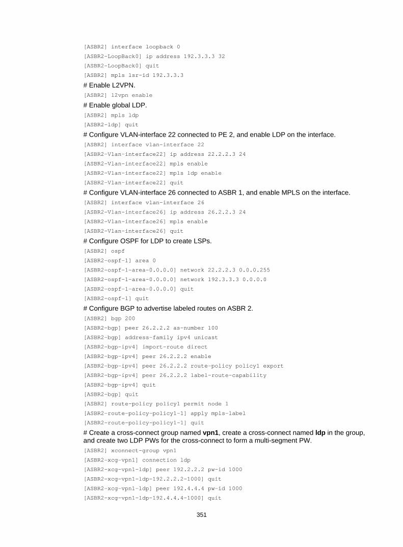
351
[ASBR2] interface loopback 0
[ASBR2-LoopBack0] ip address 192.3.3.3 32
[ASBR2-LoopBack0] quit
[ASBR2] mpls lsr-id 192.3.3.3
# Enable L2VPN. [ASBR2] l2vpn enable
# Enable global LDP. [ASBR2] mpls ldp
[ASBR2-ldp] quit
# Configure VLAN-interface 22 connected to PE 2, and enable LDP on the interface. [ASBR2] interface vlan-interface 22
[ASBR2-Vlan-interface22] ip address 22.2.2.3 24
[ASBR2-Vlan-interface22] mpls enable
[ASBR2-Vlan-interface22] mpls ldp enable
[ASBR2-Vlan-interface22] quit
# Configure VLAN-interface 26 connected to ASBR 1, and enable MPLS on the interface. [ASBR2] interface vlan-interface 26
[ASBR2-Vlan-interface26] ip address 26.2.2.3 24
[ASBR2-Vlan-interface26] mpls enable
[ASBR2-Vlan-interface26] quit
# Configure OSPF for LDP to create LSPs. [ASBR2] ospf
[ASBR2-ospf-1] area 0
[ASBR2-ospf-1-area-0.0.0.0] network 22.2.2.3 0.0.0.255
[ASBR2-ospf-1-area-0.0.0.0] network 192.3.3.3 0.0.0.0
[ASBR2-ospf-1-area-0.0.0.0] quit
[ASBR2-ospf-1] quit
# Configure BGP to advertise labeled routes on ASBR 2. [ASBR2] bgp 200
[ASBR2-bgp] peer 26.2.2.2 as-number 100
[ASBR2-bgp] address-family ipv4 unicast
[ASBR2-bgp-ipv4] import-route direct
[ASBR2-bgp-ipv4] peer 26.2.2.2 enable
[ASBR2-bgp-ipv4] peer 26.2.2.2 route-policy policy1 export
[ASBR2-bgp-ipv4] peer 26.2.2.2 label-route-capability
[ASBR2-bgp-ipv4] quit
[ASBR2-bgp] quit
[ASBR2] route-policy policy1 permit node 1
[ASBR2-route-policy-policy1-1] apply mpls-label
[ASBR2-route-policy-policy1-1] quit
# Create a cross-connect group named vpn1, create a cross-connect named ldp in the group, and create two LDP PWs for the cross-connect to form a multi-segment PW. [ASBR2] xconnect-group vpn1
[ASBR2-xcg-vpn1] connection ldp
[ASBR2-xcg-vpn1-ldp] peer 192.2.2.2 pw-id 1000
[ASBR2-xcg-vpn1-ldp-192.2.2.2-1000] quit
[ASBR2-xcg-vpn1-ldp] peer 192.4.4.4 pw-id 1000
[ASBR2-xcg-vpn1-ldp-192.4.4.4-1000] quit
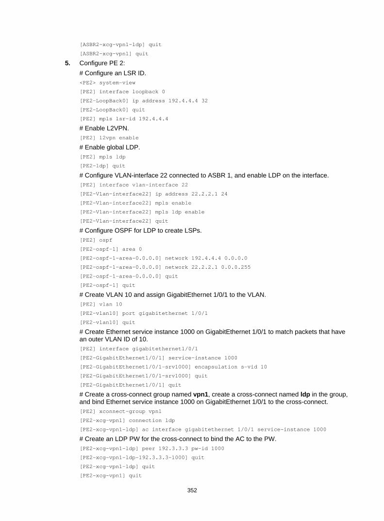
352
[ASBR2-xcg-vpn1-ldp] quit
[ASBR2-xcg-vpn1] quit
5. Configure PE 2: # Configure an LSR ID. <PE2> system-view
[PE2] interface loopback 0
[PE2-LoopBack0] ip address 192.4.4.4 32
[PE2-LoopBack0] quit
[PE2] mpls lsr-id 192.4.4.4
# Enable L2VPN. [PE2] l2vpn enable
# Enable global LDP. [PE2] mpls ldp
[PE2-ldp] quit
# Configure VLAN-interface 22 connected to ASBR 1, and enable LDP on the interface. [PE2] interface vlan-interface 22
[PE2-Vlan-interface22] ip address 22.2.2.1 24
[PE2-Vlan-interface22] mpls enable
[PE2-Vlan-interface22] mpls ldp enable
[PE2-Vlan-interface22] quit
# Configure OSPF for LDP to create LSPs. [PE2] ospf
[PE2-ospf-1] area 0
[PE2-ospf-1-area-0.0.0.0] network 192.4.4.4 0.0.0.0
[PE2-ospf-1-area-0.0.0.0] network 22.2.2.1 0.0.0.255
[PE2-ospf-1-area-0.0.0.0] quit
[PE2-ospf-1] quit
# Create VLAN 10 and assign GigabitEthernet 1/0/1 to the VLAN. [PE2] vlan 10
[PE2-vlan10] port gigabitethernet 1/0/1
[PE2-vlan10] quit
# Create Ethernet service instance 1000 on GigabitEthernet 1/0/1 to match packets that have an outer VLAN ID of 10. [PE2] interface gigabitethernet1/0/1
[PE2-GigabitEthernet1/0/1] service-instance 1000
[PE2-GigabitEthernet1/0/1-srv1000] encapsulation s-vid 10
[PE2-GigabitEthernet1/0/1-srv1000] quit
[PE2-GigabitEthernet1/0/1] quit
# Create a cross-connect group named vpn1, create a cross-connect named ldp in the group, and bind Ethernet service instance 1000 on GigabitEthernet 1/0/1 to the cross-connect. [PE2] xconnect-group vpn1
[PE2-xcg-vpn1] connection ldp
[PE2-xcg-vpn1-ldp] ac interface gigabitethernet 1/0/1 service-instance 1000
# Create an LDP PW for the cross-connect to bind the AC to the PW. [PE2-xcg-vpn1-ldp] peer 192.3.3.3 pw-id 1000
[PE2-xcg-vpn1-ldp-192.3.3.3-1000] quit
[PE2-xcg-vpn1-ldp] quit
[PE2-xcg-vpn1] quit

353
6. Configure CE 2. <CE2> system-view
[CE2] vlan 10
[CE2-vlan10] quit
[CE2] interface vlan-interface 10
[CE2-Vlan-interface10] ip address 100.1.1.2 24
[CE2-Vlan-interface10] quit
[CE2] interface gigabitethernet 1/0/1
[CE2-GigabitEthernet1/0/1] port link-type trunk
[CE2-GigabitEthernet1/0/1] port trunk permit vlan 10
[CE2-GigabitEthernet1/0/1] quit
Verifying the configuration # Display L2VPN PW information on PE 1. The output shows that a PW has been created. [PE1] display l2vpn pw
Flags: M - main, B - backup, H - hub link, S - spoke link, N - no split horizon
Total number of PWs: 1, 1 up, 0 blocked, 0 down, 0 defect
Xconnect-group Name: vpn1
Peer PW ID In/Out Label Proto Flag Link ID State
192.2.2.2 1000 65651/65779 LDP M 1 Up
# Display L2VPN PW information on ASBR 1. The output shows that two PWs have been created to form a multi-segment PW. [ASBR1] display l2vpn pw
Flags: M - main, B - backup, H - hub link, S - spoke link, N - no split horizon
Total number of PWs: 2, 2 up, 0 blocked, 0 down, 0 defect
Xconnect-group Name: vpn1
Peer PW ID In/Out Label Proto Flag Link ID State
192.1.1.1 1000 65779/65651 LDP M 0 Up
192.3.3.3 1000 65778/65651 LDP M 1 Up
# Display L2VPN PW information on ASBR 2. The output shows that two PWs have been created to form a multi-segment PW. [ASBR2] display l2vpn pw
Flags: M - main, B - backup, H - hub link, S - spoke link, N - no split horizon
Total number of PWs: 2, 2 up, 0 blocked, 0 down, 0 defect
Xconnect-group Name: vpn1
Peer PW ID In/Out Label Proto Flag Link ID State
192.2.2.2 1000 65651/65778 LDP M 0 Up
192.4.4.4 1000 65650/65779 LDP M 1 Up
# Display L2VPN PW information on PE 2. The output shows that a PW has been created. [PE2] display l2vpn pw
Flags: M - main, B - backup, H - hub link, S - spoke link, N - no split horizon
Total number of PWs: 1, 1 up, 0 blocked, 0 down, 0 defect
Xconnect-group Name: vpn1
Peer PW ID In/Out Label Proto Flag Link ID State
192.3.3.3 1000 65779/65650 LDP M 1 Up

354
# Verify that CE 1 and CE 2 can ping each other. (Details not shown.)

355
Configuring VPLS Overview
Virtual Private LAN Service (VPLS) delivers a point-to-multipoint L2VPN service over an MPLS or IP backbone. The provider backbone emulates a switch to connect all geographically dispersed sites of each customer network. The backbone is transparent to the customer sites, which can communicate with each other as if they were on the same LAN.
Basic VPLS architecture Figure 94 Basic VPLS architecture
As show in Figure 94, the VPLS architecture mainly includes the following components: • CE—A customer edge device is directly connected to the service provider network. • PE—A provider edge device connects one or more CEs to the service provider network. A PE
implements VPN access by mapping and forwarding packets between private networks and public network tunnels. A PE can be a UPE or NPE in a hierarchical VPLS.
• AC—An attachment circuit, physical or virtual, connects a CE and a PE, such as an Ethernet link or a VLAN.
• PW—A pseudowire is a bidirectional virtual connection between two PEs. An MPLS PW consists of two unidirectional MPLS LSPs in opposite directions.
• Tunnel—A tunnel can be an LSP tunnel or an MPLS TE tunnel. It carries one or more PWs over an IP/MPLS backbone. If a PW is carried on an LSP or MPLS TE tunnel, each packet on the PW contains two labels. The inner label is the PW label, which identifies the PW and makes sure the packet is forwarded to the correct VSI. The outer label is the public LSP or MPLS TE tunnel label, which makes sure the packet is correctly forwarded to the remote PE.
• VPLS instance—A customer network might include multiple geographically dispersed sites (such as site 1 and site 3 in Figure 94.) The service provider uses VPLS to connect all the sites
VPN 1
CE 1
PE 3
PE 1 PE 2 CE 2MPLS or IP backbone
PW
PE 4
PW
PW PW
Site 1
VPN 2
Site 2
CE 3
VPN 1
Site 3
VPN 2
CE 4
Site 4
AC
AC AC
AC
PWPW
Tunnel
Tunnel
Tunnel
Tunnel
TunnelTunne
l

356
to create a single Layer 2 VPN, which is referred to as a VPLS instance. Sites in different VPLS instances cannot communicate with each other at Layer 2.
• VSI—A virtual switch instance provides Layer 2 switching services for a VPLS instance on a PE. A VSI acts as a virtual switch that has all the functions of a conventional Ethernet switch, including source MAC address learning, MAC address aging, and flooding. VPLS uses VSIs to forward Layer 2 data packets in VPLS instances.
VPLS implementation Creating a PW
PEs use PWs to forward packets among VPN sites. PWs include static PWs, LDP PWs, BGP PWs, and BGP auto-discovery LDP PWs. • Static PW
To create a static PW, specify the address of the remote PE, the incoming label, and the outgoing label.
• LDP PW To create an LDP PW, specify the address of the remote PE, and use LDP to advertise the PW-label binding to the remote PE. After the two PEs receive the PW-label binding from each other, they establish an LDP PW. The FEC type in the LDP message is PWid FEC Element that includes the PW ID field (FEC 128). The PW ID identifies the PW bound to the PW label.
• BGP PW To create a BGP PW, BGP advertises label block information to the remote PE. After the two PEs receive label block information from each other, they use the label block information to calculate the incoming and outgoing labels and create the BGP PW. A PE also uses the received label block information to automatically find the remote PE.
• BGP auto-discovery LDP PW To create a BGP auto-discovery LDP PW, a PE uses BGP to automatically find the remote PE, and uses LDP to advertise the PW-label binding to the remote PE. After the two PEs receive the PW-label binding from each other, they establish a BGP auto-discovery LDP PW. The information advertised by BGP includes the ID (for example, LSR ID) and VPLS ID of the advertising PE. The receiving PE compares the received VPLS ID with its own VPLS ID. If the two VPLS IDs are identical, the two PEs use LDP to establish a PW. If not, the PEs do not establish a PW. The FEC type in the LDP message is Generalized PWid FEC Element (FEC 129), which contains the VPLS ID, Source Attachment Individual Identifier (SAII), and Target Attachment Individual Identifier (TAII). The SAII is the LSR ID of the advertising PE. The TAII identifies the remote PE and is advertised by the remote PE. VPLS ID+SAII+TAII uniquely identifies a PW in a VPLS instance.
MAC address learning, aging, and withdrawal VPLS provides reachability through source MAC learning. A PE maintains a MAC address table for each VSI.
As shown in Figure 95, a PE learns source MAC addresses in the following ways: • Learning the source MAC addresses of directly connected sites:
If the source MAC address of a packet from a CE does not exist in the MAC address table, the PE learns the source MAC address on the AC connected to the CE.
• Learning the source MAC addresses of remote sites connected through PWs: A VSI regards a PW as a logical Ethernet interface. If the source MAC address of a packet received from a PW does not exist in the MAC address table, the PE learns the source MAC address on the PW of the VSI.

357
Figure 95 Source MAC address learning on a PE
If no packet is received from a MAC address before the aging timer expires, VPLS deletes the MAC address to save MAC address table resources.
When an AC or a PW goes down, the PE deletes MAC addresses on the AC or PW. Then it sends an LDP address withdrawal message to notify all other PEs in the VPLS instance to delete those MAC addresses.
Unicast traffic forwarding and flooding After a PE receives a unicast packet from an AC, the PE searches the MAC address table of the VSI bound to the AC to determine how to forward this packet. • If a match is found, the PE forwards the packet according to the matching entry. If the outgoing
interface in the entry is a PW, the PE inserts the PW label to the packet, and adds the public tunnel header to the packet. It then forwards the packet to the remote PE over the PW. If the outgoing interface in the entry is a local interface, the PE directly forwards the packet to the local interface.
• If no match is found, the PE floods the packet to all other ACs and PWs in the VSI.
After a PE receives a unicast packet from a PW, the PE searches the MAC address table of the VSI bound to the PW to determine how to forward this packet. • If a match is found, the PE forwards the packet through the egress interface in the matching
entry. • If no match is found, the PE floods the packet to all ACs in the VSI.
Multicast and broadcast traffic forwarding and flooding After a PE receives a multicast or broadcast packet from an AC, the PE floods the packet to all other ACs and the PWs in the VSI bound to the AC.
After a PE receives a multicast or broadcast packet from a PW, the PE floods the packet to all ACs in the VSI bound to the PW.
MAC A IP 1.1.1.2
PW 3
PW 1PW 2
MAC B IP 1.1.1.3
PE 1
PE 2
PE 3
ARP broadcast
ARP responseVPN 1 A Vlan 10, port 1
VPN 1 B PW 1
VSI MAC Port
PE 1
VPN 1 A PW 3
VSI MAC Port
PE 3
VPN 1
VPN 1 B
VSI MAC
A
Vlan 10, port 1
PW 1
Port
PE 2
MPLS or IP backbone
VLAN 10Port 1
VLAN 10Port 1
VLAN 10Port 1

358
PW full mesh and split horizon A loop prevention protocol such as STP is required in a Layer 2 network to avoid loops. However, deploying a loop prevention protocol on PEs brings management and maintenance difficulties. Therefore, VPLS uses the following methods to prevent loops: • Full mesh—Every two PEs in a VPLS instance must establish a PW to create a full mesh of
PWs among PEs in the VPLS instance. • Split horizon—A PE does not forward packets received from a PW to any other PW in the
same VSI but only forwards those packets to ACs.
H-VPLS VPLS requires a full mesh of PWs among all PEs in a VPLS instance. In a large-scale network, however, a full mesh of PWs causes very high PW signaling overhead and creates difficulties for network management and expansion. Hierarchical VPLS (H-VPLS) reduces the number of PWs by dividing a VPLS network into a backbone domain and edge domains.
Only static PWs and LDP PWs support H-VPLS.
In an H-VPLS: • An edge domain provides access for a user network to the backbone domain. • The Network Provider Edge (NPE) devices are fully meshed in the backbone domain. A PW
between NPEs is referred to as an N-PW. • A User facing-Provider Edge (UPE) device only establishes a PW with the neighboring NPE. A
PW between a UPE and an NPE is referred to as a U-PW.
H-VPLS access modes Two access modes are available in H-VPLS: MPLS access and Ethernet access.
Figure 96 H-VPLS using MPLS access
As shown in Figure 96, in MPLS access mode, the edge domain is an MPLS network. The UPE creates a U-PW with NPE 1. The UPE does not create PWs to any remote PEs. After the UPE receives a packet from a CE, it adds the label assigned to the U-PW into the packet and then forwards the packet to NPE 1 through a public tunnel. NPE 1 maps the packet to the VSI that corresponds to the PW label, and searches the MAC address table of the VSI to forward the packet.
NOTE: A U-PW created on the NPE must have split horizon disabled because the NPE needs to forward packets between U-PW and N-PW.
CE 3
NPE 3NPE 1
N-PW
CE 1
CE 2
NPE 2
UPE
U-PW
N-PWN-PW
Backbone domain
Edge domain (MPLS)

359
Figure 97 H-VPLS using Ethernet access
As shown in Figure 97, in Ethernet access mode, the edge domain is an Ethernet network. The UPE and NPE 1 establish a point-to-point Ethernet QinQ connection in between (enable QinQ on the UPE interfaces connecting CEs and configure VLAN access mode on NPE 1). After UPE receives a packet from a CE, it adds an outer VLAN tag into the packet and forwards the packet to NPE 1. NPE 1 regards the outer VLAN tag as the service provider VLAN tag. It maps the packet to the VSI that corresponds to the VLAN tag and then searches the MAC address table of the VSI to forward the packet.
UPE dual homing and PW redundancy A single PW between a UPE and an NPE has a distinct drawback: once the PW fails, all customer sites connected to the UPE lose connectivity. You can connect a UPE to two NPEs to achieve U-PW redundancy.
In the H-VPLS using MPLS access as shown in Figure 98, the UPE connects to two NPEs through primary and backup U-PWs. The UPE uses the primary U-PW to forward traffic. When the primary U-PW fails, the UPE uses the backup U-PW to forward traffic.
Figure 98 UPE dual homing and redundancy in H-VPLS using MPLS access
The backup U-PW is used in the following scenarios: • The tunnel that carries the primary U-PW is deleted after a fault detection mechanism such as
BFD detects a failure on the tunnel, which causes the primary U-PW to go down.
CE 3
NPE 3NPE 1
N-PW
CE 1
CE 2
NPE 2
UPE
QinQ
N-PWN-PW
Backbone domain
Edge domain (Ethernet)
CE 1
NPE 3
NPE 1 NPE 2 CE 2
Backbone domain
N-PW
NPE 4
N-PW
N-PW N-PW
CE 3
CE 4
N-PWN-PW
UPE
Primary U-PW
Backup U-PW
Edge domain (MPLS)

360
• The primary U-PW is deleted by the control plane. For example, the LDP session on the primary U-PW link is down, causing the primary U-PW to be deleted.
• BFD detects a failure of the primary U-PW. • A primary and backup U-PW switchover is triggered by a command.
As a best practice, execute the port bridge enable command on the NPE 1' interface connected to NPE 4 when the following conditions are met: • The MPLS network (edge domain) is configured with a fast switchover mechanism, for
example, LDP FRR or MPLS TE FRR. • A primary tunnel is established over the link UPE—NPE 1, and a backup tunnel is established
over the link UPE—NPE 4—NPE 1.
When the primary tunnel fails, traffic will be immediately switched to the backup tunnel. The failover time is so short that the U-PW switchover from primary to backup might not be triggered. In this scenario, NPE 1 needs to forward traffic received from NPE 4 to NPE 4, NPE 3, and NPE 2 in the backbone domain. To ensure correct forwarding, execute the port bridge enable command on the NPE 1' interface connected to NPE 4. Then, NPE 1 can send traffic received on the interface out of the interface itself.
VPLS configuration task list To configure a VPLS network, complete the following tasks: • Configure an IGP to ensure IP connectivity within the backbone network. • Configure basic MPLS, LDP, GER, or MPLS TE to establish public tunnels on the backbone
network. • Configure VPLS on PEs. For example, configure a VSI, establish a PW, and associate an AC
and a VSI.
This chapter describes only VPLS configurations on a PE. For more information about other configurations, see relevant configuration guides.
To configure VPLS on a PE, perform the following tasks:
Tasks at a glance Remarks (Required.) Enabling L2VPN N/A
(Required.) Configuring an AC In an H-VPLS using MPLS access, do not perform this task on the access NPEs of the UPEs.
(Required.) Configuring a VSI N/A
Configuring a PW: • (Optional.) Configuring a PW class • (Required.) Choose either of the following tasks to
configure a PW: Configuring a static PW Configuring an LDP PW
Choose a PW configuration method depending on the VPLS implementation.
(Required.) Binding an AC to a VSI In an H-VPLS using MPLS access, do not perform this task on the access NPEs of the UPEs.
(Optional.) Configuring UPE dual homing: • Configuring static PW redundancy • Configuring LDP PW redundancy
N/A
(Required.) Configuring MAC address learning N/A
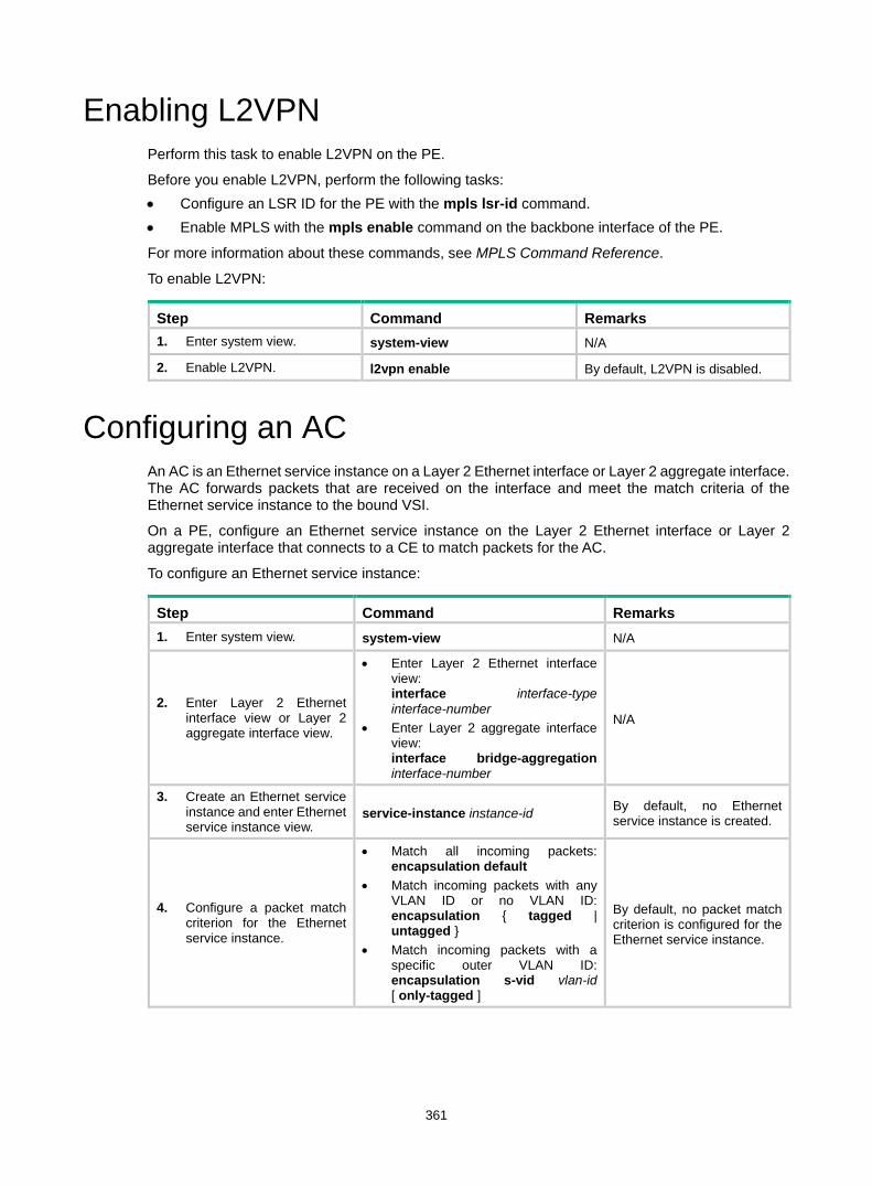
361
Enabling L2VPN Perform this task to enable L2VPN on the PE.
Before you enable L2VPN, perform the following tasks: • Configure an LSR ID for the PE with the mpls lsr-id command. • Enable MPLS with the mpls enable command on the backbone interface of the PE.
For more information about these commands, see MPLS Command Reference.
To enable L2VPN:
Step Command Remarks 1. Enter system view. system-view N/A
2. Enable L2VPN. l2vpn enable By default, L2VPN is disabled.
Configuring an AC An AC is an Ethernet service instance on a Layer 2 Ethernet interface or Layer 2 aggregate interface. The AC forwards packets that are received on the interface and meet the match criteria of the Ethernet service instance to the bound VSI.
On a PE, configure an Ethernet service instance on the Layer 2 Ethernet interface or Layer 2 aggregate interface that connects to a CE to match packets for the AC.
To configure an Ethernet service instance:
Step Command Remarks 1. Enter system view. system-view N/A
2. Enter Layer 2 Ethernet interface view or Layer 2 aggregate interface view.
• Enter Layer 2 Ethernet interface view: interface interface-type interface-number
• Enter Layer 2 aggregate interface view: interface bridge-aggregation interface-number
N/A
3. Create an Ethernet service instance and enter Ethernet service instance view.
service-instance instance-id By default, no Ethernet service instance is created.
4. Configure a packet match criterion for the Ethernet service instance.
• Match all incoming packets: encapsulation default
• Match incoming packets with any VLAN ID or no VLAN ID: encapsulation { tagged | untagged }
• Match incoming packets with a specific outer VLAN ID: encapsulation s-vid vlan-id [ only-tagged ]
By default, no packet match criterion is configured for the Ethernet service instance.

362
Configuring a VSI Step Command Remarks 1. Enter system view. system-view N/A
2. Create a VSI and enter VSI view. vsi vsi-name By default, no VSI is created.
3. (Optional.) Configure a description for the VSI. description text By default, no description is
configured for a VSI.
4. (Optional.) Configure the default PW ID for the VSI. default-pw-id default-pw-id By default, no default PW ID is
configured for the VSI.
5. Configure an MTU for the VSI. mtu mtu By default, the MTU of a VSI is
1500 bytes.
6. (Optional.) Enable the VSI. undo shutdown By default, a VSI is enabled.
Configuring a PW Configuring a PW class
In a PW class, you can configure PW attributes such as the PW data encapsulation type, and whether to enable control word. To simplify PW configuration, you can configure PWs with the same attributes by referencing the same PW class.
To configure a PW class:
Step Command Remarks 1. Enter system view. system-view N/A
2. Create a PW class and enter PW class view. pw-class class-name By default, no PW class is
created.
3. (Optional.) Enable control word. control-word enable By default, control word is
disabled.
4. (Optional.) Specify the PW data encapsulation type. pw-type { ethernet | vlan } By default, the PW data
encapsulation type is VLAN.
Configuring a static PW
Step Command Remarks 1. Enter system view. system-view N/A
2. Enter VSI view. vsi vsi-name N/A
3. Specify static signaling for PWs, and enter VSI static view.
pwsignaling static By default, no PW signaling protocol is specified.
4. Configure a static PW, and enter VSI static PW view.
peer ip-address [ pw-id pw-id ] in-label label-value out-label label-value [ no-split-horizon | pw-class class-name | tunnel-policy
By default, no static PW is configured. If you have configured a default PW ID for the VSI with the default-pw-id command, you can use the default PW ID without providing a PW ID in the peer command. If

363
Step Command Remarks tunnel-policy-name ] * no default PW ID is configured, you must
provide a PW ID in the peer command. You must specify the no-split-horizon keyword to disable split horizon when you configure an NPE to establish a U-PW with a UPE.
Configuring an LDP PW Before you configure an LDP PW, enable global and interface MPLS LDP on the PE. For information about MPLS LDP configuration, see "Configuring LDP."
To configure an LDP PW:
Step Command Remarks 1. Enter system view. system-view N/A
2. Enter VSI view. vsi vsi-name N/A
3. Specify LDP signaling for PWs, and enter VSI LDP signaling view.
pwsignaling ldp By default, no PW signaling protocol is specified.
4. Configure an LDP PW, and enter VSI LDP PW view.
peer ip-address [ pw-id pw-id ] [ no-split-horizon | pw-class class-name | tunnel-policy tunnel-policy-name ] *
By default, no LDP PW is configured. If you have configured a default PW ID for the VSI with the default-pw-id command, you can use the default PW ID without providing a PW ID in the peer command. If no default PW ID is configured, you must provide a PW ID in the peer command. You must specify the no-split-horizon keyword to disable split horizon when you configure an NPE to establish a U-PW with a UPE.
Configuring a BGP PW To configure a BGP PW, perform the following configurations on PEs: • Configure BGP to advertise VPLS label block information. • Create a BGP PW.
Configuring BGP to advertise VPLS label block information
Step Command Remarks 1. Enter system view. system-view N/A
2. Enable BGP and enter BGP view. bgp as-number By default, BGP is not enabled.
3. Configure the remote PE as a BGP peer.
peer { group-name | ip-address [ mask-length ] } as-number as-number
By default, no BGP peer is configured.
4. Create a BGP L2VPN address-family l2vpn By default, no BGP L2VPN
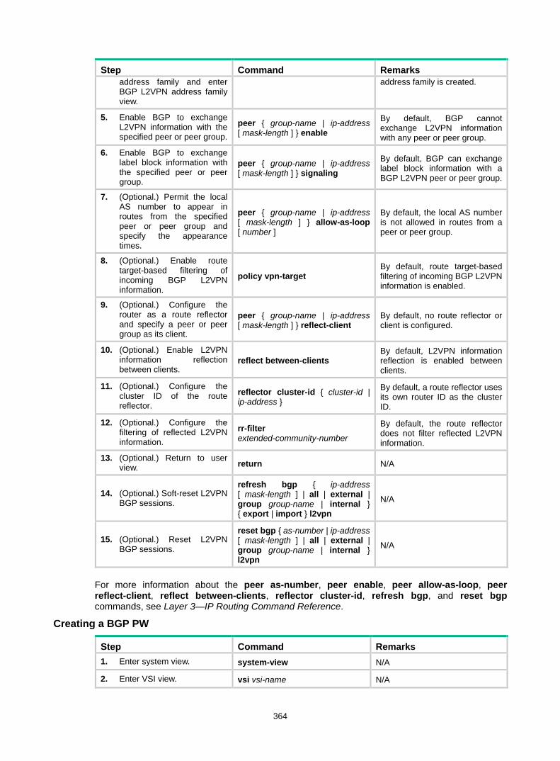
364
Step Command Remarks address family and enter BGP L2VPN address family view.
address family is created.
5. Enable BGP to exchange L2VPN information with the specified peer or peer group.
peer { group-name | ip-address [ mask-length ] } enable
By default, BGP cannot exchange L2VPN information with any peer or peer group.
6. Enable BGP to exchange label block information with the specified peer or peer group.
peer { group-name | ip-address [ mask-length ] } signaling
By default, BGP can exchange label block information with a BGP L2VPN peer or peer group.
7. (Optional.) Permit the local AS number to appear in routes from the specified peer or peer group and specify the appearance times.
peer { group-name | ip-address [ mask-length ] } allow-as-loop [ number ]
By default, the local AS number is not allowed in routes from a peer or peer group.
8. (Optional.) Enable route target-based filtering of incoming BGP L2VPN information.
policy vpn-target By default, route target-based filtering of incoming BGP L2VPN information is enabled.
9. (Optional.) Configure the router as a route reflector and specify a peer or peer group as its client.
peer { group-name | ip-address [ mask-length ] } reflect-client
By default, no route reflector or client is configured.
10. (Optional.) Enable L2VPN information reflection between clients.
reflect between-clients By default, L2VPN information reflection is enabled between clients.
11. (Optional.) Configure the cluster ID of the route reflector.
reflector cluster-id { cluster-id | ip-address }
By default, a route reflector uses its own router ID as the cluster ID.
12. (Optional.) Configure the filtering of reflected L2VPN information.
rr-filter extended-community-number
By default, the route reflector does not filter reflected L2VPN information.
13. (Optional.) Return to user view. return N/A
14. (Optional.) Soft-reset L2VPN BGP sessions.
refresh bgp { ip-address [ mask-length ] | all | external | group group-name | internal } { export | import } l2vpn
N/A
15. (Optional.) Reset L2VPN BGP sessions.
reset bgp { as-number | ip-address [ mask-length ] | all | external | group group-name | internal } l2vpn
N/A
For more information about the peer as-number, peer enable, peer allow-as-loop, peer reflect-client, reflect between-clients, reflector cluster-id, refresh bgp, and reset bgp commands, see Layer 3—IP Routing Command Reference.
Creating a BGP PW
Step Command Remarks 1. Enter system view. system-view N/A
2. Enter VSI view. vsi vsi-name N/A

365
Step Command Remarks 3. Configure the VSI to
automatically discover neighbors through BGP and enter auto-discovery VSI view.
auto-discovery bgp By default, a VSI does not automatically discover neighbors through BGP.
4. Configure an RD for the auto-discovery VSI.
route-distinguisher route-distinguisher
By default, no RD is configured for the auto-discovery VSI.
5. Configure route targets for the auto-discovery VSI.
vpn-target vpn-target&<1-8> [ both | export-extcommunity | import-extcommunity ]
By default, no route targets are configured for the auto-discovery VSI.
6. (Optional.) Specify a PW class for the auto-discovery VSI.
pw-class class-name By default, no PW class is specified.
7. (Optional.) Specify a tunnel policy for the auto-discovery VSI.
tunnel-policy tunnel-policy-name By default, no tunnel policy is specified.
8. Use BGP to create a PW to an automatically discovered remote PE and enter auto-discovery VSI BGP signaling view.
signaling-protocol bgp By default, no signaling protocol is specified.
9. Create a local site and enter site view.
site site-id [ range range-value ] [ default-offset default-offset ] By default, no local site is created.
Configuring a BGP auto-discovery LDP PW Before you perform this configuration, enable MPLS LDP on interfaces and globally. For details, see "Configuring LDP."
To configure a BGP auto-discovery LDP PW, perform the following configurations on PEs: • Configure BGP to advertise VPLS PE information. • Use LDP to create a PW.
Configuring BGP to advertise VPLS PE information
Step Command Remarks 1. Enter system view. system-view N/A
2. Enable BGP and enter BGP view. bgp as-number By default, BGP is not
enabled.
3. Configure the remote PE as a BGP peer.
peer { group-name | ip-address [ mask-length ] } as-number as-number
By default, no BGP peer is configured.
4. Create a BGP L2VPN address family and enter BGP L2VPN address family view.
address-family l2vpn By default, no BGP L2VPN address family is created.
5. Enable BGP to exchange VPLS PE information with the specified peer or peer group.
peer { group-name | ip-address [ mask-length ] } enable
By default, BGP cannot exchange VPLS PE information with a peer or peer group.
6. Enable BGP to exchange label block information with
peer { group-name | ip-address [ mask-length ] } auto-discovery
By default, BGP can exchange VPLS PE information with a

366
Step Command Remarks the specified peer or peer group.
[ non-standard ] BGP L2VPN peer or peer group by using RFC 6074 MP_REACH_NLRI.
7. (Optional.) Permit the local AS number to appear in routes from the specified peer or peer group and specify the appearance times.
peer { group-name | ip-address [ mask-length ] } allow-as-loop [ number ]
By default, the local AS number is not allowed in routes from a peer or peer group.
8. (Optional.) Enable route target-based filtering of incoming BGP L2VPN information.
policy vpn-target By default, route target-based filtering of incoming BGP L2VPN information is enabled.
9. (Optional.) Configure the router as a route reflector and specify a peer or peer group as its client.
peer { group-name | ip-address [ mask-length ] } reflect-client
By default, no route reflector or client is configured.
10. (Optional.) Enable L2VPN information reflection between clients.
reflect between-clients By default, L2VPN information reflection is enabled between clients.
11. (Optional.) Configure the cluster ID of the route reflector.
reflector cluster-id { cluster-id | ip-address }
By default, a route reflector uses its own router ID as the cluster ID.
12. (Optional.) Configure the filtering of reflected L2VPN information.
rr-filter extended-community-number
By default, the route reflector does not filter reflected L2VPN information.
13. (Optional.) Return to user view. return N/A
14. (Optional.) Soft-reset L2VPN BGP sessions.
refresh bgp { ip-address [ mask-length ] | all | external | group group-name | internal } { export | import } l2vpn
N/A
15. (Optional.) Reset L2VPN BGP sessions.
reset bgp { as-number | ip-address [ mask-length ] | all | external | group group-name | internal } l2vpn
N/A
For more information about the peer as-number, peer enable, peer allow-as-loop, peer reflect-client, reflect between-clients, reflector cluster-id, refresh bgp, and reset bgp commands, see Layer 3—IP Routing Command Reference.
Creating a BGP auto-discovery LDP PW
Step Command Remarks 1. Enter system view. system-view N/A
2. Enter VSI view. vsi vsi-name N/A
3. Configure the VSI to automatically discover neighbors through BGP and enter auto-discovery VSI view.
auto-discovery bgp By default, a VSI does not automatically discover neighbors through BGP.
4. Configure an RD for the auto-discovery VSI.
route-distinguisher route-distinguisher
By default, no RD is configured for the auto-discovery VSI.
5. Configure route targets for vpn-target vpn-target&<1-8> By default, no route targets are
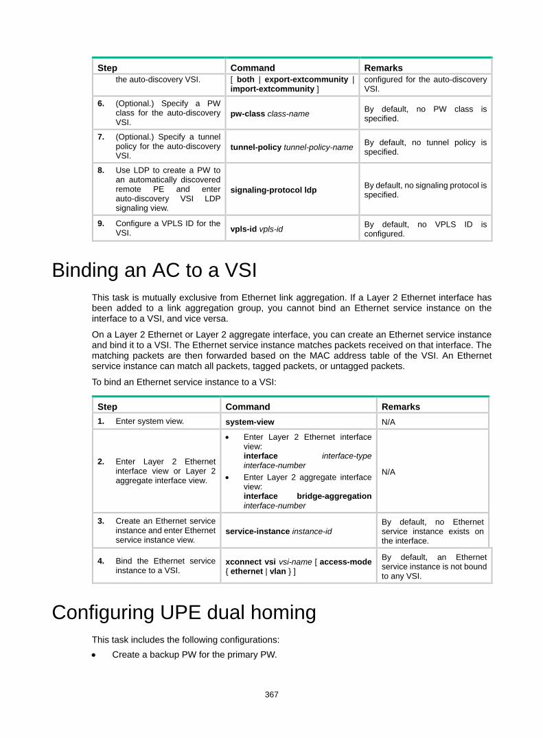
367
Step Command Remarks the auto-discovery VSI. [ both | export-extcommunity |
import-extcommunity ] configured for the auto-discovery VSI.
6. (Optional.) Specify a PW class for the auto-discovery VSI.
pw-class class-name By default, no PW class is specified.
7. (Optional.) Specify a tunnel policy for the auto-discovery VSI.
tunnel-policy tunnel-policy-name By default, no tunnel policy is specified.
8. Use LDP to create a PW to an automatically discovered remote PE and enter auto-discovery VSI LDP signaling view.
signaling-protocol ldp By default, no signaling protocol is specified.
9. Configure a VPLS ID for the VSI. vpls-id vpls-id By default, no VPLS ID is
configured.
Binding an AC to a VSI This task is mutually exclusive from Ethernet link aggregation. If a Layer 2 Ethernet interface has been added to a link aggregation group, you cannot bind an Ethernet service instance on the interface to a VSI, and vice versa.
On a Layer 2 Ethernet or Layer 2 aggregate interface, you can create an Ethernet service instance and bind it to a VSI. The Ethernet service instance matches packets received on that interface. The matching packets are then forwarded based on the MAC address table of the VSI. An Ethernet service instance can match all packets, tagged packets, or untagged packets.
To bind an Ethernet service instance to a VSI:
Step Command Remarks 1. Enter system view. system-view N/A
2. Enter Layer 2 Ethernet interface view or Layer 2 aggregate interface view.
• Enter Layer 2 Ethernet interface view: interface interface-type interface-number
• Enter Layer 2 aggregate interface view: interface bridge-aggregation interface-number
N/A
3. Create an Ethernet service instance and enter Ethernet service instance view.
service-instance instance-id By default, no Ethernet service instance exists on the interface.
4. Bind the Ethernet service instance to a VSI.
xconnect vsi vsi-name [ access-mode { ethernet | vlan } ]
By default, an Ethernet service instance is not bound to any VSI.
Configuring UPE dual homing This task includes the following configurations: • Create a backup PW for the primary PW.

368
• Specify whether to switch traffic from the backup PW to the primary PW when the primary PW recovers, and the wait time for the switchover.
• Perform a manual PW switchover.
Configuring static PW redundancy
Step Command Remarks 1. Enter system view. system-view N/A
2. Enter VSI view. vsi vsi-name N/A
3. Specify static signaling for PWs, and enter VSI static view.
pwsignaling static By default, no PW signaling protocol is specified for the VSI.
4. (Optional.) Specify whether to switch traffic from the backup PW to the primary PW when the primary PW recovers, and the wait time for the switchover.
revertive { wtr wtr-time | never } By default, when the primary PW recovers, traffic is immediately switched back from the backup PW to the primary PW.
5. Configure a static PW and enter VSI static PW view.
peer ip-address [ pw-id pw-id ] [ in-label label-value out-label label-value ] [ no-split-horizon | pw-class class-name | tunnel-policy tunnel-policy-name ] *
By default, no static PW is configured.
6. Configure a backup static PW and enter VSI static backup PW view.
backup-peer ip-address [ pw-id pw-id ] in-label label-value out-label label-value [ pw-class class-name | tunnel-policy tunnel-policy-name ] *
By default, no backup static PW is configured. If you have configured a default PW ID for the VSI with the default-pw-id command, you can use the default PW ID without providing a PW ID in the backup-peer command. If no default PW ID is configured, you must provide a PW ID in the backup-peer command.
7. Return to user view. return N/A
8. Manually switch traffic of the specified PW to its backup PW.
l2vpn switchover peer ip-address pw-id pw-id N/A
Configuring LDP PW redundancy
Step Command Remarks 1. Enter system view. system-view N/A
2. Enter VSI view. vsi vsi-name N/A
3. Specify LDP signaling for PWs, and enter VSI LDP signaling view.
pwsignaling ldp By default, no PW signaling protocol is specified for the VSI.
4. (Optional.) Specify whether to switch traffic from the backup PW to the primary
revertive { wtr wtr-time | never } By default, when the primary PW recovers, traffic is immediately switched back from the backup
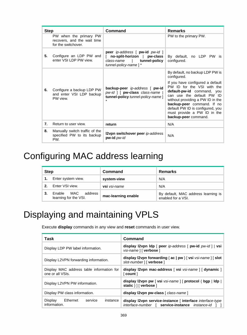
369
Step Command Remarks PW when the primary PW recovers, and the wait time for the switchover.
PW to the primary PW.
5. Configure an LDP PW and enter VSI LDP PW view.
peer ip-address [ pw-id pw-id ] [ no-split-horizon | pw-class class-name | tunnel-policy tunnel-policy-name ] *
By default, no LDP PW is configured.
6. Configure a backup LDP PW and enter VSI LDP backup PW view.
backup-peer ip-address [ pw-id pw-id ] [ pw-class class-name | tunnel-policy tunnel-policy-name ] *
By default, no backup LDP PW is configured. If you have configured a default PW ID for the VSI with the default-pw-id command, you can use the default PW ID without providing a PW ID in the backup-peer command. If no default PW ID is configured, you must provide a PW ID in the backup-peer command.
7. Return to user view. return N/A
8. Manually switch traffic of the specified PW to its backup PW.
l2vpn switchover peer ip-address pw-id pw-id N/A
Configuring MAC address learning Step Command Remarks 1. Enter system view. system-view N/A
2. Enter VSI view. vsi vsi-name N/A
3. Enable MAC address learning for the VSI. mac-learning enable By default, MAC address learning is
enabled for a VSI.
Displaying and maintaining VPLS Execute display commands in any view and reset commands in user view.
Task Command
Display LDP PW label information. display l2vpn ldp [ peer ip-address [ pw-id pw-id ] | vsi vsi-name ] [ verbose ]
Display L2VPN forwarding information. display l2vpn forwarding { ac | pw } [ vsi vsi-name ] [ slot slot-number ] [ verbose ]
Display MAC address table information for one or all VSIs.
display l2vpn mac-address [ vsi vsi-name ] [ dynamic ] [ count ]
Display L2VPN PW information. display l2vpn pw [ vsi vsi-name ] [ protocol { bgp | ldp | static } ] [ verbose ]
Display PW class information. display l2vpn pw-class [ class-name ]
Display Ethernet service instance information.
display l2vpn service-instance [ interface interface-type interface-number [ service-instance instance-id ] ]

370
Task Command [ verbose ]
Display VSI information. display l2vpn vsi [ name vsi-name ] [ verbose ]
Display information about automatically discovered VPLS PEs.
display l2vpn auto-discovery [ peer ip-address ] [ vsi vsi-name ]
Display VPLS label block information. display l2vpn bgp [ peer ip-address | local ] [ vsi vsi-name ] [ verbose ]
Display BGP L2VPN peer group information. display bgp group l2vpn [ group-name group-name ]
Display VPLS PE information maintained by BGP.
display bgp l2vpn auto-discovery [ peer ip-address { advertised | received } [ statistics ] | route-distinguisher route-distinguisher [ pe-address ip-address [ advertise-info ] ] | statistics ]
Display VPLS label block information maintained by BGP.
display bgp l2vpn signaling [ peer ip-address { advertised | received } [ statistics ] | route-distinguisher route-distinguisher [ site-id site-id [ label-offset label-offset [ advertise-info ] ] ] | statistics ]
Display BGP L2VPN peer information. display bgp peer l2vpn [ ip-address mask-length | { ip-address | group-name group-name } log-info | [ [ ip-address ] verbose ] [ standby slot slot-number ] ]
Display BGP L2VPN update group information. display bgp update-group l2vpn [ ip-address ]
Clear MAC address entries for one or all VSIs. reset l2vpn mac-address [ vsi vsi-name ]
Reset L2VPN BGP sessions. reset bgp { as-number | ip-address [ mask-length ] | all | external | group group-name | internal } l2vpn
For more information about the display bgp group l2vpn, display bgp peer l2vpn, display bgp update-group l2vpn, and reset bgp commands, see Layer 3—IP Routing Command Reference.
VPLS configuration examples Static PW configuration example Network requirements
Configure VPLS on each PE, and establish static PWs between the PEs to interconnect the CEs.

371
Figure 99 Network diagram
Configuration procedure This task includes the following configurations: • Configure basic MPLS on each PE: configure LSR ID, enable LDP, run IGP (OSPF in this
example) to establish LSPs. • Establish static PWs: enable L2VPN, create static PWs, and specify labels. 1. Configure PE 1:
# Configure an LSR ID. <PE1> system-view
[PE1] interface loopback 0
[PE1-LoopBack0] ip address 1.1.1.9 32
[PE1-LoopBack0] quit
[PE1] mpls lsr-id 1.1.1.9
# Enable L2VPN. [PE1] l2vpn enable
# Enable global LDP. [PE1] mpls ldp
[PE1-ldp] quit
# Configure VLAN-interface 20 connected to PE 2 and enable LDP on the interface. [PE1] interface vlan-interface 20
[PE1-Vlan-interface20] ip address 20.1.1.1 24
[PE1-Vlan-interface20] mpls enable
[PE1-Vlan-interface20] mpls ldp enable
[PE1-Vlan-interface20] quit
# Configure VLAN-interface 30 connected to PE 3 and enable LDP on the interface. [PE1] interface vlan-interface 30
[PE1-Vlan-interface30] ip address 30.1.1.1 24
[PE1-Vlan-interface30] mpls enable
[PE1-Vlan-interface30] mpls ldp enable
[PE1-Vlan-interface30] quit
# Configure OSPF for LDP to create LSPs. [PE1] ospf
Loop01.1.1.9/32
GE1/0/1 GE1/0/1
CE 1
VPN 1
PE 1 PE 2
Loop02.2.2.9/32
CE 2
VPN 1
Loop03.3.3.9/32
PE 3
CE 3
VPN 1
GE1/0/1
Vlan-int20 Vlan-int20
Vlan-int30
Vlan-int30 Vlan-int40
Vlan-int40

372
[PE1-ospf-1] area 0
[PE1-ospf-1-area-0.0.0.0] network 20.1.1.0 0.0.0.255
[PE1-ospf-1-area-0.0.0.0] network 30.1.1.0 0.0.0.255
[PE1-ospf-1-area-0.0.0.0] network 1.1.1.9 0.0.0.0
[PE1-ospf-1-area-0.0.0.0] quit
[PE1-ospf-1] quit
# Create a VSI on PE 1, and configure the peer PEs. [PE1] vsi svc
[PE1-vsi-svc] pwsignaling static
[PE1-vsi-svc-static] peer 2.2.2.9 pw-id 3 in-label 100 out-label 100
[PE1-vsi-svc-static-2.2.2.9-3] quit
[PE1-vsi-svc-static] peer 3.3.3.9 pw-id 3 in-label 200 out-label 200
[PE1-vsi-svc-static-3.3.3.9-3] quit
[PE1-vsi-svc-static] quit
[PE1-vsi-svc] quit
# Create Ethernet service instance 10 on GigabitEthernet 1/0/1 to match all packets. [PE1] interface gigabitethernet1/0/1
[PE1-GigabitEthernet1/0/1] service-instance 10
[PE1-GigabitEthernet1/0/1-srv10] encapsulation default
# Bind Ethernet service instance 10 to the VSI svc. [PE1-GigabitEthernet1/0/1-srv10] xconnect vsi svc
2. Configure PE 2: # Configure an LSR ID. <PE2> system-view
[PE2] interface loopback 0
[PE2-LoopBack0] ip address 2.2.2.9 32
[PE2-LoopBack0] quit
[PE2] mpls lsr-id 2.2.2.9
# Enable L2VPN. [PE2] l2vpn enable
# Enable global LDP. [PE2] mpls ldp
[PE2-ldp] quit
# Configure VLAN-interface 20 connected to PE 1, and enable LDP on the interface. [PE2] interface vlan-interface 20
[PE2-Vlan-interface20] ip address 20.1.1.2 24
[PE2-Vlan-interface20] mpls enable
[PE2-Vlan-interface20] mpls ldp enable
[PE2-Vlan-interface20] quit
# Configure VLAN-interface 40 connected to PE 3, and enable LDP on the interface. [PE2] interface vlan-interface 40
[PE2-Vlan-interface40] ip address 40.1.1.2 24
[PE2-Vlan-interface40] mpls enable
[PE2-Vlan-interface40] mpls ldp enable
[PE2-Vlan-interface40] quit
# Configure OSPF for LDP to create LSPs. [PE2] ospf

373
[PE2-ospf-1] area 0
[PE2-ospf-1-area-0.0.0.0] network 20.1.1.0 0.0.0.255
[PE2-ospf-1-area-0.0.0.0] network 40.1.1.0 0.0.0.255
[PE2-ospf-1-area-0.0.0.0] network 2.2.2.9 0.0.0.0
[PE2-ospf-1-area-0.0.0.0] quit
[PE2-ospf-1] quit
# Create a VSI on PE 2, and configure the peer PEs. [PE2] vsi svc
[PE2-vsi-svc] pwsignaling static
[PE2-vsi-svc-static] peer 1.1.1.9 pw-id 3 in-label 100 out-label 100
[PE2-vsi-svc-static-1.1.1.9-3] quit
[PE2-vsi-svc-static] peer 3.3.3.9 pw-id 3 in-label 300 out-label 300
[PE2-vsi-svc-static-3.3.3.9-3] quit
[PE2-vsi-svc-static] quit
[PE2-vsi-svc] quit
# Create Ethernet service instance 10 on GigabitEthernet 1/0/1 to match all packets. [PE2] interface gigabitethernet1/0/1
[PE2-GigabitEthernet1/0/1] service-instance 10
[PE2-GigabitEthernet1/0/1-srv10] encapsulation default
# Bind Ethernet service instance 10 to the VSI svc. [PE2-GigabitEthernet1/0/1-srv10] xconnect vsi svc
3. Configure PE 3: # Configure an LSR ID. <PE3> system-view
[PE3] interface loopback 0
[PE3-LoopBack0] ip address 3.3.3.9 32
[PE3-LoopBack0] quit
[PE3] mpls lsr-id 3.3.3.9
# Enable L2VPN. [PE3] l2vpn enable
# Enable global LDP. [PE3] mpls ldp
[PE3-ldp] quit
# Configure VLAN-interface 30 connected to PE 1, and enable LDP on the interface. [PE3] interface vlan-interface 30
[PE3-Vlan-interface30] ip address 30.1.1.3 24
[PE3-Vlan-interface30] mpls enable
[PE3-Vlan-interface30] mpls ldp enable
[PE3-Vlan-interface30] quit
# Configure VLAN-interface 40 connected to PE 2, and enable LDP on the interface. [PE3] interface vlan-interface 40
[PE3-Vlan-interface40] ip address 40.1.1.3 24
[PE3-Vlan-interface40] mpls enable
[PE3-Vlan-interface40] mpls ldp enable
[PE3-Vlan-interface40] quit
# Configure OSPF for LDP to create LSPs. [PE3] ospf

374
[PE3-ospf-1] area 0
[PE3-ospf-1-area-0.0.0.0] network 30.1.1.0 0.0.0.255
[PE3-ospf-1-area-0.0.0.0] network 40.1.1.0 0.0.0.255
[PE3-ospf-1-area-0.0.0.0] network 3.3.3.9 0.0.0.0
[PE3-ospf-1-area-0.0.0.0] quit
[PE3-ospf-1] quit
# Create a VSI on PE 3 and configure the peer PEs. [PE3] vsi svc
[PE3-vsi-svc] pwsignaling static
[PE3-vsi-svc-static] peer 1.1.1.9 pw-id 3 in-label 200 out-label 200
[PE3-vsi-svc-static-1.1.1.9-3] quit
[PE3-vsi-svc-static] peer 2.2.2.9 pw-id 3 in-label 300 out-label 300
[PE3-vsi-svc-static-2.2.2.9-3] quit
[PE3-vsi-svc-static] quit
[PE3-vsi-svc] quit
# Create Ethernet service instance 10 on GigabitEthernet 1/0/1 to match all packets. [PE3] interface gigabitethernet1/0/1
[PE3-GigabitEthernet1/0/1] service-instance 10
[PE3-GigabitEthernet1/0/1-srv10] encapsulation default
# Bind Ethernet service instance 10 to the VSI svc. [PE3-GigabitEthernet1/0/1-srv10] xconnect vsi svc
Verifying the configuration # Execute the display l2vpn pw verbose command on PE 1. The output shows that two static PWs in up state have been established. [PE1] display l2vpn pw verbose
VSI Name: svc
Peer: 2.2.2.9 PW ID: 3
Signaling Protocol : Static
Link ID : 8 PW State : Up
In Label : 100 Out Label: 100
MTU : 1500
PW Attributes : Main
VCCV CC : -
VCCV BFD : -
Tunnel Group ID : 0x1800000160000001
Tunnel NHLFE IDs : 137
Peer: 3.3.3.9 PW ID: 3
Signaling Protocol : Static
Link ID : 9 PW State : Up
In Label : 200 Out Label: 200
MTU : 1500
PW Attributes : Main
VCCV CC : -
VCCV BFD : -
Tunnel Group ID : 0x1800000260000002
Tunnel NHLFE IDs : 138

375
LDP PW configuration example Network requirements
Configure VPLS on each PE, and establish LDP PWs between the PEs to interconnect the CEs.
Figure 100 Network diagram
Configuration procedure 1. Configure an IGP and public tunnels on each PE. (Details not shown.) 2. Configure PE 1:
# Configure basic MPLS. <PE1> system-view
[PE1] interface loopback 0
[PE1-LoopBack0] ip address 1.1.1.9 32
[PE1-LoopBack0] quit
[PE1] mpls lsr-id 1.1.1.9
[PE1] mpls ldp
[PE1-ldp] quit
# Enable L2VPN. [PE1] l2vpn enable
# Configure VSI aaa that uses LDP as the PW signaling protocol, and establish a PW to PE 2 and PE 3, respectively. [PE1] vsi aaa
[PE1-vsi-aaa] pwsignaling ldp
[PE1-vsi-aaa-ldp] peer 2.2.2.9 pw-id 500
[PE1-vsi-aaa-ldp-2.2.2.9-500] quit
[PE1-vsi-aaa-ldp] peer 3.3.3.9 pw-id 500
[PE1-vsi-aaa-ldp-3.3.3.9-500] quit
[PE1-vsi-aaa-ldp] quit
[PE1-vsi-aaa] quit
# Create Ethernet service instance 10 on GigabitEthernet 1/0/1 to match all packets. [PE1] interface gigabitethernet1/0/1
[PE1-GigabitEthernet1/0/1] service-instance 10
[PE1-GigabitEthernet1/0/1-srv10] encapsulation default
Loop01.1.1.9/32
GE1/0/1 GE1/0/1
CE 1
VPN 1
PE 1 PE 2
Loop02.2.2.9/32
CE 2
VPN 1
Loop03.3.3.9/32
PE 3
CE 3
VPN 1
GE1/0/1
Vlan-int20 Vlan-int20
Vlan-int30
Vlan-int30 Vlan-int40
Vlan-int40

376
# Bind Ethernet service instance 10 to the VSI aaa. [PE1-GigabitEthernet1/0/1-srv10] xconnect vsi aaa
3. Configure PE 2: # Configure basic MPLS. <PE2> system-view
[PE2] interface loopback 0
[PE2-LoopBack0] ip address 2.2.2.9 32
[PE2-LoopBack0] quit
[PE2] mpls lsr-id 2.2.2.9
[PE2] mpls ldp
[PE2-ldp] quit
# Enable L2VPN. [PE2] l2vpn enable
# Configure VSI aaa that uses LDP as the PW signaling protocol, and establish a PW to PE 1 and PE 3, respectively. [PE2] vsi aaa
[PE2-vsi-aaa] pwsignaling ldp
[PE2-vsi-aaa-ldp] peer 1.1.1.9 pw-id 500
[PE2-vsi-aaa-ldp-1.1.1.9-500] quit
[PE2-vsi-aaa-ldp] peer 3.3.3.9 pw-id 500
[PE2-vsi-aaa-ldp-3.3.3.9-500] quit
[PE2-vsi-aaa-ldp] quit
[PE2-vsi-aaa] quit
# Create Ethernet service instance 10 on GigabitEthernet 1/0/1 to match all packets. [PE2] interface gigabitethernet1/0/1
[PE2-GigabitEthernet1/0/1] service-instance 10
[PE2-GigabitEthernet1/0/1-srv10] encapsulation default
# Bind Ethernet service instance 10 to the VSI aaa. [PE2-GigabitEthernet1/0/1-srv10] xconnect vsi aaa
4. Configure PE 3: # Configure basic MPLS. <PE3> system-view
[PE3] interface loopback 0
[PE3-LoopBack0] ip address 3.3.3.9 32
[PE3-LoopBack0] quit
[PE3] mpls lsr-id 3.3.3.9
[PE3] mpls ldp
[PE3-ldp] quit
# Enable L2VPN. [PE3] l2vpn enable
# Configure VSI aaa that uses LDP as the PW signaling protocol, and establish a PW to PE 1 and PE 2, respectively. [PE3] vsi aaa
[PE3-vsi-aaa] pwsignaling ldp
[PE3-vsi-aaa-ldp] peer 1.1.1.9 pw-id 500
[PE3-vsi-aaa-ldp-1.1.1.9-500] quit
[PE3-vsi-aaa-ldp] peer 2.2.2.9 pw-id 500
[PE3-vsi-aaa-ldp-2.2.2.9-500] quit

377
[PE3-vsi-aaa-ldp] quit
[PE3-vsi-aaa] quit
# Create Ethernet service instance 10 on GigabitEthernet 1/0/1 to match all packets. [PE3] interface gigabitethernet1/0/1
[PE3-GigabitEthernet1/0/1] service-instance 10
[PE3-GigabitEthernet1/0/1-srv10] encapsulation default
# Bind Ethernet service instance 10 to the VSI aaa. [PE3-GigabitEthernet1/0/1-srv10] xconnect vsi aaa
Verifying the configuration # Execute the display l2vpn pw verbose command on PE 1. The output shows that two LDP PWs in up state have been established. [PE1] display l2vpn pw verbose
VSI Name: aaa
Peer: 2.2.2.9 PW ID: 500
Signaling Protocol : LDP
Link ID : 8 PW State : Up
In Label : 131179 Out Label: 131179
MTU : 1500
PW Attributes : Main
VCCV CC : -
VCCV BFD : -
Tunnel Group ID : 0x1800000260000000
Tunnel NHLFE IDs : 138
Peer: 3.3.3.9 PW ID: 500
Signaling Protocol : LDP
Link ID : 9 PW State : Up
In Label : 131178 Out Label: 131177
MTU : 1500
PW Attributes : Main
VCCV CC : -
VCCV BFD : -
Tunnel Group ID : 0x1800000360000001
Tunnel NHLFE IDs : 139
BGP PW configuration example Network requirements
Create BGP PWs among PEs so CEs in different sites of VPN 1 can communicate with each other.

378
Figure 101 Network diagram
Configuration procedure 1. Configure the IGP and public tunnels. (Details not shown.) 2. Configure PE 1:
# Configure basic MPLS. <PE1> system-view
[PE1] interface loopback 0
[PE1-LoopBack0] ip address 1.1.1.9 32
[PE1-LoopBack0] quit
[PE1] mpls lsr-id 1.1.1.9
[PE1] mpls ldp
[PE1-ldp] quit
# Establish IBGP connections to PE 2 and PE 3 and use BGP to advertise VPLS label block information. [PE1] bgp 100
[PE1-bgp] peer 2.2.2.9 as-number 100
[PE1-bgp] peer 2.2.2.9 connect-interface loopback 0
[PE1-bgp] peer 3.3.3.9 as-number 100
[PE1-bgp] peer 3.3.3.9 connect-interface loopback 0
[PE1-bgp] address-family l2vpn
[PE1-bgp-l2vpn] peer 2.2.2.9 enable
[PE1-bgp-l2vpn] peer 3.3.3.9 enable
[PE1-bgp-l2vpn] quit
[PE1-bgp] quit
# Enable L2VPN. [PE1] l2vpn enable
# Configure the VSI aaa to use BGP to establish BGP PWs to PE 2 and PE 3. [PE1] vsi aaa
[PE1-vsi-aaa] auto-discovery bgp
[PE1-vsi-aaa-auto] route-distinguisher 1:1
[PE1-vsi-aaa-auto] vpn-target 1:1
[PE1-vsi-aaa-auto] signaling-protocol bgp
[PE1-vsi-aaa-auto-bgp] site 1 range 10 default-offset 0
Loop01.1.1.9/32
GE1/0/1 GE1/0/1
CE 1
VPN 1
PE 1 PE 2
Loop02.2.2.9/32
CE 2
VPN 1
Loop03.3.3.9/32
PE 3
CE 3
VPN 1
GE1/0/1
Vlan-int20 Vlan-int20
Vlan-int30
Vlan-int30 Vlan-int40
Vlan-int40
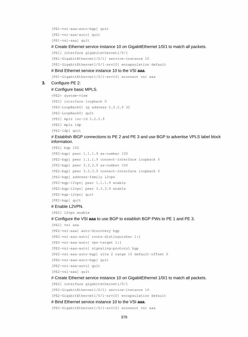
379
[PE1-vsi-aaa-auto-bgp] quit
[PE1-vsi-aaa-auto] quit
[PE1-vsi-aaa] quit
# Create Ethernet service instance 10 on GigabitEthernet 1/0/1 to match all packets. [PE1] interface gigabitethernet1/0/1
[PE1-GigabitEthernet1/0/1] service-instance 10
[PE1-GigabitEthernet1/0/1-srv10] encapsulation default
# Bind Ethernet service instance 10 to the VSI aaa. [PE1-GigabitEthernet1/0/1-srv10] xconnect vsi aaa
3. Configure PE 2: # Configure basic MPLS. <PE2> system-view
[PE2] interface loopback 0
[PE2-LoopBack0] ip address 2.2.2.9 32
[PE2-LoopBack0] quit
[PE2] mpls lsr-id 2.2.2.9
[PE2] mpls ldp
[PE2-ldp] quit
# Establish IBGP connections to PE 2 and PE 3 and use BGP to advertise VPLS label block information. [PE2] bgp 100
[PE2-bgp] peer 1.1.1.9 as-number 100
[PE2-bgp] peer 1.1.1.9 connect-interface loopback 0
[PE2-bgp] peer 3.3.3.9 as-number 100
[PE2-bgp] peer 3.3.3.9 connect-interface loopback 0
[PE2-bgp] address-family l2vpn
[PE2-bgp-l2vpn] peer 1.1.1.9 enable
[PE2-bgp-l2vpn] peer 3.3.3.9 enable
[PE2-bgp-l2vpn] quit
[PE2-bgp] quit
# Enable L2VPN. [PE2] l2vpn enable
# Configure the VSI aaa to use BGP to establish BGP PWs to PE 1 and PE 3. [PE2] vsi aaa
[PE2-vsi-aaa] auto-discovery bgp
[PE2-vsi-aaa-auto] route-distinguisher 1:1
[PE2-vsi-aaa-auto] vpn-target 1:1
[PE2-vsi-aaa-auto] signaling-protocol bgp
[PE2-vsi-aaa-auto-bgp] site 2 range 10 default-offset 0
[PE2-vsi-aaa-auto-bgp] quit
[PE2-vsi-aaa-auto] quit
[PE2-vsi-aaa] quit
# Create Ethernet service instance 10 on GigabitEthernet 1/0/1 to match all packets. [PE2] interface gigabitethernet1/0/1
[PE2-GigabitEthernet1/0/1] service-instance 10
[PE2-GigabitEthernet1/0/1-srv10] encapsulation default
# Bind Ethernet service instance 10 to the VSI aaa. [PE2-GigabitEthernet1/0/1-srv10] xconnect vsi aaa
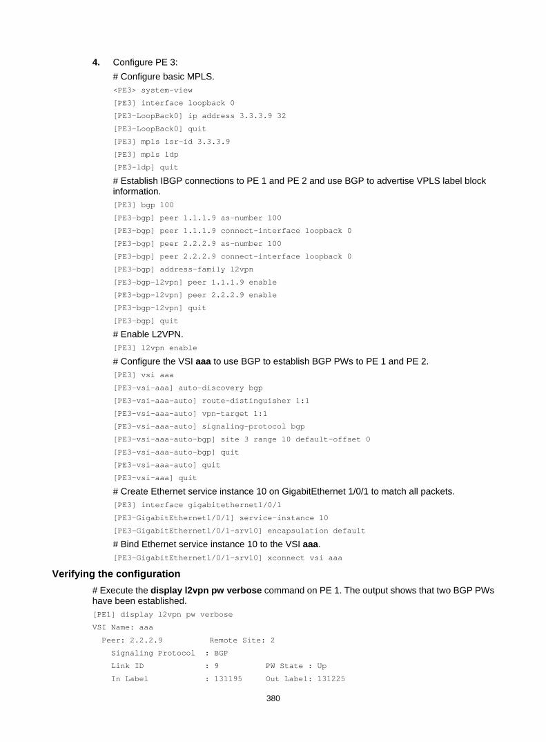
380
4. Configure PE 3: # Configure basic MPLS. <PE3> system-view
[PE3] interface loopback 0
[PE3-LoopBack0] ip address 3.3.3.9 32
[PE3-LoopBack0] quit
[PE3] mpls lsr-id 3.3.3.9
[PE3] mpls ldp
[PE3-ldp] quit
# Establish IBGP connections to PE 1 and PE 2 and use BGP to advertise VPLS label block information. [PE3] bgp 100
[PE3-bgp] peer 1.1.1.9 as-number 100
[PE3-bgp] peer 1.1.1.9 connect-interface loopback 0
[PE3-bgp] peer 2.2.2.9 as-number 100
[PE3-bgp] peer 2.2.2.9 connect-interface loopback 0
[PE3-bgp] address-family l2vpn
[PE3-bgp-l2vpn] peer 1.1.1.9 enable
[PE3-bgp-l2vpn] peer 2.2.2.9 enable
[PE3-bgp-l2vpn] quit
[PE3-bgp] quit
# Enable L2VPN. [PE3] l2vpn enable
# Configure the VSI aaa to use BGP to establish BGP PWs to PE 1 and PE 2. [PE3] vsi aaa
[PE3-vsi-aaa] auto-discovery bgp
[PE3-vsi-aaa-auto] route-distinguisher 1:1
[PE3-vsi-aaa-auto] vpn-target 1:1
[PE3-vsi-aaa-auto] signaling-protocol bgp
[PE3-vsi-aaa-auto-bgp] site 3 range 10 default-offset 0
[PE3-vsi-aaa-auto-bgp] quit
[PE3-vsi-aaa-auto] quit
[PE3-vsi-aaa] quit
# Create Ethernet service instance 10 on GigabitEthernet 1/0/1 to match all packets. [PE3] interface gigabitethernet1/0/1
[PE3-GigabitEthernet1/0/1] service-instance 10
[PE3-GigabitEthernet1/0/1-srv10] encapsulation default
# Bind Ethernet service instance 10 to the VSI aaa. [PE3-GigabitEthernet1/0/1-srv10] xconnect vsi aaa
Verifying the configuration # Execute the display l2vpn pw verbose command on PE 1. The output shows that two BGP PWs have been established. [PE1] display l2vpn pw verbose
VSI Name: aaa
Peer: 2.2.2.9 Remote Site: 2
Signaling Protocol : BGP
Link ID : 9 PW State : Up
In Label : 131195 Out Label: 131225

381
MTU : 1500
PW Attributes : Main
VCCV CC : -
VCCV BFD : -
Tunnel Group ID : 0x1800000160000001
Tunnel NHLFE IDs : 137
Peer: 3.3.3.9 Remote Site: 3
Signaling Protocol : BGP
Link ID : 10 PW State : Up
In Label : 131196 Out Label: 131225
MTU : 1500
PW Attributes : Main
VCCV CC : -
VCCV BFD : -
Tunnel Group ID : 0x1800000060000000
Tunnel NHLFE IDs : 136
# Execute the display l2vpn bgp verbose command on PE 1 to view VPLS label block information received from PE 2 and PE 3. [PE1] display l2vpn bgp verbose
VSI Name: aaa
Remote Site ID : 2
Offset : 0
RD : 1:1
PW State : Up
Encapsulation : BGP-VPLS
MTU : 1500
Nexthop : 2.2.2.9
Local VC Label : 131195
Remote VC Label : 131225
Link ID : 9
Local Label Block : 131193/10/0
Remote Label Block : 131224/10/0
Export Route Target: 1:1
Remote Site ID : 3
Offset : 0
RD : 1:1
PW State : Up
Encapsulation : BGP-VPLS
MTU : 1500
Nexthop : 3.3.3.9
Local VC Label : 131196
Remote VC Label : 131225
Link ID : 10
Local Label Block : 131193/10/0
Remote Label Block : 131224/10/0
Export Route Target: 1:1
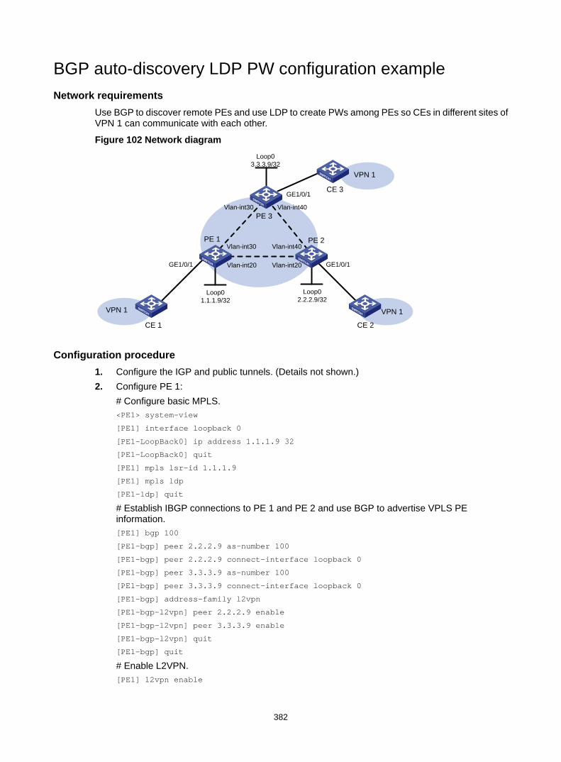
382
BGP auto-discovery LDP PW configuration example Network requirements
Use BGP to discover remote PEs and use LDP to create PWs among PEs so CEs in different sites of VPN 1 can communicate with each other.
Figure 102 Network diagram
Configuration procedure 1. Configure the IGP and public tunnels. (Details not shown.) 2. Configure PE 1:
# Configure basic MPLS. <PE1> system-view
[PE1] interface loopback 0
[PE1-LoopBack0] ip address 1.1.1.9 32
[PE1-LoopBack0] quit
[PE1] mpls lsr-id 1.1.1.9
[PE1] mpls ldp
[PE1-ldp] quit
# Establish IBGP connections to PE 1 and PE 2 and use BGP to advertise VPLS PE information. [PE1] bgp 100
[PE1-bgp] peer 2.2.2.9 as-number 100
[PE1-bgp] peer 2.2.2.9 connect-interface loopback 0
[PE1-bgp] peer 3.3.3.9 as-number 100
[PE1-bgp] peer 3.3.3.9 connect-interface loopback 0
[PE1-bgp] address-family l2vpn
[PE1-bgp-l2vpn] peer 2.2.2.9 enable
[PE1-bgp-l2vpn] peer 3.3.3.9 enable
[PE1-bgp-l2vpn] quit
[PE1-bgp] quit
# Enable L2VPN. [PE1] l2vpn enable
Loop01.1.1.9/32
GE1/0/1 GE1/0/1
CE 1
VPN 1
PE 1 PE 2
Loop02.2.2.9/32
CE 2
VPN 1
Loop03.3.3.9/32
PE 3
CE 3
VPN 1
GE1/0/1
Vlan-int20 Vlan-int20
Vlan-int30
Vlan-int30 Vlan-int40
Vlan-int40

383
# Configure the VSI aaa to use BGP to discover remote PEs and use LDP to establish LDP PWs to PE 2 and PE 3. [PE1] vsi aaa
[PE1-vsi-aaa] auto-discovery bgp
[PE1-vsi-aaa-auto] route-distinguisher 1:1
[PE1-vsi-aaa-auto] vpn-target 1:1
[PE1-vsi-aaa-auto] signaling-protocol ldp
[PE1-vsi-aaa-auto-ldp] vpls-id 100:100
[PE1-vsi-aaa-auto-ldp] quit
[PE1-vsi-aaa-auto] quit
[PE1-vsi-aaa] quit
# Create Ethernet service instance 10 on GigabitEthernet 1/0/1 to match all packets. [PE1] interface gigabitethernet1/0/1
[PE1-GigabitEthernet1/0/1] service-instance 10
[PE1-GigabitEthernet1/0/1-srv10] encapsulation default
# Bind Ethernet service instance 10 to the VSI aaa. [PE1-GigabitEthernet1/0/1-srv10] xconnect vsi aaa
3. Configure PE 2: # Configure basic MPLS. <PE2> system-view
[PE2] interface loopback 0
[PE2-LoopBack0] ip address 2.2.2.9 32
[PE2-LoopBack0] quit
[PE2] mpls lsr-id 2.2.2.9
[PE2] mpls ldp
[PE2-ldp] quit
# Establish IBGP connections to PE 1 and PE 3 and use BGP to advertise VPLS PE information. [PE2] bgp 100
[PE2-bgp] peer 1.1.1.9 as-number 100
[PE2-bgp] peer 1.1.1.9 connect-interface loopback 0
[PE2-bgp] peer 3.3.3.9 as-number 100
[PE2-bgp] peer 3.3.3.9 connect-interface loopback 0
[PE2-bgp] address-family l2vpn
[PE2-bgp-l2vpn] peer 1.1.1.9 enable
[PE2-bgp-l2vpn] peer 3.3.3.9 enable
[PE2-bgp-l2vpn] quit
[PE2-bgp] quit
# Enable L2VPN. [PE2] l2vpn enable
# Configure the VSI aaa to use BGP to discover remote PEs and use LDP to establish LDP PWs to PE 1 and PE 3. [PE2] vsi aaa
[PE2-vsi-aaa] auto-discovery bgp
[PE2-vsi-aaa-auto] route-distinguisher 1:1
[PE2-vsi-aaa-auto] vpn-target 1:1
[PE2-vsi-aaa-auto] signaling-protocol ldp
[PE2-vsi-aaa-auto-ldp] vpls-id 100:100

384
[PE2-vsi-aaa-auto-ldp] quit
[PE2-vsi-aaa-auto] quit
[PE2-vsi-aaa] quit
# Create Ethernet service instance 10 on GigabitEthernet 1/0/1 to match all packets. [PE2] interface gigabitethernet1/0/1
[PE2-GigabitEthernet1/0/1] service-instance 10
[PE2-GigabitEthernet1/0/1-srv10] encapsulation default
# Bind Ethernet service instance 10 to the VSI aaa. [PE2-GigabitEthernet1/0/1-srv10] xconnect vsi aaa
4. Configure PE 3: # Configure basic MPLS. <PE3> system-view
[PE3] interface loopback 0
[PE3-LoopBack0] ip address 3.3.3.9 32
[PE3-LoopBack0] quit
[PE3] mpls lsr-id 3.3.3.9
[PE3] mpls ldp
[PE3-ldp] quit
# Establish IBGP connections to PE 1 and PE 2 and use BGP to advertise VPLS PE information. [PE3] bgp 100
[PE3-bgp] peer 1.1.1.9 as-number 100
[PE3-bgp] peer 1.1.1.9 connect-interface loopback 0
[PE3-bgp] peer 2.2.2.9 as-number 100
[PE3-bgp] peer 2.2.2.9 connect-interface loopback 0
[PE3-bgp] address-family l2vpn
[PE3-bgp-l2vpn] peer 1.1.1.9 enable
[PE3-bgp-l2vpn] peer 2.2.2.9 enable
[PE3-bgp-l2vpn] quit
[PE3-bgp] quit
# Enable L2VPN. [PE3] l2vpn enable
# Configure the VSI aaa to use BGP to discover remote PEs and use LDP to establish LDP PWs to PE 1 and PE 2. [PE3] vsi aaa
[PE3-vsi-aaa] auto-discovery bgp
[PE3-vsi-aaa-auto] route-distinguisher 1:1
[PE3-vsi-aaa-auto] vpn-target 1:1
[PE3-vsi-aaa-auto] signaling-protocol ldp
[PE3-vsi-aaa-auto-ldp] vpls-id 100:100
[PE3-vsi-aaa-auto-ldp] quit
[PE3-vsi-aaa-auto] quit
[PE3-vsi-aaa] quit
# Create Ethernet service instance 10 on GigabitEthernet 1/0/1 to match all packets. [PE3] interface gigabitethernet1/0/1
[PE3-GigabitEthernet1/0/1] service-instance 10
[PE3-GigabitEthernet1/0/1-srv10] encapsulation default
# Bind Ethernet service instance 10 to the VSI aaa.

385
[PE3-GigabitEthernet1/0/1-srv10] xconnect vsi aaa
Verifying the configuration # Execute the display l2vpn pw verbose command on PE 1. The output shows that two LDP PWs have been established. [PE1] display l2vpn pw verbose
VSI Name: aaa
Peer: 2.2.2.9 VPLS ID: 100:100
Signaling Protocol : LDP
Link ID : 8 PW State : Up
In Label : 131155 Out Label: 131155
MTU : 1500
PW Attributes : Main
VCCV CC : -
VCCV BFD : -
Tunnel Group ID : 0x1800000060000000
Tunnel NHLFE IDs : 139
Peer: 3.3.3.9 VPLS ID: 100:100
Signaling Protocol : LDP
Link ID : 9 PW State : Up
In Label : 131154 Out Label: 131116
MTU : 1500
PW Attributes : Main
VCCV CC : -
VCCV BFD : -
Tunnel Group ID : 0x1800000160000001
Tunnel NHLFE IDs : 140
# Execute the display l2vpn ldp verbose command on PE 1 to view LDP PW label information. [PE1] display l2vpn ldp verbose
Peer: 2.2.2.9 VPLS ID: 100:100
VSI Name: aaa
PW State: Up
PW Status Communication: Notification method
PW ID FEC (Local/Remote):
Local AII : (1.1.1.9, 2.2.2.9)
Remote AII : (2.2.2.9, 1.1.1.9)
PW Type : VLAN/VLAN
Group ID : 0/0
Label : 131155/131155
Control Word: Disabled/Disabled
VCCV CV Type: -/-
VCCV CC Type: -/-
MTU : 1500/1500
PW Status : PW forwarding/PW forwarding
Peer: 3.3.3.9 VPLS ID: 100:100
VSI Name: aaa
PW State: Up
PW Status Communication: Notification method

386
PW ID FEC (Local/Remote):
Local AII : (1.1.1.9, 3.3.3.9)
Remote AII : (3.3.3.9, 1.1.1.9)
PW Type : VLAN/VLAN
Group ID : 0/0
Label : 131154/131116
Control Word: Disabled/Disabled
VCCV CV Type: -/-
VCCV CC Type: -/-
MTU : 1500/1500
PW Status : PW forwarding/PW forwarding
H-VPLS using access configuration example Network requirements
Configure an H-VPLS using MPLS access to avoid full-mesh PW configuration. The H-VPLS uses LDP as the PW signaling protocol.
Figure 103 Network diagram
Configuration procedure 1. Configure an IGP and public tunnels on each PE. (Details not shown.) 2. Configure UPE:
# Configure basic MPLS. <UPE> system-view
[UPE] interface loopback 0
[UPE-LoopBack0] ip address 1.1.1.9 32
[UPE-LoopBack0] quit
[UPE] mpls lsr-id 1.1.1.9
[UPE] mpls ldp
[UPE-ldp] quit
# Enable L2VPN. [UPE] l2vpn enable
Backbone domain
Edgedomain
UPE NPE 1
NPE 2CE 2
GE1/0/1
Loop01.1.1.9/32
Loop02.2.2.9/32
Loop03.3.3.9/32
Vlan-int1010.1.1.1/24
Vlan-int1010.1.1.2/24
Vlan-int2020.1.1.1/24
Vlan-int2020.1.1.2/24
CE 1 NPE 3CE 3
GE1/0/1
Vlan-int3030.1.1.1/24
Vlan-int3030.1.1.2/24
Loop04.4.4.9/32
GE1/0/1
Vlan-int4040.1.1.1/24
Vlan-int4040.1.1.2/24

387
# Configure VSI aaa to use LDP to establish a U-PW to NPE 1. [UPE] vsi aaa
[UPE-vsi-aaa] pwsignaling ldp
[UPE-vsi-aaa-ldp] peer 2.2.2.9 pw-id 500
[UPE-vsi-aaa-ldp-2.2.2.9-500] quit
[UPE-vsi-aaa-ldp] quit
[UPE-vsi-aaa] quit
# Create Ethernet service instance 10 on GigabitEthernet 1/0/1 to match all packets. [UPE] interface gigabitethernet1/0/1
[UPE-GigabitEthernet1/0/1] service-instance 10
[UPE-GigabitEthernet1/0/1-srv10] encapsulation default
# Bind Ethernet service instance 10 to the VSI aaa. [UPE-GigabitEthernet1/0/1-srv10] xconnect vsi aaa
3. Configure NPE 1: # Configure basic MPLS. <NPE1> system-view
[NPE1] interface loopback 0
[NPE1-LoopBack0] ip address 2.2.2.9 32
[NPE1-LoopBack0] quit
[NPE1] mpls lsr-id 2.2.2.9
[NPE1] mpls ldp
[NPE1–ldp] quit
# Enable L2VPN. [NPE1] l2vpn enable
# Configure VSI aaa that uses LDP as the PW signaling protocol, establish a U-PW to the UPE, and establish an N-PW to NPE 2 and NPE 3, respectively. [NPE1] vsi aaa
[NPE1-vsi-aaa] pwsignaling ldp
[NPE1-vsi-aaa-ldp] peer 1.1.1.9 pw-id 500 no-split-horizon
[NPE1-vsi-aaa-ldp-1.1.1.9-500] quit
[NPE1-vsi-aaa-ldp] peer 3.3.3.9 pw-id 500
[NPE1-vsi-aaa-ldp-3.3.3.9-500] quit
[NPE1-vsi-aaa-ldp] peer 4.4.4.9 pw-id 500
[NPE1-vsi-aaa-ldp-4.4.4.9-500] quit
[NPE1-vsi-aaa-ldp] quit
[NPE1-vsi-aaa] quit
4. Configure NPE 2: # Configure basic MPLS. <NPE2> system-view
[NPE2] interface loopback 0
[NPE2-LoopBack0] ip address 3.3.3.9 32
[NPE2-LoopBack0] quit
[NPE2] mpls lsr-id 3.3.3.9
[NPE2] mpls ldp
[NPE2–ldp] quit
# Enable L2VPN. [NPE2] l2vpn enable

388
# Configure VSI aaa that uses LDP as the PW signaling protocol, and establish an N-PW to NPE 1 and NPE 3, respectively. [NPE2] vsi aaa
[NPE2-vsi-aaa] pwsignal ldp
[NPE2-vsi-aaa-ldp] peer 2.2.2.9 pw-id 500
[NPE2-vsi-aaa-ldp-2.2.2.9-500] quit
[NPE2-vsi-aaa-ldp] peer 4.4.4.9 pw-id 500
[NPE2-vsi-aaa-ldp-4.4.4.9-500] quit
[NPE2-vsi-aaa-ldp] quit
[NPE2-vsi-aaa] quit
# Create Ethernet service instance 10 on GigabitEthernet 1/0/1 to match all packets. [NPE2] interface gigabitethernet1/0/1
[NPE2-GigabitEthernet1/0/1] service-instance 10
[NPE2-GigabitEthernet1/0/1-srv10] encapsulation default
# Bind Ethernet service instance 10 to the VSI aaa. [NPE2-GigabitEthernet1/0/1-srv10] xconnect vsi aaa
5. Configure NPE 3: # Configure basic MPLS. <NPE3> system-view
[NPE3] interface loopback 0
[NPE3-LoopBack0] ip address 4.4.4.9 32
[NPE3-LoopBack0] quit
[NPE3] mpls lsr-id 4.4.4.9
[NPE3] mpls ldp
[NPE3–ldp] quit
# Enable L2VPN. [NPE3] l2vpn enable
# Configure VSI aaa that uses LDP as the PW signaling protocol, and establish an N-PW to NPE 1 and NPE 2, respectively. [NPE3] vsi aaa
[NPE3-vsi-aaa] pwsignal ldp
[NPE3-vsi-aaa-ldp] peer 2.2.2.9 pw-id 500
[NPE3-vsi-aaa-ldp-2.2.2.9-500] quit
[NPE3-vsi-aaa-ldp] peer 3.3.3.9 pw-id 500
[NPE3-vsi-aaa-ldp-3.3.3.9-500] quit
[NPE3-vsi-aaa-ldp] quit
[NPE3-vsi-aaa] quit
# Create Ethernet service instance 10 on GigabitEthernet 1/0/1 to match all packets. [NPE3] interface gigabitethernet1/0/1
[NPE3-GigabitEthernet1/0/1] service-instance 10
[NPE3-GigabitEthernet1/0/1-srv10] encapsulation default
# Bind Ethernet service instance 10 to the VSI aaa. [NPE3-GigabitEthernet1/0/1-srv10] xconnect vsi aaa
Verifying the configuration # Execute the display l2vpn pw verbose command on each PE. The output shows that PWs in up state have been established. [UPE] display l2vpn pw verbose
VSI Name: aaa

389
Peer: 2.2.2.9 PW ID: 500
Signaling Protocol : LDP
Link ID : 8 PW State : Up
In Label : 131177 Out Label: 131177
MTU : 1500
PW Attributes : Main
VCCV CC : -
VCCV BFD : -
Tunnel Group ID : 0x1800000460000000
Tunnel NHLFE IDs : 130
[NPE1] display l2vpn pw verbose
VSI Name: aaa
Peer: 1.1.1.9 PW ID: 500
Signaling Protocol : LDP
Link ID : 8 PW State : Up
In Label : 131177 Out Label: 131177
MTU : 1500
PW Attributes : Main, No-split-horizon
VCCV CC : -
VCCV BFD : -
Tunnel Group ID : 0x1800000460000000
Tunnel NHLFE IDs : 130
Peer: 3.3.3.9 PW ID: 500
Signaling Protocol : LDP
Link ID : 9 PW State : Up
In Label : 131176 Out Label: 131175
MTU : 1500
PW Attributes : Main
VCCV CC : -
VCCV BFD : -
Tunnel Group ID : 0x1800000560000001
Tunnel NHLFE IDs : 131
Peer: 4.4.4.9 PW ID: 500
Signaling Protocol : LDP
Link ID : 10 PW State : Up
In Label : 131178 Out Label: 131179
MTU : 1500
PW Attributes : Main
VCCV CC : -
VCCV BFD : -
Tunnel Group ID : 0x1800000570000001
Tunnel NHLFE IDs : 132
[NPE2] display l2vpn pw verbose
VSI Name: aaa
Peer: 2.2.2.9 PW ID: 500
Signaling Protocol : LDP
Link ID : 8 PW State : Up
In Label : 131175 Out Label: 131176
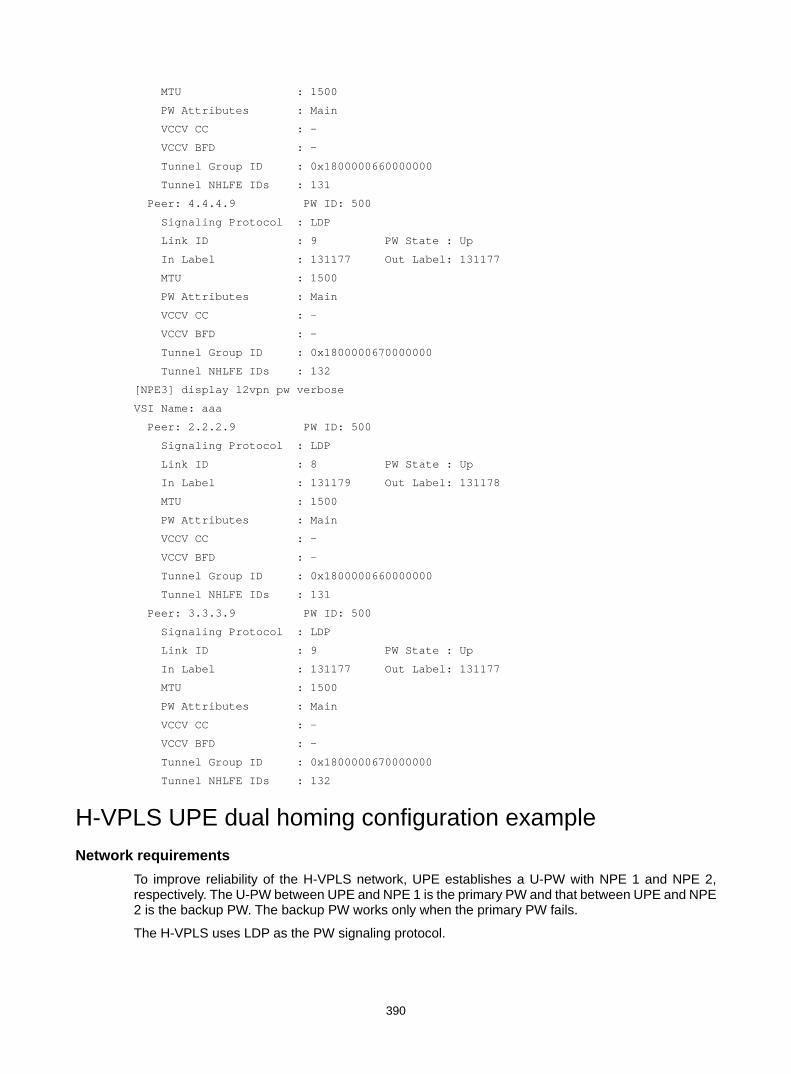
390
MTU : 1500
PW Attributes : Main
VCCV CC : -
VCCV BFD : -
Tunnel Group ID : 0x1800000660000000
Tunnel NHLFE IDs : 131
Peer: 4.4.4.9 PW ID: 500
Signaling Protocol : LDP
Link ID : 9 PW State : Up
In Label : 131177 Out Label: 131177
MTU : 1500
PW Attributes : Main
VCCV CC : -
VCCV BFD : -
Tunnel Group ID : 0x1800000670000000
Tunnel NHLFE IDs : 132
[NPE3] display l2vpn pw verbose
VSI Name: aaa
Peer: 2.2.2.9 PW ID: 500
Signaling Protocol : LDP
Link ID : 8 PW State : Up
In Label : 131179 Out Label: 131178
MTU : 1500
PW Attributes : Main
VCCV CC : -
VCCV BFD : -
Tunnel Group ID : 0x1800000660000000
Tunnel NHLFE IDs : 131
Peer: 3.3.3.9 PW ID: 500
Signaling Protocol : LDP
Link ID : 9 PW State : Up
In Label : 131177 Out Label: 131177
MTU : 1500
PW Attributes : Main
VCCV CC : -
VCCV BFD : -
Tunnel Group ID : 0x1800000670000000
Tunnel NHLFE IDs : 132
H-VPLS UPE dual homing configuration example Network requirements
To improve reliability of the H-VPLS network, UPE establishes a U-PW with NPE 1 and NPE 2, respectively. The U-PW between UPE and NPE 1 is the primary PW and that between UPE and NPE 2 is the backup PW. The backup PW works only when the primary PW fails.
The H-VPLS uses LDP as the PW signaling protocol.

391
Figure 104 Network diagram
Configuration procedure 1. Configure an IGP and public tunnels on each PE. (Details not shown.) 2. Configure UPE:
# Configure basic MPLS. <UPE> system-view
[UPE] interface loopback 0
[UPE-LoopBack0] ip address 1.1.1.1 32
[UPE-LoopBack0] quit
[UPE] mpls lsr-id 1.1.1.1
[UPE] mpls ldp
[UPE-ldp] quit
# Enable L2VPN. [UPE] l2vpn enable
# Configure VSI aaa that uses LDP as the PW signaling protocol, and establish the primary PW with NPE 1 and the backup PW to NPE 2. [UPE] vsi aaa
[UPE-vsi-aaa] pwsignaling ldp
[UPE-vsi-aaa-ldp] peer 2.2.2.2 pw-id 500
[UPE-vsi-aaa-ldp-2.2.2.2-500] backup-peer 3.3.3.3 pw-id 500
[UPE-vsi-aaa-ldp-3.3.3.3-500-backup] quit
[UPE-vsi-aaa-ldp-2.2.2.2-500] quit
[UPE-vsi-aaa-ldp] quit
[UPE-vsi-aaa] quit
# Create VLAN 10 and assign GigabitEthernet 1/0/1 to the VLAN. [UPE] vlan 10
[UPE-vlan10] port gigabitethernet 1/0/1
[UPE-vlan10] quit
# On interface GigabitEthernet 1/0/1 connected to CE 1, create an Ethernet service instance and bind the Ethernet service instance to VSI aaa.
CE 3NPE 3
NPE 1
CE 1
CE 2NPE 2
UPE
GE1/0/1VLAN 11
GE1/0/2VLAN 10
Vlan-int1212.1.1.1/24
Vlan-int1313.1.1.1/24
Vlan-int1616.1.1.1/24
Vlan-int1515.1.1.1/24
GE1/0/1VLAN 10
Loop02.2.2.2/32
Loop03.3.3.3/32
Loop04.4.4.4/32
Vlan-int1616.1.1.2/24
Vlan-int1515.1.1.2/24
Vlan-int1313.1.1.2/24
Vlan-int1212.1.1.2/24
Loop01.1.1.1/32
Backbone domain
Vlan-int1717.1.1.1/24
Vlan-int1717.1.1.2/24
Edgedomain

392
[UPE] interface gigabitethernet 1/0/1
[UPE-GigabitEthernet1/0/1] service-instance 1000
[UPE-GigabitEthernet1/0/1-srv1000] encapsulation s-vid 10
[UPE-GigabitEthernet1/0/1-srv1000] xconnect vsi aaa
[UPE-GigabitEthernet1/0/1-srv1000] quit
# Create VLAN 11 and assign GigabitEthernet 1/0/2 to the VLAN. [UPE] vlan 11
[UPE-vlan11] port gigabitethernet 1/0/2
[UPE-vlan11] quit
# On interface GigabitEthernet 1/0/2 connected to CE 2, create an Ethernet service instance and bind the Ethernet service instance to VSI aaa. [UPE] interface gigabitethernet 1/0/2
[UPE-GigabitEthernet1/0/2] service-instance 1000
[UPE-GigabitEthernet1/0/2-srv1000] encapsulation s-vid 11
[UPE-GigabitEthernet1/0/2-srv1000] xconnect vsi aaa
[UPE-GigabitEthernet1/0/2-srv1000] quit
3. Configure NPE 1: # Configure basic MPLS. <NPE1> system-view
[NPE1] interface loopback 0
[NPE1-LoopBack0] ip address 2.2.2.2 32
[NPE1-LoopBack0] quit
[NPE1] mpls lsr-id 2.2.2.2
[NPE1] mpls ldp
[NPE1–ldp] quit
# Enable L2VPN. [NPE1] l2vpn enable
# Configure VSI aaa that uses LDP as the PW signaling protocol, and establish a PW to UPE, NPE 2, and NPE 3, respectively. [NPE1] vsi aaa
[NPE1-vsi-aaa] pwsignaling ldp
[NPE1-vsi-aaa-ldp] peer 1.1.1.1 pw-id 500 no-split-horizon
[NPE1-vsi-aaa-ldp-1.1.1.1-500] quit
[NPE1-vsi-aaa-ldp] peer 3.3.3.3 pw-id 500
[NPE1-vsi-aaa-ldp-3.3.3.3-500] quit
[NPE1-vsi-aaa-ldp] peer 4.4.4.4 pw-id 500
[NPE1-vsi-aaa-ldp-4.4.4.4-500] quit
[NPE1-vsi-aaa-ldp] quit
[NPE1-vsi-aaa] quit
4. Configure NPE 2: # Configure basic MPLS. <NPE2> system-view
[NPE2] interface loopback 0
[NPE2-LoopBack0] ip address 3.3.3.3 32
[NPE2-LoopBack0] quit
[NPE2] mpls lsr-id 3.3.3.3
[NPE2] mpls ldp
[NPE2–ldp] quit

393
# Enable L2VPN. [NPE2] l2vpn enable
# Configure VSI aaa that uses LDP as the PW signaling protocol, and establish a PW to UPE, NPE 2, and NPE 3, respectively. [NPE2] vsi aaa
[NPE2-vsi-aaa] pwsignaling ldp
[NPE2-vsi-aaa-ldp] peer 1.1.1.1 pw-id 500 no-split-horizon
[NPE2-vsi-aaa-ldp-1.1.1.1-500] quit
[NPE2-vsi-aaa-ldp] peer 2.2.2.2 pw-id 500
[NPE2-vsi-aaa-ldp-2.2.2.2-500] quit
[NPE2-vsi-aaa-ldp] peer 4.4.4.4 pw-id 500
[NPE2-vsi-aaa-ldp-4.4.4.4-500] quit
[NPE2-vsi-aaa-ldp] quit
[NPE2-vsi-aaa] quit
5. Configure NPE 3: # Configure basic MPLS. <NPE3> system-view
[NPE3] interface loopback 0
[NPE3-LoopBack0] ip address 4.4.4.4 32
[NPE3-LoopBack0] quit
[NPE3] mpls lsr-id 4.4.4.4
[NPE3] mpls ldp
[NPE3–ldp] quit
# Enable L2VPN. [NPE3] l2vpn enable
# Configure VSI aaa that uses LDP as the PW signaling protocol, and establish a PW to NPE 1 and NPE 2, respectively. [NPE3] vsi aaa
[NPE3-vsi-aaa] pwsignaling ldp
[NPE3-vsi-aaa-ldp] peer 2.2.2.2 pw-id 500
[NPE3-vsi-aaa-ldp-2.2.2.2-500] quit
[NPE3-vsi-aaa-ldp] peer 3.3.3.3 pw-id 500
[NPE3-vsi-aaa-ldp-3.3.3.3-500] quit
[NPE3-vsi-aaa-ldp] quit
[NPE3-vsi-aaa] quit
# Create VLAN 10 and assign GigabitEthernet 1/0/1 to the VLAN. [NPE3] vlan 10
[NPE3-vlan10] port gigabitethernet 1/0/1
[NPE3-vlan10] quit
# On interface GigabitEthernet 1/0/1 connected to CE 3, create an Ethernet service instance and bind the Ethernet service instance to VSI aaa. [NPE3] interface gigabitethernet 1/0/1
[NPE3-GigabitEthernet1/0/1] service-instance 1000
[NPE3-GigabitEthernet1/0/1-srv1000] encapsulation s-vid 10
[NPE3-GigabitEthernet1/0/1-srv1000] xconnect vsi aaa
[NPE3-GigabitEthernet1/0/1-srv1000] quit

394
Verifying the configuration # Execute the display l2vpn pw verbose command on each PE. The output shows that PWs in up state have been established. [UPE] display l2vpn pw verbose
VSI Name: aaa
Peer: 2.2.2.2 PW ID: 500
Signaling Protocol : LDP
Link ID : 8 PW State : Up
In Label : 131151 Out Label: 131279
Wait to Restore Time: 0 sec
MTU : 1500
PW Attributes : Main
VCCV CC : -
VCCV BFD : -
Tunnel Group ID : 0x1800000260000002
Tunnel NHLFE IDs : 137
Peer: 3.3.3.3 PW ID: 500
Signaling Protocol : LDP
Link ID : 8 PW State : Blocked
In Label : 131150 Out Label: 131279
MTU : 1500
PW Attributes : Backup
VCCV CC : -
VCCV BFD : -
Tunnel Group ID : 0x1800000360000003
Tunnel NHLFE IDs : 135
[NPE1] display l2vpn pw verbose
VSI Name: aaa
Peer: 1.1.1.1 PW ID: 500
Signaling Protocol : LDP
Link ID : 8 PW State : Up
In Label : 131279 Out Label: 131151
MTU : 1500
PW Attributes : Main, No-split-horizon
VCCV CC : -
VCCV BFD : -
Tunnel Group ID : 0x180000060000000
Tunnel NHLFE IDs : 136
Peer: 3.3.3.3 PW ID: 500
Signaling Protocol : LDP
Link ID : 9 PW State : Up
In Label : 131280 Out Label: 131290
MTU : 1500
PW Attributes : Main
VCCV CC : -
VCCV BFD : -
Tunnel Group ID : 0x1800000160000005
Tunnel NHLFE IDs : 137

395
Peer: 4.4.4.4 PW ID: 500
Signaling Protocol : LDP
Link ID : 10 PW State : Up
In Label : 131278 Out Label: 131279
MTU : 1500
PW Attributes : Main
VCCV CC : -
VCCV BFD : -
Tunnel Group ID : 0x1800000160000001
Tunnel NHLFE IDs : 138
[NPE2] display l2vpn pw verbose
VSI Name: aaa
Peer: 1.1.1.1 PW ID: 500
Signaling Protocol : LDP
Link ID : 8 PW State : Up
In Label : 131279 Out Label: 131150
MTU : 1500
PW Attributes : Main, No-split-horizon
VCCV CC : -
VCCV BFD : -
Tunnel Group ID : 0x180000060000000
Tunnel NHLFE IDs : 136
Peer: 2.2.2.2 PW ID: 500
Signaling Protocol : LDP
Link ID : 9 PW State : Up
In Label : 131290 Out Label: 131280
MTU : 1500
PW Attributes : Main
VCCV CC : -
VCCV BFD : -
Tunnel Group ID : 0x1800000160000008
Tunnel NHLFE IDs : 137
Peer: 4.4.4.4 PW ID: 500
Signaling Protocol : LDP
Link ID : 10 PW State : Up
In Label : 131278 Out Label: 131278
MTU : 1500
PW Attributes : Main
VCCV CC : -
VCCV BFD : -
Tunnel Group ID : 0x1800000160000001
Tunnel NHLFE IDs : 138
[NPE3] display l2vpn pw verbose
VSI Name: aaa
Peer: 2.2.2.2 PW ID: 500
Signaling Protocol : LDP
Link ID : 8 PW State : Up
In Label : 131279 Out Label: 131278
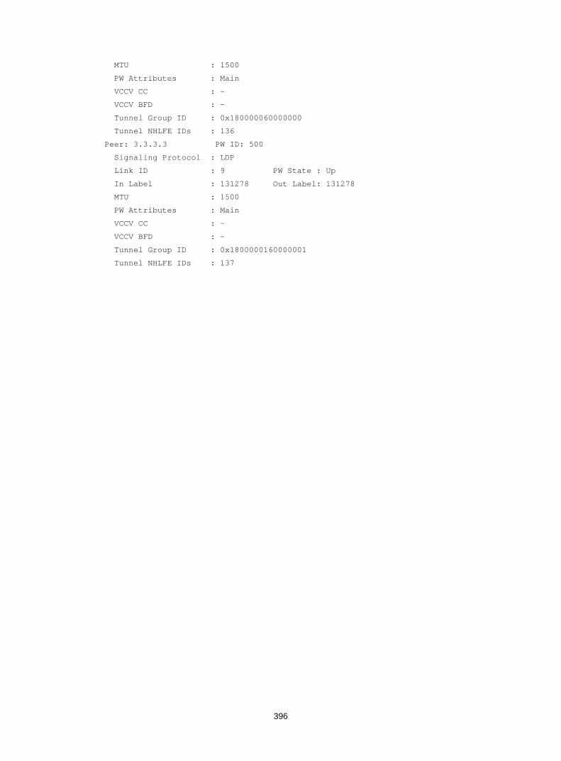
396
MTU : 1500
PW Attributes : Main
VCCV CC : -
VCCV BFD : -
Tunnel Group ID : 0x180000060000000
Tunnel NHLFE IDs : 136
Peer: 3.3.3.3 PW ID: 500
Signaling Protocol : LDP
Link ID : 9 PW State : Up
In Label : 131278 Out Label: 131278
MTU : 1500
PW Attributes : Main
VCCV CC : -
VCCV BFD : -
Tunnel Group ID : 0x1800000160000001
Tunnel NHLFE IDs : 137

397
Configuring MPLS OAM Overview
MPLS Operation, Administration, and Maintenance (OAM) provides fault management tools for the following purposes: • MPLS data plane connectivity verification. • Data plane and control plane consistency verification. • Fault locating.
These fault management tools include the following types: • On-demand tools—Tools that need to be triggered manually, such as MPLS ping and MPLS
tracert. • Proactive tools—Tools that are triggered by the system automatically, such as BFD for MPLS,
and periodic MPLS tracert.
You can use these tools to detect and locate faults of LSPs, MPLS TE tunnels, and MPLS PWs.
MPLS ping MPLS ping tests the connectivity of an LSP tunnel or a PW. At the ingress node, MPLS ping adds the label associated with a tunnel into an MPLS echo request and sends it to the egress node over the tunnel. The egress node processes the request and returns an MPLS echo reply to the ingress node. An MPLS echo reply with a success notification indicates that the tunnel is available for data forwarding, and an MPLS echo reply with an error code indicates that the tunnel has failed.
MPLS tracert MPLS tracert displays the path that an MPLS LSP tunnel travels from the ingress node to the egress node to locate errors on the tunnel. MPLS tracert consecutively sends MPLS echo requests along the LSP tunnel, with the TTL increasing from 1 to a specific value. Each hop along the tunnel returns an MPLS echo reply to the ingress due to TTL timeout so the ingress can collect information about each hop along the tunnel. This information allows you to locate the failed node or access information for each hop, for example, the label allocated by each downstream hop.
BFD for MPLS BFD for MPLS uses a BFD session to proactively verify the connectivity of an LSP tunnel, an MPLS TE tunnel, or a PW tunnel.
BFD for MPLS does the following: 1. Establishes a BFD session between the ingress and egress of the tunnel to be inspected. 2. Adds the label associated with the tunnel into a BFD control packet at the ingress. 3. Sends the packet to the egress node over the tunnel. 4. Determines the tunnel status according to the BFD control packet returned by the egress.
When BFD detects a connectivity failure, it triggers the pre-configured action, such as FRR or path protection switching, to ensure uninterrupted traffic forwarding.
A BFD session for LSP, MPLS TE tunnel, or PW connectivity verification can be established in one of the following modes:

398
• Static mode—You manually specify the local and remote discriminators through command lines to establish the BFD session.
• Dynamic mode—The system automatically runs MPLS ping to negotiate the discriminators to establish the BFD session.
In static mode, the egress node returns a BFD control packet to the ingress node through the reverse tunnel. If no reverse tunnel exists, the ingress node cannot receive the BFD control packet, resulting in a verification failure.
In dynamic mode, the egress node returns a BFD control packet to the ingress node through the reverse tunnel. If no reverse tunnel exists, the egress mode returns a BFD packet through IP routing.
Use the static mode to test the connectivity of a pair of LSPs or MPLS TE tunnels in opposite directions (one from local to remote, and the other from remote to local) between two devices. Use the dynamic mode to test the connectivity of one LSP or MPLS TE tunnel from the local device to the remote device.
A PW is bidirectional. You will get the correct result using either the static or dynamic mode.
Periodic MPLS tracert The periodic MPLS tracert function automatically traces an LSP tunnel at a specific interval. It locates errors on the LSP tunnel, verifies the consistency of the data plane and control plane, and records the detected errors in system logs. You can check the logs to monitor LSP connectivity.
If both BFD and periodic MPLS tracert are configured for an LSP, and the periodic tracert function detects a data plane and control plane inconsistency, the device does the following tasks: 1. Deletes the BFD session for the LSP. 2. Re-establishes the BFD session based on the control plane.
Protocols and standards • RFC 4379, Detecting Multi-Protocol Label Switched (MPLS) Data Plane Failures • RFC 5085, Pseudowire Virtual Circuit Connectivity Verification (VCCV): A Control Channel for
Pseudowires • RFC 5885, Bidirectional Forwarding Detection (BFD) for the Pseudowire Virtual Circuit
Connectivity Verification (VCCV)
Configuring MPLS OAM for LSP tunnels To verify LSP connectivity, you can use one of the following: • Use the ping mpls ipv4 command or the tracert mpls ipv4 command to trigger LSP
connectivity verification as needed. • Configure BFD for MPLS or periodic MPLS tracert for the system to automatically verify LSP
connectivity.
Configuring MPLS ping for LSPs Perform the following task in any view:
Task Command Use MPLS ping to verify MPLS LSP connectivity for an IPv4 prefix.
ping mpls [ -a source-ip | -c count | -exp exp-value | -h ttl-value | -m wait-time | -r reply-mode | -rtos tos-value | -s

399
Task Command packet-size | -t time-out | -v ] * ipv4 dest-addr mask-length [ destination start-address [ end-address [ address-increment ] ] ]
Configuring MPLS tracert for LSPs Perform the following task in any view:
Task Command
Use MPLS tracert to trace the LSPs for an IPv4 prefix.
tracert mpls [ -a source-ip | -exp exp-value | -h ttl-value | -r reply-mode | -rtos tos-value | -t time-out | -v | fec-check ] * ipv4 dest-addr mask-length [ destination start-address [ end-address [ address-increment ] ] ]
Configuring BFD for LSPs To configure BFD for an LSP, configure both the local and remote devices as described in Table 36.
Table 36 Configurations on the local and remote devices
BFD session establishment mode
Node type Execute the "mpls bfd enable" command?
Execute the "mpls bfd" command?
Configure the discriminator keyword?
Static mode Local Yes Yes Yes
Remote Yes Yes Yes
Dynamic mode Local Yes Yes No
Remote Yes No N/A
Follow these guidelines to configure BFD for an LSP tunnel: • To establish a static BFD session, ensure that the local and remote discriminators configured
locally are identical with the remote and local discriminators configured on the remote device, respectively.
• The source address of the BFD session is the MPLS LSR ID of the local device. Before configuring BFD for the LSP tunnel, configure an MPLS LSR ID for the local device and make sure a route is available on the remote device to reach the MPLS LSR ID.
• If multiple LSPs exist for an FEC, you can perform one of the following tasks: Create a BFD session for an LSP by specifying the next hop of the LSP. Create a BFD session for each LSP without specifying a next hop.
• On a BFD session established in static mode, the ingress node and egress node both operate in active mode. On a BFD session established in dynamic mode, the egress node operates in active mode and the ingress node operates in passive mode. Executing the bfd session init-mode command on the ingress or egress node does not change the node's operating mode.
To configure BFD for LSPs:
Step Command Remarks 1. Enter system view. system-view N/A

400
Step Command Remarks
2. Enable BFD for MPLS. mpls bfd enable By default, BFD for MPLS is disabled.
3. Configure BFD to verify LSP connectivity for an FEC.
mpls bfd dest-addr mask-length [ nexthop nexthop-address [ discriminator local local-id remote remote-id ] ] [ template template-name ]
By default, BFD is not configured to verify LSP connectivity for an FEC.
Configuring periodic MPLS tracert for LSPs
Step Command Remarks 1. Enter system view. system-view N/A
2. Enable BFD for MPLS. mpls bfd enable By default, BFD for MPLS is
disabled.
3. Enable periodic LSP tracert for an FEC.
mpls periodic-tracert dest-addr mask-length [ -a source-ip | -exp exp-value | -h ttl-value | -m wait-time | -rtos tos-value | -t time-out | -u retry-attempt | fec-check ] *
By default, periodic LSP tracert is disabled.
Configuring MPLS OAM for MPLS TE tunnels MPLS OAM only supports BFD for MPLS TE tunnel connectivity verification.
To run BFD on an MPLS TE tunnel, configure both the local and remote devices as described in Table 37.
Table 37 Configurations on the local and remote devices
BFD session establishment mode
Node type Execute the "mpls bfd enable" command?
Execute the "mpls bfd" command?
Configure the discriminator keyword?
Static mode Local Yes Yes Yes
Remote Yes Yes Yes
Dynamic mode Local Yes Yes No
Remote Yes No N/A
Follow these guidelines to configure BFD for an MPLS TE tunnel: • To establish a static BFD session, ensure that the local and remote discriminators configured
locally are identical with the remote and local discriminators configured on the remote device, respectively.
• The source address of the BFD session is the MPLS LSR ID of the local device. Before you configure BFD for the LSP tunnel, configure an MPLS LSR ID for the local device. Make sure a route is available on the remote device to reach the MPLS LSR ID.
• On a BFD session established in static mode, the ingress node and egress node both operate in active mode. On a BFD session established in dynamic mode, the egress node operates in active mode and the ingress node operates in passive mode. Executing the bfd session init-mode command on the ingress or egress node does not change the node's operating mode.

401
• If both BFD and FRR are enabled for an MPLS TE tunnel, set the BFD detection interval for MPLS TE tunnel connectivity verification to be longer than that for FRR. Otherwise, the BFD session for MPLS TE tunnel connectivity verification will be down during an FRR switchover.
To configure BFD for MPLS TE tunnels:
Step Command Remarks 1. Enter system view. system-view N/A
2. Enable BFD for MPLS. mpls bfd enable By default, BFD for MPLS is disabled.
3. Enter the view of the MPLS TE tunnel interface. interface tunnel number N/A
4. Configure BFD to verify MPLS TE tunnel connectivity.
mpls bfd [ discriminator local local-id remote remote-id ] [ template template-name ]
By default, BFD is not configured to verify MPLS TE tunnel connectivity.
Configuring MPLS OAM for a PW Virtual Circuit Connectivity Verification (VCCV) is an L2VPN PW OAM function to verify PW connectivity in data plane. VCCV can be implemented in the following modes: • On-demand mode—Execute the ping mpls pw command to trigger PW connectivity
detection. • Proactive mode—Configure BFD for a PW to test PW connectivity.
The packets used to verify PW connectivity are collectively referred to as VCCV packets. A PE transfers VCCV packets through a control channel (CC).
The switch supports only the router-alert CC that identifies a VCCV packet by adding an MPLS router alert label before the PW label.
Connectivity Verification (CV) tools include the following types: • MPLS ping—Uses MPLS ping to verify PW connectivity. • BFD—Uses BFD to verify PW connectivity. BFD packets use IP/UDP encapsulation (with
IP/UDP headers).
Configuring MPLS ping for a PW Before you configure MPLS ping for a PW, complete the following tasks: 1. Create a PW class, and use the vccv cc command to configure the VCCV CC type in PW class
view. 2. Create the PW, and reference the PW class created in the previous step for the PW.
Perform the following task in any view:
Task Command
Use MPLS ping to verify the connectivity of a PW.
ping mpls [ -a source-ip | -c count | -exp exp-value | -h ttl-value | -m wait-time | -r reply-mode | -rtos tos-value | -s packet-size | -t time-out | -v ] * pw ip-address pw-id pw-id
Configuring BFD for a PW Follow these steps to configure BFD for a PW:
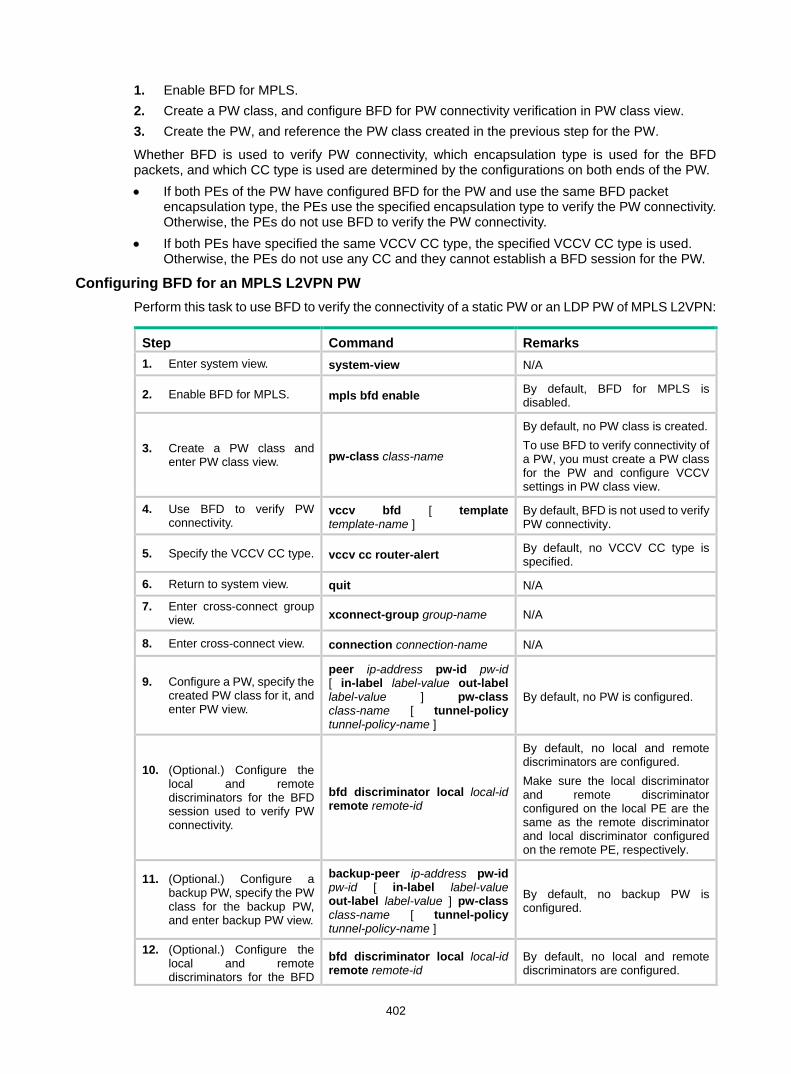
402
1. Enable BFD for MPLS. 2. Create a PW class, and configure BFD for PW connectivity verification in PW class view. 3. Create the PW, and reference the PW class created in the previous step for the PW.
Whether BFD is used to verify PW connectivity, which encapsulation type is used for the BFD packets, and which CC type is used are determined by the configurations on both ends of the PW. • If both PEs of the PW have configured BFD for the PW and use the same BFD packet
encapsulation type, the PEs use the specified encapsulation type to verify the PW connectivity. Otherwise, the PEs do not use BFD to verify the PW connectivity.
• If both PEs have specified the same VCCV CC type, the specified VCCV CC type is used. Otherwise, the PEs do not use any CC and they cannot establish a BFD session for the PW.
Configuring BFD for an MPLS L2VPN PW Perform this task to use BFD to verify the connectivity of a static PW or an LDP PW of MPLS L2VPN:
Step Command Remarks 1. Enter system view. system-view N/A
2. Enable BFD for MPLS. mpls bfd enable By default, BFD for MPLS is disabled.
3. Create a PW class and enter PW class view. pw-class class-name
By default, no PW class is created. To use BFD to verify connectivity of a PW, you must create a PW class for the PW and configure VCCV settings in PW class view.
4. Use BFD to verify PW connectivity.
vccv bfd [ template template-name ]
By default, BFD is not used to verify PW connectivity.
5. Specify the VCCV CC type. vccv cc router-alert By default, no VCCV CC type is specified.
6. Return to system view. quit N/A
7. Enter cross-connect group view. xconnect-group group-name N/A
8. Enter cross-connect view. connection connection-name N/A
9. Configure a PW, specify the created PW class for it, and enter PW view.
peer ip-address pw-id pw-id [ in-label label-value out-label label-value ] pw-class class-name [ tunnel-policy tunnel-policy-name ]
By default, no PW is configured.
10. (Optional.) Configure the local and remote discriminators for the BFD session used to verify PW connectivity.
bfd discriminator local local-id remote remote-id
By default, no local and remote discriminators are configured. Make sure the local discriminator and remote discriminator configured on the local PE are the same as the remote discriminator and local discriminator configured on the remote PE, respectively.
11. (Optional.) Configure a backup PW, specify the PW class for the backup PW, and enter backup PW view.
backup-peer ip-address pw-id pw-id [ in-label label-value out-label label-value ] pw-class class-name [ tunnel-policy tunnel-policy-name ]
By default, no backup PW is configured.
12. (Optional.) Configure the local and remote discriminators for the BFD
bfd discriminator local local-id remote remote-id
By default, no local and remote discriminators are configured.

403
Step Command Remarks session used to verify the connectivity of the backup PW.
Make sure the local discriminator and remote discriminator configured on the local PE are the same as the remote discriminator and local discriminator configured on the remote PE, respectively.
Configuring BFD for a VPLS static PW
Step Command Remarks 1. Enter system view. system-view N/A
2. Enable BFD for MPLS. mpls bfd enable By default, BFD for MPLS is disabled.
3. Create a PW class and enter PW class view. pw-class class-name
By default, no PW class is created. To use BFD to verify connectivity of a PW, you must create a PW class for the PW and configure VCCV settings in PW class view.
4. Use BFD to verify PW connectivity.
vccv bfd [ template template-name ]
By default, BFD is not used to verify PW connectivity.
5. Specify the VCCV CC type. vccv cc router-alert By default, no VCCV CC type is specified.
6. Return to system view. quit N/A
7. Enter VSI view. vsi vsi-name [ hub-spoke ] N/A
8. Configure the VSI to establish static PWs and enter VSI static view.
pwsignaling static N/A
9. Configure a VPLS PW, specify the created PW class for it, and enter VSI static PW view.
peer ip-address pw-id pw-id in-label label-value out-label label-value pw-class class-name [ hub | no-split-horizon | tunnel-policy tunnel-policy-name ] *
By default, no VPLS PW is configured.
10. (Optional.) Configure the local and remote discriminators for the BFD session used to verify PW connectivity.
bfd discriminator local local-id remote remote-id
By default, no local and remote discriminators are configured. Make sure the local discriminator and remote discriminator configured on the local PE are the same as the remote discriminator and local discriminator configured on the remote PE, respectively.
11. (Optional.) Configure a static backup PW, specify the PW class for the backup PW, and enter VSI static backup PW view.
backup-peer ip-address pw-id pw-id in-label label-value out-label label-value pw-class class-name [ tunnel-policy tunnel-policy-name ]
By default, no backup VPLS PW is configured.
12. (Optional.) Configure the local and remote discriminators for the BFD session used to verify the connectivity of the backup PW.
bfd discriminator local local-id remote remote-id
By default, no local and remote discriminators are configured. Make sure the local discriminator and remote discriminator configured on the local PE are the same as the remote discriminator and local discriminator configured
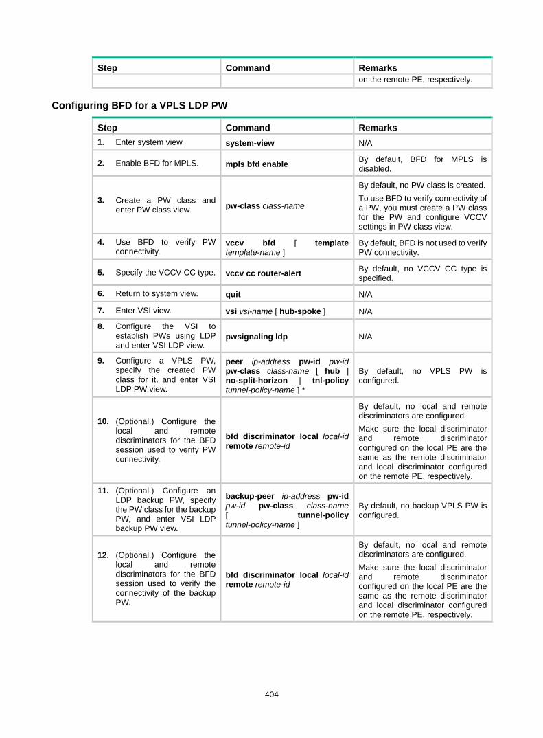
404
Step Command Remarks on the remote PE, respectively.
Configuring BFD for a VPLS LDP PW
Step Command Remarks 1. Enter system view. system-view N/A
2. Enable BFD for MPLS. mpls bfd enable By default, BFD for MPLS is disabled.
3. Create a PW class and enter PW class view. pw-class class-name
By default, no PW class is created. To use BFD to verify connectivity of a PW, you must create a PW class for the PW and configure VCCV settings in PW class view.
4. Use BFD to verify PW connectivity.
vccv bfd [ template template-name ]
By default, BFD is not used to verify PW connectivity.
5. Specify the VCCV CC type. vccv cc router-alert By default, no VCCV CC type is specified.
6. Return to system view. quit N/A
7. Enter VSI view. vsi vsi-name [ hub-spoke ] N/A
8. Configure the VSI to establish PWs using LDP and enter VSI LDP view.
pwsignaling ldp N/A
9. Configure a VPLS PW, specify the created PW class for it, and enter VSI LDP PW view.
peer ip-address pw-id pw-id pw-class class-name [ hub | no-split-horizon | tnl-policy tunnel-policy-name ] *
By default, no VPLS PW is configured.
10. (Optional.) Configure the local and remote discriminators for the BFD session used to verify PW connectivity.
bfd discriminator local local-id remote remote-id
By default, no local and remote discriminators are configured. Make sure the local discriminator and remote discriminator configured on the local PE are the same as the remote discriminator and local discriminator configured on the remote PE, respectively.
11. (Optional.) Configure an LDP backup PW, specify the PW class for the backup PW, and enter VSI LDP backup PW view.
backup-peer ip-address pw-id pw-id pw-class class-name [ tunnel-policy tunnel-policy-name ]
By default, no backup VPLS PW is configured.
12. (Optional.) Configure the local and remote discriminators for the BFD session used to verify the connectivity of the backup PW.
bfd discriminator local local-id remote remote-id
By default, no local and remote discriminators are configured. Make sure the local discriminator and remote discriminator configured on the local PE are the same as the remote discriminator and local discriminator configured on the remote PE, respectively.

405
Displaying MPLS OAM Execute display commands in any view.
Task Command Display BFD information for LSP tunnels or MPLS TE tunnels.
display mpls bfd [ ipv4 dest-addr mask-length | te tunnel tunnel-number ]
Display BFD information for PWs. display l2vpn pw bfd [ peer peer-ip pw-id pw-id ]
MPLS OAM configuration examples BFD for LSP configuration example Network requirements
Use LDP to establish an LSP from 1.1.1.9/32 to 3.3.3.9/32 and an LSP from 3.3.3.9/32 to 1.1.1.9/32. Use BFD to verify LSP connectivity.
Figure 105 Network diagram
Configuration procedure 1. Configure IP addresses for interfaces. (Details not shown.) 2. Configure OSPF to ensure IP connectivity between the switches:
# Configure Switch A. <SwitchA> system-view
[SwitchA] ospf
[SwitchA-ospf-1] area 0
[SwitchA-ospf-1-area-0.0.0.0] network 1.1.1.9 0.0.0.0
[SwitchA-ospf-1-area-0.0.0.0] network 10.1.1.0 0.0.0.255
[SwitchA-ospf-1-area-0.0.0.0] quit
[SwitchA-ospf-1] quit
# Configure Switch B. <SwitchB> system-view
[SwitchB] ospf
[SwitchB-ospf-1] area 0
[SwitchB-ospf-1-area-0.0.0.0] network 2.2.2.9 0.0.0.0
[SwitchB-ospf-1-area-0.0.0.0] network 10.1.1.0 0.0.0.255
[SwitchB-ospf-1-area-0.0.0.0] network 20.1.1.0 0.0.0.255
[SwitchB-ospf-1-area-0.0.0.0] quit
[SwitchB-ospf-1] quit
# Configure Switch C.
Loop02.2.2.9/32
Vlan-int320.1.1.1/24
Loop03.3.3.9/32
Loop01.1.1.9/32
Vlan-int210.1.1.1/24
Vlan-int210.1.1.2/24
Vlan-int320.1.1.2/24
Switch A Switch B Switch C

406
<SwitchC> system-view
[SwitchC] ospf
[SwitchC-ospf-1] area 0
[SwitchC-ospf-1-area-0.0.0.0] network 3.3.3.9 0.0.0.0
[SwitchC-ospf-1-area-0.0.0.0] network 20.1.1.0 0.0.0.255
[SwitchC-ospf-1-area-0.0.0.0] quit
[SwitchC-ospf-1] quit
3. Enable MPLS and LDP: # Configure Switch A. [SwitchA] mpls lsr-id 1.1.1.9
[SwitchA] mpls ldp
[SwitchA-ldp] quit
[SwitchA] interface vlan-interface 2
[SwitchA-Vlan-interface2] mpls enable
[SwitchA-Vlan-interface2] mpls ldp enable
[SwitchA-Vlan-interface2] quit
# Configure Switch B. [SwitchB] mpls lsr-id 2.2.2.9
[SwitchB] mpls ldp
[SwitchB-ldp] quit
[SwitchB] interface vlan-interface 2
[SwitchB-Vlan-interface2] mpls enable
[SwitchB-Vlan-interface2] mpls ldp enable
[SwitchB-Vlan-interface2] quit
[SwitchB] interface vlan-interface 3
[SwitchB-Vlan-interface3] mpls enable
[SwitchB-Vlan-interface3] mpls ldp enable
[SwitchB-Vlan-interface3] quit
# Configure Switch C. [SwitchC] mpls lsr-id 3.3.3.9
[SwitchC] mpls ldp
[SwitchC-ldp] quit
[SwitchC] interface vlan-interface 3
[SwitchC-Vlan-interface3] mpls enable
[SwitchC-Vlan-interface3] mpls ldp enable
[SwitchC-Vlan-interface3] quit
4. Enable BFD for MPLS, and configure BFD to verify LSP connectivity: # Configure Switch A. [SwitchA] mpls bfd enable
[SwitchA] mpls bfd 3.3.3.9 32
# Configure Switch C. [SwitchC] mpls bfd enable
[SwitchC] mpls bfd 1.1.1.9 32
Verifying the configuration # Display BFD information for LSPs on Switch A and Switch C, for example, on Switch A. [SwitchA] display mpls bfd
Total number of sessions: 2, 2 up, 0 down, 0 init

407
FEC Type: LSP
FEC Info:
Destination: 1.1.1.9
Mask Length: 32
NHLFE ID: -
Local Discr: 514 Remote Discr: 514
Source IP: 1.1.1.9 Destination IP: 3.3.3.9
Session State: Up Session Role: Active
Template Name: -
FEC Type: LSP
FEC Info:
Destination: 3.3.3.9
Mask Length: 32
NHLFE ID: 1025
Local Discr: 513 Remote Discr: 513
Source IP: 1.1.1.9 Destination IP: 127.0.0.1
Session State: Up Session Role: Passive
Template Name: -
The output shows that two BFD sessions have been established between Switch A and Switch C. One session verifies the connectivity of the LSP from 3.3.3.9/32 to 1.1.1.9/32 and the other session verifies the connectivity of the LSP from 1.1.1.9/32 to 3.3.3.9/32.
BFD for PW configuration example Network requirements
Create two LDP PWs to implement PW redundancy between CE 1 and CE 2. The primary PW goes through PE 1—PE 2. The backup PW goes through PE 1—PE 3. Configure BFD to inspect the connectivity of the primary PW. When the primary PW fails, CE 1 and CE 2 communicate through the backup PW.
Figure 106 Network diagram
Loop0 Loop0
CE 1 CE 2PE 1 PE 2
Vlan-int12
Vlan-int12
Loop0
PE 3
Vlan-int10
Vlan-int10
Vlan-int13
Vlan-int13
Vlan-int10
Vlan-int10
MPLS or IP backbone
Vlan-int10

408
Table 38 Interface and IP address assignment
Device Interface IP address Device Interface IP address CE 1 Vlan-int10 100.1.1.1/24 PE 2 Loop0 2.2.2.2/32
PE 1 Loop0 1.1.1.1/32 Vlan-int12 12.1.1.2/24
Vlan-int12 12.1.1.1/24 PE 3 Loop0 3.3.3.3/32
Vlan-int13 13.1.1.1/24 Vlan-int13 13.1.1.3/24
CE 2 Vlan-int10 100.1.1.2/24
Configuration procedure Before you perform the following configurations, create VLANs on each switch and add ports to the VLANs. 1. Configure CE 1.
<CE1> system-view
[CE1] interface vlan-interface 10
[CE1-Vlan-interface10] ip address 100.1.1.1 24
[CE1-Vlan-interface10] quit
2. Configure PE 1: # Configure an LSR ID. <PE1> system-view
[PE1] interface loopback 0
[PE1-LoopBack0] ip address 1.1.1.1 32
[PE1-LoopBack0] quit
[PE1] mpls lsr-id 1.1.1.1
# Enable global MPLS LDP. [PE1] mpls ldp
[PE1-ldp] quit
# Establish LDP sessions with PE 2 and PE 3. [PE1] interface vlan-interface 12
[PE1-Vlan-interface12] ip address 12.1.1.1 24
[PE1-Vlan-interface12] mpls enable
[PE1-Vlan-interface12] mpls ldp enable
[PE1-Vlan-interface12] quit
[PE1] interface vlan-interface 13
[PE1-Vlan-interface13] ip address 13.1.1.1 24
[PE1-Vlan-interface13] mpls enable
[PE1-Vlan-interface13] mpls ldp enable
[PE1-Vlan-interface13] quit
# Configure OSPF for LDP to create LSPs. [PE1] ospf
[PE1-ospf-1] area 0
[PE1-ospf-1-area-0.0.0.0] network 1.1.1.1 0.0.0.0
[PE1-ospf-1-area-0.0.0.0] network 12.1.1.0 0.0.0.255
[PE1-ospf-1-area-0.0.0.0] network 13.1.1.0 0.0.0.255
[PE1-ospf-1-area-0.0.0.0] quit
[PE1-ospf-1] quit
# Enable L2VPN.

409
[PE1] l2vpn enable
# Enable BFD for MPLS. [PE1] mpls bfd enable
# Create interface VLAN-interface 10 connected to CE 1. This interface does not need an IP address. [PE1] interface vlan-interface 10
[PE1-Vlan-interface10] quit
# Create PW class pwa. In the PW class, configure BFD to verify PW connectivity and configure the VCCV CC type as router-alert. [PE1] pw-class pwa
[PE1-pw-pwa] vccv bfd
[PE1-pw-pwa] vccv cc router-alert
[PE1-pw-pwa] quit
# Create cross-connect group vpna and create a cross-connect named ldp in the cross-connect group. Bind the cross-connect to interface VLAN-interface 10 and create the primary and backup LDP PWs in the cross-connect. The primary PW references the PW class pwa. [PE1] xconnect-group vpna
[PE1-xcg-vpna] connection ldp
[PE1-xcg-vpna-ldp] ac interface vlan-interface 10
[PE1-xcg-vpna-ldp] peer 2.2.2.2 pw-id 20 pw-class pwa
[PE1-xcg-vpna-ldp-2.2.2.2-20] backup-peer 3.3.3.3 pw-id 30
[PE1-xcg-vpna-ldp-3.3.3.3-20-backup] quit
[PE1-xcg-vpna-ldp-2.2.2.2-20] quit
[PE1-xcg-vpna-ldp] quit
[PE1-xcg-vpna] quit
[PE1] quit
3. Configure PE 2: # Configure an LSR ID. <PE2> system-view
[PE2] interface loopback 0
[PE2-LoopBack0] ip address 2.2.2.2 32
[PE2-LoopBack0] quit
[PE2] mpls lsr-id 2.2.2.2
# Enable global MPLS LDP. [PE2] mpls ldp
[PE2-ldp] quit
# Establish an LDP session with PE 1. [PE2] interface vlan-interface 12
[PE2-Vlan-interface12] ip address 12.1.1.2 24
[PE2-Vlan-interface12] mpls enable
[PE2-Vlan-interface12] mpls ldp enable
[PE2-Vlan-interface12] quit
# Configure OSPF for LDP to create LSPs. [PE2] ospf
[PE2-ospf-1] area 0
[PE2-ospf-1-area-0.0.0.0] network 12.1.1.0 0.0.0.255
[PE2-ospf-1-area-0.0.0.0] network 2.2.2.2 0.0.0.0
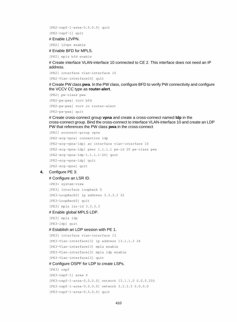
410
[PE2-ospf-1-area-0.0.0.0] quit
[PE2-ospf-1] quit
# Enable L2VPN. [PE2] l2vpn enable
# Enable BFD for MPLS. [PE2] mpls bfd enable
# Create interface VLAN-interface 10 connected to CE 2. This interface does not need an IP address. [PE2] interface vlan-interface 10
[PE2-Vlan-interface10] quit
# Create PW class pwa. In the PW class, configure BFD to verify PW connectivity and configure the VCCV CC type as router-alert. [PE2] pw-class pwa
[PE2-pw-pwa] vccv bfd
[PE2-pw-pwa] vccv cc router-alert
[PE2-pw-pwa] quit
# Create cross-connect group vpna and create a cross-connect named ldp in the cross-connect group. Bind the cross-connect to interface VLAN-interface 10 and create an LDP PW that references the PW class pwa in the cross-connect [PE2] xconnect-group vpna
[PE2-xcg-vpna] connection ldp
[PE2-xcg-vpna-ldp] ac interface vlan-interface 10
[PE2-xcg-vpna-ldp] peer 1.1.1.1 pw-id 20 pw-class pwa
[PE2-xcg-vpna-ldp-1.1.1.1-20] quit
[PE2-xcg-vpna-ldp] quit
[PE2-xcg-vpna] quit
4. Configure PE 3: # Configure an LSR ID. <PE3> system-view
[PE3] interface loopback 0
[PE3-LoopBack0] ip address 3.3.3.3 32
[PE3-LoopBack0] quit
[PE3] mpls lsr-id 3.3.3.3
# Enable global MPLS LDP. [PE3] mpls ldp
[PE3-ldp] quit
# Establish an LDP session with PE 1. [PE3] interface vlan-interface 13
[PE3-Vlan-interface13] ip address 13.1.1.3 24
[PE3-Vlan-interface13] mpls enable
[PE3-Vlan-interface13] mpls ldp enable
[PE3-Vlan-interface13] quit
# Configure OSPF for LDP to create LSPs. [PE3] ospf
[PE3-ospf-1] area 0
[PE3-ospf-1-area-0.0.0.0] network 13.1.1.0 0.0.0.255
[PE3-ospf-1-area-0.0.0.0] network 3.3.3.3 0.0.0.0
[PE3-ospf-1-area-0.0.0.0] quit

411
[PE3-ospf-1] quit
# Enable L2VPN. [PE3] l2vpn enable
# Create interface VLAN-interface 10 connected to CE 2. This interface does not need an IP address. [PE3] interface vlan-interface 10
[PE3-Vlan-interface10] quit
# Create cross-connect group vpna and create a cross-connect named ldp in the cross-connect group. Bind the cross-connect to interface VLAN-interface 10 and create an LDP PW in the cross-connect. [PE3] xconnect-group vpna
[PE3-xcg-vpna] connection ldp
[PE3-xcg-vpna-ldp] ac interface vlan-interface 10
[PE3-xcg-vpna-ldp] peer 1.1.1.1 pw-id 30
[PE3-xcg-vpna-ldp-1.1.1.1-30] quit
[PE3-xcg-vpna-ldp] quit
[PE3-xcg-vpna] quit
5. Configure CE 2. <CE2> system-view
[CE2] interface vlan-interface 10
[CE2-Vlan-interface10] ip address 100.1.1.2 24
[CE2-Vlan-interface10] quit
Verifying the configuration # Display L2VPN PW information on PE 1. The output shows that two PWs (one primary and one backup) have been established. <PE1> display l2vpn pw
Flags: M - main, B - backup, H - hub link, S - spoke link, N - no split horizon
Total number of PWs: 2, 1 up, 1 blocked, 0 down, 0 defect
Xconnect-group Name: vpna
Peer PW ID In/Out Label Proto Flag Link ID State
2.2.2.2 20 65651/65779 LDP M 1 Up
3.3.3.3 30 65650/65779 LDP B 1 Blocked
# Display L2VPN PW information on PE 2. The output shows that a PW has been established. [PE2] display l2vpn pw
Flags: M - main, B - backup, H - hub link, S - spoke link, N - no split horizon
Total number of PWs: 1, 1 up, 0 blocked, 0 down, 0 defect
Xconnect-group Name: vpna
Peer PW ID In/Out Label Proto Flag Link ID State
1.1.1.1 20 65779/65651 LDP M 1 Up
# Display L2VPN PW information on PE 3. The output shows that a PW has been established. [PE3] display l2vpn pw
Flags: M - main, B - backup, H - hub link, S - spoke link, N - no split horizon
Total number of PWs: 1, 1 up, 0 blocked, 0 down, 0 defect
Xconnect-group Name: vpna
Peer PW ID In/Out Label Proto Flag Link ID State

412
1.1.1.1 30 65779/65650 LDP M 1 Up
# Execute the display l2vpn pw bfd command on PE 1 and PE 2. The output shows that a BFD session in up state has been established between PE 1 and PE 2 to verify the PW connectivity between 1.1.1.1/32 and 3.3.3.3/32. Take PE 1 as an example: [PE1] display l2vpn pw bfd
Total number of sessions: 1, 1 up, 0 down, 0 init
FEC Type: PW FEC-128
FEC Info:
Peer IP: 3.3.3.3
PW ID: 3
Connection ID: 2147483648 Link ID: 1
Local Discr: 514 Remote Discr: 514
Source IP: 1.1.1.1 Destination IP: 127.0.0.2
Session State: Up Session Role: Active
Template Name: -
# Verify that CE 1 and CE 2 can ping each other. (Details not shown.)
# Shut down the PW between PE 1 and PE 2. Execute the display l2vpn pw bfd command. The output shows that the BFD session becomes down. [PE1] display l2vpn pw bfd
Total number of sessions: 1, 0 up, 1 down, 0 init
FEC Type: PW FEC-128
FEC Info:
Peer IP: 3.3.3.3
PW ID: 3
Connection ID: 2147483648 Link ID: 1
Local Discr: 514 Remote Discr: 514
Source IP: 1.1.1.1 Destination IP: 127.0.0.2
Session State: Down Session Role: Active
Template Name: -
# Display L2VPN PW information on PE 1. The output shows that backup PW is in use. <PE1> display l2vpn pw
Flags: M - main, B - backup, H - hub link, S - spoke link, N - no split horizon
Total number of PWs: 2, 1 up, 0 blocked, 0 down, 1 defect
Xconnect-group Name: vpna
Peer PW ID In/Out Label Proto Flag Link ID State
2.2.2.2 20 65651/65779 LDP M 1 BFD Defect
3.3.3.3 30 65650/65779 LDP B 1 Up
# Verify that CE 1 and CE 2 can ping each other. (Details not shown.)
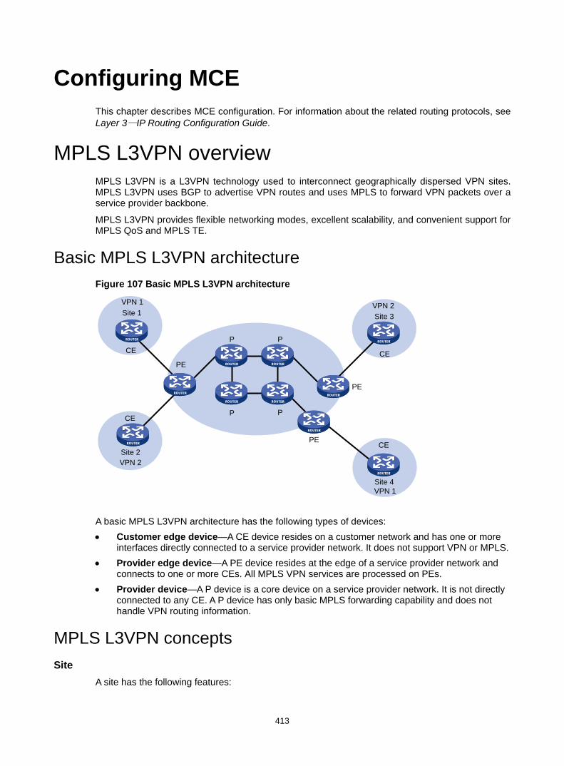
413
Configuring MCE This chapter describes MCE configuration. For information about the related routing protocols, see Layer 3—IP Routing Configuration Guide.
MPLS L3VPN overview MPLS L3VPN is a L3VPN technology used to interconnect geographically dispersed VPN sites. MPLS L3VPN uses BGP to advertise VPN routes and uses MPLS to forward VPN packets over a service provider backbone.
MPLS L3VPN provides flexible networking modes, excellent scalability, and convenient support for MPLS QoS and MPLS TE.
Basic MPLS L3VPN architecture Figure 107 Basic MPLS L3VPN architecture
A basic MPLS L3VPN architecture has the following types of devices: • Customer edge device—A CE device resides on a customer network and has one or more
interfaces directly connected to a service provider network. It does not support VPN or MPLS. • Provider edge device—A PE device resides at the edge of a service provider network and
connects to one or more CEs. All MPLS VPN services are processed on PEs. • Provider device—A P device is a core device on a service provider network. It is not directly
connected to any CE. A P device has only basic MPLS forwarding capability and does not handle VPN routing information.
MPLS L3VPN concepts Site
A site has the following features:
VPN 1
CE
Site 1
VPN 2
CE
CE
CE
Site 3VPN 2
PE
VPN 1
Site 2
Site 4
PE
PE
P P
P P

414
• A site is a group of IP systems with IP connectivity that does not rely on any service provider network.
• The classification of a site depends on the topology relationship of the devices, rather than the geographical positions. However, the devices at a site are, in most cases, adjacent to each other geographically.
• The devices at a site can belong to multiple VPNs, which means that a site can belong to multiple VPNs.
• A site is connected to a provider network through one or more CEs. A site can contain multiple CEs, but a CE can belong to only one site.
Sites connected to the same provider network can be classified into different sets by policies. Only the sites in the same set can access each other through the provider network. Such a set is called a VPN.
VPN instance VPN instances, also called virtual routing and forwarding (VRF) instances, implement route isolation, data independence, and data security for VPNs.
A VPN instance has the following components: • A separate Label Forwarding Information Base (LFIB). • An IP routing table. • Interfaces bound to the VPN instance. • VPN instance administration information, including route distinguishers (RDs), route targets
(RTs), and route filtering policies.
To associate a site with a VPN instance, bind the VPN instance to the PE's interface connected to the site. A site can be associated with only one VPN instance, and different sites can associate with the same VPN instance. A VPN instance contains the VPN membership and routing rules of associated sites.
VPN-IPv4 address Each VPN independently manages its address space. The address spaces of VPNs might overlap. For example, if both VPN 1 and VPN 2 use the addresses on subnet 10.110.10.0/24, address space overlapping occurs.
BGP cannot process overlapping VPN address spaces. For example, if both VPN 1 and VPN 2 use the subnet 10.110.10.0/24 and each advertise a route destined for the subnet, BGP selects only one of them. This results in the loss of the other route.
Multiprotocol BGP (MP-BGP) can solve this problem by advertising VPN-IPv4 addresses (also called VPNv4 addresses).
Figure 108 VPN-IPv4 address structure
As shown in Figure 108, a VPN-IPv4 address consists of 12 bytes. The first eight bytes represent the RD, followed by a four-byte IPv4 prefix. The RD and the IPv4 prefix form a unique VPN-IPv4 prefix.
An RD can be in one of the following formats: • When the Type field is 0, the Administrator subfield occupies two bytes, the Assigned number
subfield occupies four bytes, and the RD format is 16-bit AS number:32-bit user-defined number. For example, 100:1.
Type
2 bytes 4 bytes
IPv4 address prefix
6 bytes
Route Distinguisher (8 bytes)
Assigned number subfieldAdministrator subfield

415
• When the Type field is 1, the Administrator subfield occupies four bytes, the Assigned number subfield occupies two bytes, and the RD format is 32-bit IPv4 address:16-bit user-defined number. For example, 172.1.1.1:1.
• When the Type field is 2, the Administrator subfield occupies four bytes, the Assigned number subfield occupies two bytes, and the RD format is 32-bit AS number:16-bit user-defined number, where the minimum value of the AS number is 65536. For example, 65536:1.
To guarantee global uniqueness for a VPN-IPv4 address, do not set the Administrator subfield to any private AS number or private IP address.
Route target attribute MPLS L3VPN uses route target community attributes to control the advertisement of VPN routing information. A VPN instance on a PE supports the following types of route target attributes: • Export target attribute—A PE sets the export target attribute for VPN-IPv4 routes learned
from directly connected sites before advertising them to other PEs. • Import target attribute—A PE checks the export target attribute of VPN-IPv4 routes received
from other PEs. If the export target attribute matches the import target attribute of a VPN instance, the PE adds the routes to the routing table of the VPN instance.
Route target attributes define which sites can receive VPN-IPv4 routes, and from which sites a PE can receive routes.
Like RDs, route target attributes can be one of the following formats: • 16-bit AS number:32-bit user-defined number. For example, 100:1. • 32-bit IPv4 address:16-bit user-defined number. For example, 172.1.1.1:1. • 32-bit AS number:16-bit user-defined number, where the minimum value of the AS number is
65536. For example, 65536:1.
MCE overview The Multi-VPN-Instance CE (MCE) feature allows you to create multiple VPN instances on a CE. The VPN instances each have an independent routing table and an address space to achieve service isolation.
Figure 109 Network diagram for the MCE function
VPN 1Site 1
VPN 2Site 2
CE
CE
VPN 2Site 1
VPN 1Site 2
PE 3
PE 2
P
P
Vlan-int2
Vlan-int3MCE PE 1
Vlan-int2Vlan-int3
Vlan-int2Vlan-int3

416
As shown in Figure 109, the MCE exchanges private routes with VPN sites and PE 1, and adds the private routes to the routing tables of corresponding VPN instances. • Route exchange between MCE and VPN site—Create VPN instances VPN 1 and VPN 2 on
the MCE. Bind VLAN-interface 2 to VPN 1, and VLAN-interface 3 to VPN 2. The MCE adds a received route to the routing table of the VPN instance that is bound to the receiving VLAN interface.
• Route exchange between MCE and PE—The MCE connects to PE 1 through a trunk link that permits VLAN 2 and VLAN 3. On PE 1, create VPN instances VPN 1 and VPN 2. Bind VLAN-interface 2 to VPN 1, and VLAN-interface 3 to VPN 2. The MCE and PE add a received route to the routing table of the VPN instance that is bound to the receiving VLAN interface.
You can configure static routes, RIP, OSPF, IS-IS, EBGP, or IBGP between an MCE and a VPN site and between an MCE and a PE.
NOTE: To implement dynamic IP assignment for DHCP clients in private networks, you can configure DHCP server or DHCP relay agent on the MCE. When the MCE functions as the DHCP server, the IP addresses assigned to different private networks cannot overlap.
MCE configuration task list Tasks at a glance Configuring VPN instances: 1. (Required.) Creating a VPN instance 2. (Required.) Associating a VPN instance with an interface 3. (Optional.) Configuring route related attributes for a VPN instance
Configuring routing on an MCE: • (Required.) Configuring routing between an MCE and a VPN site • (Required.) Configuring routing between an MCE and a PE
Configuring VPN instances VPN instances isolate VPN routes from public network routes and routes among VPNs. You must configure VPN instances for an MCE network.
Creating a VPN instance A VPN instance is a collection of the VPN membership and routing rules of its associated site. A VPN instance may not correspond to one VPN.
To create and configure a VPN instance:
Step Command Remarks 1. Enter system view. system-view N/A
2. Create a VPN instance and enter VPN instance view.
ip vpn-instance vpn-instance-name
By default, no VPN instance is created.
3. Configure an RD for the VPN instance.
route-distinguisher route-distinguisher
By default, no RD is specified for a VPN instance.
4. (Optional.) Configure a description text By default, no description is

417
Step Command Remarks description for the VPN instance.
configured for a VPN instance.
5. (Optional.) Configure a VPN ID for the VPN instance. vpn-id vpn-id By default, no VPN ID is
configured for a VPN instance.
Associating a VPN instance with an interface After creating and configuring a VPN instance, associate the VPN instance with the MCE's interface connected to the site and the interface connected to the PE.
To associate a VPN instance with an interface:
Step Command Remarks 1. Enter system view. system-view N/A
2. Enter interface view. interface interface-type interface-number N/A
3. Associate a VPN instance with the interface.
ip binding vpn-instance vpn-instance-name
By default, an interface is not associated with a VPN instance. The ip binding vpn-instance command deletes the IP address of the current interface. You must re-configure an IP address for the interface after configuring the command.
Configuring route related attributes for a VPN instance
Step Command Remarks 1. Enter system view. system-view N/A
2. Enter VPN instance view or IPv4 VPN view.
• Enter VPN instance view: ip vpn-instance vpn-instance-name
• Enter IPv4 VPN view: a. ip vpn-instance
vpn-instance-name b. address-family ipv4
Configurations made in VPN instance view apply to both IPv4 VPN and IPv6 VPN. IPv4 VPN prefers the configurations in IPv4 VPN view over the configurations in VPN instance view.
3. Configure route targets. vpn-target vpn-target&<1-8> [ both | export-extcommunity | import-extcommunity ]
By default, no route targets are configured.
4. Set the maximum number of active routes.
routing-table limit number { warn-threshold | simply-alert }
By default, the number of active routes in a VPN instance is not limited. Setting the maximum number of active routes for a VPN instance can prevent the PE from learning too many routes.
5. Apply an import routing policy. import route-policy route-policy
By default, all routes matching the import target attribute are accepted.

418
Step Command Remarks The specified routing policy must have been created. For information about routing policies, see Layer 3—IP Routing Configuration Guide.
6. Apply an export routing policy. export route-policy route-policy
By default, routes to be advertised are not filtered. The specified routing policy must have been created. For information about routing policies, see Layer 3—IP Routing Configuration Guide.
7. Apply a tunnel policy to the VPN instance. tnl-policy tunnel-policy-name
By default, only one tunnel is selected (no load balancing) in this order: LSP tunnel, and CRLSP tunnel. The specified tunnel policy must have been created. For information about tunnel policies, see "Configuring tunnel policies."
Configuring routing on an MCE MCE implements service isolation through route isolation. MCE routing configuration includes the following: • MCE-VPN site routing configuration. • MCE-PE routing configuration.
On the PE, do the following: • Disable routing loop detection to avoid route loss during route calculation. • Disable route redistribution between routing protocols to save system resources.
Before you configure routing on an MCE, configure VPN instances, and bind the VPN instances to the interfaces connected to the VPN sites and the PE.
Configuring routing between an MCE and a VPN site You can configure static routing, RIP, OSPF, IS-IS, EBGP, or IBGP between an MCE and a VPN site.
Configuring static routing between an MCE and a VPN site An MCE can reach a VPN site through a static route. Static routing on a traditional CE is globally effective and does not support address overlapping among VPNs. An MCE supports binding a static route to a VPN instance, so that the static routes of different VPN instances can be isolated from each other.
To configure a static route to a VPN site:
Step Command Remarks 1. Enter system view. system-view N/A
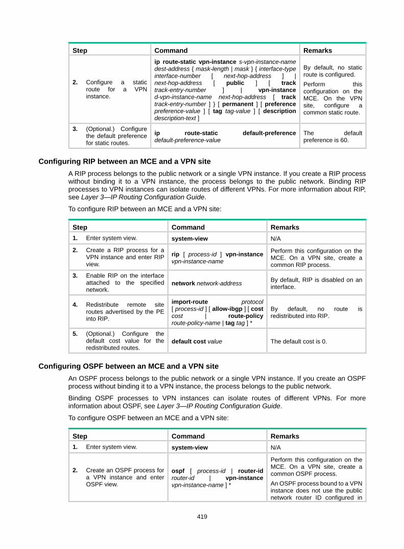
419
Step Command Remarks
2. Configure a static route for a VPN instance.
ip route-static vpn-instance s-vpn-instance-name dest-address { mask-length | mask } { interface-type interface-number [ next-hop-address ] | next-hop-address [ public ] [ track track-entry-number ] | vpn-instance d-vpn-instance-name next-hop-address [ track track-entry-number ] } [ permanent ] [ preference preference-value ] [ tag tag-value ] [ description description-text ]
By default, no static route is configured. Perform this configuration on the MCE. On the VPN site, configure a common static route.
3. (Optional.) Configure the default preference for static routes.
ip route-static default-preference default-preference-value
The default preference is 60.
Configuring RIP between an MCE and a VPN site A RIP process belongs to the public network or a single VPN instance. If you create a RIP process without binding it to a VPN instance, the process belongs to the public network. Binding RIP processes to VPN instances can isolate routes of different VPNs. For more information about RIP, see Layer 3—IP Routing Configuration Guide.
To configure RIP between an MCE and a VPN site:
Step Command Remarks 1. Enter system view. system-view N/A
2. Create a RIP process for a VPN instance and enter RIP view.
rip [ process-id ] vpn-instance vpn-instance-name
Perform this configuration on the MCE. On a VPN site, create a common RIP process.
3. Enable RIP on the interface attached to the specified network.
network network-address By default, RIP is disabled on an interface.
4. Redistribute remote site routes advertised by the PE into RIP.
import-route protocol [ process-id ] [ allow-ibgp ] [ cost cost | route-policy route-policy-name | tag tag ] *
By default, no route is redistributed into RIP.
5. (Optional.) Configure the default cost value for the redistributed routes.
default cost value The default cost is 0.
Configuring OSPF between an MCE and a VPN site An OSPF process belongs to the public network or a single VPN instance. If you create an OSPF process without binding it to a VPN instance, the process belongs to the public network.
Binding OSPF processes to VPN instances can isolate routes of different VPNs. For more information about OSPF, see Layer 3—IP Routing Configuration Guide.
To configure OSPF between an MCE and a VPN site:
Step Command Remarks 1. Enter system view. system-view N/A
2. Create an OSPF process for a VPN instance and enter OSPF view.
ospf [ process-id | router-id router-id | vpn-instance vpn-instance-name ] *
Perform this configuration on the MCE. On a VPN site, create a common OSPF process. An OSPF process bound to a VPN instance does not use the public network router ID configured in

420
Step Command Remarks system view. Therefore, configure a router ID for the OSPF process. An OSPF process can belong to only one VPN instance, but one VPN instance can use multiple OSPF processes to advertise VPN routes.
3. (Optional.) Configure the OSPF domain ID.
domain-id domain-id [ secondary ]
The default domain ID is 0. Perform this configuration on the MCE. All OSPF processes of the same VPN must be configured with the same OSPF domain ID to ensure correct route advertisement.
4. (Optional.) Configure the type codes of OSPF extended community attributes.
ext-community-type { domain-id type-code1 | router-id type-code2 | route-type type-code3 }
The defaults are as follows: • 0x0005 for Domain ID. • 0x0107 for Router ID. • 0x0306 for Route Type.
5. (Optional.) Configure the external route tag for imported VPN routes.
route-tag tag-value
By default, no route tag is configured. In some networks, a VPN might be connected to multiple MCEs. When one MCE advertises the routes learned from BGP to the VPN, the other MCEs might learn the routes, resulting in routing loops. To avoid such routing loops, you can configure route tags for VPN instances on an MCE. As a best practice, configure the same route tag for the same VPN on the MCEs.
6. Redistribute remote site routes advertised by the PE into OSPF.
import-route protocol [ process-id | all-processes | allow-ibgp ] [ allow-direct | cost cost | nssa-only | route-policy route-policy-name | tag tag | type type ] *
By default, no routes are redistributed into OSPF.
7. (Optional.) Configure OSPF to redistribute the default route.
default-route-advertise summary cost cost
By default, OSPF does not redistribute the default route. This command redistributes the default route in a Type-3 LSA. The MCE advertises the default route to the site.
8. Create an OSPF area and enter OSPF area view. area area-id By default, no OSPF area is
created.
9. Enable OSPF on the interface attached to the specified network in the area.
network ip-address wildcard-mask
By default, an interface neither belongs to any area nor runs OSPF.
Configuring IS-IS between an MCE and a VPN site An IS-IS process belongs to the public network or a single VPN instance. If you create an IS-IS process without binding it to a VPN instance, the process belongs to the public network.

421
Binding IS-IS processes to VPN instances can isolate routes of different VPNs. For more information about IS-IS, see Layer 3—IP Routing Configuration Guide.
To configure IS-IS between an MCE and a VPN site:
Step Command Remarks 1. Enter system view. system-view N/A
2. Create an IS-IS process for a VPN instance and enter IS-IS view.
isis [ process-id ] vpn-instance vpn-instance-name
Perform this configuration on the MCE. On a VPN site, configure a common IS-IS process.
3. Configure a network entity title. network-entity net By default, no NET is configured.
4. Redistribute remote site routes advertised by the PE into IS-IS.
import-route protocol [ process-id | all-processes | allow-ibgp ] [ allow-direct | cost cost | cost-type { external | internal } | [ level-1 | level-1-2 | level-2 ] | route-policy route-policy-name | tag tag ] *
By default, IS-IS does not redistribute routes from any other routing protocol. If you do not specify the route level in the command, the command redistributes routes to the level-2 routing table by default.
5. Return to system view. quit N/A
6. Enter interface view. interface interface-type interface-number N/A
7. Enable the IS-IS process on the interface. isis enable [ process-id ] By default, IS-IS is disabled.
Configuring EBGP between an MCE and a VPN site To run EBGP between an MCE and a VPN site, you must configure a BGP peer for each VPN instance on the MCE, and redistribute the IGP routes of each VPN instance on the VPN site.
You can configure filtering policies to filter received routes and advertised routes. 1. Configure the MCE:
Step Command Remarks 1. Enter system view. system-view N/A
2. Enter BGP view. bgp as-number N/A
3. Enter BGP-VPN instance view. ip vpn-instance vpn-instance-name N/A
4. Configure an EBGP peer. peer { group-name | ip-address [ mask-length ] } as-number as-number
By default, no BGP peer is configured.
5. Enter BGP-VPN IPv4 unicast address family view.
address-family ipv4 [ unicast ] N/A
6. Enable BGP to exchange IPv4 unicast routes with the peer.
peer { group-name | ip-address [ mask-length ] } enable
By default, BGP does not exchange IPv4 unicast routes with any peer.

422
Step Command Remarks 7. Allow the local AS number
to appear in the AS_PATH attribute of routes received from the peer, and set the maximum number of repetitions.
peer { group-name | ip-address [ mask-length ] } allow-as-loop [ number ]
By default, BGP discards incoming route updates that contain the local AS number.
8. Redistribute remote site routes advertised by the PE into BGP.
import-route protocol [ { process-id | all-processes } [ allow-direct | med med-value | route-policy route-policy-name ] * ]
By default, no routes are redistributed into BGP.
9. (Optional.) Configure filtering of advertised routes.
filter-policy { acl-number | prefix-list prefix-list-name } export [ protocol process-id ]
By default, BGP does not filter advertised routes.
10. (Optional.) Configure filtering of received routes.
filter-policy { acl-number | prefix-list prefix-list-name } import
By default, BGP does not filter received routes.
2. Configure a VPN site:
Step Command Remarks 1. Enter system view. system-view N/A
2. Enter BGP view. bgp as-number N/A
3. Configure the MCE as an EBGP peer.
peer { group-name | ip-address [ mask-length ] } as-number as-number
N/A
4. Enter BGP-VPN IPv4 unicast address family view. address-family ipv4 [ unicast ] N/A
5. Enable BGP to exchange IPv4 unicast routes with the peer.
peer { group-name | ip-address [ mask-length ] } enable
By default, BGP does not exchange IPv4 unicast routes with any peer.
6. Redistribute the IGP routes of the VPN into BGP.
import-route protocol [ { process-id | all-processes } [ allow-direct | med med-value | route-policy route-policy-name ] * ]
By default, no routes are redistributed into BGP. A VPN site must advertise the VPN network addresses it can reach to the connected MCE.
Configuring IBGP between MCE and VPN site To run IBGP between an MCE and a VPN site, you must configure a BGP peer for each VPN instance on the MCE, and redistribute the IGP routes of each VPN instance on the VPN site. 1. Configure the MCE:
Step Command Remarks 1. Enter system view. system-view N/A
2. Enter BGP view. bgp as-number N/A
3. Enter BGP-VPN instance view.
ip vpn-instance vpn-instance-name N/A
4. Configure an IBGP peer. peer { group-name | ip-address [ mask-length ] } as-number as-number
N/A
5. Enter BGP-VPN IPv4 unicast address-family ipv4 [ unicast ] N/A

423
Step Command Remarks address family view.
6. Enable BGP to exchange IPv4 unicast routes with the peer.
peer { group-name | ip-address [ mask-length ] } enable
By default, BGP does not exchange IPv4 unicast routes with any peer.
7. (Optional.) Configure the system to be the RR, and specify the peer as the client of the RR.
peer { group-name | ip-address [ mask-length ] } reflect-client
By default, no RR or RR client is configured. After you configure a VPN site as an IBGP peer, the MCE does not advertise the BGP routes learned from the VPN site to other IBGP peers, including VPNv4 peers. The MCE advertises routes learned from a VPN site only when you configure the VPN site as a client of the RR (the MCE).
8. Redistribute remote site routes advertised by the PE into BGP.
import-route protocol [ process-id | all-processes ] [ allow-direct | med med-value | route-policy route-policy-name ] *
By default, no routes are redistributed into BGP.
9. (Optional.) Configure filtering of advertised routes.
filter-policy { acl-number | prefix-list prefix-list-name } export [ protocol process-id ]
By default, BGP does not filter advertised routes.
10. (Optional.) Configure filtering of received routes.
filter-policy { acl-number | prefix-list prefix-list-name } import
By default, BGP does not filter received routes.
2. Configure a VPN site:
Step Command Remarks 1. Enter system view. system-view N/A
2. Enter BGP view. bgp as-number N/A
3. Configure the MCE as an IBGP peer.
peer { group-name | ip-address [ mask-length ] } as-number as-number
N/A
4. Enter BGP-VPN IPv4 unicast address family view. address-family ipv4 [ unicast ] N/A
5. Enable BGP to exchange IPv4 unicast routes with the peer.
peer { group-name | ip-address [ mask-length ] } enable
By default, BGP does not exchange IPv4 unicast routes with any peer.
6. Redistribute the IGP routes of the VPN into BGP.
import-route protocol [ { process-id | all-processes } [ allow-direct | med med-value | route-policy route-policy-name ] * ]
By default, no routes are redistributed into BGP. A VPN site must advertise VPN network addresses to the connected MCE.
Configuring routing between an MCE and a PE MCE-PE routing configuration includes the following tasks: • Binding the MCE-PE interfaces to VPN instances.

424
• Performing route configurations. • Redistributing VPN routes into the routing protocol running between the MCE and the PE.
Perform the following configurations on the MCE. Configure the PE in the same way that you configure a PE in a basic MPLS L3VPN. For more information about configuring the PE, see "Configuring MPLS L3VPN."
Configuring static routing between an MCE and a PE
Step Command Remarks 1. Enter system view. system-view N/A
2. Configure a static route for a VPN instance.
ip route-static vpn-instance s-vpn-instance-name dest-address { mask-length | mask } { interface-type interface-number [ next-hop-address ] | next-hop-address [ public ] [ track track-entry-number ] | vpn-instance d-vpn-instance-name next-hop-address [ track track-entry-number ] } [ permanent ] [ preference preference-value ] [ tag tag-value ] [ description description-text ]
By default, no static route is configured.
3. (Optional.) Configure the default preference for static routes.
ip route-static default-preference default-preference-value
The default preference is 60.
Configuring RIP between an MCE and a PE
Step Command Remarks 1. Enter system view. system-view N/A
2. Create a RIP process for a VPN instance and enter RIP view.
rip [ process-id ] vpn-instance vpn-instance-name N/A
3. Enable RIP on the interface attached to the specified network.
network network-address By default, RIP is disabled on an interface.
4. Redistribute the VPN routes.
import-route protocol [ process-id | all-processes | allow-ibgp ] [ allow-direct | cost cost | route-policy route-policy-name | tag tag ] *
By default, no routes are redistributed into RIP.
5. (Optional.) Configure the default cost for redistributed routes.
default cost value The default cost is 0.
Configuring OSPF between an MCE and a PE
Step Command Remarks 1. Enter system view. system-view N/A
2. Create an OSPF process for a VPN instance and enter OSPF view.
ospf [ process-id | router-id router-id | vpn-instance vpn-instance-name ] *
N/A
3. Disable routing loop detection. vpn-instance-capability simple
By default, routing loop detection is enabled. You must disable routing loop detection for an OSPF VRF process on the MCE. Otherwise, the MCE does not receive OSPF

425
Step Command Remarks routes from the PE.
4. (Optional.) Configure the OSPF domain ID.
domain-id domain-id [ secondary ] The default domain ID is 0.
5. (Optional.) Configure the type codes of OSPF extended community attributes.
ext-community-type { domain-id type-code1 | router-id type-code2 | route-type type-code3 }
The defaults are as follows: • 0x0005 for Domain ID. • 0x0107 for Router ID. • 0x0306 for Route Type.
6. (Optional.) Configure the external route tag for imported VPN routes.
route-tag tag-value
By default, no route tag is configured. In some networks, a VPN might be connected to multiple MCEs. When one MCE advertises the routes learned from BGP to the VPN, the other MCEs might learn the routes, resulting in routing loops. To avoid such routing loops, you can configure route tags for VPN instances on an MCE. As a best practice, configure the same route tag for the same VPN on the MCEs.
7. Redistribute the VPN routes.
import-route protocol [ process-id | all-processes | allow-ibgp ] [ allow-direct | cost cost | nssa-only | route-policy route-policy-name | tag tag | type type ] *
By default, no routes are redistributed into OSPF.
8. (Optional.) Configure OSPF to redistribute the default route.
default-route-advertise summary cost cost
By default, OSPF does not redistribute the default route. This command redistributes the default route in a Type-3 LSA. The MCE advertises the default route to the PE.
9. (Optional.) Configure filtering of advertised routes.
filter-policy { acl-number | prefix-list prefix-list-name } export [ protocol [ process-id ] ]
By default, redistributed routes are not filtered.
10. (Optional.) Configure the default parameters for redistributed routes (cost, route number, tag, and type).
default { cost cost | tag tag | type type } *
The default cost is 1, the default tag is 1, and default type of redistributed routes is Type-2.
11. Create an OSPF area and enter OSPF area view. area area-id By default, no OSPF area is
created.
12. Enable OSPF on the interface attached to the specified network in the area.
network ip-address wildcard-mask
By default, an interface neither belongs to any area nor runs OSPF.
Configuring IS-IS between an MCE and a PE
Step Command Remarks 1. Enter system view. system-view N/A
2. Create an IS-IS process for a VPN instance and enter
isis [ process-id ] vpn-instance vpn-instance-name N/A

426
Step Command Remarks IS-IS view.
3. Configure a network entity title. network-entity net By default, no NET is configured.
4. Redistribute VPN routes.
import-route protocol [ process-id | all-processes | allow-ibgp ] [ allow-direct | cost cost | cost-type { external | internal } | [ level-1 | level-1-2 | level-2 ] | route-policy route-policy-name | tag tag ] *
By default, IS-IS does not redistribute routes from any other routing protocol. If you do not specify the route level in the command, the command redistributes routes to the level-2 routing table by default.
5. (Optional.) Configure filtering of advertised routes.
filter-policy { acl-number | prefix-list prefix-list-name | route-policy route-policy-name } export [ protocol [ process-id ] ]
By default, IS-IS does not filter advertised routes.
6. Return to system view. quit N/A
7. Enter interface view. interface interface-type interface-number N/A
8. Enable the IS-IS process on the interface.
isis enable [ process-id ] By default, no IS-IS process is enabled.
Configuring EBGP between an MCE and a PE
Step Command Remarks 1. Enter system view. system-view N/A
2. Enter BGP view. bgp as-number N/A
3. Enter BGP-VPN instance view. ip vpn-instance vpn-instance-name N/A
4. Configure the PE as an EBGP peer.
peer { group-name | ip-address [ mask-length ] } as-number as-number N/A
5. Enter BGP-VPN IPv4 unicast address family view.
address-family ipv4 [ unicast ] N/A
6. Enable BGP to exchange IPv4 unicast routes with the peer.
peer { group-name | ip-address [ mask-length ] } enable
By default, BGP does not exchange IPv4 unicast routes with any peer.
7. Redistribute the VPN routes of the VPN site.
import-route protocol [ process-id | all-processes ] [ allow-direct | med med-value | route-policy route-policy-name ] *
By default, no routes are redistributed into BGP.
8. (Optional.) Configure filtering of advertised routes.
filter-policy { acl-number | prefix-list prefix-list-name } export [ protocol process-id ]
By default, BGP does not filter advertised routes.
9. (Optional.) Configure filtering of received routes.
filter-policy { acl-number | prefix-list prefix-list-name } import
By default, BGP does not filter received routes.
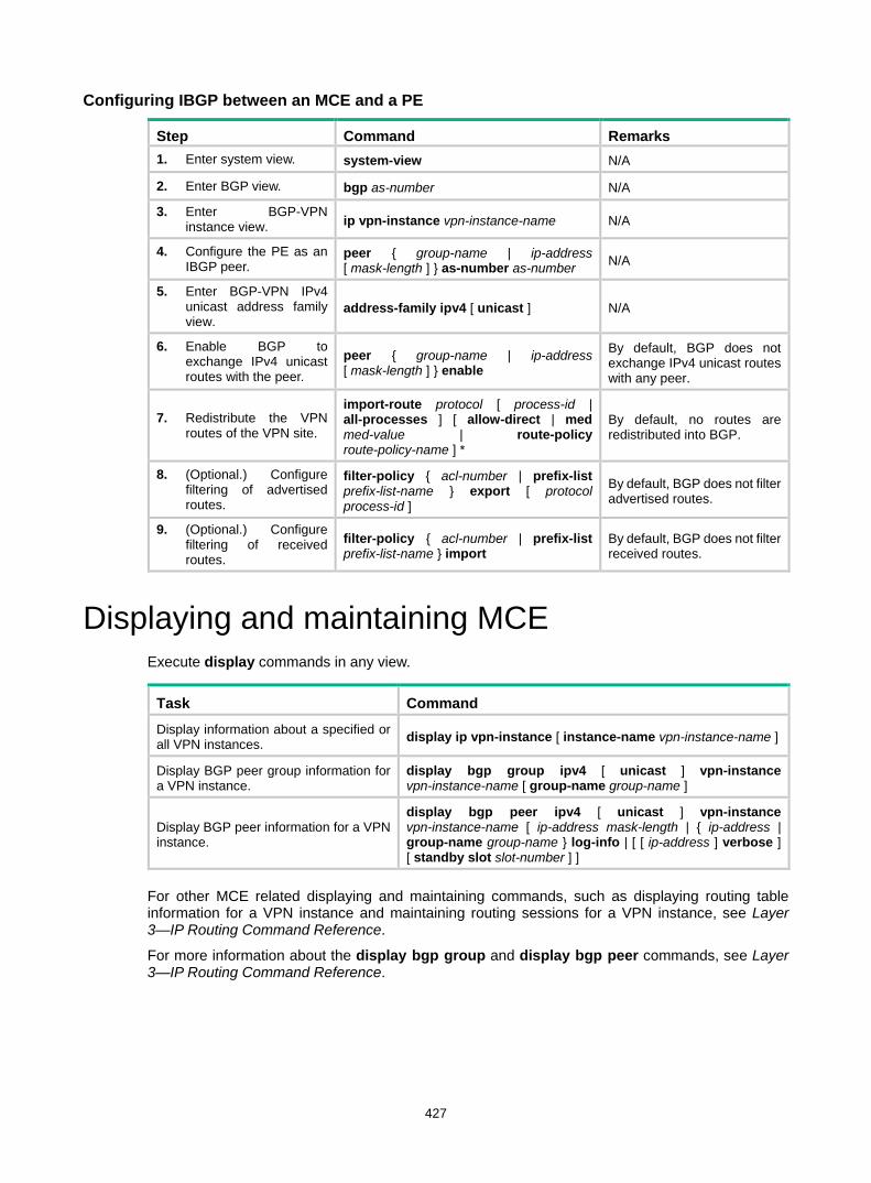
427
Configuring IBGP between an MCE and a PE
Step Command Remarks 1. Enter system view. system-view N/A
2. Enter BGP view. bgp as-number N/A
3. Enter BGP-VPN instance view. ip vpn-instance vpn-instance-name N/A
4. Configure the PE as an IBGP peer.
peer { group-name | ip-address [ mask-length ] } as-number as-number N/A
5. Enter BGP-VPN IPv4 unicast address family view.
address-family ipv4 [ unicast ] N/A
6. Enable BGP to exchange IPv4 unicast routes with the peer.
peer { group-name | ip-address [ mask-length ] } enable
By default, BGP does not exchange IPv4 unicast routes with any peer.
7. Redistribute the VPN routes of the VPN site.
import-route protocol [ process-id | all-processes ] [ allow-direct | med med-value | route-policy route-policy-name ] *
By default, no routes are redistributed into BGP.
8. (Optional.) Configure filtering of advertised routes.
filter-policy { acl-number | prefix-list prefix-list-name } export [ protocol process-id ]
By default, BGP does not filter advertised routes.
9. (Optional.) Configure filtering of received routes.
filter-policy { acl-number | prefix-list prefix-list-name } import
By default, BGP does not filter received routes.
Displaying and maintaining MCE Execute display commands in any view.
Task Command Display information about a specified or all VPN instances. display ip vpn-instance [ instance-name vpn-instance-name ]
Display BGP peer group information for a VPN instance.
display bgp group ipv4 [ unicast ] vpn-instance vpn-instance-name [ group-name group-name ]
Display BGP peer information for a VPN instance.
display bgp peer ipv4 [ unicast ] vpn-instance vpn-instance-name [ ip-address mask-length | { ip-address | group-name group-name } log-info | [ [ ip-address ] verbose ] [ standby slot slot-number ] ]
For other MCE related displaying and maintaining commands, such as displaying routing table information for a VPN instance and maintaining routing sessions for a VPN instance, see Layer 3—IP Routing Command Reference.
For more information about the display bgp group and display bgp peer commands, see Layer 3—IP Routing Command Reference.

428
MCE configuration examples Configuring the MCE that uses OSPF to advertise VPN routes to the PE Network requirements
As shown in Figure 110, VPN 2 runs OSPF. Configure the MCE device to separate routes from different VPNs and to advertise the VPN routes to PE 1 through OSPF.
Figure 110 Network diagram
Configuration procedure Assume that the system name of the MCE device is MCE, the system names of the edge devices of VPN 1 and VPN 2 are VR1 and VR2, respectively, and the system name of PE 1 is PE1. 1. Configure the VPN instances on the MCE and PE 1:
# On the MCE, configure VPN instances vpn1 and vpn2, and specify an RD and route targets for each VPN instance. <MCE> system-view
[MCE] ip vpn-instance vpn1
[MCE-vpn-instance-vpn1] route-distinguisher 10:1
[MCE-vpn-instance-vpn1] vpn-target 10:1
[MCE-vpn-instance-vpn1] quit
[MCE] ip vpn-instance vpn2
[MCE-vpn-instance-vpn2] route-distinguisher 20:1
[MCE-vpn-instance-vpn2] vpn-target 20:1
[MCE-vpn-instance-vpn2] quit
CE 2
VPN 1Site 2
CE 1
VPN 2Site 1
PE 1
PE 3
PE 2
VPN 2192.168.10.0/24
VR 2
VPN 1 192.168.0.0/24
VR 1
MCE
GE1/0/1Vlan-int10
10.214.10.3/24
GE1/0/1Vlan-int30: 30.1.1.2/24Vlan-int40: 40.1.1.2/24
GE1/0/3Vlan-int30: 30.1.1.1/24Vlan-int40: 40.1.1.1/24
GE1/0/2Vlan-int2010.214.20.3/24

429
# Create VLAN 10, add port FortyGigE 1/0/1 to VLAN 10. [MCE] vlan 10
[MCE-vlan10] port fortygige 1/0/1
[MCE-vlan10] quit
# Create VLAN-interface 10, and bind VLAN-interface 10 to VPN instance vpn1. [MCE] interface vlan-interface 10
[MCE-Vlan-interface10] ip binding vpn-instance vpn1
# Configure an IP address for VLAN-interface 10. [MCE-Vlan-interface10] ip address 10.214.10.3 24
[MCE-Vlan-interface10] quit
# Configure VLAN 20, add port FortyGigE 1/0/2 to VLAN 20. [MCE] vlan 20
[MCE-vlan20] port fortygige 1/0/2
[MCE-vlan20] quit
# Bind VLAN-interface 20 to VPN instance vpn2. [MCE] interface vlan-interface 20
[MCE-Vlan-interface20] ip binding vpn-instance vpn2
# Specify an IP address for VLAN-interface 20. [MCE-Vlan-interface20] ip address 10.214.20.3 24
[MCE-Vlan-interface20] quit
# On PE 1, configure VPN instances vpn1 and vpn2, and specify an RD and route targets for each VPN instance. <PE1> system-view
[PE1] ip vpn-instance vpn1
[PE1-vpn-instance-vpn1] route-distinguisher 10:1
[PE1-vpn-instance-vpn1] vpn-target 10:1
[PE1-vpn-instance-vpn1] quit
[PE1] ip vpn-instance vpn2
[PE1-vpn-instance-vpn2] route-distinguisher 20:1
[PE1-vpn-instance-vpn2] vpn-target 20:1
[PE1-vpn-instance-vpn2] quit
2. Configure routing between the MCE and VPN sites: The MCE is connected to VPN 1 directly, and no routing protocol is enabled in VPN 1. Therefore, you can configure static routes. # On VR 1, assign IP address 10.214.10.2/24 to the interface connected to MCE and 192.168.0.1/24 to the interface connected to VPN 1. Add ports to VLANs correctly. (Details not shown.) # On VR 1, configure a default route with the next hop being 10.214.10.3. <VR1> system-view
[VR1] ip route-static 0.0.0.0 0.0.0.0 10.214.10.3
# On the MCE, configure a static route to 192.168.0.0/24 with the next hop 10.214.10.2. Bind the static route to VPN instance vpn1. [MCE] ip route-static vpn-instance vpn1 192.168.0.0 24 10.214.10.2
# On the MCE, display the routing information maintained for VPN instance vpn1. [MCE] display ip routing-table vpn-instance vpn1
Destinations : 13 Routes : 13

430
Destination/Mask Proto Pre Cost NextHop Interface
0.0.0.0/32 Direct 0 0 127.0.0.1 InLoop0
10.214.10.0/24 Direct 0 0 10.214.10.3 Vlan10
10.214.10.0/32 Direct 0 0 10.214.10.3 Vlan10
10.214.10.3/32 Direct 0 0 127.0.0.1 InLoop0
10.214.10.255/32 Direct 0 0 10.214.10.3 Vlan10
127.0.0.0/8 Direct 0 0 127.0.0.1 InLoop0
127.0.0.0/32 Direct 0 0 127.0.0.1 InLoop0
127.0.0.1/32 Direct 0 0 127.0.0.1 InLoop0
127.255.255.255/32 Direct 0 0 127.0.0.1 InLoop0
192.168.0.0/24 Static 60 0 10.214.10.2 Vlan10
224.0.0.0/4 Direct 0 0 0.0.0.0 NULL0
224.0.0.0/24 Direct 0 0 0.0.0.0 NULL0
255.255.255.255/32 Direct 0 0 127.0.0.1 InLoop0
The output shows that the MCE has a static route for VPN instance vpn1. # Run OSPF in VPN 2. Create OSPF process 20 and bind it to VPN instance vpn2 on the MCE, so that the MCE can learn the routes of VPN 2 and add them to the routing table of the VPN instance vpn2. [MCE] ospf 2 vpn-instance vpn2
# Advertise subnet 10.214.20.0. [MCE-ospf-2] area 0
[MCE-ospf-2-area-0.0.0.0] network 10.214.20.0 0.0.0.255
[MCE-ospf-2-area-0.0.0.0] quit
[MCE-ospf-2] quit
# On VR 2, assign IP address 10.214.20.2/24 to the interface connected to MCE and 192.168.10.1/24 to the interface connected to VPN 2. (Details not shown.) # Configure OSPF process 2, and advertise subnets 192.168.10.0 and 10.214.20.0. <VR2> system-view
[VR2] ospf 2
[VR2-ospf-2] area 0
[VR2-ospf-2-area-0.0.0.0] network 192.168.10.0 0.0.0.255
[VR2-ospf-2-area-0.0.0.0] network 10.214.20.0 0.0.0.255
[VR2-ospf-2-area-0.0.0.0] quit
[VR2-ospf-2] quit
# On the MCE, display the routing information maintained for VPN instance vpn2. [MCE] display ip routing-table vpn-instance vpn2
Destinations : 13 Routes : 13
Destination/Mask Proto Pre Cost NextHop Interface
0.0.0.0/32 Direct 0 0 127.0.0.1 InLoop0
10.214.20.0/24 Direct 0 0 10.214.20.3 Vlan20
10.214.20.0/32 Direct 0 0 10.214.20.3 Vlan20
10.214.20.3/32 Direct 0 0 127.0.0.1 InLoop0
10.214.20.255/32 Direct 0 0 10.214.20.3 Vlan20
127.0.0.0/8 Direct 0 0 127.0.0.1 InLoop0
127.0.0.0/32 Direct 0 0 127.0.0.1 InLoop0
127.0.0.1/32 Direct 0 0 127.0.0.1 InLoop0

431
127.255.255.255/32 Direct 0 0 127.0.0.1 InLoop0
192.168.10.0/24 OSPF 10 2 10.214.20.2 Vlan20
224.0.0.0/4 Direct 0 0 0.0.0.0 NULL0
224.0.0.0/24 Direct 0 0 0.0.0.0 NULL0
255.255.255.255/32 Direct 0 0 127.0.0.1 InLoop0
The output shows that the MCE has learned the private routes of VPN 2. The MCE maintains the routes of VPN 1 and those of VPN2 in two different routing tables. In this way, routes from different VPNs are separated.
3. Configure routing between the MCE and PE 1: # The MCE uses port FortyGigE 1/0/3 to connect to PE's port FortyGigE 1/0/1. Configure the two ports as trunk ports, and configure them to permit packets carrying VLAN tags 30 and 40 to pass. [MCE] interface fortygige 1/0/3
[MCE-FortyGigE1/0/3] port link-type trunk
[MCE-FortyGigE1/0/3] port trunk permit vlan 30 40
[MCE-FortyGigE1/0/3] quit
# Configure port FortyGigE 1/0/1 on the PE. [PE1] interface fortygige 1/0/1
[PE1-FortyGigE1/0/1] port link-type trunk
[PE1-FortyGigE1/0/1] port trunk permit vlan 30 40
[PE1-FortyGigE1/0/1] quit
# On the MCE, create VLAN 30 and VLAN-interface 30, bind the VLAN interface to VPN instance vpn1, and configure an IP address for the VLAN interface. [MCE] vlan 30
[MCE-vlan30] quit
[MCE] interface vlan-interface 30
[MCE-Vlan-interface30] ip binding vpn-instance vpn1
[MCE-Vlan-interface30] ip address 30.1.1.1 24
[MCE-Vlan-interface30] quit
# On the MCE, create VLAN 40 and VLAN-interface 40, bind the VLAN interface to VPN instance vpn2, and configure an IP address for the VLAN interface. [MCE] vlan 40
[MCE-vlan40] quit
[MCE] interface vlan-interface 40
[MCE-Vlan-interface40] ip binding vpn-instance vpn2
[MCE-Vlan-interface40] ip address 40.1.1.1 24
[MCE-Vlan-interface40] quit
# On PE 1, create VLAN 30 and VLAN-interface 30, bind the VLAN interface to VPN instance vpn1, and configure an IP address for the VLAN interface. [PE1] vlan 30
[PE1-vlan30] quit
[PE1] interface vlan-interface 30
[PE1-Vlan-interface30] ip binding vpn-instance vpn1
[PE1-Vlan-interface30] ip address 30.1.1.2 24
[PE1-Vlan-interface30] quit
# On PE 1, create VLAN 40 and VLAN-interface 40, bind the VLAN interface to VPN instance vpn2, and configure an IP address for the VLAN interface. [PE1] vlan 40
[PE1-vlan40] quit

432
[PE1] interface vlan-interface 40
[PE1-Vlan-interface40] ip binding vpn-instance vpn2
[PE1-Vlan-interface40] ip address 40.1.1.2 24
[PE1-Vlan-interface40] quit
# Configure the IP address of the interface Loopback 0 as 101.101.10.1 for the MCE and as 100.100.10.1 for PE 1. Specify the loopback interface address as the router ID for the MCE and PE 1. (Details not shown.) # Enable OSPF process 10 on the MCE, and bind the process to VPN instance vpn1. [MCE] ospf 10 router-id 101.101.10.1 vpn-instance vpn1
# Disable OSPF routing loop detection. [MCE-ospf-10] vpn-instance-capability simple
# Set the domain ID to 10. [MCE-ospf-10] domain-id 10
# On the MCE, advertise subnet 30.1.1.0 in area 0, and redistribute the static route of VPN 1. [MCE-ospf-10] area 0
[MCE-ospf-10-area-0.0.0.0] network 30.1.1.0 0.0.0.255
[MCE-ospf-10-area-0.0.0.0] quit
[MCE-ospf-10] import-route static
# On PE 1, enable OSPF process 10, and bind the process to VPN instance vpn1. [PE1] ospf 10 router-id 100.100.10.1 vpn-instance vpn1
# Set the domain ID to 10. [PE1-ospf-10] domain-id 10
# Advertise subnet 30.1.1.0 in area 0. [PE1-ospf-10] area 0
[PE1-ospf-10-area-0.0.0.0] network 30.1.1.0 0.0.0.255
[PE1-ospf-10-area-0.0.0.0] quit
[PE1-ospf-10] quit
# Use similar procedures to configure OSPF process 20 between MCE and PE 1 and redistribute VPN 2's routing information. (Details not shown.)
Verifying the configuration # On PE 1, display the routing information for VPN 1. The output shows that the static route of VPN 1 has been redistributed to the OSPF routing table of PE 1. [PE1] display ip routing-table vpn-instance vpn1
Destinations : 13 Routes : 13
Destination/Mask Proto Pre Cost NextHop Interface
0.0.0.0/32 Direct 0 0 127.0.0.1 InLoop0
30.1.1.0/24 Direct 0 0 30.1.1.2 Vlan30
30.1.1.0/32 Direct 0 0 30.1.1.2 Vlan30
30.1.1.2/32 Direct 0 0 127.0.0.1 InLoop0
30.1.1.255/32 Direct 0 0 30.1.1.2 Vlan30
127.0.0.0/8 Direct 0 0 127.0.0.1 InLoop0
127.0.0.0/32 Direct 0 0 127.0.0.1 InLoop0
127.0.0.1/32 Direct 0 0 127.0.0.1 InLoop0
127.255.255.255/32 Direct 0 0 127.0.0.1 InLoop0
192.168.0.0/24 OSPF 150 1 30.1.1.1 Vlan30
224.0.0.0/4 Direct 0 0 0.0.0.0 NULL0

433
224.0.0.0/24 Direct 0 0 0.0.0.0 NULL0
255.255.255.255/32 Direct 0 0 127.0.0.1 InLoop0
# On PE 1, display the routing information for VPN 2. The output shows that the routes of OSPF process 2 in VPN 2 have been redistributed to the OSPF routing table of PE 1. [PE1] display ip routing-table vpn-instance vpn2
Destinations : 13 Routes : 13
Destination/Mask Proto Pre Cost NextHop Interface
0.0.0.0/32 Direct 0 0 127.0.0.1 InLoop0
40.1.1.0/24 Direct 0 0 40.1.1.2 Vlan40
40.1.1.0/32 Direct 0 0 40.1.1.2 Vlan40
40.1.1.2/32 Direct 0 0 127.0.0.1 InLoop0
40.1.1.255/32 Direct 0 0 40.1.1.2 Vlan40
127.0.0.0/8 Direct 0 0 127.0.0.1 InLoop0
127.0.0.0/32 Direct 0 0 127.0.0.1 InLoop0
127.0.0.1/32 Direct 0 0 127.0.0.1 InLoop0
127.255.255.255/32 Direct 0 0 127.0.0.1 InLoop0
192.168.10.0/24 OSPF 150 1 40.1.1.1 Vlan40
224.0.0.0/4 Direct 0 0 0.0.0.0 NULL0
224.0.0.0/24 Direct 0 0 0.0.0.0 NULL0
255.255.255.255/32 Direct 0 0 127.0.0.1 InLoop0
The routing information for the two VPNs has been redistributed into the routing tables on PE 1.
Configuring the MCE that uses EBGP to advertise VPN routes to the PE Network requirements
As shown in Figure 111, configure the MCE to advertise the routes of VPNs 1 and 2 to PE 1, so that the sites of each VPN can communicate with each other over the MPLS backbone.
Run OSPF in both VPN 1 and VPN 2. Run EBGP between the MCE and PE 1.

434
Figure 111 Network diagram
Configuration procedure 1. Create VPN instances on the MCE and PE 1, and bind the VPN instances to VLAN interfaces.
For the configuration procedure, see "Configure the VPN instances on the MCE and PE 1:." 2. Configure routing between the MCE and VPN sites:
# Enable an OSPF process on the devices in the two VPNs, and advertise the subnets. (Details not shown.) # Configure OSPF on the MCE, and bind OSPF process 10 to VPN instance vpn1 to learn the routes of VPN 1. <MCE> system-view
[MCE] ospf 10 router-id 10.10.10.1 vpn-instance vpn1
[MCE-ospf-10] area 0
[MCE-ospf-10-area-0.0.0.0] network 10.214.10.0 0.0.0.255
[MCE-ospf-10-area-0.0.0.0] quit
[MCE-ospf-10] quit
# Display the routing table of VPN 1 on the MCE. [MCE] display ip routing-table vpn-instance vpn1
Destinations : 13 Routes : 13
Destination/Mask Proto Pre Cost NextHop Interface
0.0.0.0/32 Direct 0 0 127.0.0.1 InLoop0
10.214.10.0/24 Direct 0 0 10.214.10.3 Vlan10
10.214.10.0/32 Direct 0 0 10.214.10.3 Vlan10
10.214.10.3/32 Direct 0 0 127.0.0.1 InLoop0
CE 2
VPN 1Site 2
CE 1
VPN 2Site 1
PE 1
PE 3
PE 2
VPN 2192.168.10.0/24
VR 2
VPN 1 192.168.0.0/24
VR 1
MCE
GE1/0/1Vlan-int10
10.214.10.3/24GE1/0/2Vlan-int2010.214.20.3/24
GE1/0/1Vlan-int30: 30.1.1.2/24Vlan-int40: 40.1.1.2/24
GE1/0/3Vlan-int30: 30.1.1.1/24Vlan-int40: 40.1.1.1/24

435
10.214.10.255/32 Direct 0 0 10.214.10.3 Vlan10
127.0.0.0/8 Direct 0 0 127.0.0.1 InLoop0
127.0.0.0/32 Direct 0 0 127.0.0.1 InLoop0
127.0.0.1/32 Direct 0 0 127.0.0.1 InLoop0
127.255.255.255/32 Direct 0 0 127.0.0.1 InLoop0
192.168.0.0/24 OSPF 10 2 10.214.10.2 Vlan10
224.0.0.0/4 Direct 0 0 0.0.0.0 NULL0
224.0.0.0/24 Direct 0 0 0.0.0.0 NULL0
255.255.255.255/32 Direct 0 0 127.0.0.1 InLoop0
The output shows that the MCE has learned the private route of VPN 1 through OSPF process 10. # On the MCE, bind OSPF process 20 to VPN instance vpn2 to learn the routes of VPN 2. The configuration procedure is similar to that for OSPF process 10. The output shows that the MCE has learned the private route of VPN 2 through OSPF: [MCE] display ip routing-table vpn-instance vpn2
Destinations : 13 Routes : 13
Destination/Mask Proto Pre Cost NextHop Interface
0.0.0.0/32 Direct 0 0 127.0.0.1 InLoop0
10.214.20.0/24 Direct 0 0 10.214.20.3 Vlan20
10.214.20.0/32 Direct 0 0 10.214.20.3 Vlan20
10.214.20.3/32 Direct 0 0 127.0.0.1 InLoop0
10.214.20.255/32 Direct 0 0 10.214.20.3 Vlan20
127.0.0.0/8 Direct 0 0 127.0.0.1 InLoop0
127.0.0.0/32 Direct 0 0 127.0.0.1 InLoop0
127.0.0.1/32 Direct 0 0 127.0.0.1 InLoop0
127.255.255.255/32 Direct 0 0 127.0.0.1 InLoop0
192.168.10.0/24 OSPF 10 2 10.214.20.2 Vlan20
224.0.0.0/4 Direct 0 0 0.0.0.0 NULL0
224.0.0.0/24 Direct 0 0 0.0.0.0 NULL0
255.255.255.255/32 Direct 0 0 127.0.0.1 InLoop0
3. Configure routing between the MCE and PE 1: # Configure the ports between the MCE and PE 1 as trunk ports. The configuration procedure is similar to that described in "Configure routing between the MCE and PE 1:." (Details not shown.) # Enable BGP in AS 100 on the MCE. [MCE] bgp 100
# Enter the BGP-VPN instance view of VPN instance vpn1. [MCE-bgp] ip vpn-instance vpn1
# Specify the EBGP peer PE 1 in AS 200. [MCE-bgp-vpn1] peer 30.1.1.2 as-number 200
# Activate the EBGP VPNv4 peer PE 1, and redistribute routing information from OSPF process 10 to BGP. [MCE-bgp-vpn1] address-family ipv4
[MCE-bgp-ipv4-vpn1] peer 30.1.1.2 enable
[MCE-bgp-ipv4-vpn1] import-route ospf 10
# On PE 1, enable BGP in AS 200, and specify the MCE as its EBGP peer.

436
[PE1] bgp 200
[PE1-bgp] ip vpn-instance vpn1
[PE1-bgp-vpn1] peer 30.1.1.1 as-number 100
[PE1-bgp-vpn1] address-family ipv4
[PE1-bgp-ipv4-vpn1] peer 30.1.1.1 enable
[PE1-bgp-ipv4-vpn1] quit
[PE1-bgp-vpn1] quit
[PE1-bgp] quit
# Use similar procedures to configure VPN 2 settings on MCE and PE 1. (Details not shown.)
Verifying the configuration # Display the routing information for VPN 1 on PE 1. [PE1] display ip routing-table vpn-instance vpn1
Destinations : 13 Routes : 13
Destination/Mask Proto Pre Cost NextHop Interface
0.0.0.0/32 Direct 0 0 127.0.0.1 InLoop0
30.1.1.0/24 Direct 0 0 30.1.1.2 Vlan30
30.1.1.0/32 Direct 0 0 30.1.1.2 Vlan30
30.1.1.2/32 Direct 0 0 127.0.0.1 InLoop0
30.1.1.255/32 Direct 0 0 30.1.1.2 Vlan30
127.0.0.0/8 Direct 0 0 127.0.0.1 InLoop0
127.0.0.0/32 Direct 0 0 127.0.0.1 InLoop0
127.0.0.1/32 Direct 0 0 127.0.0.1 InLoop0
127.255.255.255/32 Direct 0 0 127.0.0.1 InLoop0
192.168.0.0/24 BGP 255 3 30.1.1.1 Vlan30
224.0.0.0/4 Direct 0 0 0.0.0.0 NULL0
224.0.0.0/24 Direct 0 0 0.0.0.0 NULL0
255.255.255.255/32 Direct 0 0 127.0.0.1 InLoop0
# Display the routing information for VPN 2 on PE 1. [PE1] display ip routing-table vpn-instance vpn2
Destinations : 13 Routes : 13
Destination/Mask Proto Pre Cost NextHop Interface
0.0.0.0/32 Direct 0 0 127.0.0.1 InLoop0
40.1.1.0/24 Direct 0 0 40.1.1.2 Vlan40
40.1.1.0/32 Direct 0 0 40.1.1.2 Vlan40
40.1.1.2/32 Direct 0 0 127.0.0.1 InLoop0
40.1.1.255/32 Direct 0 0 40.1.1.2 Vlan40
127.0.0.0/8 Direct 0 0 127.0.0.1 InLoop0
127.0.0.0/32 Direct 0 0 127.0.0.1 InLoop0
127.0.0.1/32 Direct 0 0 127.0.0.1 InLoop0
127.255.255.255/32 Direct 0 0 127.0.0.1 InLoop0
192.168.10.0/24 BGP 255 3 40.1.1.1 Vlan40
224.0.0.0/4 Direct 0 0 0.0.0.0 NULL0
224.0.0.0/24 Direct 0 0 0.0.0.0 NULL0
255.255.255.255/32 Direct 0 0 127.0.0.1 InLoop0

437
The MCE has redistributed the OSPF routes of the two VPN instances into the EBGP routing tables of PE 1.
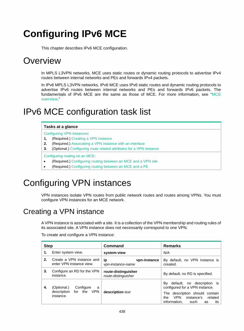
438
Configuring IPv6 MCE This chapter describes IPv6 MCE configuration.
Overview In MPLS L3VPN networks, MCE uses static routes or dynamic routing protocols to advertise IPv4 routes between internal networks and PEs and forwards IPv4 packets.
In IPv6 MPLS L3VPN networks, IPv6 MCE uses IPv6 static routes and dynamic routing protocols to advertise IPv6 routes between internal networks and PEs and forwards IPv6 packets. The fundamentals of IPv6 MCE are the same as those of MCE. For more information, see "MCE overview."
IPv6 MCE configuration task list Tasks at a glance Configuring VPN instances: 1. (Required.) Creating a VPN instance 2. (Required.) Associating a VPN instance with an interface 3. (Optional.) Configuring route related attributes for a VPN instance
Configuring routing on an MCE: • (Required.) Configuring routing between an MCE and a VPN site • (Required.) Configuring routing between an MCE and a PE
Configuring VPN instances VPN instances isolate VPN routes from public network routes and routes among VPNs. You must configure VPN instances for an MCE network.
Creating a VPN instance A VPN instance is associated with a site. It is a collection of the VPN membership and routing rules of its associated site. A VPN instance does not necessarily correspond to one VPN.
To create and configure a VPN instance:
Step Command Remarks 1. Enter system view. system-view N/A
2. Create a VPN instance and enter VPN instance view.
ip vpn-instance vpn-instance-name
By default, no VPN instance is created.
3. Configure an RD for the VPN instance.
route-distinguisher route-distinguisher By default, no RD is specified.
4. (Optional.) Configure a description for the VPN instance.
description text
By default, no description is configured for a VPN instance. The description should contain the VPN instance's related information, such as its
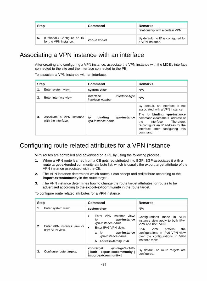
439
Step Command Remarks relationship with a certain VPN.
5. (Optional.) Configure an ID for the VPN instance. vpn-id vpn-id By default, no ID is configured for
a VPN instance.
Associating a VPN instance with an interface After creating and configuring a VPN instance, associate the VPN instance with the MCE's interface connected to the site and the interface connected to the PE.
To associate a VPN instance with an interface:
Step Command Remarks 1. Enter system view. system-view N/A
2. Enter interface view. interface interface-type interface-number N/A
3. Associate a VPN instance with the interface.
ip binding vpn-instance vpn-instance-name
By default, an interface is not associated with a VPN instance. The ip binding vpn-instance command clears the IP address of the interface. Therefore, re-configure an IP address for the interface after configuring this command.
Configuring route related attributes for a VPN instance VPN routes are controlled and advertised on a PE by using the following process: 1. When a VPN route learned from a CE gets redistributed into BGP, BGP associates it with a
route target extended community attribute list, which is usually the export target attribute of the VPN instance associated with the CE.
2. The VPN instance determines which routes it can accept and redistribute according to the import-extcommunity in the route target.
3. The VPN instance determines how to change the route target attributes for routes to be advertised according to the export-extcommunity in the route target.
To configure route related attributes for a VPN instance:
Step Command Remarks 1. Enter system view. system-view N/A
2. Enter VPN instance view or IPv6 VPN view.
• Enter VPN instance view: ip vpn-instance vpn-instance-name
• Enter IPv6 VPN view: a. ip vpn-instance
vpn-instance-name b. address-family ipv6
Configurations made in VPN instance view apply to both IPv4 VPN and IPv6 VPN. IPv6 VPN prefers the configurations in IPv6 VPN view over the configurations in VPN instance view.
3. Configure route targets. vpn-target vpn-target&<1-8> [ both | export-extcommunity | import-extcommunity ]
By default, no route targets are configured.

440
Step Command Remarks
4. Set the maximum number of active routes.
routing-table limit number { warn-threshold | simply-alert }
By default, the number of active routes in a VPN instance is not limited. Setting the maximum number of active routes for a VPN instance can prevent the PE from storing too many routes.
5. Apply an import routing policy. import route-policy route-policy
By default, all routes matching the import target attribute are accepted. Make sure the routing policy already exists. Otherwise, the device does not filter received routes. For information about routing policies, see Layer 3—IP Routing Configuration Guide.
6. Apply an export routing policy. export route-policy route-policy
By default, routes to be advertised are not filtered. Make sure the routing policy already exists. Otherwise, the device does not filter routes to be advertised. For information about routing policies, see Layer 3—IP Routing Configuration Guide.
7. Apply a tunnel policy to the VPN instance. tnl-policy tunnel-policy-name
By default, only one tunnel is selected (no load balancing) in this order: LSP tunnel, and CRLSP tunnel. The specified tunnel policy must have been created. For information about tunnel policies, see "Configuring tunnel policies."
Configuring routing on an MCE An MCE implements service isolation through route isolation. MCE routing configuration includes the following: • MCE-VPN site routing configuration. • MCE-PE routing configuration.
On a PE in an MCE network environment, do the following: • Disable routing loop detection to avoid route loss during route calculation. • Disable route redistribution between routing protocols to save system resources.
Before you configure routing on an MCE, configure VPN instances, and bind the VPN instances to the interfaces connected to the VPN sites and those connected to the PE.

441
Configuring routing between an MCE and a VPN site You can configure static routing, RIPng, OSPFv3, IPv6 IS-IS, or EBGP between an MCE and a VPN site.
Configuring static routing between an MCE and a VPN site An MCE can reach a VPN site through an IPv6 static route. IPv6 static routing on a traditional CE is globally effective and does not support address overlapping among VPNs. An MCE supports binding an IPv6 static route with an IPv6 VPN instance, so that the IPv6 static routes of different IPv6 VPN instances can be isolated from each other.
To configure IPv6 static routing between an MCE and a VPN site:
Step Command Remarks 1. Enter system view. system-view N/A
2. Configure an IPv6 static route for an IPv6 VPN instance.
ipv6 route-static vpn-instance s-vpn-instance-name ipv6-address prefix-length { interface-type interface-number [ next-hop-address ] | nexthop-address [ public ] | vpn-instance d-vpn-instance-name nexthop-address } [ permanent ] [ preference preference-value ] [ tag tag-value ] [ description description-text ]
By default, no IPv6 static route is configured. Perform this configuration on the MCE. On a VPN site, configure normal IPv6 static routes.
3. (Optional.) Configure the default preference for IPv6 static routes.
ipv6 route-static default-preference default-preference-value
The default preference for IPv6 static routes is 60.
Configuring RIPng between an MCE and a VPN site A RIPng process belongs to the public network or a single IPv6 VPN instance. If you create a RIPng process without binding it to an IPv6 VPN instance, the process belongs to the public network. By configuring RIPng process-to-IPv6 VPN instance bindings on a MCE, you allow routes of different VPNs to be exchanged between the MCE and the sites through different RIPng processes, ensuring the separation and security of IPv6 VPN routes.
For more information about RIPng, see Layer 3—IP Routing Configuration Guide.
To configure RIPng between an MCE and a VPN site:
Step Command Remarks 1. Enter system view. system-view N/A
2. Create a RIPng process for a VPN instance and enter RIPng view.
ripng [ process-id ] vpn-instance vpn-instance-name
Perform this configuration on the MCE. On a VPN site, configure normal RIPng.
3. Redistribute remote site routes advertised by the PE.
import-route protocol [ process-id ] [ allow-ibgp ] [ allow-direct | cost cost | route-policy route-policy-name ] *
By default, no routes are redistributed into RIPng.
4. (Optional.) Configure the default cost value for the redistributed routes.
default cost value The default value is 0.
5. Return to system view. quit N/A
6. Enter interface view. interface interface-type interface-number N/A

442
Step Command Remarks 7. Enable RIPng on the
interface. ripng process-id enable By default, RIPng is disabled.
Configuring OSPFv3 between an MCE and a VPN site An OSPFv3 process belongs to the public network or a single IPv6 VPN instance. If you create an OSPFv3 process without binding it to an IPv6 VPN instance, the process belongs to the public network.
By configuring OSPFv3 process-to-IPv6 VPN instance bindings on a MCE, you allow routes of different IPv6 VPNs to be exchanged between the MCE and the sites through different OSPFv3 processes, ensuring the separation and security of IPv6 VPN routes.
For more information about OSPFv3, see Layer 3—IP Routing Configuration Guide.
To configure OSPFv3 between an MCE and a VPN site:
Step Command Remarks 1. Enter system view. system-view N/A
2. Create an OSPFv3 process for a VPN instance and enter OSPFv3 view.
ospfv3 [ process-id | vpn-instance vpn-instance-name ] *
Perform this configuration on the MCE. On a VPN site, configure common OSPFv3. Deleting a VPN instance also deletes all related OSPFv3 processes.
3. Set the router ID. router-id router-id N/A
4. (Optional.) Configure an OSPFv3 domain ID.
domain-id { domain-id [ secondary ] | null }
The default domain ID is 0. Perform this configuration on the MCE. All OSPF processes of the same VPN must be configured with the same OSPF domain ID to ensure correct route advertisement.
5. Redistribute remote site routes advertised by the PE.
import-route protocol [ process-id | all-processes | allow-ibgp ] [ allow-direct | cost cost | nssa-only | route-policy route-policy-name | tag tag | type type ] *
By default, no routes are redistributed into OSPFv3.
6. Return to system view. quit N/A
7. Enter interface view. interface interface-type interface-number N/A
8. Enable OSPFv3 on the interface.
ospfv3 process-id area area-id [ instance instance-id ]
By default, OSPFv3 is disabled on an interface.
Configuring IPv6 IS-IS between an MCE and a VPN site An IPv6 IS-IS process belongs to the public network or a single IPv6 VPN instance. If you create an IPv6 IS-IS process without binding it to an IPv6 VPN instance, the process belongs to the public network.
By configuring IPv6 IS-IS process-to-IPv6 VPN instance bindings on a MCE, you allow routes of different IPv6 VPNs to be exchanged between the MCE and the sites through different IPv6 IS-IS processes. This ensures the separation and security of IPv6 VPN routes. For more information about IPv6 IS-IS, see Layer 3—IP Routing Configuration Guide.

443
To configure IPv6 IS-IS between an MCE and a VPN site:
Step Command Remarks 1. Enter system view. system-view N/A
2. Create an IPv6 IS-IS process for a VPN instance and enter IS-IS view.
isis [ process-id ] vpn-instance vpn-instance-name
Perform this configuration on the MCE. On a VPN site, configure common IPv6 IS-IS.
3. Configure a network entity title for the IS-IS process. network-entity net By default, no NET is configured.
4. Enable IPv6 for the IPv6 IS-IS process. ipv6 enable By default, IPv6 is disabled.
5. (Optional.) Redistribute remote site routes advertised by the PE.
ipv6 import-route protocol [ process-id ] [ allow-ibgp ] [ allow-direct | cost cost | [ level-1 | level-1-2 | level-2 ] | route-policy route-policy-name | tag tag ] *
By default, no routes are redistributed to IPv6 IS-IS. If you do not specify the route level in the command, redistributed routes are added to the level-2 routing table.
6. Return to system view. quit N/A
7. Enter interface view. interface interface-type interface-number N/A
8. Enable the IPv6 IS-IS process on the interface. isis ipv6 enable [ process-id ] By default, no IPv6 IS-IS process
is enabled.
Configuring EBGP between an MCE and a VPN site To use EBGP between an MCE and IPv6 VPN sites, you must configure a BGP peer for each IPv6 VPN instance on the MCE, and redistribute the IGP routes of each VPN instance on the IPv6 VPN sites. You can also configure the filtering of received and advertised routes. 1. Configure the MCE:
Step Command Remarks 1. Enter system view. system-view N/A
2. Enter BGP view. bgp as-number N/A
3. Enter BGP-VPN instance view.
ip vpn-instance vpn-instance-name N/A
4. Specify an IPv6 BGP peer in an AS.
peer { group-name | ipv6-address [ prefix-length ] } as-number as-number
By default, no BGP peer is configured.
5. Enter BGP-VPN IPv6 unicast address family view. address-family ipv6 [ unicast ] N/A
6. Enable BGP to exchange IPv6 unicast routes with the specified peer.
peer { group-name | ipv6-address [ prefix-length ] } enable
By default, BGP does not exchange IPv6 unicast routes with any peer.
7. Redistribute remote site routes advertised by the PE.
import-route protocol [ process-id [ allow-direct | med med-value | route-policy route-policy-name ] * ]
By default, no route redistribution is configured.
8. (Optional.) Configure filtering of advertised routes.
filter-policy { acl6-number | prefix-list ipv6-prefix-name } export [ protocol process-id ]
By default, BGP does not filter advertised routes.
9. (Optional.) Configure filtering filter-policy { acl6-number | By default, BGP does not filter

444
Step Command Remarks of received routes. prefix-list ipv6-prefix-name }
import received routes.
2. Configure a VPN site:
Step Command Remarks 1. Enter system view. system-view N/A
2. Enter BGP view. bgp as-number N/A
3. Configure the MCE as an EBGP peer.
peer { group-name | ipv6-address [ prefix-length ] } as-number as-number
By default, no BGP peer is configured.
4. Enter BGP IPv6 unicast address family view. address-family ipv6 [ unicast ] N/A
5. Enable BGP to exchange IPv6 unicast routes with the specified peer.
peer { group-name | ipv6-address [ prefix-length ] } enable
By default, BGP does not exchange IPv6 unicast routes with any peer.
6. Redistribute the IGP routes of the VPN.
import-route protocol [ process-id [ allow-direct | med med-value | route-policy route-policy-name ] * ]
By default, no routes are redistributed into BGP. A VPN site must advertise IPv6 VPN network addresses it can reach to the connected MCE.
Configuring IBGP between an MCE and a VPN site To use IBGP between an MCE and a VPN site, you must configure a BGP peer for each IPv6 VPN instance on the MCE, and redistribute the IGP routes of each VPN instance on the VPN site. 1. Configure the MCE:
Step Command Remarks 1. Enter system view. system-view N/A
2. Enter BGP view. bgp as-number N/A
3. Enter BGP-VPN instance view.
ip vpn-instance vpn-instance-name N/A
4. Configure an IBGP peer. peer { group-name | ipv6-address [ prefix-length ] } as-number as-number
N/A
5. Enter BGP-VPN IPv6 unicast address family view. address-family ipv6 [ unicast ] N/A
6. Enable BGP to exchange IPv6 unicast routes with the peer.
peer { group-name | ipv6-address [ prefix-length ] } enable
By default, BGP does not exchange IPv6 unicast routes with any peer.
7. (Optional.) Configure the system to be the RR, and specify the peer as the client of the RR.
peer { group-name | ipv6-address [ prefix-length ] } reflect-client
By default, no RR or RR client is configured. After you configure a VPN site as an IBGP peer, the MCE does not advertise the BGP routes learned from the VPN site to other IBGP peers, including VPNv6 peers. The MCE advertises routes learned from a VPN site only when you configure the VPN site

445
Step Command Remarks as a client of the RR (the MCE).
8. Redistribute remote site routes advertised by the PE into BGP.
import-route protocol [ process-id [ allow-direct | med med-value | route-policy route-policy-name ] * ]
By default, no routes are redistributed into BGP.
9. (Optional.) Configure filtering of advertised routes.
filter-policy { acl6-number | prefix-list ipv6-prefix-name } export [ protocol process-id ]
By default, BGP does not filter advertised routes.
10. (Optional.) Configure filtering of received routes.
filter-policy { acl6-number | prefix-list ipv6-prefix-name } import
By default, BGP does not filter received routes.
2. Configure a VPN site:
Step Command Remarks 1. Enter system view. system-view N/A
2. Enter BGP view. bgp as-number N/A
3. Configure the MCE as an IBGP peer.
peer { group-name | ipv6-address [ prefix-length ] } as-number as-number
N/A
4. Enter BGP-VPN IPv6 unicast address family view. address-family ipv6 [ unicast ] N/A
5. Enable BGP to exchange IPv6 unicast routes with the peer.
peer { group-name | ipv6-address [ prefix-length ] } enable
By default, BGP does not exchange IPv6 unicast routes with any peer.
6. Redistribute the IGP routes of the VPN into BGP.
import-route protocol [ process-id [ allow-direct | med med-value | route-policy route-policy-name ] * ]
By default, no routes are redistributed into BGP. A VPN site must advertise VPN network addresses to the connected MCE.
Configuring routing between an MCE and a PE MCE-PE routing configuration includes these tasks: • Binding the MCE-PE interfaces to IPv6 VPN instances. • Performing routing configurations. • Redistributing IPv6 VPN routes into the routing protocol running between the MCE and the PE.
Perform the following configuration tasks on the MCE. Configure the PE in the same way that you configure a PE in a basic MPLS L3VPN. For more information about configuring the PE, see "Configuring MPLS L3VPN."
Configuring IPv6 static routing between an MCE and a PE
Step Command Remarks 1. Enter system view. system-view N/A

446
Step Command Remarks
2. Configure an IPv6 static route for an IPv6 VPN instance.
ipv6 route-static vpn-instance s-vpn-instance-name ipv6-address prefix-length { interface-type interface-number [ next-hop-address ] | nexthop-address [ public ] | vpn-instance d-vpn-instance-name nexthop-address } [ permanent ] [ preference preference-value ] [ tag tag-value ] [ description description-text ]
By default, no IPv6 static route is configured.
3. (Optional.) Configure the default preference for IPv6 static routes.
ipv6 route-static default-preference default-preference-value The default value is 60.
Configuring RIPng between an MCE and a PE
Step Command Remarks 1. Enter system view. system-view N/A
2. Create a RIPng process for an IPv6 VPN instance and enter RIPng view.
ripng [ process-id ] vpn-instance vpn-instance-name N/A
3. Redistribute VPN routes.
import-route protocol [ process-id ] [ allow-ibgp ] [ allow-direct | cost cost | route-policy route-policy-name ] *
By default, no routes are redistributed into RIPng.
4. (Optional.) Configure the default cost value for redistributed routes.
default cost value The default value is 0.
5. Return to system view. quit N/A
6. Enter interface view. interface interface-type interface-number N/A
7. Enable the RIPng process on the interface. ripng process-id enable By default, RIPng is disabled on
an interface.
Configuring OSPFv3 between an MCE and a PE
Step Command Remarks 1. Enter system view. system-view N/A
2. Create an OSPFv3 process for an IPv6 VPN instance and enter OSPFv3 view.
ospfv3 [ process-id | vpn-instance vpn-instance-name ] *
N/A
3. Set the router ID. router-id router-id N/A
4. Disable routing loop detection. vpn-instance-capability simple
By default, routing loop detection is enabled. On an MCE network, you must disable routing loop detection for an OSPFv3 VRF process. Otherwise, the MCE does not receive OSPFv3 routes from the PE.
5. (Optional.) Configure an OSPFv3 domain ID.
domain-id { domain-id [ secondary ] | null } The default domain ID is 0.
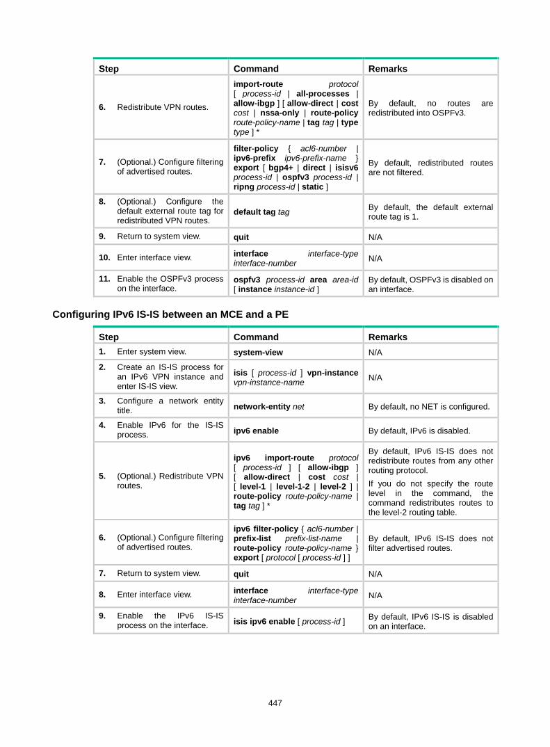
447
Step Command Remarks
6. Redistribute VPN routes.
import-route protocol [ process-id | all-processes | allow-ibgp ] [ allow-direct | cost cost | nssa-only | route-policy route-policy-name | tag tag | type type ] *
By default, no routes are redistributed into OSPFv3.
7. (Optional.) Configure filtering of advertised routes.
filter-policy { acl6-number | ipv6-prefix ipv6-prefix-name } export [ bgp4+ | direct | isisv6 process-id | ospfv3 process-id | ripng process-id | static ]
By default, redistributed routes are not filtered.
8. (Optional.) Configure the default external route tag for redistributed VPN routes.
default tag tag By default, the default external route tag is 1.
9. Return to system view. quit N/A
10. Enter interface view. interface interface-type interface-number N/A
11. Enable the OSPFv3 process on the interface.
ospfv3 process-id area area-id [ instance instance-id ]
By default, OSPFv3 is disabled on an interface.
Configuring IPv6 IS-IS between an MCE and a PE
Step Command Remarks 1. Enter system view. system-view N/A
2. Create an IS-IS process for an IPv6 VPN instance and enter IS-IS view.
isis [ process-id ] vpn-instance vpn-instance-name N/A
3. Configure a network entity title. network-entity net By default, no NET is configured.
4. Enable IPv6 for the IS-IS process. ipv6 enable By default, IPv6 is disabled.
5. (Optional.) Redistribute VPN routes.
ipv6 import-route protocol [ process-id ] [ allow-ibgp ] [ allow-direct | cost cost | [ level-1 | level-1-2 | level-2 ] | route-policy route-policy-name | tag tag ] *
By default, IPv6 IS-IS does not redistribute routes from any other routing protocol. If you do not specify the route level in the command, the command redistributes routes to the level-2 routing table.
6. (Optional.) Configure filtering of advertised routes.
ipv6 filter-policy { acl6-number | prefix-list prefix-list-name | route-policy route-policy-name } export [ protocol [ process-id ] ]
By default, IPv6 IS-IS does not filter advertised routes.
7. Return to system view. quit N/A
8. Enter interface view. interface interface-type interface-number N/A
9. Enable the IPv6 IS-IS process on the interface. isis ipv6 enable [ process-id ] By default, IPv6 IS-IS is disabled
on an interface.

448
Configuring EBGP between an MCE and a PE
Step Command Remarks 1. Enter system view. system-view N/A
2. Enter BGP view. bgp as-number N/A
3. Enter BGP-VPN instance view.
ip vpn-instance vpn-instance-name N/A
4. Configure the PE as an EBGP peer.
peer { group-name | ipv6-address [ prefix-length ] } as-number as-number
By default, no BGP peer is configured.
5. Enter BGP-VPN IPv6 unicast address family view. address-family ipv6 [ unicast ] N/A
6. Enable BGP to exchange IPv6 unicast routes with the specified peer.
peer { group-name | ipv6-address [ prefix-length ] } enable
By default, BGP does not exchange IPv6 unicast routes with any peer.
7. Redistribute VPN routes. import-route protocol [ process-id [ allow-direct | med med-value | route-policy route-policy-name ] * ]
By default, no routes are redistributed into BGP.
8. (Optional.) Configure filtering of advertised routes.
filter-policy { acl6-number | prefix-list ipv6-prefix-name } export [ protocol process-id ]
By default, BGP does not filter advertised routes.
9. (Optional.) Configure filtering of received routes.
filter-policy { acl6-number | prefix-list ipv6-prefix-name } import
By default, BGP does not filter received routes.
Configuring IBGP between an MCE and a PE
Step Command Remarks 1. Enter system view. system-view N/A
2. Enter BGP view. bgp as-number N/A
3. Enter BGP-VPN instance view. ip vpn-instance vpn-instance-name N/A
4. Configure the PE as an IBGP peer.
peer { group-name | ipv6-address [ prefix-length ] } as-number as-number N/A
5. Enter BGP-VPN IPv6 unicast address family view.
address-family ipv6 [ unicast ] N/A
6. Enable BGP to exchange IPv6 unicast routes with the peer.
peer { group-name | ipv6-address [ prefix-length ] } enable
By default, BGP does not exchange IPv6 unicast routes with any peer.
7. Redistribute the VPN routes of the VPN site.
import-route protocol [ process-id [ allow-direct | med med-value | route-policy route-policy-name ] * ]
By default, no routes are redistributed into BGP.
8. (Optional.) Configure filtering of advertised routes.
filter-policy { acl6-number | prefix-list ipv6-prefix-name } export [ protocol process-id ]
By default, BGP does not filter advertised routes.
9. (Optional.) Configure filtering of received routes.
filter-policy { acl6-number | prefix-list ipv6-prefix-name } import
By default, BGP does not filter received routes.
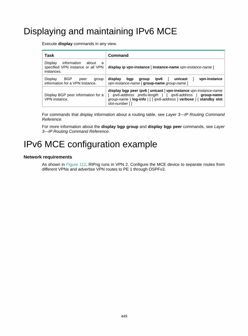
449
Displaying and maintaining IPv6 MCE Execute display commands in any view.
Task Command Display information about a specified VPN instance or all VPN instances.
display ip vpn-instance [ instance-name vpn-instance-name ]
Display BGP peer group information for a VPN instance.
display bgp group ipv6 [ unicast ] vpn-instance vpn-instance-name [ group-name group-name ]
Display BGP peer information for a VPN instance.
display bgp peer ipv6 [ unicast ] vpn-instance vpn-instance-name [ ipv6-address prefix-length | { ipv6-address | group-name group-name } log-info | [ [ ipv6-address ] verbose ] [ standby slot slot-number ] ]
For commands that display information about a routing table, see Layer 3—IP Routing Command Reference.
For more information about the display bgp group and display bgp peer commands, see Layer 3—IP Routing Command Reference.
IPv6 MCE configuration example Network requirements
As shown in Figure 112, RIPng runs in VPN 2. Configure the MCE device to separate routes from different VPNs and advertise VPN routes to PE 1 through OSPFv3.
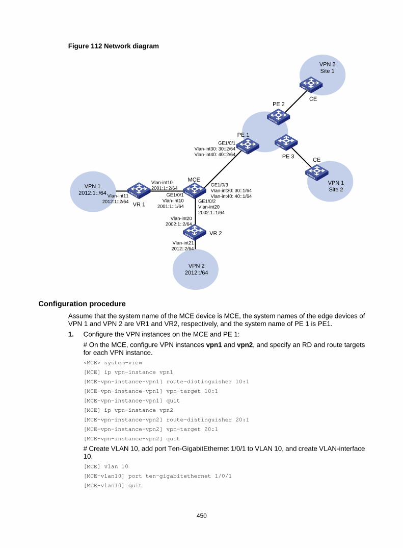
450
Figure 112 Network diagram
Configuration procedure Assume that the system name of the MCE device is MCE, the system names of the edge devices of VPN 1 and VPN 2 are VR1 and VR2, respectively, and the system name of PE 1 is PE1. 1. Configure the VPN instances on the MCE and PE 1:
# On the MCE, configure VPN instances vpn1 and vpn2, and specify an RD and route targets for each VPN instance. <MCE> system-view
[MCE] ip vpn-instance vpn1
[MCE-vpn-instance-vpn1] route-distinguisher 10:1
[MCE-vpn-instance-vpn1] vpn-target 10:1
[MCE-vpn-instance-vpn1] quit
[MCE] ip vpn-instance vpn2
[MCE-vpn-instance-vpn2] route-distinguisher 20:1
[MCE-vpn-instance-vpn2] vpn-target 20:1
[MCE-vpn-instance-vpn2] quit
# Create VLAN 10, add port Ten-GigabitEthernet 1/0/1 to VLAN 10, and create VLAN-interface 10. [MCE] vlan 10
[MCE-vlan10] port ten-gigabitethernet 1/0/1
[MCE-vlan10] quit
CE
VPN 1Site 2
CE
VPN 2Site 1
PE 1
PE 3
PE 2
VPN 22012::/64
VR 2
VPN 1 2012:1::/64
VR 1
MCE
GE1/0/1Vlan-int10
2001:1::1/64
GE1/0/1Vlan-int30: 30::2/64Vlan-int40: 40::2/64
GE1/0/3Vlan-int30: 30::1/64Vlan-int40: 40::1/64
GE1/0/2Vlan-int202002:1::1/64
Vlan-int102001:1::2/64
Vlan-int202002:1::2/64
Vlan-int112012:1::2/64
Vlan-int212012::2/64
451
# Bind VLAN-interface 10 to VPN instance vpn1, and configure an IPv6 address for the VLAN interface. [MCE] interface vlan-interface 10
[MCE-Vlan-interface10] ip binding vpn-instance vpn1
[MCE-Vlan-interface10] ipv6 address 2001:1::1 64
[MCE-Vlan-interface10] quit
# Configure VLAN 20, add port Ten-GigabitEthernet 1/0/2 to VLAN 20. [MCE] vlan 20
[MCE-vlan20] port ten-gigabitethernet 1/0/2
[MCE-vlan20] quit
# Bind VLAN-interface 20 to VPN instance vpn2. [MCE] interface vlan-interface 20
[MCE-Vlan-interface20] ip binding vpn-instance vpn2
# Assign an IPv6 address to VLAN-interface 20. [MCE-Vlan-interface20] ipv6 address 2002:1::1 64
[MCE-Vlan-interface20] quit
# On PE 1, configure VPN instances vpn1 and vpn2, and specify an RD and route targets for each VPN instance. <PE1> system-view
[PE1] ip vpn-instance vpn1
[PE1-vpn-instance-vpn1] route-distinguisher 30:1
[PE1-vpn-instance-vpn1] vpn-target 10:1
[PE1-vpn-instance-vpn1] quit
[PE1] ip vpn-instance vpn2
[PE1-vpn-instance-vpn2] route-distinguisher 40:1
[PE1-vpn-instance-vpn2] vpn-target 20:1
[PE1-vpn-instance-vpn2] quit
2. Configure routing between the MCE and VPN sites: The MCE is connected to VPN 1 directly, and no routing protocol is enabled in VPN 1. Therefore, you can configure IPv6 static routes. # On VR 1, assign IPv6 address 2001:1::2/64 to the interface connected to the MCE and 2012:1::2/64 to the interface connected to VPN 1. Add ports to VLANs. (Details not shown.) # On VR 1, configure a default route with the next hop being 2001:1::1. <VR1> system-view
[VR1] ipv6 route-static :: 0 2001:1::1
# On the MCE, configure an IPv6 static route to 2012:1::/64 with the next hop 2001:1::2. Bind the static route to VPN instance vpn1. [MCE] ipv6 route-static vpn-instance vpn1 2012:1:: 64 2001:1::2
# Run RIPng in VPN 2. Configure RIPng process 20 for VPN instance vpn2 on the MCE, so that the MCE can learn the routes of VPN 2 and add them to the routing table of VPN instance vpn2. [MCE] ripng 20 vpn-instance vpn2
# Advertise subnet 2002:1::/64 through RIPng. [MCE] interface vlan-interface 20
[MCE-Vlan-interface20] ripng 20 enable
[MCE-Vlan-interface20] quit
# On VR 2, assign IPv6 address 2002:1::2/64 to the interface connected to the MCE and 2012::2/64 to the interface connected to VPN 2. (Details not shown.) # Configure RIPng, and advertise subnets 2012::/64 and 2002:1::/64.

452
<VR2> system-view
[VR2] ripng 20
[VR2-ripng-20] quit
[VR2] interface vlan-interface 20
[VR2-Vlan-interface20] ripng 20 enable
[VR2-Vlan-interface20] quit
[VR2] interface vlan-interface 21
[VR2-Vlan-interface21] ripng 20 enable
[VR2-Vlan-interface21] quit
# On the MCE, display the routing table of VPN instance vpn1. [MCE] display ipv6 routing-table vpn-instance vpn1
Destinations : 6 Routes : 6
Destination: ::1/128 Protocol : Direct
NextHop : ::1 Preference: 0
Interface : InLoop0 Cost : 0
Destination: 2001:1::/64 Protocol : Direct
NextHop : :: Preference: 0
Interface : Vlan10 Cost : 0
Destination: 2001:1::1/128 Protocol : Direct
NextHop : ::1 Preference: 0
Interface : InLoop0 Cost : 0
Destination: 2012:1::/64 Protocol : Static
NextHop : 2001:1::2 Preference: 60
Interface : Vlan10 Cost : 0
Destination: FE80::/10 Protocol : Direct
NextHop : :: Preference: 0
Interface : NULL0 Cost : 0
Destination: FF00::/8 Protocol : Direct
NextHop : :: Preference: 0
Interface : NULL0 Cost : 0
# On the MCE, display the routing table of VPN instance vpn2. [MCE] display ipv6 routing-table vpn-instance vpn2
Destinations : 6 Routes : 6
Destination: ::1/128 Protocol : Direct
NextHop : ::1 Preference: 0
Interface : InLoop0 Cost : 0
Destination: 2002:1::/64 Protocol : Direct
NextHop : :: Preference: 0

453
Interface : Vlan20 Cost : 0
Destination: 2002:1::1/128 Protocol : Direct
NextHop : ::1 Preference: 0
Interface : InLoop0 Cost : 0
Destination: 2012::/64 Protocol : RIPng
NextHop : FE80::20C:29FF:FE40:701 Preference: 100
Interface : Vlan20 Cost : 1
Destination: FE80::/10 Protocol : Direct
NextHop : :: Preference: 0
Interface : NULL0 Cost : 0
Destination: FF00::/8 Protocol : Direct
NextHop : :: Preference: 0
Interface : NULL0 Cost : 0
The output shows that the MCE has learned the private route of VPN 2. The MCE maintains the routes of VPN 1 and VPN 2 in two different routing tables. In this way, routes from different VPNs are separated.
3. Configure routing between the MCE and PE 1: # On the MCE, configure the port connected to PE 1 as a trunk port, and configure it to permit packets of VLAN 30 and VLAN 40 to pass with VLAN tags. [MCE] interface ten-gigabitethernet 1/0/3
[MCE-Ten-GigabitEthernet1/0/3] port link-type trunk
[MCE-Ten-GigabitEthernet1/0/3] port trunk permit vlan 30 40
[MCE-Ten-GigabitEthernet1/0/3] quit
# On PE 1, configure the port connected to MCE as a trunk port, and configure it to permit packets of VLAN 30 and VLAN 40 to pass with VLAN tags. [PE1] interface ten-gigabitethernet 1/0/1
[PE1-Ten-GigabitEthernet1/0/1] port link-type trunk
[PE1-Ten-GigabitEthernet1/0/1] port trunk permit vlan 30 40
[PE1-Ten-GigabitEthernet1/0/1] quit
# On the MCE, create VLAN 30 and VLAN-interface 30, bind VLAN-interface 30 to VPN instance vpn1, and configure an IPv6 address for the VLAN-interface 30. [MCE] vlan 30
[MCE-vlan30] quit
[MCE] interface vlan-interface 30
[MCE-Vlan-interface30] ip binding vpn-instance vpn1
[MCE-Vlan-interface30] ipv6 address 30::1 64
[MCE-Vlan-interface30] quit
# On the MCE, create VLAN 40 and VLAN-interface 40, bind VLAN-interface 40 to VPN instance vpn2, and configure an IPv6 address for the VLAN-interface 40. [MCE] vlan 40
[MCE-vlan40] quit
[MCE] interface vlan-interface 40
[MCE-Vlan-interface40] ip binding vpn-instance vpn2
[MCE-Vlan-interface40] ipv6 address 40::1 64
[MCE-Vlan-interface40] quit

454
# On PE 1, create VLAN 30 and VLAN-interface 30, bind VLAN-interface 30 to VPN instance vpn1, and configure an IPv6 address for the VLAN-interface 30. [PE1] vlan 30
[PE1-vlan30] quit
[PE1] interface vlan-interface 30
[PE1-Vlan-interface30] ip binding vpn-instance vpn1
[PE1-Vlan-interface30] ipv6 address 30::2 64
[PE1-Vlan-interface30] quit
# On PE 1, create VLAN 40 and VLAN-interface 40, bind VLAN-interface 40 to VPN instance vpn2, and configure an IPv6 address for the VLAN-interface 40. [PE1] vlan 40
[PE1-vlan40] quit
[PE1] interface vlan-interface 40
[PE1-Vlan-interface40] ip binding vpn-instance vpn2
[PE1-Vlan-interface40] ipv6 address 40::2 64
[PE1-Vlan-interface40] quit
# Configure the IP address of the interface Loopback 0 as 101.101.10.1 for the MCE and as 100.100.10.1 for PE 1. Specify the loopback interface address as the router ID for the MCE and PE 1. (Details not shown.) # Enable OSPFv3 process 10 on the MCE, bind the process to VPN instance vpn1, and redistribute the IPv6 static route of VPN 1. [MCE] ospfv3 10 vpn-instance vpn1
[MCE-ospfv3-10] router-id 101.101.10.1
[MCE-ospfv3-10] import-route static
[MCE-ospfv3-10] quit
# Enable OSPFv3 on VLAN-interface 30. [MCE] interface vlan-interface 30
[MCE-Vlan-interface30] ospfv3 10 area 0.0.0.0
[MCE-Vlan-interface30] quit
# On PE 1, enable OSPFv3 process 10 and bind the process to VPN instance vpn1. [PE1] ospfv3 10 vpn-instance vpn1
[PE1-ospfv3-10] router-id 100.100.10.1
[PE1-ospfv3-10] quit
# Enable OSPFv3 on VLAN-interface 30. [PE1] interface vlan-interface 30
[PE1-Vlan-interface30] ospfv3 10 area 0.0.0.0
[PE1-Vlan-interface30] quit
# Use similar procedures to configure OSPFv3 process 20 between the MCE and PE 1 and redistribute VPN 2's routes from RIPng process 20 into the OSPFv3 routing table of the MCE. (Details not shown.)
Verifying the configuration # Display the routing table for VPN instance vpn1. The output shows that PE 1 has learned the private route of VPN 1 through OSPFv3. [PE1] display ipv6 routing-table vpn-instance vpn1
Destinations : 6 Routes : 6
Destination: ::1/128 Protocol : Direct
NextHop : ::1 Preference: 0

455
Interface : InLoop0 Cost : 0
Destination: 30::/64 Protocol : Direct
NextHop : :: Preference: 0
Interface : Vlan30 Cost : 0
Destination: 30::2/128 Protocol : Direct
NextHop : ::1 Preference: 0
Interface : InLoop0 Cost : 0
Destination: 2012:1::/64 Protocol : OSPFv3
NextHop : FE80::202:FF:FE02:2 Preference: 150
Interface : Vlan30 Cost : 1
Destination: FE80::/10 Protocol : Direct
NextHop : :: Preference: 0
Interface : NULL0 Cost : 0
Destination: FF00::/8 Protocol : Direct
NextHop : :: Preference: 0
Interface : NULL0 Cost : 0
# Display the routing table for VPN instance vpn2. The output shows that PE 1 has learned the private route of VPN 2 through OSPFv3. [PE1] display ipv6 routing-table vpn-instance vpn2
Destinations : 6 Routes : 6
Destination: ::1/128 Protocol : Direct
NextHop : ::1 Preference: 0
Interface : InLoop0 Cost : 0
Destination: 40::/64 Protocol : Direct
NextHop : :: Preference: 0
Interface : Vlan40 Cost : 0
Destination: 40::2/128 Protocol : Direct
NextHop : ::1 Preference: 0
Interface : InLoop0 Cost : 0
Destination: 2012::/64 Protocol : OSPFv3
NextHop : FE80::200:FF:FE0F:5 Preference: 150
Interface : Vlan40 Cost : 1
Destination: FE80::/10 Protocol : Direct
NextHop : :: Preference: 0
Interface : NULL0 Cost : 0
Destination: FF00::/8 Protocol : Direct

456
NextHop : :: Preference: 0
Interface : NULL0 Cost : 0
The routing information for the two VPNs has been added into the routing tables on PE 1.
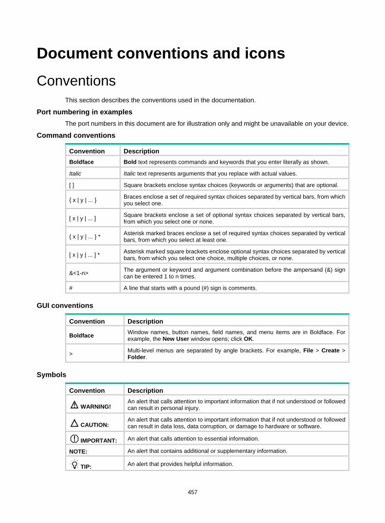
457
Document conventions and icons Conventions
This section describes the conventions used in the documentation.
Port numbering in examples The port numbers in this document are for illustration only and might be unavailable on your device.
Command conventions
Convention Description Boldface Bold text represents commands and keywords that you enter literally as shown.
Italic Italic text represents arguments that you replace with actual values.
[ ] Square brackets enclose syntax choices (keywords or arguments) that are optional.
{ x | y | ... } Braces enclose a set of required syntax choices separated by vertical bars, from which you select one.
[ x | y | ... ] Square brackets enclose a set of optional syntax choices separated by vertical bars, from which you select one or none.
{ x | y | ... } * Asterisk marked braces enclose a set of required syntax choices separated by vertical bars, from which you select at least one.
[ x | y | ... ] * Asterisk marked square brackets enclose optional syntax choices separated by vertical bars, from which you select one choice, multiple choices, or none.
&<1-n> The argument or keyword and argument combination before the ampersand (&) sign can be entered 1 to n times.
# A line that starts with a pound (#) sign is comments.
GUI conventions
Convention Description
Boldface Window names, button names, field names, and menu items are in Boldface. For example, the New User window opens; click OK.
> Multi-level menus are separated by angle brackets. For example, File > Create > Folder.
Symbols
Convention Description
WARNING! An alert that calls attention to important information that if not understood or followed can result in personal injury.
CAUTION: An alert that calls attention to important information that if not understood or followed can result in data loss, data corruption, or damage to hardware or software.
IMPORTANT: An alert that calls attention to essential information.
NOTE: An alert that contains additional or supplementary information.
TIP: An alert that provides helpful information.

458
Network topology icons Convention Description
Represents a generic network device, such as a router, switch, or firewall.
Represents a routing-capable device, such as a router or Layer 3 switch.
Represents a generic switch, such as a Layer 2 or Layer 3 switch, or a router that supports Layer 2 forwarding and other Layer 2 features.
Represents an access controller, a unified wired-WLAN module, or the access controller engine on a unified wired-WLAN switch.
Represents an access point.
Represents a wireless terminator unit.
Represents a wireless terminator.
Represents a mesh access point.
Represents omnidirectional signals.
Represents directional signals.
Represents a security product, such as a firewall, UTM, multiservice security gateway, or load balancing device.
Represents a security module, such as a firewall, load balancing, NetStream, SSL VPN, IPS, or ACG module.
TT
TT

459
Support and other resources Accessing Hewlett Packard Enterprise Support
• For live assistance, go to the Contact Hewlett Packard Enterprise Worldwide website: www.hpe.com/assistance
• To access documentation and support services, go to the Hewlett Packard Enterprise Support Center website: www.hpe.com/support/hpesc
Information to collect • Technical support registration number (if applicable) • Product name, model or version, and serial number • Operating system name and version • Firmware version • Error messages • Product-specific reports and logs • Add-on products or components • Third-party products or components
Accessing updates • Some software products provide a mechanism for accessing software updates through the
product interface. Review your product documentation to identify the recommended software update method.
• To download product updates, go to either of the following: Hewlett Packard Enterprise Support Center Get connected with updates page:
www.hpe.com/support/e-updates Software Depot website:
www.hpe.com/support/softwaredepot • To view and update your entitlements, and to link your contracts, Care Packs, and warranties
with your profile, go to the Hewlett Packard Enterprise Support Center More Information on Access to Support Materials page: www.hpe.com/support/AccessToSupportMaterials
IMPORTANT: Access to some updates might require product entitlement when accessed through the Hewlett Packard Enterprise Support Center. You must have an HP Passport set up with relevant entitlements.

460
Websites
Website Link Networking websites
Hewlett Packard Enterprise Information Library for Networking www.hpe.com/networking/resourcefinder
Hewlett Packard Enterprise Networking website www.hpe.com/info/networking
Hewlett Packard Enterprise My Networking website www.hpe.com/networking/support
Hewlett Packard Enterprise My Networking Portal www.hpe.com/networking/mynetworking
Hewlett Packard Enterprise Networking Warranty www.hpe.com/networking/warranty
General websites
Hewlett Packard Enterprise Information Library www.hpe.com/info/enterprise/docs
Hewlett Packard Enterprise Support Center www.hpe.com/support/hpesc
Hewlett Packard Enterprise Support Services Central ssc.hpe.com/portal/site/ssc/
Contact Hewlett Packard Enterprise Worldwide www.hpe.com/assistance
Subscription Service/Support Alerts www.hpe.com/support/e-updates
Software Depot www.hpe.com/support/softwaredepot
Customer Self Repair (not applicable to all devices) www.hpe.com/support/selfrepair
Insight Remote Support (not applicable to all devices) www.hpe.com/info/insightremotesupport/docs
Customer self repair Hewlett Packard Enterprise customer self repair (CSR) programs allow you to repair your product. If a CSR part needs to be replaced, it will be shipped directly to you so that you can install it at your convenience. Some parts do not qualify for CSR. Your Hewlett Packard Enterprise authorized service provider will determine whether a repair can be accomplished by CSR.
For more information about CSR, contact your local service provider or go to the CSR website:
www.hpe.com/support/selfrepair
Remote support Remote support is available with supported devices as part of your warranty, Care Pack Service, or contractual support agreement. It provides intelligent event diagnosis, and automatic, secure submission of hardware event notifications to Hewlett Packard Enterprise, which will initiate a fast and accurate resolution based on your product’s service level. Hewlett Packard Enterprise strongly recommends that you register your device for remote support.
For more information and device support details, go to the following website:
www.hpe.com/info/insightremotesupport/docs
Documentation feedback Hewlett Packard Enterprise is committed to providing documentation that meets your needs. To help us improve the documentation, send any errors, suggestions, or comments to Documentation Feedback ([email protected]). When submitting your feedback, include the document title,

461
part number, edition, and publication date located on the front cover of the document. For online help content, include the product name, product version, help edition, and publication date located on the legal notices page.

462
Index A AC
VPLS VSI+AC binding, 367 AC (attachment circuit)
MPLS L2VPN attachment circuit (AC), 310 MPLS L2VPN attachment circuit (AC) configuration, 316 MPLS L2VPN cross-connect+attachment circuit (AC) binding, 320
accessing H-VPLS access mode, 358 H-VPLS Ethernet access mode, 358
address VPLS MAC address aging, 356 VPLS MAC address learning, 356, 369 VPLS MAC address withdrawal, 356
adjacency MPLS TE traffic forwarding automatic route advertisement (forwarding adjacency), 53 MPLS TE tunnel automatic route advertisement traffic direction (forwarding adjacency), 73
advertising IPv6 MPLS L3VPN routing information advertisement, 265 LDP advertisement messages, 15 LDP label advertisement control, 42 LDP label advertisement modes, 17 LDP label advertisement policy, 27 MCE EBGP VPN route advertisement, 433 MCE OSPF VPN route advertisement, 428 MPLS egress label type advertisement, 6 MPLS L2VPN BGP label block information advertisement, 318 MPLS L3VPN basics, 175 MPLS L3VPN HoVPN, 189 MPLS L3VPN route advertisement, 157 MPLS TE attribute advertisement, 52 MPLS TE CRLSP dynamic establishment, 51 MPLS TE link attribute (IGP TE extension), 64 MPLS TE link attribute (IS-IS TE), 65 MPLS TE link attribute (OSPF TE), 64 MPLS TE traffic forwarding automatic route advertisement (forwarding adjacency), 53 MPLS TE traffic forwarding automatic route advertisement (IGP shortcut), 53
MPLS TE tunnel traffic direction (automatic route advertisement), 72 VPLS BGP label block information advertisement, 363 VPLS BGP PE information advertisement, 365
affinity MPLS TE tunnel constraints, 65
aging VPLS MAC address aging, 356
algorithm MPLS TE CSPF path calculation, 52
architecture MPLS L3VPN, 155, 413 MPLS network, 2 VPLS, 355
area MPLS L3VPN OSPF area PE-CE configuration, 169
AS IPv6 MPLS L3VPN inter-AS IPv6 VPN, 275 IPv6 MPLS L3VPN inter-AS IPv6 VPN option A, 276 IPv6 MPLS L3VPN inter-AS IPv6 VPN option C, 276 IPv6 MPLS L3VPN inter-AS option A, 286 IPv6 MPLS L3VPN inter-AS option C, 291 MPLS L3VPN BGP AS number substitution, 171, 192, 253 MPLS L3VPN inter-AS option A, 161, 209 MPLS L3VPN inter-AS option B, 162, 213 MPLS L3VPN inter-AS option C, 163, 218 MPLS L3VPN inter-AS VPN, 183 MPLS L3VPN inter-AS VPN option A, 161, 183 MPLS L3VPN inter-AS VPN option B, 161, 184 MPLS L3VPN inter-AS VPN option C, 161, 185 MPLS L3VPN inter-AS VPN option C ASBR, 186
ASBR IPv6 MPLS L3VPN inter-AS IPv6 VPN option C ASBR-PE, 277 MPLS L3VPN inter-AS VPN option C ASBR, 186
associating IPv6 MCE VPN instance+interface, 439 IPv6 MPLS L3VPN VPN instance+interface, 267 MCE VPN instance+interface, 417 MPLS L3VPN VPN instance+ interface, 176
attachment circuit (AC) VPLS architecture, 355 VPLS configuration, 361
463
attribute IPv6 MCE VPN instance route related attributes, 439 MCE VPN instance route related attributes, 417 MPLS L3VPN BGP export target attribute, 157, 415 MPLS L3VPN BGP import target attribute, 157, 415 MPLS L3VPN VPN instance route related attributes, 176, 267 MPLS TE attribute advertisement, 52 MPLS TE link attribute, 63 MPLS TE link attribute advertisement (IGP TE extension), 64 MPLS TE link attribute advertisement (IS-IS TE), 65 MPLS TE link attribute advertisement (OSPF TE), 64 MPLS TE tunnel constraints, 65
authenticating LDP MD5 configuration, 26 RSVP, 137 RSVP authentication configuration, 140
auto MPLS E FRR bypass tunnel on PLR (automatic setup), 78 MPLS L2VPN pseudowire VCCV auto mode, 314 MPLS TE automatic bandwidth adjustment, 55, 71 MPLS TE traffic forwarding automatic route advertisement (forwarding adjacency), 53 MPLS TE traffic forwarding automatic route advertisement (IGP shortcut), 53 VPLS LDP PW configuration (BGP auto-discovery), 365 VPLS LDP PW creation (BGP auto-discovery), 366
avoidance MPLS L3VPN routing loop avoidance, 170
B backbone
H-VPLS configuration (MPLS access), 386 H-VPLS UPE dual homing configuration, 390 VPLS BGP PW configuration, 377 VPLS configuration, 355, 360, 370 VPLS LDP PW configuration, 375 VPLS LDP PW configuration (BGP auto-discovery), 382 VPLS static PW configuration, 370
backing up
MPLS L3VPN FRR IPv4 route backup (VPNv4 route), 174 MPLS L3VPN FRR VPNv4 route backup (IPv4 route), 173 MPLS L3VPN FRR VPNv4 route backup (VPNv4 route), 173 MPLS TE CRLSP backup, 74 MPLS TE CRLSP backup configuration, 104 MPLS TE CRLSP hot standby backup, 56 MPLS TE CRLSP ordinary backup, 56
backoff mechanism (LDP), 25 bandwidth
MPLS TE automatic bandwidth adjustment, 71, 71 MPLS TE CRLSP dynamic establishment, 51 MPLS TE CRLSP flooding, 69 MPLS TE CRLSP static implementation, 51 MPLS TE DS-TE bandwidth constraint, 57 MPLS TE DS-TE bandwidth constraint model, 56, 57 MPLS TE link attribute, 63 MPLS TE tunnel automatic bandwidth adjustment, 55 MPLS TE tunnel constraints, 65 MPLS TE tunnel reoptimization, 55 static CRLSP configuration, 128, 129
BFD MPLS L3VPN FRR, 172 MPLS OAM BFD for LSP, 399, 405 MPLS OAM BFD for PW, 407 MPLS OAM session mode (dynamic), 397 MPLS OAM session mode (static), 397 RSVP enable, 142
BGP IPv6 MCE configuration, 438, 438, 449 IPv6 MPLS L3VPN, 266, 280 IPv6 MPLS L3VPN carrier's carrier, 297 IPv6 MPLS L3VPN configuration, 264, 280 IPv6 MPLS L3VPN inter-AS option A, 286 IPv6 MPLS L3VPN inter-AS option C, 291 IPv6 MPLS L3VPN loopback interface address redistribution, 277 IPv6 MPLS L3VPN OSPFv3 sham link, 304 IPv6 MPLS L3VPN PE-PE routing, 274 MCE configuration, 413, 416, 428 MCE EBGP VPN route advertisement, 433 MPLS L2VPN BGP label block information advertisement, 318 MPLS L2VPN BGP PW configuration, 318 MPLS L2VPN BGP PW creation, 319 MPLS L2VPN BGP PW remote CCC connection, 320

464
MPLS L2VPN remote CCC connection, 335 MPLS L3VPN, 196 MPLS L3VPN basics, 196 MPLS L3VPN BGP AS number substitution, 171, 192, 253 MPLS L3VPN BGP VPNv4 route control, 182 MPLS L3VPN BGP-OSPF interaction, 169 MPLS L3VPN carrier's carrier, 225 MPLS L3VPN configuration, 155, 174 MPLS L3VPN FRR, 172 MPLS L3VPN FRR configuration (IPv4 route/VPNv4 route backup), 259 MPLS L3VPN FRR configuration (VPNv4 route/IPv4 route backup), 261 MPLS L3VPN FRR configuration (VPNv4 route/route backup), 257 MPLS L3VPN HoVPN, 189, 242 MPLS L3VPN inter-AS option A, 209 MPLS L3VPN inter-AS option B, 213 MPLS L3VPN inter-AS option C, 218 MPLS L3VPN loopback route redistribution, 191 MPLS L3VPN MP-BGP, 157 MPLS L3VPN nested VPN, 188, 233 MPLS L3VPN OSPF sham link, 171, 249 MPLS L3VPN route target attributes, 157, 415 route flapping logging, 194, 278 VPLS BGP label block information advertisement, 363 VPLS BGP PW configuration, 363, 377 VPLS BGP PW creation, 364 VPLS LDP PW configuration (BGP auto-discovery), 365, 382 VPLS LDP PW creation (BGP auto-discovery), 366 VPLS PE information advertisement, 365
bidirectional MPLS TE tunnel configuration, 73, 98 MPLS TE tunnel implementation (associated mode), 59 MPLS TE tunnel implementation (co-routed mode), 59
binding MPLS L2VPN cross-connect+attachment circuit (AC) binding, 320 VPLS VSI+AC, 367
broadcast VPLS traffic flooding, 357 VPLS traffic forwarding, 357
C calculating
MPLS TE CSPF path calculation, 52 carrier's carrier
IPv6 MPLS L3VPN, 297 MPLS L3VPN, 165, 225 MPLS L3VPN Level 1 carrier, 165 MPLS L3VPN Level 2 carrier, 165
CCC MPLS L2VPN BGP PW remote CCC connection, 320 MPLS L2VPN remote CCC connection, 335
CE IPv6 MPLS L3VPN BGP VPNv6 route control, 274 IPv6 MPLS L3VPN inter-AS IPv6 VPN, 275 IPv6 MPLS L3VPN inter-AS IPv6 VPN option A, 276 IPv6 MPLS L3VPN inter-AS IPv6 VPN option C, 276 IPv6 MPLS L3VPN OSPF sham link, 277 IPv6 MPLS L3VPN OSPF sham link creation, 278 IPv6 MPLS L3VPN PE/CE EBGP, 271 IPv6 MPLS L3VPN PE/CE IBGP, 272 IPv6 MPLS L3VPN PE/CE routing, 268 IPv6 MPLS L3VPN PE-CE IPv6 IS-IS, 271 IPv6 MPLS L3VPN PE-CE OSPFv3, 269 IPv6 MPLS L3VPN PE-CE RIPng, 269 IPv6 MPLS L3VPN PE-CE static routing, 268 IPv6 MPLS L3VPN routing information advertisement, 265 MPLS L2VPN attachment circuit (AC) configuration, 316 MPLS L2VPN customer edge device (CE), 310 MPLS L3VPN architecture, 155, 413 MPLS L3VPN HoVPN, 189 MPLS L3VPN Layer 2 label packet forwarding, 158 MPLS L3VPN nested VPN, 167, 188 MPLS L3VPN OSPF area PE-CE configuration, 169 MPLS L3VPN OSPF sham link, 190 MPLS L3VPN OSPF sham link creation, 191 MPLS L3VPN PE-CE EBGP, 179 MPLS L3VPN PE-CE IBGP, 180 MPLS L3VPN PE-CE IS-IS, 178 MPLS L3VPN PE-CE OSPF, 177 MPLS L3VPN PE-CE RIP, 177 MPLS L3VPN PE-CE routing, 177 MPLS L3VPN PE-CE static routing, 177 MPLS L3VPN PE-PE routing, 181 VPLS architecture, 355
class

465
MPLS FEC, 1 MPLS L2VPN PW, 317 VPLS PW class configuration, 362
configuring exclusive tunnel, 152 H-VPLS (MPLS access), 386 H-VPLS UPE dual homing, 390 IPv6 MCE, 438, 438, 449 IPv6 MCE routing, 440 IPv6 MCE VPN instance, 438 IPv6 MCE VPN instance route related attributes, 439 IPv6 MCE-PE EBGP, 448 IPv6 MCE-PE IBGP, 448 IPv6 MCE-PE IPv6 IS-IS, 447 IPv6 MCE-PE IPv6 static routing, 445 IPv6 MCE-PE OSPFv3, 446 IPv6 MCE-PE RIPng, 446 IPv6 MCE-PE routing, 445 IPv6 MCE-VPN site EBGP, 443 IPv6 MCE-VPN site IBGP, 444 IPv6 MCE-VPN site IPv6 IS-IS, 442 IPv6 MCE-VPN site OSPFv3, 442 IPv6 MCE-VPN site RIPng, 441 IPv6 MCE-VPN site static routing, 441 IPv6 MPLS L3VPN, 264, 266, 280, 280 IPv6 MPLS L3VPN basics, 266 IPv6 MPLS L3VPN BGP VPNv6 route control, 274 IPv6 MPLS L3VPN carrier's carrier, 297 IPv6 MPLS L3VPN inter-AS IPv6 VPN, 275 IPv6 MPLS L3VPN inter-AS IPv6 VPN option A, 276 IPv6 MPLS L3VPN inter-AS IPv6 VPN option C, 276 IPv6 MPLS L3VPN inter-AS IPv6 VPN option C ASBR-PE, 277 IPv6 MPLS L3VPN inter-AS IPv6 VPN option C PE, 276 IPv6 MPLS L3VPN inter-AS IPv6 VPN option C routing policy, 277 IPv6 MPLS L3VPN inter-AS option A, 286 IPv6 MPLS L3VPN inter-AS option C, 291 IPv6 MPLS L3VPN IPv6 MCE-VPN site routing, 441 IPv6 MPLS L3VPN loopback interface, 277 IPv6 MPLS L3VPN OSPF sham link, 277 IPv6 MPLS L3VPN OSPFv3 sham link, 304 IPv6 MPLS L3VPN PE/CE EBGP, 271 IPv6 MPLS L3VPN PE/CE IBGP, 272 IPv6 MPLS L3VPN PE/CE routing, 268
IPv6 MPLS L3VPN PE-CE IPv6 IS-IS, 271 IPv6 MPLS L3VPN PE-CE OSPFv3, 269 IPv6 MPLS L3VPN PE-CE RIPng, 269 IPv6 MPLS L3VPN PE-CE static routing, 268 IPv6 MPLS L3VPN PE-PE routing, 274 IPv6 MPLS L3VPN VPN instance, 266 IPv6 MPLS L3VPN VPN instance route related attribute, 267 LDP, 15, 22, 34 LDP backoff, 25 LDP FRR, 33, 47 LDP GR, 31 LDP hello parameter, 24 LDP label acceptance control, 38 LDP label acceptance policy, 28 LDP label advertisement control, 42 LDP label advertisement policy, 27 LDP label distribution control mode, 27 LDP link hello timer, 24 LDP loop detection, 29 LDP LSP, 34 LDP LSP generation policy, 26 LDP MD5 authentication, 26 LDP NSR, 31 LDP session parameter (Basic Discovery), 25 LDP session parameter (Extended Discovery), 25 LDP session protection, 30 LDP targeted hello timer, 24 LDP-IGP synchronization, 31 LDP-IS-IS synchronization, 32 LDP-OSPF synchronization, 31 MCE, 416, 428 MCE configuration, 413 MCE EBGP VPN route advertisement, 433 MCE OSPF VPN route advertisement, 428 MCE routing, 418 MCE VPN instance, 416 MCE VPN instance route related attribute, 417 MCE-PE EBGP, 426 MCE-PE IBGP, 427 MCE-PE IS-IS, 425 MCE-PE OSPF, 424 MCE-PE RIP, 424 MCE-PE routing, 423 MCE-PE static routing, 424 MCE-VPN site EBGP, 421 MCE-VPN site IBGP, 422 MCE-VPN site IS-IS, 420 MCE-VPN site OSPF, 419 MCE-VPN site RIP, 419

466
MCE-VPN site routing, 418 MCE-VPN site static routing, 418 MPLS basics, 1, 5 MPLS L2VPN, 310, 315, 323 MPLS L2VPN attachment circuit (AC), 316 MPLS L2VPN BGP label block information advertisement, 318 MPLS L2VPN BGP PW, 318, 331 MPLS L2VPN BGP PW remote CCC connection, 320 MPLS L2VPN cross-connect configuration, 316 MPLS L2VPN cross-connect+attachment circuit (AC) binding, 320 MPLS L2VPN LDP PW, 317, 327 MPLS L2VPN LDP PW redundancy, 322, 338 MPLS L2VPN multi-segment PW configuration (inter-domain)(on router), 347 MPLS L2VPN multi-segment PW configuration (intra-domain)(on router), 344 MPLS L2VPN PW, 317 MPLS L2VPN PW class, 317 MPLS L2VPN PW redundancy, 321 MPLS L2VPN remote CCC connection, 335 MPLS L2VPN static PW, 317, 323 MPLS L2VPN static PW redundancy, 321 MPLS L3VPN, 155, 174, 196 MPLS L3VPN basics, 175, 196 MPLS L3VPN BGP AS number substitution, 192, 253 MPLS L3VPN BGP VPNv4 route control, 182 MPLS L3VPN carrier's carrier, 225 MPLS L3VPN FRR, 192 MPLS L3VPN FRR (IPv4 route/VPNv4 route backup), 259 MPLS L3VPN FRR (VPNv4 route/IPv4 route backup), 261 MPLS L3VPN FRR (VPNv4 route/route backup), 257 MPLS L3VPN HoVPN, 189, 242 MPLS L3VPN hub-spoke network, 202 MPLS L3VPN inter-AS option A, 209 MPLS L3VPN inter-AS option B, 213 MPLS L3VPN inter-AS option C, 218 MPLS L3VPN inter-AS VPN, 183 MPLS L3VPN inter-AS VPN option A, 183 MPLS L3VPN inter-AS VPN option B, 184 MPLS L3VPN inter-AS VPN option C, 185 MPLS L3VPN inter-AS VPN option C ASBR, 186 MPLS L3VPN inter-AS VPN option C PE, 185
MPLS L3VPN inter-AS VPN option C routing policy, 187 MPLS L3VPN loopback interface, 190 MPLS L3VPN nested VPN, 188, 233 MPLS L3VPN OSPF sham link, 190, 249 MPLS L3VPN PE-CE EBGP, 179 MPLS L3VPN PE-CE IBGP, 180 MPLS L3VPN PE-CE IS-IS, 178 MPLS L3VPN PE-CE OSPF, 177 MPLS L3VPN PE-CE RIP, 177 MPLS L3VPN PE-CE routing, 177 MPLS L3VPN PE-CE static routing, 177 MPLS L3VPN PE-PE routing, 181 MPLS L3VPN VPN instance, 175 MPLS L3VPN VPN instance route related attribute, 176 MPLS MTU, 6 MPLS OAM, 397, 405 MPLS OAM BFD for LSP, 399, 405 MPLS OAM BFD for MPLS L2VPN PW, 402 MPLS OAM BFD for PW, 401, 407 MPLS OAM BFD for VPLS LDP PW, 404 MPLS OAM BFD for VPLS static PW, 403 MPLS OAM for LSP tunnel, 398 MPLS OAM for MPLS TE tunnel, 400 MPLS OAM for PW, 401 MPLS OAM ping for LSP, 398 MPLS OAM ping for PW, 401 MPLS OAM tracert for LSP, 399 MPLS OAM tracert for LSP (periodic), 400 MPLS TE, 51, 60, 80 MPLS TE auto FRR, 114 MPLS TE automatic bandwidth adjustment, 71 MPLS TE bidirectional tunnel, 73, 98 MPLS TE CRLSP backup, 74, 104 MPLS TE CRLSP flooding interval, 69 MPLS TE CRLSP flooding thresholds, 69 MPLS TE CRLSP path selection metric type, 67 MPLS TE CRLSP reoptimization, 68 MPLS TE CRLSP route pinning, 68 MPLS TE DS-TE, 61 MPLS TE FRR, 74 MPLS TE FRR bypass tunnel on PLR, 75 MPLS TE FRR manual bypass tunnel, 108 MPLS TE FRR node fault detection, 79 MPLS TE FRR optimal bypass tunnel selection interval, 79 MPLS TE IETF DS-TE, 120 MPLS TE link attribute, 63 MPLS TE link attribute advertisement (IS-IS TE), 65
467
MPLS TE link attribute advertisement (OSPF TE), 64 MPLS TE RSVP-TE RSVP resource reservation style, 71 MPLS TE traffic forwarding, 72 MPLS TE tunnel (dynamic CRLSP), 63 MPLS TE tunnel (static CRLSP), 62 MPLS TE tunnel affinity attribute, 66 MPLS TE tunnel automatic route advertisement traffic direction (forwarding adjacency), 73 MPLS TE tunnel automatic route advertisement traffic direction (IGP shortcut), 72 MPLS TE tunnel constraints, 65 MPLS TE tunnel constraints (bandwidth), 65 MPLS TE tunnel holding priority, 66 MPLS TE tunnel interface, 61 MPLS TE tunnel loose explicit path, 66 MPLS TE tunnel setup priority, 66 MPLS TE tunnel setup retry, 70 MPLS TE tunnel strict explicit path, 66 MPLS TE tunnel traffic direction (automatic route advertisement), 72 MPLS TE tunnel traffic direction (static routing), 72 MPLS TTL propagation, 7 preferred tunnel, 152 preferred tunnel+selection order, 153 RSVP, 135, 138, 143 RSVP authentication (interface view), 140 RSVP authentication (RSVP neighbor view), 140 RSVP authentication (RSVP view), 140 RSVP GR, 142, 147 RSVP hello extension, 139 RSVP packet DSCP value, 141 RSVP refresh, 138 RSVP reliable message delivery, 139 RSVP Srefresh, 139 static CRLSP, 128, 129 static LSP, 11, 12 tunnel policy, 150, 150, 152 tunnel selection order, 153 VPLS, 355, 360, 370 VPLS AC, 361 VPLS BGP label block information advertisement, 363 VPLS BGP PE information advertisement, 365 VPLS BGP PW, 363, 377 VPLS LDP PW, 363, 375
VPLS LDP PW (BGP auto-discovery), 365, 382 VPLS MAC address learning, 369 VPLS PW, 362 VPLS PW class, 362 VPLS static PW, 362, 370 VPLS UPE dual homing, 367 VPLS UPE dual homing (redundant LDP PWs), 368 VPLS UPE dual homing (redundant static PWs), 368 VPLS VSI, 362
connecting MPLS L2VPN BGP PW remote CCC connection, 320 MPLS L2VPN cross-connect configuration, 316 MPLS L2VPN cross-connect+attachment circuit (AC) binding, 320 MPLS L2VPN remote CCC connection, 335
Constraint-based Routed Label Switched Path. See CRLSP Shortest Path First. Use CSPF
Constraint-based Routed Label Switched Paths. Use CRLSP control plane
MPLS, 2 controlling
LDP label distribution control mode, 27 MPLS TE CRLSP path selection, 67 MPLS TE tunnel setup, 69
creating IPv6 MCE VPN instance, 438 IPv6 MPLS L3VPN OSPF sham link, 278 IPv6 MPLS L3VPN VPN instance, 266 MCE VPN instance, 416 MPLS L2VPN BGP PW, 319 MPLS L3VPN OSPF sham link, 191 MPLS L3VPN VPN instance, 175 VPLS BGP PW, 364 VPLS LDP PW (BGP auto-discovery), 366
CRLSP MPLS TE auto FRR configuration, 114 MPLS TE bidirectional tunnel, 59, 73 MPLS TE bidirectional tunnel configuration, 98 MPLS TE configuration, 51, 80 MPLS TE CRLSP backup, 56 MPLS TE CRLSP backup configuration, 104 MPLS TE CRLSP path selection control, 67 MPLS TE CRLSP path selection metric type, 67 MPLS TE CRLSP reoptimization, 68 MPLS TE CRLSP route pinning, 68 MPLS TE dynamic implementation, 51

468
MPLS TE FRR, 56, 74 MPLS TE FRR bypass tunnel on PLR, 75 MPLS TE FRR link protection, 56, 56 MPLS TE FRR manual bypass tunnel, 108 MPLS TE FRR node fault detection, 79 MPLS TE FRR node protection, 56 MPLS TE FRR optimal bypass tunnel selection interval, 79 MPLS TE IETF DS-TE configuration, 120 MPLS TE inter-AS tunnel establishment (RSVP-TE), 91 MPLS TE make-before-break, 54 MPLS TE route pinning, 55 MPLS TE static implementation, 51 MPLS TE tunnel automatic bandwidth adjustment, 55 MPLS TE tunnel configuration (dynamic CRLSP), 63 MPLS TE tunnel configuration (static CRLSP), 62 MPLS TE tunnel establishment (RSVP-TE), 85 MPLS TE tunnel establishment (static CRLSP), 80 MPLS TE tunnel reoptimization, 55 RSVP authentication, 137, 140 RSVP BFD enable, 142 RSVP configuration, 135, 138, 143 RSVP GR, 137 RSVP GR configuration, 142, 147 RSVP hello extension, 139 RSVP refresh, 138 RSVP refresh mechanism, 136 RSVP reliable message delivery, 139 RSVP Srefresh configuration, 139 RSVP-TE message types, 135 RSVP-TE object types, 135 RSVP-TE tunnel establishment, 143 static CRLSP configuration, 128, 129 static CRLSP display, 129
cross-connecting MPLS L2VPN, 310 MPLS L2VPN cross-connect, 316 MPLS L2VPN cross-connect+attachment circuit (AC) binding, 320
CSPF MPLS TE CRLSP flooding, 69 MPLS TE path calculation, 52
customer edge device. See CE
D detecting
LDP loop detection, 29 MPLS TE FRR node fault detection, 79 MPLS TE loop detection, 70
device customer edge device. See CE H-VPLS configuration (MPLS access), 386 H-VPLS UPE dual homing configuration, 390 IPv6 MCE configuration, 438, 438, 449 IPv6 MCE VPN instance, 438 IPv6 MCE VPN instance route related attributes, 439 IPv6 MCE VPN instance+interface association, 439 IPv6 MPLS L3VPN, 266 IPv6 MPLS L3VPN basics, 266 IPv6 MPLS L3VPN BGP VPNv6 route control, 274 IPv6 MPLS L3VPN configuration, 264 IPv6 MPLS L3VPN inter-AS IPv6 VPN, 275 IPv6 MPLS L3VPN inter-AS IPv6 VPN option A, 276 IPv6 MPLS L3VPN inter-AS IPv6 VPN option C, 276 IPv6 MPLS L3VPN PE-CE IPv6 IS-IS, 271 IPv6 MPLS L3VPN PE-CE OSPFv3, 269 IPv6 MPLS L3VPN PE-CE RIPng, 269 IPv6 MPLS L3VPN PE-CE static routing, 268 IPv6 MPLS L3VPN VPN instance+interface association, 267 MCE configuration, 413, 416, 428 MPLS L2VPN BGP PW configuration, 331 MPLS L2VPN LDP PW configuration, 327 MPLS L2VPN LDP PW redundancy, 338 MPLS L2VPN multi-segment PW configuration (inter-domain)(on router), 347 MPLS L2VPN multi-segment PW configuration (intra-domain)(on router), 344 MPLS L2VPN remote CCC connection, 335 MPLS L2VPN static PW configuration, 323 MPLS L3VPN architecture, 155, 413 MPLS L3VPN basics, 175 MPLS L3VPN configuration, 155, 174 MPLS L3VPN PE-CE EBGP, 179 MPLS L3VPN PE-CE IBGP, 180 MPLS L3VPN PE-CE IS-IS, 178 MPLS L3VPN PE-CE OSPF, 177 MPLS L3VPN PE-CE RIP, 177 MPLS L3VPN PE-CE routing, 177 MPLS L3VPN PE-CE static routing, 177 MPLS L3VPN PE-PE routing, 181 provider device. See P

469
provider edge device. See PE static CRLSP configuration, 128 VPLS BGP PW configuration, 377 VPLS configuration, 370 VPLS LDP PW configuration, 375 VPLS LDP PW configuration (BGP auto-discovery), 382 VPLS static PW configuration, 370
DiffServ-aware TE. See DS-TE discovering
LDP discovery message type, 15 LDP peer basic discovery, 16 LDP peer extended discovery, 16 LDP session parameters (Basic Discovery), 24 LDP session parameters (Extended Discovery), 24
displaying IPv6 MCE, 449 IPv6 MPLS L3VPN, 278 LDP, 34 MCE, 427 MPLS, 10 MPLS L2VPN, 322 MPLS L3VPN, 195 MPLS OAM, 405 MPLS TE, 79 RSVP, 142 static CRLSP, 129 static LSP, 12 tunnel information, 152 VPLS, 369
distributing LDP label distribution control mode, 27
down threshold (MPLS TE flooding), 69 DSCP
RSVP packet DSCP value, 141 DS-TE
basic concepts, 56, 57 how it works, 58 MPLS TE DS-TE, 57 MPLS TE DS-TE configuration, 61 MPLS TE IETF DS-TE configuration, 120
dual homing H-VPLS UPE, 359 H-VPLS UPE dual homing configuration, 390 VPLS UPE configuration, 367 VPLS UPE dual homing configuration (redundant LDP PWs), 368 VPLS UPE dual homing configuration (redundant static PWs), 368
dynamic MPLS LSP establishment, 3 MPLS OAM BFD session mode, 397 MPLS TE CRLSP establishment, 51 MPLS TE tunnel configuration (dynamic CRLSP), 63
E EBGP
IPv6 MCE-PE EBGP, 448 IPv6 MCE-PE routing, 445 IPv6 MCE-VPN site EBGP, 443 IPv6 MPLS L3VPN PE/CE EBGP, 271 MCE-PE EBGP, 426 MCE-VPN site EBGP, 421 MPLS L3VPN hub-spoke network, 202 MPLS L3VPN inter-AS VPN option B, 161, 162 MPLS L3VPN inter-AS VPN option C, 161, 163 MPLS L3VPN PE-CE EBGP, 179
egress MPLS egress label type advertisement, 6 MPLS egress LSR, 2 MPLS L3VPN egress PE VPN label processing mode, 191
enabling BGP route flapping logging, 194, 278 LDP on interface, 23 LDP SNMP notification, 33 MPLS, 5 MPLS forwarding statistics, 9 MPLS L2VPN, 315 MPLS L3VPN SNMP notification, 194 MPLS SNMP notifications, 9 MPLS TE, 61 MPLS TE FRR, 75 MPLS TE label recording, 70 MPLS TE loop detection, 70 MPLS TE route recording, 70 MPLS TTL-expired message send, 9 RSVP, 138 RSVP BFD, 142 VPLS L2VPN, 361
establishing MPLS LSP, 3 MPLS TE inter-AS tunnel (RSVP-TE), 91 MPLS TE tunnel (RSVP-TE), 85 MPLS TE tunnel (static CRLSP), 80 MPLS TE tunnel with RSVP-TE, 67 RSVP TE tunnel, 143
Ethernet H-VPLS access mode, 358

470
exclusive tunnel (MPLS), 152 EXPLICIT_ROUTE object (RSVP-TE), 135 exporting
IPv6 MPLS L3VPN VPN instance route related attributes, 267 MCE VPN instance route related attributes, 417 MPLS L3VPN BGP export target attribute, 157, 415 MPLS L3VPN VPN instance route related attributes, 176
extended Resource Reservation Protocol. See RSVP-TE extending
MPLS L3VPN OSPF VPN extension, 169 RSVP hello extension, 139
extranet MPLS L3VPN networking scheme, 160
F
FEC LDP classification, 15 LDP configuration, 15, 22, 34 LDP label acceptance control, 38 LDP label advertisement control, 42 LDP label mapping, 15 LDP LSP configuration, 34 MPLS, 1 MPLS control plane, 2 MPLS label format, 1
flooding MPLS TE, 69
format MPLS FEC label, 1
forwarding equivalence class. Use FEC exclusive tunnel configuration, 152 IPv6 MPLS L3VPN packet forwarding, 264 LDP GR, 19 LDP NSR, 20 MPLS FEC, 1 MPLS FEC label format, 1 MPLS forwarding plane, 2 MPLS forwarding statistics, 9 MPLS L3VPN packet forwarding, 158 MPLS LFIB, 2 MPLS LSP, 2 MPLS LSP establishment, 3 MPLS LSR, 2 MPLS process, 4 MPLS TE bidirectional tunnel, 59
MPLS TE DS-TE, 57 MPLS TE make-before-break, 54 MPLS TE tunnel automatic bandwidth adjustment, 55 MPLS TE tunnel automatic route advertisement traffic direction (forwarding adjacency), 73 MPLS TE tunnel reoptimization, 55 preferred tunnel configuration, 152 preferred tunnel+selection order, 153 tunnel policy configuration, 150, 152 tunnel selection order configuration, 153 VPLS broadcast traffic forwarding, 357 VPLS multicast traffic forwarding, 357 VPLS unicast traffic forwarding, 357
FRR LDP configuration, 47 LDP FRR, 21 LDP FRR configuration, 33 MPLS L3VPN, 172 MPLS L3VPN FRR configuration, 192 MPLS L3VPN FRR configuration (IPv4 route/VPNv4 route backup), 259 MPLS L3VPN FRR configuration (VPNv4 route/IPv4 route backup), 261 MPLS L3VPN FRR configuration (VPNv4 route/route backup), 257 MPLS L3VPN FRR IPv4 route backup (VPNv4 route), 174 MPLS L3VPN FRR VPNv4 route backup (IPv4 route), 173 MPLS L3VPN FRR VPNv4 route backup (VPNv4 route), 173 MPLS TE, 56 MPLS TE auto FRR configuration, 114 MPLS TE FRR bypass tunnel on PLR configuration restrictions, 77 MPLS TE FRR configuration, 74 MPLS TE FRR configuration on PLR, 75 MPLS TE FRR CRLSP link protection, 56, 56 MPLS TE FRR CRLSP node protection, 56 MPLS TE FRR enable, 75 MPLS TE FRR manual bypass tunnel, 108 MPLS TE FRR node fault detection, 79 MPLS TE FRR optimal bypass tunnel selection interval, 79
G Graceful Restart (GR)
LDP GR, 19 LDP GR configuration, 31 LDP GR helper, 19, 31 LDP GR restarter, 19, 31

471
RSVP configuration, 147 RSVP GR, 137 RSVP GR configuration, 142 RSVP GR helper, 137 RSVP GR restarter, 137
GRE exclusive tunnel configuration, 152 preferred tunnel configuration, 152 preferred tunnel+selection order, 153 tunnel policy configuration, 150, 152 tunnel selection order configuration, 153
H hello
LDP session protection, 30 RSVP GR, 137 RSVP GR configuration, 142 RSVP hello extension, 139 RSVP-TE Hello message, 135
hierarchical VPLS. Use H-VPLS hierarchy
of PE. See HoVPN of VPN. See HoVPN
hop count (LDP loop detection), 29 hot standby CRLSP backup (MPLS TE), 56 HoVPN
configuration, 189, 242 network model, 168
hub-spoke MPLS L3VPN networking configuration, 202 MPLS L3VPN networking scheme, 159 VPLS BGP label block information advertisement, 363 VPLS BGP PW configuration, 363 VPLS LDP PW configuration, 363 VPLS LDP PW configuration (BGP auto-discovery), 365 VPLS static PW configuration, 362 VPLS VSI configuration, 362 VPLS VSI+AC binding, 367
H-VPLS access mode, 358 backbone domain, 358 edge domain, 358 H-VPLS configuration (MPLS access), 386 NPE, 358 UPE, 358 UPE dual homing, 359 UPE dual homing configuration, 390 UPE redundancy, 359
I
IBGP IPv6 MCE-PE IBGP, 448 IPv6 MCE-VPN site IBGP, 444 IPv6 MPLS L3VPN PE/CE IBGP, 272 MCE-PE IBGP configuration, 427 MCE-VPN site IBGP, 422 MPLS L3VPN PE-CE IBGP, 180
ICMP MPLS TTL-expired message send, 9
identifying LDP identifier, 15
IETF DS-TE MPLS TE DiffServ-aware TE mode, 57 MPLS TE IETF DS-TE configuration, 120
IGP LDP-IGP synchronization, 21, 31 MPLS TE attribute advertisement, 52 MPLS TE CRLSP flooding, 69 MPLS TE link attribute advertisement (IGP TE extension), 64 MPLS TE link attribute advertisement (IS-IS TE), 65 MPLS TE link attribute advertisement (OSPF TE), 64 MPLS TE traffic forwarding automatic route advertisement (IGP shortcut), 53 MPLS TE tunnel automatic route advertisement traffic direction (IGP shortcut), 72
implementing VPLS, 356
importing IPv6 MPLS L3VPN VPN instance route related attributes, 267 MCE VPN instance route related attributes, 417 MPLS L3VPN BGP import target attribute, 157, 415 MPLS L3VPN VPN instance route related attributes, 176
ingress MPLS ingress LSR, 2
instance MCE VPN instance, 416 MCE VPN instance+interface association, 417 MCEVPN instance creation, 416 MPLS L3VPN VPN instance, 156, 175, 414 MPLS L3VPN VPN instance creation, 175 MPLS L3VPN VPN instance+interface association, 176
interaction MPLS L3VPN BGP-OSPF interaction, 169
inter-AS

472
MPLS TE inter-AS tunnel establishment (RSVP-TE), 91
inter-AS VPN IPv6 MPLS L3VPN, 275 IPv6 MPLS L3VPN option A, 276, 286 IPv6 MPLS L3VPN option C, 276, 291 MPLS L3VPN, 183 MPLS L3VPN option A, 161, 161, 183, 209 MPLS L3VPN option B, 161, 162, 184, 213 MPLS L3VPN option C, 161, 163, 185, 218
inter-domain multi-segment PW configuration, 347 MPLS L2VPN, 314
interval MPLS TE CRLSP flooding, 69 MPLS TE FRR optimal bypass tunnel selection interval, 79
intra-domain multi-segment PW configuration, 344 MPLS L2VPN, 313
IP H-VPLS configuration (MPLS access), 386 H-VPLS UPE dual homing configuration, 390 MPLS L3VPN loopback interface, 190 MPLS L3VPN loopback route redistribution, 191 VPLS BGP PW configuration, 377 VPLS configuration, 355, 360, 370 VPLS LDP PW configuration, 375 VPLS LDP PW configuration (BGP auto-discovery), 382 VPLS static PW configuration, 370
IP routing BGP route flapping logging, 194, 278 LDP backoff, 25 LDP configuration, 15, 22, 34 LDP FRR configuration, 33 LDP GR, 19 LDP GR configuration, 31 LDP label acceptance control, 38 LDP label acceptance policy, 28 LDP label advertisement control, 42 LDP label advertisement policy, 27 LDP label distribution control mode, 27 LDP loop detection, 29 LDP LSP configuration, 34 LDP LSP generation policy, 26 LDP MD5 authentication, 26 LDP NSR, 20 LDP NSR configuration, 31 LDP operation, 16
LDP session parameters, 24 LDP session protection, 30 LDP session reset, 33 LDP SNMP notification, 33 LDP-IGP synchronization, 21, 31 LDP-IS-IS synchronization, 32 LDP-OSPF synchronization, 31 MPLS basics configuration, 1, 5 static LSP configuration, 11, 12
IPv4 MCE-PE EBGP configuration, 426 MCE-PE IBGP configuration, 427 MPLS L3VPN FRR IPv4 route backup (VPNv4 route), 174 MPLS L3VPN FRR VPNv4 route backup (IPv4 route), 173 MPLS L3VPN inter-AS VPN option B, 161, 162 MPLS L3VPN inter-AS VPN option C, 161, 163 MPLS L3VPN loopback route redistribution, 191 MPLS L3VPN VPN-IPv4 address, 156, 414 MPLS OAM BFD for LSP, 405 MPLS OAM BFD for PW, 407 MPLS OAM configuration, 397, 405
IPv6 MPLS L3VPN. See IPv6 MPLS L3VPN MPLS L3VPN loopback interface, 277 MPLS L3VPN loopback interface address redistribution, 277
IPv6 IS-IS IPv6 MCE-PE EBGP, 448 IPv6 MCE-PE IBGP, 448 IPv6 MCE-PE IPv6 IS-IS, 447 IPv6 MCE-VPN site IPv6 IS-IS, 442 IPv6 MPLS L3VPN PE-CE IPv6 IS-IS, 271
IPv6 MCE configuration, 438, 438, 449 display, 449 IPv6 MCE-PE EBGP, 448 IPv6 MCE-PE IBGP, 448 IPv6 MCE-PE IPv6 IS-IS, 447 IPv6 MCE-PE IPv6 static routing, 445 IPv6 MCE-PE OSPFv3, 446 IPv6 MCE-PE RIPng, 446 IPv6 MCE-VPN site EBGP, 443 IPv6 MCE-VPN site IBGP, 444 IPv6 MCE-VPN site IPv6 IS-IS, 442 IPv6 MCE-VPN site OSPFv3, 442 IPv6 MCE-VPN site RIPng, 441 IPv6 MCE-VPN site static routing, 441 MCE-PE routing, 445 routing configuration, 440

473
VPN instance configuration, 438 VPN instance creation, 438 VPN instance route related attributes, 439 VPN instance+interface association, 439
IPv6 MPLS L3VPN basics, 266 BGP VPNv6 route control, 274 carrier's carrier, 297 configuration, 264, 266, 280, 280 display, 278 functions, 265 inter-AS IPv6 VPN, 275 inter-AS IPv6 VPN option A, 276 inter-AS IPv6 VPN option C, 276 inter-AS IPv6 VPN option C ASBR-PE, 277 inter-AS IPv6 VPN option C PE, 276 inter-AS IPv6 VPN option C routing policy, 277 inter-AS option A, 286 inter-AS option C, 291 IPv6 MCE routing configuration, 440 IPv6 MCE-PE EBGP, 448 IPv6 MCE-PE IBGP, 448 IPv6 MCE-PE IPv6 IS-IS, 447 IPv6 MCE-PE IPv6 static routing, 445 IPv6 MCE-PE OSPFv3, 446 IPv6 MCE-PE RIPng, 446 IPv6 MCE-VPN site EBGP, 443 IPv6 MCE-VPN site IBGP, 444 IPv6 MCE-VPN site IPv6 IS-IS, 442 IPv6 MCE-VPN site OSPFv3, 442 IPv6 MCE-VPN site RIPng, 441 IPv6 MCE-VPN site routing, 441 IPv6 MCE-VPN site static routing, 441 loopback interface, 277 loopback interface address redistribution, 277 maintain, 278 MCE-PE routing, 445 network schemes, 265 OSPF sham link, 277 OSPF sham link creation, 278 OSPFv3 sham link, 304 packet forwarding, 264 PE/CE EBGP, 271 PE/CE IBGP, 272 PE/CE routing, 268 PE-CE IPv6 IS-IS, 271 PE-CE OSPFv3, 269 PE-CE RIPng, 269 PE-CE static routing, 268 PE-PE routing, 274
routing information advertisement, 265 VPN instance, 266 VPN instance creation, 266 VPN instance route related attributes, 267 VPN instance+interface association, 267
IS-IS LDP-IS-IS synchronization, 32 MCE-PE IS-IS, 425 MCE-VPN site IS-IS, 420 MPLS L3VPN PE-CE IS-IS configuration, 178 MPLS TE attribute advertisement, 52 MPLS TE link attribute advertisement (IS-IS TE), 65
ISP MPLS L3VPN inter-AS VPN, 161 MPLS L3VPN inter-AS VPN option A, 161 MPLS L3VPN nested VPN, 167
K keepalive
LDP session parameter, 24
L label
distribution protocol. Use LDP Label Forwarding Information Base. Use LFIB LDP distribution control, 18 LDP FEC label mapping, 15 LDP label advertisement modes, 17 LDP label distribution control mode, 27 LDP label spaces, 15 LDP retention mode, 18 MPLS egress label type advertisement, 6 MPLS FEC label format, 1 MPLS forwarding process, 4 MPLS L3VPN Layer 1 label packet forwarding, 158 MPLS L3VPN Layer 2 label packet forwarding, 158 MPLS L3VPN POP forwarding mode, 191 MPLS L3VPN POPGO forwarding mode, 191 MPLS LFIB, 2, 2 MPLS LSP, 2 MPLS LSR, 2 MPLS MTU configuration, 6 MPLS TE CRLSP dynamic establishment, 51 MPLS TE CRLSP RSVP-TE setup, 53 MPLS TE CRLSP static implementation, 51 MPLS TE label recording, 70 RSVP configuration, 135, 138, 143 RSVP GR configuration, 147 RSVP-TE LABEL object, 135

474
RSVP-TE LABEL_REQUEST object, 135 RSVP-TE tunnel establishment, 143 static CRLSP configuration, 128, 129 static LSP configuration, 11, 12 switched path. Use LSP switching router. Use LSR
LAN virtual private LAN service. Use VPLS
Layer 2 MPLS VPN. See MPLS L2VPN VPLS Layer 2 Ethernet AC interface configuration, 361
Layer 3 MPLS L3VPN. See MPLS L3VPN VPLS Layer 3 Ethernet AC interface/subinterface configuration, 361
LDP backoff parameter configuration, 25 configuration, 15, 22, 34 display, 34 enable, 23 enable globally, 23 FRR, 21 FRR configuration, 33, 47 GR, 19 GR configuration, 31 GR helper, 19 GR restarter, 19 hello parameters, 24 IGP synchronization, 21, 31 IS-IS synchronization, 32 label acceptance control, 38 label acceptance policy, 28 label advertisement control, 42 label advertisement policy, 27 label distribution control, 18 label distribution control mode, 27 label distribution+control, 17 label retention mode, 18 loop detection configuration, 29 LSP configuration, 34 LSP establishment, 16 LSP generation policy, 26 MD5 authentication, 26 message types, 15 MPLS L2VPN BGP PW configuration, 331 MPLS L2VPN LDP PW configuration, 317, 327 MPLS L2VPN LDP PW redundancy, 338 MPLS L2VPN LDP PW redundancy configuration, 322
MPLS L2VPN multi-segment PW configuration (inter-domain)(on router), 347 MPLS L2VPN multi-segment PW configuration (intra-domain)(on router), 344 MPLS OAM BFD for VPLS LDP PW, 404 nonstop routing (NSR), 20 nonstop routing (NSR) configuration, 31 operation, 16 OSPF synchronization, 31 peer discovery, 16 peer maintenance, 16 protocols and standards, 22 session establishment, 16 session maintenance, 16 session parameters configuration, 24 session protection, 30 session reset, 33 SNMP notification enable, 33 terminology, 15 VPLS LDP PW configuration, 363, 375 VPLS LDP PW configuration (BGP auto-discovery), 365, 382 VPLS LDP PW creation (BGP auto-discovery), 366 VPLS UPE dual homing configuration (redundant LDP PWs), 368
learning VPLS MAC address learning, 356, 369
level MPLS L3VPN Level 1 carrier, 165 MPLS L3VPN Level 2 carrier, 165
LFIB MPLS control plane, 2 MPLS forwarding plane, 2 MPLS forwarding process, 4
link IPv6 MPLS L3VPN OSPF sham link, 277 IPv6 MPLS L3VPN OSPF sham link creation, 278 IPv6 MPLS L3VPN OSPFv3 sham link, 304 LDP FRR, 21 LDP FRR configuration, 33 LDP link hello parameters, 24 LDP session protection, 30 MPLS L2VPN attachment circuit (AC), 310 MPLS L3VPN OSPF sham link, 171, 190, 249 MPLS L3VPN OSPF sham link creation, 191 MPLS TE attribute advertisement, 52 MPLS TE FRR CRLSP link protection, 56 MPLS TE link attribute, 63 MPLS TE link attribute advertisement (IGP TE extension), 64
475
MPLS TE link attribute advertisement (IS-IS TE), 65 MPLS TE link attribute advertisement (OSPF TE), 64
local MPLS L2VPN connection configuration, 315
logging BGP route flapping logging, 194, 278
loop LDP loop detection max hop count, 29 LDP loop detection path vector, 29 MPLS L3VPN routing loop avoidance, 170 MPLS TE loop detection, 70 VPLS PW full mesh forwarding, 358 VPLS split horizon forwarding, 358
loopback IPv6 MPLS L3VPN loopback interface, 277 IPv6 MPLS L3VPN loopback interface address redistribution, 277 MPLS L3VPN loopback interface, 190 MPLS L3VPN loopback route redistribution, 191
loose explicit path MPLS TE configuration, 66
LSA troubleshooting MPLS TE no TE LSA generated, 127
LSP exclusive tunnel configuration, 152 LDP configuration, 15, 22, 34 LDP label acceptance control, 38 LDP label advertisement control, 42 LDP loop detection, 29 LDP LSP configuration, 34 LDP LSP establishment, 16 LDP LSP generation policy, 26 MPLS control plane, 2 MPLS dynamic LSP establishment, 3 MPLS OAM BFD for LSP, 399, 405, 405 MPLS OAM BFD for PW, 407 MPLS OAM configuration, 397, 405 MPLS OAM for LSP tunnel configuration, 398 MPLS OAM ping for LSP, 398 MPLS OAM tracert for LSP, 399 MPLS OAM tracert for LSP (periodic), 400 MPLS static LSP establishment, 3 MPLS TE auto FRR configuration, 114 MPLS TE bidirectional tunnel configuration, 98 MPLS TE configuration, 51, 60, 80 MPLS TE CRLSP backup configuration, 104
MPLS TE FRR manual bypass tunnel, 108 MPLS TE IETF DS-TE configuration, 120 MPLS TE inter-AS tunnel establishment (RSVP-TE), 91 MPLS TE tunnel establishment (RSVP-TE), 85 MPLS TE tunnel establishment (static CRLSP), 80 MPLS TTL propagation, 7 preferred tunnel configuration, 152 preferred tunnel+selection order, 153 static LSP configuration, 11 static LSP configuration restrictions, 12 static LSP display, 12, 12 tunnel policy configuration, 150, 152 tunnel selection order configuration, 153
LSR LDP configuration, 15, 22, 34 LDP GR, 19 LDP label acceptance control, 38 LDP label advertisement control, 42 LDP LSP configuration, 34 MPLS control plane, 2 MPLS network architecture, 2 MPLS TTL propagation, 7 MPLS TTL-expired message send, 9
M MAC addressing
VPLS MAC address aging, 356 VPLS MAC address learning, 356, 369 VPLS MAC address withdrawal, 356
maintaining IPv6 MPLS L3VPN, 278 LDP peer, 16 MCE, 427 MPLS, 10 MPLS L2VPN, 322 MPLS L3VPN, 195 MPLS TE, 79 RSVP, 142 VPLS, 369
make-before-break (MPLS TE), 54 MAM
MPLS TE DS-TE bandwidth constraint model, 56, 57
manual MPLS E FRR bypass tunnel on PLR (manual setup), 77 MPLS L2VPN pseudowire VCCV manual mode, 314
mapping

476
LDP configuration, 15, 22, 34 LDP FEC label mapping, 15 LDP GR, 19 LDP label acceptance control, 38 LDP label advertisement control, 42 LDP LSP configuration, 34 LDP message types, 15 LDP operation, 16 LDP terminology, 15
Maximum Allocation Model. See MAM MCE
configuration, 413, 416, 428 display, 427 EBGP VPN route advertisement, 433 IPv6 MPLS L3VPN IPv6 MCE-VPN site routing, 441 maintain, 427 MCE-PE EBGP, 426 MCE-PE IBGP configuration, 427 MCE-PE IS-IS, 425 MCE-PE OSPF, 424 MCE-PE RIP, 424 MCE-PE routing configuration, 423 MCE-PE static routing, 424 MCE-VPN site EBGP, 421 MCE-VPN site IBGP, 422 MCE-VPN site IS-IS, 420 MCE-VPN site OSPF, 419 MCE-VPN site RIP, 419 MCE-VPN site routing, 418 MCE-VPN site static routing, 418 OSPF VPN route advertisement, 428 routing configuration, 418 VPN instance configuration, 416 VPN instance creation, 416 VPN instance route related attributes, 417 VPN instance+interface association, 417
MD5 LDP authentication configuration, 26 RSVP authentication, 137
message CRLSP setup, 136 LDP advertisement, 15 LDP discovery, 15 LDP notification, 15 LDP session, 15 MPLS TTL-expired message send, 9 RSVP authentication, 137 RSVP refresh message, 136 RSVP reliable message delivery, 136
RSVP Srefresh mechanism, 136 RSVP-TE message types, 135
mode H-VPLS Ethernet access, 358 H-VPLS MPLS access, 358 LDP label advertisement downstream on demand (DoD), 17 LDP label advertisement downstream unsolicited (DU), 17 LDP label distribution control, 27 LDP label retention conservative, 18 LDP label retention liberal, 18 MPLS L2VPN pseudowire VCCV auto, 314 MPLS L2VPN pseudowire VCCV manual, 314 MPLS L3VPN POP label forwarding, 191 MPLS L3VPN POPGO label forwarding, 191 MPLS OAM BFD dynamic, 397 MPLS OAM BFD static, 397 MPLS TE bidirectional tunnel associated mode, 59 MPLS TE bidirectional tunnel co-routed mode, 59
MP MPLS TE FRR CRLSP link protection, 56
MP-IBGP MPLS L3VPN hub-spoke network, 202
MPLS basic concepts, 1 basics configuration, 1, 5 control plane, 2 display, 10 displaying tunnel information, 152 egress label type advertisement, 6 enable, 5 exclusive tunnel configuration, 152 FEC, 1 FEC label format, 1 forwarding plane, 2 forwarding process, 4 forwarding statistics enable, 9 IPv4 LDP label acceptance control, 38 IPv4 LDP label advertisement control, 42 IPv4 LDP LSP configuration, 34 L2VPN. See MPLS L2VPN L3VPN. See MPLS L3VPN LDP backoff, 25 LDP configuration, 15, 22, 34 LDP display, 34 LDP enable, 23 LDP FRR, 21 LDP FRR configuration, 33, 47 LDP GR, 19

477
LDP GR configuration, 31 LDP hello parameters, 24 LDP label acceptance policy, 28 LDP label advertisement policy, 27 LDP label distribution control mode, 27 LDP loop detection, 29 LDP LSP generation policy, 26 LDP MD5 authentication, 26 LDP message types, 15 LDP NSR, 20 LDP NSR configuration, 31 LDP operation, 16 LDP protocols and standards, 22 LDP session parameters, 24 LDP session protection, 30, 30 LDP session reset, 33 LDP SNMP notification, 33 LDP-IGP synchronization, 31 LFIB, 2 LSP, 2 LSP establishment, 3 LSR, 2 maintain, 10 MTU configuration, 6 network architecture, 2 OAM. See MPLS OAM PHP, 4 preferred tunnel configuration, 152 preferred tunnel+selection order configuration, 153 protocols and standards, 5 RSVP display, 142 RSVP maintain, 142 RSVP protocols and standards, 138 SNMP notifications enable, 9 static CRLSP configuration, 128, 129 static CRLSP display, 129 static LSP configuration, 11, 12 static LSP configuration restrictions, 12 TE. See MPLS TE Transport Profile. See MPLS-TP TTL propagation, 7 TTL-expired message send, 9 tunnel policy configuration, 150, 150, 152 tunnel selection order configuration, 153
MPLS L2VPN attachment circuit (AC) configuration, 316 basic concepts, 310 BGP label block information advertisement, 318 BGP PW configuration, 318, 331
BGP PW creation, 319 BGP PW remote CCC connection, 320 configuration, 310, 315, 323 cross-connect configuration, 316 cross-connect+attachment circuit (AC) binding, 320 display, 322 enable, 315 H-VPLS configuration (MPLS access), 386 H-VPLS UPE dual homing configuration, 390 LDP PW configuration, 317, 327 LDP PW redundancy, 322 LDP PW redundancy configuration, 338 maintain, 322 MPLS OAM BFD for MPLS L2VPN PW, 402 multi-segment PW, 313 multi-segment PW configuration (inter-domain)(on router), 347 multi-segment PW configuration (intra-domain)(on router), 344 network models, 311 PW class configuration, 317 PW configuration, 317 PW redundancy, 312 PW redundancy configuration, 321 PW VCCV, 314 remote CCC connection, 335 static PW configuration, 317, 323 static PW redundancy configuration, 321 VPLS BGP PW configuration, 377 VPLS configuration, 355, 360, 370 VPLS LDP PW configuration, 375 VPLS LDP PW configuration (BGP auto-discovery), 382 VPLS MAC address learning, 369 VPLS static PW configuration, 370
MPLS L3VPN architecture, 155, 413 basic configuration, 175 basics, 196 BGP AS number substitution, 171, 192, 253 BGP route target attributes, 157, 415 BGP VPNv4 route control, 182 BGP-OSPF interaction, 169 carrier's carrier, 165, 225 concepts, 155, 413 configuration, 155, 174, 196 display, 195 egress PE VPN label processing mode, 191 FRR, 172, 192

478
FRR configuration (IPv4 route/VPNv4 route backup), 259 FRR configuration (VPNv4 route/IPv4 route backup), 261 FRR configuration (VPNv4 route/route backup), 257 FRR IPv4 route backup (VPNv4 route), 174 FRR VPNv4 route backup (IPv4 route), 173 FRR VPNv4 route backup (VPNv4 route), 173 HoVPN, 189 HoVPN configuration, 242 HoVPN network, 168 hub-spoke network, 202 inter-AS option A, 209 inter-AS option B, 213 inter-AS option C, 218 inter-AS VPN, 161, 183 inter-AS VPN option A, 183 inter-AS VPN option B, 184 inter-AS VPN option C, 185 inter-AS VPN option C ASBR, 186 inter-AS VPN option C PE, 185 inter-AS VPN option C routing policy, 187 IPv6. See IPv6 MPLS L3VPN IPv6 MCE configuration, 438, 438, 449 loopback interface, 190 loopback route redistribution, 191 maintain, 195 MCE configuration, 413, 416, 428 MCE display, 427 MCE EBGP VPN route advertisement, 433 MCE maintain, 427 MCE OSPF VPN route advertisement, 428 MCE routing configuration, 418 MCE-PE EBGP, 426 MCE-PE IBGP, 427 MCE-PE IS-IS, 425 MCE-PE OSPF, 424 MCE-PE RIP, 424 MCE-PE routing configuration, 423 MCE-PE static routing, 424 MCE-VPN site EBGP, 421 MCE-VPN site IBGP, 422 MCE-VPN site IS-IS, 420 MCE-VPN site OSPF, 419 MCE-VPN site RIP, 419 MCE-VPN site routing, 418 MCE-VPN site static routing, 418 MP-BGP, 157 nested VPN, 167, 188, 233
nested VPN routing information propagation, 167 networking scheme, 159 networking scheme (basic), 159 networking scheme (extranet), 160 networking scheme (hub-spoke), 159 OSPF area PE-CE configuration, 169 OSPF sham link, 171, 190 OSPF sham link configuration, 249 OSPF sham link creation, 191 OSPF VPN extension, 169 OSPF VPN on PE, 169 packet forwarding, 158 PE-CE EBGP, 179 PE-CE IBGP, 180 PE-CE IS-IS, 178 PE-CE OSPF, 177 PE-CE RIP, 177 PE-CE routing, 177 PE-CE static routing, 177 PE-PE routing, 181 protocols and standards, 174 route advertisement, 157 routing loop avoidance, 170 site, 155, 413 SNMP notification enable, 194 VPN instance, 156, 414 VPN instance configuration, 175 VPN instance creation, 175 VPN instance route related attributes, 176 VPN instance+interface association, 176 VPN-IPv4 address, 156, 414
MPLS OAM BFD, 397 BFD for LSP, 399, 405 BFD for MPLS L2VPN PW, 402 BFD for PW, 401, 407 BFD for VPLS LDP PW, 404 BFD for VPLS static PW, 403 configuration, 397, 405 display, 405 LSP tunnel configuration, 398 MPLS TE tunnel configuration, 400 ping, 397 ping for LSP, 398 ping for PW, 401 protocols and standards, 398 PW configuration, 401 tracert, 397 tracert (periodic), 398 tracert for LSP, 399

479
tracert for LSP (periodic), 400 MPLS QoS
IPv6 MCE configuration, 449 IPv6 MPLS L3VPN, 266, 280 IPv6 MPLS L3VPN carrier's carrier, 297 IPv6 MPLS L3VPN configuration, 264, 280 IPv6 MPLS L3VPN inter-AS option A, 286 IPv6 MPLS L3VPN inter-AS option C, 291 IPv6 MPLS L3VPN OSPFv3 sham link, 304 MCE configuration, 428 MCE EBGP VPN route advertisement, 433 MCE OSPF VPN route advertisement, 428 MPLS L3VPN, 196 MPLS L3VPN basics, 196 MPLS L3VPN BGP AS number substitution, 253 MPLS L3VPN carrier's carrier, 225 MPLS L3VPN configuration, 155, 174 MPLS L3VPN HoVPN, 242 MPLS L3VPN inter-AS option A, 209 MPLS L3VPN inter-AS option B, 213 MPLS L3VPN inter-AS option C, 218 MPLS L3VPN nested VPN, 233 MPLS L3VPN OSPF sham link, 249
MPLS TE attribute advertisement, 52 auto FRR configuration, 114 basic concepts, 51 bidirectional tunnel, 59 bidirectional tunnel configuration, 73, 98 class type, 56, 57 configuration, 51, 60, 80 CRLSP backup, 56, 74 CRLSP backup configuration, 104 CRLSP MPLS TE tunnel, 51 CRLSP path selection control, 67 CRLSP RSVP-TE setup, 53 CRLSP setup, 136 CSPF path calculation, 52 display, 79 DS-TE, 56, 57, 57 DS-TE configuration, 61 enable, 61 exclusive tunnel configuration, 152 FRR, 56, 74 FRR bypass tunnel on PLR, 75 FRR CRLSP link protection, 56 FRR CRLSP node protection, 56 FRR manual bypass tunnel, 108 FRR node fault detection, 79
FRR optimal bypass tunnel selection interval, 79 IETF DS-TE configuration, 120 inter-AS tunnel establishment (RSVP-TE), 91 IPv6 MCE configuration, 449 IPv6 MPLS L3VPN, 266, 280 IPv6 MPLS L3VPN carrier's carrier, 297 IPv6 MPLS L3VPN configuration, 264, 280 IPv6 MPLS L3VPN inter-AS option A, 286 IPv6 MPLS L3VPN inter-AS option C, 291 IPv6 MPLS L3VPN OSPFv3 sham link, 304 link attribute advertisement (IGP TE extension), 64 link attribute advertisement (IS-IS TE), 65 link attribute advertisement (OSPF TE), 64 link attribute configuration, 63 maintain, 79 make-before-break, 54 MCE configuration, 428 MCE EBGP VPN route advertisement, 433 MCE OSPF VPN route advertisement, 428 MPLS L3VPN, 196 MPLS L3VPN basics, 196 MPLS L3VPN BGP AS number substitution, 253 MPLS L3VPN carrier's carrier, 225 MPLS L3VPN configuration, 155, 174 MPLS L3VPN HoVPN, 242 MPLS L3VPN inter-AS option A, 209 MPLS L3VPN inter-AS option B, 213 MPLS L3VPN inter-AS option C, 218 MPLS L3VPN nested VPN, 233 MPLS L3VPN OSPF sham link, 249 MPLS OAM for MPLS TE tunnel, 400 preferred tunnel configuration, 152 preferred tunnel+selection order, 153 protocols and standards, 59 route pinning, 55 RSVP authentication, 137, 140 RSVP BFD enable, 142 RSVP configuration, 135, 138, 143 RSVP GR configuration, 142, 147 RSVP Graceful Restart (GR), 137 RSVP hello extension, 139 RSVP packet DSCP value, 141 RSVP refresh, 138 RSVP refresh mechanism, 136 RSVP reliable message delivery, 139 RSVP Srefresh configuration, 139 RSVP-TE message types, 135 RSVP-TE object types, 135 RSVP-TE tunnel establishment, 67, 143

480
traffic forwarding, 53 traffic forwarding automatic route advertisement, 53 traffic forwarding configuration, 72 traffic forwarding static routing, 53 troubleshoot, 127 troubleshoot no TE LSA generated, 127 tunnel automatic bandwidth adjustment, 55 tunnel configuration (dynamic CRLSP), 63 tunnel configuration (static CRLSP), 62 tunnel constraint configuration, 65 tunnel establishment (RSVP-TE), 85 tunnel establishment (static CRLSP), 80 tunnel interface configuration, 61 tunnel policy configuration, 150, 152 tunnel reoptimization, 55 tunnel selection order configuration, 153 tunnel setup, 69 tunnel traffic direction (automatic route advertisement), 72 tunnel traffic direction (static routing), 72
MPLS-TP MPLS TE bidirectional tunnel, 59
MTU MPLS MTU configuration, 6
multicast VPLS traffic flooding, 357 VPLS traffic forwarding, 357
Multiprotocol Label Switching. Use MPLS multi-segment PW
MPLS L2VPN, 313 MPLS L2VPN configuration, 315 MPLS L2VPN inter-domain, 314 MPLS L2VPN inter-domain configuration, 347 MPLS L2VPN intra-domain, 313 MPLS L2VPN intra-domain configuration, 344
Multi-VPN-Instance CE. Use MCE
N nested VPN
configuration, 188, 233 MPLS L3VPN, 167 routing information propagation, 167
network BGP route flapping logging, 194, 278 exclusive tunnel configuration, 152 H-VPLS configuration (MPLS access), 386 H-VPLS UPE dual homing configuration, 390 IPv6 MCE routing configuration, 440 IPv6 MCE VPN instance, 438 IPv6 MCE VPN instance creation, 438
IPv6 MCE VPN instance route related attributes, 439 IPv6 MCE VPN instance+interface association, 439 IPv6 MCE-PE EBGP, 448 IPv6 MCE-PE IBGP, 448 IPv6 MCE-PE IPv6 IS-IS, 447 IPv6 MCE-PE IPv6 static routing, 445 IPv6 MCE-PE OSPFv3, 446 IPv6 MCE-PE RIPng, 446 IPv6 MCE-PE routing, 445 IPv6 MCE-VPN site EBGP, 443 IPv6 MCE-VPN site IBGP, 444 IPv6 MCE-VPN site IPv6 IS-IS, 442 IPv6 MCE-VPN site OSPFv3, 442 IPv6 MCE-VPN site RIPng, 441 IPv6 MCE-VPN site static routing, 441 IPv6 MPLS L3VPN basics, 266 IPv6 MPLS L3VPN BGP VPNv6 route control, 274 IPv6 MPLS L3VPN carrier's carrier, 297 IPv6 MPLS L3VPN configuration, 280 IPv6 MPLS L3VPN functions, 265 IPv6 MPLS L3VPN inter-AS IPv6 VPN, 275 IPv6 MPLS L3VPN inter-AS IPv6 VPN option A, 276 IPv6 MPLS L3VPN inter-AS IPv6 VPN option C, 276 IPv6 MPLS L3VPN inter-AS option A, 286 IPv6 MPLS L3VPN inter-AS option C, 291 IPv6 MPLS L3VPN IPv6 MCE-VPN site routing, 441 IPv6 MPLS L3VPN loopback interface, 277 IPv6 MPLS L3VPN loopback interface address redistribution, 277 IPv6 MPLS L3VPN network schemes, 265 IPv6 MPLS L3VPN OSPF sham link, 277 IPv6 MPLS L3VPN OSPF sham link creation, 278 IPv6 MPLS L3VPN OSPFv3 sham link, 304 IPv6 MPLS L3VPN packet forwarding, 264 IPv6 MPLS L3VPN PE/CE EBGP, 271 IPv6 MPLS L3VPN PE/CE IBGP, 272 IPv6 MPLS L3VPN PE/CE routing, 268 IPv6 MPLS L3VPN PE-CE IPv6 IS-IS, 271 IPv6 MPLS L3VPN PE-CE OSPFv3, 269 IPv6 MPLS L3VPN PE-CE RIPng, 269 IPv6 MPLS L3VPN PE-CE static routing, 268 IPv6 MPLS L3VPN PE-PE routing, 274 IPv6 MPLS L3VPN routing information advertisement, 265 IPv6 MPLS L3VPN VPN instance, 266

481
IPv6 MPLS L3VPN VPN instance creation, 266 IPv6 MPLS L3VPN VPN instance route related attributes, 267 IPv6 MPLS L3VPN VPN instance+interface association, 267 LDP backoff, 25 LDP enable, 23 LDP FRR, 21 LDP FRR configuration, 33, 47 LDP GR, 19 LDP GR configuration, 31 LDP hello parameters, 24 LDP label acceptance control, 38 LDP label acceptance policy, 28 LDP label advertisement control, 42 LDP label advertisement policy, 27 LDP label distribution control mode, 27 LDP loop detection, 29 LDP LSP configuration, 34 LDP LSP generation policy, 26 LDP MD5 authentication, 26 LDP message types, 15 LDP NSR, 20 LDP NSR configuration, 31 LDP operation, 16 LDP session parameters, 24 LDP session protection, 30 LDP session reset, 33 LDP SNMP notification, 33 LDP terminology, 15 LDP-IGP synchronization, 21, 31 LDP-IS-IS synchronization, 32 LDP-OSPF synchronization, 31 MCE EBGP VPN route advertisement, 433 MCE OSPF VPN route advertisement, 428 MCE routing configuration, 418 MCE VPN instance, 416 MCE VPN instance route related attributes, 417 MCE VPN instance+interface association, 417 MCE-PE EBGP, 426 MCE-PE IBGP configuration, 427 MCE-PE IS-IS, 425 MCE-PE OSPF, 424 MCE-PE RIP, 424 MCE-PE routing configuration, 423 MCE-PE static routing, 424 MCEVPN instance creation, 416 MCE-VPN site EBGP, 421
MCE-VPN site IBGP, 422 MCE-VPN site IS-IS, 420 MCE-VPN site OSPF, 419 MCE-VPN site RIP, 419 MCE-VPN site routing, 418 MCE-VPN site static routing, 418 MPLS control plane, 2 MPLS egress label type advertisement, 6 MPLS FEC, 1 MPLS FEC label format, 1 MPLS forwarding plane, 2 MPLS forwarding process, 4 MPLS forwarding statistics, 9 MPLS L2VPN attachment circuit (AC) configuration, 316 MPLS L2VPN BGP PW, 318 MPLS L2VPN BGP PW configuration, 331 MPLS L2VPN BGP PW remote CCC connection, 320 MPLS L2VPN cross-connect configuration, 316, 316 MPLS L2VPN cross-connect+attachment circuit (AC) binding, 320, 320 MPLS L2VPN LDP PW, 317 MPLS L2VPN LDP PW configuration, 327 MPLS L2VPN LDP PW redundancy, 322, 338 MPLS L2VPN multi-segment PW, 313 MPLS L2VPN multi-segment PW configuration (inter-domain)(on router), 347 MPLS L2VPN multi-segment PW configuration (intra-domain)(on router), 344 MPLS L2VPN network models, 311 MPLS L2VPN PW class, 317 MPLS L2VPN PW configuration, 317, 317 MPLS L2VPN PW redundancy, 312, 321 MPLS L2VPN PW VCCV, 314 MPLS L2VPN remote CCC connection, 335 MPLS L2VPN static PW, 317 MPLS L2VPN static PW configuration, 323 MPLS L2VPN static PW redundancy, 321 MPLS L3VPN basics, 175, 196 MPLS L3VPN BGP AS number substitution, 171, 192, 253 MPLS L3VPN BGP route target attributes, 157, 415 MPLS L3VPN BGP VPNv4 route control, 182 MPLS L3VPN BGP-OSPF interaction, 169 MPLS L3VPN carrier's carrier, 165, 225 MPLS L3VPN concepts, 155, 413 MPLS L3VPN egress PE VPN label processing mode, 191 MPLS L3VPN FRR, 172, 192

482
MPLS L3VPN FRR configuration (IPv4 route/VPNv4 route backup), 259 MPLS L3VPN FRR configuration (VPNv4 route/IPv4 route backup), 261 MPLS L3VPN FRR configuration (VPNv4 route/route backup), 257 MPLS L3VPN HoVPN, 189, 242 MPLS L3VPN HoVPN network, 168 MPLS L3VPN hub-spoke network, 202 MPLS L3VPN inter-AS option A, 209 MPLS L3VPN inter-AS option B, 213 MPLS L3VPN inter-AS option C, 218 MPLS L3VPN inter-AS VPN, 161, 183 MPLS L3VPN inter-AS VPN option A, 161, 183 MPLS L3VPN inter-AS VPN option B, 184 MPLS L3VPN inter-AS VPN option C, 185 MPLS L3VPN loopback interface, 190 MPLS L3VPN loopback route redistribution, 191 MPLS L3VPN MP-BGP, 157 MPLS L3VPN nested VPN, 167, 188, 233 MPLS L3VPN nested VPN routing information propagation, 167 MPLS L3VPN networking scheme, 159 MPLS L3VPN networking scheme (basic), 159 MPLS L3VPN networking scheme (extranet), 160 MPLS L3VPN networking scheme (hub-spoke), 159 MPLS L3VPN OSPF area PE-CE configuration, 169 MPLS L3VPN OSPF sham link, 171, 190, 249 MPLS L3VPN OSPF sham link creation, 191 MPLS L3VPN OSPF VPN extension, 169 MPLS L3VPN OSPF VPN on PE, 169 MPLS L3VPN packet forwarding, 158 MPLS L3VPN PE-CE EBGP, 179 MPLS L3VPN PE-CE IBGP, 180 MPLS L3VPN PE-CE IS-IS, 178 MPLS L3VPN PE-CE OSPF, 177 MPLS L3VPN PE-CE RIP, 177 MPLS L3VPN PE-CE routing, 177 MPLS L3VPN PE-CE static routing, 177 MPLS L3VPN PE-PE routing, 181 MPLS L3VPN route advertisement, 157 MPLS L3VPN routing loop avoidance, 170 MPLS L3VPN site, 155, 413 MPLS L3VPN SNMP notification, 194 MPLS L3VPN VPN instance, 156, 175, 414 MPLS L3VPN VPN instance creation, 175
MPLS L3VPN VPN instance route related attributes, 176 MPLS L3VPN VPN instance+interface association, 176 MPLS L3VPN VPN-IPv4 address, 156, 414 MPLS LFIB, 2 MPLS LSP, 2 MPLS LSP establishment, 3 MPLS LSR, 2 MPLS MTU configuration, 6 MPLS OAM BFD for LSP, 399, 405 MPLS OAM BFD for MPLS L2VPN PW, 402 MPLS OAM BFD for PW, 401, 407 MPLS OAM BFD for VPLS LDP PW, 404 MPLS OAM BFD for VPLS static PW, 403 MPLS OAM for LSP tunnel configuration, 398 MPLS OAM for MPLS TE tunnel, 400 MPLS OAM for PW, 401 MPLS OAM ping for LSP, 398 MPLS OAM ping for PW, 401 MPLS OAM tracert for LSP, 399 MPLS OAM tracert for LSP (periodic), 400 MPLS PHP, 4 MPLS TE auto FRR configuration, 114 MPLS TE bidirectional tunnel, 59 MPLS TE bidirectional tunnel configuration, 98 MPLS TE CRLSP backup, 56, 74 MPLS TE CRLSP backup configuration, 104 MPLS TE CRLSP RSVP-TE setup, 53 MPLS TE CSPF path calculation, 52 MPLS TE DS-TE, 57, 61 MPLS TE FRR, 56, 74 MPLS TE FRR bypass tunnel on PLR, 75 MPLS TE FRR manual bypass tunnel, 108 MPLS TE FRR node fault detection, 79 MPLS TE FRR optimal bypass tunnel selection interval, 79 MPLS TE IETF DS-TE configuration, 120 MPLS TE inter-AS tunnel establishment (RSVP-TE), 91 MPLS TE make-before-break, 54 MPLS TE route pinning, 55 MPLS TE traffic forwarding, 53, 72 MPLS TE tunnel automatic bandwidth adjustment, 55 MPLS TE tunnel configuration (dynamic CRLSP), 63 MPLS TE tunnel configuration (static CRLSP), 62 MPLS TE tunnel establishment (RSVP-TE), 85 MPLS TE tunnel establishment (static CRLSP), 80

483
MPLS TE tunnel interface, 61 MPLS TE tunnel reoptimization, 55 MPLS TE tunnel setup, 69 MPLS TE tunnel with RSVP-TE, 67 MPLS TTL propagation, 7 MPLS TTL-expired message send, 9 preferred tunnel configuration, 152 preferred tunnel+selection order, 153 provider edge. Use NPE RSVP authentication, 140 RSVP BFD enable, 142 RSVP GR configuration, 142, 147 RSVP hello extension, 139 RSVP packet DSCP value, 141 RSVP refresh, 138 RSVP reliable message delivery, 139 RSVP Srefresh configuration, 139 RSVP-TE tunnel establishment, 143 tunnel policy configuration, 150 tunnel selection order configuration, 153 VPLS AC configuration, 361 VPLS BGP PW configuration, 363, 377 VPLS implementation, 356 VPLS LDP PW configuration, 363, 375 VPLS LDP PW configuration (BGP auto-discovery), 365, 382 VPLS MAC address learning, 369 VPLS PW class configuration, 362 VPLS PW configuration, 362 VPLS static PW configuration, 362, 370 VPLS VSI configuration, 362 VPLS VSI+AC binding, 367
network management IPv6 MCE configuration, 438, 438, 449 IPv6 MPLS L3VPN, 266, 280 IPv6 MPLS L3VPN configuration, 264 LDP configuration, 15, 22, 34 MCE configuration, 413, 416, 428 MPLS architecture, 2 MPLS basic concepts, 1 MPLS basics configuration, 1, 5 MPLS L2VPN basic concepts, 310 MPLS L2VPN configuration, 310, 315, 323 MPLS L3VPN, 196 MPLS L3VPN architecture, 155, 413 MPLS L3VPN configuration, 155, 174 MPLS OAM configuration, 397, 405 MPLS TE configuration, 51, 60, 80 RSVP configuration, 135, 138, 143 static CRLSP configuration, 128, 129
static LSP configuration, 11, 12 tunnel policy configuration, 150, 152 VPLS architecture, 355 VPLS configuration, 355, 360, 370
node MPLS TE FRR node fault detection, 79 RSVP configuration, 135, 138, 143 RSVP GR configuration, 147 RSVP-TE tunnel establishment, 143 static CRLSP configuration, 128, 129
nonstop routing (NSR) LDP NSR, 20 LDP NSR configuration, 31
notifying LDP notification message, 15 LDP SNMP notification, 33 MPLS L3VPN SNMP notification, 194 MPLS SNMP notifications, 9
NPE H-VPLS, 358
number MPLS L3VPN BGP AS number substitution, 171, 192, 253
O
OAM MPLS L2VPN PW VCCV, 314 MPLS OAM. See MPLS OAM MPLS TE bidirectional tunnel, 59
object RSVP-TE object types, 135
optimizing MPLS TE CRLSP reoptimization, 68 MPLS TE tunnel reoptimization, 55
ordinary CRLSP backup (MPLS TE), 56 OSPF
IPv6 MPLS L3VPN OSPF sham link creation, 278 LDP-OSPF synchronization, 31 MCE OSPF VPN route advertisement, 428 MCE-PE OSPF, 424 MCE-VPN site OSPF, 419 MPLS L3VPN BGP-OSPF interaction, 169 MPLS L3VPN hub-spoke network, 202 MPLS L3VPN OSPF area PE-CE configuration, 169 MPLS L3VPN OSPF sham link, 171, 249 MPLS L3VPN OSPF sham link creation, 191 MPLS L3VPN OSPF VPN extension, 169 MPLS L3VPN OSPF VPN on PE, 169 MPLS L3VPN PE-CE OSPF, 177 MPLS L3VPN sham link, 190
484
MPLS TE attribute advertisement, 52 MPLS TE link attribute advertisement (OSPF TE), 64
OSPFv3 IPv6 MCE-PE OSPFv3, 446 IPv6 MCE-VPN site OSPFv3, 442 IPv6 MPLS L3VPN OSPFv3 sham link, 304 IPv6 MPLS L3VPN PE-CE OSPFv3, 269 IPv6 MPLS L3VPN sham link, 277
P P device
MPLS L3VPN architecture, 155, 413 P2P
MPLS L2VPN configuration, 310, 323 MPLS L2VPN static PW configuration, 323
packet IPv6 MPLS L3VPN packet forwarding, 264 LDP FRR, 21 LDP FRR configuration, 33 MPLS control plane, 2 MPLS egress label type advertisement, 6 MPLS FEC, 1 MPLS FEC label format, 1 MPLS forwarding plane, 2 MPLS forwarding process, 4 MPLS L3VPN packet forwarding, 158 MPLS MTU configuration, 6 MPLS TTL propagation, 7 RSVP packet DSCP value, 141
parameter LDP keepalive, 24 LDP link hello, 24 LDP session, 24 LDP targeted hello, 24
path LDP loop detection path vector, 29 MPLS TE CRLSP path selection, 67 MPLS TE CSPF calculation, 52 MPLS TE route pinning, 55 MPLS TE tunnel automatic bandwidth adjustment, 55 MPLS TE tunnel loose explicit path, 66 MPLS TE tunnel reoptimization, 55 MPLS TE tunnel strict explicit path, 66 RSVP-TE Path message, 135 RSVP-TE PathErr message, 135 RSVP-TE PathTear message, 135
PE IPv6 MCE routing configuration, 440 IPv6 MCE-PE EBGP, 448
IPv6 MCE-PE IBGP, 448 IPv6 MCE-PE IPv6 IS-IS, 447 IPv6 MCE-PE IPv6 static routing, 445 IPv6 MCE-PE OSPFv3, 446 IPv6 MCE-PE RIPng, 446 IPv6 MCE-PE routing, 445 IPv6 MCE-VPN site EBGP, 443 IPv6 MCE-VPN site IBGP, 444 IPv6 MCE-VPN site IPv6 IS-IS, 442 IPv6 MCE-VPN site OSPFv3, 442 IPv6 MCE-VPN site RIPng, 441 IPv6 MCE-VPN site static routing, 441 IPv6 MPLS L3VPN BGP VPNv6 route control, 274 IPv6 MPLS L3VPN inter-AS IPv6 VPN, 275 IPv6 MPLS L3VPN inter-AS IPv6 VPN option A, 276 IPv6 MPLS L3VPN inter-AS IPv6 VPN option C, 276 IPv6 MPLS L3VPN IPv6 MCE-VPN site routing, 441 IPv6 MPLS L3VPN OSPF sham link, 277 IPv6 MPLS L3VPN OSPF sham link creation, 278 IPv6 MPLS L3VPN PE/CE EBGP, 271 IPv6 MPLS L3VPN PE/CE IBGP, 272 IPv6 MPLS L3VPN PE/CE routing, 268 IPv6 MPLS L3VPN PE-CE IPv6 IS-IS, 271 IPv6 MPLS L3VPN PE-CE OSPFv3, 269 IPv6 MPLS L3VPN PE-CE RIPng, 269 IPv6 MPLS L3VPN PE-CE static routing, 268 IPv6 MPLS L3VPN PE-PE routing, 274 MCE EBGP VPN route advertisement, 433 MCE OSPF VPN route advertisement, 428 MCE routing configuration, 418 MCE-PE EBGP, 426 MCE-PE IBGP configuration, 427 MCE-PE IS-IS, 425 MCE-PE OSPF, 424 MCE-PE RIP, 424 MCE-PE routing configuration, 423 MCE-PE static routing, 424 MPLS L2VPN attachment circuit (AC) configuration, 316 MPLS L2VPN provider edge device (PE), 310 MPLS L3VPN architecture, 155, 413 MPLS L3VPN egress PE VPN label processing mode, 191 MPLS L3VPN HoVPN, 189 MPLS L3VPN inter-AS VPN option C ASBR, 186 MPLS L3VPN inter-AS VPN option C PE, 185

485
MPLS L3VPN Layer 1 label packet forwarding, 158 MPLS L3VPN MP-BGP, 157 MPLS L3VPN nested VPN, 167, 188 MPLS L3VPN OSPF area PE-CE configuration, 169 MPLS L3VPN OSPF sham link, 190 MPLS L3VPN OSPF sham link creation, 191 MPLS L3VPN OSPF VPN on PE, 169 MPLS L3VPN PE-CE EBGP, 179 MPLS L3VPN PE-CE IBGP, 180 MPLS L3VPN PE-CE IS-IS, 178 MPLS L3VPN PE-CE OSPF, 177 MPLS L3VPN PE-CE RIP, 177 MPLS L3VPN PE-CE routing, 177 MPLS L3VPN PE-CE static routing, 177 MPLS L3VPN PE-PE routing, 181 VPLS architecture, 355
peer LDP hello parameters, 24 LDP peer maintenance, 16 LDP session parameters, 24 LDP session protection, 30
penultimate hop popping. Use PHP PHP
MPLS, 4 ping
MPLS OAM, 397 MPLS OAM BFD for PW, 401 MPLS OAM configuration, 397, 405 MPLS OAM ping for LSP, 398 MPLS OAM ping for PW, 401
PLR MPLS TE FRR configuration on PLR, 75 MPLS TE FRR CRLSP link protection, 56
policy IPv6 MPLS L3VPN inter-AS IPv6 VPN option C routing policy, 277 LDP label acceptance policy, 28 LDP label advertisement policy, 27 LDP LSP generation policy, 26 MPLS L3VPN inter-AS VPN option C routing policy, 187 tunnel policy configuration, 150
POP label forwarding mode (MPLS L3VPN), 191 POPGO label forwarding mode (MPLS L3VPN), 191 preference
preferred tunnel configuration, 152 preferred tunnel+selection order, 153
prestandard mode DS-TE (MPLS TE), 57
priority MPLS TE tunnel holding priority, 66 MPLS TE tunnel setup priority, 66
procedure advertising MPLS TE link attribute (IGP TE extension), 64 associating IPv6 MCE VPN instance+interface, 439 associating IPv6 MPLS L3VPN VPN instance+interface, 267 associating MCE VPN instance+interface, 417 associating MPLS L3VPN VPN instance+interface, 176 binding VPLS VSI+AC, 367 configuring exclusive tunnel, 152 configuring H-VPLS (MPLS access), 386 configuring H-VPLS UPE dual homing, 390 configuring IPv6 MCE, 438, 449 configuring IPv6 MCE routing, 440 configuring IPv6 MCE VPN instance, 438 configuring IPv6 MCE VPN instance route related attributes, 439 configuring IPv6 MCE-PE EBGP, 448 configuring IPv6 MCE-PE IBGP, 448 configuring IPv6 MCE-PE IPv6 IS-IS, 447 configuring IPv6 MCE-PE IPv6 static routing, 445 configuring IPv6 MCE-PE OSPFv3, 446 configuring IPv6 MCE-PE RIPng, 446 configuring IPv6 MCE-PE routing, 445 configuring IPv6 MCE-VPN site EBGP, 443 configuring IPv6 MCE-VPN site IBGP, 444 configuring IPv6 MCE-VPN site IPv6 IS-IS, 442 configuring IPv6 MCE-VPN site OSPFv3, 442 configuring IPv6 MCE-VPN site RIPng, 441 configuring IPv6 MCE-VPN site static routing, 441 configuring IPv6 MPLS L3VPN, 266, 280 configuring IPv6 MPLS L3VPN basics, 266 configuring IPv6 MPLS L3VPN BGP VPNv6 route control, 274 configuring IPv6 MPLS L3VPN carrier's carrier, 297 configuring IPv6 MPLS L3VPN inter-AS IPv6 VPN, 275 configuring IPv6 MPLS L3VPN inter-AS IPv6 VPN option A, 276 configuring IPv6 MPLS L3VPN inter-AS IPv6 VPN option C, 276 configuring IPv6 MPLS L3VPN inter-AS IPv6 VPN option C ASBR-PE, 277 configuring IPv6 MPLS L3VPN inter-AS IPv6 VPN option C PE, 276
486
configuring IPv6 MPLS L3VPN inter-AS IPv6 VPN option C routing policy, 277 configuring IPv6 MPLS L3VPN inter-AS option A, 286 configuring IPv6 MPLS L3VPN inter-AS option C, 291 configuring IPv6 MPLS L3VPN IPv6 MCE-VPN site routing, 441 configuring IPv6 MPLS L3VPN loopback interface, 277 configuring IPv6 MPLS L3VPN OSPF sham link, 277 configuring IPv6 MPLS L3VPN OSPFv3 sham link, 304 configuring IPv6 MPLS L3VPN PE/CE EBGP, 271 configuring IPv6 MPLS L3VPN PE/CE IBGP, 272 configuring IPv6 MPLS L3VPN PE/CE routing, 268 configuring IPv6 MPLS L3VPN PE-CE IPv6 IS-IS, 271 configuring IPv6 MPLS L3VPN PE-CE OSPFv3, 269 configuring IPv6 MPLS L3VPN PE-CE RIPng, 269 configuring IPv6 MPLS L3VPN PE-CE static routing, 268 configuring IPv6 MPLS L3VPN PE-PE routing, 181 configuring IPv6 MPLS L3VPN VPN instance, 266 configuring IPv6 MPLS L3VPN VPN instance route related attribute, 267 configuring LDP, 22 configuring LDP backoff, 25 configuring LDP FRR, 33, 47 configuring LDP GR, 31 configuring LDP hello parameter, 24 configuring LDP label acceptance control, 38 configuring LDP label acceptance policy, 28 configuring LDP label advertisement control, 42 configuring LDP label advertisement policy, 27 configuring LDP label distribution control mode, 27 configuring LDP link hello timer, 24 configuring LDP loop detection, 29 configuring LDP LSP, 34 configuring LDP LSP generation policy, 26 configuring LDP MD5 authentication, 26 configuring LDP NSR, 31
configuring LDP session parameter (Basic Discovery), 25 configuring LDP session parameter (Extended Discovery), 25 configuring LDP session protection, 30 configuring LDP-IGP synchronization, 31 configuring LDP-IS-IS synchronization, 32 configuring LDP-OSPF synchronization, 31 configuring LSP targeted hello timer, 24 configuring MCE, 416, 428 configuring MCE EBGP VPN route advertisement, 433 configuring MCE OSPF VPN route advertisement, 428 configuring MCE routing, 418 configuring MCE VPN instance, 416 configuring MCE VPN instance route related attribute, 417 configuring MCE-PE EBGP, 426 configuring MCE-PE IBGP, 427 configuring MCE-PE IS-IS, 425 configuring MCE-PE OSPF, 424 configuring MCE-PE RIP, 424 configuring MCE-PE routing, 423 configuring MCE-PE static routing, 424 configuring MCE-VPN site EBGP, 421 configuring MCE-VPN site IBGP, 422 configuring MCE-VPN site IS-IS, 420 configuring MCE-VPN site OSPF, 419 configuring MCE-VPN site RIP, 419 configuring MCE-VPN site routing, 418 configuring MCE-VPN site static routing, 418 configuring MPLS basics, 5 configuring MPLS L2VPN, 315 configuring MPLS L2VPN attachment circuit (AC), 316 configuring MPLS L2VPN BGP label block information advertisement, 318 configuring MPLS L2VPN BGP PW, 318, 331 configuring MPLS L2VPN BGP PW remote CCC connection, 320 configuring MPLS L2VPN cross-connect, 316 configuring MPLS L2VPN cross-connect+attachment circuit (AC) binding, 320 configuring MPLS L2VPN LDP PW, 317, 327 configuring MPLS L2VPN LDP PW redundancy, 322, 338 configuring MPLS L2VPN multi-segment PW (inter-domain)(on router), 347 configuring MPLS L2VPN multi-segment PW (intra-domain)(on router), 344

487
configuring MPLS L2VPN PW, 317 configuring MPLS L2VPN PW class, 317 configuring MPLS L2VPN PW redundancy, 321 configuring MPLS L2VPN remote CCC connection, 335 configuring MPLS L2VPN static PW, 317, 323 configuring MPLS L2VPN static PW redundancy, 321 configuring MPLS L3VPN, 174 configuring MPLS L3VPN basics, 175, 196 configuring MPLS L3VPN BGP AS number substitution, 192, 253 configuring MPLS L3VPN BGP VPNv4 route control, 182 configuring MPLS L3VPN carrier's carrier, 225 configuring MPLS L3VPN FRR, 192 configuring MPLS L3VPN FRR (IPv4 route/VPNv4 route backup), 259 configuring MPLS L3VPN FRR (VPNv4 route/IPv4 route backup), 261 configuring MPLS L3VPN FRR (VPNv4 route/route backup), 257 configuring MPLS L3VPN HoVPN, 189, 242 configuring MPLS L3VPN hub-spoke network, 202 configuring MPLS L3VPN inter-AS option A, 209 configuring MPLS L3VPN inter-AS option B, 213 configuring MPLS L3VPN inter-AS option C, 218 configuring MPLS L3VPN inter-AS VPN, 183 configuring MPLS L3VPN inter-AS VPN option A, 183 configuring MPLS L3VPN inter-AS VPN option B, 184 configuring MPLS L3VPN inter-AS VPN option C, 185 configuring MPLS L3VPN inter-AS VPN option C ASBR, 186 configuring MPLS L3VPN inter-AS VPN option C PE, 185 configuring MPLS L3VPN inter-AS VPN option C routing policy, 187 configuring MPLS L3VPN loopback interface, 190 configuring MPLS L3VPN nested VPN, 188, 233 configuring MPLS L3VPN OSPF sham link, 190, 249 configuring MPLS L3VPN PE-CE EBGP, 179 configuring MPLS L3VPN PE-CE IBGP, 180
configuring MPLS L3VPN PE-CE IS-IS, 178 configuring MPLS L3VPN PE-CE OSPF, 177 configuring MPLS L3VPN PE-CE RIP, 177 configuring MPLS L3VPN PE-CE routing, 177 configuring MPLS L3VPN PE-CE static routing, 177 configuring MPLS L3VPN PE-PE routing, 181 configuring MPLS L3VPN VPN instance, 175 configuring MPLS L3VPN VPN instance route related attribute, 176 configuring MPLS MTU, 6 configuring MPLS OAM BFD for LSP, 399, 405 configuring MPLS OAM BFD for MPLS L2VPN PW, 402 configuring MPLS OAM BFD for PW, 401, 407 configuring MPLS OAM BFD for VPLS LDP PW, 404 configuring MPLS OAM BFD for VPLS static PW, 403 configuring MPLS OAM for LSP tunnel, 398 configuring MPLS OAM for MPLS TE tunnel, 400 configuring MPLS OAM for PW, 401 configuring MPLS OAM ping for LSP, 398 configuring MPLS OAM ping for PW, 401 configuring MPLS OAM tracert for LSP, 399 configuring MPLS OAM tracert for LSP (periodic), 400 configuring MPLS TE, 60 configuring MPLS TE auto FRR, 114 configuring MPLS TE automatic bandwidth adjustment, 71 configuring MPLS TE bidirectional tunnel, 73, 98 configuring MPLS TE CRLSP backup, 74, 104 configuring MPLS TE CRLSP flooding interval, 69 configuring MPLS TE CRLSP flooding thresholds, 69 configuring MPLS TE CRLSP path selection metric type, 67 configuring MPLS TE CRLSP reoptimization, 68 configuring MPLS TE CRLSP route pinning, 68 configuring MPLS TE DS-TE, 61 configuring MPLS TE FRR, 74 configuring MPLS TE FRR bypass tunnel on PLR, 75 configuring MPLS TE FRR manual bypass tunnel, 108 configuring MPLS TE FRR node fault detection, 79 configuring MPLS TE FRR optimal bypass tunnel selection interval, 79 configuring MPLS TE IETF DS-TE, 120 configuring MPLS TE link attribute, 63
488
configuring MPLS TE link attribute advertisement (IS-IS TE), 65 configuring MPLS TE link attribute advertisement (OSPF TE), 64 configuring MPLS TE RSVP-TE RSVP resource reservation style, 71 configuring MPLS TE traffic forwarding, 72 configuring MPLS TE tunnel (dynamic CRLSP), 63 configuring MPLS TE tunnel (static CRLSP), 62 configuring MPLS TE tunnel affinity attribute, 66 configuring MPLS TE tunnel automatic route advertisement traffic direction (forwarding adjacency), 73 configuring MPLS TE tunnel automatic route advertisement traffic direction (IGP shortcut), 72 configuring MPLS TE tunnel constraints, 65 configuring MPLS TE tunnel constraints (bandwidth), 65 configuring MPLS TE tunnel holding priority, 66 configuring MPLS TE tunnel interface, 61 configuring MPLS TE tunnel loose explicit path, 66 configuring MPLS TE tunnel setup priority, 66 configuring MPLS TE tunnel setup retry, 70 configuring MPLS TE tunnel strict explicit path, 66 configuring MPLS TE tunnel traffic direction (automatic route advertisement), 72 configuring MPLS TE tunnel traffic direction (static routing), 72 configuring MPLS TTL propagation, 7 configuring preferred tunnel, 152 configuring preferred tunnel+selection order, 153 configuring RSVP, 138 configuring RSVP authentication (interface view), 140 configuring RSVP authentication (RSVP neighbor view), 140 configuring RSVP authentication (RSVP view), 140 configuring RSVP GR, 142, 147 configuring RSVP hello extension, 139 configuring RSVP packet DSCP value, 141 configuring RSVP refresh, 138 configuring RSVP reliable message delivery, 139 configuring RSVP Srefresh, 139
configuring static CRLSP, 128, 129 configuring static LSP, 12 configuring tunnel policy, 150 configuring tunnel selection order, 153 configuring VPLS, 360 configuring VPLS AC, 361 configuring VPLS BGP label block information advertisement, 363 configuring VPLS BGP PE information advertisement, 365 configuring VPLS BGP PW, 363, 377 configuring VPLS LDP PW, 363, 375 configuring VPLS LDP PW (BGP auto-discovery), 365, 382 configuring VPLS MAC address learning, 369 configuring VPLS PW, 362 configuring VPLS PW class, 362 configuring VPLS static PW, 362, 370 configuring VPLS UPE dual homing, 367 configuring VPLS UPE dual homing (redundant LDP PWs), 368 configuring VPLS UPE dual homing (redundant static PWs), 368 configuring VPLS VSI, 362 controlling MPLS TE CRLSP path selection, 67 controlling MPLS TE tunnel setup, 69 creating IPv6 MCE VPN instance, 438 creating IPv6 MPLS L3VPN OSPF sham link, 278 creating IPv6 MPLS L3VPN VPN instance, 266 creating MCE VPN instance, 416 creating MPLS L2VPN BGP PW, 319 creating MPLS L3VPN OSPF sham link, 191 creating MPLS L3VPN VPN instance, 175 creating VPLS BGP PW, 364 creating VPLS LDP PW (BGP auto-discovery), 366 displaying IPv6 MCE, 449 displaying IPv6 MPLS L3VPN, 278 displaying LDP, 34 displaying MCE, 427 displaying MPLS, 10 displaying MPLS L2VPN, 322 displaying MPLS L3VPN, 195 displaying MPLS OAM, 405 displaying MPLS TE, 79 displaying RSVP, 142 displaying static CRLSP, 129 displaying static LSP, 12 displaying tunnel information, 152 displaying VPLS, 369 enabling BGP route flapping logging, 194, 278

489
enabling LDP globally, 23 enabling LDP on interface, 23 enabling LDP SNMP notification, 33 enabling MPLS, 5 enabling MPLS forwarding statistics, 9 enabling MPLS L2VPN, 315 enabling MPLS L3VPN SNMP notification, 194 enabling MPLS SNMP notifications, 9 enabling MPLS TE, 61 enabling MPLS TE FRR, 75 enabling MPLS TE label recording, 70 enabling MPLS TE loop detection, 70 enabling MPLS TE route recording, 70 enabling MPLS TTL-expired message send, 9 enabling RSVP, 138 enabling RSVP BFD, 142 enabling VPLS L2VPN, 361 establishing MPLS TE inter-AS tunnel (RSVP-TE), 91 establishing MPLS TE tunnel (RSVP-TE), 85 establishing MPLS TE tunnel (static CRLSP), 80 establishing MPLS TE tunnel with RSVP-TE, 67 establishing RSVP-TE tunnel, 143 maintaining IPv6 MPLS L3VPN, 278 maintaining MCE, 427 maintaining MPLS, 10 maintaining MPLS L2VPN, 322 maintaining MPLS L3VPN, 195 maintaining MPLS TE, 79 maintaining RSVP, 142 maintaining VPLS, 369 redistributing IPv6 MPLS L3VPN loopback interface address, 277 redistributing MPLS L3VPN loopback route, 191 resetting LDP session, 33 setting up MPLS E FRR bypass tunnel on PLR (automatic), 78 setting up MPLS E FRR bypass tunnel on PLR (manual), 77 specifying MPLS egress label type advertisement, 6 specifying MPLS L3VPN egress PE VPN label processing mode, 191 troubleshooting MPLS TE no TE LSA generated, 127
propagating MPLS L3VPN nested VPN information, 167 MPLS TTL, 7
protocols and standards IPv6 MPLS L3VPN, 265 LDP, 22 MPLS, 5 MPLS L3VPN, 174 MPLS OAM, 398 MPLS TE, 59 RSVP, 138
provider device. See P device edge device. See PE
PSC MPLS TE bidirectional tunnel, 59
Pseudo Wire Emulation Edge-to-Edge. Use PWE3 pseudowire. See PW public tunnel (MPLS L2VPN), 310 PW
BGP PW configuration, 363 class configuration, 362 configuration, 362 H-VPLS redundancy, 359, 359 LDP PW configuration, 363, 375 LDP PW configuration (BGP auto-discovery), 365 MPLS L2VPN BGP PW, 318 MPLS L2VPN BGP PW configuration, 331 MPLS L2VPN BGP PW remote CCC connection, 320 MPLS L2VPN inter-domain multi-segment PW, 314 MPLS L2VPN intra-domain multi-segment PW, 313 MPLS L2VPN LDP PW, 317 MPLS L2VPN LDP PW configuration, 327 MPLS L2VPN LDP PW redundancy, 322, 338 MPLS L2VPN multi-segment PW, 313 MPLS L2VPN multi-segment PW configuration (inter-domain)(on router), 347 MPLS L2VPN multi-segment PW configuration (intra-domain)(on router), 344 MPLS L2VPN pseudowire (PW), 310 MPLS L2VPN PW class, 317 MPLS L2VPN PW configuration, 317 MPLS L2VPN PW redundancy, 312, 321 MPLS L2VPN PW VCCV, 314 MPLS L2VPN remote CCC connection, 335 MPLS L2VPN static PW, 317 MPLS L2VPN static PW configuration, 323 MPLS L2VPN static PW redundancy, 321 MPLS OAM BFD for MPLS L2VPN PW, 402 MPLS OAM BFD for PW, 401, 407 MPLS OAM BFD for VPLS LDP PW, 404

490
MPLS OAM BFD for VPLS static PW, 403 MPLS OAM for PW, 401 MPLS OAM ping for PW, 401 static configuration, 362 VPLS architecture, 355 VPLS BGP PW configuration, 377 VPLS BGP PW creation, 364 VPLS creation, 356 VPLS LDP PW configuration (BGP auto-discovery), 382 VPLS LDP PW creation (BGP auto-discovery), 366 VPLS static PW configuration, 370 VPLS UPE dual homing configuration, 367 VPLS UPE dual homing configuration (redundant LDP PWs), 368 VPLS UPE dual homing configuration (redundant static PWs), 368
Q QoS
MPLS TE CRLSP RSVP-TE setup, 53 MPLS TE DS-TE, 57
R RDM
MPLS TE DS-TE bandwidth constraint model, 56, 57
RECORD_ROUTE object (RSVP-TE), 135 redistributing
IPv6 MCE-PE routing, 445 IPv6 MPLS L3VPN loopback interface address, 277 MPLS L3VPN inter-AS VPN option B, 161, 162 MPLS L3VPN inter-AS VPN option C, 161, 163 MPLS L3VPN loopback route, 191
redundancy H-VPLS UPE, 359 MPLS L2VPN LDP PW redundancy, 322 MPLS L2VPN PW redundancy, 312, 321 MPLS L2VPN static PW redundancy, 321 VPLS UPE dual homing configuration (redundant LDP PWs), 368 VPLS UPE dual homing configuration (redundant static PWs), 368
refreshing RSVP refresh, 138 RSVP refresh mechanism, 136 RSVP Srefresh configuration, 139 RSVP Srefresh mechanism, 136
reliable message delivery (RSVP), 136, 139
remote MPLS L2VPN BGP PW remote CCC connection, 320 MPLS L2VPN remote CCC connection, 335 MPLS L2VPN remote connection configuration, 315
reoptimizing MPLS TE tunnel reoptimization, 55
resetting LDP session, 33
Resource Reservation Protocol. See RSVP-TE restrictions
MPLS TE FRR bypass tunnel on PLR, 77 static LSP configuration, 12
Resv message (RSVP-TE), 135 ResvConf message (RSVP-TE), 135 ResvErr message (RSVP-TE), 135 ResvTear message (RSVP-TE), 135 RIP
MCE-PE RIP, 424 MCE-VPN site RIP, 419 MPLS L3VPN PE-CE RIP configuration, 177
RIPng IPv6 MCE-PE RIPng, 446 IPv6 MCE-VPN site RIPng, 441 IPv6 MPLS L3VPN PE-CE RIPng, 269
route IPv6 MCE VPN instance route related attributes, 439 IPv6 MPLS L3VPN BGP VPNv6 route control, 274 IPv6 MPLS L3VPN inter-AS IPv6 VPN, 275 IPv6 MPLS L3VPN inter-AS IPv6 VPN option A, 276 IPv6 MPLS L3VPN inter-AS IPv6 VPN option C, 276 IPv6 MPLS L3VPN VPN instance route related attributes, 267 MCE VPN instance route related attributes, 417 MPLS L3VPN BGP VPNv4 route control, 182 MPLS L3VPN loopback route redistribution, 191 MPLS L3VPN route advertisement, 157 MPLS L3VPN VPN instance route related attributes, 176
router H-VPLS configuration (MPLS access), 386 H-VPLS UPE dual homing configuration, 390 IPv6 MCE configuration, 449 MCE configuration, 428 MPLS L2VPN BGP PW configuration, 331 MPLS L2VPN LDP PW configuration, 327

491
MPLS L2VPN multi-segment PW configuration (inter-domain), 347 MPLS L2VPN multi-segment PW configuration (intra-domain), 344 MPLS L2VPN remote CCC connection, 335 MPLS L2VPN static PW configuration, 323 VPLS BGP PW configuration, 377 VPLS configuration, 370 VPLS LDP PW configuration, 375 VPLS LDP PW configuration (BGP auto-discovery), 382 VPLS static PW configuration, 370
routing IPv6 MCE configuration, 438, 449 IPv6 MCE routing configuration, 440 IPv6 MCE VPN instance, 438 IPv6 MCE VPN instance route related attributes, 439 IPv6 MCE VPN instance+interface association, 439 IPv6 MCE-PE, 445 IPv6 MCE-PE EBGP, 448 IPv6 MCE-PE IBGP, 448 IPv6 MCE-PE IPv6 IS-IS, 447 IPv6 MCE-PE IPv6 static routing, 445 IPv6 MCE-PE OSPFv3, 446 IPv6 MCE-PE RIPng, 446 IPv6 MCE-VPN site EBGP, 443 IPv6 MCE-VPN site IBGP, 444 IPv6 MCE-VPN site IPv6 IS-IS, 442 IPv6 MCE-VPN site OSPFv3, 442 IPv6 MCE-VPN site RIPng, 441 IPv6 MCE-VPN site static routing, 441 IPv6 MPLS L3VPN, 266, 280 IPv6 MPLS L3VPN basics, 266 IPv6 MPLS L3VPN carrier's carrier, 297 IPv6 MPLS L3VPN configuration, 264, 280 IPv6 MPLS L3VPN functions, 265 IPv6 MPLS L3VPN inter-AS IPv6 VPN, 275 IPv6 MPLS L3VPN inter-AS IPv6 VPN option A, 276 IPv6 MPLS L3VPN inter-AS IPv6 VPN option C, 276 IPv6 MPLS L3VPN inter-AS IPv6 VPN option C routing policy, 277 IPv6 MPLS L3VPN inter-AS option A, 286 IPv6 MPLS L3VPN inter-AS option C, 291 IPv6 MPLS L3VPN IPv6 MCE-VPN site routing, 441 IPv6 MPLS L3VPN loopback interface address redistribution, 277 IPv6 MPLS L3VPN network schemes, 265
IPv6 MPLS L3VPN OSPFv3 sham link, 304 IPv6 MPLS L3VPN packet forwarding, 264 IPv6 MPLS L3VPN PE/CE EBGP, 271 IPv6 MPLS L3VPN PE/CE IBGP, 272 IPv6 MPLS L3VPN PE/CE routing, 268 IPv6 MPLS L3VPN PE-CE IPv6 IS-IS, 271 IPv6 MPLS L3VPN PE-CE OSPFv3, 269 IPv6 MPLS L3VPN PE-CE RIPng, 269 IPv6 MPLS L3VPN PE-CE static routing, 268 IPv6 MPLS L3VPN PE-PE routing, 274 IPv6 MPLS L3VPN routing information advertisement, 265 IPv6 MPLS L3VPN VPN instance, 266 IPv6 MPLS L3VPN VPN instance creation, 266 IPv6 MPLS L3VPN VPN instance+interface association, 267 LDP FRR configuration, 47 MCE configuration, 413, 428 MCE EBGP VPN route advertisement, 433 MCE OSPF VPN routes advertisement, 428 MCE routing configuration, 418 MCE-PE EBGP, 426 MCE-PE IBGP configuration, 427 MCE-PE IS-IS, 425 MCE-PE OSPF, 424 MCE-PE RIP, 424 MCE-PE routing configuration, 423 MCE-PE static routing, 424 MCE-VPN site EBGP, 421 MCE-VPN site IBGP, 422 MCE-VPN site IS-IS, 420 MCE-VPN site OSPF, 419 MCE-VPN site RIP, 419 MCE-VPN site routing, 418 MCE-VPN site static routing, 418 MPLS forwarding process, 4 MPLS L3VPN, 196 MPLS L3VPN basics, 196 MPLS L3VPN BGP AS number substitution, 171, 253 MPLS L3VPN BGP route target attributes, 157, 415 MPLS L3VPN BGP VPNv4 route control, 182 MPLS L3VPN carrier's carrier, 225 MPLS L3VPN egress PE VPN label processing mode, 191 MPLS L3VPN FRR, 172, 192 MPLS L3VPN FRR configuration (IPv4 route/VPNv4 route backup), 259 MPLS L3VPN FRR configuration (VPNv4 route/IPv4 route backup), 261
492
MPLS L3VPN FRR configuration (VPNv4 route/route backup), 257 MPLS L3VPN HoVPN, 242 MPLS L3VPN hub-spoke network, 202 MPLS L3VPN inter-AS option A, 209 MPLS L3VPN inter-AS option B, 213 MPLS L3VPN inter-AS option C, 218 MPLS L3VPN inter-AS VPN option C routing policy, 187 MPLS L3VPN loopback route redistribution, 191 MPLS L3VPN MP-BGP, 157 MPLS L3VPN nested VPN, 233 MPLS L3VPN nested VPN routing information propagation, 167 MPLS L3VPN OSPF sham link, 171, 249 MPLS L3VPN OSPF VPN extension, 169 MPLS L3VPN OSPF VPN on PE, 169 MPLS L3VPN PE-PE routing, 181 MPLS L3VPN route advertisement, 157 MPLS L3VPN routing loop avoidance, 170 MPLS L3VPN SNMP notification, 194 MPLS LFIB, 2 MPLS LSP, 2 MPLS LSP establishment, 3 MPLS LSR, 2 MPLS PHP, 4 MPLS TE auto FRR configuration, 114 MPLS TE bidirectional tunnel configuration, 98 MPLS TE configuration, 51, 60 MPLS TE CRLSP backup configuration, 104 MPLS TE FRR, 56 MPLS TE FRR manual bypass tunnel, 108 MPLS TE IETF DS-TE configuration, 120 MPLS TE inter-AS tunnel establishment (RSVP-TE), 91 MPLS TE make-before-break, 54 MPLS TE route pinning, 55 MPLS TE traffic forwarding, 53, 72 MPLS TE tunnel establishment (RSVP-TE), 85 MPLS TE tunnel establishment (static CRLSP), 80 MPLS TE tunnel traffic direction (automatic route advertisement), 72 MPLS TE tunnel traffic direction (static routing), 72 RSVP configuration, 135, 138, 143 RSVP GR configuration, 147 RSVP-TE EXPLICIT_ROUTE object, 135 RSVP-TE RECORD_ROUTE object, 135
RSVP-TE tunnel establishment, 143 RSVP
authentication, 137 authentication configuration, 140 BFD enable, 142 configuration, 135, 138, 143 CRLSP setup, 136 display, 142 enable, 138 GR configuration, 142, 147 Graceful Restart (GR), 137 hello extension configuration, 139 maintain, 142 packet DSCP value, 141 protocols and standards, 138 refresh configuration, 138 refresh mechanism, 136 reliable message delivery configuration, 139 Srefresh configuration, 139 tunnel establishment, 143
RSVP-TE LABEL object, 135 message types, 135 MPLS TE auto FRR configuration, 114 MPLS TE bidirectional tunnel, 59, 73 MPLS TE bidirectional tunnel configuration, 98 MPLS TE configuration, 51, 80 MPLS TE CRLSP backup, 74 MPLS TE CRLSP backup configuration, 104 MPLS TE CRLSP dynamic establishment, 51 MPLS TE CRLSP path selection, 67 MPLS TE CRLSP setup, 53 MPLS TE FRR, 74 MPLS TE FRR bypass tunnel on PLR, 75 MPLS TE FRR manual bypass tunnel, 108 MPLS TE FRR node fault detection, 79 MPLS TE FRR optimal bypass tunnel selection interval, 79 MPLS TE IETF DS-TE configuration, 120 MPLS TE inter-AS tunnel establishment (RSVP-TE), 91 MPLS TE link attribute, 63 MPLS TE make-before-break FF, 54 MPLS TE make-before-break SE, 54 MPLS TE tunnel constraints, 65 MPLS TE tunnel establishment (RSVP-TE), 85 MPLS TE tunnel establishment (static CRLSP), 80 MPLS TE tunnel with RSVP-TE, 67 RSVP configuration, 138 tunnel establishment, 143

493
Russian Dolls Model. See RDM
S scheme
IPv6 MPLS L3VPN network, 265 MPLS L3VPN networking, 159 MPLS L3VPN networking (basic), 159 MPLS L3VPN networking (extranet), 160 MPLS L3VPN networking (hub-spoke), 159
security LDP MD5 authentication, 26 RSVP authentication, 140
selecting preferred tunnel+selection order, 153 tunnel selection order configuration, 153
sending MPLS TTL-expired message send, 9
session LDP message type, 15 LDP protection, 30 LDP session establishment, 16 LDP session maintenance, 16 LDP session parameters, 24 LDP session reset, 33 MPLS OAM BFD mode (dynamic), 397 MPLS OAM BFD mode (static), 397 RSVP-TE SESSION_ATTRIBUTE object, 135
setting LDP session reset, 33
setting up MPLS E FRR bypass tunnel on PLR (automatic), 78 MPLS E FRR bypass tunnel on PLR (manual), 77 MPLS TE tunnel setup, 69 MPLS TE tunnel setup retry, 70
sham link IPv6 MPLS L3VPN OSPF sham link configuration, 277 IPv6 MPLS L3VPN OSPF sham link creation, 278 IPv6 MPLS L3VPN OSPFv3 sham link, 304 MPLS L3VPN OSPF sham link, 249 MPLS L3VPN OSPF sham link configuration, 190 MPLS L3VPN OSPF sham link creation, 191
site MPLS L3VPN, 155, 413
SNMP MPLS L3VPN notification, 194 MPLS SNMP notifications, 9
SPE MPLS L3VPN HoVPN, 189
specifying MPLS egress label type advertisement, 6 MPLS L3VPN egress PE VPN label processing mode, 191
Srefresh RSVP Srefresh configuration, 139
static IPv6 MCE-PE IPv6 static routing, 445 IPv6 MCE-VPN site static routing, 441 IPv6 MPLS L3VPN PE-CE static routing, 268 label switched path. Use LSP MCE-PE static routing, 424 MCE-VPN site static routing, 418 MPLS L2VPN BGP PW configuration, 331 MPLS L2VPN LDP PW configuration, 327 MPLS L2VPN LDP PW redundancy, 338 MPLS L2VPN PW configuration, 323 MPLS L2VPN PW redundancy, 321 MPLS L2VPN static PW, 317 MPLS L3VPN PE-CE static routing, 177 MPLS LSP establishment, 3 MPLS OAM BFD for VPLS static PW, 403 MPLS OAM BFD session mode, 397 MPLS TE CRLSP establishment, 51 MPLS TE traffic forwarding static routing, 53 MPLS TE tunnel establishment (static CRLSP), 80 MPLS TE tunnel traffic direction (static routing), 72 VPLS static PW configuration, 362, 370 VPLS UPE dual homing configuration (redundant static PWs), 368
static CRLSP configuration, 128, 129 display, 129 MPLS TE tunnel configuration, 62
static LSP configuration, 11, 12 configuration restrictions, 12 display, 12
statistics MPLS forwarding statistics, 9
strict explicit path MPLS TE configuration, 66
substituting MPLS L3VPN BGP AS number substitution, 171, 192, 253
switch MCE EBGP VPN route advertisement, 433
494
MCE OSPF VPN route advertisement, 428 MPLS L2VPN LDP PW redundancy, 338
switching MPLS basics configuration, 1, 5 MPLS L2VPN configuration, 310, 323 MPLS L2VPN network models, 311 MPLS L2VPN static PW configuration, 323 MPLS TE auto FRR configuration, 114 MPLS TE bidirectional tunnel configuration, 98 MPLS TE configuration, 51, 60, 80 MPLS TE CRLSP backup configuration, 104 MPLS TE FRR, 56 MPLS TE FRR manual bypass tunnel, 108 MPLS TE IETF DS-TE configuration, 120 MPLS TE inter-AS tunnel establishment (RSVP-TE), 91 MPLS TE tunnel establishment (RSVP-TE), 85 MPLS TE tunnel establishment (static CRLSP), 80
synchronizing LDP-IGP synchronization, 21, 31 LDP-IS-IS synchronization, 32 LDP-OSPF synchronization, 31
T
targeted hello (LDP), 24 TE database. See TEDB TEDB
MPLS TE attribute advertisement, 52 MPLS TE CSPF calculation, 52
timer LDP backoff delay, 25 LDP link hello, 24 LDP targeted hello, 24
topology MPLS network architecture, 2 static LSP configuration, 11, 12
traceroute. See tracert tracert
MPLS OAM configuration, 397, 405 MPLS OAM tracert, 397 MPLS OAM tracert (periodic), 398 MPLS OAM tracert for LSP, 399 MPLS OAM tracert for LSP (periodic), 400
traffic engineering. See specific, e.g., DS-TE, MPLS TE, RSVP-TE forwarding. See traffic forwarding VPLS broadcast traffic flooding, 357
VPLS multicast traffic flooding, 357 VPLS unicast traffic flooding, 357, 357
traffic forwarding MPLS TE, 53 MPLS TE automatic route advertisement (forwarding adjacency), 53 MPLS TE automatic route advertisement (IGP shortcut), 53 MPLS TE CRLSP backup, 56 MPLS TE FRR, 56 MPLS TE make-before-break, 54 MPLS TE static routing, 53 MPLS TE traffic forwarding, 72
transit MPLS transit LSR, 2
transporting LDP transport address, 24
trapping LDP SNMP notification, 33 MPLS L3VPN SNMP notification, 194 MPLS SNMP notifications, 9
troubleshooting MPLS TE, 127 MPLS TE no TE LSA generated, 127
TTL MPLS TTL propagation, 7 MPLS TTL-expired message send, 9
tunnel policy configuration, 150, 150, 152 information display, 152
tunneling exclusive tunnel configuration, 152 MPLS L2VPN public tunnel, 310 MPLS OAM BFD for LSP, 405 MPLS OAM BFD for PW, 407 MPLS OAM configuration, 397, 405 MPLS OAM for LSP tunnel configuration, 398 MPLS OAM for MPLS TE tunnel, 400 MPLS TE auto FRR configuration, 114 MPLS TE bidirectional tunnel, 59, 73 MPLS TE bidirectional tunnel configuration, 98 MPLS TE configuration, 51, 60, 80 MPLS TE CRLSP backup, 74 MPLS TE CRLSP backup configuration, 104 MPLS TE DS-TE, 57, 61 MPLS TE FRR, 56, 74 MPLS TE FRR bypass tunnel on PLR, 75 MPLS TE FRR manual bypass tunnel, 108 MPLS TE FRR node fault detection, 79 MPLS TE FRR optimal bypass tunnel selection interval, 79

495
MPLS TE IETF DS-TE configuration, 120 MPLS TE inter-AS tunnel establishment (RSVP-TE), 91 MPLS TE make-before-break, 54 MPLS TE traffic forwarding, 53, 72 MPLS TE tunnel automatic bandwidth adjustment, 55 MPLS TE tunnel configuration (dynamic CRLSP), 63 MPLS TE tunnel configuration (static CRLSP), 62 MPLS TE tunnel establishment (RSVP-TE), 85 MPLS TE tunnel establishment (static CRLSP), 80 MPLS TE tunnel interface, 61 MPLS TE tunnel reoptimization, 55 MPLS TE tunnel setup, 69 MPLS TE tunnel with RSVP-TE, 67 policy. See tunnel policy preferred tunnel configuration, 152 preferred tunnel+selection order, 153 RSVP-TE tunnel establishment, 143 tunnel policy configuration, 150, 150, 152 tunnel selection order configuration, 153 VPLS architecture, 355
type RSVP-TE EXPLICIT_ROUTE object, 135 RSVP-TE Hello message, 135 RSVP-TE LABEL_REQUEST object, 135 RSVP-TE Path message, 135 RSVP-TE PathErr message, 135 RSVP-TE PathTear message, 135 RSVP-TE RECORD_ROUTE object, 135 RSVP-TE Resv message, 135 RSVP-TE ResvConf message, 135 RSVP-TE ResvErr message, 135 RSVP-TE ResvTear message, 135 RSVP-TE SESSION_ATTRIBUTE object, 135
U unicast
VPLS traffic flooding, 357 VPLS traffic forwarding, 357
up threshold (MPLS TE flooding), 69 UPE
H-VPLS, 358 H-VPLS dual homing, 359, 359 H-VPLS UPE dual homing, 390 MPLS L3VPN HoVPN, 189 VPLS UPE dual homing configuration, 367
VPLS UPE dual homing configuration (redundant LDP PWs), 368 VPLS UPE dual homing configuration (redundant static PWs), 368
user-facing network provider edge. Use UPE
V
VCCV MPLS L2VPN pseudowire, 314 MPLS OAM for PW, 401
virtual private LAN service. Use VPLS switch instance. Use VSI Virtual Circuit Connectivity Verification. See VCCV
VLAN MPLS L2VPN BGP PW configuration, 331 MPLS L2VPN LDP PW configuration, 327 VPLS VLAN AC interface, 361
VPLS AC configuration, 361 architecture, 355 BGP label block information advertisement, 363 BGP PW configuration, 363, 377 BGP PW creation, 364 BGP VPLS PE information advertisement, 365 broadcast traffic flooding, 357 broadcast traffic forwarding, 357 configuration, 355, 360, 370 display, 369 H-VPLS, 358 H-VPLS access mode, 358 H-VPLS configuration (MPLS access), 386 H-VPLS UPE dual homing, 359 H-VPLS UPE dual homing configuration, 390 H-VPLS UPE redundancy, 359 implementation, 356 instance, 355 L2VPN enable, 361 LDP PW configuration, 375 LDP PW configuration (BGP auto-discovery), 365, 382 LDP PW creation (BGP auto-discovery), 366 MAC address aging, 356 MAC address learning, 356 MAC address learning configuration, 369 MAC address withdrawal, 356 maintain, 369 MPLS L2VPN BGP PW configuration, 331 MPLS L2VPN configuration, 310, 315, 323 MPLS L2VPN LDP PW configuration, 327

496
MPLS L2VPN LDP PW redundancy, 338 MPLS L2VPN multi-segment PW configuration (inter-domain)(on router), 347 MPLS L2VPN multi-segment PW configuration (intra-domain)(on router), 344 MPLS L2VPN static PW configuration, 323 MPLS OAM BFD for VPLS LDP PW, 404 MPLS OAM BFD for VPLS static PW, 403 multicast traffic flooding, 357 multicast traffic forwarding, 357 PW class configuration, 362 PW configuration, 362 PW creation, 356 PW full mesh forwarding, 358 PW LDP configuration, 363 PW split horizon forwarding, 358 static PW configuration, 362, 370 unicast traffic flooding, 357 unicast traffic forwarding, 357 UPE dual homing configuration, 367 UPE dual homing configuration (redundant LDP PWs), 368 UPE dual homing configuration (redundant static PWs), 368 VSI configuration, 362 VSI+AC binding, 367
VPN exclusive tunnel configuration, 152 hierarchy of VPN. See HoVPN IPv6 MPLS L3VPN. See IPv6 MPLS L3VPN Layer 2 MPLS VPN. See MPLS L2VPN MPLS L3VPN. See MPLS L3VPN MPLS L3VPN VPN-IPv4 address, 156, 414 preferred tunnel configuration, 152 preferred tunnel+selection order, 153 tunnel policy configuration, 150, 152 tunnel selection order configuration, 153 virtual private LAN service. Use VPLS VPLS PW creation, 356
VPNv6 IPv6 MPLS L3VPN PE-PE routing, 274
VRF MPLS L3VPN inter-AS VPN option A, 161, 161
VSI configuration, 362 VPLS architecture, 355 VPLS VSI+AC binding, 367
W withdrawing
VPLS MAC address withdrawal, 356