Embed Size (px)
Citation preview
1
HPC SIMULATION AND OPTIMIZATION OF MATERIAL FORMING PROCESSES
Prof. J.-L. Chenot,
(Mines ParisTech and Transvalor, France);
Dr. G. François, Dr. O. Jaouen, Dr. E. Perchat, Dr. L. Ville,
(Transvalor, France)
1. Introduction
Finite element simulation of material forming processes followed the development of computer hardware, and replaced progressively semi-analytical methods, which could not be adapted to complex geometrical and physical problems.
Applications to plastic metal forming processes were initiated in academic laboratories at the beginning of the 70‟s. First for 2D configurations: hydrostatic extrusion by Iwata et al, hot rolling by Cornfield and Johnson, analysis of relative slip on the tools by Lee and Kobayashi, and large deformations of viscoplastic materials by Zienkiewicz and Godbole. Development of 3D simulation codes started in the 80‟s, with laboratory numerical results on forging by Surdon and Chenot. Since these early scientific approaches, commercial finite element computer codes are widely utilized by the engineers as complex industrial processes can be treated with a realistic approach.
Finite element simulation of polymer and composite forming started slightly later, at the end of the 70‟s and the beginning of 80‟s, with a 2.5D approach of injection molding by Hieber and Shen, extrusion and solidification by Pittman and Nakazawa with 2D approximations, and in 3D extrusion by Menges et al. Today several computer codes are widely utilized in industrial practice and 3D approaches allow the engineer to address very complex problems such a gas or water assisted injection (see Mesri et al.).
First simulations of the casting process took place in the 70‟s, using only simple thermal models, in order to estimate the cooling of the cast product. Within the 80‟s, the first filling models were developed in 2D, then in 3D, with a discretization by the finite different (FDM) and/or by the finite volume methods (FVM). At the end of 80‟s and beginning of
HPC SIMULATION AND OPTIMIZATION OF MATERIAL FORMING PROCESSES
2
90‟s, other models based on finite element (FEM), appeared. They were mainly used in thermo-mechanical simulations. During the 90‟s, two different kinds of software were developed: the FDM/FVM based models aiming to simulate the filling stage followed by a thermal analysis of the cooling phase; and FEM models for predicting the deformation of the cooling phase, assuming a constant initial temperature.
Today, Magma, THERCAST®, ProCast, NovaCast, Flow3D Cast, etc. are available on the market of casting software, utilizing different methods to treat the filling stage as well as the evolution of the work-piece during cooling. Regarding continuous casting simulation, the complete solutions are rare and the engineer must utilize first a CFD code for simulation on the primary cooling, then a structure code for secondary cooling, approximating the cast product as a beam. An
integrated complete solution is possible with THERCAST® or ProCast, to simulate the complete process from the top of the machine to the end.
2. Solid and fluid modeling
For a more complete description of material modeling see Wagoner and Chenot for metal forming simulation and Agassant et al. for polymers.
2.1. Mechanical and thermal equations
The mechanical equations are generally expressed with an integral
formulation on the domain in term of density acceleration virtual
velocity v*, stress tensor virtualstrain rate * and stress boundary
condition on a part c of the boundary
(1)
The classical integral form of the heat equation is written according to :
0( ) ( ) ( )V ncTwdV kgrad T grad w dV q L wdV wdS
(2)
Where w is a scalar test function, k is the thermal conductivity, Vq is the
heat dissipated by plastic or viscoplastic deformation, L is the enthalpy
of phase transformation rate, n is the heat flow on a part of the
boundary, which comes from conduction, friction or radiation.
c
v*dV dV v dS 0
: * *
HPC SIMULATION AND OPTIMIZATION OF MATERIAL FORMING PROCESSES
3
Equations (1) and (2) are coupled as deformation is (partially) transformed into heat and physical parameters depend on temperature.
2.2. Constitutive and friction modeling
The first approaches of FE modeling of forming processes were based on a Newtonian approximation for molten polymers and liquid metals, or on a viscoplastic behavior for solid metals and molten polymers. The Norton, or power law approximation is expressed as:
1
1ε 1 σ σmK K
/ / (3)
We have introduced‟ the deviatoric stress tensor, the usual
equivalent stress, K the material consistency and m the strain rate
sensitivity.
For plastic deformation of metals, it is desirable to take into account the elastic component of the deformation, that will allow us to predict the residual stresses, spring back, etc. An elastic viscoplastic, or elastoplastic, approach is selected in which the strain rate is
decomposed into an elastic part e and an irreversible contribution p , as a first approximation:
e p (4)
For metals, the elastic law is often written with the Jauman derivative for material objectivity:
2d e eJ trdt
( ) (5)
where and are the usual Lamé coefficients. The viscoplastic contribution obeys equation (3).
When contact occurs between the work-piece and the tools, with velocities v and toolv the non-penetration condition is expressed as:
( - ). . 0toolv v n v n (6)
Where n is the normal to the surface of contact.
The tangential friction stress at the interface c , that can be given
for example by a Coulomb-Norton law:
HPC SIMULATION AND OPTIMIZATION OF MATERIAL FORMING PROCESSES
4
1-- ( ) / fp
f n v v (7)
Where f is a function of the normal stress component n , and
fp is a
friction coefficient.
2.3. Finite element discretization
In material forming simulation by the Finite Element method (FEM), the geometry is generally complex, the initial mesh can be progressively distorted when the process in non-stationary, and adaptation imposes to regenerate the mesh periodically. Therefore the work-piece must be discretized by elements which are convenient for initial meshing and automatic adaptive remeshing. Tetrahedral elements are recognized as the most suitable elements for that purpose but, in order to avoid numerical locking, a mixed formulation must be used in term of velocity v and pressure p. For example equation (1) will be rewritten:
v* * ( *) * 0
c
fdV dV pdiv v dV v dS
(8)
Where is the deviatoric stress tensor and p the hydrostatic pressure.
The mass conservation equation is written :
3 0T
p( div(v) T ) p* dV
(9)
Where is the compressibility coefficient and T the
thermal linear
dilatation parameter.
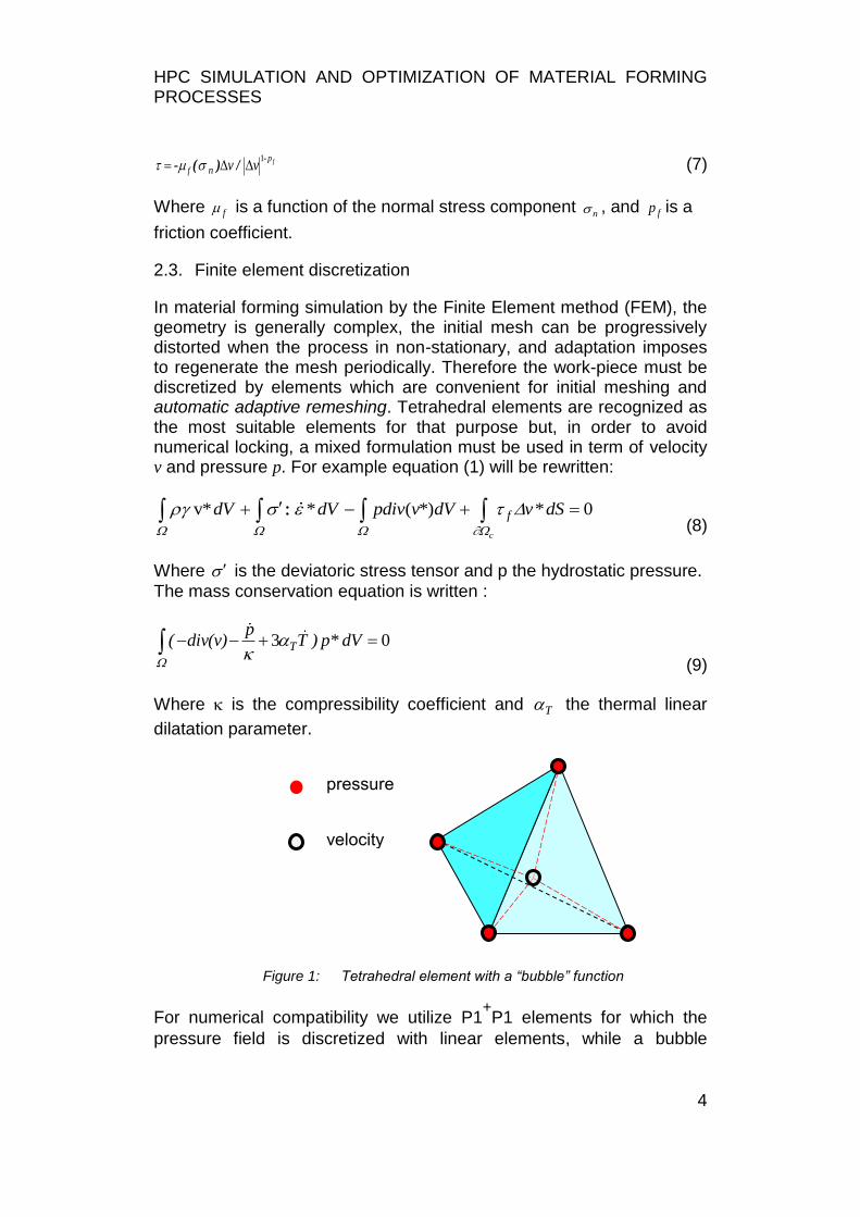
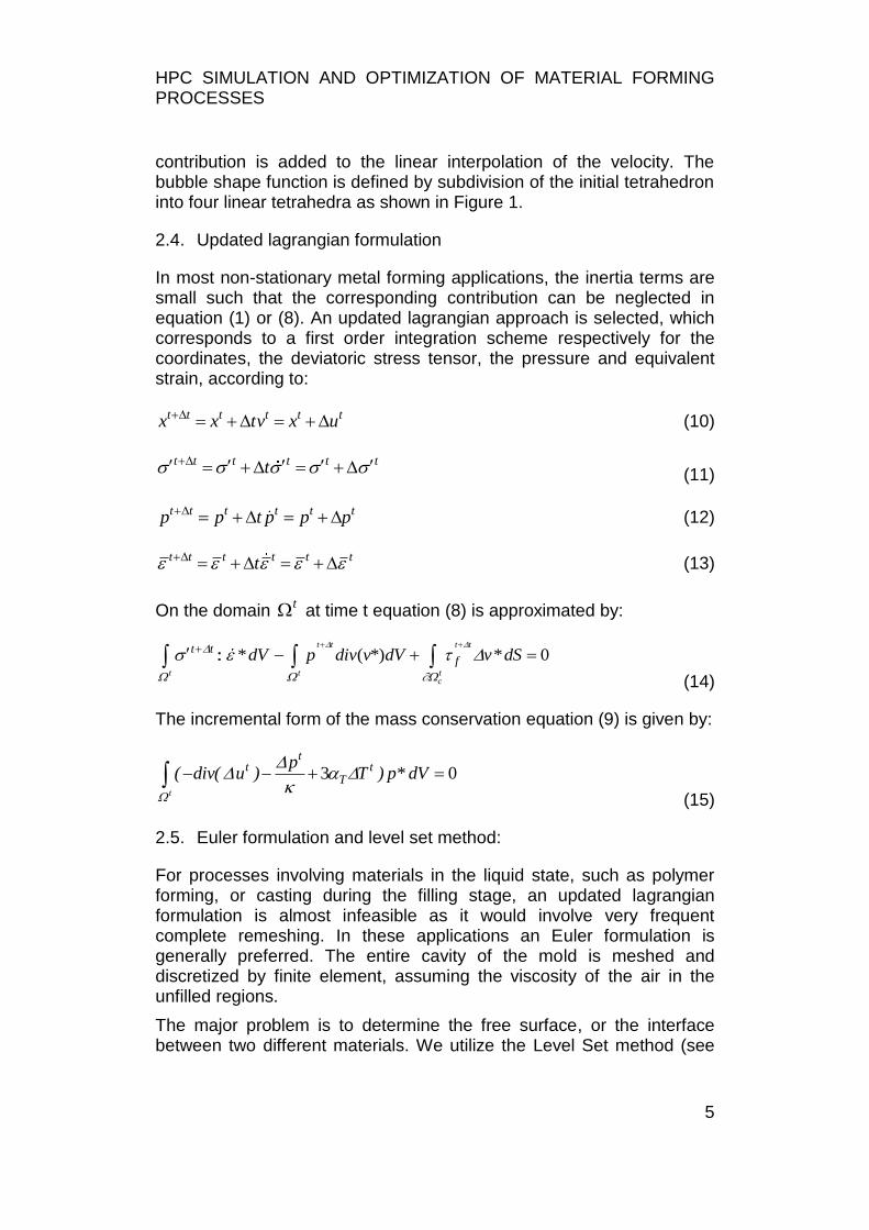
Figure 1: Tetrahedral element with a “bubble” function
For numerical compatibility we utilize P1+P1 elements for which the
pressure field is discretized with linear elements, while a bubble
pressure
velocity
HPC SIMULATION AND OPTIMIZATION OF MATERIAL FORMING PROCESSES
5
contribution is added to the linear interpolation of the velocity. The bubble shape function is defined by subdivision of the initial tetrahedron into four linear tetrahedra as shown in Figure 1.
2.4. Updated lagrangian formulation
In most non-stationary metal forming applications, the inertia terms are small such that the corresponding contribution can be neglected in equation (1) or (8). An updated lagrangian approach is selected, which corresponds to a first order integration scheme respectively for the coordinates, the deviatoric stress tensor, the pressure and equivalent strain, according to:
t t t t t tx x tv x u (10)
t t t t t tt (11)
t t t t t tp p t p p p (12)
t t t t t tt (13)
On the domain t at time t equation (8) is approximated by:
* ( *) * 0t t t t
t t tc
t tfdV p div v dV v dS
(14)
The incremental form of the mass conservation equation (9) is given by:
3 0t
tt t
T
p( div( u ) T ) p* dV
(15)
2.5. Euler formulation and level set method:
For processes involving materials in the liquid state, such as polymer forming, or casting during the filling stage, an updated lagrangian formulation is almost infeasible as it would involve very frequent complete remeshing. In these applications an Euler formulation is generally preferred. The entire cavity of the mold is meshed and discretized by finite element, assuming the viscosity of the air in the unfilled regions.
The major problem is to determine the free surface, or the interface between two different materials. We utilize the Level Set method (see
HPC SIMULATION AND OPTIMIZATION OF MATERIAL FORMING PROCESSES
6
Ville et al.), in which a scalar function ( t ,x ) is defined as the distance
from the surface of any point of the domain. Practically, at time t = 0, the distance is computed for any node of the mesh with coordinate x and interpolated on the mesh, so that the surface is defined by:
0 0( ,x ) (16)
The Level Set function is then updated using the velocity field v of the material according to:
0(t,x )
v.grad (t,x )t
(17)
In order to preserve accuracy of the computation, it is necessary to
regenerate periodically the function. As a refined mesh in the vicinity of the surface is required for accuracy, it is compulsory to rebuild the mesh in order to follow the evolution of the surface. Moreover, in order to avoid generation of too many nodes, and increase overmuch computer time, an anisotropic mesh can be built the elements of which are more refined in the direction perpendicular to the surface.
2.6. Simulation of turbulence
One of the main problematic issue in metal casting simulation lies in giving a realistic representation of the materials. Due to the low liquid metal viscosities and to the representative characteristics of the process, the Reynolds number is generally up to 106. Classical resolution finite element methods, and today accessible number of nodes meshes, make it numerically impossible to solve it with a standard Navier-Stokes equation. This is why, in recent decades, several kind of turbulence models have been developed in order to solve more and more complex CFD problems, for which casting processes are special cases. The most common approach is the RANS (or k-ε), developed in Launder and Spalding. However, this method is complex to implement as it requires additional equations to be solved, as well as additional parameters to identify.
For these reasons we have used a Large Eddy Simulation (LES) model, which is based on velocity and pressure space averaging:
u u u (18)
'p p p (19)
HPC SIMULATION AND OPTIMIZATION OF MATERIAL FORMING PROCESSES
7
Where ̅ and ̅ are the large scale values, and are the small-scales values. Only the large scale values problem is solved, while small scales are modeled as an additional viscous contribution to the Navier-Stokes equations: the turbulent viscosity. It is then computed depending on previous large-scales values, and added to the fluid molecular viscosity. Classically, turbulent viscosity is defined locally using the model published by Smagorinsky:
v
t fpuuut
u
)(2
(20)
2
Δht SC | u (21)
Where is linked to the mesh size, ̅ is the generalized shear rate
and is a constant (usually ).
Finally, a dynamic model (Germano et al.) was implemented by in order
to obtain a flow depending (François 2011). This approach enables us to have a realistic description of the flow, while using no additional parameters for resolution.
2.7. Coupling with physical parameters:
The large plastic strains involved in metals during forming processes imply microstructural changes. These changes lead to a modification of the material rheology impacting the process itself. The new challenge
for hot metal forming simulation software such as FORGE® is to predict these metallurgical evolutions taking into account the various physical mechanisms occurring during thermo-mechanical processes. Three approaches working at different length scales to predict the microstructure can be considered.
In the semi-empirical Johnson-Mehl-Avrami-Kolmogorov, or JMAK approach, a global description of the recrystallized fraction in constant conditions of strain rate and temperature is modeled by the recrystallization analytical kinetics equation.
( ) (22)
Where X is the recrystallized fraction and b and n the Avrami‟s coefficients obtained by fitting the experimental curves. Dynamic, post-dynamic and static recrystallization can be considered. The model was generalized to simulate any thermo-mechanical local loading and multi-pass processes as described in Teodorescu et al..
HPC SIMULATION AND OPTIMIZATION OF MATERIAL FORMING PROCESSES
8
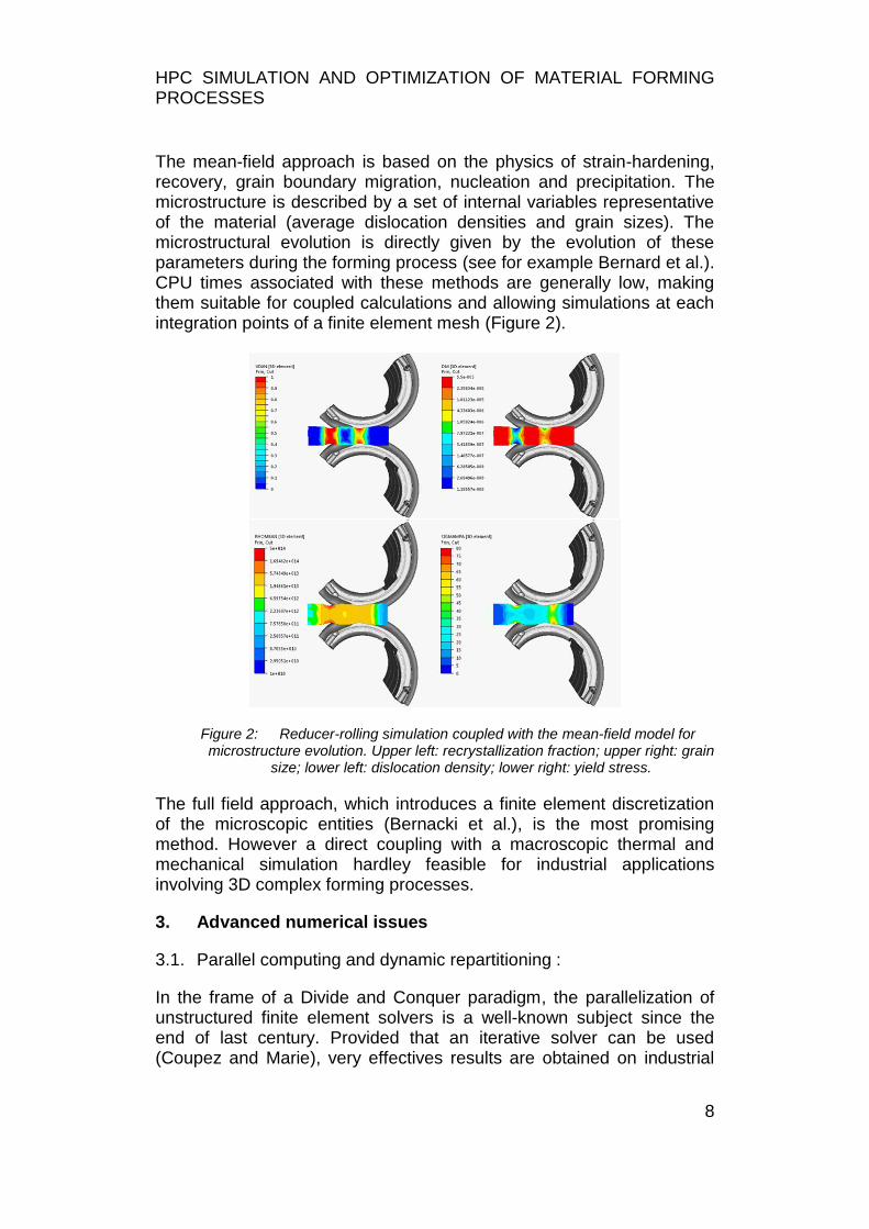
The mean-field approach is based on the physics of strain-hardening, recovery, grain boundary migration, nucleation and precipitation. The microstructure is described by a set of internal variables representative of the material (average dislocation densities and grain sizes). The microstructural evolution is directly given by the evolution of these parameters during the forming process (see for example Bernard et al.). CPU times associated with these methods are generally low, making them suitable for coupled calculations and allowing simulations at each integration points of a finite element mesh (Figure 2).
Figure 2: Reducer-rolling simulation coupled with the mean-field model for microstructure evolution. Upper left: recrystallization fraction; upper right: grain
size; lower left: dislocation density; lower right: yield stress.
The full field approach, which introduces a finite element discretization of the microscopic entities (Bernacki et al.), is the most promising method. However a direct coupling with a macroscopic thermal and mechanical simulation hardley feasible for industrial applications involving 3D complex forming processes.
3. Advanced numerical issues
3.1. Parallel computing and dynamic repartitioning :
In the frame of a Divide and Conquer paradigm, the parallelization of unstructured finite element solvers is a well-known subject since the end of last century. Provided that an iterative solver can be used (Coupez and Marie), very effectives results are obtained on industrial
HPC SIMULATION AND OPTIMIZATION OF MATERIAL FORMING PROCESSES
9
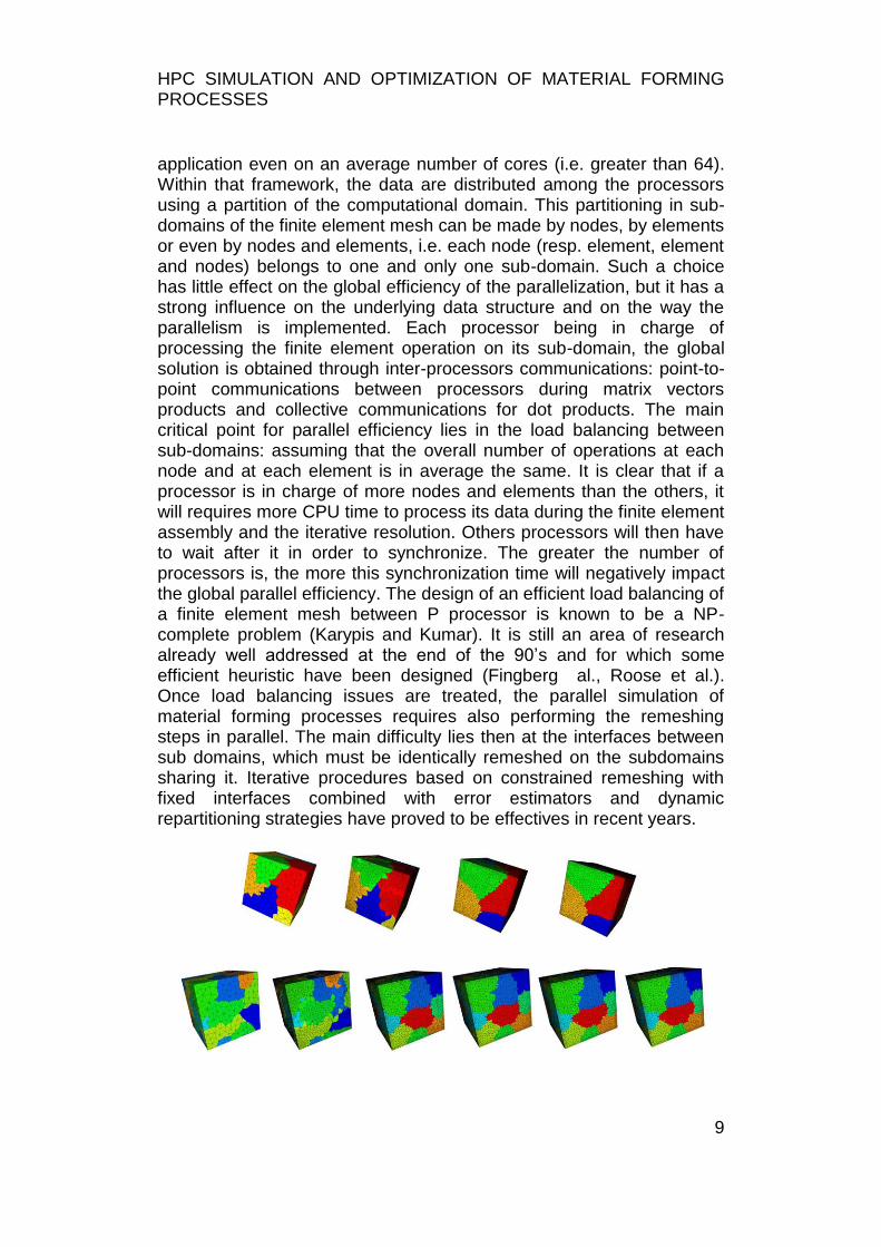
application even on an average number of cores (i.e. greater than 64). Within that framework, the data are distributed among the processors using a partition of the computational domain. This partitioning in sub-domains of the finite element mesh can be made by nodes, by elements or even by nodes and elements, i.e. each node (resp. element, element and nodes) belongs to one and only one sub-domain. Such a choice has little effect on the global efficiency of the parallelization, but it has a strong influence on the underlying data structure and on the way the parallelism is implemented. Each processor being in charge of processing the finite element operation on its sub-domain, the global solution is obtained through inter-processors communications: point-to-point communications between processors during matrix vectors products and collective communications for dot products. The main critical point for parallel efficiency lies in the load balancing between sub-domains: assuming that the overall number of operations at each node and at each element is in average the same. It is clear that if a processor is in charge of more nodes and elements than the others, it will requires more CPU time to process its data during the finite element assembly and the iterative resolution. Others processors will then have to wait after it in order to synchronize. The greater the number of processors is, the more this synchronization time will negatively impact the global parallel efficiency. The design of an efficient load balancing of a finite element mesh between P processor is known to be a NP-complete problem (Karypis and Kumar). It is still an area of research already well addressed at the end of the 90‟s and for which some efficient heuristic have been designed (Fingberg al., Roose et al.). Once load balancing issues are treated, the parallel simulation of material forming processes requires also performing the remeshing steps in parallel. The main difficulty lies then at the interfaces between sub domains, which must be identically remeshed on the subdomains sharing it. Iterative procedures based on constrained remeshing with fixed interfaces combined with error estimators and dynamic repartitioning strategies have proved to be effectives in recent years.
HPC SIMULATION AND OPTIMIZATION OF MATERIAL FORMING PROCESSES
10
Figure 3: Successive remeshing iterations with fixed interfaces and dynamic repartitioning of a cube on 8 cores (up) and on 24 cores (bottom).
To illustrate this strategy, we present in Figure 3 the remeshing of a cube of edge length 10, with an initial uniform mesh size of 1. A systematic refinement is made with a required final mesh size of 1/3, in order to easily differentiate the remeshed areas and to highlight the iterative remeshing process on 8 cores (up) and on 24 cores (bottom).
3.2. Error estimation and anisotropic remeshing:
Control of accuracy is based on an estimation of the finite element discretization error. The elements must be refined automatically in the zones where the error is higher. This is achieved by prescribing a map of estimated elements sizes and imposing that the mesh is rebuilt accordingly (Fourment and Chenot).
A refined mesh consisting in almost regular tetrahedra would generate a very large number of elements and increase excessively computational time. This drawback can be overcome by using an anisotropic mesh, having a thin dimension in the direction of high strain gradient, and an elongated one in the orthogonal directions (Gruau and Coupez). We introduce a metric matrix (Coupez) in the local principal axes according to:
21
22
23
1/ 0 0
0 1/ 0
0 0 1/
h
M h
h
(23)
Where 1 2 3, ,h h h are the thicknesses in the directions of local principle
axis of the tetrahedron.
In practice the metric tensor is composed of several contributions.
The elements would be refined in the direction of maximum gradient of the function, for example according to the strains rate tensor, we obtain
the first contribution eM to the metric.
When treating thin parts, especially in sheet metal forming, or polymer injection with small thicknesses, a “skin adaptation” depends on the
desired size sh of the mesh in the thickness; the corresponding metric is:
HPC SIMULATION AND OPTIMIZATION OF MATERIAL FORMING PROCESSES
11
2
1 22
1/ 0 01
0 0 0 axis , ,
0 0 0
ss
s
h
M n n n t th
(24)
Where n is the normal to the surface and 1 2,t t are any orthogonal
tangential unit vectors.
Local curvature of the boundary of the part is characterized by two radii
1R and 2R , with which we introduce the last contribution to the metric
tensor:
21 1 22
22
0 0 01
0 1/ 0 axis , ,
0 0 1/
cM R n t t
R
(25)
The coefficient is chosen in order to impose a minimum condition of angle variation on an element.
Finally the metric tensor is the sum of the three previous contributions:
e s cM M M M (26)
The anisotropic mesh is built according to the algorithm used for the isotropic case, but the distances are evaluated with the local metric tensor.
4. Application to industrial forming processes
4.1 Metal forming simulation
Our simulation code FORGE® was developed since 40 years ago for hot, warm or cold plastic deformation of metals. It is coupled with advanced modules of adaptive remeshing, parallel computing, physical coupling with micro structure evolution, induction heating and surface chemical treatments.
Hot forging of a crankshaft
In this example a thermal and mechanical simulation of a crankshaft of a truck was achieved with a full coupling between the tool and the work-piece. At the end of the process, and after many remeshing steps of the part only, we have about 264 000 nodes and 860 000 elements for the
HPC SIMULATION AND OPTIMIZATION OF MATERIAL FORMING PROCESSES
12
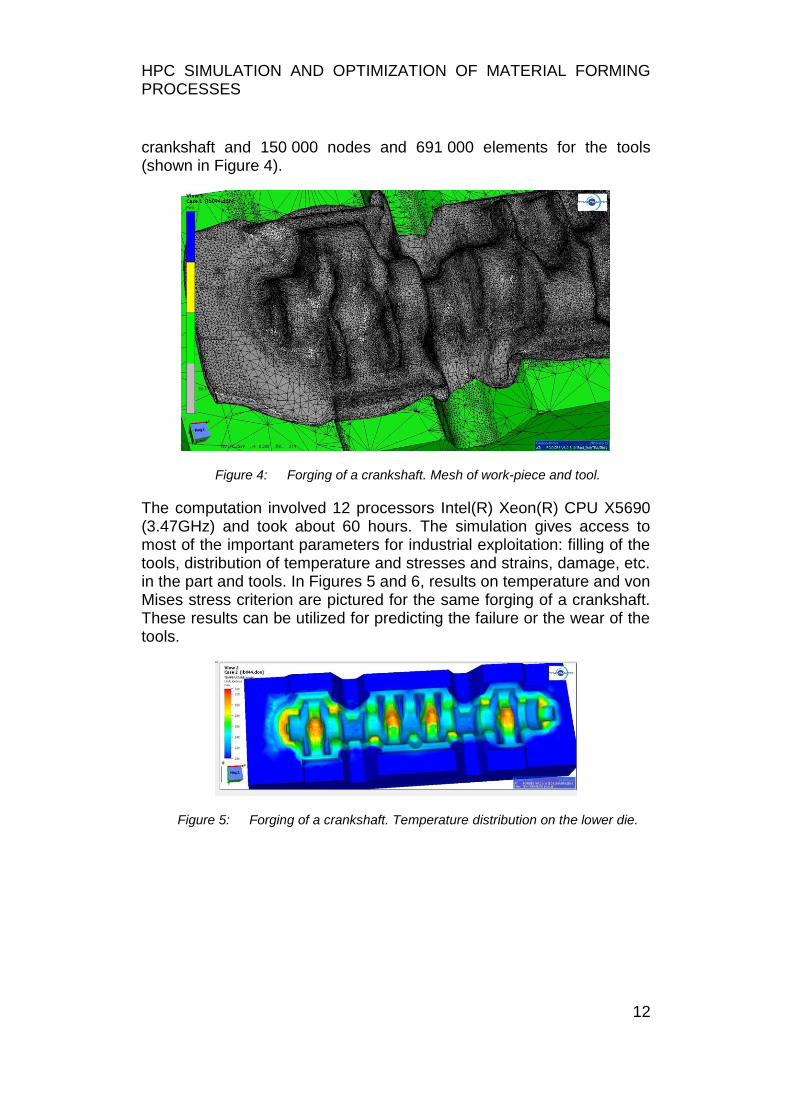
crankshaft and 150 000 nodes and 691 000 elements for the tools (shown in Figure 4).
Figure 4: Forging of a crankshaft. Mesh of work-piece and tool.
The computation involved 12 processors Intel(R) Xeon(R) CPU X5690 (3.47GHz) and took about 60 hours. The simulation gives access to most of the important parameters for industrial exploitation: filling of the tools, distribution of temperature and stresses and strains, damage, etc. in the part and tools. In Figures 5 and 6, results on temperature and von Mises stress criterion are pictured for the same forging of a crankshaft. These results can be utilized for predicting the failure or the wear of the tools.
Figure 5: Forging of a crankshaft. Temperature distribution on the lower die.
HPC SIMULATION AND OPTIMIZATION OF MATERIAL FORMING PROCESSES
13
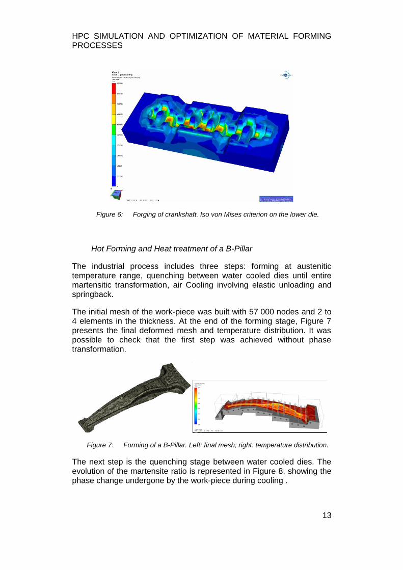
Figure 6: Forging of crankshaft. Iso von Mises criterion on the lower die.
Hot Forming and Heat treatment of a B-Pillar
The industrial process includes three steps: forming at austenitic temperature range, quenching between water cooled dies until entire martensitic transformation, air Cooling involving elastic unloading and springback.
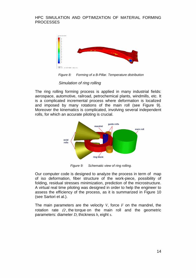
The initial mesh of the work-piece was built with 57 000 nodes and 2 to 4 elements in the thickness. At the end of the forming stage, Figure 7 presents the final deformed mesh and temperature distribution. It was possible to check that the first step was achieved without phase transformation.
Figure 7: Forming of a B-Pillar. Left: final mesh; right: temperature distribution.
The next step is the quenching stage between water cooled dies. The evolution of the martensite ratio is represented in Figure 8, showing the phase change undergone by the work-piece during cooling .
HPC SIMULATION AND OPTIMIZATION OF MATERIAL FORMING PROCESSES
14
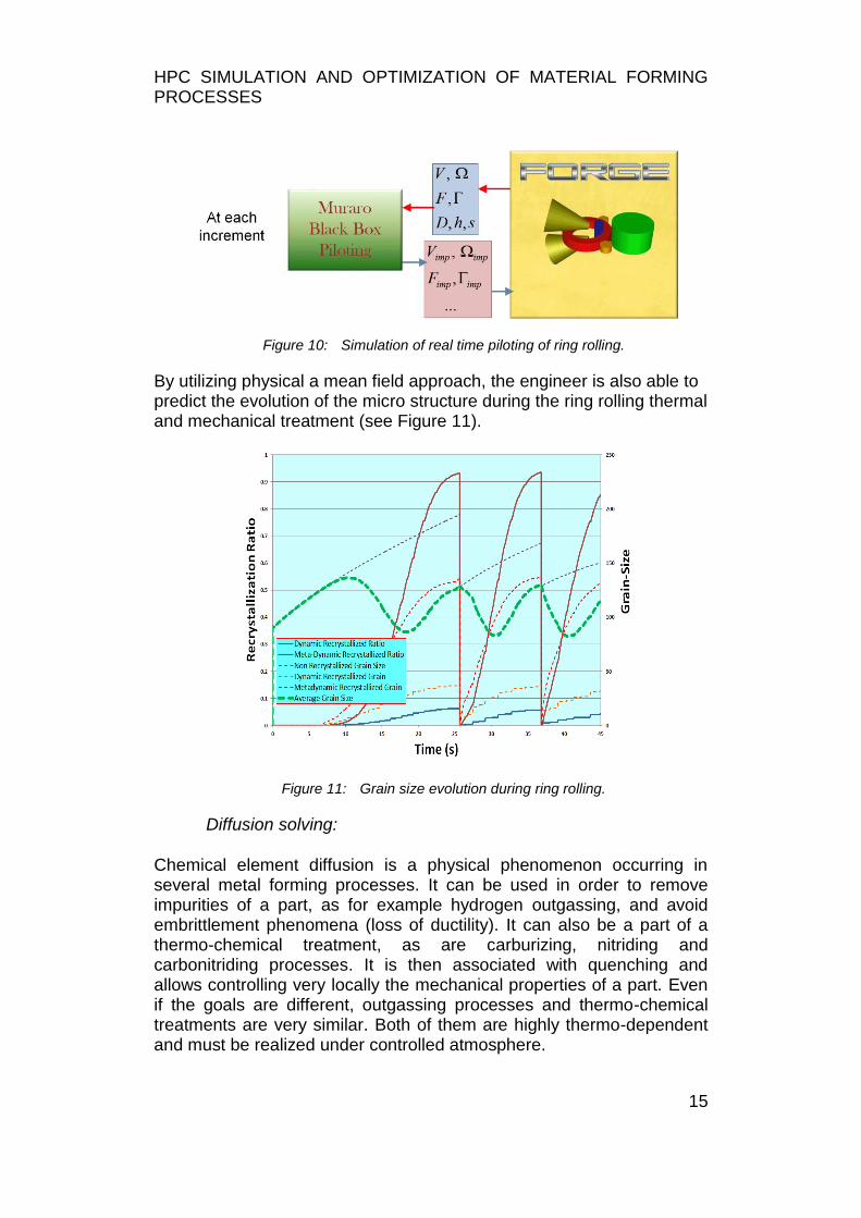
Figure 8: Forming of a B-Pillar. Temperature distribution
Simulation of ring rolling
The ring rolling forming process is applied in many industrial fields: aerospace, automotive, railroad, petrochemical plants, windmills, etc. It is a complicated incremental process where deformation is localized and imposed by many rotations of the main roll (see Figure 9). Moreover the kinematics is complicated, involving several independent rolls, for which an accurate piloting is crucial.
Figure 9: Schematic view of ring rolling.
Our computer code is designed to analyze the process in term of map of iso deformation, fiber structure of the work-piece, possibility of folding, residual stresses minimization, prediction of the microstructure. A virtual real time piloting was designed in order to help the engineer to assess the efficiency of the process, as it is summarized in Figure 10 (see Sartori et al.).
The main parameters are the velocity V, force F on the mandrel, the
rotation rate ,thetorqueon the main roll and the geometric parameters: diameter D, thickness h, eight s.
HPC SIMULATION AND OPTIMIZATION OF MATERIAL FORMING PROCESSES
15
Figure 10: Simulation of real time piloting of ring rolling.
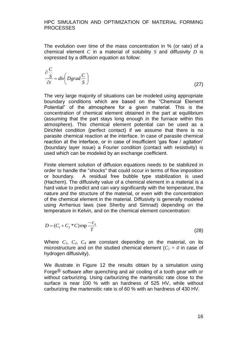
By utilizing physical a mean field approach, the engineer is also able to predict the evolution of the micro structure during the ring rolling thermal and mechanical treatment (see Figure 11).
Figure 11: Grain size evolution during ring rolling.
Diffusion solving:
Chemical element diffusion is a physical phenomenon occurring in several metal forming processes. It can be used in order to remove impurities of a part, as for example hydrogen outgassing, and avoid embrittlement phenomena (loss of ductility). It can also be a part of a thermo-chemical treatment, as are carburizing, nitriding and carbonitriding processes. It is then associated with quenching and allows controlling very locally the mechanical properties of a part. Even if the goals are different, outgassing processes and thermo-chemical treatments are very similar. Both of them are highly thermo-dependent and must be realized under controlled atmosphere.
HPC SIMULATION AND OPTIMIZATION OF MATERIAL FORMING PROCESSES
16
The evolution over time of the mass concentration in % (or rate) of a chemical element C in a material of solubility S and diffusivity D is expressed by a diffusion equation as follow:
S
CDgraddiv
t
S
C
(27)
The very large majority of situations can be modeled using appropriate boundary conditions which are based on the “Chemical Element Potential” of the atmosphere for a given material. This is the concentration of chemical element obtained in the part at equilibrium (assuming that the part stays long enough in the furnace within this atmosphere). This chemical element potential can be used as a Dirichlet condition (perfect contact) if we assume that there is no parasite chemical reaction at the interface. In case of parasite chemical reaction at the interface, or in case of insufficient „gas flow / agitation‟ (boundary layer issue) a Fourier condition (contact with resistivity) is used which can be modeled by an exchange coefficient.
Finite element solution of diffusion equations needs to be stabilized in order to handle the "shocks" that could occur in terms of flow imposition or boundary. A residual free bubble type stabilization is used (Hachem). The diffusivity value of a chemical element in a material is a hard value to predict and can vary significantly with the temperature, the nature and the structure of the material, or even with the concentration of the chemical element in the material. Diffusivity is generally modeled using Arrhenius laws (see Sherby and Simnad) depending on the temperature in Kelvin, and on the chemical element concentration:
T
cCCCD 4
21 exp)*(
(28)
Where C1, C2, C4 are constant depending on the material, on its microstructure and on the studied chemical element (C2 = 0 in case of hydrogen diffusivity).
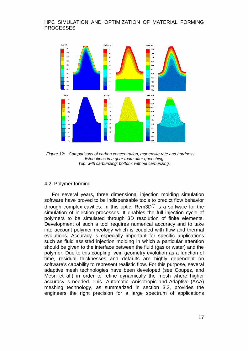
We illustrate in Figure 12 the results obtain by a simulation using
Forge® software after quenching and air cooling of a tooth gear with or without carburizing. Using carburizing the martensitic rate close to the surface is near 100 % with an hardness of 525 HV, while without carburizing the martensitic rate is of 60 % with an hardness of 430 HV.
HPC SIMULATION AND OPTIMIZATION OF MATERIAL FORMING PROCESSES
17
Figure 12: Comparisons of carbon concentration, martensite rate and hardness distributions in a gear tooth after quenching.
Top: with carburizing; bottom: without carburizing.
4.2. Polymer forming
For several years, three dimensional injection molding simulation software have proved to be indispensable tools to predict flow behavior
through complex cavities. In this optic, Rem3D® is a software for the simulation of injection processes. It enables the full injection cycle of polymers to be simulated through 3D resolution of finite elements. Development of such a tool requires numerical accuracy and to take into account polymer rheology which is coupled with flow and thermal evolutions. Accuracy is especially important for specific applications such as fluid assisted injection molding in which a particular attention should be given to the interface between the fluid (gas or water) and the polymer. Due to this coupling, vein geometry evolution as a function of time, residual thicknesses and defaults are highly dependent on software's capability to represent realistic flow. For this purpose, several adaptive mesh technologies have been developed (see Coupez, and Mesri et al.) in order to refine dynamically the mesh where higher accuracy is needed. This Automatic, Anisotropic and Adaptive (AAA) meshing technology, as summarized in section 3.2, provides the engineers the right precision for a large spectrum of applications
HPC SIMULATION AND OPTIMIZATION OF MATERIAL FORMING PROCESSES
18
(processes and geometries), within a reasonable computation time, compatible with a 6 cores computer.
Full 3D temperature description
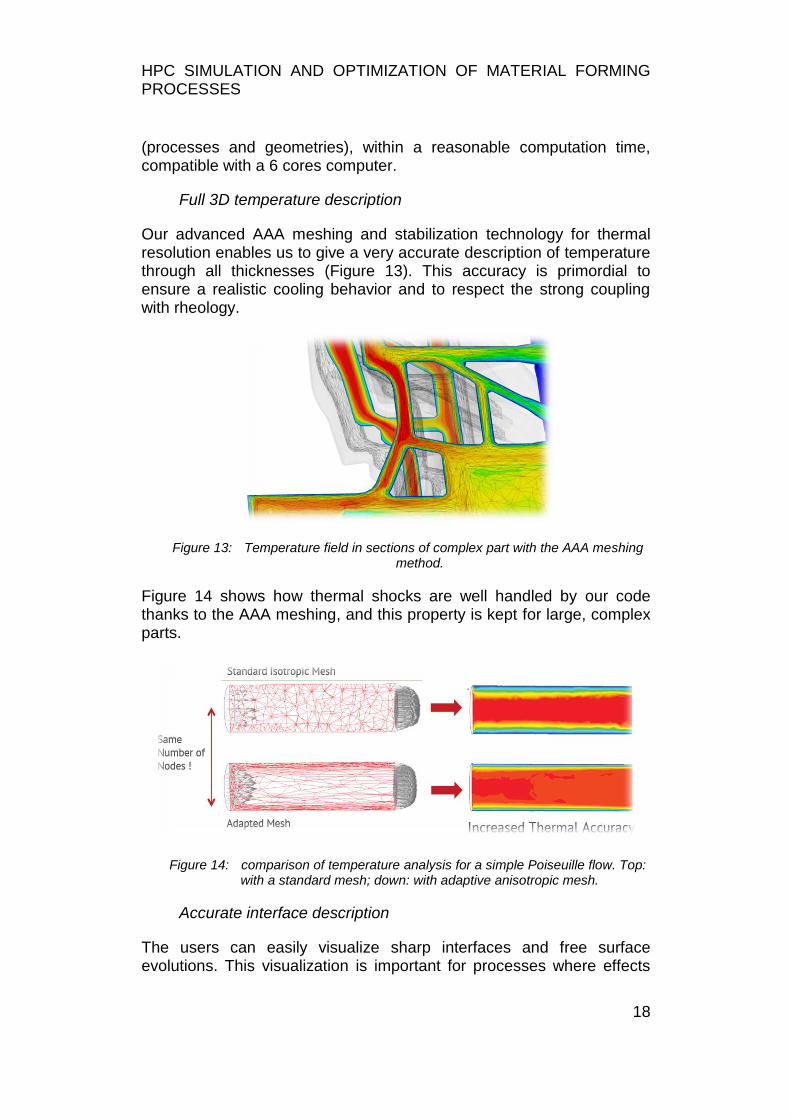
Our advanced AAA meshing and stabilization technology for thermal resolution enables us to give a very accurate description of temperature through all thicknesses (Figure 13). This accuracy is primordial to ensure a realistic cooling behavior and to respect the strong coupling with rheology.
Figure 13: Temperature field in sections of complex part with the AAA meshing method.
Figure 14 shows how thermal shocks are well handled by our code thanks to the AAA meshing, and this property is kept for large, complex parts.
Figure 14: comparison of temperature analysis for a simple Poiseuille flow. Top: with a standard mesh; down: with adaptive anisotropic mesh.
Accurate interface description
The users can easily visualize sharp interfaces and free surface evolutions. This visualization is important for processes where effects
HPC SIMULATION AND OPTIMIZATION OF MATERIAL FORMING PROCESSES
19
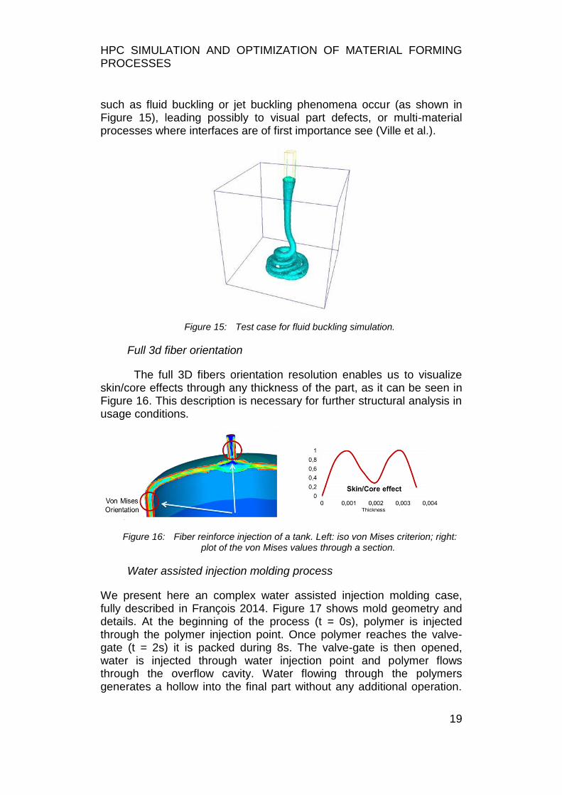
such as fluid buckling or jet buckling phenomena occur (as shown in Figure 15), leading possibly to visual part defects, or multi-material processes where interfaces are of first importance see (Ville et al.).
Figure 15: Test case for fluid buckling simulation.
Full 3d fiber orientation
The full 3D fibers orientation resolution enables us to visualize skin/core effects through any thickness of the part, as it can be seen in Figure 16. This description is necessary for further structural analysis in usage conditions.
Figure 16: Fiber reinforce injection of a tank. Left: iso von Mises criterion; right: plot of the von Mises values through a section.
Water assisted injection molding process
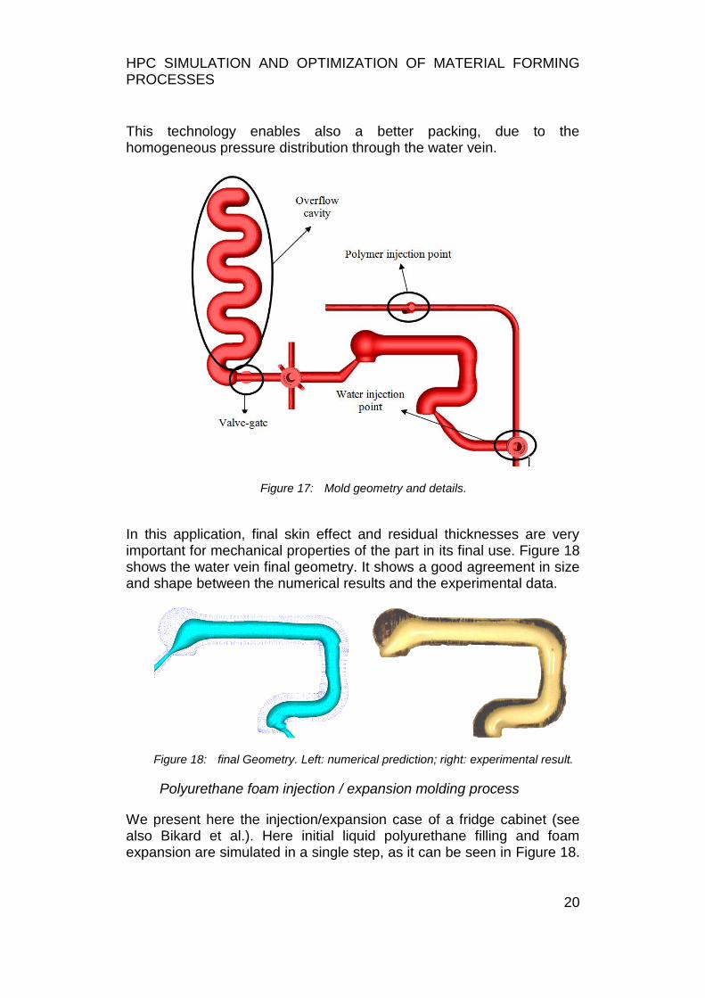
We present here an complex water assisted injection molding case, fully described in François 2014. Figure 17 shows mold geometry and details. At the beginning of the process (t = 0s), polymer is injected through the polymer injection point. Once polymer reaches the valve-gate (t = 2s) it is packed during 8s. The valve-gate is then opened, water is injected through water injection point and polymer flows through the overflow cavity. Water flowing through the polymers generates a hollow into the final part without any additional operation.
HPC SIMULATION AND OPTIMIZATION OF MATERIAL FORMING PROCESSES
20
This technology enables also a better packing, due to the homogeneous pressure distribution through the water vein.
Figure 17: Mold geometry and details.
In this application, final skin effect and residual thicknesses are very important for mechanical properties of the part in its final use. Figure 18 shows the water vein final geometry. It shows a good agreement in size and shape between the numerical results and the experimental data.
Figure 18: final Geometry. Left: numerical prediction; right: experimental result.
Polyurethane foam injection / expansion molding process
We present here the injection/expansion case of a fridge cabinet (see also Bikard et al.). Here initial liquid polyurethane filling and foam expansion are simulated in a single step, as it can be seen in Figure 18.
HPC SIMULATION AND OPTIMIZATION OF MATERIAL FORMING PROCESSES
21
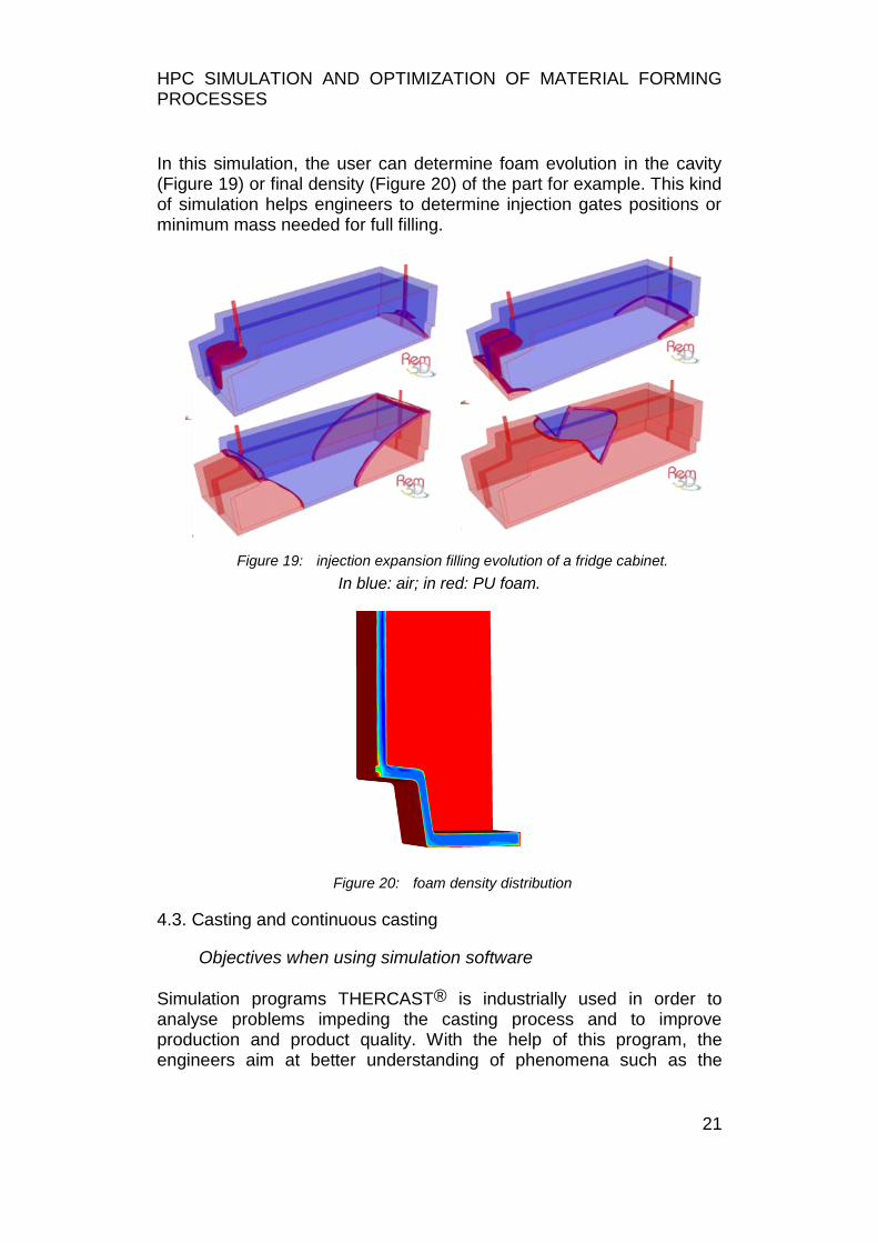
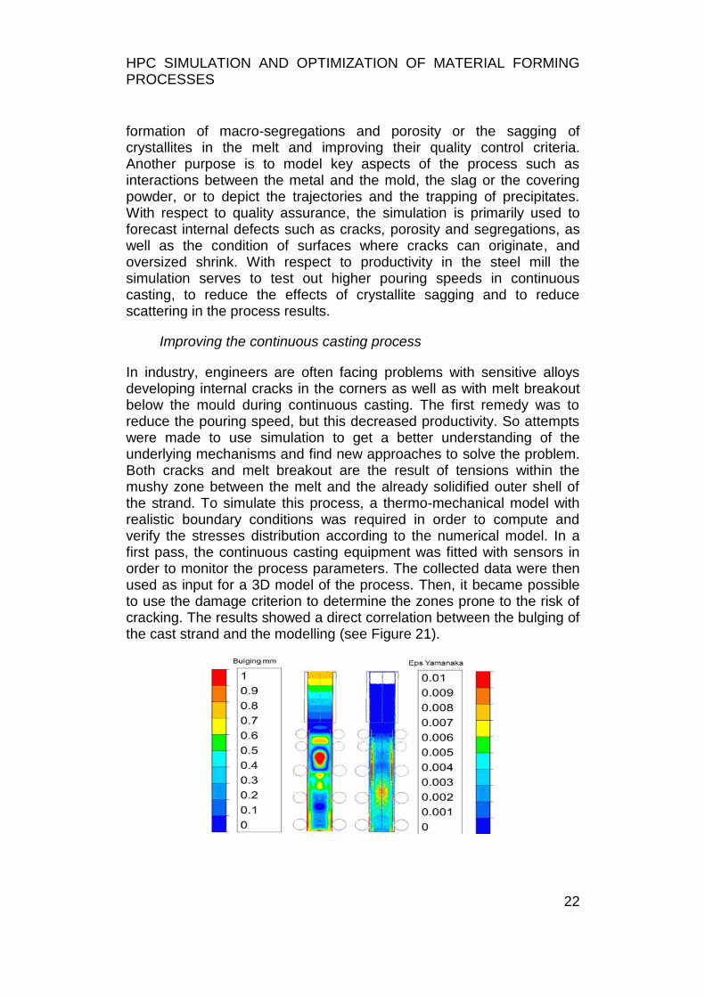
In this simulation, the user can determine foam evolution in the cavity (Figure 19) or final density (Figure 20) of the part for example. This kind of simulation helps engineers to determine injection gates positions or minimum mass needed for full filling.
Figure 19: injection expansion filling evolution of a fridge cabinet.
In blue: air; in red: PU foam.
Figure 20: foam density distribution
4.3. Casting and continuous casting
Objectives when using simulation software
Simulation programs THERCAST® is industrially used in order to analyse problems impeding the casting process and to improve production and product quality. With the help of this program, the engineers aim at better understanding of phenomena such as the
HPC SIMULATION AND OPTIMIZATION OF MATERIAL FORMING PROCESSES
22
formation of macro-segregations and porosity or the sagging of crystallites in the melt and improving their quality control criteria. Another purpose is to model key aspects of the process such as interactions between the metal and the mold, the slag or the covering powder, or to depict the trajectories and the trapping of precipitates. With respect to quality assurance, the simulation is primarily used to forecast internal defects such as cracks, porosity and segregations, as well as the condition of surfaces where cracks can originate, and oversized shrink. With respect to productivity in the steel mill the simulation serves to test out higher pouring speeds in continuous casting, to reduce the effects of crystallite sagging and to reduce scattering in the process results.
Improving the continuous casting process
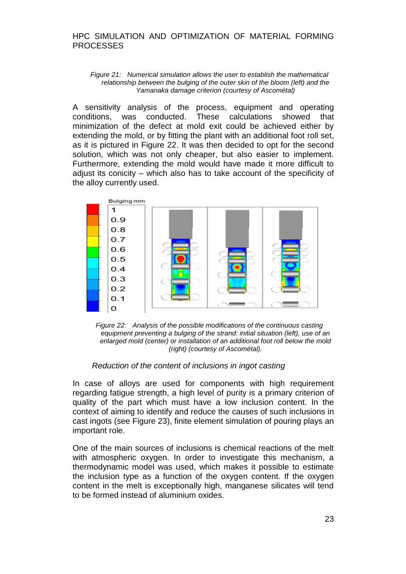
In industry, engineers are often facing problems with sensitive alloys developing internal cracks in the corners as well as with melt breakout below the mould during continuous casting. The first remedy was to reduce the pouring speed, but this decreased productivity. So attempts were made to use simulation to get a better understanding of the underlying mechanisms and find new approaches to solve the problem. Both cracks and melt breakout are the result of tensions within the mushy zone between the melt and the already solidified outer shell of the strand. To simulate this process, a thermo-mechanical model with realistic boundary conditions was required in order to compute and verify the stresses distribution according to the numerical model. In a first pass, the continuous casting equipment was fitted with sensors in order to monitor the process parameters. The collected data were then used as input for a 3D model of the process. Then, it became possible to use the damage criterion to determine the zones prone to the risk of cracking. The results showed a direct correlation between the bulging of the cast strand and the modelling (see Figure 21).
HPC SIMULATION AND OPTIMIZATION OF MATERIAL FORMING PROCESSES
23
Figure 21: Numerical simulation allows the user to establish the mathematical relationship between the bulging of the outer skin of the bloom (left) and the
Yamanaka damage criterion (courtesy of Ascométal)
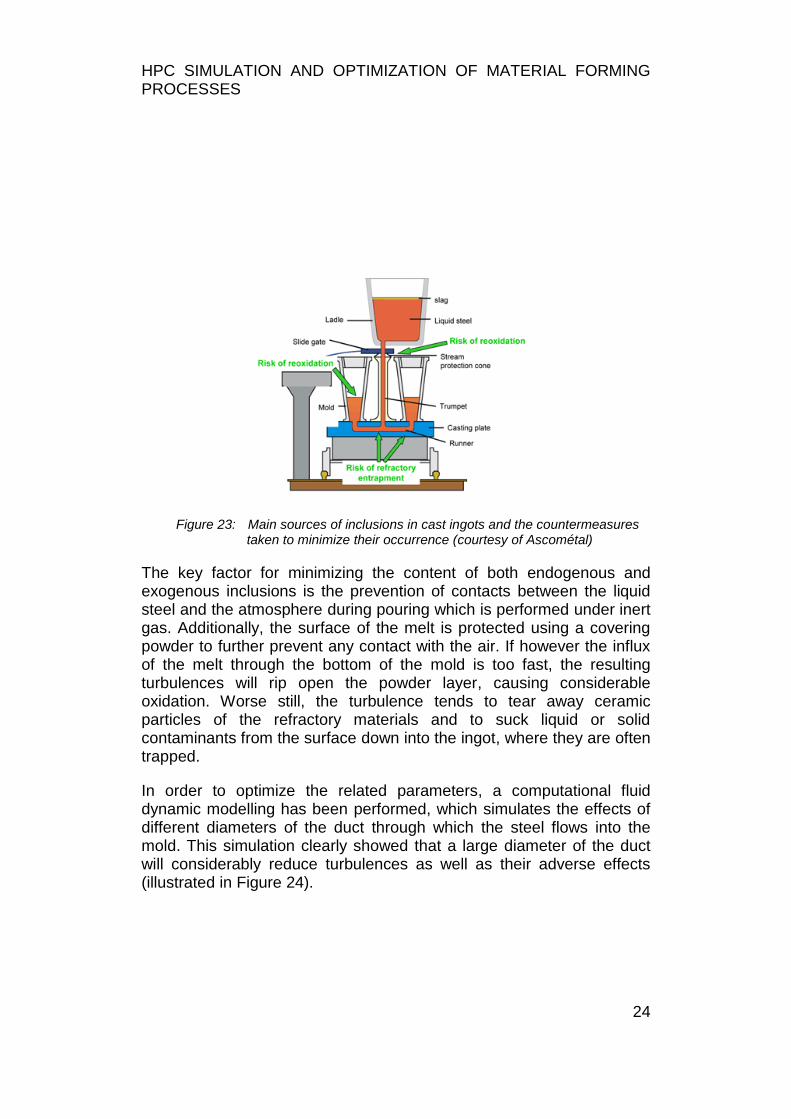
A sensitivity analysis of the process, equipment and operating conditions, was conducted. These calculations showed that minimization of the defect at mold exit could be achieved either by extending the mold, or by fitting the plant with an additional foot roll set, as it is pictured in Figure 22. It was then decided to opt for the second solution, which was not only cheaper, but also easier to implement. Furthermore, extending the mold would have made it more difficult to adjust its conicity – which also has to take account of the specificity of the alloy currently used.
Figure 22: Analysis of the possible modifications of the continuous casting equipment preventing a bulging of the strand: initial situation (left), use of an enlarged mold (center) or installation of an additional foot roll below the mold
(right) (courtesy of Ascométal).
Reduction of the content of inclusions in ingot casting
In case of alloys are used for components with high requirement regarding fatigue strength, a high level of purity is a primary criterion of quality of the part which must have a low inclusion content. In the context of aiming to identify and reduce the causes of such inclusions in cast ingots (see Figure 23), finite element simulation of pouring plays an important role.
One of the main sources of inclusions is chemical reactions of the melt with atmospheric oxygen. In order to investigate this mechanism, a thermodynamic model was used, which makes it possible to estimate the inclusion type as a function of the oxygen content. If the oxygen content in the melt is exceptionally high, manganese silicates will tend to be formed instead of aluminium oxides.
HPC SIMULATION AND OPTIMIZATION OF MATERIAL FORMING PROCESSES
24
Figure 23: Main sources of inclusions in cast ingots and the countermeasures taken to minimize their occurrence (courtesy of Ascométal)
The key factor for minimizing the content of both endogenous and exogenous inclusions is the prevention of contacts between the liquid steel and the atmosphere during pouring which is performed under inert gas. Additionally, the surface of the melt is protected using a covering powder to further prevent any contact with the air. If however the influx of the melt through the bottom of the mold is too fast, the resulting turbulences will rip open the powder layer, causing considerable oxidation. Worse still, the turbulence tends to tear away ceramic particles of the refractory materials and to suck liquid or solid contaminants from the surface down into the ingot, where they are often trapped.
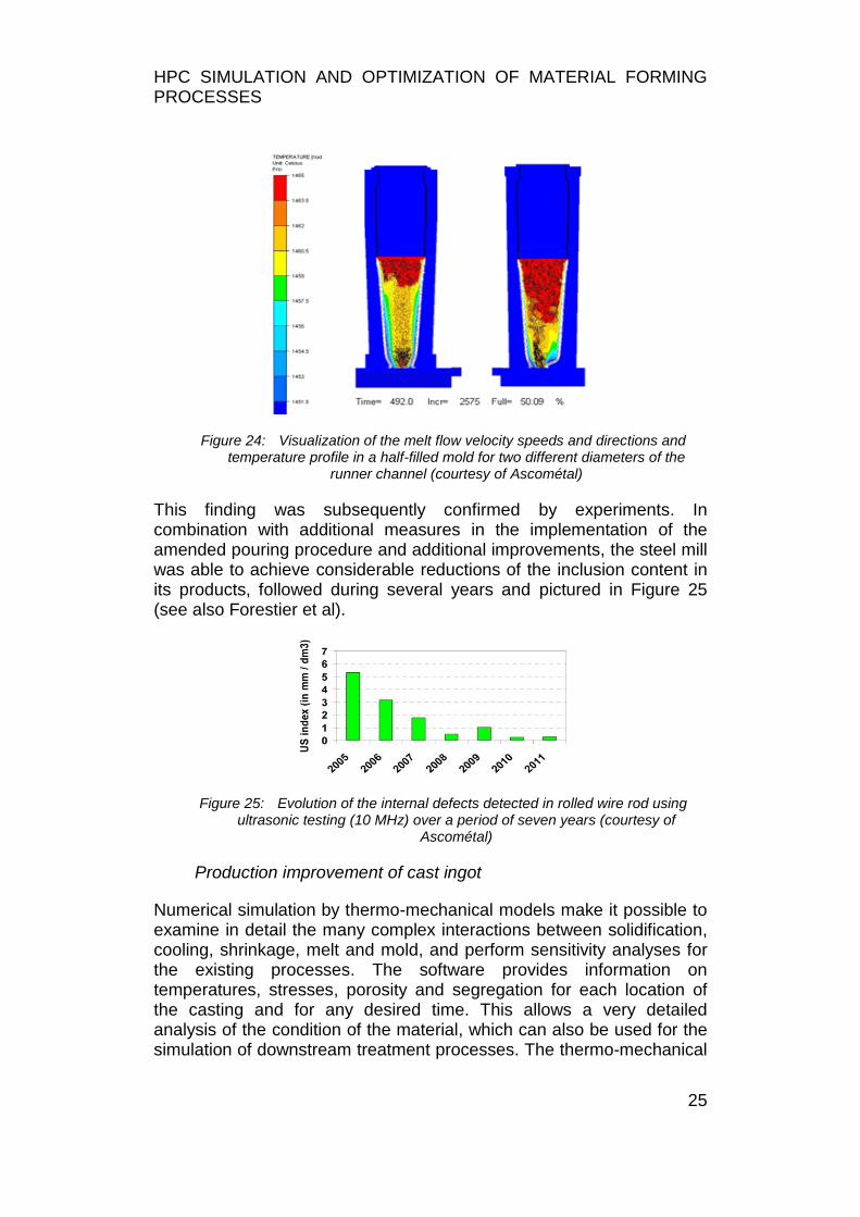
In order to optimize the related parameters, a computational fluid dynamic modelling has been performed, which simulates the effects of different diameters of the duct through which the steel flows into the mold. This simulation clearly showed that a large diameter of the duct will considerably reduce turbulences as well as their adverse effects (illustrated in Figure 24).
HPC SIMULATION AND OPTIMIZATION OF MATERIAL FORMING PROCESSES
25
Figure 24: Visualization of the melt flow velocity speeds and directions and temperature profile in a half-filled mold for two different diameters of the
runner channel (courtesy of Ascométal)
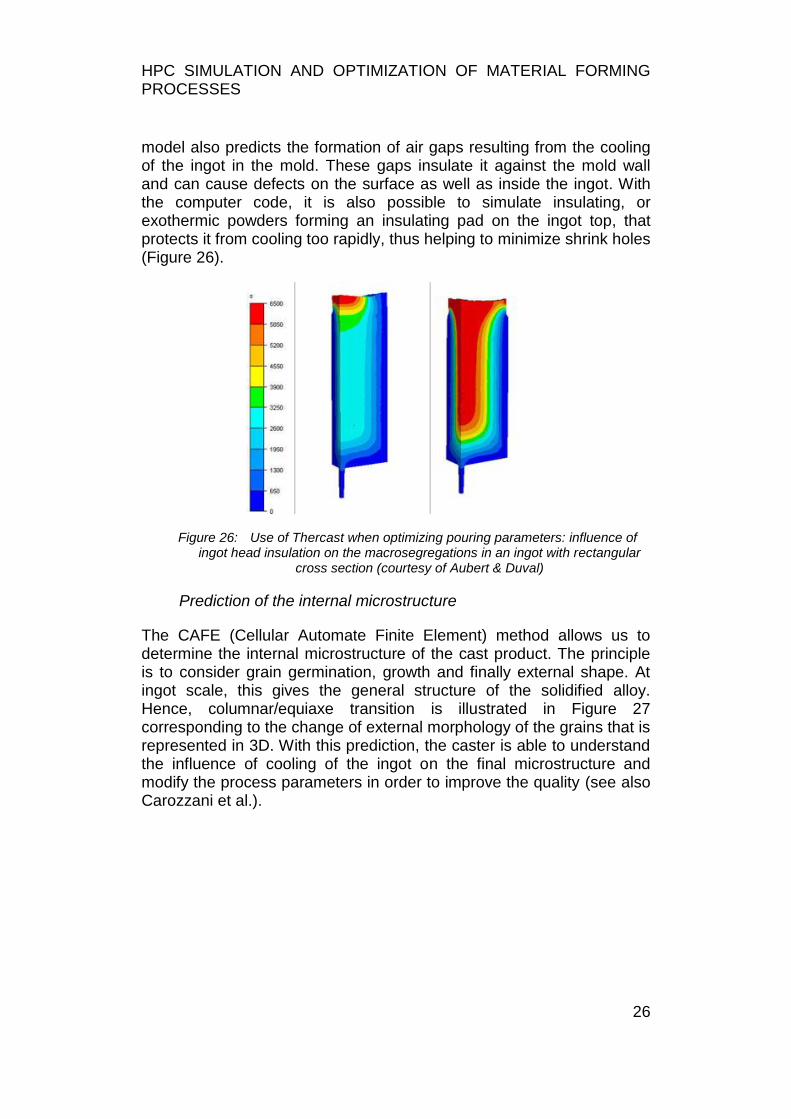
This finding was subsequently confirmed by experiments. In combination with additional measures in the implementation of the amended pouring procedure and additional improvements, the steel mill was able to achieve considerable reductions of the inclusion content in its products, followed during several years and pictured in Figure 25 (see also Forestier et al).
Figure 25: Evolution of the internal defects detected in rolled wire rod using ultrasonic testing (10 MHz) over a period of seven years (courtesy of
Ascométal)
Production improvement of cast ingot
Numerical simulation by thermo-mechanical models make it possible to examine in detail the many complex interactions between solidification, cooling, shrinkage, melt and mold, and perform sensitivity analyses for the existing processes. The software provides information on temperatures, stresses, porosity and segregation for each location of the casting and for any desired time. This allows a very detailed analysis of the condition of the material, which can also be used for the simulation of downstream treatment processes. The thermo-mechanical
HPC SIMULATION AND OPTIMIZATION OF MATERIAL FORMING PROCESSES
26
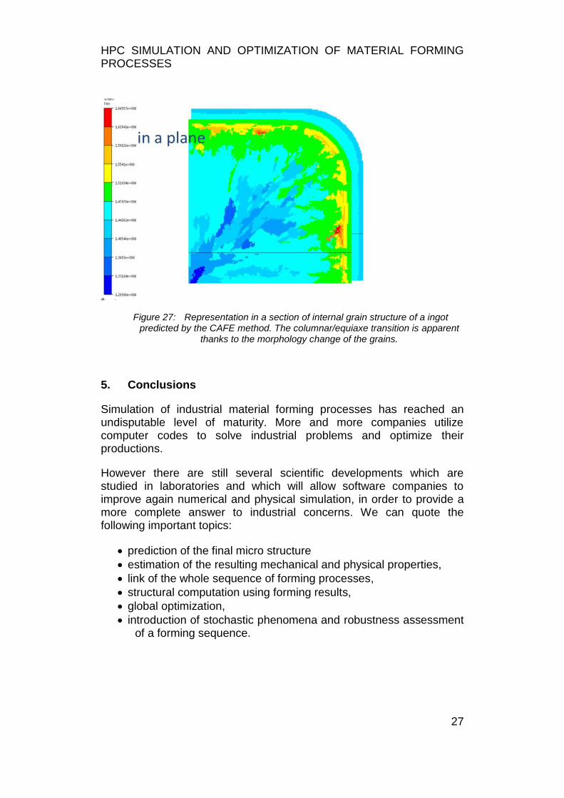
model also predicts the formation of air gaps resulting from the cooling of the ingot in the mold. These gaps insulate it against the mold wall and can cause defects on the surface as well as inside the ingot. With the computer code, it is also possible to simulate insulating, or exothermic powders forming an insulating pad on the ingot top, that protects it from cooling too rapidly, thus helping to minimize shrink holes (Figure 26).
Figure 26: Use of Thercast when optimizing pouring parameters: influence of ingot head insulation on the macrosegregations in an ingot with rectangular
cross section (courtesy of Aubert & Duval)
Prediction of the internal microstructure
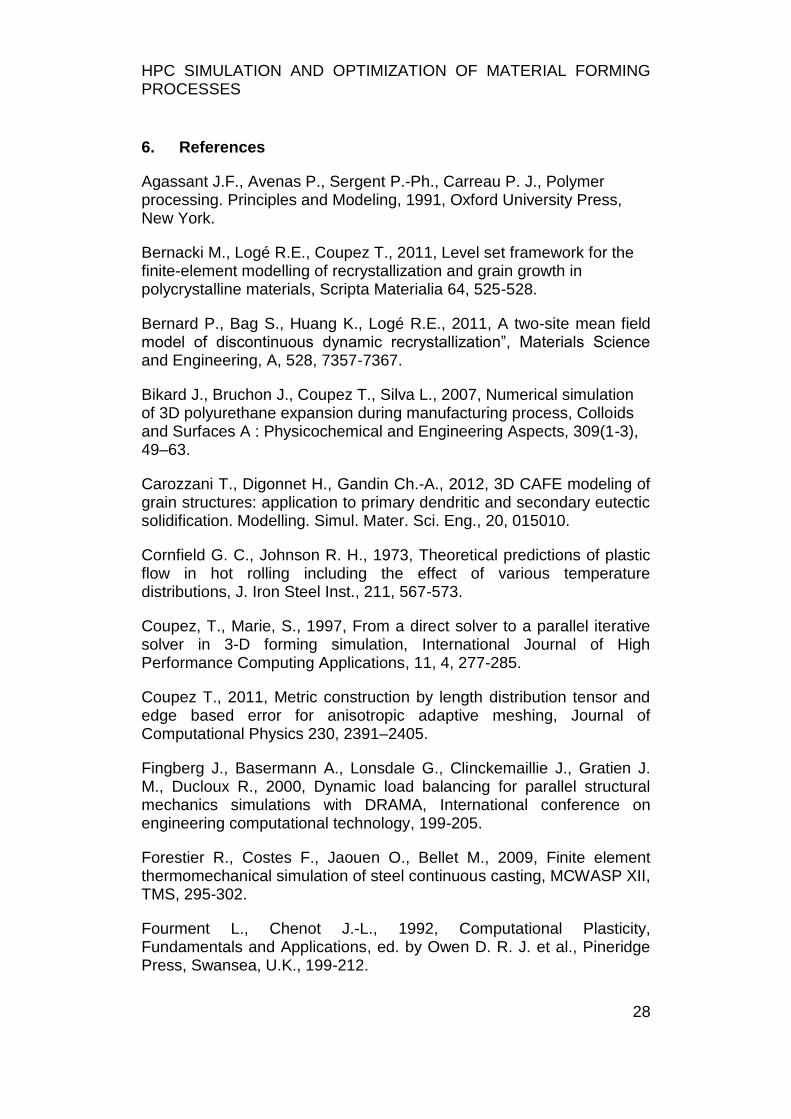
The CAFE (Cellular Automate Finite Element) method allows us to determine the internal microstructure of the cast product. The principle is to consider grain germination, growth and finally external shape. At ingot scale, this gives the general structure of the solidified alloy. Hence, columnar/equiaxe transition is illustrated in Figure 27 corresponding to the change of external morphology of the grains that is represented in 3D. With this prediction, the caster is able to understand the influence of cooling of the ingot on the final microstructure and modify the process parameters in order to improve the quality (see also Carozzani et al.).
HPC SIMULATION AND OPTIMIZATION OF MATERIAL FORMING PROCESSES
27
Figure 27: Representation in a section of internal grain structure of a ingot predicted by the CAFE method. The columnar/equiaxe transition is apparent
thanks to the morphology change of the grains.
5. Conclusions
Simulation of industrial material forming processes has reached an undisputable level of maturity. More and more companies utilize computer codes to solve industrial problems and optimize their productions.
However there are still several scientific developments which are studied in laboratories and which will allow software companies to improve again numerical and physical simulation, in order to provide a more complete answer to industrial concerns. We can quote the following important topics:
prediction of the final micro structure
estimation of the resulting mechanical and physical properties,
link of the whole sequence of forming processes,
structural computation using forming results,
global optimization,
introduction of stochastic phenomena and robustness assessment of a forming sequence.
HPC SIMULATION AND OPTIMIZATION OF MATERIAL FORMING PROCESSES
28
6. References
Agassant J.F., Avenas P., Sergent P.-Ph., Carreau P. J., Polymer processing. Principles and Modeling, 1991, Oxford University Press, New York.
Bernacki M., Logé R.E., Coupez T., 2011, Level set framework for the finite-element modelling of recrystallization and grain growth in polycrystalline materials, Scripta Materialia 64, 525-528.
Bernard P., Bag S., Huang K., Logé R.E., 2011, A two-site mean field model of discontinuous dynamic recrystallization”, Materials Science and Engineering, A, 528, 7357-7367.
Bikard J., Bruchon J., Coupez T., Silva L., 2007, Numerical simulation of 3D polyurethane expansion during manufacturing process, Colloids and Surfaces A : Physicochemical and Engineering Aspects, 309(1-3), 49–63.
Carozzani T., Digonnet H., Gandin Ch.-A., 2012, 3D CAFE modeling of grain structures: application to primary dendritic and secondary eutectic solidification. Modelling. Simul. Mater. Sci. Eng., 20, 015010.
Cornfield G. C., Johnson R. H., 1973, Theoretical predictions of plastic flow in hot rolling including the effect of various temperature distributions, J. Iron Steel Inst., 211, 567-573.
Coupez, T., Marie, S., 1997, From a direct solver to a parallel iterative solver in 3-D forming simulation, International Journal of High Performance Computing Applications, 11, 4, 277-285.
Coupez T., 2011, Metric construction by length distribution tensor and edge based error for anisotropic adaptive meshing, Journal of Computational Physics 230, 2391–2405.
Fingberg J., Basermann A., Lonsdale G., Clinckemaillie J., Gratien J. M., Ducloux R., 2000, Dynamic load balancing for parallel structural mechanics simulations with DRAMA, International conference on engineering computational technology, 199-205.
Forestier R., Costes F., Jaouen O., Bellet M., 2009, Finite element thermomechanical simulation of steel continuous casting, MCWASP XII, TMS, 295-302.
Fourment L., Chenot J.-L., 1992, Computational Plasticity, Fundamentals and Applications, ed. by Owen D. R. J. et al., Pineridge Press, Swansea, U.K., 199-212.
HPC SIMULATION AND OPTIMIZATION OF MATERIAL FORMING PROCESSES
29
François G., Stabilized finite elements for high Reynold the filling stage in casting, 2011, PhD Thesis, Ecole Nationale Supérieure des Mines de Paris, Sophia-Antipolis, France (in French).
François G., 2014, Multi criteria adaptive meshing for polymers
processing in Rem3D®, 30th Polymer Processing Society.
Germano M., Piomelli U, Moin P., Cabot W. H., 1991, A dynamic subgrid-scale eddy viscosity model. Phys. Fluids, A 3, 1760.
Gruau C., Coupez T., 2005, 3D tetrahedral, unstructured and anisotropic mesh generation with adaptation to natural and multidomain metric, Comp. Meth in Appl. Mech and Engrg, 194, 48-49, 4951-4976.
Hieber C.A., Shen S. F., 1980, A finite-element/finite-difference simulation of the injection-molding filling process, Journal of Non-Newtonian Fluid Mechanics, 7, 1, 1–32
Iwata K., Osakada K., Fujino S., 1972, Analysis of hydrostatic extrusion by the finite element method., Transactions of the ASME, Ser. B, 94-2, 697-703.
Karypis G., Kumar V., 1995, Analysis of multilevel graph partitioning, Proceedings of the 1995 ACM/IEEE conference on Supercomputing, 29.
Lasne P., Settefrati A., Barbelet M., 2013, Simulation of the Ring Rolling Process taking into account Automatic Motion Control - Prediction of Microstructure, XII International Conference on Computational Plasticity. Fundamentals and Applications.
Launder B. E., Spalding D. B., 1974, The numerical computation of turbulent flows, Computer Methods in Applied Mechanics and Engineering, 3(2): 269-289.
Lee C. H., Kobayashi S., 1973, New Solutions to Rigid-Plastic Deformation Problems Using a Matrix Method, J. Eng. Ind., 95, 865.
Menges G., Masberg U., Gesenhue B., Berry C., Numerical simulation of three-dimensional non-newtonian flow in thermoplastic extrusion dies with finite element methods, 1984, Numerical analysis of forming processes, Edited by Pittman, J. F. T. et al., John Wiley and Sons, 307-350.
Mesri Y., Zerguine W., Digonnet H., Silva L., Coupez T., 2008, Dynamic Parallel Adaption for Three Dimensional Unstructured Meshes: Application to Interface Tracking., Rao V. Garimella, 17th International
HPC SIMULATION AND OPTIMIZATION OF MATERIAL FORMING PROCESSES
30
Meshing Roundtable, Oct 2008, Pittsburgh, PA, United States. Springer, 195-212.
Pittman J. F. T., Nakazawa S., Finite element analysis of polymer processing operations, 1984, Numerical analysis of forming processes, Edited by Pittman, J. F. T. et al., John Wiley and Sons, 165-218.
Roose D., Maerten B., Coupez T., Digonnet H., Hartman U., Basermann A., Fingberg J., Lonsdale G., 2000, Repartitionning algorithm of the DRAMA library, Appl. Math. Modelling, 25, 83-98.
Sartori A ., Lasne P., Gabrielli M., 2014, External Piloting with FORGE for Ring Rolling Application: A collaboration between Muraro and Transvalor, Proceedings of the international CAE Conference, Pacengo del Garda (Verona) – Italy.
Sherby, O.D., Simnad M.T., 1961, Prediction of atomic mobility in metallic systems, Trans. Am. Soc. Metals,54, 227.
Smagorinsky J., 1963, General circulation experiments with primitive equations, Mon. Weather Rev., 91, 99-164,.
Surdon G., Chenot J.-L., 1987, Finite element calculation of three-dimensional hot forging, Int. J. Numer. Meth. Eng., 24, 2107-2117
Teodorescu M., Lasne P., Logé R., 2007, Modeling recrystallization for 3D multi-pass forming processes, Materials Science Forum, 558-559, 1201-1206.
Ville L., Silva L., Coupez T., 2011, Convected level set method for the numerical simulation of fluid buckling, International Journal for Numerical Methods in Fluids, 324–344.
Wagoner R. H., Chenot J.-L., 2001, Metal forming analysis, Cambridge, Cambridge University Press
Zienkiewicz O. C., Godbole K., 1974, Flow of Plastic and Visco-Plastic Solids with Special Reference to Extrusion and Forming Processes, Int. J. Numer. Meth. Eng., 8, 1, 1-16.