Embed Size (px)
Citation preview

HPC-250HT
Photovoltaic Inverter
User Manual

USER MANUAL of HPC-250HT
PE07019-022-B Page 2 of 69
Table of Contents 1 NOTES ON THIS MANUAL ...................................................................................................................... 4
1.1 TARGET GROUP AND APPLICABILITY ..................................................................................................... 4
2 SAFETY INSTRUCTIONS ......................................................................................................................... 5
3 DESCRIPTION OF THE HPC-250HT ...................................................................................................... 6
3.1 IDENTIFYING THE HPC-250HT .............................................................................................................. 63.2 THE HPC-250HT’S CONTROL ELEMENTS .............................................................................................. 6
3.2.1 AC Side Rotary Handle Circuit Breaker ........................................................................................... 73.2.2 Emergency-Off Button (-S2) .............................................................................................................. 83.2.3 Start / Stop Key Operated Spring-Return Switch (-S1) ..................................................................... 93.2.4 HPC-250HT User Interface ............................................................................................................ 103.2.5 Light Indicators (-H1, -H2) ............................................................................................................. 11
3.3 OPERATING MODES .............................................................................................................................. 113.3.1 Operating Modes of the HPC-250HT ............................................................................................. 12
3.3.1.1 Automatic Startup ................................................................................................................................... 123.3.1.2 Waiting after Grid Failure ...................................................................................................................... 133.3.1.3 Testing of String Voltage ....................................................................................................................... 143.3.1.4 Grid Voltage and Frequency Test ........................................................................................................... 153.3.1.5 Connecting to Solar Arrays .................................................................................................................... 163.3.1.6 Connecting to Grid, Test of String Voltage ............................................................................................ 173.3.1.7 Feeding to the Grid (4) ........................................................................................................................... 183.3.1.8 Shut Down (5) ........................................................................................................................................ 203.3.1.9 Disconnecting from Grid ........................................................................................................................ 213.3.1.10 Offline .................................................................................................................................................... 22
4 HPC-250HT CONTROL OPERATION .................................................................................................. 23
4.1 HPC-250HT CONTROL MENU ............................................................................................................. 234.2 OVERVIEW OF THE MENU ..................................................................................................................... 25
4.2.1 Start (Brief Description) .................................................................................................................. 254.2.2 Online Info (Brief Description) ....................................................................................................... 264.2.3 Fault Handling (Brief Description) ................................................................................................. 274.2.4 Log (Brief Description) ................................................................................................................... 284.2.5 System (Brief Description) .............................................................................................................. 294.2.6 Email (Brief Description) ................................................................................................................ 304.2.7 Operator (Brief Description) .......................................................................................................... 314.2.8 Setting 1 (Brief Description) ........................................................................................................... 324.2.9 Setting 2 (Brief Description) ........................................................................................................... 334.2.10 Start (Detailed Description) ....................................................................................................... 344.2.11 Online Info (Detailed Description) ............................................................................................. 354.2.12 Fault Handling (Detailed Description) ....................................................................................... 374.2.13 Log (Detailed Description) ......................................................................................................... 384.2.14 System (Detailed Description) .................................................................................................... 394.2.15 Email (Detailed Description) ...................................................................................................... 414.2.16 Operator (Detailed Description) ................................................................................................ 424.2.17 Setting 1 (Detailed Description) ................................................................................................. 444.2.18 Setting 2 (Detailed Description) ................................................................................................. 46
4.3 OPERATOR LOGIN/LOGOUT .................................................................................................................. 474.3.1 Log ON Procedure .......................................................................................................................... 484.3.2 Add Operator Password .................................................................................................................. 484.3.3 Log OFF procedure ........................................................................................................................ 50
4.4 CHANGING DATE AND TIME ................................................................................................................. 51
5 PARAMETERS .......................................................................................................................................... 52
5.1 DESCRIPTION OF THE PARAMETER FUNCTIONS .................................................................................... 525.2 DEFAULT PARAMETER SETTINGS ......................................................................................................... 545.3 ENTERING PARAMETERS AND SETTINGS .............................................................................................. 56

USER MANUAL of HPC-250HT
PE07019-022-B Page 3 of 69
6 COMMUNICATION ................................................................................................................................. 57
6.1 ENTERING OR CHANGING EMAIL ADDRESSES ...................................................................................... 576.2 SELECTING THE REPORT TYPES TO SEND ............................................................................................. 596.3 SENDING A TEST EMAIL ....................................................................................................................... 60
7 FAULTS ...................................................................................................................................................... 63
7.1 FAULT DIAGNOSTICS ............................................................................................................................ 637.1.1 Types of Faults ................................................................................................................................ 63
7.1.1.1 Emergencies ........................................................................................................................................... 637.1.1.2 Alarms .................................................................................................................................................... 647.1.1.3 Trips ....................................................................................................................................................... 647.1.1.4 Failure handling ...................................................................................................................................... 67
7.2 CONFIRMING FAULTS ON THE HPC-250HT USER INTERFACE .............................................................. 68
8 CONTACT .................................................................................................................................................. 69

USER MANUAL of HPC-250HT
PE07019-022-B Page 4 of 69
1 Notes on this Manual
1.1 Target Group and Applicability The purpose of this manual is to be an aid for HPC-250HT installers and operators in installing, operating, maintenance and troubleshooting of the HPC-250HT Photovoltaic Inverter. It serves as a rule regarding the operation of the HPC-250HT and User Interface, and applies for UI software version 1.0. This manual was written with the greatest possible care. However, discrepancies cannot be excluded.

USER MANUAL of HPC-250HT
PE07019-022-B Page 5 of 69
2 Safety Instructions
Risk of life-threatening injuries!
- Special care is required if working with components of the HPC-250HT which are connected to the utility grid or solar power plant!
- Do not touch the live – voltage carrying or current carrying - components of the HPC-
250HT, the utility grid or the solar plant!
- Follow all the regarding safety instruction, directives and regulations which go for working on a low-voltage utility grid!
- All actions during installation, operation, troubleshooting and maintenance or any
other cause have to be carried out by qualified and trained technician!
- All actions described in this manual that are performed on the HPC-250HT have to be carried out as described in the following sections of this user manual.
- Safety instructions found in the HPC-250HT Installation Guide must also be taken
into account!
- Damage to the HPC-250HT may engender lethal danger due to fire or electric shock! - Be sure to only use HPC-250HT Photovoltaic Inverter if it is secure to do so!
- Be sure to only use HPC-250HT Photovoltaic Inverter if damage is obviously absent! - Visually examine the HPC-250HT at regular intervals!
- Be sure that all of the external safety equipments are readily accessible at any time
and that their reliable performance is tested on a regular basis! - Before working with electronic components of the HPC-250HT Photovoltaic Inverter
always remember to discharge any electrostatic charge by touching the grounded cabinet housing!
- Before working with electronic components of the HPC-250HT Photovoltaic Inverter
do not forget to review all ESD security regulations! This document alongside the installation guide and wiring diagrams of the HPC-250HT Photovoltaic Inverter must be available to operators, maintenance and troubleshooting staff every time.

USER MANUAL of HPC-250HT
PE07019-022-B Page 6 of 69
3 Description of the HPC-250HT The HPC-250HT is a photovoltaic inverter cabinet for converting solar energy generated by photovoltaic power modules to three phase, sinusoidal, low level voltages and currents, ready to be fed back to the utility grid.
3.1 Identifying the HPC-250HT
3.2 The HPC-250HT’s Control Elements
By analyzing the below depiction the user will be able to identify the location of the HPC-250HT’s control elements!
ID Description A AC Side, Rotary Handle Circuit Breaker (-Q2) B User Interface C,D Trip (Red) and Alarm (Yellow) Light Indicators (-H1, -H2) E Start / Stop Key Operated Spring Return Switch (-S1) F Emergency Button (-S2)

USER MANUAL of HPC-250HT
PE07019-022-B Page 7 of 69
3.2.1 AC Side Rotary Handle Circuit Breaker By means of the rotary handle operated circuit breaker located on the door of the AC cabinet the HPC-250HT can be manually disconnected from, or connected to the utility grid. The internal components of the HPC-250HT are exposed to substantial stresses if the AC side rotary handle circuit breaker is operated under load. Irregular use of the Rotary handle operating mechanism may cause serious damage to the HPC-250HT. Only use the Rotary handle operating mechanism if the HPC-250HT has been set to “Offline” mode using the Start / Stop key operated switch. The HPC-250HT connects to the utility grid by means of an AC Circuit Breaker. If manually turned to the “Off” position the circuit breaker isolates the AC contactor (-K1), AC EMC filter (-A12), transformer (-T1), LC filter capacitor (C1…18) and inductor (-T2) and the 3ph inverter (-A1) from the utility grid and protects these devices from AC side overcurrent. The AC Circuit Breaker is equipped with an external lockable rotary handle mounted on the -E2 cabinet door. The AC side rotary handle circuit breaker can be identified as the device “–Q2” on the picture below.
USER MANUAL of HPC-250HT
PE07019-022-B Page 8 of 69
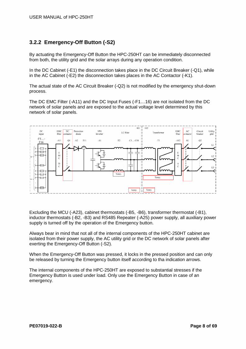
3.2.2 Emergency-Off Button (-S2) By actuating the Emergency-Off Button the HPC-250HT can be immediately disconnected from both, the utility grid and the solar arrays during any operation condition. In the DC Cabinet (-E1) the disconnection takes place in the DC Circuit Breaker (-Q1), while in the AC Cabinet (-E2) the disconnection takes places in the AC Contactor (-K1). The actual state of the AC Circuit Breaker (-Q2) is not modified by the emergency shut-down process. The DC EMC Filter (-A11) and the DC Input Fuses (-F1…16) are not isolated from the DC network of solar panels and are exposed to the actual voltage level determined by this network of solar panels.
Excluding the MCU (-A23), cabinet thermostats (-B5, -B6), transformer thermostat (-B1), inductor thermostats (-B2, -B3) and RS485 Repeater (-A25) power supply, all auxiliary power supply is turned off by the operation of the Emergency button. Always bear in mind that not all of the internal components of the HPC-250HT cabinet are isolated from their power supply, the AC utility grid or the DC network of solar panels after exerting the Emergency-Off Button (-S2). When the Emergency-Off Button was pressed, it locks in the pressed position and can only be released by turning the Emergency button itself according to tha indication arrows. The internal components of the HPC-250HT are exposed to substantial stresses if the Emergency Button is used under load. Only use the Emergency Button in case of an emergency.

USER MANUAL of HPC-250HT
PE07019-022-B Page 9 of 69
3.2.3 Start / Stop Key Operated Spring-Return Switch (-S1) The key operated spring-return switch (–S1) can be in one of three possible positions START, STOP and CENTER. START and STOP are momentary positions and the switch automatically returns to the CENTER position after leaving hold of its operating key. The HPC-250HT can be set to “Offline” or “Connecting to Solar Arrays” mode, the “Automatic Startup” sequence can be aborted or skipped and the User Interface backlight illumination can be turned ON with the Start / Stop Key Operated Spring-Return Switch (-S1). Instantaneous operation of the Start / Stop Key Operated Spring Return Switch (-S1) in either direction enables the backlight illumination of the HPC-250HT User Interface. The backlight illumination of the HPC-250HT User Interface will stay enabled for 60 minutes counting from the last actuation of the Start / Stop Key Operated Switch in either direction. In case the system is in “Offline” state, when the switch is turned to the Start position for at least three seconds the system state of the HPC-250HT changes from “Offline” to “Conencting to Solar Arrays”. In case the system is not in “Trip”, “Emergency” or “Waiting after Grid Failure” state, when the switch is turned to the stop position for at least three seconds the system initializes a shut down sequence and the system state changes according to, and the steps of this shut-down sequence depend on the actual state of the system at the moment of the stop request. Each time the auxiliary power supply was connected to the MCU of the HPC-250HT the system waits for additional 5 minutes before initiating an automatic start up sequence. This waiting time can be interrupted by turning the Start/Stop Key operated Switch in Stop direction for at least three seconds, or skipped by turning the Start/Stop Key Operated Switch in Start direction for at least 3 second three. If the automatic startup process is skipped, the operation state is redirected to “Waiting after Grid Failure” state. Each time the utility grid voltage is disconnected from the HPC-250HT or the power supply is disconnected from the MCU of the HPC-250HT, the system waits for additional five minutes counting from the reconnection of the MCU power supply or counting from the moment in which the stable condition of the utility network has been met, respectively, before the HPC-250HT is allowed to connect to the utility grid again. Note, that the utility grid stability waiting time can be in coincidence with the Automatic Start Up waiting time, but can not be shortened or interrupted. The conditions, in which the utility network can be considered stable can be defined on the “Setting 2” tab page of the User Interface and are identified as “Nominal Grid Voltage”, “Nominal Grid Frequency”, “Minimum Grid Voltage”, “Maximum Grid Voltage”, “Grid Frequency Limit Fmax-Fnom” and “Grid Frequency Limit Fnom-Fmin”.

USER MANUAL of HPC-250HT
PE07019-022-B Page 10 of 69
3.2.4 HPC-250HT User Interface The HPC-250HT operation can be observed and the system settings may be modified by means of the HPC-250HT User Interface. Control, monitoring, reporting and administrative functions can be exercised, observed and altered using the UI residing at the front of the AC side cabinet (-E2). Conveniently situated actions contain:
- Monitoring of System Operation - Supervising Inverter Operation
- Displaying Online Measurement Data
- Adjustment of Parameters
- Displaying and Acknowledgement of Fault events
- Modification and Test of Communication Parameters
- Observing operation of String Boxes connected
- Supervising and modifying String Box settings
For turning on/off backlight illumination of the HPC-250HT User Interface see chapter 3.2.3!

USER MANUAL of HPC-250HT
PE07019-022-B Page 11 of 69
3.2.5 Light Indicators (-H1, -H2) In case of a fault during operation of the HPC-250HT, the type of the occurred fault is being indicated via a red and a yellow light on the front of the AC side cabinet (-E2) of the HPC-250HT cubicle.
- Yellow An ALARM event did occur during operation of the HPC-250HT. The system does not switch itself off.
- Red A TRIP or EMERGENCY event did occur during operation of the HPC-250HT.
3.3 Operating Modes
OFFLINE
AUTOMATIC STARTUP
WAITING AFTER GRID FAILURE
CONNECTING TO SOLAR ARRAYS
WAITING AFTER LOW POWER
STOP
WAITING AFTER GRID FAILURE
TESTING OF STRING
VOLTAGE
GRID VOLTAGE AND
FREQUENCY TEST
CONNECTING TO GRID, TEST
OF STRING VOLTAGE
FEEDING TO THE GRID
SHUT DOWN
SHUT DOWN
DISCONNECTING FROM GRID
USER MANUAL of HPC-250HT
PE07019-022-B Page 12 of 69
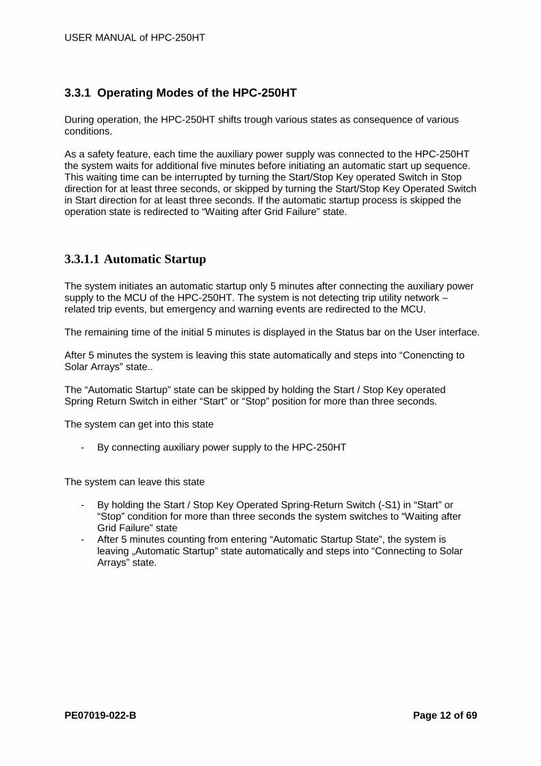
3.3.1 Operating Modes of the HPC-250HT During operation, the HPC-250HT shifts trough various states as consequence of various conditions. As a safety feature, each time the auxiliary power supply was connected to the HPC-250HT the system waits for additional five minutes before initiating an automatic start up sequence. This waiting time can be interrupted by turning the Start/Stop Key operated Switch in Stop direction for at least three seconds, or skipped by turning the Start/Stop Key Operated Switch in Start direction for at least three seconds. If the automatic startup process is skipped the operation state is redirected to “Waiting after Grid Failure” state.
3.3.1.1 Automatic Startup The system initiates an automatic startup only 5 minutes after connecting the auxiliary power supply to the MCU of the HPC-250HT. The system is not detecting trip utility network –related trip events, but emergency and warning events are redirected to the MCU. The remaining time of the initial 5 minutes is displayed in the Status bar on the User interface. After 5 minutes the system is leaving this state automatically and steps into “Conencting to Solar Arrays” state.. The “Automatic Startup” state can be skipped by holding the Start / Stop Key operated Spring Return Switch in either “Start” or “Stop” position for more than three seconds. The system can get into this state
- By connecting auxiliary power supply to the HPC-250HT
The system can leave this state
- By holding the Start / Stop Key Operated Spring-Return Switch (-S1) in “Start” or “Stop” condition for more than three seconds the system switches to “Waiting after Grid Failure” state
- After 5 minutes counting from entering “Automatic Startup State”, the system is leaving „Automatic Startup” state automatically and steps into “Connecting to Solar Arrays” state.
USER MANUAL of HPC-250HT
PE07019-022-B Page 13 of 69
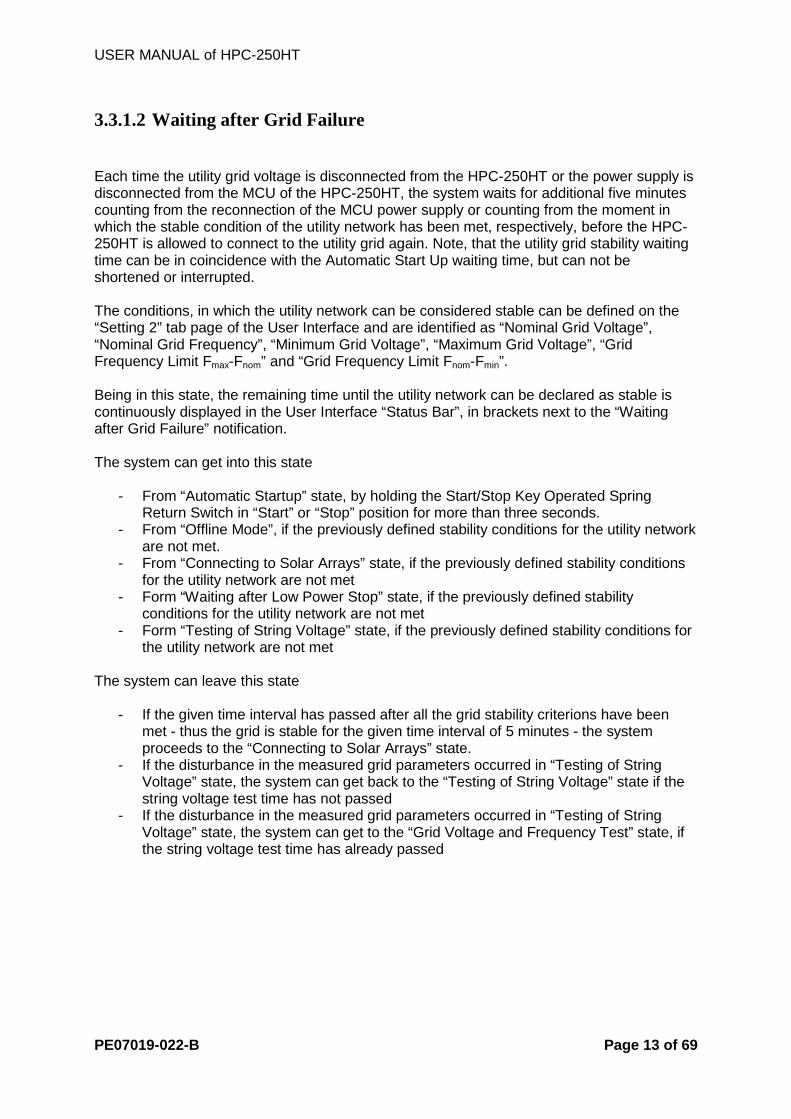
3.3.1.2 Waiting after Grid Failure Each time the utility grid voltage is disconnected from the HPC-250HT or the power supply is disconnected from the MCU of the HPC-250HT, the system waits for additional five minutes counting from the reconnection of the MCU power supply or counting from the moment in which the stable condition of the utility network has been met, respectively, before the HPC-250HT is allowed to connect to the utility grid again. Note, that the utility grid stability waiting time can be in coincidence with the Automatic Start Up waiting time, but can not be shortened or interrupted. The conditions, in which the utility network can be considered stable can be defined on the “Setting 2” tab page of the User Interface and are identified as “Nominal Grid Voltage”, “Nominal Grid Frequency”, “Minimum Grid Voltage”, “Maximum Grid Voltage”, “Grid Frequency Limit Fmax-Fnom” and “Grid Frequency Limit Fnom-Fmin”. Being in this state, the remaining time until the utility network can be declared as stable is continuously displayed in the User Interface “Status Bar”, in brackets next to the “Waiting after Grid Failure” notification. The system can get into this state
- From “Automatic Startup” state, by holding the Start/Stop Key Operated Spring Return Switch in “Start” or “Stop” position for more than three seconds.
- From “Offline Mode”, if the previously defined stability conditions for the utility network are not met.
- From “Connecting to Solar Arrays” state, if the previously defined stability conditions for the utility network are not met
- Form “Waiting after Low Power Stop” state, if the previously defined stability conditions for the utility network are not met
- Form “Testing of String Voltage” state, if the previously defined stability conditions for the utility network are not met
The system can leave this state
- If the given time interval has passed after all the grid stability criterions have been met - thus the grid is stable for the given time interval of 5 minutes - the system proceeds to the “Connecting to Solar Arrays” state.
- If the disturbance in the measured grid parameters occurred in “Testing of String Voltage” state, the system can get back to the “Testing of String Voltage” state if the string voltage test time has not passed
- If the disturbance in the measured grid parameters occurred in “Testing of String Voltage” state, the system can get to the “Grid Voltage and Frequency Test” state, if the string voltage test time has already passed

USER MANUAL of HPC-250HT
PE07019-022-B Page 14 of 69
3.3.1.3 Testing of String Voltage In thi state the HPC-250HT ascertains the sufficient level of DC voltage. This check is performed by measuring the DC voltage level at the DC power input of the HPC-250HT until sufficient DC voltage vs. time area was measured. The time that has passed with the DC voltage level above the set threshold is continuously indicated in brackets next to the “Start Time” value on the “Settings” tab page of the User Interface and indicated on the Status bar In brackets, net to the “Testing of String Voltage” text. The system can get into this state
- From “Waiting after Low Power Stop“ state, if the time set in the “Wait Time” textbox on the “Setting 1” tab page has passed.
- From “Waiting after Grid Failure” state if the necessary waiting time after the grid failure has passed.
- From “Connecting to Solar Arrays” state after successful connection to the solar arrays
The system can leave this state
- If the measured DC voltage level is above the voltage level set in the “Start Voltage”
[volts] textbox for the time duration set in the “Start Time” [seconds] textbox on the “Setting 1” tab-page, and – after a regular, low-power shut down - the “Wait Time” defined on the “Setting 1” tab page has passed, the system switches to “Grid Voltage and Frequency Test” state
- By holding the Start / Stop Key Operated Spring-Return Switch (-S1) in “Stop” condition for more than 3 seconds the system switches to “Shut Down” state

USER MANUAL of HPC-250HT
PE07019-022-B Page 15 of 69
3.3.1.4 Grid Voltage and Frequency Test During this step several measurements are undertaken to safely decide the operating conditions of the utility grid the HPC-250HT cabinet is connected to. Only after the connected utility grid is in stable state - with its key properties within standard-defined ranges - may the HPC-250HT proceed with preparations of grid connection. The standard-defined ranges can be individually set to align on the local conditions and regulations on the “Setting 2” tab page of the User Interface. Modifiable grid parameters are
- nominal voltage - range of voltage level deviation from nominal value in two directions separately - frequency - range of frequency deviation from nominal value in two directions separately
The system can get into this state
- From “Testing of String Voltage” state if the start conditions defined on the “Setting 1” tab page have been met.
The system can leave this state
- After all of the grid parameters have been identified and are in the pre-defined ranges as set on the “Setting 2” tab-page, the system switches to “Connecting to Grid, Test of String Voltage” state
- By holding the Start / Stop Key Operated Spring-Return Switch (-S1) in “Stop” condition for more than three seconds the system switches to the “Shut Down” state

USER MANUAL of HPC-250HT
PE07019-022-B Page 16 of 69
3.3.1.5 Connecting to Solar Arrays The HPC-250HT DC side circuit breaker is a motor driven automatically operated DC circuit breaker with two turn-on cycle states as follows
- Recharge of the actuating spring - Turn On circuit breaker
The motor driven automatically operated DC circuit breaker isolates the 3 phase inverter (-A1) from the DC EMC filter (-A11), the input DC fuses (optional) (-F1…-F16) and the network of solar panels.
The system can get into this state
- After 5 minutes counting from entering “Automatic Startup State”, the system is leaving „Automatic Startup” state automatically and steps into “Connecting to Solar Arrays” state.
- Form “Waiting after Grid Failure” state, if the given time interval has passed after all the grid stability criterions have been met - thus the grid is stable for the given time interval of 5 minutes - the system proceeds to the “Connecting to Solar Arrays” state.
The system can leave this state
- The system switches to ”Testing of String Voltage” state if the utility grid operation conditions set on the “Setting 2” tab page are met and the HPC-250HT did not perform a regular low-power shut down, or, the “Wait Time” accessible on the “Setting 1” tab page is set to zero.
- The system switches to ”Waiting after Low Power Stop” state if the utility grid operation conditions set on the “Setting 2” tab page are met and the HPC-250HT did perform a regular low-power shut down and the “Wait Time” accessible on the “Setting 1” tab page is not set to zero.
- The system switches to ”Waiting after Grid failure” state if the utility grid operation conditions set on the “Setting 2” tab page are not met

USER MANUAL of HPC-250HT
PE07019-022-B Page 17 of 69
3.3.1.6 Connecting to Grid, Test of String Voltage The output power delivery capability of the network of solar arrays is tested in this step of the HPC-250HT start sequence. The network of solar arrays is loaded and input voltage drop is measured. The measured voltage level (factory-determined voltage level, always below the value set in the “Start Voltage” textbox on the “Setting 1” tab page) on the input of the HPC-250HT determines the next step of the start sequence.
The system can get into this state
- From the “Grid Voltage and Frequency Test” state if the utility network parameters are within the ranges defined on the “Setting 2” tab page.
The system can leave this state
- If the measured input voltage level of the HPC-250HT during the String Voltage Test is above a factory-set safety value, the AC Contactor (-K1) turns ON, the system connects to the utility network and system state switches to “Feeding to the Grid”
- If the measured input voltage level of the HPC-250HT during the String Voltage Test is below a factory-set safety value, the system state switches to “Waiting after Low power Stop”
- By holding the Start / Stop Key Operated Spring-Return Switch (-S1) in “Stop” condition for more than three seconds the system switches to “Shut Down” state

USER MANUAL of HPC-250HT
PE07019-022-B Page 18 of 69
3.3.1.7 Feeding to the Grid (4) After synchronization of the inverter output voltage and frequency value to the corresponding measured values on the utility grid the AC Contactor (-K1) is turned ON to perform inverter-to-grid connection. In the moment of connection the equipments and devices on both ends of the AC Contactor (-K1) are energized and are operating on the same voltage and frequency levels, therefore assuring a zero-current switch on of the contactor. After successful completion of the start sequence the state of the HPC-250HT changes to “Feeding to the Grid”, the system behaves according to the Maximum Power Point and “Maximum Output Power” settings on the “Online Info” and the “Setting 2” tab page.
At first, in case MPP is activated on the “Online Info” tab page, after every successful grid connection the system automatically performs one MPP scanning cycle. After determining the current optimal power point the HPC-250HT is able to
- Reside in grid connected state and deliver power to the utility according to the previously found maximum power point (MPP OFF)
- Search for new maximum power points at time intervals defined by “Scan Delay”
[seconds] on the “Online Info” tab-page. (MPP)
- Track the last found optimal power point (MPP Tracking)
- Track the previously found maximum power point and perform a new MPP search after every set time interval defined in “”Scan Delay” [seconds] on the “Online Info” tab page (MPP with Tracking)
- Feed back power not exceeding the value defined by “Maximum Output Power”
[percentage, Nominal Power = 100%] on the “Settings” tab-page. A maximum power point scanning cycle can be initiated any time by tapping the “Start MPP Scan” button on the “Online Info” tab page. The time that has passed with the Output Power level above the set threshold is continuously indicated in brackets next to the “Stop Time” value on the “Settings” tab page of the User Interface.

USER MANUAL of HPC-250HT
PE07019-022-B Page 19 of 69
The system can get into this state
- If the measured input voltage level of the HPC-250HT during the String Voltage Test is above a factory-set safety value, the AC Contactor (-K1) turns ON, the system connects to the utility network and system state switches to “Feeding to the Grid”
The system can leave this state
- By holding the Start / Stop Key Operated Spring-Return Switch (-S1) in “Stop” condition for more than three seconds the system switches to “Shut Down” state
- If the measured DC power falls below the value set in “Stop Power” [kW] for an interval defined in “Stop Time” [seconds], both located on the “Settings” tab-page the system switches to “Shut Down” state. In this case, however, a time interval - equivalent to the one set in the “Wait Time” textbox on the “Setting 1” tab page – has to pass before a new, automatic start up sequence is initiated by the system.

USER MANUAL of HPC-250HT
PE07019-022-B Page 20 of 69
3.3.1.8 Shut Down (5) The system or the user initiates and performs a regular shut down sequence consisting of actual system-state-defined steps, if one of the following requirements is met.
The system can get into this state
- If the Start / Stop Key Operated Spring-return Switch (-S1) is operated and held in the
“Stop” position for more than three seconds - After an automatic shutdown process was initiated, meaning that the input DC power
of the HPC250-HT is lower than the threshold value set in the “Stop Power” [kW] textbox for the time interval set in the “Stop Time” [seconds] textbox on the “Settings” tab page.
The system can leave this state,
- And - depending on the state of the system in the moment of an incoming shut-down request the system - automatically jumps over to one of the following states:
o Waiting after Grid Failure -> Offline o Waiting after Low Power Stop -> Offline o Testing of String Voltage - > Offline o Grid Voltage and Frequency Test ->Offline o Connecting to Grid, Test of String Voltage -> Shut Down

USER MANUAL of HPC-250HT
PE07019-022-B Page 21 of 69
3.3.1.9 Disconnecting from Grid This step of the shut down sequence disconnects the HPC-250HT from the utility grid by turning OFF the AC Contactor (-K1).
The system can get into this state
- From “Shut Down” state, after an automatic shutdown process was initiated, meaning that the input DC power of the HPC250-HT is lower than the threshold value set in the “Stop Power” [kW] textbox for the time interval set in the “Stop Time” [seconds] textbox on the “Settings” tab page.
- From “Shut Down” state, after the Start / Stop Key Operated Spring-return Switch (-S1) is operated and held in the “Stop” position for more than three seconds in the following system states
o “Connecting to Grid, test of String Voltage” o “Feeding to the Grid”
The system can leave this state
- In case of a regular low-power shut down the system state changes to “Waiting after Low Power Stop”
- In case of a shut down initiated by means of the Start / Stop Key Operated Spring-return Switch (-S1), the system state changes to “Offline”

USER MANUAL of HPC-250HT
PE07019-022-B Page 22 of 69
3.3.1.10 Offline The HPC-250HT is deactivated and resides in this state until the Start / Stop Key Operated Spring-Return Switch (-S1) is turned to “Start” position for at least three seconds to maneuver the HPC-250HT into “Wait” mode. The system can get into this state
- By holding the Start / Stop Key Operated Spring-Return (-S1) switch in “Stop” position for more than three seconds
The system can leave this state
- By holding the Start / Stop Key Operated Spring-Return (-S1) Switch in “Start” position for more than three seconds

USER MANUAL of HPC-250HT
PE07019-022-B Page 23 of 69
4 HPC-250HT Control Operation The HPC-250HT User Interface is mounted on the front door of the -E2 cubicle of the cabinet. It is operated by tapping on the screen with the designated touch panel operating pen. Make sure to only use the designated touch panel operating pen to operate the touch screen of the User Interface.
The display background illumination can be activated by turning the Start/Stop key operated Spring-Return Switch in either “Start” or “Stop” position for an interval of less than three seconds. The backlight illumination of the HPC-250HT User Interface will stay enabled for 30 minutes counting from the last actuation of the Start / Stop Key-Operated Spring-Return Switch.
4.1 HPC-250HT Control Menu After connecting the auxiliary power supply to the HPC-250HT the system performs a first main initialization. The termination of the main initialization requires about one minute after every connection of auxiliary power supply. Note, that the auxiliary power supply is connected to the cubicle the first time during installation of the HPC-250HT. Under regular conditions, during normal operation without having the auxiliary power supply interrupted, the HPC-250HT does perform the main initialization only once.

USER MANUAL of HPC-250HT
PE07019-022-B Page 24 of 69
The completion of the main initialization is indicated by the illumination of the User Interface and a LED indicator lighting up at the left side of the User Interface. The screen of the User Interface can be divided into three sections as displayed on the picture below
Identifier Description A Tab Page Selector
B Status Bar
C Progress Bar
The “Tab Page Selector” and the “Progress Bar” are visible under every circumstances, the “Status Bar” is only visible in the following five of the altogether nine tab pages.
Tab Page Status Bar Visibility Start
Visible
Online info
Visible
Fault Handling
Not Visible
Log
Not Visible
System
Visible
Tab Page Status Bar Visibility Email
Not Visible
Operator
Visible
Setting 1
Visible
Setting 2
Not Visible

USER MANUAL of HPC-250HT
PE07019-022-B Page 25 of 69
4.2 Overview of the Menu The HPC-250HT User Interface consists of altogether nine pages, each of them subdivided into categories which contain system information accessible by the system operator. To choose and switch between the menu pages one has to tap the name of the menu on the tab page selector and the display automatically changes to the selected menu screen.
4.2.1 Start (Brief Description)
Menu Page
Category System information
Start Status bar
System Time, System Date, System Status, Operator Status
Device Info Device Serial Number, User Interface Version Number
COM Speed Communication speed of RS485-based data acquisition system

USER MANUAL of HPC-250HT
PE07019-022-B Page 26 of 69
4.2.2 Online Info (Brief Description)
Menu Page
Category System information
Online Info Status bar System Time,
System Date, System Status, Operator Status
Online Info Total Energy Grid Power Grid Voltage Grid Current PV Power PV Voltage PV Current Choke Temperature Bridge Temperature
Maximum Power Point Start MPP Scan Scan Delay MPP Mode

USER MANUAL of HPC-250HT
PE07019-022-B Page 27 of 69
4.2.3 Fault Handling (Brief Description)
Menu Page
Category System information
Fault Handling Emergency Emergency Information,
Emergency Acknowledgement
Trip Trip Information, Trip Acknowledgement
Alarm Alarm Information, Alarm Acknowledgement

USER MANUAL of HPC-250HT
PE07019-022-B Page 28 of 69
4.2.4 Log (Brief Description)
Menu Page
Category System information
Log Fault List Show Fault list content
Start / Stop List
Show Start / Stop list content
Tech. Event List Show Technical Event list content

USER MANUAL of HPC-250HT
PE07019-022-B Page 29 of 69
4.2.5 System (Brief Description)
Menu Page
Category System information
System Status bar System Date,
System Status, Operator Status
System Information On Time Last Start Time System Started Emergency Counter Trip Counter Alarm Counter PVC Communication
Report Sending Enable/Disable Start / Stop Email Report Sending Enable/Disable Fault Email Report Sending

USER MANUAL of HPC-250HT
PE07019-022-B Page 30 of 69
4.2.6 Email (Brief Description)
Menu Page
Category System information
Email Email Settings Email Sender
Email Receiver Email Server IP Email Server Port
Test Email Send Test Email Email State Email Progress Email Sending State

USER MANUAL of HPC-250HT
PE07019-022-B Page 31 of 69
4.2.7 Operator (Brief Description)
Menu Page
Category System information
Operator Equipment Test Turn ON DC Circuit Breaker (-Q1)
Turn OFF DC Circuit Breaker(-Q1) Turn ON/OFF Red and Yellow Indicator Lights Control Power ON Control Power OFF AC Contactor ON (-K1) AC Contactor OFF (-K1) Turn ON/OFF Inverter Fans Turn ON/OFF Cabinet Fans
Operator Login/Logout
Operator Login/Logout Button Show/Hide Input Panel Button Add Operator Password Button

USER MANUAL of HPC-250HT
PE07019-022-B Page 32 of 69
4.2.8 Setting 1 (Brief Description)
Menu Page
Category System information
Setting 1 Change Time and Date
New System Year, Month, Date, Hour, Minute
Start/Stop Condition
Start Voltage, Start Time, Stop Power, Stop Time Wait Time

USER MANUAL of HPC-250HT
PE07019-022-B Page 33 of 69
4.2.9 Setting 2 (Brief Description)
Menu Page
Category System information
Test Grid Nominal Values Nominal Grid Voltage
Nominal Grid Frequency
Grid Voltage Limits Maximal Grid Voltage Minimal Grid Voltage
Grid Frequency Limits Fmax-Fnom Fnom-Fmin
Maximum Output Power
Output Power Limitaton
Turn Ratio and LCK Nr.
Factory Settings, can not be modified by the user

USER MANUAL of HPC-250HT
PE07019-022-B Page 34 of 69
4.2.10 Start (Detailed Description) The “Start” tab page is the first page of the HPC-250HT User Interface. The “Start” tab page displays the HPC-250HT “Serial Number” and the “User Interface version number” together with the actual date and time, system operator status and the RS485 based external data acquisition system communication speed setting.

USER MANUAL of HPC-250HT
PE07019-022-B Page 35 of 69
4.2.11 Online Info (Detailed Description) The Online Info screen displays system status dependent main measured values, complemented with online system information and MPP-related parameters. Note that measured or calculated values are displayed only in system states in which they are evaluated. In other system states, no value is indicated in these textboxes. “Total Energy” [kW] textbox displays the summarized energy yield of the HPC-250HT. “Grid Power” [kW] stands for the calculated output power of the HPC-250HT cabinet. “Grid Voltage” [V] displays the calculated output voltage level of the HPC-250HT. “Grid Current” [A] shows the measured output current of the HPC-250HT. The “PV Power” [kW] textbox holds the calculated value of the HPC-250HT input power from the network of solar arrays. “PV Voltage” [V] displays the measured direct voltage supplied by the network of solar arrays connected to the input of the HPC-250HT. “PV Current” [A] textbox contains the measured direct current flowing from the network of solar arrays to the input of the HPC-250HT. “Choke Temperature” [°C] and “Bridge Temperature” [°C] textboxes serve to indicate the measured temperature inside the AC power filter choke [-T2] and the highest temperature occurring inside the three IGBT bridges. By tapping the “Start MPP Scan” button the HPC-250HT initiates an MPP Scan cycle in case the actual system state does not exclude its initiation. To perform an MPP Scan cycle is only possible from “Feeding to the Grid” system state. The “MPP Mode” shows what kind of maximum power point detection algorithm is currently enabled for the HPC-250HT. With “MPP” enabled the HPC-250HT performs a Maximum Power Point Tracking cycle every “Scan Delay” [s] interval. Between two MPPS cycles the DC Voltage value on the coupling point of the HPC-250HT and the network of solar arrays is regulated to a constant value defined from the results of the previously performed MPP cycle. Note that the system automatically performs an MPP cycle if entering “Feeding to the Grid” system state assuring that the system is operating in an optimal working point right after grid connection. Because changes in maximum power point of a network of solar array depend on individual conditions at site and the essence of maximum power point scanning carries inevitable losses during the scanning process, the time passing between two maximum power point scanning cycles can be set by the user to assure maximal assimilation of HPC-250HT operation on different environmental and economical conditions. The release of “MPP Tracking”, Maximum Power Point Tracking algorithm assures maximum system power yield by tracking changes of the connected network of solar array maximum power point between two MPP cycles by applying power losses minimizing tracking algorithm.

USER MANUAL of HPC-250HT
PE07019-022-B Page 36 of 69
The “MPP Tracking” and MPP algorithms can be enabled and disabled together or independently, however both are suggested to be enabled to achieve optimal power yield under every environmental condition. ID Displayed Text MPP Algorithm 0 MPP Tracking Maximum Power Point Tracking
Only the maximum power point tracking algorithm is enabled.
1 MPP Maximum Power point Scanning Only the maximum power point scanning algorithm is enabled.
2 MPP with Tracking
Maximum Power Point Tracking and Scanning Both, the maximum power point tracking and scanning algorithms are enabled.
3 MPP OFF None of the maximum power point tracking and scanning algorithms is enabled.
USER MANUAL of HPC-250HT
PE07019-022-B Page 37 of 69
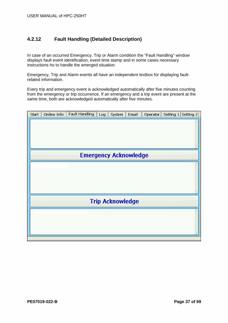
4.2.12 Fault Handling (Detailed Description) In case of an occurred Emergency, Trip or Alarm condition the “Fault Handling” window displays fault event identification, event time stamp and in some cases necessary instructions ho to handle the emerged situation. Emergency, Trip and Alarm events all have an independent textbox for displaying fault-related information. Every trip and emergency event is acknowledged automatically after five minutes counting from the emergency or trip occurrence. If an emergency and a trip event are present at the same time, both are acknowledged automatically after five minutes.
USER MANUAL of HPC-250HT
PE07019-022-B Page 38 of 69
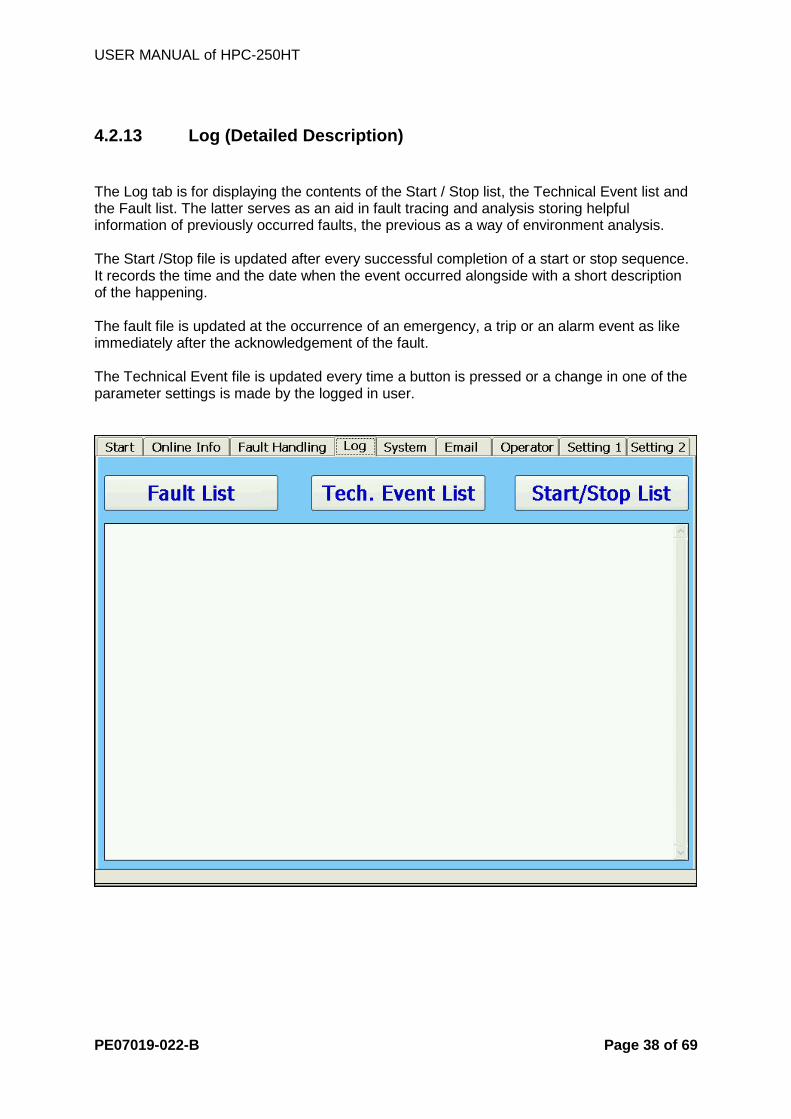
4.2.13 Log (Detailed Description) The Log tab is for displaying the contents of the Start / Stop list, the Technical Event list and the Fault list. The latter serves as an aid in fault tracing and analysis storing helpful information of previously occurred faults, the previous as a way of environment analysis. The Start /Stop file is updated after every successful completion of a start or stop sequence. It records the time and the date when the event occurred alongside with a short description of the happening. The fault file is updated at the occurrence of an emergency, a trip or an alarm event as like immediately after the acknowledgement of the fault. The Technical Event file is updated every time a button is pressed or a change in one of the parameter settings is made by the logged in user.

USER MANUAL of HPC-250HT
PE07019-022-B Page 39 of 69
4.2.14 System (Detailed Description) Information displayed on the “System” tab page is part of the system-related set of statements - also located on other tab pages. The “On Time” [h] text box holds the number of hours the HPC250-HT MCU was connected to te utility netwok, thus the summarized time of power generation. The “Last Start Time”[h:m:s”] stores the time of the last start of utility network connection of the HPC-250HT. Closing the AC Contactor (-K1) is meant to indicate the moment of connection, thus this action of the start-up process is taken to update the time displayed in the “Last Start Time” textbox. The number appearing in the “System Started” textbox is increased by one every time the auxiliary power supply is connected to the HPC-250HT, thus, after every start of the HPC-250 MCU
Emergency- , Alarm-, and Trip Counter display the number of occurred fault events. PVC Communication indicates inter-system communication state and should in normal operating conditions always display “ON” value.

USER MANUAL of HPC-250HT
PE07019-022-B Page 40 of 69
The appropriate set-up of email sending parameters on the “Email” tab page enables the HPC-250HT to send notification emails in case of an occurred fault event or after connecting to (Start) and disconnecting from (Stop) the utility network. For enabling/disabling one of the email sending options tap the button on the “System” tab page of the User Interface corresponding to the desired action to be performed. The current status of the email sending possibilities is indicated by “Enabled” / “Disabled” text respectively.

USER MANUAL of HPC-250HT
PE07019-022-B Page 41 of 69
4.2.15 Email (Detailed Description) Appropriate set-up of email sending parameters on the “Email” tab page enables the HPC-250HT to send notification emails in case of an occurred fault event or after connecting to (Start) and disconnecting from (Stop) the utility network. The email address where the email should be sent to can be set in the “Email Receiver” textbox. An ID can be assigned to the HPC-250HT cabinet in the “Email Sender” textbox to make sender assignation possible. Internet Protocol address of the mail server necessary for sending the email and the port number used to communicate with the mail server also have to be defined in the “Email Server IP” and “Email Port” fields, respectively. To evaluate the new settings the “Save Settings” button on the “Email” tab page has to be tapped after modification of email sending parameters. To evaluate the email settings a test message can be generated by tapping the “Send Test Email” button. The result of the test is shown on the three textboxes “Email State”, “Email Progress” and “Email Sending State”.

USER MANUAL of HPC-250HT
PE07019-022-B Page 42 of 69
4.2.16 Operator (Detailed Description) The Operator window is an aid to access system components of HPC-250HT which are restricted in normal operation. Following actions are restricted until log-in as Operator
- Start MPP Scan cycle - Change MPP Scan Delay - Change MPP Mode - Enable/Disable Fault and Start/Stop Email Sending - Change System Time and Date - Change Start and Stop Conditions - Change Email Settings - Send Test Email - Change Utility Network Nominal Voltage and Frequency - Change Utility Network Voltage and Frequency Tolerances - Perform Device Test Actions
According to the logged on status of the operator the Status bar is visible on five of the nine user interface pages changes. The logged on status is marked with a red “Logged ON” label, as displayed in the picture below, whereas the logged off status is indicated by a “Logged OFF” label. The 9 test-dedicated buttons on the bottom of the “Operator” tab page are active only in “Offline” system state. They serve as an aid in regular maintenance and test-related tasks. “Turn OFF DC CB” button and “Turn ON DC CB” button turn on /off the DC side Circuit Breaker (-Q1), respectively. “Light ON/OFF” button turn on the red and yellow cabinet lights (-H1, -H2) for a certain amount of time. By pushing the “Cabinet Fan” button following fans inside the HPC-250HT cabinet are energized and start operation
- Diode Module Fan (+E1-A2-M1) - 2 Cabinet Fans (+E1-M4, +E1-M5)
If energized, they can be turned OFF by tapping the “Cabinet Fan” button a second time. By pushing the “Inverter Fan” button following fans inside the HPC-250HT cabinet are energized and start operation
- 6 Inverter Fans (+E1-A1) If energized, they can be turned OFF by tapping the “Inverter Fan” button a second time.

USER MANUAL of HPC-250HT
PE07019-022-B Page 43 of 69

USER MANUAL of HPC-250HT
PE07019-022-B Page 44 of 69
4.2.17 Setting 1 (Detailed Description) For changing system time and date besides modifying power feeding start and stop conditions of the HPC-250HT, the Settings tab in the user interface has to be selected. In the basic state the actually set system time and date are displayed in the corresponding “Year”, “Month”, “Day”, “Hour” and “Minute” textboxes. Their value can be changed independently by tapping the “Change” button next to the text box whose content is meant to be changed. To evaluate the new time or date settings one has to tap the “Set Time” or “Set Date” buttons, respectively. To assure system power yield at best possible rate, the power feeding start and stop conditions can be set individually for each HPC-250HT on the “Settings” tab page. Before grid connection, the HPC-250HT is continuously monitoring the input voltage determined by the connected network of solar arrays. The user can define the level of measured input voltage at which a system startup is initiated by setting a value between 450 and 600 in the “Start Voltage” [V] textbox. To guarantee the stability of the measured voltage at the input of the HPC-250HT, the voltage set in the “Start Voltage” textbox has to be stable for a certain time interval. This user-defined time interval can be set in the “Start Time” [s] textbox to a value between 30 and 600 (equivalent to 0.5 and 10 minutes).

USER MANUAL of HPC-250HT
PE07019-022-B Page 45 of 69
After connection to the grid the HPC-250HT continuously monitors the power flowing from the network of solar arrays to the utility. A minimal power value can be defined which flowing through the HPC-250HT – to – network of solar arrays coupling point initiates disconnection form the utility network. This power value can be set between 2 and 20 in the “Stop Power” [kW] textbox. This calculated power value has to be stable for a user-definable time interval which can be set between 30 seconds and 2 minutes by writing a value between 30 and 120 in the “Stop Time” [s] textbox. User can define the minimum time how long the HPC-25HT has to wait after a regular low-power stop before the next start up attempt of the system. This minimum time can be seen in the “Wait Time” textbox.

USER MANUAL of HPC-250HT
PE07019-022-B Page 46 of 69
4.2.18 Setting 2 (Detailed Description) To assure a wide possible field of operation, area of application and environmental conditions for the HPC-250HT, the parameters of the utility network can be set in wide ranges. The nominal grid voltage can be set between 380 and 480 V in the “Nominal Grid Voltage” [V] textbox. The nominal grid frequency displayed in the “Nominal Grid Frequency” [Hz] textbox can be set to either 50 or 60 Hz. Allowed deviation from these optimal values can be set independently for both positive and negative direction of changes. Maximum grid voltage can beset between 90% and 120%, minimum grid voltage can be set between 80% and 115% of the nominal grid voltage value in the “Maximum Grid Voltage” and “Minimum Grid Voltage” textboxes, respectively. The allowed deviation from the nominal frequency can be set as distance in frequency between 0.1 and 2.5 Hz in both positive and negative frequency deviation directions in the “Fmax-Fnom” and “Fnom-Fmin” textboxes, respectively. Some installation sites or situations may require the limitation of the maximal output power achievable by the HPC-250HT to a certain value below its rated output power. This limitation of energy yield can be accomplished by writing a value between 0 and 100 in the “Maximum Output Power” [%] textbox, corresponding to the maximal achievable in percentage (100 meaning 100% of output power, equivalent to rated output power, no limitation).
USER MANUAL of HPC-250HT
PE07019-022-B Page 47 of 69
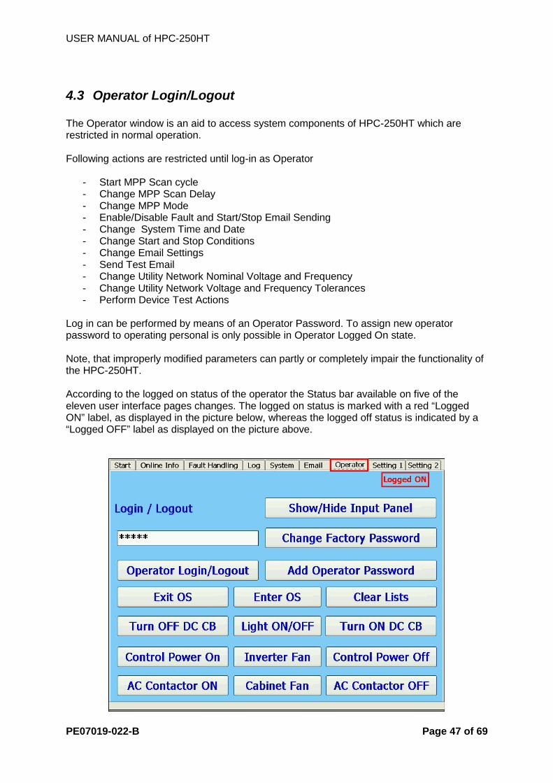
4.3 Operator Login/Logout The Operator window is an aid to access system components of HPC-250HT which are restricted in normal operation. Following actions are restricted until log-in as Operator
- Start MPP Scan cycle - Change MPP Scan Delay - Change MPP Mode - Enable/Disable Fault and Start/Stop Email Sending - Change System Time and Date - Change Start and Stop Conditions - Change Email Settings - Send Test Email - Change Utility Network Nominal Voltage and Frequency - Change Utility Network Voltage and Frequency Tolerances - Perform Device Test Actions
Log in can be performed by means of an Operator Password. To assign new operator password to operating personal is only possible in Operator Logged On state. Note, that improperly modified parameters can partly or completely impair the functionality of the HPC-250HT. According to the logged on status of the operator the Status bar available on five of the eleven user interface pages changes. The logged on status is marked with a red “Logged ON” label, as displayed in the picture below, whereas the logged off status is indicated by a “Logged OFF” label as displayed on the picture above.

USER MANUAL of HPC-250HT
PE07019-022-B Page 48 of 69
4.3.1 Log ON Procedure
1. Select the “Operator” tab page 2. The Operator Log On procedure is initialized by tapping the “Show/Hide Input Panel”
Button in the Operator tab.
3. The HPC-250HT Input Panel appears in the right upper corner of the display and he cursor in the “Login/Logout” textbox starts to blink.
4. After typing a valid operator password into the textbox and tapping the “Operator Login/Logout” button the Operator status label changes to “Logged ON” and one is allowed to perform the intended parameter modifications or fault acknowledgements. Note, that the Input Panel disappears automatically after tapping the “Operator Login/Logout” button.
4.3.2 Add Operator Password
1. To add a new operator password to the system is only possible after logging ON to the HPC-250HT as operator. In operator “”Logged ON” state, tap the “Add Operator Password” button.

USER MANUAL of HPC-250HT
PE07019-022-B Page 49 of 69
2. The “New Operator Password” input box appears. Type in the new operator password you want to assign system access privileges to.
3. If the new operator password is already assigned in the system, a message box appears and you have to repeat the procedure with another operator password.

USER MANUAL of HPC-250HT
PE07019-022-B Page 50 of 69
4.3.3 Log OFF procedure By tapping the “Operator Login/Logout” button in “Logged ON” status the operator status changes from “Logged ON” to “Logged OFF”, and parameter modification and fault acknowledge possibilities are no more available until a new Log ON procedure is performed.
USER MANUAL of HPC-250HT
PE07019-022-B Page 51 of 69
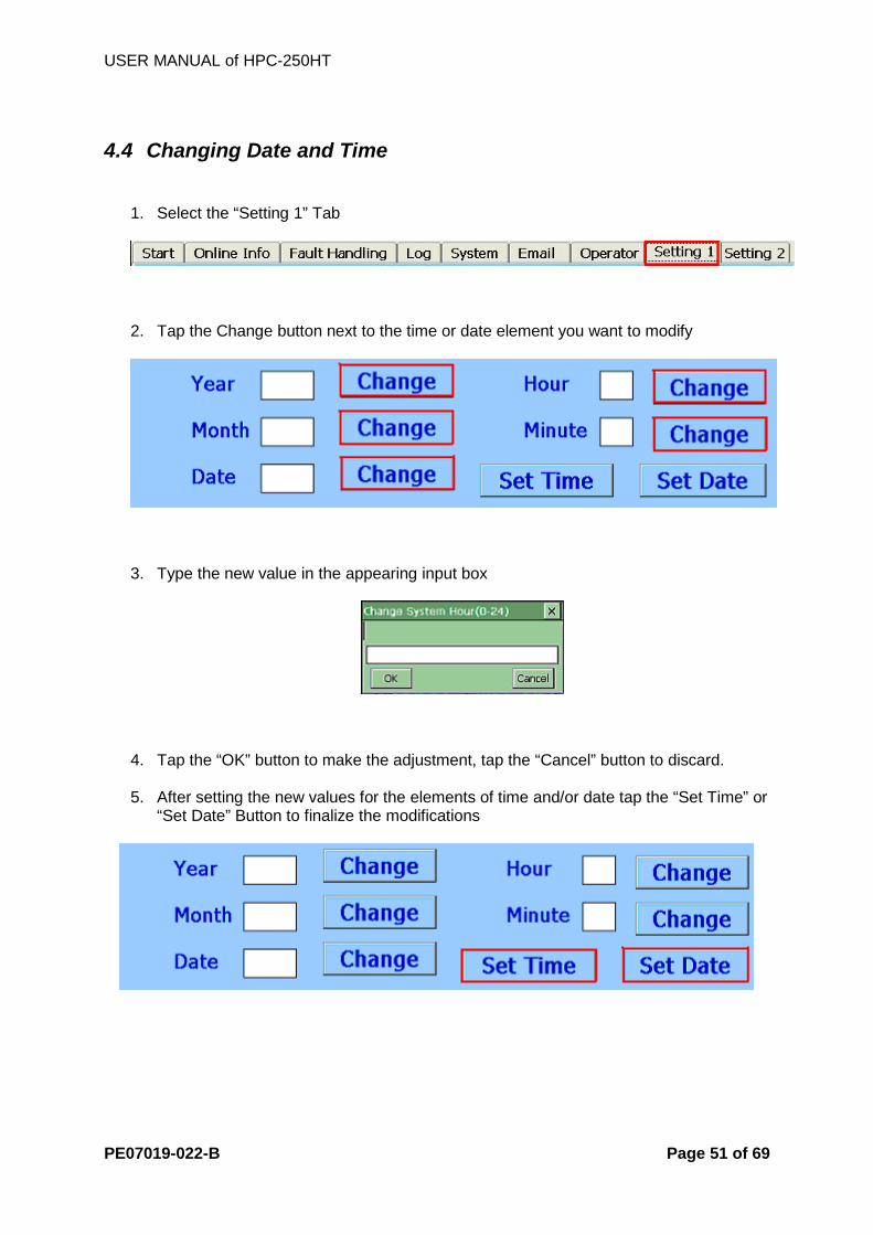
4.4 Changing Date and Time
1. Select the “Setting 1” Tab
2. Tap the Change button next to the time or date element you want to modify
3. Type the new value in the appearing input box
4. Tap the “OK” button to make the adjustment, tap the “Cancel” button to discard. 5. After setting the new values for the elements of time and/or date tap the “Set Time” or
“Set Date” Button to finalize the modifications

USER MANUAL of HPC-250HT
PE07019-022-B Page 52 of 69
5 Parameters Improperly modified parameters can partly or completely impair the functionality of the HPC-250HT. Note that for making changes in any of the parameters available for modification in the HPC-250HT User Interface you have to log in as an operator. Majority of the HPC-250HT parameters are ready configured for operation. However, if modifications are necessary they can be performed in the HPC-250HT User Interface. The parameters can be divided into following 5 sections:
- Maximum Power Point Scanning and Tracking - Start/Stop parameters
- Communication parameters
- System parameters
- String box parameters
5.1 Description of the Parameter Functions Parameter Description of the function COM Speed Communication speed of the external data acquisition system. Scan Delay
The HPC-250HT initiates an MPP Scan cycle every “Scan Delay” interval
MPP Mode
Sets one of four MPP modes available 0 – MPP Tracking 1 – MPP 2 – MPPS with Tracking 3 – MPP OFF
Start / Stop Email Report Sending
Enables or disables sending of Start/Stop email report
Fault Email Report Sending
Enables or disables sending of Fault email report
Start Voltage
If the measured DC voltage on HPC-250HT-to-network of solar arrays coupling point is greater than the level set in “Start Voltage” for “Start Time” interval, the HPC-250HT switches form “Waiting for Sufficient String Voltage” system state to “Start Up, Thermostat Check” system state.
Start Time

USER MANUAL of HPC-250HT
PE07019-022-B Page 53 of 69
Parameter Description of the function Stop Power
If the measured input power level on the HPC-250HT-to-network of solar is lower than the level set in Stop Power for Stop Time interval, the HPC-250HT switches to Shut Down mode.
Stop Time Wait Time
After a regular shut down the HPC-250HT waits additional minutes defined as the “Wait Time” parameter before the next start attempt.
Email Receiver
The receiver of the emails sent by HPC-250HT
Email Sender
The HPC-250HT identifier to appear in the sent emails
Email Server IP
The IP address of the mail server used for sending emails
Email Server Port
The port number in the mail server used for sending emails
Nominal Grid Voltage
Nominal value of utility grid voltage
Nominal Grid Frequency
Nominal value of utility grid frequency
Maximum Grid Voltage
Maximum allowed grid voltage value.
Minimum Grid Voltage
Minimum allowed grid voltage value.
Grid Frequency Limit (Positive Direction)
Maximum deviation from nominal grid frequency value in positive direction.
Grid Frequency Limit (Negative Direction)
Maximum deviation from nominal grid frequency value in negative direction.
Turn ratio and CLK Nr. Factory Settings, can not be modified

USER MANUAL of HPC-250HT
PE07019-022-B Page 54 of 69
5.2 Default Parameter Settings This table lists the adjustable parameters of HPC-250HT together with their adjustable range and default values.
Parameter Range Scan Delay
10 s – 60000 s
MPP Mode 0 – MPP Tracking 1 – MPP 2 – MPP with Tracking 3 – MPP OFF
Start / Stop Email Report Sending
Enabled / Disabled
Fault Email Report Sending
Enabled / Disabled
Start Voltage
450V – 800V
Start Time
1 – 600 s
Stop Power
2 kW – 10 kW
Stop Time
1 – 300 s
Maximum Output Power
0 - 100%
Email Receiver
5 – 48 characters
Email Sender
1 – 48 characters
Email Server IP Regular IP address (7-15 characters)
Email Server Port
1 – 65535
Automatic Acknowledge
Enabled / Disabled
Nominal Grid Voltage
380V - 480V
Nominal Grid Frequency
50Hz-60Hz
Maximum Grid Voltage 90%-125%
Minimum Grid Voltage
80%-115%

USER MANUAL of HPC-250HT
PE07019-022-B Page 55 of 69
Parameter Range Grid Frequency Limit (Positive Direction)
Fnom+0.1Hz – Fnom+2.5Hz
Grid Frequency Limit (Negative Direction)
Fnom-0.1Hz – Fnom-2.5Hz
Wait Time
0 - 1800000
COM Speed
9600, 19200, 38400
Turn ratio and CLK Nr Factory Settings, can not be modified

USER MANUAL of HPC-250HT
PE07019-022-B Page 56 of 69
5.3 Entering Parameters and Settings Improperly modified parameters can partly or completely impair the functionality of the HPC-250HT. Note that for making changes in any of the parameters available for modification in the HPC-250HT User Interface you have to log in as an operator. You can modify the HPC-250HT parameters by tapping on a designated button next to the parameters present - displayed - value. After tapping the corresponding button, the parameters edit input box appears - showing the actual parameter value – together with the input panel as an aid for character input.
After modification of the values confirm the new value by tapping on the OK button or discard the changes by tapping on the Cancel button, or the cross labeled button in the upper right corner f the input box.
The input panel disappears automatically after the actual input box has vanished. Note that some parameters have to be stored in system memory by tapping “Save Settings” button next to, or on the same page as the modified parameter.

USER MANUAL of HPC-250HT
PE07019-022-B Page 57 of 69
6 Communication The HPC-250HT can inform you by means of email reports regarding the start and stop events or occurred emergencies, trips and alarms. Next to setting email sending parameters in the Email menu you need to specify the report types you want to receive in the System menu.
6.1 Entering or Changing Email Addresses Appropriate set-up of email sending parameters on the “Email” tab page enables the HPC-250HT to send notification emails in case of an occurred fault event or after connecting to (Start) and disconnecting from (Stop) the utility network. The email address where the email should be sent to can be set in the “Email Receiver” textbox. An ID can be assigned to the HPC-250HT cabinet in the “Email Sender” textbox to make sender assignation possible. Internet Protocol address of the mail server necessary for sending the email and the port number used to communicate with the mail server also have to be defined in the “Email Server IP” and “Email Port” fields, respectively. To evaluate the new settings the “Save Settings” button on the “Email” tab page has to be tapped after modification of email sending parameters. To test the accuracy of the email settings a test message can be generated by tapping the “Send Test Email” button. The result of the test is shown on the three textboxes “Email State”, “Email Progress” and “Email Sending State”. On the HPC-250HT display, select the Email tab for modifying the email sending settings as desired. Attention should be paid to following:
- The receiver email address can have a maximal length of 46 characters - The sender of the email does not need to be a valid email address. Any kind of 46
characters long text can be used to identify the message. - The default setting for the port number of the email server is 25

USER MANUAL of HPC-250HT
PE07019-022-B Page 58 of 69
USER MANUAL of HPC-250HT
PE07019-022-B Page 59 of 69
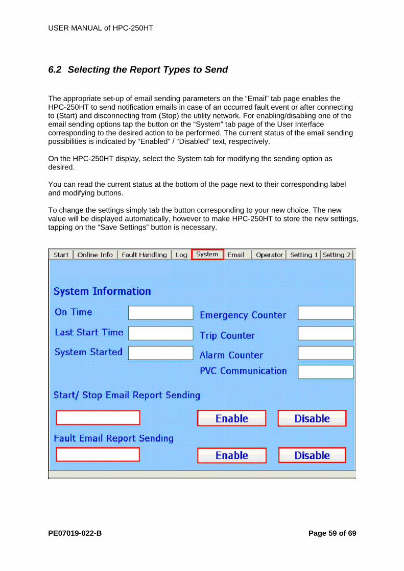
6.2 Selecting the Report Types to Send The appropriate set-up of email sending parameters on the “Email” tab page enables the HPC-250HT to send notification emails in case of an occurred fault event or after connecting to (Start) and disconnecting from (Stop) the utility network. For enabling/disabling one of the email sending options tap the button on the “System” tab page of the User Interface corresponding to the desired action to be performed. The current status of the email sending possibilities is indicated by “Enabled” / “Disabled” text, respectively. On the HPC-250HT display, select the System tab for modifying the sending option as desired. You can read the current status at the bottom of the page next to their corresponding label and modifying buttons. To change the settings simply tab the button corresponding to your new choice. The new value will be displayed automatically, however to make HPC-250HT to store the new settings, tapping on the “Save Settings” button is necessary.

USER MANUAL of HPC-250HT
PE07019-022-B Page 60 of 69
6.3 Sending a Test Email On the HPC-250HT display, select the Email tab for sending a test email. Do not forget to set valid email receiver, email server port number and email server IP number settings. The internal steps and the result of the sending process are shown in the following three text boxes:
- Email state
- Email progress
- Email sending state

USER MANUAL of HPC-250HT
PE07019-022-B Page 61 of 69
Displayed message Description Email State Can not Connect to Mail
Server. Check validity of “Email Server IP”, “Email Port” and correct cable connection
Sender Rejected by Mail Server.
Check validity of “Email Sender”
Time out. Check validity of “Email Server IP”, “Email Port” and correct cable connection
Port number error. Check validity of “Email Server IP”, “Email Port” and correct cable connection
Receiver Rejected by Mail Server.
Check validity of “Email Receiver”
No Action. Waiting for email sending process to begin
Busy, still sending one email... The previous email sending process still active
Email sent successfully. Notification in case of successful sending
Email Progress No action Waiting for email sending process to begin
Connecting to Mail Server... Connecting to the mail server identified by “Mail Server IP” and “Email Port”
Mail Server Connected. Sending: Hello...
Standard SMTP protocol message
Sending: Mail From... Standard SMTP protocol message
Sending: Mail To... Standard SMTP protocol message
Sending: Data... Standard SMTP protocol message
Sending: “x” % Remaining sending process in %

USER MANUAL of HPC-250HT
PE07019-022-B Page 62 of 69
Displayed message Description Email Sending State
Sending State OK! No error occurred in the email sending process.
Start Busy. Still sending one email...
The previous email sending process still active
Email Receiver Error! Check validity of “Email Receiver”
Mail Server Error! Check validity of “Email Server IP”, “Email Port” and correct cable connection
Email Sender Error! Check validity of “Email Sender”
Start Value Error! Please contact Service Line
Subject Error! Please contact Service Line
Email Settings are not validated!
Please contact Service Line
Num Value Error! Please contact Service Line
Attachment File Error! Please contact Service Line

USER MANUAL of HPC-250HT
PE07019-022-B Page 63 of 69
7 Faults
7.1 Fault Diagnostics
7.1.1 Types of Faults
7.1.1.1 Emergencies
Displayed Message Description No Emergency Occurred
Emergency Stop Relay released! Please proceed as Follows:
- Deactivate the emergency button using its operation key!
- Cabinet Door E1-S4 and E1-S5
open if –Q2 is closed
- Emergency Stop button on the front of the HPC-250HT was activated.
- Check the doors of the E1
and E2 cabinet. If they are open together with AC side Circuit Breaker (–Q2) closed, an Emergency occurs.

USER MANUAL of HPC-250HT
PE07019-022-B Page 64 of 69
7.1.1.2 Alarms Displayed message Description No Alarm Occurred Alarm: Overvoltage! Please proceed as Follows:
- check fault signaling of the overvoltage protectors and replace protector if necessary
A surge arrester inside the cabinet tripped.
Alarm: Fans Turn ON Indication Fan-operation related factory alarm message, in case of occurrence please contact Service Line.
PVC Communication Alarm Cabinet-internal communication related factory alarm message, in case of occurrence please contact Service Line.
Alarm: Insulation Monitoring Device! Please proceed as Follows:
- Check the HPC-250HT-to-Network of Solar Arrays wiring. (+) and the (-) DC wire are not allowed to be grounded.
The HPC-250HT has to be connected to an ungrounded Network of Solar Arrays. The HPC-250HT indicates an “Alarm” event in case the insulation resistance of the connected Network of Solar Arrays measured by the HPC-250HT is between the lower and the threshold value.
7.1.1.3 Trips DC Voltage and DC current are measured between the DC side Circuit Breaker (-Q1) and the 3ph Inverter (-A1). Utility Grid voltage is measured between the AC side Circuit Breaker (-Q2) and the AC Contactor (-K1). AC Current is measured between the 3ph Inverter and the sinusoidal filter choke (-T2).

USER MANUAL of HPC-250HT
PE07019-022-B Page 65 of 69
Displayed Message Description No Trip Occurred
Trip: Overtemperature! Please proceed as Follows:
- Check functionality of cabinet cooling
- Clean or replace dirty air filters - Check ambient temperature - Check and – if necessary –
manually adjust the cabinet thermostat overtemperature indication level
The measured cabinet or transformer temperature level has reached its acceptable maximum value.
Trip: AC or DC Circuit Breakers Alarm! Trip: Insulation Fault! Please proceed as follows:
- Check the HPC-250HT-to-Network of Solar Arrays wiring. (+) and the (-) DC wire are not allowed to be grounded.
The HPC-250HT has to be connected to an ungrounded Network of Solar Arrays. The HPC-250HT indicates a “Trip” event in case the insulation resistance f the connected Network of Solar Arrays measured by the HPC-250HT is below the lower threshold value.
Trip: AC Side Overcurrent (Error Code) The measured current in one phase of the utility grid was above the permitted value. The phase with overcurrent is identified by the “Error Code”.
Trip: DC Side Overvoltage (Error Code) The measured DC voltage was above the permitted value.
Trip: Overtemperature (73) The measured choke or bridge temperature has reached its acceptable maximum value.
Trip: AC Side Undervoltage (82) The measured grid voltage was below the permitted value.
Trip: AC Side Overvoltage (83) The measured grid voltage was above the permitted value.
Trip: AC Side Voltage Breakdown (84) Abrupt breakdown of utility network voltage occurred.
Trip: AC Side Voltage Peak (85)
Voltage peak occurred on the utility network
Trip: AC Side Frequency Out of Range(low) (86)
The measured grid frequency was below the permitted value.

USER MANUAL of HPC-250HT
PE07019-022-B Page 66 of 69
Displayed Message Description Trip: AC Side Frequency Out of Range (high) (87)
The measured grid frequency was above the permitted value.
Trip: Precharging Error (25)
Cabinet-internal Trip event, in case of occurrence please contact Service Line.
Trip: I1 Off Error! (28) Cabinet-internal Trip event, in case of occurrence please contact Service Line.
Trip: I2 Off Error! (29) Cabinet-internal Trip event, in case of occurrence please contact Service Line.
Trip: PVC Card Error! (Error Code) Cabinet-internal Trip event, in case of occurrence please contact Service Line.
Trip: DC Arc Detected! (88) Cabinet-internal Trip event, in case of occurrence please contact Service Line.

USER MANUAL of HPC-250HT
PE07019-022-B Page 67 of 69
7.1.1.4 Failure handling In case of a failure occurring at any state of the HPC-250HT operation, the system behavior is determined by to the occurred event.
- In case of an ”Emergency” event, the system de-energizes the cubicle except the HPC-250HT user interface
o The red light on the front of the cabinet is illuminated (-H1) o The AC side main contactor is opened automatically – disconnection from the
AC side (-K1) o The DC side circuit breaker is opened automatically – disconnected from the
DC side (-Q1)
o Auxiliary power supply except User Interface is interrupted
o Cooling system shuts down automatically (1 diode module cooling fan (E1-A2-M1), 2 DC side cabinet cooling fans (E1-M2, E1-M3), 2 AC side cabinet cooling fans (-M4, -M5), 5 three phase inverter cooling fans (E1-A1))
o With “Fault Report Sending” enabled, an emergency email is sent by the
HPC-250HT containing a timestamp and a description of the occurred emergency
- In case of a trip event, the system de-energizes the cubicle except the HPC-250HT
user interface, cooling system and auxiliary power system
o The red light on the front of the cabinet is illuminated (-H1) o The AC side main contactor is opened automatically – disconnection from the
AC side (-K1)
o The DC side circuit breaker is opened automatically – disconnected from the DC side (-Q1)
o Cooling system shuts down automatically after 30 seconds counted from the
trip event being recognized (1 diode module cooling fan (E1-A2-M1), 2 AC side cabinet cooling fans (-M4, -M5), 5 three phase inverter cooling fans (E1-A1))
o With “Fault Report Sending” enabled, a trip email is sent by the HPC-250HT
containing a timestamp and a description of the occurred trip
- In case of an alarm event, the system operation is not effected at the instant of event happening.
o With “Fault Report Sending” enabled, an alarm email is sent by the HPC-
250HT containing a timestamp and a description of the occurred alarm

USER MANUAL of HPC-250HT
PE07019-022-B Page 68 of 69
7.2 Confirming Faults on the HPC-250HT User Interface Select the “Fault Handling” tab on the HPC-250HT User Interface. Information regarding the actual “Emergency”, “Trip” or “Alarm” event is displayed in the corresponding textbox on the screen.
To acknowledge one of the occurrences, tap the “Emergency Acknowledge” or “Trip Acknowledge” button. Priorities are assigned to fault events. The hierarchy is as follows:
- Highest priority level: Emergency - Middle priority level: Trip
- Lowest priority level: Alarm
You only can acknowledge a fault event, if there is no higher priority fault present. The successful or failed acknowledgement attempt is indicated by an appearing message box.
USER MANUAL of HPC-250HT
PE07019-022-B Page 69 of 69
8 Contact Should there be any remarks or questions regarding the HPC-250HT or this documentation feel free to contact our Service line via phone or email message. To give you a satisfying answer as convenient and as fast as possible please contain the following information in your letter or have them available at the time of your call!
- HPC-250HT serial number - Number of string boxes connected to the HPC-250HT
- Type and number of solar modules connected to the string boxes
- Displayed emergency, trip or Alarm message