Embed Size (px)
Citation preview
HP ZBook 17 Mobile Workstation
Maintenance and Service GuideIMPORTANT! This document is intended for HPauthorized service providers only.

© Copyright 2013 Hewlett-PackardDevelopment Company, L.P.
Bluetooth is a trademark owned by itsproprietor and used by Hewlett-PackardCompany under license. Intel, Centrino, andCore are trademarks or registeredtrademarks of Intel Corporation in the UnitedStates and other countries. Microsoft andWindows are U.S. registered trademarks ofMicrosoft Corporation. SD Logo is atrademark of its proprietor.
The information contained herein is subjectto change without notice. The onlywarranties for HP products and services areset forth in the express warranty statementsaccompanying such products and services.Nothing herein should be construed asconstituting an additional warranty. HP shallnot be liable for technical or editorial errorsor omissions contained herein.
First Edition: August 2013
Document Part number: 723271-001
Product notice
This guide describes features that arecommon to most models. Some features maynot be available on your computer.
Not all features are available in all editionsof Windows 8. Your computer may requireupgraded and/or separately purchasedhardware, drivers, and/or software to takefull advantage of Windows 8 functionality.See http://www.microsoft.com for details.

Important Notice about Customer Self-Repair Parts
CAUTION: Your computer includes Customer Self-Repair parts and parts that should only beaccessed by an authorized service provider. See Chapter 5, "Removal and replacement procedures forCustomer Self-Repair parts," for details. Accessing parts described in Chapter 6, "Removal andreplacement procedures for Authorized Service Provider only parts," can damage the computer or voidyour warranty.
iii

iv Important Notice about Customer Self-Repair Parts

Safety warning notice
WARNING! To reduce the possibility of heat-related injuries or of overheating the computer, do notplace the computer directly on your lap or obstruct the computer air vents. Use the computer only on ahard, flat surface. Do not allow another hard surface, such as an adjoining optional printer, or a softsurface, such as pillows or rugs or clothing, to block airflow. Also, do not allow the AC adapter tocontact the skin or a soft surface, such as pillows or rugs or clothing, during operation. The computerand the AC adapter comply with the user-accessible surface temperature limits defined by theInternational Standard for Safety of Information Technology Equipment (IEC 60950).
v

vi Safety warning notice
Table of contents
1 Product description ........................................................................................................... 1
2 External component identification ..................................................................................... 8
Top ........................................................................................................................................ 8TouchPad ................................................................................................................. 8Lights ....................................................................................................................... 9Buttons and speakers ............................................................................................... 10Keys ...................................................................................................................... 12
Front ..................................................................................................................................... 14Right .................................................................................................................................... 15Left ....................................................................................................................................... 16Rear ..................................................................................................................................... 17Display ................................................................................................................................. 18Bottom .................................................................................................................................. 19Service tag and PCID label ..................................................................................................... 21
Service tag ............................................................................................................. 21PCID label .............................................................................................................. 22
Windows 8 models .................................................................................. 23Non Windows 8 models ........................................................................... 23
3 Illustrated parts catalog .................................................................................................. 24
Computer major components ................................................................................................... 24Display components ............................................................................................................... 28Plastics Kit ............................................................................................................................. 30Cable Kit .............................................................................................................................. 31Bracket Kit ............................................................................................................................. 32Mass storage devices ............................................................................................................. 33Miscellaneous parts ................................................................................................................ 35Sequential part number listing .................................................................................................. 36
vii

4 Removal and replacement procedures preliminary requirements .................................... 41
Tools required ....................................................................................................................... 41Service considerations ............................................................................................................ 41
Plastic parts ............................................................................................................ 41Cables and and pointing stick connectors .................................................................. 41Drive handling ........................................................................................................ 42
Grounding guidelines ............................................................................................................. 42Electrostatic discharge damage ................................................................................. 42
Packaging and transporting guidelines ....................................................... 43Workstation guidelines ............................................................................. 44Equipment guidelines ................................................................................ 44
5 Removal and replacement procedures for Customer Self-Repair parts ............................. 46
Component replacement procedures ........................................................................................ 46Battery ................................................................................................................... 46SIM ....................................................................................................................... 47Service door ........................................................................................................... 48Hard drives, primary and secondary ......................................................................... 49Solid-state drive (SSD) – mSATA ................................................................................ 51WLAN module ........................................................................................................ 52WWAN module ..................................................................................................... 54RTC battery ............................................................................................................ 55Optical drive .......................................................................................................... 57Upgrade bay hard drive .......................................................................................... 59Expansion memory module ....................................................................................... 62Keyboard ............................................................................................................... 63Primary memory module .......................................................................................... 65
6 Removal and replacement procedures for Authorized Service Provider parts .................. 67
Component replacement procedures ........................................................................................ 67Display bezel ......................................................................................................... 67Webcam module .................................................................................................... 69Display panel ......................................................................................................... 70Top cover ............................................................................................................... 72Speaker assembly ................................................................................................... 75Multifunction board ................................................................................................. 77Touchpad ............................................................................................................... 79Fingerprint reader ................................................................................................... 80Power button board ................................................................................................. 82Display assembly .................................................................................................... 84
viii

ExpressCard assembly ............................................................................................. 91Smart Card reader .................................................................................................. 92Audio/USB board ................................................................................................... 93Processor heat sink .................................................................................................. 95Processor ............................................................................................................... 98Graphics board fan/heat sink assembly .................................................................. 100Graphics board .................................................................................................... 103Power connector cable .......................................................................................... 105System board ....................................................................................................... 106
7 Computer Setup (BIOS), MultiBoot, and System Diagnostics in Windows 8 ..................... 110
Using Computer Setup .......................................................................................................... 110Starting Computer Setup ........................................................................................ 110Navigating and selecting in Computer Setup ............................................................ 111Restoring default settings in Computer Setup ............................................................. 111Updating the BIOS ................................................................................................ 112
Determining the BIOS version .................................................................. 112Downloading a BIOS update ................................................................... 113
Using MultiBoot ................................................................................................................... 114About the boot device order ................................................................................... 114Choosing MultiBoot preferences .............................................................................. 114
Setting a new boot order in Computer Setup ............................................. 114Dynamically choosing a boot device using the f9 prompt ............................ 115Setting a MultiBoot Express prompt ........................................................... 115Entering MultiBoot Express preferences ..................................................... 116
Using System Diagnostics ...................................................................................................... 116
8 Computer Setup (BIOS), MultiBoot, and UEFI in Windows 7 ........................................... 118
Using Computer Setup .......................................................................................................... 118Starting Computer Setup ........................................................................................ 118Navigating and selecting in Computer Setup ............................................................ 119Restoring default settings in Computer Setup ............................................................. 119Updating the BIOS ................................................................................................ 120
Determining the BIOS version .................................................................. 120Downloading a BIOS update ................................................................... 121
Using MultiBoot ................................................................................................................... 122About the boot device order ................................................................................... 122Choosing MultiBoot preferences .............................................................................. 122
Setting a new boot order in Computer Setup ............................................. 122Dynamically choosing a boot device using the f9 prompt ............................ 123Setting a MultiBoot Express prompt ........................................................... 123
ix
Entering MultiBoot Express preferences ..................................................... 124Using HP PC Hardware Diagnostics (UEFI) (select models only) .................................................. 124
Downloading HP PC Hardware Diagnostics (UEFI) to a USB device ............................. 124
9 Computer Setup (BIOS) and Advanced System Diagnostics in SUSE Linux ....................... 126
Starting Computer Setup ....................................................................................................... 126Using Computer Setup .......................................................................................................... 127
Navigating and selecting in Computer Setup ............................................................ 127Restoring default settings in Computer Setup ............................................................. 128
Updating the BIOS ............................................................................................................... 128Determining the BIOS version ................................................................................. 128Downloading a BIOS update .................................................................................. 129
Using Advanced System Diagnostics ...................................................................................... 129
10 Specifications .............................................................................................................. 131
Computer specifications ........................................................................................................ 13143.9 cm (17.3 in) HD+ display specifications ......................................................................... 13243.9 cm (17.3 in) FHD display specifications .......................................................................... 132Hard drive specifications ...................................................................................................... 133Blu-ray R/RE DVD±RW SuperMulti Double-Layer Drive specifications .......................................... 134Blu-ray ROM DVD±RW SuperMulti Double-Layer Drive specifications ......................................... 135DVD±RW SuperMulti Double-Layer Drive specifications ............................................................ 136DVD-ROM Drive specifications ............................................................................................... 137
11 Backup and recovery in Windows 8 ........................................................................... 138
Backing up your information .................................................................................................. 138Performing a system recovery ................................................................................................ 140
Using f11 recovery tools ........................................................................................ 140Using Windows 8 operating system media (purchased separately) .............................. 140Using Windows Refresh for quick and easy recovery ................................................. 142Remove everything and reinstall Windows ............................................................... 142Using HP Software Setup ....................................................................................... 143
12 Backup and recovery in Windows 7 ........................................................................... 144
Creating recovery media and backups ................................................................................... 144Guidelines ............................................................................................................ 145Creating recovery media with HP Recovery Disc Creator ............................................ 145
Creating recovery media ......................................................................... 145Backing up your information ................................................................................... 145
Performing a system recovery ................................................................................................ 146
x
Using the Windows recovery tools .......................................................................... 147Using f11 recovery tools (select models only) ............................................................ 148Using Windows 7 operating system media .............................................................. 148
13 Backup and Recovery in SUSE Linux ........................................................................... 150
Creating backups ................................................................................................................. 150Creating restore media ......................................................................................................... 150Backing up your information .................................................................................................. 151Performing a system recovery ................................................................................................ 151Remove everything and reinstall SLED ..................................................................................... 152
14 Statement of Volatility ................................................................................................ 154
Non-volatile memory usage ................................................................................................... 156Questions and answers ......................................................................................................... 158
15 Power cord set requirements ...................................................................................... 159
Requirements for all countries ................................................................................................ 159Requirements for specific countries and regions ....................................................................... 160
16 Recycling .................................................................................................................... 161
Index ............................................................................................................................... 162
xi

xii

1 Product description
Category Description
Product Name HP ZBook 17 Mobile Workstation
Processors Intel® Core™ i7 processors, (support Intel Turbo Boost Technology):
● i7-4930MX, 3.00 GHz (Turbo up to 3.90 GHz), 1600 MHz, 8 MB L3 Cache, 8 threads, 57W
● i7-4900MQ, 2.80 GHz (Turbo up to 3.80 GHz), 1600 MHz, 8 MB L3 Cache, 8 threads, 47W
● i7-4800MQ, 2.70 GHz (Turbo up to 3.70 GHz), 1600 MHz, 6 MB L3 Cache, 8 threads, 47W
● i7-4700MQ, 2.40 GHz (Turbo up to 3.40 GHz), 1600 MHz, 6 MB L3 Cache, 8 threads, 47W
● i7-4600M, 2.90 GHz (Turbo up to 3.60 GHz), 1600 MHz, 4 MB L3 Cache, 4 threads, 37W
Intel Core i5 processors, (support Intel Turbo Boost Technology):
● i5-4330M, 2.80 GHz (Turbo up to 3.50 GHz), 1600 MHz, 3 MB L3 Cache, 4 threads, 37W
● i5-4300M, 2.60 GHz (Turbo up to 3.30 GHz), 1600 MHz, 3 MB L3 Cache, 4 threads, 37W
Chipset Mobile Intel QM87
Graphics Support for the following graphics subsystem boards (all feature OpenGL driver support, hybrid(switchable) graphics, DisplayPort 1.2, up to 4 total displays (through APR), and NVIDIA MosaicTechnology):
● NVIDIA Quadro K610M, N15E-Q2, 1 GB dedicated GDDR5 video memory
● NVIDIA Quadro K3100M, N15E-Q1, 4 GB dedicated GDDR5 video memory
● NVIDIA Quadro K4100M, N15E-Q3, 4 GB dedicated GDDR5 video memory
● NVIDIA Quadro K5100M, N15E-Q5, 8 GB dedicated GDDR5 video memory
Display All displays are 16:9 aspect ratio, 7.2-mm, wedge design, LVDS panels; DreamColor requires eDP.
● Display assembly, 43.9 cm (17.3 in), High Definition Plus (HD+), 1600x900, Anti-Glare (AG),LED, SVA, with or without webcam
● Display assembly, 43.9 cm (17.3 in), Full High Definition (FHD), 1920x1080, Anti-Glare (AG),LED, WVA, with or without webcam
● Display assembly, 43.9 cm (17.3 in), Full High Definition (FHD), 1920x1080, Anti-Glare (AG),RGB, LED, UVWA Dream Color 2 with or without webcam (not available with HP MobileBroadband)
Memory 4 customer-accessible/upgradable memory module slots
1
Category Description
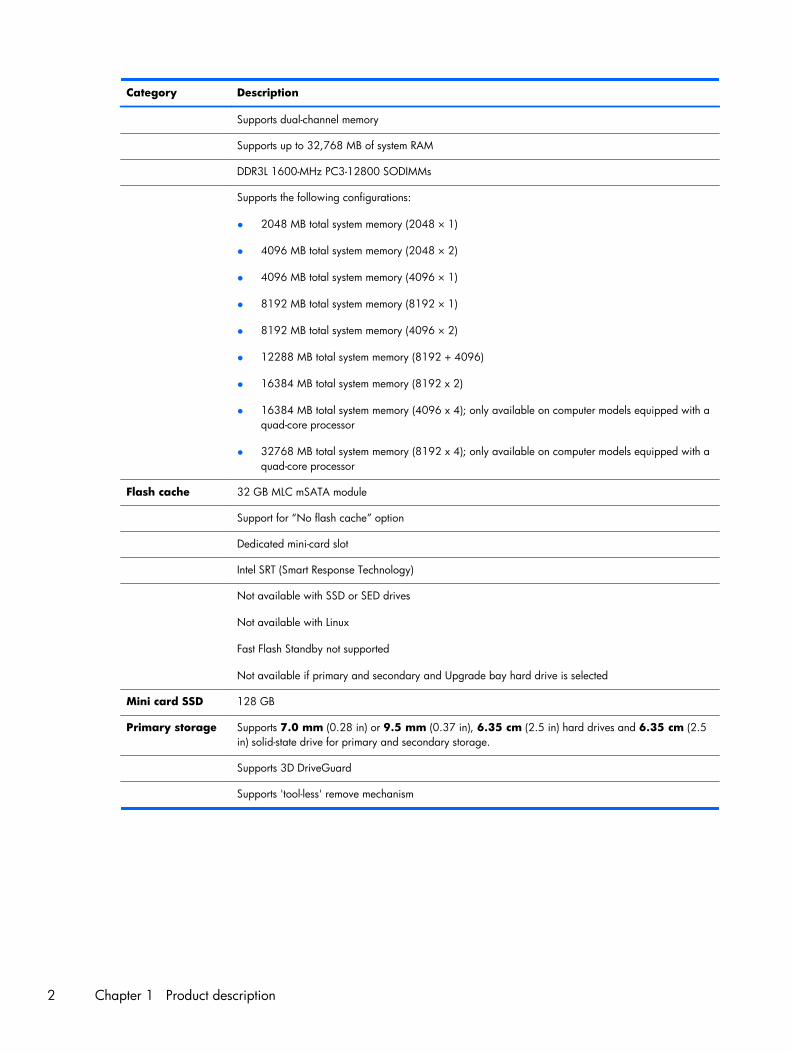
Supports dual-channel memory
Supports up to 32,768 MB of system RAM
DDR3L 1600-MHz PC3-12800 SODIMMs
Supports the following configurations:
● 2048 MB total system memory (2048 × 1)
● 4096 MB total system memory (2048 × 2)
● 4096 MB total system memory (4096 × 1)
● 8192 MB total system memory (8192 × 1)
● 8192 MB total system memory (4096 × 2)
● 12288 MB total system memory (8192 + 4096)
● 16384 MB total system memory (8192 x 2)
● 16384 MB total system memory (4096 x 4); only available on computer models equipped with aquad-core processor
● 32768 MB total system memory (8192 x 4); only available on computer models equipped with aquad-core processor
Flash cache 32 GB MLC mSATA module
Support for “No flash cache” option
Dedicated mini-card slot
Intel SRT (Smart Response Technology)
Not available with SSD or SED drives
Not available with Linux
Fast Flash Standby not supported
Not available if primary and secondary and Upgrade bay hard drive is selected
Mini card SSD 128 GB
Primary storage Supports 7.0 mm (0.28 in) or 9.5 mm (0.37 in), 6.35 cm (2.5 in) hard drives and 6.35 cm (2.5in) solid-state drive for primary and secondary storage.
Supports 3D DriveGuard
Supports 'tool-less' remove mechanism
2 Chapter 1 Product description
Category Description
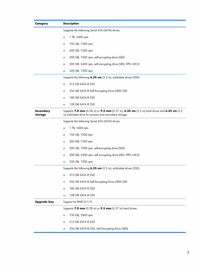
Supports the following Serial ATA (SATA) drives:
● 1 TB, 5400 rpm
● 750 GB, 7200 rpm
● 500 GB, 7200 rpm
● 500 GB, 7200 rpm, self-encrypting drive (SED)
● 500 GB, 5400 rpm, self encrypting drive (SED, FIPS-140-2)
● 320 GB, 7200 rpm
Supports the following 6.35 cm (2.5 in), solid-state drives (SSD):
● 512 GB SATA III SSD
● 256 GB SATA III Self Encrypting Drive (SED) SSD
● 180 GB SATA III SSD
● 128 GB SATA III SSD
Secondarystorage
Supports 7.0 mm (0.28 in) or 9.5 mm (0.37 in), 6.35 cm (2.5 in) hard drives and 6.35 cm (2.5in) solid-state drive for primary and secondary storage.
Supports the following Serial ATA (SATA) drives:
● 1 TB, 5400 rpm
● 750 GB, 7200 rpm
● 500 GB, 7200 rpm
● 500 GB, 7200 rpm, self-encrypting drive (SED)
● 500 GB, 5400 rpm, self encrypting drive (SED, FIPS-140-2)
● 320 GB, 7200 rpm
Supports the following 6.35 cm (2.5 in), solid-state drives (SSD):
● 512 GB SATA III SSD
● 256 GB SATA III Self Encrypting Drive (SED) SSD
● 180 GB SATA III SSD
● 128 GB SATA III SSD
Upgrade bay Support for RAID 0/1/5
Supports 7.0 mm (0.28 in) or 9.5 mm (0.37 in) hard drives:
● 750 GB, 5400 rpm
● 512 GB SATA III SSD
● 256 GB SATA III SSD, Self Encrypting Drive (SED)
3
Category Description
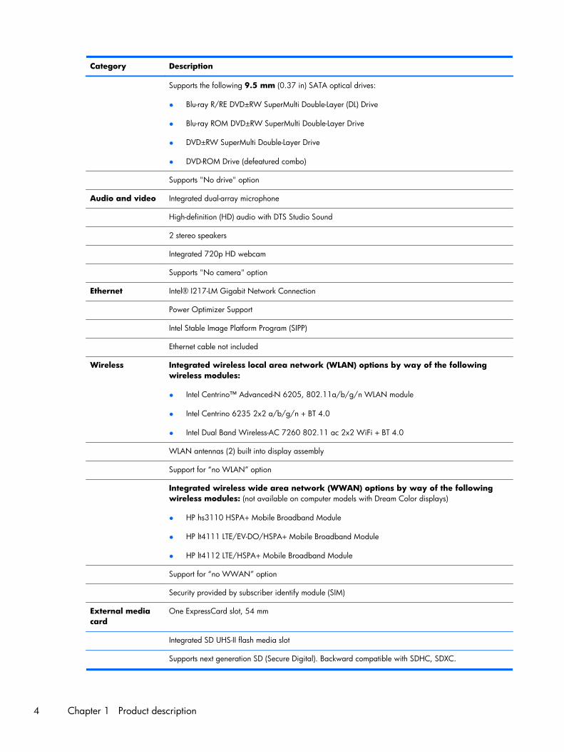
Supports the following 9.5 mm (0.37 in) SATA optical drives:
● Blu-ray R/RE DVD±RW SuperMulti Double-Layer (DL) Drive
● Blu-ray ROM DVD±RW SuperMulti Double-Layer Drive
● DVD±RW SuperMulti Double-Layer Drive
● DVD-ROM Drive (defeatured combo)
Supports "No drive" option
Audio and video Integrated dual-array microphone
High-definition (HD) audio with DTS Studio Sound
2 stereo speakers
Integrated 720p HD webcam
Supports "No camera" option
Ethernet Intel® I217-LM Gigabit Network Connection
Power Optimizer Support
Intel Stable Image Platform Program (SIPP)
Ethernet cable not included
Wireless Integrated wireless local area network (WLAN) options by way of the followingwireless modules:
● Intel Centrino™ Advanced-N 6205, 802.11a/b/g/n WLAN module
● Intel Centrino 6235 2x2 a/b/g/n + BT 4.0
● Intel Dual Band Wireless-AC 7260 802.11 ac 2x2 WiFi + BT 4.0
WLAN antennas (2) built into display assembly
Support for “no WLAN” option
Integrated wireless wide area network (WWAN) options by way of the followingwireless modules: (not available on computer models with Dream Color displays)
● HP hs3110 HSPA+ Mobile Broadband Module
● HP lt4111 LTE/EV-DO/HSPA+ Mobile Broadband Module
● HP lt4112 LTE/HSPA+ Mobile Broadband Module
Support for “no WWAN” option
Security provided by subscriber identify module (SIM)
External mediacard
One ExpressCard slot, 54 mm
Integrated SD UHS-II flash media slot
Supports next generation SD (Secure Digital). Backward compatible with SDHC, SDXC.
4 Chapter 1 Product description
Category Description
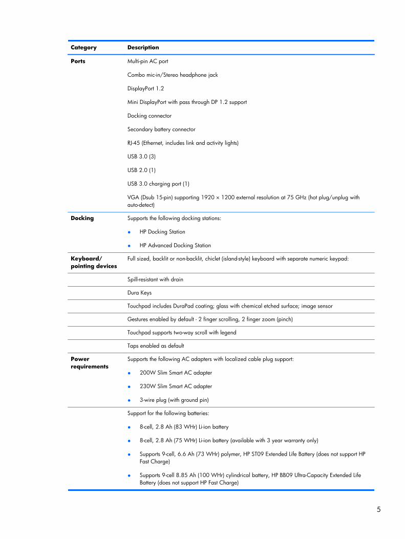
Ports Multi-pin AC port
Combo mic-in/Stereo headphone jack
DisplayPort 1.2
Mini DisplayPort with pass through DP 1.2 support
Docking connector
Secondary battery connector
RJ-45 (Ethernet, includes link and activity lights)
USB 3.0 (3)
USB 2.0 (1)
USB 3.0 charging port (1)
VGA (Dsub 15-pin) supporting 1920 × 1200 external resolution at 75 GHz (hot plug/unplug withauto-detect)
Docking Supports the following docking stations:
● HP Docking Station
● HP Advanced Docking Station
Keyboard/pointing devices
Full sized, backlit or non-backlit, chiclet (island-style) keyboard with separate numeric keypad:
Spill-resistant with drain
Dura Keys
Touchpad includes DuraPad coating; glass with chemical etched surface; image sensor
Gestures enabled by default - 2 finger scrolling, 2 finger zoom (pinch)
Touchpad supports two-way scroll with legend
Taps enabled as default
Powerrequirements
Supports the following AC adapters with localized cable plug support:
● 200W Slim Smart AC adapter
● 230W Slim Smart AC adapter
● 3-wire plug (with ground pin)
Support for the following batteries:
● 8-cell, 2.8 Ah (83 WHr) Li-ion battery
● 8-cell, 2.8 Ah (75 WHr) Li-ion battery (available with 3 year warranty only)
● Supports 9-cell, 6.6 Ah (73 WHr) polymer, HP ST09 Extended Life Battery (does not support HPFast Charge)
● Supports 9-cell 8.85 Ah (100 WHr) cylindrical battery, HP BB09 Ultra-Capacity Extended LifeBattery (does not support HP Fast Charge)
5
Category Description
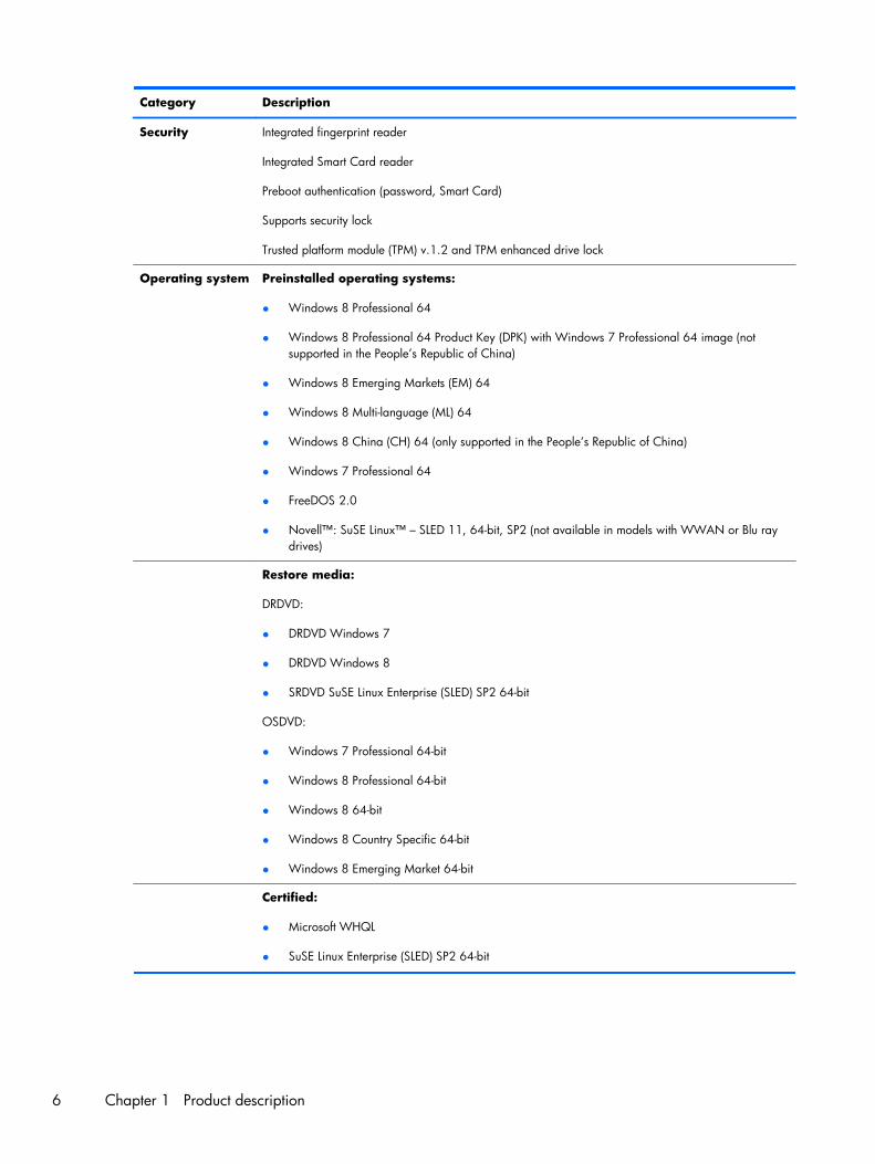
Security Integrated fingerprint reader
Integrated Smart Card reader
Preboot authentication (password, Smart Card)
Supports security lock
Trusted platform module (TPM) v.1.2 and TPM enhanced drive lock
Operating system Preinstalled operating systems:
● Windows 8 Professional 64
● Windows 8 Professional 64 Product Key (DPK) with Windows 7 Professional 64 image (notsupported in the People’s Republic of China)
● Windows 8 Emerging Markets (EM) 64
● Windows 8 Multi-language (ML) 64
● Windows 8 China (CH) 64 (only supported in the People’s Republic of China)
● Windows 7 Professional 64
● FreeDOS 2.0
● Novell™: SuSE Linux™ – SLED 11, 64-bit, SP2 (not available in models with WWAN or Blu raydrives)
Restore media:
DRDVD:
● DRDVD Windows 7
● DRDVD Windows 8
● SRDVD SuSE Linux Enterprise (SLED) SP2 64-bit
OSDVD:
● Windows 7 Professional 64-bit
● Windows 8 Professional 64-bit
● Windows 8 64-bit
● Windows 8 Country Specific 64-bit
● Windows 8 Emerging Market 64-bit
Certified:
● Microsoft WHQL
● SuSE Linux Enterprise (SLED) SP2 64-bit
6 Chapter 1 Product description
Category Description
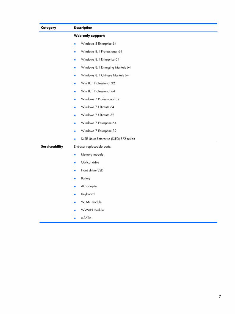
Web-only support:
● Windows 8 Enterprise 64
● Windows 8.1 Professional 64
● Windows 8.1 Enterprise 64
● Windows 8.1 Emerging Markets 64
● Windows 8.1 Chinese Markets 64
● Win 8.1 Professional 32
● Win 8.1 Professional 64
● Windows 7 Professional 32
● Windows 7 Ultimate 64
● Windows 7 Ultimate 32
● Windows 7 Enterprise 64
● Windows 7 Enterprise 32
● SuSE Linux Enterprise (SLED) SP2 64-bit
Serviceability End-user replaceable parts:
● Memory module
● Optical drive
● Hard drive/SSD
● Battery
● AC adapter
● Keyboard
● WLAN module
● WWAN module
● mSATA
7
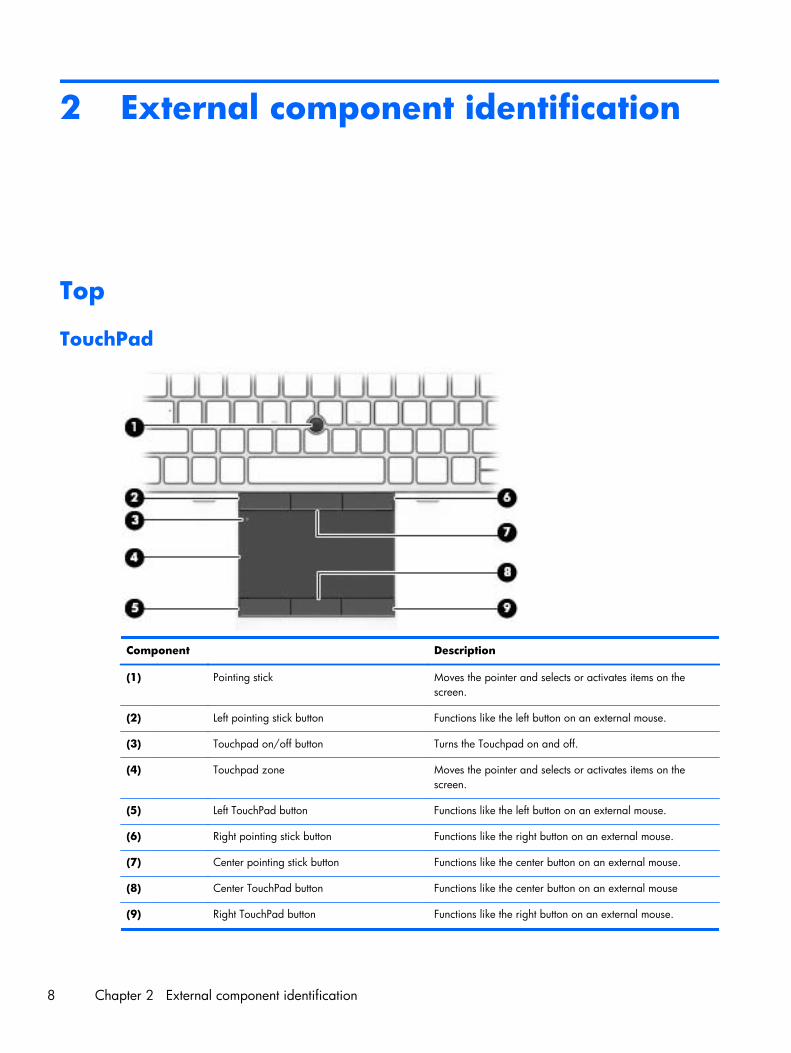
2 External component identification
Top
TouchPad
Component Description
(1) Pointing stick Moves the pointer and selects or activates items on thescreen.
(2) Left pointing stick button Functions like the left button on an external mouse.
(3) Touchpad on/off button Turns the Touchpad on and off.
(4) Touchpad zone Moves the pointer and selects or activates items on thescreen.
(5) Left TouchPad button Functions like the left button on an external mouse.
(6) Right pointing stick button Functions like the right button on an external mouse.
(7) Center pointing stick button Functions like the center button on an external mouse.
(8) Center TouchPad button Functions like the center button on an external mouse
(9) Right TouchPad button Functions like the right button on an external mouse.
8 Chapter 2 External component identification
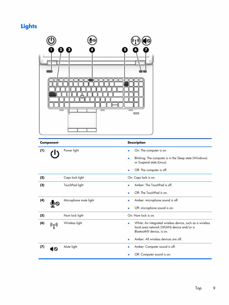
Lights
Component Description
(1) Power light ● On: The computer is on.
● Blinking: The computer is in the Sleep state (Windows)or Suspend state (Linux).
● Off: The computer is off.
(2) Caps lock light On: Caps lock is on.
(3) TouchPad light ● Amber: The TouchPad is off.
● Off: The TouchPad is on.
(4) Microphone mute light ● Amber: microphone sound is off.
● Off: microphone sound is on.
(5) Num lock light On: Num lock is on.
(6) Wireless light ● White: An integrated wireless device, such as a wirelesslocal area network (WLAN) device and/or aBluetooth® device, is on.
● Amber: All wireless devices are off.
(7) Mute light ● Amber: Computer sound is off.
● Off: Computer sound is on.
Top 9

Buttons and speakers
10 Chapter 2 External component identification
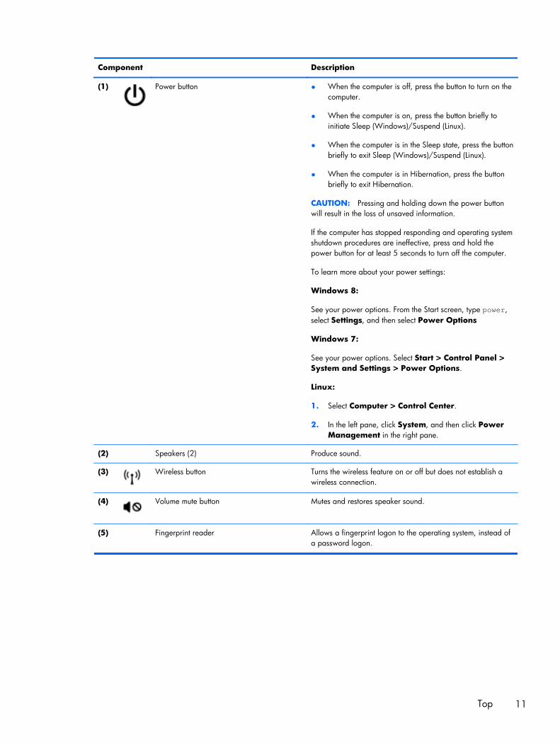
Component Description
(1) Power button ● When the computer is off, press the button to turn on thecomputer.
● When the computer is on, press the button briefly toinitiate Sleep (Windows)/Suspend (Linux).
● When the computer is in the Sleep state, press the buttonbriefly to exit Sleep (Windows)/Suspend (Linux).
● When the computer is in Hibernation, press the buttonbriefly to exit Hibernation.
CAUTION: Pressing and holding down the power buttonwill result in the loss of unsaved information.
If the computer has stopped responding and operating systemshutdown procedures are ineffective, press and hold thepower button for at least 5 seconds to turn off the computer.
To learn more about your power settings:
Windows 8:
See your power options. From the Start screen, type power,select Settings, and then select Power Options
Windows 7:
See your power options. Select Start > Control Panel >System and Settings > Power Options.
Linux:
1. Select Computer > Control Center.
2. In the left pane, click System, and then click PowerManagement in the right pane.
(2) Speakers (2) Produce sound.
(3) Wireless button Turns the wireless feature on or off but does not establish awireless connection.
(4) Volume mute button Mutes and restores speaker sound.
(5) Fingerprint reader Allows a fingerprint logon to the operating system, instead ofa password logon.
Top 11
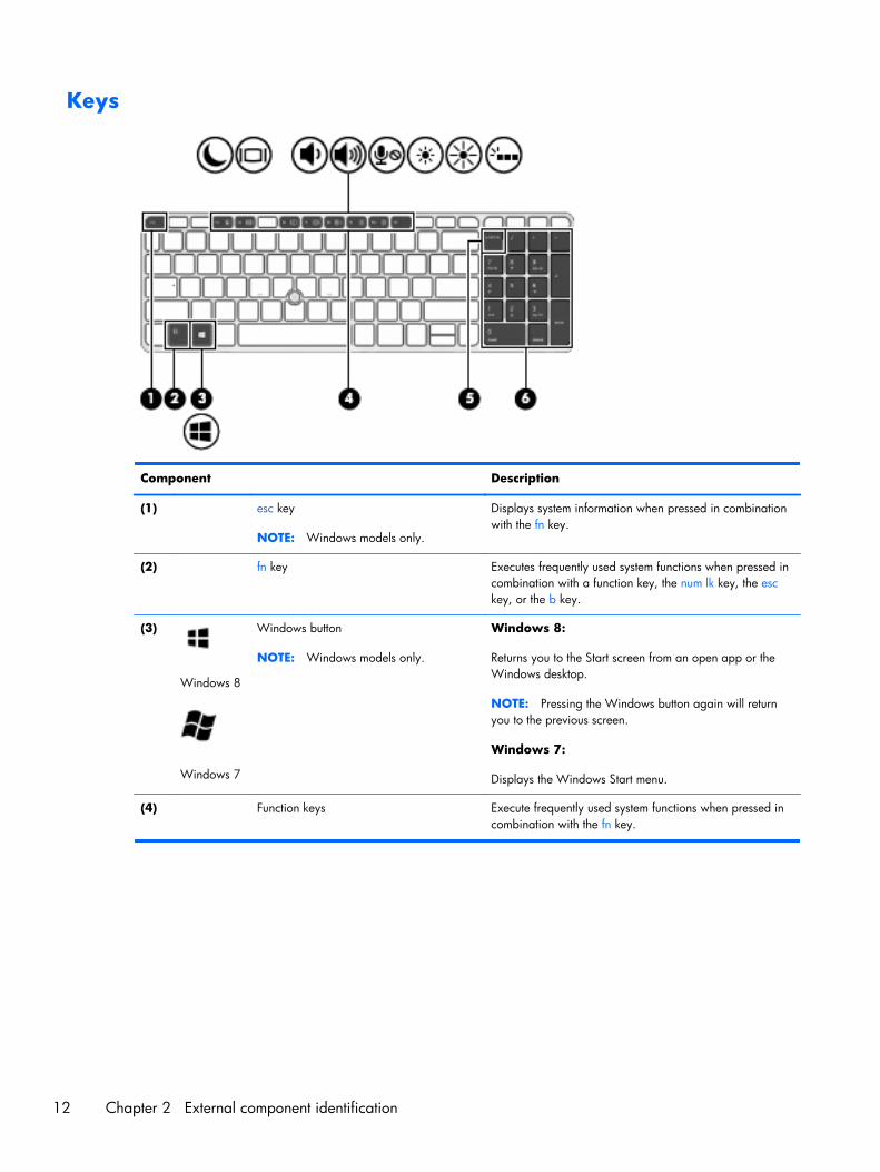
Keys
Component Description
(1) esc key
NOTE: Windows models only.
Displays system information when pressed in combinationwith the fn key.
(2) fn key Executes frequently used system functions when pressed incombination with a function key, the num lk key, the esckey, or the b key.
(3)
Windows 8
Windows 7
Windows button
NOTE: Windows models only.
Windows 8:
Returns you to the Start screen from an open app or theWindows desktop.
NOTE: Pressing the Windows button again will returnyou to the previous screen.
Windows 7:
Displays the Windows Start menu.
(4) Function keys Execute frequently used system functions when pressed incombination with the fn key.
12 Chapter 2 External component identification
Component Description
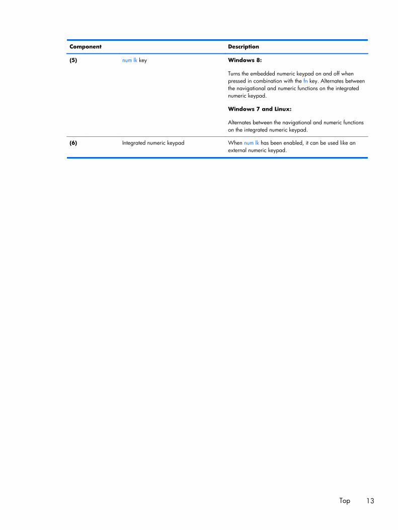
(5) num lk key Windows 8:
Turns the embedded numeric keypad on and off whenpressed in combination with the fn key. Alternates betweenthe navigational and numeric functions on the integratednumeric keypad.
Windows 7 and Linux:
Alternates between the navigational and numeric functionson the integrated numeric keypad.
(6) Integrated numeric keypad When num lk has been enabled, it can be used like anexternal numeric keypad.
Top 13

Front
Component Description
(1) Wireless light ● White: An integrated device, such as a wirelesslocal area network (WLAN) device and/or aBluetooth device, is on.
● Amber: All wireless devices are off.
(2) Power light ● On: The computer is on.
● Blinking: The computer is in the Sleep state.
● Off: The computer is off.
(3) AC adapter/Battery light ● White: The computer is connected to externalpower and the battery is charged from 90 to 99percent.
● Amber: The computer is connected to externalpower and the battery is charged from 0 to 90percent.
● Blinking amber: A battery that is the onlyavailable power source has reached a low batterylevel. When the battery reaches a critical batterylevel, the battery light begins blinking rapidly.
● Off: The battery is fully charged.
(4) Hard drive light ● Blinking white: The hard drive is being accessed.
● Amber: HP 3D DriveGuard has temporarilyparked the hard drive.
14 Chapter 2 External component identification
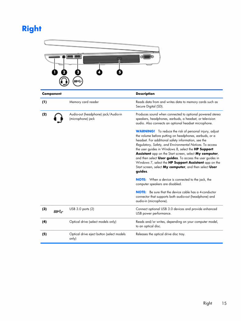
Right
Component Description
(1) Memory card reader Reads data from and writes data to memory cards such asSecure Digital (SD).
(2) Audio-out (headphone) jack/Audio-in(microphone) jack
Produces sound when connected to optional powered stereospeakers, headphones, earbuds, a headset, or televisionaudio. Also connects an optional headset microphone.
WARNING! To reduce the risk of personal injury, adjustthe volume before putting on headphones, earbuds, or aheadset. For additional safety information, see theRegulatory, Safety, and Environmental Notices. To accessthe user guides in Windows 8, select the HP SupportAssistant app on the Start screen, select My computer,and then select User guides. To access the user guides inWindows 7, select the HP Support Assistant app on theStart screen, select My computer, and then select Userguides.
NOTE: When a device is connected to the jack, thecomputer speakers are disabled.
NOTE: Be sure that the device cable has a 4-conductorconnector that supports both audio-out (headphone) andaudio-in (microphone).
(3) USB 3.0 ports (2) Connect optional USB 3.0 devices and provide enhancedUSB power performance.
(4) Optical drive (select models only) Reads and/or writes, depending on your computer model,to an optical disc.
(5) Optical drive eject button (select modelsonly)
Releases the optical drive disc tray.
Right 15
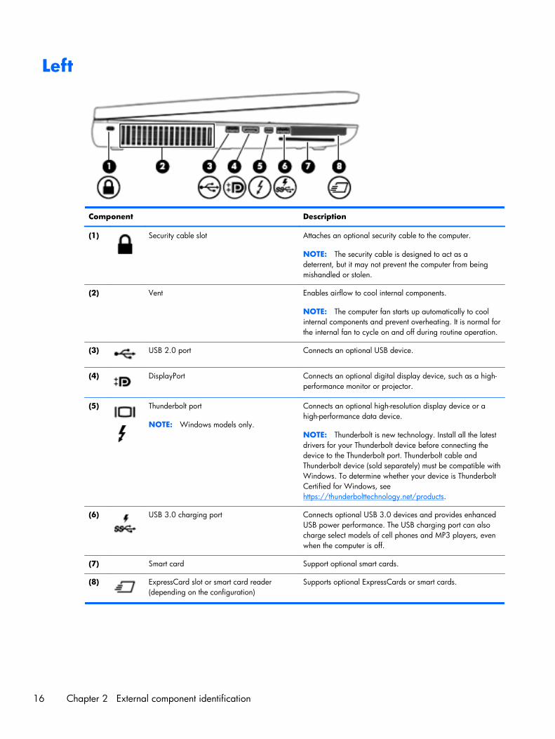
Left
Component Description
(1) Security cable slot Attaches an optional security cable to the computer.
NOTE: The security cable is designed to act as adeterrent, but it may not prevent the computer from beingmishandled or stolen.
(2) Vent Enables airflow to cool internal components.
NOTE: The computer fan starts up automatically to coolinternal components and prevent overheating. It is normal forthe internal fan to cycle on and off during routine operation.
(3) USB 2.0 port Connects an optional USB device.
(4) DisplayPort Connects an optional digital display device, such as a high-performance monitor or projector.
(5) Thunderbolt port
NOTE: Windows models only.
Connects an optional high-resolution display device or ahigh-performance data device.
NOTE: Thunderbolt is new technology. Install all the latestdrivers for your Thunderbolt device before connecting thedevice to the Thunderbolt port. Thunderbolt cable andThunderbolt device (sold separately) must be compatible withWindows. To determine whether your device is ThunderboltCertified for Windows, seehttps://thunderbolttechnology.net/products.
(6) USB 3.0 charging port Connects optional USB 3.0 devices and provides enhancedUSB power performance. The USB charging port can alsocharge select models of cell phones and MP3 players, evenwhen the computer is off.
(7) Smart card Support optional smart cards.
(8) ExpressCard slot or smart card reader(depending on the configuration)
Supports optional ExpressCards or smart cards.
16 Chapter 2 External component identification
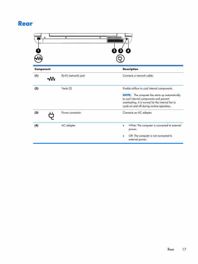
Rear
Component Description
(1) RJ-45 (network) jack Connects a network cable.
(2) Vents (2) Enable airflow to cool internal components.
NOTE: The computer fan starts up automaticallyto cool internal components and preventoverheating. It is normal for the internal fan tocycle on and off during routine operation.
(3) Power connector Connects an AC adapter.
(4) AC adapter ● White: The computer is connected to externalpower.
● Off: The computer is not connected toexternal power.
Rear 17
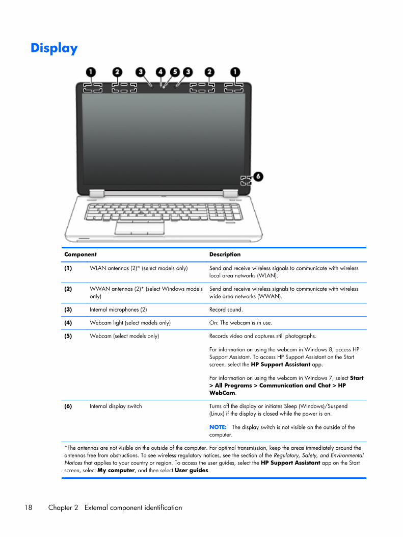
Display
Component Description
(1) WLAN antennas (2)* (select models only) Send and receive wireless signals to communicate with wirelesslocal area networks (WLAN).
(2) WWAN antennas (2)* (select Windows modelsonly)
Send and receive wireless signals to communicate with wirelesswide area networks (WWAN).
(3) Internal microphones (2) Record sound.
(4) Webcam light (select models only) On: The webcam is in use.
(5) Webcam (select models only) Records video and captures still photographs.
For information on using the webcam in Windows 8, access HPSupport Assistant. To access HP Support Assistant on the Startscreen, select the HP Support Assistant app.
For information on using the webcam in Windows 7, select Start> All Programs > Communication and Chat > HPWebCam.
(6) Internal display switch Turns off the display or initiates Sleep (Windows)/Suspend(Linux) if the display is closed while the power is on.
NOTE: The display switch is not visible on the outside of thecomputer.
*The antennas are not visible on the outside of the computer. For optimal transmission, keep the areas immediately around theantennas free from obstructions. To see wireless regulatory notices, see the section of the Regulatory, Safety, and EnvironmentalNotices that applies to your country or region. To access the user guides, select the HP Support Assistant app on the Startscreen, select My computer, and then select User guides.
18 Chapter 2 External component identification
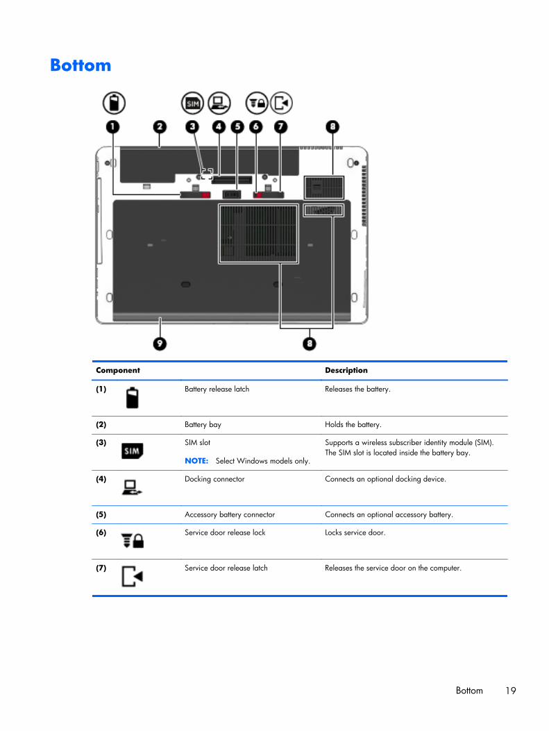
Bottom
Component Description
(1) Battery release latch Releases the battery.
(2) Battery bay Holds the battery.
(3) SIM slot
NOTE: Select Windows models only.
Supports a wireless subscriber identity module (SIM).The SIM slot is located inside the battery bay.
(4) Docking connector Connects an optional docking device.
(5) Accessory battery connector Connects an optional accessory battery.
(6) Service door release lock Locks service door.
(7) Service door release latch Releases the service door on the computer.
Bottom 19
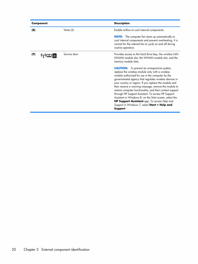
Component Description
(8) Vents (3) Enable airflow to cool internal components.
NOTE: The computer fan starts up automatically tocool internal components and prevent overheating. It isnormal for the internal fan to cycle on and off duringroutine operation.
(9) Service door Provides access to the hard drive bay, the wireless LAN(WLAN) module slot, the WWAN module slot, and thememory module slots.
CAUTION: To prevent an unresponsive system,replace the wireless module only with a wirelessmodule authorized for use in the computer by thegovernmental agency that regulates wireless devices inyour country or region. If you replace the module andthen receive a warning message, remove the module torestore computer functionality, and then contact supportthrough HP Support Assistant. To access HP SupportAssistant in Windows 8, on the Start screen, select theHP Support Assistant app. To access Help andSupport in Windows 7, select Start > Help andSupport.
20 Chapter 2 External component identification

Service tag and PCID label
Service tag
IMPORTANT: All labels described in this section will be located in one of 3 places depending onyour computer model: Affixed to the bottom of the computer, located in the battery bay, or under theservice door.
When ordering parts or requesting information, provide the computer serial number and model numberprovided on the service tag.
NOTE: Your service labels will resemble one of the examples shown below. Refer to the illustrationthat most closely matches the service label on your computer.
Item Component Description
(1) Product name This is the product name affixed to the front of thecomputer.
(2) Serial number (s/n) This is an alphanumeric identifier that is unique to eachproduct.
Service tag and PCID label 21
Item Component Description
(3) Product number (p/n) This number provides specific information about theproduct’s hardware components. The part number helpsa service technician determine what components andparts are needed.
(4) Warranty period This number describes the duration of the warrantyperiod for the computer.
(5) Model number (select models only) This is the alphanumeric identifier needed to locatedocuments, drivers, and support for the computer.
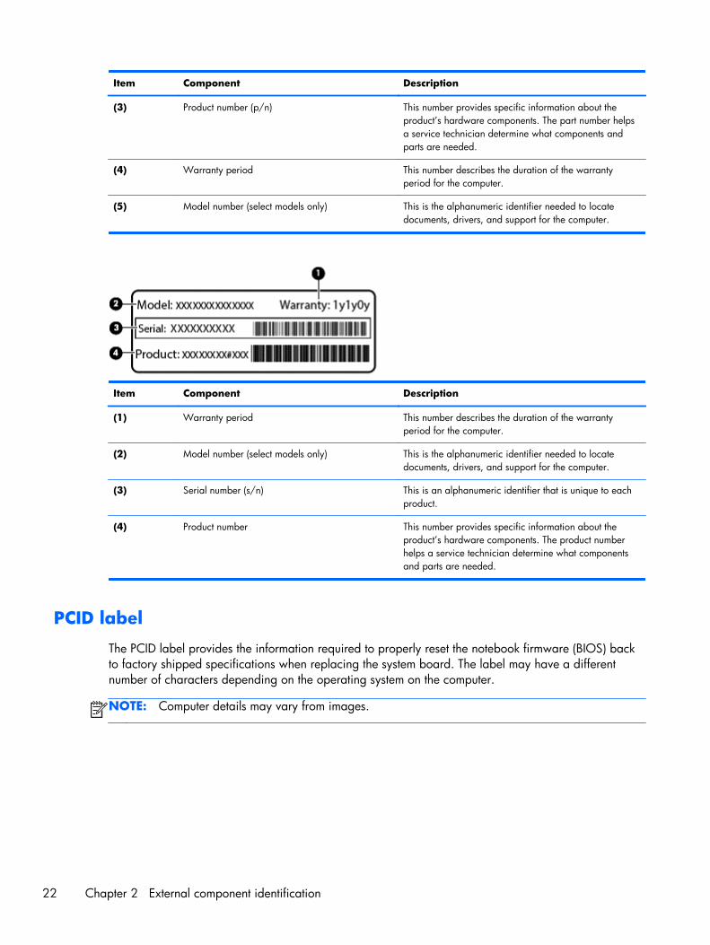
Item Component Description
(1) Warranty period This number describes the duration of the warrantyperiod for the computer.
(2) Model number (select models only) This is the alphanumeric identifier needed to locatedocuments, drivers, and support for the computer.
(3) Serial number (s/n) This is an alphanumeric identifier that is unique to eachproduct.
(4) Product number This number provides specific information about theproduct’s hardware components. The product numberhelps a service technician determine what componentsand parts are needed.
PCID label
The PCID label provides the information required to properly reset the notebook firmware (BIOS) backto factory shipped specifications when replacing the system board. The label may have a differentnumber of characters depending on the operating system on the computer.
NOTE: Computer details may vary from images.
22 Chapter 2 External component identification
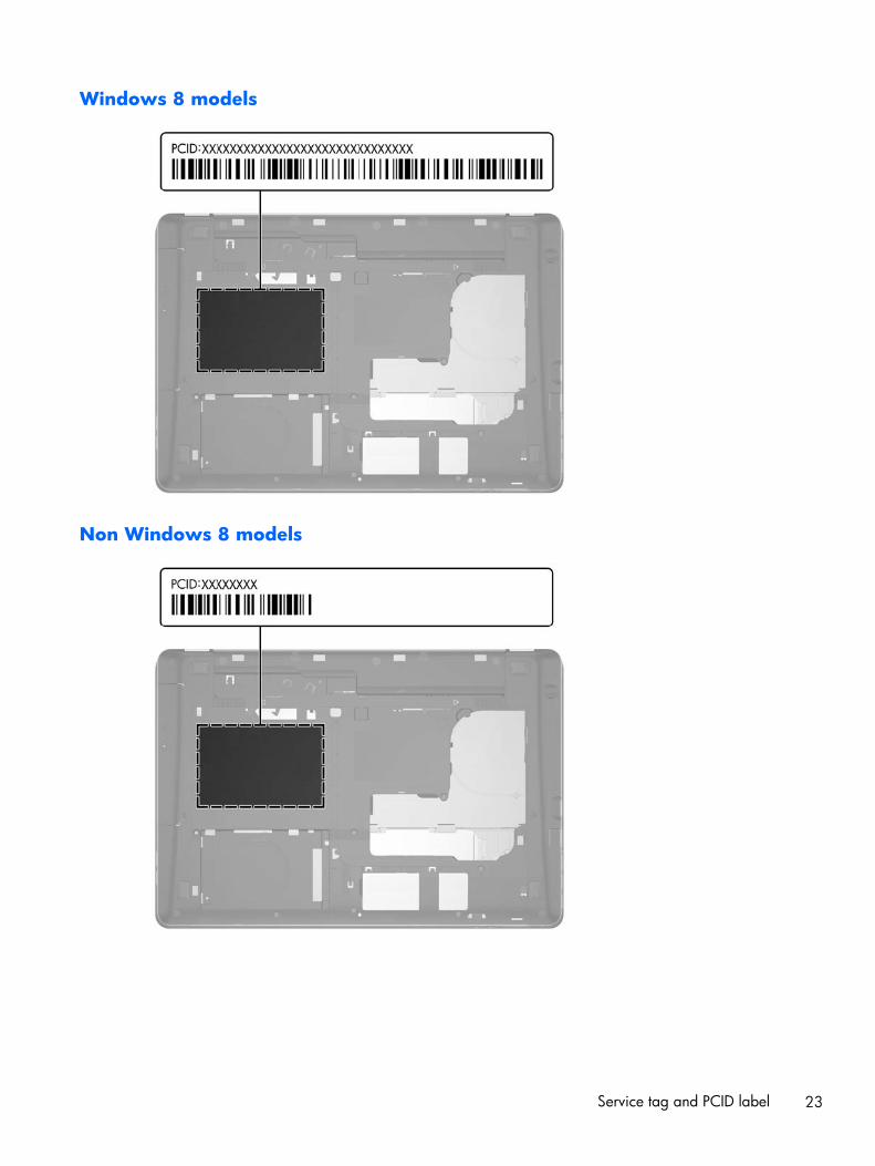
Windows 8 models
Non Windows 8 models
Service tag and PCID label 23

3 Illustrated parts catalog
Computer major components
24 Chapter 3 Illustrated parts catalog

Item Description Spare part number
(1) Display
Display assembly, 43.9 cm (17.3 in), FHD, anti-glare, LED, UWVA, DreamColor for use inmodels with a webcam
735369-001
Display assembly, 43.9 cm (17.3 in), FHD, anti-glare, LED, UWVA, DreamColor for use inmodels without a webcam
735368-001
NOTE: See Display components on page 28 for more display component information and spare part numbers.
(2) Keyboard (backlit, includes keyboard cable, pointing stick and pointing stick cable):
NOTE: For a detailed list of available keyboards, see Sequential part number listingon page 36.
733688-xx1
(3) Top cover 735587-001
(4) Power button board (includes cable) 733636-001
(5) Memory modules (PC3L-12800, 1600 MHz, DDR3)
8 GB 693374-001
4 GB 691740-001
(6) Fingerprint reader (includes cable) 737730-001
(7) Processor (includes replacement thermal material):
Intel Core processors (support Intel Turbo Boost Technology):
i7-4930MX, 3.00 GHz (Turbo up to 3.90 GHz), 1600 MHz, 8 MB L3 cache, 57W 735099-002
i7-4900MQ, 2.80 GHz (Turbo up to 3.80 GHz), 1600 MHz, 8 MB L3 cache, 47W 723523-002
i7-4800MQ, 2.70 GHz (Turbo up to 3.70 GHz), 1600 MHz, 6 MB L3 cache, 47W 723524-002
i7-4700MQ, 2.40 GHz (Turbo up to 3.40 GHz), 1600 MHz, 6 MB L3 cache, 47W 723521-002
i7-4600M, 2.90 GHz (Turbo up to 3.60 GHz), 1600 MHz, 4 MB L3 cache, 37W 737330-002
Intel Core i5 processors (support Intel Turbo Boost Technology):
i5-4330M, 2.80 GHz (Turbo up to 3.50 GHz), 1600 MHz, 3 MB L3 cache, 37W 738201-002
i5-4300M, 2.60 GHz (Turbo up to 3.30 GHz), 1600 MHz, 3 MB L3 cache, 37W 738309-002
(8) Graphics board (includes replacement thermal material):
NVIDIA Quadro K5100M, 8 GB dedicated GDDR5 video memory 728555-001
NVIDIA Quadro K4100M, 4 GB dedicated GDDR5 video memory 728556-001
NVIDIA Quadro K3100M, 4 GB dedicated GDDR5 video memory 728557-001
NVIDIA Quadro K610M, 1 GB dedicated GDDR5 video memory 728554-001
(9) Multifunction board (includes LED light pipe) 733639-001
(10) System board (includes replacement thermal material)
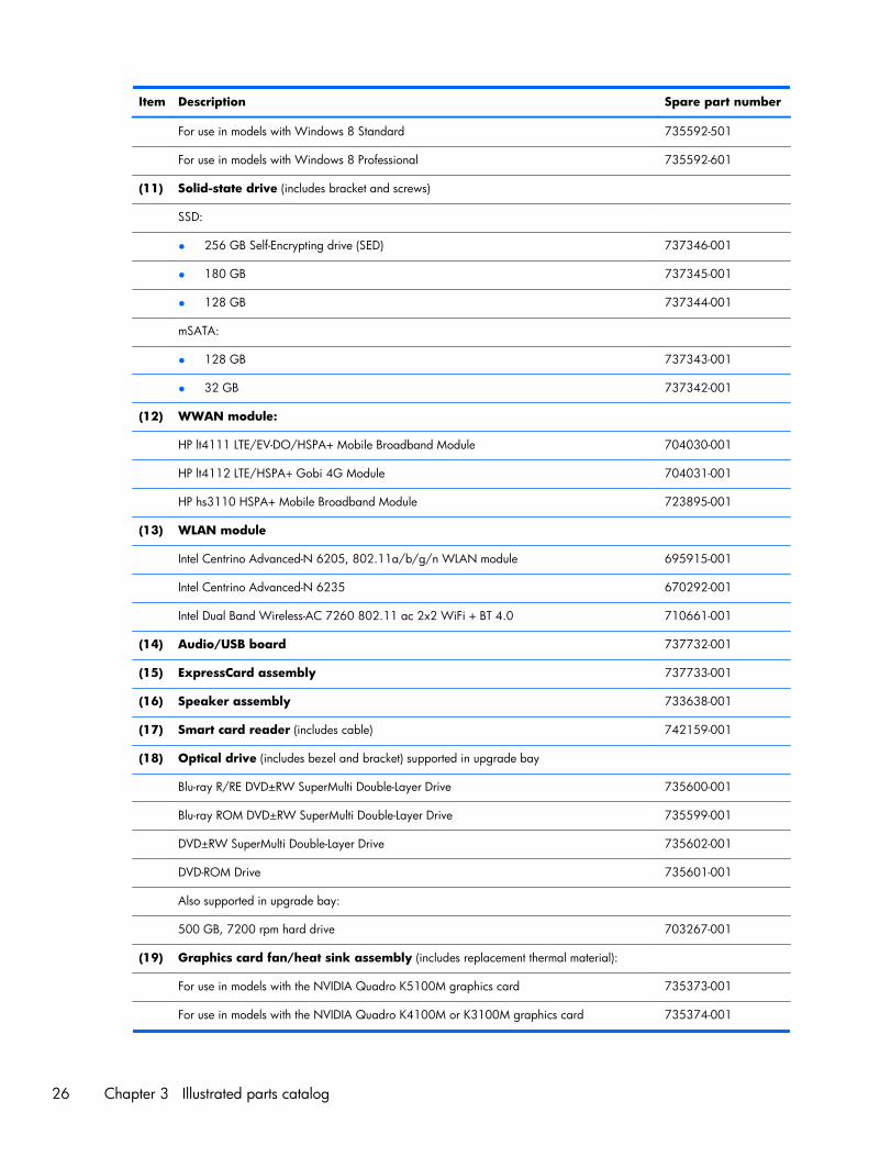
For use in non-Windows 8 models 735592-001
Computer major components 25
Item Description Spare part number
For use in models with Windows 8 Standard 735592-501
For use in models with Windows 8 Professional 735592-601
(11) Solid-state drive (includes bracket and screws)
SSD:
● 256 GB Self-Encrypting drive (SED) 737346-001
● 180 GB 737345-001
● 128 GB 737344-001
mSATA:
● 128 GB 737343-001
● 32 GB 737342-001
(12) WWAN module:
HP lt4111 LTE/EV-DO/HSPA+ Mobile Broadband Module 704030-001
HP lt4112 LTE/HSPA+ Gobi 4G Module 704031-001
HP hs3110 HSPA+ Mobile Broadband Module 723895-001
(13) WLAN module
Intel Centrino Advanced-N 6205, 802.11a/b/g/n WLAN module 695915-001
Intel Centrino Advanced-N 6235 670292-001
Intel Dual Band Wireless-AC 7260 802.11 ac 2x2 WiFi + BT 4.0 710661-001
(14) Audio/USB board 737732-001
(15) ExpressCard assembly 737733-001
(16) Speaker assembly 733638-001
(17) Smart card reader (includes cable) 742159-001
(18) Optical drive (includes bezel and bracket) supported in upgrade bay
Blu-ray R/RE DVD±RW SuperMulti Double-Layer Drive 735600-001
Blu-ray ROM DVD±RW SuperMulti Double-Layer Drive 735599-001
DVD±RW SuperMulti Double-Layer Drive 735602-001
DVD-ROM Drive 735601-001
Also supported in upgrade bay:
500 GB, 7200 rpm hard drive 703267-001
(19) Graphics card fan/heat sink assembly (includes replacement thermal material):
For use in models with the NVIDIA Quadro K5100M graphics card 735373-001
For use in models with the NVIDIA Quadro K4100M or K3100M graphics card 735374-001
26 Chapter 3 Illustrated parts catalog
Item Description Spare part number
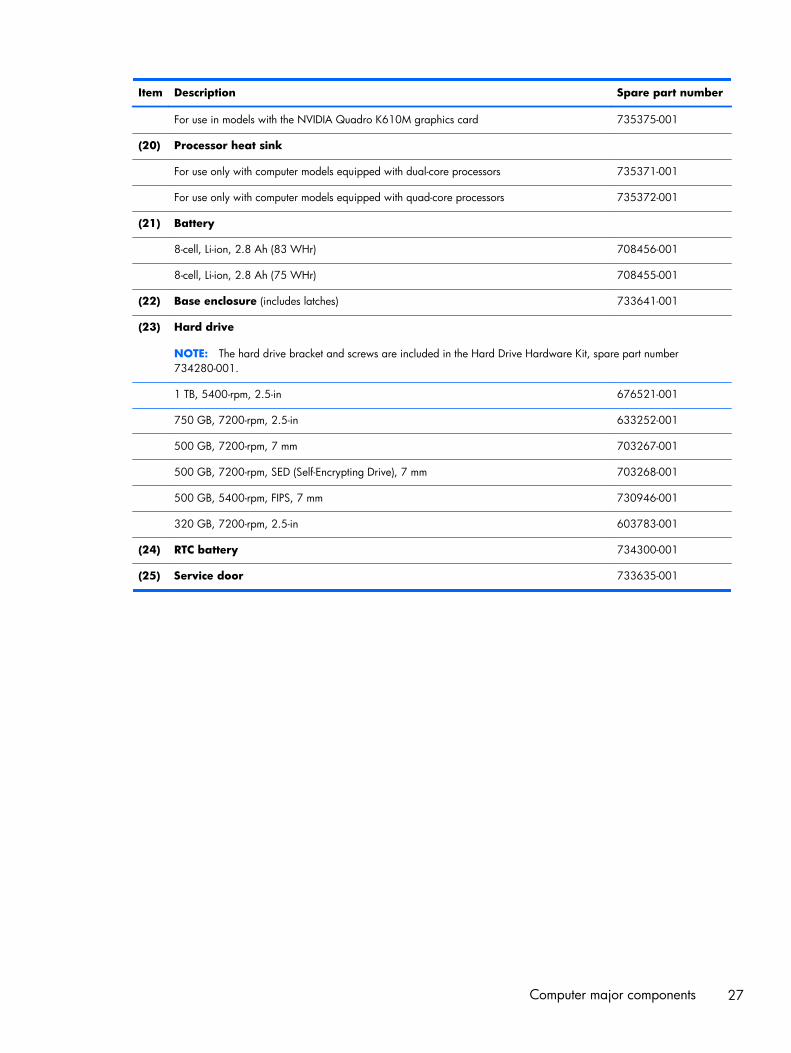
For use in models with the NVIDIA Quadro K610M graphics card 735375-001
(20) Processor heat sink
For use only with computer models equipped with dual-core processors 735371-001
For use only with computer models equipped with quad-core processors 735372-001
(21) Battery
8-cell, Li-ion, 2.8 Ah (83 WHr) 708456-001
8-cell, Li-ion, 2.8 Ah (75 WHr) 708455-001
(22) Base enclosure (includes latches) 733641-001
(23) Hard drive
NOTE: The hard drive bracket and screws are included in the Hard Drive Hardware Kit, spare part number734280-001.
1 TB, 5400-rpm, 2.5-in 676521-001
750 GB, 7200-rpm, 2.5-in 633252-001
500 GB, 7200-rpm, 7 mm 703267-001
500 GB, 7200-rpm, SED (Self-Encrypting Drive), 7 mm 703268-001
500 GB, 5400-rpm, FIPS, 7 mm 730946-001
320 GB, 7200-rpm, 2.5-in 603783-001
(24) RTC battery 734300-001
(25) Service door 733635-001
Computer major components 27
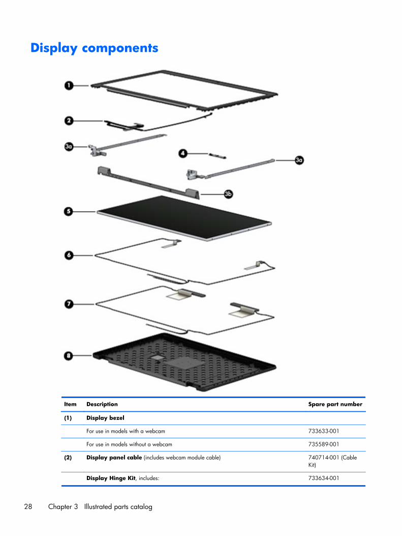
Display components
Item Description Spare part number
(1) Display bezel
For use in models with a webcam 733633-001
For use in models without a webcam 735589-001
(2) Display panel cable (includes webcam module cable) 740714-001 (CableKit)
Display Hinge Kit, includes: 733634-001
28 Chapter 3 Illustrated parts catalog
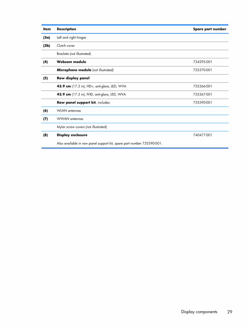
Item Description Spare part number
(3a) Left and right hinges
(3b) Clutch cover
Brackets (not illustrated)
(4) Webcam module 734295-001
Microphone module (not illustrated) 735370-001
(5) Raw display panel
43.9 cm (17.3 in), HD+, anti-glare, LED, WVA 735366-001
43.9 cm (17.3 in), FHD, anti-glare, LED, WVA 735367-001
Raw panel support kit, includes: 735590-001
(6) WLAN antennas
(7) WWAN antennas
Mylar screw covers (not illustrated)
(8) Display enclosure
Also available in raw panel support kit, spare part number 735590-001.
740477-001
Display components 29
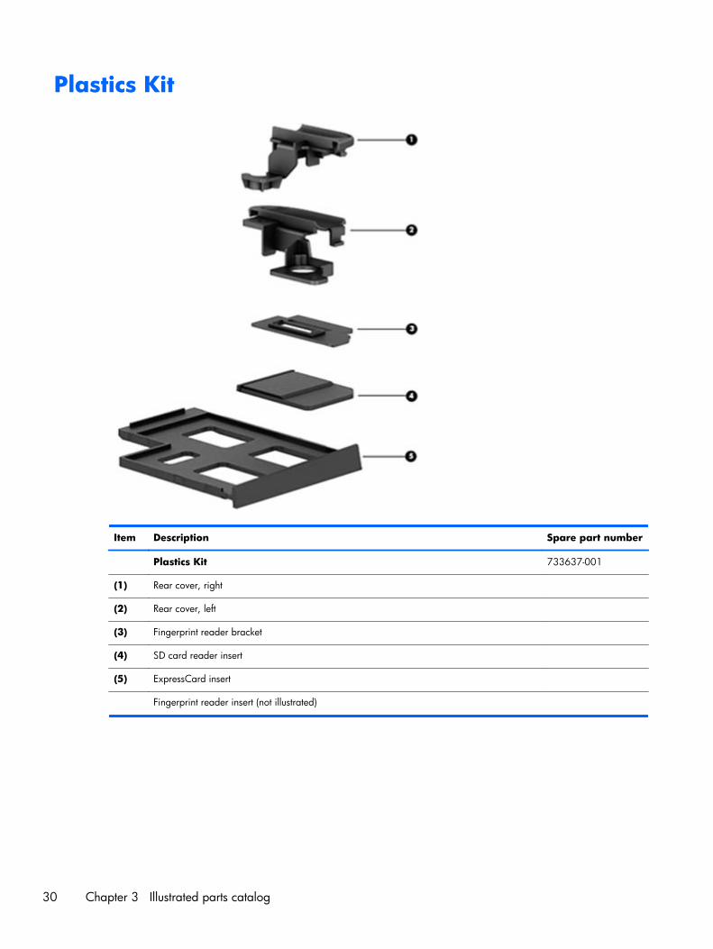
Plastics Kit
Item Description Spare part number
Plastics Kit 733637-001
(1) Rear cover, right
(2) Rear cover, left
(3) Fingerprint reader bracket
(4) SD card reader insert
(5) ExpressCard insert
Fingerprint reader insert (not illustrated)
30 Chapter 3 Illustrated parts catalog
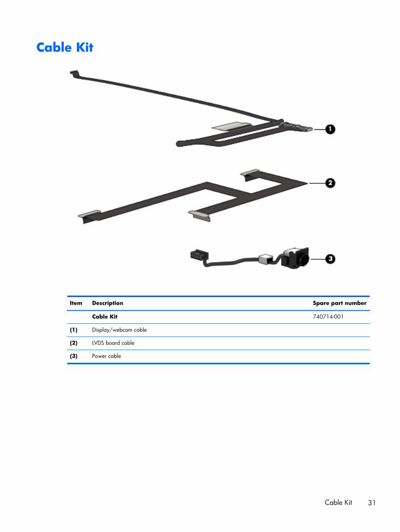
Cable Kit
Item Description Spare part number
Cable Kit 740714-001
(1) Display/webcam cable
(2) LVDS board cable
(3) Power cable
Cable Kit 31
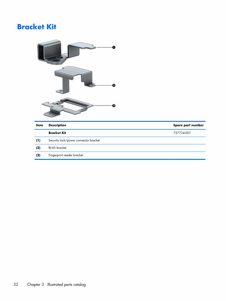
Bracket Kit
Item Description Spare part number
Bracket Kit 737734-001
(1) Security lock/power connector bracket
(2) RJ-45 bracket
(3) Fingerprint reader bracket
32 Chapter 3 Illustrated parts catalog
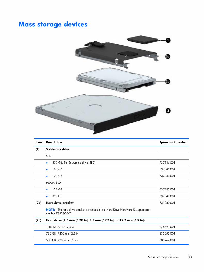
Mass storage devices
Item Description Spare part number
(1) Solid-state drive
SSD:
● 256 GB, Self-Encrypting drive (SED) 737346-001
● 180 GB 737345-001
● 128 GB 737344-001
mSATA SSD:
● 128 GB 737343-001
● 32 GB 737342-001
(2a) Hard drive bracket
NOTE: The hard drive bracket is included in the Hard Drive Hardware Kit, spare partnumber 734280-001.
734280-001
(2b) Hard drive (7.0 mm [0.28 in], 9.5 mm [0.37 in], or 12.7 mm [0.5 in]):
1 TB, 5400-rpm, 2.5-in 676521-001
750 GB, 7200-rpm, 2.5-in 633252-001
500 GB, 7200-rpm, 7 mm 703267-001
Mass storage devices 33

Item Description Spare part number
500 GB, 7200-rpm, SED (Self-Encrypting Drive), 7 mm 703268-001
500 GB, 5400-rpm, FIPS, 7 mm 730946-001
320 GB, 7200-rpm, 2.5-in 603783-001
(3) Optical drive (includes bezel, bracket, and screws)
Blu-ray R/RE DVD±RW SuperMulti Double-Layer Drive 735600-001
DVD±RW SuperMulti Double-Layer Drive 735599-001
Blu-ray ROM DVD±RW SuperMulti Double-Layer Drive 735602-001
DVD-ROM Drive 735601-001
34 Chapter 3 Illustrated parts catalog

Miscellaneous parts
Description Spare part number
HP USB laser mouse 674318-001
Cable lock for use on the docking station 575921-001
AC Adapter
200W PFC Slim AC Smart Adapter 693708-001
230W PFC Slim AC Smart Adapter 693706-001
Power cord (3 conductor, black,1.83 m):
For use in Argentina 491683-D01
For use in APD 491683-D91
For use in Australia 491683-011
For use in Brazil 491683-202
For use in the People’s Republic of China 491683-AA1
For use in Denmark 491683-081
For use in India 491683-D61
For use in Israel 491683-BB1
For use in Italy 491683-061
For use in Japan 491683-291
For use in the Netherlands 491683-B91
For use in North America 491683-001
For use in Saudi Arabia 491683-171
For use in Singapore 491683-AF1
For use in South Africa 491683-AR1
For use in South Korea 491683-291
For use in Switzerland 491683-111
For use in Taiwan 491683-AB1
For use in Thailand 491683-281
For use in the United Kingdom and Singapore 491683-031
Hard Drive Hardware Kit (includes hard drive bracket and screws) 734280-001
Screw Kit 741619-001
Miscellaneous parts 35

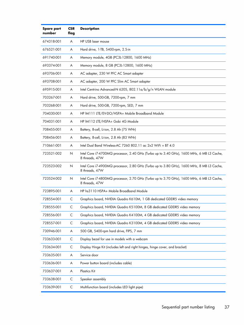
Sequential part number listingCSR flag designations:
A = Mandatory
B = Optional
C = Service technician recommended
N = Non-user replaceable
Spare partnumber
CSRflag
Description
491683-001 A Power cord for use in North America (3 conductor, black,1.83 m)
491683-011 A Power cord for use in Australia (3 conductor, black,1.83 m)
491683-031 A Power cord for use in Singapore and the United Kingdom (3 conductor, black,1.83 m)
491683-061 A Power cord for use in Italy (3 conductor, black,1.83 m)
491683-081 A Power cord for use in Denmark (3 conductor, black,1.83 m)
491683-111 A Power cord for use in Switzerland (3 conductor, black,1.83 m)
491683-171 A Power cord for use in Saudi Arabia (3 conductor, black,1.83 m)
491683-201 A Power cord for use in Thailand (3 conductor, black,1.83 m)
491683-202 A Power cord for use in Brazil (3 conductor, black,1.83 m)
491683-291 A Power cord for use in Japan (3 conductor, black,1.83 m)
491683-AA1 A Power cord for use in the People’s Republic of China (3 conductor, black,1.83 m)
491683-AB1 A Power cord for use in the Taiwan a (3 conductor, black,1.83 m)
491683-AD1 A Power cord for use in South Korea (3 conductor, black,1.83 m)
491683-AF1 A Power cord for use in Singapore (3 conductor, black,1.83 m)
491683-AR1 A Power cord for use in South Africa (3 conductor, black,1.83 m)
491683-B91 A Power cord for use in the Netherlands (3 conductor, black,1.83 m)
491683-BB1 A Power cord for use in Israel (3 conductor, black,1.83 m)
491683-D01 A Power cord for use in Argentina (3 conductor, black,1.83 m)
491683-D61 A Power cord for use in India (3 conductor, black,1.83 m)
491683-D91 A Power cord for use in APD (3 conductor, black,1.83 m)
575921-001 A Cable lock for use on the docking station
603783-001 A Hard drive, 320 GB, 7200-rpm, 2.5-in
633252-001 A Hard drive, 750 GB, 7200-rpm, 2.5-in
670292-001 A Intel Centrino Advanced-N 6235
36 Chapter 3 Illustrated parts catalog
Spare partnumber
CSRflag
Description
674318-001 A HP USB laser mouse
676521-001 A Hard drive, 1-TB, 5400-rpm, 2.5-in
691740-001 A Memory module, 4GB (PC3L-12800, 1600 MHz)
693374-001 A Memory module, 8 GB (PC3L-12800, 1600 MHz)
693706-001 A AC adapter, 230 W PFC AC Smart adapter
693708-001 A AC adapter, 200 W PFC Slim AC Smart adapter
695915-001 A Intel Centrino Advanced-N 6205, 802.11a/b/g/n WLAN module
703267-001 A Hard drive, 500-GB, 7200-rpm, 7 mm
703268-001 A Hard drive, 500-GB, 7200-rpm, SED, 7 mm
704030-001 A HP lt4111 LTE/EV-DO/HSPA+ Mobile Broadband Module
704031-001 A HP lt4112 LTE/HSPA+ Gobi 4G Module
708455-001 A Battery, 8-cell, Li-ion, 2.8 Ah (75 WHr)
708456-001 A Battery, 8-cell, Li-ion, 2.8 Ah (83 WHr)
710661-001 A Intel Dual Band Wireless-AC 7260 802.11 ac 2x2 WiFi + BT 4.0
723521-002 N Intel Core i7-4700MQ processor, 2.40 GHz (Turbo up to 3.40 GHz), 1600 MHz, 6 MB L3 Cache,8 threads, 47W
723523-002 N Intel Core i7-4900MQ processor, 2.80 GHz (Turbo up to 3.80 GHz), 1600 MHz, 8 MB L3 Cache,8 threads, 47W
723524-002 N Intel Core i7-4800MQ processor, 2.70 GHz (Turbo up to 3.70 GHz), 1600 MHz, 6 MB L3 Cache,8 threads, 47W
723895-001 A HP hs3110 HSPA+ Mobile Broadband Module
728554-001 C Graphics board, NVIDIA Quadro K610M, 1 GB dedicated GDDR5 video memory
728555-001 C Graphics board, NVIDIA Quadro K5100M, 8 GB dedicated GDDR5 video memory
728556-001 C Graphics board, NVIDIA Quadro K4100M, 4 GB dedicated GDDR5 video memory
728557-001 C Graphics board, NVIDIA Quadro K3100M, 4 GB dedicated GDDR5 video memory
730946-001 A 500 GB, 5400-rpm hard drive, FIPS, 7 mm
733633-001 C Display bezel for use in models with a webcam
733634-001 C Display Hinge Kit (includes left and right hinges, hinge cover, and bracket)
733635-001 A Service door
733636-001 A Power button board (includes cable)
733637-001 A Plastics Kit
733638-001 C Speaker assembly
733639-001 C Multifunction board (includes LED light pipe)
Sequential part number listing 37
Spare partnumber
CSRflag
Description
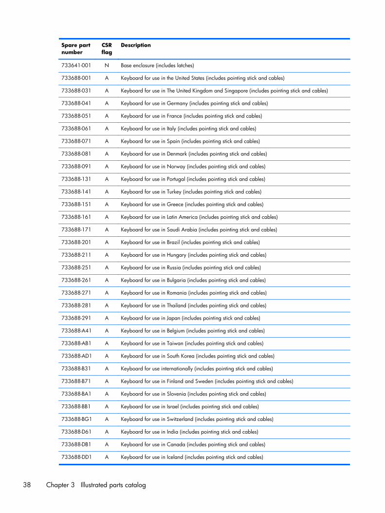
733641-001 N Base enclosure (includes latches)
733688-001 A Keyboard for use in the United States (includes pointing stick and cables)
733688-031 A Keyboard for use in The United Kingdom and Singapore (includes pointing stick and cables)
733688-041 A Keyboard for use in Germany (includes pointing stick and cables)
733688-051 A Keyboard for use in France (includes pointing stick and cables)
733688-061 A Keyboard for use in Italy (includes pointing stick and cables)
733688-071 A Keyboard for use in Spain (includes pointing stick and cables)
733688-081 A Keyboard for use in Denmark (includes pointing stick and cables)
733688-091 A Keyboard for use in Norway (includes pointing stick and cables)
733688-131 A Keyboard for use in Portugal (includes pointing stick and cables)
733688-141 A Keyboard for use in Turkey (includes pointing stick and cables)
733688-151 A Keyboard for use in Greece (includes pointing stick and cables)
733688-161 A Keyboard for use in Latin America (includes pointing stick and cables)
733688-171 A Keyboard for use in Saudi Arabia (includes pointing stick and cables)
733688-201 A Keyboard for use in Brazil (includes pointing stick and cables)
733688-211 A Keyboard for use in Hungary (includes pointing stick and cables)
733688-251 A Keyboard for use in Russia (includes pointing stick and cables)
733688-261 A Keyboard for use in Bulgaria (includes pointing stick and cables)
733688-271 A Keyboard for use in Romania (includes pointing stick and cables)
733688-281 A Keyboard for use in Thailand (includes pointing stick and cables)
733688-291 A Keyboard for use in Japan (includes pointing stick and cables)
733688-A41 A Keyboard for use in Belgium (includes pointing stick and cables)
733688-AB1 A Keyboard for use in Taiwan (includes pointing stick and cables)
733688-AD1 A Keyboard for use in South Korea (includes pointing stick and cables)
733688-B31 A Keyboard for use internationally (includes pointing stick and cables)
733688-B71 A Keyboard for use in Finland and Sweden (includes pointing stick and cables)
733688-BA1 A Keyboard for use in Slovenia (includes pointing stick and cables)
733688-BB1 A Keyboard for use in Israel (includes pointing stick and cables)
733688-BG1 A Keyboard for use in Switzerland (includes pointing stick and cables)
733688-D61 A Keyboard for use in India (includes pointing stick and cables)
733688-DB1 A Keyboard for use in Canada (includes pointing stick and cables)
733688-DD1 A Keyboard for use in Iceland (includes pointing stick and cables)
38 Chapter 3 Illustrated parts catalog
Spare partnumber
CSRflag
Description
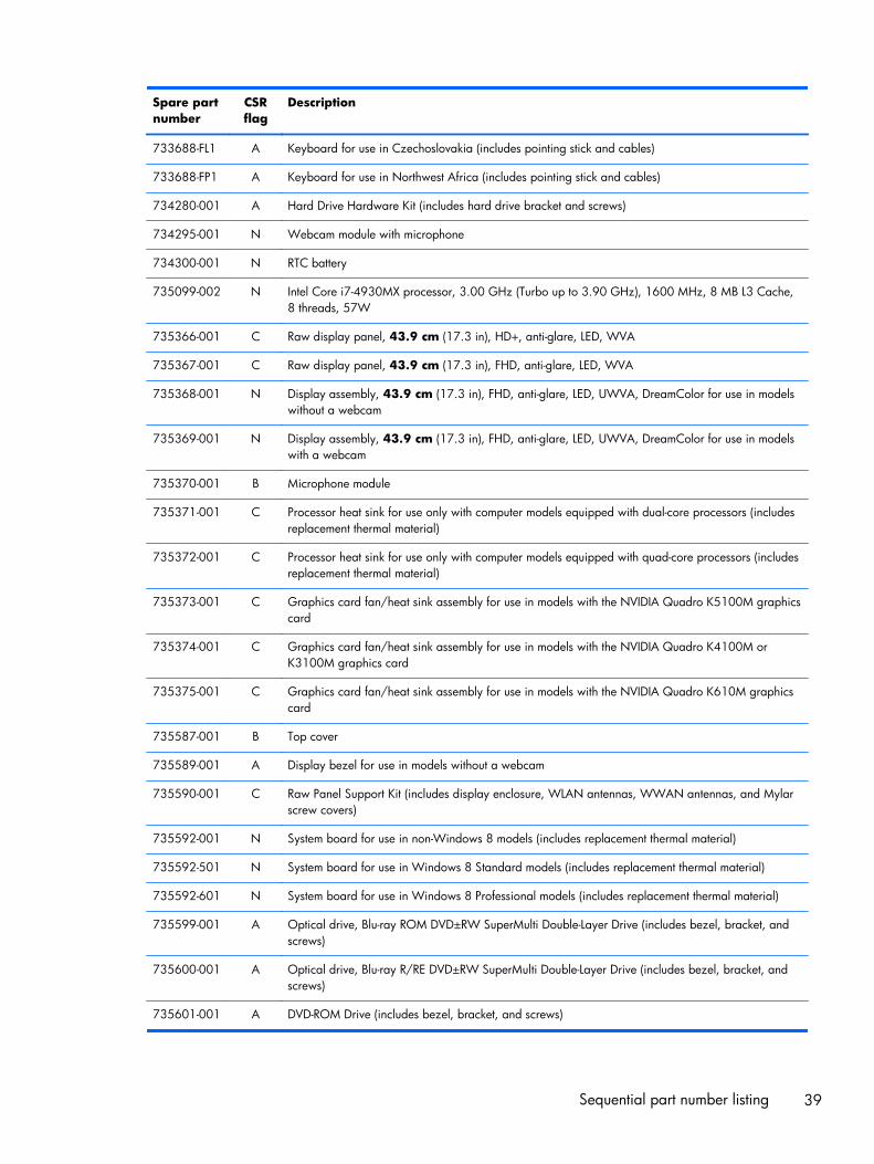
733688-FL1 A Keyboard for use in Czechoslovakia (includes pointing stick and cables)
733688-FP1 A Keyboard for use in Northwest Africa (includes pointing stick and cables)
734280-001 A Hard Drive Hardware Kit (includes hard drive bracket and screws)
734295-001 N Webcam module with microphone
734300-001 N RTC battery
735099-002 N Intel Core i7-4930MX processor, 3.00 GHz (Turbo up to 3.90 GHz), 1600 MHz, 8 MB L3 Cache,8 threads, 57W
735366-001 C Raw display panel, 43.9 cm (17.3 in), HD+, anti-glare, LED, WVA
735367-001 C Raw display panel, 43.9 cm (17.3 in), FHD, anti-glare, LED, WVA
735368-001 N Display assembly, 43.9 cm (17.3 in), FHD, anti-glare, LED, UWVA, DreamColor for use in modelswithout a webcam
735369-001 N Display assembly, 43.9 cm (17.3 in), FHD, anti-glare, LED, UWVA, DreamColor for use in modelswith a webcam
735370-001 B Microphone module
735371-001 C Processor heat sink for use only with computer models equipped with dual-core processors (includesreplacement thermal material)
735372-001 C Processor heat sink for use only with computer models equipped with quad-core processors (includesreplacement thermal material)
735373-001 C Graphics card fan/heat sink assembly for use in models with the NVIDIA Quadro K5100M graphicscard
735374-001 C Graphics card fan/heat sink assembly for use in models with the NVIDIA Quadro K4100M orK3100M graphics card
735375-001 C Graphics card fan/heat sink assembly for use in models with the NVIDIA Quadro K610M graphicscard
735587-001 B Top cover
735589-001 A Display bezel for use in models without a webcam
735590-001 C Raw Panel Support Kit (includes display enclosure, WLAN antennas, WWAN antennas, and Mylarscrew covers)
735592-001 N System board for use in non-Windows 8 models (includes replacement thermal material)
735592-501 N System board for use in Windows 8 Standard models (includes replacement thermal material)
735592-601 N System board for use in Windows 8 Professional models (includes replacement thermal material)
735599-001 A Optical drive, Blu-ray ROM DVD±RW SuperMulti Double-Layer Drive (includes bezel, bracket, andscrews)
735600-001 A Optical drive, Blu-ray R/RE DVD±RW SuperMulti Double-Layer Drive (includes bezel, bracket, andscrews)
735601-001 A DVD-ROM Drive (includes bezel, bracket, and screws)
Sequential part number listing 39
Spare partnumber
CSRflag
Description
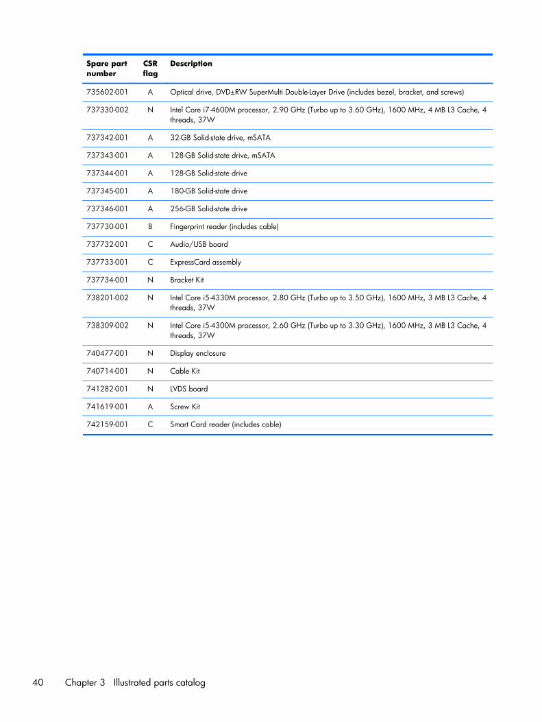
735602-001 A Optical drive, DVD±RW SuperMulti Double-Layer Drive (includes bezel, bracket, and screws)
737330-002 N Intel Core i7-4600M processor, 2.90 GHz (Turbo up to 3.60 GHz), 1600 MHz, 4 MB L3 Cache, 4threads, 37W
737342-001 A 32-GB Solid-state drive, mSATA
737343-001 A 128-GB Solid-state drive, mSATA
737344-001 A 128-GB Solid-state drive
737345-001 A 180-GB Solid-state drive
737346-001 A 256-GB Solid-state drive
737730-001 B Fingerprint reader (includes cable)
737732-001 C Audio/USB board
737733-001 C ExpressCard assembly
737734-001 N Bracket Kit
738201-002 N Intel Core i5-4330M processor, 2.80 GHz (Turbo up to 3.50 GHz), 1600 MHz, 3 MB L3 Cache, 4threads, 37W
738309-002 N Intel Core i5-4300M processor, 2.60 GHz (Turbo up to 3.30 GHz), 1600 MHz, 3 MB L3 Cache, 4threads, 37W
740477-001 N Display enclosure
740714-001 N Cable Kit
741282-001 N LVDS board
741619-001 A Screw Kit
742159-001 C Smart Card reader (includes cable)
40 Chapter 3 Illustrated parts catalog
4 Removal and replacementprocedures preliminaryrequirements
Tools requiredYou will need the following tools to complete the removal and replacement procedures:
● Flat-bladed screwdriver
● Magnetic screwdriver
● Phillips P0 and P1 screwdrivers
● Torx T8 screwdriver
● 5.0 mm hex socket driver
Service considerationsThe following sections include some of the considerations that you must keep in mind duringdisassembly and assembly procedures.
NOTE: As you remove each subassembly from the computer, place the subassembly (and allaccompanying screws) away from the work area to prevent damage.
Plastic parts
Using excessive force during disassembly and reassembly can damage plastic parts. Use care whenhandling the plastic parts. Apply pressure only at the points designated in the maintenance instructions.
Cables and and pointing stick connectors
CAUTION: When servicing the computer, be sure that cables are placed in their proper locationsduring the reassembly process. Improper cable placement can damage the computer.
Cables must be handled with extreme care to avoid damage. Apply only the tension required to unseator seat the cables during removal and insertion. Handle cables by the connector whenever possible. In
Tools required 41

all cases, avoid bending, twisting, or tearing cables. Be sure that cables are routed in such a way thatthey cannot be caught or snagged by parts being removed or replaced. Handle flex cables withextreme care; these cables tear easily.
Drive handling
CAUTION: Drives are fragile components that must be handled with care. To prevent damage to thecomputer, damage to a drive, or loss of information, observe these precautions:
Before removing or inserting a hard drive, shut down the computer. If you are unsure whether thecomputer is off or in Hibernation, turn the computer on, and then shut it down through the operatingsystem.
Before handling a drive, be sure that you are discharged of static electricity. While handling a drive,avoid touching the connector.
Before removing a diskette drive or optical drive, be sure that a diskette or disc is not in the drive andbe sure that the optical drive tray is closed.
Handle drives on surfaces covered with at least one inch of shock-proof foam.
Avoid dropping drives from any height onto any surface.
After removing a hard drive, an optical drive, or a diskette drive, place it in a static-proof bag.
Avoid exposing a hard drive to products that have magnetic fields, such as monitors or speakers.
Avoid exposing a drive to temperature extremes or liquids.
If a drive must be mailed, place the drive in a bubble pack mailer or other suitable form of protectivepackaging and label the package “FRAGILE.”
Grounding guidelines
Electrostatic discharge damage
Electronic components are sensitive to electrostatic discharge (ESD). Circuitry design and structuredetermine the degree of sensitivity. Networks built into many integrated and pointing stick circuitsprovide some protection, but in many cases, ESD contains enough power to alter device parameters ormelt silicon junctions.
A discharge of static electricity from a finger or other conductor can destroy static-sensitive devices ormicrocircuitry. Even if the spark is neither felt nor heard, damage may have occurred.
An electronic device exposed to ESD may not be affected at all and and pointing stick can workperfectly throughout a normal cycle. Or the device may function normally for a while, then degrade inthe internal layers, reducing its life expectancy.
42 Chapter 4 Removal and replacement procedures preliminary requirements

CAUTION: To prevent damage to the computer when you are removing or installing internalcomponents, observe these precautions:
Keep components in their electrostatic-safe containers until you area ready to install them.
Use nonmagnetic tools.
Before touching an electronic component, discharge static electricity by using the guidelines describedin this section.
Avoid touching pins, leads, and pointing stick circuitry. Handle electronic components as little aspossible.
If you remove a component, place it in an electrostatic-safe container.
The following table shows how humidity affects the electrostatic voltage levels generated by differentactivities.
CAUTION: A product can be degraded by as little as 700 V.
Typical electrostatic voltage levels
Relative humidity
Event 10% 40% 55%
Walking across carpet 35,000 V 15,000 V 7,500 V
Walking across vinyl floor 12,000 V 5,000 V 3,000 V
Motions of bench worker 6,000 V 800 V 400 V
Removing DIPS from plastic tube 2,000 V 700 V 400 V
Removing DIPS from vinyl tray 11,500 V 4,000 V 2,000 V
Removing DIPS from Styrofoam 14,500 V 5,000 V 3,500 V
Removing bubble pack from PCB 26,500 V 20,000 V 7,000 V
Packing PCBs in foam-lined box 21,000 V 11,000 V 5,000 V
Packaging and transporting guidelines
Follow these grounding guidelines when packaging and transporting equipment:
● To avoid hand and pointing stick contact, transport products in static-safe tubes, bags, or boxes.
● Protect ESD-sensitive parts and assemblies with conductive or approved and pointing stickcontainers or packaging.
● Keep ESD-sensitive parts in their containers until the parts arrive at static-free workstations.
● Place items on a grounded surface before removing items from their containers.
● Always be properly grounded when touching a component or assembly.
Grounding guidelines 43
● Store reusable ESD-sensitive parts from assemblies in protective packaging or nonconductivefoam.
● Use transporters and pointing stick conveyors made of antistatic belts and roller bushings. Be surethat mechanized equipment used for moving materials is wired to ground and that propermaterials are selected to avoid static charging. When grounding is not possible, use an ionizer todissipate electric charges.
Workstation guidelines
Follow these grounding workstation guidelines:
● Cover the workstation with approved static-shielding material.
● Use a wrist strap connected to a properly grounded work surface and use properly grounded toolsand equipment.
● Use conductive field service tools, such as cutters, screwdrivers, and vacuums.
● When fixtures must directly contact dissipative surfaces, use fixtures made only of static-safematerials.
● Keep the work area free of non conductive materials, such as ordinary plastic assembly aids andStyrofoam.
● Handle ESD-sensitive components, parts, and assemblies by the case or PCM laminate. Handlethese items only at static-free workstations.
● Avoid and pointing stick contact with pins, leads, or circuitry.
● Turn off power and input signals before inserting or removing connectors or test equipment.
Equipment guidelines
Grounding equipment must include either a wrist strap or a foot strap at a grounded workstation.
● When seated, wear a wrist strap connected to a grounded system. Wrist straps are flexible strapswith a minimum of one megohm ±10% resistance in the ground and pointing stick cords. Toprovide proper ground, wear a strap snugly against the skin at all times. On grounded mats withbanana-plug connectors, use alligator clips to connect a wrist strap.
● When standing, use foot straps and a grounded floor mat. Foot straps (heel, toe, or boot straps)can be used at standing workstations and are compatible with most types of shoes or boots. Onconductive floors or dissipative floor mats, use foot straps on both feet with a minimum of onemegohm resistance between the operator and ground. To be effective, the conductive strips mustbe worn in contact with the skin.
The following grounding equipment is recommended to prevent electrostatic damage:
● Antistatic tape
● Antistatic smocks, aprons, and sleeve protectors
● Conductive bins and other assembly or soldering aids
44 Chapter 4 Removal and replacement procedures preliminary requirements

● Nonconductive foam
● Conductive tabletop workstations with ground and pointing stick cords of one megohm resistance
● Static-dissipative tables or floor mats with hard ties to the ground
● Field service kits
● Static awareness labels
● Material-handling packages
● Non conductive plastic bags, tubes, or boxes
● Metal tote boxes
● Electrostatic voltage levels and protective materials
The following table lists the shielding protection provided by antistatic bags and floor mats.
Material Use Voltage protection level
Antistatic plastic Bags 1,500 V
Carbon-loaded plastic Floor mats 7,500 V
Metallized laminate Floor mats 5,000 V
Grounding guidelines 45

5 Removal and replacementprocedures for Customer Self-Repair parts
CAUTION: The Customer Self-Repair program is not available in all locations. Installing a part notsupported by the Customer Self-Repair program may void your warranty. Check your warranty todetermine if Customer Self-Repair is supported in your location.
Component replacement proceduresThis chapter provides removal and replacement procedures.
There are as many as 120 screws that must be removed, replaced, or loosened when servicing thecomputer. Make special note of each screw size and location during removal and replacement.
Battery
Description Spare part number
8-cell, Li-ion 2.8 Ah (83 WHr) 708456-001
8-cell, Li-ion 2.8 Ah (75 WHr) 708455-001
Before disassembling the computer, follow these steps:
1. Shut down the computer. If you are unsure whether the computer is off or in Hibernation, turn thecomputer on, and then shut it down through the operating system.
2. Disconnect all external devices connected to the computer.
3. Disconnect the power from the computer by first unplugging the power cord from the AC outletand then unplugging the AC adapter from the computer.
Remove the battery:
1. Position the computer upside down on a flat surface, with the front toward you.
2. Slide the battery release latch (1) to release the battery.
46 Chapter 5 Removal and replacement procedures for Customer Self-Repair parts
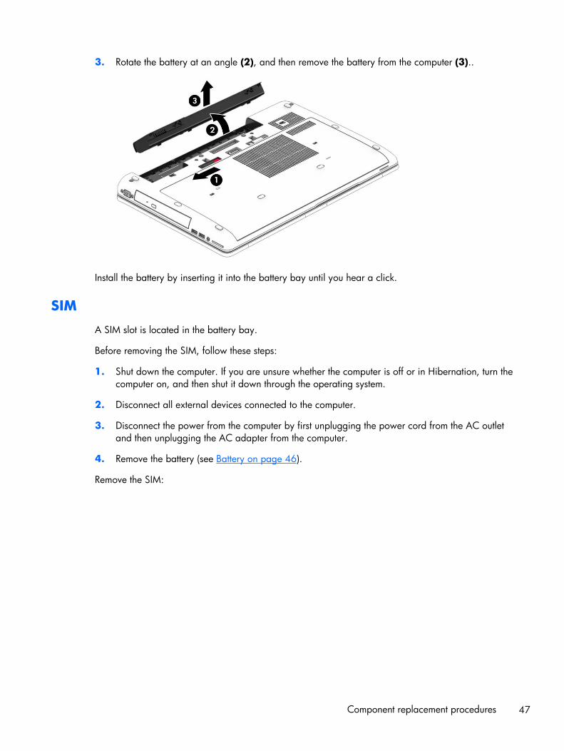
3. Rotate the battery at an angle (2), and then remove the battery from the computer (3)..
Install the battery by inserting it into the battery bay until you hear a click.
SIM
A SIM slot is located in the battery bay.
Before removing the SIM, follow these steps:
1. Shut down the computer. If you are unsure whether the computer is off or in Hibernation, turn thecomputer on, and then shut it down through the operating system.
2. Disconnect all external devices connected to the computer.
3. Disconnect the power from the computer by first unplugging the power cord from the AC outletand then unplugging the AC adapter from the computer.
4. Remove the battery (see Battery on page 46).
Remove the SIM:
Component replacement procedures 47
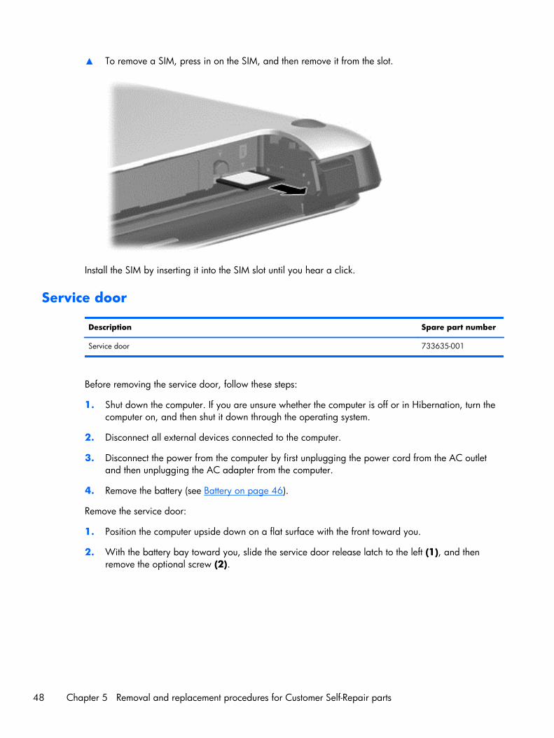
▲ To remove a SIM, press in on the SIM, and then remove it from the slot.
Install the SIM by inserting it into the SIM slot until you hear a click.
Service door
Description Spare part number
Service door 733635-001
Before removing the service door, follow these steps:
1. Shut down the computer. If you are unsure whether the computer is off or in Hibernation, turn thecomputer on, and then shut it down through the operating system.
2. Disconnect all external devices connected to the computer.
3. Disconnect the power from the computer by first unplugging the power cord from the AC outletand then unplugging the AC adapter from the computer.
4. Remove the battery (see Battery on page 46).
Remove the service door:
1. Position the computer upside down on a flat surface with the front toward you.
2. With the battery bay toward you, slide the service door release latch to the left (1), and thenremove the optional screw (2).
48 Chapter 5 Removal and replacement procedures for Customer Self-Repair parts

3. Slide the service door release latch to the left again (3), slide the service door forward (4), andthen lift to remove the service door (5).
NOTE: If you do not want to use the optional screw, you can store it inside the service door.
Reverse this procedure to install the service door.
Hard drives, primary and secondary
NOTE: The hard drive bracket is included in the Hard Drive Hardware Kit, spare part number734280-001.
Description Spare part number
1 TB, 5400-rpm hard drive, 2.5-in 676521-001
750 GB, 7200-rpm, 2.5-in 633252-001
500 GB, 7200-rpm hard drive, 7 mm 703267-001
500 GB, 7200-rpm, SED hard drive, 7 mm 703268-001
500 GB, 5400-rpm hard drive, FIPS, 7 mm 730946-001
320 GB, 7200-rpm, 2.5-in 603783-001
256 GB solid-state drive, Self-encrypting Drive (SED) 737346-001
180 GB solid-state drive 737345-001
128 GB solid-state drive 737344-001
Component replacement procedures 49
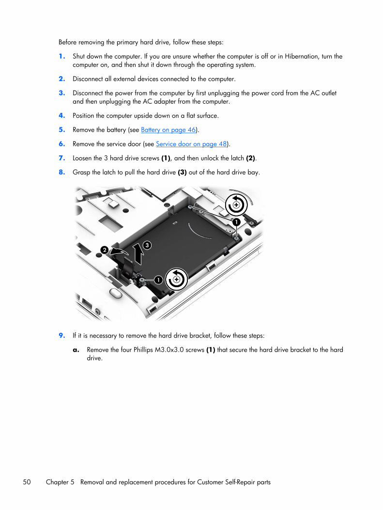
Before removing the primary hard drive, follow these steps:
1. Shut down the computer. If you are unsure whether the computer is off or in Hibernation, turn thecomputer on, and then shut it down through the operating system.
2. Disconnect all external devices connected to the computer.
3. Disconnect the power from the computer by first unplugging the power cord from the AC outletand then unplugging the AC adapter from the computer.
4. Position the computer upside down on a flat surface.
5. Remove the battery (see Battery on page 46).
6. Remove the service door (see Service door on page 48).
7. Loosen the 3 hard drive screws (1), and then unlock the latch (2).
8. Grasp the latch to pull the hard drive (3) out of the hard drive bay.
9. If it is necessary to remove the hard drive bracket, follow these steps:
a. Remove the four Phillips M3.0x3.0 screws (1) that secure the hard drive bracket to the harddrive.
50 Chapter 5 Removal and replacement procedures for Customer Self-Repair parts
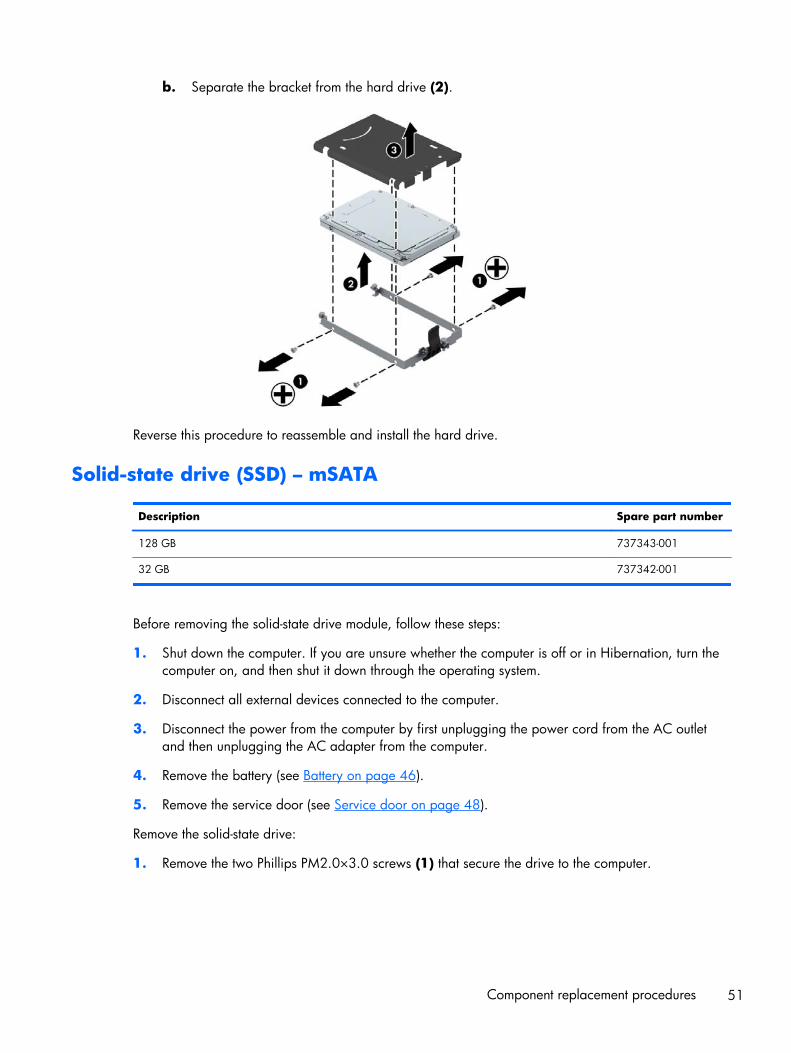
b. Separate the bracket from the hard drive (2).
Reverse this procedure to reassemble and install the hard drive.
Solid-state drive (SSD) – mSATA
Description Spare part number
128 GB 737343-001
32 GB 737342-001
Before removing the solid-state drive module, follow these steps:
1. Shut down the computer. If you are unsure whether the computer is off or in Hibernation, turn thecomputer on, and then shut it down through the operating system.
2. Disconnect all external devices connected to the computer.
3. Disconnect the power from the computer by first unplugging the power cord from the AC outletand then unplugging the AC adapter from the computer.
4. Remove the battery (see Battery on page 46).
5. Remove the service door (see Service door on page 48).
Remove the solid-state drive:
1. Remove the two Phillips PM2.0×3.0 screws (1) that secure the drive to the computer.
Component replacement procedures 51
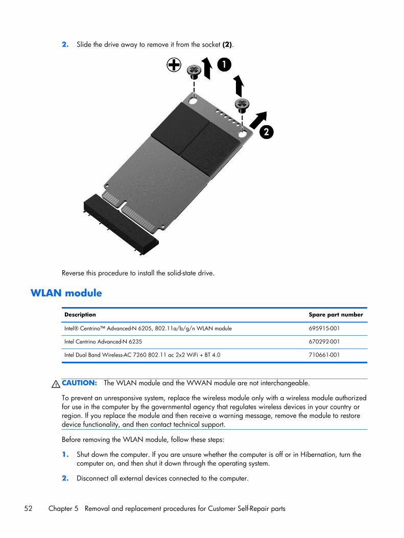
2. Slide the drive away to remove it from the socket (2).
Reverse this procedure to install the solid-state drive.
WLAN module
Description Spare part number
Intel® Centrino™ Advanced-N 6205, 802.11a/b/g/n WLAN module 695915-001
Intel Centrino Advanced-N 6235 670292-001
Intel Dual Band Wireless-AC 7260 802.11 ac 2x2 WiFi + BT 4.0 710661-001
CAUTION: The WLAN module and the WWAN module are not interchangeable.
To prevent an unresponsive system, replace the wireless module only with a wireless module authorizedfor use in the computer by the governmental agency that regulates wireless devices in your country orregion. If you replace the module and then receive a warning message, remove the module to restoredevice functionality, and then contact technical support.
Before removing the WLAN module, follow these steps:
1. Shut down the computer. If you are unsure whether the computer is off or in Hibernation, turn thecomputer on, and then shut it down through the operating system.
2. Disconnect all external devices connected to the computer.
52 Chapter 5 Removal and replacement procedures for Customer Self-Repair parts
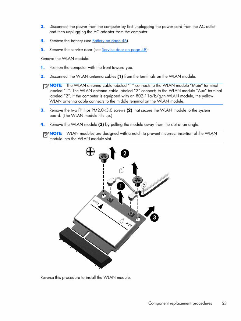
3. Disconnect the power from the computer by first unplugging the power cord from the AC outletand then unplugging the AC adapter from the computer.
4. Remove the battery (see Battery on page 46).
5. Remove the service door (see Service door on page 48).
Remove the WLAN module:
1. Position the computer with the front toward you.
2. Disconnect the WLAN antenna cables (1) from the terminals on the WLAN module.
NOTE: The WLAN antenna cable labeled “1” connects to the WLAN module “Main” terminallabeled “1”. The WLAN antenna cable labeled “2” connects to the WLAN module “Aux” terminallabeled “2”. If the computer is equipped with an 802.11a/b/g/n WLAN module, the yellowWLAN antenna cable connects to the middle terminal on the WLAN module.
3. Remove the two Phillips PM2.0×3.0 screws (2) that secure the WLAN module to the systemboard. (The WLAN module tilts up.)
4. Remove the WLAN module (3) by pulling the module away from the slot at an angle.
NOTE: WLAN modules are designed with a notch to prevent incorrect insertion of the WLANmodule into the WLAN module slot.
Reverse this procedure to install the WLAN module.
Component replacement procedures 53
WWAN module
Description Spare part number
HP lt4111 LTE/EV-DO/HSPA+ Mobile Broadband Module 704030-001
HP lt4112 LTE/HSPA+ Gobi 4G Module 704031-001
HP hs3110 HSPA+ Mobile Broadband Module 723895-001
CAUTION: The WWAN module and the WLAN module are not interchangeable.
To prevent an unresponsive system, replace the wireless module only with a wireless module authorizedfor use in the computer by the governmental agency that regulates wireless devices in your country orregion. If you replace the module and then receive a warning message, remove the module to restoredevice functionality, and then contact technical support.
Before removing the WWAN module, follow these steps:
1. Shut down the computer. If you are unsure whether the computer is off or in Hibernation, turn thecomputer on, and then shut it down through the operating system.
2. Disconnect all external devices connected to the computer.
3. Disconnect the power from the computer by first unplugging the power cord from the AC outletand then unplugging the AC adapter from the computer.
4. Remove the battery (see Battery on page 46).
5. Remove the service door (see Service door on page 48).
Remove the WWAN module:
1. Disconnect the WWAN antenna cables (1) from the terminals on the WWAN module.
NOTE: The red WWAN antenna cable is connected to the WWAN module “Main” terminal.The blue WWAN antenna cable is connected to the WWAN module “Aux” terminal.
2. Remove the Phillips PM2.0×3.0 screw (2) that secures the WWAN module to the system board.(The WWAN module tilts up.)
54 Chapter 5 Removal and replacement procedures for Customer Self-Repair parts

3. Remove the WWAN module (3) by pulling the module away from the slot at an angle.
Reverse this procedure to install the WWAN module.
RTC battery
Description Spare part number
RTC battery 734300-001
Before removing the RTC battery, follow these steps:
1. Shut down the computer. If you are unsure whether the computer is off or in Hibernation, turn thecomputer on, and then shut it down through the operating system.
2. Disconnect all external devices connected to the computer.
3. Disconnect the power from the computer by first unplugging the power cord from the AC outletand then unplugging the AC adapter from the computer.
Component replacement procedures 55

4. Remove the battery (see Battery on page 46).
5. Remove the service door (see Service door on page 48).
Remove the RTC battery:
▲ Disconnect the RTC battery cable (1) from the system board and remove the RTC battery (2).
NOTE: You may need to remove some double-sided adhesive.
Reverse this procedure to install the RTC battery.
56 Chapter 5 Removal and replacement procedures for Customer Self-Repair parts
Optical drive
NOTE: The upgrade bay supports both optical drives and hard drives. If you switch from a hard driveto an optical drive in the upgrade bay, you will need to remove four additional screws that secure thehard drive carrier.
NOTE: All optical drive spare part kits include bezel, bracket, and screws.
Description Spare part number
Blu-ray R/RE DVD±RW SuperMulti Double-Layer Drive 735600-001
DVD±RW SuperMulti Double-Layer Drive 735602-001
Blu-ray ROM DVD±RW SuperMulti Double-Layer Drive 735599-001
DVD-ROM Drive 735601-001
Before removing the optical drive, follow these steps:
1. Shut down the computer. If you are unsure whether the computer is off or in Hibernation, turn thecomputer on, and then shut it down through the operating system.
2. Disconnect all external devices connected to the computer.
3. Disconnect the power from the computer by first unplugging the power cord from the AC outletand then unplugging the AC adapter from the computer.
4. Remove the battery (see Battery on page 46).
5. Remove the service door (see Service door on page 48).
Remove the optical drive:
1. Position the computer with the front toward you.
2. Loosen the Phillips captive screw (1) that secures the optical drive to the computer.
3. Insert a flat-bladed screwdriver or similar tool into the optical drive tab access (2) and press thetab to the left to release the optical drive from the computer.
Component replacement procedures 57

4. Remove the optical drive (3).
5. If it is necessary to replace the optical drive bracket:
a. Position the optical drive with the rear toward you.
b. Remove the two Phillips M2.0×3.0 screws (1) that secure the optical drive bracket to theoptical drive.
c. Remove the optical drive bracket (2).
Reverse this procedure to reassemble and install the optical drive.
58 Chapter 5 Removal and replacement procedures for Customer Self-Repair parts

Upgrade bay hard drive
Description Spare part number
Optical drives:
Blu-ray R/RE DVD±RW SuperMulti Double-Layer Drive 735600-001
Blu-ray ROM DVD±RW SuperMulti Double-Layer Drive 735599-001
DVD±RW SuperMulti Double-Layer Drive 735602-001
DVD-ROM Drive 735601-001
Hard drives/Solid-state drives:
750 GB, 7200-rpm, 2.5-in 633252-001
256-GB Solid-state drive (SSD), Self-encrypting drive (SED) 737346-001
Before removing the upgrade bay hard drive, follow these steps:
1. Shut down the computer. If you are unsure whether the computer is off or in Hibernation, turn thecomputer on, and then shut it down through the operating system.
2. Disconnect all external devices connected to the computer.
3. Disconnect the power from the computer by first unplugging the power cord from the AC outletand then unplugging the AC adapter from the computer.
4. Remove the battery (see Battery on page 46).
5. Remove the service door (see Service door on page 48).
Remove the upgrade bay hard drive:
1. Position the computer with the front toward you.
2. Remove the four Phillips PM3.0×5.0 screws (1) that secure the upgrade bay hard drive carrier tothe computer.
Component replacement procedures 59
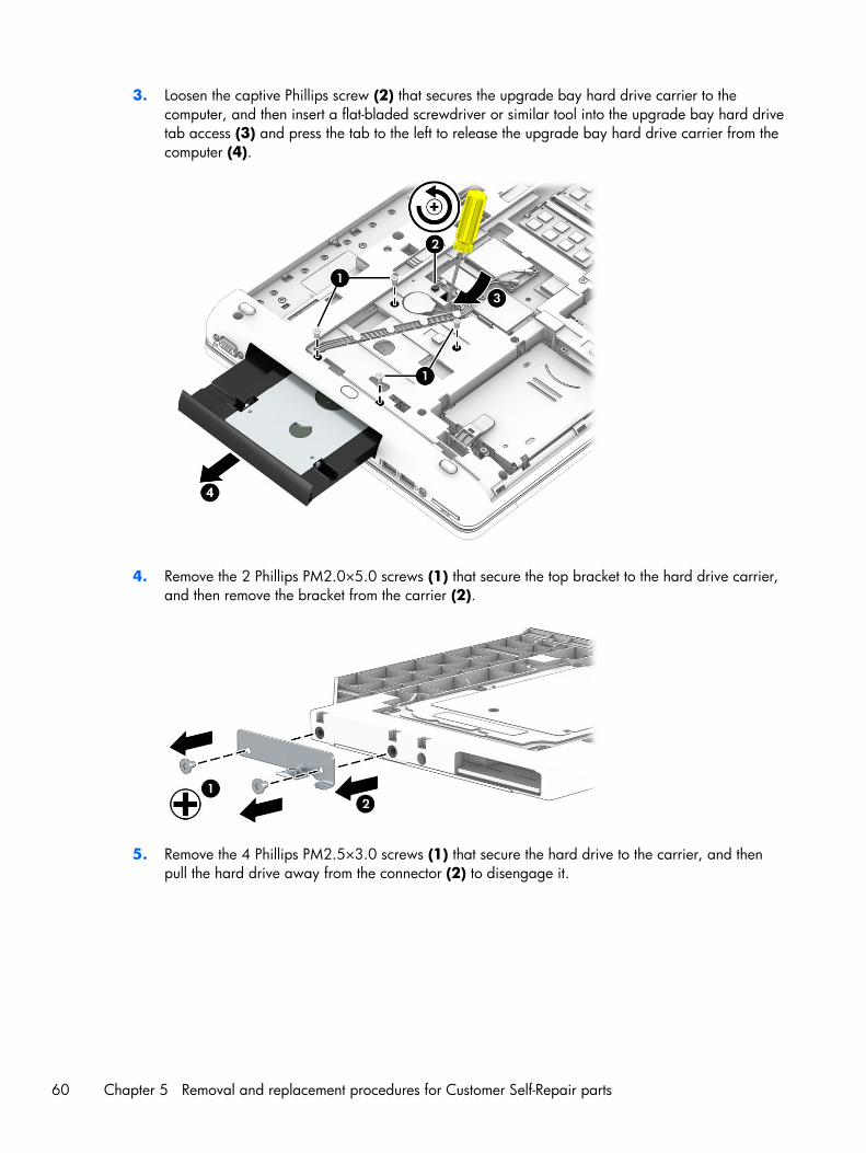
3. Loosen the captive Phillips screw (2) that secures the upgrade bay hard drive carrier to thecomputer, and then insert a flat-bladed screwdriver or similar tool into the upgrade bay hard drivetab access (3) and press the tab to the left to release the upgrade bay hard drive carrier from thecomputer (4).
4. Remove the 2 Phillips PM2.0×5.0 screws (1) that secure the top bracket to the hard drive carrier,and then remove the bracket from the carrier (2).
5. Remove the 4 Phillips PM2.5×3.0 screws (1) that secure the hard drive to the carrier, and thenpull the hard drive away from the connector (2) to disengage it.
60 Chapter 5 Removal and replacement procedures for Customer Self-Repair parts
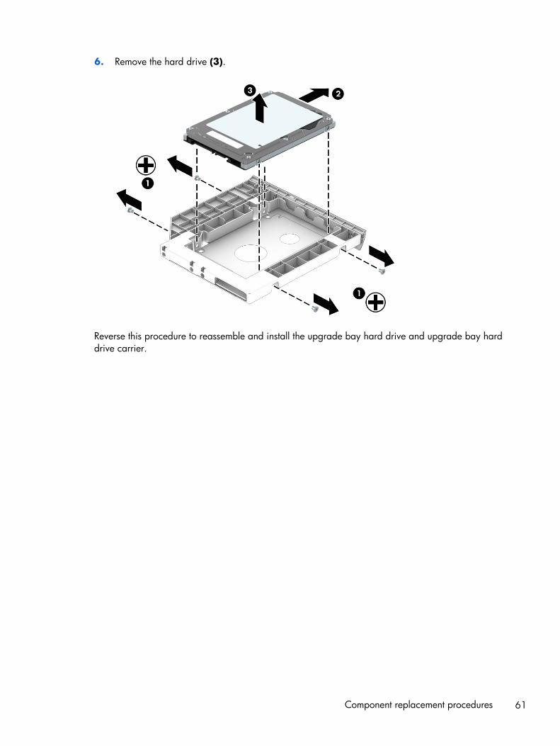
6. Remove the hard drive (3).
Reverse this procedure to reassemble and install the upgrade bay hard drive and upgrade bay harddrive carrier.
Component replacement procedures 61
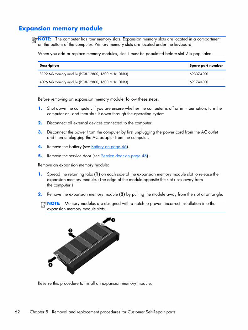
Expansion memory module
NOTE: The computer has four memory slots. Expansion memory slots are located in a compartmenton the bottom of the computer. Primary memory slots are located under the keyboard.
When you add or replace memory modules, slot 1 must be populated before slot 2 is populated.
Description Spare part number
8192 MB memory module (PC3L-12800, 1600 MHz, DDR3) 693374-001
4096 MB memory module (PC3L-12800, 1600 MHz, DDR3) 691740-001
Before removing an expansion memory module, follow these steps:
1. Shut down the computer. If you are unsure whether the computer is off or in Hibernation, turn thecomputer on, and then shut it down through the operating system.
2. Disconnect all external devices connected to the computer.
3. Disconnect the power from the computer by first unplugging the power cord from the AC outletand then unplugging the AC adapter from the computer.
4. Remove the battery (see Battery on page 46).
5. Remove the service door (see Service door on page 48).
Remove an expansion memory module:
1. Spread the retaining tabs (1) on each side of the expansion memory module slot to release theexpansion memory module. (The edge of the module opposite the slot rises away fromthe computer.)
2. Remove the expansion memory module (2) by pulling the module away from the slot at an angle.
NOTE: Memory modules are designed with a notch to prevent incorrect installation into theexpansion memory module slots.
Reverse this procedure to install an expansion memory module.
62 Chapter 5 Removal and replacement procedures for Customer Self-Repair parts
Keyboard
NOTE: For a detailed list of available keyboards, see Sequential part number listing on page 36.
Description Spare part number
Keyboard 733688-xx1
Before removing the keyboard, follow these steps:
1. Shut down the computer. If you are unsure whether the computer is off or in Hibernation, turn thecomputer on, and then shut it down through the operating system.
2. Disconnect all external devices connected to the computer.
3. Disconnect the power from the computer by first unplugging the power cord from the AC outletand then unplugging the AC adapter from the computer.
4. Remove the battery (see Battery on page 46).
5. Remove the service door (see Service door on page 48).
6. Remove the optical drive (see Optical drive on page 57) or upgrade bay hard drive (see Upgradebay hard drive on page 59).
NOTE: The optical drive or hard drive carrier in the upgrade bay must be removed to remove thekeyboard.
Remove the keyboard:
1. Position the computer upside down.
Component replacement procedures 63

2. Loosen the two Phillips captive screws that secure the keyboard to the computer.
3. Position the computer on its side with the display open at a 90 degree angle.
4. A hole in the optical drive bay provides access to the back of the keyboard. Insert a tool or afinger through the hole in the optical drive bay and push to disengage the keyboard.
NOTE: You must remove the optical drive or upgrade hard drive before performing thisprocedure.
64 Chapter 5 Removal and replacement procedures for Customer Self-Repair parts

5. Position the computer right-side up and open it as far as possible.
6. Lift the top of the keyboard, and then place the keyboard upside down on the palm rest.
7. Disconnect the keyboard cable (1) and the pointing stick/backlight cable (2) from the systemboard.
8. Remove the keyboard from the computer (3).
Reverse this procedure to install the keyboard.
Primary memory module
NOTE: The computer has four memory slots. Expansion memory slots are located in a compartmenton the bottom of the computer. Primary memory slots are located under the keyboard.
When you add or replace the primary memory modules, populate the bottom slot before the top slot.
Component replacement procedures 65

Description Spare part number
8192 MB memory module (PC3L-12800, 1600 MHz, DDR3) 693374-001
4096 MB memory module (PC3L-12800, 1600 MHz, DDR3) 691740-001
Before removing a primary memory module, follow these steps:
1. Shut down the computer. If you are unsure whether the computer is off or in Hibernation, turn thecomputer on, and then shut it down through the operating system.
2. Disconnect all external devices connected to the computer.
3. Disconnect the power from the computer by first unplugging the power cord from the AC outletand then unplugging the AC adapter from the computer.
4. Remove the battery (see Battery on page 46).
5. Remove the service door (see Service door on page 48)
6. Remove the optical drive (see Optical drive on page 57) or upgrade bay hard drive (see Upgradebay hard drive on page 59).
7. Remove the keyboard (see Keyboard on page 63).
Remove the primary memory module:
1. Spread the retaining tabs (1) on each side of the primary memory module slot to release theprimary memory module. (The edge of the module opposite the slot rises away from the computer.)
2. Remove the primary memory module (2) by pulling the module away from the slot at an angle.
NOTE: Memory modules are designed with a notch to prevent incorrect installation into theprimary memory module slots.
Reverse this procedure to install a primary memory module.
66 Chapter 5 Removal and replacement procedures for Customer Self-Repair parts
6 Removal and replacementprocedures for Authorized ServiceProvider parts
CAUTION: Components described in this chapter should only be accessed by an authorized serviceprovider. Accessing these parts can damage the computer or void the warranty.
Component replacement proceduresNOTE: Details about your computer, including model, serial number, product key, and length ofwarranty, are on the service tag at the bottom of your computer. See Service tag and PCID labelon page 21 for details.
This chapter provides removal and replacement procedures for Authorized Service Provider only parts.
There are as many as 92 screws that must be removed, replaced, or loosened when servicingAuthorized Service Provider only parts. Make special note of each screw size and location duringremoval and replacement.
Display bezel
You can remove the display bezel, webcam, and display panel without removing the entire displayfrom the computer on models with standard displays (not DreamColor or touchscreen displays).
Description Spare part number
Display bezel for use with computer models with a webcam 733633-001
Display bezel for use in models without a webcam 735589-001
Before removing the display bezel, follow these steps:
1. Shut down the computer. If you are unsure whether the computer is off or in Hibernation, turn thecomputer on, and then shut it down through the operating system.
2. Disconnect all external devices connected to the computer.
Component replacement procedures 67
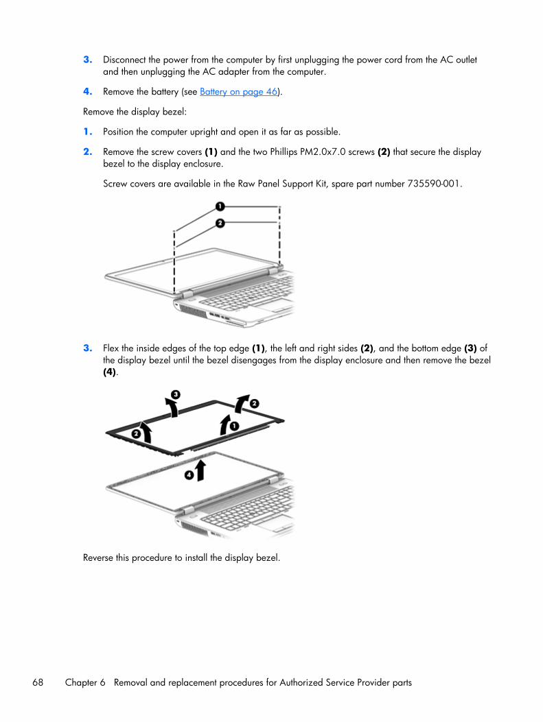
3. Disconnect the power from the computer by first unplugging the power cord from the AC outletand then unplugging the AC adapter from the computer.
4. Remove the battery (see Battery on page 46).
Remove the display bezel:
1. Position the computer upright and open it as far as possible.
2. Remove the screw covers (1) and the two Phillips PM2.0x7.0 screws (2) that secure the displaybezel to the display enclosure.
Screw covers are available in the Raw Panel Support Kit, spare part number 735590-001.
3. Flex the inside edges of the top edge (1), the left and right sides (2), and the bottom edge (3) ofthe display bezel until the bezel disengages from the display enclosure and then remove the bezel(4).
Reverse this procedure to install the display bezel.
68 Chapter 6 Removal and replacement procedures for Authorized Service Provider parts

Webcam module
Description Spare part number
Webcam module with microphone 734295-001
Microphone module 735370-001
Before removing the webcam module, follow these steps:
1. Shut down the computer. If you are unsure whether the computer is off or in Hibernation, turn thecomputer on, and then shut it down through the operating system.
2. Disconnect all external devices connected to the computer.
3. Disconnect the power from the computer by first unplugging the power cord from the AC outletand then unplugging the AC adapter from the computer.
4. Remove the battery (see Battery on page 46).
5. Remove the display bezel (see Display bezel on page 67).
Remove the webcam module:
1. Disconnect the cable from the webcam (1).
2. Pry to remove the webcam module from the display enclosure (2). The webcam module is securedwith adhesive.
Reverse this procedure to install the webcam module.
Component replacement procedures 69
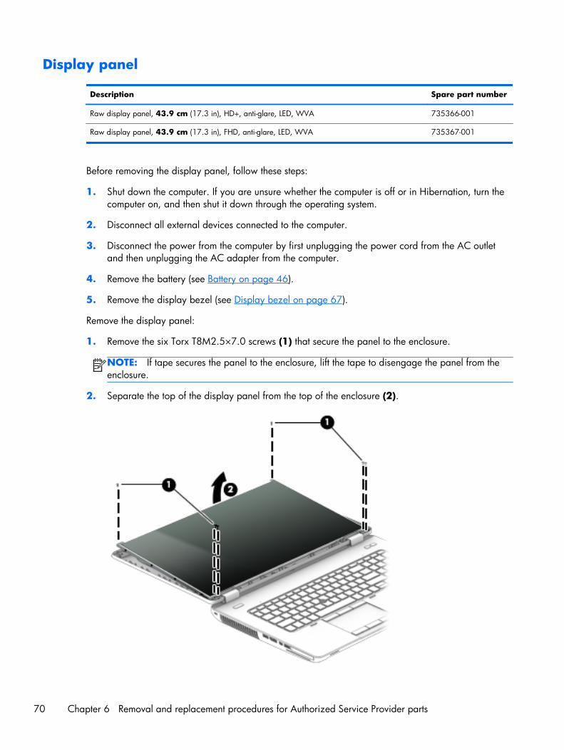
Display panel
Description Spare part number
Raw display panel, 43.9 cm (17.3 in), HD+, anti-glare, LED, WVA 735366-001
Raw display panel, 43.9 cm (17.3 in), FHD, anti-glare, LED, WVA 735367-001
Before removing the display panel, follow these steps:
1. Shut down the computer. If you are unsure whether the computer is off or in Hibernation, turn thecomputer on, and then shut it down through the operating system.
2. Disconnect all external devices connected to the computer.
3. Disconnect the power from the computer by first unplugging the power cord from the AC outletand then unplugging the AC adapter from the computer.
4. Remove the battery (see Battery on page 46).
5. Remove the display bezel (see Display bezel on page 67).
Remove the display panel:
1. Remove the six Torx T8M2.5×7.0 screws (1) that secure the panel to the enclosure.
NOTE: If tape secures the panel to the enclosure, lift the tape to disengage the panel from theenclosure.
2. Separate the top of the display panel from the top of the enclosure (2).
70 Chapter 6 Removal and replacement procedures for Authorized Service Provider parts
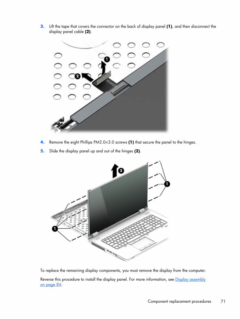
3. Lift the tape that covers the connector on the back of display panel (1), and then disconnect thedisplay panel cable (2).
4. Remove the eight Phillips PM2.0×3.0 screws (1) that secure the panel to the hinges.
5. Slide the display panel up and out of the hinges (2).
To replace the remaining display components, you must remove the display from the computer.
Reverse this procedure to install the display panel. For more information, see Display assemblyon page 84.
Component replacement procedures 71
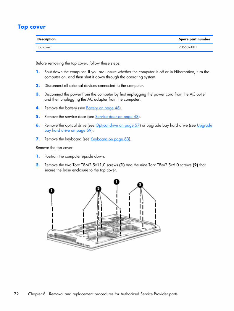
Top cover
Description Spare part number
Top cover 735587-001
Before removing the top cover, follow these steps:
1. Shut down the computer. If you are unsure whether the computer is off or in Hibernation, turn thecomputer on, and then shut it down through the operating system.
2. Disconnect all external devices connected to the computer.
3. Disconnect the power from the computer by first unplugging the power cord from the AC outletand then unplugging the AC adapter from the computer.
4. Remove the battery (see Battery on page 46).
5. Remove the service door (see Service door on page 48).
6. Remove the optical drive (see Optical drive on page 57) or upgrade bay hard drive (see Upgradebay hard drive on page 59).
7. Remove the keyboard (see Keyboard on page 63).
Remove the top cover:
1. Position the computer upside down.
2. Remove the two Torx T8M2.5x11.0 screws (1) and the nine Torx T8M2.5x6.0 screws (2) thatsecure the base enclosure to the top cover.
72 Chapter 6 Removal and replacement procedures for Authorized Service Provider parts

3. Remove the four Torx T8M2.5x5.0 screws inside the battery bay (1) and the three TorxT8M2.5x5.0 screws in the optical drive/upgrade drive bay (2).
4. Position the computer upright and open it as far as possible.
5. Disconnect the following cables:
● (1) Function board
● (2) Power button board cable
● (3) TouchPad cable
● (4) Fingerprint reader board
6. Starting at the top right, pry the top cover up to disengage it from the base enclosure (1).
Component replacement procedures 73
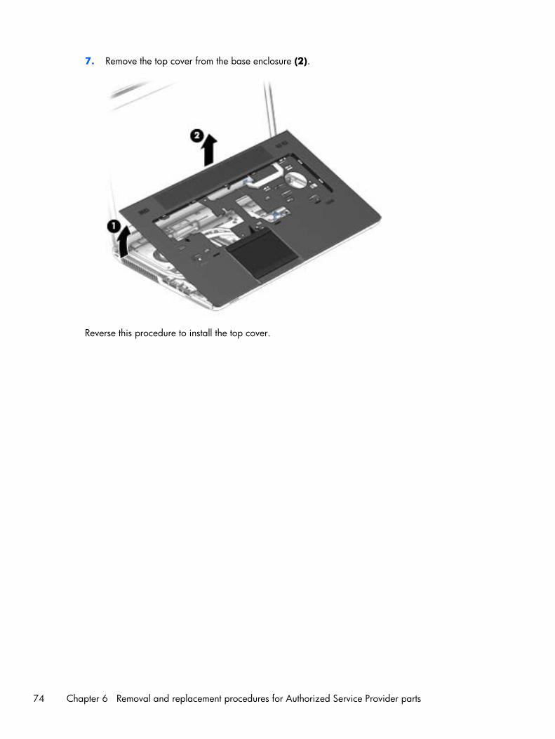
7. Remove the top cover from the base enclosure (2).
Reverse this procedure to install the top cover.
74 Chapter 6 Removal and replacement procedures for Authorized Service Provider parts
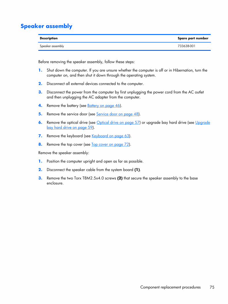
Speaker assembly
Description Spare part number
Speaker assembly 733638-001
Before removing the speaker assembly, follow these steps:
1. Shut down the computer. If you are unsure whether the computer is off or in Hibernation, turn thecomputer on, and then shut it down through the operating system.
2. Disconnect all external devices connected to the computer.
3. Disconnect the power from the computer by first unplugging the power cord from the AC outletand then unplugging the AC adapter from the computer.
4. Remove the battery (see Battery on page 46).
5. Remove the service door (see Service door on page 48).
6. Remove the optical drive (see Optical drive on page 57) or upgrade bay hard drive (see Upgradebay hard drive on page 59).
7. Remove the keyboard (see Keyboard on page 63).
8. Remove the top cover (see Top cover on page 72).
Remove the speaker assembly:
1. Position the computer upright and open as far as possible.
2. Disconnect the speaker cable from the system board (1).
3. Remove the two Torx T8M2.5x4.0 screws (2) that secure the speaker assembly to the baseenclosure.
Component replacement procedures 75
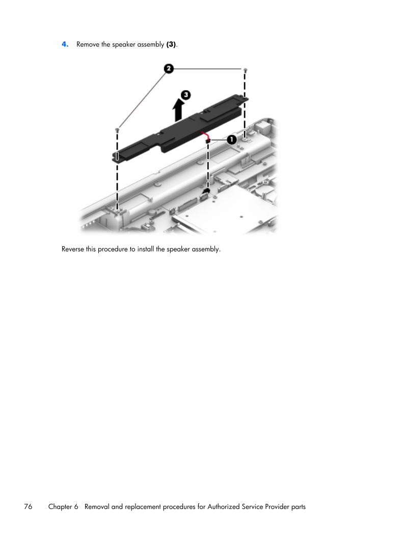
4. Remove the speaker assembly (3).
Reverse this procedure to install the speaker assembly.
76 Chapter 6 Removal and replacement procedures for Authorized Service Provider parts

Multifunction board
Description Spare part number
Multifunction board (includes LED light pipe) 733639-001
Before removing the multifunction board, follow these steps:
1. Shut down the computer. If you are unsure whether the computer is off or in Hibernation, turn thecomputer on, and then shut it down through the operating system.
2. Disconnect all external devices connected to the computer.
3. Disconnect the power from the computer by first unplugging the power cord from the AC outletand then unplugging the AC adapter from the computer.
4. Remove the battery (see Battery on page 46).
5. Remove the service door (see Service door on page 48).
6. Remove the optical drive (see Optical drive on page 57) or upgrade bay hard drive (see Upgradebay hard drive on page 59).
7. Remove the keyboard (see Keyboard on page 63).
8. Remove the top cover (see Top cover on page 72).
Remove the multifunction board:
1. Position the top cover upright with the front toward you.
Component replacement procedures 77

2. Lift the multifunction board cable to disengage the adhesive that secures it to the top of the topcover.
3. Position the top cover upside down with the front toward you.
4. Remove the Phillips PM2.0x3.0 screw (1) that secures the multifunction board to the top cover.
5. Slide the cable through the slot in top cover (2).
78 Chapter 6 Removal and replacement procedures for Authorized Service Provider parts

6. Remove the board/cable assembly from the top cover (3).
Reverse this procedure to install the multifunction board.
Touchpad
Description Spare part number
Touchpad (includes cable) spared with top cover
Before removing the TouchPad, follow these steps:
1. Shut down the computer. If you are unsure whether the computer is off or in Hibernation, turn thecomputer on, and then shut it down through the operating system.
2. Disconnect all external devices connected to the computer.
3. Disconnect the power from the computer by first unplugging the power cord from the AC outletand then unplugging the AC adapter from the computer.
4. Remove the battery (see Battery on page 46).
5. Remove the service door (see Service door on page 48).
6. Remove the optical drive (see Optical drive on page 57) or upgrade bay hard drive (see Upgradebay hard drive on page 59).
7. Remove the keyboard (see Keyboard on page 63).
8. Remove the top cover (see Top cover on page 72).
Component replacement procedures 79
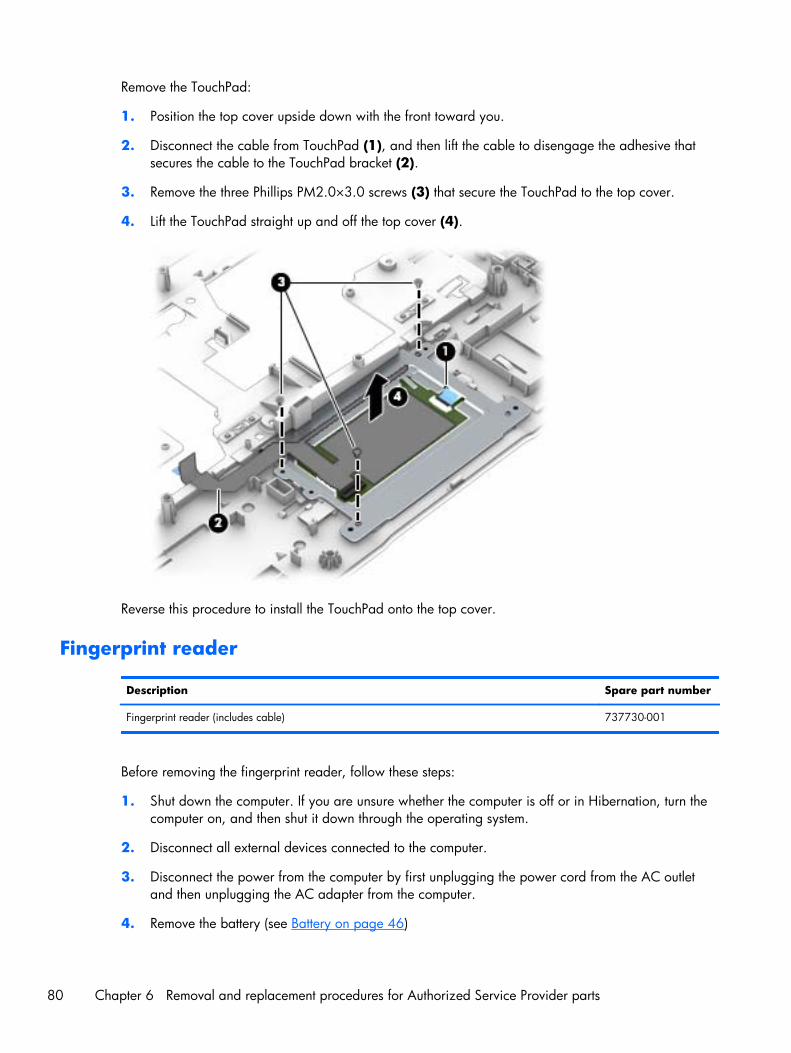
Remove the TouchPad:
1. Position the top cover upside down with the front toward you.
2. Disconnect the cable from TouchPad (1), and then lift the cable to disengage the adhesive thatsecures the cable to the TouchPad bracket (2).
3. Remove the three Phillips PM2.0×3.0 screws (3) that secure the TouchPad to the top cover.
4. Lift the TouchPad straight up and off the top cover (4).
Reverse this procedure to install the TouchPad onto the top cover.
Fingerprint reader
Description Spare part number
Fingerprint reader (includes cable) 737730-001
Before removing the fingerprint reader, follow these steps:
1. Shut down the computer. If you are unsure whether the computer is off or in Hibernation, turn thecomputer on, and then shut it down through the operating system.
2. Disconnect all external devices connected to the computer.
3. Disconnect the power from the computer by first unplugging the power cord from the AC outletand then unplugging the AC adapter from the computer.
4. Remove the battery (see Battery on page 46)
80 Chapter 6 Removal and replacement procedures for Authorized Service Provider parts

5. Remove the service door (see Service door on page 48).
6. Remove the optical drive (see Optical drive on page 57) or upgrade bay hard drive (see Upgradebay hard drive on page 59).
7. Remove the keyboard (see Keyboard on page 63).
8. Remove the top cover (see Top cover on page 72).
Remove the fingerprint reader:
1. Position the top cover upside down with the front toward you.
2. Remove the Phillips PM2.0×3.0 screw (1) that secures the fingerprint reader bracket to the topcover.
3. Pull the bracket from atop the fingerprint reader board (2).
4. Disengage the cable from adhesive that secures it to top cover (3).
The fingerprint reader bracket is available in the Bracket Kit using spare part number737734-001.
The fingerprint reader bezel and insert are available in the Plastics Kit using spare part number733637-001.
5. Lift the fingerprint reader from the top cover (4).
Reverse this procedure to install the fingerprint reader.
Component replacement procedures 81
Power button board
Description Spare part number
Power button board (includes cable) 733636-001
Before removing the power button board, follow these steps:
1. Shut down the computer. If you are unsure whether the computer is off or in Hibernation, turn thecomputer on, and then shut it down through the operating system.
2. Disconnect all external devices connected to the computer.
3. Disconnect the power from the computer by first unplugging the power cord from the AC outletand then unplugging the AC adapter from the computer.
4. Remove the battery (see Battery on page 46)
5. Remove the service door (see Service door on page 48).
6. Remove the optical drive (see Optical drive on page 57) or upgrade bay hard drive (see Upgradebay hard drive on page 59).
7. Remove the keyboard (see Keyboard on page 63).
8. Remove the top cover (see Top cover on page 72).
Remove the power button board:
1. Position the top cover upside down with the front toward you.
2. Pull the cable through the slot in top cover (1).
3. Disengage the cable from adhesive that secures it to top cover (2).
4. Remove the Phillips PM2.0×3.0 screw (3) that secures the power button board to the top cover.
82 Chapter 6 Removal and replacement procedures for Authorized Service Provider parts

5. Lift the bottom (cable side) of the board up, and then pull the board out from under the tabs thatsecure it in place (4).
Reverse this procedure to install the power button board.
Component replacement procedures 83
Display assembly
You can remove the display bezel, webcam, and display panel without removing the entire displayfrom the computer on models with standard displays (not DreamColor or touchscreen displays). SeeDisplay bezel on page 67, Webcam module on page 69, and Display panel on page 70 earlier in thischapter for more information.
Description Spare part number
43.9 cm (17.3 in), FHD, anti-glare, LED, UWVA, DreamColor for use in models without a webcam 735368-001
43.9 cm (17.3 in), FHD, anti-glare, LED, UWVA, DreamColor for use in models with a webcam 735369-001
Display Hinge Kit (includes left and right hinges, hinge cover, and bracket) 733634-001
Raw Panel Support Kit (includes display enclosure, WLAN antennas, WWAN antennas, and Mylarscrew covers)
735590-001
Before removing the display assembly, follow these steps:
1. Shut down the computer. If you are unsure whether the computer is off or in Hibernation, turn thecomputer on, and then shut it down through the operating system.
2. Disconnect all external devices connected to the computer.
3. Disconnect the power from the computer by first unplugging the power cord from the AC outletand then unplugging the AC adapter from the computer.
4. Remove the battery (see Battery on page 46).
5. Remove the service door (see Service door on page 48).
6. Remove the optical drive (see Optical drive on page 57) or upgrade bay hard drive (see Upgradebay hard drive on page 59).
7. Remove the keyboard (see Keyboard on page 63).
8. Remove the top cover (see Top cover on page 72).
Remove the display assembly:
1. Position the computer upside down.
84 Chapter 6 Removal and replacement procedures for Authorized Service Provider parts
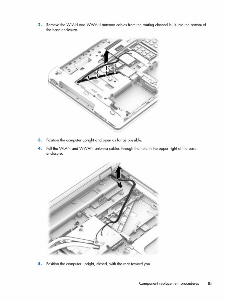
2. Remove the WLAN and WWAN antenna cables from the routing channel built into the bottom ofthe base enclosure.
3. Position the computer upright and open as far as possible.
4. Pull the WLAN and WWAN antenna cables through the hole in the upper right of the baseenclosure.
5. Position the computer upright, closed, with the rear toward you.
Component replacement procedures 85
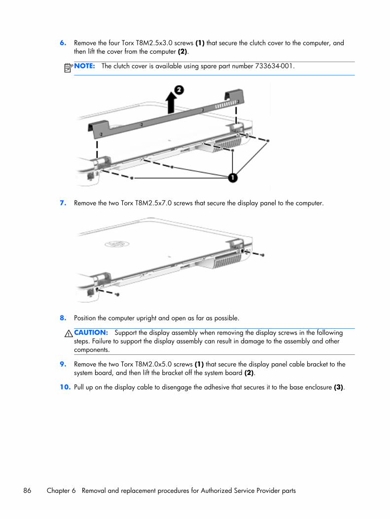
6. Remove the four Torx T8M2.5x3.0 screws (1) that secure the clutch cover to the computer, andthen lift the cover from the computer (2).
NOTE: The clutch cover is available using spare part number 733634-001.
7. Remove the two Torx T8M2.5x7.0 screws that secure the display panel to the computer.
8. Position the computer upright and open as far as possible.
CAUTION: Support the display assembly when removing the display screws in the followingsteps. Failure to support the display assembly can result in damage to the assembly and othercomponents.
9. Remove the two Torx T8M2.0x5.0 screws (1) that secure the display panel cable bracket to thesystem board, and then lift the bracket off the system board (2).
10. Pull up on the display cable to disengage the adhesive that secures it to the base enclosure (3).
86 Chapter 6 Removal and replacement procedures for Authorized Service Provider parts
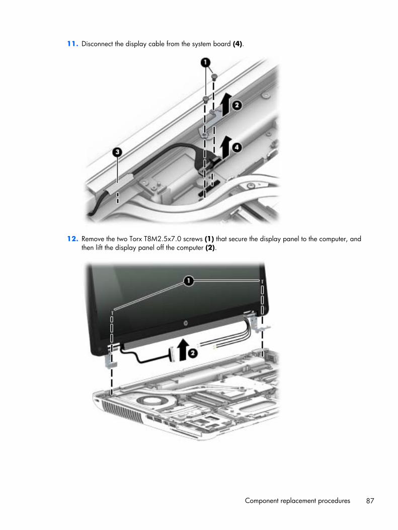
11. Disconnect the display cable from the system board (4).
12. Remove the two Torx T8M2.5x7.0 screws (1) that secure the display panel to the computer, andthen lift the display panel off the computer (2).
Component replacement procedures 87

13. Remove the six Torx T8M2.5×7.0 screws (1) that secure the panel to the enclosure.
NOTE: If tape secures the panel to the enclosure, lift the tape to disengage the panel from theenclosure.
14. Lift the top of the display panel, and then remove the panel from the enclosure (2).
15. If you need to remove the display hinge brackets from the display enclosure:
NOTE: Display hinge brackets are available in the Hinge Kit using spare part number733634-001.
a. Remove the four Phillips PM2.0x3.0 screws (1) that secure the display panel to each hinge.
b. Remove the hinge brackets from the display panel (2).
88 Chapter 6 Removal and replacement procedures for Authorized Service Provider parts
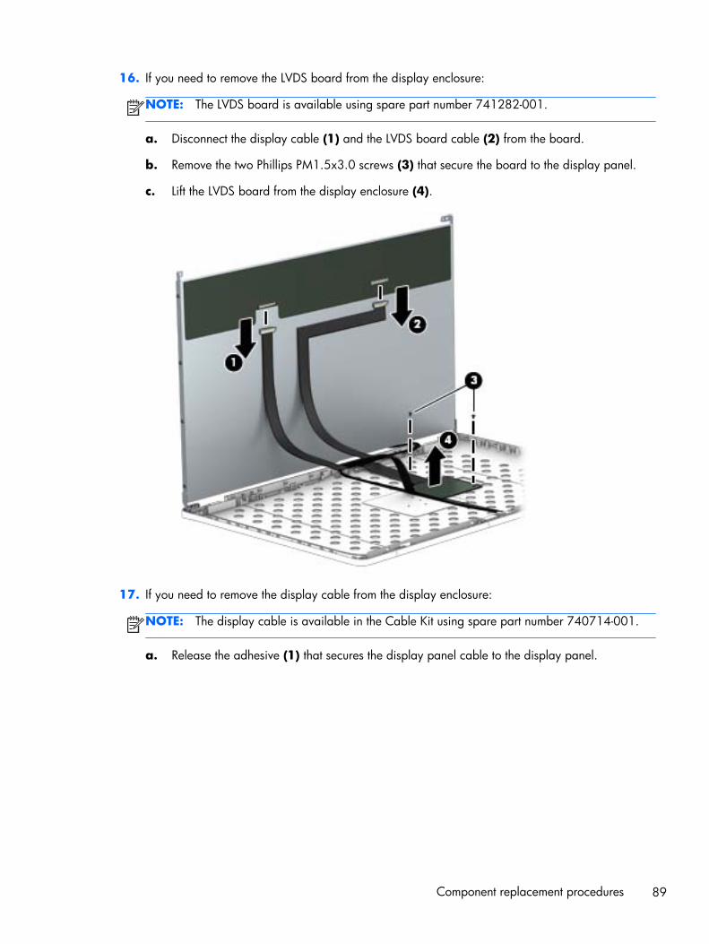
16. If you need to remove the LVDS board from the display enclosure:
NOTE: The LVDS board is available using spare part number 741282-001.
a. Disconnect the display cable (1) and the LVDS board cable (2) from the board.
b. Remove the two Phillips PM1.5x3.0 screws (3) that secure the board to the display panel.
c. Lift the LVDS board from the display enclosure (4).
17. If you need to remove the display cable from the display enclosure:
NOTE: The display cable is available in the Cable Kit using spare part number 740714-001.
a. Release the adhesive (1) that secures the display panel cable to the display panel.
Component replacement procedures 89

b. Remove the cable (2).
18. If you need to remove the antenna cables from the display enclosure:
a. Lift the antennas from the routing paths on the display enclosure (1).
b. Remove the WLAN antennas (2) and WWAN antennas from the enclosure (3).
Antenna cables are available in the Raw Panel Support Kit, spare part number 735590-001.
The display enclosure is available using spare part number 740477-001.
Reverse this procedure to install the display assembly.
90 Chapter 6 Removal and replacement procedures for Authorized Service Provider parts
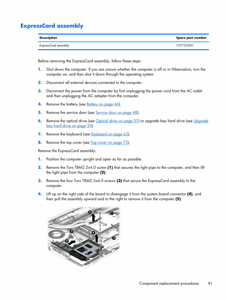
ExpressCard assembly
Description Spare part number
ExpressCard assembly 737733-001
Before removing the ExpressCard assembly, follow these steps:
1. Shut down the computer. If you are unsure whether the computer is off or in Hibernation, turn thecomputer on, and then shut it down through the operating system.
2. Disconnect all external devices connected to the computer.
3. Disconnect the power from the computer by first unplugging the power cord from the AC outletand then unplugging the AC adapter from the computer.
4. Remove the battery (see Battery on page 46).
5. Remove the service door (see Service door on page 48).
6. Remove the optical drive (see Optical drive on page 57) or upgrade bay hard drive (see Upgradebay hard drive on page 59).
7. Remove the keyboard (see Keyboard on page 63).
8. Remove the top cover (see Top cover on page 72).
Remove the ExpressCard assembly:
1. Position the computer upright and open as far as possible.
2. Remove the Torx T8M2.5x4.0 screw (1) that secures the light pipe to the computer, and then liftthe light pipe from the computer (2).
3. Remove the four Torx T8M2.5x4.0 screws (3) that secure the ExpressCard assembly to thecomputer.
4. Lift up on the right side of the board to disengage it from the system board connector (4), andthen pull the assembly upward and to the right to remove it from the computer (5).
Component replacement procedures 91

Reverse this procedure to install the ExpressCard assembly.
Smart Card reader
Description Spare part number
Smart Card reader (includes cable) 742159-001
The Smart Card reader is located under the ExpressCard assembly.
Before removing the Smart Card reader, follow these steps:
1. Shut down the computer. If you are unsure whether the computer is off or in Hibernation, turn thecomputer on, and then shut it down through the operating system.
2. Disconnect all external devices connected to the computer.
3. Disconnect the power from the computer by first unplugging the power cord from the AC outletand then unplugging the AC adapter from the computer.
4. Remove the battery (see Battery on page 46).
5. Remove the service door (see Service door on page 48).
6. Remove the optical drive (see Optical drive on page 57) or upgrade bay hard drive (see Upgradebay hard drive on page 59).
7. Remove the keyboard (see Keyboard on page 63).
8. Remove the top cover (see Top cover on page 72).
9. Remove the ExpressCard assembly (see ExpressCard assembly on page 91).
Remove the Smart Card:
1. Position the computer upright and open as far as possible.
2. Remove the three Phillips PM2.5x4.0 screws (1) that secure the Smart Card reader to thecomputer.
3. Lift the Smart Card reader slightly upward and toward the left (2), and then disconnect the cablefrom the ZIF connector on the system board (3).
92 Chapter 6 Removal and replacement procedures for Authorized Service Provider parts
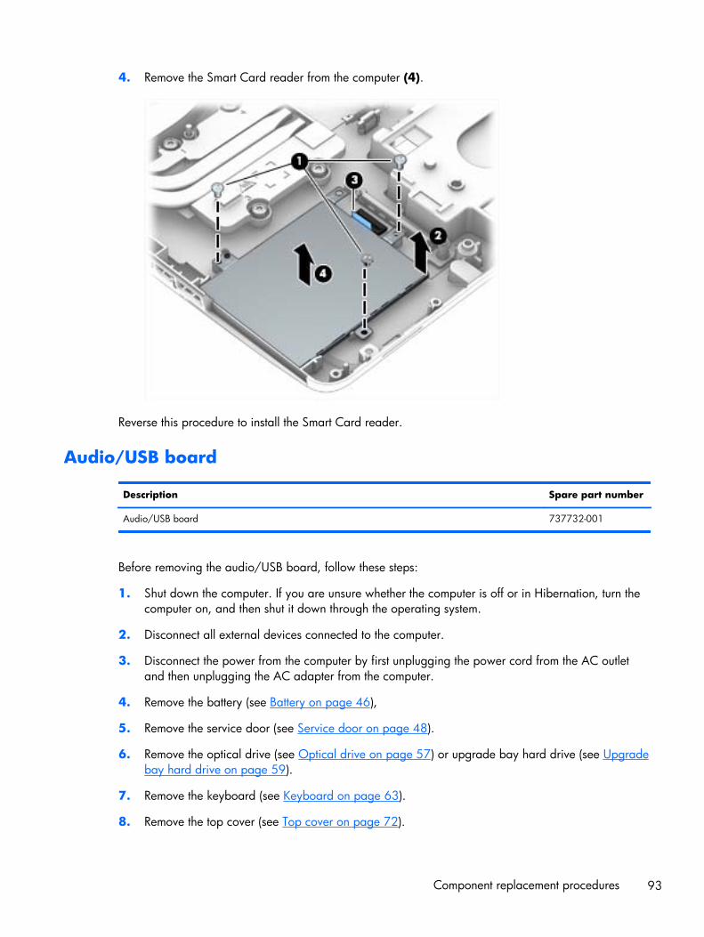
4. Remove the Smart Card reader from the computer (4).
Reverse this procedure to install the Smart Card reader.
Audio/USB board
Description Spare part number
Audio/USB board 737732-001
Before removing the audio/USB board, follow these steps:
1. Shut down the computer. If you are unsure whether the computer is off or in Hibernation, turn thecomputer on, and then shut it down through the operating system.
2. Disconnect all external devices connected to the computer.
3. Disconnect the power from the computer by first unplugging the power cord from the AC outletand then unplugging the AC adapter from the computer.
4. Remove the battery (see Battery on page 46),
5. Remove the service door (see Service door on page 48).
6. Remove the optical drive (see Optical drive on page 57) or upgrade bay hard drive (see Upgradebay hard drive on page 59).
7. Remove the keyboard (see Keyboard on page 63).
8. Remove the top cover (see Top cover on page 72).
Component replacement procedures 93
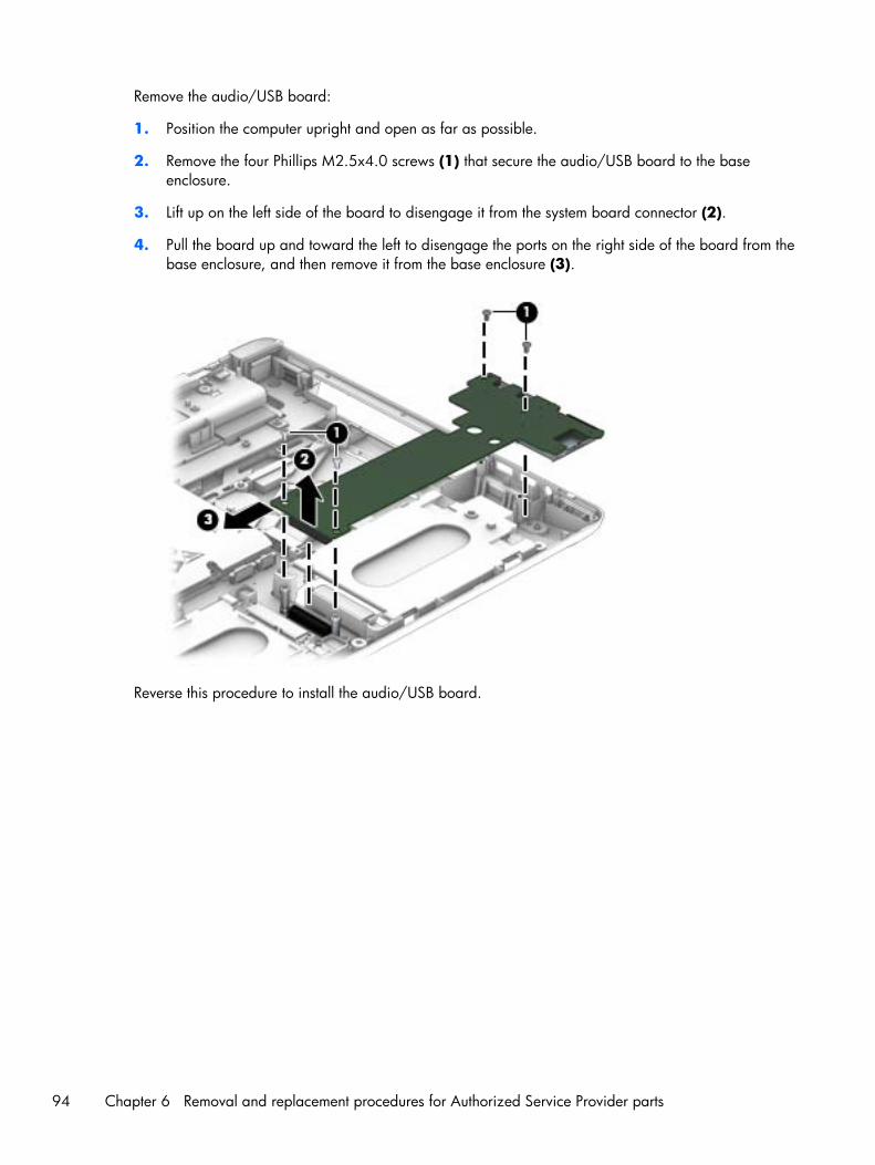
Remove the audio/USB board:
1. Position the computer upright and open as far as possible.
2. Remove the four Phillips M2.5x4.0 screws (1) that secure the audio/USB board to the baseenclosure.
3. Lift up on the left side of the board to disengage it from the system board connector (2).
4. Pull the board up and toward the left to disengage the ports on the right side of the board from thebase enclosure, and then remove it from the base enclosure (3).
Reverse this procedure to install the audio/USB board.
94 Chapter 6 Removal and replacement procedures for Authorized Service Provider parts

Processor heat sink
Description Spare part number
For use only with computer models equipped with quad-core processors 735372-001
For use only with computer models equipped with dual-core processors 735371-001
Before removing the processor heat sink, follow these steps:
1. Shut down the computer. If you are unsure whether the computer is off or in Hibernation, turn thecomputer on, and then shut it down through the operating system.
2. Disconnect all external devices connected to the computer.
3. Disconnect the power from the computer by first unplugging the power cord from the AC outletand then unplugging the AC adapter from the computer.
4. Remove the battery (see Battery on page 46)
5. Remove the service door (see Service door on page 48).
6. Remove the optical drive (see Optical drive on page 57) or upgrade bay hard drive (see Upgradebay hard drive on page 59).
7. Remove the keyboard (see Keyboard on page 63).
8. Remove the top cover (see Top cover on page 72).
Remove the processor heat sink:
1. Following the sequence stamped into the processor heat sink, loosen the four Phillips captivescrews (1) that secure the processor heat sink to the system board.
NOTE: If there is Mylar tape that secures the heat sink to the fan, lift up on the tape todisengage the heat sink.
Component replacement procedures 95
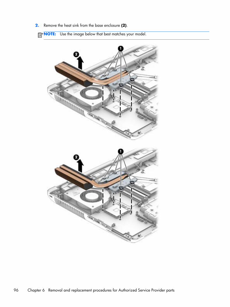
2. Remove the heat sink from the base enclosure (2).
NOTE: Use the image below that best matches your model.
96 Chapter 6 Removal and replacement procedures for Authorized Service Provider parts

3. Thermal paste located on the surfaces of the processor (1) and the processor heat sink (2).Replacement thermal paste and pads are included in the processor heat sink and processor sparepart kits.
Reverse this procedure to install the processor heat sink.
Component replacement procedures 97
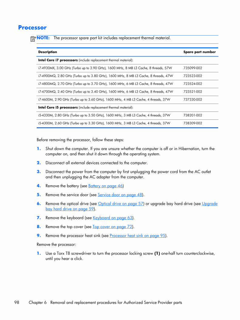
Processor
NOTE: The processor spare part kit includes replacement thermal material.
Description Spare part number
Intel Core i7 processors (include replacement thermal material):
i7-4930MX, 3.00 GHz (Turbo up to 3.90 GHz), 1600 MHz, 8 MB L3 Cache, 8 threads, 57W 735099-002
i7-4900MQ, 2.80 GHz (Turbo up to 3.80 GHz), 1600 MHz, 8 MB L3 Cache, 8 threads, 47W 723523-002
i7-4800MQ, 2.70 GHz (Turbo up to 3.70 GHz), 1600 MHz, 6 MB L3 Cache, 8 threads, 47W 723524-002
i7-4700MQ, 2.40 GHz (Turbo up to 3.40 GHz), 1600 MHz, 6 MB L3 Cache, 8 threads, 47W 723521-002
i7-4600M, 2.90 GHz (Turbo up to 3.60 GHz), 1600 MHz, 4 MB L3 Cache, 4 threads, 37W 737330-002
Intel Core i5 processors (include replacement thermal material):
i5-4330M, 2.80 GHz (Turbo up to 3.50 GHz), 1600 MHz, 3 MB L3 Cache, 4 threads, 37W 738201-002
i5-4300M, 2.60 GHz (Turbo up to 3.30 GHz), 1600 MHz, 3 MB L3 Cache, 4 threads, 37W 738309-002
Before removing the processor, follow these steps:
1. Shut down the computer. If you are unsure whether the computer is off or in Hibernation, turn thecomputer on, and then shut it down through the operating system.
2. Disconnect all external devices connected to the computer.
3. Disconnect the power from the computer by first unplugging the power cord from the AC outletand then unplugging the AC adapter from the computer.
4. Remove the battery (see Battery on page 46)
5. Remove the service door (see Service door on page 48).
6. Remove the optical drive (see Optical drive on page 57) or upgrade bay hard drive (see Upgradebay hard drive on page 59).
7. Remove the keyboard (see Keyboard on page 63).
8. Remove the top cover (see Top cover on page 72).
9. Remove the processor heat sink (see Processor heat sink on page 95).
Remove the processor:
1. Use a Torx T8 screwdriver to turn the processor locking screw (1) one-half turn counterclockwise,until you hear a click.
98 Chapter 6 Removal and replacement procedures for Authorized Service Provider parts
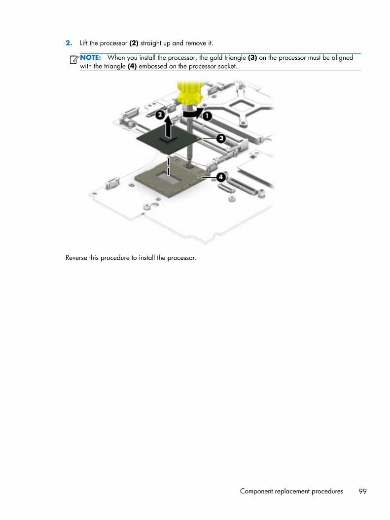
2. Lift the processor (2) straight up and remove it.
NOTE: When you install the processor, the gold triangle (3) on the processor must be alignedwith the triangle (4) embossed on the processor socket.
Reverse this procedure to install the processor.
Component replacement procedures 99
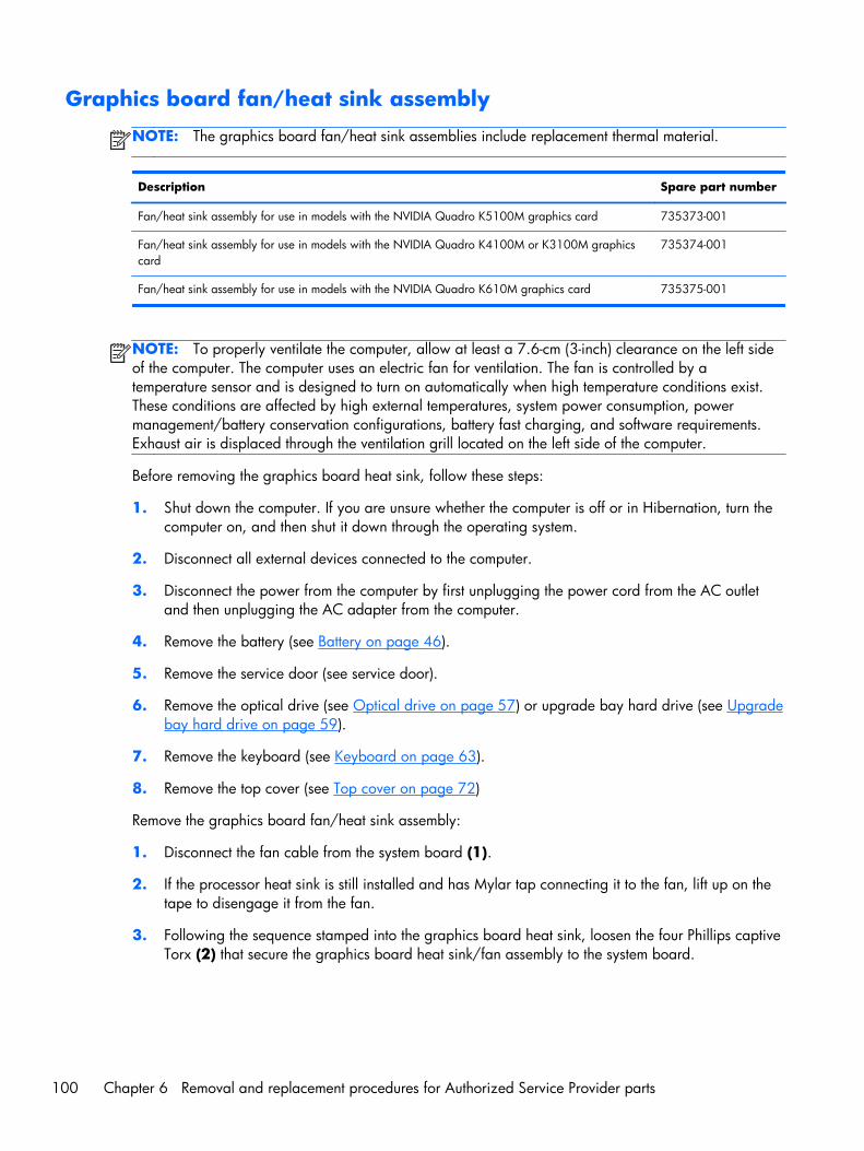
Graphics board fan/heat sink assembly
NOTE: The graphics board fan/heat sink assemblies include replacement thermal material.
Description Spare part number
Fan/heat sink assembly for use in models with the NVIDIA Quadro K5100M graphics card 735373-001
Fan/heat sink assembly for use in models with the NVIDIA Quadro K4100M or K3100M graphicscard
735374-001
Fan/heat sink assembly for use in models with the NVIDIA Quadro K610M graphics card 735375-001
NOTE: To properly ventilate the computer, allow at least a 7.6-cm (3-inch) clearance on the left sideof the computer. The computer uses an electric fan for ventilation. The fan is controlled by atemperature sensor and is designed to turn on automatically when high temperature conditions exist.These conditions are affected by high external temperatures, system power consumption, powermanagement/battery conservation configurations, battery fast charging, and software requirements.Exhaust air is displaced through the ventilation grill located on the left side of the computer.
Before removing the graphics board heat sink, follow these steps:
1. Shut down the computer. If you are unsure whether the computer is off or in Hibernation, turn thecomputer on, and then shut it down through the operating system.
2. Disconnect all external devices connected to the computer.
3. Disconnect the power from the computer by first unplugging the power cord from the AC outletand then unplugging the AC adapter from the computer.
4. Remove the battery (see Battery on page 46).
5. Remove the service door (see service door).
6. Remove the optical drive (see Optical drive on page 57) or upgrade bay hard drive (see Upgradebay hard drive on page 59).
7. Remove the keyboard (see Keyboard on page 63).
8. Remove the top cover (see Top cover on page 72)
Remove the graphics board fan/heat sink assembly:
1. Disconnect the fan cable from the system board (1).
2. If the processor heat sink is still installed and has Mylar tap connecting it to the fan, lift up on thetape to disengage it from the fan.
3. Following the sequence stamped into the graphics board heat sink, loosen the four Phillips captiveTorx (2) that secure the graphics board heat sink/fan assembly to the system board.
100 Chapter 6 Removal and replacement procedures for Authorized Service Provider parts
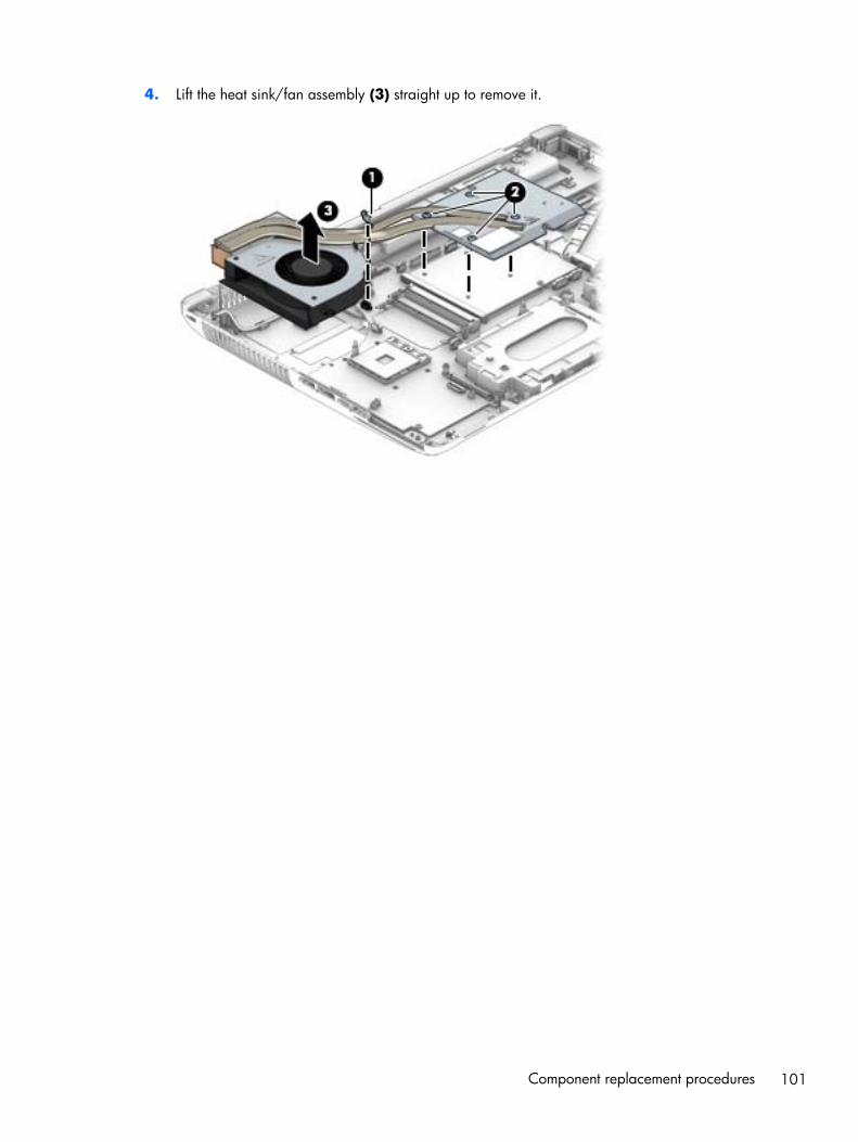
4. Lift the heat sink/fan assembly (3) straight up to remove it.
Component replacement procedures 101
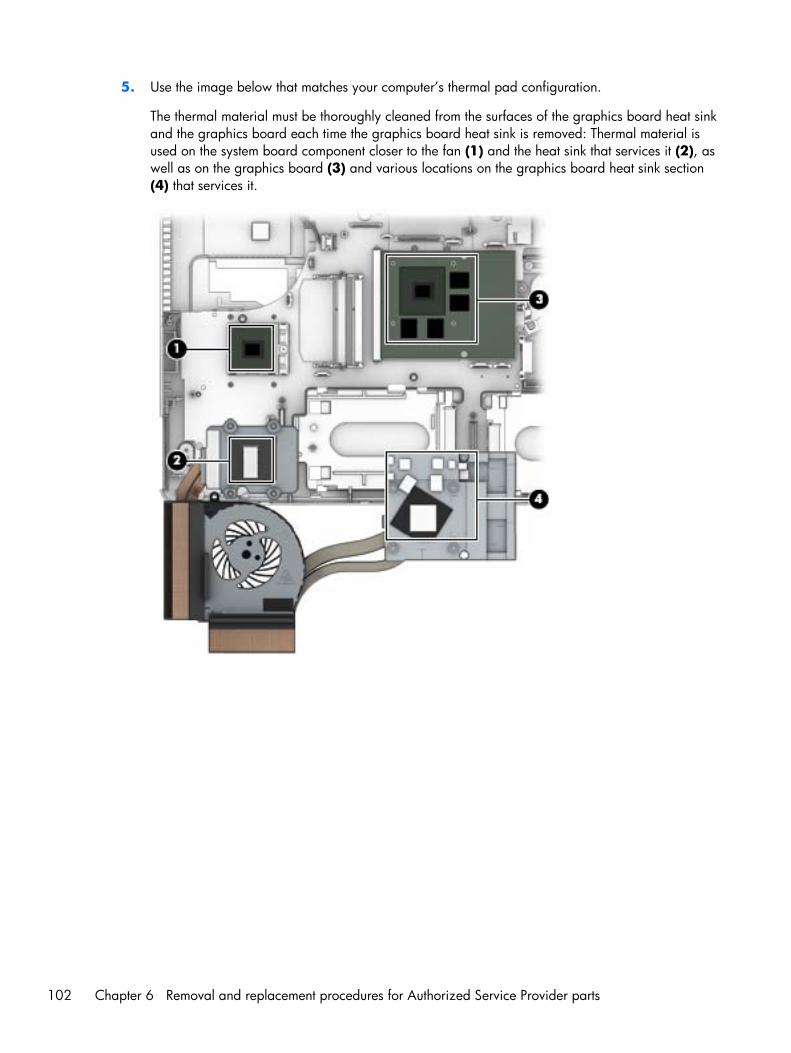
5. Use the image below that matches your computer’s thermal pad configuration.
The thermal material must be thoroughly cleaned from the surfaces of the graphics board heat sinkand the graphics board each time the graphics board heat sink is removed: Thermal material isused on the system board component closer to the fan (1) and the heat sink that services it (2), aswell as on the graphics board (3) and various locations on the graphics board heat sink section(4) that services it.
102 Chapter 6 Removal and replacement procedures for Authorized Service Provider parts
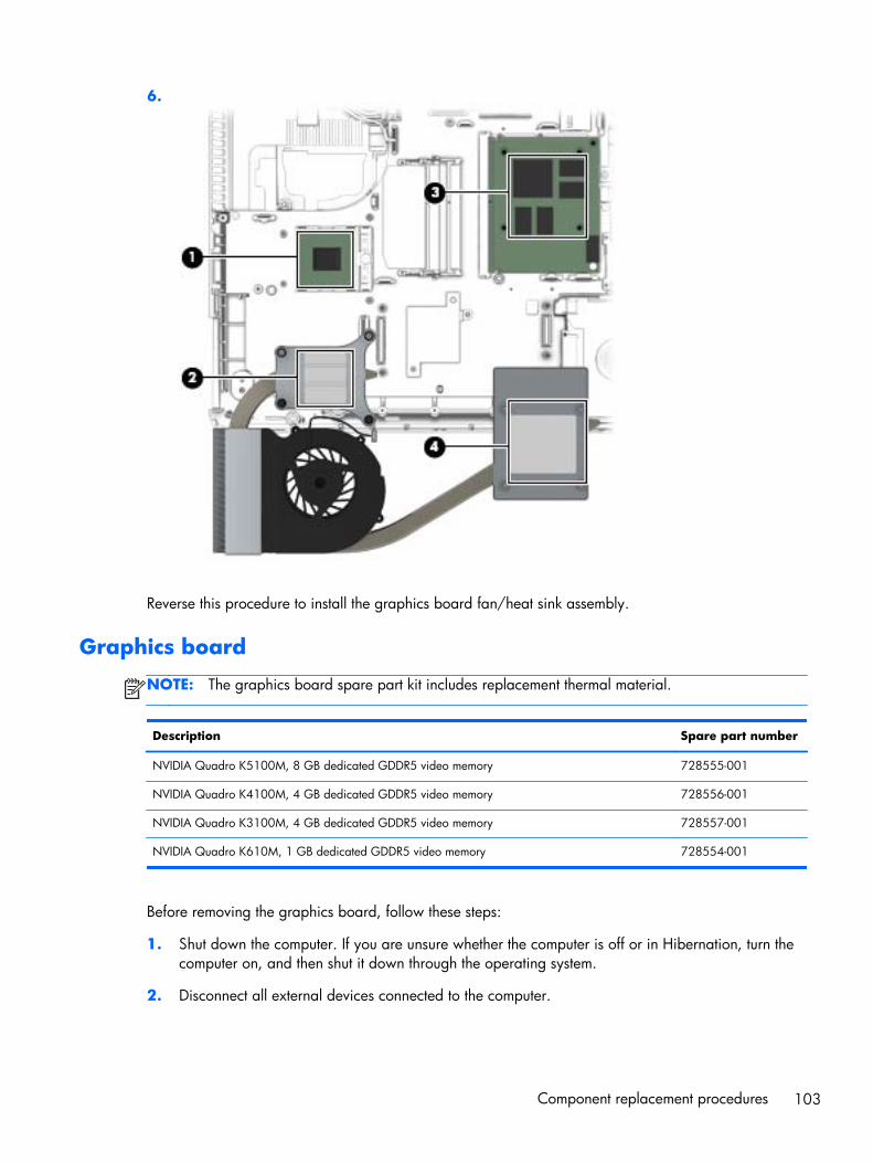
6.
Reverse this procedure to install the graphics board fan/heat sink assembly.
Graphics board
NOTE: The graphics board spare part kit includes replacement thermal material.
Description Spare part number
NVIDIA Quadro K5100M, 8 GB dedicated GDDR5 video memory 728555-001
NVIDIA Quadro K4100M, 4 GB dedicated GDDR5 video memory 728556-001
NVIDIA Quadro K3100M, 4 GB dedicated GDDR5 video memory 728557-001
NVIDIA Quadro K610M, 1 GB dedicated GDDR5 video memory 728554-001
Before removing the graphics board, follow these steps:
1. Shut down the computer. If you are unsure whether the computer is off or in Hibernation, turn thecomputer on, and then shut it down through the operating system.
2. Disconnect all external devices connected to the computer.
Component replacement procedures 103
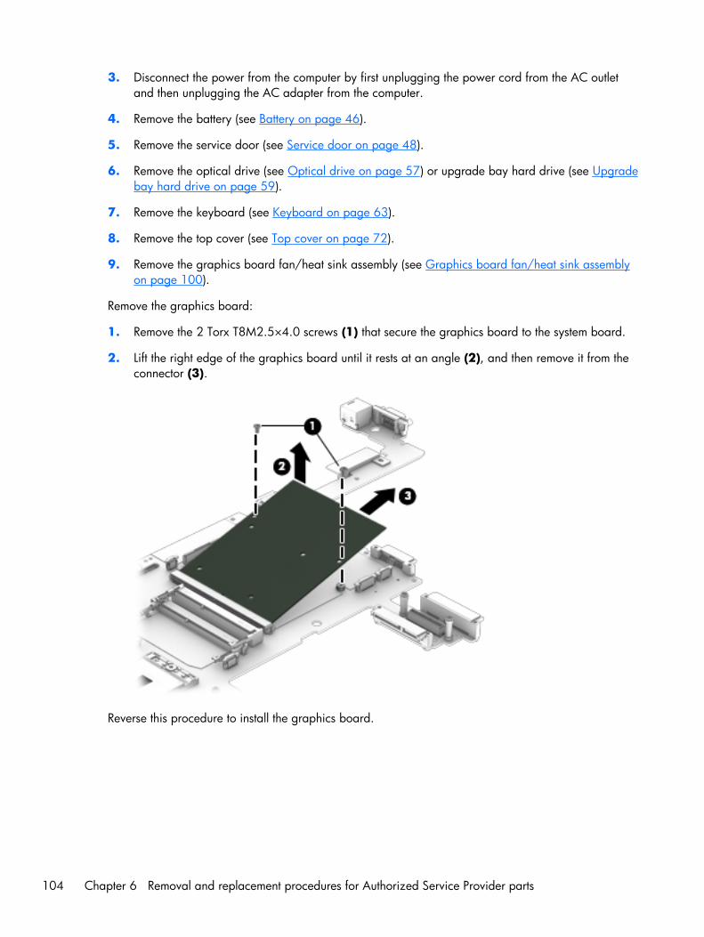
3. Disconnect the power from the computer by first unplugging the power cord from the AC outletand then unplugging the AC adapter from the computer.
4. Remove the battery (see Battery on page 46).
5. Remove the service door (see Service door on page 48).
6. Remove the optical drive (see Optical drive on page 57) or upgrade bay hard drive (see Upgradebay hard drive on page 59).
7. Remove the keyboard (see Keyboard on page 63).
8. Remove the top cover (see Top cover on page 72).
9. Remove the graphics board fan/heat sink assembly (see Graphics board fan/heat sink assemblyon page 100).
Remove the graphics board:
1. Remove the 2 Torx T8M2.5×4.0 screws (1) that secure the graphics board to the system board.
2. Lift the right edge of the graphics board until it rests at an angle (2), and then remove it from theconnector (3).
Reverse this procedure to install the graphics board.
104 Chapter 6 Removal and replacement procedures for Authorized Service Provider parts

Power connector cable
Before removing the power connector cable, follow these steps:
1. Shut down the computer. If you are unsure whether the computer is off or in Hibernation, turn thecomputer on, and then shut it down through the operating system.
2. Disconnect all external devices connected to the computer.
3. Disconnect the power from the computer by first unplugging the power cord from the AC outletand then unplugging the AC adapter from the computer.
4. Remove the battery (see Battery on page 46).
5. Remove the service door (see Service door on page 48).
6. Remove the optical drive (see Optical drive on page 57) or upgrade bay hard drive (see Upgradebay hard drive on page 59).
7. Remove the keyboard (see Keyboard on page 63).
8. Remove the top cover (see Top cover on page 72).
9. Remove the display assembly (see Display assembly on page 84).
10. Remove the graphics board fan/heat sink (see Graphics board fan/heat sink assemblyon page 100).
Remove the power connector cable:
1. Remove the Torx T8M2.5×7.0 screw (1) that secures to the left, rear plastic cover to the baseenclosure, and the lift the plastic piece off the base enclosure (2).
The left, rear plastic cover is available in the Plastics Kit using spare part number 733637-001.
2. Remove the Torx T8M2.5×4.0 screw (3) that secures to the bracket to the base enclosure, and thelift the bracket out of the base enclosure (4).
The bracket is available in the Bracket Kit using spare part number 737734-001.
3. Disconnect the cable from the system board (5).
Component replacement procedures 105
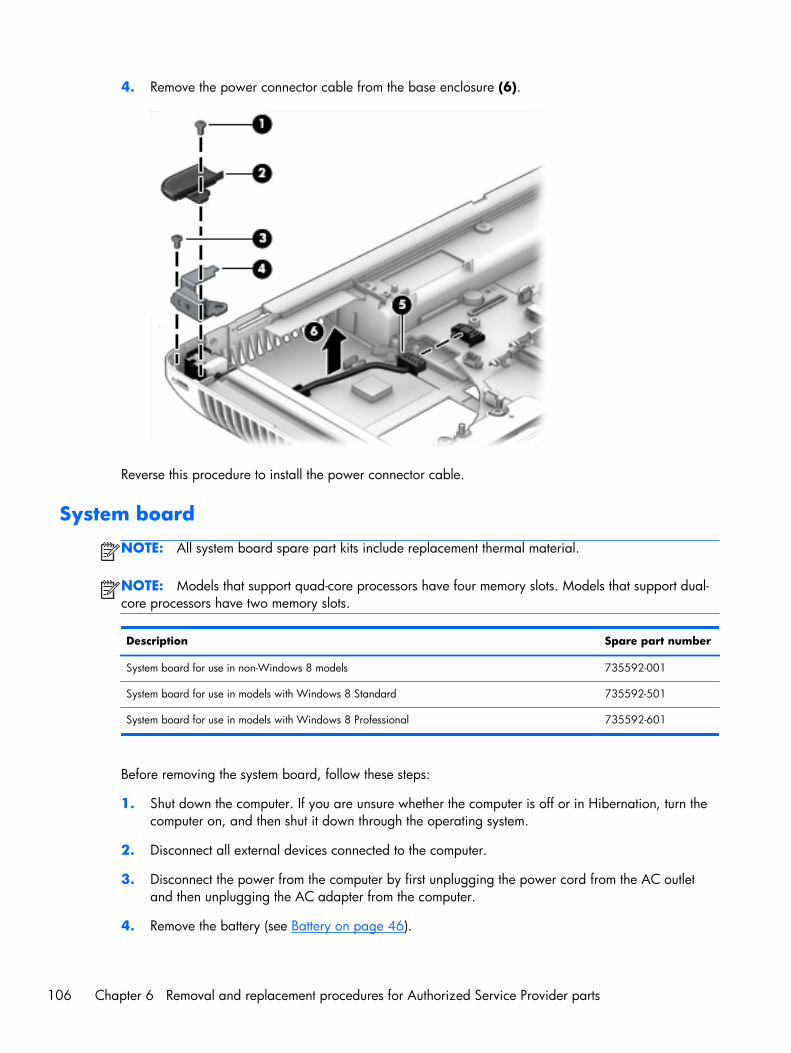
4. Remove the power connector cable from the base enclosure (6).
Reverse this procedure to install the power connector cable.
System board
NOTE: All system board spare part kits include replacement thermal material.
NOTE: Models that support quad-core processors have four memory slots. Models that support dual-core processors have two memory slots.
Description Spare part number
System board for use in non-Windows 8 models 735592-001
System board for use in models with Windows 8 Standard 735592-501
System board for use in models with Windows 8 Professional 735592-601
Before removing the system board, follow these steps:
1. Shut down the computer. If you are unsure whether the computer is off or in Hibernation, turn thecomputer on, and then shut it down through the operating system.
2. Disconnect all external devices connected to the computer.
3. Disconnect the power from the computer by first unplugging the power cord from the AC outletand then unplugging the AC adapter from the computer.
4. Remove the battery (see Battery on page 46).
106 Chapter 6 Removal and replacement procedures for Authorized Service Provider parts
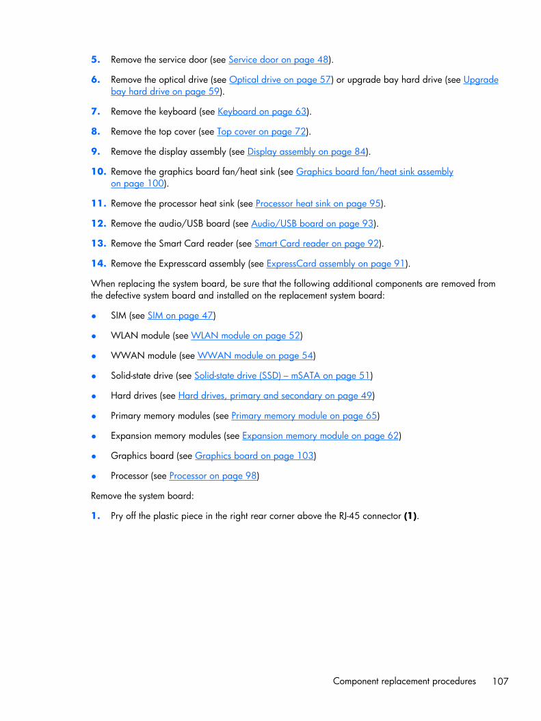
5. Remove the service door (see Service door on page 48).
6. Remove the optical drive (see Optical drive on page 57) or upgrade bay hard drive (see Upgradebay hard drive on page 59).
7. Remove the keyboard (see Keyboard on page 63).
8. Remove the top cover (see Top cover on page 72).
9. Remove the display assembly (see Display assembly on page 84).
10. Remove the graphics board fan/heat sink (see Graphics board fan/heat sink assemblyon page 100).
11. Remove the processor heat sink (see Processor heat sink on page 95).
12. Remove the audio/USB board (see Audio/USB board on page 93).
13. Remove the Smart Card reader (see Smart Card reader on page 92).
14. Remove the Expresscard assembly (see ExpressCard assembly on page 91).
When replacing the system board, be sure that the following additional components are removed fromthe defective system board and installed on the replacement system board:
● SIM (see SIM on page 47)
● WLAN module (see WLAN module on page 52)
● WWAN module (see WWAN module on page 54)
● Solid-state drive (see Solid-state drive (SSD) – mSATA on page 51)
● Hard drives (see Hard drives, primary and secondary on page 49)
● Primary memory modules (see Primary memory module on page 65)
● Expansion memory modules (see Expansion memory module on page 62)
● Graphics board (see Graphics board on page 103)
● Processor (see Processor on page 98)
Remove the system board:
1. Pry off the plastic piece in the right rear corner above the RJ-45 connector (1).
Component replacement procedures 107
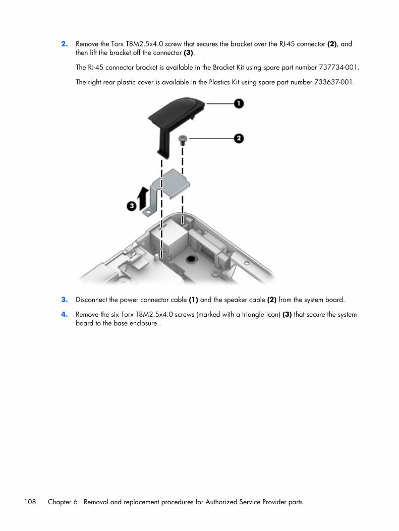
2. Remove the Torx T8M2.5x4.0 screw that secures the bracket over the RJ-45 connector (2), andthen lift the bracket off the connector (3).
The RJ-45 connector bracket is available in the Bracket Kit using spare part number 737734-001.
The right rear plastic cover is available in the Plastics Kit using spare part number 733637-001.
3. Disconnect the power connector cable (1) and the speaker cable (2) from the system board.
4. Remove the six Torx T8M2.5x4.0 screws (marked with a triangle icon) (3) that secure the systemboard to the base enclosure .
108 Chapter 6 Removal and replacement procedures for Authorized Service Provider parts
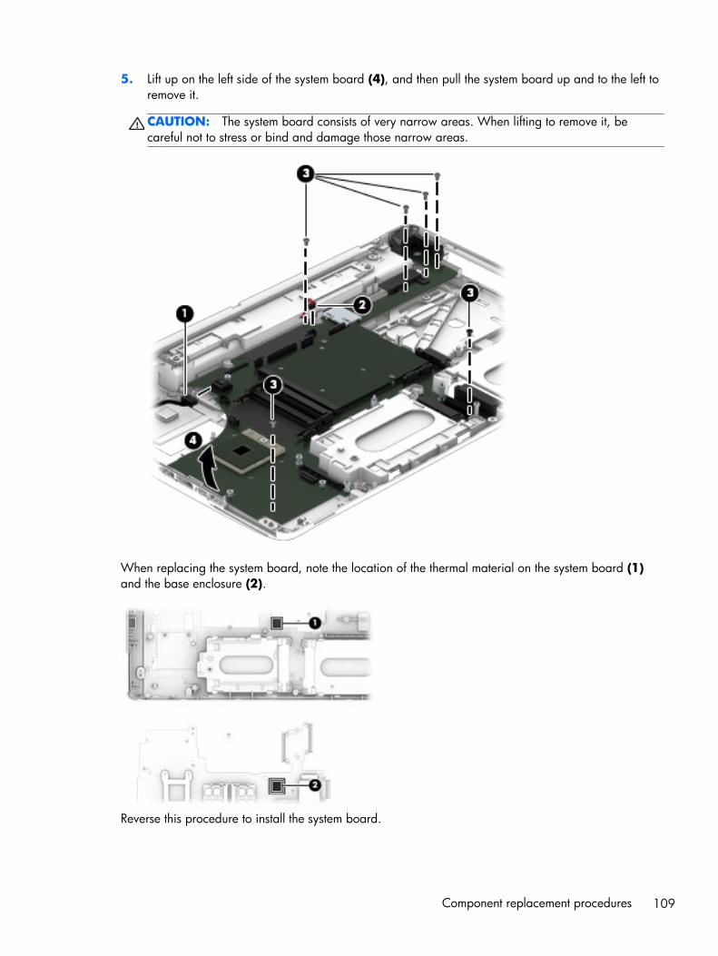
5. Lift up on the left side of the system board (4), and then pull the system board up and to the left toremove it.
CAUTION: The system board consists of very narrow areas. When lifting to remove it, becareful not to stress or bind and damage those narrow areas.
When replacing the system board, note the location of the thermal material on the system board (1)and the base enclosure (2).
Reverse this procedure to install the system board.
Component replacement procedures 109
7 Computer Setup (BIOS), MultiBoot,and System Diagnostics inWindows 8
Using Computer SetupComputer Setup, or Basic Input/Output System (BIOS), controls communication between all the inputand output devices on the system (such as disk drives, display, keyboard, mouse, and printer).Computer Setup includes settings for the types of devices installed, the startup sequence of thecomputer, and the amount of system and extended memory.
NOTE: Use extreme care when making changes in Computer Setup. Errors can prevent the computerfrom operating properly.
Starting Computer Setup
NOTE: An external keyboard or mouse connected to a USB port can be used with Computer Setuponly if USB legacy support is enabled.
To start Computer Setup, follow these steps:
1. Turn on or restart the computer, and then press esc while the “Press the ESC key for Startup Menu”message is displayed at the bottom of the screen.
2. Press f10 to enter Computer Setup.
110 Chapter 7 Computer Setup (BIOS), MultiBoot, and System Diagnostics in Windows 8

Navigating and selecting in Computer Setup
To navigate and select in Computer Setup, follow these steps:
1. Turn on or restart the computer, and then press esc while the “Press the ESC key for Startup Menu”message is displayed at the bottom of the screen.
NOTE: You can use either a pointing device (TouchPad, pointing stick, or USB mouse) or thekeyboard to navigate and make selections in Computer Setup.
2. Press f10 to enter Computer Setup.
● To select a menu or a menu item, use the tab key and the keyboard arrow keys and thenpress enter, or use a pointing device to click the item.
● To scroll up and down, click the up arrow or the down arrow in the upper-right corner of thescreen, or use the up arrow key or the down arrow key on the keyboard.
● To close open dialog boxes and return to the main Computer Setup screen, press esc, andthen follow the on-screen instructions.
To exit Computer Setup menus, choose one of the following methods:
● To exit Computer Setup menus without saving your changes:
Click the Exit icon in the lower-right corner of the screen, and then follow the on-screeninstructions.
– or –
Use the tab key and the arrow keys to select File > Ignore Changes and Exit, and then pressenter.
● To save your changes and exit Computer Setup menus:
Click the Save icon in the lower-right corner of the screen, and then follow the on-screeninstructions.
– or –
Use the tab key and the arrow keys to select File > Save Changes and Exit, and then pressenter.
Your changes go into effect when the computer restarts.
Restoring default settings in Computer Setup
NOTE: Restoring defaults will not change the hard drive mode.
To return all settings in Computer Setup to the values that were set at the factory, follow these steps:
1. Turn on or restart the computer, and then press esc while the “Press the ESC key for Startup Menu”message is displayed at the bottom of the screen.
2. Press f10 to enter Computer Setup.
Using Computer Setup 111

3. Use a pointing device or the arrow keys to select File > Restore Defaults.
4. Follow the on-screen instructions.
5. To save your changes and exit, click the Save icon in the lower-right corner of the screen, andthen follow the on-screen instructions.
– or –
Use the arrow keys to select File > Save Changes and Exit, and then press enter.
Your changes go into effect when the computer restarts.
NOTE: Your password settings and security settings are not changed when you restore the defaultsettings.
Updating the BIOS
Updated versions of the BIOS may be available on the HP website.
Most BIOS updates on the HP website are packaged in compressed files called SoftPaqs.
Some download packages contain a file named Readme.txt, which contains information regardinginstalling and troubleshooting the file.
Determining the BIOS version
To determine whether available BIOS updates contain later BIOS versions than those currently installedon the computer, you need to know the version of the system BIOS currently installed.
BIOS version information (also known as ROM date and System BIOS) can be displayed by pressing fn+esc (if you are already in Windows) or by using Computer Setup.
1. Start Computer Setup.
2. Use a pointing device or the arrow keys to select File > System Information.
3. To exit Computer Setup without saving your changes, click the Exit icon in the lower-right cornerof the screen, and then follow the on-screen instructions.
– or –
Use the tab key and the arrow keys to select File > Ignore Changes and Exit, and then pressenter.
112 Chapter 7 Computer Setup (BIOS), MultiBoot, and System Diagnostics in Windows 8
Downloading a BIOS update
CAUTION: To reduce the risk of damage to the computer or an unsuccessful installation, downloadand install a BIOS update only when the computer is connected to reliable external power using the ACadapter. Do not download or install a BIOS update while the computer is running on battery power,docked in an optional docking device, or connected to an optional power source. During thedownload and installation, follow these instructions:
Do not disconnect power on the computer by unplugging the power cord from the AC outlet.
Do not shut down the computer or initiate Sleep.
Do not insert, remove, connect, or disconnect any device, cable, or cord.
1. From the Start screen, select the HP Support Assistant app.
2. Select Updates and tune-ups, and then select Check for HP updates now.
3. At the download area, follow these steps:
a. Identify the most recent BIOS update and compare it to the BIOS version currently installed onyour computer. Make a note of the date, name, or other identifier. You may need thisinformation to locate the update later, after it has been downloaded to your hard drive.
b. Follow the on-screen instructions to download your selection to the hard drive.
If the update is more recent than your BIOS, make a note of the path to the location on yourhard drive where the BIOS update is downloaded. You will need to access this path whenyou are ready to install the update.
NOTE: If you connect your computer to a network, consult the network administrator beforeinstalling any software updates, especially system BIOS updates.
BIOS installation procedures vary. Follow any instructions that are displayed on the screen after thedownload is complete. If no instructions are displayed, follow these steps:
1. From the Start screen, type e, and then click File Explorer.
2. Click your hard drive designation. The hard drive designation is typically Local Disk (C:).
3. Using the hard drive path you recorded earlier, open the folder on your hard drive that containsthe update.
4. Double-click the file that has an .exe extension (for example, filename.exe).
The BIOS installation begins.
5. Complete the installation by following the on-screen instructions.
NOTE: After a message on the screen reports a successful installation, you can delete thedownloaded file from your hard drive.
Using Computer Setup 113

Using MultiBoot
About the boot device order
As the computer starts, the system attempts to boot from enabled devices. The MultiBoot utility, which isenabled at the factory, controls the order in which the system selects a boot device. Boot devices caninclude optical drives, diskette drives, a network interface card (NIC), hard drives, and USB devices.Boot devices contain bootable media or files that the computer needs to start and operate properly.
NOTE: Some boot devices must be enabled in Computer Setup before they can be included in theboot order.
You can change the order in which the computer searches for a boot device by changing the bootorder in Computer Setup. You can also press esc while the “Press the ESC key for Startup Menu”message is displayed at the bottom of the screen, and then press f9. Pressing f9 displays a menu thatshows the current boot devices and allows you to select a boot device. Or, you can use MultiBootExpress to set the computer to prompt you for a boot location each time the computer turns on orrestarts.
Choosing MultiBoot preferences
You can use MultiBoot in the following ways:
● To set a new boot order that the computer uses each time it is turned on, by changing the bootorder in Computer Setup.
● To dynamically choose the boot device, by pressing esc while the “Press the ESC key for StartupMenu” message is displayed at the bottom of the screen, and then pressing f9 to enter the BootDevice Options menu.
● To use MultiBoot Express to set variable boot orders. This feature prompts you for a boot deviceeach time the computer is turned on or restarted.
Setting a new boot order in Computer Setup
To start Computer Setup and set a boot device order that the computer uses each time it is turned on orrestarted, follow these steps:
1. Turn on or restart the computer, and then press esc while the “Press the ESC key for Startup Menu”message is displayed at the bottom of the screen.
2. Press f10 to enter Computer Setup.
3. Use a pointing device or the arrow keys to select the Legacy Boot Order list, and then pressenter.
4. To move the device up in the boot order, use a pointing device to click the up arrow, or press the+ key.
– or –
114 Chapter 7 Computer Setup (BIOS), MultiBoot, and System Diagnostics in Windows 8
To move the device down in the boot order, use a pointing device to click the down arrow, orpress the - key.
5. To save your changes and exit Computer Setup, click the Save icon in the lower-left corner of thescreen, and then follow the on-screen instructions.
– or –
Use the arrow keys to select File > Save Changes and Exit, and then press enter.
Dynamically choosing a boot device using the f9 prompt
To dynamically choose a boot device for the current startup sequence, follow these steps:
1. Open the Select Boot Device menu by turning on or restarting the computer, and then pressing escwhile the “Press the ESC key for Startup Menu” message is displayed at the bottom of the screen.
2. Press f9.
3. Use a pointing device or the arrow keys to select a boot device, then press enter.
Setting a MultiBoot Express prompt
To start Computer Setup and set the computer to display the MultiBoot startup location menu each timethe computer is started or restarted, follow these steps:
1. Turn on or restart the computer, and then press esc while the “Press the ESC key for Startup Menu”message is displayed at the bottom of the screen.
2. Press f10 to enter Computer Setup.
3. Use a pointing device or the arrow keys to select System Configuration > Boot Options,and then press enter.
4. In the MultiBoot Express Popup Delay (Sec) field, enter the length of time in seconds thatyou want the computer to display the startup location menu before it defaults to the currentMultiBoot setting. (When 0 is selected, the Express Boot startup location menu is not displayed.)
5. To save your changes and exit Computer Setup, click the Save icon in the lower-left corner of thescreen, and then follow the on-screen instructions.
– or –
Use the arrow keys to select File > Save Changes and Exit, and then press enter.
Your changes go into effect when the computer restarts.
Using MultiBoot 115

Entering MultiBoot Express preferences
When the Express Boot menu is displayed during startup, you have the following choices:
● To specify a boot device from the Express Boot menu, select your preference within the allottedtime, and then press enter.
● To prevent the computer from defaulting to the current MultiBoot setting, press any key before theallotted time expires. The computer will not start until you select a boot device and press enter.
● To allow the computer to start according to the current MultiBoot settings, wait for the allotted timeto expire.
Using System DiagnosticsSystem Diagnostics allows you to run diagnostic tests to determine if the computer hardware isfunctioning properly. The following diagnostic tests may be available in System Diagnostics:
● System Tune-Up—This group of additional tests checks your computer to make sure that the maincomponents are functioning correctly. System Tune-Up runs longer and more comprehensive testson memory modules, hard drive SMART attributes, the hard drive surface, the battery (and batterycalibration), video memory, and the WLAN module status.
● Start-up test—This test analyzes the main computer components that are required to start thecomputer.
● Run-in test—This test repeats the start-up test and checks for intermittent problems that the start-uptest does not detect.
● Hard disk test—This test analyzes the physical condition of the hard drive, and then checks alldata in every sector of the hard drive. If the test detects a damaged sector, it attempts to move thedata to a good sector.
● Memory test—This test analyzes the physical condition of the memory modules. If it reports anerror, replace the memory modules immediately.
● Battery test—This test analyzes the condition of the battery and calibrates the battery if necessary.If the battery fails the test, contact HP support to report the issue and purchase a replacementbattery.
● BIOS Management—You can update or rollback the version of the BIOS on the system. Do notshut down or remove external power during the process. You will be given a confirmation screenbefore your BIOS is modified. Select BIOS update, BIOS Rollback, or Back to mainmenu.
You can view system information and error logs or select languages in the System Diagnostics window.
116 Chapter 7 Computer Setup (BIOS), MultiBoot, and System Diagnostics in Windows 8
To start System Diagnostics:
1. Turn on or restart the computer. While the “Press the ESC key for Startup Menu” message isdisplayed in the lower-left corner of the screen, press esc. When the Startup Menu is displayed,press f2.
2. Click the diagnostic test you want to run, and then follow the on-screen instructions.
NOTE: If you need to stop a diagnostics test while it is running, press esc.
Using System Diagnostics 117
8 Computer Setup (BIOS), MultiBoot,and UEFI in Windows 7
Using Computer SetupComputer Setup, or Basic Input/Output System (BIOS), controls communication between all the inputand output devices on the system (such as disk drives, display, keyboard, mouse, and printer).Computer Setup includes settings for the types of devices installed, the startup sequence of thecomputer, and the amount of system and extended memory.
NOTE: Use extreme care when making changes in Computer Setup. Errors can prevent the computerfrom operating properly.
Starting Computer Setup
NOTE: An external keyboard or mouse connected to a USB port can be used with Computer Setuponly if USB legacy support is enabled.
To start Computer Setup, follow these steps:
1. Turn on or restart the computer, and then press esc while the “Press the ESC key for Startup Menu”message is displayed at the bottom of the screen.
2. Press f10 to enter Computer Setup.
118 Chapter 8 Computer Setup (BIOS), MultiBoot, and UEFI in Windows 7
Navigating and selecting in Computer Setup
To navigate and select in Computer Setup, follow these steps:
1. Turn on or restart the computer, and then press esc while the “Press the ESC key for Startup Menu”message is displayed at the bottom of the screen.
NOTE: You can use either a pointing device (TouchPad, pointing stick, or USB mouse) or thekeyboard to navigate and make selections in Computer Setup.
2. Press f10 to enter Computer Setup.
● To select a menu or a menu item, use the tab key and the keyboard arrow keys and thenpress enter, or use a pointing device to click the item.
● To scroll up and down, click the up arrow or the down arrow in the upper-right corner of thescreen, or use the up arrow key or the down arrow key on the keyboard.
● To close open dialog boxes and return to the main Computer Setup screen, press esc, andthen follow the on-screen instructions.
To exit Computer Setup menus, choose one of the following methods:
● To exit Computer Setup menus without saving your changes:
Click the Exit icon in the lower-right corner of the screen, and then follow the on-screeninstructions.
– or –
Use the tab key and the arrow keys to select File > Ignore Changes and Exit, and then pressenter.
● To save your changes and exit Computer Setup menus:
Click the Save icon in the lower-right corner of the screen, and then follow the on-screeninstructions.
– or –
Use the tab key and the arrow keys to select File > Save Changes and Exit, and then pressenter.
Your changes go into effect when the computer restarts.
Restoring default settings in Computer Setup
NOTE: Restoring defaults will not change the hard drive mode.
To return all settings in Computer Setup to the values that were set at the factory, follow these steps:
1. Turn on or restart the computer, and then press esc while the “Press the ESC key for Startup Menu”message is displayed at the bottom of the screen.
2. Press f10 to enter Computer Setup.
Using Computer Setup 119
3. Use a pointing device or the arrow keys to select File > Restore Defaults.
4. Follow the on-screen instructions.
5. To save your changes and exit, click the Save icon in the lower-right corner of the screen, andthen follow the on-screen instructions.
– or –
Use the arrow keys to select File > Save Changes and Exit, and then press enter.
Your changes go into effect when the computer restarts.
NOTE: Your password settings and security settings are not changed when you restore the defaultsettings.
Updating the BIOS
Updated versions of the BIOS may be available on the HP website.
Most BIOS updates on the HP website are packaged in compressed files called SoftPaqs.
Some download packages contain a file named Readme.txt, which contains information regardinginstalling and troubleshooting the file.
Determining the BIOS version
To determine whether available BIOS updates contain later BIOS versions than those currently installedon the computer, you need to know the version of the system BIOS currently installed.
BIOS version information (also known as ROM date and System BIOS) can be displayed by pressing fn+esc (if you are already in Windows) or by using Computer Setup.
1. Start Computer Setup.
2. Use a pointing device or the arrow keys to select File > System Information.
3. To exit Computer Setup without saving your changes, click the Exit icon in the lower-right cornerof the screen, and then follow the on-screen instructions.
– or –
Use the tab key and the arrow keys to select File > Ignore Changes and Exit, and then pressenter.
120 Chapter 8 Computer Setup (BIOS), MultiBoot, and UEFI in Windows 7
Downloading a BIOS update
CAUTION: To reduce the risk of damage to the computer or an unsuccessful installation, downloadand install a BIOS update only when the computer is connected to reliable external power using the ACadapter. Do not download or install a BIOS update while the computer is running on battery power,docked in an optional docking device, or connected to an optional power source. During thedownload and installation, follow these instructions:
Do not disconnect power on the computer by unplugging the power cord from the AC outlet.
Do not shut down the computer or initiate Sleep.
Do not insert, remove, connect, or disconnect any device, cable, or cord.
1. Access Help and Support by selecting Start > Help and Support.
2. Select Updates and tune-ups, and then select Check for HP updates now.
3. At the download area, follow these steps:
a. Identify the most recent BIOS update and compare it to the BIOS version currently installed onyour computer. Make a note of the date, name, or other identifier. You may need thisinformation to locate the update later, after it has been downloaded to your hard drive.
b. Follow the on-screen instructions to download your selection to the hard drive.
If the update is more recent than your BIOS, make a note of the path to the location on yourhard drive where the BIOS update is downloaded. You will need to access this path whenyou are ready to install the update.
NOTE: If you connect your computer to a network, consult the network administrator beforeinstalling any software updates, especially system BIOS updates.
BIOS installation procedures vary. Follow any instructions that are displayed on the screen after thedownload is complete. If no instructions are displayed, follow these steps:
1. Select Start > Computer.
2. Click your hard drive designation. The hard drive designation is typically Local Disk (C:).
3. Using the hard drive path you recorded earlier, open the folder on your hard drive that containsthe update.
4. Double-click the file that has an .exe extension (for example, filename.exe).
The BIOS installation begins.
5. Complete the installation by following the on-screen instructions.
NOTE: After a message on the screen reports a successful installation, you can delete thedownloaded file from your hard drive.
Using Computer Setup 121
Using MultiBoot
About the boot device order
As the computer starts, the system attempts to boot from enabled devices. The MultiBoot utility, which isenabled at the factory, controls the order in which the system selects a boot device. Boot devices caninclude optical drives, diskette drives, a network interface card (NIC), hard drives, and USB devices.Boot devices contain bootable media or files that the computer needs to start and operate properly.
NOTE: Some boot devices must be enabled in Computer Setup before they can be included in theboot order.
You can change the order in which the computer searches for a boot device by changing the bootorder in Computer Setup. You can also press esc while the “Press the ESC key for Startup Menu”message is displayed at the bottom of the screen, and then press f9. Pressing f9 displays a menu thatshows the current boot devices and allows you to select a boot device. Or, you can use MultiBootExpress to set the computer to prompt you for a boot location each time the computer turns on orrestarts.
Choosing MultiBoot preferences
You can use MultiBoot in the following ways:
● To set a new boot order that the computer uses each time it is turned on, by changing the bootorder in Computer Setup.
● To dynamically choose the boot device, by pressing esc while the “Press the ESC key for StartupMenu” message is displayed at the bottom of the screen, and then pressing f9 to enter the BootDevice Options menu.
● To use MultiBoot Express to set variable boot orders. This feature prompts you for a boot deviceeach time the computer is turned on or restarted.
Setting a new boot order in Computer Setup
To start Computer Setup and set a boot device order that the computer uses each time it is turned on orrestarted, follow these steps:
1. Turn on or restart the computer, and then press esc while the “Press the ESC key for Startup Menu”message is displayed at the bottom of the screen.
2. Press f10 to enter Computer Setup.
3. Use a pointing device or the arrow keys to select the Legacy Boot Order list, and then pressenter.
4. To move the device up in the boot order, use a pointing device to click the up arrow, or press the+ key.
– or –
122 Chapter 8 Computer Setup (BIOS), MultiBoot, and UEFI in Windows 7

To move the device down in the boot order, use a pointing device to click the down arrow, orpress the - key.
5. To save your changes and exit Computer Setup, click the Save icon in the lower-left corner of thescreen, and then follow the on-screen instructions.
– or –
Use the arrow keys to select File > Save Changes and Exit, and then press enter.
Dynamically choosing a boot device using the f9 prompt
To dynamically choose a boot device for the current startup sequence, follow these steps:
1. Open the Select Boot Device menu by turning on or restarting the computer, and then pressing escwhile the “Press the ESC key for Startup Menu” message is displayed at the bottom of the screen.
2. Press f9.
3. Use a pointing device or the arrow keys to select a boot device, then press enter.
Setting a MultiBoot Express prompt
To start Computer Setup and set the computer to display the MultiBoot startup location menu each timethe computer is started or restarted, follow these steps:
1. Turn on or restart the computer, and then press esc while the “Press the ESC key for Startup Menu”message is displayed at the bottom of the screen.
2. Press f10 to enter Computer Setup.
3. Use a pointing device or the arrow keys to select System Configuration > Boot Options,and then press enter.
4. In the MultiBoot Express Popup Delay (Sec) field, enter the length of time in seconds thatyou want the computer to display the startup location menu before it defaults to the currentMultiBoot setting. (When 0 is selected, the Express Boot startup location menu is not displayed.)
5. To save your changes and exit Computer Setup, click the Save icon in the lower-left corner of thescreen, and then follow the on-screen instructions.
– or –
Use the arrow keys to select File > Save Changes and Exit, and then press enter.
Your changes go into effect when the computer restarts.
Using MultiBoot 123
Entering MultiBoot Express preferences
When the Express Boot menu is displayed during startup, you have the following choices:
● To specify a boot device from the Express Boot menu, select your preference within the allottedtime, and then press enter.
● To prevent the computer from defaulting to the current MultiBoot setting, press any key before theallotted time expires. The computer will not start until you select a boot device and press enter.
● To allow the computer to start according to the current MultiBoot settings, wait for the allotted timeto expire.
Using HP PC Hardware Diagnostics (UEFI) (selectmodels only)
HP PC Hardware Diagnostics is a Unified Extensible Firmware Interface (UEFI) that allows you to rundiagnostic tests to determine if the computer hardware is functioning properly. The tool runs outside ofthe operating system to isolate hardware failures from issues that may be caused by the operatingsystem or other software components.
To start HP PC Hardware Diagnostics UEFI:
1. Turn on or restart the computer, quickly press esc, and then press f2.
After pressing f2, the BIOS searches three places for the HP PC Hardware Diagnostics (UEFI) toolsin the following order:
a. Connected USB drive
NOTE: To download the HP PC Hardware Diagnostics (UEFI) tool to a USB drive, seeDownloading HP PC Hardware Diagnostics (UEFI) to a USB device on page 124.
b. Hard drive
c. BIOS
2. Click the type of diagnostic test you want to run, and then follow the on-screen instructions.
NOTE: If you need to stop a diagnostic test while it is running, press esc.
Downloading HP PC Hardware Diagnostics (UEFI) to a USB device
NOTE: The HP PC Hardware Diagnostics (UEFI) download instructions are provided in English only.
1. Go to http://www.hp.com.
2. Click Support & Drivers, and then click the Drivers & Software tab.
3. Enter the product name in the text box, and then click Search.
124 Chapter 8 Computer Setup (BIOS), MultiBoot, and UEFI in Windows 7

4. Select your computer model, and then select your operating system.
5. In the Diagnostic section, click HP UEFI Support Environment.
– or –
Click Download, and then select Run.
Using HP PC Hardware Diagnostics (UEFI) (select models only) 125

9 Computer Setup (BIOS) andAdvanced System Diagnostics inSUSE Linux
Computer Setup, or Basic Input/Output System (BIOS), controls communication between all the inputand output devices on the system (such as disk drives, display, keyboard, mouse, and printer).Computer Setup includes settings for the types of peripherals installed, the startup sequence of thecomputer, and the amount of system and extended memory.
NOTE: Use extreme care when making changes in Computer Setup. Errors can prevent the computerfrom operating properly.
Starting Computer SetupNOTE: An external keyboard or mouse connected to a USB port can be used with Computer Setuponly if USB legacy support is enabled.
To start Computer Setup, follow these steps:
1. Turn on or restart the computer, and then press esc while the “Press the ESC key for Startup Menu”message is displayed at the bottom of the screen.
2. Press f10 to enter Computer Setup.
126 Chapter 9 Computer Setup (BIOS) and Advanced System Diagnostics in SUSE Linux
Using Computer Setup
Navigating and selecting in Computer Setup
To navigate and select in Computer Setup, follow these steps:
1. Turn on or restart the computer, and then press esc while the “Press the ESC key for Startup Menu”message is displayed at the bottom of the screen.
● To select a menu or a menu item, use the tab key and the keyboard arrow keys and thenpress enter, or use a pointing device to click the item.
● To scroll up and down, click the up arrow or the down arrow in the upper-right corner of thescreen, or use the up arrow key or the down arrow key.
● To close open dialog boxes and return to the main Computer Setup screen, press esc, andthen follow the on-screen instructions.
NOTE: You can use either a pointing device (TouchPad, pointing stick, or USB mouse) or thekeyboard to navigate and make selections in Computer Setup.
2. Press f10 to enter Computer Setup.
To exit Computer Setup menus, choose one of the following methods:
● To exit Computer Setup menus without saving your changes, click the Exit icon in the lower-leftcorner of the screen, and then follow the on-screen instructions.
– or –
Use the tab key and the arrow keys to select File > Ignore Changes and Exit, and then pressenter.
– or –
● To save your changes and exit Computer Setup menus, click the Save icon in the lower-left cornerof the screen, and then follow the on-screen instructions.
– or –
Use the tab key and the arrow keys to select File > Save Changes and Exit, and then pressenter.
Your changes go into effect when the computer restarts.
Using Computer Setup 127
Restoring default settings in Computer Setup
NOTE: Restoring defaults will not change the hard drive mode.
To return all settings in Computer Setup to the values that were set at the factory, follow these steps:
1. Turn on or restart the computer, and then press esc while the “Press the ESC key for Startup Menu”message is displayed at the bottom of the screen.
2. Press f10 to enter Computer Setup.
3. Use a pointing device or the arrow keys to select File > Restore Defaults.
4. Follow the on-screen instructions.
5. To save your changes and exit, click the Save icon in the lower-left corner of the screen, and thenfollow the on-screen instructions.
– or –
Use the arrow keys to select File > Save Changes and Exit, and then press enter.
Your changes go into effect when the computer restarts.
NOTE: Your password settings and security settings are not changed when you restore the defaultsettings.
Updating the BIOSUpdated versions of the BIOS may be available on the HP Web site.
Most BIOS updates on the HP Web site are packaged in compressed files called SoftPaqs.
Some download packages contain a file named Readme.txt, which contains information regardinginstalling and troubleshooting the file.
Determining the BIOS version
To determine whether available BIOS updates contain later BIOS versions than those currently installedon the computer, you need to know the version of the system BIOS currently installed.
BIOS version information (also known as ROM date and System BIOS) can be displayed as follows:
1. Start Computer Setup.
2. Use a pointing device or the arrow keys to select File > System Information.
3. To exit Computer Setup without saving your changes, click the Exit icon in the lower-left corner ofthe screen, and then follow the on-screen instructions.
– or –
Use the tab key and the arrow keys to select File > Ignore Changes and Exit, and then pressenter.
128 Chapter 9 Computer Setup (BIOS) and Advanced System Diagnostics in SUSE Linux

NOTE: You can also determine the BIOS version by turning on or restarting the computer, pressingthe esc key while the “Press the ESC key for Startup Menu” message is displayed at the bottom of thescreen, and then pressing the f1 key. Follow the on-screen instructions to exit this screen.
Downloading a BIOS update
CAUTION: To reduce the risk of damage to the computer or an unsuccessful installation, downloadand install a BIOS update only when the computer is connected to reliable external power using the ACadapter. Do not download or install a BIOS update while the computer is running on battery power,docked in an optional docking device, or connected to an optional power source. During thedownload and installation, follow these instructions:
Do not disconnect power from the computer by unplugging the power cord from the AC outlet.
Do not shut down the computer or initiate Suspend or Hibernation.
Do not insert, remove, connect, or disconnect any device, cable, or cord.
1. Open your web browser. For U.S. support, go to http://www.hp.com/go/contactHP. Forworldwide support, go to http://welcome.hp.com/country/us/en/wwcontact_us.html.
2. Follow the on-screen instructions to identify your computer and access the BIOS update you wantto download.
3. Click the option for software and driver downloads, type your computer model number in theproduct box, and then press enter. Follow the on-screen instructions to identify your computer andaccess the BIOS update you want to download.
4. Click your specific product from the models listed.
5. Click the appropriate operating system.
6. Go to the BIOS section and download the BIOS software package.
7. Follow the installation instructions as provided with the downloaded BIOS software package.
NOTE: After a message on the screen reports a successful installation, you can delete thedownloaded file from your hard drive.
Using Advanced System DiagnosticsAdvanced System Diagnostics allows you to run diagnostic tests to determine if the computer hardwareis functioning properly. The following diagnostic tests are available in Advanced System Diagnostics:
● Start-up test—This test analyzes the main computer components that are required to start thecomputer.
● Run-in test—This test repeats the start-up test and checks for intermittent problems that the start-uptest does not detect.
● Hard disk test—This test analyzes the physical condition of the hard drive, and then checks alldata in every sector of the hard drive. If the test detects a damaged sector, it attempts to move thedata to a good sector.
Using Advanced System Diagnostics 129
● Memory test—This test analyzes the physical condition of the memory modules. If it reports anerror, replace the memory modules immediately.
● Battery test—This test analyzes the condition of the battery and calibrates the battery if necessary.If the battery fails the test, contact support to report the issue and purchase a replacement battery.
● System Tune-Up—This group of additional tests checks your computer to make sure that the maincomponents are functioning correctly. System Tune-Up runs longer and more comprehensive testson memory modules, hard drive SMART attributes, the hard drive surface, the battery (and batterycalibration), video memory, and the WLAN module status.
You can view system information and error logs in the Advanced System Diagnostics window.
To start Advanced System Diagnostics:
1. Turn on or restart the computer. While the “Press the ESC key for Startup Menu” message isdisplayed in the lower-left corner of the screen, press esc. When the Startup Menu is displayed,press f2.
2. Click the diagnostic test you want to run, and then follow the on-screen instructions.
NOTE: If you need to stop a diagnostics test while it is running, press esc.
130 Chapter 9 Computer Setup (BIOS) and Advanced System Diagnostics in SUSE Linux
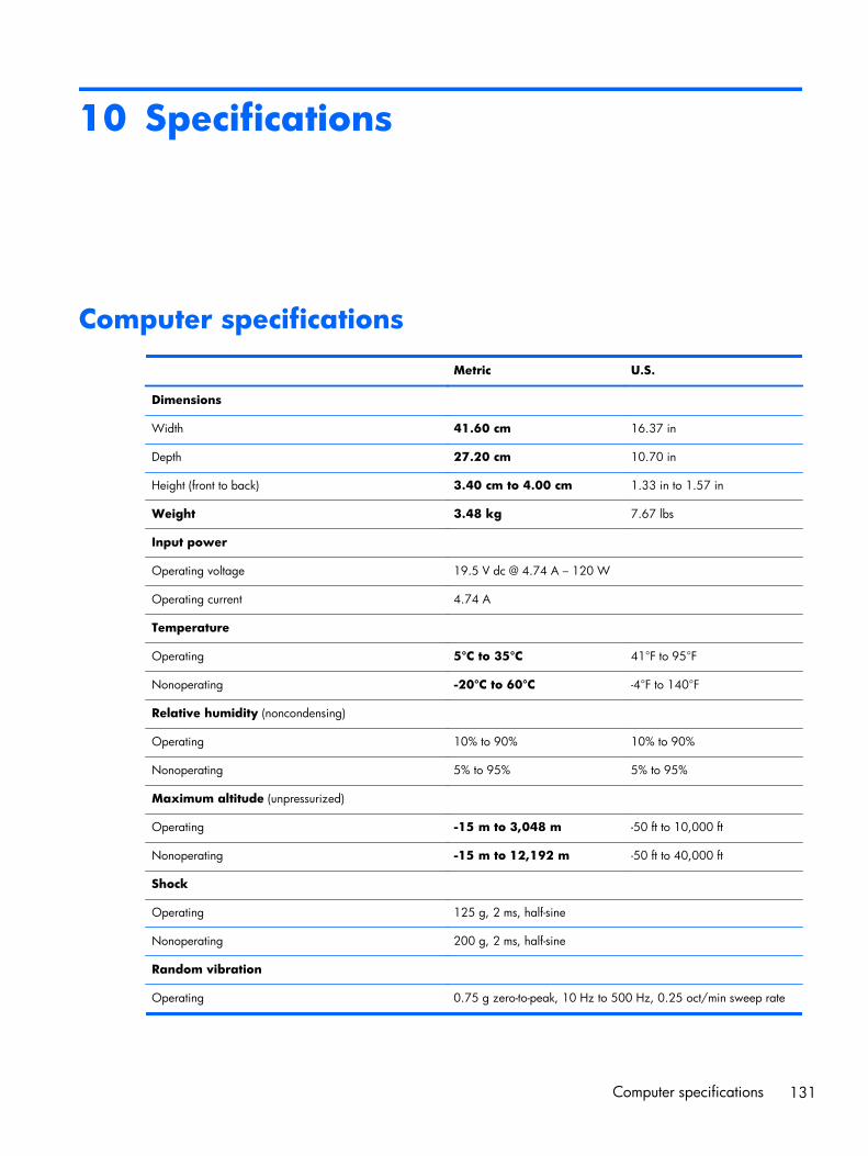
10 Specifications
Computer specifications
Metric U.S.
Dimensions
Width 41.60 cm 16.37 in
Depth 27.20 cm 10.70 in
Height (front to back) 3.40 cm to 4.00 cm 1.33 in to 1.57 in
Weight 3.48 kg 7.67 lbs
Input power
Operating voltage 19.5 V dc @ 4.74 A – 120 W
Operating current 4.74 A
Temperature
Operating 5°C to 35°C 41°F to 95°F
Nonoperating -20°C to 60°C -4°F to 140°F
Relative humidity (noncondensing)
Operating 10% to 90% 10% to 90%
Nonoperating 5% to 95% 5% to 95%
Maximum altitude (unpressurized)
Operating -15 m to 3,048 m -50 ft to 10,000 ft
Nonoperating -15 m to 12,192 m -50 ft to 40,000 ft
Shock
Operating 125 g, 2 ms, half-sine
Nonoperating 200 g, 2 ms, half-sine
Random vibration
Operating 0.75 g zero-to-peak, 10 Hz to 500 Hz, 0.25 oct/min sweep rate
Computer specifications 131
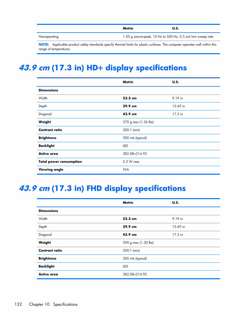
Metric U.S.
Nonoperating 1.50 g zero-to-peak, 10 Hz to 500 Hz, 0.5 oct/min sweep rate
NOTE: Applicable product safety standards specify thermal limits for plastic surfaces. The computer operates well within thisrange of temperatures.
43.9 cm (17.3 in) HD+ display specifications
Metric U.S.
Dimensions
Width 23.3 cm 9.19 in
Depth 39.9 cm 15.69 in
Diagonal 43.9 cm 17.3 in
Weight 570 g max (1.26 lbs)
Contrast ratio 300:1 (min)
Brightness 200 nits (typical)
Backlight LED
Active area 382.08×214.92
Total power consumption 5.3 W max
Viewing angle SVA
43.9 cm (17.3 in) FHD display specifications
Metric U.S.
Dimensions
Width 23.3 cm 9.19 in
Depth 39.9 cm 15.69 in
Diagonal 43.9 cm 17.3 in
Weight 590 g max (1.30 lbs)
Contrast ratio 500:1 (min)
Brightness 300 nits (typical)
Backlight LED
Active area 382.08×214.92
132 Chapter 10 Specifications
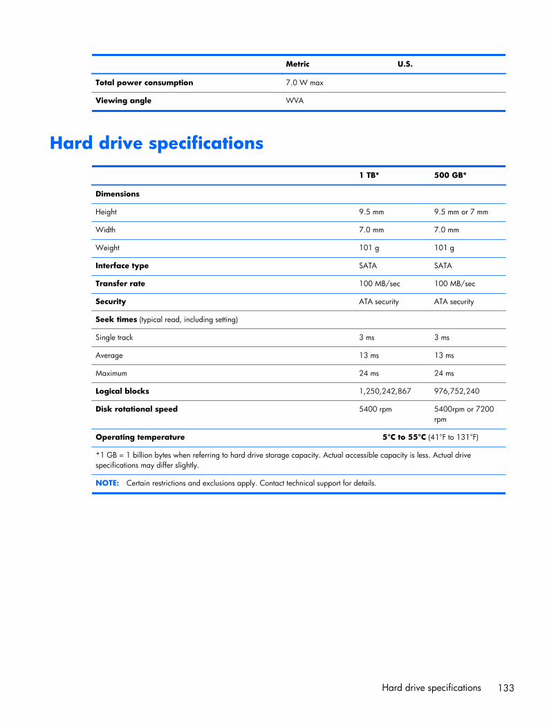
Metric U.S.
Total power consumption 7.0 W max
Viewing angle WVA
Hard drive specifications
1 TB* 500 GB*
Dimensions
Height 9.5 mm 9.5 mm or 7 mm
Width 7.0 mm 7.0 mm
Weight 101 g 101 g
Interface type SATA SATA
Transfer rate 100 MB/sec 100 MB/sec
Security ATA security ATA security
Seek times (typical read, including setting)
Single track 3 ms 3 ms
Average 13 ms 13 ms
Maximum 24 ms 24 ms
Logical blocks 1,250,242,867 976,752,240
Disk rotational speed 5400 rpm 5400rpm or 7200rpm
Operating temperature 5°C to 55°C (41°F to 131°F)
*1 GB = 1 billion bytes when referring to hard drive storage capacity. Actual accessible capacity is less. Actual drivespecifications may differ slightly.
NOTE: Certain restrictions and exclusions apply. Contact technical support for details.
Hard drive specifications 133
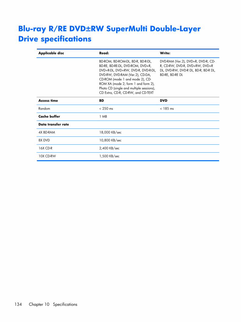
Blu-ray R/RE DVD±RW SuperMulti Double-LayerDrive specifications
Applicable disc Read: Write:
BD-ROM, BD-ROM-DL, BD-R, BD-R-DL,BD-RE, BD-RE-DL, DVD-ROM, DVD+R,DVD+R-DL, DVD+RW, DVD-R, DVD-R-DL,DVD-RW, DVD-RAM (Ver.2), CD-DA,CD-ROM (mode 1 and mode 2), CD-ROM XA (mode 2, form 1 and form 2),Photo CD (single and multiple sessions),CD Extra, CD-R, CD-RW, and CD-TEXT
DVD-RAM (Ver.2), DVD+R, DVD-R, CD-R, CD-RW, DVD-R, DVD+RW, DVD+RDL, DVD-RW, DVD-R DL, BD-R, BD-R DL,BD-RE, BD-RE DL
Access time BD DVD
Random < 250 ms < 185 ms
Cache buffer 1 MB
Data transfer rate
4X BD-RAM 18,000 KB/sec
8X DVD 10,800 KB/sec
16X CD-R 2,400 KB/sec
10X CD-RW 1,500 KB/sec
134 Chapter 10 Specifications
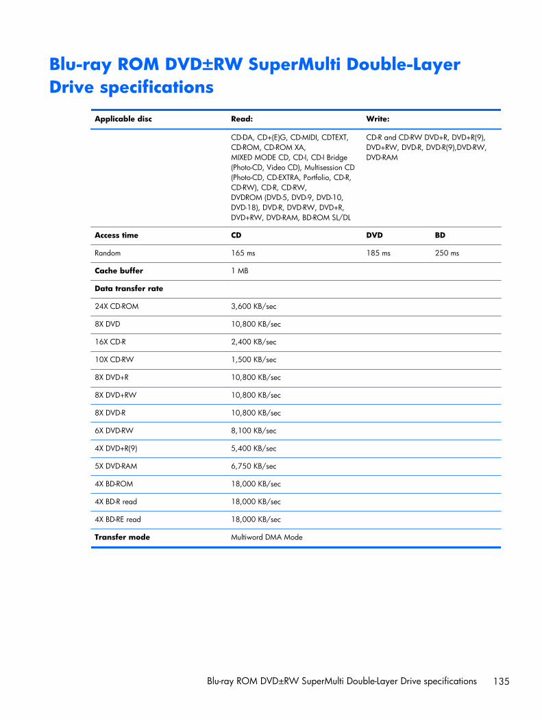
Blu-ray ROM DVD±RW SuperMulti Double-LayerDrive specifications
Applicable disc Read: Write:
CD-DA, CD+(E)G, CD-MIDI, CDTEXT,CD-ROM, CD-ROM XA,MIXED MODE CD, CD-I, CD-I Bridge(Photo-CD, Video CD), Multisession CD(Photo-CD, CD-EXTRA, Portfolio, CD-R,CD-RW), CD-R, CD-RW,DVDROM (DVD-5, DVD-9, DVD-10,DVD-18), DVD-R, DVD-RW, DVD+R,DVD+RW, DVD-RAM, BD-ROM SL/DL
CD-R and CD-RW DVD+R, DVD+R(9),DVD+RW, DVD-R, DVD-R(9),DVD-RW,DVD-RAM
Access time CD DVD BD
Random 165 ms 185 ms 250 ms
Cache buffer 1 MB
Data transfer rate
24X CD-ROM 3,600 KB/sec
8X DVD 10,800 KB/sec
16X CD-R 2,400 KB/sec
10X CD-RW 1,500 KB/sec
8X DVD+R 10,800 KB/sec
8X DVD+RW 10,800 KB/sec
8X DVD-R 10,800 KB/sec
6X DVD-RW 8,100 KB/sec
4X DVD+R(9) 5,400 KB/sec
5X DVD-RAM 6,750 KB/sec
4X BD-ROM 18,000 KB/sec
4X BD-R read 18,000 KB/sec
4X BD-RE read 18,000 KB/sec
Transfer mode Multiword DMA Mode
Blu-ray ROM DVD±RW SuperMulti Double-Layer Drive specifications 135
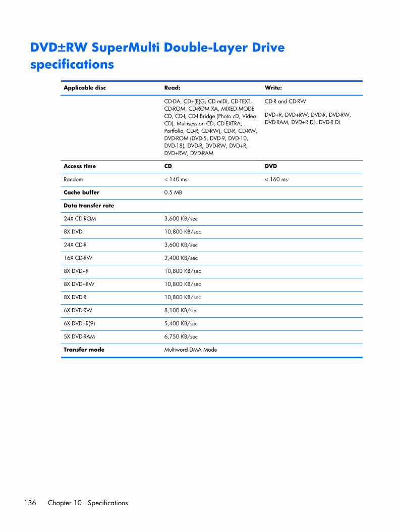
DVD±RW SuperMulti Double-Layer Drivespecifications
Applicable disc Read: Write:
CD-DA, CD+(E)G, CD mIDI, CD-TEXT,CD-ROM, CD-ROM XA, MIXED MODECD, CD-I, CD-I Bridge (Photo cD, VideoCD), Multisession CD, CD-EXTRA,Portfolio, CD-R, CD-RW), CD-R, CD-RW,DVD-ROM (DVD-5, DVD-9, DVD-10,DVD-18), DVD-R, DVD-RW, DVD+R,DVD+RW, DVD-RAM
CD-R and CD-RW
DVD+R, DVD+RW, DVD-R, DVD-RW,DVD-RAM, DVD+R DL, DVD-R DL
Access time CD DVD
Random < 140 ms < 160 ms
Cache buffer 0.5 MB
Data transfer rate
24X CD-ROM 3,600 KB/sec
8X DVD 10,800 KB/sec
24X CD-R 3,600 KB/sec
16X CD-RW 2,400 KB/sec
8X DVD+R 10,800 KB/sec
8X DVD+RW 10,800 KB/sec
8X DVD-R 10,800 KB/sec
6X DVD-RW 8,100 KB/sec
6X DVD+R(9) 5,400 KB/sec
5X DVD-RAM 6,750 KB/sec
Transfer mode Multiword DMA Mode
136 Chapter 10 Specifications
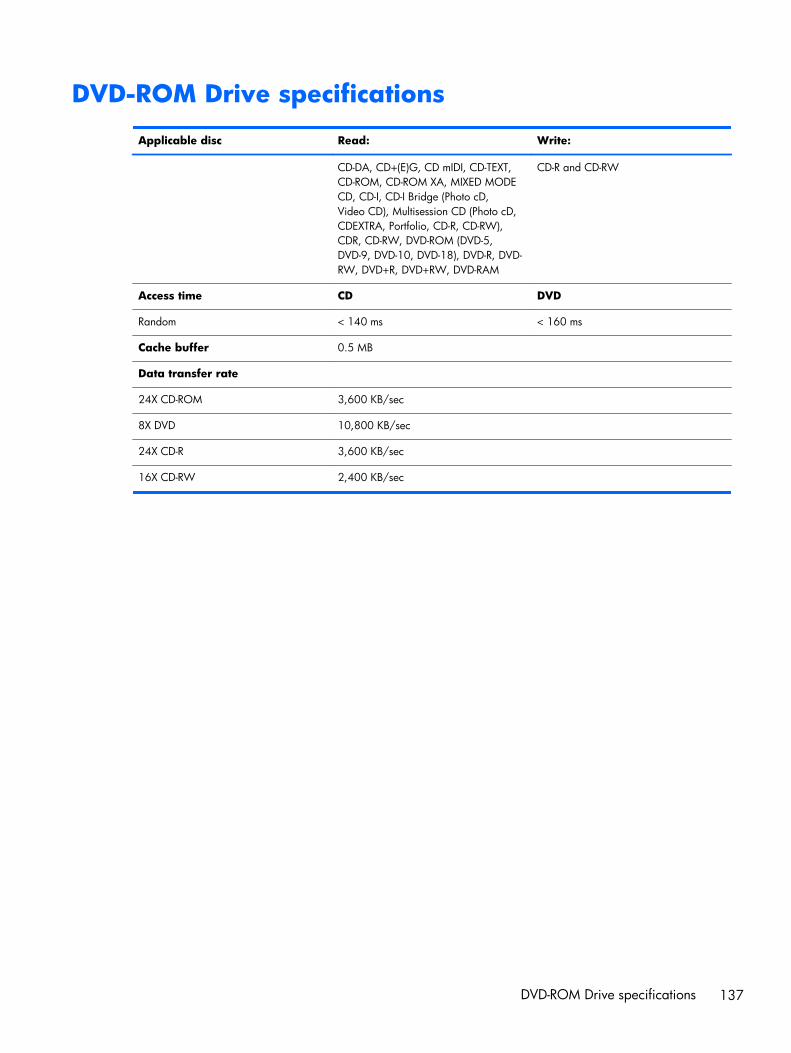
DVD-ROM Drive specifications
Applicable disc Read: Write:
CD-DA, CD+(E)G, CD mIDI, CD-TEXT,CD-ROM, CD-ROM XA, MIXED MODECD, CD-I, CD-I Bridge (Photo cD,Video CD), Multisession CD (Photo cD,CDEXTRA, Portfolio, CD-R, CD-RW),CDR, CD-RW, DVD-ROM (DVD-5,DVD-9, DVD-10, DVD-18), DVD-R, DVD-RW, DVD+R, DVD+RW, DVD-RAM
CD-R and CD-RW
Access time CD DVD
Random < 140 ms < 160 ms
Cache buffer 0.5 MB
Data transfer rate
24X CD-ROM 3,600 KB/sec
8X DVD 10,800 KB/sec
24X CD-R 3,600 KB/sec
16X CD-RW 2,400 KB/sec
DVD-ROM Drive specifications 137
11 Backup and recovery in Windows 8
To protect your information, use Windows backup and restore utilities to back up individual files andfolders, back up your entire hard drive, create system repair media (select models only) by using theinstalled optical drive (select models only) or an optional external optical drive, or create system restorepoints. In case of system failure, you can use the backup files to restore the contents of your computer.
In Windows 8, from the Start screen, type restore, click Settings, and then select from the list ofdisplayed options.
- or -
In Windows 8.1, from the Start screen, type restore, and then select from the list of displayedoptions.
NOTE: For detailed instructions on various backup and restore options, perform a search for thesetopics in HP Support Assistant. To access HP Support Assistant on the Start screen, select the HPSupport Assistant app.
In case of system instability, HP recommends that you print the recovery procedures and save them forlater use.
NOTE: Windows includes the User Account Control feature to improve the security of your computer.You may be prompted for your permission or password for tasks such as installing software, runningutilities, or changing Windows settings. Refer to HP Support Assistant. To access HP Support Assistanton the Start screen, select the HP Support Assistant app.
Backing up your informationRecovery after a system failure is as good as your most recent backup. You should create system repairmedia and your initial backup immediately after initial system setup. As you add new software anddata files, you should continue to back up your system on a regular basis to maintain a reasonablycurrent backup. The system repair media (select models only) are used to start up (boot) the computerand repair the operating system in case of system instability or failure. Your initial and subsequentbackups allow you to restore your data and settings if a failure occurs.
On Start screen, type backup, click Settings, and then select Save backup copies of your fileswith File History.
You can back up your information to an optional external hard drive or a network drive.
138 Chapter 11 Backup and recovery in Windows 8
Note the following when backing up:
● Store personal files in the Documents library, and back it up regularly.
● Back up templates that are stored in their associated programs.
● Save customized settings that appear in a window, toolbar, or menu bar by taking a screen shotof your settings. The screen shot can be a time-saver if you have to reset your preferences.
To create a backup using Backup and Restore in Windows 8.0:
NOTE: Be sure that the computer is connected to AC power before you start the backup process.
NOTE: The backup process may take over an hour, depending on file size and the speed of thecomputer.
1. From the Start screen, type backup, and then click Settings.
2. Click Save backup copy of your files with file history.
File History windows are launched.
3. Follow the on-screen instructions to use file history to backup files.
- or -
Click recovery to create a recovery drive using a USB flash drive.
- or -
Click Windows 7 file recovery, and then click create a system image to create a systemimage.
To create a backup using Backup and Restore in Windows 8.1:
NOTE: Be sure that the computer is connected to AC power before you start the backup process.
NOTE: The backup process may take over an hour, depending on file size and the speed of thecomputer.
1. From the Start screen, type backup.
2. Click Save backup copy of your files with file history.
File History windows are launched.
3. Follow the on-screen instructions to use file history to backup files.
- or -
Click recovery to create a recovery drive using a USB flash drive.
- or -
Click System Image Backup to create a system image.
Backing up your information 139

Performing a system recoveryIn case of system failure or instability, the computer provides the following tools to recover your files:
● Windows recovery tools: You can use Windows Backup and Restore to recover information youhave previously backed up. You can also use Windows Automatic Repair to fix problems thatmight prevent Windows from starting correctly.
● f11 recovery tools: You can use the f11 recovery tools to recover your original hard drive image.The image includes the Windows operating system and software programs installed at the factory.
NOTE: If you are unable to boot (start up) your computer and you cannot use the system repairmedia you previously created (select models only), you must purchase Windows 8 operating systemmedia to reboot the computer and repair the operating system.
Using f11 recovery tools
CAUTION: Using f11 completely erases hard drive contents and reformats the hard drive. All filesthat you have created and any software that you have installed on the computer are permanentlyremoved. The f11 recovery tool reinstalls the operating system and HP programs and drivers that wereinstalled at the factory. Software not installed at the factory must be reinstalled.
To recover the original hard drive image using f11:
1. If possible, back up all personal files.
2. If possible, check for the presence of the Recovery Image partition: From the Start screen, type C,and then select Computer.
NOTE: If the Recovery Image partition is not listed, you must recover your operating system andprograms using the Windows 8 operating system media and the Driver Recovery media (bothpurchased separately).
3. If the Recovery Image partition is listed, restart the computer, and then press esc while the “Pressthe ESC key for Startup Menu” message is displayed at the bottom of the screen.
4. Press f11 while the “Press <F11> for recovery” message is displayed on the screen.
5. Choose your language.
6. Choose your keyboard layout.
7. Select Troubleshoot from the boot options menu.
8. Select Reset your PC, and follow the on-screen instructions.
Using Windows 8 operating system media (purchased separately)
To order a Windows 8 operating system DVD, go to http://www.hp.com/support, select your countryor region, and follow the on-screen instructions. You can also order the DVD by calling support. Forcontact information, see the Worldwide Telephone Numbers booklet included with the computer.
140 Chapter 11 Backup and recovery in Windows 8
CAUTION: Using a Windows 8 operating system media completely erases hard drive contents andreformats the hard drive. All files that you have created and any software that you have installed on thecomputer are permanently removed. When reformatting is complete, the recovery process helps yourestore the operating system, as well as drivers, software, and utilities.
To initiate recovery using a Windows 8 operating system DVD:
NOTE: This process takes several minutes.
1. If possible, back up all personal files.
2. Restart the computer, and then insert the Windows 8 operating system DVD into the optical drivebefore the Windows operating system loads.
3. Power off the computer.
4. Power on the computer, and then press F9 to show the BIOS boot menu.
5. When the DVD is booting, select the DVD from the UEFI Boot Sources.
6. When prompted, press any keyboard key.
7. Follow the on-screen instructions.
After the installation is completed:
1. Eject the Windows 8 operating system media and then insert the Driver Recovery media.
2. Install the Hardware Enabling Drivers first, and then install Recommended Applications.
Performing a system recovery 141

Using Windows Refresh for quick and easy recovery
When your computer is not working properly and you need to regain system stability, the WindowsRefresh option allows you to start fresh and keep what is important to you.
IMPORTANT: Refresh removes any traditional applications that were not originally installed on thesystem at the factory.
NOTE: During Refresh, a list of removed traditional applications will be saved so that you have aquick way to see what you might need to reinstall. See HP Support Assistant for instructions onreinstalling traditional applications. To access HP Support Assistant on the Start screen, select the HPSupport Assistant app.
NOTE: You may be prompted for your permission or password when using Refresh. See HP SupportAssistant for more information. To access HP Support Assistant on the Start screen, select the HPSupport Assistant app.
To start Refresh:
1. On the Start screen, point to the far-right upper or lower corner of the screen to display thecharms.
2. Click Settings.
3. Click Change PC settings in the bottom-right corner of the screen.
4. In Windows 8.0, select General from the PC settings screen.
- or -
In Windows 8.1, select Update and Recovery , and then select Recovery.
5. Scroll the right-side choices down to display Refresh your PC without affecting your files.
6. Under Refresh your PC without affecting your files, select Get started, and follow theon-screen instructions.
Remove everything and reinstall Windows
Sometimes you want to perform detailed reformatting of your computer, or you want to removepersonal information before you give away or recycle your computer. The process described in thissection provides a speedy, simple way to return the computer to its original state. This option removesall personal data, apps, and settings from your computer, and reinstalls Windows.
IMPORTANT: This option does not provide backups of your information. Before using this option,back up any personal information you wish to retain.
You can initiate this option by using the f11 key or from the Start screen.
142 Chapter 11 Backup and recovery in Windows 8
To use the f11 key:
1. Press f11 while the computer boots.
– or –
Press and hold f11 as you press the power button.
2. Choose your language.
3. Choose your keyboard layout.
4. Select Troubleshoot from the boot options menu.
5. Select Reset your PC, and follow the on-screen instructions.
To use the Start screen:
1. On the Start screen, point to the far-right upper or lower corner of the screen to display thecharms.
2. Click Settings.
3. Click Change PC settings in the bottom-right corner of the screen.
4. In Windows 8.0, select General from the PC settings screen.
- or -
In Windows 8.1, select Update and Recovery , and then select Recovery.
5. Scroll the right-side choices down to display Remove everything and reinstall Windows.
6. Under Remove everything and reinstall Windows, select Get started, and follow theon-screen instructions.
Using HP Software Setup
HP Software Setup can be used to reinstall drivers or select software that has been corrupted or deletedfrom the system.
1. From the Start screen, type HP Software Setup, and select Apps.
2. Open HP Software Setup.
3. Follow the on-screen directions to reinstall drivers or select software.
Performing a system recovery 143
12 Backup and recovery in Windows 7
Your computer includes HP and Windows tools to help you safeguard your information and retrieve it ifyou ever need to. These tools will help you return your computer to a proper working state, all withsimple steps. This section provides information about the following processes:
● Creating recovery media and backups
● Restoring and recovering your system
Creating recovery media and backupsRecovery after a system failure is only as good as your most recent backup.
1. After you successfully set up the computer, create HP Recovery media. This step creates aWindows 7 operating system DVD and a Driver Recovery DVD. The Windows DVD can be usedto reinstall the original operating system in cases where the hard drive is corrupted or has beenreplaced. The Driver Recovery DVD installs specific drivers and applications. See Creatingrecovery media with HP Recovery Disc Creator on page 145.
2. Use Windows Backup and Recovery tools to perform the following:
● Back up individual files and folders
● Back up your entire hard drive (select models only)
● Create system repair discs (select models only) with the installed optical drive (select modelsonly) or an optional external optical drive
● Create system restore points
NOTE: This guide describes an overview of backing up, restoring, and recovering options. For moredetails about the tools provided, see Help and Support. To access Help and Support, select Start >Help and Support.
NOTE: HP recommends that you print the recovery procedures and save them for later use, in case ofsystem instability.
In case of system failure, you can use the backup files to restore the contents of your computer. SeeBacking up your information on page 145.
144 Chapter 12 Backup and recovery in Windows 7
Guidelines
● When creating recovery media or backing up to discs, use any of the following types of discs(purchased separately): DVD+R, DVD+R DL, DVD-R, DVD-R DL, or DVD±RW. The discs you usewill depend on the type of optical drive you are using.
● Be sure that the computer is connected to AC power before you start the recovery media creationprocess or the backup process.
Creating recovery media with HP Recovery Disc Creator
HP Recovery Disc Creator is a software program that offers an alternative way to create recoverymedia. After you successfully set up the computer, you can create recovery media using HP RecoveryDisc Creator. This recovery media allows you to reinstall your original operating system as well asselect drivers and applications if the hard drive becomes corrupted. HP Recovery Disc Creator cancreate two kinds of recovery DVDs:
● Windows 7 operating system DVD—Installs the operating system without additional drivers orapplications.
● Driver Recovery DVD—Installs specific drivers and applications only, in the same way that the HPSoftware Setup utility installs drivers and applications.
Creating recovery media
NOTE: The Windows 7 operating system DVD can be created only once. Thereafter, the option tocreate that media will not be available after you create a Windows DVD.
To create the Windows DVD:
1. Select Start > All Programs > Productivity and Tools > HP Recovery Disc Creator.
2. Select Windows disk.
3. From the drop-down menu, select the drive for burning the recovery media.
4. Click the Create button to start the burning process. Label the disc after you create it, and store itin a secure place.
After the Windows 7 operating system DVD has been created, create the Driver Recovery DVD:
1. Select Start > All Programs > Productivity and Tools > HP Recovery Disc Creator.
2. Select Driver disk.
3. From the drop-down menu, select the drive for burning the recovery media.
4. Click the Create button to start the burning process. Label the disc after you create it, and store itin a secure place.
Backing up your information
You should create system repair media and your initial backup immediately after initial system setup.As you add new software and data files, you should continue to back up your system on a regular
Creating recovery media and backups 145
basis to maintain a reasonably current backup. You should also create Windows system repair media(select models only) which can be used to start up (boot) the computer and repair the operating systemin case of system instability or failure. Your initial and subsequent backups allow you to restore yourdata and settings if a failure occurs.
You can back up your information to an optional external hard drive, a network drive, or discs.
Note the following when backing up:
● Store personal files in the Documents library, and back it up regularly.
● Back up templates that are stored in their associated directories.
● Save customized settings that appear in a window, toolbar, or menu bar by taking a screen shotof your settings. The screen shot can be a time-saver if you have to reset your preferences.
● When backing up to discs, number each disc after removing it from the drive.
NOTE: For detailed instructions on various backup and restore options, perform a search for thesetopics in Help and Support. To access Help and Support, select Start > Help and Support.
NOTE: Windows includes the User Account Control feature to improve the security of your computer.You may be prompted for your permission or password for tasks such as installing software, runningutilities, or changing Windows settings. Refer to Help and Support. To access Help and Support, selectStart > Help and Support.
To create a backup using Windows Backup and Restore:
NOTE: The backup process may take over an hour, depending on file size and the speed of thecomputer.
1. Select Start > All Programs > Maintenance > Backup and Restore.
2. Follow the on-screen instructions to set up your backup, create a system image (select modelsonly), or create system repair media (select models only).
Performing a system recoveryIn case of system failure or instability, the computer provides the following tools to recover your files:
● Windows recovery tools: You can use Windows Backup and Restore to recover information youhave previously backed up. You can also use Windows Startup Repair to fix problems that mightprevent Windows from starting correctly.
● f11 recovery tools (select models only): You can use the f11 recovery tools to recover your originalhard drive image. The image includes the Windows operating system and software programsinstalled at the factory.
NOTE: If you are unable to boot (start up) your computer and you cannot use the system repairmedia you previously created (select models only), you must purchase Windows 7 operating systemmedia to reboot the computer and repair the operating system.
146 Chapter 12 Backup and recovery in Windows 7
Using the Windows recovery tools
Using the Windows recovery tools, you can:
● Recover individual files
● Restore the computer to a previous system restore point
● Recover information using recovery tools
NOTE: For detailed instructions on various recovery and restore options, perform a search for thesetopics in Help and Support. To access Help and Support, select Start > Help and Support.
NOTE: Windows includes the User Account Control feature to improve the security of your computer.You may be prompted for your permission or password for tasks such as installing software, runningutilities, or changing Windows settings. Refer to Help and Support. To access Help and Support, selectStart > Help and Support.
To recover information you previously backed up:
1. Select Start > All Programs > Maintenance > Backup and Restore.
2. Follow the on-screen instructions to recover your system settings, your computer (select modelsonly), or your files.
To recover your information using Startup Repair, follow these steps:
CAUTION: Some Startup Repair options will completely erase and reformat the hard drive. All filesyou have created and any software installed on the computer are permanently removed. Whenreformatting is complete, the recovery process restores the operating system, as well as the drivers,software, and utilities from the backup used for recovery.
1. If possible, back up all personal files.
2. If possible, check for the presence of the Recovery Image partition and the Windows partition.
To check for the Windows partition, select Start > Computer.
NOTE: If the Windows partition and the Recovery Image partition is not listed, you must recoveryour operating system and programs using the Windows 7 operating system DVD and the DriverRecovery media.
3. If the Windows partition is listed, restart the computer, and then press f8 before the Windowsoperating system loads.
4. Select Startup Repair.
5. Follow the on-screen instructions.
NOTE: For additional information on recovering information using the Windows tools, select Start >Help and Support.
Performing a system recovery 147
Using f11 recovery tools (select models only)
CAUTION: Using f11 completely erases hard drive contents and reformats the hard drive. All filesthat you have created and any software that you have installed on the computer are permanentlyremoved. The f11 recovery tool reinstalls the operating system and HP programs and drivers that wereinstalled at the factory. Software not installed at the factory must be reinstalled.
To recover the original hard drive image using f11:
1. If possible, back up all personal files.
2. If possible, check for the presence of the Recovery Image partition: click Start, right-clickComputer, click Manage, and then click Disk Management.
NOTE: If the Recovery Image partition is not listed, you must recover your operating system andprograms using the Windows 7 operating system media and the Driver Recovery media.
3. If the Recovery Image partition is listed, restart the computer, and then press esc while the “Pressthe ESC key for Startup Menu” message is displayed at the bottom of the screen.
4. Press f11 while the “Press <F11> for recovery” message is displayed on the screen.
5. Follow the on-screen instructions.
Using Windows 7 operating system media
If you cannot use the recovery media you previously created using the HP Recovery Disc Creator (selectmodels only), you must purchase a Windows 7 operating system DVD to reboot the computer andrepair the operating system.
To order a Windows 7 operating system DVD, go to the HP website. For U.S. support, go tohttp://www.hp.com/support. For worldwide support, go to http://welcome.hp.com/country/us/en/wwcontact_us.html. You can also order the DVD by calling support. For contact information, see theWorldwide Telephone Numbers booklet included with the computer.
CAUTION: Using a Windows 7 operating system DVD completely erases hard drive contents andreformats the hard drive. All files that you have created and any software that you have installed on thecomputer are permanently removed. When reformatting is complete, the recovery process helps yourestore the operating system, as well as drivers, software, and utilities.
To initiate recovery using a Windows 7 operating system DVD:
NOTE: This process takes several minutes.
1. If possible, back up all personal files.
2. Restart the computer, and then insert the Windows 7 operating system DVD into the optical drivebefore the Windows operating system loads.
3. When prompted, press any keyboard key.
4. Follow the on-screen instructions.
148 Chapter 12 Backup and recovery in Windows 7

5. Click Next.
6. Select Install now.
7. Follow the on-screen instructions.
After the installation is completed:
1. Eject the Windows 7 operating system DVD and then insert the Driver Recovery DVD.
2. Install the Hardware Enabling Drivers first, and then install Recommended Applications.
Performing a system recovery 149
13 Backup and Recovery in SUSE Linux
Recovery after a system failure is as good as your most recent backup. As you add new software anddata files, you should continue to back up your system on a regular basis to maintain a reasonablycurrent backup.
Your computer includes tools provided by HP to help you safeguard your information and retrieve it ifever needed.
Creating backups1. Create restore media immediately after you set up the computer.
2. As you add files, routinely create a backup of your system and personal information.
Creating restore mediaYou can create an HP Factory Image, using an installed or an external DVD±RW optical drive or a USBdrive. The HP Factory Image can be used to perform system recovery in the event of a system failure.The recovery tool reinstalls the original operating system and HP programs and drivers that wereinstalled at the factory.
To create the restore media:
1. Select Computer > More Applications.
2. In the left pane, click Tools, and then click Create HP Factory Image in the right pane.
3. Follow the on-screen instructions to create an image file to burn a recovery disc.
NOTE: The image produced by HP Create Factory Image can be written to a USB disk on keyor a DVD. If you are writing to a DVD, follow the on-screen instructions. To write the image to aUSB disk on key:
To write the image to a USB disk on key:
a. Insert the USB disk on key in a USB port.
b. To transfer the image to a USB disk on key, use the dd command.
150 Chapter 13 Backup and Recovery in SUSE Linux
Backing up your informationYou should back up your computer files on a regular schedule to maintain a current backup. You canmanually back up your information to an optional external drive, a network drive, or discs. Back upyour system at the following times:
● At regularly scheduled times
● Before the computer is repaired or restored
● Before you add or modify hardware or software
To back up your home directory files using Backup Manager Settings:
1. Select Computer > More Applications > Tools > Backup Manager Settings, and clickBackup my home directory.
2. Click Storage Destination Location, and then select a location to back up your information.
3. Click Schedule, and then select a time schedule to perform backups at a regularly scheduledtime.
To immediately back up your information, click the Backup Now check box.
NOTE: Before you back up your information, be sure you have designated a location to savethe backup files.
4. Click Save and Backup to start the backup and to save the backup settings.
To restore backup files:
1. Select Computer > More Applications > Tools > Backup Manager Restore.
2. Click Backup Source, and then select the location of the backup files.
3. Click Restore Destination, and then select the destination to restore the files.
4. To restore all files from the selected location, click Restore all files. To restore select files only,click Restore selected files, click Select Files and then select the files to be restored.
5. Under Restore Point, click the time and date of the backup.
NOTE: If multiple backups have been performed, click Use the latest version to restore thelatest version.
6. Click Restore to start restoring the files, or click Cancel to cancel the operation.
Performing a system recoveryRecovery allows you to repair or restore the computer to its original factory state.
Backing up your information 151
CAUTION: Using Recovery completely erases hard drive contents and reformats the hard drive. Allfiles you have created and any software installed on the computer are permanently removed. Therecovery tool reinstalls the original operating system and HP programs and drivers that were installed atthe factory. Software, drivers, and updates not installed by HP must be manually reinstalled. Personalfiles must be restored from a backup.
To restore the computer using the HP Factory Image, you must first create the recovery media. If youhave not already created it, see Creating restore media on page 150.
To restore the computer from the recovery disc, follow these steps:
1. If possible, back up all personal files.
2. Insert the HP Factory Image into the optical drive or insert the USB disk on key into the USB port,and restart the computer.
3. As the computer is restarting, press f9 to open the Computer Setup boot option menu and selectthe option for the optical drive, if you are using a DVD to restore. If you are using a USB disk tokey, select USB disk on key.
4. Press the down arrow to select Restore SLED HP-BNB preload image from the Linux bootmenu, and then press enter.
5. Using the arrow keys, select Yes when prompted: Do you want to start the System-Restore?
6. Follow the on-screen instructions.
NOTE: The image produced by the Create Factory Image utility may be written to either a USB diskon a key or a DVD. To write the image to a disk, use the dd command to transfer the image to a USBdisk on a key. The USB disk on a key may be inserted in a USB port.
Remove everything and reinstall SLEDSometimes you want to perform detailed reformatting of your computer, or you want to removepersonal information before you give away or recycle your computer. The process described in thissection provides a speedy, simple way to return the computer to its original state. This option removesall personal data, applications, and settings from your computer, and reinstalls the Linux operatingsystem.
IMPORTANT: This option does not provide backups of your information. Before using this option,back up any personal information you wish to retain.
You can initiate this option by using the f11 key.
To use the f11 key:
Press f11 while the computer boots.
– or –
Press and hold f11 as you press the power button.
152 Chapter 13 Backup and Recovery in SUSE Linux

The following options are available:
● Cancel/Reboot—Reboots the system. No recovery or restore activity is performed.
● Recover/Repair System—This option repairs a system that is not working properly and preservesuser data.
● Restore Factory System—This option restores the system back to the original factory state. Userdata is not preserved.
Select an option and follow the on-screen instructions.
Remove everything and reinstall SLED 153

14 Statement of Volatility
The purpose of this document is to provide general information regarding non-volatile memory inindustry-standards based HP Business Notebook PC systems and provide general instructions forrestoring nonvolatile memory that can contain personal data after the system has been powered off andthe hard drive has been removed.
HP Business Notebook PC products that use Intel®-based or AMD®-based system boards containvolatile DDR memory. The amount of nonvolatile memory present in the system depends upon thesystem configuration. Intel-based and AMD-based system boards contain nonvolatile memorysubcomponents as originally shipped from HP assuming that no subsequent modifications have beenmade to the system and assuming that no applications, features, or functionality have been added to orinstalled on the system.
Following system shutdown and removal of all power sources from an HP Business Notebook PCsystem, personal data can remain on volatile system memory (DIMMs) for a finite period of time andwill also remain in nonvolatile memory. The steps below will remove personal data from the notebookPC, including the nonvolatile memory found in Intel-based and AMD-based system boards. Some ofthese steps are disclosed in the Maintenance & Service Guides available for HP PC products availableon the product support pages at www.hp.com.
1. Follow steps (a) through (I) below to restore the nonvolatile memory that can contain personaldata. Restoring or re-programming nonvolatile memory that does not store personal data is neithernecessary nor recommended.
a. Enter BIOS (F10) Setup by powering on the system and pressing F10 when prompted nearthe bottom of the display, or press the ESC key to display the start up menu, then press F10 .If the system has a BIOS administrator password, enter the password at the prompt.
b. Select the File menu, then Restore Defaults.
c. Select the System Configuration menu, then Restore Security Defaults.
d. If an asset or ownership tag is set, select the Security menu and scroll down to the Utilitiesmenu. Select System IDs, and then select the tag that has been set. Press the spacebaronce to clear the tag, then press Enter to return to the prior menu.
e. If a DriveLock password is set, select the Security menu, scroll down to DriveLock, thenselect DriveLock password. Select the desired hard drive. Click Disable protection,enter the existing master DriveLock password, then press Enter to confirm and return to theprior menu. Repeat this procedure if more than one hard drive has a DriveLock password.
154 Chapter 14 Statement of Volatility

f. If an Automatic DriveLock password is set, select the Security menu, scroll down toAutomatic DriveLock, then select the desired hard drive and disable protection. Repeatthis procedure if more than one hard drive has an Automatic DriveLock password.
g. Select the File menu, then Reset BIOS Security to factory default. Click yes at thewarning message.
h. Select the File menu, then Save Changes and Exit.
i. Reboot the system. If the system has a Trusted Platform Module (TPM) and/or fingerprintsensor, one or two prompts will appear. One to clear the TPM and the other to ResetFingerprint Sensor; press F1 to accept or F2 to reject.
If the HP notebook model number ends in a ‘p’ or ‘w’ and includes Intel® Centrino withVProTM, reboot the PC and enter BIOS Setup by pressing F10 when prompted. SelectSystem Configuration, then AMT Options. Then select Un-configure AMT on nextboot. Select Save then Yes. Select the File menu, and then select Save Changes andExit. Reboot the system and confirm that you want to un-configure AMT.
j. If the optional Intel® Anti-Theft Technology (AT) was activated, contact the provider to de-activate it.
k. If the optional Absolute® Software Computrace® management and tracking service wasactivated on the notebook PC, contact the provider to deactivate it.
l. Remove all power and system batteries for at least 24 hours.
2. Remove and retain the storage drive or clear the contents of the drive.
a. Hard Disk Drive (HDD)
Clear the HDD contents by using the HP Disk Sanitizer® utility or a third party applicationthat, ideally, is U.S. Department of Defense (DOD) 5220.22-M approved.
To run HP Disk Sanitizer, enter BIOS Setup by powering on the system and pressing F10when prompted near the bottom of the display, or press ESC to display the start up menu,then press F10. Select the Security menu and scroll down to the Utilities menu. SelectDisk Sanitizer and select the desired drive. For a higher level of protection, selectOptimum.
NOTE: This process will take a long time, and the amount of time varies based on the harddrive capacity.
b. Solid State Drive (SSD)
Clear the SSD contents by using the BIOS Setup Secure Erase command option, or by using athird party utility designed to erase data from an SSD. To run Secure Erase, enter BIOS Setupby powering on the system and pressing F10 when prompted near the bottom of the display.Select the Security menu and scroll down to the Utilities menu. Select Secure Erase andselect the desired hard drive.
155
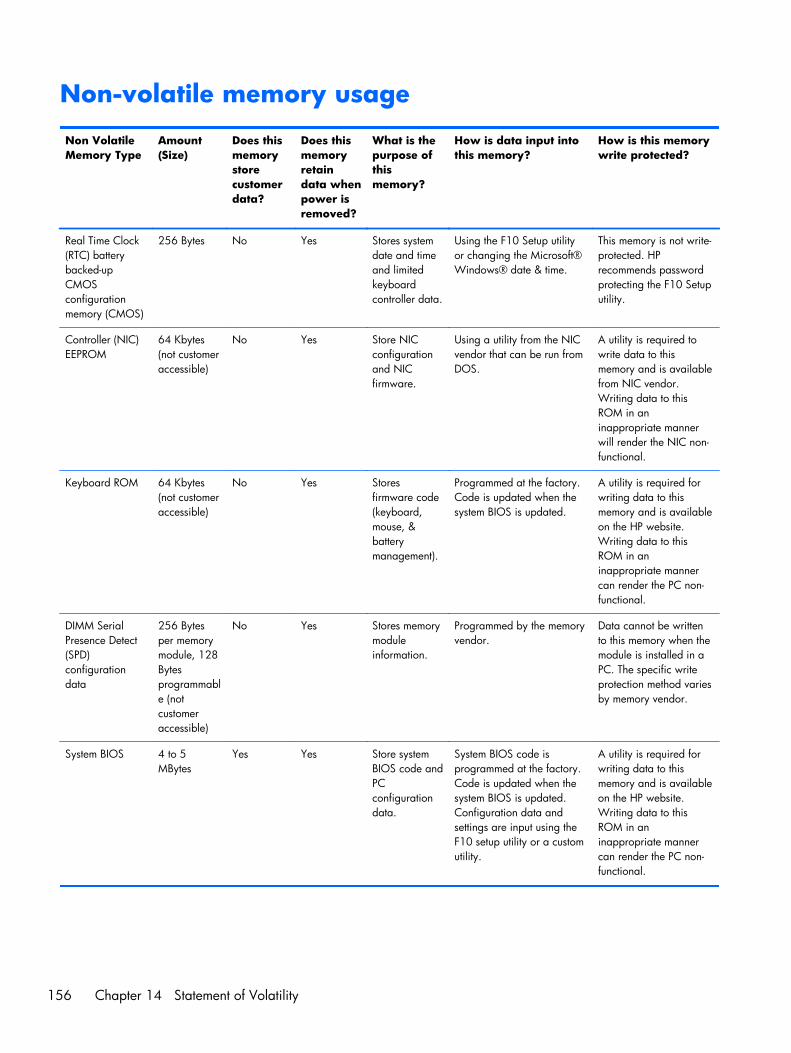
Non-volatile memory usage
Non VolatileMemory Type
Amount(Size)
Does thismemorystorecustomerdata?
Does thismemoryretaindata whenpower isremoved?
What is thepurpose ofthismemory?
How is data input intothis memory?
How is this memorywrite protected?
Real Time Clock(RTC) batterybacked-upCMOSconfigurationmemory (CMOS)
256 Bytes No Yes Stores systemdate and timeand limitedkeyboardcontroller data.
Using the F10 Setup utilityor changing the Microsoft®Windows® date & time.
This memory is not write-protected. HPrecommends passwordprotecting the F10 Setuputility.
Controller (NIC)EEPROM
64 Kbytes(not customeraccessible)
No Yes Store NICconfigurationand NICfirmware.
Using a utility from the NICvendor that can be run fromDOS.
A utility is required towrite data to thismemory and is availablefrom NIC vendor.Writing data to thisROM in aninappropriate mannerwill render the NIC non-functional.
Keyboard ROM 64 Kbytes(not customeraccessible)
No Yes Storesfirmware code(keyboard,mouse, &batterymanagement).
Programmed at the factory.Code is updated when thesystem BIOS is updated.
A utility is required forwriting data to thismemory and is availableon the HP website.Writing data to thisROM in aninappropriate mannercan render the PC non-functional.
DIMM SerialPresence Detect(SPD)configurationdata
256 Bytesper memorymodule, 128Bytesprogrammable (notcustomeraccessible)
No Yes Stores memorymoduleinformation.
Programmed by the memoryvendor.
Data cannot be writtento this memory when themodule is installed in aPC. The specific writeprotection method variesby memory vendor.
System BIOS 4 to 5MBytes
Yes Yes Store systemBIOS code andPCconfigurationdata.
System BIOS code isprogrammed at the factory.Code is updated when thesystem BIOS is updated.Configuration data andsettings are input using theF10 setup utility or a customutility.
A utility is required forwriting data to thismemory and is availableon the HP website.Writing data to thisROM in aninappropriate mannercan render the PC non-functional.
156 Chapter 14 Statement of Volatility
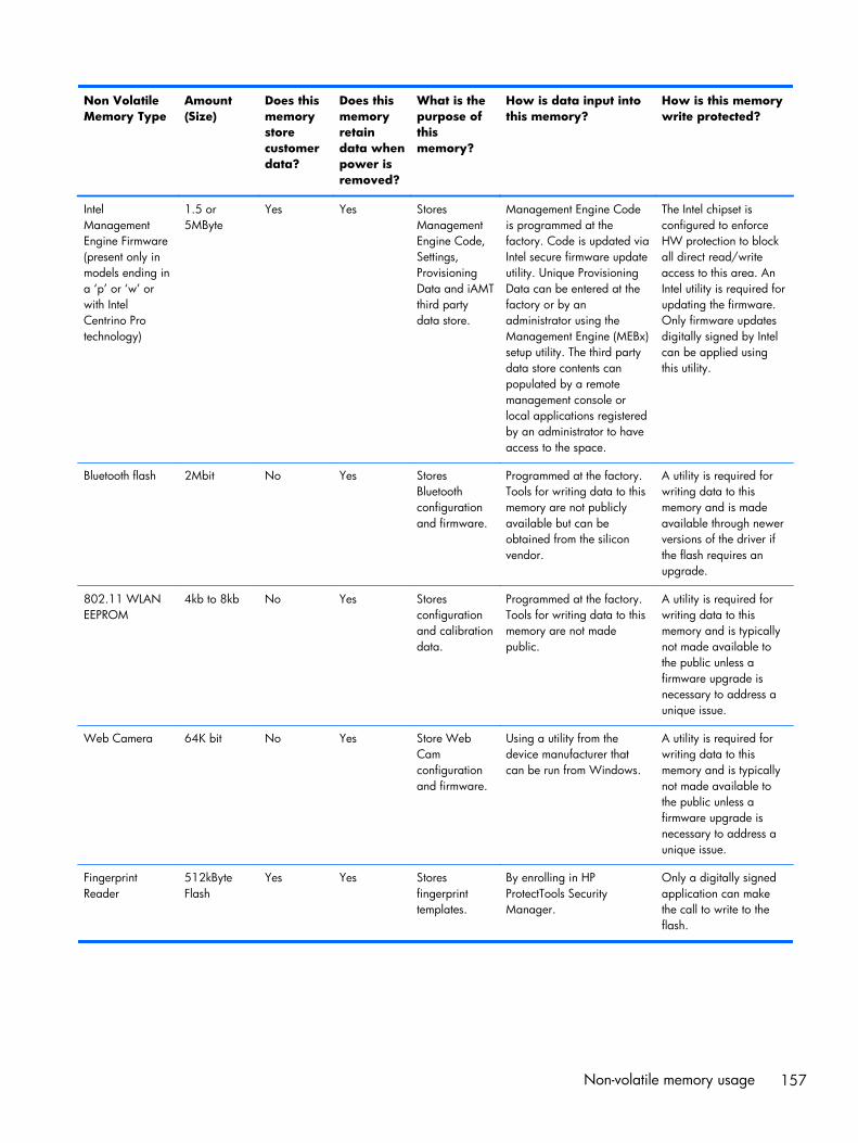
Non VolatileMemory Type
Amount(Size)
Does thismemorystorecustomerdata?
Does thismemoryretaindata whenpower isremoved?
What is thepurpose ofthismemory?
How is data input intothis memory?
How is this memorywrite protected?
IntelManagementEngine Firmware(present only inmodels ending ina ‘p’ or ‘w’ orwith IntelCentrino Protechnology)
1.5 or5MByte
Yes Yes StoresManagementEngine Code,Settings,ProvisioningData and iAMTthird partydata store.
Management Engine Codeis programmed at thefactory. Code is updated viaIntel secure firmware updateutility. Unique ProvisioningData can be entered at thefactory or by anadministrator using theManagement Engine (MEBx)setup utility. The third partydata store contents canpopulated by a remotemanagement console orlocal applications registeredby an administrator to haveaccess to the space.
The Intel chipset isconfigured to enforceHW protection to blockall direct read/writeaccess to this area. AnIntel utility is required forupdating the firmware.Only firmware updatesdigitally signed by Intelcan be applied usingthis utility.
Bluetooth flash 2Mbit No Yes StoresBluetoothconfigurationand firmware.
Programmed at the factory.Tools for writing data to thismemory are not publiclyavailable but can beobtained from the siliconvendor.
A utility is required forwriting data to thismemory and is madeavailable through newerversions of the driver ifthe flash requires anupgrade.
802.11 WLANEEPROM
4kb to 8kb No Yes Storesconfigurationand calibrationdata.
Programmed at the factory.Tools for writing data to thismemory are not madepublic.
A utility is required forwriting data to thismemory and is typicallynot made available tothe public unless afirmware upgrade isnecessary to address aunique issue.
Web Camera 64K bit No Yes Store WebCamconfigurationand firmware.
Using a utility from thedevice manufacturer thatcan be run from Windows.
A utility is required forwriting data to thismemory and is typicallynot made available tothe public unless afirmware upgrade isnecessary to address aunique issue.
FingerprintReader
512kByteFlash
Yes Yes Storesfingerprinttemplates.
By enrolling in HPProtectTools SecurityManager.
Only a digitally signedapplication can makethe call to write to theflash.
Non-volatile memory usage 157
Questions and answers1. How can the BIOS settings be restored (returned to default settings)?
a. Turn on or restart the computer and press F10 when prompted near the bottom of the display.
b. Select File, then select Restore defaults.
c. Follow the on-screen instructions.
d. Select File, save changes and exit, then press Enter.
2. What kind of configuration data is stored on the DIMM Serial Presence Detect(SPD) memory module? How would this data be written?
The DIMM SPD memory contains information about the memory module such as size, serialnumber, data width, speed/timing, voltage and thermal information. This information is written bythe module manufacturer and stored on an EEPROM. This EEPROM cannot be written to when thememory module is installed in a PC. Third party tools do exist that can write to the EEPROM whenthe memory module is not installed in a PC. There are various third party tools available to readSPD memory.
3. Does the “Firmware Hub for System BIOS” contain the BIOS program? Is this chipwritable, and if so how?
The Firmware Hub does contain the BIOS program and is writable. A utility is required to performthe write function.
4. In some PC systems, the Firmware Hub for System BIOS is a flash memory chipso that updates can be written by the customer. Is this true for these BIOS chips?
Yes, they are flash memory chips.
5. What is meant by “Restore the nonvolatile memory found in Intel-based systemboards”?
This relates to clearing the Real Time Clock (RTC) CMOS memory that contains PC configurationdata.
6. Does resetting the CMOS configuration memory return the PC back to factorydefaults?
The process of resetting the CMOS will return certain system settings to factory default but will notreset many of the system data and configuration defaults to their default settings. To return thesesystem data and configuration defaults to default settings, refer to question and answer 1 andfollow the instructions for returning the BIOS settings to factory defaults.
158 Chapter 14 Statement of Volatility

15 Power cord set requirements
The wide-range input feature of the computer permits it to operate from any line voltage from 100 to120 volts AC, or from 220 to 240 volts AC.
The 3-conductor power cord set included with the computer meets the requirements for use in thecountry or region where the equipment is purchased.
Power cord sets for use in other countries and regions must meet the requirements of the country orregion where the computer is used.
Requirements for all countriesThe following requirements are applicable to all countries and regions:
● The length of the power cord set must be at least 1.0m (3.3t) and no more than 2.0 m (6.5 ft).
● All power cord sets must be approved by an acceptable accredited agency responsible forevaluation in the country or region where the power cord set will be used.
● The power cord sets must have a minimum current capacity of 10 amps and a nominal voltagerating of 125 or 250 V AC, as required by the power system of each country or region.
● The appliance coupler must meet the mechanical configuration of an EN 60 320/IEC 320Standard Sheet C13 connector for mating with the appliance inlet on the back of the computer.
Requirements for all countries 159
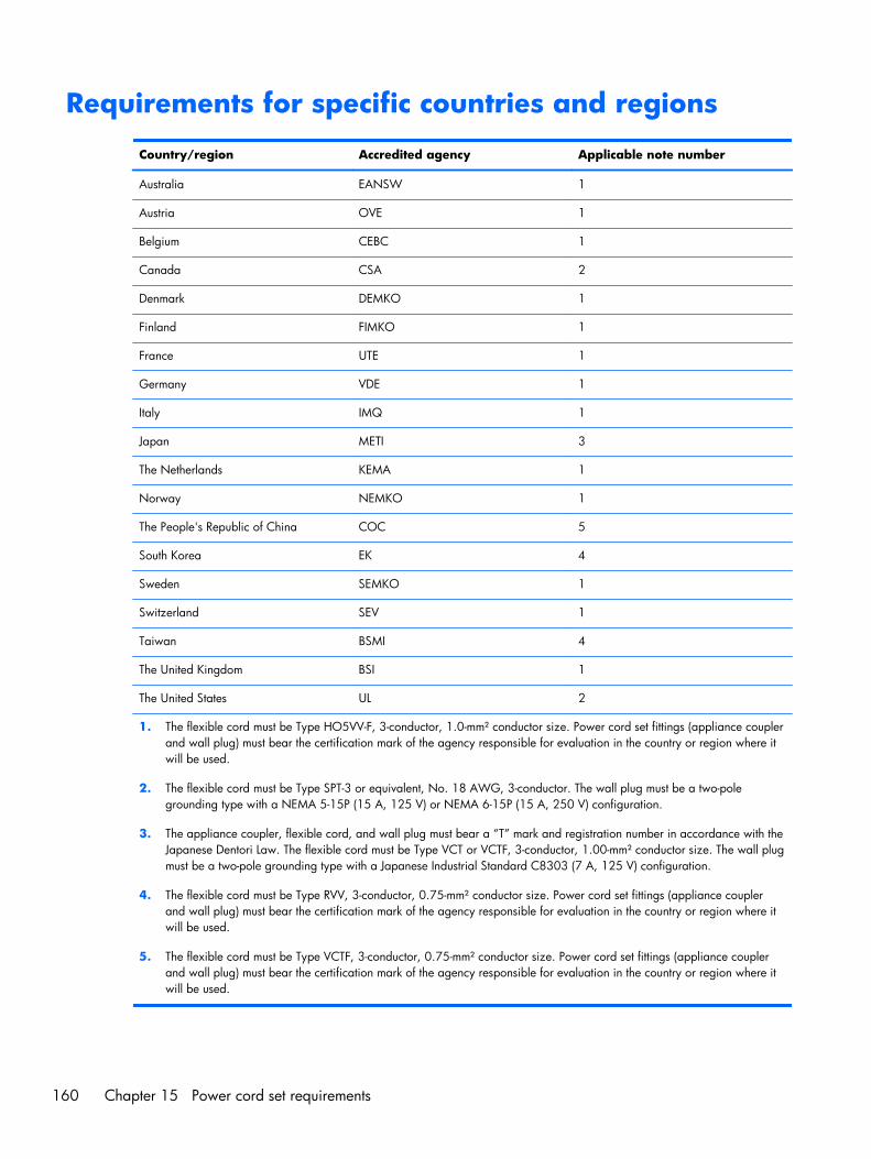
Requirements for specific countries and regions
Country/region Accredited agency Applicable note number
Australia EANSW 1
Austria OVE 1
Belgium CEBC 1
Canada CSA 2
Denmark DEMKO 1
Finland FIMKO 1
France UTE 1
Germany VDE 1
Italy IMQ 1
Japan METI 3
The Netherlands KEMA 1
Norway NEMKO 1
The People's Republic of China COC 5
South Korea EK 4
Sweden SEMKO 1
Switzerland SEV 1
Taiwan BSMI 4
The United Kingdom BSI 1
The United States UL 2
1. The flexible cord must be Type HO5VV-F, 3-conductor, 1.0-mm² conductor size. Power cord set fittings (appliance couplerand wall plug) must bear the certification mark of the agency responsible for evaluation in the country or region where itwill be used.
2. The flexible cord must be Type SPT-3 or equivalent, No. 18 AWG, 3-conductor. The wall plug must be a two-polegrounding type with a NEMA 5-15P (15 A, 125 V) or NEMA 6-15P (15 A, 250 V) configuration.
3. The appliance coupler, flexible cord, and wall plug must bear a “T” mark and registration number in accordance with theJapanese Dentori Law. The flexible cord must be Type VCT or VCTF, 3-conductor, 1.00-mm² conductor size. The wall plugmust be a two-pole grounding type with a Japanese Industrial Standard C8303 (7 A, 125 V) configuration.
4. The flexible cord must be Type RVV, 3-conductor, 0.75-mm² conductor size. Power cord set fittings (appliance couplerand wall plug) must bear the certification mark of the agency responsible for evaluation in the country or region where itwill be used.
5. The flexible cord must be Type VCTF, 3-conductor, 0.75-mm² conductor size. Power cord set fittings (appliance couplerand wall plug) must bear the certification mark of the agency responsible for evaluation in the country or region where itwill be used.
160 Chapter 15 Power cord set requirements

16 Recycling
When a non-rechargeable or rechargeable battery has reached the end of its useful life, do not disposeof the battery in general household waste. Follow the local laws and regulations in your area forbattery disposal.
HP encourages customers to recycle used electronic hardware, HP original print cartridges, andrechargeable batteries. For more information about recycling programs, see the HP Web site athttp://www.hp.com/recycle.
161
Index
AAC adapter 17AC adapter, spare part numbers
35, 37AC adapter/battery light 14accessory battery connector,
identifying 19audio, product description 4audio-in (microphone) jack,
identifying 15audio-out (headphone) jack,
identifying 15audio/USB board
removal 93spare part number 26, 40, 93
Bbackup 150Backup and Restore 139, 146backup tools 144backups
creating 145recovering 147
base enclosurespare part number 27, 38
batteryremoval 46spare part numbers 27, 37,
46battery release latch 19battery, identifying 19BIOS
determining version 112, 120,128
downloading an update 113,121, 129
updating 112, 120, 128
Blu-ray Disc ROM with SuperMultiDVD±R/RW DL Drive
specifications 135Blu-ray R/RE DVD±RW SuperMulti
Double-Layer Driveprecautions 42spare part number 26, 34,
39, 57, 59specifications 134
Blu-ray ROM DVD±RW SuperMultiDouble-Layer Drive
spare part number 26, 34,39, 57, 59
Bracket Kit, spare part number32, 40
buttonsleft pointing stick 8left TouchPad 8optical drive eject 15power 11right pointing stick 8right TouchPad 8Windows button 12
CCable Kit, spare part number 31,
40cables, service considerations 41caps lock light, identifying 9chipset, product description 1components
bottom 19display 18front 14left side 16rear 17right side 15top 8
computer part number 22
computer reset 142, 152Computer Setup
navigating and selecting 111,119, 127
restoring default settings 111,119, 128
computer specifications 131connector, power 17connector, service considerations
41
Ddiskette drive
precautions 42display assembly
removal 84spare part numbers 25, 84
display bezelremoval 67spare part numbers 28, 37,
39, 67display enclosure, spare part
number 29, 40, 90Display Hinge Kit, spare part
number 28, 37display panel
product description 1removal 70spare part numbers 39, 70
display panel cablespare part number 28
display specifications 132display/webcam cable,
illustrated 31DisplayPort, identifying 16docking connector, identifying 19docking support, product
description 5
162 Index
Driver Recovery DVD,creating 145using for restore 148
drives, preventing damage 42DVD-ROM Drive
precautions 42spare part number 26, 34,
39, 57, 59specifications 137
DVD±RW and CD-RW SuperMultiDouble-Layer combo Drive
precautions 42specifications 136
DVD±RW SuperMulti Double-LayerDrive
spare part number 26, 34,40, 57, 59
specifications 136
Eelectrostatic discharge 42esc key, identifying 12Ethernet, product description 4ExpressCard assembly
removal 91spare part number 40, 91
ExpressCard insert, illustrated 30ExpressCard slot 16external media cards, product
description 4
Ff11 recovery 140, 148fingerprint reader
removal 80spare part numbers 25, 40,
80fingerprint reader bracket,
illustrated 30, 32fingerprint reader insert,
illustrated 30fingerprint reader, identifying 11fn key, identifying 12function keys, identifying 12
Ggraphics board
removal 103spare part numbers 25, 37,
103
graphics board fan/heat sinkassembly
removal 100spare part numbers 100
graphics, product description 1grounding equipment and
methods 44
Hhard drive
precautions 42product description 2removal 49spare part numbers 33, 36,
37, 49specifications 133
Hard Drive Hardware Kitspare part number 35, 39
hard drive light 14hard drive recovery 140, 148hard drive, identifying 20headphone (audio-out) jack 15hinge
spare part number 28, 37HP Recovery Disc Creator, using
145HP Recovery partition
checking for presence 148using for recovery 148
Iintegrated numeric keypad,
identifying 13integrated webcam light,
identifying 18internal display switch 18internal microphones, identifying
18
Jjacks
audio-in (microphone) 15audio-out (headphone) 15network 17RJ-45 (network) 17
Kkeyboard
product description 5
removal 63spare part numbers 25, 38,
39, 63keypad
integrated numeric 13keys
esc 12fn 12function 12
Llatch, battery release 19latches, service door release 19legacy support, USB 110, 118,
126lights
AC adapter 17AC adapter/battery 14caps lock 9hard drive 14num lock 9power 9, 14TouchPad 9webcam 18wireless 9
LVDS board cable, illustrated 31
Mmass storage device
spare part numbers 33mass storage device, spare part
numbers 27memory card reader, identifying
15memory module
identifying 20product description 1removal 62, 65spare part numbers 25, 37,
62, 65microphone
product description 4microphone (audio-in) jack,
identifying 15microphone module
spare part number 29, 39, 69miscellaneous parts
spare part numbers 35model name 1
Index 163
mousespare part number 35, 37
multifunction boardremoval 77spare part number 25, 37, 77
mylar screw covers, spare partnumber 29
Nnetwork jack, identifying 17num lock light 9
Ooperating system, product
description 6optical drive
precautions 42product description 3removal 57spare part numbers 26, 34,
39, 57specifications 134, 135, 136,
137optical drive eject button,
identifying 15optical drive, identifying 15
Ppacking guidelines 43plastic parts 41Plastics Kit, spare part number
30, 37pointing device
product description 5pointing stick 8ports
DisplayPort 16product description 5USB 16
power button boardremoval 82spare part number 25, 37, 82
power button, identifying 11power cable, illustrated 31power connector cable
removal 105power connector, identifying 17power cord
set requirements 159spare part numbers 35, 36
power lights 9, 14
power requirements, productdescription 5
processorproduct description 1removal 98spare pare numbers 37, 39spare part numbers 25, 37,
40, 98processor heat sink
removal 95spare part numbers 26, 27,
39, 95processor,
spare pare numbers 40product description
audio 4chipset 1display panel 1docking support 5Ethernet 4external media cards 4graphics 1hard drives 2keyboard 5memory module 1microphone 4operating system 6optical drives 3pointing devices 5ports 5power requirements 5processors 1product name 1security 6serviceability 7solid state drive 2video 4wireless 4
product name 1, 21, 22product number 22
Rrear cover, left, illustrated 30rear cover, right, illustrated 30recovery 142, 150recovery media, creating 145recovery media, using for restore
148recovery partition 140, 148recovery tools 144
recovery tools, Windows 147recovery, system 146recycle
computer 142refresh 142removal/replacement
preliminaries 41procedures 46, 67
remove everything and reinstallWindows 142
resetcomputer 142, 152steps 142, 152
restoring the hard drive 140, 148RJ-45 (network) jack, identifying
17RJ-45 bracket, illustrated 32RTC battery
removal 55spare part number 27, 39, 55
SScrew Kit
spare part number 35, 40SD card reader insert, illustrated
30security cable slot, identifying 16security lock bracket, illustrated
32security, product description 6sequential part numbers 36serial number 21, 22service considerations 41service door
removal 48spare part number 27, 37,
48service door release latch 19service tag 21serviceability, product description
7setup utility
navigating and selecting 111,119
restoring default settings 111,119
SIM slot, identifying 19SIM, removal 47
164 Index

SLEDremove everything and reinstall
option 152slots
ExpressCard 16security cable 16SIM 19smart card 16
Smart Card readerremoval 92spare part number 26, 40, 92
smart card slot 16solid-state drive
precautions 42product description 2spare part numbers 26, 33,
51solid-state drive (SSD)
removal 51speaker assembly
removal 75spare part number 37, 75
specificationsBlu-ray Disc ROM with
SuperMulti DVD±R/RW DLDrive 135
Blu-ray R/RE DVD±RWSuperMulti Double-LayerDrive 134
computer 131display 132DVD-ROM Drive 137DVD±RW SuperMulti Double-
Layer Drive 136hard drive 133optical drive 134, 135, 136,
137Startup Repair, using 147static-shielding materials 45system board
removal 106spare part numbers 25, 106
System Diagnostics 116
Ttools required 41top cover
removal 72spare part number 25, 39, 72
TouchPadbuttons 8removal 79spare part number 79
TouchPad light, identifying 9TouchPad zone
identifying 8transporting guidelines 43
Uupgrade bay hard drive
removal 59spare part number 59
USB 3.0 port 15, 16USB legacy support 110, 118,
126USB ports, identifying 15, 16
Vvents, identifying 16, 17, 20video, product description 4
Wwarranty period 22webcam 18
identifying 18removal 69spare part number 29, 39, 69
webcam light, identifying 18Windows
Refresh 142reinstall 142remove everything and reinstall
option 142reset 142
Windows 7 operating system DVDcreating 145using for restore 148
Windows 7 operating systemmedia
creating 145using for restore 148
Windows 8 operating systemDVD 140
Windows button, identifying 12Windows Startup Repair, using
147wireless
product description 4wireless antennas, identifying 18wireless light 9
WLAN antenna and cables, sparepart number 29
WLAN antennas, identifying 18WLAN module
removal 52spare part numbers 26, 37,
52workstation guidelines 44WWAN antenna and cables,
spare part number 29WWAN antennas, identifying 18WWAN module
removal 54spare part numbers 26, 37,
54
Index 165