Embed Size (px)
Citation preview
HP Switch SoftwareMulticast and Routing Guide K/KA.15.13
AbstractThis switch software guide is intended for network administrators and support personnel, and applies to the switch modelslisted on this page unless otherwise noted. This guide does not provide information about upgrading or replacing switchhardware. The information in this guide is subject to change without notice.
Applicable Products
HP Switch 8206zl (J9475A)HP Switch 3500 Series (J8692A–J8693A, J9310A–J9311A,J9470A—J9473A, J9573A-J9576A, J9584A-J9588A
HP Switch 8212zl (J8715A/B)HP Switch 5406zl (J9447A)HP Switch 6600 Series (J9451A–J9452A, J9263A-J9265A)HP Switch 5412zl Series(J9448A, J8698A, J8700A)
HP Switch 6200yl-24G (J8992A)
HP Part Number: 5998-4395Published: June 2013Edition: 2

© Copyright 2008, 2013 Hewlett-Packard Development Company, L.P.
Confidential computer software. Valid license from HP required for possession, use or copying. Consistent with FAR 12.211 and 12.212, CommercialComputer Software, Computer Software Documentation, and Technical Data for Commercial Items are licensed to the U.S. Government undervendor's standard commercial license. The information contained herein is subject to change without notice. The only warranties for HP productsand services are set forth in the express warranty statements accompanying such products and services. Nothing herein should be construed asconstituting an additional warranty. HP shall not be liable for technical or editorial errors or omissions contained herein. UNIX is a registeredtrademark of The Open Group.
Acknowledgments
Microsoft, Windows, Windows XP, and Windows NT are U.S. registered trademarks of Microsoft Corporation.
Java and Oracle are registered trademarks of Oracle and/or its affiliates.
Warranty
For the software end user license agreement and the hardware limited warranty information for HP Networking products, visit www.hp.com/networking/support.
Contents1 Multimedia Traffic Control with IP Multicast (IGMP).......................................15
Overview..............................................................................................................................16Enabling IGMP......................................................................................................................16Configuring and displaying IGMP (CLI).....................................................................................16
Viewing IGMP configuration for VLANs................................................................................16Viewing the current IGMP configuration................................................................................17Viewing IGMP high level statistics for all VLANs on the switch..................................................18Viewing IGMP historical counters for a VLAN........................................................................19Viewing IGMP group address information.............................................................................19Viewing IGMP group information for a VLAN with a filtered address........................................20Enabling or disabling IGMP on a VLAN...............................................................................20Configuring per-port IGMP traffic filters.................................................................................21Configuring the querier function...........................................................................................22Configuring the querier interval............................................................................................22Configuring static multicast groups.......................................................................................22
Configuring fast-leave IGMP.....................................................................................................23Configuring forced fast-leave IGMP...........................................................................................23
Configuring fast learn.........................................................................................................23Configuring delayed group flush..........................................................................................23Preventing unjoined multicast traffic......................................................................................24
Configuring IGMP proxy (CLI)..................................................................................................24Adding or leaving a multicast domain..................................................................................24Informs the VLAN which IGMP proxy domains to use with joins on the VLAN.............................25Viewing the IGMP proxy data..............................................................................................25
IGMP general operation and features........................................................................................26Enhancements...................................................................................................................27Number of IP multicast addresses allowed.............................................................................27
How IGMP operates...............................................................................................................27Operation with or without IP addressing................................................................................28Automatic fast-leave IGMP..................................................................................................29Default (enabled) IGMP operation solves the "delayed leave" problem......................................30Forced fast-leave IGMP.......................................................................................................31Fast learn..........................................................................................................................31Unjoined multicast traffic.....................................................................................................31IGMP proxy forwarding......................................................................................................33
How IGMP proxy forwarding works.................................................................................34Operating notes for IGMP proxy forwarding.....................................................................34
About using the switch as querier..............................................................................................36Well-known or reserved multicast addresses excluded from IP multicast filtering...............................37IP multicast filters....................................................................................................................37
Reserved addresses excluded from IP multicast (IGMP) filtering.................................................372 PIM-DM (Dense Mode)..............................................................................38
Overview..............................................................................................................................39Global and PIM configuration contexts......................................................................................40
Enabling or disabling IP multicast routing..............................................................................40Enabling or disabling PIM at the global level; placing the CLI in the PIM context........................40Setting the interval in seconds between successive state-refresh messages originated by the routingswitch...............................................................................................................................40Enabling and disabling PIM SNMP traps..............................................................................40
PIM VLAN (interface) configuration context................................................................................42Enabling multicast routing on the VLAN interface to which the CLI is currently set........................42
Contents 3
Specifying the IP address to use as the source address for PIM protocol packets outbound on theVLAN...............................................................................................................................43Changing the frequency at which the routing switch transmits PIM hello messages on the currentVLAN...............................................................................................................................43Changing the maximum time in seconds before the routing switch actually transmits the initial PIMhello message on the current VLAN......................................................................................44Changing the interval the routing switch waits for the graft ack from another router before resendingthe graft request.................................................................................................................44Changing the number of times the routing switch retries sending the same graft packet to join aflow.................................................................................................................................44Enabling the LAN prune delay option on the current VLAN.....................................................45Computing the lan-prune-delay setting..................................................................................45Setting the multicast datagram time-to-live (router hop-count) threshold for the VLAN...................46Example of configuring PIM-DM operation at the VLAN level...................................................46
Displaying PIM data and configuration settings...........................................................................48Displaying PIM route data...................................................................................................48Displays the PIM interfaces currently configured.....................................................................49Viewing VLAN, protocol identity, and TTL settings..................................................................49Viewing data for a specified flow (multicast group).................................................................50Displaying PIM status.........................................................................................................52Displaying PIM neighbor data.............................................................................................52
Variation......................................................................................................................53Listing the PIM interfaces (VLANs) currently configured in the routing switch...............................53Viewing the current configuration for the specified VLAN (PIM interface)....................................54Viewing PIM-specific information from the IP multicast routing table (MRT)..................................55Viewing the PIM route entry information for the specified multicast group (flow)..........................55Listing PIM neighbor information for all PIM neighbors connected to the routing switch................56
About PIM-DM.......................................................................................................................57PIM-DM features................................................................................................................58
PIM-DM operation..................................................................................................................58Multicast flow management.................................................................................................60
Initial flood and prune...................................................................................................60Maintaining the prune state............................................................................................60State-refresh packets and bandwidth conservation.............................................................60
General configuration elements...........................................................................................61About configuring PIM-DM.......................................................................................................61Operating notes.....................................................................................................................62
PIM-DM operating rules......................................................................................................62PIM routers without state-refresh messaging capability.............................................................62Flow capacity....................................................................................................................62IGMP traffic high-priority disabled........................................................................................62ACLs and PIM...................................................................................................................62When to enable IGMP on a VLAN.......................................................................................62IP address removed............................................................................................................62
Troubleshooting......................................................................................................................63Symptom: Noticeable slowdown in some multicast traffic.........................................................63Heavy memory usage........................................................................................................63IPv4 table operation...........................................................................................................63
Messages related to PIM operation...........................................................................................63Applicable RFCs.....................................................................................................................66Exceptions to Support for RFC 2932 - Multicast Routing MIB.........................................................66
3 PIM-SM (Sparse Mode).............................................................................68Configuring router protocol independent multicast (PIM)...............................................................70Configuring PIM-SM on the router.............................................................................................71
4 Contents
Global configuration context for supporting PIM-SM...............................................................71Configuring global context commands..................................................................................71
VLAN context commands for configuring PIM-SM........................................................................74Enabling or disabling IGMP in a VLAN................................................................................74Enabling or disabling PIM-SM per-VLAN...............................................................................74Changing the interval for PIM-SM neighbor notification...........................................................74Changing the randomized delay setting for PIM-SM neighbor notification..................................75Enabling or disabling lan prune delay..................................................................................75Changing the Lan-prune-delay interval..................................................................................76Neighbor timeout..............................................................................................................76Changing the DR priority....................................................................................................76Configuring PIM-SM support in a VLAN context.....................................................................76
Router PIM context commands for configuring PIM-SM operation...................................................77Configuring a BSR candidate..............................................................................................77Enabling or disabling a BSR Candidate................................................................................77Changing the priority setting...............................................................................................78Changing the distribution....................................................................................................78Changing the message interval............................................................................................78
Configuring C-RPs on PIM-SM routers........................................................................................79Specifying the source IP VLAN (and optionally configuring one or more multicast groups or rangeof groups).........................................................................................................................79Enabling or disabling C-RP operation...................................................................................81Adding or deleting a multicast group address........................................................................81Changing the C-RP hold-time...............................................................................................82Changing a C-RP's election priority......................................................................................82
Enabling, disabling, or changing router PIM notification traps......................................................82Changing the global join-prune interval on the router..................................................................83Changing the shortest-path tree (SPT) operation..........................................................................83Statically configuring an RP to accept multicast traffic..................................................................83
Configuring PIM-SM support in the router PIM context.............................................................84Configuring PIM RPF override...................................................................................................85Displaying configured RPF overrides..........................................................................................86Displaying PIM route data........................................................................................................86
Listing basic route data for active multicast groups..................................................................86Listing data for an active multicast group...............................................................................88Listing all VLANs having currently active PIM flows.................................................................91
Displaying PIM-specific data....................................................................................................91Displaying the current PIM status and global configuration......................................................92Displaying current PIM entries existing in the multicast routing table..........................................92Listing currently configured PIM interfaces..............................................................................93Displaying IP PIM VLAN configurations.................................................................................93
Displaying PIM neighbor data..................................................................................................94Display pending join requests...................................................................................................95Displaying BSR data...............................................................................................................96
Displaying BSR status and configuration................................................................................96Listing non-default BSR configuration settings.........................................................................97
Displaying the current RP set....................................................................................................98Displaying C-RP data..............................................................................................................99
Displaying the router's C-RP status and configuration..............................................................99Listing non-default C-RP configuration settings......................................................................100
PIM-SM overview..................................................................................................................101PIM-SM features...................................................................................................................101PIM-SM operation and router types.........................................................................................102
Pim-SM operation.............................................................................................................102Rendezvous-point tree (RPT)...............................................................................................102
Contents 5
Shortest-path tree (SPT).....................................................................................................103Shortest-path tree operation..........................................................................................103Restricting multicast traffic to RPTs..................................................................................104Maintaining an active route for multicast group members..................................................104Border routers and multiple PIM-SM domains..................................................................104
Pim-SM router types..............................................................................................................104DR.................................................................................................................................105BSR................................................................................................................................105
BSR configuration and election......................................................................................105BSR role in fault recovery..............................................................................................106
RP..................................................................................................................................106Defining supported multicast groups..............................................................................106C-RP election..............................................................................................................107Redundant Group Coverage Provides Fault-Tolerance.......................................................107
Static RP (static RP)...........................................................................................................107General application....................................................................................................107Supporting a static RP as primary..................................................................................108Operating rules for static RPs........................................................................................108Configuration.............................................................................................................109
Operating rules and recommendations....................................................................................109Configuration steps for PIM-SM...............................................................................................109
Planning considerations....................................................................................................109Per-router global configuration context................................................................................110Per-VLAN PIM-SM configuration.........................................................................................110Router Pim configuration...................................................................................................111
Operating notes...................................................................................................................112Event log messages...............................................................................................................113
4 Routing Basics........................................................................................115Viewing the IP route table......................................................................................................115Increasing ARP age timeout (CLI)............................................................................................115Setting and viewing the arp-age value (Menu)..........................................................................116Reconfiguring the router ID (optional)......................................................................................117
Changing the router ID.....................................................................................................117Enabling proxy ARP..............................................................................................................117
Enabling local proxy ARP.................................................................................................118Enabling forwarding of IP directed broadcasts (CLI)..................................................................118
Disabling the directed broadcasts......................................................................................119Disabling replies to broadcast ping requests.............................................................................119
Disabling all ICMP unreachable messages..........................................................................119Disabling ICMP redirects...................................................................................................119
Overview of IP routing...........................................................................................................119IP interfaces.........................................................................................................................120IP tables and caches.............................................................................................................120
ARP cache table..............................................................................................................120ARP cache.................................................................................................................121
IP route table...................................................................................................................121Routing paths.............................................................................................................121Administrative distance................................................................................................121
IP forwarding cache..............................................................................................................122IP route exchange protocols...................................................................................................122
IP global parameters for routing switches............................................................................122IP interface parameters for routing switches.........................................................................124
Configuring IP parameters for routing switches..........................................................................125Configuring IP addresses..................................................................................................125
6 Contents
Changing the router ID.....................................................................................................125Configuring ARP parameters.............................................................................................126
How ARP works..........................................................................................................126About enabling proxy ARP...........................................................................................127Proxy ARP and local proxy ARP behavior.......................................................................127
Configuring forwarding parameters........................................................................................128Enabling forwarding of directed broadcasts........................................................................128
Configuring ICMP.................................................................................................................128Disabling ICMP messages.................................................................................................128Disabling ICMP destination unreachable messages..............................................................129
5 Static Routing.........................................................................................130Configuring an IPv4 Route.....................................................................................................130Configuring an IPv6 Route.....................................................................................................132Viewing static route information..............................................................................................134
Configuring the default route.............................................................................................134Static route types..................................................................................................................134
Other sources of routes in the routing table..........................................................................135Static IP route parameters..................................................................................................135Static route states follow VLAN states..................................................................................135
Configuring equal cost multi-path (ECMP) routing for static IP routes...................................1366 Routing Information Protocol....................................................................137
Configuring RIP parameters....................................................................................................137Enabling RIP....................................................................................................................137Enabling RIP on the routing switch and entering the RIP router context.....................................138Enabling IP RIP on a VLAN...............................................................................................139Configuring a RIP authentication key..................................................................................139Changing the RIP type on a VLAN interface........................................................................139Changing the cost of routes learned on a VLAN interface.....................................................140
Configuring for redistribution..................................................................................................140Modifying default metric for redistribution...........................................................................141Enabling RIP route redistribution.........................................................................................141
Changing the route loop prevention method.............................................................................142Viewing RIP information.........................................................................................................142
Viewing general RIP information........................................................................................142Viewing RIP interface information.......................................................................................144Viewing RIP peer information.............................................................................................145Viewing RIP redistribution information.................................................................................146Viewing RIP redistribution filter (restrict) information...............................................................146
Overview of RIP....................................................................................................................146RIP parameters and defaults...................................................................................................147
RIP global parameters......................................................................................................147RIP interface parameters...................................................................................................147
Configuring RIP redistribution.................................................................................................148Defining RIP redistribution filters.........................................................................................148
Changing the route loop prevention method.............................................................................1497 Open Shortest Path First Protocol (OSPF)....................................................150
Configuring OSPF on the routing switch...................................................................................153Enabling IP routing...........................................................................................................153Enabling global OSPF routing...........................................................................................154Changing the RFC 1583 OSPF compliance setting...............................................................154
Assigning the routing switch to OSPF areas..............................................................................155Configuring an OSPF backbone or normal area...................................................................155Configuring a stub orNSSA area........................................................................................156
Contents 7
Assigning VLANs and/or subnets to each area....................................................................158Assigning loopback addresses to an area (optional).............................................................159
OSPF redistribution of loopback addresses.....................................................................160Configuring external route redistribution in an OSPF domain (optional)........................................161
Configuring redistribution filters..........................................................................................161Enabling route redistribution..............................................................................................162Modifying the default metric for redistribution (optional)........................................................162Modifying the redistribution metric type (optional)................................................................163
Configuring ranges on an ABR to reduce advertising to the backbone (optional)...........................163Assigning a cost..............................................................................................................164Allowing or blocking advertisement of a range of internal routes available in an area by anABR...............................................................................................................................165Allowing or blocking a range of external routes available through an ASBR in an NSSA...........166
Influencing route choices by changing the administrative distance default (optional)......................166Changing OSPF trap generation choices (optional)...................................................................166Adjusting performance by changing the VLAN or subnet interface settings (optional).....................167
Indicating the cost per-interface.........................................................................................168Indicating the per-interface dead interval............................................................................168Indicating the per-interface hello interval.............................................................................168Changing priority per-interface..........................................................................................169Changing retransmit interval per-interface...........................................................................169Changing transit-delay per-interface...................................................................................169Examples of changing per-interface settings.........................................................................170
Configuring OSPF interface authentication (optional).................................................................170Configuring OSPF password authentication.........................................................................170Configuring OSPF MD5 authentication...............................................................................171
Configuring a virtual link.......................................................................................................172Changing the dead interval on a virtual link........................................................................173Indicating the hello interval on a virtual link.........................................................................173Changing the retransmitting interval on a virtual link............................................................174Changing the transit-delay on a virtual link..........................................................................174
Configuring OSPF authentication on a virtual link......................................................................175Authenticating the OSPF password on a virtual link..............................................................175Authenticating OSPF MD5 on a virtual link..........................................................................176
Configuring a passive OSPF interface......................................................................................176Configuring the calculation interval.........................................................................................177Viewing OSPF information.....................................................................................................178
Viewing general OSPF configuration information..................................................................178Viewing OSPF area information.........................................................................................180Viewing OSPF external link-state information........................................................................181Viewing OSPF interface information...................................................................................182Viewing OSPF interface information for a specific VLAN or IP address....................................184Viewing OSPF packet statistics for a subnet or VLAN............................................................186Clearing OSPF statistics for all VLAN interfaces on the switch................................................188Viewing OSPF link-state information....................................................................................188Viewing OSPF neighbor information...................................................................................193Viewing OSPF redistribution information..............................................................................194Viewing OSPF redistribution filter (restrict) information...........................................................195Viewing OSPF virtual neighbor information.........................................................................195Viewing OSPF virtual link information.................................................................................196Viewing OSPF SPF statistics...............................................................................................197Displaying OSPF route information.....................................................................................198Viewing OSPF traps enabled.............................................................................................200Debugging OSFP routing messages....................................................................................200
Enabling load sharing among next-hop routes..........................................................................200
8 Contents
Viewing the current IP load-sharing configuration.................................................................201Overview of OSPF................................................................................................................201
OSPF router types............................................................................................................202Interior routers.............................................................................................................202Area border routers (ABRs)...........................................................................................203Autonomous system boundary router (ASBR)...................................................................203Designated routers (DRs)..............................................................................................203
OSPF area types..................................................................................................................205Backbone area................................................................................................................205Normal area...................................................................................................................206Not-so-stubby-area (NSSA)................................................................................................206Stub area........................................................................................................................206
OSPF RFC compliance..........................................................................................................207Reducing AS external LSAs and Type-3 summary LSAs...............................................................207
Algorithm for AS external LSA reduction..............................................................................208Replacing type-3summary LSAs and type-7 default external LSAs with a type-3 default routeLSA................................................................................................................................208
Equal cost multi-path routing (ECMP).......................................................................................208Dynamic OSPF activation and configuration.............................................................................210
General configuration steps for OSPF.................................................................................211Configuration rules......................................................................................................211OSPF global and interface settings................................................................................212
Changing the RFC 1583 OSPF compliance setting....................................................................212Assigning the routing switch to OSPF areas..............................................................................212Configuring for external route redistribution in an OSPF domain.................................................213Configuring ranges on an ABR to reduce advertising to the backbone (optional)...........................213Influencing route choices by changing the administrative distance default (optional)......................213Adjusting performance by changing the VLAN or subnet interface settings (optional).....................214Configuring OSPF interface authentication (optional).................................................................214Configuring an ABR to use a virtual link to the backbone...........................................................214Adjusting virtual link performance by changing the interface settings (optional).............................215Configuring OSPF authentication on a virtual link......................................................................215About OSPF passive..............................................................................................................215About configuring shortest path first (SPF) scheduling.................................................................215Graceful shutdown of OSPF routing.........................................................................................216
Modules operating in nonstop mode..................................................................................216OSPF equal-cost multipath (ECMP) for different subnets available through the same next-hoproutes.............................................................................................................................216
8 Route Policy...........................................................................................218Using prefix lists...................................................................................................................218
Creating prefix list entries..................................................................................................219Entering a prefix list description.........................................................................................220Viewing prefix lists...........................................................................................................221
Creating a route map............................................................................................................222Deleting all or part of a route map.....................................................................................222Viewing route maps.........................................................................................................223
Using match commands........................................................................................................223Matching VLANs.............................................................................................................223Matching prefix lists.........................................................................................................223Matching next-hop addresses............................................................................................224Matching route sources.....................................................................................................224Matching route metrics.....................................................................................................224Matching metric types......................................................................................................224Matching source protocols................................................................................................225
Contents 9
Matching tags.................................................................................................................225Using set commands.............................................................................................................225
Setting the next hop.........................................................................................................225Setting the route metric.....................................................................................................226Setting the metric type......................................................................................................226Setting the tag value........................................................................................................226
Route policy overview............................................................................................................226Configuring route policy...................................................................................................227
Route maps..........................................................................................................................227Match commands.................................................................................................................228Using route policy in route redistribution..................................................................................228
Baseline: Intra-domain routing using default settings.............................................................229Basic inter-domain protocol redistribution............................................................................232Finer control of inter-domain routing using route policy..........................................................233Redistribution using tags...................................................................................................237
9 ICMP Router Discovery Protocol................................................................239Configuring IRDP..................................................................................................................239
Enabling IRDP globally.....................................................................................................239Enabling IRDP on an individual VLAN interface...................................................................240
Viewing IRDP information......................................................................................................24110 Dynamic Host Configuration Protocol.......................................................242
Enabling DHCP relay............................................................................................................242Using DCHP Option 12 to send a hostname.............................................................................243Configuring a BOOTP/DHCP relay gateway............................................................................243
Viewing the BOOTP gateway............................................................................................244Operating notes..........................................................................................................244
Configuring an IP helper address............................................................................................244Operating notes..............................................................................................................245
Disabling the hop count in DHCP requests...............................................................................245Operating notes..............................................................................................................245
Verifying the DHCP relay configuration....................................................................................245Viewing the DHCP relay setting.........................................................................................245Viewing DHCP helper addresses........................................................................................246Viewing the hop count setting............................................................................................246
Viewing the MAC address for a routing switch..........................................................................247Configuring Option 82..........................................................................................................247
Operating notes..............................................................................................................250Overview of DHCP...............................................................................................................251
DHCP packet forwarding..................................................................................................251Unicast forwarding......................................................................................................251Broadcast forwarding..................................................................................................251
Enabling DHCP relay operation.........................................................................................251Hop count in DHCP requests..................................................................................................251DHCP Option 82..................................................................................................................252
Option 82 server support..................................................................................................253General DHCP Option 82 requirements and operation.........................................................253
Requirements..............................................................................................................253General DHCP-relay operation with Option 82...............................................................253
Option 82 field content.....................................................................................................254Forwarding policies..........................................................................................................255Multiple Option 82 relay agents in a client request path.......................................................256Validation of server response packets.................................................................................257Multinetted VLANs...........................................................................................................259
10 Contents
11 User Datagram Protocol.........................................................................260Configuring and enabling UDP broadcast forwarding...............................................................260
Globally enabling UDP broadcast forwarding.....................................................................260Configuring UDP broadcast forwarding on individual VLANs.................................................260Viewing the current IP forward-protocol configuration............................................................261Operating notes for UDP broadcast forwarding...................................................................262
Maximum number of entries.........................................................................................262TCP/UDP port number ranges.......................................................................................263
Messages related to UDP broadcast forwarding...................................................................263UDP broadcast forwarding....................................................................................................263Subnet masking for UDP forwarding addresses.........................................................................264
12 Virtual Router Redundancy Protocol (VRRP)...............................................265VRRP overview.....................................................................................................................266Configuring VRRP.................................................................................................................267
Enabling VRRP in the global configuration context................................................................267Creating a VR and entering the VR context..........................................................................268
Selecting a Version of VRRP...................................................................................................268Configuring a VR instance on a VLAN interface........................................................................269
Configuring a virtual IP address (VIP) in a VR.......................................................................269Reconfiguring the priority for a backup...............................................................................270
Changing VR advertisement interval and source IP address........................................................270Configuring preempt mode on VRRP backup routers..................................................................271Enabling or disabling VRRP operation on a VR.........................................................................271Dynamically changing the priority of the VR.............................................................................272
Configuring track interface................................................................................................272Configuring track VLAN....................................................................................................272
Removing all tracked entities..................................................................................................272Viewing VRRP tracked entities.................................................................................................273Forcing the backup VR operating as master to relinquish ownership of the VR instance...................273Forcing the backup VR to take ownership of the VR instance.......................................................273Configuring the Authentication Data Field................................................................................273Pinging the virtual IP of a backup router...................................................................................274
Enabling the response to a ping request..............................................................................274Controlling ping responses................................................................................................274Viewing VRRP ping information..........................................................................................275Operational notes............................................................................................................279
Specifying the time a router waits before taking control of the VIP...............................................279Viewing VRRP configuration data............................................................................................280
Viewing the VRRP global configuration...............................................................................280Viewing all VR configurations on the router..........................................................................280Viewing a specific VR configuration....................................................................................282Viewing VRRP statistics data..............................................................................................283Viewing global VRRP statistics only.....................................................................................284Viewing statistics for all VRRP instances on the router............................................................284Viewing statistics for all VRRP instances in a VLAN...............................................................286Viewing statistics for a specific VRRP instance......................................................................287Viewing the "near-failovers" statistic...................................................................................288
Using the debug command with the VRRP option......................................................................289General operation................................................................................................................290
Virtual router (VR)............................................................................................................292Virtual IP address (VIP).....................................................................................................293Master router...................................................................................................................293
Control of master selection...........................................................................................293Function of the VRRP advertisement................................................................................293
Contents 11
Owner router..................................................................................................................293Backup router..................................................................................................................294
VR priority operation...................................................................................................294Preempt mode............................................................................................................294
Virtual router MAC address...............................................................................................294VRRP and ARP for IPv4.....................................................................................................294VRRP and neighbor discovery for IPv6................................................................................294Duplicate address detection (DAD).....................................................................................295General operating rules....................................................................................................295
Steps for provisioning VRRP operation.....................................................................................296Basic configuration process...............................................................................................296Example configuration......................................................................................................298Associating more than one VIP with a VR............................................................................299
Dynamically changing the priority of the VR.............................................................................300Failover operation.................................................................................................................300Pinging the virtual IP of a backup router...................................................................................301Using the Pre-empt Delay Timer (PDT)......................................................................................301
When OSPF is also enabled on the VRRP routers.................................................................301Configuring the PDT.........................................................................................................301
VRRP preempt mode with LACP and older HP devices......................................................301What occurs at startup.................................................................................................301Selecting a value for the PDT........................................................................................302
Possible configuration scenarios.........................................................................................302PDT=zero seconds.......................................................................................................302PDT is greater than or equal to the master down time (3 times the advertisement interval)......302PDT is less than the master down time............................................................................302
When the PDT is not applicable.........................................................................................302Standards compliance...........................................................................................................303Operating notes...................................................................................................................303
Dynamic priority change operating notes............................................................................304Error messages—Track interface.............................................................................................304
13 Border Gateway Protocol (BGP)..............................................................305Introduction..........................................................................................................................305Configuring BGP globally......................................................................................................305
Configuring a BGP routing process.....................................................................................306Configuring a fixed router ID for local BGP routing process...................................................306Specifying the networks to be advertised by the BGP routing process......................................306Adjusting BGP network timers............................................................................................307Re-enabling state contained within nodes of BGP processes...................................................307
Configuring BGP policy globally.............................................................................................307Delaying sending the BGP open message...........................................................................308Specifying the maximum routes that BGP will accept for installation into the RIB.......................309Enabling comparison of MED for paths from neighbors in different autonomous systems............309Specifying the number of times an AS number can appear in AS_PATH..................................309Configuring BGP to not consider AS_PATH..........................................................................309Breaking ties between routes based on originator ID value....................................................309Comparing identical routes received from different external peers...........................................310Assigning value of infinity to routes missing MED attribute.....................................................310Setting BGP MED on routes when advertised to peers...........................................................310Specifying a route's preference..........................................................................................310Enabling client-to-client route reflection................................................................................310Specifying cluster ID when BGP router is route-reflector.........................................................311
BGP graceful restart..............................................................................................................311Configuring BGP graceful restart timers...............................................................................311
12 Contents
Enabling event logging.....................................................................................................311Describing a neighbor......................................................................................................312Enabling nonstop forwarding for BGP.................................................................................312
Neighbor configuration and neighbor policy configuration........................................................312Adding an entry to the BGP neighbor table in router configuration mode................................314Exporting graceful restart capabilities to peering session.......................................................314Enabling or disabling dynamic capabilities.........................................................................314Specifying the IP address for local end of TCP connection with peer.......................................315Specifying the number of times the autonomous system can appear in an AS path...................315Replacing occurrences of peer's AS with one from an export.................................................315Allowing BGP to keep routes without AS number..................................................................315Identifying the AS that BGP is representing to a peer............................................................316Specifying maximum number of routes for installation into the RIB...........................................316Specifying the amount of time route is present in database before exported to BGP..................316Comparing preferences for route selection...........................................................................316Sending a community's attribute to a BGP neighbor.............................................................316Processing sent and received MEDs....................................................................................316Setting the timer for a BGP peer........................................................................................317Resetting BGP peering sessions..........................................................................................317Enabling or disabling multi-hop peering..............................................................................317Using the router's outbound interface address as next hop....................................................317Specifying no peering connection to peer...........................................................................317Removing the private AS number from updates to EBGP peer.................................................317Acting as a route-reflector for the peer................................................................................317Shutting down the BGP peering session without removing peer configuration...........................318Enabling or disabling advertisement of route-refresh capability in open message......................318
Synchronizing BGP-IGP..........................................................................................................318Specifying routes to export into BGP...................................................................................318Specifying route map to be exported in or out of BGP..........................................................318
BGP path attributes...............................................................................................................319Classification of path attributes..........................................................................................319Using BGP path attributes.................................................................................................319
BGP route selection...............................................................................................................322Route selection rules.........................................................................................................322Recursive route in iBGP.....................................................................................................323Route selection with BGP load sharing................................................................................323BGP route advertisement rules............................................................................................324
Protocols and standards........................................................................................................324BGP extensions....................................................................................................................325
Route reflection................................................................................................................325BGP graceful restart (GR)..................................................................................................325Route refresh...................................................................................................................326
BGP basic configuration .......................................................................................................326Configuring a BGP connection...........................................................................................326
Prerequisites...............................................................................................................326Creating a BGP connection..........................................................................................326Specifying the source interface for TCP connections.........................................................327Establishing MD5 authentication for TCP connections.......................................................327Allowing establishment of an eBGP connection to a non-directly connected peer.................328
Controlling route distribution, reception and advertisement....................................................328Prerequisites...............................................................................................................328Configuring BGP Route Redistribution.............................................................................328Configuring BGP route inbound and outbound filtering policies.........................................328
Configuring BGP route attributes........................................................................................329Prerequisites...............................................................................................................329
Contents 13
Configuration procedure..............................................................................................329Tuning and optimizing BGP networks.................................................................................330
Prerequisites...............................................................................................................330Configuring a BGP keepalive interval and holdtime.........................................................330
Configuring a large scale BGP network..............................................................................331Prerequisites...............................................................................................................331Configuring a BGP route reflector..................................................................................331
Configuring BGP graceful restart (GR).................................................................................331Displaying information about BGP configuration.......................................................................332
Displaying BGP information...............................................................................................332BGP configuration examples..................................................................................................333
BGP basic configuration...................................................................................................333Network requirements..................................................................................................333Configuration procedure..............................................................................................333
Route filter configuration...................................................................................................336Network requirements..................................................................................................336Configuration procedure..............................................................................................336
BGP route reflector configuration........................................................................................338Network requirements..................................................................................................338Configuration procedure..............................................................................................338
BGP path selection configuration........................................................................................340Network requirements..................................................................................................340Configuration procedure..............................................................................................341
BGP GR configuration......................................................................................................344Network requirements..................................................................................................344Configuration procedure..............................................................................................345Verification.................................................................................................................346
BGP show routines................................................................................................................346BGP solution use cases..........................................................................................................351
Solution 1 — Campus iBGP..............................................................................................351Solution 2 — Remote site iBGP..........................................................................................354
Troubleshooting BGP.............................................................................................................354Event log messages..........................................................................................................354Debug log messages........................................................................................................354No BGP peer relationship established................................................................................354
Index.......................................................................................................356
14 Contents
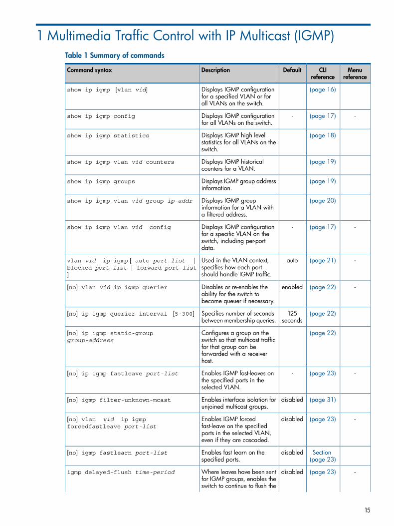
1 Multimedia Traffic Control with IP Multicast (IGMP)Table 1 Summary of commands
Menureference
CLIreference
DefaultDescriptionCommand syntax
(page 16)Displays IGMP configurationfor a specified VLAN or forall VLANs on the switch.
show ip igmp [vlan vid]
-(page 17)-Displays IGMP configurationfor all VLANs on the switch.
show ip igmp config
(page 18)Displays IGMP high levelstatistics for all VLANs on theswitch.
show ip igmp statistics
(page 19)Displays IGMP historicalcounters for a VLAN.
show ip igmp vlan vid counters
(page 19)Displays IGMP group addressinformation.
show ip igmp groups
(page 20)Displays IGMP groupinformation for a VLAN witha filtered address.
show ip igmp vlan vid group ip-addr
-(page 17)-Displays IGMP configurationfor a specific VLAN on the
show ip igmp vlan vid config
switch, including per-portdata.
-(page 21)autoUsed in the VLAN context,specifies how each portshould handle IGMP traffic.
vlan vid ip igmp [ auto port-list |blocked port-list | forward port-list]
-(page 22)enabledDisables or re-enables theability for the switch tobecome queuer if necessary.
[no] vlan vid ip igmp querier
(page 22)125seconds
Specifies number of secondsbetween membership queries.
[no] ip igmp querier interval [5-300]
(page 22)Configures a group on theswitch so that multicast traffic
[no] ip igmp static-groupgroup-address
for that group can beforwarded with a receiverhost.
-(page 23)-Enables IGMP fast-leaves onthe specified ports in theselected VLAN.
[no] ip igmp fastleave port-list
(page 31)disabledEnables interface isolation forunjoined multicast groups.
[no] igmp filter-unknown-mcast
-(page 23)disabledEnables IGMP forcedfast-leave on the specified
[no] vlan vid ip igmpforcedfastleave port-list
ports in the selected VLAN,even if they are cascaded.
Section(page 23)
disabledEnables fast learn on thespecified ports.
[no] igmp fastlearn port-list
-(page 23)disabledWhere leaves have been sentfor IGMP groups, enables the
igmp delayed-flush time-period
switch to continue to flush the
15
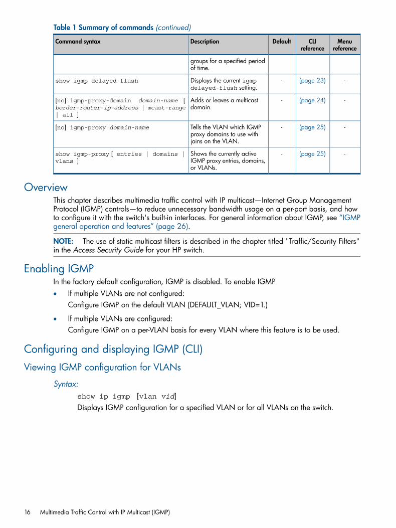
Table 1 Summary of commands (continued)
Menureference
CLIreference
DefaultDescriptionCommand syntax
groups for a specified periodof time.
-(page 23)-Displays the current igmpdelayed-flush setting.
show igmp delayed-flush
-(page 24)-Adds or leaves a multicastdomain.
[no] igmp-proxy-domain domain-name [border-router-ip-address | mcast-range| all ]
-(page 25)-Tells the VLAN which IGMPproxy domains to use withjoins on the VLAN.
[no] igmp-proxy domain-name
-(page 25)-Shows the currently activeIGMP proxy entries, domains,or VLANs.
show igmp-proxy [ entries | domains |vlans ]
OverviewThis chapter describes multimedia traffic control with IP multicast—Internet Group ManagementProtocol (IGMP) controls—to reduce unnecessary bandwidth usage on a per-port basis, and howto configure it with the switch's built-in interfaces. For general information about IGMP, see “IGMPgeneral operation and features” (page 26).
NOTE: The use of static multicast filters is described in the chapter titled "Traffic/Security Filters"in the Access Security Guide for your HP switch.
Enabling IGMPIn the factory default configuration, IGMP is disabled. To enable IGMP• If multiple VLANs are not configured:
Configure IGMP on the default VLAN (DEFAULT_VLAN; VID=1.)
• If multiple VLANs are configured:Configure IGMP on a per-VLAN basis for every VLAN where this feature is to be used.
Configuring and displaying IGMP (CLI)
Viewing IGMP configuration for VLANs
Syntax:show ip igmp [vlan vid]Displays IGMP configuration for a specified VLAN or for all VLANs on the switch.
16 Multimedia Traffic Control with IP Multicast (IGMP)
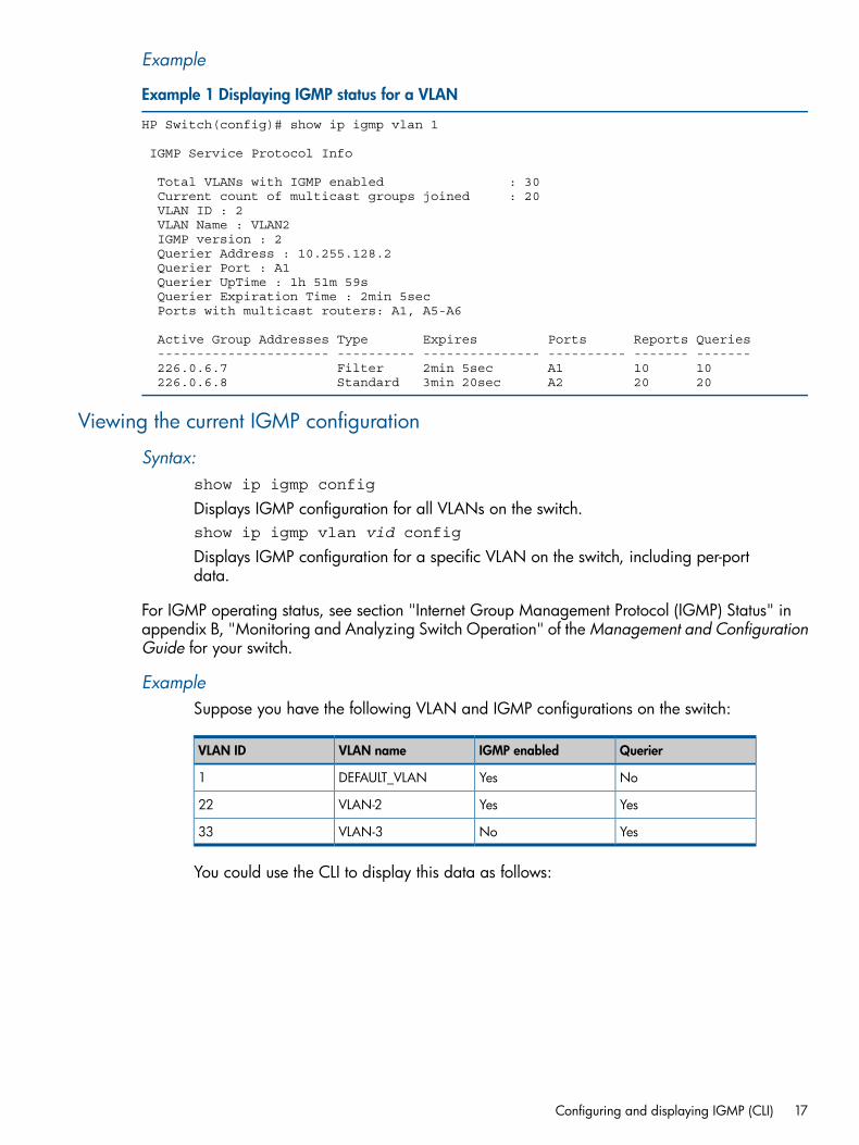
Example
Example 1 Displaying IGMP status for a VLAN
HP Switch(config)# show ip igmp vlan 1
IGMP Service Protocol Info
Total VLANs with IGMP enabled : 30 Current count of multicast groups joined : 20 VLAN ID : 2 VLAN Name : VLAN2 IGMP version : 2 Querier Address : 10.255.128.2 Querier Port : A1 Querier UpTime : 1h 51m 59s Querier Expiration Time : 2min 5sec Ports with multicast routers: A1, A5-A6
Active Group Addresses Type Expires Ports Reports Queries ---------------------- ---------- --------------- ---------- ------- ------- 226.0.6.7 Filter 2min 5sec A1 10 10 226.0.6.8 Standard 3min 20sec A2 20 20
Viewing the current IGMP configuration
Syntax:show ip igmp config
Displays IGMP configuration for all VLANs on the switch.show ip igmp vlan vid config
Displays IGMP configuration for a specific VLAN on the switch, including per-portdata.
For IGMP operating status, see section "Internet Group Management Protocol (IGMP) Status" inappendix B, "Monitoring and Analyzing Switch Operation" of the Management and ConfigurationGuide for your switch.
ExampleSuppose you have the following VLAN and IGMP configurations on the switch:
QuerierIGMP enabledVLAN nameVLAN ID
NoYesDEFAULT_VLAN1
YesYesVLAN-222
YesNoVLAN-333
You could use the CLI to display this data as follows:
Configuring and displaying IGMP (CLI) 17
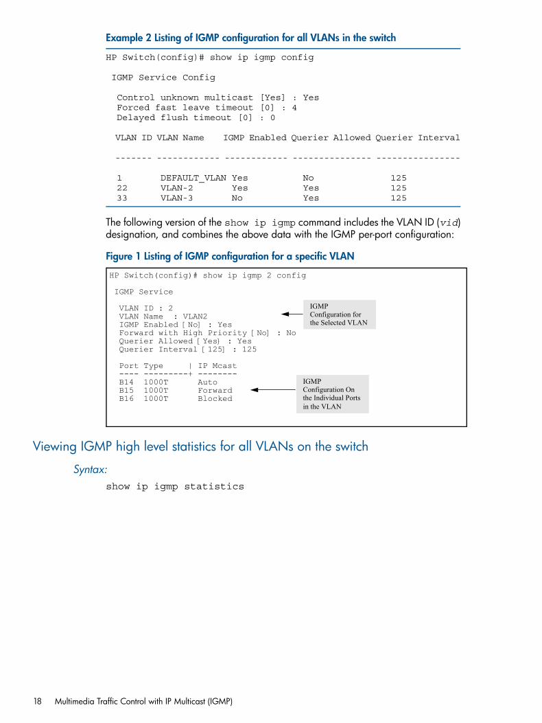
Example 2 Listing of IGMP configuration for all VLANs in the switch
HP Switch(config)# show ip igmp config
IGMP Service Config
Control unknown multicast [Yes] : Yes Forced fast leave timeout [0] : 4 Delayed flush timeout [0] : 0
VLAN ID VLAN Name IGMP Enabled Querier Allowed Querier Interval
------- ------------ ------------ --------------- ----------------
1 DEFAULT_VLAN Yes No 125 22 VLAN-2 Yes Yes 125 33 VLAN-3 No Yes 125
The following version of the show ip igmp command includes the VLAN ID (vid)designation, and combines the above data with the IGMP per-port configuration:
Figure 1 Listing of IGMP configuration for a specific VLAN
HP Switch(config)# show ip igmp 2 config
IGMP Service
VLAN ID : 2 VLAN Name : VLAN2 IGMP Enabled [No] : Yes Forward with High Priority [No] : No Querier Allowed [Yes} : Yes Querier Interval [125] : 125
Port Type | IP Mcast ---- ---------+ -------- B14 1000T Auto B15 1000T Forward B16 1000T Blocked
IGMP Configuration for the Selected VLAN
IGMP Configuration On the Individual Portsin the VLAN
Viewing IGMP high level statistics for all VLANs on the switch
Syntax:show ip igmp statistics
18 Multimedia Traffic Control with IP Multicast (IGMP)
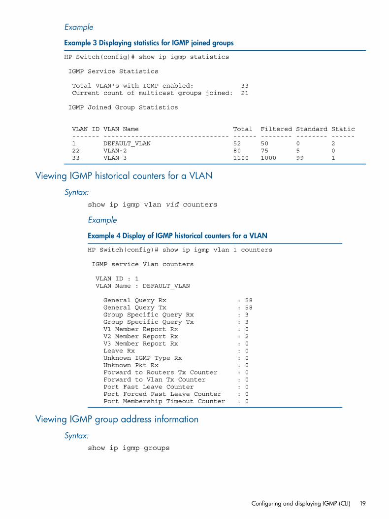
Example
Example 3 Displaying statistics for IGMP joined groups
HP Switch(config)# show ip igmp statistics
IGMP Service Statistics
Total VLAN's with IGMP enabled: 33 Current count of multicast groups joined: 21
IGMP Joined Group Statistics
VLAN ID VLAN Name Total Filtered Standard Static ------- -------------------------------- ------ -------- -------- ------ 1 DEFAULT_VLAN 52 50 0 2 22 VLAN-2 80 75 5 0 33 VLAN-3 1100 1000 99 1
Viewing IGMP historical counters for a VLAN
Syntax:show ip igmp vlan vid counters
Example
Example 4 Display of IGMP historical counters for a VLAN
HP Switch(config)# show ip igmp vlan 1 counters
IGMP service Vlan counters
VLAN ID : 1 VLAN Name : DEFAULT_VLAN
General Query Rx : 58 General Query Tx : 58 Group Specific Query Rx : 3 Group Specific Query Tx : 3 V1 Member Report Rx : 0 V2 Member Report Rx : 2 V3 Member Report Rx : 0 Leave Rx : 0 Unknown IGMP Type Rx : 0 Unknown Pkt Rx : 0 Forward to Routers Tx Counter : 0 Forward to Vlan Tx Counter : 0 Port Fast Leave Counter : 0 Port Forced Fast Leave Counter : 0 Port Membership Timeout Counter : 0
Viewing IGMP group address information
Syntax:show ip igmp groups
Configuring and displaying IGMP (CLI) 19
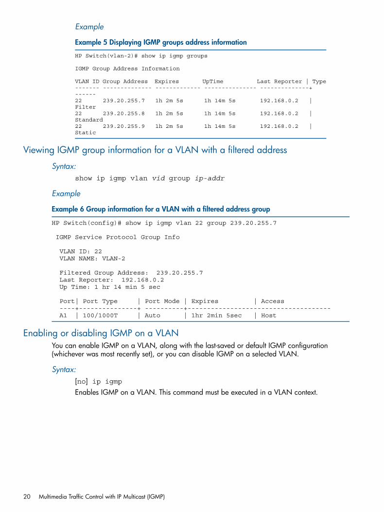
Example
Example 5 Displaying IGMP groups address information
HP Switch(vlan-2)# show ip igmp groups
IGMP Group Address Information
VLAN ID Group Address Expires UpTime Last Reporter | Type------- -------------- ------------- --------------- --------------+ ------22 239.20.255.7 1h 2m 5s 1h 14m 5s 192.168.0.2 | Filter22 239.20.255.8 1h 2m 5s 1h 14m 5s 192.168.0.2 | Standard22 239.20.255.9 1h 2m 5s 1h 14m 5s 192.168.0.2 | Static
Viewing IGMP group information for a VLAN with a filtered address
Syntax:show ip igmp vlan vid group ip-addr
Example
Example 6 Group information for a VLAN with a filtered address group
HP Switch(config)# show ip igmp vlan 22 group 239.20.255.7
IGMP Service Protocol Group Info
VLAN ID: 22 VLAN NAME: VLAN-2
Filtered Group Address: 239.20.255.7 Last Reporter: 192.168.0.2 Up Time: 1 hr 14 min 5 sec
Port| Port Type | Port Mode | Expires | Access ----+---------------+ ----------+------------------------------------- A1 | 100/1000T | Auto | 1hr 2min 5sec | Host
Enabling or disabling IGMP on a VLANYou can enable IGMP on a VLAN, along with the last-saved or default IGMP configuration(whichever was most recently set), or you can disable IGMP on a selected VLAN.
Syntax:[no] ip igmpEnables IGMP on a VLAN. This command must be executed in a VLAN context.
20 Multimedia Traffic Control with IP Multicast (IGMP)
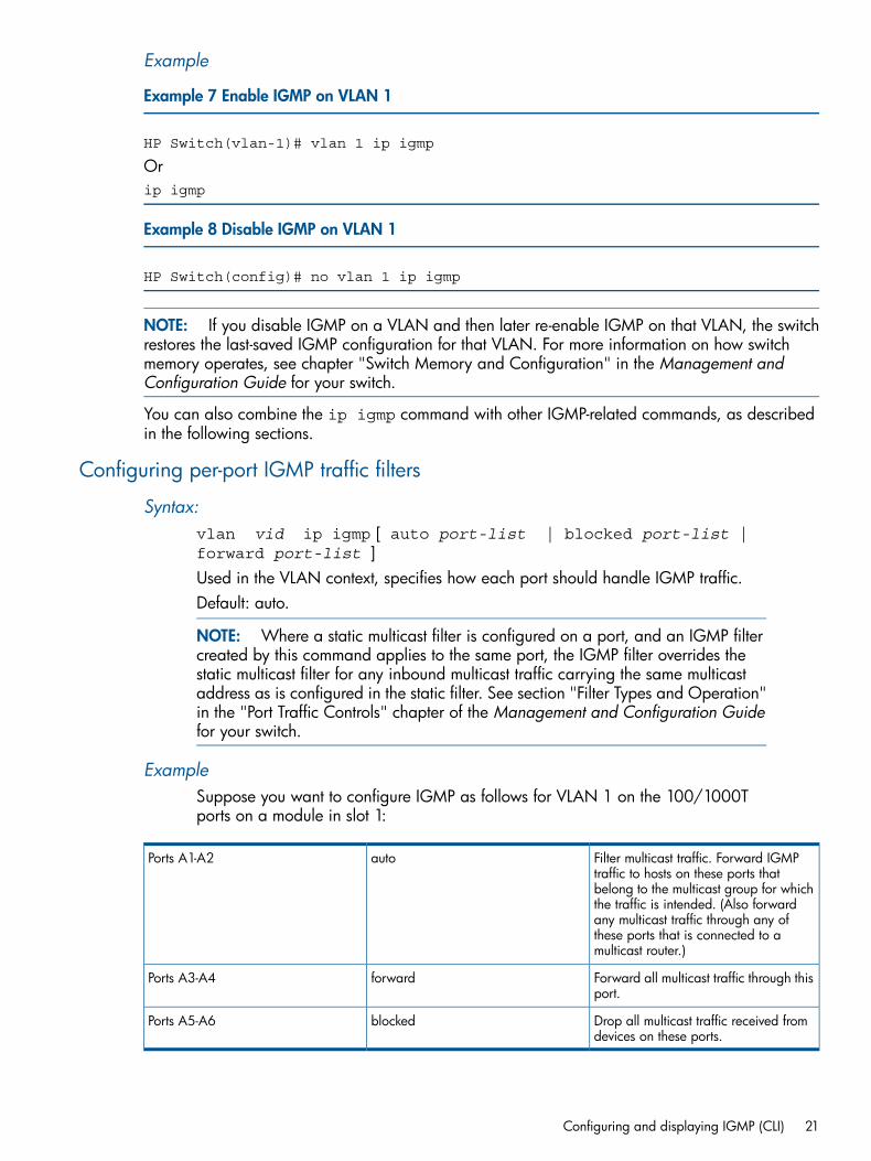
Example
Example 7 Enable IGMP on VLAN 1
HP Switch(vlan-1)# vlan 1 ip igmp
Orip igmp
Example 8 Disable IGMP on VLAN 1
HP Switch(config)# no vlan 1 ip igmp
NOTE: If you disable IGMP on a VLAN and then later re-enable IGMP on that VLAN, the switchrestores the last-saved IGMP configuration for that VLAN. For more information on how switchmemory operates, see chapter "Switch Memory and Configuration" in the Management andConfiguration Guide for your switch.
You can also combine the ip igmp command with other IGMP-related commands, as describedin the following sections.
Configuring per-port IGMP traffic filters
Syntax:vlan vid ip igmp [ auto port-list | blocked port-list |forward port-list ]Used in the VLAN context, specifies how each port should handle IGMP traffic.Default: auto.
NOTE: Where a static multicast filter is configured on a port, and an IGMP filtercreated by this command applies to the same port, the IGMP filter overrides thestatic multicast filter for any inbound multicast traffic carrying the same multicastaddress as is configured in the static filter. See section "Filter Types and Operation"in the "Port Traffic Controls" chapter of the Management and Configuration Guidefor your switch.
ExampleSuppose you want to configure IGMP as follows for VLAN 1 on the 100/1000Tports on a module in slot 1:
Filter multicast traffic. Forward IGMPtraffic to hosts on these ports that
autoPorts A1-A2
belong to the multicast group for whichthe traffic is intended. (Also forwardany multicast traffic through any ofthese ports that is connected to amulticast router.)
Forward all multicast traffic through thisport.
forwardPorts A3-A4
Drop all multicast traffic received fromdevices on these ports.
blockedPorts A5-A6
Configuring and displaying IGMP (CLI) 21
For a description of the default behavior of data-driven switches, see “Automaticfast-leave IGMP” (page 29).Depending on the privilege level, you could use one of the following commands toconfigure IGMP on VLAN 1 with the above settings:
HP Switch(config)# vlan 1 ip igmp auto a1,a2 forward a3,a4blocked a5,a6HP Switch(vlan-1)# ip igmp auto a1,a2 forward a3,a4blocked a5,a6
The following command displays the VLAN and per-port configuration resultingfrom the above commands.
HP Switch show igmp vlan 1 config
Configuring the querier function
Syntax:[no] vlan vid ip igmp querierThis command disables or re-enables the ability for the switch to become querierif necessary.The no version of the command disables the querier function on the switch. Theshow ip igmp config command displays the current querier command.Default querier capability: Enabled
Configuring the querier intervalTo specify the number of seconds between membership queries, enter this command with thedesired interval.
Syntax:[no] ip igmp querier interval [5-300]
NOTE: This command must be issued in a VLAN context.
Specifies the number of seconds between membership queries. The no form of thecommand sets the interval to the default of 125 seconds.Default: 125 seconds
For example, to set the querier interval to 300 seconds on ports in VLAN 8:HP Switch(vlan-8)# ip igmp querier interval 300
Configuring static multicast groupsUse this command to configure a group on the switch so that multicast traffic for that group canbe forwarded with a receiver host. Traffic will be flooded for this group.
Syntax:[no] ip igmp static-group group-address
NOTE: This command must be issued in a VLAN context.
Creates the IGMP static group with the specified group address on the selectedVLAN. The no form of the command deletes the static group on the selected VLAN.
22 Multimedia Traffic Control with IP Multicast (IGMP)
Configuring fast-leave IGMPFor information about fast-leave IGMP, see “Automatic fast-leave IGMP” (page 29).
Syntax:[no] ip igmp fastleave port-listEnables IGMP fast-leaves on the specified ports in the selected VLAN.The no form of the command disables IGMP fast-leave on the specified ports in theselected VLAN.Use show running to display the ports per-VLAN on which fast-leave is disabled.Default: Enabled
Configuring forced fast-leave IGMPFor information about forced fast-leave, see “Forced fast-leave IGMP” (page 31).
Syntax:[no] vlan vid ip igmp forcedfastleave port-list
Enables IGMP forced fast-leave on the specified ports in the selected VLAN, evenif they are cascaded.The no form of the command disables forced fast-leave on the specified ports inthe selected VLAN.Use show running to display the ports per-VLAN on which forced fast-leave isenabled.Default: Disabledshow running-config
Displays a non-default IGMP forced fast-leave configuration on a VLAN. Theshow running-config output does not include forced fast-leave if it is setto the default of 0.
forcedfastleave
Can be used when there are multiple devices attached to a port.
Configuring fast learnThe fast learn option allows fast convergence of multicast traffic after a topology change. Thiscommand is executed in the global config context.
Syntax:[no] igmp fastlearn port-listThis command enabled fast learn on the specified ports. The no form of the commanddisables the fast learn function on the specified ports.Default: Disabled
Example 9 To enable fastlearn on ports 5 and 6
HP Switch(config)# igmp fastlearn 5-6
Configuring delayed group flushWhen enabled, this feature continues to filter IGMP groups for a specified additional period oftime after IGMP leaves have been sent. The delay in flushing the group filter prevents unregisteredtraffic from being forwarded by the server during the delay period. In practice, this is rarely
Configuring fast-leave IGMP 23
necessary on the switches, which support data-driven IGMP. (Data-driven IGMP, which is enabledby default, prunes off any unregistered IGMP streams detected on the switch.)
Syntax:igmp delayed-flush time-period
Where leaves have been sent for IGMP groups, enables the switch to continue toflush the groups for a specified period of time. This command is applied globallyto all IGMP-configured VLANs on the switch.Range: 0 - 255; Default: Disabled (0)
Syntax:show igmp delayed-flush
Displays the current igmp delayed-flush setting.
Preventing unjoined multicast trafficFor more information about unjoined multicast traffic, see “Unjoined multicast traffic” (page 31).
Syntax:[no] igmp filter-unknown-mcastEnables interface isolation for unjoined multicast groups. IGMP is configured sothat each interface with IGMP enabled will have a data-driven multicast filterassociated with it, preventing unjoined IP multicast packets from being flooded. Areboot is required for the change to take effect.Default: Disabled
Configuring IGMP proxy (CLI)For more information on IGMP proxy, see “IGMP general operation and features” (page 26).
Adding or leaving a multicast domain
Syntax:[no] igmp-proxy-domain domain-name [ border-router-ip-address| mcast-range | all ]The no form of the command is used to remove a multicast domain.All VLANs associated with the domain must first be removed for this command towork. See the no form of igmp-proxy in the VLAN context command.domain-name
User-defined name to associate with the PIM border router and multicast rangethat is being sent toward the border router.
border-router-ip-addr
The IP address of the border router toward which IGMP proxy packets are sent.Not required for the no form of the command.
NOTE: The current routing FIB determines the best path toward the borderrouter and therefore the VLAN that a proxy is sent out on
[ low-bound-ip-address | all ]The low boundary (inclusive) of the multicast address range to associate withthis domain (for example, 234.0.0.1.)
24 Multimedia Traffic Control with IP Multicast (IGMP)
If all is selected, the multicast addresses in the range of 224.0.1.0 to239.255.255.255 are included in this domain.
NOTE: Addresses 224.0.0.0 to 224.0.0.255 are never used, because theseaddresses are reserved for protocols.
high-bound-ip-address
The high boundary (inclusive) of the multicast address range to associate withthis domain (for example, 236.1.1.1.)
Examples
Example 10 IGMP proxy border IP address command
This example shows the IGMP proxy border IP addrses (111.11.111.111) being configured.HP Switch(config)# igmp-proxy-domain Bob 111.11.111.111
Example 11 Setting the lower and upper bounds for multicasting
This example shows the lower and upper boundaries of the multicast address range associatedwith the domain named Bob.HP Switch(config)# igmp-proxy-domain Bob 111.11.111.111 234.0.0.1HP Switch(config)# igmp-proxy-domain Bob 111.11.111.111 236.1.1.1
Informs the VLAN which IGMP proxy domains to use with joins on the VLANThis command is performed when in VLAN context mode. When a query occurs on the upstreaminterface, an IGMP join is sent for all multicast addresses that are currently joined on the downstreaminterface.
Syntax:[no] igmp-proxy domain-nameThe no version of the command with no domain name specified removes all domainsassociated with this VLAN.
NOTE: Multiple different domains may be configured in the same VLAN contextwhere the VLAN is considered the downstream interface. The domain name mustexist prior to using this command to add the domain.
NOTE: If the unicast routing path to the specified IP address was through the specified VLAN,no proxy IGMP would occur, that is, a proxy is not sent back out on the VLAN that the IGMP joincame in on.
If no unicast route exists to the border router, no proxy IGMP packets are sent.
Viewing the IGMP proxy data
Syntax:show igmp-proxy [ entries | domains | vlans ]Shows the currently active IGMP proxy entries, domains, or VLANs.
Configuring IGMP proxy (CLI) 25
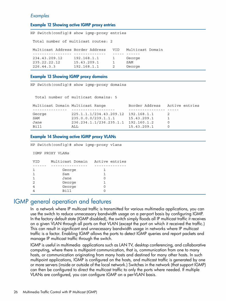
Examples
Example 12 Showing active IGMP proxy entries
HP Switch(config)# show igmp-proxy entries
Total number of multicast routes: 2
Multicast Address Border Address VID Multicast Domain ----------------- -------------- ----- ------ 234.43.209.12 192.168.1.1 1 George 235.22.22.12 15.43.209.1 1 SAM 226.44.3.3 192.168.1.1 2 George
Example 13 Showing IGMP proxy domains
HP Switch(config)# show igmp-proxy domains
Total number of multicast domains: 5
Multicast Domain Multicast Range Border Address Active entries --------------- ------------------- ---------------- ----- George 225.1.1.1/234.43.209.12 192.168.1.1 2 SAM 235.0.0.0/239.1.1.1 15.43.209.1 1 Jane 236.234.1.1/236.235.1.1 192.160.1.2 0 Bill ALL 15.43.209.1 0
Example 14 Showing active IGMP proxy VLANs
HP Switch(config)# show igmp-proxy vlans
IGMP PROXY VLANs
VID Multicast Domain Active entries ------ ---------------- -------------- 1 George 1 1 Sam 1 1 Jane 0 2 George 1 4 George 0 4 Bill 0
IGMP general operation and featuresIn a network where IP multicast traffic is transmitted for various multimedia applications, you canuse the switch to reduce unnecessary bandwidth usage on a per-port basis by configuring IGMP.In the factory default state (IGMP disabled), the switch simply floods all IP multicast traffic it receiveson a given VLAN through all ports on that VLAN (except the port on which it received the traffic.)This can result in significant and unnecessary bandwidth usage in networks where IP multicasttraffic is a factor. Enabling IGMP allows the ports to detect IGMP queries and report packets andmanage IP multicast traffic through the switch.IGMP is useful in multimedia applications such as LAN TV, desktop conferencing, and collaborativecomputing, where there is multipoint communication, that is, communication from one to manyhosts, or communication originating from many hosts and destined for many other hosts. In suchmultipoint applications, IGMP is configured on the hosts, and multicast traffic is generated by oneor more servers (inside or outside of the local network.) Switches in the network (that support IGMP)can then be configured to direct the multicast traffic to only the ports where needed. If multipleVLANs are configured, you can configure IGMP on a per-VLAN basis.
26 Multimedia Traffic Control with IP Multicast (IGMP)
Enabling IGMP allows detection of IGMP queries and report packets used to manage IP multicasttraffic through the switch. If no other querier is detected, the switch then also functions as thequerier. If you need to disable the querier feature, do so through the IGMP configuration MIB, see“Configuring the querier function” (page 22).
NOTE: IGMP configuration on the switches operates at the VLAN context level. If you are notusing VLANs, configure IGMP in VLAN 1 (the default VLAN) context.
EnhancementsWith the CLI, you can configure these additional options:Forward with high priority
Disabling this parameter (the default) causes the switch or VLAN to process IP multicast traffic,along with other traffic, in the order received (usually, normal priority.) Enabling this parametercauses the switch or VLAN to give a higher priority to IP multicast traffic than to other traffic.
Auto/blocked/forward
You can use the console to configure individual ports to any of the following states:Auto
(Default) Causes the switch to interpret IGMP packets and to filter IP multicast traffic basedon the IGMP packet information for ports belonging to a multicast group. This means thatIGMP traffic will be forwarded on a specific port only if an IGMP host or multicast routeris connected to the port.
Blocked
Causes the switch to drop all IGMP transmissions received from a specific port.Forward
Causes the switch to forward all IGMP and IP multicast transmissions through the port.Operation with or without IP addressing
This feature helps to conserve IP addresses by enabling IGMP to run on VLANs that do nothave an IP address. See “Operation with or without IP addressing” (page 28).
Querier capability
The switch performs this function for IGMP on VLANs having an IP address when there is noother device in the VLAN acting as querier. See “About using the switch as querier” (page 36).
NOTE: Whenever IGMP is enabled, the switch generates an Event Log message indicatingwhether querier functionality is enabled.IP multicast traffic groups are identified by IP addresses in the range of 224.0.0.0 to239.255.255.255. Also, incoming IGMP packets intended for reserved, or "well-known" multicastaddresses, automatically flood through all ports (except the port on which the packets entered theswitch.) For more on this topic, see “Well-known or reserved multicast addresses excluded from IPmulticast filtering” (page 37)".
For more information about IGMP, see “How IGMP operates” (page 27).
Number of IP multicast addresses allowedThe number of IGMP filters (addresses) and static multicast filters available is 2,038. Additionally,16 static multicast filters are allowed, If multiple VLANs are configured, then each filter is countedonce per VLAN in which it is used.
How IGMP operatesIGMP is an internal protocol of the IP suite. IP manages multicast traffic by using switches, multicastrouters, and hosts that support IGMP. A multicastrouter is not necessary as long as a switch is
How IGMP operates 27
configured to support IGMP with the querier feature enabled. A set of hosts, routers, and/orswitches that send or receive multicast data streams to or from the same sources is called a multicastgroup, and all devices in the group use the same multicast group address. The multicast grouprunning version 2 of IGMP uses three fundamental types of messages to communicate:Query
A message sent from the querier (multicast router or switch) asking for a response from eachhost belonging to the multicast group. If a multicast router supporting IGMP is not present, theswitch must assume this function to elicit group membership information from the hosts on thenetwork. If you need to disable the querier feature, do so through the CLI using the IGMPconfiguration MIB, see “Configuring the querier function” (page 22).
Report (Join)A message sent by a host to the querier to indicate that the host wants to be or is a memberof a given group indicated in the report message.
Leave groupA message sent by a host to the querier to indicate that the host has ceased to be a memberof a specific multicast group.
Note on IGMP version 3 support:When an IGMPv3 Join is received by the switch, it accepts the host request and begins to forwardthe IGMP traffic. This means that ports that have not joined the group and are not connected torouters or the IGMP Querier will not receive the group's multicast traffic.The switch does not support the IGMPv3 "Exclude Source" or "Include Source" options in the JoinReports. Rather, the group is simply joined from all sources.The switch does not support becoming a version 3 Querier. It becomes a version 2 Querier in theabsence of any other Querier on the network.
An IP multicast packet includes the multicast group (address) to which the packet belongs. Whenan IGMP client connected to a switch port needs to receive multicast traffic from a specific group,it joins the group by sending an IGMP report (join request) to the network. (The multicast groupspecified in the join request is determined by the requesting application running on the IGMPclient.) When a networking device with IGMP enabled receives the join request for a specificgroup, it forwards any IP multicast traffic it receives for that group through the port on which thejoin request was received. When the client is ready to leave the multicast group, it sends a LeaveGroup message to the network and ceases to be a group member. When the leave request isdetected, the appropriate IGMP device ceases transmitting traffic for the designated multicast groupthrough the port on which the leave request was received (as long as there are no other currentmembers of that group on the affected port.)Thus, IGMP identifies members of a multicast group (within a subnet) and allows IGMP-configuredhosts (and routers) to join or leave multicast groups.To display IGMP data showing active group addresses, reports, queries, querier access port, andactive group address data (port, type, and access), see section "Internet Group ManagementProtocol (IGMP) Status" in appendix B, "Monitoring and Analyzing Switch Operation" of theManagement and Configuration Guide for your switch.
Operation with or without IP addressingYou can configure IGMP on VLANs that do not have IP addressing. The benefit of IGMP withoutIP addressing is a reduction in the number of IP addresses you have to use and configure. This canbe significant in a network with a large number of VLANs. The limitation on IGMP without IPaddressing is that the switch cannot become Querier on any VLANs for which it has no IPaddress—so the network administrator must ensure that another IGMP device will act as Querier.It is also advisable to have an additional IGMP device available as a backup Querier. See“Comparison of IGMP operation with and without IP addressing” (page 29).
28 Multimedia Traffic Control with IP Multicast (IGMP)
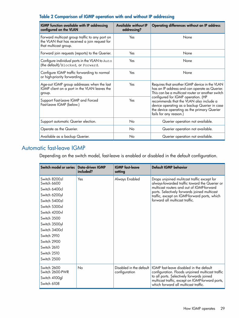
Table 2 Comparison of IGMP operation with and without IP addressing
Operating differences without an IP addressAvailable without IPaddressing?
IGMP function available with IP addressingconfigured on the VLAN
NoneYesForward multicast group traffic to any port onthe VLAN that has received a join request forthat multicast group.
NoneYesForward join requests (reports) to the Querier.
NoneYesConfigure individual ports in the VLAN to Auto(the default)/Blocked, or Forward.
NoneYesConfigure IGMP traffic forwarding to normalor high-priority forwarding.
Requires that another IGMP device in the VLANhas an IP address and can operate as Querier.
YesAge-out IGMP group addresses when the lastIGMP client on a port in the VLAN leaves thegroup. This can be a multicast router or another switch
configured for IGMP operation. (HPYesSupport Fast-Leave IGMP and Forced
Fast-Leave IGMP (below.)recommends that the VLAN also include adevice operating as a backup Querier in casethe device operating as the primary Querierfails for any reason.)
Querier operation not available.NoSupport automatic Querier election.
Querier operation not available.NoOperate as the Querier.
Querier operation not available.NoAvailable as a backup Querier.
Automatic fast-leave IGMPDepending on the switch model, fast-leave is enabled or disabled in the default configuration.
Default IGMP behaviorIGMP fast-leavesetting
Data-driven IGMPincluded?
Switch model or series
Drops unjoined mulitcast traffic except foralways-fowarded traffic toward the Querier or
Always EnabledYesSwitch 8200zlSwitch 6600
multicast routers and out of IGMP-forwardSwitch 6400clports. Selectively forwards joined multicast
Switch 6200yl traffic, except on IGMP-forward ports, whichforward all multicast traffic.Switch 5400zl
Switch 5300xlSwitch 4200vlSwitch 3500Switch 3500ylSwitch 3400clSwitch 2910Switch 2900Switch 2610Switch 2510Switch 2500
IGMP fast-leave disabled in the defaultconfiguration. Floods unjoined multicast traffic
Disabled in the defaultconfiguration
NoSwitch 2600Switch 2600-PWR
to all ports. Selectively forwards joinedSwitch 4100glmulticast traffic, except on IGMP-forward ports,which forward all multicast traffic.Switch 6108
How IGMP operates 29
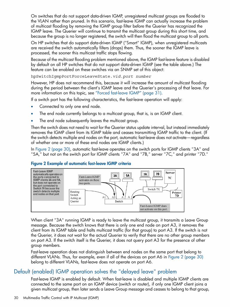
On switches that do not support data-driven IGMP, unregistered multicast groups are flooded tothe VLAN rather than pruned. In this scenario, fast-leave IGMP can actually increase the problemof multicast flooding by removing the IGMP group filter before the Querier has recognized theIGMP leave. The Querier will continue to transmit the multicast group during this short time, andbecause the group is no longer registered, the switch will then flood the multicast group to all ports.On HP switches that do support data-driven IGMP ("Smart" IGMP), when unregistered multicastsare received the switch automatically filters (drops) them. Thus, the sooner the IGMP leave isprocessed, the sooner this multicast traffic stops flowing.Because of the multicast flooding problem mentioned above, the IGMP fast-leave feature is disabledby default on all HP switches that do not support data-driven IGMP (see the table above.) Thefeature can be enabled on these switches via an SNMP set of this object:hpSwitchIgmpPortForceLeaveState.vid.port number
However, HP does not recommend this, because it will increase the amount of multicast floodingduring the period between the client's IGMP leave and the Querier's processing of that leave. Formore information on this topic, see “Forced fast-leave IGMP” (page 31).If a switch port has the following characteristics, the fast-leave operation will apply:• Connected to only one end node.
• The end node currently belongs to a multicast group, that is, is an IGMP client.
• The end node subsequently leaves the multicast group.Then the switch does not need to wait for the Querier status update interval, but instead immediatelyremoves the IGMP client from its IGMP table and ceases transmitting IGMP traffic to the client. (Ifthe switch detects multiple end nodes on the port, automatic fast-leave does not activate—regardlessof whether one or more of these end nodes are IGMP clients.)In Figure 2 (page 30), automatic fast-leave operates on the switch ports for IGMP clients "3A" and"5A," but not on the switch port for IGMP clients "7A" and "7B," server "7C," and printer "7D."
Figure 2 Example of automatic fast-leave IGMP criteria
When client "3A" running IGMP is ready to leave the multicast group, it transmits a Leave Groupmessage. Because the switch knows that there is only one end node on port A3, it removes theclient from its IGMP table and halts multicast traffic (for that group) to port A3. If the switch is notthe Querier, it does not wait for the actual Querier to verify that there are no other group memberson port A3. If the switch itself is the Querier, it does not query port A3 for the presence of othergroup members.Fast-leave operation does not distinguish between end nodes on the same port that belong todifferent VLANs. Thus, for example, even if all of the devices on port A6 in Figure 2 (page 30)belong to different VLANs, fast-leave does not operate on port A6.
Default (enabled) IGMP operation solves the "delayed leave" problemFast-leave IGMP is enabled by default. When fast-leave is disabled and multiple IGMP clients areconnected to the same port on an IGMP device (switch or router), if only one IGMP client joins agiven multicast group, then later sends a Leave Group message and ceases to belong to that group,
30 Multimedia Traffic Control with IP Multicast (IGMP)
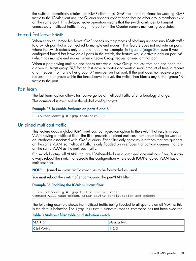
the switch automatically retains that IGMP client in its IGMP table and continues forwarding IGMPtraffic to the IGMP client until the Querier triggers confirmation that no other group members existon the same port. This delayed leave operation means that the switch continues to transmitunnecessary multicast traffic through the port until the Querier renews multicast group status.
Forced fast-leave IGMPWhen enabled, forced fast-leave IGMP speeds up the process of blocking unnecessary IGMP trafficto a switch port that is connect ed to multiple end nodes. (This feature does not activate on portswhere the switch detects only one end node.) For example, in Figure 2 (page 30), even if youconfigured forced fast-leave on all ports in the switch, the feature would activate only on port A6(which has multiple end nodes) when a Leave Group request arrived on that port.When a port having multiple end nodes receives a Leave Group request from one end node fora given multicast group "X," forced fast-leave activates and waits a small amount of time to receivea join request from any other group "X" member on that port. If the port does not receive a joinrequest for that group within the forced-leave interval, the switch then blocks any further group "X"traffic to the port.
Fast learnThe fast learn option allows fast convergence of multicast traffic after a topology change.This command is executed in the global config context.
Example 15 To enable fastlearn on ports 5 and 6
HP Switch(config)# igmp fastlearn 5-6
Unjoined multicast trafficThis feature adds a global IGMP multicast configuration option to the switch that results in eachVLAN having a multicast filter. The filter prevents unjoined multicast traffic from being forwardedon interfaces associated with IGMP queriers. Each filter only contains interfaces that are querierson the same VLAN, so multicast traffic is only flooded on interfaces that contain queriers that areon the same VLAN as the multicast traffic.On switch bootup, all VLANs that are IGMP-enabled are guaranteed one multicast filter. You canalways reboot the switch to recreate this configuration where each IGMP-enabled VLAN has amulticast filter.
NOTE: Joined multicast traffic continues to be forwarded as usual.
You must reboot the switch after configuring the per-VLAN filter.
Example 16 Enabling the IGMP multicast filter
HP Switch(config)# igmp filter-unknown-mcastCommand will take effect after saving configuration and reboot.
The following example shows the multicast traffic being flooded to all queriers on all VLANs; thisis the default behavior. The igmp filter-unknown-mcast command has not been executed.
Table 3 Multicast filter table on distribution switch
Member PortsVLAN ID
1, 2, 30 (all VLANs)
How IGMP operates 31
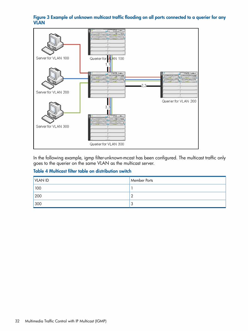
Figure 3 Example of unknown multicast traffic flooding on all ports connected to a querier for anyVLAN
In the following example, igmp filter-unknown-mcast has been configured. The multicast traffic onlygoes to the querier on the same VLAN as the multicast server.
Table 4 Multicast filter table on distribution switch
Member PortsVLAN ID
1100
2200
3300
32 Multimedia Traffic Control with IP Multicast (IGMP)
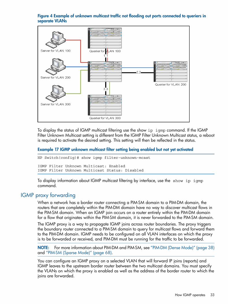
Figure 4 Example of unknown multicast traffic not flooding out ports connected to queriers inseparate VLANs
To display the status of IGMP multicast filtering use the show ip igmp command. If the IGMPFilter Unknown Multicast setting is different from the IGMP Filter Unknown Multicast status, a rebootis required to activate the desired setting. This setting will then be reflected in the status.
Example 17 IGMP unknown multicast filter setting being enabled but not yet activated
HP Switch(config)# show igmp filter-unknown-mcast
IGMP Filter Unknown Multicast: EnabledIGMP Filter Unknown Multicast Status: Disabled
To display information about IGMP multicast filtering by interface, use the show ip igmpcommand.
IGMP proxy forwardingWhen a network has a border router connecting a PIM-SM domain to a PIM-DM domain, therouters that are completely within the PIM-DM domain have no way to discover multicast flows inthe PIM-SM domain. When an IGMP join occurs on a router entirely within the PIM-DM domainfor a flow that originates within the PIM-SM domain, it is never forwarded to the PIM-SM domain.The IGMP proxy is a way to propagate IGMP joins across router boundaries. The proxy triggersthe boundary router connected to a PIM-SM domain to query for multicast flows and forward themto the PIM-DM domain. IGMP needs to be configured on all VLAN interfaces on which the proxyis to be forwarded or received, and PIM-DM must be running for the traffic to be forwarded.
NOTE: For more information about PIM-DM and PIM-SM, see “PIM-DM (Dense Mode)” (page 38)and “PIM-SM (Sparse Mode)” (page 68).
You can configure an IGMP proxy on a selected VLAN that will forward IP joins (reports) andIGMP leaves to the upstream border router between the two multicast domains. You must specifythe VLANs on which the proxy is enabled as well as the address of the border router to which thejoins are forwarded.
How IGMP operates 33
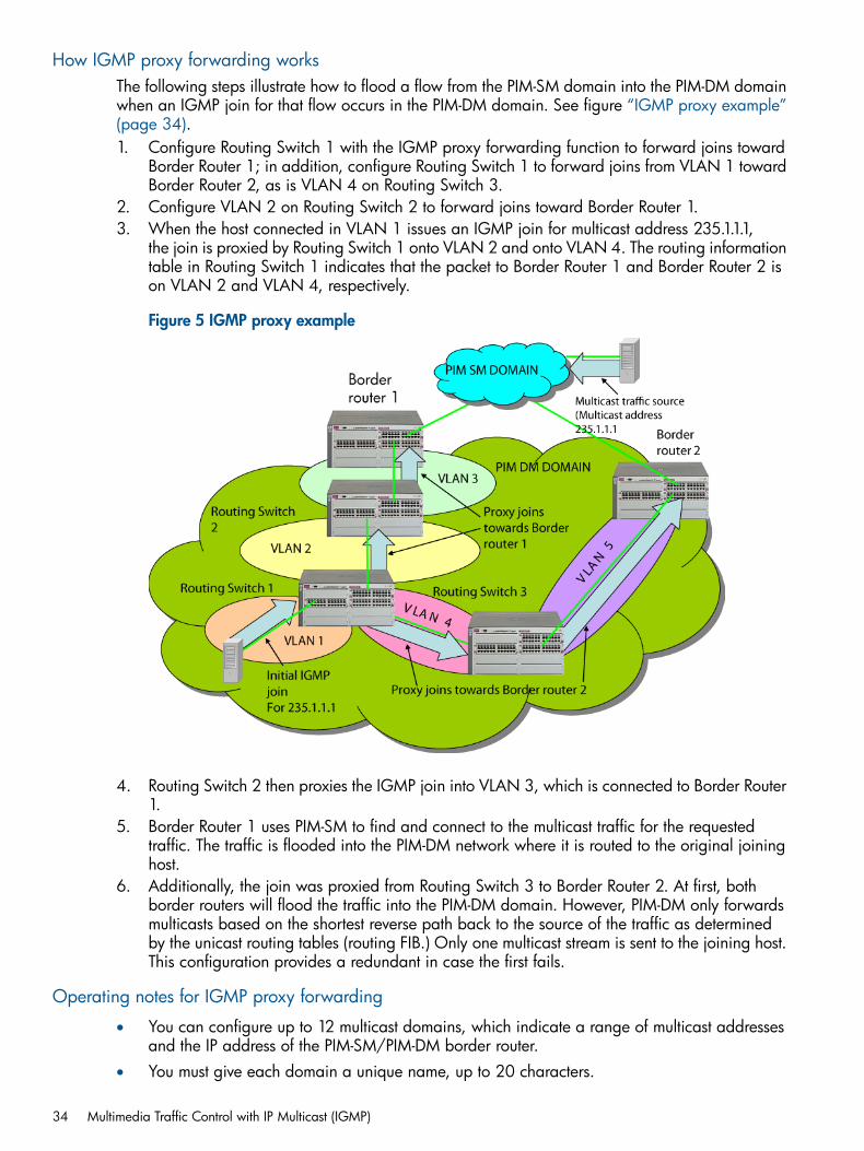
How IGMP proxy forwarding worksThe following steps illustrate how to flood a flow from the PIM-SM domain into the PIM-DM domainwhen an IGMP join for that flow occurs in the PIM-DM domain. See figure “IGMP proxy example”(page 34).1. Configure Routing Switch 1 with the IGMP proxy forwarding function to forward joins toward
Border Router 1; in addition, configure Routing Switch 1 to forward joins from VLAN 1 towardBorder Router 2, as is VLAN 4 on Routing Switch 3.
2. Configure VLAN 2 on Routing Switch 2 to forward joins toward Border Router 1.3. When the host connected in VLAN 1 issues an IGMP join for multicast address 235.1.1.1,
the join is proxied by Routing Switch 1 onto VLAN 2 and onto VLAN 4. The routing informationtable in Routing Switch 1 indicates that the packet to Border Router 1 and Border Router 2 ison VLAN 2 and VLAN 4, respectively.
Figure 5 IGMP proxy example
4. Routing Switch 2 then proxies the IGMP join into VLAN 3, which is connected to Border Router1.
5. Border Router 1 uses PIM-SM to find and connect to the multicast traffic for the requestedtraffic. The traffic is flooded into the PIM-DM network where it is routed to the original joininghost.
6. Additionally, the join was proxied from Routing Switch 3 to Border Router 2. At first, bothborder routers will flood the traffic into the PIM-DM domain. However, PIM-DM only forwardsmulticasts based on the shortest reverse path back to the source of the traffic as determinedby the unicast routing tables (routing FIB.) Only one multicast stream is sent to the joining host.This configuration provides a redundant in case the first fails.
Operating notes for IGMP proxy forwarding
• You can configure up to 12 multicast domains, which indicate a range of multicast addressesand the IP address of the PIM-SM/PIM-DM border router.
• You must give each domain a unique name, up to 20 characters.
34 Multimedia Traffic Control with IP Multicast (IGMP)
• The domains may have overlapping multicast ranges.
• The IP address of the border router may be the same or different in each configured domain.
• Duplicate IGMP joins are automatically prevented, or leaves that would remove a flow currentlyjoined by multiple hosts.
• Range overlap allows for redundant connectivity and the ability for multicasts to arrive fromdifferent border routers based on the shortest path back to the source of the traffic.
• The configured domain names must be associated with one or more VLANs for which theproxy joins are to be done.
• All routers in the path between the edge router receiving the initial IGMP packets and theborder router have to be configured to forward IGMP using IGMP proxy.
• All upstream and downstream interfaces using IGMP proxy forwarding require IGMP and PIMto be enabled.
• You must remove all VLAN associations with the domain name before that domain name canbe removed.
• The appropriate border routers must be used for each VLAN, or PIM-DM will not forward thetraffic. This could occur when multiple border routers exist. It may be necessary to configuremultiple overlapping domains if the multicast source address can generate the same multicastaddress and have different best paths to the PIM-DM domain.
CAUTION: Be careful to avoid configuring a IGMP forward loop, because this would leave theVLANs in a joined state forever once an initial join is sent from a host. For example, a join is issuedfrom the host in VLAN 2 and Routing Switch 2 will proxy the join onto VLAN 1. Routing Switch 3will then proxy the join back onto VLAN 2 and increment its internal count of the number of joinson VLAN 2. Even after the host on VLAN 2 issues a leave, the proxy join will continue to remainand refresh itself each time a query occurs on VLAN 2. This type of loop could be created withmultiple routers if an IGMP proxy is allowed to get back to the VLAN of the router that initiallyreceived the IGMP join from a host; see Figure 6 (page 36).
How IGMP operates 35
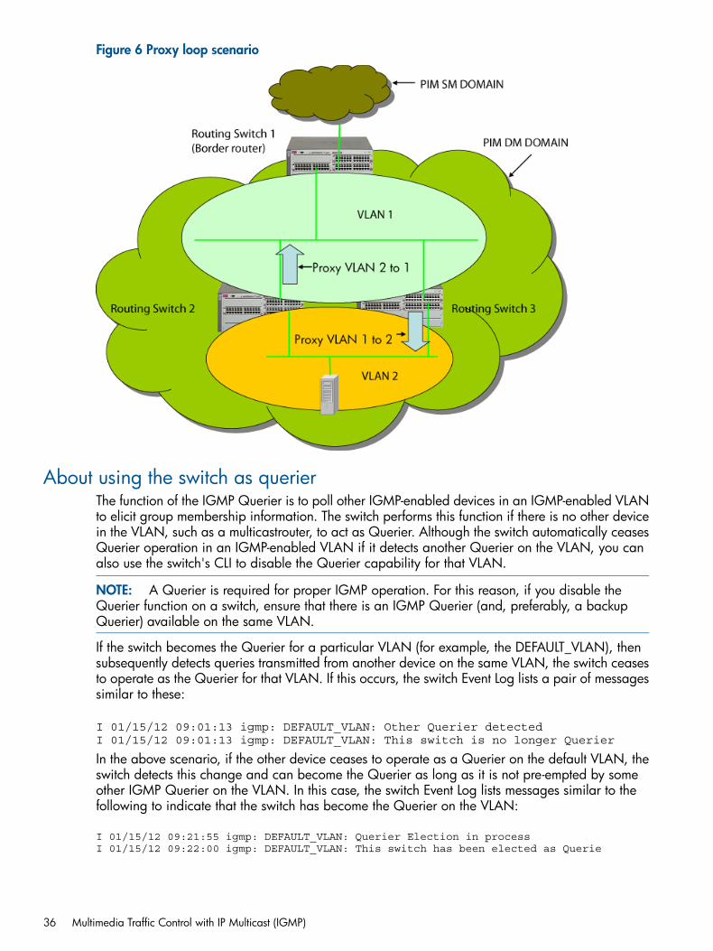
Figure 6 Proxy loop scenario
About using the switch as querierThe function of the IGMP Querier is to poll other IGMP-enabled devices in an IGMP-enabled VLANto elicit group membership information. The switch performs this function if there is no other devicein the VLAN, such as a multicastrouter, to act as Querier. Although the switch automatically ceasesQuerier operation in an IGMP-enabled VLAN if it detects another Querier on the VLAN, you canalso use the switch's CLI to disable the Querier capability for that VLAN.
NOTE: A Querier is required for proper IGMP operation. For this reason, if you disable theQuerier function on a switch, ensure that there is an IGMP Querier (and, preferably, a backupQuerier) available on the same VLAN.
If the switch becomes the Querier for a particular VLAN (for example, the DEFAULT_VLAN), thensubsequently detects queries transmitted from another device on the same VLAN, the switch ceasesto operate as the Querier for that VLAN. If this occurs, the switch Event Log lists a pair of messagessimilar to these:
I 01/15/12 09:01:13 igmp: DEFAULT_VLAN: Other Querier detectedI 01/15/12 09:01:13 igmp: DEFAULT_VLAN: This switch is no longer Querier
In the above scenario, if the other device ceases to operate as a Querier on the default VLAN, theswitch detects this change and can become the Querier as long as it is not pre-empted by someother IGMP Querier on the VLAN. In this case, the switch Event Log lists messages similar to thefollowing to indicate that the switch has become the Querier on the VLAN:
I 01/15/12 09:21:55 igmp: DEFAULT_VLAN: Querier Election in processI 01/15/12 09:22:00 igmp: DEFAULT_VLAN: This switch has been elected as Querie
36 Multimedia Traffic Control with IP Multicast (IGMP)
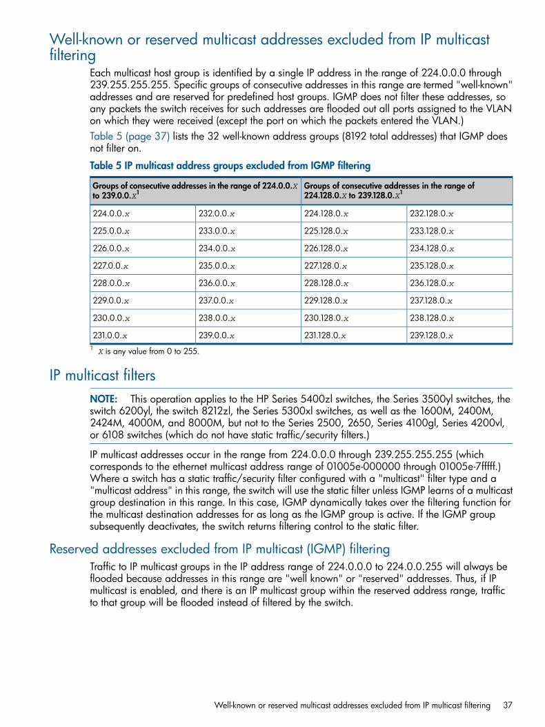
Well-known or reserved multicast addresses excluded from IP multicastfiltering
Each multicast host group is identified by a single IP address in the range of 224.0.0.0 through239.255.255.255. Specific groups of consecutive addresses in this range are termed "well-known"addresses and are reserved for predefined host groups. IGMP does not filter these addresses, soany packets the switch receives for such addresses are flooded out all ports assigned to the VLANon which they were received (except the port on which the packets entered the VLAN.)Table 5 (page 37) lists the 32 well-known address groups (8192 total addresses) that IGMP doesnot filter on.
Table 5 IP multicast address groups excluded from IGMP filtering
Groups of consecutive addresses in the range of224.128.0.X to 239.128.0.X1
Groups of consecutive addresses in the range of 224.0.0.Xto 239.0.0.X1
232.128.0.x224.128.0.x232.0.0.x224.0.0.x
233.128.0.x225.128.0.x233.0.0.x225.0.0.x
234.128.0.x226.128.0.x234.0.0.x226.0.0.x
235.128.0.x227.128.0.x235.0.0.x227.0.0.x
236.128.0.x228.128.0.x236.0.0.x228.0.0.x
237.128.0.x229.128.0.x237.0.0.x229.0.0.x
238.128.0.x230.128.0.x238.0.0.x230.0.0.x
239.128.0.x231.128.0.x239.0.0.x231.0.0.x1 X is any value from 0 to 255.
IP multicast filtersNOTE: This operation applies to the HP Series 5400zl switches, the Series 3500yl switches, theswitch 6200yl, the switch 8212zl, the Series 5300xl switches, as well as the 1600M, 2400M,2424M, 4000M, and 8000M, but not to the Series 2500, 2650, Series 4100gl, Series 4200vl,or 6108 switches (which do not have static traffic/security filters.)
IP multicast addresses occur in the range from 224.0.0.0 through 239.255.255.255 (whichcorresponds to the ethernet multicast address range of 01005e-000000 through 01005e-7fffff.)Where a switch has a static traffic/security filter configured with a "multicast" filter type and a"multicast address" in this range, the switch will use the static filter unless IGMP learns of a multicastgroup destination in this range. In this case, IGMP dynamically takes over the filtering function forthe multicast destination addresses for as long as the IGMP group is active. If the IGMP groupsubsequently deactivates, the switch returns filtering control to the static filter.
Reserved addresses excluded from IP multicast (IGMP) filteringTraffic to IP multicast groups in the IP address range of 224.0.0.0 to 224.0.0.255 will always beflooded because addresses in this range are "well known" or "reserved" addresses. Thus, if IPmulticast is enabled, and there is an IP multicast group within the reserved address range, trafficto that group will be flooded instead of filtered by the switch.
Well-known or reserved multicast addresses excluded from IP multicast filtering 37
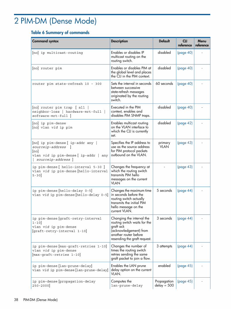
2 PIM-DM (Dense Mode)Table 6 Summary of commands
Menureference
CLIreference
DefaultDescriptionCommand syntax
-(page 40)disabledEnables or disables IPmulticast routing on therouting switch.
[no] ip multicast-routing
-(page 40)disabledEnables or disables PIM atthe global level and placesthe CLI in the PIM context.
[no] router pim
-(page 40)60 secondsSets the interval in secondsbetween successive
router pim state-refresh 10 - 300
state-refresh messagesoriginated by the routingswitch.
-(page 40)disabledExecuted in the PIMcontext, enables anddisables PIM SNMP traps.
[no] router pim trap [ all |neighbor-loss | hardware-mrt-full |software-mrt-full ]
-(page 42)disabledEnables multicast routingon the VLAN interface to
[no] ip pim-dense[no] vlan vid ip pim
which the CLI is currentlyset.
-(page 43)primaryVLAN
Specifies the IP address touse as the source address
[no] ip pim-dense [ ip-addr any |sourceip-address ][no]vlan vid ip pim-dense [ ip-addr | any| sourceip-address ]
for PIM protocol packetsoutbound on the VLAN.
-(page 43)-Changes the frequency atwhich the routing switch
ip pim-dense [ hello-interval 5-30 ]vlan vid ip pim-dense [hello-interval5-30] transmits PIM hello
messages on the currentVLAN
-(page 44)5 secondsChanges the maximum timein seconds before the
ip pim-dense [hello-delay 0-5]vlan vid ip pim-dense [hello-delay 0-5]
routing switch actuallytransmits the initial PIMhello message on thecurrent VLAN.
-(page 44)3 secondsChanging the interval therouting switch waits for the
ip pim-dense [graft-retry-interval1-10]vlan vid ip pim-dense[graft-retry-interval 1-10]
graft ack(acknowledgement) fromanother router beforeresending the graft request.
-(page 44)3 attemptsChanges the number oftimes the routing switch
ip pim-dense [max-graft-retries 1-10]vlan vid ip pim-dense[max-graft-retries 1-10] retries sending the same
graft packet to join a flow.
-(page 45)enabledEnables the LAN prunedelay option on the currentVLAN.
ip pim-dense [lan-prune-delay]vlan vid ip pim-dense [lan-prune-delay]
-(page 45)Propagationdelay = 500
Computes thelan-prune-delay
ip pim-dense [propagation-delay250-2000]
38 PIM-DM (Dense Mode)
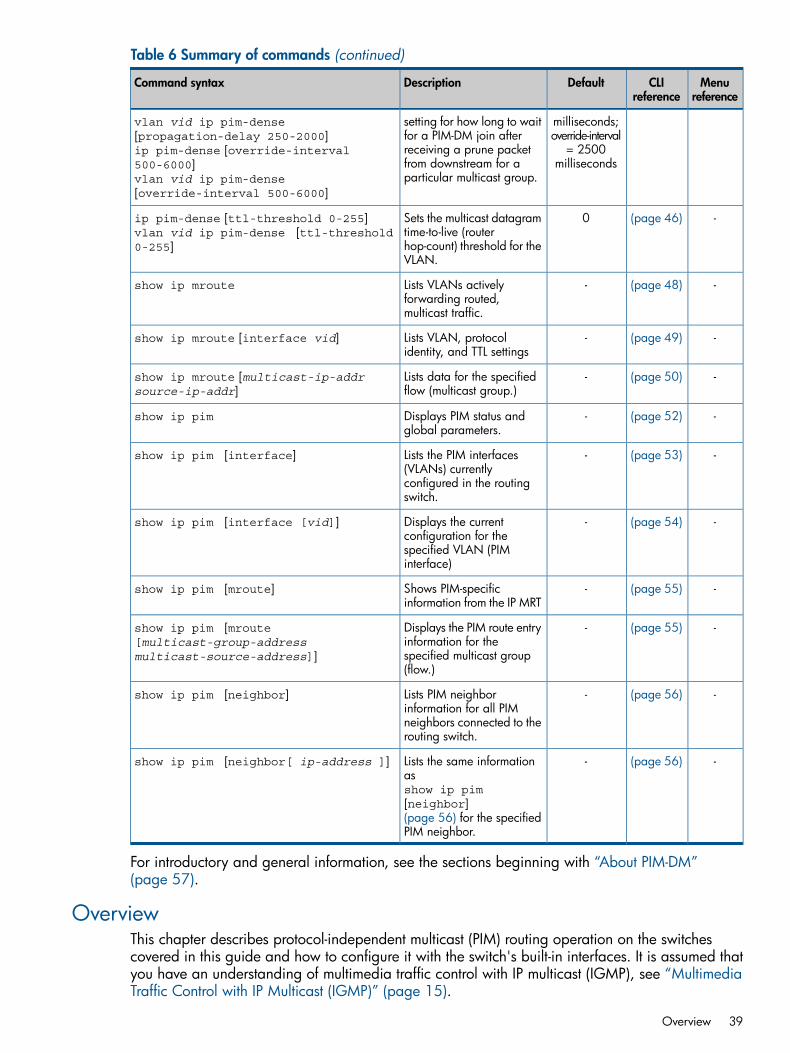
Table 6 Summary of commands (continued)
Menureference
CLIreference
DefaultDescriptionCommand syntax
vlan vid ip pim-dense[propagation-delay 250-2000]ip pim-dense [override-interval500-6000]vlan vid ip pim-dense[override-interval 500-6000]
milliseconds;override-interval
= 2500milliseconds
setting for how long to waitfor a PIM-DM join afterreceiving a prune packetfrom downstream for aparticular multicast group.
-(page 46)0Sets the multicast datagramtime-to-live (router
ip pim-dense [ttl-threshold 0-255]vlan vid ip pim-dense [ttl-threshold0-255] hop-count) threshold for the
VLAN.
-(page 48)-Lists VLANs activelyforwarding routed,multicast traffic.
show ip mroute
-(page 49)-Lists VLAN, protocolidentity, and TTL settings
show ip mroute [interface vid]
-(page 50)-Lists data for the specifiedflow (multicast group.)
show ip mroute [multicast-ip-addrsource-ip-addr]
-(page 52)-Displays PIM status andglobal parameters.
show ip pim
-(page 53)-Lists the PIM interfaces(VLANs) currently
show ip pim [interface]
configured in the routingswitch.
-(page 54)-Displays the currentconfiguration for the
show ip pim [interface [vid]]
specified VLAN (PIMinterface)
-(page 55)-Shows PIM-specificinformation from the IP MRT
show ip pim [mroute]
-(page 55)-Displays the PIM route entryinformation for the
show ip pim [mroute[multicast-group-addressmulticast-source-address]] specified multicast group
(flow.)
-(page 56)-Lists PIM neighborinformation for all PIM
show ip pim [neighbor]
neighbors connected to therouting switch.
-(page 56)-Lists the same informationasshow ip pim[neighbor]
show ip pim [neighbor[ ip-address ]]
(page 56) for the specifiedPIM neighbor.
For introductory and general information, see the sections beginning with “About PIM-DM”(page 57).
OverviewThis chapter describes protocol-independent multicast (PIM) routing operation on the switchescovered in this guide and how to configure it with the switch's built-in interfaces. It is assumed thatyou have an understanding of multimedia traffic control with IP multicast (IGMP), see “MultimediaTraffic Control with IP Multicast (IGMP)” (page 15).
Overview 39
Global and PIM configuration contextsNOTE: PIM-DM operation requires a routing protocol enabled on the routing switch. You canuse RIP, OSPF, and/or static routing. The examples in this section use RIP.
Enabling or disabling IP multicast routing
Syntax:[no] ip multicast-routingEnables or disables IP multicast routing on the routing switch. IP routing must beenabled.Default: Disabled
Enabling or disabling PIM at the global level; placing the CLI in the PIM context
Syntax:[no] router pimEnables or disables PIM at the global level and places the CLI in the PIM context.IP routing must first be enabled.Default: Disabled.
Setting the interval in seconds between successive state-refresh messages originatedby the routing switch
Syntax:router pim state-refresh [10-300]
Executed in the PIM context, this command sets the interval in seconds betweensuccessive state-refresh messages originated by the routing switch. Only the routingswitch connected directly to the unicast source initiates state-refresh packets. Allother PIM routers in the network only propagate these state-refresh packets.Default: 60 seconds
Enabling and disabling PIM SNMP traps
Syntax:[no]router pim trap [[all] | neighbor-loss | hardware-mrt-full| software-mrt-full ]Executed in the PIM context, this command enables and disables these PIM SNMPtraps:[all]
Enable/disable all PIM notification traps.[neighbor-loss]
Enable/disable the notification trap sent when the timer for a multicast routerneighbor expires and the switch has no other multicast router neighbors on thesame VLAN with a lower IP address.Default: Disabled
40 PIM-DM (Dense Mode)

[hardware-mrt-full]Enable/disable notification trap when the hardwareMRT is full (2048 activeflows.) In this state, any additional flows are handled by the software MRT,which increases processing time for the affected flows.Default: Disabled
[software-mrt-full]Enable/disable notification trap when the routing switch'ssoftware MRT is full(routing resources for active flows are exhausted.)Default: Disabled
NOTE: In this state, the routing switch does not accept any additional flows.
Global and PIM configuration contexts 41
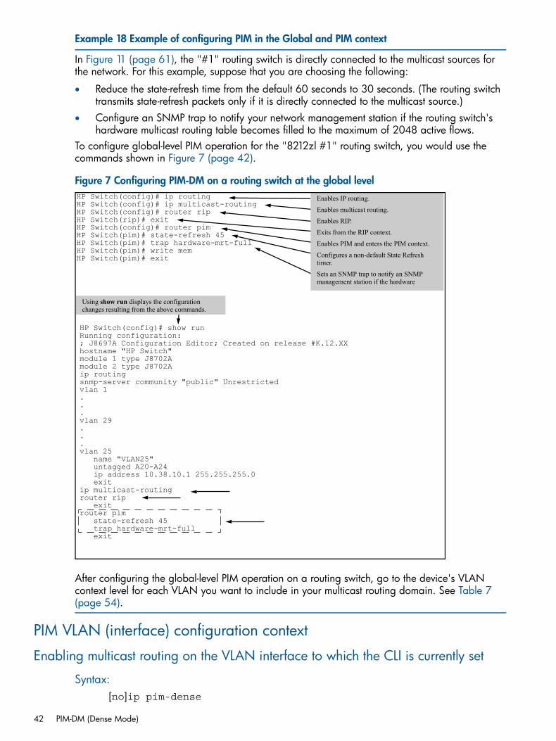
Example 18 Example of configuring PIM in the Global and PIM context
In Figure 11 (page 61), the "#1" routing switch is directly connected to the multicast sources forthe network. For this example, suppose that you are choosing the following:
• Reduce the state-refresh time from the default 60 seconds to 30 seconds. (The routing switchtransmits state-refresh packets only if it is directly connected to the multicast source.)
• Configure an SNMP trap to notify your network management station if the routing switch'shardware multicast routing table becomes filled to the maximum of 2048 active flows.
To configure global-level PIM operation for the "8212zl #1" routing switch, you would use thecommands shown in Figure 7 (page 42).
Figure 7 Configuring PIM-DM on a routing switch at the global level
HP Switch(config)# show runRunning configuration:; J8697A Configuration Editor; Created on release #K.12.XXhostname "HP Switch"module 1 type J8702Amodule 2 type J8702Aip routingsnmp-server community "public" Unrestrictedvlan 1...vlan 29...vlan 25 name "VLAN25" untagged A20-A24 ip address 10.38.10.1 255.255.255.0 exitip multicast-routingrouter rip exitrouter pim state-refresh 45 trap hardware-mrt-full exit
HP Switch(config)# ip routingHP Switch(config)# ip multicast-routingHP Switch(config)# router ripHP Switch(rip)# exitHP Switch(config)# router pimHP Switch(pim)# state-refresh 45HP Switch(pim)# trap hardware-mrt-fullHP Switch(pim)# write memHP Switch(pim)# exit
Enables IP routing.
Enables multicast routing.
Enables RIP.
Exits from the RIP context.
Enables PIM and enters the PIM context.
Configures a non-default State Refresh timer.
Sets an SNMP trap to notify an SNMP management station if the hardware
Using show run displays the configuration changes resulting from the above commands.
After configuring the global-level PIM operation on a routing switch, go to the device's VLANcontext level for each VLAN you want to include in your multicast routing domain. See Table 7(page 54).
PIM VLAN (interface) configuration context
Enabling multicast routing on the VLAN interface to which the CLI is currently set
Syntax:[no]ip pim-dense
42 PIM-DM (Dense Mode)
[no]vlanvidip pimEnables multicast routing on the VLAN interface to which the CLI is currently set.The no form disables PIM on the VLAN.Default: Disabled
Specifying the IP address to use as the source address for PIM protocol packetsoutbound on the VLAN
Syntax:[no]ip pim-dense [ ip-addr any | sourceip-address ][no]vlan[vid]ip pim-dense [ ip-addr | any |sourceip-address ]In networks using multinetted VLANs, all routers on a given VLAN intended to routemulticast packets must have a least one common subnet on that VLAN. Use thiscommand when the VLAN is configured with multiple IP addresses (multinetting) tospecify the IP address to use as the source address for PIM protocol packets outboundon the VLAN.
• Use ip-address to designate a single subnet in cases where multicast routerson the same multinetted VLAN are not configured with identical sets of subnetIP addresses.
• Use all if the multinetted VLAN is configured with the same set of subnetaddresses.
Default: the primary VLAN
Changing the frequency at which the routing switch transmits PIM hello messages onthe current VLAN
Syntax:ip pim-dense [ hello-interval 5-30 ]vlan [vid]ip pim-dense [hello-interval 5-30]Changes the frequency at which the routing switch transmit PIM hello messages onthe current VLAN. The routing switch uses hello packets to inform neighboringrouters of its presence. The routing switch also uses this setting to compute the hellohold time, which is included in hello packets sent to neighbor routers. hello holdtime tells neighbor routers how long to wait for the next hello packet from the routingswitch. If another packet does not arrive within that time, the router removes theneighbor adjacency on that VLAN from the routing table, which removes any flowsrunning on that interface.Shortening the hello interval reduces the hello hold time. This has the effect ofchanging how quickly other routers will stop sending traffic to the routing switch ifthey do not receive a new hello packet when expected.
NOTE: Not used with the [no]form of the ip pim-dense command.
PIM VLAN (interface) configuration context 43
Example 19 ExampleIf multiple routers are connected to the same VLAN and the routing switch requestsmulticast traffic, all routers on the VLAN receive that traffic. (Those that have prunedthe traffic will drop it when they receive it.)If the upstream router loses contact with the routing switch receiving the multicasttraffic (that is, fails to receive a hello packet when expected), the shorter hellointerval causes it to stop transmitting multicast traffic onto the VLAN sooner, resultingin less unnecessary bandwidth usage.
Changing the maximum time in seconds before the routing switch actually transmitsthe initial PIM hello message on the current VLAN
Syntax:ip pim-dense [hello-delay 0-5]vlan [vid]ip pim-dense [hello-delay 0-5]Changes the maximum time in seconds before the routing switch actually transmitsthe initial PIM hello message on the current VLAN. In cases where a new VLANactivates with connections to multiple routers, if all of the connected routers senthello packets at the same time, the receiving router could become momentarilyoverloaded. This value randomizes the transmission delay to a time between 0 andthe hello delay setting. Using 0 means no delay.After the routing switch sends the initial hello packet to a newly detected VLANinterface, it sends subsequent hello packets according to the current hello intervalsetting.
NOTE: Not used with the [no] form of the ip pim-dense command.
Default: 5 seconds
Changing the interval the routing switch waits for the graft ack from another routerbefore resending the graft request
Syntax:ip pim-dense [graft-retry-interval[1-10]]vlan[vid]ip pim-dense [graft-retry-interval[1-10]]Graft packets result when a downstream router transmits a request to join a flow.The upstream router responds with a graft acknowledgment packet. If the graft ack(acknowledgement) is not received within the time period of the graft-retry-interval,it resends the graft packet. The command [graft-retry-interval[1-10]]changes the interval (in seconds) the routing switch waits for the graft ack fromanother router before resending the graft request.
NOTE: Not used with the [no] form of the ip pim-dense command.
Default: 3 seconds
Changing the number of times the routing switch retries sending the same graft packetto join a flow
Syntax:ip pim-dense [max-graft-retries[1-10]]vlan[vid]ip pim-dense [max-graft-retries[1-10]]
44 PIM-DM (Dense Mode)
Changes to the number of times the routing switch will retry sending the same graftpacket to join a flow. If a graft ack response is not received after the specifiednumber of retries, the routing switch ceases trying to join the flow. In this case theflow is removed until either a state-refresh from upstream re-initiates the flow or anupstream router floods the flow.Increasing this value helps to improve multicast reliability.
NOTE: Not used with the [no] form of the ip pim-dense command.
Default: 3 attempts
Enabling the LAN prune delay option on the current VLAN
Syntax:ip pim-dense [lan-prune-delay]vlan[vid]ip pim-dense [lan-prune-delay]Enables the LAN prune delay option on the current VLAN. With lan-prune-delayenabled, the routing switch informs downstream neighbors how long it will waitbefore pruning a flow after receiving a prune request. Other, downstream routerson the same VLAN must send a Join request to override the prune before thelan-prune-delay times out if they want the flow to continue. This prompts anydownstream neighbors with hosts continuing to belong to the flow to reply with aJoin. If no joins are received after the lan-prune-delay period, the routing switchprunes the flow.The propagation-delay and override-interval settings determine the lan-prune-delaysetting. See “Computing the lan-prune-delay setting” (page 45).
NOTE: Uses the [no] form of the ip pim-dense command to disable the LANprune delay option.
Default: Enabled
Computing the lan-prune-delay setting
Syntax:ip pim-dense [propagation-delay[250-2000]]vlan[vid]ip pim-dense [propagation-delay[250-2000]]ip pim-dense [override-interval[500-6000]]vlan [vid]ip pim-dense [override-interval[500-6000]]A routing switch sharing a VLAN with other multicast routers uses these two valuesto compute the lan-prune-delay setting for how long to wait for a PIM-DM Join afterreceiving a prune packet from downstream for a particular multicast group.Defaults: propagation-delay=500 milliseconds; override-interval = 2500 milliseconds
PIM VLAN (interface) configuration context 45
Example 20 Upstream router pruneA network may have multiple routing switches sharing VLAN "X". When an upstreamrouting switch initially floods traffic from multicast group "X" to VLAN "Y", if oneof the routing switches on VLAN "Y" does not want this traffic, it issues a pruneresponse to the upstream neighbor. The upstream neighbor then goes into a prunepending state for group "X" on VLAN "Y". (During this period, the upstream neighborcontinues to forward the traffic.)During the prune pending period, another routing switch on VLAN "Y" can senda group "X" Join to the upstream neighbor. If this happens, the upstream neighbordrops the prune pending state and continues forwarding the traffic. If no routers onthe VLAN send a Join, the upstream router prunes group "X" from VLAN "Y" whenthe lan-prune-delay timer expires.
Setting the multicast datagram time-to-live (router hop-count) threshold for the VLAN
Syntax:ip pim-dense [ttl-threshold[0-255]]vlan[vid]ip pim-dense [ttl-threshold[0-255]]Sets the multicast datagram time-to-live (router hop-count) threshold for the VLAN.Any IP multicast datagrams or state-refresh packets with a TTL less than this thresholdwill not be forwarded out the interface. The default value of 0 means all multicastpackets are forwarded out the interface.The VLAN connected to the multicast source does not receive state refresh packetsand thus is not state-refresh capable. Downstream VLANs in the switches coveredin this guide are state-refresh capable. This parameter provides a method forcontaining multicast traffic within a network, or even within specific areas of anetwork. Initially, the multicast traffic source sets a TTL value in the packets ittransmits. Each time one of these packets passes through a multicast routing device,the TTL setting decrements by 1. If the packet arrives with a TTL lower than themroute ttl-threshold, the routing switch does not forward the packet.Changing this parameter on a routing switch requires knowledge of the TTL settingof incoming multicast packets:
• A value that is too high can allow multicast traffic to go beyond your internalnetwork.
• A value that is too low may prevent some intended hosts from receiving thedesired multicast traffic.
Default: 0—forwards multicast traffic regardless of packet TTL setting
Example of configuring PIM-DM operation at the VLAN levelThe network in Figure 8 (page 47) uses VLAN 25 for multicast traffic. However, this VLAN ismultinetted and there is only one subnet (10.38.10.x) in VLAN 25 that is common to all threerouting switches. Thus, when configuring VLAN 25 on these routing switches to perform multicastrouting, it is necessary to use ip pim-dense source-ip-address to designate the commonsubnet as the source address for outbound multicast traffic on VLAN 25. (If only identical subnetswere present in the multinetted VLAN 25 configuration on all three devices, the ip pim-denseip-addr any command would be used instead.) The other VLANs in the network are notmultinetted and therefore do not require the ip pim-dense ip-addrany|source-ip-address option.For this example, assume that the VLANs and IP addressing are already configured on the routingswitch.
46 PIM-DM (Dense Mode)
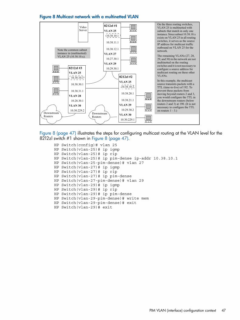
Figure 8 Multicast network with a multinetted VLAN
8212zl #3VLAN 25
10.38.10.3
10.38.30.1
10.38.31.1
VLAN 2810.28.30.1
VLAN 3010.30.229.2
8212zl #1VLAN 25
10.38.10.1
10.38.11.1
10.38.12.1
VLAN 2710.27.30.1
VLAN 2910.29.30.1
8212zl #2VLAN 25
10.38.10.2
10.38.20.1
10.38.21.1
VLAN 2910.29.30.2
VLAN 3010.30.229.1
On the three routing switches, VLAN 25 is multinetted with subnets that match in only one instance. Since subnet 10.38.10.x exists on VLAN 25 in all routing switches, it serves as the source IP address for multicast traffic outbound on VLAN 25 for the network.
The remaining VLANs (27, 28, 29, and 30) in the network are not multinetted on the routing switches and it is not necessary to configure a source address for multicast routing on these other VLANs.
In this example, the multicast source transmits packets with a TTL (time-to-live) of 192. To prevent these packets from moving beyond routers 2 and 3, you would configure the TTL in the downstream routers (below routers 2 and 3) at 190. (It is not necessary to configure the TTL on routers 1 - 3.)
VideoServer
Note the common subnet instance in (multinetted) VLAN 25 (10.38.10.x).
Downstream Routers
Downstream Routers
Figure 8 (page 47) illustrates the steps for configuring multicast routing at the VLAN level for the8212zl switch #1 shown in Figure 8 (page 47).
HP Switch(config)# vlan 25HP Switch(vlan-25)# ip igmpHP Switch(vlan-25)# ip ripHP Switch(vlan-25)# ip pim-dense ip-addr 10.38.10.1HP Switch(vlan-25-pim-dense)# vlan 27HP Switch(vlan-27)# ip igmpHP Switch(vlan-27)# ip ripHP Switch(vlan-27)# ip pim-denseHP Switch(vlan-27-pim-dense)# vlan 29HP Switch(vlan-29)# ip igmpHP Switch(vlan-29)# ip ripHP Switch(vlan-29)# ip pim-denseHP Switch(vlan-29-pim-dense)# write memHP Switch(vlan-29-pim-dense)# exitHP Switch(vlan-29)# exit
PIM VLAN (interface) configuration context 47
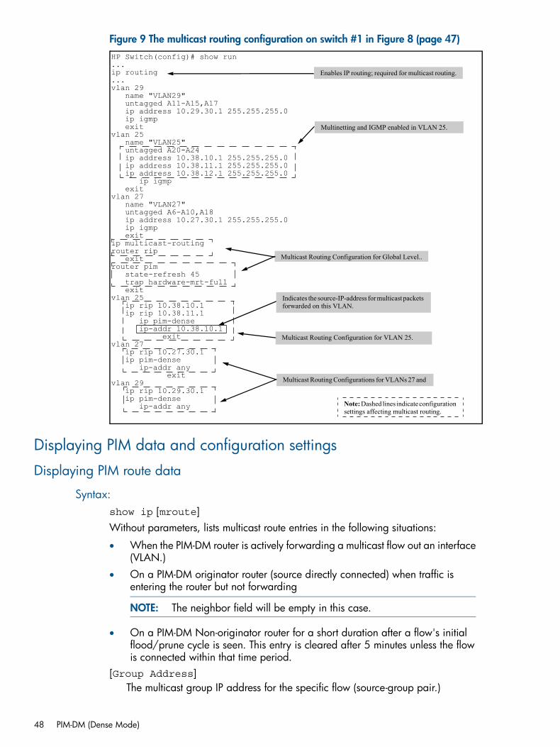
Figure 9 The multicast routing configuration on switch #1 in Figure 8 (page 47)HP Switch(config)# show run...ip routing...vlan 29 name "VLAN29" untagged A11-A15,A17 ip address 10.29.30.1 255.255.255.0 ip igmp exitvlan 25 name "VLAN25" untagged A20-A24 ip address 10.38.10.1 255.255.255.0 ip address 10.38.11.1 255.255.255.0 ip address 10.38.12.1 255.255.255.0 ip igmp exitvlan 27 name "VLAN27" untagged A6-A10,A18 ip address 10.27.30.1 255.255.255.0 ip igmp exitip multicast-routingrouter rip exitrouter pim state-refresh 45 trap hardware-mrt-full exitvlan 25 ip rip 10.38.10.1 ip rip 10.38.11.1 ip pim-dense ip-addr 10.38.10.1 exitvlan 27 ip rip 10.27.30.1 ip pim-dense ip-addr any exitvlan 29 ip rip 10.29.30.1 ip pim-dense ip-addr any Note: Dashed lines indicate configuration
settings affecting multicast routing.
Multinetting and IGMP enabled in VLAN 25.
Multicast Routing Configuration for Global Level..
Enables IP routing; required for multicast routing.
Indicates the source-IP-address for multicast packets forwarded on this VLAN.
Multicast Routing Configuration for VLAN 25.
Multicast Routing Configurations for VLANs 27 and
Displaying PIM data and configuration settings
Displaying PIM route data
Syntax:show ip [mroute]Without parameters, lists multicast route entries in the following situations:
• When the PIM-DM router is actively forwarding a multicast flow out an interface(VLAN.)
• On a PIM-DM originator router (source directly connected) when traffic isentering the router but not forwarding
NOTE: The neighbor field will be empty in this case.
• On a PIM-DM Non-originator router for a short duration after a flow's initialflood/prune cycle is seen. This entry is cleared after 5 minutes unless the flowis connected within that time period.
[Group Address]The multicast group IP address for the specific flow (source-group pair.)
48 PIM-DM (Dense Mode)
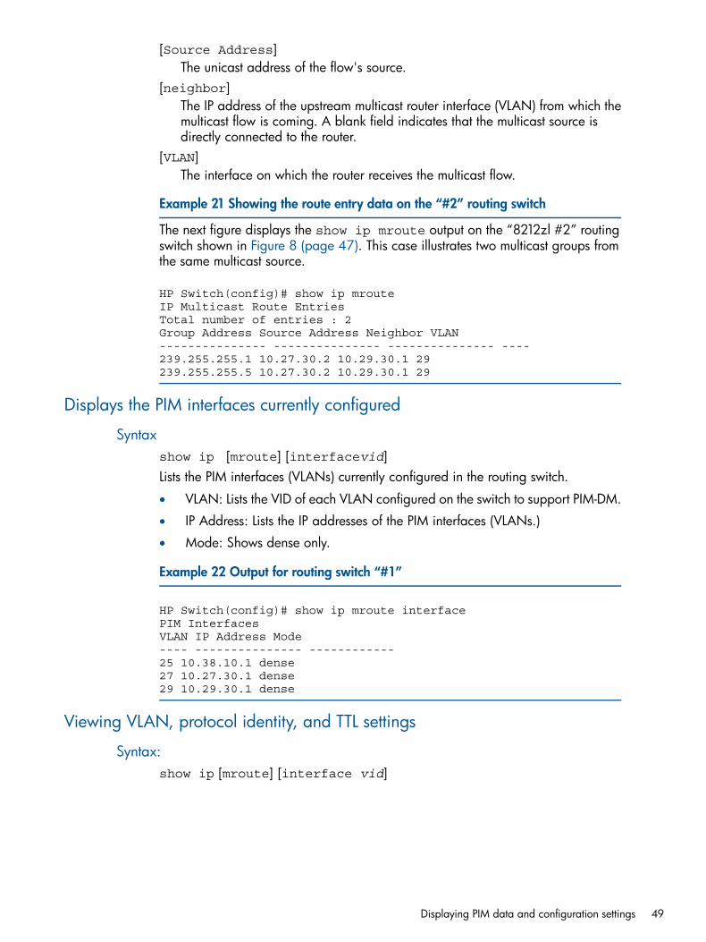
[Source Address]The unicast address of the flow's source.
[neighbor]The IP address of the upstream multicast router interface (VLAN) from which themulticast flow is coming. A blank field indicates that the multicast source isdirectly connected to the router.
[VLAN]The interface on which the router receives the multicast flow.
Example 21 Showing the route entry data on the “#2” routing switch
The next figure displays the show ip mroute output on the “8212zl #2” routingswitch shown in Figure 8 (page 47). This case illustrates two multicast groups fromthe same multicast source.
HP Switch(config)# show ip mrouteIP Multicast Route EntriesTotal number of entries : 2Group Address Source Address Neighbor VLAN--------------- --------------- --------------- ----239.255.255.1 10.27.30.2 10.29.30.1 29239.255.255.5 10.27.30.2 10.29.30.1 29
Displays the PIM interfaces currently configured
Syntaxshow ip [mroute] [interfacevid]Lists the PIM interfaces (VLANs) currently configured in the routing switch.
• VLAN: Lists the VID of each VLAN configured on the switch to support PIM-DM.
• IP Address: Lists the IP addresses of the PIM interfaces (VLANs.)
• Mode: Shows dense only.
Example 22 Output for routing switch “#1”
HP Switch(config)# show ip mroute interfacePIM InterfacesVLAN IP Address Mode---- --------------- ------------25 10.38.10.1 dense27 10.27.30.1 dense29 10.29.30.1 dense
Viewing VLAN, protocol identity, and TTL settings
Syntax:show ip [mroute] [interface vid]
Displaying PIM data and configuration settings 49
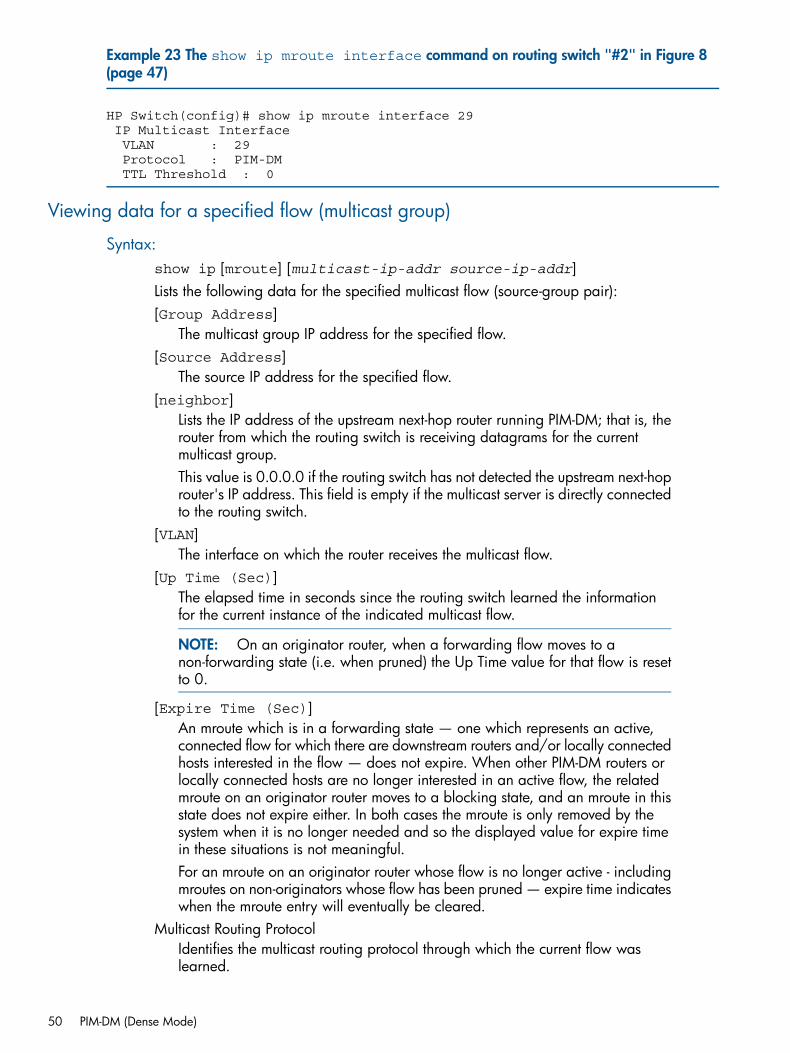
Example 23 The show ip mroute interface command on routing switch "#2" in Figure 8(page 47)
HP Switch(config)# show ip mroute interface 29 IP Multicast Interface VLAN : 29 Protocol : PIM-DM TTL Threshold : 0
Viewing data for a specified flow (multicast group)
Syntax:show ip [mroute] [multicast-ip-addr source-ip-addr]Lists the following data for the specified multicast flow (source-group pair):[Group Address]
The multicast group IP address for the specified flow.[Source Address]
The source IP address for the specified flow.[neighbor]
Lists the IP address of the upstream next-hop router running PIM-DM; that is, therouter from which the routing switch is receiving datagrams for the currentmulticast group.This value is 0.0.0.0 if the routing switch has not detected the upstream next-hoprouter's IP address. This field is empty if the multicast server is directly connectedto the routing switch.
[VLAN]The interface on which the router receives the multicast flow.
[Up Time (Sec)]The elapsed time in seconds since the routing switch learned the informationfor the current instance of the indicated multicast flow.
NOTE: On an originator router, when a forwarding flow moves to anon-forwarding state (i.e. when pruned) the Up Time value for that flow is resetto 0.
[Expire Time (Sec)]An mroute which is in a forwarding state — one which represents an active,connected flow for which there are downstream routers and/or locally connectedhosts interested in the flow — does not expire. When other PIM-DM routers orlocally connected hosts are no longer interested in an active flow, the relatedmroute on an originator router moves to a blocking state, and an mroute in thisstate does not expire either. In both cases the mroute is only removed by thesystem when it is no longer needed and so the displayed value for expire timein these situations is not meaningful.For an mroute on an originator router whose flow is no longer active - includingmroutes on non-originators whose flow has been pruned — expire time indicateswhen the mroute entry will eventually be cleared.
Multicast Routing ProtocolIdentifies the multicast routing protocol through which the current flow waslearned.
50 PIM-DM (Dense Mode)
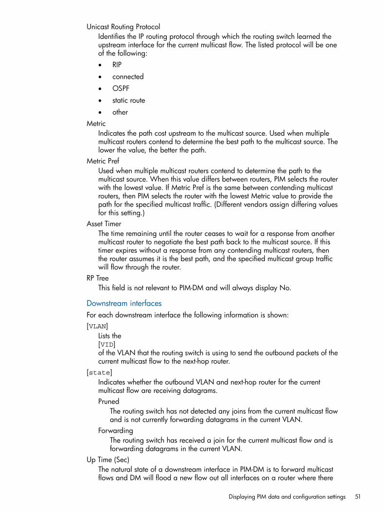
Unicast Routing ProtocolIdentifies the IP routing protocol through which the routing switch learned theupstream interface for the current multicast flow. The listed protocol will be oneof the following:• RIP
• connected
• OSPF
• static route
• otherMetric
Indicates the path cost upstream to the multicast source. Used when multiplemulticast routers contend to determine the best path to the multicast source. Thelower the value, the better the path.
Metric PrefUsed when multiple multicast routers contend to determine the path to themulticast source. When this value differs between routers, PIM selects the routerwith the lowest value. If Metric Pref is the same between contending multicastrouters, then PIM selects the router with the lowest Metric value to provide thepath for the specified multicast traffic. (Different vendors assign differing valuesfor this setting.)
Asset TimerThe time remaining until the router ceases to wait for a response from anothermulticast router to negotiate the best path back to the multicast source. If thistimer expires without a response from any contending multicast routers, thenthe router assumes it is the best path, and the specified multicast group trafficwill flow through the router.
RP TreeThis field is not relevant to PIM-DM and will always display No.
Downstream interfacesFor each downstream interface the following information is shown:[VLAN]
Lists the[VID]of the VLAN that the routing switch is using to send the outbound packets of thecurrent multicast flow to the next-hop router.
[state]Indicates whether the outbound VLAN and next-hop router for the currentmulticast flow are receiving datagrams.Pruned
The routing switch has not detected any joins from the current multicast flowand is not currently forwarding datagrams in the current VLAN.
ForwardingThe routing switch has received a join for the current multicast flow and isforwarding datagrams in the current VLAN.
Up Time (Sec)The natural state of a downstream interface in PIM-DM is to forward multicastflows and DM will flood a new flow out all interfaces on a router where there
Displaying PIM data and configuration settings 51
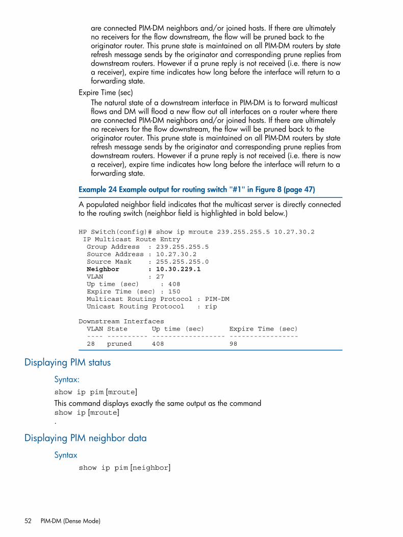
are connected PIM-DM neighbors and/or joined hosts. If there are ultimatelyno receivers for the flow downstream, the flow will be pruned back to theoriginator router. This prune state is maintained on all PIM-DM routers by staterefresh message sends by the originator and corresponding prune replies fromdownstream routers. However if a prune reply is not received (i.e. there is nowa receiver), expire time indicates how long before the interface will return to aforwarding state.
Expire Time (sec)The natural state of a downstream interface in PIM-DM is to forward multicastflows and DM will flood a new flow out all interfaces on a router where thereare connected PIM-DM neighbors and/or joined hosts. If there are ultimatelyno receivers for the flow downstream, the flow will be pruned back to theoriginator router. This prune state is maintained on all PIM-DM routers by staterefresh message sends by the originator and corresponding prune replies fromdownstream routers. However if a prune reply is not received (i.e. there is nowa receiver), expire time indicates how long before the interface will return to aforwarding state.
Example 24 Example output for routing switch "#1" in Figure 8 (page 47)
A populated neighbor field indicates that the multicast server is directly connectedto the routing switch (neighbor field is highlighted in bold below.)
HP Switch(config)# show ip mroute 239.255.255.5 10.27.30.2 IP Multicast Route Entry Group Address : 239.255.255.5 Source Address : 10.27.30.2 Source Mask : 255.255.255.0Neighbor : 10.30.229.1
VLAN : 27 Up time (sec) : 408 Expire Time (sec) : 150 Multicast Routing Protocol : PIM-DM Unicast Routing Protocol : rip
Downstream Interfaces VLAN State Up time (sec) Expire Time (sec) ---- ---------- ------------------ ----------------- 28 pruned 408 98
Displaying PIM status
Syntax:show ip pim [mroute]This command displays exactly the same output as the commandshow ip [mroute].
Displaying PIM neighbor data
Syntaxshow ip pim [neighbor]
52 PIM-DM (Dense Mode)
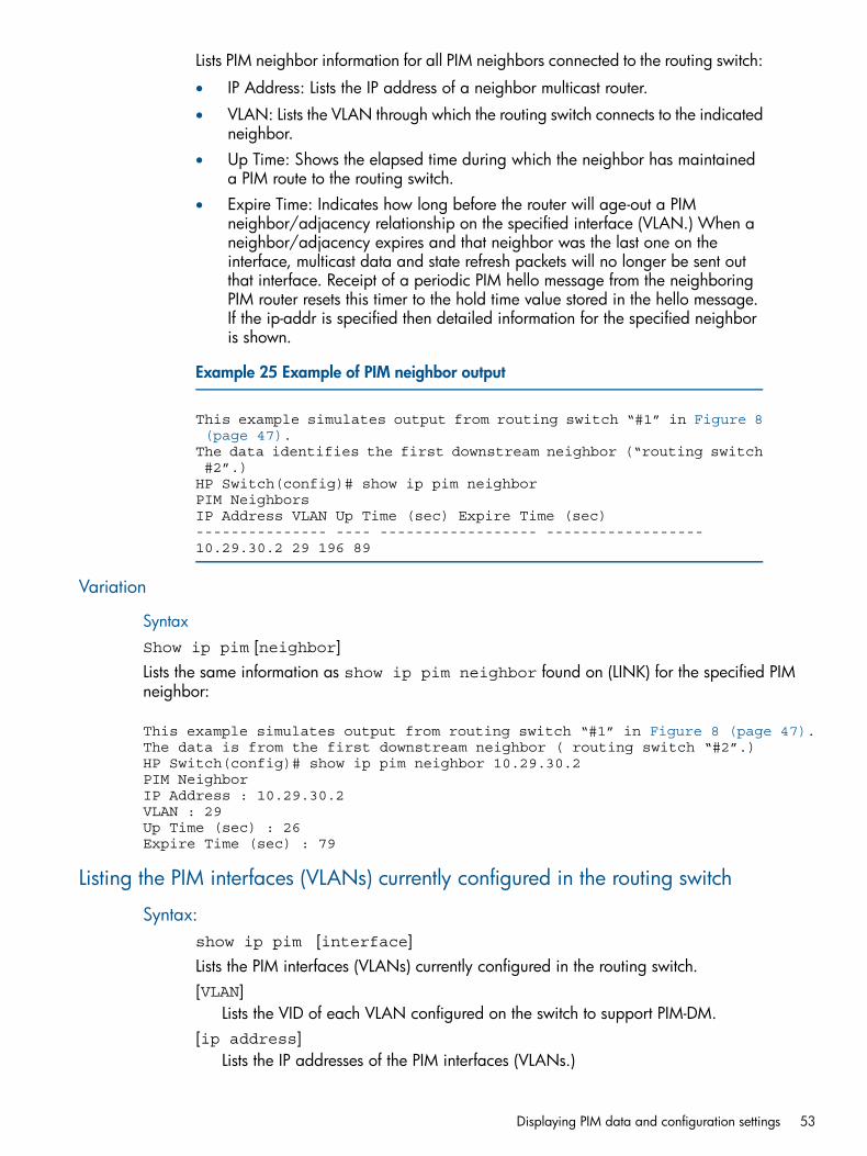
Lists PIM neighbor information for all PIM neighbors connected to the routing switch:
• IP Address: Lists the IP address of a neighbor multicast router.
• VLAN: Lists the VLAN through which the routing switch connects to the indicatedneighbor.
• Up Time: Shows the elapsed time during which the neighbor has maintaineda PIM route to the routing switch.
• Expire Time: Indicates how long before the router will age-out a PIMneighbor/adjacency relationship on the specified interface (VLAN.) When aneighbor/adjacency expires and that neighbor was the last one on theinterface, multicast data and state refresh packets will no longer be sent outthat interface. Receipt of a periodic PIM hello message from the neighboringPIM router resets this timer to the hold time value stored in the hello message.If the ip-addr is specified then detailed information for the specified neighboris shown.
Example 25 Example of PIM neighbor output
This example simulates output from routing switch “#1” in Figure 8 (page 47).The data identifies the first downstream neighbor (“routing switch #2”.)HP Switch(config)# show ip pim neighborPIM NeighborsIP Address VLAN Up Time (sec) Expire Time (sec)--------------- ---- ------------------ ------------------10.29.30.2 29 196 89
Variation
SyntaxShow ip pim [neighbor]Lists the same information as show ip pim neighbor found on (LINK) for the specified PIMneighbor:
This example simulates output from routing switch “#1” in Figure 8 (page 47).The data is from the first downstream neighbor ( routing switch “#2”.)HP Switch(config)# show ip pim neighbor 10.29.30.2PIM NeighborIP Address : 10.29.30.2VLAN : 29Up Time (sec) : 26Expire Time (sec) : 79
Listing the PIM interfaces (VLANs) currently configured in the routing switch
Syntax:show ip pim [interface]Lists the PIM interfaces (VLANs) currently configured in the routing switch.[VLAN]
Lists the VID of each VLAN configured on the switch to support PIM-DM.[ip address]
Lists the IP addresses of the PIM interfaces (VLANs.)
Displaying PIM data and configuration settings 53
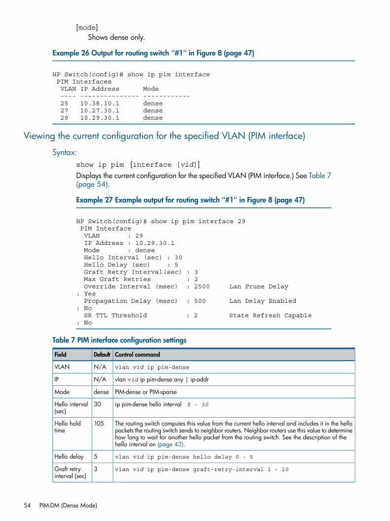
[mode]Shows dense only.
Example 26 Output for routing switch "#1" in Figure 8 (page 47)
HP Switch(config)# show ip pim interface PIM Interfaces VLAN IP Address Mode ---- --------------- ------------ 25 10.38.10.1 dense 27 10.27.30.1 dense 29 10.29.30.1 dense
Viewing the current configuration for the specified VLAN (PIM interface)
Syntax:show ip pim [interface [vid]]Displays the current configuration for the specified VLAN (PIM interface.) See Table 7(page 54).
Example 27 Example output for routing switch "#1" in Figure 8 (page 47)
HP Switch(config)# show ip pim interface 29 PIM Interface VLAN : 29 IP Address : 10.29.30.1 Mode : dense Hello Interval (sec) : 30 Hello Delay (sec) : 5 Graft Retry Interval(sec) : 3 Max Graft Retries : 2 Override Interval (msec) : 2500 Lan Prune Delay : Yes Propagation Delay (msec) : 500 Lan Delay Enabled : No SR TTL Threshold : 2 State Refresh Capable : No
Table 7 PIM interface configuration settings
Control commandDefaultField
vlan vid ip pim-denseN/AVLAN
vlan vid ip pim-dense any | ip-addrN/AIP
PIM-dense or PIM-sparsedenseMode
ip pim-dense hello interval 5 - 3030Hello interval(sec)
The routing switch computes this value from the current hello interval and includes it in the hellopackets the routing switch sends to neighbor routers. Neighbor routers use this value to determine
105Hello holdtime
how long to wait for another hello packet from the routing switch. See the description of thehello interval on (page 42).
vlan vid ip pim-dense hello delay 0 - 55Hello delay
vlan vid ip pim-dense graft-retry-interval 1 - 103Graft retryinterval (sec)
54 PIM-DM (Dense Mode)
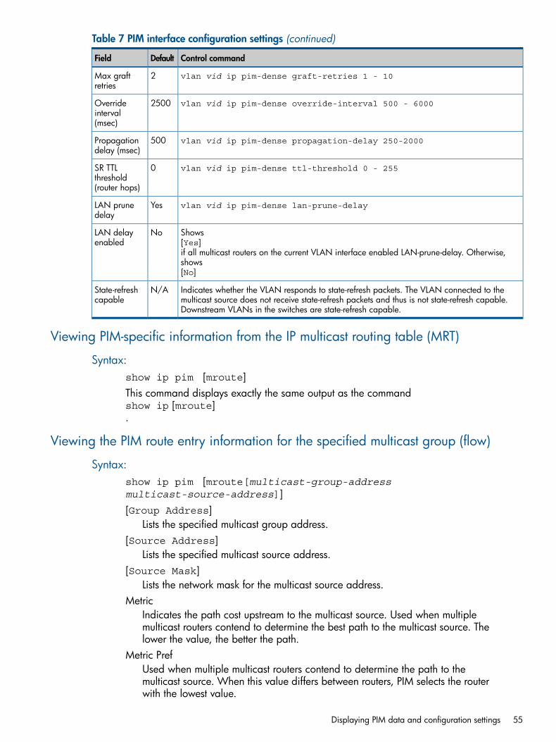
Table 7 PIM interface configuration settings (continued)
Control commandDefaultField
vlan vid ip pim-dense graft-retries 1 - 102Max graftretries
vlan vid ip pim-dense override-interval 500 - 60002500Overrideinterval(msec)
vlan vid ip pim-dense propagation-delay 250-2000500Propagationdelay (msec)
vlan vid ip pim-dense ttl-threshold 0 - 2550SR TTLthreshold(router hops)
vlan vid ip pim-dense lan-prune-delayYesLAN prunedelay
Shows[Yes]
NoLAN delayenabled
if all multicast routers on the current VLAN interface enabled LAN-prune-delay. Otherwise,shows[No]
Indicates whether the VLAN responds to state-refresh packets. The VLAN connected to themulticast source does not receive state-refresh packets and thus is not state-refresh capable.Downstream VLANs in the switches are state-refresh capable.
N/AState-refreshcapable
Viewing PIM-specific information from the IP multicast routing table (MRT)
Syntax:show ip pim [mroute]This command displays exactly the same output as the commandshow ip [mroute].
Viewing the PIM route entry information for the specified multicast group (flow)
Syntax:show ip pim [mroute[multicast-group-addressmulticast-source-address]][Group Address]
Lists the specified multicast group address.[Source Address]
Lists the specified multicast source address.[Source Mask]
Lists the network mask for the multicast source address.Metric
Indicates the path cost upstream to the multicast source. Used when multiplemulticast routers contend to determine the best path to the multicast source. Thelower the value, the better the path.
Metric PrefUsed when multiple multicast routers contend to determine the path to themulticast source. When this value differs between routers, PIM selects the routerwith the lowest value.
Displaying PIM data and configuration settings 55
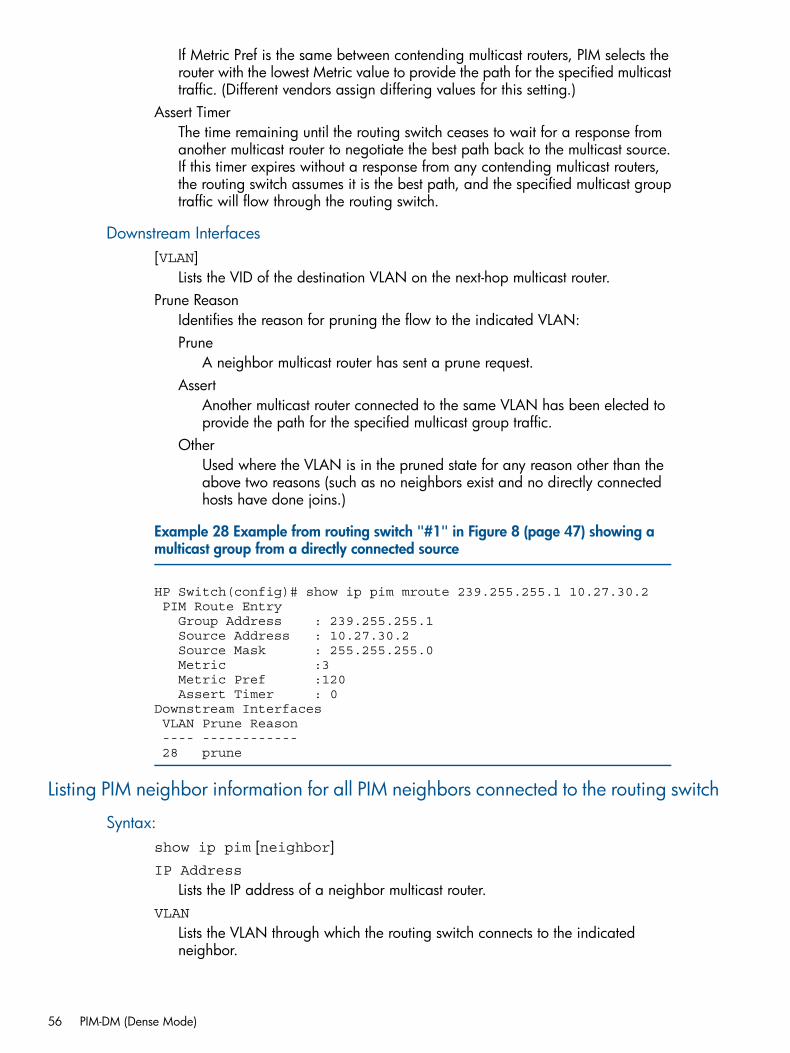
If Metric Pref is the same between contending multicast routers, PIM selects therouter with the lowest Metric value to provide the path for the specified multicasttraffic. (Different vendors assign differing values for this setting.)
Assert TimerThe time remaining until the routing switch ceases to wait for a response fromanother multicast router to negotiate the best path back to the multicast source.If this timer expires without a response from any contending multicast routers,the routing switch assumes it is the best path, and the specified multicast grouptraffic will flow through the routing switch.
Downstream Interfaces[VLAN]
Lists the VID of the destination VLAN on the next-hop multicast router.Prune Reason
Identifies the reason for pruning the flow to the indicated VLAN:Prune
A neighbor multicast router has sent a prune request.Assert
Another multicast router connected to the same VLAN has been elected toprovide the path for the specified multicast group traffic.
OtherUsed where the VLAN is in the pruned state for any reason other than theabove two reasons (such as no neighbors exist and no directly connectedhosts have done joins.)
Example 28 Example from routing switch "#1" in Figure 8 (page 47) showing amulticast group from a directly connected source
HP Switch(config)# show ip pim mroute 239.255.255.1 10.27.30.2 PIM Route Entry Group Address : 239.255.255.1 Source Address : 10.27.30.2 Source Mask : 255.255.255.0 Metric :3 Metric Pref :120 Assert Timer : 0Downstream Interfaces VLAN Prune Reason ---- ------------ 28 prune
Listing PIM neighbor information for all PIM neighbors connected to the routing switch
Syntax:show ip pim [neighbor]IP Address
Lists the IP address of a neighbor multicast router.VLAN
Lists the VLAN through which the routing switch connects to the indicatedneighbor.
56 PIM-DM (Dense Mode)
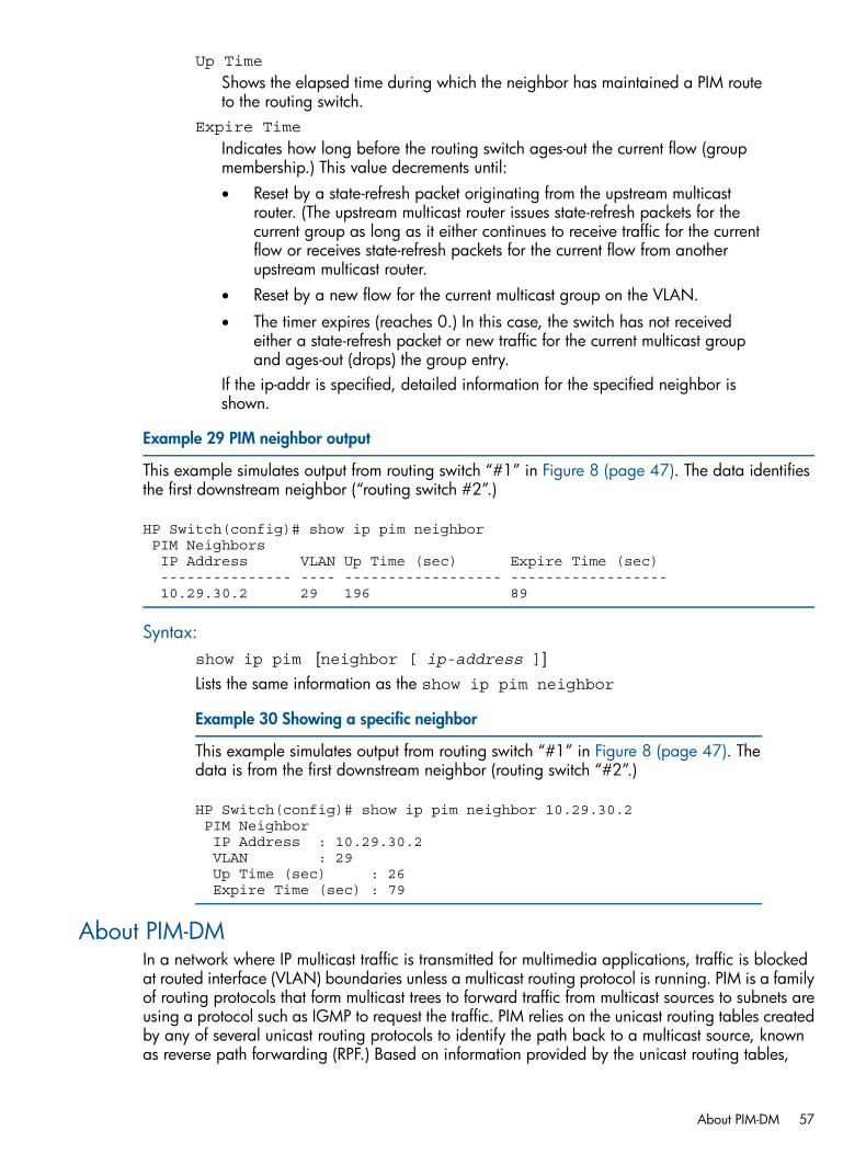
Up Time
Shows the elapsed time during which the neighbor has maintained a PIM routeto the routing switch.
Expire Time
Indicates how long before the routing switch ages-out the current flow (groupmembership.) This value decrements until:• Reset by a state-refresh packet originating from the upstream multicast
router. (The upstream multicast router issues state-refresh packets for thecurrent group as long as it either continues to receive traffic for the currentflow or receives state-refresh packets for the current flow from anotherupstream multicast router.
• Reset by a new flow for the current multicast group on the VLAN.
• The timer expires (reaches 0.) In this case, the switch has not receivedeither a state-refresh packet or new traffic for the current multicast groupand ages-out (drops) the group entry.
If the ip-addr is specified, detailed information for the specified neighbor isshown.
Example 29 PIM neighbor output
This example simulates output from routing switch “#1” in Figure 8 (page 47). The data identifiesthe first downstream neighbor (“routing switch #2”.)
HP Switch(config)# show ip pim neighbor PIM Neighbors IP Address VLAN Up Time (sec) Expire Time (sec) --------------- ---- ------------------ ------------------ 10.29.30.2 29 196 89
Syntax:show ip pim [neighbor [ ip-address ]]Lists the same information as the show ip pim neighbor
Example 30 Showing a specific neighbor
This example simulates output from routing switch “#1” in Figure 8 (page 47). Thedata is from the first downstream neighbor (routing switch “#2”.)
HP Switch(config)# show ip pim neighbor 10.29.30.2 PIM Neighbor IP Address : 10.29.30.2 VLAN : 29 Up Time (sec) : 26 Expire Time (sec) : 79
About PIM-DMIn a network where IP multicast traffic is transmitted for multimedia applications, traffic is blockedat routed interface (VLAN) boundaries unless a multicast routing protocol is running. PIM is a familyof routing protocols that form multicast trees to forward traffic from multicast sources to subnets areusing a protocol such as IGMP to request the traffic. PIM relies on the unicast routing tables createdby any of several unicast routing protocols to identify the path back to a multicast source, knownas reverse path forwarding (RPF.) Based on information provided by the unicast routing tables,
About PIM-DM 57
PIM sets up a distribution tree for the multicast traffic. The PIM-DM and PIM-SM protocols on theswitches enable and control multicast traffic routing.IGMP provides the multicast traffic link between a host and a multicast router running PIM-DM orPIM-SM. IGMP and either PIM-DM or PIM-SM must be enabled on VLANs whose member portshave directly connected hosts with a valid need to join multicast groups. PIM-DM is used in networkswhere, at any given time, multicast group members exist in relatively large numbers and are presentin most subnets.
License requirements:In the 3500yl, 5400zl, and 6600 and 8200zl switches, PIM-DM is included with the PremiumLicense. In the 6200yl switches, this feature is included with the base feature set.
PIM-DM featuresPIM-DM features on switches covered by this guide include:
Routing protocol supportPIM uses whichever unicast routing protocol is running on the routing switch.These can include:• RIP
• OSPF
• Static routes
• Directly connected interfacesVLAN interface support
The MRT supports up to 128 outbound VLANs at any given time. The sum ofall outbound VLANs across all current flows on a router may not exceed 128.(A single flow may span one inbound VLAN and up to 128 outbound VLANs,depending on the VLAN memberships of the hosts actively belonging to theflow.)
Flow capacityUp to 2048 flows are supported in hardware across a maximum of 128outbound VLANs. (A flow is composed of an IP source address and an IPmulticast group address, regardless of the number of active hosts belonging tothe multicast group at any given time.)
IGMP compatibilityPIM-DM is compatible with IGMP (V1 to V3) and is fully interoperable withIGMP for determining multicast flows.
VRRPPIM-DM is fully interoperable with VRRP to quickly transition multicast routes inthe event of a failover.
MIB supportWith some exceptions, PIM-DM supports the parts of the multicast routing MIBapplicable to PIM-DM operation. See “Exceptions to Support for RFC 2932 -Multicast Routing MIB” (page 66).
PIM draft specificationsCompatible with PIM-DM draft specifications (V1 and V2.)
PIM-DM operationPIM-DM operates at the router level to direct traffic for a particular multicast group along the mostefficient path to the VLANs which have hosts that have joined that group. A unicast source address
58 PIM-DM (Dense Mode)
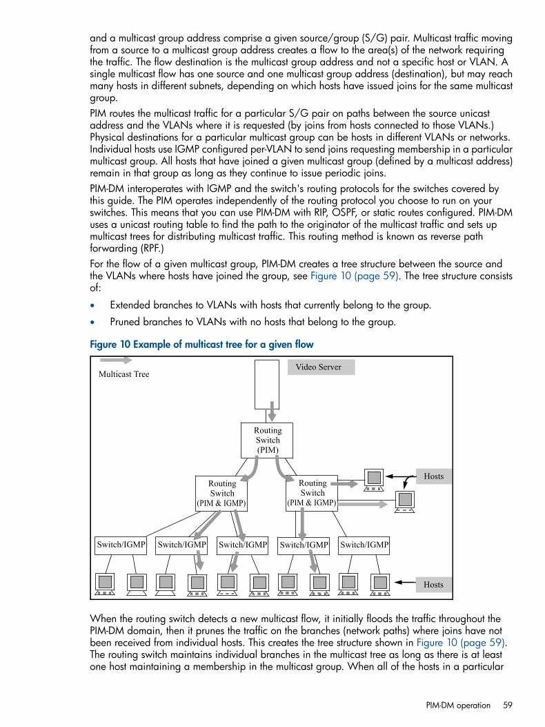
and a multicast group address comprise a given source/group (S/G) pair. Multicast traffic movingfrom a source to a multicast group address creates a flow to the area(s) of the network requiringthe traffic. The flow destination is the multicast group address and not a specific host or VLAN. Asingle multicast flow has one source and one multicast group address (destination), but may reachmany hosts in different subnets, depending on which hosts have issued joins for the same multicastgroup.PIM routes the multicast traffic for a particular S/G pair on paths between the source unicastaddress and the VLANs where it is requested (by joins from hosts connected to those VLANs.)Physical destinations for a particular multicast group can be hosts in different VLANs or networks.Individual hosts use IGMP configured per-VLAN to send joins requesting membership in a particularmulticast group. All hosts that have joined a given multicast group (defined by a multicast address)remain in that group as long as they continue to issue periodic joins.PIM-DM interoperates with IGMP and the switch's routing protocols for the switches covered bythis guide. The PIM operates independently of the routing protocol you choose to run on yourswitches. This means that you can use PIM-DM with RIP, OSPF, or static routes configured. PIM-DMuses a unicast routing table to find the path to the originator of the multicast traffic and sets upmulticast trees for distributing multicast traffic. This routing method is known as reverse pathforwarding (RPF.)For the flow of a given multicast group, PIM-DM creates a tree structure between the source andthe VLANs where hosts have joined the group, see Figure 10 (page 59). The tree structure consistsof:
• Extended branches to VLANs with hosts that currently belong to the group.
• Pruned branches to VLANs with no hosts that belong to the group.
Figure 10 Example of multicast tree for a given flow
Switch/IGMP
RoutingSwitch
(PIM & IGMP)
Routing Switch
(PIM & IGMP)
Switch/IGMP
RoutingSwitch(PIM)
Switch/IGMP Switch/IGMP Switch/IGMP
Video ServerMulticast Tree
Hosts
Hosts
When the routing switch detects a new multicast flow, it initially floods the traffic throughout thePIM-DM domain, then it prunes the traffic on the branches (network paths) where joins have notbeen received from individual hosts. This creates the tree structure shown in Figure 10 (page 59).The routing switch maintains individual branches in the multicast tree as long as there is at leastone host maintaining a membership in the multicast group. When all of the hosts in a particular
PIM-DM operation 59
VLAN drop out of the group, PIM-DM prunes that VLAN from the multicast tree. Similarly, if therouting switch detects a join from a host in a pruned VLAN, it adds that branch back into the tree.
NOTE: Where the multicast routers in a network use one or more multinetted VLANs, there mustbe at least one subnet common to all routers on the VLAN. This is necessary to provide a continuousforwarding path for the multicast traffic on the VLAN. See “PIM VLAN (interface) configurationcontext” (page 42).
Multicast flow managementThis section provides details on how the routing switch manages forwarding and pruned flows.This information is useful when you plan topologies to include multicast support and when viewingand interpreting the show command output for PIM-DM features.
Initial flood and pruneWhen a router running PIM-DM receives a new multicast flow, it initially floods the traffic to alldownstream multicast routers. PIM-DM then prunes the traffic on paths to VLANs that have no hostjoins for that multicast address. (PIM-DM does not re-forward traffic back to its source VLAN.)
Maintaining the prune stateFor a multicast group "X" on a given VLAN, when the last host belonging to group "X" leaves thegroup, PIM places that VLAN in a prune state; this means that the group "X" multicast traffic isblocked to that VLAN. The prune state remains until a host on the same VLAN issues a join forgroup "X", in which case the router cancels the prune state and changes the flow to the forwardingstate.
State-refresh packets and bandwidth conservationA multicast switch, if directly connected to a multicast source (such as a video conferenceapplication), periodically transmit state-refresh packets to downstream multicast routers. On routersthat have pruned the multicast flow, the state-refresh packets keep the pruned state alive. On routersthat have been added to the network after the initial flooding and pruning of a multicast group,the state-refresh packets inform the newly added router of the current state of that branch. Thismeans that if all multicast routers in a network support the state-refresh packet, the multicast routerdirectly connected to the multicast source performs only one flood-prune cycle to the edge of thenetwork when a new flow (multicast group) is introduced and preserves bandwidth for other uses.
NOTE: Some vendors' multicast routers do not offer the state-refresh feature. In this case, PIM-DMmust periodically advertise an active multicast group to these devices by repeating the flood/prunecycle on the paths to such routers. For better traffic management in multicast-intensive networkswhere some multicast routers do not offer the state-refresh feature, you may want to group suchrouters where the increased bandwidth usage will have the least effect on overall networkperformance.
See Figure 11 (page 61) for an example of bandwidth conservation.
60 PIM-DM (Dense Mode)
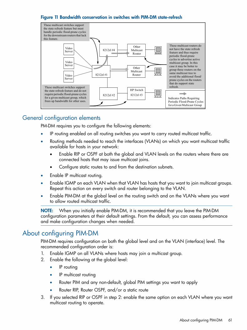
Figure 11 Bandwidth conservation in switches with PIM-DM state-refresh
8212zl #1
8212zl #2
HP Switch
8212zl #3
8212zl #4Other
MulticastRouter
OtherMulticast
Router
Indicates Paths Requiring Periodic Flood-Prune Cyclesfor a Given Multicast Group
These multicast routers do not have the state refresh feature and thus require periodic flood-prune cycles to advertise active multicast group. In this case it may be better to group these routers on the same multicast tree to avoid the additional flood/prune cycles on the routers that do support state refresh.
These multicast switches support the state refresh feature but must handle periodic flood-prune cycles for the downstream routers that lack this feature.
These multicast switches support the state refresh feature and do not require periodic flood-prune cycles for a given multicast group, which frees up bandwidth for other uses.
VideoServer
VideoServer
VideoServer
General configuration elementsPM-DM requires you to configure the following elements:
• IP routing enabled on all routing switches you want to carry routed multicast traffic.
• Routing methods needed to reach the interfaces (VLANs) on which you want multicast trafficavailable for hosts in your network:• Enable RIP or OSPF at both the global and VLAN levels on the routers where there are
connected hosts that may issue multicast joins.• Configure static routes to and from the destination subnets.
• Enable IP multicast routing.
• Enable IGMP on each VLAN when that VLAN has hosts that you want to join multicast groups.Repeat this action on every switch and router belonging to the VLAN.
• Enable PIM-DM at the global level on the routing switch and on the VLANs where you wantto allow routed multicast traffic.
NOTE: When you initially enable PIM-DM, it is recommended that you leave the PIM-DMconfiguration parameters at their default settings. From the default, you can assess performanceand make configuration changes when needed.
About configuring PIM-DMPIM-DM requires configuration on both the global level and on the VLAN (interface) level. Therecommended configuration order is:1. Enable IGMP on all VLANs where hosts may join a multicast group.2. Enable the following at the global level:
• IP routing
• IP multicast routing
• Router PIM and any non-default, global PIM settings you want to apply
• Router RIP, Router OSPF, and/or a static route3. If you selected RIP or OSPF in step 2: enable the same option on each VLAN where you want
multicast routing to operate.
About configuring PIM-DM 61
4. Enable the following in each VLAN context where you want multicast routing to operate:• IP RIP or IP OSPF
• IP PIM
• Any non-default, VLAN-level IP PIM settings you want to apply
Operating notes
PIM-DM operating rules• The routing switch supports 2048 multicast flows in hardware. See,“Flow capacity” (page 62).
• The multicast routing table (MRT) that PIM-DM creates allows up to 128 outbound VLANs atany given time. PIM-DM supports multicast routing across 128 VLANs.
• The routing switch allows one instance of PIM per VLAN. For networks using multinetted VLANs,all routers on the intended VLAN must have at least one common subnet if you intend onrouting multicast packets. The routing switch provides a command for specifying which IPaddress PIM will use on each VLAN.
PIM routers without state-refresh messaging capabilityA PIM router without a state-refresh messaging capability learns of currently active flows in amulticast network through periodic flood and prune cycles on the path back to the source. Theswitches covered in this guide sense downstream multicast routers that do not have the state-refreshcapability and will periodically flood active multicast groups to these devices. This periodic floodingis not necessary if all downstream multicast routers are switches covered in this guide. (The HProuting switch Series 9300 and the routers offered by some other vendors do not offer thestate-refresh capability.)
Flow capacityThe routing switch provides an ample multicast environment, supporting 2048 multicast flows inhardware across a maximum of 64 VLANs. (A flow comprises a unicast source address and amulticast group address, regardless of the number of active hosts belonging to the multicast groupat any given time.)
IGMP traffic high-priority disabledEnabling IP multicast routing to support PIM-DM operation has the effect of disabling IGMP traffichigh-priority, if configured. See “Configuring the querier function” (page 22).
ACLs and PIMThe switch allows ACL filtering on unicast addresses, but not on multicast addresses. Also, an ACLdoes not take effect on a flow if the flow began before the ACL was configured.
When to enable IGMP on a VLANWhen PIM is enabled on a VLAN, it is not necessary to also enable IGMP unless there may bejoins occurring on that VLAN. But if IGMP is enabled on a VLAN, you must also enable PIM if youwant that VLAN to participate in multicast routing.
IP address removedIf you remove the IP address for a VLAN, the switch automatically removes the PIM configurationfor that VLAN.
62 PIM-DM (Dense Mode)
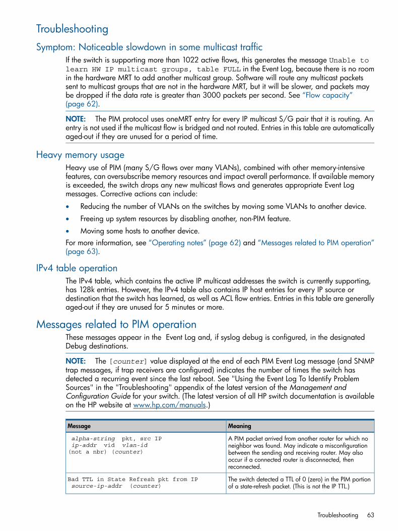
Troubleshooting
Symptom: Noticeable slowdown in some multicast trafficIf the switch is supporting more than 1022 active flows, this generates the message Unable tolearn HW IP multicast groups, table FULL in the Event Log, because there is no roomin the hardware MRT to add another multicast group. Software will route any multicast packetssent to multicast groups that are not in the hardware MRT, but it will be slower, and packets maybe dropped if the data rate is greater than 3000 packets per second. See “Flow capacity”(page 62).
NOTE: The PIM protocol uses oneMRT entry for every IP multicast S/G pair that it is routing. Anentry is not used if the multicast flow is bridged and not routed. Entries in this table are automaticallyaged-out if they are unused for a period of time.
Heavy memory usageHeavy use of PIM (many S/G flows over many VLANs), combined with other memory-intensivefeatures, can oversubscribe memory resources and impact overall performance. If available memoryis exceeded, the switch drops any new multicast flows and generates appropriate Event Logmessages. Corrective actions can include:
• Reducing the number of VLANs on the switches by moving some VLANs to another device.
• Freeing up system resources by disabling another, non-PIM feature.
• Moving some hosts to another device.For more information, see “Operating notes” (page 62) and “Messages related to PIM operation”(page 63).
IPv4 table operationThe IPv4 table, which contains the active IP multicast addresses the switch is currently supporting,has 128k entries. However, the IPv4 table also contains IP host entries for every IP source ordestination that the switch has learned, as well as ACL flow entries. Entries in this table are generallyaged-out if they are unused for 5 minutes or more.
Messages related to PIM operationThese messages appear in the Event Log and, if syslog debug is configured, in the designatedDebug destinations.
NOTE: The [counter] value displayed at the end of each PIM Event Log message (and SNMPtrap messages, if trap receivers are configured) indicates the number of times the switch hasdetected a recurring event since the last reboot. See "Using the Event Log To Identify ProblemSources" in the "Troubleshooting" appendix of the latest version of the Management andConfiguration Guide for your switch. (The latest version of all HP switch documentation is availableon the HP website at www.hp.com/manuals.)
MeaningMessage
A PIM packet arrived from another router for which noneighbor was found. May indicate a misconfiguration
alpha-string pkt, src IP ip-addr vid vlan-id
(not a nbr) (counter) between the sending and receiving router. May alsooccur if a connected router is disconnected, thenreconnected.
The switch detected a TTL of 0 (zero) in the PIM portionof a state-refresh packet. (This is not the IP TTL.)
Bad TTL in State Refresh pkt from IP source-ip-addr (counter)
Troubleshooting 63
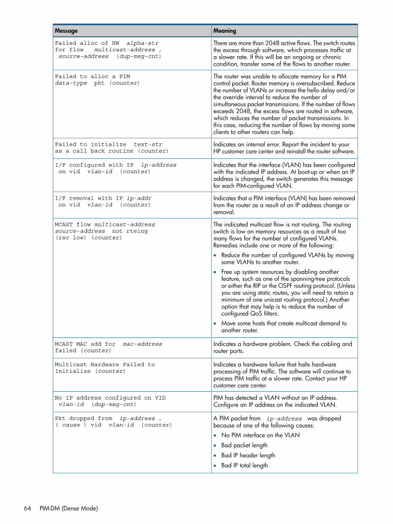
MeaningMessage
There are more than 2048 active flows. The switch routesthe excess through software, which processes traffic at
Failed alloc of HW alpha-strfor flow multicast-address ,source-address (dup-msg-cnt) a slower rate. If this will be an ongoing or chronic
condition, transfer some of the flows to another router.
The router was unable to allocate memory for a PIMcontrol packet. Router memory is oversubscribed. Reduce
Failed to alloc a PIM data-type pkt (counter)
the number of VLANs or increase the hello delay and/orthe override interval to reduce the number ofsimultaneous packet transmissions. If the number of flowsexceeds 2048, the excess flows are routed in software,which reduces the number of packet transmissions. Inthis case, reducing the number of flows by moving someclients to other routers can help.
Indicates an internal error. Report the incident to yourHP customer care center and reinstall the router software.
Failed to initialize text-stras a call back routine (counter)
Indicates that the interface (VLAN) has been configuredwith the indicated IP address. At boot-up or when an IP
I/F configured with IP ip-address on vid vlan-id (counter)
address is changed, the switch generates this messagefor each PIM-configured VLAN.
Indicates that a PIM interface (VLAN) has been removedfrom the router as a result of an IP address change orremoval.
I/F removal with IP ip-addr on vid vlan-id (counter)
The indicated multicast flow is not routing. The routingswitch is low on memory resources as a result of too
MCAST flow multicast-addresssource-address not rteing(rsc low) (counter) many flows for the number of configured VLANs.
Remedies include one or more of the following:• Reduce the number of configured VLANs by moving
some VLANs to another router.• Free up system resources by disabling another
feature, such as one of the spanning-tree protocolsor either the RIP or the OSPF routing protocol. (Unlessyou are using static routes, you will need to retain aminimum of one unicast routing protocol.) Anotheroption that may help is to reduce the number ofconfigured QoS filters.
• Move some hosts that create multicast demand toanother router.
Indicates a hardware problem. Check the cabling androuter ports.
MCAST MAC add for mac-addressfailed (counter)
Indicates a hardware failure that halts hardwareprocessing of PIM traffic. The software will continue to
Multicast Hardware Failed toInitialize (counter)
process PIM traffic at a slower rate. Contact your HPcustomer care center.
PIM has detected a VLAN without an IP address.Configure an IP address on the indicated VLAN.
No IP address configured on VID vlan-id (dup-msg-cnt)
A PIM packet from ip-address was droppedbecause of one of the following causes:
Pkt dropped from ip-address ,( cause ) vid vlan-id (counter)
• No PIM interface on the VLAN
• Bad packet length
• Bad IP header length
• Bad IP total length
64 PIM-DM (Dense Mode)
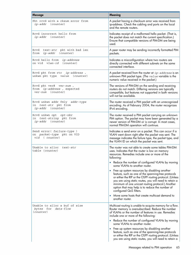
MeaningMessage
A packet having a checksum error was received fromip-address. Check the cabling and ports on the localand the remote routers.
Pkt rcvd with a cksum error from ip-addr (counter)
Indicates receipt of a malformed hello packet. (That is,the packet does not match the current specification.)
Rcvd incorrect hello fromip-addr (counter)
Ensure that compatible versions of PIM-DM are beingused.
A peer router may be sending incorrectly formatted PIMpackets.
Rcvd text-str pkt with bad lenfrom ip-addr (counter)
Indicates a misconfiguration where two routers aredirectly connected with different subnets on the sameconnected interface.
Rcvd hello from ip-addresson vid vlan-id (counter)
A packet received from the router at ip-address is anunknown PIM packet type. (The value variable is thenumeric value received in the packet.)
Rcvd pkt from rtr ip-address ,unkwn pkt type value (counter)
The versions of PIM-DM on the sending and receivingrouters do not match. Differing versions are typically
Rcvd pkt ver# ver-num ,from ip-address , expectedver-num (counter) compatible, but features not supported in both versions
will not be available.
The router received a PIM packet with an unrecognizedencoding. As of February 2004, the router recognizesIPv4 encoding.
Rcvd unkwn addr fmly addr-typein text-str pkt fromip-addr (counter)
The router received a PIM packet carrying an unknownPIM option. The packet may have been generated by a
Rcvd unkwn opt opt-nbrin text-string pkt fromip-addr (counter) newer version of PIM-DM or is corrupt. In most cases,
normal PIM-DM operation will continue.
Indicates a send error on a packet. This can occur if aVLAN went down right after the packet was sent. The
Send error( failure-type )on packet-type pkt on VIDvid ( counter) message indicates the failure type, the packet type, and
the VLAN ID on which the packet was sent.
The router was not able to create some tables PIM-DMuses. Indicates that the router is low on memory
Unable to alloc text-strtable (counter)
resources. Remedies include one or more of thefollowing:• Reduce the number of configured VLANs by moving
some VLANs to another router.• Free up system resources by disabling another
feature, such as one of the spanning-tree protocolsor either the RIP or the OSPF routing protocol. (Unlessyou are using static routes, you will need to retain aminimum of one unicast routing protocol.) Anotheroption that may help is to reduce the number ofconfigured QoS filters.
• Move some hosts that create multicast demand toanother router.
Multicast routing is unable to acquire memory for a flow.Router memory is oversubscribed. Reduce the number
Unable to alloc a buf of size bytes for data-flow
(counter) of VLANs or the number of features in use. Remediesinclude one or more of the following:• Reduce the number of configured VLANs by moving
some VLANs to another router.• Free up system resources by disabling another
feature, such as one of the spanning-tree protocolsor either the RIP or the OSPF routing protocol. (Unlessyou are using static routes, you will need to retain a
Messages related to PIM operation 65
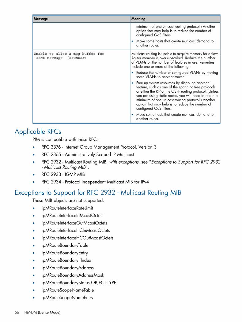
MeaningMessage
minimum of one unicast routing protocol.) Anotheroption that may help is to reduce the number ofconfigured QoS filters.
• Move some hosts that create multicast demand toanother router.
Multicast routing is unable to acquire memory for a flow.Router memory is oversubscribed. Reduce the number
Unable to alloc a msg buffer for text-message (counter)
of VLANs or the number of features in use. Remediesinclude one or more of the following:• Reduce the number of configured VLANs by moving
some VLANs to another router.• Free up system resources by disabling another
feature, such as one of the spanning-tree protocolsor either the RIP or the OSPF routing protocol. (Unlessyou are using static routes, you will need to retain aminimum of one unicast routing protocol.) Anotheroption that may help is to reduce the number ofconfigured QoS filters.
• Move some hosts that create multicast demand toanother router.
Applicable RFCsPIM is compatible with these RFCs:
• RFC 3376 - Internet Group Management Protocol, Version 3
• RFC 2365 - Administratively Scoped IP Multicast
• RFC 2932 - Multicast Routing MIB, with exceptions, see "Exceptions to Support for RFC 2932- Multicast Routing MIB".
• RFC 2933 - IGMP MIB
• RFC 2934 - Protocol Independent Multicast MIB for IPv4
Exceptions to Support for RFC 2932 - Multicast Routing MIBThese MIB objects are not supported:
• ipMRouteInterfaceRateLimit
• ipMRouteInterfaceInMcastOctets
• ipMRouteInterfaceOutMcastOctets
• ipMRouteInterfaceHCInMcastOctets
• ipMRouteInterfaceHCOutMcastOctets
• ipMRouteBoundaryTable
• ipMRouteBoundaryEntry
• ipMRouteBoundaryIfIndex
• ipMRouteBoundaryAddress
• ipMRouteBoundaryAddressMask
• ipMRouteBoundaryStatus OBJECT-TYPE
• ipMRouteScopeNameTable
• ipMRouteScopeNameEntry
66 PIM-DM (Dense Mode)

• ipMRouteScopeNameAddress
• ipMRouteScopeNameAddressMask
• ipMRouteScopeNameLanguage
• ipMRouteScopeNameString
• ipMRouteScopeNameDefault
• ipMRouteScopeNameStatus
Exceptions to Support for RFC 2932 - Multicast Routing MIB 67
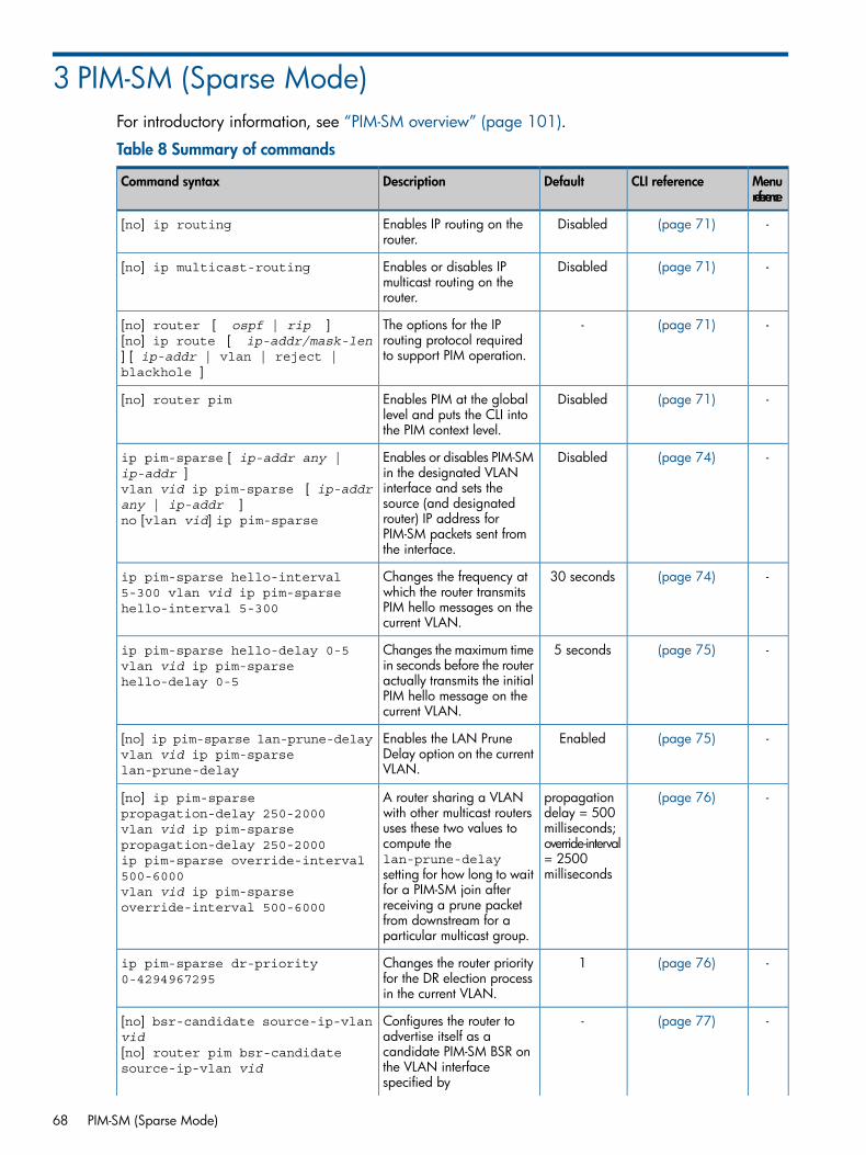
3 PIM-SM (Sparse Mode)For introductory information, see “PIM-SM overview” (page 101).
Table 8 Summary of commands
Menureference
CLI referenceDefaultDescriptionCommand syntax
-(page 71)DisabledEnables IP routing on therouter.
[no] ip routing
-(page 71)DisabledEnables or disables IPmulticast routing on therouter.
[no] ip multicast-routing
-(page 71)-The options for the IProuting protocol requiredto support PIM operation.
[no] router [ ospf | rip ][no] ip route [ ip-addr/mask-len] [ ip-addr | vlan | reject |blackhole ]
-(page 71)DisabledEnables PIM at the globallevel and puts the CLI intothe PIM context level.
[no] router pim
-(page 74)DisabledEnables or disables PIM-SMin the designated VLAN
ip pim-sparse [ ip-addr any |ip-addr ]vlan vid ip pim-sparse [ ip-addrany | ip-addr ]no [vlan vid] ip pim-sparse
interface and sets thesource (and designatedrouter) IP address forPIM-SM packets sent fromthe interface.
-(page 74)30 secondsChanges the frequency atwhich the router transmits
ip pim-sparse hello-interval5-300 vlan vid ip pim-sparsehello-interval 5-300 PIM hello messages on the
current VLAN.
-(page 75)5 secondsChanges the maximum timein seconds before the router
ip pim-sparse hello-delay 0-5vlan vid ip pim-sparsehello-delay 0-5 actually transmits the initial
PIM hello message on thecurrent VLAN.
-(page 75)EnabledEnables the LAN PruneDelay option on the currentVLAN.
[no] ip pim-sparse lan-prune-delayvlan vid ip pim-sparselan-prune-delay
-(page 76)propagationdelay = 500
A router sharing a VLANwith other multicast routers
[no] ip pim-sparsepropagation-delay 250-2000vlan vid ip pim-sparsepropagation-delay 250-2000
milliseconds;override-interval= 2500milliseconds
uses these two values tocompute thelan-prune-delaysetting for how long to wait
ip pim-sparse override-interval500-6000vlan vid ip pim-sparseoverride-interval 500-6000
for a PIM-SM join afterreceiving a prune packetfrom downstream for aparticular multicast group.
-(page 76)1Changes the router priorityfor the DR election processin the current VLAN.
ip pim-sparse dr-priority0-4294967295
-(page 77)-Configures the router toadvertise itself as a
[no] bsr-candidate source-ip-vlanvid
candidate PIM-SM BSR on[no] router pim bsr-candidatesource-ip-vlan vid the VLAN interface
specified by
68 PIM-SM (Sparse Mode)
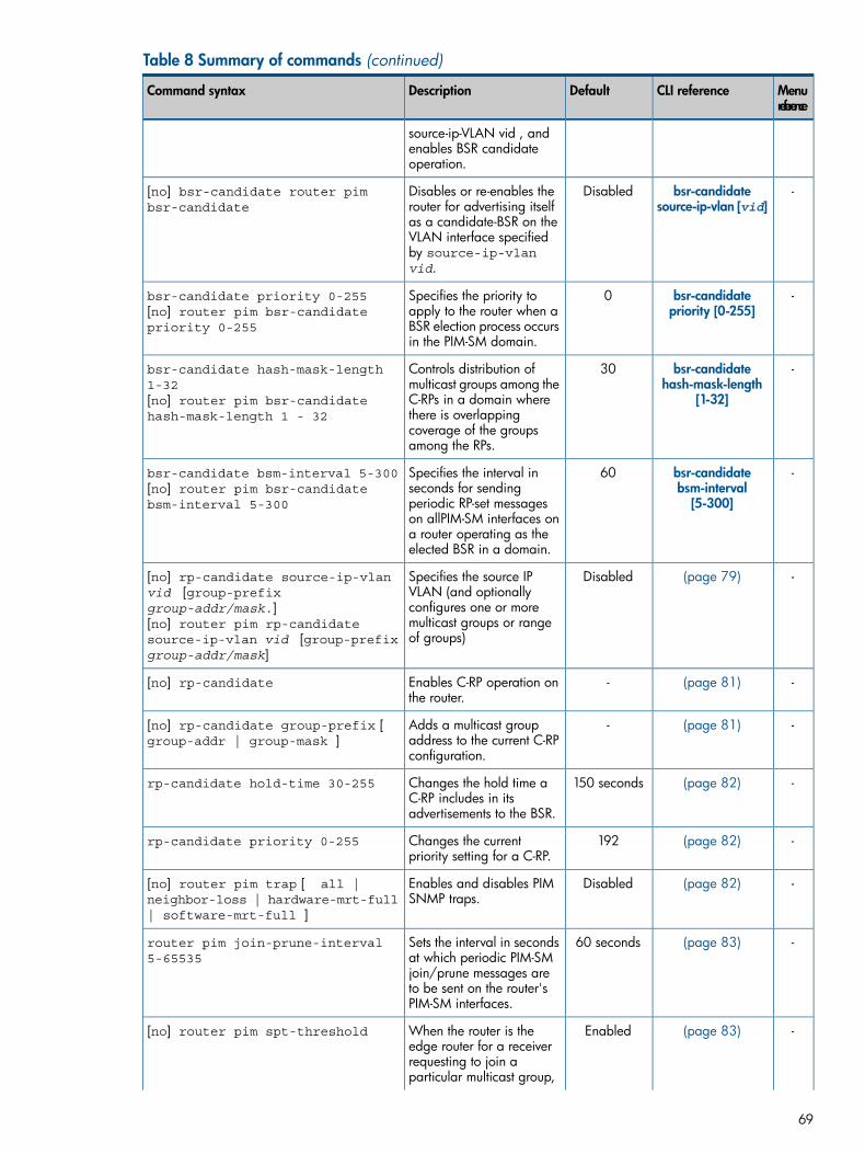
Table 8 Summary of commands (continued)
Menureference
CLI referenceDefaultDescriptionCommand syntax
source-ip-VLAN vid , andenables BSR candidateoperation.
-bsr-candidatesource-ip-vlan [vid]
DisabledDisables or re-enables therouter for advertising itselfas a candidate-BSR on the
[no] bsr-candidate router pimbsr-candidate
VLAN interface specifiedby source-ip-vlanvid.
-bsr-candidatepriority [0-255]
0Specifies the priority toapply to the router when a
bsr-candidate priority 0-255[no] router pim bsr-candidatepriority 0-255 BSR election process occurs
in the PIM-SM domain.
-bsr-candidatehash-mask-length
[1-32]
30Controls distribution ofmulticast groups among theC-RPs in a domain where
bsr-candidate hash-mask-length1-32[no] router pim bsr-candidatehash-mask-length 1 - 32 there is overlapping
coverage of the groupsamong the RPs.
-bsr-candidatebsm-interval
[5-300]
60Specifies the interval inseconds for sendingperiodic RP-set messages
bsr-candidate bsm-interval 5-300[no] router pim bsr-candidatebsm-interval 5-300
on allPIM-SM interfaces ona router operating as theelected BSR in a domain.
-(page 79)DisabledSpecifies the source IPVLAN (and optionally
[no] rp-candidate source-ip-vlanvid [group-prefixgroup-addr/mask.] configures one or more
multicast groups or rangeof groups)
[no] router pim rp-candidatesource-ip-vlan vid [group-prefixgroup-addr/mask]
-(page 81)-Enables C-RP operation onthe router.
[no] rp-candidate
-(page 81)-Adds a multicast groupaddress to the current C-RPconfiguration.
[no] rp-candidate group-prefix [group-addr | group-mask ]
-(page 82)150 secondsChanges the hold time aC-RP includes in itsadvertisements to the BSR.
rp-candidate hold-time 30-255
-(page 82)192Changes the currentpriority setting for a C-RP.
rp-candidate priority 0-255
-(page 82)DisabledEnables and disables PIMSNMP traps.
[no] router pim trap [ all |neighbor-loss | hardware-mrt-full| software-mrt-full ]
-(page 83)60 secondsSets the interval in secondsat which periodic PIM-SM
router pim join-prune-interval5-65535
join/prune messages areto be sent on the router'sPIM-SM interfaces.
-(page 83)EnabledWhen the router is theedge router for a receiver
[no] router pim spt-threshold
requesting to join aparticular multicast group,
69
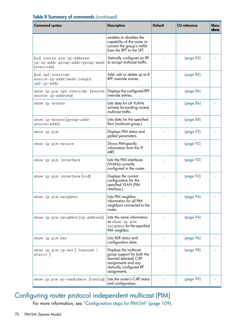
Table 8 Summary of commands (continued)
Menureference
CLI referenceDefaultDescriptionCommand syntax
enables or disables thecapability of the router toconvert the group's trafficfrom the RPT to the SPT.
-(page 83)-Statically configures an RPto accept multicast traffic.
[no] router pim rp-addressrp-ip-addr group-addr/group-mask[override]
(page 85)Add, edit or delete up to 8RPF override entries.
[no] rpf-overridesource-ip-addr/mask-lengthrpf-ip-addr
(page 86)Displays the configured RPFoverride entries.
show ip pim rpf-override [sourcesource ip-address]
-(page 86)-Lists data for all VLANsactively forwarding routed,multicast traffic.
show ip mroute
-(page 88)-Lists data for the specifiedflow (multicast group.)
show ip mroute [group-addrsource-addr]
-(page 92)-Displays PIM status andglobal parameters.
show ip pim
-(page 92)-Shows PIM-specificinformation from the IPMRT.
show ip pim mroute
-(page 93)-Lists the PIM interfaces(VLANs) currentlyconfigured in the router.
show ip pim interface
-(page 93)-Displays the currentconfiguration for the
show ip pim interface [vid]
specified VLAN (PIMinterface.)
-(page 94)-Lists PIM neighborinformation for all PIM
show ip pim neighbor
neighbors connected to therouter.
-(page 94)-Lists the same informationas show ip pim
show ip pim neighbor [ip-address]
neighbor for the specifiedPIM neighbor.
-(page 96)-Lists BSR status andconfiguration data.
show ip pim bsr
-(page 98)-Displays the multicastgroup support for both the
show ip pim rp-set [ learned |static ]
learned (elected) C-RPassignments and anystatically configured RPassignments.
-(page 99)-Lists the router's C-RP statusand configuration.
show ip pim rp-candidate [config]
Configuring router protocol independent multicast (PIM)For more information, see “Configuration steps for PIM-SM” (page 109).
70 PIM-SM (Sparse Mode)
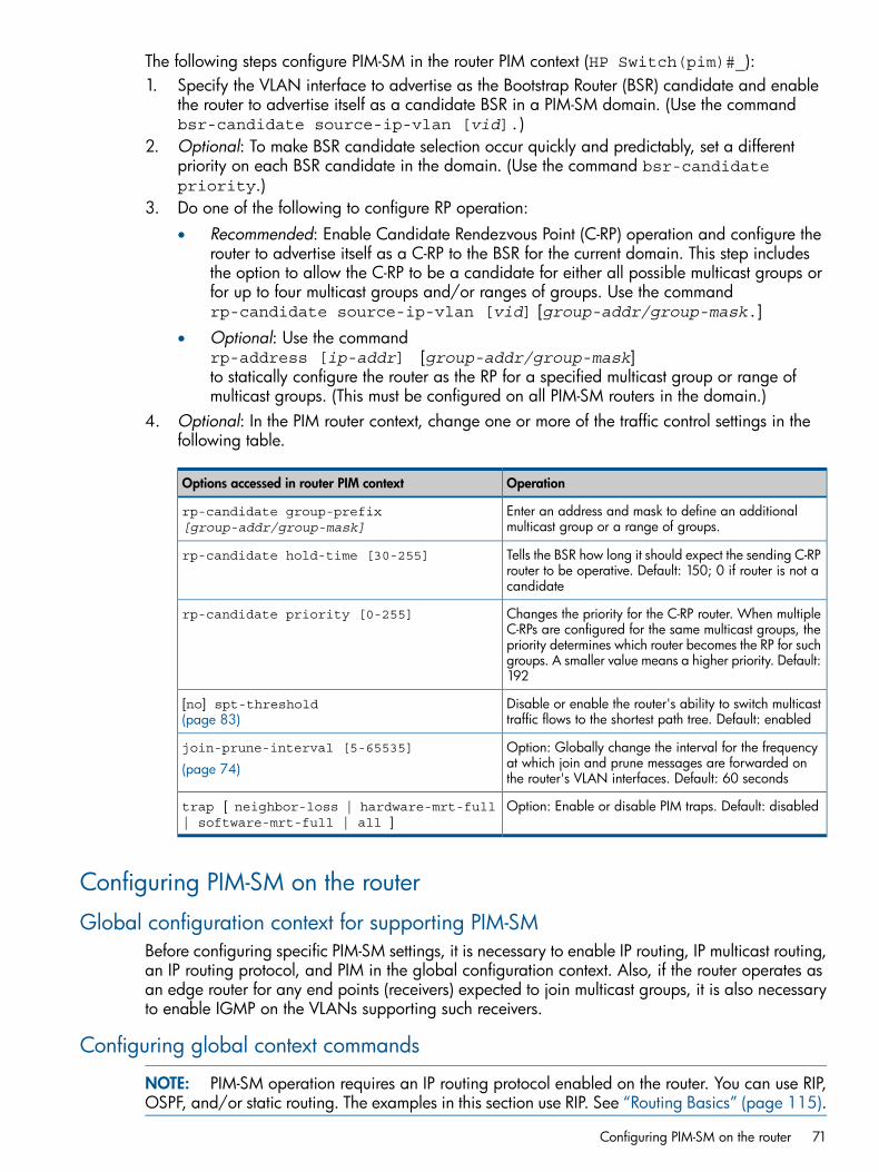
The following steps configure PIM-SM in the router PIM context (HP Switch(pim)#_):1. Specify the VLAN interface to advertise as the Bootstrap Router (BSR) candidate and enable
the router to advertise itself as a candidate BSR in a PIM-SM domain. (Use the commandbsr-candidate source-ip-vlan [vid].)
2. Optional: To make BSR candidate selection occur quickly and predictably, set a differentpriority on each BSR candidate in the domain. (Use the command bsr-candidatepriority.)
3. Do one of the following to configure RP operation:• Recommended: Enable Candidate Rendezvous Point (C-RP) operation and configure the
router to advertise itself as a C-RP to the BSR for the current domain. This step includesthe option to allow the C-RP to be a candidate for either all possible multicast groups orfor up to four multicast groups and/or ranges of groups. Use the commandrp-candidate source-ip-vlan [vid] [group-addr/group-mask.]
• Optional: Use the commandrp-address [ip-addr] [group-addr/group-mask]to statically configure the router as the RP for a specified multicast group or range ofmulticast groups. (This must be configured on all PIM-SM routers in the domain.)
4. Optional: In the PIM router context, change one or more of the traffic control settings in thefollowing table.
OperationOptions accessed in router PIM context
Enter an address and mask to define an additionalmulticast group or a range of groups.
rp-candidate group-prefix[group-addr/group-mask]
Tells the BSR how long it should expect the sending C-RProuter to be operative. Default: 150; 0 if router is not acandidate
rp-candidate hold-time [30-255]
Changes the priority for the C-RP router. When multipleC-RPs are configured for the same multicast groups, thepriority determines which router becomes the RP for suchgroups. A smaller value means a higher priority. Default:192
rp-candidate priority [0-255]
Disable or enable the router's ability to switch multicasttraffic flows to the shortest path tree. Default: enabled
[no] spt-threshold(page 83)
Option: Globally change the interval for the frequencyat which join and prune messages are forwarded onthe router's VLAN interfaces. Default: 60 seconds
join-prune-interval [5-65535]
(page 74)
Option: Enable or disable PIM traps. Default: disabledtrap [ neighbor-loss | hardware-mrt-full| software-mrt-full | all ]
Configuring PIM-SM on the router
Global configuration context for supporting PIM-SMBefore configuring specific PIM-SM settings, it is necessary to enable IP routing, IP multicast routing,an IP routing protocol, and PIM in the global configuration context. Also, if the router operates asan edge router for any end points (receivers) expected to join multicast groups, it is also necessaryto enable IGMP on the VLANs supporting such receivers.
Configuring global context commands
NOTE: PIM-SM operation requires an IP routing protocol enabled on the router. You can use RIP,OSPF, and/or static routing. The examples in this section use RIP. See “Routing Basics” (page 115).
Configuring PIM-SM on the router 71
Syntax:[no] ip routingEnables IP routing on the router.The no form of the command disables IP routing. Note that before disabling IProuting, it is necessary to disable all other IP routing protocols on the router.(Default: Disabled)
Syntax:[no] ip multicast-routingEnables or disables IP multicast routing on the router. IP routing must first be enabled.Note that router PIM must be disabled before disabling IP multicast routing.(Default: Disabled)
Syntax:[no] router [ ospf | rip ][no] ip route [ ip-addr/mask-len ] [ ip-addr | vlan | reject |blackhole ]These commands are the options for the IP routing protocol required to support PIMoperation. For more on these options, see “Routing Basics” (page 115).
Syntax:[no] router pim [[enable] | [disable]]Puts the CLI into the PIM context level. IP routing must be enabled before enablingPIM.The no router pim command deletes the PIM configuration. (Default: Disabled)[enable]
Enables PIM globally.[disable]
Disables PIM globally. Disabling PIM does not delete the PIM configuration.
72 PIM-SM (Sparse Mode)
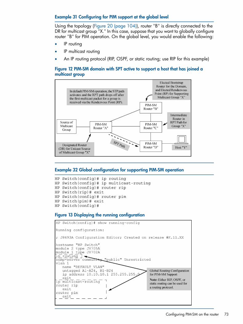
Example 31 Configuring for PIM support at the global level
Using the topology (Figure 20 (page 104)), router "B" is directly connected to theDR for multicast group "X." In this case, suppose that you want to globally configurerouter "B" for PIM operation. On the global level, you would enable the following:• IP routing
• IP multicast routing
• An IP routing protocol (RIP, OSPF, or static routing; use RIP for this example)
Figure 12 PIM-SM domain with SPT active to support a host that has joined amulticast group
Example 32 Global configuration for supporting PIM-SM operation
HP Switch(config)# ip routingHP Switch(config)# ip multicast-routingHP Switch(config)# router ripHP Switch(rip)# exitHP Switch(config)# router pimHP Switch(pim)# exitHP Switch(config)#
Figure 13 Displaying the running configuration
Configuring PIM-SM on the router 73
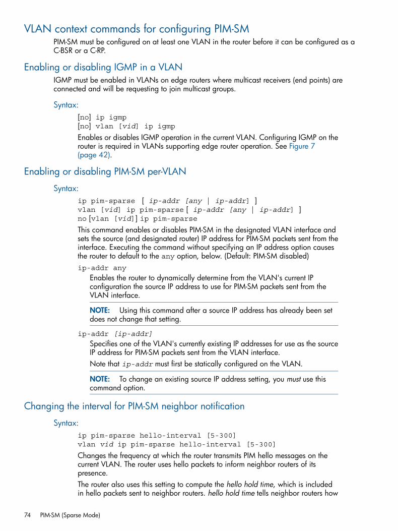
VLAN context commands for configuring PIM-SMPIM-SM must be configured on at least one VLAN in the router before it can be configured as aC-BSR or a C-RP.
Enabling or disabling IGMP in a VLANIGMP must be enabled in VLANs on edge routers where multicast receivers (end points) areconnected and will be requesting to join multicast groups.
Syntax:[no] ip igmp[no] vlan [vid] ip igmpEnables or disables IGMP operation in the current VLAN. Configuring IGMP on therouter is required in VLANs supporting edge router operation. See Figure 7(page 42).
Enabling or disabling PIM-SM per-VLAN
Syntax:ip pim-sparse [ ip-addr [any | ip-addr] ]vlan [vid] ip pim-sparse [ ip-addr [any | ip-addr] ]no [vlan [vid]] ip pim-sparseThis command enables or disables PIM-SM in the designated VLAN interface andsets the source (and designated router) IP address for PIM-SM packets sent from theinterface. Executing the command without specifying an IP address option causesthe router to default to the any option, below. (Default: PIM-SM disabled)ip-addr any
Enables the router to dynamically determine from the VLAN's current IPconfiguration the source IP address to use for PIM-SM packets sent from theVLAN interface.
NOTE: Using this command after a source IP address has already been setdoes not change that setting.
ip-addr [ip-addr]
Specifies one of the VLAN's currently existing IP addresses for use as the sourceIP address for PIM-SM packets sent from the VLAN interface.Note that ip-addr must first be statically configured on the VLAN.
NOTE: To change an existing source IP address setting, you must use thiscommand option.
Changing the interval for PIM-SM neighbor notification
Syntax:ip pim-sparse hello-interval [5-300]vlan vid ip pim-sparse hello-interval [5-300]
Changes the frequency at which the router transmits PIM hello messages on thecurrent VLAN. The router uses hello packets to inform neighbor routers of itspresence.The router also uses this setting to compute the hello hold time, which is includedin hello packets sent to neighbor routers. hello hold time tells neighbor routers how
74 PIM-SM (Sparse Mode)
long to wait for the next hello packet from the router. If another packet does notarrive within that time, the router removes the neighbor adjacency on that VLANfrom the routing table, which removes any flows running on that interface.Shortening the hello interval reduces the hello hold time. This changes how quicklyother routers will stop sending traffic to the router if they do not receive a new hellopacket when expected. For example, if multiple routers are connected to the sameVLAN and the router requests multicast traffic, all routers on the VLAN receive thattraffic. (Those that have pruned the traffic will drop it when they receive it.) If theupstream router loses contact with the router receiving the multicast traffic (that is,fails to receive a hello packet when expected), the shorter hello interval causes itto stop transmitting multicast traffic onto the VLAN sooner, resulting in lessunnecessary bandwidth use.(Default: 30 seconds)
Changing the randomized delay setting for PIM-SM neighbor notification
Syntax:ip pim-sparse hello-delay [0-5]vlan [vid] ip pim-sparse hello-delay [0-5]
Changes the maximum time in seconds before the router actually transmits the initialPIM hello message on the current VLAN. In cases where a new VLAN activates withconnections to multiple routers, if all of the connected routers sent hello packets atthe same time, the receiving router could become momentarily overloaded. Thisvalue randomizes the transmission delay to a time between 0 and the hello delaysetting. Using 0 means no delay.After the router sends the initial hello packet to a newly detected VLAN interface,it sends subsequent hello packets according to the current Hello Interval setting.Not used with the no form of the ip pim command.(Default: 5 seconds)
Enabling or disabling lan prune delay
Syntax:[no] ip pim-sparse lan-prune-delay[no]vlan [vid] ip pim-sparse lan-prune-delay
Enables the LAN prune delay option on the current VLAN. With lan-prune-delayenabled, the router informs downstream neighbors how long it will wait beforepruning a flow after receiving a prune request.Other downstream routers on the same VLAN must send a join to override the prunebefore the lan-prune-delay time if they want the flow to continue. This promptsany downstream neighbors with multicast receivers continuing to belong to the flowto reply with a join. If no joins are received after the lan-prune-delay period,the router prunes the flow.The propagation-delay and override-interval settings (below) determinethe lan-prune-delay setting.Uses the no form of the command to disable the LAN prune delayoption.(Default: Enabled)
VLAN context commands for configuring PIM-SM 75
Changing the Lan-prune-delay interval
Syntax:ip pim-sparse propagation-delay [250-2000]vlan [vid] ip pim-sparse propagation-delay [250-2000]ip pim-sparse override-interval [500-6000]vlan [vid] ip pim-sparse override-interval [500-6000]
A router sharing a VLAN with other multicast routers uses these two values tocompute the lan-prune-delay setting (above) for how long to wait for a PIM-SMjoin after receiving a prune packet from downstream for a particular multicast group.
Example 33 Multiple routers sharing VLAN
A network may have multiple routers sharing VLAN "X." When an upstream routeris forwarding traffic from multicast group "X" to VLAN "Y," if one of the routers onVLAN "Y" does not want this traffic, it issues a prune response to the upstreamneighbor. The upstream neighbor then goes into a prune pending state for group"X" on VLAN "Y." (During this period, the upstream neighbor continues to forwardthe traffic.) During the pending period, another router on VLAN "Y" can send agroup "X" join to the upstream neighbor. If this happens, the upstream neighbordrops the prune pending state and continues forwarding the traffic. But if no routerson the VLAN send a join, the upstream router prunes group "X" from VLAN "Y"when the lan-prune-delay timer expires.
(Defaults: propagation-delay = 500 milliseconds; override-interval =2500 milliseconds)
Neighbor timeout
Syntax:ip pim-sparse nbr-timeout [60-65536]
Changing the DR priority
Syntax:ip pim-sparse dr-priority [0-4294967295]
This command changes the router priority for the DR election process in the currentVLAN. A numerically higher value means a higher priority. If the highest priority isshared by multiple routers in the same VLAN, the router with the highest IP addressis selected as the DR.A 0 (zero) value disables DR operation for the router on the current VLAN.(Range: 0 - 2147483647; Default: 1)
Configuring PIM-SM support in a VLAN contextPIM-SM support must be configured in each VLAN where you want PIM-SM forwarding of multicasttraffic. This illustrates the following per-VLAN configuration steps:• Enabling PIM-SM on VLAN 120 and allowing the default any option to select a source IP
address for PIM-SM packets forwarded from this VLAN. (Because the VLAN in this example
76 PIM-SM (Sparse Mode)
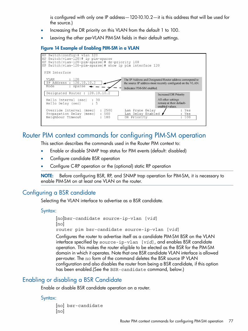
is configured with only one IP address—120-10.10.2—it is this address that will be used forthe source.)
• Increasing the DR priority on this VLAN from the default 1 to 100.
• Leaving the other per-VLAN PIM-SM fields in their default settings.
Figure 14 Example of Enabling PIM-SM in a VLAN
Router PIM context commands for configuring PIM-SM operationThis section describes the commands used in the Router PIM context to:• Enable or disable SNMP trap status for PIM events (default: disabled)
• Configure candidate BSR operation
• Configure C-RP operation or the (optional) static RP operation
NOTE: Before configuring BSR, RP, and SNMP trap operation for PIM-SM, it is necessary toenable PIM-SM on at least one VLAN on the router.
Configuring a BSR candidateSelecting the VLAN interface to advertise as a BSR candidate.
Syntax:[no]bsr-candidate source-ip-vlan [vid][no]router pim bsr-candidate source-ip-vlan [vid]
Configures the router to advertise itself as a candidate PIM-SM BSR on the VLANinterface specified by source-ip-vlan [vid], and enables BSR candidateoperation. This makes the router eligible to be elected as the BSR for the PIM-SMdomain in which it operates. Note that one BSR candidate VLAN interface is allowedper-router. The no form of the command deletes the BSR source IP VLANconfiguration and also disables the router from being a BSR candidate, if this optionhas been enabled.(See the BSR-candidate command, below.)
Enabling or disabling a BSR CandidateEnable or disable BSR candidate operation on a router.
Syntax:[no] bsr-candidate[no]
Router PIM context commands for configuring PIM-SM operation 77
router pim bsr-candidate
Disables or re-enables the router for advertising itself as a Candidate-BSR on theVLAN interface specified by source-ip-vlan [vid]. This command is used todisable and re-enable BSR candidate operation after the bsr-candidatesource-ip-vlan [vid] command has been used to enable C-BSR operationon the router. (This command operates only after the BSR source-ip-VLAN IDhas been configured.)(Default: Disabled)
Changing the priority settingChanging the priority setting for a BSR-candidate router.
Syntax:bsr-candidate priority [0-255][no] router pim bsr-candidate priority [0-255]Specifies the priority to apply to the router when a BSR election process occurs inthe PIM-SM domain. The candidate with the highest priority becomes the BSR forthe domain. If the highest priority is shared by multiple routers, the candidate havingthe highest IP address becomes the domain's BSR. Zero (0) is the lowest priority.To make BSR selection easily predictable, use this command to assign a differentpriority to each candidate BSR in the PIM-SM domain.(Default: 0; Range 0–255)
NOTE: Disabling PIM-SM on the elected BSR or disabling the C-BSR functionalityon the elected BSR causes the router to send a Bootstrap Message (BSM) with apriority setting of 0 to trigger a new BSR election. If all BSRs in the domain are setto the default priority (0), the election will fail because the result is to re-elect theBSR that has become unavailable. For this reason, it is recommended that all C-BSRsin the domain be configured with a bsr-candidate priority greater than 0.
Changing the distributionChanging the distribution of multicast groups across a domain.
Syntax:bsr-candidate hash-mask-length [1-32][no] router pim bsr-candidate hash-mask-length [1-32]Controls distribution of multicast groups among the C-RPs in a domain where thereis overlapping coverage of the groups among the RPs. This value specifies the length(number of significant bits) taken into account when allocating this distribution. Alonger hash-mask-length results in fewer multicast groups in each block ofgroup addresses assigned to the various RPs. Because multiple blocks of addressesare typically assigned to each C-RP, this results in a wider dispersal of addressesand enhances load-sharing of the multicast traffic of different groups being used inthe domain at the same time.(Default: 30; Range 1–32)
Changing the message intervalChanging the BSR message interval.
Syntax:bsr-candidate bsm-interval [5-300]
78 PIM-SM (Sparse Mode)
[no] bsr-candidate bsm-interval [5-300]Specifies the interval in seconds for sending periodic RP-Set messages on all PIM-SMinterfaces on a router operating as the elected BSR in a domain.
NOTE: This setting must be smaller than the rp-candidate hold-time settings(range of 30 to 255; default 150) configured in the RPs operating in the domain.
(Default: 60; Range 5–300)
Configuring C-RPs on PIM-SM routersAn RP candidate advertises its availability, IP address, and the multicast group or range of groupsit supports. The commands in this section are used to configure C-RP operation. The sequence ofsteps is as follows:1. Specify the source IP VLAN.2. Enable C-RP operation.3. Option: enable or disable specific multicast address groups.
NOTE: Before configuring BSR, RP, and SNMP trap operation for PIM-SM, it is necessary toenable PIM-SM on at least one VLAN on the router.
Specifying the source IP VLAN (and optionally configuring one or more multicastgroups or range of groups)
Specifying the source IP VLAN ID automatically configures the C-RP to support all multicastgroups (unless you include an individual group or range of groups in the command.) Therecommended approach is to allow all multicast groups unless you have a reason to limit thepermitted groups to a specific set.
Syntax:[no] rp-candidate source-ip-vlan [vid] [group-prefixgroup-addr/mask][no] router pim rp-candidate source-ip-vlan [vid] [group-prefixgroup-addr/mask]
Configuring C-RPs on PIM-SM routers 79
These commands configure C-RP operation in the following way.
• Specify the VLAN interface from which the RP IP address will be selected foradvertising the router as an RP candidate.
NOTE: Only one VLAN on the router can be configured for this purpose atany time.
• Enable the router as an RP candidate.
• Specify the multicast groups for which the router is a CRP. (Default: Disabled.)
NOTE: When executed without specifying a multicast group or range ofgroups, the resulting RP candidate defaults to allow support for all multicastgroups — 224.0.0.0, 240.0.0.0, or 224.0.0.0/4.
Additionally, the following commands may be required:
• To later add to or change multicast groups, or to delete multicast groups, usethe command rp-candidate group-prefix [group-addr |group-mask]. See “Adding or deleting a multicast group address” (page 81).
• To disable C-RP operation without removing the current CRP configuration, usethe command no rp-candidate. See “Enabling or disabling C-RP operation”(page 81).
• The no form of these commands:
Deletes the RP source IP VLAN configuration.◦◦ Deletes the multicast group assignments configured on the router for this
RP.
◦ Disables the router from being an RP candidate.
[vid]
The command identifies the VLAN source of the IP address to advertise as theRP candidate address for the router.
group-prefix [group-addr/mask]:Specifies the multicast group(s) to advertise as supported by the RP candidate.Use this option when you want to enable the C-RP and simultaneously configureit to support a subset of multicast addresses or ranges of addresses instead ofall possible multicast addresses.A group prefix can specify all multicast groups (224.0.0.0 to239.255.255.255), a range (subset) of groups, or a single group. A givenaddress is defined by its nonzero octets and mask. The mask is applied fromthe high end (leftmost) bits of the address and must extend to the last nonzerobit in the lowest-order, nonzero octet. Any intervening zero or nonzero octetrequires eight mask bits. Following are examples.
80 PIM-SM (Sparse Mode)
Example 34 228.0.0.64/26:
Defines a multicast address range of 228.0.0.64 through 228.0.0.127. (Thelast six bits of the rightmost octet are wildcards.)
Example 35 228.0.0.64/30:
Defines a multicast address range of 228.0.0.64 through 228.0.0.67. (Thelast two bits of the rightmost octet are wildcards.)
Example 36 228.0.0.64/32:
Defines a single multicast address of 228.0.0.64. (There are no wildcards inthis group prefix.)
Example 37 228.0.0.64/25:
Creates an error condition caused by the mask failing to include the last(rightmost) nonzero bit in the lowest-order, nonzero octet. (That is, this masksupports an address of 228.0.0.128, but not 228.0.0.64.)
NOTE: The larger the mask, the smaller the range of multicast addressessupported. A mask of 32 bits always specifies a single multicast address. Forexample 230.0.15.240/32 defines a single multicast address of 230.0.15.240.
Enabling or disabling C-RP operationUse this command when the router is already configured with a source IP VLAN ID and you wantto enable or disable C-RP operation on the router.
Syntax:[no]rp-candidateEnables C-RP operation on the router. Requires that the source IP VLAN is currentlyconfigured, but disabled. See (page 79).The no form of the command disables the currently configured C-RP operation, butdoes not change the configured C-RP settings.
Adding or deleting a multicast group addressUse this command if you need to modify the multicast address group configuration for a C-RP onthe router.
Syntax:[no]rp-candidate group-prefix [ group-addr | group-mask ]Adds a multicast group address to the current C-RP configuration. Requires that thesource IP VLAN (See 79) is already configured. The no form of the commandremoves a multicast group address from the current C-RP configuration.This command does not enable or disable RP candidate operation.
NOTE: An RP candidate supports up to four separate multicast address groups.If only one group-prefix address exists in the router PIM configuration, you cannotdelete it unless you first add another group-prefix address.
Configuring C-RPs on PIM-SM routers 81
Changing the C-RP hold-timeHold-time is included in the advertisements the C-RP periodically sends to the domain's electedBSR, and updates the BSR on how long to wait after the last advertisement from the reporting RPbefore assuming that it has become unavailable. See “BSR role in fault recovery” (page 106).
Syntax:rp-candidate hold-time [30-255]
Changes the hold time a C-RP includes in its advertisements to the BSR. Also, if C-RPis configured, but disabled, this command re-enables it.(Default: 150 seconds; Range: 30–255 seconds.)
Changing a C-RP's election priorityThis priority is significant when multiple C-RPs in a given domain are configured to support one ormore of the same multicast groups.
Syntax:rp-candidate priority [0-255]
Changes the current priority setting for a C-RP. Where multiple C-RPs are configuredto support the same multicast group(s), the candidate having the highest priority iselected. Zero (0) is the highest priority, and 255 is the lowest priority.(Default: 192)
Enabling, disabling, or changing router PIM notification traps
Syntax:[no] router pim trap [ all | neighbor-loss | hardware-mrt-full| software-mrt-full ]Enables and disables the following PIM SNMP traps:all
Enable/Disable all PIM notification traps.(Default: Disabled)
neighbor-loss
Enable/Disable the notification trap sent when the timer for a multicast routerneighbor expires and the switch has no other multicast router neighbors on thesame VLAN with a lower IP address.(Default: Disabled)
hardware-mrt-full
Enable/Disable notification trap sent when the hardware multicast routing table(MRT) is full (2048 active flows.) In this state, any additional flows are handledby the software MRT, which increases processing time for the affected flows.(Default: Disabled)
software-mrt-full
Enable/Disable notification trap sent when the router's software MRT is full (thatis, when routing resources for active flows are exhausted.) Note that in thisstate, the router does not accept any additional flows.(Default: Disabled)
82 PIM-SM (Sparse Mode)
NOTE: Trap operation requires configuring an SNMP trap receiver by using thesnmp-server host[ip-addr] command at the global configuration level.
Changing the global join-prune interval on the router
Syntax:router pim join-prune-interval [5-65535]
Sets the interval in seconds at which periodic PIM-SM join/prune messages are tobe sent on the router's PIM-SM interfaces. This setting is applied to every PIM-SMinterface on the router.(Default: 60 seconds)
NOTE: All routers in a PIM-SM domain should have the same join-prune-intervalsetting.
Changing the shortest-path tree (SPT) operationGenerally, using the SPT option eliminates unnecessary levels of PIM-SM traffic in a domain.However, in cases where it is necessary to tightly control the paths used by PIM-SM flows to edgeswitches, disabling SPT maintains the flows through their original C-RPs regardless of whethershorter paths exist.
Syntax:router pim spt-threshold[no] router pim spt-thresholdWhen the router is the edge router for a receiver requesting to join a particularmulticast group, this command enables or disables the capability of the router toconvert the group's traffic from the RPT to the SPT.See “Restricting multicast traffic to RPTs” (page 104).(Default: Enabled)
Statically configuring an RP to accept multicast trafficA given static RP entry should be manually configured on all routers in the PIM-SM domain. See“Static RP (static RP)” (page 107).
Syntax:router pim rp-address [rp-ip-addr] [group-addr/group-mask][override][no] router pim rp-address [rp-ip-addr][group-addr/group-mask][overide][rp-ip-addr]
Statically specifies the IP address of the interface to use as an RP. Up to eightstatic RP IP addresses can be configured. (Each address can be entered multipletimes for different multicast groups or group ranges.)
[group-addr/group-mask]
Specifies the multicast group or range of contiguous groups supported by thestatically configured RP. Up to eight multicast group ranges can be configured.
[override]
Where a static RP and a C-RP are configured to support the same multicastgroup(s) and the multicast group mask for the static RP is equal to or greater
Changing the global join-prune interval on the router 83
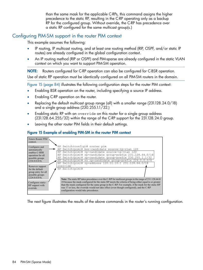
than the same mask for the applicable C-RPs, this command assigns the higherprecedence to the static RP, resulting in the C-RP operating only as a backupRP for the configured group. Without override, the C-RP has precedence overa static RP configured for the same multicast group(s.)
Configuring PIM-SM support in the router PIM contextThis example assumes the following:• IP routing, IP multicast routing, and at least one routing method (RIP, OSPF, and/or static IP
routes) are already configured in the global configuration context.• An IP routing method (RIP or OSPF) and PIM-sparse are already configured in the static VLAN
context on which you want to support PIM-SM operation.
NOTE: Routers configured for C-RP operation can also be configured for C-BSR operation.Use of static RP operation must be identically configured on all PIM-SM routers in the domain.
Figure 15 (page 84) illustrates the following configuration steps for the router PIM context:• Enabling BSR operation on the router, including specifying a source IP address.
• Enabling C-RP operation on the router.
• Replacing the default multicast group range (all) with a smaller range (231.128.24.0/18)and a single group address (230.255.1.1/32.)
• Enabling static RP with an override on this router for a single group address(231.128.64.255/32) within the range of the C-RP support for the 231.128.24.0 group.
• Leaving the other router PIM fields in their default settings.
Figure 15 Example of enabling PIM-SM in the router PIM context
HP Switch(config)# router pimHP Switch(pim)# bsr-candidate source-ip-vlan 120HP Switch(pim)# rp-candidate source-ip-vlan 120HP Switch(pim)# rp-candidate group-prefix 231.128.64.0/18HP Switch(pim)# rp-candidate group-prefix 230.255.1.1/32HP Switch(pim)# no rp-candidate group-prefix 224.0.0.0/4HP Switch(pim)# rp-address 120.11.10.1 231.128.64.0/18overrideHP Switch(pim)#
Enters Router PIM context.
Configures and automatically enables C-BSR operation for all possible groups (224.0.0.0/4).
Removes support for the default group entry for all possible groups (224.0.0.0/4).
Configures static-RP support with override.
Note: The static RP takes precedence over the C-RP for multicast groups in the range of 231.128.64.0/18 because the mask configured for the static RP meets the criteria of being either equal to or greater than the mask configured for the same group in the C-RP. For example, if the mask for the static-RP was 17 or less, the override would not take effect (even though configured), and the C-RP configuration would take precedence.
The next figure illustrates the results of the above commands in the router's running configuration.
84 PIM-SM (Sparse Mode)
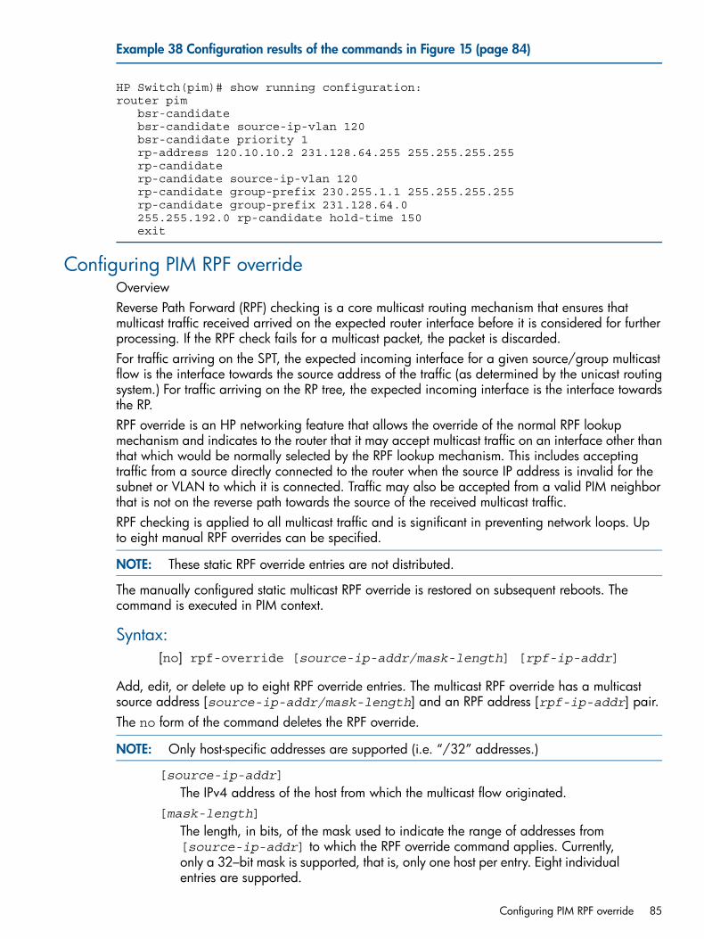
Example 38 Configuration results of the commands in Figure 15 (page 84)
HP Switch(pim)# show running configuration:router pim bsr-candidate bsr-candidate source-ip-vlan 120 bsr-candidate priority 1 rp-address 120.10.10.2 231.128.64.255 255.255.255.255 rp-candidate rp-candidate source-ip-vlan 120 rp-candidate group-prefix 230.255.1.1 255.255.255.255 rp-candidate group-prefix 231.128.64.0 255.255.192.0 rp-candidate hold-time 150 exit
Configuring PIM RPF overrideOverviewReverse Path Forward (RPF) checking is a core multicast routing mechanism that ensures thatmulticast traffic received arrived on the expected router interface before it is considered for furtherprocessing. If the RPF check fails for a multicast packet, the packet is discarded.For traffic arriving on the SPT, the expected incoming interface for a given source/group multicastflow is the interface towards the source address of the traffic (as determined by the unicast routingsystem.) For traffic arriving on the RP tree, the expected incoming interface is the interface towardsthe RP.RPF override is an HP networking feature that allows the override of the normal RPF lookupmechanism and indicates to the router that it may accept multicast traffic on an interface other thanthat which would be normally selected by the RPF lookup mechanism. This includes acceptingtraffic from a source directly connected to the router when the source IP address is invalid for thesubnet or VLAN to which it is connected. Traffic may also be accepted from a valid PIM neighborthat is not on the reverse path towards the source of the received multicast traffic.RPF checking is applied to all multicast traffic and is significant in preventing network loops. Upto eight manual RPF overrides can be specified.
NOTE: These static RPF override entries are not distributed.
The manually configured static multicast RPF override is restored on subsequent reboots. Thecommand is executed in PIM context.
Syntax:[no] rpf-override [source-ip-addr/mask-length] [rpf-ip-addr]
Add, edit, or delete up to eight RPF override entries. The multicast RPF override has a multicastsource address [source-ip-addr/mask-length] and an RPF address [rpf-ip-addr] pair.The no form of the command deletes the RPF override.
NOTE: Only host-specific addresses are supported (i.e. “/32” addresses.)
[source-ip-addr]
The IPv4 address of the host from which the multicast flow originated.[mask-length]
The length, in bits, of the mask used to indicate the range of addresses from[source-ip-addr] to which the RPF override command applies. Currently,only a 32–bit mask is supported, that is, only one host per entry. Eight individualentries are supported.
Configuring PIM RPF override 85
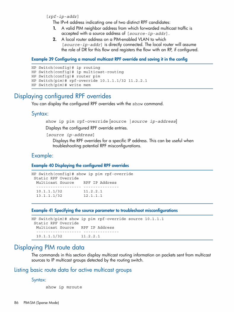
[rpf-ip-addr]
The IPv4 address indicating one of two distinct RPF candidates:1. A valid PIM neighbor address from which forwarded multicast traffic is
accepted with a source address of [source-ip-addr].2. A local router address on a PIM-enabled VLAN to which
[source-ip-addr] is directly connected. The local router will assumethe role of DR for this flow and registers the flow with an RP, if configured.
Example 39 Configuring a manual multicast RPF override and saving it in the config
HP Switch(config)# ip routingHP Switch(config)# ip multicast-routingHP Switch(config)# router pimHP Switch(pim)# rpf-override 10.1.1.1/32 11.2.2.1HP Switch(pim)# write mem
Displaying configured RPF overridesYou can display the configured RPF overrides with the show command.
Syntax:show ip pim rpf-override [source |source ip-address]Displays the configured RPF override entries.[source ip-address]
Displays the RPF overrides for a specific IP address. This can be useful whentroubleshooting potential RPF misconfigurations.
Example:
Example 40 Displaying the configured RPF overrides
HP Switch(config)# show ip pim rpf-override Static RPF Override Multicast Source RPF IP Address ------------------- --------------- 10.1.1.1/32 11.2.2.1 13.1.1.1/32 12.1.1.1
Example 41 Specifying the source parameter to troubleshoot misconfigurations
HP Switch(pim)# show ip pim rpf-override source 10.1.1.1 Static RPF Override Multicast Source RPF IP Address ------------------- --------------- 10.1.1.1/32 11.2.2.1
Displaying PIM route dataThe commands in this section display multicast routing information on packets sent from multicastsources to IP multicast groups detected by the routing switch.
Listing basic route data for active multicast groups
Syntax:show ip mroute
86 PIM-SM (Sparse Mode)
Lists the following data for all VLANs actively forwarding multicast traffic, or forVLANs receiving registered but non-forwarding traffic on an RP.Group Address
The multicast group IP address of the specific flow (source-group pair.)Source Address
The unicast address of the flow's source.Neighbor
The IP address of the upstream multicast router interface (VLAN) from which themulticast traffic is coming. A blank field for a given multicast group indicatesthat the multicast server is directly connected to the router.
VLAN
The interface on which the router received the multicast flow.
ExampleThe following figures display the show ip mroute output illustrating three different cases:
Displaying PIM route data 87
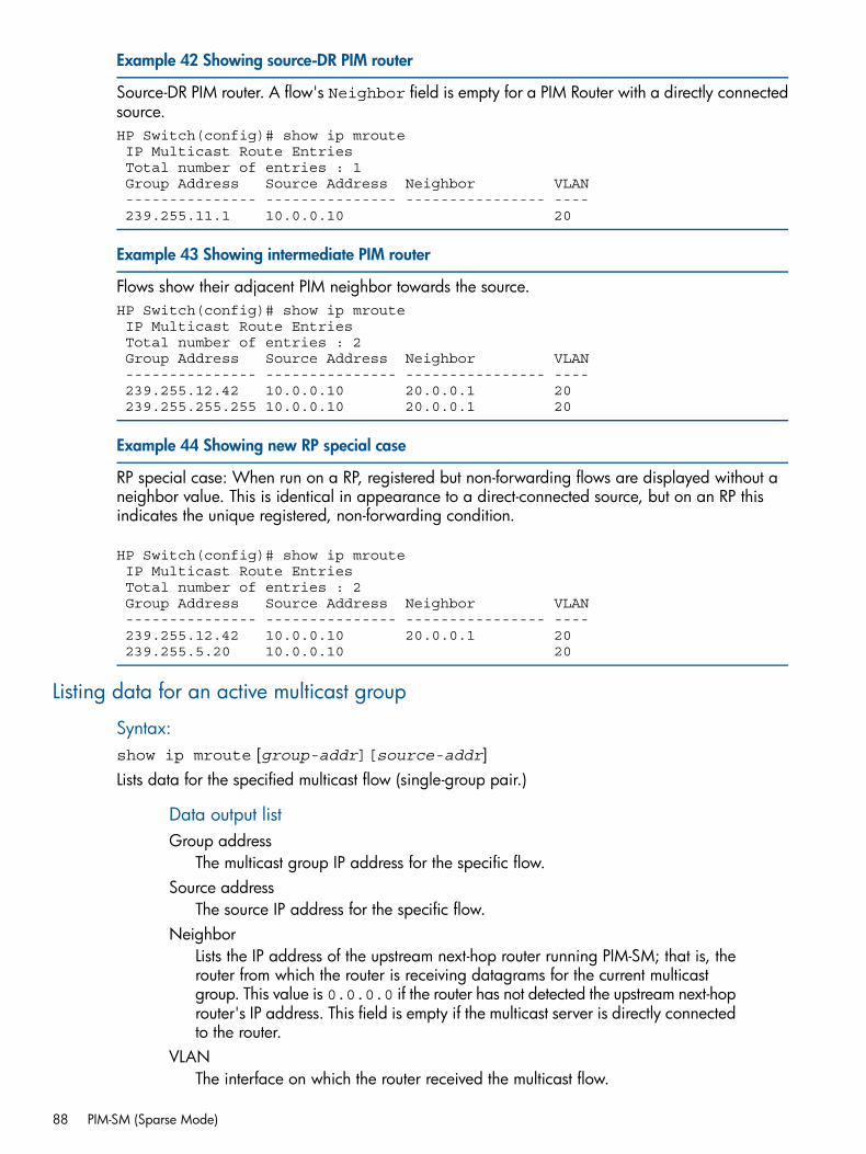
Example 42 Showing source-DR PIM router
Source-DR PIM router. A flow's Neighbor field is empty for a PIM Router with a directly connectedsource.HP Switch(config)# show ip mroute IP Multicast Route Entries Total number of entries : 1 Group Address Source Address Neighbor VLAN --------------- --------------- ---------------- ---- 239.255.11.1 10.0.0.10 20
Example 43 Showing intermediate PIM router
Flows show their adjacent PIM neighbor towards the source.HP Switch(config)# show ip mroute IP Multicast Route Entries Total number of entries : 2 Group Address Source Address Neighbor VLAN --------------- --------------- ---------------- ---- 239.255.12.42 10.0.0.10 20.0.0.1 20 239.255.255.255 10.0.0.10 20.0.0.1 20
Example 44 Showing new RP special case
RP special case: When run on a RP, registered but non-forwarding flows are displayed without aneighbor value. This is identical in appearance to a direct-connected source, but on an RP thisindicates the unique registered, non-forwarding condition.
HP Switch(config)# show ip mroute IP Multicast Route Entries Total number of entries : 2 Group Address Source Address Neighbor VLAN --------------- --------------- ---------------- ---- 239.255.12.42 10.0.0.10 20.0.0.1 20 239.255.5.20 10.0.0.10 20
Listing data for an active multicast group
Syntax:show ip mroute [group-addr][source-addr]Lists data for the specified multicast flow (single-group pair.)
Data output listGroup address
The multicast group IP address for the specific flow.Source address
The source IP address for the specific flow.Neighbor
Lists the IP address of the upstream next-hop router running PIM-SM; that is, therouter from which the router is receiving datagrams for the current multicastgroup. This value is 0.0.0.0 if the router has not detected the upstream next-hoprouter's IP address. This field is empty if the multicast server is directly connectedto the router.
VLANThe interface on which the router received the multicast flow.
88 PIM-SM (Sparse Mode)
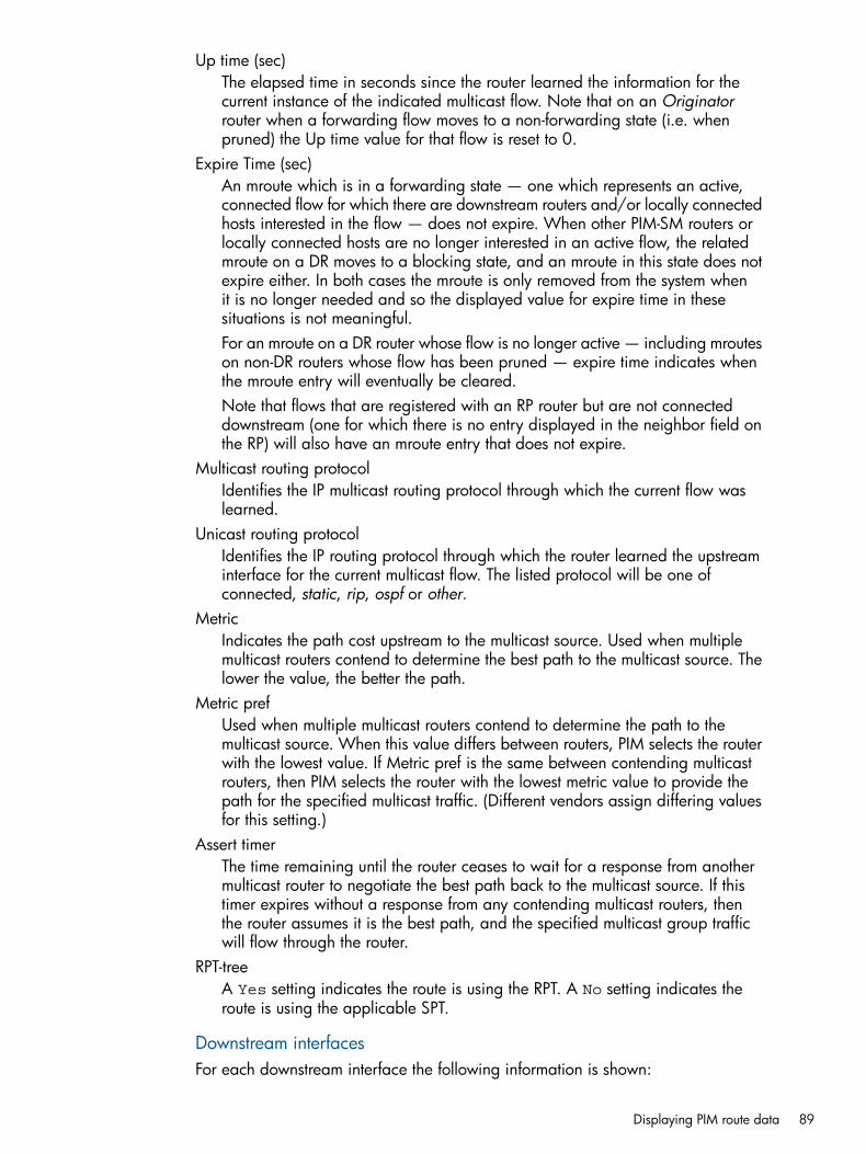
Up time (sec)The elapsed time in seconds since the router learned the information for thecurrent instance of the indicated multicast flow. Note that on an Originatorrouter when a forwarding flow moves to a non-forwarding state (i.e. whenpruned) the Up time value for that flow is reset to 0.
Expire Time (sec)An mroute which is in a forwarding state — one which represents an active,connected flow for which there are downstream routers and/or locally connectedhosts interested in the flow — does not expire. When other PIM-SM routers orlocally connected hosts are no longer interested in an active flow, the relatedmroute on a DR moves to a blocking state, and an mroute in this state does notexpire either. In both cases the mroute is only removed from the system whenit is no longer needed and so the displayed value for expire time in thesesituations is not meaningful.For an mroute on a DR router whose flow is no longer active — including mrouteson non-DR routers whose flow has been pruned — expire time indicates whenthe mroute entry will eventually be cleared.Note that flows that are registered with an RP router but are not connecteddownstream (one for which there is no entry displayed in the neighbor field onthe RP) will also have an mroute entry that does not expire.
Multicast routing protocolIdentifies the IP multicast routing protocol through which the current flow waslearned.
Unicast routing protocolIdentifies the IP routing protocol through which the router learned the upstreaminterface for the current multicast flow. The listed protocol will be one ofconnected, static, rip, ospf or other.
MetricIndicates the path cost upstream to the multicast source. Used when multiplemulticast routers contend to determine the best path to the multicast source. Thelower the value, the better the path.
Metric prefUsed when multiple multicast routers contend to determine the path to themulticast source. When this value differs between routers, PIM selects the routerwith the lowest value. If Metric pref is the same between contending multicastrouters, then PIM selects the router with the lowest metric value to provide thepath for the specified multicast traffic. (Different vendors assign differing valuesfor this setting.)
Assert timerThe time remaining until the router ceases to wait for a response from anothermulticast router to negotiate the best path back to the multicast source. If thistimer expires without a response from any contending multicast routers, thenthe router assumes it is the best path, and the specified multicast group trafficwill flow through the router.
RPT-treeA Yes setting indicates the route is using the RPT. A No setting indicates theroute is using the applicable SPT.
Downstream interfacesFor each downstream interface the following information is shown:
Displaying PIM route data 89

VLANLists the vid of the VLAN the router is using to send the outbound packets ofthe current multicast flow to the next-hop router:
StateIndicates whether the outbound VLAN and next-hop router for the currentmulticast flow are receiving datagrams.
PrunedThe router has not detected any joins from the current multicast flow and is notcurrently forwarding datagrams in the current VLAN.
ForwardingThe router has received a join for the current multicast flow and is forwardingdatagrams in the current VLAN.
Up Time (sec)Indicates the elapsed time in seconds since the router learned the displayedinformation about the current multicast flow.
Expire Time (sec)Downstream interface entries for an mroute in PIM-SM are only created whenthose interfaces become joined for the mroute's flow. Unless join state isperiodically refreshed, a downstream interface will eventually move fromforwarding to pruned. When forwarding, Expire Time indicates when therouter expects forwarding to end unless another join for the flow is received.After moving to prune state, the downstream interface entry will last for a shortwhile longer, indicated by Expire Time, before being removed completely.
90 PIM-SM (Sparse Mode)
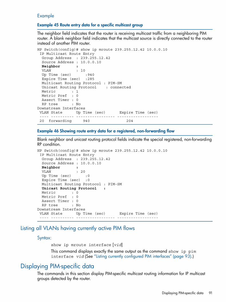
Example
Example 45 Route entry data for a specific multicast group
The neighbor field indicates that the router is receiving multicast traffic from a neighboring PIMrouter. A blank neighbor field indicates that the multicast source is directly connected to the routerinstead of another PIM router.HP Switch(config)# show ip mroute 239.255.12.42 10.0.0.10 IP Multicast Route Entry Group Address : 239.255.12.42 Source Address : 10.0.0.10Neighbor :
VLAN : l0 Up Time (sec) :940 Expire Time (sec) :285 Multicast Routing Protocol : PIM-SM Unicast Routing Protocol : connected Metric : 1 Metric Pref : 0 Assert Timer : 0 RP tree : NoDownstream Interfaces VLAN State Up Time (sec) Expire Time (sec) ---- ---------- ----------------- ------------------ 20 forwarding 940 204
Example 46 Showing route entry data for a registered, non-forwarding flow
Blank neighbor and unicast routing protocol fields indicate the special registered, non-forwardingRP condition.HP Switch(config)# show ip mroute 239.255.12.42 10.0.0.10 IP Multicast Route Entry Group Address : 239.255.12.42 Source Address : 10.0.0.10Neighbor :
VLAN : 20 Up Time (sec) :0 Expire Time (sec) :0 Multicast Routing Protocol : PIM-SM Unicast Routing Protocol :
Metric : 0 Metric Pref : 0 Assert Timer : 0 RP tree : NoDownstream Interfaces VLAN State Up Time (sec) Expire Time (sec) ---- ---------- ----------------- ------------------
Listing all VLANs having currently active PIM flows
Syntax:show ip mroute interface [vid]This command displays exactly the same output as the command show ip piminterface vid (See “Listing currently configured PIM interfaces” (page 93).)
Displaying PIM-specific dataThe commands in this section display PIM-specific multicast routing information for IP multicastgroups detected by the router.
Displaying PIM-specific data 91
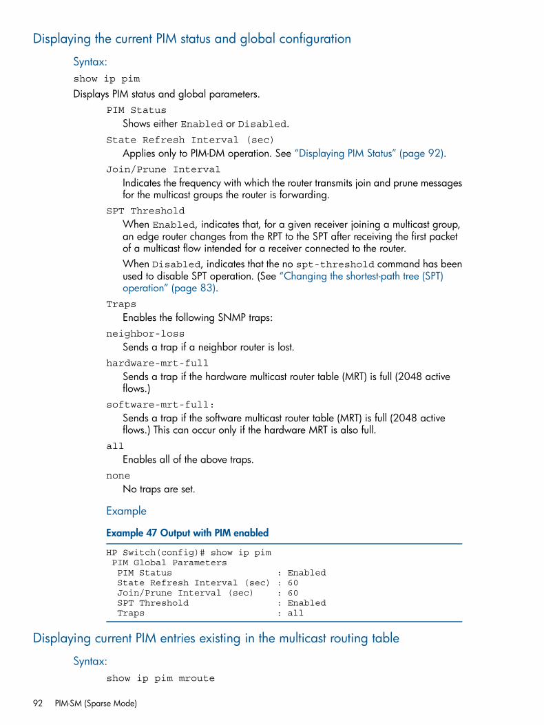
Displaying the current PIM status and global configuration
Syntax:show ip pim
Displays PIM status and global parameters.PIM Status
Shows either Enabled or Disabled.State Refresh Interval (sec)
Applies only to PIM-DM operation. See “Displaying PIM Status” (page 92).Join/Prune Interval
Indicates the frequency with which the router transmits join and prune messagesfor the multicast groups the router is forwarding.
SPT Threshold
When Enabled, indicates that, for a given receiver joining a multicast group,an edge router changes from the RPT to the SPT after receiving the first packetof a multicast flow intended for a receiver connected to the router.When Disabled, indicates that the no spt-threshold command has beenused to disable SPT operation. (See “Changing the shortest-path tree (SPT)operation” (page 83).
Traps
Enables the following SNMP traps:neighbor-loss
Sends a trap if a neighbor router is lost.hardware-mrt-full
Sends a trap if the hardware multicast router table (MRT) is full (2048 activeflows.)
software-mrt-full:
Sends a trap if the software multicast router table (MRT) is full (2048 activeflows.) This can occur only if the hardware MRT is also full.
all
Enables all of the above traps.none
No traps are set.
Example
Example 47 Output with PIM enabled
HP Switch(config)# show ip pim PIM Global Parameters PIM Status : Enabled State Refresh Interval (sec) : 60 Join/Prune Interval (sec) : 60 SPT Threshold : Enabled Traps : all
Displaying current PIM entries existing in the multicast routing table
Syntax:show ip pim mroute
92 PIM-SM (Sparse Mode)
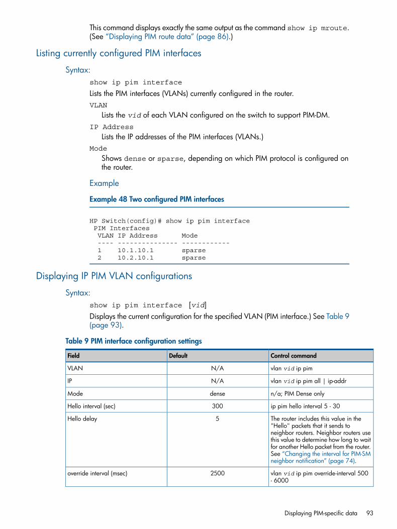
This command displays exactly the same output as the command show ip mroute.(See “Displaying PIM route data” (page 86).)
Listing currently configured PIM interfaces
Syntax:show ip pim interface
Lists the PIM interfaces (VLANs) currently configured in the router.VLAN
Lists the vid of each VLAN configured on the switch to support PIM-DM.IP Address
Lists the IP addresses of the PIM interfaces (VLANs.)Mode
Shows dense or sparse, depending on which PIM protocol is configured onthe router.
Example
Example 48 Two configured PIM interfaces
HP Switch(config)# show ip pim interface PIM Interfaces VLAN IP Address Mode ---- --------------- ------------ 1 10.1.10.1 sparse 2 10.2.10.1 sparse
Displaying IP PIM VLAN configurations
Syntax:show ip pim interface [vid]Displays the current configuration for the specified VLAN (PIM interface.) See Table 9(page 93).
Table 9 PIM interface configuration settings
Control commandDefaultField
vlan vid ip pimN/AVLAN
vlan vid ip pim all | ip-addrN/AIP
n/a; PIM Dense onlydenseMode
ip pim hello interval 5 - 30300Hello interval (sec)
The router includes this value in the"Hello" packets that it sends to
5Hello delay
neighbor routers. Neighbor routers usethis value to determine how long to waitfor another Hello packet from the router.See “Changing the interval for PIM-SMneighbor notification” (page 74).
vlan vid ip pim override-interval 500- 6000
2500override interval (msec)
Displaying PIM-specific data 93
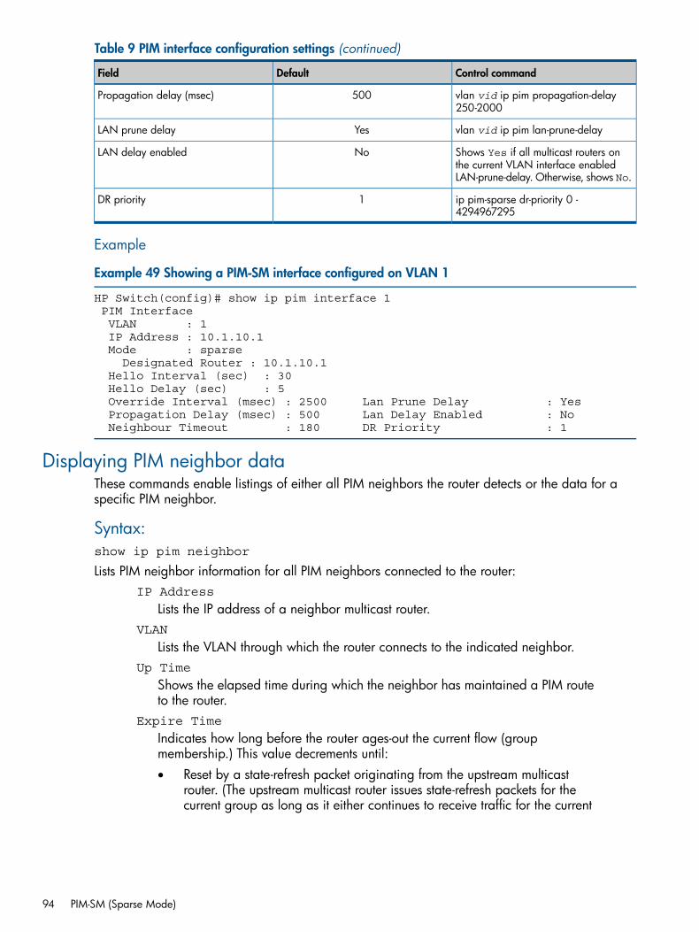
Table 9 PIM interface configuration settings (continued)
Control commandDefaultField
vlan vid ip pim propagation-delay250-2000
500Propagation delay (msec)
vlan vid ip pim lan-prune-delayYesLAN prune delay
Shows Yes if all multicast routers onthe current VLAN interface enabledLAN-prune-delay. Otherwise, shows No.
NoLAN delay enabled
ip pim-sparse dr-priority 0 -4294967295
1DR priority
Example
Example 49 Showing a PIM-SM interface configured on VLAN 1
HP Switch(config)# show ip pim interface 1 PIM Interface VLAN : 1 IP Address : 10.1.10.1 Mode : sparse Designated Router : 10.1.10.1 Hello Interval (sec) : 30 Hello Delay (sec) : 5 Override Interval (msec) : 2500 Lan Prune Delay : Yes Propagation Delay (msec) : 500 Lan Delay Enabled : No Neighbour Timeout : 180 DR Priority : 1
Displaying PIM neighbor dataThese commands enable listings of either all PIM neighbors the router detects or the data for aspecific PIM neighbor.
Syntax:show ip pim neighbor
Lists PIM neighbor information for all PIM neighbors connected to the router:IP Address
Lists the IP address of a neighbor multicast router.VLAN
Lists the VLAN through which the router connects to the indicated neighbor.Up Time
Shows the elapsed time during which the neighbor has maintained a PIM routeto the router.
Expire Time
Indicates how long before the router ages-out the current flow (groupmembership.) This value decrements until:• Reset by a state-refresh packet originating from the upstream multicast
router. (The upstream multicast router issues state-refresh packets for thecurrent group as long as it either continues to receive traffic for the current
94 PIM-SM (Sparse Mode)
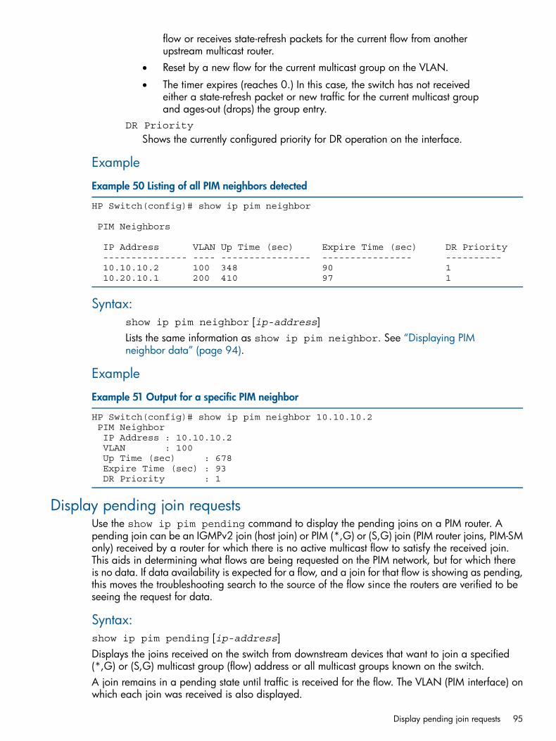
flow or receives state-refresh packets for the current flow from anotherupstream multicast router.
• Reset by a new flow for the current multicast group on the VLAN.
• The timer expires (reaches 0.) In this case, the switch has not receivedeither a state-refresh packet or new traffic for the current multicast groupand ages-out (drops) the group entry.
DR Priority
Shows the currently configured priority for DR operation on the interface.
Example
Example 50 Listing of all PIM neighbors detected
HP Switch(config)# show ip pim neighbor
PIM Neighbors
IP Address VLAN Up Time (sec) Expire Time (sec) DR Priority --------------- ---- ---------------- ---------------- ---------- 10.10.10.2 100 348 90 1 10.20.10.1 200 410 97 1
Syntax:show ip pim neighbor [ip-address]Lists the same information as show ip pim neighbor. See “Displaying PIMneighbor data” (page 94).
Example
Example 51 Output for a specific PIM neighbor
HP Switch(config)# show ip pim neighbor 10.10.10.2 PIM Neighbor IP Address : 10.10.10.2 VLAN : 100 Up Time (sec) : 678 Expire Time (sec) : 93 DR Priority : 1
Display pending join requestsUse the show ip pim pending command to display the pending joins on a PIM router. Apending join can be an IGMPv2 join (host join) or PIM (*,G) or (S,G) join (PIM router joins, PIM-SMonly) received by a router for which there is no active multicast flow to satisfy the received join.This aids in determining what flows are being requested on the PIM network, but for which thereis no data. If data availability is expected for a flow, and a join for that flow is showing as pending,this moves the troubleshooting search to the source of the flow since the routers are verified to beseeing the request for data.
Syntax:show ip pim pending [ip-address]Displays the joins received on the switch from downstream devices that want to join a specified(*,G) or (S,G) multicast group (flow) address or all multicast groups known on the switch.A join remains in a pending state until traffic is received for the flow. The VLAN (PIM interface) onwhich each join was received is also displayed.
Display pending join requests 95
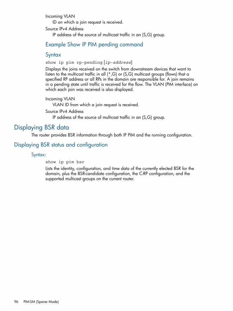
Incoming VLANID on which a join request is received.
Source IPv4 AddressIP address of the source of multicast traffic in an (S,G) group.
Example Show IP PIM pending command
Syntaxshow ip pim rp-pending [ip-address]Displays the joins received on the switch from downstream devices that want tolisten to the multicast traffic in all (*,G) or (S,G) multicast groups (flows) that aspecified RP address or all RPs in the domain are responsible for. A join remainsin a pending state until traffic is received for the flow. The VLAN (PIM interface) onwhich each join was received is also displayed.
Incoming VLANVLAN ID from which a join request is received.
Source IPv4 AddressIP address of the source of multicast traffic in an (S,G) group.
Displaying BSR dataThe router provides BSR information through both IP PIM and the running configuration.
Displaying BSR status and configuration
Syntax:show ip pim bsr
Lists the identity, configuration, and time data of the currently elected BSR for thedomain, plus the BSR-candidate configuration, the C-RP configuration, and thesupported multicast groups on the current router.
96 PIM-SM (Sparse Mode)
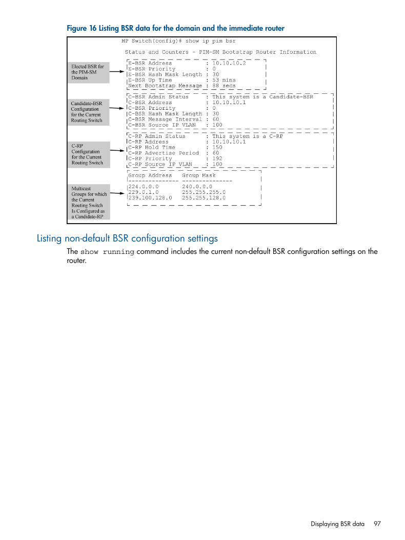
Figure 16 Listing BSR data for the domain and the immediate router
Listing non-default BSR configuration settingsThe show running command includes the current non-default BSR configuration settings on therouter.
Displaying BSR data 97
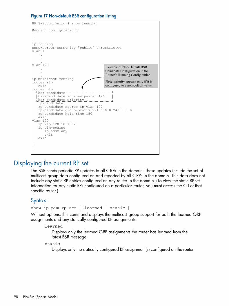
Figure 17 Non-default BSR configuration listing
bsr-candidate source-ip-vlan 120 bsr-candidate priority 1 rp-candidate rp-candidate source-ip-vlan 120 rp-candidate group-prefix 224.0.0.0 240.0.0.0 rp-candidate hold-time 150 exit
HP Switch(config)# show running
Running configuration:...ip routingsnmp-server community "public" Unrestrictedvlan 1 . . .vlan 120 . . .ip multicast-routingrouter rip exitrouter pim bsr-candidate
vlan 120 ip rip 120.10.10.2 ip pim-sparse ip-addr any exit exit...
Example of Non-Default BSR Candidate Configuration in the Router’s Running Configuration
Note: priority appears only if it is configured to a non-default value.
Displaying the current RP setThe BSR sends periodic RP updates to all C-RPs in the domain. These updates include the set ofmulticast group data configured on and reported by all C-RPs in the domain. This data does notinclude any static RP entries configured on any router in the domain. (To view the static RP-setinformation for any static RPs configured on a particular router, you must access the CLI of thatspecific router.)
Syntax:show ip pim rp-set [ learned | static ]Without options, this command displays the multicast group support for both the learned C-RPassignments and any statically configured RP assignments.
learned
Displays only the learned C-RP assignments the router has learned from thelatest BSR message.
static
Displays only the statically configured RP assignment(s) configured on the router.
98 PIM-SM (Sparse Mode)
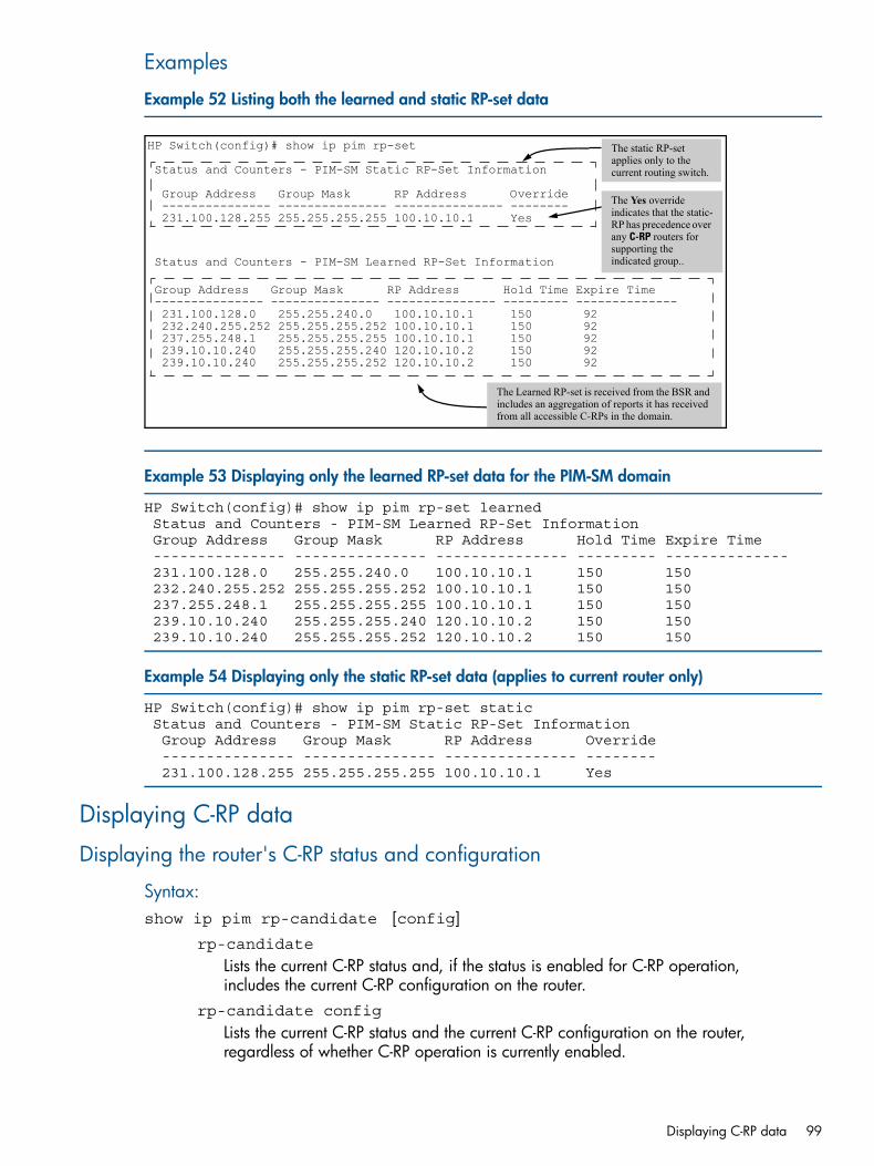
Examples
Example 52 Listing both the learned and static RP-set data
HP Switch(config)# show ip pim rp-set
Status and Counters - PIM-SM Static RP-Set Information
Group Address Group Mask RP Address Override --------------- --------------- --------------- -------- 231.100.128.255 255.255.255.255 100.10.10.1 Yes
Status and Counters - PIM-SM Learned RP-Set Information
Group Address Group Mask RP Address Hold Time Expire Time --------------- --------------- --------------- --------- -------------- 231.100.128.0 255.255.240.0 100.10.10.1 150 92 232.240.255.252 255.255.255.252 100.10.10.1 150 92 237.255.248.1 255.255.255.255 100.10.10.1 150 92 239.10.10.240 255.255.255.240 120.10.10.2 150 92 239.10.10.240 255.255.255.252 120.10.10.2 150 92
The static RP-set applies only to the current routing switch.
The Learned RP-set is received from the BSR and includes an aggregation of reports it has received from all accessible C-RPs in the domain.
The Yes override indicates that the static-RP has precedence over any C-RP routers for supporting the indicated group..
Example 53 Displaying only the learned RP-set data for the PIM-SM domain
HP Switch(config)# show ip pim rp-set learned Status and Counters - PIM-SM Learned RP-Set Information Group Address Group Mask RP Address Hold Time Expire Time --------------- --------------- --------------- --------- -------------- 231.100.128.0 255.255.240.0 100.10.10.1 150 150 232.240.255.252 255.255.255.252 100.10.10.1 150 150 237.255.248.1 255.255.255.255 100.10.10.1 150 150 239.10.10.240 255.255.255.240 120.10.10.2 150 150 239.10.10.240 255.255.255.252 120.10.10.2 150 150
Example 54 Displaying only the static RP-set data (applies to current router only)
HP Switch(config)# show ip pim rp-set static Status and Counters - PIM-SM Static RP-Set Information Group Address Group Mask RP Address Override --------------- --------------- --------------- -------- 231.100.128.255 255.255.255.255 100.10.10.1 Yes
Displaying C-RP data
Displaying the router's C-RP status and configuration
Syntax:show ip pim rp-candidate [config]
rp-candidate
Lists the current C-RP status and, if the status is enabled for C-RP operation,includes the current C-RP configuration on the router.
rp-candidate config
Lists the current C-RP status and the current C-RP configuration on the router,regardless of whether C-RP operation is currently enabled.
Displaying C-RP data 99
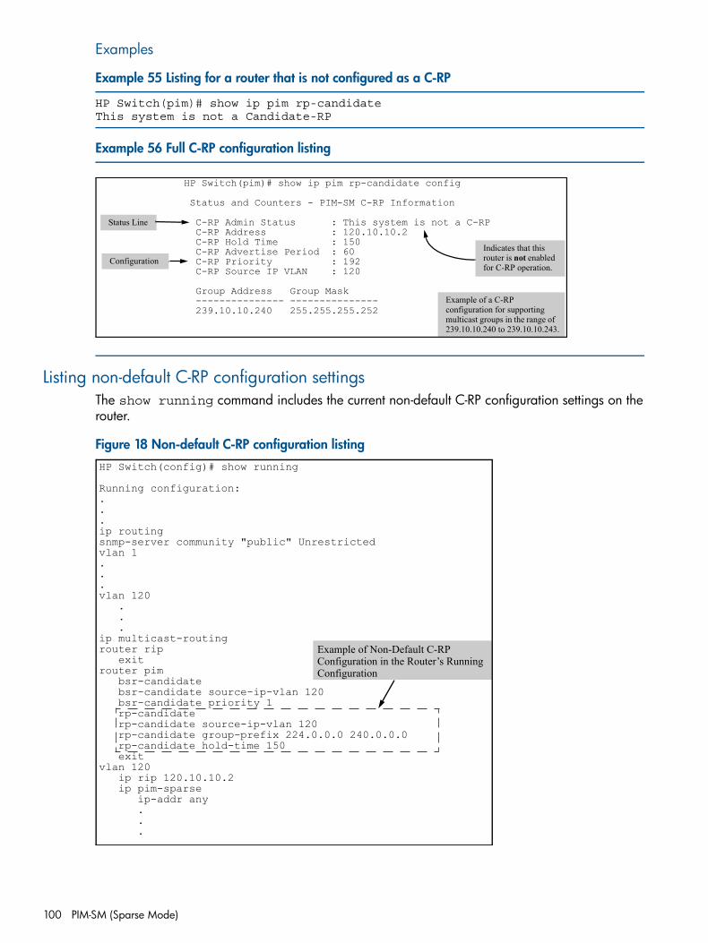
Examples
Example 55 Listing for a router that is not configured as a C-RP
HP Switch(pim)# show ip pim rp-candidateThis system is not a Candidate-RP
Example 56 Full C-RP configuration listing
HP Switch(pim)# show ip pim rp-candidate config
Status and Counters - PIM-SM C-RP Information
C-RP Admin Status : This system is not a C-RP C-RP Address : 120.10.10.2 C-RP Hold Time : 150 C-RP Advertise Period : 60 C-RP Priority : 192 C-RP Source IP VLAN : 120
Group Address Group Mask --------------- --------------- 239.10.10.240 255.255.255.252
Example of a C-RP configuration for supporting multicast groups in the range of 239.10.10.240 to 239.10.10.243.
Indicates that this router is not enabled for C-RP operation.
Status Line
Configuration
Listing non-default C-RP configuration settingsThe show running command includes the current non-default C-RP configuration settings on therouter.
Figure 18 Non-default C-RP configuration listingHP Switch(config)# show running
Running configuration:...ip routingsnmp-server community "public" Unrestrictedvlan 1...vlan 120 . . .ip multicast-routingrouter rip exitrouter pim bsr-candidate bsr-candidate source-ip-vlan 120 bsr-candidate priority 1 rp-candidate rp-candidate source-ip-vlan 120 rp-candidate group-prefix 224.0.0.0 240.0.0.0 rp-candidate hold-time 150 exitvlan 120 ip rip 120.10.10.2 ip pim-sparse ip-addr any . . .
Example of Non-Default C-RP Configuration in the Router’s Running Configuration
100 PIM-SM (Sparse Mode)
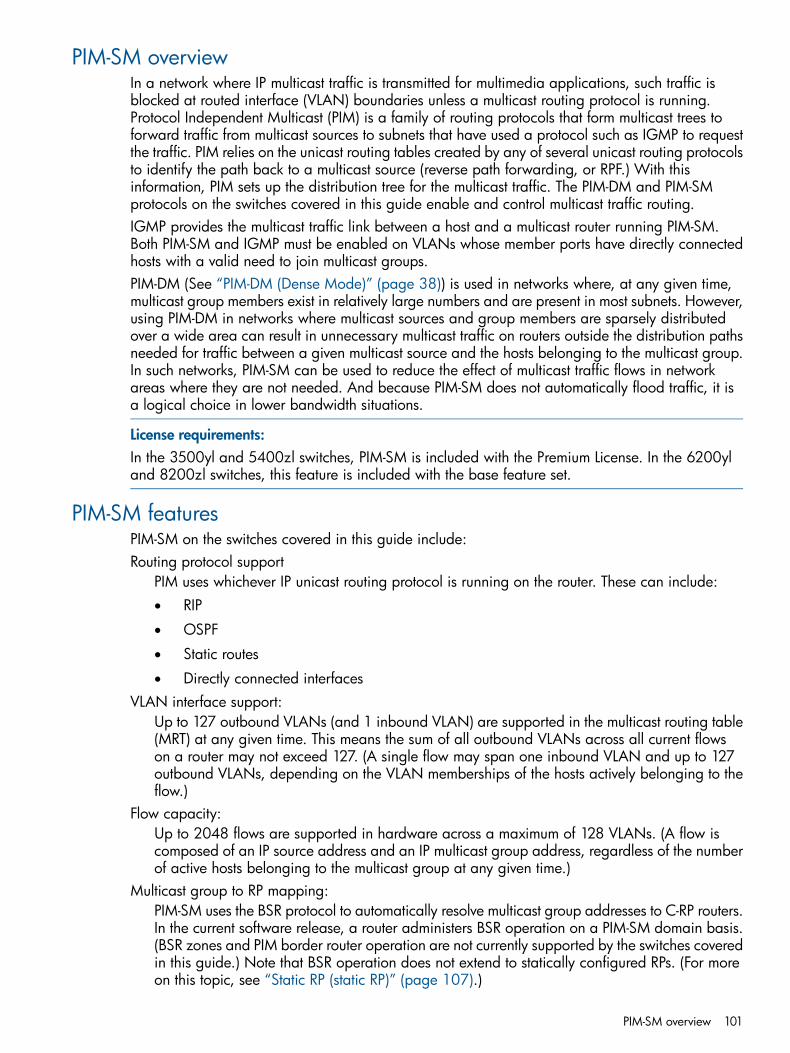
PIM-SM overviewIn a network where IP multicast traffic is transmitted for multimedia applications, such traffic isblocked at routed interface (VLAN) boundaries unless a multicast routing protocol is running.Protocol Independent Multicast (PIM) is a family of routing protocols that form multicast trees toforward traffic from multicast sources to subnets that have used a protocol such as IGMP to requestthe traffic. PIM relies on the unicast routing tables created by any of several unicast routing protocolsto identify the path back to a multicast source (reverse path forwarding, or RPF.) With thisinformation, PIM sets up the distribution tree for the multicast traffic. The PIM-DM and PIM-SMprotocols on the switches covered in this guide enable and control multicast traffic routing.IGMP provides the multicast traffic link between a host and a multicast router running PIM-SM.Both PIM-SM and IGMP must be enabled on VLANs whose member ports have directly connectedhosts with a valid need to join multicast groups.PIM-DM (See “PIM-DM (Dense Mode)” (page 38)) is used in networks where, at any given time,multicast group members exist in relatively large numbers and are present in most subnets. However,using PIM-DM in networks where multicast sources and group members are sparsely distributedover a wide area can result in unnecessary multicast traffic on routers outside the distribution pathsneeded for traffic between a given multicast source and the hosts belonging to the multicast group.In such networks, PIM-SM can be used to reduce the effect of multicast traffic flows in networkareas where they are not needed. And because PIM-SM does not automatically flood traffic, it isa logical choice in lower bandwidth situations.
License requirements:In the 3500yl and 5400zl switches, PIM-SM is included with the Premium License. In the 6200yland 8200zl switches, this feature is included with the base feature set.
PIM-SM featuresPIM-SM on the switches covered in this guide include:Routing protocol support
PIM uses whichever IP unicast routing protocol is running on the router. These can include:• RIP
• OSPF
• Static routes
• Directly connected interfacesVLAN interface support:
Up to 127 outbound VLANs (and 1 inbound VLAN) are supported in the multicast routing table(MRT) at any given time. This means the sum of all outbound VLANs across all current flowson a router may not exceed 127. (A single flow may span one inbound VLAN and up to 127outbound VLANs, depending on the VLAN memberships of the hosts actively belonging to theflow.)
Flow capacity:Up to 2048 flows are supported in hardware across a maximum of 128 VLANs. (A flow iscomposed of an IP source address and an IP multicast group address, regardless of the numberof active hosts belonging to the multicast group at any given time.)
Multicast group to RP mapping:PIM-SM uses the BSR protocol to automatically resolve multicast group addresses to C-RP routers.In the current software release, a router administers BSR operation on a PIM-SM domain basis.(BSR zones and PIM border router operation are not currently supported by the switches coveredin this guide.) Note that BSR operation does not extend to statically configured RPs. (For moreon this topic, see “Static RP (static RP)” (page 107).)
PIM-SM overview 101
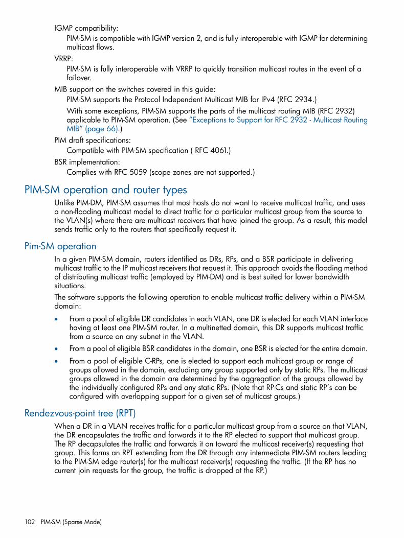
IGMP compatibility:PIM-SM is compatible with IGMP version 2, and is fully interoperable with IGMP for determiningmulticast flows.
VRRP:PIM-SM is fully interoperable with VRRP to quickly transition multicast routes in the event of afailover.
MIB support on the switches covered in this guide:PIM-SM supports the Protocol Independent Multicast MIB for IPv4 (RFC 2934.)With some exceptions, PIM-SM supports the parts of the multicast routing MIB (RFC 2932)applicable to PIM-SM operation. (See “Exceptions to Support for RFC 2932 - Multicast RoutingMIB” (page 66).)
PIM draft specifications:Compatible with PIM-SM specification ( RFC 4061.)
BSR implementation:Complies with RFC 5059 (scope zones are not supported.)
PIM-SM operation and router typesUnlike PIM-DM, PIM-SM assumes that most hosts do not want to receive multicast traffic, and usesa non-flooding multicast model to direct traffic for a particular multicast group from the source tothe VLAN(s) where there are multicast receivers that have joined the group. As a result, this modelsends traffic only to the routers that specifically request it.
Pim-SM operationIn a given PIM-SM domain, routers identified as DRs, RPs, and a BSR participate in deliveringmulticast traffic to the IP multicast receivers that request it. This approach avoids the flooding methodof distributing multicast traffic (employed by PIM-DM) and is best suited for lower bandwidthsituations.The software supports the following operation to enable multicast traffic delivery within a PIM-SMdomain:
• From a pool of eligible DR candidates in each VLAN, one DR is elected for each VLAN interfacehaving at least one PIM-SM router. In a multinetted domain, this DR supports multicast trafficfrom a source on any subnet in the VLAN.
• From a pool of eligible BSR candidates in the domain, one BSR is elected for the entire domain.
• From a pool of eligible C-RPs, one is elected to support each multicast group or range ofgroups allowed in the domain, excluding any group supported only by static RPs. The multicastgroups allowed in the domain are determined by the aggregation of the groups allowed bythe individually configured RPs and any static RPs. (Note that RP-Cs and static RP’s can beconfigured with overlapping support for a given set of multicast groups.)
Rendezvous-point tree (RPT)When a DR in a VLAN receives traffic for a particular multicast group from a source on that VLAN,the DR encapsulates the traffic and forwards it to the RP elected to support that multicast group.The RP decapsulates the traffic and forwards it on toward the multicast receiver(s) requesting thatgroup. This forms an RPT extending from the DR through any intermediate PIM-SM routers leadingto the PIM-SM edge router(s) for the multicast receiver(s) requesting the traffic. (If the RP has nocurrent join requests for the group, the traffic is dropped at the RP.)
102 PIM-SM (Sparse Mode)
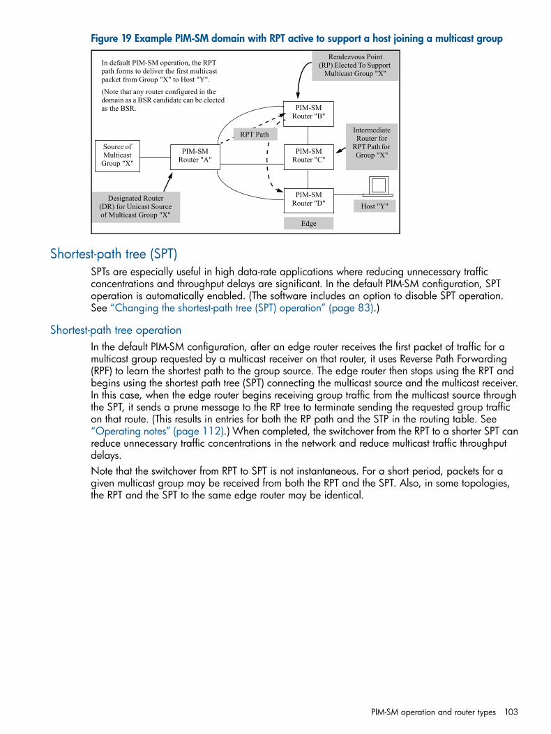
Figure 19 Example PIM-SM domain with RPT active to support a host joining a multicast group
PIM-SM Router "A"
PIM-SM Router "B"
PIM-SM Router "C"
PIM-SM Router "D"
Source of Multicast
Group "X"
RPT Path
Host "Y"Designated Router
(DR) for Unicast Source of Multicast Group "X"
Rendezvous Point(RP) Elected To Support
Multicast Group "X"
Edge
Intermediate Router for
RPT Path for Group "X"
In default PIM-SM operation, the RPT path forms to deliver the first multicast packet from Group "X" to Host "Y".
(Note that any router configured in the domain as a BSR candidate can be elected as the BSR.
Shortest-path tree (SPT)SPTs are especially useful in high data-rate applications where reducing unnecessary trafficconcentrations and throughput delays are significant. In the default PIM-SM configuration, SPToperation is automatically enabled. (The software includes an option to disable SPT operation.See “Changing the shortest-path tree (SPT) operation” (page 83).)
Shortest-path tree operationIn the default PIM-SM configuration, after an edge router receives the first packet of traffic for amulticast group requested by a multicast receiver on that router, it uses Reverse Path Forwarding(RPF) to learn the shortest path to the group source. The edge router then stops using the RPT andbegins using the shortest path tree (SPT) connecting the multicast source and the multicast receiver.In this case, when the edge router begins receiving group traffic from the multicast source throughthe SPT, it sends a prune message to the RP tree to terminate sending the requested group trafficon that route. (This results in entries for both the RP path and the STP in the routing table. See“Operating notes” (page 112).) When completed, the switchover from the RPT to a shorter SPT canreduce unnecessary traffic concentrations in the network and reduce multicast traffic throughputdelays.Note that the switchover from RPT to SPT is not instantaneous. For a short period, packets for agiven multicast group may be received from both the RPT and the SPT. Also, in some topologies,the RPT and the SPT to the same edge router may be identical.
PIM-SM operation and router types 103
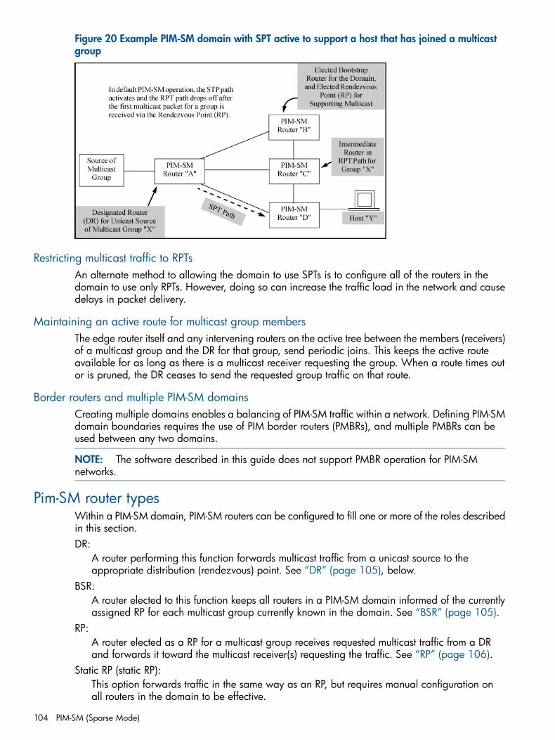
Figure 20 Example PIM-SM domain with SPT active to support a host that has joined a multicastgroup
Restricting multicast traffic to RPTsAn alternate method to allowing the domain to use SPTs is to configure all of the routers in thedomain to use only RPTs. However, doing so can increase the traffic load in the network and causedelays in packet delivery.
Maintaining an active route for multicast group membersThe edge router itself and any intervening routers on the active tree between the members (receivers)of a multicast group and the DR for that group, send periodic joins. This keeps the active routeavailable for as long as there is a multicast receiver requesting the group. When a route times outor is pruned, the DR ceases to send the requested group traffic on that route.
Border routers and multiple PIM-SM domainsCreating multiple domains enables a balancing of PIM-SM traffic within a network. Defining PIM-SMdomain boundaries requires the use of PIM border routers (PMBRs), and multiple PMBRs can beused between any two domains.
NOTE: The software described in this guide does not support PMBR operation for PIM-SMnetworks.
Pim-SM router typesWithin a PIM-SM domain, PIM-SM routers can be configured to fill one or more of the roles describedin this section.DR:
A router performing this function forwards multicast traffic from a unicast source to theappropriate distribution (rendezvous) point. See “DR” (page 105), below.
BSR:A router elected to this function keeps all routers in a PIM-SM domain informed of the currentlyassigned RP for each multicast group currently known in the domain. See “BSR” (page 105).
RP:A router elected as a RP for a multicast group receives requested multicast traffic from a DRand forwards it toward the multicast receiver(s) requesting the traffic. See “RP” (page 106).
Static RP (static RP):This option forwards traffic in the same way as an RP, but requires manual configuration onall routers in the domain to be effective.
104 PIM-SM (Sparse Mode)
All of the above functions can be enabled on each of several routers in a PIMSM domain.
DRIn a VLAN populated by one or more routers running PIM-SM, one such router is elected the DRfor that VLAN. When the DR receives a Join request from a multicast receiver on that VLAN, itforwards the join toward the router operating as the RP for the requested multicast group.Where multiple PIM-SM routers exist in a VLAN, the following criteria is used to elect a DR:1. The router configured with the highest DR priority in the VLAN is elected.2. If multiple routers in the VLAN are configured with the highest DR priority, the router having
the highest IP address is elected.In a given domain, each VLAN capable of receiving multicast traffic from a unicast source shouldhave at least one DR. (Enabling PIM-SM on a VLAN automatically enables the router as a DR forthat VLAN.) Because there is an election process for DR on each VLAN, all routers on a VLANneed to be enabled for DR. Where it is important to ensure that a particular router is elected asthe DR for a given VLAN, you can increase the DR priority on that VLAN configuration for thatrouter.If it is necessary to prevent a router from operating as a DR on a given VLAN, disable DR operationby configuring the DR priority as zero (0.)
BSRBefore a DR can forward encapsulated packets for a specific multicast group to an RP, it must knowwhich router in the domain is the elected RP for that multicast group. The BSR function enables thisoperation by doing the following:1. Learns the group-to-RP mappings on the C-RPs in the domain by reading the periodic
advertisements each one sends to the BSR.2. Distributes the aggregate C-RP information as an RP-set to the PIM-SM routers in the domain.
This is followed by an election to assign a specific multicast group or range of groups to theC-RPs in the domain. (The software supports assignment of up to four multicast addressesand/or ranges of multicast addresses to a C-RP.)
The BSR periodically sends bootstrap messages to the other PIM-SM routers in the domain tomaintain and update the RP-set data throughout the domain, and to maintain its status as the electedBSR.
NOTE: Where static RPs are configured in the domain to support the same multicast group(s) asone or more (dynamic) C-RPs, then the RP-set data has the precedence for assigning RPs for thesegroups unless the static RPs have been configured with the override option and if the multicastgroup mask for the static RP equals or exceeds the same mask for the applicable C-RP(s.)
BSR configuration and electionThere should be multiple BSR candidates configured in a PIM-SM domain so that if the elected BSRbecomes unavailable, another router will take its place. In the BSR election process, the BSRcandidate configured with the highest priority number is selected. Where the highest priority settingis shared by multiple candidates, the candidate having the highest IP address is selected. In theevent that the selected BSR subsequently fails, another election takes place among the remainingBSR candidates. To facilitate a predictable BSR election, configure a higher priority on the routeryou want elected as the BSR for the domain.
NOTE: A router serving as the BSR for a domain should be central to the network topology. Thishelps to ensure optimal performance and also reduce the possibility of a network problem isolatingthe BSR.
Pim-SM router types 105
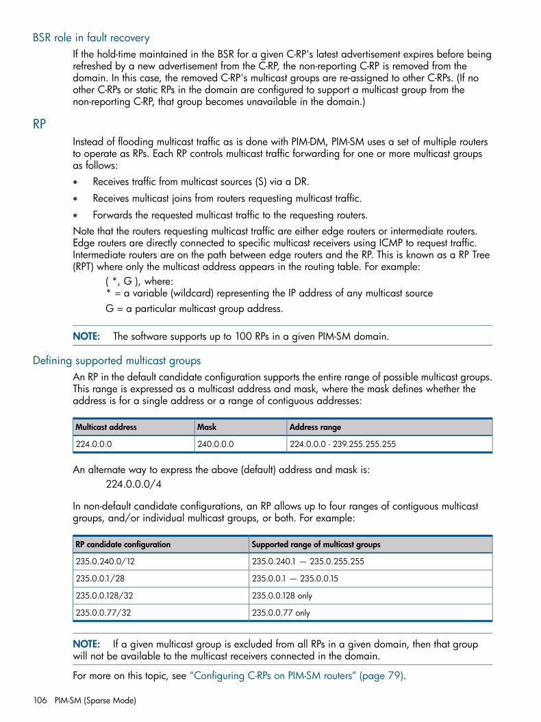
BSR role in fault recoveryIf the hold-time maintained in the BSR for a given C-RP's latest advertisement expires before beingrefreshed by a new advertisement from the C-RP, the non-reporting C-RP is removed from thedomain. In this case, the removed C-RP's multicast groups are re-assigned to other C-RPs. (If noother C-RPs or static RPs in the domain are configured to support a multicast group from thenon-reporting C-RP, that group becomes unavailable in the domain.)
RPInstead of flooding multicast traffic as is done with PIM-DM, PIM-SM uses a set of multiple routersto operate as RPs. Each RP controls multicast traffic forwarding for one or more multicast groupsas follows:• Receives traffic from multicast sources (S) via a DR.
• Receives multicast joins from routers requesting multicast traffic.
• Forwards the requested multicast traffic to the requesting routers.Note that the routers requesting multicast traffic are either edge routers or intermediate routers.Edge routers are directly connected to specific multicast receivers using ICMP to request traffic.Intermediate routers are on the path between edge routers and the RP. This is known as a RP Tree(RPT) where only the multicast address appears in the routing table. For example:
( *, G ), where:* = a variable (wildcard) representing the IP address of any multicast sourceG = a particular multicast group address.
NOTE: The software supports up to 100 RPs in a given PIM-SM domain.
Defining supported multicast groupsAn RP in the default candidate configuration supports the entire range of possible multicast groups.This range is expressed as a multicast address and mask, where the mask defines whether theaddress is for a single address or a range of contiguous addresses:
Address rangeMaskMulticast address
224.0.0.0 - 239.255.255.255240.0.0.0224.0.0.0
An alternate way to express the above (default) address and mask is:224.0.0.0/4
In non-default candidate configurations, an RP allows up to four ranges of contiguous multicastgroups, and/or individual multicast groups, or both. For example:
Supported range of multicast groupsRP candidate configuration
235.0.240.1 — 235.0.255.255235.0.240.0/12
235.0.0.1 — 235.0.0.15235.0.0.1/28
235.0.0.128 only235.0.0.128/32
235.0.0.77 only235.0.0.77/32
NOTE: If a given multicast group is excluded from all RPs in a given domain, then that groupwill not be available to the multicast receivers connected in the domain.
For more on this topic, see “Configuring C-RPs on PIM-SM routers” (page 79).
106 PIM-SM (Sparse Mode)
C-RP electionWithin a PIM-SM domain, different RPs support different multicast addresses or ranges of multicastaddresses. (That is, a given PIM-SM multicast group or range of groups is supported by only oneactive RP, although other C-RPs can also be configured with overlapping or identical support.)A C-RP's group-prefix configuration identifies the multicast groups the RP is enabled to support.If multiple C-RPs have group-prefixes configured so that any of these RPs can support a givenmulticast group, then the following criteria are used to select the RP to support the group:1. The C-RP configured with the longest group-prefix mask applicable to the multicast group is
selected to support the group. Step 2 of this procedure applies if multiple RP candidates meetthis criterion.
2. The C-RP configured with the highest priority is selected. Step 3 of this procedure applies ifmultiple RP candidates meet this criterion.
3. A hash function (using the configured bsr-candidate hash-mask-length value) generatesa series of mask length values that are individually assigned to the set of eligible C-RPs. If thehash function matches a single RP candidate to a longer mask length than the other candidates,that candidate is selected to support the group. Apply step 4 of this procedure if the hashfunction matches the longest mask length to multiple RP candidates.
4. The C-RP having the highest IP address is selected to support the group.
NOTE: In a PIM-SM domain where there are overlapping ranges of multicast groups configuredon the C-RPs, discrete ranges of these groups are assigned to the domain's C-RPs in blocks ofsequential group numbers. The number of multicast groups in the blocks assigned within a givendomain is determined by the bsr-candidate hash-mask-length value (range=1 to 32)configured on the elected BSR for the domain. A higher value means fewer sequential groupnumbers in each block of sequential group numbers, which results in a wider dispersal of multicastgroups across the C-RPs in the domain.As indicated above, multiple C-RPs can be configured to support the same multicast group(s.) Thisis the generally recommended practice and results in redundancy that helps to prevent loss ofsupport for desired multicast groups in the event that a router in the domain becomes unavailable.Configuring a C-RP to support a given multicast group does not ensure election of the C-RP tosupport that group unless the group is excluded from all other RPs in the domain.
Also, within a PIM-SM domain, a router can be configured as a C-RP available for a given multicastgroup or range of groups and as the static RP for a given multicast group or range of groups. Therecommended practice is to use C-RPs for all multicast groups unless there is a need to ensure thata specific group or range of groups is always supported by the same routing switch. See “StaticRP (static RP)” (page 107).
Redundant Group Coverage Provides Fault-ToleranceIf a C-RP elected to support a particular multicast group or range of groups becomes unavailable,the router is excluded from the RP-set. If the multicast group configuration of one or more otherC-RPs overlaps the configuration in the failed RP, then another C-RP is elected to support the multicastgroup(s) formerly relying on the failed RP.
Static RP (static RP)
General applicationLike C-RPs, static RPs control multicast forwarding of specific multicast groups or ranges of contiguousgroups. However, static RPs are not dynamically learned, and increase the configuration and
Pim-SM router types 107
monitoring effort needed to maintain them. As a result, static RPs are not generally recommendedfor use except where one of the following conditions applies:• It is desirable to designate a specific router interface as a backup RP for specific group(s.)
• Specific multicast groups are expected, and a static RP would help to avoid overloading agiven RP with a high volume of multicast traffic.
• A C-RP for the same group(s) is less reliable than another RP that would not normally be electedto support the group(s.)
• Tighter traffic control or a higher priority is desired for specific multicast groups
NOTE: While the use of C-RPs and a BSR enable a dynamic selection of RPs for the multicastgroup traffic in a network, using static RPs involves manually configuring all routers in the domainto be aware of each static RP. This can increase the possibility of multicast traffic failure from tomisconfigurations within the PIM-SM domain. Also, because a BSR does not administer static RPs,troubleshooting PIM-SM traffic problems can become more complex. For these reasons, use ofstatic RPs should be limited to applications where no viable alternatives exist, or where the networkis stable and requires configuring and maintaining only a few routers.If a static RP operating as the primary RP for a multicast group fails, and the PIM-SM configurationin the domain does not include a (secondary) dynamic RP (C-RP) backup to the static RP, then newmulticast groups assigned to the static RP will not be available to multicast receivers in the domain.Also, if a static RP fails, support for existing groups routed through SPTs that exclude the failedrouter will continue, but any existing flows routed through the RPT will fail.
Supporting a static RP as primaryA static RP can be configured to operate as either a secondary or primary RP. With the primaryoption, a dynamic (C-RP) backup is recommended. The precedence of a static RP over a dynamicRP is determined by the following static RP configuration options:• override enabled on the static RP.
• A group mask on the static RP that equals or exceeds the group mask on the C-RP for the samemulticast group(s.)
For override configuration information, see “Statically configuring an RP to accept multicasttraffic” (page 83).
Operating rules for static RPs
• Static RPs can be configured on the same routers as C-RPs.
• Where a C-RP and a static RP are configured to support the same multicast group(s), the C-RPtakes precedence over the static RP unless the static RP is configured to override the C-RP. (See“Supporting a static RP as primary” (page 108).)
• Any static RP in a domain must be configured identically on all routers in the domain.Otherwise, some DRs will not know of the static RP and will not forward the appropriatemulticast traffic, and some routers will not know where to send Joins for the groups supportedby static RP.
• Up to four static RP entries can be configured on a router. Each entry can be for either a singlemulticast group or a range of contiguous groups.
• Only one interface can be configured as the static RP for a given multicast group or range ofgroups. For example, a properly configured PIM-SM domain does not support configuring10.10.10.1 and 10.20.10.1 to both support a multicast group identified as 239.255.255.10.
108 PIM-SM (Sparse Mode)
• Static RPs are not included in the RP-set messages generated by the BSR, and do not generateadvertisements.
• If a static RP becomes unavailable, it is necessary to remove and/or replace the configurationfor this RP in all routers in the domain.
ConfigurationSee “Statically configuring an RP to accept multicast traffic” (page 83).
Operating rules and recommendationsGuideline for configuring C-RPs and BSRs
Routers in a PIM-SM domain should usually be configured as both C-RPs and candidate BSRs;this can reduce some overhead traffic.
The SPT policy should be the same for all RPs in a domain.Allowing some RPs to remain configured to implement SPTs while configuring other RPs in thesame domain to force RPT use can result in unstable traffic flows. (Use the [no] ippim-sparse spt-threshold command to change between SPT and RPT operation oneach router.)
Application of RPs to multicast groups.In a PIM-SM domain, a given multicast group or range of groups can be supported by onlyone RP. (Typically, multiple C-RPs in a domain are configured with overlapping coverage ofmulticast groups, but only one such candidate will be elected to support a given group.)
Ensuring that the C-RPs in a PIM-SM domain cover all desired multicast groups.All of the multicast groups you want to allow in a given PIM-SM domain must be included inthe aggregate of the multicast groups configured in the domain's C-RPs. In most cases, all C-RPsin a domain should be configured to support all RP groups (the default configuration for arouter enabled as a C-RP.) This provides redundancy in case an RP becomes unavailable. (Ifthe C-RP supporting a particular multicast group becomes unavailable, another C-RP is electedto support the group as long as there is redundancy in the C-RP configuration for multiplerouters.) Note that is cases where routers are statically configured to support a specific groupor range of groups, the C-RP prioritization mechanism allows for redundant support.
PIM-SM and PIM-DM.These two features cannot both be enabled on the same router at the same time.
Supporting PIM-SM across a PIM Domain.To properly move multicast traffic across a PIM-SM domain, all routers in the domain must beconfigured to support PIM-SM. That is, a router without PIM-SM capability blocks routed multicasttraffic in a PIM-SM domain.
Configuration steps for PIM-SMThis process assumes that the necessary VLANs and IP addressing have already been configuredon the routing switch.
NOTE: The switches described in this guide do not support PMBR operation in the current softwarerelease.
Planning considerations• Where multiple routers are available to operate as the DR for a given source, set the DR
priority on each router according to how you want the router used.• Determine whether there are any bandwidth considerations that would call for disabling SPT
operation. (If any routers in the domain have SPT operation disabled, it should be disabledon all RPs in the domain. See “Operating rules for static RPs” (page 108).)
Operating rules and recommendations 109
• Determine the routers to configure as C-BSRs. In many applications, the best choice may beto configure all routers in the domain as candidates for this function.
• Determine the multicast group support you want on each C-RP and any static RPs in the domain.The easiest option is to enable C-RP to support all possible multicast groups on all routers inthe domain. However, if there are traffic control considerations you want to apply, you canlimit specific multicast groups to specific routers and/or set priorities so that default trafficroutes support optimum bandwidth usage.
Per-router global configuration contextUse these steps to enable routing and PIM operation in the global configuration context of eachPIM-SM router (HP(config)#_):1. Enable routing. (Use ip routing.)2. Enable multicast routing. (Use ip multicast-routing.)3. Enable PIM. (Use router pim.)
4. Configure the routing method(s) needed to reach the interfaces (VLANs) on which you wantmulticast traffic available for multicast receivers in your network:• Enable RIP or OSPF. (Use routerrip|ospf )
• If desired, configure static routes to the destination subnets. (Use ip routedest-ip-address/mask-bits next-hop-ip-addr.)
Per-VLAN PIM-SM configurationThese steps configure PIM-SM in the VLAN interface context for each VLAN configured on therouter (HP Switch(vlan-vid)#_.)1. Enable IGMP. (Use ip igmp.) Repeat this action on every router (and switch) having
membership in the VLAN.2. For both the global and VLAN levels on the routers where there are connected multicast
receivers that may issue joins or send multicast traffic, use the same routing method as Step4 of this procedure.
3. Enable PIM-SM on the VLAN interfaces where you want to allow routed multicast traffic.(Default: disabled)a. If these VLANs do not already have static IP addresses, then statically configure one or
more IP addresses on each VLAN you want to support PIM-SM operation. (PIM-SM cannotbe enabled on a VLAN that does not have a statically configured IP address. That is,PIM-SM cannot use an IP address acquired by DHCP/Bootp.)
b. Use ip pim-sparse to enter the VLAN's pim-sparse context and do one of thefollowing:• Enable PIM-SM on the VLAN and allow the default option (any) to dynamically
determine the source IP address for the PIM-SM packets sent from this VLAN interface.• Enable PIM-SM on the VLAN and allow the default option (any) to dynamically
determine the source IP address for the PIM-SM packets sent from this VLAN interface.• Enable PIM-SM on the VLAN and specify an IP address for the PIM-SM packets sent
from this VLAN interface. (The specified IP address must already be staticallyconfigured on the VLAN.)
110 PIM-SM (Sparse Mode)
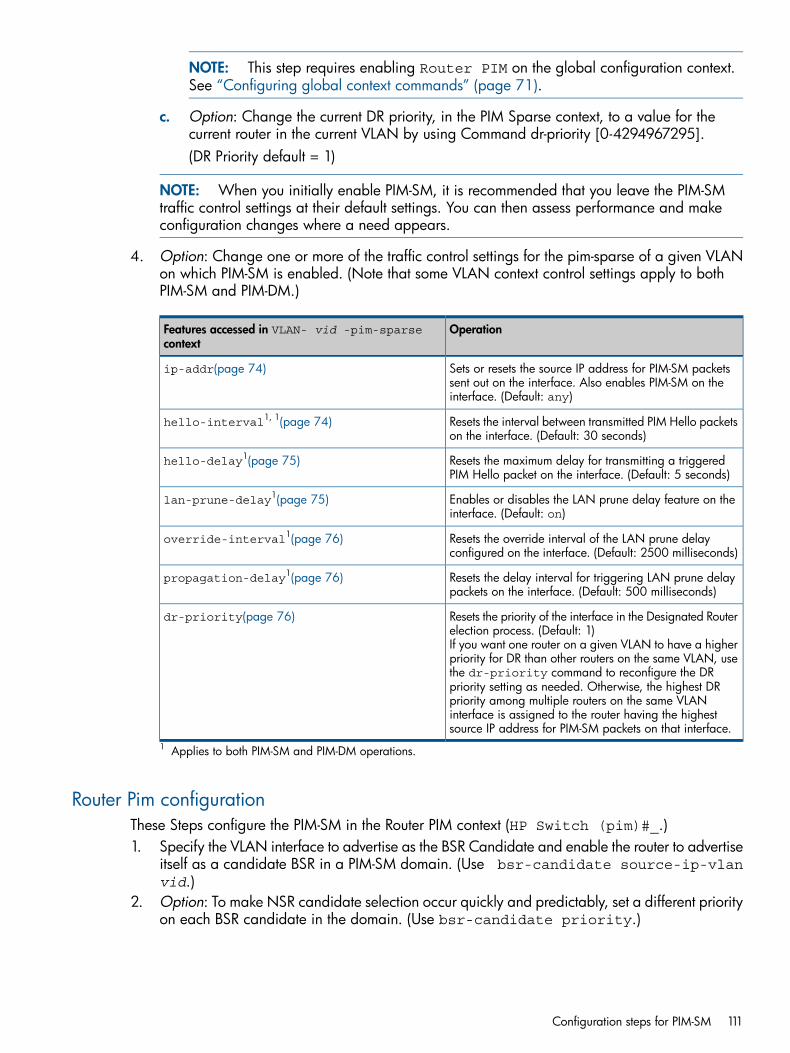
NOTE: This step requires enabling Router PIM on the global configuration context.See “Configuring global context commands” (page 71).
c. Option: Change the current DR priority, in the PIM Sparse context, to a value for thecurrent router in the current VLAN by using Command dr-priority [0-4294967295].(DR Priority default = 1)
NOTE: When you initially enable PIM-SM, it is recommended that you leave the PIM-SMtraffic control settings at their default settings. You can then assess performance and makeconfiguration changes where a need appears.
4. Option: Change one or more of the traffic control settings for the pim-sparse of a given VLANon which PIM-SM is enabled. (Note that some VLAN context control settings apply to bothPIM-SM and PIM-DM.)
OperationFeatures accessed in VLAN- vid -pim-sparsecontext
Sets or resets the source IP address for PIM-SM packetssent out on the interface. Also enables PIM-SM on theinterface. (Default: any)
ip-addr(page 74)
Resets the interval between transmitted PIM Hello packetson the interface. (Default: 30 seconds)
hello-interval1, 1(page 74)
Resets the maximum delay for transmitting a triggeredPIM Hello packet on the interface. (Default: 5 seconds)
hello-delay1(page 75)
Enables or disables the LAN prune delay feature on theinterface. (Default: on)
lan-prune-delay1(page 75)
Resets the override interval of the LAN prune delayconfigured on the interface. (Default: 2500 milliseconds)
override-interval1(page 76)
Resets the delay interval for triggering LAN prune delaypackets on the interface. (Default: 500 milliseconds)
propagation-delay1(page 76)
Resets the priority of the interface in the Designated Routerelection process. (Default: 1)If you want one router on a given VLAN to have a higherpriority for DR than other routers on the same VLAN, usethe dr-priority command to reconfigure the DRpriority setting as needed. Otherwise, the highest DRpriority among multiple routers on the same VLANinterface is assigned to the router having the highestsource IP address for PIM-SM packets on that interface.
dr-priority(page 76)
1 Applies to both PIM-SM and PIM-DM operations.
Router Pim configurationThese Steps configure the PIM-SM in the Router PIM context (HP Switch (pim)#_.)1. Specify the VLAN interface to advertise as the BSR Candidate and enable the router to advertise
itself as a candidate BSR in a PIM-SM domain. (Use bsr-candidate source-ip-vlanvid.)
2. Option: To make NSR candidate selection occur quickly and predictably, set a different priorityon each BSR candidate in the domain. (Use bsr-candidate priority.)
Configuration steps for PIM-SM 111
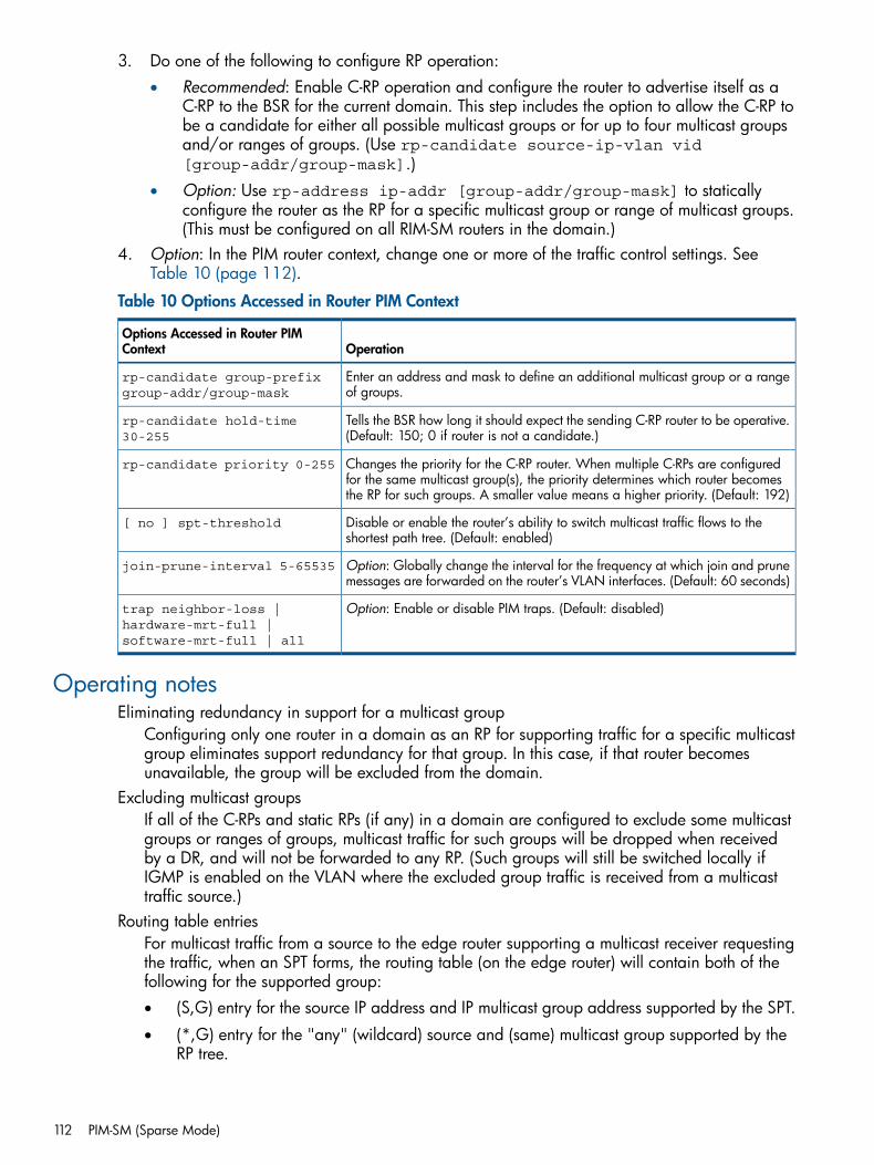
3. Do one of the following to configure RP operation:• Recommended: Enable C-RP operation and configure the router to advertise itself as a
C-RP to the BSR for the current domain. This step includes the option to allow the C-RP tobe a candidate for either all possible multicast groups or for up to four multicast groupsand/or ranges of groups. (Use rp-candidate source-ip-vlan vid[group-addr/group-mask].)
• Option: Use rp-address ip-addr [group-addr/group-mask] to staticallyconfigure the router as the RP for a specific multicast group or range of multicast groups.(This must be configured on all RIM-SM routers in the domain.)
4. Option: In the PIM router context, change one or more of the traffic control settings. SeeTable 10 (page 112).
Table 10 Options Accessed in Router PIM Context
OperationOptions Accessed in Router PIMContext
Enter an address and mask to define an additional multicast group or a rangeof groups.
rp-candidate group-prefixgroup-addr/group-mask
Tells the BSR how long it should expect the sending C-RP router to be operative.(Default: 150; 0 if router is not a candidate.)
rp-candidate hold-time30-255
Changes the priority for the C-RP router. When multiple C-RPs are configuredfor the same multicast group(s), the priority determines which router becomesthe RP for such groups. A smaller value means a higher priority. (Default: 192)
rp-candidate priority 0-255
Disable or enable the router’s ability to switch multicast traffic flows to theshortest path tree. (Default: enabled)
[ no ] spt-threshold
Option: Globally change the interval for the frequency at which join and prunemessages are forwarded on the router’s VLAN interfaces. (Default: 60 seconds)
join-prune-interval 5-65535
Option: Enable or disable PIM traps. (Default: disabled)trap neighbor-loss |hardware-mrt-full |software-mrt-full | all
Operating notesEliminating redundancy in support for a multicast group
Configuring only one router in a domain as an RP for supporting traffic for a specific multicastgroup eliminates support redundancy for that group. In this case, if that router becomesunavailable, the group will be excluded from the domain.
Excluding multicast groupsIf all of the C-RPs and static RPs (if any) in a domain are configured to exclude some multicastgroups or ranges of groups, multicast traffic for such groups will be dropped when receivedby a DR, and will not be forwarded to any RP. (Such groups will still be switched locally ifIGMP is enabled on the VLAN where the excluded group traffic is received from a multicasttraffic source.)
Routing table entriesFor multicast traffic from a source to the edge router supporting a multicast receiver requestingthe traffic, when an SPT forms, the routing table (on the edge router) will contain both of thefollowing for the supported group:• (S,G) entry for the source IP address and IP multicast group address supported by the SPT.
• (*,G) entry for the "any" (wildcard) source and (same) multicast group supported by theRP tree.
112 PIM-SM (Sparse Mode)
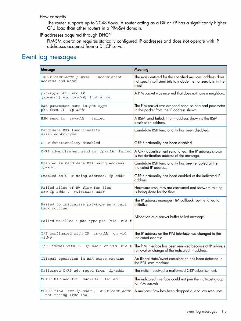
Flow capacityThe router supports up to 2048 flows. A router acting as a DR or RP has a significantly higherCPU load than other routers in a PIM-SM domain.
IP addresses acquired through DHCPPIM-SM operation requires statically configured IP addresses and does not operate with IPaddresses acquired from a DHCP server.
Event log messages
MeaningMessage
The mask entered for the specified multicast address doesnot specify sufficient bits to include the nonzero bits in themask.
multicast-addr / mask Inconsistent address and mask.
A PIM packet was received that does not have a neighbor..pkt-type pkt, src IP [ip-addr] vid [vid-#] (not a nbr)
The PIM packet was dropped because of a bad parameterin the packet from the IP address shown.
Bad parameter-name in pkt-typepkt from IP ip-addr
A BSM send failed. The IP address shown is the BSMdestination address.
BSM send to ip-addr failed
Candidate BSR functionality has been disabled.Candidate BSR functionality disabledpkt-type
C-RP functionality has been disabled.C-RP functionality disabled
A C-RP advertisement send failed. The IP address shownis the destination address of the message.
C-RP advertisement send to ip-addr failed
Candidate BSR functionality has been enabled at theindicated IP address.
Enabled as Candidate BSR using address:ip-addr
C-RP functionality has been enabled at the indicated IPaddress.
Enabled as C-RP using address: ip-addr
Hardware resources are consumed and software routingis being done for the flow.
Failed alloc of HW flow for flowsrc-ip-addr , multicast-addr
The IP address manager PIM callback routine failed toinitialize.Failed to initialize pkt-type as a call
back routine
Allocation of a packet buffer failed message.Failed to alloc a pkt-type pkt (vid vid-#)
The IP address on the PIM interface has changed to theindicated address.
I/F configured with IP ip-addr on vid vid-#
The PIM interface has been removed because of IP addressremoval or change of the indicated IP address.
I/F removal with IP ip-addr on vid vid-#
An illegal state/event combination has been detected inthe BSR state machine.
Illegal operation in BSR state machine
The switch received a malformed C-RP-advertisement.Malformed C-RP adv recvd from ip-addr
The indicated interface could not join the multicast groupfor PIM packets.
MCAST MAC add for mac-addr failed
A multicast flow has been dropped due to low resourcesMCAST flow src-ip-addr , multicast-addr not rteing (rsc low)
Event log messages 113
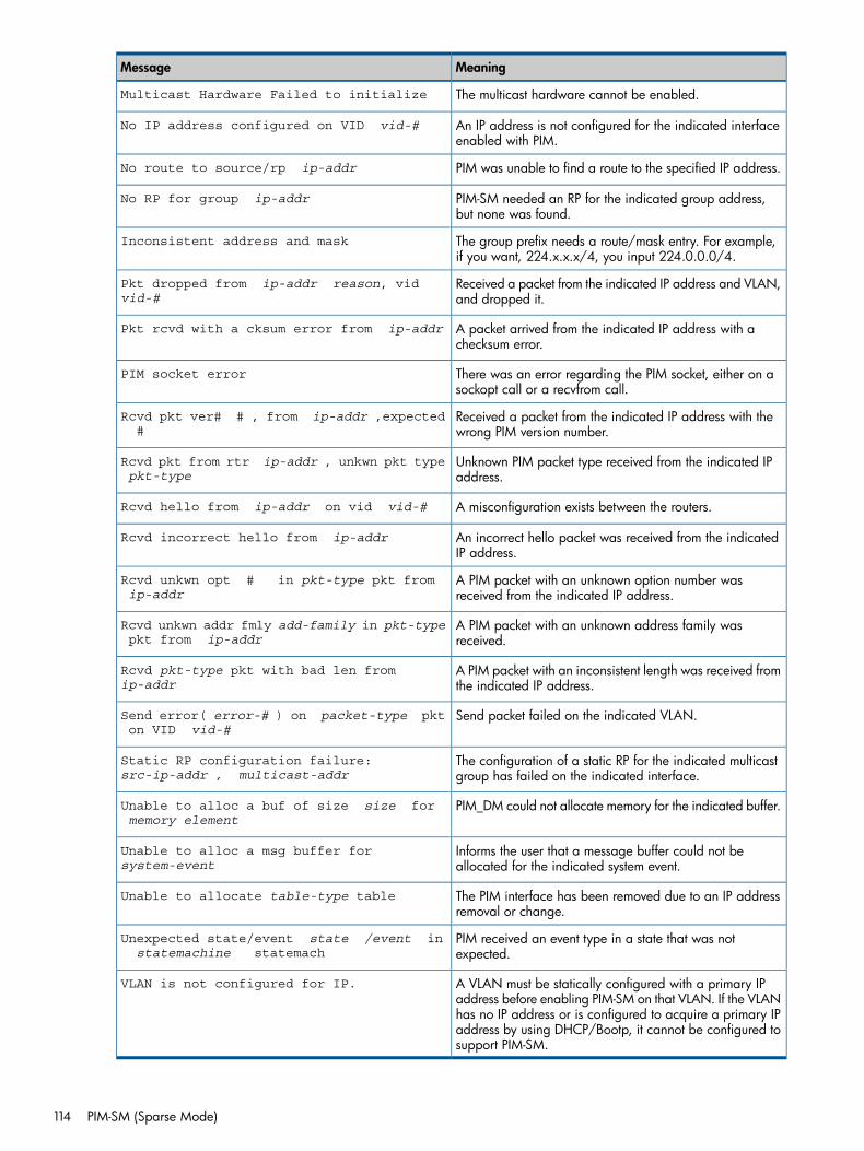
MeaningMessage
The multicast hardware cannot be enabled.Multicast Hardware Failed to initialize
An IP address is not configured for the indicated interfaceenabled with PIM.
No IP address configured on VID vid-#
PIM was unable to find a route to the specified IP address.No route to source/rp ip-addr
PIM-SM needed an RP for the indicated group address,but none was found.
No RP for group ip-addr
The group prefix needs a route/mask entry. For example,if you want, 224.x.x.x/4, you input 224.0.0.0/4.
Inconsistent address and mask
Received a packet from the indicated IP address and VLAN,and dropped it.
Pkt dropped from ip-addr reason, vid vid-#
A packet arrived from the indicated IP address with achecksum error.
Pkt rcvd with a cksum error from ip-addr
There was an error regarding the PIM socket, either on asockopt call or a recvfrom call.
PIM socket error
Received a packet from the indicated IP address with thewrong PIM version number.
Rcvd pkt ver# # , from ip-addr ,expected #
Unknown PIM packet type received from the indicated IPaddress.
Rcvd pkt from rtr ip-addr , unkwn pkt typepkt-type
A misconfiguration exists between the routers.Rcvd hello from ip-addr on vid vid-#
An incorrect hello packet was received from the indicatedIP address.
Rcvd incorrect hello from ip-addr
A PIM packet with an unknown option number wasreceived from the indicated IP address.
Rcvd unkwn opt # in pkt-type pkt from ip-addr
A PIM packet with an unknown address family wasreceived.
Rcvd unkwn addr fmly add-family in pkt-type pkt from ip-addr
A PIM packet with an inconsistent length was received fromthe indicated IP address.
Rcvd pkt-type pkt with bad len from ip-addr
Send packet failed on the indicated VLAN.Send error( error-# ) on packet-type pkt on VID vid-#
The configuration of a static RP for the indicated multicastgroup has failed on the indicated interface.
Static RP configuration failure:src-ip-addr , multicast-addr
PIM_DM could not allocate memory for the indicated buffer.Unable to alloc a buf of size size for memory element
Informs the user that a message buffer could not beallocated for the indicated system event.
Unable to alloc a msg buffer for system-event
The PIM interface has been removed due to an IP addressremoval or change.
Unable to allocate table-type table
PIM received an event type in a state that was notexpected.
Unexpected state/event state /event instatemachine statemach
A VLAN must be statically configured with a primary IPaddress before enabling PIM-SM on that VLAN. If the VLAN
VLAN is not configured for IP.
has no IP address or is configured to acquire a primary IPaddress by using DHCP/Bootp, it cannot be configured tosupport PIM-SM.
114 PIM-SM (Sparse Mode)
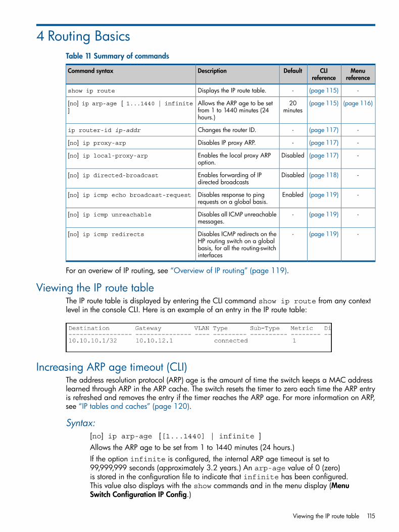
4 Routing BasicsTable 11 Summary of commands
Menureference
CLIreference
DefaultDescriptionCommand syntax
-(page 115)-Displays the IP route table.show ip route
(page 116)(page 115)20minutes
Allows the ARP age to be setfrom 1 to 1440 minutes (24hours.)
[no] ip arp-age [ 1...1440 | infinite]
-(page 117)-Changes the router ID.ip router-id ip-addr
-(page 117)-Disables IP proxy ARP.[no] ip proxy-arp
-(page 117)DisabledEnables the local proxy ARPoption.
[no] ip local-proxy-arp
-(page 118)DisabledEnables forwarding of IPdirected broadcasts
[no] ip directed-broadcast
-(page 119)EnabledDisables response to pingrequests on a global basis.
[no] ip icmp echo broadcast-request
-(page 119)-Disables all ICMP unreachablemessages.
[no] ip icmp unreachable
-(page 119)-Disables ICMP redirects on theHP routing switch on a global
[no] ip icmp redirects
basis, for all the routing-switchinterfaces
For an overiew of IP routing, see “Overview of IP routing” (page 119).
Viewing the IP route tableThe IP route table is displayed by entering the CLI command show ip route from any contextlevel in the console CLI. Here is an example of an entry in the IP route table:
Increasing ARP age timeout (CLI)The address resolution protocol (ARP) age is the amount of time the switch keeps a MAC addresslearned through ARP in the ARP cache. The switch resets the timer to zero each time the ARP entryis refreshed and removes the entry if the timer reaches the ARP age. For more information on ARP,see “IP tables and caches” (page 120).
Syntax:[no] ip arp-age [[1...1440] | infinite ]Allows the ARP age to be set from 1 to 1440 minutes (24 hours.)If the option infinite is configured, the internal ARP age timeout is set to99,999,999 seconds (approximately 3.2 years.) An arp-age value of 0 (zero)is stored in the configuration file to indicate that infinite has been configured.This value also displays with the show commands and in the menu display (MenuSwitch Configuration IP Config.)
Viewing the IP route table 115
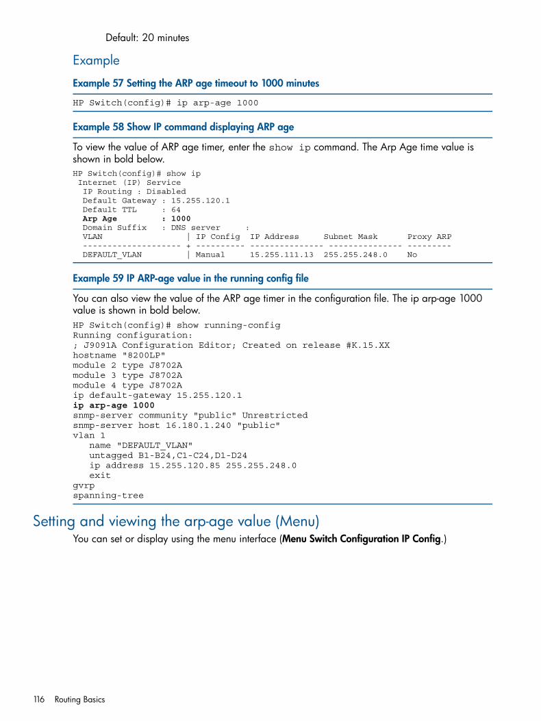
Default: 20 minutes
Example
Example 57 Setting the ARP age timeout to 1000 minutes
HP Switch(config)# ip arp-age 1000
Example 58 Show IP command displaying ARP age
To view the value of ARP age timer, enter the show ip command. The Arp Age time value isshown in bold below.HP Switch(config)# show ip Internet (IP) Service IP Routing : Disabled Default Gateway : 15.255.120.1 Default TTL : 64
Arp Age : 1000 Domain Suffix : DNS server : VLAN | IP Config IP Address Subnet Mask Proxy ARP -------------------- + ---------- --------------- --------------- --------- DEFAULT_VLAN | Manual 15.255.111.13 255.255.248.0 No
Example 59 IP ARP-age value in the running config file
You can also view the value of the ARP age timer in the configuration file. The ip arp-age 1000value is shown in bold below.HP Switch(config)# show running-configRunning configuration:; J9091A Configuration Editor; Created on release #K.15.XXhostname "8200LP" module 2 type J8702A module 3 type J8702A module 4 type J8702Aip default-gateway 15.255.120.1 ip arp-age 1000snmp-server community "public" Unrestricted snmp-server host 16.180.1.240 "public"vlan 1 name "DEFAULT_VLAN" untagged B1-B24,C1-C24,D1-D24 ip address 15.255.120.85 255.255.248.0 exitgvrpspanning-tree
Setting and viewing the arp-age value (Menu)You can set or display using the menu interface (Menu Switch Configuration IP Config.)
116 Routing Basics
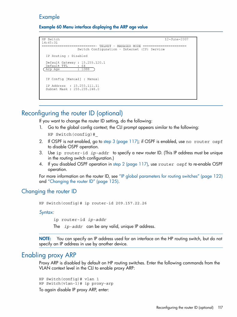
Example
Example 60 Menu interface displaying the ARP age value
Reconfiguring the router ID (optional)If you want to change the router ID setting, do the following:1. Go to the global config context; the CLI prompt appears similar to the following:
HP Switch(config)#_
2. If OSPF is not enabled, go to step 3 (page 117); if OSPF is enabled, use no router ospfto disable OSPF operation.
3. Use ip router-id ip-addr to specify a new router ID. (This IP address must be uniquein the routing switch configuration.)
4. If you disabled OSPF operation in step 2 (page 117), use router ospf to re-enable OSPFoperation.
For more information on the router ID, see “IP global parameters for routing switches” (page 122)and “Changing the router ID” (page 125).
Changing the router ID
HP Switch(config)# ip router-id 209.157.22.26
Syntax:ip router-id ip-addr
The ip-addr can be any valid, unique IP address.
NOTE: You can specify an IP address used for an interface on the HP routing switch, but do notspecify an IP address in use by another device.
Enabling proxy ARPProxy ARP is disabled by default on HP routing switches. Enter the following commands from theVLAN context level in the CLI to enable proxy ARP:
HP Switch(config)# vlan 1HP Switch(vlan-1)# ip proxy-arp
To again disable IP proxy ARP, enter:
Reconfiguring the router ID (optional) 117
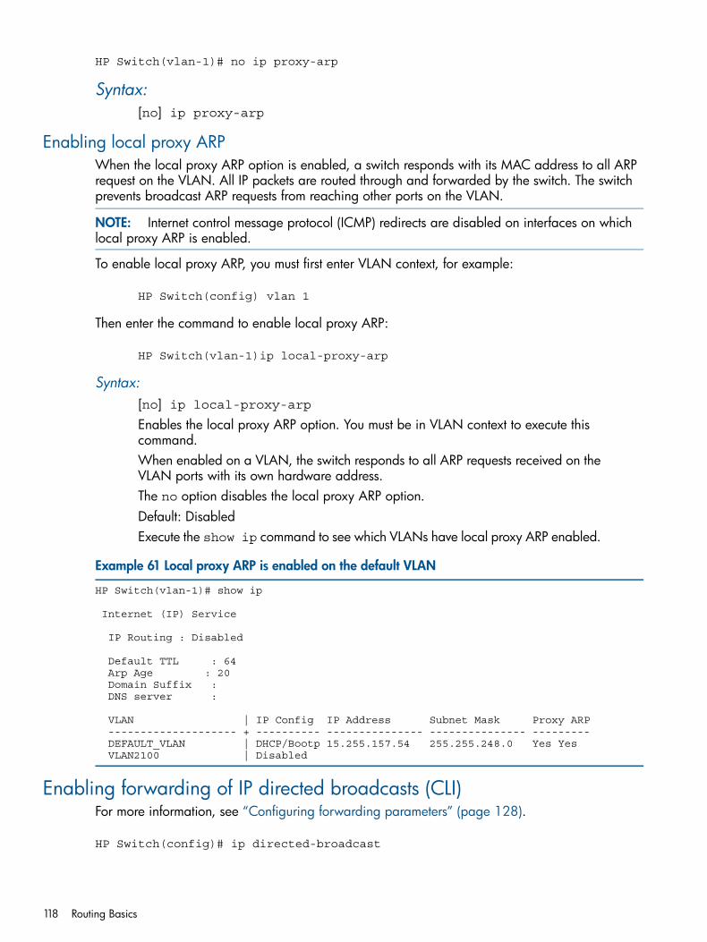
HP Switch(vlan-1)# no ip proxy-arp
Syntax:[no] ip proxy-arp
Enabling local proxy ARPWhen the local proxy ARP option is enabled, a switch responds with its MAC address to all ARPrequest on the VLAN. All IP packets are routed through and forwarded by the switch. The switchprevents broadcast ARP requests from reaching other ports on the VLAN.
NOTE: Internet control message protocol (ICMP) redirects are disabled on interfaces on whichlocal proxy ARP is enabled.
To enable local proxy ARP, you must first enter VLAN context, for example:
HP Switch(config) vlan 1
Then enter the command to enable local proxy ARP:
HP Switch(vlan-1)ip local-proxy-arp
Syntax:[no] ip local-proxy-arpEnables the local proxy ARP option. You must be in VLAN context to execute thiscommand.When enabled on a VLAN, the switch responds to all ARP requests received on theVLAN ports with its own hardware address.The no option disables the local proxy ARP option.Default: DisabledExecute the show ip command to see which VLANs have local proxy ARP enabled.
Example 61 Local proxy ARP is enabled on the default VLAN
HP Switch(vlan-1)# show ip
Internet (IP) Service
IP Routing : Disabled
Default TTL : 64 Arp Age : 20 Domain Suffix : DNS server :
VLAN | IP Config IP Address Subnet Mask Proxy ARP -------------------- + ---------- --------------- --------------- --------- DEFAULT_VLAN | DHCP/Bootp 15.255.157.54 255.255.248.0 Yes Yes VLAN2100 | Disabled
Enabling forwarding of IP directed broadcasts (CLI)For more information, see “Configuring forwarding parameters” (page 128).
HP Switch(config)# ip directed-broadcast
118 Routing Basics
Syntax:[no] ip directed-broadcastHP software makes the forwarding decision based on the routing switch's knowledgeof the destination network prefix. Routers cannot determine that a message is unicastor directed broadcast apart from the destination network prefix. The decision toforward or not forward the message is by definition only possible in the last-hoprouter.
Disabling the directed broadcasts
HP Switch(config)# no ip directed-broadcast
Disabling replies to broadcast ping requestsBy default, HP devices are enabled to respond to broadcast ICMP echo packets, which are pingrequests (for more information, see “Disabling ICMP messages” (page 128). You can disableresponse to ping requests on a global basis using the following CLI command:
HP Switch(config)# no ip icmp echo broadcast-request
Syntax:[no] ip icmp echo broadcast-request
If you need to re-enable response to ping requests, enter the following command:
HP Switch(config)# ip icmp echo broadcast-request
Disabling all ICMP unreachable messagesFor more information, see “Disabling ICMP destination unreachable messages” (page 129).
HP Switch(config)# no ip icmp unreachable
Syntax:[no] ip icmp unreachable
Disabling ICMP redirectsYou can disable ICMP redirects on the HP routing switch only on a global basis, for all therouting-switch interfaces.Enter the following command at the global CONFIG level of the CLI:
HP Switch(config)# no ip icmp redirects
Syntax:[no] ip icmp redirects
Overview of IP routingThe switches offer the following IP routing features:Static routes
Up to 256 static routesRIP (Router Information Protocol)
Supports RIP Version 1, Version 1 compatible with Version 2 (default), and Version 2
Disabling replies to broadcast ping requests 119
OSPF (open shortest path first)The standard routing protocol for handling larger routed networks
IRDP (ICMP Router Discovery Protocol)Advertises the IP addresses of the routing interfaces on this switch to directly attached hostsystems
DHCP RelayAllows you to extend the service range of your DHCP server beyond its single local networksegment
License requirements:In the 3500, 3500yl, 5400zl, 6600, and 8200zl switches, OSPF is included with the PremiumLicense. In the 6200yl switches, this feature is included with the base feature set.
Throughout this chapter, the switches are referred to as "routing switches." When IP routing isenabled on your switch, it behaves just like any other IP router.Basic IP routing configuration consists of adding IP addresses, enabling IP routing, and enablinga route exchange protocol, such as RIP.For configuring the IP addresses, see chapter "Configuring IP Addresses" in the Management andConfiguration Guide for your switch. Use the information in this chapter if you need to changesome of the IP parameters from their default values or if you want to view configuration informationor statistics.
IP interfacesOn the routing switches, IP addresses are associated with individual VLANs. By default, there isa single VLAN (Default_VLAN) on the routing switch. In that configuration, a single IP addressserves as the management access address for the entire device. If routing is enabled on the routingswitch, the IP address on the single VLAN also acts as the routing interface.Each IP address on a routing switch must be in a different subnet. You can have only one VLANinterface in a given subnet. For example, you can configure IP addresses 192.168.1.1/24 and192.168.2.1/24 on the same routing switch, but you cannot configure 192.168.1.1/24 and192.168.1.2/24 on the same routing switch.You can configure multiple IP addresses on the same VLAN.The number of IP addresses you can configure on an individual VLAN interface is 32.You can use any of the IP addresses you configure on the routing switch for Telnet, Webmanagement, or SNMP access, as well as for routing.
NOTE: All HP devices support configuration and display of IP address in classical subnet format(example: 192.168.1.1 255.255.255.0) and Classless Interdomain Routing (CIDR) format (example:192.168.1.1/24.) You can use either format when configuring IP address information. IP addressesare displayed in classical subnet format only.
IP tables and caches
ARP cache tableThe ARP cache contains entries that map IP addresses to MAC addresses. Generally, the entriesare for devices that are directly attached to the routing switch.An exception is an ARP entry for an interface-based static route that goes to a destination that isone or more router hops away. For this type of entry, the MAC address is either the destinationdevice's MAC address or the MAC address of the router interface that answered an ARP requeston behalf of the device, using proxy ARP.
120 Routing Basics
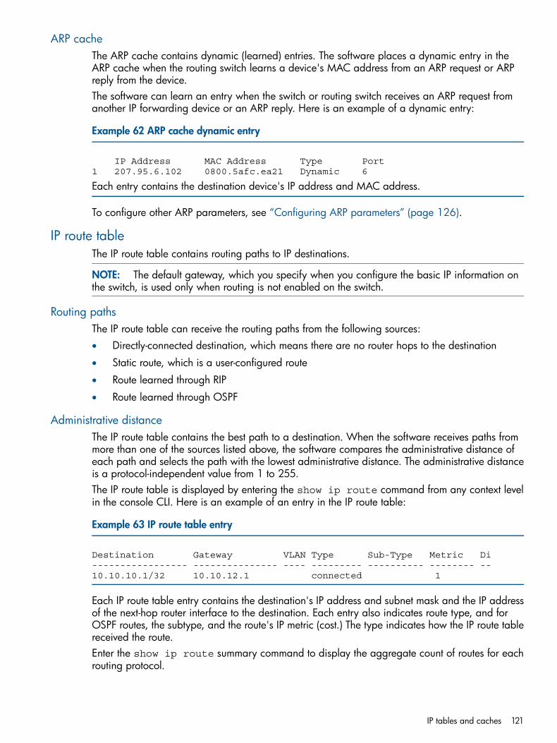
ARP cacheThe ARP cache contains dynamic (learned) entries. The software places a dynamic entry in theARP cache when the routing switch learns a device's MAC address from an ARP request or ARPreply from the device.The software can learn an entry when the switch or routing switch receives an ARP request fromanother IP forwarding device or an ARP reply. Here is an example of a dynamic entry:
Example 62 ARP cache dynamic entry
IP Address MAC Address Type Port1 207.95.6.102 0800.5afc.ea21 Dynamic 6
Each entry contains the destination device's IP address and MAC address.
To configure other ARP parameters, see “Configuring ARP parameters” (page 126).
IP route tableThe IP route table contains routing paths to IP destinations.
NOTE: The default gateway, which you specify when you configure the basic IP information onthe switch, is used only when routing is not enabled on the switch.
Routing pathsThe IP route table can receive the routing paths from the following sources:• Directly-connected destination, which means there are no router hops to the destination
• Static route, which is a user-configured route
• Route learned through RIP
• Route learned through OSPF
Administrative distanceThe IP route table contains the best path to a destination. When the software receives paths frommore than one of the sources listed above, the software compares the administrative distance ofeach path and selects the path with the lowest administrative distance. The administrative distanceis a protocol-independent value from 1 to 255.The IP route table is displayed by entering the show ip route command from any context levelin the console CLI. Here is an example of an entry in the IP route table:
Example 63 IP route table entry
Destination Gateway VLAN Type Sub-Type Metric Di----------------- --------------- ---- --------- ---------- -------- --10.10.10.1/32 10.10.12.1 connected 1
Each IP route table entry contains the destination's IP address and subnet mask and the IP addressof the next-hop router interface to the destination. Each entry also indicates route type, and forOSPF routes, the subtype, and the route's IP metric (cost.) The type indicates how the IP route tablereceived the route.Enter the show ip route summary command to display the aggregate count of routes for eachrouting protocol.
IP tables and caches 121
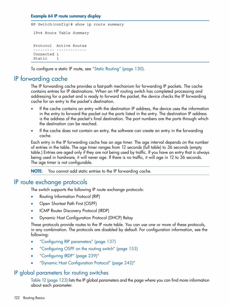
Example 64 IP route summary display
HP Switch(config)# show ip route summary
IPv4 Route Table Summary
Protocol Active Routes --------- ------------- Connected 1 Static 1
To configure a static IP route, see “Static Routing” (page 130).
IP forwarding cacheThe IP forwarding cache provides a fast-path mechanism for forwarding IP packets. The cachecontains entries for IP destinations. When an HP routing switch has completed processing andaddressing for a packet and is ready to forward the packet, the device checks the IP forwardingcache for an entry to the packet's destination.
• If the cache contains an entry with the destination IP address, the device uses the informationin the entry to forward the packet out the ports listed in the entry. The destination IP addressis the address of the packet's final destination. The port numbers are the ports through whichthe destination can be reached.
• If the cache does not contain an entry, the software can create an entry in the forwardingcache.
Each entry in the IP forwarding cache has an age timer. The age interval depends on the numberof entries in the table. The age timer ranges from 12 seconds (full table) to 36 seconds (emptytable.) Entries are aged only if they are not being used by traffic. If you have an entry that is alwaysbeing used in hardware, it will never age. If there is no traffic, it will age in 12 to 36 seconds.The age timer is not configurable.
NOTE: You cannot add static entries to the IP forwarding cache.
IP route exchange protocolsThe switch supports the following IP route exchange protocols:• Routing Information Protocol (RIP)
• Open Shortest Path First (OSPF)
• ICMP Router Discovery Protocol (IRDP)
• Dynamic Host Configuration Protocol (DHCP) RelayThese protocols provide routes to the IP route table. You can use one or more of these protocols,in any combination. The protocols are disabled by default. For configuration information, see thefollowing:• “Configuring RIP parameters” (page 137)
• “Configuring OSPF on the routing switch” (page 153)
• “Configuring IRDP” (page 239)"
• “Dynamic Host Configuration Protocol” (page 242)"
IP global parameters for routing switchesTable 12 (page 123) lists the IP global parameters and the page where you can find more informationabout each parameter.
122 Routing Basics
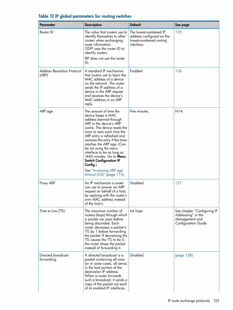
Table 12 IP global parameters for routing switches
See pageDefaultDescriptionParameter
125The lowest-numbered IPaddress configured on the
The value that routers use toidentify themselves to other
Router ID
lowest-numbered routinginterface.
routers when exchangingroute information.OSPF uses the router ID toidentify routers.RIP does not use the routerID.
126EnabledA standard IP mechanismthat routers use to learn the
Address Resolution Protocol(ARP)
MAC address of a deviceon the network. The routersends the IP address of adevice in the ARP requestand receives the device'sMAC address in an ARPreply.
N/AFive minutes.The amount of time thedevice keeps a MAC
ARP age
address learned throughARP in the device's ARPcache. The device resets thetimer to zero each time theARP entry is refreshed andremoves the entry if the timerreaches the ARP age. (Canbe set using the menuinterface to be as long as1440 minutes. Go to MenuSwitch Configuration IPConfig.)See “Increasing ARP agetimeout (CLI)” (page 115).
127DisabledAn IP mechanism a routercan use to answer an ARP
Proxy ARP
request on behalf of a host,by replying with the router'sown MAC address insteadof the host's.
See chapter "Configuring IPAddressing" in the
64 hopsThe maximum number ofrouters (hops) through which
Time to Live (TTL)
Management andConfiguration Guide.
a packet can pass beforebeing discarded. Eachrouter decreases a packet'sTTL by 1 before forwardingthe packet. If decreasing theTTL causes the TTL to be 0,the router drops the packetinstead of forwarding it.
(page 128)DisabledA directed broadcast is apacket containing all ones
Directed broadcastforwarding
(or in some cases, all zeros)in the host portion of thedestination IP address.When a router forwardssuch a broadcast, it sends acopy of the packet out eachof its enabled IP interfaces.
IP route exchange protocols 123
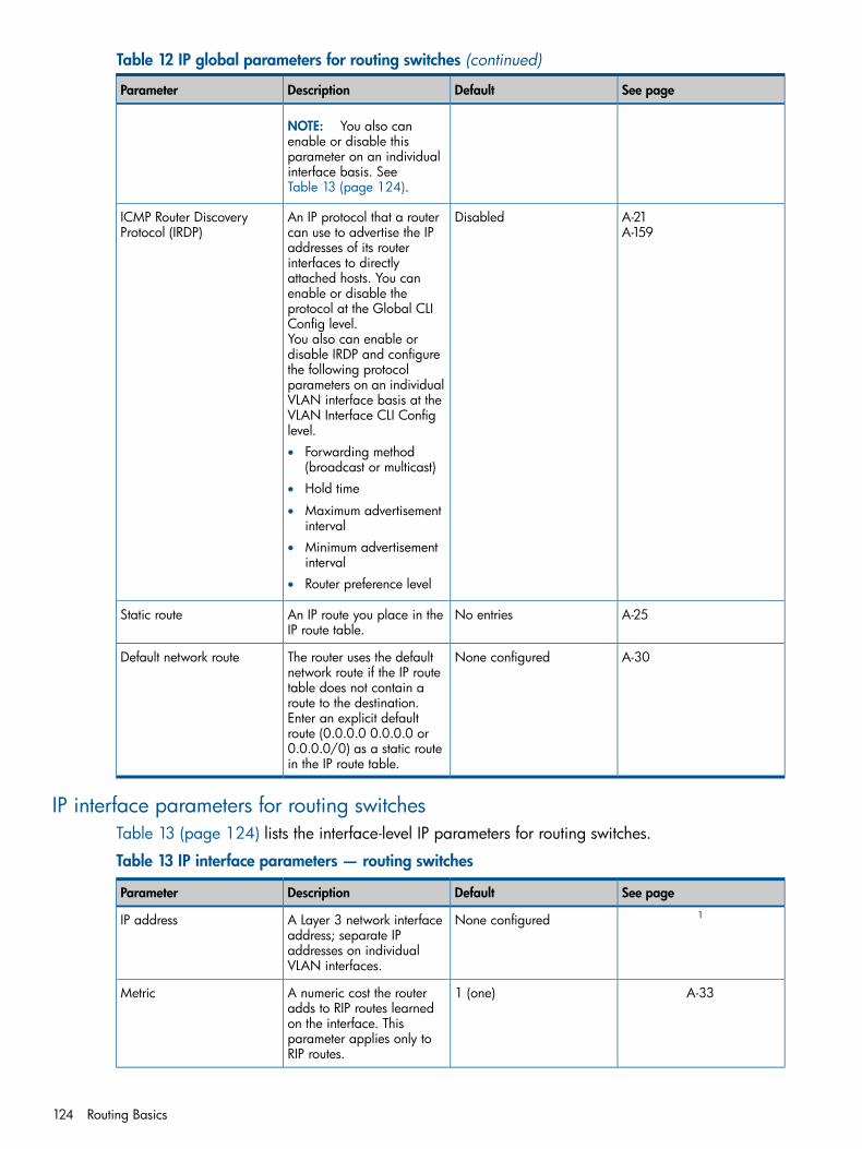
Table 12 IP global parameters for routing switches (continued)
See pageDefaultDescriptionParameter
NOTE: You also canenable or disable thisparameter on an individualinterface basis. SeeTable 13 (page 124).
A-21A-159
DisabledAn IP protocol that a routercan use to advertise the IP
ICMP Router DiscoveryProtocol (IRDP)
addresses of its routerinterfaces to directlyattached hosts. You canenable or disable theprotocol at the Global CLIConfig level.You also can enable ordisable IRDP and configurethe following protocolparameters on an individualVLAN interface basis at theVLAN Interface CLI Configlevel.• Forwarding method
(broadcast or multicast)• Hold time
• Maximum advertisementinterval
• Minimum advertisementinterval
• Router preference level
A-25No entriesAn IP route you place in theIP route table.
Static route
A-30None configuredThe router uses the defaultnetwork route if the IP route
Default network route
table does not contain aroute to the destination.Enter an explicit defaultroute (0.0.0.0 0.0.0.0 or0.0.0.0/0) as a static routein the IP route table.
IP interface parameters for routing switchesTable 13 (page 124) lists the interface-level IP parameters for routing switches.
Table 13 IP interface parameters — routing switches
See pageDefaultDescriptionParameter1None configuredA Layer 3 network interface
address; separate IPIP address
addresses on individualVLAN interfaces.
A-331 (one)A numeric cost the routeradds to RIP routes learned
Metric
on the interface. Thisparameter applies only toRIP routes.
124 Routing Basics
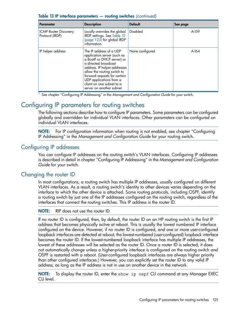
Table 13 IP interface parameters — routing switches (continued)
See pageDefaultDescriptionParameter
A-159DisabledLocally overrides the globalIRDP settings. See Table 12
ICMP Router DiscoveryProtocol (IRDP)
(page 123) for global IRDPinformation.
A-164None configuredThe IP address of a UDPapplication server (such as
IP helper address
a BootP or DHCP server) ora directed broadcastaddress. IP helper addressesallow the routing switch toforward requests for certainUDP applications from aclient on one subnet to aserver on another subnet.
1 See chapter "Configuring IP Addressing" in the Management and Configuration Guide for your switch.
Configuring IP parameters for routing switchesThe following sections describe how to configure IP parameters. Some parameters can be configuredglobally and overridden for individual VLAN interfaces. Other parameters can be configured onindividual VLAN interfaces.
NOTE: For IP configuration information when routing is not enabled, see chapter "ConfiguringIP Addressing" in the Management and Configuration Guide for your routing switch.
Configuring IP addressesYou can configure IP addresses on the routing switch's VLAN interfaces. Configuring IP addressesis described in detail in chapter "Configuring IP Addressing" in the Management and ConfigurationGuide for your switch.
Changing the router IDIn most configurations, a routing switch has multiple IP addresses, usually configured on differentVLAN interfaces. As a result, a routing switch's identity to other devices varies depending on theinterface to which the other device is attached. Some routing protocols, including OSPF, identifya routing switch by just one of the IP addresses configured on the routing switch, regardless of theinterfaces that connect the routing switches. This IP address is the router ID.
NOTE: RIP does not use the router ID.
If no router ID is configured, then, by default, the router ID on an HP routing switch is the first IPaddress that becomes physically active at reboot. This is usually the lowest numbered IP interfaceconfigured on the device. However, if no router ID is configured, and one or more user-configuredloopback interfaces are detected at reboot, the lowest-numbered (user-configured) loopback interfacebecomes the router ID. If the lowest-numbered loopback interface has multiple IP addresses, thelowest of these addresses will be selected as the router ID. Once a router ID is selected, it doesnot automatically change unless a higher-priority interface is configured on the routing switch andOSPF is restarted with a reboot. (User-configured loopback interfaces are always higher prioritythan other configured interfaces.) However, you can explicitly set the router ID to any valid IPaddress, as long as the IP address is not in use on another device in the network.
NOTE: To display the router ID, enter the show ip ospf CLI command at any Manager EXECCLI level.
Configuring IP parameters for routing switches 125
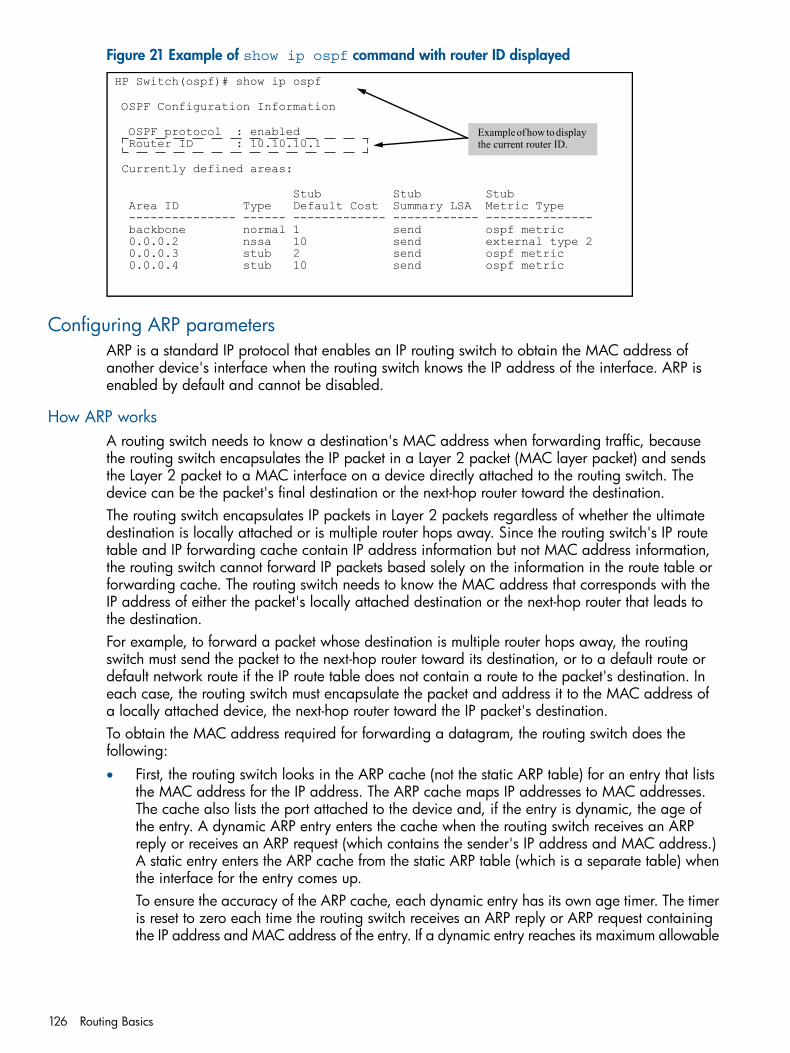
Figure 21 Example of show ip ospf command with router ID displayed
HP Switch(ospf)# show ip ospf
OSPF Configuration Information
OSPF protocol : enabled Router ID : 10.10.10.1
Currently defined areas:
Stub Stub Stub Area ID Type Default Cost Summary LSA Metric Type --------------- ------ ------------- ------------ --------------- backbone normal 1 send ospf metric 0.0.0.2 nssa 10 send external type 2 0.0.0.3 stub 2 send ospf metric 0.0.0.4 stub 10 send ospf metric
Example of how to display the current router ID.
Configuring ARP parametersARP is a standard IP protocol that enables an IP routing switch to obtain the MAC address ofanother device's interface when the routing switch knows the IP address of the interface. ARP isenabled by default and cannot be disabled.
How ARP worksA routing switch needs to know a destination's MAC address when forwarding traffic, becausethe routing switch encapsulates the IP packet in a Layer 2 packet (MAC layer packet) and sendsthe Layer 2 packet to a MAC interface on a device directly attached to the routing switch. Thedevice can be the packet's final destination or the next-hop router toward the destination.The routing switch encapsulates IP packets in Layer 2 packets regardless of whether the ultimatedestination is locally attached or is multiple router hops away. Since the routing switch's IP routetable and IP forwarding cache contain IP address information but not MAC address information,the routing switch cannot forward IP packets based solely on the information in the route table orforwarding cache. The routing switch needs to know the MAC address that corresponds with theIP address of either the packet's locally attached destination or the next-hop router that leads tothe destination.For example, to forward a packet whose destination is multiple router hops away, the routingswitch must send the packet to the next-hop router toward its destination, or to a default route ordefault network route if the IP route table does not contain a route to the packet's destination. Ineach case, the routing switch must encapsulate the packet and address it to the MAC address ofa locally attached device, the next-hop router toward the IP packet's destination.To obtain the MAC address required for forwarding a datagram, the routing switch does thefollowing:• First, the routing switch looks in the ARP cache (not the static ARP table) for an entry that lists
the MAC address for the IP address. The ARP cache maps IP addresses to MAC addresses.The cache also lists the port attached to the device and, if the entry is dynamic, the age ofthe entry. A dynamic ARP entry enters the cache when the routing switch receives an ARPreply or receives an ARP request (which contains the sender's IP address and MAC address.)A static entry enters the ARP cache from the static ARP table (which is a separate table) whenthe interface for the entry comes up.To ensure the accuracy of the ARP cache, each dynamic entry has its own age timer. The timeris reset to zero each time the routing switch receives an ARP reply or ARP request containingthe IP address and MAC address of the entry. If a dynamic entry reaches its maximum allowable
126 Routing Basics
age, the entry times out and the software removes the entry from the table. Static entries donot age-out and can be removed only by you.
• If the ARP cache does not contain an entry for the destination IP address, the routing switchbroadcasts an ARP request out all of its IP interfaces. The ARP request contains the IP addressof the destination. If the device with the IP address is directly attached to the routing switch,the device sends an ARP response containing its MAC address. The response is a unicastpacket addressed directly to the routing switch. The routing switch places the information fromthe ARP response into the ARP cache.ARP requests contain the IP address and MAC address of the sender, so all devices that receivethe request learn the MAC address and IP address of the sender and can update their ownARP caches accordingly.
NOTE: The ARP request broadcast is a MAC broadcast, which means the broadcast goesonly to devices that are directly attached to the routing switch. A MAC broadcast is not routedto other networks. However, some routers, including HP routing switches, can be configuredto reply to ARP requests from one network on behalf of devices on another network. For moreinformation, see “About enabling proxy ARP” (page 127).
NOTE: If the routing switch receives an ARP request packet that it is unable to deliver to the finaldestination because of the ARP time-out, and no ARP response is received (the routing switch knowsof no route to the destination address), the routing switch sends an ICMP Host Unreachable messageto the source.
About enabling proxy ARPProxy ARP allows a routing switch to answer ARP requests from devices on one network on behalfof devices in another network. Since ARP requests are MAC-layer broadcasts, they reach only thedevices that are directly connected to the sender of the ARP request. Thus, ARP requests do notcross routers.For example, if Proxy ARP is enabled on a routing switch connected to two subnets, 10.10.10.0/24and 20.20.20.0/24, the routing switch can respond to an ARP request from 10.10.10.69 for theMAC address of the device with IP address 20.20.20.69. In standard ARP, a request from a devicein the 10.10.10.0/24 subnet cannot reach a device in the 20.20.20.0 subnet if the subnets areon different network cables, and thus is not answered.An ARP request from one subnet can reach another subnet when both subnets are on the samephysical segment (Ethernet cable), since MAC-layer broadcasts reach all the devices on the segment.
Proxy ARP and local proxy ARP behaviorWhen local proxy ARP is enabled, all valid ARP requests receive a response.
Configuring IP parameters for routing switches 127
When proxy ARP is enabled, all valid ARP requests receive a response if the following conditionsare met:
• There is a route to the target IP address in the ARP request (this can be a route or default route),and the VLAN (interface) the ARP request is received on does NOT match the interface forthe next hop in the matched route to get to the target IP address.
AND
• There is a route back to the source IP address in the ARP request and the interface the ARPrequest came in on DOES match the interface for the nex thop in the matched route to get tothe source IP address.
Configuring forwarding parametersThe following configurable parameters control the forwarding behavior of HP routing switches:• Time-To-Live (TTL) threshold
The configuration of this parameter is covered in the chapter "Configuring IP Addressing" inthe Management and Configuration Guide for your routing switch.
• Forwarding of directed broadcastsThese parameters are global and thus affect all IP interfaces configured on the routing switch.
Enabling forwarding of directed broadcastsA directed broadcast is an IP broadcast to all devices within a single directly-attached network orsubnet. A net-directed broadcast goes to all devices on a given network. A subnet-directed broadcastgoes to all devices within a given subnet.
NOTE: A less common type, the all-subnets broadcast, goes to all directly-attached subnets.Forwarding for this broadcast type also is supported, but most networks use IP multicasting insteadof all-subnet broadcasting.
Forwarding for all types of IP directed broadcasts is disabled by default. You can enable forwardingfor all types if needed. You cannot enable forwarding for specific broadcast types.
Configuring ICMPYou can configure the following ICMP limits:Burst-normal
The maximum number of ICMP replies to send per second.Reply limit
You can enable or disable ICMP reply rate limiting.
Disabling ICMP messagesHP devices are enabled to reply to ICMP echo messages and send ICMP Destination Unreachablemessages by default.You can selectively disable the following types of Internet Control Message Protocol (ICMP)messages:Echo messages (ping messages)
The routing switch replies to IP pings from other IP devices.Destination unreachable messages
If the routing switch receives an IP packet that it cannot deliver to its destination, the routingswitch discards the packet and sends a message back to the device that sent the packet to therouting switch. The message informs the device that the destination cannot be reached by therouting switch.
128 Routing Basics
Address mask repliesYou can enable or disable ICMP address mask replies.
Disabling ICMP destination unreachable messagesBy default, when a HP device receives an IP packet that the device cannot deliver, the device sendsan ICMP unreachable message back to the host that sent the packet. The following types of ICMPunreachable messages are generated:Administration
The packet was dropped by the HP device due to a filter or ACL configured on the device.Fragmentation-needed
The packet has the "Don't Fragment" bit set in the IP Flag field, but the HP device cannotforward the packet without fragmenting it.
HostThe destination network or subnet of the packet is directly connected to the HP device, but thehost specified in the destination IP address of the packet is not on the network.
NetworkThe HP device cannot reach the network specified in the destination IP address of the packet.
PortThe destination host does not have the destination TCP or UDP port specified in the packet. Inthis case, the host sends the ICMP Port Unreachable message to the HP device, which in turnsends the message to the host that sent the packet.
ProtocolThe TCP or UDP protocol on the destination host is not running. This message is different fromthe Port Unreachable message, which indicates that the protocol is running on the host but therequested protocol port is unavailable.
Source-route-failureThe device received a source-routed packet but cannot locate the next-hop IP address indicatedin the packet's Source-Route option.
NOTE: Disabling an ICMP Unreachable message type does not change the HP device's abilityto forward packets. Disabling ICMP Unreachable messages prevents the device from generatingor forwarding the Unreachable messages.
Configuring ICMP 129
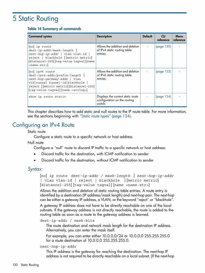
5 Static RoutingTable 14 Summary of commands
Menureference
CLIreference
DefaultDescriptionCommand syntax
-(page 130)-Allows the addition and deletionof IPv4 static routing tableentries.
[no] ip routedest-ip-addr/mask-length [next-hop-ip-addr | vlan vlan-id |reject | blackhole ] [metric metric][distance1-255] [tag-value tagval] [name<name-str>]
-(page 132)-Allows the addition and deletionof IPv6 static routing tableentries.
[no] ipv6 routedest-ipv6-addr/prefix-length [next-hop-gateway-addr | vlanvid|tunnel tunnel-id|blackhole |reject ] [metric metric] [distance1-255][tag-value tagval] [name <string>]
-(page 134)-Displays the current static routeconfiguration on the routingswitch.
show ip route static
This chapter describes how to add static and null routes to the IP route table. For more information,see the sections beginning with “Static route types” (page 134).
Configuring an IPv4 RouteStatic route
Configure a static route to a specific network or host addressNull route
Configure a "null" route to discard IP traffic to a specific network or host address:• Discard traffic for the destination, with ICMP notification to sender
• Discard traffic for the destination, without ICMP notification to sender
Syntax:[no] ip route dest-ip-addr / mask-length [ next-hop-ip-addr| vlan vlan-id | reject | blackhole ] [metric metric][distance1-255] [tag-value tagval] [name <name-str>]Allows the addition and deletion of static routing table entries. A route entry isidentified by a destination (IP address/mask length) and next-hop pair. The next-hopcan be either a gateway IP address, a VLAN, or the keyword "reject" or "blackhole".A gateway IP address does not have to be directly reachable on one of the localsubnets. If the gateway address is not directly reachable, the route is added to therouting table as soon as a route to the gateway address is learned.dest-ip-addr / mask-bits
The route destination and network mask length for the destination IP address.Alternatively, you can enter the mask itself.For example, you can enter either 10.0.0.0/24 or 10.0.0.0 255.255.255.0for a route destination of 10.0.0.0 255.255.255.0.
next-hop-ip-addr
This IP address is the gateway for reaching the destination. The next-hop IPaddress is not required to be directly reachable on a local subnet. (If the next-hop
130 Static Routing
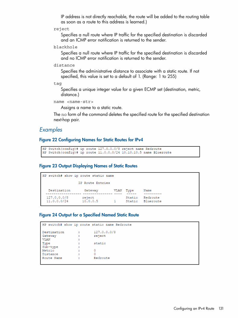
IP address is not directly reachable, the route will be added to the routing tableas soon as a route to this address is learned.)
reject
Specifies a null route where IP traffic for the specified destination is discardedand an ICMP error notification is returned to the sender.
blackhole
Specifies a null route where IP traffic for the specified destination is discardedand no ICMP error notification is returned to the sender.
distance
Specifies the administrative distance to associate with a static route. If notspecified, this value is set to a default of 1. (Range: 1 to 255)
tag
Specifies a unique integer value for a given ECMP set (destination, metric,distance.)
name <name-str>
Assigns a name to a static route.The no form of the command deletes the specified route for the specified destinationnext-hop pair.
Examples
Figure 22 Configuring Names for Static Routes for IPv4
Figure 23 Output Displaying Names of Static Routes
Figure 24 Output for a Specified Named Static Route
Configuring an IPv4 Route 131
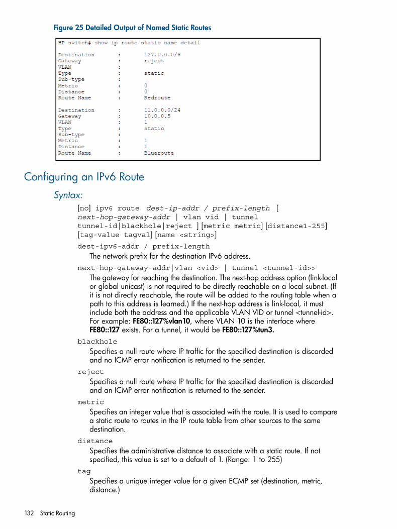
Figure 25 Detailed Output of Named Static Routes
Configuring an IPv6 Route
Syntax:[no] ipv6 route dest-ip-addr / prefix-length [next-hop-gateway-addr | vlan vid | tunneltunnel-id|blackhole|reject ] [metric metric] [distance1-255][tag-value tagval] [name <string>]dest-ipv6-addr / prefix-length
The network prefix for the destination IPv6 address.next-hop-gateway-addr|vlan <vid> | tunnel <tunnel-id>>
The gateway for reaching the destination. The next-hop address option (link-localor global unicast) is not required to be directly reachable on a local subnet. (Ifit is not directly reachable, the route will be added to the routing table when apath to this address is learned.) If the next-hop address is link-local, it mustinclude both the address and the applicable VLAN VID or tunnel <tunnel-id>.For example: FE80::127%vlan10, where VLAN 10 is the interface whereFE80::127 exists. For a tunnel, it would be FE80::127%tun3.
blackhole
Specifies a null route where IP traffic for the specified destination is discardedand no ICMP error notification is returned to the sender.
reject
Specifies a null route where IP traffic for the specified destination is discardedand an ICMP error notification is returned to the sender.
metric
Specifies an integer value that is associated with the route. It is used to comparea static route to routes in the IP route table from other sources to the samedestination.
distance
Specifies the administrative distance to associate with a static route. If notspecified, this value is set to a default of 1. (Range: 1 to 255)
tag
Specifies a unique integer value for a given ECMP set (destination, metric,distance.)
132 Static Routing
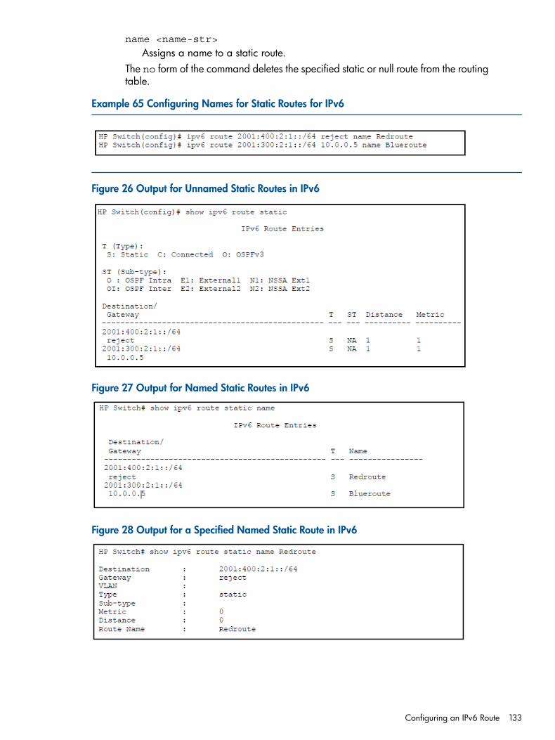
name <name-str>
Assigns a name to a static route.The no form of the command deletes the specified static or null route from the routingtable.
Example 65 Configuring Names for Static Routes for IPv6
Figure 26 Output for Unnamed Static Routes in IPv6
Figure 27 Output for Named Static Routes in IPv6
Figure 28 Output for a Specified Named Static Route in IPv6
Configuring an IPv6 Route 133
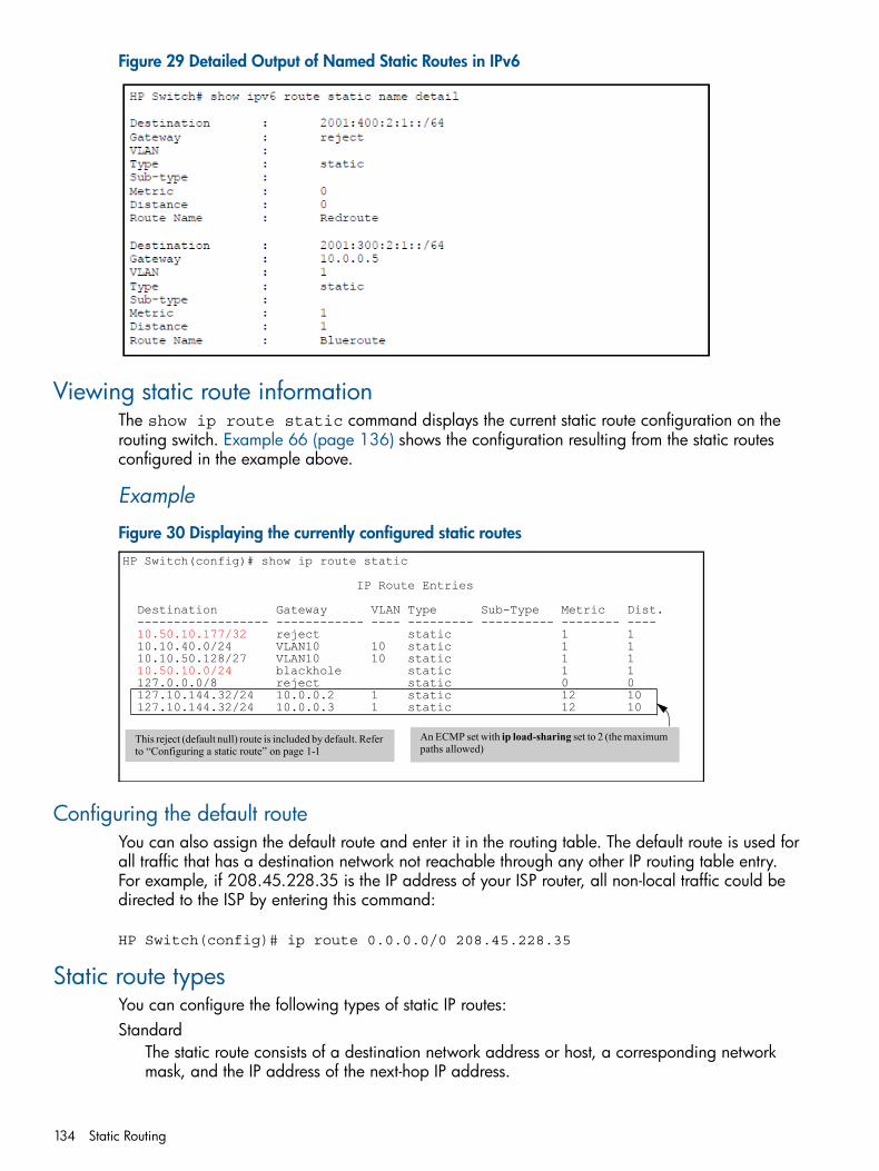
Figure 29 Detailed Output of Named Static Routes in IPv6
Viewing static route informationThe show ip route static command displays the current static route configuration on therouting switch. Example 66 (page 136) shows the configuration resulting from the static routesconfigured in the example above.
Example
Figure 30 Displaying the currently configured static routesHP Switch(config)# show ip route static
IP Route Entries
Destination Gateway VLAN Type Sub-Type Metric Dist. ------------------ ------------ ---- --------- ---------- -------- ----10.50.10.177/32 reject static 1 1
10.10.40.0/24 VLAN10 10 static 1 1 10.10.50.128/27 VLAN10 10 static 1 110.50.10.0/24 blackhole static 1 1
127.0.0.0/8 reject static 0 0 127.10.144.32/24 10.0.0.2 1 static 12 10 127.10.144.32/24 10.0.0.3 1 static 12 10
This reject (default null) route is included by default. Refer to “Configuring a static route” on page 1-1
An ECMP set with ip load-sharing set to 2 (the maximum paths allowed)
Configuring the default routeYou can also assign the default route and enter it in the routing table. The default route is used forall traffic that has a destination network not reachable through any other IP routing table entry.For example, if 208.45.228.35 is the IP address of your ISP router, all non-local traffic could bedirected to the ISP by entering this command:
HP Switch(config)# ip route 0.0.0.0/0 208.45.228.35
Static route typesYou can configure the following types of static IP routes:Standard
The static route consists of a destination network address or host, a corresponding networkmask, and the IP address of the next-hop IP address.
134 Static Routing
Null (discard)The null route consists of the destination network address or host, a corresponding networkmask, and either the reject or blackhole keyword. Typically, the null route is configuredas a backup route for discarding traffic if the primary route is unavailable. By default, whenIP routing is enabled, a route for the 127.0.0.0/8 network is created to the null interface.Traffic to this interface is rejected (dropped.)
This route is for all traffic to the "loopback" network, with the single exception of traffic to the hostaddress of the switch's loopback interface (127.0.0.1/32.) Figure A-3 on page 1-6 shows thedefault null route entry in the switch's routing table.
NOTE: On a single routing switch you can create one null route to a given destination. Multiplenull routes to the same destination are not supported.
Other sources of routes in the routing tableThe IP route table can also receive routes from the following sources:• Directly connected networks: One route is created per IP interface. When you add an IP
interface, the routing switch automatically creates a route for the network the interface is in.• RIP: If RIP is enabled, the routing switch can learn about routes from the advertisements other
RIP routers send to the routing switch. If the RIP route has a lower administrative distance thanany other routes from different sources to the same destination, the routing switch places theroute in the IP route table. See “Administrative distance” (page 121).
• OSPF: See RIP, but substitute "OSPF" for "RIP".
• Default route: This is a specific static route that the routing switch uses if other routes to thedestination are not available. See “Configuring the default route” (page 134).
Static IP route parametersWhen you configure a static IP route, you must specify the following parameters:• The IP address and network mask for the route's destination network or host.
• The route's path, which can be one of the following:IP address of a next-hop router.•
• "Null" interface; the routing switch drops traffic forwarded to the null interface.
The routing switch also applies default values for the route's administrative distance (page A-10.)In the case of static routes, this is the value the routing switch uses to compare a static route toroutes from other route sources to the same destination before placing a route in the IP route table.The default administrative distance for static IP routes is 1, but can be configured to any value from1 to 255.The fixed administrative distance values ensure that the routing switch always prefers static IP routesover routes from other sources to the same destination.
Static route states follow VLAN statesIP static routes remain in the IP route table only so long as the IP interface to the next-hop router isup. If the next-hop interface goes down, the software removes the static route from the IP routetable. If the next-hop interface comes up again, the software adds the route back to the route table.This feature allows the routing switch to adjust to changes in network topology. The routing switchdoes not continue trying to use routes on unreachable paths, but instead uses routes only whentheir paths are reachable.For example, the following command configures a static route to 207.95.7.0 (with a network maskof 255.255.255.0), using 207.95.6.157 as the next-hop router's IP address.HP Switch(config)# ip route 207.95.7.0/24 207.95.6.157
Static route types 135
A static IP route specifies the route's destination address and the next-hop router's IP address orrouting switch interface through which the routing switch can reach the destination. (The route isadded to the routing switch's IP route table.)In the above example, routing switch "A" knows that 207.95.6.157 is reachable through portA2, and assumes that local interfaces within that subnet are on the same port. Routing switch "A"deduces that IP interface 207.95.7.188 is also on port A2. The software automatically removesa static route from the route table if the next-hop VLAN used by that route becomes unavailable.When the VLAN becomes available again, the software automatically re-adds the route to theroute table.
Configuring equal cost multi-path (ECMP) routing for static IP routesECMP routing allows multiple entries for routes to the same destination. Each path has the samecost as the other paths, but a different next-hop router. The ip load-sharing command specifiesthe maximum number of equal paths that can be configured. Values range from 2 to 4. For moreinformation about the ip load-sharing command, see page A-127.
Example 66 Example of an ECMP set with the same destination but different next-hop routers
This example shows configuration of an ECMP set with two different gateways to the samedestination address but through different next-hop routers. For more information about ECMP, see“OSPF equal-cost multipath (ECMP) for different subnets available through the same next-hop routes”(page 216)".HP Switch(config)# ip route 127.10.144.21/24 10.10.10.2 metric 12 distance 10HP Switch(config)# ip route 127.10.144.21/24 10.10.10.3 metric 12 distance 10
136 Static Routing
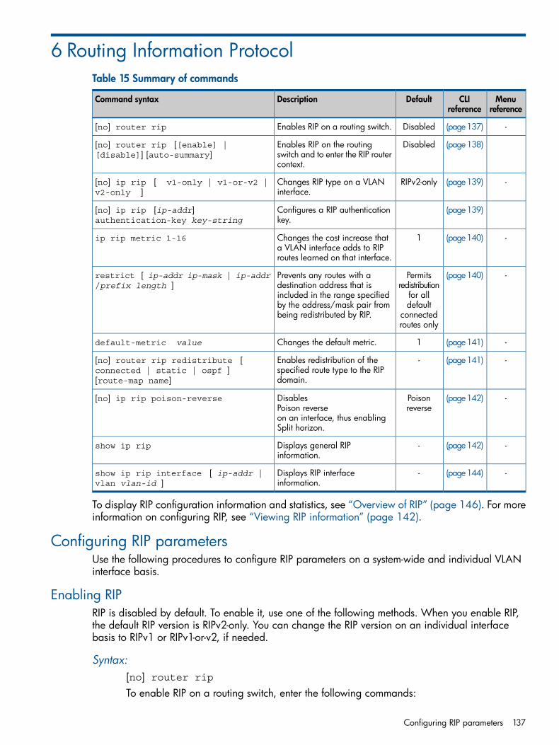
6 Routing Information ProtocolTable 15 Summary of commands
Menureference
CLIreference
DefaultDescriptionCommand syntax
-(page137)DisabledEnables RIP on a routing switch.[no] router rip
(page138)DisabledEnables RIP on the routingswitch and to enter the RIP routercontext.
[no] router rip [[enable] |[disable]] [auto-summary]
-(page139)RIPv2-onlyChanges RIP type on a VLANinterface.
[no] ip rip [ v1-only | v1-or-v2 |v2-only ]
(page139)Configures a RIP authenticationkey.
[no] ip rip [ip-addr]authentication-key key-string
-(page140)1Changes the cost increase thata VLAN interface adds to RIProutes learned on that interface.
ip rip metric 1-16
-(page140)Permitsredistribution
Prevents any routes with adestination address that is
restrict [ ip-addr ip-mask | ip-addr/prefix length ]
for allincluded in the range specifieddefaultby the address/mask pair from
being redistributed by RIP. connectedroutes only
-(page141)1Changes the default metric.default-metric value
-(page141)-Enables redistribution of thespecified route type to the RIPdomain.
[no] router rip redistribute [connected | static | ospf ][route-map name]
-(page142)Poisonreverse
DisablesPoison reverse
[no] ip rip poison-reverse
on an interface, thus enablingSplit horizon.
-(page142)-Displays general RIPinformation.
show ip rip
-(page144)-Displays RIP interfaceinformation.
show ip rip interface [ ip-addr |vlan vlan-id ]
To display RIP configuration information and statistics, see “Overview of RIP” (page 146). For moreinformation on configuring RIP, see “Viewing RIP information” (page 142).
Configuring RIP parametersUse the following procedures to configure RIP parameters on a system-wide and individual VLANinterface basis.
Enabling RIPRIP is disabled by default. To enable it, use one of the following methods. When you enable RIP,the default RIP version is RIPv2-only. You can change the RIP version on an individual interfacebasis to RIPv1 or RIPv1-or-v2, if needed.
Syntax:[no] router ripTo enable RIP on a routing switch, enter the following commands:
Configuring RIP parameters 137
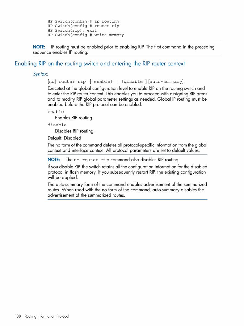
HP Switch(config)# ip routingHP Switch(config)# router ripHP Switch(rip)# exitHP Switch(config)# write memory
NOTE: IP routing must be enabled prior to enabling RIP. The first command in the precedingsequence enables IP routing.
Enabling RIP on the routing switch and entering the RIP router context
Syntax:[no] router rip [[enable] | [disable]] [auto-summary]Executed at the global configuration level to enable RIP on the routing switch andto enter the RIP router context. This enables you to proceed with assigning RIP areasand to modify RIP global parameter settings as needed. Global IP routing must beenabled before the RIP protocol can be enabled.enable
Enables RIP routing.disable
Disables RIP routing.Default: DisabledThe no form of the command deletes all protocol-specific information from the globalcontext and interface context. All protocol parameters are set to default values.
NOTE: The no router rip command also disables RIP routing.If you disable RIP, the switch retains all the configuration information for the disabledprotocol in flash memory. If you subsequently restart RIP, the existing configurationwill be applied.The auto-summary form of the command enables advertisement of the summarizedroutes. When used with the no form of the command, auto-summary disables theadvertisement of the summarized routes.
138 Routing Information Protocol
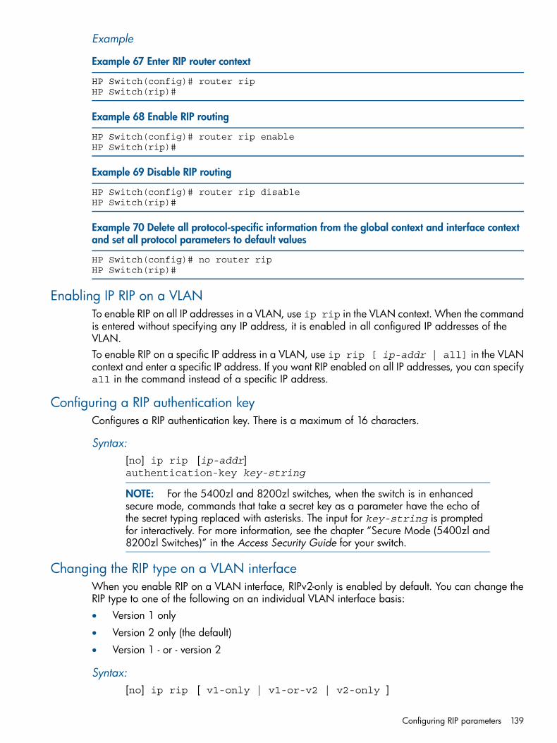
Example
Example 67 Enter RIP router context
HP Switch(config)# router ripHP Switch(rip)#
Example 68 Enable RIP routing
HP Switch(config)# router rip enableHP Switch(rip)#
Example 69 Disable RIP routing
HP Switch(config)# router rip disableHP Switch(rip)#
Example 70 Delete all protocol-specific information from the global context and interface contextand set all protocol parameters to default values
HP Switch(config)# no router ripHP Switch(rip)#
Enabling IP RIP on a VLANTo enable RIP on all IP addresses in a VLAN, use ip rip in the VLAN context. When the commandis entered without specifying any IP address, it is enabled in all configured IP addresses of theVLAN.To enable RIP on a specific IP address in a VLAN, use ip rip [ ip-addr | all] in the VLANcontext and enter a specific IP address. If you want RIP enabled on all IP addresses, you can specifyall in the command instead of a specific IP address.
Configuring a RIP authentication keyConfigures a RIP authentication key. There is a maximum of 16 characters.
Syntax:[no] ip rip [ip-addr]authentication-key key-string
NOTE: For the 5400zl and 8200zl switches, when the switch is in enhancedsecure mode, commands that take a secret key as a parameter have the echo ofthe secret typing replaced with asterisks. The input for key-string is promptedfor interactively. For more information, see the chapter “Secure Mode (5400zl and8200zl Switches)” in the Access Security Guide for your switch.
Changing the RIP type on a VLAN interfaceWhen you enable RIP on a VLAN interface, RIPv2-only is enabled by default. You can change theRIP type to one of the following on an individual VLAN interface basis:• Version 1 only
• Version 2 only (the default)
• Version 1 - or - version 2
Syntax:[no] ip rip [ v1-only | v1-or-v2 | v2-only ]
Configuring RIP parameters 139
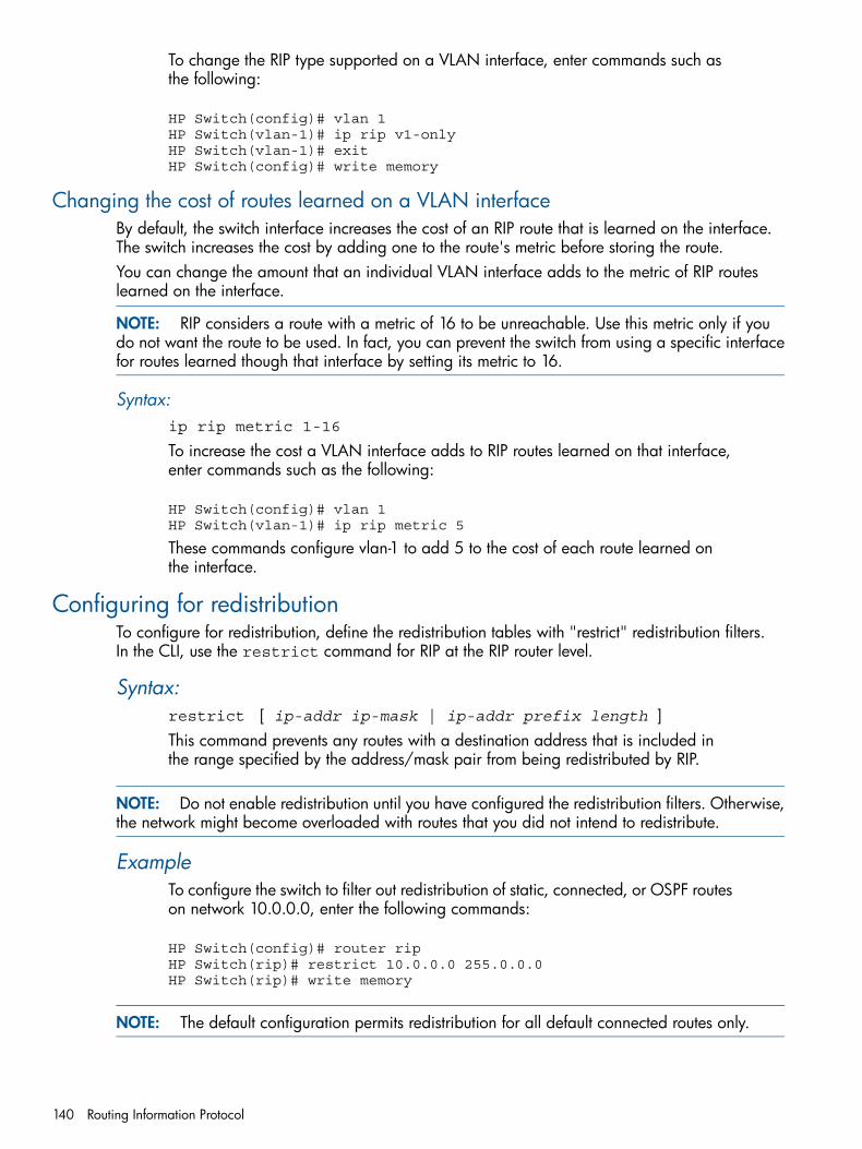
To change the RIP type supported on a VLAN interface, enter commands such asthe following:
HP Switch(config)# vlan 1HP Switch(vlan-1)# ip rip v1-onlyHP Switch(vlan-1)# exitHP Switch(config)# write memory
Changing the cost of routes learned on a VLAN interfaceBy default, the switch interface increases the cost of an RIP route that is learned on the interface.The switch increases the cost by adding one to the route's metric before storing the route.You can change the amount that an individual VLAN interface adds to the metric of RIP routeslearned on the interface.
NOTE: RIP considers a route with a metric of 16 to be unreachable. Use this metric only if youdo not want the route to be used. In fact, you can prevent the switch from using a specific interfacefor routes learned though that interface by setting its metric to 16.
Syntax:ip rip metric 1-16
To increase the cost a VLAN interface adds to RIP routes learned on that interface,enter commands such as the following:
HP Switch(config)# vlan 1HP Switch(vlan-1)# ip rip metric 5
These commands configure vlan-1 to add 5 to the cost of each route learned onthe interface.
Configuring for redistributionTo configure for redistribution, define the redistribution tables with "restrict" redistribution filters.In the CLI, use the restrict command for RIP at the RIP router level.
Syntax:restrict [ ip-addr ip-mask | ip-addr prefix length ]This command prevents any routes with a destination address that is included inthe range specified by the address/mask pair from being redistributed by RIP.
NOTE: Do not enable redistribution until you have configured the redistribution filters. Otherwise,the network might become overloaded with routes that you did not intend to redistribute.
ExampleTo configure the switch to filter out redistribution of static, connected, or OSPF routeson network 10.0.0.0, enter the following commands:
HP Switch(config)# router ripHP Switch(rip)# restrict 10.0.0.0 255.0.0.0HP Switch(rip)# write memory
NOTE: The default configuration permits redistribution for all default connected routes only.
140 Routing Information Protocol
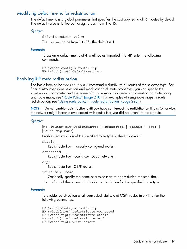
Modifying default metric for redistributionThe default metric is a global parameter that specifies the cost applied to all RIP routes by default.The default value is 1. You can assign a cost from 1 to 15.
Syntax:default-metric value
The value can be from 1 to 15. The default is 1.
ExampleTo assign a default metric of 4 to all routes imported into RIP, enter the followingcommands:
HP Switch(config)# router ripHP Switch(rip)# default-metric 4
Enabling RIP route redistributionThe basic form of the redistribute command redistributes all routes of the selected type. Forfiner control over route selection and modification of route properties, you can specify theroute-map parameter and the name of a route map. (For general information on route policyand route maps, see “Route Policy” (page 218). For examples of using route maps in routeredistribution, see “Using route policy in route redistribution” (page 228).)
NOTE: Do not enable redistribution until you have configured the redistribution filters. Otherwise,the network might become overloaded with routes that you did not intend to redistribute.
Syntax:[no] router rip redistribute [ connected | static | ospf ][route-map name]Enables redistribution of the specified route type to the RIP domain.static
Redistribute from manually configured routes.connected
Redistribute from locally connected networks.ospf
Redistribute from OSPF routes.route-map name
Optionally specify the name of a route-map to apply during redistribution.The no form of the command disables redistribution for the specified route type.
ExampleTo enable redistribution of all connected, static, and OSPF routes into RIP, enter thefollowing commands.
HP Switch(config)# router ripHP Switch(rip)# redistribute connectedHP Switch(rip)# redistribute staticHP Switch(rip)# redistribute ospfHP Switch(rip)# write memory
Configuring for redistribution 141
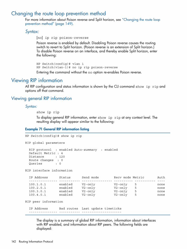
Changing the route loop prevention methodFor more information about Poison reverse and Split horizon, see “Changing the route loopprevention method” (page 149).
Syntax:[no] ip rip poison-reversePoison reverse is enabled by default. Disabling Poison reverse causes the routingswitch to revert to Split horizon. (Poison reverse is an extension of Split horizon.)To disable Poison reverse on an interface, and thereby enable Split horizon, enterthe following:
HP Switch(config)# vlan 1HP Switch(vlan-1)# no ip rip poison-reverse
Entering the command without the no option re-enables Poison reverse.
Viewing RIP informationAll RIP configuration and status information is shown by the CLI command show ip rip andoptions off that command.
Viewing general RIP information
Syntax:show ip rip
To display general RIP information, enter show ip rip at any context level. Theresulting display will appear similar to the following:
Example 71 General RIP information listing
HP Switch(config)# show ip rip
RIP global parameters
RIP protocol : enabled Auto-summary : enabled Default Metric : 4 Distance : 120 Route changes : 0 Queries : 0
RIP interface information
IP Address Status Send mode Recv mode Metric Auth --------------- ----------- ---------------- ---------- ----------- ---- 100.1.0.1 enabled V2-only V2-only 5 none 100.2.0.1 enabled V2-only V2-only 5 none 100.3.0.1 enabled V2-only V2-only 5 none 100.4.0.1 enabled V2-only V2-only 5 none
RIP peer information
IP Address Bad routes Last update timeticks --------------- ----------- ---------------------
The display is a summary of global RIP information, information about interfaceswith RIP enabled, and information about RIP peers. The following fields aredisplayed:
142 Routing Information Protocol
RIP protocol
Status of the RIP protocol on the router. RIP must be enabled here and on theVLAN interface for RIP to be active.The default is disabled.
Auto-summary
Status of auto-summary for all interfaces running RIP. If auto-summary is enabled,subnets will be summarized to a class network when advertising outside of thegiven network.
Default metric
Sets the default metric for imported routes. This is the metric that will beadvertised with the imported route to other RIP peers. A RIP metric is ameasurement used to determine the "best" path to network: 1 is the best, 15 isthe worst, 16 is unreachable.
Route changes
The number of times RIP has modified the routing switch’s routing table.Queries
The number of RIP queries that have been received by the routing switch.RIP interface information
RIP information on the VLAN interfaces on which RIP is enabled:IP address
Address of the VLAN interface running RIP.Status
Status of RIP on the VLAN interface.Send mode
Format of the RIP updates: RIP 1, RIP 2, or RIP 2 version 1 compatible.Recv mode
The switch can process RIP 1, RIP 2, or RIP 2 version 1 compatible updatemessages.
MetricPath "cost," a measurement used to determine the "best" RIP route path: 1is the best, 15 is the worst, 16 is unreachable.
AuthRIP messages can be required to include an authentication key if enabledon the interface.
RIP peer information
RIP peers are neighboring routers from which the routing switch has receivedRIP updates:
IP addressIP address of the RIP neighbor.
Bad routesNumber of route entries which were not processed for any reason.
Last update timeticksNumber of seconds that have passed since we received an update from thisneighbor.
Viewing RIP information 143
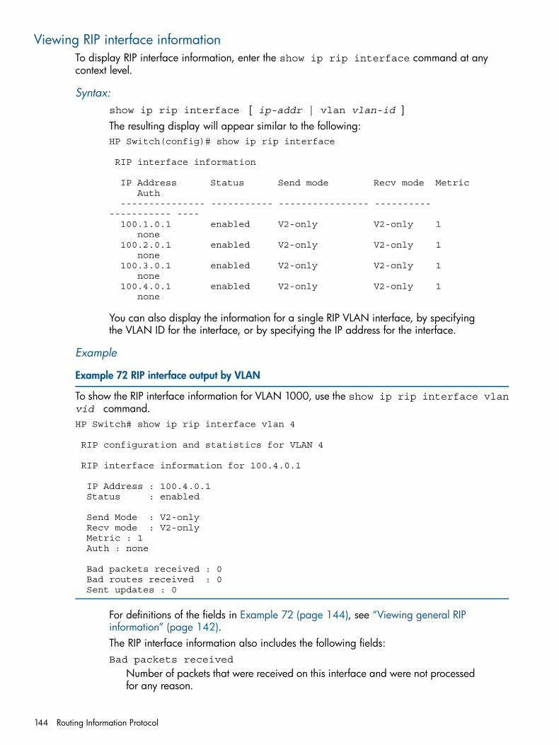
Viewing RIP interface informationTo display RIP interface information, enter the show ip rip interface command at anycontext level.
Syntax:show ip rip interface [ ip-addr | vlan vlan-id ]The resulting display will appear similar to the following:HP Switch(config)# show ip rip interface
RIP interface information
IP Address Status Send mode Recv mode Metric Auth --------------- ----------- ---------------- ---------- ----------- ---- 100.1.0.1 enabled V2-only V2-only 1 none 100.2.0.1 enabled V2-only V2-only 1 none 100.3.0.1 enabled V2-only V2-only 1 none 100.4.0.1 enabled V2-only V2-only 1 none
You can also display the information for a single RIP VLAN interface, by specifyingthe VLAN ID for the interface, or by specifying the IP address for the interface.
Example
Example 72 RIP interface output by VLAN
To show the RIP interface information for VLAN 1000, use the show ip rip interface vlanvid command.HP Switch# show ip rip interface vlan 4
RIP configuration and statistics for VLAN 4
RIP interface information for 100.4.0.1
IP Address : 100.4.0.1 Status : enabled
Send Mode : V2-only Recv mode : V2-only Metric : 1 Auth : none
Bad packets received : 0 Bad routes received : 0 Sent updates : 0
For definitions of the fields in Example 72 (page 144), see “Viewing general RIPinformation” (page 142).The RIP interface information also includes the following fields:Bad packets received
Number of packets that were received on this interface and were not processedfor any reason.
144 Routing Information Protocol
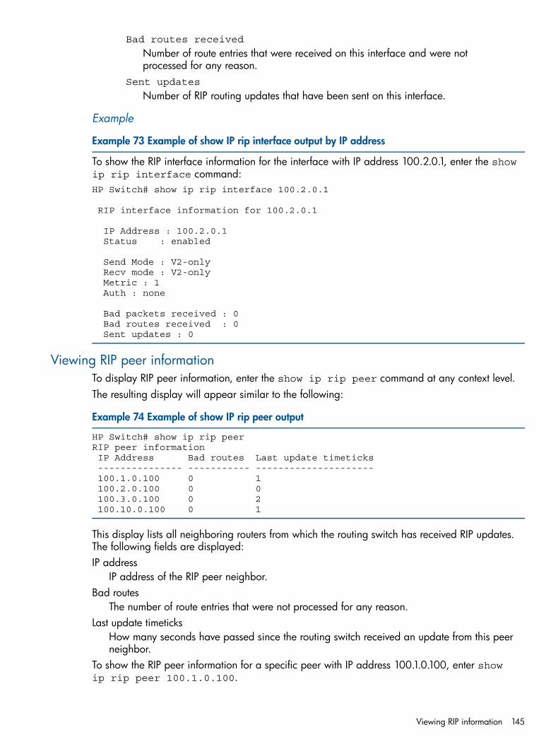
Bad routes received
Number of route entries that were received on this interface and were notprocessed for any reason.
Sent updates
Number of RIP routing updates that have been sent on this interface.
Example
Example 73 Example of show IP rip interface output by IP address
To show the RIP interface information for the interface with IP address 100.2.0.1, enter the showip rip interface command:HP Switch# show ip rip interface 100.2.0.1
RIP interface information for 100.2.0.1
IP Address : 100.2.0.1 Status : enabled
Send Mode : V2-only Recv mode : V2-only Metric : 1 Auth : none
Bad packets received : 0 Bad routes received : 0 Sent updates : 0
Viewing RIP peer informationTo display RIP peer information, enter the show ip rip peer command at any context level.The resulting display will appear similar to the following:
Example 74 Example of show IP rip peer output
HP Switch# show ip rip peerRIP peer information IP Address Bad routes Last update timeticks --------------- ----------- --------------------- 100.1.0.100 0 1 100.2.0.100 0 0 100.3.0.100 0 2 100.10.0.100 0 1
This display lists all neighboring routers from which the routing switch has received RIP updates.The following fields are displayed:IP address
IP address of the RIP peer neighbor.Bad routes
The number of route entries that were not processed for any reason.Last update timeticks
How many seconds have passed since the routing switch received an update from this peerneighbor.
To show the RIP peer information for a specific peer with IP address 100.1.0.100, enter showip rip peer 100.1.0.100.
Viewing RIP information 145
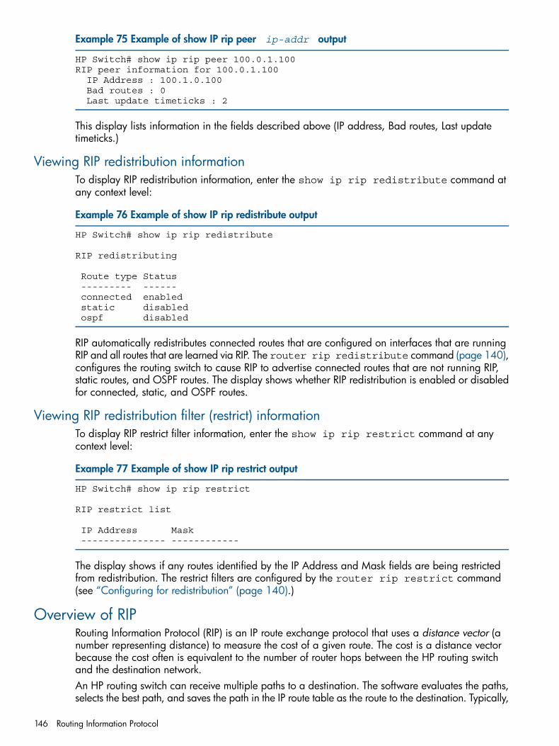
Example 75 Example of show IP rip peer ip-addr output
HP Switch# show ip rip peer 100.0.1.100RIP peer information for 100.0.1.100 IP Address : 100.1.0.100 Bad routes : 0 Last update timeticks : 2
This display lists information in the fields described above (IP address, Bad routes, Last updatetimeticks.)
Viewing RIP redistribution informationTo display RIP redistribution information, enter the show ip rip redistribute command atany context level:
Example 76 Example of show IP rip redistribute output
HP Switch# show ip rip redistribute
RIP redistributing
Route type Status --------- ------ connected enabled static disabled ospf disabled
RIP automatically redistributes connected routes that are configured on interfaces that are runningRIP and all routes that are learned via RIP. The router rip redistribute command (page 140),configures the routing switch to cause RIP to advertise connected routes that are not running RIP,static routes, and OSPF routes. The display shows whether RIP redistribution is enabled or disabledfor connected, static, and OSPF routes.
Viewing RIP redistribution filter (restrict) informationTo display RIP restrict filter information, enter the show ip rip restrict command at anycontext level:
Example 77 Example of show IP rip restrict output
HP Switch# show ip rip restrict
RIP restrict list
IP Address Mask --------------- ------------
The display shows if any routes identified by the IP Address and Mask fields are being restrictedfrom redistribution. The restrict filters are configured by the router rip restrict command(see “Configuring for redistribution” (page 140).)
Overview of RIPRouting Information Protocol (RIP) is an IP route exchange protocol that uses a distance vector (anumber representing distance) to measure the cost of a given route. The cost is a distance vectorbecause the cost often is equivalent to the number of router hops between the HP routing switchand the destination network.An HP routing switch can receive multiple paths to a destination. The software evaluates the paths,selects the best path, and saves the path in the IP route table as the route to the destination. Typically,
146 Routing Information Protocol
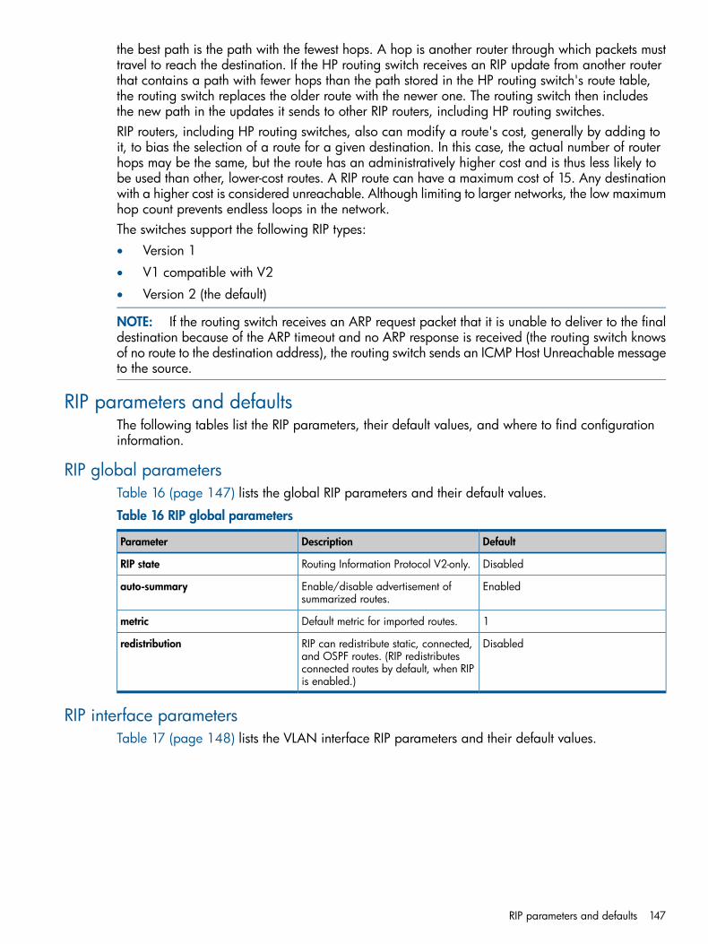
the best path is the path with the fewest hops. A hop is another router through which packets musttravel to reach the destination. If the HP routing switch receives an RIP update from another routerthat contains a path with fewer hops than the path stored in the HP routing switch's route table,the routing switch replaces the older route with the newer one. The routing switch then includesthe new path in the updates it sends to other RIP routers, including HP routing switches.RIP routers, including HP routing switches, also can modify a route's cost, generally by adding toit, to bias the selection of a route for a given destination. In this case, the actual number of routerhops may be the same, but the route has an administratively higher cost and is thus less likely tobe used than other, lower-cost routes. A RIP route can have a maximum cost of 15. Any destinationwith a higher cost is considered unreachable. Although limiting to larger networks, the low maximumhop count prevents endless loops in the network.The switches support the following RIP types:• Version 1
• V1 compatible with V2
• Version 2 (the default)
NOTE: If the routing switch receives an ARP request packet that it is unable to deliver to the finaldestination because of the ARP timeout and no ARP response is received (the routing switch knowsof no route to the destination address), the routing switch sends an ICMP Host Unreachable messageto the source.
RIP parameters and defaultsThe following tables list the RIP parameters, their default values, and where to find configurationinformation.
RIP global parametersTable 16 (page 147) lists the global RIP parameters and their default values.
Table 16 RIP global parameters
DefaultDescriptionParameter
DisabledRouting Information Protocol V2-only.RIP state
EnabledEnable/disable advertisement ofsummarized routes.
auto-summary
1Default metric for imported routes.metric
DisabledRIP can redistribute static, connected,and OSPF routes. (RIP redistributes
redistribution
connected routes by default, when RIPis enabled.)
RIP interface parametersTable 17 (page 148) lists the VLAN interface RIP parameters and their default values.
RIP parameters and defaults 147
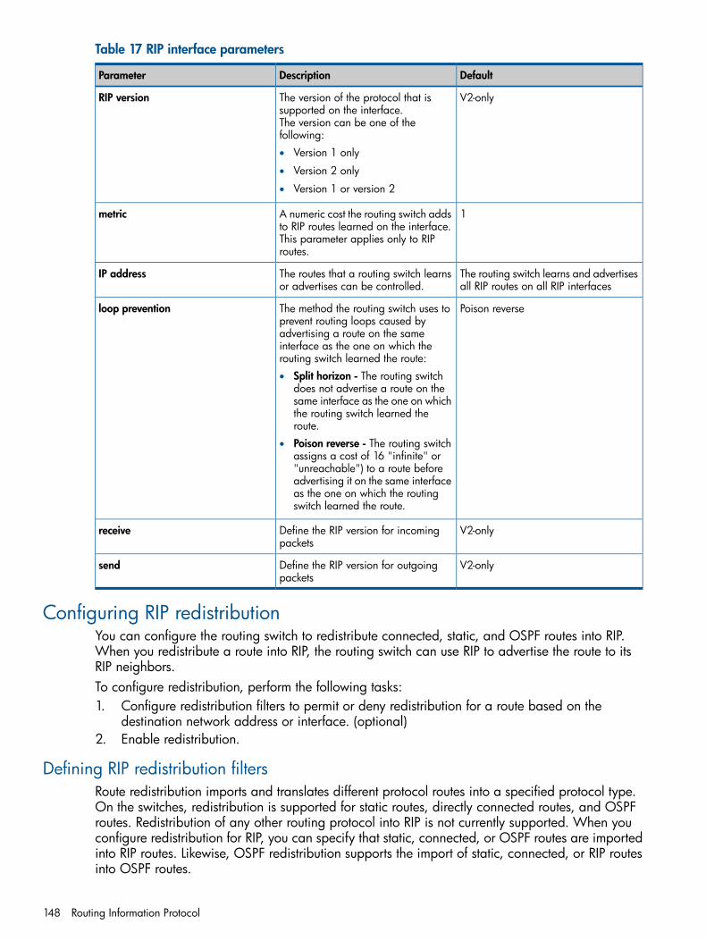
Table 17 RIP interface parameters
DefaultDescriptionParameter
V2-onlyThe version of the protocol that issupported on the interface.The version can be one of thefollowing:
RIP version
• Version 1 only
• Version 2 only
• Version 1 or version 2
1A numeric cost the routing switch addsto RIP routes learned on the interface.
metric
This parameter applies only to RIProutes.
The routing switch learns and advertisesall RIP routes on all RIP interfaces
The routes that a routing switch learnsor advertises can be controlled.
IP address
Poison reverseThe method the routing switch uses toprevent routing loops caused by
loop prevention
advertising a route on the sameinterface as the one on which therouting switch learned the route:• Split horizon - The routing switch
does not advertise a route on thesame interface as the one on whichthe routing switch learned theroute.
• Poison reverse - The routing switchassigns a cost of 16 "infinite" or"unreachable") to a route beforeadvertising it on the same interfaceas the one on which the routingswitch learned the route.
V2-onlyDefine the RIP version for incomingpackets
receive
V2-onlyDefine the RIP version for outgoingpackets
send
Configuring RIP redistributionYou can configure the routing switch to redistribute connected, static, and OSPF routes into RIP.When you redistribute a route into RIP, the routing switch can use RIP to advertise the route to itsRIP neighbors.To configure redistribution, perform the following tasks:1. Configure redistribution filters to permit or deny redistribution for a route based on the
destination network address or interface. (optional)2. Enable redistribution.
Defining RIP redistribution filtersRoute redistribution imports and translates different protocol routes into a specified protocol type.On the switches, redistribution is supported for static routes, directly connected routes, and OSPFroutes. Redistribution of any other routing protocol into RIP is not currently supported. When youconfigure redistribution for RIP, you can specify that static, connected, or OSPF routes are importedinto RIP routes. Likewise, OSPF redistribution supports the import of static, connected, or RIP routesinto OSPF routes.
148 Routing Information Protocol

Changing the route loop prevention methodRIP can use the following methods to prevent routing loops:• Split horizon -the routing switch does not advertise a route on the same interface as the one
on which the routing switch learned the route.• Poison reverse - the routing switch assigns a cost of 16 ("infinity" or "unreachable") to a route
before advertising it on the same interface as the one on which the routing switch learned theroute. This is the default.
These loop prevention methods are configurable on an individual VLAN interface basis.
NOTE: These methods are in addition to RIP's maximum valid route cost of 15.
Changing the route loop prevention method 149
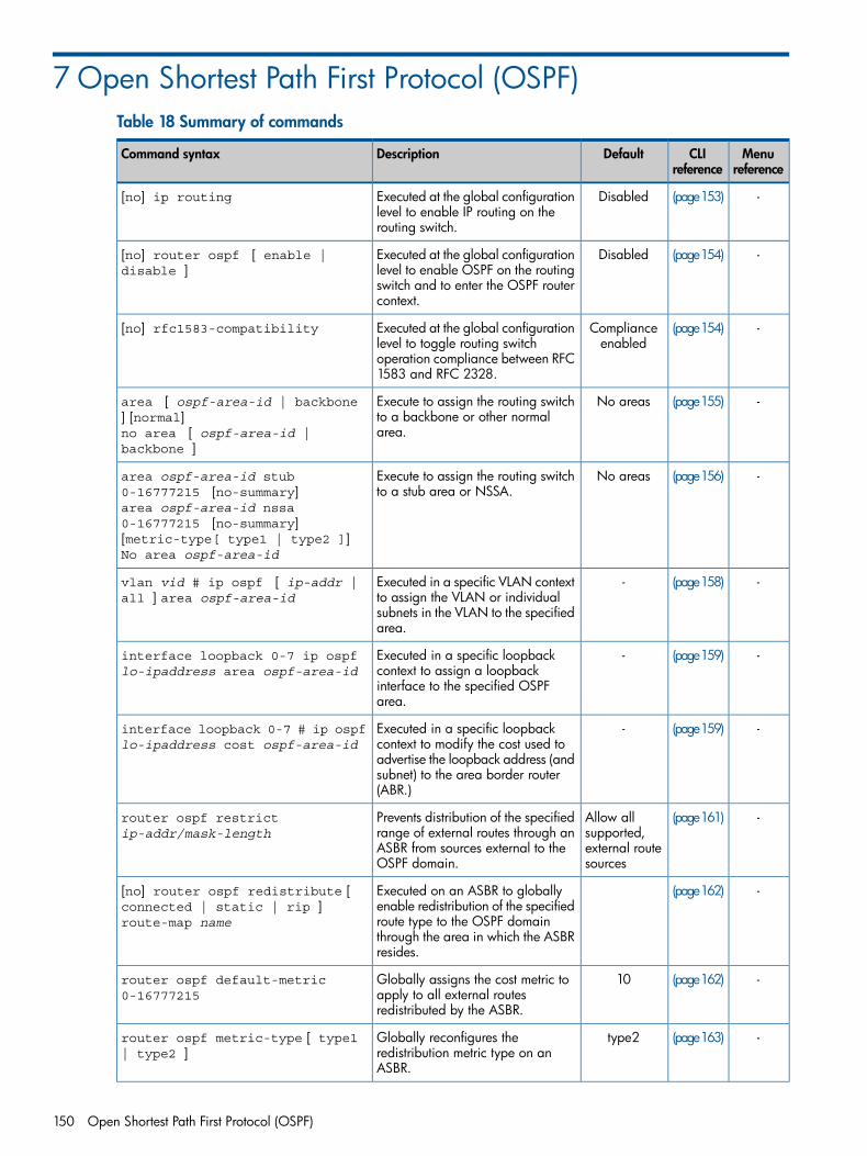
7 Open Shortest Path First Protocol (OSPF)Table 18 Summary of commands
Menureference
CLIreference
DefaultDescriptionCommand syntax
-(page153)DisabledExecuted at the global configurationlevel to enable IP routing on therouting switch.
[no] ip routing
-(page154)DisabledExecuted at the global configurationlevel to enable OSPF on the routing
[no] router ospf [ enable |disable ]
switch and to enter the OSPF routercontext.
-(page154)Complianceenabled
Executed at the global configurationlevel to toggle routing switch
[no] rfc1583-compatibility
operation compliance between RFC1583 and RFC 2328.
-(page155)No areasExecute to assign the routing switchto a backbone or other normalarea.
area [ ospf-area-id | backbone] [normal]no area [ ospf-area-id |backbone ]
-(page156)No areasExecute to assign the routing switchto a stub area or NSSA.
area ospf-area-id stub0-16777215 [no-summary]area ospf-area-id nssa0-16777215 [no-summary][metric-type[ type1 | type2 ]]No area ospf-area-id
-(page158)-Executed in a specific VLAN contextto assign the VLAN or individual
vlan vid # ip ospf [ ip-addr |all ] area ospf-area-id
subnets in the VLAN to the specifiedarea.
-(page159)-Executed in a specific loopbackcontext to assign a loopback
interface loopback 0-7 ip ospflo-ipaddress area ospf-area-id
interface to the specified OSPFarea.
-(page159)-Executed in a specific loopbackcontext to modify the cost used to
interface loopback 0-7 # ip ospflo-ipaddress cost ospf-area-id
advertise the loopback address (andsubnet) to the area border router(ABR.)
-(page161)Allow allsupported,
Prevents distribution of the specifiedrange of external routes through an
router ospf restrictip-addr/mask-length
external routesources
ASBR from sources external to theOSPF domain.
-(page162)Executed on an ASBR to globallyenable redistribution of the specified
[no] router ospf redistribute [connected | static | rip ]route-map name route type to the OSPF domain
through the area in which the ASBRresides.
-(page162)10Globally assigns the cost metric toapply to all external routesredistributed by the ASBR.
router ospf default-metric0-16777215
-(page163)type2Globally reconfigures theredistribution metric type on anASBR.
router ospf metric-type [ type1| type2 ]
150 Open Shortest Path First Protocol (OSPF)
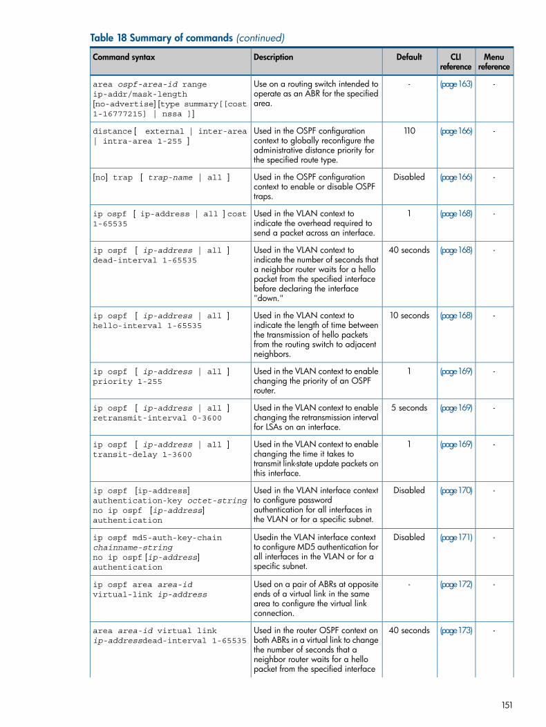
Table 18 Summary of commands (continued)
Menureference
CLIreference
DefaultDescriptionCommand syntax
-(page163)-Use on a routing switch intended tooperate as an ABR for the specifiedarea.
area ospf-area-id rangeip-addr/mask-length[no-advertise] [type summary[[cost1-16777215] | nssa ]]
-(page166)110Used in the OSPF configurationcontext to globally reconfigure the
distance [ external | inter-area| intra-area 1-255 ]
administrative distance priority forthe specified route type.
-(page166)DisabledUsed in the OSPF configurationcontext to enable or disable OSPFtraps.
[no] trap [ trap-name | all ]
-(page168)1Used in the VLAN context toindicate the overhead required tosend a packet across an interface.
ip ospf [ ip-address | all ] cost1-65535
-(page168)40 secondsUsed in the VLAN context toindicate the number of seconds that
ip ospf [ ip-address | all ]dead-interval 1-65535
a neighbor router waits for a hellopacket from the specified interfacebefore declaring the interface"down."
-(page168)10 secondsUsed in the VLAN context toindicate the length of time between
ip ospf [ ip-address | all ]hello-interval 1-65535
the transmission of hello packetsfrom the routing switch to adjacentneighbors.
-(page169)1Used in the VLAN context to enablechanging the priority of an OSPFrouter.
ip ospf [ ip-address | all ]priority 1-255
-(page169)5 secondsUsed in the VLAN context to enablechanging the retransmission intervalfor LSAs on an interface.
ip ospf [ ip-address | all ]retransmit-interval 0-3600
-(page169)1Used in the VLAN context to enablechanging the time it takes to
ip ospf [ ip-address | all ]transit-delay 1-3600
transmit link-state update packets onthis interface.
-(page170)DisabledUsed in the VLAN interface contextto configure password
ip ospf [ip-address]authentication-key octet-string
authentication for all interfaces inthe VLAN or for a specific subnet.
no ip ospf [ip-address]authentication
-(page171)DisabledUsedin the VLAN interface contextto configure MD5 authentication for
ip ospf md5-auth-key-chainchainname-string
all interfaces in the VLAN or for aspecific subnet.
no ip ospf [ip-address]authentication
-(page172)-Used on a pair of ABRs at oppositeends of a virtual link in the same
ip ospf area area-idvirtual-link ip-address
area to configure the virtual linkconnection.
-(page173)40 secondsUsed in the router OSPF context onboth ABRs in a virtual link to change
area area-id virtual linkip-addressdead-interval 1-65535
the number of seconds that aneighbor router waits for a hellopacket from the specified interface
151
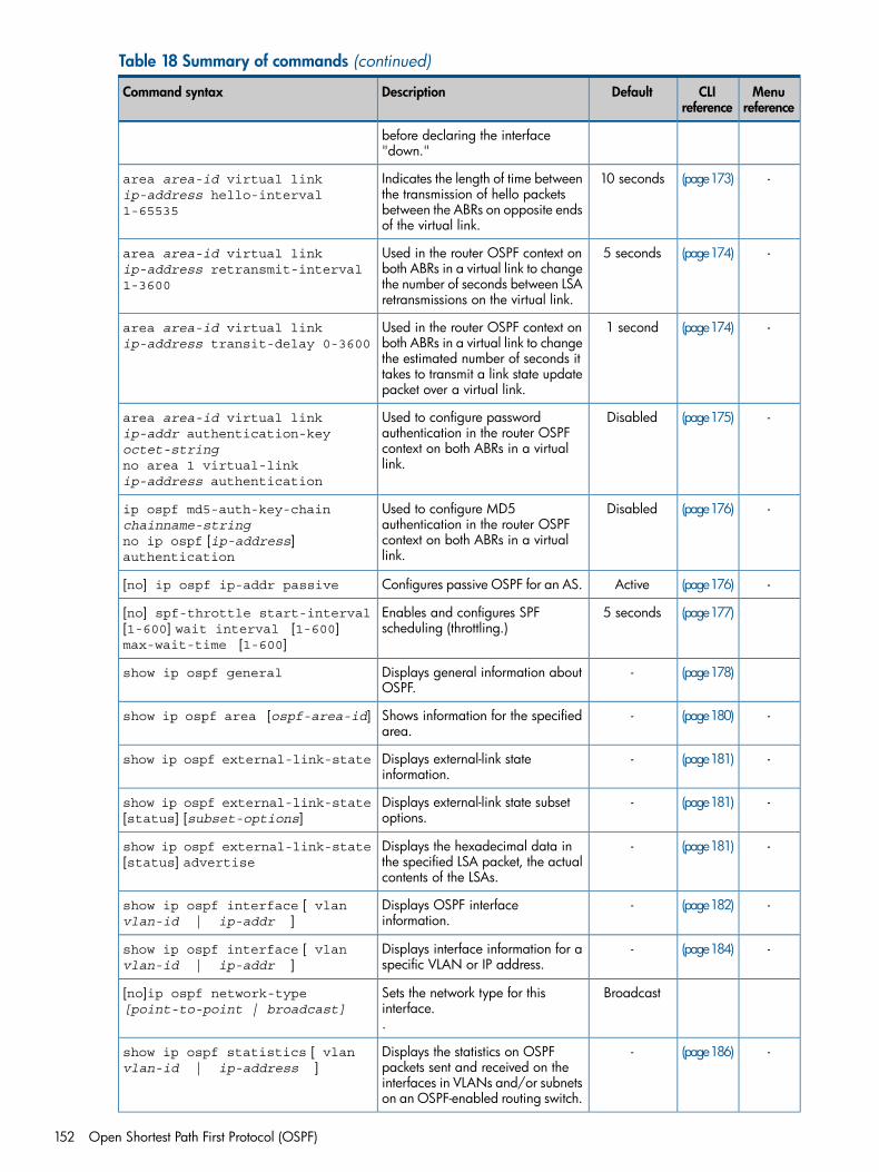
Table 18 Summary of commands (continued)
Menureference
CLIreference
DefaultDescriptionCommand syntax
before declaring the interface"down."
-(page173)10 secondsIndicates the length of time betweenthe transmission of hello packets
area area-id virtual linkip-address hello-interval1-65535 between the ABRs on opposite ends
of the virtual link.
-(page174)5 secondsUsed in the router OSPF context onboth ABRs in a virtual link to change
area area-id virtual linkip-address retransmit-interval1-3600 the number of seconds between LSA
retransmissions on the virtual link.
-(page174)1 secondUsed in the router OSPF context onboth ABRs in a virtual link to change
area area-id virtual linkip-address transit-delay 0-3600
the estimated number of seconds ittakes to transmit a link state updatepacket over a virtual link.
-(page175)DisabledUsed to configure passwordauthentication in the router OSPF
area area-id virtual linkip-addr authentication-keyoctet-string context on both ABRs in a virtual
link.no area 1 virtual-linkip-address authentication
-(page176)DisabledUsed to configure MD5authentication in the router OSPF
ip ospf md5-auth-key-chainchainname-string
context on both ABRs in a virtuallink.
no ip ospf [ip-address]authentication
-(page176)ActiveConfigures passive OSPF for an AS.[no] ip ospf ip-addr passive
(page177)5 secondsEnables and configures SPFscheduling (throttling.)
[no] spf-throttle start-interval[1-600] wait interval [1-600]max-wait-time [1-600]
(page178)-Displays general information aboutOSPF.
show ip ospf general
-(page180)-Shows information for the specifiedarea.
show ip ospf area [ospf-area-id]
-(page181)-Displays external-link stateinformation.
show ip ospf external-link-state
-(page181)-Displays external-link state subsetoptions.
show ip ospf external-link-state[status] [subset-options]
-(page181)-Displays the hexadecimal data inthe specified LSA packet, the actualcontents of the LSAs.
show ip ospf external-link-state[status] advertise
-(page182)-Displays OSPF interfaceinformation.
show ip ospf interface [ vlanvlan-id | ip-addr ]
-(page184)-Displays interface information for aspecific VLAN or IP address.
show ip ospf interface [ vlanvlan-id | ip-addr ]
BroadcastSets the network type for thisinterface.
[no]ip ospf network-type[point-to-point | broadcast]
.
-(page186)-Displays the statistics on OSPFpackets sent and received on the
show ip ospf statistics [ vlanvlan-id | ip-address ]
interfaces in VLANs and/or subnetson an OSPF-enabled routing switch.
152 Open Shortest Path First Protocol (OSPF)
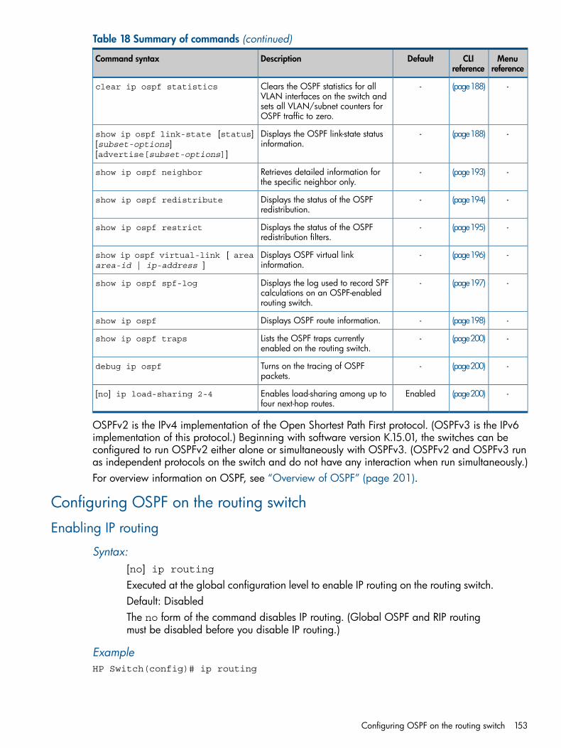
Table 18 Summary of commands (continued)
Menureference
CLIreference
DefaultDescriptionCommand syntax
-(page188)-Clears the OSPF statistics for allVLAN interfaces on the switch and
clear ip ospf statistics
sets all VLAN/subnet counters forOSPF traffic to zero.
-(page188)-Displays the OSPF link-state statusinformation.
show ip ospf link-state [status][subset-options][advertise[subset-options]]
-(page193)-Retrieves detailed information forthe specific neighbor only.
show ip ospf neighbor
-(page194)-Displays the status of the OSPFredistribution.
show ip ospf redistribute
-(page195)-Displays the status of the OSPFredistribution filters.
show ip ospf restrict
-(page196)-Displays OSPF virtual linkinformation.
show ip ospf virtual-link [ areaarea-id | ip-address ]
-(page197)-Displays the log used to record SPFcalculations on an OSPF-enabledrouting switch.
show ip ospf spf-log
-(page198)-Displays OSPF route information.show ip ospf
-(page200)-Lists the OSPF traps currentlyenabled on the routing switch.
show ip ospf traps
-(page200)-Turns on the tracing of OSPFpackets.
debug ip ospf
-(page200)EnabledEnables load-sharing among up tofour next-hop routes.
[no] ip load-sharing 2-4
OSPFv2 is the IPv4 implementation of the Open Shortest Path First protocol. (OSPFv3 is the IPv6implementation of this protocol.) Beginning with software version K.15.01, the switches can beconfigured to run OSPFv2 either alone or simultaneously with OSPFv3. (OSPFv2 and OSPFv3 runas independent protocols on the switch and do not have any interaction when run simultaneously.)For overview information on OSPF, see “Overview of OSPF” (page 201).
Configuring OSPF on the routing switch
Enabling IP routing
Syntax:[no] ip routingExecuted at the global configuration level to enable IP routing on the routing switch.Default: DisabledThe no form of the command disables IP routing. (Global OSPF and RIP routingmust be disabled before you disable IP routing.)
ExampleHP Switch(config)# ip routing
Configuring OSPF on the routing switch 153
Enabling global OSPF routing
Syntax:[no] router ospf [ enable | disable ]Executed at the global configuration level to enable OSPF on the routing switchand to enter the OSPF router context. This enables you to proceed with assigningOSPF areas, including area border router (ABR) and autonomous system boundaryrouter (ASBR) configuration, and to modify OSPF global parameter settings asneeded.The enable form of the command enables OSPF routing, and the disable formof the command disables OSPF routing.Global IP routing must be enabled before executing this command.Default: DisabledThe no form of the command deletes all protocol specific information from the globalcontext and interface context. All protocol parameters are set to default values.
NOTE: If you disable OSPF, the switch retains all the configuration informationfor the disabled protocol in flash memory. If you subsequently restart OSPF, theexisting configuration will be applied. After restarting OSPF, the exiting configurationwill be applied and the protocol will be in the disabled state.
Example
Example 78 To enter the OSPF router context
HP Switch(config)#router ospf HP Switch(ospf)#
Example 79 To enable OSPF routing
HP Switch(config)#router ospf enableHP Switch(ospf)#
Example 80 To disable OSPF routing
HP Switch(config)#router ospf disableHP Switch(ospf)#
NOTE: The no router ospf enable command also disables OSPF routing.
To delete all protocol-specific information from the global context and interface context and set allprotocol parameters to default values.:HP Switch(config)#no router ospfHP Switch(ospf)#
Changing the RFC 1583 OSPF compliance settingFor more information on this setting, see “Changing the RFC 1583 OSPF compliance setting”(page 212).
Syntax:[no] rfc1583-compatibilityExecuted at the global configuration level to toggle routing switch operationcompliance between RFC 1583 and RFC 2328.
154 Open Shortest Path First Protocol (OSPF)
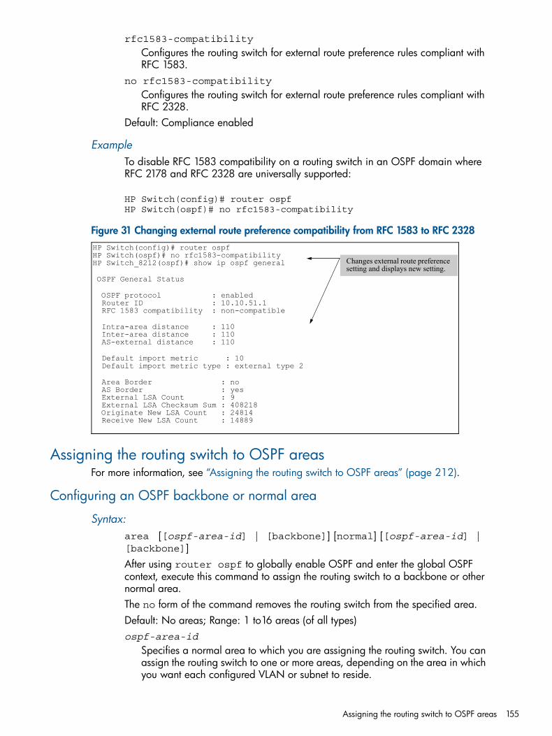
rfc1583-compatibility
Configures the routing switch for external route preference rules compliant withRFC 1583.
no rfc1583-compatibility
Configures the routing switch for external route preference rules compliant withRFC 2328.
Default: Compliance enabled
ExampleTo disable RFC 1583 compatibility on a routing switch in an OSPF domain whereRFC 2178 and RFC 2328 are universally supported:
HP Switch(config)# router ospf HP Switch(ospf)# no rfc1583-compatibility
Figure 31 Changing external route preference compatibility from RFC 1583 to RFC 2328HP Switch(config)# router ospfHP Switch(ospf)# no rfc1583-compatibilityHP Switch_8212(ospf)# show ip ospf general
OSPF General Status
OSPF protocol : enabled Router ID : 10.10.51.1 RFC 1583 compatibility : non-compatible
Intra-area distance : 110 Inter-area distance : 110 AS-external distance : 110
Default import metric : 10 Default import metric type : external type 2
Area Border : no AS Border : yes External LSA Count : 9 External LSA Checksum Sum : 408218 Originate New LSA Count : 24814 Receive New LSA Count : 14889
Changes external route preference setting and displays new setting.
Assigning the routing switch to OSPF areasFor more information, see “Assigning the routing switch to OSPF areas” (page 212).
Configuring an OSPF backbone or normal area
Syntax:area [[ospf-area-id] | [backbone]] [normal] [[ospf-area-id] |[backbone]]After using router ospf to globally enable OSPF and enter the global OSPFcontext, execute this command to assign the routing switch to a backbone or othernormal area.The no form of the command removes the routing switch from the specified area.Default: No areas; Range: 1 to16 areas (of all types)ospf-area-id
Specifies a normal area to which you are assigning the routing switch. You canassign the routing switch to one or more areas, depending on the area in whichyou want each configured VLAN or subnet to reside.
Assigning the routing switch to OSPF areas 155
You can enter area IDs in either whole number or dotted decimal format. (Therouting switch automatically converts whole numbers to the dotted decimalformat.)For example, if you enter an area-ID of 1, it appears in the switch's configurationas 0.0.0.1 and an area-ID of 256 appears in the switch configuration as0.0.1.0.An area ID can be a value selected to match the IP address of a VLAN belongingto the area or a value corresponding to a numbering system you devise for theareas in a given autonomous system (AS.)Entering an area ID of 0 or 0.0.0.0 automatically joins the routing switch tothe backbone area.The maximum area ID value is 255.255.255.254 (4,294,967,294.)
backbone
Assigns the routing switch to the backbone area and automatically assigns anarea ID of0.0.0.0 and an area type of normal.Using 0 or 0.0.0.0 with the above ospf-area-id option achieves the sameresult. The backbone area is automatically configured as a normal area type.
ExampleTo configure a backbone and a normal area with an ID of "1" (0.0.0.1) on arouting switch:
HP Switch(ospf)# area backbone HP Switch(ospf)# area 1
Configuring a stub orNSSA area
Syntax:area ospf-area-id stub 0-16777215 [no-summary]area ospf-area-id nssa 0-16777215 [no-summary] [metric-type[type1 | type2 ]]No area ospf-area-id
After using router ospf to globally enable OSPF and enter the global OSPFcontext, execute this command to assign the routing switch to a stub area or NSSA.(Does not apply to backbone and normal OSPF area ABRs.)The no form of the command removes the routing switch from the specified area.Default: No areas; Range: 1 to 16 areas (of all types)ospf-area-id
Same area ID as in “Configuring an OSPF backbone or normal area” (page 155),except you cannot assign a backbone area number ( 0 or 0.0.0.0) to a stubor NSSA area.
[ stub | nssa ]Designates the area identified by ospf-area-id as a stub area or NSSA.
0-16777215
If the routing switch is used as an ABR for the designated area, assigns the costof the default route (to the backbone) that is injected into the area.
NOTE: If the routing switch is not an ABR for the stub area or NSSA, theabove cost setting is still required by the CLI, but is not used.
156 Open Shortest Path First Protocol (OSPF)
In the default configuration, a routing switch acting as an ABR for a stub area orNSSA injects type-3 summary routes into the area. For an NSSA, the routing switchalso injects a type-7 default route into the area.[no-summary]
Where the routing switch is an ABR for a stub area or an NSSA, this optionreduces the amount of link-state advertisement (LSA) traffic entering the areafrom the backbone by replacing the injection of type-3 summary routes withinjection of a type-3 default summary route.For NSSAs, this command also disables injection of the type-7 default externalroute from the backbone into the area (included in the metric-type operationdescribed below.)Default: DisabledFor more on this topic, see “Not-so-stubby-area (NSSA)” (page 206), “Stub area”(page 206), and “Replacing type-3summary LSAs and type-7 default externalLSAs with a type-3 default route LSA” (page 208).
[metric-type[ type1 | type2 ]]Used in NSSA ABRs only.Enables injection of the type-7 default external route and type-3 summary routesinto the area instead of a type 3 default route. Also specifies the type of internalcost metric to include in type-7 LSAs advertised for redistribution of externalroutes in the NSSA. (The redistribution—or external—cost metric is a globalsetting on the routing switch set by the default-metric command.)The metric-type command specifies whether to include the redistributioncost in the cost metric calculation for a type-7 default LSA injected into the area.type1
Calculate external route cost for a type-7 default LSA as the sum of (1) theexternal route cost assigned by the ASBR plus (2) the internal cost from therouter with traffic for the external route to the ASBR advertising the route.
type2
Calculate external route cost for a type-7 default LSA as being only the costfrom the router with traffic for the external route to the ASBR advertising theroute.If metric-type is not specified, the default (type2) will be used.
Using the area ospf-area-id nssa 0-16777215 without entering eitherno-summary or metric-type resets the routing switch to the state where injectionof type-3 summary routes and the type-7 default external routes is enabled withmetric-type set to type2.Default: Enabled with metric-type type2
NOTE: Different routers in the NSSA can be configured with differentmetric-type values.
ExamplesThe following examples of configuring a stub area and an NSSA on a routingswitch use an (arbitrary) cost of "10".
Assigning the routing switch to OSPF areas 157
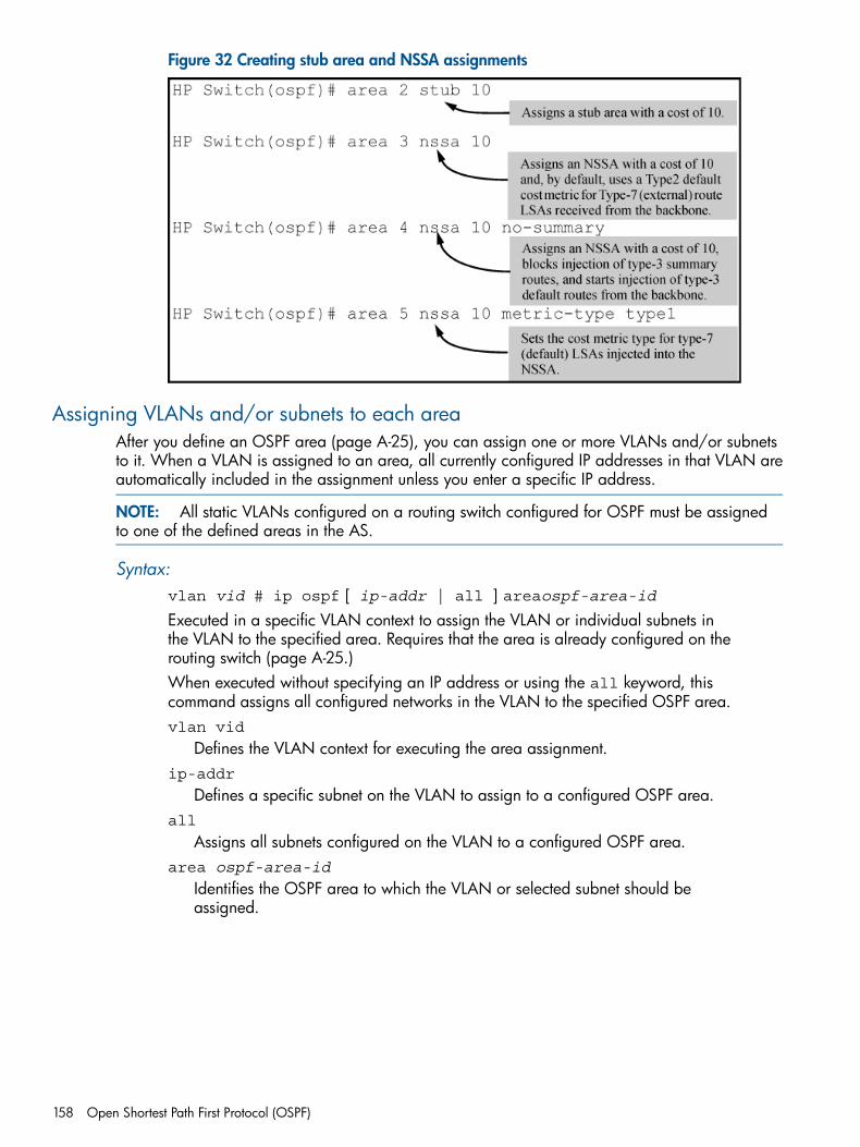
Figure 32 Creating stub area and NSSA assignments
Assigning VLANs and/or subnets to each areaAfter you define an OSPF area (page A-25), you can assign one or more VLANs and/or subnetsto it. When a VLAN is assigned to an area, all currently configured IP addresses in that VLAN areautomatically included in the assignment unless you enter a specific IP address.
NOTE: All static VLANs configured on a routing switch configured for OSPF must be assignedto one of the defined areas in the AS.
Syntax:vlan vid # ip ospf [ ip-addr | all ] areaospf-area-idExecuted in a specific VLAN context to assign the VLAN or individual subnets inthe VLAN to the specified area. Requires that the area is already configured on therouting switch (page A-25.)When executed without specifying an IP address or using the all keyword, thiscommand assigns all configured networks in the VLAN to the specified OSPF area.vlan vid
Defines the VLAN context for executing the area assignment.ip-addr
Defines a specific subnet on the VLAN to assign to a configured OSPF area.all
Assigns all subnets configured on the VLAN to a configured OSPF area.area ospf-area-id
Identifies the OSPF area to which the VLAN or selected subnet should beassigned.
158 Open Shortest Path First Protocol (OSPF)
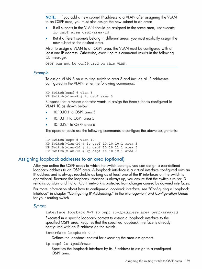
NOTE: If you add a new subnet IP address to a VLAN after assigning the VLANto an OSPF area, you must also assign the new subnet to an area:• If all subnets in the VLAN should be assigned to the same area, just execute
ip ospf area ospf-area-id .• But if different subnets belong in different areas, you must explicitly assign the
new subnet to the desired area.Also, to assign a VLAN to an OSPF area, the VLAN must be configured with atleast one IP address. Otherwise, executing this command results in the followingCLI message:OSPF can not be configured on this VLAN.
ExampleTo assign VLAN 8 on a routing switch to area 3 and include all IP addressesconfigured in the VLAN, enter the following commands:
HP Switch(ospf)# vlan 8HP Switch(vlan-8)# ip ospf area 3
Suppose that a system operator wants to assign the three subnets configured inVLAN 10 as shown below:• 10.10.10.1 to OSPF area 5
• 10.10.11.1 to OSPF area 5
• 10.10.12.1 to OSPF area 6The operator could use the following commands to configure the above assignments:
HP Switch(ospf)# vlan 10HP Switch(vlan-10)# ip ospf 10.10.10.1 area 5HP Switch(vlan-10)# ip ospf 10.10.11.1 area 5HP Switch(vlan-10)# ip ospf 10.10.12.1 area 6
Assigning loopback addresses to an area (optional)After you define the OSPF areas to which the switch belongs, you can assign a user-definedloopback address to an OSPF area. A loopback interface is a virtual interface configured with anIP address and is always reachable as long as at least one of the IP interfaces on the switch isoperational. Because the loopback interface is always up, you ensure that the switch's router IDremains constant and that an OSPF network is protected from changes caused by downed interfaces.For more information about how to configure a loopback interface, see "Configuring a LoopbackInterface" in chapter "Configuring IP Addressing," in the Management and Configuration Guidefor your routing switch.
Syntax:interface loopback 0-7 ip ospf lo-ipaddress area ospf-area-id
Executed in a specific loopback context to assign a loopback interface to thespecified OSPF area. Requires that the specified loopback interface is alreadyconfigured with an IP address on the switch.interface loopback 0-7
Defines the loopback context for executing the area assignment.ip ospf lo-ipaddress
Specifies the loopback interface by its IP address to assign to a configuredOSPF area.
Assigning the routing switch to OSPF areas 159
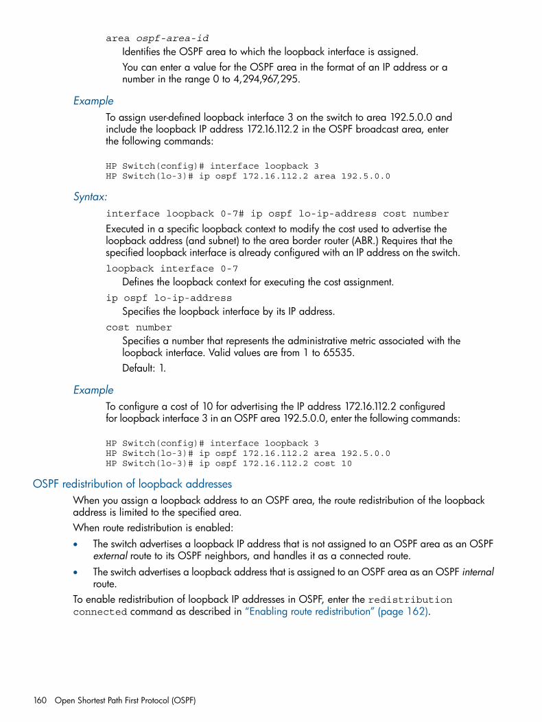
area ospf-area-id
Identifies the OSPF area to which the loopback interface is assigned.You can enter a value for the OSPF area in the format of an IP address or anumber in the range 0 to 4,294,967,295.
ExampleTo assign user-defined loopback interface 3 on the switch to area 192.5.0.0 andinclude the loopback IP address 172.16.112.2 in the OSPF broadcast area, enterthe following commands:
HP Switch(config)# interface loopback 3HP Switch(lo-3)# ip ospf 172.16.112.2 area 192.5.0.0
Syntax:interface loopback 0-7# ip ospf lo-ip-address cost number
Executed in a specific loopback context to modify the cost used to advertise theloopback address (and subnet) to the area border router (ABR.) Requires that thespecified loopback interface is already configured with an IP address on the switch.loopback interface 0-7
Defines the loopback context for executing the cost assignment.ip ospf lo-ip-address
Specifies the loopback interface by its IP address.cost number
Specifies a number that represents the administrative metric associated with theloopback interface. Valid values are from 1 to 65535.Default: 1.
ExampleTo configure a cost of 10 for advertising the IP address 172.16.112.2 configuredfor loopback interface 3 in an OSPF area 192.5.0.0, enter the following commands:
HP Switch(config)# interface loopback 3HP Switch(lo-3)# ip ospf 172.16.112.2 area 192.5.0.0HP Switch(lo-3)# ip ospf 172.16.112.2 cost 10
OSPF redistribution of loopback addressesWhen you assign a loopback address to an OSPF area, the route redistribution of the loopbackaddress is limited to the specified area.When route redistribution is enabled:• The switch advertises a loopback IP address that is not assigned to an OSPF area as an OSPF
external route to its OSPF neighbors, and handles it as a connected route.• The switch advertises a loopback address that is assigned to an OSPF area as an OSPF internal
route.To enable redistribution of loopback IP addresses in OSPF, enter the redistributionconnected command as described in “Enabling route redistribution” (page 162).
160 Open Shortest Path First Protocol (OSPF)
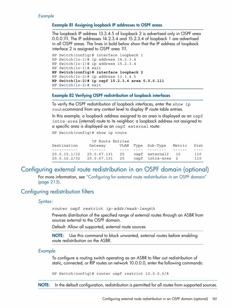
Example
Example 81 Assigning loopback IP addresses to OSPF areas
The loopback IP address 13.3.4.5 of loopback 2 is advertised only in OSPF area0.0.0.111. The IP addresses 14.2.3.4 and 15.2.3.4 of loopback 1 are advertisedin all OSPF areas. The lines in bold below show that the IP address of loopbackinterface 2 is assigned to OSPF area 111.HP Switch(config)# interface loopback 1HP Switch(lo-1)# ip address 14.2.3.4HP Switch(lo-1)# ip address 15.2.3.4HP Switch(lo-1)# exitHP Switch(config)# interface loopback 2HP Switch(lo-2)# ip address 13.3.4.5HP Switch(lo-2)# ip ospf 15.2.3.4 area 0.0.0.111HP Switch(lo-2)# exit
Example 82 Verifying OSPF redistribution of loopback interfaces
To verify the OSPF redistribution of loopback interfaces, enter the show iproutecommand from any context level to display IP route table entries.In this example, a loopback address assigned to an area is displayed as an ospfintra-area (internal) route to its neighbor; a loopback address not assigned toa specific area is displayed as an ospf external route:HP Switch(config)# show ip route
IP Route EntriesDestination Gateway VLAN Type Sub-Type Metric Dist----------- ------- ---- ---- -------- ------ ----20.0.15.1/32 25.0.67.131 25 ospf external2 10 11020.0.16.2/32 25.0.67.131 25 ospf intra-area 2 110
Configuring external route redistribution in an OSPF domain (optional)For more information, see “Configuring for external route redistribution in an OSPF domain”(page 213).
Configuring redistribution filters
Syntax:router ospf restrict ip-addr/mask-length
Prevents distribution of the specified range of external routes through an ASBR fromsources external to the OSPF domain.Default: Allow all supported, external route sources
NOTE: Use this command to block unwanted, external routes before enablingroute redistribution on the ASBR.
ExampleTo configure a routing switch operating as an ASBR to filter out redistribution ofstatic, connected, or RIP routes on network 10.0.0.0, enter the following commands:
HP Switch(config)# router ospf restrict 10.0.0.0/8
NOTE: In the default configuration, redistribution is permitted for all routes from supported sources.
Configuring external route redistribution in an OSPF domain (optional) 161
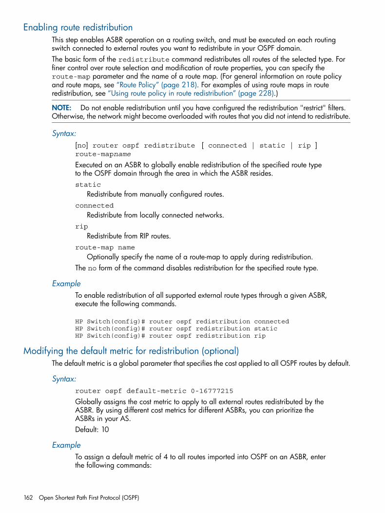
Enabling route redistributionThis step enables ASBR operation on a routing switch, and must be executed on each routingswitch connected to external routes you want to redistribute in your OSPF domain.The basic form of the redistribute command redistributes all routes of the selected type. Forfiner control over route selection and modification of route properties, you can specify theroute-map parameter and the name of a route map. (For general information on route policyand route maps, see “Route Policy” (page 218). For examples of using route maps in routeredistribution, see “Using route policy in route redistribution” (page 228).)
NOTE: Do not enable redistribution until you have configured the redistribution "restrict" filters.Otherwise, the network might become overloaded with routes that you did not intend to redistribute.
Syntax:[no] router ospf redistribute [ connected | static | rip ]route-mapname
Executed on an ASBR to globally enable redistribution of the specified route typeto the OSPF domain through the area in which the ASBR resides.static
Redistribute from manually configured routes.connected
Redistribute from locally connected networks.rip
Redistribute from RIP routes.route-map name
Optionally specify the name of a route-map to apply during redistribution.The no form of the command disables redistribution for the specified route type.
ExampleTo enable redistribution of all supported external route types through a given ASBR,execute the following commands.
HP Switch(config)# router ospf redistribution connectedHP Switch(config)# router ospf redistribution staticHP Switch(config)# router ospf redistribution rip
Modifying the default metric for redistribution (optional)The default metric is a global parameter that specifies the cost applied to all OSPF routes by default.
Syntax:router ospf default-metric 0-16777215
Globally assigns the cost metric to apply to all external routes redistributed by theASBR. By using different cost metrics for different ASBRs, you can prioritize theASBRs in your AS.Default: 10
ExampleTo assign a default metric of 4 to all routes imported into OSPF on an ASBR, enterthe following commands:
162 Open Shortest Path First Protocol (OSPF)
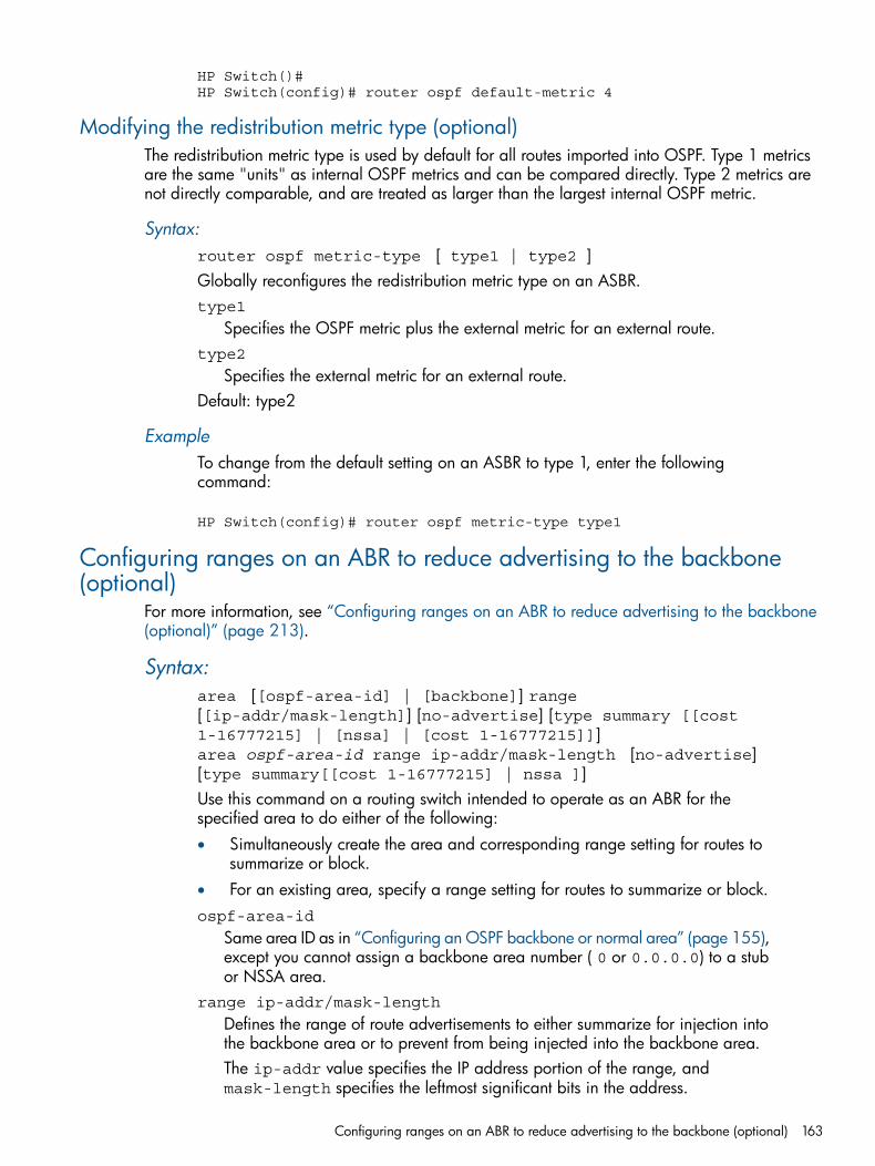
HP Switch()#HP Switch(config)# router ospf default-metric 4
Modifying the redistribution metric type (optional)The redistribution metric type is used by default for all routes imported into OSPF. Type 1 metricsare the same "units" as internal OSPF metrics and can be compared directly. Type 2 metrics arenot directly comparable, and are treated as larger than the largest internal OSPF metric.
Syntax:router ospf metric-type [ type1 | type2 ]Globally reconfigures the redistribution metric type on an ASBR.type1
Specifies the OSPF metric plus the external metric for an external route.type2
Specifies the external metric for an external route.Default: type2
ExampleTo change from the default setting on an ASBR to type 1, enter the followingcommand:
HP Switch(config)# router ospf metric-type type1
Configuring ranges on an ABR to reduce advertising to the backbone(optional)
For more information, see “Configuring ranges on an ABR to reduce advertising to the backbone(optional)” (page 213).
Syntax:area [[ospf-area-id] | [backbone]] range[[ip-addr/mask-length]] [no-advertise] [type summary [[cost1-16777215] | [nssa] | [cost 1-16777215]]]area ospf-area-id range ip-addr/mask-length [no-advertise][type summary[[cost 1-16777215] | nssa ]]Use this command on a routing switch intended to operate as an ABR for thespecified area to do either of the following:• Simultaneously create the area and corresponding range setting for routes to
summarize or block.• For an existing area, specify a range setting for routes to summarize or block.ospf-area-id
Same area ID as in “Configuring an OSPF backbone or normal area” (page 155),except you cannot assign a backbone area number ( 0 or 0.0.0.0) to a stubor NSSA area.
range ip-addr/mask-length
Defines the range of route advertisements to either summarize for injection intothe backbone area or to prevent from being injected into the backbone area.The ip-addr value specifies the IP address portion of the range, andmask-length specifies the leftmost significant bits in the address.
Configuring ranges on an ABR to reduce advertising to the backbone (optional) 163
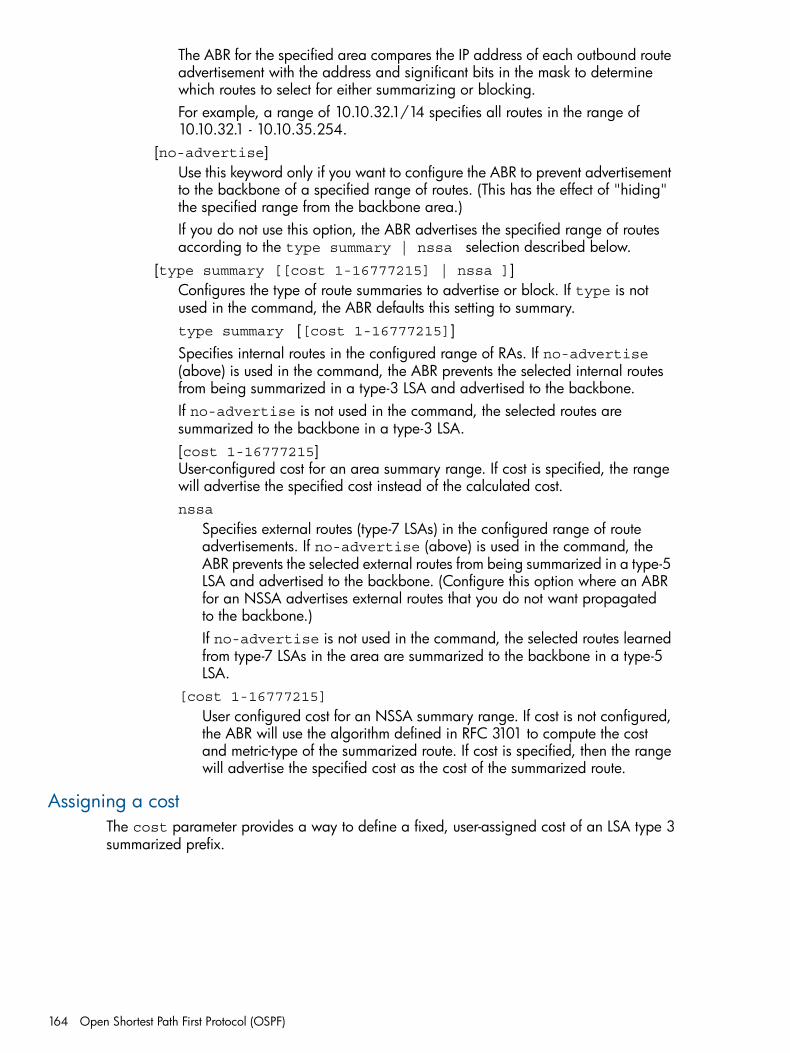
The ABR for the specified area compares the IP address of each outbound routeadvertisement with the address and significant bits in the mask to determinewhich routes to select for either summarizing or blocking.For example, a range of 10.10.32.1/14 specifies all routes in the range of10.10.32.1 - 10.10.35.254.
[no-advertise]Use this keyword only if you want to configure the ABR to prevent advertisementto the backbone of a specified range of routes. (This has the effect of "hiding"the specified range from the backbone area.)If you do not use this option, the ABR advertises the specified range of routesaccording to the type summary | nssa selection described below.
[type summary [[cost 1-16777215] | nssa ]]Configures the type of route summaries to advertise or block. If type is notused in the command, the ABR defaults this setting to summary.type summary [[cost 1-16777215]]Specifies internal routes in the configured range of RAs. If no-advertise(above) is used in the command, the ABR prevents the selected internal routesfrom being summarized in a type-3 LSA and advertised to the backbone.If no-advertise is not used in the command, the selected routes aresummarized to the backbone in a type-3 LSA.[cost 1-16777215]User-configured cost for an area summary range. If cost is specified, the rangewill advertise the specified cost instead of the calculated cost.nssa
Specifies external routes (type-7 LSAs) in the configured range of routeadvertisements. If no-advertise (above) is used in the command, theABR prevents the selected external routes from being summarized in a type-5LSA and advertised to the backbone. (Configure this option where an ABRfor an NSSA advertises external routes that you do not want propagatedto the backbone.)If no-advertise is not used in the command, the selected routes learnedfrom type-7 LSAs in the area are summarized to the backbone in a type-5LSA.
[cost 1-16777215]
User configured cost for an NSSA summary range. If cost is not configured,the ABR will use the algorithm defined in RFC 3101 to compute the costand metric-type of the summarized route. If cost is specified, then the rangewill advertise the specified cost as the cost of the summarized route.
Assigning a costThe cost parameter provides a way to define a fixed, user-assigned cost of an LSA type 3summarized prefix.
164 Open Shortest Path First Protocol (OSPF)
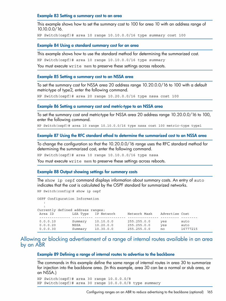
Example 83 Setting a summary cost to an area
This example shows how to set the summary cost to 100 for area 10 with an address range of10.10.0.0/16.HP Switch(ospf)# area 10 range 10.10.0.0/16 type summary cost 100
Example 84 Using a standard summary cost for an area
This example shows how to use the standard method for determining the summarized cost.HP Switch(ospf)# area 10 range 10.10.0.0/16 type summary
You must execute write mem to preserve these settings across reboots.
Example 85 Setting a summary cost to an NSSA area
To set the summary cost for NSSA area 20 address range 10.20.0.0/16 to 100 with a defaultmetric-type of type2, enter the following command.HP Switch(ospf)# area 20 range 10.20.0.0/16 type nssa cost 100
Example 86 Setting a summary cost and metric-type to an NSSA area
To set the summary cost and metric-type for NSSA area 20 address range 10.20.0.0/16 to 100,enter the following command.HP Switch(ospf)# area 10 range 10.10.0.0/16 type nssa cost 100 metric-type type1
Example 87 Using the RFC standard ethod to determine the summarized cost to an NSSA area
To change the configuration so that the 10.20.0.0/16 range uses the RFC standard method fordetermining the summarized cost, enter the following command.HP Switch(ospf)# area 10 range 10.10.0.0/16 type nssa
You must execute write mem to preserve these settings across reboots.
Example 88 Output showing settings for summary costs
The show ip ospf command displays information about summary costs. An entry of autoindicates that the cost is calculated by the OSPF standard for summarized networks.HP Switch(config)# show ip ospf
OSPF Configuration Information : :Currently defined address ranges: Area ID LSA Type IP Network Network Mask Advertise Cost --------------- ---------- --------------- --------------- --------- -------- 0.0.0.10 Summary 10.10.0.0 255.255.0.0 yes auto 0.0.0.20 NSSA 10.20.0.0 255.255.0.0 yes auto 0.0.0.30 Summary 10.30.0.0 255.255.0.0 no 16777215
Allowing or blocking advertisement of a range of internal routes available in an areaby an ABR
Example 89 Defining a range of internal routes to advertise to the backbone
The commands in this example define the same range of internal routes in area 30 to summarizefor injection into the backbone area. (In this example, area 30 can be a normal or stub area, oran NSSA.)HP Switch(ospf)# area 30 range 10.0.0.0/8HP Switch(ospf)# area 30 range 10.0.0.0/8 type summary
Configuring ranges on an ABR to reduce advertising to the backbone (optional) 165
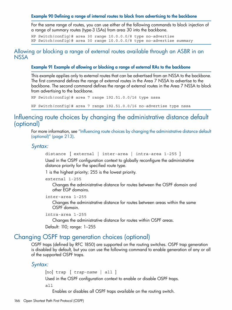
Example 90 Defining a range of internal routes to block from advertising to the backbone
For the same range of routes, you can use either of the following commands to block injection ofa range of summary routes (type-3 LSAs) from area 30 into the backbone.HP Switch(config)# area 30 range 10.0.0.0/8 type no-advertiseHP Switch(config)# area 30 range 10.0.0.0/8 type no-advertise summary
Allowing or blocking a range of external routes available through an ASBR in anNSSA
Example 91 Example of allowing or blocking a range of external RAs to the backbone
This example applies only to external routes that can be advertised from an NSSA to the backbone.The first command defines the range of external routes in the Area 7 NSSA to advertise to thebackbone. The second command defines the range of external routes in the Area 7 NSSA to blockfrom advertising to the backbone.HP Switch(config)# area 7 range 192.51.0.0/16 type nssa
HP Switch(config)# area 7 range 192.51.0.0/16 no-advertise type nssa
Influencing route choices by changing the administrative distance default(optional)
For more information, see “Influencing route choices by changing the administrative distance default(optional)” (page 213).
Syntax:distance [ external | inter-area | intra-area 1-255 ]Used in the OSPF configuration context to globally reconfigure the administrativedistance priority for the specified route type.1 is the highest priority; 255 is the lowest priority.external 1-255
Changes the administrative distance for routes between the OSPF domain andother EGP domains.
inter-area 1-255
Changes the administrative distance for routes between areas within the sameOSPF domain.
intra-area 1-255
Changes the administrative distance for routes within OSPF areas.Default: 110; range: 1–255
Changing OSPF trap generation choices (optional)OSPF traps (defined by RFC 1850) are supported on the routing switches. OSPF trap generationis disabled by default, but you can use the following command to enable generation of any or allof the supported OSPF traps.
Syntax:[no] trap [ trap-name | all ]Used in the OSPF configuration context to enable or disable OSPF traps.all
Enables or disables all OSPF traps available on the routing switch.
166 Open Shortest Path First Protocol (OSPF)
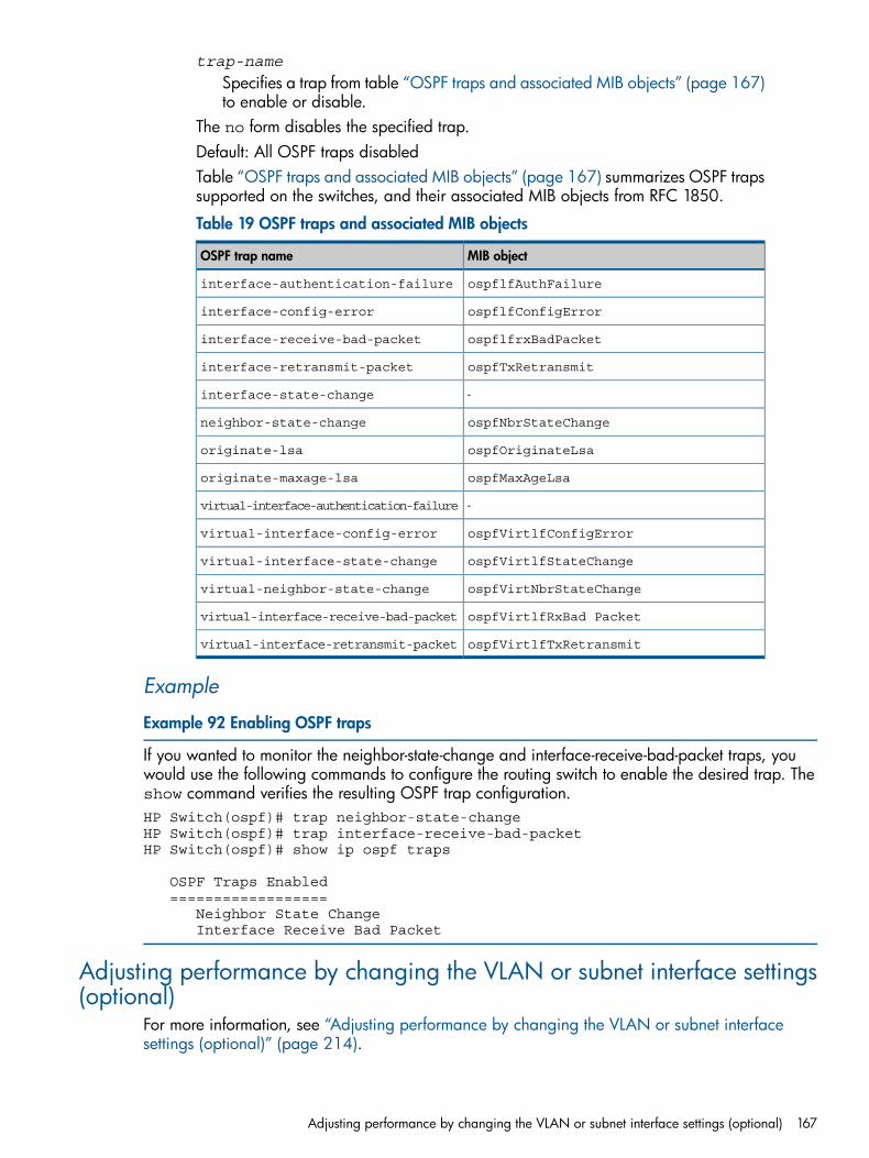
trap-name
Specifies a trap from table “OSPF traps and associated MIB objects” (page 167)to enable or disable.
The no form disables the specified trap.Default: All OSPF traps disabledTable “OSPF traps and associated MIB objects” (page 167) summarizes OSPF trapssupported on the switches, and their associated MIB objects from RFC 1850.
Table 19 OSPF traps and associated MIB objects
MIB objectOSPF trap name
ospflfAuthFailureinterface-authentication-failure
ospflfConfigErrorinterface-config-error
ospflfrxBadPacketinterface-receive-bad-packet
ospfTxRetransmitinterface-retransmit-packet
-interface-state-change
ospfNbrStateChangeneighbor-state-change
ospfOriginateLsaoriginate-lsa
ospfMaxAgeLsaoriginate-maxage-lsa
-virtual-interface-authentication-failure
ospfVirtlfConfigErrorvirtual-interface-config-error
ospfVirtlfStateChangevirtual-interface-state-change
ospfVirtNbrStateChangevirtual-neighbor-state-change
ospfVirtlfRxBad Packetvirtual-interface-receive-bad-packet
ospfVirtlfTxRetransmitvirtual-interface-retransmit-packet
Example
Example 92 Enabling OSPF traps
If you wanted to monitor the neighbor-state-change and interface-receive-bad-packet traps, youwould use the following commands to configure the routing switch to enable the desired trap. Theshow command verifies the resulting OSPF trap configuration.HP Switch(ospf)# trap neighbor-state-changeHP Switch(ospf)# trap interface-receive-bad-packetHP Switch(ospf)# show ip ospf traps
OSPF Traps Enabled ================== Neighbor State Change Interface Receive Bad Packet
Adjusting performance by changing the VLAN or subnet interface settings(optional)
For more information, see “Adjusting performance by changing the VLAN or subnet interfacesettings (optional)” (page 214).
Adjusting performance by changing the VLAN or subnet interface settings (optional) 167
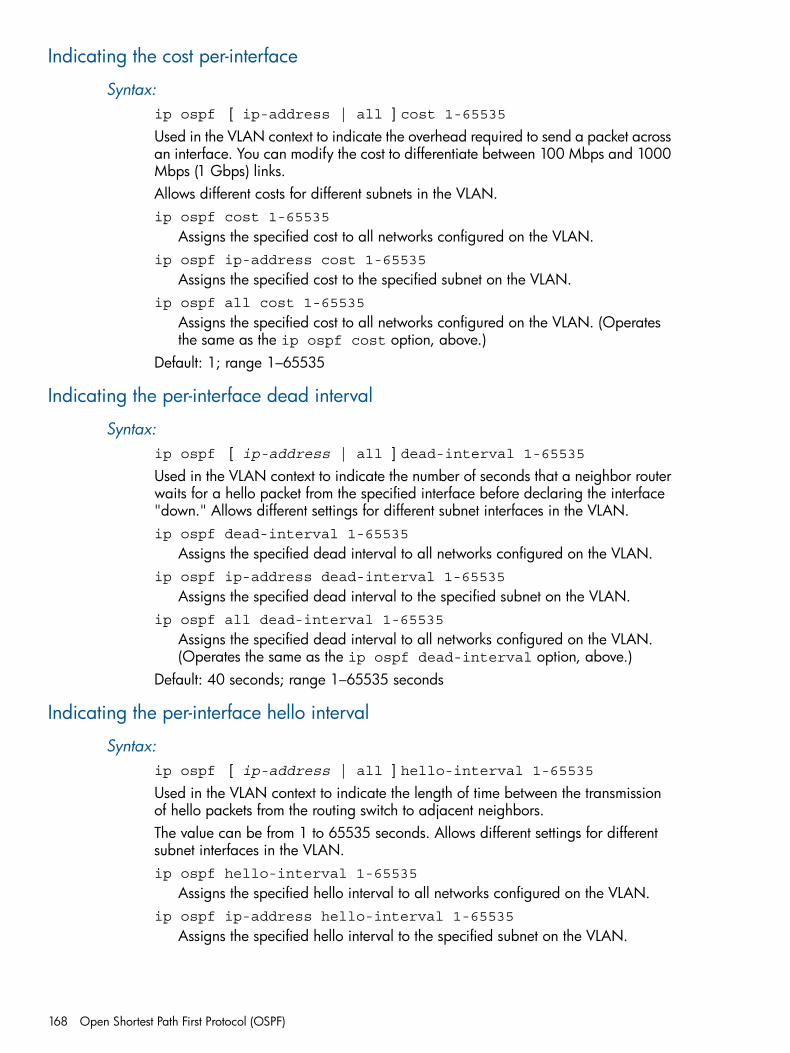
Indicating the cost per-interface
Syntax:ip ospf [ ip-address | all ] cost 1-65535Used in the VLAN context to indicate the overhead required to send a packet acrossan interface. You can modify the cost to differentiate between 100 Mbps and 1000Mbps (1 Gbps) links.Allows different costs for different subnets in the VLAN.ip ospf cost 1-65535
Assigns the specified cost to all networks configured on the VLAN.ip ospf ip-address cost 1-65535
Assigns the specified cost to the specified subnet on the VLAN.ip ospf all cost 1-65535
Assigns the specified cost to all networks configured on the VLAN. (Operatesthe same as the ip ospf cost option, above.)
Default: 1; range 1–65535
Indicating the per-interface dead interval
Syntax:ip ospf [ ip-address | all ] dead-interval 1-65535Used in the VLAN context to indicate the number of seconds that a neighbor routerwaits for a hello packet from the specified interface before declaring the interface"down." Allows different settings for different subnet interfaces in the VLAN.ip ospf dead-interval 1-65535
Assigns the specified dead interval to all networks configured on the VLAN.ip ospf ip-address dead-interval 1-65535
Assigns the specified dead interval to the specified subnet on the VLAN.ip ospf all dead-interval 1-65535
Assigns the specified dead interval to all networks configured on the VLAN.(Operates the same as the ip ospf dead-interval option, above.)
Default: 40 seconds; range 1–65535 seconds
Indicating the per-interface hello interval
Syntax:ip ospf [ ip-address | all ] hello-interval 1-65535Used in the VLAN context to indicate the length of time between the transmissionof hello packets from the routing switch to adjacent neighbors.The value can be from 1 to 65535 seconds. Allows different settings for differentsubnet interfaces in the VLAN.ip ospf hello-interval 1-65535
Assigns the specified hello interval to all networks configured on the VLAN.ip ospf ip-address hello-interval 1-65535
Assigns the specified hello interval to the specified subnet on the VLAN.
168 Open Shortest Path First Protocol (OSPF)
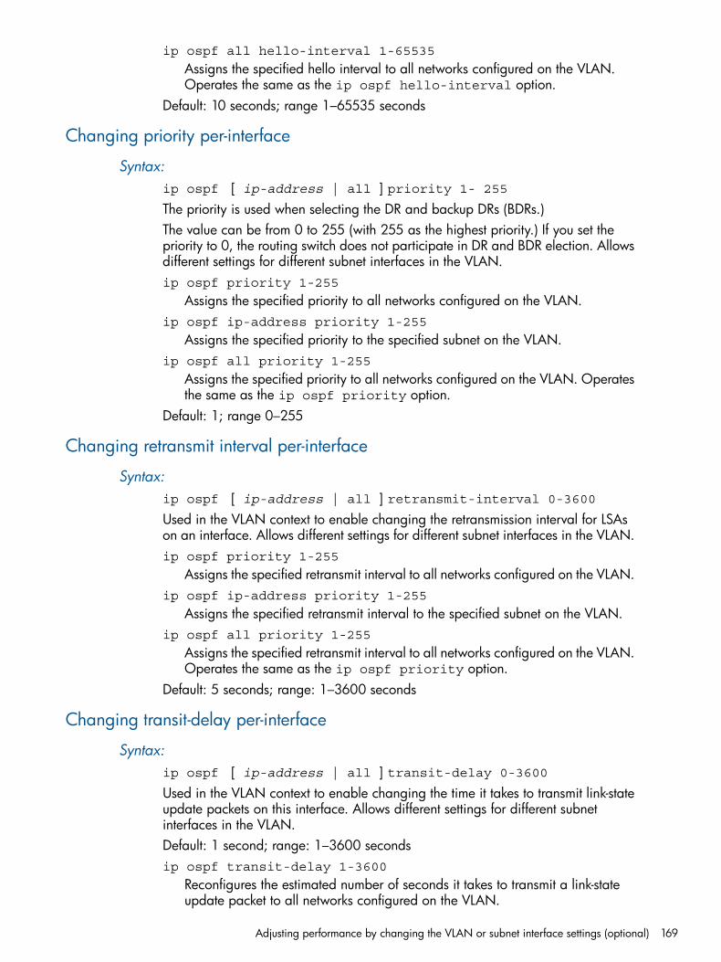
ip ospf all hello-interval 1-65535
Assigns the specified hello interval to all networks configured on the VLAN.Operates the same as the ip ospf hello-interval option.
Default: 10 seconds; range 1–65535 seconds
Changing priority per-interface
Syntax:ip ospf [ ip-address | all ] priority 1- 255The priority is used when selecting the DR and backup DRs (BDRs.)The value can be from 0 to 255 (with 255 as the highest priority.) If you set thepriority to 0, the routing switch does not participate in DR and BDR election. Allowsdifferent settings for different subnet interfaces in the VLAN.ip ospf priority 1-255
Assigns the specified priority to all networks configured on the VLAN.ip ospf ip-address priority 1-255
Assigns the specified priority to the specified subnet on the VLAN.ip ospf all priority 1-255
Assigns the specified priority to all networks configured on the VLAN. Operatesthe same as the ip ospf priority option.
Default: 1; range 0–255
Changing retransmit interval per-interface
Syntax:ip ospf [ ip-address | all ] retransmit-interval 0-3600Used in the VLAN context to enable changing the retransmission interval for LSAson an interface. Allows different settings for different subnet interfaces in the VLAN.ip ospf priority 1-255
Assigns the specified retransmit interval to all networks configured on the VLAN.ip ospf ip-address priority 1-255
Assigns the specified retransmit interval to the specified subnet on the VLAN.ip ospf all priority 1-255
Assigns the specified retransmit interval to all networks configured on the VLAN.Operates the same as the ip ospf priority option.
Default: 5 seconds; range: 1–3600 seconds
Changing transit-delay per-interface
Syntax:ip ospf [ ip-address | all ] transit-delay 0-3600Used in the VLAN context to enable changing the time it takes to transmit link-stateupdate packets on this interface. Allows different settings for different subnetinterfaces in the VLAN.Default: 1 second; range: 1–3600 secondsip ospf transit-delay 1-3600
Reconfigures the estimated number of seconds it takes to transmit a link-stateupdate packet to all networks configured on the VLAN.
Adjusting performance by changing the VLAN or subnet interface settings (optional) 169
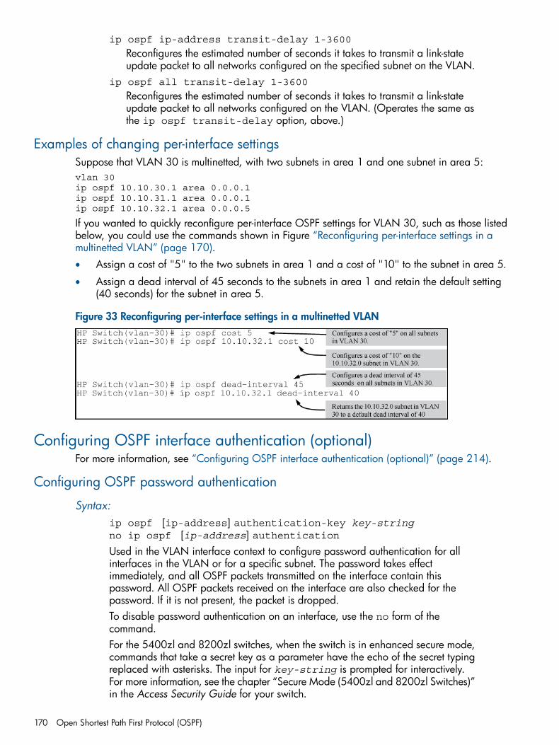
ip ospf ip-address transit-delay 1-3600
Reconfigures the estimated number of seconds it takes to transmit a link-stateupdate packet to all networks configured on the specified subnet on the VLAN.
ip ospf all transit-delay 1-3600
Reconfigures the estimated number of seconds it takes to transmit a link-stateupdate packet to all networks configured on the VLAN. (Operates the same asthe ip ospf transit-delay option, above.)
Examples of changing per-interface settingsSuppose that VLAN 30 is multinetted, with two subnets in area 1 and one subnet in area 5:vlan 30 ip ospf 10.10.30.1 area 0.0.0.1ip ospf 10.10.31.1 area 0.0.0.1ip ospf 10.10.32.1 area 0.0.0.5
If you wanted to quickly reconfigure per-interface OSPF settings for VLAN 30, such as those listedbelow, you could use the commands shown in Figure “Reconfiguring per-interface settings in amultinetted VLAN” (page 170).• Assign a cost of "5" to the two subnets in area 1 and a cost of "10" to the subnet in area 5.
• Assign a dead interval of 45 seconds to the subnets in area 1 and retain the default setting(40 seconds) for the subnet in area 5.
Figure 33 Reconfiguring per-interface settings in a multinetted VLAN
Configuring OSPF interface authentication (optional)For more information, see “Configuring OSPF interface authentication (optional)” (page 214).
Configuring OSPF password authentication
Syntax:ip ospf [ip-address] authentication-key key-stringno ip ospf [ip-address] authenticationUsed in the VLAN interface context to configure password authentication for allinterfaces in the VLAN or for a specific subnet. The password takes effectimmediately, and all OSPF packets transmitted on the interface contain thispassword. All OSPF packets received on the interface are also checked for thepassword. If it is not present, the packet is dropped.To disable password authentication on an interface, use the no form of thecommand.For the 5400zl and 8200zl switches, when the switch is in enhanced secure mode,commands that take a secret key as a parameter have the echo of the secret typingreplaced with asterisks. The input for key-string is prompted for interactively.For more information, see the chapter “Secure Mode (5400zl and 8200zl Switches)”in the Access Security Guide for your switch.
170 Open Shortest Path First Protocol (OSPF)
ip-address
Used in subnetted VLAN contexts where you want to assign or remove apassword associated with a specific subnet.Omit this option when you want the command to apply to all interfacesconfigured in the VLAN.
key-string
An alphanumeric string of one to eight characters. (Spaces are not allowed.)To change the password, re-execute the command with the new password.
Use show ip ospf interface ip-address to view the current authenticationsetting.
NOTE: To replace the password method with the MD5 method on a giveninterface, overwrite the password configuration by using the MD5 form of thecommand shown in the next syntax description. (It is not necessary to disable thecurrently configured OSPF password.)
Default: Disabled
Configuring OSPF MD5 authentication
Syntax:ip ospf md5-auth-key-chain chainname-stringno ip ospf [ip-address] authenticationUsed in the VLAN interface context to configure MD5 authentication for all interfacesin the VLAN or for a specific subnet. The MD5 authentication takes effectimmediately, and all OSPF packets transmitted on the interface contain thedesignated key. All OSPF packets received on the interface are also checked forthe key. If it is not present, the packet is dropped.To disable MD5 authentication on an interface, use the no form of the command.
NOTE: Before using this authentication option, you must configure one or morekey chains on the routing switch by using the Key Management System (KMS)described in chapter "Key Management System" in the Access Security Guide foryour routing switch.
Default: Disabledip-address
Used in subnetted VLAN contexts where you want to assign or remove MD5authentication associated with a specific subnet.Omit this option when you want the command to apply to all interfacesconfigured in the VLAN.
chain-name-string
The name of a key generated using the key-chain chain_name keykey_id.To change the MD5 authentication configured on an interface, re-execute thecommand with the new MD5 key.
Use show ip ospf interface ip-address to view the current authentication setting.
NOTE: To replace the MD5 method with the password method on a given interface, overwritethe MD5 configuration by using the password form of the command shown in the next syntaxdescription. (It is not necessary to disable the currently configured OSPF MD5 authentication.)
Configuring OSPF interface authentication (optional) 171
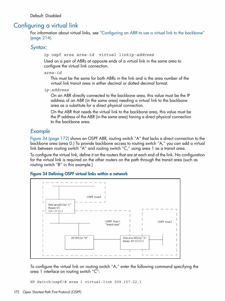
Default: Disabled
Configuring a virtual linkFor information about virtual links, see “Configuring an ABR to use a virtual link to the backbone”(page 214).
Syntax:ip ospf area area-id virtual linkip-address
Used on a pair of ABRs at opposite ends of a virtual link in the same area toconfigure the virtual link connection.area-id
This must be the same for both ABRs in the link and is the area number of thevirtual link transit area in either decimal or dotted decimal format.
ip-address
On an ABR directly connected to the backbone area, this value must be the IPaddress of an ABR (in the same area) needing a virtual link to the backbonearea as a substitute for a direct physical connection.On the ABR that needs the virtual link to the backbone area, this value must bethe IP address of the ABR (in the same area) having a direct physical connectionto the backbone area.
ExampleFigure 34 (page 172) shows an OSPF ABR, routing switch "A" that lacks a direct connection to thebackbone area (area 0.) To provide backbone access to routing switch "A," you can add a virtuallink between routing switch "A" and routing switch "C," using area 1 as a transit area.To configure the virtual link, define it on the routers that are at each end of the link. No configurationfor the virtual link is required on the other routers on the path through the transit area (such asrouting switch "B" in this example.)
Figure 34 Defining OSPF virtual links within a network
To configure the virtual link on routing switch "A," enter the following command specifying thearea 1 interface on routing switch "C":
HP Switch(ospf)# area 1 virtual-link 209.157.22.1
172 Open Shortest Path First Protocol (OSPF)
To configure the virtual link on routing switch "C," enter the following command specifying thearea 1 interface on routing switch "A":
HP Switch(ospf)# area 1 virtual-link 10.0.0.1
See “Changing the dead interval on a virtual link” (page 173) for descriptions of virtual link interfaceparameters you can either use in their default settings or reconfigure as needed.
Changing the dead interval on a virtual linkFor more information, see “Adjusting virtual link performance by changing the interface settings(optional)” (page 215).
Syntax:area area-id virtual link ip-address dead-interval 1-65535
Used in the router OSPF context on both ABRs in a virtual link to change the numberof seconds that a neighbor router waits for a hello packet from the specified interfacebefore declaring the interface "down." This should be some multiple of the hellointerval. The dead-interval setting must be the same on both ABRs on a givenvirtual link.area-id
Specifies the OSPF area in which both ABRs in a given virtual link operate. Inthis use, the area ID is sometimes termed "transit area ID."This value must be the same for both ABRs in the virtual link.
ip-address
For an ABR in a given virtual link, this is the IP address used to create the linkon that ABR.This IP address matches the IP address of the interface on the opposite end ofthe virtual link. See the description of ip-address in the syntax descriptionunder “Configuring a virtual link” (page 172).
Use show ip ospf virtual-link ip-address to view the current setting.Default: 40 seconds; range: 1–65535 seconds
Indicating the hello interval on a virtual link
Syntax:area area-id virtual link ip-address hello-interval 1-65535
Used in the router OSPF context on both ABRs in a virtual link to indicate the lengthof time between the transmission of hello packets between the ABRs on oppositeends of the virtual link.The hello-interval setting must be the same on both ABRs on a given virtual link.Default: 10 seconds; range: 1–65535 secondsarea-id
Specifies the OSPF area in which both ABRs in a given virtual link operate. Inthis use, the area ID is sometimes termed "transit area ID."This value must be the same for both ABRs in the virtual link.
ip-address
For an ABR in a given virtual link, this is the IP address used to create the linkon that ABR. (This IP address matches the IP address of the interface on theopposite end of the virtual link. See the description of ip-address in thesyntax description under “Configuring a virtual link” (page 172).)
Configuring a virtual link 173
Use show ip ospf virtual-link ip-address to view the current setting.
Changing the retransmitting interval on a virtual link
Syntax:area area-id virtual link ip-address retransmit-interval1-3600
Used in the router OSPF context on both ABRs in a virtual link to change the numberof seconds between LSA retransmissions on the virtual link.The retransmit-interval setting must be the same on both ABRs on a given virtuallink. This value is also used when retransmitting database description and link-staterequest packets.area-id
Specifies the OSPF area in which both ABRs in a given virtual link operate. Inthis use, the area ID is sometimes termed "transit area ID." This value must bethe same for both ABRs in the virtual link.
ip-address
For an ABR in a given virtual link, this is the IP address used to create the linkon that ABR. (This IP address matches the IP address of the interface on theopposite end of the virtual link. See the description of ip-address in thesyntax description under “Configuring a virtual link” (page 172).)
Use show ip ospf virtual-link ip-address to view the current setting.Default: 5 seconds; range: 1–3600 seconds
Changing the transit-delay on a virtual link
Syntax:area area-id virtual link ip-address transit-delay [0-3600]Used in the router OSPF context on both ABRs in a virtual link to change theestimated number of seconds it takes to transmit a link state update packet over avirtual link. The transit-delay setting must be the same on both ABRs on agiven virtual link.area-id
Specifies the OSPF area in which both ABRs in a given virtual link operate. Inthis use, the area ID is sometimes termed "transit area ID." This value must bethe same for both ABRs in the virtual link.
ip-address
For an ABR in a given virtual link, this is the IP address used to create the linkon that ABR. (This IP address matches the IP address of the interface on theopposite end of the virtual link. See the description of ip-address in thesyntax description under “Configuring a virtual link” (page 172).)
Use show ip ospf virtual-link ip-address to view the current setting.Default: 1 second; range: 1–3600 seconds
ExampleTo change the hello-interval on the virtual link configured for the network in Figure 34(page 172) to 60 seconds:• On routing switch "A" (IP address 10.0.0.1) you would use the following
command to reconfigure the current hello-interval to 60 seconds:
174 Open Shortest Path First Protocol (OSPF)
HP Switch(ospf)# area 1 virtual-link 209.157.22.1 hello-interval 60
• On routing switch "C" (IP address 209.157.22.1) you would use the followingcommand to reconfigure the current hello-interval to 60 secondsHP Switch(ospf)# area 1 virtual-link 10.0.0.1 hello-interval 60
Configuring OSPF authentication on a virtual linkFor more information, see “Configuring OSPF authentication on a virtual link” (page 215).
Authenticating the OSPF password on a virtual link
Syntax:area area-id virtual-link ip-addr authentication-keykey-string no area 1 virtual-link ip-address authentication
Used to configure password authentication in the router OSPF context on both ABRsin a virtual link. The password takes effect immediately, and all OSPF packetstransmitted on the link contain this password. Every OSPF packet received on theinterface for the virtual link on each ABR is checked for the password. If it is notpresent, the packet is dropped.To disable password authentication on an ABR interface used for a virtual link, usethe no form of the command.The password must be the same on both ABRs on a given virtual link.
NOTE: For the 5400zl and 8200zl switches, when the switch is in enhancedsecure mode, commands that take a secret key as a parameter have the echo ofthe secret typing replaced with asterisks. The input for key-string is promptedfor interactively. For more information, see the chapter, “Secure Mode (5400zl and8200zl Switches)” in the Access Security Guide for your switch.
area-id
Specifies the OSPF area in which both ABRs in a given virtual link operate. Inthis use, the area ID is sometimes termed "transit area ID." This value must bethe same for both ABRs in the virtual link.
ip-address
For an ABR in a given virtual link, this is the IP address used to create the linkon that ABR. (This IP address matches the IP address of the interface on theopposite end of the virtual link. See the description of ip-address in thesyntax description under “Configuring a virtual link” (page 172).)
key-string
An alphanumeric string of one to eight characters. (Spaces are not allowed.)To change the password, re-execute the command with the new password.
NOTE: To replace the password method with the MD5 method on a giveninterface, overwrite the password configuration by using the MD5 form of thecommand shown in “Authenticating OSPF MD5 on a virtual link” (page 176). (It isnot necessary to disable the currently configured OSPF password.)
Default: Disabled
Configuring OSPF authentication on a virtual link 175
Authenticating OSPF MD5 on a virtual link
Syntax:ip ospf md5-auth-key-chain chain-name-string no ip ospf[ip-address]authentication
Used to configure MD5 authentication in the router OSPF context on both ABRs ina virtual link. The MD5 authentication takes effect immediately, and all OSPF packetstransmitted on the link contain the designated key. Every OSPF packet received onthe interface for the virtual link on each ABR is checked for the key. If it is not present,the packet is dropped.To disable MD5 authentication on an ABR interface used for a virtual link, use theno form of the command. The password must be the same on both ABRs on a givenvirtual link.
NOTE: Before using this authentication option, you must configure one or morekey chains on the routing switch by using the Key Management System (KMS)described in chapter "Key Management System" in the Access Security Guide foryour routing switch.ip-address
For an ABR in a given virtual link, this is the IP address used to create the linkon that ABR. (This IP address matches the IP address of the interface on theopposite end of the virtual link. See the description of ip-addressin thesyntax description under “Configuring a virtual link” (page 172).)
chain-name-string
The name of a key generated using the key-chain chain_name keykey_id command.To change the MD5 authentication configured on a virtual link, re-execute thecommand with the new MD5 key.
NOTE: To replace the MD5 method with the password method on a virtual link,overwrite the MD5 configuration by using the password form of the commandshown under “Authenticating the OSPF password on a virtual link” (page 175). (Itis not necessary to disable the currently configured OSPF MD5 authentication.)
Default: Disabled
Configuring a passive OSPF interfaceFor more information, see “About OSPF passive” (page 215).Enter this command in VLAN context:
HP Switch(vlan-1)# ip ospf passive
Syntax:[no] ip ospf ip-addr passiveConfigures passive OSPF for an AS.
ip-addr
Optionally, you can configure an IP address on the VLAN.The no option disables the passive option; the interface becomes an active interface.Default: Active
176 Open Shortest Path First Protocol (OSPF)
ExampleTo display the OSPF passive information, enter the command shown in Figure A-14:
Example 93 show ip ospf interface command with passive configured on an interface
HP Switch(vlan-1)# show ip ospf interface
OSPF Interface Status
IP Address Status Area ID State Auth-type Cost Priority Passive---------- ------ ------- ----- --------- ---- -------- -------10.10.10.1 enabled 0.0.0.2 down none 1 1 Yes10.12.13.1 enabled 0.0.0.2 wait none 1 1 No
You can display the OSPF passive information for a particular VLAN, as shown in Example 94(page 177).
Example 94 show ip ospf interface command for a specific VLAN with passive configured on aninterface
HP Switch(config) show ip ospf interface vlan 4
OSPF configuration and statistics for VLAN 4
OSPF Interface Status for 10.10.10.1
IP Address: : 10.10.10.1 Status : enabled AreaID : 0.0.0.2 Passive : Yes
State : DOWN Auth-type : none Cost : 1 Chain : Type : BCAST Priority : 1
Transit Delay : 1 Retrans Interval : 5 Hello Interval : 10 Rtr Dead Interval : 40 Designated Router: Events : 0 Backup Desig. Rtr: Passive : yes Neighbors : 2
Configuring the calculation interval
Syntax:[no] spf-throttle start-interval [1-600] wait interval [1-600]max-wait-time [1-600]Enables and configures SPF scheduling (throttling.) This delays SPF calculationsduring periods of network topology changes.SPF calculations occur at the interval set by the spf-throttle command. Thiscommand is executed in ospf context.Default: 5 secondsstart-interval [1–600]
Specifies the initial SPF schedule delay in seconds.wait-interval [1–600]
specifies the amount of time to wait until the next SPF calculation occurs, inseconds.
Configuring the calculation interval 177
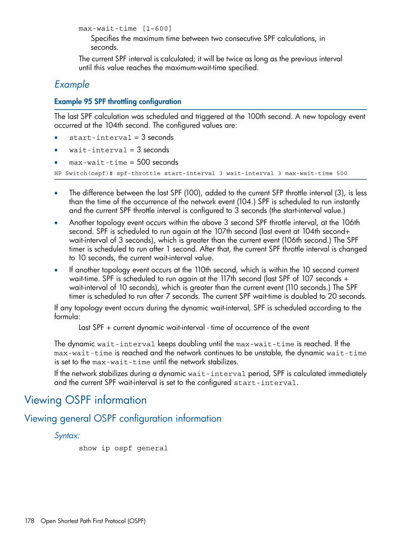
max-wait-time [1–600]
Specifies the maximum time between two consecutive SPF calculations, inseconds.
The current SPF interval is calculated; it will be twice as long as the previous intervaluntil this value reaches the maximum-wait-time specified.
Example
Example 95 SPF throttling configuration
The last SPF calculation was scheduled and triggered at the 100th second. A new topology eventoccurred at the 104th second. The configured values are:• start-interval = 3 seconds
• wait-interval = 3 seconds
• max-wait-time = 500 secondsHP Switch(ospf)# spf-throttle start-interval 3 wait-interval 3 max-wait-time 500
• The difference between the last SPF (100), added to the current SFP throttle interval (3), is lessthan the time of the occurrence of the network event (104.) SPF is scheduled to run instantlyand the current SPF throttle interval is configured to 3 seconds (the start-interval value.)
• Another topology event occurs within the above 3 second SPF throttle interval, at the 106thsecond. SPF is scheduled to run again at the 107th second (last event at 104th second+wait-interval of 3 seconds), which is greater than the current event (106th second.) The SPFtimer is scheduled to run after 1 second. After that, the current SPF throttle interval is changedto 10 seconds, the current wait-interval value.
• If another topology event occurs at the 110th second, which is within the 10 second currentwait-time. SPF is scheduled to run again at the 117th second (last SPF of 107 seconds +wait-interval of 10 seconds), which is greater than the current event (110 seconds.) The SPFtimer is scheduled to run after 7 seconds. The current SPF wait-time is doubled to 20 seconds.
If any topology event occurs during the dynamic wait-interval, SPF is scheduled according to theformula:
Last SPF + current dynamic wait-interval - time of occurrence of the event
The dynamic wait-interval keeps doubling until the max-wait-time is reached. If themax-wait-time is reached and the network continues to be unstable, the dynamic wait-timeis set to the max-wait-time until the network stabilizes.If the network stabilizes during a dynamic wait-interval period, SPF is calculated immediatelyand the current SPF wait-interval is set to the configured start-interval.
Viewing OSPF information
Viewing general OSPF configuration information
Syntax:show ip ospf general
178 Open Shortest Path First Protocol (OSPF)
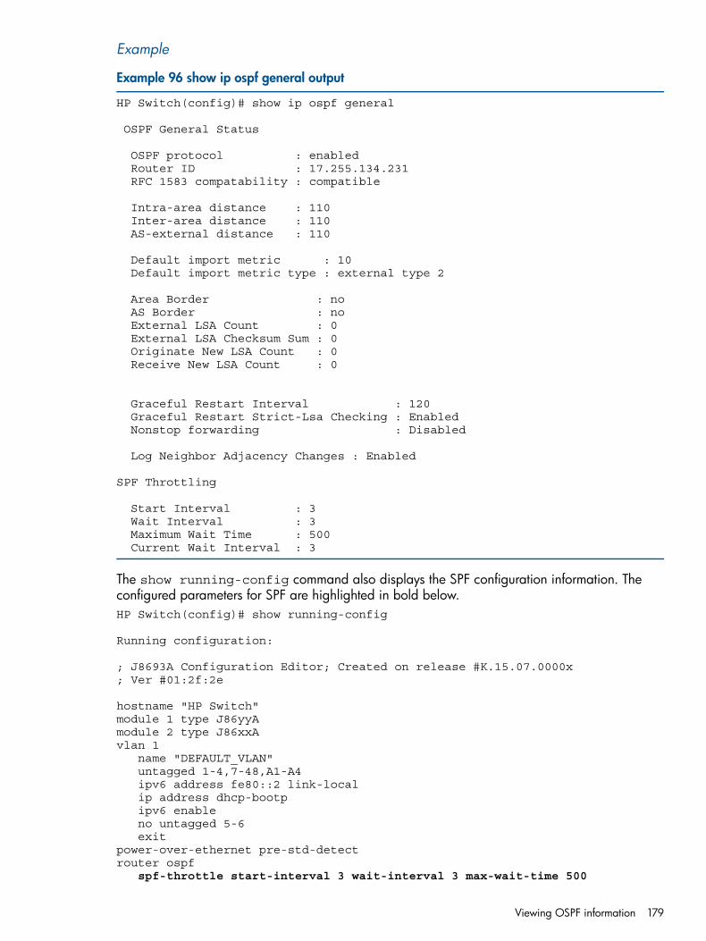
Example
Example 96 show ip ospf general output
HP Switch(config)# show ip ospf general
OSPF General Status
OSPF protocol : enabled Router ID : 17.255.134.231 RFC 1583 compatability : compatible
Intra-area distance : 110 Inter-area distance : 110 AS-external distance : 110
Default import metric : 10 Default import metric type : external type 2
Area Border : no AS Border : no External LSA Count : 0 External LSA Checksum Sum : 0 Originate New LSA Count : 0 Receive New LSA Count : 0
Graceful Restart Interval : 120 Graceful Restart Strict-Lsa Checking : Enabled Nonstop forwarding : Disabled
Log Neighbor Adjacency Changes : Enabled
SPF Throttling
Start Interval : 3 Wait Interval : 3 Maximum Wait Time : 500 Current Wait Interval : 3
The show running-config command also displays the SPF configuration information. Theconfigured parameters for SPF are highlighted in bold below.HP Switch(config)# show running-config
Running configuration:
; J8693A Configuration Editor; Created on release #K.15.07.0000x; Ver #01:2f:2e
hostname "HP Switch" module 1 type J86yyA module 2 type J86xxA vlan 1 name "DEFAULT_VLAN" untagged 1-4,7-48,A1-A4 ipv6 address fe80::2 link-local ip address dhcp-bootp ipv6 enable no untagged 5-6 exitpower-over-ethernet pre-std-detectrouter ospf
spf-throttle start-interval 3 wait-interval 3 max-wait-time 500
Viewing OSPF information 179
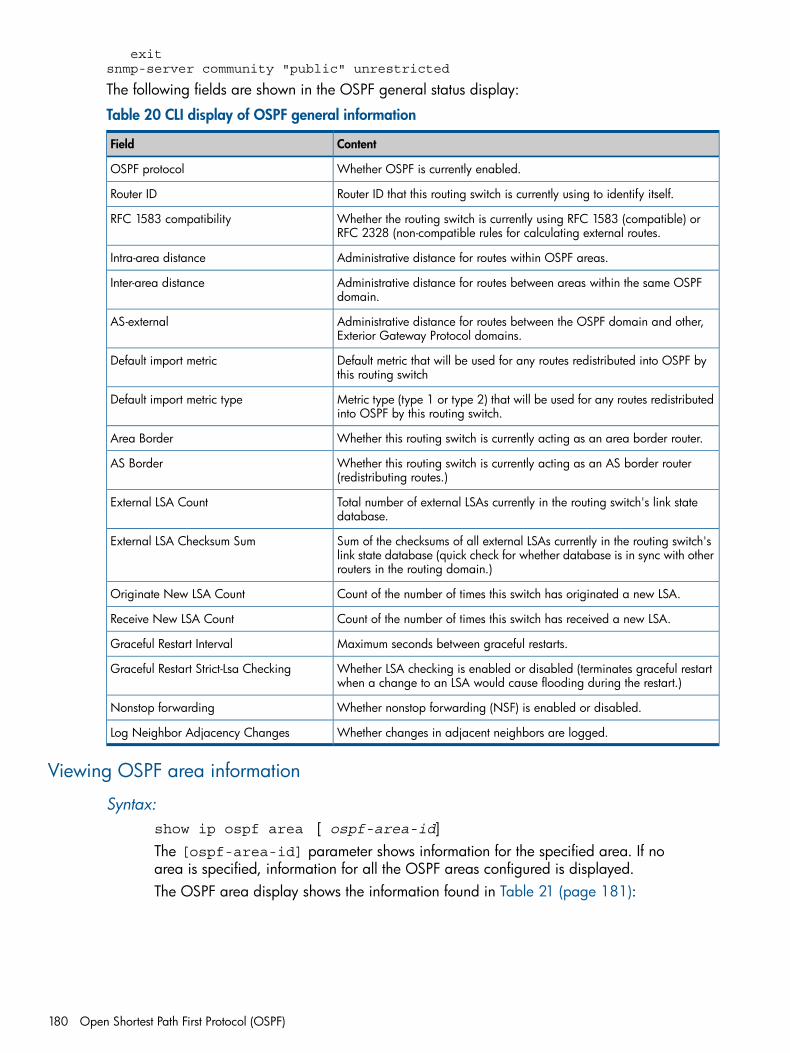
exitsnmp-server community "public" unrestricted
The following fields are shown in the OSPF general status display:
Table 20 CLI display of OSPF general information
ContentField
Whether OSPF is currently enabled.OSPF protocol
Router ID that this routing switch is currently using to identify itself.Router ID
Whether the routing switch is currently using RFC 1583 (compatible) orRFC 2328 (non-compatible rules for calculating external routes.
RFC 1583 compatibility
Administrative distance for routes within OSPF areas.Intra-area distance
Administrative distance for routes between areas within the same OSPFdomain.
Inter-area distance
Administrative distance for routes between the OSPF domain and other,Exterior Gateway Protocol domains.
AS-external
Default metric that will be used for any routes redistributed into OSPF bythis routing switch
Default import metric
Metric type (type 1 or type 2) that will be used for any routes redistributedinto OSPF by this routing switch.
Default import metric type
Whether this routing switch is currently acting as an area border router.Area Border
Whether this routing switch is currently acting as an AS border router(redistributing routes.)
AS Border
Total number of external LSAs currently in the routing switch's link statedatabase.
External LSA Count
Sum of the checksums of all external LSAs currently in the routing switch'slink state database (quick check for whether database is in sync with otherrouters in the routing domain.)
External LSA Checksum Sum
Count of the number of times this switch has originated a new LSA.Originate New LSA Count
Count of the number of times this switch has received a new LSA.Receive New LSA Count
Maximum seconds between graceful restarts.Graceful Restart Interval
Whether LSA checking is enabled or disabled (terminates graceful restartwhen a change to an LSA would cause flooding during the restart.)
Graceful Restart Strict-Lsa Checking
Whether nonstop forwarding (NSF) is enabled or disabled.Nonstop forwarding
Whether changes in adjacent neighbors are logged.Log Neighbor Adjacency Changes
Viewing OSPF area information
Syntax:show ip ospf area [ ospf-area-id]The [ospf-area-id] parameter shows information for the specified area. If noarea is specified, information for all the OSPF areas configured is displayed.The OSPF area display shows the information found in Table 21 (page 181):
180 Open Shortest Path First Protocol (OSPF)
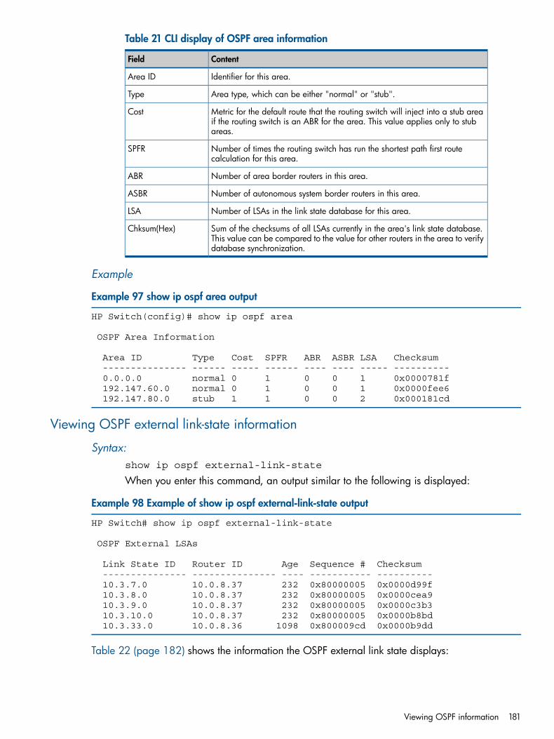
Table 21 CLI display of OSPF area information
ContentField
Identifier for this area.Area ID
Area type, which can be either "normal" or "stub".Type
Metric for the default route that the routing switch will inject into a stub areaif the routing switch is an ABR for the area. This value applies only to stubareas.
Cost
Number of times the routing switch has run the shortest path first routecalculation for this area.
SPFR
Number of area border routers in this area.ABR
Number of autonomous system border routers in this area.ASBR
Number of LSAs in the link state database for this area.LSA
Sum of the checksums of all LSAs currently in the area's link state database.This value can be compared to the value for other routers in the area to verifydatabase synchronization.
Chksum(Hex)
Example
Example 97 show ip ospf area output
HP Switch(config)# show ip ospf area
OSPF Area Information
Area ID Type Cost SPFR ABR ASBR LSA Checksum --------------- ------ ----- ------ ---- ---- ----- ---------- 0.0.0.0 normal 0 1 0 0 1 0x0000781f 192.147.60.0 normal 0 1 0 0 1 0x0000fee6 192.147.80.0 stub 1 1 0 0 2 0x000181cd
Viewing OSPF external link-state information
Syntax:show ip ospf external-link-state
When you enter this command, an output similar to the following is displayed:
Example 98 Example of show ip ospf external-link-state output
HP Switch# show ip ospf external-link-state
OSPF External LSAs
Link State ID Router ID Age Sequence # Checksum --------------- --------------- ---- ----------- ---------- 10.3.7.0 10.0.8.37 232 0x80000005 0x0000d99f 10.3.8.0 10.0.8.37 232 0x80000005 0x0000cea9 10.3.9.0 10.0.8.37 232 0x80000005 0x0000c3b3 10.3.10.0 10.0.8.37 232 0x80000005 0x0000b8bd 10.3.33.0 10.0.8.36 1098 0x800009cd 0x0000b9dd
Table 22 (page 182) shows the information the OSPF external link state displays:
Viewing OSPF information 181
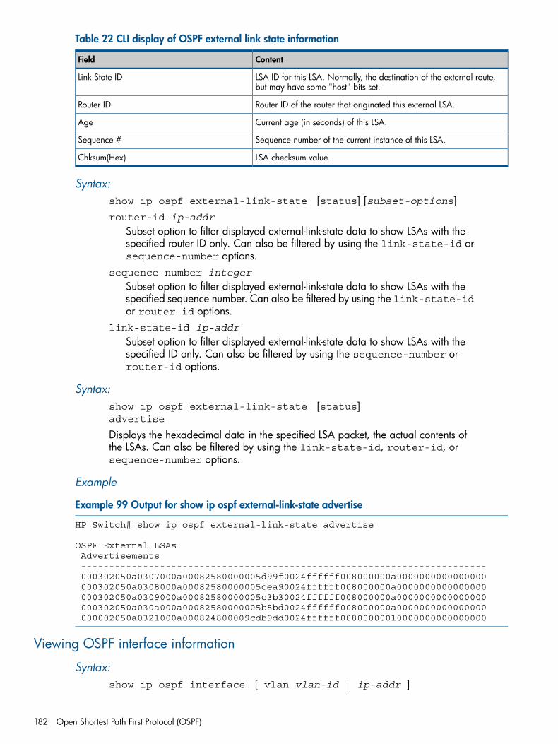
Table 22 CLI display of OSPF external link state information
ContentField
LSA ID for this LSA. Normally, the destination of the external route,but may have some "host" bits set.
Link State ID
Router ID of the router that originated this external LSA.Router ID
Current age (in seconds) of this LSA.Age
Sequence number of the current instance of this LSA.Sequence #
LSA checksum value.Chksum(Hex)
Syntax:show ip ospf external-link-state [status] [subset-options]router-id ip-addr
Subset option to filter displayed external-link-state data to show LSAs with thespecified router ID only. Can also be filtered by using the link-state-id orsequence-number options.
sequence-number integer
Subset option to filter displayed external-link-state data to show LSAs with thespecified sequence number. Can also be filtered by using the link-state-idor router-id options.
link-state-id ip-addr
Subset option to filter displayed external-link-state data to show LSAs with thespecified ID only. Can also be filtered by using the sequence-number orrouter-id options.
Syntax:show ip ospf external-link-state [status]advertise
Displays the hexadecimal data in the specified LSA packet, the actual contents ofthe LSAs. Can also be filtered by using the link-state-id, router-id, orsequence-number options.
Example
Example 99 Output for show ip ospf external-link-state advertise
HP Switch# show ip ospf external-link-state advertise
OSPF External LSAs Advertisements ------------------------------------------------------------------------ 000302050a0307000a00082580000005d99f0024ffffff008000000a0000000000000000 000302050a0308000a00082580000005cea90024ffffff008000000a0000000000000000 000302050a0309000a00082580000005c3b30024ffffff008000000a0000000000000000 000302050a030a000a00082580000005b8bd0024ffffff008000000a0000000000000000 000002050a0321000a000824800009cdb9dd0024ffffff00800000010000000000000000
Viewing OSPF interface information
Syntax:show ip ospf interface [ vlan vlan-id | ip-addr ]
182 Open Shortest Path First Protocol (OSPF)
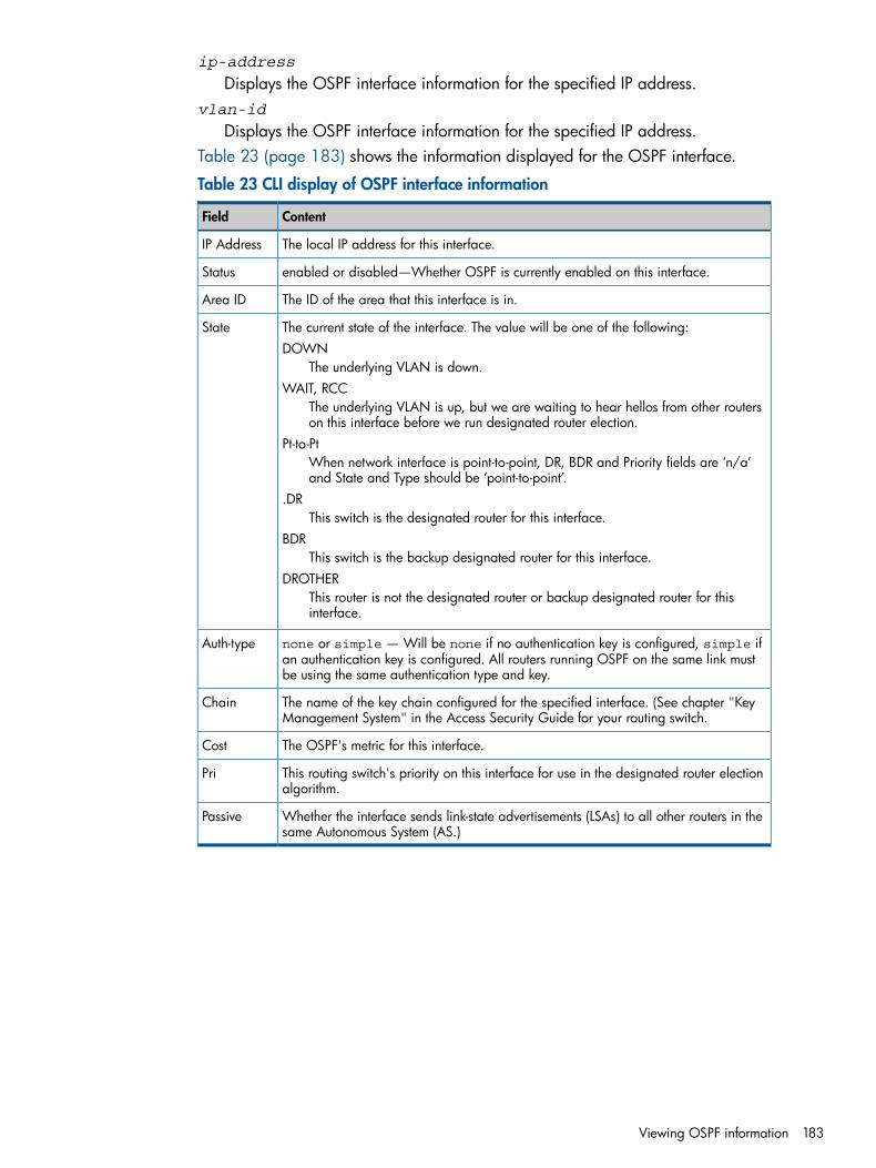
ip-address
Displays the OSPF interface information for the specified IP address.vlan-id
Displays the OSPF interface information for the specified IP address.Table 23 (page 183) shows the information displayed for the OSPF interface.
Table 23 CLI display of OSPF interface information
ContentField
The local IP address for this interface.IP Address
enabled or disabled—Whether OSPF is currently enabled on this interface.Status
The ID of the area that this interface is in.Area ID
The current state of the interface. The value will be one of the following:DOWN
The underlying VLAN is down.
State
WAIT, RCCThe underlying VLAN is up, but we are waiting to hear hellos from other routerson this interface before we run designated router election.
Pt-to-PtWhen network interface is point-to-point, DR, BDR and Priority fields are ‘n/a’and State and Type should be ‘point-to-point’.
.DRThis switch is the designated router for this interface.
BDRThis switch is the backup designated router for this interface.
DROTHERThis router is not the designated router or backup designated router for thisinterface.
none or simple — Will be none if no authentication key is configured, simple ifan authentication key is configured. All routers running OSPF on the same link mustbe using the same authentication type and key.
Auth-type
The name of the key chain configured for the specified interface. (See chapter "KeyManagement System" in the Access Security Guide for your routing switch.
Chain
The OSPF's metric for this interface.Cost
This routing switch's priority on this interface for use in the designated router electionalgorithm.
Pri
Whether the interface sends link-state advertisements (LSAs) to all other routers in thesame Autonomous System (AS.)
Passive
Viewing OSPF information 183
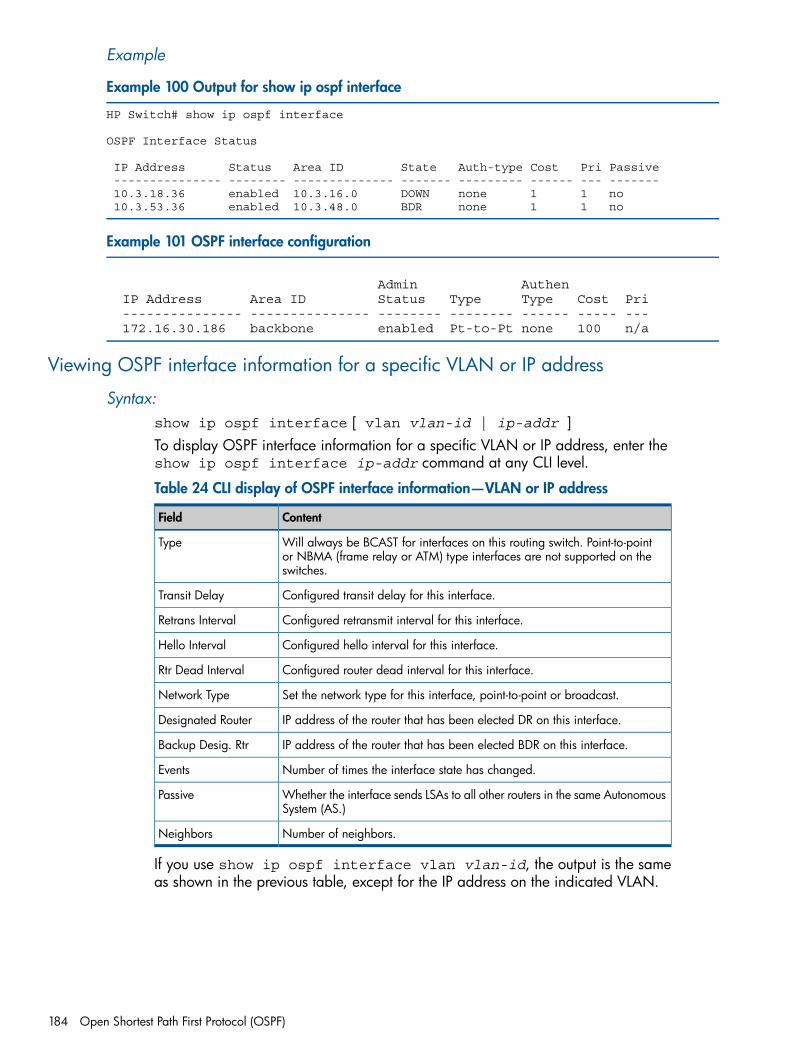
Example
Example 100 Output for show ip ospf interface
HP Switch# show ip ospf interface
OSPF Interface Status
IP Address Status Area ID State Auth-type Cost Pri Passive --------------- -------- -------------- ------- --------- ------ --- ------- 10.3.18.36 enabled 10.3.16.0 DOWN none 1 1 no 10.3.53.36 enabled 10.3.48.0 BDR none 1 1 no
Example 101 OSPF interface configuration
Admin Authen IP Address Area ID Status Type Type Cost Pri --------------- --------------- -------- -------- ------ ----- --- 172.16.30.186 backbone enabled Pt-to-Pt none 100 n/a
Viewing OSPF interface information for a specific VLAN or IP address
Syntax:show ip ospf interface [ vlan vlan-id | ip-addr ]To display OSPF interface information for a specific VLAN or IP address, enter theshow ip ospf interface ip-addr command at any CLI level.
Table 24 CLI display of OSPF interface information—VLAN or IP address
ContentField
Will always be BCAST for interfaces on this routing switch. Point-to-pointor NBMA (frame relay or ATM) type interfaces are not supported on theswitches.
Type
Configured transit delay for this interface.Transit Delay
Configured retransmit interval for this interface.Retrans Interval
Configured hello interval for this interface.Hello Interval
Configured router dead interval for this interface.Rtr Dead Interval
Set the network type for this interface, point-to-point or broadcast.Network Type
IP address of the router that has been elected DR on this interface.Designated Router
IP address of the router that has been elected BDR on this interface.Backup Desig. Rtr
Number of times the interface state has changed.Events
Whether the interface sends LSAs to all other routers in the same AutonomousSystem (AS.)
Passive
Number of neighbors.Neighbors
If you use show ip ospf interface vlan vlan-id, the output is the sameas shown in the previous table, except for the IP address on the indicated VLAN.
184 Open Shortest Path First Protocol (OSPF)
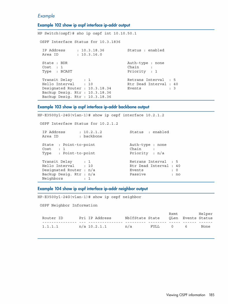
Example
Example 102 show ip ospf interface ip-addr output
HP Switch(ospf)# sho ip ospf int 10.10.50.1
OSPF Interface Status for 10.3.1836
IP Address : 10.3.18.36 Status : enabled Area ID : 10.3.16.0
State : BDR Auth-type : none Cost : 1 Chain : Type : BCAST Priority : 1
Transit Delay : 1 Retrans Interval : 5 Hello Interval : 10 Rtr Dead Interval : 40 Designated Router : 10.3.18.34 Events : 3 Backup Desig. Rtr : 10.3.18.36 Backup Desig. Rtr : 10.3.18.36
Example 103 show ip ospf interface ip-addr backbone output
HP-E3500yl-24G(vlan-1)# show ip ospf interface 10.2.1.2
OSPF Interface Status for 10.2.1.2
IP Address : 10.2.1.2 Status : enabled Area ID : backbone
State : Point-to-point Auth-type : none Cost : 1 Chain : Type : Point-to-point Priority : n/a
Transit Delay : 1 Retrans Interval : 5 Hello Interval : 10 Rtr Dead Interval : 40 Designated Router : n/a Events : 0 Backup Desig. Rtr : n/a Passive : no Neighbors : 1
Example 104 show ip ospf interface ip-addr neighbor output
HP-E3500yl-24G(vlan-1)# show ip ospf neighbor
OSPF Neighbor Information
Rxmt Helper Router ID Pri IP Address NbIfState State QLen Events Status --------------- --- --------------- --------- -------- ----- ------ ------ 1.1.1.1 n/a 10.2.1.1 n/a FULL 0 6 None
Viewing OSPF information 185
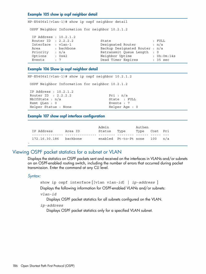
Example 105 show ip ospf neighbor detail
HP-E5406zl(vlan-1)# show ip ospf neighbor detail
OSPF Neighbor Information for neighbor 10.2.1.2
IP Address : 10.2.1.2 Router ID : 2.2.2.2 State : FULL Interface : vlan-1 Designated Router : n/a Area : backbone Backup Designated Router : n/a Priority : n/a Retransmit Queue Length : 0 Options : 0x42 Neighbor Uptime : 0h:0m:14s Events : 7 Dead Timer Expires : 35 sec
Example 106 Show ip ospf neighbor detail
HP-E5406zl(vlan-1)# show ip ospf neighbor 10.2.1.2
OSPF Neighbor Information for neighbor 10.2.1.2
IP Address : 10.2.1.2 Router ID : 2.2.2.2 Pri : n/a NbIfState : n/a State : FULL Rxmt QLen : 0 Events : 7 Helper Status : None Helper Age : 0
Example 107 show ospf interface configuration
Admin Authen IP Address Area ID Status Type Type Cost Pri --------------- --------------- -------- -------- ------ ----- --- 172.16.30.186 backbone enabled Pt-to-Pt none 100 n/a .
Viewing OSPF packet statistics for a subnet or VLANDisplays the statistics on OSPF packets sent and received on the interfaces in VLANs and/or subnetson an OSPF-enabled routing switch, including the number of errors that occurred during packettransmission. Enter the command at any CLI level.
Syntax:show ip ospf interface [[vlan vlan-id] | ip-address ]Displays the following information for OSPF-enabled VLANs and/or subnets:vlan-id
Displays OSPF packet statistics for all subnets configured on the VLAN.ip-address
Displays OSPF packet statistics only for a specified VLAN subnet.
186 Open Shortest Path First Protocol (OSPF)
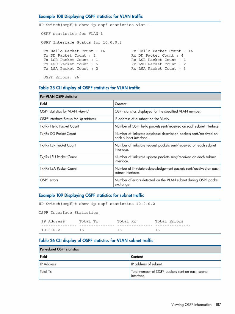
Example 108 Displaying OSPF statistics for VLAN traffic
HP Switch(ospf)# show ip ospf statistics vlan 1
OSPF statistics for VLAN 1
OSPF Interface Status for 10.0.0.2
Tx Hello Packet Count : 16 Rx Hello Packet Count : 16 Tx DD Packet Count : 2 Rx DD Packet Count : 4 Tx LSR Packet Count : 1 Rx LSR Packet Count : 1 Tx LSU Packet Count : 5 Rx LSU Packet Count : 2 Tx LSA Packet Count : 2 Rx LSA Packet Count : 3
OSPF Errors: 26
Table 25 CLI display of OSPF statistics for VLAN traffic
Per-VLAN OSPF statistics
ContentField
OSPF statistics displayed for the specified VLAN number.OSPF statistics for VLAN vlan-id
IP address of a subnet on the VLAN.OSPF Interface Status for ip-address
Number of OSPF hello packets sent/received on each subnet interface.Tx/Rx Hello Packet Count
Number of link-state database description packets sent/received oneach subnet interface.
Tx/Rx DD Packet Count
Number of link-state request packets sent/received on each subnetinterface.
Tx/Rx LSR Packet Count
Number of link-state update packets sent/received on each subnetinterface.
Tx/Rx LSU Packet Count
Number of link-state acknowledgement packets sent/received on eachsubnet interface.
Tx/Rx LSA Packet Count
Number of errors detected on the VLAN subnet during OSPF packetexchange.
OSPF errors
Example 109 Displaying OSPF statistics for subnet traffic
HP Switch(ospf)# show ip ospf statistics 10.0.0.2
OSPF Interface Statistics
IP Address Total Tx Total Rx Total Errors --------------- --------------- --------------- --------------- 10.0.0.2 15 15 15
Table 26 CLI display of OSPF statistics for VLAN subnet traffic
Per-subnet OSPF statistics
ContentField
IP address of subnet.IP Address
Total number of OSPF packets sent on each subnetinterface.
Total Tx
Viewing OSPF information 187
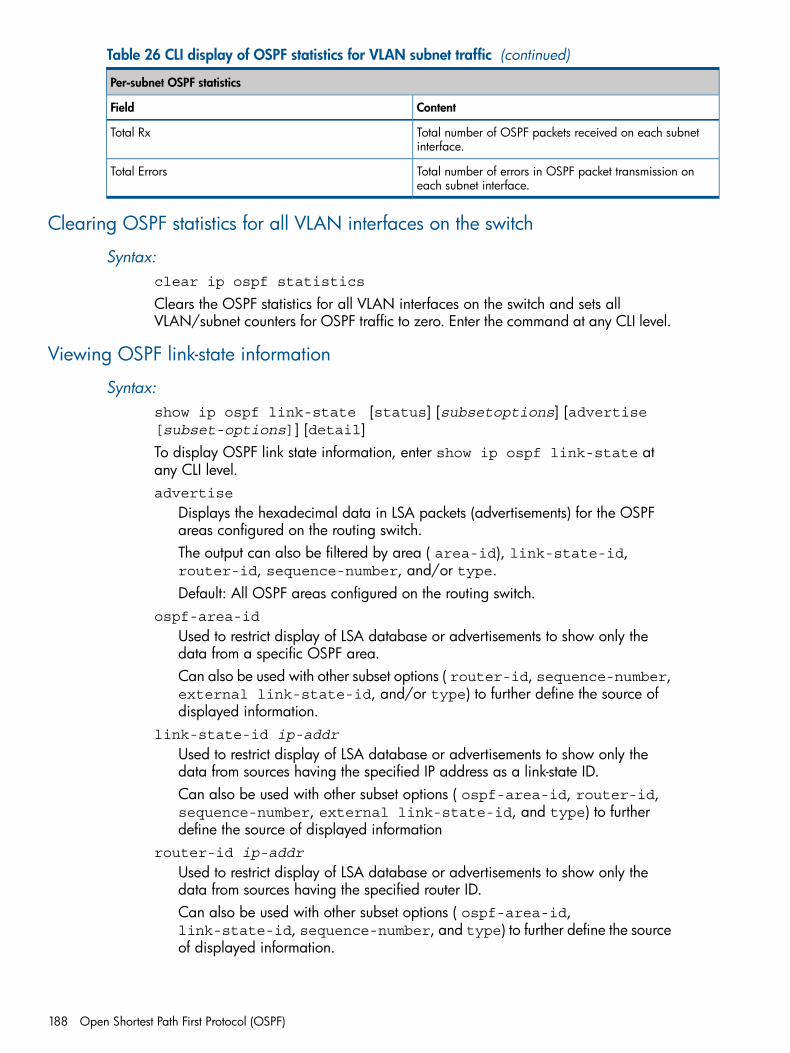
Table 26 CLI display of OSPF statistics for VLAN subnet traffic (continued)
Per-subnet OSPF statistics
ContentField
Total number of OSPF packets received on each subnetinterface.
Total Rx
Total number of errors in OSPF packet transmission oneach subnet interface.
Total Errors
Clearing OSPF statistics for all VLAN interfaces on the switch
Syntax:clear ip ospf statistics
Clears the OSPF statistics for all VLAN interfaces on the switch and sets allVLAN/subnet counters for OSPF traffic to zero. Enter the command at any CLI level.
Viewing OSPF link-state information
Syntax:show ip ospf link-state [status] [subsetoptions] [advertise[subset-options]] [detail]To display OSPF link state information, enter show ip ospf link-state atany CLI level.advertise
Displays the hexadecimal data in LSA packets (advertisements) for the OSPFareas configured on the routing switch.The output can also be filtered by area ( area-id), link-state-id,router-id, sequence-number, and/or type.Default: All OSPF areas configured on the routing switch.
ospf-area-id
Used to restrict display of LSA database or advertisements to show only thedata from a specific OSPF area.Can also be used with other subset options ( router-id, sequence-number,external link-state-id, and/or type) to further define the source ofdisplayed information.
link-state-id ip-addr
Used to restrict display of LSA database or advertisements to show only thedata from sources having the specified IP address as a link-state ID.Can also be used with other subset options ( ospf-area-id, router-id,sequence-number, external link-state-id, and type) to furtherdefine the source of displayed information
router-id ip-addr
Used to restrict display of LSA database or advertisements to show only thedata from sources having the specified router ID.Can also be used with other subset options ( ospf-area-id,link-state-id, sequence-number, and type) to further define the sourceof displayed information.
188 Open Shortest Path First Protocol (OSPF)
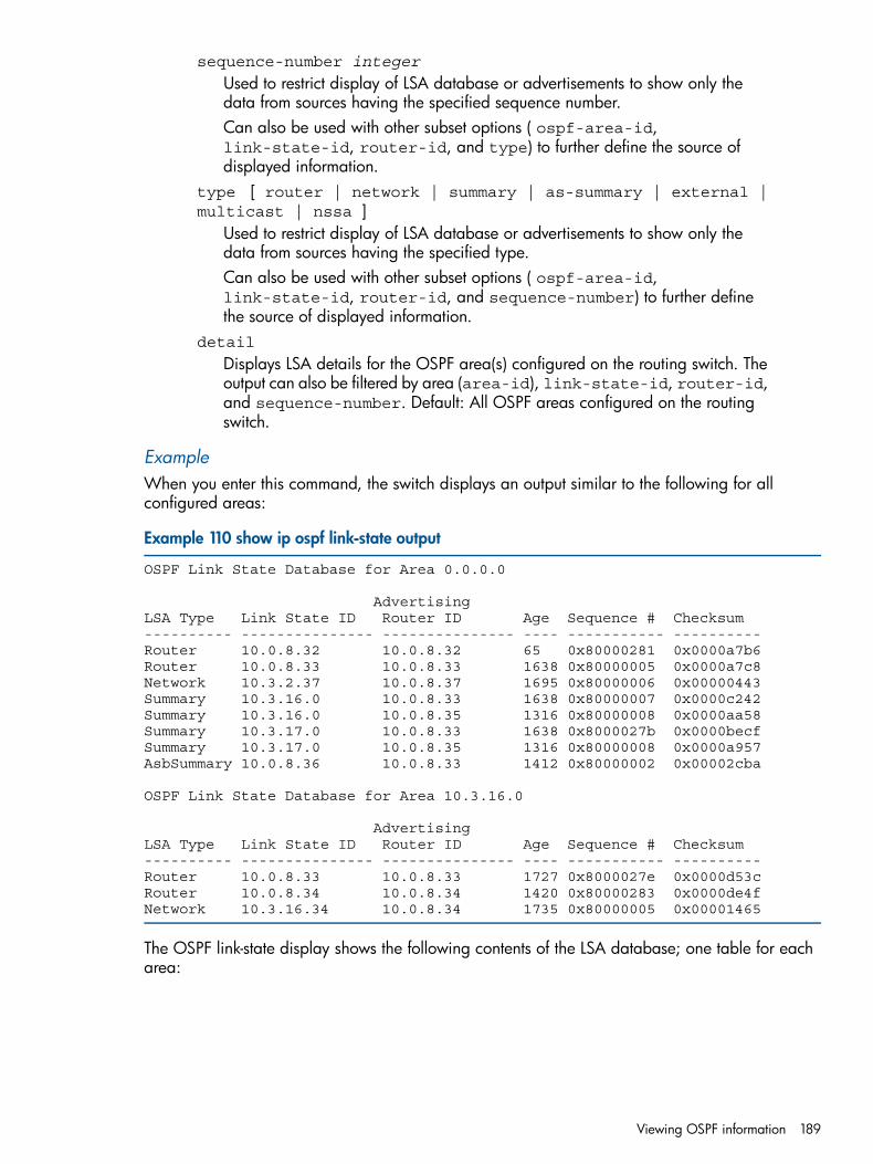
sequence-number integer
Used to restrict display of LSA database or advertisements to show only thedata from sources having the specified sequence number.Can also be used with other subset options ( ospf-area-id,link-state-id, router-id, and type) to further define the source ofdisplayed information.
type [ router | network | summary | as-summary | external |multicast | nssa ]
Used to restrict display of LSA database or advertisements to show only thedata from sources having the specified type.Can also be used with other subset options ( ospf-area-id,link-state-id, router-id, and sequence-number) to further definethe source of displayed information.
detail
Displays LSA details for the OSPF area(s) configured on the routing switch. Theoutput can also be filtered by area (area-id), link-state-id, router-id,and sequence-number. Default: All OSPF areas configured on the routingswitch.
ExampleWhen you enter this command, the switch displays an output similar to the following for allconfigured areas:
Example 110 show ip ospf link-state output
OSPF Link State Database for Area 0.0.0.0
AdvertisingLSA Type Link State ID Router ID Age Sequence # Checksum---------- --------------- --------------- ---- ----------- ---------- Router 10.0.8.32 10.0.8.32 65 0x80000281 0x0000a7b6Router 10.0.8.33 10.0.8.33 1638 0x80000005 0x0000a7c8Network 10.3.2.37 10.0.8.37 1695 0x80000006 0x00000443Summary 10.3.16.0 10.0.8.33 1638 0x80000007 0x0000c242Summary 10.3.16.0 10.0.8.35 1316 0x80000008 0x0000aa58Summary 10.3.17.0 10.0.8.33 1638 0x8000027b 0x0000becfSummary 10.3.17.0 10.0.8.35 1316 0x80000008 0x0000a957AsbSummary 10.0.8.36 10.0.8.33 1412 0x80000002 0x00002cba
OSPF Link State Database for Area 10.3.16.0
AdvertisingLSA Type Link State ID Router ID Age Sequence # Checksum---------- --------------- --------------- ---- ----------- ---------- Router 10.0.8.33 10.0.8.33 1727 0x8000027e 0x0000d53c Router 10.0.8.34 10.0.8.34 1420 0x80000283 0x0000de4f Network 10.3.16.34 10.0.8.34 1735 0x80000005 0x00001465
The OSPF link-state display shows the following contents of the LSA database; one table for eacharea:
Viewing OSPF information 189
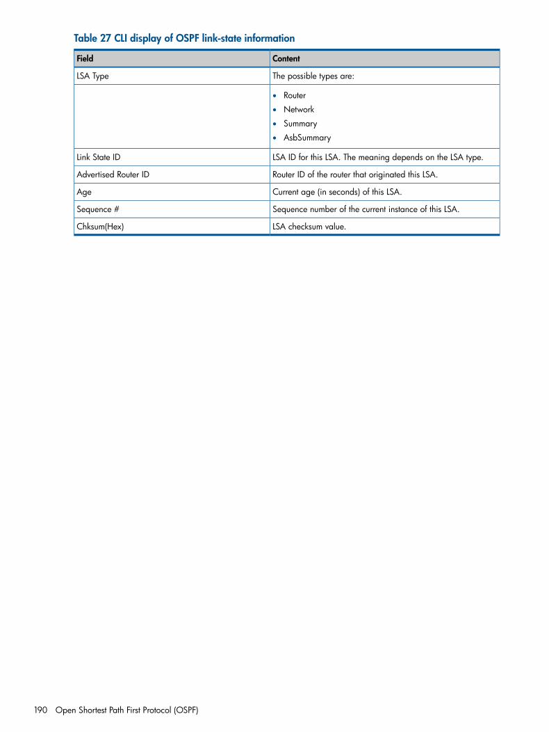
Table 27 CLI display of OSPF link-state information
ContentField
The possible types are:LSA Type
• Router
• Network
• Summary
• AsbSummary
LSA ID for this LSA. The meaning depends on the LSA type.Link State ID
Router ID of the router that originated this LSA.Advertised Router ID
Current age (in seconds) of this LSA.Age
Sequence number of the current instance of this LSA.Sequence #
LSA checksum value.Chksum(Hex)
190 Open Shortest Path First Protocol (OSPF)
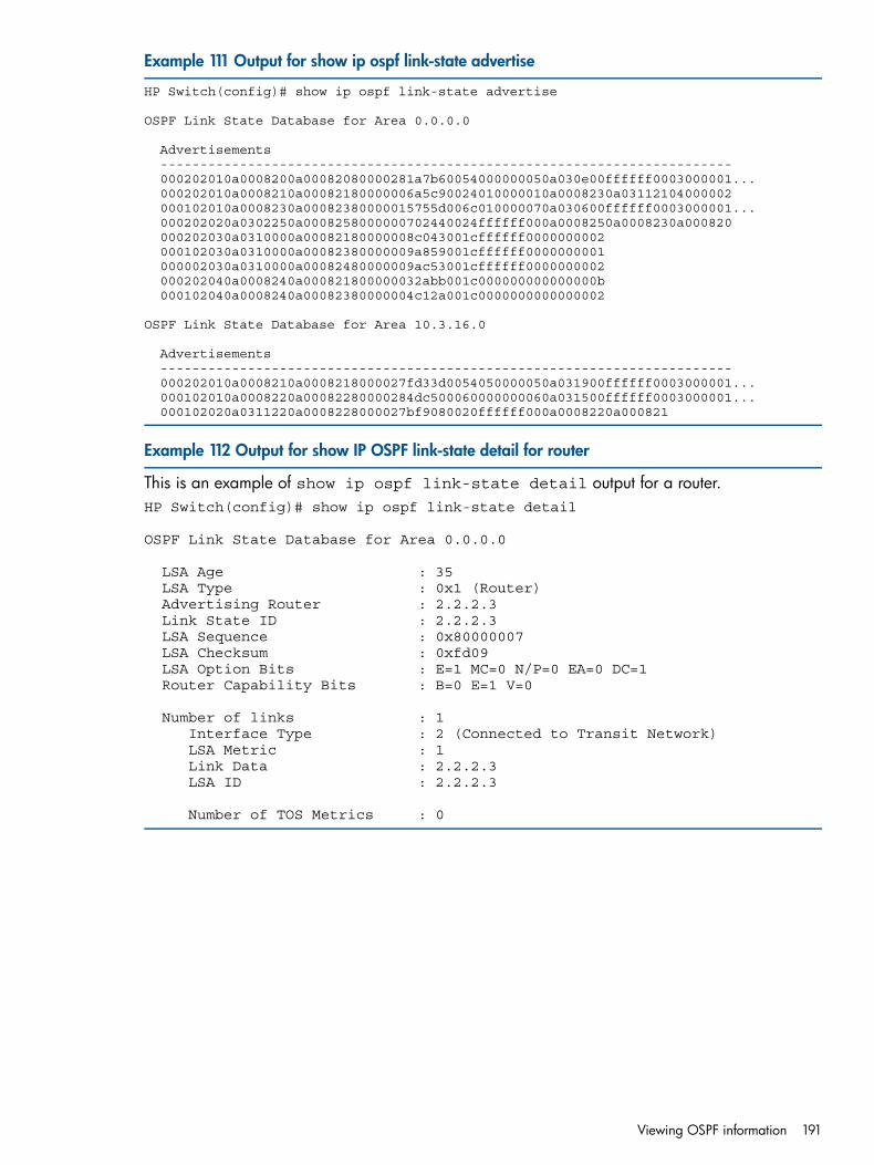
Example 111 Output for show ip ospf link-state advertise
HP Switch(config)# show ip ospf link-state advertise
OSPF Link State Database for Area 0.0.0.0
Advertisements ------------------------------------------------------------------------ 000202010a0008200a00082080000281a7b60054000000050a030e00ffffff0003000001... 000202010a0008210a00082180000006a5c90024010000010a0008230a03112104000002 000102010a0008230a00082380000015755d006c010000070a030600ffffff0003000001... 000202020a0302250a0008258000000702440024ffffff000a0008250a0008230a000820 000202030a0310000a00082180000008c043001cffffff0000000002 000102030a0310000a00082380000009a859001cffffff0000000001 000002030a0310000a00082480000009ac53001cffffff0000000002 000202040a0008240a000821800000032abb001c000000000000000b 000102040a0008240a00082380000004c12a001c0000000000000002
OSPF Link State Database for Area 10.3.16.0
Advertisements ------------------------------------------------------------------------ 000202010a0008210a0008218000027fd33d0054050000050a031900ffffff0003000001... 000102010a0008220a00082280000284dc500060000000060a031500ffffff0003000001... 000102020a0311220a0008228000027bf9080020ffffff000a0008220a000821
Example 112 Output for show IP OSPF link-state detail for router
This is an example of show ip ospf link-state detail output for a router.HP Switch(config)# show ip ospf link-state detail
OSPF Link State Database for Area 0.0.0.0
LSA Age : 35 LSA Type : 0x1 (Router) Advertising Router : 2.2.2.3 Link State ID : 2.2.2.3 LSA Sequence : 0x80000007 LSA Checksum : 0xfd09 LSA Option Bits : E=1 MC=0 N/P=0 EA=0 DC=1 Router Capability Bits : B=0 E=1 V=0
Number of links : 1 Interface Type : 2 (Connected to Transit Network) LSA Metric : 1 Link Data : 2.2.2.3 LSA ID : 2.2.2.3
Number of TOS Metrics : 0
Viewing OSPF information 191
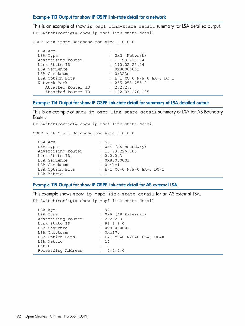
Example 113 Output for show IP OSPF link-state detail for a network
This is an example of show ip ospf link-state detail summary for LSA detailed output.HP Switch(config)# show ip ospf link-state detail
OSPF Link State Database for Area 0.0.0.0
LSA Age : 19 LSA Type : 0x2 (Network) Advertising Router : 16.93.223.84 Link State ID : 192.22.23.24 LSA Sequence : 0x80000001 LSA Checksum : 0x323e LSA Option Bits : E=1 MC=0 N/P=0 EA=0 DC=1 Network Mask : 255.255.255.0 Attached Router ID : 2.2.2.3 Attached Router ID : 192.93.226.105
Example 114 Output for show IP OSPF link-state detail for summary of LSA detailed output
This is an example of show ip ospf link-state detail summary of LSA for AS BoundaryRouter.HP Switch(config)# show ip ospf link-state detail
OSPF Link State Database for Area 0.0.0.0
LSA Age : 58 LSA Type : 0x4 (AS Boundary) Advertising Router : 16.93.226.105 Link State ID : 2.2.2.3 LSA Sequence : 0x80000001 LSA Checksum : 0x4bc4 LSA Option Bits : E=1 MC=0 N/P=0 EA=0 DC=1 LSA Metric : 1
Example 115 Output for show IP OSPF link-state detail for AS external LSA
This example shows show ip ospf link-state detail for an AS external LSA.HP Switch(config)# show ip ospf link-state detail
LSA Age : 971 LSA Type : 0x5 (AS External) Advertising Router : 2.2.2.3 Link State ID : 55.5.5.0 LSA Sequence : 0x80000001 LSA Checksum : 0xe17c LSA Option Bits : E=1 MC=0 N/P=0 EA=0 DC=0 LSA Metric : 10 Bit E : 0 Forwarding Address : 0.0.0.0
192 Open Shortest Path First Protocol (OSPF)
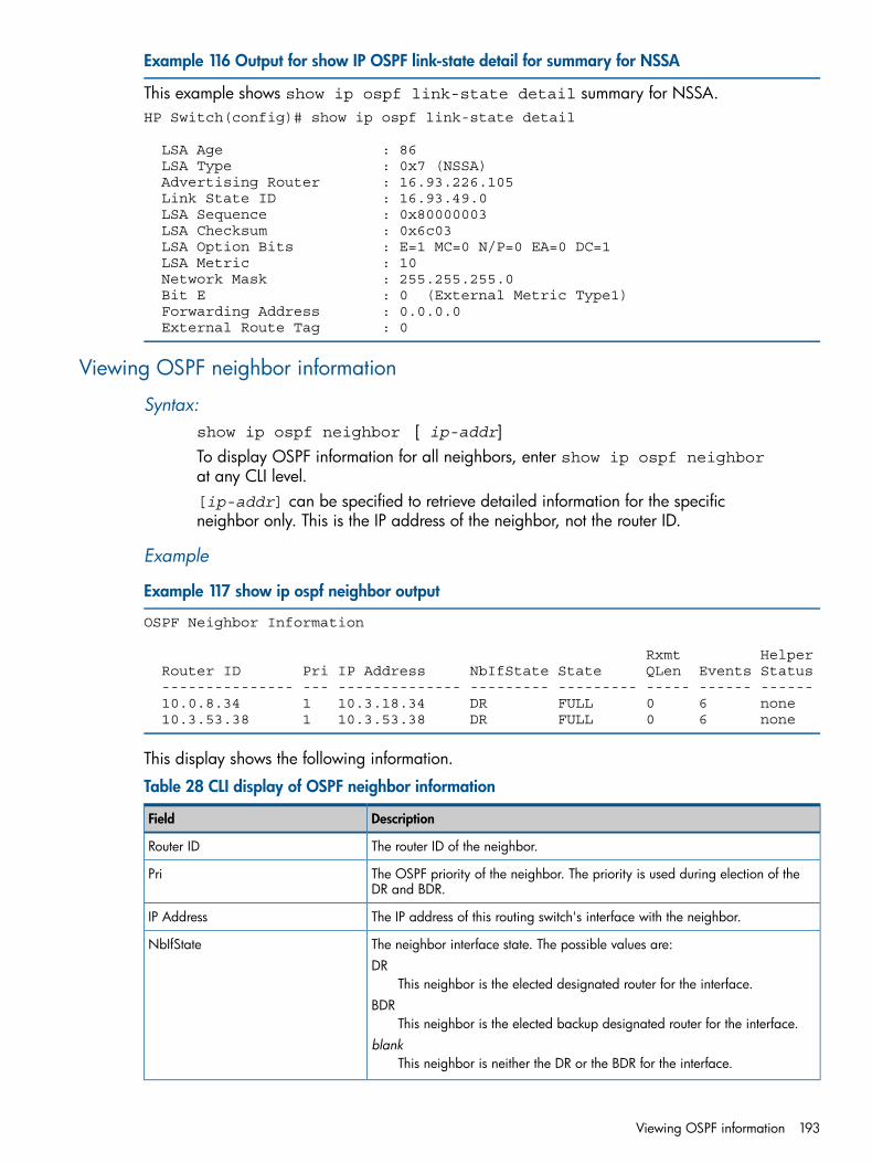
Example 116 Output for show IP OSPF link-state detail for summary for NSSA
This example shows show ip ospf link-state detail summary for NSSA.HP Switch(config)# show ip ospf link-state detail
LSA Age : 86 LSA Type : 0x7 (NSSA) Advertising Router : 16.93.226.105 Link State ID : 16.93.49.0 LSA Sequence : 0x80000003 LSA Checksum : 0x6c03 LSA Option Bits : E=1 MC=0 N/P=0 EA=0 DC=1 LSA Metric : 10 Network Mask : 255.255.255.0 Bit E : 0 (External Metric Type1) Forwarding Address : 0.0.0.0 External Route Tag : 0
Viewing OSPF neighbor information
Syntax:show ip ospf neighbor [ ip-addr]To display OSPF information for all neighbors, enter show ip ospf neighborat any CLI level.[ip-addr] can be specified to retrieve detailed information for the specificneighbor only. This is the IP address of the neighbor, not the router ID.
Example
Example 117 show ip ospf neighbor output
OSPF Neighbor Information
Rxmt Helper Router ID Pri IP Address NbIfState State QLen Events Status --------------- --- -------------- --------- --------- ----- ------ ------ 10.0.8.34 1 10.3.18.34 DR FULL 0 6 none 10.3.53.38 1 10.3.53.38 DR FULL 0 6 none
This display shows the following information.
Table 28 CLI display of OSPF neighbor information
DescriptionField
The router ID of the neighbor.Router ID
The OSPF priority of the neighbor. The priority is used during election of theDR and BDR.
Pri
The IP address of this routing switch's interface with the neighbor.IP Address
The neighbor interface state. The possible values are:DR
This neighbor is the elected designated router for the interface.
NbIfState
BDRThis neighbor is the elected backup designated router for the interface.
blankThis neighbor is neither the DR or the BDR for the interface.
Viewing OSPF information 193
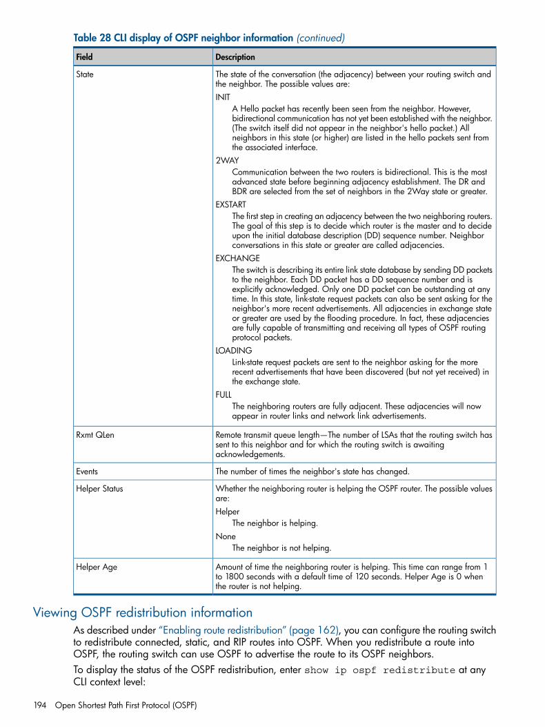
Table 28 CLI display of OSPF neighbor information (continued)
DescriptionField
The state of the conversation (the adjacency) between your routing switch andthe neighbor. The possible values are:INIT
A Hello packet has recently been seen from the neighbor. However,bidirectional communication has not yet been established with the neighbor.
State
(The switch itself did not appear in the neighbor's hello packet.) Allneighbors in this state (or higher) are listed in the hello packets sent fromthe associated interface.
2WAYCommunication between the two routers is bidirectional. This is the mostadvanced state before beginning adjacency establishment. The DR andBDR are selected from the set of neighbors in the 2Way state or greater.
EXSTARTThe first step in creating an adjacency between the two neighboring routers.The goal of this step is to decide which router is the master and to decideupon the initial database description (DD) sequence number. Neighborconversations in this state or greater are called adjacencies.
EXCHANGEThe switch is describing its entire link state database by sending DD packetsto the neighbor. Each DD packet has a DD sequence number and isexplicitly acknowledged. Only one DD packet can be outstanding at anytime. In this state, link-state request packets can also be sent asking for theneighbor's more recent advertisements. All adjacencies in exchange stateor greater are used by the flooding procedure. In fact, these adjacenciesare fully capable of transmitting and receiving all types of OSPF routingprotocol packets.
LOADINGLink-state request packets are sent to the neighbor asking for the morerecent advertisements that have been discovered (but not yet received) inthe exchange state.
FULLThe neighboring routers are fully adjacent. These adjacencies will nowappear in router links and network link advertisements.
Remote transmit queue length—The number of LSAs that the routing switch hassent to this neighbor and for which the routing switch is awaitingacknowledgements.
Rxmt QLen
The number of times the neighbor's state has changed.Events
Whether the neighboring router is helping the OSPF router. The possible valuesare:Helper
The neighbor is helping.
Helper Status
NoneThe neighbor is not helping.
Amount of time the neighboring router is helping. This time can range from 1to 1800 seconds with a default time of 120 seconds. Helper Age is 0 whenthe router is not helping.
Helper Age
Viewing OSPF redistribution informationAs described under “Enabling route redistribution” (page 162), you can configure the routing switchto redistribute connected, static, and RIP routes into OSPF. When you redistribute a route intoOSPF, the routing switch can use OSPF to advertise the route to its OSPF neighbors.To display the status of the OSPF redistribution, enter show ip ospf redistribute at anyCLI context level:
194 Open Shortest Path First Protocol (OSPF)
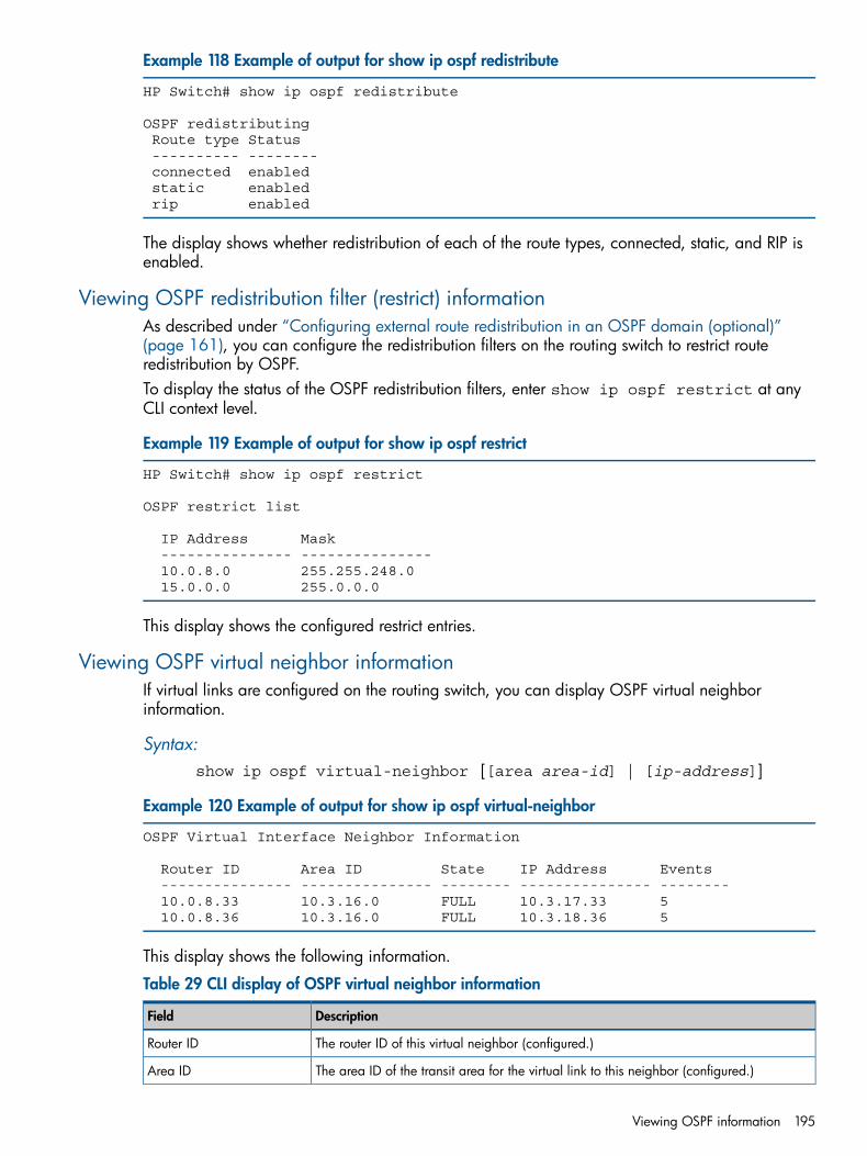
Example 118 Example of output for show ip ospf redistribute
HP Switch# show ip ospf redistribute
OSPF redistributing Route type Status ---------- -------- connected enabled static enabled rip enabled
The display shows whether redistribution of each of the route types, connected, static, and RIP isenabled.
Viewing OSPF redistribution filter (restrict) informationAs described under “Configuring external route redistribution in an OSPF domain (optional)”(page 161), you can configure the redistribution filters on the routing switch to restrict routeredistribution by OSPF.To display the status of the OSPF redistribution filters, enter show ip ospf restrict at anyCLI context level.
Example 119 Example of output for show ip ospf restrict
HP Switch# show ip ospf restrict
OSPF restrict list
IP Address Mask --------------- --------------- 10.0.8.0 255.255.248.0 15.0.0.0 255.0.0.0
This display shows the configured restrict entries.
Viewing OSPF virtual neighbor informationIf virtual links are configured on the routing switch, you can display OSPF virtual neighborinformation.
Syntax:show ip ospf virtual-neighbor [[area area-id] | [ip-address]]
Example 120 Example of output for show ip ospf virtual-neighbor
OSPF Virtual Interface Neighbor Information
Router ID Area ID State IP Address Events --------------- --------------- -------- --------------- -------- 10.0.8.33 10.3.16.0 FULL 10.3.17.33 5 10.0.8.36 10.3.16.0 FULL 10.3.18.36 5
This display shows the following information.
Table 29 CLI display of OSPF virtual neighbor information
DescriptionField
The router ID of this virtual neighbor (configured.)Router ID
The area ID of the transit area for the virtual link to this neighbor (configured.)Area ID
Viewing OSPF information 195
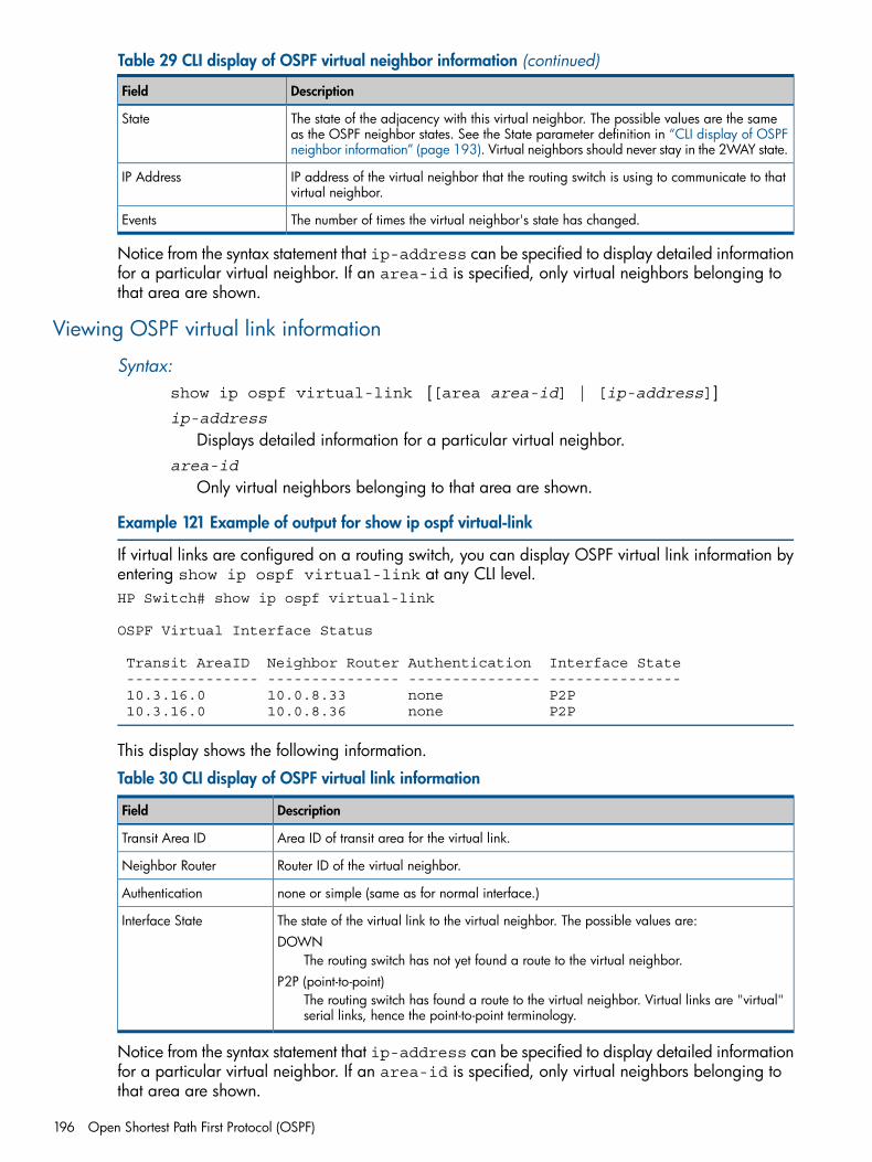
Table 29 CLI display of OSPF virtual neighbor information (continued)
DescriptionField
The state of the adjacency with this virtual neighbor. The possible values are the sameas the OSPF neighbor states. See the State parameter definition in “CLI display of OSPFneighbor information” (page 193). Virtual neighbors should never stay in the 2WAY state.
State
IP address of the virtual neighbor that the routing switch is using to communicate to thatvirtual neighbor.
IP Address
The number of times the virtual neighbor's state has changed.Events
Notice from the syntax statement that ip-address can be specified to display detailed informationfor a particular virtual neighbor. If an area-id is specified, only virtual neighbors belonging tothat area are shown.
Viewing OSPF virtual link information
Syntax:show ip ospf virtual-link [[area area-id] | [ip-address]]ip-address
Displays detailed information for a particular virtual neighbor.area-id
Only virtual neighbors belonging to that area are shown.
Example 121 Example of output for show ip ospf virtual-link
If virtual links are configured on a routing switch, you can display OSPF virtual link information byentering show ip ospf virtual-link at any CLI level.HP Switch# show ip ospf virtual-link
OSPF Virtual Interface Status
Transit AreaID Neighbor Router Authentication Interface State --------------- --------------- --------------- --------------- 10.3.16.0 10.0.8.33 none P2P 10.3.16.0 10.0.8.36 none P2P
This display shows the following information.
Table 30 CLI display of OSPF virtual link information
DescriptionField
Area ID of transit area for the virtual link.Transit Area ID
Router ID of the virtual neighbor.Neighbor Router
none or simple (same as for normal interface.)Authentication
The state of the virtual link to the virtual neighbor. The possible values are:DOWN
The routing switch has not yet found a route to the virtual neighbor.
Interface State
P2P (point-to-point)The routing switch has found a route to the virtual neighbor. Virtual links are "virtual"serial links, hence the point-to-point terminology.
Notice from the syntax statement that ip-address can be specified to display detailed informationfor a particular virtual neighbor. If an area-id is specified, only virtual neighbors belonging tothat area are shown.
196 Open Shortest Path First Protocol (OSPF)
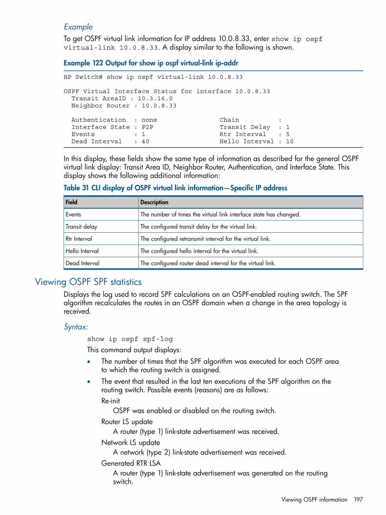
ExampleTo get OSPF virtual link information for IP address 10.0.8.33, enter show ip ospfvirtual-link 10.0.8.33. A display similar to the following is shown.
Example 122 Output for show ip ospf virtual-link ip-addr
HP Switch# show ip ospf virtual-link 10.0.8.33
OSPF Virtual Interface Status for interface 10.0.8.33 Transit AreaID : 10.3.16.0 Neighbor Router : 10.0.8.33
Authentication : none Chain : Interface State : P2P Transit Delay : 1 Events : 1 Rtr Interval : 5 Dead Interval : 40 Hello Interval : 10
In this display, these fields show the same type of information as described for the general OSPFvirtual link display: Transit Area ID, Neighbor Router, Authentication, and Interface State. Thisdisplay shows the following additional information:
Table 31 CLI display of OSPF virtual link information—Specific IP address
DescriptionField
The number of times the virtual link interface state has changed.Events
The configured transit delay for the virtual link.Transit delay
The configured retransmit interval for the virtual link.Rtr Interval
The configured hello interval for the virtual link.Hello Interval
The configured router dead interval for the virtual link.Dead Interval
Viewing OSPF SPF statisticsDisplays the log used to record SPF calculations on an OSPF-enabled routing switch. The SPFalgorithm recalculates the routes in an OSPF domain when a change in the area topology isreceived.
Syntax:show ip ospf spf-log
This command output displays:• The number of times that the SPF algorithm was executed for each OSPF area
to which the routing switch is assigned.• The event that resulted in the last ten executions of the SPF algorithm on the
routing switch. Possible events (reasons) are as follows:Re-init
OSPF was enabled or disabled on the routing switch.Router LS update
A router (type 1) link-state advertisement was received.Network LS update
A network (type 2) link-state advertisement was received.Generated RTR LSA
A router (type 1) link-state advertisement was generated on the routingswitch.
Viewing OSPF information 197
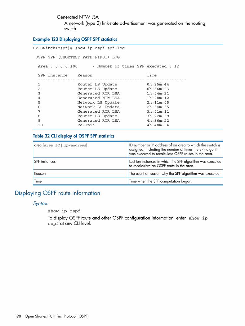
Generated NTW LSAA network (type 2) link-state advertisement was generated on the routingswitch.
Example 123 Displaying OSPF SPF statistics
HP Switch(ospf)# show ip ospf spf-log
OSPF SPF (SHORTEST PATH FIRST) LOG
Area : 0.0.0.100 - Number of times SPF executed : 12
SPF Instance Reason Time --------------- --------------------------- ---------------- 1 Router LS Update 0h:35m:44 2 Router LS Update 0h:36m:03 3 Generated RTR LSA 1h:04m:21 4 Generated NTW LSA 1h:28m:12 5 Network LS Update 2h:11m:05 6 Network LS Update 2h:54m:55 7 Generated RTR LSA 3h:01m:11 8 Router LS Update 3h:22m:39 9 Generated RTR LSA 4h:36m:22 10 Re-Init 4h:48m:54
Table 32 CLI display of OSPF SPF statistics
ID number or IP address of an area to which the switch isassigned, including the number of times the SPF algorithmwas executed to recalculate OSPF routes in the area.
area [area id | ip-address]
Last ten instances in which the SPF algorithm was executedto recalculate an OSPF route in the area.
SPF instances
The event or reason why the SPF algorithm was executed.Reason
Time when the SPF computation began.Time
Displaying OSPF route information
Syntax:show ip ospf
To display OSPF route and other OSPF configuration information, enter show ipospf at any CLI level.
198 Open Shortest Path First Protocol (OSPF)
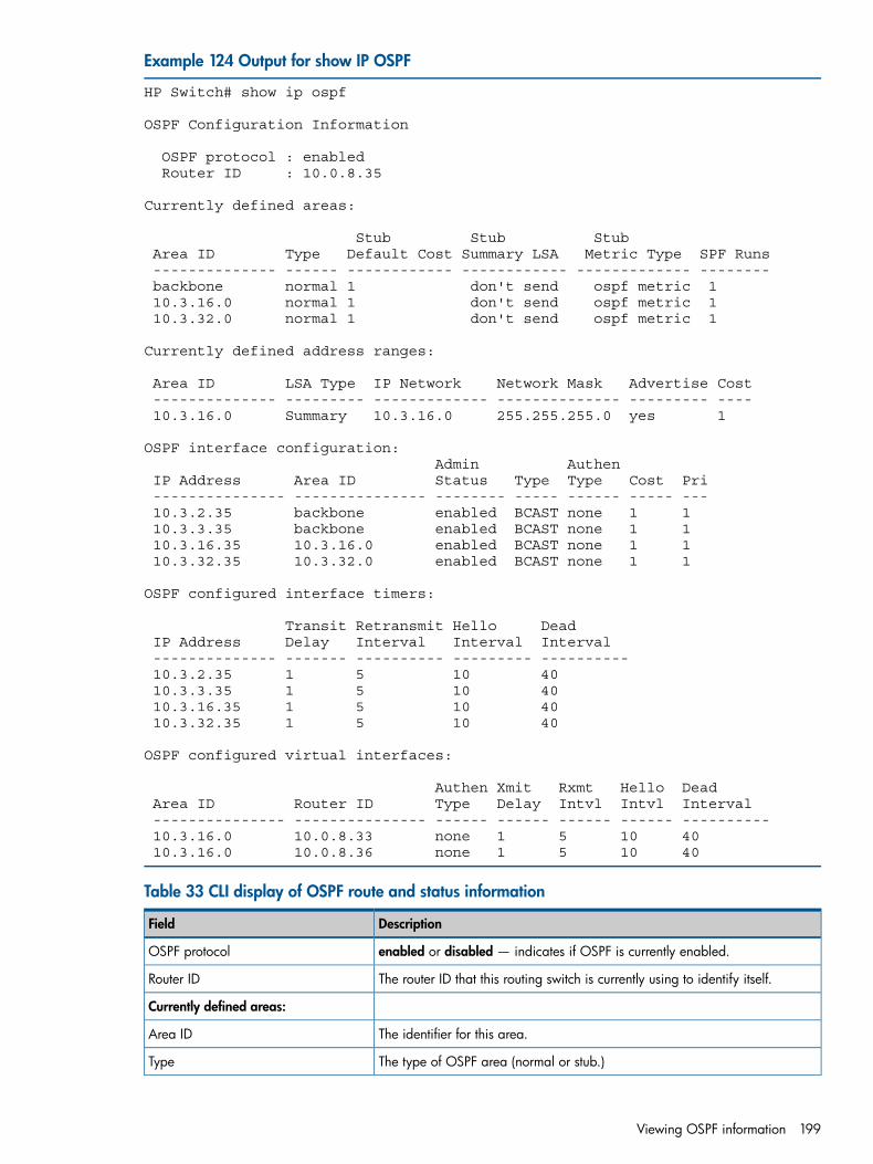
Example 124 Output for show IP OSPF
HP Switch# show ip ospf
OSPF Configuration Information
OSPF protocol : enabled Router ID : 10.0.8.35
Currently defined areas:
Stub Stub Stub Area ID Type Default Cost Summary LSA Metric Type SPF Runs -------------- ------ ------------ ------------ ------------- -------- backbone normal 1 don't send ospf metric 1 10.3.16.0 normal 1 don't send ospf metric 1 10.3.32.0 normal 1 don't send ospf metric 1
Currently defined address ranges:
Area ID LSA Type IP Network Network Mask Advertise Cost -------------- --------- ------------- -------------- --------- ---- 10.3.16.0 Summary 10.3.16.0 255.255.255.0 yes 1
OSPF interface configuration: Admin Authen IP Address Area ID Status Type Type Cost Pri --------------- --------------- -------- ----- ------ ----- --- 10.3.2.35 backbone enabled BCAST none 1 1 10.3.3.35 backbone enabled BCAST none 1 1 10.3.16.35 10.3.16.0 enabled BCAST none 1 1 10.3.32.35 10.3.32.0 enabled BCAST none 1 1
OSPF configured interface timers:
Transit Retransmit Hello Dead IP Address Delay Interval Interval Interval -------------- ------- ---------- --------- ---------- 10.3.2.35 1 5 10 40 10.3.3.35 1 5 10 40 10.3.16.35 1 5 10 40 10.3.32.35 1 5 10 40
OSPF configured virtual interfaces:
Authen Xmit Rxmt Hello Dead Area ID Router ID Type Delay Intvl Intvl Interval --------------- --------------- ------ ------ ------ ------ ---------- 10.3.16.0 10.0.8.33 none 1 5 10 40 10.3.16.0 10.0.8.36 none 1 5 10 40
Table 33 CLI display of OSPF route and status information
DescriptionField
enabled or disabled — indicates if OSPF is currently enabled.OSPF protocol
The router ID that this routing switch is currently using to identify itself.Router ID
Currently defined areas:
The identifier for this area.Area ID
The type of OSPF area (normal or stub.)Type
Viewing OSPF information 199
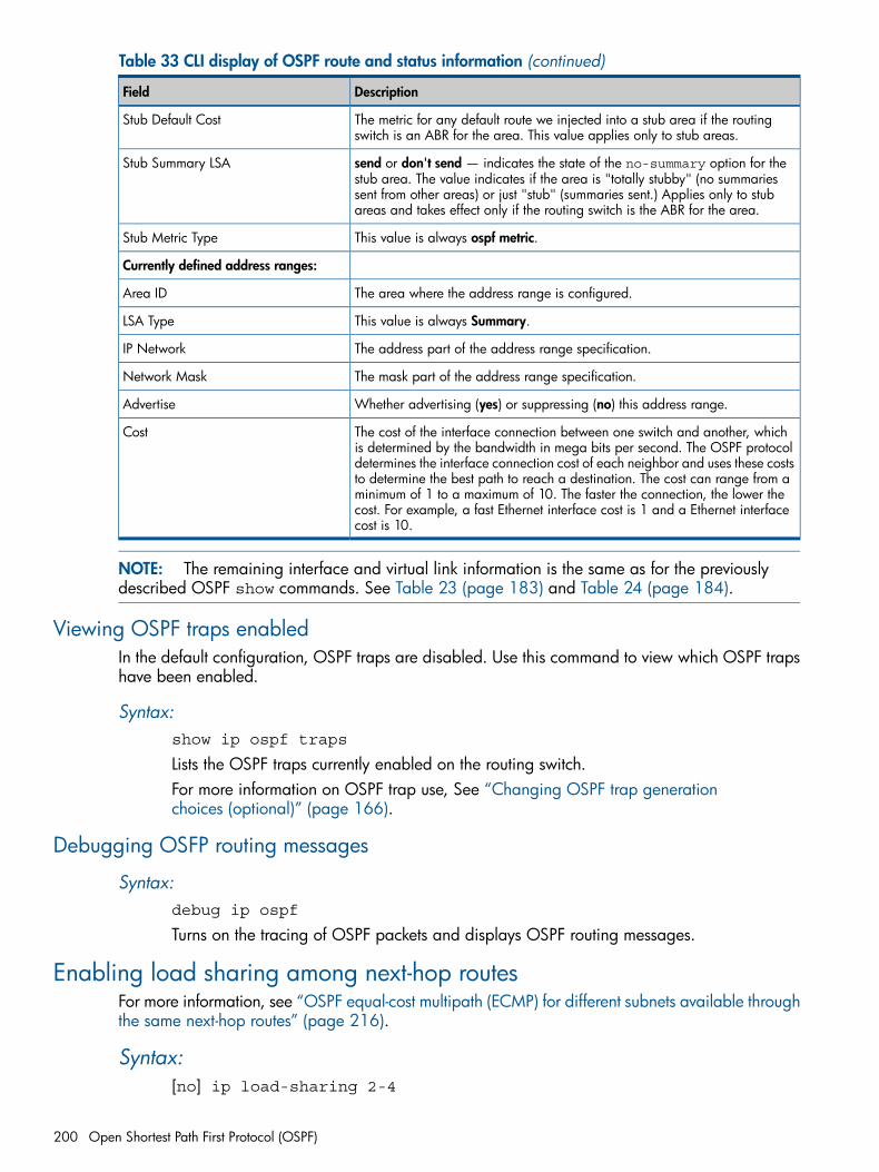
Table 33 CLI display of OSPF route and status information (continued)
DescriptionField
The metric for any default route we injected into a stub area if the routingswitch is an ABR for the area. This value applies only to stub areas.
Stub Default Cost
send or don't send — indicates the state of the no-summary option for thestub area. The value indicates if the area is "totally stubby" (no summaries
Stub Summary LSA
sent from other areas) or just "stub" (summaries sent.) Applies only to stubareas and takes effect only if the routing switch is the ABR for the area.
This value is always ospf metric.Stub Metric Type
Currently defined address ranges:
The area where the address range is configured.Area ID
This value is always Summary.LSA Type
The address part of the address range specification.IP Network
The mask part of the address range specification.Network Mask
Whether advertising (yes) or suppressing (no) this address range.Advertise
The cost of the interface connection between one switch and another, whichis determined by the bandwidth in mega bits per second. The OSPF protocol
Cost
determines the interface connection cost of each neighbor and uses these coststo determine the best path to reach a destination. The cost can range from aminimum of 1 to a maximum of 10. The faster the connection, the lower thecost. For example, a fast Ethernet interface cost is 1 and a Ethernet interfacecost is 10.
NOTE: The remaining interface and virtual link information is the same as for the previouslydescribed OSPF show commands. See Table 23 (page 183) and Table 24 (page 184).
Viewing OSPF traps enabledIn the default configuration, OSPF traps are disabled. Use this command to view which OSPF trapshave been enabled.
Syntax:show ip ospf traps
Lists the OSPF traps currently enabled on the routing switch.For more information on OSPF trap use, See “Changing OSPF trap generationchoices (optional)” (page 166).
Debugging OSFP routing messages
Syntax:debug ip ospf
Turns on the tracing of OSPF packets and displays OSPF routing messages.
Enabling load sharing among next-hop routesFor more information, see “OSPF equal-cost multipath (ECMP) for different subnets available throughthe same next-hop routes” (page 216).
Syntax:[no] ip load-sharing 2-4
200 Open Shortest Path First Protocol (OSPF)
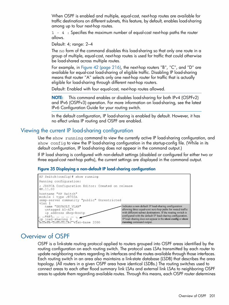
When OSPF is enabled and multiple, equal-cost, next-hop routes are available fortraffic destinations on different subnets, this feature, by default, enables load-sharingamong up to four next-hop routes.1 - 4 : Specifies the maximum number of equal-cost next-hop paths the routerallows.Default: 4; range: 2–4The no form of the command disables this load-sharing so that only one route in agroup of multiple, equal-cost, next-hop routes is used for traffic that could otherwisebe load-shared across multiple routes.For example, in Figure 42 (page 216), the next-hop routers "B", "C", and "D" areavailable for equal-cost load-sharing of eligible traffic. Disabling IP load-sharingmeans that router "A" selects only one next-hop router for traffic that is actuallyeligible for load-sharing through different next-hop routers.Default: Enabled with four equal-cost, next-hop routes allowed.
NOTE: This command enables or disables load-sharing for both IPv4 (OSPFv2)and IPv6 (OSPFv3) operation. For more information on load-sharing, see the latestIPv6 Configuration Guide for your routing switch.
In the default configuration, IP load-sharing is enabled by default. However, it hasno effect unless IP routing and OSPF are enabled.
Viewing the current IP load-sharing configurationUse the show running command to view the currently active IP load-sharing configuration, andshow config to view the IP load-sharing configuration in the startup-config file. (While in itsdefault configuration, IP load-sharing does not appear in the command output.)If IP load sharing is configured with non-default settings (disabled or configured for either two orthree equal-cost next-hop paths), the current settings are displayed in the command output.
Figure 35 Displaying a non-default IP load-sharing configuration
Overview of OSPFOSPF is a link-state routing protocol applied to routers grouped into OSPF areas identified by therouting configuration on each routing switch. The protocol uses LSAs transmitted by each router toupdate neighboring routers regarding its interfaces and the routes available through those interfaces.Each routing switch in an area also maintains a link-state database (LSDB) that describes the areatopology. (All routers in a given OSPF area have identical LSDBs.) The routing switches used toconnect areas to each other flood summary link LSAs and external link LSAs to neighboring OSPFareas to update them regarding available routes. Through this means, each OSPF router determines
Overview of OSPF 201
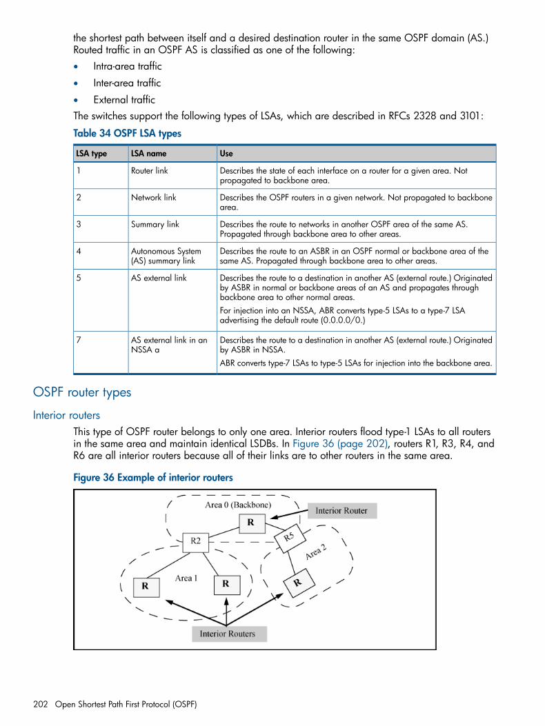
the shortest path between itself and a desired destination router in the same OSPF domain (AS.)Routed traffic in an OSPF AS is classified as one of the following:• Intra-area traffic
• Inter-area traffic
• External trafficThe switches support the following types of LSAs, which are described in RFCs 2328 and 3101:
Table 34 OSPF LSA types
UseLSA nameLSA type
Describes the state of each interface on a router for a given area. Notpropagated to backbone area.
Router link1
Describes the OSPF routers in a given network. Not propagated to backbonearea.
Network link2
Describes the route to networks in another OSPF area of the same AS.Propagated through backbone area to other areas.
Summary link3
Describes the route to an ASBR in an OSPF normal or backbone area of thesame AS. Propagated through backbone area to other areas.
Autonomous System(AS) summary link
4
Describes the route to a destination in another AS (external route.) Originatedby ASBR in normal or backbone areas of an AS and propagates throughbackbone area to other normal areas.
AS external link5
For injection into an NSSA, ABR converts type-5 LSAs to a type-7 LSAadvertising the default route (0.0.0.0/0.)
Describes the route to a destination in another AS (external route.) Originatedby ASBR in NSSA.
AS external link in anNSSA a
7
ABR converts type-7 LSAs to type-5 LSAs for injection into the backbone area.
OSPF router types
Interior routersThis type of OSPF router belongs to only one area. Interior routers flood type-1 LSAs to all routersin the same area and maintain identical LSDBs. In Figure 36 (page 202), routers R1, R3, R4, andR6 are all interior routers because all of their links are to other routers in the same area.
Figure 36 Example of interior routers
202 Open Shortest Path First Protocol (OSPF)
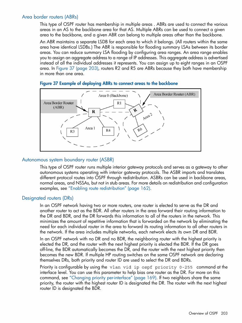
Area border routers (ABRs)This type of OSPF router has membership in multiple areas . ABRs are used to connect the variousareas in an AS to the backbone area for that AS. Multiple ABRs can be used to connect a givenarea to the backbone, and a given ABR can belong to multiple areas other than the backbone.An ABR maintains a separate LSDB for each area to which it belongs. (All routers within the samearea have identical LSDBs.) The ABR is responsible for flooding summary LSAs between its borderareas. You can reduce summary LSA flooding by configuring area ranges. An area range enablesyou to assign an aggregate address to a range of IP addresses. This aggregate address is advertisedinstead of all the individual addresses it represents. You can assign up to eight ranges in an OSPFarea. In Figure 37 (page 203), routers R2 and R5 are ABRs because they both have membershipin more than one area.
Figure 37 Example of deploying ABRs to connect areas to the backbone
Autonomous system boundary router (ASBR)This type of OSPF router runs multiple interior gateway protocols and serves as a gateway to otherautonomous systems operating with interior gateway protocols. The ASBR imports and translatesdifferent protocol routes into OSPF through redistribution. ASBRs can be used in backbone areas,normal areas, and NSSAs, but not in stub areas. For more details on redistribution and configurationexamples, see “Enabling route redistribution” (page 162).
Designated routers (DRs)In an OSPF network having two or more routers, one router is elected to serve as the DR andanother router to act as the BDR. All other routers in the area forward their routing information tothe DR and BDR, and the DR forwards this information to all of the routers in the network. Thisminimizes the amount of repetitive information that is forwarded on the network by eliminating theneed for each individual router in the area to forward its routing information to all other routers inthe network. If the area includes multiple networks, each network elects its own DR and BDR.In an OSPF network with no DR and no BDR, the neighboring router with the highest priority iselected the DR, and the router with the next highest priority is elected the BDR. If the DR goesoff-line, the BDR automatically becomes the DR, and the router with the next highest priority thenbecomes the new BDR. If multiple HP routing switches on the same OSPF network are declaringthemselves DRs, both priority and router ID are used to select the DR and BDRs.Priority is configurable by using the vlan vid ip ospf priority 0-255 command at theinterface level. You can use this parameter to help bias one router as the DR. For more on thiscommand, see “Changing priority per-interface” (page 169). If two neighbors share the samepriority, the router with the highest router ID is designated the DR. The router with the next highestrouter ID is designated the BDR.
Overview of OSPF 203
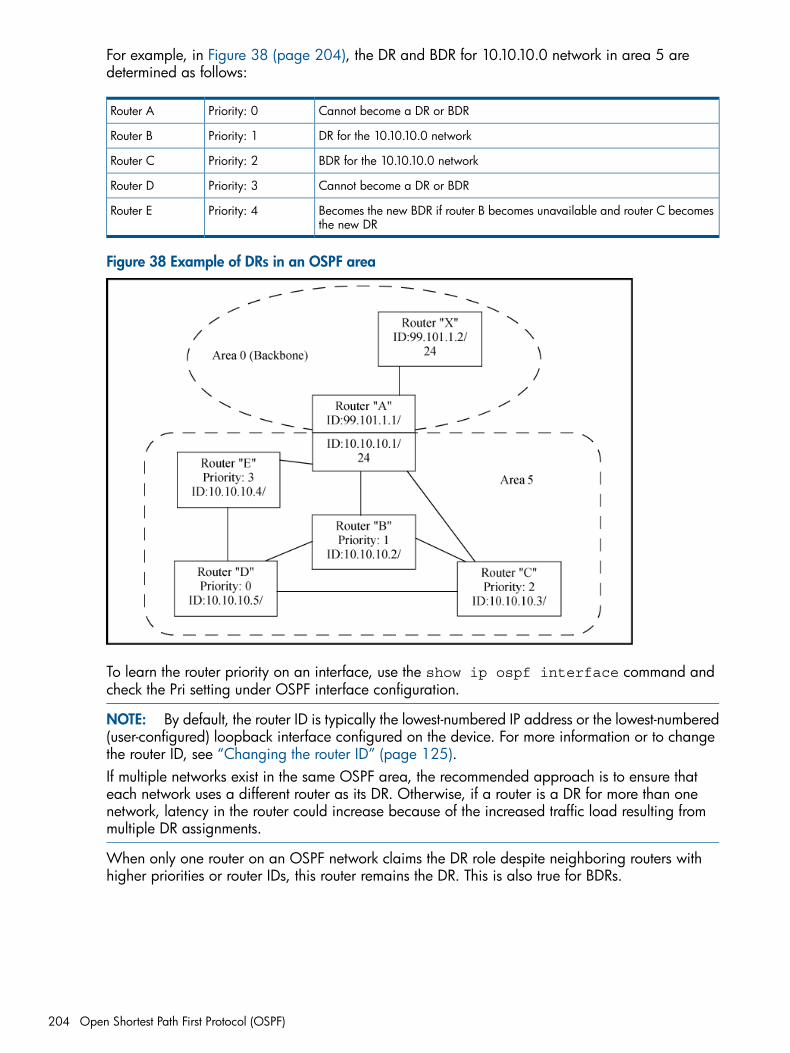
For example, in Figure 38 (page 204), the DR and BDR for 10.10.10.0 network in area 5 aredetermined as follows:
Cannot become a DR or BDRPriority: 0Router A
DR for the 10.10.10.0 networkPriority: 1Router B
BDR for the 10.10.10.0 networkPriority: 2Router C
Cannot become a DR or BDRPriority: 3Router D
Becomes the new BDR if router B becomes unavailable and router C becomesthe new DR
Priority: 4Router E
Figure 38 Example of DRs in an OSPF area
To learn the router priority on an interface, use the show ip ospf interface command andcheck the Pri setting under OSPF interface configuration.
NOTE: By default, the router ID is typically the lowest-numbered IP address or the lowest-numbered(user-configured) loopback interface configured on the device. For more information or to changethe router ID, see “Changing the router ID” (page 125).If multiple networks exist in the same OSPF area, the recommended approach is to ensure thateach network uses a different router as its DR. Otherwise, if a router is a DR for more than onenetwork, latency in the router could increase because of the increased traffic load resulting frommultiple DR assignments.
When only one router on an OSPF network claims the DR role despite neighboring routers withhigher priorities or router IDs, this router remains the DR. This is also true for BDRs.
204 Open Shortest Path First Protocol (OSPF)
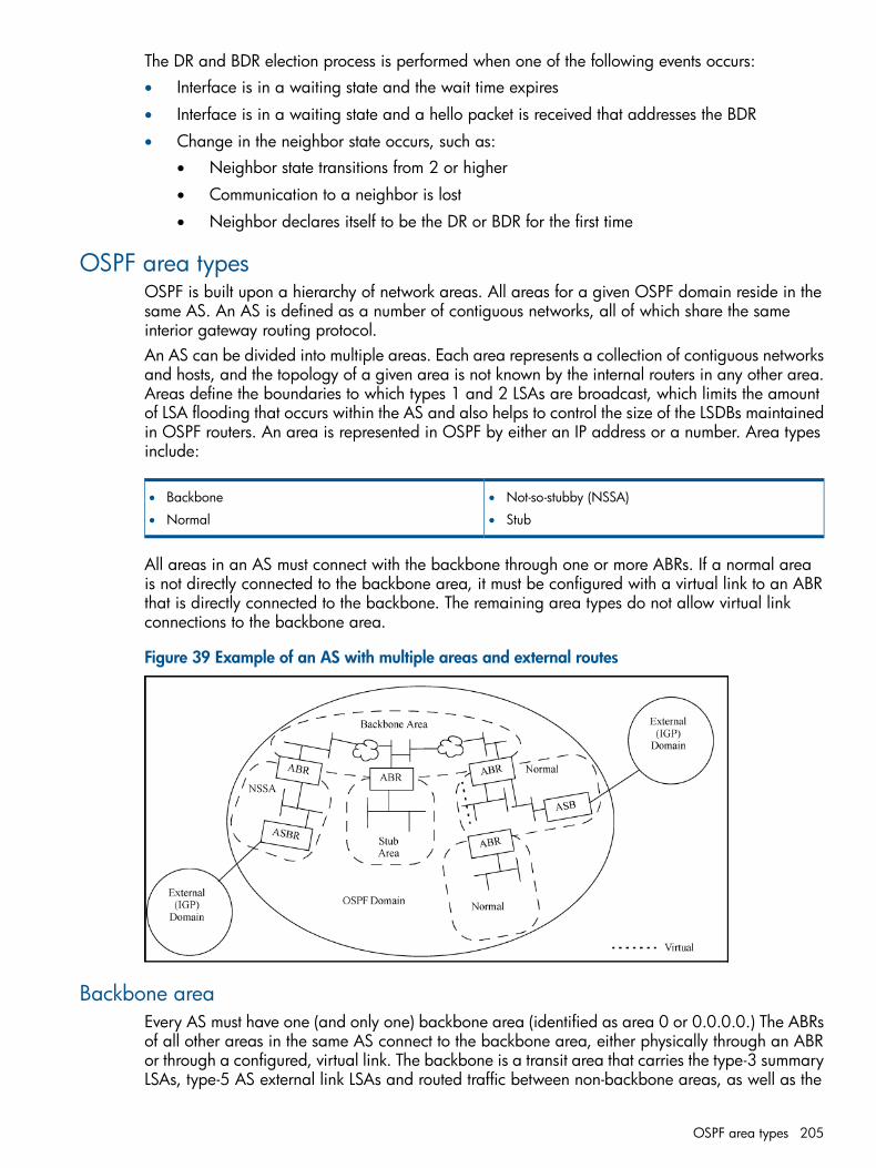
The DR and BDR election process is performed when one of the following events occurs:• Interface is in a waiting state and the wait time expires
• Interface is in a waiting state and a hello packet is received that addresses the BDR
• Change in the neighbor state occurs, such as:Neighbor state transitions from 2 or higher•
• Communication to a neighbor is lost
• Neighbor declares itself to be the DR or BDR for the first time
OSPF area typesOSPF is built upon a hierarchy of network areas. All areas for a given OSPF domain reside in thesame AS. An AS is defined as a number of contiguous networks, all of which share the sameinterior gateway routing protocol.An AS can be divided into multiple areas. Each area represents a collection of contiguous networksand hosts, and the topology of a given area is not known by the internal routers in any other area.Areas define the boundaries to which types 1 and 2 LSAs are broadcast, which limits the amountof LSA flooding that occurs within the AS and also helps to control the size of the LSDBs maintainedin OSPF routers. An area is represented in OSPF by either an IP address or a number. Area typesinclude:
• Not-so-stubby (NSSA)• Backbone
• •Normal Stub
All areas in an AS must connect with the backbone through one or more ABRs. If a normal areais not directly connected to the backbone area, it must be configured with a virtual link to an ABRthat is directly connected to the backbone. The remaining area types do not allow virtual linkconnections to the backbone area.
Figure 39 Example of an AS with multiple areas and external routes
Backbone areaEvery AS must have one (and only one) backbone area (identified as area 0 or 0.0.0.0.) The ABRsof all other areas in the same AS connect to the backbone area, either physically through an ABRor through a configured, virtual link. The backbone is a transit area that carries the type-3 summaryLSAs, type-5 AS external link LSAs and routed traffic between non-backbone areas, as well as the
OSPF area types 205
type-1 and type-2 LSAs and routed traffic internal to the area. ASBRs are allowed in backboneareas.
Normal areaThis area connects to the AS backbone area through one or more ABRs (physically or through avirtual link) and supports type-3 summary LSAs and type-5 external link LSAs to and from thebackbone area. ASBRs are allowed in normal areas.
Not-so-stubby-area (NSSA)Beginning with software release K.12.xx, this area is available and connects to the backbone areathrough one or more ABRs. NSSAs are intended for use where an ASBR exists in an area whereyou want to control the following:• Advertising the ASBR's external route paths to the backbone area
• Advertising the NSSA's summary routes to the backbone area
• Allowing LSAs from the backbone area to advertise in the NSSA:Summary routes (type-3 LSAs) from other areas•
• External routes (type-5 LSAs) from other areas as a default external route (type-7 LSAs)
In the above operation, the ASBR in the NSSA injects external routes as type 7 LSAs. (Type 5 LSAsare not allowed in an NSSA.) The ABR connecting the NSSA to the backbone converts the type 7LSAs to type 5 LSAs and injects them into the backbone area for propagation to networks in thebackbone and to any normal areas configured in the AS. The ABR also injects type-3 summaryLSAs:• From the NSSA into the backbone area
• From the backbone into the NSSAIf the ABR detects type-5 external LSAs on the backbone, it injects a corresponding type-7 LSAdefault route (0.0.0.0/0) into the NSSAYou can also configure the NSSA ABR to do the following:• Suppress advertising some or all of the area's summarized internal or external routes into the
backbone area. See “Configuring ranges on an ABR to reduce advertising to the backbone(optional)” (page 163).
• Replace all type-3 summary routes and the type-7 default route with the type-3 default summaryroute (0.0.0.0/0.)
Virtual links are not allowed for NSSAs.
Stub areaThis area connects to the AS backbone through one or more ABRs. It does not allow an internalASBR, and does not allow external (type 5) LSAs. A stub area supports these actions:• Advertise the area's summary routes to the backbone area.
• Advertise summary routes from other areas.
• Use the default summary (type-3) route to advertise both of the following:Summary routes to other areas in the AS•
• External routes to other ASs
206 Open Shortest Path First Protocol (OSPF)
You can configure the stub area ABR to do the following:• Suppress advertising some or all of the area's summarized internal routes into the backbone
area.• Suppress LSA traffic from other areas in the AS by replacing type-3 summary LSAs and the
default external route from the backbone area with the default summary route (0.0.0.0/0.)Virtual links are not allowed for stub areas.
OSPF RFC complianceThe OSFP features covered in this guide comply with the following:• RFC 2328 OSPF version 2
• RFC 3101 OSPF NSSA option (s/w release K.12.xx and greater)
• RFC 1583 (Enabled in the default OSPF configuration. See the following Note.)
• RFC 4750 MIB variables.
NOTE: If all of the routers in your OSPF domain support RFC 2178, RFC 2328, or later, youshould disable RFC 1583 compatibility on all routers in the domain. See “Changing the RFC 1583OSPF compliance setting” (page 154).
Reducing AS external LSAs and Type-3 summary LSAsAn OSPF ASBR uses AS external LSAs to originate advertisements of a route to another routingdomain, such as an RIP domain. These advertisements are• Flooded in the area in which the ASBR operates
• Injected into the backbone area and then propagated to any other OSPF areas (except stubareas) within the local OSPF AS. If the AS includes an NSSA, there are two additional options:• If the NSSA includes an ASBR, you can suppress advertising some or all of its summarized
external routes into the backbone area.• Replace all type-3 summary LSAs and the default external route from the backbone area
with the default summary route (0.0.0.0/0.)
In some cases, multiple ASBRs in an AS can originate equivalent external LSAs. The LSAs areequivalent when they have the same cost, the same next hop, and the same destination. In suchcases, the HP switch optimizes OSPF by eliminating duplicate AS external LSAs. That is, the ASBRwith the highest router ID floods the AS external LSAs for the external domain into the OSPF AS,while the other ASBRs flush the equivalent AS external LSAs from their databases. As a result, theoverall volume of route advertisement traffic within the AS is reduced and the switches that flushthe duplicate AS external LSAs have more memory for other OSPF data.This enhancement implements the portion of RFC 2328 that describes AS external LSA reduction.This enhancement is enabled by default, requires no configuration, and cannot be disabled.
OSPF RFC compliance 207
Algorithm for AS external LSA reductionThe AS external LSA reduction feature behavior changes under the following conditions:• There is one ASBR advertising (originating) a route to the external destination, but one of the
following happens:• A second ASBR comes on-line.
• A second ASBR that is already on-line begins advertising an equivalent route to the samedestination.In either of these cases, the HP switch with the higher router ID floods the AS externalLSAs and the other HP switch flushes its equivalent AS external LSAs.
• One of the ASBRs starts advertising a route that is no longer equivalent to the route the otherASBR is advertising. In this case, the ASBRs each flood AS external LSAs. Since the LSAs eitherno longer have the same cost or no longer have the same next-hop router, the LSAs are nolonger equivalent, and the LSA reduction feature no longer applies.
• The ASBR with the higher router ID becomes unavailable or is reconfigured so that it is nolonger an ASBR. In this case, the other ASBR floods the AS external LSAs.
Replacing type-3summary LSAs and type-7 default external LSAs with a type-3 defaultroute LSA
By default, a routing switch operating as an ABR for a stub area or NSSA injects non-default,summary routes (LSA type 3) into the stub areas and NSSAs. For NSSAs, the routing switch alsoinjects a type-7 default external route. You can further reduce LSA traffic into these areas by usingno-summary.This command option configures the routing switch to:• Replace type-3 summary LSA injection into a stub area or NSSA with a type-3 default summary
route (0.0.0.0/0.)• Disable injection of the type-7 default external route into an NSSA.You can enable this behavior when you first configure the stub area or NSSA, or at a later time.For the full command to use, see “Configuring a stub orNSSA area” (page 156).The no-summary command does not affect intra-area advertisements, meaning the switch stillaccepts summary LSAs from OSPF neighbors within its area and floods them to other neighbors.The switch can form adjacencies with other routers regardless of whether summarization is enabledor disabled for areas on each switch.When you use no-summary, the change takes effect immediately. If you apply the option to apreviously configured area, the switch flushes all of the summary LSAs it has generated (as an ABR)from the area.
NOTE: This feature applies only when the switch is configured as an ABR for a stub area orNSSA. To completely prevent summary LSAs from injection into the area, use no-summary todisable the summary LSAs on each OSPF router that is an ABR for the area.
To implement the above operation for a stub area or NSSA, enter a command such as the following:
HP Switch(ospf)# area 40 stub 3 no-summary
Equal cost multi-path routing (ECMP)The ECMP feature allows OSPF to add routes with multiple next-hop addresses and with equalcosts to a given destination in the forwarding information base (FIB) on the routing switch. Forexample, if you display the IP route table by entering the show ip route command, multiplenext-hop routers are listed for the same destination network (21.0.9.0/24) as shown in Example 125(page 209).
208 Open Shortest Path First Protocol (OSPF)
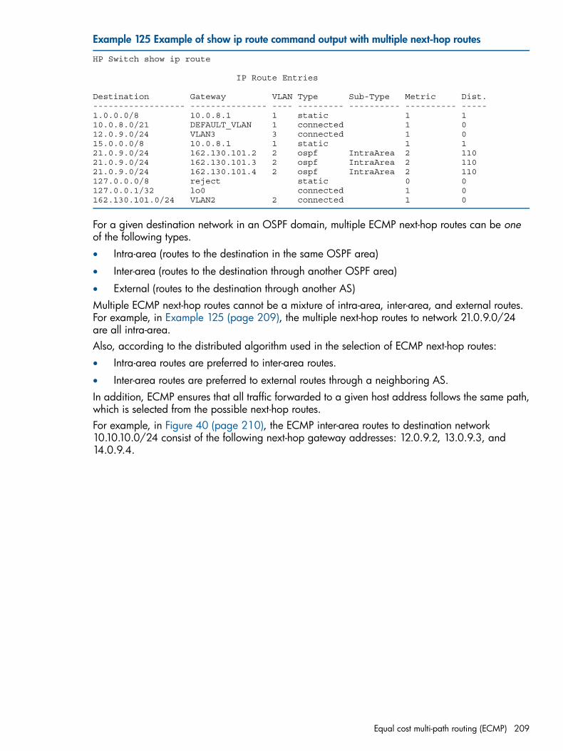
Example 125 Example of show ip route command output with multiple next-hop routes
HP Switch show ip route
IP Route Entries
Destination Gateway VLAN Type Sub-Type Metric Dist.------------------ --------------- ---- --------- ---------- ---------- -----1.0.0.0/8 10.0.8.1 1 static 1 110.0.8.0/21 DEFAULT_VLAN 1 connected 1 012.0.9.0/24 VLAN3 3 connected 1 015.0.0.0/8 10.0.8.1 1 static 1 121.0.9.0/24 162.130.101.2 2 ospf IntraArea 2 11021.0.9.0/24 162.130.101.3 2 ospf IntraArea 2 11021.0.9.0/24 162.130.101.4 2 ospf IntraArea 2 110127.0.0.0/8 reject static 0 0127.0.0.1/32 lo0 connected 1 0162.130.101.0/24 VLAN2 2 connected 1 0
For a given destination network in an OSPF domain, multiple ECMP next-hop routes can be oneof the following types.• Intra-area (routes to the destination in the same OSPF area)
• Inter-area (routes to the destination through another OSPF area)
• External (routes to the destination through another AS)Multiple ECMP next-hop routes cannot be a mixture of intra-area, inter-area, and external routes.For example, in Example 125 (page 209), the multiple next-hop routes to network 21.0.9.0/24are all intra-area.Also, according to the distributed algorithm used in the selection of ECMP next-hop routes:• Intra-area routes are preferred to inter-area routes.
• Inter-area routes are preferred to external routes through a neighboring AS.In addition, ECMP ensures that all traffic forwarded to a given host address follows the same path,which is selected from the possible next-hop routes.For example, in Figure 40 (page 210), the ECMP inter-area routes to destination network10.10.10.0/24 consist of the following next-hop gateway addresses: 12.0.9.2, 13.0.9.3, and14.0.9.4.
Equal cost multi-path routing (ECMP) 209
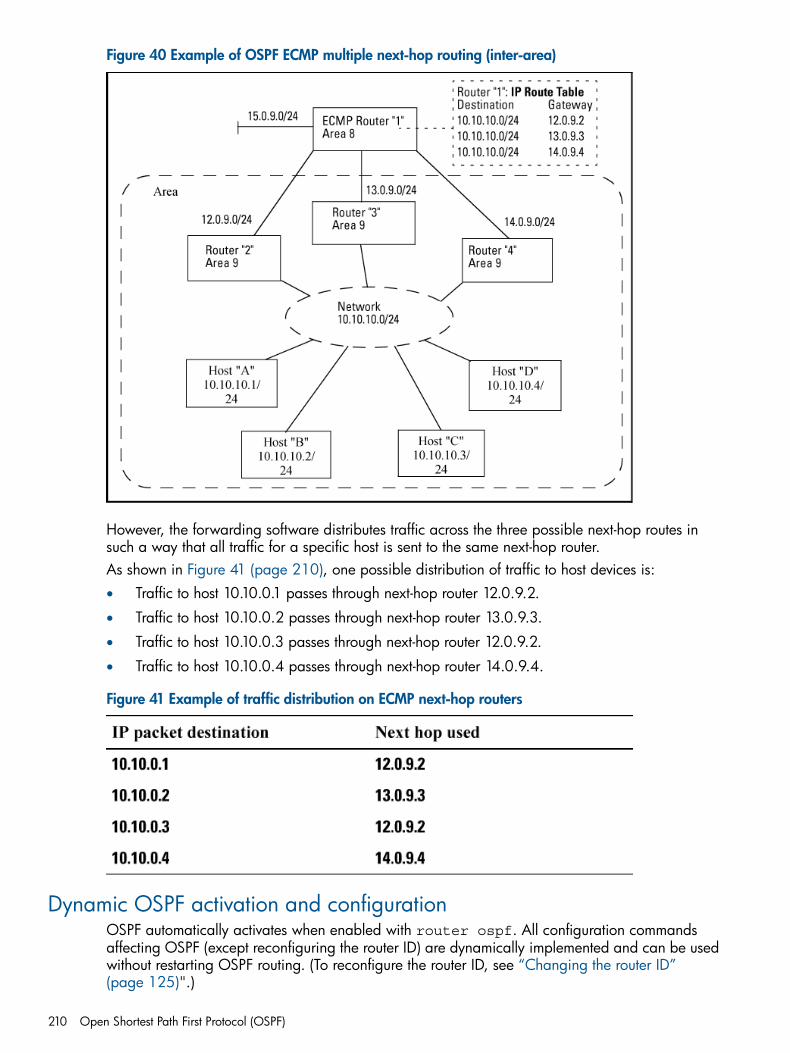
Figure 40 Example of OSPF ECMP multiple next-hop routing (inter-area)
However, the forwarding software distributes traffic across the three possible next-hop routes insuch a way that all traffic for a specific host is sent to the same next-hop router.As shown in Figure 41 (page 210), one possible distribution of traffic to host devices is:• Traffic to host 10.10.0.1 passes through next-hop router 12.0.9.2.
• Traffic to host 10.10.0.2 passes through next-hop router 13.0.9.3.
• Traffic to host 10.10.0.3 passes through next-hop router 12.0.9.2.
• Traffic to host 10.10.0.4 passes through next-hop router 14.0.9.4.
Figure 41 Example of traffic distribution on ECMP next-hop routers
Dynamic OSPF activation and configurationOSPF automatically activates when enabled with router ospf. All configuration commandsaffecting OSPF (except reconfiguring the router ID) are dynamically implemented and can be usedwithout restarting OSPF routing. (To reconfigure the router ID, see “Changing the router ID”(page 125)".)
210 Open Shortest Path First Protocol (OSPF)
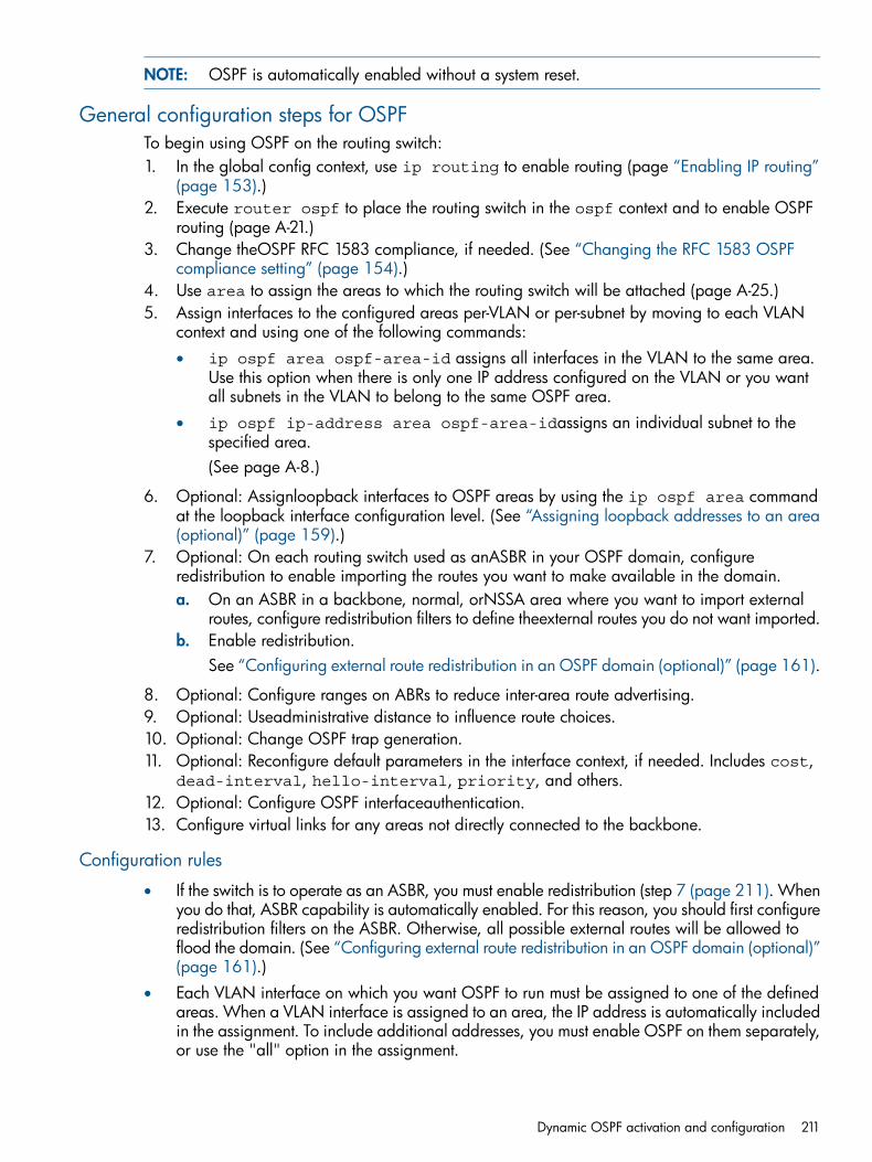
NOTE: OSPF is automatically enabled without a system reset.
General configuration steps for OSPFTo begin using OSPF on the routing switch:1. In the global config context, use ip routing to enable routing (page “Enabling IP routing”
(page 153).)2. Execute router ospf to place the routing switch in the ospf context and to enable OSPF
routing (page A-21.)3. Change theOSPF RFC 1583 compliance, if needed. (See “Changing the RFC 1583 OSPF
compliance setting” (page 154).)4. Use area to assign the areas to which the routing switch will be attached (page A-25.)5. Assign interfaces to the configured areas per-VLAN or per-subnet by moving to each VLAN
context and using one of the following commands:• ip ospf area ospf-area-id assigns all interfaces in the VLAN to the same area.
Use this option when there is only one IP address configured on the VLAN or you wantall subnets in the VLAN to belong to the same OSPF area.
• ip ospf ip-address area ospf-area-idassigns an individual subnet to thespecified area.(See page A-8.)
6. Optional: Assignloopback interfaces to OSPF areas by using the ip ospf area commandat the loopback interface configuration level. (See “Assigning loopback addresses to an area(optional)” (page 159).)
7. Optional: On each routing switch used as anASBR in your OSPF domain, configureredistribution to enable importing the routes you want to make available in the domain.a. On an ASBR in a backbone, normal, orNSSA area where you want to import external
routes, configure redistribution filters to define theexternal routes you do not want imported.b. Enable redistribution.
See “Configuring external route redistribution in an OSPF domain (optional)” (page 161).
8. Optional: Configure ranges on ABRs to reduce inter-area route advertising.9. Optional: Useadministrative distance to influence route choices.10. Optional: Change OSPF trap generation.11. Optional: Reconfigure default parameters in the interface context, if needed. Includes cost,
dead-interval, hello-interval, priority, and others.12. Optional: Configure OSPF interfaceauthentication.13. Configure virtual links for any areas not directly connected to the backbone.
Configuration rules
• If the switch is to operate as an ASBR, you must enable redistribution (step 7 (page 211). Whenyou do that, ASBR capability is automatically enabled. For this reason, you should first configureredistribution filters on the ASBR. Otherwise, all possible external routes will be allowed toflood the domain. (See “Configuring external route redistribution in an OSPF domain (optional)”(page 161).)
• Each VLAN interface on which you want OSPF to run must be assigned to one of the definedareas. When a VLAN interface is assigned to an area, the IP address is automatically includedin the assignment. To include additional addresses, you must enable OSPF on them separately,or use the "all" option in the assignment.
Dynamic OSPF activation and configuration 211
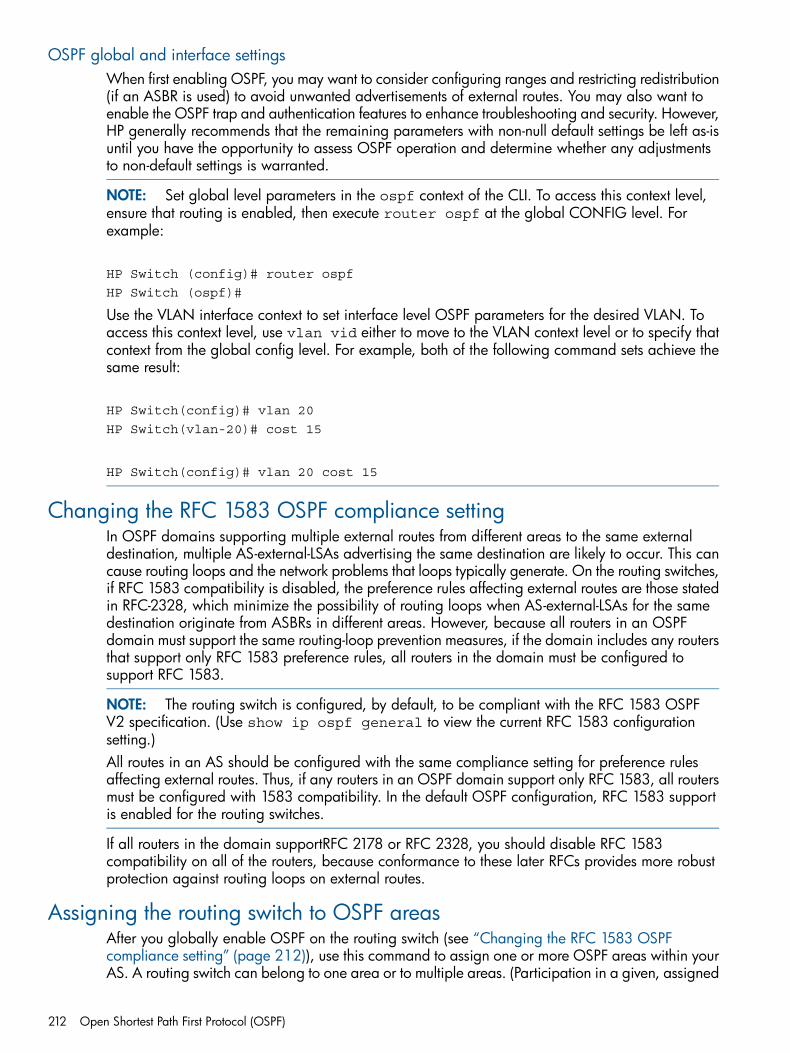
OSPF global and interface settingsWhen first enabling OSPF, you may want to consider configuring ranges and restricting redistribution(if an ASBR is used) to avoid unwanted advertisements of external routes. You may also want toenable the OSPF trap and authentication features to enhance troubleshooting and security. However,HP generally recommends that the remaining parameters with non-null default settings be left as-isuntil you have the opportunity to assess OSPF operation and determine whether any adjustmentsto non-default settings is warranted.
NOTE: Set global level parameters in the ospf context of the CLI. To access this context level,ensure that routing is enabled, then execute router ospf at the global CONFIG level. Forexample:
HP Switch (config)# router ospf
HP Switch (ospf)#
Use the VLAN interface context to set interface level OSPF parameters for the desired VLAN. Toaccess this context level, use vlan vid either to move to the VLAN context level or to specify thatcontext from the global config level. For example, both of the following command sets achieve thesame result:
HP Switch(config)# vlan 20
HP Switch(vlan-20)# cost 15
HP Switch(config)# vlan 20 cost 15
Changing the RFC 1583 OSPF compliance settingIn OSPF domains supporting multiple external routes from different areas to the same externaldestination, multiple AS-external-LSAs advertising the same destination are likely to occur. This cancause routing loops and the network problems that loops typically generate. On the routing switches,if RFC 1583 compatibility is disabled, the preference rules affecting external routes are those statedin RFC-2328, which minimize the possibility of routing loops when AS-external-LSAs for the samedestination originate from ASBRs in different areas. However, because all routers in an OSPFdomain must support the same routing-loop prevention measures, if the domain includes any routersthat support only RFC 1583 preference rules, all routers in the domain must be configured tosupport RFC 1583.
NOTE: The routing switch is configured, by default, to be compliant with the RFC 1583 OSPFV2 specification. (Use show ip ospf general to view the current RFC 1583 configurationsetting.)All routes in an AS should be configured with the same compliance setting for preference rulesaffecting external routes. Thus, if any routers in an OSPF domain support only RFC 1583, all routersmust be configured with 1583 compatibility. In the default OSPF configuration, RFC 1583 supportis enabled for the routing switches.
If all routers in the domain supportRFC 2178 or RFC 2328, you should disable RFC 1583compatibility on all of the routers, because conformance to these later RFCs provides more robustprotection against routing loops on external routes.
Assigning the routing switch to OSPF areasAfter you globally enable OSPF on the routing switch (see “Changing the RFC 1583 OSPFcompliance setting” (page 212)), use this command to assign one or more OSPF areas within yourAS. A routing switch can belong to one area or to multiple areas. (Participation in a given, assigned
212 Open Shortest Path First Protocol (OSPF)
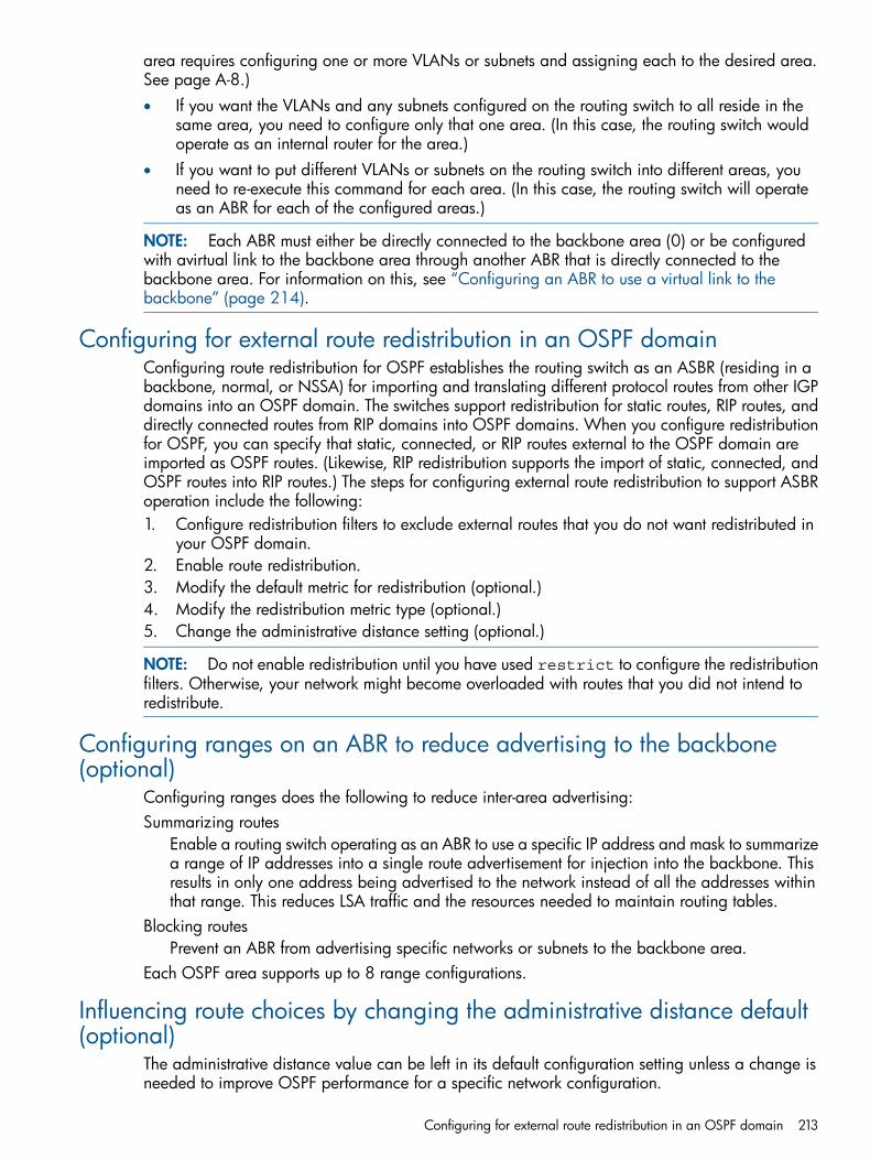
area requires configuring one or more VLANs or subnets and assigning each to the desired area.See page A-8.)• If you want the VLANs and any subnets configured on the routing switch to all reside in the
same area, you need to configure only that one area. (In this case, the routing switch wouldoperate as an internal router for the area.)
• If you want to put different VLANs or subnets on the routing switch into different areas, youneed to re-execute this command for each area. (In this case, the routing switch will operateas an ABR for each of the configured areas.)
NOTE: Each ABR must either be directly connected to the backbone area (0) or be configuredwith avirtual link to the backbone area through another ABR that is directly connected to thebackbone area. For information on this, see “Configuring an ABR to use a virtual link to thebackbone” (page 214).
Configuring for external route redistribution in an OSPF domainConfiguring route redistribution for OSPF establishes the routing switch as an ASBR (residing in abackbone, normal, or NSSA) for importing and translating different protocol routes from other IGPdomains into an OSPF domain. The switches support redistribution for static routes, RIP routes, anddirectly connected routes from RIP domains into OSPF domains. When you configure redistributionfor OSPF, you can specify that static, connected, or RIP routes external to the OSPF domain areimported as OSPF routes. (Likewise, RIP redistribution supports the import of static, connected, andOSPF routes into RIP routes.) The steps for configuring external route redistribution to support ASBRoperation include the following:1. Configure redistribution filters to exclude external routes that you do not want redistributed in
your OSPF domain.2. Enable route redistribution.3. Modify the default metric for redistribution (optional.)4. Modify the redistribution metric type (optional.)5. Change the administrative distance setting (optional.)
NOTE: Do not enable redistribution until you have used restrict to configure the redistributionfilters. Otherwise, your network might become overloaded with routes that you did not intend toredistribute.
Configuring ranges on an ABR to reduce advertising to the backbone(optional)
Configuring ranges does the following to reduce inter-area advertising:Summarizing routes
Enable a routing switch operating as an ABR to use a specific IP address and mask to summarizea range of IP addresses into a single route advertisement for injection into the backbone. Thisresults in only one address being advertised to the network instead of all the addresses withinthat range. This reduces LSA traffic and the resources needed to maintain routing tables.
Blocking routesPrevent an ABR from advertising specific networks or subnets to the backbone area.
Each OSPF area supports up to 8 range configurations.
Influencing route choices by changing the administrative distance default(optional)
The administrative distance value can be left in its default configuration setting unless a change isneeded to improve OSPF performance for a specific network configuration.
Configuring for external route redistribution in an OSPF domain 213
The switch can learn about networks from various protocols, including RIP and OSPF. Consequently,the routes to a network may differ depending on the protocol from which the routes were learned.For the switches, the administrative distance for OSPF routes is set at 110 for all route types (external,inter-area, and intra-area.)The switch selects one route over another based on the source of the route information. To do so,the switch can use the administrative distances assigned to the sources to influence route choices.You can change the distance settings in the OSPF global context to enable preference of one routetype over another.
Adjusting performance by changing the VLAN or subnet interface settings(optional)
A setting described in this section can be configured with the same value across all subnets in aVLAN or be configured on a per-interface basis with different values.
NOTE: Most of the OSPF interface parameters also apply to virtual link configurations. However,when used on a virtual link configuration, the OSPF context requirement is different and theparameters are applied only to the interfaces included in the virtual link. See “Changing the deadinterval on a virtual link” (page 173).
Configuring OSPF interface authentication (optional)OSPF supports two methods of authentication for each VLAN or subnet—simple password andMD5. In addition, the value can be disabled, meaning no authentication is performed. Only onemethod of authentication can be active on a VLAN or subnet at a time, and if one method isconfigured on an interface, configuring the alternative method on the same interface automaticallyoverwrites the first method used.In the default configuration, OSPF authentication is disabled. All interfaces in the same networkor subnet must have the same authentication method (password or MD5 key chain) and credentials.
Configuring an ABR to use a virtual link to the backboneAll ABRs must have either a direct, physical or indirect, virtual link to the OSPF backbone area(0.0.0.0 or 0.) If an ABR does not have a physical link to the area backbone, the ABR can use avirtual link to provide a logical connection to another ABR having a direct physical connection tothe area backbone. Both ABRs must belong to the same area, and this area becomes a transitarea for traffic to and from the indirectly connected ABR.
NOTE: A backbone area can be purely virtual with no physical backbone links. Also, virtuallinks can be "daisy chained." If so, the virtual link may not have one end physically connected tothe backbone.
Because both ABRs in a virtual link connection are in the same OSPF area, they use the sametransit area ID. This setting is automatically determined by the ABRs and should match the area IDvalue configured on both ABRs in the virtual link.The ABRs in a virtual link connection also identify each other with a neighbor router setting:• On the ABR having the direct connection to the backbone area, the neighbor router is the IP
address of the router interface needing a logical connection to the backbone.• On the opposite ABR (the one needing a logical connection to the backbone), the neighbor
router is the IP address of the ABR that is directly connected to the backbone.
214 Open Shortest Path First Protocol (OSPF)
NOTE: By default, therouter ID is the lowest numbered IP address or (user-configured) loopbackinterface configured on the device. For more information or to change the router ID, see "Changingthe Router ID" on page E-16.When you establish an area virtual link, you must configure it on both of the ABRs (both ends ofthe virtual link.)
Adjusting virtual link performance by changing the interface settings(optional)
The OSPF interface parameters for this process are automatically set to their default values forvirtual links. No change to the defaults is usually required unless needed for specific networkconditions. These parameters are a subset of the parameters described under “Adjusting performanceby changing the VLAN or subnet interface settings (optional)” (page 167). (The cost and prioritysettings are not configurable for a virtual link, and the commands for reconfiguring the settings areaccessed in the router OSPF context instead of the VLAN context.)
NOTE: The parameter settings for virtual links must be the same on the ABRs at both ends of agiven link.
Configuring OSPF authentication on a virtual linkOSPF supports the same two methods of authentication for virtual links as it does for VLANs andsubnets in an area—password and MD5. In the default configuration, OSPF authentication isdisabled. Only one method of authentication can be active on a virtual link at a time, and if onemethod is configured on a virtual link, configuring the alternative method on the same linkautomatically replaces the first method with the second. Both ends of a virtual link must use thesame authentication method (none, password, or MD5 key chain) and related credentials.(Anyinterfaces that share a VLAN or subnet with the interface used on an ABR for a virtual link, includingintermediate routing switches, must be configured with the same OSPF authentication.)
About OSPF passiveOSPF sends LSAs to all other routers in the same AS. To limit the flooding of LSAs throughout theAS, you can configure OSPF to be passive. OSPF does not run in the AS, but it does advertise theinterface as a stub link into OSPF. Routing updates are accepted by a passive interface, but notsent out.There is a limit of 512 total active and passive interfaces, but only a total of 128 can be activeinterfaces.
About configuring shortest path first (SPF) schedulingSPF scheduling (throttling) can be configured in intervals of seconds to potentially delay SPFcalculations when the network is unstable or there is a change in topology. It provides a granularityof one to four seconds between SPF calculations as opposed to the current default of five seconds.The interval for the SPF calculations is dynamically chosen, based on the frequency of topologychanges in the network. The chosen interval is within user-specified ranges of values. When thenetwork topology is unstable, SPF throttling calculates SPF scheduling intervals that are longer,until the topology is again stable.
NOTE: It is guaranteed that no SPF will be calculated within the SPF currently in effect, however,it is not guaranteed that the SPF will be calculated at the exact expiration of the timer if there havebeen updates. The timer may be delayed due to system constraints.
Adjusting virtual link performance by changing the interface settings (optional) 215
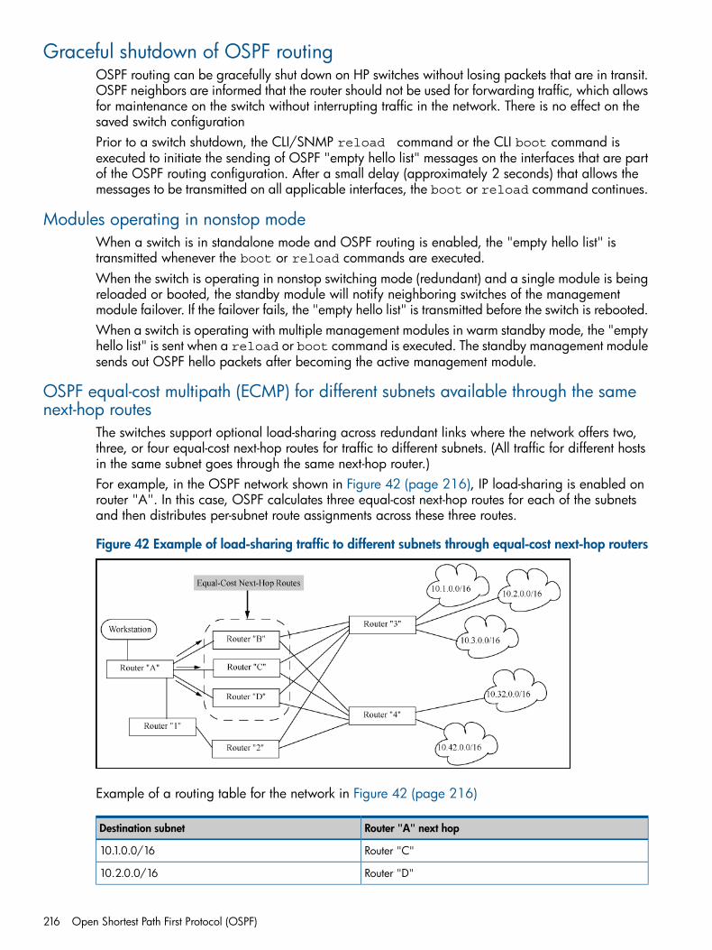
Graceful shutdown of OSPF routingOSPF routing can be gracefully shut down on HP switches without losing packets that are in transit.OSPF neighbors are informed that the router should not be used for forwarding traffic, which allowsfor maintenance on the switch without interrupting traffic in the network. There is no effect on thesaved switch configurationPrior to a switch shutdown, the CLI/SNMP reload command or the CLI boot command isexecuted to initiate the sending of OSPF "empty hello list" messages on the interfaces that are partof the OSPF routing configuration. After a small delay (approximately 2 seconds) that allows themessages to be transmitted on all applicable interfaces, the boot or reload command continues.
Modules operating in nonstop modeWhen a switch is in standalone mode and OSPF routing is enabled, the "empty hello list" istransmitted whenever the boot or reload commands are executed.When the switch is operating in nonstop switching mode (redundant) and a single module is beingreloaded or booted, the standby module will notify neighboring switches of the managementmodule failover. If the failover fails, the "empty hello list" is transmitted before the switch is rebooted.When a switch is operating with multiple management modules in warm standby mode, the "emptyhello list" is sent when a reload or boot command is executed. The standby management modulesends out OSPF hello packets after becoming the active management module.
OSPF equal-cost multipath (ECMP) for different subnets available through the samenext-hop routes
The switches support optional load-sharing across redundant links where the network offers two,three, or four equal-cost next-hop routes for traffic to different subnets. (All traffic for different hostsin the same subnet goes through the same next-hop router.)For example, in the OSPF network shown in Figure 42 (page 216), IP load-sharing is enabled onrouter "A". In this case, OSPF calculates three equal-cost next-hop routes for each of the subnetsand then distributes per-subnet route assignments across these three routes.
Figure 42 Example of load-sharing traffic to different subnets through equal-cost next-hop routers
Example of a routing table for the network in Figure 42 (page 216)
Router "A" next hopDestination subnet
Router "C"10.1.0.0/16
Router "D"10.2.0.0/16
216 Open Shortest Path First Protocol (OSPF)

Router "A" next hopDestination subnet
Router "B"10.3.0.0/16
Router "B"10.32.0.0/16
Router "D"10.42.0.0/16
IP load-sharing does not affect routed traffic to different hosts on the same subnet. That is, all trafficfor different hosts on the same subnet will go through the same next-hop router. For example, ifsubnet 10.32.0.0 includes two servers at 10.32.0.11 and 10.32.0.22, all traffic from router "A"to these servers will go through router "B".
Graceful shutdown of OSPF routing 217
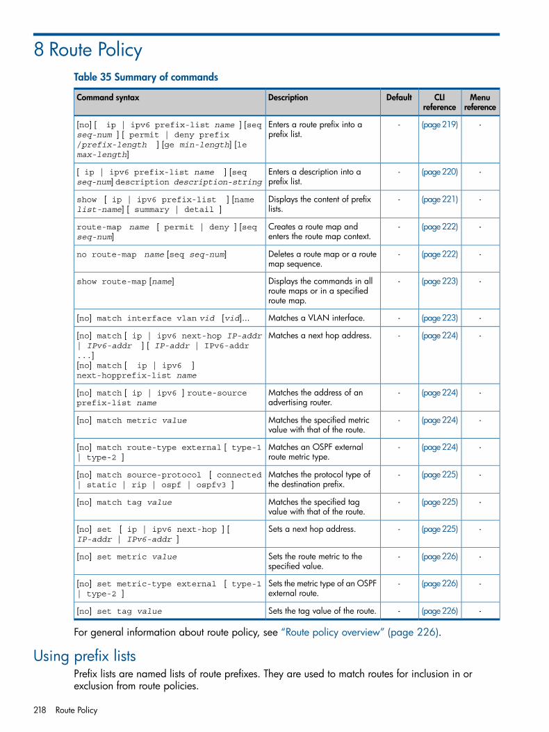
8 Route PolicyTable 35 Summary of commands
Menureference
CLIreference
DefaultDescriptionCommand syntax
-(page219)-Enters a route prefix into aprefix list.
[no] [ ip | ipv6 prefix-list name ] [seqseq-num ] [ permit | deny prefix/prefix-length ] [ge min-length] [lemax-length]
-(page220)-Enters a description into aprefix list.
[ ip | ipv6 prefix-list name ] [seqseq-num] description description-string
-(page221)-Displays the content of prefixlists.
show [ ip | ipv6 prefix-list ] [namelist-name] [ summary | detail ]
-(page222)-Creates a route map andenters the route map context.
route-map name [ permit | deny ] [seqseq-num]
-(page222)-Deletes a route map or a routemap sequence.
no route-map name [seq seq-num]
-(page223)-Displays the commands in allroute maps or in a specifiedroute map.
show route-map [name]
-(page223)-Matches a VLAN interface.[no] match interface vlan vid [vid]...
-(page224)-Matches a next hop address.[no] match [ ip | ipv6 next-hop IP-addr| IPv6-addr ] [ IP-addr | IPv6-addr...][no] match [ ip | ipv6 ]next-hopprefix-list name
-(page224)-Matches the address of anadvertising router.
[no] match [ ip | ipv6 ] route-sourceprefix-list name
-(page224)-Matches the specified metricvalue with that of the route.
[no] match metric value
-(page224)-Matches an OSPF externalroute metric type.
[no] match route-type external [ type-1| type-2 ]
-(page225)-Matches the protocol type ofthe destination prefix.
[no] match source-protocol [ connected| static | rip | ospf | ospfv3 ]
-(page225)-Matches the specified tagvalue with that of the route.
[no] match tag value
-(page225)-Sets a next hop address.[no] set [ ip | ipv6 next-hop ] [IP-addr | IPv6-addr ]
-(page226)-Sets the route metric to thespecified value.
[no] set metric value
-(page226)-Sets the metric type of an OSPFexternal route.
[no] set metric-type external [ type-1| type-2 ]
-(page226)-Sets the tag value of the route.[no] set tag value
For general information about route policy, see “Route policy overview” (page 226).
Using prefix listsPrefix lists are named lists of route prefixes. They are used to match routes for inclusion in orexclusion from route policies.
218 Route Policy
Creating prefix list entriesA prefix list can include one or more rules, each defined by a sequence number, permit or denyinstruction, prefix, and range of allowed prefix lengths.
Syntax:[no] [ ip | ipv6 prefix-list name ] [seq seq-num] [ permit | denyprefix /prefix-length ] [ge min-length] [le max-length]Enters a route prefix into a prefix list.[ ip | ipv6 ]
Specifies a list of either IPv4 (IP) or IPv6 prefixes.name
Specifies the name of the prefix list to which this prefix will be added. If thenamed list does not exist, this command creates it.To add a prefix to an existing list, specify the name of that list.
seq seq-num
Optionally specifies a sequence number for the entry. (See discussion ofsequence numbering below.)
permit
Permits the prefix when a successful match is made.deny
Denies the prefix when a successful match is made.prefix/prefix-length
Specifies an IPv4 or IPv6 network prefix and its mask length, in CIDR notation.For example: 10.1.4.1/24.
ge min-length
Specifies a minimum mask length of the prefix to match. min-length musthave a value between 1 and 32 for IPv4, or a value between 1 and 128 forIPv6.This value must be greater than or equal to prefix-length. If this optionalparameter is not specified, its value defaults to prefix-length.
le max-length
Specifies a maximum mask length of the prefix to match. max-length musthave a value between 1 and 32 for IPv4, or a value between 1 and 128 forIPv6.This value must be greater than or equal to min-length. If this optionalparameter is not specified, its value defaults to prefix-length. (If you havespecified a value for min-length that is greater than prefix-length , youmust explicitly specify le with a max-length value that is greater than orequal to min-length.)
no [ ip | ipv6 prefix-list name ]Deletes the entire prefix list identified by name.no [ ip | ipv6 prefix-list name ] [seq seq-num]Deletes the entry with the specified sequence number from the prefix list identifiedby name.Individual prefix list entries are made using separate commands in the generalconfiguration context. All entries that have the same prefix list name are part of the
Using prefix lists 219
same prefix list. Thus, the following commands, taken from a showrunning-config listing, constitute two prefix lists.
. . .ip prefix-list "Odd" seq 5 permit 10.1.1.1 255.255.255.0 ge 24 le 24ip prefix-list "Odd" seq 10 deny 10.1.2.1 255.255.255.0 ge 24 le 24ip prefix-list "Odd" seq 15 permit 10.1.3.1 255.255.255.0 ge 24 le 24ip prefix-list "Odd" seq 20 deny 10.1.4.1 255.255.255.0 ge 24 le 24ip prefix-list "Even" seq 5 deny 10.1.1.1 255.255.255.0 ge 24 le 24ip prefix-list "Even" seq 10 permit 10.1.2.1 255.255.255.0 ge 24 le 24ip prefix-list "Even" seq 15 deny 10.1.3.1 255.255.255.0 ge 24 le 24ip prefix-list "Even" seq 20 permit 10.1.4.1 255.255.255.0 ge 24 le 24 . . .
Sequence numbers, which are optional, determine the order in which prefix listentries are evaluated during match operations. If you do not specify a sequencenumber for an entry, the switch uses a number that is 5 more than the highestsequence number already used in the list. (For the first entry in a prefix list, thedefault value of the sequence number is 5.) You can insert a new entry in a prefixlist between two entries already in the list by specifying a sequence number for thenew entry that is between the sequence numbers of the two existing entries.
Entering a prefix list descriptionUse the following command to enter a description string into an existing prefix list:
Syntax:[ ip | ipv6 prefix-list name ] [seq seq-num descriptiondescription-string]Enters a description into a prefix list.[ ip | ipv6 ]
Specifies an IPv4 (IP) or IPv6 prefix list.name
Specifies the name of the prefix list to which this description will be added. Theprefix list must already exist.
seq seq-num
Optionally specifies a sequence number for the description entry. The descriptionis attached to the prefix list entry identified by that sequence number. If theprefix list does not contain an entry with that sequence number, no descriptionis entered.If you do not specify a sequence number, the description is attached to the firstentry in the prefix list at the time the description is entered.
description-string
Specifies a description string of up to 80 characters.
220 Route Policy
If you delete the entry to which the description is attached, the description is deletedalso.
Viewing prefix listsThe show ip prefix-list command displays the content of prefix lists.
Syntax:show [ ip | ipv6 prefix-list ] [name list-name] [ summary |detail ]Displays the content of prefix lists.[ ip | ipv6 ]
Specifies an IPv4 (IP) or IPv6 prefix list.name list-name
Specifies the name of the prefix list to display. If this parameter is omitted, allprefix lists are displayed.
[ summary | detail ]If neither summary nor detail is specified, the listing displays the name ofthe prefix list and each entry in the list (not including descriptions.)If summary is specified, the listing displays the name of the list and a summaryof the entries (but not the entries themselves.)If detail is specified, the listing displays the summary information, thedescription (if it exists), and the entries in the list.
ExampleIn a switch that contains two prefix lists, a standard display looks like this:
HP Switch# show ip prefix-list
ip prefix-list Odd: 4 entries seq 5 permit 10.1.1.1/24 ge 24 le 24 seq 10 deny 10.1.2.1/24 ge 24 le 24 seq 15 permit 10.1.3.1/24 ge 24 le 24 seq 20 deny 10.1.4.1/24 ge 24 le 24
ip prefix-list Even: 4 entries seq 5 deny 10.1.1.1/24 ge 24 le 24 seq 10 permit 10.1.2.1/24 ge 24 le 24 seq 15 deny 10.1.3.1/24 ge 24 le 24 seq 20 permit 10.1.4.1/24 ge 24 le 24
A summary of the prefix lists looks like this:
HP Switch# show ip prefix-list summary
ip prefix-list Odd: Count:4, Range-entries: 4, Sequences: 5 - 20
ip prefix-list Even: Count:4, Range-entries: 4, Sequences: 5 - 20
A detailed display of one of the prefix lists looks like this:
HP Switch# show ip prefix-list name Even detail
ip prefix-list Even: Count:4, Range-entries: 4, Sequences: 5 - 20
Using prefix lists 221
seq 5 deny 10.1.1.1/24 ge 24 le 24 Description: Permit even-numbered subnets
seq 10 permit 10.1.2.1/24 ge 24 le 24 seq 15 deny 10.1.3.1/24 ge 24 le 24 seq 20 permit 10.1.4.1/24 ge 24 le 24
Creating a route mapThe route-map command creates a route map sequence. It specifies a route map name, a permitor deny instruction, and, optionally, a sequence number. All sequences that have the same routemap name belong to the same route map. For more information about route maps, see “Routemaps” (page 227).
Syntax:route-map name [ permit | deny ] [seq seq-num]Creates a route map and enters the route map context.name
Specifies the name of the route map.permit
Instructs the policy engine to permit the route if the match succeeds.deny
Instructs the policy engine to deny the route if the match succeeds.seq seq-num
Specifies a sequence number for the route-map. If a sequence number is notspecified at the first instance of the route-map name command, the switchuses a default value of 10. (See below for more information on sequencenumbering.)
Deleting all or part of a route mapUse The no form of the route-map command to delete a sequence or an entire route map.
Syntax:no route-map name [seq seq-num]Deletes a route map or a route map sequence.name
Specifies the name of the route map.seq seq-num
Optional sequence number. Specifies a sequence to delete from the namedroute map.If no sequence number is specified, the entire route map is deleted.
To delete a match or set clause from a route-map, first enter the context of thatroute map and then issue The no form of the clause to delete it.
ExampleTo delete the match metric 25 clause from sequence 20 of Map4, you woulduse the following commands:
HP Switch(config)# route-map Map4 permit seq 20HP Switch(route-map-Map4-20)# no match metric 25
222 Route Policy
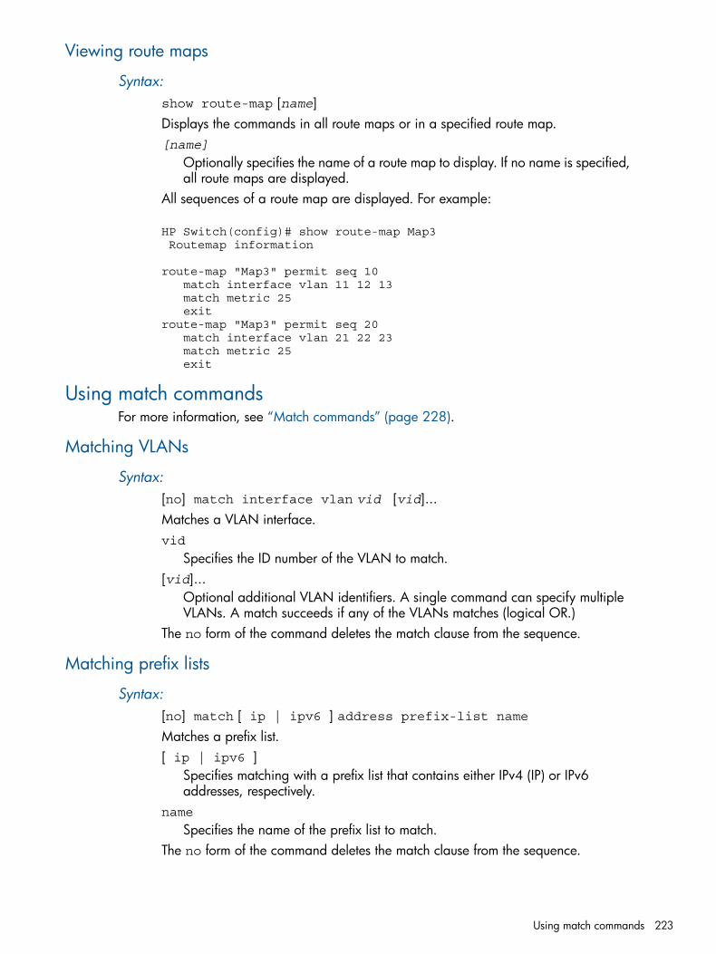
Viewing route maps
Syntax:show route-map [name]Displays the commands in all route maps or in a specified route map.[name]
Optionally specifies the name of a route map to display. If no name is specified,all route maps are displayed.
All sequences of a route map are displayed. For example:
HP Switch(config)# show route-map Map3 Routemap information
route-map "Map3" permit seq 10 match interface vlan 11 12 13 match metric 25 exitroute-map "Map3" permit seq 20 match interface vlan 21 22 23 match metric 25 exit
Using match commandsFor more information, see “Match commands” (page 228).
Matching VLANs
Syntax:[no] match interface vlan vid [vid]...Matches a VLAN interface.vid
Specifies the ID number of the VLAN to match.[vid]...
Optional additional VLAN identifiers. A single command can specify multipleVLANs. A match succeeds if any of the VLANs matches (logical OR.)
The no form of the command deletes the match clause from the sequence.
Matching prefix lists
Syntax:[no] match [ ip | ipv6 ] address prefix-list nameMatches a prefix list.[ ip | ipv6 ]
Specifies matching with a prefix list that contains either IPv4 (IP) or IPv6addresses, respectively.
name
Specifies the name of the prefix list to match.The no form of the command deletes the match clause from the sequence.
Using match commands 223
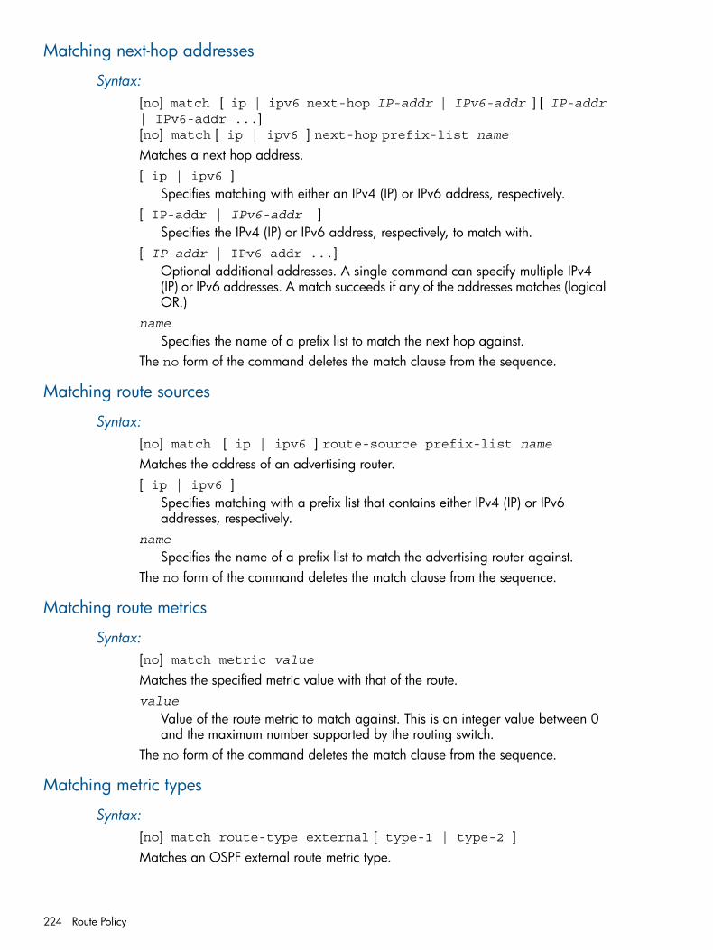
Matching next-hop addresses
Syntax:[no] match [ ip | ipv6 next-hop IP-addr | IPv6-addr ] [ IP-addr| IPv6-addr ...][no] match [ ip | ipv6 ] next-hop prefix-list name
Matches a next hop address.[ ip | ipv6 ]
Specifies matching with either an IPv4 (IP) or IPv6 address, respectively.[ IP-addr | IPv6-addr ]
Specifies the IPv4 (IP) or IPv6 address, respectively, to match with.[ IP-addr | IPv6-addr ...]
Optional additional addresses. A single command can specify multiple IPv4(IP) or IPv6 addresses. A match succeeds if any of the addresses matches (logicalOR.)
name
Specifies the name of a prefix list to match the next hop against.The no form of the command deletes the match clause from the sequence.
Matching route sources
Syntax:[no] match [ ip | ipv6 ] route-source prefix-list nameMatches the address of an advertising router.[ ip | ipv6 ]
Specifies matching with a prefix list that contains either IPv4 (IP) or IPv6addresses, respectively.
name
Specifies the name of a prefix list to match the advertising router against.The no form of the command deletes the match clause from the sequence.
Matching route metrics
Syntax:[no] match metric valueMatches the specified metric value with that of the route.value
Value of the route metric to match against. This is an integer value between 0and the maximum number supported by the routing switch.
The no form of the command deletes the match clause from the sequence.
Matching metric types
Syntax:[no] match route-type external [ type-1 | type-2 ]Matches an OSPF external route metric type.
224 Route Policy
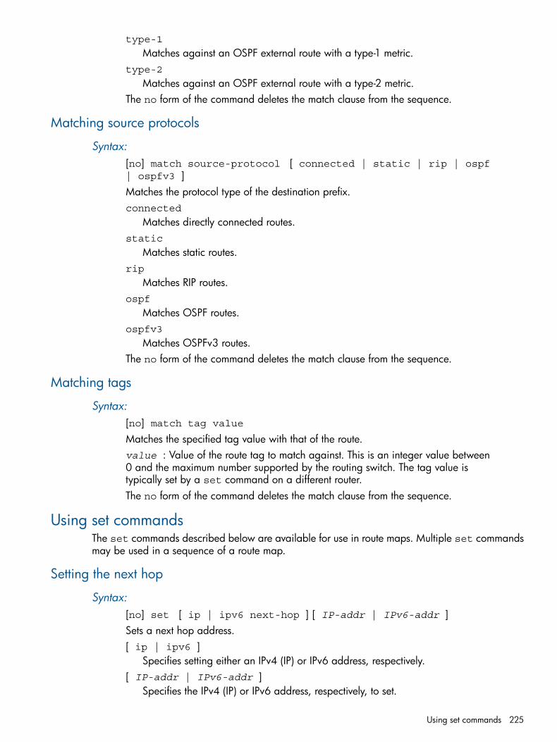
type-1
Matches against an OSPF external route with a type-1 metric.type-2
Matches against an OSPF external route with a type-2 metric.The no form of the command deletes the match clause from the sequence.
Matching source protocols
Syntax:[no] match source-protocol [ connected | static | rip | ospf| ospfv3 ]Matches the protocol type of the destination prefix.connected
Matches directly connected routes.static
Matches static routes.rip
Matches RIP routes.ospf
Matches OSPF routes.ospfv3
Matches OSPFv3 routes.The no form of the command deletes the match clause from the sequence.
Matching tags
Syntax:[no] match tag valueMatches the specified tag value with that of the route.value : Value of the route tag to match against. This is an integer value between0 and the maximum number supported by the routing switch. The tag value istypically set by a set command on a different router.The no form of the command deletes the match clause from the sequence.
Using set commandsThe set commands described below are available for use in route maps. Multiple set commandsmay be used in a sequence of a route map.
Setting the next hop
Syntax:[no] set [ ip | ipv6 next-hop ] [ IP-addr | IPv6-addr ]Sets a next hop address.[ ip | ipv6 ]
Specifies setting either an IPv4 (IP) or IPv6 address, respectively.[ IP-addr | IPv6-addr ]
Specifies the IPv4 (IP) or IPv6 address, respectively, to set.
Using set commands 225
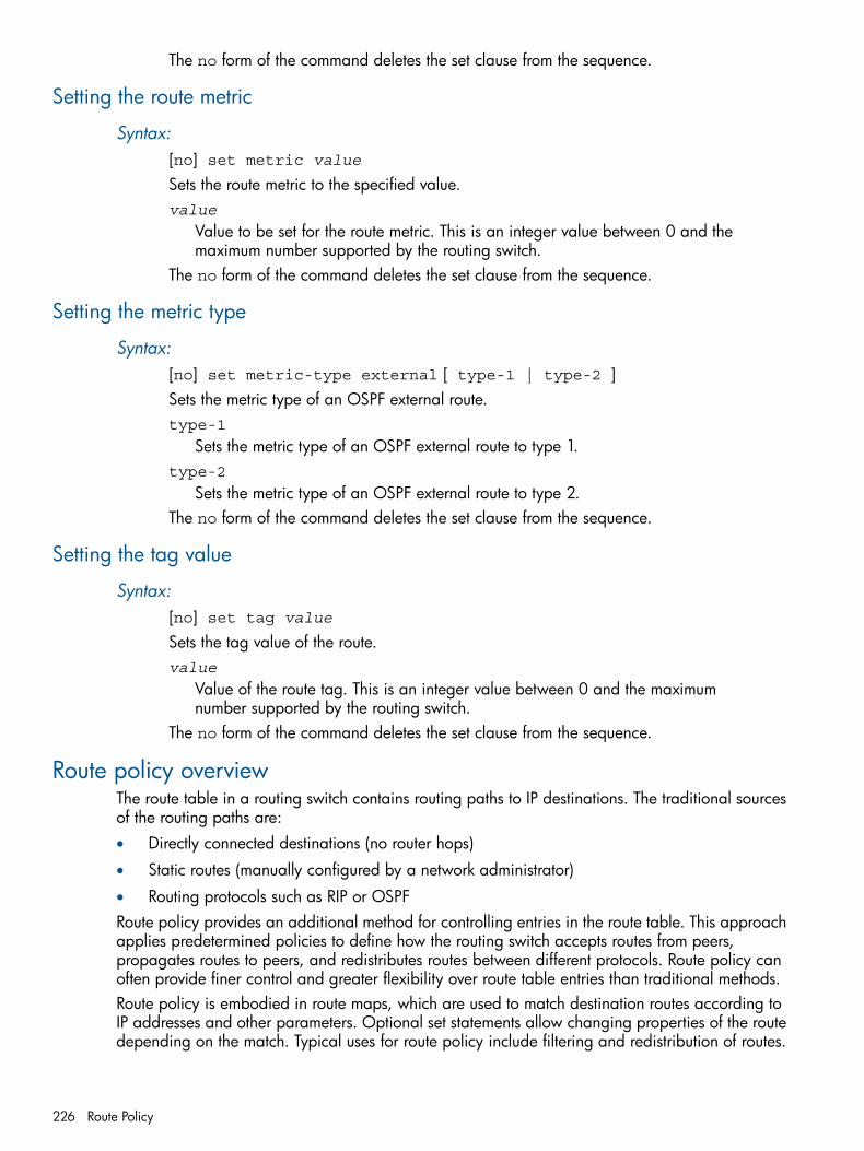
The no form of the command deletes the set clause from the sequence.
Setting the route metric
Syntax:[no] set metric valueSets the route metric to the specified value.value
Value to be set for the route metric. This is an integer value between 0 and themaximum number supported by the routing switch.
The no form of the command deletes the set clause from the sequence.
Setting the metric type
Syntax:[no] set metric-type external [ type-1 | type-2 ]Sets the metric type of an OSPF external route.type-1
Sets the metric type of an OSPF external route to type 1.type-2
Sets the metric type of an OSPF external route to type 2.The no form of the command deletes the set clause from the sequence.
Setting the tag value
Syntax:[no] set tag valueSets the tag value of the route.value
Value of the route tag. This is an integer value between 0 and the maximumnumber supported by the routing switch.
The no form of the command deletes the set clause from the sequence.
Route policy overviewThe route table in a routing switch contains routing paths to IP destinations. The traditional sourcesof the routing paths are:• Directly connected destinations (no router hops)
• Static routes (manually configured by a network administrator)
• Routing protocols such as RIP or OSPFRoute policy provides an additional method for controlling entries in the route table. This approachapplies predetermined policies to define how the routing switch accepts routes from peers,propagates routes to peers, and redistributes routes between different protocols. Route policy canoften provide finer control and greater flexibility over route table entries than traditional methods.Route policy is embodied in route maps, which are used to match destination routes according toIP addresses and other parameters. Optional set statements allow changing properties of the routedepending on the match. Typical uses for route policy include filtering and redistribution of routes.
226 Route Policy
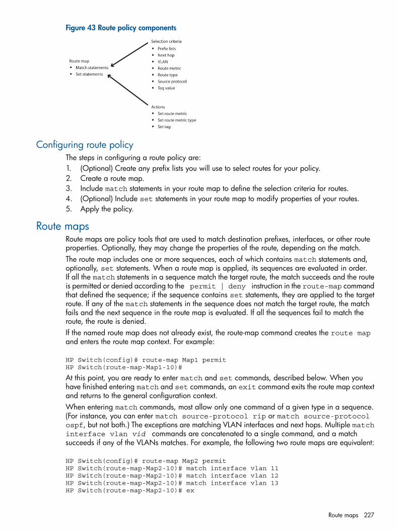
Figure 43 Route policy components
Configuring route policyThe steps in configuring a route policy are:1. (Optional) Create any prefix lists you will use to select routes for your policy.2. Create a route map.3. Include match statements in your route map to define the selection criteria for routes.4. (Optional) Include set statements in your route map to modify properties of your routes.5. Apply the policy.
Route mapsRoute maps are policy tools that are used to match destination prefixes, interfaces, or other routeproperties. Optionally, they may change the properties of the route, depending on the match.The route map includes one or more sequences, each of which contains match statements and,optionally, set statements. When a route map is applied, its sequences are evaluated in order.If all the match statements in a sequence match the target route, the match succeeds and the routeis permitted or denied according to the permit | deny instruction in the route-map commandthat defined the sequence; if the sequence contains set statements, they are applied to the targetroute. If any of the match statements in the sequence does not match the target route, the matchfails and the next sequence in the route map is evaluated. If all the sequences fail to match theroute, the route is denied.If the named route map does not already exist, the route-map command creates the route mapand enters the route map context. For example:
HP Switch(config)# route-map Map1 permitHP Switch(route-map-Map1-10)#
At this point, you are ready to enter match and set commands, described below. When youhave finished entering match and set commands, an exit command exits the route map contextand returns to the general configuration context.When entering match commands, most allow only one command of a given type in a sequence.(For instance, you can enter match source-protocol rip or match source-protocolospf, but not both.) The exceptions are matching VLAN interfaces and next hops. Multiple matchinterface vlan vid commands are concatenated to a single command, and a matchsucceeds if any of the VLANs matches. For example, the following two route maps are equivalent:
HP Switch(config)# route-map Map2 permitHP Switch(route-map-Map2-10)# match interface vlan 11HP Switch(route-map-Map2-10)# match interface vlan 12HP Switch(route-map-Map2-10)# match interface vlan 13HP Switch(route-map-Map2-10)# ex
Route maps 227
HP Switch(config)# route-map Map3 permitHP Switch(route-map-Map3-10)# match interface vlan 11 12 13HP Switch(route-map-Map3-10)# ex
Similarly, multiple instances of the match ip next-hop IP-addr and match ipv6next-hop IPv6-addr commands are concatenated internally into single commands,respectively.The general limitation of only one match command of a given type applies within a sequence. Thesame type of match command can be repeated in other sequences in the same route map.All of the match clauses of the sequence must match for a match to succeed. (For this purpose,multiple match interface vlan, match ip next-hop, and match ipv6 next-hopclauses are treated as a single clause. In such a clause, the interfaces or next hops are treated inlogical OR fashion: if there is a match with any one of them, the match clause succeeds.)A match sequence that contains no match commands will permit all routes. (Such a sequence maybe used in a route map that denies certain routes but permits all others.)Like most match commands, set commands allow only one command of a given type in asequence. So, for instance, if a match sequence is successful, you can set a metric of 23, but notmetrics of 23 and 25 simultaneously.To re-enter the context of an existing route map that has only one sequence (say, to add or deletematch or set statements), the sequence number is optional: route-map name permit | deny. If the route-map has more than one sequence, the sequence number is required: route-mapname permit | deny seq seq-num .To create a new sequence in an existing route map (that is, under the same route map name), usethe route-map command with a different sequence number. Sequence numbers are significant:they determine the order of evaluation of sequences in route maps—the sequence with the lowestnumber is evaluated first.
Match commandsThe match commands described in this chapter are available for use in route maps.Multiple match commands may be used in a sequence of a route map. For most commands, onlyone match of a given type is permitted in a sequence. For the match interface vlan vid, match ip next-hop IP-addr , and match ipv6 next-hop IPv6-addr commands,multiple instances of those commands are permitted in a single sequence, because all instancesof those commands in a sequence are concatenated internally into single commands, respectively.
Using route policy in route redistributionThe following examples show some basic uses of route policy based on the figure below. (Allsubnets have 24-bit masks.)
228 Route Policy
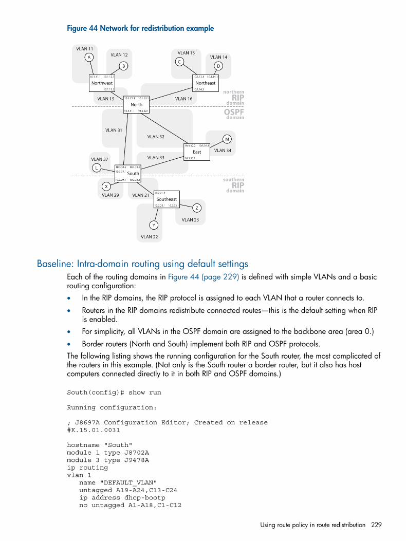
Figure 44 Network for redistribution example
Baseline: Intra-domain routing using default settingsEach of the routing domains in Figure 44 (page 229) is defined with simple VLANs and a basicrouting configuration:• In the RIP domains, the RIP protocol is assigned to each VLAN that a router connects to.
• Routers in the RIP domains redistribute connected routes—this is the default setting when RIPis enabled.
• For simplicity, all VLANs in the OSPF domain are assigned to the backbone area (area 0.)
• Border routers (North and South) implement both RIP and OSPF protocols.The following listing shows the running configuration for the South router, the most complicated ofthe routers in this example. (Not only is the South router a border router, but it also has hostcomputers connected directly to it in both RIP and OSPF domains.)
South(config)# show run
Running configuration:
; J8697A Configuration Editor; Created on release#K.15.01.0031
hostname "South"module 1 type J8702Amodule 3 type J9478Aip routingvlan 1 name "DEFAULT_VLAN" untagged A19-A24,C13-C24 ip address dhcp-bootp no untagged A1-A18,C1-C12
Using route policy in route redistribution 229
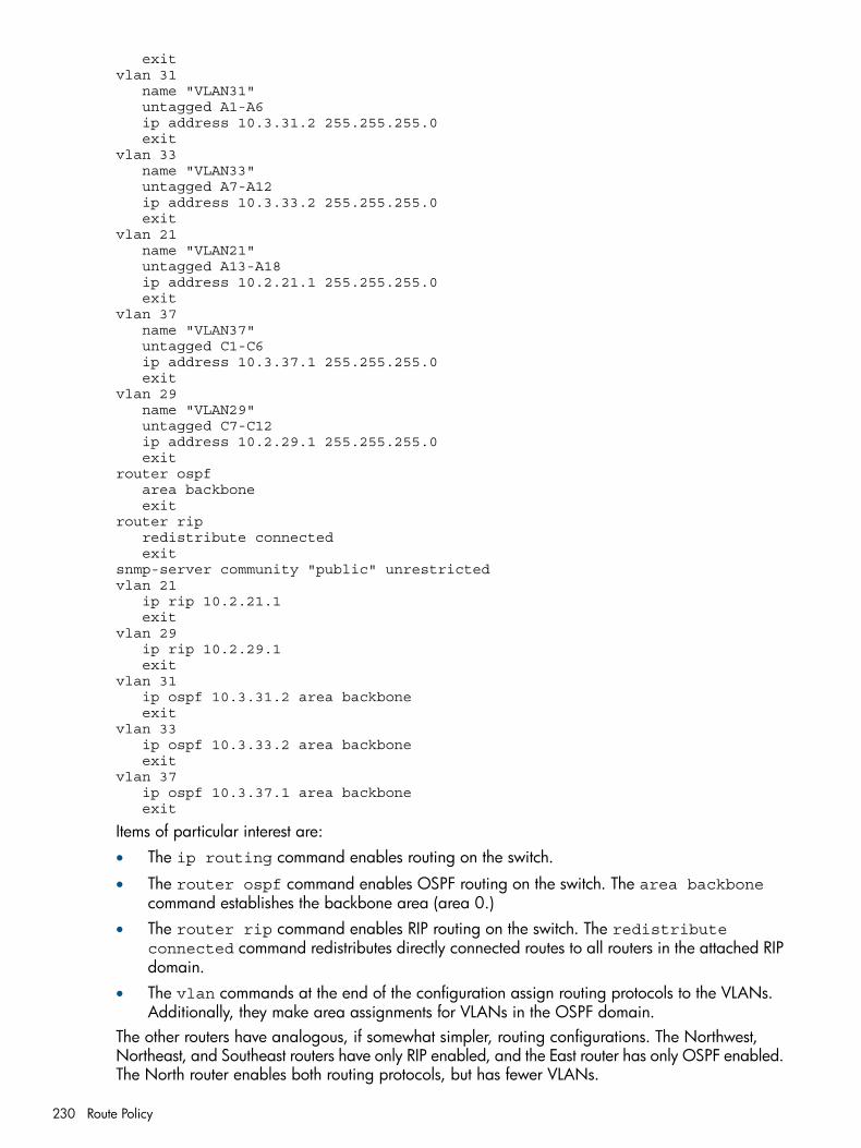
exitvlan 31 name "VLAN31" untagged A1-A6 ip address 10.3.31.2 255.255.255.0 exitvlan 33 name "VLAN33" untagged A7-A12 ip address 10.3.33.2 255.255.255.0 exitvlan 21 name "VLAN21" untagged A13-A18 ip address 10.2.21.1 255.255.255.0 exitvlan 37 name "VLAN37" untagged C1-C6 ip address 10.3.37.1 255.255.255.0 exitvlan 29 name "VLAN29" untagged C7-C12 ip address 10.2.29.1 255.255.255.0 exitrouter ospf area backbone exitrouter rip redistribute connected exitsnmp-server community "public" unrestrictedvlan 21 ip rip 10.2.21.1 exitvlan 29 ip rip 10.2.29.1 exitvlan 31 ip ospf 10.3.31.2 area backbone exitvlan 33 ip ospf 10.3.33.2 area backbone exitvlan 37 ip ospf 10.3.37.1 area backbone exit
Items of particular interest are:• The ip routing command enables routing on the switch.
• The router ospf command enables OSPF routing on the switch. The area backbonecommand establishes the backbone area (area 0.)
• The router rip command enables RIP routing on the switch. The redistributeconnected command redistributes directly connected routes to all routers in the attached RIPdomain.
• The vlan commands at the end of the configuration assign routing protocols to the VLANs.Additionally, they make area assignments for VLANs in the OSPF domain.
The other routers have analogous, if somewhat simpler, routing configurations. The Northwest,Northeast, and Southeast routers have only RIP enabled, and the East router has only OSPF enabled.The North router enables both routing protocols, but has fewer VLANs.
230 Route Policy
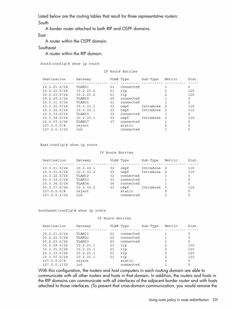
Listed below are the routing tables that result for three representative routers:South
A border router attached to both RIP and OSPF domains.East
A router within the OSPF domain.Southeast
A router within the RIP domain.
South(config)# show ip route
IP Route Entries
Destination Gateway VLAN Type Sub-Type Metric Dist. --------------- --------------- ---- --------- ---------- ---------- ----- 10.2.21.0/24 VLAN21 21 connected 1 0 10.2.22.0/24 10.2.21.2 21 rip 2 120 10.2.23.0/24 10.2.21.2 21 rip 2 120 10.2.29.0/24 VLAN29 29 connected 1 0 10.3.31.0/24 VLAN31 31 connected 1 0 10.3.32.0/24 10.3.31.1 31 ospf IntraArea 2 110 10.3.32.0/24 10.3.33.1 33 ospf IntraArea 2 110 10.3.33.0/24 VLAN33 33 connected 1 0 10.3.34.0/24 10.3.33.1 33 ospf IntraArea 2 110 10.3.37.0/24 VLAN37 37 connected 1 0 127.0.0.0/8 reject static 0 0 127.0.0.1/32 lo0 connected 1 0
East(config)# show ip route
IP Route Entries
Destination Gateway VLAN Type Sub-Type Metric Dist. --------------- --------------- ---- --------- ---------- ---------- ----- 10.3.31.0/24 10.3.32.1 32 ospf IntraArea 2 110 10.3.31.0/24 10.3.33.2 33 ospf IntraArea 2 110 10.3.32.0/24 VLAN32 32 connected 1 0 10.3.33.0/24 VLAN33 33 connected 1 0 10.3.34.0/24 VLAN34 34 connected 1 0 10.3.37.0/24 10.3.33.2 33 ospf IntraArea 2 110 127.0.0.0/8 reject static 0 0 127.0.0.1/32 lo0 connected 1 0
Southeast(config)# show ip route
IP Route Entries
Destination Gateway VLAN Type Sub-Type Metric Dist. --------------- --------------- ---- --------- ---------- ---------- ----- 10.2.21.0/24 VLAN21 21 connected 1 0 10.2.22.0/24 VLAN22 22 connected 1 0 10.2.23.0/24 VLAN23 23 connected 1 0 10.2.29.0/24 10.2.21.1 21 rip 2 120 10.3.31.0/24 10.2.21.1 21 rip 2 120 10.3.33.0/24 10.2.21.1 21 rip 2 120 10.3.37.0/24 10.2.21.1 21 rip 2 120 127.0.0.0/8 reject static 0 0 127.0.0.1/32 lo0 connected 1 0
With this configuration, the routers and host computers in each routing domain are able tocommunicate with all other routers and hosts in that domain. In addition, the routers and hosts inthe RIP domains can communicate with all interfaces of the adjacent border router and with hostsattached to those interfaces. (To prevent that cross-domain communication, you would remove the
Using route policy in route redistribution 231
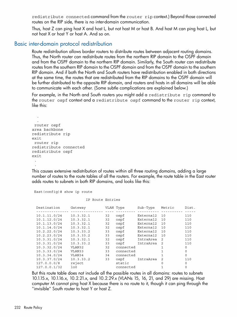
redistribute connected command from the router rip context.) Beyond those connectedroutes on the RIP side, there is no inter-domain communication.Thus, host Z can ping host X and host L, but not host M or host B. And host M can ping host L, butnot host X or host Y or host A. And so on.
Basic inter-domain protocol redistributionRoute redistribution allows border routers to distribute routes between adjacent routing domains.Thus, the North router can redistribute routes from the northern RIP domain to the OSPF domainand from the OSPF domain to the northern RIP domain. Similarly, the South router can redistributeroutes from the southern RIP domain to the OSPF domain and from the OSPF domain to the southernRIP domain. And if both the North and South routers have redistribution enabled in both directionsat the same time, the routes that are redistributed from the RIP domains to the OSPF domain willbe further distributed to the opposite RIP domain, and routers and hosts in all domains will be ableto communicate with each other. (Some subtle complications are explained below.)For example, in the North and South routers you might add a redistribute rip command tothe router ospf context and a redistribute ospf command to the router rip context,like this:
. . router ospf area backbone redistribute rip exit router rip redistribute connected redistribute ospf exit . .
This causes extensive redistribution of routes within all three routing domains, adding a largenumber of routes to the route tables of all the routers. For example, the route table in the East routeradds routes to subnets in both RIP domains, and looks like this:
East(config)# show ip route
IP Route Entries
Destination Gateway VLAN Type Sub-Type Metric Dist. --------------- --------------- ---- --------- ---------- ---------- ----- 10.1.11.0/24 10.3.32.1 32 ospf External2 10 110 10.1.12.0/24 10.3.32.1 32 ospf External2 10 110 10.1.13.0/24 10.3.32.1 32 ospf External2 10 110 10.1.14.0/24 10.3.32.1 32 ospf External2 10 110 10.2.22.0/24 10.3.33.2 33 ospf External2 10 110 10.2.23.0/24 10.3.33.2 33 ospf External2 10 110 10.3.31.0/24 10.3.32.1 32 ospf IntraArea 2 110 10.3.31.0/24 10.3.33.2 33 ospf IntraArea 2 110 10.3.32.0/24 VLAN32 32 connected 1 0 10.3.33.0/24 VLAN33 33 connected 1 0 10.3.34.0/24 VLAN34 34 connected 1 0 10.3.37.0/24 10.3.33.2 33 ospf IntraArea 2 110 127.0.0.0/8 reject static 0 0 127.0.0.1/32 lo0 connected 1 0
But this route table does not include all the possible routes in all domains: routes to subnets10.1.15.x, 10.1.16.x, 10.2.21.x, and 10.2.29.x (VLANs 15, 16, 21, and 29) are missing. Hostcomputer M cannot ping host X because there is no route to it, though it can ping through the"invisible" South router to host Y or host Z.
232 Route Policy
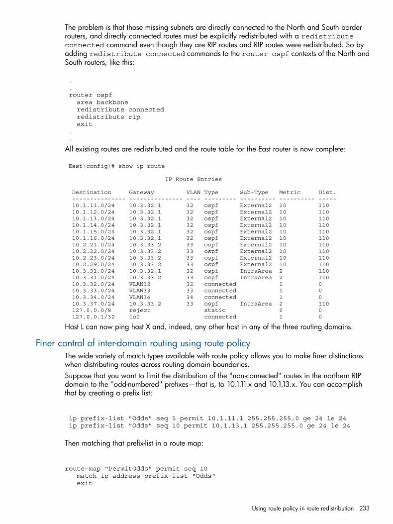
The problem is that those missing subnets are directly connected to the North and South borderrouters, and directly connected routes must be explicitly redistributed with a redistributeconnected command even though they are RIP routes and RIP routes were redistributed. So byadding redistribute connected commands to the router ospf contexts of the North andSouth routers, like this:
. . router ospf area backbone redistribute connected redistribute rip exit . .
All existing routes are redistributed and the route table for the East router is now complete:
East(config)# show ip route
IP Route Entries
Destination Gateway VLAN Type Sub-Type Metric Dist. --------------- --------------- ---- --------- ---------- ---------- ----- 10.1.11.0/24 10.3.32.1 32 ospf External2 10 110 10.1.12.0/24 10.3.32.1 32 ospf External2 10 110 10.1.13.0/24 10.3.32.1 32 ospf External2 10 110 10.1.14.0/24 10.3.32.1 32 ospf External2 10 110 10.1.15.0/24 10.3.32.1 32 ospf External2 10 110 10.1.16.0/24 10.3.32.1 32 ospf External2 10 110 10.2.21.0/24 10.3.33.2 33 ospf External2 10 110 10.2.22.0/24 10.3.33.2 33 ospf External2 10 110 10.2.23.0/24 10.3.33.2 33 ospf External2 10 110 10.2.29.0/24 10.3.33.2 33 ospf External2 10 110 10.3.31.0/24 10.3.32.1 32 ospf IntraArea 2 110 10.3.31.0/24 10.3.33.2 33 ospf IntraArea 2 110 10.3.32.0/24 VLAN32 32 connected 1 0 10.3.33.0/24 VLAN33 33 connected 1 0 10.3.34.0/24 VLAN34 34 connected 1 0 10.3.37.0/24 10.3.33.2 33 ospf IntraArea 2 110 127.0.0.0/8 reject static 0 0 127.0.0.1/32 lo0 connected 1 0
Host L can now ping host X and, indeed, any other host in any of the three routing domains.
Finer control of inter-domain routing using route policyThe wide variety of match types available with route policy allows you to make finer distinctionswhen distributing routes across routing domain boundaries.Suppose that you want to limit the distribution of the "non-connected" routes in the northern RIPdomain to the "odd-numbered" prefixes—that is, to 10.1.11.x and 10.1.13.x. You can accomplishthat by creating a prefix list:
ip prefix-list "Odds" seq 5 permit 10.1.11.1 255.255.255.0 ge 24 le 24 ip prefix-list "Odds" seq 10 permit 10.1.13.1 255.255.255.0 ge 24 le 24
Then matching that prefix-list in a route map:
route-map "PermitOdds" permit seq 10 match ip address prefix-list "Odds" exit
Using route policy in route redistribution 233
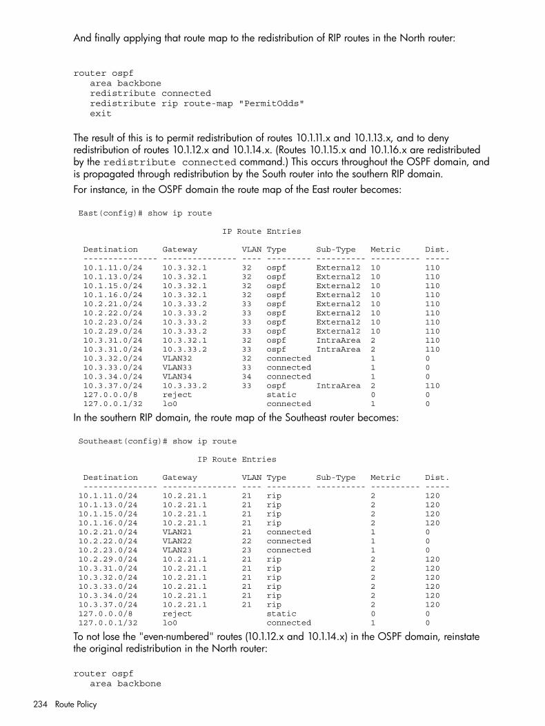
And finally applying that route map to the redistribution of RIP routes in the North router:
router ospf area backbone redistribute connected redistribute rip route-map "PermitOdds" exit
The result of this is to permit redistribution of routes 10.1.11.x and 10.1.13.x, and to denyredistribution of routes 10.1.12.x and 10.1.14.x. (Routes 10.1.15.x and 10.1.16.x are redistributedby the redistribute connected command.) This occurs throughout the OSPF domain, andis propagated through redistribution by the South router into the southern RIP domain.For instance, in the OSPF domain the route map of the East router becomes:
East(config)# show ip route
IP Route Entries
Destination Gateway VLAN Type Sub-Type Metric Dist. --------------- --------------- ---- --------- ---------- ---------- ----- 10.1.11.0/24 10.3.32.1 32 ospf External2 10 110 10.1.13.0/24 10.3.32.1 32 ospf External2 10 110 10.1.15.0/24 10.3.32.1 32 ospf External2 10 110 10.1.16.0/24 10.3.32.1 32 ospf External2 10 110 10.2.21.0/24 10.3.33.2 33 ospf External2 10 110 10.2.22.0/24 10.3.33.2 33 ospf External2 10 110 10.2.23.0/24 10.3.33.2 33 ospf External2 10 110 10.2.29.0/24 10.3.33.2 33 ospf External2 10 110 10.3.31.0/24 10.3.32.1 32 ospf IntraArea 2 110 10.3.31.0/24 10.3.33.2 33 ospf IntraArea 2 110 10.3.32.0/24 VLAN32 32 connected 1 0 10.3.33.0/24 VLAN33 33 connected 1 0 10.3.34.0/24 VLAN34 34 connected 1 0 10.3.37.0/24 10.3.33.2 33 ospf IntraArea 2 110 127.0.0.0/8 reject static 0 0 127.0.0.1/32 lo0 connected 1 0
In the southern RIP domain, the route map of the Southeast router becomes:
Southeast(config)# show ip route
IP Route Entries
Destination Gateway VLAN Type Sub-Type Metric Dist. --------------- --------------- ---- --------- ---------- ---------- ----- 10.1.11.0/24 10.2.21.1 21 rip 2 120 10.1.13.0/24 10.2.21.1 21 rip 2 120 10.1.15.0/24 10.2.21.1 21 rip 2 120 10.1.16.0/24 10.2.21.1 21 rip 2 120 10.2.21.0/24 VLAN21 21 connected 1 0 10.2.22.0/24 VLAN22 22 connected 1 0 10.2.23.0/24 VLAN23 23 connected 1 0 10.2.29.0/24 10.2.21.1 21 rip 2 120 10.3.31.0/24 10.2.21.1 21 rip 2 120 10.3.32.0/24 10.2.21.1 21 rip 2 120 10.3.33.0/24 10.2.21.1 21 rip 2 120 10.3.34.0/24 10.2.21.1 21 rip 2 120 10.3.37.0/24 10.2.21.1 21 rip 2 120 127.0.0.0/8 reject static 0 0 127.0.0.1/32 lo0 connected 1 0
To not lose the "even-numbered" routes (10.1.12.x and 10.1.14.x) in the OSPF domain, reinstatethe original redistribution in the North router:
router ospf area backbone
234 Route Policy
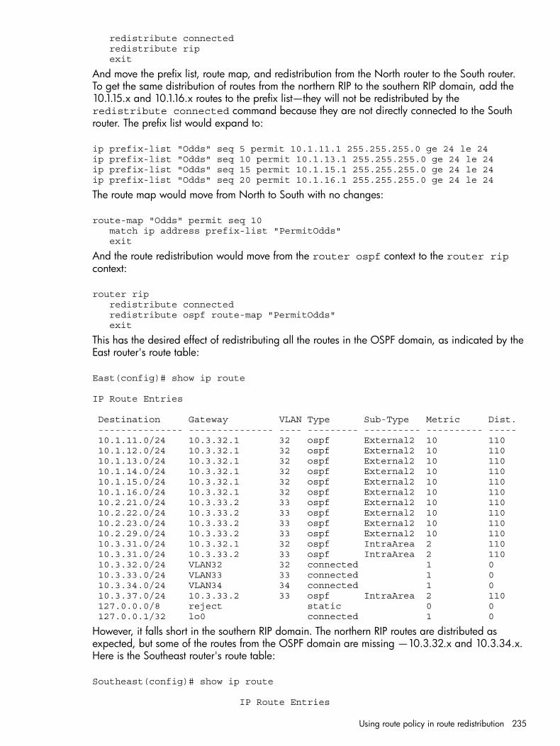
redistribute connected redistribute rip exit
And move the prefix list, route map, and redistribution from the North router to the South router.To get the same distribution of routes from the northern RIP to the southern RIP domain, add the10.1.15.x and 10.1.16.x routes to the prefix list—they will not be redistributed by theredistribute connected command because they are not directly connected to the Southrouter. The prefix list would expand to:
ip prefix-list "Odds" seq 5 permit 10.1.11.1 255.255.255.0 ge 24 le 24ip prefix-list "Odds" seq 10 permit 10.1.13.1 255.255.255.0 ge 24 le 24ip prefix-list "Odds" seq 15 permit 10.1.15.1 255.255.255.0 ge 24 le 24ip prefix-list "Odds" seq 20 permit 10.1.16.1 255.255.255.0 ge 24 le 24
The route map would move from North to South with no changes:
route-map "Odds" permit seq 10 match ip address prefix-list "PermitOdds" exit
And the route redistribution would move from the router ospf context to the router ripcontext:
router rip redistribute connected redistribute ospf route-map "PermitOdds" exit
This has the desired effect of redistributing all the routes in the OSPF domain, as indicated by theEast router's route table:
East(config)# show ip route
IP Route Entries
Destination Gateway VLAN Type Sub-Type Metric Dist. --------------- --------------- ---- --------- ---------- ---------- ----- 10.1.11.0/24 10.3.32.1 32 ospf External2 10 110 10.1.12.0/24 10.3.32.1 32 ospf External2 10 110 10.1.13.0/24 10.3.32.1 32 ospf External2 10 110 10.1.14.0/24 10.3.32.1 32 ospf External2 10 110 10.1.15.0/24 10.3.32.1 32 ospf External2 10 110 10.1.16.0/24 10.3.32.1 32 ospf External2 10 110 10.2.21.0/24 10.3.33.2 33 ospf External2 10 110 10.2.22.0/24 10.3.33.2 33 ospf External2 10 110 10.2.23.0/24 10.3.33.2 33 ospf External2 10 110 10.2.29.0/24 10.3.33.2 33 ospf External2 10 110 10.3.31.0/24 10.3.32.1 32 ospf IntraArea 2 110 10.3.31.0/24 10.3.33.2 33 ospf IntraArea 2 110 10.3.32.0/24 VLAN32 32 connected 1 0 10.3.33.0/24 VLAN33 33 connected 1 0 10.3.34.0/24 VLAN34 34 connected 1 0 10.3.37.0/24 10.3.33.2 33 ospf IntraArea 2 110 127.0.0.0/8 reject static 0 0 127.0.0.1/32 lo0 connected 1 0
However, it falls short in the southern RIP domain. The northern RIP routes are distributed asexpected, but some of the routes from the OSPF domain are missing —10.3.32.x and 10.3.34.x.Here is the Southeast router's route table:
Southeast(config)# show ip route
IP Route Entries
Using route policy in route redistribution 235
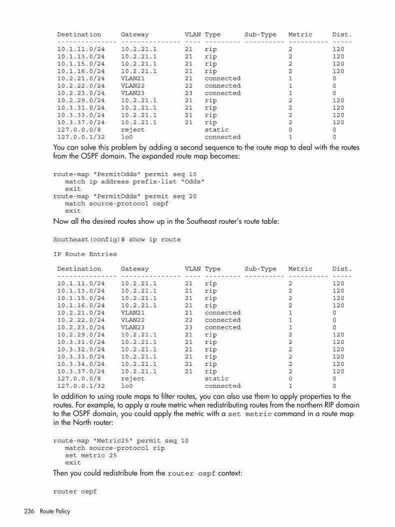
Destination Gateway VLAN Type Sub-Type Metric Dist. --------------- --------------- ---- --------- ---------- ---------- ----- 10.1.11.0/24 10.2.21.1 21 rip 2 120 10.1.13.0/24 10.2.21.1 21 rip 2 120 10.1.15.0/24 10.2.21.1 21 rip 2 120 10.1.16.0/24 10.2.21.1 21 rip 2 120 10.2.21.0/24 VLAN21 21 connected 1 0 10.2.22.0/24 VLAN22 22 connected 1 0 10.2.23.0/24 VLAN23 23 connected 1 0 10.2.29.0/24 10.2.21.1 21 rip 2 120 10.3.31.0/24 10.2.21.1 21 rip 2 120 10.3.33.0/24 10.2.21.1 21 rip 2 120 10.3.37.0/24 10.2.21.1 21 rip 2 120 127.0.0.0/8 reject static 0 0 127.0.0.1/32 lo0 connected 1 0
You can solve this problem by adding a second sequence to the route map to deal with the routesfrom the OSPF domain. The expanded route map becomes:
route-map "PermitOdds" permit seq 10 match ip address prefix-list "Odds" exitroute-map "PermitOdds" permit seq 20 match source-protocol ospf exit
Now all the desired routes show up in the Southeast router's route table:
Southeast(config)# show ip route
IP Route Entries
Destination Gateway VLAN Type Sub-Type Metric Dist. --------------- --------------- ---- --------- ---------- ---------- ----- 10.1.11.0/24 10.2.21.1 21 rip 2 120 10.1.13.0/24 10.2.21.1 21 rip 2 120 10.1.15.0/24 10.2.21.1 21 rip 2 120 10.1.16.0/24 10.2.21.1 21 rip 2 120 10.2.21.0/24 VLAN21 21 connected 1 0 10.2.22.0/24 VLAN22 22 connected 1 0 10.2.23.0/24 VLAN23 23 connected 1 0 10.2.29.0/24 10.2.21.1 21 rip 2 120 10.3.31.0/24 10.2.21.1 21 rip 2 120 10.3.32.0/24 10.2.21.1 21 rip 2 120 10.3.33.0/24 10.2.21.1 21 rip 2 120 10.3.34.0/24 10.2.21.1 21 rip 2 120 10.3.37.0/24 10.2.21.1 21 rip 2 120 127.0.0.0/8 reject static 0 0 127.0.0.1/32 lo0 connected 1 0
In addition to using route maps to filter routes, you can also use them to apply properties to theroutes. For example, to apply a route metric when redistributing routes from the northern RIP domainto the OSPF domain, you could apply the metric with a set metric command in a route mapin the North router:
route-map "Metric25" permit seq 10 match source-protocol rip set metric 25 exit
Then you could redistribute from the router ospf context:
router ospf
236 Route Policy
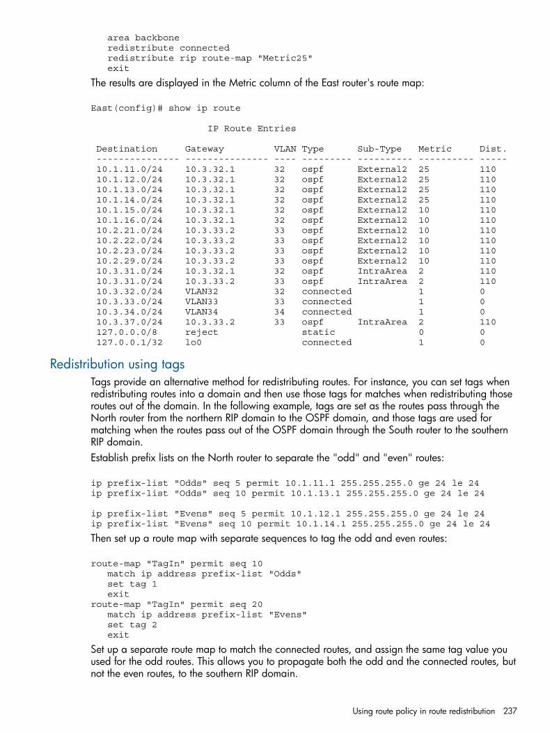
area backbone redistribute connected redistribute rip route-map "Metric25" exit
The results are displayed in the Metric column of the East router's route map:
East(config)# show ip route
IP Route Entries
Destination Gateway VLAN Type Sub-Type Metric Dist. --------------- --------------- ---- --------- ---------- ---------- ----- 10.1.11.0/24 10.3.32.1 32 ospf External2 25 110 10.1.12.0/24 10.3.32.1 32 ospf External2 25 110 10.1.13.0/24 10.3.32.1 32 ospf External2 25 110 10.1.14.0/24 10.3.32.1 32 ospf External2 25 110 10.1.15.0/24 10.3.32.1 32 ospf External2 10 110 10.1.16.0/24 10.3.32.1 32 ospf External2 10 110 10.2.21.0/24 10.3.33.2 33 ospf External2 10 110 10.2.22.0/24 10.3.33.2 33 ospf External2 10 110 10.2.23.0/24 10.3.33.2 33 ospf External2 10 110 10.2.29.0/24 10.3.33.2 33 ospf External2 10 110 10.3.31.0/24 10.3.32.1 32 ospf IntraArea 2 110 10.3.31.0/24 10.3.33.2 33 ospf IntraArea 2 110 10.3.32.0/24 VLAN32 32 connected 1 0 10.3.33.0/24 VLAN33 33 connected 1 0 10.3.34.0/24 VLAN34 34 connected 1 0 10.3.37.0/24 10.3.33.2 33 ospf IntraArea 2 110 127.0.0.0/8 reject static 0 0 127.0.0.1/32 lo0 connected 1 0
Redistribution using tagsTags provide an alternative method for redistributing routes. For instance, you can set tags whenredistributing routes into a domain and then use those tags for matches when redistributing thoseroutes out of the domain. In the following example, tags are set as the routes pass through theNorth router from the northern RIP domain to the OSPF domain, and those tags are used formatching when the routes pass out of the OSPF domain through the South router to the southernRIP domain.Establish prefix lists on the North router to separate the "odd" and "even" routes:
ip prefix-list "Odds" seq 5 permit 10.1.11.1 255.255.255.0 ge 24 le 24ip prefix-list "Odds" seq 10 permit 10.1.13.1 255.255.255.0 ge 24 le 24
ip prefix-list "Evens" seq 5 permit 10.1.12.1 255.255.255.0 ge 24 le 24ip prefix-list "Evens" seq 10 permit 10.1.14.1 255.255.255.0 ge 24 le 24
Then set up a route map with separate sequences to tag the odd and even routes:
route-map "TagIn" permit seq 10 match ip address prefix-list "Odds" set tag 1 exitroute-map "TagIn" permit seq 20 match ip address prefix-list "Evens" set tag 2 exit
Set up a separate route map to match the connected routes, and assign the same tag value youused for the odd routes. This allows you to propagate both the odd and the connected routes, butnot the even routes, to the southern RIP domain.
Using route policy in route redistribution 237
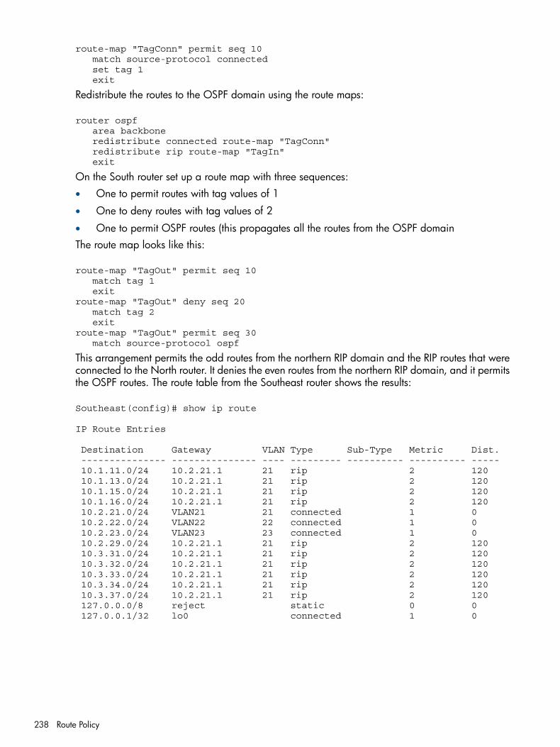
route-map "TagConn" permit seq 10 match source-protocol connected set tag 1 exit
Redistribute the routes to the OSPF domain using the route maps:
router ospf area backbone redistribute connected route-map "TagConn" redistribute rip route-map "TagIn" exit
On the South router set up a route map with three sequences:• One to permit routes with tag values of 1
• One to deny routes with tag values of 2
• One to permit OSPF routes (this propagates all the routes from the OSPF domainThe route map looks like this:
route-map "TagOut" permit seq 10 match tag 1 exitroute-map "TagOut" deny seq 20 match tag 2 exitroute-map "TagOut" permit seq 30 match source-protocol ospf
This arrangement permits the odd routes from the northern RIP domain and the RIP routes that wereconnected to the North router. It denies the even routes from the northern RIP domain, and it permitsthe OSPF routes. The route table from the Southeast router shows the results:
Southeast(config)# show ip route
IP Route Entries
Destination Gateway VLAN Type Sub-Type Metric Dist. --------------- --------------- ---- --------- ---------- ---------- ----- 10.1.11.0/24 10.2.21.1 21 rip 2 120 10.1.13.0/24 10.2.21.1 21 rip 2 120 10.1.15.0/24 10.2.21.1 21 rip 2 120 10.1.16.0/24 10.2.21.1 21 rip 2 120 10.2.21.0/24 VLAN21 21 connected 1 0 10.2.22.0/24 VLAN22 22 connected 1 0 10.2.23.0/24 VLAN23 23 connected 1 0 10.2.29.0/24 10.2.21.1 21 rip 2 120 10.3.31.0/24 10.2.21.1 21 rip 2 120 10.3.32.0/24 10.2.21.1 21 rip 2 120 10.3.33.0/24 10.2.21.1 21 rip 2 120 10.3.34.0/24 10.2.21.1 21 rip 2 120 10.3.37.0/24 10.2.21.1 21 rip 2 120 127.0.0.0/8 reject static 0 0 127.0.0.1/32 lo0 connected 1 0
238 Route Policy
9 ICMP Router Discovery ProtocolThe ICMP Router Discovery Protocol (IRDP) is used by HP routing switches to advertise the IPaddresses of their router interfaces to directly attached hosts. IRDP is disabled by default. You canenable the feature on a global basis or on an individual VLAN interface basis.
Configuring IRDPWhen IRDP is enabled, the routing switch periodically sends Router Advertisement messages outthe IP interfaces on which the feature is enabled. The messages advertise the routing switch's IPaddresses to directly attached hosts who listen for the messages. In addition, hosts can be configuredto query the routing switch for the information by sending Router Solicitation messages.Some types of hosts use the Router Solicitation messages to discover their default gateway. WhenIRDP is enabled on the HP routing switch, the routing switch responds to the Router Solicitationmessages. Some clients interpret this response to mean that the routing switch is the default gateway.If another router is actually the default gateway for these clients, leave IRDP disabled on the HProuting switch.IRDP uses the following parameters. If you enable IRDP on individual VLAN interfaces, you canconfigure these parameters on an individual VLAN interface basis.Packet type
The routing switch can send Router Advertisement messages as IP broadcasts or as IP multicastsaddressed to IP multicast group 224.0.0.1. The default packet type is IP broadcast.
Hold timeEach Router Advertisement message contains a hold time value. This value specifies the maximumamount of time the host should consider an advertisement to be valid until a newer advertisementarrives. When a new advertisement arrives, the hold time is reset. The hold time is alwayslonger than the maximum advertisement interval. Therefore, if the hold time for an advertisementexpires, the host can reasonably conclude that the router interface that sent the advertisementis no longer available. The default hold time is three times the maximum message interval.
Maximum message interval and minimum message intervalWhen IRDP is enabled, the routing switch sends the Router Advertisement messages every450-600 seconds by default. The time within this interval that the routing switch selects israndom for each message and is not affected by traffic loads or other network factors. Therandom interval minimizes the probability that a host will receive Router Advertisement messagesfrom other routers at the same time. The interval on each IRDP-enabled routing switch interfaceis independent of the interval on other IRDP-enabled interfaces. The default maximum messageinterval is 600 seconds. The default minimum message interval is 450 seconds.
PreferenceIf a host receives multiple Router Advertisement messages from different routers, the host selectsthe router that send the message with the highest preference as the default gateway. Thepreference can be a number from -4294967296 to 4294967295. The default is 0.
Enabling IRDP globallyEnter the following command:
HP Switch(config)# ip irdp
This command enables IRDP on the IP interfaces on all ports. Each port uses the default values forthe IRDP parameters.
Configuring IRDP 239
Enabling IRDP on an individual VLAN interfaceTo enable IRDP on an individual VLAN interface and configure IRDP parameters, enter commandssuch as the following:
HP Switch(config)# vlan 1HP Switch(vlan-1)# ip irdp maxadvertinterval 400
This example shows how to enable IRDP on a specific interface (VLAN 1) and change the maximumadvertisement interval for Router Advertisement messages to 400 seconds.
Syntax:[no] ip irdp [ broadcast | multicast ] [holdtime seconds][maxadvertinterval seconds] [minadvertinterval seconds][preference number]broadcast | multicast
Specifies the packet type the routing switch uses to send the RouterAdvertisement:broadcast
The routing switch sends Router Advertisements as IP broadcasts.multicast
The routing switch sends Router Advertisements as multicast packetsaddressed to IP multicast group 224.0.0.1. This is the default.
holdtime seconds
Specifies how long a host that receives a Router Advertisement from the routingswitch should consider the advertisement to be valid.When a host receives a new Router Advertisement message from the routingswitch, the host resets the hold time for the routing switch to the hold timespecified in the new advertisement. If the hold time of an advertisement expires,the host discards the advertisement, concluding that the router interface thatsent the advertisement is no longer available. The value must be greater thanthe value of the maxadvertinterval parameter and cannot be greater than 9000.The default is three times the value of the maxadvertinterval parameter.
maxadvertinterval
Specifies the maximum amount of time the routing switch waits between sendingRouter Advertisements. You can specify a value from 1 to the current value ofthe holdtime parameter. The default is 600 seconds.
minadvertinterval
Specifies the minimum amount of time the routing switch can wait betweensending Router Advertisements. The default is three-fourths (0.75) the value ofthe maxadvertinterval parameter.If you change the maxadvertinterval parameter, the software automaticallyadjusts the minadvertinterval parameter to be three-fourths the new value of themaxadvertinterval parameter. If you want to override the automaticallyconfigured value, you can specify an interval from 1 to the current value of themaxadvertinterval parameter
preference number
Specifies the IRDP preference level of this routing switch. If a host receives RouterAdvertisements from multiple routers, the host selects the router interface thatsent the message with the highest preference as the host's default gateway. Thevalid range is -4294967296 to 4294967295. The default is 0.
240 ICMP Router Discovery Protocol
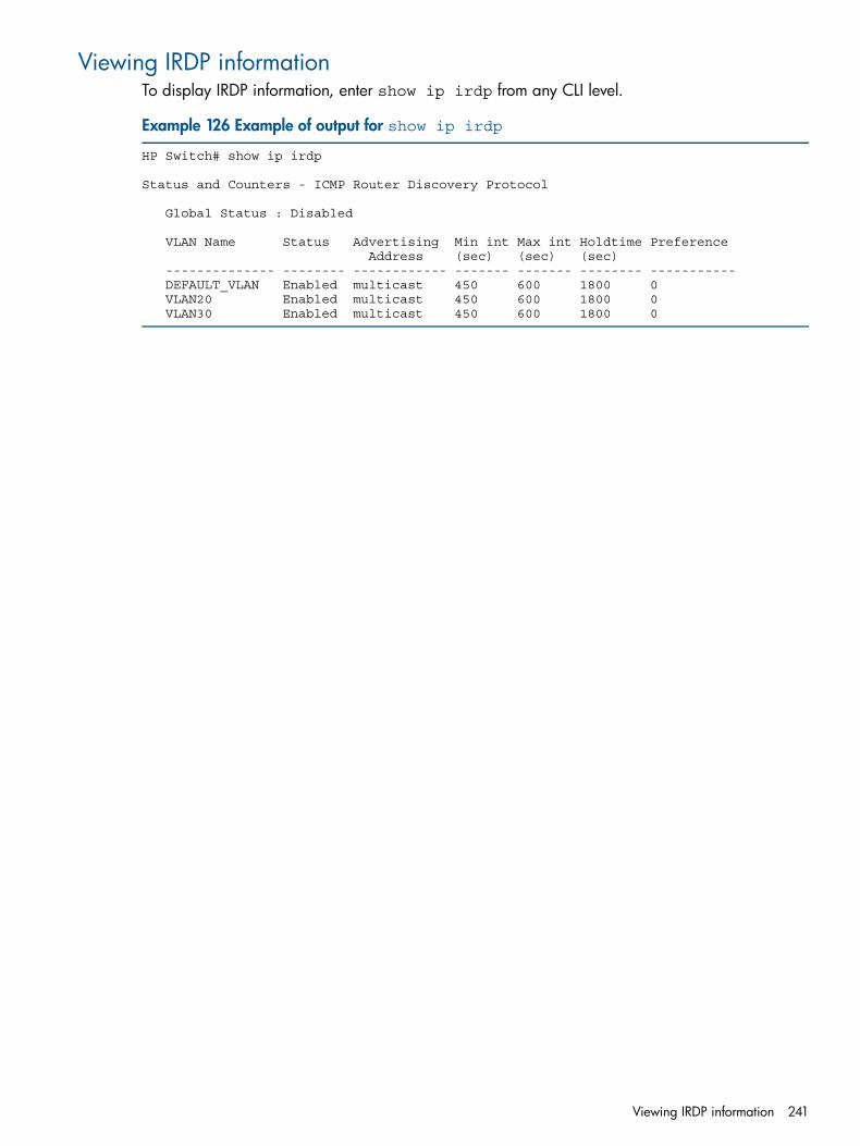
Viewing IRDP informationTo display IRDP information, enter show ip irdp from any CLI level.
Example 126 Example of output for show ip irdp
HP Switch# show ip irdp
Status and Counters - ICMP Router Discovery Protocol
Global Status : Disabled
VLAN Name Status Advertising Min int Max int Holdtime Preference Address (sec) (sec) (sec) -------------- -------- ------------ ------- ------- -------- ----------- DEFAULT_VLAN Enabled multicast 450 600 1800 0 VLAN20 Enabled multicast 450 600 1800 0 VLAN30 Enabled multicast 450 600 1800 0
Viewing IRDP information 241
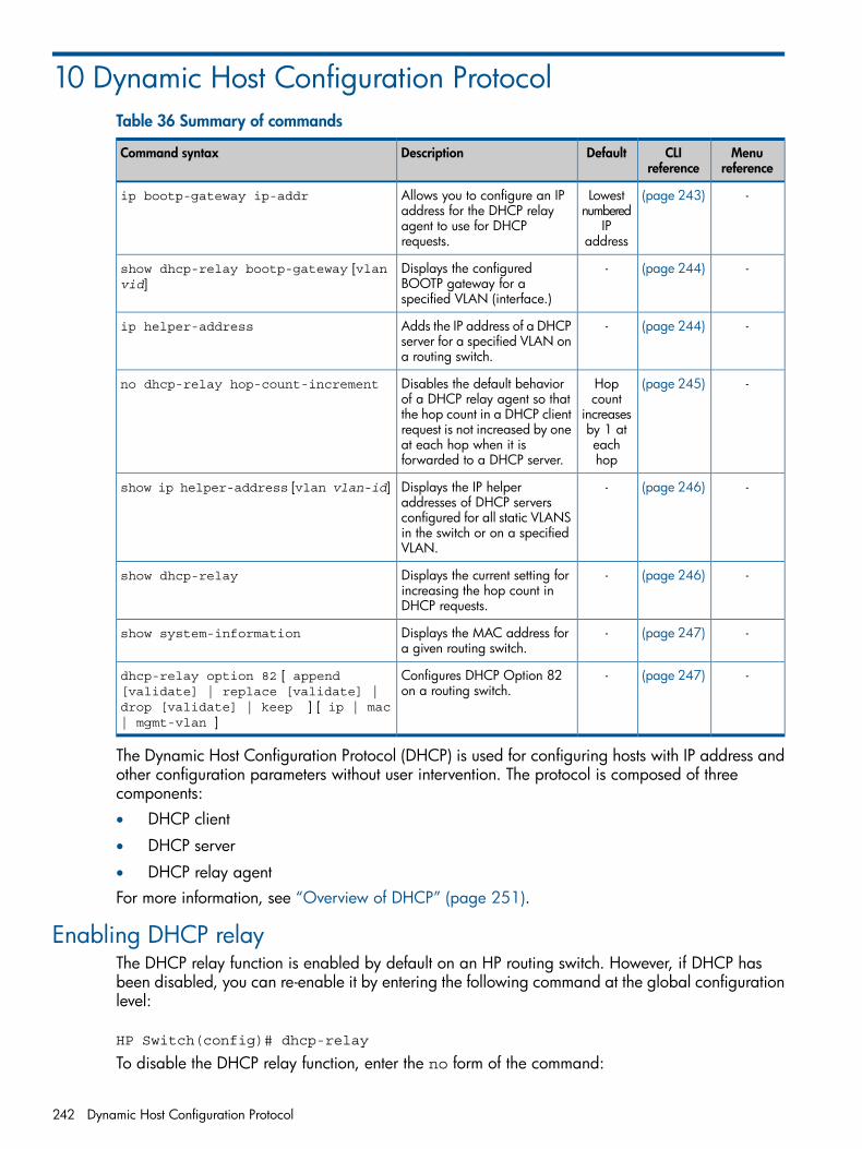
10 Dynamic Host Configuration ProtocolTable 36 Summary of commands
Menureference
CLIreference
DefaultDescriptionCommand syntax
-(page 243)Lowestnumbered
Allows you to configure an IPaddress for the DHCP relay
ip bootp-gateway ip-addr
IPaddress
agent to use for DHCPrequests.
-(page 244)-Displays the configuredBOOTP gateway for aspecified VLAN (interface.)
show dhcp-relay bootp-gateway [vlanvid]
-(page 244)-Adds the IP address of a DHCPserver for a specified VLAN ona routing switch.
ip helper-address
-(page 245)Hopcount
Disables the default behaviorof a DHCP relay agent so that
no dhcp-relay hop-count-increment
increasesthe hop count in a DHCP clientby 1 atrequest is not increased by oneeachhop
at each hop when it isforwarded to a DHCP server.
-(page 246)-Displays the IP helperaddresses of DHCP servers
show ip helper-address [vlan vlan-id]
configured for all static VLANSin the switch or on a specifiedVLAN.
-(page 246)-Displays the current setting forincreasing the hop count inDHCP requests.
show dhcp-relay
-(page 247)-Displays the MAC address fora given routing switch.
show system-information
-(page 247)-Configures DHCP Option 82on a routing switch.
dhcp-relay option 82 [ append[validate] | replace [validate] |drop [validate] | keep ] [ ip | mac| mgmt-vlan ]
The Dynamic Host Configuration Protocol (DHCP) is used for configuring hosts with IP address andother configuration parameters without user intervention. The protocol is composed of threecomponents:• DHCP client
• DHCP server
• DHCP relay agentFor more information, see “Overview of DHCP” (page 251).
Enabling DHCP relayThe DHCP relay function is enabled by default on an HP routing switch. However, if DHCP hasbeen disabled, you can re-enable it by entering the following command at the global configurationlevel:
HP Switch(config)# dhcp-relay
To disable the DHCP relay function, enter the no form of the command:
242 Dynamic Host Configuration Protocol
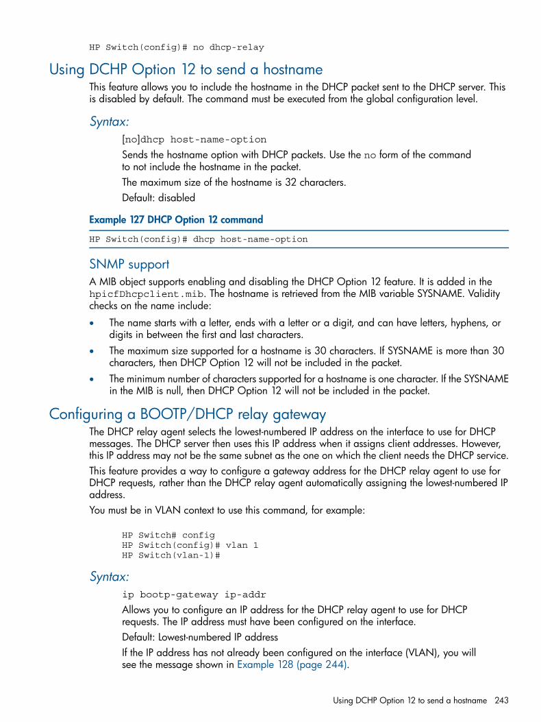
HP Switch(config)# no dhcp-relay
Using DCHP Option 12 to send a hostnameThis feature allows you to include the hostname in the DHCP packet sent to the DHCP server. Thisis disabled by default. The command must be executed from the global configuration level.
Syntax:[no]dhcp host-name-optionSends the hostname option with DHCP packets. Use the no form of the commandto not include the hostname in the packet.The maximum size of the hostname is 32 characters.Default: disabled
Example 127 DHCP Option 12 command
HP Switch(config)# dhcp host-name-option
SNMP supportA MIB object supports enabling and disabling the DHCP Option 12 feature. It is added in thehpicfDhcpclient.mib. The hostname is retrieved from the MIB variable SYSNAME. Validitychecks on the name include:
• The name starts with a letter, ends with a letter or a digit, and can have letters, hyphens, ordigits in between the first and last characters.
• The maximum size supported for a hostname is 30 characters. If SYSNAME is more than 30characters, then DHCP Option 12 will not be included in the packet.
• The minimum number of characters supported for a hostname is one character. If the SYSNAMEin the MIB is null, then DHCP Option 12 will not be included in the packet.
Configuring a BOOTP/DHCP relay gatewayThe DHCP relay agent selects the lowest-numbered IP address on the interface to use for DHCPmessages. The DHCP server then uses this IP address when it assigns client addresses. However,this IP address may not be the same subnet as the one on which the client needs the DHCP service.This feature provides a way to configure a gateway address for the DHCP relay agent to use forDHCP requests, rather than the DHCP relay agent automatically assigning the lowest-numbered IPaddress.You must be in VLAN context to use this command, for example:
HP Switch# configHP Switch(config)# vlan 1HP Switch(vlan-1)#
Syntax:ip bootp-gateway ip-addr
Allows you to configure an IP address for the DHCP relay agent to use for DHCPrequests. The IP address must have been configured on the interface.Default: Lowest-numbered IP addressIf the IP address has not already been configured on the interface (VLAN), you willsee the message shown in Example 128 (page 244).
Using DCHP Option 12 to send a hostname 243
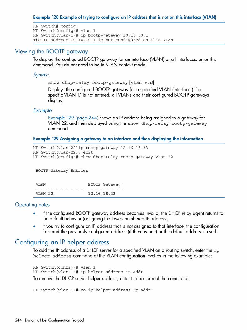
Example 128 Example of trying to configure an IP address that is not on this interface (VLAN)
HP Switch# configHP Switch(config)# vlan 1HP Switch(vlan-1)# ip bootp-gateway 10.10.10.1The IP address 10.10.10.1 is not configured on this VLAN.
Viewing the BOOTP gatewayTo display the configured BOOTP gateway for an interface (VLAN) or all interfaces, enter thiscommand. You do not need to be in VLAN context mode.
Syntax:show dhcp-relay bootp-gateway [vlan vid]Displays the configured BOOTP gateway for a specified VLAN (interface.) If aspecific VLAN ID is not entered, all VLANs and their configured BOOTP gatewaysdisplay.
ExampleExample 129 (page 244) shows an IP address being assigned to a gateway forVLAN 22, and then displayed using the show dhcp-relay bootp-gatewaycommand.
Example 129 Assigning a gateway to an interface and then displaying the information
HP Switch(vlan-22)ip bootp-gateway 12.16.18.33HP Switch(vlan-22)# exitHP Switch(config)# show dhcp-relay bootp-gateway vlan 22
BOOTP Gateway Entries
VLAN BOOTP Gateway -------------------- --------------- VLAN 22 12.16.18.33
Operating notes
• If the configured BOOTP gateway address becomes invalid, the DHCP relay agent returns tothe default behavior (assigning the lowest-numbered IP address.)
• If you try to configure an IP address that is not assigned to that interface, the configurationfails and the previously configured address (if there is one) or the default address is used.
Configuring an IP helper addressTo add the IP address of a DHCP server for a specified VLAN on a routing switch, enter the iphelper-address command at the VLAN configuration level as in the following example:
HP Switch(config)# vlan 1HP Switch(vlan-1)# ip helper-address ip-addr
To remove the DHCP server helper address, enter the no form of the command:
HP Switch(vlan-1)# no ip helper-address ip-addr
244 Dynamic Host Configuration Protocol
Operating notes• You can configure up to 4000 IP helper addresses on a routing switch. The helper addresses
are shared between the DHCP relay agent and UDP forwarder feature.• A maximum of sixteen IP helper addresses is supported in each VLAN.
Disabling the hop count in DHCP requestsFor more information, see “Hop count in DHCP requests” (page 251).To disable the default behavior of a DHCP relay agent so that the hop count in a DHCP clientrequest is not increased by one at each hop when it is forwarded to a DHCP server, enter the nodhcp-relay hop-count-increment command at the global configuration level:
HP Switch(config)# no dhcp-relay hop-count-increment
To reset the default function, which increases the hop count in each DHCP request forwarded toa DHCP server, enter the following command:
HP Switch(config)# dhcp-relay hop-count-increment
Operating notes• By default, the DHCP relay agent increases the hop count in each DHCP request by one. You
must enter the no dhcp-relay hop-count-increment command to disable this function.• You enter the no dhcp-relay hop-count-increment command at the global
configuration level. The command is applied to all interfaces on the routing switch that areconfigured to forward DHCP requests.
• This DHCP relay enhancement applies only to DHCP requests forwarded to a DHCP server.The server does not change the hop count included in the DHCP response sent to DHCP clients.
• When you disable or re-enable the DHCP hop count function, no other behavior of the relayagent is affected.
• You can configure the DHCP relay hop count function only from the CLI; you cannot configurethis software feature from the drop-down menus.
• A new MIB variable, hpDhcpRelayHopCount, is introduced to support SNMP managementof the hop count increment by the DHCP relay agent in a switch.
Verifying the DHCP relay configuration
Viewing the DHCP relay settingUse the show config command (or show running for the running-config file) to display thecurrent DHCP relay setting.
NOTE: The DHCP relay and hop count increment settings appear in the show config commandoutput only if the non-default values are configured. For more information about the DHCP hopcount increment, see “Hop count in DHCP requests” (page 251).
Disabling the hop count in DHCP requests 245
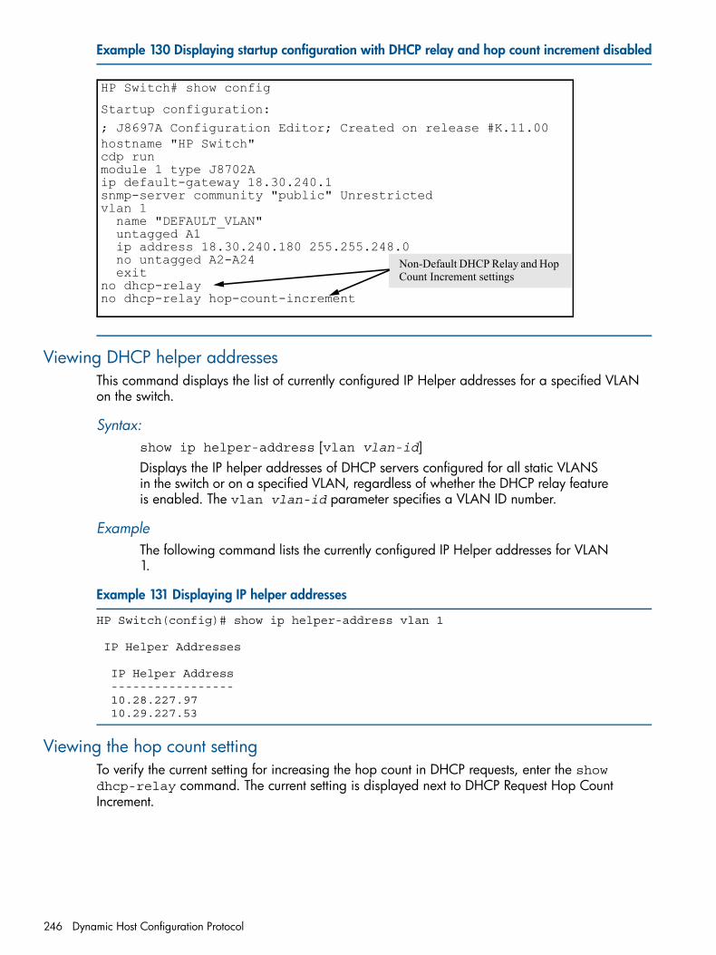
Example 130 Displaying startup configuration with DHCP relay and hop count increment disabled
HP Switch# show config
Startup configuration:
; J8697A Configuration Editor; Created on release #K.11.00hostname "HP Switch"cdp runmodule 1 type J8702Aip default-gateway 18.30.240.1snmp-server community "public" Unrestrictedvlan 1 name "DEFAULT_VLAN" untagged A1 ip address 18.30.240.180 255.255.248.0 no untagged A2-A24 exitno dhcp-relayno dhcp-relay hop-count-increment
Non-Default DHCP Relay and Hop Count Increment settings
Viewing DHCP helper addressesThis command displays the list of currently configured IP Helper addresses for a specified VLANon the switch.
Syntax:show ip helper-address [vlan vlan-id]Displays the IP helper addresses of DHCP servers configured for all static VLANSin the switch or on a specified VLAN, regardless of whether the DHCP relay featureis enabled. The vlan vlan-id parameter specifies a VLAN ID number.
ExampleThe following command lists the currently configured IP Helper addresses for VLAN1.
Example 131 Displaying IP helper addresses
HP Switch(config)# show ip helper-address vlan 1
IP Helper Addresses
IP Helper Address ----------------- 10.28.227.97 10.29.227.53
Viewing the hop count settingTo verify the current setting for increasing the hop count in DHCP requests, enter the showdhcp-relay command. The current setting is displayed next to DHCP Request Hop CountIncrement.
246 Dynamic Host Configuration Protocol
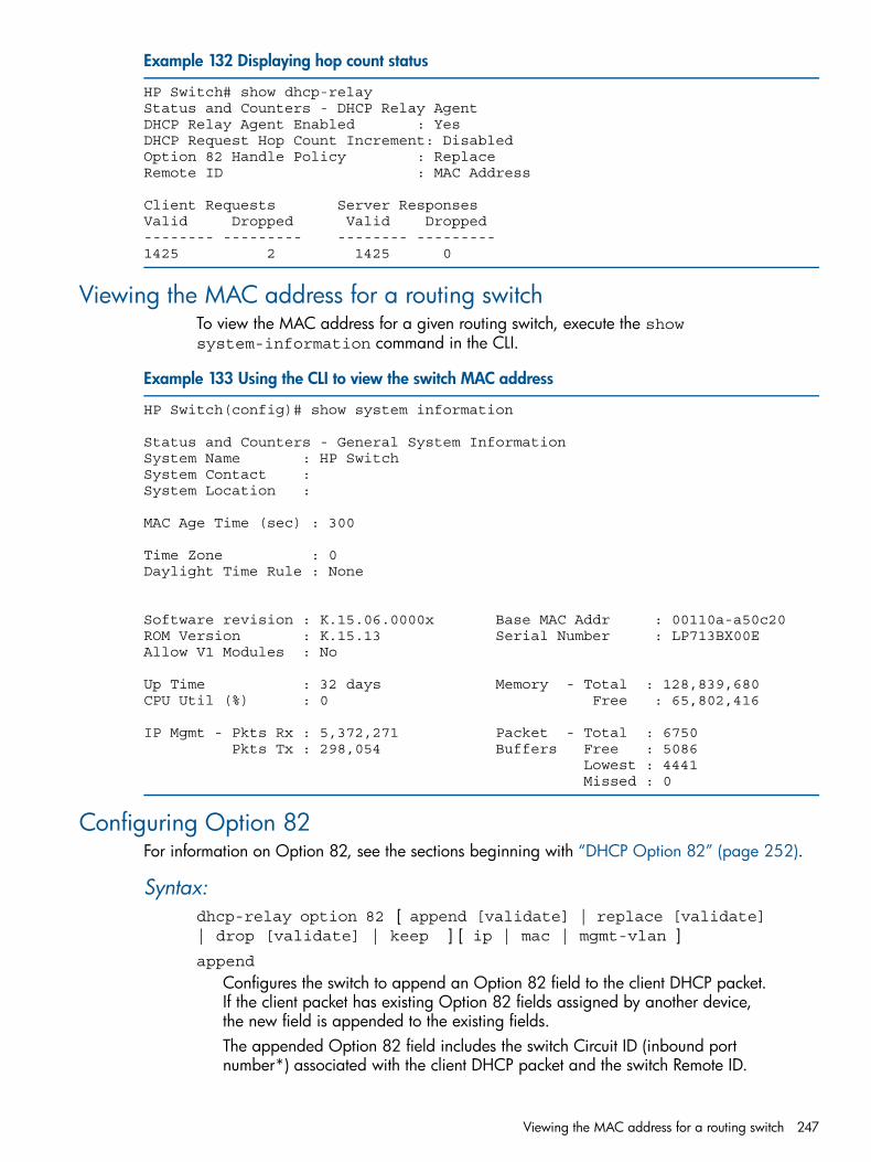
Example 132 Displaying hop count status
HP Switch# show dhcp-relayStatus and Counters - DHCP Relay AgentDHCP Relay Agent Enabled : YesDHCP Request Hop Count Increment: Disabled Option 82 Handle Policy : Replace Remote ID : MAC Address
Client Requests Server ResponsesValid Dropped Valid Dropped-------- --------- -------- ---------1425 2 1425 0
Viewing the MAC address for a routing switchTo view the MAC address for a given routing switch, execute the showsystem-information command in the CLI.
Example 133 Using the CLI to view the switch MAC address
HP Switch(config)# show system information
Status and Counters - General System InformationSystem Name : HP SwitchSystem Contact :System Location :
MAC Age Time (sec) : 300
Time Zone : 0Daylight Time Rule : None
Software revision : K.15.06.0000x Base MAC Addr : 00110a-a50c20ROM Version : K.15.13 Serial Number : LP713BX00EAllow V1 Modules : No
Up Time : 32 days Memory - Total : 128,839,680CPU Util (%) : 0 Free : 65,802,416
IP Mgmt - Pkts Rx : 5,372,271 Packet - Total : 6750 Pkts Tx : 298,054 Buffers Free : 5086 Lowest : 4441 Missed : 0
Configuring Option 82For information on Option 82, see the sections beginning with “DHCP Option 82” (page 252).
Syntax:dhcp-relay option 82 [ append [validate] | replace [validate]| drop [validate] | keep ] [ ip | mac | mgmt-vlan ]append
Configures the switch to append an Option 82 field to the client DHCP packet.If the client packet has existing Option 82 fields assigned by another device,the new field is appended to the existing fields.The appended Option 82 field includes the switch Circuit ID (inbound portnumber*) associated with the client DHCP packet and the switch Remote ID.
Viewing the MAC address for a routing switch 247
The default switch remote ID is the MAC address of the switch on which thepacket was received from the client.To use the incoming VLAN's IP address or the Management VLAN IP address(if configured) for the remote ID instead of the switch MAC address, use the ipor mgmt-vlan option (below.)
replace
Configures the switch to replace existing Option 82 fields in an inbound clientDHCP packet with an Option 82 field for the switch.The replacement Option 82 field includes the switch circuit ID (inbound portnumber*) associated with the client DHCP packet and the switch remote ID.The default switch remote ID is the MAC address of the switch on which thepacket was received from the client.To use the incoming VLAN's IP address or the Management VLAN IP address(if configured) for the remote ID instead of the switch MAC address, use the ipor mgmt-vlan option (below.)
drop
Configures the routing switch to unconditionally drop any client DHCP packetreceived with existing Option 82 fields. This means that such packets will notbe forwarded. Use this option where access to the routing switch by untrustedclients is possible.If the routing switch receives a client DHCP packet without an Option 82 field,it adds an Option 82 field to the client and forwards the packet. The addedOption 82 field includes the switch circuit ID (inbound port number*) associatedwith the client DHCP packet and the switch remote ID. The default switch remoteID is the MAC address of the switch on which the packet was received fromthe client.To use the incoming VLAN's IP address or the Management VLAN IP address(if configured) for the remote ID instead of the switch MAC address, use the ipor mgmt-vlan option (below.)
keep
For any client DHCP packet received with existing Option 82 fields, configuresthe routing switch to forward the packet as-is, without replacing or adding tothe existing Option 82 fields.
validate
Operates when the routing switch is configured with append, replace, or dropas a forwarding policy. With validate enabled, the routing switch appliesstricter rules to an incoming Option 82 server response to determine whetherto forward or drop the response. For more information, see “Validation of serverresponse packets” (page 257).
[ ip | mac | mgmt-vlan ]Specifies the remote ID suboption that the switch uses in Option 82 fields addedor appended to DHCP client packets. The type of remote ID defines DHCP policyareas in the client requests sent to the DHCP server. If a remote ID suboption is
248 Dynamic Host Configuration Protocol
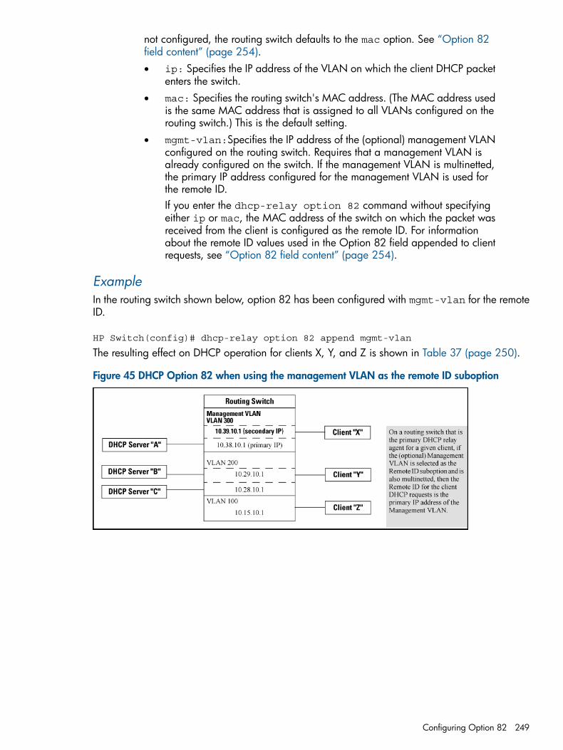
not configured, the routing switch defaults to the mac option. See “Option 82field content” (page 254).• ip: Specifies the IP address of the VLAN on which the client DHCP packet
enters the switch.• mac: Specifies the routing switch's MAC address. (The MAC address used
is the same MAC address that is assigned to all VLANs configured on therouting switch.) This is the default setting.
• mgmt-vlan:Specifies the IP address of the (optional) management VLANconfigured on the routing switch. Requires that a management VLAN isalready configured on the switch. If the management VLAN is multinetted,the primary IP address configured for the management VLAN is used forthe remote ID.If you enter the dhcp-relay option 82 command without specifyingeither ip or mac, the MAC address of the switch on which the packet wasreceived from the client is configured as the remote ID. For informationabout the remote ID values used in the Option 82 field appended to clientrequests, see “Option 82 field content” (page 254).
ExampleIn the routing switch shown below, option 82 has been configured with mgmt-vlan for the remoteID.
HP Switch(config)# dhcp-relay option 82 append mgmt-vlan
The resulting effect on DHCP operation for clients X, Y, and Z is shown in Table 37 (page 250).
Figure 45 DHCP Option 82 when using the management VLAN as the remote ID suboption
Configuring Option 82 249
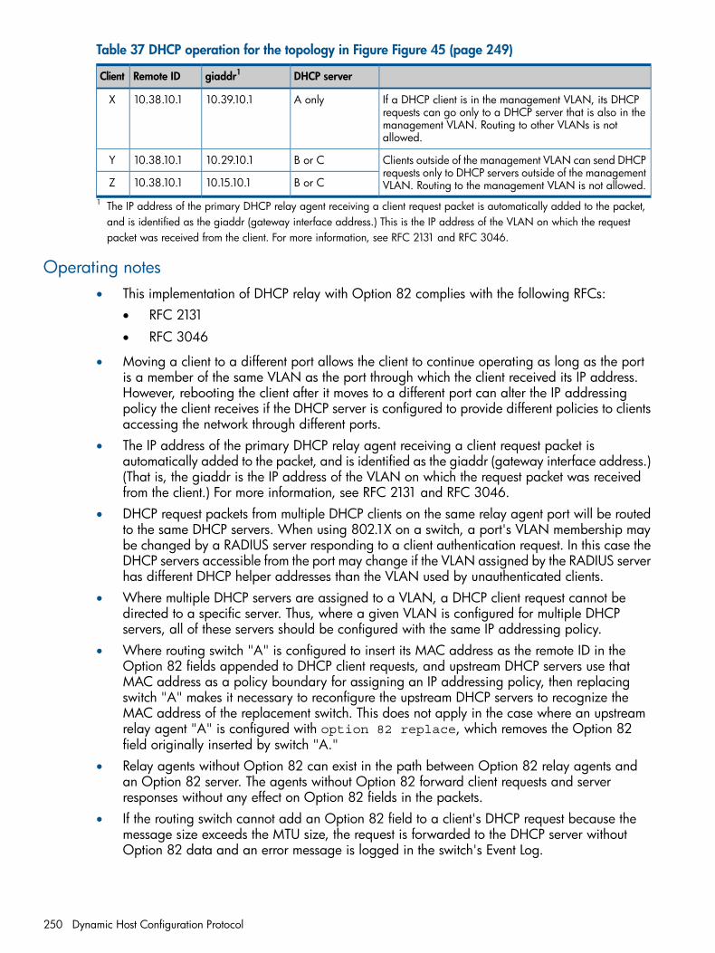
Table 37 DHCP operation for the topology in Figure Figure 45 (page 249)
DHCP servergiaddr1Remote IDClient
If a DHCP client is in the management VLAN, its DHCPrequests can go only to a DHCP server that is also in themanagement VLAN. Routing to other VLANs is notallowed.
A only10.39.10.110.38.10.1X
Clients outside of the management VLAN can send DHCPrequests only to DHCP servers outside of the managementVLAN. Routing to the management VLAN is not allowed.
B or C10.29.10.110.38.10.1Y
B or C10.15.10.110.38.10.1Z
1 The IP address of the primary DHCP relay agent receiving a client request packet is automatically added to the packet,and is identified as the giaddr (gateway interface address.) This is the IP address of the VLAN on which the requestpacket was received from the client. For more information, see RFC 2131 and RFC 3046.
Operating notes• This implementation of DHCP relay with Option 82 complies with the following RFCs:
RFC 2131•
• RFC 3046
• Moving a client to a different port allows the client to continue operating as long as the portis a member of the same VLAN as the port through which the client received its IP address.However, rebooting the client after it moves to a different port can alter the IP addressingpolicy the client receives if the DHCP server is configured to provide different policies to clientsaccessing the network through different ports.
• The IP address of the primary DHCP relay agent receiving a client request packet isautomatically added to the packet, and is identified as the giaddr (gateway interface address.)(That is, the giaddr is the IP address of the VLAN on which the request packet was receivedfrom the client.) For more information, see RFC 2131 and RFC 3046.
• DHCP request packets from multiple DHCP clients on the same relay agent port will be routedto the same DHCP servers. When using 802.1X on a switch, a port's VLAN membership maybe changed by a RADIUS server responding to a client authentication request. In this case theDHCP servers accessible from the port may change if the VLAN assigned by the RADIUS serverhas different DHCP helper addresses than the VLAN used by unauthenticated clients.
• Where multiple DHCP servers are assigned to a VLAN, a DHCP client request cannot bedirected to a specific server. Thus, where a given VLAN is configured for multiple DHCPservers, all of these servers should be configured with the same IP addressing policy.
• Where routing switch "A" is configured to insert its MAC address as the remote ID in theOption 82 fields appended to DHCP client requests, and upstream DHCP servers use thatMAC address as a policy boundary for assigning an IP addressing policy, then replacingswitch "A" makes it necessary to reconfigure the upstream DHCP servers to recognize theMAC address of the replacement switch. This does not apply in the case where an upstreamrelay agent "A" is configured with option 82 replace, which removes the Option 82field originally inserted by switch "A."
• Relay agents without Option 82 can exist in the path between Option 82 relay agents andan Option 82 server. The agents without Option 82 forward client requests and serverresponses without any effect on Option 82 fields in the packets.
• If the routing switch cannot add an Option 82 field to a client's DHCP request because themessage size exceeds the MTU size, the request is forwarded to the DHCP server withoutOption 82 data and an error message is logged in the switch's Event Log.
250 Dynamic Host Configuration Protocol
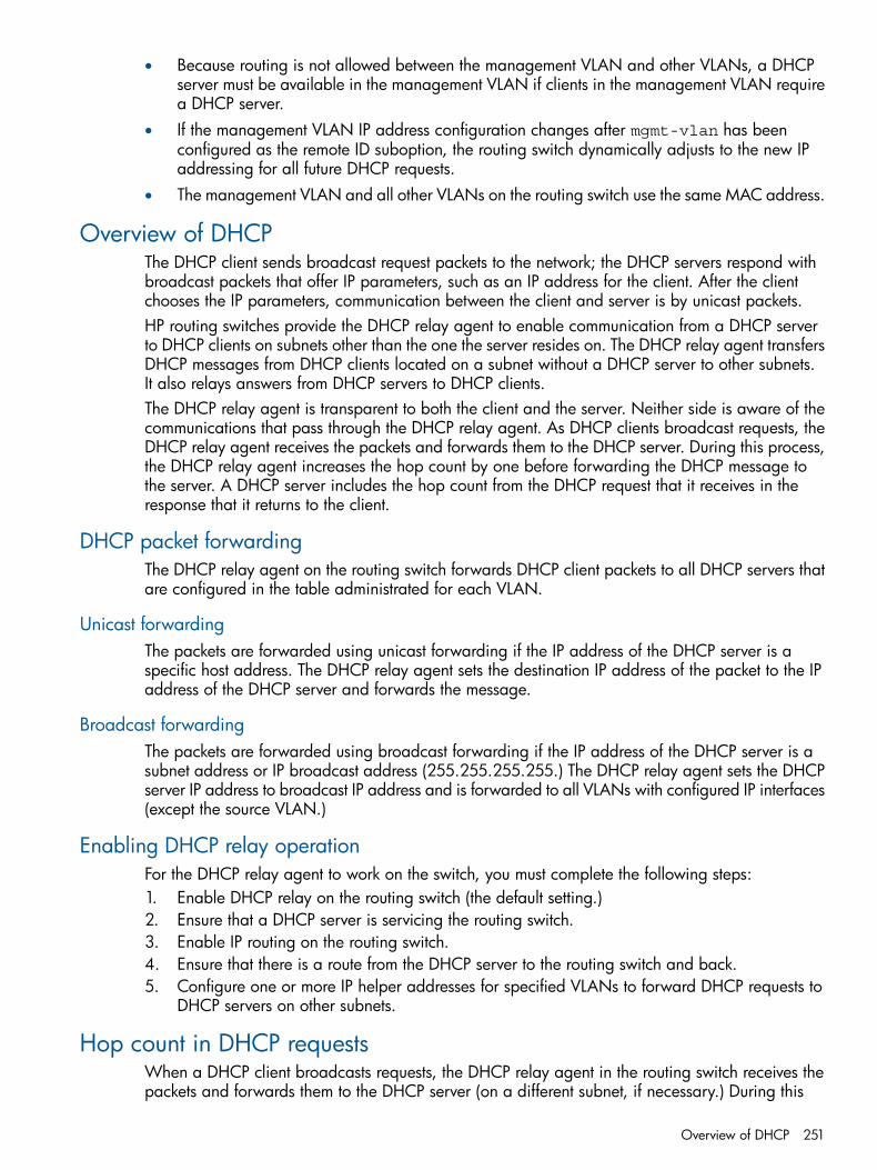
• Because routing is not allowed between the management VLAN and other VLANs, a DHCPserver must be available in the management VLAN if clients in the management VLAN requirea DHCP server.
• If the management VLAN IP address configuration changes after mgmt-vlan has beenconfigured as the remote ID suboption, the routing switch dynamically adjusts to the new IPaddressing for all future DHCP requests.
• The management VLAN and all other VLANs on the routing switch use the same MAC address.
Overview of DHCPThe DHCP client sends broadcast request packets to the network; the DHCP servers respond withbroadcast packets that offer IP parameters, such as an IP address for the client. After the clientchooses the IP parameters, communication between the client and server is by unicast packets.HP routing switches provide the DHCP relay agent to enable communication from a DHCP serverto DHCP clients on subnets other than the one the server resides on. The DHCP relay agent transfersDHCP messages from DHCP clients located on a subnet without a DHCP server to other subnets.It also relays answers from DHCP servers to DHCP clients.The DHCP relay agent is transparent to both the client and the server. Neither side is aware of thecommunications that pass through the DHCP relay agent. As DHCP clients broadcast requests, theDHCP relay agent receives the packets and forwards them to the DHCP server. During this process,the DHCP relay agent increases the hop count by one before forwarding the DHCP message tothe server. A DHCP server includes the hop count from the DHCP request that it receives in theresponse that it returns to the client.
DHCP packet forwardingThe DHCP relay agent on the routing switch forwards DHCP client packets to all DHCP servers thatare configured in the table administrated for each VLAN.
Unicast forwardingThe packets are forwarded using unicast forwarding if the IP address of the DHCP server is aspecific host address. The DHCP relay agent sets the destination IP address of the packet to the IPaddress of the DHCP server and forwards the message.
Broadcast forwardingThe packets are forwarded using broadcast forwarding if the IP address of the DHCP server is asubnet address or IP broadcast address (255.255.255.255.) The DHCP relay agent sets the DHCPserver IP address to broadcast IP address and is forwarded to all VLANs with configured IP interfaces(except the source VLAN.)
Enabling DHCP relay operationFor the DHCP relay agent to work on the switch, you must complete the following steps:1. Enable DHCP relay on the routing switch (the default setting.)2. Ensure that a DHCP server is servicing the routing switch.3. Enable IP routing on the routing switch.4. Ensure that there is a route from the DHCP server to the routing switch and back.5. Configure one or more IP helper addresses for specified VLANs to forward DHCP requests to
DHCP servers on other subnets.
Hop count in DHCP requestsWhen a DHCP client broadcasts requests, the DHCP relay agent in the routing switch receives thepackets and forwards them to the DHCP server (on a different subnet, if necessary.) During this
Overview of DHCP 251
process, the DHCP relay agent increments the hop count before forwarding DHCP packets to theserver. The DHCP server, in turn, includes the hop count from the received DHCP request in theresponse sent back to a DHCP client.As a result, the DHCP client receives a non-zero hop count in the DHCP response packet. Becausesome legacy DHCP/BootP clients discard DHCP responses that contain a hop count greater thanone, they may fail to boot up properly. Although this behavior is in compliance with RFC 1542,it prevents a legacy DHCP/BootP client from being automatically configured with a network IPaddress.
DHCP Option 82Option 82 is called the relay agent information option and is inserted by the DHCP relay agentwhen forwarding client-originated DHCP packets to a DHCP server. Servers recognizing the relayagent information option may use the information to implement IP address or other parameterassignment policies. The DHCP server echoes the option back verbatim to the relay agent inserver-to-client replies, and the relay agent strips the option before forwarding the reply to theclient.The relay agent information option is organized as a single DHCP option that contains one ormore suboptions that convey information known by the relay agent. The initial suboptions aredefined for a relay agent that is co-located in a public circuit access unit. These include a circuitID for the incoming circuit and a remote ID that provides a trusted identifier for the remote high-speedmodem.The routing switch can operate as a DHCP relay agent to enable communication between a clientand a DHCP server on a different subnet. Without Option 82, DHCP operation modifies client IPaddress request packets to the extent needed to forward the packets to a DHCP server. Option 82enhances this operation by enabling the routing switch to append an Option 82 field to such clientrequests. This field includes two suboptions for identifying the routing switch (by MAC address orIP address) and the routing switch port the client is using to access the network. A DHCP serverwith Option 82 capability can read the appended field and use this data as criteria for selectingthe IP addressing it will return to the client through the usual DHCP server response packet. Thisoperation provides several advantages over DHCP without Option 82:• An Option 82 DHCP server can use a relay agent's identity and client source port information
to administer IP addressing policies based on client and relay agent location within the network,regardless of whether the relay agent is the client's primary relay agent or a secondary agent.
• A routing switch operating as a primary Option 82 relay agent for DHCP clients requestingan IP address can enhance network access protection by blocking attempts to use an invalidOption 82 field to imitate an authorized client, or by blocking attempts to use response packetswith missing or invalid Option 82 suboptions to imitate valid response packets from anauthorized DHCP server.
• An Option 82 relay agent can also eliminate unnecessary broadcast traffic by forwarding anOption 82 DHCP server response only to the port on which the requesting client is connected,instead of broadcasting the DHCP response to all ports on the VLAN.
NOTE: The routing switch's DHCP relay information (Option 82) feature can be used in networkswhere the DHCP servers are compliant with RFC 3046 Option 82 operation. DHCP servers thatare not compliant with Option 82 operation ignore Option 82 fields. For information on configuringan Option 82 DHCP server, see the documentation provided with the server application.Some client applications can append an Option 82 field to their DHCP requests; see thedocumentation provided for your client application.
It is not necessary for all relay agents on the path between a DHCP client and the server to supportOption 82, and a relay agent without Option 82 should forward DHCP packets regardless ofwhether they include Option 82 fields. However, Option 82 relay agents should be positioned at
252 Dynamic Host Configuration Protocol
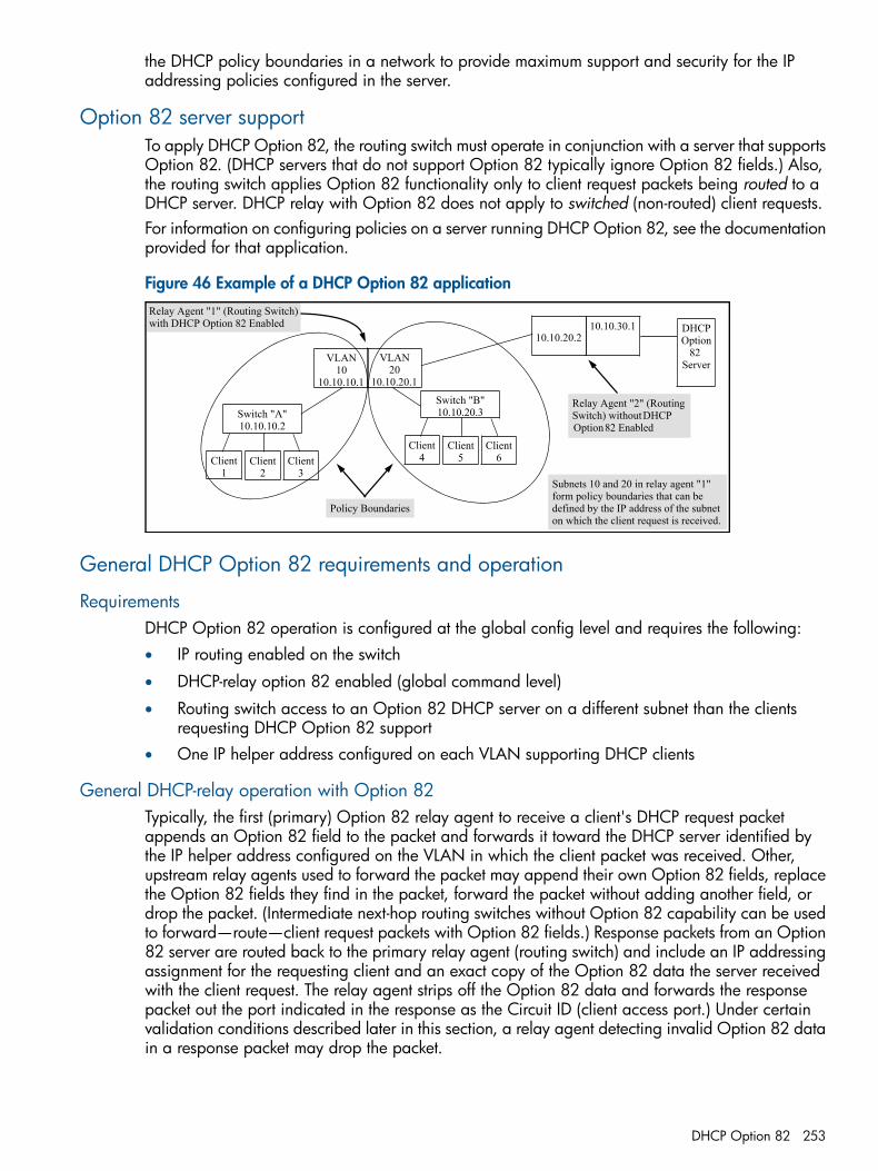
the DHCP policy boundaries in a network to provide maximum support and security for the IPaddressing policies configured in the server.
Option 82 server supportTo apply DHCP Option 82, the routing switch must operate in conjunction with a server that supportsOption 82. (DHCP servers that do not support Option 82 typically ignore Option 82 fields.) Also,the routing switch applies Option 82 functionality only to client request packets being routed to aDHCP server. DHCP relay with Option 82 does not apply to switched (non-routed) client requests.For information on configuring policies on a server running DHCP Option 82, see the documentationprovided for that application.
Figure 46 Example of a DHCP Option 82 application
Switch "A"10.10.10.2
VLAN10
10.10.10.1
Client3
DHCPOption
82 Server
Subnets 10 and 20 in relay agent "1" form policy boundaries that can be defined by the IP address of the subnet on which the client request is received.
Relay Agent "1" (Routing Switch) with DHCP Option 82 Enabled
Client1
Client2
VLAN20
10.10.20.1
Switch "B"10.10.20.3
Client6
Client4
Client5
10.10.20.210.10.30.1
Relay Agent "2" (Routing Switch) without DHCP Option 82 Enabled
Policy Boundaries
General DHCP Option 82 requirements and operation
RequirementsDHCP Option 82 operation is configured at the global config level and requires the following:• IP routing enabled on the switch
• DHCP-relay option 82 enabled (global command level)
• Routing switch access to an Option 82 DHCP server on a different subnet than the clientsrequesting DHCP Option 82 support
• One IP helper address configured on each VLAN supporting DHCP clients
General DHCP-relay operation with Option 82Typically, the first (primary) Option 82 relay agent to receive a client's DHCP request packetappends an Option 82 field to the packet and forwards it toward the DHCP server identified bythe IP helper address configured on the VLAN in which the client packet was received. Other,upstream relay agents used to forward the packet may append their own Option 82 fields, replacethe Option 82 fields they find in the packet, forward the packet without adding another field, ordrop the packet. (Intermediate next-hop routing switches without Option 82 capability can be usedto forward—route—client request packets with Option 82 fields.) Response packets from an Option82 server are routed back to the primary relay agent (routing switch) and include an IP addressingassignment for the requesting client and an exact copy of the Option 82 data the server receivedwith the client request. The relay agent strips off the Option 82 data and forwards the responsepacket out the port indicated in the response as the Circuit ID (client access port.) Under certainvalidation conditions described later in this section, a relay agent detecting invalid Option 82 datain a response packet may drop the packet.
DHCP Option 82 253
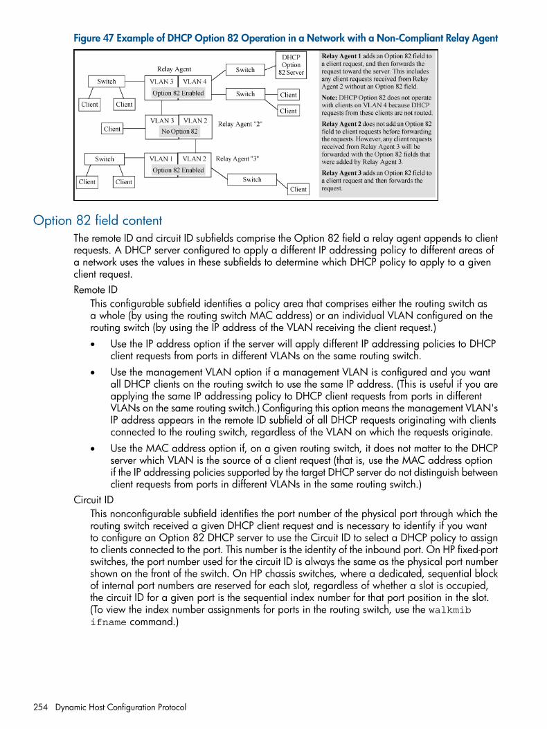
Figure 47 Example of DHCP Option 82 Operation in a Network with a Non-Compliant Relay Agent
Option 82 field contentThe remote ID and circuit ID subfields comprise the Option 82 field a relay agent appends to clientrequests. A DHCP server configured to apply a different IP addressing policy to different areas ofa network uses the values in these subfields to determine which DHCP policy to apply to a givenclient request.Remote ID
This configurable subfield identifies a policy area that comprises either the routing switch asa whole (by using the routing switch MAC address) or an individual VLAN configured on therouting switch (by using the IP address of the VLAN receiving the client request.)• Use the IP address option if the server will apply different IP addressing policies to DHCP
client requests from ports in different VLANs on the same routing switch.• Use the management VLAN option if a management VLAN is configured and you want
all DHCP clients on the routing switch to use the same IP address. (This is useful if you areapplying the same IP addressing policy to DHCP client requests from ports in differentVLANs on the same routing switch.) Configuring this option means the management VLAN'sIP address appears in the remote ID subfield of all DHCP requests originating with clientsconnected to the routing switch, regardless of the VLAN on which the requests originate.
• Use the MAC address option if, on a given routing switch, it does not matter to the DHCPserver which VLAN is the source of a client request (that is, use the MAC address optionif the IP addressing policies supported by the target DHCP server do not distinguish betweenclient requests from ports in different VLANs in the same routing switch.)
Circuit IDThis nonconfigurable subfield identifies the port number of the physical port through which therouting switch received a given DHCP client request and is necessary to identify if you wantto configure an Option 82 DHCP server to use the Circuit ID to select a DHCP policy to assignto clients connected to the port. This number is the identity of the inbound port. On HP fixed-portswitches, the port number used for the circuit ID is always the same as the physical port numbershown on the front of the switch. On HP chassis switches, where a dedicated, sequential blockof internal port numbers are reserved for each slot, regardless of whether a slot is occupied,the circuit ID for a given port is the sequential index number for that port position in the slot.(To view the index number assignments for ports in the routing switch, use the walkmibifname command.)
254 Dynamic Host Configuration Protocol
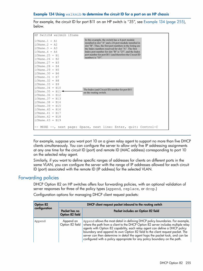
Example 134 Using walkmib to determine the circuit ID for a port on an HP chassis
For example, the circuit ID for port B11 on an HP switch is "35”, see Example 134 (page 255),below.
HP Switch# walkmib ifname
ifName.1 = A1ifName.2 = A2ifName.3 = A3ifName.4 = A4ifName.25 = B1ifName.26 = B2ifName.27 = B3ifName.28 = B4ifName.29 = B5ifName.30 = B6ifName.31 = B7ifName.32 = B8ifName.33 = B9ifName.34 = B10ifName.35 = B11ifName.36 = B12ifName.37 = B13ifName.38 = B14ifName.39 = B15ifName.40 = B16ifName.41 = B17ifName.42 = B18ifName.43 = B19
-- MORE --, next page: Space, next line: Enter, quit: Control-C
In this example, the switch has a 4-port module installed in slot "A" and a 24-port module installed in slot "B". Thus, the first port numbers in the listing are the Index numbers reserved for slot "A". The first Index port number for slot "B" is "25", and the Index port number for port B11 (and therefore the Circuit ID number) is "35".
The Index (and Circuit ID) number for port B11 on the routing switch.
For example, suppose you want port 10 on a given relay agent to support no more than five DHCPclients simultaneously. You can configure the server to allow only five IP addressing assignmentsat any one time for the circuit ID (port) and remote ID (MAC address) corresponding to port 10on the selected relay agent.Similarly, if you want to define specific ranges of addresses for clients on different ports in thesame VLAN, you can configure the server with the range of IP addresses allowed for each circuitID (port) associated with the remote ID (IP address) for the selected VLAN.
Forwarding policiesDHCP Option 82 on HP switches offers four forwarding policies, with an optional validation ofserver responses for three of the policy types (append, replace, or drop.)Configuration options for managing DHCP client request packets:
DHCP client request packet inbound to the routing switchOption 82configuration
Packet includes an Option 82 fieldPacket has noOption 82 field
Append allows the most detail in defining DHCP policy boundaries. For example,where the path from a client to the DHCP Option 82 server includes multiple relay
Append anOption 82 field
Append
agents with Option 82 capability, each relay agent can define a DHCP policyboundary and append its own Option 82 field to the client request packet. Theserver can then determine in detail the agent hops the packet took, and can beconfigured with a policy appropriate for any policy boundary on the path.
DHCP Option 82 255
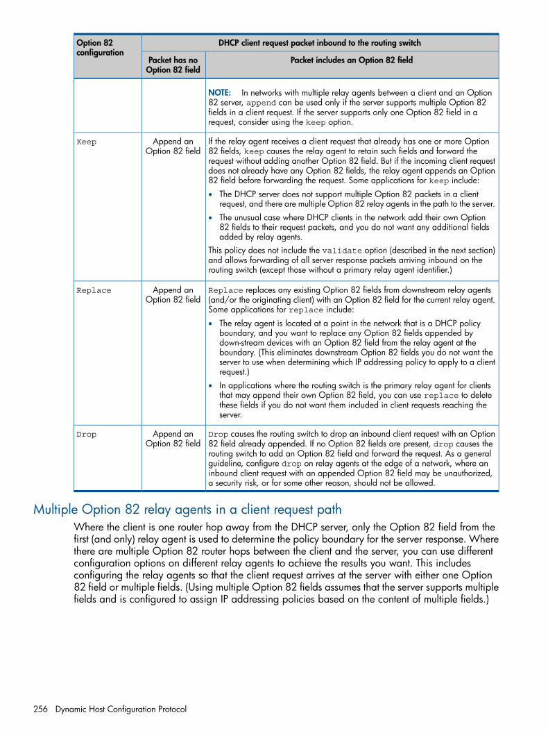
DHCP client request packet inbound to the routing switchOption 82configuration
Packet includes an Option 82 fieldPacket has noOption 82 field
NOTE: In networks with multiple relay agents between a client and an Option82 server, append can be used only if the server supports multiple Option 82fields in a client request. If the server supports only one Option 82 field in arequest, consider using the keep option.
If the relay agent receives a client request that already has one or more Option82 fields, keep causes the relay agent to retain such fields and forward the
Append anOption 82 field
Keep
request without adding another Option 82 field. But if the incoming client requestdoes not already have any Option 82 fields, the relay agent appends an Option82 field before forwarding the request. Some applications for keep include:
• The DHCP server does not support multiple Option 82 packets in a clientrequest, and there are multiple Option 82 relay agents in the path to the server.
• The unusual case where DHCP clients in the network add their own Option82 fields to their request packets, and you do not want any additional fieldsadded by relay agents.
This policy does not include the validate option (described in the next section)and allows forwarding of all server response packets arriving inbound on therouting switch (except those without a primary relay agent identifier.)
Replace replaces any existing Option 82 fields from downstream relay agents(and/or the originating client) with an Option 82 field for the current relay agent.Some applications for replace include:
Append anOption 82 field
Replace
• The relay agent is located at a point in the network that is a DHCP policyboundary, and you want to replace any Option 82 fields appended bydown-stream devices with an Option 82 field from the relay agent at theboundary. (This eliminates downstream Option 82 fields you do not want theserver to use when determining which IP addressing policy to apply to a clientrequest.)
• In applications where the routing switch is the primary relay agent for clientsthat may append their own Option 82 field, you can use replace to deletethese fields if you do not want them included in client requests reaching theserver.
Drop causes the routing switch to drop an inbound client request with an Option82 field already appended. If no Option 82 fields are present, drop causes the
Append anOption 82 field
Drop
routing switch to add an Option 82 field and forward the request. As a generalguideline, configure drop on relay agents at the edge of a network, where aninbound client request with an appended Option 82 field may be unauthorized,a security risk, or for some other reason, should not be allowed.
Multiple Option 82 relay agents in a client request pathWhere the client is one router hop away from the DHCP server, only the Option 82 field from thefirst (and only) relay agent is used to determine the policy boundary for the server response. Wherethere are multiple Option 82 router hops between the client and the server, you can use differentconfiguration options on different relay agents to achieve the results you want. This includesconfiguring the relay agents so that the client request arrives at the server with either one Option82 field or multiple fields. (Using multiple Option 82 fields assumes that the server supports multiplefields and is configured to assign IP addressing policies based on the content of multiple fields.)
256 Dynamic Host Configuration Protocol
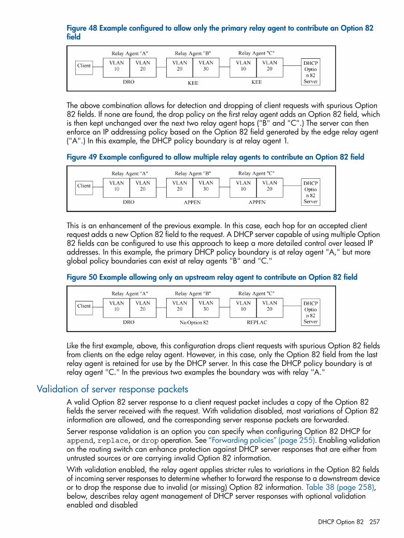
Figure 48 Example configured to allow only the primary relay agent to contribute an Option 82field
The above combination allows for detection and dropping of client requests with spurious Option82 fields. If none are found, the drop policy on the first relay agent adds an Option 82 field, whichis then kept unchanged over the next two relay agent hops ("B" and "C".) The server can thenenforce an IP addressing policy based on the Option 82 field generated by the edge relay agent("A".) In this example, the DHCP policy boundary is at relay agent 1.
Figure 49 Example configured to allow multiple relay agents to contribute an Option 82 field
This is an enhancement of the previous example. In this case, each hop for an accepted clientrequest adds a new Option 82 field to the request. A DHCP server capable of using multiple Option82 fields can be configured to use this approach to keep a more detailed control over leased IPaddresses. In this example, the primary DHCP policy boundary is at relay agent "A," but moreglobal policy boundaries can exist at relay agents "B" and "C."
Figure 50 Example allowing only an upstream relay agent to contribute an Option 82 field
Like the first example, above, this configuration drops client requests with spurious Option 82 fieldsfrom clients on the edge relay agent. However, in this case, only the Option 82 field from the lastrelay agent is retained for use by the DHCP server. In this case the DHCP policy boundary is atrelay agent "C." In the previous two examples the boundary was with relay "A."
Validation of server response packetsA valid Option 82 server response to a client request packet includes a copy of the Option 82fields the server received with the request. With validation disabled, most variations of Option 82information are allowed, and the corresponding server response packets are forwarded.Server response validation is an option you can specify when configuring Option 82 DHCP forappend, replace, or drop operation. See “Forwarding policies” (page 255). Enabling validationon the routing switch can enhance protection against DHCP server responses that are either fromuntrusted sources or are carrying invalid Option 82 information.With validation enabled, the relay agent applies stricter rules to variations in the Option 82 fieldsof incoming server responses to determine whether to forward the response to a downstream deviceor to drop the response due to invalid (or missing) Option 82 information. Table 38 (page 258),below, describes relay agent management of DHCP server responses with optional validationenabled and disabled
DHCP Option 82 257
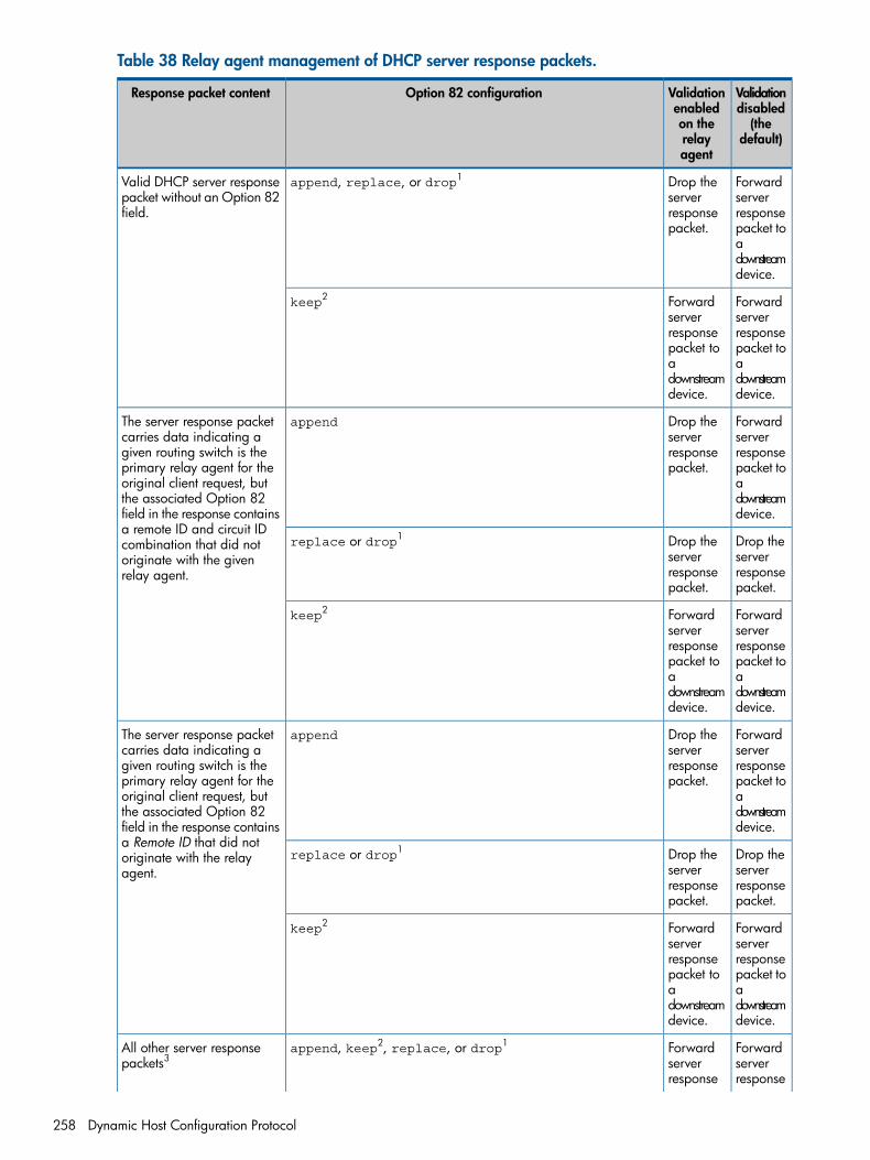
Table 38 Relay agent management of DHCP server response packets.
Validationdisabled
Validationenabled
Option 82 configurationResponse packet content
(thedefault)
on therelayagent
Forwardserver
Drop theserver
append, replace, or drop1Valid DHCP server responsepacket without an Option 82field. responseresponse
packet. packet toadownstreamdevice.
Forwardserver
Forwardserver
keep2
responseresponsepacket topacket toaadownstreamdevice.
downstreamdevice.
Forwardserver
Drop theserver
appendThe server response packetcarries data indicating a
responseresponsepacket.
given routing switch is theprimary relay agent for the packet tooriginal client request, but athe associated Option 82 downstream
device.field in the response containsa remote ID and circuit ID
Drop theserver
Drop theserver
replace or drop1combination that did notoriginate with the givenrelay agent. response
packet.responsepacket.
Forwardserver
Forwardserver
keep2
responseresponsepacket topacket toaadownstreamdevice.
downstreamdevice.
Forwardserver
Drop theserver
appendThe server response packetcarries data indicating a
responseresponsepacket.
given routing switch is theprimary relay agent for the packet tooriginal client request, but athe associated Option 82 downstream
device.field in the response containsa Remote ID that did not
Drop theserver
Drop theserver
replace or drop1originate with the relayagent.
responsepacket.
responsepacket.
Forwardserver
Forwardserver
keep2
responseresponsepacket topacket toaadownstreamdevice.
downstreamdevice.
Forwardserver
Forwardserver
append, keep2, replace, or drop1All other server responsepackets3
responseresponse
258 Dynamic Host Configuration Protocol
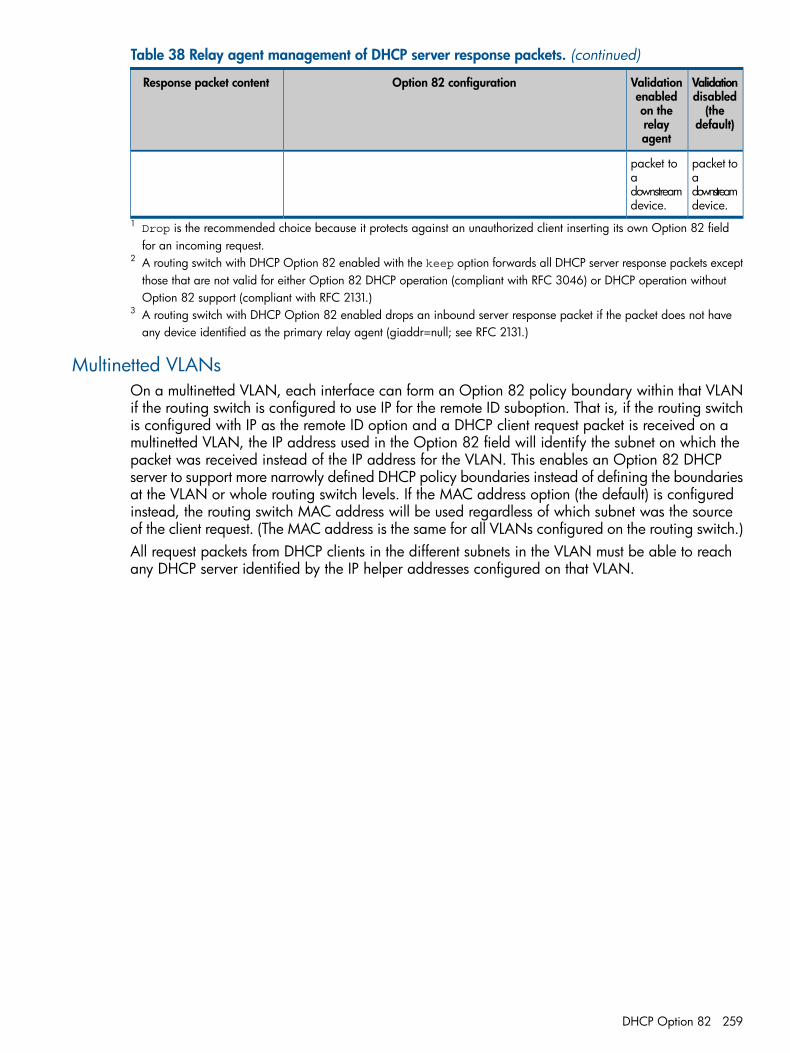
Table 38 Relay agent management of DHCP server response packets. (continued)
Validationdisabled(the
default)
Validationenabledon therelayagent
Option 82 configurationResponse packet content
packet toa
packet toa
downstreamdevice.
downstreamdevice.
1 Drop is the recommended choice because it protects against an unauthorized client inserting its own Option 82 fieldfor an incoming request.
2 A routing switch with DHCP Option 82 enabled with the keep option forwards all DHCP server response packets exceptthose that are not valid for either Option 82 DHCP operation (compliant with RFC 3046) or DHCP operation withoutOption 82 support (compliant with RFC 2131.)
3 A routing switch with DHCP Option 82 enabled drops an inbound server response packet if the packet does not haveany device identified as the primary relay agent (giaddr=null; see RFC 2131.)
Multinetted VLANsOn a multinetted VLAN, each interface can form an Option 82 policy boundary within that VLANif the routing switch is configured to use IP for the remote ID suboption. That is, if the routing switchis configured with IP as the remote ID option and a DHCP client request packet is received on amultinetted VLAN, the IP address used in the Option 82 field will identify the subnet on which thepacket was received instead of the IP address for the VLAN. This enables an Option 82 DHCPserver to support more narrowly defined DHCP policy boundaries instead of defining the boundariesat the VLAN or whole routing switch levels. If the MAC address option (the default) is configuredinstead, the routing switch MAC address will be used regardless of which subnet was the sourceof the client request. (The MAC address is the same for all VLANs configured on the routing switch.)All request packets from DHCP clients in the different subnets in the VLAN must be able to reachany DHCP server identified by the IP helper addresses configured on that VLAN.
DHCP Option 82 259
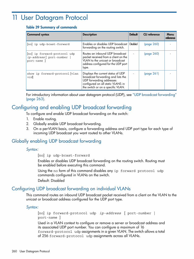
11 User Datagram ProtocolTable 39 Summary of commands
Menureference
CLI referenceDefaultDescriptionCommand syntax
-(page 260)DisabledEnables or disables UDP broadcastforwarding on the routing switch.
[no] ip udp-bcast-forward
-(page 260)-Routes an inbound UDP broadcastpacket received from a client on the
[no] ip forward-protocol udpip-address [ port-number |port-name ] VLAN to the unicast or broadcast
address configured for the UDP porttype.
-(page 261)-Displays the current status of UDPbroadcast forwarding and lists the
show ip forward-protocol [vlanvid]
UDP forwarding addressesconfigured on all static VLANS inthe switch or on a specific VLAN.
For introductory information about user datagram protocol (UDP), see “UDP broadcast forwarding”(page 263).
Configuring and enabling UDP broadcast forwardingTo configure and enable UDP broadcast forwarding on the switch:1. Enable routing.2. Globally enable UDP broadcast forwarding.3. On a per-VLAN basis, configure a forwarding address and UDP port type for each type of
incoming UDP broadcast you want routed to other VLANs.
Globally enabling UDP broadcast forwarding
Syntax:[no] ip udp-bcast-forwardEnables or disables UDP broadcast forwarding on the routing switch. Routing mustbe enabled before executing this command.Using the no form of this command disables any ip forward protocol udpcommands configured in VLANs on the switch.Default: Disabled
Configuring UDP broadcast forwarding on individual VLANsThis command routes an inbound UDP broadcast packet received from a client on the VLAN to theunicast or broadcast address configured for the UDP port type.
Syntax:[no] ip forward-protocol udp ip-address [ port-number |port-name ]Used in a VLAN context to configure or remove a server or broadcast address andits associated UDP port number. You can configure a maximum of 16forward-protocol udp assignments in a given VLAN. The switch allows a totalof 256 forward-protocol udp assignments across all VLANs.
260 User Datagram Protocol
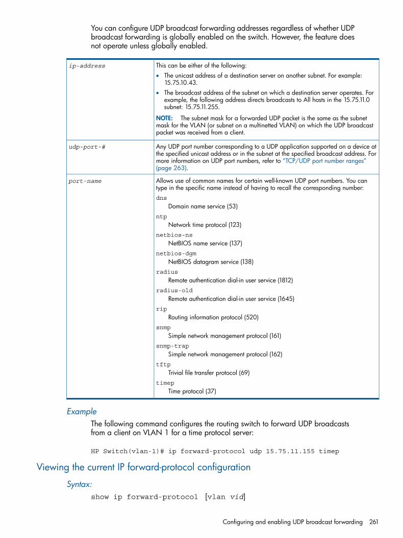
You can configure UDP broadcast forwarding addresses regardless of whether UDPbroadcast forwarding is globally enabled on the switch. However, the feature doesnot operate unless globally enabled.
This can be either of the following:ip-address
• The unicast address of a destination server on another subnet. For example:15.75.10.43.
• The broadcast address of the subnet on which a destination server operates. Forexample, the following address directs broadcasts to All hosts in the 15.75.11.0subnet: 15.75.11.255.
NOTE: The subnet mask for a forwarded UDP packet is the same as the subnetmask for the VLAN (or subnet on a multinetted VLAN) on which the UDP broadcastpacket was received from a client.
Any UDP port number corresponding to a UDP application supported on a device atthe specified unicast address or in the subnet at the specified broadcast address. For
udp-port-#
more information on UDP port numbers, refer to “TCP/UDP port number ranges”(page 263).
Allows use of common names for certain well-known UDP port numbers. You cantype in the specific name instead of having to recall the corresponding number:dns
Domain name service (53)
port-name
ntp
Network time protocol (123)netbios-ns
NetBIOS name service (137)netbios-dgm
NetBIOS datagram service (138)radius
Remote authentication dial-in user service (1812)radius-old
Remote authentication dial-in user service (1645)rip
Routing information protocol (520)snmp
Simple network management protocol (161)snmp-trap
Simple network management protocol (162)tftp
Trivial file transfer protocol (69)timep
Time protocol (37)
ExampleThe following command configures the routing switch to forward UDP broadcastsfrom a client on VLAN 1 for a time protocol server:
HP Switch(vlan-1)# ip forward-protocol udp 15.75.11.155 timep
Viewing the current IP forward-protocol configuration
Syntax:show ip forward-protocol [vlan vid]
Configuring and enabling UDP broadcast forwarding 261
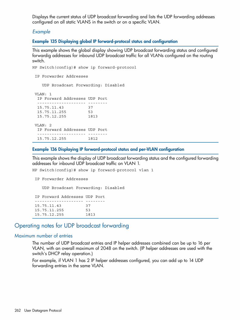
Displays the current status of UDP broadcast forwarding and lists the UDP forwarding addressesconfigured on all static VLANS in the switch or on a specific VLAN.
Example
Example 135 Displaying global IP forward-protocol status and configuration
This example shows the global display showing UDP broadcast forwarding status and configuredforwardig addresses for inbound UDP broadcast traffic for all VLANs configured on the routingswitch.HP Switch(config)# show ip forward-protocol
IP Forwarder Addresses
UDP Broadcast Forwarding: Disabled
VLAN: 1 IP Forward Addresses UDP Port -------------------- -------- 15.75.11.43 37 15.75.11.255 53 15.75.12.255 1813
VLAN: 2 IP Forward Addresses UDP Port -------------------- -------- 15.75.12.255 1812
Example 136 Displaying IP forward-protocol status and per-VLAN configuration
This example shows the display of UDP broadcast forwarding status and the configured forwardingaddresses for inbound UDP broadcast traffic on VLAN 1.HP Switch(config)# show ip forward-protocol vlan 1
IP Forwarder Addresses
UDP Broadcast Forwarding: Disabled
IP Forward Addresses UDP Port -------------------- -------- 15.75.11.43 37 15.75.11.255 53 15.75.12.255 1813
Operating notes for UDP broadcast forwarding
Maximum number of entriesThe number of UDP broadcast entries and IP helper addresses combined can be up to 16 perVLAN, with an overall maximum of 2048 on the switch. (IP helper addresses are used with theswitch's DHCP relay operation.)For example, if VLAN 1 has 2 IP helper addresses configured, you can add up to 14 UDPforwarding entries in the same VLAN.
262 User Datagram Protocol
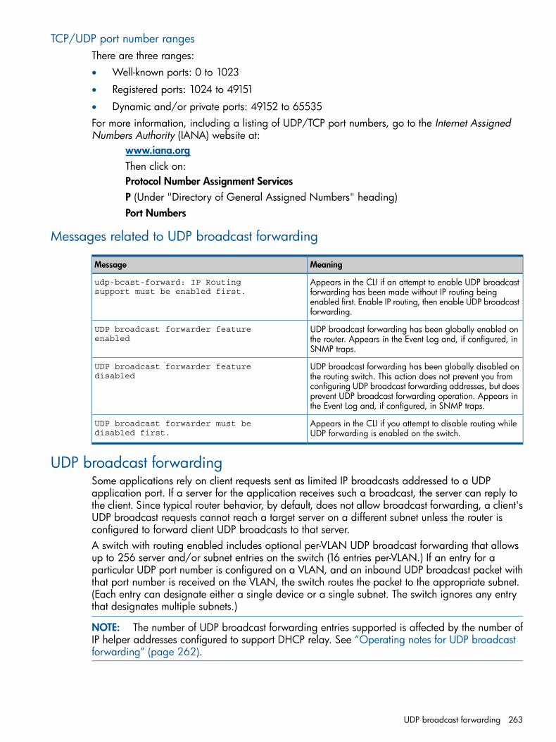
TCP/UDP port number rangesThere are three ranges:• Well-known ports: 0 to 1023
• Registered ports: 1024 to 49151
• Dynamic and/or private ports: 49152 to 65535For more information, including a listing of UDP/TCP port numbers, go to the Internet AssignedNumbers Authority (IANA) website at:
www.iana.orgThen click on:Protocol Number Assignment ServicesP (Under "Directory of General Assigned Numbers" heading)Port Numbers
Messages related to UDP broadcast forwarding
MeaningMessage
Appears in the CLI if an attempt to enable UDP broadcastforwarding has been made without IP routing being
udp-bcast-forward: IP Routingsupport must be enabled first.
enabled first. Enable IP routing, then enable UDP broadcastforwarding.
UDP broadcast forwarding has been globally enabled onthe router. Appears in the Event Log and, if configured, inSNMP traps.
UDP broadcast forwarder featureenabled
UDP broadcast forwarding has been globally disabled onthe routing switch. This action does not prevent you from
UDP broadcast forwarder featuredisabled
configuring UDP broadcast forwarding addresses, but doesprevent UDP broadcast forwarding operation. Appears inthe Event Log and, if configured, in SNMP traps.
Appears in the CLI if you attempt to disable routing whileUDP forwarding is enabled on the switch.
UDP broadcast forwarder must bedisabled first.
UDP broadcast forwardingSome applications rely on client requests sent as limited IP broadcasts addressed to a UDPapplication port. If a server for the application receives such a broadcast, the server can reply tothe client. Since typical router behavior, by default, does not allow broadcast forwarding, a client'sUDP broadcast requests cannot reach a target server on a different subnet unless the router isconfigured to forward client UDP broadcasts to that server.A switch with routing enabled includes optional per-VLAN UDP broadcast forwarding that allowsup to 256 server and/or subnet entries on the switch (16 entries per-VLAN.) If an entry for aparticular UDP port number is configured on a VLAN, and an inbound UDP broadcast packet withthat port number is received on the VLAN, the switch routes the packet to the appropriate subnet.(Each entry can designate either a single device or a single subnet. The switch ignores any entrythat designates multiple subnets.)
NOTE: The number of UDP broadcast forwarding entries supported is affected by the number ofIP helper addresses configured to support DHCP relay. See “Operating notes for UDP broadcastforwarding” (page 262).
UDP broadcast forwarding 263
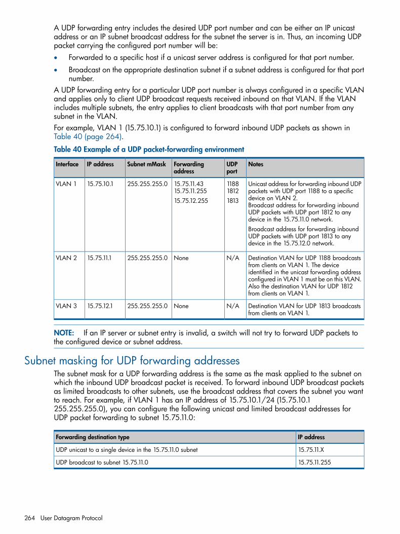
A UDP forwarding entry includes the desired UDP port number and can be either an IP unicastaddress or an IP subnet broadcast address for the subnet the server is in. Thus, an incoming UDPpacket carrying the configured port number will be:• Forwarded to a specific host if a unicast server address is configured for that port number.
• Broadcast on the appropriate destination subnet if a subnet address is configured for that portnumber.
A UDP forwarding entry for a particular UDP port number is always configured in a specific VLANand applies only to client UDP broadcast requests received inbound on that VLAN. If the VLANincludes multiple subnets, the entry applies to client broadcasts with that port number from anysubnet in the VLAN.For example, VLAN 1 (15.75.10.1) is configured to forward inbound UDP packets as shown inTable 40 (page 264).
Table 40 Example of a UDP packet-forwarding environment
NotesUDPport
Forwardingaddress
Subnet mMaskIP addressInterface
Unicast address for forwarding inbound UDPpackets with UDP port 1188 to a specificdevice on VLAN 2.Broadcast address for forwarding inboundUDP packets with UDP port 1812 to anydevice in the 15.75.11.0 network.
118818121813
15.75.11.4315.75.11.25515.75.12.255
255.255.255.015.75.10.1VLAN 1
Broadcast address for forwarding inboundUDP packets with UDP port 1813 to anydevice in the 15.75.12.0 network.
Destination VLAN for UDP 1188 broadcastsfrom clients on VLAN 1. The device
N/ANone255.255.255.015.75.11.1VLAN 2
identified in the unicast forwarding addressconfigured in VLAN 1 must be on this VLAN.Also the destination VLAN for UDP 1812from clients on VLAN 1.
Destination VLAN for UDP 1813 broadcastsfrom clients on VLAN 1.
N/ANone255.255.255.015.75.12.1VLAN 3
NOTE: If an IP server or subnet entry is invalid, a switch will not try to forward UDP packets tothe configured device or subnet address.
Subnet masking for UDP forwarding addressesThe subnet mask for a UDP forwarding address is the same as the mask applied to the subnet onwhich the inbound UDP broadcast packet is received. To forward inbound UDP broadcast packetsas limited broadcasts to other subnets, use the broadcast address that covers the subnet you wantto reach. For example, if VLAN 1 has an IP address of 15.75.10.1/24 (15.75.10.1255.255.255.0), you can configure the following unicast and limited broadcast addresses forUDP packet forwarding to subnet 15.75.11.0:
IP addressForwarding destination type
15.75.11.XUDP unicast to a single device in the 15.75.11.0 subnet
15.75.11.255UDP broadcast to subnet 15.75.11.0
264 User Datagram Protocol
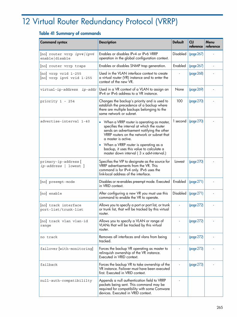
12 Virtual Router Redundancy Protocol (VRRP)Table 41 Summary of commands
Menureference
CLIreference
DefaultDescriptionCommand syntax
-(page267)DisabledEnables or disables IPv4 or IPv6 VRRPoperation in the global configuration context.
[no] router vrrp ipv4|ipv6enable|disable
-(page267)EnabledEnables or disables SNMP trap generation.[no] router vrrp traps
-(page268)-Used in the VLAN interface context to createa virtual router (VR) instance and to enter thecontext of the new VR.
[no] vrrp vrid 1-255[no] vrrp ipv6 vrid 1-255
-(page269)NoneUsed in a VR context of a VLAN to assign anIPv4 or IPv6 address to a VR instance.
virtual-ip-address ip-addr
-(page270)100Changes the backup's priority and is used toestablish the precedence of a backup where
priority 1 - 254
there are multiple backups belonging to thesame network or subnet.
-(page270)1 secondadvertise-interval 1-40 • When a VRRP router is operating as master,specifies the interval at which the routersends an advertisement notifying the otherVRRP routers on the network or subnet thata master is active.
• When a VRRP router is operating as abackup, it uses this value to calculate amaster down interval ( 3 x advt-interval.)
-(page270)LowestSpecifies the VIP to designate as the source forVRRP advertisements from the VR. This
primary-ip-address [ip-address | lowest ]
command is for IPv4 only. IPv6 uses thelink-local address of the interface.
-(page271)EnabledDisables or re-enables preempt mode. Executedin VRID context.
[no] preempt-mode
-(page271)DisabledAfter configuring a new VR you must use thiscommand to enable the VR to operate.
[no] enable
-(page272)-Allows you to specify a port or port list, or trunkor trunk list, that will be tracked by this virtualrouter.
[no] track interfaceport-list/trunk-list
-(page272)-Allows you to specify a VLAN or range ofVLANs that will be tracked by this virtualrouter.
[no] track vlan vlan-idrange
-(page272)-Removes all interfaces and vlans from beingtracked.
no track
-(page273)-Forces the backup VR operating as master torelinquish ownership of the VR instance.Executed in VRID context.
failover [with-monitoring]
-(page273)-Forces the backup VR to take ownership of theVR instance. Failover must have been executedfirst. Executed in VRID context.
failback
-Appends a null authentication field to VRRPpackets being sent. This command may be
null-auth-compatibililty
required for compatibility with some Comwaredevices. Executed in VRID context.
265
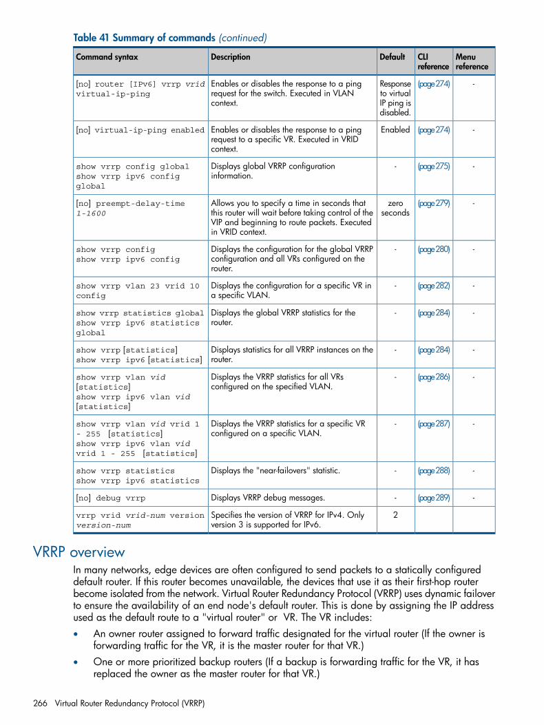
Table 41 Summary of commands (continued)
Menureference
CLIreference
DefaultDescriptionCommand syntax
-(page274)Responseto virtual
Enables or disables the response to a pingrequest for the switch. Executed in VLANcontext.
[no] router [IPv6] vrrp vridvirtual-ip-ping
IP ping isdisabled.
-(page274)EnabledEnables or disables the response to a pingrequest to a specific VR. Executed in VRIDcontext.
[no] virtual-ip-ping enabled
-(page275)-Displays global VRRP configurationinformation.
show vrrp config globalshow vrrp ipv6 configglobal
-(page279)zeroseconds
Allows you to specify a time in seconds thatthis router will wait before taking control of the
[no] preempt-delay-time1-1600
VIP and beginning to route packets. Executedin VRID context.
-(page280)-Displays the configuration for the global VRRPconfiguration and all VRs configured on therouter.
show vrrp configshow vrrp ipv6 config
-(page282)-Displays the configuration for a specific VR ina specific VLAN.
show vrrp vlan 23 vrid 10config
-(page284)-Displays the global VRRP statistics for therouter.
show vrrp statistics globalshow vrrp ipv6 statisticsglobal
-(page284)-Displays statistics for all VRRP instances on therouter.
show vrrp [statistics]show vrrp ipv6 [statistics]
-(page286)-Displays the VRRP statistics for all VRsconfigured on the specified VLAN.
show vrrp vlan vid[statistics]show vrrp ipv6 vlan vid[statistics]
-(page287)-Displays the VRRP statistics for a specific VRconfigured on a specific VLAN.
show vrrp vlan vid vrid 1- 255 [statistics]show vrrp ipv6 vlan vidvrid 1 - 255 [statistics]
-(page288)-Displays the "near-failovers" statistic.show vrrp statisticsshow vrrp ipv6 statistics
-(page289)-Displays VRRP debug messages.[no] debug vrrp
2Specifies the version of VRRP for IPv4. Onlyversion 3 is supported for IPv6.
vrrp vrid vrid-num versionversion-num
VRRP overviewIn many networks, edge devices are often configured to send packets to a statically configureddefault router. If this router becomes unavailable, the devices that use it as their first-hop routerbecome isolated from the network. Virtual Router Redundancy Protocol (VRRP) uses dynamic failoverto ensure the availability of an end node's default router. This is done by assigning the IP addressused as the default route to a "virtual router" or VR. The VR includes:• An owner router assigned to forward traffic designated for the virtual router (If the owner is
forwarding traffic for the VR, it is the master router for that VR.)• One or more prioritized backup routers (If a backup is forwarding traffic for the VR, it has
replaced the owner as the master router for that VR.)
266 Virtual Router Redundancy Protocol (VRRP)
This redundancy provides a backup for gateway IP addresses (first-hop routers) so that if a VR'smaster router becomes unavailable, the traffic it supports will be transferred to a backup routerwithout major delays or operator intervention. This operation can eliminate single-point-of-failureproblems and provide dynamic failover (and failback) support. As long as one physical router ina VR configuration is available, the IP addresses assigned to the VR are always available, and theedge devices can send packets to these IP addresses without interruption.Advantages to using VRRP include:• Minimizing failover time and bandwidth overhead if a primary router becomes unavailable.
• Minimizing service disruptions during a failover.
• Providing backup for a load-balanced routing solution.
• Addressing failover problems at the router level instead of on the network edge.
• Avoiding the need to make configuration changes in the end nodes if a gateway router fails.
• Eliminating the need for router discovery protocols to support failover operation.Both VRRPv2 and VRRPv3 are supported. IPv4 VRs can be configured for both version 2 and version3. IPv6 VRs can only be configured for version 3.For more information, see “General operation” (page 290).
Configuring VRRP
Enabling VRRP in the global configuration contextVRRP can be configured regardless of the global VRRP configuration status. However, enabling aVR and running VRRP requires enabling it in the global configuration context.
Syntax:[no] router vrrp IPv4|IPv6 enable|disable
Enables or disables VRRP operation in the global configuration context. for IPv4,IP routing must be enabled before enabling VRRP on the router. For IPv6, IPv6unicast-routing must be enabled before enabling VRRP on the router. Disablingglobal VRRP halts VRRP operation on the router, but does not affect the current VRRPconfiguration. Enabling or disabling VRRP generates an Event Log message.Note: This command has been revised from the prior router vrrpenablecommand.To display the current global VRRP configuration, use show vrrp configglobal.Default: Disabled
Syntax:[no] router vrrp trapsEnables or disables SNMP trap generation for the following events:New master
Indicates that the sending router has transitioned to 'master' state.Authentication Failure
Indicates that a VRRP packet has been received from a router whoseauthentication key or authentication type conflicts with this router's authenticationkey or authentication type.
Configuring VRRP 267
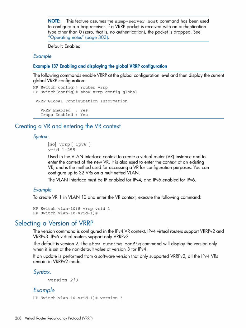
NOTE: This feature assumes the snmp-server host command has been usedto configure a a trap receiver. If a VRRP packet is received with an authenticationtype other than 0 (zero, that is, no authentication), the packet is dropped. See“Operating notes” (page 303).
Default: Enabled
Example
Example 137 Enabling and displaying the global VRRP configuration
The following commands enable VRRP at the global configuration level and then display the currentglobal VRRP configuration:HP Switch(config)# router vrrpHP Switch(config)# show vrrp config global
VRRP Global Configuration Information
VRRP Enabled : Yes Traps Enabled : Yes
Creating a VR and entering the VR context
Syntax:[no] vrrp [ ipv6 ]vrid 1-255
Used in the VLAN interface context to create a virtual router (VR) instance and toenter the context of the new VR. It is also used to enter the context of an existingVR, and is the method used for accessing a VR for configuration purposes. You canconfigure up to 32 VRs on a multinetted VLAN.The VLAN interface must be IP enabled for IPv4, and IPv6 enabled for IPv6.
ExampleTo create VR 1 in VLAN 10 and enter the VR context, execute the following command:
HP Switch(vlan-10)# vrrp vrid 1HP Switch(vlan-10-vrid-1)#
Selecting a Version of VRRPThe version command is configured in the IPv4 VR context. IPv4 virtual routers support VRRPv2 andVRRPv3. IPv6 virtual routers support only VRRPv3.The default is version 2. The show running-config command will display the version onlywhen it is set at the non-default value of version 3 for IPv4.If an update is performed from a software version that only supported VRRPv2, all the IPv4 VRsremain in VRRPv2 mode.
Syntax.version 2|3
ExampleHP Switch(vlan-10-vrid-1)# version 3
268 Virtual Router Redundancy Protocol (VRRP)
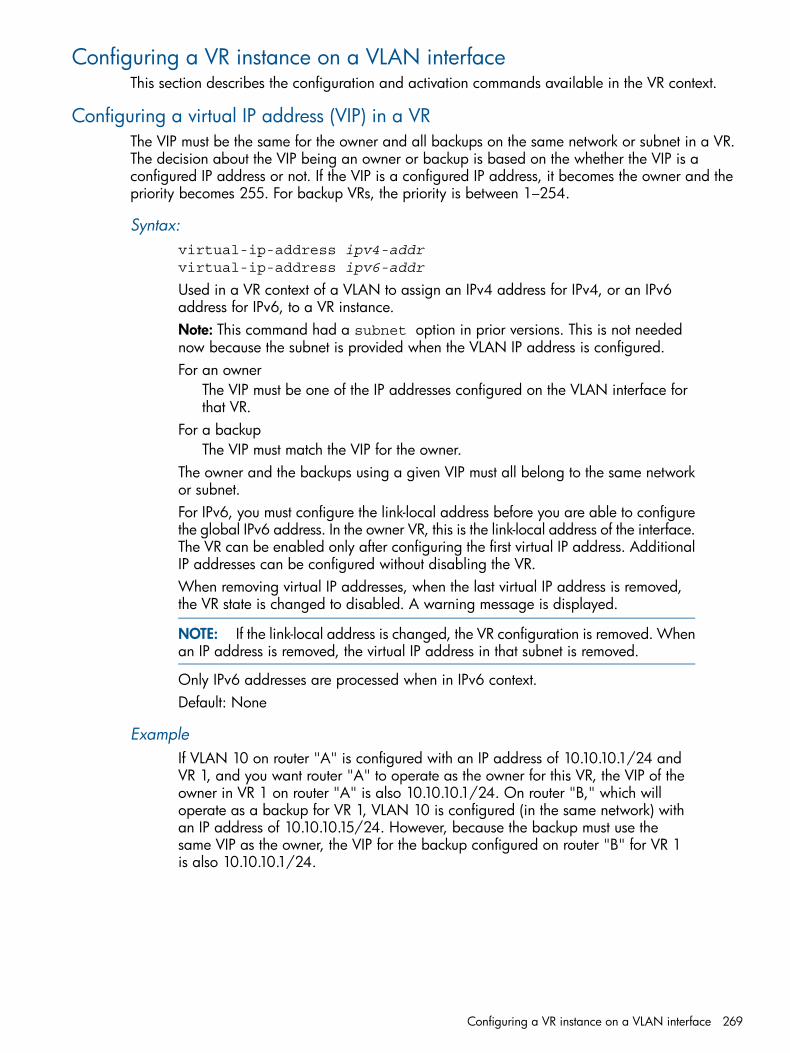
Configuring a VR instance on a VLAN interfaceThis section describes the configuration and activation commands available in the VR context.
Configuring a virtual IP address (VIP) in a VRThe VIP must be the same for the owner and all backups on the same network or subnet in a VR.The decision about the VIP being an owner or backup is based on the whether the VIP is aconfigured IP address or not. If the VIP is a configured IP address, it becomes the owner and thepriority becomes 255. For backup VRs, the priority is between 1–254.
Syntax:virtual-ip-address ipv4-addrvirtual-ip-address ipv6-addr
Used in a VR context of a VLAN to assign an IPv4 address for IPv4, or an IPv6address for IPv6, to a VR instance.Note: This command had a subnet option in prior versions. This is not needednow because the subnet is provided when the VLAN IP address is configured.For an owner
The VIP must be one of the IP addresses configured on the VLAN interface forthat VR.
For a backupThe VIP must match the VIP for the owner.
The owner and the backups using a given VIP must all belong to the same networkor subnet.For IPv6, you must configure the link-local address before you are able to configurethe global IPv6 address. In the owner VR, this is the link-local address of the interface.The VR can be enabled only after configuring the first virtual IP address. AdditionalIP addresses can be configured without disabling the VR.When removing virtual IP addresses, when the last virtual IP address is removed,the VR state is changed to disabled. A warning message is displayed.
NOTE: If the link-local address is changed, the VR configuration is removed. Whenan IP address is removed, the virtual IP address in that subnet is removed.
Only IPv6 addresses are processed when in IPv6 context.Default: None
ExampleIf VLAN 10 on router "A" is configured with an IP address of 10.10.10.1/24 andVR 1, and you want router "A" to operate as the owner for this VR, the VIP of theowner in VR 1 on router "A" is also 10.10.10.1/24. On router "B," which willoperate as a backup for VR 1, VLAN 10 is configured (in the same network) withan IP address of 10.10.10.15/24. However, because the backup must use thesame VIP as the owner, the VIP for the backup configured on router "B" for VR 1is also 10.10.10.1/24.
Configuring a VR instance on a VLAN interface 269
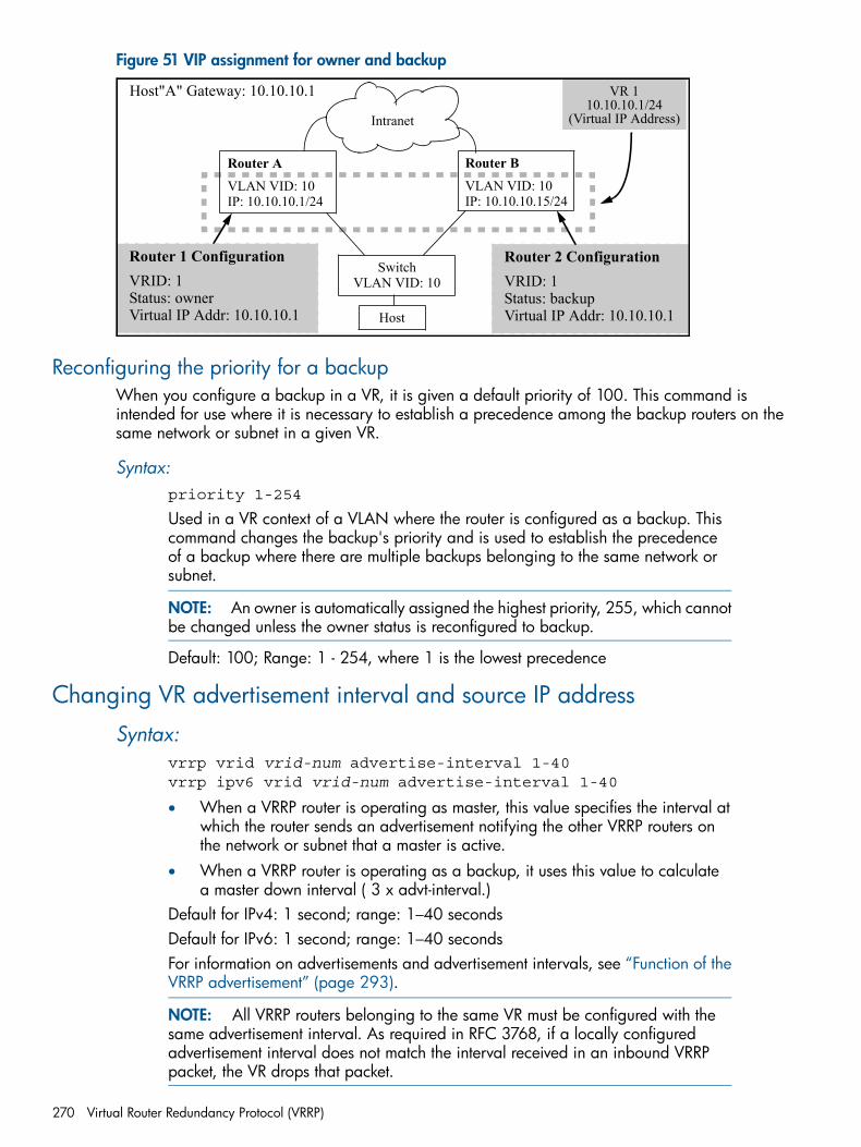
Figure 51 VIP assignment for owner and backup
Router 1 ConfigurationVRID: 1Status: ownerVirtual IP Addr: 10.10.10.1
Router AVLAN VID: 10IP: 10.10.10.1/24
Router BVLAN VID: 10IP: 10.10.10.15/24
SwitchVLAN VID: 10
Intranet
Host
Router 2 ConfigurationVRID: 1Status: backupVirtual IP Addr: 10.10.10.1
Host"A" Gateway: 10.10.10.1 VR 110.10.10.1/24
(Virtual IP Address)
Reconfiguring the priority for a backupWhen you configure a backup in a VR, it is given a default priority of 100. This command isintended for use where it is necessary to establish a precedence among the backup routers on thesame network or subnet in a given VR.
Syntax:priority 1-254
Used in a VR context of a VLAN where the router is configured as a backup. Thiscommand changes the backup's priority and is used to establish the precedenceof a backup where there are multiple backups belonging to the same network orsubnet.
NOTE: An owner is automatically assigned the highest priority, 255, which cannotbe changed unless the owner status is reconfigured to backup.
Default: 100; Range: 1 - 254, where 1 is the lowest precedence
Changing VR advertisement interval and source IP address
Syntax:vrrp vrid vrid-num advertise-interval 1-40vrrp ipv6 vrid vrid-num advertise-interval 1-40
• When a VRRP router is operating as master, this value specifies the interval atwhich the router sends an advertisement notifying the other VRRP routers onthe network or subnet that a master is active.
• When a VRRP router is operating as a backup, it uses this value to calculatea master down interval ( 3 x advt-interval.)
Default for IPv4: 1 second; range: 1–40 secondsDefault for IPv6: 1 second; range: 1–40 secondsFor information on advertisements and advertisement intervals, see “Function of theVRRP advertisement” (page 293).
NOTE: All VRRP routers belonging to the same VR must be configured with thesame advertisement interval. As required in RFC 3768, if a locally configuredadvertisement interval does not match the interval received in an inbound VRRPpacket, the VR drops that packet.
270 Virtual Router Redundancy Protocol (VRRP)
Syntax:primary-ip-address [ ip-address | lowest ]
NOTE: For IPv4 only. IPv6 does not have a primary-ip-address option; the primaryIP address is the link-local address of the real interface over which the packet istransmitted.
Specifies the VIP to designate as the source for VRRP advertisements from the VR.If there is only one VIP configured on the VR, the default setting (lowest) issufficient. Where there are multiple VIPs in the same VR and you want to designatean advertisement source other than the lowest IP Address, use this command.For an owner VR, the primary IP address must be one of the VIPs configured on theVR.For a backup VR, the primary IP address must be in the same subnet as one of theVIPs configured on the VR. In addition, the primary IP address for a backup VR mustbe one of the IP addresses configured on the VLAN on which the VR is configured.Executed in VRID context.Default: lowest
NOTE: It is common in VRRP applications to have only one VIP per VR. In suchcases, the protocol uses that address as the source IP address for VRRPadvertisements, and it is not necessary to specify an address.
Configuring preempt mode on VRRP backup routersThis command applies to VRRP backup routers only and is used to minimize network disruptioncaused by unnecessary preemption of the master operation among backup routers. It is executedin VRID context.
Syntax:[no] preempt-modeDisables or re-enables preempt mode. In the default mode, a backup router comingup with a higher priority than another backup that is currently operating as masterwill take over the master function.Using the no form of the command disables this operation, thus preventing thehigher-priority backup from taking over the master operation from a lower-prioritybackup.This command does not prevent an owner router from resuming the master functionafter recovering from being unavailable.For more on preempt mode, see “Preempt mode” (page 294).Default: Enabled
Enabling or disabling VRRP operation on a VR
Syntax:[no] enableEnabling or disabling a VR enables or disables dynamic VRRP operation on thatVR.Default: Disabled
Configuring preempt mode on VRRP backup routers 271
Dynamically changing the priority of the VRNOTE: You can configure tracked interfaces or VLANs on the backup router only.
Configuring track interface
Syntax:[no] track interface port-list/trunk-listAllows you to specify a port or port list, or trunk or trunk list, that will be trackedby this virtual router. If the port or trunk is down, the virtual router switches to therouter specified by the priority value. The command is executed in VRID instancecontext.
Example
HP Switch(config)# vlan 25
HP Switch(vlan-25)# vrid 1
HP Switch(vlan-25-vrid-1)# track interface 10-12, Trk1
Configuring track VLAN
NOTE: The VR's operating VLAN cannot be configured as a tracking VLAN for that VR.
Syntax:[no] track vlan vlan-id rangeAllows you to specify a VLAN or range of VLANs that will be tracked by this virtualrouter. If the VLAN is down, or if the VLAN or IP address has been deleted, thevirtual router switches to the router specified by the priority value. The command isexecuted in VRID instance context.
Example
HP Switch(config)# vlan 25
HP Switch(vlan-25)# vrid 1
HP Switch(vlan-25-vrid-1)# track vlan 10 24-26
NOTE: When the first tracked port or tracked VLAN comes up after being down, the VR waitsfor the pre-empt delay time before it tries to take control back. The VR resumes being a backupwith its configured priority as soon as the first tracked entity is up.The behavior of the VR is not affected by any tracked entities until after the expiration of the preemptdelay time. However, if while waiting for the preempt delay time to expire, a master goes down,the VR tries to take control of the virtual IP.
Removing all tracked entities
Syntax:no track
Allows you to remove tracking for all configured track entities (ports, trunks, andVLANs.) The command is executed in VRID instance context.
272 Virtual Router Redundancy Protocol (VRRP)
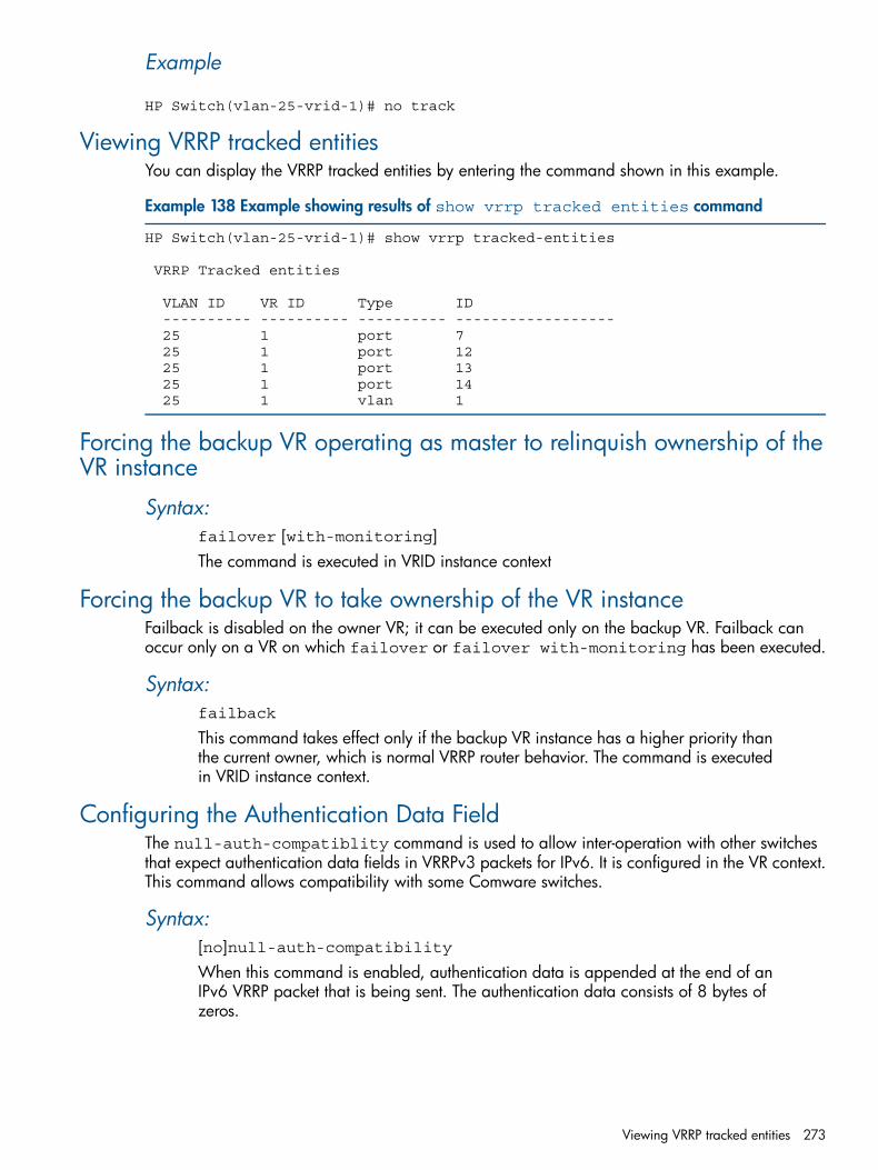
Example
HP Switch(vlan-25-vrid-1)# no track
Viewing VRRP tracked entitiesYou can display the VRRP tracked entities by entering the command shown in this example.
Example 138 Example showing results of show vrrp tracked entities command
HP Switch(vlan-25-vrid-1)# show vrrp tracked-entities
VRRP Tracked entities
VLAN ID VR ID Type ID ---------- ---------- ---------- ------------------ 25 1 port 7 25 1 port 12 25 1 port 13 25 1 port 14 25 1 vlan 1
Forcing the backup VR operating as master to relinquish ownership of theVR instance
Syntax:failover [with-monitoring]The command is executed in VRID instance context
Forcing the backup VR to take ownership of the VR instanceFailback is disabled on the owner VR; it can be executed only on the backup VR. Failback canoccur only on a VR on which failover or failover with-monitoring has been executed.
Syntax:failback
This command takes effect only if the backup VR instance has a higher priority thanthe current owner, which is normal VRRP router behavior. The command is executedin VRID instance context.
Configuring the Authentication Data FieldThe null-auth-compatiblity command is used to allow inter-operation with other switchesthat expect authentication data fields in VRRPv3 packets for IPv6. It is configured in the VR context.This command allows compatibility with some Comware switches.
Syntax:[no]null-auth-compatibilityWhen this command is enabled, authentication data is appended at the end of anIPv6 VRRP packet that is being sent. The authentication data consists of 8 bytes ofzeros.
Viewing VRRP tracked entities 273
Example
Example 139 Configuring the Authentication Data Field
HP Switch(vlan-2-vrid-1)# null-auth-compatibility
Pinging the virtual IP of a backup router
Enabling the response to a ping requestThe backup router can be enabled to respond to pings using the following command. For moreinformation, see “Pinging the virtual IP of a backup router” (page 301).
Syntax:[no] router vrrp virtual-ip-pingEnables or disables the response to a ping request for the switch. When enabled,all VRs that are not owners and are not explicitly disabled (see virtual-ip-pingenabled command) respond to ping requests sent to the VIP when the backup VRis acting as master.Default: Response to virtual IP ping is disabled.
Example
Example 140 Enabling the response to ping requests
HP-Router1# configHP-Router1(config)# ip routingHP-Router1(config)# router vrrpHP-Router1(config)# router vrrp virtual-ip-ping
Controlling ping responses
Syntax:[no] virtual-ip-ping enabledEnables or disables the response to a ping request to a specific VR. The commandapplies to all VIPs on the VR.Must be executed in VRRP context (vlan vid vrrp vrid vrid)
NOTE: The VR should be configured as a backup.
Default: Enabled
274 Virtual Router Redundancy Protocol (VRRP)
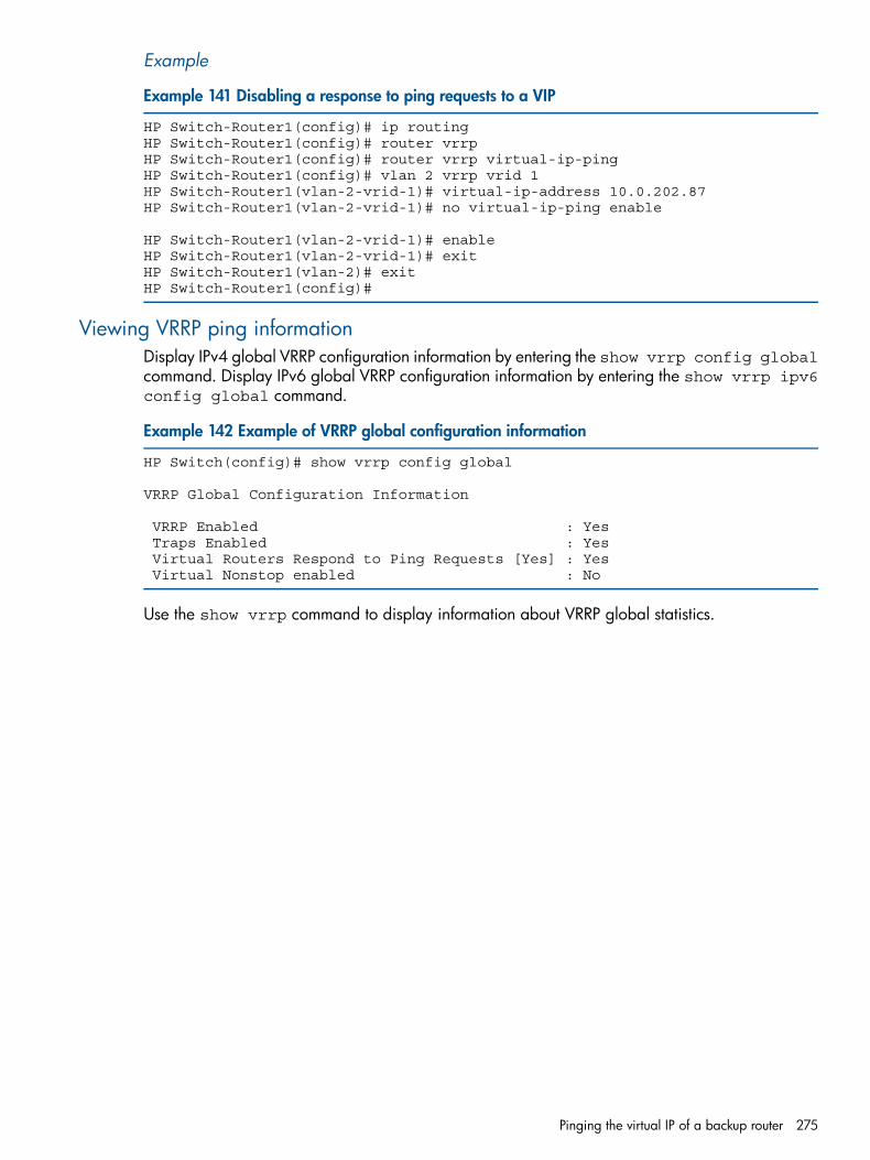
Example
Example 141 Disabling a response to ping requests to a VIP
HP Switch-Router1(config)# ip routingHP Switch-Router1(config)# router vrrpHP Switch-Router1(config)# router vrrp virtual-ip-pingHP Switch-Router1(config)# vlan 2 vrrp vrid 1HP Switch-Router1(vlan-2-vrid-1)# virtual-ip-address 10.0.202.87HP Switch-Router1(vlan-2-vrid-1)# no virtual-ip-ping enable
HP Switch-Router1(vlan-2-vrid-1)# enableHP Switch-Router1(vlan-2-vrid-1)# exitHP Switch-Router1(vlan-2)# exitHP Switch-Router1(config)#
Viewing VRRP ping informationDisplay IPv4 global VRRP configuration information by entering the show vrrp config globalcommand. Display IPv6 global VRRP configuration information by entering the show vrrp ipv6config global command.
Example 142 Example of VRRP global configuration information
HP Switch(config)# show vrrp config global
VRRP Global Configuration Information
VRRP Enabled : Yes Traps Enabled : Yes Virtual Routers Respond to Ping Requests [Yes] : Yes Virtual Nonstop enabled : No
Use the show vrrp command to display information about VRRP global statistics.
Pinging the virtual IP of a backup router 275
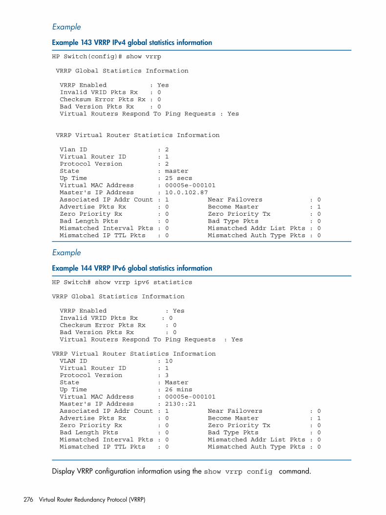
Example
Example 143 VRRP IPv4 global statistics information
HP Switch(config)# show vrrp
VRRP Global Statistics Information
VRRP Enabled : Yes Invalid VRID Pkts Rx : 0 Checksum Error Pkts Rx : 0 Bad Version Pkts Rx : 0 Virtual Routers Respond To Ping Requests : Yes
VRRP Virtual Router Statistics Information
Vlan ID : 2 Virtual Router ID : 1 Protocol Version : 2 State : master Up Time : 25 secs Virtual MAC Address : 00005e-000101 Master's IP Address : 10.0.102.87 Associated IP Addr Count : 1 Near Failovers : 0 Advertise Pkts Rx : 0 Become Master : 1 Zero Priority Rx : 0 Zero Priority Tx : 0 Bad Length Pkts : 0 Bad Type Pkts : 0 Mismatched Interval Pkts : 0 Mismatched Addr List Pkts : 0 Mismatched IP TTL Pkts : 0 Mismatched Auth Type Pkts : 0
Example
Example 144 VRRP IPv6 global statistics information
HP Switch# show vrrp ipv6 statistics
VRRP Global Statistics Information
VRRP Enabled : Yes Invalid VRID Pkts Rx : 0 Checksum Error Pkts Rx : 0 Bad Version Pkts Rx : 0 Virtual Routers Respond To Ping Requests : Yes
VRRP Virtual Router Statistics Information VLAN ID : 10 Virtual Router ID : 1 Protocol Version : 3 State : Master Up Time : 26 mins Virtual MAC Address : 00005e-000101 Master's IP Address : 2130::21 Associated IP Addr Count : 1 Near Failovers : 0 Advertise Pkts Rx : 0 Become Master : 1 Zero Priority Rx : 0 Zero Priority Tx : 0 Bad Length Pkts : 0 Bad Type Pkts : 0 Mismatched Interval Pkts : 0 Mismatched Addr List Pkts : 0 Mismatched IP TTL Pkts : 0 Mismatched Auth Type Pkts : 0
Display VRRP configuration information using the show vrrp config command.
276 Virtual Router Redundancy Protocol (VRRP)
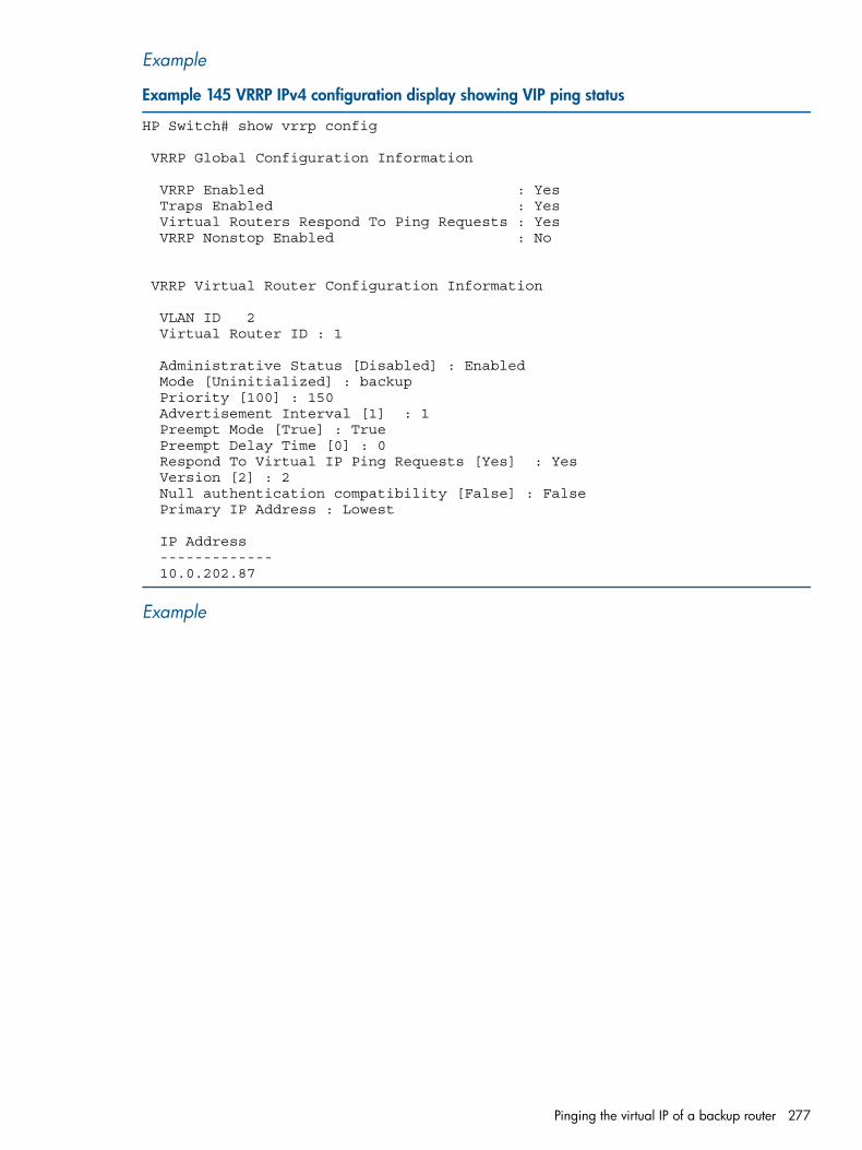
Example
Example 145 VRRP IPv4 configuration display showing VIP ping status
HP Switch# show vrrp config
VRRP Global Configuration Information
VRRP Enabled : Yes Traps Enabled : Yes Virtual Routers Respond To Ping Requests : Yes VRRP Nonstop Enabled : No
VRRP Virtual Router Configuration Information
VLAN ID 2 Virtual Router ID : 1
Administrative Status [Disabled] : Enabled Mode [Uninitialized] : backup Priority [100] : 150 Advertisement Interval [1] : 1 Preempt Mode [True] : True Preempt Delay Time [0] : 0 Respond To Virtual IP Ping Requests [Yes] : Yes Version [2] : 2 Null authentication compatibility [False] : False Primary IP Address : Lowest
IP Address ------------- 10.0.202.87
Example
Pinging the virtual IP of a backup router 277
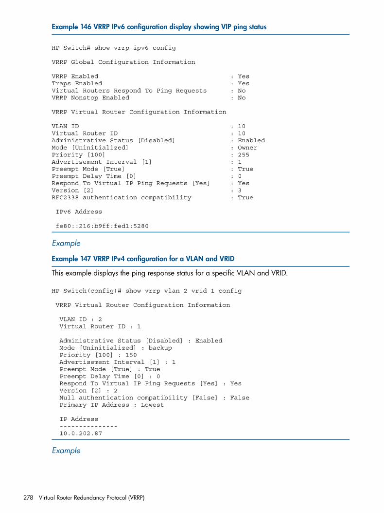
Example 146 VRRP IPv6 configuration display showing VIP ping status
HP Switch# show vrrp ipv6 config
VRRP Global Configuration Information
VRRP Enabled : YesTraps Enabled : YesVirtual Routers Respond To Ping Requests : NoVRRP Nonstop Enabled : No
VRRP Virtual Router Configuration Information
VLAN ID : 10Virtual Router ID : 10Administrative Status [Disabled] : EnabledMode [Uninitialized] : OwnerPriority [100] : 255Advertisement Interval [1] : 1Preempt Mode [True] : TruePreempt Delay Time [0] : 0Respond To Virtual IP Ping Requests [Yes] : YesVersion [2] : 3RFC2338 authentication compatibility : True
IPv6 Address ------------- fe80::216:b9ff:fed1:5280
Example
Example 147 VRRP IPv4 configuration for a VLAN and VRID
This example displays the ping response status for a specific VLAN and VRID.
HP Switch(config)# show vrrp vlan 2 vrid 1 config
VRRP Virtual Router Configuration Information
VLAN ID : 2 Virtual Router ID : 1
Administrative Status [Disabled] : Enabled Mode [Uninitialized] : backup Priority [100] : 150 Advertisement Interval [1] : 1 Preempt Mode [True] : True Preempt Delay Time [0] : 0 Respond To Virtual IP Ping Requests [Yes] : Yes Version [2] : 2 Null authentication compatibility [False] : False Primary IP Address : Lowest
IP Address --------------- 10.0.202.87
Example
278 Virtual Router Redundancy Protocol (VRRP)
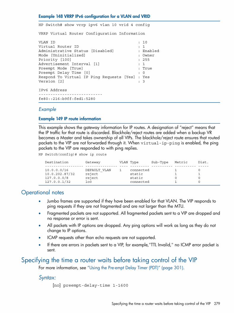
Example 148 VRRP IPv6 configuration for a VLAN and VRID
HP Switch# show vrrp ipv6 vlan 10 vrid 4 config
VRRP Virtual Router Configuration Information
VLAN ID : 10Virtual Router ID : 1Administrative Status [Disabled] : EnabledMode [Uninitialized] : OwnerPriority [100] : 255Advertisement Interval [1] : 1Preempt Mode [True] : TruePreempt Delay Time [0] : 0Respond To Virtual IP Ping Requests [Yes] : YesVersion [2] : 3
IPv6 Address---------------------------fe80::216:b9ff:fed1:5280
Example
Example 149 IP route information
This example shows the gateway information for IP routes. A designation of "reject" means thatthe IP traffic for that route is discarded. Blackhole/reject routes are added when a backup VRbecomes a Master and takes ownership of all VIPs. The blackhole/reject route ensures that routedpackets to the VIP are not forwarded through it. When virtual-ip-ping is enabled, the pingpackets to the VIP are responded to with ping replies.HP Switch(config)# show ip route
Destination Gateway VLAN Type Sub-Type Metric Dist. ------------------ --------------- ---- --------- ---------- ---------- ----- 10.0.0.0/16 DEFAULT_VLAN 1 connected 1 0 10.0.202.87/32 reject static 1 1 127.0.0.0/8 reject static 0 0 127.0.0.1/32 lo0 connected 1 0
Operational notes• Jumbo frames are supported if they have been enabled for that VLAN. The VIP responds to
ping requests if they are not fragmented and are not larger than the MTU.• Fragmented packets are not supported. All fragmented packets sent to a VIP are dropped and
no response or error is sent.• All packets with IP options are dropped. Any ping options will work as long as they do not
change to IP options.• ICMP requests other than echo requests are not supported.
• If there are errors in packets sent to a VIP, for example,"TTL Invalid," no ICMP error packet issent.
Specifying the time a router waits before taking control of the VIPFor more information, see “Using the Pre-empt Delay Timer (PDT)” (page 301).
Syntax:[no] preempt-delay-time 1-1600
Specifying the time a router waits before taking control of the VIP 279
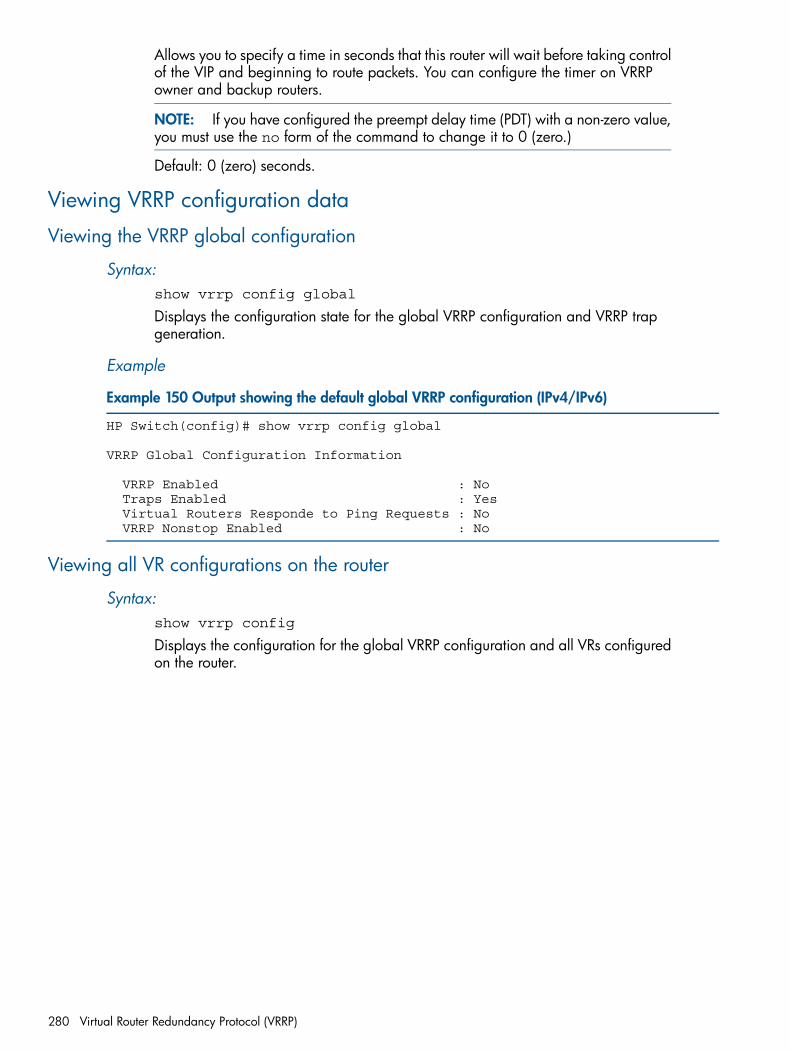
Allows you to specify a time in seconds that this router will wait before taking controlof the VIP and beginning to route packets. You can configure the timer on VRRPowner and backup routers.
NOTE: If you have configured the preempt delay time (PDT) with a non-zero value,you must use the no form of the command to change it to 0 (zero.)
Default: 0 (zero) seconds.
Viewing VRRP configuration data
Viewing the VRRP global configuration
Syntax:show vrrp config global
Displays the configuration state for the global VRRP configuration and VRRP trapgeneration.
Example
Example 150 Output showing the default global VRRP configuration (IPv4/IPv6)
HP Switch(config)# show vrrp config global
VRRP Global Configuration Information
VRRP Enabled : No Traps Enabled : Yes Virtual Routers Responde to Ping Requests : No VRRP Nonstop Enabled : No
Viewing all VR configurations on the router
Syntax:show vrrp config
Displays the configuration for the global VRRP configuration and all VRs configuredon the router.
280 Virtual Router Redundancy Protocol (VRRP)
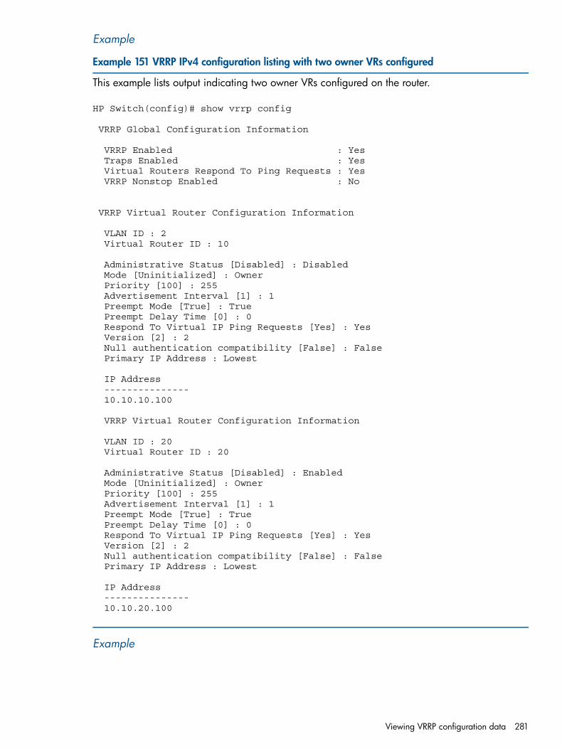
Example
Example 151 VRRP IPv4 configuration listing with two owner VRs configured
This example lists output indicating two owner VRs configured on the router.
HP Switch(config)# show vrrp config
VRRP Global Configuration Information
VRRP Enabled : Yes Traps Enabled : Yes Virtual Routers Respond To Ping Requests : Yes VRRP Nonstop Enabled : No
VRRP Virtual Router Configuration Information
VLAN ID : 2 Virtual Router ID : 10
Administrative Status [Disabled] : Disabled Mode [Uninitialized] : Owner Priority [100] : 255 Advertisement Interval [1] : 1 Preempt Mode [True] : True Preempt Delay Time [0] : 0 Respond To Virtual IP Ping Requests [Yes] : Yes Version [2] : 2 Null authentication compatibility [False] : False Primary IP Address : Lowest
IP Address --------------- 10.10.10.100
VRRP Virtual Router Configuration Information
VLAN ID : 20 Virtual Router ID : 20
Administrative Status [Disabled] : Enabled Mode [Uninitialized] : Owner Priority [100] : 255 Advertisement Interval [1] : 1 Preempt Mode [True] : True Preempt Delay Time [0] : 0 Respond To Virtual IP Ping Requests [Yes] : Yes Version [2] : 2 Null authentication compatibility [False] : False Primary IP Address : Lowest
IP Address --------------- 10.10.20.100
Example
Viewing VRRP configuration data 281
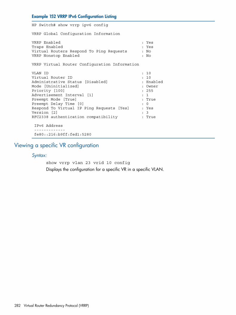
Example 152 VRRP IPv6 Configuration Listing
HP Switch# show vrrp ipv6 config
VRRP Global Configuration Information
VRRP Enabled : YesTraps Enabled : YesVirtual Routers Respond To Ping Requests : NoVRRP Nonstop Enabled : No
VRRP Virtual Router Configuration Information
VLAN ID : 10Virtual Router ID : 10Administrative Status [Disabled] : EnabledMode [Uninitialized] : OwnerPriority [100] : 255Advertisement Interval [1] : 1Preempt Mode [True] : TruePreempt Delay Time [0] : 0Respond To Virtual IP Ping Requests [Yes] : YesVersion [2] : 3RFC2338 authentication compatibility : True
IPv6 Address ------------- fe80::216:b9ff:fed1:5280
Viewing a specific VR configuration
Syntax:show vrrp vlan 23 vrid 10 config
Displays the configuration for a specific VR in a specific VLAN.
282 Virtual Router Redundancy Protocol (VRRP)
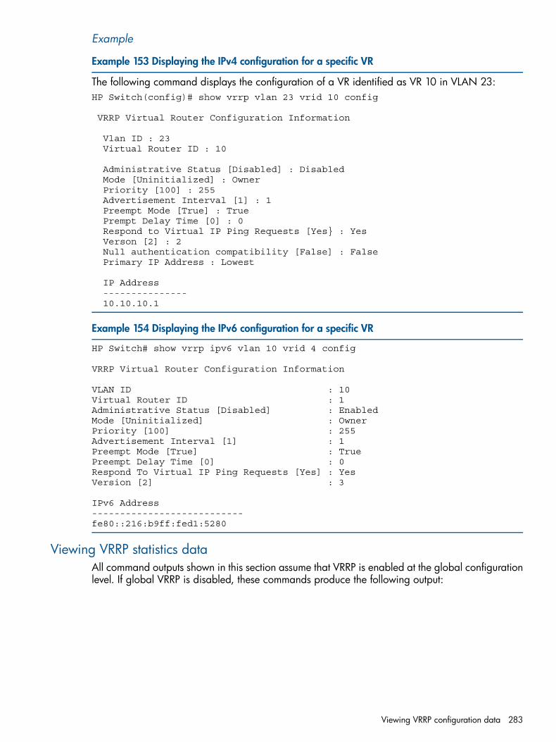
Example
Example 153 Displaying the IPv4 configuration for a specific VR
The following command displays the configuration of a VR identified as VR 10 in VLAN 23:HP Switch(config)# show vrrp vlan 23 vrid 10 config
VRRP Virtual Router Configuration Information
Vlan ID : 23 Virtual Router ID : 10
Administrative Status [Disabled] : Disabled Mode [Uninitialized] : Owner Priority [100] : 255 Advertisement Interval [1] : 1 Preempt Mode [True] : True Prempt Delay Time [0] : 0 Respond to Virtual IP Ping Requests [Yes} : Yes Verson [2] : 2 Null authentication compatibility [False] : False Primary IP Address : Lowest
IP Address --------------- 10.10.10.1
Example 154 Displaying the IPv6 configuration for a specific VR
HP Switch# show vrrp ipv6 vlan 10 vrid 4 config
VRRP Virtual Router Configuration Information
VLAN ID : 10Virtual Router ID : 1Administrative Status [Disabled] : EnabledMode [Uninitialized] : OwnerPriority [100] : 255Advertisement Interval [1] : 1Preempt Mode [True] : TruePreempt Delay Time [0] : 0Respond To Virtual IP Ping Requests [Yes] : YesVersion [2] : 3
IPv6 Address---------------------------fe80::216:b9ff:fed1:5280
Viewing VRRP statistics dataAll command outputs shown in this section assume that VRRP is enabled at the global configurationlevel. If global VRRP is disabled, these commands produce the following output:
Viewing VRRP configuration data 283
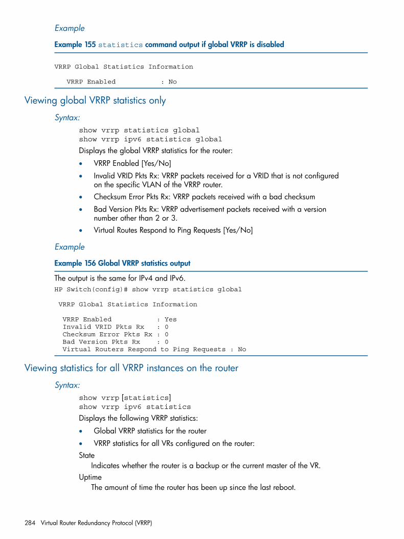
Example
Example 155 statistics command output if global VRRP is disabled
VRRP Global Statistics Information
VRRP Enabled : No
Viewing global VRRP statistics only
Syntax:show vrrp statistics globalshow vrrp ipv6 statistics global
Displays the global VRRP statistics for the router:
• VRRP Enabled [Yes/No]
• Invalid VRID Pkts Rx: VRRP packets received for a VRID that is not configuredon the specific VLAN of the VRRP router.
• Checksum Error Pkts Rx: VRRP packets received with a bad checksum
• Bad Version Pkts Rx: VRRP advertisement packets received with a versionnumber other than 2 or 3.
• Virtual Routes Respond to Ping Requests [Yes/No]
Example
Example 156 Global VRRP statistics output
The output is the same for IPv4 and IPv6.HP Switch(config)# show vrrp statistics global
VRRP Global Statistics Information
VRRP Enabled : Yes Invalid VRID Pkts Rx : 0 Checksum Error Pkts Rx : 0 Bad Version Pkts Rx : 0 Virtual Routers Respond to Ping Requests : No
Viewing statistics for all VRRP instances on the router
Syntax:show vrrp [statistics]show vrrp ipv6 statistics
Displays the following VRRP statistics:
• Global VRRP statistics for the router
• VRRP statistics for all VRs configured on the router:State
Indicates whether the router is a backup or the current master of the VR.Uptime
The amount of time the router has been up since the last reboot.
284 Virtual Router Redundancy Protocol (VRRP)
Virtual MAC AddressThe virtual MAC address for the VR instance.
master's IP AddressThe IP address used as the source IP address in the last advertisement packetreceived from the VR master. If this VR is the master, this is the primary IP addressof the VR. If the VR is disabled, this value appears as 0.0.0.0 for IPv4, and0:0:0:0:0:ffff:0:0 for IPv6.
Associated IP Address CountNumber of VIPs.
Advertise Packets RxThe number of VRRP master advertisements the VR has received from other VRRProuters since the last reboot.
Zero Priority TxThe number of VRRP advertisement packets received with the priority field setto 0 (zero.)
Bad Length PktsThe number of VRRp packets received with missing fields of information.
Mismatched Interval PktsThe number of VRRP packets received from other routers (since the last reboot)with an advertisement interval that is different from the interval configured onthe current VR.VRRP packets received with an interval mismatch are dropped.
Mismatched IP TTL PktsThe number of VRRP packets received with the IP TTL field not set to 255. Suchpackets are dropped.
Near FailoversTracks the occurrence of "near failovers" on the backup VRRP routers. Thismakes visible any difficulties the VRRP routers are having receiving the"heartbeat" advertisement from the master router. A "near failover" is one thatis within one missed VRRP advertisement packet of beginning the masterdetermination process.
Become masterThe number of times the VR has become the master since the last reboot.
Zero Priority TxThe number of VRRP advertisement packets sent with the priority field set to 0(zero.)
Bad Type PktsThe number of VRRP packets received with packet type not equal to 1 (that is,not an advertisement packet.)
Mismatched Addr List PktsThe number of VRRP packets received wherein the list of VIPs does not matchthe locally configured VIPs for a VR.
Mismatched Auth Type PktsThe number of VRRP packets received with the authentication type not equal to0 (zero, which is no authentication.)
Note that show vrrp and show vrrp statistics give the same output.
Viewing VRRP configuration data 285
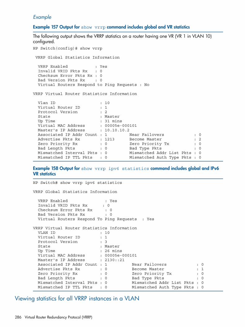
Example
Example 157 Output for show vrrp command includes global and VR statistics
The following output shows the VRRP statistics on a router having one VR (VR 1 in VLAN 10)configured.HP Switch(config)# show vrrp
VRRP Global Statistics Information
VRRP Enabled : Yes Invalid VRID Pkts Rx : 0 Checksum Error Pkts Rx : 0 Bad Version Pkts Rx : 0 Virtual Routers Respond to Ping Requests : No
VRRP Virtual Router Statistics Information
Vlan ID : 10 Virtual Router ID : 1 Protocol Version : 2 State : Master Up Time : 31 mins Virtual MAC Address : 00005e-000101 Master's IP Address : 10.10.10.2 Associated IP Addr Count : 1 Near Failovers : 0 Advertise Pkts Rx : 1213 Become Master : 2 Zero Priority Rx : 0 Zero Priority Tx : 0 Bad Length Pkts : 0 Bad Type Pkts : 0 Mismatched Interval Pkts : 0 Mismatched Addr List Pkts : 0 Mismatched IP TTL Pkts : 0 Mismatched Auth Type Pkts : 0
Example 158 Output for show vrrp ipv6 statistics command includes global and IPv6VR statistics
HP Switch# show vrrp ipv6 statistics
VRRP Global Statistics Information
VRRP Enabled : Yes Invalid VRID Pkts Rx : 0 Checksum Error Pkts Rx : 0 Bad Version Pkts Rx : 0 Virtual Routers Respond To Ping Requests : Yes
VRRP Virtual Router Statistics Information VLAN ID : 10 Virtual Router ID : 1 Protocol Version : 3 State : Master Up Time : 26 mins Virtual MAC Address : 00005e-000101 Master's IP Address : 2130::21 Associated IP Addr Count : 1 Near Failovers : 0 Advertise Pkts Rx : 0 Become Master : 1 Zero Priority Rx : 0 Zero Priority Tx : 0 Bad Length Pkts : 0 Bad Type Pkts : 0 Mismatched Interval Pkts : 0 Mismatched Addr List Pkts : 0 Mismatched IP TTL Pkts : 0 Mismatched Auth Type Pkts : 0
Viewing statistics for all VRRP instances in a VLAN
286 Virtual Router Redundancy Protocol (VRRP)
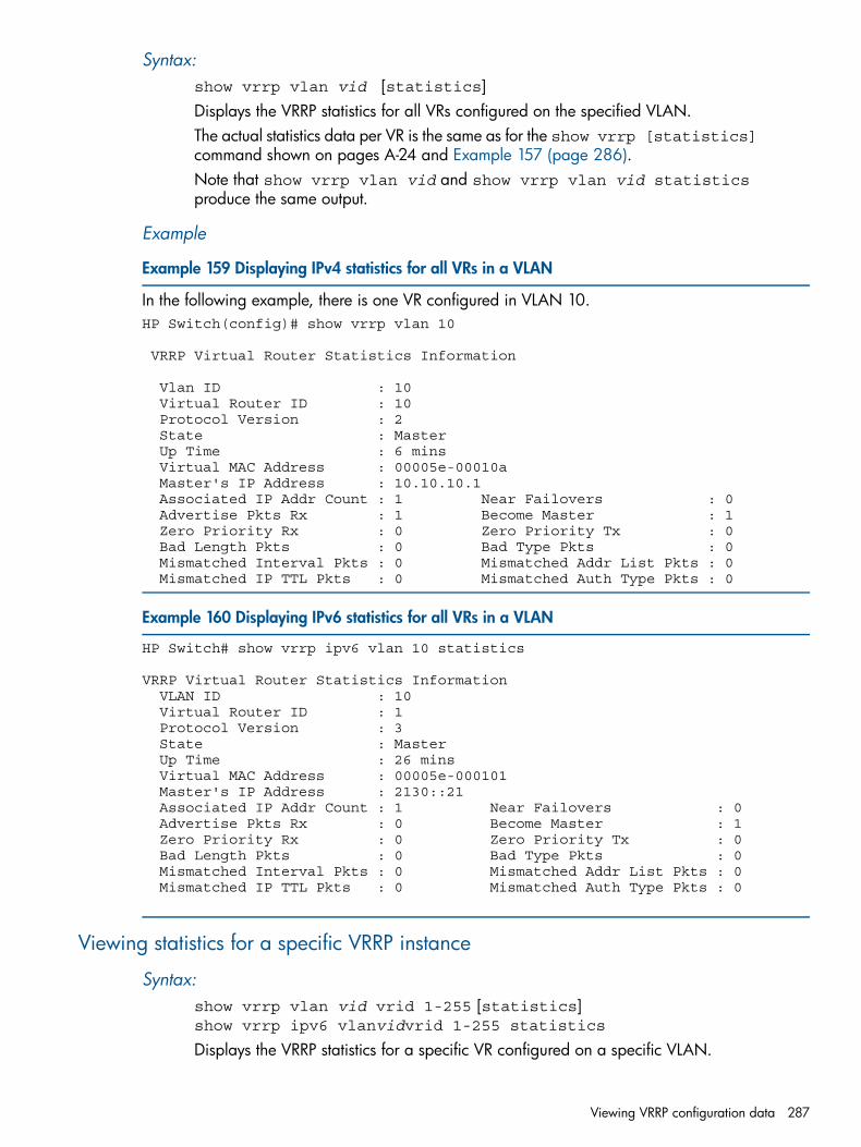
Syntax:show vrrp vlan vid [statistics]Displays the VRRP statistics for all VRs configured on the specified VLAN.The actual statistics data per VR is the same as for the show vrrp [statistics]command shown on pages A-24 and Example 157 (page 286).Note that show vrrp vlan vid and show vrrp vlan vid statisticsproduce the same output.
Example
Example 159 Displaying IPv4 statistics for all VRs in a VLAN
In the following example, there is one VR configured in VLAN 10.HP Switch(config)# show vrrp vlan 10
VRRP Virtual Router Statistics Information
Vlan ID : 10 Virtual Router ID : 10 Protocol Version : 2 State : Master Up Time : 6 mins Virtual MAC Address : 00005e-00010a Master's IP Address : 10.10.10.1 Associated IP Addr Count : 1 Near Failovers : 0 Advertise Pkts Rx : 1 Become Master : 1 Zero Priority Rx : 0 Zero Priority Tx : 0 Bad Length Pkts : 0 Bad Type Pkts : 0 Mismatched Interval Pkts : 0 Mismatched Addr List Pkts : 0 Mismatched IP TTL Pkts : 0 Mismatched Auth Type Pkts : 0
Example 160 Displaying IPv6 statistics for all VRs in a VLAN
HP Switch# show vrrp ipv6 vlan 10 statistics
VRRP Virtual Router Statistics Information VLAN ID : 10 Virtual Router ID : 1 Protocol Version : 3 State : Master Up Time : 26 mins Virtual MAC Address : 00005e-000101 Master's IP Address : 2130::21 Associated IP Addr Count : 1 Near Failovers : 0 Advertise Pkts Rx : 0 Become Master : 1 Zero Priority Rx : 0 Zero Priority Tx : 0 Bad Length Pkts : 0 Bad Type Pkts : 0 Mismatched Interval Pkts : 0 Mismatched Addr List Pkts : 0 Mismatched IP TTL Pkts : 0 Mismatched Auth Type Pkts : 0
Viewing statistics for a specific VRRP instance
Syntax:show vrrp vlan vid vrid 1-255 [statistics]show vrrp ipv6 vlanvidvrid 1-255 statistics
Displays the VRRP statistics for a specific VR configured on a specific VLAN.
Viewing VRRP configuration data 287

The actual statistics data per VR is the same as for the show vrrp [statistics]command.Note that show vrrp vlan vid vrid 1 - 255 and show vrrp vlanvid vrid 1 - 255 statistics produce the same output.
Viewing the "near-failovers" statisticThe "near failovers" statistic tracks occurrences of near failovers on the backup VRRP routers. Thismakes visible any difficulties the VRRP routers are having receiving the "heartbeat" advertisementfrom the master router. (A "near failover" is one that is within one missed VRRP advertisementpacket of beginning the master determination process.)The show vrrp or show vrrp ipv6 statistics command displays this statistic.
288 Virtual Router Redundancy Protocol (VRRP)
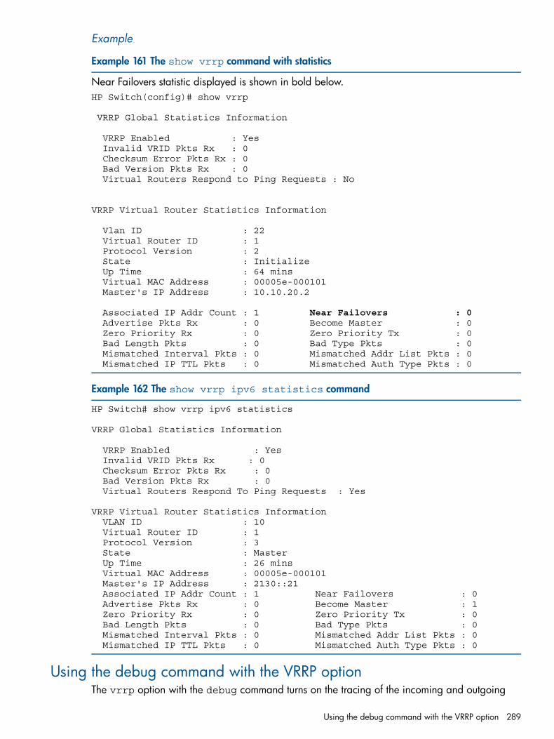
Example
Example 161 The show vrrp command with statistics
Near Failovers statistic displayed is shown in bold below.HP Switch(config)# show vrrp
VRRP Global Statistics Information
VRRP Enabled : Yes Invalid VRID Pkts Rx : 0 Checksum Error Pkts Rx : 0 Bad Version Pkts Rx : 0 Virtual Routers Respond to Ping Requests : No
VRRP Virtual Router Statistics Information
Vlan ID : 22 Virtual Router ID : 1 Protocol Version : 2 State : Initialize Up Time : 64 mins Virtual MAC Address : 00005e-000101 Master's IP Address : 10.10.20.2
Associated IP Addr Count : 1 Near Failovers : 0 Advertise Pkts Rx : 0 Become Master : 0 Zero Priority Rx : 0 Zero Priority Tx : 0 Bad Length Pkts : 0 Bad Type Pkts : 0 Mismatched Interval Pkts : 0 Mismatched Addr List Pkts : 0 Mismatched IP TTL Pkts : 0 Mismatched Auth Type Pkts : 0
Example 162 The show vrrp ipv6 statistics command
HP Switch# show vrrp ipv6 statistics
VRRP Global Statistics Information
VRRP Enabled : Yes Invalid VRID Pkts Rx : 0 Checksum Error Pkts Rx : 0 Bad Version Pkts Rx : 0 Virtual Routers Respond To Ping Requests : Yes
VRRP Virtual Router Statistics Information VLAN ID : 10 Virtual Router ID : 1 Protocol Version : 3 State : Master Up Time : 26 mins Virtual MAC Address : 00005e-000101 Master's IP Address : 2130::21 Associated IP Addr Count : 1 Near Failovers : 0 Advertise Pkts Rx : 0 Become Master : 1 Zero Priority Rx : 0 Zero Priority Tx : 0 Bad Length Pkts : 0 Bad Type Pkts : 0 Mismatched Interval Pkts : 0 Mismatched Addr List Pkts : 0 Mismatched IP TTL Pkts : 0 Mismatched Auth Type Pkts : 0
Using the debug command with the VRRP optionThe vrrp option with the debug command turns on the tracing of the incoming and outgoing
Using the debug command with the VRRP option 289
VRRP packets.
Syntax:[no] debug vrrpDisplays VRRP debug messages.
General operationLicense requirements:In the 3500yl, 3800, 5400zl, 6600, and 8200zl switches, VRRP is included with the PremiumLicense. In the 6200yl switches, this feature is included with the base feature set.
VRRP supports router redundancy through a prioritized election process among routers configuredas members of the same virtual router (VR.)On a given VLAN, a VR includes two or more member routers configured with a VIP that is alsoconfigured as a real IP address on one of the routers, plus a virtual router MAC address. The routerthat owns the IP address is configured to operate as the owner of the VR for traffic-forwardingpurposes and by default has the highest VRRP priority in the VR. The other routers in the VR havea lower priority and are configured to operate as backups in case the owner router becomesunavailable.The owner normally operates as the master for a VR. But if it becomes unavailable, then a failoverto a backup router belonging to the same VR occurs, and this backup becomes the current master.If the owner recovers, a failback occurs and "master" status reverts to the owner. (Using more thanone backup provides additional redundancy" if both the owner and the highest-priority backupfail, another, lower-priority backup can take over as master.)
NOTE:• The VIP used by all VRRP routers in a VR instance is a realIP address that is also configured
on the applicable VLAN interface on the VR's owner router.• The same MAC and VIPs are included in the VRRP configuration for the owner and all backup
routers belonging to the same VR and are used as the source addresses for all traffic forwardedby the VR.
Figure 52 (page 291) shows a VR on VLAN 100 supported by Router 1 (R1) and Router 2 (R2.)
290 Virtual Router Redundancy Protocol (VRRP)
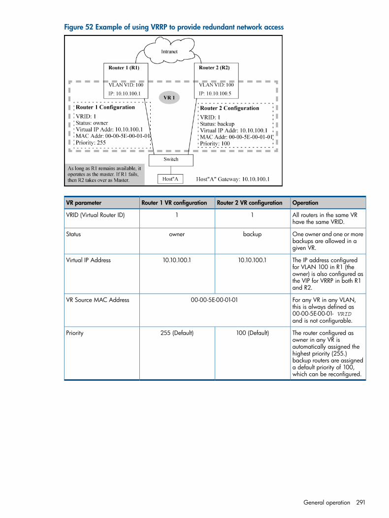
Figure 52 Example of using VRRP to provide redundant network access
OperationRouter 2 VR configurationRouter 1 VR configurationVR parameter
All routers in the same VRhave the same VRID.
11VRID (Virtual Router ID)
One owner and one or morebackups are allowed in agiven VR.
backupownerStatus
The IP address configuredfor VLAN 100 in R1 (the
10.10.100.110.10.100.1Virtual IP Address
owner) is also configured asthe VIP for VRRP in both R1and R2.
For any VR in any VLAN,this is always defined as
00-00-5E-00-01-01VR Source MAC Address
00-00-5E-00-01- VRIDand is not configurable.
The router configured asowner in any VR is
100 (Default)255 (Default)Priority
automatically assigned thehighest priority (255.)backup routers are assigneda default priority of 100,which can be reconfigured.
General operation 291
In Figure 52 (page 291):• Host "A" uses 10.10.100.1 as its next-hop gateway out of the subnet, as represented by the
VR (VR 1.)• Router 1 (the configured owner) advertises itself as the master in the VR supporting the
gateway and:• "Owns" the VR's (virtual) IP address
• Transmits ARP responses that associate the VR's VIP with the (shared) source MACaddress for VR 1.
• During normal operation, Router 1 forwards the routed traffic for host "A."
• If Router 1 fails or otherwise becomes unavailable:Router 1 advertisements of its master status for VR 1 fail to reach Router 2 (which is theonly configured backup.)
a.
b. After the time-out period for receiving master advertisements expires on Router 2, the VRinitiates a failover to Router 2 and it becomes the new master of the VR.
c. Router 2 advertises itself as the master of the VR supporting the gateway and:• Takes control of the VR's (virtual) IP address
• Begins transmitting ARP responses that associate the VR's VIP with the (shared) sourceMAC address for VR 1
d. Host "A" routed traffic then moves through Router 2.
• If Router 1 again becomes available:Router 1 resumes advertising itself as the master for the VR and sends ARP responses thatassociate the VR's VIP with the (shared) source MAC address for VR 1.
a.
b. Router 2 receives the advertisement from Router 1 and ceases to operate as the VR'smaster, and halts further transmission of its own VRRP advertisements and ARP responsesrelated to VR 1.
c. The VR executes a failback to Router 1 as master, and Host "A" traffic again movesthrough Router 1.
Virtual router (VR)A VR instance consists of one owner router and one or more backup routers belonging to the samenetwork. Any VR instance exists within a specific VLAN, and all members of a given VR must belongto the same subnet. In a multinetted VLAN, multiple VRs can be configured. The owner operatesas the VR's master unless it becomes unavailable, in which case the highest-priority backup becomesthe VR's master.A VR includes the following:• VR identification (VRID) configured on all VRRP routers in the same network or, in the case of
a multinetted VLAN, on all routers in the same subnet .• Same VIP configured on each instance of the same VR.
• Satus of either owner or backup configured on each instance of the same VR (on a given VR,there can be one owner and one or more backups.)
• Priority level configured on each instance of the VR (on the owner router the highest prioritysetting, 255, is automatically fixed; on backups, the default priority setting is 100 and isconfigurable.)
• VR MAC address (not configurable.)Where a VLAN is configured with only one network (IP address), one VR is allowed in that VLAN.In a multinetted VLAN, there can be one VR per subnet, with a maximum of 32 VRs in anycombination of masters and backups.
292 Virtual Router Redundancy Protocol (VRRP)
NOTE: All routers in a given VR must belong to the same network (or subnet, in the case of amultinetted VLAN.)
Virtual IP address (VIP)The VIP associated with a VR must be a real IP address already configured in the associated VLANinterface on the owner router in the VR. If the VIP is an IPv6 address, a link-local address must beconfigured before adding a global IPv6 address. Also, the owner and all other (backup) routersbelonging to the VR have this IP address configured in their VRID contexts as the VIP. In Figure 52(page 291), 10.10.100.1 is a real IP address configured on VLAN 100 in Router 1 and is the VIPassociated with VR 1.If the configured owner in a VR becomes unavailable, it is no longer the master for the VR and abackup router in the VR is elected to assume the role of master, as described under “Backup router”(page 294).A subnetted VLAN allows multiple VIPs. However, if there are 32 or fewer IP addresses in a VLANinterface, and you want VRRP support on multiple subnets, the recommended approach is toconfigure a separate VR instance for each IP address in the VLAN. In cases where VRRP supportis needed for more than 32 IP addresses in the same VLAN, see “Associating more than one VIPwith a VR” (page 299).
Master routerThe current master router in a VR operates as the "real" or physical gateway router for the networkor subnet for which a VIP is configured.
Control of master selectionSelection of the master is controlled by the VRRP priority value configured in the VRID context ofeach router in the VR. The router configured as the owner in the VR is automatically assigned thehighest VRRP priority (255) and, as long as it remains available, operates as the master router forthe VR. The other routers belonging to the VR as backups are assigned the default priority value(100) and can be reconfigured to any priority value between 1 and 254, inclusive. If the currentmaster becomes unavailable, the protocol uses the priority values configured on the other, availablerouters in the VR to select another router in the VR to take over the master function.
Function of the VRRP advertisementThe current master router sends periodic advertisements to inform the other routers in the VR of itsoperational status. If the backup VRs fail to receive a master advertisement within the timeoutinterval, the current master is assumed to be unavailable and a new master is elected from theexisting backups. The timeout interval for a VR is three times the advertisement interval configuredon the VRs in the network or subnet. In the default VRRP configuration, the advertisement intervalis one second and the resulting timeout interval is three seconds.
NOTE: All VRRP routers belonging to the same VR must be configured with the same advertisementinterval. As required in RFC 3768, if a locally configured advertisement interval does not matchthe interval received in an inbound VRRP packet, the VR drops that packet.
Most IPv6 host configurations learn the default gateway IPv6 address using router advertisements.The VR that becomes the master sends router advertisements for its virtual IP address.
Owner routerAn owner router for a VR is the default master router for the VR and operates as the owner for allsubnets included in the VR. The VRRP priority on an owner router is always 255 (the highest.)
General operation 293
NOTE: On a multinetted VLAN where multiple subnets are configured in the same VR, the routermust be either the owner for all subnets in the VR or a backup for all subnets in the VR.
Backup routerThere must be at least one backup router. A given VR instance on a backup router must beconfigured with the same VIP as the owner for that VR (and both routers must belong to the samenetwork or subnet.) Router 2 in Figure 52 (page 291) illustrates this point.
VR priority operationIn a backup router's VR configuration, the virtual router priority defaults to 100. (The priority forthe configured owner is automatically set to the highest value: 255.) In a VR where there are twoor more backup routers, the priority settings can be reconfigured to define the order in whichbackups are reassigned as master in the event of a failover from the owner.
Preempt modeWhere multiple backup routers exist in a VR, if the current master fails and the highest-prioritybackup is not available, VRRP selects the next-highest priority backup to operate as master. If thehighest-priority backup later becomes available, it preempts the lower-priority backup and takesover the master function. If you do not want a backup router to have this preemptive ability on aparticular VR, you can disable this operation with the no preempt-mode command. (Preemptmode applies only to VRRP routers configured as backups.) See “Configuring preempt mode onVRRP backup routers” (page 271).
Virtual router MAC addressWhen a VR instance is configured, the protocol automatically assigns a MAC address based onthe standard MAC prefix for VRRP packets, plus the VRID number (as described in RFC 3768.)The first five octets form the standard MAC prefix for VRRP, and the last octet is the configuredVRID. that is:
00-00-5E-00-01- VRid
For example, the virtual router MAC address for the VR in Figure 52 (page 291) is00-00-5E-00-01-01.
VRRP and ARP for IPv4The master for a given VR responds to ARP requests for the VIPs with the VR's assigned MACaddress. The virtual MAC address is also used as the source MAC address for the periodicadvertisements sent by the current master.The VRRP router responds to ARP requests for non-VIPs (IP addresses on a VLAN interface that arenot configured as VIPs for any VR on that VLAN) with the system MAC address.
VRRP and neighbor discovery for IPv6Neighbor Discovery (ND) is the IPv6 equivalent of the IPv4 ARP for layer 2 address resolution, anduses IPv6 ICMP messages to do the following:
• Determine the link-layer address of neighbors on the same VLAN interface.
• Verify that a neighbor is reachable.
• Track neighbor (local) routers.Neighbor Discovery enables functions such as the following:
• Router and neighbor solicitations and discovery
• Detecting address changes for devices on a VLAN
294 Virtual Router Redundancy Protocol (VRRP)
• Identifying a replacement for a router or router path that has become unavailable
• Duplicate address detection (DAD)
• Router Advertisement processing
• Neighbor reachability
• Autoconfiguration of unicast addresses
• Resolution of destination addresses
• Changes to link-layer addresses.An instance of Neighbor Discovery is triggered on a device when a new or changed IPv6 addressis detected. VRRPv3 provides a faster failover to a backup router by not using standard NDprocedures. A failover to a backup router can occur in approximately three seconds without anyinteraction with hosts and with a minimum of VRRPv3 traffic.
Duplicate address detection (DAD)Duplicate Address Detection verifies that a configured unicast IPv6 address is unique before it isassigned to a VLAN interface. When the owner router fails, the backup VRRP router assumes themaster role. When the owner router becomes operational, DAD will fail as there is a backup VRRProuter in the master role that responds to the DAD request. To avoid this, virtual routers that are inowner mode (priority = 255) will not send DAD requests for the VLAN interface on which the ownerVR is configured.
General operating rules• IP routing (IPv4) or IPv6 unicast-routing (IPv6) must be enabled on the router before enabling
VRRP.• IP must be enabled on a VLAN before creating a VR instance on the VLAN.
• VIP:On an owner
The VIP configured in a VR instance must match one of the IP addresses configured in theVLAN interface on which the VR is configured.
On a backupThe VIP configured in a VR instance cannot be a "real" IP address configured in a VLANinterface on that router.
NOTE: The VIP configured for one VR cannot be configured on another VR.
• Before changing a router from owner to backup, or the reverse, the VIP must be removed fromthe configuration.
• The priority configuration on an owner can be only 255. The priority configuration on abackup must be 254 or lower, the default being 100.
• Advertisement intervals:• If a VRRP router has a different advertisement interval than a VRRP packet it receives, the
router drops the packet. For this reason, the advertisement interval must be the same forthe owner and all backups in the same VR.
• A VR exists within a single VLAN interface. If the VLAN is multinetted, a separate VR can beconfigured within the VLAN for each subnet. A VLAN allows up to 32 VRs, and the switchallows up to 2048 VRs.
• All routers in the same VR must belong to the same network or subnet.
General operation 295
• The router supports the following maximums:32 VRs per VLAN in any combination of masters and backups•
• 512 IPv4 and IPv6 VRs in combination
• 2048 Virtual IP addresses
• 512 VR sessions on the switch
• 512 VRRPv2 and VRRPv3 sessions, in any mix
• 32 IP addresses per VR
• Each VR uses one MAC address as described under “Virtual router MAC address” (page 294).
• If an IP address is deleted on a VLAN interface, one of the following occurs:VR owner: If the VR uses the same IP address as a VIP, that IP address is deleted from theVR.
•
• VR backup: If the VR has a VIP in the same subnet as that of the deleted IP address, thatVIP will be deleted from the VR.
If the deleted VIP was the last VIP of an active VR, the VR will be deactivated. (For more onmultiple, VIPs on a VR, see “Associating more than one VIP with a VR” (page 299).
• The VRRP backup router can respond to ping requests when the virtual-ip-ping featureis enabled. For more information about this feature, see “Pinging the virtual IP of a backuprouter” (page 301).
Steps for provisioning VRRP operation
Basic configuration processThis process assumes the following for VRRP operation:• VLANs on the selected routers are already configured and IP-enabled.
• IP routing (IPv4) or IPv6 unicast-routing (IPv6) is enabled.
• The network topology allows multiple paths for routed traffic between edge devices.
296 Virtual Router Redundancy Protocol (VRRP)
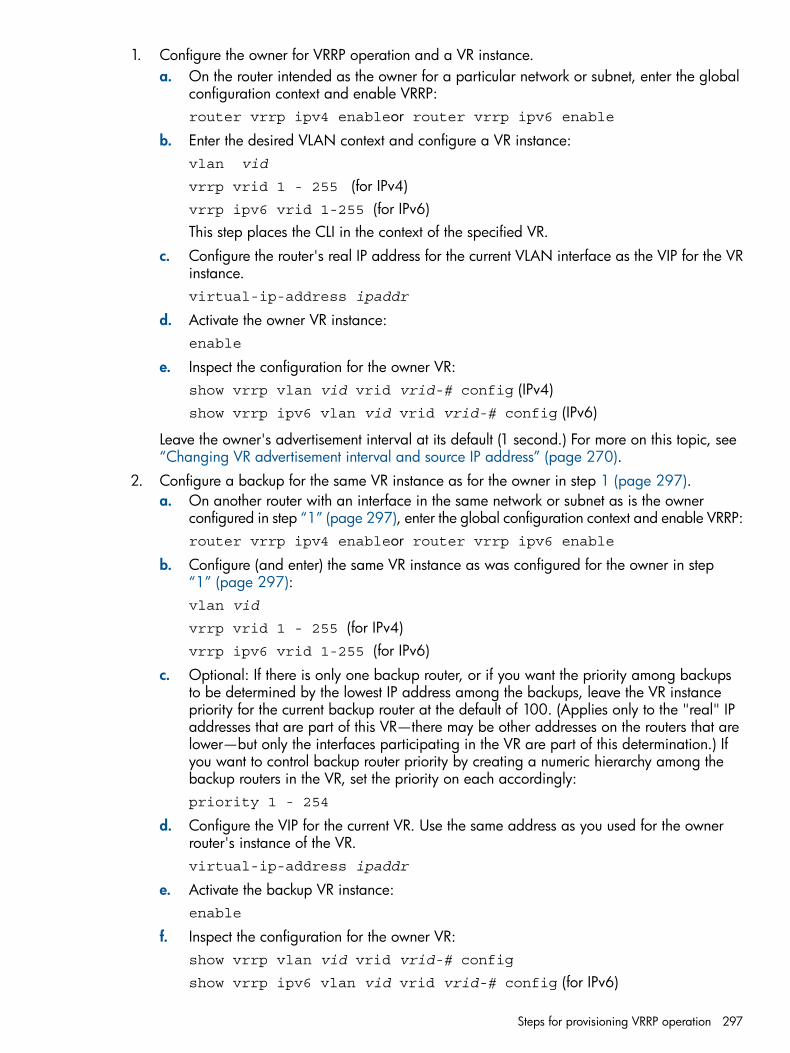
1. Configure the owner for VRRP operation and a VR instance.a. On the router intended as the owner for a particular network or subnet, enter the global
configuration context and enable VRRP:router vrrp ipv4 enableor router vrrp ipv6 enable
b. Enter the desired VLAN context and configure a VR instance:vlan vid
vrrp vrid 1 - 255 (for IPv4)vrrp ipv6 vrid 1-255 (for IPv6)This step places the CLI in the context of the specified VR.
c. Configure the router's real IP address for the current VLAN interface as the VIP for the VRinstance.virtual-ip-address ipaddr
d. Activate the owner VR instance:enable
e. Inspect the configuration for the owner VR:show vrrp vlan vid vrid vrid-# config (IPv4)show vrrp ipv6 vlan vid vrid vrid-# config (IPv6)
Leave the owner's advertisement interval at its default (1 second.) For more on this topic, see“Changing VR advertisement interval and source IP address” (page 270).
2. Configure a backup for the same VR instance as for the owner in step 1 (page 297).a. On another router with an interface in the same network or subnet as is the owner
configured in step “1” (page 297), enter the global configuration context and enable VRRP:router vrrp ipv4 enableor router vrrp ipv6 enable
b. Configure (and enter) the same VR instance as was configured for the owner in step“1” (page 297):vlan vid
vrrp vrid 1 - 255 (for IPv4)vrrp ipv6 vrid 1-255 (for IPv6)
c. Optional: If there is only one backup router, or if you want the priority among backupsto be determined by the lowest IP address among the backups, leave the VR instancepriority for the current backup router at the default of 100. (Applies only to the "real" IPaddresses that are part of this VR—there may be other addresses on the routers that arelower—but only the interfaces participating in the VR are part of this determination.) Ifyou want to control backup router priority by creating a numeric hierarchy among thebackup routers in the VR, set the priority on each accordingly:priority 1 - 254
d. Configure the VIP for the current VR. Use the same address as you used for the ownerrouter's instance of the VR.virtual-ip-address ipaddr
e. Activate the backup VR instance:enable
f. Inspect the configuration for the owner VR:show vrrp vlan vid vrid vrid-# config
show vrrp ipv6 vlan vid vrid vrid-# config (for IPv6)
Steps for provisioning VRRP operation 297
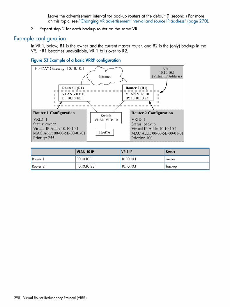
Leave the advertisement interval for backup routers at the default (1 second.) For moreon this topic, see “Changing VR advertisement interval and source IP address” (page 270).
3. Repeat step 2 for each backup router on the same VR.
Example configurationIn VR 1, below, R1 is the owner and the current master router, and R2 is the (only) backup in theVR. If R1 becomes unavailable, VR 1 fails over to R2.
Figure 53 Example of a basic VRRP configuration
Router 1 ConfigurationVRID: 1Status: ownerVirtual IP Addr: 10.10.10.1MAC Addr: 00-00-5E-00-01-01Priority: 255
Router 1 (R1)VLAN VID: 10IP: 10.10.10.1
Router 2 (R1)VLAN VID: 10IP: 10.10.10.23
SwitchVLAN VID: 10
Intranet
Host"A
Router 2 ConfigurationVRID: 1Status: backupVirtual IP Addr: 10.10.10.1MAC Addr: 00-00-5E-00-01-01Priority: 100
Host"A" Gateway: 10.10.10.1 VR 110.10.10.1
(Virtual IP Address)
StatusVR 1 IPVLAN 10 IP
owner10.10.10.110.10.10.1Router 1
backup10.10.10.110.10.10.23Router 2
298 Virtual Router Redundancy Protocol (VRRP)
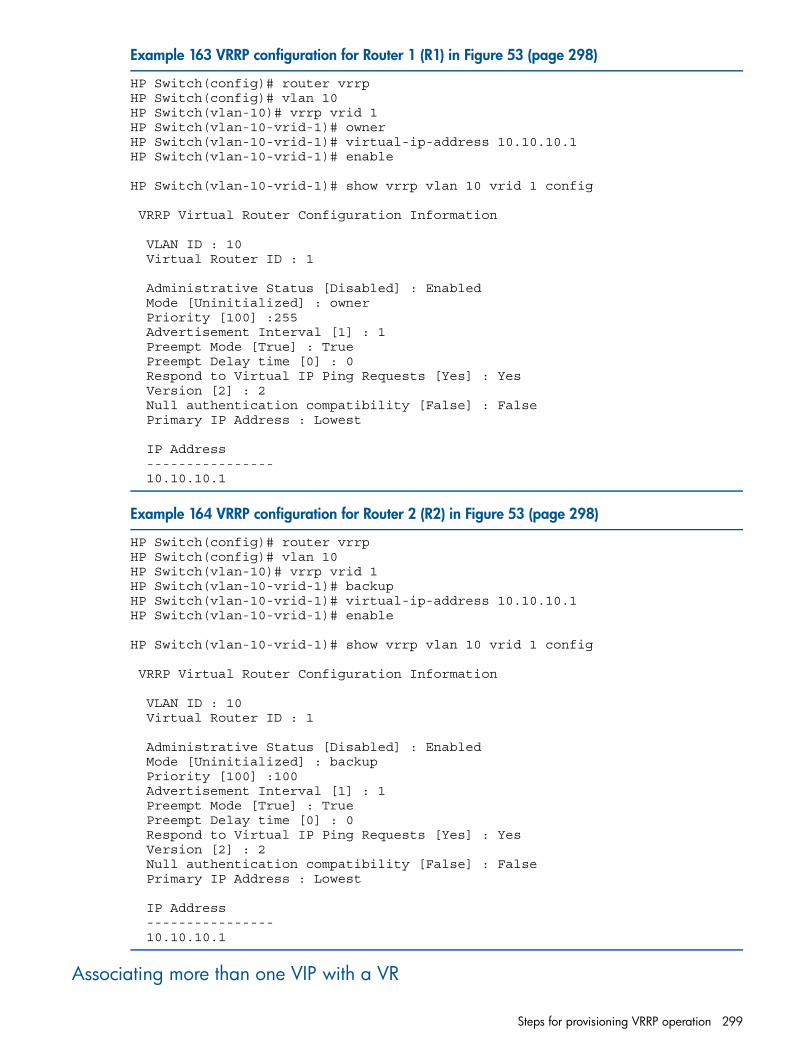
Example 163 VRRP configuration for Router 1 (R1) in Figure 53 (page 298)
HP Switch(config)# router vrrpHP Switch(config)# vlan 10HP Switch(vlan-10)# vrrp vrid 1HP Switch(vlan-10-vrid-1)# ownerHP Switch(vlan-10-vrid-1)# virtual-ip-address 10.10.10.1HP Switch(vlan-10-vrid-1)# enable
HP Switch(vlan-10-vrid-1)# show vrrp vlan 10 vrid 1 config
VRRP Virtual Router Configuration Information
VLAN ID : 10 Virtual Router ID : 1
Administrative Status [Disabled] : Enabled Mode [Uninitialized] : owner Priority [100] :255 Advertisement Interval [1] : 1 Preempt Mode [True] : True Preempt Delay time [0] : 0 Respond to Virtual IP Ping Requests [Yes] : Yes Version [2] : 2 Null authentication compatibility [False] : False Primary IP Address : Lowest
IP Address ---------------- 10.10.10.1
Example 164 VRRP configuration for Router 2 (R2) in Figure 53 (page 298)
HP Switch(config)# router vrrpHP Switch(config)# vlan 10HP Switch(vlan-10)# vrrp vrid 1HP Switch(vlan-10-vrid-1)# backupHP Switch(vlan-10-vrid-1)# virtual-ip-address 10.10.10.1HP Switch(vlan-10-vrid-1)# enable
HP Switch(vlan-10-vrid-1)# show vrrp vlan 10 vrid 1 config
VRRP Virtual Router Configuration Information
VLAN ID : 10 Virtual Router ID : 1
Administrative Status [Disabled] : Enabled Mode [Uninitialized] : backup Priority [100] :100 Advertisement Interval [1] : 1 Preempt Mode [True] : True Preempt Delay time [0] : 0 Respond to Virtual IP Ping Requests [Yes] : Yes Version [2] : 2 Null authentication compatibility [False] : False Primary IP Address : Lowest
IP Address ---------------- 10.10.10.1
Associating more than one VIP with a VR
Steps for provisioning VRRP operation 299
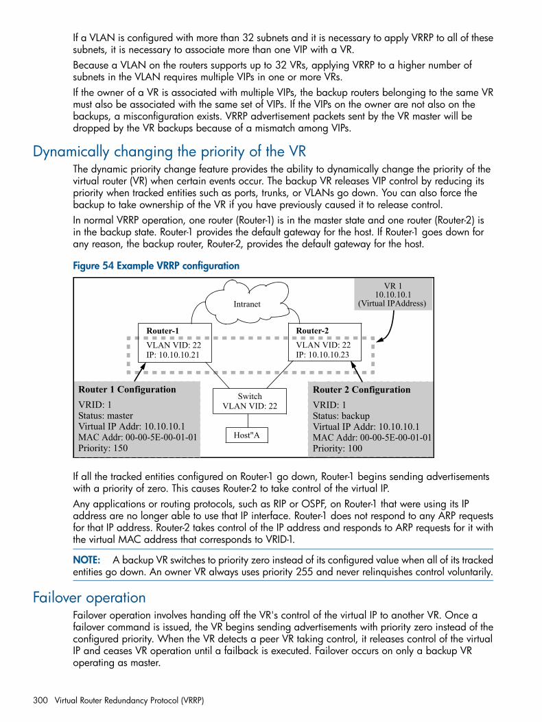
If a VLAN is configured with more than 32 subnets and it is necessary to apply VRRP to all of thesesubnets, it is necessary to associate more than one VIP with a VR.Because a VLAN on the routers supports up to 32 VRs, applying VRRP to a higher number ofsubnets in the VLAN requires multiple VIPs in one or more VRs.If the owner of a VR is associated with multiple VIPs, the backup routers belonging to the same VRmust also be associated with the same set of VIPs. If the VIPs on the owner are not also on thebackups, a misconfiguration exists. VRRP advertisement packets sent by the VR master will bedropped by the VR backups because of a mismatch among VIPs.
Dynamically changing the priority of the VRThe dynamic priority change feature provides the ability to dynamically change the priority of thevirtual router (VR) when certain events occur. The backup VR releases VIP control by reducing itspriority when tracked entities such as ports, trunks, or VLANs go down. You can also force thebackup to take ownership of the VR if you have previously caused it to release control.In normal VRRP operation, one router (Router-1) is in the master state and one router (Router-2) isin the backup state. Router-1 provides the default gateway for the host. If Router-1 goes down forany reason, the backup router, Router-2, provides the default gateway for the host.
Figure 54 Example VRRP configuration
Router 1 ConfigurationVRID: 1Status: masterVirtual IP Addr: 10.10.10.1MAC Addr: 00-00-5E-00-01-01Priority: 150
Router-1VLAN VID: 22IP: 10.10.10.21
Router-2VLAN VID: 22IP: 10.10.10.23
SwitchVLAN VID: 22
Intranet
Host"A
Router 2 ConfigurationVRID: 1Status: backupVirtual IP Addr: 10.10.10.1MAC Addr: 00-00-5E-00-01-01Priority: 100
VR 110.10.10.1
(Virtual IPAddress)
If all the tracked entities configured on Router-1 go down, Router-1 begins sending advertisementswith a priority of zero. This causes Router-2 to take control of the virtual IP.Any applications or routing protocols, such as RIP or OSPF, on Router-1 that were using its IPaddress are no longer able to use that IP interface. Router-1 does not respond to any ARP requestsfor that IP address. Router-2 takes control of the IP address and responds to ARP requests for it withthe virtual MAC address that corresponds to VRID-1.
NOTE: A backup VR switches to priority zero instead of its configured value when all of its trackedentities go down. An owner VR always uses priority 255 and never relinquishes control voluntarily.
Failover operationFailover operation involves handing off the VR's control of the virtual IP to another VR. Once afailover command is issued, the VR begins sending advertisements with priority zero instead of theconfigured priority. When the VR detects a peer VR taking control, it releases control of the virtualIP and ceases VR operation until a failback is executed. Failover occurs on only a backup VRoperating as master.
300 Virtual Router Redundancy Protocol (VRRP)
If you specify the with-monitoring option, the VR continues to monitor the virtual IP after ceasingVR operation. If the master VR goes down, it then retakes control of the virtual IP.
Pinging the virtual IP of a backup routerWhen in compliance with RFC 3768 , only owner VRs reply to ping requests (ICMP echo requests)to the VIP. When the virtual IP ping option is enabled, a backup VR operating as the master canrespond to ping requests made to the VIP. This makes it possible to test the availability of the defaultgateway with ping. A non-owner VR that is not master drops all packets to the VIP.
NOTE: This feature is not a part of RFC 3768. Enabling this feature results in non-compliancewith RFC 3768 rules.
Using the Pre-empt Delay Timer (PDT)To maintain availability of the default gateway router, the VRRP advertises a "virtual" router to thehosts. At least two other physical routers are configured to be virtual routers, but only one routerprovides the default router functionality at any given time. If the owner router or its VLAN goesdown, the backup router takes over. When the owner router comes back on line (fail-back), it takescontrol of the VIP that has been assigned to it. It begins sending out VRRP advertisement packetsat regular intervals. The backup router receives the VRRP advertisement packet and transitions tothe backup state.
When OSPF is also enabled on the VRRP routersWhen OSPF is enabled on the routers and a fail-back event occurs, the owner router immediatelytakes control of the VIP and provides the default gateway functionality. If OSPF has not converged,the route table in the owner router may not be completely populated. When the hosts send packetsto the default gateway, the owner router may not know where to send them and packets may bedropped.
CAUTION: While you can run OSPF and VRRP concurrently on a router, it is best not to run VRRPwith other routing protocols, such as RIP or OSPF, on the same interface or VLAN, as this cancreate operational issues.
Configuring the PDTThe VRRP PDT allows you to configure a period of time before the VR takes control of the VIP. Itdoes not transition to the master state until the timer period expires. The timer value configuredshould be long enough to allow OSPF convergence following OSPF updates.The PDT is applied only during initialization of the router, that is, when the router is rebooting withthe VRRP parameters present in the startup config file.
VRRP preempt mode with LACP and older HP devicesThere can be an issue with VRRP preempt mode if an older HP device (2524, 2650, 2848, 3400,or 5300) is the intermediate device connecting to a VRRP router and has LACP set in "enable,passive" mode. This mode is set by default on older HP devices, whereas it is disabled by defaulton later models such as the HP Series 5400zl. HP recommends that you use compatible LACPsettings on devices that connect with VRRP routers on VRRP VLANs.
What occurs at startupWhen the owner router comes online, it waits for the configured amount of time before takingcontrol of the VIP. This period of time is calculated as follows:
If the value of the master down time (3 * advertisement interval) is less than or equalto the preempt delay time, the owner router will wait until the master down time (3* advertisement interval) has expired.
Pinging the virtual IP of a backup router 301
During this waiting period, if the owner router receives a VRRP packet for its VIP from the backuprouter, it waits until the PDT expires before taking control of its VIP. If the owner router does notreceive any VRRP packets and the master down time expires, the owner router can take control ofits VIP immediately.
If the value of the master down time (3 * advertisement interval) is greater than thepreempt delay time, the owner router will wait until the PDT expires before takingcontrol of its VIP.
Selecting a value for the PDTYou should select the value for the PDT carefully to allow time for OSPF to populate the ownerrouter's route tables. The choice depends on the following:• The OFPF router dead interval—the number of seconds the OSPF router waits to receive a
hello packet before assuming its neighbor is down.• The number of router interfaces that participate in OSPF
• The time it may take from reception of the OSPF packets to when the population of the routetable is completed.
There are trade-offs between selecting a small advertisement value and a large PDT. A smalladvertisement value results in a faster failover to the backup router. A larger PDT value allowsOSPF to converge before the owner router takes back control of its VIP.Choosing a large PDT value (greater than the master down time) may result in an unnecessaryfailover to the backup router when the VRRP routers (owner and backup) start up together. Choosinga large advertisement interval and thereby a large master down time results in a slower failoverto the backup router when the owner router fails.
Possible configuration scenarios
PDT=zero secondsThis is the default behavior. It works in the same way that VRRP works currently.
PDT is greater than or equal to the master down time (3 times the advertisement interval)a. An owner VR after reboot—waits for the master down time. If the owner router does not receive
a packet during this time, it becomes the master. If it receives a VRRP advertisement from itspeer during this time, it waits until the expiration of the preempt delay time before becomingthe master.
b. A backup VR after reboot—waits for the master down time. If the backup router does notreceive a packet during this time, it becomes the master. If it receives a VRRP advertisementfrom its peer during this time, and it has a higher priority value than this peer, it waits untilthe expiration of the preempt delay time before becoming the backup.
PDT is less than the master down timea. Owner router—becomes the master after expiration of the PDT.b. Backup router—becomes the backup after expiration of the PDT if it does not receive a VRRP
advertisement from a higher priority peer (or the owner.)
When the PDT is not applicableOnce the router has rebooted and is in steady state VRRP operation, the PDT is not applicable if:• The VRRP VLAN goes down and comes back up.
• The VR is disabled and re-enabled.
• VRRP is globally disabled and then re-enabled.
302 Virtual Router Redundancy Protocol (VRRP)
Standards complianceVRRP on the switches includes the following:• Complies with RFC 3768 VRRP version 2.
• Complies with RFC 5798 version 3 with two exceptions—advertisementintervals below onesecond are not supported, and accept mode is not supported (only ping application forvirtual-ip-ping).
• Compatible with HP Series 9300m routers, the HP 9408sl router, and the HP Series 8100flswitches. (VRRP on these devices is based on RFC 2338.)
• Complies with RFC 2787—Definitions of Managed Objects for VRRP, except for support forauthentication-related values.
• Unified standard MIB RFC 6527 supports both IPv4 and IPv6.
• Private MIB hpicfVrrpv3.mib is added to support new IPv6 extensions and VR-specific extensionsof the deprecated, private MIB hpcifVrrp.mib. Global extensions still use hpicfVrrp.mib
Operating notes• VRRP advertisements not reaching the backup(s)
If a master is forwarding traffic properly, but its backups are prevented from receiving themaster's VRRP advertisements, both routers will operate in the master mode for the VR. If thisoccurs, traffic for the applicable gateway will continuously alternate between routers (sometimestermed "flapping".)
• Deleting an IP address used to support a VRSee “General operating rules” (page 295).
• VR limitsA VLAN allows up to 32 VRs, and a VR allows up to 32 IP addresses. This means that oneVR can support up to 32 subnets. This capacity enables use of VRRP on all subnets in a VLANthat has more than 32 subnets.
• Upgrading from VRRPv2Upgrading from a software version that only supports VRRPv2 retains the VRRPv2 mode.
• Downgrading to a VRRPv2 software versionBefore downgrading to a software version that does not support VRRPv3, ensure that the activeconfiguration does not include IPv6 settings. The downgrade is not supported if VRRP IPv6settings are included in the active configuration file.
• Proxy-ARP requests and MAC addressesThe following table shows which MAC address is returned in response to a proxy-ARP request.
Returns:Administratively:Configured as:
VRRP MAC addressEnabledowner
Default VLAN MAC addressDisabledowner
VRRP MAC addressEnabled, in master statebackup
VRRP router does not respond toproxy-ARP request.
Enabled, not in master statebackup
Default VLAN MAC addressDisabledbackup
Standards compliance 303
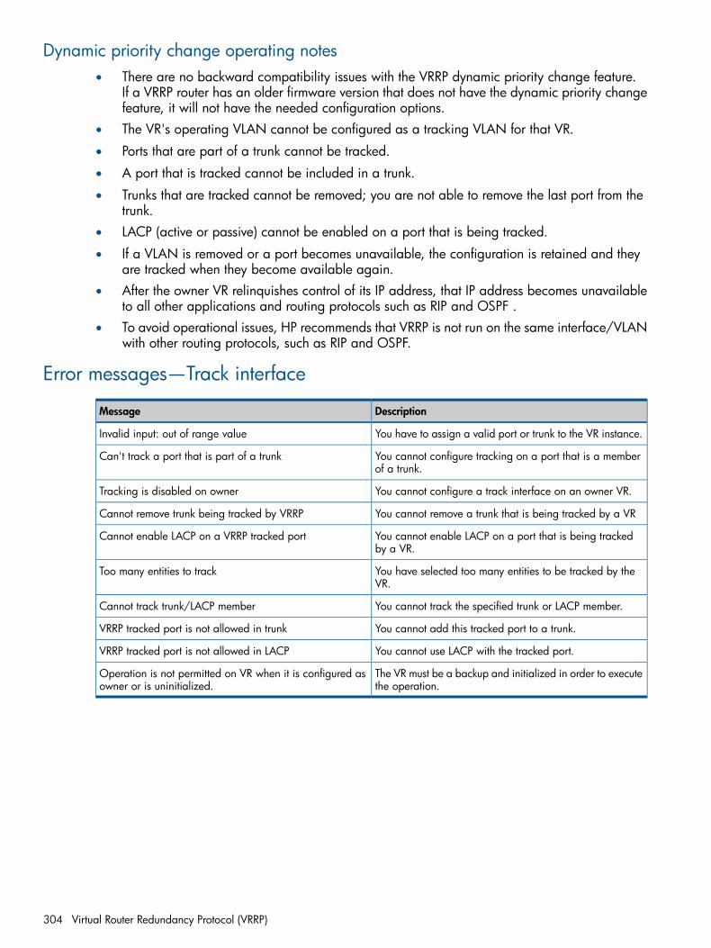
Dynamic priority change operating notes• There are no backward compatibility issues with the VRRP dynamic priority change feature.
If a VRRP router has an older firmware version that does not have the dynamic priority changefeature, it will not have the needed configuration options.
• The VR's operating VLAN cannot be configured as a tracking VLAN for that VR.
• Ports that are part of a trunk cannot be tracked.
• A port that is tracked cannot be included in a trunk.
• Trunks that are tracked cannot be removed; you are not able to remove the last port from thetrunk.
• LACP (active or passive) cannot be enabled on a port that is being tracked.
• If a VLAN is removed or a port becomes unavailable, the configuration is retained and theyare tracked when they become available again.
• After the owner VR relinquishes control of its IP address, that IP address becomes unavailableto all other applications and routing protocols such as RIP and OSPF .
• To avoid operational issues, HP recommends that VRRP is not run on the same interface/VLANwith other routing protocols, such as RIP and OSPF.
Error messages—Track interface
DescriptionMessage
You have to assign a valid port or trunk to the VR instance.Invalid input: out of range value
You cannot configure tracking on a port that is a memberof a trunk.
Can't track a port that is part of a trunk
You cannot configure a track interface on an owner VR.Tracking is disabled on owner
You cannot remove a trunk that is being tracked by a VRCannot remove trunk being tracked by VRRP
You cannot enable LACP on a port that is being trackedby a VR.
Cannot enable LACP on a VRRP tracked port
You have selected too many entities to be tracked by theVR.
Too many entities to track
You cannot track the specified trunk or LACP member.Cannot track trunk/LACP member
You cannot add this tracked port to a trunk.VRRP tracked port is not allowed in trunk
You cannot use LACP with the tracked port.VRRP tracked port is not allowed in LACP
The VR must be a backup and initialized in order to executethe operation.
Operation is not permitted on VR when it is configured asowner or is uninitialized.
304 Virtual Router Redundancy Protocol (VRRP)
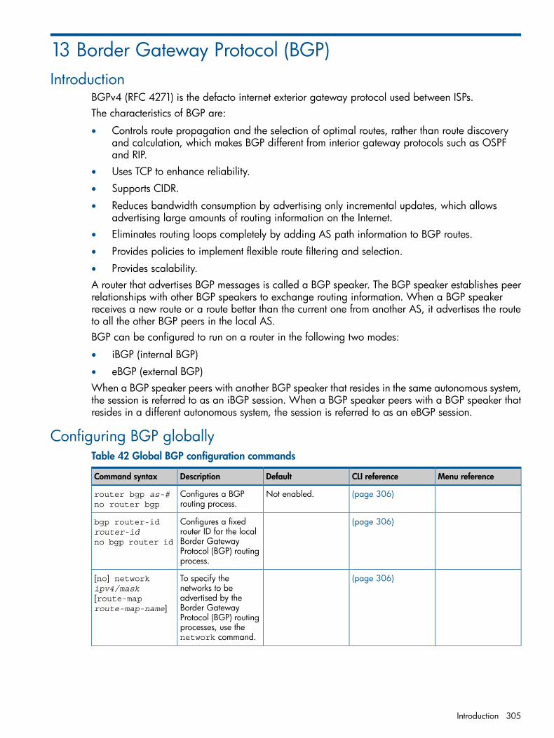
13 Border Gateway Protocol (BGP)Introduction
BGPv4 (RFC 4271) is the defacto internet exterior gateway protocol used between ISPs.The characteristics of BGP are:
• Controls route propagation and the selection of optimal routes, rather than route discoveryand calculation, which makes BGP different from interior gateway protocols such as OSPFand RIP.
• Uses TCP to enhance reliability.
• Supports CIDR.
• Reduces bandwidth consumption by advertising only incremental updates, which allowsadvertising large amounts of routing information on the Internet.
• Eliminates routing loops completely by adding AS path information to BGP routes.
• Provides policies to implement flexible route filtering and selection.
• Provides scalability.A router that advertises BGP messages is called a BGP speaker. The BGP speaker establishes peerrelationships with other BGP speakers to exchange routing information. When a BGP speakerreceives a new route or a route better than the current one from another AS, it advertises the routeto all the other BGP peers in the local AS.BGP can be configured to run on a router in the following two modes:
• iBGP (internal BGP)
• eBGP (external BGP)When a BGP speaker peers with another BGP speaker that resides in the same autonomous system,the session is referred to as an iBGP session. When a BGP speaker peers with a BGP speaker thatresides in a different autonomous system, the session is referred to as an eBGP session.
Configuring BGP globallyTable 42 Global BGP configuration commands
Menu referenceCLI referenceDefaultDescriptionCommand syntax
(page 306)Not enabled.Configures a BGProuting process.
router bgp as-#no router bgp
(page 306)Configures a fixedrouter ID for the local
bgp router-idrouter-id
Border Gatewayno bgp router idProtocol (BGP) routingprocess.
(page 306)To specify thenetworks to be
[no] networkipv4/mask
advertised by the[route-maproute-map-name] Border Gateway
Protocol (BGP) routingprocesses, use thenetwork command.
Introduction 305
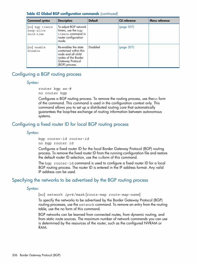
Table 42 Global BGP configuration commands (continued)
Menu referenceCLI referenceDefaultDescriptionCommand syntax
(page 307)To adjust BGP networktimers, use the bgp
[no] bgp timerskeep-alivehold-time timers command in
router configurationmode.
(page 307)DisabledRe-enables the statecontained within this
[no] enabledisable
node and all childnodes of the BorderGateway Protocol(BGP) process.
Configuring a BGP routing process
Syntax:router bgp as-#no router bgp
Configures a BGP routing process. To remove the routing process, use theno formof the command. This command is used in the configuration context only. Thiscommand allows you to set up a distributed routing core that automaticallyguarantees the loop-free exchange of routing information between autonomoussystems.
Configuring a fixed router ID for local BGP routing process
Syntax:bgp router-id router-idno bgp router id
Configures a fixed router ID for the local Border Gateway Protocol (BGP) routingprocess. To remove the fixed router ID from the running configuration file and restorethe default router ID selection, use the noform of this command.The bgp router-id command is used to configure a fixed router ID for a localBGP routing process. The router ID is entered in the IP address format. Any validIP address can be used.
Specifying the networks to be advertised by the BGP routing process
Syntax:[no] network ipv4/mask [route-map route-map-name]To specify the networks to be advertised by the Border Gateway Protocol (BGP)routing processes, use the network command. To remove an entry from the routingtable, use the no form of this command.BGP networks can be learned from connected routes, from dynamic routing, andfrom static route sources. The maximum number of network commands you can useis determined by the resources of the router, such as the configured NVRAM orRAM.
306 Border Gateway Protocol (BGP)
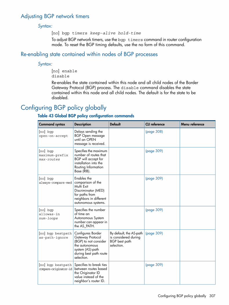
Adjusting BGP network timers
Syntax:[no] bgp timers keep-alive hold-time
To adjust BGP network timers, use the bgp timers command in router configurationmode. To reset the BGP timing defaults, use the no form of this command.
Re-enabling state contained within nodes of BGP processes
Syntax:[no] enabledisable
Re-enables the state contained within this node and all child nodes of the BorderGateway Protocol (BGP) process. The disable command disables the statecontained within this node and all child nodes. The default is for the state to bedisabled.
Configuring BGP policy globallyTable 43 Global BGP policy configuration commands
Menu referenceCLI referenceDefaultDescriptionCommand syntax
(page 308)Delays sending theBGP Open message
[no] bgpopen-on-accept
until an OPENmessage is received.
(page 309)Specifies the maximumnumber of routes that
[no] bgpmaximum-prefixmax-routes BGP will accept for
installation into theRouting InformationBase (RIB).
(page 309)Enables thecomparison of the
[no] bgpalways-compare-med
Multi ExitDiscriminator (MED)for paths fromneighbors in differentautonomous systems.
(page 309)Specifies the numberof time an
[no] bgpallowas-innum-loops Autonomous System
number can appear inthe AS_PATH.
(page 309)By default, the AS-pathis considered during
Configures BorderGateway Protocol
[no] bgp bestpathas-path-ignore
BGP best pathselection.
(BGP) to not considerthe autonomoussystem (AS)-pathduring best path routeselection.
(page 309)Specifies to break tiesbetween routes based
[no] bgp bestpathcompare-originator-id
the Originator IDvalue instead of theneighbor’s router ID.
Configuring BGP policy globally 307
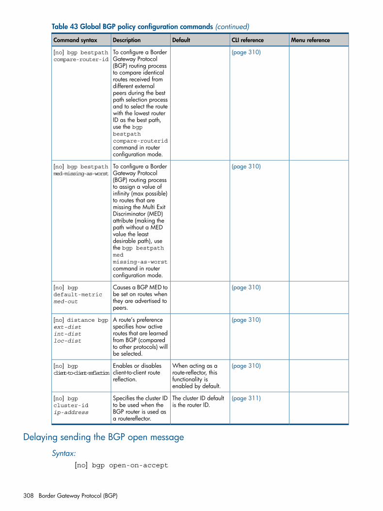
Table 43 Global BGP policy configuration commands (continued)
Menu referenceCLI referenceDefaultDescriptionCommand syntax
(page 310)To configure a BorderGateway Protocol
[no] bgp bestpathcompare-router-id
(BGP) routing processto compare identicalroutes received fromdifferent externalpeers during the bestpath selection processand to select the routewith the lowest routerID as the best path,use the bgpbestpathcompare-routeridcommand in routerconfiguration mode.
(page 310)To configure a BorderGateway Protocol
[no] bgp bestpathmed-missing-as-worst
(BGP) routing processto assign a value ofinfinity (max possible)to routes that aremissing the Multi ExitDiscriminator (MED)attribute (making thepath without a MEDvalue the leastdesirable path), usethe bgp bestpathmedmissing-as-worstcommand in routerconfiguration mode.
(page 310)Causes a BGP MED tobe set on routes when
[no] bgpdefault-metricmed-out they are advertised to
peers.
(page 310)A route’s preferencespecifies how active
[no] distance bgpext-dist
routes that are learnedint-distloc-dist from BGP (compared
to other protocols) willbe selected.
(page 310)When acting as aroute-reflector, this
Enables or disablesclient-to-client routereflection.
[no] bgpclient-to-client-reflection
functionality isenabled by default.
(page 311)The cluster ID defaultis the router ID.
Specifies the cluster IDto be used when the
[no] bgpcluster-idip-address BGP router is used as
a routereflector.
Delaying sending the BGP open message
Syntax:[no] bgp open-on-accept
308 Border Gateway Protocol (BGP)
Delays sending the BGP Open message until an OPEN message is received. Whenthis command is specified, an OPEN message will be immediately sent when theTCP connection has completed for configured peers. If the peer is not configured(is matched by an allow clause, but not a peer command), it will continue to waitfor the OPEN message from the remote peer before sending its own BGP OPENmessage.
Specifying the maximum routes that BGP will accept for installation into the RIB
Syntax:[no] bgp maximum-prefix max-routesSpecifies the maximum number of routes that BGP will accept for installation intothe Routing information Base (RIB). Use the noform of the command to set theparameter to its default value.
Enabling comparison of MED for paths from neighbors in different autonomous systems
Syntax:[no] bgp always-compare-medEnables the comparison of the Multi Exit Discriminator (MED) for paths fromneighbors in different autonomous systems. To disallow the comparison, use the noform of this command.The MED is one of the parameters that is considered when selecting the best pathamong many alternative paths. The path with a lower MED is preferred over a pathwith a higher MED. During the best-path selection process, MED comparison isdone only among paths from the same autonomous system. The bgpalways-compare-med command is used to change this behavior by enforcingMED comparison between all paths, regardless of the autonomous system fromwhich the paths are received.
Specifying the number of times an AS number can appear in AS_PATH
Syntax:[no] bgp allowas-in num-loopsSpecifies the number of times an Autonomous System number can appear in theAS_PATH. Use the no form of the command to set the parameter to its default valueof ‘1’.
Configuring BGP to not consider AS_PATH
Syntax:[no] bgp bestpath as-path-ignoreConfigures Border Gateway Protocol (BGP) to not consider the autonomous system(AS)-path during best path route selection. To restore default behavior and configureBGP to consider the AS-path during route selection, use the no form of this command.By default, the AS-path is considered during BGP best path selection.
Breaking ties between routes based on originator ID value
Syntax:[no] bgp bestpath compare-originator-id
Configuring BGP policy globally 309
Specifies to break ties between routes based the Originator ID value instead of theneighbor’s router ID. Use the no form of the command to not compare routes basedon originator ID.
Comparing identical routes received from different external peers
Syntax:[no] bgp bestpath compare-router-idTo configure a Border Gateway Protocol (BGP) routing process to compare identicalroutes received from different external peers during the best path selection processand to select the route with the lowest router ID as the best path, use the bgpbestpath compare-routerid command in router configuration mode. Toreturn the BGP routing process to the default operation, use the no form of thiscommand.The behavior of this command is disabled by default; BGP selects the route thatwas received first when two routes with identical attributes are received.
Assigning value of infinity to routes missing MED attribute
Syntax:[no] bgp bestpath med-missing-as-worstTo configure a Border Gateway Protocol (BGP) routing process to assign a valueof infinity (max possible) to routes that are missing the Multi Exit Discriminator (MED)attribute (making the path without a MED value the least desirable path), use thebgp bestpath med missing-as-worst command in router configurationmode. To return the router to the default behavior (assign a value of 0 to the missingMED), use the no form of this command.
Setting BGP MED on routes when advertised to peers
Syntax:[no] bgp default-metric med-outCauses a BGP MED to be set on routes when they are advertised to peers. Thisvalue applies to all BGP peers. It can be overridden on a per-peer basis. The noform of this command, no default-metric, removes the configured value.
Specifying a route's preference
Syntax:[no] distance bgp ext-dist int-dist loc-dist
A route’s preference specifies how active routes that are learned from BGP(compared to other protocols) will be selected. When a route has been learnedfrom more than one protocol, the active route will be selected from the protocolwith the lowest preference. Each protocol has a default preference in this selection.This preference can be overridden by a preference value specified on the peer.
Enabling client-to-client route reflection
Syntax:[no] bgp client-to-client-reflectionEnables or disables client-to-client route reflection. When acting as a route-reflector,this functionality is enabled by default.
310 Border Gateway Protocol (BGP)
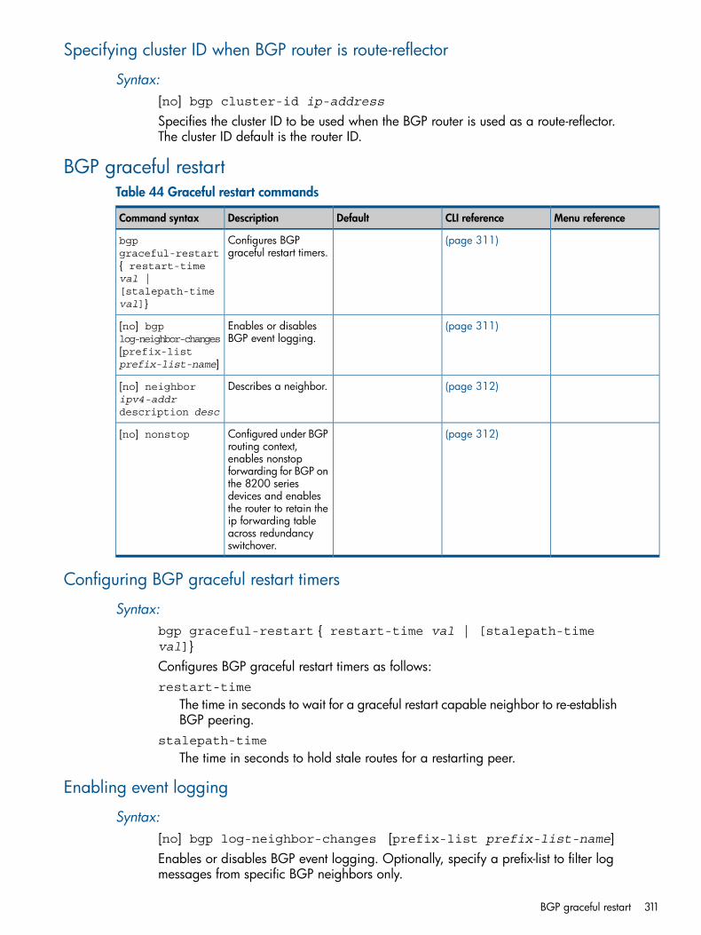
Specifying cluster ID when BGP router is route-reflector
Syntax:[no] bgp cluster-id ip-addressSpecifies the cluster ID to be used when the BGP router is used as a route-reflector.The cluster ID default is the router ID.
BGP graceful restartTable 44 Graceful restart commands
Menu referenceCLI referenceDefaultDescriptionCommand syntax
(page 311)Configures BGPgraceful restart timers.
bgpgraceful-restart{ restart-timeval |[stalepath-timeval]}
(page 311)Enables or disablesBGP event logging.
[no] bgplog-neighbor-changes[prefix-listprefix-list-name]
(page 312)Describes a neighbor.[no] neighboripv4-addrdescription desc
(page 312)Configured under BGProuting context,
[no] nonstop
enables nonstopforwarding for BGP onthe 8200 seriesdevices and enablesthe router to retain theip forwarding tableacross redundancyswitchover.
Configuring BGP graceful restart timers
Syntax:bgp graceful-restart { restart-time val | [stalepath-timeval]}Configures BGP graceful restart timers as follows:restart-time
The time in seconds to wait for a graceful restart capable neighbor to re-establishBGP peering.
stalepath-time
The time in seconds to hold stale routes for a restarting peer.
Enabling event logging
Syntax:[no] bgp log-neighbor-changes [prefix-list prefix-list-name]Enables or disables BGP event logging. Optionally, specify a prefix-list to filter logmessages from specific BGP neighbors only.
BGP graceful restart 311
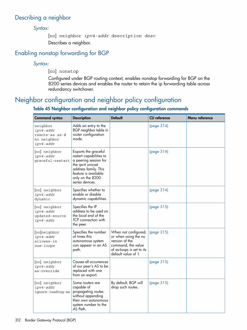
Describing a neighbor
Syntax:[no] neighbor ipv4-addr description descDescribes a neighbor.
Enabling nonstop forwarding for BGP
Syntax:[no] nonstopConfigured under BGP routing context, enables nonstop forwarding for BGP on the8200 series devices and enables the router to retain the ip forwarding table acrossredundancy switchover.
Neighbor configuration and neighbor policy configurationTable 45 Neighbor configuration and neighbor policy configuration commands
Menu referenceCLI referenceDefaultDescriptionCommand syntax
(page 314)Adds an entry to theBGP neighbor table in
neighboripv4-addrremote-as as-# router configuration
mode.no neighboripv4-addr
(page 314)Exports the gracefulrestart capabilities to
[no] neighboripv4-addrgraceful-restart a peering session for
the ipv4 unicastaddress family. Thisfeature is availableonly on the 8200series devices.
(page 314)Specifies whether toenable or disabledynamic capabilities.
[no] neighboripv4-addrdynamic
(page 315)Specifies the IPaddress to be used on
[no] neighboripv4-addr
the local end of theupdated-sourceipv4-addr TCP connection with
the peer.
(page 315)When not configured,or when using the no
Specifies the numberof times this
[no]neighboripv4-addr
version of theautonomous systemallowas-innum-loops command, the value
of as-loops is set to itsdefault value of 1.
can appear in an ASpath.
(page 315)Causes all occurrencesof our peer’s AS to be
[no] neighboripv4-addras-override replaced with one
from an export.
(page 315)By default, BGP willdrop such routes.
Some routers arecapable of
[no] neighboripv4-addrignore-leading-as propagating routes
without appendingtheir own autonomoussystem number to theAS Path.
312 Border Gateway Protocol (BGP)
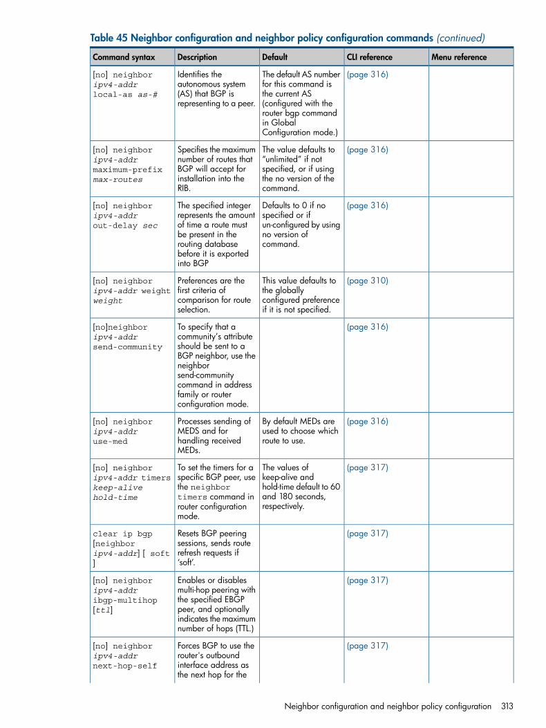
Table 45 Neighbor configuration and neighbor policy configuration commands (continued)
Menu referenceCLI referenceDefaultDescriptionCommand syntax
(page 316)The default AS numberfor this command is
Identifies theautonomous system
[no] neighboripv4-addrlocal-as as-# the current AS
(configured with the(AS) that BGP isrepresenting to a peer.
router bgp commandin GlobalConfiguration mode.)
(page 316)The value defaults to“unlimited” if not
Specifies the maximumnumber of routes that
[no] neighboripv4-addr
specified, or if usingBGP will accept formaximum-prefixmax-routes the no version of the
command.installation into theRIB.
(page 316)Defaults to 0 if nospecified or if
The specified integerrepresents the amount
[no] neighboripv4-addrout-delay sec un-configured by using
no version ofcommand.
of time a route mustbe present in therouting databasebefore it is exportedinto BGP
(page 310)This value defaults tothe globally
Preferences are thefirst criteria of
[no] neighboripv4-addr weightweight configured preference
if it is not specified.comparison for routeselection.
(page 316)To specify that acommunity’s attribute
[no]neighboripv4-addrsend-community should be sent to a
BGP neighbor, use theneighborsend-communitycommand in addressfamily or routerconfiguration mode.
(page 316)By default MEDs areused to choose whichroute to use.
Processes sending ofMEDS and forhandling receivedMEDs.
[no] neighboripv4-addruse-med
(page 317)The values ofkeep-alive and
To set the timers for aspecific BGP peer, use
[no] neighboripv4-addr timers
hold-time default to 60the neighborkeep-alivehold-time and 180 seconds,
respectively.timers command inrouter configurationmode.
(page 317)Resets BGP peeringsessions, sends route
clear ip bgp[neighbor
refresh requests if‘soft’.
ipv4-addr] [ soft]
(page 317)Enables or disablesmulti-hop peering with
[no] neighboripv4-addr
the specified EBGPibgp-multihop[ttl] peer, and optionally
indicates the maximumnumber of hops (TTL.)
(page 317)Forces BGP to use therouter's outbound
[no] neighboripv4-addrnext-hop-self interface address as
the next hop for the
Neighbor configuration and neighbor policy configuration 313
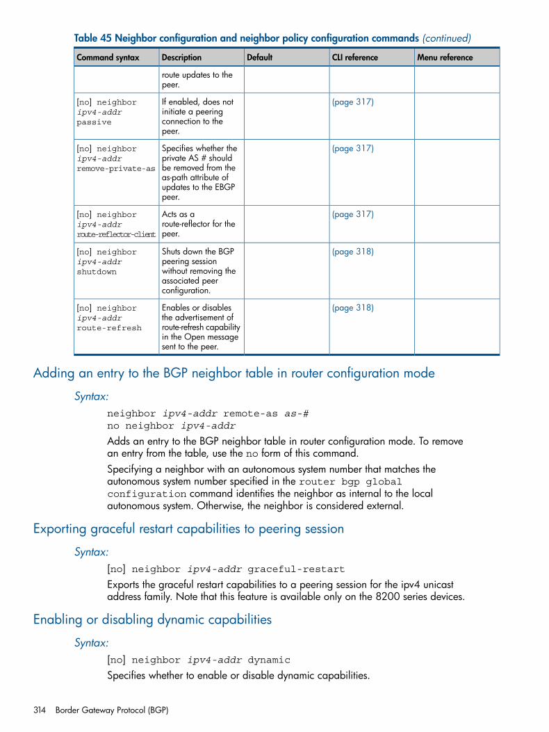
Table 45 Neighbor configuration and neighbor policy configuration commands (continued)
Menu referenceCLI referenceDefaultDescriptionCommand syntax
route updates to thepeer.
(page 317)If enabled, does notinitiate a peering
[no] neighboripv4-addrpassive connection to the
peer.
(page 317)Specifies whether theprivate AS # should
[no] neighboripv4-addrremove-private-as be removed from the
as-path attribute ofupdates to the EBGPpeer.
(page 317)Acts as aroute-reflector for thepeer.
[no] neighboripv4-addrroute-reflector-client
(page 318)Shuts down the BGPpeering session
[no] neighboripv4-addrshutdown without removing the
associated peerconfiguration.
(page 318)Enables or disablesthe advertisement of
[no] neighboripv4-addrroute-refresh route-refresh capability
in the Open messagesent to the peer.
Adding an entry to the BGP neighbor table in router configuration mode
Syntax:neighbor ipv4-addr remote-as as-#no neighbor ipv4-addr
Adds an entry to the BGP neighbor table in router configuration mode. To removean entry from the table, use the no form of this command.Specifying a neighbor with an autonomous system number that matches theautonomous system number specified in the router bgp globalconfiguration command identifies the neighbor as internal to the localautonomous system. Otherwise, the neighbor is considered external.
Exporting graceful restart capabilities to peering session
Syntax:[no] neighbor ipv4-addr graceful-restartExports the graceful restart capabilities to a peering session for the ipv4 unicastaddress family. Note that this feature is available only on the 8200 series devices.
Enabling or disabling dynamic capabilities
Syntax:[no] neighbor ipv4-addr dynamicSpecifies whether to enable or disable dynamic capabilities.
314 Border Gateway Protocol (BGP)
BGP Dynamic Capabilities allow the communication of a change in a BGP peer’scapabilities without having to restart the peering session. The BGP implementationis done on a per-peer basis and in such a way that dynamic capabilities aresupported as long as the BGP peer supports BGP Dynamic Capabilities. BGPadvertises Dynamic Capabilities in the OPEN message. If a BGP peer advertisessupport for BGP Dynamic Capabilities in the OPEN message, then it turns onDynamic Capabilities. Otherwise, the dynamic capabilities for this peer will bedisabled. BGP supports the following BGP Dynamic Capabilities:
• Graceful restart
• Route refresh
Specifying the IP address for local end of TCP connection with peer
Syntax:[no] neighbor ipv4-addr updated-source ipv4-addrSpecifies the IP address to be used on the local end of the TCP connection with thepeer. This is the address of a broadcast, NBMA or loopback interface and the localaddress of a point-to-point interface. For external peers, the local address must beon an interface that is shared with the peer or with the peer’s gateway when agateway is used. A session with an external peer will be opened only when aninterface with the appropriate local address (through which the peer or gatewayaddress is directly reachable) is operating. For internal peers, a peer session willbe maintained when any interface with the specified local address is operating. Inany case, an incoming connection will be recognized as a match for a configuredpeer only if it is addressed to the configured local address.
Specifying the number of times the autonomous system can appear in an AS path
Syntax:[no]neighbor ipv4-addr allowas-in num-loopsSpecifies the number of times this autonomous system can appear in an AS path.When not configured, or when using theno version of the command, the value ofas-loops is set to its default value of 1.
Replacing occurrences of peer's AS with one from an export
Syntax:[no] neighbor ipv4-addr as-overrideCauses all occurrences of our peer’s AS to be replaced with one from an export.
Allowing BGP to keep routes without AS number
Syntax:[no] neighbor ipv4-addr ignore-leading-asSome routers are capable of propagating routes without appending their ownautonomous system number to the AS Path. By default, BGP will drop such routes.Turning this parameter “on” allows BGP to keep these routes. This option shouldbe used only if there is no doubt that these peers are not normal routers.
Neighbor configuration and neighbor policy configuration 315
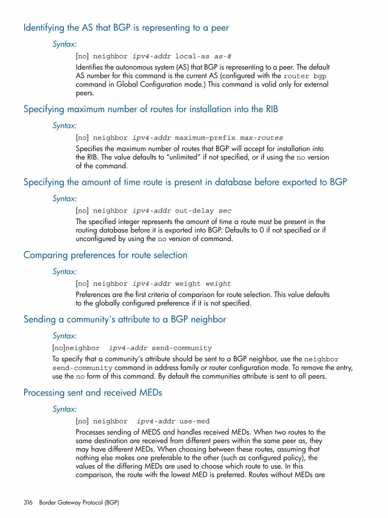
Identifying the AS that BGP is representing to a peer
Syntax:[no] neighbor ipv4-addr local-as as-#Identifies the autonomous system (AS) that BGP is representing to a peer. The defaultAS number for this command is the current AS (configured with the router bgpcommand in Global Configuration mode.) This command is valid only for externalpeers.
Specifying maximum number of routes for installation into the RIB
Syntax:[no] neighbor ipv4-addr maximum-prefix max-routesSpecifies the maximum number of routes that BGP will accept for installation intothe RIB. The value defaults to “unlimited” if not specified, or if using the no versionof the command.
Specifying the amount of time route is present in database before exported to BGP
Syntax:[no] neighbor ipv4-addr out-delay secThe specified integer represents the amount of time a route must be present in therouting database before it is exported into BGP. Defaults to 0 if not specified or ifunconfigured by using the no version of command.
Comparing preferences for route selection
Syntax:[no] neighbor ipv4-addr weight weightPreferences are the first criteria of comparison for route selection. This value defaultsto the globally configured preference if it is not specified.
Sending a community's attribute to a BGP neighbor
Syntax:[no]neighbor ipv4-addr send-community
To specify that a community’s attribute should be sent to a BGP neighbor, use the neighborsend-community command in address family or router configuration mode. To remove the entry,use the no form of this command. By default the communities attribute is sent to all peers.
Processing sent and received MEDs
Syntax:[no] neighbor ipv4-addr use-med
Processes sending of MEDS and handles received MEDs. When two routes to thesame destination are received from different peers within the same peer as, theymay have different MEDs. When choosing between these routes, assuming thatnothing else makes one preferable to the other (such as configured policy), thevalues of the differing MEDs are used to choose which route to use. In thiscomparison, the route with the lowest MED is preferred. Routes without MEDs are
316 Border Gateway Protocol (BGP)
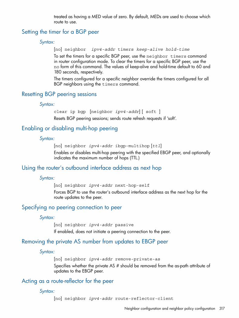
treated as having a MED value of zero. By default, MEDs are used to choose whichroute to use.
Setting the timer for a BGP peer
Syntax:[no] neighbor ipv4-addr timers keep-alive hold-time
To set the timers for a specific BGP peer, use the neighbor timers commandin router configuration mode. To clear the timers for a specific BGP peer, use theno form of this command. The values of keep-alive and hold-time default to 60 and180 seconds, respectively.The timers configured for a specific neighbor override the timers configured for allBGP neighbors using the timers command.
Resetting BGP peering sessions
Syntax:clear ip bgp [neighbor ipv4-addr] [ soft ]Resets BGP peering sessions; sends route refresh requests if ‘soft’.
Enabling or disabling multi-hop peering
Syntax:[no] neighbor ipv4-addr ibgp-multihop [ttl]Enables or disables multi-hop peering with the specified EBGP peer, and optionallyindicates the maximum number of hops (TTL.)
Using the router's outbound interface address as next hop
Syntax:[no] neighbor ipv4-addr next-hop-selfForces BGP to use the router's outbound interface address as the next hop for theroute updates to the peer.
Specifying no peering connection to peer
Syntax:[no] neighbor ipv4-addr passiveIf enabled, does not initiate a peering connection to the peer.
Removing the private AS number from updates to EBGP peer
Syntax:[no] neighbor ipv4-addr remove-private-asSpecifies whether the private AS # should be removed from the as-path attribute ofupdates to the EBGP peer.
Acting as a route-reflector for the peer
Syntax:[no] neighbor ipv4-addr route-reflector-client
Neighbor configuration and neighbor policy configuration 317
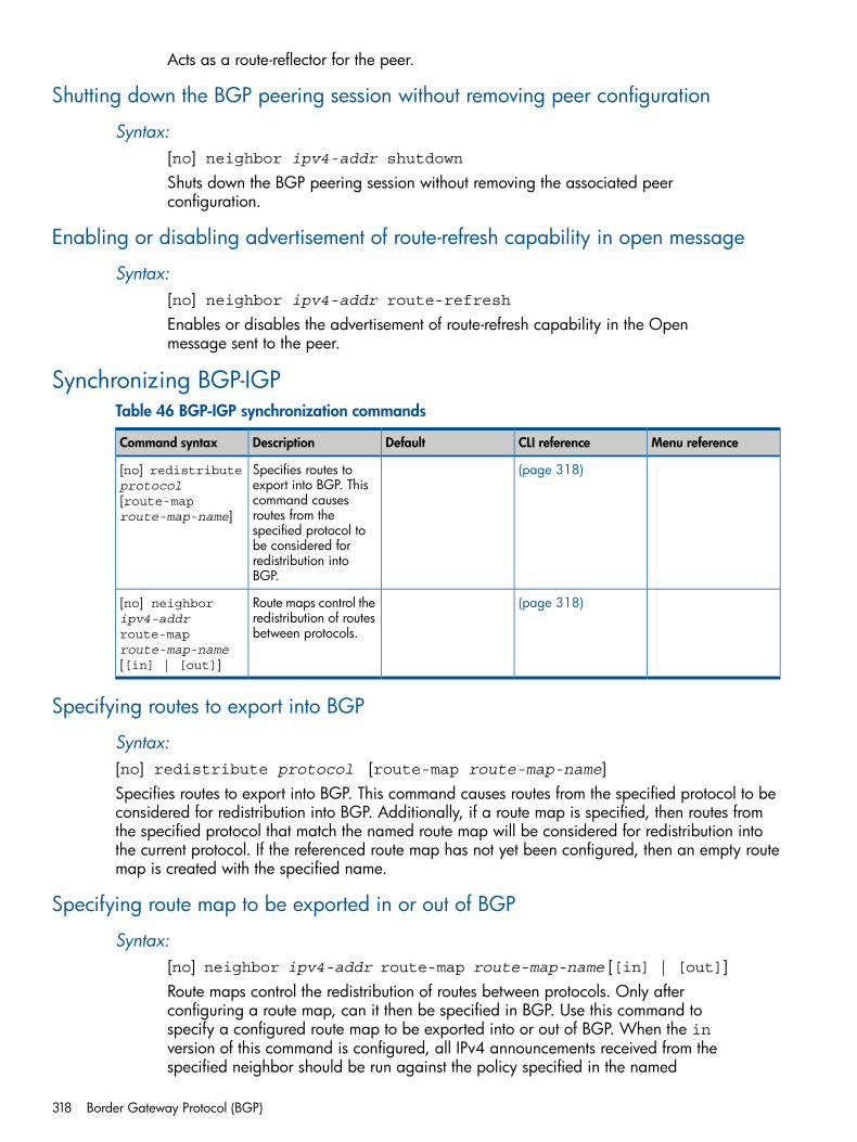
Acts as a route-reflector for the peer.
Shutting down the BGP peering session without removing peer configuration
Syntax:[no] neighbor ipv4-addr shutdownShuts down the BGP peering session without removing the associated peerconfiguration.
Enabling or disabling advertisement of route-refresh capability in open message
Syntax:[no] neighbor ipv4-addr route-refreshEnables or disables the advertisement of route-refresh capability in the Openmessage sent to the peer.
Synchronizing BGP-IGPTable 46 BGP-IGP synchronization commands
Menu referenceCLI referenceDefaultDescriptionCommand syntax
(page 318)Specifies routes toexport into BGP. This
[no] redistributeprotocol
command causes[route-maproute-map-name] routes from the
specified protocol tobe considered forredistribution intoBGP.
(page 318)Route maps control theredistribution of routesbetween protocols.
[no] neighboripv4-addrroute-maproute-map-name[[in] | [out]]
Specifying routes to export into BGP
Syntax:[no] redistribute protocol [route-map route-map-name]Specifies routes to export into BGP. This command causes routes from the specified protocol to beconsidered for redistribution into BGP. Additionally, if a route map is specified, then routes fromthe specified protocol that match the named route map will be considered for redistribution intothe current protocol. If the referenced route map has not yet been configured, then an empty routemap is created with the specified name.
Specifying route map to be exported in or out of BGP
Syntax:[no] neighbor ipv4-addr route-map route-map-name [[in] | [out]]Route maps control the redistribution of routes between protocols. Only afterconfiguring a route map, can it then be specified in BGP. Use this command tospecify a configured route map to be exported into or out of BGP. When the inversion of this command is configured, all IPv4 announcements received from thespecified neighbor should be run against the policy specified in the named
318 Border Gateway Protocol (BGP)
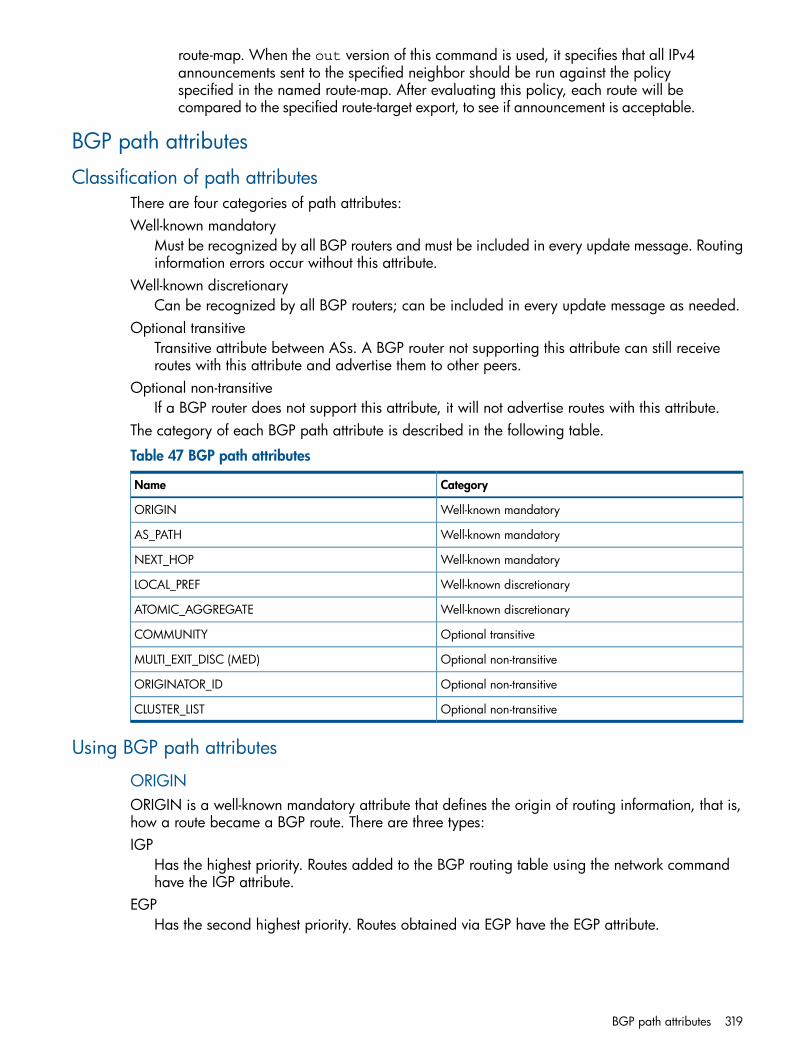
route-map. When the out version of this command is used, it specifies that all IPv4announcements sent to the specified neighbor should be run against the policyspecified in the named route-map. After evaluating this policy, each route will becompared to the specified route-target export, to see if announcement is acceptable.
BGP path attributes
Classification of path attributesThere are four categories of path attributes:Well-known mandatory
Must be recognized by all BGP routers and must be included in every update message. Routinginformation errors occur without this attribute.
Well-known discretionaryCan be recognized by all BGP routers; can be included in every update message as needed.
Optional transitiveTransitive attribute between ASs. A BGP router not supporting this attribute can still receiveroutes with this attribute and advertise them to other peers.
Optional non-transitiveIf a BGP router does not support this attribute, it will not advertise routes with this attribute.
The category of each BGP path attribute is described in the following table.
Table 47 BGP path attributes
CategoryName
Well-known mandatoryORIGIN
Well-known mandatoryAS_PATH
Well-known mandatoryNEXT_HOP
Well-known discretionaryLOCAL_PREF
Well-known discretionaryATOMIC_AGGREGATE
Optional transitiveCOMMUNITY
Optional non-transitiveMULTI_EXIT_DISC (MED)
Optional non-transitiveORIGINATOR_ID
Optional non-transitiveCLUSTER_LIST
Using BGP path attributes
ORIGINORIGIN is a well-known mandatory attribute that defines the origin of routing information, that is,how a route became a BGP route. There are three types:IGP
Has the highest priority. Routes added to the BGP routing table using the network commandhave the IGP attribute.
EGPHas the second highest priority. Routes obtained via EGP have the EGP attribute.
BGP path attributes 319
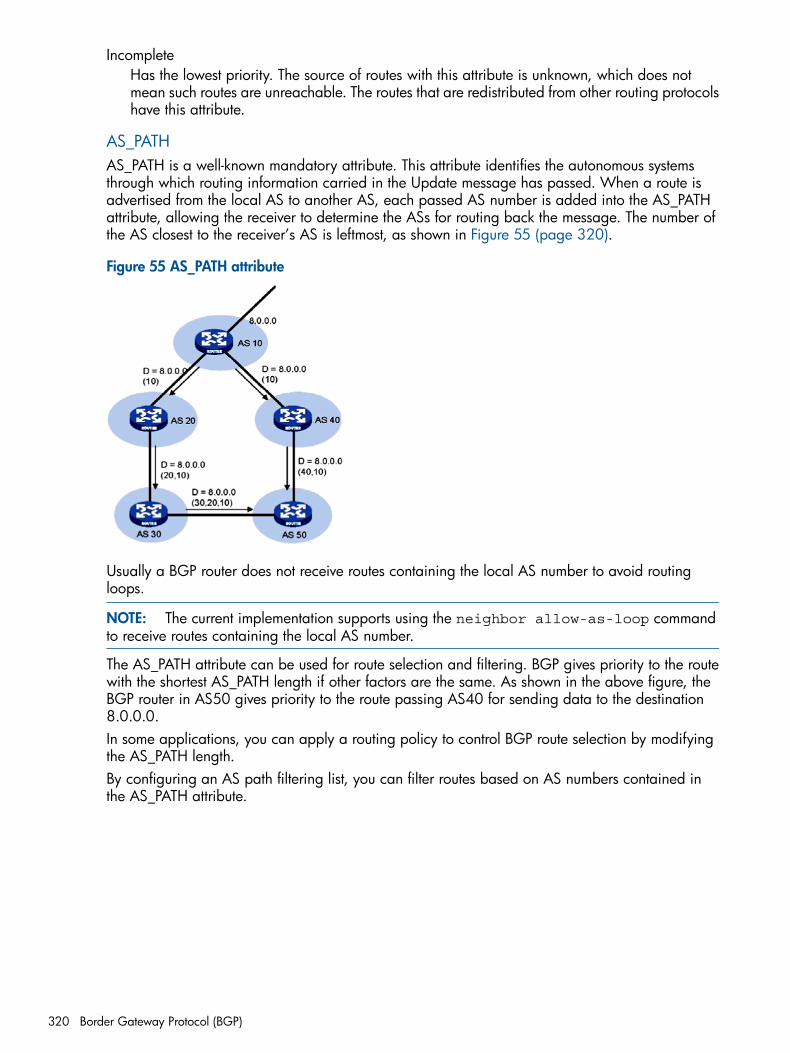
IncompleteHas the lowest priority. The source of routes with this attribute is unknown, which does notmean such routes are unreachable. The routes that are redistributed from other routing protocolshave this attribute.
AS_PATHAS_PATH is a well-known mandatory attribute. This attribute identifies the autonomous systemsthrough which routing information carried in the Update message has passed. When a route isadvertised from the local AS to another AS, each passed AS number is added into the AS_PATHattribute, allowing the receiver to determine the ASs for routing back the message. The number ofthe AS closest to the receiver’s AS is leftmost, as shown in Figure 55 (page 320).
Figure 55 AS_PATH attribute
Usually a BGP router does not receive routes containing the local AS number to avoid routingloops.
NOTE: The current implementation supports using the neighbor allow-as-loop commandto receive routes containing the local AS number.
The AS_PATH attribute can be used for route selection and filtering. BGP gives priority to the routewith the shortest AS_PATH length if other factors are the same. As shown in the above figure, theBGP router in AS50 gives priority to the route passing AS40 for sending data to the destination8.0.0.0.In some applications, you can apply a routing policy to control BGP route selection by modifyingthe AS_PATH length.By configuring an AS path filtering list, you can filter routes based on AS numbers contained inthe AS_PATH attribute.
320 Border Gateway Protocol (BGP)
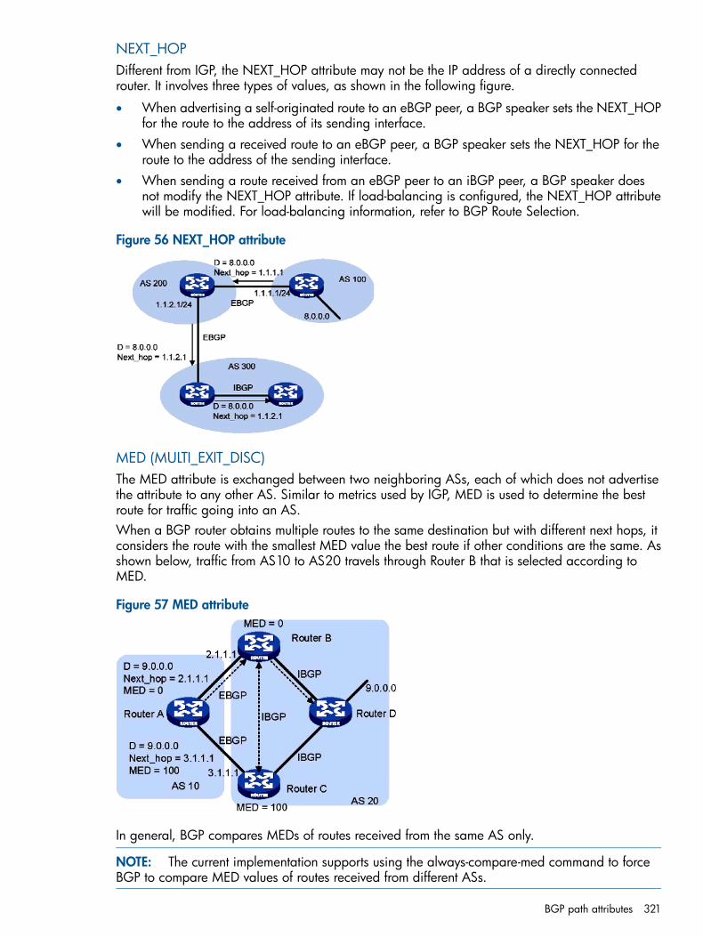
NEXT_HOPDifferent from IGP, the NEXT_HOP attribute may not be the IP address of a directly connectedrouter. It involves three types of values, as shown in the following figure.
• When advertising a self-originated route to an eBGP peer, a BGP speaker sets the NEXT_HOPfor the route to the address of its sending interface.
• When sending a received route to an eBGP peer, a BGP speaker sets the NEXT_HOP for theroute to the address of the sending interface.
• When sending a route received from an eBGP peer to an iBGP peer, a BGP speaker doesnot modify the NEXT_HOP attribute. If load-balancing is configured, the NEXT_HOP attributewill be modified. For load-balancing information, refer to BGP Route Selection.
Figure 56 NEXT_HOP attribute
MED (MULTI_EXIT_DISC)The MED attribute is exchanged between two neighboring ASs, each of which does not advertisethe attribute to any other AS. Similar to metrics used by IGP, MED is used to determine the bestroute for traffic going into an AS.When a BGP router obtains multiple routes to the same destination but with different next hops, itconsiders the route with the smallest MED value the best route if other conditions are the same. Asshown below, traffic from AS10 to AS20 travels through Router B that is selected according toMED.
Figure 57 MED attribute
In general, BGP compares MEDs of routes received from the same AS only.
NOTE: The current implementation supports using the always-compare-med command to forceBGP to compare MED values of routes received from different ASs.
BGP path attributes 321
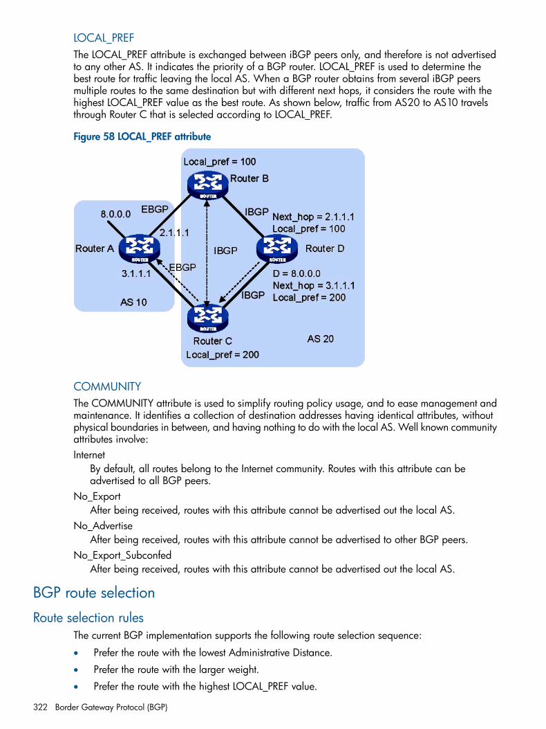
LOCAL_PREFThe LOCAL_PREF attribute is exchanged between iBGP peers only, and therefore is not advertisedto any other AS. It indicates the priority of a BGP router. LOCAL_PREF is used to determine thebest route for traffic leaving the local AS. When a BGP router obtains from several iBGP peersmultiple routes to the same destination but with different next hops, it considers the route with thehighest LOCAL_PREF value as the best route. As shown below, traffic from AS20 to AS10 travelsthrough Router C that is selected according to LOCAL_PREF.
Figure 58 LOCAL_PREF attribute
COMMUNITYThe COMMUNITY attribute is used to simplify routing policy usage, and to ease management andmaintenance. It identifies a collection of destination addresses having identical attributes, withoutphysical boundaries in between, and having nothing to do with the local AS. Well known communityattributes involve:Internet
By default, all routes belong to the Internet community. Routes with this attribute can beadvertised to all BGP peers.
No_ExportAfter being received, routes with this attribute cannot be advertised out the local AS.
No_AdvertiseAfter being received, routes with this attribute cannot be advertised to other BGP peers.
No_Export_SubconfedAfter being received, routes with this attribute cannot be advertised out the local AS.
BGP route selection
Route selection rulesThe current BGP implementation supports the following route selection sequence:
• Prefer the route with the lowest Administrative Distance.
• Prefer the route with the larger weight.
• Prefer the route with the highest LOCAL_PREF value.
322 Border Gateway Protocol (BGP)
• Prefer the path that was locally originated via a network or through redistribution from anIGP.
• Prefer the route with the shortest path, excluding confederation segments.
• Prefer the route with the “best” ORIGIN. IGP is better than EGP, which is better than Incomplete.
• If bgp always-compare-med is not configured, prefer any routes that do not have an inferiorMED. If bgp always-compare-med has been configured, prefer the route with the lowest MED.
• Prefer the route with the lowest IGP cost to the BGP next hop. IGP cost is determined bycomparing the preference, then the weight, then the metric, and finally the metric2 of the tworesolving routes.
• If “ip load-sharing” is enabled, BGP inserts up to n most recently received paths in the IProuting table. This allows eBGP multipath load sharing. The maximum value of n is currently4. The default value of n, when “ip load-sharing” is disabled, is 1. The oldest received pathis marked as the best path in the output of show ip bgp prefix/len.
• Prefer routes received from external peers.
• If bgp tie-break-on-age has been specified, prefer the older route.
• If bgp bestpath compare-router-id has been specified, prefer the route learned withthe lowest router ID. The router ID is taken from the Open message of the peering session overwhich the route was received, unless bgp bestpath compare-originator-id has beenspecified, and the route was received with an ORIGIN_ID. In the latter case, the ORIGIN_IDis used instead of the router ID from the Open message.
• If bgp bestpath compare-cluster-list-length has been specified, prefer the routewith the lowest CLUSTER_LIST length.
• Prefer the route with the lowest neighbor address.
NOTE: CLUSTER_IDs of route reflectors form a CLUSTER_LIST. If a route reflector receives a routethat contains its own CLUSTER ID in the CLUSTER_LIST, the router discards the route to avoid routingloops.
Recursive route in iBGPThe nexthop of an iBGP route may not always be directly connected. One of the reasons is nexthops in routing information exchanged between iBGPs are not modified. In this case, the BGProuter needs to find the directly connected next hop via IGP. The matching route with the directnext hop is called the recursive route. The process of finding a recursive route is route recursion.
Route selection with BGP load sharingBGP differs from IGP in the implementation of load balancing in the following:
• IGP routing protocols such as RIP and OSPF compute metrics of routes, and then implementload sharing over routes with the same metric and to the same destination. The route selectioncriterion is metric.
• BGP has no route computation algorithm, so it cannot implement load sharing according tometrics of routes. However, BGP has abundant route selection rules, through which it selectsavailable routes for load sharing and adds load sharing to route selection rules.
BGP route selection 323
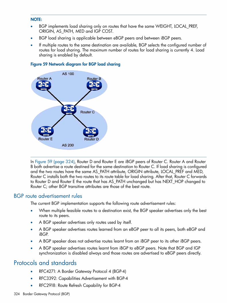
NOTE:• BGP implements load sharing only on routes that have the same WEIGHT, LOCAL_PREF,
ORIGIN, AS_PATH, MED and IGP COST.• BGP load sharing is applicable between eBGP peers and between iBGP peers.
• If multiple routes to the same destination are available, BGP selects the configured number ofroutes for load sharing. The maximum number of routes for load sharing is currently 4. Loadsharing is enabled by default.
Figure 59 Network diagram for BGP load sharing
In Figure 59 (page 324), Router D and Router E are iBGP peers of Router C. Router A and RouterB both advertise a route destined for the same destination to Router C. If load sharing is configuredand the two routes have the same AS_PATH attribute, ORIGIN attribute, LOCAL_PREF and MED,Router C installs both the two routes to its route table for load sharing. After that, Router C forwardsto Router D and Router E the route that has AS_PATH unchanged but has NEXT_HOP changed toRouter C; other BGP transitive attributes are those of the best route.
BGP route advertisement rulesThe current BGP implementation supports the following route advertisement rules:
• When multiple feasible routes to a destination exist, the BGP speaker advertises only the bestroute to its peers.
• A BGP speaker advertises only routes used by itself.
• A BGP speaker advertises routes learned from an eBGP peer to all its peers, both eBGP andiBGP.
• A BGP speaker does not advertise routes learnt from an iBGP peer to its other iBGP peers.
• A BGP speaker advertises routes learnt from iBGP to eBGP peers. Note that BGP and IGPsynchronization is disabled always and those routes are advertised to eBGP peers directly.
Protocols and standards• RFC4271: A Border Gateway Protocol 4 (BGP-4)
• RFC3392: Capabilities Advertisement with BGP-4
• RFC2918: Route Refresh Capability for BGP-4
324 Border Gateway Protocol (BGP)
• RFC1997: BGP Communities Attribute
• RFC2796: BGP Route Reflection
• RFC4724: Graceful Restart Mechanism for BGP
BGP extensions
Route reflectionBy design, IBGP peers do not advertise iBGP routes to other iBGP peers. In order for iBGP peersto learn all the routes within the autonomous system as well as all the external routes, the iBGPpeers would have to be fully meshed. This means for n iBGP peers there would have to be n*(n-1)/2iBGP sessions. In a large autonomous system network configuration would become an issue.Route Reflection is one of the alternate solutions to alleviate this problem. In the BGP network, oneof the iBGP speakers is designated as the route reflector. The route reflector advertises the routesit learns to other iBGP peers.In a route reflector configuration the other iBGP peers are classified as clientpeers and non-clientpeers.The action taken by the route reflector (after determining the best route) depends on whether thebest route was received from a client peer or a non-client peer. If the route was received from aclient peer, the route reflector will reflect that route to all the client peers and non-client peers.If the route was received from a non-client peer, then the route is advertised to all its configuredclients.Route reflection introduces two new discretionary attributes: Originator ID and Cluster List, whichare used in determining the best path as defined in “BGP route selection” (page 322).In an Autonomous System more than one route reflector can be configured.
BGP graceful restart (GR)When a BGP speaker shuts down, planned or unplanned, the routes that are advertised by thespeaker and reachable via the speaker now become unreachable. Upon detecting that the BGPspeaker has restarted, the peers delete the routes and re-add them when the restarting routeradvertises them again. This results in route-flap across the BGP connectivity and impacts multiplerouting domains causing transient instability in the network.The Graceful Restart capability is supported as a 'helper router` on the HP 3500, 5400, and 8200product series. In 'helper only' mode the router helps the other restarting router by holding thereceived routes from it as stale routes and not dropping them.On the HP 8200 product series, the Graceful Restart capability is supported as a restarting routerin non-stop routing mode.1. To establish a BGP session with a peer, a BGP GR Restarter sends an OPEN message with
GR capability to the peer.2. Upon receipt of this message, the peer is aware that the sending router is capable of Graceful
Restart, and sends an OPEN message with GR Capability to the GR Restarter to establish aGR session. If neither party has the GR capability, the session established between them willnot be GR capable.
3. The GR session between the GR Restarter and its peer goes down when the GR Restarterrestarts BGP. The GR capable peer will mark all routes associated with the GR Restarter asstale. However, during the configured GR Time, it still uses these routes for packet forwarding.
4. After the restart, the GR Restarter will reestablish a GR session with its peer and send a newGR message notifying the completion of restart. Routing information is exchanged betweenthem for the GR Restarter to create a new routing table and forwarding table with stale routinginformation removed. Then the BGP routing convergence is complete.
BGP extensions 325
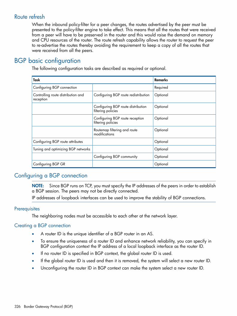
Route refreshWhen the inbound policy-filter for a peer changes, the routes advertised by the peer must bepresented to the policy-filter engine to take effect. This means that all the routes that were receivedfrom a peer will have to be preserved in the router and this would raise the demand on memoryand CPU resources of the router. The route refresh capability allows the router to request the peerto re-advertise the routes thereby avoiding the requirement to keep a copy of all the routes thatwere received from all the peers.
BGP basic configurationThe following configuration tasks are described as required or optional.
RemarksTask
RequiredConfiguring BGP connection
OptionalConfiguring BGP route redistributionControlling route distribution andreception
OptionalConfiguring BGP route distributionfiltering policies
OptionalConfiguring BGP route receptionfiltering policies
OptionalRoutemap filtering and routemodifications
OptionalConfiguring BGP route attributes
OptionalTuning and optimizing BGP networks
OptionalConfiguring BGP community
OptionalConfiguring BGP GR
Configuring a BGP connection
NOTE: Since BGP runs on TCP, you must specify the IP addresses of the peers in order to establisha BGP session. The peers may not be directly connected.IP addresses of loopback interfaces can be used to improve the stability of BGP connections.
PrerequisitesThe neighboring nodes must be accessible to each other at the network layer.
Creating a BGP connection
• A router ID is the unique identifier of a BGP router in an AS.
• To ensure the uniqueness of a router ID and enhance network reliability, you can specify inBGP configuration context the IP address of a local loopback interface as the router ID.
• If no router ID is specified in BGP context, the global router ID is used.
• If the global router ID is used and then it is removed, the system will select a new router ID.
• Unconfiguring the router ID in BGP context can make the system select a new router ID.
326 Border Gateway Protocol (BGP)
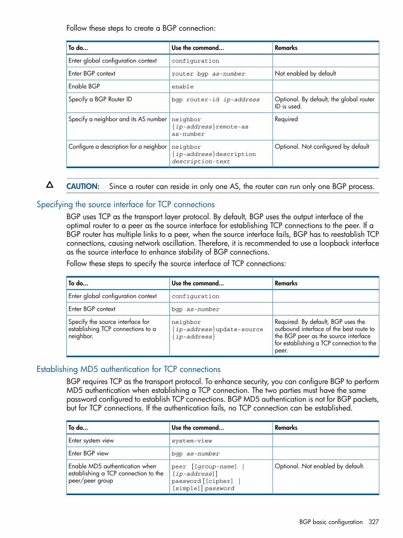
Follow these steps to create a BGP connection:
RemarksUse the command...To do...
configurationEnter global configuration context
Not enabled by defaultrouter bgp as-numberEnter BGP context
enableEnable BGP
Optional. By default, the global routerID is used.
bgp router-id ip-addressSpecify a BGP Router ID
Requiredneighbor{ip-address}remote-asas-number
Specify a neighbor and its AS number
Optional. Not configured by defaultneighbor{ip-address}descriptiondescription-text
Configure a description for a neighbor
CAUTION: Since a router can reside in only one AS, the router can run only one BGP process.
Specifying the source interface for TCP connectionsBGP uses TCP as the transport layer protocol. By default, BGP uses the output interface of theoptimal router to a peer as the source interface for establishing TCP connections to the peer. If aBGP router has multiple links to a peer, when the source interface fails, BGP has to reestablish TCPconnections, causing network oscillation. Therefore, it is recommended to use a loopback interfaceas the source interface to enhance stability of BGP connections.Follow these steps to specify the source interface of TCP connections:
RemarksUse the command...To do...
configurationEnter global configuration context
bgp as-numberEnter BGP context
Required. By default, BGP uses theoutbound interface of the best route to
neighbor{ip-address}update-source{ip-address}
Specify the source interface forestablishing TCP connections to aneighbor. the BGP peer as the source interface
for establishing a TCP connection to thepeer.
Establishing MD5 authentication for TCP connectionsBGP requires TCP as the transport protocol. To enhance security, you can configure BGP to performMD5 authentication when establishing a TCP connection. The two parties must have the samepassword configured to establish TCP connections. BGP MD5 authentication is not for BGP packets,but for TCP connections. If the authentication fails, no TCP connection can be established.
RemarksUse the command...To do...
system-viewEnter system view
bgp as-numberEnter BGP view
Optional. Not enabled by default.peer [[group-name] |[ip-address]]password [[cipher] |[simple]] password
Enable MD5 authentication whenestablishing a TCP connection to thepeer/peer group
BGP basic configuration 327
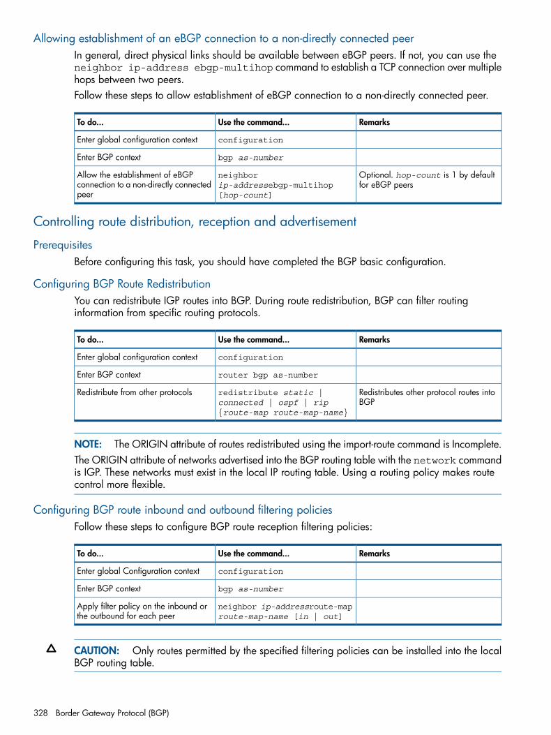
Allowing establishment of an eBGP connection to a non-directly connected peerIn general, direct physical links should be available between eBGP peers. If not, you can use theneighbor ip-address ebgp-multihop command to establish a TCP connection over multiplehops between two peers.Follow these steps to allow establishment of eBGP connection to a non-directly connected peer.
RemarksUse the command...To do...
configurationEnter global configuration context
bgp as-numberEnter BGP context
Optional. hop-count is 1 by defaultfor eBGP peers
neighborip-addressebgp-multihop[hop-count]
Allow the establishment of eBGPconnection to a non-directly connectedpeer
Controlling route distribution, reception and advertisement
PrerequisitesBefore configuring this task, you should have completed the BGP basic configuration.
Configuring BGP Route RedistributionYou can redistribute IGP routes into BGP. During route redistribution, BGP can filter routinginformation from specific routing protocols.
RemarksUse the command...To do...
configurationEnter global configuration context
router bgp as-numberEnter BGP context
Redistributes other protocol routes intoBGP
redistribute static |connected | ospf | rip{route-map route-map-name}
Redistribute from other protocols
NOTE: The ORIGIN attribute of routes redistributed using the import-route command is Incomplete.The ORIGIN attribute of networks advertised into the BGP routing table with the network commandis IGP. These networks must exist in the local IP routing table. Using a routing policy makes routecontrol more flexible.
Configuring BGP route inbound and outbound filtering policiesFollow these steps to configure BGP route reception filtering policies:
RemarksUse the command...To do...
configurationEnter global Configuration context
bgp as-numberEnter BGP context
neighbor ip-addressroute-maproute-map-name [in | out]
Apply filter policy on the inbound orthe outbound for each peer
CAUTION: Only routes permitted by the specified filtering policies can be installed into the localBGP routing table.
328 Border Gateway Protocol (BGP)
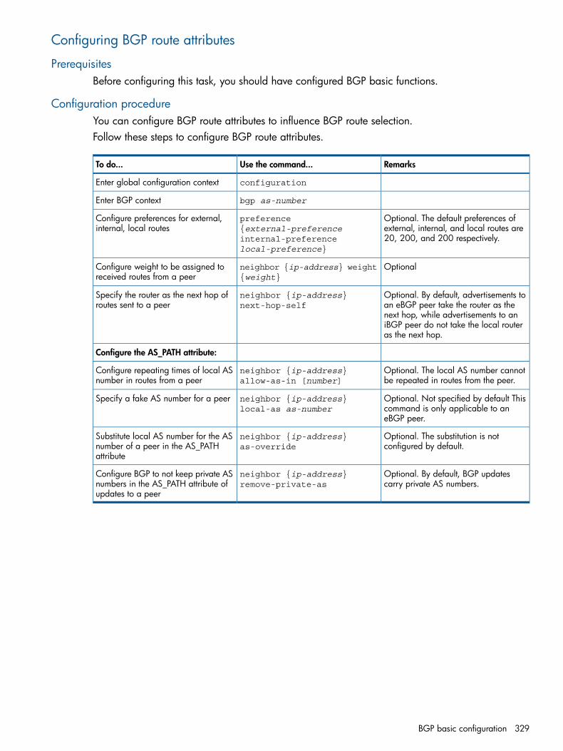
Configuring BGP route attributes
PrerequisitesBefore configuring this task, you should have configured BGP basic functions.
Configuration procedureYou can configure BGP route attributes to influence BGP route selection.Follow these steps to configure BGP route attributes.
RemarksUse the command...To do...
configurationEnter global configuration context
bgp as-numberEnter BGP context
Optional. The default preferences ofexternal, internal, and local routes are20, 200, and 200 respectively.
preference{external-preferenceinternal-preferencelocal-preference}
Configure preferences for external,internal, local routes
Optionalneighbor {ip-address} weight{weight}
Configure weight to be assigned toreceived routes from a peer
Optional. By default, advertisements toan eBGP peer take the router as the
neighbor {ip-address}next-hop-self
Specify the router as the next hop ofroutes sent to a peer
next hop, while advertisements to aniBGP peer do not take the local routeras the next hop.
Configure the AS_PATH attribute:
Optional. The local AS number cannotbe repeated in routes from the peer.
neighbor {ip-address}allow-as-in [number]
Configure repeating times of local ASnumber in routes from a peer
Optional. Not specified by default Thiscommand is only applicable to aneBGP peer.
neighbor {ip-address}local-as as-number
Specify a fake AS number for a peer
Optional. The substitution is notconfigured by default.
neighbor {ip-address}as-override
Substitute local AS number for the ASnumber of a peer in the AS_PATHattribute
Optional. By default, BGP updatescarry private AS numbers.
neighbor {ip-address}remove-private-as
Configure BGP to not keep private ASnumbers in the AS_PATH attribute ofupdates to a peer
BGP basic configuration 329
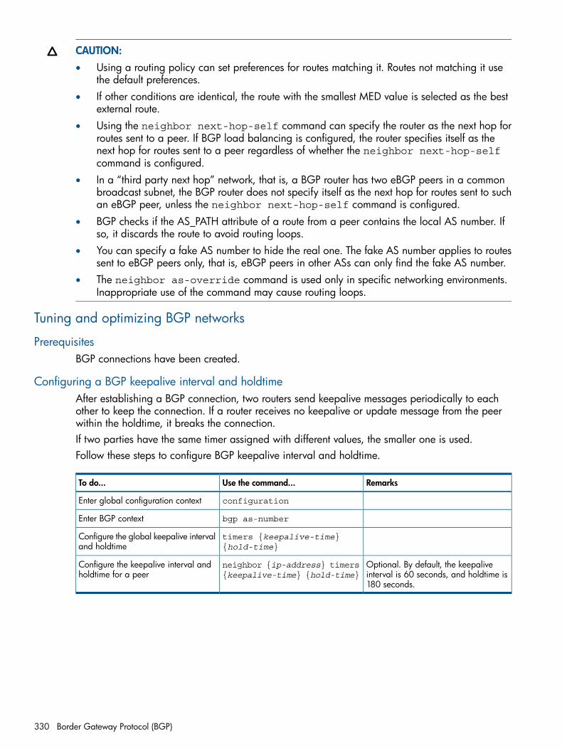
CAUTION:• Using a routing policy can set preferences for routes matching it. Routes not matching it use
the default preferences.• If other conditions are identical, the route with the smallest MED value is selected as the best
external route.• Using the neighbor next-hop-self command can specify the router as the next hop for
routes sent to a peer. If BGP load balancing is configured, the router specifies itself as thenext hop for routes sent to a peer regardless of whether the neighbor next-hop-selfcommand is configured.
• In a “third party next hop” network, that is, a BGP router has two eBGP peers in a commonbroadcast subnet, the BGP router does not specify itself as the next hop for routes sent to suchan eBGP peer, unless the neighbor next-hop-self command is configured.
• BGP checks if the AS_PATH attribute of a route from a peer contains the local AS number. Ifso, it discards the route to avoid routing loops.
• You can specify a fake AS number to hide the real one. The fake AS number applies to routessent to eBGP peers only, that is, eBGP peers in other ASs can only find the fake AS number.
• The neighbor as-override command is used only in specific networking environments.Inappropriate use of the command may cause routing loops.
Tuning and optimizing BGP networks
PrerequisitesBGP connections have been created.
Configuring a BGP keepalive interval and holdtimeAfter establishing a BGP connection, two routers send keepalive messages periodically to eachother to keep the connection. If a router receives no keepalive or update message from the peerwithin the holdtime, it breaks the connection.If two parties have the same timer assigned with different values, the smaller one is used.Follow these steps to configure BGP keepalive interval and holdtime.
RemarksUse the command...To do...
configurationEnter global configuration context
bgp as-numberEnter BGP context
timers {keepalive-time}{hold-time}
Configure the global keepalive intervaland holdtime
Optional. By default, the keepaliveinterval is 60 seconds, and holdtime is180 seconds.
neighbor {ip-address} timers{keepalive-time} {hold-time}
Configure the keepalive interval andholdtime for a peer
330 Border Gateway Protocol (BGP)
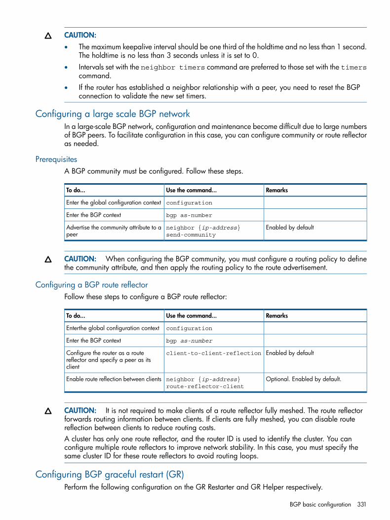
CAUTION:• The maximum keepalive interval should be one third of the holdtime and no less than 1 second.
The holdtime is no less than 3 seconds unless it is set to 0.• Intervals set with the neighbor timers command are preferred to those set with the timers
command.• If the router has established a neighbor relationship with a peer, you need to reset the BGP
connection to validate the new set timers.
Configuring a large scale BGP networkIn a large-scale BGP network, configuration and maintenance become difficult due to large numbersof BGP peers. To facilitate configuration in this case, you can configure community or route reflectoras needed.
PrerequisitesA BGP community must be configured. Follow these steps.
RemarksUse the command...To do...
configurationEnter the global configuration context
bgp as-numberEnter the BGP context
Enabled by defaultneighbor {ip-address}send-community
Advertise the community attribute to apeer
CAUTION: When configuring the BGP community, you must configure a routing policy to definethe community attribute, and then apply the routing policy to the route advertisement.
Configuring a BGP route reflectorFollow these steps to configure a BGP route reflector:
RemarksUse the command...To do...
configurationEnterthe global configuration context
bgp as-numberEnter the BGP context
Enabled by defaultclient-to-client-reflectionConfigure the router as a routereflector and specify a peer as itsclient
Optional. Enabled by default.neighbor {ip-address}route-reflector-client
Enable route reflection between clients
CAUTION: It is not required to make clients of a route reflector fully meshed. The route reflectorforwards routing information between clients. If clients are fully meshed, you can disable routereflection between clients to reduce routing costs.A cluster has only one route reflector, and the router ID is used to identify the cluster. You canconfigure multiple route reflectors to improve network stability. In this case, you must specify thesame cluster ID for these route reflectors to avoid routing loops.
Configuring BGP graceful restart (GR)Perform the following configuration on the GR Restarter and GR Helper respectively.
BGP basic configuration 331
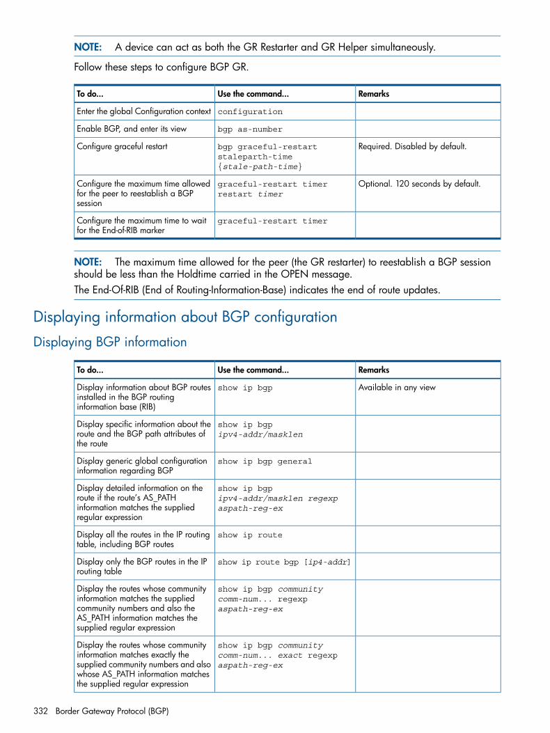
NOTE: A device can act as both the GR Restarter and GR Helper simultaneously.
Follow these steps to configure BGP GR.
RemarksUse the command...To do...
configurationEnter the global Configuration context
bgp as-numberEnable BGP, and enter its view
Required. Disabled by default.bgp graceful-restartstaleparth-time{stale-path-time}
Configure graceful restart
Optional. 120 seconds by default.graceful-restart timerrestart timer
Configure the maximum time allowedfor the peer to reestablish a BGPsession
graceful-restart timerConfigure the maximum time to waitfor the End-of-RIB marker
NOTE: The maximum time allowed for the peer (the GR restarter) to reestablish a BGP sessionshould be less than the Holdtime carried in the OPEN message.The End-Of-RIB (End of Routing-Information-Base) indicates the end of route updates.
Displaying information about BGP configuration
Displaying BGP information
RemarksUse the command...To do...
Available in any viewshow ip bgpDisplay information about BGP routesinstalled in the BGP routinginformation base (RIB)
show ip bgpipv4-addr/masklen
Display specific information about theroute and the BGP path attributes ofthe route
show ip bgp generalDisplay generic global configurationinformation regarding BGP
show ip bgpipv4-addr/masklen regexpaspath-reg-ex
Display detailed information on theroute if the route’s AS_PATHinformation matches the suppliedregular expression
show ip routeDisplay all the routes in the IP routingtable, including BGP routes
show ip route bgp [ip4-addr]Display only the BGP routes in the IProuting table
show ip bgp communitycomm-num... regexpaspath-reg-ex
Display the routes whose communityinformation matches the suppliedcommunity numbers and also theAS_PATH information matches thesupplied regular expression
show ip bgp communitycomm-num... exact regexpaspath-reg-ex
Display the routes whose communityinformation matches exactly thesupplied community numbers and alsowhose AS_PATH information matchesthe supplied regular expression
332 Border Gateway Protocol (BGP)
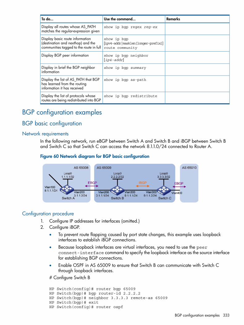
RemarksUse the command...To do...
show ip bgp regex reg-exDisplay all routes whose AS_PATHmatches the regular-expression given
show ip bgp[ipv4-addr|masklen[longer-prefix]]route community
Display basic route information(destination and nexthop) and thecommunities tagged to the route in full
show ip bgp neighbor[ip4-addr]
Display BGP peer information
show ip bgp summaryDisplay in brief the BGP neighborinformation
show ip bgp as-pathDisplay the list of AS_PATH that BGPhas learned from the routinginformation it has received
show ip bgp redistributeDisplay the list of protocols whoseroutes are being redistributed into BGP
BGP configuration examples
BGP basic configuration
Network requirementsIn the following network, run eBGP between Switch A and Switch B and iBGP between Switch Band Switch C so that Switch C can access the network 8.1.1.0/24 connected to Router A.
Figure 60 Network diagram for BGP basic configuration
Configuration procedure1. Configure IP addresses for interfaces (omitted.)2. Configure iBGP.
• To prevent route flapping caused by port state changes, this example uses loopbackinterfaces to establish iBGP connections.
• Because loopback interfaces are virtual interfaces, you need to use the peerconnect-interface command to specify the loopback interface as the source interfacefor establishing BGP connections.
• Enable OSPF in AS 65009 to ensure that Switch B can communicate with Switch Cthrough loopback interfaces.
# Configure Switch B
HP Switch(config)# router bgp 65009HP Switch(bgp)# bgp router-id 2.2.2.2HP Switch(bgp)# neighbor 3.3.3.3 remote-as 65009HP Switch(bgp)# exitHP Switch(config)# router ospf
BGP configuration examples 333
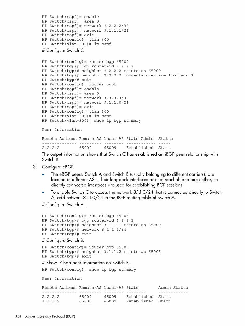
HP Switch(ospf)# enableHP Switch(ospf)# area 0HP Switch(ospf)# network 2.2.2.2/32HP Switch(ospf)# network 9.1.1.1/24HP Switch(ospf)# exitHP Switch(config)# vlan 300HP Switch(vlan-300)# ip ospf
# Configure Switch C
HP Switch(config)# router bgp 65009HP Switch(bgp)# bgp router-id 3.3.3.3HP Switch(bgp)# neighbor 2.2.2.2 remote-as 65009HP Switch(bgp)# neighbor 2.2.2.2 connect-interface loopback 0HP Switch(bgp)# exitHP Switch(config)# router ospfHP Switch(ospf)# enableHP Switch(ospf)# area 0HP Switch(ospf)# network 3.3.3.3/32HP Switch(ospf)# network 9.1.1.0/24HP Switch(ospf)# exitHP Switch(config)# vlan 300HP Switch(vlan-300)# ip ospfHP Switch(vlan-300)# show ip bgp summary
Peer Information
Remote Address Remote-AS Local-AS State Admin Status-------------- --------- -------- ------------ -----2.2.2.2 65009 65009 Established Start
The output information shows that Switch C has established an iBGP peer relationship withSwitch B.
3. Configure eBGP.• The eBGP peers, Switch A and Switch B (usually belonging to different carriers), are
located in different ASs. Their loopback interfaces are not reachable to each other, sodirectly connected interfaces are used for establishing BGP sessions.
• To enable Switch C to access the network 8.1.1.0/24 that is connected directly to SwitchA, add network 8.1.1.0/24 to the BGP routing table of Switch A.
# Configure Switch A.
HP Switch(config)# router bgp 65008HP Switch(bgp)# bgp router-id 1.1.1.1HP Switch(bgp)# neighbor 3.1.1.1 remote-as 65009HP Switch(bgp)# network 8.1.1.1/24HP Switch(bgp)# exit
# Configure Switch B.HP Switch(config)# router bgp 65009HP Switch(bgp)# neighbor 3.1.1.2 remote-as 65008HP Switch(bgp)# exit
# Show IP bgp peer information on Switch B.HP Switch(config)# show ip bgp summary
Peer Information
Remote Address Remote-AS Local-AS State Admin Status-------------- --------- -------- -------- ------------2.2.2.2 65009 65009 Established Start3.1.1.2 65008 65009 Established Start
334 Border Gateway Protocol (BGP)
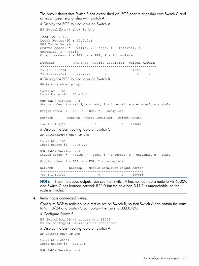
The output shows that Switch B has established an iBGP peer relationship with Switch C andan eBGP peer relationship with Switch A.# Display the BGP routing table on Switch A.HP Switch(bgp)# show ip bgp
Local AS : 100Local Router-id : 20.0.0.1BGP Table Version : 0Status codes: * - valid, > - best, i - internal, e -external, s - staleOrigin codes: i - IGP, e - EGP, ? - incomplete
Network Nexthop Metric LocalPref Weight AsPath----------------------------------------------------------*> 8.1.1.0/24 0 32768 I*> 8.1.1.0/24 0.0.0.0 0 0 I
# Display the BGP routing table on Switch B.HP Switch# show ip bgp
Local AS : 100Local Router-id : 20.0.0.1
BGP Table Version : 0Status codes: * - valid, > - best, i - internal, e - external, s - stale
Origin codes: i - IGP, e - EGP, ? - incomplete
Network Nexthop Metric LocalPref Weight AsPath---------------------------------------------------------*>e 8.1.1.0/24 0 0 65008i
# Display the BGP routing table on Switch C.HP Switch(bgp)# show ip bgp
Local AS : 100Local Router-id : 20.0.0.1
BGP Table Version : 0Status codes: * - valid, > - best, i - internal, e - external, s - stale
Origin codes: i - IGP, e - EGP, ? - incomplete
Network Nexthop Metric LocalPref Weight AsPath---------------------------------------------------------*>i 8.1.1.0/24 0 0 65008i
NOTE: From the above outputs, you see that Switch A has not learned a route to AS 65009,and Switch C has learned network 8.1.1.0 but the next hop 3.1.1.2 is unreachable, so theroute is invalid.
4. Redistribute connected routes.Configure BGP to redistribute direct routes on Switch B, so that Switch A can obtain the routeto 9.1.1.0/24 and Switch C can obtain the route to 3.1.1.0/24.# Configure Switch B.HP Switch(config)# router bgp 65009HP Switch(bgp)# redistribute connected
# Display the BGP routing table on Switch A.HP Switch# show ip bgp
Local AS : 65009Local Router-id : 1.1.1.1
BGP Table Version : 0
BGP configuration examples 335
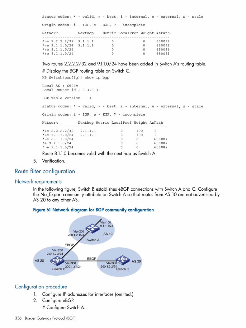
Status codes: * - valid, > - best, i - internal, e - external, s - stale
Origin codes: i - IGP, e - EGP, ? - incomplete
Network Nexthop Metric LocalPref Weight AsPath---------------------------------------------------------*>e 2.2.2.2/32 3.1.1.1 0 0 65009?*>e 3.1.1.0/24 3.1.1.1 0 0 65009?*>e 8.1.1.0/24 0 0 65008i*>e 8.1.1.0/24 0 0 65008i
Two routes 2.2.2.2/32 and 9.1.1.0/24 have been added in Switch A’s routing table.# Display the BGP routing table on Switch C.HP Switch(config)# show ip bgp
Local AS : 65009Local Router-id : 3.3.3.3
BGP Table Version : 1
Status codes: * - valid, > - best, i - internal, e - external, s - stale
Origin codes: i - IGP, e - EGP, ? - incomplete
Network Nexthop Metric LocalPref Weight AsPath-------------------------------------------------------*>e 2.2.2.2/32 9.1.1.1 0 100 I*>e 3.1.1.0/24 9.1.1.1 0 100 I*>e 8.1.1.0/24 0 0 65008i*e 9.1.1.0/24 0 0 65008i*>e 9.1.1.0/24 0 0 65008i
Route 8.1.1.0 becomes valid with the next hop as Switch A.5. Verification.
Route filter configuration
Network requirementsIn the following figure, Switch B establishes eBGP connections with Switch A and C. Configurethe No_Export community attribute on Switch A so that routes from AS 10 are not advertised byAS 20 to any other AS.
Figure 61 Network diagram for BGP community configuration
Configuration procedure1. Configure IP addresses for interfaces (omitted.)2. Configure eBGP.
# Configure Switch A.
336 Border Gateway Protocol (BGP)
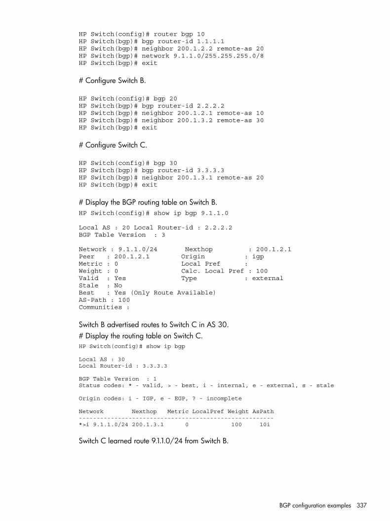
HP Switch(config)# router bgp 10HP Switch(bgp)# bgp router-id 1.1.1.1HP Switch(bgp)# neighbor 200.1.2.2 remote-as 20HP Switch(bgp)# network 9.1.1.0/255.255.255.0/8HP Switch(bgp)# exit
# Configure Switch B.
HP Switch(config)# bgp 20HP Switch(bgp)# bgp router-id 2.2.2.2HP Switch(bgp)# neighbor 200.1.2.1 remote-as 10HP Switch(bgp)# neighbor 200.1.3.2 remote-as 30HP Switch(bgp)# exit
# Configure Switch C.
HP Switch(config)# bgp 30HP Switch(bgp)# bgp router-id 3.3.3.3HP Switch(bgp)# neighbor 200.1.3.1 remote-as 20HP Switch(bgp)# exit
# Display the BGP routing table on Switch B.HP Switch(config)# show ip bgp 9.1.1.0
Local AS : 20 Local Router-id : 2.2.2.2BGP Table Version : 3
Network : 9.1.1.0/24 Nexthop : 200.1.2.1Peer : 200.1.2.1 Origin : igp Metric : 0 Local Pref : Weight : 0 Calc. Local Pref : 100Valid : Yes Type : externalStale : NoBest : Yes (Only Route Available) AS-Path : 100Communities :
Switch B advertised routes to Switch C in AS 30.# Display the routing table on Switch C.HP Switch(config)# show ip bgp
Local AS : 30Local Router-id : 3.3.3.3
BGP Table Version : 1Status codes: * - valid, > - best, i - internal, e - external, s - stale
Origin codes: i - IGP, e - EGP, ? - incomplete
Network Nexthop Metric LocalPref Weight AsPath-------------------------------------------------------*>i 9.1.1.0/24 200.1.3.1 0 100 10i
Switch C learned route 9.1.1.0/24 from Switch B.
BGP configuration examples 337
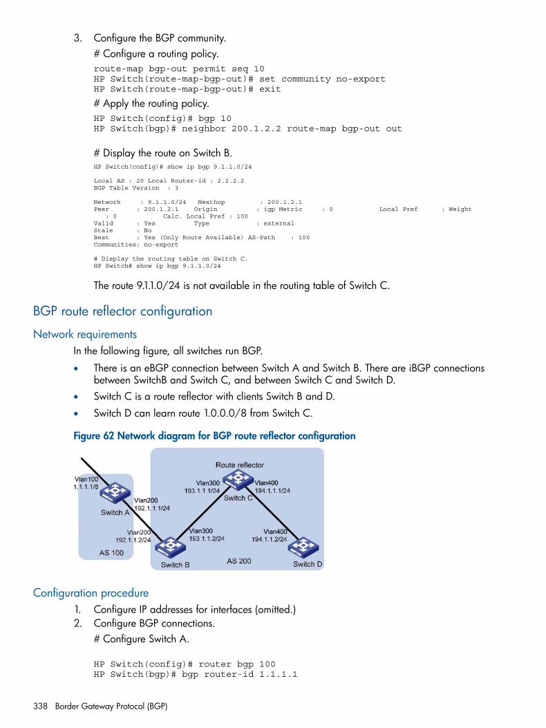
3. Configure the BGP community.# Configure a routing policy.route-map bgp-out permit seq 10HP Switch(route-map-bgp-out)# set community no-exportHP Switch(route-map-bgp-out)# exit
# Apply the routing policy.HP Switch(config)# bgp 10HP Switch(bgp)# neighbor 200.1.2.2 route-map bgp-out out
# Display the route on Switch B.HP Switch(config)# show ip bgp 9.1.1.0/24
Local AS : 20 Local Router-id : 2.2.2.2BGP Table Version : 3
Network : 9.1.1.0/24 Nexthop : 200.1.2.1Peer : 200.1.2.1 Origin : igp Metric : 0 Local Pref : Weight : 0 Calc. Local Pref : 100Valid : Yes Type : externalStale : NoBest : Yes (Only Route Available) AS-Path : 100Communities: no-export
# Display the routing table on Switch C.HP Switch# show ip bgp 9.1.1.0/24
The route 9.1.1.0/24 is not available in the routing table of Switch C.
BGP route reflector configuration
Network requirementsIn the following figure, all switches run BGP.
• There is an eBGP connection between Switch A and Switch B. There are iBGP connectionsbetween SwitchB and Switch C, and between Switch C and Switch D.
• Switch C is a route reflector with clients Switch B and D.
• Switch D can learn route 1.0.0.0/8 from Switch C.
Figure 62 Network diagram for BGP route reflector configuration
Configuration procedure1. Configure IP addresses for interfaces (omitted.)2. Configure BGP connections.
# Configure Switch A.
HP Switch(config)# router bgp 100HP Switch(bgp)# bgp router-id 1.1.1.1
338 Border Gateway Protocol (BGP)
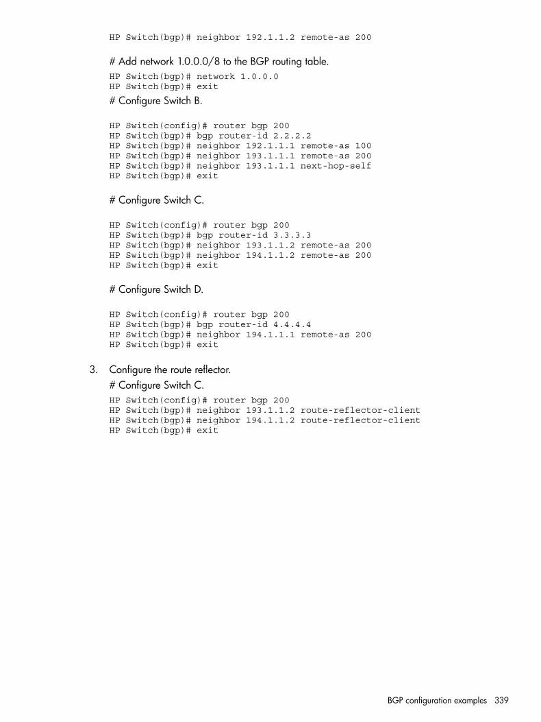
HP Switch(bgp)# neighbor 192.1.1.2 remote-as 200
# Add network 1.0.0.0/8 to the BGP routing table.HP Switch(bgp)# network 1.0.0.0HP Switch(bgp)# exit
# Configure Switch B.
HP Switch(config)# router bgp 200HP Switch(bgp)# bgp router-id 2.2.2.2HP Switch(bgp)# neighbor 192.1.1.1 remote-as 100HP Switch(bgp)# neighbor 193.1.1.1 remote-as 200HP Switch(bgp)# neighbor 193.1.1.1 next-hop-selfHP Switch(bgp)# exit
# Configure Switch C.
HP Switch(config)# router bgp 200HP Switch(bgp)# bgp router-id 3.3.3.3HP Switch(bgp)# neighbor 193.1.1.2 remote-as 200HP Switch(bgp)# neighbor 194.1.1.2 remote-as 200HP Switch(bgp)# exit
# Configure Switch D.
HP Switch(config)# router bgp 200HP Switch(bgp)# bgp router-id 4.4.4.4HP Switch(bgp)# neighbor 194.1.1.1 remote-as 200HP Switch(bgp)# exit
3. Configure the route reflector.# Configure Switch C.HP Switch(config)# router bgp 200HP Switch(bgp)# neighbor 193.1.1.2 route-reflector-clientHP Switch(bgp)# neighbor 194.1.1.2 route-reflector-clientHP Switch(bgp)# exit
BGP configuration examples 339
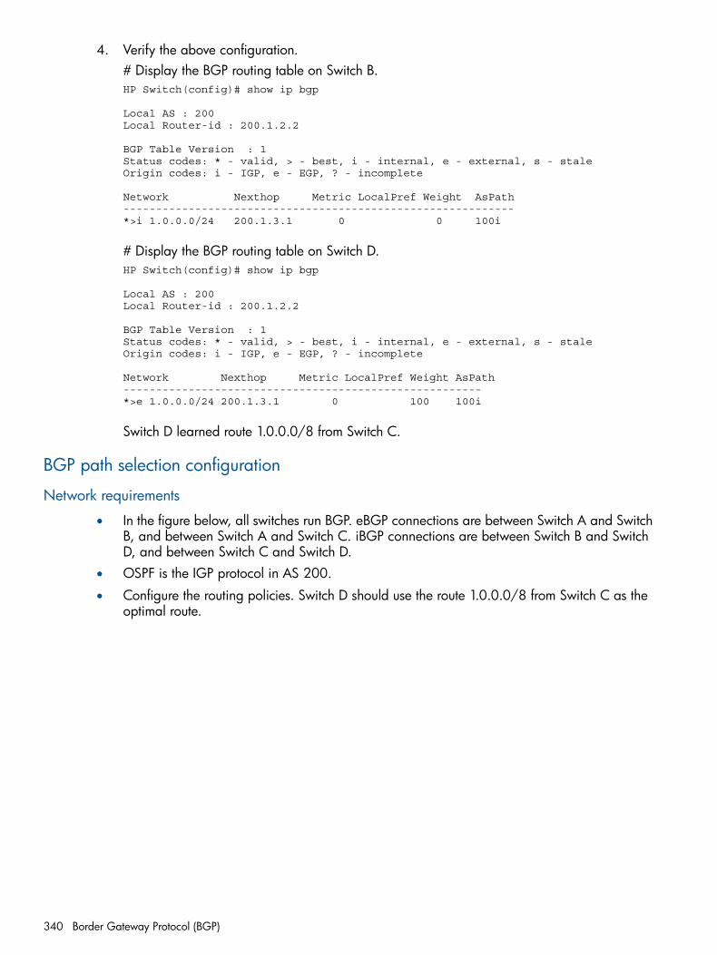
4. Verify the above configuration.# Display the BGP routing table on Switch B.HP Switch(config)# show ip bgp
Local AS : 200Local Router-id : 200.1.2.2
BGP Table Version : 1Status codes: * - valid, > - best, i - internal, e - external, s - staleOrigin codes: i - IGP, e - EGP, ? - incomplete
Network Nexthop Metric LocalPref Weight AsPath------------------------------------------------------------*>i 1.0.0.0/24 200.1.3.1 0 0 100i
# Display the BGP routing table on Switch D.HP Switch(config)# show ip bgp
Local AS : 200Local Router-id : 200.1.2.2
BGP Table Version : 1Status codes: * - valid, > - best, i - internal, e - external, s - staleOrigin codes: i - IGP, e - EGP, ? - incomplete
Network Nexthop Metric LocalPref Weight AsPath-------------------------------------------------------*>e 1.0.0.0/24 200.1.3.1 0 100 100i
Switch D learned route 1.0.0.0/8 from Switch C.
BGP path selection configuration
Network requirements
• In the figure below, all switches run BGP. eBGP connections are between Switch A and SwitchB, and between Switch A and Switch C. iBGP connections are between Switch B and SwitchD, and between Switch C and Switch D.
• OSPF is the IGP protocol in AS 200.
• Configure the routing policies. Switch D should use the route 1.0.0.0/8 from Switch C as theoptimal route.
340 Border Gateway Protocol (BGP)
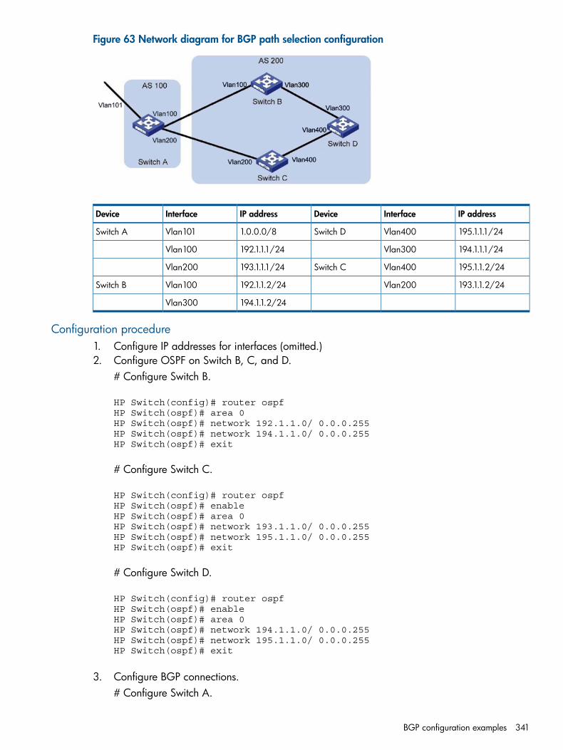
Figure 63 Network diagram for BGP path selection configuration
IP addressInterfaceDeviceIP addressInterfaceDevice
195.1.1.1/24Vlan400Switch D1.0.0.0/8Vlan101Switch A
194.1.1.1/24Vlan300192.1.1.1/24Vlan100
195.1.1.2/24Vlan400Switch C193.1.1.1/24Vlan200
193.1.1.2/24Vlan200192.1.1.2/24Vlan100Switch B
194.1.1.2/24Vlan300
Configuration procedure1. Configure IP addresses for interfaces (omitted.)2. Configure OSPF on Switch B, C, and D.
# Configure Switch B.
HP Switch(config)# router ospfHP Switch(ospf)# area 0HP Switch(ospf)# network 192.1.1.0/ 0.0.0.255HP Switch(ospf)# network 194.1.1.0/ 0.0.0.255HP Switch(ospf)# exit
# Configure Switch C.
HP Switch(config)# router ospfHP Switch(ospf)# enableHP Switch(ospf)# area 0HP Switch(ospf)# network 193.1.1.0/ 0.0.0.255HP Switch(ospf)# network 195.1.1.0/ 0.0.0.255HP Switch(ospf)# exit
# Configure Switch D.
HP Switch(config)# router ospfHP Switch(ospf)# enableHP Switch(ospf)# area 0HP Switch(ospf)# network 194.1.1.0/ 0.0.0.255HP Switch(ospf)# network 195.1.1.0/ 0.0.0.255HP Switch(ospf)# exit
3. Configure BGP connections.# Configure Switch A.
BGP configuration examples 341

HP Switch(config)# router bgp 100HP Switch(bgp)# neighbor 192.1.1.2 remote-as 200HP Switch(bgp)# neighbor 193.1.1.2 remote-as 200
# Add network 1.0.0.0/8 to the BGP routing table on Switch A.HP Switch(bgp)# network 1.0.0.0/8HP Switch(bgp)# exit
# Configure Switch B.HP Switch(config)# router bgp 200HP Switch(bgp)# neighbor 192.1.1.1 remote-as 100HP Switch(bgp)# neighbor 194.1.1.1 remote-as 200HP Switch(bgp)# exit
# Configure Switch C.HP Switch(config)# router bgp 200HP Switch(bgp)# neighbor 193.1.1.1 remote-as 100HP Switch(bgp)# neighbor 195.1.1.1 remote-as 200HP Switch(bgp)# exit
# Configure Switch D.HP Switch(config)# router bgp 200HP Switch(bgp)# neighbor 194.1.1.2 remote-as 200HP Switch(bgp)# neighbor 195.1.1.2 remote-as 200HP Switch(bgp)# exit
342 Border Gateway Protocol (BGP)
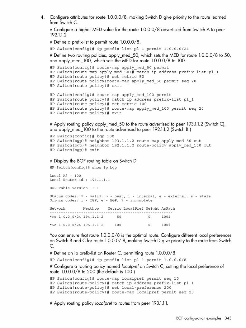
4. Configure attributes for route 1.0.0.0/8, making Switch D give priority to the route learnedfrom Switch C.# Configure a higher MED value for the route 1.0.0.0/8 advertised from Switch A to peer192.1.1.2.# Define a prefix-list to permit route 1.0.0.0/8.HP Switch(config)# ip prefix-list pl_1 permit 1.0.0.0/24
# Define two routing policies, apply_med_50, which sets the MED for route 1.0.0.0/8 to 50,and apply_med_100, which sets the MED for route 1.0.0.0/8 to 100.HP Switch(config)# route-map apply_med_50 permitHP Switch(route-map-apply_med_50)# match ip address prefix-list pl_1HP Switch(route policy)# set metric 50HP Switch(route policy)route-map apply_med_50 permit seq 20HP Switch(route policy)# exit
HP Switch(config)# route-map apply_med_100 permitHP Switch(route policy)# match ip address prefix-list pl_1HP Switch(route policy)# set metric 100HP Switch(route policy)# route-map apply_med_100 permit seq 20HP Switch(route policy)# exit
# Apply routing policy apply_med_50 to the route advertised to peer 193.1.1.2 (Switch C),and apply_med_100 to the route advertised to peer 192.1.1.2 (Switch B.)HP Switch(config)# bgp 100HP Switch(bgp)# neighbor 193.1.1.2 route-map apply_med_50 outHP Switch(bgp)# neighbor 192.1.1.2 route-policy apply_med_100 outHP Switch(bgp)# exit
# Display the BGP routing table on Switch D.HP Switch(config)# show ip bgp
Local AS : 100Local Router-id : 194.1.1.1
BGP Table Version : 1
Status codes: * - valid, > - best, i - internal, e - external, s - staleOrigin codes: i - IGP, e - EGP, ? - incomplete
Network Nexthop Metric LocalPref Weight AsPath-------------------------------------------------------*>e 1.0.0.0/24 194.1.1.2 50 0 100i
*>e 1.0.0.0/24 195.1.1.2 100 0 100i
You can ensure that route 1.0.0.0/8 is the optimal route. Configure different local preferenceson Switch B and C for route 1.0.0.0/ 8, making Switch D give priority to the route from SwitchC.# Define an ip prefix-list on Router C, permitting route 1.0.0.0/8.HP Switch(config)# ip prefix-list pl_1 permit 1.0.0.0/8
# Configure a routing policy named localpref on Switch C, setting the local preference ofroute 1.0.0.0/8 to 200 (the default is 100.)HP Switch(config)# route-map localpref permit seq 10HP Switch(route-policy)# match ip address prefix-list pl_1HP Switch(route-policy)# set local-preference 200HP Switch(route-policy)# route-map localpref permit seq 20
# Apply routing policy localpref to routes from peer 193.1.1.1.
BGP configuration examples 343
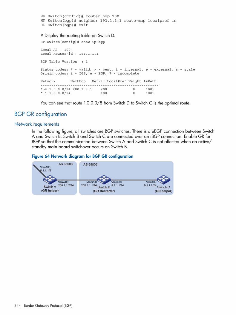
HP Switch(config)# router bgp 200HP Switch(bgp)# neighbor 193.1.1.1 route-map localpref inHP Switch(bgp)# exit
# Display the routing table on Switch D.HP Switch(config)# show ip bgp
Local AS : 100Local Router-id : 194.1.1.1
BGP Table Version : 1
Status codes: * - valid, > - best, i - internal, e - external, s - staleOrigin codes: i - IGP, e - EGP, ? - incomplete
Network Nexthop Metric LocalPref Weight AsPath-------------------------------------------------------*>e 1.0.0.0/24 200.1.3.1 200 0 100i* i 1.0.0.0/24 100 0 100i
You can see that route 1.0.0.0/8 from Switch D to Switch C is the optimal route.
BGP GR configuration
Network requirementsIn the following figure, all switches are BGP switches. There is a eBGP connection between SwitchA and Switch B. Switch B and Switch C are connected over an iBGP connection. Enable GR forBGP so that the communication between Switch A and Switch C is not affected when an active/standby main board switchover occurs on Switch B.
Figure 64 Network diagram for BGP GR configuration
344 Border Gateway Protocol (BGP)
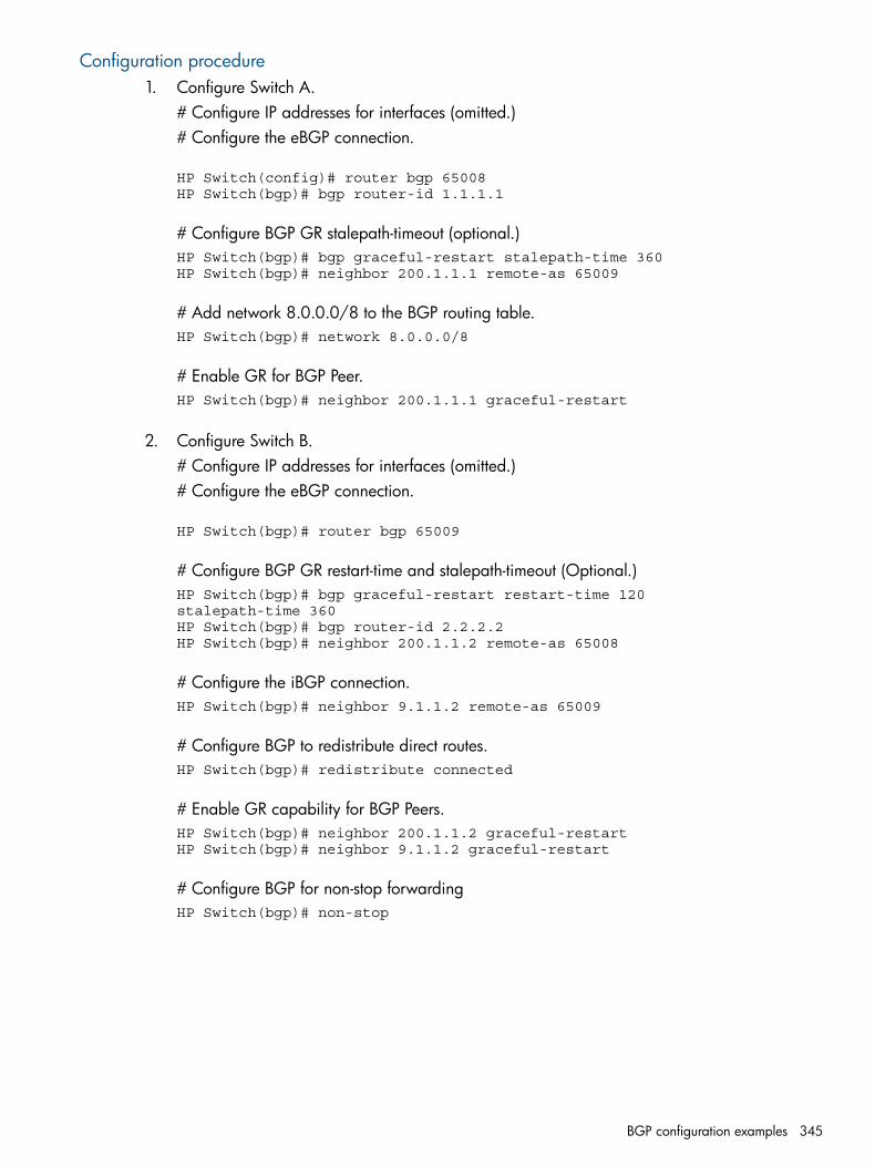
Configuration procedure1. Configure Switch A.
# Configure IP addresses for interfaces (omitted.)# Configure the eBGP connection.
HP Switch(config)# router bgp 65008HP Switch(bgp)# bgp router-id 1.1.1.1
# Configure BGP GR stalepath-timeout (optional.)HP Switch(bgp)# bgp graceful-restart stalepath-time 360HP Switch(bgp)# neighbor 200.1.1.1 remote-as 65009
# Add network 8.0.0.0/8 to the BGP routing table.HP Switch(bgp)# network 8.0.0.0/8
# Enable GR for BGP Peer.HP Switch(bgp)# neighbor 200.1.1.1 graceful-restart
2. Configure Switch B.# Configure IP addresses for interfaces (omitted.)# Configure the eBGP connection.
HP Switch(bgp)# router bgp 65009
# Configure BGP GR restart-time and stalepath-timeout (Optional.)HP Switch(bgp)# bgp graceful-restart restart-time 120stalepath-time 360HP Switch(bgp)# bgp router-id 2.2.2.2HP Switch(bgp)# neighbor 200.1.1.2 remote-as 65008
# Configure the iBGP connection.HP Switch(bgp)# neighbor 9.1.1.2 remote-as 65009
# Configure BGP to redistribute direct routes.HP Switch(bgp)# redistribute connected
# Enable GR capability for BGP Peers.HP Switch(bgp)# neighbor 200.1.1.2 graceful-restartHP Switch(bgp)# neighbor 9.1.1.2 graceful-restart
# Configure BGP for non-stop forwardingHP Switch(bgp)# non-stop
BGP configuration examples 345
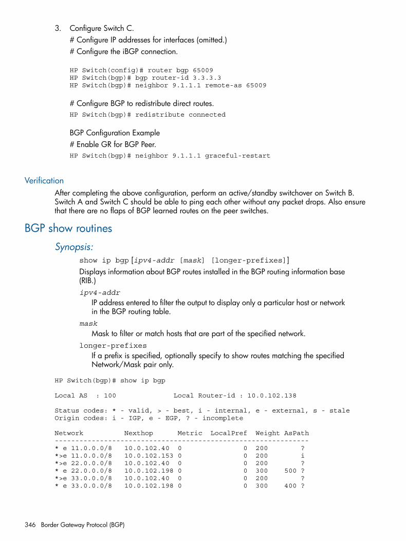
3. Configure Switch C.# Configure IP addresses for interfaces (omitted.)# Configure the iBGP connection.
HP Switch(config)# router bgp 65009HP Switch(bgp)# bgp router-id 3.3.3.3HP Switch(bgp)# neighbor 9.1.1.1 remote-as 65009
# Configure BGP to redistribute direct routes.HP Switch(bgp)# redistribute connected
BGP Configuration Example# Enable GR for BGP Peer.HP Switch(bgp)# neighbor 9.1.1.1 graceful-restart
VerificationAfter completing the above configuration, perform an active/standby switchover on Switch B.Switch A and Switch C should be able to ping each other without any packet drops. Also ensurethat there are no flaps of BGP learned routes on the peer switches.
BGP show routines
Synopsis:show ip bgp [ipv4-addr [mask] [longer-prefixes]]Displays information about BGP routes installed in the BGP routing information base(RIB.)ipv4-addr
IP address entered to filter the output to display only a particular host or networkin the BGP routing table.
mask
Mask to filter or match hosts that are part of the specified network.longer-prefixes
If a prefix is specified, optionally specify to show routes matching the specifiedNetwork/Mask pair only.
HP Switch(bgp)# show ip bgp
Local AS : 100 Local Router-id : 10.0.102.138
Status codes: * - valid, > - best, i - internal, e - external, s - staleOrigin codes: i - IGP, e - EGP, ? - incomplete
Network Nexthop Metric LocalPref Weight AsPath--------------------------------------------------------------* e 11.0.0.0/8 10.0.102.40 0 0 200 ?*>e 11.0.0.0/8 10.0.102.153 0 0 200 i*>e 22.0.0.0/8 10.0.102.40 0 0 200 ?* e 22.0.0.0/8 10.0.102.198 0 0 300 500 ?*>e 33.0.0.0/8 10.0.102.40 0 0 200 ?* e 33.0.0.0/8 10.0.102.198 0 0 300 400 ?
346 Border Gateway Protocol (BGP)
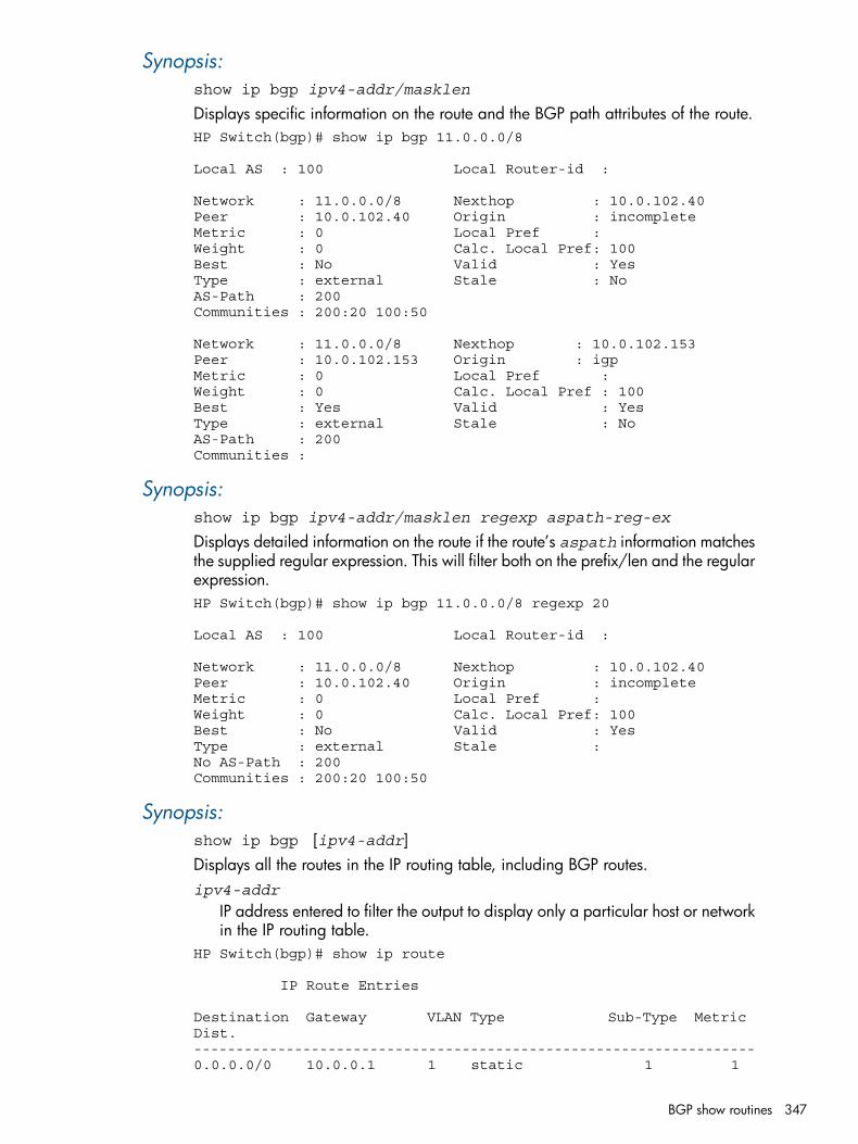
Synopsis:show ip bgp ipv4-addr/masklen
Displays specific information on the route and the BGP path attributes of the route.HP Switch(bgp)# show ip bgp 11.0.0.0/8
Local AS : 100 Local Router-id :
Network : 11.0.0.0/8 Nexthop : 10.0.102.40Peer : 10.0.102.40 Origin : incompleteMetric : 0 Local Pref : Weight : 0 Calc. Local Pref: 100Best : No Valid : Yes Type : external Stale : No AS-Path : 200Communities : 200:20 100:50
Network : 11.0.0.0/8 Nexthop : 10.0.102.153Peer : 10.0.102.153 Origin : igp Metric : 0 Local Pref : Weight : 0 Calc. Local Pref : 100Best : Yes Valid : Yes Type : external Stale : No AS-Path : 200Communities :
Synopsis:show ip bgp ipv4-addr/masklen regexp aspath-reg-ex
Displays detailed information on the route if the route’s aspath information matchesthe supplied regular expression. This will filter both on the prefix/len and the regularexpression.HP Switch(bgp)# show ip bgp 11.0.0.0/8 regexp 20
Local AS : 100 Local Router-id :
Network : 11.0.0.0/8 Nexthop : 10.0.102.40Peer : 10.0.102.40 Origin : incompleteMetric : 0 Local Pref : Weight : 0 Calc. Local Pref: 100Best : No Valid : Yes Type : external Stale : No AS-Path : 200Communities : 200:20 100:50
Synopsis:show ip bgp [ipv4-addr]Displays all the routes in the IP routing table, including BGP routes.ipv4-addr
IP address entered to filter the output to display only a particular host or networkin the IP routing table.
HP Switch(bgp)# show ip route
IP Route Entries
Destination Gateway VLAN Type Sub-Type Metric Dist.-------------------------------------------------------------------0.0.0.0/0 10.0.0.1 1 static 1 1
BGP show routines 347
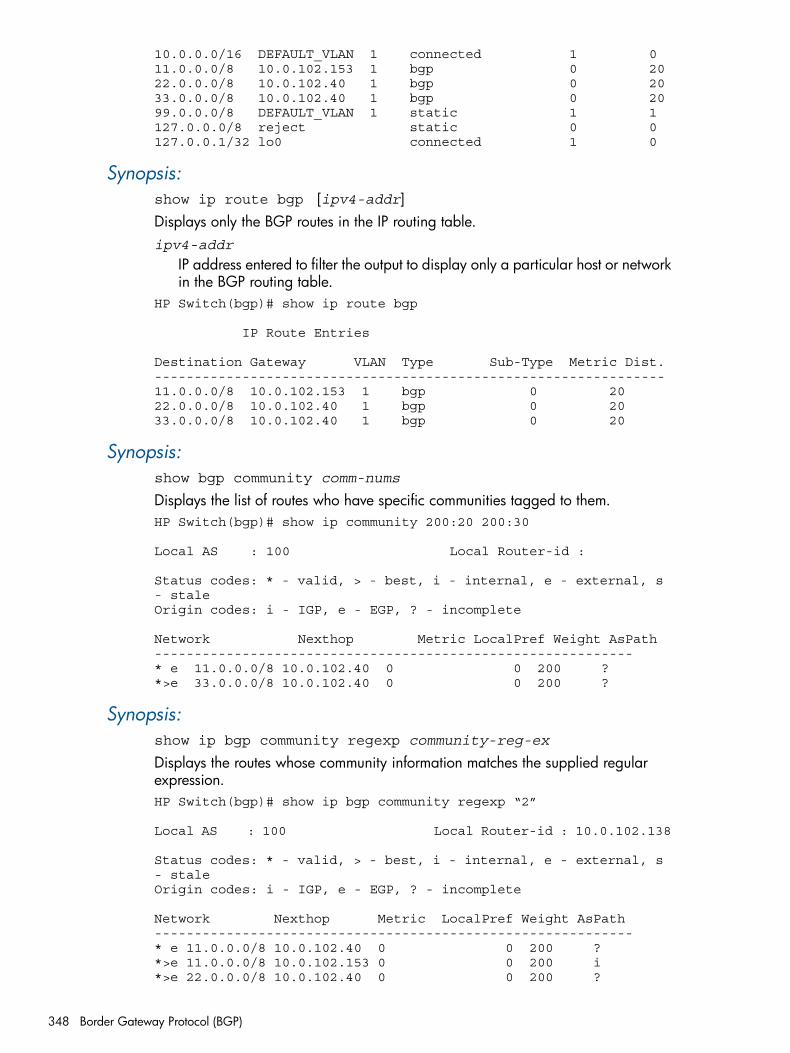
10.0.0.0/16 DEFAULT_VLAN 1 connected 1 011.0.0.0/8 10.0.102.153 1 bgp 0 2022.0.0.0/8 10.0.102.40 1 bgp 0 2033.0.0.0/8 10.0.102.40 1 bgp 0 2099.0.0.0/8 DEFAULT_VLAN 1 static 1 1127.0.0.0/8 reject static 0 0127.0.0.1/32 lo0 connected 1 0
Synopsis:show ip route bgp [ipv4-addr]Displays only the BGP routes in the IP routing table.ipv4-addr
IP address entered to filter the output to display only a particular host or networkin the BGP routing table.
HP Switch(bgp)# show ip route bgp
IP Route Entries
Destination Gateway VLAN Type Sub-Type Metric Dist.----------------------------------------------------------------11.0.0.0/8 10.0.102.153 1 bgp 0 2022.0.0.0/8 10.0.102.40 1 bgp 0 2033.0.0.0/8 10.0.102.40 1 bgp 0 20
Synopsis:show bgp community comm-nums
Displays the list of routes who have specific communities tagged to them.HP Switch(bgp)# show ip community 200:20 200:30
Local AS : 100 Local Router-id :
Status codes: * - valid, > - best, i - internal, e - external, s - staleOrigin codes: i - IGP, e - EGP, ? - incomplete
Network Nexthop Metric LocalPref Weight AsPath------------------------------------------------------------* e 11.0.0.0/8 10.0.102.40 0 0 200 ?*>e 33.0.0.0/8 10.0.102.40 0 0 200 ?
Synopsis:show ip bgp community regexp community-reg-ex
Displays the routes whose community information matches the supplied regularexpression.HP Switch(bgp)# show ip bgp community regexp “2”
Local AS : 100 Local Router-id : 10.0.102.138
Status codes: * - valid, > - best, i - internal, e - external, s - staleOrigin codes: i - IGP, e - EGP, ? - incomplete
Network Nexthop Metric LocalPref Weight AsPath------------------------------------------------------------* e 11.0.0.0/8 10.0.102.40 0 0 200 ?*>e 11.0.0.0/8 10.0.102.153 0 0 200 i*>e 22.0.0.0/8 10.0.102.40 0 0 200 ?
348 Border Gateway Protocol (BGP)
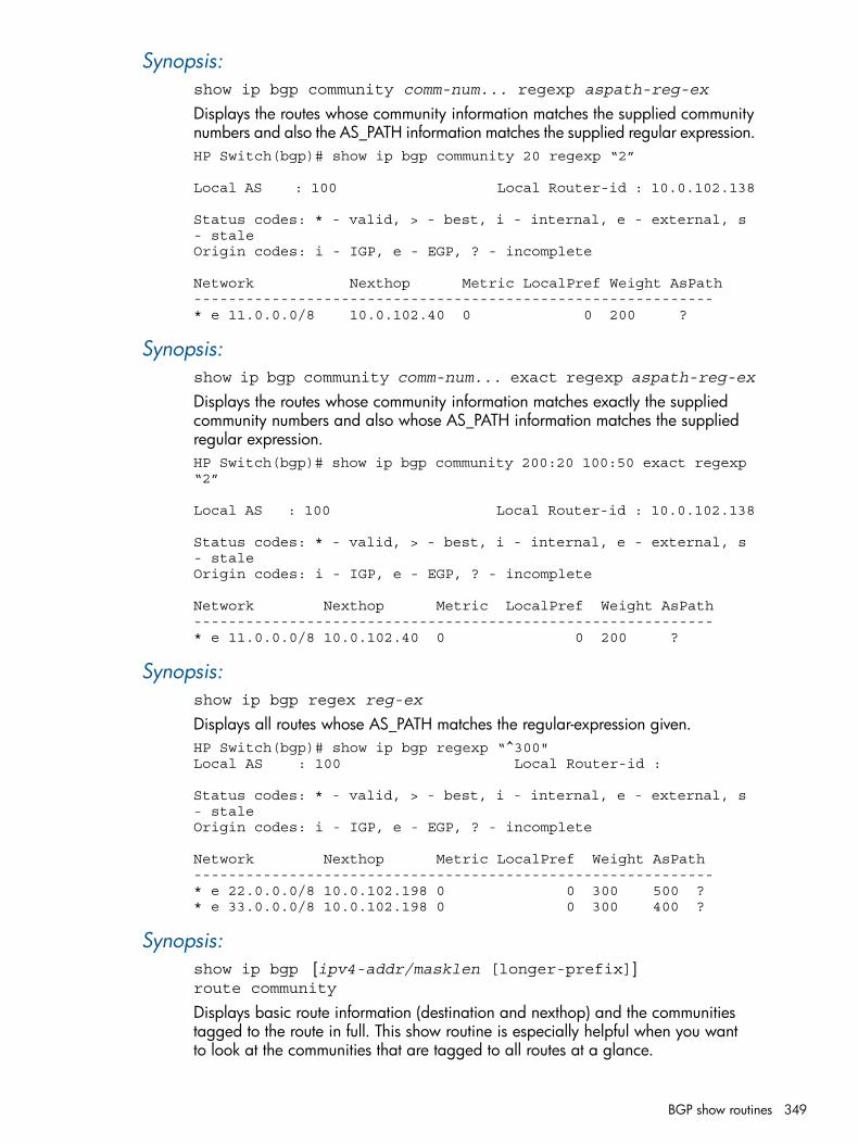
Synopsis:show ip bgp community comm-num... regexp aspath-reg-ex
Displays the routes whose community information matches the supplied communitynumbers and also the AS_PATH information matches the supplied regular expression.HP Switch(bgp)# show ip bgp community 20 regexp “2”
Local AS : 100 Local Router-id : 10.0.102.138
Status codes: * - valid, > - best, i - internal, e - external, s - staleOrigin codes: i - IGP, e - EGP, ? - incomplete
Network Nexthop Metric LocalPref Weight AsPath------------------------------------------------------------* e 11.0.0.0/8 10.0.102.40 0 0 200 ?
Synopsis:show ip bgp community comm-num... exact regexp aspath-reg-ex
Displays the routes whose community information matches exactly the suppliedcommunity numbers and also whose AS_PATH information matches the suppliedregular expression.HP Switch(bgp)# show ip bgp community 200:20 100:50 exact regexp “2”
Local AS : 100 Local Router-id : 10.0.102.138
Status codes: * - valid, > - best, i - internal, e - external, s - staleOrigin codes: i - IGP, e - EGP, ? - incomplete
Network Nexthop Metric LocalPref Weight AsPath------------------------------------------------------------* e 11.0.0.0/8 10.0.102.40 0 0 200 ?
Synopsis:show ip bgp regex reg-ex
Displays all routes whose AS_PATH matches the regular-expression given.HP Switch(bgp)# show ip bgp regexp “^300"Local AS : 100 Local Router-id :
Status codes: * - valid, > - best, i - internal, e - external, s - staleOrigin codes: i - IGP, e - EGP, ? - incomplete
Network Nexthop Metric LocalPref Weight AsPath------------------------------------------------------------* e 22.0.0.0/8 10.0.102.198 0 0 300 500 ?* e 33.0.0.0/8 10.0.102.198 0 0 300 400 ?
Synopsis:show ip bgp [ipv4-addr/masklen [longer-prefix]]route community
Displays basic route information (destination and nexthop) and the communitiestagged to the route in full. This show routine is especially helpful when you wantto look at the communities that are tagged to all routes at a glance.
BGP show routines 349
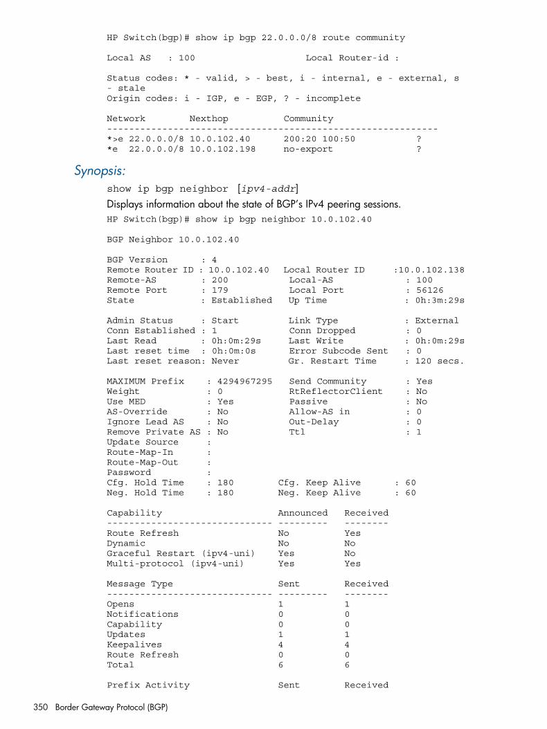
HP Switch(bgp)# show ip bgp 22.0.0.0/8 route community
Local AS : 100 Local Router-id :
Status codes: * - valid, > - best, i - internal, e - external, s - staleOrigin codes: i - IGP, e - EGP, ? - incomplete
Network Nexthop Community------------------------------------------------------------*>e 22.0.0.0/8 10.0.102.40 200:20 100:50 ?*e 22.0.0.0/8 10.0.102.198 no-export ?
Synopsis:show ip bgp neighbor [ipv4-addr]Displays information about the state of BGP’s IPv4 peering sessions.HP Switch(bgp)# show ip bgp neighbor 10.0.102.40
BGP Neighbor 10.0.102.40
BGP Version : 4Remote Router ID : 10.0.102.40 Local Router ID :10.0.102.138Remote-AS : 200 Local-AS : 100Remote Port : 179 Local Port : 56126State : Established Up Time : 0h:3m:29s
Admin Status : Start Link Type : External Conn Established : 1 Conn Dropped : 0Last Read : 0h:0m:29s Last Write : 0h:0m:29sLast reset time : 0h:0m:0s Error Subcode Sent : 0Last reset reason: Never Gr. Restart Time : 120 secs.
MAXIMUM Prefix : 4294967295 Send Community : Yes Weight : 0 RtReflectorClient : No Use MED : Yes Passive : No AS-Override : No Allow-AS in : 0Ignore Lead AS : No Out-Delay : 0Remove Private AS : No Ttl : 1Update Source : Route-Map-In : Route-Map-Out : Password :Cfg. Hold Time : 180 Cfg. Keep Alive : 60Neg. Hold Time : 180 Neg. Keep Alive : 60
Capability Announced Received------------------------------ --------- -------- Route Refresh No Yes Dynamic No No Graceful Restart (ipv4-uni) Yes NoMulti-protocol (ipv4-uni) Yes Yes
Message Type Sent Received------------------------------ --------- -------- Opens 1 1Notifications 0 0Capability 0 0Updates 1 1Keepalives 4 4Route Refresh 0 0Total 6 6
Prefix Activity Sent Received
350 Border Gateway Protocol (BGP)
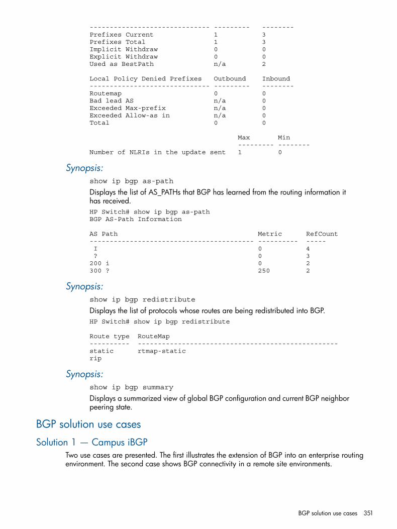
------------------------------ --------- -------- Prefixes Current 1 3Prefixes Total 1 3Implicit Withdraw 0 0Explicit Withdraw 0 0Used as BestPath n/a 2
Local Policy Denied Prefixes Outbound Inbound------------------------------ --------- -------- Routemap 0 0Bad lead AS n/a 0Exceeded Max-prefix n/a 0Exceeded Allow-as in n/a 0Total 0 0
Max Min --------- -------- Number of NLRIs in the update sent 1 0
Synopsis:show ip bgp as-path
Displays the list of AS_PATHs that BGP has learned from the routing information ithas received.HP Switch# show ip bgp as-pathBGP AS-Path Information
AS Path Metric RefCount----------------------------------------- ---------- ----- I 0 4 ? 0 3200 i 0 2300 ? 250 2
Synopsis:show ip bgp redistribute
Displays the list of protocols whose routes are being redistributed into BGP.HP Switch# show ip bgp redistribute
Route type RouteMap---------- -------------------------------------------------- static rtmap-staticrip
Synopsis:show ip bgp summary
Displays a summarized view of global BGP configuration and current BGP neighborpeering state.
BGP solution use cases
Solution 1 — Campus iBGPTwo use cases are presented. The first illustrates the extension of BGP into an enterprise routingenvironment. The second case shows BGP connectivity in a remote site environments.
BGP solution use cases 351
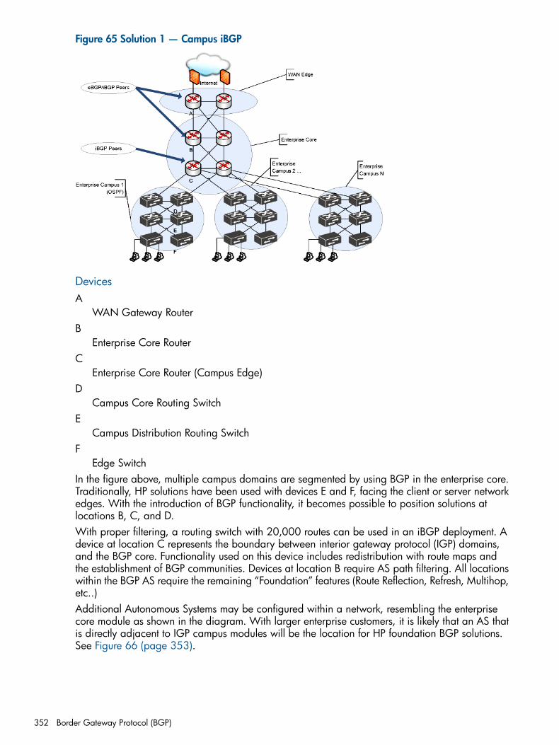
Figure 65 Solution 1 — Campus iBGP
DevicesA
WAN Gateway RouterB
Enterprise Core RouterC
Enterprise Core Router (Campus Edge)D
Campus Core Routing SwitchE
Campus Distribution Routing SwitchF
Edge SwitchIn the figure above, multiple campus domains are segmented by using BGP in the enterprise core.Traditionally, HP solutions have been used with devices E and F, facing the client or server networkedges. With the introduction of BGP functionality, it becomes possible to position solutions atlocations B, C, and D.With proper filtering, a routing switch with 20,000 routes can be used in an iBGP deployment. Adevice at location C represents the boundary between interior gateway protocol (IGP) domains,and the BGP core. Functionality used on this device includes redistribution with route maps andthe establishment of BGP communities. Devices at location B require AS path filtering. All locationswithin the BGP AS require the remaining “Foundation” features (Route Reflection, Refresh, Multihop,etc..)Additional Autonomous Systems may be configured within a network, resembling the enterprisecore module as shown in the diagram. With larger enterprise customers, it is likely that an AS thatis directly adjacent to IGP campus modules will be the location for HP foundation BGP solutions.See Figure 66 (page 353).
352 Border Gateway Protocol (BGP)
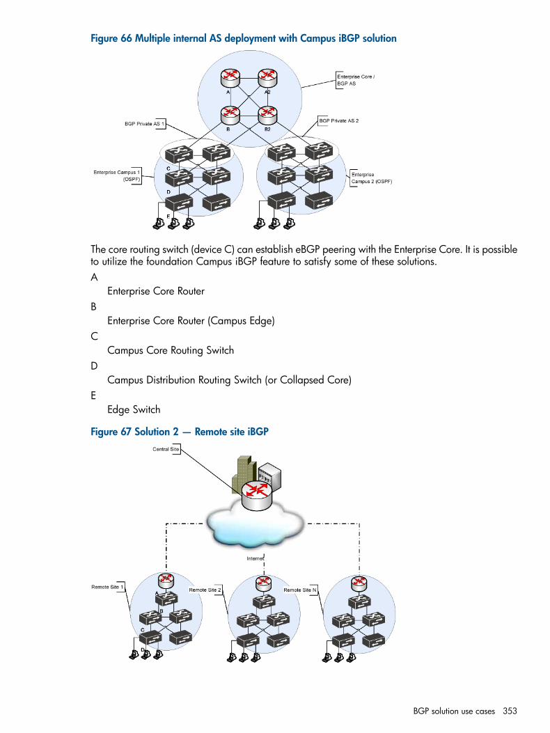
Figure 66 Multiple internal AS deployment with Campus iBGP solution
The core routing switch (device C) can establish eBGP peering with the Enterprise Core. It is possibleto utilize the foundation Campus iBGP feature to satisfy some of these solutions.A
Enterprise Core RouterB
Enterprise Core Router (Campus Edge)C
Campus Core Routing SwitchD
Campus Distribution Routing Switch (or Collapsed Core)E
Edge Switch
Figure 67 Solution 2 — Remote site iBGP
BGP solution use cases 353
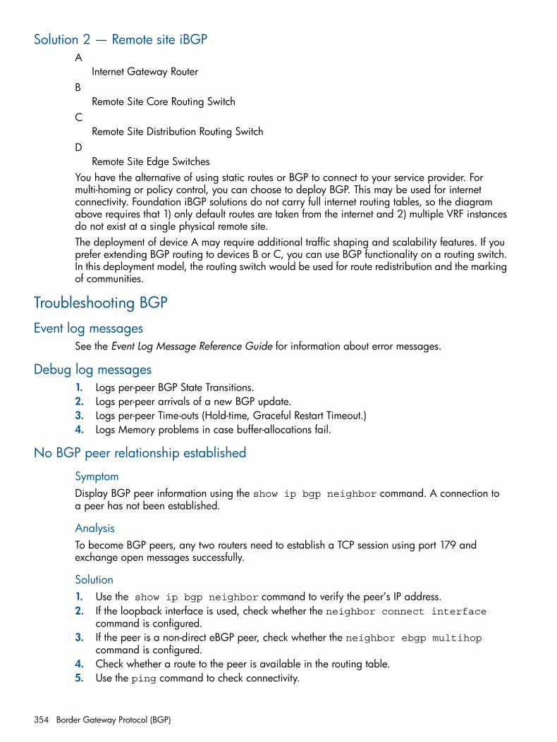
Solution 2 — Remote site iBGPA
Internet Gateway RouterB
Remote Site Core Routing SwitchC
Remote Site Distribution Routing SwitchD
Remote Site Edge SwitchesYou have the alternative of using static routes or BGP to connect to your service provider. Formulti-homing or policy control, you can choose to deploy BGP. This may be used for internetconnectivity. Foundation iBGP solutions do not carry full internet routing tables, so the diagramabove requires that 1) only default routes are taken from the internet and 2) multiple VRF instancesdo not exist at a single physical remote site.The deployment of device A may require additional traffic shaping and scalability features. If youprefer extending BGP routing to devices B or C, you can use BGP functionality on a routing switch.In this deployment model, the routing switch would be used for route redistribution and the markingof communities.
Troubleshooting BGP
Event log messagesSee the Event Log Message Reference Guide for information about error messages.
Debug log messages1. Logs per-peer BGP State Transitions.2. Logs per-peer arrivals of a new BGP update.3. Logs per-peer Time-outs (Hold-time, Graceful Restart Timeout.)4. Logs Memory problems in case buffer-allocations fail.
No BGP peer relationship established
SymptomDisplay BGP peer information using the show ip bgp neighbor command. A connection toa peer has not been established.
AnalysisTo become BGP peers, any two routers need to establish a TCP session using port 179 andexchange open messages successfully.
Solution1. Use the show ip bgp neighbor command to verify the peer’s IP address.2. If the loopback interface is used, check whether the neighbor connect interface
command is configured.3. If the peer is a non-direct eBGP peer, check whether the neighbor ebgp multihop
command is configured.4. Check whether a route to the peer is available in the routing table.5. Use the ping command to check connectivity.
354 Border Gateway Protocol (BGP)

6. Use the display tcp status command to check the TCP connection.7. Check whether an ACL is configured that disables TCP port 179.
Troubleshooting BGP 355
Index
AABR
definition, 203OSPF, 203
ACLoperation with PIM, 62
addressIP, 125
administrative distance, OSPFOSPF
administrative distance, 213advertisement
OSPF, 202area
OSPF, 180area information
area, OSPFdisplaying area information, 180
OSPF, 180area range, OSPF
configuring, 163, 213area, OSPF
assigning VLAN to, 158, 159configuring, 212definition, 205
ARPcache table, 120configuring parameters, 126enabling local proxy, 118how it works, 126local proxy option, 118proxy, 127
assigningIP address, 125
assigning VLAN toVLAN
assigning OSPF area to, 158, 159authentication
OSPF MD5, 171auto port setting, 27Autonomous system, OSPF
OSPF autonomous system, 205
Bblocked port
from IGMP operation, 27boot
with OSPF, 216BOOTP
invalid gateway address, 244Bootp
displaying configured gateway, 244broadcast forwarding, 251broadcast traffic
enabling forwarding of directed, 128
BSRchange priority setting, 78configuration, 105display data, 96election, 105enable or disable operation, 77fault recovery, 106non-default settings, 97operation, 105
CC-RP
add multicast group, 69, 81change hold time, 82configuring operation, 80display config, 70, 99display status, 70, 99election priority, 82enabling or disabling, 81multicast groups, 80specify VLAN interface, 80
cachesIP forwarding, 122
CIDR, 125circuit ID, 254configuration
ARP parameters, 126default route, 134DHCP Relay, 242RIP, 137
enabling RIP globally, 137router ID, 125static IP routes, 130
configuringadvertisement, 212OSPF
assigning area range, 163, 213
Ddebug
VRRP, 289default route, 134default settings, 267, 268, 271, 280, 292, 295
ip multicast-routing, disabled, 40PIM-DM:recommendation to keep defaults, 61PIM-DM:router pim trap, disabled, 40PIM-DM:router pim, disabled, 40PIM-DM:vlan ip pim, disabled;default
settings:PIM-DM:vlan configuration settings, 43defaults
OSPF, 215changing defaults, 167, 214
Designated Routerelection criteria, 105in VLAN, 105
DHCP
356 Index
assigning a gateway, 243hop count, disabling, 245hop count, displaying, 246relay agent, 243
DHCP Relay, 251broadcast
forwarding, 251configuration, 242enabling, 242helper address, 244hop count in requests, 251minimum requirements, 251Option 82
circuit ID, 254packet forwarding, 251verifying configuration, 245
directed broadcasts, 128displaying
OSPF, 181restrict redistribution filters, display, 195
displaying informationvirtual link, 196
Downstream interface, 51DR (designated router)
election criteria, 105dynamic priority change, 300
OSPF, 304RIP, 304
EECMP
feature description, 208in OSPF, 208
electionDR (designated router):OSPF election, 203
enablingOSPF, 162
enabling redistributionOSPF, 162
event logcounter, 63
external LSALSA, 181
external, displayingexternal LSA, 181
Ffailover, VRRP, 300filters
effect of IGMP, 37maximum allowed, 27
forwardingdirected broadcasts, 128parameters, IP routing
configuring, 128forwarding port, IGMP, 27
Ggateway, DHCP, 243
graftmax graft retries, 45
graft acknowledgementgraft ack, 44
Hhelper address for DHCP Relay, 244hop count in DHCP requests
disabling, 245displaying configuration, 246
IIANA, 263ICMP
configuring, 128disabling messages, 128
IGMPbenefits, 26effect on filters, 37Exclude Source, 28Fast Leave, 29high-priority disabled with PIM;, 62high-priority forwarding, 27Include Source, 28IP multicast address range, 37leave group, 28maximum address count, 27multicast group, 28multimedia, 26operation, 28port states, 27proxy
forwarding, 33proxy: forward loop, 35proxy: forwarding commands, 24proxy: show command, 25proxy: vlan context command, 25query, 28report, 28status, 28traffic, 27Version 3, 28
IGMP control, 27IP address
assigning, 125CIDR notation, 125multiple, 299virtual, 290
IP forwarding cache, 122IP interface parameters, 124IP route exchange protocols, 122IP route table;tables
IP route, 121IP routing
ARP cache table, 120chain, 183changing ARP parameters, 126changing router ID, 125configuring static routes, 130
357

default route, 134DHCP Relay configuration, 242directed broadcasts, 128forwarding cache, 122forwarding parameters, 128helper address, 244helper address, UDP, 125interface parameters, 124IP static routes
administrative distance, 132blackhole, 135configuration, 130default route, 124, 135default route, configuring, 134display, 134null interface, 135null route, 130VLAN state, 135
IP static routes:maximum, 119overview, 119parameter configuring;configuration:IP routing
parameters, 125Proxy ARP, enabling, 127redistribution, 228route exchange protocols, 122route policy, 218
configuring, 227match commands, 228prefix lists, 218route maps, 227set commands, 225
router ID, 204router ID;OSPF:router ID, 203routing table, 121static route configuration, 130static route parameters, 135static route types, 134static routes
discard traffic, 130discard, ICMP notification, 130
tables and caches, 120VLAN interface;VLAN interface:description, 120
IPv6 routingIP static routes
configuration, 130IPv6 static routes
configuration, 132IRDP
configuring;, 239displaying information, 241enabling globally, 239enabling on VLAN interface;, 240
Lloopback interface
router priority;IP routingloopback interface, 204
LSAdisplaying information, 181
LSAdisplaying, 188
Mmanagement VLAN, 247match commands, 228MD5
MD5 authenticationOSPF, 171
metric typemetric
OSPF redistribution, 163multinetted VLANS and Option 82, 259multiple relay agents, 256
Nnear failovers
statistic, 288VRRP, 285
OOption 82, 252
circuit ID, 254compliance, 252configuring operation, 247field content, 254forwarding policy, 255management VLAN, 247, 254multinetted VLANS, 259multiple relay agents, 256operation, 253Option 82 field, 252overview, 252Relay Agent Information, 252remote ID, 254requirements, 253server support, 253validating server response packets, 257
originator router, 50OSPF
ABR, connection requirement, 213ABR, range configuration, 211administrative distance, 211, 213administrative distance;OSPF:route choice, influencing,
166advertisement, blocking, 165area, 158, 159, 205, 211, 212area border router;OSPF:ABR, 203area configuration, 212area range, 163, 213area types, 205ASBR, 203, 211ASBR, advertising, 208ASBR, in NSSA, 211authentication, 171, 175, 211, 215
description, 170, 214, 215interface, 214MD5, 171, 176password, 170, 175
358 Index
authentication:MD5, 151, 152, 171authentication:password, 151, 152autonomous system boundary router, 203backbone area, 205backbone area, configure;OSPF:normal area, configure,
155backbone area;, 205blocking routes, 213boot, 216chain
chain, key management, 183changing compliance setting, 154changing port parameters, 154configuration rules, 211configuration steps, 153cost, 211cost; OSPF: summary cost, 164dead-interval, 211default parameter settings, 211default port parameters, 154displaying configuration and status, 178displaying information, 178, 180, 181, 183, 184,
188, 196neighbor, 193virtual link, 196
displaying redistribution, 194DR (designated router), 203enabling, 154, 210equal cost multi-path (ECMP) multiple next-hop routing,
208external route cost options, 157external routes, redistribution, 211general configuration steps, 211general information, 178hello-interval, 211interface, 167, 214interface parameters, 167interior router, 202loopback interface, 204, 211loopback interface, assigning, 159loopback interface, redistribution, 160LSA types, 202LSA, external, reduction, 208MD5 authentication, 171neighbor, 214no-summary, 157no-summary, effect, 208normal area, 205, 206NSSA, 202, 205, 206NSSA, configuring, 156overview, 153parameters, 215passive, 176, 215password, 170priority, 211range, blocking, 166redistribution, 162, 163
metric, 162redistribution filters, 195
redistribution, configuring, 161redistribution, loopback interface, 160reload, 216restrict redistribution., 213RFC 1583 compliance option, 211RFC 1583, compliance setting, 212RFC 1583, example, 155RFC 2178, 212RFC 2328, 202, 207, 212RFC 2328;RFCs:RFC 2328, 207RFC 3101, 202RFC 3101;RFCs:RFC 3101, 207RFC compliance, 207route choice, influencing, 213router ID, 125, 189, 190, 193, 196, 199, 204, 207,
208, 210, 215router ID, displayed, 180, 181, 182routing table, displaying
routing table, displaying, 198show commands, 178show passive information, 177software license requirements, 120SPF statistics, displaying, 197stub area, 205, 206stub area, configuring, 156summarizing routes, 213transit area, 214transit area ID, 173, 174, 175traps, 166, 211type-3 default summary LSA, 157type-3 LSA, 207type-3 summary LSA, 157, 208type-7 default external LSA, 157, 208virtual link, 196, 213, 215
configuration, 214interface parameters, 215
virtual neighbor:displaying information;virtualneighbor:OSPF:displayinginformation;OSPF:displaying information:virtualneighbor, 195
VLAN/subnet statistics, displaying, 186with Pre-empt Delay Timer, 301
Pparameters
IP interface, 124OSPF interface, 167virtual link, 215
peers, RIPdisplaying information, 145
PIM hello messagehello delay, 44
PIM interfacesVLAN, 49
PIM-DMAsset Timer, 51bandwidth conservation;PIM-DM:state refresh, 61common subnet requirement;PIM-DM:subnet, common,
60
359
configuration, 40, 48, 61configuration order, recommended, 61configuration, general elements, 61configuration, router;PIM-DM:router configuration, 61default settings recommended, 61draft versions 1 and 2;PIM-DM:compatible draft
versions, 58error messages, 63expire time, 52, 53extended branch;PIM-DM:pruned branch, 59flood and prune, 59, 60flood and prune cycle, 62flood and prune;, 60flow, bridged, 63flow, equalizing, 64, 65, 66flow, multicast, limit, 64flow, software, 41flow;PIM-DM:flood;PIM-DM:prune;PIM-DM:join, 59forwarding, 51general operation, 58graft packets, 38, 44hello interval, effect, 43IGMP requirement, 62IGMP version 1;PIM-DM:IGMP version 2;PIM-DM:IGMP
version 3;, 58IGMP, per VLAN, 59interfaces, 53IP address required, 62, 64join, 59log message, 63log message counter operation, 63log message;, 63Metric, 51Metric Pref, 51MIB support, 58MRT, 63MRT;PIM-DM:flow, hardware, 41multicast address, 59multicast router, Asset Timer, 56multicast router, multiple, 55multinetted VLAN, 46multinetted VLAN:common subnet required, 43neighbor, PIM, 39, 49, 56prune, 51, 56prune delay, 38, 45prune reason, 56prune state;PIM-DM:forwarding state, 60prune-pending state, 46pruning;, 60RFC 2932 exceptions;RFCs:RFC 2932 MIB exceptions,
66RFCs, applicable;RFCs:PIM-applicable, 66RIP;PIM-DM:OSPF;PIM-DM:static route, 59route data, 48routing protocol, 61routing switch 9300, 62RP Tree, 51SNMP traps, 40software license requirements, 39
state refresh, 38, 40, 42, 55, 57, 62state refresh, on other routers, 62state refresh;, 60time-to-live threshold, 39, 46traps, SNMP, 40tree, multicast, 59TTL zero, 63unicast routing, 58, 59up time, 52, 53version differences, 65VLAN support, outbound;PIM-DM:VLAN support,
inbound, 58VLAN, flow limit;PIM-DM:flow, VLAN limit, 58VLAN, multinetted;PIM-DM:multinetted VLAN, 60XRRP, 58
PIM-SMborder routers, 104BSR, 104, 105
message interval, 69, 79non-default settings, 97priority setting, 78protocol, 101
changing DR priority, 68, 76compatible draft versions, 102configuration, 94configuring C-RPs, 79Designated Router, 104display BSR data, 96display C-RP config, 70, 99display config, 92display status, 92DR
priority, 95draft versions 1 and 2, 102enable/disable SNMP Traps, 82entries in routing table, 70, 93event log messages, 113expire time, 94features, 101flow capacity, 101flow, software, 82flow, VLAN limit, 101group address, 70, 87, 93hello delay, 75hello hold-time, 74hello interval, 75hello interval, effect, 75IGMP link, 101IGMP version 1, 102IGMP version 2, 102IGMP version 3, 102join/prune interval, 69, 83lan-prune-delay, 75list interfaces, 93MIB support, 102MRT, 70, 93multicast group distribution, 69, 78neighbor, 87neighbor, PIM, 70, 94
360 Index

non-flooding model, 102operating notes, 100PMBR not supported, 104propagation delay, 75prune, 90
delay, 68, 75prune delay, 68, 76prune-pending state, 76router types, 104RP, 104RP mapping, 101show VLAN configs, 93SNMP traps, 92software license requirements, 101source address, 70, 87, 93state refresh, 92, 94static RP, 104traps, SNMP, 92unicast routing, 101using SPT controls, 83VLAN support, inbound, 101VLAN support, outbound, 101VLAN, flow limit, 101VRRP, 102
pingVRRP backup responds to, 296
PMBR, 104port
auto, IGMP, 27blocked, IGMP, 27forwarding, IGMP, 27state, 27
Pre-empt Delay TimerPDT value, 302with older devices, 301
Pre-empt DelayTimer, 272prefix lists, 218Premium License
OSPF, 120PIM-DM, 58PIM-SM, 101VRRP, 290
priorityIP multicast traffic, 27
protocolsIP route exchange, 122
Proxy ARP, enabling, 127proxy forwarding, IGMP, 34
Rredistribution, 141, 228
and route policy, 162OSPF
redistribution information, 194reload
with OSPF, 216RFCs
RFC 1583 compliance option, 211, 212RFC 2178, 207, 212
RFC 2328, 202, 207, 212RFC 2338, 303RFC 2787, 303RFC 3101, 202RFC 3768, 293, 294, 303RFC 3768;, 296RFC 4061, 102
RIPchanging cost of RIP routes, 140changing RIP type, 139changing the RIP metric, 140configuring, 137configuring an authentication key, 139displaying configuration and status, 142displaying general information, 142displaying information, 142displaying interface information, 144displaying peer information, 145displaying redistribution information, 146displaying restrict information, 146enabling globally, 137enabling on a VLAN, 139enabling on the routing switch, 138enabling route redistribution, 141entering RIP router context, 138general information, 142global parameters, 147interface information, 144interface parameters, 147parameters and defaults, 147peer information, 145redistribution, 141
and route policy, 141displaying, 146enabling, 141
redistribution filtersdisplaying, 146
redistribution into RIP, 148redistribution, configuring, 148restrict filter information, 146restrict redistribution, 146
route maps, 227route policy, 218
configuring, 227router ID, changing, 125router, multicast, with IGMP, 27RPT
traffic restricted to, 104
Sset commands, 225SPF
configuring scheduling, 177SPF algorithm
displaying OSPF statistics, 197SPT
operation, 103PIM-SM traffic, 83
static IP routes, 134
361
configuring, 130route types, 134
static IPv6 routesconfiguring, 132
static RPmanual configuration, 83
subnet, 28
Ttables
ARP cache, 120IP, 120
tracked entitiesdisplaying, 273
transit areaOSPF, 214
trapsOSPF, 166
UUDP broadcast forwarding, 260
address types, 264application, 263configure, 260global enable, 260invalid entry, 264IP helper address, effect, 263maximum entries, 263port-number ranges, 263subnet address, 264subnet masking, 264UDP/TCP port number listing, 263unicast address, 264VLAN, subnetted, 264
unicast routing protocolRIP, connected, OSPF, static route, other, 51
Vvirtual link
authentication, 175, 215change settings, 215OSPF, 175, 215
virtual MAC address, 294VLAN
IGMP configuration;IGMP:configure per VLAN, 16interface, 49
VLAN interfaceIP routing parameters, 124OSPF
interface parameters, 167VR
advertisement interval, 295deactivate, 296IP address, 296IP address limit, 303IP address, delete, 303MAC address, 290MAC address, source, 291maximum in a VLAN, 292
maximum per switch, 295maximum per VLAN, 295membership, 292multiple IP addresses, 299multiple VRs in VLAN, 292multiple, in a VLAN, 293operation, 292specific, 282subnet limit per VLAN, 303
VRIDconfigure, 265, 268maximum per VLAN, 265, 268
VRRP, 265, 268, 290, 291, 292, 293, 295, 296, 299, 303advantages, 267advertisement, 292
function, 293interval, 293, 295
ARP response, 292, 294authentication data, 273backup responds to ping, 296Backup router, 266, 294
as Master, 266elected as Master, 293multiple, 290no response to ping, 296not receiving advertisements, 303priority, 294priority, configure, 270virtual IP address, 294
configuration example, 299debug, 289disable global, 265, 267disable on VR, 271display, 282
statistics, global, 266, 284uptime, 284VR, specific, 266
displaying tracked entities, 273dynamic priority change, 300election process, 290enable global, 265, 267enable on VR, 271event log, 265, 267example, 291, 298failback, 267, 290, 292failover, 266, 291, 292, 294failover operation, 300failover, VRRP, 266global configuration, 280IP address, deleting, 296IP address, per VR, 296IP address, real, 290, 293IP address, virtual, 290, 291, 292, 293, 294, 295LACP and tracked ports, 304MAC address
shared, 292source, 292, 294virtual, 294
362 Index

Master router, 266, 290, 293see also Owner router
advertisements failing, 303election, 293Owner unavailable, 293
multinetted VLAN, 292, 294, 295near failovers, 288near failovers stat, 285overview, 266Owner priority see priorityOwner priority, 255, 295Owner router, 266, 290, 293see also Master router
default Master, 293priority, 293
pre-empt delay time, 272pre-empt delay timer and OSPF, 301Pre-empt Delay Timer with LACP, 301Pre-empt Delay Timer with older devices, 301Pre-empt Delay Timer, PDT value, 302pre-empt mode, 294pre-empt mode, configure, 265, 271preempt mode, enabled, 271preempt-delay time, 0 seconds, 280primary-ip-address, lowest, 271priority, 291, 293
Backup, 292, 295Backup default, 293Owner, 290, 292, 293, 295Owner default, 294range for Backup router, 293VR, 294
priority, Owner, 290, 292, 293, 295real gateway, 293RFC see RFCsrouter vrrp traps, enabled, 268router vrrp, disabled, 267software license requirements, 290source address for VR, 290standards compliance, 303traps, disable, 265, 267traps, enable, 265, 267version, 268virtual router see VRVLAN, subnetted, 293VR
advertisement interval, change;, 270virtual IP address, configure, 271virtual IP address, default, 271
VR priority see VRRP, priorityVR priority, 100, 292VRID, 291, 292, 294
363


![4th Year - Deeniyat · khat kasheeda alfaaz mein kaun sa qaida hoga us par [P] ka nishaan lagaayein? 10 Tanween ka Idgaam. Tanween ka Ikhfaa. Tanween ka Izhaar Tanween ka Idgaam Tanween](https://img.pdfslide.us/doc/110x75/5f6039e7c988fa06d72aec6a/4th-year-deeniyat-khat-kasheeda-alfaaz-mein-kaun-sa-qaida-hoga-us-par-p-ka-nishaan.jpg)