Embed Size (px)
Citation preview
HP ProLiant DL760 Generation 2 Server
User Guide
June 2003 (Second Edition) Part Number 201264-002
HP CONFIDENTIAL Writer: Jennifer Hayward File Name: a-frnt.doc
Codename: Pioneer Part Number: 201264-002 Last Saved On: 6/16/03 1:40 PM
© 2002, 2003 Hewlett-Packard Development Group, L.P.
Microsoft®, Windows®, and Windows NT® are US registered trademarks of Microsoft Corporation.
Intel® is a US registered trademark of Intel Corporation.
UNIX® is a registered trademark of The Open Group.
All other product names may be trademarks of their respective companies.
Hewlett-Packard Company shall not be liable for technical or editorial errors or omissions contained herein. The information in this document is provided “as is” without warranty of any kind and is subject to change without notice. The warranties for HP products are set forth in the express limited warranty statements accompanying such products. Nothing herein should be construed as constituting an additional warranty.
HP ProLiant DL760 Generation 2 Server User Guide
June 2003 (Second Edition) Part Number 201264-002
HP CONFIDENTIAL Writer: Jennifer Hayward File Name: a-frnt.doc
Codename: Pioneer Part Number: 201264-002 Last Saved On: 6/16/03 1:40 PM
HP ProLiant DL760 Generation 2 Server User Guide iii
HP CONFIDENTIAL Writer: Jennifer Hayward File Name: a-frnt.doc
Codename: Pioneer Part Number: 201264-002 Last Saved On: 6/16/03 1:40 PM
Internal Hot-Plug Drive Bays ................................................................................. 1-13
Contents
About This Guide Audience Assumptions...................................................................................................... xi Important Safety Information ............................................................................................ xi Symbols on Equipment ..................................................................................................... xi Rack Stability .................................................................................................................. xiii Symbols in Text............................................................................................................... xiii Hood Labels and Indicators............................................................................................. xiv Related Documents............................................................................................................xv Getting Help .................................................................................................................... xvi
Technical Support ..................................................................................................... xvi HP Website ............................................................................................................... xvi Authorized Reseller ................................................................................................. xvii Optional Installation Service.................................................................................... xvii
Reader’s Comments ...................................................................................................... xviii
Chapter 1 Server Features HP ProLiant DL760 Generation 2 Servers ...................................................................... 1-1 Overview ......................................................................................................................... 1-2 Standard Features ............................................................................................................ 1-7
Processors ................................................................................................................. 1-7 Hot Plug RAID Memory........................................................................................... 1-9 PCI-X Technology.................................................................................................. 1-11 PCI Hot Plug........................................................................................................... 1-12 Network Interface Controller .................................................................................. 1-12 Disk Controller ....................................................................................................... 1-13
Contents
Fixed Internal Media Drive Bays ............................................................................1-13
iv HP ProLiant DL760 Generation 2 Server User Guide
HP CONFIDENTIAL Writer: Jennifer Hayward File Name: a-frnt.doc
Codename: Pioneer Part Number: 201264-002 Last Saved On: 6/16/03 1:40 PM
Shipping Brackets ...................................................................................................2-10
Video .......................................................................................................................1-14 Redundant Hot-Plug Power Supplies ......................................................................1-14 Redundant Hot-Plug Fans .......................................................................................1-15 Supported Interfaces................................................................................................1-15
Optional Features...........................................................................................................1-16 Supported Operating Systems........................................................................................1-16 Server Configuration and Management Features...........................................................1-17
SmartStart................................................................................................................1-17 ROM-Based Setup Utility .......................................................................................1-18 Remote-Flash Redundant ROM ..............................................................................1-18 Smart Components for Online ROM Flash .............................................................1-19 Advanced Data Guarding ........................................................................................1-19 HP Utilities for Microsoft Windows .......................................................................1-20 HP Utilities for Caldera OpenUNIX 8 or SCO UnixWare 7.1.3.............................1-20 HP Utilities for Linux..............................................................................................1-21 Insight Manager 7....................................................................................................1-21 Integrated Management Log ...................................................................................1-23 Integrated Management Display .............................................................................1-23
Diagnostic Tools ............................................................................................................1-24 Security Features............................................................................................................1-25
Software Security ....................................................................................................1-25 Hardware Security...................................................................................................1-26
Server Registration ........................................................................................................1-27 Routine Maintenance .....................................................................................................1-27 Warranty ........................................................................................................................1-27
Chapter 2 Installing the Server in a Rack Rack Installation Overview..............................................................................................2-2 Selecting a Site.................................................................................................................2-3
Space and Airflow Requirements..............................................................................2-3 Power Requirements..................................................................................................2-4 Grounding Requirements ..........................................................................................2-7 Temperature Requirements .......................................................................................2-8
Shipping Box Contents ....................................................................................................2-9 Removing the Shipping Safeguards.................................................................................2-9
Contents
Shipping Screws ..................................................................................................... 2-12 Security Screw............................................................................................................... 2-13 Rack Considerations...................................................................................................... 2-14
Rack Stability.......................................................................................................... 2-14 Warnings and Precautions....................................................................................... 2-16
Preparing the Rack for Server Installation .................................................................... 2-17 Measuring with the Rack Template ........................................................................ 2-17 Installing the Slide Bracket Assemblies.................................................................. 2-22
Preparing the Server for Rack Installation .................................................................... 2-23 Lightening the Chassis............................................................................................ 2-24 Attaching the Inner Slide Members ........................................................................ 2-25
Installing the Server in the Rack ................................................................................... 2-26
Chapter 3 Server Access Server I/O Lid and Modules ............................................................................................ 3-2
Accessing the I/O Module ........................................................................................ 3-3 Removing the I/O Module ........................................................................................ 3-4 Removing the Processor and Memory Module......................................................... 3-6 Processor and Memory Module Components........................................................... 3-9 Removing the Media Module ................................................................................. 3-10 Media Module Components.................................................................................... 3-13
Chapter 4 Installing Hardware Options, Server Power Off Intel Xeon Processor MP................................................................................................. 4-2 Installing a Processor Board............................................................................................ 4-3 External Tape Drive Storage Devices ............................................................................. 4-6 Non-Hot-Plug I/O Expansion .......................................................................................... 4-7
Locating the I/O Expansion Slots ............................................................................. 4-8 Adding Non-Hot-Plug Expansion Boards................................................................. 4-9
Installing the Remote Insight Lights-Out Edition II...................................................... 4-13 Installing the Integrated Array Bypass .......................................................................... 4-18
HP ProLiant DL760 Generation 2 Server User Guide v
HP CONFIDENTIAL Writer: Jennifer Hayward File Name: a-frnt.doc
Codename: Pioneer Part Number: 201264-002 Last Saved On: 6/16/03 1:40 PM
Contents
Chapter 5 Installing Hardware Options, Hot-Pluggable Hot Plug RAID Memory..................................................................................................5-2
Memory Cartridge Overview ....................................................................................5-2 Memory Cartridge Guidelines...................................................................................5-4 Memory Cartridge LED Indicators ...........................................................................5-6 Accessing the DIMMs...............................................................................................5-8 DIMM Overview.....................................................................................................5-10 Installing DIMMs into the Memory Cartridge ........................................................5-13 Hot Plug RAID Memory Operating System Support..............................................5-14 Hot-Replacing Memory...........................................................................................5-15 Hot-Adding Memory...............................................................................................5-17 Hot-Upgrading Memory..........................................................................................5-20
Non-RAID Memory Support .........................................................................................5-23 Installing Hot-Plug Hard Drives ....................................................................................5-24
Hot-Plug SCSI Hard Drive LED Indicators ............................................................5-26 Guidelines for Installing Hot-Plug SCSI Hard Drives ............................................5-28 Installing a Hot-Plug SCSI Hard Disk Drive ..........................................................5-29 Guidelines for Replacing Hot-Plug SCSI Hard Drives ...........................................5-30 Removing a Hot-Plug SCSI Hard Disk Drive.........................................................5-32
Installing a StorageWorks Hot-Plug Tape Drive ...........................................................5-33 Installing a Hot-Plug Power Supply ..............................................................................5-34
Power Supply LED Indicators.................................................................................5-39 PCI Hot Plug I/O Expansion Boards .............................................................................5-40
Locating the I/O Expansion Slots............................................................................5-41 PCI Hot Plug LED Indicators..................................................................................5-43 PCI Hot Plug Operating System Support ................................................................5-45 Adding PCI Hot Plug Expansion Boards ................................................................5-50 Removing or Replacing a PCI Hot Plug Expansion Board .....................................5-55
Replacing Hot-Plug Fans ...............................................................................................5-57
Chapter 6 Cabling the Server Cable Connectors .............................................................................................................6-2
vi HP ProLiant DL760 Generation 2 Server User Guide
HP CONFIDENTIAL Writer: Jennifer Hayward File Name: a-frnt.doc
Codename: Pioneer Part Number: 201264-002 Last Saved On: 6/16/03 1:40 PM
Contents
Chapter 7
HP ProLiant DL760 Generation 2 Server User Guide vii
HP CONFIDENTIAL Writer: Jennifer Hayward File Name: a-frnt.doc
Codename: Pioneer Part Number: 201264-002 Last Saved On: 6/16/03 1:40 PM
Integrated Management Log.......................................................................................... 9-15 Multiple Ways of Viewing the Integrated Management Log ................................. 9-16
Server Power System Power Overview ................................................................................................. 7-2
Power Supplies ......................................................................................................... 7-3 Power Supply LED Indicators .................................................................................. 7-4 System Interconnect Status Indicators ...................................................................... 7-5
Powering Up the Server................................................................................................... 7-7 Server Power............................................................................................................. 7-7 Power-On Self-Test .................................................................................................. 7-9
Powering Down the Server............................................................................................ 7-13
Chapter 8 Configuring the Server Setting Up the Base Environment ................................................................................... 8-2
Enhanced Auto-Configuration Process..................................................................... 8-2 Manual Configuration............................................................................................... 8-4 Accessing the System Maintenance Menu................................................................ 8-6 System Maintenance Menu....................................................................................... 8-8 ROM-Based Setup Utility......................................................................................... 8-9 ROM-Based Inspect Utility .................................................................................... 8-10 ROM-Based Diagnostic Utility............................................................................... 8-11
Configuring the Drive Array Controller........................................................................ 8-15 Option ROM Configuration for Arrays .................................................................. 8-17 Array Configuration Utility .................................................................................... 8-20 Array Configuration Replicator Utility................................................................... 8-24
Installing the Operating System .................................................................................... 8-25 Assisted SmartStart Operating System Installation ................................................ 8-25
Installing HP Drivers and Utilities ................................................................................ 8-26
Chapter 9 Software Management Integrated Management Display...................................................................................... 9-2
Configuring the Integrated Management Display..................................................... 9-2 Customizing Management Display Fields ................................................................ 9-5 Standard Integrated Management Display Fields ..................................................... 9-8 Navigating the Menus ............................................................................................. 9-10
Contents
Insight Manager 7 ..........................................................................................................9-20
viii HP ProLiant DL760 Generation 2 Server User Guide
HP CONFIDENTIAL Writer: Jennifer Hayward File Name: a-frnt.doc
Codename: Pioneer Part Number: 201264-002 Last Saved On: 6/16/03 1:40 PM
System Power LED Indicator...................................................................................D-2 Auxiliary Power LED Indicator ...............................................................................D-3
Survey Utility.................................................................................................................9-21 Array Configuration Utility ...........................................................................................9-22
Step 1—Running ACU as a Local-Only Application .............................................9-22 Step 2—Running ACU as a Service With Remote Accessibility ...........................9-23
Appendix A Regulatory Compliance Notices Regulatory Compliance Identification Numbers ............................................................A-1 Federal Communications Commission Notice ...............................................................A-2
Modifications ...........................................................................................................A-2 Mouse Compliance Statement..................................................................................A-2 Cables .......................................................................................................................A-2
Canadian Notice (Avis Canadien) ..................................................................................A-3 European Union Notice ..................................................................................................A-3 Japanese Notice...............................................................................................................A-4 BSMI Notice ...................................................................................................................A-4 Laser Devices..................................................................................................................A-5
Laser Safety Warnings .............................................................................................A-5 Compliance with CDRH Regulations ......................................................................A-5 Compliance with International Regulations .............................................................A-5
Power Cords....................................................................................................................A-6 Battery Replacement Notice ...........................................................................................A-7
Appendix B Electrostatic Discharge Grounding Methods ........................................................................................................ B-2
Appendix C Server Error Messages POST Error Messages..................................................................................................... C-1 ADU Error Messages...................................................................................................... C-1
Appendix D LED Indicators and Switches LED Indicators................................................................................................................D-1
Contents
System Interconnect LED Indicators ....................................................................... D-4 System Attention LED Indicators ............................................................................ D-6 Hot-Plug SCSI Hard Drive LED Indicators............................................................. D-7 Power Supply LED Indicators ................................................................................. D-9 Hot-Plug Fan LED Indicators ................................................................................ D-10 PCI Hot Plug LED Indicators ................................................................................ D-11 Memory Cartridge and DIMM Status LED Indicators .......................................... D-13
Switches........................................................................................................................ D-15 I/O Board Configuration Switches......................................................................... D-15
Appendix E Troubleshooting Information Server Startup Problems..................................................................................................E-2 Diagnosis Steps ...............................................................................................................E-4 Problems After Initial Boot ...........................................................................................E-17 Remote-Flash Redundant ROM ....................................................................................E-20
Appendix F Server Specifications Server Specifications ....................................................................................................... F-1
Appendix G System Battery Internal Battery............................................................................................................... G-1
Index
HP ProLiant DL760 Generation 2 Server User Guide ix
HP CONFIDENTIAL Writer: Jennifer Hayward File Name: a-frnt.doc
Codename: Pioneer Part Number: 201264-002 Last Saved On: 6/16/03 1:40 PM
About This Guide
This guide provides step-by-step installation instructions and reference information for operating, troubleshooting, and upgrading of the ProLiant DL760 G2 server.
Audience Assumptions
This guide is for the person who installs, administers, and troubleshoots servers. HP assumes you are qualified in the servicing of computer equipment and trained in recognizing hazards in products with hazardous energy levels.
Important Safety Information
Before installing this product, read the Important Safety Information document included with the server.
Symbols on Equipment
The following symbols may be placed on equipment to indicate the presence of potentially hazardous conditions:
WARNING: This symbol, in conjunction with any of the following symbols, indicates the presence of a potential hazard. The potential for injury exists if warnings are not observed. Consult your documentation for specific details.
HP ProLiant DL760 Generation 2 Server User Guide xi
HP CONFIDENTIAL Writer: Jennifer Hayward File Name: a-frnt.doc
Codename: Pioneer Part Number: 201264-002 Last Saved On: 6/16/03 1:40 PM
About This Guide
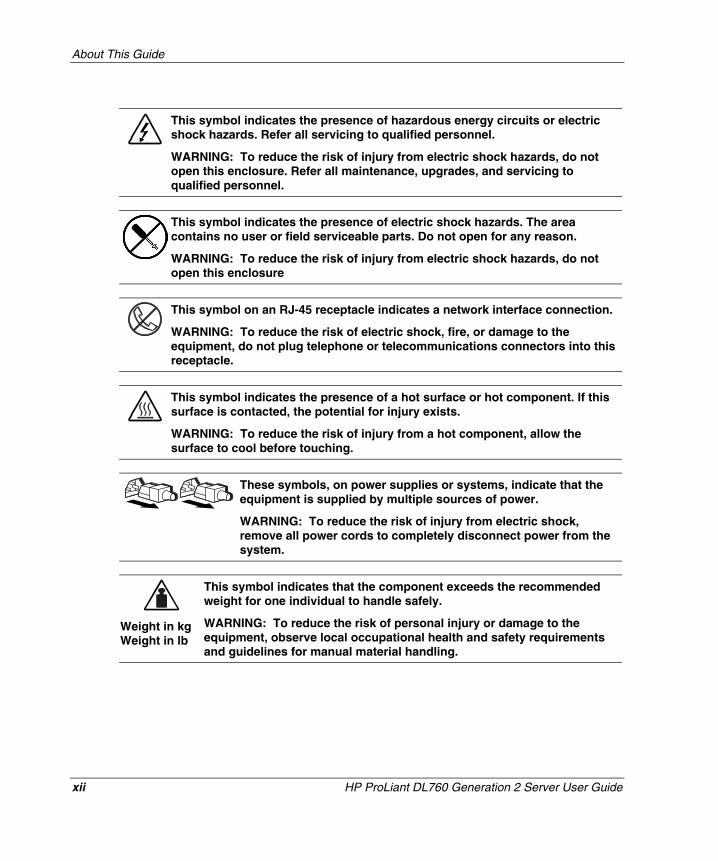
This symbol indicates the presence of hazardous energy circuits or electric shock hazards. Refer all servicing to qualified personnel.
WARNING: To reduce the risk of injury from electric shock hazards, do not open this enclosure. Refer all maintenance, upgrades, and servicing to qualified personnel.
This symbol indicates the presence of electric shock hazards. The area contains no user or field serviceable parts. Do not open for any reason.
WARNING: To reduce the risk of injury from electric shock hazards, do not open this enclosure
This symbol on an RJ-45 receptacle indicates a network interface connection.
WARNING: To reduce the risk of electric shock, fire, or damage to the equipment, do not plug telephone or telecommunications connectors into this receptacle.
This symbol indicates the presence of a hot surface or hot component. If this surface is contacted, the potential for injury exists.
WARNING: To reduce the risk of injury from a hot component, allow the surface to cool before touching.
These symbols, on power supplies or systems, indicate that the equipment is supplied by multiple sources of power.
WARNING: To reduce the risk of injury from electric shock, remove all power cords to completely disconnect power from the system.
Weight in kg Weight in lb
This symbol indicates that the component exceeds the recommended weight for one individual to handle safely.
WARNING: To reduce the risk of personal injury or damage to the equipment, observe local occupational health and safety requirements and guidelines for manual material handling.
xii HP ProLiant DL760 Generation 2 Server User Guide
HP CONFIDENTIAL Writer: Jennifer Hayward File Name: a-frnt.doc
Codename: Pioneer Part Number: 201264-002 Last Saved On: 6/16/03 1:40 PM
About This Guide
Rack Stability
WARNING: To reduce the risk of personal injury or damage to the equipment, be sure that:
• The leveling jacks are extended to the floor.
• The full weight of the rack rests on the leveling jacks.
• The stabilizing feet are attached to the rack if it is a single-rack installation.
• The racks are coupled together in multiple-rack installations.
• Only one component is extended at a time. A rack may become unstable if more than one component is extended for any reason.
Symbols in Text
These symbols may be found in the text of this guide. They have the following meanings.
WARNING: Text set off in this manner indicates that failure to follow directions in the warning could result in bodily harm or loss of life.
CAUTION: Text set off in this manner indicates that failure to follow directions could result in damage to equipment or loss of information.
IMPORTANT: Text set off in this manner presents essential information to explain a concept or complete a task.
NOTE: Text set off in this manner presents additional information to emphasize or supplement important points of the main text.
HP ProLiant DL760 Generation 2 Server User Guide xiii
HP CONFIDENTIAL Writer: Jennifer Hayward File Name: a-frnt.doc
Codename: Pioneer Part Number: 201264-002 Last Saved On: 6/16/03 1:40 PM
About This Guide
Hood Labels and Indicators
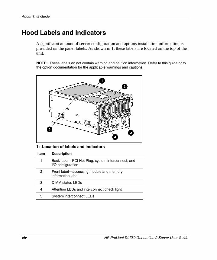
A significant amount of server configuration and options installation information is provided on the panel labels. As shown in 1, these labels are located on the top of the unit.
NOTE: These labels do not contain warning and caution information. Refer to this guide or to the option documentation for the applicable warnings and cautions.
1: Location of labels and indicators
Item Description
1 Back label—PCI Hot Plug, system interconnect, and I/O configuration
2 Front label—accessing module and memory information label
3 DIMM status LEDs
4 Attention LEDs and interconnect check light
5 System interconnect LEDs
xiv HP ProLiant DL760 Generation 2 Server User Guide
HP CONFIDENTIAL Writer: Jennifer Hayward File Name: a-frnt.doc
Codename: Pioneer Part Number: 201264-002 Last Saved On: 6/16/03 1:40 PM
About This Guide
Related Documents
For additional information on the topics covered in this guide, refer to the following documentation:
• Rack Resource Kits are included with the racks and include the following (depending on rack model):
— Rack Products Documentation CD—Available on the HP website or included with the Rack Resource Kit.
— 10000 Series Rack Resource Kit—Included with all HP 10000 Series racks.
— 9000 Series Products Audio-Visual (AV) CD Kit—Included with the Compaq branded 9000 Series Rack Resource Kit.
— The Rack 7000/4000 Series Rack Resource Kit—Included with all Compaq branded 7000 and 4000 Series racks.
— Rack Builder Online—Available on the HP website. Instructions on how to access and use this online tool are included in the Rack Resource Kit.
• Documentation included on the Documentation CD:
— Smart Array 5i Controller User Guide
— ROM-Based Setup Utility User Guide
— HP Servers Troubleshooting Guide
— PCI Hot Plug Administration Guide
— Remote Insight Lights-Out Edition II User Guide
• HP ProLiant DL760 G2 Power Calculator—Available on the ActiveAnswers website at
activeanswers.compaq.com
HP ProLiant DL760 Generation 2 Server User Guide xv
HP CONFIDENTIAL Writer: Jennifer Hayward File Name: a-frnt.doc
Codename: Pioneer Part Number: 201264-002 Last Saved On: 6/16/03 1:40 PM
About This Guide
Getting Help
If you have a problem and have exhausted the information in this guide, you can get further information and other help in the following locations.
Technical Support
In North America, call the HP Technical Support Phone Center at 1-800-652-6672. This service is available 24 hours a day, 7 days a week. For continuous quality improvement, calls may be recorded or monitored. Outside North America, call the nearest HP Technical Support Phone Center. Telephone numbers for worldwide Technical Support Centers are listed on the HP website, www.hp.com.
Be sure to have the following information available before you call HP:
• Technical support registration number (if applicable)
• Product serial number
• Product model name and number
• Applicable error messages
• Add-on boards or hardware
• Third-party hardware or software
• Operating system type and revision level
HP Website
The HP website has information on this product as well as the latest drivers and flash ROM images. You can access the HP website at www.hp.com.
xvi HP ProLiant DL760 Generation 2 Server User Guide
HP CONFIDENTIAL Writer: Jennifer Hayward File Name: a-frnt.doc
Codename: Pioneer Part Number: 201264-002 Last Saved On: 6/16/03 1:40 PM
About This Guide
Authorized Reseller
For the name of your nearest authorized reseller:
• In the United States, call 1-800-345-1518.
• In Canada, call 1-800-263-5868.
• Elsewhere, see the HP website for locations and telephone numbers.
Optional Installation Service
You may choose to have HP install your system. The installation service can be purchased as a CarePaq packaged service or as a customized service agreement to meet your specific requirements. CarePaq services include:
• CarePaq Installation Services for Hardware
• CarePaq Installation and Start-up Services for Microsoft Windows 2000 and Windows NT
• CarePaq Installation and Start-up Services for Insight Manager 7
Visit the HP website for detailed descriptions of these CarePaq services. This installation method helps ensure top performance from the start and is especially valuable for business-critical environments.
HP ProLiant DL760 Generation 2 Server User Guide xvii
HP CONFIDENTIAL Writer: Jennifer Hayward File Name: a-frnt.doc
Codename: Pioneer Part Number: 201264-002 Last Saved On: 6/16/03 1:40 PM
About This Guide
The optional hardware installation service is available in all countries where HP has a direct or indirect service presence. Service may be ordered from and directly provided by an HP authorized service reseller or, in the United States only, service may be ordered by calling 1-800-652-6672. In the United States, HP makes all of the arrangements to have the system installed by qualified guaranteed service providers.
For U.S. ordering information, refer to
www.compaq.com/services/carepaq/us/install
For worldwide ordering information, refer to
www.compaq.com/services/carepaq/global
Reader’s Comments
HP welcomes your comments on this guide. Please send your comments and suggestions by e-mail to [email protected].
xviii HP ProLiant DL760 Generation 2 Server User Guide
HP CONFIDENTIAL Writer: Jennifer Hayward File Name: a-frnt.doc
Codename: Pioneer Part Number: 201264-002 Last Saved On: 6/16/03 1:40 PM
1 Server Features
HP ProLiant DL760 Generation 2 Servers
The HP ProLiant DL760 Generation 2 (G2) server, a high-density enterprise-class and data center server, delivers 8-way scalable performance for 24 x 7 multiserver rack environments. The ProLiant DL760 G2 server, which is based on HP F8 architecture, delivers this performance through Intel® Xeon processor MP technology, scalable performance of I/O and memory, and high levels of fault tolerance and manageability for the data center.
• Performance is maximized with up to eight Intel Xeon processors MP with Hyper-Threading technology.
• The ProLiant DL760 G2 server is equipped with Hot Plug RAID Memory. This new technology allows industry-standard DIMMs to be replaced, added, or upgraded while the server is running.
• Up to 40 GB of Hot Plug RAID Memory using industry-standard PC133 SDRAM DIMMs (32 GB of addressable memory).
• Ten 64-bit PCI-X slots operating at 100 MHz and one 64-bit PCI slot operating at 33 MHz feature PCI Hot Plug capability.
• Drive performance is enhanced with a Smart Array 5i Controller and Ultra3 hard drives.
HP ProLiant DL760 Generation 2 Server User Guide 1-1
HP CONFIDENTIAL Writer: Jennifer Hayward File Name: b-ch1 Server Features.doc
Codename: Pioneer Part Number: 201264-002 Last Saved On: 6/16/03 1:43 PM
Server Features
Overview
This chapter provides an overview of the HP ProLiant DL760 G2 server features and briefly describes its maximum performance, high-availability, server management, and serviceability features.
Key redundancy and hot-plug features create a high-availability environment:
• Hot Plug RAID Memory
• Redundant array of memory with error checking and correcting (ECC) and multibit error (MBE) correction
• Fault-tolerant integrated Processor Power Module (PPM)
• PCI Hot Plug slots
• Fault-tolerant hot-pluggable power supplies
• Fault-tolerant hot-pluggable fans
• Fault-tolerant network interface controller (NIC) support
• Smart Array 5i Controller
• Disk drive fault tolerance
• Redundant ROM images
• Automatic Server Recovery-2 (ASR-2)
1-2 HP ProLiant DL760 Generation 2 Server User Guide
HP CONFIDENTIAL Writer: Jennifer Hayward File Name: b-ch1 Server Features.doc
Codename: Pioneer Part Number: 201264-002 Last Saved On: 6/16/03 1:43 PM
Server Features
The ProLiant DL760 G2 server also features management and configuration tools that are the hallmark of ProLiant servers:
• ProLiant Essentials software
• ProLiant Essentials scripting
• ROM-Based Setup Utility (RBSU)
• Preboot eXecution Environment (PXE)
• Remote-Flash Redundant ROM
• Insight Manager 7
• ASR-2
• Integrated Management Log (IML)
• Hot Plug RAID Memory interface—diagnostic LEDs and caution alarm
• System interconnect status indicators
• Survey Utility
• Online ROM Flash
In ProLiant DL760 G2 servers, you can access options and accessories easily through a sliding I/O lid and three removable modules: the processor and memory module, the media module, and the I/O module. Refer to Figure 1-1, Figure 1-2, and Figure 1-3 for identification of these modules and other components.
HP ProLiant DL760 Generation 2 Server User Guide 1-3
HP CONFIDENTIAL Writer: Jennifer Hayward File Name: b-ch1 Server Features.doc
Codename: Pioneer Part Number: 201264-002 Last Saved On: 6/16/03 1:43 PM
Server Features
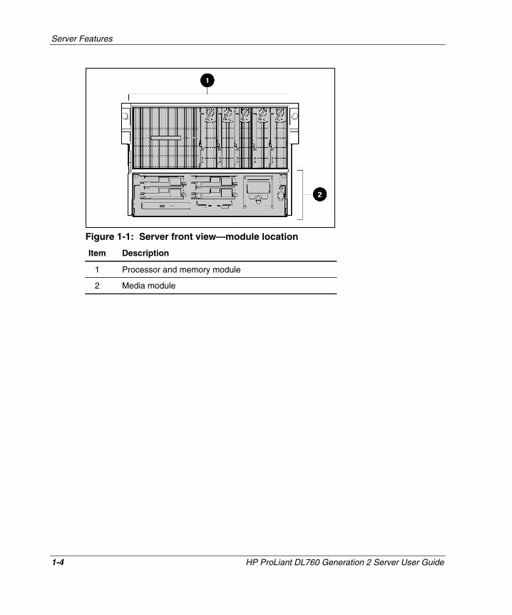
Figure 1-1: Server front view—module location
Item Description
1 Processor and memory module
2 Media module
1-4 HP ProLiant DL760 Generation 2 Server User Guide
HP CONFIDENTIAL Writer: Jennifer Hayward File Name: b-ch1 Server Features.doc
Codename: Pioneer Part Number: 201264-002 Last Saved On: 6/16/03 1:43 PM
Server Features
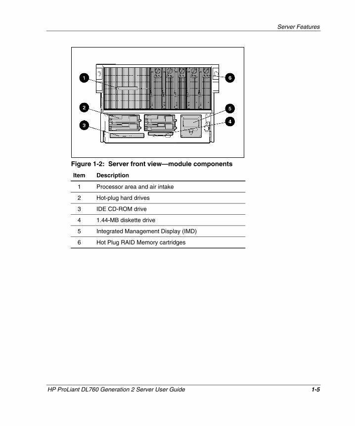
Figure 1-2: Server front view—module components
Item Description
1 Processor area and air intake
2 Hot-plug hard drives
3 IDE CD-ROM drive
4 1.44-MB diskette drive
5 Integrated Management Display (IMD)
6 Hot Plug RAID Memory cartridges
HP ProLiant DL760 Generation 2 Server User Guide 1-5
HP CONFIDENTIAL Writer: Jennifer Hayward File Name: b-ch1 Server Features.doc
Codename: Pioneer Part Number: 201264-002 Last Saved On: 6/16/03 1:43 PM
Server Features
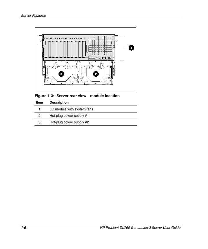
Figure 1-3: Server rear view—module location
Item Description
1 I/O module with system fans
2 Hot-plug power supply #1
3 Hot-plug power supply #2
1-6 HP ProLiant DL760 Generation 2 Server User Guide
HP CONFIDENTIAL Writer: Jennifer Hayward File Name: b-ch1 Server Features.doc
Codename: Pioneer Part Number: 201264-002 Last Saved On: 6/16/03 1:43 PM
Server Features
Standard Features
The following additional features are available on ProLiant DL760 G2 server models.
Processors
The server supports four or eight Intel Xeon processors MP with the following features:
• A 4P server that is easily upgraded to an 8P server
• HP designed ZIF sockets with tool-less actuation and tool-less quick release heat sink clamps
• Keyed, self-aligning heat sink design to protect processor pins and allow for blind mate assembly
• Pre-attached processor heat sink assembly for easy service and optimum thermals without the need for messy greases
• Fault-tolerant integrated processor power
Each of the processor boards has embedded power, front and back covers for enhanced thermals and handling, and a single hand rack-and-pinion lever for blind mate installation in a matter of seconds.
HP ProLiant DL760 Generation 2 Server User Guide 1-7
HP CONFIDENTIAL Writer: Jennifer Hayward File Name: b-ch1 Server Features.doc
Codename: Pioneer Part Number: 201264-002 Last Saved On: 6/16/03 1:43 PM
Server Features
Hyper-Threading technology, developed by Intel, improves the performance of IA-32 processors when executing multiple-processor (MP) capable operating systems and multithreaded applications. With this technology, one physical processor looks like two logical processors to the operating system and applications. The two logical processors can execute two separate tasks (or code streams called threads) concurrently by using shared hardware resources.
Hyper-Threading technology is designed to improve the performance of IA-32 processors by using the multithreaded nature of contemporary operating systems and server applications in such a way as to increase the use of the on-chip execution resources available in the Intel NetBurst microarchitecture. The integrated cache subsystem results in reduced memory access times and increased throughput and performance of the memory subsystem. Specifically, integrated Level 3 cache, which is only available on the Xeon processor MP, provides a high-bandwidth path to memory, increasing throughput for large server workloads.
1-8 HP ProLiant DL760 Generation 2 Server User Guide
HP CONFIDENTIAL Writer: Jennifer Hayward File Name: b-ch1 Server Features.doc
Codename: Pioneer Part Number: 201264-002 Last Saved On: 6/16/03 1:43 PM
Server Features
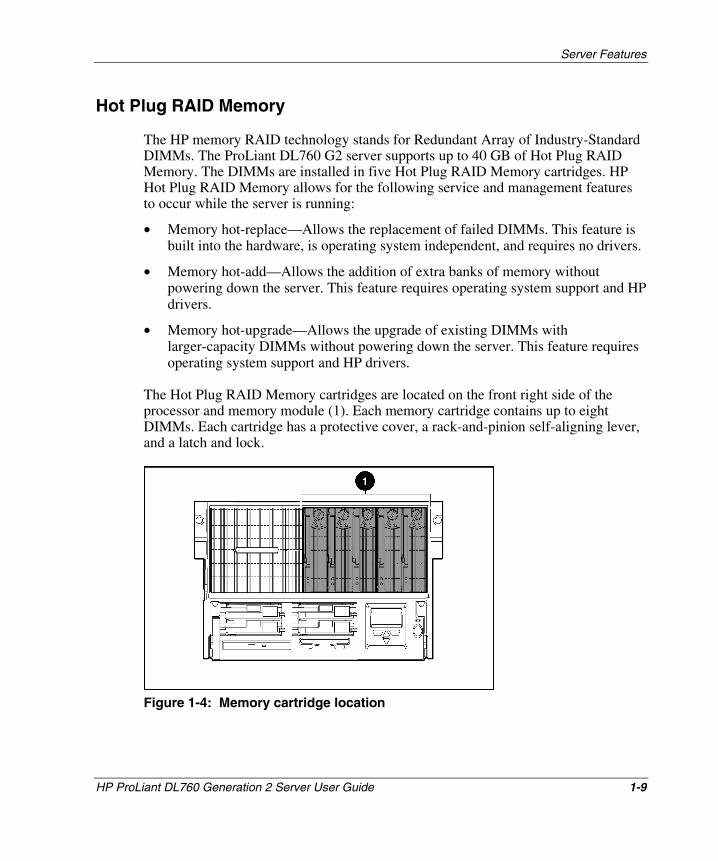
Hot Plug RAID Memory
The HP memory RAID technology stands for Redundant Array of Industry-Standard DIMMs. The ProLiant DL760 G2 server supports up to 40 GB of Hot Plug RAID Memory. The DIMMs are installed in five Hot Plug RAID Memory cartridges. HP Hot Plug RAID Memory allows for the following service and management features to occur while the server is running:
• Memory hot-replace—Allows the replacement of failed DIMMs. This feature is built into the hardware, is operating system independent, and requires no drivers.
• Memory hot-add—Allows the addition of extra banks of memory without powering down the server. This feature requires operating system support and HP drivers.
• Memory hot-upgrade—Allows the upgrade of existing DIMMs with larger-capacity DIMMs without powering down the server. This feature requires operating system support and HP drivers.
The Hot Plug RAID Memory cartridges are located on the front right side of the processor and memory module (1). Each memory cartridge contains up to eight DIMMs. Each cartridge has a protective cover, a rack-and-pinion self-aligning lever, and a latch and lock.
Figure 1-4: Memory cartridge location
HP ProLiant DL760 Generation 2 Server User Guide 1-9
HP CONFIDENTIAL Writer: Jennifer Hayward File Name: b-ch1 Server Features.doc
Codename: Pioneer Part Number: 201264-002 Last Saved On: 6/16/03 1:43 PM
Server Features
The ProLiant DL760 G2 server has eight memory banks, each consisting of five DIMMs installed across the five memory cartridges. In each memory cartridge, similar DIMMs are installed in bank pairs (1+2, 3+4, 5+6, 7+8) for memory interleaving to increase performance.
Basic memory features include:
• ECC memory with single-bit and multibit error (MBE) correction and detection down to the failed DIMM level
• Support for standard ECC 133-MHz registered SDRAM
• Driverless hot-replace functionality
• Expandability to 40 GB of Hot Plug RAID Memory using industry-standard PC133 SDRAM DIMMs (32 GB of addressable memory)
• Support for up to eight memory banks, with each bank consisting of five DIMMs (one DIMM is for redundancy):
— Each DIMM of a given bank must be of the same size, type, and speed.
— DIMMs are populated in bank pairs for interleaved operation to increase performance.
NOTE: The DIMM size, type, and speed are defined by the DIMM part number. All DIMMs in a bank must have the same part number, as indicated by the following example:
123456-12x
All numbers except the last (designated by x) must match for DIMMs to be considered the same.
• Front-loadable and lockable memory cartridge
• Cartridge and DIMM diagnostic information
1-10 HP ProLiant DL760 Generation 2 Server User Guide
HP CONFIDENTIAL Writer: Jennifer Hayward File Name: b-ch1 Server Features.doc
Codename: Pioneer Part Number: 201264-002 Last Saved On: 6/16/03 1:43 PM
Server Features
PCI-X Technology
PCI-X technology leverages the wide acceptance of the PCI bus and provides an evolutionary I/O upgrade to conventional PCI. PCI-X technology enhances the PCI protocol and frequency to meet bandwidth needs of enterprise computing systems. PCI-X provides backward compatibility with the PCI bus at both the expansion board and system level.
Expansion Slots
The ProLiant DL760 G2 server has ten 64-bit PCI-X expansion slots operating at 100 MHz and one 64-bit PCI expansion slot operating at 33 MHz.
• Slots 1 and 2 (bus 19) support PCI-X expansion boards at 100 MHz and 66 MHz or PCI expansion boards at 66 MHz and 33 MHz; it is keyed for 3.3v signaling.
• Slots 3 and 4 (bus 13) support PCI-X expansion boards at 100 MHz and 66 MHz or PCI expansion boards at 66 MHz and 33 MHz; it is keyed for 3.3v signaling.
• Slots 5 and 6 (bus 11) support PCI-X expansion boards at 100 MHz and 66 MHz or PCI expansion boards at 66 MHz and 33 MHz; it is keyed for 3.3v signaling.
• Slots 7 and 8 (bus 7) support PCI-X expansion boards at 100 MHz and 66 MHz or PCI expansion boards at 66 MHz and 33 MHz; it is keyed for 3.3v signaling.
• Slot 9 (bus 0) supports PCI expansion boards at 33 MHz; it is keyed for 5v signaling.
• Slots 10 and 11 (bus 3) support PCI-X expansion boards at 100 MHz and 66 MHz or PCI expansion boards at 66 MHz and 33 MHz; it is keyed for 3.3v signaling.
NOTE: The operating system detects PCI devices in the following slot order: 9-10-11-7-8-5-6-3-4-1-2.
NOTE: The ProLiant DL760 G2 server ships with the NIC preinstalled in slot 11.
NOTE: It is recommended that you install the optional RILOE II board into slot 9.
HP ProLiant DL760 Generation 2 Server User Guide 1-11
HP CONFIDENTIAL Writer: Jennifer Hayward File Name: b-ch1 Server Features.doc
Codename: Pioneer Part Number: 201264-002 Last Saved On: 6/16/03 1:43 PM
Server Features
PCI Hot Plug
PCI Hot Plug provides the ability to remove, replace, upgrade, and add PCI/PCI-X expansion boards without powering down the server. PCI and PCI-X boards can be placed in a PCI Hot Plug slot. PCI Hot Plug device drivers and operating system support are required to enable PCI Hot Plug.
A PCI Hot Plug button is located above each PCI/PCI-X slot, providing PCI Hot Plug control directly at the server without the use of the PCI Hot Plug utility software.
For more information about PCI Hot Plug, refer to the server Documentation CD.
Network Interface Controller
The ProLiant DL760 G2 server ships with an NC7770 PCI-X Gigabit NIC pre-installed in slot 11. This 10/100/1000 Base TX UTP, 64-bit, 133-MHz PCI-X NIC includes the following features:
• One RJ-45 connector for 10BaseT, 100BaseTX, or 1000BaseTX Ethernet
• Pre-boot eXecution Environment (PXE) support
For information about the NIC, refer to the HP website:
www.hp.com
Redundant NIC software, located on the SmartStart CD, supports a redundant NIC configuration. This feature may be used with one dual-port, two single-port, or two dual-port NICs.
1-12 HP ProLiant DL760 Generation 2 Server User Guide
HP CONFIDENTIAL Writer: Jennifer Hayward File Name: b-ch1 Server Features.doc
Codename: Pioneer Part Number: 201264-002 Last Saved On: 6/16/03 1:43 PM
Server Features
Disk Controller
The ProLiant DL760 G2 server provides an embedded dual-channel Smart Array 5i Controller. One channel is dedicated to the internal drive bays, and the other channel is connected to the external VHDCI SCSI connector. Refer to Chapter 8 for descriptions of the features and array setup procedures for the controller. The disk controller has 32 MB of read data cache.
The Smart Array 5i Controller supports Ultra3 or Ultra320 SCSI hard drives. Ultra3 is a high-performance SCSI technology that offers data transfer speeds of up to 160 MB/sec. It is a term that is synonymous with Ultra160 SCSI and describes any device that combines Ultra2 SCSI with Cyclic Redundancy Check (CRC), domain validation, and double transition clocking. HP Ultra3 universal hot-pluggable hard drives provide this level of performance in addition to compatibility with ProLiant servers, AlphaServers, and StorageWorks Enclosure 4200 solutions.
Ultra320 hard drives will run at Ultra3 speeds unless you install an optional Ultra320 Array Controller and the Twisted Pair Cable Array Bypass kit included with the system.
NOTE: ProLiant DL760 servers that have been upgraded to ProLiant DL760 Generation 2 servers will run internal hard drives up to Ultra3 speeds regardless of the capability of the drive.
Internal Hot-Plug Drive Bays
The internal hot-plug drive bays support four 1-inch Ultra3 SCSI hard drives. Drives may be of any storage capacity but must be mounted on HP universal drive carriers (hot-plug drive trays). The internal drive bays also support the StorageWorks Hot-Plug Tape Drive, which takes up two hot-plug drive bays in the media module.
Fixed Internal Media Drive Bays
The fixed internal media drive bays support two non-hot-plug media drives:
• 1.44-MB diskette drive
HP ProLiant DL760 Generation 2 Server User Guide 1-13
HP CONFIDENTIAL Writer: Jennifer Hayward File Name: b-ch1 Server Features.doc
Codename: Pioneer Part Number: 201264-002 Last Saved On: 6/16/03 1:43 PM
• IDE CD-ROM drive
Server Features
Video
The HP Integrated PCI Video Controller with 8 MB of video RAM can obtain a maximum resolution of 1280 x 1024 in 32-bit true color. The PCI video controller supports:
• From 16 to more than 256 colors, depending on graphics mode.
• SVGA, VGA, and EGA graphics resolution.
Redundant Hot-Plug Power Supplies
The ProLiant DL760 G2 server supports 1150-W redundant hot-plug power supplies.
WARNING: Hot-plug power supplies are not designed to be installed with AC current connected to the power supply. To prevent personal injury or damage to the equipment, be sure to disconnect the power supply from AC current before removal or installation of the power supply.
• Power supplies are load balancing and have microcontroller monitoring for advanced health and configuration management.
• The ProLiant DL760 G2 server supports up to two power supplies. Refer to the “Power Requirements” section of Chapter 2 to determine power supply requirements.
CAUTION: To prevent data corruption, do not connect the server to a low line power source (110 VAC). Low line power is not supported.
IMPORTANT: Most system configurations require 200-240 VAC. Use 200-240 VAC line cords to power the server.
NOTE: A few server configurations may exceed the power rating of a single power supply, resulting in a loss of power redundancy for the server. Use the ProLiant DL760 G2 Power Calculator available on ActiveAnswers to ensure that power redundancy will be maintained for your configuration.
1-14 HP ProLiant DL760 Generation 2 Server User Guide
HP CONFIDENTIAL Writer: Jennifer Hayward File Name: b-ch1 Server Features.doc
Codename: Pioneer Part Number: 201264-002 Last Saved On: 6/16/03 1:43 PM
Server Features
Redundant Hot-Plug Fans
ProLiant DL760 G2 servers include 1 + 1 redundant hot-plug fans. If a fan fails, the server generates a system alert and the remaining fan increases speed automatically to cool the system by itself indefinitely. The redundant hot-plug system fans protect the various server components from overheating and possibly causing a system interruption.
These custom-designed fans were developed using military, aviation, and satellite application technology. Fine-tuned for everyday acoustic operation in the server, a single fan can handle the most thermally adverse data center environments.
Both fans come equipped with keyed, rugged, thermally optimized, and blind mate housing, yet only require one finger to install or release. Diagnostic LEDs exist on each fan and on the front of the server. For more information on the hot-plug fan LEDs, refer to Appendix D.
Supported Interfaces
Supported interfaces that ship standard in the server include:
• Ultra SCSI VHDCI connector
• Serial connector
• Video port
• Keyboard connector
• Mouse connector
• RJ-45 Server LAN connection
HP ProLiant DL760 Generation 2 Server User Guide 1-15
HP CONFIDENTIAL Writer: Jennifer Hayward File Name: b-ch1 Server Features.doc
Codename: Pioneer Part Number: 201264-002 Last Saved On: 6/16/03 1:43 PM
Server Features
Optional Features
The ProLiant DL760 G2 server supports a wide range of server hardware options. HP server options are available from an HP authorized reseller or HP authorized service provider. Additional information about HP servers and options can be found in the QuickSpecs on the HP website.
This guide also provides basic installation instructions for the following server options:
• Dual Inline Memory Modules (DIMMs)
• Processor board with Intel Xeon processors MP
• Hot-plug Ultra3 or Ultra320 SCSI hard drives
• I/O expansion boards (including PCI and PCI-X expansion boards with PCI Hot Plug driver support)
• Intelligent Fibre Channel HBAs
• Remote Insight Lights-Out Edition II
• Integrated Smart Array Bypass Kit (included with the server)
• Smart Array controllers
NOTE: Hardware options installation instructions can be found inside each hardware option kit.
Supported Operating Systems
For a list of operating systems that are supported on the ProLiant DL760 G2 server, refer to the ProLiant OS Support Matrix located on the Web:
ftp://ftp.compaq.com/pub/products/servers/os-support-matrix-310.pdf
1-16 HP ProLiant DL760 Generation 2 Server User Guide
HP CONFIDENTIAL Writer: Jennifer Hayward File Name: b-ch1 Server Features.doc
Codename: Pioneer Part Number: 201264-002 Last Saved On: 6/16/03 1:43 PM
Server Features
Server Configuration and Management Features
HP offers an extensive set of features and tools to support effective server configuration and management, including:
• SmartStart
• RBSU
• Remote-Flash Redundant ROM
• Advanced data guarding (RAID ADG)
• HP utilities for Microsoft Windows
• HP utilities for Caldera OpenUNIX 8
• HP utilities for Linux
• Insight Manager 7
• HP Web-Enabled Server Management
• IML
• Integrated Management Display (IMD)
SmartStart
SmartStart, which is located on the SmartStart CD, allows you to configure your HP server and load operating system software. SmartStart uses a step-by-step process to configure the server and to load the system software, thereby achieving a well-integrated server to ensure maximum dependability and supportability.
For information about SmartStart, refer to the ProLiant Essentials Foundation Pack included in the shipping box.
HP ProLiant DL760 Generation 2 Server User Guide 1-17
HP CONFIDENTIAL Writer: Jennifer Hayward File Name: b-ch1 Server Features.doc
Codename: Pioneer Part Number: 201264-002 Last Saved On: 6/16/03 1:43 PM
Server Features
ROM-Based Setup Utility
The ROM-Based Setup Utility (RBSU) automatically configures the system based on the selected operating system. RBSU supports a wide range of configuration customization features, including:
• Selection of a primary operating system from a list of supported operating systems
• Selection of a Primary Boot Controller from a list of installed mass storage devices
• Configuration of embedded system devices, such as serial and mouse ports
• Configuration of standard interrupts (IRQs) for PCI devices
• Setting of date and time
• Configuration of IMD and system asset text
• Automatic resolution of resource conflicts in areas such as port addresses and interrupts (IRQs)
• Storage of configuration in nonvolatile memory
The RBSU is preinstalled in the embedded system ROM on the server. The RBSU has embedded support for English, French, German, Italian, Spanish, and Japanese languages.
NOTE: Systems that use RBSU do not support the System Configuration Utility. For additional information on using RBSU, refer to the ROM-Based Setup Utility User Guide located on the Documentation CD.
Remote-Flash Redundant ROM
This server is equipped with a Remote-Flash Redundant ROM that enables the system to recover the last known good system ROM if the current system ROM has been corrupted. When the server leaves the factory, both system ROMs contain the same image.
1-18 HP ProLiant DL760 Generation 2 Server User Guide
HP CONFIDENTIAL Writer: Jennifer Hayward File Name: b-ch1 Server Features.doc
Codename: Pioneer Part Number: 201264-002 Last Saved On: 6/16/03 1:43 PM
Server Features
Smart Components for Online ROM Flash
Online ROM flash technology consists of a combination of components that allow system administrators to upgrade system or option ROM images across a wide range of HP servers and server options while the server is running. The ROM upgrades are performed locally or across a network from a single point of execution and are flashed individually or grouped together to perform multiple ROM upgrades in a single step.
HP Smart Components for ROM Flash include installation logic that automatically checks for hardware, firmware, and operating system dependencies, installing only the correct ROM upgrades required by each target server.
Advanced Data Guarding
As storage capacities continue to rapidly expand, disk drive fault protection becomes more important. This fault protection needs to be implemented without doubling the investment in disk drives or a new storage infrastructure. Currently, RAID 5 is only recommended for protecting up to 14 disk drives in an array. RAID 1 provides greater fault protection, but requires every drive to be mirrored, so it is often too costly to implement on large RAID volumes.
With Advanced Data Guarding (RAID ADG), you can safely and economically protect a RAID volume of up to 2 TB and a total of 56 disk drives. RAID ADG offers fault protection greater than RAID 1 or RAID 5 and only consumes the capacity of one additional disk drive for each distributed parity data drive.
RAID ADG is essentially an extension of RAID 5, which allows for additional fault tolerance by using a second independent distributed parity scheme. Data is striped across a set of drives, just as in RAID 5, and a second set of parity is calculated and written across all the drives. RAID ADG provides for an extremely high data fault tolerance and can sustain multiple simultaneous drive failures. This solution is very important for protecting mission-critical data.
Only the Smart Array 5300 Controllers support RAID ADG. The Smart Array 5304/128 is shipped with RAID ADG and is available as an upgrade option for the
HP ProLiant DL760 Generation 2 Server User Guide 1-19
HP CONFIDENTIAL Writer: Jennifer Hayward File Name: b-ch1 Server Features.doc
Codename: Pioneer Part Number: 201264-002 Last Saved On: 6/16/03 1:43 PM
Server Features
Smart Array 5302/32 and 5302/64. This new Advanced RAID level offers dramatically higher fault tolerance than RAID 5 with lower implementation costs than RAID 1.
For further details on RAID ADG, refer to the storage controller documentation at
www.compaq.com/products/servers/proliantstorage/arraycontrollers/ docs/index.html#tech
HP Utilities for Microsoft Windows
HP servers running Windows can use the following utilities:
• Array Configuration Utility
• Power Supply Viewer
• Integrated Management Log Viewer
• Integrated Management Display Utility
• Management Agents
These utilities are provided on the ProLiant Support Pack for Microsoft Windows 2000 and the ProLiant Support Pack for Microsoft Windows Server 2003.
HP Utilities for Caldera OpenUNIX 8 or SCO UnixWare 7.1.3
HP servers running Caldera OpenUNIX 8 or SCO UnixWare 7.1.3 can use the following utilities:
• Array Configuration Utility
• PCI Hot Plug Utility
• Integrated Management Log Viewer
• Integrated Management Display Utility
• Management Agents
1-20 HP ProLiant DL760 Generation 2 Server User Guide
HP CONFIDENTIAL Writer: Jennifer Hayward File Name: b-ch1 Server Features.doc
Codename: Pioneer Part Number: 201264-002 Last Saved On: 6/16/03 1:43 PM
These utilities are provided as part of the HP Extended Feature Supplement (EFS). The EFS is available on the SmartStart CD.
Server Features
HP Utilities for Linux
HP servers running Linux can take advantage of several utilities that provide detailed system information, including:
• Array Configuration Utility for Linux
• Compaq Storage Agents for Linux
• Insight Diagnostics
• Lights-Out Drivers and Agents for Linux
• NIC Agents for Linux
• Red Hat GL Utility Toolkit (GLUT)
• Server Management Drivers and Agents
These utilities are provided on the ProLiant Support Pack for Linux operating system.
HP has an array of Opensource projects for Linux. For more information on HP Opensource projects refer to
opensource.hp.com/
HP only supports servers configured with certified Linux operating system versions found on the Linux server certification matrix website:
h18000.www1.hp.com/products/servers/linux/hplinuxcert.html
Insight Manager 7
Insight Manager 7 is a systems management tool that provides performance, configuration, and fault management for HP servers and clients. Insight Manager 7 has two components:
• Insight Manager 7 software, which runs on the management console
• Management Agents (operating system-specific), which run on a server or managed desktop client
HP ProLiant DL760 Generation 2 Server User Guide 1-21
HP CONFIDENTIAL Writer: Jennifer Hayward File Name: b-ch1 Server Features.doc
Codename: Pioneer Part Number: 201264-002 Last Saved On: 6/16/03 1:43 PM
Server Features
Insight Manager 7 features an easy-to-use graphical interface and includes online documentation and context-sensitive help. Key features include:
• Server fault condition alerts
• Server performance and fault condition monitoring
• Server security and configuration control
• Remote control of the server
• Rapid recovery services
For more information on Insight Manager 7, refer to the Management CD that shipped with your server.
1-22 HP ProLiant DL760 Generation 2 Server User Guide
HP CONFIDENTIAL Writer: Jennifer Hayward File Name: b-ch1 Server Features.doc
Codename: Pioneer Part Number: 201264-002 Last Saved On: 6/16/03 1:43 PM
Server Features
Integrated Management Log
The IML records all system events and stores them in an easily viewable form. These events are recorded and marked with a time stamp. For more information about the IML, refer to Chapter 9.
Integrated Management Display
The Integrated Management Display (IMD) is a server management tool that provides fault information, service, and configuration capabilities in an easy-to-use, integrated hardware display. IMD features include:
• Power-On Self-Test (POST) messages
• User-defined administrative information
• Configuration information
• System alerts and event descriptions
For more information about the IMD, refer to Chapter 9.
HP ProLiant DL760 Generation 2 Server User Guide 1-23
HP CONFIDENTIAL Writer: Jennifer Hayward File Name: b-ch1 Server Features.doc
Codename: Pioneer Part Number: 201264-002 Last Saved On: 6/16/03 1:43 PM
Server Features
Diagnostic Tools
Software, firmware, and hardware diagnostic features of the ProLiant DL760 G2 server include:
• Diagnostic LED indicators that are all viewable from the exterior of the server
• Diagnostic alarms that are audible from the exterior
• POST messages
• Memory Configuration Manager
• Server Diagnostics Utility
• ROMPaq utilities to upgrade flash ROMs
• Array Configuration Utility (ACU)
• IMD
• IML
For information about HP diagnostic tools, refer to Appendix E or to the HP Servers Troubleshooting Guide on the Documentation CD.
1-24 HP ProLiant DL760 Generation 2 Server User Guide
HP CONFIDENTIAL Writer: Jennifer Hayward File Name: b-ch1 Server Features.doc
Codename: Pioneer Part Number: 201264-002 Last Saved On: 6/16/03 1:43 PM
Server Features
Security Features
The following sections outline the security features available for the ProLiant DL760 G2 server.
Software Security
The following software security features are established through the ROM-Based Setup Utility:
• Administrator password—Prevents changes to the configuration unless you enter the password.
• Diskette drive control—Enables and disables the diskette drive. When disabled, the diskette drive will not read, write, or boot.
• Diskette write control—Enables and disables diskette write functions. When disabled, the drive will not write, but boot and read functions are still available.
• Power-on password—Locks out the keyboard to prevent unauthorized access to HP servers. The keyboard lockout prevents logins or commands until the proper password is entered.
• Network server mode—Permits system startups from a hard disk or network server while the keyboard and mouse are disabled.
• QuickLock—Disables the keyboard and mouse without exiting the application. The application remains in view on the monitor screen, but cannot be accessed.
• Serial interface control—Disables the serial port. When disabled, all data transfer through the integrated serial port is blocked.
HP ProLiant DL760 Generation 2 Server User Guide 1-25
HP CONFIDENTIAL Writer: Jennifer Hayward File Name: b-ch1 Server Features.doc
Codename: Pioneer Part Number: 201264-002 Last Saved On: 6/16/03 1:43 PM
Server Features
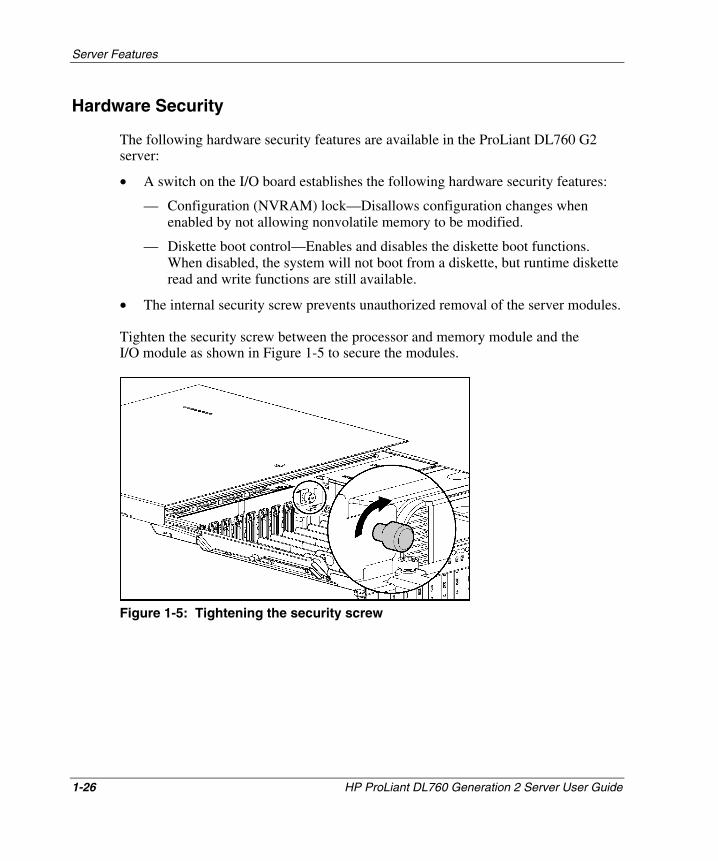
Hardware Security
The following hardware security features are available in the ProLiant DL760 G2 server:
• A switch on the I/O board establishes the following hardware security features:
— Configuration (NVRAM) lock—Disallows configuration changes when enabled by not allowing nonvolatile memory to be modified.
— Diskette boot control—Enables and disables the diskette boot functions. When disabled, the system will not boot from a diskette, but runtime diskette read and write functions are still available.
• The internal security screw prevents unauthorized removal of the server modules.
Tighten the security screw between the processor and memory module and the I/O module as shown in Figure 1-5 to secure the modules.
Figure 1-5: Tightening the security screw
1-26 HP ProLiant DL760 Generation 2 Server User Guide
HP CONFIDENTIAL Writer: Jennifer Hayward File Name: b-ch1 Server Features.doc
Codename: Pioneer Part Number: 201264-002 Last Saved On: 6/16/03 1:43 PM
Server Features
HP ProLiant DL760 Generation 2 Server User Guide 1-27
HP CONFIDENTIAL Writer: Jennifer Hayward File Name: b-ch1 Server Features.doc
Codename: Pioneer Part Number: 201264-002 Last Saved On: 6/16/03 1:43 PM
Server Registration
Registering your server provides HP with valuable information about server installation. This information helps HP better serve customer needs. To register your server, visit the HP website:
www.compaq.com/register
Customers can register to receive Product Change Notifications (PCN) at:
web14.compaq.com/pcn/login.asp?ru=/pcn/index.asp&
Customers can also register with the ActiveUpdate page to receive software component delivery:
www.compaq.com/products/servers/management/activeupdate
Routine Maintenance
For information about routine maintenance and safety precautions, refer to the Documentation CD included with your server.
Warranty • Three-Year Parts, Labor, and On-Site Limited Warranty with next business day
response
• Pre-Failure Warranty on processors, memory, and hard drives (requires installation of Insight Manager 7)
• For additional service and support offerings, visit the HP website:
www.hp.com
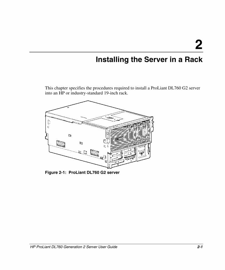
2 Installing the Server in a Rack
This chapter specifies the procedures required to install a ProLiant DL760 G2 server into an HP or industry-standard 19-inch rack.
Figure 2-1: ProLiant DL760 G2 server
HP ProLiant DL760 Generation 2 Server User Guide 2-1
HP CONFIDENTIAL Writer: Jennifer Hayward File Name: c-ch2 Installing the Server in a Rack.doc
Codename: Pioneer Part Number: 201264-002 Last Saved On: 6/17/03 9:22 AM
Installing the Server in a Rack
Rack Installation Overview
Installing the ProLiant DL760 G2 server in a rack requires the following steps (detailed later in this chapter):
1. Select a site and unpack the server. Refer to the “Selecting a Site” and “Shipping Box Contents” sections in this chapter.
2. Remove the power supply and I/O module shipping brackets and the shipping screws. Refer to “Removing the Shipping Safeguards” later in this chapter.
3. Remove the processor and memory module, I/O module, media module, and power supplies to lighten the chassis.
4. Install any expansion boards or other options, such as additional memory. Refer to Chapter 4 and Chapter 5 to install many of the major options.
NOTE: If the operating system is preinstalled on the server, refer to the Factory-Installed Operating System Software User Guide that is included with the server.
5. Install the chassis in the rack and replace the modules and power supplies.
NOTE: Refer to the rack template included with the server for more details on installing the server in a rack.
6. Connect the following cables: keyboard, mouse, monitor, network, storage, and power. Refer to Chapter 6 for more information.
2-2 HP ProLiant DL760 Generation 2 Server User Guide
HP CONFIDENTIAL Writer: Jennifer Hayward File Name: c-ch2 Installing the Server in a Rack.doc
Codename: Pioneer Part Number: 201264-002 Last Saved On: 6/17/03 9:22 AM
Installing the Server in a Rack
Selecting a Site
When installing the ProLiant DL760 G2 server in a rack, the following standards must be met:
• Space and airflow requirements
• Power requirements
• Grounding requirements
• Temperature requirements
Space and Airflow Requirements
To allow for servicing and adequate airflow, observe the following spatial requirements when deciding where to install a rack:
• Leave a minimum clearance of 127 cm (50 inches) in front of the rack.
• Leave a minimum clearance of 76.2 cm (30 inches) behind the rack.
• Leave a minimum clearance of 121.9 cm (48 inches) from the back of the rack to the back of another rack or row of racks.
HP servers draw in cool air through the front door and expel warm air through the rear door. Therefore, the front and rear rack doors must be adequately ventilated to allow ambient room air to enter the cabinet, and the rear door must be adequately ventilated to allow the warm air to escape from the cabinet.
CAUTION: To prevent improper cooling and damage to the equipment, do not block the ventilation openings.
When there is vertical space in the rack not filled by a server or rack component, the gaps between the components cause changes in airflow through the rack and across the servers. Cover all gaps with blanking panels to maintain proper airflow.
HP ProLiant DL760 Generation 2 Server User Guide 2-3
HP CONFIDENTIAL Writer: Jennifer Hayward File Name: c-ch2 Installing the Server in a Rack.doc
Codename: Pioneer Part Number: 201264-002 Last Saved On: 6/17/03 9:22 AM
Installing the Server in a Rack
CAUTION: Always use blanking panels to fill empty vertical spaces in the rack. This arrangement ensures proper airflow. Using a rack without blanking panels results in improper cooling that can lead to thermal damage.
Compaq branded 9000 and 10000 Series racks provide proper server cooling from flow-through perforations in the front and rear doors that provide 64 percent open area for ventilation.
CAUTION: If a third-party rack is used, observe the following additional requirements to ensure adequate airflow and to prevent damage to the equipment:
• Front and rear doors—If the 42U server rack includes closing front and rear doors, you must allow 5,350 sq cm (830 square inches) of holes evenly distributed from top to bottom to permit adequate airflow (equivalent to the required 64 percent open area for ventilation).
• Side—The clearance between the installed rack component and the side panels of the rack must be a minimum of 7 cm (2.75 inches).
CAUTION: When using a Compaq branded 7000 Series rack, you must install the high airflow rack door insert [P/N 327281-B21 (42U) or P/N 157847-B21 (22U)] to provide proper front-to-back airflow and cooling.
Power Requirements
WARNING: To reduce the risk of personal injury, fire, or damage to the equipment, do not overload the AC supply branch circuit that provides power to the rack. Consult the electrical authority having jurisdiction over your facility wiring and installation requirements.
IMPORTANT: Because of the 100 to 240 VAC electrical rating of each power supply, some local electrical authorities may require either one 15-Ampere circuit for each power supply or one 20-Ampere circuit for both power supplies.
• The power load needs to be balanced between available AC supply branch circuits.
• The overall system AC current load must not exceed 80 percent of the branch circuit AC current rating.
2-4 HP ProLiant DL760 Generation 2 Server User Guide
HP CONFIDENTIAL Writer: Jennifer Hayward File Name: c-ch2 Installing the Server in a Rack.doc
Codename: Pioneer Part Number: 201264-002 Last Saved On: 6/17/03 9:22 AM
Installing the Server in a Rack
• If a power strip is used, the load should not exceed 80 percent of the marked electrical current rating of the power strip.
NOTE: For server specifications, refer to Appendix F.
The installation of this equipment must be in accordance with local or regional electrical regulations governing the installation of Information Technology Equipment by licensed electricians. This equipment is designed to operate in installations covered by the National Electric Code (ANSI/NFPA 70, 1999) and the code for Protection of Electronic Computer/Data Processing Equipment (ANSI/NFPA 75, 1992).
For electrical power ratings of options, refer to the rating label on the product or to the user documentation supplied with those options.
IMPORTANT: Most system configurations require 200-240 VAC. Use 200-240 VAC line cords to power the server.
HP ProLiant DL760 Generation 2 Server User Guide 2-5
HP CONFIDENTIAL Writer: Jennifer Hayward File Name: c-ch2 Installing the Server in a Rack.doc
Codename: Pioneer Part Number: 201264-002 Last Saved On: 6/17/03 9:22 AM
Installing the Server in a Rack
Power Supplies
• The ProLiant DL760 G2 server has two hot-plug, redundant power supplies. Depending on the system load configuration, more than one power supply may be required to power the system.
• Power supplies are load balancing and have microcontroller monitoring for advanced health and configuration management.
• Power supplies should be run at highline (200-240 VAC) for redundancy.
A few server configurations may exceed the power rating of a single power supply, resulting in a loss of power redundancy for the server. To estimate the power requirements for a specific server configuration, use the ProLiant DL760 G2 Power Calculator located on the HP ActiveAnswers Online Solutions website:
activeanswers.compaq.com
1. Select System Configurator under Tools.
2. Click Select Product Family and select ProLiant Servers.
3. From the list, select ProLiant DL760 G2 Server.
The subsequent Web pages contain information and a link to the ProLiant DL760 G2 Power Calculator.
Power supply advanced features include:
• Auto Line Sensing—No switch is needed to select the appropriate line voltage.
• Power Supply Viewer—Provided as part of the HP utilities.
IMPORTANT: Most system configurations require 200-240 VAC. Use 200-240 VAC line cords to power the server.
NOTE: Power supplies provide 1150 watts of power to the system from highline (200−240 VAC) input line voltage.
2-6 HP ProLiant DL760 Generation 2 Server User Guide
HP CONFIDENTIAL Writer: Jennifer Hayward File Name: c-ch2 Installing the Server in a Rack.doc
Codename: Pioneer Part Number: 201264-002 Last Saved On: 6/17/03 9:22 AM
Installing the Server in a Rack
Grounding Requirements
WARNING: To reduce the risk of electrical shock due to high leakage currents, a reliable, grounded (earthed) connection is essential before connecting the unit to an AC supply.
For proper operation and safety, this equipment is required to be correctly grounded.
• In the United States, install the equipment in accordance with ANSI/NFPA 70, 1999, Article 250, and with any local and regional building codes.
• In Canada, the equipment should be installed in accordance with Canadian Standards Association, CSA C22.1, Canadian Electrical Code.
• In all other countries, the installation should follow any regional or national electrical wiring codes, such as the International Electrotechnical Commission (IEC) 364, parts one through seven.
All power distribution devices used in the installation, including branch wiring, receptacles, and so on, should be Listed or Certified ground-type devices.
Due to the higher ground leakage currents associated with the equipment, HP recommends the use of a Power Distribution Unit (PDU) that provides a supplementary ground conductor. This supplementary ground conductor should be permanently connected to a suitable building ground terminal. The use of common power outlet strips for this equipment is not recommended.
HP ProLiant DL760 Generation 2 Server User Guide 2-7
HP CONFIDENTIAL Writer: Jennifer Hayward File Name: c-ch2 Installing the Server in a Rack.doc
Codename: Pioneer Part Number: 201264-002 Last Saved On: 6/17/03 9:22 AM
Installing the Server in a Rack
Temperature Requirements
To be sure of continued safe and reliable operation of the equipment, install the system in a well-ventilated, climate-controlled environment.
The Maximum Recommended Ambient Operating Temperature (TMRA) for most server products is 35°C (95°F). The temperature in the room where the rack is located should not exceed 35°C (95°F).
The operating temperature inside the rack will always be higher than the room temperature and is dependent on the configuration of equipment in the rack. The TMRA for each piece of equipment should be checked before installation. The maximum internal rack temperature for your configuration should not exceed the values shown in Table 2-1.
Table 2-1: Rack Internal Temperature Maximums
Equipment Included Maximum Internal Rack Temperature
Rack-mountable ProLiant DL760 G2 servers
35°C (95°F)
HP rack-mountable options 35°C (95°F) Other manufacturers’ options Refer to other manufacturers’
specifications
CAUTION: To reduce the risk of damage to the equipment when installing third-party options:
• Be sure that the optional equipment does not impede airflow to the rack-mountable ProLiant DL760 G2 servers or increase the internal rack temperature beyond the HP specified maximum rating.
• Be sure that the manufacturer’s TMRA of the optional equipment is not exceeded when the equipment is installed in the rack.
2-8 HP ProLiant DL760 Generation 2 Server User Guide
HP CONFIDENTIAL Writer: Jennifer Hayward File Name: c-ch2 Installing the Server in a Rack.doc
Codename: Pioneer Part Number: 201264-002 Last Saved On: 6/17/03 9:22 AM
Installing the Server in a Rack
Shipping Box Contents
Unpack the shipping boxes by following the instructions and illustrations printed on the outside of the boxes. The shipping boxes contain the following materials:
• ProLiant DL760 G2 server
• Power cords (located inside the country kit box with the documentation box)
NOTE: A 110 VAC power cord is not included. Low line power is not supported by the server.
• Hardware documentation and software packs (inside the country kit box), including the ProLiant Essentials Foundation Pack, Reference Information, and Software Products
In addition to these supplied items, you may need the following unsupplied items to complete the installation:
• Options to be installed, such as expansion boards, monitors, an uninterruptible power supply (UPS), hard drives, tape drives, processor boards, or additional memory
• Hardware kit, containing rack rails and the cable management arm
• Application software
Removing the Shipping Safeguards
Refer to the following sections on removing the shipping brackets and screws installed to protect the server from damage during shipping.
CAUTION: To prevent damage to the server, the shipping brackets and shipping screws must be installed before shipping.
HP ProLiant DL760 Generation 2 Server User Guide 2-9
HP CONFIDENTIAL Writer: Jennifer Hayward File Name: c-ch2 Installing the Server in a Rack.doc
Codename: Pioneer Part Number: 201264-002 Last Saved On: 6/17/03 9:22 AM
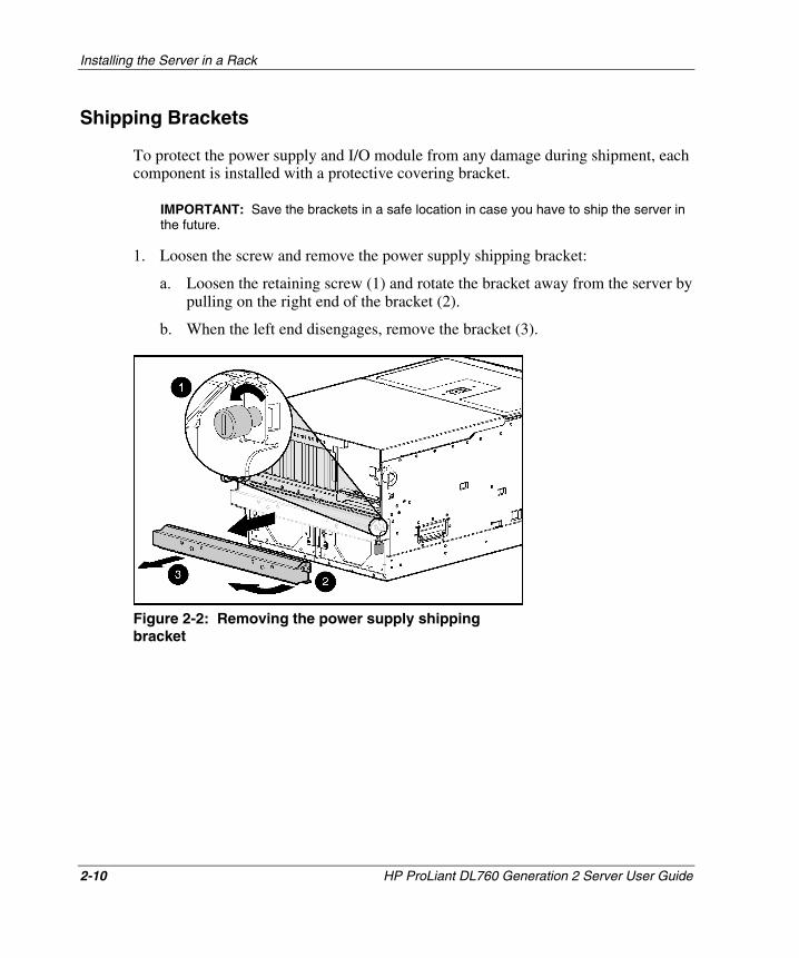
Installing the Server in a Rack
Shipping Brackets
To protect the power supply and I/O module from any damage during shipment, each component is installed with a protective covering bracket.
IMPORTANT: Save the brackets in a safe location in case you have to ship the server in the future.
1. Loosen the screw and remove the power supply shipping bracket:
a. Loosen the retaining screw (1) and rotate the bracket away from the server by pulling on the right end of the bracket (2).
b. When the left end disengages, remove the bracket (3).
Figure 2-2: Removing the power supply shipping bracket
2-10 HP ProLiant DL760 Generation 2 Server User Guide
HP CONFIDENTIAL Writer: Jennifer Hayward File Name: c-ch2 Installing the Server in a Rack.doc
Codename: Pioneer Part Number: 201264-002 Last Saved On: 6/17/03 9:22 AM
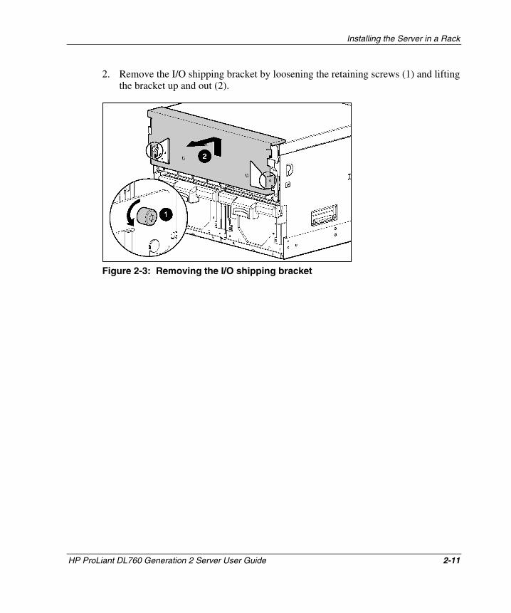
Installing the Server in a Rack
2. Remove the I/O shipping bracket by loosening the retaining screws (1) and lifting the bracket up and out (2).
Figure 2-3: Removing the I/O shipping bracket
HP ProLiant DL760 Generation 2 Server User Guide 2-11
HP CONFIDENTIAL Writer: Jennifer Hayward File Name: c-ch2 Installing the Server in a Rack.doc
Codename: Pioneer Part Number: 201264-002 Last Saved On: 6/17/03 9:22 AM
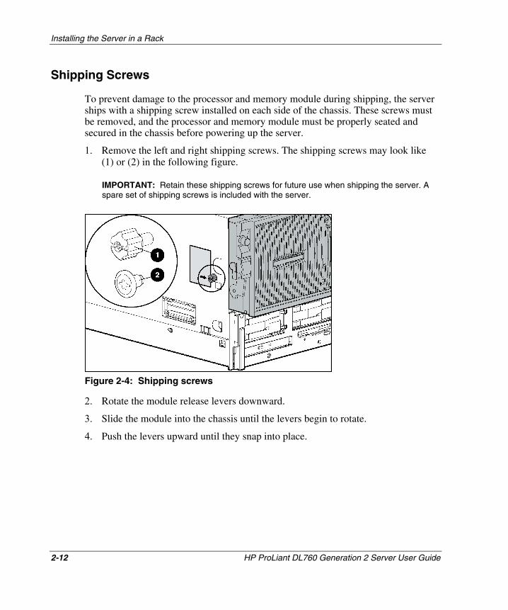
Installing the Server in a Rack
Shipping Screws
To prevent damage to the processor and memory module during shipping, the server ships with a shipping screw installed on each side of the chassis. These screws must be removed, and the processor and memory module must be properly seated and secured in the chassis before powering up the server.
1. Remove the left and right shipping screws. The shipping screws may look like (1) or (2) in the following figure.
IMPORTANT: Retain these shipping screws for future use when shipping the server. A spare set of shipping screws is included with the server.
Figure 2-4: Shipping screws
2. Rotate the module release levers downward.
3. Slide the module into the chassis until the levers begin to rotate.
4. Push the levers upward until they snap into place.
2-12 HP ProLiant DL760 Generation 2 Server User Guide
HP CONFIDENTIAL Writer: Jennifer Hayward File Name: c-ch2 Installing the Server in a Rack.doc
Codename: Pioneer Part Number: 201264-002 Last Saved On: 6/17/03 9:22 AM
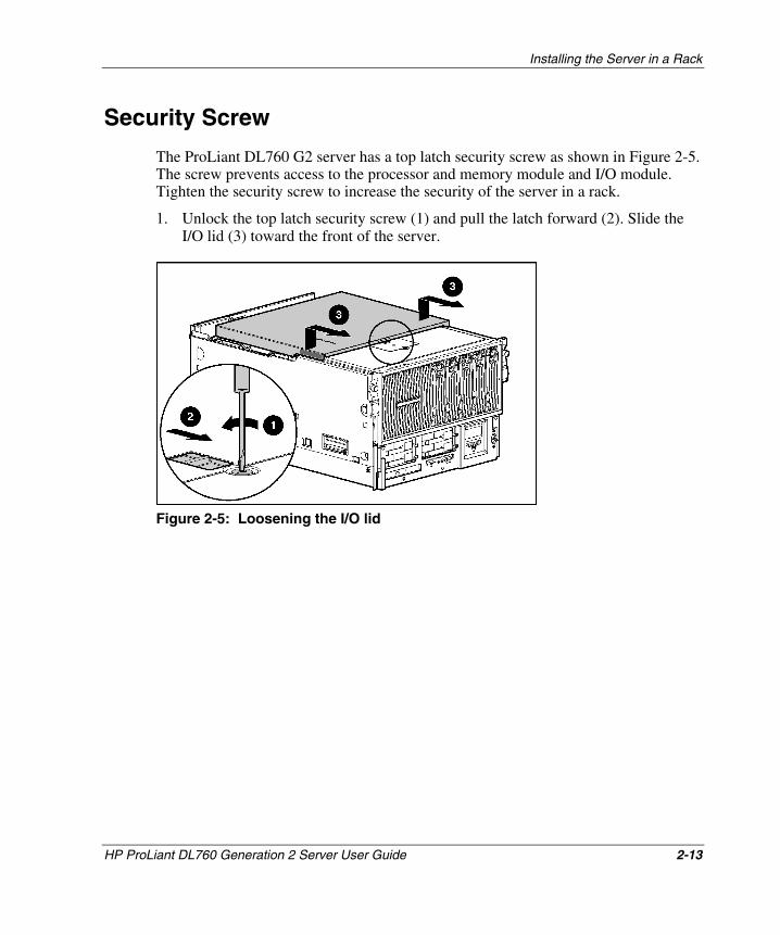
Installing the Server in a Rack
Security Screw
The ProLiant DL760 G2 server has a top latch security screw as shown in Figure 2-5. The screw prevents access to the processor and memory module and I/O module. Tighten the security screw to increase the security of the server in a rack.
1. Unlock the top latch security screw (1) and pull the latch forward (2). Slide the I/O lid (3) toward the front of the server.
Figure 2-5: Loosening the I/O lid
HP ProLiant DL760 Generation 2 Server User Guide 2-13
HP CONFIDENTIAL Writer: Jennifer Hayward File Name: c-ch2 Installing the Server in a Rack.doc
Codename: Pioneer Part Number: 201264-002 Last Saved On: 6/17/03 9:22 AM
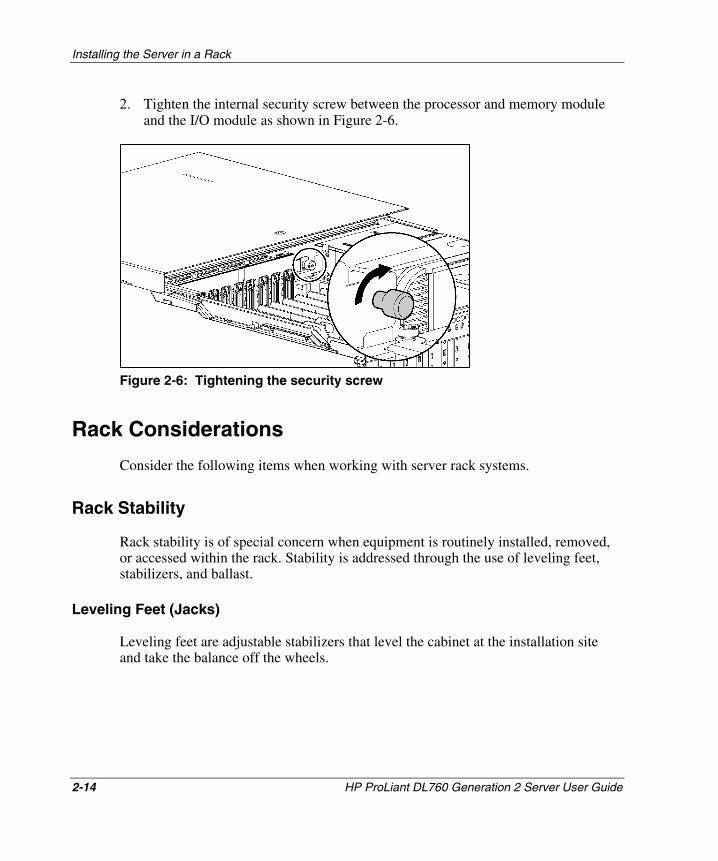
Installing the Server in a Rack
2. Tighten the internal security screw between the processor and memory module and the I/O module as shown in Figure 2-6.
Figure 2-6: Tightening the security screw
Rack Considerations
Consider the following items when working with server rack systems.
Rack Stability
Rack stability is of special concern when equipment is routinely installed, removed, or accessed within the rack. Stability is addressed through the use of leveling feet, stabilizers, and ballast.
Leveling Feet (Jacks)
Leveling feet are adjustable stabilizers that level the cabinet at the installation site and take the balance off the wheels.
2-14 HP ProLiant DL760 Generation 2 Server User Guide
HP CONFIDENTIAL Writer: Jennifer Hayward File Name: c-ch2 Installing the Server in a Rack.doc
Codename: Pioneer Part Number: 201264-002 Last Saved On: 6/17/03 9:22 AM
Installing the Server in a Rack
Stabilizers
The anti-tip stabilizer provides stability and support when equipment is installed, removed, or accessed within the rack. HP recommends that you use a stabilizer option kit with a stand-alone rack.
Ballast Kits
Ballast kits can be added to a cabinet to increase side-to-side and front-to-back mechanical stability. Lightly loaded cabinets may require ballast to keep them from tipping over when a force is applied to the side of the cabinet. Heavily loaded systems, depending on the particular configuration involved, usually do not require ballast.
To be sure of rack stability, the minimum weight of the installed equipment should be 114 kg (210 lb). Ballast kits should be added in the event a system has less than 114 kg (210 lb) minimum weight. In addition, ballast kits should also be installed if any single system component weighs over 45 kg (100 lb) such that a minimum of 91 kg (200 lb) of ballast and equipment remains in place when the component is extended from the rack.
A single ProLiant DL760 G2 server typically weighs between 63 kg and 73 kg (140 lb to 161 lb), depending on configuration. If a single ProLiant DL760 G2 server is the only component installed in a rack, you must add two ballast kits. Each kit contains two 18 kg (40 lb) ballasts. Two ballast kits (a total of four ballasts) equal 73 kg (160 lb), bringing the total up to a minimum of 136 kg (300 lb).
If two ProLiant DL760 G2 servers are the only components installed in a rack, you must add a single ballast kit, which maintains a minimum weight of 91 kg (200 lb) remaining in the rack when one of the servers is extended.
Refer to any additional installation documentation provided with the rack.
HP ProLiant DL760 Generation 2 Server User Guide 2-15
HP CONFIDENTIAL Writer: Jennifer Hayward File Name: c-ch2 Installing the Server in a Rack.doc
Codename: Pioneer Part Number: 201264-002 Last Saved On: 6/17/03 9:22 AM
Installing the Server in a Rack
Warnings and Precautions
Before beginning the following procedures, be sure you understand the following warnings:
63−73 kg 140−161 lb
WARNING: To reduce the risk of personal injury or damage to the equipment:
• Observe local occupational health and safety requirements and guidelines for manual material handling.
• Obtain adequate assistance to lift and stabilize the chassis during installation or removal.
• The product will be unstable when not fastened to the rails.
• Remove all hot-plug power supplies and drives to reduce the overall weight of the product.
WARNING: To reduce the risk of personal injury or damage to the equipment, be sure that:
• The leveling jacks are extended to the floor.
• The full rack weight rests on the leveling jacks.
• The stabilizing feet are attached to the rack if it is a single rack installation.
• The racks are coupled together in multiple rack installations.
• A rack may become unstable if more than one component is extended for any reason. Extend only one component at a time.
CAUTION: To maintain optimum cooling, a perforated rack door must be used with this server. Failure to use a properly ventilated door results in thermal damage to your server. Compaq branded 7000 series racks require an upgraded door. You can order a high-airflow perforated door from HP, Part Number [P/N] 327881-B21 for a 42U rack, or Part Number [P/N] 157847-B21 for a 22U rack.
IMPORTANT: To reduce the overall weight of the system, HP recommends that all power supplies, the I/O module, and the processor and memory module be removed from the server before loading it onto the rails.
2-16 HP ProLiant DL760 Generation 2 Server User Guide
HP CONFIDENTIAL Writer: Jennifer Hayward File Name: c-ch2 Installing the Server in a Rack.doc
Codename: Pioneer Part Number: 201264-002 Last Saved On: 6/17/03 9:22 AM
Installing the Server in a Rack
IMPORTANT: Refer to the following rack documentation for further cautions:
• 9000 Rack Series Products Audio-Visual (AV) CD Kit (shipped with HP racks)
• Rack Builder Pro Configuration Tool CD (available on the HP website or ordered with the Rack Resource CD Kit)
• Rack Products Documentation CD (available on the HP website or ordered with the Rack Resource CD Kit)
• Rack 7000/4000 Series Rack Resource CD Kit (shipped with all Compaq 7000 and 4000 Series Racks)
Preparing the Rack for Server Installation
To prepare the rack for a server installation:
• Measure with the rack template and install cage nuts
• Install the slide bracket assemblies
Measuring with the Rack Template
The rack template provides an easy and reliable way to properly position the rack rail assemblies in the rack.
• The template is two-sided and is printed with arrows that show you where to insert rack rail assemblies on the front and back of the rack.
• Use a pencil to mark the top and bottom edges of the template against the rack supports, identifying where the server fits and providing a starting point for installing the next unit.
WARNING: Always mount the heaviest item on the bottom of the rack and work from the bottom to the top.
HP ProLiant DL760 Generation 2 Server User Guide 2-17
HP CONFIDENTIAL Writer: Jennifer Hayward File Name: c-ch2 Installing the Server in a Rack.doc
Codename: Pioneer Part Number: 201264-002 Last Saved On: 6/17/03 9:22 AM
Installing the Server in a Rack
WARNING: Reduce the risk of personal injury or damage to the equipment by ensuring that the rack leveling feet extend to the floor and support the full weight of the rack. Each rack must be level and stable. Racks that are not coupled require stabilizers. This must be done before you perform any work on the rack.
Refer to the Rack Planning and Installation Guide on the Documentation CD that accompanies the Compaq branded rack for more information on leveling feet and stabilizers.
IMPORTANT: Determine where in the rack to place the server before you start installing the rack rail assemblies. To remind you of the proper placement of the server in the rack, refer to the Rack Builder report you printed when you planned your rack configuration with the Rack Builder tools provided with the Compaq branded rack.
2-18 HP ProLiant DL760 Generation 2 Server User Guide
HP CONFIDENTIAL Writer: Jennifer Hayward File Name: c-ch2 Installing the Server in a Rack.doc
Codename: Pioneer Part Number: 201264-002 Last Saved On: 6/17/03 9:22 AM
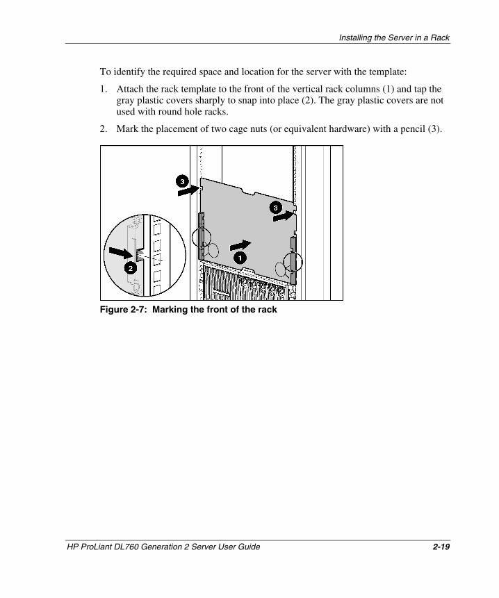
Installing the Server in a Rack
To identify the required space and location for the server with the template:
1. Attach the rack template to the front of the vertical rack columns (1) and tap the gray plastic covers sharply to snap into place (2). The gray plastic covers are not used with round hole racks.
2. Mark the placement of two cage nuts (or equivalent hardware) with a pencil (3).
Figure 2-7: Marking the front of the rack
HP ProLiant DL760 Generation 2 Server User Guide 2-19
HP CONFIDENTIAL Writer: Jennifer Hayward File Name: c-ch2 Installing the Server in a Rack.doc
Codename: Pioneer Part Number: 201264-002 Last Saved On: 6/17/03 9:22 AM
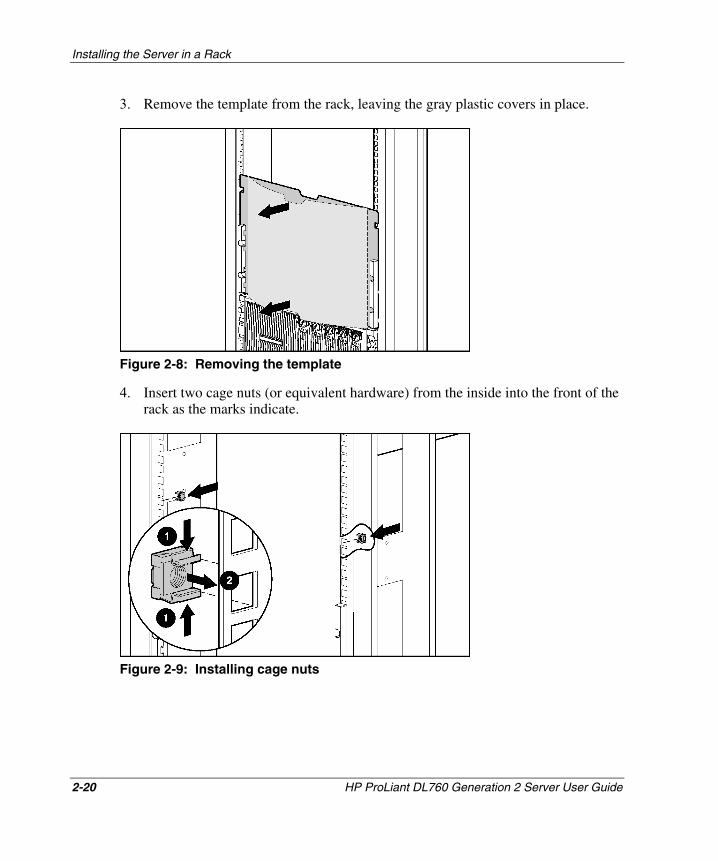
Installing the Server in a Rack
3. Remove the template from the rack, leaving the gray plastic covers in place.
Figure 2-8: Removing the template
4. Insert two cage nuts (or equivalent hardware) from the inside into the front of the rack as the marks indicate.
Figure 2-9: Installing cage nuts
2-20 HP ProLiant DL760 Generation 2 Server User Guide
HP CONFIDENTIAL Writer: Jennifer Hayward File Name: c-ch2 Installing the Server in a Rack.doc
Codename: Pioneer Part Number: 201264-002 Last Saved On: 6/17/03 9:22 AM
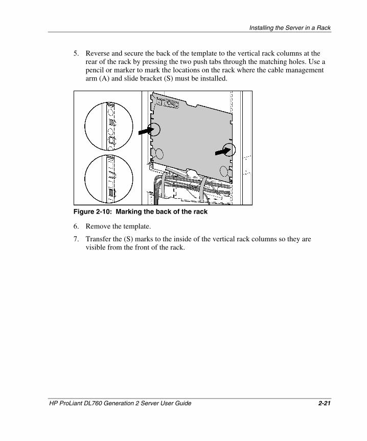
Installing the Server in a Rack
5. Reverse and secure the back of the template to the vertical rack columns at the rear of the rack by pressing the two push tabs through the matching holes. Use a pencil or marker to mark the locations on the rack where the cable management arm (A) and slide bracket (S) must be installed.
Figure 2-10: Marking the back of the rack
6. Remove the template.
7. Transfer the (S) marks to the inside of the vertical rack columns so they are visible from the front of the rack.
HP ProLiant DL760 Generation 2 Server User Guide 2-21
HP CONFIDENTIAL Writer: Jennifer Hayward File Name: c-ch2 Installing the Server in a Rack.doc
Codename: Pioneer Part Number: 201264-002 Last Saved On: 6/17/03 9:22 AM
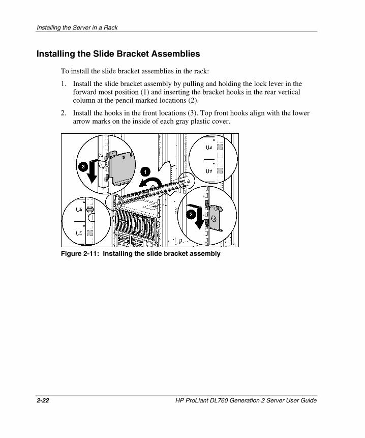
Installing the Server in a Rack
Installing the Slide Bracket Assemblies
To install the slide bracket assemblies in the rack:
1. Install the slide bracket assembly by pulling and holding the lock lever in the forward most position (1) and inserting the bracket hooks in the rear vertical column at the pencil marked locations (2).
2. Install the hooks in the front locations (3). Top front hooks align with the lower arrow marks on the inside of each gray plastic cover.
Figure 2-11: Installing the slide bracket assembly
2-22 HP ProLiant DL760 Generation 2 Server User Guide
HP CONFIDENTIAL Writer: Jennifer Hayward File Name: c-ch2 Installing the Server in a Rack.doc
Codename: Pioneer Part Number: 201264-002 Last Saved On: 6/17/03 9:22 AM
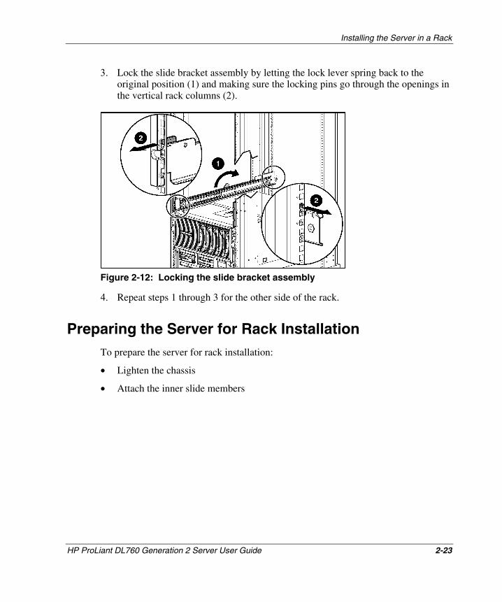
Installing the Server in a Rack
3. Lock the slide bracket assembly by letting the lock lever spring back to the original position (1) and making sure the locking pins go through the openings in the vertical rack columns (2).
Figure 2-12: Locking the slide bracket assembly
4. Repeat steps 1 through 3 for the other side of the rack.
Preparing the Server for Rack Installation To prepare the server for rack installation:
• Lighten the chassis
• Attach the inner slide members
HP ProLiant DL760 Generation 2 Server User Guide 2-23
HP CONFIDENTIAL Writer: Jennifer Hayward File Name: c-ch2 Installing the Server in a Rack.doc
Codename: Pioneer Part Number: 201264-002 Last Saved On: 6/17/03 9:22 AM
Installing the Server in a Rack
Lightening the Chassis
WARNING: The processor and memory module weighs more than 16 kg (35 lb). HP recommends either removing ALL of the memory cartridges before handling the module or having two people handling the module together.
Remove the modules and power supplies from the chassis to lighten the server:
1. Remove the I/O module. Refer to “Removing the I/O Module” in Chapter 3.
2. Remove the processor and memory module from the server chassis. Refer to “Removing the Processor and Memory Module” in Chapter 3.
3. Remove the media module from the server chassis. Refer to “Removing the Media Module” in Chapter 3.
4. Remove the power supplies. Refer to “Installing a Hot-Plug Power Supply” in Chapter 5.
2-24 HP ProLiant DL760 Generation 2 Server User Guide
HP CONFIDENTIAL Writer: Jennifer Hayward File Name: c-ch2 Installing the Server in a Rack.doc
Codename: Pioneer Part Number: 201264-002 Last Saved On: 6/17/03 9:22 AM
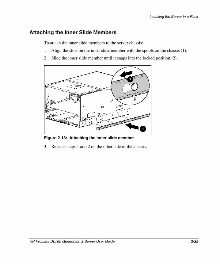
Installing the Server in a Rack
Attaching the Inner Slide Members
To attach the inner slide members to the server chassis:
1. Align the slots on the inner slide member with the spools on the chassis (1).
2. Slide the inner slide member until it snaps into the locked position (2).
Figure 2-13: Attaching the inner slide member
3. Repeats steps 1 and 2 on the other side of the chassis.
HP ProLiant DL760 Generation 2 Server User Guide 2-25
HP CONFIDENTIAL Writer: Jennifer Hayward File Name: c-ch2 Installing the Server in a Rack.doc
Codename: Pioneer Part Number: 201264-002 Last Saved On: 6/17/03 9:22 AM
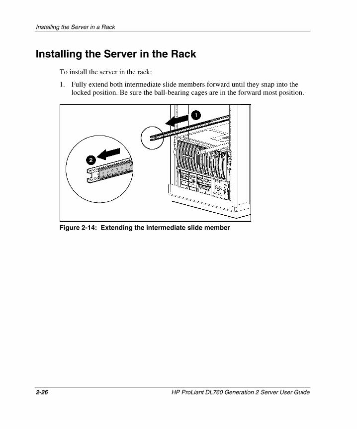
Installing the Server in a Rack
Installing the Server in the Rack
To install the server in the rack:
1. Fully extend both intermediate slide members forward until they snap into the locked position. Be sure the ball-bearing cages are in the forward most position.
Figure 2-14: Extending the intermediate slide member
2-26 HP ProLiant DL760 Generation 2 Server User Guide
HP CONFIDENTIAL Writer: Jennifer Hayward File Name: c-ch2 Installing the Server in a Rack.doc
Codename: Pioneer Part Number: 201264-002 Last Saved On: 6/17/03 9:22 AM
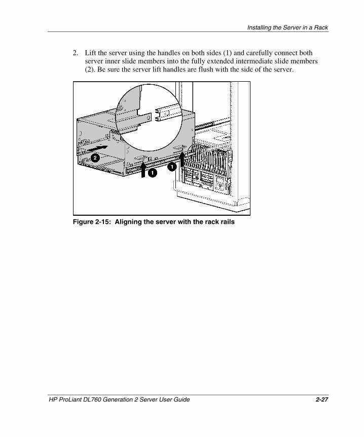
Installing the Server in a Rack
2. Lift the server using the handles on both sides (1) and carefully connect both server inner slide members into the fully extended intermediate slide members (2). Be sure the server lift handles are flush with the side of the server.
Figure 2-15: Aligning the server with the rack rails
HP ProLiant DL760 Generation 2 Server User Guide 2-27
HP CONFIDENTIAL Writer: Jennifer Hayward File Name: c-ch2 Installing the Server in a Rack.doc
Codename: Pioneer Part Number: 201264-002 Last Saved On: 6/17/03 9:22 AM
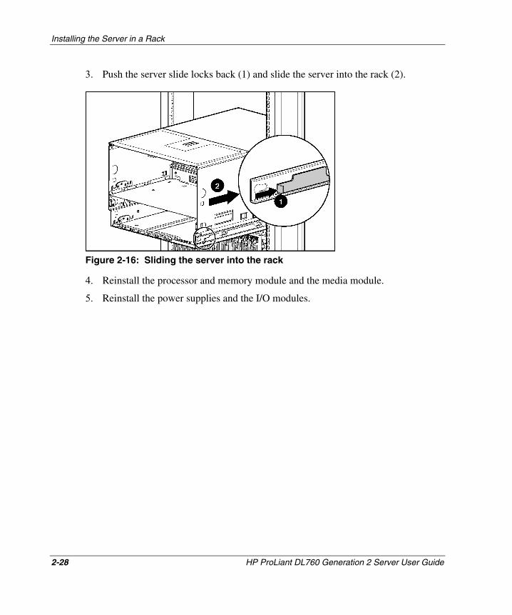
Installing the Server in a Rack
3. Push the server slide locks back (1) and slide the server into the rack (2).
Figure 2-16: Sliding the server into the rack
4. Reinstall the processor and memory module and the media module.
5. Reinstall the power supplies and the I/O modules.
2-28 HP ProLiant DL760 Generation 2 Server User Guide
HP CONFIDENTIAL Writer: Jennifer Hayward File Name: c-ch2 Installing the Server in a Rack.doc
Codename: Pioneer Part Number: 201264-002 Last Saved On: 6/17/03 9:22 AM
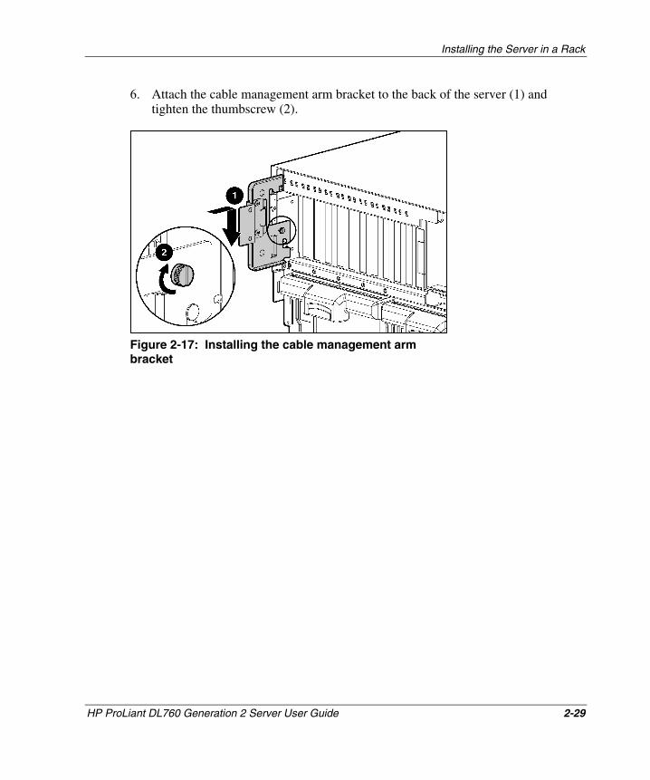
Installing the Server in a Rack
6. Attach the cable management arm bracket to the back of the server (1) and tighten the thumbscrew (2).
Figure 2-17: Installing the cable management arm bracket
HP ProLiant DL760 Generation 2 Server User Guide 2-29
HP CONFIDENTIAL Writer: Jennifer Hayward File Name: c-ch2 Installing the Server in a Rack.doc
Codename: Pioneer Part Number: 201264-002 Last Saved On: 6/17/03 9:22 AM
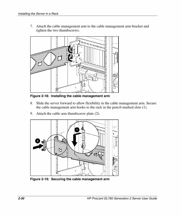
Installing the Server in a Rack
7. Attach the cable management arm to the cable management arm bracket and tighten the two thumbscrews.
Figure 2-18: Installing the cable management arm
8. Slide the server forward to allow flexibility in the cable management arm. Secure the cable management arm hooks to the rack in the pencil-marked slots (1).
9. Attach the cable arm thumbscrew plate (2).
Figure 2-19: Securing the cable management arm
2-30 HP ProLiant DL760 Generation 2 Server User Guide
HP CONFIDENTIAL Writer: Jennifer Hayward File Name: c-ch2 Installing the Server in a Rack.doc
Codename: Pioneer Part Number: 201264-002 Last Saved On: 6/17/03 9:22 AM
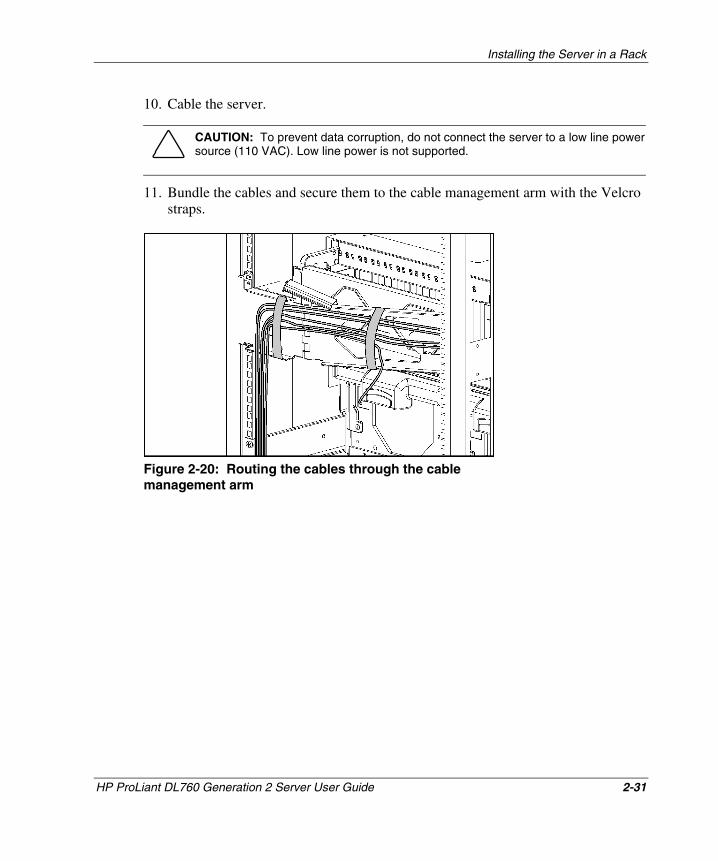
Installing the Server in a Rack
10. Cable the server.
CAUTION: To prevent data corruption, do not connect the server to a low line power source (110 VAC). Low line power is not supported.
11. Bundle the cables and secure them to the cable management arm with the Velcro straps.
Figure 2-20: Routing the cables through the cable management arm
HP ProLiant DL760 Generation 2 Server User Guide 2-31
HP CONFIDENTIAL Writer: Jennifer Hayward File Name: c-ch2 Installing the Server in a Rack.doc
Codename: Pioneer Part Number: 201264-002 Last Saved On: 6/17/03 9:22 AM
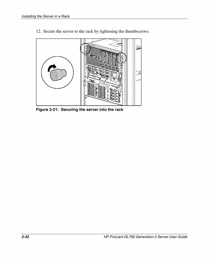
Installing the Server in a Rack
2-32 HP ProLiant DL760 Generation 2 Server User Guide
HP CONFIDENTIAL Writer: Jennifer Hayward File Name: c-ch2 Installing the Server in a Rack.doc
Codename: Pioneer Part Number: 201264-002 Last Saved On: 6/17/03 9:22 AM
12. Secure the server to the rack by tightening the thumbscrews.
Figure 2-21: Securing the server into the rack
3 Server Access
The ProLiant DL760 G2 server provides easy access to all internal components for installation and maintenance. This chapter provides details concerning system power and power supply indicators and removal of the server modules.
HP ProLiant DL760 Generation 2 Server User Guide 3-1
HP CONFIDENTIAL Writer: Jennifer Hayward File Name: d-ch3 Server Access.doc
Codename: Pioneer Part Number: 201264-002 Last Saved On: 6/17/03 9:26 AM
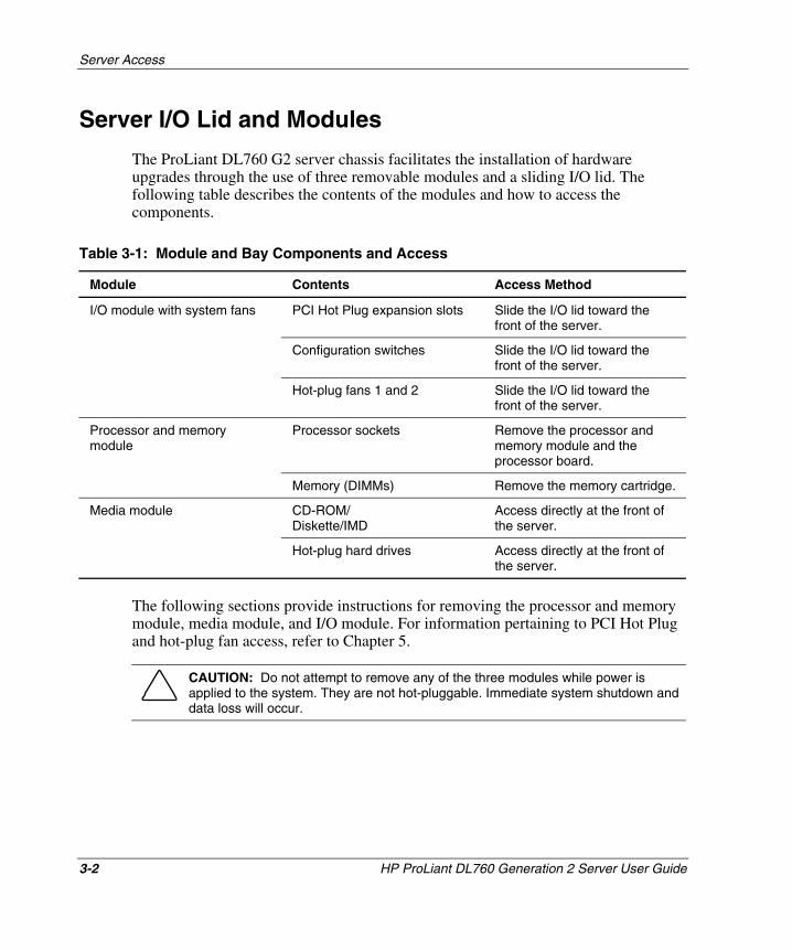
Server Access
Server I/O Lid and Modules
The ProLiant DL760 G2 server chassis facilitates the installation of hardware upgrades through the use of three removable modules and a sliding I/O lid. The following table describes the contents of the modules and how to access the components.
Table 3-1: Module and Bay Components and Access
Module Contents Access Method
PCI Hot Plug expansion slots Slide the I/O lid toward the front of the server.
Configuration switches Slide the I/O lid toward the front of the server.
I/O module with system fans
Hot-plug fans 1 and 2 Slide the I/O lid toward the front of the server.
Processor sockets Remove the processor and memory module and the processor board.
Processor and memory module
Memory (DIMMs) Remove the memory cartridge.
CD-ROM/ Diskette/IMD
Access directly at the front of the server.
Media module
Hot-plug hard drives Access directly at the front of the server.
The following sections provide instructions for removing the processor and memory module, media module, and I/O module. For information pertaining to PCI Hot Plug and hot-plug fan access, refer to Chapter 5.
CAUTION: Do not attempt to remove any of the three modules while power is applied to the system. They are not hot-pluggable. Immediate system shutdown and data loss will occur.
3-2 HP ProLiant DL760 Generation 2 Server User Guide
HP CONFIDENTIAL Writer: Jennifer Hayward File Name: d-ch3 Server Access.doc
Codename: Pioneer Part Number: 201264-002 Last Saved On: 6/17/03 9:26 AM
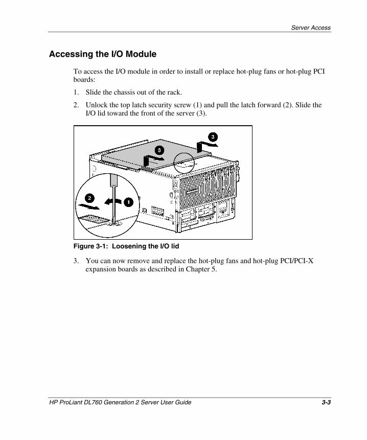
Server Access
Accessing the I/O Module
To access the I/O module in order to install or replace hot-plug fans or hot-plug PCI boards:
1. Slide the chassis out of the rack.
2. Unlock the top latch security screw (1) and pull the latch forward (2). Slide the I/O lid toward the front of the server (3).
Figure 3-1: Loosening the I/O lid
3. You can now remove and replace the hot-plug fans and hot-plug PCI/PCI-X expansion boards as described in Chapter 5.
HP ProLiant DL760 Generation 2 Server User Guide 3-3
HP CONFIDENTIAL Writer: Jennifer Hayward File Name: d-ch3 Server Access.doc
Codename: Pioneer Part Number: 201264-002 Last Saved On: 6/17/03 9:26 AM
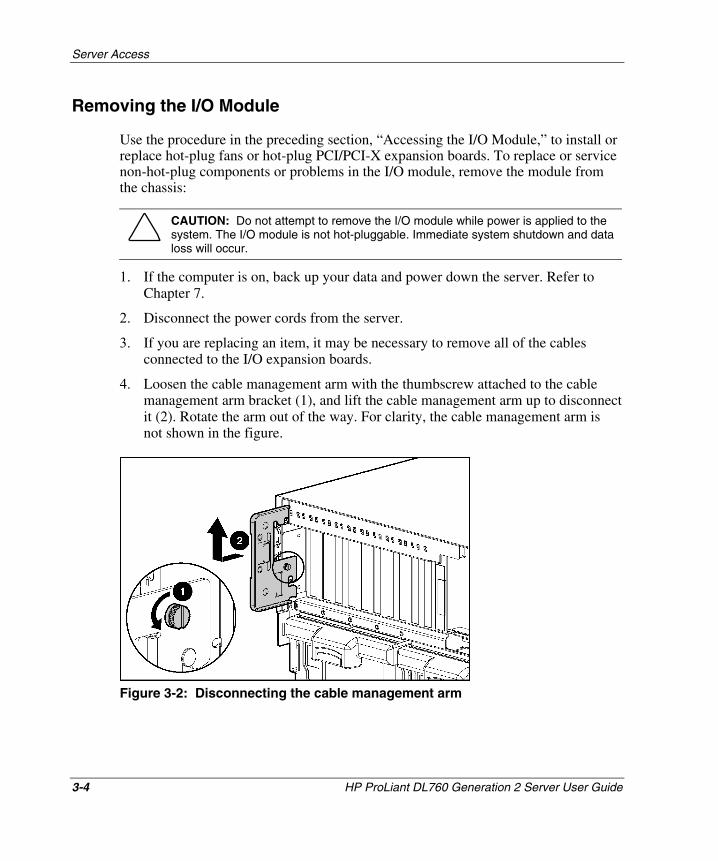
Server Access
Removing the I/O Module
Use the procedure in the preceding section, “Accessing the I/O Module,” to install or replace hot-plug fans or hot-plug PCI/PCI-X expansion boards. To replace or service non-hot-plug components or problems in the I/O module, remove the module from the chassis:
CAUTION: Do not attempt to remove the I/O module while power is applied to the system. The I/O module is not hot-pluggable. Immediate system shutdown and data loss will occur.
1. If the computer is on, back up your data and power down the server. Refer to Chapter 7.
2. Disconnect the power cords from the server.
3. If you are replacing an item, it may be necessary to remove all of the cables connected to the I/O expansion boards.
4. Loosen the cable management arm with the thumbscrew attached to the cable management arm bracket (1), and lift the cable management arm up to disconnect it (2). Rotate the arm out of the way. For clarity, the cable management arm is not shown in the figure.
Figure 3-2: Disconnecting the cable management arm
3-4 HP ProLiant DL760 Generation 2 Server User Guide
HP CONFIDENTIAL Writer: Jennifer Hayward File Name: d-ch3 Server Access.doc
Codename: Pioneer Part Number: 201264-002 Last Saved On: 6/17/03 9:26 AM
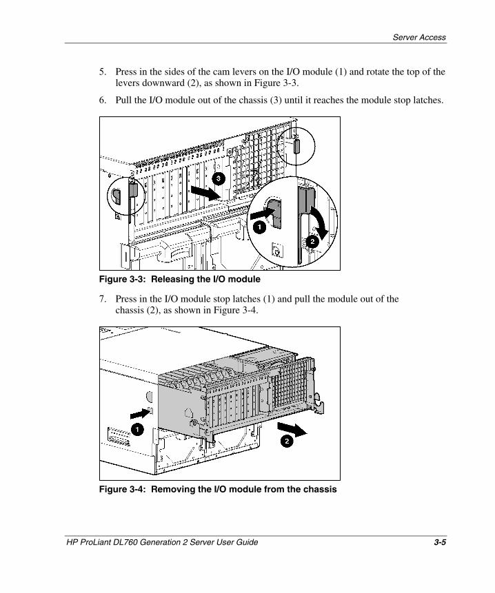
Server Access
5. Press in the sides of the cam levers on the I/O module (1) and rotate the top of the levers downward (2), as shown in Figure 3-3.
6. Pull the I/O module out of the chassis (3) until it reaches the module stop latches.
Figure 3-3: Releasing the I/O module
7. Press in the I/O module stop latches (1) and pull the module out of the chassis (2), as shown in Figure 3-4.
Figure 3-4: Removing the I/O module from the chassis
HP ProLiant DL760 Generation 2 Server User Guide 3-5
HP CONFIDENTIAL Writer: Jennifer Hayward File Name: d-ch3 Server Access.doc
Codename: Pioneer Part Number: 201264-002 Last Saved On: 6/17/03 9:26 AM
Server Access
8. Set the I/O module aside for servicing non-hot-plug components.
WARNING: To reduce the risk of personal injury from hot surfaces, allow the internal system components to cool before touching them.
9. To view the top panel labels, pull the chassis out of the rack until the chassis makes contact with the rail stop.
NOTE: The top panel labels provide instructions about installing expansion boards, setting switches, and installing hot-plug fans, along with information about PCI Hot Plug. Refer to Chapter 5 for hot-plug procedures.
10. To reassemble the server, slide the module into the chassis until the cam levers begin to rotate. Then push the cam levers shut until they snap into place.
11. Reinstall the cable management arm and I/O cables in the reverse order from the steps used to remove them.
12. Connect all power cords.
Removing the Processor and Memory Module
WARNING: The processor and memory module weighs more than 35 lb. HP recommends either removing ALL of the memory cartridges before handling the module, or having two people handling the module together.
CAUTION: Do not attempt to remove the processor and memory module while power is applied to the system. The module is not hot-pluggable. Immediate system shutdown and data loss will occur.
To remove the processor and memory module:
1. If the computer is on, backup your data and power down the server. Refer to Chapter 7.
2. Disconnect the power cords from the server.
3-6 HP ProLiant DL760 Generation 2 Server User Guide
HP CONFIDENTIAL Writer: Jennifer Hayward File Name: d-ch3 Server Access.doc
Codename: Pioneer Part Number: 201264-002 Last Saved On: 6/17/03 9:26 AM
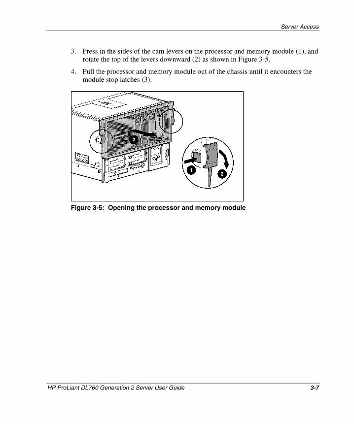
Server Access
3. Press in the sides of the cam levers on the processor and memory module (1), and rotate the top of the levers downward (2) as shown in Figure 3-5.
4. Pull the processor and memory module out of the chassis until it encounters the module stop latches (3).
Figure 3-5: Opening the processor and memory module
HP ProLiant DL760 Generation 2 Server User Guide 3-7
HP CONFIDENTIAL Writer: Jennifer Hayward File Name: d-ch3 Server Access.doc
Codename: Pioneer Part Number: 201264-002 Last Saved On: 6/17/03 9:26 AM
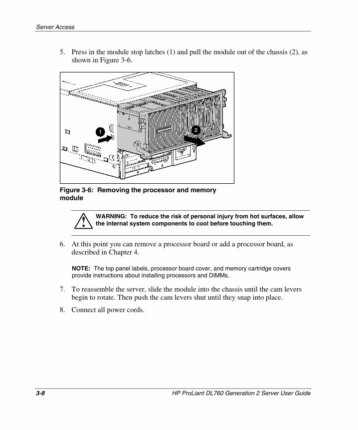
Server Access
5. Press in the module stop latches (1) and pull the module out of the chassis (2), as shown in Figure 3-6.
Figure 3-6: Removing the processor and memory module
WARNING: To reduce the risk of personal injury from hot surfaces, allow the internal system components to cool before touching them.
6. At this point you can remove a processor board or add a processor board, as described in Chapter 4.
NOTE: The top panel labels, processor board cover, and memory cartridge covers provide instructions about installing processors and DIMMs.
7. To reassemble the server, slide the module into the chassis until the cam levers begin to rotate. Then push the cam levers shut until they snap into place.
8. Connect all power cords.
3-8 HP ProLiant DL760 Generation 2 Server User Guide
HP CONFIDENTIAL Writer: Jennifer Hayward File Name: d-ch3 Server Access.doc
Codename: Pioneer Part Number: 201264-002 Last Saved On: 6/17/03 9:26 AM
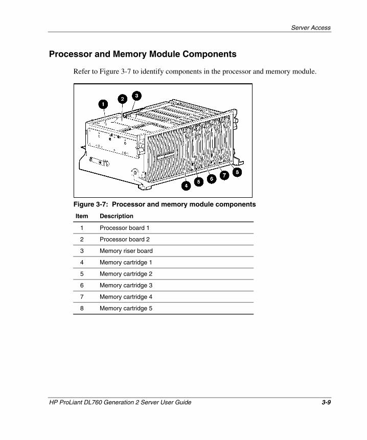
Server Access
Processor and Memory Module Components
Refer to Figure 3-7 to identify components in the processor and memory module.
Figure 3-7: Processor and memory module components
Item Description
1 Processor board 1
2 Processor board 2
3 Memory riser board
4 Memory cartridge 1
5 Memory cartridge 2
6 Memory cartridge 3
7 Memory cartridge 4
8 Memory cartridge 5
HP ProLiant DL760 Generation 2 Server User Guide 3-9
HP CONFIDENTIAL Writer: Jennifer Hayward File Name: d-ch3 Server Access.doc
Codename: Pioneer Part Number: 201264-002 Last Saved On: 6/17/03 9:26 AM
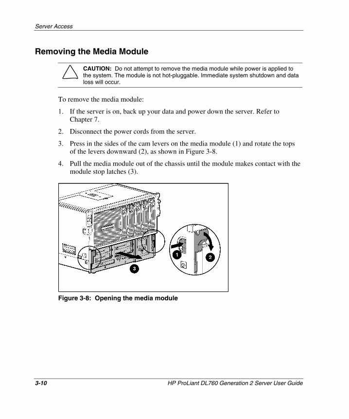
Server Access
Removing the Media Module
CAUTION: Do not attempt to remove the media module while power is applied to the system. The module is not hot-pluggable. Immediate system shutdown and data loss will occur.
To remove the media module:
1. If the server is on, back up your data and power down the server. Refer to Chapter 7.
2. Disconnect the power cords from the server.
3. Press in the sides of the cam levers on the media module (1) and rotate the tops of the levers downward (2), as shown in Figure 3-8.
4. Pull the media module out of the chassis until the module makes contact with the module stop latches (3).
Figure 3-8: Opening the media module
3-10 HP ProLiant DL760 Generation 2 Server User Guide
HP CONFIDENTIAL Writer: Jennifer Hayward File Name: d-ch3 Server Access.doc
Codename: Pioneer Part Number: 201264-002 Last Saved On: 6/17/03 9:26 AM
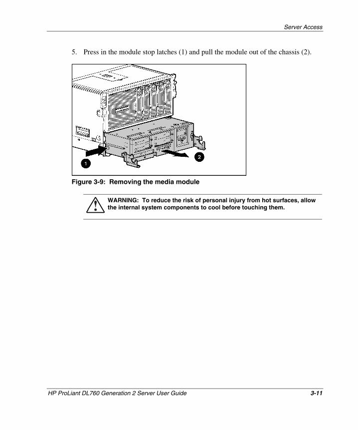
Server Access
5. Press in the module stop latches (1) and pull the module out of the chassis (2).
Figure 3-9: Removing the media module
WARNING: To reduce the risk of personal injury from hot surfaces, allow the internal system components to cool before touching them.
HP ProLiant DL760 Generation 2 Server User Guide 3-11
HP CONFIDENTIAL Writer: Jennifer Hayward File Name: d-ch3 Server Access.doc
Codename: Pioneer Part Number: 201264-002 Last Saved On: 6/17/03 9:26 AM
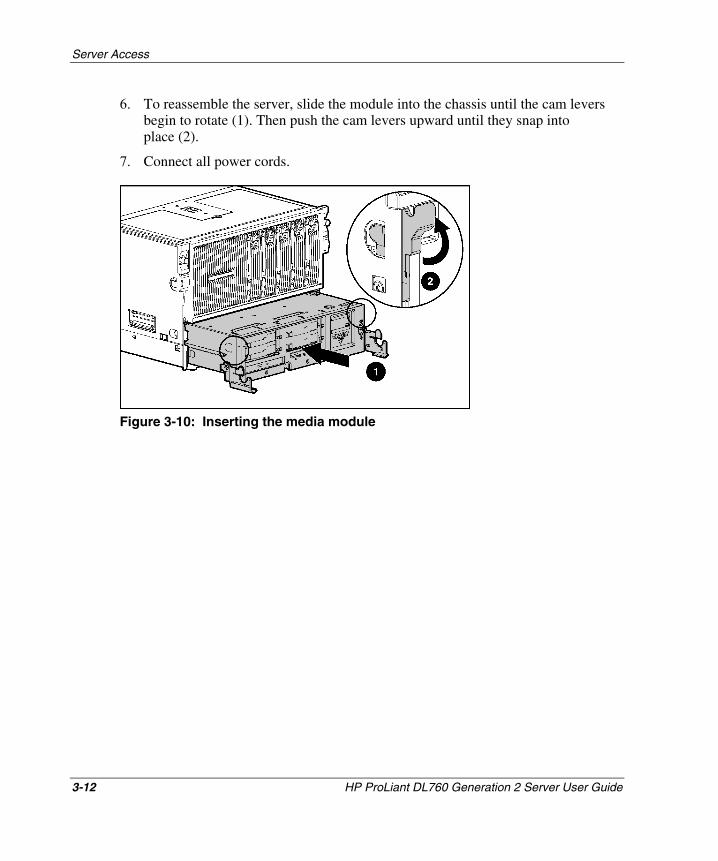
Server Access
6. To reassemble the server, slide the module into the chassis until the cam levers begin to rotate (1). Then push the cam levers upward until they snap into place (2).
7. Connect all power cords.
Figure 3-10: Inserting the media module
3-12 HP ProLiant DL760 Generation 2 Server User Guide
HP CONFIDENTIAL Writer: Jennifer Hayward File Name: d-ch3 Server Access.doc
Codename: Pioneer Part Number: 201264-002 Last Saved On: 6/17/03 9:26 AM
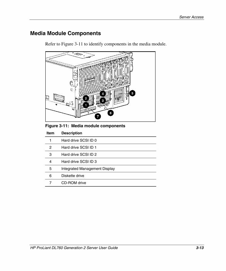
Server Access
HP ProLiant DL760 Generation 2 Server User Guide 3-13
HP CONFIDENTIAL Writer: Jennifer Hayward File Name: d-ch3 Server Access.doc
Codename: Pioneer Part Number: 201264-002 Last Saved On: 6/17/03 9:26 AM
Media Module Components
Refer to Figure 3-11 to identify components in the media module.
Figure 3-11: Media module components
Item Description
1 Hard drive SCSI ID 0
2 Hard drive SCSI ID 1
3 Hard drive SCSI ID 2
4 Hard drive SCSI ID 3
5 Integrated Management Display
6 Diskette drive
7 CD-ROM drive
4 Installing Hardware Options, Server Power Off
The following instructions are provided as an overview for installing hardware option upgrades that require the system power to be off. HP recommends that you use the documentation provided with the hardware option for complete installation instructions. You can also refer to the HP ProLiant DL760 Generation 2 Server Setup Poster included in the shipping box or to the labels attached to the top panel of the server.
WARNING: To reduce the risk of personal injury or damage to the equipment, heed all warnings and cautions throughout the installation instructions.
WARNING: To reduce the risk of personal injury or damage to the equipment, the installation of options other than hot-plug power supplies and hot-plug hard drives should be performed only by individuals who are qualified in servicing computer equipment and are trained to deal with products capable of producing hazardous energy levels.
WARNING: To reduce the risk of personal injury from hazardous energy or damage to the equipment when working on energized servers:
• Remove all watches, rings, and any other loose-fitting jewelry.
• Avoid the use of conductive tools that could bridge live parts.
CAUTION: Electrostatic discharge can damage electronic components. Be sure that you are properly grounded before beginning any installation procedure. Refer to Appendix B for more information.
HP ProLiant DL760 Generation 2 Server User Guide 4-1
HP CONFIDENTIAL Writer: Jennifer Hayward File Name: e-ch4 Installing Options-Power Off.doc
Codename: Pioneer Part Number: 201264-002 Last Saved On: 6/17/03 9:32 AM
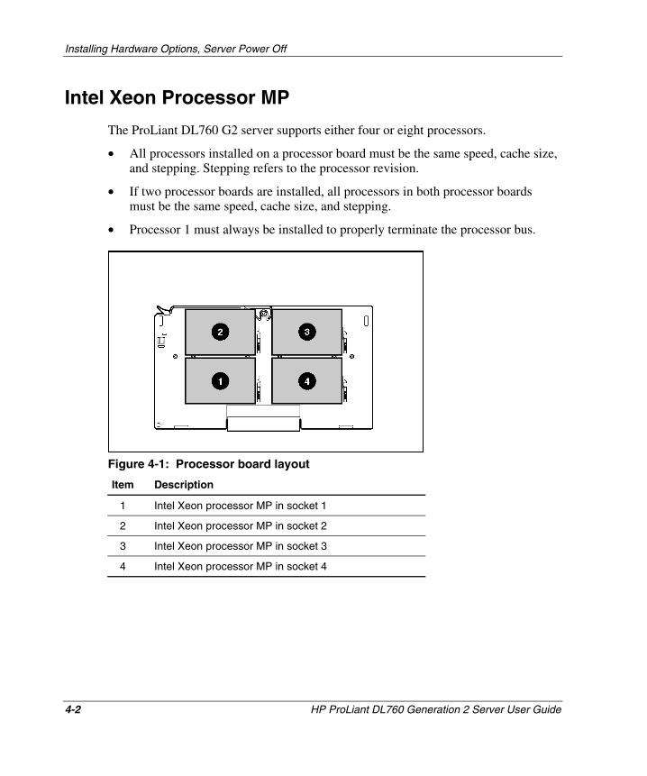
Installing Hardware Options, Server Power Off
Intel Xeon Processor MP
The ProLiant DL760 G2 server supports either four or eight processors.
• All processors installed on a processor board must be the same speed, cache size, and stepping. Stepping refers to the processor revision.
• If two processor boards are installed, all processors in both processor boards must be the same speed, cache size, and stepping.
• Processor 1 must always be installed to properly terminate the processor bus.
Figure 4-1: Processor board layout
Item Description
1 Intel Xeon processor MP in socket 1
2 Intel Xeon processor MP in socket 2
3 Intel Xeon processor MP in socket 3
4 Intel Xeon processor MP in socket 4
4-2 HP ProLiant DL760 Generation 2 Server User Guide
HP CONFIDENTIAL Writer: Jennifer Hayward File Name: e-ch4 Installing Options-Power Off.doc
Codename: Pioneer Part Number: 201264-002 Last Saved On: 6/17/03 9:32 AM
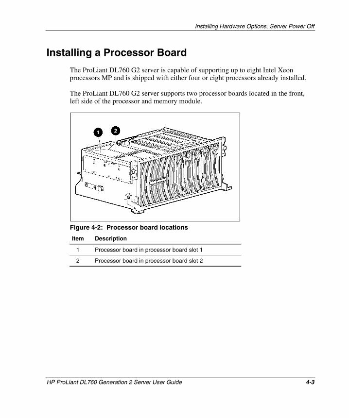
Installing Hardware Options, Server Power Off
Installing a Processor Board
The ProLiant DL760 G2 server is capable of supporting up to eight Intel Xeon processors MP and is shipped with either four or eight processors already installed.
The ProLiant DL760 G2 server supports two processor boards located in the front, left side of the processor and memory module.
Figure 4-2: Processor board locations
Item Description
1 Processor board in processor board slot 1
2 Processor board in processor board slot 2
HP ProLiant DL760 Generation 2 Server User Guide 4-3
HP CONFIDENTIAL Writer: Jennifer Hayward File Name: e-ch4 Installing Options-Power Off.doc
Codename: Pioneer Part Number: 201264-002 Last Saved On: 6/17/03 9:32 AM
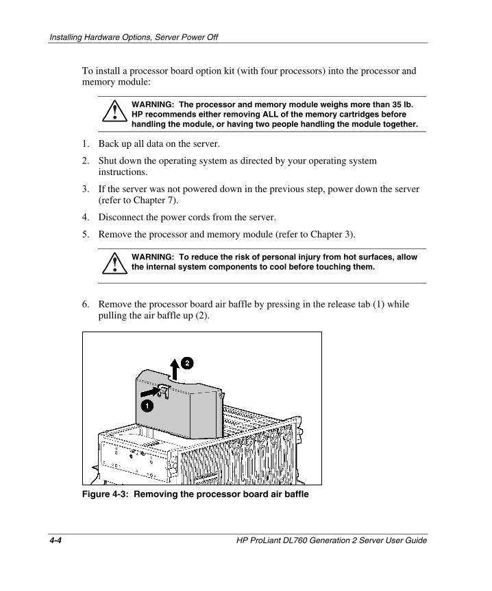
Installing Hardware Options, Server Power Off
To install a processor board option kit (with four processors) into the processor and memory module:
WARNING: The processor and memory module weighs more than 35 lb. HP recommends either removing ALL of the memory cartridges before handling the module, or having two people handling the module together.
1. Back up all data on the server.
2. Shut down the operating system as directed by your operating system instructions.
3. If the server was not powered down in the previous step, power down the server (refer to Chapter 7).
4. Disconnect the power cords from the server.
5. Remove the processor and memory module (refer to Chapter 3).
WARNING: To reduce the risk of personal injury from hot surfaces, allow the internal system components to cool before touching them.
6. Remove the processor board air baffle by pressing in the release tab (1) while pulling the air baffle up (2).
Figure 4-3: Removing the processor board air baffle
4-4 HP ProLiant DL760 Generation 2 Server User Guide
HP CONFIDENTIAL Writer: Jennifer Hayward File Name: e-ch4 Installing Options-Power Off.doc
Codename: Pioneer Part Number: 201264-002 Last Saved On: 6/17/03 9:32 AM
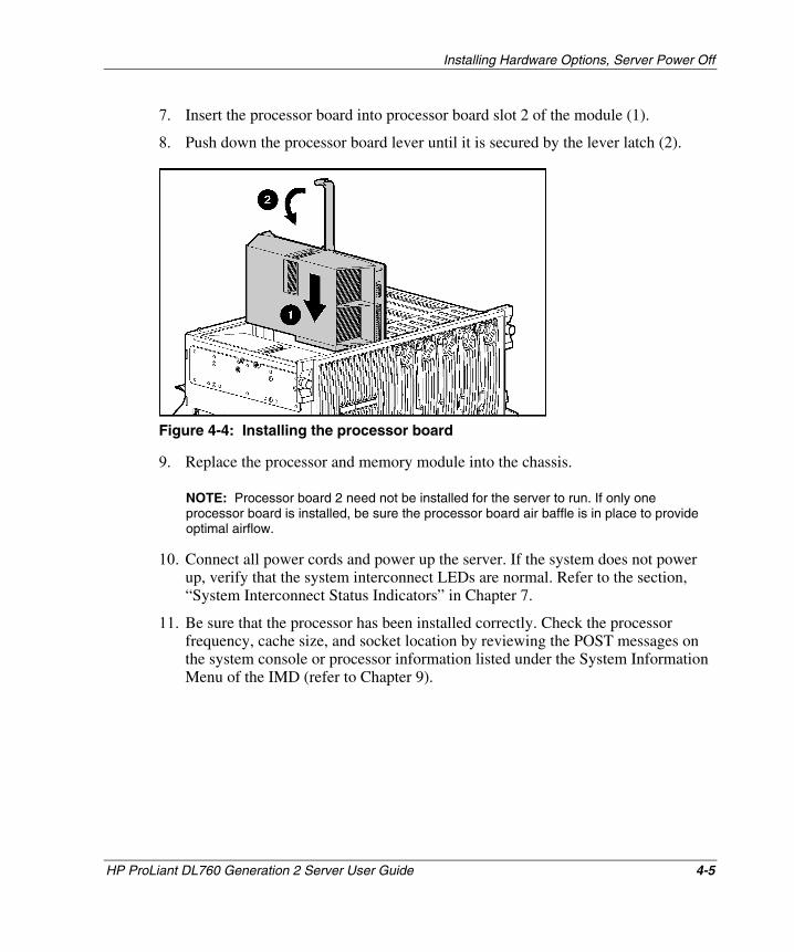
Installing Hardware Options, Server Power Off
7. Insert the processor board into processor board slot 2 of the module (1).
8. Push down the processor board lever until it is secured by the lever latch (2).
Figure 4-4: Installing the processor board
9. Replace the processor and memory module into the chassis.
NOTE: Processor board 2 need not be installed for the server to run. If only one processor board is installed, be sure the processor board air baffle is in place to provide optimal airflow.
10. Connect all power cords and power up the server. If the system does not power up, verify that the system interconnect LEDs are normal. Refer to the section, “System Interconnect Status Indicators” in Chapter 7.
11. Be sure that the processor has been installed correctly. Check the processor frequency, cache size, and socket location by reviewing the POST messages on the system console or processor information listed under the System Information Menu of the IMD (refer to Chapter 9).
HP ProLiant DL760 Generation 2 Server User Guide 4-5
HP CONFIDENTIAL Writer: Jennifer Hayward File Name: e-ch4 Installing Options-Power Off.doc
Codename: Pioneer Part Number: 201264-002 Last Saved On: 6/17/03 9:32 AM
Installing Hardware Options, Server Power Off
External Tape Drive Storage Devices
Optional external tape drive mass storage devices can be connected to the ProLiant DL760 G2 server by using an external VHDCI SCSI connector.
The Smart Array 5i Controller is an integrated SCSI controller that is accessible by means of an external VHDCI SCSI connector. The controller supports tape drives running up to Ultra3 speeds.
To install an external storage device, refer to the installation documentation that was shipped with the external storage device. Figure 4-5 provides an overview of the installation procedure:
1. Back up all data on the server.
2. Shut down the operating system as directed by your operating system instructions.
3. If the server was not powered down in the previous step, power down the server (refer to Chapter 7).
4. Disconnect the power cords from the server.
5. If the external storage device is on, disconnect the power to the device.
6. Connect one end of the SCSI cable to the external VHDCI SCSI connector on the rear panel of the server.
7. Connect the other end of the SCSI cable to an external SCSI connector on the rear panel of the external storage device.
4-6 HP ProLiant DL760 Generation 2 Server User Guide
HP CONFIDENTIAL Writer: Jennifer Hayward File Name: e-ch4 Installing Options-Power Off.doc
Codename: Pioneer Part Number: 201264-002 Last Saved On: 6/17/03 9:32 AM
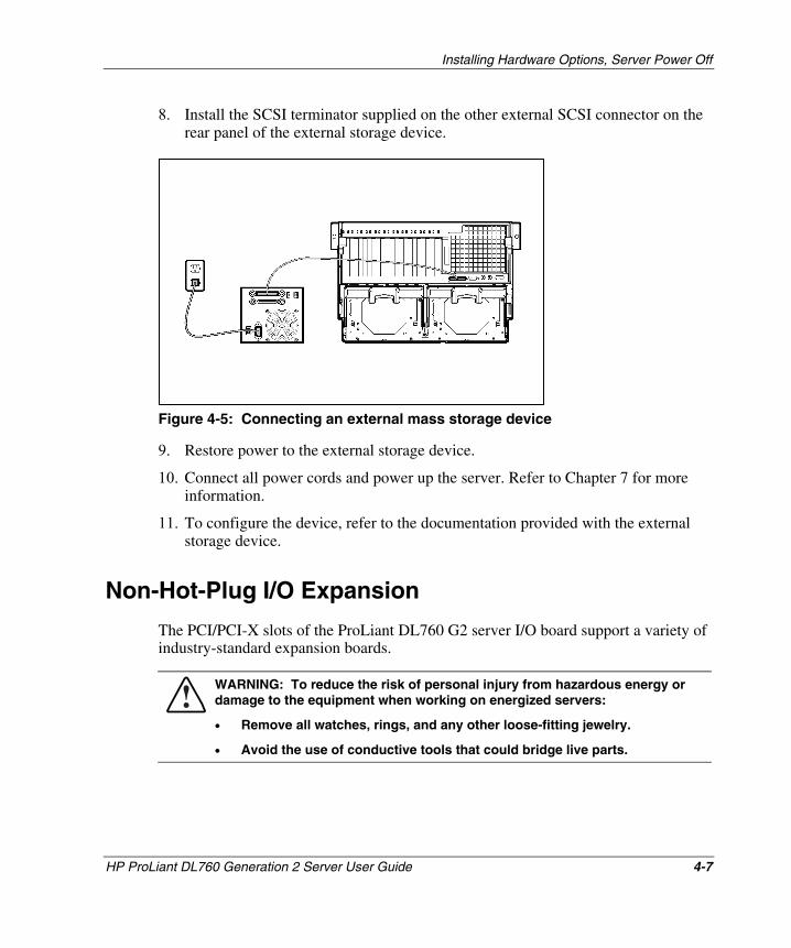
Installing Hardware Options, Server Power Off
8. Install the SCSI terminator supplied on the other external SCSI connector on the rear panel of the external storage device.
Figure 4-5: Connecting an external mass storage device
9. Restore power to the external storage device.
10. Connect all power cords and power up the server. Refer to Chapter 7 for more information.
11. To configure the device, refer to the documentation provided with the external storage device.
Non-Hot-Plug I/O Expansion
The PCI/PCI-X slots of the ProLiant DL760 G2 server I/O board support a variety of industry-standard expansion boards.
WARNING: To reduce the risk of personal injury from hazardous energy or damage to the equipment when working on energized servers:
• Remove all watches, rings, and any other loose-fitting jewelry.
• Avoid the use of conductive tools that could bridge live parts.
HP ProLiant DL760 Generation 2 Server User Guide 4-7
HP CONFIDENTIAL Writer: Jennifer Hayward File Name: e-ch4 Installing Options-Power Off.doc
Codename: Pioneer Part Number: 201264-002 Last Saved On: 6/17/03 9:32 AM
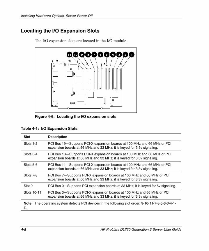
Installing Hardware Options, Server Power Off
Locating the I/O Expansion Slots
The I/O expansion slots are located in the I/O module.
Figure 4-6: Locating the I/O expansion slots
Table 4-1: I/O Expansion Slots
Slot Description
Slots 1-2 PCI Bus 19—Supports PCI-X expansion boards at 100 MHz and 66 MHz or PCI expansion boards at 66 MHz and 33 MHz; it is keyed for 3.3v signaling.
Slots 3-4 PCI Bus 13—Supports PCI-X expansion boards at 100 MHz and 66 MHz or PCI expansion boards at 66 MHz and 33 MHz; it is keyed for 3.3v signaling.
Slots 5-6 PCI Bus 11—Supports PCI-X expansion boards at 100 MHz and 66 MHz or PCI expansion boards at 66 MHz and 33 MHz; it is keyed for 3.3v signaling.
Slots 7-8 PCI Bus 7—Supports PCI-X expansion boards at 100 MHz and 66 MHz or PCI expansion boards at 66 MHz and 33 MHz; it is keyed for 3.3v signaling.
Slot 9 PCI Bus 0—Supports PCI expansion boards at 33 MHz; it is keyed for 5v signaling.
Slots 10-11 PCI Bus 3—Supports PCI-X expansion boards at 100 MHz and 66 MHz or PCI expansion boards at 66 MHz and 33 MHz; it is keyed for 3.3v signaling.
Note: The operating system detects PCI devices in the following slot order: 9-10-11-7-8-5-6-3-4-1-2.
4-8 HP ProLiant DL760 Generation 2 Server User Guide
HP CONFIDENTIAL Writer: Jennifer Hayward File Name: e-ch4 Installing Options-Power Off.doc
Codename: Pioneer Part Number: 201264-002 Last Saved On: 6/17/03 9:32 AM
Installing Hardware Options, Server Power Off
The I/O expansion slots are distributed among one PCI bus and five separate PCI-X buses.
NOTE: It is recommended that you install the optional RILOE II board into slot 9.
NOTE: Each PCI-X bus will automatically configure to run in the most advanced mode (PCI-X or PCI) and the highest frequency supported by all expansion boards installed in the slots on the bus.
NOTE: The ProLiant DL760 G2 server ships with a NIC preinstalled in slot 11.
Adding Non-Hot-Plug Expansion Boards
You can use non-hot-plug expansion boards in the ProLiant DL760 G2 server, but you must install them according to the following procedure. To prepare the server:
1. If this is the first time you have powered up the server, skip to step 4. If you have previously powered up the server, back up all data on the server.
2. Shut down the operating system as directed in your operating system instructions.
3. Power down the server (refer to Chapter 7).
4. Disconnect the power cords from the server.
5. Slide the server out of the rack.
6. Open the I/O lid as shown in Chapter 3.
HP ProLiant DL760 Generation 2 Server User Guide 4-9
HP CONFIDENTIAL Writer: Jennifer Hayward File Name: e-ch4 Installing Options-Power Off.doc
Codename: Pioneer Part Number: 201264-002 Last Saved On: 6/17/03 9:32 AM
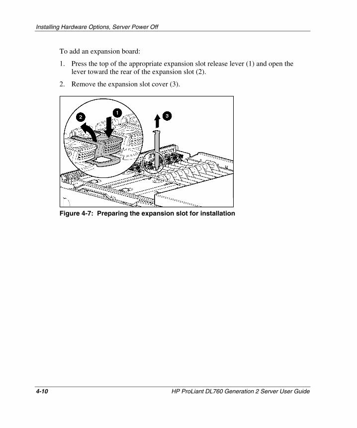
Installing Hardware Options, Server Power Off
To add an expansion board:
1. Press the top of the appropriate expansion slot release lever (1) and open the lever toward the rear of the expansion slot (2).
2. Remove the expansion slot cover (3).
Figure 4-7: Preparing the expansion slot for installation
4-10 HP ProLiant DL760 Generation 2 Server User Guide
HP CONFIDENTIAL Writer: Jennifer Hayward File Name: e-ch4 Installing Options-Power Off.doc
Codename: Pioneer Part Number: 201264-002 Last Saved On: 6/17/03 9:32 AM
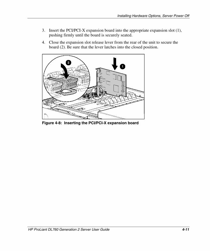
Installing Hardware Options, Server Power Off
3. Insert the PCI/PCI-X expansion board into the appropriate expansion slot (1), pushing firmly until the board is securely seated.
4. Close the expansion slot release lever from the rear of the unit to secure the board (2). Be sure that the lever latches into the closed position.
Figure 4-8: Inserting the PCI/PCI-X expansion board
HP ProLiant DL760 Generation 2 Server User Guide 4-11
HP CONFIDENTIAL Writer: Jennifer Hayward File Name: e-ch4 Installing Options-Power Off.doc
Codename: Pioneer Part Number: 201264-002 Last Saved On: 6/17/03 9:32 AM
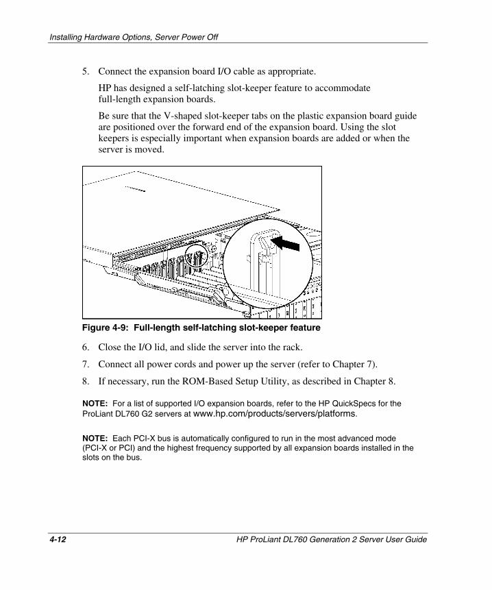
Installing Hardware Options, Server Power Off
5. Connect the expansion board I/O cable as appropriate.
HP has designed a self-latching slot-keeper feature to accommodate full-length expansion boards.
Be sure that the V-shaped slot-keeper tabs on the plastic expansion board guide are positioned over the forward end of the expansion board. Using the slot keepers is especially important when expansion boards are added or when the server is moved.
Figure 4-9: Full-length self-latching slot-keeper feature
6. Close the I/O lid, and slide the server into the rack.
7. Connect all power cords and power up the server (refer to Chapter 7).
8. If necessary, run the ROM-Based Setup Utility, as described in Chapter 8.
NOTE: For a list of supported I/O expansion boards, refer to the HP QuickSpecs for the ProLiant DL760 G2 servers at www.hp.com/products/servers/platforms.
NOTE: Each PCI-X bus is automatically configured to run in the most advanced mode (PCI-X or PCI) and the highest frequency supported by all expansion boards installed in the slots on the bus.
4-12 HP ProLiant DL760 Generation 2 Server User Guide
HP CONFIDENTIAL Writer: Jennifer Hayward File Name: e-ch4 Installing Options-Power Off.doc
Codename: Pioneer Part Number: 201264-002 Last Saved On: 6/17/03 9:32 AM
Installing Hardware Options, Server Power Off
Installing the Remote Insight Lights-Out Edition II
The ProLiant DL760 G2 server supports the Remote Insight Lights-Out Edition (RILOE) II with a Remote Management connector (30-pin) located on the I/O board.
To install RILOE II:
1. If you have previously powered up the server, back up your server data.
2. Shut down the operating system as directed in your operating system instructions.
3. Power down the server (refer to Chapter 7).
4. Disconnect the power cords from the server.
5. Slide the server out of the rack.
6. Open the I/O lid as shown in Chapter 3.
HP ProLiant DL760 Generation 2 Server User Guide 4-13
HP CONFIDENTIAL Writer: Jennifer Hayward File Name: e-ch4 Installing Options-Power Off.doc
Codename: Pioneer Part Number: 201264-002 Last Saved On: 6/17/03 9:32 AM
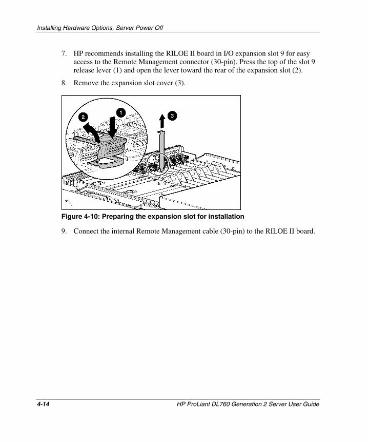
Installing Hardware Options, Server Power Off
7. HP recommends installing the RILOE II board in I/O expansion slot 9 for easy access to the Remote Management connector (30-pin). Press the top of the slot 9 release lever (1) and open the lever toward the rear of the expansion slot (2).
8. Remove the expansion slot cover (3).
Figure 4-10: Preparing the expansion slot for installation
9. Connect the internal Remote Management cable (30-pin) to the RILOE II board.
4-14 HP ProLiant DL760 Generation 2 Server User Guide
HP CONFIDENTIAL Writer: Jennifer Hayward File Name: e-ch4 Installing Options-Power Off.doc
Codename: Pioneer Part Number: 201264-002 Last Saved On: 6/17/03 9:32 AM
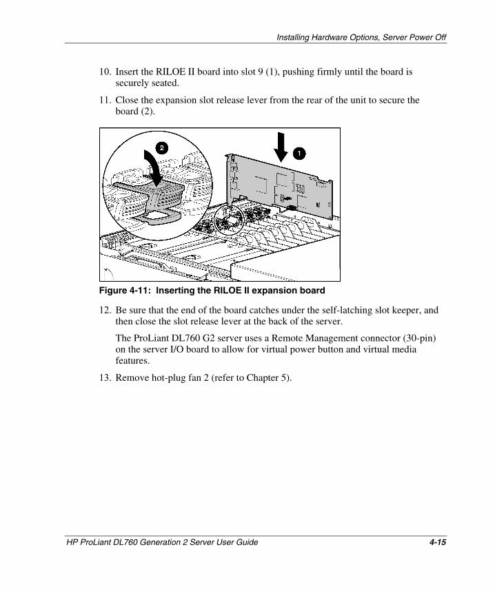
Installing Hardware Options, Server Power Off
10. Insert the RILOE II board into slot 9 (1), pushing firmly until the board is securely seated.
11. Close the expansion slot release lever from the rear of the unit to secure the board (2).
Figure 4-11: Inserting the RILOE II expansion board
12. Be sure that the end of the board catches under the self-latching slot keeper, and then close the slot release lever at the back of the server.
The ProLiant DL760 G2 server uses a Remote Management connector (30-pin) on the server I/O board to allow for virtual power button and virtual media features.
13. Remove hot-plug fan 2 (refer to Chapter 5).
HP ProLiant DL760 Generation 2 Server User Guide 4-15
HP CONFIDENTIAL Writer: Jennifer Hayward File Name: e-ch4 Installing Options-Power Off.doc
Codename: Pioneer Part Number: 201264-002 Last Saved On: 6/17/03 9:32 AM
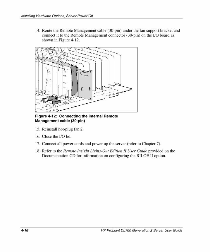
Installing Hardware Options, Server Power Off
14. Route the Remote Management cable (30-pin) under the fan support bracket and connect it to the Remote Management connector (30-pin) on the I/O board as shown in Figure 4-12.
Figure 4-12: Connecting the internal Remote Management cable (30-pin)
15. Reinstall hot-plug fan 2.
16. Close the I/O lid.
17. Connect all power cords and power up the server (refer to Chapter 7).
18. Refer to the Remote Insight Lights-Out Edition II User Guide provided on the Documentation CD for information on configuring the RILOE II option.
4-16 HP ProLiant DL760 Generation 2 Server User Guide
HP CONFIDENTIAL Writer: Jennifer Hayward File Name: e-ch4 Installing Options-Power Off.doc
Codename: Pioneer Part Number: 201264-002 Last Saved On: 6/17/03 9:32 AM
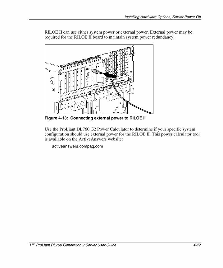
Installing Hardware Options, Server Power Off
RILOE II can use either system power or external power. External power may be required for the RILOE II board to maintain system power redundancy.
Figure 4-13: Connecting external power to RILOE II
Use the ProLiant DL760 G2 Power Calculator to determine if your specific system configuration should use external power for the RILOE II. This power calculator tool is available on the ActiveAnswers website:
activeanswers.compaq.com
HP ProLiant DL760 Generation 2 Server User Guide 4-17
HP CONFIDENTIAL Writer: Jennifer Hayward File Name: e-ch4 Installing Options-Power Off.doc
Codename: Pioneer Part Number: 201264-002 Last Saved On: 6/17/03 9:32 AM
Installing Hardware Options, Server Power Off
Installing the Integrated Array Bypass
Use the Integrated Array Bypass kit to bypass the Smart Array 5i Controller and use an optional controller.
The Smart Array 5i Controller is routed to the internal drives through a daughter board, the Array Enabler board, in the I/O module.
The Integrated Array Bypass kit allows you to replace the Array Enabler board with a connector and cable that you can connect to an optional controller board.
WARNING: To reduce the risk of personal injury from hot surfaces, allow the internal system components to cool before touching them.
CAUTION: Back up your data each time you move drive arrays or change the configuration.
To install the Integrated Array Bypass assembly:
1. If you have not powered up the server for the first time, skip to step 4. If you have powered up the server, back up the server data.
2. Shut down the operating system as directed in the operating system instructions.
3. Power down the server (refer to Chapter 7).
4. Disconnect the power cords from the server.
5. Slide the server out of the rack.
6. Open the I/O lid as shown in Chapter 3.
4-18 HP ProLiant DL760 Generation 2 Server User Guide
HP CONFIDENTIAL Writer: Jennifer Hayward File Name: e-ch4 Installing Options-Power Off.doc
Codename: Pioneer Part Number: 201264-002 Last Saved On: 6/17/03 9:32 AM
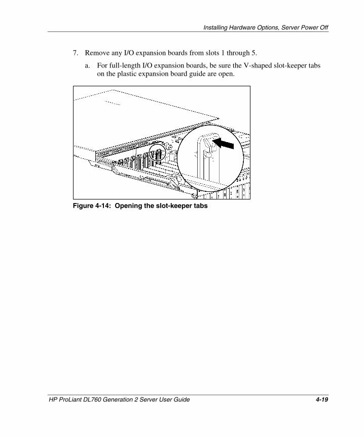
Installing Hardware Options, Server Power Off
7. Remove any I/O expansion boards from slots 1 through 5.
a. For full-length I/O expansion boards, be sure the V-shaped slot-keeper tabs on the plastic expansion board guide are open.
Figure 4-14: Opening the slot-keeper tabs
HP ProLiant DL760 Generation 2 Server User Guide 4-19
HP CONFIDENTIAL Writer: Jennifer Hayward File Name: e-ch4 Installing Options-Power Off.doc
Codename: Pioneer Part Number: 201264-002 Last Saved On: 6/17/03 9:32 AM
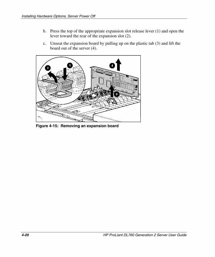
Installing Hardware Options, Server Power Off
b. Press the top of the appropriate expansion slot release lever (1) and open the lever toward the rear of the expansion slot (2).
c. Unseat the expansion board by pulling up on the plastic tab (3) and lift the board out of the server (4).
Figure 4-15: Removing an expansion board
4-20 HP ProLiant DL760 Generation 2 Server User Guide
HP CONFIDENTIAL Writer: Jennifer Hayward File Name: e-ch4 Installing Options-Power Off.doc
Codename: Pioneer Part Number: 201264-002 Last Saved On: 6/17/03 9:32 AM
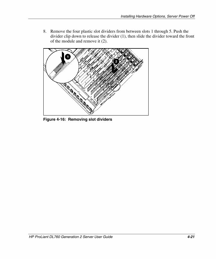
Installing Hardware Options, Server Power Off
8. Remove the four plastic slot dividers from between slots 1 through 5. Push the divider clip down to release the divider (1), then slide the divider toward the front of the module and remove it (2).
Figure 4-16: Removing slot dividers
HP ProLiant DL760 Generation 2 Server User Guide 4-21
HP CONFIDENTIAL Writer: Jennifer Hayward File Name: e-ch4 Installing Options-Power Off.doc
Codename: Pioneer Part Number: 201264-002 Last Saved On: 6/17/03 9:32 AM
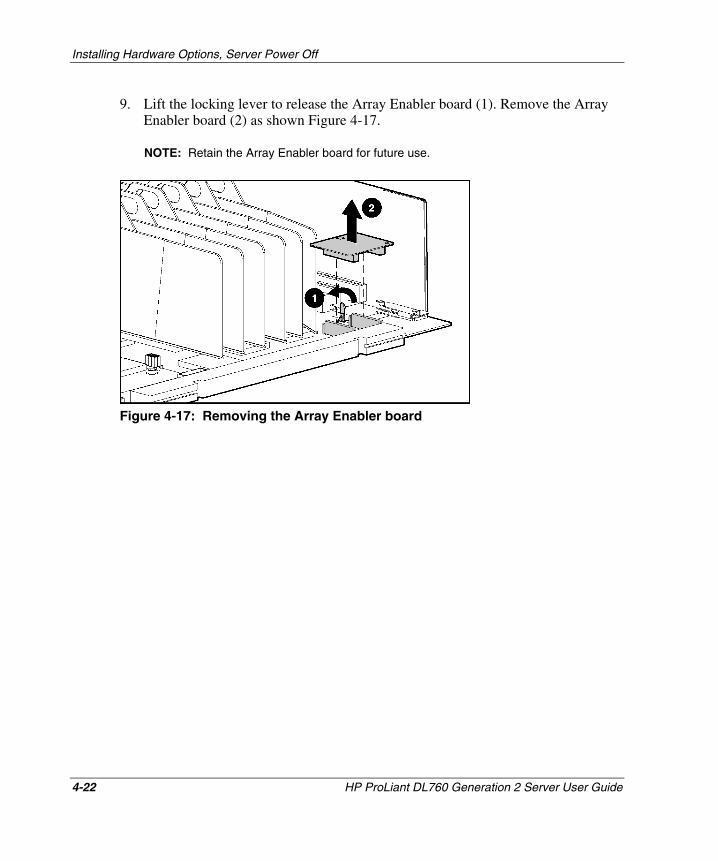
Installing Hardware Options, Server Power Off
9. Lift the locking lever to release the Array Enabler board (1). Remove the Array Enabler board (2) as shown Figure 4-17.
NOTE: Retain the Array Enabler board for future use.
Figure 4-17: Removing the Array Enabler board
4-22 HP ProLiant DL760 Generation 2 Server User Guide
HP CONFIDENTIAL Writer: Jennifer Hayward File Name: e-ch4 Installing Options-Power Off.doc
Codename: Pioneer Part Number: 201264-002 Last Saved On: 6/17/03 9:32 AM
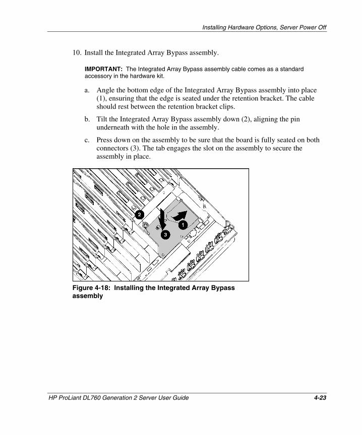
Installing Hardware Options, Server Power Off
10. Install the Integrated Array Bypass assembly.
IMPORTANT: The Integrated Array Bypass assembly cable comes as a standard accessory in the hardware kit.
a. Angle the bottom edge of the Integrated Array Bypass assembly into place (1), ensuring that the edge is seated under the retention bracket. The cable should rest between the retention bracket clips.
b. Tilt the Integrated Array Bypass assembly down (2), aligning the pin underneath with the hole in the assembly.
c. Press down on the assembly to be sure that the board is fully seated on both connectors (3). The tab engages the slot on the assembly to secure the assembly in place.
Figure 4-18: Installing the Integrated Array Bypass assembly
HP ProLiant DL760 Generation 2 Server User Guide 4-23
HP CONFIDENTIAL Writer: Jennifer Hayward File Name: e-ch4 Installing Options-Power Off.doc
Codename: Pioneer Part Number: 201264-002 Last Saved On: 6/17/03 9:32 AM
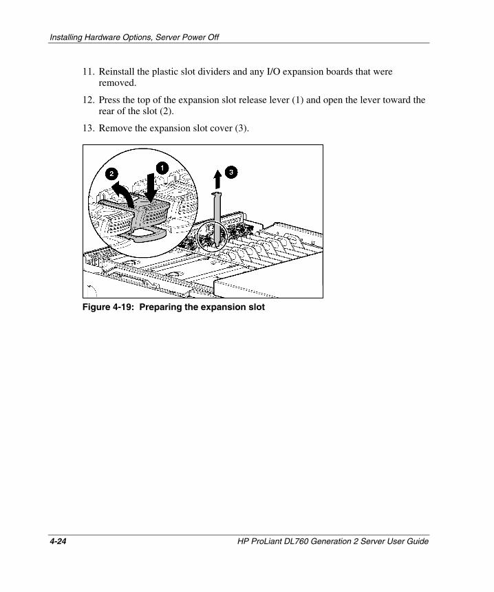
Installing Hardware Options, Server Power Off
11. Reinstall the plastic slot dividers and any I/O expansion boards that were removed.
12. Press the top of the expansion slot release lever (1) and open the lever toward the rear of the slot (2).
13. Remove the expansion slot cover (3).
Figure 4-19: Preparing the expansion slot
4-24 HP ProLiant DL760 Generation 2 Server User Guide
HP CONFIDENTIAL Writer: Jennifer Hayward File Name: e-ch4 Installing Options-Power Off.doc
Codename: Pioneer Part Number: 201264-002 Last Saved On: 6/17/03 9:32 AM
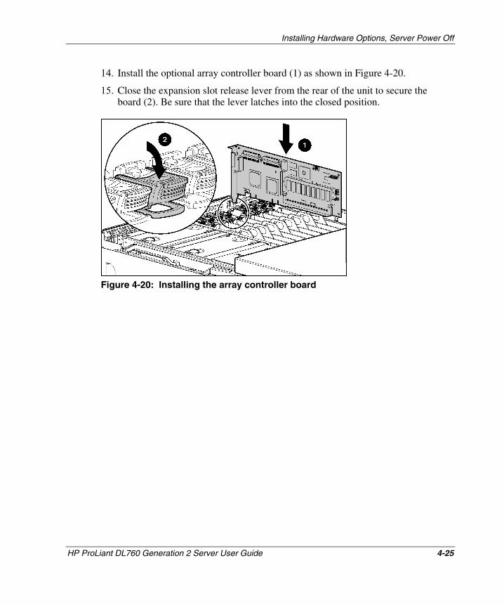
Installing Hardware Options, Server Power Off
14. Install the optional array controller board (1) as shown in Figure 4-20.
15. Close the expansion slot release lever from the rear of the unit to secure the board (2). Be sure that the lever latches into the closed position.
Figure 4-20: Installing the array controller board
HP ProLiant DL760 Generation 2 Server User Guide 4-25
HP CONFIDENTIAL Writer: Jennifer Hayward File Name: e-ch4 Installing Options-Power Off.doc
Codename: Pioneer Part Number: 201264-002 Last Saved On: 6/17/03 9:32 AM
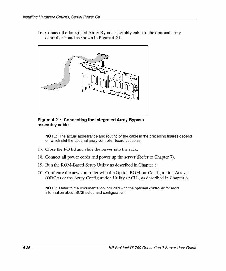
Installing Hardware Options, Server Power Off
4-26 HP ProLiant DL760 Generation 2 Server User Guide
HP CONFIDENTIAL Writer: Jennifer Hayward File Name: e-ch4 Installing Options-Power Off.doc
Codename: Pioneer Part Number: 201264-002 Last Saved On: 6/17/03 9:32 AM
16. Connect the Integrated Array Bypass assembly cable to the optional array controller board as shown in Figure 4-21.
Figure 4-21: Connecting the Integrated Array Bypass assembly cable
NOTE: The actual appearance and routing of the cable in the preceding figures depend on which slot the optional array controller board occupies.
17. Close the I/O lid and slide the server into the rack.
18. Connect all power cords and power up the server (Refer to Chapter 7).
19. Run the ROM-Based Setup Utility as described in Chapter 8.
20. Configure the new controller with the Option ROM for Configuration Arrays (ORCA) or the Array Configuration Utility (ACU), as described in Chapter 8.
NOTE: Refer to the documentation included with the optional controller for more information about SCSI setup and configuration.

5 Installing Hardware Options, Hot-Pluggable
The following instructions are provided as an overview for installing hardware option upgrades that are hot-pluggable. HP recommends that you use the documentation provided with the hardware option for complete installation instructions. You can also refer to the HP ProLiant DL760 Generation 2 Server Setup Poster included in the shipping box or to the labels attached to the I/O lid of the server.
WARNING: To reduce the risk of personal injury or damage to the equipment, heed all warnings and cautions throughout the installation instructions.
WARNING: To reduce the risk of personal injury or damage to the equipment, the installation of options other than hot-plug power supplies and hot-plug hard drives should be performed only by individuals who are qualified in servicing computer equipment and are trained to deal with products capable of producing hazardous energy levels.
WARNING: To reduce the risk of personal injury from hazardous energy or damage to the equipment when working on energized servers:
• Remove all watches, rings, and any other loose-fitting jewelry.
• Avoid the use of conductive tools that could bridge live parts.
CAUTION: Electrostatic discharge can damage electronic components. Be sure that you are properly grounded before beginning any installation procedure. Refer to Appendix B for more information.
HP ProLiant DL760 Generation 2 Server User Guide 5-1
HP CONFIDENTIAL Writer: Bryce Miller File Name: f-ch5 Installing Options-Hot Pluggable.doc
Codename: Comet Part Number: 201264-001 Last Saved On: 6/17/03 9:47 AM
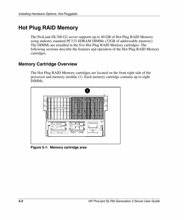
Installing Hardware Options, Hot-Pluggable
Hot Plug RAID Memory
The ProLiant DL760 G2 server supports up to 40 GB of Hot Plug RAID Memory using industry standard PC133 SDRAM DIMMs (32GB of addressable memory). The DIMMs are installed in the five Hot Plug RAID Memory cartridges. The following sections describe the features and operation of the Hot Plug RAID Memory cartridges.
Memory Cartridge Overview
The Hot Plug RAID Memory cartridges are located on the front right side of the processor and memory module (1). Each memory cartridge contains up to eight DIMMs.
Figure 5-1: Memory cartridge area
5-2 HP ProLiant DL760 Generation 2 Server User Guide
HP CONFIDENTIAL Writer: Bryce Miller File Name: f-ch5 Installing Options-Hot Pluggable.doc
Codename: Comet Part Number: 201264-001 Last Saved On: 6/17/03 9:47 AM
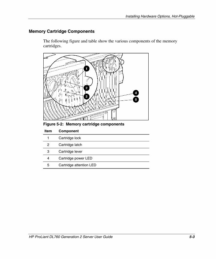
Installing Hardware Options, Hot-Pluggable
Memory Cartridge Components
The following figure and table show the various components of the memory cartridges.
Figure 5-2: Memory cartridge components
Item Component
1 Cartridge lock
2 Cartridge latch
3 Cartridge lever
4 Cartridge power LED
5 Cartridge attention LED
HP ProLiant DL760 Generation 2 Server User Guide 5-3
HP CONFIDENTIAL Writer: Bryce Miller File Name: f-ch5 Installing Options-Hot Pluggable.doc
Codename: Comet Part Number: 201264-001 Last Saved On: 6/17/03 9:47 AM
Installing Hardware Options, Hot-Pluggable
Memory Cartridge Guidelines
The ProLiant DL760 G2 server has five Hot Plug RAID Memory cartridges. They are designed to allow the removal of a single cartridge while the server is running.
CAUTION: The system will halt with more than one memory cartridge removed.
The ProLiant DL760 G2 server has eight memory banks, each consisting of five DIMMs installed across the five memory cartridges. Similar DIMMs are installed in bank pairs (1+2, 3+4, 5+6, 7+8) for memory interleaving to increase performance.
NOTE: For more details, refer to the memory cartridge covers or DIMM installation guidelines later in this chapter.
Memory Cartridge Requirements
The following requirements are the minimum Hot Plug RAID Memory configuration requirements:
• Five cartridges must be installed.
• All five cartridges must have the same configuration and type of DIMMs installed for redundancy (refer to diagram on cartridge cover).
IMPORTANT: The server will run in non-RAID memory configuration mode if all DIMM sockets in cartridge 5 are empty.
• All DIMMs must be supported by the system (refer to QuickSpecs).
• All DIMMs in a bank pair must be same speed, type, and size. They should have the same part number (for example 123456-12x, where x is not required to match).
5-4 HP ProLiant DL760 Generation 2 Server User Guide
HP CONFIDENTIAL Writer: Bryce Miller File Name: f-ch5 Installing Options-Hot Pluggable.doc
Codename: Comet Part Number: 201264-001 Last Saved On: 6/17/03 9:47 AM
Installing Hardware Options, Hot-Pluggable
The following additional guidelines apply to DIMM installation:
• DIMM configurations must match in all five cartridges (DIMM similarity and socket).
• Similar DIMMs or no DIMMs must be installed in bank pair order (1+2, then 3+4, then 5+6, then 7+8).
IMPORTANT: POST requires all minimum memory requirements to be met before operating system load is permitted with the exception of a nonredundant configuration. DIMM configuration errors will be reported by two long beeps, video, IMD, or DIMM status LEDs.
HP ProLiant DL760 Generation 2 Server User Guide 5-5
HP CONFIDENTIAL Writer: Bryce Miller File Name: f-ch5 Installing Options-Hot Pluggable.doc
Codename: Comet Part Number: 201264-001 Last Saved On: 6/17/03 9:47 AM
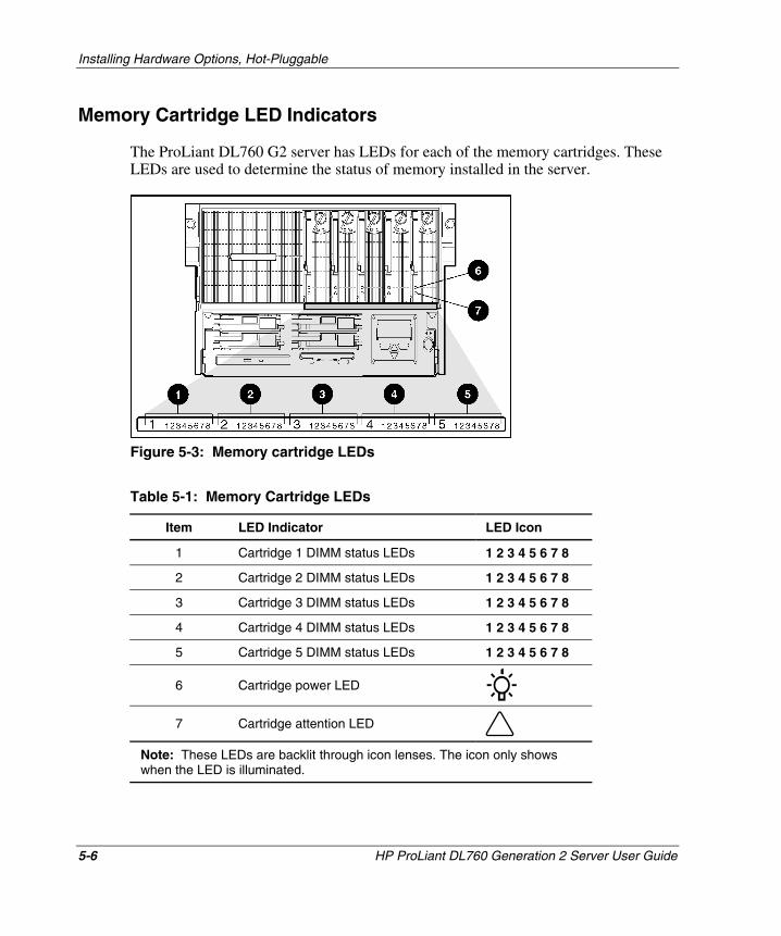
Installing Hardware Options, Hot-Pluggable
Memory Cartridge LED Indicators
The ProLiant DL760 G2 server has LEDs for each of the memory cartridges. These LEDs are used to determine the status of memory installed in the server.
Figure 5-3: Memory cartridge LEDs
Table 5-1: Memory Cartridge LEDs
Item LED Indicator LED Icon
1 Cartridge 1 DIMM status LEDs 1 2 3 4 5 6 7 8
2 Cartridge 2 DIMM status LEDs 1 2 3 4 5 6 7 8
3 Cartridge 3 DIMM status LEDs 1 2 3 4 5 6 7 8
4 Cartridge 4 DIMM status LEDs 1 2 3 4 5 6 7 8
5 Cartridge 5 DIMM status LEDs 1 2 3 4 5 6 7 8
6 Cartridge power LED
7 Cartridge attention LED
Note: These LEDs are backlit through icon lenses. The icon only shows when the LED is illuminated.
5-6 HP ProLiant DL760 Generation 2 Server User Guide
HP CONFIDENTIAL Writer: Bryce Miller File Name: f-ch5 Installing Options-Hot Pluggable.doc
Codename: Comet Part Number: 201264-001 Last Saved On: 6/17/03 9:47 AM
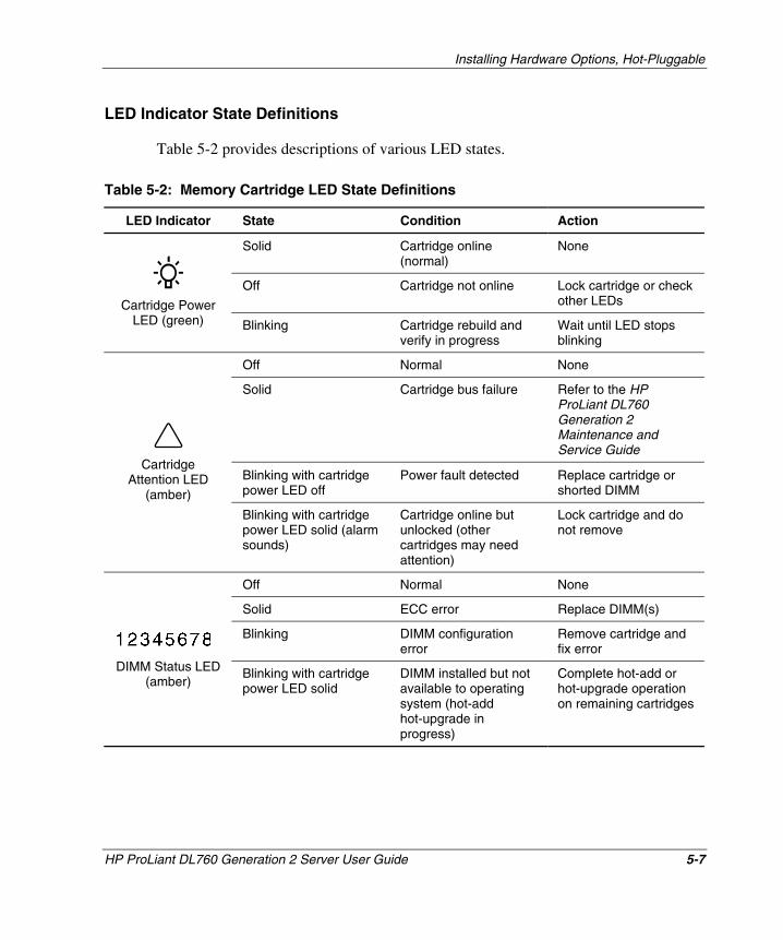
Installing Hardware Options, Hot-Pluggable
LED Indicator State Definitions
Table 5-2 provides descriptions of various LED states.
Table 5-2: Memory Cartridge LED State Definitions
LED Indicator State Condition Action
Solid Cartridge online (normal)
None
Off Cartridge not online Lock cartridge or check other LEDs
DIMM Status LED (amber)
Blinking with cartridge power LED solid
DIMM installed but not available to operating system (hot-add hot-upgrade in progress)
Complete hot-add or hot-upgrade operation on remaining cartridges
Cartridge Power LED (green) Blinking Cartridge rebuild and
verify in progress Wait until LED stops blinking
Off Normal None
Solid Cartridge bus failure Refer to the HP ProLiant DL760 Generation 2 Maintenance and Service Guide
Blinking with cartridge power LED off
Power fault detected Replace cartridge or shorted DIMM
Cartridge Attention LED
(amber)
Blinking with cartridge power LED solid (alarm sounds)
Cartridge online but unlocked (other cartridges may need attention)
Lock cartridge and do not remove
Off Normal None
Solid ECC error Replace DIMM(s)
Blinking DIMM configuration error
Remove cartridge and fix error
HP ProLiant DL760 Generation 2 Server User Guide 5-7
HP CONFIDENTIAL Writer: Bryce Miller File Name: f-ch5 Installing Options-Hot Pluggable.doc
Codename: Comet Part Number: 201264-001 Last Saved On: 6/17/03 9:47 AM
Installing Hardware Options, Hot-Pluggable
Accessing the DIMMs
To access the DIMMs in the server, you must remove the memory cartridge. The Hot Plug RAID Memory cartridge is designed to allow replacing, adding, or upgrading of memory while the system is online.
Removing the Memory Cartridge
To remove a memory cartridge from the ProLiant DL760 G2 server:
1. Unlock the memory cartridge by rotating the cartridge lock counterclockwise (1) as shown in Figure 5-4.
IMPORTANT: If the memory cartridge is not required for continued operation (with at least four other memory cartridges installed, online, and error free), the memory cartridge power LED will go off.
If the cartridge is required for continued operation, an audible caution alarm will sound and the memory cartridge attention LED will blink until the cartridge is locked again.
5-8 HP ProLiant DL760 Generation 2 Server User Guide
HP CONFIDENTIAL Writer: Bryce Miller File Name: f-ch5 Installing Options-Hot Pluggable.doc
Codename: Comet Part Number: 201264-001 Last Saved On: 6/17/03 9:47 AM

Installing Hardware Options, Hot-Pluggable
2. Be sure that the cartridge power LED is off (2).
CAUTION: Do not remove a memory cartridge if the cartridge power LED is blinking or is solid green. The system will halt.
3. Push the lever latch upward (3) to release the memory cartridge lever.
4. Pull the memory cartridge lever down (4).
5. Slide the cartridge out of the processor and memory module (5).
Figure 5-4: Removing the memory cartridge
WARNING: To reduce the risk of personal injury from hot surfaces, allow the internal system components to cool before touching them.
HP ProLiant DL760 Generation 2 Server User Guide 5-9
HP CONFIDENTIAL Writer: Bryce Miller File Name: f-ch5 Installing Options-Hot Pluggable.doc
Codename: Comet Part Number: 201264-001 Last Saved On: 6/17/03 9:47 AM
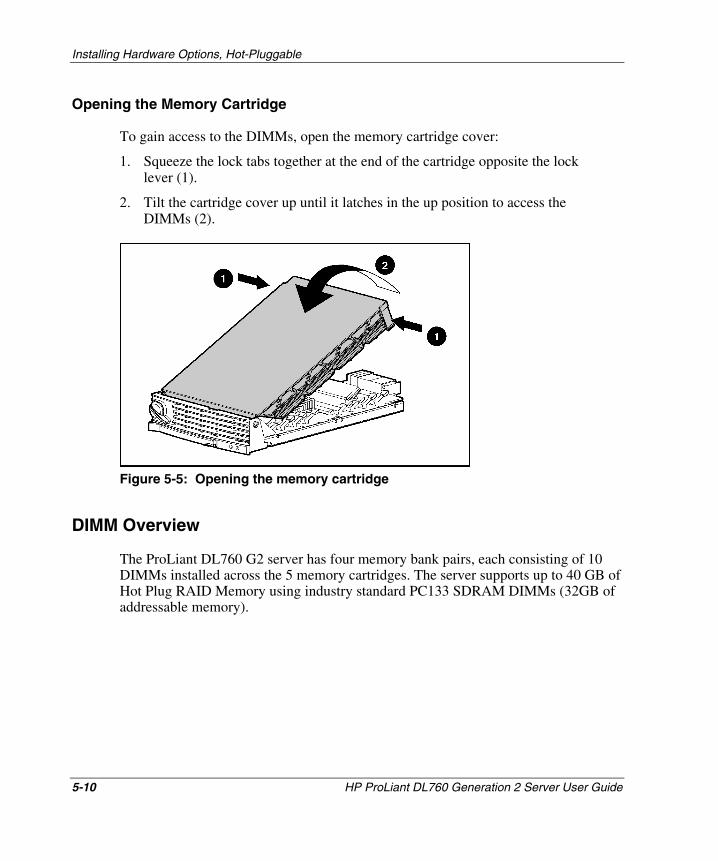
Installing Hardware Options, Hot-Pluggable
Opening the Memory Cartridge
To gain access to the DIMMs, open the memory cartridge cover:
1. Squeeze the lock tabs together at the end of the cartridge opposite the lock lever (1).
2. Tilt the cartridge cover up until it latches in the up position to access the DIMMs (2).
Figure 5-5: Opening the memory cartridge
DIMM Overview
The ProLiant DL760 G2 server has four memory bank pairs, each consisting of 10 DIMMs installed across the 5 memory cartridges. The server supports up to 40 GB of Hot Plug RAID Memory using industry standard PC133 SDRAM DIMMs (32GB of addressable memory).
5-10 HP ProLiant DL760 Generation 2 Server User Guide
HP CONFIDENTIAL Writer: Bryce Miller File Name: f-ch5 Installing Options-Hot Pluggable.doc
Codename: Comet Part Number: 201264-001 Last Saved On: 6/17/03 9:47 AM
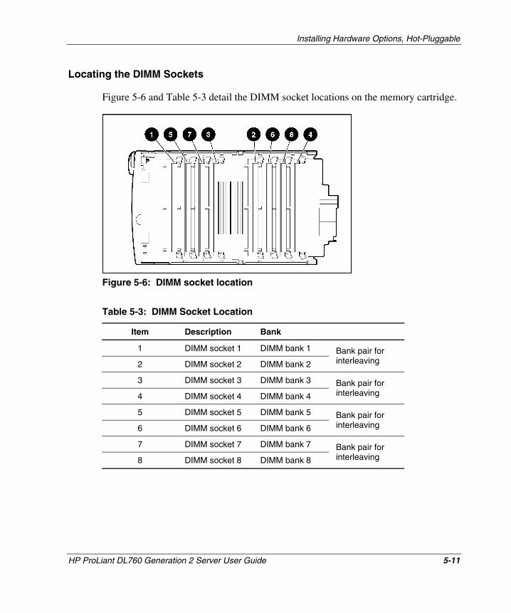
Installing Hardware Options, Hot-Pluggable
Locating the DIMM Sockets
Figure 5-6 and Table 5-3 detail the DIMM socket locations on the memory cartridge.
Figure 5-6: DIMM socket location
Table 5-3: DIMM Socket Location
Item Description Bank
1 DIMM socket 1 DIMM bank 1
2 DIMM socket 2 DIMM bank 2
Bank pair for interleaving
3 DIMM socket 3 DIMM bank 3
4 DIMM socket 4 DIMM bank 4
Bank pair for interleaving
5 DIMM socket 5 DIMM bank 5
6 DIMM socket 6 DIMM bank 6
Bank pair for interleaving
7 DIMM socket 7 DIMM bank 7
8 DIMM socket 8 DIMM bank 8
Bank pair for interleaving
HP ProLiant DL760 Generation 2 Server User Guide 5-11
HP CONFIDENTIAL Writer: Bryce Miller File Name: f-ch5 Installing Options-Hot Pluggable.doc
Codename: Comet Part Number: 201264-001 Last Saved On: 6/17/03 9:47 AM
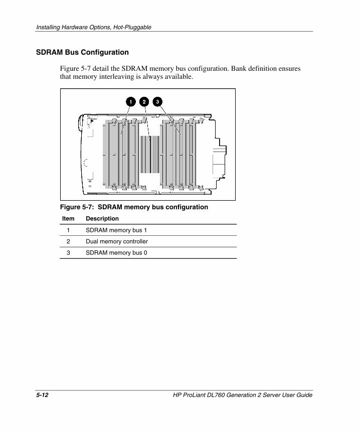
Installing Hardware Options, Hot-Pluggable
SDRAM Bus Configuration
Figure 5-7 detail the SDRAM memory bus configuration. Bank definition ensures that memory interleaving is always available.
Figure 5-7: SDRAM memory bus configuration
Item Description
1 SDRAM memory bus 1
2 Dual memory controller
3 SDRAM memory bus 0
5-12 HP ProLiant DL760 Generation 2 Server User Guide
HP CONFIDENTIAL Writer: Bryce Miller File Name: f-ch5 Installing Options-Hot Pluggable.doc
Codename: Comet Part Number: 201264-001 Last Saved On: 6/17/03 9:47 AM
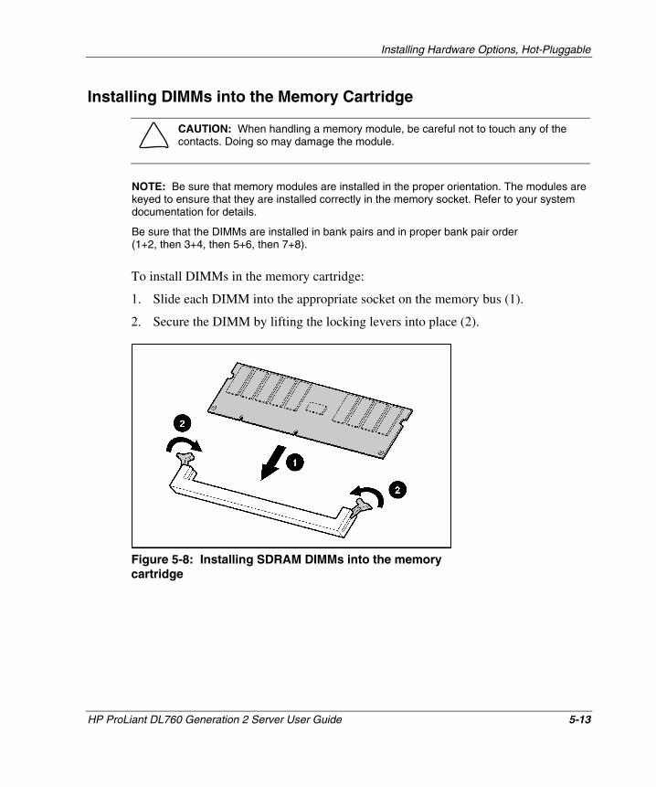
Installing Hardware Options, Hot-Pluggable
Installing DIMMs into the Memory Cartridge
CAUTION: When handling a memory module, be careful not to touch any of the contacts. Doing so may damage the module.
NOTE: Be sure that memory modules are installed in the proper orientation. The modules are keyed to ensure that they are installed correctly in the memory socket. Refer to your system documentation for details.
Be sure that the DIMMs are installed in bank pairs and in proper bank pair order (1+2, then 3+4, then 5+6, then 7+8).
To install DIMMs in the memory cartridge:
1. Slide each DIMM into the appropriate socket on the memory bus (1).
2. Secure the DIMM by lifting the locking levers into place (2).
Figure 5-8: Installing SDRAM DIMMs into the memory cartridge
HP ProLiant DL760 Generation 2 Server User Guide 5-13
HP CONFIDENTIAL Writer: Bryce Miller File Name: f-ch5 Installing Options-Hot Pluggable.doc
Codename: Comet Part Number: 201264-001 Last Saved On: 6/17/03 9:47 AM
Installing Hardware Options, Hot-Pluggable
3. Be sure that all of the DIMM socket levers are rotated inward before closing the cartridge cover.
4. Close the memory cartridge cover.
5. Insert the memory cartridge in the server and secure it in place by lifting the cartridge ejector lever.
6. Lock the memory cartridge in place by rotating the cartridge lock clockwise.
7. Be sure that the cartridge is online (cartridge power LED solid).
Hot Plug RAID Memory Operating System Support
Software support is an integral part of Hot Plug RAID Memory. HP, in partnership with operating system vendors and the Linux open source community, has developed Hot Plug RAID Memory software support for the ProLiant DL760 G2 server.
HP provides a hot-plug memory driver for each of the supported operating systems, as well as embedded functionality in the ProLiant DL760 G2 server. Hot-replace functionality is available natively in the server, while hot-add and hot-upgrade functionality require installation of the hot-plug memory driver. Operating system vendors may also provide enhanced functionality in their operating systems to enable the detection of added or upgraded memory without a reboot. For current information on Hot Plug RAID Memory support for your operating system, refer to the Operating System Support for Hot Plug RAID Memory white paper available on the HP website:
www.hp.com
Hot-plug memory drivers are provided on the SmartStart CD and the HP website:
www.hp.com
ProLiant Support Packs are available on SmartStart CD or on the HP website.
Supported operating systems include:
• Microsoft Windows 2000 (supports hot-replace only)
• Microsoft Windows Server 2003
5-14 HP ProLiant DL760 Generation 2 Server User Guide
HP CONFIDENTIAL Writer: Bryce Miller File Name: f-ch5 Installing Options-Hot Pluggable.doc
Codename: Comet Part Number: 201264-001 Last Saved On: 6/17/03 9:47 AM
• Caldera Open UNIX 8
Installing Hardware Options, Hot-Pluggable
• SCO UnixWare 7.1.3
• Red Hat Linux 7.2
• SuSE Linux Enterprise Server 7
Hot-Replacing Memory
If there is a problem with a DIMM in your server, the DIMM status LEDs will illuminate either solid or blinking. If the DIMM status LED for a specific DIMM in a specific cartridge is solid, then the DIMM needs to be replaced.
CAUTION: A redundant memory configuration is required when performing Hot Plug RAID Memory functions.
• If all five memory cartridges are online and error free, any memory cartridge can be removed.
• If one of the five memory cartridges requires attention, only that memory cartridge can be removed.
• If two or more memory cartridges require attention and are online (cartridge power LED is illuminated), no cartridge can be removed while the system is online. An audible alarm will sound if any cartridge is unlocked.
IMPORTANT: You cannot perform a hot-replace of memory if only four memory cartridges are installed. The system must have a redundant memory configuration (five cartridges online and error free) before the hot-replace feature will function.
HP ProLiant DL760 Generation 2 Server User Guide 5-15
HP CONFIDENTIAL Writer: Bryce Miller File Name: f-ch5 Installing Options-Hot Pluggable.doc
Codename: Comet Part Number: 201264-001 Last Saved On: 6/17/03 9:47 AM
Installing Hardware Options, Hot-Pluggable
To replace DIMMs:
1. Unlock the cartridge and slide it out of the server following the procedure in the “Removing the Memory Cartridge” section of this chapter.
CAUTION: Do not remove a memory cartridge if the cartridge power LED is blinking or is solid green. The system will halt.
2. Lift the memory cartridge cover and remove the failed DIMM.
3. Replace the failed DIMM with a working DIMM of the same speed, type, and size. It should have the same part number (for example 123456-12x, where x is not required to match).
CAUTION: When handling a memory module, be careful not to touch any of the contacts. Doing so can damage the module.
NOTE: Be sure memory modules are installed in proper orientation. The modules are keyed to ensure that they are installed correctly in the memory socket.
4. Be sure that all of the DIMM socket levers are rotated inward before closing the cartridge cover and then close the memory cartridge cover.
5. Insert the memory cartridge in the server and secure it in place by closing the cartridge ejector lever.
6. Lock the memory cartridge in place by rotating the cartridge lock clockwise to the locked position.
7. The system will rebuild and verify the data on the DIMMs in the memory cartridge as the cartridge power LEDs are blinking. This process is complete when the cartridge power LED is illuminated solid green, indicating that the cartridge is online.
8. Continue with normal server operation.
5-16 HP ProLiant DL760 Generation 2 Server User Guide
HP CONFIDENTIAL Writer: Bryce Miller File Name: f-ch5 Installing Options-Hot Pluggable.doc
Codename: Comet Part Number: 201264-001 Last Saved On: 6/17/03 9:47 AM
Installing Hardware Options, Hot-Pluggable
Hot-Adding Memory
For the hot-add feature to work on the ProLiant DL760 G2 server, the operating system must have driver support. Refer to “Installing HP Drivers and Utilities” in Chapter 8 for details on installing HP software. HP recommends having all DIMMs that will be added available before beginning this procedure.
CAUTION: A redundant memory configuration is required when performing Hot Plug RAID Memory functions.
• If all five memory cartridges are online and error free, any memory cartridge can be removed.
• If one of the five memory cartridges requires attention, only that memory cartridge can be removed.
• If two or more memory cartridges require attention and are online (cartridge power LED is illuminated), no cartridge can be removed while the system is online. An audible alarm will sound if any cartridge is unlocked.
IMPORTANT: The ProLiant DL760 G2 server does not support hot-removal of DIMMs.
IMPORTANT: You cannot perform a hot-add of memory if only four memory cartridges are installed. The system must have a redundant memory configuration (five cartridges online and error free) before the removal of any memory cartridge is permitted.
HP ProLiant DL760 Generation 2 Server User Guide 5-17
HP CONFIDENTIAL Writer: Bryce Miller File Name: f-ch5 Installing Options-Hot Pluggable.doc
Codename: Comet Part Number: 201264-001 Last Saved On: 6/17/03 9:47 AM
Installing Hardware Options, Hot-Pluggable
To install additional DIMMs in the server, you must add them in bank pairs across all five of the memory cartridges, one cartridge at a time. You must add memory and bring the cartridge back online before taking the next cartridge offline.
1. Begin with memory cartridge 1:
a. Unlock the cartridge and slide it out of the server following the procedure in the “Removing the Memory Cartridge” section of this chapter.
CAUTION: Do not remove a memory cartridge if the cartridge power LED is blinking or is solid green. The system will halt.
b. Lift the memory cartridge cover and add the memory in accordance with the following guidelines:
— Similar DIMMs must be installed in bank pairs and in bank pair order (1+2, then 3+4, then 5+6, then 7+8).
— DIMMs must be of the same speed, type, and size. They should have the same part number (for example 123456-12x, where x is not required to match).
— More than one bank pair can be installed during a single hot-add operation.
CAUTION: When handling a memory module, be careful not to touch any of the contacts. Doing so may damage the module.
NOTE: Be sure memory modules are installed in proper orientation. The modules are keyed to ensure that they are installed correctly in the memory socket.
c. Ensure that all of the DIMM socket levers are rotated inward before closing the cartridge cover and then close the memory cartridge cover.
d. Insert the memory cartridge in the server and secure it in place by closing the cartridge ejector lever.
e. Lock the memory cartridge in place by rotating the cartridge lock clockwise to the locked position.
5-18 HP ProLiant DL760 Generation 2 Server User Guide
HP CONFIDENTIAL Writer: Bryce Miller File Name: f-ch5 Installing Options-Hot Pluggable.doc
Codename: Comet Part Number: 201264-001 Last Saved On: 6/17/03 9:47 AM
Installing Hardware Options, Hot-Pluggable
f. The system will rebuild and verify the data on the DIMMs in the memory cartridge as the cartridge power LEDs are blinking. This process is complete when the cartridge power LED is illuminated solid green, and the cartridge is online.
g. Memory cartridge 1 is online but the newly installed memory has not been activated. The DIMM status LEDs for the newly installed DIMMs will be blinking.
IMPORTANT: The memory cartridge power LED must be illuminated solid before you can unlock the next memory cartridge.
2. Repeat step 1 with memory cartridges 2, 3, 4, and 5.
Memory cartridges 2, 3, 4, and 5 will not come online unless their memory configurations match cartridge 1.
3. After cartridge 5 is online, the newly added memory can be made available to the operating system.
By default, the additional memory is made available to the system immediately after memory cartridge 5 comes online.
IMPORTANT: Do not unlock any of the memory cartridges while one or all of the memory cartridges are rebuilding.
4. The DIMM status LEDs should go off.
5. All five memory cartridge power LEDs will blink as the memory is made available to the operating system. This process is complete when all five memory cartridge power LEDs stop blinking and illuminate solid green.
The hot-add is complete and normal server operation can resume.
HP ProLiant DL760 Generation 2 Server User Guide 5-19
HP CONFIDENTIAL Writer: Bryce Miller File Name: f-ch5 Installing Options-Hot Pluggable.doc
Codename: Comet Part Number: 201264-001 Last Saved On: 6/17/03 9:47 AM
Installing Hardware Options, Hot-Pluggable
Hot-Upgrading Memory
For the hot-upgrade feature to work on the ProLiant DL760 G2 server, the operating system must have driver support. Refer to “Installing HP Drivers and Utilities,” in Chapter 8 for details on installing HP software. HP recommends having all DIMMs that will replace existing DIMMs available before beginning this upgrade procedure. An upgrade is replacing smaller size DIMMs with larger size DIMMs.
CAUTION: A redundant memory configuration is required when performing Hot Plug RAID Memory functions.
• If all five memory cartridges are online and error free, any memory cartridge can be removed.
• If one of the five memory cartridges requires attention, only that memory cartridge can be removed.
• If two or more memory cartridges require attention and are online (cartridge power LED is illuminated), no cartridge can be removed while the system is online. An audible alarm will sound if any cartridge is unlocked.
IMPORTANT: You cannot perform a hot-upgrade of memory if only four memory cartridges are installed. The system must have a redundant memory configuration (five cartridges online and error free) before the hot-upgrade feature will function.
5-20 HP ProLiant DL760 Generation 2 Server User Guide
HP CONFIDENTIAL Writer: Bryce Miller File Name: f-ch5 Installing Options-Hot Pluggable.doc
Codename: Comet Part Number: 201264-001 Last Saved On: 6/17/03 9:47 AM
Installing Hardware Options, Hot-Pluggable
To upgrade memory, replace existing DIMMs with new ones in bank pairs across all five of the memory cartridges, one cartridge at a time. You must add memory and bring the cartridge back online before taking the next cartridge offline.
IMPORTANT: Hot-upgrading memory results in the system switching into a safe memory timing mode from the time the first cartridge is installed with upgraded memory until all five cartridges have upgraded memory and the memory is made available to the operating system. During this time some applications may show a decrease in performance, but the system continues to operate.
1. Begin with memory cartridge 1:
a. Unlock the cartridge and slide it out of the server following the procedure in “Removing the Memory Cartridge” section of this chapter.
b. Lift the memory cartridge cover and remove the DIMMs you are upgrading.
c. Install the new memory in the same sockets from which the DIMMs have been removed in accordance with the following guidelines:
— Similar DIMMs must be installed in bank pairs and in bank pair order (1+2, then 3+4, then 5+6, then 7+8).
— DIMMs must be of the same speed, type, and size. They should have the same part number (for example 123456-12x, where x is not required to match).
— More than one bank pair can be installed during a single hot-upgrade operation.
CAUTION: When handling a memory module, be careful not to touch any of the contacts. Doing so may damage the module.
NOTE: Be sure memory modules are installed in proper orientation. The modules are keyed to ensure that they are installed correctly in the memory socket.
d. Be sure that all of the DIMM socket levers are rotated inward before closing the cartridge cover and then close the memory cartridge cover.
e. Insert the memory cartridge in the server and secure it in place by closing the cartridge ejector lever.
HP ProLiant DL760 Generation 2 Server User Guide 5-21
HP CONFIDENTIAL Writer: Bryce Miller File Name: f-ch5 Installing Options-Hot Pluggable.doc
Codename: Comet Part Number: 201264-001 Last Saved On: 6/17/03 9:47 AM
Installing Hardware Options, Hot-Pluggable
f. Lock the memory cartridge in place by rotating the cartridge lock clockwise to the locked position.
g. The system will rebuild and verify the data on the DIMMs in the memory cartridge as the cartridge power LEDs are blinking. This process is complete when the cartridge power LED is illuminated solid green, and the cartridge is online.
h. Memory cartridge 1 is online but the newly installed memory has not been activated. The DIMM status LEDs for the newly installed DIMMs will be blinking.
IMPORTANT: The memory cartridge power LED must be illuminated solid before you can unlock the next memory cartridge.
2. Repeat step 1 with memory cartridges 2, 3, 4, and 5.
Memory cartridges 2, 3, 4, and 5 will not come online unless their memory configurations match cartridge 1.
3. After cartridge 5 is online, the newly added memory can be made available to the operating system.
By default, the additional memory is made available to the system immediately after memory cartridge 5 comes online.
IMPORTANT: Do not unlock any of the memory cartridges while one or all of the memory cartridges are rebuilding.
4. All of the DIMM status LEDs should go off.
5. All five memory cartridge power LEDs will blink as the memory is made available to the operating system. This process is complete when all five memory cartridge power LEDs stop blinking and illuminate solid green.
The hot-upgrade is complete and normal server operation can resume.
5-22 HP ProLiant DL760 Generation 2 Server User Guide
HP CONFIDENTIAL Writer: Bryce Miller File Name: f-ch5 Installing Options-Hot Pluggable.doc
Codename: Comet Part Number: 201264-001 Last Saved On: 6/17/03 9:47 AM
Installing Hardware Options, Hot-Pluggable
Non-RAID Memory Support
Non-RAID memory configuration is now more user-friendly in the ProLiant DL760 Generation 2 Server with SmartStart 6.4 and ROM dated 4/21/03 and higher.
CAUTION: Running the system in non-RAID memory configuration leaves the system unprotected from multi-bit errors.
IMPORTANT: You cannot perform a hot replace, hot add, or hot upgrade of memory if the system is in a non-redundant memory configuration. The system must have a redundant memory configuration (five cartridges online and error free) before a hot replace, hot add, or hot upgrade will function.
NOTE: To maintain proper airflow, all five memory cartridges must be installed, whether running in redundant or non-redundant configuration mode.
To place the server in non-RAID memory configuration mode:
1. Remove the recommended memory cartridge. Refer to “Removing the Memory Cartridge” in this chapter.
NOTE: If the server is run in non-RAID memory configuration mode, it is recommended that the memory be removed from the fifth cartridge.
2. Open the memory cartridge and remove all DIMMs. Refer to “Opening the Memory Cartridge” in this chapter.
3. Reinstall the memory cartridge. The server will detect that no memory is available in cartridge five and will automatically turn off the appropriate cartridge LEDs.
To return to a redundant RAID memory configuration, add DIMMs of the same type and configuration as those installed in the other four cartridges to the empty cartridge.
HP ProLiant DL760 Generation 2 Server User Guide 5-23
HP CONFIDENTIAL Writer: Bryce Miller File Name: f-ch5 Installing Options-Hot Pluggable.doc
Codename: Comet Part Number: 201264-001 Last Saved On: 6/17/03 9:47 AM
Installing Hardware Options, Hot-Pluggable
Installing Hot-Plug Hard Drives
The following sections provide an overview for installing hot-plug SCSI hard drives.
The ProLiant DL760 G2 server supports up to four 1-inch Ultra3 or Ultra320 Single Connector Assembly (SCA) hot-plug hard drives. Ultra320 hard drives will run at Ultra3 speeds unless you install an optional Ultra320 Array Controller and the Twisted Pair Cable Array Bypass kit included with the system.
NOTE: ProLiant DL760 servers that have been upgraded to ProLiant DL760 Generation 2 servers will run internal hard drives up to Ultra 3 speeds regardless of the capability of the drive.
The server ships with the media module occupied by a diskette drive and a slimline CD-ROM drive.
5-24 HP ProLiant DL760 Generation 2 Server User Guide
HP CONFIDENTIAL Writer: Bryce Miller File Name: f-ch5 Installing Options-Hot Pluggable.doc
Codename: Comet Part Number: 201264-001 Last Saved On: 6/17/03 9:47 AM
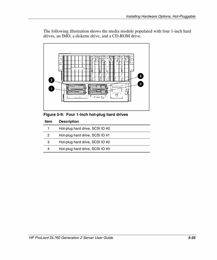
Installing Hardware Options, Hot-Pluggable
The following illustration shows the media module populated with four 1-inch hard drives, an IMD, a diskette drive, and a CD-ROM drive.
Figure 5-9: Four 1-inch hot-plug hard drives
Item Description
1 Hot-plug hard drive, SCSI ID #0
2 Hot-plug hard drive, SCSI ID #1
3 Hot-plug hard drive, SCSI ID #2
4 Hot-plug hard drive, SCSI ID #3
HP ProLiant DL760 Generation 2 Server User Guide 5-25
HP CONFIDENTIAL Writer: Bryce Miller File Name: f-ch5 Installing Options-Hot Pluggable.doc
Codename: Comet Part Number: 201264-001 Last Saved On: 6/17/03 9:47 AM
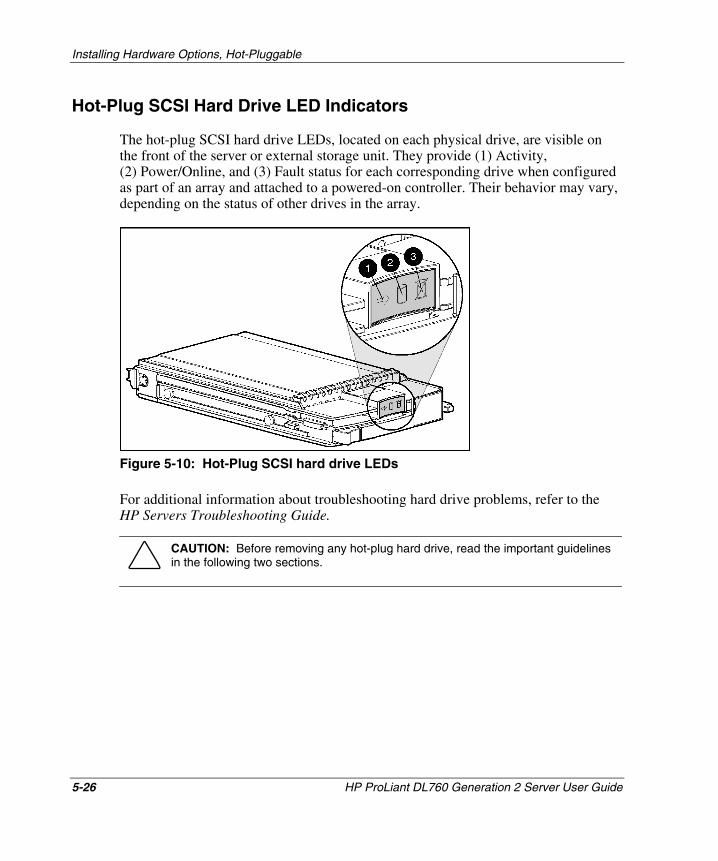
Installing Hardware Options, Hot-Pluggable
Hot-Plug SCSI Hard Drive LED Indicators
The hot-plug SCSI hard drive LEDs, located on each physical drive, are visible on the front of the server or external storage unit. They provide (1) Activity, (2) Power/Online, and (3) Fault status for each corresponding drive when configured as part of an array and attached to a powered-on controller. Their behavior may vary, depending on the status of other drives in the array.
Figure 5-10: Hot-Plug SCSI hard drive LEDs
For additional information about troubleshooting hard drive problems, refer to the HP Servers Troubleshooting Guide.
CAUTION: Before removing any hot-plug hard drive, read the important guidelines in the following two sections.
5-26 HP ProLiant DL760 Generation 2 Server User Guide
HP CONFIDENTIAL Writer: Bryce Miller File Name: f-ch5 Installing Options-Hot Pluggable.doc
Codename: Comet Part Number: 201264-001 Last Saved On: 6/17/03 9:47 AM

Installing Hardware Options, Hot-Pluggable
Figure 5-11: SCSI hard drive LEDs
HP ProLiant DL760 Generation 2 Server User Guide 5-27
HP CONFIDENTIAL Writer: Bryce Miller File Name: f-ch5 Installing Options-Hot Pluggable.doc
Codename: Comet Part Number: 201264-001 Last Saved On: 6/17/03 9:47 AM
Installing Hardware Options, Hot-Pluggable
Guidelines for Installing Hot-Plug SCSI Hard Drives
Follow these guidelines when adding SCSI hard drives:
• A maximum of four 1-inch Ultra3 SCSI drives may be added in the media module. Ultra320 hard drives will run at Ultra3 speeds unless you install an optional Ultra320 Array Controller and the Twisted Pair Cable Array Bypass kit included with the system.
NOTE: ProLiant DL760 servers that have been upgraded to ProLiant DL760 Generation 2 servers will run internal hard drives up to Ultra 3 speeds regardless of the capability of the drive.
• If only one SCSI hard drive is used, it should be installed in the lowest-numbered bay. If several drives are installed, the system boot drive should be installed in the lowest-numbered bay.
• To maintain proper system cooling, blanking panels should be installed in unused drive bays.
CAUTION: If a hard drive is removed, a blanking panel must be added for static immunity and airflow integrity.
The server has one embedded Smart Array 5i Controller. The integrated controller is hardwired through an Array Enabler board to the four SCSI hard drive bays and the external SCSI connector that can be used for a tape backup unit.
5-28 HP ProLiant DL760 Generation 2 Server User Guide
HP CONFIDENTIAL Writer: Bryce Miller File Name: f-ch5 Installing Options-Hot Pluggable.doc
Codename: Comet Part Number: 201264-001 Last Saved On: 6/17/03 9:47 AM
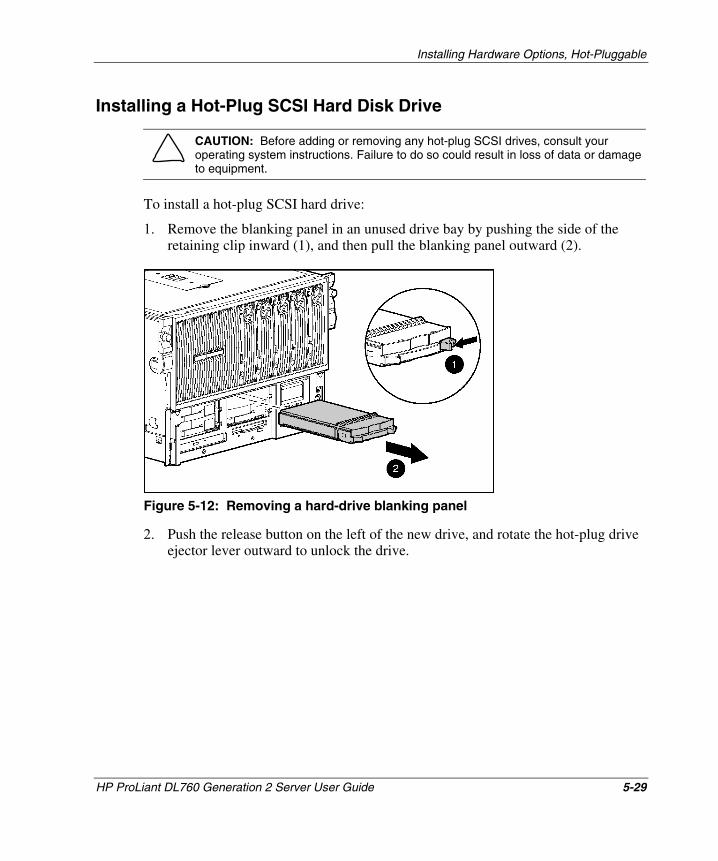
Installing Hardware Options, Hot-Pluggable
Installing a Hot-Plug SCSI Hard Disk Drive
CAUTION: Before adding or removing any hot-plug SCSI drives, consult your operating system instructions. Failure to do so could result in loss of data or damage to equipment.
To install a hot-plug SCSI hard drive:
1. Remove the blanking panel in an unused drive bay by pushing the side of the retaining clip inward (1), and then pull the blanking panel outward (2).
Figure 5-12: Removing a hard-drive blanking panel
2. Push the release button on the left of the new drive, and rotate the hot-plug drive ejector lever outward to unlock the drive.
HP ProLiant DL760 Generation 2 Server User Guide 5-29
HP CONFIDENTIAL Writer: Bryce Miller File Name: f-ch5 Installing Options-Hot Pluggable.doc
Codename: Comet Part Number: 201264-001 Last Saved On: 6/17/03 9:47 AM
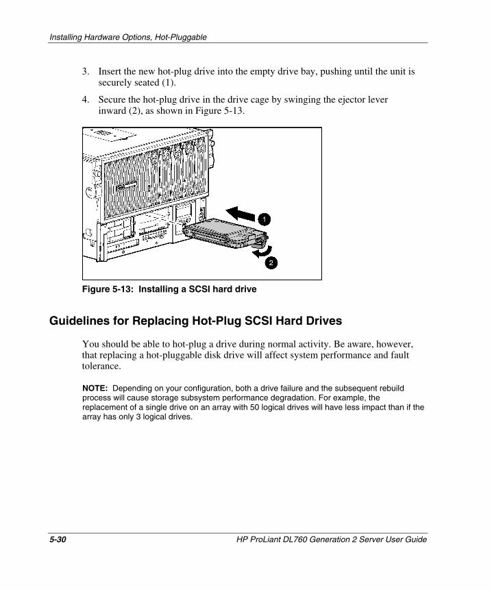
Installing Hardware Options, Hot-Pluggable
3. Insert the new hot-plug drive into the empty drive bay, pushing until the unit is securely seated (1).
4. Secure the hot-plug drive in the drive cage by swinging the ejector lever inward (2), as shown in Figure 5-13.
Figure 5-13: Installing a SCSI hard drive
Guidelines for Replacing Hot-Plug SCSI Hard Drives
You should be able to hot-plug a drive during normal activity. Be aware, however, that replacing a hot-pluggable disk drive will affect system performance and fault tolerance.
NOTE: Depending on your configuration, both a drive failure and the subsequent rebuild process will cause storage subsystem performance degradation. For example, the replacement of a single drive on an array with 50 logical drives will have less impact than if the array has only 3 logical drives.
5-30 HP ProLiant DL760 Generation 2 Server User Guide
HP CONFIDENTIAL Writer: Bryce Miller File Name: f-ch5 Installing Options-Hot Pluggable.doc
Codename: Comet Part Number: 201264-001 Last Saved On: 6/17/03 9:47 AM
Installing Hardware Options, Hot-Pluggable
Advanced Data Guarding
When a disk drive is hot-plugged, although the system is functionally operational, the disk subsystem may no longer be fault tolerant. Fault tolerance will be lost until the removed drive is subsequently replaced and the rebuild operation is completed. This procedure takes several hours, even if the system is not busy while the rebuild is in progress. If another drive in the array should incur an error during the period when fault tolerance is unavailable, a fatal system error could result. If another drive fails during this period, the entire array contents will be lost.
IMPORTANT: Perform disk drive replacement during low activity periods whenever possible. In addition, a current valid backup of the logical drives in the array of the drive being replaced should be available even if the drive replacement is being made during server downtime.
When replacing hot-plug hard drives in a fault-tolerant configuration, you must follow these guidelines:
• Never remove more than one drive at a time. When a drive is replaced, the controller uses data from the other drives in the array to reconstruct data on the replacement drive. If more than one drive is removed, a complete data set is not available to reconstruct data on the replacement drive.
• Never remove a working drive when another drive has failed. Drives that have been failed by the controller are indicated by the amber Drive Failure LED on the drive tray. Permanent data loss will occur if a working drive is removed while a failed drive is being replaced.
• Never remove a drive while another drive is being rebuilt. The Online LED of a drive will flash green while the drive is being rebuilt. A replaced drive is restored from data stored on the other drives.
HP ProLiant DL760 Generation 2 Server User Guide 5-31
HP CONFIDENTIAL Writer: Bryce Miller File Name: f-ch5 Installing Options-Hot Pluggable.doc
Codename: Comet Part Number: 201264-001 Last Saved On: 6/17/03 9:47 AM
Installing Hardware Options, Hot-Pluggable
• Never turn a disk enclosure off while the initiator or controller is powered on or active. Doing so can cause the initiator or controller to mark the drives as “failed.” This action can result in permanent data loss.
• If a drive is replaced while the system is off, it may be necessary to rebuild the replaced drive. Follow the instructions on the screen or the instructions outlined in the system reference guide.
CAUTION: Pressing the F2 key will cause permanent data loss to the entire logical drive. Press the F2 key only if all of the drives have been replaced or if complete data loss is required.
NOTE: When a drive configured for fault tolerance is replaced, the replacement drive automatically begins restoring when it is installed. When a drive is in the process of being restored, the Online LED blinks green. The LED continues to flash until the drive is completely restored.
Removing a Hot-Plug SCSI Hard Disk Drive
To remove a hot-plug SCSI hard disk drive:
1. To remove a hot-plug SCSI hard drive, push the release button on the left of the drive and rotate the hot-plug drive ejector lever outward to unlock the drive.
2. Pull the drive out of the drive bay.
5-32 HP ProLiant DL760 Generation 2 Server User Guide
HP CONFIDENTIAL Writer: Bryce Miller File Name: f-ch5 Installing Options-Hot Pluggable.doc
Codename: Comet Part Number: 201264-001 Last Saved On: 6/17/03 9:47 AM
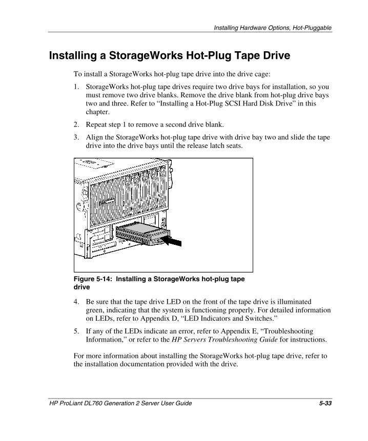
Installing Hardware Options, Hot-Pluggable
Installing a StorageWorks Hot-Plug Tape Drive
To install a StorageWorks hot-plug tape drive into the drive cage:
1. StorageWorks hot-plug tape drives require two drive bays for installation, so you must remove two drive blanks. Remove the drive blank from hot-plug drive bays two and three. Refer to “Installing a Hot-Plug SCSI Hard Disk Drive” in this chapter.
2. Repeat step 1 to remove a second drive blank.
3. Align the StorageWorks hot-plug tape drive with drive bay two and slide the tape drive into the drive bays until the release latch seats.
Figure 5-14: Installing a StorageWorks hot-plug tape drive
4. Be sure that the tape drive LED on the front of the tape drive is illuminated green, indicating that the system is functioning properly. For detailed information on LEDs, refer to Appendix D, “LED Indicators and Switches.”
5. If any of the LEDs indicate an error, refer to Appendix E, “Troubleshooting Information,” or refer to the HP Servers Troubleshooting Guide for instructions.
For more information about installing the StorageWorks hot-plug tape drive, refer to the installation documentation provided with the drive.
HP ProLiant DL760 Generation 2 Server User Guide 5-33
HP CONFIDENTIAL Writer: Bryce Miller File Name: f-ch5 Installing Options-Hot Pluggable.doc
Codename: Comet Part Number: 201264-001 Last Saved On: 6/17/03 9:47 AM
Installing Hardware Options, Hot-Pluggable
Installing a Hot-Plug Power Supply
The ProLiant DL760 G2 server ships with two hot-plug power supplies. The system power in the ProLiant DL760 G2 server does not have to be shut off to replace one of the power supplies.
WARNING: To reduce the risk of electric shock or damage to the equipment:
• Install the power supply before connecting the power cord to it.
• Unplug the power cord before removing the power supply from the server.
• Disconnect power from the server by unplugging all power cords from either the electrical outlet or the server.
CAUTION: To prevent data corruption, do not connect the server to a low line power source (110 VAC). Low line power is not supported.
IMPORTANT: Most system configurations require 200-240 VAC. Use 200-240 VAC line cords to power the server.
NOTE: A few server configurations may exceed the power rating of a single power supply resulting in a loss of power redundancy for the server. Use the ProLiant DL760 G2 Power Calculator available on ActiveAnswers to ensure that power redundancy will be maintained for your configuration.
5-34 HP ProLiant DL760 Generation 2 Server User Guide
HP CONFIDENTIAL Writer: Bryce Miller File Name: f-ch5 Installing Options-Hot Pluggable.doc
Codename: Comet Part Number: 201264-001 Last Saved On: 6/17/03 9:47 AM
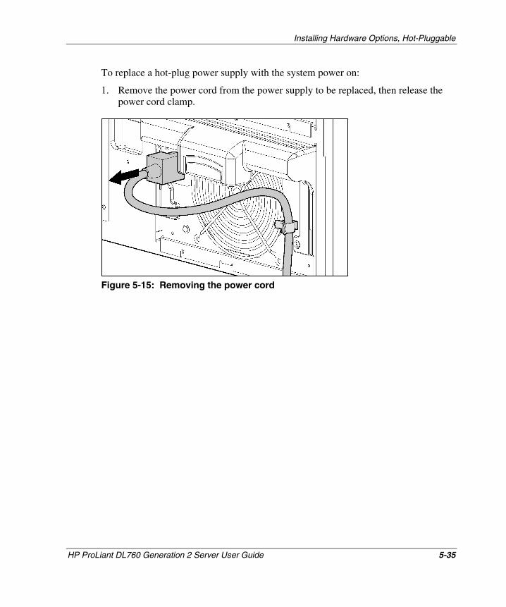
Installing Hardware Options, Hot-Pluggable
To replace a hot-plug power supply with the system power on:
1. Remove the power cord from the power supply to be replaced, then release the power cord clamp.
Figure 5-15: Removing the power cord
HP ProLiant DL760 Generation 2 Server User Guide 5-35
HP CONFIDENTIAL Writer: Bryce Miller File Name: f-ch5 Installing Options-Hot Pluggable.doc
Codename: Comet Part Number: 201264-001 Last Saved On: 6/17/03 9:47 AM
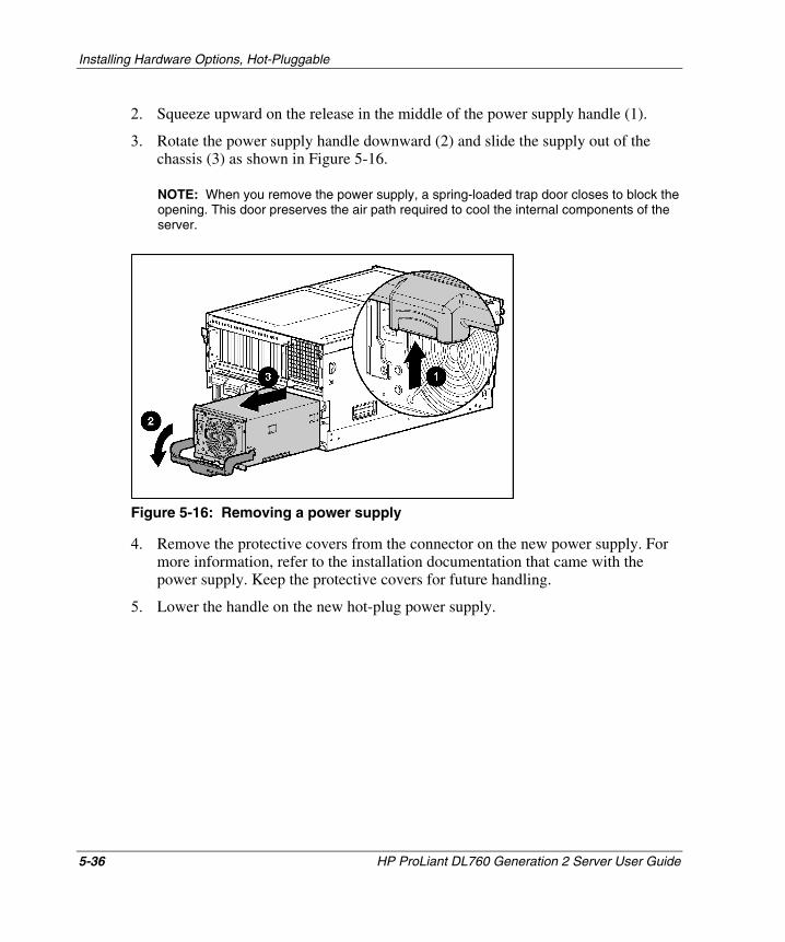
Installing Hardware Options, Hot-Pluggable
2. Squeeze upward on the release in the middle of the power supply handle (1).
3. Rotate the power supply handle downward (2) and slide the supply out of the chassis (3) as shown in Figure 5-16.
NOTE: When you remove the power supply, a spring-loaded trap door closes to block the opening. This door preserves the air path required to cool the internal components of the server.
Figure 5-16: Removing a power supply
4. Remove the protective covers from the connector on the new power supply. For more information, refer to the installation documentation that came with the power supply. Keep the protective covers for future handling.
5. Lower the handle on the new hot-plug power supply.
5-36 HP ProLiant DL760 Generation 2 Server User Guide
HP CONFIDENTIAL Writer: Bryce Miller File Name: f-ch5 Installing Options-Hot Pluggable.doc
Codename: Comet Part Number: 201264-001 Last Saved On: 6/17/03 9:47 AM
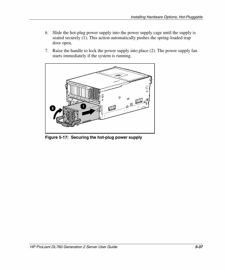
Installing Hardware Options, Hot-Pluggable
6. Slide the hot-plug power supply into the power supply cage until the supply is seated securely (1). This action automatically pushes the spring-loaded trap door open.
7. Raise the handle to lock the power supply into place (2). The power supply fan starts immediately if the system is running.
Figure 5-17: Securing the hot-plug power supply
HP ProLiant DL760 Generation 2 Server User Guide 5-37
HP CONFIDENTIAL Writer: Bryce Miller File Name: f-ch5 Installing Options-Hot Pluggable.doc
Codename: Comet Part Number: 201264-001 Last Saved On: 6/17/03 9:47 AM
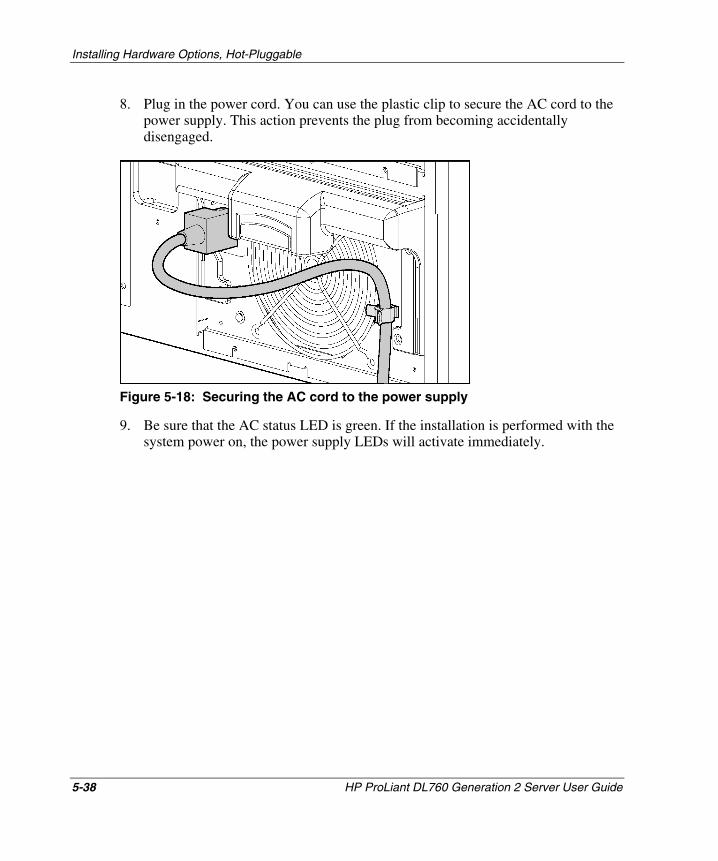
Installing Hardware Options, Hot-Pluggable
8. Plug in the power cord. You can use the plastic clip to secure the AC cord to the power supply. This action prevents the plug from becoming accidentally disengaged.
Figure 5-18: Securing the AC cord to the power supply
9. Be sure that the AC status LED is green. If the installation is performed with the system power on, the power supply LEDs will activate immediately.
5-38 HP ProLiant DL760 Generation 2 Server User Guide
HP CONFIDENTIAL Writer: Bryce Miller File Name: f-ch5 Installing Options-Hot Pluggable.doc
Codename: Comet Part Number: 201264-001 Last Saved On: 6/17/03 9:47 AM
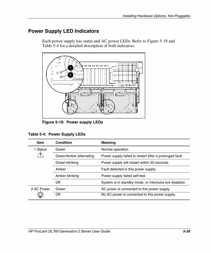
Installing Hardware Options, Hot-Pluggable
Power Supply LED Indicators
Each power supply has status and AC power LEDs. Refer to Figure 5-19 and Table 5-4 for a detailed description of both indicators.
Figure 5-19: Power supply LEDs
Table 5-4: Power Supply LEDs
Item Condition Meaning
Green Normal operation
Green/Amber alternating Power supply failed to restart after a prolonged fault.
Green blinking Power supply will restart within 20 seconds.
Amber Fault detected in this power supply.
Amber blinking Power supply failed self-test.
1 Status
Off No AC power is connected to this power supply.
Off System is in standby mode, or interlocks are disabled.
Green AC power is connected to this power supply. 2 AC Power
HP ProLiant DL760 Generation 2 Server User Guide 5-39
HP CONFIDENTIAL Writer: Bryce Miller File Name: f-ch5 Installing Options-Hot Pluggable.doc
Codename: Comet Part Number: 201264-001 Last Saved On: 6/17/03 9:47 AM
Installing Hardware Options, Hot-Pluggable
PCI Hot Plug I/O Expansion Boards
The ProLiant DL760 G2 server supports PCI Hot Plug. PCI Hot Plug and the operating system of the server work together to allow the following hot-plug actions:
• Hot-replace—Allows you to replace a failed expansion board with an identical expansion board without powering down the server.
• Hot-add—Allows you to install new PCI/PCI-X expansion boards in previously empty slots without powering down the server under some operating systems.
• Hot-upgrade—Allows you to replace an expansion board with a different expansion board without powering down the server.
PCI Hot Plug is backward-compatible, although system components fit into one of two categories: hot-plug aware or non-hot-plug aware. The following three components are required in the server for complete PCI Hot Plug capability:
• PCI Hot Plug system hardware (available in this server)
• Operating system with PCI Hot Plug support (support levels vary)
• PCI Hot Plug device drivers (available from operating system vendors, the SmartStart CD, HP website, and some individual hardware vendors)
WARNING: To reduce the risk of personal injury from hazardous energy or damage to the equipment when working on energized servers:
• Remove all watches, rings, and any other loose-fitting jewelry.
• Avoid the use of conductive tools that could bridge live parts.
IMPORTANT: If any of the three required components are non-hot-plug aware, the system is fully functional but is not PCI Hot Plug-capable.
5-40 HP ProLiant DL760 Generation 2 Server User Guide
HP CONFIDENTIAL Writer: Bryce Miller File Name: f-ch5 Installing Options-Hot Pluggable.doc
Codename: Comet Part Number: 201264-001 Last Saved On: 6/17/03 9:47 AM
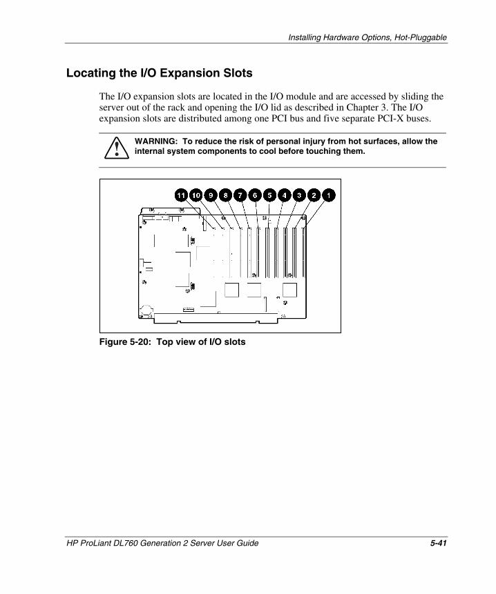
Installing Hardware Options, Hot-Pluggable
Locating the I/O Expansion Slots
The I/O expansion slots are located in the I/O module and are accessed by sliding the server out of the rack and opening the I/O lid as described in Chapter 3. The I/O expansion slots are distributed among one PCI bus and five separate PCI-X buses.
WARNING: To reduce the risk of personal injury from hot surfaces, allow the internal system components to cool before touching them.
Figure 5-20: Top view of I/O slots
HP ProLiant DL760 Generation 2 Server User Guide 5-41
HP CONFIDENTIAL Writer: Bryce Miller File Name: f-ch5 Installing Options-Hot Pluggable.doc
Codename: Comet Part Number: 201264-001 Last Saved On: 6/17/03 9:47 AM
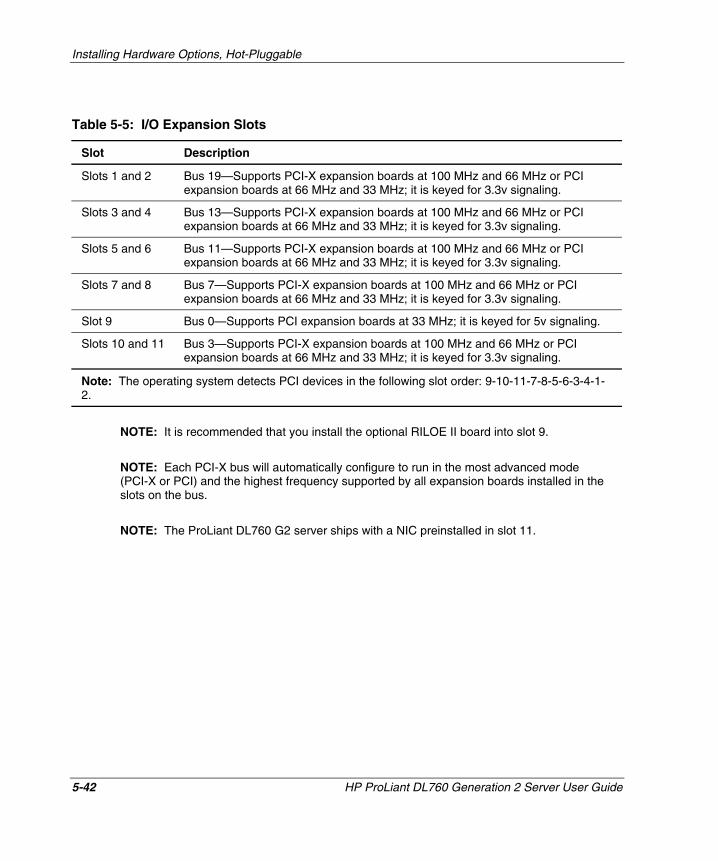
Installing Hardware Options, Hot-Pluggable
Table 5-5: I/O Expansion Slots
Slot Description
Slots 1 and 2 Bus 19—Supports PCI-X expansion boards at 100 MHz and 66 MHz or PCI expansion boards at 66 MHz and 33 MHz; it is keyed for 3.3v signaling.
Slots 3 and 4 Bus 13—Supports PCI-X expansion boards at 100 MHz and 66 MHz or PCI expansion boards at 66 MHz and 33 MHz; it is keyed for 3.3v signaling.
Slots 5 and 6 Bus 11—Supports PCI-X expansion boards at 100 MHz and 66 MHz or PCI expansion boards at 66 MHz and 33 MHz; it is keyed for 3.3v signaling.
Slots 7 and 8 Bus 7—Supports PCI-X expansion boards at 100 MHz and 66 MHz or PCI expansion boards at 66 MHz and 33 MHz; it is keyed for 3.3v signaling.
Slot 9 Bus 0—Supports PCI expansion boards at 33 MHz; it is keyed for 5v signaling.
Slots 10 and 11 Bus 3—Supports PCI-X expansion boards at 100 MHz and 66 MHz or PCI expansion boards at 66 MHz and 33 MHz; it is keyed for 3.3v signaling.
Note: The operating system detects PCI devices in the following slot order: 9-10-11-7-8-5-6-3-4-1-2.
NOTE: It is recommended that you install the optional RILOE II board into slot 9.
NOTE: Each PCI-X bus will automatically configure to run in the most advanced mode (PCI-X or PCI) and the highest frequency supported by all expansion boards installed in the slots on the bus.
NOTE: The ProLiant DL760 G2 server ships with a NIC preinstalled in slot 11.
5-42 HP ProLiant DL760 Generation 2 Server User Guide
HP CONFIDENTIAL Writer: Bryce Miller File Name: f-ch5 Installing Options-Hot Pluggable.doc
Codename: Comet Part Number: 201264-001 Last Saved On: 6/17/03 9:47 AM

Installing Hardware Options, Hot-Pluggable
PCI Hot Plug LED Indicators
The PCI Hot Plug amber (1) and green (2) LEDs (shown in the following figure for one slot) provide a visual reference of the status of each slot. The LEDs are viewed from the rear of the server as shown in Figure 5-21 or by opening the I/O lid as shown in Figure 5-22.
Figure 5-21: PCI Hot Plug LEDs from rear of the server
Figure 5-22: PCI Hot Plug LEDs in the I/O module
HP ProLiant DL760 Generation 2 Server User Guide 5-43
HP CONFIDENTIAL Writer: Bryce Miller File Name: f-ch5 Installing Options-Hot Pluggable.doc
Codename: Comet Part Number: 201264-001 Last Saved On: 6/17/03 9:47 AM
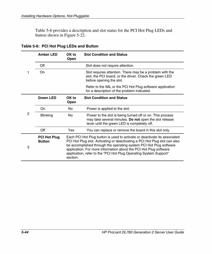
Installing Hardware Options, Hot-Pluggable
Table 5-6 provides a description and slot status for the PCI Hot Plug LEDs and button shown in Figure 5-22.
Table 5-6: PCI Hot Plug LEDs and Button
Amber LED OK to Open
Slot Condition and Status
Off Slot does not require attention.
1 On Slot requires attention. There may be a problem with the slot, the PCI board, or the driver. Check the green LED before opening the slot.
Refer to the IML or the PCI Hot Plug software application for a description of the problem indicated.
Green LED OK to Open
Slot Condition and Status
On No Power is applied to the slot.
Blinking No Power to the slot is being turned off or on. This process may take several minutes. Do not open the slot release lever until the green LED is completely off.
2
Off Yes You can replace or remove the board in this slot only.
3
PCI Hot Plug Button
Each PCI Hot Plug button is used to activate or deactivate its associated PCI Hot Plug slot. Activating or deactivating a PCI Hot Plug slot can also be accomplished through the operating system PCI Hot Plug software application. For more information about the PCI Hot Plug software application, refer to the “PCI Hot Plug Operating System Support” section.
5-44 HP ProLiant DL760 Generation 2 Server User Guide
HP CONFIDENTIAL Writer: Bryce Miller File Name: f-ch5 Installing Options-Hot Pluggable.doc
Codename: Comet Part Number: 201264-001 Last Saved On: 6/17/03 9:47 AM
Installing Hardware Options, Hot-Pluggable
PCI Hot Plug Operating System Support
Software support is an integral part of PCI Hot Plug. HP, in partnership with Microsoft, Caldera, and SCO has developed PCI Hot Plug software support for each operating system.
You can use either the PCI Hot Plug button on the server or your operating system PCI Hot Plug software to control the PCI Hot Plug slots. You can use the software to indicate that you want to replace an expansion board in the hot-plug slot or configure a board that you have already added to the system. The PCI Hot Plug software also allows you to enable or disable specific system slots. Supported operating systems include:
• Microsoft Windows 2000
• Microsoft Windows Server 2003
• Caldera Open Unix 8
• SCO UnixWare 7.x
• Linux
HP ProLiant DL760 Generation 2 Server User Guide 5-45
HP CONFIDENTIAL Writer: Bryce Miller File Name: f-ch5 Installing Options-Hot Pluggable.doc
Codename: Comet Part Number: 201264-001 Last Saved On: 6/17/03 9:47 AM
Installing Hardware Options, Hot-Pluggable
Microsoft Windows 2000
Supported PCI Hot Plug Functionality
PCI Hot Plug support within Microsoft Windows 2000 provides full PCI Hot Plug capability including:
• Hot-add
• Hot-replace
• Hot-removal
• Hot-upgrade
PCI Hot Plug operations can be initiated through the use of the PCI/PCI-X slot power buttons or the Windows 2000 Eject/Remove Hardware applet that is accessed through the Windows Status box.
CAUTION: Before removing any PCI/PCI-X expansion board, be sure to turn off power to the PCI/PCI-X slot by using either the PCI/PCI-X power button or the Windows 2000 Eject/Remove Hardware applet. Failure to do so will result in a “surprise-style” removal and may result in system failure.
Software Components
PCI Hot Plug support for Windows 2000 is provided through the PCI Hot Plug Filter driver. This component is included in the ProLiant Support Pack for Windows 2000.
Installing PCI Hot Plug Support
The ProLiant Support Pack for Microsoft Windows 2000, version 5.00A or later, contains all of the software components required to support PCI Hot Plug. Included on the Support Pack are hot-plug-aware device drivers, such as HP NC 7770 controllers and the Smart Array 5300 controller. The Support Pack also provides the PCI Hot Plug Filter driver and the System Management drivers.
5-46 HP ProLiant DL760 Generation 2 Server User Guide
HP CONFIDENTIAL Writer: Bryce Miller File Name: f-ch5 Installing Options-Hot Pluggable.doc
Codename: Comet Part Number: 201264-001 Last Saved On: 6/17/03 9:47 AM
Installing Hardware Options, Hot-Pluggable
Microsoft Windows Server 2003
Supported PCI Hot Plug Functionality
PCI Hot Plug support within Microsoft Windows Server 2003 provides full PCI Hot Plug capability including:
• Hot-add
• Hot-replace
• Hot-removal
• Hot-upgrade
PCI Hot Plug operations can be initiated through the use of the PCI/PCI-X slot power buttons or the Windows Server 2003 Eject/Remove Hardware applet that is accessed through the Windows Status box.
CAUTION: Before removing any PCI/PCI-X expansion board, be sure to turn off power to the PCI/PCI-X slot by using either the PCI/PCI-X power button or the Windows Server 2003 Eject/Remove Hardware applet. Failure to do so will result in a “surprise-style” removal and may result in system failure.
Software Components
PCI Hot Plug support for Windows Server 2003 is provided through the PCI Hot Plug Filter driver. This component is included in the ProLiant Support Pack for Windows Server 2003.
Installing PCI Hot Plug Support
The ProLiant Support Pack for Microsoft Windows Server 2003 contains all of the software components required to support PCI Hot Plug. Included on the Support Pack are hot-plug-aware device drivers, such as HP NC 7770 controllers and the Smart Array 5300 controller. The Support Pack also provides the PCI Hot Plug Filter driver and the System Management drivers.
HP ProLiant DL760 Generation 2 Server User Guide 5-47
HP CONFIDENTIAL Writer: Bryce Miller File Name: f-ch5 Installing Options-Hot Pluggable.doc
Codename: Comet Part Number: 201264-001 Last Saved On: 6/17/03 9:47 AM
Installing Hardware Options, Hot-Pluggable
SCO/Caldera UnixWare
Supported PCI Hot Plug Functionality
HP support of PCI Hot Plug within Caldera Open UNIX 8 and SCO UnixWare 7.1.1 or later, provides full PCI Hot Plug capability for most PCI expansion boards including:
• Hot-add
• Hot-replace
• Hot-removal
• Hot-upgrade
You can eliminate downtime when you replace faulty expansion boards, upgrade your systems, and dynamically add new expansion boards.
IMPORTANT: SCO UnixWare 7.1.1 runs PCI or PCI-X adapters under PCI mode only. For running PCI-X I/O expansion boards in PCI-X mode, you must upgrade the operating system to SCO UnixWare 7.1.3 or later and install the PCI-X drivers located on the SCO UnixWare 7.1.3 CD #2.
Software Components
The primary software components for hot-plug support include:
• Hot-plug user interface Admin Manager
• Hot-plug controller interface
• Hot-plug system and device drivers
• Device Driver Interface (DDI-8) specification
The Admin Manager is the graphical or character-based user interface for PCI Hot Plug technology. All user commands to add, remove, or replace an expansion board funnel through the Admin Manager. The Hot Plug Admin Manager is incorporated into the SCO system-managed framework called SCO Admin.
5-48 HP ProLiant DL760 Generation 2 Server User Guide
HP CONFIDENTIAL Writer: Bryce Miller File Name: f-ch5 Installing Options-Hot Pluggable.doc
Codename: Comet Part Number: 201264-001 Last Saved On: 6/17/03 9:47 AM
Installing Hardware Options, Hot-Pluggable
The device driver interface specification defines how device drivers communicate with the SCO UnixWare operating system. The SCO UnixWare DDI-8 and other device driver interfaces are enhanced to provide the functions for adding or removing driver instances and suspending or resuming operation in conjunction with hot-plug operations.
Installing PCI Hot Plug Support
The HP Extended Feature Supplement (EFS) contains all of the software components required to support PCI Hot Plug.
For more information, refer to the PCI Hot Plug Administration Guide on the server Documentation CD; the UnixWare online documentation; or the HP white paper, PCI Hot Plug Technology with SCO Software Architecture, found on the HP website:
www.hp.com
Linux
HP servers running Linux can take advantage of the PCI Hot Plug functionality. HP supported drivers and utilities for Linux can be found on the website:
www.compaq.com/products/servers/linux/linux-drivers.html
HP has an array of Opensource projects for Linux. For more information on HP Opensource projects refer to:
opensource.hp.com/
HP only supports servers configured with certified Linux operating system versions found on the Linux server certification matrix website:
www.compaq.com/products/servers/linux/certMatrix.html
HP ProLiant DL760 Generation 2 Server User Guide 5-49
HP CONFIDENTIAL Writer: Bryce Miller File Name: f-ch5 Installing Options-Hot Pluggable.doc
Codename: Comet Part Number: 201264-001 Last Saved On: 6/17/03 9:47 AM
Installing Hardware Options, Hot-Pluggable
Adding PCI Hot Plug Expansion Boards
The PCI/PCI-X slots of the ProLiant DL760 G2 I/O board are hot-plug-capable and support a variety of industry-standard expansion boards. For a list of supported I/O expansion boards, refer to the HP QuickSpecs for the ProLiant DL760 G2 servers:
www.hp.com/products/servers/platforms
CAUTION: Do not attempt this hot-plug operation if your operating system does not provide PCI/PCI-X Hot Plug support or if you do not have the appropriate drivers installed. Failure to properly execute a hot-plug operation can halt your system.
Refer to Figure 5-21, Figure 5-22, and Table 5-6 for definitions of the PCI Hot Plug LEDs. To add a PCI/PCI-X expansion board into PCI Hot Plug slots 1 through 11:
1. Open the I/O lid.
2. If the PCI Hot Plug green LED is on, power down the slot by pressing the PCI Hot Plug button corresponding to the slot or by using a PCI Hot Plug software application. Wait until the flashing green LED is off. For more information about PCI Hot Plug LEDs, refer to “PCI Hot Plug LED Indicators” earlier in this chapter.
CAUTION: To avoid system power-down and subsequent data loss, do not open the slot release lever unless the green PCI Hot Plug LED of the slot is off.
NOTE: The PCI Hot Plug button allows you to press the button again within five seconds of the first press to cancel the action.
3. Disconnect the cables to the PCI/PCI-X board when the green LED of the slot is off.
5-50 HP ProLiant DL760 Generation 2 Server User Guide
HP CONFIDENTIAL Writer: Bryce Miller File Name: f-ch5 Installing Options-Hot Pluggable.doc
Codename: Comet Part Number: 201264-001 Last Saved On: 6/17/03 9:47 AM
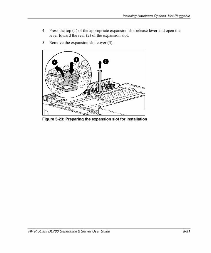
Installing Hardware Options, Hot-Pluggable
4. Press the top (1) of the appropriate expansion slot release lever and open the lever toward the rear (2) of the expansion slot.
5. Remove the expansion slot cover (3).
Figure 5-23: Preparing the expansion slot for installation
HP ProLiant DL760 Generation 2 Server User Guide 5-51
HP CONFIDENTIAL Writer: Bryce Miller File Name: f-ch5 Installing Options-Hot Pluggable.doc
Codename: Comet Part Number: 201264-001 Last Saved On: 6/17/03 9:47 AM
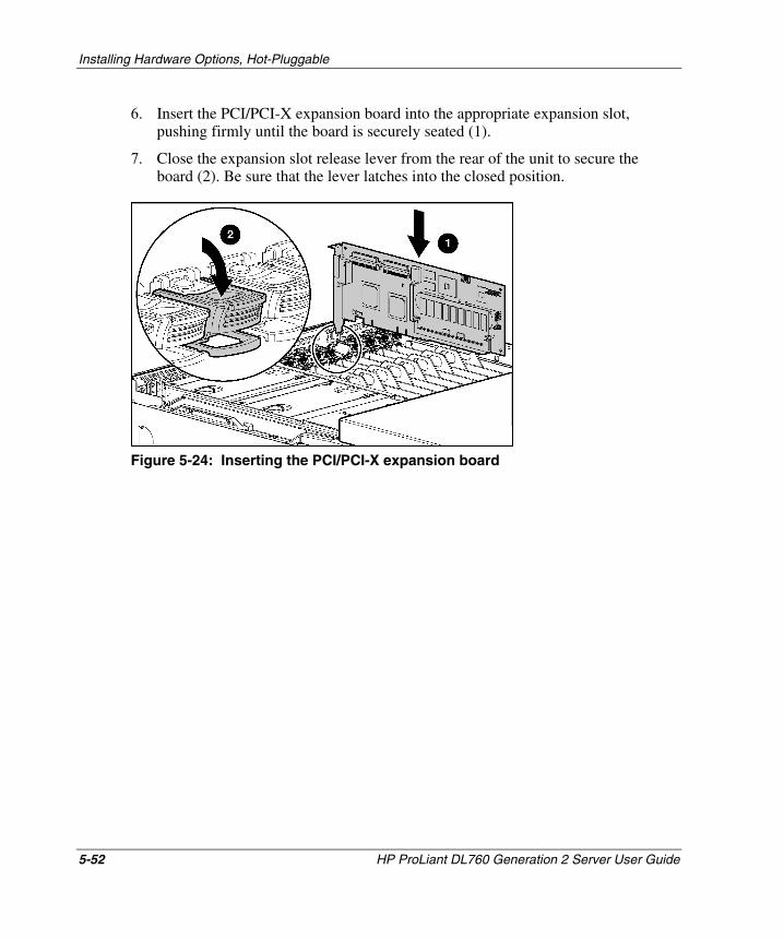
Installing Hardware Options, Hot-Pluggable
6. Insert the PCI/PCI-X expansion board into the appropriate expansion slot, pushing firmly until the board is securely seated (1).
7. Close the expansion slot release lever from the rear of the unit to secure the board (2). Be sure that the lever latches into the closed position.
Figure 5-24: Inserting the PCI/PCI-X expansion board
5-52 HP ProLiant DL760 Generation 2 Server User Guide
HP CONFIDENTIAL Writer: Bryce Miller File Name: f-ch5 Installing Options-Hot Pluggable.doc
Codename: Comet Part Number: 201264-001 Last Saved On: 6/17/03 9:47 AM
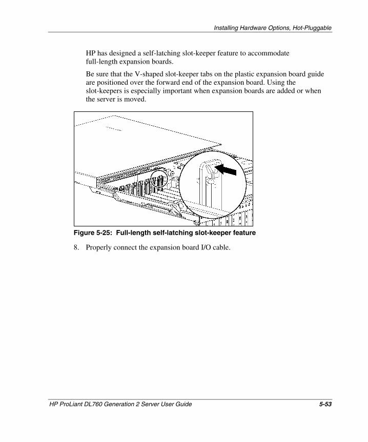
Installing Hardware Options, Hot-Pluggable
HP has designed a self-latching slot-keeper feature to accommodate full-length expansion boards.
Be sure that the V-shaped slot-keeper tabs on the plastic expansion board guide are positioned over the forward end of the expansion board. Using the slot-keepers is especially important when expansion boards are added or when the server is moved.
Figure 5-25: Full-length self-latching slot-keeper feature
8. Properly connect the expansion board I/O cable.
HP ProLiant DL760 Generation 2 Server User Guide 5-53
HP CONFIDENTIAL Writer: Bryce Miller File Name: f-ch5 Installing Options-Hot Pluggable.doc
Codename: Comet Part Number: 201264-001 Last Saved On: 6/17/03 9:47 AM
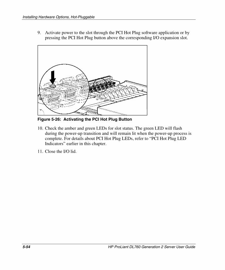
Installing Hardware Options, Hot-Pluggable
9. Activate power to the slot through the PCI Hot Plug software application or by pressing the PCI Hot Plug button above the corresponding I/O expansion slot.
Figure 5-26: Activating the PCI Hot Plug Button
10. Check the amber and green LEDs for slot status. The green LED will flash during the power-up transition and will remain lit when the power-up process is complete. For details about PCI Hot Plug LEDs, refer to “PCI Hot Plug LED Indicators” earlier in this chapter.
11. Close the I/O lid.
5-54 HP ProLiant DL760 Generation 2 Server User Guide
HP CONFIDENTIAL Writer: Bryce Miller File Name: f-ch5 Installing Options-Hot Pluggable.doc
Codename: Comet Part Number: 201264-001 Last Saved On: 6/17/03 9:47 AM
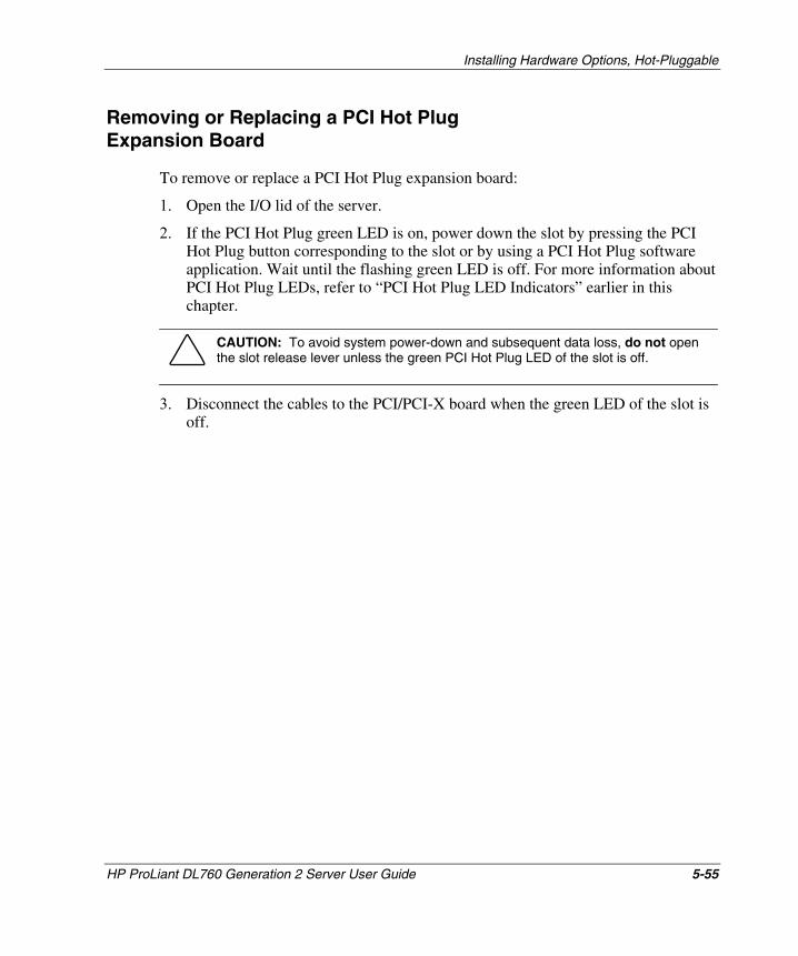
Installing Hardware Options, Hot-Pluggable
Removing or Replacing a PCI Hot Plug Expansion Board
To remove or replace a PCI Hot Plug expansion board:
1. Open the I/O lid of the server.
2. If the PCI Hot Plug green LED is on, power down the slot by pressing the PCI Hot Plug button corresponding to the slot or by using a PCI Hot Plug software application. Wait until the flashing green LED is off. For more information about PCI Hot Plug LEDs, refer to “PCI Hot Plug LED Indicators” earlier in this chapter.
CAUTION: To avoid system power-down and subsequent data loss, do not open the slot release lever unless the green PCI Hot Plug LED of the slot is off.
3. Disconnect the cables to the PCI/PCI-X board when the green LED of the slot is off.
HP ProLiant DL760 Generation 2 Server User Guide 5-55
HP CONFIDENTIAL Writer: Bryce Miller File Name: f-ch5 Installing Options-Hot Pluggable.doc
Codename: Comet Part Number: 201264-001 Last Saved On: 6/17/03 9:47 AM
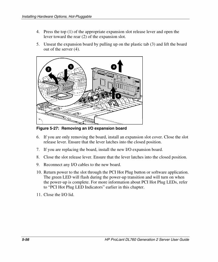
Installing Hardware Options, Hot-Pluggable
4. Press the top (1) of the appropriate expansion slot release lever and open the lever toward the rear (2) of the expansion slot.
5. Unseat the expansion board by pulling up on the plastic tab (3) and lift the board out of the server (4).
Figure 5-27: Removing an I/O expansion board
6. If you are only removing the board, install an expansion slot cover. Close the slot release lever. Ensure that the lever latches into the closed position.
7. If you are replacing the board, install the new I/O expansion board.
8. Close the slot release lever. Ensure that the lever latches into the closed position.
9. Reconnect any I/O cables to the new board.
10. Return power to the slot through the PCI Hot Plug button or software application. The green LED will flash during the power-up transition and will turn on when the power-up is complete. For more information about PCI Hot Plug LEDs, refer to “PCI Hot Plug LED Indicators” earlier in this chapter.
11. Close the I/O lid.
5-56 HP ProLiant DL760 Generation 2 Server User Guide
HP CONFIDENTIAL Writer: Bryce Miller File Name: f-ch5 Installing Options-Hot Pluggable.doc
Codename: Comet Part Number: 201264-001 Last Saved On: 6/17/03 9:47 AM
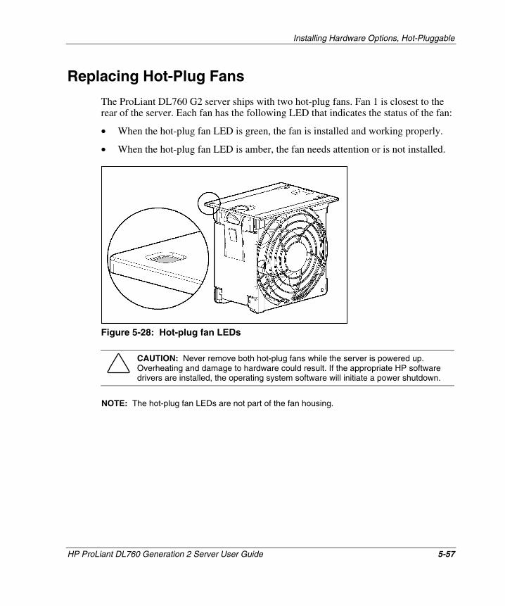
Installing Hardware Options, Hot-Pluggable
Replacing Hot-Plug Fans
The ProLiant DL760 G2 server ships with two hot-plug fans. Fan 1 is closest to the rear of the server. Each fan has the following LED that indicates the status of the fan:
• When the hot-plug fan LED is green, the fan is installed and working properly.
• When the hot-plug fan LED is amber, the fan needs attention or is not installed.
Figure 5-28: Hot-plug fan LEDs
CAUTION: Never remove both hot-plug fans while the server is powered up. Overheating and damage to hardware could result. If the appropriate HP software drivers are installed, the operating system software will initiate a power shutdown.
NOTE: The hot-plug fan LEDs are not part of the fan housing.
HP ProLiant DL760 Generation 2 Server User Guide 5-57
HP CONFIDENTIAL Writer: Bryce Miller File Name: f-ch5 Installing Options-Hot Pluggable.doc
Codename: Comet Part Number: 201264-001 Last Saved On: 6/17/03 9:47 AM
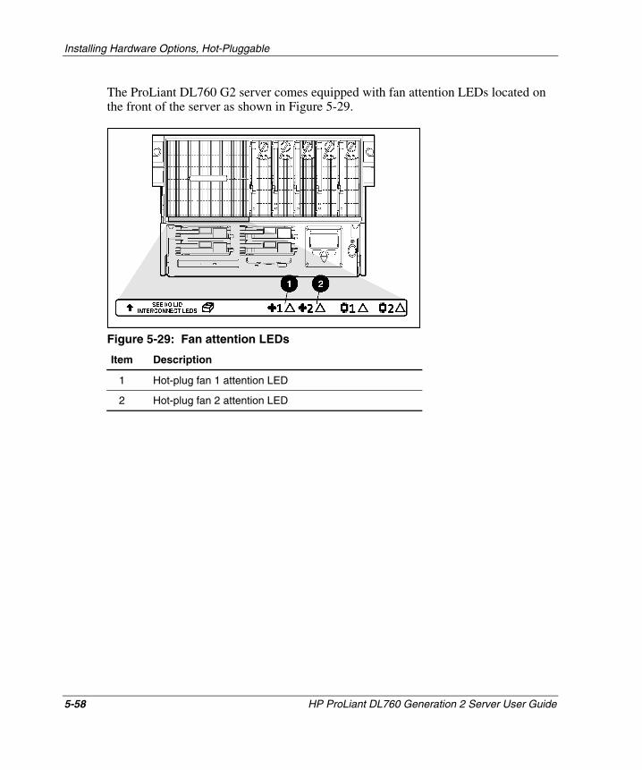
Installing Hardware Options, Hot-Pluggable
The ProLiant DL760 G2 server comes equipped with fan attention LEDs located on the front of the server as shown in Figure 5-29.
Figure 5-29: Fan attention LEDs
Item Description
1 Hot-plug fan 1 attention LED
2 Hot-plug fan 2 attention LED
5-58 HP ProLiant DL760 Generation 2 Server User Guide
HP CONFIDENTIAL Writer: Bryce Miller File Name: f-ch5 Installing Options-Hot Pluggable.doc
Codename: Comet Part Number: 201264-001 Last Saved On: 6/17/03 9:47 AM
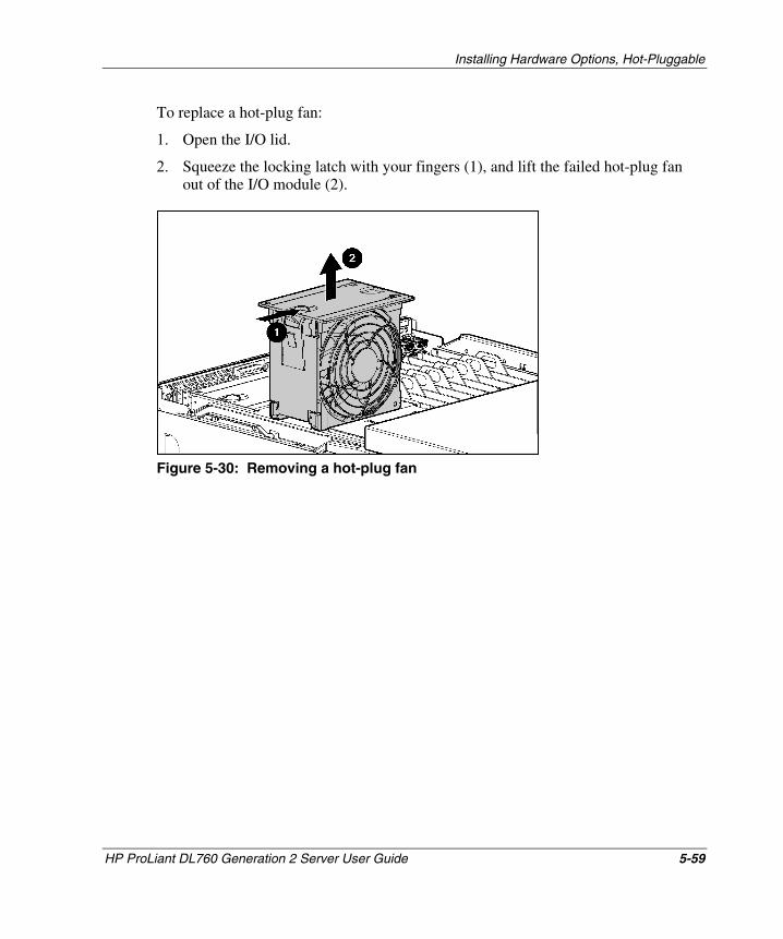
Installing Hardware Options, Hot-Pluggable
To replace a hot-plug fan:
1. Open the I/O lid.
2. Squeeze the locking latch with your fingers (1), and lift the failed hot-plug fan out of the I/O module (2).
Figure 5-30: Removing a hot-plug fan
HP ProLiant DL760 Generation 2 Server User Guide 5-59
HP CONFIDENTIAL Writer: Bryce Miller File Name: f-ch5 Installing Options-Hot Pluggable.doc
Codename: Comet Part Number: 201264-001 Last Saved On: 6/17/03 9:47 AM
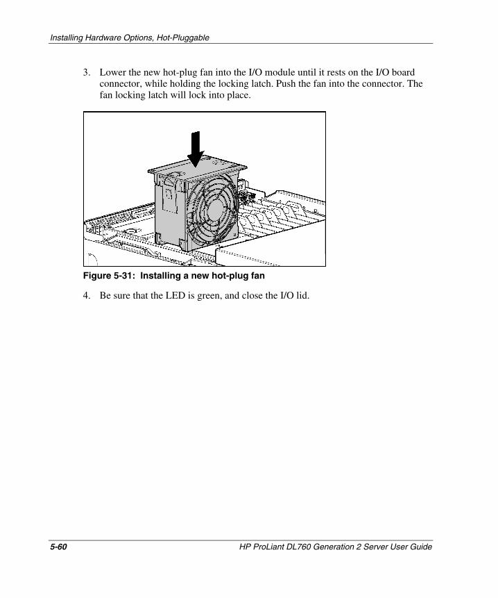
Installing Hardware Options, Hot-Pluggable
5-60 HP ProLiant DL760 Generation 2 Server User Guide
HP CONFIDENTIAL Writer: Bryce Miller File Name: f-ch5 Installing Options-Hot Pluggable.doc
Codename: Comet Part Number: 201264-001 Last Saved On: 6/17/03 9:47 AM
3. Lower the new hot-plug fan into the I/O module until it rests on the I/O board connector, while holding the locking latch. Push the fan into the connector. The fan locking latch will lock into place.
Figure 5-31: Installing a new hot-plug fan
4. Be sure that the LED is green, and close the I/O lid.
6 Cabling the Server
This chapter provides information about how to cable a ProLiant DL760 G2 server.
HP ProLiant DL760 Generation 2 Server User Guide 6-1
HP CONFIDENTIAL Writer: Jennifer Hayward File Name: g-ch6 Cabling the Server.doc
Codename: Pioneer Part Number: 201264-002 Last Saved On: 6/17/03 10:05 AM
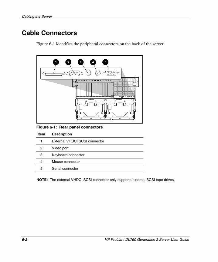
Cabling the Server
Cable Connectors
Figure 6-1 identifies the peripheral connectors on the back of the server.
Figure 6-1: Rear panel connectors
Item Description
1 External VHDCI SCSI connector
2 Video port
3 Keyboard connector
4 Mouse connector
5 Serial connector
NOTE: The external VHDCI SCSI connector only supports external SCSI tape drives.
6-2 HP ProLiant DL760 Generation 2 Server User Guide
HP CONFIDENTIAL Writer: Jennifer Hayward File Name: g-ch6 Cabling the Server.doc
Codename: Pioneer Part Number: 201264-002 Last Saved On: 6/17/03 10:05 AM
Cabling the Server
WARNING: To reduce the risk of electric shock or damage to the equipment:
• Install the power supply before connecting the power cord to the power supply.
• Unplug the power cord before removing the power supply from the server.
• If the system has multiple power supplies, disconnect power from the system by unplugging all power cords from the power supplies.
• Do not disable the power cord grounding plug. The grounding plug is an important safety feature.
• Plug the power cord into a grounded (earthed) electrical outlet that is easily accessible at all times.
WARNING: To reduce the risk of electrical shock or fire, do not plug telecommunications/telephone connectors into the network interface card (NIC) receptacles.
CAUTION: To prevent data corruption, do not connect the server to a low line power source (110 VAC). Low line power is not supported.
To cable your server:
1. Connect the power cords and peripheral devices such as the keyboard, mouse, and monitor.
NOTE: When the power cord is connected, the IMD display should light up, indicating that the server is in Standby mode.
HP ProLiant DL760 Generation 2 Server User Guide 6-3
HP CONFIDENTIAL Writer: Jennifer Hayward File Name: g-ch6 Cabling the Server.doc
Codename: Pioneer Part Number: 201264-002 Last Saved On: 6/17/03 10:05 AM
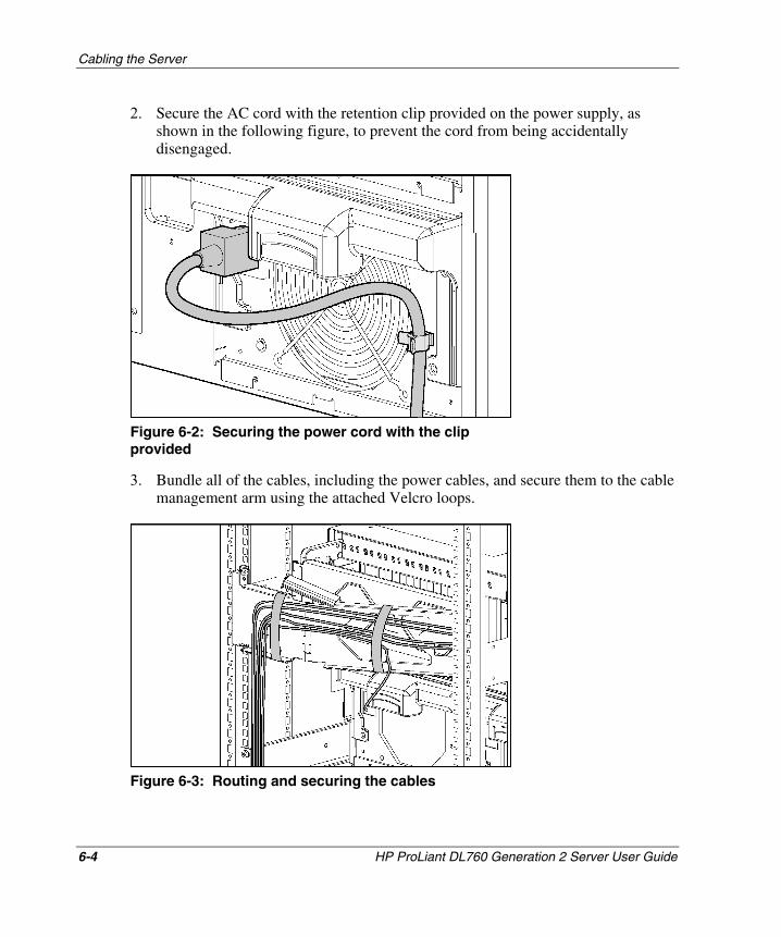
Cabling the Server
2. Secure the AC cord with the retention clip provided on the power supply, as shown in the following figure, to prevent the cord from being accidentally disengaged.
Figure 6-2: Securing the power cord with the clip provided
3. Bundle all of the cables, including the power cables, and secure them to the cable management arm using the attached Velcro loops.
Figure 6-3: Routing and securing the cables
6-4 HP ProLiant DL760 Generation 2 Server User Guide
HP CONFIDENTIAL Writer: Jennifer Hayward File Name: g-ch6 Cabling the Server.doc
Codename: Pioneer Part Number: 201264-002 Last Saved On: 6/17/03 10:05 AM
Cabling the Server
HP ProLiant DL760 Generation 2 Server User Guide 6-5
HP CONFIDENTIAL Writer: Jennifer Hayward File Name: g-ch6 Cabling the Server.doc
Codename: Pioneer Part Number: 201264-002 Last Saved On: 6/17/03 10:05 AM
4. To route cables to the other side of the rack, attach the bundled cables to the cable support and join the other cables in the opposite cable channel.
5. Extend the bundled cables down the cable channel of the rack.
NOTE: When the cable bundle on the back of the server exceeds 2 inches in diameter, use the HP high-capacity cable management arm. This option is designed for complex rack installations that include a large number of cables. If your system requires a high-capacity cable management arm, refer to the HP High-Capacity Cable Management Arm option kit, part number 124711-B21.
7 Server Power
This chapter provides information about the operation of the server power supplies.
The purpose of this chapter is to guide you through the sequence of events that follows the first-time power-up of the system. The first time you power up the system, you must to follow these steps in the order they are presented here. After these steps have been performed, you may need to revisit this chapter in the future to reinstall a particular component or to make changes to configuration settings.
HP ProLiant DL760 Generation 2 Server User Guide 7-1
HP CONFIDENTIAL Writer: Jennifer Hayward File Name: h-ch7 Server Power.doc
Codename: Pioneer Part Number: 201264-002 Last Saved On: 6/17/03 10:08 AM
Server Power
System Power Overview
The system power in the ProLiant DL760 G2 server does not shut off completely with the front panel Power On/Standby switch. The two modes of the power switch are on and standby, rather than on and off. The Standby position removes power from most of the electronics and the drives, but portions of the power supply, the IMD, the system interlock circuitry, and some internal circuitry remain active.
To remove all power from the system completely, you must disconnect all power cords from the server.
WARNING: To reduce the risk of electric shock or damage to the equipment:
• Disconnect power from the system by unplugging all power cords from the power supplies.
• Do not disable the power cord grounding plug. The grounding plug is an important safety feature.
• Plug the power cord into a grounded (earthed) electrical outlet that is easily accessible at all times.
WARNING: The power supplies in the ProLiant DL760 G2 server produce hazardous energy levels. The installation of options and the routine maintenance and service of this product should be performed by individuals who are knowledgeable about the procedures, precautions, and hazards associated with equipment containing hazardous energy circuits.
CAUTION: Electrostatic discharge can damage electronic components. Be sure that you are properly grounded before beginning any installation procedure. Refer to Appendix B for more information.
NOTE: All ProLiant servers support server management features that provide in-depth monitoring, analysis, and control of the fault performance and configuration aspects of HP servers. Refer to your system Documentation CD for information about server management features, Flash ROM, and Insight Manager 7.
7-2 HP ProLiant DL760 Generation 2 Server User Guide
HP CONFIDENTIAL Writer: Jennifer Hayward File Name: h-ch7 Server Power.doc
Codename: Pioneer Part Number: 201264-002 Last Saved On: 6/17/03 10:08 AM
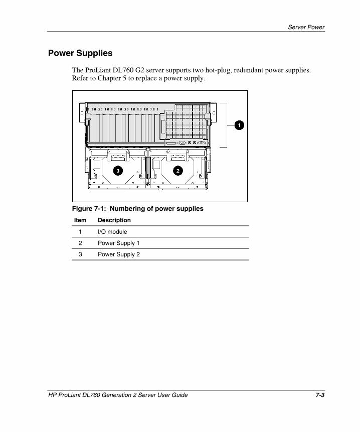
Server Power
Power Supplies
The ProLiant DL760 G2 server supports two hot-plug, redundant power supplies. Refer to Chapter 5 to replace a power supply.
Figure 7-1: Numbering of power supplies
Item Description
1 I/O module
2 Power Supply 1
3 Power Supply 2
HP ProLiant DL760 Generation 2 Server User Guide 7-3
HP CONFIDENTIAL Writer: Jennifer Hayward File Name: h-ch7 Server Power.doc
Codename: Pioneer Part Number: 201264-002 Last Saved On: 6/17/03 10:08 AM
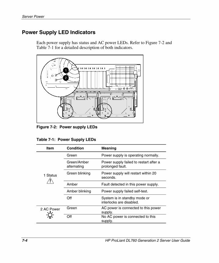
Server Power
Power Supply LED Indicators
Each power supply has status and AC power LEDs. Refer to Figure 7-2 and Table 7-1 for a detailed description of both indicators.
Figure 7-2: Power supply LEDs
Table 7-1: Power Supply LEDs
Item Condition Meaning
Green Power supply is operating normally.
Green/Amber alternating
Power supply failed to restart after a prolonged fault.
Green blinking Power supply will restart within 20 seconds.
Amber Fault detected in this power supply.
Amber blinking Power supply failed self-test.
1 Status
Off No AC power is connected to this supply.
Off System is in standby mode or interlocks are disabled.
Green AC power is connected to this power supply.
2 AC Power
7-4 HP ProLiant DL760 Generation 2 Server User Guide
HP CONFIDENTIAL Writer: Jennifer Hayward File Name: h-ch7 Server Power.doc
Codename: Pioneer Part Number: 201264-002 Last Saved On: 6/17/03 10:08 AM
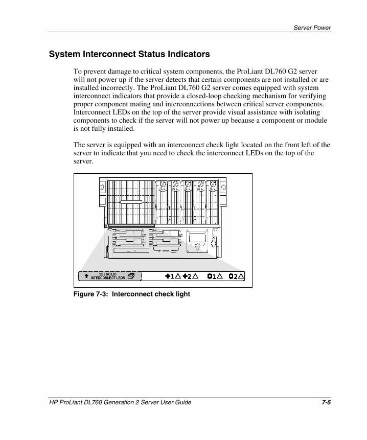
Server Power
System Interconnect Status Indicators
To prevent damage to critical system components, the ProLiant DL760 G2 server will not power up if the server detects that certain components are not installed or are installed incorrectly. The ProLiant DL760 G2 server comes equipped with system interconnect indicators that provide a closed-loop checking mechanism for verifying proper component mating and interconnections between critical server components. Interconnect LEDs on the top of the server provide visual assistance with isolating components to check if the server will not power up because a component or module is not fully installed.
The server is equipped with an interconnect check light located on the front left of the server to indicate that you need to check the interconnect LEDs on the top of the server.
Figure 7-3: Interconnect check light
HP ProLiant DL760 Generation 2 Server User Guide 7-5
HP CONFIDENTIAL Writer: Jennifer Hayward File Name: h-ch7 Server Power.doc
Codename: Pioneer Part Number: 201264-002 Last Saved On: 6/17/03 10:08 AM
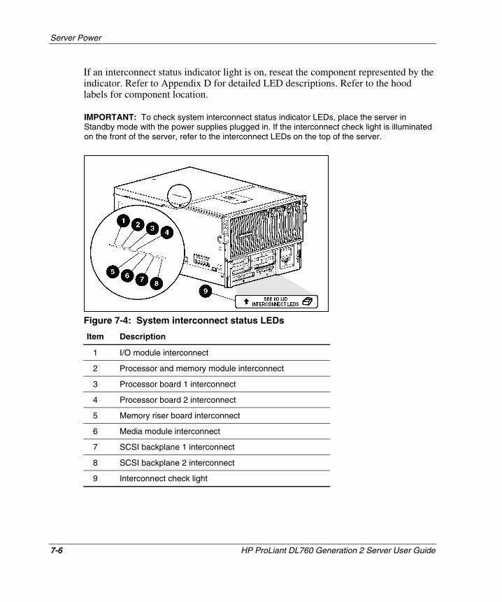
Server Power
If an interconnect status indicator light is on, reseat the component represented by the indicator. Refer to Appendix D for detailed LED descriptions. Refer to the hood labels for component location.
IMPORTANT: To check system interconnect status indicator LEDs, place the server in Standby mode with the power supplies plugged in. If the interconnect check light is illuminated on the front of the server, refer to the interconnect LEDs on the top of the server.
Figure 7-4: System interconnect status LEDs
Item Description
1 I/O module interconnect
2 Processor and memory module interconnect
3 Processor board 1 interconnect
4 Processor board 2 interconnect
5 Memory riser board interconnect
6 Media module interconnect
7 SCSI backplane 1 interconnect
8 SCSI backplane 2 interconnect
9 Interconnect check light
7-6 HP ProLiant DL760 Generation 2 Server User Guide
HP CONFIDENTIAL Writer: Jennifer Hayward File Name: h-ch7 Server Power.doc
Codename: Pioneer Part Number: 201264-002 Last Saved On: 6/17/03 10:08 AM
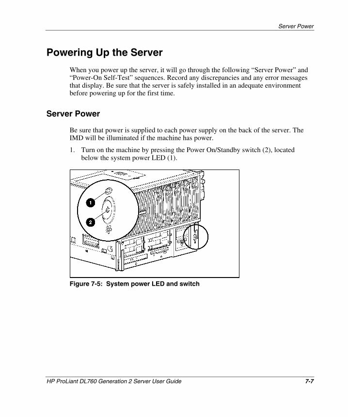
Server Power
Powering Up the Server
When you power up the server, it will go through the following “Server Power” and “Power-On Self-Test” sequences. Record any discrepancies and any error messages that display. Be sure that the server is safely installed in an adequate environment before powering up for the first time.
Server Power
Be sure that power is supplied to each power supply on the back of the server. The IMD will be illuminated if the machine has power.
1. Turn on the machine by pressing the Power On/Standby switch (2), located below the system power LED (1).
Figure 7-5: System power LED and switch
HP ProLiant DL760 Generation 2 Server User Guide 7-7
HP CONFIDENTIAL Writer: Jennifer Hayward File Name: h-ch7 Server Power.doc
Codename: Pioneer Part Number: 201264-002 Last Saved On: 6/17/03 10:08 AM
Server Power
2. Check the system power LED:
7-8 HP ProLiant DL760 Generation 2 Server User Guide
HP CONFIDENTIAL Writer: Jennifer Hayward File Name: h-ch7 Server Power.doc
Codename: Pioneer Part Number: 201264-002 Last Saved On: 6/17/03 10:08 AM
ending with cartridge 5 (left to right, cartridges 1, 2, 3, 4, 5).
— The system power LED (1), as shown in Figure 7-5, should blink to indicate that the system is trying to power up. If the LED does not blink when the power button is pressed, then one of the system components is improperly installed, or there is no main power applied to the system power supplies.
— If the system power LED is amber or if the interconnect check light is illuminated, check the system interconnect status indicators (located on the top of the server). For more information, refer to the “System Interconnect Status Indicators” section of this chapter.
— The system power LED will blink every one to two seconds between a power-down and power-up condition or immediately after applying power to the system. This action indicates that the Power/On Standby switch has been pressed and that the system will power up momentarily.
3. Check the power supplies on the back of the server. The following settings indicate that the power switch is on and the power supply is in a “power-on delay” mode:
— Top LED begins blinking (green).
— Bottom LED is on (solid green).
If the power supply top LED does not begin blinking (the server will not power up), refer to the “System Interconnect Status Indicators” section in this chapter.
When the top LED illuminates solid green, listen for the fans to start.
4. Check the hard drive and CD-ROM drive LEDs on the front of the server. The hard drive and CD-ROM drive LEDs should blink. If the LEDs do not light, verify that the hard drives are fully installed in the system and the array bypass is initialized.
5. Check the memory cartridge LEDs. The memory cartridge attention and power LEDs will illuminate solid and then go out in sequence beginning with memory cartridge 1, and ending with memory cartridge 5 (left to right, cartridges 1, 2, 3, 4, 5).
6. Check the DIMM status LEDs. The DIMM status LEDs for each cartridge will illuminate solid and then go out in sequence beginning with cartridge 1, and
Server Power
7. Watch for memory system initialization. As the system initializes, the memory cartridge power LEDs on all five memory cartridges begin blinking. After the memory system is initialized, all memory cartridges power LEDs will illuminate solid.
8. The server begins the Power-On Self-Test (POST) sequence. The IMD displays each step of the POST sequence.
Power-On Self-Test
As the POST process continues during server power-up, you need to:
1. Check for the IMD messages about:
a. Server name
b. LCD firmware
c. System initialization
d. PCI auto configuration
e. Video
f. Processors
2. Check the IMD video initialization message. If a monitor is connected, refer to the HP initialization screen.
3. Check the IMD memory test message. The monitor displays the memory initialization, memory detected, and redundant memory.
4. Check the IMD processors message. The monitor displays the number, speed, and cache size of the processors.
5. Check for IMD messages about:
a. Diskette drive
b. Option ROM
c. SCSI devices
HP ProLiant DL760 Generation 2 Server User Guide 7-9
HP CONFIDENTIAL Writer: Jennifer Hayward File Name: h-ch7 Server Power.doc
Codename: Pioneer Part Number: 201264-002 Last Saved On: 6/17/03 10:08 AM
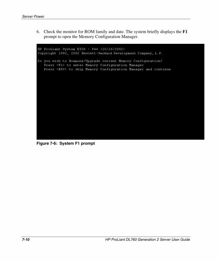
Server Power
6. Check the monitor for ROM family and date. The system briefly displays the F1 prompt to open the Memory Configuration Manager.
Figure 7-6: System F1 prompt
7-10 HP ProLiant DL760 Generation 2 Server User Guide
HP CONFIDENTIAL Writer: Jennifer Hayward File Name: h-ch7 Server Power.doc
Codename: Pioneer Part Number: 201264-002 Last Saved On: 6/17/03 10:08 AM
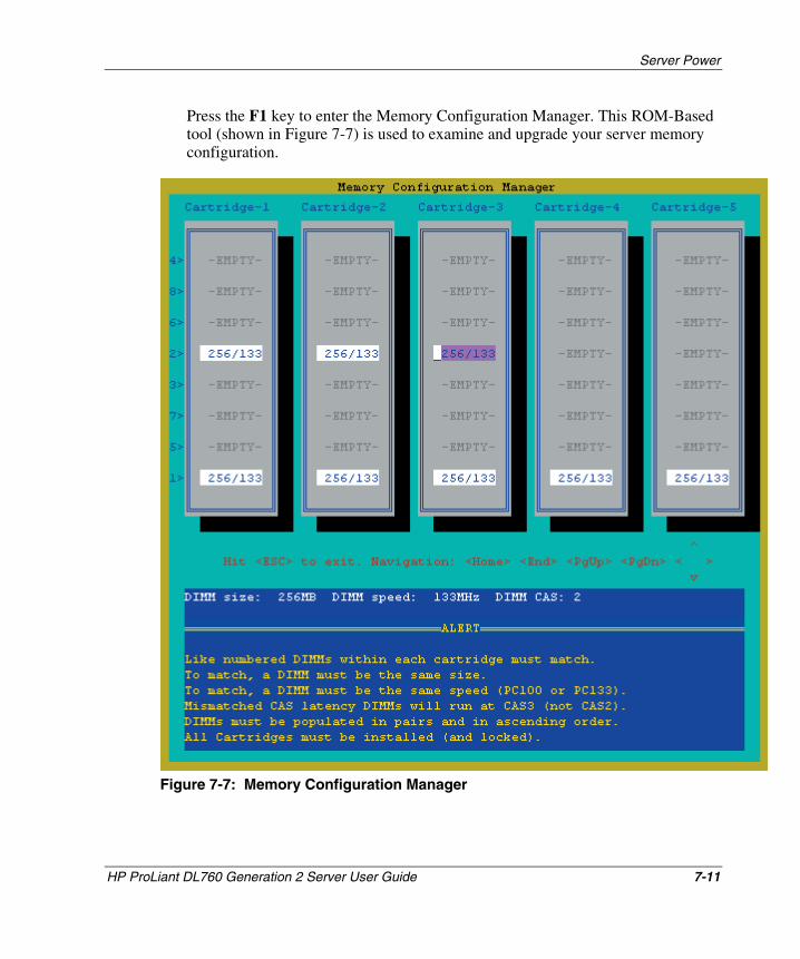
Server Power
Press the F1 key to enter the Memory Configuration Manager. This ROM-Based tool (shown in Figure 7-7) is used to examine and upgrade your server memory configuration.
Figure 7-7: Memory Configuration Manager
HP ProLiant DL760 Generation 2 Server User Guide 7-11
HP CONFIDENTIAL Writer: Jennifer Hayward File Name: h-ch7 Server Power.doc
Codename: Pioneer Part Number: 201264-002 Last Saved On: 6/17/03 10:08 AM
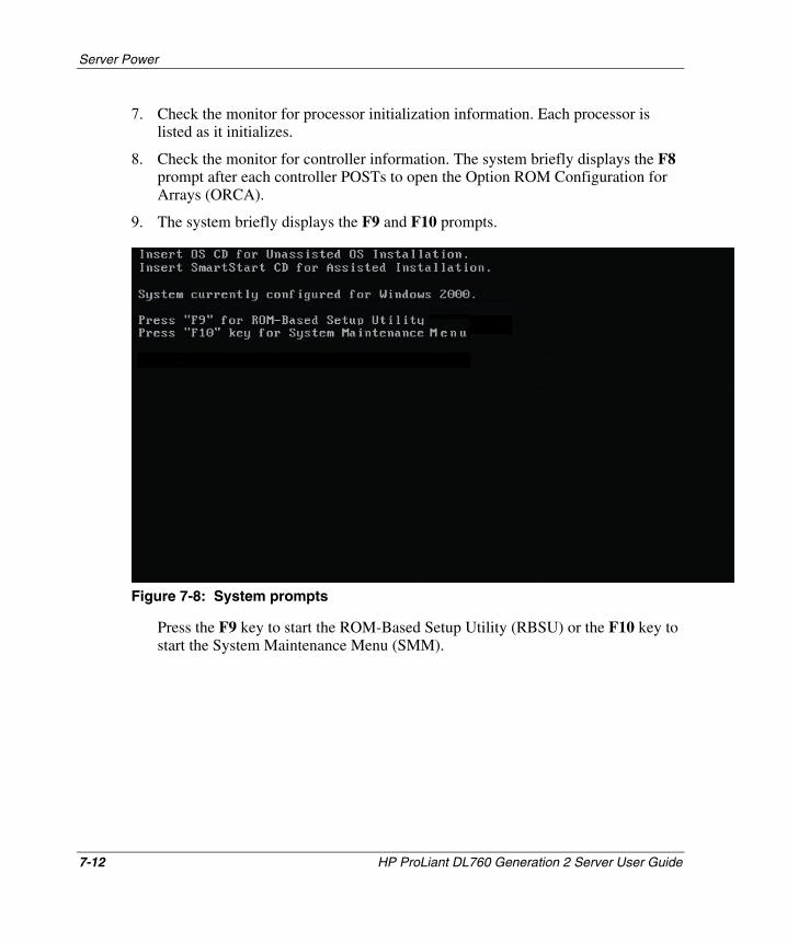
Server Power
7. Check the monitor for processor initialization information. Each processor is listed as it initializes.
8. Check the monitor for controller information. The system briefly displays the F8 prompt after each controller POSTs to open the Option ROM Configuration for Arrays (ORCA).
9. The system briefly displays the F9 and F10 prompts.
Figure 7-8: System prompts
Press the F9 key to start the ROM-Based Setup Utility (RBSU) or the F10 key to start the System Maintenance Menu (SMM).
7-12 HP ProLiant DL760 Generation 2 Server User Guide
HP CONFIDENTIAL Writer: Jennifer Hayward File Name: h-ch7 Server Power.doc
Codename: Pioneer Part Number: 201264-002 Last Saved On: 6/17/03 10:08 AM
Server Power
HP ProLiant DL760 Generation 2 Server User Guide 7-13
HP CONFIDENTIAL Writer: Jennifer Hayward File Name: h-ch7 Server Power.doc
Codename: Pioneer Part Number: 201264-002 Last Saved On: 6/17/03 10:08 AM
10. Be sure that each green PCI Hot Plug LED is illuminated for each PCI/PCI-X I/O expansion slot (viewable from inside and outside the chassis). To check the inside LEDs, open the I/O lid. If any LEDs are not on, power down the server and be sure that the following statements are true:
— Each slot has an expansion board or a slot cover.
— Each slot release lever is closed.
— The expansion boards are properly seated. If necessary, try removing and reseating the boards.
— The PCI Hot Plug interface board cables are properly connected to the I/O board.
— The PCI Hot Plug interface boards are properly seated on the rear I/O panel of the chassis.
Powering Down the Server
The system power in the ProLiant DL760 G2 server does not shut off completely with the front panel Power On/Standby switch. The two switch modes are on and standby, rather than on and off. The Standby position removes power from most of the electronics and the drives, but portions of the power supply, the IMD, the system interlock circuitry, and some internal circuitry remain active. To completely remove all power from the system, you must disconnect all power cords from the server.
WARNING: To reduce the risk of electric shock or damage to the equipment, disconnect power from the server by unplugging all power cords from either the electrical outlet or the server.
To power down the server:
1. Press the Power On/Standby switch to go to standby mode. Placing the server in standby mode disables the main power supply output and provides auxiliary power (+ 5V) to the server. Standby mode does not disable auxiliary power.
2. Be sure that the system LED on the front panel, near the Power On/Standby switch, becomes dark and fan noise abates.
3. Disconnect all power cords from the server to disable power to the server.
8 Configuring the Server
This chapter discusses how to configure the ProLiant DL760 G2 server by setting up the server environment, setting up the hard drive SCSI array, installing the operating system, and installing HP drivers and utilities.
HP ProLiant DL760 Generation 2 Server User Guide 8-1
HP CONFIDENTIAL Writer: Jennifer Hayward File Name: i-ch8 Configuring the Server.doc
Codename: Pioneer Part Number: 201264-002 Last Saved On: 6/17/03 10:10 AM
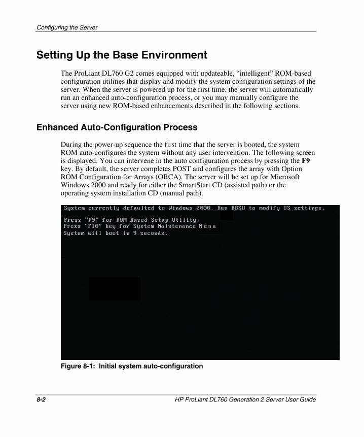
Configuring the Server
Setting Up the Base Environment
The ProLiant DL760 G2 comes equipped with updateable, “intelligent” ROM-based configuration utilities that display and modify the system configuration settings of the server. When the server is powered up for the first time, the server will automatically run an enhanced auto-configuration process, or you may manually configure the server using new ROM-based enhancements described in the following sections.
Enhanced Auto-Configuration Process
During the power-up sequence the first time that the server is booted, the system ROM auto-configures the system without any user intervention. The following screen is displayed. You can intervene in the auto configuration process by pressing the F9 key. By default, the server completes POST and configures the array with Option ROM Configuration for Arrays (ORCA). The server will be set up for Microsoft Windows 2000 and ready for either the SmartStart CD (assisted path) or the operating system installation CD (manual path).
Figure 8-1: Initial system auto-configuration
8-2 HP ProLiant DL760 Generation 2 Server User Guide
HP CONFIDENTIAL Writer: Jennifer Hayward File Name: i-ch8 Configuring the Server.doc
Codename: Pioneer Part Number: 201264-002 Last Saved On: 6/17/03 10:10 AM
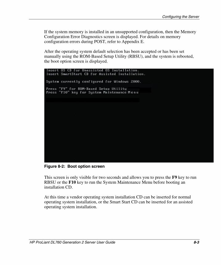
Configuring the Server
If the system memory is installed in an unsupported configuration, then the Memory Configuration Error Diagnostics screen is displayed. For details on memory configuration errors during POST, refer to Appendix E.
After the operating system default selection has been accepted or has been set manually using the ROM-Based Setup Utility (RBSU), and the system is rebooted, the boot option screen is displayed.
Figure 8-2: Boot option screen
This screen is only visible for two seconds and allows you to press the F9 key to run RBSU or the F10 key to run the System Maintenance Menu before booting an installation CD.
At this time a vendor operating system installation CD can be inserted for normal operating system installation, or the Smart Start CD can be inserted for an assisted operating system installation.
HP ProLiant DL760 Generation 2 Server User Guide 8-3
HP CONFIDENTIAL Writer: Jennifer Hayward File Name: i-ch8 Configuring the Server.doc
Codename: Pioneer Part Number: 201264-002 Last Saved On: 6/17/03 10:10 AM
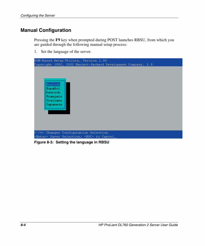
Configuring the Server
Manual Configuration
Pressing the F9 key when prompted during POST launches RBSU, from which you are guided through the following manual setup process:
1. Set the language of the server.
Figure 8-3: Setting the language in RBSU
8-4 HP ProLiant DL760 Generation 2 Server User Guide
HP CONFIDENTIAL Writer: Jennifer Hayward File Name: i-ch8 Configuring the Server.doc
Codename: Pioneer Part Number: 201264-002 Last Saved On: 6/17/03 10:10 AM
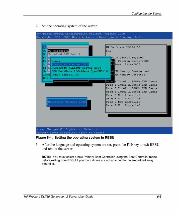
Configuring the Server
2. Set the operating system of the server.
Figure 8-4: Setting the operating system in RBSU
3. After the language and operating system are set, press the F10 key to exit RBSU and reboot the server.
NOTE: You must select a new Primary Boot Controller using the Boot Controller menu before exiting from RBSU if your boot drives are not attached to the embedded array controller.
HP ProLiant DL760 Generation 2 Server User Guide 8-5
HP CONFIDENTIAL Writer: Jennifer Hayward File Name: i-ch8 Configuring the Server.doc
Codename: Pioneer Part Number: 201264-002 Last Saved On: 6/17/03 10:10 AM
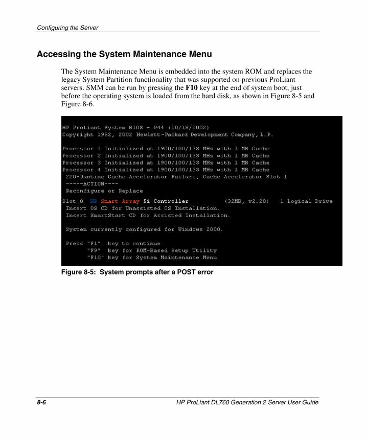
Configuring the Server
Accessing the System Maintenance Menu
The System Maintenance Menu is embedded into the system ROM and replaces the legacy System Partition functionality that was supported on previous ProLiant servers. SMM can be run by pressing the F10 key at the end of system boot, just before the operating system is loaded from the hard disk, as shown in Figure 8-5 and Figure 8-6.
Figure 8-5: System prompts after a POST error
8-6 HP ProLiant DL760 Generation 2 Server User Guide
HP CONFIDENTIAL Writer: Jennifer Hayward File Name: i-ch8 Configuring the Server.doc
Codename: Pioneer Part Number: 201264-002 Last Saved On: 6/17/03 10:10 AM
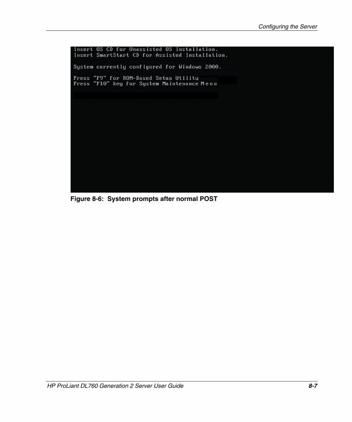
Configuring the Server
Figure 8-6: System prompts after normal POST
HP ProLiant DL760 Generation 2 Server User Guide 8-7
HP CONFIDENTIAL Writer: Jennifer Hayward File Name: i-ch8 Configuring the Server.doc
Codename: Pioneer Part Number: 201264-002 Last Saved On: 6/17/03 10:10 AM
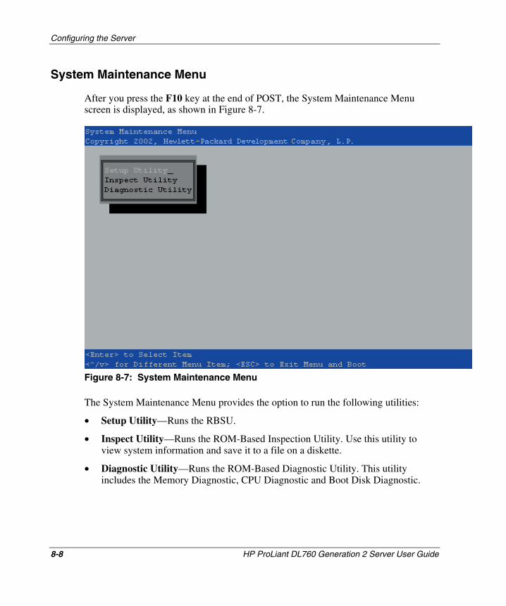
Configuring the Server
System Maintenance Menu
After you press the F10 key at the end of POST, the System Maintenance Menu screen is displayed, as shown in Figure 8-7.
Figure 8-7: System Maintenance Menu
The System Maintenance Menu provides the option to run the following utilities:
• Setup Utility—Runs the RBSU.
• Inspect Utility—Runs the ROM-Based Inspection Utility. Use this utility to view system information and save it to a file on a diskette.
• Diagnostic Utility—Runs the ROM-Based Diagnostic Utility. This utility includes the Memory Diagnostic, CPU Diagnostic and Boot Disk Diagnostic.
8-8 HP ProLiant DL760 Generation 2 Server User Guide
HP CONFIDENTIAL Writer: Jennifer Hayward File Name: i-ch8 Configuring the Server.doc
Codename: Pioneer Part Number: 201264-002 Last Saved On: 6/17/03 10:10 AM
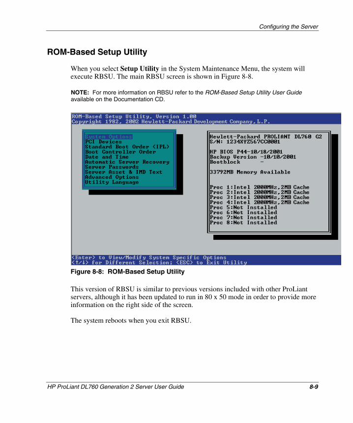
Configuring the Server
ROM-Based Setup Utility
When you select Setup Utility in the System Maintenance Menu, the system will execute RBSU. The main RBSU screen is shown in Figure 8-8.
NOTE: For more information on RBSU refer to the ROM-Based Setup Utility User Guide available on the Documentation CD.
Figure 8-8: ROM-Based Setup Utility
This version of RBSU is similar to previous versions included with other ProLiant servers, although it has been updated to run in 80 x 50 mode in order to provide more information on the right side of the screen.
The system reboots when you exit RBSU.
HP ProLiant DL760 Generation 2 Server User Guide 8-9
HP CONFIDENTIAL Writer: Jennifer Hayward File Name: i-ch8 Configuring the Server.doc
Codename: Pioneer Part Number: 201264-002 Last Saved On: 6/17/03 10:10 AM
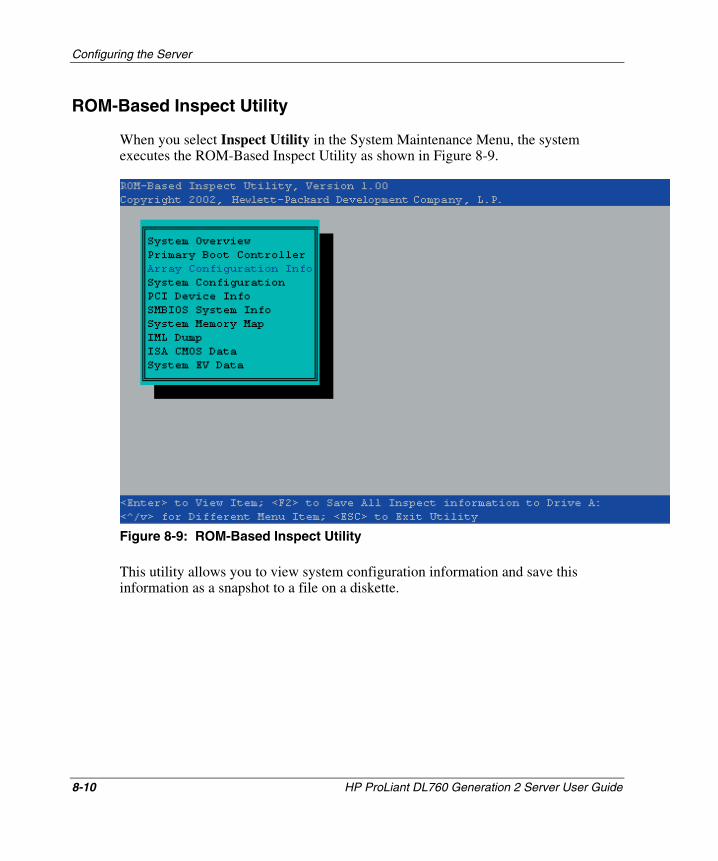
Configuring the Server
ROM-Based Inspect Utility
When you select Inspect Utility in the System Maintenance Menu, the system executes the ROM-Based Inspect Utility as shown in Figure 8-9.
Figure 8-9: ROM-Based Inspect Utility
This utility allows you to view system configuration information and save this information as a snapshot to a file on a diskette.
8-10 HP ProLiant DL760 Generation 2 Server User Guide
HP CONFIDENTIAL Writer: Jennifer Hayward File Name: i-ch8 Configuring the Server.doc
Codename: Pioneer Part Number: 201264-002 Last Saved On: 6/17/03 10:10 AM
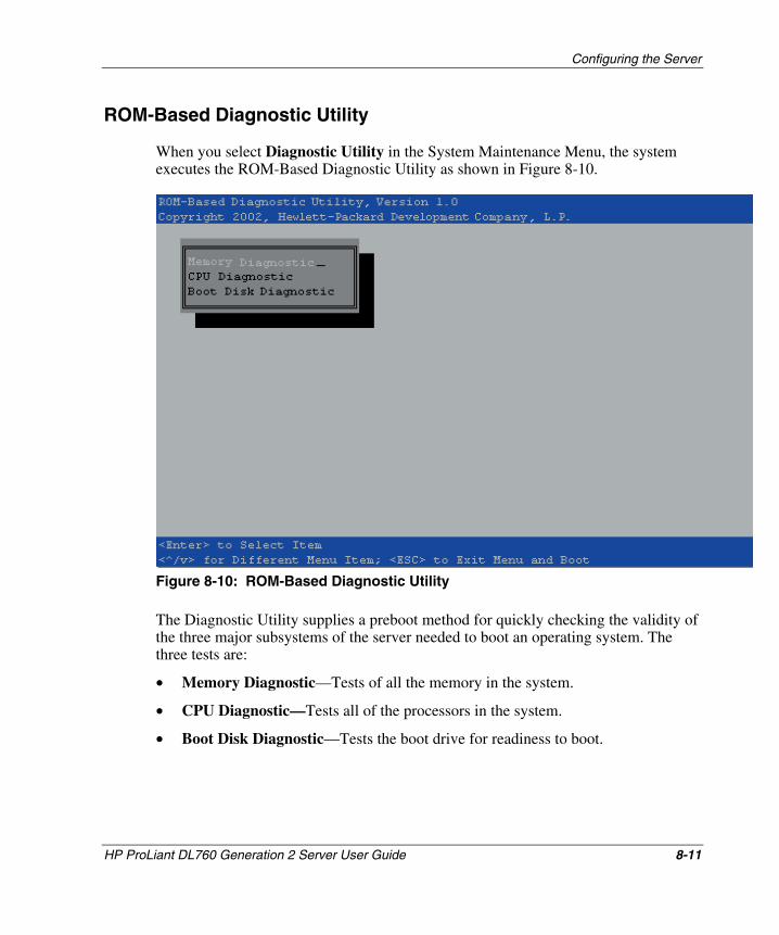
Configuring the Server
ROM-Based Diagnostic Utility
When you select Diagnostic Utility in the System Maintenance Menu, the system executes the ROM-Based Diagnostic Utility as shown in Figure 8-10.
Figure 8-10: ROM-Based Diagnostic Utility
The Diagnostic Utility supplies a preboot method for quickly checking the validity of the three major subsystems of the server needed to boot an operating system. The three tests are:
• Memory Diagnostic—Tests of all the memory in the system.
• CPU Diagnostic—Tests all of the processors in the system.
• Boot Disk Diagnostic—Tests the boot drive for readiness to boot.
HP ProLiant DL760 Generation 2 Server User Guide 8-11
HP CONFIDENTIAL Writer: Jennifer Hayward File Name: i-ch8 Configuring the Server.doc
Codename: Pioneer Part Number: 201264-002 Last Saved On: 6/17/03 10:10 AM
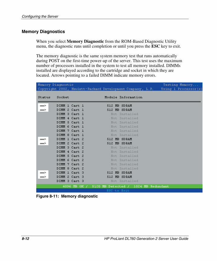
Configuring the Server
Memory Diagnostics
When you select Memory Diagnostic from the ROM-Based Diagnostic Utility menu, the diagnostic runs until completion or until you press the ESC key to exit.
The memory diagnostic is the same system memory test that runs automatically during POST on the first-time power-up of the server. This test uses the maximum number of processors installed in the system to test all memory installed. DIMMs installed are displayed according to the cartridge and socket in which they are located. Arrows pointing to a failed DIMM indicate memory errors.
Figure 8-11: Memory diagnostic
8-12 HP ProLiant DL760 Generation 2 Server User Guide
HP CONFIDENTIAL Writer: Jennifer Hayward File Name: i-ch8 Configuring the Server.doc
Codename: Pioneer Part Number: 201264-002 Last Saved On: 6/17/03 10:10 AM
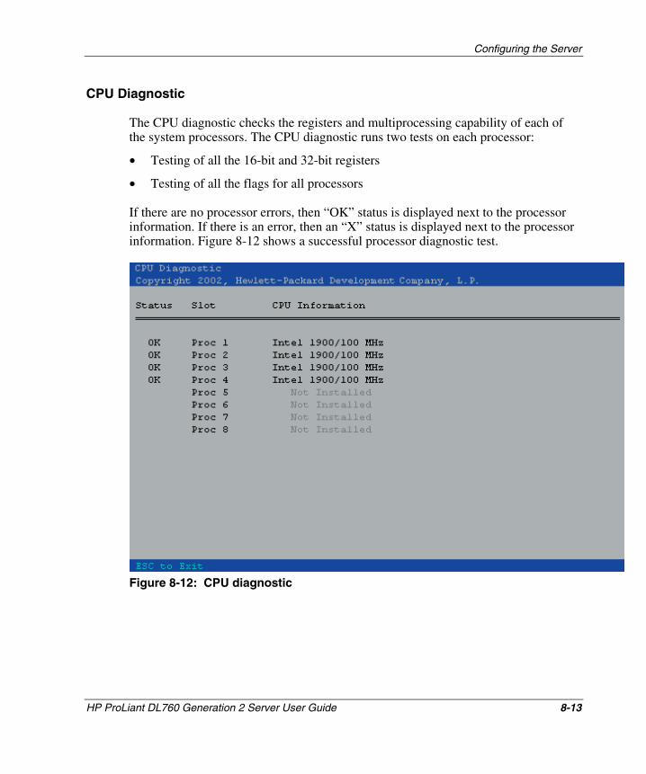
Configuring the Server
CPU Diagnostic
The CPU diagnostic checks the registers and multiprocessing capability of each of the system processors. The CPU diagnostic runs two tests on each processor:
• Testing of all the 16-bit and 32-bit registers
• Testing of all the flags for all processors
If there are no processor errors, then “OK” status is displayed next to the processor information. If there is an error, then an “X” status is displayed next to the processor information. Figure 8-12 shows a successful processor diagnostic test.
Figure 8-12: CPU diagnostic
HP ProLiant DL760 Generation 2 Server User Guide 8-13
HP CONFIDENTIAL Writer: Jennifer Hayward File Name: i-ch8 Configuring the Server.doc
Codename: Pioneer Part Number: 201264-002 Last Saved On: 6/17/03 10:10 AM
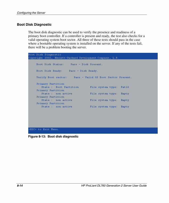
Configuring the Server
Boot Disk Diagnostic
The boot disk diagnostic can be used to verify the presence and readiness of a primary boot controller. If a controller is present and ready, the test also checks for a valid operating system boot sector. All three of these tests should pass in the case where a bootable operating system is installed on the server. If any of the tests fail, there will be a problem booting the server.
Figure 8-13: Boot disk diagnostic
8-14 HP ProLiant DL760 Generation 2 Server User Guide
HP CONFIDENTIAL Writer: Jennifer Hayward File Name: i-ch8 Configuring the Server.doc
Codename: Pioneer Part Number: 201264-002 Last Saved On: 6/17/03 10:10 AM
Configuring the Server
Configuring the Drive Array Controller
If you are using a simple SCSI controller to boot from the internal drives, disregard this section and proceed to the “Installing the Operating System” section later in this chapter. If you are using a Smart Array 5i Controller or an array controller installed into a PCI/PCI-X slot to boot from the internal drives, the first time the system is powered up, you must create the logical drive (or drives) in the RAID array.
The Smart Array 5i Controller built into the ProLiant DL760 G2 server can use any of the following utilities to create logical drives based on the RAID configuration that you specify:
• Option ROM Configuration for Arrays (ORCA)
• Array Configuration Utility (ACU)
• Array Configuration Replicator Utility (ACR)
The ProLiant DL760 G2 server has an embedded Smart Array 5i Controller. This controller is a dual channel Ultra3 SCSI array controller embedded on the I/O board. Both channels support Low Voltage Differential (LVD) SCSI devices. The controller provides the following features:
• 32 MB of total memory, 12 MB of read-ahead cache
• Support for up to four internal Ultra3 SCSI hot-plug drives in RAID 0, 1, 1+0, and 5 configurations
• External connector support for external tape drives to back up the internal drives
• Migration between RAID levels
• Migration between stripe sizes
• Prefailure notification and Pre-Failure Warranty (through Insight Manager 7)
• Online spares
Port 1 is connected to an external very high density connector interface (VHDCI) SCSI connector. Port 2 is dedicated to controlling the SCSI drives in the internal drive bay.
HP ProLiant DL760 Generation 2 Server User Guide 8-15
HP CONFIDENTIAL Writer: Jennifer Hayward File Name: i-ch8 Configuring the Server.doc
Codename: Pioneer Part Number: 201264-002 Last Saved On: 6/17/03 10:10 AM
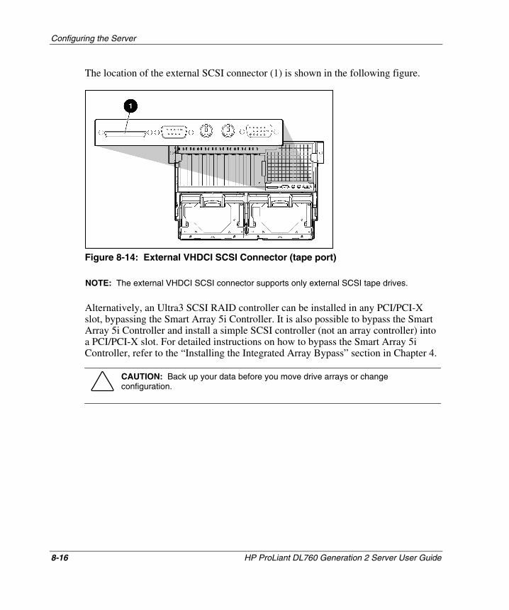
Configuring the Server
The location of the external SCSI connector (1) is shown in the following figure.
Figure 8-14: External VHDCI SCSI Connector (tape port)
NOTE: The external VHDCI SCSI connector supports only external SCSI tape drives.
Alternatively, an Ultra3 SCSI RAID controller can be installed in any PCI/PCI-X slot, bypassing the Smart Array 5i Controller. It is also possible to bypass the Smart Array 5i Controller and install a simple SCSI controller (not an array controller) into a PCI/PCI-X slot. For detailed instructions on how to bypass the Smart Array 5i Controller, refer to the “Installing the Integrated Array Bypass” section in Chapter 4.
CAUTION: Back up your data before you move drive arrays or change configuration.
8-16 HP ProLiant DL760 Generation 2 Server User Guide
HP CONFIDENTIAL Writer: Jennifer Hayward File Name: i-ch8 Configuring the Server.doc
Codename: Pioneer Part Number: 201264-002 Last Saved On: 6/17/03 10:10 AM
Configuring the Server
Option ROM Configuration for Arrays
After the POST sequence successfully concludes, the server executes the option ROMs. An option ROM is the code programmed in the read-only memory (ROM) of any PCI expansion boards or embedded devices that are installed in the server. Option ROMs allow you to make hardware configuration changes for each PCI expansion board. These settings are retained when the server is powered down so that they can be restored the next time the server is powered up.
The ORCA utility is a hardware-level configuration program that is embedded in the option ROM of the controller. ORCA is also embedded into the ROM of other array controllers.
ORCA provides the following benefits:
• Because it is loaded from ROM, it does not require diskettes or CDs to run.
• It can be started on initial power-up.
• It can configure any number of drives.
• It can be executed during any boot sequence.
• It allows easy configuration of the following:
— RAID 0, RAID 1, RAID 1+0, and RAID 5 configurations
— Online spare (hot spare)
— Boot controller order
• It allows independent configuration control over each logical drive.
HP ProLiant DL760 Generation 2 Server User Guide 8-17
HP CONFIDENTIAL Writer: Jennifer Hayward File Name: i-ch8 Configuring the Server.doc
Codename: Pioneer Part Number: 201264-002 Last Saved On: 6/17/03 10:10 AM
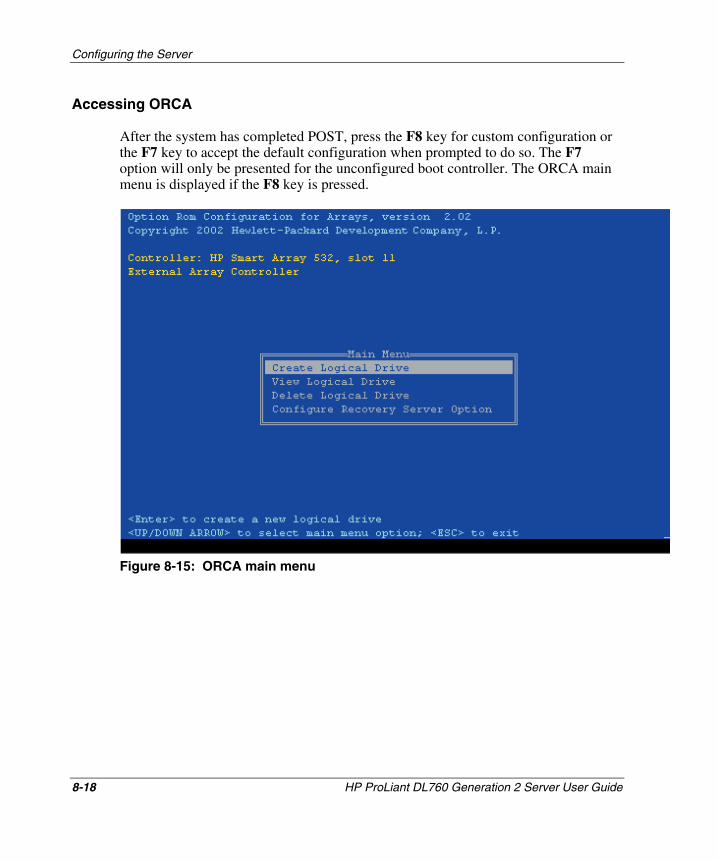
Configuring the Server
Accessing ORCA
After the system has completed POST, press the F8 key for custom configuration or the F7 key to accept the default configuration when prompted to do so. The F7 option will only be presented for the unconfigured boot controller. The ORCA main menu is displayed if the F8 key is pressed.
Figure 8-15: ORCA main menu
8-18 HP ProLiant DL760 Generation 2 Server User Guide
HP CONFIDENTIAL Writer: Jennifer Hayward File Name: i-ch8 Configuring the Server.doc
Codename: Pioneer Part Number: 201264-002 Last Saved On: 6/17/03 10:10 AM
Configuring the Server
Using ORCA
To configure the drive array controller:
CAUTION: If you have installed any previously used hard drives in the ProLiant DL760 G2 server, you must delete any array configuration information that those drives contain. Doing so destroys any data on those hard drives.
1. If you have any previously used hard drives installed in the server, select View Logical Drive, and then press the Enter key to view the configuration of the drives. If you do not see any logical drives configured, press the Esc key to return to the ORCA main menu, and then proceed to step 2.
If you do see an existing logical drive or drives, do the following:
a. Press the Esc key to return to the main menu.
b. From the main menu, select Delete Logical Drive. The Delete Logical Drive screen displays.
c. Follow the instructions on the screen to delete the logical drive or drives. After the drives have been deleted, you are returned to the main menu.
2. Select Create Logical Drive, and then press the Enter key.
3. Follow the screen prompts to define the RAID configuration. For more information about configuring your specific array controller, refer to the documentation that comes with your array controller, or refer to the HP website:
www.hp.com/support/storage/index.shtml
From this website, click Array and SCSI controllers, and then navigate to the appropriate controller information.
4. When you have finished configuring the array, press the Esc key to exit ORCA.
HP ProLiant DL760 Generation 2 Server User Guide 8-19
HP CONFIDENTIAL Writer: Jennifer Hayward File Name: i-ch8 Configuring the Server.doc
Codename: Pioneer Part Number: 201264-002 Last Saved On: 6/17/03 10:10 AM
Configuring the Server
Array Configuration Utility
The Array Configuration Utility (ACU) is an easy-to-use graphical configuration utility to help set up and change drive array configurations. It can be used to configure the standard internal drive controller and any option controller boards that are installed. This utility:
• Provides a graphical view of HP drive array configurations
• Provides express or custom initial configuration
• Supports adding capacity
• Supports RAID 0, 1+0, 5 and RAID ADG fault-tolerant configurations
• Supports RAID level and stripe size migration
• Optimizes array configurations using configuration wizards
• Sets drive rebuild priorities
• Allows online spare (hot spare) configuration
• Allows separate fault-tolerance configurations on a logical drive basis
ACU allows you to configure a disk array quickly and simply without an in-depth understanding of RAID or drive array technology.
8-20 HP ProLiant DL760 Generation 2 Server User Guide
HP CONFIDENTIAL Writer: Jennifer Hayward File Name: i-ch8 Configuring the Server.doc
Codename: Pioneer Part Number: 201264-002 Last Saved On: 6/17/03 10:10 AM
Configuring the Server
Starting the Array Configuration Utility
The ACU software can be run from CD or from within supported operating systems.
Running ACU from the SmartStart CD
The ProLiant DL760 G2 server is shipped with the ACU on the SmartStart CD. Start the utility as described in the following procedure. If, for any reason, you cannot start the utility as described here, the utility is available in a variety of locations.
1. Power off the server, if necessary, then power on the server.
2. Boot the SmartStart CD.
3. Select the Maintenance tab at the top.
4. Select the Array Configuration Utility program.
When you start the ACU, the software checks the configuration of each controller and its drive arrays. The ACU defaults to the standard configuration path. If you would like to run the configuration wizards, select them from the right-hand side of the screen.
Online Help
The configuration wizards contain context-sensitive help on the right hand side of the screen. To access more detailed help, or for help on the standard configuration screens, click help on the top right of the screen.
HP ProLiant DL760 Generation 2 Server User Guide 8-21
HP CONFIDENTIAL Writer: Jennifer Hayward File Name: i-ch8 Configuring the Server.doc
Codename: Pioneer Part Number: 201264-002 Last Saved On: 6/17/03 10:10 AM
Configuring the Server
Running ACU from the Operating System
If the server that you are configuring is running in Windows 2000, Windows Server 2003, or Linux, you can install and run the configuration utility online:
• Windows 2000 and Windows Server 2003—When you install the ProLiant Support Pack for Windows 2000 and the ProLiant Support Pack for Windows Server 2003, the ACU is automatically installed on the server.
• Linux—The Array Configuration Utility is available for download from the HP website:
h18000.www1.hp.com/products/servers/linux/softwaredrivers.html
Refer to the README.TXT file included with the utility for version support information and instructions about loading the utility.
Capacity Expansion
Capacity expansion involves adding storage capacity to an array that has already been configured. If an existing array is nearly full of data, you can expand the capacity without disturbing the existing data. The Smart Array 5i capacity expansion feature allows new physical drives to be added to the array.
Logical drive extension allows you to increase the size of existing logical drives without disturbing the data on those logical drives. If an existing logical drive is full of data, you can extend the logical drive when there is free space on the array. If no free space is available on the array, you can add drives to the array and proceed to extend the logical drive.
IMPORTANT: Logical drive extension is not supported by all operating systems. Only extend logical drives that are used with an operating system that supports extension.
8-22 HP ProLiant DL760 Generation 2 Server User Guide
HP CONFIDENTIAL Writer: Jennifer Hayward File Name: i-ch8 Configuring the Server.doc
Codename: Pioneer Part Number: 201264-002 Last Saved On: 6/17/03 10:10 AM
Configuring the Server
Extending Logical Drives — Operating Systems
The following operating systems support logical drive extension:
• Microsoft Windows 2000 with Service Pack 3
• Microsoft Windows Server 2003
If the operating system is not listed, check the operating system documentation or contact the operating system vendor before extending logical drives.
RAID Level and Stripe Size Migration
Use the Online RAID Level or Stripe Size Migration screen to:
• Reconfigure a currently configured logical drive to a new fault-tolerance (RAID) level.
• Change the stripe size of an existing logical drive to a new stripe size.
Both migrations can be executed online on Windows 2000 or Windows Server 2003 without causing data loss. These migrations can also be performed offline on other operating systems by booting the SmartStart CD and running the ACU.
Errors and Warnings
When you start the ACU, the software checks each controller for configuration errors. If a problem is found, the ACU displays an error or warning message that describes the problem. Error and warning messages include instructions to correct configurations. For more information, refer to documentation on the SmartStart CD.
HP ProLiant DL760 Generation 2 Server User Guide 8-23
HP CONFIDENTIAL Writer: Jennifer Hayward File Name: i-ch8 Configuring the Server.doc
Codename: Pioneer Part Number: 201264-002 Last Saved On: 6/17/03 10:10 AM
Configuring the Server
Array Configuration Replicator Utility
The Array Configuration Replicator (ACR) utility enables you to configure Smart Array controllers remotely on a target server. ACR is part of the SmartStart Scripting Toolkit.
ACR creates a configuration script file containing the array controller configuration information. ACR can then read this configuration information from a script file and apply the configuration to the controllers in the target server. ACR allows the array configuration existing on one ProLiant DL760 G2 server to be replicated on other ProLiant DL760 G2 servers.
ACR has three modes of operation:
• Capture mode—Captures the array configuration on all HP Storage Array controllers configured in the server and saves it to a script file that can be used later for replication purposes.
• Custom mode—Reads an array configuration specified in a script file and applies the configuration on a target system, allowing the user to specify all the details of a configuration. Custom mode is typically required when applying a captured configuration.
• Auto mode—Reads the array configuration specified in a script file and applies the configuration on a target system, relying on basic input parameters and making automatic decisions to apply a configuration on a controller.
For more information on the SmartStart Scripting Toolkit, refer to:
• SmartStart Scripting Toolkit documentation:
— Next Generation Server Deployment Tools: SmartStart Scripting Toolkit white paper
— SmartStart Scripting Toolkit User Guide
— SmartStart Scripting Toolkit Best Practices
• SmartStart Scripting Toolkit website:
www.hp.com/servers/sstoolkit
8-24 HP ProLiant DL760 Generation 2 Server User Guide
HP CONFIDENTIAL Writer: Jennifer Hayward File Name: i-ch8 Configuring the Server.doc
Codename: Pioneer Part Number: 201264-002 Last Saved On: 6/17/03 10:10 AM
Configuring the Server
Installing the Operating System
If you are installing the operating system using the SmartStart CD, configure it by using the instructions in the following section.
NOTE: In this chapter, configuring the server means creating partitions on the hard drive, installing HP utilities, and installing the operating system.
Assisted SmartStart Operating System Installation
If you purchased the operating system separately, you need to configure the server and install the operating system using the SmartStart CD.
NOTE: If you do not use the SmartStart CD, refer to the Array Controller Driver Installation kit for your boot device drivers.
SmartStart is the intelligent way to configure the server and to load the system software, thereby achieving a well-integrated server that ensures maximum dependability and supportability.
To install the SmartStart CD:
1. With the server turned on, locate the CD-ROM drive.
2. Push the button to release the tray. Pull out the tray.
3. Place the SmartStart CD in the tray (label facing up), handling the CD from the edges, not by the flat surfaces of the disc.
HP ProLiant DL760 Generation 2 Server User Guide 8-25
HP CONFIDENTIAL Writer: Jennifer Hayward File Name: i-ch8 Configuring the Server.doc
Codename: Pioneer Part Number: 201264-002 Last Saved On: 6/17/03 10:10 AM

Configuring the Server
8-26 HP ProLiant DL760 Generation 2 Server User Guide
HP CONFIDENTIAL Writer: Jennifer Hayward File Name: i-ch8 Configuring the Server.doc
Codename: Pioneer Part Number: 201264-002 Last Saved On: 6/17/03 10:10 AM
4. Reboot the server from the SmartStart CD.
5. Follow the screen prompts.
6. Install Insight Manager 7 when prompted by SmartStart.
When the CD-ROM busy LED is lit, the SmartStart installation sequence begins.
NOTE: Refer to the ProLiant Essentials Foundation Pack for instructions about using SmartStart.
NOTE: To manage the system, refer to the Management CD provided in the ProLiant Essentials Foundation Pack that was shipped with your server.
Installing HP Drivers and Utilities
After successfully installing and configuring the operating system, you need to install software drivers and utilities that are specific to HP and the installed operating system. HP has made every effort to get the primary drivers included in the supported operating system. In addition, HP provides value-add software drivers, agents, and utilities included in the ProLiant Essentials Foundation Pack. The ProLiant Essentials Foundation Pack contains the SmartStart CD and the Management CD.
The procedure for installing this software varies, depending on the installed operating system. Refer to the documentation included on each CD for details.

9 Software Management
HP provides several tools that aid in managing and maintaining the ProLiant DL760 G2 server:
• Integrated Management Display (IMD)
• Integrated Management Log (IML)
• Insight Manager 7
• Survey Utility
• Array Configuration Utility (ACU)
HP ProLiant DL760 Generation 2 Server User Guide 9-1
HP CONFIDENTIAL Writer: Jennifer Hayward File Name: j-ch9 Software Management.doc
Codename: Pioneer Part Number: 201264-002 Last Saved On: 6/17/03 10:14 AM
Software Management
Integrated Management Display
The Integrated Management Display (IMD) is an integrated 16x4 character display mounted on the front of the server. This display provides easy-to-use, menu-driven access to server information. The following sections supply information about configuring, navigating, and using the IMD menus.
Configuring the Integrated Management Display
The IMD can be configured to display a variety of menus that you can customize to meet your specific needs. This section describes several different methods to configure and customize the IMD.
Setup with the ROM-Based Setup Utility
Use the ROM-Based Setup Utility (RBSU) to configure the IMD.
NOTE: Some operating systems allow for online IMD configuration. Refer to the SmartStart CD for more information.
9-2 HP ProLiant DL760 Generation 2 Server User Guide
HP CONFIDENTIAL Writer: Jennifer Hayward File Name: j-ch9 Software Management.doc
Codename: Pioneer Part Number: 201264-002 Last Saved On: 6/17/03 10:14 AM
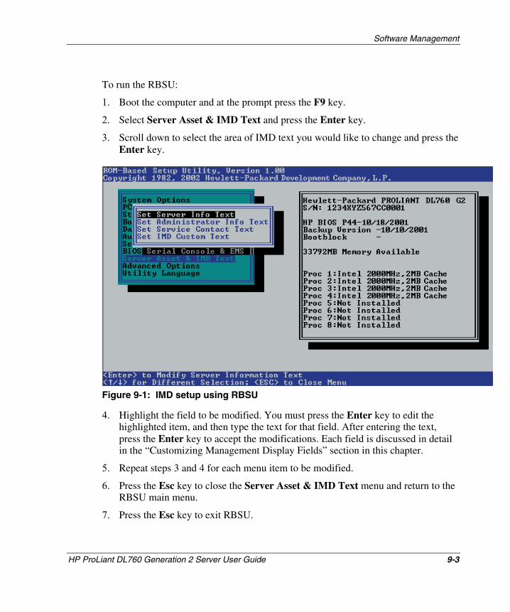
Software Management
To run the RBSU:
1. Boot the computer and at the prompt press the F9 key.
2. Select Server Asset & IMD Text and press the Enter key.
3. Scroll down to select the area of IMD text you would like to change and press the Enter key.
Figure 9-1: IMD setup using RBSU
4. Highlight the field to be modified. You must press the Enter key to edit the highlighted item, and then type the text for that field. After entering the text, press the Enter key to accept the modifications. Each field is discussed in detail in the “Customizing Management Display Fields” section in this chapter.
5. Repeat steps 3 and 4 for each menu item to be modified.
6. Press the Esc key to close the Server Asset & IMD Text menu and return to the RBSU main menu.
7. Press the Esc key to exit RBSU.
HP ProLiant DL760 Generation 2 Server User Guide 9-3
HP CONFIDENTIAL Writer: Jennifer Hayward File Name: j-ch9 Software Management.doc
Codename: Pioneer Part Number: 201264-002 Last Saved On: 6/17/03 10:14 AM
Software Management
8. Press the F10 key at the prompt to confirm the exit from RBSU.
The changes you have entered will not be displayed on the Display Panel until you reboot the computer. Standard IMD fields are defined in the “Navigating the Menus” section later in this chapter.
Setup with the Integrated Management Display Utility
After installing the hardware and software, you can configure the Integrated Management Display using the Integrated Management Display Utility. This utility is used to configure your IMD in Windows.
To run the Integrated Management Display Utility:
1. Boot the computer and log on to the system as administrator or a user with administrator privileges.
2. Select Start, Programs, System Tools, Integrated Management Display Utility.
3. Select the Field box and click the down arrow to open a pull-down menu of the various fields of the IMD to edit.
4. Select Idle Screen. Three lines of information can be displayed on the IMD.
5. To change the values in lines 1, 2, and 3, click the arrow to the right of the line.
6. Click Save to finish editing. This action will save your changes and update the IMD.
7. Click Exit to return to the system.
9-4 HP ProLiant DL760 Generation 2 Server User Guide
HP CONFIDENTIAL Writer: Jennifer Hayward File Name: j-ch9 Software Management.doc
Codename: Pioneer Part Number: 201264-002 Last Saved On: 6/17/03 10:14 AM
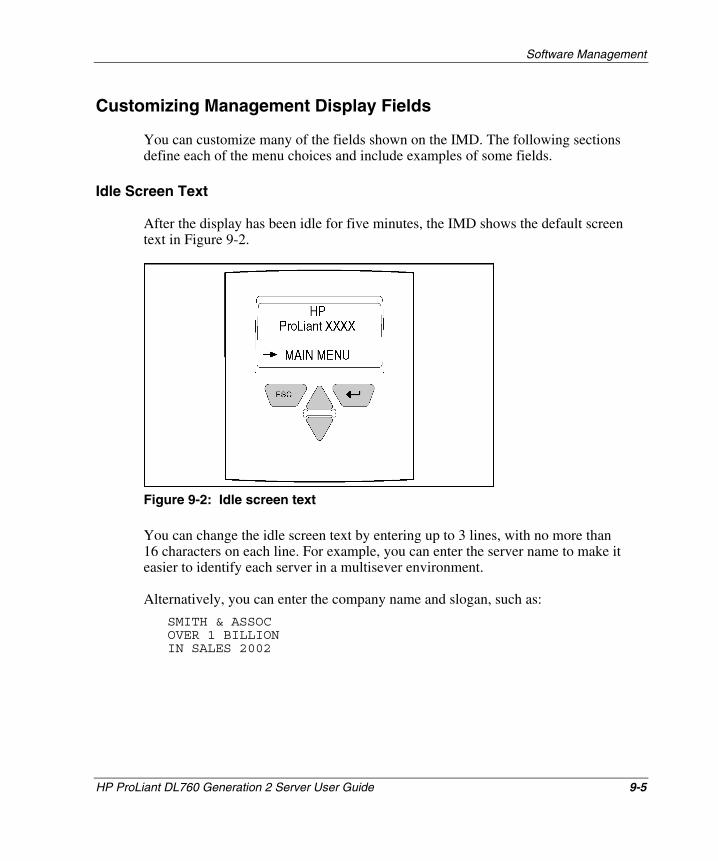
Software Management
Customizing Management Display Fields
You can customize many of the fields shown on the IMD. The following sections define each of the menu choices and include examples of some fields.
Idle Screen Text
After the display has been idle for five minutes, the IMD shows the default screen text in Figure 9-2.
Figure 9-2: Idle screen text
You can change the idle screen text by entering up to 3 lines, with no more than 16 characters on each line. For example, you can enter the server name to make it easier to identify each server in a multisever environment.
Alternatively, you can enter the company name and slogan, such as:
SMITH & ASSOC OVER 1 BILLION IN SALES 2002
HP ProLiant DL760 Generation 2 Server User Guide 9-5
HP CONFIDENTIAL Writer: Jennifer Hayward File Name: j-ch9 Software Management.doc
Codename: Pioneer Part Number: 201264-002 Last Saved On: 6/17/03 10:14 AM
Software Management
Custom Menu Item
Custom Menu Item is a user-defined field for customizing a server. This one-line field can hold up to 14 characters. If text is entered in this field, the text displays as another choice in the main menu.
Custom Menu Screen
The Custom Menu screen is a user-defined field for customizing the server. You can enter up to 4 lines of 14 characters each.
Server Information
Server Name
Enter up to 2 lines of no more than 14 characters each. For example, to name the server by Customer Service and Western Region departments, type:
CUST SERVICE WESTERN REGION
NOTE: The server name cannot be changed in the Integrated Management Display Utility.
Server Asset Tag
Enter the server asset tag. Enter up to 2 lines of 16 characters each.
Primary Operating System
Enter the primary operating system of the server, for example, Windows 2000. You can enter up to 3 lines of 14 characters each.
NOTE: The primary operating system cannot be changed in the Integrated Management Display Utility.
9-6 HP ProLiant DL760 Generation 2 Server User Guide
HP CONFIDENTIAL Writer: Jennifer Hayward File Name: j-ch9 Software Management.doc
Codename: Pioneer Part Number: 201264-002 Last Saved On: 6/17/03 10:14 AM
Software Management
Server Other
Enter any additional information about the server that might be helpful. You can enter up to 2 lines of 14 characters each. For example, enter the server serial number in this field.
Administrator Information
Administrator Name
The Administrator Name field contains the name of the system administrator. You can enter up to 2 lines of no more than 14 characters each.
Administrator Phone Number
The Administrator Phone Number field contains the phone number of the system administrator. Enter up to 2 lines of no more than 14 characters each.
Administrator Pager Number
The Administrator Pager Number field contains the pager number of the system administrator. Enter up to 2 lines of no more than 14 characters each.
Administrator Other
This is a user-defined field. You can enter any additional administrator information, such as the name of an additional administrator who serves as a backup to the primary administrator. Enter up to 2 lines of no more than 14 characters each.
Service Information
Service Contact Name
The Service Contact Name field contains the name of the service provider. Enter up to 2 lines of no more than 14 characters each.
HP ProLiant DL760 Generation 2 Server User Guide 9-7
HP CONFIDENTIAL Writer: Jennifer Hayward File Name: j-ch9 Software Management.doc
Codename: Pioneer Part Number: 201264-002 Last Saved On: 6/17/03 10:14 AM
Software Management
Service Contact Phone Number
The Service Contact Phone Number field contains the phone number of the service provider. Enter up to 2 lines of no more than 14 characters each.
Service Contact Pager Number
The Service Contact Pager Number field contains the pager number of the service provider. Enter up to 2 lines of no more than 14 characters each.
Service Contact Other
This is a user-defined field. You can enter any additional service information, such as the service contract number. Enter up to 2 lines of no more than 14 characters each. For example, enter server history information such as:
SERVICE CONTRACT 1C2002
Standard Integrated Management Display Fields
In addition to the user-defined fields that are customized during configuration, the IMD automatically provides the following standard fields.
System Information
Events
The Events menu choice enables you to scroll through a list of all error events starting with the most recent event.
ROM
The ROM Family and the ROM Date is the month, date, and year of the current server ROM.
9-8 HP ProLiant DL760 Generation 2 Server User Guide
HP CONFIDENTIAL Writer: Jennifer Hayward File Name: j-ch9 Software Management.doc
Codename: Pioneer Part Number: 201264-002 Last Saved On: 6/17/03 10:14 AM
Software Management
Bootblock Date
The Bootblock Date is the month, date, and year of the current server Bootblock.
Memory
The Memory field shows the total memory of the server installed at boot.
PCI Slot
There is a PCI Slot field for each of the PCI slots. This field displays the slot information at boot.
System Processor
There is a System Processor field for each of the processors installed on the server. The System Processor field shows the processor speed and other details about the processor.
F1 Prompt
The F1 Prompt menu choice enables you to continue booting without a keyboard or monitor. This feature is useful for service and diagnostic purposes, allowing you to continue the boot process without attaching a monitor and keyboard and their respective cables.
Contrast
You can adjust the level of contrast on the display by using the up and down arrows. Press the up arrow to increase the contrast and the down arrow to decrease the contrast.
Other Info
This field is reserved for server-specific information.
HP ProLiant DL760 Generation 2 Server User Guide 9-9
HP CONFIDENTIAL Writer: Jennifer Hayward File Name: j-ch9 Software Management.doc
Codename: Pioneer Part Number: 201264-002 Last Saved On: 6/17/03 10:14 AM
Software Management
Navigating the Menus
The IMD is menu-driven and designed to be easy to use. The following sections provide information about how to navigate and use the menus.
Normal Run-Time Behavior
After configuring the display and rebooting the server, a series of server POST operations is displayed. The first screen you see after rebooting the server shows the model number and IMD firmware revision of your display, then the POST screen is displayed.
During POST, a spinning bar beside the menu item indicates that the server test is in progress. When the test is finished, the IMD shows a check mark by the completed menu item. A check mark indicates that the test is complete but does not necessarily mean that the test was error free.
If an error occurs during POST, the server logs the error to the IMD under Unviewed Events and requires you to view the error before proceeding to any other menu choices. If there are no errors, you will see the default idle screen text, as shown in Figure 9-2. This screen can be different if the text was changed during configuration.
9-10 HP ProLiant DL760 Generation 2 Server User Guide
HP CONFIDENTIAL Writer: Jennifer Hayward File Name: j-ch9 Software Management.doc
Codename: Pioneer Part Number: 201264-002 Last Saved On: 6/17/03 10:14 AM
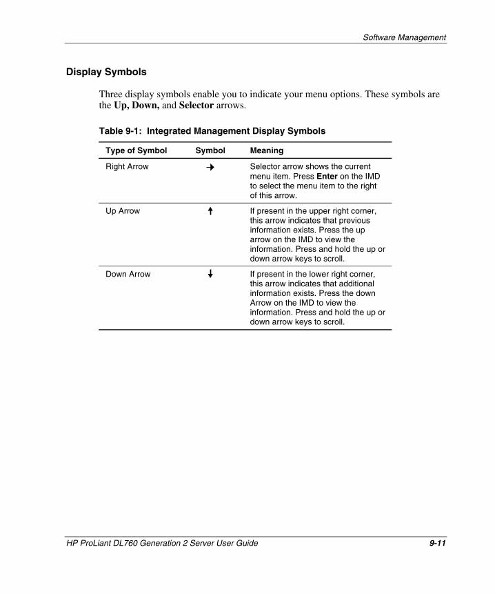
Software Management
Display Symbols
Three display symbols enable you to indicate your menu options. These symbols are the Up, Down, and Selector arrows.
Table 9-1: Integrated Management Display Symbols
Type of Symbol Symbol Meaning
Right Arrow
If present in the lower right corner, this arrow indicates that additional information exists. Press the down Arrow on the IMD to view the information. Press and hold the up or down arrow keys to scroll.
Selector arrow shows the current menu item. Press Enter on the IMD to select the menu item to the right of this arrow.
Up Arrow If present in the upper right corner, this arrow indicates that previous information exists. Press the up arrow on the IMD to view the information. Press and hold the up or down arrow keys to scroll.
Down Arrow
HP ProLiant DL760 Generation 2 Server User Guide 9-11
HP CONFIDENTIAL Writer: Jennifer Hayward File Name: j-ch9 Software Management.doc
Codename: Pioneer Part Number: 201264-002 Last Saved On: 6/17/03 10:14 AM
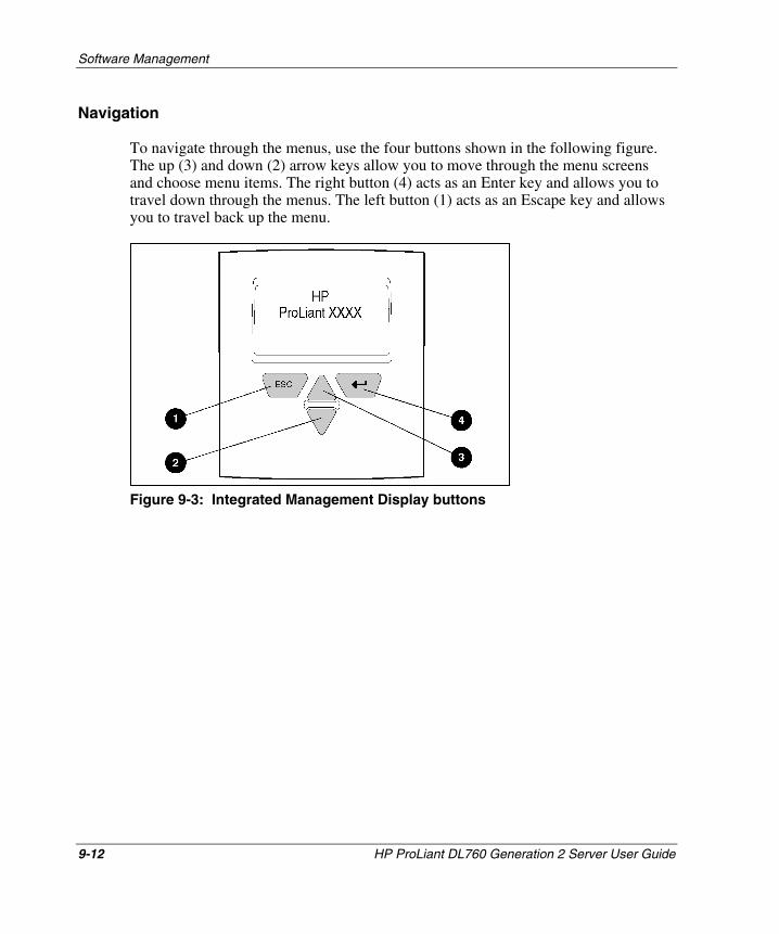
Software Management
Navigation
To navigate through the menus, use the four buttons shown in the following figure. The up (3) and down (2) arrow keys allow you to move through the menu screens and choose menu items. The right button (4) acts as an Enter key and allows you to travel down through the menus. The left button (1) acts as an Escape key and allows you to travel back up the menu.
Figure 9-3: Integrated Management Display buttons
9-12 HP ProLiant DL760 Generation 2 Server User Guide
HP CONFIDENTIAL Writer: Jennifer Hayward File Name: j-ch9 Software Management.doc
Codename: Pioneer Part Number: 201264-002 Last Saved On: 6/17/03 10:14 AM
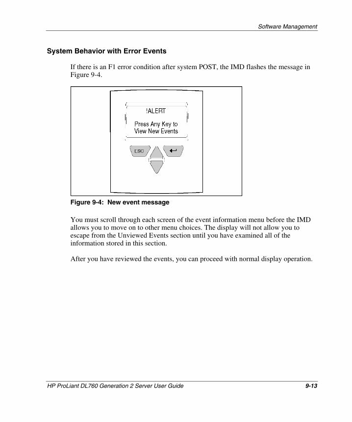
Software Management
System Behavior with Error Events
If there is an F1 error condition after system POST, the IMD flashes the message in Figure 9-4.
Figure 9-4: New event message
You must scroll through each screen of the event information menu before the IMD allows you to move on to other menu choices. The display will not allow you to escape from the Unviewed Events section until you have examined all of the information stored in this section.
After you have reviewed the events, you can proceed with normal display operation.
HP ProLiant DL760 Generation 2 Server User Guide 9-13
HP CONFIDENTIAL Writer: Jennifer Hayward File Name: j-ch9 Software Management.doc
Codename: Pioneer Part Number: 201264-002 Last Saved On: 6/17/03 10:14 AM
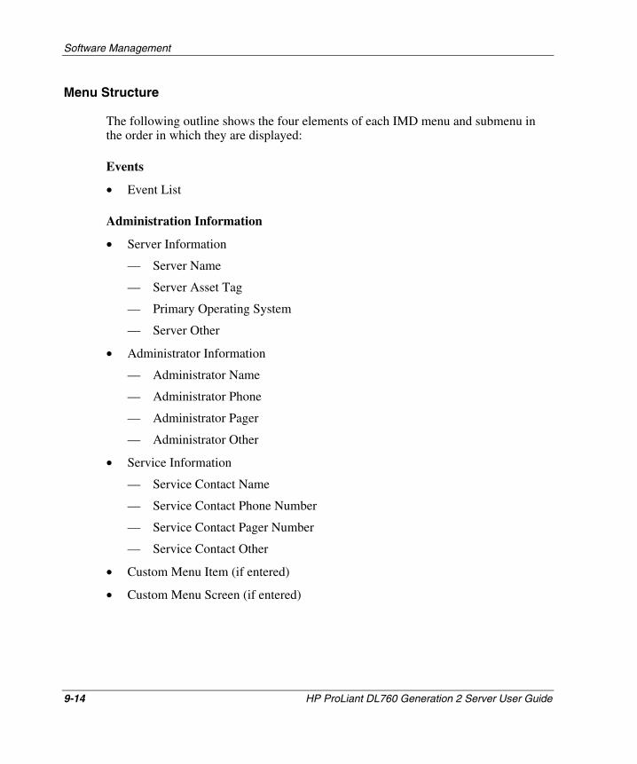
Software Management
Menu Structure
The following outline shows the four elements of each IMD menu and submenu in the order in which they are displayed:
Events
• Event List
Administration Information
• Server Information
— Server Name
— Server Asset Tag
— Primary Operating System
— Server Other
• Administrator Information
— Administrator Name
— Administrator Phone
— Administrator Pager
— Administrator Other
• Service Information
— Service Contact Name
— Service Contact Phone Number
— Service Contact Pager Number
— Service Contact Other
• Custom Menu Item (if entered)
• Custom Menu Screen (if entered)
9-14 HP ProLiant DL760 Generation 2 Server User Guide
HP CONFIDENTIAL Writer: Jennifer Hayward File Name: j-ch9 Software Management.doc
Codename: Pioneer Part Number: 201264-002 Last Saved On: 6/17/03 10:14 AM
Software Management
System Information
• ROM
• Bootblock Date
• Memory
• PCI Slot
• System Processor
Contrast
• Contrast
Other Info
Integrated Management Log
The IML records system events and stores them in an easily viewable form. The IML improves serviceability of an HP server by recording hundreds of events when service is required. The IML marks each event with a time stamp with one-minute granularity.
Events listed in the IML are categorized by one of four event severity levels:
• Status/Informational—Indicates that the message is informational only.
• Repaired—Indicates that corrective action has been taken.
• Caution—Indicates a nonfatal error condition.
• Critical—Indicates a component failure.
The IML requires the use of HP operating system-dependent drivers for full support. Refer to the SmartStart CD for instructions about installing the appropriate drivers.
HP ProLiant DL760 Generation 2 Server User Guide 9-15
HP CONFIDENTIAL Writer: Jennifer Hayward File Name: j-ch9 Software Management.doc
Codename: Pioneer Part Number: 201264-002 Last Saved On: 6/17/03 10:14 AM
Software Management
Multiple Ways of Viewing the Integrated Management Log
You can view an event in the IML in one of three ways:
• From the IMD
• From within Survey Utility
• From within Insight Manager 7
NOTE: You can only view the event list on the IMD; you cannot print it. Events are shown in a shorter form on the display than in Insight Manager 7.
Viewing the IML with the IMD
If an error occurs during the POST sequence, the IMD forces you to view the entire event list before resuming normal operation. Refer to the “System Behavior with Error Events” section earlier in this chapter.
To view the IML during normal operation:
1. From the IMD main menu, select Events.
2. Use the up and down arrow keys to scroll through the list.
3. When you have finished viewing the IML, press the Esc key to return to the main menu.
9-16 HP ProLiant DL760 Generation 2 Server User Guide
HP CONFIDENTIAL Writer: Jennifer Hayward File Name: j-ch9 Software Management.doc
Codename: Pioneer Part Number: 201264-002 Last Saved On: 6/17/03 10:14 AM
Software Management
Viewing the IML with the Survey Utility
The Survey Utility is an online information-gathering agent that runs on servers, gathering critical hardware and software information from various sources, and saving it as a history of multiple sessions. This utility runs only under Microsoft Windows Advanced Server Limited Edition. It was developed to allow you to resolve problems without taking the server offline, thus maximizing server availability.
When the Survey Utility runs, it creates (or replaces) an ASCII text file called SURVEY.TXT. The default location of this file is in the C:/COMPAQ/SURVEY directory. The survey.txt file contains information about hardware, services running, and system resources. It also contains the IML.
To view the IML using the Survey Utility in Windows:
1. Open a command prompt.
2. Navigate to the C:/COMPAQ/SURVEY directory.
3. Execute the SURVEY.EXE file.
NOTE: To view a list of command-line options for SURVEY.EXE, enter survey /? at the command prompt.
4. When the program is finished executing, open the SURVEY.TXT file using any ASCII text viewer. The default location for this file is in the C:/COMPAQ/SURVEY directory.
5. Scroll down to the heading, “Integrated Management Log,” to view the IML.
HP ProLiant DL760 Generation 2 Server User Guide 9-17
HP CONFIDENTIAL Writer: Jennifer Hayward File Name: j-ch9 Software Management.doc
Codename: Pioneer Part Number: 201264-002 Last Saved On: 6/17/03 10:14 AM
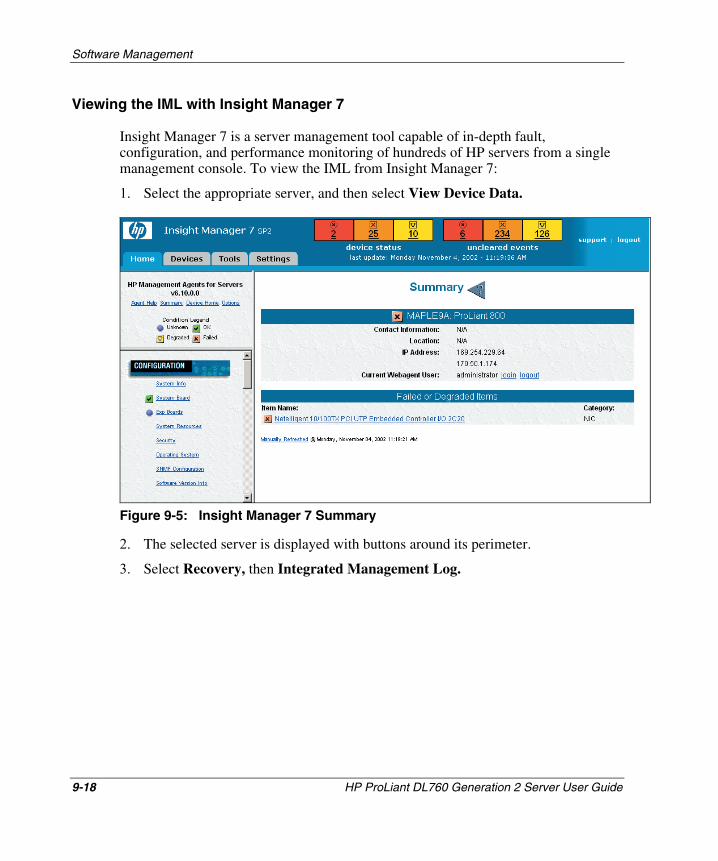
Software Management
Viewing the IML with Insight Manager 7
Insight Manager 7 is a server management tool capable of in-depth fault, configuration, and performance monitoring of hundreds of HP servers from a single management console. To view the IML from Insight Manager 7:
1. Select the appropriate server, and then select View Device Data.
Figure 9-5: Insight Manager 7 Summary
2. The selected server is displayed with buttons around its perimeter.
3. Select Recovery, then Integrated Management Log.
9-18 HP ProLiant DL760 Generation 2 Server User Guide
HP CONFIDENTIAL Writer: Jennifer Hayward File Name: j-ch9 Software Management.doc
Codename: Pioneer Part Number: 201264-002 Last Saved On: 6/17/03 10:14 AM
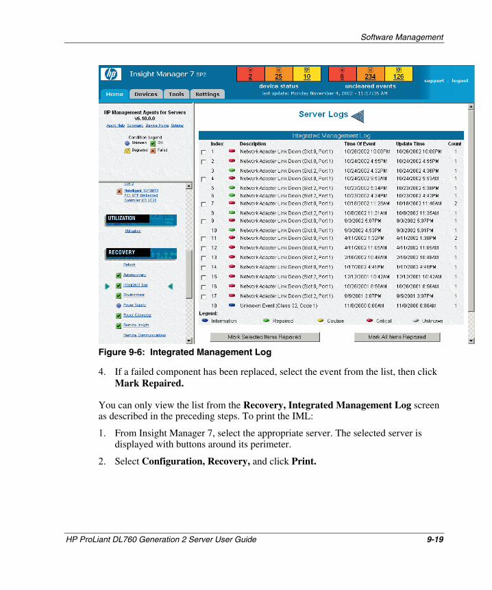
Software Management
Figure 9-6: Integrated Management Log
4. If a failed component has been replaced, select the event from the list, then click Mark Repaired.
You can only view the list from the Recovery, Integrated Management Log screen as described in the preceding steps. To print the IML:
1. From Insight Manager 7, select the appropriate server. The selected server is displayed with buttons around its perimeter.
2. Select Configuration, Recovery, and click Print.
HP ProLiant DL760 Generation 2 Server User Guide 9-19
HP CONFIDENTIAL Writer: Jennifer Hayward File Name: j-ch9 Software Management.doc
Codename: Pioneer Part Number: 201264-002 Last Saved On: 6/17/03 10:14 AM
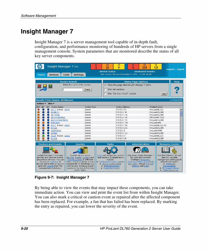
Software Management
Insight Manager 7
Insight Manager 7 is a server management tool capable of in-depth fault, configuration, and performance monitoring of hundreds of HP servers from a single management console. System parameters that are monitored describe the status of all key server components.
Figure 9-7: Insight Manager 7
By being able to view the events that may impact these components, you can take immediate action. You can view and print the event list from within Insight Manager. You can also mark a critical or caution event as repaired after the affected component has been replaced. For example, a fan that has failed has been replaced. By marking the entry as repaired, you can lower the severity of the event.
9-20 HP ProLiant DL760 Generation 2 Server User Guide
HP CONFIDENTIAL Writer: Jennifer Hayward File Name: j-ch9 Software Management.doc
Codename: Pioneer Part Number: 201264-002 Last Saved On: 6/17/03 10:14 AM
Software Management
HP ProLiant DL760 Generation 2 Server User Guide 9-21
HP CONFIDENTIAL Writer: Jennifer Hayward File Name: j-ch9 Software Management.doc
Codename: Pioneer Part Number: 201264-002 Last Saved On: 6/17/03 10:14 AM
command line parameters.
Survey Utility
The Survey Utility is a serviceability tool for Microsoft Windows 2000, Windows Server 2003, Caldera UNIX, and Linux that delivers online configuration capture and comparison information to maximize server availability. The utility is available on the Management CD in the ProLiant Essentials Foundation Pack, or on the HP website:
www.hp.com
NOTE: Refer to the Management CD for information about installing and running the Survey Utility.
The Survey Utility includes a Web browser interface in addition to a command line interface. This enables remote control of the utility and facilitates easy transfer of Survey information from remote machines to a service provider.
Information the utility gathers is accessible two ways:
• As a plain text file (survey.txt)
• As a dynamic web page locally or remotely through a browser:
https://system-name:2381
You can use the Survey Utility to perform the following functions:
• View the hardware and software configuration of the system. • Compare historical configurations of the system.
• Capture a new configuration sample.
• Download the Configuration History file (survey.idi) from the system to your local workstation for mailing to a service provider or for archival purposes.
• Analyze a configuration file from another system.
The Survey Utility is typically installed to run at boot-up and at regular time intervals to ensure that the latest information and change history are always recorded and available when needed. You can modify the data-gathering interval by modifying the
Software Management
Array Configuration Utility
The Array Configuration Utility (ACU) software for Smart Array controllers, the StorageWorks RAID Array 4x00 family of products, and the StorageWorks MSA1000 controller makes it easy to configure and expand disk drive arrays remotely. This Web-based tool is intuitive; by using its Configuration Wizards, an array controller can be set-up and ready to use in minutes. ACU also can be used to locally or remotely configure an array controller, add additional disk drives to an existing configuration, or reconfigure a disk drive array.
Features such as Online Capacity Expansion, Logical Drive Capacity Extension, and RAID Level Migration allow you to change an array configuration and settings as your storage needs grow.
ACU can be run from the local host machine or remotely from a client computer on machines running an operating system that ACU supports.
For more information on ACU, to download the utility, or to access the Array Configuration Utility User Guide, refer to
h18000.www1.hp.com/products/servers/proliantstorage/software-management/acumatrix/index.html
The ACU can be run either as a local-only application or as a service that can be accessed remotely.
Step 1—Running ACU as a Local-Only Application
During installation (or later by running setup), choose to install ACU as a local-only application.
Click Start, and then select Programs, HP System Tools, Array Configuration Utility. The ACU opens a Web browser window and launches the ACU. The ACU icon is displayed in the system tray.
9-22 HP ProLiant DL760 Generation 2 Server User Guide
HP CONFIDENTIAL Writer: Jennifer Hayward File Name: j-ch9 Software Management.doc
Codename: Pioneer Part Number: 201264-002 Last Saved On: 6/17/03 10:14 AM
Software Management
Step 2—Running ACU as a Service With Remote Accessibility
During installation (or later by running setup), choose to install ACU as a service with remote accessibility.
The first time the ACU is run, if you have not already set up the Web agent password, ACU will launch an applet for setting up the passwords. You must have an administrator password set up to run ACU as a service.
To access ACU with a Web browser:
1. On either the ProLiant DL760 G2 server or a client PC, launch the preferred Web browser.
2. Enter the address of the computer you wish to configure:
— If you are using local access, you must enter the loop-back address:
http://127.0.0.1:2301
— If you are using remote access, enter:
http://computer:2301
where computer is either the IP address or the name (under DNS) of the system you want to manage.
After you enter the address, the Device Home Page is displayed.
NOTE: The :2301 in the URL is the port or socket number that ACU uses to communicate with the browser. If this number is not specified, the browser might attempt to connect to another Web page if the host server is running a Web server.
HP ProLiant DL760 Generation 2 Server User Guide 9-23
HP CONFIDENTIAL Writer: Jennifer Hayward File Name: j-ch9 Software Management.doc
Codename: Pioneer Part Number: 201264-002 Last Saved On: 6/17/03 10:14 AM
Software Management
9-24 HP ProLiant DL760 Generation 2 Server User Guide
HP CONFIDENTIAL Writer: Jennifer Hayward File Name: j-ch9 Software Management.doc
Codename: Pioneer Part Number: 201264-002 Last Saved On: 6/17/03 10:14 AM
The Device Home Page is the first page displayed when you access the device at port 2301. This page displays available HP Web-enabled services. To use ACU, you must log on as administrator. To log on as administrator:
1. Click the Login link to access the Account Login screen.
2. In the User field, select administrator.
3. In the Password field, enter the administrator password.
4. Click OK to return to the Device Home Page.
IMPORTANT: You must configure the Web browser, enabling JavaScript for ACU to work properly.
The Device Home Page contains the following links:
• Array Configuration Utility—Accesses ACU.
• Refresh—Reloads the Device Home Page.
• Options—Sets attributes for the device.
• Devices—Displays the device list.
• HP on the Internet—Allows you to view HP Web-based support links.
In addition to these links, you may see links to other HP Web-based services, such as the Management Agents and the Survey Utility, depending on the software that is installed and running on the system being viewed.
To access ACU, click the Array Configuration Utility link on the Device Home Page. The ACU Home Page is displayed. For specific instructions on how to use ACU, click Help to access the online help provided with the utility.
A Regulatory Compliance Notices
Regulatory Compliance Identification Numbers
For the purpose of regulatory compliance certifications and identification, your ProLiant DL760 G2 server is assigned a HP series number. The HP series number for this product number can be found on the Regulatory Compliance label, along with the required approval markings and information. The Regulatory Compliance label is located on the top cover of the server. When requesting certification information for this product, always refer to this series number. This series number should not be confused with the marketing name or model number for your ProLiant DL760 G2 server.
HP ProLiant DL760 Generation 2 Server User Guide A-1
HP CONFIDENTIAL Writer: Jennifer Hayward File Name: k-appa Regulatory Compliance Notices.doc Codename: Pioneer Part Number: 201264-002 Last Saved On: 6/17/03 10:17 AM
Regulatory Compliance Notices
Federal Communications Commission Notice
This equipment has been tested and found to comply with the limits for a Class A digital device, pursuant to Part 15 of the FCC Rules. These limits are designed to provide reasonable protection against harmful interference when the equipment is operated in a commercial environment. This equipment generates, uses, and can radiate radio frequency energy and, if not installed and used in accordance with the instructions, may cause harmful interference to radio communications. Operation of this equipment in a residential area is likely to cause harmful interference, in which case the user will be required to correct the interference at personal expense.
Modifications
The FCC requires the user to be notified that any changes or modifications made to this device that are not expressly approved by Hewlett-Packard Company may void the user’s authority to operate the equipment.
Mouse Compliance Statement
This device complies with Part 15 of the FCC Rules. Operation is subject to the following two conditions: (1) this device may not cause harmful interference, and (2) this device must accept any interference received, including interference that may cause undesired operation.
Cables
Connections to this device must be made with shielded cables with metallic RFI/EMI connector hoods in order to maintain compliance with FCC Rules and Regulations.
A-2 HP ProLiant DL760 Generation 2 Server User Guide
HP CONFIDENTIAL Writer: Jennifer Hayward File Name: k-appa Regulatory Compliance Notices.doc Codename: Pioneer Part Number: 201264-002 Last Saved On: 6/17/03 10:17 AM

Regulatory Compliance Notices
Canadian Notice (Avis Canadien)
This Class A digital apparatus meets all requirements of the Canadian Interference-Causing Equipment Regulations.
Cet appareil numérique de la classe A respecte toutes les exigences du Règlement sur le matériel brouilleur du Canada.
European Union Notice
Products bearing the CE marking comply with the EMC Directive (89/336/EEC) and the Low Voltage Directive (73/23/EEC) issued by the Commission of the European Community and if this product has telecommunication functionality, the R&TTE Directive (1999/5/EC).
Compliance with these directives implies conformity to the following European Norms (in parentheses are the equivalent international standards and regulations):
• EN 55022 (CISPR 22—Electromagnetic Interference
• EN55024 (IEC61000-4-2, 3, 4, 5, 6, 8, 11)—Electromagnetic Immunity
• EN61000-3-2 (IEC61000-3-2)—Power Line Harmonics
• EN61000-3-3 (IEC61000-3-3)—Power Line Flicker
• EN 60950 (IEC 60950)—Product Safety
HP ProLiant DL760 Generation 2 Server User Guide A-3
HP CONFIDENTIAL Writer: Jennifer Hayward File Name: k-appa Regulatory Compliance Notices.doc Codename: Pioneer Part Number: 201264-002 Last Saved On: 6/17/03 10:17 AM
Regulatory Compliance Notices
Japanese Notice
BSMI Notice
A-4 HP ProLiant DL760 Generation 2 Server User Guide
HP CONFIDENTIAL Writer: Jennifer Hayward File Name: k-appa Regulatory Compliance Notices.doc Codename: Pioneer Part Number: 201264-002 Last Saved On: 6/17/03 10:17 AM
Regulatory Compliance Notices
Laser Devices
All HP systems equipped with a laser device comply with safety standards, including International Electrotechnical Commission (IEC) 825. With specific regard to the laser, the equipment complies with laser product performance standards set by government agencies as a Class 1 laser product. The product does not emit hazardous light; the beam is totally enclosed during all modes of customer operation and maintenance.
Laser Safety Warnings
WARNING: To reduce the risk of exposure to hazardous radiation:
• Do not try to open the laser device enclosure. There are no user-serviceable components inside.
• Do not operate controls, make adjustments, or perform procedures to the laser device other than those specified herein.
• Allow only HP authorized service technicians to repair the laser device.
Compliance with CDRH Regulations
The Center for Devices and Radiological Health (CDRH) of the U.S. Food and Drug Administration implemented regulations for laser products on August 2, 1976. These regulations apply to laser products manufactured from August 1, 1976. Compliance is mandatory for products marketed in the United States.
Compliance with International Regulations
All HP systems equipped with laser devices comply with appropriate safety standards including IEC 825.
HP ProLiant DL760 Generation 2 Server User Guide A-5
HP CONFIDENTIAL Writer: Jennifer Hayward File Name: k-appa Regulatory Compliance Notices.doc Codename: Pioneer Part Number: 201264-002 Last Saved On: 6/17/03 10:17 AM
Regulatory Compliance Notices
Power Cords
The power cord set included in your server meets the requirements for use in the country where you purchased your server. If you need to use this server in another country, you should purchase a power cord that is approved for use in that country.
The power cord must be rated for the product and for the voltage and current marked on the product’s electrical ratings label. The voltage and current rating of the cord should be greater than the voltage and current rating marked on the product. In addition, the diameter of the conductors must be a minimum of 1.50 mm2 or 16AWG, and the length of the cord must be between 1.8 m (6 feet) and 3.6 m (12 feet). If you have questions about the type of power cord to use, contact your HP authorized service provider.
A power cord should be routed so that it is not likely to be walked on or pinched by items placed upon it or against it. Particular attention should be paid to the plug, electrical outlet, and the point where the cord exits from the product.
A-6 HP ProLiant DL760 Generation 2 Server User Guide
HP CONFIDENTIAL Writer: Jennifer Hayward File Name: k-appa Regulatory Compliance Notices.doc Codename: Pioneer Part Number: 201264-002 Last Saved On: 6/17/03 10:17 AM
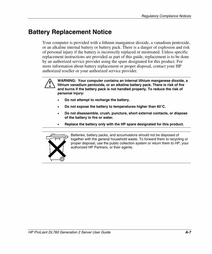
Regulatory Compliance Notices
HP ProLiant DL760 Generation 2 Server User Guide A-7
HP CONFIDENTIAL Writer: Jennifer Hayward File Name: k-appa Regulatory Compliance Notices.doc Codename: Pioneer Part Number: 201264-002 Last Saved On: 6/17/03 10:17 AM
Battery Replacement Notice
Your computer is provided with a lithium manganese dioxide, a vanadium pentoxide, or an alkaline internal battery or battery pack. There is a danger of explosion and risk of personal injury if the battery is incorrectly replaced or mistreated. Unless specific replacement instructions are provided as part of this guide, replacement is to be done by an authorized service provider using the spare designated for this product. For more information about battery replacement or proper disposal, contact your HP authorized reseller or your authorized service provider.
WARNING: Your computer contains an internal lithium manganese dioxide, a lithium vanadium pentoxide, or an alkaline battery pack. There is risk of fire and burns if the battery pack is not handled properly. To reduce the risk of personal injury:
• Do not attempt to recharge the battery.
• Do not expose the battery to temperatures higher than 60°C.
• Do not disassemble, crush, puncture, short external contacts, or dispose of the battery in fire or water.
• Replace the battery only with the HP spare designated for this product.
Batteries, battery packs, and accumulators should not be disposed of together with the general household waste. To forward them to recycling or proper disposal, use the public collection system or return them to HP, your authorized HP Partners, or their agents.
B Electrostatic Discharge
To prevent damage to the system, be aware of the precautions you need to follow when setting up the system or handling parts. A discharge of static electricity from a finger or other conductor can damage system boards or other static-sensitive devices. This type of damage can reduce the life expectancy of the device.
To prevent electrostatic damage, observe the following precautions:
• Avoid hand contact by transporting and storing products in static-safe containers.
• Keep electrostatic-sensitive parts in their containers until they arrive at static-free workstations.
• Place parts on a grounded surface before removing them from their containers.
• Avoid touching pins, leads, or circuitry.
• Always be properly grounded when touching a static-sensitive component or assembly.
HP ProLiant DL760 Generation 2 Server User Guide B-1
HP CONFIDENTIAL Writer: Jennifer Hayward File Name: l-appb Electrostatic Discharge.doc
Codename: Pioneer Part Number: 201264-002 Last Saved On: 6/17/03 10:20 AM
Electrostatic Discharge
B-2 HP ProLiant DL760 Generation 2 Server User Guide
HP CONFIDENTIAL Writer: Jennifer Hayward File Name: l-appb Electrostatic Discharge.doc
Codename: Pioneer Part Number: 201264-002 Last Saved On: 6/17/03 10:20 AM
Grounding Methods
There are several methods for grounding. Use one or more of the following methods when handling or installing electrostatic-sensitive parts:
• Use a wrist strap connected by a ground cord to a grounded workstation or computer chassis. Wrist straps are flexible straps with a minimum of 1 megohm ±10 percent resistance in the ground cords. To provide proper ground, wear the strap snug against the skin.
• Use heel straps, toe straps, or boot straps at standing workstations. Wear the straps on both feet when standing on conductive floors or dissipating floor mats.
• Use conductive field service tools.
• Use a portable field service kit with a folding static-dissipating work mat.
If you do not have any of the suggested equipment for proper grounding, have an HP authorized reseller install the part.
NOTE: For more information about static electricity or for assistance with product installation, contact your HP authorized reseller.
C Server Error Messages
POST Error Messages
All Power-On Self-Test (POST) error messages provided for this server are included in the HP Servers Troubleshooting Guide. For a complete listing of possible error messages generated during POST, along with steps to take to correct each problem, refer to the HP Servers Troubleshooting Guide.
NOTE: The HP Servers Troubleshooting Guide is located on the Documentation CD included with the server.
ADU Error Messages
All Array Diagnostic Utility (ADU) error messages provided for this server are included in the HP Servers Troubleshooting Guide. For a complete listing of possible error messages generated by ADU, along with steps to take to correct each problem, refer to the HP Servers Troubleshooting Guide.
NOTE: The HP Servers Troubleshooting Guide is located on the Documentation CD included with the server.
HP ProLiant DL760 Generation 2 Server User Guide C-1
HP CONFIDENTIAL Writer: Jennifer Hayward File Name: m-appc Server Error Messages.doc
Codename: Pioneer Part Number: 201264-002 Last Saved On: 6/17/03 10:38 AM
D LED Indicators and Switches
LED Indicators
Status LEDs are located on the front, back, and inside of your server. These LEDs communicate the current status of varying aspects of the server components and operations, thus aiding you in diagnosing problems. The following ProLiant DL760 G2 server LEDs are explained in this chapter.
• System power LED—Located on the server above the power button
• Auxiliary power LED—Located on the I/O board
• System interconnect LEDs—Located on the top of the server
• System attention LEDs—Located on the front left side of the server
• Hot-plug SCSI hard drive LEDs—Located on the front of each hard drive
• Power supply LEDs—Located on the rear of the server
• Hot-plug fan LEDs—Located on each fan inside the server
• PCI Hot Plug LEDs—Located on the rear of the server and inside the I/O module
• Memory cartridge LEDs—Located on the memory cartridges
• DIMM status LEDs—Located on the front right side of the server
HP ProLiant DL760 Generation 2 Server User Guide D-1
HP CONFIDENTIAL Writer: Jennifer Hayward File Name: n-appd LED Indicators and Switches.doc
Codename: Pioneer Part Number: 201264-002 Last Saved On: 6/17/03 10:43 AM
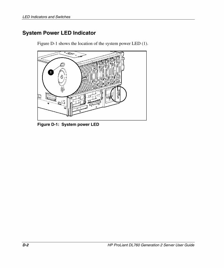
LED Indicators and Switches
System Power LED Indicator
Figure D-1 shows the location of the system power LED (1).
Figure D-1: System power LED
D-2 HP ProLiant DL760 Generation 2 Server User Guide
HP CONFIDENTIAL Writer: Jennifer Hayward File Name: n-appd LED Indicators and Switches.doc
Codename: Pioneer Part Number: 201264-002 Last Saved On: 6/17/03 10:43 AM
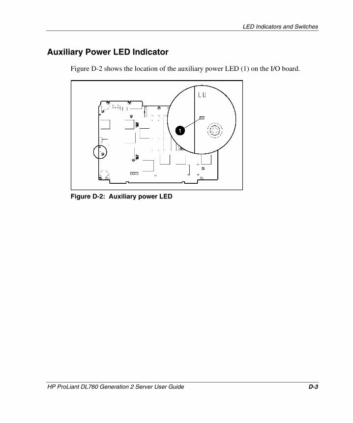
LED Indicators and Switches
Auxiliary Power LED Indicator
Figure D-2 shows the location of the auxiliary power LED (1) on the I/O board.
Figure D-2: Auxiliary power LED
HP ProLiant DL760 Generation 2 Server User Guide D-3
HP CONFIDENTIAL Writer: Jennifer Hayward File Name: n-appd LED Indicators and Switches.doc
Codename: Pioneer Part Number: 201264-002 Last Saved On: 6/17/03 10:43 AM
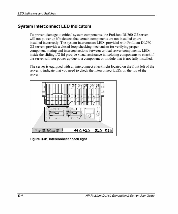
LED Indicators and Switches
System Interconnect LED Indicators
To prevent damage to critical system components, the ProLiant DL760 G2 server will not power up if it detects that certain components are not installed or are installed incorrectly. The system interconnect LEDs provided with ProLiant DL760 G2 servers provide a closed-loop checking mechanism for verifying proper component mating and interconnections between critical server components. LEDs inside the sliding I/O lid provide visual assistance in isolating components to check if the server will not power up due to a component or module that is not fully installed.
The server is equipped with an interconnect check light located on the front left of the server to indicate that you need to check the interconnect LEDs on the top of the server.
Figure D-3: Interconnect check light
D-4 HP ProLiant DL760 Generation 2 Server User Guide
HP CONFIDENTIAL Writer: Jennifer Hayward File Name: n-appd LED Indicators and Switches.doc
Codename: Pioneer Part Number: 201264-002 Last Saved On: 6/17/03 10:43 AM
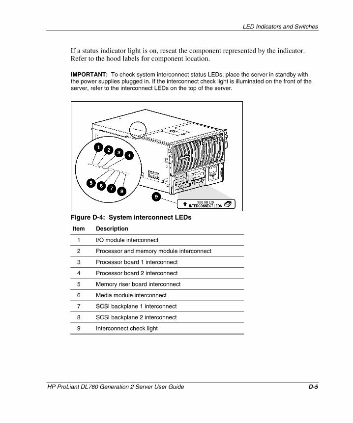
LED Indicators and Switches
If a status indicator light is on, reseat the component represented by the indicator. Refer to the hood labels for component location.
IMPORTANT: To check system interconnect status LEDs, place the server in standby with the power supplies plugged in. If the interconnect check light is illuminated on the front of the server, refer to the interconnect LEDs on the top of the server.
Figure D-4: System interconnect LEDs
Item Description
1 I/O module interconnect
2 Processor and memory module interconnect
3 Processor board 1 interconnect
4 Processor board 2 interconnect
5 Memory riser board interconnect
6 Media module interconnect
7 SCSI backplane 1 interconnect
8 SCSI backplane 2 interconnect
9 Interconnect check light
HP ProLiant DL760 Generation 2 Server User Guide D-5
HP CONFIDENTIAL Writer: Jennifer Hayward File Name: n-appd LED Indicators and Switches.doc
Codename: Pioneer Part Number: 201264-002 Last Saved On: 6/17/03 10:43 AM
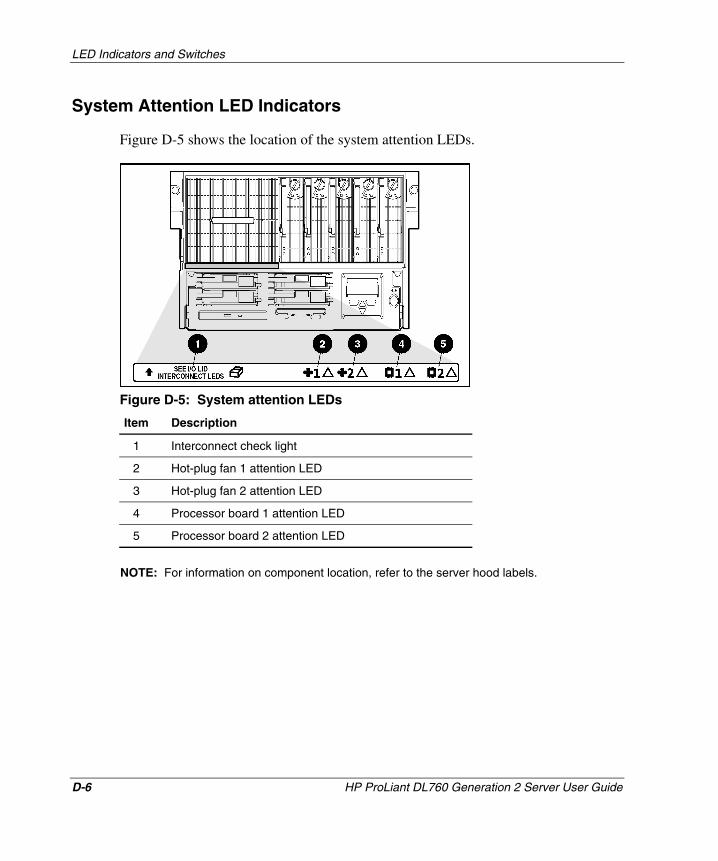
LED Indicators and Switches
System Attention LED Indicators
Figure D-5 shows the location of the system attention LEDs.
Figure D-5: System attention LEDs
Item Description
1 Interconnect check light
2 Hot-plug fan 1 attention LED
3 Hot-plug fan 2 attention LED
4 Processor board 1 attention LED
5 Processor board 2 attention LED
NOTE: For information on component location, refer to the server hood labels.
D-6 HP ProLiant DL760 Generation 2 Server User Guide
HP CONFIDENTIAL Writer: Jennifer Hayward File Name: n-appd LED Indicators and Switches.doc
Codename: Pioneer Part Number: 201264-002 Last Saved On: 6/17/03 10:43 AM
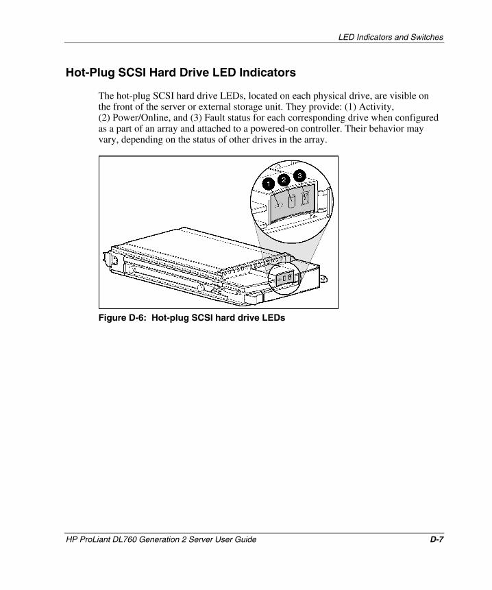
LED Indicators and Switches
Hot-Plug SCSI Hard Drive LED Indicators
The hot-plug SCSI hard drive LEDs, located on each physical drive, are visible on the front of the server or external storage unit. They provide: (1) Activity, (2) Power/Online, and (3) Fault status for each corresponding drive when configured as a part of an array and attached to a powered-on controller. Their behavior may vary, depending on the status of other drives in the array.
Figure D-6: Hot-plug SCSI hard drive LEDs
HP ProLiant DL760 Generation 2 Server User Guide D-7
HP CONFIDENTIAL Writer: Jennifer Hayward File Name: n-appd LED Indicators and Switches.doc
Codename: Pioneer Part Number: 201264-002 Last Saved On: 6/17/03 10:43 AM
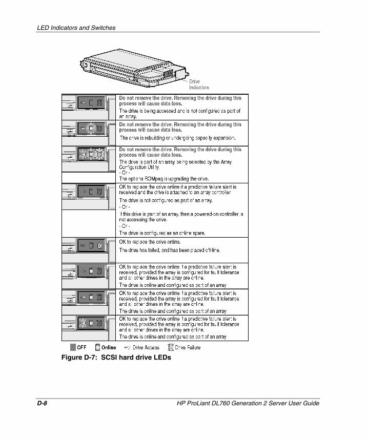
LED Indicators and Switches
Figure D-7: SCSI hard drive LEDs
D-8 HP ProLiant DL760 Generation 2 Server User Guide
HP CONFIDENTIAL Writer: Jennifer Hayward File Name: n-appd LED Indicators and Switches.doc
Codename: Pioneer Part Number: 201264-002 Last Saved On: 6/17/03 10:43 AM
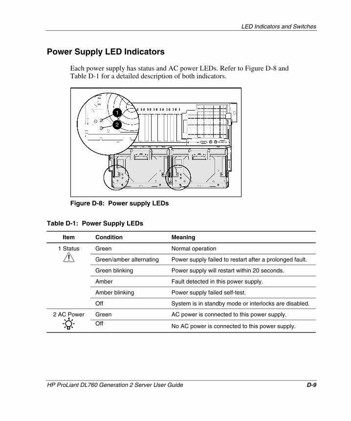
LED Indicators and Switches
Power Supply LED Indicators
Each power supply has status and AC power LEDs. Refer to Figure D-8 and Table D-1 for a detailed description of both indicators.
Figure D-8: Power supply LEDs
Table D-1: Power Supply LEDs
Item Condition Meaning
Green Normal operation
Green/amber alternating Power supply failed to restart after a prolonged fault.
Green blinking Power supply will restart within 20 seconds.
Amber Fault detected in this power supply.
Amber blinking Power supply failed self-test.
1 Status
Off No AC power is connected to this power supply.
Off System is in standby mode or interlocks are disabled.
Green AC power is connected to this power supply. 2 AC Power
HP ProLiant DL760 Generation 2 Server User Guide D-9
HP CONFIDENTIAL Writer: Jennifer Hayward File Name: n-appd LED Indicators and Switches.doc
Codename: Pioneer Part Number: 201264-002 Last Saved On: 6/17/03 10:43 AM
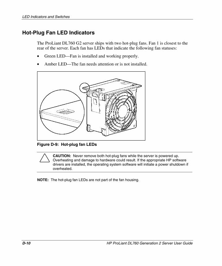
LED Indicators and Switches
Hot-Plug Fan LED Indicators
The ProLiant DL760 G2 server ships with two hot-plug fans. Fan 1 is closest to the rear of the server. Each fan has LEDs that indicate the following fan statuses:
• Green LED—Fan is installed and working properly.
• Amber LED—The fan needs attention or is not installed.
Figure D-9: Hot-plug fan LEDs
CAUTION: Never remove both hot-plug fans while the server is powered up. Overheating and damage to hardware could result. If the appropriate HP software drivers are installed, the operating system software will initiate a power shutdown if overheated.
NOTE: The hot-plug fan LEDs are not part of the fan housing.
D-10 HP ProLiant DL760 Generation 2 Server User Guide
HP CONFIDENTIAL Writer: Jennifer Hayward File Name: n-appd LED Indicators and Switches.doc
Codename: Pioneer Part Number: 201264-002 Last Saved On: 6/17/03 10:43 AM
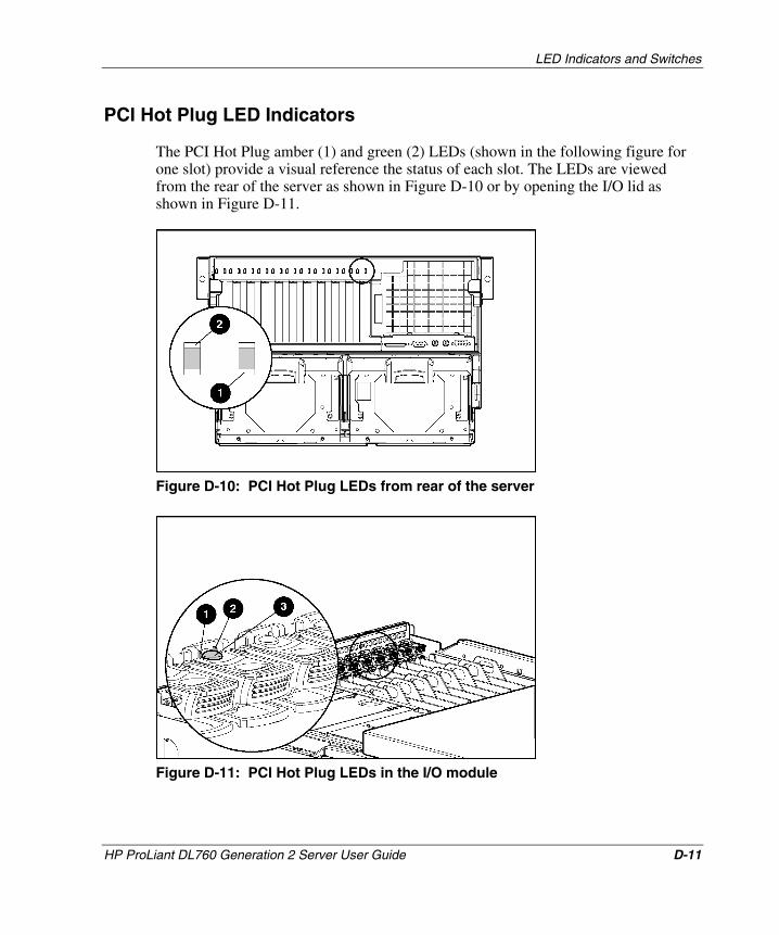
LED Indicators and Switches
PCI Hot Plug LED Indicators
The PCI Hot Plug amber (1) and green (2) LEDs (shown in the following figure for one slot) provide a visual reference the status of each slot. The LEDs are viewed from the rear of the server as shown in Figure D-10 or by opening the I/O lid as shown in Figure D-11.
Figure D-10: PCI Hot Plug LEDs from rear of the server
Figure D-11: PCI Hot Plug LEDs in the I/O module
HP ProLiant DL760 Generation 2 Server User Guide D-11
HP CONFIDENTIAL Writer: Jennifer Hayward File Name: n-appd LED Indicators and Switches.doc
Codename: Pioneer Part Number: 201264-002 Last Saved On: 6/17/03 10:43 AM
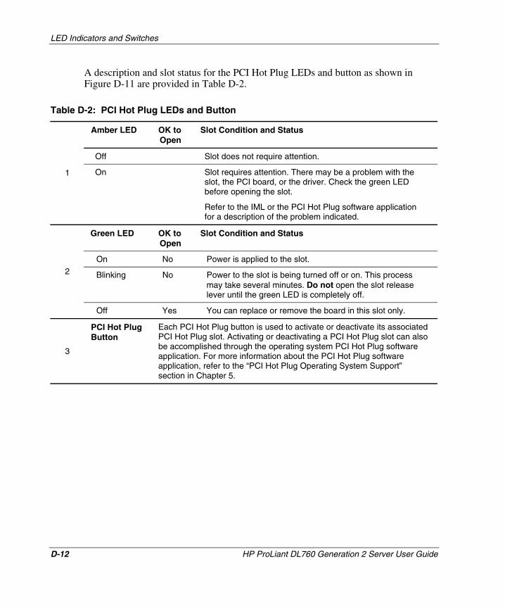
LED Indicators and Switches
A description and slot status for the PCI Hot Plug LEDs and button as shown in Figure D-11 are provided in Table D-2.
Table D-2: PCI Hot Plug LEDs and Button
Amber LED OK to Open
Slot Condition and Status
Off Slot does not require attention.
1 On Slot requires attention. There may be a problem with the slot, the PCI board, or the driver. Check the green LED before opening the slot.
Refer to the IML or the PCI Hot Plug software application for a description of the problem indicated.
Green LED OK to Open
Slot Condition and Status
On No Power is applied to the slot.
Blinking No Power to the slot is being turned off or on. This process may take several minutes. Do not open the slot release lever until the green LED is completely off.
2
Off Yes You can replace or remove the board in this slot only.
3
PCI Hot Plug Button
Each PCI Hot Plug button is used to activate or deactivate its associated PCI Hot Plug slot. Activating or deactivating a PCI Hot Plug slot can also be accomplished through the operating system PCI Hot Plug software application. For more information about the PCI Hot Plug software application, refer to the “PCI Hot Plug Operating System Support” section in Chapter 5.
D-12 HP ProLiant DL760 Generation 2 Server User Guide
HP CONFIDENTIAL Writer: Jennifer Hayward File Name: n-appd LED Indicators and Switches.doc
Codename: Pioneer Part Number: 201264-002 Last Saved On: 6/17/03 10:43 AM
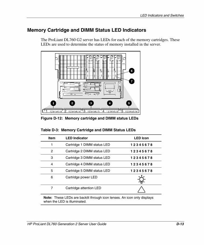
LED Indicators and Switches
Memory Cartridge and DIMM Status LED Indicators
The ProLiant DL760 G2 server has LEDs for each of the memory cartridges. These LEDs are used to determine the status of memory installed in the server.
Figure D-12: Memory cartridge and DIMM status LEDs
Table D-3: Memory Cartridge and DIMM Status LEDs
Item LED Indicator LED Icon
1 Cartridge 1 DIMM status LED 1 2 3 4 5 6 7 8
2 Cartridge 2 DIMM status LED 1 2 3 4 5 6 7 8
3 Cartridge 3 DIMM status LED 1 2 3 4 5 6 7 8
4 Cartridge 4 DIMM status LED 1 2 3 4 5 6 7 8
5 Cartridge 5 DIMM status LED 1 2 3 4 5 6 7 8
6 Cartridge power LED
7 Cartridge attention LED
Note: These LEDs are backlit through icon lenses. An icon only displays when the LED is illuminated.
HP ProLiant DL760 Generation 2 Server User Guide D-13
HP CONFIDENTIAL Writer: Jennifer Hayward File Name: n-appd LED Indicators and Switches.doc
Codename: Pioneer Part Number: 201264-002 Last Saved On: 6/17/03 10:43 AM
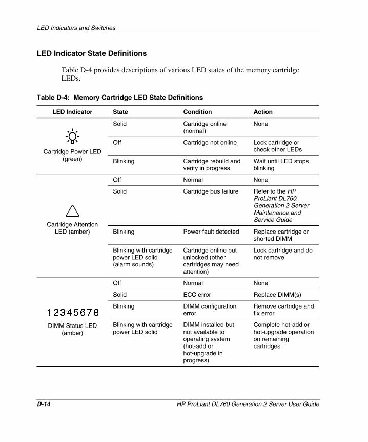
LED Indicators and Switches
LED Indicator State Definitions
Table D-4 provides descriptions of various LED states of the memory cartridge LEDs.
Table D-4: Memory Cartridge LED State Definitions
LED Indicator State Condition Action
Solid Cartridge online (normal)
None
Off Cartridge not online Lock cartridge or check other LEDs
DIMM Status LED (amber)
Blinking with cartridge power LED solid
DIMM installed but not available to operating system (hot-add or hot-upgrade in progress)
Complete hot-add or hot-upgrade operation on remaining cartridges
Cartridge Power LED (green) Blinking Cartridge rebuild and
verify in progress Wait until LED stops blinking
Off Normal None
Solid Cartridge bus failure Refer to the HP ProLiant DL760 Generation 2 Server Maintenance and Service Guide
Blinking Power fault detected Replace cartridge or shorted DIMM
Cartridge Attention LED (amber)
Blinking with cartridge power LED solid (alarm sounds)
Cartridge online but unlocked (other cartridges may need attention)
Lock cartridge and do not remove
Off Normal None
Solid ECC error Replace DIMM(s)
Blinking DIMM configuration error
Remove cartridge and fix error
D-14 HP ProLiant DL760 Generation 2 Server User Guide
HP CONFIDENTIAL Writer: Jennifer Hayward File Name: n-appd LED Indicators and Switches.doc
Codename: Pioneer Part Number: 201264-002 Last Saved On: 6/17/03 10:43 AM
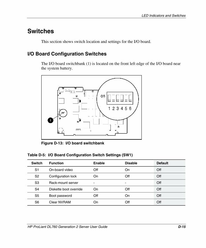
LED Indicators and Switches
Switches
This section shows switch location and settings for the I/O board.
I/O Board Configuration Switches
The I/O board switchbank (1) is located on the front left edge of the I/O board near the system battery.
Figure D-13: I/O board switchbank
Table D-5: I/O Board Configuration Switch Settings (SW1)
Switch Function Enable Disable Default
S1 On-board video Off On Off
S2 Configuration lock On Off Off
S3 Rack-mount server - - Off
S4 Diskette boot override On Off Off
S5 Boot password Off On Off
S6 Clear NVRAM On Off Off
HP ProLiant DL760 Generation 2 Server User Guide D-15
HP CONFIDENTIAL Writer: Jennifer Hayward File Name: n-appd LED Indicators and Switches.doc
Codename: Pioneer Part Number: 201264-002 Last Saved On: 6/17/03 10:43 AM
E Troubleshooting Information
This appendix provides step-by-step instructions about what to try and where to go for help for the most common problems encountered during the initial Power-On Self-Test (POST). The server must complete this test each time you power up your server, before the server can load the operating system and start running software applications.
If the server completes POST and attempts to load the operating system, go to “Problems After Initial Boot” later in this appendix.
WARNING: There is a risk of personal injury from hazardous energy levels. The installation of options and routine maintenance and service of this product must be performed by individuals who are knowledgeable about the procedures, precautions, and hazards associated with equipment containing hazardous energy circuits.
HP ProLiant DL760 Generation 2 Server User Guide E-1
HP CONFIDENTIAL Writer: Jennifer Hayward File Name: o-appe Troubleshooting Information.doc
Codename: Pioneer Part Number: 201264-002 Last Saved On: 6/17/03 10:42 AM
Troubleshooting Information
Server Startup Problems
Complete these steps if the server does not start:
1. Be sure that the computer and monitor are plugged into a working 220V outlet.
2. Be sure your power source is working properly:
— Check status using the system power LED. Refer to Appendix D for the location of the system power LED.
— Was the momentary contact power switch pressed firmly?
Refer to “Powering Up the Server” in Chapter 7 for an explanation of this operation.
Refer to the HP Servers Troubleshooting Guide for details about what else to check.
3. Be sure that the power supplies are working properly:
— Check status using the power supply LEDs. Refer to the “Power Supply LED Indicators” section in Appendix D for the location of these LEDs and an explanation of statuses.
— Refer to the HP Servers Troubleshooting Guide.
IMPORTANT: If your system configuration includes more than four PCI-X I/O expansion boards, eight processors, and more than 4 GB memory, make sure that both power supplies are plugged into a working 220V outlet.
To estimate the power requirements for a specific server configuration, use the ProLiant DL760 Generation 2 Power Calculator located on HP ActiveAnswers Online Solutions website
activeanswers.compaq.com
4. If the system does not complete the POST or start loading an operating system, refer to the HP Servers Troubleshooting Guide.
5. If the server is power cycling, verify that the system is not rebooting due to an Automatic Server Recovery-2 (ASR-2) reboot caused by another problem.
Also refer to the HP Servers Troubleshooting Guide.
E-2 HP ProLiant DL760 Generation 2 Server User Guide
HP CONFIDENTIAL Writer: Jennifer Hayward File Name: o-appe Troubleshooting Information.doc
Codename: Pioneer Part Number: 201264-002 Last Saved On: 6/17/03 10:42 AM
Troubleshooting Information
HP ProLiant DL760 Generation 2 Server User Guide E-3
HP CONFIDENTIAL Writer: Jennifer Hayward File Name: o-appe Troubleshooting Information.doc
Codename: Pioneer Part Number: 201264-002 Last Saved On: 6/17/03 10:42 AM
section.
NOTE: ASR-2 can be enabled to restart your server and automatically load the operating system. If a critical error occurs, ASR-2 logs the error in the Integrated Management Log (IML) and restarts the server. The system ROM then pages the designated administrator and executes the normal restart process.
6. Restart the server.
7. Check the Integrated Management Display (IMD) for the following normal power-up sequence to verify that your system meets the minimal hardware requirements and is powered up under normal operation:
a. The front panel system power LED turns from Standby (blinking green) to On (solid green).
b. The fans start up.
c. The IMD displays messages regarding the server name and LCD firmware version.
d. The IMD displays messages in the following sequence regarding server initialization:
— System initialization
— PCI auto-configuration
— Video initialization. If a monitor is connected, it also displays the HP initialization screen.
— Processor initialization
— Memory test
— Memory initialization
— Diskette drive
— Option ROM
— SCSI devices
8. The operating system loads to complete the boot process.
If completing these steps does not solve the problem, continue with the following
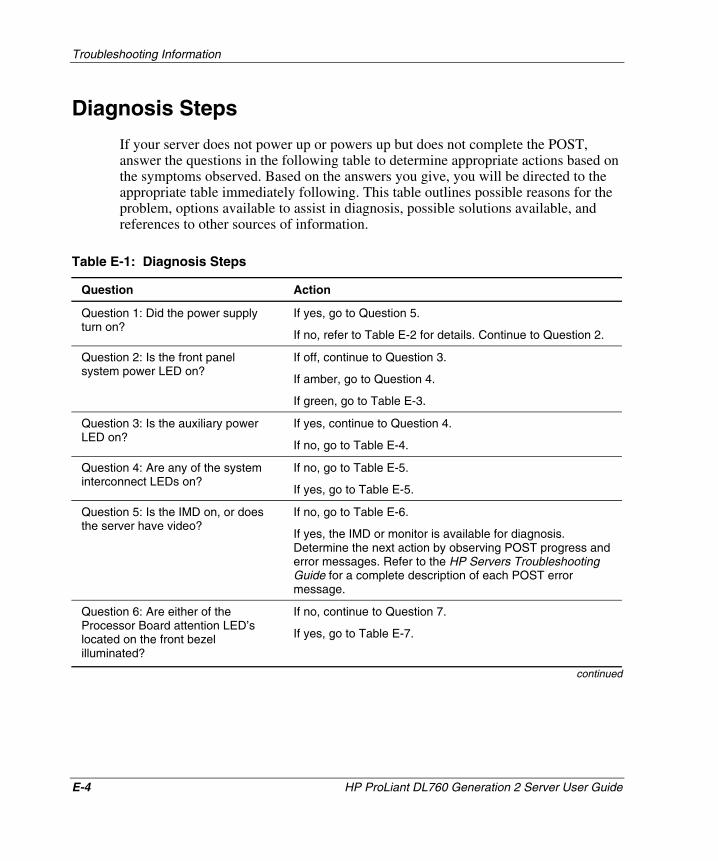
Troubleshooting Information
Diagnosis Steps
If your server does not power up or powers up but does not complete the POST, answer the questions in the following table to determine appropriate actions based on the symptoms observed. Based on the answers you give, you will be directed to the appropriate table immediately following. This table outlines possible reasons for the problem, options available to assist in diagnosis, possible solutions available, and references to other sources of information.
Table E-1: Diagnosis Steps
Question Action
Question 1: Did the power supply turn on?
If yes, go to Question 5.
If no, refer to Table E-2 for details. Continue to Question 2.
Question 2: Is the front panel system power LED on?
If off, continue to Question 3.
If amber, go to Question 4.
If green, go to Table E-3.
Question 3: Is the auxiliary power LED on?
If yes, continue to Question 4.
If no, go to Table E-4.
Question 4: Are any of the system interconnect LEDs on?
If no, go to Table E-5.
If yes, go to Table E-5.
Question 5: Is the IMD on, or does the server have video?
If no, go to Table E-6.
If yes, the IMD or monitor is available for diagnosis. Determine the next action by observing POST progress and error messages. Refer to the HP Servers Troubleshooting Guide for a complete description of each POST error message.
Question 6: Are either of the Processor Board attention LED’s located on the front bezel illuminated?
If no, continue to Question 7.
If yes, go to Table E-7.
continued
E-4 HP ProLiant DL760 Generation 2 Server User Guide
HP CONFIDENTIAL Writer: Jennifer Hayward File Name: o-appe Troubleshooting Information.doc
Codename: Pioneer Part Number: 201264-002 Last Saved On: 6/17/03 10:42 AM
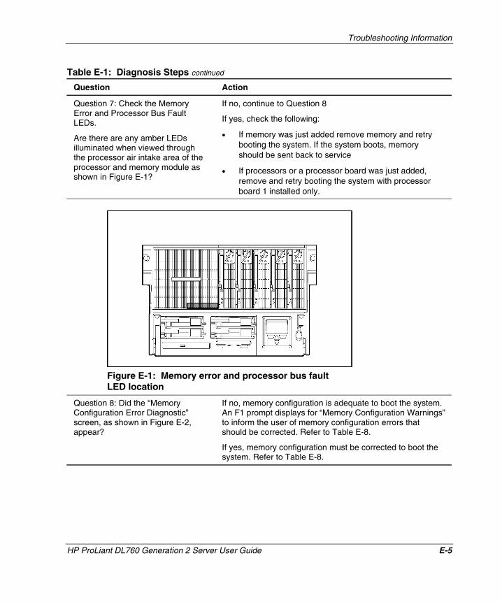
Troubleshooting Information
Table E-1: Diagnosis Steps continued
Question Action
Question 7: Check the Memory Error and Processor Bus Fault LEDs.
Are there are any amber LEDs illuminated when viewed through the processor air intake area of the processor and memory module as shown in Figure E-1?
If no, continue to Question 8
If yes, check the following:
• If memory was just added remove memory and retry booting the system. If the system boots, memory should be sent back to service
• If processors or a processor board was just added, remove and retry booting the system with processor board 1 installed only.
Figure E-1: Memory error and processor bus fault LED location
Question 8: Did the “Memory Configuration Error Diagnostic” screen, as shown in Figure E-2, appear?
If no, memory configuration is adequate to boot the system. An F1 prompt displays for “Memory Configuration Warnings” to inform the user of memory configuration errors that should be corrected. Refer to Table E-8.
If yes, memory configuration must be corrected to boot the system. Refer to Table E-8.
HP ProLiant DL760 Generation 2 Server User Guide E-5
HP CONFIDENTIAL Writer: Jennifer Hayward File Name: o-appe Troubleshooting Information.doc
Codename: Pioneer Part Number: 201264-002 Last Saved On: 6/17/03 10:42 AM
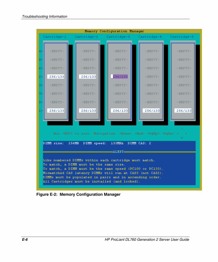
Troubleshooting Information
Figure E-2: Memory Configuration Manager
E-6 HP ProLiant DL760 Generation 2 Server User Guide
HP CONFIDENTIAL Writer: Jennifer Hayward File Name: o-appe Troubleshooting Information.doc
Codename: Pioneer Part Number: 201264-002 Last Saved On: 6/17/03 10:42 AM
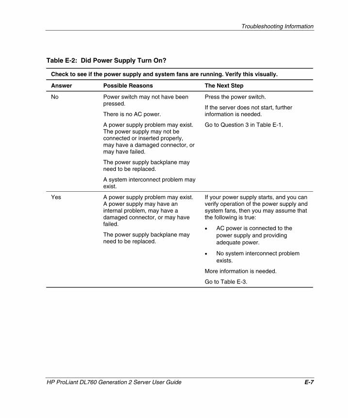
Troubleshooting Information
Table E-2: Did Power Supply Turn On?
Check to see if the power supply and system fans are running. Verify this visually.
Answer Possible Reasons The Next Step
No Power switch may not have been pressed.
There is no AC power.
A power supply problem may exist. The power supply may not be connected or inserted properly, may have a damaged connector, or may have failed.
The power supply backplane may need to be replaced.
A system interconnect problem may exist.
Press the power switch.
If the server does not start, further information is needed.
Go to Question 3 in Table E-1.
Yes A power supply problem may exist. A power supply may have an internal problem, may have a damaged connector, or may have failed.
The power supply backplane may need to be replaced.
If your power supply starts, and you can verify operation of the power supply and system fans, then you may assume that the following is true:
• AC power is connected to the power supply and providing adequate power.
• No system interconnect problem exists.
More information is needed.
Go to Table E-3.
HP ProLiant DL760 Generation 2 Server User Guide E-7
HP CONFIDENTIAL Writer: Jennifer Hayward File Name: o-appe Troubleshooting Information.doc
Codename: Pioneer Part Number: 201264-002 Last Saved On: 6/17/03 10:42 AM
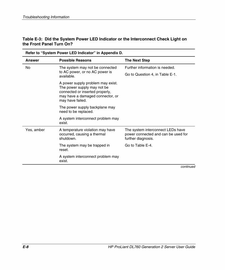
Troubleshooting Information
Table E-3: Did the System Power LED Indicator or the Interconnect Check Light on the Front Panel Turn On?
Refer to “System Power LED Indicator” in Appendix D.
Answer Possible Reasons The Next Step
No The system may not be connected to AC power, or no AC power is available.
A power supply problem may exist. The power supply may not be connected or inserted properly, may have a damaged connector, or may have failed.
The power supply backplane may need to be replaced.
A system interconnect problem may exist.
Further information is needed.
Go to Question 4, in Table E-1.
Yes, amber A temperature violation may have occurred, causing a thermal shutdown.
The system may be trapped in reset.
A system interconnect problem may exist.
The system interconnect LEDs have power connected and can be used for further diagnosis.
Go to Table E-4.
continued
E-8 HP ProLiant DL760 Generation 2 Server User Guide
HP CONFIDENTIAL Writer: Jennifer Hayward File Name: o-appe Troubleshooting Information.doc
Codename: Pioneer Part Number: 201264-002 Last Saved On: 6/17/03 10:42 AM
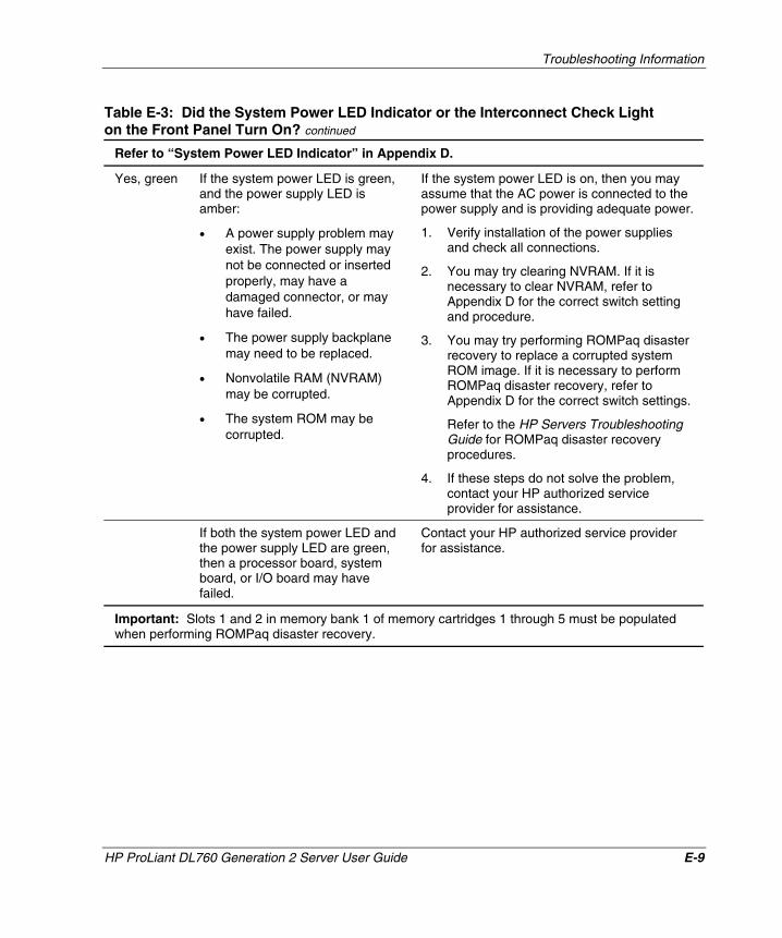
Troubleshooting Information
Table E-3: Did the System Power LED Indicator or the Interconnect Check Light on the Front Panel Turn On? continued
Refer to “System Power LED Indicator” in Appendix D.
Yes, green If the system power LED is green, and the power supply LED is amber:
• A power supply problem may exist. The power supply may not be connected or inserted properly, may have a damaged connector, or may have failed.
• The power supply backplane may need to be replaced.
• Nonvolatile RAM (NVRAM) may be corrupted.
• The system ROM may be corrupted.
If the system power LED is on, then you may assume that the AC power is connected to the power supply and is providing adequate power.
1. Verify installation of the power supplies and check all connections.
2. You may try clearing NVRAM. If it is necessary to clear NVRAM, refer to Appendix D for the correct switch setting and procedure.
3. You may try performing ROMPaq disaster recovery to replace a corrupted system ROM image. If it is necessary to perform ROMPaq disaster recovery, refer to Appendix D for the correct switch settings.
Refer to the HP Servers Troubleshooting Guide for ROMPaq disaster recovery procedures.
4. If these steps do not solve the problem, contact your HP authorized service provider for assistance.
If both the system power LED and the power supply LED are green, then a processor board, system board, or I/O board may have failed.
Contact your HP authorized service provider for assistance.
Important: Slots 1 and 2 in memory bank 1 of memory cartridges 1 through 5 must be populated when performing ROMPaq disaster recovery.
HP ProLiant DL760 Generation 2 Server User Guide E-9
HP CONFIDENTIAL Writer: Jennifer Hayward File Name: o-appe Troubleshooting Information.doc
Codename: Pioneer Part Number: 201264-002 Last Saved On: 6/17/03 10:42 AM
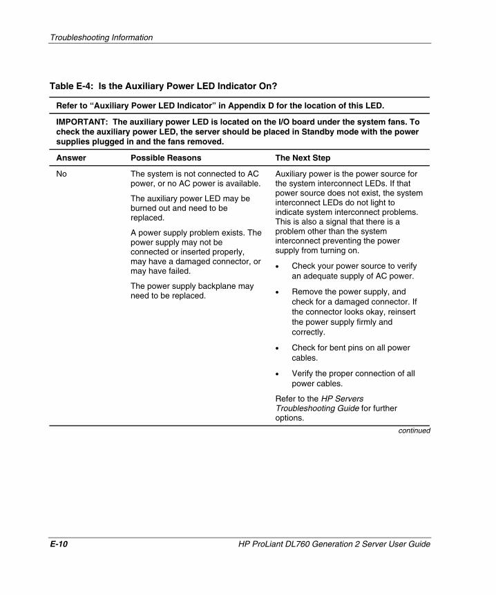
Troubleshooting Information
Table E-4: Is the Auxiliary Power LED Indicator On?
Refer to “Auxiliary Power LED Indicator” in Appendix D for the location of this LED.
IMPORTANT: The auxiliary power LED is located on the I/O board under the system fans. To check the auxiliary power LED, the server should be placed in Standby mode with the power supplies plugged in and the fans removed.
Answer Possible Reasons The Next Step
No The system is not connected to AC power, or no AC power is available.
The auxiliary power LED may be burned out and need to be replaced.
A power supply problem exists. The power supply may not be connected or inserted properly, may have a damaged connector, or may have failed.
The power supply backplane may need to be replaced.
Auxiliary power is the power source for the system interconnect LEDs. If that power source does not exist, the system interconnect LEDs do not light to indicate system interconnect problems. This is also a signal that there is a problem other than the system interconnect preventing the power supply from turning on.
• Check your power source to verify an adequate supply of AC power.
• Remove the power supply, and check for a damaged connector. If the connector looks okay, reinsert the power supply firmly and correctly.
• Check for bent pins on all power cables.
• Verify the proper connection of all power cables.
Refer to the HP Servers Troubleshooting Guide for further options.
continued
E-10 HP ProLiant DL760 Generation 2 Server User Guide
HP CONFIDENTIAL Writer: Jennifer Hayward File Name: o-appe Troubleshooting Information.doc
Codename: Pioneer Part Number: 201264-002 Last Saved On: 6/17/03 10:42 AM
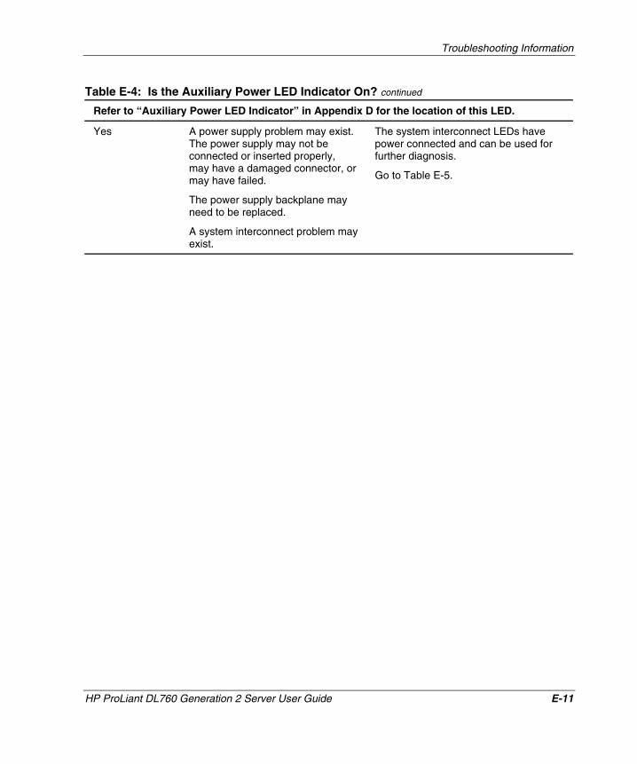
Troubleshooting Information
Table E-4: Is the Auxiliary Power LED Indicator On? continued
Refer to “Auxiliary Power LED Indicator” in Appendix D for the location of this LED.
Yes A power supply problem may exist. The power supply may not be connected or inserted properly, may have a damaged connector, or may have failed.
The power supply backplane may need to be replaced.
A system interconnect problem may exist.
The system interconnect LEDs have power connected and can be used for further diagnosis.
Go to Table E-5.
HP ProLiant DL760 Generation 2 Server User Guide E-11
HP CONFIDENTIAL Writer: Jennifer Hayward File Name: o-appe Troubleshooting Information.doc
Codename: Pioneer Part Number: 201264-002 Last Saved On: 6/17/03 10:42 AM
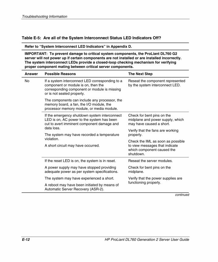
Troubleshooting Information
Table E-5: Are all of the System Interconnect Status LED Indicators Off?
Refer to “System Interconnect LED Indicators” in Appendix D.
IMPORTANT: To prevent damage to critical system components, the ProLiant DL760 G2 server will not power up if certain components are not installed or are installed incorrectly. The system interconnect LEDs provide a closed-loop checking mechanism for verifying proper component mating between critical server components.
Answer Possible Reasons The Next Step
If a system interconnect LED corresponding to a component or module is on, then the corresponding component or module is missing or is not seated properly.
The components can include any processor, the memory board, a fan, the I/O module, the processor memory module, or media module.
Reseat the component represented by the system interconnect LED.
If the emergency shutdown system interconnect LED is on, AC power to the system has been cut to avert imminent component damage and data loss.
The system may have recorded a temperature violation.
A short circuit may have occurred.
Check for bent pins on the midplane and power supply, which may have caused a short.
Verify that the fans are working properly.
Check the IML as soon as possible to view messages that indicate which component caused the shutdown.
No
If the reset LED is on, the system is in reset.
A power supply may have stopped providing adequate power as per system specifications.
The system may have experienced a short.
A reboot may have been initiated by means of Automatic Server Recovery (ASR-2).
Reseat the server modules.
Check for bent pins on the midplane.
Verify that the power supplies are functioning properly.
continued
E-12 HP ProLiant DL760 Generation 2 Server User Guide
HP CONFIDENTIAL Writer: Jennifer Hayward File Name: o-appe Troubleshooting Information.doc
Codename: Pioneer Part Number: 201264-002 Last Saved On: 6/17/03 10:42 AM
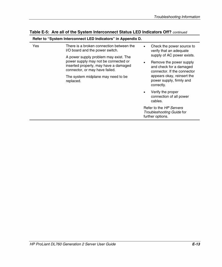
Troubleshooting Information
Table E-5: Are all of the System Interconnect Status LED Indicators Off? continued
Refer to “System Interconnect LED Indicators” in Appendix D.
Yes There is a broken connection between the I/O board and the power switch.
A power supply problem may exist. The power supply may not be connected or inserted properly, may have a damaged connector, or may have failed.
The system midplane may need to be replaced.
• Check the power source to verify that an adequate supply of AC power exists.
• Remove the power supply and check for a damaged connector. If the connector appears okay, reinsert the power supply, firmly and correctly.
• Verify the proper connection of all power cables.
Refer to the HP Servers Troubleshooting Guide for further options.
HP ProLiant DL760 Generation 2 Server User Guide E-13
HP CONFIDENTIAL Writer: Jennifer Hayward File Name: o-appe Troubleshooting Information.doc
Codename: Pioneer Part Number: 201264-002 Last Saved On: 6/17/03 10:42 AM
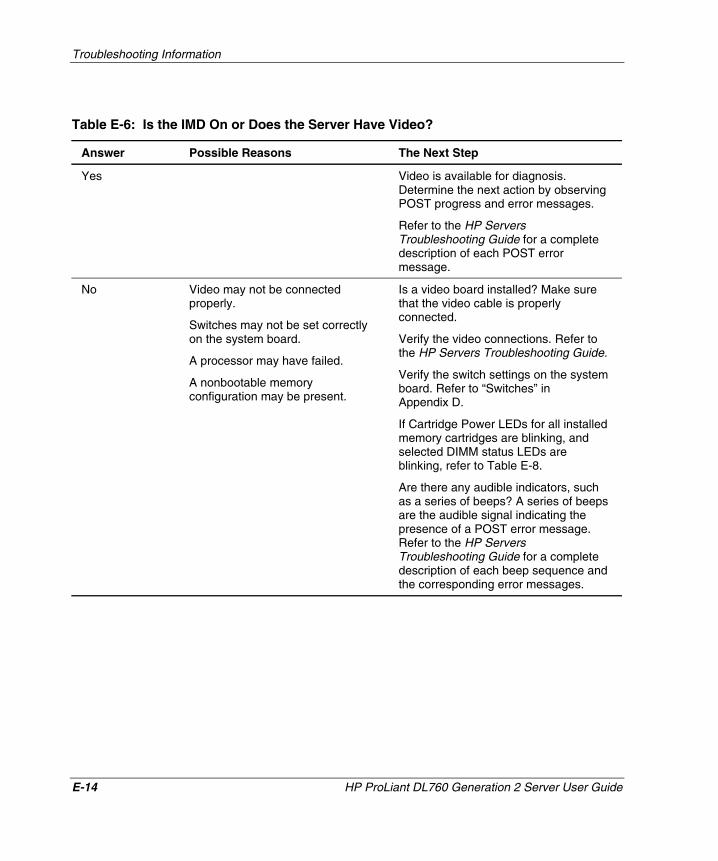
Troubleshooting Information
Table E-6: Is the IMD On or Does the Server Have Video?
Answer Possible Reasons The Next Step
Yes Video is available for diagnosis. Determine the next action by observing POST progress and error messages.
Refer to the HP Servers Troubleshooting Guide for a complete description of each POST error message.
No Video may not be connected properly.
Switches may not be set correctly on the system board.
A processor may have failed.
A nonbootable memory configuration may be present.
Is a video board installed? Make sure that the video cable is properly connected.
Verify the video connections. Refer to the HP Servers Troubleshooting Guide.
Verify the switch settings on the system board. Refer to “Switches” in Appendix D.
If Cartridge Power LEDs for all installed memory cartridges are blinking, and selected DIMM status LEDs are blinking, refer to Table E-8.
Are there any audible indicators, such as a series of beeps? A series of beeps are the audible signal indicating the presence of a POST error message. Refer to the HP Servers Troubleshooting Guide for a complete description of each beep sequence and the corresponding error messages.
E-14 HP ProLiant DL760 Generation 2 Server User Guide
HP CONFIDENTIAL Writer: Jennifer Hayward File Name: o-appe Troubleshooting Information.doc
Codename: Pioneer Part Number: 201264-002 Last Saved On: 6/17/03 10:42 AM
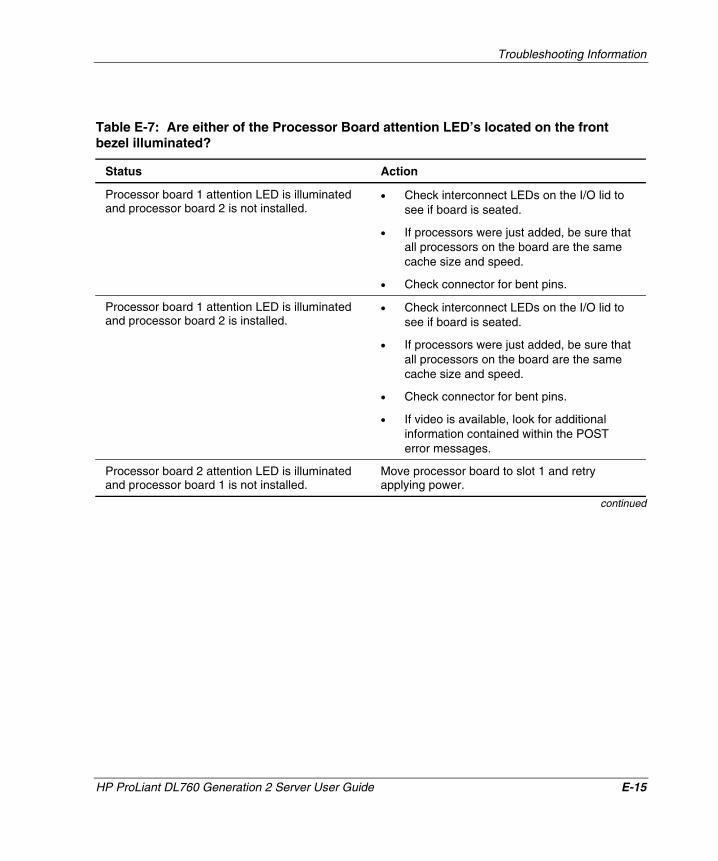
Troubleshooting Information
Table E-7: Are either of the Processor Board attention LED’s located on the front bezel illuminated?
Status Action
Processor board 1 attention LED is illuminated and processor board 2 is not installed.
• Check interconnect LEDs on the I/O lid to see if board is seated.
• If processors were just added, be sure that all processors on the board are the same cache size and speed.
• Check connector for bent pins.
Processor board 1 attention LED is illuminated and processor board 2 is installed.
• Check interconnect LEDs on the I/O lid to see if board is seated.
• If processors were just added, be sure that all processors on the board are the same cache size and speed.
• Check connector for bent pins.
• If video is available, look for additional information contained within the POST error messages.
Processor board 2 attention LED is illuminated and processor board 1 is not installed.
Move processor board to slot 1 and retry applying power.
continued
HP ProLiant DL760 Generation 2 Server User Guide E-15
HP CONFIDENTIAL Writer: Jennifer Hayward File Name: o-appe Troubleshooting Information.doc
Codename: Pioneer Part Number: 201264-002 Last Saved On: 6/17/03 10:42 AM
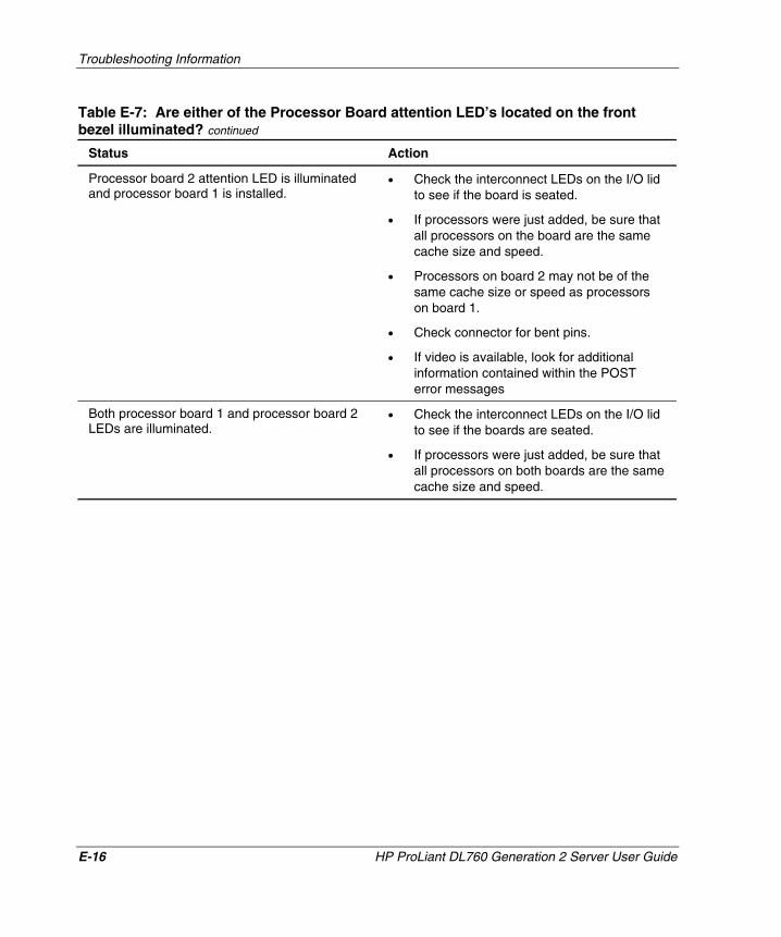
Troubleshooting Information
Table E-7: Are either of the Processor Board attention LED’s located on the front bezel illuminated? continued
Status Action
Processor board 2 attention LED is illuminated and processor board 1 is installed.
• Check the interconnect LEDs on the I/O lid to see if the board is seated.
• If processors were just added, be sure that all processors on the board are the same cache size and speed.
• Processors on board 2 may not be of the same cache size or speed as processors on board 1.
• Check connector for bent pins.
• If video is available, look for additional information contained within the POST error messages
Both processor board 1 and processor board 2 LEDs are illuminated.
• Check the interconnect LEDs on the I/O lid to see if the boards are seated.
• If processors were just added, be sure that all processors on both boards are the same cache size and speed.
E-16 HP ProLiant DL760 Generation 2 Server User Guide
HP CONFIDENTIAL Writer: Jennifer Hayward File Name: o-appe Troubleshooting Information.doc
Codename: Pioneer Part Number: 201264-002 Last Saved On: 6/17/03 10:42 AM
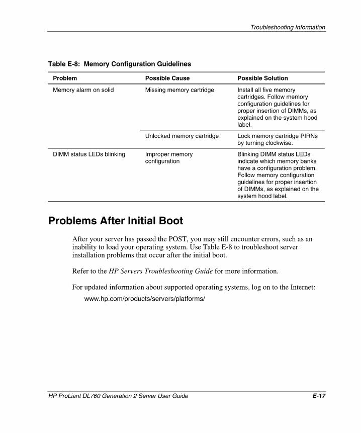
Troubleshooting Information
Table E-8: Memory Configuration Guidelines
Problem Possible Cause Possible Solution
Missing memory cartridge Install all five memory cartridges. Follow memory configuration guidelines for proper insertion of DIMMs, as explained on the system hood label.
Memory alarm on solid
Unlocked memory cartridge Lock memory cartridge PIRNs by turning clockwise.
DIMM status LEDs blinking Improper memory configuration
Blinking DIMM status LEDs indicate which memory banks have a configuration problem. Follow memory configuration guidelines for proper insertion of DIMMs, as explained on the system hood label.
Problems After Initial Boot
After your server has passed the POST, you may still encounter errors, such as an inability to load your operating system. Use Table E-8 to troubleshoot server installation problems that occur after the initial boot.
Refer to the HP Servers Troubleshooting Guide for more information.
For updated information about supported operating systems, log on to the Internet:
www.hp.com/products/servers/platforms/
HP ProLiant DL760 Generation 2 Server User Guide E-17
HP CONFIDENTIAL Writer: Jennifer Hayward File Name: o-appe Troubleshooting Information.doc
Codename: Pioneer Part Number: 201264-002 Last Saved On: 6/17/03 10:42 AM
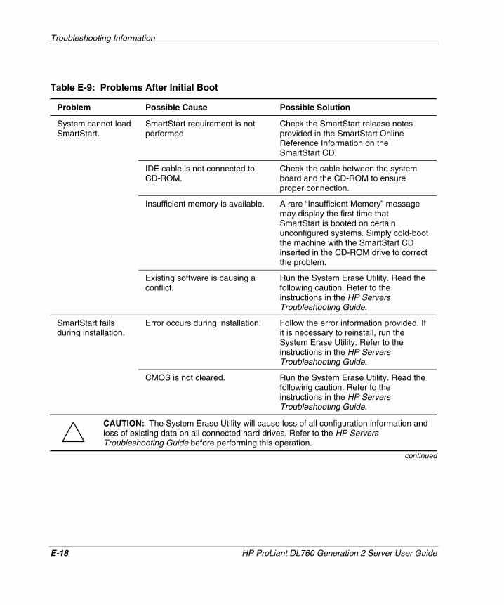
Troubleshooting Information
Table E-9: Problems After Initial Boot
Problem Possible Cause Possible Solution
SmartStart requirement is not performed.
Check the SmartStart release notes provided in the SmartStart Online Reference Information on the SmartStart CD.
IDE cable is not connected to CD-ROM.
Check the cable between the system board and the CD-ROM to ensure proper connection.
Insufficient memory is available. A rare “Insufficient Memory” message may display the first time that SmartStart is booted on certain unconfigured systems. Simply cold-boot the machine with the SmartStart CD inserted in the CD-ROM drive to correct the problem.
System cannot load SmartStart.
Existing software is causing a conflict.
Run the System Erase Utility. Read the following caution. Refer to the instructions in the HP Servers Troubleshooting Guide.
Error occurs during installation. Follow the error information provided. If it is necessary to reinstall, run the System Erase Utility. Refer to the instructions in the HP Servers Troubleshooting Guide.
SmartStart fails during installation.
CMOS is not cleared. Run the System Erase Utility. Read the following caution. Refer to the instructions in the HP Servers Troubleshooting Guide.
CAUTION: The System Erase Utility will cause loss of all configuration information and loss of existing data on all connected hard drives. Refer to the HP Servers Troubleshooting Guide before performing this operation.
continued
E-18 HP ProLiant DL760 Generation 2 Server User Guide
HP CONFIDENTIAL Writer: Jennifer Hayward File Name: o-appe Troubleshooting Information.doc
Codename: Pioneer Part Number: 201264-002 Last Saved On: 6/17/03 10:42 AM
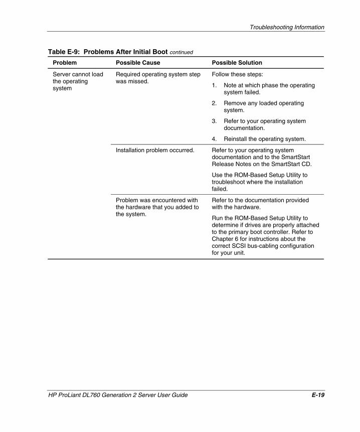
Troubleshooting Information
Table E-9: Problems After Initial Boot continued
Problem Possible Cause Possible Solution
Required operating system step was missed.
Follow these steps:
1. Note at which phase the operating system failed.
2. Remove any loaded operating system.
3. Refer to your operating system documentation.
4. Reinstall the operating system.
Installation problem occurred. Refer to your operating system documentation and to the SmartStart Release Notes on the SmartStart CD.
Use the ROM-Based Setup Utility to troubleshoot where the installation failed.
Server cannot load the operating system
Problem was encountered with the hardware that you added to the system.
Refer to the documentation provided with the hardware.
Run the ROM-Based Setup Utility to determine if drives are properly attached to the primary boot controller. Refer to Chapter 6 for instructions about the correct SCSI bus-cabling configuration for your unit.
HP ProLiant DL760 Generation 2 Server User Guide E-19
HP CONFIDENTIAL Writer: Jennifer Hayward File Name: o-appe Troubleshooting Information.doc
Codename: Pioneer Part Number: 201264-002 Last Saved On: 6/17/03 10:42 AM
Troubleshooting Information
E-20 HP ProLiant DL760 Generation 2 Server User Guide
HP CONFIDENTIAL Writer: Jennifer Hayward File Name: o-appe Troubleshooting Information.doc
Codename: Pioneer Part Number: 201264-002 Last Saved On: 6/17/03 10:42 AM
Refer to the HP Servers Troubleshooting Guide for the following:
• Information that you will need to collect when diagnosing software problems and to provide when contacting technical support.
• Instructions about how to upgrade your operating system and its drivers. The recovery options that are available and advice about minimizing downtime are also provided.
Remote-Flash Redundant ROM
Through subsequent boots of the server, if any integrity errors are detected by the Bootblock, the system automatically launches the redundant image and continues the POST process.
If this situation occurs, you will see a 105 error message indicating which system ROM is faulty. The ROMPaq utility flashes the failed system ROM to the latest released version.
During the flash process, the ROMPaq driver automatically detects which system ROM is inactive and flashes that system ROM with the image obtained from the ROMPaq diskette. When the flash process is complete, the server contains a fully redundant system ROM.
The system ROM can also be flashed remotely with the redundant ROM as a backup.
NOTE: If you are familiar with the process of flashing an HP server using the ROMPaq utility, there are no noticeable changes to the ROMPaq user interface. This feature is implemented in the ROMPaq driver and the system boot block only. User configuration of this feature is not required.
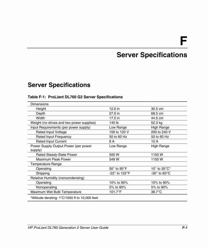
F Server Specifications
Server Specifications
Table F-1: ProLiant DL760 G2 Server Specifications
Dimensions Height 12.0 in 30.5 cm Depth 27.0 in 68.5 cm Width 17.5 in 44.5 cm
Weight (no drives and two power supplies) 140 lb 52.3 kg Input Requirements (per power supply) Low Range High Range
Rated Input Voltage 100 to 120 V 200 to 240 V Rated Input Frequency 50 to 60 Hz 50 to 60 Hz Rated Input Current 8 A 10 A
Power Supply Output Power (per power supply)
Low Range High Range
Rated Steady-State Power 500 W 1150 W Maximum Peak Power 549 W 1150 W
Temperature Range Operating 50° to 95°F 10° to 35°C* Shipping -22° to 122°F -30° to 60°C
Relative Humidity (noncondensing) Operating 10% to 90% 10% to 90% Nonoperating 5% to 90% 5% to 90%
Maximum Wet Bulb Temperature 101.7°F 38.7°C
*Altitude derating: 1oC/1000 ft to 10,000 feet
HP ProLiant DL760 Generation 2 Server User Guide F-1
HP CONFIDENTIAL Writer: Jennifer Hayward File Name: p-appf Server Specifications.doc
Codename: Pioneer Part Number: 201264-002 Last Saved On: 6/17/03 10:45 AM
G System Battery
This appendix provides information about replacement of the ProLiant DL760 G2 server system battery.
Internal Battery
To remove the internal battery:
1. Back up all data on the server.
2. Shut down the operating system as directed by your operating system instructions.
3. If the server was not powered down in the previous step, power down the server (refer to Chapter 7).
4. Disconnect the power cords from the server.
5. Open the I/O lid.
HP ProLiant DL760 Generation 2 Server User Guide G-1
HP CONFIDENTIAL Writer: Jennifer Hayward File Name: q-appg System Battery.doc
Codename: Pioneer Part Number: 201264-002 Last Saved On: 6/17/03 10:47 AM
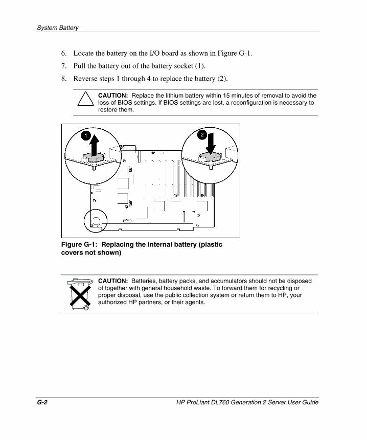
System Battery
G-2 HP ProLiant DL760 Generation 2 Server User Guide
HP CONFIDENTIAL Writer: Jennifer Hayward File Name: q-appg System Battery.doc
Codename: Pioneer Part Number: 201264-002 Last Saved On: 6/17/03 10:47 AM
6. Locate the battery on the I/O board as shown in Figure G-1.
7. Pull the battery out of the battery socket (1).
8. Reverse steps 1 through 4 to replace the battery (2).
CAUTION: Replace the lithium battery within 15 minutes of removal to avoid the loss of BIOS settings. If BIOS settings are lost, a reconfiguration is necessary to restore them.
Figure G-1: Replacing the internal battery (plastic covers not shown)
CAUTION: Batteries, battery packs, and accumulators should not be disposed of together with general household waste. To forward them for recycling or proper disposal, use the public collection system or return them to HP, your authorized HP partners, or their agents.
HP ProLiant DL760 Generation 2 Server User Guide Index-1
COMPAQ CONFIDENTIAL Writer: Jennifer Hayward File Name: x-index.doc
Codename: Pioneer Part Number: 230508-002 Last Saved On: 6/17/03 10:51 AM
memory cartridges 5-4 overview 8-1
Index
A ACR (Array Configuration Replicator)
utility 8-24 Administration Information, IMD 9-14 Administrator Information, IMD 9-7 ADU (Array Diagnostic Utility) C-1 Advanced Data Guarding 5-31 Array Bypass kit 4-18 Array Configuration Replicator (ACR)
utility 8-24 Array Configuration Utility (ACU) 8-20,
9-23 array controllers See controllers Array Diagnostic Utility (ADU) C-1 Array Enabler board 4-18 attaching server rails 2-25 authorized reseller xvii auto mode of operation, ACR 8-24 auto-configuration process 8-2 auxiliary power LED indicator D-3, D-6,
E-10
B ballast kits 2-15 battery
care of system G-1 replacement notice A-7
boot disk diagnostic 8-14 boot option screen 8-3 BSMI notice A-4
C cables
connecting 6-2 FCC compliance statement A-2
Caldera Open UNIX PCI Hot Plug support 5-48 utilities for 1-20
Canadian regulatory notice A-3 capacity expansion 8-22 capture mode of operation, ACR 8-24 CarePaq xvii cautions
electrostatic discharge 4-1 third-party options 2-8 ventilation 2-16
CD-ROM drive location 1-5 overview 1-13
Center for Devices and Radiological Health (CDRH) regulations A-5
configuration array controller 8-15 features 1-17 IMD 9-2 installing operating system 8-25
Index
RBSU features 1-18 setting up server environment 8-2 system load 2-6
configuration tools 1-3 connectors, supported 1-15 controllers See also Smart Array 5i
Controller configuration 8-15 NIC 1-12
CPU See processors CPU diagnostic 8-13 Custom Menu Item field, IMD 9-6
error messages C-1 Ethernet controllers See network interface
controllers (NICs) European Union regulatory notice A-3 Event List, IMD 9-14 expansion boards, RILOE II 4-13. See also
PCI/PCI-X expansion boards external storage devices, installing 4-6
F F2 key 5-32
Index-2 HP ProLiant DL760 Generation 2 Server User Guide
COMPAQ CONFIDENTIAL Writer: Jennifer Hayward File Name: x-index.doc
Codename: Pioneer Part Number: 230508-002 Last Saved On: 6/17/03 10:51 AM
precautions 4-1, B-1 error events, IMD 9-13
grounding requirements 2-7, B-2
Custom Menu screen, IMD 9-6 custom mode of operation, ACR 8-24
D data guarding 1-19, 5-31 Diagnostic Utility 8-11 diagnostics
procedures E-4 tools available 1-24
DIMMs See Hot Plug RAID Memory disk controller features 1-13 diskette drive
location 1-5 overview 1-13
display, video features 1-14 troubleshooting E-14
drive bays 1-13 hard-drive blanking panel 5-29 hot-plug hard drive 5-30 StorageWorks hot-plug tape drive 5-33
drivers, installing 8-26 drives See hard drives drives,tape See tape drives
E electrostatic discharge (ESD)
fans features 1-15 LED indicators D-10 replacing 5-57
fault tolerance 5-32 features
array controller 8-15 configuration tools 1-3 diagnostics 1-24 disk controllers 1-13 drive bays 1-13 hot-plug fans 1-15 internal hot-plug drive bays 1-13 management tools 1-3 memory 1-9 NIC 1-12 PCI Hot Plug 1-12 PCI/PCI-X expansion boards 1-11 processor 1-7 security 1-25 server overview 1-1 video 1-14
Federal Communications Commission (FCC) notice A-2
fixed internal media drive bays 1-13
G graphics resolution 1-14
Index
H hard drives
fault protection 1-19 installing 5-24 LED indicators 5-26, D-7 location 1-5, 3-13 supported 1-13 VHDCI connector 8-15
hardware See also specific components installing 2-1 overview of options 1-16
power-off installations 4-1 rack installation 2-1 software management tools 9-1 specifications F-1 troubleshooting E-1
HP website xvi Hyper-Threading technology 1-8
I I/O expansion boards
installing 4-7, 5-40
HP ProLiant DL760 Generation 2 Server User Guide Index-3
COMPAQ CONFIDENTIAL Writer: Jennifer Hayward File Name: x-index.doc
Codename: Pioneer Part Number: 230508-002 Last Saved On: 6/17/03 10:51 AM
overview 1-1 power components 7-1
processors 4-2 rack considerations 2-14
Hot Plug RAID Memory 5-14 accessing DIMMs 5-8 DIMM configurations 5-10 features 1-9 installation 5-4, 5-13 LED indicators 5-6, D-13 location 1-5 operating system support 5-14 overview 5-2 replacing DIMMs 5-15
hot surface warning 4-4 hot-add feature 1-9, 5-17 hot-plug components See also Hot Plug
RAID Memory; PCI/PCI-X expansion boards
drive bays 1-13 fans 1-15, 5-57, D-10 hard drives 1-5, 5-24, D-7 installation overview 5-1 power supplies 1-6, 1-14, 2-6, 5-34
hot-replace feature 1-9, 5-15 hot-upgrade feature 1-9, 5-20 HP ProLiant DL760 G2 server
accessing 3-1 battery G-1 cabling procedure 6-1 error messages C-1 hot-plug installations 5-1 LED indicators and switches D-1
slot features 1-11 switch locations D-15
I/O lid xiv, 3-2 I/O module
accessing 3-2, 3-3 array controller 4-18 location 1-6, 4-8 RILOE II installation 4-13
idle screen, IMD 9-5 IMD (Integrated Management Display) See
Integrated Management Display (IMD) IML (Integrated Management Log) See
Integrated Management Log (IML) Insight Manager 7
overview 1-21, 9-20 viewing IML with 9-18
Inspect Utility 8-10 installation
components list 2-9 hardware requirements 2-3 Hot Plug RAID Memory 5-2 I/O expansion boards 4-7, 5-40 Integrated Array Bypass 4-18 operating systems 8-25, E-19 optional service xvii overview 2-1 PCI Hot Plug 5-50 power supplies 5-34 power-off method 4-1
Index
rack rail assemblies 2-22 RILOE II 4-13 storage devices 5-24 tape drive 5-33
Integrated Array Bypass kit 4-18 Integrated Management Display (IMD)
configuring 9-2 customizing 9-5 location 1-5 navigating menus 9-10 overview 1-23, 9-2 standard fields 9-8
leveling feet/jacks 2-14 lightening of server chassis 2-24 Linux
PCI Hot Plug support 5-49 utilities for 1-21
load balancing, power supplies 1-14, 2-6 logical drives
configuring 8-15 extension of 8-22 setting up 8-19
logs, IML 9-15 low line power 1-14, 5-34, 6-3
Index-4 HP ProLiant DL760 Generation 2 Server User Guide
COMPAQ CONFIDENTIAL Writer: Jennifer Hayward File Name: x-index.doc
Codename: Pioneer Part Number: 230508-002 Last Saved On: 6/17/03 10:51 AM
system power D-2 troubleshooting with E-8
hot-replace 5-15 hot-upgrade 5-20
viewing IML from 9-16 Integrated Management Display Utility 9-4 Integrated Management Log (IML)
overview 1-23, 9-15 viewing options 9-16
Intel Xeon processors MP 1-7, 4-2 interfaces, supported 1-15 internal hot-plug drive bays 1-13
J Japanese regulatory notice A-4
L labels
location xiv purpose 3-6
language settings 8-4 laser devices, regulatory notice A-5 LED indicators
auxiliary power D-3, D-6 fans 5-58, D-10 Hot Plug RAID Memory 5-6, D-13 overview D-1 PCI Hot Plug 5-43, D-11 power supplies 5-39 SCSI hard drives 5-26, D-7 system interconnect status 7-5, D-4
M maintenance, routine 1-27 Management Agents 1-21 Management CD 8-26 management tools 1-3 manual server configuration 8-4 mass storage, installation 5-24. See also
specific types Maximum Recommended Ambient
(TMRA) 2-8 media drive bays, features 1-13 media module
accessing 3-2 identifying components 3-13 installing components 5-24 removing 3-10
memory See also Hot Plug RAID Memory diagnostics for 8-12 features 1-9 installing 5-2 RAID ADG 1-19 troubleshooting E-6, E-17
memory cartridge 5-13 components 5-3 DIMM sockets 5-11 guidelines 5-4 hot-add 5-17
Index
LED indicators 5-6 location 5-2 removal 5-8
Memory Diagnostic option 8-12 Microsoft Windows
PCI Hot Plug support 5-46 running ACU from 8-22 utilities for 1-20
migration, RAID level and stripe size 8-23 modules See also I/O module; media
module; processor and memory module access methods 3-2
setting server 8-3 supported 1-16 utilities for 1-20
Option ROM-Based Configuration for Arrays (ORCA) utility 8-17
P PCI Hot Plug expansion boards
adding 5-50 features 1-12 installation 5-40
location 1-3 mouse, FCC compliance statement A-2 multi-bit errors 5-23 multiple power supplies 1-14
N network interface controllers (NICs)
features 1-12 location 4-9
non-hot-plug components expansion boards 4-7 I/O module 3-4 media drives 1-13 media module 3-10 processor and memory module 3-6
non-RAID memory configuration 5-23
O online help 8-21 online ROM flash 1-19 operating systems
Hot Plug RAID Memory support 5-14 installing 8-25, E-19 logical drive extension support 8-23 PCI Hot Plug support 5-45 PCI slot detection order 1-11 running ACU from 8-22
LED indicators 5-43, D-11 operating system support 5-45
PCI Hot Plug utility 1-12 PCI slot detection order 1-11 PCI/PCI-X expansion boards
adding 5-50 overview 1-11
POST (Power-On Self-Test) See Power-On Self-Test (POST)
power and power supplies hot-plug installation 5-34 indicators 7-4, D-9 LED indicators 5-39, D-3, D-6 location 1-6, 7-3 overview 7-1 power cord regulations A-6 powering down server 7-13 powering up server 7-7 redundant 1-14 requirements 2-4 troubleshooting E-2, E-7
Power On/Standby switch 7-2 Power-On Self-Test (POST)
error messages C-1 IMD 9-10 power-up process 7-9 troubleshooting with E-1
HP ProLiant DL760 Generation 2 Server User Guide Index-5
COMPAQ CONFIDENTIAL Writer: Jennifer Hayward File Name: x-index.doc
Codename: Pioneer Part Number: 230508-002 Last Saved On: 6/17/03 10:51 AM
Index
processor and memory module accessing 3-2 identifying components 3-9 installing memory 5-2 removing 3-6
processor board air baffle 4-4 attention LED D-6 installing 4-3 interconnect status LED D-5 processors 4-2
processors
RBSU See ROM-Based Setup Utility (RBSU)
redundant hot-plug power supplies 1-14 redundant NIC software 1-12 registration, software 1-27 regulatory compliance notices 2-5, A-1 Remote Insight Lights-Out Edition (RILOE)
II board 4-13 Remote-Flash Redundant ROM
overview 1-18 troubleshooting E-20
removing components
Index-6 HP ProLiant DL760 Generation 2 Server User Guide
COMPAQ CONFIDENTIAL Writer: Jennifer Hayward File Name: x-index.doc
Codename: Pioneer Part Number: 230508-002 Last Saved On: 6/17/03 10:51 AM
migrating levels 8-23
diagnostic for 8-13 features 1-7 Hyper-Threading technology 1-8 installing 4-2 processor board 4-2
R rack
preparing server for mounting 2-1 selecting site 2-3 stability considerations 2-14 temperature requirements 2-8 template for 2-19 warnings and precautions 2-16
rack model installation loading the server 2-26 preparation tasks 2-17 rack installation, preparation 2-23 rack rail assemblies, installing 2-22 rack templates, requirements 2-17 server rails, attaching 2-25
rack rail assemblies installing 2-22
rack template requirements 2-17 warnings 2-17
RAID See also Hot Plug RAID Memory Advanced Data Guarding 1-19
hard drives 5-31 I/O module 3-4 media module 3-10 processor and memory module 3-6
replacing components, hot-plug SCSI hard drives 5-30
requirements hardware installation 2-3 memory configuration 5-4 PCI Hot Plug 5-40
RILOE II (Remote Insight Lights-Out Edition II) 4-13
ROM configuration of 8-2 recovering 1-18
ROM-Based Diagnostic Utility 8-11 ROM-Based Inspect Utility 8-10 ROM-Based Setup Utility (RBSU)
basic server configuration 8-3 configuration procedure 8-9 IMD configuration 9-2 overview 1-18
ROMPaq utility E-20
S SCO UnixWare
PCI Hot Plug support 5-48 utilities for 1-20
Index
SCO/Caldera UNIX PCI Hot Plug support 5-48 utilities for 1-20
SCSI devices, installing 4-6. See also hard drives
SDRAM bus configuration 5-12 security
hardware features 1-26 security screw 2-13 software features 1-25
server loading onto rack rails 2-26
startup, server procedure 7-7 troubleshooting E-2
storage devices See specific types StorageWorks hot-plug tape drives See tape
drives stripe size, migrating 8-23 Survey Utility 9-17, 9-21 switch locations D-15 symbols in text xiii System Information fields, IMD 9-8, 9-15 system interconnect status LED
HP ProLiant DL760 Generation 2 Server User Guide Index-7
COMPAQ CONFIDENTIAL Writer: Jennifer Hayward File Name: x-index.doc
Codename: Pioneer Part Number: 230508-002 Last Saved On: 6/17/03 10:51 AM
unpacking components 2-9
Server Information options, IMD 9-6 server rails, attaching 2-25 Service Information options, IMD 9-7 Setup Utility 8-9 shipping box contents 2-9 Smart Array 5300 Controller 1-19 Smart Array 5i Controller
bypassing 4-18 configuring 8-15 installing tape drives 4-6 overview 1-13
SmartStart See SmartStart CD SmartStart CD
OS installation 8-25 overview 1-17 troubleshooting installation E-18
SmartStart Scripting Toolkit 8-24 SMM (System Maintenance Menu) 8-6 software See also operating systems;
utilities features 1-17 IMD 1-23, 9-2 IML 1-23, 9-15 Insight Manager 7 1-21, 9-18, 9-20 NIC 1-12 power supply 2-6 security 1-25
specifications F-1 stability of rack 2-14
indicators 7-5, D-4, E-12 system LED indicator D-2, E-8 System Maintenance Menu (SMM) 8-6
T tape drives
installation 4-6, 5-33 StorageWork hot-plug 5-33
technical support xvi telephone numbers xvi, xvii temperature requirements 2-8 TMRA (Maximum Recommended Ambient
Temperature) 2-8 troubleshooting
diagnostic process E-4 flashing ROM E-20 overview E-1 power problems E-2 server installation, post-boot E-17
U Ultra3 SCSI hard drives, features 1-13 Ultra320 SCSI hard drives, features 1-13,
5-24 UNIX
PCI Hot Plug support 5-48 utilities for 1-20
Index
utilities ACR 8-24 ACU 8-20 Boot Disk Diagnostic 8-11 CPU Diagnostic 8-11 IMD 9-4 installing 8-26 Memory Diagnostic 8-11 operating system 1-20 ORCA 8-17 overview 1-17 RBSU 8-3 Remote-Flash Redundant ROM 1-18,
E-20 ROM-Based Diagnostic 8-11 ROM-Based Setup Utility 1-18, 8-2, 9-2 ROMPaq E-20 SmartStart 8-25, E-18 Survey Utility 9-17, 9-21
V VHDCI SCSI connector 8-15 video display
overview 1-14 troubleshooting E-14
W warnings
electric shock 6-3 rack precautions 2-16
warranty 1-27 websites
ACU 9-22 array controllers 8-19 HP xvi Linux drivers 5-49 operating systems E-17 services xviii SmartStart Scripting Toolkit 8-24
weight of components rack 2-15 server 2-24
Windows PCI Hot Plug support 5-46 running ACU from 8-22 utilities for 1-20
X Xeon processors MP 1-7, 4-2
Index-8 HP ProLiant DL760 Generation 2 Server User Guide
COMPAQ CONFIDENTIAL Writer: Jennifer Hayward File Name: x-index.doc
Codename: Pioneer Part Number: 230508-002 Last Saved On: 6/17/03 10:51 AM