Embed Size (px)
Citation preview
HP ProLiant DL120 G6 Server Maintenance and Service Guide
Part number 579573-003 Third edition March 2010

Legal notices © Copyright 2009, 2010 Hewlett-Packard Development Company, L.P. The information contained herein is subject to change without notice. The only warranties for HP products and services are set forth in the express warranty statements accompanying such products and services. Nothing herein should be construed as constituting an additional warranty. HP shall not be liable for technical or editorial errors or omissions contained herein. Intel and Intel Xeon are trademarks of Intel Corporation in the U.S. and other countries. Microsoft and Windows Server are U.S. registered trademarks of Microsoft Corporation.
Contents 3
Contents
Customer Self Repair ..............................................................................................................................5 Parts only warranty service........................................................................................................................ 5
Illustrated parts catalog.........................................................................................................................17 Mechanical components ......................................................................................................................... 17 System components ................................................................................................................................ 21 HP contact information ........................................................................................................................... 27
Before you contact HP ....................................................................................................................... 27 Removal and replacement procedures ....................................................................................................28
Required tools ....................................................................................................................................... 28 Server warnings and cautions.................................................................................................................. 28 Symbols on equipment............................................................................................................................ 29 Electrostatic discharge information ........................................................................................................... 30 Pre-installation procedure ........................................................................................................................ 30 Post-installation procedure....................................................................................................................... 31 Powering down the server ....................................................................................................................... 31 Cable management................................................................................................................................ 32 Top cover ............................................................................................................................................. 33 Drive bay configuration .......................................................................................................................... 34
System drive cable management ......................................................................................................... 35 Hot-plug backplane board.................................................................................................................. 39 Hard drives ...................................................................................................................................... 41 Optical disc drive ............................................................................................................................. 46
Flash-backed write cache procedures ....................................................................................................... 49 Flash-backed write cache module........................................................................................................ 49 Flash-backed write cache capacitor pack ............................................................................................. 52
System board configuration..................................................................................................................... 54 Processor ......................................................................................................................................... 54 Memory........................................................................................................................................... 60 Expansion board .............................................................................................................................. 62 System battery .................................................................................................................................. 72 System battery replacement warnings .................................................................................................. 72
System fan ............................................................................................................................................ 75 Power supply unit................................................................................................................................... 77
PSU replacement warnings................................................................................................................. 78 Diagnostics tools ..................................................................................................................................83
Troubleshooting resources ....................................................................................................................... 83 HP Insight Diagnostics ............................................................................................................................ 83 Survey Utility ......................................................................................................................................... 84 Array Diagnostic Utility........................................................................................................................... 84 HP Instant Support Enterprise Edition ........................................................................................................ 84 Web-Based Enterprise Service ................................................................................................................. 84 Open Services Event Manager ................................................................................................................ 85 IPMI Event Log ....................................................................................................................................... 85 Phoenix SecureCore BIOS software .......................................................................................................... 86
Configuring the system BIOS .............................................................................................................. 86 Setup Utility navigation keys ............................................................................................................... 88
Contents 4
Setup Utility menus ............................................................................................................................ 89 BIOS splash screen ......................................................................................................................... 109 Recording custom Setup values ......................................................................................................... 109 Loading system defaults ................................................................................................................... 110 Clearing CMOS ............................................................................................................................. 110 Recovering BIOS............................................................................................................................. 111 Flashing the system BIOS ................................................................................................................. 112 Power-On-Self-Test ........................................................................................................................... 112
Connectors, switches, and LEDs ...........................................................................................................115 Connectors and components ................................................................................................................. 115
Front panel..................................................................................................................................... 115 Rear panel ..................................................................................................................................... 116 System board ................................................................................................................................. 117
System buttons, switches, and jumpers .................................................................................................... 119 UID button with LED indicator ........................................................................................................... 119 System configuration switch.............................................................................................................. 120 System jumpers............................................................................................................................... 121
Status LED indicators ............................................................................................................................ 122 External LED indicators .................................................................................................................... 122 System board LED indicators ............................................................................................................ 124 FBWC module LEDs ........................................................................................................................ 125
System specifications ..........................................................................................................................126 Hardware specifications ....................................................................................................................... 126
System unit..................................................................................................................................... 126 Memory......................................................................................................................................... 127 Processor ....................................................................................................................................... 128 Power supply unit............................................................................................................................ 128
Software specifications ......................................................................................................................... 129 Physical specifications .......................................................................................................................... 130 Environmental specifications.................................................................................................................. 130
Index ................................................................................................................................................131
Customer Self Repair 5
Customer Self Repair
HP products are designed with many Customer Self Repair (CSR) parts to minimize repair time and allow for greater flexibility in performing defective parts replacement. If during the diagnosis period HP (or HP service providers or service partners) identifies that the repair can be accomplished by the use of a CSR part, HP will ship that part directly to you for replacement. There are two categories of CSR parts: • Mandatory— Parts for which customer self repair is mandatory. If, however, you require that HP
replace them for you, there may be additional charges, depending on the type of warranty service designated for your product.
• Optional—Parts for which customer self repair is optional. These parts are also designed for customer self repair. If, however, you require that HP replace them for you, there may or may not be additional charges, depending on the type of warranty service designated for your product.
NOTE: Some HP parts are not designed for customer self repair. In order to satisfy the customer warranty, HP requires that an authorized service provider replace the part. These parts are identified as "No" in the Illustrated Parts Catalog.
Based on availability and where geography permits, CSR parts will be shipped for next business day delivery. Same day or four-hour delivery may be offered at an additional charge where geography permits. If assistance is required, you can call the HP Technical Support Center and a technician will help you over the telephone. HP specifies in the materials shipped with a replacement CSR part whether a defective part must be returned to HP. In cases where it is required to return the defective part to HP, you must ship the defective part back to HP within a defined period of time, normally five (5) business days. The defective part must be returned with the associated documentation in the provided shipping material. Failure to return the defective part may result in HP billing you for the replacement. With a customer self repair, HP will pay all shipping and part return costs and determine the courier/carrier to be used.
For more information about HP's Customer Self Repair program, contact your local service provider. For the North American program, refer to the HP website (http://www.hp.com/go/selfrepair).
Parts only warranty service Your HP Limited Warranty may include a parts only warranty service. Under the terms of parts only warranty service, HP will provide replacement parts free of charge.
For parts only warranty service, CSR part replacement is mandatory. If you request HP to replace these parts, you will be charged for the travel and labor costs of this service.
Customer Self Repair 6
Réparation par le client (CSR)
Les produits HP comportent de nombreuses pièces CSR (Customer Self Repair = réparation par le client) afin de minimiser les délais de réparation et faciliter le remplacement des pièces défectueuses. Si pendant la période de diagnostic, HP (ou ses partenaires ou mainteneurs agréés) détermine que la réparation peut être effectuée à l'aide d'une pièce CSR, HP vous l'envoie directement. Il existe deux catégories de pièces CSR: • Obligatoire—Pièces pour lesquelles la réparation par le client est obligatoire. Si vous demandez
à HP de remplacer ces pièces, les coûts de déplacement et main d'œuvre du service vous seront facturés.
• Facultatif—Pièces pour lesquelles la réparation par le client est facultative. Ces pièces sont également conçues pour permettre au client d'effectuer lui-même la réparation. Toutefois, si vous demandez à HP de remplacer ces pièces, l'intervention peut ou non vous être facturée, selon le type de garantie applicable à votre produit.
REMARQUE: Certaines pièces HP ne sont pas conçues pour permettre au client d'effectuer lui-même la réparation. Pour que la garantie puisse s'appliquer, HP exige que le remplacement de la pièce soit effectué par un Mainteneur Agréé. Ces pièces sont identifiées par la mention "Non" dans le Catalogue illustré.
Les pièces CSR sont livrées le jour ouvré suivant, dans la limite des stocks disponibles et selon votre situation géographique. Si votre situation géographique le permet et que vous demandez une livraison le jour même ou dans les 4 heures, celle-ci vous sera facturée. Pour bénéficier d'une assistance téléphonique, appelez le Centre d'assistance technique HP. Dans les documents envoyés avec la pièce de rechange CSR, HP précise s'il est nécessaire de lui retourner la pièce défectueuse. Si c'est le cas, vous devez le faire dans le délai indiqué, généralement cinq (5) jours ouvrés. La pièce et sa documentation doivent être retournées dans l'emballage fourni. Si vous ne retournez pas la pièce défectueuse, HP se réserve le droit de vous facturer les coûts de remplacement. Dans le cas d'une pièce CSR, HP supporte l'ensemble des frais d'expédition et de retour, et détermine la société de courses ou le transporteur à utiliser.
Pour plus d'informations sur le programme CSR de HP, contactez votre Mainteneur Agrée local. Pour plus d'informations sur ce programme en Amérique du Nord, consultez le site Web HP (http://www.hp.com/go/selfrepair).
Service de garantie “pièces seules” Votre garantie limitée HP peut inclure un service de garantie "pièces seules". Dans ce cas, les pièces de rechange fournies par HP ne sont pas facturées.
Dans le cadre de ce service, la réparation des pièces CSR par le client est obligatoire. Si vous demandez à HP de remplacer ces pièces, les coûts de déplacement et main d'œuvre du service vous seront facturés.
Customer Self Repair 7
Riparazione da parte del cliente
Per abbreviare i tempi di riparazione e garantire una maggiore flessibilità nella sostituzione di parti difettose, i prodotti HP sono realizzati con numerosi componenti che possono essere riparati direttamente dal cliente (CSR, Customer Self Repair). Se in fase di diagnostica HP (o un centro di servizi o di assistenza HP) identifica il guasto come riparabile mediante un ricambio CSR, HP lo spedirà direttamente al cliente per la sostituzione. Vi sono due categorie di parti CSR: • Obbligatorie—Parti che devono essere necessariamente riparate dal cliente. Se il cliente ne
affida la riparazione ad HP, deve sostenere le spese di spedizione e di manodopera per il servizio.
• Opzionali—Parti la cui riparazione da parte del cliente è facoltativa. Si tratta comunque di componenti progettati per questo scopo. Se tuttavia il cliente ne richiede la sostituzione ad HP, potrebbe dover sostenere spese addizionali a seconda del tipo di garanzia previsto per il prodotto.
NOTA: Alcuni componenti HP non sono progettati per la riparazione da parte del cliente. Per rispettare la garanzia, HP richiede che queste parti siano sostituite da un centro di assistenza autorizzato. Tali parti sono identificate da un "No" nel Catalogo illustrato dei componenti.
In base alla disponibilità e alla località geografica, le parti CSR vengono spedite con consegna entro il giorno lavorativo seguente. La consegna nel giorno stesso o entro quattro ore è offerta con un supplemento di costo solo in alcune zone. In caso di necessità si può richiedere l'assistenza telefonica di un addetto del centro di supporto tecnico HP. Nel materiale fornito con una parte di ricambio CSR, HP specifica se il cliente deve restituire dei componenti. Qualora sia richiesta la resa ad HP del componente difettoso, lo si deve spedire ad HP entro un determinato periodo di tempo, generalmente cinque (5) giorni lavorativi. Il componente difettoso deve essere restituito con la documentazione associata nell'imballo di spedizione fornito. La mancata restituzione del componente può comportare la fatturazione del ricambio da parte di HP. Nel caso di riparazione da parte del cliente, HP sostiene tutte le spese di spedizione e resa e sceglie il corriere/vettore da utilizzare.
Per ulteriori informazioni sul programma CSR di HP contattare il centro di assistenza di zona. Per il programma in Nord America fare riferimento al sito Web HP (http://www.hp.com/go/selfrepair).
Servizio di garanzia per i soli componenti La garanzia limitata HP può includere un servizio di garanzia per i soli componenti. Nei termini di garanzia del servizio per i soli componenti, HP fornirà gratuitamente le parti di ricambio.
Per il servizio di garanzia per i soli componenti è obbligatoria la formula CSR che prevede la riparazione da parte del cliente. Se il cliente invece richiede la sostituzione ad HP, dovrà sostenere le spese di spedizione e di manodopera per il servizio.
Customer Self Repair 8
Customer Self Repair
HP Produkte enthalten viele CSR-Teile (Customer Self Repair), um Reparaturzeiten zu minimieren und höhere Flexibilität beim Austausch defekter Bauteile zu ermöglichen. Wenn HP (oder ein HP Servicepartner) bei der Diagnose feststellt, dass das Produkt mithilfe eines CSR-Teils repariert werden kann, sendet Ihnen HP dieses Bauteil zum Austausch direkt zu. CSR-Teile werden in zwei Kategorien unterteilt: • Zwingend—Teile, für die das Customer Self Repair-Verfahren zwingend vorgegeben ist. Wenn
Sie den Austausch dieser Teile von HP vornehmen lassen, werden Ihnen die Anfahrt- und Arbeitskosten für diesen Service berechnet.
• Optional—Teile, für die das Customer Self Repair-Verfahren optional ist. Diese Teile sind auch für Customer Self Repair ausgelegt. Wenn Sie jedoch den Austausch dieser Teile von HP vornehmen lassen möchten, können bei diesem Service je nach den für Ihr Produkt vorgesehenen Garantiebedingungen zusätzliche Kosten anfallen.
HINWEIS: Einige Teile sind nicht für Customer Self Repair ausgelegt. Um den Garantieanspruch des Kunden zu erfüllen, muss das Teil von einem HP Servicepartner ersetzt werden. Im illustrierten Teilekatalog sind diese Teile mit „No“ bzw. „Nein“ gekennzeichnet.
CSR-Teile werden abhängig von der Verfügbarkeit und vom Lieferziel am folgenden Geschäftstag geliefert. Für bestimmte Standorte ist eine Lieferung am selben Tag oder innerhalb von vier Stunden gegen einen Aufpreis verfügbar. Wenn Sie Hilfe benötigen, können Sie das HP technische Support Center anrufen und sich von einem Mitarbeiter per Telefon helfen lassen. Den Materialien, die mit einem CSR-Ersatzteil geliefert werden, können Sie entnehmen, ob das defekte Teil an HP zurückgeschickt werden muss. Wenn es erforderlich ist, das defekte Teil an HP zurückzuschicken, müssen Sie dies innerhalb eines vorgegebenen Zeitraums tun, in der Regel innerhalb von fünf (5) Geschäftstagen. Das defekte Teil muss mit der zugehörigen Dokumentation in der Verpackung zurückgeschickt werden, die im Lieferumfang enthalten ist. Wenn Sie das defekte Teil nicht zurückschicken, kann HP Ihnen das Ersatzteil in Rechnung stellen. Im Falle von Customer Self Repair kommt HP für alle Kosten für die Lieferung und Rücksendung auf und bestimmt den Kurier-/Frachtdienst.
Weitere Informationen über das HP Customer Self Repair Programm erhalten Sie von Ihrem Servicepartner vor Ort. Informationen über das CSR-Programm in Nordamerika finden Sie auf der HP Website unter (http://www.hp.com/go/selfrepair).
Parts-only Warranty Service (Garantieservice ausschließlich für Teile)
Ihre HP Garantie umfasst möglicherweise einen Parts-only Warranty Service (Garantieservice ausschließlich für Teile). Gemäß den Bestimmungen des Parts-only Warranty Service stellt HP Ersatzteile kostenlos zur Verfügung.
Für den Parts-only Warranty Service ist das CSR-Verfahren zwingend vorgegeben. Wenn Sie den Austausch dieser Teile von HP vornehmen lassen, werden Ihnen die Anfahrt- und Arbeitskosten für diesen Service berechnet.
Customer Self Repair 9
Reparaciones del propio cliente
Los productos de HP incluyen muchos componentes que el propio usuario puede reemplazar (Customer Self Repair, CSR) para minimizar el tiempo de reparación y ofrecer una mayor flexibilidad a la hora de realizar sustituciones de componentes defectuosos. Si, durante la fase de diagnóstico, HP (o los proveedores o socios de servicio de HP) identifica que una reparación puede llevarse a cabo mediante el uso de un componente CSR, HP le enviará dicho componente directamente para que realice su sustitución. Los componentes CSR se clasifican en dos categorías: • Obligatorio—Componentes para los que la reparación por parte del usuario es obligatoria. Si
solicita a HP que realice la sustitución de estos componentes, tendrá que hacerse cargo de los gastos de desplazamiento y de mano de obra de dicho servicio.
• Opcional—Componentes para los que la reparación por parte del usuario es opcional. Estos componentes también están diseñados para que puedan ser reparados por el usuario. Sin embargo, si precisa que HP realice su sustitución, puede o no conllevar costes adicionales, dependiendo del tipo de servicio de garantía correspondiente al producto.
NOTA: Algunos componentes no están diseñados para que puedan ser reparados por el usuario. Para que el usuario haga valer su garantía, HP pone como condición que un proveedor de servicios autorizado realice la sustitución de estos componentes. Dichos componentes se identifican con la palabra "No" en el catálogo ilustrado de componentes.
Según la disponibilidad y la situación geográfica, los componentes CSR se enviarán para que lleguen a su destino al siguiente día laborable. Si la situación geográfica lo permite, se puede solicitar la entrega en el mismo día o en cuatro horas con un coste adicional. Si precisa asistencia técnica, puede llamar al Centro de asistencia técnica de HP y recibirá ayuda telefónica por parte de un técnico. Con el envío de materiales para la sustitución de componentes CSR, HP especificará si los componentes defectuosos deberán devolverse a HP. En aquellos casos en los que sea necesario devolver algún componente a HP, deberá hacerlo en el periodo de tiempo especificado, normalmente cinco días laborables. Los componentes defectuosos deberán devolverse con toda la documentación relacionada y con el embalaje de envío. Si no enviara el componente defectuoso requerido, HP podrá cobrarle por el de sustitución. En el caso de todas sustituciones que lleve a cabo el cliente, HP se hará cargo de todos los gastos de envío y devolución de componentes y escogerá la empresa de transporte que se utilice para dicho servicio.
Para obtener más información acerca del programa de Reparaciones del propio cliente de HP, póngase en contacto con su proveedor de servicios local. Si está interesado en el programa para Norteamérica, visite la página web de HP siguiente (http://www.hp.com/go/selfrepair).
Servicio de garantía exclusivo de componentes La garantía limitada de HP puede que incluya un servicio de garantía exclusivo de componentes. Según las condiciones de este servicio exclusivo de componentes, HP le facilitará los componentes de repuesto sin cargo adicional alguno.
Para este servicio de garantía exclusivo de componentes, es obligatoria la sustitución de componentes por parte del usuario (CSR). Si solicita a HP que realice la sustitución de estos
Customer Self Repair 10
componentes, tendrá que hacerse cargo de los gastos de desplazamiento y de mano de obra de dicho servicio.
Customer Self Repair 11
Customer Self Repair
Veel onderdelen in HP producten zijn door de klant zelf te repareren, waardoor de reparatieduur tot een minimum beperkt kan blijven en de flexibiliteit in het vervangen van defecte onderdelen groter is. Deze onderdelen worden CSR-onderdelen (Customer Self Repair) genoemd. Als HP (of een HP Service Partner) bij de diagnose vaststelt dat de reparatie kan worden uitgevoerd met een CSR-onderdeel, verzendt HP dat onderdeel rechtstreeks naar u, zodat u het defecte onderdeel daarmee kunt vervangen. Er zijn twee categorieën CSR-onderdelen: • Verplicht—Onderdelen waarvoor reparatie door de klant verplicht is. Als u HP verzoekt deze
onderdelen voor u te vervangen, worden u voor deze service reiskosten en arbeidsloon in rekening gebracht.
• Optioneel—Onderdelen waarvoor reparatie door de klant optioneel is. Ook deze onderdelen zijn ontworpen voor reparatie door de klant. Als u echter HP verzoekt deze onderdelen voor u te vervangen, kunnen daarvoor extra kosten in rekening worden gebracht, afhankelijk van het type garantieservice voor het product.
OPMERKING: Sommige HP onderdelen zijn niet ontwikkeld voor reparatie door de klant. In verband met de garantievoorwaarden moet het onderdeel door een geautoriseerde Service Partner worden vervangen. Deze onderdelen worden in de geïllustreerde onderdelencatalogus aangemerkt met "Nee".
Afhankelijk van de leverbaarheid en de locatie worden CSR-onderdelen verzonden voor levering op de eerstvolgende werkdag. Levering op dezelfde dag of binnen vier uur kan tegen meerkosten worden aangeboden, indien dit mogelijk is gezien de locatie. Indien assistentie gewenst is, belt u een HP Service Partner om via de telefoon technische ondersteuning te ontvangen. HP vermeldt in de documentatie bij het vervangende CSR-onderdeel of het defecte onderdeel aan HP moet worden geretourneerd. Als het defecte onderdeel aan HP moet worden teruggezonden, moet u het defecte onderdeel binnen een bepaalde periode, gewoonlijk vijf (5) werkdagen, retourneren aan HP. Het defecte onderdeel moet met de bijbehorende documentatie worden geretourneerd in het meegeleverde verpakkingsmateriaal. Als u het defecte onderdeel niet terugzendt, kan HP u voor het vervangende onderdeel kosten in rekening brengen. Bij reparatie door de klant betaalt HP alle verzendkosten voor het vervangende en geretourneerde onderdeel en kiest HP zelf welke koerier/transportonderneming hiervoor wordt gebruikt.
Neem contact op met een Service Partner voor meer informatie over het Customer Self Repair programma van HP. Informatie over Service Partners vindt u op de HP website (http://www.hp.com/go/selfrepair).
Garantieservice "Parts Only" Het is mogelijk dat de HP garantie alleen de garantieservice "Parts Only" omvat. Volgens de bepalingen van de Parts Only garantieservice zal HP kosteloos vervangende onderdelen ter beschikking stellen.
Voor de Parts Only garantieservice is vervanging door CSR-onderdelen verplicht. Als u HP verzoekt deze onderdelen voor u te vervangen, worden u voor deze service reiskosten en arbeidsloon in rekening gebracht.
Customer Self Repair 12
Reparo feito pelo cliente
Os produtos da HP são projetados com muitas peças para reparo feito pelo cliente (CSR) de modo a minimizar o tempo de reparo e permitir maior flexibilidade na substituição de peças com defeito. Se, durante o período de diagnóstico, a HP (ou fornecedores/parceiros de serviço da HP) concluir que o reparo pode ser efetuado pelo uso de uma peça CSR, a peça de reposição será enviada diretamente ao cliente. Existem duas categorias de peças CSR: • Obrigatória—Peças cujo reparo feito pelo cliente é obrigatório. Se desejar que a HP substitua
essas peças, serão cobradas as despesas de transporte e mão-de-obra do serviço. • Opcional—Peças cujo reparo feito pelo cliente é opcional. Essas peças também são projetadas
para o reparo feito pelo cliente. No entanto, se desejar que a HP as substitua, pode haver ou não a cobrança de taxa adicional, dependendo do tipo de serviço de garantia destinado ao produto.
OBSERVAÇÃO: Algumas peças da HP não são projetadas para o reparo feito pelo cliente. A fim de cumprir a garantia do cliente, a HP exige que um técnico autorizado substitua a peça. Essas peças estão identificadas com a marca "No" (Não), no catálogo de peças ilustrado.
Conforme a disponibilidade e o local geográfico, as peças CSR serão enviadas no primeiro dia útil após o pedido. Onde as condições geográficas permitirem, a entrega no mesmo dia ou em quatro horas pode ser feita mediante uma taxa adicional. Se precisar de auxílio, entre em contato com o Centro de suporte técnico da HP para que um técnico o ajude por telefone. A HP especifica nos materiais fornecidos com a peça CSR de reposição se a peça com defeito deve ser devolvida à HP. Nos casos em que isso for necessário, é preciso enviar a peça com defeito à HP dentro do período determinado, normalmente cinco (5) dias úteis. A peça com defeito deve ser enviada com a documentação correspondente no material de transporte fornecido. Caso não o faça, a HP poderá cobrar a reposição. Para as peças de reparo feito pelo cliente, a HP paga todas as despesas de transporte e de devolução da peça e determina a transportadora/serviço postal a ser utilizado.
Para obter mais informações sobre o programa de reparo feito pelo cliente da HP, entre em contato com o fornecedor de serviços local. Para o programa norte-americano, visite o site da HP (http://www.hp.com/go/selfrepair).
Serviço de garantia apenas para peças A garantia limitada da HP pode incluir um serviço de garantia apenas para peças. Segundo os termos do serviço de garantia apenas para peças, a HP fornece as peças de reposição sem cobrar nenhuma taxa.
No caso desse serviço, a substituição de peças CSR é obrigatória. Se desejar que a HP substitua essas peças, serão cobradas as despesas de transporte e mão-de-obra do serviço.
Customer Self Repair 13
Customer Self Repair 14
Customer Self Repair 15
Customer Self Repair 16
Illustrated parts catalog 17
Illustrated parts catalog
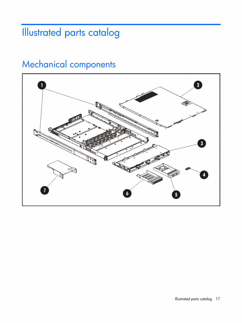
Mechanical components
Illustrated parts catalog 18
Item Description Spare part number Customer self repair (see page 5)
1 Rail mounting kit 573091-001 Mandatory1
2 Top cover 507262-001 Mandatory1
3 HDD cage 532114-001 Mandatory1
Miscellaneous
4 ODD bracket 532475-001 Mandatory1
5 HDD blank 511816-001 Mandatory1
6 Non-hot-plug HDD carrier 585183-001 Mandatory1
7 Processor air baffle 579585-001 Mandatory1
* Not shown1Mandatory—Parts for which customer self repair is mandatory. If, however, you require that HP replace them for you, there may be additional charges, depending on the type of warranty service designated for your product. 2No— Some HP parts are not designed for customer self repair. In order to satisfy the customer warranty, HP requires that an authorized service provider replace the part. These parts are identified as "No" in the Illustrated Parts Catalog3
1Mandatory: Obligatoire—Pièces pour lesquelles la réparation par le client est obligatoire. Si vous demandez à HP de remplacer ces pièces, les coûts de déplacement et main d'œuvre du service vous seront facturés. 2 No: Non—Certaines pièces HP ne sont pas conçues pour permettre au client d'effectuer lui-même la réparation. Pour que la garantie puisse s'appliquer, HP exige que le remplacement de la pièce soit effectué par un Mainteneur Agréé. Ces pièces sont identifiées par la mention “Non” dans le Catalogue illustré.
1Mandatory: Obbligatorie—Parti che devono essere necessariamente riparate dal cliente. Se il cliente ne affida la riparazione ad HP, deve sostenere le spese di spedizione e di manodopera per il servizio. 2 No: Non CSR—Alcuni componenti HP non sono progettati per la riparazione da parte del cliente. Per rispettare la garanzia, HP richiede che queste parti siano sostituite da un centro di assistenza autorizzato. Tali parti sono identificate da un “No” nel Catalogo illustrato dei componenti.
Illustrated parts catalog 19
1Mandatory: Zwingend—Teile, die im Rahmen des Customer Self Repair Programms ersetzt werden müssen. Wenn Sie diese Teile von HP ersetzen lassen, werden Ihnen die Versand- und Arbeitskosten für diesen Service berechnet. 2 No: Kein—Einige Teile sind nicht für Customer Self Repair ausgelegt. Um den Garantieanspruch des Kunden zu erfüllen, muss das Teil von einem HP Servicepartner ersetzt werden. Im illustrierten Teilekatalog sind diese Teile mit „No“ bzw. „Nein“ gekennzeichnet.
1Mandatory: Obligatorio—componentes para los que la reparación por parte del usuario es obligatoria. Si solicita a HP que realice la sustitución de estos componentes, tendrá que hacerse cargo de los gastos de desplazamiento y de mano de obra de dicho servicio. 2 No: No—Algunos componentes no están diseñados para que puedan ser reparados por el usuario. Para que el usuario haga valer su garantía, HP pone como condición que un proveedor de servicios autorizado realice la sustitución de estos componentes. Dichos componentes se identifican con la palabra “No” en el catálogo ilustrado de componentes..
1Mandatory: Verplicht—Onderdelen waarvoor Customer Self Repair verplicht is. Als u HP verzoekt deze onderdelen te vervangen, komen de reiskosten en het arbeidsloon voor uw rekening. 2 No: Nee—Sommige HP onderdelen zijn niet ontwikkeld voor reparatie door de klant. In verband met de garantievoorwaarden moet het onderdeel door een geautoriseerde Service Partner worden vervangen. Deze onderdelen worden in de geïllustreerde onderdelencatalogus aangemerkt met "Nee".
1Mandatory: Obrigatória—Peças cujo reparo feito pelo cliente é obrigatório. Se desejar que a HP substitua essas peças, serão cobradas as despesas de transporte e mão-de-obra do serviço. 2 No: Nenhuma—Algumas peças da HP não são projetadas para o reparo feito pelo cliente. A fim de cumprir a garantia do cliente, a HP exige que um técnico autorizado substitua a peça. Essas peças estão identificadas com a marca “No” (Não), no catálogo de peças ilustrado.

Illustrated parts catalog 20
Illustrated parts catalog 21
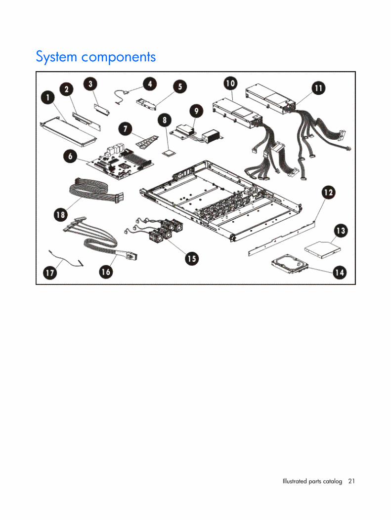
System components
Illustrated parts catalog 22
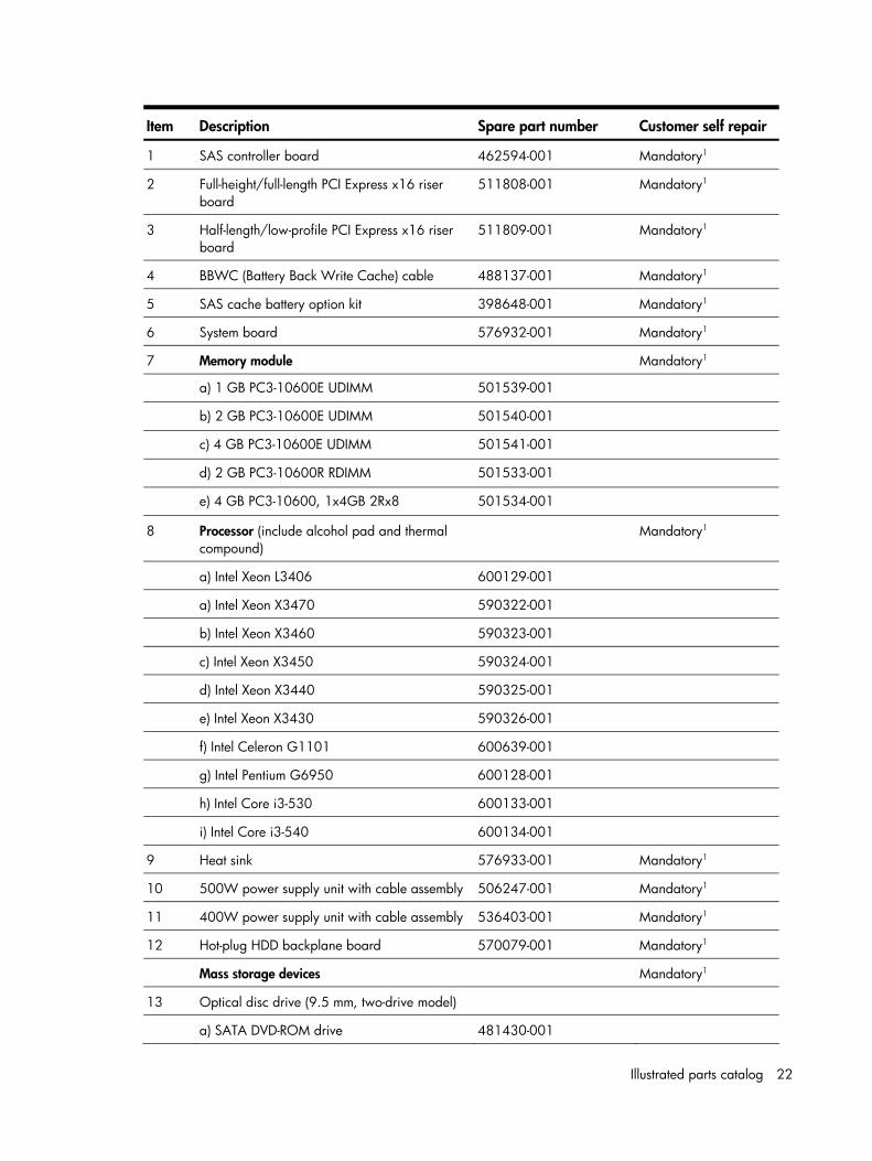
Item Description Spare part number Customer self repair
1 SAS controller board 462594-001 Mandatory1
2 Full-height/full-length PCI Express x16 riser board
511808-001 Mandatory1
3 Half-length/low-profile PCI Express x16 riser board
511809-001 Mandatory1
4 BBWC (Battery Back Write Cache) cable 488137-001 Mandatory1
5 SAS cache battery option kit 398648-001 Mandatory1
6 System board 576932-001 Mandatory1
7 Memory module Mandatory1
a) 1 GB PC3-10600E UDIMM 501539-001
b) 2 GB PC3-10600E UDIMM 501540-001
c) 4 GB PC3-10600E UDIMM 501541-001
d) 2 GB PC3-10600R RDIMM 501533-001
e) 4 GB PC3-10600, 1x4GB 2Rx8 501534-001
8 Processor (include alcohol pad and thermal compound)
Mandatory1
a) Intel Xeon L3406 600129-001
a) Intel Xeon X3470 590322-001
b) Intel Xeon X3460 590323-001
c) Intel Xeon X3450 590324-001
d) Intel Xeon X3440 590325-001
e) Intel Xeon X3430 590326-001
f) Intel Celeron G1101 600639-001
g) Intel Pentium G6950 600128-001
h) Intel Core i3-530 600133-001
i) Intel Core i3-540 600134-001
9 Heat sink 576933-001 Mandatory1
10 500W power supply unit with cable assembly 506247-001 Mandatory1
11 400W power supply unit with cable assembly 536403-001 Mandatory1
12 Hot-plug HDD backplane board 570079-001 Mandatory1
Mass storage devices Mandatory1
13 Optical disc drive (9.5 mm, two-drive model)
a) SATA DVD-ROM drive 481430-001
Illustrated parts catalog 23
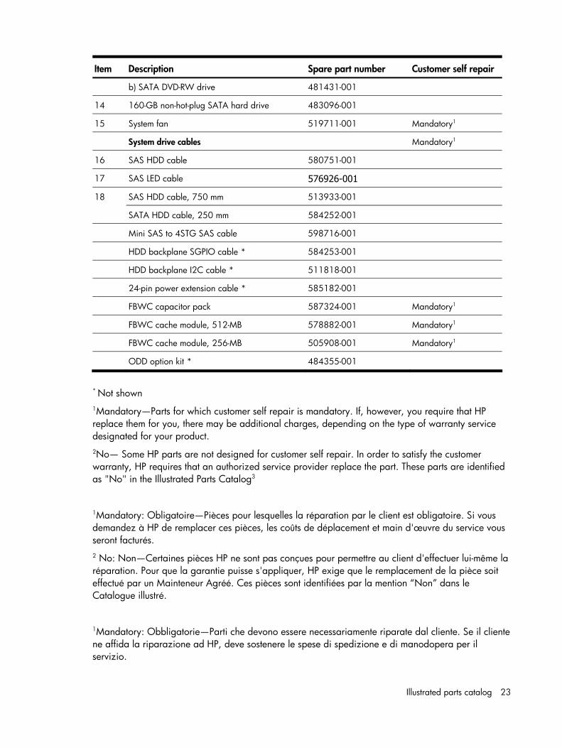
Item Description Spare part number Customer self repair
b) SATA DVD-RW drive 481431-001
14 160-GB non-hot-plug SATA hard drive 483096-001
15 System fan 519711-001 Mandatory1
System drive cables Mandatory1
16 SAS HDD cable 580751-001
17 SAS LED cable 576926-001
SAS HDD cable, 750 mm 513933-001 18
SATA HDD cable, 250 mm 584252-001
Mini SAS to 4STG SAS cable 598716-001
HDD backplane SGPIO cable * 584253-001
HDD backplane I2C cable * 511818-001
24-pin power extension cable * 585182-001
FBWC capacitor pack 587324-001 Mandatory1
FBWC cache module, 512-MB 578882-001 Mandatory1
FBWC cache module, 256-MB 505908-001 Mandatory1
ODD option kit * 484355-001
* Not shown
1Mandatory—Parts for which customer self repair is mandatory. If, however, you require that HP replace them for you, there may be additional charges, depending on the type of warranty service designated for your product. 2No— Some HP parts are not designed for customer self repair. In order to satisfy the customer warranty, HP requires that an authorized service provider replace the part. These parts are identified as "No" in the Illustrated Parts Catalog3
1Mandatory: Obligatoire—Pièces pour lesquelles la réparation par le client est obligatoire. Si vous demandez à HP de remplacer ces pièces, les coûts de déplacement et main d'œuvre du service vous seront facturés. 2 No: Non—Certaines pièces HP ne sont pas conçues pour permettre au client d'effectuer lui-même la réparation. Pour que la garantie puisse s'appliquer, HP exige que le remplacement de la pièce soit effectué par un Mainteneur Agréé. Ces pièces sont identifiées par la mention “Non” dans le Catalogue illustré.
1Mandatory: Obbligatorie—Parti che devono essere necessariamente riparate dal cliente. Se il cliente ne affida la riparazione ad HP, deve sostenere le spese di spedizione e di manodopera per il servizio.
Illustrated parts catalog 24
2 No: Non CSR—Alcuni componenti HP non sono progettati per la riparazione da parte del cliente. Per rispettare la garanzia, HP richiede che queste parti siano sostituite da un centro di assistenza autorizzato. Tali parti sono identificate da un “No” nel Catalogo illustrato dei componenti.
1Mandatory: Zwingend—Teile, die im Rahmen des Customer Self Repair Programms ersetzt werden müssen. Wenn Sie diese Teile von HP ersetzen lassen, werden Ihnen die Versand- und Arbeitskosten für diesen Service berechnet. 2 No: Kein—Einige Teile sind nicht für Customer Self Repair ausgelegt. Um den Garantieanspruch des Kunden zu erfüllen, muss das Teil von einem HP Servicepartner ersetzt werden. Im illustrierten Teilekatalog sind diese Teile mit „No“ bzw. „Nein“ gekennzeichnet.
Illustrated parts catalog 25
1Mandatory: Obligatorio—componentes para los que la reparación por parte del usuario es obligatoria. Si solicita a HP que realice la sustitución de estos componentes, tendrá que hacerse cargo de los gastos de desplazamiento y de mano de obra de dicho servicio. 2 No: No—Algunos componentes no están diseñados para que puedan ser reparados por el usuario. Para que el usuario haga valer su garantía, HP pone como condición que un proveedor de servicios autorizado realice la sustitución de estos componentes. Dichos componentes se identifican con la palabra “No” en el catálogo ilustrado de componentes..
1Mandatory: Verplicht—Onderdelen waarvoor Customer Self Repair verplicht is. Als u HP verzoekt deze onderdelen te vervangen, komen de reiskosten en het arbeidsloon voor uw rekening. 2 No: Nee—Sommige HP onderdelen zijn niet ontwikkeld voor reparatie door de klant. In verband met de garantievoorwaarden moet het onderdeel door een geautoriseerde Service Partner worden vervangen. Deze onderdelen worden in de geïllustreerde onderdelencatalogus aangemerkt met "Nee".
1Mandatory: Obrigatória—Peças cujo reparo feito pelo cliente é obrigatório. Se desejar que a HP substitua essas peças, serão cobradas as despesas de transporte e mão-de-obra do serviço. 2 No: Nenhuma—Algumas peças da HP não são projetadas para o reparo feito pelo cliente. A fim de cumprir a garantia do cliente, a HP exige que um técnico autorizado substitua a peça. Essas peças estão identificadas com a marca “No” (Não), no catálogo de peças ilustrado.
Illustrated parts catalog 26
Illustrated parts catalog 27
HP contact information For the name of the nearest HP authorized reseller: • In the United States, call 1-800-345-1518. • In Canada, call 1-800-263-5868. • In other locations, refer to the HP website at www.hp.com.
For HP technical support: • In North America:
○ Call 1-800-HP-INVENT (1-800-474-6836). This service is available 24 hours a day, 7 days a week. For continuous quality improvement, calls may be recorded or monitored.
○ If you have purchased a Care Pack (service upgrade), call 1-800-633-3600. For more information about Care Packs, refer to the HP website at www.hp.com.
• Outside North America, call the nearest HP Technical Support Phone Center. For telephone numbers of worldwide Technical Support Centers, refer to the HP website at www.hp.com.
Before you contact HP Be sure to have the following information available before you call HP: • Technical support registration number (if applicable) • Product serial number (printed on the serial pull tab located on the front panel) • Product model name and number • Applicable error messages • Add-on boards or hardware • Third-party hardware or software • Operating system type and revision level
Removal and replacement procedures 28
Removal and replacement procedures
Required tools In performing any hardware configuration procedure you may need the following tools: • T10/T15 wrench (secured on the rear panel) • Phillips screwdriver (for ODD replacement)
The following references and software tools may also be used: • HP ProLiant DL120 G6 Server Easy Set-up CD • IPMI Event Log • Diagnostics software
Server warnings and cautions Before installing a server, be sure that you understand the following warnings and cautions.
WARNING: To reduce the risk of personal injury from hot surfaces, allow the drives and the internal system components to cool before touching them.
CAUTION: The server must always be operated with the system covers on. Proper cooling is not achieved when the system covers are removed.
CAUTION: Whenever installing hardware or performing maintenance procedures requiring access to internal components, it is recommended that users first back up all server data to avoid loss.
IMPORTANT: Before removing any serviceable parts, determine whether the part is hot-plug or non-hot-plug. If the device is non-hot-plug, you must power down the server. Non-hot-plug devices in the server include the processor, all boards, memory modules, fans, and expansion boards.
IMPORTANT: Review the specifications of a new component before installing it to make sure it is compatible with the server. When you integrate new components into the system, record its model and serial number, and any other pertinent information for future reference. After completing any removal or replacement procedure, run the diagnostics program to verify that all components operate properly.
Removal and replacement procedures 29
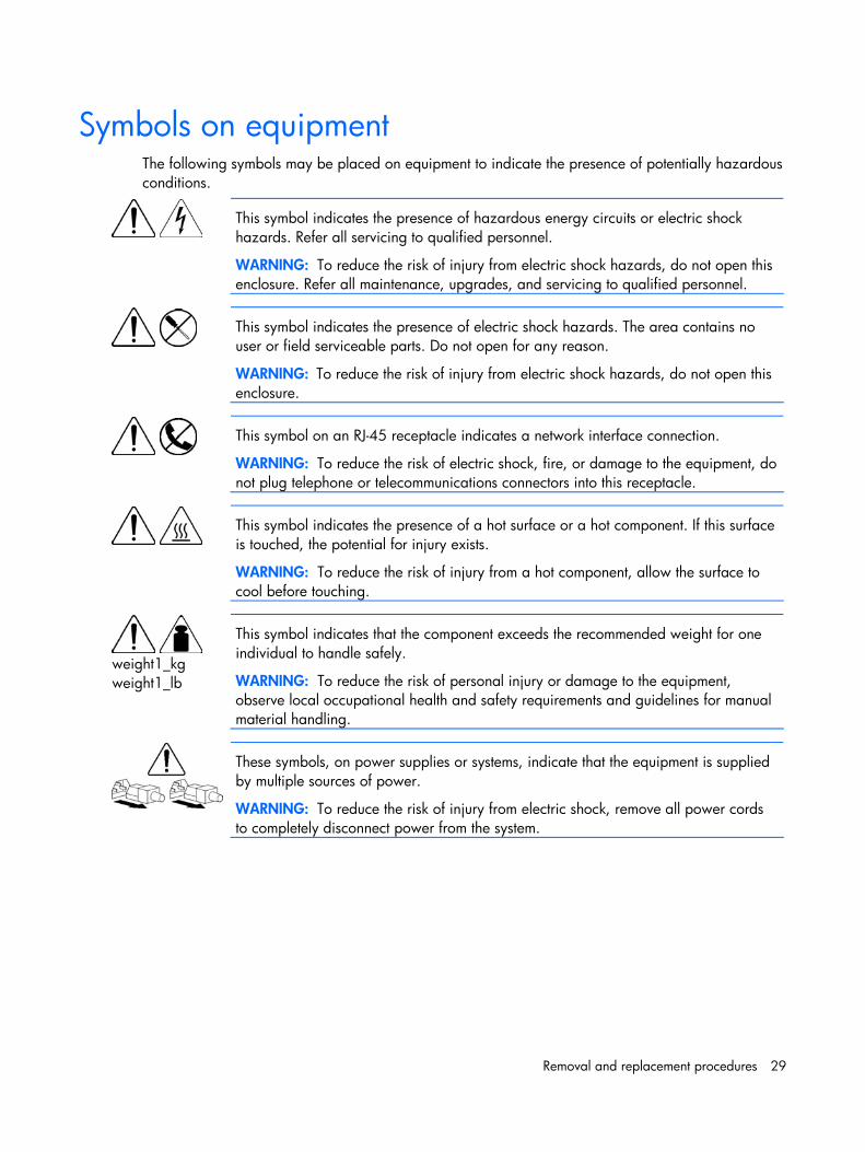
Symbols on equipment The following symbols may be placed on equipment to indicate the presence of potentially hazardous conditions.
This symbol indicates the presence of hazardous energy circuits or electric shock hazards. Refer all servicing to qualified personnel.
WARNING: To reduce the risk of injury from electric shock hazards, do not open this enclosure. Refer all maintenance, upgrades, and servicing to qualified personnel.
This symbol indicates the presence of electric shock hazards. The area contains no user or field serviceable parts. Do not open for any reason.
WARNING: To reduce the risk of injury from electric shock hazards, do not open this enclosure.
This symbol on an RJ-45 receptacle indicates a network interface connection.
WARNING: To reduce the risk of electric shock, fire, or damage to the equipment, do not plug telephone or telecommunications connectors into this receptacle.
This symbol indicates the presence of a hot surface or a hot component. If this surface is touched, the potential for injury exists.
WARNING: To reduce the risk of injury from a hot component, allow the surface to cool before touching.
weight1_kg weight1_lb
This symbol indicates that the component exceeds the recommended weight for one individual to handle safely.
WARNING: To reduce the risk of personal injury or damage to the equipment, observe local occupational health and safety requirements and guidelines for manual material handling.
These symbols, on power supplies or systems, indicate that the equipment is supplied by multiple sources of power.
WARNING: To reduce the risk of injury from electric shock, remove all power cords to completely disconnect power from the system.
Removal and replacement procedures 30
Electrostatic discharge information An electrostatic discharge (ESD) can damage static-sensitive devices or microcircuitry. Proper packaging and grounding techniques are necessary precautions to prevent damage. To prevent electrostatic damage, observe the following precautions: • Transport products in static-safe containers such as conductive tubes, bags, or boxes. • Keep electrostatic-sensitive parts in their containers until they arrive at static-free stations. • Cover workstations with approved static-dissipating material. Use a wrist strap connected to the
work surface, and properly grounded (earthed) tools and equipment. • Keep work area free of nonconductive materials, such as ordinary plastic assembly aids and
foam packing. • Make sure that you are always properly grounded (earthed) when touching a static-sensitive
component or assembly. • Avoid touching pins, leads, or circuitry. • Always place drives with the Printed Circuit Board (PCB) assembly-side down. • Use conductive field service tools.
Pre-installation procedure Perform the steps below before you open the server or before you remove or replace any component.
1. Perform data backup.
2. Turn off the server and all the peripherals connected to it.
3. Unplug all cables from the power outlets to avoid exposure to high energy levels that may cause burns when parts are short circuited by metal objects such as tools or jewelry.
4. If necessary, label each cable to expedite reassembly.
5. Disconnect all telecommunication cables to avoid exposure to shock hazard from ringing voltages.
6. Remove the server from the rack.
7. Open the server according to the instructions described in the “Top cover” section on page 33.
8. Follow the ESD precautions listed previously in this chapter when handling any hardware component.
IMPORTANT: To streamline the configuration process, read through the entire installation/removal procedure first and make sure you understand it before you begin.
Removal and replacement procedures 31
Post-installation procedure 1. Perform the steps below after installing or removing a server component.
2. Be sure all components are installed according to the described step-by-step instructions.
3. Check to make sure you have not left loose tools or parts inside the server.
4. Reinstall any expansion board, peripheral, and system cables that have previously been removed.
CAUTION: Do not operate the server for more than 10 minutes with the access panel and disk drives removed. Otherwise, improper cooling airflow may damage the system components.
5. Reinstall the top cover.
6. Connect all external cables and the AC power cord to the system.
7. Press the power button on the front panel to turn on the server.
Powering down the server The server does not completely power down when the power button is pressed. The button toggles between On and Standby. The standby position removes power from most electronics and the drives, but some internal circuitry remains active. To completely remove all power from the system, disconnect all power cords from the server.
WARNING: Hazardous voltages are present inside the server. Always disconnect AC power from the server and other associated assemblies while working inside the unit. Serious injury may result if this warning is not observed.
WARNING: To reduce the risk of electric shock or damage to the equipment: • Do not disable the power cord grounding plug. The grounding plug is an important safety feature. • Plug the power cord into a grounded (earthed) electrical outlet that is easily accessible at all times. • Unplug the power cord from the power supply to disconnect power to the equipment. • Do not route the power cord where it can be walked on or pinched by items placed against it. Pay
particular attention to the plug, electrical outlet, and the point where the cord extends from the server.
CAUTION: Protect the server from power fluctuations and temporary interruptions with a regulating uninterruptible power supply (UPS). This device protects the hardware from damage caused by power surges and voltage spikes, and keeps the system in operation during a power failure.
1. Shut down the server as directed by the operating system documentation.
2. Press the power button to toggle to Standby.
3. This places the server in standby mode changing the power LED indicator to amber. In this mode, the main power supply output is disabled. Standby does not completely disable or remove power from the system.
Removal and replacement procedures 32
4. Disconnect the AC power cord from the AC outlet and then from the server.
5. Check that the power LED indicator is turned off and that the fan noise has stopped.
6. Disconnect all external peripheral devices from the server.
Cable management Always follow good cable management practices when working inside the computer. • Keep cables away from major heat sources like the heat sink. • Do not jam cables on top of expansion cards or memory modules. Printed circuit cards are not
designed to withstand excessive pressure. • Keep cables clear of sliding or moveable parts to prevent cutting or crimping. • When folding a flat ribbon cable, never fold to a sharp crease. Sharp creases may damage the
wires. • Some flat ribbon cables come prefolded. Never change the folds on these cables. • Do not sharply bend any cable. A sharp bend can break the internal wires. • Never bend a SATA data cable tighter than a 30 mm (1.18 in) radius. • Never crease a SATA data cable. • Do not rely on components like the drive cage, power supply, or system cover to push cables
down into the chassis.
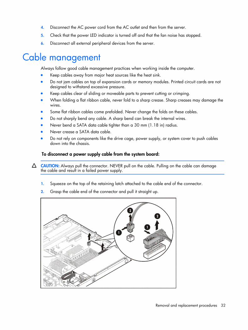
To disconnect a power supply cable from the system board:
CAUTION: Always pull the connector. NEVER pull on the cable. Pulling on the cable can damage the cable and result in a failed power supply.
1. Squeeze on the top of the retaining latch attached to the cable end of the connector.
2. Grasp the cable end of the connector and pull it straight up.
Removal and replacement procedures 33
Top cover You must remove the top cover before you can remove or replace a non--hot-plug server component.
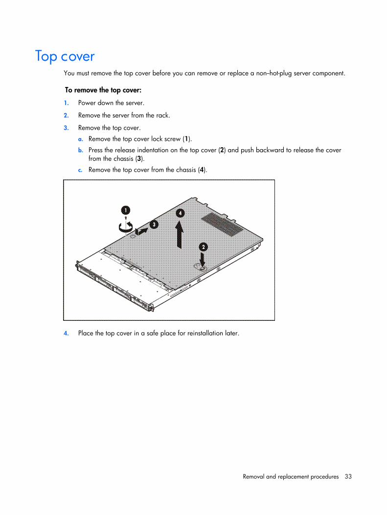
To remove the top cover:
1. Power down the server.
2. Remove the server from the rack.
3. Remove the top cover.
a. Remove the top cover lock screw (1).
b. Press the release indentation on the top cover (2) and push backward to release the cover from the chassis (3).
c. Remove the top cover from the chassis (4).
4. Place the top cover in a safe place for reinstallation later.
Removal and replacement procedures 34
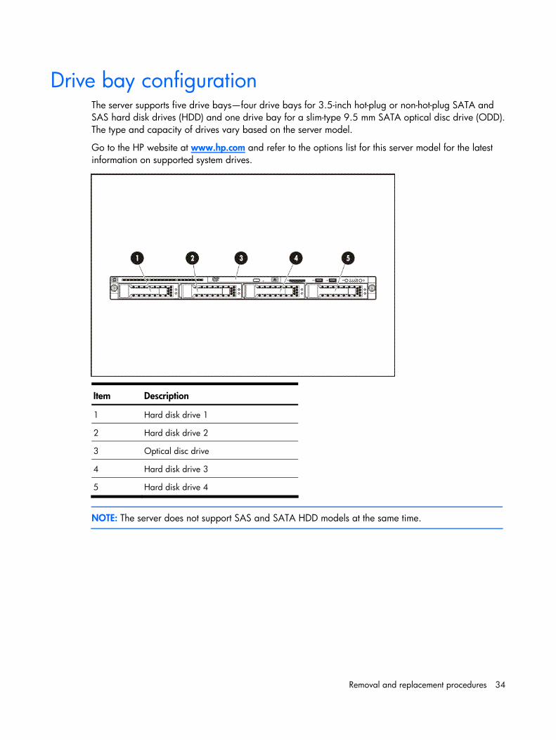
Drive bay configuration The server supports five drive bays—four drive bays for 3.5-inch hot-plug or non-hot-plug SATA and SAS hard disk drives (HDD) and one drive bay for a slim-type 9.5 mm SATA optical disc drive (ODD). The type and capacity of drives vary based on the server model.
Go to the HP website at www.hp.com and refer to the options list for this server model for the latest information on supported system drives.
Item Description
1 Hard disk drive 1
2 Hard disk drive 2
3 Optical disc drive
4 Hard disk drive 3
5 Hard disk drive 4
NOTE: The server does not support SAS and SATA HDD models at the same time.
Removal and replacement procedures 35
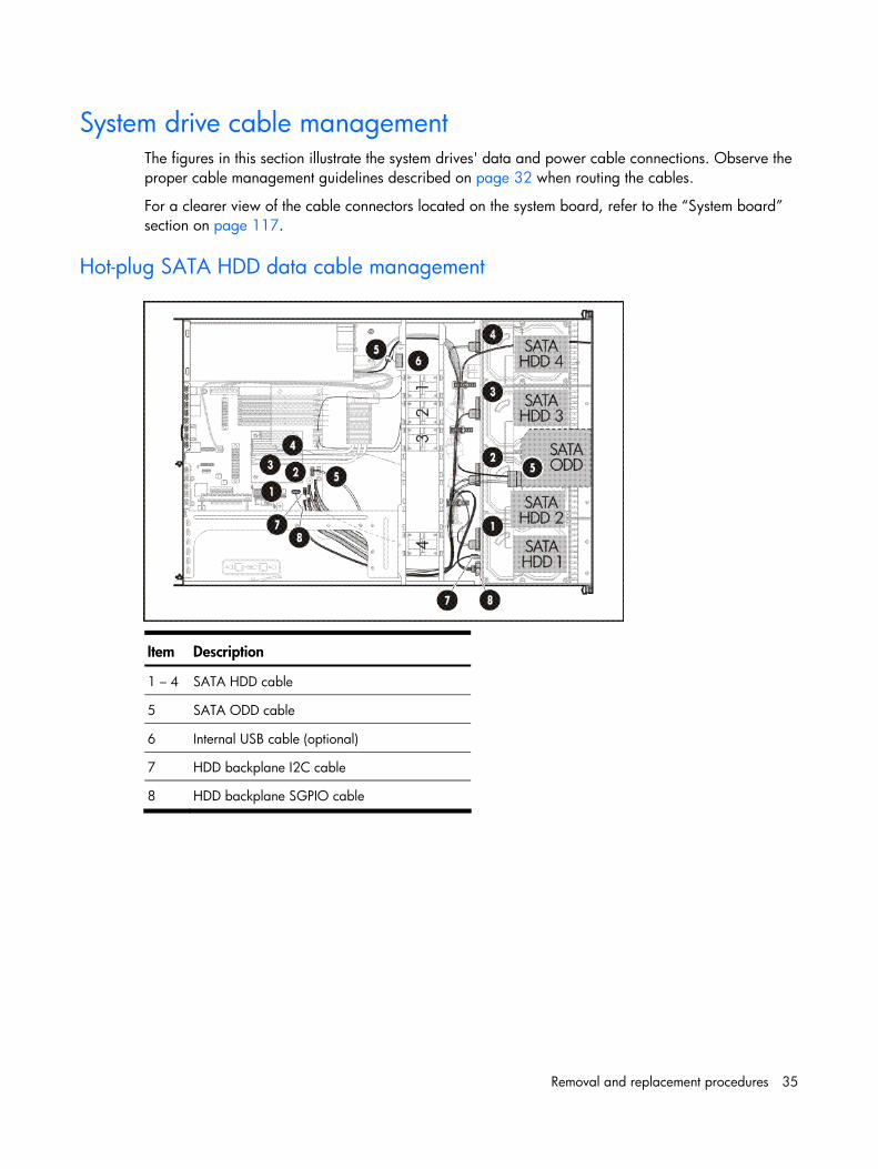
System drive cable management The figures in this section illustrate the system drives' data and power cable connections. Observe the proper cable management guidelines described on page 32 when routing the cables.
For a clearer view of the cable connectors located on the system board, refer to the “System board” section on page 117.
Hot-plug SATA HDD data cable management
Item Description
1 – 4 SATA HDD cable
5 SATA ODD cable
6 Internal USB cable (optional)
7 HDD backplane I2C cable
8 HDD backplane SGPIO cable
Removal and replacement procedures 36
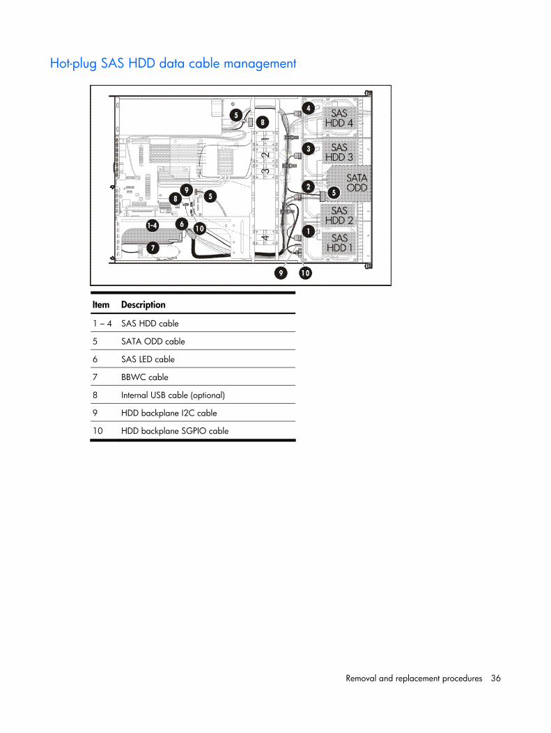
Hot-plug SAS HDD data cable management
Item Description
1 – 4 SAS HDD cable
5 SATA ODD cable
6 SAS LED cable
7 BBWC cable
8 Internal USB cable (optional)
9 HDD backplane I2C cable
10 HDD backplane SGPIO cable
Removal and replacement procedures 37
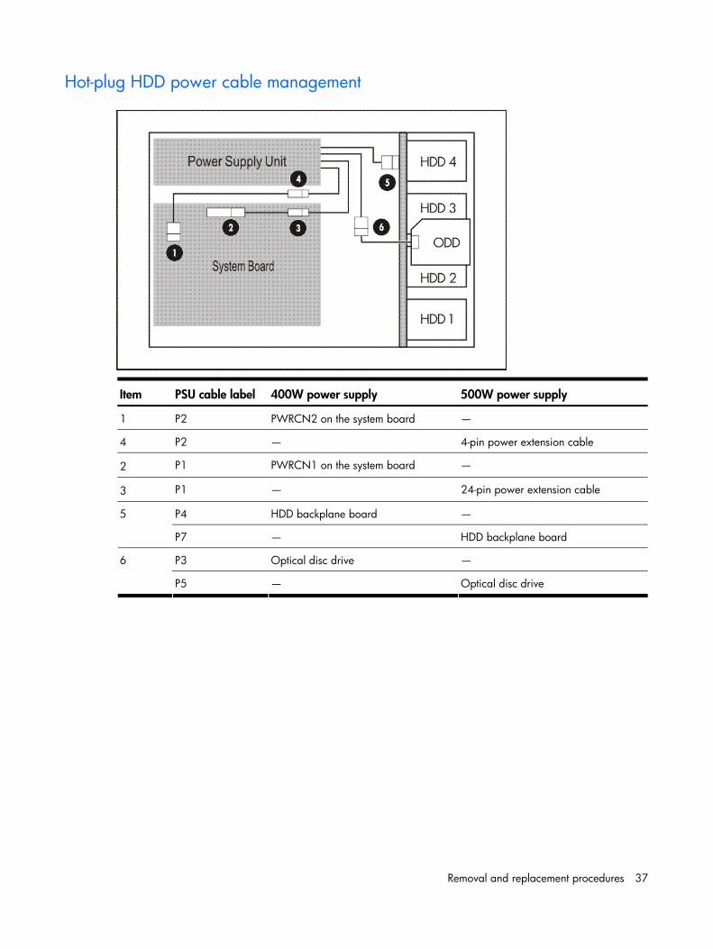
Hot-plug HDD power cable management
Item PSU cable label 400W power supply 500W power supply
1 P2 PWRCN2 on the system board —
4 P2 — 4-pin power extension cable
2 P1 PWRCN1 on the system board —
3 P1 — 24-pin power extension cable
P4 HDD backplane board — 5
P7 — HDD backplane board
P3 Optical disc drive — 6
P5 — Optical disc drive
Removal and replacement procedures 38
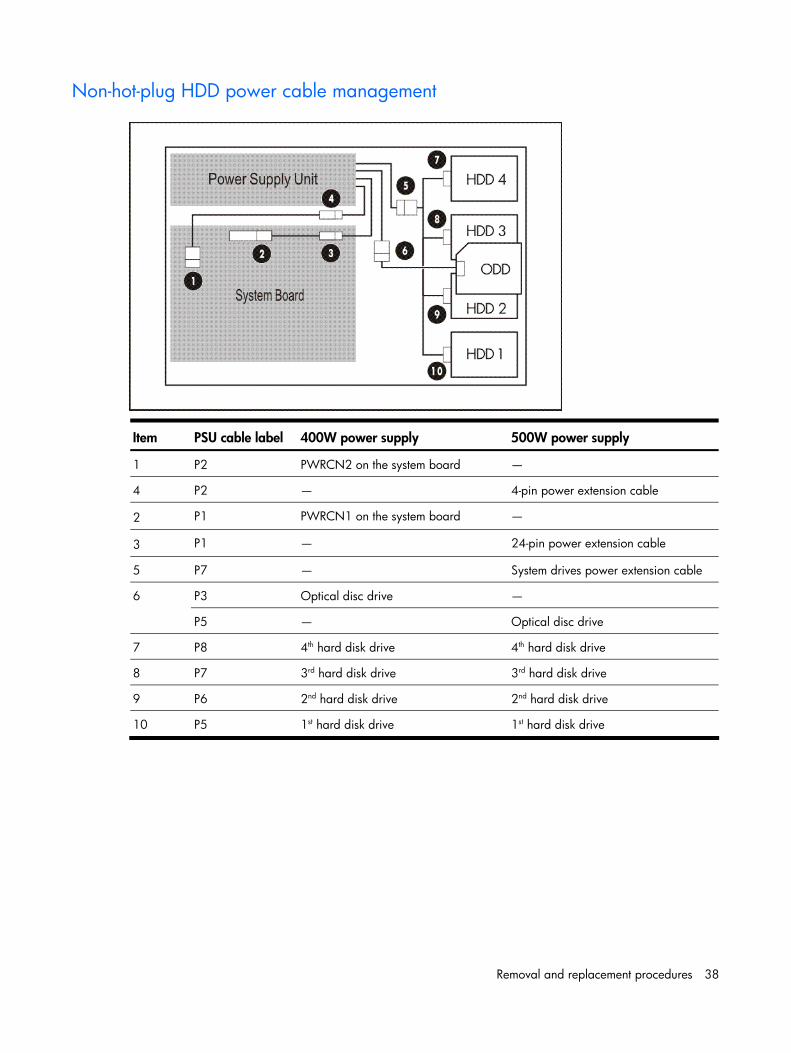
Non-hot-plug HDD power cable management
Item PSU cable label 400W power supply 500W power supply
1 P2 PWRCN2 on the system board —
4 P2 — 4-pin power extension cable
2 P1 PWRCN1 on the system board —
3 P1 — 24-pin power extension cable
5 P7 — System drives power extension cable
P3 Optical disc drive — 6
P5 — Optical disc drive
7 P8 4th hard disk drive 4th hard disk drive
8 P7 3rd hard disk drive 3rd hard disk drive
9 P6 2nd hard disk drive 2nd hard disk drive
10 P5 1st hard disk drive 1st hard disk drive
Removal and replacement procedures 39
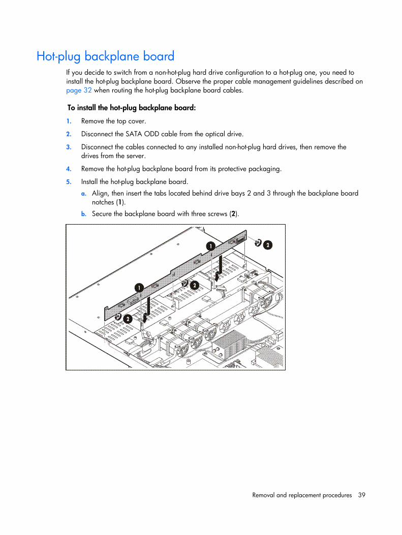
Hot-plug backplane board If you decide to switch from a non-hot-plug hard drive configuration to a hot-plug one, you need to install the hot-plug backplane board. Observe the proper cable management guidelines described on page 32 when routing the hot-plug backplane board cables.
To install the hot-plug backplane board:
1. Remove the top cover.
2. Disconnect the SATA ODD cable from the optical drive.
3. Disconnect the cables connected to any installed non-hot-plug hard drives, then remove the drives from the server.
4. Remove the hot-plug backplane board from its protective packaging.
5. Install the hot-plug backplane board.
a. Align, then insert the tabs located behind drive bays 2 and 3 through the backplane board notches (1).
b. Secure the backplane board with three screws (2).
Removal and replacement procedures 40
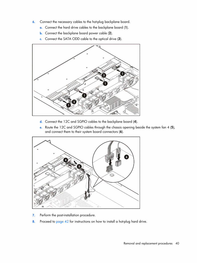
6. Connect the necessary cables to the hot-plug backplane board.
a. Connect the hard drive cables to the backplane board (1).
b. Connect the backplane board power cable (2).
c. Connect the SATA ODD cable to the optical drive (3).
d. Connect the 12C and SGPIO cables to the backplane board (4).
e. Route the 12C and SGPIO cables through the chassis opening beside the system fan 4 (5), and connect them to their system board connectors (6).
7. Perform the post-installation procedure.
8. Proceed to page 42 for instructions on how to install a hot-plug hard drive.
Removal and replacement procedures 41
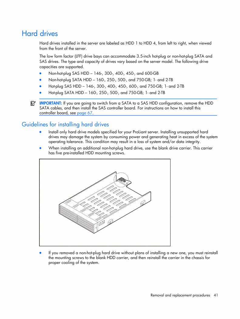
Hard drives Hard drives installed in the server are labeled as HDD 1 to HDD 4, from left to right, when viewed from the front of the server.
The low form factor (LFF) drive bays can accommodate 3.5-inch hot-plug or non-hot-plug SATA and SAS drives. The type and capacity of drives vary based on the server model. The following drive capacities are supported. • Non-hot-plug SAS HDD – 146-, 300-, 400-, 450-, and 600-GB • Non-hot-plug SATA HDD – 160-, 250-, 500-, and 750-GB; 1- and 2-TB • Hot-plug SAS HDD – 146-, 300-, 400-, 450-, 600-, and 750-GB; 1- and 2-TB • Hot-plug SATA HDD – 160-, 250-, 500-, and 750-GB; 1- and 2-TB
IMPORTANT: If you are going to switch from a SATA to a SAS HDD configuration, remove the HDD SATA cables, and then install the SAS controller board. For instructions on how to install this controller board, see page 67.
Guidelines for installing hard drives • Install only hard drive models specified for your ProLiant server. Installing unsupported hard
drives may damage the system by consuming power and generating heat in excess of the system operating tolerance. This condition may result in a loss of system and/or data integrity.
• When installing an additional non-hot-plug hard drive, use the blank drive carrier. This carrier has five pre-installed HDD mounting screws.
• If you removed a non-hot-plug hard drive without plans of installing a new one, you must reinstall the mounting screws to the blank HDD carrier, and then reinstall the carrier in the chassis for proper cooling of the system.
Removal and replacement procedures 42
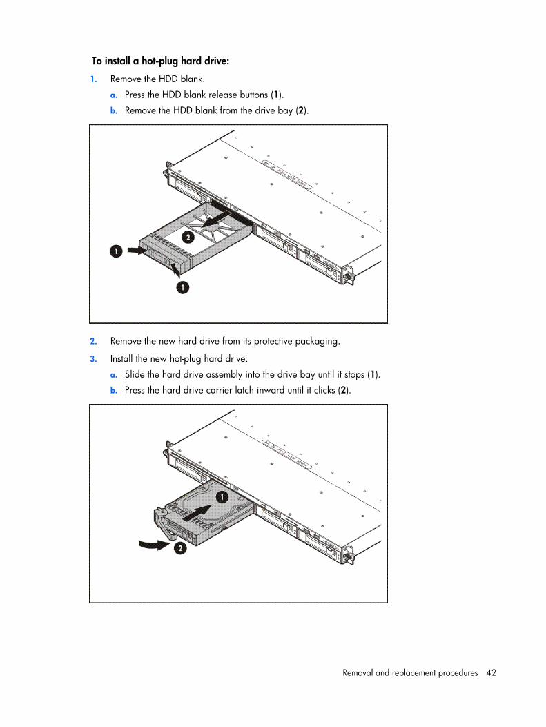
To install a hot-plug hard drive:
1. Remove the HDD blank.
a. Press the HDD blank release buttons (1).
b. Remove the HDD blank from the drive bay (2).
2. Remove the new hard drive from its protective packaging.
3. Install the new hot-plug hard drive.
a. Slide the hard drive assembly into the drive bay until it stops (1).
b. Press the hard drive carrier latch inward until it clicks (2).
Removal and replacement procedures 43
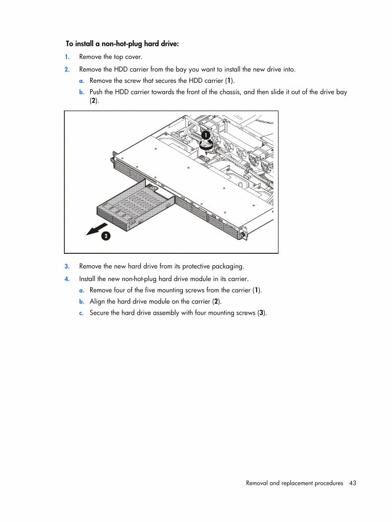
To install a non-hot-plug hard drive:
1. Remove the top cover.
2. Remove the HDD carrier from the bay you want to install the new drive into.
a. Remove the screw that secures the HDD carrier (1).
b. Push the HDD carrier towards the front of the chassis, and then slide it out of the drive bay (2).
3. Remove the new hard drive from its protective packaging.
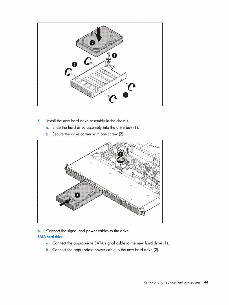
4. Install the new non-hot-plug hard drive module in its carrier.
a. Remove four of the five mounting screws from the carrier (1).
b. Align the hard drive module on the carrier (2).
c. Secure the hard drive assembly with four mounting screws (3).
Removal and replacement procedures 44
5. Install the new hard drive assembly in the chassis.
a. Slide the hard drive assembly into the drive bay (1).
b. Secure the drive carrier with one screw (2).
6. Connect the signal and power cables to the drive SATA hard drive
a. Connect the appropriate SATA signal cable to the new hard drive (1).
b. Connect the appropriate power cable to the new hard drive (2).
Removal and replacement procedures 45
Removal and replacement procedures 46
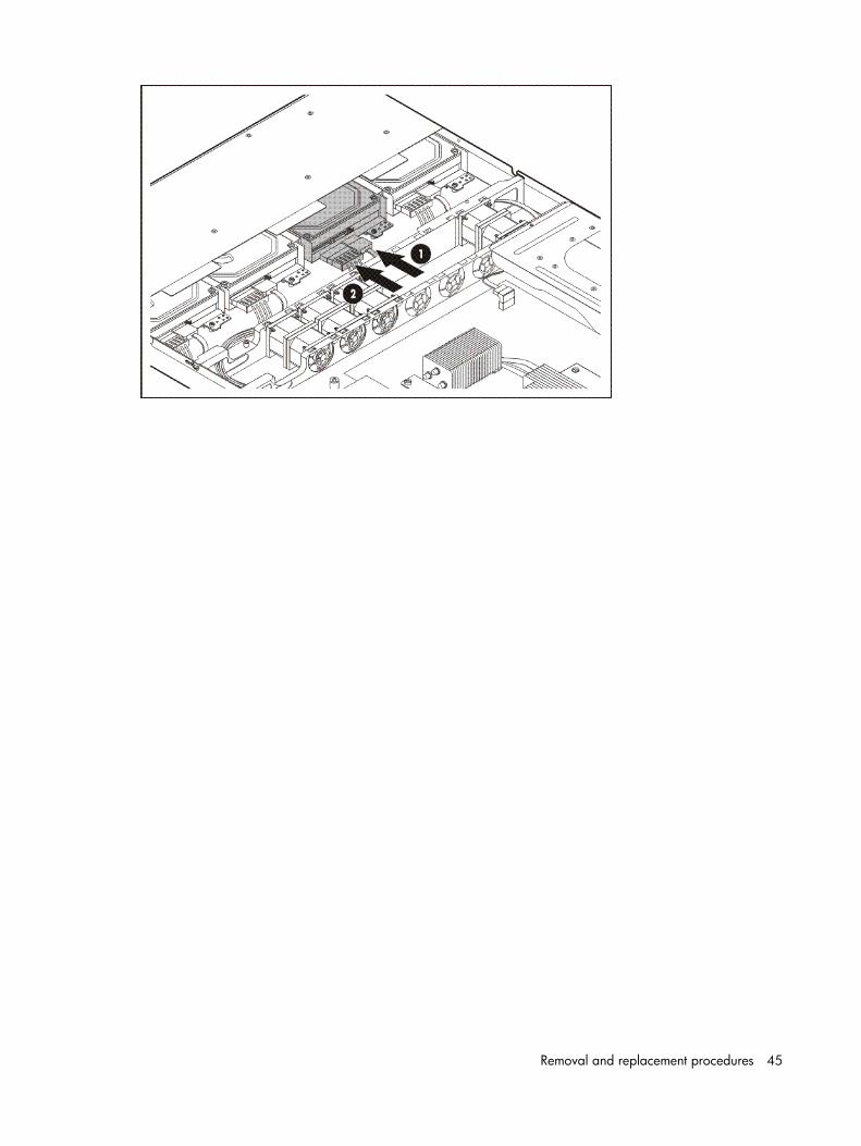
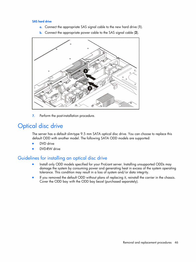
SAS hard drive
a. Connect the appropriate SAS signal cable to the new hard drive (1).
b. Connect the appropriate power cable to the SAS signal cable (2).
7. Perform the post-installation procedure.
Optical disc drive The server has a default slim-type 9.5 mm SATA optical disc drive. You can choose to replace this default ODD with another model. The following SATA ODD models are supported: • DVD drive • DVD-RW drive
Guidelines for installing an optical disc drive • Install only ODD models specified for your ProLiant server. Installing unsupported ODDs may
damage the system by consuming power and generating heat in excess of the system operating tolerance. This condition may result in a loss of system and/or data integrity.
• If you removed the default ODD without plans of replacing it, reinstall the carrier in the chassis. Cover the ODD bay with the ODD bay bezel (purchased separately).
Removal and replacement procedures 47
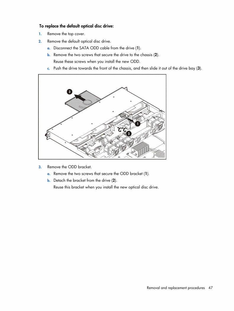
To replace the default optical disc drive:
1. Remove the top cover.
2. Remove the default optical disc drive.
a. Disconnect the SATA ODD cable from the drive (1).
b. Remove the two screws that secure the drive to the chassis (2).
Reuse these screws when you install the new ODD.
c. Push the drive towards the front of the chassis, and then slide it out of the drive bay (3).
3. Remove the ODD bracket.
a. Remove the two screws that secure the ODD bracket (1).
b. Detach the bracket from the drive (2).
Reuse this bracket when you install the new optical disc drive.
Removal and replacement procedures 48
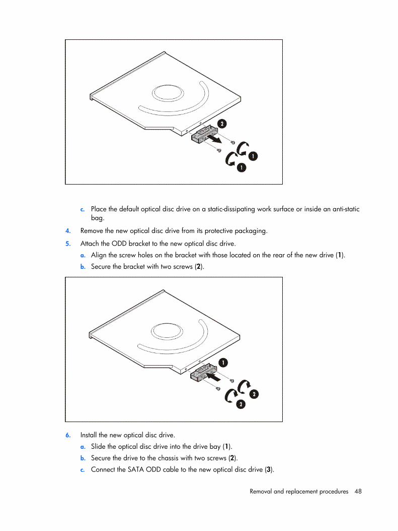
c. Place the default optical disc drive on a static-dissipating work surface or inside an anti-static bag.
4. Remove the new optical disc drive from its protective packaging.
5. Attach the ODD bracket to the new optical disc drive.
a. Align the screw holes on the bracket with those located on the rear of the new drive (1).
b. Secure the bracket with two screws (2).
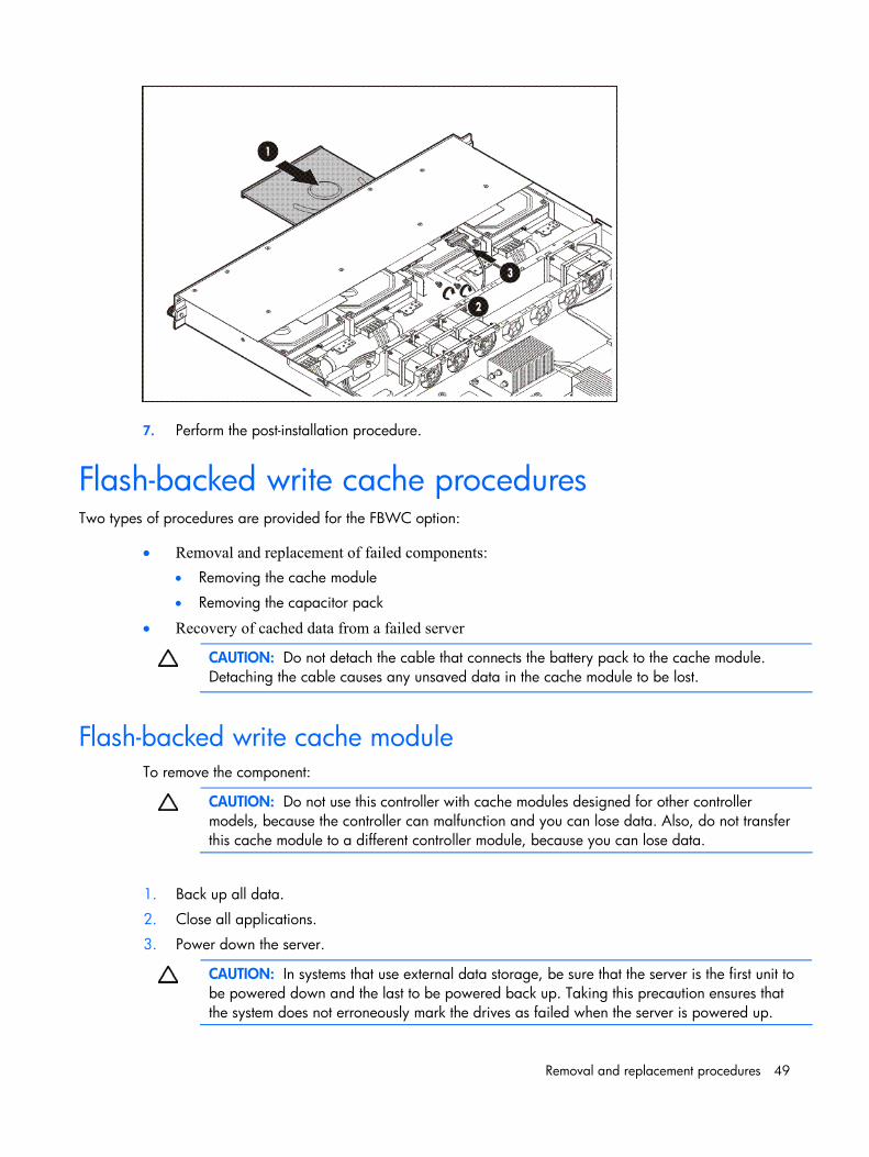
6. Install the new optical disc drive.
a. Slide the optical disc drive into the drive bay (1).
b. Secure the drive to the chassis with two screws (2).
c. Connect the SATA ODD cable to the new optical disc drive (3).
Removal and replacement procedures 49
7. Perform the post-installation procedure.
Flash-backed write cache procedures Two types of procedures are provided for the FBWC option:
• Removal and replacement of failed components: • Removing the cache module
• Removing the capacitor pack
• Recovery of cached data from a failed server
CAUTION: Do not detach the cable that connects the battery pack to the cache module. Detaching the cable causes any unsaved data in the cache module to be lost.
Flash-backed write cache module To remove the component:
CAUTION: Do not use this controller with cache modules designed for other controller models, because the controller can malfunction and you can lose data. Also, do not transfer this cache module to a different controller module, because you can lose data.
1. Back up all data.
2. Close all applications.
3. Power down the server.
CAUTION: In systems that use external data storage, be sure that the server is the first unit to be powered down and the last to be powered back up. Taking this precaution ensures that the system does not erroneously mark the drives as failed when the server is powered up.
Removal and replacement procedures 50
4. Extend the server from the rack.
5. Remove the access panel.
6. If the existing cache module is connected to a capacitor pack, observe the FBWC module LEDs:
• If the amber LED is flashing, data is trapped in the cache. Restore system power, and restart this procedure from step 1.
• If the amber LED is not lit, remove the controller from the server, and then continue with the next step.
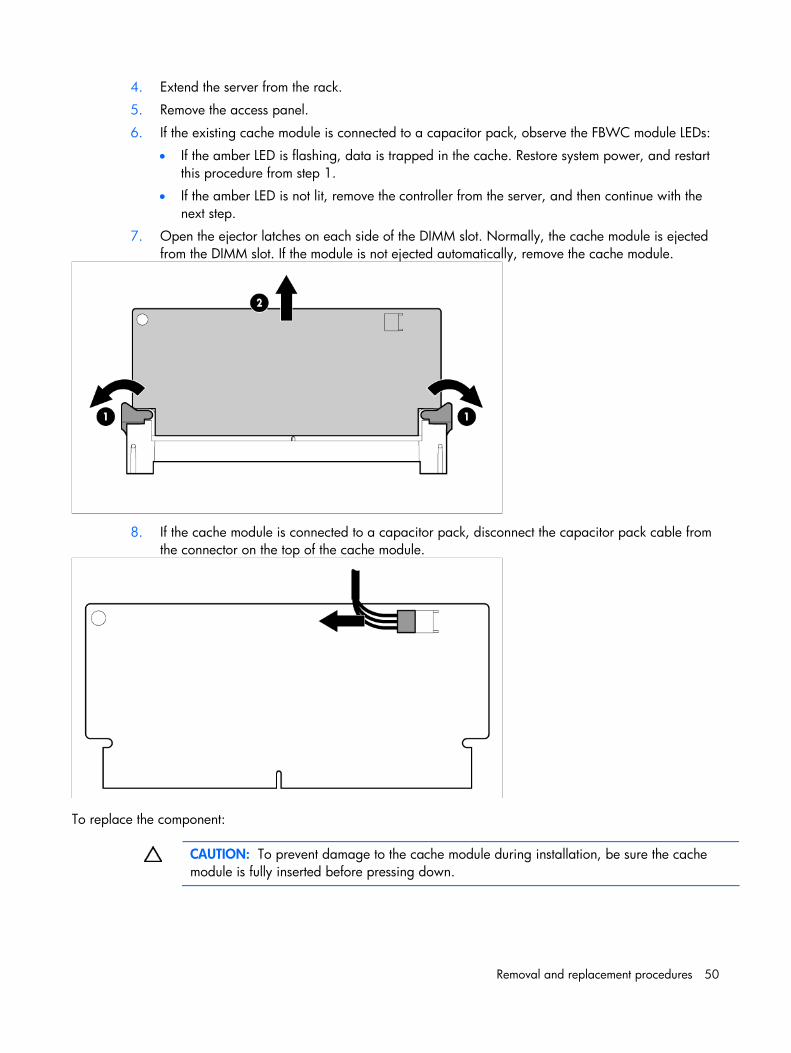
7. Open the ejector latches on each side of the DIMM slot. Normally, the cache module is ejected from the DIMM slot. If the module is not ejected automatically, remove the cache module.
8. If the cache module is connected to a capacitor pack, disconnect the capacitor pack cable from the connector on the top of the cache module.
To replace the component:
CAUTION: To prevent damage to the cache module during installation, be sure the cache module is fully inserted before pressing down.
Removal and replacement procedures 51
CAUTION: Do not use this controller with cache modules designed for other controller models, because the controller can malfunction and you can lose data. Also, do not transfer this cache module to a different controller module, because you can lose data.
1. Back up all data.
2. Close all applications.
3. Power down the server.
CAUTION: In systems that use external data storage, be sure that the server is the first unit to be powered down and the last to be powered back up. Taking this precaution ensures that the system does not erroneously mark the drives as failed when the server is powered up.
4. Remove the server from the rack.
5. Remove the access panel.
6. Install the storage controller, if not installed.
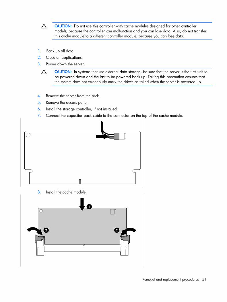
7. Connect the capacitor pack cable to the connector on the top of the cache module.
8. Install the cache module.
Removal and replacement procedures 52
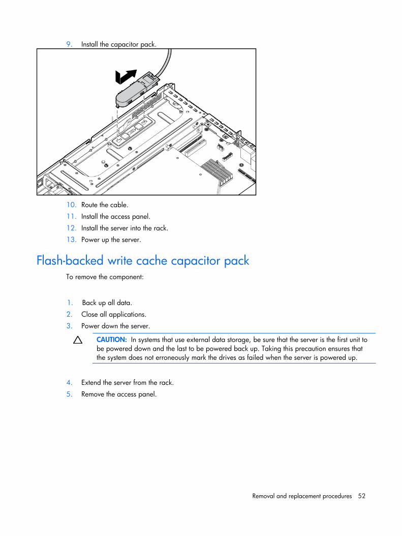
9. Install the capacitor pack.
10. Route the cable.
11. Install the access panel.
12. Install the server into the rack.
13. Power up the server.
Flash-backed write cache capacitor pack To remove the component:
1. Back up all data.
2. Close all applications.
3. Power down the server.
CAUTION: In systems that use external data storage, be sure that the server is the first unit to be powered down and the last to be powered back up. Taking this precaution ensures that the system does not erroneously mark the drives as failed when the server is powered up.
4. Extend the server from the rack.
5. Remove the access panel.
Removal and replacement procedures 53
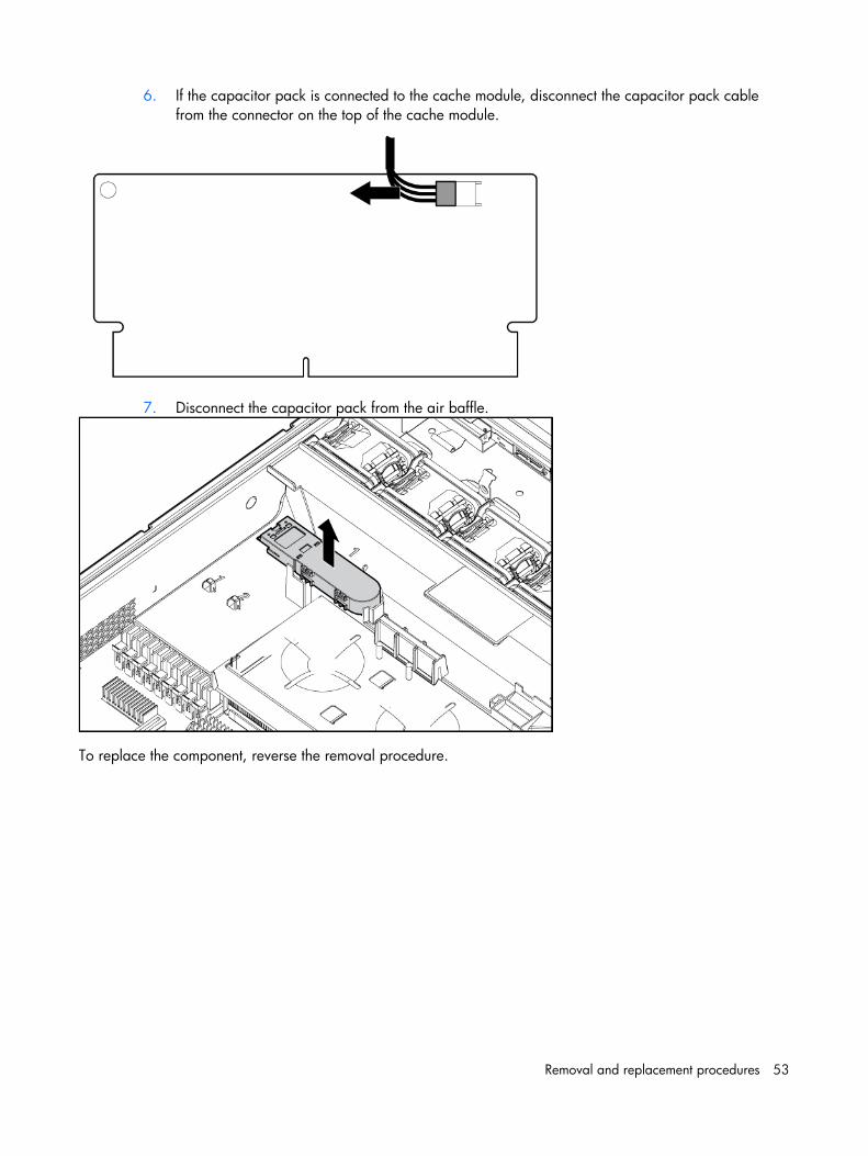
6. If the capacitor pack is connected to the cache module, disconnect the capacitor pack cable from the connector on the top of the cache module.
7. Disconnect the capacitor pack from the air baffle.
To replace the component, reverse the removal procedure.
Removal and replacement procedures 54
System board configuration Refer to the following sections for instructions about how to remove or replace the processor, the memory modules, the expansion cards, and the system battery. Procedure for installing the SAS controller board option kit is also provided.
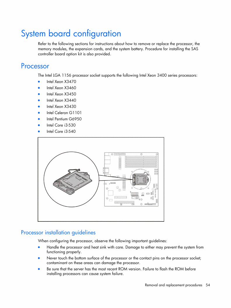
Processor The Intel LGA 1156 processor socket supports the following Intel Xeon 3400 series processors: • Intel Xeon X3470 • Intel Xeon X3460 • Intel Xeon X3450 • Intel Xeon X3440 • Intel Xeon X3430 • Intel Celeron G1101 • Intel Pentium G6950 • Intel Core i3-530 • Intel Core i3-540
Processor installation guidelines When configuring the processor, observe the following important guidelines: • Handle the processor and heat sink with care. Damage to either may prevent the system from
functioning properly. • Never touch the bottom surface of the processor or the contact pins on the processor socket;
contaminant on these areas can damage the processor. • Be sure that the server has the most recent ROM version. Failure to flash the ROM before
installing processors can cause system failure.
Removal and replacement procedures 55
Processor installation
WARNING: To reduce the risk of personal injury from hot surfaces, allow the heat sink and the processor to cool before touching them.
CAUTION: To prevent the heat sink from tilting to one side during installation/removal procedures, observe a diagonally opposite pattern (an “X” pattern) when loosening and tightening the four spring loaded screws.
The procedure for replacing the current processor consists of five major steps which are as follows:
1. Remove the heat sink.
2. Remove the current processor.
3. Apply the thermal compound.
4. Install the new processor.
5. Install the heat sink.
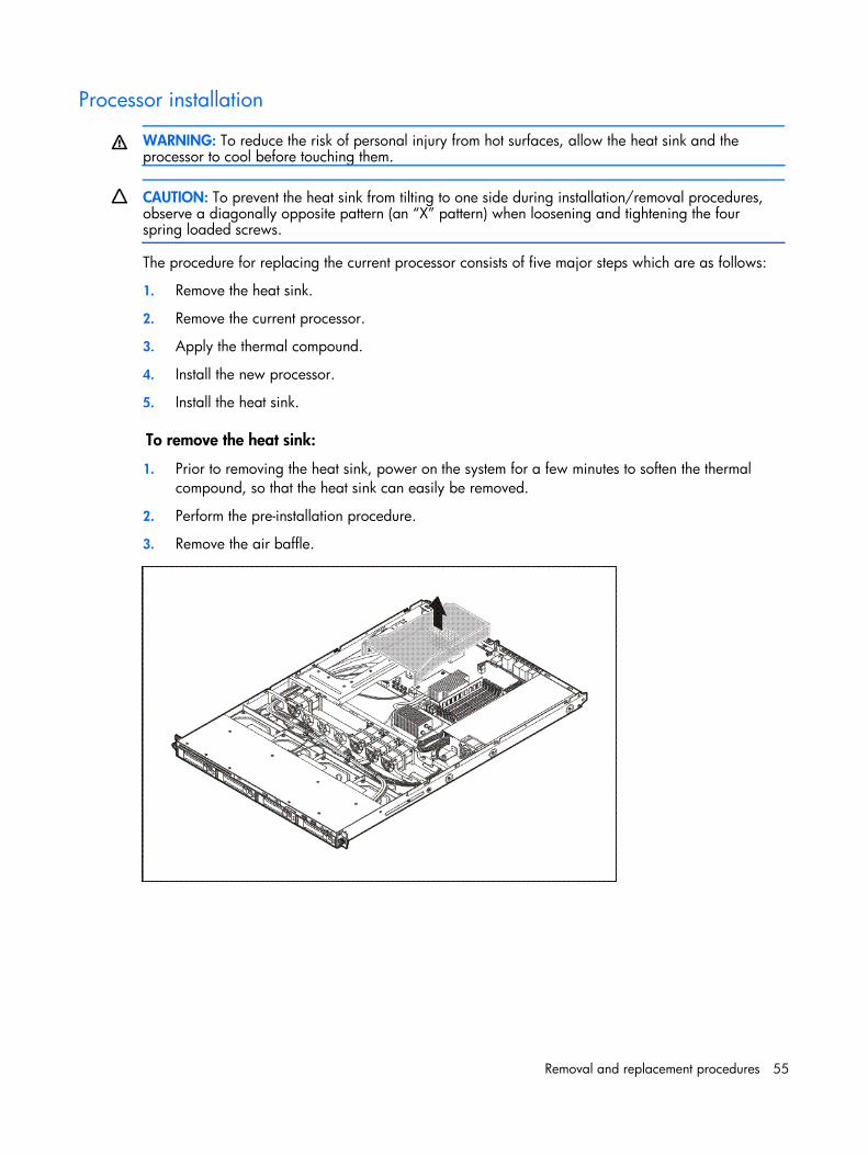
To remove the heat sink:
1. Prior to removing the heat sink, power on the system for a few minutes to soften the thermal compound, so that the heat sink can easily be removed.
2. Perform the pre-installation procedure.
3. Remove the air baffle.
Removal and replacement procedures 56
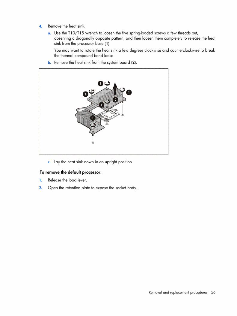
4. Remove the heat sink.
a. Use the T10/T15 wrench to loosen the five spring-loaded screws a few threads out, observing a diagonally opposite pattern, and then loosen them completely to release the heat sink from the processor base (1).
You may want to rotate the heat sink a few degrees clockwise and counterclockwise to break the thermal compound bond loose
b. Remove the heat sink from the system board (2).
c. Lay the heat sink down in an upright position.
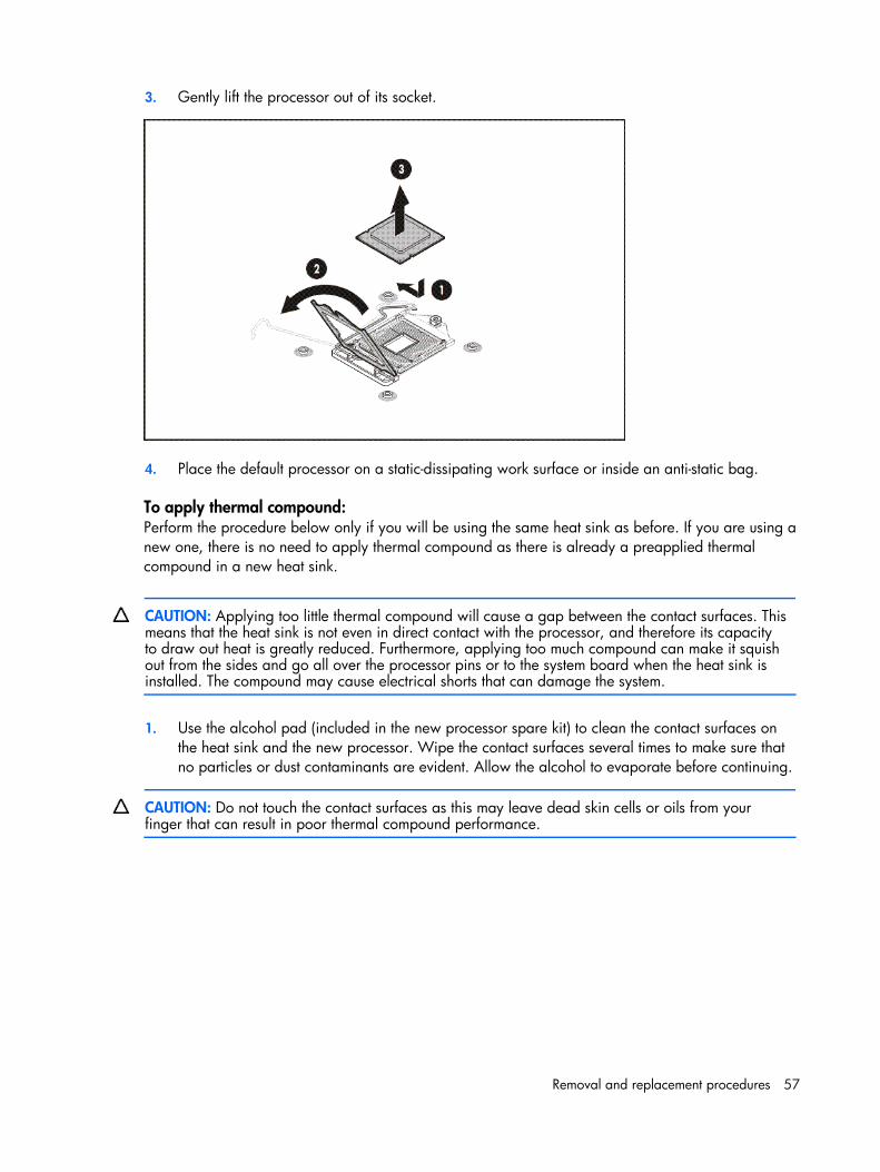
To remove the default processor:
1. Release the load lever.
2. Open the retention plate to expose the socket body.
Removal and replacement procedures 57
3. Gently lift the processor out of its socket.
4. Place the default processor on a static-dissipating work surface or inside an anti-static bag.
To apply thermal compound: Perform the procedure below only if you will be using the same heat sink as before. If you are using a new one, there is no need to apply thermal compound as there is already a preapplied thermal compound in a new heat sink.
CAUTION: Applying too little thermal compound will cause a gap between the contact surfaces. This means that the heat sink is not even in direct contact with the processor, and therefore its capacity to draw out heat is greatly reduced. Furthermore, applying too much compound can make it squish out from the sides and go all over the processor pins or to the system board when the heat sink is installed. The compound may cause electrical shorts that can damage the system.
1. Use the alcohol pad (included in the new processor spare kit) to clean the contact surfaces on the heat sink and the new processor. Wipe the contact surfaces several times to make sure that no particles or dust contaminants are evident. Allow the alcohol to evaporate before continuing.
CAUTION: Do not touch the contact surfaces as this may leave dead skin cells or oils from your finger that can result in poor thermal compound performance.
Removal and replacement procedures 58
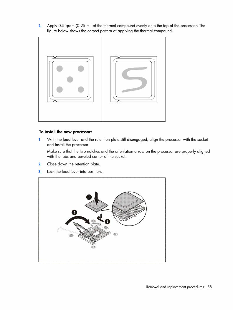
2. Apply 0.5 gram (0.25 ml) of the thermal compound evenly onto the top of the processor. The figure below shows the correct pattern of applying the thermal compound.
To install the new processor:
1. With the load lever and the retention plate still disengaged, align the processor with the socket and install the processor.
Make sure that the two notches and the orientation arrow on the processor are properly aligned with the tabs and beveled corner of the socket.
2. Close down the retention plate.
3. Lock the load lever into position.
Removal and replacement procedures 59
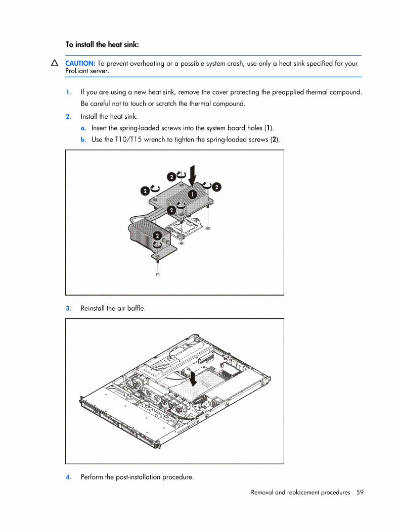
To install the heat sink:
CAUTION: To prevent overheating or a possible system crash, use only a heat sink specified for your ProLiant server.
1. If you are using a new heat sink, remove the cover protecting the preapplied thermal compound.
Be careful not to touch or scratch the thermal compound.
2. Install the heat sink.
a. Insert the spring-loaded screws into the system board holes (1).
b. Use the T10/T15 wrench to tighten the spring-loaded screws (2).
3. Reinstall the air baffle.
4. Perform the post-installation procedure.
Removal and replacement procedures 60
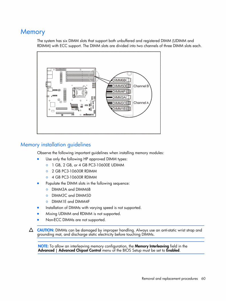
Memory The system has six DIMM slots that support both unbuffered and registered DIMM (UDIMM and RDIMM) with ECC support. The DIMM slots are divided into two channels of three DIMM slots each.
Memory installation guidelines Observe the following important guidelines when installing memory modules: • Use only the following HP approved DIMM types:
○ 1 GB, 2 GB, or 4 GB PC3-10600E UDIMM ○ 2 GB PC3-10600R RDIMM ○ 4 GB PC3-10600R RDIMM
• Populate the DIMM slots in the following sequence: ○ DIMM3A and DIMM6B ○ DIMM2C and DIMM5D ○ DIMM1E and DIMM4F
• Installation of DIMMs with varying speed is not supported. • Mixing UDIMM and RDIMM is not supported. • Non-ECC DIMMs are not supported.
CAUTION: DIMMs can be damaged by improper handling. Always use an anti-static wrist strap and grounding mat, and discharge static electricity before touching DIMMs.
NOTE: To allow an interleaving memory configuration, the Memory Interleaving field in the Advanced | Advanced Chipset Control menu of the BIOS Setup must be set to Enabled.
Removal and replacement procedures 61
To install a memory module:
1. Perform the pre-installation procedure.
2. Remove the air baffle.
3. Locate an empty DIMM slot on the system board.
4. If necessary, open the holding clips of the selected DIMM slot.
5. Remove the memory module from its protective packaging, handling it by the edges.
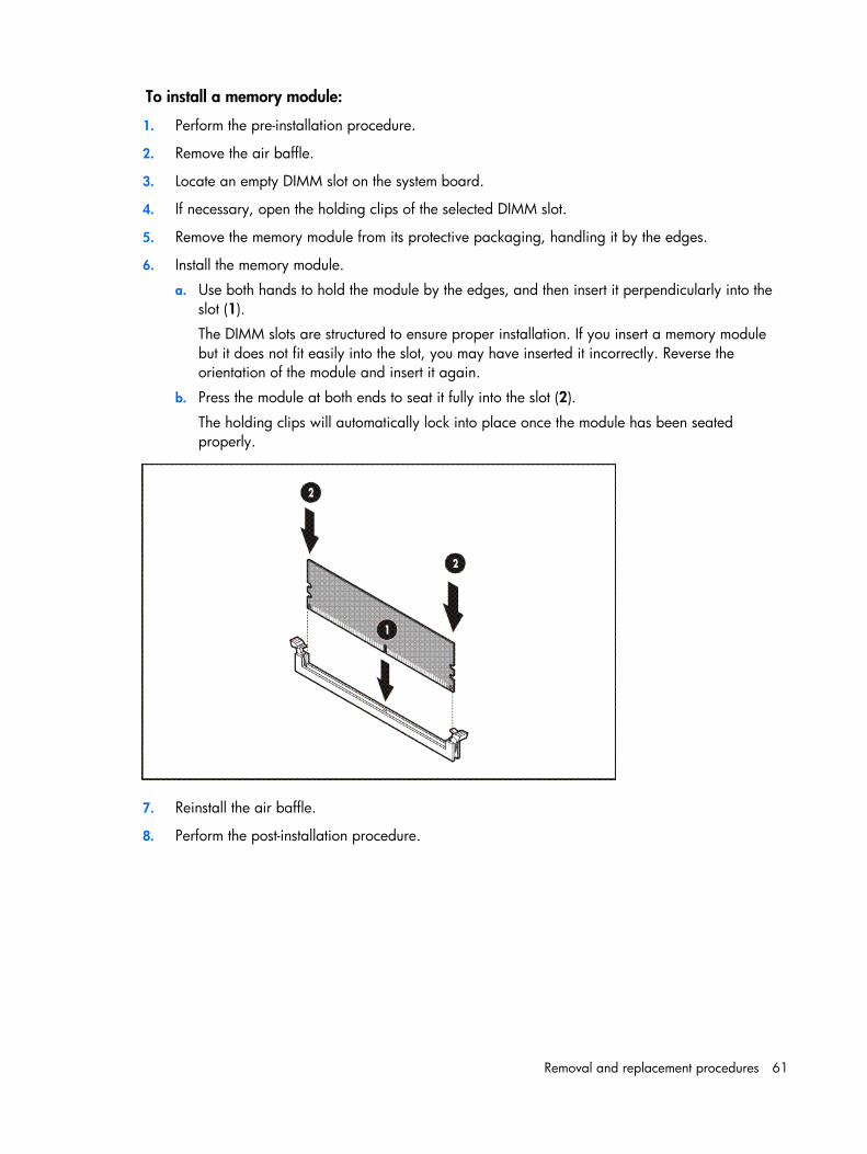
6. Install the memory module.
a. Use both hands to hold the module by the edges, and then insert it perpendicularly into the slot (1).
The DIMM slots are structured to ensure proper installation. If you insert a memory module but it does not fit easily into the slot, you may have inserted it incorrectly. Reverse the orientation of the module and insert it again.
b. Press the module at both ends to seat it fully into the slot (2).
The holding clips will automatically lock into place once the module has been seated properly.
7. Reinstall the air baffle.
8. Perform the post-installation procedure.
Removal and replacement procedures 62
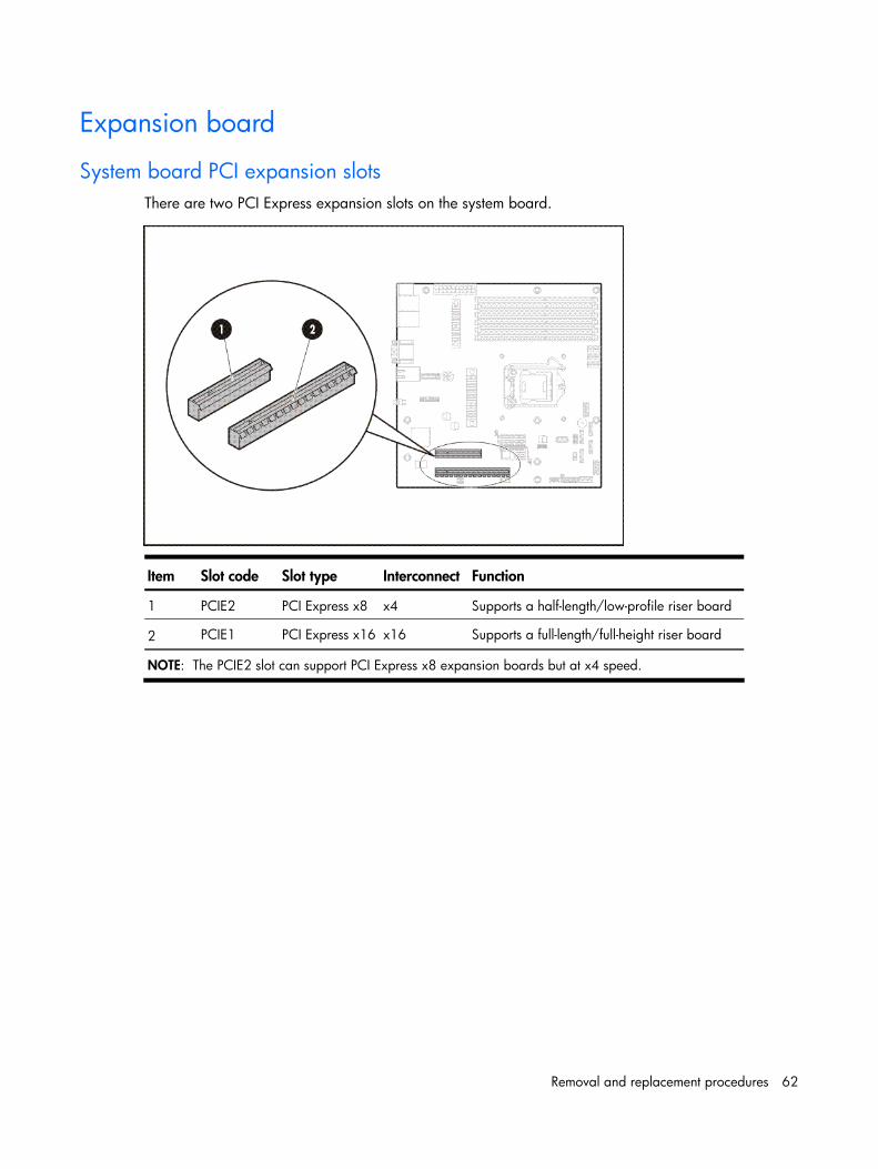
Expansion board
System board PCI expansion slots There are two PCI Express expansion slots on the system board.
Item Slot code Slot type Interconnect Function
1 PCIE2 PCI Express x8 x4 Supports a half-length/low-profile riser board
2 PCIE1 PCI Express x16 x16 Supports a full-length/full-height riser board
NOTE: The PCIE2 slot can support PCI Express x8 expansion boards but at x4 speed.
Removal and replacement procedures 63
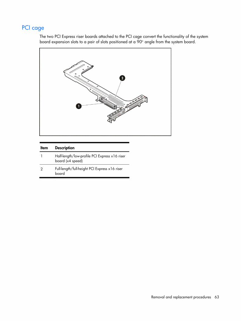
PCI cage The two PCI Express riser boards attached to the PCI cage convert the functionality of the system board expansion slots to a pair of slots positioned at a 90° angle from the system board.
Item Description
1 Half-length/low-profile PCI Express x16 riser board (x4 speed)
2 Full-length/full-height PCI Express x16 riser board
Removal and replacement procedures 64
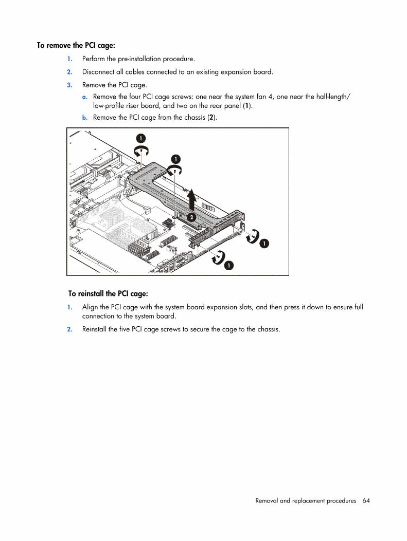
To remove the PCI cage:
1. Perform the pre-installation procedure.
2. Disconnect all cables connected to an existing expansion board.
3. Remove the PCI cage.
a. Remove the four PCI cage screws: one near the system fan 4, one near the half-length/ low-profile riser board, and two on the rear panel (1).
b. Remove the PCI cage from the chassis (2).
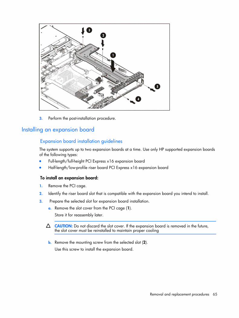
To reinstall the PCI cage:
1. Align the PCI cage with the system board expansion slots, and then press it down to ensure full connection to the system board.
2. Reinstall the five PCI cage screws to secure the cage to the chassis.
Removal and replacement procedures 65
3. Perform the post-installation procedure.
Installing an expansion board
Expansion board installation guidelines
The system supports up to two expansion boards at a time. Use only HP supported expansion boards of the following types: • Full-length/full-height PCI Express x16 expansion board • Half-length/low-profile riser board PCI Express x16 expansion board
To install an expansion board:
1. Remove the PCI cage.
2. Identify the riser board slot that is compatible with the expansion board you intend to install.
3. Prepare the selected slot for expansion board installation.
a. Remove the slot cover from the PCI cage (1).
Store it for reassembly later.
CAUTION: Do not discard the slot cover. If the expansion board is removed in the future, the slot cover must be reinstalled to maintain proper cooling
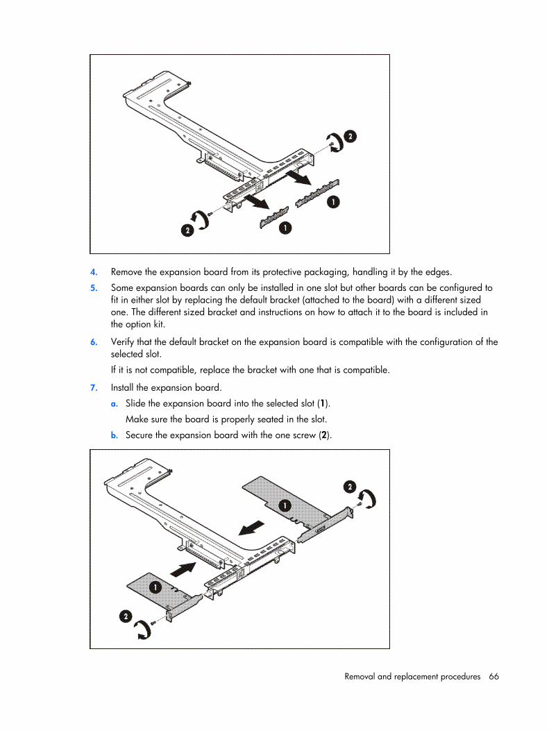
b. Remove the mounting screw from the selected slot (2).
Use this screw to install the expansion board.
Removal and replacement procedures 66
4. Remove the expansion board from its protective packaging, handling it by the edges.
5. Some expansion boards can only be installed in one slot but other boards can be configured to fit in either slot by replacing the default bracket (attached to the board) with a different sized one. The different sized bracket and instructions on how to attach it to the board is included in the option kit.
6. Verify that the default bracket on the expansion board is compatible with the configuration of the selected slot.
If it is not compatible, replace the bracket with one that is compatible.
7. Install the expansion board.
a. Slide the expansion board into the selected slot (1).
Make sure the board is properly seated in the slot.
b. Secure the expansion board with the one screw (2).
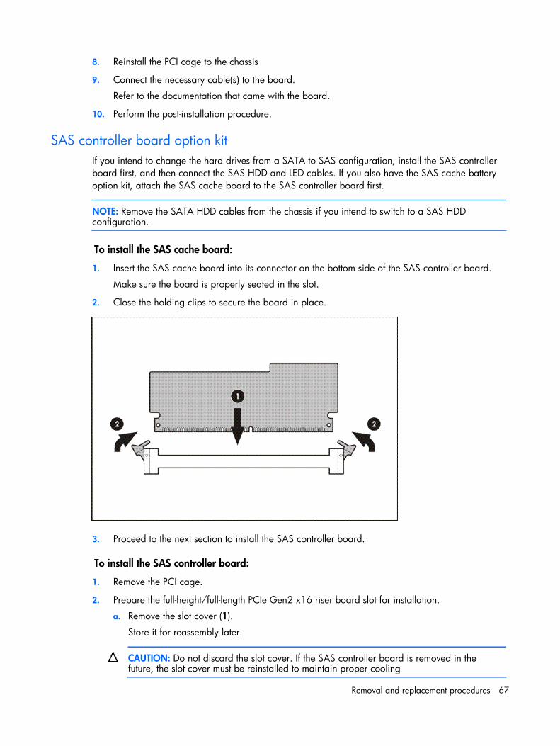
Removal and replacement procedures 67
8. Reinstall the PCI cage to the chassis
9. Connect the necessary cable(s) to the board.
Refer to the documentation that came with the board.
10. Perform the post-installation procedure.
SAS controller board option kit If you intend to change the hard drives from a SATA to SAS configuration, install the SAS controller board first, and then connect the SAS HDD and LED cables. If you also have the SAS cache battery option kit, attach the SAS cache board to the SAS controller board first.
NOTE: Remove the SATA HDD cables from the chassis if you intend to switch to a SAS HDD configuration.
To install the SAS cache board:
1. Insert the SAS cache board into its connector on the bottom side of the SAS controller board.
Make sure the board is properly seated in the slot.
2. Close the holding clips to secure the board in place.
3. Proceed to the next section to install the SAS controller board.
To install the SAS controller board:
1. Remove the PCI cage.
2. Prepare the full-height/full-length PCIe Gen2 x16 riser board slot for installation.
a. Remove the slot cover (1).
Store it for reassembly later.
CAUTION: Do not discard the slot cover. If the SAS controller board is removed in the future, the slot cover must be reinstalled to maintain proper cooling
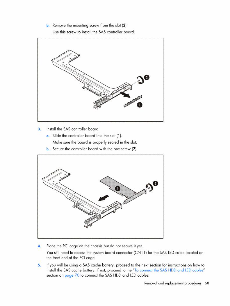
Removal and replacement procedures 68
b. Remove the mounting screw from the slot (2).
Use this screw to install the SAS controller board.
3. Install the SAS controller board.
a. Slide the controller board into the slot (1).
Make sure the board is properly seated in the slot.
b. Secure the controller board with the one screw (2).
4. Place the PCI cage on the chassis but do not secure it yet.
You still need to access the system board connector (CN11) for the SAS LED cable located on the front end of the PCI cage.
5. If you will be using a SAS cache battery, proceed to the next section for instructions on how to install the SAS cache battery. If not, proceed to the “To connect the SAS HDD and LED cables” section on page 70 to connect the SAS HDD and LED cables.
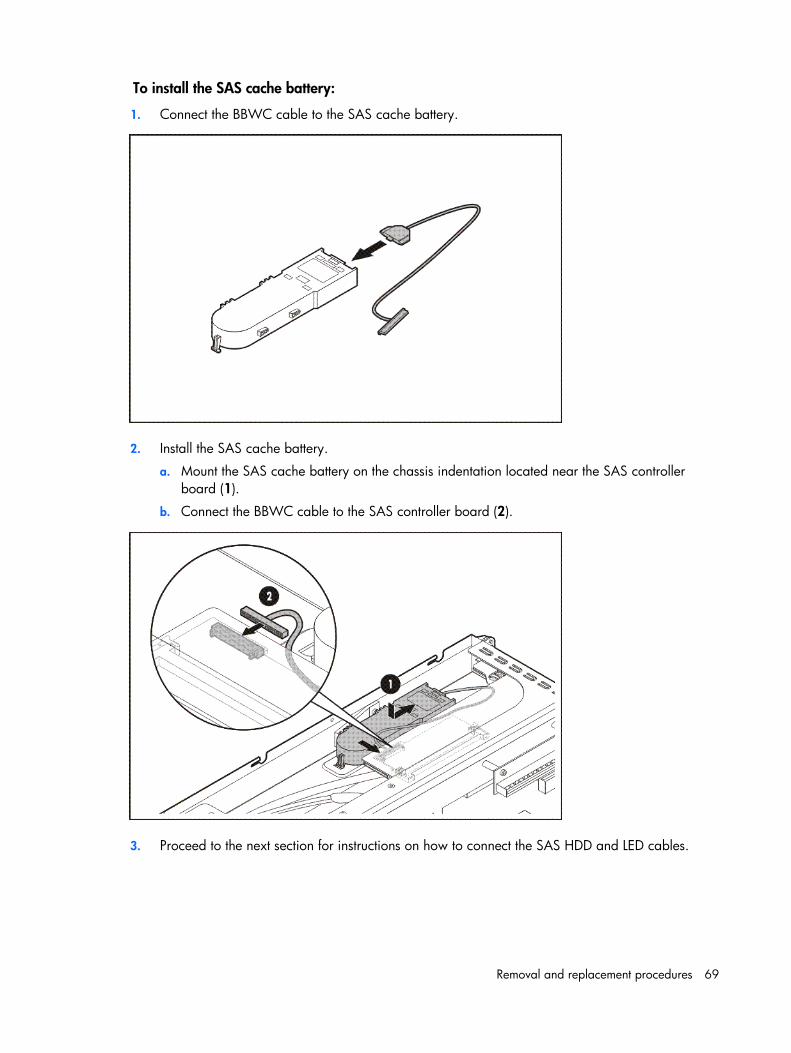
Removal and replacement procedures 69
To install the SAS cache battery:
1. Connect the BBWC cable to the SAS cache battery.
2. Install the SAS cache battery.
a. Mount the SAS cache battery on the chassis indentation located near the SAS controller board (1).
b. Connect the BBWC cable to the SAS controller board (2).
3. Proceed to the next section for instructions on how to connect the SAS HDD and LED cables.
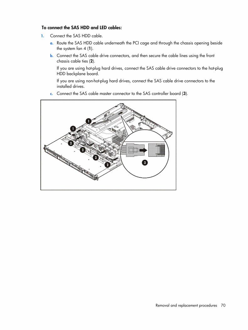
Removal and replacement procedures 70
To connect the SAS HDD and LED cables:
1. Connect the SAS HDD cable.
a. Route the SAS HDD cable underneath the PCI cage and through the chassis opening beside the system fan 4 (1).
b. Connect the SAS cable drive connectors, and then secure the cable lines using the front chassis cable ties (2).
If you are using hot-plug hard drives, connect the SAS cable drive connectors to the hot-plug HDD backplane board.
If you are using non-hot-plug hard drives, connect the SAS cable drive connectors to the installed drives.
c. Connect the SAS cable master connector to the SAS controller board (3).
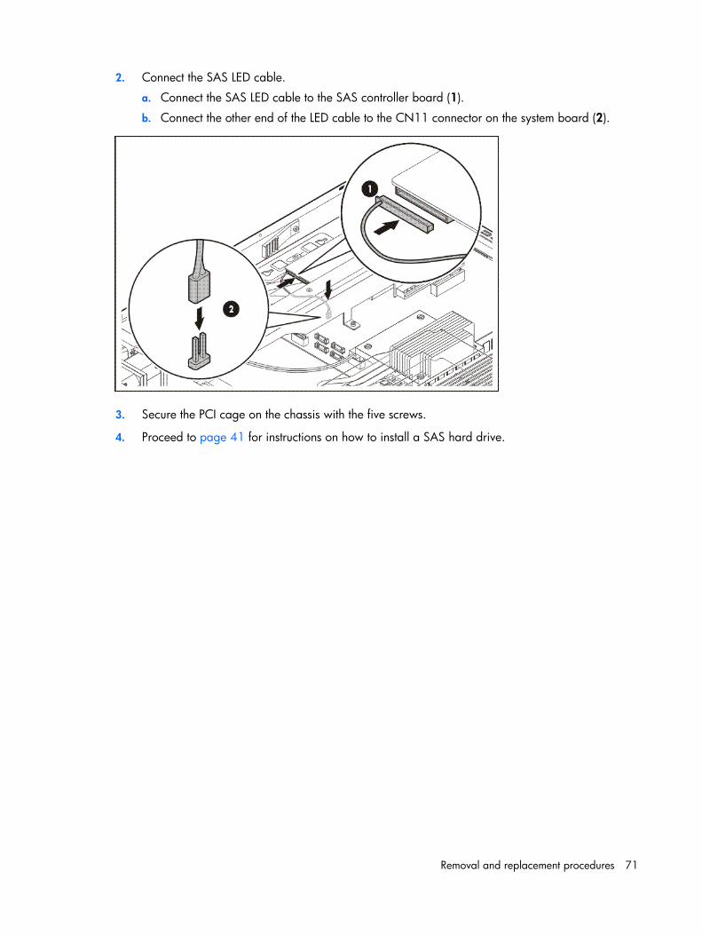
Removal and replacement procedures 71
2. Connect the SAS LED cable.
a. Connect the SAS LED cable to the SAS controller board (1).
b. Connect the other end of the LED cable to the CN11 connector on the system board (2).
3. Secure the PCI cage on the chassis with the five screws.
4. Proceed to page 41 for instructions on how to install a SAS hard drive.
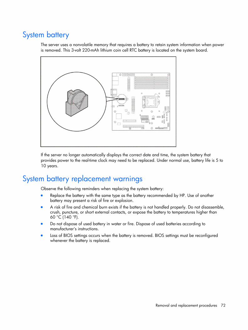
Removal and replacement procedures 72
System battery The server uses a nonvolatile memory that requires a battery to retain system information when power is removed. This 3-volt 220-mAh lithium coin cell RTC battery is located on the system board.
If the server no longer automatically displays the correct date and time, the system battery that provides power to the real-time clock may need to be replaced. Under normal use, battery life is 5 to 10 years.
System battery replacement warnings Observe the following reminders when replacing the system battery: • Replace the battery with the same type as the battery recommended by HP. Use of another
battery may present a risk of fire or explosion. • A risk of fire and chemical burn exists if the battery is not handled properly. Do not disassemble,
crush, puncture, or short external contacts, or expose the battery to temperatures higher than 60 °C (140 °F).
• Do not dispose of used battery in water or fire. Dispose of used batteries according to manufacturer's instructions.
• Loss of BIOS settings occurs when the battery is removed. BIOS settings must be reconfigured whenever the battery is replaced.
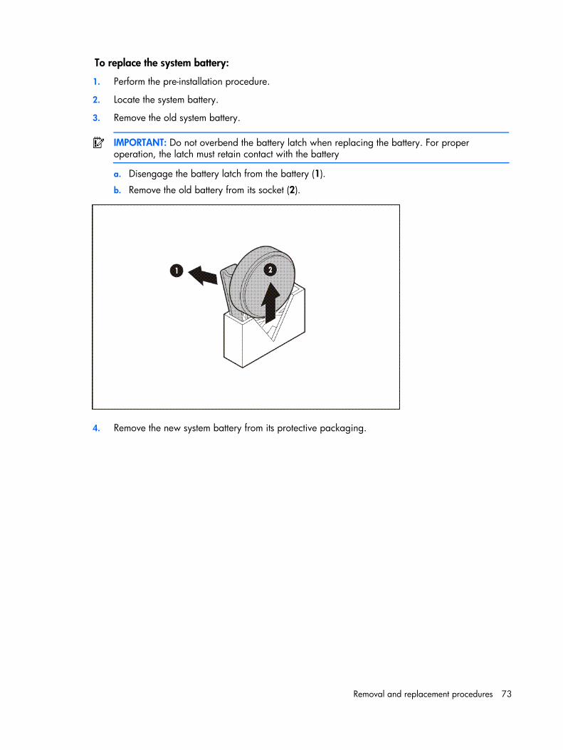
Removal and replacement procedures 73
To replace the system battery:
1. Perform the pre-installation procedure.
2. Locate the system battery.
3. Remove the old system battery.
IMPORTANT: Do not overbend the battery latch when replacing the battery. For proper operation, the latch must retain contact with the battery
a. Disengage the battery latch from the battery (1).
b. Remove the old battery from its socket (2).
4. Remove the new system battery from its protective packaging.
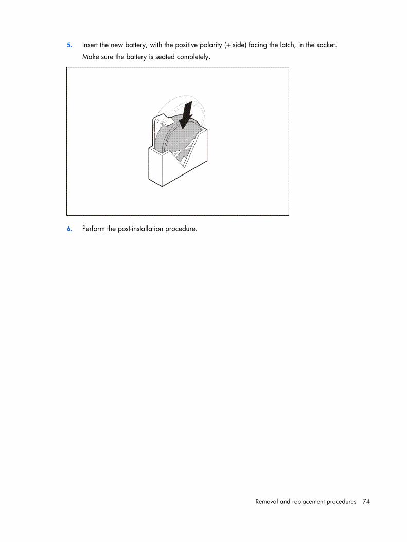
Removal and replacement procedures 74
5. Insert the new battery, with the positive polarity (+ side) facing the latch, in the socket.
Make sure the battery is seated completely.
6. Perform the post-installation procedure.
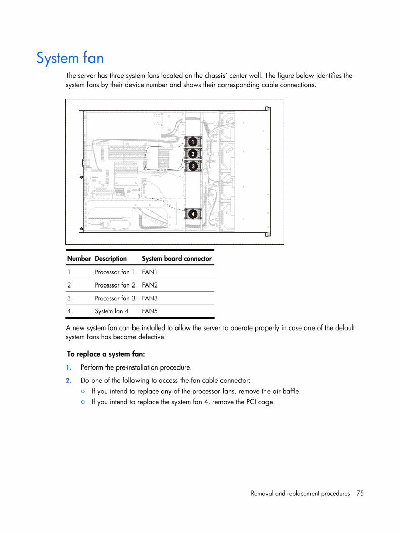
Removal and replacement procedures 75
System fan The server has three system fans located on the chassis’ center wall. The figure below identifies the system fans by their device number and shows their corresponding cable connections.
Number Description System board connector
1 Processor fan 1 FAN1
2 Processor fan 2 FAN2
3 Processor fan 3 FAN3
4 System fan 4 FAN5
A new system fan can be installed to allow the server to operate properly in case one of the default system fans has become defective.
To replace a system fan:
1. Perform the pre-installation procedure.
2. Do one of the following to access the fan cable connector: ○ If you intend to replace any of the processor fans, remove the air baffle. ○ If you intend to replace the system fan 4, remove the PCI cage.
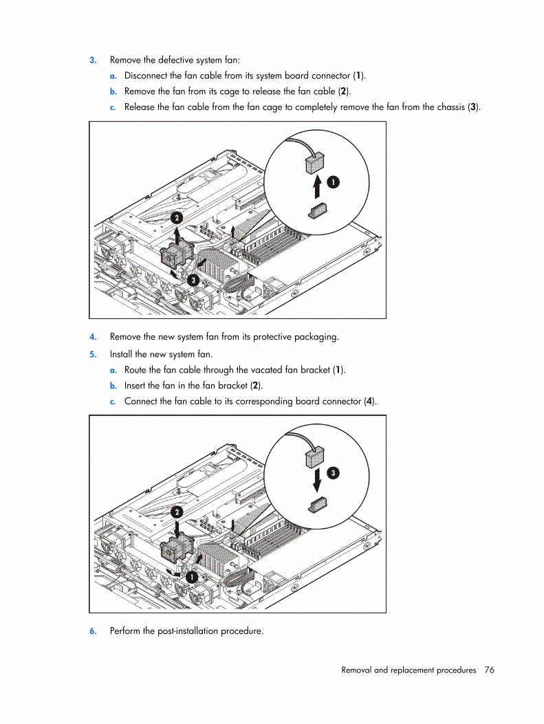
Removal and replacement procedures 76
3. Remove the defective system fan:
a. Disconnect the fan cable from its system board connector (1).
b. Remove the fan from its cage to release the fan cable (2).
c. Release the fan cable from the fan cage to completely remove the fan from the chassis (3).
4. Remove the new system fan from its protective packaging.
5. Install the new system fan.
a. Route the fan cable through the vacated fan bracket (1).
b. Insert the fan in the fan bracket (2).
c. Connect the fan cable to its corresponding board connector (4).
6. Perform the post-installation procedure.
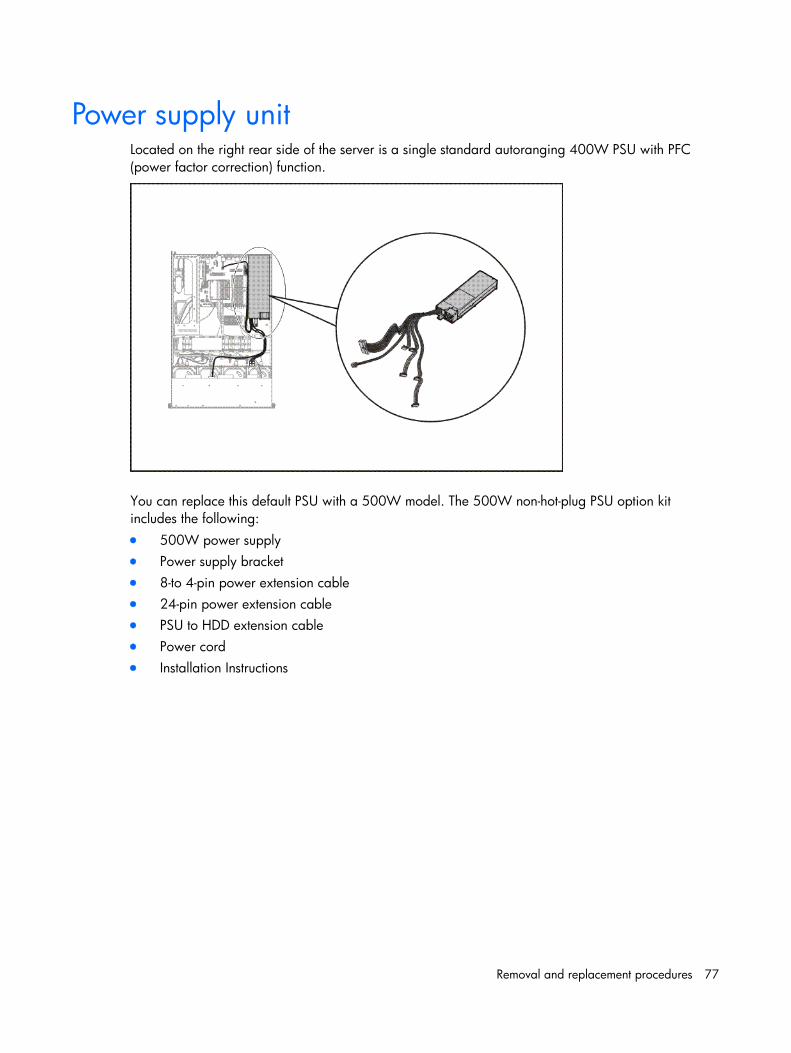
Removal and replacement procedures 77
Power supply unit Located on the right rear side of the server is a single standard autoranging 400W PSU with PFC (power factor correction) function.
You can replace this default PSU with a 500W model. The 500W non-hot-plug PSU option kit includes the following: • 500W power supply • Power supply bracket • 8-to 4-pin power extension cable • 24-pin power extension cable • PSU to HDD extension cable • Power cord • Installation Instructions
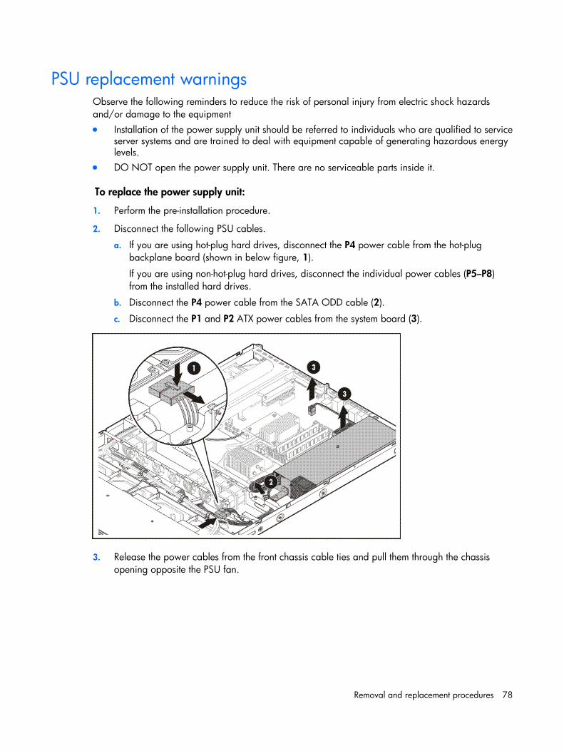
Removal and replacement procedures 78
PSU replacement warnings Observe the following reminders to reduce the risk of personal injury from electric shock hazards and/or damage to the equipment • Installation of the power supply unit should be referred to individuals who are qualified to service
server systems and are trained to deal with equipment capable of generating hazardous energy levels.
• DO NOT open the power supply unit. There are no serviceable parts inside it.
To replace the power supply unit:
1. Perform the pre-installation procedure.
2. Disconnect the following PSU cables.
a. If you are using hot-plug hard drives, disconnect the P4 power cable from the hot-plug backplane board (shown in below figure, 1).
If you are using non-hot-plug hard drives, disconnect the individual power cables (P5–P8) from the installed hard drives.
b. Disconnect the P4 power cable from the SATA ODD cable (2).
c. Disconnect the P1 and P2 ATX power cables from the system board (3).
3. Release the power cables from the front chassis cable ties and pull them through the chassis opening opposite the PSU fan.
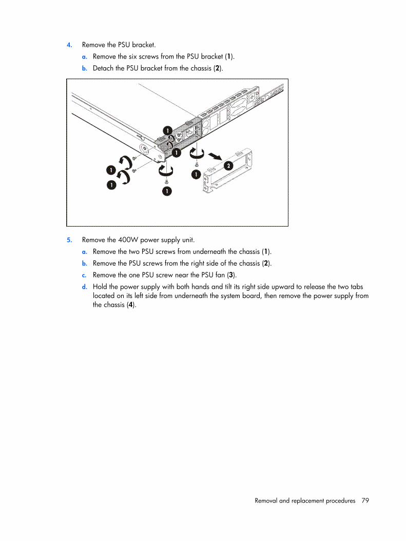
Removal and replacement procedures 79
4. Remove the PSU bracket.
a. Remove the six screws from the PSU bracket (1).
b. Detach the PSU bracket from the chassis (2).
5. Remove the 400W power supply unit.
a. Remove the two PSU screws from underneath the chassis (1).
b. Remove the PSU screws from the right side of the chassis (2).
c. Remove the one PSU screw near the PSU fan (3).
d. Hold the power supply with both hands and tilt its right side upward to release the two tabs located on its left side from underneath the system board, then remove the power supply from the chassis (4).
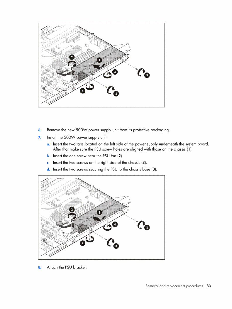
Removal and replacement procedures 80
6. Remove the new 500W power supply unit from its protective packaging.
7. Install the 500W power supply unit.
a. Insert the two tabs located on the left side of the power supply underneath the system board. After that make sure the PSU screw holes are aligned with those on the chassis (1).
b. Insert the one screw near the PSU fan (2)
c. Insert the two screws on the right side of the chassis (3).
d. Insert the two screws securing the PSU to the chassis base (3).
8. Attach the PSU bracket.
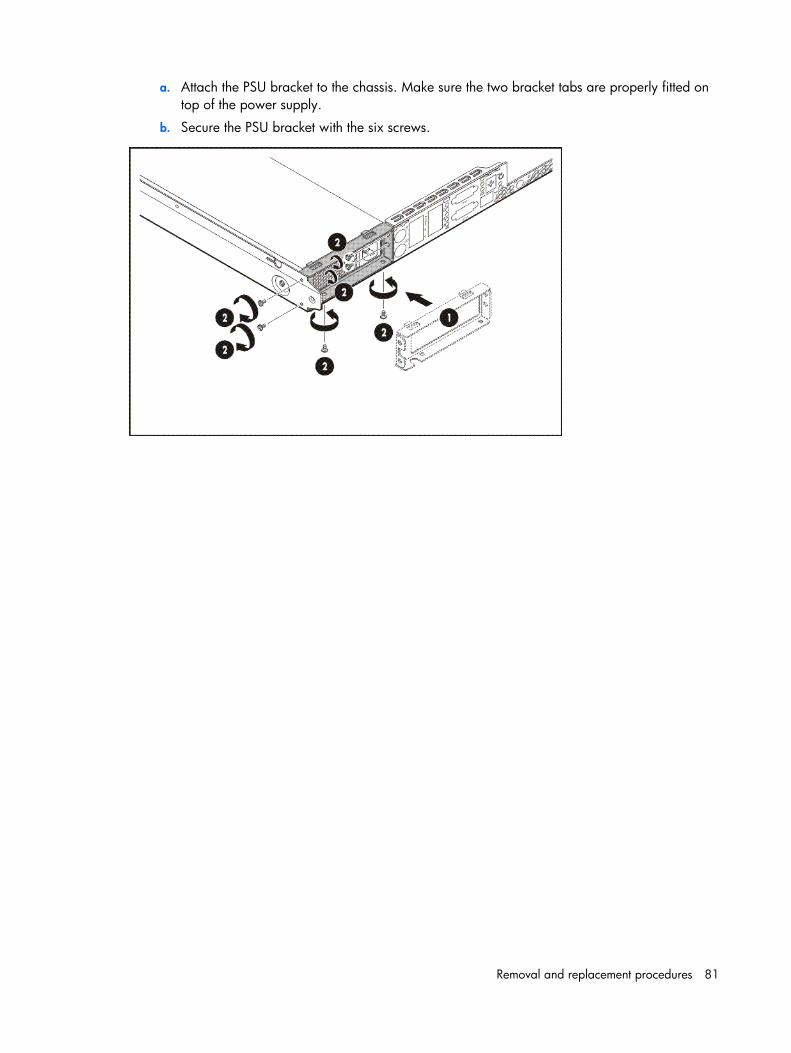
Removal and replacement procedures 81
a. Attach the PSU bracket to the chassis. Make sure the two bracket tabs are properly fitted on top of the power supply.
b. Secure the PSU bracket with the six screws.
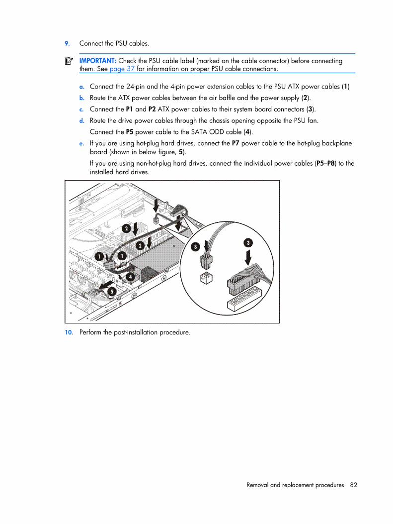
Removal and replacement procedures 82
9. Connect the PSU cables.
IMPORTANT: Check the PSU cable label (marked on the cable connector) before connecting them. See page 37 for information on proper PSU cable connections.
a. Connect the 24-pin and the 4-pin power extension cables to the PSU ATX power cables (1)
b. Route the ATX power cables between the air baffle and the power supply (2).
c. Connect the P1 and P2 ATX power cables to their system board connectors (3).
d. Route the drive power cables through the chassis opening opposite the PSU fan.
Connect the P5 power cable to the SATA ODD cable (4).
e. If you are using hot-plug hard drives, connect the P7 power cable to the hot-plug backplane board (shown in below figure, 5).
If you are using non-hot-plug hard drives, connect the individual power cables (P5–P8) to the installed hard drives.
10. Perform the post-installation procedure.
Diagnostics tools 83
Diagnostics tools
Troubleshooting resources
NOTE: For common troubleshooting procedures, the term "server" is used to mean servers and server blades.
The HP ProLiant Servers Troubleshooting Guide provides simple procedures for resolving common problems as well as a comprehensive course of action for fault isolation and identification, error message interpretation, issue resolution, and software maintenance.
To obtain the guide, refer to any of the following sources and then select the HP ProLiant Servers Troubleshooting Guide: • The server-specific Documentation CD • The Business Support Center on the HP website (http://www.hp.com/support). Navigate to the
server technical support page. Under self-help resources, select ProLiant Troubleshooting Guide. • The Technical Documentation website (http://www.docs.hp.com). Select Enterprise Servers,
Workstations and Systems Hardware, and then the appropriate server.
HP Insight Diagnostics HP Insight Diagnostics is a proactive server management tool, available in both offline and online versions, that provides diagnostics and troubleshooting capabilities to assist IT administrators who verify server installations, troubleshoot problems, and perform repair validation.
HP Insight Diagnostics Offline Edition performs various in-depth system and component testing while the OS is not running. To run this utility, launch the Easy Set-up CD.
HP Insight Diagnostics Online Edition is a web-based application that captures system configuration and other related data needed for effective server management. Available in Microsoft® Windows® and Linux versions, the utility helps to ensure proper system operation.
For more information or to download the utility, refer to the HP website (http://www.hp.com/servers/diags).
Diagnostics tools 84
Survey Utility Survey Utility, a feature within HP Insight Diagnostics, gathers critical hardware and software information on ProLiant servers.
This utility supports operating systems that may not be supported by the server. For operating systems supported by the server, refer to the HP website (http://www.hp.com/go/supportos).
If a significant change occurs between data-gathering intervals, the Survey Utility marks the previous information and overwrites the Survey text files to reflect the latest changes in the configuration.
Array Diagnostic Utility The HP Array Diagnostics Utility is a web-based application that creates a report of all HP storage controllers and disk drives. This report provides vital information to assist in identifying faults or conditions that may require attention. ADU can be downloaded from the HP website (http://www.hp.com).
HP Instant Support Enterprise Edition ISEE is a proactive remote monitoring and diagnostic tool to help manage your systems and devices, a feature of HP support. ISEE provides continuous hardware event monitoring and automated notification to identify and prevent potential critical problems. Through remote diagnostic scripts and vital system configuration information collected about your systems, ISEE enables fast restoration of your systems. Install ISEE on your systems to help mitigate risk and prevent potential critical problems.
For more information on ISEE, refer to the HP website (http://www.hp.com/hps/hardware/hw_enterprise.html).
To download HP ISEE, visit the HP website (http://www.hp.com/hps/hardware/hw_downloads.html).
For installation information, refer to the HP ISEE Client Installation and Upgrade Guide (ftp://ftp.hp.com/pub/services/hardware/info/isee_client.pdf).
Web-Based Enterprise Service WEBES enables administrators to manage hardware events proactively, either locally or online. The service provides real-time multiple event analysis, crash analysis, and notification, locally through SMTP and remotely through ISEE for OpenVMS, Tru64, and Microsoft Windows operating system binary error logs.
For more information, refer to the HP website (http://h18000.www1.hp.com/support/svctools/).
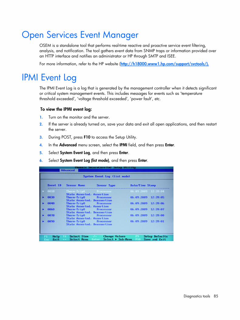
Diagnostics tools 85
Open Services Event Manager OSEM is a standalone tool that performs real-time reactive and proactive service event filtering, analysis, and notification. The tool gathers event data from SNMP traps or information provided over an HTTP interface and notifies an administrator or HP through SMTP and ISEE.
For more information, refer to the HP website (http://h18000.www1.hp.com/support/svctools/).
IPMI Event Log The IPMI Event Log is a log that is generated by the management controller when it detects significant or critical system management events. This includes messages for events such as ‘temperature threshold exceeded’, ‘voltage threshold exceeded’, ‘power fault’, etc.
To view the IPMI event log:
1. Turn on the monitor and the server.
2. If the server is already turned on, save your data and exit all open applications, and then restart the server.
3. During POST, press F10 to access the Setup Utility.
4. In the Advanced menu screen, select the IPMI field, and then press Enter.
5. Select System Event Log, and then press Enter.
6. Select System Event Log (list mode), and then press Enter.
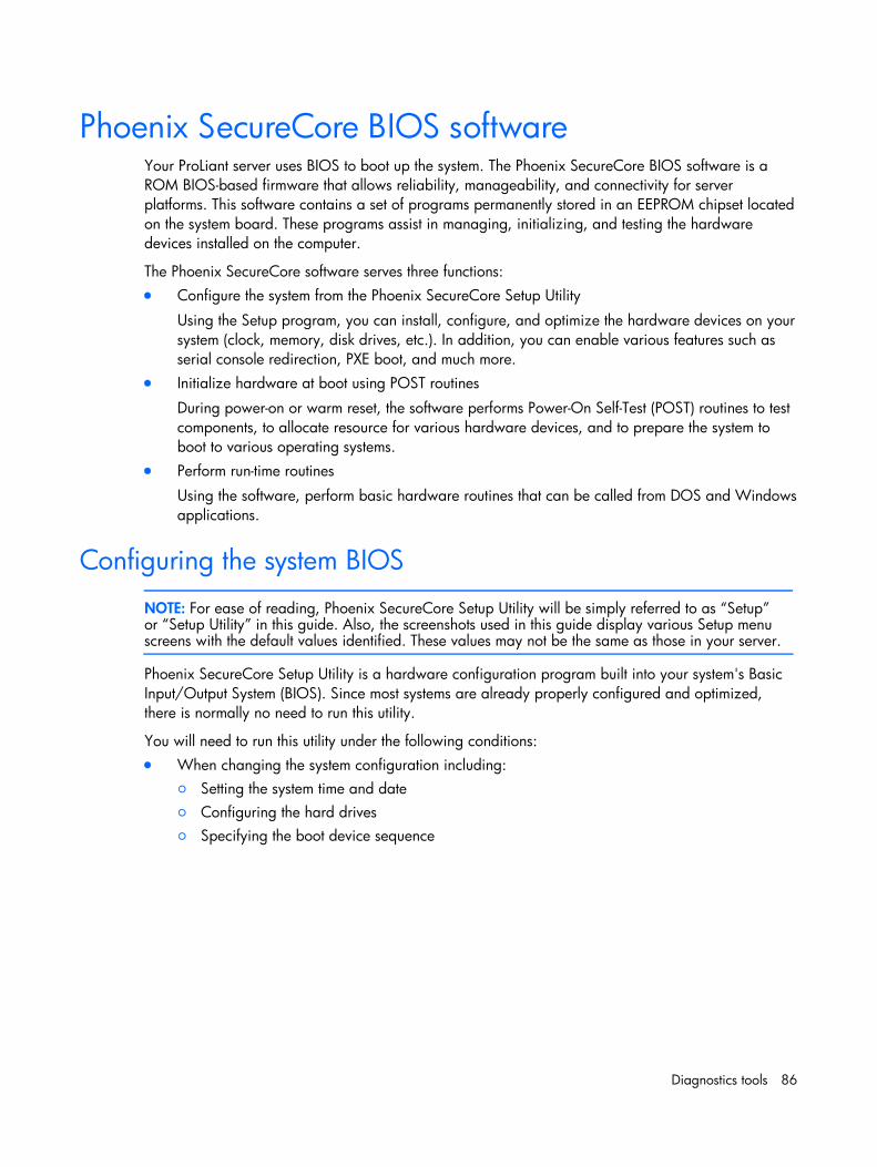
Diagnostics tools 86
Phoenix SecureCore BIOS software Your ProLiant server uses BIOS to boot up the system. The Phoenix SecureCore BIOS software is a ROM BIOS-based firmware that allows reliability, manageability, and connectivity for server platforms. This software contains a set of programs permanently stored in an EEPROM chipset located on the system board. These programs assist in managing, initializing, and testing the hardware devices installed on the computer.
The Phoenix SecureCore software serves three functions: • Configure the system from the Phoenix SecureCore Setup Utility
Using the Setup program, you can install, configure, and optimize the hardware devices on your system (clock, memory, disk drives, etc.). In addition, you can enable various features such as serial console redirection, PXE boot, and much more.
• Initialize hardware at boot using POST routines
During power-on or warm reset, the software performs Power-On Self-Test (POST) routines to test components, to allocate resource for various hardware devices, and to prepare the system to boot to various operating systems.
• Perform run-time routines
Using the software, perform basic hardware routines that can be called from DOS and Windows applications.
Configuring the system BIOS
NOTE: For ease of reading, Phoenix SecureCore Setup Utility will be simply referred to as “Setup” or “Setup Utility” in this guide. Also, the screenshots used in this guide display various Setup menu screens with the default values identified. These values may not be the same as those in your server.
Phoenix SecureCore Setup Utility is a hardware configuration program built into your system's Basic Input/Output System (BIOS). Since most systems are already properly configured and optimized, there is normally no need to run this utility.
You will need to run this utility under the following conditions: • When changing the system configuration including:
○ Setting the system time and date ○ Configuring the hard drives ○ Specifying the boot device sequence
Diagnostics tools 87
○ Installing PCI expansion boards ○ Upgrading the system BIOS ○ Configuring the power management modes ○ Setting up system passwords or making other changes to the security setup
• When a configuration error is detected by the system and you are prompted (Run Setup message) to make changes to the BIOS settings.
NOTE: If you repeatedly receive Run Setup messages, the system battery may be defective. In this case, the system cannot retain configuration values in CMOS. Replace the system battery with a new one.
The Setup Utility loads the configuration values in a battery-backed nonvolatile memory called CMOS RAM. This memory area is not part of the system RAM, which allows configuration data to be retained when power is turned off. The values take effect when the system is booted. POST uses these values to configure the hardware. If the values and the actual hardware do not agree, POST generates an error message. You must run this utility to change the BIOS settings from the default or current configuration.
The Setup Utility has five primary menu selections, including: • Main • Advanced • Security • Boot • Exit
To run the Setup Utility:
1. Turn on the monitor and the server.
If the server is already turned on, save your data and exit all open applications, and then restart the server.
2. During POST, press F10.
If you fail to press F10 before POST is completed, you will need to restart the server.
The first page to be displayed will be the Main menu showing the Setup Utility menu bar. Use the left ( ) and right ( ) arrow keys to move between selections on the menu bar.
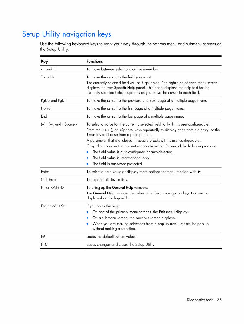
Diagnostics tools 88
Setup Utility navigation keys Use the following keyboard keys to work your way through the various menu and submenu screens of the Setup Utility.
Key Functions
← and → To move between selections on the menu bar.
↑ and ↓ To move the cursor to the field you want. The currently selected field will be highlighted. The right side of each menu screen displays the Item Specific Help panel. This panel displays the help text for the currently selected field. It updates as you move the cursor to each field.
PgUp and PgDn To move the cursor to the previous and next page of a multiple page menu.
Home To move the cursor to the first page of a multiple page menu.
End To move the cursor to the last page of a multiple page menu.
(+) , (–), and <Space> To select a value for the currently selected field (only if it is user-configurable). Press the (+), (–), or <Space> keys repeatedly to display each possible entry, or the Enter key to choose from a pop-up menu. A parameter that is enclosed in square brackets [ ] is user-configurable. Grayed-out parameters are not user-configurable for one of the following reasons: • The field value is auto-configured or auto-detected. • The field value is informational only. • The field is password-protected.
Enter To select a field value or display more options for menu marked with ►.
Ctrl+Enter To expand all device lists.
F1 or <Alt+H> To bring up the General Help window. The General Help window describes other Setup navigation keys that are not displayed on the legend bar.
Esc or <Alt+X> If you press this key: • On one of the primary menu screens, the Exit menu displays. • On a submenu screen, the previous screen displays. • When you are making selections from a pop-up menu, closes the pop-up
without making a selection.
F9 Loads the default system values.
F10 Saves changes and closes the Setup Utility.
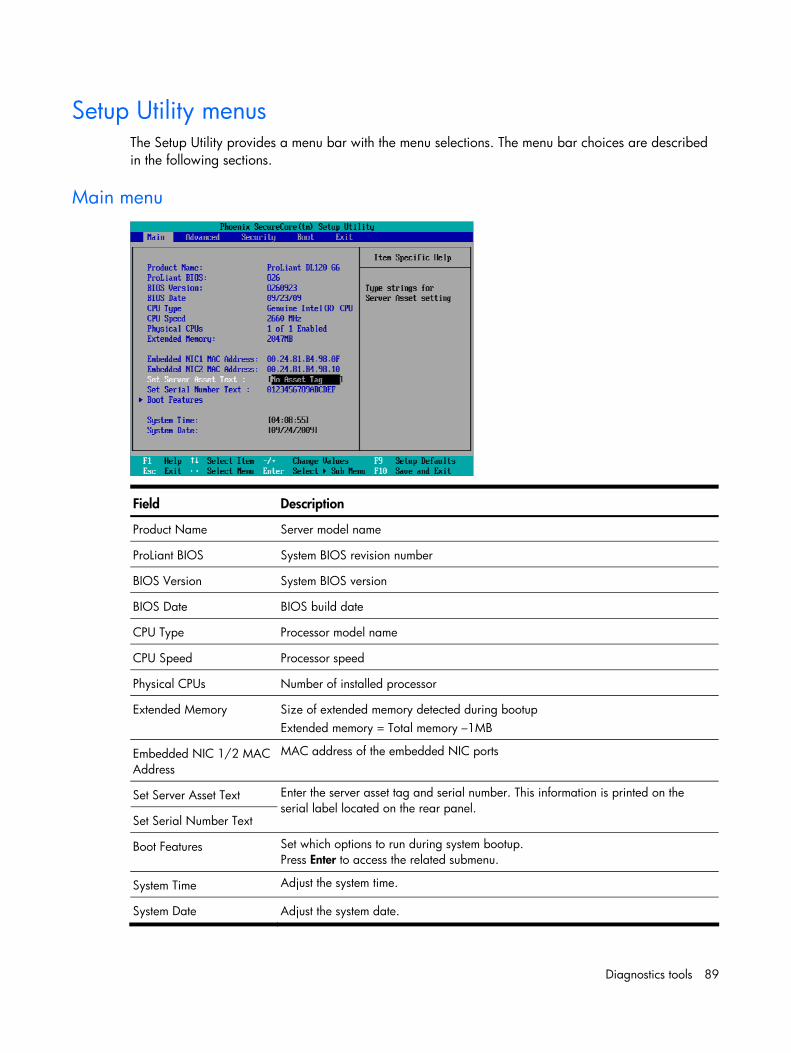
Diagnostics tools 89
Setup Utility menus The Setup Utility provides a menu bar with the menu selections. The menu bar choices are described in the following sections.
Main menu
Field Description
Product Name Server model name
ProLiant BIOS System BIOS revision number
BIOS Version System BIOS version
BIOS Date BIOS build date
CPU Type Processor model name
CPU Speed Processor speed
Physical CPUs Number of installed processor
Extended Memory Size of extended memory detected during bootup Extended memory = Total memory –1MB
Embedded NIC 1/2 MAC Address
MAC address of the embedded NIC ports
Set Server Asset Text
Set Serial Number Text
Enter the server asset tag and serial number. This information is printed on the serial label located on the rear panel.
Boot Features Set which options to run during system bootup. Press Enter to access the related submenu.
System Time Adjust the system time.
System Date Adjust the system date.
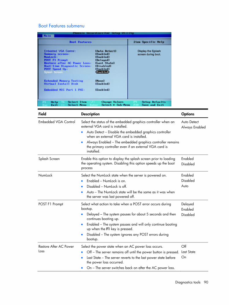
Diagnostics tools 90
Boot Features submenu
Field Description Options
Embedded VGA Control Select the status of the embedded graphics controller when an external VGA card is installed. • Auto Detect – Disable the embedded graphics controller
when an external VGA card is installed. • Always Enabled – The embedded graphics controller remains
the primary controller even if an external VGA card is installed.
Auto Detect Always Enabled
Splash Screen Enable this option to display the splash screen prior to loading the operating system. Disabling this option speeds up the boot process
Enabled Disabled
NumLock Select the NumLock state when the server is powered on. • Enabled – NumLock is on. • Disabled – NumLock is off. • Auto – The NumLock state will be the same as it was when
the server was last powered off.
Enabled Disabled Auto
POST F1 Prompt Select what action to take when a POST error occurs during bootup. • Delayed – The system pauses for about 5 seconds and then
continues booting up. • Enabled – The system pauses and will only continue booting
up when the F1 key is pressed. • Disabled – The system ignores any POST errors during
bootup.
Delayed Enabled Disabled
Restore After AC Power Loss
Select the power state when an AC power loss occurs. • Off – The server remains off until the power button is pressed. • Last State – The server reverts to the last power state before
the power loss occurred. • On – The server switches back on after the AC power loss.
Off Last State On
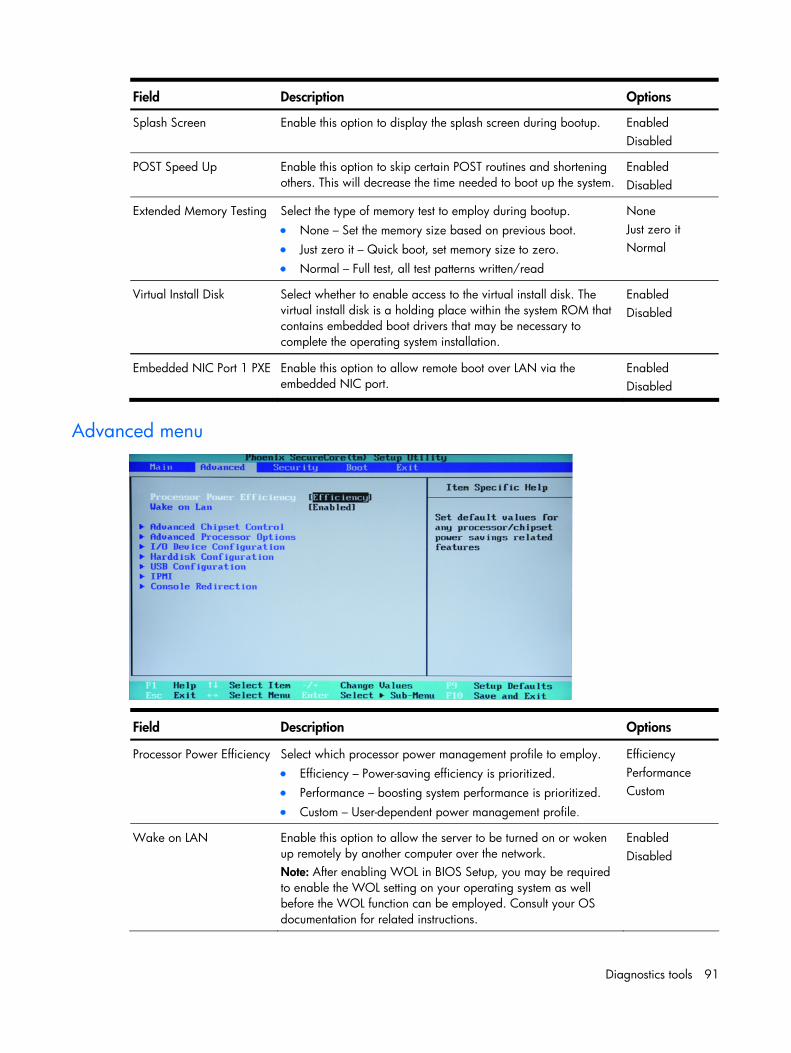
Diagnostics tools 91
Field Description Options
Splash Screen Enable this option to display the splash screen during bootup. Enabled Disabled
POST Speed Up Enable this option to skip certain POST routines and shortening others. This will decrease the time needed to boot up the system.
Enabled Disabled
Extended Memory Testing Select the type of memory test to employ during bootup. • None – Set the memory size based on previous boot. • Just zero it – Quick boot, set memory size to zero. • Normal – Full test, all test patterns written/read
None Just zero it Normal
Virtual Install Disk Select whether to enable access to the virtual install disk. The virtual install disk is a holding place within the system ROM that contains embedded boot drivers that may be necessary to complete the operating system installation.
Enabled Disabled
Embedded NIC Port 1 PXE Enable this option to allow remote boot over LAN via the embedded NIC port.
Enabled Disabled
Advanced menu
Field Description Options
Processor Power Efficiency Select which processor power management profile to employ. • Efficiency – Power-saving efficiency is prioritized. • Performance – boosting system performance is prioritized. • Custom – User-dependent power management profile.
Efficiency Performance Custom
Wake on LAN Enable this option to allow the server to be turned on or woken up remotely by another computer over the network. Note: After enabling WOL in BIOS Setup, you may be required to enable the WOL setting on your operating system as well before the WOL function can be employed. Consult your OS documentation for related instructions.
Enabled Disabled
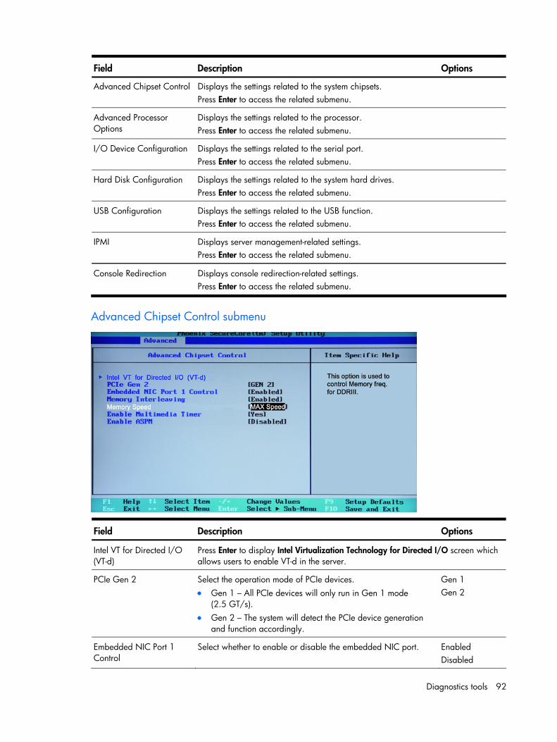
Diagnostics tools 92
Field Description Options
Advanced Chipset Control Displays the settings related to the system chipsets. Press Enter to access the related submenu.
Advanced Processor Options
Displays the settings related to the processor. Press Enter to access the related submenu.
I/O Device Configuration Displays the settings related to the serial port. Press Enter to access the related submenu.
Hard Disk Configuration Displays the settings related to the system hard drives. Press Enter to access the related submenu.
USB Configuration Displays the settings related to the USB function. Press Enter to access the related submenu.
IPMI Displays server management-related settings. Press Enter to access the related submenu.
Console Redirection Displays console redirection-related settings. Press Enter to access the related submenu.
Advanced Chipset Control submenu
Field Description Options
Intel VT for Directed I/O (VT-d)
Press Enter to display Intel Virtualization Technology for Directed I/O screen which allows users to enable VT-d in the server.
PCIe Gen 2 Select the operation mode of PCIe devices. • Gen 1 – All PCIe devices will only run in Gen 1 mode
(2.5 GT/s). • Gen 2 – The system will detect the PCIe device generation
and function accordingly.
Gen 1 Gen 2
Embedded NIC Port 1 Control
Select whether to enable or disable the embedded NIC port. Enabled Disabled
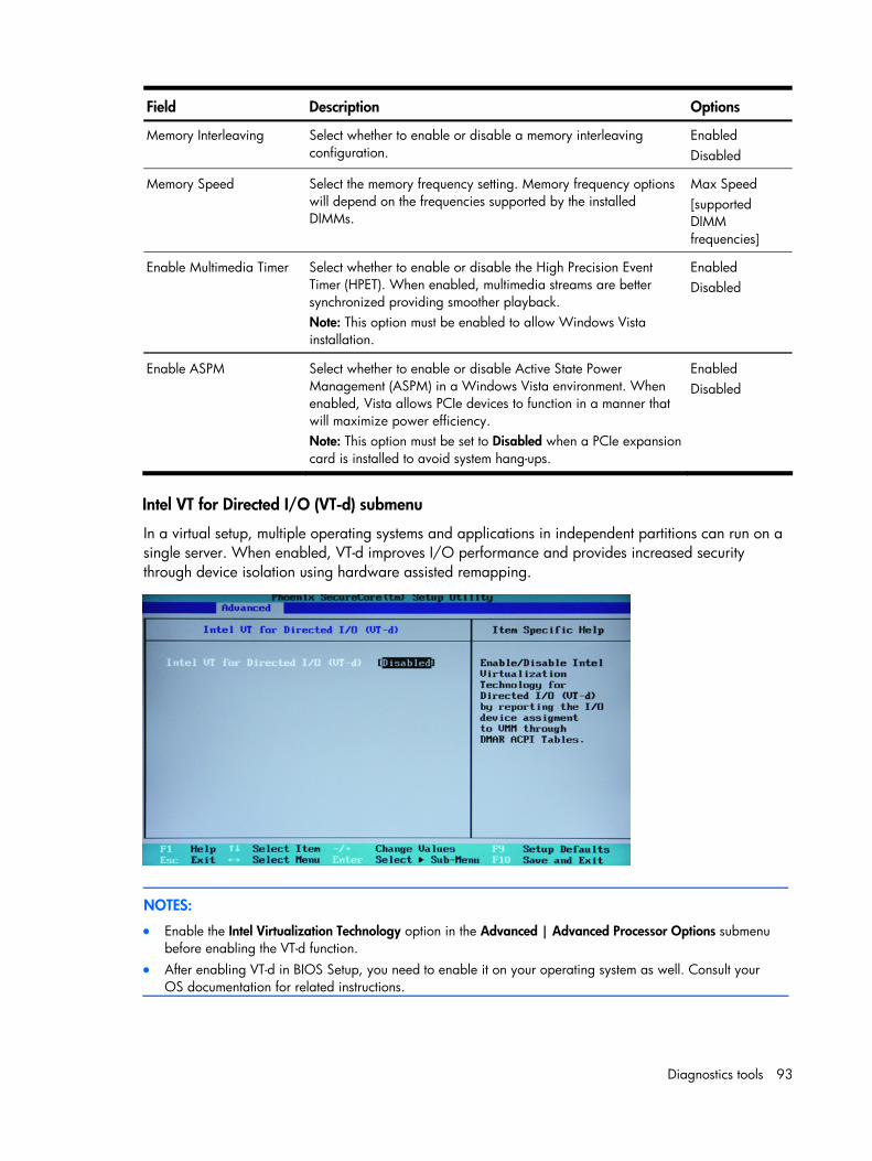
Diagnostics tools 93
Field Description Options
Memory Interleaving Select whether to enable or disable a memory interleaving configuration.
Enabled Disabled
Memory Speed Select the memory frequency setting. Memory frequency options will depend on the frequencies supported by the installed DIMMs.
Max Speed [supported DIMM frequencies]
Enable Multimedia Timer Select whether to enable or disable the High Precision Event Timer (HPET). When enabled, multimedia streams are better synchronized providing smoother playback. Note: This option must be enabled to allow Windows Vista installation.
Enabled Disabled
Enable ASPM Select whether to enable or disable Active State Power Management (ASPM) in a Windows Vista environment. When enabled, Vista allows PCIe devices to function in a manner that will maximize power efficiency. Note: This option must be set to Disabled when a PCIe expansion card is installed to avoid system hang-ups.
Enabled Disabled
Intel VT for Directed I/O (VT-d) submenu
In a virtual setup, multiple operating systems and applications in independent partitions can run on a single server. When enabled, VT-d improves I/O performance and provides increased security through device isolation using hardware assisted remapping.
NOTES:
• Enable the Intel Virtualization Technology option in the Advanced | Advanced Processor Options submenu before enabling the VT-d function.
• After enabling VT-d in BIOS Setup, you need to enable it on your operating system as well. Consult your OS documentation for related instructions.
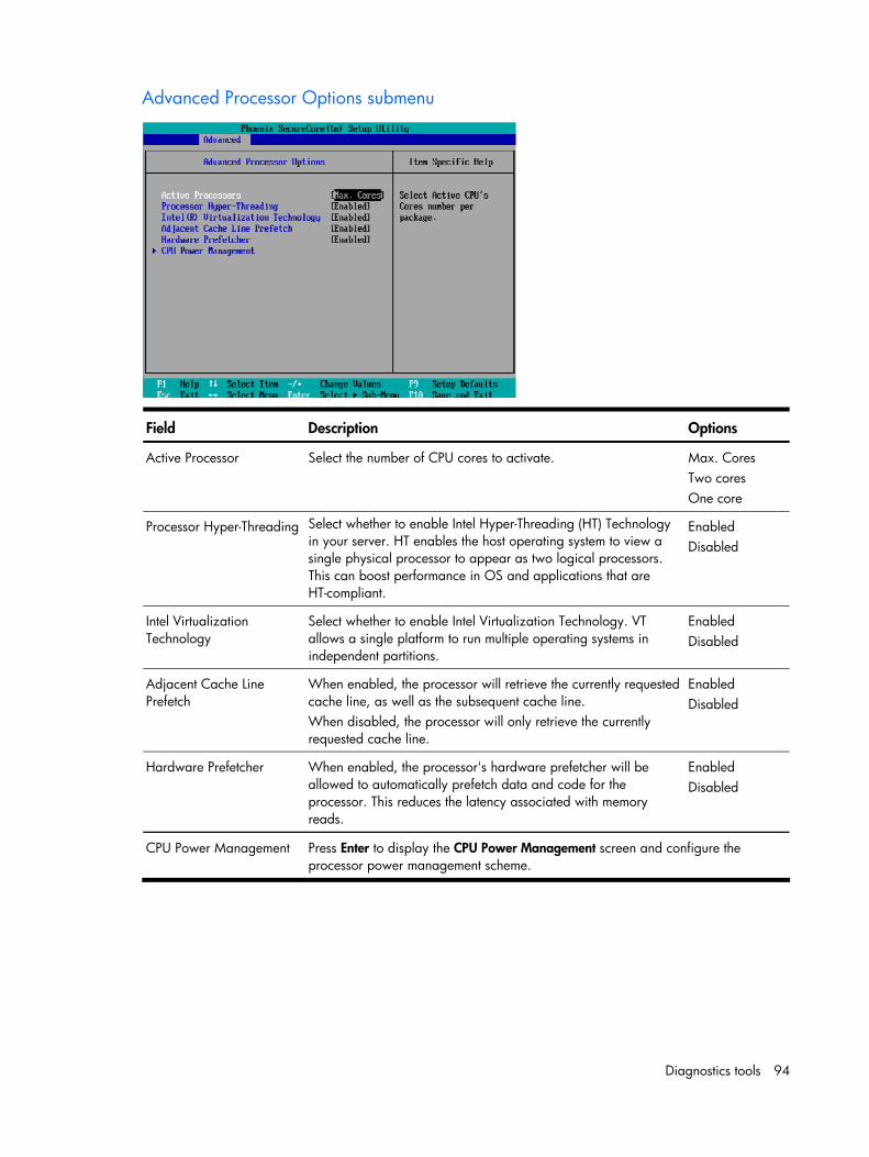
Diagnostics tools 94
Advanced Processor Options submenu
Field Description Options
Active Processor Select the number of CPU cores to activate. Max. Cores Two cores One core
Processor Hyper-Threading Select whether to enable Intel Hyper-Threading (HT) Technology in your server. HT enables the host operating system to view a single physical processor to appear as two logical processors. This can boost performance in OS and applications that are HT-compliant.
Enabled Disabled
Intel Virtualization Technology
Select whether to enable Intel Virtualization Technology. VT allows a single platform to run multiple operating systems in independent partitions.
Enabled Disabled
Adjacent Cache Line Prefetch
When enabled, the processor will retrieve the currently requested cache line, as well as the subsequent cache line. When disabled, the processor will only retrieve the currently requested cache line.
Enabled Disabled
Hardware Prefetcher When enabled, the processor's hardware prefetcher will be allowed to automatically prefetch data and code for the processor. This reduces the latency associated with memory reads.
Enabled Disabled
CPU Power Management Press Enter to display the CPU Power Management screen and configure the processor power management scheme.
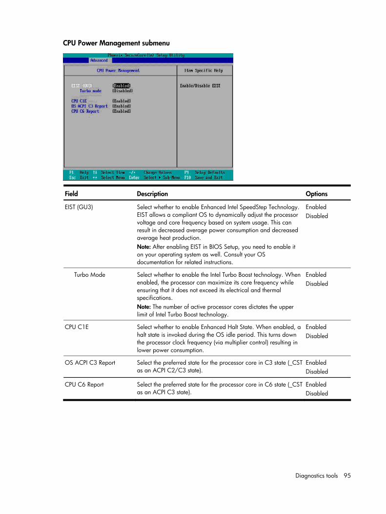
Diagnostics tools 95
CPU Power Management submenu
Field Description Options
EIST (GU3) Select whether to enable Enhanced Intel SpeedStep Technology. EIST allows a compliant OS to dynamically adjust the processor voltage and core frequency based on system usage. This can result in decreased average power consumption and decreased average heat production. Note: After enabling EIST in BIOS Setup, you need to enable it on your operating system as well. Consult your OS documentation for related instructions.
Enabled Disabled
Turbo Mode Select whether to enable the Intel Turbo Boost technology. When enabled, the processor can maximize its core frequency while ensuring that it does not exceed its electrical and thermal specifications. Note: The number of active processor cores dictates the upper limit of Intel Turbo Boost technology.
Enabled Disabled
CPU C1E Select whether to enable Enhanced Halt State. When enabled, a halt state is invoked during the OS idle period. This turns down the processor clock frequency (via multiplier control) resulting in lower power consumption.
Enabled Disabled
OS ACPI C3 Report Select the preferred state for the processor core in C3 state (_CST as an ACPI C2/C3 state).
Enabled Disabled
CPU C6 Report Select the preferred state for the processor core in C6 state (_CST as an ACPI C3 state).
Enabled Disabled
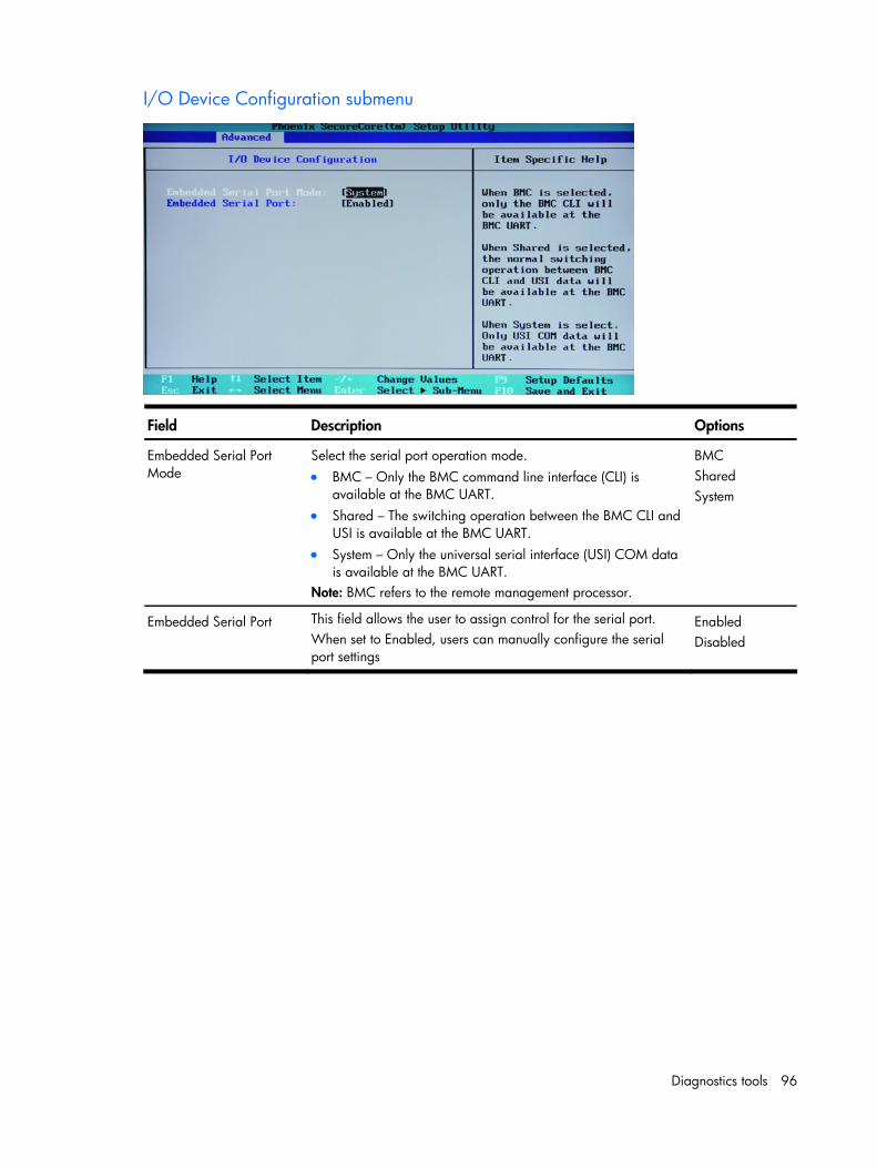
Diagnostics tools 96
I/O Device Configuration submenu
Field Description Options
Embedded Serial Port Mode
Select the serial port operation mode. • BMC – Only the BMC command line interface (CLI) is
available at the BMC UART. • Shared – The switching operation between the BMC CLI and
USI is available at the BMC UART. • System – Only the universal serial interface (USI) COM data
is available at the BMC UART. Note: BMC refers to the remote management processor.
BMC Shared System
Embedded Serial Port This field allows the user to assign control for the serial port. When set to Enabled, users can manually configure the serial port settings
Enabled Disabled
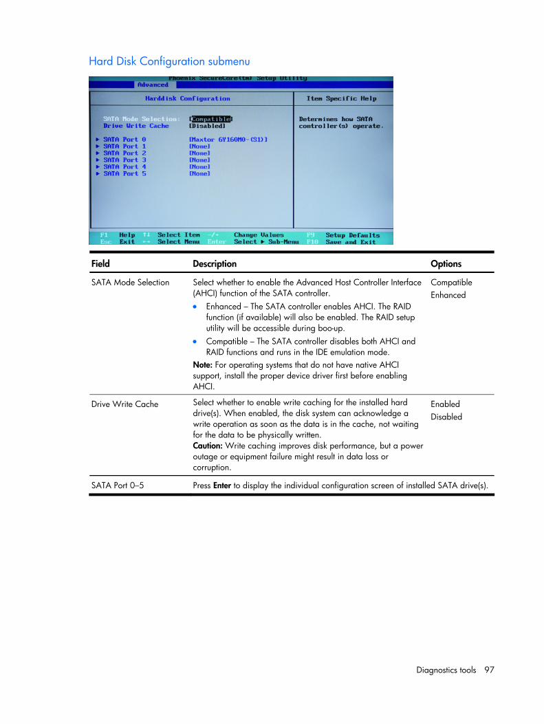
Diagnostics tools 97
Hard Disk Configuration submenu
Field Description Options
SATA Mode Selection Select whether to enable the Advanced Host Controller Interface (AHCI) function of the SATA controller. • Enhanced – The SATA controller enables AHCI. The RAID
function (if available) will also be enabled. The RAID setup utility will be accessible during boo-up.
• Compatible – The SATA controller disables both AHCI and RAID functions and runs in the IDE emulation mode.
Note: For operating systems that do not have native AHCI support, install the proper device driver first before enabling AHCI.
Compatible Enhanced
Drive Write Cache Select whether to enable write caching for the installed hard drive(s). When enabled, the disk system can acknowledge a write operation as soon as the data is in the cache, not waiting for the data to be physically written. Caution: Write caching improves disk performance, but a power outage or equipment failure might result in data loss or corruption.
Enabled Disabled
SATA Port 0–5 Press Enter to display the individual configuration screen of installed SATA drive(s).
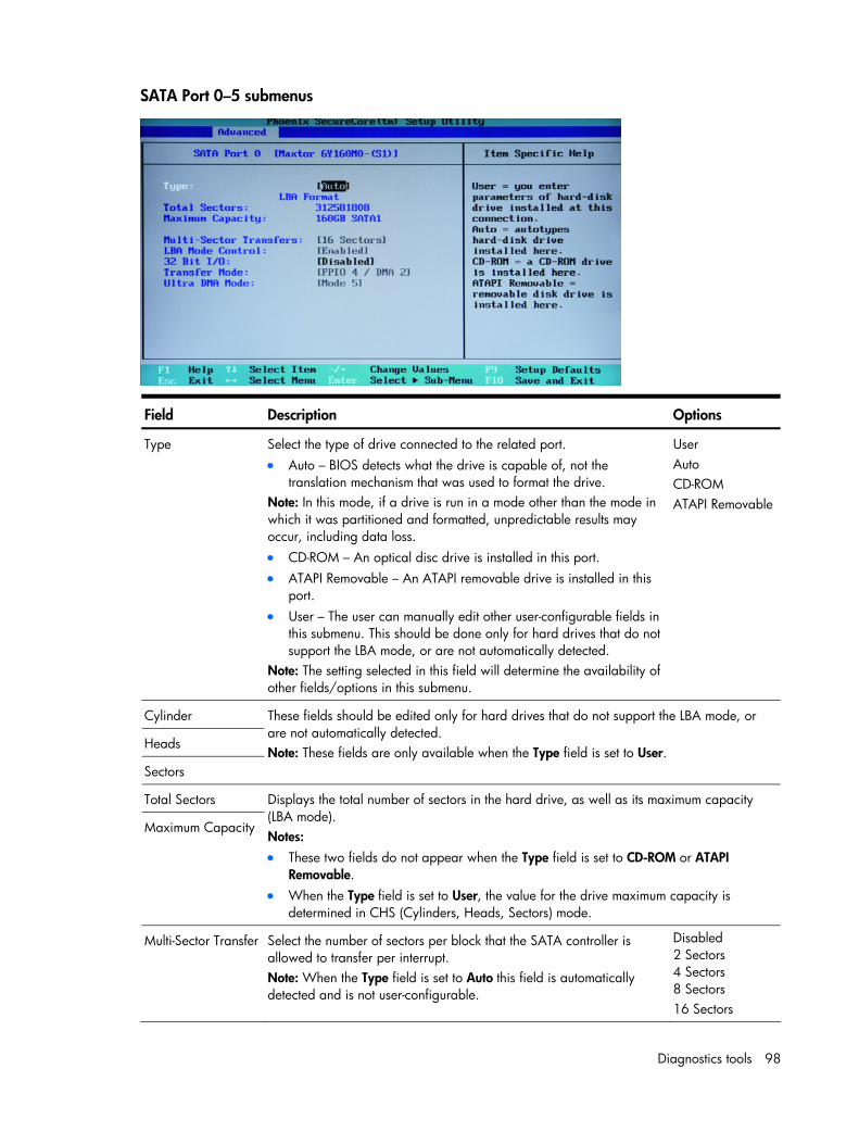
Diagnostics tools 98
SATA Port 0–5 submenus
Field Description Options
Type Select the type of drive connected to the related port. • Auto – BIOS detects what the drive is capable of, not the
translation mechanism that was used to format the drive. Note: In this mode, if a drive is run in a mode other than the mode in which it was partitioned and formatted, unpredictable results may occur, including data loss. • CD-ROM – An optical disc drive is installed in this port. • ATAPI Removable – An ATAPI removable drive is installed in this
port. • User – The user can manually edit other user-configurable fields in
this submenu. This should be done only for hard drives that do not support the LBA mode, or are not automatically detected.
Note: The setting selected in this field will determine the availability of other fields/options in this submenu.
User Auto CD-ROM ATAPI Removable
Cylinder
Heads
Sectors
These fields should be edited only for hard drives that do not support the LBA mode, or are not automatically detected. Note: These fields are only available when the Type field is set to User.
Total Sectors
Maximum Capacity
Displays the total number of sectors in the hard drive, as well as its maximum capacity (LBA mode). Notes: • These two fields do not appear when the Type field is set to CD-ROM or ATAPI
Removable. • When the Type field is set to User, the value for the drive maximum capacity is
determined in CHS (Cylinders, Heads, Sectors) mode.
Multi-Sector Transfer Select the number of sectors per block that the SATA controller is allowed to transfer per interrupt. Note: When the Type field is set to Auto this field is automatically detected and is not user-configurable.
Disabled 2 Sectors 4 Sectors 8 Sectors 16 Sectors
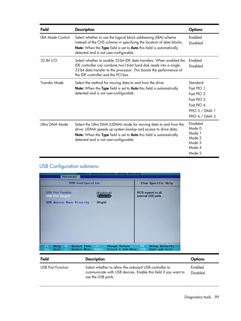
Diagnostics tools 99
Field Description Options
LBA Mode Control Select whether to use the logical block addressing (LBA) scheme instead of the CHS scheme in specifying the location of data blocks. Note: When the Type field is set to Auto this field is automatically detected and is not user-configurable.
Enabled Disabled
32 Bit I/O Select whether to enable 32-bit IDE data transfers. When enabled the IDE controller can combine two16-bit hard disk reads into a single 32-bit data transfer to the processor. This boosts the performance of the IDE controller and the PCI bus.
Enabled Disabled
Transfer Mode Select the method for moving data to and from the drive. Note: When the Type field is set to Auto this field is automatically detected and is not user-configurable.
Standard Fast PIO 1 Fast PIO 2 Fast PIO 3 Fast PIO 4 FPIO 3 / DMA 1 FPIO 4 / DMA 2
Ultra DMA Mode Select the Ultra DMA (UDMA) mode for moving data to and from the drive. UDMA speeds up system bootup and access to drive data. Note: When the Type field is set to Auto this field is automatically detected and is not user-configurable.
Disabled Mode 0 Mode 1 Mode 2 Mode 3 Mode 4 Mode 5
USB Configuration submenu
Field Description Options
USB Port Function Select whether to allow the onboard USB controller to communicate with USB devices. Enable this field if you want to use the USB ports.
Enabled Disabled
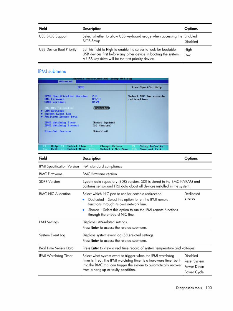
Diagnostics tools 100
Field Description Options
USB BIOS Support Select whether to allow USB keyboard usage when accessing the BIOS Setup.
Enabled Disabled
USB Device Boot Priority Set this field to High to enable the server to look for bootable USB devices first before any other device in booting the system. A USB key drive will be the first priority device.
High Low
IPMI submenu
Field Description Options
IPMI Specification Version IPMI standard compliance
BMC Firmware BMC firmware version
SDRR Version System data repository (SDR) version. SDR is stored in the BMC NVRAM and contains sensor and FRU data about all devices installed in the system.
BMC NIC Allocation Select which NIC port to use for console redirection. • Dedicated – Select this option to run the IPMI remote
functions through its own network line. • Shared – Select this option to run the IPMI remote functions
through the onboard NIC line.
Dedicated Shared
LAN Settings Displays LAN-related settings. Press Enter to access the related submenu.
System Event Log Displays system event log (SEL)-related settings. Press Enter to access the related submenu.
Real Time Sensor Data Press Enter to view a real time record of system temperature and voltages.
IPMI Watchdog Timer Select what system event to trigger when the IPMI watchdog timer is fired. The IPMI watchdog timer is a hardware timer built into the BMC that can trigger the system to automatically recover from a hang-up or faulty condition.
Disabled Reset System Power Down Power Cycle
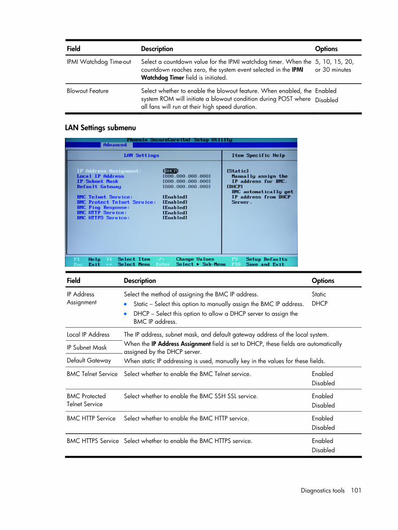
Diagnostics tools 101
Field Description Options
IPMI Watchdog Time-out Select a countdown value for the IPMI watchdog timer. When the countdown reaches zero, the system event selected in the IPMI Watchdog Timer field is initiated.
5, 10, 15, 20, or 30 minutes
Blowout Feature Select whether to enable the blowout feature. When enabled, the system ROM will initiate a blowout condition during POST where all fans will run at their high speed duration.
Enabled Disabled
LAN Settings submenu
Field Description Options
IP Address Assignment
Select the method of assigning the BMC IP address. • Static – Select this option to manually assign the BMC IP address. • DHCP – Select this option to allow a DHCP server to assign the
BMC IP address.
Static DHCP
Local IP Address
IP Subnet Mask
Default Gateway
The IP address, subnet mask, and default gateway address of the local system. When the IP Address Assignment field is set to DHCP, these fields are automatically assigned by the DHCP server. When static IP addressing is used, manually key in the values for these fields.
BMC Telnet Service Select whether to enable the BMC Telnet service. Enabled Disabled
BMC Protected Telnet Service
Select whether to enable the BMC SSH SSL service. Enabled Disabled
BMC HTTP Service Select whether to enable the BMC HTTP service. Enabled Disabled
BMC HTTPS Service Select whether to enable the BMC HTTPS service. Enabled Disabled
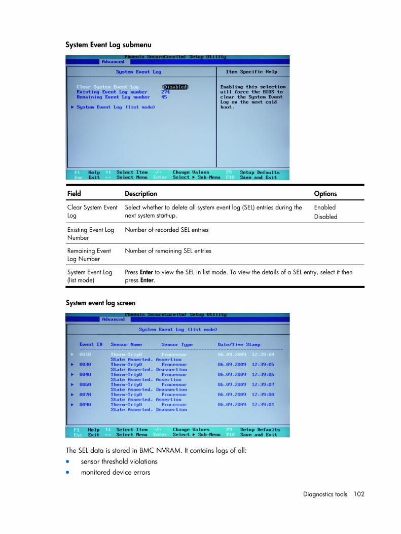
Diagnostics tools 102
System Event Log submenu
Field Description Options
Clear System Event Log
Select whether to delete all system event log (SEL) entries during the next system start-up.
Enabled Disabled
Existing Event Log Number
Number of recorded SEL entries
Remaining Event Log Number
Number of remaining SEL entries
System Event Log (list mode)
Press Enter to view the SEL in list mode. To view the details of a SEL entry, select it then press Enter.
System event log screen
The SEL data is stored in BMC NVRAM. It contains logs of all: • sensor threshold violations • monitored device errors
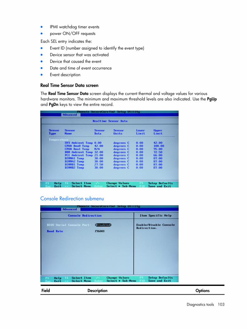
Diagnostics tools 103
• IPMI watchdog timer events • power ON/OFF requests
Each SEL entry indicates the: • Event ID (number assigned to identify the event type) • Device sensor that was activated • Device that caused the event • Date and time of event occurrence • Event description
Real Time Sensor Data screen
The Real Time Sensor Data screen displays the current thermal and voltage values for various hardware monitors. The minimum and maximum threshold levels are also indicated. Use the PgUp and PgDn keys to view the entire record.
Console Redirection submenu
Field Description Options
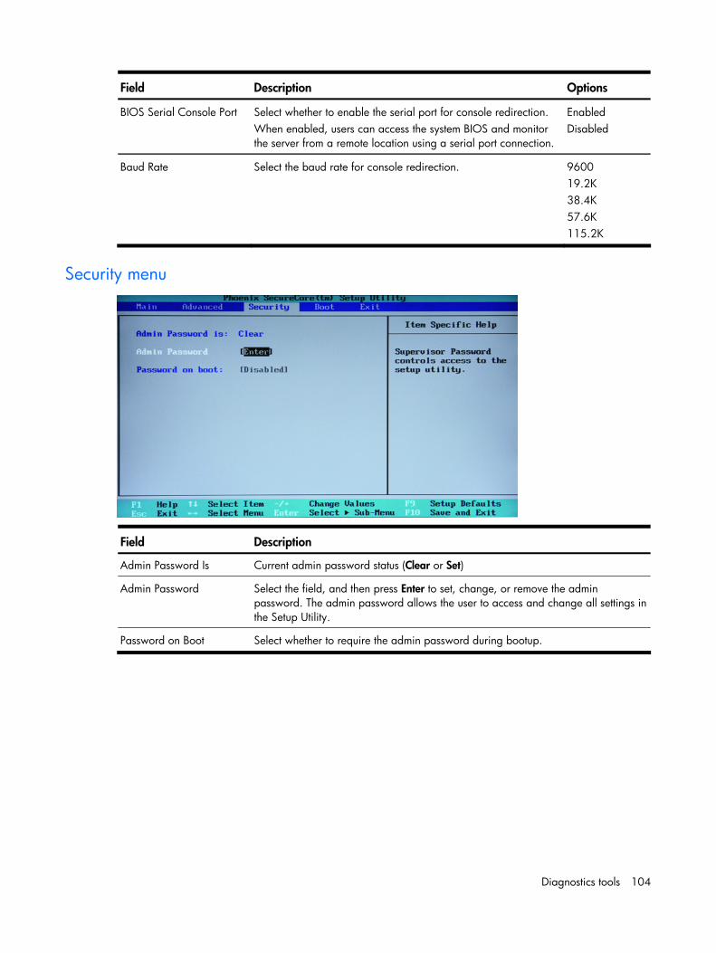
Diagnostics tools 104
Field Description Options
BIOS Serial Console Port Select whether to enable the serial port for console redirection. When enabled, users can access the system BIOS and monitor the server from a remote location using a serial port connection.
Enabled Disabled
Baud Rate Select the baud rate for console redirection. 9600 19.2K 38.4K 57.6K 115.2K
Security menu
Field Description
Admin Password Is Current admin password status (Clear or Set)
Admin Password Select the field, and then press Enter to set, change, or remove the admin password. The admin password allows the user to access and change all settings in the Setup Utility.
Password on Boot Select whether to require the admin password during bootup.
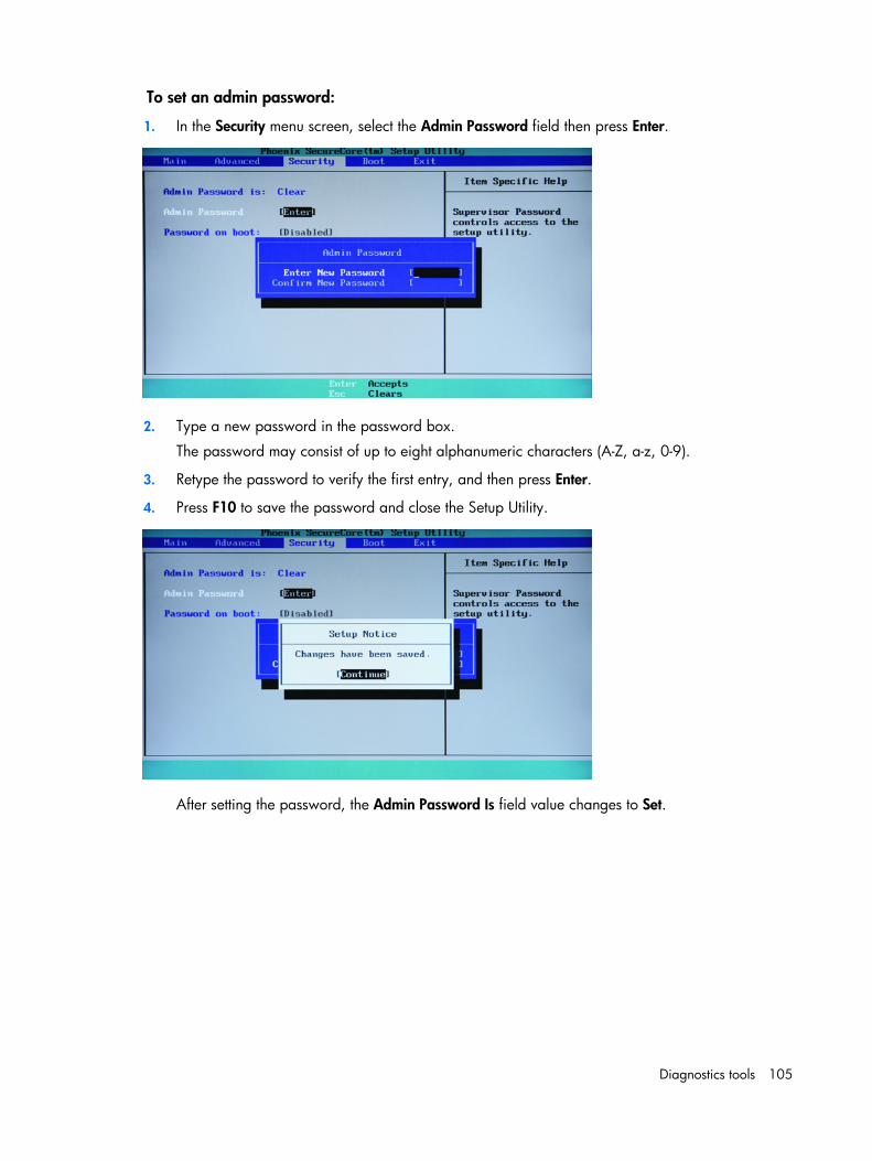
Diagnostics tools 105
To set an admin password:
1. In the Security menu screen, select the Admin Password field then press Enter.
2. Type a new password in the password box.
The password may consist of up to eight alphanumeric characters (A-Z, a-z, 0-9).
3. Retype the password to verify the first entry, and then press Enter.
4. Press F10 to save the password and close the Setup Utility.
After setting the password, the Admin Password Is field value changes to Set.
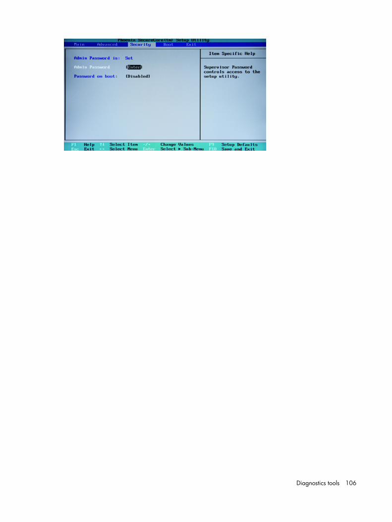
Diagnostics tools 106
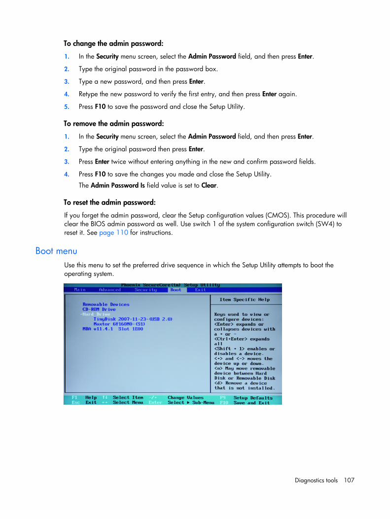
Diagnostics tools 107
To change the admin password:
1. In the Security menu screen, select the Admin Password field, and then press Enter.
2. Type the original password in the password box.
3. Type a new password, and then press Enter.
4. Retype the new password to verify the first entry, and then press Enter again.
5. Press F10 to save the password and close the Setup Utility.
To remove the admin password:
1. In the Security menu screen, select the Admin Password field, and then press Enter.
2. Type the original password then press Enter.
3. Press Enter twice without entering anything in the new and confirm password fields.
4. Press F10 to save the changes you made and close the Setup Utility.
The Admin Password Is field value is set to Clear.
To reset the admin password:
If you forget the admin password, clear the Setup configuration values (CMOS). This procedure will clear the BIOS admin password as well. Use switch 1 of the system configuration switch (SW4) to reset it. See page 110 for instructions.
Boot menu Use this menu to set the preferred drive sequence in which the Setup Utility attempts to boot the operating system.
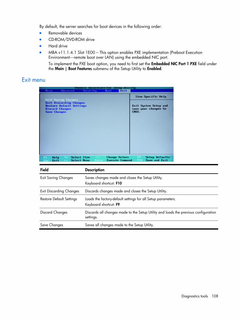
Diagnostics tools 108
By default, the server searches for boot devices in the following order: • Removable devices • CD-ROM/DVD-ROM drive • Hard drive • MBA v11.1.4.1 Slot 1E00 – This option enables PXE implementation (Preboot Execution
Environment—remote boot over LAN) using the embedded NIC port. To implement the PXE boot option, you need to first set the Embedded NIC Port 1 PXE field under the Main | Boot Features submenu of the Setup Utility to Enabled.
Exit menu
Field Description
Exit Saving Changes Saves changes made and closes the Setup Utility. Keyboard shortcut: F10
Exit Discarding Changes Discards changes made and closes the Setup Utility.
Restore Default Settings Loads the factory-default settings for all Setup parameters. Keyboard shortcut: F9
Discard Changes Discards all changes made to the Setup Utility and loads the previous configuration settings.
Save Changes Saves all changes made to the Setup Utility.
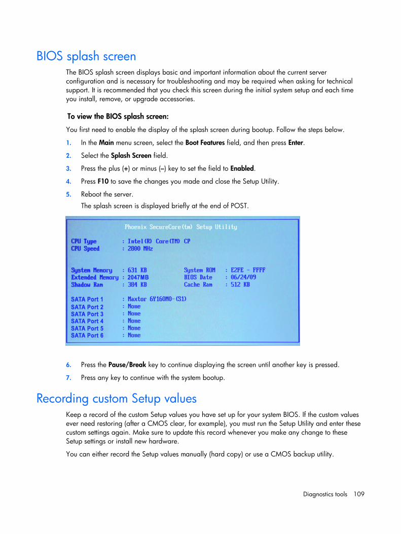
Diagnostics tools 109
BIOS splash screen The BIOS splash screen displays basic and important information about the current server configuration and is necessary for troubleshooting and may be required when asking for technical support. It is recommended that you check this screen during the initial system setup and each time you install, remove, or upgrade accessories.
To view the BIOS splash screen:
You first need to enable the display of the splash screen during bootup. Follow the steps below.
1. In the Main menu screen, select the Boot Features field, and then press Enter.
2. Select the Splash Screen field.
3. Press the plus (+) or minus (–) key to set the field to Enabled.
4. Press F10 to save the changes you made and close the Setup Utility.
5. Reboot the server.
The splash screen is displayed briefly at the end of POST.
6. Press the Pause/Break key to continue displaying the screen until another key is pressed.
7. Press any key to continue with the system bootup.
Recording custom Setup values Keep a record of the custom Setup values you have set up for your system BIOS. If the custom values ever need restoring (after a CMOS clear, for example), you must run the Setup Utility and enter these custom settings again. Make sure to update this record whenever you make any change to these Setup settings or install new hardware.
You can either record the Setup values manually (hard copy) or use a CMOS backup utility.
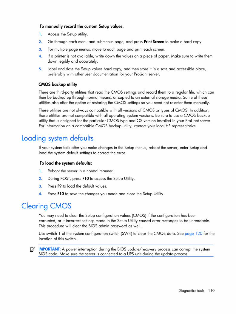
Diagnostics tools 110
To manually record the custom Setup values:
1. Access the Setup utility.
2. Go through each menu and submenus page, and press Print Screen to make a hard copy.
3. For multiple page menus, move to each page and print each screen.
4. If a printer is not available, write down the values on a piece of paper. Make sure to write them down legibly and accurately.
5. Label and date the Setup values hard copy, and then store it in a safe and accessible place, preferably with other user documentation for your ProLiant server.
CMOS backup utility
There are third-party utilities that read the CMOS settings and record them to a regular file, which can then be backed up through normal means, or copied to an external storage media. Some of these utilities also offer the option of restoring the CMOS settings so you need not re-enter them manually.
These utilities are not always compatible with all versions of CMOS or types of CMOS. In addition, these utilities are not compatible with all operating system versions. Be sure to use a CMOS backup utility that is designed for the particular CMOS type and OS version installed in your ProLiant server. For information on a compatible CMOS backup utility, contact your local HP representative.
Loading system defaults If your system fails after you make changes in the Setup menus, reboot the server, enter Setup and load the system default settings to correct the error.
To load the system defaults:
1. Reboot the server in a normal manner.
2. During POST, press F10 to access the Setup Utility.
3. Press F9 to load the default values.
4. Press F10 to save the changes you made and close the Setup Utility.
Clearing CMOS You may need to clear the Setup configuration values (CMOS) if the configuration has been corrupted, or if incorrect settings made in the Setup Utility caused error messages to be unreadable. This procedure will clear the BIOS admin password as well.
Use switch 1 of the system configuration switch (SW4) to clear the CMOS data. See page 120 for the location of this switch.
IMPORTANT: A power interruption during the BIOS update/recovery process can corrupt the system BIOS code. Make sure the server is connected to a UPS unit during the update process.
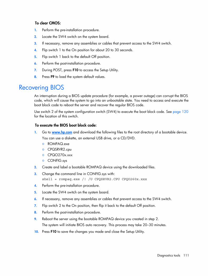
Diagnostics tools 111
To clear CMOS:
1. Perform the pre-installation procedure.
2. Locate the SW4 switch on the system board.
3. If necessary, remove any assemblies or cables that prevent access to the SW4 switch.
4. Flip switch 1 to the On position for about 20 to 30 seconds.
5. Flip switch 1 back to the default Off position.
6. Perform the post-installation procedure.
7. During POST, press F10 to access the Setup Utility.
8. Press F9 to load the system default values.
Recovering BIOS An interruption during a BIOS update procedure (for example, a power outage) can corrupt the BIOS code, which will cause the system to go into an unbootable state. You need to access and execute the boot block code to reboot the server and recover the regular BIOS code.
Use switch 2 of the system configuration switch (SW4) to execute the boot block code. See page 120 for the location of this switch.
To execute the BIOS boot block code:
1. Go to www.hp.com and download the following files to the root directory of a bootable device.
You can use a diskette, an external USB drive, or a CD/DVD. ○ ROMPAQ.exe ○ CPQSRVR2.cpu ○ CPQO270x.xxx ○ CONFIG.sys
2. Create and label a bootable ROMPAQ device using the downloaded files.
3. Change the command line in CONFIG.sys with: shell = rompaq.exe /! /U CPQSRVR2.CPU CPQO260x.xxx
4. Perform the pre-installation procedure.
5. Locate the SW4 switch on the system board.
6. If necessary, remove any assemblies or cables that prevent access to the SW4 switch.
7. Flip switch 2 to the On position, then flip it back to the default Off position.
8. Perform the post-installation procedure.
9. Reboot the server using the bootable ROMPAQ device you created in step 2.
The system will initiate BIOS auto recovery. This process may take 20–30 minutes.
10. Press F10 to save the changes you made and close the Setup Utility.
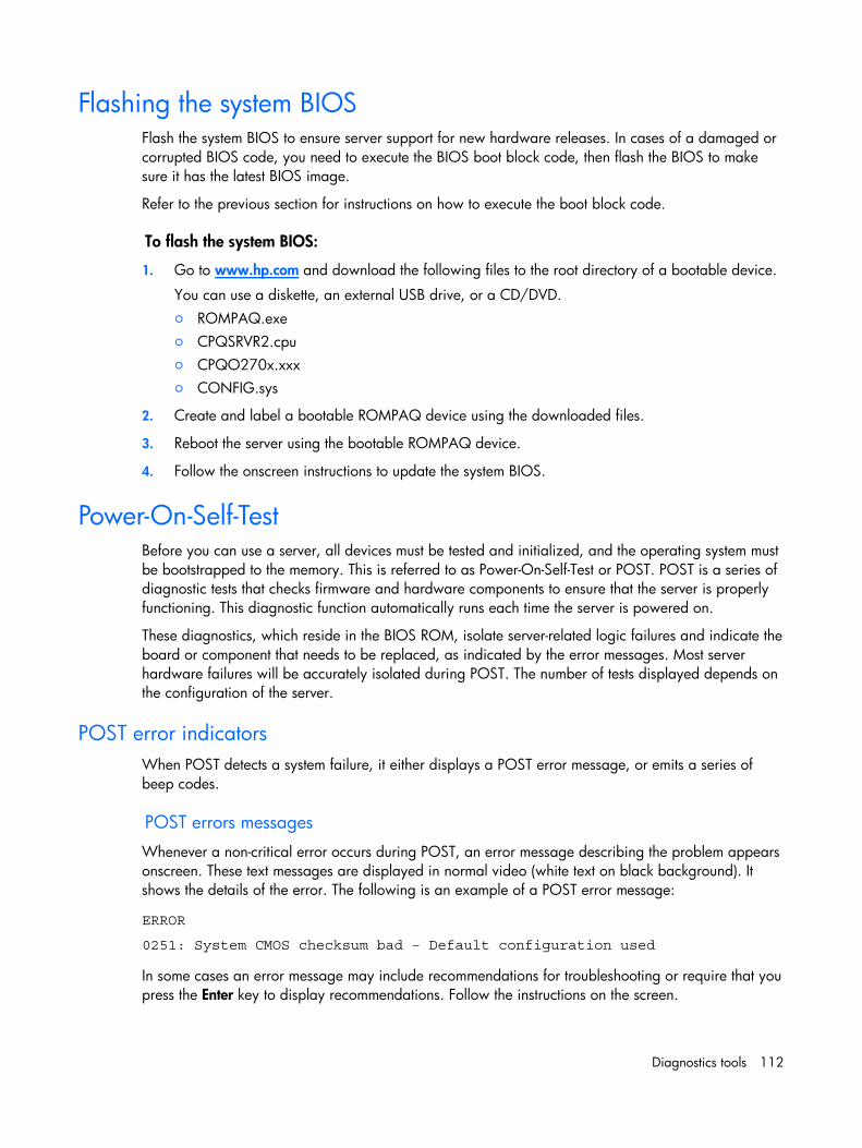
Diagnostics tools 112
Flashing the system BIOS Flash the system BIOS to ensure server support for new hardware releases. In cases of a damaged or corrupted BIOS code, you need to execute the BIOS boot block code, then flash the BIOS to make sure it has the latest BIOS image.
Refer to the previous section for instructions on how to execute the boot block code.
To flash the system BIOS:
1. Go to www.hp.com and download the following files to the root directory of a bootable device.
You can use a diskette, an external USB drive, or a CD/DVD. ○ ROMPAQ.exe ○ CPQSRVR2.cpu ○ CPQO270x.xxx ○ CONFIG.sys
2. Create and label a bootable ROMPAQ device using the downloaded files.
3. Reboot the server using the bootable ROMPAQ device.
4. Follow the onscreen instructions to update the system BIOS.
Power-On-Self-Test Before you can use a server, all devices must be tested and initialized, and the operating system must be bootstrapped to the memory. This is referred to as Power-On-Self-Test or POST. POST is a series of diagnostic tests that checks firmware and hardware components to ensure that the server is properly functioning. This diagnostic function automatically runs each time the server is powered on.
These diagnostics, which reside in the BIOS ROM, isolate server-related logic failures and indicate the board or component that needs to be replaced, as indicated by the error messages. Most server hardware failures will be accurately isolated during POST. The number of tests displayed depends on the configuration of the server.
POST error indicators When POST detects a system failure, it either displays a POST error message, or emits a series of beep codes.
POST errors messages Whenever a non-critical error occurs during POST, an error message describing the problem appears onscreen. These text messages are displayed in normal video (white text on black background). It shows the details of the error. The following is an example of a POST error message:
ERROR
0251: System CMOS checksum bad – Default configuration used
In some cases an error message may include recommendations for troubleshooting or require that you press the Enter key to display recommendations. Follow the instructions on the screen.
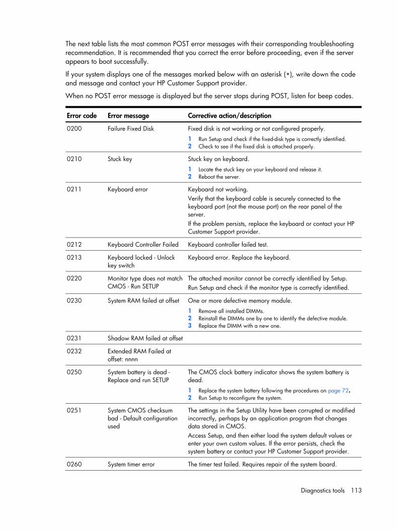
Diagnostics tools 113
The next table lists the most common POST error messages with their corresponding troubleshooting recommendation. It is recommended that you correct the error before proceeding, even if the server appears to boot successfully.
If your system displays one of the messages marked below with an asterisk (*), write down the code and message and contact your HP Customer Support provider.
When no POST error message is displayed but the server stops during POST, listen for beep codes.
Error code Error message Corrective action/description
0200 Failure Fixed Disk Fixed disk is not working or not configured properly.
1 Run Setup and check if the fixed-disk type is correctly identified. 2 Check to see if the fixed disk is attached properly.
0210 Stuck key Stuck key on keyboard.
1 Locate the stuck key on your keyboard and release it. 2 Reboot the server.
0211 Keyboard error Keyboard not working. Verify that the keyboard cable is securely connected to the keyboard port (not the mouse port) on the rear panel of the server. If the problem persists, replace the keyboard or contact your HP Customer Support provider.
0212 Keyboard Controller Failed Keyboard controller failed test.
0213 Keyboard locked - Unlock key switch
Keyboard error. Replace the keyboard.
0220 Monitor type does not match CMOS - Run SETUP
The attached monitor cannot be correctly identified by Setup. Run Setup and check if the monitor type is correctly identified.
0230 System RAM failed at offset One or more defective memory module.
1 Remove all installed DIMMs. 2 Reinstall the DIMMs one by one to identify the defective module. 3 Replace the DIMM with a new one.
0231 Shadow RAM failed at offset
0232 Extended RAM Failed at offset: nnnn
0250 System battery is dead - Replace and run SETUP
The CMOS clock battery indicator shows the system battery is dead.
1 Replace the system battery following the procedures on page 72. 2 Run Setup to reconfigure the system.
0251 System CMOS checksum bad - Default configuration used
The settings in the Setup Utility have been corrupted or modified incorrectly, perhaps by an application program that changes data stored in CMOS. Access Setup, and then either load the system default values or enter your own custom values. If the error persists, check the system battery or contact your HP Customer Support provider.
0260 System timer error The timer test failed. Requires repair of the system board.
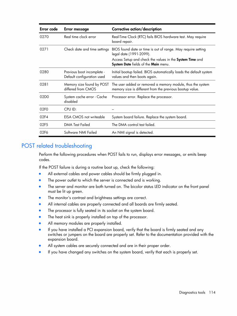
Diagnostics tools 114
Error code Error message Corrective action/description
0270 Real time clock error Real-Time Clock (RTC) fails BIOS hardware test. May require board repair.
0271 Check date and time settings BIOS found date or time is out of range. May require setting legal date (1991-2099). Access Setup and check the values in the System Time and System Date fields of the Main menu.
0280 Previous boot incomplete - Default configuration used
Initial bootup failed. BIOS automatically loads the default system values and then boots again.
0281 Memory size found by POST differed from CMOS
The user added or removed a memory module, thus the system memory size is different from the previous bootup value.
02D0 System cache error - Cache disabled
Processor error. Replace the processor.
02F0 CPU ID: –
02F4 EISA CMOS not writeable System board failure. Replace the system board.
02F5 DMA Test Failed The DMA control test failed.
02F6 Software NMI Failed An NMI signal is detected.
POST related troubleshooting Perform the following procedures when POST fails to run, displays error messages, or emits beep codes.
If the POST failure is during a routine boot up, check the following: • All external cables and power cables should be firmly plugged in. • The power outlet to which the server is connected and is working. • The server and monitor are both turned on. The bicolor status LED indicator on the front panel
must be lit up green. • The monitor's contrast and brightness settings are correct. • All internal cables are properly connected and all boards are firmly seated. • The processor is fully seated in its socket on the system board. • The heat sink is properly installed on top of the processor. • All memory modules are properly installed. • If you have installed a PCI expansion board, verify that the board is firmly seated and any
switches or jumpers on the board are properly set. Refer to the documentation provided with the expansion board.
• All system cables are securely connected and are in their proper order. • If you have changed any switches on the system board, verify that each is properly set.
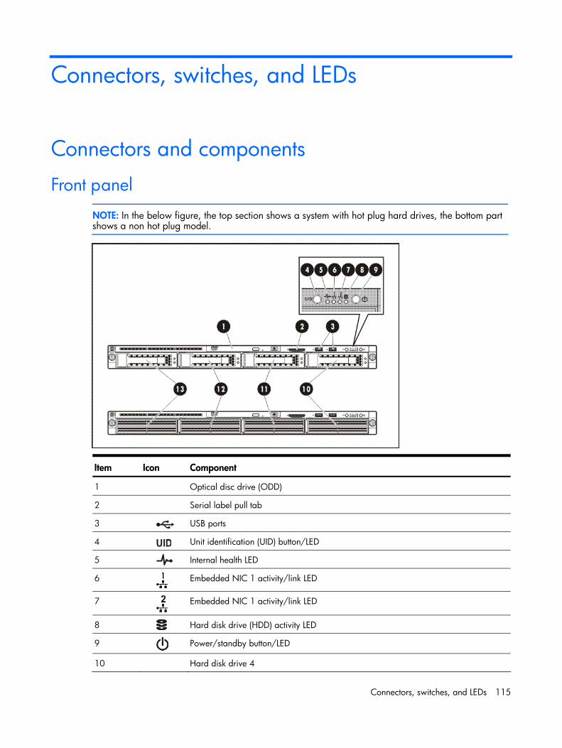
Connectors, switches, and LEDs 115
Connectors, switches, and LEDs
Connectors and components
Front panel
NOTE: In the below figure, the top section shows a system with hot plug hard drives, the bottom part shows a non hot plug model.
Item Icon Component
1 Optical disc drive (ODD)
2 Serial label pull tab
3 USB ports
4 Unit identification (UID) button/LED
5 Internal health LED
6
Embedded NIC 1 activity/link LED
7
Embedded NIC 1 activity/link LED
8 Hard disk drive (HDD) activity LED
9 Power/standby button/LED
10 Hard disk drive 4
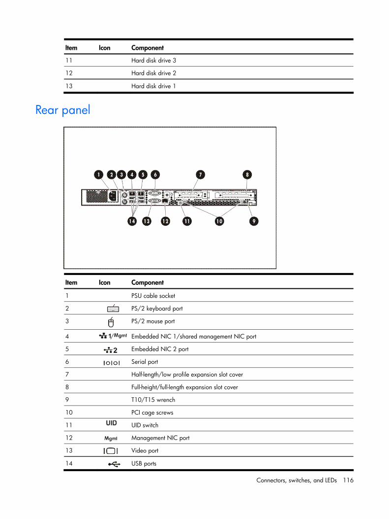
Connectors, switches, and LEDs 116
Item Icon Component
11 Hard disk drive 3
12 Hard disk drive 2
13 Hard disk drive 1
Rear panel
Item Icon Component
1 PSU cable socket
2 PS/2 keyboard port
3
PS/2 mouse port
4 / Embedded NIC 1/shared management NIC port
5 Embedded NIC 2 port
6 Serial port
7 Half-length/low profile expansion slot cover
8 Full-height/full-length expansion slot cover
9 T10/T15 wrench
10 PCI cage screws
11 UID switch
12 Management NIC port
13 Video port
14 USB ports
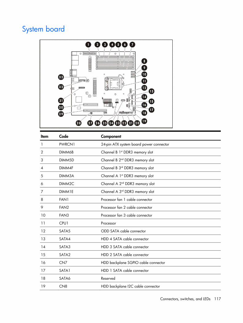
Connectors, switches, and LEDs 117
System board
Item Code Component
1 PWRCN1 24-pin ATX system board power connector
2 DIMM6B Channel B 1st DDR3 memory slot
3 DIMM5D Channel B 2nd DDR3 memory slot
4 DIMM4F Channel B 3rd DDR3 memory slot
5 DIMM3A Channel A 1st DDR3 memory slot
6 DIMM2C Channel A 2nd DDR3 memory slot
7 DIMM1E Channel A 3rd DDR3 memory slot
8 FAN1 Processor fan 1 cable connector
9 FAN2 Processor fan 2 cable connector
10 FAN3 Processor fan 3 cable connector
11 CPU1 Processor
12 SATA5 ODD SATA cable connector
13 SATA4 HDD 4 SATA cable connector
14 SATA3 HDD 3 SATA cable connector
15 SATA2 HDD 2 SATA cable connector
16 CN7 HDD backplane SGPIO cable connector
17 SATA1 HDD 1 SATA cable connector
18 SATA6 Reserved
19 CN8 HDD backplane I2C cable connector
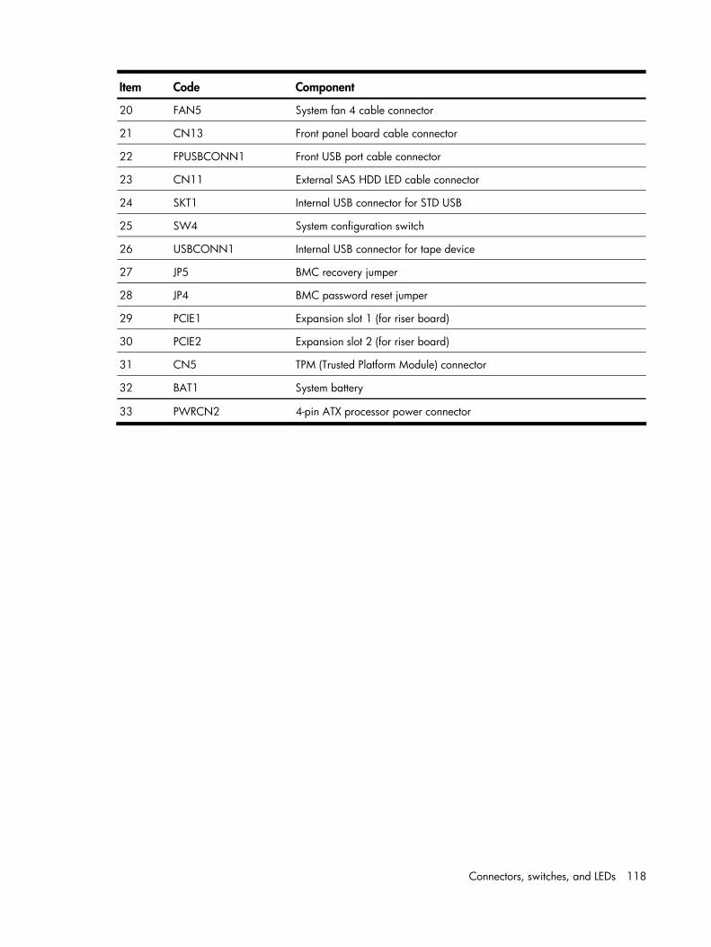
Connectors, switches, and LEDs 118
Item Code Component
20 FAN5 System fan 4 cable connector
21 CN13 Front panel board cable connector
22 FPUSBCONN1 Front USB port cable connector
23 CN11 External SAS HDD LED cable connector
24 SKT1 Internal USB connector for STD USB
25 SW4 System configuration switch
26 USBCONN1 Internal USB connector for tape device
27 JP5 BMC recovery jumper
28 JP4 BMC password reset jumper
29 PCIE1 Expansion slot 1 (for riser board)
30 PCIE2 Expansion slot 2 (for riser board)
31 CN5 TPM (Trusted Platform Module) connector
32 BAT1 System battery
33 PWRCN2 4-pin ATX processor power connector
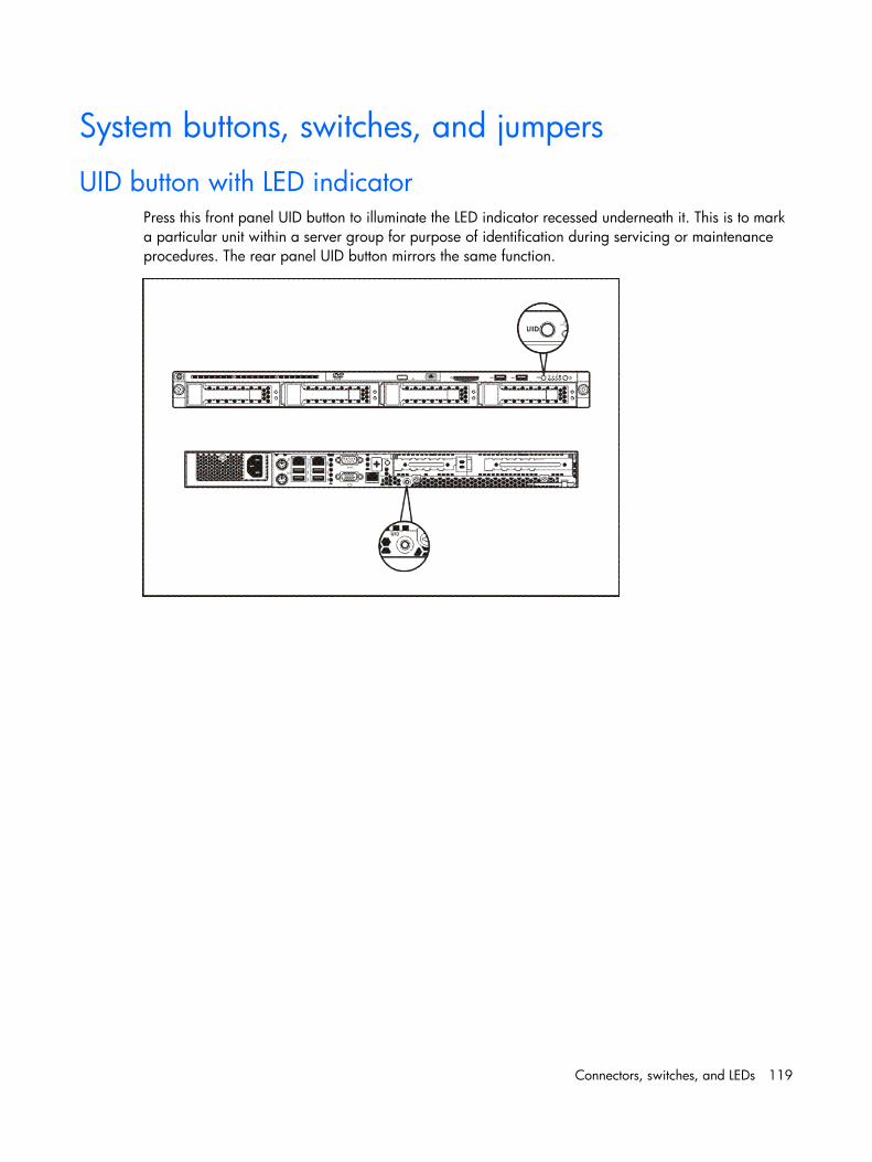
Connectors, switches, and LEDs 119
System buttons, switches, and jumpers
UID button with LED indicator Press this front panel UID button to illuminate the LED indicator recessed underneath it. This is to mark a particular unit within a server group for purpose of identification during servicing or maintenance procedures. The rear panel UID button mirrors the same function.
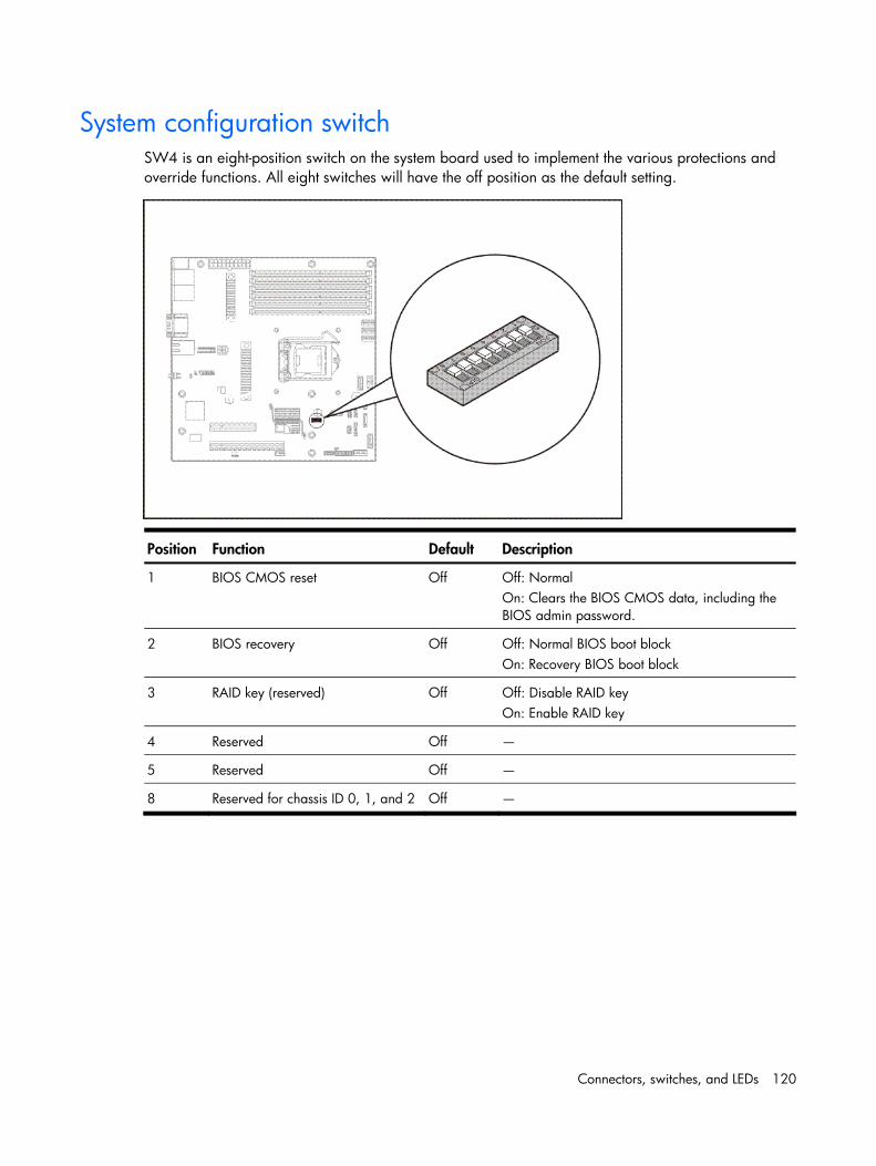
Connectors, switches, and LEDs 120
System configuration switch SW4 is an eight-position switch on the system board used to implement the various protections and override functions. All eight switches will have the off position as the default setting.
Position Function Default Description
1 BIOS CMOS reset Off Off: Normal On: Clears the BIOS CMOS data, including the BIOS admin password.
2 BIOS recovery Off Off: Normal BIOS boot block On: Recovery BIOS boot block
3 RAID key (reserved) Off Off: Disable RAID key On: Enable RAID key
4 Reserved Off —
5 Reserved Off —
8 Reserved for chassis ID 0, 1, and 2 Off —
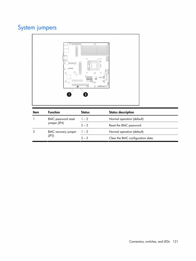
Connectors, switches, and LEDs 121
System jumpers
Item Function Status Status description
1 – 2 Normal operation (default) 1 BMC password reset jumper (JP4)
2 – 3 Reset the BMC password
1 – 2 Normal operation (default) 2 BMC recovery jumper (JP5)
2 – 3 Clear the BMC configuration data
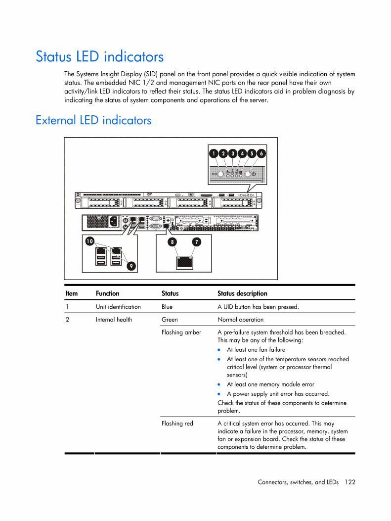
Connectors, switches, and LEDs 122
Status LED indicators The Systems Insight Display (SID) panel on the front panel provides a quick visible indication of system status. The embedded NIC 1/2 and management NIC ports on the rear panel have their own activity/link LED indicators to reflect their status. The status LED indicators aid in problem diagnosis by indicating the status of system components and operations of the server.
External LED indicators
Item Function Status Status description
1 Unit identification Blue A UID button has been pressed.
Green Normal operation
Flashing amber A pre-failure system threshold has been breached. This may be any of the following: • At least one fan failure • At least one of the temperature sensors reached
critical level (system or processor thermal sensors)
• At least one memory module error • A power supply unit error has occurred. Check the status of these components to determine problem.
2 Internal health
Flashing red A critical system error has occurred. This may indicate a failure in the processor, memory, system fan or expansion board. Check the status of these components to determine problem.
Connectors, switches, and LEDs 123
Item Function Status Status description
Solid green An active network link exists.
Flashing green An ongoing network data activity exists.
3 and 4 Embedded NIC 1/2 activity/link
Off The server is off-line.
5 HDD activity Green Ongoing hard drive activity
Flashing green System bootup
Solid green Power on mode
Amber Standby mode; failed bootup
6 System power
Off No power connection
Amber 10/100 Mbps connection 7 Management NIC link
Green Gigabit connection
8 Management NIC activity
Flashing green Ongoing network activity
9 Embedded NIC 1/2 activity
Flashing green Ongoing network activity
Amber 10/100 Mbps connection 10 Embedded NIC 1/2 link
Green Gigabit connection
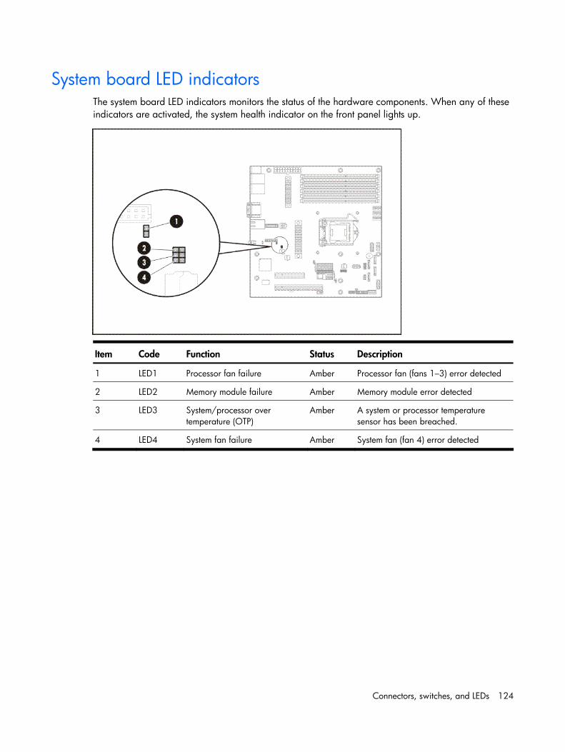
Connectors, switches, and LEDs 124
System board LED indicators The system board LED indicators monitors the status of the hardware components. When any of these indicators are activated, the system health indicator on the front panel lights up.
Item Code Function Status Description
1 LED1 Processor fan failure Amber Processor fan (fans 1–3) error detected
2 LED2 Memory module failure Amber Memory module error detected
3 LED3 System/processor over temperature (OTP)
Amber A system or processor temperature sensor has been breached.
4 LED4 System fan failure Amber System fan (fan 4) error detected
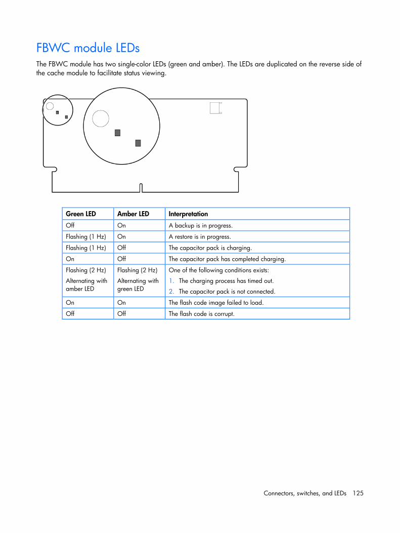
Connectors, switches, and LEDs 125
FBWC module LEDs The FBWC module has two single-color LEDs (green and amber). The LEDs are duplicated on the reverse side of the cache module to facilitate status viewing.
Green LED Amber LED Interpretation
Off On A backup is in progress.
Flashing (1 Hz) On A restore is in progress.
Flashing (1 Hz) Off The capacitor pack is charging.
On Off The capacitor pack has completed charging.
Flashing (2 Hz)
Alternating with amber LED
Flashing (2 Hz)
Alternating with green LED
One of the following conditions exists:
1. The charging process has timed out.
2. The capacitor pack is not connected.
On On The flash code image failed to load.
Off Off The flash code is corrupt.
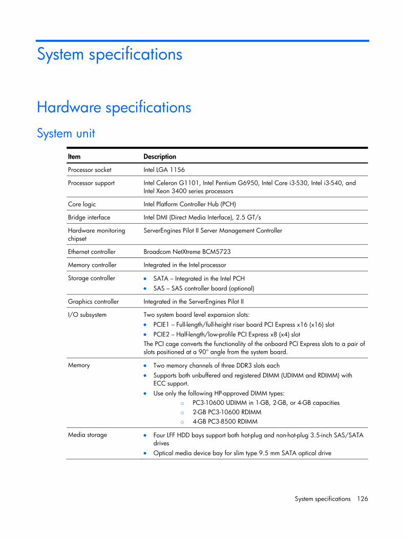
System specifications 126
System specifications
Hardware specifications
System unit
Item Description
Processor socket Intel LGA 1156
Processor support Intel Celeron G1101, Intel Pentium G6950, Intel Core i3-530, Intel i3-540, and Intel Xeon 3400 series processors
Core logic Intel Platform Controller Hub (PCH)
Bridge interface Intel DMI (Direct Media Interface), 2.5 GT/s
Hardware monitoring chipset
ServerEngines Pilot II Server Management Controller
Ethernet controller Broadcom NetXtreme BCM5723
Memory controller Integrated in the Intel processor
Storage controller • SATA – Integrated in the Intel PCH • SAS – SAS controller board (optional)
Graphics controller Integrated in the ServerEngines Pilot II
I/O subsystem Two system board level expansion slots: • PCIE1 – Full-length/full-height riser board PCI Express x16 (x16) slot • PCIE2 – Half-length/low-profile PCI Express x8 (x4) slot The PCI cage converts the functionality of the onboard PCI Express slots to a pair of slots positioned at a 90° angle from the system board.
Memory • Two memory channels of three DDR3 slots each • Supports both unbuffered and registered DIMM (UDIMM and RDIMM) with
ECC support. • Use only the following HP-approved DIMM types:
o PC3-10600 UDIMM in 1-GB, 2-GB, or 4-GB capacities o 2-GB PC3-10600 RDIMM o 4-GB PC3-8500 RDIMM
Media storage • Four LFF HDD bays support both hot-plug and non-hot-plug 3.5-inch SAS/SATA drives
• Optical media device bay for slim type 9.5 mm SATA optical drive
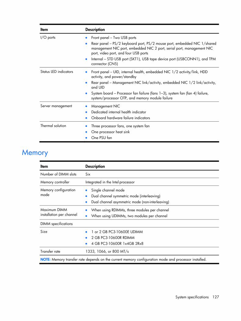
System specifications 127
Item Description
I/O ports • Front panel – Two USB ports • Rear panel – PS/2 keyboard port, PS/2 mouse port, embedded NIC 1/shared
management NIC port, embedded NIC 2 port, serial port, management NIC port, video port, and four USB ports
• Internal – STD USB port (SKT1), USB tape device port (USBCONN1), and TPM connector (CN5)
Status LED indicators • Front panel – UID, internal health, embedded NIC 1/2 activity/link, HDD activity, and power/standby
• Rear panel – Management NIC link/activity, embedded NIC 1/2 link/activity, and UID
• System board – Processor fan failure (fans 1–3), system fan (fan 4) failure, system/processor OTP, and memory module failure
Server management • Management NIC • Dedicated internal health indicator • Onboard hardware failure indicators
Thermal solution • heat sink
Three processor fans, one system fan • One processor• One PSU fan
Memory
Item Description
Number of DIMM slots Six
Memory controller Integrated in the Intel processor
Memory configuration mode
• Single channel mode • Dual channel symmetric mode (interleaving) • Dual channel asymmetric mode (non-interleaving)
Maximum DIMM installation per channel
• When using UDIMMs, two modules per channel • When using RDIMMs, three modules per channel
DIMM specifications
Size MM
2Rx8
• 1 or 2 GB PC3-10600E UDI• 2 GB PC3-10600R RDIMM • 4 GB PC3-10600R 1x4GB
Transfer rate 1333, 1066, or 800 MT/s
NOTE: Memory transfer rate depends on the current memory configuration mode and processor installed.
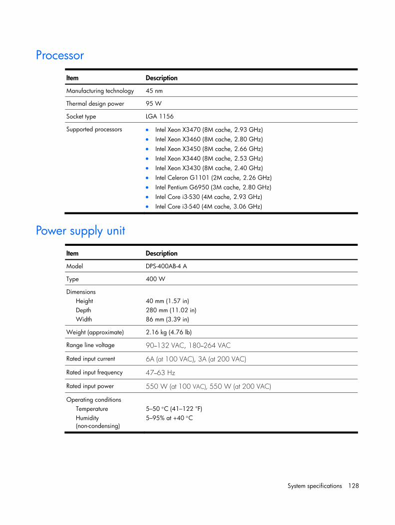
System specifications 128
Processor
Item Description
Manufacturing technology 45 nm
Thermal design power 95 W
Socket type LGA 1156
Supported processors • Intel Xeon X3470 (8M cache, 2.93 GHz) • Intel Xeon X3460 (8M cache, 2.80 GHz) • Intel Xeon X3450 (8M cache, 2.66 GHz) • Intel Xeon X3440 (8M cache, 2.53 GHz) • Intel Xeon X3430 (8M cache, 2.40 GHz) • Intel Celeron G1101 (2M cache, 2.26 GHz) • Intel Pentium G6950 (3M cache, 2.80 GHz) • Intel Core i3-530 (4M cache, 2.93 GHz) • Intel Core i3-540 (4M cache, 3.06 GHz)
Power supply unit
Item Description
Model DPS-400AB-4 A
Type 400 W
Dimensions Height Depth Width
40 mm (1.57 in) 280 mm (11.02 in) 86 mm (3.39 in)
Weight (approximate) 2.16 kg (4.76 lb)
Range line voltage 90–132 VAC, 180–264 VAC
Rated input current 6A (at 100 VAC), 3A (at 200 VAC)
Rated input frequency 47–63 Hz
Rated input power 550 W (at 100 VAC), 550 W (at 200 VAC)
Operating conditions Temperature Humidity (non-condensing)
5–50 °C (41–122 °F) 5–95% at +40 °C
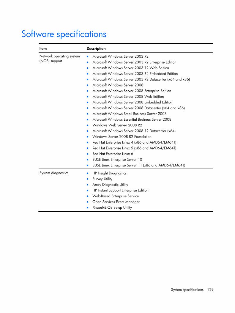
System specifications 129
Software specifications
Item Description
Network operating system (NOS) support
• Microsoft Windows Server 2003 R2 • Microsoft Windows Server 2003 R2 Enterprise Edition • Microsoft Windows Server 2003 R2 Web Edition • Microsoft Windows Server 2003 R2 Embedded Edition • Microsoft Windows Server 2003 R2 Datacenter (x64 and x86) • Microsoft Windows Server 2008 • Microsoft Windows Server 2008 Enterprise Edition • Microsoft Windows Server 2008 Web Edition • Microsoft Windows Server 2008 Embedded Edition • nd x86) Microsoft Windows Server 2008 Datacenter (x64 a• Microsoft Windows Small Business Server 2008
ness Server 2008 • Microsoft Windows Essential Busi• Windows Web Server 2008 R2 • Microsoft Windows Server 2008 R2 Datacenter (x64)
x86 and AMD64/EM64T)
11 (x86 and AMD64/EM64T)
• Windows Server 2008 R2 Foundation • Red Hat Enterprise Linux 4 (x86 and AMD64/EM64T) • Red Hat Enterprise Linux 5 (• Red Hat Enterprise Linux 6 • SUSE Linux Enterprise Server 10 • SUSE Linux Enterprise Server
System diagnostics gnostics
ition
ger • PhoenixBIOS Setup Utility
• HP Insight Dia• Survey Utility • Array Diagnostic Utility • HP Instant Support Enterprise Ed• Web-Based Enterprise Service • Open Services Event Mana
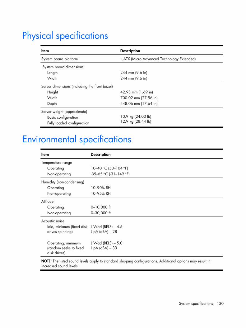
System specifications 130
Physical specifications
Item Description
System board platform uATX (Micro Advanced Technology Extended)
System board dimensions Length Width
244 mm (9.6 in) 244 mm (9.6 in)
Server dimensions (including the front bezel) Height Width Depth
42.93 mm (1.69 in) 700.02 mm (27.56 in) 448.06 mm (17.64 in)
Server weight (approximate) Basic configuration Fully loaded configuration
10.9 kg (24.03 lb) 12.9 kg (28.44 lb)
Environmental specifications
Item Description
Temperature range Operating Non-operating
10–40 °C (50–104 °F) -35–65 °C (-31–149 °F)
Humidity (non-condensing) Operating Non-operating
10–90% RH 10–95% RH
Altitude Operating Non-operating
0–10,000 ft 0–30,000 ft
Acoustic noise Idle, minimum (fixed disk drives spinning) Operating, minimum (random seeks to fixed disk drives)
L Wad (BELS) – 4.5 L pA (dBA) – 28 L Wad (BELS) – 5.0 L pA (dBA) – 33
NOTE: The listed sound levels apply to standard shipping configurations. Additional options may result in increased sound levels.
Index 131
Index
A AC power
power-down procedure, 30
status indicator, 119
admin password
changing, 103
removing, 103
resetting, 103
setting, 102
air baffle
removing, 53
B Basic Input/Output System, 83
battery
location, 70
replacement warnings, 70
replacing, 71
BIOS. See Basic Input/Output System
CMOS clear, 106
flashing, 108
recovering, 107
updating, 108
BIOS boot block, 107
BIOS splash screen
viewing, 105
boot sequence
default settings, 104
C cable management, 31
CMOS RAM
clearing, 106
definition, 84
POST error messages, 109
resetting, 106
core logic chipset
south bridge, 122
CSR. See customer self repair
Customer Self Repair, 5
D diagnostics
Array Diagnostic Utility, 81
HP Insight Diagnostics, 80
HP Instant Support Enterprise Edition, 81
IPMI Event Log, 82
Open Services Event Manager, 82
Phoenix SecureCore, 83
Survey Utility, 81
Web-Based Enterprise Service, 81
drive bay configuration
data cable management, 34
hard drives, 40
optical disc drive, 44
system drive bays, 33
E electrostatic discharge. See ESD
embedded NIC
front panel LED, 119
embedded NIC port
MAC address, 86
environmental specifications
acoustic noise, 126
altitude, 126
relative humidity, 126
temperature, 126
ESD
precautions, 29
work area recommendations, 29
expansion board
expansion slots, 60
installing, 63
PCI cage, 61
system board expansion slots, 60
expansion boards
installation guidelines, 63
F front panel, 111

Index 132
G General Help window, 85
H hard disk drive
configuring, 89
hard drive
installation guidelines, 40
installing, hot-plug, 41
installing, non-hot-plug, 42
s hot-plug backplane board, 38
status indicator, 119
storage controller, 122
supported drives, 40
hardware configuration
BIOS splash screen, 105
ESD damage prevention, 29
expansion board, 60
memory, 58
Phoenix SecureCore Setup Utility, 83
post-installation procedure, 30
power supply unit, 75
pre-installation procedure, 29
processor, 52
references, 27
SAS cache battery, 65
SAS controller board, 65
SAS HDD cable, 68
symbols in equipment, 28
system battery, 70
system drives, 33
system fans, 73
tools, 27
warnings/precautions, 27
hardware monitoring
internal health indicator, 118
heat sink
installing, 57
part number, 21
precaution, 53
removing, 53
hot-plug backplane board
configuration, 38
HP
contact information, 26
technical support, 26
I I/O ports
front panel, 111
listing, 123
rear panel, 112
I/O subsystem, 122
illustrated parts catalog
mechanical components, 16
system components, 20
installation guidelines
expansion boards, 63
hard drive, 40
optical disc drive, 44
IPMI Event Log
diagnostic, 82
viewing, 82
Item Specific Help panel, 85
M MAC address, 86
mechanical components, 16
Media Access Control. See MAC address
memory
DIMM part numbers, 21
DIMM slots location, 58
error LED indicator, 120
installation guidelines, 58
installing, 59
population sequence, 58
specifications, 123
memory controller, 122
multi-boot support, 104
N network operating system. See NOS support
NOS support, 125
O ODD bracket
installing, 46
removing, 45
onboard controllers
LAN, 122
memory controller, 122
storage controller, 122

Index 133
VGA, 122
optical disc drive
cable connections, 34
installation guidelines, 44
part numbers, 21
replacing, 45
supported drives, 44
P PCI cage
description, 61
reinstalling, 62
removing, 62
PCI slot cover
removing, 63
PCI slot cover retainer
removing, 63
Phoenix SecureCore
overview, 83
Phoenix SecureCore Setup Utility
flashing the BIOS, 108
Phoenix SecureCore Setup Utility
admin password, 101
Advanced menu, 88
BIOS recovery, 107
Boot menu, 103
clearing the CMOS RAM, 106
closing, 104
CMOS RAM, 84
General Help window, 85
Item Specific Help panel, 85
loading system defaults, 106
Main menu, 86
navigation keys, 85
non-user-configurable field, 85
overview, 83
recording Setup values, 105
running, 84
Security menu, 101
splash screen, 105
user-configurable field, 85
Phoenix SecureCore software
POST, 108
PhoenixBIOS Setup Utility
”Run Setup” message, 84
physical specifications
server, 126
system board, 126
POST. See Power On Self Test
power fluctuations, caution, 30
Power On Self Test
overview, 108
running, 108
power supply unit
installing, 78
part number, 22
replacement warnings, 76
power-down procedures, 30
Power-On-Self-Test
error indicators, 108
errors messages, 108
non-critical errors, 108
troubleshooting, 110
Preboot Execution Environment, 104
processor
configuring, 88
installation guidelines, 52
installing, 56
part numbers, 21
removing, 54
socket location, 52
technical specifications, 124
thermal compound, 55
PSU. See power supply unit, See power supply unit
part number, 21
power cable connections, hot-plug, 36
power cable connections, non-hot-plug, 37
specifications, 124
PXE. See Preboot Execution Environment
R rear panel, 112
recording Setup values
CMOS backup utility, 106
manual record, 106
S SAS cache battery
installing, 65
SAS controller board
installing, 65

Index 134
SAS hard drive
cable connections, 35
SAS cache battery, 65
SAS controller board, 65
SAS HDD cable, 68
SAS HDD cable
connecting, 68
connection, 35
part number, 22
SAS LED cable
connection, 35
part number, 22
SATA data cable
connections, 34
SATA hard drive
cable connections, 34
part number, 21
server management
configuring, 89
specification, 123
status LED indicators, 118
software specifications
NOS, 125
system diagnostics, 125
spare parts
mechanical components, 16
storing, 29
system components, 20
transporting, 29
standby mode
activating, 30
effects, 30
status indicator, 119
status LED indicators
embedded NIC, front, 119
hard drive activity, 119
internal health, 118
power, 119
system board, 120
UID, front, 118
system board
dimensions, 126
layout, 113
part numbers, 21
platform, 126
status LED indicators, 120
system components, 20
front panel, 111
rear panel, 112
system board, 113
system date
POST error message, 110
setting, 86
system fan
error LED indicator, 120
replacing, 73
system fans
cable connections, 73
device number, 73
installing, 74
part number, 22
removing, 74
system health
critical errors, 118
external indicator, 118
pre-failure component error, 118
system jumpers, 115
system time
POST error message, 110
setting, 86
T technical specifications
environmental, 126
hardware, 122
memory, 123
physical, 126
power supply unit, 124
processor, 124
software, 125
thermal compound, 55
thermal solution, 123
top cover
removing, 32
U uATX
Micro Advanced Technology Extended. See system board, platform
UID. See unit identification

Index 135
uninterruptible power supply. See UPS
unit identification
function, 115
LED indicator, front, 118
UPS, 30
V VGA controller, 122
W warranty, 5