Embed Size (px)
Citation preview

Less Work , More Ne twork
HP ProCurve Switch 2424M and 4000MManagement and Configuration Guide
ht tp : / /www .hp . com/go/procurve
HP ProCurve Switches and Hubs


tomcat.book Page i Wednesday, January 13, 1999 1:48 PM
HP ProCurve Switch 2424M and 4000M
Management and Configuration Guide

Hewlett-Packard Company8000 Foothills Boulevard, m/s 5552Roseville, California 95747-5552http://www.hp.com/go/procurve
© Copyright 1998 Hewlett-Packard CompanyAll Rights Reserved.
This document contains information which is protected by copyright. Reproduction, adaptation, or translation without prior permission is prohibited, except as allowed under the copyright laws.
Publication Number
5967-6967December 1998
Applicable Product
HP ProCurve Switch 4000M (J4121A)HP ProCurve Switch 2424M (J4093A)
Trademark Credits
Microsoft, Windows, Windows 95, and Microsoft Windows NT are registered trademarks of Microsoft Corporation. Internet Explorer is a trademark of Microsoft Corporation.Ethernet is a registered trademark of Xerox Corporation.Netscape is a registered trademark of Netscape Corporation.
Disclaimer
The information contained in this document is subject to change without notice.
HEWLETT-PACKARD COMPANY MAKES NO WARRANTY OF ANY KIND WITH REGARD TO THIS MATERIAL, INCLUDING, BUT NOT LIMITED TO, THE IMPLIED WARRANTIES OF MERCHANTABILITY AND FITNESS FOR A PARTICULAR PURPOSE. Hewlett-Packard shall not be liable for errors contained herein or for incidental or consequential damages in connection with the furnishing, performance, or use of this material.
Hewlett-Packard assumes no responsibility for the use or reliability of its software on equipment that is not furnished by Hewlett-Packard.
Warranty
See the Customer Support/Warranty booklet included with the product.
A copy of the specific warranty terms applicable to your Hewlett-Packard products and replacement parts can be obtained from your HP Sales and Service Office or authorized dealer.
tomcat.book Page ii Wednesday, January 13, 1999 1:48 PM

Preface
tomcat.book Page iii Wednesday, January 13, 1999 1:48 PM
Preface
Use of This Guide and Other Switch 2424M and Switch 4000M Documentation
This guide describes how to use the browser interface and console interface for the HP ProCurve Switch 2424M and HP ProCurve Switch 4000M (hereafter referred to as the “Switch 2424M and Switch 4000M”).
■ If you need information on specific parameters in the console interface, refer to the online help provided in the console interface.
■ If you need information on specific features in the HP Web Browser Interface (hereafter referred to as the “web browser interface”), use the online help available with the web browser interface. For more informa-tion on Help options, refer to “Online Help for the HP Web Browser Interface” on page 3-10.
■ If you need further information on Hewlett-Packard switch technology, refer to HP’s Network City website at:
http://www.hp.com/go/procurve
iii

tomcat.book Page iv Wednesday, January 13, 1999 1:48 PM

Contents
tomcat.book Page v Wednesday, January 13, 1999 1:48 PM
1 Selecting a Management Interface
Understanding Management Interfaces . . . . . . . . . . . . . . . . . . . . . . . . . 1-1
Advantages of Using the HP Web Browser Interface . . . . . . . . . . . . . 1-2
Advantages of Using the Switch Console . . . . . . . . . . . . . . . . . . . . . . . . 1-3
2 Configuring an IP Address on the Switch
Methods for Configuring an IP Address and Subnet Mask . . . . . . . 2-2
Manually Configuring an IP Address . . . . . . . . . . . . . . . . . . . . . . . . . . . 2-2
Where To Go From Here . . . . . . . . . . . . . . . . . . . . . . . . . . . . . . . . . . . . . 2-4
3 Using the HP Web Browser Interface
Overview . . . . . . . . . . . . . . . . . . . . . . . . . . . . . . . . . . . . . . . . . . . . . . . . . . . . . 3-1
Web Browser Interface Requirements . . . . . . . . . . . . . . . . . . . . . . . . . . 3-2
Starting an HP Web Browser Interface Session with the Switch . . 3-3
Using a Standalone Web Browser in a PC or UNIX Workstation . . . . 3-3
Using HP TopTools for Hubs & Switches . . . . . . . . . . . . . . . . . . . . . . . 3-4
Tasks for Your First HP Web Browser Interface Session . . . . . . . . . 3-6
Viewing the “First Time Install” Window . . . . . . . . . . . . . . . . . . . . . . . . 3-6
Creating Usernames and Passwords in the Browser Interface . . . . . . 3-8
Online Help for the HP Web Browser Interface . . . . . . . . . . . . . . . . . 3-10
The Web Browser Interface Screen Layout . . . . . . . . . . . . . . . . . . . . 3-12
The Overview Window . . . . . . . . . . . . . . . . . . . . . . . . . . . . . . . . . . . . . . 3-12
The Port Utilization and Status Displays . . . . . . . . . . . . . . . . . . . . . . . 3-14
The Alert Log . . . . . . . . . . . . . . . . . . . . . . . . . . . . . . . . . . . . . . . . . . . . . . 3-16
The Tab Bar . . . . . . . . . . . . . . . . . . . . . . . . . . . . . . . . . . . . . . . . . . . . . . . 3-21
Setting Fault Detection Policy . . . . . . . . . . . . . . . . . . . . . . . . . . . . . . . . 3-25
v

tomcat.book Page vi Wednesday, January 13, 1999 1:48 PM
4 Using the Switch Console Interface
Overview . . . . . . . . . . . . . . . . . . . . . . . . . . . . . . . . . . . . . . . . . . . . . . . . . . . . . 4-1
Starting and Ending a Console Session . . . . . . . . . . . . . . . . . . . . . . . . . 4-2
How To Start a Console Session: . . . . . . . . . . . . . . . . . . . . . . . . . . . . . . 4-2
How To End a Console Session: . . . . . . . . . . . . . . . . . . . . . . . . . . . . . . . 4-3
Main Menu Features . . . . . . . . . . . . . . . . . . . . . . . . . . . . . . . . . . . . . . . . . . 4-4
Screen Structure and Navigation . . . . . . . . . . . . . . . . . . . . . . . . . . . . . . . 4-6
Using Password Security . . . . . . . . . . . . . . . . . . . . . . . . . . . . . . . . . . . . . . . 4-9
To set Manager and Operator passwords: . . . . . . . . . . . . . . . . . . . . . . 4-10
Rebooting the Switch . . . . . . . . . . . . . . . . . . . . . . . . . . . . . . . . . . . . . . . . . 4-12
The Command Prompt . . . . . . . . . . . . . . . . . . . . . . . . . . . . . . . . . . . . . . . . 4-14
5 Using HP TopTools or Other SNMP Tools To Monitor and
Manage the Switch
SNMP Management Features . . . . . . . . . . . . . . . . . . . . . . . . . . . . . . . . . . 5-1
SNMP Configuration Process . . . . . . . . . . . . . . . . . . . . . . . . . . . . . . . . . . 5-3
Advanced Management: RMON and HP Extended RMON Support 5-4
RMON . . . . . . . . . . . . . . . . . . . . . . . . . . . . . . . . . . . . . . . . . . . . . . . . . . . . . 5-4
Extended RMON . . . . . . . . . . . . . . . . . . . . . . . . . . . . . . . . . . . . . . . . . . . . 5-4
6 Configuring the Switch
Overview . . . . . . . . . . . . . . . . . . . . . . . . . . . . . . . . . . . . . . . . . . . . . . . . . . . . . 6-1
Configuration Features . . . . . . . . . . . . . . . . . . . . . . . . . . . . . . . . . . . . . . . 6-2
Support URLs Feature . . . . . . . . . . . . . . . . . . . . . . . . . . . . . . . . . . . . . . . . . 6-4
Support URL . . . . . . . . . . . . . . . . . . . . . . . . . . . . . . . . . . . . . . . . . . . . . . . 6-4
Management Server URL . . . . . . . . . . . . . . . . . . . . . . . . . . . . . . . . . . . . . 6-5
IP Configuration . . . . . . . . . . . . . . . . . . . . . . . . . . . . . . . . . . . . . . . . . . . . . . 6-6
Configuring IP Addressing from the Web Browser Interface . . . . . . . 6-7
Configuring IP Addressing from the Switch Console . . . . . . . . . . . . . . 6-8
How IP Addressing Affects Switch Operation . . . . . . . . . . . . . . . . . . . 6-10
DHCP/Bootp Operation . . . . . . . . . . . . . . . . . . . . . . . . . . . . . . . . . . . . . 6-11
Globally Assigned IP Network Addresses . . . . . . . . . . . . . . . . . . . . . . 6-15
vi

tomcat.book Page vii Wednesday, January 13, 1999 1:48 PM
SNMP Communities . . . . . . . . . . . . . . . . . . . . . . . . . . . . . . . . . . . . . . . . . . 6-16
Configuring SNMP Communities from the Switch Console . . . . . . . 6-16
Trap Receivers . . . . . . . . . . . . . . . . . . . . . . . . . . . . . . . . . . . . . . . . . . . . . . 6-19
Console/Serial Link . . . . . . . . . . . . . . . . . . . . . . . . . . . . . . . . . . . . . . . . . . 6-21
Configuring the Console/Serial Link from the Switch Console . . . . . 6-22
System Information . . . . . . . . . . . . . . . . . . . . . . . . . . . . . . . . . . . . . . . . . . 6-23
Configuring System Parameters from the Web Browser Interface . 6-23
Configuring System Information from the Console . . . . . . . . . . . . . . 6-24
Port Settings . . . . . . . . . . . . . . . . . . . . . . . . . . . . . . . . . . . . . . . . . . . . . . . . . 6-25
Configuring Port Parameters from the Web Browser Interface . . . . 6-27
Configuring Port Parameters from the Switch Console . . . . . . . . . . . 6-28
Network Monitoring Port Features . . . . . . . . . . . . . . . . . . . . . . . . . . . 6-29
Configuring Port Monitoring from the Web Browser Interface . . . . 6-29
Configuring Port Monitoring from the Switch Console . . . . . . . . . . . 6-31
Spanning Tree Protocol (STP) . . . . . . . . . . . . . . . . . . . . . . . . . . . . . . . . 6-34
Enabling STP from the Web Browser Interface . . . . . . . . . . . . . . . . . 6-35
Configuring STP from the Switch Console . . . . . . . . . . . . . . . . . . . . . 6-36
How STP Operates . . . . . . . . . . . . . . . . . . . . . . . . . . . . . . . . . . . . . . . . . 6-37
Traffic/Security Filter Features . . . . . . . . . . . . . . . . . . . . . . . . . . . . . 6-40
Configuring Traffic/Security Filters from the Switch Console . . . . . 6-40
Filter Types and Operation . . . . . . . . . . . . . . . . . . . . . . . . . . . . . . . . . . 6-43
Port-Based Virtual LANs (VLANs) . . . . . . . . . . . . . . . . . . . . . . . . . . . . 6-45
Overview of Using VLANs . . . . . . . . . . . . . . . . . . . . . . . . . . . . . . . . . . . 6-48
Configuring VLAN Parameters from the Switch Console . . . . . . . . . 6-49
VLAN Tagging Information . . . . . . . . . . . . . . . . . . . . . . . . . . . . . . . . . . 6-55
Effect of VLANs on Other Switch Features . . . . . . . . . . . . . . . . . . . . . 6-59
VLAN Restrictions . . . . . . . . . . . . . . . . . . . . . . . . . . . . . . . . . . . . . . . . . . 6-61
Load Balancing: Port Trunking . . . . . . . . . . . . . . . . . . . . . . . . . . . . . . . . 6-63
Interoperability . . . . . . . . . . . . . . . . . . . . . . . . . . . . . . . . . . . . . . . . . . . . 6-65
Trunk Configuration Options . . . . . . . . . . . . . . . . . . . . . . . . . . . . . . . . . 6-65
Configuring Port Trunks from the Switch Console . . . . . . . . . . . . . . 6-66
Operating Information . . . . . . . . . . . . . . . . . . . . . . . . . . . . . . . . . . . . . . 6-69
vii

tomcat.book Page viii Wednesday, January 13, 1999 1:48 PM
IP Multicast (IGMP) Features—Multimedia Traffic Control . . . . 6-71
Configuring IGMP from the Web Browser Interface . . . . . . . . . . . . . 6-72
Configuring IGMP from the Switch Console . . . . . . . . . . . . . . . . . . . . 6-74
How IGMP Operates . . . . . . . . . . . . . . . . . . . . . . . . . . . . . . . . . . . . . . . . 6-76
7 Monitoring and Analyzing Switch Operation
Overview . . . . . . . . . . . . . . . . . . . . . . . . . . . . . . . . . . . . . . . . . . . . . . . . . . . . . 7-1
Status and Counters Screens . . . . . . . . . . . . . . . . . . . . . . . . . . . . . . . . . . 7-2
Switch Console Status and Counters Menu . . . . . . . . . . . . . . . . . . . . . 7-3
Web Browser Interface Status Information . . . . . . . . . . . . . . . . . . . . . 7-4
General System Information . . . . . . . . . . . . . . . . . . . . . . . . . . . . . . . . . . 7-5
Switch Management Address Information . . . . . . . . . . . . . . . . . . . . . . . 7-6
Module Information . . . . . . . . . . . . . . . . . . . . . . . . . . . . . . . . . . . . . . . . . 7-7
Port Status . . . . . . . . . . . . . . . . . . . . . . . . . . . . . . . . . . . . . . . . . . . . . . . . . . . 7-8
Displaying Port Status from the Web Browser Interface . . . . . . . . . . . 7-8
Displaying Port Status from the Console Interface . . . . . . . . . . . . . . . 7-9
Port Counters . . . . . . . . . . . . . . . . . . . . . . . . . . . . . . . . . . . . . . . . . . . . . . . . 7-10
Displaying Port Counters from the Web Browser Interface . . . . . . . 7-11
Displaying Port Counters from the Console Interface . . . . . . . . . . . . 7-12
Address Table . . . . . . . . . . . . . . . . . . . . . . . . . . . . . . . . . . . . . . . . . . . . . . . . 7-14
Port Address Table . . . . . . . . . . . . . . . . . . . . . . . . . . . . . . . . . . . . . . . . . . . 7-15
Spanning Tree (STP) Information . . . . . . . . . . . . . . . . . . . . . . . . . . . . . 7-17
IP Multicast (IGMP) Status . . . . . . . . . . . . . . . . . . . . . . . . . . . . . . . . . . . 7-19
VLAN Information . . . . . . . . . . . . . . . . . . . . . . . . . . . . . . . . . . . . . . . . . . . . 7-21
8 Troubleshooting
Troubleshooting Approaches . . . . . . . . . . . . . . . . . . . . . . . . . . . . . . . . . . . 8-2
Browser or Console Access Problems . . . . . . . . . . . . . . . . . . . . . . . . . . . 8-3
Unusual Network Activity . . . . . . . . . . . . . . . . . . . . . . . . . . . . . . . . . . . . . 8-4
Using the Event Log To Identify Problem Sources . . . . . . . . . . . . . . . 8-8
viii

tomcat.book Page ix Wednesday, January 13, 1999 1:48 PM
Diagnostics . . . . . . . . . . . . . . . . . . . . . . . . . . . . . . . . . . . . . . . . . . . . . . . . . . 8-13
Ping and Link Tests . . . . . . . . . . . . . . . . . . . . . . . . . . . . . . . . . . . . . . . . . 8-13
The Configuration File . . . . . . . . . . . . . . . . . . . . . . . . . . . . . . . . . . . . . . 8-17
Using the Command Prompt . . . . . . . . . . . . . . . . . . . . . . . . . . . . . . . . . 8-19
Restoring the Factory Default Configuration . . . . . . . . . . . . . . . . . . 8-20
A File Transfers
Overview . . . . . . . . . . . . . . . . . . . . . . . . . . . . . . . . . . . . . . . . . . . . . . . . . . . . A-1
Downloading an Operating System (OS) . . . . . . . . . . . . . . . . . . . . . . . A-1
Using TFTP To Download the OS File . . . . . . . . . . . . . . . . . . . . . . . . . A-2
Using the SNMP-Based HP Download Manager . . . . . . . . . . . . . . . . . A-4
Switch-to-Switch Download . . . . . . . . . . . . . . . . . . . . . . . . . . . . . . . . . A-4
Using Xmodem to Download the OS File . . . . . . . . . . . . . . . . . . . . . . . A-5
Troubleshooting TFTP Downloads . . . . . . . . . . . . . . . . . . . . . . . . . . . . A-6
Transferring Switch Configurations . . . . . . . . . . . . . . . . . . . . . . . . . . . A-8
B MAC Address Management
Overview . . . . . . . . . . . . . . . . . . . . . . . . . . . . . . . . . . . . . . . . . . . . . . . . . . . . B-1
Determining the MAC Addresses . . . . . . . . . . . . . . . . . . . . . . . . . . . . . . B-1
The Base and VLAN MAC Addresses . . . . . . . . . . . . . . . . . . . . . . . . . . B-2
Switch Port MAC Addresses . . . . . . . . . . . . . . . . . . . . . . . . . . . . . . . . . B-3
ix

tomcat.book Page x Wednesday, January 13, 1999 1:48 PM

Selecting a Managem
ent Interface
tomcat.book Page 1 Wednesday, January 13, 1999 1:48 PM
1
Selecting a Management Interface
This chapter describes the following:
■ Management interfaces for the Switch 4000M and the Switch 2424M
■ Advantages of using each interface
Understanding Management Interfaces
Management interfaces enable you to reconfigure the switch and to monitor switch status and performance.
The HP Switch 4000M and the Switch 2424M offer the following interfaces:
■ the web browser interface --an interface that is built into the switch and can be accessed using a standard web browser (such as Netscape Navigator or Microsoft Internet Explorer). For specific requirements, see “Web Browser Interface Requirements” on page 3-2.
■ the switch console—a VT-100/ANSI console interface built into the switch
■ HP TopTools for Hubs & Switches--an easy-to-use, browser-based network management tool that works with HP proactive networking features built into managed HP hubs and switches (included on a CD with the switch at no extra cost)
Each interface consists of a series of management features, accessed either through a menu-driven screen system or a split Window with tab navigation. Each approach has its advantages that are described in the next sections.
This manual describes how to use the web browser interface (chapter 3) and the switch console (chapter 4), and how to configure the switch using either interface (chapter 6).
To use HP TopTools for Hubs & Switches, refer to the HP TopTools User’s
Guide and the TopTools online help, both of which are available on the CD-ROM shipped with your HP switch. For information on the methods for accessing browser interface Help for the Switch 4000M and Switch 2424M, refer to “Online Help for the Web Browser Interface” on page 3-10.
1-1
Selecting a Management InterfaceAdvantages of Using the HP Web Browser Interface
Sele
ctin
g a
Man
agem
ent
Inte
rfac
e
tomcat.book Page 2 Wednesday, January 13, 1999 1:48 PM
Advantages of Using the HP Web Browser Interface
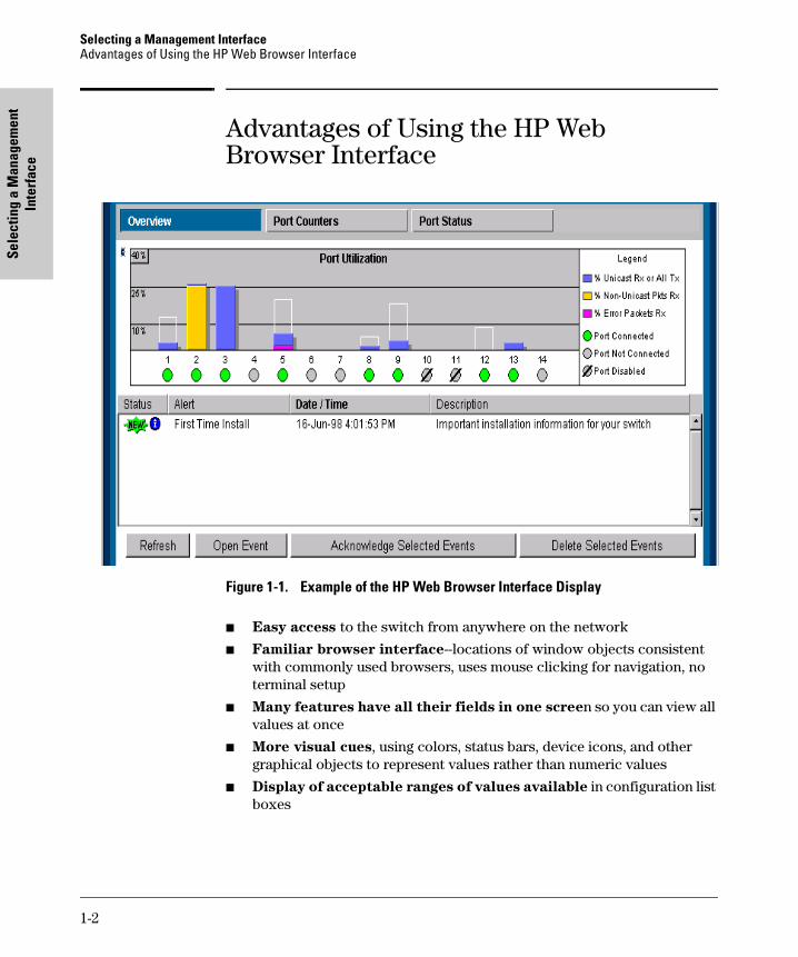
Figure 1-1. Example of the HP Web Browser Interface Display
■ Easy access to the switch from anywhere on the network
■ Familiar browser interface--locations of window objects consistent with commonly used browsers, uses mouse clicking for navigation, no terminal setup
■ Many features have all their fields in one screen so you can view all values at once
■ More visual cues, using colors, status bars, device icons, and other graphical objects to represent values rather than numeric values
■ Display of acceptable ranges of values available in configuration list boxes
1-2

Selecting a Management InterfaceAdvantages of Using the Switch Console
Selecting a Managem
ent Interface
tomcat.book Page 3 Wednesday, January 13, 1999 1:48 PM
Advantages of Using the Switch Console
Figure 1-2. Example of the Console Interface Display
■ Contains a complete set of features and parameters
■ Out-of-band access (through RS-232 connection) to switch, so network bottlenecks, crashes, lack of configured or correct IP address, and network downtime do not slow or prevent access
■ Ability to configure management access, for example, creating an IP address, and setting Community Names and Authorized Managers
■ Telnet access to the full console functionality
■ Faster navigation, avoiding delays that occur with slower display of graphical objects over a web browser interface
■ More secure; configuration information and passwords are not seen on the network
1-3

Selecting a Management InterfaceAdvantages of Using the Switch Console
Sele
ctin
g a
Man
agem
ent
Inte
rfac
e
tomcat.book Page 4 Wednesday, January 13, 1999 1:48 PM
HP TopTools for Hubs & Switches
You can operate HP TopTools from a PC on the network to monitor traffic, manage your hubs and switches, and proactively recommend network changes to increase network uptime and optimize performance. Easy to install and use, HP TopTools for Hubs & Switches (formerly HP AdvanceStack Assistant) is the answer to your management challenges.
Figure 1-3. Example of HP TopTools Main Screen
HP TopTools for Hubs& Switches has three main sections: Network Devices, Hetwork Traffic, and Network Growth
Network Devices:
■ Enables fast installation of hubs and switches.
■ Quickly finds and notifies you of the location of problems, saving valuable time.
■ Notifies you when HP hubs use “self-healing” features to fix or limit common network problems.
■ Identifies users by port and lets you assign easy-to-remember names to any network device.
■ Enables you to configure and monitor network devices from your PC.
1-4

Selecting a Management InterfaceAdvantages of Using the Switch Console
Selecting a Managem
ent Interface
tomcat.book Page 5 Wednesday, January 13, 1999 1:48 PM
Network Traffic:
■ Watches the network for problems.
■ Shows traffic and “top talker” nodes on screen.
■ Uses traffic monitor diagrams to make bottlenecks easy to see.
■ Improves network reliability through real-time fault isolation.
■ See your entire network without having to put RMON probes on every segment (up to 1500 segments).
Network Growth:
■ Monitors, stores, and analyzes network traffic to determine where upgrades are needed.
■ Uses Network Performance Advisor to give clear, easy-to-follow plans detailing the most cost-effective way to upgrade your network.
1-5

tomcat.book Page 6 Wednesday, January 13, 1999 1:48 PM
Configuring an IP Address
on the Switch
tomcat.book Page 1 Wednesday, January 13, 1999 1:48 PM
2
Configuring an IP Address on the Switch
This chapter helps you to quickly assign an IP (Internet Protocol) address and subnet mask to the switch. In the factory default configuration, the switch does not have an IP address and subnet mask, so it can be managed only by using a direct connection to the switch console.
Configuring an IP (Internet Protocol) address and subnet mask enables the switch to operate as a managed device in your network, giving you in-band (networked) access to these interfaces:
■ HP web browser interface built into the switch
■ HP TopTools for Hubs & Switches—SNMP-based network management software shipped with the switch
■ the switch console through a telnet connection
For a listing of switch features available with and without an IP address, refer to “How IP Addressing Affects Switch Operation” on page 6-10.
For more information on this topic, refer to “IP Configuration” on page 6-6.
N o t e The IP address and subnet mask assigned for the switch should be compatible with the IP addressing used in your network. If your network is a standalone network, your IP addressing and subnet mask scheme can be set up in any way that meets your local needs. However, if you will be connecting your network to other networks that use globally assigned IP addresses, refer to “Globally Assigned Network Addresses” on page 6-15.
2-1

Configuring an IP Address on the SwitchMethods for Configuring an IP Address and Subnet Mask
Conf
igur
ing
an IP
Add
ress
on
the
Switc
h
tomcat.book Page 2 Wednesday, January 13, 1999 1:48 PM
Methods for Configuring an IP Address and Subnet Mask
If the switch has not already been configured with an IP address and subnet mask compatible with your network, use either of the following two methods to do so:
■ Manually through the switch’s console: This is the easiest method if you have direct-connect or modem access to a terminal emulator on a PC (such as HyperTerminal in Windows 95 or Windows NT), or a direct connection to a VT-100 ASCII terminal. Refer to “Manually Configuring an IP Address” on the next page.
■ Configure your DHCP/Bootp server to support the switch: By default, the switch is configured to acquire an IP address configuration from a DHCP or Bootp server. To use DHCP/Bootp, refer to “DHCP/Bootp Operation” on page 6-11.
Manually Configuring an IP Address
This section describes how to use the switch console to configure an IP address. The following assumes that no VLANs have been configured on the switch.
N o t e In its factory default configuration, all ports on the switch belong to one, default virtual LAN (VLAN), and only one IP address is needed. If you configure the switch with more than one VLAN, each VLAN may have its own IP address. For more on VLANs, refer to “Port-Based Virtual LANs (VLANs)” on page 6-45.
1. Use the instructions in your switch installation manual to connect a PC running a terminal emulator, or a terminal, to the Console port on the switch, and display the Main Menu.
2. From the Main Menu, select
2. Switch Management Access Configuration
1. IP Configuration
You will see a screen similar to the one shown in figure 2-1.
2-2
Configuring an IP Address on the SwitchManually Configuring an IP Address
Configuring an IP Address
on the Switch
tomcat.book Page 3 Wednesday, January 13, 1999 1:48 PM
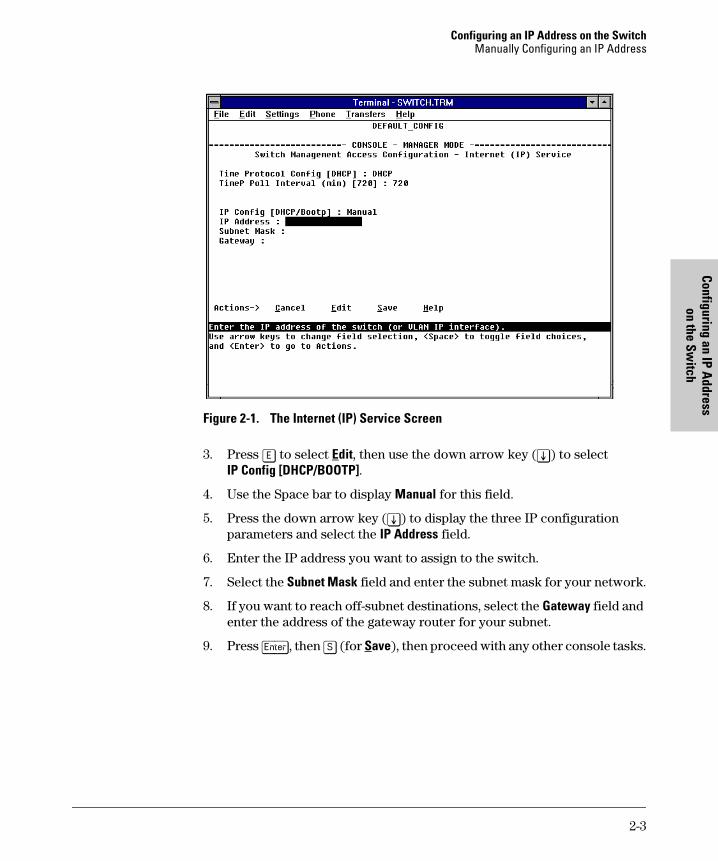
Figure 2-1. The Internet (IP) Service Screen
3. Press [E] to select Edit, then use the down arrow key ([v]) to select IP Config [DHCP/BOOTP].
4. Use the Space bar to display Manual for this field.
5. Press the down arrow key ([v]) to display the three IP configuration parameters and select the IP Address field.
6. Enter the IP address you want to assign to the switch.
7. Select the Subnet Mask field and enter the subnet mask for your network.
8. If you want to reach off-subnet destinations, select the Gateway field and enter the address of the gateway router for your subnet.
9. Press [Enter], then [S] (for Save), then proceed with any other console tasks.
2-3

Configuring an IP Address on the SwitchManually Configuring an IP Address
Conf
igur
ing
an IP
Add
ress
on
the
Switc
h
tomcat.book Page 4 Wednesday, January 13, 1999 1:48 PM
Where To Go From Here
The above procedure configures your switch with an IP address and subnet mask. With the proper network connections, you can now manage the switch from a network management station or from a PC equipped with a web browser.
■ To access the switch using a web browser, refer to chapter 3, “Using the HP Web Browser Interface”.
■ To continue to use the console interface, refer to chapter 4, “Using the Switch Console Interface”.
■ To access the switch using a network management tool, refer to chapter 5, “Using HP TopTools or Other SNMP Tools to Monitor and Manage the Switch”.
■ Inbound telnet access to the switch is enabled in the factory default.
• To change the current telnet access parameter, turn to “Using the Switch Console To Configure the Console/Serial Link” on page 6-22.
• To use telnet to access the switch console, refer to “Starting and Ending a Console Session” on page 4-2.
You can also start a telnet session to the switch console from the web browser interface. Click on the Configuration tab in the web browser interface, then click on telnet session to the switch console. If you need information on how to access the switch via the web browser inter-face, refer to chapter 3, “Using the HP Web Browser Interface”.
■ For problems or error indications, refer to chapter 8, “Troubleshooting”.
2-4

Using the H
P Web B
rowser
Interface
tomcat.book Page 1 Wednesday, January 13, 1999 1:48 PM
3
Using the HP Web Browser Interface
Overview
The HP web browser interface built into the switch lets you easily access the switch from a browser-based PC on your network. This lets you do the following:
■ optimize your network uptime by using the Alert Log and other diagnostic tools
■ make configuration changes to the switch
■ maintain security by configuring usernames and passwords
Using the web browser interface to configure the switch is covered in chapter 6, “Configuring the Switch”. This chapter covers the following:
■ system requirements for using the web browser interface (page 3-2)
■ starting a web browser interface session (page 3-3)
■ tasks for your first web browser interface session (page 3-6)
• creating usernames and passwords in the web browser interface (page 3-8)
• selecting the fault detection configuration for the Alert Log operation (page 3-25)
• getting access to online help for the web browser interface (page 3-10)
■ description of the web browser interface:
• the Overview window and tabs (page 3-12)
• the Port Utilization and Status displays (page 3-14)
• the Alert Log and Alert types (page 3-16)
• setting the Fault Detection Policy (page 3-25)
N o t e If you want security beyond that achieved with user names and passwords, you can disable access to the web browser interface. This is done by changing the Web Agent Enabled parameter setting in the Serial Link configuration screen in the switch console. See “Console/Serial Link” on page 6-21.
3-1
Using the HP Web Browser InterfaceWeb Browser Interface Requirements
Usi
ng th
e H
P W
eb B
row
ser
Inte
rfac
e
tomcat.book Page 2 Wednesday, January 13, 1999 1:48 PM
Web Browser Interface Requirements
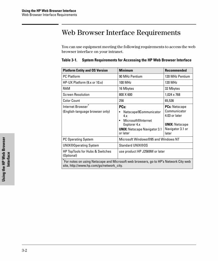
You can use equipment meeting the following requirements to access the web browser interface on your intranet.
Table 3-1. System Requirements for Accessing the HP Web Browser Interface
Platform Entity and OS Version Minimum Recommended
PC Platform 90 MHz Pentium 120 MHz Pentium
HP-UX Platform (9.x or 10.x) 100 MHz 120 MHz
RAM 16 Mbytes 32 Mbytes
Screen Resolution 800 X 600 1,024 x 768
Color Count 256 65,536
Internet Browser*
(English-language browser only)PCs:• Netscape® Communicator
4.x• Microsoft® Internet
Explorer 4.xUNIX: Netscape Navigator 3.1 or later
PCs: Netscape Communicator 4.03 or later
UNIX: Netscape Navigator 3.1 or later
PC Operating System Microsoft Windows® 95 and Windows NT
UNIX® Operating System Standard UNIX® OS
HP TopTools for Hubs & Switches (Optional)
use product HP J2569M or later
*For notes on using Netscape and Microsoft web browsers, go to HP’s Network City web site, http://www.hp.com/go/network_city.
3-2

Using the HP Web Browser InterfaceStarting an HP Web Browser Interface Session with the Switch
Using the H
P Web B
rowser
Interface
tomcat.book Page 3 Wednesday, January 13, 1999 1:48 PM
Starting an HP Web Browser Interface Session with the Switch
You can start a web browser session in the following ways:
■ Using a standalone web browser on a network connection from a PC or UNIX workstation:
• directly connected to your network
• connected through remote access to your network
■ Using a management station running HP TopTools for Hubs & Switches on your network.
N o t e HP TopTools is designed for installation on a network management worksta-tion. For this reason, the HP TopTools system requirements are different from the system requirements for accessing the switch’s web browser interface from a non-management PC or workstation. For HP TopTools requirements, refer to the information printed on the sleeve in which the HP TopTools CD is shipped, or to the system requirements information in the user’s guide included on the HP TopTools CD.
Using a Standalone Web Browser in a PC or UNIX Workstation
This procedure assumes that you have a supported web browser (page 3-2) installed on your PC or workstation, and that an IP address has been config-ured on the switch. (For more on assigning an IP address, refer to chapter 2, “Configuring an IP Address on the Switch”.)
1. Make sure the JavaTM applets are enabled for your browser. If they are not, do one of the following:
• In Netscape 4.03, click on Edit, Preferences..., Advanced, then select Enable Java and Enable JavaScript options.
• In Microsoft Internet Explorer 4.x, click on View, Internet Options, Security, Custom, [Settings] and scroll to the Java Permissions. Then refer to the online Help for specific information on enabling the Java applets.
3-3

Using the HP Web Browser InterfaceStarting an HP Web Browser Interface Session with the Switch
Usi
ng th
e H
P W
eb B
row
ser
Inte
rfac
e
tomcat.book Page 4 Wednesday, January 13, 1999 1:48 PM
2. Type the IP address (or DNS name) of the switch in the browser Location or Address field and press [Enter]. (It is not necessary to include http://.)
switch4000 [Enter] (example of a DNS-type name)
10.11.12.195 [Enter] (example of an IP address)
If you are using a Domain Name Server (DNS), your device may have a name associated with it (for example, switch4000) that you can type in the Location or Address field instead of the IP address. Using DNS names typically improves browser performance. See your network administrator for any name associated with the switch.
The web browser interface automatically starts with the Status Overview window displayed for the selected device as shown in figure 3-1 on page 3-5.
Using HP TopTools for Hubs & Switches
For information on HP TopTools web browser and system requirements, refer to the information printed on the sleeve in which the HP TopTools CD is shipped, or to the system requirements information in the user’s guide included on the HP TopTools CD.
This procedure assumes that:
■ You have installed the web browser recommended for HP TopTools on a PC or workstation that serves as your network management station.
■ The networked device you want to access has been assigned an IP address and (optionally) a DNS name and has been discovered by HP TopTools. (For more on assigning an IP address, refer to chapter 2, “Configuring an IP Address on the Switch”.)
To establish a web browser session with HP TopTools running, do the following on the network management station:
1. Make sure the JavaTM applets are enabled for your web browser. If they are not, refer to the web browser online Help for specific information on enabling the Java applets.
2. Do one of the following tasks:
• On the HP TopTools Maps view, double-click on the symbol for the networking device that you want to access.
• In HP TopTools, in the Topology Information dialog box, in the device list, double-click on the entry for the device you want to access (IP address or DNS name).
3-4

Using the HP Web Browser InterfaceStarting an HP Web Browser Interface Session with the Switch
Using the H
P Web B
rowser
Interface
tomcat.book Page 5 Wednesday, January 13, 1999 1:48 PM
3. The web browser interface automatically starts with the Status Overview window displayed for the selected device, as shown in figure 3-1.
Figure 3-1. Status Overview Screen
Alert Log
First-TimeInstall Alert
3-5

Using the HP Web Browser InterfaceTasks for Your First HP Web Browser Interface Session
Usi
ng th
e H
P W
eb B
row
ser
Inte
rfac
e
tomcat.book Page 6 Wednesday, January 13, 1999 1:48 PM
Tasks for Your First HP Web Browser Interface Session
The first time you access the web browser interface, there are three tasks that you should perform:
■ Review the “First Time Install” window
■ Set Manager and Operator passwords
■ Set access to the web browser interface online help
Viewing the “First Time Install” Window
When you access the switch’s web browser interface for the first time, the Alert log contains a “First Time Install” alert, as shown in figure 3-1. This gives you information about first time installations, and provides an immediate opportunity to set passwords for security and to specify a Fault Detection policy, which determines the types of messages that will be displayed in the Alert Log.
Double click on First Time Install in the Alert log (see above). The web browser interface then displays the “First Time Install” window, as shown in figure 3-2.
Figure 3-2. First-Time Install Window
3-6

Using the HP Web Browser InterfaceTasks for Your First HP Web Browser Interface Session
Using the H
P Web B
rowser
Interface
tomcat.book Page 7 Wednesday, January 13, 1999 1:48 PM
This window is the launching point for the basic configuration you need to perform to set web browser interface passwords to maintain security and Fault Detection policy, which determines the types of messages that will be displayed in the Alert Log.
To set web browser interface passwords, click on the jump string secure access to the device to display the Device Passwords screen, and then go to the next page. You can also access the password screen by clicking on the Security tab.
To set Fault Detection policy, click on the jump string select the fault detection configuration in the second bullet in the window and go to the section, “Setting Fault Detection Policy” on page 3-25.
3-7

Using the HP Web Browser InterfaceTasks for Your First HP Web Browser Interface Session
Usi
ng th
e H
P W
eb B
row
ser
Inte
rfac
e
tomcat.book Page 8 Wednesday, January 13, 1999 1:48 PM
Creating Usernames and Passwords in the Browser Interface
You may want to create both a username and password to create access security for your switch. There are two levels of access to the interface that can be controlled by setting user names and passwords:
■ Operator. An Operator-level user name and password allows read-only access to most of the web browser interface, but prevents access to the Security window.
■ Manager. A Manager-level user name and password allows full read/write access to the web browser interface.
Figure 3-3. The Device Passwords Window
To set the passwords:
1. Access the Device Passwords screen by one of the following methods:
• If the Alert Log includes a “First Time Install” event entry, double click on this event, then, in the resulting display, click on the secure access to the device link.
• Select the Security tab.
3-8

Using the HP Web Browser InterfaceTasks for Your First HP Web Browser Interface Session
Using the H
P Web B
rowser
Interface
tomcat.book Page 9 Wednesday, January 13, 1999 1:48 PM
2. Click in the appropriate box in the Device Passwords window and enter user names and passwords. You will be required to repeat the password strings in the confirmation boxes.
Both the user names and passwords can be up to 16 printable ASCII characters.
3. Click on [Apply Changes] to activate the user names and passwords.
N o t e Strings you assign in the web browser interface will overwrite previous access strings assigned in either the web browser interface or the switch console.
Using the Passwords
The manager and operator passwords are used to control access to both the web browser interface and the switch console. Once set, you will be chal-lenged to supply the password every time you try to access either the web browser interface or switch console. The password you enter determines the capability you have during that session:
■ Entering the manager password gives you full read/write capabilities
■ Entering the operator password gives you read and limited write capabil-ities.
Using the User Names
If you also set user names in the web browser interface screen, you must supply the correct user name for web browser interface access, but switch console access requires only the password. If a user name has not been set, you must leave the User Name field in the web browser interface access popup blank.
The switch console uses only the passwords and does not prompt you for the User Names.
If You Lose a Password
If you lose the passwords, you can clear them by pressing the Clear button on the front of the switch. This action deletes all password and user name protection for both the web browser interface and the switch console.
The Clear button is provided for your convenience, but its presence means
that if you are concerned with the security of the switch configuration and
operation, you should make sure the switch is installed in a secure location,
such as a locked wiring closet.
3-9

Using the HP Web Browser InterfaceTasks for Your First HP Web Browser Interface Session
Usi
ng th
e H
P W
eb B
row
ser
Inte
rfac
e
tomcat.book Page 10 Wednesday, January 13, 1999 1:48 PM
Online Help for the HP Web Browser Interface
Online Help is available for the web browser interface. You can use it by clicking on the question mark in the upper right corner of any of the web browser interface screens. Context-sensitive help is provided for the screen you are on.
Providing Online Help. The Help files are automatically available if you
install HP TopTools for Hubs & Switches on your network or if you already
have Internet access to the World Wide Web. (The Help files are included with HP TopTools for Hubs & Switches, and are also automatically available from HP via the World Wide Web.)
Retrieval of the Help files as described above is controlled by automatic entries to the Management Server URL field on the Configuration / Support URLs screen, shown in figure 3-4. The switch is shipped with the URL set to retrieve online Help from the HP World Wide Web site. However, if HP TopTools for Hubs & Switches is installed on a management station on your network and discovers the switch, the Management Server URL is automatically changed to retrieve the Help from your TopTools management station.
If Online Help Fails To Operate. Do one of the following:
■ If HP TopTools for Hubs & Switches is installed and running on your network, enter the IP address or DNS name of the network management station in the Management Server URL field shown in figure 3-4 on page 3-11.
■ If you have World Wide Web access from your PC or workstation, and do not have HP TopTools installed on your network, enter the following URL in the Management Server URL field shown in figure 3-4 on page 3-11:
http://www.hp.com/rnd/device_help
3-10

Using the HP Web Browser InterfaceTasks for Your First HP Web Browser Interface Session
Using the H
P Web B
rowser
Interface
tomcat.book Page 11 Wednesday, January 13, 1999 1:48 PM
Figure 3-4. How To Access Web Browser Interface Online Help
If you do not have HP TopTools for Hubs and Switches installed on your network and do not have an active connection to the World Wide Web, then Online help for the web browser interface will not be available.
See also “Support URLs Feature” on page 6-4.
Enter IP address of HP TopTools network management station, or URL of location of help files on HP’s World Wide Web site here.
3-11

Using the HP Web Browser InterfaceThe Web Browser Interface Screen Layout
Usi
ng th
e H
P W
eb B
row
ser
Inte
rfac
e
tomcat.book Page 12 Wednesday, January 13, 1999 1:48 PM
The Web Browser Interface Screen Layout
This section describes the elements of the web browser interface screen layout starting with the first screen you see, the Status, Overview window.
The Overview Window
The Overview Window is the home screen for any entry into the web browser interface.The following figure identifies the various parts of the screen.
Figure 3-5. The Overview Window
The areas and fields in the web browser interface Overview Window are described on the next page.
Alert Log Control Bar
Port Utilization Graphs
Active TabActive Button
Alert Log Header Bar
Alert Log
Port Status Indicators
Button Bar
Tab Bar
Status Bar
3-12

Using the HP Web Browser InterfaceThe Web Browser Interface Screen Layout
Using the H
P Web B
rowser
Interface
tomcat.book Page 13 Wednesday, January 13, 1999 1:48 PM
■ Tab Bar. The row of tabs displaying all the top level menus for the web browser interface.
■ Active Tab. The current tab selected. The tab is darkened and all the buttons under the tab are displayed.
■ Status Bar. The region above the Tab Bar that displays status and device name information.
■ Port Utilization and Status Displays. The region containing graphs that indicate network traffic on each switch port and symbols indicating the status of each port.
■ Button Bar. The row of buttons that are contained within the Active Tab.
■ Active Button. The current button selected. The button is darkened and the window associated with the button is displayed.
■ Alert Log. A list of all events, or alerts, that can be retrieved from the switch’s firmware at the current time. Information associated with the alerts is displayed, including Status, Alert Name, the date and time the Alert was reported by the switch, and a short description of the alert. You can double click on any of the entries in the log and get a detailed description. See “The Alert Log” on page 3-16.
■ Alert Log Header Bar. The row of column heads running across the top of the Alert Log.
■ Alert Log Control Bar. The region at the bottom of the Alert Log containing buttons that enable you to refresh the Alert Log to display all alerts that have been reported since you first displayed the log. Also available in the bar are a button to acknowledge new alerts and a button to delete alerts.
3-13

Using the HP Web Browser InterfaceThe Web Browser Interface Screen Layout
Usi
ng th
e H
P W
eb B
row
ser
Inte
rfac
e
tomcat.book Page 14 Wednesday, January 13, 1999 1:48 PM
The Port Utilization and Status Displays
The Port Utilization and Status displays show an overview of the status of the switch and the amount of network activity on each port. The following figure shows a sample reading of the Port Utilization and Port Status.
Figure 3-6. The Graphs Area
Port Utilization
The Port Utilization bar graphs show the network traffic on the port with a breakdown of the packet types that have been detected (unicast packets, non-unicast packets, and error packets). The Legend identifies traffic types and their associated colors on the bar graph:
■ % Unicast Rx & All Tx: This is all unicast traffic received and all transmitted traffic of any type. This indicator (a blue color on many systems) can signify either transmitted or received traffic.
■ % Non-Unicast Pkts Rx: All multicast and broadcast traffic received by the port. This indicator (a gold color on many systems) enables you to know “at-a-glance” the source of any non-unicast traffic that is causing high utilization of the switch. For example, if one port is receiving heavy broadcast or multicast traffic, all ports will become highly utilized. By color-coding the received broadcast and multicast utilization, the bar graph quickly and easily identifies the offending port. This makes it faster and easier to discover the exact source of the heavy traffic because you don’t have to examine port counter data from several ports.
■ % Error Pkts Rx: All error packets received by the port. (This indicator is a reddish color on many systems.) Although errors received on a port are not propagated to the rest of the network, a consistently high number of errors on a specific port may indicate a problem on the device or network segment connected to the indicated port.
Port Status Indicators
Port Utilization Bar GraphsBandwidth Display Control
Legend
3-14

Using the HP Web Browser InterfaceThe Web Browser Interface Screen Layout
Using the H
P Web B
rowser
Interface
tomcat.book Page 15 Wednesday, January 13, 1999 1:48 PM
A network utilization of 40% is considered the maximum that a typical Ethernet-type network can experience before encountering performance difficulties. If you observe utilization that is consistently higher than 40% on any port, click on the Port Counters button to get a detailed set of counters for the port.
■ Maximum Activity Indicator: As the bars in the graph area change height to reflect the level of network activity on the corresponding port, they leave an outline to identify the maximum activity level that has been observed on the port.
To change the amount of bandwidth the Port Utilization bar graph
shows. Click on the bandwidth display control button in the upper left corner of the graph. (The button shows the current scale setting, such as 40%.) In the resulting menu, select the bandwidth scale you want the graph to show (3%, 10%, 25%, 40%, 75%, or 100%), as shown in figure 3-7.
Note that when viewing activity on a gigabit port, you may want to select a lower value (such as 3% or 10%). This is because the bandwidth utilization of current network applications on gigabit links is typically minimal, and may not appear on the graph if the scale is set to show high bandwidth utilization.
Figure 3-7. Changing the Graph Area Scale
To display values for each graph bar. Hold the mouse cursor over any of the bars in the graph, and a pop-up display is activated showing the port identification and numerical values for each of the sections of the bar, as shown in figure 3-8.
Figure 3-8. Display of Numerical Values for the Bar
3-15

Using the HP Web Browser InterfaceThe Web Browser Interface Screen Layout
Usi
ng th
e H
P W
eb B
row
ser
Inte
rfac
e
tomcat.book Page 16 Wednesday, January 13, 1999 1:48 PM
Port Status
The Port Status indicators show a symbol for each port that indicates the general status of the port. There are four possible statuses:
■ Port Connected – the port is enabled and is properly connected to an active network device.
■ Port Not Connected – the port is enabled but is not connected to an active network device. A cable may not be connected to the port, or the device at the other end may be powered off or inoperable, or the cable or connected device could be faulty.
■ Port Disabled – the port has been configured as disabled through the web browser interface, the switch console, or SNMP network manage-ment.
■ Port Fault-Disabled – a fault condition has occurred on the port that has caused it to be auto-disabled. Note that the Port Fault-Disabled symbol will be displayed in the legend only if one or more of the ports is in that status. See chapter 7, “Monitoring and Analyzing Switch Operation” for more information.
The Alert Log
The web browser interface Alert Log, shown in the lower half of the screen, shows a list of network occurrences, or alerts, that were detected by the switch. Typical alerts are, Broadcast Storm, indicating an excessive number of broadcasts received on a port, and Problem Cable, indicating a faulty cable. A full list of alerts is shown in the table on page 3-18.
3-16

Using the HP Web Browser InterfaceThe Web Browser Interface Screen Layout
Using the H
P Web B
rowser
Interface
tomcat.book Page 17 Wednesday, January 13, 1999 1:48 PM
Figure 3-9. The Alert Log
Each alert has the following fields of information:
■ Status – The level of severity of the event generated. Severity levels can be Information, Normal, Warning, and Critical. If the alert is new (has not yet been acknowledged), the New symbol is also in the Status column.
■ Alert – The specific event identification.
■ Date/Time – The date and time the event was received by the web browser interface. This value is shown in the format: DD-MM-YY HH:MM:SS AM/PM, for example, 12-Sep-97 3:57:20 PM.
■ Description – A short narrative statement that describes the event. For example, Lost connection to multiple devices on port 1.
Sorting the Alert Log Entries
The alerts are sorted, by default, by the Date/Time field with the most recent alert listed at the top of the list. The second most recent alert is displayed below the top alert and so on. If alerts occurred at the same time, the simultaneous alerts are sorted by order in which they appear in the MIB.
The alert field that is being used to sort the alert log is indicated by which column heading is in bold. You can sort by any of the other columns by clicking on the column heading. The Alert and Description columns are sorted alpha-betically, while the Status column is sorted by severity type, with more critical severity indicators appearing above less critical indicators.
3-17

Using the HP Web Browser InterfaceThe Web Browser Interface Screen Layout
Usi
ng th
e H
P W
eb B
row
ser
Inte
rfac
e
tomcat.book Page 18 Wednesday, January 13, 1999 1:48 PM
Alert Types
The following table lists the types of alerts that can be generated.
Table 3-2. Alert Strings and Descriptions
N o t e When troubleshooting the sources of alerts, it may be helpful to check the switch’s Port Status and Port Counter windows (page 7-8 and page 7-10) and the Event Log in the console interface (page 8-8).
Alert String Alert Description
First Time Install Important installation information for your switch.
Problem Driver or NIC Problem software driver or LAN adapter detected on port.
Problem XCVR or NIC Problem transceiver or LAN adapter card detected on port.
Problem Cable Problem cable or duplex mismatch (full-duplex configured on one end of the link, half-duplex configured on the other) detected on port.
Cable Length/Repeater Hops • Problem cable detected on port.• Packet loss detected, which could be due to excessive
number of gateways to traverse or to duplex mismatch (full-duplex configured on one end of the link, half-duplex configured on the other).
Over Bandwidth Excessive network traffic on port.
Broadcast Storm Excessive broadcasts detected on port.
Fault-Disabled Port The port has been automatically disabled due to a detected fault condition, for example, an incorrect transceiver installed in a transceiver slot.
Polarity Reversal Miswired cable detected on port.
Network Loop Network loop detected by switch.Network loop detected on port.
Loss of Link Lost connection to multiple devices on port.
3-18

Using the HP Web Browser InterfaceThe Web Browser Interface Screen Layout
Using the H
P Web B
rowser
Interface
tomcat.book Page 19 Wednesday, January 13, 1999 1:48 PM
Viewing Detail Views of Alert Log Entries
By double clicking on Alert Entries, the web browser interface displays a Detail View or separate window detailing information about the events. The Detail View contains a description of the problem and a possible solution. It also provides four management buttons:
■ Acknowledge Event – removes the New symbol from the log entry
■ Delete Event – removes the alert from the Alert Log
■ Retest Button – polls the switch again to determine whether or not the alert can be regenerated.
■ Cancel Button – closes the detail view with no change to the status of the alert and returns you to the Overview screen.
A sample Detail View describing a Loss of Link alert is shown here.
Figure 3-10. Detail View
3-19

Using the HP Web Browser InterfaceThe Web Browser Interface Screen Layout
Usi
ng th
e H
P W
eb B
row
ser
Inte
rfac
e
tomcat.book Page 20 Wednesday, January 13, 1999 1:48 PM
The Alert Control Bar
The Alert Control Bar appears at the bottom of the Alert Log and contains buttons that enable you to manage the Overview Window.
The buttons in the control bar are:
■ Refresh – redraws the Alert Log screen and displays new alerts that have occurred since you opened or last refreshed this window.
■ Open Event – displays the detailed view of the highlighted alert; the same as double-clicking on the alert.
■ Acknowledge Selected Events – removes the New symbol from the entry. This feature is useful if you have more than one system adminis-trator working on a problem. It shows that someone has looked at it.
If an alert has not been acknowledged, the New label continues to appear in the Status column to the left of the Status Indicator. Once the alert has been acknowledged from either the Alert Log screen or the Detailed View screen, the New label is removed.
■ Delete Selected Events – removes an alert from the Alert Log.
3-20

Using the HP Web Browser InterfaceThe Web Browser Interface Screen Layout
Using the H
P Web B
rowser
Interface
tomcat.book Page 21 Wednesday, January 13, 1999 1:48 PM
The Tab Bar
The Tab bar in the web browser interface contains six tabs, four of which launch button bars which launch specific functional windows. One tab, Iden-tity, launches a dedicated functional window with no buttons. Another tab, Support, launches a separate web page with support information.
To navigate through the different features of the web browser interface, click on the appropriate tab in the Tab Bar. The tabs are as follows:
Identity Tab
This tab displays the Identity Window which is a source of quick information about the switch.
■ Editable Information (System Name, Location, and Contact) – is maintained in the Administration dialog box.
■ Read-Only Information – The System Up Time shows the elapsed time since the switch was last rebooted. Product is the switch product name. Version is the software (operating system) version currently running in the switch. IP Address is the IP address assigned to the switch. Management Server is the currently assigned Management Server URL (page 6-4).
Status Tab
This tab displays the Status Button bar which contains buttons that display switch settings and statistics that represent recent switch behavior. The buttons are:
■ Overview – the home position for the web browser interface. Displays the screen shown in figure 3-5.
■ Port Counters – displays a summary of the network activity statistics for all the switch ports, with access to detailed port-level statistics
■ Port Status – displays a summary table of the operational status of all the switch ports
3-21
Using the HP Web Browser InterfaceThe Web Browser Interface Screen Layout
Usi
ng th
e H
P W
eb B
row
ser
Inte
rfac
e
tomcat.book Page 22 Wednesday, January 13, 1999 1:48 PM
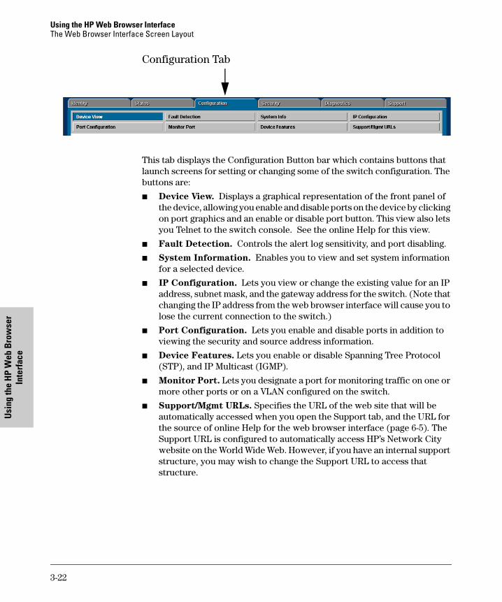
Configuration Tab
This tab displays the Configuration Button bar which contains buttons that launch screens for setting or changing some of the switch configuration. The buttons are:
■ Device View. Displays a graphical representation of the front panel of the device, allowing you enable and disable ports on the device by clicking on port graphics and an enable or disable port button. This view also lets you Telnet to the switch console. See the online Help for this view.
■ Fault Detection. Controls the alert log sensitivity, and port disabling.
■ System Information. Enables you to view and set system information for a selected device.
■ IP Configuration. Lets you view or change the existing value for an IP address, subnet mask, and the gateway address for the switch. (Note that changing the IP address from the web browser interface will cause you to lose the current connection to the switch.)
■ Port Configuration. Lets you enable and disable ports in addition to viewing the security and source address information.
■ Device Features. Lets you enable or disable Spanning Tree Protocol (STP), and IP Multicast (IGMP).
■ Monitor Port. Lets you designate a port for monitoring traffic on one or more other ports or on a VLAN configured on the switch.
■ Support/Mgmt URLs. Specifies the URL of the web site that will be automatically accessed when you open the Support tab, and the URL for the source of online Help for the web browser interface (page 6-5). The Support URL is configured to automatically access HP’s Network City website on the World Wide Web. However, if you have an internal support structure, you may wish to change the Support URL to access that structure.
3-22

Using the HP Web Browser InterfaceThe Web Browser Interface Screen Layout
Using the H
P Web B
rowser
Interface
tomcat.book Page 23 Wednesday, January 13, 1999 1:48 PM
Security Tab
This tab displays the Security Button bar which contains the button that enables you view and set operator names and passwords to restrict access to your switch. The button displayed is:
■ Device Passwords. Enables you to set operator and manager-level user names and passwords for the switch.
Diagnostics Tab
This tab displays the Diagnostics Button bar which contains buttons that enable you to perform troubleshooting tasks for your switch. The buttons are:
■ Ping/Link Test. Enables you to send test packets to devices connected to a port, using both the IP address (Ping) and the MAC address (Link) as criteria for a valid connection.
■ Device Reset. Causes the switch to reset its state as though it were powered on and off.
■ Configuration Report. Displays a master list of various settings for the switch, including information about port status, authorized managers, community names, backup links, IP addresses, security configuration, and general system information.
Support Tab
The URL for this window is set in the Configuration | Support/Mgmt URLs option. By default, it is set to Hewlett-Packard’s Network City web site, but you can change it to the URL for another location, such as an internal support resource. See also page 3-10 and “Support URLs Feature” on page 6-4.
3-23

Using the HP Web Browser InterfaceThe Web Browser Interface Screen Layout
Usi
ng th
e H
P W
eb B
row
ser
Inte
rfac
e
tomcat.book Page 24 Wednesday, January 13, 1999 1:48 PM
The Status Bar
The Status Bar is displayed in the upper left corner of the web browser interface screen. Figure 3-11 shows an expanded view of the status bar.
Figure 3-11. Example of the Status Bar
The Status bar consists of four objects:
■ Status Indicator. Indicates, by icon, the severity of the most critical alert in the current display of the Alert Log. This indicator can be one of three shapes and colors as shown in the following table.
Table 3-3. Status Indicator Key
■ System Name. The name you have configured for the switch in the Identity screen or through the switch console System Information screen.
■ Most Critical Alert Description. A short narrative description of the earliest, unacknowledged alert with the current highest severity in the Alert Log, appearing in the right portion of the Status Bar. In instances where multiple critical alerts have the same severity level, only the earliest unacknowledged alert is deployed in the Status bar.
■ Product Name. The product name of the switch to which you are connected in the current web browser interface session.
Color Switch Status Status Indicator ShapeGreen Normal Activity
Yellow Warning
Red Critical
Status Indicator
Most Critical Alert DescriptionSystem Name
Product Name
3-24

Using the HP Web Browser InterfaceThe Web Browser Interface Screen Layout
Using the H
P Web B
rowser
Interface
tomcat.book Page 25 Wednesday, January 13, 1999 1:48 PM
Setting Fault Detection Policy
One of the powerful features in the web browser interface is the Fault Detection facility. For your switch, this feature controls the types of alerts reported to the Alert Log based on their level of severity.
Set this policy in the Fault Detection window (figure 3-12).
Figure 3-12. The Fault Detection Window
Working With Fault Detection
The Fault Detection screen contains a list box for setting fault detection and response policy. You set the sensitivity level at which a network problem should generate an alert and send it to the Alert Log.
To provide the most information on network problems in the Alert Log, the recommended sensitivity level for Log Network Problems is High Sensitivity. The Fault Detection settings are:
■ High Sensitivity. This policy directs the switch to send all alerts to the Alert Log. This setting is most effective on networks that have none or few problems.
3-25
Using the HP Web Browser InterfaceThe Web Browser Interface Screen Layout
Usi
ng th
e H
P W
eb B
row
ser
Inte
rfac
e
tomcat.book Page 26 Wednesday, January 13, 1999 1:48 PM
■ Medium Sensitivity. This policy directs the switch to send alerts related to network problems to the Alert Log. If you want to be notified of problems which cause a noticeable slowdown on the network, use this setting.
■ Low Sensitivity. This policy directs the switch to send only the most severe alerts to the Alert Log. This policy is most effective on a network that normally has a lot of problems and you want to be informed of only the most severe ones.
■ Never. Disables the Alert Log and transmission of alerts (traps) to the management server (in cases where a network management tool such as HP TopTools for Hubs & Switches is in use). Use this option when you don’t want to use the Alert Log.
The Fault Detection Window also contains three Change Control Buttons:
■ Apply Changes. This button stores the settings you have selected for all future sessions with the web browser interface until you decide to change them.
■ Clear Changes. This button removes your settings and returns the settings for the list box to the level it was at in the last saved detection-setting session.
■ Reset to Default Settings. This button reverts the policy setting to Medium Sensitivity for Log Network Problems.
3-26
Using the Sw
itch Console Interface
tomcat.book Page 1 Wednesday, January 13, 1999 1:48 PM
4
Using the Switch Console Interface
This chapter describes the following features:
■ overview of the switch console (page 4-1)
■ starting and ending a console session (page 4-2)
■ the Main Menu (page 4-4)
■ screen structure and navigation (page 4-6)
■ using password security (page 4-9)
■ rebooting the switch (page 4-12)
■ using the command prompt (page 4-14)
OverviewAbout the Switch Console. The switch console enables you to do the fol-lowing:
■ Modify the switch’s configuration (see chapter 6).
■ Configure the switch with an IP address that allows you to manage the switch from an SNMP-based network management station (chapter 2), through the switch’s web browser interface (chapter 3), or through Telnet access to the console. (See “How To Start a Console Session” on page 4-2.)
■ Monitor the switch and its port status (chapter 7).
■ Monitor the network activity through the switch (page 6-29).
■ Control console security by configuring passwords. (See “Using Password Security” on page 4-9.)
■ Download new software to the switch (appendix A).
Switch Console Interaction with the Web Browser Interface. Config-uration changes made through the console will overwrite previous changes made through the web browser interface. Similarly, configuration changes made through the web browser interface will overwrite any prior changes made through the console. The console gives you access to all switch config-uration parameters (except for control of the Alert Log in the web browser interface). The web browser interface gives you access to a subset of switch configuration parameters, plus easy-to-use status and alert information. Refer to chapter 3, “Using the HP Web Browser Interface” and chapter 6, “Configur-ing the Switch”.
4-1

Using the Switch Console InterfaceStarting and Ending a Console Session
Usi
ng th
e Sw
itch
Cons
ole
Inte
rfac
e
tomcat.book Page 2 Wednesday, January 13, 1999 1:48 PM
Starting and Ending a Console Session
You can access the switch console interface using either:
■ a direct serial connection to the switch’s console port, as described in the installation guide you received with the switch
■ through a Telnet from a networked PC running a Telnet application or running the web browser interface. (Telnet access to the switch is avail-able from the web browser interface.) Telnet requires that an IP address and subnet mask have already been configured on the switch—see chap-ter 2.
N o t e This section assumes that either a terminal device is already configured and connected to your switch (as described in chapter 1, “Installation” of the Installation Guide that came with your switch) or that you have already configured an IP address on the switch so you can start a Telnet session with the switch.
How To Start a Console Session:
1. Start your PC terminal emulator or terminal, or Telnet to the switch from a remote terminal device or from the web browser interface. (For web browser access, see “Starting an HP Web Browser Session with the Switch” on page 3-3.)
2. Do one of the following:
• If you are using Telnet, go to step 3.
• If you are using a PC terminal emulator or a terminal, press [Enter] twice.
3. The screen briefly displays a message indicating the baud rate at which the serial interface is operating, followed by the copyright screen. Do one of the following:
• If a password has been set, the Password prompt appears. Type the password and press [Enter] to display the Main Menu (figure 4-1). Figure 4-1 shows the Main Menu for manager-level access. If you enter the operator password to start the console session, the Main Menu has a subset of these items.
4-2

Using the Switch Console InterfaceStarting and Ending a Console Session
Using the Sw
itch Console Interface
tomcat.book Page 3 Wednesday, January 13, 1999 1:48 PM
• If no password has been set, you will see this prompt:
Press any key to continue.
Press any key to display the Main Menu (figure 4-1).
If there is any system-down information to report, the switch displays it in this step and in the Event Log.
For a description of Main Menu features, refer to “Main Menu Features” on page 4-4.
How To End a Console Session:
The process of ending the console session depends on whether, during the console session, you have made any changes to the switch configuration that requires a reboot of the switch to activate. Configuration changes requiring a reboot of the switch are indicated by an asterisk (*) next to the configured item in the Configuration menu and also next to the Switch Configuration item in the Main Menu.
1. If you have not made configuration changes in the current session that require a switch reboot to activate, return to the Main Menu, and press [0] to log out. Then just exit from the terminal program, turn off the terminal, or quit from the Telnet session.
2. If you have made configuration changes that require a switch reboot:
a. Return to the Main Menu.
b. Press [6] to select Reboot Switch and follow the instructions on the reboot screen.
Rebooting the switch terminates the console session, and, if you are using Telnet, disconnects the Telnet session.
(See “Rebooting To Activate Configuration Changes” on page 4-13.)
3. Exit from the terminal program, turn off the terminal, or close the Telnet application program.
4-3
Using the Switch Console InterfaceMain Menu Features
Usi
ng th
e Sw
itch
Cons
ole
Inte
rfac
e
tomcat.book Page 4 Wednesday, January 13, 1999 1:48 PM
Main Menu Features
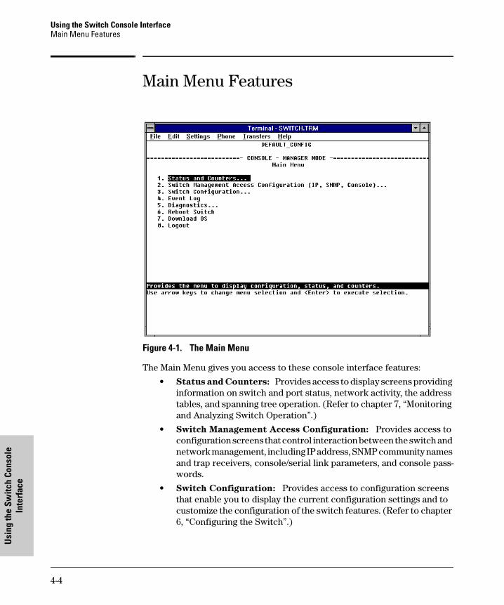
Figure 4-1. The Main Menu
The Main Menu gives you access to these console interface features:
• Status and Counters: Provides access to display screens providing information on switch and port status, network activity, the address tables, and spanning tree operation. (Refer to chapter 7, “Monitoring and Analyzing Switch Operation”.)
• Switch Management Access Configuration: Provides access to configuration screens that control interaction between the switch and network management, including IP address, SNMP community names and trap receivers, console/serial link parameters, and console pass-words.
• Switch Configuration: Provides access to configuration screens that enable you to display the current configuration settings and to customize the configuration of the switch features. (Refer to chapter 6, “Configuring the Switch”.)
4-4

Using the Switch Console InterfaceMain Menu Features
Using the Sw
itch Console Interface
tomcat.book Page 5 Wednesday, January 13, 1999 1:48 PM
• Event Log: Enables you to read progress and error messages that are useful for checking and troubleshooting switch operation. (Refer to “Using the Event Log To Identify Problem Sources” in chapter 8, “Troubleshooting”.)
• Diagnostics: Provides access to screens for doing Link and Ping connectivity testing, listing the current switch configuration, and to a command prompt for executing system management, monitoring, and troubleshooting commands. (Refer to “Diagnostics” in chapter 8, “Troubleshooting”.)
• Reboot Switch: Performs a software reboot of the switch, which clears most temporary error conditions, resets the network activity counters to zero, and resets the system up time to zero. A reboot is required (in one case) to activate a configuration change that has been made. (Refer to “Rebooting To Activate Configuration Changes” on page 4-13.)
• Download OS: Enables you to download a new software version to the switch. (Refer to appendix A, "Transferring an Operating System or Configuration".)
• Logout: Terminates the console session and disconnects Telnet access to the switch. (Refer to "How to End a Console Session on page 4-3.)
4-5

Using the Switch Console InterfaceScreen Structure and Navigation
Usi
ng th
e Sw
itch
Cons
ole
Inte
rfac
e
tomcat.book Page 6 Wednesday, January 13, 1999 1:48 PM
Screen Structure and NavigationConsole screens include these three elements:
■ Parameter fields and/or read-only information such as statistics
■ Navigation and configuration actions, such as Save, Edit, and Cancel
■ Help line to describe navigation options, individual parameters, and read-only data
For example, in the System Information screen on the next page:
Figure 4-2. Elements of the Screen Structure
“Forms” Design. The configuration screens, in particular, operate similarly to a number of PC applications that use forms for data entry. When you first enter these screens, you see the current configuration for the item you have selected. To change the configuration, the basic operation is to:
1. Press [E] to select the Edit action.
2. Navigate through the screen making ALL the necessary configuration changes. (See Table 4-1 on the next page.)
3. Press [Enter] to return to the Actions line. From there you can save the configuration changes or cancel the changes. Cancel returns the configu-ration to the values you saw when you first entered the screen.
Help line describing the selected action or selected parameter field
System name
Parameter fields
Help describing each of the items in the parameter menu
Navigation instructions
Actions line
Screen title – identifies the location within the menu structure
4-6

Using the Switch Console InterfaceScreen Structure and Navigation
Using the Sw
itch Console Interface
tomcat.book Page 7 Wednesday, January 13, 1999 1:48 PM
Table 4-1. How To Navigate in the Console
Task: Actions:
Execute an actionfrom an “Actions –[>] list at the bottom ofthe screen:
Use either of the following methods:• Use the arrow keys ( [<] ,or [>] ) to highlight the action you want
to execute, then press [Enter].• Press the key corresponding to the capital letter in the action
name. For example, in a configuration menu, press [E] to select Edit and begin editing parameter values.
Reconfigure (edit) a parameter setting or a field:
1. Select a configuration item, such as System Name. (See figure 4-2.)
2. Press [E] (for Edit on the Actions line).3. Use [Tab] or the arrow keys ([<], [>], [^], or [v]) to highlight the
item or field.4. Do one of the following:
– If the parameter has preconfigured values, either use the Space bar to select a new option or type the first part of your selection and the rest of the selection appears automatically. (The help line instructs you to “Select” a value.)
– If there are no preconfigured values, type in a value (the Help line instructs you to “Enter” a value).
5. If you want to change another parameter value, return to step 3.6. If you are finished editing parameters in the displayed screen,
press [Enter] to return to the Actions line and do one of the following:– To save any configuration changes you have made, press [S]
(for the Save action).– To exit from the screen without saving any changes that you
have made (or if you have not made changes), press [C] (for the Cancel action).
Note: Most parameter changes are activated when you execute Save, and it is therefore not necessary to reboot the switch after making these changes. But if an asterisk appears next to any menu item you reconfigure, it is necessary to reboot the switch to implement the change. In this case, rebooting should be done after you have made all desired changes and then returned to the Main Menu.
7. When you are finished editing parameters, return to the Main Menu.
8. If necessary, reboot the switch by highlighting Reboot Switch in the Main Menu and pressing [Enter]. (Refer to the Note, above.)
Exit from a read-only screen.
Press [B] (for the Back action).
4-7

Using the Switch Console InterfaceScreen Structure and Navigation
Usi
ng th
e Sw
itch
Cons
ole
Inte
rfac
e
tomcat.book Page 8 Wednesday, January 13, 1999 1:48 PM
To get Help on individual parameter descriptions. In all screens except the Command Prompt screen there is a Help option in the Actions line. Whenever any of the items in the Actions line is highlighted, press [H], and a separate help screen is displayed. For example:
Figure 4-3. Example Showing How To Display Help
To get Help on the actions or data fields in each screen: Use the arrow keys ( [<], [>], [^], or [v]) to select an action or data field. The help line under the Actions items describes the currently selected action or data field.
For guidance on how to navigate in a screen: See the instructions provided at the bottom of the screen, or refer to “Screen Structure and Navigation” on page 4-6.)
The Help line describes the purpose of the currently highlighted item in the Actions line.
Pressing [H] or highlighting Help and pressing [Enter] displays Help for the parameters listed in the upper part of the screen
Highlight on any item in the Actions line indicates that the Actions line is active.
4-8

Using the Switch Console InterfaceUsing Password Security
Using the Sw
itch Console Interface
tomcat.book Page 9 Wednesday, January 13, 1999 1:48 PM
Using Password Security
There are two levels of console access: Manager and Operator. For security, you can set a password on each of these levels.
To use password security:
1. Set a Manager password (and an Operator password, if applicable for your system) as described on page 4-10.
2. Exit from the current console session. A Manager password will now be needed for full access to the console.
If you do steps 1 and 2, above, then the next time a console session is started, the console interface will prompt for a password. Assuming that both a Manager password and an Operator password have been set, the level of access to the console interface will be determined by which password is entered in response to the prompt.
If you set a Manager password, you may also want to configure the Connection Inactivity Time parameter in the Console/Serial Link configuration screen that is under the Switch Management Access Configuration menu (see page 6-22). This causes the console session to end after the specified period of inactivity, thus giving you added security against unauthorized console access.
N o t e The manager and operator passwords control access to both the web browser interface and the switch console interface.
Level Actions Permitted
Manager: Access to all console interface areas.This is the default level. That is, if a Manager password has not been set prior to starting the current console session, then anyone having access to the console can access any area of the console interface.
Operator: Access to the Status and Counters menu, the Event Log, and the Diagnostics menu, but no Configuration capabilities.On the Operator level, the configuration menus, Download OS, and Reboot Switch options in the Main Menu, and the Command Prompt option in the Diagnostics menu are not available.
4-9

Using the Switch Console InterfaceUsing Password Security
Usi
ng th
e Sw
itch
Cons
ole
Inte
rfac
e
tomcat.book Page 10 Wednesday, January 13, 1999 1:48 PM
N o t e If there is only a Manager password set (with no Operator password), and the Manager password is not entered correctly when the console session begins, the switch operates on the Operator level.
If there are both a Manager password and an Operator password, but neither is entered correctly, access to the console will be denied.
If a Manager password is not set, anyone having access to the console
interface can operate the console with full manager privileges, regardless of
whether an Operator password is set, by simply pressing [Enter] at the
password prompt.
Passwords are case-sensitive.
The rest of this section covers how to:
■ Set Passwords
■ Delete Passwords
■ Recover from a Lost Password
To set Manager and Operator passwords:
1. From the Main Menu select:
2. Switch Management Access Configuration
5. Console Passwords
Figure 4-4. The Set Password Screen
4-10

Using the Switch Console InterfaceUsing Password Security
Using the Sw
itch Console Interface
tomcat.book Page 11 Wednesday, January 13, 1999 1:48 PM
2. To set a new password:
a. Select Set Manager Password or Set Operator Password. You will then be prompted with Enter new password.
b. Type a password of up to 16 ASCII characters with no spaces and press [Enter]. (Remember that passwords are case-sensitive.)
c. When prompted with Enter new password again, retype the new pass-word and press [Enter].
3. When you have finished all password configuration, select Return to Main Menu to return to the Main menu, or Return to the Previous Menu to return to the Switch Management Access Configuration menu.
After a password is set, if you subsequently start a new console session, you will be prompted to enter the password.
To Delete Password Protection (Including Recovery from a Lost
Password): This procedure deletes both passwords (Manager and Opera-tor). If you have physical access to the switch, press the Clear button on the front of the switch to clear all password protection, then enter new passwords as described earlier in this chapter. If you do not have physical access to the switch, you will need the Manager password:
1. Enter the console at the Manager level.
2. Go to the Console Passwords screen as described above.
3. Select Delete Password Protection. You will then see the following prompt:
Continue Deletion of password protection?
4. Press the Space bar to select Yes, then press [Enter].
5. Press [Enter] to clear the Password Protection message.
6. Select Return to Main Menu to return to the Main menu, or Return to the Previous Menu to return to the Switch Management Access Configuration menu.
To Recover from a Lost Manager Password: If you cannot start a con-sole session at the manager level because of a lost Manager password, you can clear the password by getting physical access to the switch and pressing the Clear button. This action deletes all passwords and user names (Manager and Operator) used by both the console and the web browser interface.
4-11

Using the Switch Console InterfaceRebooting the Switch
Usi
ng th
e Sw
itch
Cons
ole
Inte
rfac
e
tomcat.book Page 12 Wednesday, January 13, 1999 1:48 PM
Rebooting the Switch
Rebooting the switch terminates the current console session and performs a reset of the operating system. Rebooting the switch also activates certain configuration changes that require a reboot and resets statistical counters to zero. (Note that statistical counters can be reset to zero without rebooting the switch. See “Displaying Port Counters from the Console Interface” on page 7-12.)
To Reboot the switch, use the Reboot Switch option in the Main Menu. (Note that the Reboot Switch option is not available if you log on in Operator mode; that is, if you enter an Operator password instead of a manager password at the password prompt.)
Figure 4-5. The Reboot Switch Option in the Main Menu
Reboot Switch option
4-12

Using the Switch Console InterfaceRebooting the Switch
Using the Sw
itch Console Interface
tomcat.book Page 13 Wednesday, January 13, 1999 1:48 PM
Rebooting To Activate Configuration Changes. Configuration changes for some parameters become effective as soon as you save them. However, you must reboot the switch in order to implement any changes to any parameters in the following areas:
■ Console/Serial Link (under 2. Switch Management Access Configuration menu)
■ VLAN Names (under 3. Switch Configuration | 5. Advanced Feature | 4. VLAN Menu)
If configuration changes requiring a reboot have been made, the switch displays an asterisk (*) next to the menu item in which the change has been made. For example, if you change and save parameter values for the switch’s Console/Serial Link configuration, the need for rebooting the switch would be indicated by an asterisk appearing next to the item Console/Serial Link in the Switch Management Access Configuration menu, and in the Main Menu as shown in figure 4-6:
Figure 4-6. Example of a Configuration Change Requiring a Reboot
Asterisk indicates a configuration change that requires a reboot in order to take effect.
Reminder to reboot the switch to activate configuration changes.
4-13

Using the Switch Console InterfaceThe Command Prompt
Usi
ng th
e Sw
itch
Cons
ole
Inte
rfac
e
tomcat.book Page 14 Wednesday, January 13, 1999 1:48 PM
The Command PromptIn addition to the menu-based part of the console interface, under the Diag-nostics Menu, a command-line based interface is available. The commands are primarily for the expert user and for diagnostics purposes. For more informa-tion, refer to “Using the Command Prompt” on page 8-19.
4-14

Monitoring and M
anaging the Sw
itch
tomcat.book Page 1 Wednesday, January 13, 1999 1:48 PM
5
Using HP TopTools or Other SNMP Tools To Monitor and Manage the Switch
You can manage the switch via SNMP from a network management station. Included with your switch is a CD-ROM containing a copy of HP TopTools for Hubs & Switches, an easy-to-install and use network management application that runs on your Windows NT- or Windows 95-based PC.
HP TopTools for Hubs & Switches provides control of your switch through its graphical interface. In addition, it makes use of the RMON agent and statistical sampling software that is included in the switch to provide powerful, but easy-to-use traffic monitoring and network activity analysis tools.
This chapter provides:
■ An overview of SNMP management for the switch
■ An overview of the configuration process for supporting SNMP manage-ment of the switch. (For the configuration procedures for specific fea-tures, refer to chapter 6, “Configuring the Switch”.)
■ Information on advanced management through RMON and HP Extended RMON Support
To implement SNMP management, you must either configure the switch with the appropriate IP address or, if you are using DHCP/Bootp to configure the switch, ensure that the DHCP or Bootp process provides the IP address. (The IPX address is automatically learned.) If multiple VLANs are configured, each VLAN interface should have its own IP or IPX network address.
SNMP Management Features
SNMP management features on the switch include:
■ Security via configuration of SNMP communities
■ Event reporting via SNMP traps and RMON
■ Managing the switch with a network management tool such as HP Top-Tools for Hubs & Switches
5-1

Using HP TopTools or Other SNMP Tools To Monitor and Manage the SwitchSNMP Management Features
Mon
itori
ng a
nd M
anag
ing
the
Switc
h
tomcat.book Page 2 Wednesday, January 13, 1999 1:48 PM
■ Monitoring data normally associated with the SNMP agent (“Get” operations). Supported Standard MIBs include:
• Bridge MIB (RFC 1493)
dot1dBase, dot1dTp, dot1dStp
• Ethernet MAU MIB (RFC 1515)
dot3IfMauBasicGroup
• Interfaces Evolution MIB (RFC 1573)
ifGeneralGroup, ifRcvAddressGroup, ifStackGroup
• RMON MIB (RFC 1757)
etherstats, events, alarms, and history
• SNMP MIB-II (RFC 1213)
system, interfaces, at, ip, icmp, tcp, udp, snmp
• Entity MIB (RFC 2037)
HP Proprietary MIBs include:
• Statistics for message and packet buffers, tcp, telnet, and timep (netswtst.mib)
• Port counters, forwarding table, and CPU statistics (stat.mib)
• tftp download (downld.mib)
• Integrated Communications Facility Authentication Manager and SNMP communities (icf.mib)
• HP ProCurve Switch 4000 M and Switch 2400M configuration (con-fig.mib)
• HP VLAN configuration information (vlan.mib) supporting hpVlanGeneralGroup
• HP Extended RMON MIB version 4 to allow statistical sampling
• HP Entity MIB (entity.mib)
The switch SNMP agent also uses certain variables that are included in a Hewlett-Packard proprietary MIB file you can add to the SNMP database in your network management tool. You can copy the MIB file from the HP TopTools for Hubs & Switches CD shipped with the switch, or from following World Wide Web site:
http://www.hp.com/go/procurve
For more information, refer to Customer Support/Warranty booklet included with your switch.
5-2

Using HP TopTools or Other SNMP Tools To Monitor and Manage the SwitchSNMP Configuration Process
Monitoring and M
anaging the Sw
itch
tomcat.book Page 3 Wednesday, January 13, 1999 1:48 PM
SNMP Configuration Process
This requires that you configure the switch with the appropriate IP address. (Refer to chapter 2, “Configure an IP Address on the Switch”. If you are using DHCP/Bootp to configure the switch, ensure that the DHCP/Bootp process provides the IP address. (Refer to “DHCP/Bootp Operation” on page 6-11.)
The general steps to configuring for SNMP access to the preceding features are:
1. From the Main menu, select
2. Switch Management Access Configuration
1. IP Configuration
2. Use either of the following methods to configure a network address for the switch, including any necessary gateway:
• Use DHCP/Boot, which is enabled by default, to acquire an IP address. Make sure the DHCP/Bootp server is configured to support the switch. (Refer to “DHCP/Bootp Operation” on page 6-11.)
• Manually configure an IP address. (Refer to chapter 2, “Configuring an IP Address on the Switch”.)
3. Configure the appropriate SNMP communities. (The “public” community exists by default and is used by HP’s network management applications.) (For more on configuring SNMP communities, refer to “SNMP Communi-ties” on page 6-16.)
4. Configure the appropriate trap receivers. (For more on configuring trap receivers, refer to “Trap Receivers” on page 6-19.)
In many networks, manager addresses are not used. In this case, all manage-ment stations using the correct community name may access this device with the View and Access levels that have been set for that community. If you want to restrict access to one or more specific nodes, you can enter up to ten IP addresses of such nodes into the Manager Address field. Configuring one or
more IP addresses in the Manager Address field means that only the network
management stations at those addresses are authorized to use the commu-
nity name to access the switch.
5-3

Using HP TopTools or Other SNMP Tools To Monitor and Manage the SwitchAdvanced Management: RMON and HP Extended RMON Support
Mon
itori
ng a
nd M
anag
ing
the
Switc
h
tomcat.book Page 4 Wednesday, January 13, 1999 1:48 PM
C a u t i o n Deleting the community named “public” disables many network management functions (such as auto-discovery, traffic monitoring, and threshold setting). If security for network management is a concern, it is recommended that you change the write access for the “public” community to “Restricted”.
N o t e SNMP community and trap receiver configurations are activated when saved. Rebooting the switch is not necessary unless you have also configured other parameters that require rebooting in order to be activated. (For more on when it is necessary to reboot, refer to “Rebooting the Switch” on page 4-12.)
Advanced Management: RMON and HP Extended RMON Support
The switch supports RMON (Remote Monitoring) and HP Extended RMON on all connected network segments. This allows for troubleshooting and optimizing your network.
RMON
The following RMON groups are supported:
■ Ethernet Statistics (except the numbers of packets of different frame sizes)■ Alarm■ History (of the supported Ethernet statistics)■ Event
You can access the Ethernet statistics, Alarm, and Event groups from the HP TopTools for Hubs & Switches network management software included with your switch.
Extended RMON
Extended RMON provides network monitoring and troubleshooting informa-tion that analyzes traffic from a network-wide perspective. Extended RMON notifies you about network problems and identifies the end node at fault. That information can be used to set up RMON to study the problem more closely, if desired. Because it is based on detailed statistical sampling, Extended RMON lessens the load on devices and network bandwidth.
5-4

Configuring the Switch
tomcat.book Page 1 Wednesday, January 13, 1999 1:48 PM
6
Configuring the Switch
Overview
This chapter describes the switch configuration features available in both the switch console and the HP web browser interface. If you need information on how to operate either the web browser interface or the console, refer to:
■ Chapter 3, “Using the HP Web Browser Interface”
■ Chapter 4, “Using the Console Interface”
Why Reconfigure? In its factory default configuration, the switch operates as a multiport learning bridge with network connectivity provided by the particular modules you have installed. However, to enable specific manage-ment features and to “fine-tune” your switch for the specific performance and security needs in your network, you may want to reconfigure individual switch parameters.
How To Find Configuration Information. Each section in this chapter is organized as follows:
■ Introductory feature information: Provides an overview of the fea-ture.
■ “How-To” Configuration steps: Describes the step-by-step process used to actually configure the feature. It also includes examples of the web browser interface and console interface screens.
■ Detailed feature information: Provides a more in-depth description of the feature, along with notes on interoperation with other features.
To find a specific feature, see the table in the next section.
6-1

Configuring the Switch Overview
Conf
igur
ing
the
Switc
h
tomcat.book Page 2 Wednesday, January 13, 1999 1:48 PM
Configuration Features
Table 6-1. Configurable Feature Comparison
Feature SwitchConsole
Web Browser Interface
Page
Time Protocol Yes — 6-9
IP Configuration Yes Yes 6-6
SNMP Communities Yes — 6-16
Authentication TrapsTrap Receivers
Yes — 6-19
Fault Detection Yes Yes 3-16
Console/Serial Link• Enable Inbound Telnet to Console• Enable Web Browser Interface Access• Terminal Settings
YesYesYes
———
6-216-226-226-22
Operator and Manager UsernamesOperator and Manager Passwords
—Yes
YesYes
3-83-8, 4-9
System InformationAddress Age IntervalSystem Time
YesYesYes
Yes——
6-23
Port Settings Yes Yes 6-25
Network Monitoring Port Yes Yes 6-29
Spanning Tree Enable/DisableSpanning Tree Parameters
YesYes
Yes—
6-34
Traffic/Security Filters Yes — 6-40
Enable/Disable VLANsVLAN Names and Port Assignment
YesYes
——
6-45
Load Balancing: Port Trunking Yes — 6-63
IP Multicast (IGMP) Enable/DisableIGMP Priority and Port Settings
YesYes
Yes—
6-71
6-2

Configuring the SwitchOverview
Configuring the Switch
tomcat.book Page 3 Wednesday, January 13, 1999 1:48 PM
N o t e In the factory default configuration, the Spanning Tree Protocol (STP—which automatically blocks redundant links) is disabled. Generally, you should enable STP to prevent broadcast storms if there are redundant links in your network. However, due to the requirements of the 802.1Q VLAN standard, STP blocks redundant physical links even if they are in separate VLANs. This could result in blocking links unnecessarily. For more information, refer to “Span-ning Tree Protocol” on page 6-34.
6-3

Configuring the Switch Support URLs Feature
Conf
igur
ing
the
Switc
h
tomcat.book Page 4 Wednesday, January 13, 1999 1:48 PM
Support URLs Feature
The Support/Mgmt URLs window enables you to change the World Wide Web Universal Resource Locator (URL) for two functions:
■ Support URL – a support information site for your switch
■ Management Server URL – the site for online help for the web browser interface, and, if set up, the URL of a network management station running HP TopTools for Hubs & Switches.
Figure 6-1. The Default Support/Mgmt URLs Window
Support URL
This is the site that will be accessed when you click on the Support tab on the web browser interface. The default URL is:
http://www.hp.com/go/procurve
which is the World Wide Web site for Hewlett-Packard’s networking products.
3. Enter URLs for:- the support information source that is accessed when you click on the web browser interface Support tab – the default is HP’s network products World Wide Web home page- the URL of the network Management server or other source of the online help files for this web browser inter- face. (The default is a location on HP’s World Wide Web site.)
1. Click Here 2. Click Here
4. Click on Apply Changes
6-4

Configuring the SwitchSupport URLs Feature
Configuring the Switch
tomcat.book Page 5 Wednesday, January 13, 1999 1:48 PM
Click on the [Support] button on that page and you can get to support information regarding your switch, including white papers, operating system (OS) updates, and more.
You could instead enter the URL for a local site that you use for entering reports about network performance, or whatever other function you would like to be able to easily access by clicking on the [Support] tab.
Management Server URL
This field specifies which of the following two locations the switch will use to find online Help for the web browser interface:
■ The URL of online Help provided by HP on the world wide web
■ The URL of a network management station running HP TopTools for Hubs & Switches
The default URL is:
http://www.hp.com/rnd/device_help
which is the location on HP’s World Wide Web site of the help files for the web browser interface. To use this site, you must have a modem link or other access to the World Wide Web operating when you run the web browser interface. Then, when you click on the [?] button on any of the web browser interface screens, the context sensitive help for that screen will be retrieved from HP.
Alternatively, if you install HP TopTools for Hubs & Switches on your network and TopTools discovers your switch, it automatically overwrites the Manage-ment Server URL field with the address or name of the TopTools management station. In this case, online help will automatically be provided from the network management station. Refer to “Online Help for the HP Web Browser Interface” on page 3-10.
Additionally, HP Top Tools for Hubs & Switches has the capability to perform network-wide policy management and configuration of your switch. This field identifies the management station that is performing that function. For more information, refer to the documentation provided on the HP TopTools CD shipped with the switch.
6-5

Configuring the Switch IP Configuration
Conf
igur
ing
the
Switc
h
tomcat.book Page 6 Wednesday, January 13, 1999 1:48 PM
IP Configuration
Configuring the switch with an IP address expands your ability to manage the switch, and also enhances the switch features that can be used.
The switch console screen enables you to configure the initial values for:
■ IP address, subnet mask, and (optionally) the gateway address for the switch so that it can be managed in an IP network
■ The time server information (used if you want the switch to get its time information from another device operating as a Timep server)
The web browser interface screen enables you to modify the initial IP configuration if needed.
N o t e If you change the IP address through the web browser interface, the browser will lose connection to the switch. You can reconnect by entering the new IP address as the URL.
By default, the switch is configured to receive IP addressing from a DHCP/Bootp server that you have configured correctly with information for your switch. (Refer “DHCP/Bootp Operation” on page 6-11 for information on setting up automatic configuration from a server.) Through the web browser interface or switch console, you can manually enter a different address, or you can disable the IP operation.
N o t e s ■ If VLANs are not configured, then configure one IP address for the entire switch. If VLANs are configured, then configure an IP address for each VLAN. This is because each VLAN is a separate network and requires a unique IP address, and subnet mask. A gateway (IP) address is optional. For more on VLANs, refer to “Virtual LANs (VLANs)” on page 6-45.
■ The IP addressing used in the switch should be compatible with your network: the IP address must be unique, and the subnet mask must be the same for all devices on the same IP network.
■ If you plan to connect to other networks that use globally administered IP addressing, refer to “Globally Assigned IP Network Addresses” on page 6-15.
For information on how IP addressing affects switch performance, refer to “How IP Addressing Affects Switch Operation” on page 6-10.
6-6

Configuring the SwitchIP Configuration
Configuring the Switch
tomcat.book Page 7 Wednesday, January 13, 1999 1:48 PM
Configuring IP Addressing from the Web Browser Interface
Figure 6-2. Configuring IP Addressing on the Web Browser Interface
1. Click here. 2. Click here.
3. If multiple VLANs are configured, select a VLAN.
4.To enable manual entry of the IP address, set this to “Manual”.
5. Enter an IP address, subnet mask, and, if needed, the IP address of the default gateway.
6.Click on this to activate the changes you made in steps 3 - 5.
Parameter Description
VLAN If you have configured multiple VLANs, then use this parameter to select the VLAN to which you want to assign an IP address. Otherwise, leave it set to the default.
IP Configuration The method the switch uses to acquire its IP configuration. • DHCP/Bootp (default): The switch attempts to get its IP
configuration or its complete configuration from a DHCP or Bootp server.
• Manual: Enables you to manually enter the IP configuration into the next three fields.
• Disabled: Network management access to the switch over IP is disabled.
The default setting for Time Protocol Config is DHCP. Setting it to Manual, then pressing [v] or [Tab] causes the Timep Server Address parameter to appear.
The default setting for IP Config is DHCP/Bootp. Using the Space bar to set it to Manual, then pressing [v] or [Tab] causes the IP Address, Subnet Mask, and Gateway parameters to appear.
For descriptions of these parameters, refer to the online Help for this screen.
Before using the DHCP/Bootp option, refer to DHCP/Bootp Operation on page 6-11.
6-7

Configuring the Switch IP Configuration
Conf
igur
ing
the
Switc
h
tomcat.book Page 8 Wednesday, January 13, 1999 1:48 PM
Configuring IP Addressing from the Switch Console
You can use the console to manually configure an IP address, subnet mask, and a Gateway IP address (if needed). Or, you can use DHCP/Bootp to configure IP from a DHCP or Bootp server. (To use the DHCP/Bootp option, you must also configure the DHCP or Bootp server accordingly.)
Do one of the following:
■ To use the console, set the IP Config parameter to Manual and then manually enter the IP address, subnet mask, and default gateway you want for the switch.
■ If you plan to use DHCP or Bootp, use the console to ensure that the IP Config parameter is set to DHCP/Bootp, then refer to “DHCP/Bootp Opera-tion” on page 6-11.
To Access IP Addressing:
1. From the Console Main Menu, Select...
2. Switch Management Access Configuration (IP, SNMP, Console)...
1. IP Configuration
N o t e If multiple VLANs are configured, a screen showing all VLANs appears instead of the following screen. You would first select the VLAN you want to configure, then the following screen would appear to configure IP for that VLAN.
IP Address IP address for the switch (or VLAN) IP interface. If DHCP/Bootp is selected for IP Configuration, this is a read-only field displaying the value received from a DHCP or Bootp server.
Subnet Mask The same subnet mask that is used by all devices in the IP subnet being configured. If DHCP/Bootp is selected for IP Configuration, this is a read-only field displaying the value received from a DHCP or Bootp server.
Default Gateway The IP address of the next-hop gateway node for reaching off-subnet destinations. Used as the default gateway if the requested destination address is not on the local subnet. If DHCP/Bootp is selected for IP Configuration, this is a read-only field displaying the value received from a DHCP or Bootp server.
Parameter Description
6-8

Configuring the SwitchIP Configuration
Configuring the Switch
tomcat.book Page 9 Wednesday, January 13, 1999 1:48 PM
Figure 6-3. Example of the IP Service Configuration Screen
2. Press [E] (for Edit).
3. At the Time Protocol Config field, if you want the switch to obtain its system time from a Timep server, and the server is configured correctly, keep the value as DHCP , or use the Space bar to select Manual. If you don’t have a Timep server set up, use the Space bar to change to value to Disable.
4. If you select Manual , press the Tab or Down Arrow key, and additional fields will be displayed for entering the IP address and subnet mask for the Timep server.
5. Select the Time Poll Interval field if you want to change to value for how often the switch will poll the Timep server for time information.
6. If you want to have the switch retrieve its IP configuration from a DHCP or Bootp server, at the IP Config field, keep the value as DHCP/Bootp and go to step 10. If you want to manually configure the IP information, use the Space bar to select Manual and press the Tab or Down Arrow key to reveal the other IP configuration fields.
7. Select the IP Address field and enter the IP address for the switch.
8. Select the Subnet Mask field and enter the subnet mask for the IP address.
6-9

Configuring the Switch IP Configuration
Conf
igur
ing
the
Switc
h
tomcat.book Page 10 Wednesday, January 13, 1999 1:48 PM
9. If you want to reach off-subnet destinations, select the Gateway field and enter the IP address of the gateway router.
10. Press [Enter], then [S] (for Save).
11. Return to the Main Menu.
How IP Addressing Affects Switch Operation
Without an IP address and subnet mask compatible with your network, the switch operates as a multiport transparent bridge and can be managed only through a direct terminal device connection to the Console RS-232 port. In this state, the switch simply learns which nodes are on which ports and forwards or blocks traffic accordingly. You can use direct-connect console access to take advantage of features that do not depend on IP addressing. However, to realize the full performance capabilities HP proactive networking offers through the switch, configure the switch with an IP address and subnet mask compatible with your network. The following table lists the general features available with and without a network-compatible IP address config-ured.
Features Available Without an IP Address Additional HP Proactive Networking Features Available with an IP Address and Subnet Mask
• Direct-connect console access• DHCP or Bootp support for automatic IP address
configuration, and DHCP support for automatic time server IP address configuration
• Spanning Tree Protocol• Port trunking• Traffic filtering• Console-based status and counters information for
monitoring switch operation and diagnosing problems.• VLANs• Serial downloads of operating system (OS) updates
and configuration files (Xmodem)
• HP web browser interface access, with configuration, security, and diagnostic tools, plus the Alert Log for discovering problems detected in the switch along with suggested solutions
• SNMP network management access such as HP TopTools network configuration, monitoring, problem-finding and reporting, analysis, and recommendations for changes to increase control and uptime
• Telnet console access• IGMP• Time server configuration• TFTP download of configurations and OS updates• Ping test
6-10

Configuring the SwitchIP Configuration
Configuring the Switch
tomcat.book Page 11 Wednesday, January 13, 1999 1:48 PM
DHCP/Bootp Operation
Overview
DHCP/Bootp is used to download configuration data from a DHCP or Bootp server respectively to the switch or to a VLAN configured on the switch. With DHCP you can have the switch automatically retrieve the IP address with no configuration required on either the switch or the DHCP server. A Bootp server requires some configuration, but you can additionally identify a file to be downloaded to the switch containing a full switch configuration.
N o t e The Switch 4000M and Switch 2424M are compatible with both DHCP and Bootp servers.
To use DHCP/Bootp for IP configuration of a VLAN, the DHCP/Bootp server must be in that VLAN in order for the switch to access it.
The DHCP/Bootp Process
Whenever the IP Config parameter in the switch or in an individual VLAN in the switch is configured to DHCP/Bootp (the default), or when the switch is rebooted with this configuration:
1. DHCP/Bootp requests are automatically broadcast on the local network. (The switch sends one type of request which either a DHCP or Bootp server can process.)
2. When a DHCP or Bootp server receives the request, it replies with an automatically generated IP address and subnet mask for the switch. The switch also receives an IP Gateway address if the server has been config-ured to provide one. In the case of Bootp, the server must first be configured with an entry that has the MAC address of the switch. (The switch properly handles replies from either type of server. If multiple replies are returned, the switch tries to use the first DHCP reply.)
If the switch is initially configured for DHCP/Bootp operation (the default), or if it is rebooted with this configuration, it immediately begins sending request packets on the network. If the switch does not receive a reply to its DHCP/Bootp requests, it continues to periodically send request packets, but with decreasing frequency. Thus, if a DHCP or Bootp server is not available or accessible to the switch when DHCP/Bootp is first configured, the switch may not immediately receive the desired configuration. After verifying that the server has become accessible to the switch, reboot the switch to re-start the process.
6-11

Configuring the Switch IP Configuration
Conf
igur
ing
the
Switc
h
tomcat.book Page 12 Wednesday, January 13, 1999 1:48 PM
DHCP Operation. A significant difference between a DHCP configuration and a Bootp configuration is that an IP address assignment from a DHCP server is automatic, requiring no configuration of the DHCP server. Using that automatic feature, though, the address is temporarily leased. Periodically the switch may be required to renew its lease of the IP configuration. Thus, the IP addressing provided by the server may be different each time the switch reboots or renews its configuration from the server. However, you can fix the address assignment for the switch by doing either of the following:
■ Configure the server to issue an “infinite” lease.
■ Using the switch’s MAC address as an identifier, configure the server with a “Reservation” so that it will always assign the same IP address to the switch. (For MAC address information, refer to appendix B, “MAC Address Management”.)
For more information on either of these procedures, refer to the documenta-tion provided with the DHCP server.
Bootp Operation. When a Bootp server receives a request it searches its Bootp database for a record entry that matches the MAC address in the Bootp request from the switch. If a match is found, the configuration data in the associated database record is returned to the switch. For most Unix systems, the Bootp database is contained in the /etc/bootptab file. In contrast to DHCP operation, Bootp configurations are always the same for each receiving device. That is, the Bootp server replies to a request with a configuration previously stored in the server and designated for the requesting device.
Bootp Database Record Entries. A minimal entry in the Bootp table file/etc/bootptab to update an IP address and subnet mask to the switch or a VLAN configured in the switch would be similar to this entry:
j4121switch:\ht=ether:\ha=040009123456:\sm=255.255.248.0:\gw=55.66.77.1:\lg=11.22.33.44:\hn:\ip=55.66.77.88:\vm=rfc1048
6-12

Configuring the SwitchIP Configuration
Configuring the Switch
tomcat.book Page 13 Wednesday, January 13, 1999 1:48 PM
An entry in the Bootp table file /etc/bootptab to tell the switch or VLAN where to obtain a configuration file download would be similar to this entry:
j4121switch:\ht=ether:\ha=040009123456:\ip=55.66.77.88:\sm=255.255.248.0:\gw=55.66.77.1:\lg=11.22.33.44:\T144=”switch.cfg”:\vm=rfc1048
where:
N o t e The above Bootp table entry is a sample that will work for the Switch 4000M and Switch 2424M when the appropriate addresses and file names are used. There are other features and parameters that can be implemented with Bootp. See the documentation for your Bootp server for more information.
j4121switch is a user-defined symbolic name to help you find the correct section of the bootptab file. If you have multiple switches that will be using Bootp to get their IP configuration, you should use a unique symbolic name for each switch.
ht is the “hardware type”. For the Switch 4000M and Switch 2424M, set this to ether (for Ethernet). This tag must precede the ha tag.
ha is the “hardware address” . Use the switch's (or VLAN's) 12-digit MAC address.
ip is the IP address to be assigned to the switch (or VLAN).
sm is the subnet mask of the subnet in which the switch (or VLAN) is installed.
gw is the IP address of the default gateway.
lg TFTP server address (source of final configuration file)
T144 is the vendor-specific “tag” identifying the configuration file to download.
vm is a required entry that specifies the Bootp report format. For the Switch 4000M and Switch 2424M, set this parameter to rfc1048.
6-13

Configuring the Switch IP Configuration
Conf
igur
ing
the
Switc
h
tomcat.book Page 14 Wednesday, January 13, 1999 1:48 PM
Configuring DHCP/Bootp
In its default configuration, the switch is configured for DHCP/Bootp opera-tion. However, if an IP address has previously been configured or if the IP Config parameter has been set to Disabled, then you will need to use this procedure to reconfigure the parameter to enable DHCP/Bootp operation.
This procedure assumes that, for Bootp operation:
■ A Bootp database record has already been entered into an appropriate Bootp server.
■ The necessary network connections are in place
■ The Bootp server is accessible from the switch
and, for DHCP operation:
■ The necessary network connections are in place
■ A DHCP server is accessible from the switch
To configure the switch or a VLAN for DHCP/Bootp:
1. From the Main Menu, select
2. Switch Management Access Configuration (IP, SNMP, Console)
1. IP Configuration
2. Press [E] (for Edit mode), then use [v] to move the cursor to the IP Config parameter field.
3. Use the Space bar to select the DHCP/Bootp option for the IP Config parameter. (This disables access to the IP Address, Subnet Mask, and Gateway parameters.)
4. Press [Enter] to exit from edit mode, then press [S] to save the configuration change.
When you press [S] to save the configuration change or reboot the switch with DHCP/Bootp enabled in a network providing DHCP/Bootp service, it will do the following:
■ Receive an IP address and subnet mask and, if configured in the server, a gateway IP address and the address of a Timep server.
■ For Bootp operation, if the reply provides information for downloading a configuration file, the switch then uses TFTP to download the file from the designated source, then reboots itself. (This assumes that the switch or VLAN has connectivity to the TFTP file server specified in the Bootp database configuration record, that the Bootp database record is correctly configured, and that the configuration file exists in the TFTP directory.)
6-14

Configuring the SwitchIP Configuration
Configuring the Switch
tomcat.book Page 15 Wednesday, January 13, 1999 1:48 PM
Globally Assigned IP Network Addresses
If you intend to connect your network to other networks that use globally administered IP addresses, Hewlett-Packard strongly recommends that you use IP addresses that have a network address assigned to you. There is a formal process for assigning unique IP addresses to networks worldwide. Contact one of the following companies:
For more information, refer to Internetworking with TCP/IP: Principles,
Protocols and Architecture by Douglas E. Comer (Prentice-Hall, Inc., publisher).
Country Phone Number/E-Mail/URL Company Name/Address
United States/Countries not in Europe or Asia/Pacific
[email protected]://rs.internic.net
Network Solutions, Inc.Attn: InterNIC Registration Service505 Huntmar Park DriveHerndon, VA 22070
Europe +31 20 592 [email protected]://www.ripe.net
RIPE NCC Kruislaan409NL-1098 SJAmsterdam, The Netherlands
Asia/Pacific [email protected]://www.apnic.net
Attention: IN-ADDR.ARPA RegistrationAsia Pacific Network Information Centerc/o Internet Initiative Japan, Inc.Sanbancho Annex Bldg. 1-4 Sanban-choChiyoda-ku Tokyo 102, Japan
6-15

Configuring the Switch SNMP Communities
Conf
igur
ing
the
Switc
h
tomcat.book Page 16 Wednesday, January 13, 1999 1:48 PM
SNMP Communities
From the switch console only you can add, edit, or delete SNMP communi-ties. Use this feature to restrict access to the switch by SNMP management stations. You can configure up to five SNMP communities, each with either an operator-level or a manager-level view, and either restricted or unrestricted write access.
In the default configuration, no Manager addresses are configured, and all management stations using the correct community name may access the switch with the corresponding View and Access levels specified for those communities. For any community name, if you want to restrict access to one or more specific nodes, you can enter up to ten IP addresses of such nodes into the Manager Address field. Entering one or more IP addresses in the Manager Address field restricts access with that community to only those addresses.
For more on this topic, refer to chapter 5, “Using HP TopTools or Other SNMP Tools To Monitor and Manage Your Network”, and to the online Help.
Configuring SNMP Communities from the Switch Console
Before you begin, ensure that the switch has been configured for IP.
C a u t i o n Deleting or changing the community named “public” prevents network man-agement applications (such as auto-discovery, traffic monitoring, and thresh-old setting) from operating in the switch. (Changing or deleting the “public” name also generates an Event Log message.) If security for network manage-ment is a concern, it is recommended that you change the write access for the “public” community to “Restricted”.
6-16

Configuring the SwitchSNMP Communities
Configuring the Switch
tomcat.book Page 17 Wednesday, January 13, 1999 1:48 PM
To View, Edit, or Add SNMP Communities:
1. From the Console Main Menu, Select:
2. Switch Management Access Configuration (IP, SNMP, Console)...
2. SNMP Community Names/Authorized Managers
Figure 6-4. The SNMP Communities Screen (Default Values)
2. From the Configuration screen, select SNMP Communities to display a screen similar to the one above.
3. Press [A] (for Add) to display the following screen:
Add and Edit options are used to modify the SNMP options. See figure 6-5.
Note: This screen gives an overview of the SNMP communities that are currently configured. All fields in this screen are read-only.
6-17

Configuring the Switch SNMP Communities
Conf
igur
ing
the
Switc
h
tomcat.book Page 18 Wednesday, January 13, 1999 1:48 PM
Figure 6-5. The SNMP Add or Edit Screen
N o t e In the default configuration, no manager addresses are configured. In this case, all management stations using the correct community name may access the switch with the corresponding View and Access levels. If you want to restrict access to one or more specific nodes, you can enter up to ten IP addresses of such nodes into the Manager Address field. Entering one or more IP addresses in the Manager Address field limits access to only those addresses.
4. Enter the appropriate value in each of the above fields (use the [Tab] key to move from one field to the next).
5. Press [Enter], then [S] (for Save).
If you are adding a community, the fields in this screen are blank.
If you are editing an existing community, the values for the currently selected Community appear in the fields.
Type the value for these fields.
Use the Space bar to select values for other fields
6-18
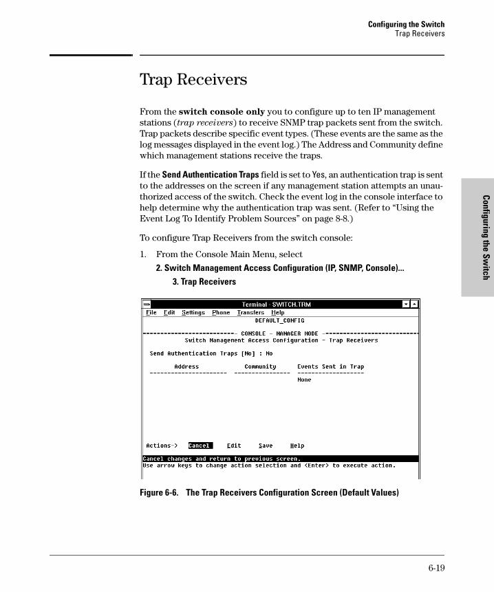
Configuring the SwitchTrap Receivers
Configuring the Switch
tomcat.book Page 19 Wednesday, January 13, 1999 1:48 PM
Trap Receivers
From the switch console only you to configure up to ten IP management stations (trap receivers) to receive SNMP trap packets sent from the switch. Trap packets describe specific event types. (These events are the same as the log messages displayed in the event log.) The Address and Community define which management stations receive the traps.
If the Send Authentication Traps field is set to Yes, an authentication trap is sent to the addresses on the screen if any management station attempts an unau-thorized access of the switch. Check the event log in the console interface to help determine why the authentication trap was sent. (Refer to “Using the Event Log To Identify Problem Sources” on page 8-8.)
To configure Trap Receivers from the switch console:
1. From the Console Main Menu, select
2. Switch Management Access Configuration (IP, SNMP, Console)...
3. Trap Receivers
Figure 6-6. The Trap Receivers Configuration Screen (Default Values)
6-19

Configuring the Switch Trap Receivers
Conf
igur
ing
the
Switc
h
tomcat.book Page 20 Wednesday, January 13, 1999 1:48 PM
2. Press [E] (for Edit). The cursor moves to the Send Authentication Traps field.
3. Press the Space bar to enable (Yes) or disable (No) sending authentication traps, then press [Tab] to move the cursor to the Address field.
4. Type in the IP address of a network management station to which you want the switch to send SNMP trap packets, then press [Tab] to move the cursor to the Community field.
5. Type in the name of the SNMP community to which the network manage-ment station belongs, then press [Tab] to move the cursor to the Events field.
6. Use the Space bar to select the level of internal switch events that cause trap packets to be sent:
7. Press [Enter], then press [S] (for Save) and return to the Main Menu.
Event Level Description
None (default) Send no log messages.
All Send all log messages.
Not INFO Send the log messages that are not information-only.
Critical Send critical-level log messages.
Debug Reserved for HP-internal use.
6-20

Configuring the SwitchConsole/Serial Link
Configuring the Switch
tomcat.book Page 21 Wednesday, January 13, 1999 1:48 PM
Console/Serial Link
From the switch console only you can configure the following console terminal emulation and communication characteristics:
■ Enable or disable inbound Telnet access (default: enabled)
■ Enable or disable HP web browser interface access (default: enabled)
■ Specify:
• Terminal type (default: VT-100)
• Console screen refresh interval for statistics screens (the frequency with which statistics are updated on the screen—default: 3 seconds)
• The types of events displayed in the console event log (default: all)
■ Customize the Console configuration for the PC or terminal you are using for console access.
• Baud Rate (default: Speed Sense)
• Flow Control (default: XON/XOFF)
• Connection Inactivity Time (default: 10 minutes)
In most cases, the default configuration is acceptable for standard operation. If you need to change any of the above parameters, use the switch console.
N o t e If you change the Baud Rate or Flow Control settings for the switch, you should make the corresponding changes in your console access device. Oth-erwise, you may lose connectivity between the switch and your terminal emulator due to differences between the terminal and switch settings for these two parameters.
6-21

Configuring the Switch Console/Serial Link
Conf
igur
ing
the
Switc
h
tomcat.book Page 22 Wednesday, January 13, 1999 1:48 PM
Configuring the Console/Serial Link from the Switch Console
This screen allows you to:
■ Enable or disable inbound Telnet and web browser interface access
■ Determine which log events will be displayed
■ Modify console and serial link parameters
To Access Console/Serial Link Features
1. From the Console Main Menu, Select...
2. Switch Management Access Configuration (IP, SNMP, Console)...
4. Console/Serial Link Configuration
Figure 6-7. The Console/Serial Link Configuration Screen (Default Values)
2. Press [E] (for Edit). The cursor moves to the top field on the screen.
3. Refer to the online help provided with this screen for further information on configuration options for these features.
4. When you have finished making changes to the above parameters, press [Enter], then press [S] (for Save) and return to the Main Menu
6-22

Configuring the SwitchSystem Information
Configuring the Switch
tomcat.book Page 23 Wednesday, January 13, 1999 1:48 PM
System Information
From the web browser interface and the switch console you can configure basic switch management information, including system data, address aging, and time zone parameters.
Configuring System Parameters from the Web Browser Interface
In the web browser interface, you can enter the system information shown below. For access to the Address Age Interval and the Time parameters, use the console.
Figure 6-8. Example of System Info Screen on the Web Browser Interface
1. Click here.2. Click here.
3. Enter the system information you want.
4. Click on Apply Changes.
6-23

Configuring the Switch System Information
Conf
igur
ing
the
Switc
h
tomcat.book Page 24 Wednesday, January 13, 1999 1:48 PM
Configuring System Information from the Console
To Access System Information:
1. From the Console Main Menu, Select...
2. Switch Configuration...
1. System Information
Figure 6-9. The System Configuration Screen (Default Values)
N o t e To help simplify administration, it is recommended that you configure System Name to a character string that is meaningful within your system.
To set the time and date, set the Time Protocol parameters under “IP Config-uration” (page 6-6) for your time server or use the time and date commands described in chapter 7, “Monitoring and Analyzing Switch Operation”.
2. Press [E] (for Edit). The cursor moves to the System Name field.
3. Refer to the online help provided with this screen for further information on configuration options for these features.
4. When you have finished making changes to the above parameters, press [Enter], then press [S] (for Save) and return to the Main Menu.
System Name
6-24

Configuring the SwitchPort Settings
Configuring the Switch
tomcat.book Page 25 Wednesday, January 13, 1999 1:48 PM
Port Settings
From the web browser interface and switch console you can configure the operating state for each port. Also optionally enables you to restrict the amount of broadcast traffic on the port. The read-only fields in this screen display the port numbers and port types. Port numbers in the configuration correspond to port numbers on the front of the switch.
The following table shows the settings available for each port type. The same parameter settings are available in both the web browser interface and the switch console.
Parameter Description
Enabled Yes (default): The port is ready t be connected in a network.No: The port will not operate, even if properly connected in a network. Use this setting if the port needs to be shut down for diagnostic purposes or while you are making topology changes, for example.
Mode or Config Mode
The operational mode of the port.For gigabit ports:1000FDx (default): 1000 Mbps (1 Gbps), Full DuplexAuto: The port operates at 1000FDx and auto-negotiates flow control with the device connected to the port.
For 10/100TX ports:Auto (default): Auto-negotiates with the port at the other end of the link for speed (10 Mbps or 100 Mbps) and data transfer operation (half-duplex or full-duplex). Note: Ensure that the device attached to the port is configured for the same setting that you select here. Also, if “Auto” is used, the device to which the port is connected must operate in compliance with the IEEE 802.3u “Auto Negotiation” standard for 100Base-T networks.10HDx:10 Mbps, Half-Duplex100HDx: 100 Mbps, Half-Duplex10FDx: 10 Mbps, Full-Duplex100FDx: 100 Mbps, Full-Duplex
For 100FX ports:100HDx (default): 100 Mbps, Half-Duplex100FDx: 100 Mbps, Full-Duplex
For 10 FL ports:10HDx:(default): 10 Mbps, Half-Duplex10FDx: 10 Mbps, Full-Duplex
6-25

Configuring the Switch Port Settings
Conf
igur
ing
the
Switc
h
tomcat.book Page 26 Wednesday, January 13, 1999 1:48 PM
Auto (Auto-Negotiation): This feature complies with the IEEE 802.3u Auto-Negotiation standard, and is the default setting for 10/100TX ports on the switch. Using Auto, the port automatically selects the network speed (10 or 100 Mbps) and the data transfer operation (full- or half-duplex) for the connection to another device, provided that the other device also complies with the IEEE 802.3u Auto-Negotiation protocol and is set to Auto. If the other device does not comply with the 802.3u standard, or is not set to Auto, then the port configuration on the switch must be manually set to match the port configuration on the other device.
N o t e Both ports in a link must be configured with the same settings.
Flow Control Maximizes circuit efficiency by enabling negotiation of packet parameters with the device to which the port is connected.Disabled (default): The port will not generate flow control packets and drops received flow control packets.Enabled: The port uses 802.3x Link Layer Flow Control, generates flow control packets and processes received flow control packets.
Bcast Limit The theoretical maximum of network bandwidth percentage that can be used for broadcast and multicast traffic. Any broadcast or multicast traffic exceeding that limit will be dropped. Zero (0) means the feature is disabled.
Parameter Description
6-26

Configuring the SwitchPort Settings
Configuring the Switch
tomcat.book Page 27 Wednesday, January 13, 1999 1:48 PM
Configuring Port Parameters from the Web Browser Interface
Figure 6-10. Example of Port Configuration Screen on the Web Browser Interface
Figure 6-11. Example of Port Modification Screen on the Web Browser Interface
1. Click Here
2. Click Here
3. Select a port to configure.
4. Click on “Modify Selected Ports”.
5. Select configuration changes.
(Note: For BroadCast Limit, type in a value from 0 to 99.)
6. Click on “Apply Settings” to activate changes.
6-27

Configuring the Switch Port Settings
Conf
igur
ing
the
Switc
h
tomcat.book Page 28 Wednesday, January 13, 1999 1:48 PM
Configuring Port Parameters from the Switch Console
To Access Port Settings:
1. From the Console Main Menu, Select:
3. Switch Configuration...
2. Port Settings
Figure 6-12. Example of the Port Configuration Screen
2. Press [E] (for Edit). The cursor moves to the Enabled field for the first port.
3. Refer to the online help provided with this screen for further information on configuration options for these features.
4. When you have finished making changes to the above parameters, press [Enter], then press [S] (for Save) and return to the Main Menu.
6-28

Configuring the SwitchNetwork Monitoring Port Features
Configuring the Switch
tomcat.book Page 29 Wednesday, January 13, 1999 1:48 PM
Network Monitoring Port Features
From the web browser interface and switch console you can designate a port for monitoring traffic on one or more other ports or on a VLAN configured on the switch. The switch monitors the network activity by copying all traffic from the specified ports or VLAN to the designated monitoring port.
N o t e It is possible, when monitoring multiple ports in networks with high traffic levels, to copy more traffic to a monitor port than the link can support. In this situation, some packets may not be copied to the monitor port.
Configuring Port Monitoring from the Web Browser Interface
Figure 6-13. Setting Up Port Monitoring on the Web Browser Interface
Do one of the following:
• If you want to monitor one port or several ports, click on the Monitor Selected Ports button. (See figure 6-14, below.)
• If you want to monitor VLAN traffic, click on the Monitor 1 VLAN button. (See figure 6-15, below.)
3. Select the port to use for the Designated Monitoring Port
2. Click Here
1. Click Here
6-29

Configuring the Switch Network Monitoring Port Features
Conf
igur
ing
the
Switc
h
tomcat.book Page 30 Wednesday, January 13, 1999 1:48 PM
Figure 6-14. Selecting the Port(s) To Monitor
Figure 6-15. Selecting a VLAN To Monitor
• To monitor a single port, click on that port, then click on Apply Changes.• To monitor a several ports:
a. Press and hold [Ctrl].b. Click on the ports that you want to monitor, then release [Ctrl]. The selected
series of ports should now be highlighted.c. Click on Apply Changes
To monitor a VLAN, click on this menu, select the desired VLAN, then click on Apply Changes.
6-30

Configuring the SwitchNetwork Monitoring Port Features
Configuring the Switch
tomcat.book Page 31 Wednesday, January 13, 1999 1:48 PM
Configuring Port Monitoring from the Switch Console
To Access Port Monitoring:
This procedure describes configuring the switch for monitoring when moni-toring is disabled. (If monitoring has already been enabled, the screens will appear differently than shown in this procedure.)
1. From the Console Main Menu, Select:
3. Switch Configuration...
3. Network Monitoring Port
Figure 6-16. The Default Network Monitoring Configuration Screen
2. In the Actions menu, press [E] (for Edit).
3. If monitoring is currently disabled (the default) then enable it by pressing the Space bar (or [Y]) to select Yes.
4. Press [v] to display a screen similar to the following and move the cursor to the Monitoring Port parameter.
Enable monitoring by setting this parameter to “Yes”.
6-31

Configuring the Switch Network Monitoring Port Features
Conf
igur
ing
the
Switc
h
tomcat.book Page 32 Wednesday, January 13, 1999 1:48 PM
Figure 6-17. Example of Selecting a Monitoring Port
5. Use the Space bar to select which port to use for the monitoring port, then press [v] to move to the Monitor parameter. (The default setting is Ports, which you will use if you want to monitor one or more individual ports on the switch.)
6. Do one of the following:
• If you want to monitor individual ports, leave the Monitor parameter set to Ports and press [v] to move the cursor to the Action column for the individual ports. Press the Space bar to select Monitor for each port that you want monitored. (Use [v] to move from one port to the next in the Action column.) When you are finished, press [Enter], then press [S] (for Save) to save your changes and exit from the screen.
• If, instead of individual ports, you want to monitor all of the ports in a VLAN, press the Space bar to select VLAN in the Monitor parameter, then press [v] to move to the VLAN parameter (figure 6-18 on page 6-33). Then press the Space bar again to select the VLAN that you want to monitor. When you are finished, press [Enter], then press [S] (for Save) to save your changes and exit from the screen.
Move the cursor to the Monitoring Port parameter.
6-32

Configuring the SwitchNetwork Monitoring Port Features
Configuring the Switch
tomcat.book Page 33 Wednesday, January 13, 1999 1:48 PM
Figure 6-18. Example of Selecting a VLAN to Monitor
7. Return to the Main Menu.
Example of a VLAN Monitoring Parameter
Note:This screen appears instead of the one in figure 6-17 if the Monitor parameter is set to VLAN
6-33

Configuring the Switch Spanning Tree Protocol (STP)
Conf
igur
ing
the
Switc
h
tomcat.book Page 34 Wednesday, January 13, 1999 1:48 PM
Spanning Tree Protocol (STP)
The switch uses the IEEE 802.1D Spanning Tree Protocol (STP), when enabled, to ensure that only one path at a time is active between any two nodes on the network. In networks where there is more than one physical path between any two nodes, STP ensures a single active path between them by blocking all redundant paths. Enabling STP is necessary in such networks because having more than one path between a pair of nodes causes loops in the network, which can result in duplication of messages, leading to a “broad-cast storm” that can bring down the network.
N o t e You should enable STP in any Switch 4000M or Switch 2424M that is part of a redundant physical link (loop topology). (It is recommended that you enable STP on all switches belonging to a loop topology.) This topic is covered in more detail under “How STP Operates” on page 6-37.
As recommended in the IEEE 802.1Q VLAN standard, the Switch 4000M and Switch 2424M use single-instance STP; a single spanning tree is created to make sure there are no network loops associated with any of the connections to the switch, regardless of whether VLANs are configured on the switch. Thus, these switches do not distinguish between VLANs when identifying redundant physical links. If VLANs are configured on the switch, see “STP Operation with 802.1Q VLANs” on page 6-39.
From the web browser interface, you can activate and deactivate the IEEE 802.1D Spanning Tree Protocol (STP); from the switch console, you can activate and deactivate STP and adjust the STP parameters. In the factory default configuration, STP is off. If a redundant link (loop) exists between nodes in your network, you should set the Spanning Tree Enabled parameter to Yes.
C a u t i o n Because the switch automatically gives faster links a higher priority, the default STP parameter settings are usually adequate for spanning tree operation. Because incorrect STP settings can adversely affect network performance, you should avoid making changes without having a strong understanding of how STP operates. For more on STP, examine the IEEE 802.1D standard.
6-34

Configuring the SwitchSpanning Tree Protocol (STP)
Configuring the Switch
tomcat.book Page 35 Wednesday, January 13, 1999 1:48 PM
Enabling STP from the Web Browser Interface
This procedure enables or disables STP on the switch.
Figure 6-19. Configuring STP from the Web Browser Interface
2. Click Here1. Click Here
3. To enable or disable STP, click on the drop-down menu, then click on your selection (On or Off).
4. Click on Apply Changes to activate your choice.
Parameter Description
Spanning Tree
Default: Off
Enables or disables Spanning Tree Protocol across all ports on the switch, including those in separate VLANs. Other STP parameters are available through the console interface. Enabling or disabling STP through the web browser interface does not affect the settings of these other parameters. For more information on STP operation, refer to “How STP Operates” on page 6-37.
6-35

Configuring the Switch Spanning Tree Protocol (STP)
Conf
igur
ing
the
Switc
h
tomcat.book Page 36 Wednesday, January 13, 1999 1:48 PM
Configuring STP from the Switch Console
In most cases, the default STP parameter settings are adequate. In cases where they are not, use this procedure to make configuration changes.
C a u t i o n If you enable STP, it is recommended that you leave the remainder of the STP parameter settings at their default values until you have had an opportunity to evaluate STP performance in your network. Because incorrect STP settings can adversely affect network performance, you should avoid making changes without having a strong understanding of how STP operates. To learn the details of STP operation, refer to the IEEE 802.1D standard.
To Access STP:
1. From the Main Menu, select:
3. Switch Configuration . . .
4. Spanning Tree Operation
2. Press [E] (for Edit) to highlight the Spanning Tree Enabled parameter.
3. Press the Space bar to select Yes . (This enables STP.)
Figure 6-20. Example of the STP Configuration Screen
4. If the remaining STP parameter settings are adequate for your network, go to step 8.
Read-Only Fields
6-36

Configuring the SwitchSpanning Tree Protocol (STP)
Configuring the Switch
tomcat.book Page 37 Wednesday, January 13, 1999 1:48 PM
5. Use [Tab] or the arrow keys to select the next parameter you want to change, then type in the new value or press the Space Bar to select a value. (If you need information on STP parameters, press [Enter] to select the Actions line, then press H to get help.)
6. Repeat step 5 for each additional parameter you want to change.
For information on the Mode parameter, see “STP Fast Mode” below.
7. When you are finished editing parameters, press [Enter] to return to the Actions line.
8. Press [S] to save the currently displayed STP parameter settings, then return to the Main Menu.
How STP Operates
The switch automatically senses port identity and type, and automatically defines port cost and priority for each type. The console interface allows you to adjust the Cost and Priority for each port, as well as the Mode for each port and the global STP parameter values for the switch.
While allowing only one active path through a network at any time, STP retains any redundant physical path to serve as a backup (blocked) path in case the existing active path fails. Thus, if an active path fails, STP automatically activates (unblocks) an available backup to serve as the new active path for as long as the original active path is down. For example:
Figure 6-21. Example of Redundant Paths Between Two Nodes
nodeA
switch A
nodeB
switch Dswitch B switch C
1path cost: 100
3path cost: 100
4path cost:200
• Active path from node A to node B: 1—> 3• Backup (redundant) path from node A to node B: 4 —> 2 —> 3
2path cost: 100
6-37
Configuring the Switch Spanning Tree Protocol (STP)
Conf
igur
ing
the
Switc
h
tomcat.book Page 38 Wednesday, January 13, 1999 1:48 PM
STP Fast Mode
For standard STP operation, when a network connection is established on a device that is running STP, the port used for the connection goes through a sequence of states (Listening and Learning) before getting to its final state (Forwarding or Blocking, as determined by the STP negotiation). This sequence takes two times the forward delay value configured for the switch. The default is 15 seconds on HP switches, per the IEEE 802.1D standard recommendation, resulting in a total STP negotiation time of 30 seconds. Each switch port goes through this start-up sequence whenever the network con-nection is established on the port. This includes, for example, when the switch or connected device is powered up, or the network cable is connected.
A problem can arise from this long STP start-up sequence because some end nodes are configured to automatically try to access a network server when-ever the end node detects a network connection. Typical server access includes to Novell servers, DHCP servers, and X terminal servers. If the server access is attempted during the time that the switch port is negotiating its STP state, the server access will fail. To provide support for this end node behavior, the Switch 4000M and 2424M offer a configuration mode, called “Fast Mode”, that causes the switch port to skip the standard STP start-up sequence and put the port directly into the “Forwarding” state, thus allowing the server access request to be forwarded when the end node needs it.
If you encounter end nodes that repeatedly indicate server access failure when attempting to bring up their network connection, and you have enabled STP on the switch, try changing the configuration of the switch ports associated with those end nodes to STP Fast Mode.
C a u t i o n The Fast Mode configuration should be used only on switch ports connected to end nodes. Changing the Mode to Fast on ports connected to hubs, switches, or routers may cause loops in your network that STP may not be able to immediately detect, in all cases. This will cause temporary loops in your network. After the fast start-up sequence, though, the switch ports operate according to the STP standard, and will adjust their state to eliminate continu-ing network loops.
To Configure Fast Mode for a Switch Port. From the switch console configuration screen for Spanning Tree Operation, shown on page 6-36:
1. Select the [Edit] action.
2. Scroll or Tab to the Mode column for the port you want to change.
3. Press the Space Bar to display Fast.
6-38

Configuring the SwitchSpanning Tree Protocol (STP)
Configuring the Switch
tomcat.book Page 39 Wednesday, January 13, 1999 1:48 PM
4. Repeat steps 2 and 3 for all the switch ports you want to change that are connected to end nodes.
5. When you have finished the configuration changes, press [Enter] to return to the Actions line and press [S] to save the new configuration.
STP Operation with 802.1Q VLANs
As recommended in the IEEE 802.1Q VLAN standard, when spanning tree is enabled on the switch, a single spanning tree is configured for all ports across the switch, including those in separate VLANs. This means that if redundant physical links exist in separate VLANs, spanning tree will block all but one of those links. However, if you need to use STP on the Switch 4000M or Switch 2424M in a VLAN environment with redundant physical links, you can prevent blocked redundant links by using a port trunk. The following example shows how you can use a port trunk with 802.1Q (tagged) VLANs and STP without unnecessarily blocking any links or losing any bandwidth.
Figure 6-22. Example of Using a Trunked Link with STP and VLANs
For more information, refer to “Spanning Tree Protocol Operation with VLANs” on page 6-59.
Problem:STP enabled with 2separate (non-trunked)links blocks a VLAN link.
Solution:STP enabled with one trunked link.
Nodes 1 and 2 cannotcommunicate becauseSTP is blocking the link.
Nodes 1 and 2 can communicatebecause STP sees the trunk as asingle link and 802.1Q (tagged) VLANsenable the use of one (trunked) linkfor both VLANs.
6-39

Configuring the Switch Traffic/Security Filter Features
Conf
igur
ing
the
Switc
h
tomcat.book Page 40 Wednesday, January 13, 1999 1:48 PM
Traffic/Security Filter Features
From the switch console only, you can enhance bandwidth usage and in-band security on the switch by configuring static per-port filters to forward desired traffic or drop unwanted traffic, as described below.
Table 6-2. Filter Types and Criteria
Up to 141 static filters can be configured in the switch. For configuration information, turn to the next page. For more information on filter types and operation, refer to “Filter Types and Operation” on page 6-43.
Configuring Traffic/Security Filters from the Switch Console
Use this procedure to specify the type of filters to use on the switch and whether to forward or drop filtered packets for each filter you specify.
To Access Traffic/Security Filters
1. From the Console Main Menu, Select:
3. Switch Configuration...
5. Advanced Features...
1. Traffic/Security Filters
and the following screen appears:
Static Filter Type
Selection Criteria
Multicast Traffic having a specified multicast address will be forwarded or dropped on a per-port (destination) basis.
Source Port Traffic from a designated source port will be forwarded or dropped on a per-port (destination) basis within the same VLAN.
6-40

Configuring the SwitchTraffic/Security Filter Features
Configuring the Switch
tomcat.book Page 41 Wednesday, January 13, 1999 1:48 PM
Figure 6-23. The Traffic/Security Filters List Screen (Default Values)
2. In the Actions line, press [A] (for Add) to display the Traffic/Security Filters Configuration screen shown in figure 6-24.
Figure 6-24. Example of the Traffic/Security Filters Configuration Screen
Filter Type Parameter
6-41

Configuring the Switch Traffic/Security Filter Features
Conf
igur
ing
the
Switc
h
tomcat.book Page 42 Wednesday, January 13, 1999 1:48 PM
3. Press the Space bar to select the type of filter you want to configure. The options are:
• Multicast (the default)
• Source Port
4. Press [v] once to highlight the next line. Depending on the type of filter you selected in step 3, select one of the options listed in the following table:
5. Configure the filter action for each destination port. For example:
Figure 6-25. Example of Specifying Filter Actions for Individual Ports
a. Press [v] to highlight the Action option for a destination port ( Dest Port ).
b. Press the Space bar to select the filter action for that port ( Forward filtered packets--the default--or Drop filtered packets).
Filter Type Option Selected in step 3
Next Line for Filter Type Option
Action for Selected Filter Option
Multicast Multicast Address Type in the multicast address.
Source Port Source Port Use the Space bar to select the source port.
A Drop action has been specified for ports A8 and B1. Thus, traffic from port A2 will not be forwarded by ports A8 and B1.
A “Source Port “filter type has been selected for port A2
6-42

Configuring the SwitchTraffic/Security Filter Features
Configuring the Switch
tomcat.book Page 43 Wednesday, January 13, 1999 1:48 PM
c. Do one of the following:– To configure the filter action for another destination port, return
to step a. – If you are finished configuring actions for the current filter, go to
step 6.
6. Press [Enter] to return to the Actions line, then press [S] (for Save ) to save the current filter configuration.
7. Do one of the following:
• If you want to configure another filter, return to step 3.
• If you are finished configuring filters, press [B] (for Back ) to return to the Configuration menu.
8. When you are finished configuring the switch, return to the Main Menu.
Filter Types and Operation
Multicast Filters
This filter type enables the switch to send multicast traffic to a specified set of destination ports. This helps to preserve bandwidth by reducing multicast traffic on ports where it is unnecessary, and to isolate multicast traffic to enhance security.
IGMP-controlled filters will override multicast filters defined in the Traffic/Security Filters screen and having the same multicast address as specified by IGMP (page 6-71).
Static multicast filters and IGMP filters (addresses) together can total up to 255 in the switch. If multiple VLANs are configured, then each filter is counted once per VLAN in which it is used.
N o t e :
I P M u l t i c a s t F i l t e r s
IP multicast addresses occur in the range from 224.0.0.0 through 239.255.255.255. Any static Traffic/Security filters (page 6-40) configured with a “Multicast” filter type and a “Multicast Address” in this range will continue to be in effect unless IGMP learns of a multicast group destination in this range. In this case, IGMP takes over the filtering function for the multicast destina-tion address(es) for as long as the IGMP group is active. If the IGMP group subsequently deactivates, the static filter resumes control over traffic to the multicast address formerly controlled by IGMP.
6-43

Configuring the Switch Traffic/Security Filter Features
Conf
igur
ing
the
Switc
h
tomcat.book Page 44 Wednesday, January 13, 1999 1:48 PM
C a u t i o n If Spanning Tree is enabled, then the Spanning Tree multicast MAC address should not be filtered. (STP will not operate properly if the multicast MAC address is filtered.)
Source Port Filters
This filter type enables the switch to restrict traffic from all end nodes on the indicated source port to specific destination ports (or to be dropped for all destination ports on the switch). If VLANs are configured, the destination port must be in the same VLAN as the source port. Only one source port filter can be configured for each of the ports in the switch.
N o t e If more than one VLAN is configured, then the set of destination ports (Dest Port parameter) can consist of only the destination ports that are in the same VLAN as the source port.
6-44

Configuring the SwitchPort-Based Virtual LANs (VLANs)
Configuring the Switch
tomcat.book Page 45 Wednesday, January 13, 1999 1:48 PM
Port-Based Virtual LANs (VLANs)
A VLAN is a group of ports designated by the switch as belonging to the same broadcast domain. (That is, all ports carrying traffic for a particular subnet address would normally belong to the same VLAN.) Using a VLAN, you can group users by logical function instead of physical location. This helps to control bandwidth usage by allowing you to group high-bandwidth users on low-traffic segments and to organize users from different LAN segments according to their need for common resources. The Switch 4000M and the Switch 2424M enable you to configure up to 30 port-based, 802.1Q-compatible VLANs. The 802.1Q compatibility enables you to assign each switch port to two or more VLANs, if needed, and the port-based nature of the configuration allows interoperation with older switches that require a separate port for each VLAN.
General Use and Operation. Port-based VLANs are typically used to enable broadcast traffic reduction and to increase security. A group of net-work users assigned to a VLAN form a separate traffic domain; packets are forwarded only between ports that are designated for the same VLAN. Thus, all ports carrying traffic for a particular subnet address should be configured to the same VLAN. Cross-domain broadcast traffic is eliminated and band-width is saved by not allowing packets to flood throughout the network. An external router is required to enable separate VLANs to communicate with each other.
For example, referring to figure 6-26, if ports 1 through 4 belong to VLAN_1 and ports 5 through 8 belong to VLAN_2, traffic from end-node stations on ports 2 through 4 is restricted to only VLAN_1, while traffic from ports 5 through 7 is restricted to only VLAN_2. For nodes on VLAN_1 to communicate with VLAN_2, their traffic must go through an external router via ports 1 and 8.
6-45

Configuring the Switch Port-Based Virtual LANs (VLANs)
Conf
igur
ing
the
Switc
h
tomcat.book Page 46 Wednesday, January 13, 1999 1:48 PM
Figure 6-26. Example of Routing Between VLANs via an External Router
Overlapping (Tagged) VLANs. A port on the Switch 4000M or Switch 2424M can be a member of more than one VLAN if the device to which it is connected complies with the 802.1Q VLAN standard. For example, a port connected to a central server using a network interface card (NIC) that complies with the 802.1Q standard can be a member of multiple VLANs, allowing members of multiple VLANs to use the server. Although these VLANs cannot communicate with each other through the server, they can all access the server over the same connection from the switch. Where VLANs overlap in this way, VLAN “tags” are used to distinguish between traffic from different VLANs.
Figure 6-27. Example of Overlapping VLANs Using the Same Server
ExternalRouter
VLAN_2
VLAN_1
Port 1
Port 8
Port 2Port 3Port 4
Port 5Port 6Port 7
Switch with Two VLANs Configured
6-46

Configuring the SwitchPort-Based Virtual LANs (VLANs)
Configuring the Switch
tomcat.book Page 47 Wednesday, January 13, 1999 1:48 PM
Similarly, using 802.1Q-compliant switches, you can connect multiple VLANs through a single switch-to-switch link.
Figure 6-28. Example of Connecting Multiple VLANs Through the Same Link
Introducing Tagged VLAN Technology into Networks Running Legacy
(Untagged) VLANs. You can introduce 802.1Q-compliant devices into net-works that have built untagged VLANs based on earlier VLAN technology. The fundamental rule is that legacy/untagged VLANs require a separate link for each VLAN, while 802.1Q, or tagged VLANs can combine several VLANs in one link. This means that on the 802.1Q-compliant device, a separate port must be used to connect separate VLANs to non-802.1Q devices.
Figure 6-29. Example of Tagged and Untagged VLAN Technology in the Same Network
For more information on VLANs, refer to:
■ “Overview of Using VLANs”, on the next page.
■ “Configuring VLAN Parameters from the Switch Console” on page 6-49.
■ “VLAN Tagging Information” on page 6-55.
■ “Effect of VLANs on Other Switch Features” on page 6-59.
■ “VLAN Restrictions” on page 6-61.
Non-802.1Q-compliant switch
6-47

Configuring the Switch Port-Based Virtual LANs (VLANs)
Conf
igur
ing
the
Switc
h
tomcat.book Page 48 Wednesday, January 13, 1999 1:48 PM
Overview of Using VLANs
VLAN Support and the Default VLAN
In the factory default configuration, VLAN support is de-activated and all the ports are only in the switch physical broadcast domain, which is given the name DEFAULT_VLAN. You can partition the switch into multiple virtual broad-cast domains by adding one or more additional VLANs and moving ports from the default VLAN to the new VLANs. Because the default VLAN permanently exists in the switch, adding one new VLAN results in two VLANs existing in the switch. Adding another VLAN results in three VLANs existing in the switch, and so on. (The switch can have a maximum of 30 VLANs, including the default VLAN.)
To use VLANs, follow these general steps:
1. Plan your VLAN strategy and create a map of the logical topology that will result from configuring VLANs. Include consideration for the interaction between VLANs and other features such as Spanning Tree Protocol, load balancing, and IGMP. (Refer to “Effect of VLANs on Other Switch Fea-tures” on page 6-59.)
2. Enable VLANs in the switch. (In the factory default configuration, VLANs are disabled.)
3. Configure at least one VLAN in addition to the default VLAN.
4. Reboot the switch to activate the new VLAN(s).
5. If you are managing VLANs with SNMP in an IP network, each VLAN must have an IP address. Refer to “IP Configuration” on page 6-6.
Some Notes on Using VLANs
■ IGMP and some other features operate on a “per VLAN” basis. This means you must configure such features separately for each VLAN in which you want them to operate.
■ DEFAULT_VLAN can be renamed, but not deleted.
■ Any ports not specifically assigned to another VLAN will remain assigned to DEFAULT_VLAN.
■ Before you delete a VLAN, you must first re-assign its ports to another VLAN.
6-48

Configuring the SwitchPort-Based Virtual LANs (VLANs)
Configuring the Switch
tomcat.book Page 49 Wednesday, January 13, 1999 1:48 PM
■ If you activate VLAN support and configure VLANs, then subsequently de-activate VLAN support, all VLANs except the DEFAULT_VLAN will be cleared from the switch and all ports will be reassigned to the default VLAN. Depending on the network topology, this could result in redundant links causing broadcast storms unless the Spanning Tree Protocol is enabled.
Configuring VLAN Parameters from the Switch Console
In the factory default state, VLANs are disabled and all ports belong to the same broadcast/multicast domain. This domain is called DEFAULT_VLAN and appears in the “VLAN Names” screen after you activate VLAN support and reboot the switch. You can create up to 29 additional VLANs by adding new VLAN names, and then assigning one or more ports to each VLAN. (The switch accepts a maximum of 30 VLANs, including the default VLAN.) Note that each port can be assigned to multiple VLANs by using VLAN tagging (described later in this section).
To Activate VLANs:
In the factory default configuration, VLANs are deactivated. Before you can configure VLANs, you must first activate VLAN support and reboot the switch.
1. From the Main Menu select:
3. Switch Configuration
5. Advanced Features
5. VLAN Menu . . .
1. Activate VLAN Support
You will then see the following screen:
6-49

Configuring the Switch Port-Based Virtual LANs (VLANs)
Conf
igur
ing
the
Switc
h
tomcat.book Page 50 Wednesday, January 13, 1999 1:48 PM
Figure 6-30. VLAN Support Activation Screen
2. Press the Space bar to select Yes (for activating VLAN support), then press [Enter]. You will then see the VLAN Menu screen:
Figure 6-31. The VLAN Menu Screen
3. Add one or more specific VLANs now, as described in the next section, “How To Create or Edit a VLAN”.
Press the Space bar to select “Yes” for VLAN activation.
6-50

Configuring the SwitchPort-Based Virtual LANs (VLANs)
Configuring the Switch
tomcat.book Page 51 Wednesday, January 13, 1999 1:48 PM
To Create or Edit a VLAN
Use this procedure to add a new VLAN or to edit the name of an existing VLAN.
N o t e After you add a new VLAN or edit the name of an existing VLAN, you must reboot the switch to activate the new VLAN before assigning ports to the VLAN. (A new VLAN or VLAN name change will not appear in the Port VLAN Assignment screen until after the switch is rebooted.)
When you assign a port to an active VLAN, the new assignment is automatically enabled, and it is not necessary to reboot the switch a second time.
1. From the Main Menu select:
3. Switch Configuration
5. Advanced Features
5. VLAN Menu . . .
2. VLAN Names
If multiple VLANs are not configured you will see a screen similar to the one shown next.
Figure 6-32. The (Default) VLAN Names Screen
Default VLAN and VLAN ID
6-51

Configuring the Switch Port-Based Virtual LANs (VLANs)
Conf
igur
ing
the
Switc
h
tomcat.book Page 52 Wednesday, January 13, 1999 1:48 PM
2. Press [A] (for Add). You will then be prompted for a new VLAN name and VLAN ID:
Name : _ 802.1Q VLAN ID : 1
3. Type the name (up to 12 characters, with no spaces) of a new VLAN that you want to add, then press [Enter].
4. Press [v] to move the cursor to the 802.1Q VLAN ID line and type in a VLAN ID number, then press [Enter]. (This can be any number between 1 and 4095 that is not already being used by another VLAN.) Remember that a VLAN must have the same VLAN ID in every switch in which you configure that same VLAN.
5. Press [S] (for Save). You will then see the VLAN Names screen with the new VLAN listed.
Figure 6-33. Example of the VLAN Names Screen with a New VLAN Added
6. Return to the Main Menu and reboot the switch to activate the new VLAN(s) you have just entered.
Example of a New VLAN and ID
6-52

Configuring the SwitchPort-Based Virtual LANs (VLANs)
Configuring the Switch
tomcat.book Page 53 Wednesday, January 13, 1999 1:48 PM
To Add or Change a Port VLAN Assignment
Use this procedure to add ports to a VLAN or to change the VLAN assign-ment(s) for any port. (Ports not specifically assigned to a VLAN are automat-ically in the default VLAN.)
1. From the Main Menu select:
3. Switch Configuration
5. Advanced Features
5. VLAN Menu . . .
2. VLAN Port Assignment
You will then see a VLAN Port Assignment screen similar to the following:
Figure 6-34. Example of the VLAN Port Assignment Screen
In this example, the “Red_VLAN” has been defined, but no ports have yet been assigned to it. (“No” means the port is not assigned to that VLAN.)
A port can be assigned to several VLANs, but only one of those assignments can be “Untagged”.
6-53

Configuring the Switch Port-Based Virtual LANs (VLANs)
Conf
igur
ing
the
Switc
h
tomcat.book Page 54 Wednesday, January 13, 1999 1:48 PM
2. To change a port’s VLAN assignment(s):
a. Press [E] (for Edit).
b. Use the arrow keys to select a VLAN assignment you want to change.
c. Press the Space bar to make your assignment selection (No, Tagged, or Untagged).
N o t e Only one untagged VLAN is allowed per port. Also, there must be at least one VLAN assigned to each port. In the factory default configu-ration, all ports are assigned to the default VLAN (DEFAULT_VLAN).
For example, if you wanted ports A4 and A5 to belong to both the DEFAULT_VLAN and the Red_VLAN, and ports A6 and A7 to belong only to the Red_VLAN, your selections could look like this:
Figure 6-35. Example of VLAN Assignments for Specific Ports
For information on VLAN tags (“Untagged” and “Tagged”), refer to “VLAN Tagging Information” below.
d. If you are finished assigning ports to VLANs, press [Enter] and then [S] (for Save) to activate the changes you've made and to return to the Configuration menu. (The console then returns to the VLAN menu.)
3. Return to the Main menu. (It is not necessary to reboot the switch for changes in port VLAN assignments; they are implemented when you do the “save” in the preceding step.)
Ports A4 and A5 are assigned to both VLANs.
Ports A6 and A7 are assigned only to the Red VLAN.
All other ports are assigned only to the Default VLAN.
6-54
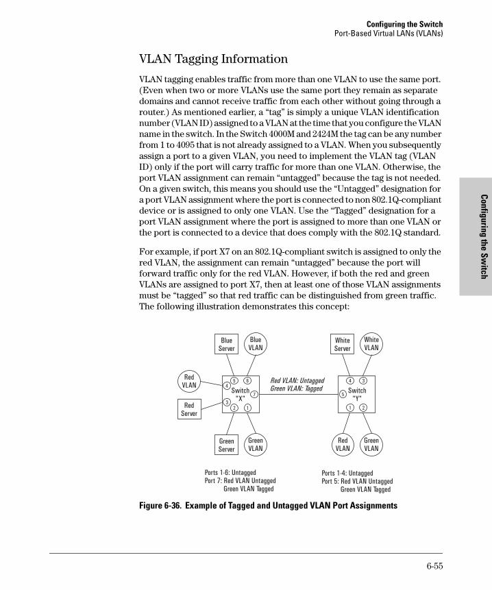
Configuring the SwitchPort-Based Virtual LANs (VLANs)
Configuring the Switch
tomcat.book Page 55 Wednesday, January 13, 1999 1:48 PM
VLAN Tagging Information
VLAN tagging enables traffic from more than one VLAN to use the same port. (Even when two or more VLANs use the same port they remain as separate domains and cannot receive traffic from each other without going through a router.) As mentioned earlier, a “tag” is simply a unique VLAN identification number (VLAN ID) assigned to a VLAN at the time that you configure the VLAN name in the switch. In the Switch 4000M and 2424M the tag can be any number from 1 to 4095 that is not already assigned to a VLAN. When you subsequently assign a port to a given VLAN, you need to implement the VLAN tag (VLAN ID) only if the port will carry traffic for more than one VLAN. Otherwise, the port VLAN assignment can remain “untagged” because the tag is not needed. On a given switch, this means you should use the “Untagged” designation for a port VLAN assignment where the port is connected to non 802.1Q-compliant device or is assigned to only one VLAN. Use the “Tagged” designation for a port VLAN assignment where the port is assigned to more than one VLAN or the port is connected to a device that does comply with the 802.1Q standard.
For example, if port X7 on an 802.1Q-compliant switch is assigned to only the red VLAN, the assignment can remain “untagged” because the port will forward traffic only for the red VLAN. However, if both the red and green VLANs are assigned to port X7, then at least one of those VLAN assignments must be “tagged” so that red traffic can be distinguished from green traffic. The following illustration demonstrates this concept:
Figure 6-36. Example of Tagged and Untagged VLAN Port Assignments
BlueServer
WhiteServer
GreenServer
RedServer
RedVLAN
BlueVLAN
WhiteVLAN
GreenVLAN
GreenVLAN
RedVLAN
Switch"X"
5 6
7
4
13
2
Switch"Y"
5
4
1
3
2
Red VLAN: UntaggedGreen VLAN: Tagged
Ports 1-6: UntaggedPort 7: Red VLAN Untagged
Green VLAN Tagged
Ports 1-4: UntaggedPort 5: Red VLAN Untagged
Green VLAN Tagged
6-55

Configuring the Switch Port-Based Virtual LANs (VLANs)
Conf
igur
ing
the
Switc
h
tomcat.book Page 56 Wednesday, January 13, 1999 1:48 PM
■ In switch X:
• VLANs assigned to ports X1 - X6 can all be untagged because there is only one VLAN assignment per port. Red traffic will go out only the red ports; green traffic will go out only the green ports, and so on. Devices connected to these ports do not have to be 802.1Q-compliant.
• However, because both the red VLAN and the green VLAN are assigned to port X7, at least one of the VLANs must be tagged for this port.
■ In switch Y:
• VLANs assigned to ports Y1 - Y4 can all be untagged because there is only one VLAN assignment per port. Devices connected to these ports do not have to be 802.1Q-compliant.
• Because both the red VLAN and the green VLAN are assigned to port Y5, at least one of the VLANs must be tagged for this port.
■ In both switches: The ports on the link between the two switches must be configured the same. That is, the Red VLAN must be untagged on port X7 and Y5 and the Green VLAN must be tagged on port X7 and Y5, or vice-versa.
N o t e Each 802.1Q-compliant VLAN must have its own unique VLAN ID number, and that VLAN must be given the same VLAN ID in every device in which it is configured. That is, if the “red” VLAN has a VLAN ID of 10 in switch “X”, then 10 must also be used for the red VLAN ID in switch “Y”.
6-56

Configuring the SwitchPort-Based Virtual LANs (VLANs)
Configuring the Switch
tomcat.book Page 57 Wednesday, January 13, 1999 1:48 PM
Figure 6-37. Example of VLAN ID Numbers Assigned in the VLAN Names Screen
VLAN tagging gives you several options:
■ Since the purpose of VLAN tagging is to allow multiple VLANs on the same port, any port that has only one VLAN assigned to it can be configured as “Untagged” (the default).
■ Any port that has two or more VLANs assigned to it can have one VLAN assignment for that port as “Untagged”. All other VLANs assigned to the same port must be configured as “Tagged”. (There can be no more than one Untagged VLAN on a port.)
■ If all end nodes on a port comply with the 802.1Q standard and are configured to use the correct VLAN tag number, then, you can configure all VLAN assignments on a port as “Tagged” if doing so makes it easier to manage your VLAN assignments, or for security reasons.
For example, in the following network, switches “X” and “Y” and servers S1 and S2 are 802.1Q-compliant. (Server S3 could also be 802.1Q-compliant, but it makes no difference for this example.)
VLAN ID Numbers
6-57

Configuring the Switch Port-Based Virtual LANs (VLANs)
Conf
igur
ing
the
Switc
h
tomcat.book Page 58 Wednesday, January 13, 1999 1:48 PM
Figure 6-38. Example of Networked 802.1Q-Compliant Devices with Multiple VLANs on Some Ports
The VLANs assigned to ports X3, X4, Y2, Y3, and Y4 can all be untagged because there is only one VLAN assigned per port. Port X1 has multiple VLANs assigned, which means that one VLAN assigned to this port can be untagged and any others must be tagged. The same applies to ports X2, Y1, and Y5.
N o t e VLAN configurations on ports connected by the same link must match. Because ports X2 and Y5 are opposite ends of the same point-to-point connec-tion, both ports must have the same VLAN configuration; that is, both ports configure the Red VLAN as “Untagged” and the Green VLAN as “Tagged”.
Switch “X” Switch “Y”
Port Red VLAN Green VLAN Port Red VLAN Green VLAN
X1 Untagged Tagged Y1 Untagged Tagged
X2 Untagged Tagged Y2 No* Untagged
X3 No* Untagged Y3 No* Untagged
X4 Untagged No* Y4 Untagged No*
Y5 Untagged Tagged
*”No” means the port is not a member of that VLAN. For example, port X3 is not a member of the Red VLAN and does not carry Red VLAN traffic.
Red VLAN: Untagged
Red VLAN: Untagged Red VLAN: Untagged
Green VLAN: Tagged
Green VLAN: Tagged Green VLAN: Tagged
Green VLAN only
ServerS1
ServerS2
ServerS3
GreenVLAN
GreenVLAN
RedVLAN
RedVLAN
Switch"X"
X1
X2
X3X4
Switch"Y"
Y1
Y4
Y2Y5
Y3
6-58

Configuring the SwitchPort-Based Virtual LANs (VLANs)
Configuring the Switch
tomcat.book Page 59 Wednesday, January 13, 1999 1:48 PM
To summarize:
Effect of VLANs on Other Switch Features
Spanning Tree Protocol Operation with VLANs
Because the Switch 4000M and the Switch 2424M follow the 802.1Q VLAN recommendation to use single-instance spanning tree, STP operates across the switch instead of on a per-VLAN basis. This means that if redundant physical links exist between the switch and another 802.1Q device, all but one link will be blocked, regardless of whether the redundant links are in separate VLANs. However, you can use port trunking to prevent STP from unnecessar-ily blocking ports (and to improve overall network performance). Refer to “STP Operation with 802.1Q VLANs” on page 6-39.
Note that STP operates differently in different devices. For example, in the (non-802.1Q) HP Switch 2000 and the HP Switch 800T, STP operates on a per-VLAN basis, allowing redundant physical links as long as they are in separate VLANs. Thus, redundant links connecting a Switch 4000M or Switch 2424M to the Switch 2000 or Switch 800T in a VLAN environment will not be blocked if the links are in different VLANs.
IPX and IP Interfaces.
There is a one-to-one relationship between a VLAN and an IP or IPX network interface. Since the VLAN is defined by a group of ports, the state (up/down) of those ports determines the state of the IP or IPX network interface associ-ated with that VLAN. When a VLAN comes up because one or more of its ports is up, the IP or IPX interface for that VLAN is also activated. Likewise, when a VLAN is deactivated because all of its ports are down, the corresponding IP or IPX interface is also deactivated.
VLANs Per Port
Tagging Scheme
1 Untagged or Tagged
2 or More 1 VLAN Untagged; all others Tagged orAll VLANs Tagged
A given VLAN must have the same VLAN ID on any 802.1Q-compliant device in which the VLAN is configured.The ports connecting two 802.1Q devices should have identical VLAN configurations, as shown for ports X2 and Y5, above.
6-59

Configuring the Switch Port-Based Virtual LANs (VLANs)
Conf
igur
ing
the
Switc
h
tomcat.book Page 60 Wednesday, January 13, 1999 1:48 PM
VLAN MAC Addresses
The switch has one unique MAC address for each of its VLAN interfaces. You can send an 802.2 test packet to this MAC address to verify connectivity to the switch. Likewise, you can assign an IP address to the VLAN interface, and when you Ping that address, ARP will resolve the IP address to this MAC address. (For IPX networks, each VLAN interface is automatically assigned a node address that is equivalent to the MAC address for that VLAN interface.) The switch allows up to 30 VLAN MAC addresses (one per possible VLAN).
Port Trunks
When assigning a port trunk to a VLAN, all ports in the trunk are automatically assigned to the same VLAN. You cannot split trunk members across multiple VLANs. Also, a port trunk is tagged, untagged, or excluded from a VLAN in the same way as for individual, untrunked ports.
Port Monitoring
If you designate a port on the switch for network monitoring, this port will appear in the Port VLAN Assignment screen and can be configured as a member of any VLAN. For information on how broadcast, multicast, and unicast packets are tagged inside and outside of the VLAN to which the monitor port is assigned, refer to page 8-6.
6-60

Configuring the SwitchPort-Based Virtual LANs (VLANs)
Configuring the Switch
tomcat.book Page 61 Wednesday, January 13, 1999 1:48 PM
VLAN Restrictions
■ A port must be a member of at least one VLAN. In the factory default configuration, all ports are assigned to the default VLAN (DEFAULT_VLAN).
■ A port can be assigned to several VLANs, but only one of those assign-ments can be untagged. (The “Untagged” designation enables VLAN oper-ation with non 802.1Q-compliant devices.)
■ An external router must be used to communicate between VLANs.
■ Duplicate MAC addresses on different VLANs are not supported and can cause VLAN operating problems. These duplicates are possible and com-mon in situations involving Sun workstations with multiple network interface cards, with DECnet routers, and with certain Hewlett-Packard routers using OS versions earlier than A.09.70 where any of the following are enabled:
• IPX
• IP Host-Only
• STP
• XNS
• DECnet
Currently, the problem of duplicate MAC addresses in IPX and IP Host-Only environments is addressed through the HP router OS version described below. However, for XNS and DECnet environments, a satisfac-tory solution is not available from any vendor at this time.
N o t e Operating problems associated with duplicate MAC addresses are likely to occur in VLAN environments where XNS and DECnet are used. For this reason, using VLANs in XNS and DECnet environments is not currently supported.
■ Before you can delete a VLAN, you must re-assign all ports in the VLAN to another VLAN.
6-61

Configuring the Switch Port-Based Virtual LANs (VLANs)
Conf
igur
ing
the
Switc
h
tomcat.book Page 62 Wednesday, January 13, 1999 1:48 PM
HP Router Requirements. Use the Hewlett-Packard version A.09.70 (or
later) router OS release if any of the following Hewlett-Packard routers are
installed in networks in which you will be using VLANs:
HP Router 440 (formerly Router ER)HP Router 470 (formerly Router LR)HP Router 480 (formerly Router BR)HP Router 650
Release A.09.70 (or later) is available electronically through the HP BBS service and the World Wide Web. Refer to the “Customer Support Services” booklet shipped with the switch.
Symptoms of Duplicate MAC Addresses in VLAN Environments
There are no definitive events or statistics to indicate the presence of duplicate MAC addresses in a VLAN environment. However, one symptom that may occur is that a duplicate MAC address can appear in the Port Address Table screen to be linked with one port, and then later appear to be linked to another port.
6-62

Configuring the SwitchLoad Balancing: Port Trunking
Configuring the Switch
tomcat.book Page 63 Wednesday, January 13, 1999 1:48 PM
Load Balancing: Port Trunking
Figure 6-39. Conceptual Illustration of Port Trunking
Port trunking allows up to four ports to be connected together to function as a single, higher-speed link that dramatically increases bandwidth. This capa-bility can be applied to connections between backbone devices as well as connections in other network areas where traffic bottlenecks have developed. With full-duplex operation in a four-port trunk, this enables the following bandwidth capabilities:
■ 10Base-T links: Up to 80 Mbps
■ 100Base-T links: Up to 800 Mbps
The Switch 4000M and the Switch 2424M both support up to ten four-port trunks.
N o t e To avoid broadcast storms or loops in your network while configuring trunks, first disable or disconnect all ports you want to add or remove from both sides of the trunk. After you finish configuring the trunk, enable or re-connect the ports.
Traffic distribution across the links in a port trunk is based on source/destination or source-only address forwarding methods described later in this section. This results in load balancing based on distribution of source and/or destination addresses across the links in a trunk. Because the amount of traffic coming from or going to various nodes in a network can vary widely, it is possible for one link in a trunk to be fully utilized while others in the same trunk have unused bandwidth capacity even though the address assignments are evenly distributed across the links in a trunk. In actual networking
Switch 1 Switch 2
The multiple ports in a trunk behave as one logical port
port a port wport b port xport c port y... port zport n ... port n
port 1 port 2 port 3 ... port n
port 5 port 6 port 7 port 8... port n
Switch 3
6-63

Configuring the Switch Load Balancing: Port Trunking
Conf
igur
ing
the
Switc
h
tomcat.book Page 64 Wednesday, January 13, 1999 1:48 PM
environments, this is rarely a problem. However, if it becomes a problem, you can use the HP TopTools for Hubs & Switches network management software available from Hewlett-Packard to quickly and easily identify the sources of heavy traffic (top talkers) and make adjustments to improve performance.
Fault Tolerance: If a link in a port trunk fails, traffic originally destined for that link will be redistributed to the remaining links in the trunk. The trunk remains operable as long as there is at least one link in operation. If a link is restored, that link is automatically included in the traffic distribution again.
Port Connections and Configuration: All port trunk links must be point-to-point connections between the Switch 4000M or Switch 2424M and another switch, router, server, or workstation. It is important to note that ports on both ends of a port trunk should be configured with the same trunk type, mode, flow control, and broadcast limit settings.
N o t e Using more than one media type and/or link speed in a port trunk is not supported. The console interface allows only links of the same media type within the same trunk. Similarly, it is recommended that all links in the same trunk have the same speed. You should also apply these rules when using a network management application to configure a port trunk.
Use with Spanning Tree and Advanced Features. A configured trunk appears as a single port (labeled Trk1, Trk2...Trk9, Trk0) on other configuration screens, such as the Spanning Tree, IP Multicast (IGMP), and VLAN port assignment screens. When Spanning Tree forwards on a trunk, all ports in the trunk will be forwarding. Conversely, when Spanning Tree blocks a trunk, all ports in the trunk are blocked. Also, when a trunk port is assigned to a VLAN, all ports in that trunk are assigned to the same VLAN. (If you assign a trunk to a VLAN, and then remove a port from the trunk, that port will automatically be assigned to the same VLAN as the trunk.)
When you add a port to a trunk, the port takes on the properties of the trunk. If you remove a port from a trunk, the port retains the trunk properties (except for the filtering properties, which are returned to their previous state). For example, if you:
1. use ports A1, A2, and A3 to create trunk 1 in the red VLAN.
2. move trunk 1 to the blue VLAN.
3. remove port A3 from the trunk.
then port A3 will be a member of the blue VLAN instead of the original red VLAN.
6-64

Configuring the SwitchLoad Balancing: Port Trunking
Configuring the Switch
tomcat.book Page 65 Wednesday, January 13, 1999 1:48 PM
However, if filters were in use on port A3, it will return to filtering as it did before joining the trunk:
• If, for example, port A3 was configured with filters to drop specific packets before it became a member of trunk 1 and . . .
• If trunk 1 was configured to forward those packets, then port A3 will also forward the packets while it is a member of trunk 1.
• However, if you subsequently remove port A3 from trunk 1, then port A3 resumes dropping the specific packets according to its original filter configuration.
Interoperability
The Switch 4000M and the Switch 2424M enable trunking with the HP switch products listed below. These two switches also offer trunking interoperation with products offered by some other vendors.
N o t e When this manual was released, an IEEE standard for port trunking was not yet available. Thus, standards compliance cannot yet be used to determine how successfully various vendors’ implementations of port trunking will interoperate with the Switch 4000M and Switch 2424M. (However, note that the Trunk option uses the IEEE 802.3 standards for auto-negotiating half- or full-duplex operation and auto-sensing 10 Mbps, 100 Mbps links.) For more on trunking to non-HP devices, see the Technology area of HP’s Network City website at www.hp.com/go/procurve .
Trunk Configuration Options
There are two trunk configuration types from which to select:
Type Distribution Method Recommended Switch 4000M/2424M Configuration for Trunking to:
Trunk Source Address/Destination Address (SA/DA)
• Another HP Switch 4000M/2424M• HP Switch 8000M/1600M• HP Switch 2000A/B• HP Switch 800T• SA/DA forwarding devices such as the Sun
Trunk Server and some vendors’ switches• Windows NT and HP-UX workstations and
servers
SA-Trunk Source-Address Distribution Forwarding devices such as low-end switches or devices that do not support SA/DA port trunks.
6-65

Configuring the Switch Load Balancing: Port Trunking
Conf
igur
ing
the
Switc
h
tomcat.book Page 66 Wednesday, January 13, 1999 1:48 PM
Configuring Port Trunks from the Switch Console
Important. Use this procedure to configure port trunking before you connect the trunked links between switches. Otherwise, a broadcast storm could occur. (If you need to connect the ports before configuring them for trunking, you can use the Port Settings feature—page 6-25—to temporarily disable the ports until the trunk is configured.)
To Access Port Trunking:
1. If you need to connect ports for a trunk before configuring them, refer to “Port Settings” on page 6-25 to temporarily disable the ports until the trunk is configured. Otherwise, just avoid connecting the ports in the trunk until after you configure trunking. (This avoids creating a loop that could result in overloading the network with a broadcast storm.)
2. From the Main Menu, Select:
3. Switch Configuration
5. Advanced Features
2. Load Balancing (Trunks)
3. Press [E] (for Edit) to access the load balancing parameters.
Figure 6-40. Example of the Screen for Configuring Ports for Load Balancing
6-66

Configuring the SwitchLoad Balancing: Port Trunking
Configuring the Switch
tomcat.book Page 67 Wednesday, January 13, 1999 1:48 PM
4. In the Group column, move the cursor to the port you want to configure.
5. Use the Space bar (or type the trunk name, such as trk5) to choose a trunk assignment for the selected port.
• All ports in a trunk should have the same media type and mode (such as 10/100TX set to 100HDx, or 100FX set to 100FDx). The flow control and broadcast limit settings should also be the same for all ports in a given trunk. To verify these settings, refer to “Port Settings” on page 6-25.
• You can configure up to ten different trunks (Trk1...Trk9,Trk0), with one, two, three, or four ports per trunk. A port can be assigned to only one trunk. However, you can move ports between trunks. If multiple VLANs are configured, all ports within a given trunk will be assigned to the same VLAN or set of VLANs. (With the 802.1Q VLAN capability built into the switch, more than one VLAN can be assigned to a trunk. Refer to “Port-Based Virtual LANs (VLANs)” on page 6-45.)
(To return a port to a non-trunk status, keep pressing the Space bar until a blank appears in the highlighted Group value for that port.)
Figure 6-41. Example of Trunk Group Assignments for Several Ports
6-67

Configuring the Switch Load Balancing: Port Trunking
Conf
igur
ing
the
Switc
h
tomcat.book Page 68 Wednesday, January 13, 1999 1:48 PM
6. Move the cursor to the Type column for the selected port and use the Space bar to select the trunk type:
– Trunk (Source Address/Destination Address trunk; the default type if you do not select a type)—page 6-69.
– SA-Trunk (Source-Address trunk)—page 6-70
All ports in the same trunk must have the same Type (Trunk or SA-Trunk).
Figure 6-42. Example of trunks with different trunk types
7. When you are finished assigning ports to trunks, press [Enter], then [S] (for Save) and return to the Main Menu. (It is not necessary to reboot the switch.)
8. Connect the trunked ports on the switch to the corresponding ports on the opposite device. If you previously disabled any of the trunked ports on the switch, enable them now. (Refer to “Port Settings” on page 6-25.)
9. Check the Event Log (page 8-8) to verify that the trunked ports are operating properly.
6-68

Configuring the SwitchLoad Balancing: Port Trunking
Configuring the Switch
tomcat.book Page 69 Wednesday, January 13, 1999 1:48 PM
Operating Information
This section describes port usage and how traffic is distributed by the various trunking options.
Trunk Operation Using the Trunk (Source Address/Destination Address, or SA/DA) Option
This method provides the best means for evenly distributing traffic over trunked links to devices.
Configuring the Trunk (SA/DA) option for a port trunk causes the switch to distribute traffic in a sequential manner to the links within the trunk on the basis of source/destination pairs. That is, traffic from the same source address to the same destination addresses will travel over the same trunked link. Traffic from the same source address but meant for different destination addresses will be distributed across different links. Likewise, traffic for the same destination address but from different source addresses will be distrib-uted across different links. Because of this feature, broadcasts, multicasts, and floods from different source addresses are distributed evenly across the links. As links are added or deleted, traffic will be redistributed across the trunk. For example, in the three-port trunk shown below, traffic could be assigned as shown in the table below.
Figure 6-43. Example of Port-Trunked Network
Example of Link Assignments in a Trunk ((SA/DA Distribution)
Source: Destination: Link:
Node A Node W 1
Node B Node X 2
Node C Node Y 3
Node D Node Z 1
Node A Node Y 2
Node B Node W 3
Switch Switch
A W
C Y
B X
D Z
123
6-69

Configuring the Switch Load Balancing: Port Trunking
Conf
igur
ing
the
Switc
h
tomcat.book Page 70 Wednesday, January 13, 1999 1:48 PM
Trunk Operation Using the SA-Trunk (Source-Address Distribution) Option
This option is less efficient than the SA/DA option described above. However, it is useful for trunking to devices that do not have built-in support for theSA/DA-trunking method.
Configuring the SA-Trunk option for a port trunk causes the switch to distrib-ute traffic in a sequential manner to the links within the trunk on the basis of source address only. That is, traffic from the same source address will travel over the same trunked link regardless of destination address. Traffic from other sources to the same or different destinations may travel over different links within the same trunk. This prevents the source address from appearing on different ports in the non-trunking device.
Example of Link Assignments in an SA-Only Trunk
(refer to figure 6-43 above)
C a u t i o n SA/DA Trunking and SA-only Trunking are not compatible. If you are trunking an SA-only device to a Switch 2424M or 4000M, make sure the involved switch ports are configured as SA-Trunk.
Source Nodes: Destination Nodes: Link:
Source Nodes A and D Always Appear on Port 1
Node A Node W 1
Node B Node X 2
Node C Node Y 3
Node D Node Z 1
Node A Node Y 1
Node B Node W 2
6-70

Configuring the SwitchIP Multicast (IGMP) Features—Multimedia Traffic Control
Configuring the Switch
tomcat.book Page 71 Wednesday, January 13, 1999 1:48 PM
IP Multicast (IGMP) Features—Multimedia Traffic Control
In a network where IP multicast traffic is transmitted for various multimedia applications, you can use the switch to reduce unnecessary bandwidth usage on a per-port basis by configuring IGMP (Internet Group Management Proto-col). In the factory default state (IGMP disabled), the switch forwards all IGMP traffic to all ports, which can cause unnecessary bandwidth usage on ports not belonging to multicast groups. Enabling IGMP allows the ports to detect IGMP queries and report packets and manage IP multicast traffic through the switch.
IGMP is useful in multimedia applications such as LAN TV, desktop confer-encing, and collaborative computing, where there is multipoint communica-tion; that is, communication from one to many hosts, or communication originating from many hosts and destined for many other hosts. In such multipoint applications, IGMP will be configured on the hosts, and multicast traffic will be generated by one or more servers (inside or outside of the local network). Switches in the network (that support IGMP) can then be config-ured to direct the multicast traffic to only the ports where needed. If multiple VLANs are configured, you can configure IGMP on a per-VLAN basis.
Enabling IGMP allows the ports to detect IGMP queries and report packets and manage IP multicast traffic through the switch. If no other querier is detected, the switch will then also function as the querier. (If you need to disable the querier feature, you can do so through the IGMP configuration MIB. Refer to “Changing the Querier Configuration Setting” on page 6-81.)
N o t e In order for IGMP service to take effect, an IP address must be configured and active. If multiple VLANs are configured, an IP address must be configured for the VLAN in which you are configuring IGMP. Refer to “IP Configuration” on page 6-6.
For more information on IGMP operation, refer to “How IGMP Operates” on page 6-76.
6-71

Configuring the Switch IP Multicast (IGMP) Features—Multimedia Traffic Control
Conf
igur
ing
the
Switc
h
tomcat.book Page 72 Wednesday, January 13, 1999 1:48 PM
Configuring IGMP from the Web Browser Interface
Figure 6-44. Configuring IGMP on the Web Browser Interface
1. Click Here 2. Click Here
3. If multiple VLANs are configured, select the VLAN in which you want to configure IGMP.
4. To enable or disable IGMP, click on the drop-down menu, click on your selection (On or Off), and then click on Apply Changes in the lower-right corner of the screen.
6-72

Configuring the SwitchIP Multicast (IGMP) Features—Multimedia Traffic Control
Configuring the Switch
tomcat.book Page 73 Wednesday, January 13, 1999 1:48 PM
Parameter Description
Multicast Filtering (IGMP)
Default: Off
Determines whether the switch or VLAN uses IGMP on a per-port basis to manage IP Multicast traffic. If multiple VLANs are configured, you can configure IGMP separately for each VLAN. To access a VLAN using the HP web browser interface, enter that VLAN’s IP address as the URL.
When Off, all ports on the switch or VLAN simply forward IP multicast traffic.
When On, enables each port on the switch or VLAN to detect IGMP queries and report packets, and to manage IP multicast traffic.
When you use the web browser interface to enable Multicast Filtering, the default operation is for each port in the switch or VLAN to automatically forward or drop IGMP traffic, depending on whether there are any IGMP hosts or multicast routers on the port.
Further Options Available in the Switch Console
By using the switch console, you can make these further changes to IGMP operation:• On a per-port basis, block or forward all IP multicast traffic. • For all ports on the switch or VLAN, forward IP multicast traffic at high
priority. (The default is for the switch or VLAN to process IGMP traffic, along with other traffic, in the order received.)
• Change the querier configuration setting. (By default, the switch will act as a querier if a multicast router is not present to perform this function.)
For more information, refer to “Configuring IGMP from the Switch Console” (page 6-74) and “How IGMP Operates” (page 6-76.).
6-73
Configuring the Switch IP Multicast (IGMP) Features—Multimedia Traffic Control
Conf
igur
ing
the
Switc
h
tomcat.book Page 74 Wednesday, January 13, 1999 1:48 PM
Configuring IGMP from the Switch Console
In the factory default configuration, IGMP is disabled. If multiple VLANs are configured, you can configure IGMP on a per-VLAN basis. When you use either the console or the web browser interface to enable IGMP on the switch or a VLAN, the switch forwards IGMP traffic only to ports belonging to multicast groups. Using the console enables these additional options:
■ Forward with High Priority. Disabling this parameter (the default) causes the switch or VLAN to process IP multicast traffic, along with other traffic, in the order received. Enabling this parameter causes the switch or VLAN to give a higher priority to IP multicast traffic than to other traffic.
■ Auto/Blocked/Forward: You can use the console to configure individual ports to any of the following states:
• Auto (the default): Causes the switch to interpret IGMP packets and to filter IP multicast traffic based on the IGMP packet information for ports belonging to a multicast group. This means that IGMP traffic will be forwarded on a specific port only if an IGMP host or multicast router is connected to the port.
• Blocked: Causes the switch to drop all IGMP transmissions received from a specific port and to block all outgoing IP Multicast packets for that port. This has the effect of preventing IGMP traffic from moving through specific ports.
• Forward: Causes the switch to forward all IGMP and IP multicast transmissions through the port.
For more information, refer to “How IGMP Operates” on page 6-76.
6-74

Configuring the SwitchIP Multicast (IGMP) Features—Multimedia Traffic Control
Configuring the Switch
tomcat.book Page 75 Wednesday, January 13, 1999 1:48 PM
To Access IGMP Service:
Use this procedure to configure or edit the IGMP settings for a switch or VLAN.
1. From the Main Menu, select:
3. Switch Configuration
5. Advanced Features
3. IP Multicast (IGMP) Service
Figure 6-45. Example of the (Default) IGMP Service Screen
2. Press the Space bar to select Yes (to enable IGMP).
3. Use [v] to highlight the Forward with High Priority parameter.
4. If you want IGMP traffic to be forwarded with a higher priority than other traffic on the switch or VLAN, use the Space bar to select Yes. Otherwise, leave this parameter set to No.
5. Use [v] to highlight the IP Mcast parameter setting for a port you want to reconfigure. (The options are: Auto, Blocked, and Forward. Refer to the previous page or online Help for further information on these choices.)
6. Repeat step 5 for each port you want to configure.
6-75

Configuring the Switch IP Multicast (IGMP) Features—Multimedia Traffic Control
Conf
igur
ing
the
Switc
h
tomcat.book Page 76 Wednesday, January 13, 1999 1:48 PM
7. When you are finished configuring the IP Mcast parameter for the dis-played ports, press [Enter] and [S] (for Save) to activate the changes you’ve made to the IGMP configuration.
8. Return to the Main Menu. (It is not necessary to reboot the switch. The new IGMP configuration is implemented when you select “Save” in step 7.)
How IGMP Operates
The Internet Group Management Protocol (IGMP) is an internal protocol of the Internet Protocol (IP) suite. IP manages multicast traffic by using switches, multicast routers, and hosts that support IGMP. (In Hewlett-Pack-ard’s implementation of IGMP, a multicast router is not necessary as long as a switch is configured to support IGMP with the querier feature enabled.) A set of hosts, routers, and/or switches that send or receive multicast data streams to or from the same source(s) is termed a multicast group, and all devices in the group use the same multicast group address. The multicast group running version 2 of IGMP uses three fundamental types of messages to communicate:
■ Query: A message sent from the querier (multicast router or switch) asking for a response from each host belonging to the multicast group. If a multicast router supporting IGMP is not present, then the switch must assume this function in order to elicit group membership information from the hosts on the network. (If you need to disable the querier feature, you can do so through the console, using the IGMP configuration MIB. Refer to “Changing the Querier Configuration Setting” on page 6-81.)
■ Report: A message sent by a host to the querier to indicate that the host wants to be or is a member of a given group indicated in the report message.
■ Leave Group: A message sent by a host to the querier to indicate that the host has ceased to be a member of a specific multicast group.
Thus, IGMP identifies members of a multicast group (within a subnet) and allows IGMP-configured hosts (and routers) to join or leave multicast groups.
IGMP Data. To display data showing active group addresses, reports, que-ries, querier access port, and active group address data (port, type, and access), see “IP Multicast (IGMP) Status” on page 7-19.
6-76

Configuring the SwitchIP Multicast (IGMP) Features—Multimedia Traffic Control
Configuring the Switch
tomcat.book Page 77 Wednesday, January 13, 1999 1:48 PM
Role of the Switch
When IGMP is enabled on the switch, it examines the IGMP packets it receives:
■ To learn which of its ports are linked to IGMP hosts and multicast routers/queriers belonging to any multicast group
■ To become a querier if a multicast router/querier is not discovered on the network
Once the switch learns the port location of the hosts belonging to any partic-ular multicast group, it can direct group traffic to only those ports, resulting in bandwidth savings on ports where group members do not reside. The following example illustrates this operation.
Figure 6-46 on page 6-78 shows a network running IGMP.
■ PCs 1 and 4, Switch 2, and all of the routers are members of an IP multicast group. (The routers operate as queriers.)
■ Switch 1 ignores IGMP traffic and does not distinguish between IP multi-cast group members and non-members. Thus, it is sending large amounts of unwanted multicast traffic out the ports to PCs 2 and 3.
■ Switch 2 is recognizing IGMP traffic and learns that PC 4 is in the IP multicast group receiving multicast data from the video server (PC X). Switch 2 then sends the multicast data only to the port for PC 4, thus avoiding unwanted multicast traffic on the ports for PCs 5 and 6.
6-77

Configuring the Switch IP Multicast (IGMP) Features—Multimedia Traffic Control
Conf
igur
ing
the
Switc
h
tomcat.book Page 78 Wednesday, January 13, 1999 1:48 PM
Figure 6-46. The Advantage of Using IGMP
The next figure (6-47) shows a network running IP multicasting using IGMP without a multicast router. In this case, the IGMP-configured switch runs as a querier.
PCs 2, 5, and 6 are members of the same IP multicast group.
IGMP is configured on switches 3 and 4. Either of these switches can operate as querier because a multicast router is not present on the network. (If an IGMP switch does not detect a querier, it automatically assumes this role, assuming the querier feature is enabled—the default—within IGMP.)
PC X
Video Server
RouterRouter
PC 1
Video Client
Switch 1
Router
Router
Switch 2
PC 2PC 3 PC 4
Video Client PC 5
PC 6
Multicast Data Stream
IGMP is NOT Running Here
IGMP IS Running Here
6-78

Configuring the SwitchIP Multicast (IGMP) Features—Multimedia Traffic Control
Configuring the Switch
tomcat.book Page 79 Wednesday, January 13, 1999 1:48 PM
Figure 6-47. Isolating IP Multicast Traffic in a Network
■ In the above figure, the multicast group traffic does not go to switch 1 and beyond because either the port on switch 3 that connects to switch 1 has been configured as blocked or there are no hosts connected to switch 1 or switch 2 that belong to the multicast group.
■ For PC #1 to become a member of the same multicast group without flooding IP multicast traffic on all ports of switches 1 and 2, IGMP must be configured on both switches 1 and 2, and the port on Switch 3 that connects to Switch 1 must be unblocked.
Switch 4
PC 1
PC 2
PC 5 PC 6
Multicast Data Stream
IGMP IS Running Here
Switch 1
Switch 2
IGMP is NOT Running Here
Switch 3
IGMP IS Running Here
6-79

Configuring the Switch IP Multicast (IGMP) Features—Multimedia Traffic Control
Conf
igur
ing
the
Switc
h
tomcat.book Page 80 Wednesday, January 13, 1999 1:48 PM
N o t e :
I P M u l t i c a s t F i l t e r s
IP multicast addresses occur in the range from 224.0.0.0 through 239.255.255.255. Any static Traffic/Security filters (page 6-40) configured with a “Multicast” filter type and a “Multicast Address” in this range will continue in effect unless IGMP learns of a multicast group destination in this range. In that case, IGMP takes over the filtering function for the multicast destination address(es) for as long as the IGMP group is active. If the IGMP group subsequently deactivates, the static filter resumes control over traffic to the multicast address formerly controlled by IGMP.
Number of IP Multicast Addresses Allowed
Multicast filters and IGMP filters (addresses) together can total up to 255 in the switch. If multiple VLANs are configured, then each filter is counted once per VLAN in which it is used.
Interaction with Multicast Traffic/Security Filters.
IGMP-controlled filters override multicast filters defined in the Traffic/Secu-rity Filters screen (page 6-40) and having the same multicast address as specified by IGMP.
6-80

Configuring the SwitchIP Multicast (IGMP) Features—Multimedia Traffic Control
Configuring the Switch
tomcat.book Page 81 Wednesday, January 13, 1999 1:48 PM
Changing the Querier Configuration Setting
The Querier feature, by default, is enabled and in most cases should be left in this setting. If you need to change the querier setting, you can do so using the IGMP Configuration MIB. To disable the querier setting, select the Command Prompt from the Diagnostics Menu and enter this command:
setmib hpSwitchIgmpQuerierState.<vlan number> -i 2
To enable the querier setting, select the Command Prompt from the Main Menu and enter this command:
setmib hpSwitchIgmpQuerierState.<vlan number> -i 1
To view the current querier setting, select the Command Prompt from the Main Menu and enter this command:
getmib hpSwitchIgmpQuerierState.<vlan number>
where:
<vlan number> is the sequential (index) number of the specific VLAN. If no VLANs are configured, use “1”. For example:
getmib hpSwitchIgmpQuerierState.1
N o t e The above commands are case-sensitive.
Whenever IGMP is enabled, the switch generates an Event Log message indicating whether querier functionality is enabled.
6-81

tomcat.book Page 82 Wednesday, January 13, 1999 1:48 PM

Monitoring and A
nalyzing Sw
itch Operation
tomcat.book Page 1 Wednesday, January 13, 1999 1:48 PM
7
Monitoring and Analyzing Switch Operation
Overview
You can use the switch console (and, in some cases, the web browser inter-face) to access read-only status and counter information to help you monitor, analyze, and troubleshoot switch operation.
In particular, the web browser interface has an Alert Log that can help that can help you quickly identify network problems. See chapter 3, “Using the Web Browser Interface” for more information about the web browser interface and the Alert Log.
N o t e Link test, ping test, browse configuration, and the Command prompt—analysis tools in troubleshooting situations—are described in chapter 8, “Troubleshoot-ing”. See “Diagnostics” on page 8-13.
The Event Log, a diagnostic tool that is often used for troubleshooting switch operation, is described in chapter 8, “Troubleshooting”. See “Using the Event Log To Identify Problem Sources” on page 8-8.
7-1

Monitoring and Analyzing Switch OperationStatus and Counters Screens
Mon
itori
ng a
nd A
naly
zing
Sw
itch
Ope
ratio
n
tomcat.book Page 2 Wednesday, January 13, 1999 1:48 PM
Status and Counters Screens
This section describes the status and counters screens available through the switch console interface and/or the web browser interface.
N o t e You can access all console screens from the web browser interface via Telnet to the console. See “Configuration Tab” on page 3-22.
Status or Counters Type Interface Purpose Page
General System Information Console Lists switch-level operating information. 7-5
Management Address Information
Console Lists the MAC address, IP address, and IPX network number for each VLAN or, if no VLANs are configured, for the switch.
7-6
Module Information Console For each slot, lists the module type (such as 10/100TX) and description.
7-7
Port Status Overview Browser Shows port utilization and the Alert Log. 3-12
Port Status Console/ Browser
Displays the operational status of each port. 7-8
Port Counters Console/ Browser
Summarizes port activity. 7-10
Address Table(Address Forwarding Table)
Console Lists the MAC addresses of nodes the switch has detected on the network, with the corresponding switch port.
7-14
Port Address Table Console Lists the MAC addresses that the switch has learned from the selected port.
7-15
Spanning Tree Information Console Lists Spanning Tree data for the switch and for individual ports. If VLANs are configured, reports on a per-VLAN basis.
7-17
IP Multicast (IGMP) Status Console Lists IGMP groups, reports, queries, and port on which querier is located.
7-19
VLAN Information Console For each VLAN configured in the switch, lists 802.1Q VLAN ID and up/down status.
7-21
7-2

Monitoring and Analyzing Switch OperationSwitch Console Status and Counters Menu
Monitoring and A
nalyzing Sw
itch Operation
tomcat.book Page 3 Wednesday, January 13, 1999 1:48 PM
Switch Console Status and Counters Menu
Select Status and Counters from the Main Menu to display the Status and Counters menu:
Figure 7-1. The Status and Counters Menu
Each of the above menu items accesses the read-only screens described on the following pages. Refer to the online help for a description of the entries displayed in these screens.
7-3

Monitoring and Analyzing Switch OperationWeb Browser Interface Status Information
Mon
itori
ng a
nd A
naly
zing
Sw
itch
Ope
ratio
n
tomcat.book Page 4 Wednesday, January 13, 1999 1:48 PM
Web Browser Interface Status Information
The “home” screen for the web browser interface is the Status Overview screen, as shown in figure 7-2. As the title implies, it provides an overview of the status of the switch, including summary graphs indicating the network utilization on each of the switch ports, symbolic port status indicators, and the Alert Log, which informs you of any problems that may have occurred on the switch.
For more information on this screen, see chapter 3, “Using the HP Web Browser Interface”.
Figure 7-2. Example of a Web Browser Interface Status Overview Screen
The other web browser interface status screens, Port Counters, and Port Status are described later in this chapter.
Alert Log
Port Status Indicators
Port Utilization Graphs
7-4

Monitoring and Analyzing Switch OperationWeb Browser Interface Status Information
Monitoring and A
nalyzing Sw
itch Operation
tomcat.book Page 5 Wednesday, January 13, 1999 1:48 PM
General System Information
To access this screen from the console Main Menu, select:
1. Status and Counters
1. General System Information
Figure 7-3. Example of General Switch Information
This screen dynamically indicates how individual switch resources are being used. See the online Help for details.
7-5

Monitoring and Analyzing Switch OperationWeb Browser Interface Status Information
Mon
itori
ng a
nd A
naly
zing
Sw
itch
Ope
ratio
n
tomcat.book Page 6 Wednesday, January 13, 1999 1:48 PM
Switch Management Address Information
To access this screen from the Main Menu, select:
1 Status and Counters
2. Switch Management Address Information
Figure 7-4. Example of Management Address Information with VLANs Configured
This screen displays addresses that are important for management of the switch. If multiple VLANs are not configured, this screen displays a single set of addresses for the entire switch. See the online Help for details.
7-6

Monitoring and Analyzing Switch OperationWeb Browser Interface Status Information
Monitoring and A
nalyzing Sw
itch Operation
tomcat.book Page 7 Wednesday, January 13, 1999 1:48 PM
Module Information
To access this screen from the Main Menu, select:
1. Status and Counters
3. Module Information
Figure 7-5. Example of the Module Information Screen (Switch 4000M)
Displays information on the modules installed in the switch. See the online Help for details.
7-7

Monitoring and Analyzing Switch OperationPort Status
Mon
itori
ng a
nd A
naly
zing
Sw
itch
Ope
ratio
n
tomcat.book Page 8 Wednesday, January 13, 1999 1:48 PM
Port Status
The web browser interface and the console interface show the same port status data.
Displaying Port Status from the Web Browser Interface
Figure 7-6. Example of Port Status on the Web Browser Interface (Switch 4000M)
1. Click here 2. Click here
7-8

Monitoring and Analyzing Switch OperationPort Status
Monitoring and A
nalyzing Sw
itch Operation
tomcat.book Page 9 Wednesday, January 13, 1999 1:48 PM
Displaying Port Status from the Console Interface
To access this screen from the Main Menu, select:
1. Status and Counters
4. Port Status
Figure 7-7. Example of Port Status on the Console Interface (Switch 4000M)
7-9

Monitoring and Analyzing Switch OperationPort Counters
Mon
itori
ng a
nd A
naly
zing
Sw
itch
Ope
ratio
n
tomcat.book Page 10 Wednesday, January 13, 1999 1:48 PM
Port Counters
The web browser interface and the console interface show the same port counter data.
These screens enables you to determine the traffic patterns for each port. Port Counter features include:
■ Dynamic display of counters summarizing the traffic on each port since the last reboot or reset
■ Option to reset the counters to zero (for the current console session). This is useful for troubleshooting. Refer to the Note, below.
■ An option to display the link status and further port activity details for a specific port (console: Show details or browser: Details for Select Port).
N o t e The Reset action resets the counter display to zero for the current session, but does not affect the cumulative values in the actual hardware counters. (In compliance with the SNMP standard, the values in the hardware counters are not reset to zero unless you reboot the switch.) Thus, using the Reset action resets the displayed counters to zero for the current session only. Exiting from the console session and starting a new session restores the counter displays to the accumulated values in the hardware counters.
7-10

Monitoring and Analyzing Switch OperationPort Counters
Monitoring and A
nalyzing Sw
itch Operation
tomcat.book Page 11 Wednesday, January 13, 1999 1:48 PM
Displaying Port Counters from the Web Browser Interface
Figure 7-8. Example of Port Counters and Details on the Web Browser Interface
3. To view details about the traffic on a particular port, highlight that port number, then click on Details for Select Port.
1. Click here 2. Click here
4. Click here to return to the Port Counters screen.
7-11

Monitoring and Analyzing Switch OperationPort Counters
Mon
itori
ng a
nd A
naly
zing
Sw
itch
Ope
ratio
n
tomcat.book Page 12 Wednesday, January 13, 1999 1:48 PM
Displaying Port Counters from the Console Interface
To access this screen from the Main Menu, select:
1. Status and Counters
5. Port Counters
Figure 7-9. Example of Port Counters on the Console Interface
To view details about the traffic on a particular port, highlight that port number (figure 7-9), then select Show Details. For example, selecting port A1 displays a screen similar to figure 7-10, on the next page.
7-12

Monitoring and Analyzing Switch OperationPort Counters
Monitoring and A
nalyzing Sw
itch Operation
tomcat.book Page 13 Wednesday, January 13, 1999 1:48 PM
Figure 7-10. Example of the Display for Show details on a Selected Port
This screen also includes the Reset action. Refer to the note on page 7-10.
7-13

Monitoring and Analyzing Switch OperationAddress Table
Mon
itori
ng a
nd A
naly
zing
Sw
itch
Ope
ratio
n
tomcat.book Page 14 Wednesday, January 13, 1999 1:48 PM
Address Table
To access the Address Table screen from the Main Menu, select:
1. Status and Counters
6. Address Table
Figure 7-11. Example of the Address Table (Switch 4000M)
This screen lets you determine which switch port is being used to communi-cate with a specific device on the network. The listing includes:
■ The MAC addresses that the switch has learned from network devices attached to the switch
■ The port on which each MAC address was learned
Use the Search action at the bottom of the screen to locate a specific device (MAC address).
7-14
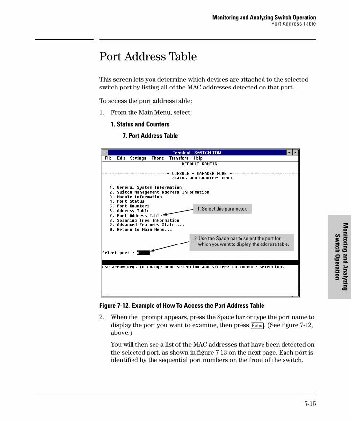
Monitoring and Analyzing Switch OperationPort Address Table
Monitoring and A
nalyzing Sw
itch Operation
tomcat.book Page 15 Wednesday, January 13, 1999 1:48 PM
Port Address Table
This screen lets you determine which devices are attached to the selected switch port by listing all of the MAC addresses detected on that port.
To access the port address table:
1. From the Main Menu, select:
1. Status and Counters
7. Port Address Table
Figure 7-12. Example of How To Access the Port Address Table
2. When the prompt appears, press the Space bar or type the port name to display the port you want to examine, then press [Enter]. (See figure 7-12, above.)
You will then see a list of the MAC addresses that have been detected on the selected port, as shown in figure 7-13 on the next page. Each port is identified by the sequential port numbers on the front of the switch.
2. Use the Space bar to select the port for which you want to display the address table.
1. Select this parameter.
7-15

Monitoring and Analyzing Switch OperationPort Address Table
Mon
itori
ng a
nd A
naly
zing
Sw
itch
Ope
ratio
n
tomcat.book Page 16 Wednesday, January 13, 1999 1:48 PM
Figure 7-13. Example of a Port Address Table for a Specific Port
Use the Search action at the bottom of the screen to determine whether a specific device (MAC address) is connected to the selected port.
In this example, several MAC addresses accessed through port 1 appear in the initial listing. To view any additional addresses that may be in the listing, use the Next page or Search action.
7-16

Monitoring and Analyzing Switch OperationSpanning Tree (STP) Information
Monitoring and A
nalyzing Sw
itch Operation
tomcat.book Page 17 Wednesday, January 13, 1999 1:48 PM
Spanning Tree (STP) Information
To access the Spanning Tree Information from the Main Menu, select:
1. Status and Counters
8. Spanning Tree Information
STP must be enabled on the switch to display the following data:
Figure 7-14. Example of Spanning Tree Information
Use this screen to determine current switch-level STP parameter settings and statistics.
7-17

Monitoring and Analyzing Switch OperationSpanning Tree (STP) Information
Mon
itori
ng a
nd A
naly
zing
Sw
itch
Ope
ratio
n
tomcat.book Page 18 Wednesday, January 13, 1999 1:48 PM
You can use the Show ports action at the bottom of the screen to display port-level information and parameter settings for each port in the switch (including port type, cost, priority, operating state, and designated bridge) as shown in figure 7-15.
Figure 7-15. Example of STP Port Information (Switch 4000M)
7-18

Monitoring and Analyzing Switch OperationIP Multicast (IGMP) Status
Monitoring and A
nalyzing Sw
itch Operation
tomcat.book Page 19 Wednesday, January 13, 1999 1:48 PM
IP Multicast (IGMP) Status
To access this screen from the Main Menu, select:
1. Status and Counters
9. Advanced Features Status
1. IP Multicast (IGMP) Status
N o t e If multiple VLANs are configured on the switch, you will be prompted to select a VLAN (by using the Space bar, then pressing [Enter]) to display this screen.
This screen identifies the active IP multicast groups the switch has detected, along with the number of report packets and query packets seen for each group. It also indicates which port is used for connecting to the querier.
Figure 7-16. Example of IGMP Status Screen
7-19

Monitoring and Analyzing Switch OperationIP Multicast (IGMP) Status
Mon
itori
ng a
nd A
naly
zing
Sw
itch
Ope
ratio
n
tomcat.book Page 20 Wednesday, January 13, 1999 1:48 PM
You can also display the port status of the individual multicast groups. (That is, you can display the ports, port types, and whether the IGMP devices connected to the switch via the port are hosts, routers, or both.) To do so, select the group from the above screen and press [S] for Show ports. For example, suppose you wanted to view the status of the IP multicast group 224.0.1.24 shown in the above screen. You would highlight the row beginning with that group number, then press [S]. You would then see a screen similar to the following:
Figure 7-17. Example of an IGMP Status Screen for a Selected Multicast Group
7-20

Monitoring and Analyzing Switch OperationVLAN Information
Monitoring and A
nalyzing Sw
itch Operation
tomcat.book Page 21 Wednesday, January 13, 1999 1:48 PM
VLAN Information
To access this screen from the Main Menu, select:
1. Status and Counters
9. Advanced Features Status
4. VLAN Information
Figure 7-18. Example of VLAN Information Screen
This screen displays the VLAN identification and status for each VLAN con-figured in the switch.
7-21

tomcat.book Page 22 Wednesday, January 13, 1999 1:48 PM

Troubleshooting
tomcat.book Page 1 Wednesday, January 13, 1999 1:48 PM
8
Troubleshooting
This chapter addresses performance-related network problems that can be caused by topology, switch configuration, and the effects of other devices or their configurations on switch operation. (For switch-specific information on hardware problems indicated by LED behavior, cabling requirements, and other potential hardware-related problems, refer to the installation guide you received with the switch.)
This chapter includes:
■ Troubleshooting Approaches (page 8-2)
■ Browser or Console Interface Problems (page 8-3)
■ Unusual Network Activity (page 8-4)
• General Problems (page 8-4)
• IGMP-Related Problems (page 8-5)
• STP-Related Problems (page 8-6)
• VLAN-Related Problems (page 8-6)
■ Using the Event Log To Identify Problem Sources (page 8-8)
■ Diagnostics and management tools (page 8-13), including:
• Link test (page 8-13)
• Ping test (page 8-14)
• Browse configuration (page 8-17)
• Command prompt (page 8-19)
• Restoring the factory default configuration (page 8-20)
For information on support and warranty provisions, see the Support and Warranty booklet shipped with the switch.
8-1

TroubleshootingTroubleshooting Approaches
Trou
bles
hoot
ing
tomcat.book Page 2 Wednesday, January 13, 1999 1:48 PM
Troubleshooting Approaches
There are six primary ways to diagnose switch problems:
■ Check the switch LEDs for indications of proper switch operation:
• Each switch port has a Link LED that should light whenever an active network device is connected to the port.
• Problems with the switch hardware and software are indicated by flashing the Fault and other switch LEDs.
See the Installation Guide shipped with the switch for a description of the LED behavior and information on using the LEDs for trouble-shooting.
■ Check the network topology/installation. See the Installation Guide shipped with the switch for topology information.
■ Check cables for damage, correct type, and proper connections. See the Installation Guide shipped with the switch for correct cable types and connector pin-outs.
■ Use HP TopTools for Hubs & Switches (if installed on your network) to help isolate problems and recommend solutions. HP TopTools is shipped at no extra cost with the switch.
■ Use the Port Utilization Graph and Alert Log in the web browser interface included in the switch to help isolate problems. See chapter 3, “Using the HP Web Browser Interface” for operating information. These tools are available through the web browser interface:
• Port Utilization Graph
• Alert Log
• Port Status and Port Counters screens
• Diagnostic tools (Link test, Ping test, configuration file browser)
■ For help in isolating problems, use the easy-to-access switch console built into the switch or Telnet to the switch console. See chapter 4, “Using the Switch Console Interface” for operating information. These tools are available through the switch console
• Status and Counters screens
• Event Log
• Diagnostics tools (Link test, Ping test, configuration file browser, and advanced user commands)
8-2

TroubleshootingBrowser or Console Access Problems
Troubleshooting
tomcat.book Page 3 Wednesday, January 13, 1999 1:48 PM
Browser or Console Access Problems
Cannot access the web browser interface:
■ Access may be disabled by the Web Agent Enabled parameter in the switch console. Check the setting on this parameter by selecting:
2. Switch Management Access Configuration
4. Console/Serial Link.
■ The switch may not have the correct IP address, subnet mask or gateway. Verify by connecting a console to the switch’s Console port and selecting:
2. Status Management Access Configuration (IP, SNMP, Console...)
1. IP Configuration
Note: If DHCP/Bootp is used to configure the switch, use 2. Switch Management Address Information under 1. Status and Counters to view IP addressing information. If Bootp is in use, check the Bootp configuration file in the Bootp server to verify correct gateway addressing.
■ If you are using DHCP to acquire the IP address for the switch, the IP address “lease time” may have expired so that the IP address has changed. For more information on how to “reserve” an IP address, refer to the documentation for the DHCP application that you are using.
■ Java™ applets may not be running on the web browser. They are required for the switch web browser interface to operate correctly. See the online Help on your web browser for how to run the Java applets.
Cannot Telnet into the switch console from a station on the network:
■ Telnet access may be disabled by the Inbound Telnet Enabled parameter in the switch console. See “Using the Switch Console To Configure the Console/Serial Link” on page 6-22.
■ The switch may not have the correct IP address, subnet mask, or gateway. Verify by connecting a console to the switch’s Console port and selecting:
2. Status Management Access Configuration (IP, SNMP, Console...)
1. IP Configuration
Note: If DHCP/Bootp is used to configure the switch, see the Note, above.
■ If you are using DHCP to acquire the IP address for the switch, the IP address “lease time” may have expired so that the IP address has changed. For more information on how to “reserve” an IP address, refer to the documentation for the DHCP application that you are using.
8-3

TroubleshootingUnusual Network Activity
Trou
bles
hoot
ing
tomcat.book Page 4 Wednesday, January 13, 1999 1:48 PM
Unusual Network Activity
Network activity that exceeds accepted norms often indicates a hardware problem with one or more of the network components, possibly including the switch. Unusual network activity is usually indicated by the LEDs on the front of the switch or measured with the switch console interface or with a network management tool such as the HP TopTools for Hubs & Switches. Refer to the Installation Guide you received with the switch for information on using LEDs to identify unusual network activity.
General Problems
The network runs slow; processes fail; users cannot access servers or
other devices. Broadcast storms may be occurring in the network. These may be due to redundant links between nodes.
• If you are configuring a port trunk, finish configuring the ports in the trunk before connecting the related cables. Otherwise you may inad-vertently create a number of redundant links that will cause broadcast storms.
• Turn on Spanning Tree Protocol to block redundant links.
Duplicate IP Addresses. This is indicated by this Event Log message:
ip: Invalid ARP source: IP address on IP address
where: both instances of IP address are the same address, indicating the switch’s IP address has been duplicated somewhere on the network.
Duplicate IP Addresses in a DHCP Network. If you use a DHCP server to automatically assign IP addresses in your network and you find a device with a valid IP address that does not appear to communicate properly with the server or other devices, a duplicate IP address may have been issued by the server. This can occur if a client has not released a DHCP-assigned IP address after the intended expiration time and the server “leases” the address to another device. This can also happen, for example, if the server is first configured to issue IP addresses with an unlimited duration, then is subse-quently configured to issue IP addresses that will expire after a limited duration. One solution is to configure “reservations” in the DHCP server for specific IP addresses to be assigned to devices having specific MAC addresses. For more information, refer to the documentation for the DHCP server.
8-4

TroubleshootingUnusual Network Activity
Troubleshooting
tomcat.book Page 5 Wednesday, January 13, 1999 1:48 PM
One indication of a duplicate IP address in a DHCP network is this Event Log message:
ip: Invalid ARP source: IP address on IP address
where: both instances of IP address are the same address, indicating the IP address that has been duplicated somewhere on the network.
The Switch Has Been Configured for DHCP/Bootp Operation, But Has
Not Received a DHCP or Bootp Reply. When the switch is first config-ured for DHCP/Bootp operation, or if it is rebooted with this configuration, it immediately begins sending request packets on the network. If the switch does not receive a reply to its DHCP/Bootp requests, it continues to periodically send request packets, but with decreasing frequency. Thus, if a DHCP or Bootp server is not available or accessible to the switch when DHCP/Bootp is first configured, the switch may not immediately receive the desired configuration. After verifying that the server has become accessible to the switch, reboot the switch to re-start the process.
IGMP-Related Problems
IP Multicast (IGMP) Traffic Does Not Reach IGMP Hosts or a Multicast
Router Connected to a Port. IGMP must be enabled on the switch and the affected port must be configured for “Auto” or “Forward” operation.
IP Multicast Traffic Floods Out All Ports; IGMP Does Not Appear To
Filter Traffic. The IGMP feature does not operate if the switch or VLAN does not have an IP address configured manually or obtained through DHCP/Bootp. To verify whether an IP address is configured for the switch or VLAN, do either of the following:
■ Try Using the Web Browser Interface: If you can access the web browser interface, then an IP address is configured.
■ Try To Telnet to the Switch Console: If you can Telnet to the switch, then an IP address is configured.
■ Using the Switch Console Interface: From the Main Menu, check the Management Address Information screen by clicking on
1. Status and Counters
2. Switch Management Address Information
8-5

TroubleshootingUnusual Network Activity
Trou
bles
hoot
ing
tomcat.book Page 6 Wednesday, January 13, 1999 1:48 PM
STP-Related Problems
Broadcast Storms and/or Duplicate MAC Addresses Appearing in the
Network. This can occur where STP is not detecting physical loops (redun-dant links).Where this exists, you should enable STP on all bridging devices in the loop in order for the loop to be detected.
C a u t i o n If you enable STP, it is recommended that you leave the remainder of the STP parameter settings at their default values until you have had an opportunity to evaluate STP performance in your network. Because incorrect STP settings can adversely affect network performance, you should avoid making changes without having a strong understanding of how STP operates. To learn the details of STP operation, refer to the IEEE 802.1d standard.
STP Blocks a Link in a VLAN Even Though There Are No Redundant
Links in that VLAN. In 802.1Q-compliant switches such as the Switch 4000M and Switch 2424M, STP blocks redundant physical links even if they are in separate VLANs. A solution is to use only one, multiple-VLAN link between the devices. Also, if ports are available, you can improve the band-width in this situation by using a port trunk. See “STP Operation with 802.1Q VLAN” on page 6-39.
VLAN-Related Problems
Monitor Port. When using the monitor port in a multiple VLAN environ-ment, it can be useful to know how broadcast, multicast, and unicast traffic is tagged. The following table describes the tagging to expect.
Within Same Tagged VLANas Monitor Port
Within SameUntagged VLANas Monitor Port
Outside ofTagged MonitorPort VLAN
Outside ofUntagged MonitorPort VLAN
Broadcast Tagged Untagged Untagged Untagged
Multicast Tagged Untagged Untagged Untagged
Unicast Flood Tagged Untagged Untagged Untagged
Unicast Not to Monitor Port
Untagged Untagged Untagged Untagged
Unicast to Monitor Port
Tagged Untagged N/A—Dropped N/A—Dropped
8-6

TroubleshootingUnusual Network Activity
Troubleshooting
tomcat.book Page 7 Wednesday, January 13, 1999 1:48 PM
None of the devices assigned to one or more VLANs on an 802.1Q-
compliant switch are being recognized. If multiple VLANs are being used on ports connecting 802.1Q-compliant devices, inconsistent VLAN IDs may have been assigned to one or more VLANs. For a given VLAN, the same VLAN ID must be used on all connected 802.1Q-compliant devices.
Link Configured for Multiple VLANs Does Not Support Traffic for One
or More VLANs. One or more VLANs may not be properly configured as “Tagged” or “Untagged”. A VLAN assigned to a port connecting two 802.1Q-compliant devices must be configured the same on both ports. For example, VLAN_1 and VLAN_2 use the same link between switch “X” and switch “Y”.
Figure 8-1. Example of Correct VLAN Port Assignments on a Link
1. If VLAN_1 is configured as “Untagged” on port 3 on switch “X”, then it must also be configured as “Untagged” on port 7 on switch “Y”.
2. Similarly, if VLAN_2 is configured as “Tagged on the link port on switch “A”, then it must also be configured as “Tagged” on the link port on switch “B”.
Duplicate MAC Addresses Across VLANs. Duplicate MAC addresses on different VLANs are not supported and can cause VLAN operating problems. There are no explicit events or statistics to indicate the presence of duplicate MAC addresses in a VLAN environment. However, one symptom that may occur is that a duplicate MAC address can appear in the Port Address Table of one port, and then later appear to be linked to another port. (This can also occur in a LAN where there are redundant paths between nodes and Spanning Tree is turned off.) For more information, refer to “VLAN Restrictions” on page 6-61.
Switch “Y”Switch “X”
Link supporting VLAN_1 and VLAN_2
VLAN Port Assignment
Port VLAN_1 VLAN_2
X-3 Untagged Tagged
Port X-3 Port Y- 7
VLAN Port Assignment
Port VLAN_1 VLAN_2
Y-7 Untagged Tagged
8-7

TroubleshootingUsing the Event Log To Identify Problem Sources
Trou
bles
hoot
ing
tomcat.book Page 8 Wednesday, January 13, 1999 1:48 PM
Using the Event Log To Identify Problem Sources
The Event Log records operating events as single-line entries listed in chrono-logical order, and serves as a tool for isolating problems. Each Event Log entry is composed of five fields:
Severity is one of the following codes:
I (information) indicates routine events.
W (warning) indicates that a service has behaved unexpectedly.
C (critical) indicates that a severe switch error has occurred.
D (debug) reserved for HP internal diagnostic information.
Date is the date in mm/dd/yy format that the entry was placed in the log.
Time is the time in hh:mm:ss format that the entry was placed in the log.
System Module is the internal module (such as “ports” for port manager) that generated the log entry. If VLANs are configured, then a VLAN name also appears for an event that is specific to an individual VLAN. Table 8-1 on page 8-9 lists the individual modules.
Event Message is a brief description of the operating event.
Severity Date Time System Module Event Message
I 08/05/98 10:52:32 ports: port 1 enabled
8-8

TroubleshootingUsing the Event Log To Identify Problem Sources
Troubleshooting
tomcat.book Page 9 Wednesday, January 13, 1999 1:48 PM
Table 8-1. Event Log System Modules
Entering and Navigating in the Event Log Display. From the Main Menu, select Event Log.
Figure 8-2. Example of an Event Log Display
Module Event Description Module Event Description
addrMgr Address table pagp Port trunks
chassis switch hardware ports Change in port status
bootp bootp addressing snmp SNMP communications
console Console interface stp Spanning Tree
dhcp DHCP addressing sys, system Switch management
download file transfer telnet Telnet activity
fault Web browser interface alert log tcp Transmission control
igmp IP Multicast tftp File transfer for new OS or config.
ip IP-related timep Time protocol
ipx Novell Netware vlan VLAN operations
mgr Console management Xmodem Xmodem file transfer
Range of Events in the Log
Range of Log Events Displayed
Log Status Line
8-9

TroubleshootingUsing the Event Log To Identify Problem Sources
Trou
bles
hoot
ing
tomcat.book Page 10 Wednesday, January 13, 1999 1:48 PM
To display various portions of the Event Log, either preceding or following the currently visible portion, use either the actions listed at the bottom of the display (Next page, Prev page, or End), or the keys described in the following table:
Table 8-2. Event Log Control Keys
The event log holds up to 1000 lines in chronological order, from the oldest to the newest. Each line consists of one complete event message. Once the log has received 1000 entries, it discards the current oldest line each time a new line is received. The event log window contains 14 log entry lines and can be positioned to any location in the log.
The log status line at the bottom of the display identifies where in the sequence of event messages the display is currently positioned.
The event log will be erased if any of the following occurs:
■ The switch is reset using the Reset button.
■ Power to the switch is interrupted.
■ A new operating system is downloaded to the switch.
(The event log is not erased by using the Reboot Switch command in the Main Menu.)
Key Action
[N] Advance the display by one page (next page).
[P] Roll back the display by one page (previous page).
[v] Advance display by one event (down one line).
[^] Roll back display by one event (up one line).
[E] Advance to the end of the log.
[H] Display Help for the event log.
8-10

TroubleshootingUsing the Event Log To Identify Problem Sources
Troubleshooting
tomcat.book Page 11 Wednesday, January 13, 1999 1:48 PM
To Change the Severity Level of Messages Displayed in the Event Log
In its default setting, the Event Log displays all event levels. If you want to change the severity level for which events will be displayed in the Event Log, change the setting for the Displayed Events parameter in the Console/Serial Link screen. Options include:
1. From the Console Main Menu, Select...
2. Switch Management Access Configuration (IP, SNMP, Console)... 4. Console/Serial Link Configuration
Severity Level
Event Log Action
All (default) Display all events.
None Display no events.
Not INFO Display all events except informational-only events.
Critical Display only critical-level events.
Debug Reserved for HP internal use only.
8-11

TroubleshootingUsing the Event Log To Identify Problem Sources
Trou
bles
hoot
ing
tomcat.book Page 12 Wednesday, January 13, 1999 1:48 PM
Figure 8-3. The Console/Serial Link Configuration Screen (Default Values)
2. Press [E] (for Edit). The cursor moves to the Baud Rate field.
3. Move the cursor to the Displayed Events field.
4. Use the Space bar to select the severity level you want for displayed Event Log messages, then press [Enter].
5. When you have finished making changes in the Console/Serial Link screen, press [Enter], then press [S] (for Save) to activate the change(s) you’ve made.
6. Return to the Main Menu.
To change the severity level for events displayed in the Event Log, change this setting.
8-12

TroubleshootingDiagnostics
Troubleshooting
tomcat.book Page 13 Wednesday, January 13, 1999 1:48 PM
Diagnostics
The switch’s diagnostic tools include the following:
Ping and Link Tests
The Ping test and the Link test are point-to-point tests between your switch and another IEEE 802.3-compliant device on your network. These tests can tell you whether the switch is communicating properly with another device.
N o t e To respond to a Ping test or a Link test, the device you are trying to reach must be IEEE 802.3-compliant.
Ping Test. This is a test of the path between the switch and another device on the same or another IP network that can respond to IP packets. (“Ping” is an acronym for “Packet INternet Groper”.)
Link Test. This is a test of the connection between the switch and a desig-nated network device on the same LAN (or VLAN, if configured). During the link test, IEEE 802.3 test packets are sent to the designated network device in the same VLAN or broadcast domain. The remote device returns the data to the switch, where it is compared to the data transmitted. If the received data matches the transmitted data, the test passes.
Feature Switch Console Web Browser Interface
Page
Link Test Yes Yes 8-13
Ping Test Yes Yes 8-13
Browse Config File
Yes Yes 8-17
Command Prompt
Yes No 8-19
8-13

TroubleshootingDiagnostics
Trou
bles
hoot
ing
tomcat.book Page 14 Wednesday, January 13, 1999 1:48 PM
Executing Ping or Link Tests from the Web Browser Interface
Figure 8-4. Link and Ping Test Screen on the Web Browser Interface
Successes indicates the number of Ping or Link packets that successfully completed the most recent test.
Failures indicates the number of Ping or Link packets that were unsuccessful in the last test. Failures indicate connectivity or network performance prob-lems (such as overloaded links or devices).
Destination IP/MAC Address is the network address of the target, or destination, device to which you want to test a connection with the switch. An IP address is in the X.X.X.X format where X is a decimal number between 0 and 255. A MAC address is made up of 12 hexadecimal digits, for example, 0060b0-080400.
Number of Packets to Send is the number of times you want the switch to attempt to test a connection.
Timeout in Seconds is the number of seconds to allow per attempt to test a connection before determining that the current attempt has failed.
To halt a Link or Ping test before it concludes, click on the Stop button. To reset the screen to its default settings, click on the Defaults button.
4. For a Ping test, enter the IP address of the target device. For a Link test, enter the MAC address of the target device.
3. Select Ping Test (the default) or Link Test
5. Select the number of tries (packets) and the timeout for each try from the drop-down menus.
6. Click on Start to begin the test.
2. Click here.1. Click here.
8-14

TroubleshootingDiagnostics
Troubleshooting
tomcat.book Page 15 Wednesday, January 13, 1999 1:48 PM
Executing Ping or Link Tests from the Switch Console
(To cancel a Ping or Link test that is in progress, press [Ctrl] [C].)
1. From the Main Menu, select:
5. Diagnostics . . .
1. Link Test
or
2. Ping Test
Figure 8-5. Examples of Link Test and Ping Test Screens with VLANs Configured
2. Do one of the following:
a. For a Link test, enter the MAC address of the target device. (This is a 12-digit hexadecimal number. For an example, see the screen on page 7-14.)
b. For a Ping test, enter the IP address of the target device.
3. If the VLAN parameter does not appear, multiple VLANs are not config-ured; go to the next step. If the VLAN parameter appears, select it and use the Space bar to select the VLAN of the target device.
4. Select the Repetitions parameter and type in the number of times you want the test to be made.
5. Select Time-out and select the number of seconds to allow for each test.
8-15

TroubleshootingDiagnostics
Trou
bles
hoot
ing
tomcat.book Page 16 Wednesday, January 13, 1999 1:48 PM
The console displays the result of each test. For example, if a Link test succeeds, you will see
Linktest Command Successful.
If the Link test fails, you will see
Linktest Command Timed out.
If a Ping test succeeds, you will see a message indicating the target IP address is “alive”, along with a test counter and elapsed time for each test. For example:
12.10.8.207 is alive, iteration 1, time = 1 ms
If a Ping test fails, you will see a message such as the following:
Ping Failed or Target did not Respond
8-16

TroubleshootingDiagnostics
Troubleshooting
tomcat.book Page 17 Wednesday, January 13, 1999 1:48 PM
The Configuration File
The complete switch configuration is contained in a file that you can browse from either the web browser interface or the switch console. It may be useful in some troubleshooting scenarios to view the switch configuration.
Browsing the Configuration File from the Web Browser Interface
To display the currently saved switch configuration through the web browser interface:
Figure 8-6. Example of the Web Browser Interface Configuration Report
1. Click here.2. Click here.
8-17

TroubleshootingDiagnostics
Trou
bles
hoot
ing
tomcat.book Page 18 Wednesday, January 13, 1999 1:48 PM
Browsing the Configuration File from the Switch Console
To display the configuration file that is currently saved:
1. From the Main Menu, select:
5. Diagnostics
3. Browse Configuration File
Figure 8-7. Example of the Browse Configuration Display
2. When -- MORE -- appears in the display, press [Enter] to see the next line of the configuration, or press the Space bar to display the next page of the configuration.
To halt a configuration listing, press [Q] (for Quit) and then press any key to return to the Diagnostics menu.
When -- More -- appears, press [Enter] to see the next line; press the Space bar to see the next page
8-18

TroubleshootingDiagnostics
Troubleshooting
tomcat.book Page 19 Wednesday, January 13, 1999 1:48 PM
Using the Command Prompt
These commands are primarily for the expert user and for diagnostics pur-poses. Selecting Command Prompt from the Diagnostics Menu presents a command prompt from which you can enter the following commands:
To get a definition of these commands and their syntax, enter Help at the command prompt. When you see -- MORE -- at the bottom of the screen:
■ To advance the display one line at a time, use [Enter].
■ To advance the display one screen at a time, use the Space bar.
■ To stop the help listing, press [Q].
How To Use the Command Prompt:
1. From the Main Menu, select 5. Diagnostics ... , then from the Diagnostics Menu, select 4. Command Prompt
2. One of the following appears:
• If VLANs are configured, you will see a prompt similar to the following:
Select VLAN : DEFAULT_VLAN
Use the Space bar to select the VLAN in which you want to execute a command, then press [Enter] to display the command prompt. The text in the prompt will match the name of the VLAN you select.
• If no VLANs are configured, the command prompt appears near the bottom of the screen. For example:
DEFAULT_CONFIG:
The text in the prompt matches the System Name parameter. In the above example, the factory default configuration name appears because no system name is configured.
List of Commands Available at the Command Prompt
Help History Page Version
Exit Kill Ping Vlan
Browse Get Print WalkMIB
Config Put Redo Xget
Date LinkTest GetMIB Xput
Time Log SetMIB romversion
Delete
8-19

TroubleshootingRestoring the Factory Default Configuration
Trou
bles
hoot
ing
tomcat.book Page 20 Wednesday, January 13, 1999 1:48 PM
3. Type in the command you want to execute and press [Enter]. For example, to set the time to 9:55 a.m. you would execute the following command:
DEFAULT_CONFIG: time 9:55 [Enter]
How To Exit from the command prompt:
Type exit and press [Enter] to return to the Diagnostics Menu.
Restoring the Factory Default Configuration
As part of your troubleshooting process, it may become necessary to return the switch configuration to the factory default settings. This process momen-tarily interrupts the switch operation, clears any passwords, clears the console event log, resets the network counters to zero, performs a complete self test, and reboots the switch into its factory default configuration including deleting an IP address.
To execute the factory default reset, perform these steps:
1. Using pointed objects, simultaneously press both the Reset and Clear buttons on the front of the switch.
2. Continue to press the Clear button while releasing the Reset button.
3. When the Self Test LED begins to flash, release the Clear button.
The switch will then complete its self test and begin operating with the configuration restored to the factory default settings.
8-20

File Transfers
tomcat.book Page 1 Wednesday, January 13, 1999 1:48 PM
A
File Transfers
Overview
You can download new switch software (operating system—OS) and upload or download switch configuration files. These features are useful for acquiring periodic switch software upgrades and for storing or retrieving a switch configuration.
This appendix includes the following information:
■ downloading an operating system (this page)
■ transferring switch configurations (page A-8)
Downloading an Operating System (OS)HP periodically provides switch operating system (OS) updates through the Network City website (http://www.hp.com/go/network_city) and the HP FTP Library Service. For more information, see the support and warranty booklet shipped with the switch. After you acquire the new OS file, you can use one of the following methods for downloading the operating system (OS) code to the switch:
■ The TFTP feature (Download OS) command in the Main Menu of the switch console interface (page A-2)
■ HP’s SNMP Download Manager included in HP TopTools for Hubs & Switches
■ A switch-to-switch file transfer
■ Xmodem transfer method
N o t e Downloading a new OS does not change the current switch configuration. The switch configuration is contained in a separate file that can also be transferred, for example, for archive purposes or to be used in another switch of the same model. See “Transferring Switch Configurations” on page A-8.
A-1

File TransfersDownloading an Operating System (OS)
File
Tra
nsfe
rs
tomcat.book Page 2 Wednesday, January 13, 1999 1:48 PM
Using TFTP To Download the OS File
This procedure assumes that:
■ An OS file for the switch has been stored on a TFTP server accessible to the switch. (The OS file is typically available from HP’s electronic ser-vices—see the support and warranty booklet shipped with the switch.)
■ The switch is properly connected to your network and has already been configured with a compatible IP address and subnet mask.
■ The TFTP server is accessible to the switch via IP.
Before you use the procedure, do the following:
■ Obtain the IP address of the TFTP server in which the OS file has been stored.
■ If VLANs are configured on the switch, determine the name of the VLAN in which the TFTP server is operating.
■ Determine the name of the OS file stored in the TFTP server for the switch (for example, A_01_01.swi).
N o t e If your TFTP server is a Unix workstation, ensure that the case (upper or
lower) that you specify for the filename in the switch console Download OS
screen is the same case as the characters in the OS filenames on the server.
1. In the console Main Menu, select Download OS to display this screen:
Figure A-1. Example of the Download OS Screen (Default Values)
This line appears only if VLANs are configured.
A-2

File TransfersDownloading an Operating System (OS)
File Transfers
tomcat.book Page 3 Wednesday, January 13, 1999 1:48 PM
2. Press [E] (for Edit).
3. Ensure that the Method field is set to TFTP (the default).
4. In the TFTP Server field, type in the IP address of the TFTP server in which the OS file has been stored.
5. If the VLAN field appears, use the Space bar to select the VLAN in which the TFTP server is operating (The VLAN field appears only if multiple VLANs are configured in the switch.)
6. In the Remote File Name field, then type the name of the OS file. If you are using a UNIX system, remember that the filename is case-sensitive.
7. Press [Enter], then [X] (for eXecute) to begin the OS download. The following screen then appears:
Figure A-2. Example of the Download OS Screen During a Download
8. A “progress” bar indicates the progress of the download. When the entire operating system has been received, all activity on the switch halts and you will see Transfer completed followed by Validating and writing system software to FLASH...
After the system flash memory has been updated with the new operating system, the switch reboots itself and begins running with the new operat-ing system.
9. To confirm that the operating system downloaded correctly:
a. From the Main Menu, select 1. Status and Counters, and from the Status and Counters menu, select 1. General System Information
b. Check the Firmware revision line.
Example of a TFTP Server Address
Example of a Remote File Name on a TFTP Server
A-3

File TransfersDownloading an Operating System (OS)
File
Tra
nsfe
rs
tomcat.book Page 4 Wednesday, January 13, 1999 1:48 PM
Using the SNMP-Based HP Download Manager
Included with your switch is the HP TopTools for Hubs & Switches CD ROM (available Fall 1998). The HP Download Manager is included with HP TopTools and enables you to initiate a firmware (OS) download over the network to the switch. This capability assumes that the switch is properly connected to the network and has been discovered by HP TopTools. For further information, refer to the documentation and online Help provided with HP TopTools.
Switch-to-Switch Download
If you have two or more Switch 4000Ms and/or Switch 2424Ms networked together, you can download the OS software from one switch to another by using the Download OS feature in the switch console interface. (The Switch 4000M and the Switch 2424M use the same OS.) To do so:
1. From the switch console Main Menu in the switch to receive the down-load, select 7. Download OS screen.
2. Ensure that the Method parameter is set to TFTP (the default).
3. In the TFTP Server field, enter the IP address of the remote Switch 4000M or 2424M containing the OS you want to download.
4. Enter “os” for the Remote File Name. (Type “os” in lowercase characters.)
5. Press [Enter], then [X] (for eXecute) to begin the OS download.
6. A “progress” bar indicates the progress of the download. When the entire operating system has been received, all activity on the switch halts and the following messages appear:
Validating and writing system software to FLASH...
Transfer completed
After the system flash memory has been updated with the new operating system, the switch reboots itself and begins running with the new operat-ing system.
7. To confirm that the operating system downloaded correctly:
a. From the Main Menu, select
Status and Counters
General System Information
b. Check the Firmware revision line.
A-4

File TransfersDownloading an Operating System (OS)
File Transfers
tomcat.book Page 5 Wednesday, January 13, 1999 1:48 PM
Using Xmodem to Download the OS File
This procedure assumes that:
■ The switch is connected via the Console RS-232 port on a PC operating as a terminal. (Refer to the Installation Guide you received with the switch for information on connecting a PC as a terminal and running the switch console interface.)
■ The switch operating system (OS) is stored on a disk drive in the PC.
■ The terminal emulator you are using includes the Xmodem binary transfer feature. (For example, in the Windows 3.1 terminal emulator, you would use the Send Binary File option in the Transfers dropdown menu.)
To Perform the OS Download:
1. From the console Main Menu, select
7. Download OS
2. Press [E] (for Edit).
3. Use the Space bar to select XMODEM in the Method field.
4. Press [Enter], then [X] (for eXecute) to begin the OS download. The following message then appears:
Press enter and then initiate Xmodem transferfrom the attached computer.....
5. Execute the terminal emulator command(s) to begin Xmodem binary transfer.
The download can take several minutes, depending on the baud rate used for the transfer.
6. When the download finishes, the switch automatically resets itself and begins running the new OS version.
7. To confirm that the operating system downloaded correctly:
a. From the Main Menu, select
1. Status and Counters
1. General System Information
b. Check the Firmware revision line.
A-5

File TransfersTroubleshooting TFTP Downloads
File
Tra
nsfe
rs
tomcat.book Page 6 Wednesday, January 13, 1999 1:48 PM
Troubleshooting TFTP Downloads
If a TFTP download fails, the Download OS screen indicates the failure.
Figure A-3. Example of Message for Download Failure
To find more information on the cause of a download failure, examine the messages in the switch’s Event Log. (See “Event Log” on page 8-8.)
Some of the causes of download failures include:
■ Incorrect or unreachable address specified for the TFTP Server parameter. This may include network problems.
■ Incorrect VLAN.
■ Incorrect name specified for the Remote File Name parameter, or the specified file cannot be found on the TFTP server. This can also occur if the TFTP server is a Unix machine and the case (upper or lower) for the filename on the server does not match the case for the filename entered for the Remote File Name parameter in the Download OS screen.
■ One or more of the switch’s IP configuration parameters are incorrect.
Message Indicating cause of TFTP Download Failure
A-6
File TransfersTroubleshooting TFTP Downloads
File Transfers
tomcat.book Page 7 Wednesday, January 13, 1999 1:48 PM
■ For a Unix TFTP server, the file permissions for the OS file do not allow the file to be copied.
■ Another console session (through either a direct connection to a terminal device or through Telnet) was already running when you started the session in which the download was attempted.
N o t e If an error occurs in which normal switch operation cannot be restored, the switch automatically reboots itself. In this case, an appropriate message is displayed in the copyright screen that appears after the switch reboots. You can display the same information by selecting the Command Prompt option from the Diagnostics menu and executing the History command.
A-7

File TransfersTransferring Switch Configurations
File
Tra
nsfe
rs
tomcat.book Page 8 Wednesday, January 13, 1999 1:48 PM
Transferring Switch Configurations
You can use the following commands to transfer Switch 4000M and Switch 2424M configurations between the switch and a PC or Unix workstation.
Using Get and Put To Transfer a Configuration Between the Switch and a Networked PC or Unix Workstation
To use Get or Put, you need the following:
■ The IP address of the remote PC or Unix workstation that is acting as a TFTP server
■ The name assigned to the configuration file you will use on the remote PC or Unix workstation
N o t e For the “Put” operation, most UNIX TFTP servers require that a file of the same name already exists in the server’s TFTP directory, and that the file has “write” permissions.
Get or Xget overwrites the switch’s current configuration with the down-loaded configuration. The switch then automatically reboots itself.
1. From the Main Menu select
5. Diagnostics...
4. Command Prompt
Command Function
Get Download a switch configuration file from a networked PC or Unix workstation using TFTP.
Put Upload a switch configuration to a file in a networked PC or Unix workstation using TFTP.
XGet Uses an Xmodem-compatible terminal emulation program to download a switch configuration file from a PC or Unix workstation connected to the switch’s console port.
XPut Uses an Xmodem-compatible terminal emulation program to upload a switch configuration to a file in a PC or Unix workstation connected to the switch’s console port.
A-8

File TransfersTransferring Switch Configurations
File Transfers
tomcat.book Page 9 Wednesday, January 13, 1999 1:48 PM
2. At the command prompt, execute the following commands:
To upload a configuration to a file on a PC or Unix workstation:
put IP_address CONFIG remote_file
To download a configuration from a file on a PC or Unix workstation:
get IP_address CONFIG remote_file
where: IP address is the address of the PC or Unixworkstation in which the configuration is stored (get) or is to be stored (put).
remote_file is the name of the configuration file in the PC orUnix workstation
Using XGet and XPut To Transfer a Configuration Between the Switch and a PC or Unix Workstation
The PC or workstation must be operating as a VT-100 or ANSI terminal and connected directly to the switch’s console port. Also, the PC or workstation must be running an Xmodem-compatible terminal emulation program. If a manager password has been set, you must log on to the switch using that password in order to execute the Xget or Xput commands.
N o t e XGet overwrites the switch’s current configuration with the downloaded configuration. The switch then automatically reboots itself.
To use XGet or XPut, you need the name assigned to the configuration file on the PC or workstation.
1. On the PC or workstation, start the Xmodem-compatible terminal emula-tion program, then follow the instructions provided with the program to prepare for a file transfer.
2. From the switch’s Main Menu select:
5. Diagnostics...
Command Prompt
A-9

File TransfersTransferring Switch Configurations
File
Tra
nsfe
rs
tomcat.book Page 10 Wednesday, January 13, 1999 1:48 PM
3. At the command prompt, execute one of the following commands:
To upload a configuration to a file on a PC or Unix workstation:
xput config remote_file [pc/unix]
To download a configuration from a file on a PC or Unix workstation:
xget config remote_file [pc/unix]
where: remote_file is the name of the file in which the configuration is stored or is to be stored.
[pc/unix] is one of the following optional values:
unix (the default) specifies the Unix file format.
pc specifies the PC file format.
If the PC or workstation does not respond to an XPut or XGet command, the command times out and control returns to the Command Prompt line.
A-10

MA
C Address M
anagement
tomcat.book Page 1 Wednesday, January 13, 1999 1:48 PM
B
MAC Address Management
Overview
The switch assigns MAC addresses in these areas:
■ For management functions:
• One Base MAC address assigned to the switch
• Additional MAC address(es) corresponding to any VLANs you configure in the switch
■ For internal switch operations: One MAC address per port
MAC addresses are assigned at the factory. The switch automatically implements these addresses for VLANs and ports as they are added to the switch
Determining the MAC Addresses
You can use the switch console to determine the switch’s base MAC address and the VLAN addresses (if any VLANs are configured on the switch), and the port MAC addresses for the switch. The methods are described in the rest of this appendix.
B-1

MAC Address ManagementDetermining the MAC Addresses
MA
C A
ddre
ss M
anag
emen
t
tomcat.book Page 2 Wednesday, January 13, 1999 1:48 PM
The Base and VLAN MAC Addresses
These addresses appear in the Management Address Information screen. Also, the Base MAC address appears on a label on the front of the switch.
N o t e The Base MAC address is used by the first (default) VLAN in the switch. This is usually the VLAN named “DEFAULT_VLAN” unless the name has been changed (by using the VLAN Names screen).
To display (in hexadecimal format) the switch’s Base MAC address and
the MAC Addresses Assigned to any VLANs Configured:
1. From the Main Menu, Select
1. Status and Counters
2. Switch Management Address Information
If multiple VLANs are not configured, this screen appears. If multiple VLANs are configured, each VLAN is listed with its corresponding address data.
Figure B-1. Example of the Management Address Information Screen
switch base MAC address
The IPX Network Number is automatically learned if IPX is running on your network.
B-2

MAC Address ManagementDetermining the MAC Addresses
MA
C Address M
anagement
tomcat.book Page 3 Wednesday, January 13, 1999 1:48 PM
Switch Port MAC Addresses
The MAC address assigned to each switch port is used internally by such features as Flow Control and the Spanning Tree Protocol. Determining the MAC address assignments for individual ports can sometimes be useful when diagnosing switch operation. To display these addresses, use the walkmib command at the command prompt
1. From the Main Menu, select 5. Diagnostics and from the Diagnostics menu, select 4. Command Prompt
2. If multiple VLANs are configured, use the Space bar to select a VLAN.
N o t e This procedure displays the MAC addresses for all ports and existing VLANs in the switch, regardless of which VLAN you select.
3. Type the following command to display the MAC address for each port on the switch: walkmib ifPhysAddress
The following figure is an example of the display:
Figure B-2. Example of Port MAC Address Assignments on the Switch 4000M
ifPhysAddress.1 - 8: A1-A8 (10/100 module)
ifPhysAddress.33 - 36: Ports E1-E4 (100FX module)
ifPhysAddress.49 Port G-1 (Gigabit module)
ifPhysAddress.92 Base MAC Address
ifPhysAddress.93 MAC Address Assigned to VLAN_2
Command Prompt
B-3

tomcat.book Page 4 Wednesday, January 13, 1999 1:48 PM

Index
Index
tomcat.book Page 1 Wednesday, January 13, 1999 1:48 PM
Numerics
802.1Q VLAN standard … 6-34802.1Q VLAN standard.802.1Q … 6-3802.3u auto negotiation standard … 6-26
A
A.09.70 router release … 6-62access
manager … 6-16operator … 6-16
access level configuration tasks … 1-3Actions line … 4-6–4-8
location on screen … 4-6active button … 3-13active path … 6-34active tab … 3-13address aging … 6-23address table, port … 7-14address, manager … 6-16, 6-18address, network manager … 5-3AdvanceStack Assistant … 1-4alert log … 3-13, 3-16–3-17
alert types … 3-18Control bar … 3-13sorting the entries … 3-17
alert log header bar … 3-13alert log, disable … 3-26alert log, sensitivity level … 3-25analysis, traffic … 5-1ANSI terminal … A-9ASCII terminal … 2-2asterisk … 4-7authentication trap … 6-19auto port setting … 6-74auto-discovery … 5-4auto-negotiation … 6-26
B
bandwidth display control … 3-14bandwidth usage, filters … 6-40bandwidth, savings … 6-77baud rate … 4-2
blocked link … 6-39blocked port … 6-37, 6-74Bootp … 5-1, 6-6, 6-11
Bootp table file … 6-13Bootptab file … 6-12configuring … 6-14
Bootp configuration, automatic … 2-2Bootp table file … 6-13Bootp, no reply … 8-4Bootp, Unix systems … 6-12Bootp/DHCP differences … 6-12Bootptab file … 6-12broadcast domain … 6-45broadcast limit … 6-26–6-27broadcast storm … 6-3, 6-34, 6-49, 6-63, 8-6broadcast, restricting … 6-25browser interface
online help location … 6-5browsers … 3-2button bar … 3-13
C
Clear button … 3-9restoring factory default configuration … 8-20
Clear button, to delete password protection … 4-11command prompt … 4-5, 8-19
for troubleshooting … 8-19command prompt, exit … 8-20communities, SNMP … 6-17Community field … 6-20comparison, features … 6-2configuration … 4-4, 6-37
activating … 5-4Bootp … 6-12, 6-14console … 6-21copying … A-8DHCP/Bootp … 2-2download … A-1factory default … 6-1, 6-3, 6-34, 6-49, 8-19features … 6-2IGMP, console … 6-75IP … 2-2, 6-6IP address, manually … 2-2
Index – 1

Inde
x
tomcat.book Page 2 Wednesday, January 13, 1999 1:48 PM
network monitoring … 6-29port … 6-25port trunk … 6-64restoring factory defaults … 8-20serial link … 6-21SNMP … 2-1, 5-3, 6-16spanning tree … 6-34spanning tree protocol … 6-37subnet mask … 2-2switch management access … 4-4system … 6-23traffic/security filter … 6-40transfer … A-8transferring … A-8trap receivers … 6-19VLAN … 6-45
configuration filebrowsing for troubleshooting … 8-17
connection inactivity time … 4-9console … 6-21, 8-4
ending a session … 4-3features … 1-3Main menu … 4-4navigation … 4-6–4-7operation … 4-7starting a session … 4-2status and counters access … 4-4switch management access configuration … 4-4troubleshooting access problems … 8-3
control bar, alert log … 3-13copyright screen … 4-2CPU utilization … 7-5crash information … 4-3
D
date format … 8-8date parameter … 6-24DEFAULT_VLAN
See VLANDevice Passwords Window … 3-7device, managed … 2-1DHCP … 6-8, 6-11DHCP configuration, automatic … 2-2DHCP, address problems … 8-4DHCP, no reply … 8-4DHCP/Bootp differences … 6-12DHCP/Bootp process … 6-11
diagnostics tab … 3-23diagnostics tools … 8-13
browsing the configuration file … 8-17command prompt … 8-19ping and link tests … 8-13
disable IP address … 6-6DNS name … 3-4domain … 6-49Domain Name Server … 3-4down time … 4-3download
SNMP-based … A-4switch-to-switch … A-4troubleshooting … A-6Xmodem … A-5
download configuration … A-8download OS … 8-10, A-4download, TFTP … A-1–A-2duplicate MAC address … 6-61–6-62, 8-7
E
ending a console session … 4-3event log … 4-3, 4-5, 6-19, 8-8, 8-10
navigation … 8-9severity level … 6-22, 8-8use during troubleshooting … 8-8
exiting from command prompt … 8-20extended RMON … 5-4
F
factory default configuration … 6-3restoring … 8-20
failure, OS download … A-6fast mode
spanning tree … 6-38fault detection … 3-7fault detection policy … 3-7, 3-25fault detection policy, setting … 3-25fault detection window … 3-25fault-tolerance … 6-64feature comparison … 6-2filter … 6-40
IGMP override … 6-80maximum allowed … 6-80multicast … 6-43source port … 6-44
2 – Index

Index
tomcat.book Page 3 Wednesday, January 13, 1999 1:48 PM
static … 6-40types … 6-40
filters, effect of IGMP … 6-43, 6-80firmware version … 7-5flow control … 6-26flow control, terminal … 6-21format, date … 8-8format, time … 8-8forwarding port, IGMP … 6-74
G
gateway … 6-8gateway (IP) address … 6-6, 6-10Get … A-8getmib … 6-81graphs area … 3-13
H
header bar, alert log … 3-13Help … 3-10, 4-8Help line, about … 4-6Help line, location on screens … 4-6help, online inoperable … 3-10History command … A-7host-only … 6-61HP extended RMON … 5-4HP proprietary MIB … 5-2HP Router 440 … 6-62HP Router 470 … 6-62HP Router 480 … 6-62HP Router 650 … 6-62HP TopTools
SeeTopTools. … 1-4HP web browser interface … 1-2
I
IEEE 802.1d … 6-34, 6-36, 8-6IGMP
traffic … 6-74configuring … 6-74, 6-76console configuration … 6-75effect on filters … 6-43, 6-80example … 6-77–6-78filter override … 6-80high priority forwarding … 6-75
high-priority forwarding … 6-74host not receiving … 8-5IP multicast address range … 6-43, 6-80leave group … 6-76maximum address count … 6-80multicast group … 6-76, 6-79multimedia … 6-71not working … 8-5operation … 6-76port states … 6-74querier setting, changing … 6-81query … 6-76report … 6-76statistics … 7-19status … 6-76
in-band … 2-1in-band security … 6-40Inbound Telnet Enabled parameter … 8-3interfaces listed … 1-1IP
address function … 2-1configuration … 6-6DHCP/Bootp … 6-6disable … 6-6duplicate address … 8-4duplicate address, DHCP network … 8-4effect when address not used … 6-10gateway … 6-8gateway (IP) address … 6-6global assignment … 6-15globally assigned addressing … 6-15subnet mask … 6-6, 6-9using for web browser interface … 3-4VLAN … 6-6web browser interface … 6-7–6-8
IP addressSee IP.
IP host-only … 6-61IP, for SNMP … 5-1IPX network number … 7-6, B-2
J
Java … 3-3–3-4
L
learning bridge … 6-1
Index – 3

Inde
x
tomcat.book Page 4 Wednesday, January 13, 1999 1:48 PM
leave groupSee IGMP.
legacy VLAN … 6-47link speed, port trunk … 6-64link status, port … 7-10link test … 8-13
for troubleshooting … 8-13link, redundant … 6-3link, serial … 6-21load balancing
See port trunk
loop … 6-34, 6-37, 6-63loop, redundant … 6-49lost password … 3-9
M
MAC address … 6-12, 7-5, B-1duplicate … 6-61–6-62, 8-6–8-7learned … 7-14port … 7-15, B-1–B-2switch … B-1VLAN … 6-60, B-1
Main menu … 2-2, 4-4managed device … 2-1management
access configuration from console … 4-4interfaces described … 1-1server URL … 6-4–6-5server URL default … 3-10
manager access … 6-16manager address … 6-16, 6-18Manager Address field … 5-3manager password … 3-8–3-9, 4-9, 4-11Manual, IP address … 6-9media type, port trunk … 6-64message, system down … 4-3MIB … 5-2, 6-81MIB listing … 5-2MIB, HP proprietary … 5-2MIB, standard … 5-2Microsoft Internet Explorer … 3-3Monitor parameter … 6-32monitoring a VLAN … 6-33monitoring traffic … 6-29monitoring, traffic … 5-1multicast address, spanning tree protocol … 6-44multicast filter … 6-40, 6-43
multicast groupSee IGMP.
multimediaSee IGMP.
multiple VLAN … 5-1multi-port bridge … 6-1
N
navigation, console interface … 4-6–4-7navigation, event log … 8-10Netscape … 3-3Network City
support URL … 6-4network management functions … 5-4network manager address … 5-3network monitoring
traffic overload … 6-29VLAN monitoring parameter … 6-33
Network Monitoring Port screen … 6-29network slow … 8-4notes on using VLANs … 6-48
O
online help … 3-10online help location, specifying … 6-5operator access … 6-16operator mode … 4-10operator password … 3-8–3-9, 4-9, 4-11OS
download failure … A-6download, troubleshooting … A-6switch-to-switch download … A-4version … A-3–A-5
OS download, TFTP … A-2OS, download … 8-10out-of-band … 1-3Overview window
active button … 3-13active tab … 3-13alert log … 3-13alert log control bar … 3-13alert log header bar … 3-13button bar … 3-13graphs area … 3-13Status bar … 3-13
4 – Index

Index
tomcat.book Page 5 Wednesday, January 13, 1999 1:48 PM
P
password … 3-7, 3-9, 4-2browser/console access … 4-9case-sensitive … 4-11creating … 3-8delete … 3-9, 4-11deleting with the Clear button … 4-11if you lose the password … 3-9, 4-11incorrect … 4-10length … 4-11lost … 3-9manager … 3-8operator … 3-8setting … 4-10using to access browser and console … 3-9
password, manager … 3-8password, setting … 3-8path cost … 6-37ping test … 8-13
for troubleshooting … 8-13Port … 3-13port
address table … 7-14Address Table screen … 6-62auto, IGMP … 6-74auto-negotiation … 6-26blocked … 6-37blocked, IGMP … 6-74cost
See spanning tree protocol.counters … 7-10counters, reset … 7-10forwarding, IGMP … 6-74MAC address … B-2–B-3monitoring … 6-60monitoring, VLAN … 6-30numbering … 6-25state, IGMP control … 6-74traffic patterns … 7-10utilization … 3-14
web browser interface … 3-14port trunk … 6-63
configuration … 6-64interoperation … 6-65limit … 6-63media type … 6-64network management … 6-64SA/DA … 6-69
SA-trunk … 6-70spanning tree protocol … 6-64VLAN … 6-60, 6-64
priority … 6-74See spanning tree protocol
proprietary MIB … 5-2public SNMP community … 5-3–5-4Put … A-8
Q
querier … 6-81query
See IGMP.
R
reboot … 4-5, 4-7, 4-12, 5-4reconfigure … 4-7redundant link … 6-3redundant path … 6-34, 6-37
spanning tree … 6-34report
See IGMP.reset … 4-12, 8-10Reset button … 8-10
restoring factory default configuration … 8-20reset port counters … 7-10resetting the switch
factory default reset … 8-20restricted access … 6-16restricted write access … 6-16RFC
See MIB.
RFC 1213 … 5-2RFC 1493 … 5-2RFC 1515 … 5-2RFC 1573 … 5-2RFC 1757 … 5-2RMON … 5-1RMON groups supported … 5-4router … 6-62, 6-76
gateway … 6-10router release A.09.70 … 6-62RS-232 … 1-3
Index – 5

Inde
x
tomcat.book Page 6 Wednesday, January 13, 1999 1:48 PM
S
security … 3-9security filter … 6-40security, in-band … 6-40Self Test LED
behavior during factory default reset … 8-20send authentication traps … 6-20Serial Link Configuration screen … 6-21serial number … 7-5server, DHCP/Bootp … 6-8server, TFTP … A-8server, Timep … 6-7setmib … 6-81setting a password … 4-10setting fault detection policy … 3-25severity code, event log … 8-8slow network … 8-4SNMP … 5-1
communities … 5-3, 6-16–6-17Communities screen … 6-16communityconfigure … 5-3IP … 5-1manager address … 6-16, 6-18public community … 5-4, 6-16restricted access … 6-16traps … 5-1v1 agent … 5-2
SNMP-based download … A-4software version … 7-5sorting alert log entries … 3-17source port filter … 6-40source port filters … 6-44spanning tree
global information … 7-17Spanning Tree Configuration screen … 6-34spanning tree protocol … 6-34
blocked link … 6-39blocked port … 6-37blocking in VLANs … 6-3browser interface … 6-35defaultdescription of operation … 6-37duplicate MAC … 6-61fast mode … 6-38filter … 6-44link priority … 6-34port cost … 6-37
port trunk … 6-64priority … 6-37problems … 8-6root data … 7-17statistics … 7-17VLANs … 6-59
standard MIB … 5-2starting a console session … 4-2static filter limit … 6-40statistical sampling … 5-1statistics … 4-4, 7-2statistics, clear counters … 4-12status and counters
access from console … 4-4status and counters menu … 7-3Status bar … 3-13status overview screen … 3-5subnet … 6-76subnet address … 6-45subnet mask … 2-3, 6-6, 6-8–6-9
IP … 6-6See also IP.
Sun workstation … 6-61support
changing default URL … 6-4URL … 6-4URL default … 6-4URL Window … 6-4
support URLSee support
support/mgmt URLs … 3-22switch management
access configuration … 4-4switch-to-switch download … A-4system configuration screen … 6-23system down … 4-3system name
when none is specified … 8-19System Name parameter … 6-24
T
Tab bar, web browser interface … 3-13tagged VLAN
See VLAN.Telnet … 4-2Telnet, problem … 8-3terminal type … 6-21
6 – Index

Index
tomcat.book Page 7 Wednesday, January 13, 1999 1:48 PM
terminal, ANSI … A-9terminal, VT-100 … A-9TFTP
download … A-1–A-2OS download … A-2server … A-8
threshold setting … 5-4time command, how to enter … 8-20time format … 8-8time parameter … 6-23Time Protocol Enabled … 6-24Time Protocol parameter … 6-9time server … 6-6Timep … 6-6–6-7Timep Poll Interval … 6-9Timep Server … 6-9TopTools … 1-4TopTools access … 3-4TopTools system requirements … 3-3TopTools, main screen … 1-4traffic analysis … 5-1traffic monitoring … 5-1, 5-4traffic, monitoring … 6-29traffic, port … 7-10trap … 3-26, 6-19
authentication trap … 6-19event levels … 6-20limit … 6-19SNMP … 6-19Trap Receivers Configuration screen … 6-19
trap receiver … 5-3–5-4troubleshooting … 7-1
approaches … 8-2browsing the configuration file … 8-17command prompt … 8-19console access problems … 8-3diagnosing unusual network activity … 8-4diagnostics tools … 8-13OS download … A-6ping and link tests … 8-13restoring factory default configuration … 8-20unusual network activity … 8-4using the event log … 8-8web browser access problems … 8-3
trunkSee port trunk
types of alert log entries … 3-18
U
unauthorized access … 6-19Universal Resource Locator
See URL.Unix, Bootp … 6-12unrestricted write access … 6-16unusual network activity … 8-4up time … 7-5upload configuration … A-8URL … 3-10
browser interface online help location … 6-5browser interface, changing default … 6-4management … 6-5management server … 6-4–6-5Network City … 6-4online help … 6-5support … 6-4
URL, support/mgmt … 3-22user name, using for browser or console
access … 3-8–3-9using the passwords … 3-9utilization, port … 3-14
V
version, OS … A-3–A-5VLAN … 6-6, 6-32–6-33, 6-45, 6-59–6-62, 8-7, B-1
802.1Q … 6-39address … 5-1Bootp … 6-12Bootp or DHCP … 6-11configuring Bootp … 6-12default … 2-2DEFAULT_VLAN … 2-2, 6-48–6-49deleting … 6-61device not seen … 8-7event log entries … 8-8IP address … 2-2, 6-6limit … 6-49link blocked … 8-6MAC address … 6-60monitoring … 6-30, 6-33multiple … 5-1multiple VLANs on port … 6-57network monitoring … 6-29notes on using … 6-48OS download … A-2port assignment … 6-53
Index – 7

Inde
x
tomcat.book Page 8 Wednesday, January 13, 1999 1:48 PM
port configuration … 6-58, 8-7port monitoring … 6-60port trunk … 6-60, 6-64reboot … 6-51restrictions … 6-61source port filters … 6-44spanning tree operation … 6-39spanning tree protocol … 6-59Switch 2000 … 6-59Switch 800T … 6-59switch capacity … 6-45tagged … 6-46tagging … 6-55, 6-57tagging broadcast, multicast, and unicast
traffic … 8-6untagged … 6-47, 6-54VLAN ID … 6-57
VT-100 terminal … 2-2, 6-21, A-9
W
warranty … iiweb agent enabled … 3-1web agent,
advantages … 1-2web browser interface
access parameters … 3-7active button … 3-13active tab … 3-13alert log … 3-5, 3-13, 3-16–3-17alert log control … 3-20alert log control bar … 3-13alert log details … 3-19alert log header bar … 3-13alert types … 3-18bandwidth adjustment … 3-15bar graph adjustment … 3-15Button bar … 3-13button bar … 3-13configuration tab … 3-22configuration, support URL … 3-10diagnostics tab … 3-23disable access … 3-1enabling … 3-3error packets … 3-14fault detection policy … 3-7, 3-25fault detection window … 3-25features … 1-2
first-time install … 3-6first-time tasks … 3-6graphs area … 3-13help via TopTools … 3-10identity tab … 3-21main screen … 3-12management server URL … 3-10online help … 3-10online help, inoperable … 3-10overview … 3-12Overview window … 3-12password lost … 3-9password, setting … 3-8port status … 3-16port utilization … 3-14port utilization and status displays … 3-14screen elements … 3-12screen layout … 3-12security … 3-1, 3-7security tab … 3-23standalone … 3-3Status bar … 3-13status bar … 3-24status indicators … 3-24status overview screen … 3-5status tab … 3-21support tab … 3-23system requirements … 3-2–3-3troubleshooting access problems … 8-3URL default … 3-10URL, management server … 3-11URL, support … 3-11
web site, HP … 5-2window … 6-4world wide web site, HP
See Network City.write access … 6-16
X
Xmodem OS download … A-5XNS … 6-61XPut … A-8
8 – Index


Printed in Singapore 12/98
Manual Part Number5967-6967
Technical information in this documentis subject to change without notice.
©Copyright Hewlett-Packard Company1998. All rights reserved. Reproduction,adaptation, or translation without priorwritten permission is prohibited exceptas allowed under the copyright laws.
*5967-6967*