Embed Size (px)
Citation preview

HP Pavilion dv4 Entertainment PC
Display Replacement Guide

© Copyright 2009 Hewlett-PackardDevelopment Company, L.P.
Athlon, Sempron, and Turion are trademarksof Advanced Micro Devices, Inc. Bluetooth isa trademark owned by its proprietor and usedby Hewlett-Packard Company under license.Intel, Celeron, Pentium, and Core aretrademarks of Intel Corporation in the U.S.and other countries. Microsoft, Windows,and Windows Vista are U.S. registeredtrademarks of Microsoft Corporation. SDLogo is a trademark of its proprietor.
The information contained herein is subjectto change without notice. The onlywarranties for HP products and services areset forth in the express warranty statementsaccompanying such products and services.Nothing herein should be construed asconstituting an additional warranty. HP shallnot be liable for technical or editorial errorsor omissions contained herein.
First Edition: September 2009
Document Part Number: 592771-001

Safety warning noticeWARNING! To reduce the possibility of heat-related injuries or of overheating the computer, do notplace the computer directly on your lap or obstruct the computer air vents. Use the computer only on ahard, flat surface. Do not allow another hard surface, such as an adjoining optional printer, or a softsurface, such as pillows or rugs or clothing, to block airflow. Also, do not allow the AC adapter to contactthe skin or a soft surface, such as pillows or rugs or clothing, during operation. The computer and theAC adapter comply with the user-accessible surface temperature limits defined by the InternationalStandard for Safety of Information Technology Equipment (IEC 60950).
ENWW iii

iv Safety warning notice ENWW

Table of contents
1 Removal and replacement proceduresPreliminary replacement requirements ................................................................................................. 2
Tools required ...................................................................................................................... 2Service considerations ......................................................................................................... 2
Plastic parts ......................................................................................................... 2Cables and connectors ....................................................................................... 3Drive handling ..................................................................................................... 3
Grounding guidelines ........................................................................................................... 4Electrostatic discharge damage .......................................................................... 4
Component replacement procedures ................................................................................................... 5Display assembly ................................................................................................................. 5Standard display assembly ................................................................................................ 15Flush Glass display assembly ........................................................................................... 18
2 RecyclingDisplay ................................................................................................................................................ 23
Index ................................................................................................................................................................... 29
ENWW v

vi ENWW

1 Removal and replacement procedures
ENWW 1

Preliminary replacement requirementsTools required
You will need the following tools to complete the removal and replacement procedures:
● Flat-bladed screwdriver
● Magnetic screwdriver
● Phillips P0 and P1 screwdrivers
Service considerationsThe following sections include some of the considerations that you must keep in mind duringdisassembly and assembly procedures.
NOTE: As you remove each subassembly from the computer, place the subassembly (and allaccompanying screws) away from the work area to prevent damage.
Plastic partsUsing excessive force during disassembly and reassembly can damage plastic parts. Use care whenhandling the plastic parts. Apply pressure only at the points designated in the maintenance instructions.
2 Chapter 1 Removal and replacement procedures ENWW

Cables and connectorsCAUTION: When servicing the computer, be sure that cables are placed in their proper locationsduring the reassembly process. Improper cable placement can damage the computer.
Cables must be handled with extreme care to avoid damage. Apply only the tension required to unseator seat the cables during removal and insertion. Handle cables by the connector whenever possible. Inall cases, avoid bending, twisting, or tearing cables. Be sure that cables are routed in such a way thatthey cannot be caught or snagged by parts being removed or replaced. Handle flex cables with extremecare; these cables tear easily.
Drive handlingCAUTION: Drives are fragile components that must be handled with care. To prevent damage to thecomputer, damage to a drive, or loss of information, observe these precautions:
Before removing or inserting a hard drive, shut down the computer. If you are unsure whether thecomputer is off or in Hibernation, turn the computer on, and then shut it down through the operatingsystem.
Before handling a drive, be sure that you are discharged of static electricity. While handling a drive,avoid touching the connector.
Before removing a diskette drive or optical drive, be sure that a diskette or disc is not in the drive andbe sure that the optical drive tray is closed.
Handle drives on surfaces covered with at least one inch of shock-proof foam.
Avoid dropping drives from any height onto any surface.
After removing a hard drive, an optical drive, or a diskette drive, place it in a static-proof bag.
Avoid exposing a hard drive to products that have magnetic fields, such as monitors or speakers.
Avoid exposing a drive to temperature extremes or liquids.
If a drive must be mailed, place the drive in a bubble pack mailer or other suitable form of protectivepackaging and label the package “FRAGILE.”
ENWW Preliminary replacement requirements 3

Grounding guidelines
Electrostatic discharge damageElectronic components are sensitive to electrostatic discharge (ESD). Circuitry design and structuredetermine the degree of sensitivity. Networks built into many integrated circuits provide some protection,but in many cases, ESD contains enough power to alter device parameters or melt silicon junctions.
A discharge of static electricity from a finger or other conductor can destroy static-sensitive devices ormicrocircuitry. Even if the spark is neither felt nor heard, damage may have occurred.
An electronic device exposed to ESD may not be affected at all and can work perfectly throughout anormal cycle. Or the device may function normally for a while, then degrade in the internal layers,reducing its life expectancy.
CAUTION: To prevent damage to the computer when you are removing or installing internalcomponents, observe these precautions:
Keep components in their electrostatic-safe containers until you are ready to install them.
Use nonmagnetic tools.
Before touching an electronic component, discharge static electricity by using the guidelines describedin this section.
Avoid touching pins, leads, and circuitry. Handle electronic components as little as possible.
If you remove a component, place it in an electrostatic-safe container.
4 Chapter 1 Removal and replacement procedures ENWW

Component replacement proceduresDisplay assembly
Description Spare part number
Display assemblies
● 14.1-inch WXGA, Brightview display assembly with a camera/microphone module foruse with standard computer models
486882-001
● 14.1-inch WXGA, Brightview display assembly with a camera/microphone module foruse with bronze-colored computer models
496736-001
● 14.1-inch WXGA, Brightview LED display assembly with a camera/microphone modulefor use with standard computer models
486883-001
● 14.1-inch WXGA, Brightview LED display assembly with a camera/microphone modulefor use with bronze-colored computer models
496741-001
● 14.1-inch WXGA, Brightview Flush Glass display assembly with a camera/microphonemodule for use with standard computer models
486872-001
● 14.1-inch WXGA, Brightview Flush Glass display assembly with a camera/microphonemodule for use with bronze-colored computer models
496732-001
● 14.1-inch WXGA, Brightview Flush Glass display assembly with a camera/microphonemodule for use in blue-colored computer models
502577-001
Display bezels
● For use only with standard computer models equipped with a camera/microphonemodule (includes openings for camera module and microphones)
494978-001
● For use only with standard computer models not equipped with a camera/microphonemodule (includes openings for microphones)
486893-001
● For use only with bronze-colored computer models equipped with a camera/microphone module (includes openings for camera module and microphones)
496743-001
● For use only with bronze-colored computer models not equipped with a camera/microphone module (includes openings for camera/microphone module andmicrophones)
496735-001
Display Hinge Kits
● For use with standard display assemblies 486894-001
● For use with Flush Glass display assemblies 486880-001
Display panels (includes display panel cable)
● 14.1-inch, WXGA, BrightView display panel for use in computers with Intelprocessors (includes display panel cable)
483261-001
● 14.1-inch, WXGA, BrightView LED display panel for use in computers with Intelprocessors (includes display panel cable)
483262-001
● 14.1-inch, WXGA, BrightView display panel for use in computers with AMDprocessors (includes display panel cable)
497182-001
● 14.1-inch, WXGA, BrightView LED display panel for use in computers with AMDprocessors (includes display panel cable)
497183-001
Display inverter (includes Mylar shield) 486736-001
ENWW Component replacement procedures 5

Description Spare part number
Wireless Antenna Kits
● For use with standard display assemblies 489068-001
● For use with Flush Glass display assemblies 489067-001
Display enclosures (includes logo light and cables)
● For use with standard computer models with a camera/microphone module 486890-001
● For use with bronze-colored computer models with a camera/microphone module 496734-001
● For use with standard computer models 494967-001
● For use with bronze-colored computer models 496742-001
● For use with standard computer models with Flush Glass display assemblies 486875-001
● For use with bronze-colored computer models with Flush Glass display assemblies 496733-001
● For use in blue-colored computer models 502578-001
Rubber display bezel kits (contains all rubber pieces for the display bezel)
● For use with standard computer models 496729-001
● For use with bronze-colored computer models 486874-001
Miscellaneous display parts
● Hinge trim for use on standard computer models with Flush Glass display assemblies 495629-001
● Hinge trim for use on bronze-colored computer models with Flush Glass displayassemblies
502592-001
● Hinge trim for use on blue-colored computer models 502595-001
● Display trim for use with standard computer models with Flush Glass displayassemblies
486877-001
● Display trim for use with bronze-colored computer models with Flush Glass displayassemblies
502593-001
● Display trim for use with blue-colored computer models 502596-001
● LCD cable for Flush Glass display assemblies 486878-001
● Microphone cable for Flush Glass display assemblies 495631-001
● LED transfer board for standard display assemblies 494977-001
Remove the display assembly:
1. Shut down the computer. If you are unsure whether the computer is off or in Hibernation, turn thecomputer on, and then shut it down through the operating system.
2. Disconnect all external devices connected to the computer.
3. Disconnect the power from the computer by first unplugging the power cord from the AC outlet andthen unplugging the AC adapter from the computer.
4. Turn the computer upside down on a flat surface.
6 Chapter 1 Removal and replacement procedures ENWW
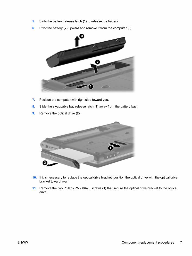
5. Slide the battery release latch (1) to release the battery.
6. Pivot the battery (2) upward and remove it from the computer (3).
7. Position the computer with right side toward you.
8. Slide the swappable bay release latch (1) away from the battery bay.
9. Remove the optical drive (2).
10. If it is necessary to replace the optical drive bracket, position the optical drive with the optical drivebracket toward you.
11. Remove the two Phillips PM2.0×4.0 screws (1) that secure the optical drive bracket to the opticaldrive.
ENWW Component replacement procedures 7

12. Remove the optical drive bracket (2).
13. Position the computer with the front toward you.
14. Loosen the two Phillips PM2.5×6.0 captive screws (1) that secure the hard drive bay cover to thecomputer.
15. Lift the left side of the hard drive bay cover (2), swing it to right, and remove the cover (3). The harddrive bay cover is included in the Plastics Kit, spare part number 486833-001.
16. Remove the three black Phillips PM2.0×4.0 screws (1) that secure the hard drive to the computer.
17. Use the Mylar tab (2) to slide the hard drive away from the hard drive connector (3).
8 Chapter 1 Removal and replacement procedures ENWW

18. Remove the hard drive from the hard drive bay (4).
19. If it is necessary to replace the hard drive bracket, remove the four Phillips PM3.0×4.0screws (1) that secure the hard drive bracket to the hard drive.
20. Lift the bracket (2) straight up to remove it from the hard drive.
21. Disconnect the wireless antenna wires (1) from the from the wireless module.
22. Remove the 2 Phillips PM2.0×4.0 screws (2) securing the WLAN module to the computer.
ENWW Component replacement procedures 9

23. Remove the WLAN module (3) by pulling it away from the slot at an angle. (The edge of the moduleopposite the slot rises away from the computer.)
NOTE: WLAN modules are designed with a notch (4) to prevent incorrect insertion into the WLANmodule slot.
CAUTION: The WWAN module and the WLAN module are not interchangeable.
CAUTION: To prevent an unresponsive system, replace the wireless module only with a wirelessmodule authorized for use in the computer by the governmental agency that regulates wirelessdevices in your country or region. If you replace the module and then receive a warning message,remove the module to restore computer functionality, and then contact technical support throughHelp and Support.
24. Turn the computer upside down, with the front toward you.
25. Remove the two Phillips PM2.5×17.0 screws (1), and the Phillips PM2.5×9.0 screw (2) that securethe keyboard to the computer.
26. Turn the computer display-side up, with the front toward you.
10 Chapter 1 Removal and replacement procedures ENWW

27. Open the computer as far as possible.
28. Lift the rear edge of the keyboard (1) until it rests at an angle.
29. Release the keyboard (2) by sliding it back to disengage the tabs on the front edge of the keyboardfrom the top cover.
30. Release the zero insertion force (ZIF) connector (1) to which the keyboard cable is attached anddisconnect the keyboard cable (2) from the system board.
31. Remove the keyboard.
32. Turn the computer upside down, with the front toward you.
ENWW Component replacement procedures 11

33. Remove the two Phillips PM2.5×7.0 screws (1), the two Phillips PM2.0×4.0 screws (2), and thethree Phillips PM2.5×3.0 screws (3) that secure the keyboard cover to the computer.
34. Turn the computer display-side up, with the front toward you.
35. Open the computer as far as possible.
36. Remove the Phillips PM2.5×9.0 screw (1), and the Phillips PM2.5×4.0 screw (2) securing thekeyboard cover to the top cover.
37. Release the keyboard cover (3) by sliding it toward the display assembly until it disengages fromthe computer.
38. Remove the keyboard cover (4).
39. Disconnect the num lock cable (1) from the system board.
40. Remove the two Phillips PM2.5×4.0 screws (2) that secure the speaker assembly to the computer.
41. Remove the Phillips PM2.5×9.0 screw (3) that secures the speaker assembly to the computer.
42. Disconnect the speaker cable (4) from the system board.
12 Chapter 1 Removal and replacement procedures ENWW

43. Lift the speaker assembly (5) straight up to remove it from the computer.
44. Locate the wireless antenna cable (1), and remove from path (2).
45. Disconnect the wireless antenna cable from the system board (3).
ENWW Component replacement procedures 13

46. Remove the wireless antenna cable from the path (1) and disconnect it from the system board(2).
CAUTION: The display assembly will be unsupported when the following screws are removed.To prevent damage to the display assembly, support it before removing the screws.
47. Remove the four Phillips PM2.5×7.0 screws (1) that secure the display assembly to the computer.
48. Remove the display assembly (2).
If it is necessary to replace other display assembly components, continue to the section that correspondsto the appropriate display assembly
14 Chapter 1 Removal and replacement procedures ENWW
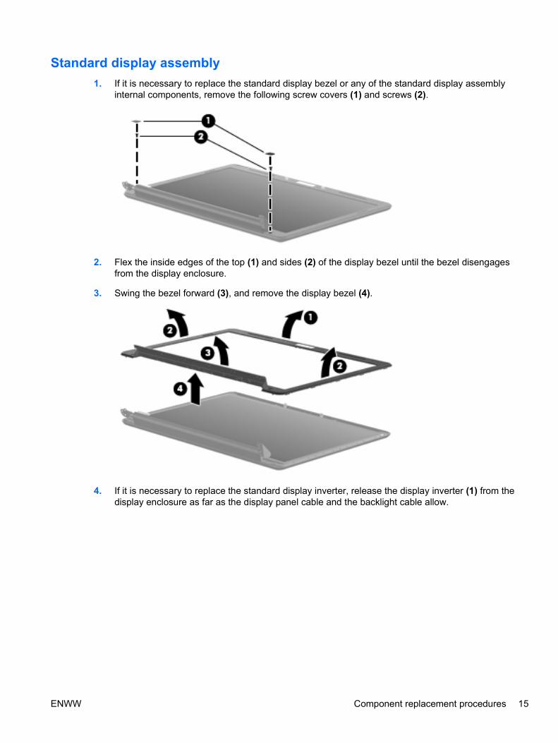
Standard display assembly1. If it is necessary to replace the standard display bezel or any of the standard display assembly
internal components, remove the following screw covers (1) and screws (2).
2. Flex the inside edges of the top (1) and sides (2) of the display bezel until the bezel disengagesfrom the display enclosure.
3. Swing the bezel forward (3), and remove the display bezel (4).
4. If it is necessary to replace the standard display inverter, release the display inverter (1) from thedisplay enclosure as far as the display panel cable and the backlight cable allow.
ENWW Component replacement procedures 15

5. Disconnect the display panel cable (2) and the backlight cable (3) from the display inverter.
6. Remove the display inverter.
7. If it is necessary to replace the standard display panel, remove the four Phillips PM2.5×6.0 screws(1), and the four Phillips PM2.5×4.0 screws (2) that secure the display panel to the displayenclosure.
8. Lift the display panel out of the display enclosure (3), and disconnect the display LED cable (4).
9. If it is necessary to replace the standard display panel cable, release the foil shield (1) coveringthe cable.
10. Remove the tape (2) securing the cable to the display panel.
11. Disconnect the display panel cable (3) from the display panel.
16 Chapter 1 Removal and replacement procedures ENWW
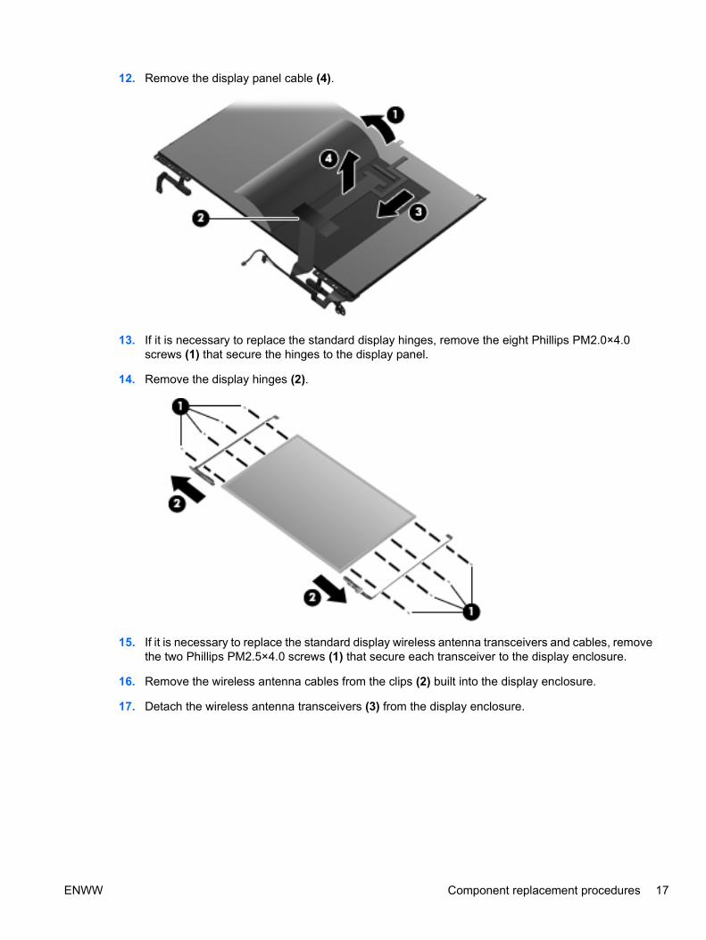
12. Remove the display panel cable (4).
13. If it is necessary to replace the standard display hinges, remove the eight Phillips PM2.0×4.0screws (1) that secure the hinges to the display panel.
14. Remove the display hinges (2).
15. If it is necessary to replace the standard display wireless antenna transceivers and cables, removethe two Phillips PM2.5×4.0 screws (1) that secure each transceiver to the display enclosure.
16. Remove the wireless antenna cables from the clips (2) built into the display enclosure.
17. Detach the wireless antenna transceivers (3) from the display enclosure.
ENWW Component replacement procedures 17

18. Remove the wireless antenna transceivers and cables (4) from the display enclosure.
Reverse this procedure to reassemble and install the standard display assembly.
Flush Glass display assembly1. If it is necessary to replace the Flush Glass display enclosure or any of the replaceable Flush Glass
display assembly components, remove the following screw covers (1) and screws (2):
2. Turn the display assembly over.
3. Slide the display enclosure toward the bottom edge of the assembly (1), and lift up to detach (2).
18 Chapter 1 Removal and replacement procedures ENWW

4. Disconnect the LED board from the enclosure (3) to remove the enclosure.
5. If it is necessary to replace the camera/microphone assembly, remove the two Phillips PM2.5×4.0screws (1) that secure the camera/microphone module.
6. Lift the module out as far as the camera/microphone module cable allows (2).
7. Disconnect the camera/microphone module cable (3) from the camera/microphone module.
8. If it is necessary to replace the Flush Glass display panel cable, turn the display assembly over.
9. Release the foil shield covering the display panel cable (1).
10. Remove the tape (2) securing the cable to the display panel.
11. Disconnect the display panel cable (3) from the display panel.
ENWW Component replacement procedures 19

12. Remove the display panel cable (4).
13. If it is necessary to replace the inverter, remove the four Phillips PM2.5×4.0 screws (1) that securethe inverter cover to the display assembly, and remove the inverter cover (2).
14. Release the inverter from the display assembly, and lift as far as the attached cables will allow(1).
20 Chapter 1 Removal and replacement procedures ENWW

15. Disconnect the backlight cable (2), and the display panel cable (3) from the inverter.
16. If it is necessary to replace the display hinges, release the foil tab (1).
17. Remove the six Phillips PM2.5×4.0 screws (2), and the eight Phillips PM2.0×4.0 screws (3) thatsecure the hinges to the display panel.
18. Remove the hinges (4).
19. If it is necessary to replace the wireless antenna assembly, remove the two Phillips PM2.5×4.0screws (1) that secure the transceivers to the display enclosure.
20. Detach the wireless antenna transceivers (2) from the display enclosure.
21. Remove the wireless antenna cables from the clips (3) built into the display enclosure.
ENWW Component replacement procedures 21
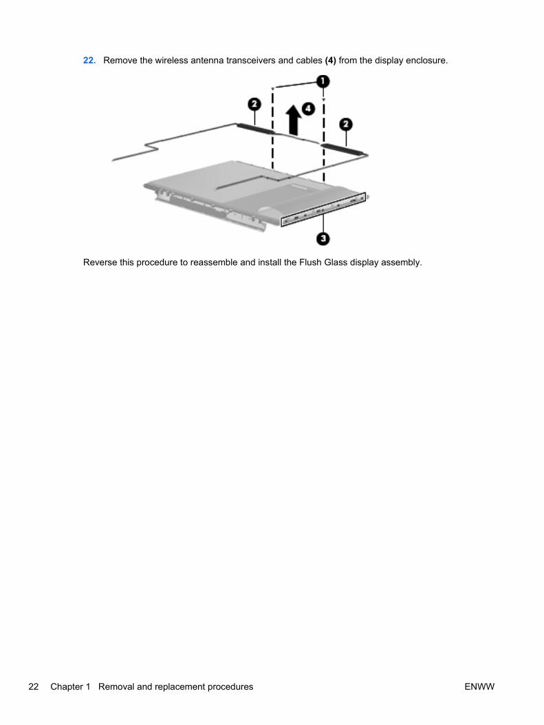
22. Remove the wireless antenna transceivers and cables (4) from the display enclosure.
Reverse this procedure to reassemble and install the Flush Glass display assembly.
22 Chapter 1 Removal and replacement procedures ENWW

2 Recycling
DisplayWARNING! The backlight contains mercury. Caution must be exercised when removing and handlingthe backlight to avoid damaging this component and causing exposure to the mercury.
CAUTION: The procedures in this appendix can result in damage to display components. The onlycomponents intended for recycling purposes are the liquid crystal display (LCD) panel and the backlight.Careful handling must be exercised when removing these components.
NOTE: Materials Disposal. This HP product contains mercury in the backlight in the display assemblythat might require special handling at end-of-life. Disposal of mercury may be regulated because ofenvironmental considerations. For disposal or recycling information, contact your local authorities, orsee the Electronic Industries Alliance (EIA) Web site at http://www.eiae.org.
This section provides disassembly instructions for the display assembly. The display assembly must bedisassembled to gain access to the backlight (1) and the liquid crystal display (LCD) panel (2).
NOTE: The procedures provided in this appendix are general disassembly instructions. Specificdetails, such as screw sizes, quantities, and locations, and component shapes and sizes, can vary fromone computer model to another.
ENWW Display 23
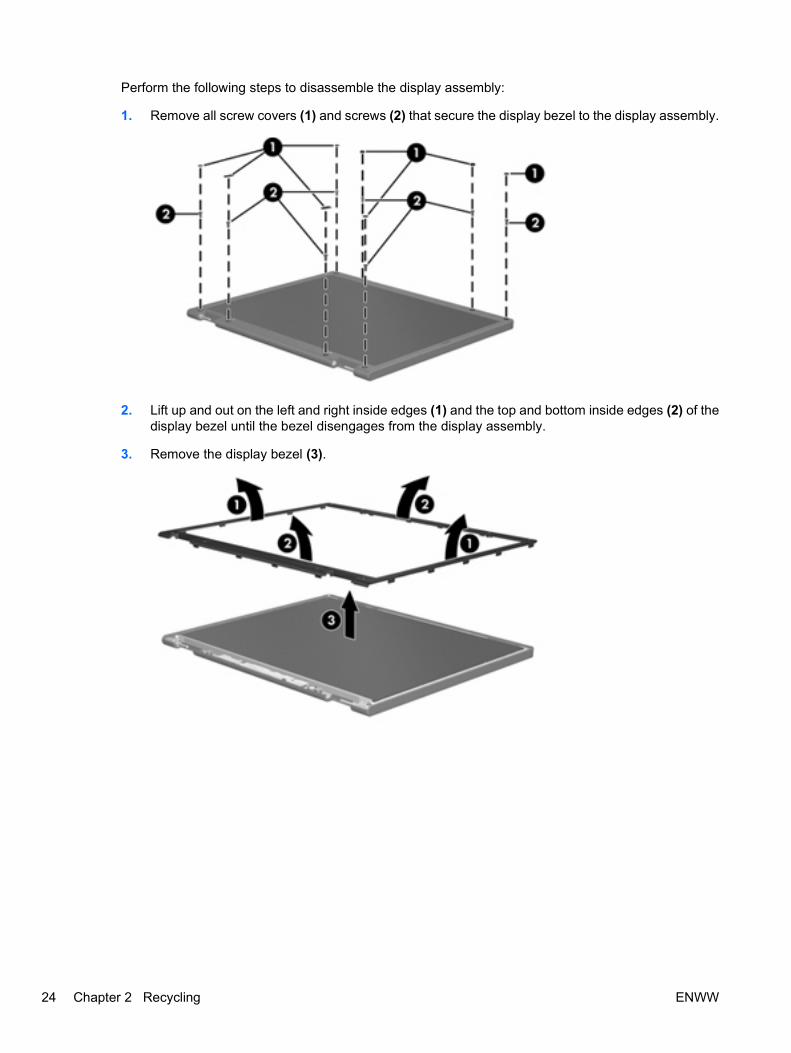
Perform the following steps to disassemble the display assembly:
1. Remove all screw covers (1) and screws (2) that secure the display bezel to the display assembly.
2. Lift up and out on the left and right inside edges (1) and the top and bottom inside edges (2) of thedisplay bezel until the bezel disengages from the display assembly.
3. Remove the display bezel (3).
24 Chapter 2 Recycling ENWW

4. Disconnect all display panel cables (1) from the display inverter and remove the inverter (2).
5. Remove all screws (1) that secure the display panel assembly to the display enclosure.
6. Remove the display panel assembly (2) from the display enclosure.
7. Turn the display panel assembly upside down.
8. Remove all screws that secure the display panel frame to the display panel.
9. Use a sharp-edged tool to cut the tape (1) that secures the sides of the display panel to the displaypanel frame.
ENWW Display 25

10. Remove the display panel frame (2) from the display panel.
11. Remove the screws (1) that secure the backlight cover to the display panel.
12. Lift the top edge of the backlight cover (2) and swing it outward.
13. Remove the backlight cover.
14. Turn the display panel right-side up.
26 Chapter 2 Recycling ENWW

15. Remove the backlight cables (1) from the clip (2) in the display panel.
16. Turn the display panel upside down.
17. Remove the backlight frame from the display panel.
WARNING! The backlight contains mercury. Exercise caution when removing and handling thebacklight to avoid damaging this component and causing exposure to the mercury.
18. Remove the backlight from the backlight frame.
ENWW Display 27

19. Disconnect the display cable (1) from the LCD panel.
20. Remove the screws (2) that secure the LCD panel to the display rear panel.
21. Release the LCD panel (3) from the display rear panel.
22. Release the tape (4) that secures the LCD panel to the display rear panel.
23. Remove the LCD panel.
24. Recycle the LCD panel and backlight.
28 Chapter 2 Recycling ENWW

Index
Aantenna
removal 17spare part number 6, 17
Bbezel
spare part numbers 5, 15
Ccables, service considerations 3connectors, service
considerations 3
Ddiskette drive
precautions 3display assembly
removal 5spare part numbers 5
display bezelspare part numbers 5, 15
display componentsrecycling 23
display enclosurespare part numbers 6
display hingeremoval 17spare part number 5, 17
Display Hinge Kit, spare partnumber 5, 17
display inverterspare part number 5
display panelremoval 16spare part number 5, 16
display switch modulespare part number 5
drivespreventing damage 3
DVD/CD-RW Combo Driveprecautions 3
DVD±RW and CD-RW ComboDrive
precautions 3
Eelectrostatic discharge 4
Hhard drive
precautions 3hard drive bay cover
removal 8hinge
removal 17spare part number 5, 17
hinge coverspare part number 5, 17
Iinverter
spare part number 5
Ooptical drive
precautions 3
Pplastic parts 2
Rremoval/replacement
preliminaries 2procedures 5
Sservice considerations 2
Ttools required 2
Wwireless antenna
removal 17spare part number 6, 17
Wireless Antenna Kit, spare partnumber 6, 17
wireless module, removal 9
ENWW Index 29

30 Index ENWW