Embed Size (px)
Citation preview

HPP4000 SAN Solution User Guide
AbstractThis guide provides information for configuring and using the HP SAN Solution. It includes hardware configuration andinformation about designing and implementing a P4000 SAN. The intended audience is system administrators responsible forimplementing, maintaining, and managing a P4000 SAN Solution.
HP Part Number: AX696-96168Published: February 2012Edition: 7

© Copyright 2009, 2012 Hewlett-Packard Development Company, L.P.
Confidential computer software. Valid license from HP required for possession, use or copying. Consistent with FAR 12.211 and 12.212, CommercialComputer Software, Computer Software Documentation, and Technical Data for Commercial Items are licensed to the U.S. Government undervendor's standard commercial license.
The information contained herein is subject to change without notice. The only warranties for HP products and services are set forth in the expresswarranty statements accompanying such products and services. Nothing herein should be construed as constituting an additional warranty. HP shallnot be liable for technical or editorial errors or omissions contained herein.
Acknowledgements
Microsoft, Windows, Windows XP, and Windows NT are U.S. registered trademarks of Microsoft Corporation.
Contents1 Getting started.........................................................................................12
Using the CMC......................................................................................................................12Layout of the CMC.............................................................................................................12Auto discover systems in the CMC........................................................................................13Logging in........................................................................................................................13Performing tasks in the CMC using the menu bar...................................................................13
Configuring systems to add to management groups.....................................................................14Using the Map View ..............................................................................................................14
Using the display tools.......................................................................................................14Using views and layouts......................................................................................................15
Setting preferences.................................................................................................................15Setting the font size and locale............................................................................................15Setting naming conventions.................................................................................................15
Creating storage by using the Getting Started Launch Pad...........................................................16Prerequisites......................................................................................................................16Configuring storage systems................................................................................................17Creating a volume using the wizard.....................................................................................17Enabling server access to volumes........................................................................................18
Finding storage systems after the first time..................................................................................19Controlling which storage systems appear in the CMC............................................................19Troubleshooting—Storage systems not found..........................................................................19
Setting up the CMC for remote support......................................................................................202 Working with storage systems....................................................................21
Storage system configuration categories.....................................................................................21Storage system configuration category definitions...................................................................21
Storage system tasks...............................................................................................................21Working with the storage system..........................................................................................21Logging in to and out of storage systems...............................................................................21Changing the storage system hostname................................................................................22Locating the storage system in a rack....................................................................................22
Powering off or rebooting the storage system..............................................................................22Powering on or off, or rebooting storage systems with modular components...............................23Rebooting the storage system...............................................................................................23Powering off the storage system...........................................................................................24
Upgrading the SAN/iQ software on the storage system...............................................................25Upgrading the CMC and storage systems.............................................................................25Setting upgrade preferences................................................................................................25Checking for available upgrades.........................................................................................25Upgrading the CMC..........................................................................................................26Upgrading storage systems in a management group or available storage systems......................28
Registering advanced features for a storage system.....................................................................29Determining volume and snapshot availability............................................................................29Checking status of dedicated boot devices.................................................................................30
Checking boot device status................................................................................................30Replacing a dedicated boot device......................................................................................31
3 Configuring RAID and Managing Disks.......................................................32Getting there..........................................................................................................................32Configuring and managing RAID..............................................................................................32RAID Levels............................................................................................................................32Explaining RAID devices in the RAID setup report.......................................................................33
Contents 3

RAID devices by RAID type.................................................................................................34Planning the RAID configuration...............................................................................................34
Data protection..................................................................................................................34Using disk RAID with Network RAID in a cluster.....................................................................35Mixing RAID configurations.................................................................................................36
Setting RAID rebuild rate.........................................................................................................36General guidelines for setting the RAID rebuild rate................................................................36Setting the RAID rebuild rate...............................................................................................36
Reconfiguring RAID.................................................................................................................37To reconfigure RAID...........................................................................................................37Configuring RAID for a P4800 G2 with 2 TB drives................................................................37
Monitoring RAID status............................................................................................................38Data reads and writes and RAID status.................................................................................38Data redundancy and RAID status........................................................................................38
Managing disks.....................................................................................................................39Getting there.....................................................................................................................39Reading the disk report on the Disk Setup tab........................................................................39Verifying disk status............................................................................................................41
Replacing a disk.....................................................................................................................44Using Repair Storage System...............................................................................................45Replacing disks in hot-swap storage systems..........................................................................45Preparing for a disk replacement.........................................................................................46Replacing a disk in a hot-swap storage system ......................................................................46
4 Managing the network..............................................................................48Network best practices............................................................................................................48Changing network configurations.............................................................................................49Managing settings on network interfaces...................................................................................50
TCP status tab....................................................................................................................50Changing speed and duplex settings....................................................................................50Changing NIC frame size...................................................................................................51Changing NIC flow control.................................................................................................52
The TCP/IP tab.......................................................................................................................53Identifying the network interfaces.........................................................................................53Pinging an IP address.........................................................................................................54
Configuring the IP address manually.........................................................................................54Using DHCP..........................................................................................................................55Configuring network interface bonds.........................................................................................55
Bonding with 10 GbE interfaces..........................................................................................56IP address for NIC bonds....................................................................................................57NIC bonding and speed, duplex, frame size, and flow control settings......................................57How Active-Passive bonding works.......................................................................................57How link aggregation dynamic mode bonding works.............................................................61How Adaptive Load Balancing works ..................................................................................63Creating a NIC bond.........................................................................................................65Viewing the status of a NIC bond........................................................................................68Deleting a NIC bond..........................................................................................................69
Disabling a network interface...................................................................................................71Configuring a disabled interface..........................................................................................72
Using a DNS server................................................................................................................72DNS and DHCP................................................................................................................72DNS and static IP addresses................................................................................................72Adding the DNS domain name...........................................................................................72Adding the DNS server......................................................................................................72Adding domain names to the DNS suffixes............................................................................73
4 Contents

Editing a DNS server..........................................................................................................73Editing a domain name in the DNS suffixes list......................................................................73Removing a DNS server......................................................................................................73Removing a domain suffix from the DNS suffixes list................................................................73
Setting up routing...................................................................................................................74Adding routing information.................................................................................................74Editing routing information..................................................................................................74Deleting routing information................................................................................................74
Configuring storage system communication................................................................................75Selecting the interface used by the SAN/iQ software.............................................................75Updating the list of manager IP addresses.............................................................................76
5 Setting the date and time..........................................................................77Management group time.........................................................................................................77Getting there..........................................................................................................................77Refreshing the management group time.....................................................................................77Using NTP.............................................................................................................................77
Editing NTP servers............................................................................................................78Deleting an NTP server.......................................................................................................78Changing the order of NTP servers .....................................................................................78
Editing the date and time.........................................................................................................79Editing the time zone only........................................................................................................79
6 Administrative users and groups.................................................................80Getting there..........................................................................................................................80Managing administrative users.................................................................................................80
Default administrative user..................................................................................................80Editing administrative users.................................................................................................80
Managing administrative groups..............................................................................................81Default administrative groups...............................................................................................81Editing administrative groups...............................................................................................82
7 Monitoring the SAN.................................................................................84Monitoring SAN status............................................................................................................84
Configuring the SAN Status Page ........................................................................................84Using the SAN Status Page.................................................................................................86
Alarms and events overview.....................................................................................................86Working with alarms...............................................................................................................88
Filtering the alarms list........................................................................................................88Viewing and copying alarm details......................................................................................88Viewing alarms in a separate window..................................................................................88Exporting alarm data to a .csv file.......................................................................................89
Configuring events..................................................................................................................89Changing the event retention period.....................................................................................89Setting up remote log destinations........................................................................................89Viewing events in a separate window...................................................................................89
Working with events...............................................................................................................90Viewing new events............................................................................................................90Filtering the events list.........................................................................................................90Viewing event details..........................................................................................................91Copying events to the clipboard...........................................................................................91Exporting event data to a .csv or .txt file...............................................................................91
Setting up email notification.....................................................................................................92Setting up the email server..................................................................................................92Setting up email recipients..................................................................................................92
Setting up SNMP....................................................................................................................93
Contents 5

Enabling SNMP agents.......................................................................................................93Adding SNMP traps...........................................................................................................95Using the SNMP MIBs........................................................................................................96
Running diagnostic reports.......................................................................................................97List of diagnostic tests.........................................................................................................98
Generating a hardware information report.................................................................................98Saving a hardware information report..................................................................................99Hardware information report details.....................................................................................99
Using log files......................................................................................................................101Saving log files locally......................................................................................................101Exporting the System Summary..........................................................................................101Configuring a remote log and remote log destination...........................................................102Editing remote log targets.................................................................................................102Deleting remote logs........................................................................................................102Exporting support logs......................................................................................................103
8 Working with management groups...........................................................104Functions of management groups............................................................................................104Guide for management groups...............................................................................................104Creating a management group..............................................................................................105
Creating a new management group...................................................................................105Best practice for managers in a management group.............................................................107
Managers overview..............................................................................................................107Functions of managers......................................................................................................107Managers and quorum.....................................................................................................107Regular managers and specialized managers......................................................................108
Configuration Summary overview...........................................................................................109Summary roll-up..............................................................................................................109Configuration guidance....................................................................................................110
Best Practice summary overview..............................................................................................112Disk level data protection..................................................................................................113Cluster-level data protection...............................................................................................113Volume-level data protection..............................................................................................114Volume access.................................................................................................................114Systems running managers................................................................................................114Network bonding............................................................................................................114Network bond consistency................................................................................................114Network flow control consistency.......................................................................................114Network frame size consistency.........................................................................................114
Management group maintenance tasks...................................................................................114Logging in to a management group....................................................................................114Logging out of a management group..................................................................................115Adding a storage system to an existing management group...................................................115Starting and stopping managers........................................................................................115Editing a management group............................................................................................116Saving management group configuration information...........................................................117
Safely shutting down a management group..............................................................................117Prerequisites....................................................................................................................118Start the management group back up.................................................................................118
Removing a storage system from a management group..............................................................119Prerequisites....................................................................................................................119
Deleting a management group...............................................................................................120Prerequisites....................................................................................................................120Setting the management group version...............................................................................120
6 Contents

9 Using specialized managers....................................................................121Failover Manager.................................................................................................................121
Planning the virtual network configuration...........................................................................121Failover Manager requirements..........................................................................................121
Using the Failover Manager on Microsoft Hyper-V Server...........................................................122Installing the Failover Manager for Hyper-V Server...............................................................122
Using the Failover Manager for VMware ................................................................................123Installing the Failover Manager for ESX Server ....................................................................123Installing the Failover Manager using the OVF files with the VI Client......................................124Installing the Failover Manager for VMware Server or VMware Workstation............................125Troubleshooting the Failover Manager on ESX Server............................................................125Uninstalling the Failover Manager from VMware ESX Server..................................................126
Virtual manager...................................................................................................................126When to use a virtual manager.........................................................................................126Disaster recovery using a virtual manager...........................................................................127Storage system maintenance using a virtual manager...........................................................127Requirements for using a virtual manager............................................................................127Configuring a cluster for disaster recovery...........................................................................128Adding a virtual manager.................................................................................................130Starting a virtual manager to regain quorum.......................................................................131Verifying virtual manager status.........................................................................................132Stopping a virtual manager...............................................................................................132Removing a virtual manager from a management group.......................................................132
10 Working with clusters............................................................................133Clusters and storage systems..................................................................................................133Creating a cluster.................................................................................................................133
Cluster Map View............................................................................................................134Monitoring cluster usage.......................................................................................................134Editing a cluster....................................................................................................................134
Editing cluster properties...................................................................................................134Editing iSNS servers.........................................................................................................134Editing cluster VIP addresses..............................................................................................135Reconnecting volumes and applications after changing VIPs or iSNS servers............................135
Maintaining storage systems in clusters....................................................................................136Adding a new storage system to a cluster............................................................................136Upgrading the storage systems in a cluster using cluster swap................................................136Reordering storage systems in a cluster...............................................................................137Exchange a storage system in a cluster...............................................................................137Removing a storage system from a cluster............................................................................137
Troubleshooting a cluster.......................................................................................................137Auto Performance Protection..............................................................................................137Repairing a storage system................................................................................................139
Deleting a cluster..................................................................................................................14011 Provisioning storage..............................................................................141
Understanding how the capacity of the SAN is used.................................................................141Provisioning storage..............................................................................................................141Provisioning volumes.............................................................................................................141
Full provisioning...............................................................................................................142Thin provisioning.............................................................................................................142Planning data protection...................................................................................................142
Provisioning snapshots...........................................................................................................147Snapshots versus backups.................................................................................................147The effect of snapshots on cluster space..............................................................................147Managing capacity using volume size and snapshots...........................................................148
Contents 7

Ongoing capacity management.............................................................................................148Number of volumes and snapshots.....................................................................................148Reviewing SAN capacity and usage...................................................................................148Measuring disk capacity and volume size...........................................................................152Changing the volume size on the server..............................................................................153Changing configuration characteristics to manage space......................................................154
12 Using volumes......................................................................................155Volumes and server access....................................................................................................155
Prerequisites....................................................................................................................155Planning volumes..................................................................................................................155
Planning how many volumes.............................................................................................155Planning volume types......................................................................................................155
Guide for volumes................................................................................................................155Creating a volume................................................................................................................157
Creating a basic volume...................................................................................................157Configuring advanced volume settings [optional].................................................................158
Volumes map view................................................................................................................158Editing a volume..................................................................................................................158
To edit a volume..............................................................................................................159Deleting a volume.................................................................................................................161
Restrictions on deleting volumes.........................................................................................161Prerequisites....................................................................................................................161To delete the volume........................................................................................................161
13 Using snapshots....................................................................................162Types of snapshots................................................................................................................162
Uses and best practices for snapshots.................................................................................162Planning snapshots...............................................................................................................163
Prerequisites for application-managed snapshots..................................................................164Creating snapshots...............................................................................................................164
Editing a snapshot...........................................................................................................166Scheduling snapshots............................................................................................................166
Best practices for scheduling snapshots of volumes...............................................................166Requirements for snapshot schedules..................................................................................167Scheduling snapshots for volume sets..................................................................................167Creating a schedule to snapshot a volume..........................................................................168
Mounting a snapshot............................................................................................................170Mounting the snapshot on a host.......................................................................................170Making a Windows application-managed snapshot available...............................................171Managing snapshot temporary space.................................................................................173
Rolling back a volume to a snapshot or clone point...................................................................173Rolling back a volume to a snapshot or clone point..............................................................174
Deleting a snapshot..............................................................................................................17614 SmartClone volumes..............................................................................178
What are SmartClone volumes?.............................................................................................178Prerequisites....................................................................................................................178SmartClone volume terminology.........................................................................................178Example scenarios for using SmartClone volumes.................................................................179
Planning SmartClone volumes................................................................................................180Space requirements..........................................................................................................180Naming convention for SmartClone volumes........................................................................181Server access..................................................................................................................181
Defining SmartClone volume characteristics..............................................................................181Naming SmartClone volumes.................................................................................................182
8 Contents

Shared versus individual characteristics...................................................................................183Clone point..........................................................................................................................185Shared snapshot ..................................................................................................................187Creating SmartClone volumes................................................................................................189To create a SmartClone volume..............................................................................................189Viewing SmartClone volumes.................................................................................................190
Map view.......................................................................................................................190Editing SmartClone volumes...................................................................................................193
To edit the SmartClone volumes.........................................................................................194Deleting SmartClone volumes.................................................................................................194
Deleting the clone point ...................................................................................................194Deleting multiple SmartClone volumes................................................................................195
15 Working with scripting..........................................................................196Scripting documentation........................................................................................................196
16 Controlling server access to volumes........................................................197Change in server access control from version 7.0 and earlier......................................................197Adding server connections to management groups....................................................................198
Prerequisites....................................................................................................................198Guide for servers.............................................................................................................198Adding a server connection..............................................................................................199
Managing server connections................................................................................................199Editing server connections.................................................................................................200Deleting server connections...............................................................................................200
Clustering server connections.................................................................................................200Requirements for clustering servers.....................................................................................200Creating a server cluster...................................................................................................201Server cluster map view....................................................................................................202Working with a server cluster............................................................................................202Deleting a server cluster....................................................................................................202
Assigning server connections access to volumes........................................................................203Assigning server connections from a volume........................................................................204Assigning volumes from a server connection........................................................................204Editing server connection and volume assignments...............................................................204
Completing the iSCSI Initiator and disk setup...........................................................................205Persistent targets or favorite targets.....................................................................................205HP P4000 DSM for MPIO settings......................................................................................205Disk management............................................................................................................205
17 Monitoring performance .......................................................................206Prerequisites.........................................................................................................................206Introduction to using performance information..........................................................................206
What can I learn about my SAN?......................................................................................206Fault isolation example.....................................................................................................207
What can I learn about my volumes?......................................................................................208Most active volumes examples...........................................................................................208Activity generated by a specific server example...................................................................209
Planning for SAN improvements.............................................................................................209Network utilization to determine if NIC bonding could improve performance example..............209Load comparison of two clusters example............................................................................210Load comparison of two volumes example...........................................................................210
Accessing and understanding the Performance Monitor window.................................................211Performance Monitor toolbar.............................................................................................212Performance monitor graph...............................................................................................212Performance monitor table................................................................................................213
Contents 9

Understanding the performance statistics.............................................................................214Monitoring and comparing multiple clusters.............................................................................216Performance monitoring and analysis concepts.........................................................................216
Workloads......................................................................................................................216Access type.....................................................................................................................216Access size.....................................................................................................................217Access pattern.................................................................................................................217Queue depth...................................................................................................................217
Changing the sample interval and time zone............................................................................217Adding statistics...................................................................................................................217
Viewing statistic details.....................................................................................................218Removing and clearing statistics.............................................................................................219
Removing a statistic..........................................................................................................219Clearing the sample data..................................................................................................219Clearing the display.........................................................................................................219Resetting defaults.............................................................................................................219
Pausing and restarting monitoring...........................................................................................220Changing the graph.............................................................................................................220
Hiding and showing the graph..........................................................................................220Displaying or hiding a line................................................................................................220Changing the color or style of a line..................................................................................220Highlighting a line...........................................................................................................220Changing the scaling factor..............................................................................................221
Exporting data.....................................................................................................................221Exporting statistics to a CSV file.........................................................................................221Saving the graph to an image file......................................................................................222
18 Registering advanced features................................................................223Evaluation period for using advanced features..........................................................................223
Starting the evaluation period............................................................................................223Backing out of Remote Copy evaluation..............................................................................224
Scripting evaluation..............................................................................................................224Turn on scripting evaluation...............................................................................................224Turn off scripting evaluation...............................................................................................225
Registering advanced features................................................................................................225Using license keys............................................................................................................225Registering available storage systems for license keys...........................................................225Registering storage systems in a management group.............................................................226
Saving and editing your customer information..........................................................................22819 iSCSI and the HP P4000 SAN Solution....................................................230
Number of iSCSI sessions......................................................................................................230Virtual IP addresses...............................................................................................................230
Requirements for using a virtual IP address..........................................................................230iSNS server.........................................................................................................................230iSCSI load balancing............................................................................................................231
Requirements...................................................................................................................231Authentication (CHAP)...........................................................................................................231
Requirements for configuring CHAP....................................................................................232iSCSI and CHAP terminology.................................................................................................232
Sample iSCSI configurations..............................................................................................233Best practice...................................................................................................................234
About HP DSM for MPIO.......................................................................................................23420 Using the Configuration Interface............................................................235
Connecting to the Configuration Interface................................................................................235
10 Contents

Establishing a terminal emulation session on a Windows system.............................................235Establishing a terminal emulation session on a Linux/UNIX system..........................................235Opening the Configuration Interface from the terminal emulation session.................................236
Logging in to the Configuration Interface.................................................................................236Configuring administrative users.............................................................................................236Configuring a network connection..........................................................................................236Deleting a NIC bond............................................................................................................237Setting the TCP speed, duplex, and frame size..........................................................................237Removing a storage system from a management group..............................................................238Resetting the storage system to factory defaults.........................................................................238
21 Support and other resources...................................................................239Contacting HP......................................................................................................................239
Subscription service..........................................................................................................239HP Insight Remote Support Software........................................................................................239New and changed information in this edition...........................................................................240Related information...............................................................................................................240
HP websites....................................................................................................................240Customer self repair..............................................................................................................240
A Replacing hardware...............................................................................241Replacing disks and rebuilding data.......................................................................................241
Replacing disks...............................................................................................................241Rebuilding data...............................................................................................................243Returning the storage system to the cluster...........................................................................243Rebuilding volume data....................................................................................................244Removing the ghost storage system.....................................................................................245
Replacing the RAID controller.................................................................................................245Verifying component failure...............................................................................................245Removing the RAID controller............................................................................................247Installing the RAID controller..............................................................................................250Verifying proper operation................................................................................................251
B Third-party licenses.................................................................................252C SANiQ TCP and UDP Port Usage.............................................................253Glossary..................................................................................................256Index.......................................................................................................262
Contents 11

1 Getting startedWelcome to the SAN/iQ software and the Centralized Management Console (CMC). Use theCMC to configure and manage the HP P4000 SAN Solution.This product guide provides instructions for configuring individual storage systems, as well as forcreating storage clusters, volumes, snapshots, and remote copies.
Using the CMCUse the CMC to:
• Configure and manage storage systems
• Create and manage the P4000 SAN solution
Layout of the CMCThe CMC is divided into sections, as shown in Figure 1 (page 12).
Figure 1 Parts of the CMC
1. Navigation window
2. Tab window
3. Alarms window
4. Status bar
12 Getting started
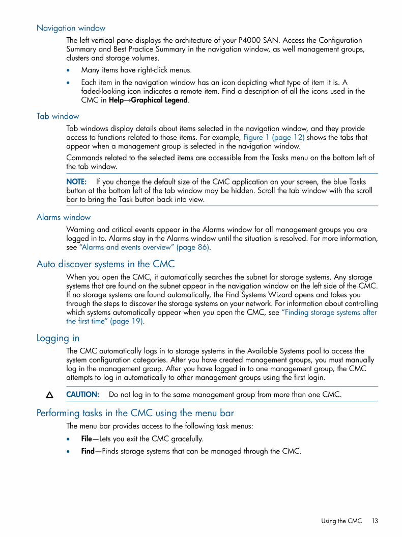
Navigation windowThe left vertical pane displays the architecture of your P4000 SAN. Access the ConfigurationSummary and Best Practice Summary in the navigation window, as well management groups,clusters and storage volumes.• Many items have right-click menus.
• Each item in the navigation window has an icon depicting what type of item it is. Afaded-looking icon indicates a remote item. Find a description of all the icons used in theCMC in Help→Graphical Legend.
Tab windowTab windows display details about items selected in the navigation window, and they provideaccess to functions related to those items. For example, Figure 1 (page 12) shows the tabs thatappear when a management group is selected in the navigation window.Commands related to the selected items are accessible from the Tasks menu on the bottom left ofthe tab window.
NOTE: If you change the default size of the CMC application on your screen, the blue Tasksbutton at the bottom left of the tab window may be hidden. Scroll the tab window with the scrollbar to bring the Task button back into view.
Alarms windowWarning and critical events appear in the Alarms window for all management groups you arelogged in to. Alarms stay in the Alarms window until the situation is resolved. For more information,see “Alarms and events overview” (page 86).
Auto discover systems in the CMCWhen you open the CMC, it automatically searches the subnet for storage systems. Any storagesystems that are found on the subnet appear in the navigation window on the left side of the CMC.If no storage systems are found automatically, the Find Systems Wizard opens and takes youthrough the steps to discover the storage systems on your network. For information about controllingwhich systems automatically appear when you open the CMC, see “Finding storage systems afterthe first time” (page 19).
Logging inThe CMC automatically logs in to storage systems in the Available Systems pool to access thesystem configuration categories. After you have created management groups, you must manuallylog in the management group. After you have logged in to one management group, the CMCattempts to log in automatically to other management groups using the first login.
CAUTION: Do not log in to the same management group from more than one CMC.
Performing tasks in the CMC using the menu barThe menu bar provides access to the following task menus:
• File—Lets you exit the CMC gracefully.
• Find—Finds storage systems that can be managed through the CMC.
Using the CMC 13

• Tasks—Lets you access all storage configuration tasks. The tasks in this menu are grouped bylogical or physical items. Tasks are also accessible through right-click menus and from theTasks button in the tab window.
• Help—Lets you open the online help, access the online upgrades feature, and set CMCpreferences. The Graphical Legend is a key to the icons used in the CMC and is availablefrom the Help menu.
Configuring systems to add to management groupsSystems, including Failover Managers, that have not been added to management groups appearin the Available Systems. These systems are available to be added to management groups.Other information in the navigation window depicts the storage architecture you create on yoursystem. An example setup is shown in Figure 1 (page 12).
Using the Map ViewThe Map View tab is available for viewing the relationships between management groups, servers,sites, clusters, volumes and snapshots. When you log in to a management group, there is a MapView tab for each of those elements in the management group. For example, when you want tomake changes such as moving a volume to a different cluster, or deleting shared snapshots, theMap View allows you to easily identify how many snapshots and volumes are affected by suchchanges.The Map View pane contains display tools to control and manipulate the view. The display toolsare available from the Map View Tasks menu or from the tool bar across the top of the pane. Thetools function the same from either the tool bar or the Map View tasks menu.
Using the display toolsUse these tools, described in Table 1 (page 14), to select specific areas of the map to view, zoomin on, rotate, and move around the window. If you have a complex configuration, use the MapView tools to easily view and monitor the configuration.
Table 1 Map View display tools
FunctionTool Icon
Zoom In—incrementally magnifies the Map View window.
Zoom Out—incrementally reduces the Map View window.
Magnify—creates magnification area, like a magnifyingglass, that you can move over sections of the map view.Note that the magnify tool toggles on and off. You mustclick the icon to use it, and you must click the icon to turnit off.
Zoom to Fit—returns the map view to its default size andview.
Select to Zoom—allows you to select an area of the mapview and zoom in on just that area.
Rotate—turns the map view 90 degrees at a time.
You can left-click in the Map View window and drag themap around the window
Click and drag
14 Getting started

Using views and layoutsThe views and layouts differ for each element of your network that uses the map view.For views and layouts available, see:• Working with management groups, “Management group map view tab” (page 106)
• Controlling server access to volumes, “Server cluster map view” (page 202)
• Sites, HP P4000 Multi-Site HA/DR Solution Pack User Guide
• Clusters, “Cluster Map View” (page 134)
• Volumes and Snapshots, “Volumes map view” (page 158)
• SmartClone volumes, “Using views” (page 191)
Setting preferencesUse the Preferences window to set the following:
• Font size in the CMC
• Locale for the CMC. The locale determines the language displayed in the CMC.
• Naming conventions for storage elements
• Online upgrade options. See “Setting upgrade preferences” (page 25).
Setting the font size and localeUse the Preferences window, opened from the Help menu, to set font size and locale in the CMC.Font sizes from 9 through 16 are available.The CMC obtains the locale setting from your computer. If you change the locale on your computerand open the CMC, it uses the new locale, if available in the CMC.You can override the locale setting from your computer by selecting a different locale in the CMC.Changing the locale in the CMC affects the language of the text that appears in the CMC and inthe online help.After changing the locale, you must close and reopen the CMC to see the change.
Setting naming conventionsUse the Preferences window, opened from the Help menu, to set naming conventions for elementsyou create when building the HP P4000 SAN Solution. You can use the default values or createyour own set of customized values.When you install the CMC for the first time, or upgrade from release 7.0.x, default names areenabled for snapshots, including schedules to snapshot a volume, and for SmartClone volumes.No default names are provided for management groups, clusters, and volumes.
Setting preferences 15

Figure 2 Default naming conventions for snapshots and SmartClone volumes
Changing naming conventionsChange the elements that use a default naming convention or change the naming convention itself.If you use the given defaults, the resulting names look like those in Table 2 (page 16). Notice thatthe volume name carries into all the snapshot elements, including SmartClone volumes, which arecreated from a snapshot.
Table 2 Example of how default names work
ExampleDefault nameElement
VOL_VOL_ExchLogs_SS_3_1VOL_SmartClone Volumes
VOL_ExchLogs_SS_1_SS_Snapshots
VOL_RemoteBackup_RS_1_RS_Remote Snapshots
VOL_ExchLogs_Sch_SS_2.1_Sch_SS_Schedules to Snapshot a Volume
VOL_ExchLogs_Sch_RS_2_Pri.1,VOL_RemoteBackup_Sch_RS_1_Rmt.1
_Sch_RS_Schedules to Remote Snapshot aVolume
If you delete all the default names from the Preferences Naming window, the only automaticallygenerated naming elements that remain will incrementally number a series of snapshots orSmartClone volumes.
Creating storage by using the Getting Started Launch PadFollow the steps in this section to set up a volume quickly. Using the wizards on the Getting StartedLaunch Pad, work through these steps with one storage system, and with one strategy. The rest ofthis product guide describes other methods to create storage, as well as detailed information onfeatures of the iSCSI SAN.
Prerequisites• Install the storage systems on your network.
• Know the IP address you configured with the KVM or serial Configuration Interface when youinstalled the storage system.
16 Getting started

• Install the HP P4000 CMC software on a management workstation or server that can connectto the storage systems on the network.
• Install an iSCSI initiator, such as the latest version of the Microsoft iSCSI Initiator, on theapplication server(s).
Finding storage systemsWhen you open the CMC, it searches for systems using Auto Discover by Broadcast. If no systemsare found, the Find Systems window opens. Add individual IP addresses to find systems.
Configuring storage systemsConfigure the storage system next. If you plan to use multiple storage systems, they must all beconfigured before you use them for clustered storage.The most important categories to configure are:
• RAID—The storage system is shipped with RAID already configured and operational. Findinstructions for changing RAID, and for ensuring that drives in the storage system are properlyconfigured and operating in “Configuring RAID and Managing Disks” (page 32).
• TCP/IP Network—Bond the NIC interfaces and set the frame size, NIC flow control, and speedand duplex settings. Read detailed network configuration instructions in “Managing thenetwork” (page 48).
To configure storage systems1. From the navigation window, select a storage system in the Available Systems pool.2. Open the tree underneath the storage system.3. In the list of configuration categories, select the Storage category.4. Select the RAID Setup tab and verify the RAID settings or change the RAID level.5. In the list of configuration categories, select the TCP/IP Network category and configure the
network settings.
Creating a volume using the wizardNext, you create storage volumes using the Management Groups, Clusters, and Volumes wizard,found on the Getting Started Launch Pad. Select Getting Started in the navigation window to accessthe Getting Started Launch Pad. On the Launch Pad, select the Management Groups, Clusters, andVolumes Wizard.The wizard takes you through creating the tasks of creating a management group, a cluster, anda storage volume. This storage hierarchy is depicted in Figure 3 (page 18).
Creating storage by using the Getting Started Launch Pad 17

Figure 3 The SAN/iQ software storage hierarchy
1. Management group
2. Cluster
3. Volume
To complete this wizard, you will need the following information:
• A name for the management group.
• A storage system discovered on the network and then configured for RAID and the TCP/IPNetwork settings
• DNS domain name, suffix, and server IP address for email event notification
• IP address or hostname and port of your email (SMTP) server for event notification
• A name for the cluster
• Virtual IP address to use for the cluster
• A name for the volume
• The size of the volume
NOTE: Names of management groups, clusters, volumes, and snapshots cannot be changed inthe future without destroying the management group.
Enabling server access to volumesUse the Assign Volume and Snapshot wizard to prepare the volume for server access. You set upapplication servers in the management group, then assign volumes to the servers. See “Controllingserver access to volumes” (page 197) for a complete discussion of these functions.To work through the Assign Volume and Snapshot wizard, you must first have created a managementgroup, cluster, and at least one volume. You should also plan the following:
• The application servers that need access to volumes.
• The iSCSI initiator you plan to use. You need the server’s initiator name, and CHAP informationif you plan to use CHAP.
18 Getting started

Finding storage systems after the first timeThe Find settings from your first search are saved in the CMC. Every time you open the CMC, thesame search automatically takes place, and the navigation window is populated with all the storagesystems that are found.Control the systems that appear in the CMC based on criteria you set in the Find Systems window,opened from either the menu bar or the Getting Started Launch Pad. Choose to display a smallgroup of storage systems, such as those in one management group, or display all storage systemson the subnet at one time.
Turn off Auto Discover by Broadcast for storage systemsIf you do not want the CMC to automatically discover all the storage systems on the network whenit opens, turn off Auto Discover by Broadcast.1. From the menu bar, select Find→Find Systems.2. Clear the Auto Discover by Broadcast check box.
The next time you open the CMC, it will not search the network for all storage systems.
Clearing the found storage systems from the navigation window1. From the menu bar, select Find→Clear All Found Items to remove all storage systems from
view in the navigation window.
Controlling which storage systems appear in the CMCControl which storage systems appear in the navigation window by entering only specific IPs inthe Find Systems window. Then, when you open the CMC, only those storage systems will appearin the navigation window. Use this method to control which management groups appear.
To control which storage systems appear1. From the menu bar, select Find→Find Systems.2. Click Add to enter the IP address of a storage system. Repeat for all the IP addresses of the
desired set of storage systems.3. Click Find to search for the list of IP addresses.
Troubleshooting—Storage systems not foundIf the network has a lot of traffic, or if a storage system is busy reading or writing data, it may notbe found when a search is performed. Try the following steps to find the storage system.1. If the storage system you are looking for does not appear in the navigation window, search
again using the Find menu.2. If you have searched using Auto Discover by Broadcast, try adding individual IP Addresses
and clicking Find.3. If you have searched by Individual IP addresses, try searching by Auto Discover instead.4. If searching again does not work, try the following:
• Check the physical connection of the storage system.
• Wait a few minutes and try the search again. If activity to the storage system was frequent,the storage system might not have responded to the search.
Possible reasons for not finding storage systemsOther problems can prevent the CMC from finding a storage system:
Finding storage systems after the first time 19

• Extremely high network traffic to and from the storage system.
• The IP address could have changed if the storage system is configured to use DHCP (notrecommended).
• The storage system may have been rebooted and is not yet online.
• Power could have failed to a network switch that the storage system is connected to.
• The CMC might be running on a system that is on a different physical network than the storagesystem. Poor network routing performance at the site may severely affect performance of theCMC.
Setting up the CMC for remote supportIf you are using HP remote support, the table below lists the required CMC setup.
Table 3 CMC setup for remote support
For more information, seeRequirement
“Enabling SNMP agents” (page 93)SNMP enabled on each storage system
“Adding SNMP traps” (page 95)SNMP trap recipient set to IP address of the system wherethe remote support client is installed
Your network administratorPort 8959 (used for the CLI) open
“Adding a new administrative user” (page 80)Management group login and password for a read-only(View_Only_Administrator group) user
20 Getting started

2 Working with storage systemsStorage systems displayed in the navigation window have a tree structure of configuration categoriesunder them. The storage system configuration categories include:
• Diagnostics
• Storage
• TCP/IP Network
Storage system configuration categoriesStorage system configuration categories allow access to all the configuration tasks for individualstorage systems. You must log in to each storage system individually to configure the functions ofthat storage system.
Figure 4 Storage system configuration categories
Storage system configuration category definitions• Diagnostics—Run hardware diagnostic tests, view current hardware status and configuration
information, and save log files.• Storage—Manage RAID and the individual disks in the storage system.
• TCP/IP Network—For each storage system, configure and manage the network settings,including network interface cards (NICs), the routing table, and which interface carries SAN/iQcommunication.
Storage system tasks
Working with the storage systemAfter finding all the storage systems on the network, you configure each storage system individually.1. Select the storage system in the navigation window.
Usually you will be logged in automatically. However, you will have to log in manually forany storage systems running a software version earlier than release 7.0. If you do need tomanually log in, the Log In window opens.
2. Enter a user name and password.3. Click Log In.
Logging in to and out of storage systemsYou must log in to a management group to perform any tasks in that group. Logging into themanagement group automatically logs you into the storage systems in that group. You can log outof individual storage systems in the management group, and log back in to them individually.
Storage system configuration categories 21

Automatic loginOnce you have logged in to a management group, additional log ins are automatic if the sameuser names and passwords are assigned. If management groups have different user names orpasswords, then the automatic log in fails. In that case you must log in manually.1. Enter the correct user name and password.2. Click Log In.
Logging out of a storage system1. Select a storage system in the navigation window.2. Right-click, and select Log Out.
NOTE: If you are logged in to multiple storage systems, you must log out of each storage systemindividually.
Changing the storage system hostnameThe storage system arrives configured with a default hostname. Use these steps to change thehostname of a storage system.1. In the navigation window, log in to the storage system.2. On the Details tab, click Storage System Tasks and select Edit Hostname.3. Enter the new name, and click OK.4. Click OK.
NOTE: Add the hostname and IP pair to the hostname resolution methodology employed in yourenvironment, for example, DNS or WINS.
Locating the storage system in a rackThe Set ID LED turns on lights on the physical storage system so that you can physically locate thatstorage system in a rack.
NOTE: The Set ID LED is available depending on the storage system.
1. Select a storage system in the navigation window and log in.2. Click Storage System Tasks on the Details tab and select Set ID LED On.
The ID LED on the front of the storage system is now a bright blue. Another ID LED is locatedon the back of the storage system.When you click Set ID LED On, the status changes to On.
3. Select Set ID LED Off when you have finished.The LED on the storage system turns off.
Powering off or rebooting the storage systemReboot or power off the storage system from the CMC. Set the amount of time before the processbegins, to ensure that all activity to the storage system has stopped.Powering off the storage system through the CMC physically powers it off. The CMC controls thepower down process so that data is protected.Powering off an individual storage system is appropriate for servicing or moving that storagesystem. However, if you want to shut down more than one storage system in a management group,you should shut down the management group instead of individually powering off the storagesystems in that group. See “Safely shutting down a management group” (page 117).
22 Working with storage systems

Powering on or off, or rebooting storage systems with modular componentsSome storage systems are comprised of modular components, that may include:• Disk enclosure
• Server blades enclosure
• System controllerThe P4800 is an example of a storage system that is comprised of modular components.Power on the components in the following order:1. Disk enclosure.2. Server blades enclosure or system controller.
Allow up to 6 minutes for the system controller to come up completely and be discovered bythe CMC. If the CMC cannot find the storage system after 6 minutes, contact Customer Support.
3. If you do not power on the disk enclosure first, the Storage System Details tab shows the statuswith No Formatted Devices Available.
Figure 5 Disk enclosure not found as shown in Details tab
When powering off the storage system, be sure to power off the components in the following order:1. Power off the server blades enclosure or system controller from the CMC as described in
“Powering off the storage system” (page 24).2. Manually power off the disk enclosure.When you reboot the storage system, use the CMC, as described in “Rebooting the storage system”(page 23). This process reboots only the server blades enclosure or the system controller.
Rebooting the storage system1. Select a storage system in the navigation window and log in.2. Click Storage System Tasks on the Details tab and select Power Off or Reboot.3. In the minutes field, enter the number of minutes before the reboot should begin.
Enter any whole number greater than or equal to 0. If you enter 0, the storage system rebootsshortly after you confirm the reboot.
NOTE: If you enter 0 for the value when rebooting, you cannot cancel the action. Any valuegreater than 0 allows you to cancel before the reboot actually takes place.
Powering off or rebooting the storage system 23

4. Select Reboot to perform a software reboot without a power cycle.5. Click OK.
The storage system starts the reboot in the specified number of minutes. The reboot takesseveral minutes.
6. Search for the storage system to reconnect the CMC to the storage system once it has finishedrebooting.See “Finding storage systems” (page 17).
Powering off the storage system1. Log in to the storage system.2. Select Storage System Tasks on the Details tab and select Power Off or Reboot.3. Select Power Off.
The button changes to Power Off.4. In the minutes field, enter the number of minutes before the powering off should begin.
Enter any whole number greater than or equal to 0. If you enter 0, the storage system powersoff shortly after you confirm the power off.
NOTE: If you enter 0 for the value when powering off, you cannot cancel the action. Anyvalue greater than 0 allows you to cancel before the power off actually takes place.
5. Click Power Off.
Figure 6 Confirming storage system power off
Depending on the configuration of the management group and volumes, your volumes andsnapshots can remain available.
24 Working with storage systems

Upgrading the SAN/iQ software on the storage systemThe CMC enables automated upgrades for the P4000 SAN Solution, including firmware, SAN/iQupgrades and patches, and CMC upgrades. Use the CMC to check for upgrades and to downloadand install upgrades and patches.
• Check for upgrades for the CMC and storage systems on the SAN. Click the menu bar button,Check for Upgrades, to see if any upgrades are available.
• Upgrades are available when the button on the menu bar says Upgrades Available. To seewhat upgrades are available for the CMC and storage systems, navigate to the Upgradestab, found on the Tab View for the Configuration Summary
NOTE: When you upgrade the SAN/iQ software on a storage system, the version numberchanges. Check the current software version by selecting a storage system in the navigation windowand viewing the Details tab window.
Upgrading the CMC and storage systemsThe following options are available for CMC and SAN/iQ upgrades:• Set upgrade preferences. See “Setting upgrade preferences” (page 25).
• Check for available upgrades. See“Checking for available upgrades” (page 25).
• Upgrade the CMC. See“Upgrading the CMC” (page 26).
• Upgrade storage systems in one or more management groups or available storage systems.See “Upgrading storage systems in a management group or available storage systems”(page 28).
Setting upgrade preferencesUpgrade preferences, opened from the Help menu, control the settings described in Table 4(page 25).
Table 4 Upgrade preferences
OptionsPreference
Download • Automatic—System automatically downloads upgrade files when they become available.
• On Request—(Default) When upgrades are available, you must click Start Downloadfrom the Upgrades tab to download upgrade files.
Bandwidth Speed • Fast—Uses available bandwidth for file downloads.
• Normal—(Default) Reduces bandwidth used for file downloads (downloads are about20% slower).
Upgrade Selection Mode • Advanced—Lets you select which upgrade or patch to install.
• Normal—(Default) Installs all upgrades and patches needed to upgrade to the latestversion.
Use the default directory or click Browse to select a different one. If you change thedirectory, the system copies all files from the old directory to the new one and downloadsany additional files you need.
Download Directory
Checking for available upgradesA button on the CMC menu bar lets you see when upgrades are available. The button changes tothe following states:
Upgrading the SAN/iQ software on the storage system 25

• Software Up to Date—System has checked for upgrades, and no upgrades are available.
• Upgrades Available—Upgrades are available. Click for more information.
• Check for Upgrades—Appears briefly until the system connects to the FTP site to check forupgrades. Persists when the system cannot access the FTP site to check for upgrades. Click tosee a message on the Upgrades tab.
To check for upgrades online:1. Click Upgrades Available or Check for Upgrades.
The Upgrades tab opens, with the list of available upgrades. If you are using VSS, the HPDSM for MPIO, or the CLI, it also lists the most current versions of those programs.The system accesses an FTP site and determines which patch and upgrade files you need. Ifyou do not have all of the files, the Start Download button is displayed.If you see a message about a problem connecting to the download site, check your Internetconnection and click Check for Upgrades.
2. If the button is displayed, click Start Download.Patch and upgrade files download to your download directory. To verify or change thedownload directory, see “Setting upgrade preferences” (page 25).If you decide not to install some upgrades now, the next time you check for upgrades, thesystem will not download files you already have.
3. Continue with the upgrading process.To upgrade the CMC, see “Upgrading the CMC” (page 26).To upgrade storage systems in a management group or available systems, see “Upgradingstorage systems in a management group or available storage systems” (page 28).
To check for upgrades in an offline environment:1. Install the Version 9.5 CMC on a computer that can connect to the Internet outside of a firewall.2. Start the CMC.3. Select Configuration Summary and click the Upgrades tab. Click Start Download to download
all the upgrade and patch files to the computer where the CMC is installed.4. Click Help→Preferences→Upgrades.5. Note the download directory. This is where all the upgrade files were downloaded. The default
location in Microsoft Windows is Program Files→HP→P4000→UI→downloads.6. Close the CMC.7. Return the computer to your own network.8. Copy the downloaded files to a network share location or to portable media, or use the CMC
on that computer to upgrade your storage systems. If you do copy the files to a networklocation, any CMC you use to do upgrades must point to that network location to see the files.a. Click Help→Preferences→Upgrades.b. Browse to the network location where you copied the files.c. Click OK to close the Preferences window and continue with the upgrade.
Upgrading the CMCHP recommends that you upgrade to the latest version of the SAN/iQ software for your storagesystems, and to the latest CMC. You can also use the latest CMC to manage storage systems,management groups and clusters that are running earlier versions of the SAN/iQ software. Forexample, a Version 9.5.x CMC will manage clusters of storage systems running Version 9.0SAN/iQ software.
26 Working with storage systems

When you upgrade the CMC, the CMC closes and the CMC installer wizard runs. The new versionof the CMC opens when the installation is finished.Before upgrading the CMC, verify the following:• You are using Version 9.0 or later of the CMC.
• You are using the CMC that you want to upgrade.To upgrade the CMC in an online environment:1. When you see an available CMC upgrade, click Install next to the CMC icon.
The CMC closes, then installs the upgrade.2. Follow the instructions in the installation wizard.
If you want to install the SNMP MIBs, select the Complete installation.To upgrade the CMC using an offline directory:The option to use local media is only available if the CMC can’t connect to the FTP server.1. Start the CMC.2. Select Configuration Summary and click the Upgrades tab.3. Click Use Local Media.4. Choose the network directory where you stored the files, and proceed with the upgrades.
Install upgrades and patch sets using the latest CMC on an earlier version of SAN/iQ softwareUse the latest CMC to manage an earlier version SAN Solution. For example, use the latest Version9.5.x CMC to manage a Version 9.0.x SAN Solution.1. Select Configuration Summary in the Navigation pane of the CMC.2. Select the Upgrades tab.3. Click Start Download.4. Click Continue to upgrade the CMC.5. To remain at the earlier SAN/iQ version while using a later version CMC, click the link Click
here to stay at current software version.6. Select the option Only notify me of patches available for my current version of software and
click OK.7. Log in to the management group targeted for the upgrade and click Continue next to the
Upgrades Available (Patches).
Install upgrades and patch sets using earlier versions of the CMCUse these instructions to continue using the earlier version CMC to manage an earlier version SANSolution. For example, use a Version 9.0.x CMC to manage a Version 9.0.x SAN Solution.1. Select Help→Preferences from the menu bar.2. Expand Preferences, and then select Upgrades from the tree.3. Select the Advanced option under Upgrade Selection Mode, and then click OK.4. Select the Upgrades tab in the tab window, and then click Start Download.5. After the download is finished, click Continue to upgrade the CMC.6. Select the Version 9.0 CMC in the CMC Upgrade window, and click Install.7. When the CMC is upgraded and has restarted, select Help→Preferences.8. Expand Preferences, and then select Upgrades from the tree.9. Select the Normal option under Upgrade Selection Mode, and then click OK.10. To remain at SAN/iQ Version 9.0 and use a Version 9.0 CMC, click the link Click here to
stay at current software version.
Upgrading the SAN/iQ software on the storage system 27

11. Select the option Only notify me of patches available for my current version of software andclick OK.
12. Log in to the management group targeted for the upgrade and click Continue next to theUpgrades Available (Patches).
Upgrading storage systems in a management group or available storage systemsThe system upgrades one storage system at a time in management group, making every effort tokeep volumes available. The process includes all patches and upgrades.When upgrading storage systems in the Available Systems list, all storage systems in the list areupgraded.Before upgrading the storage systems in a management group or available storage systems, verifythe following:• For all storage systems:
You are using Version 9.0 or later of the CMC.◦◦ All storage systems are in a good state, with no critical events.
◦ If you are using the HP DSM for MPIO or the CLI, upgrade them first.
◦ If you are using VSS, be prepared to upgrade it during the SAN/iQ upgrade process.
• For storage systems in a management group:You are logged in to the management groups you want to upgrade.◦
◦ At least two storage systems are running managers, so you will not lose quorum.
◦ If you want to maintain availability to volumes during the upgrade, your managementgroup must be configured with Network RAID-10 (2–Way Mirror) or higher.
◦ All virtual managers in the management group are stopped.
NOTE: During the upgrade procedure, you may receive a warning that the CPU Utilization valueexceeds 90, for example: CPU Utilization = 97.8843. Value exceeds 90. This is anexpected occurrence during an upgrade. No action is needed.
To upgrade storage systems:1. When you see an upgrade for a management group or for available systems, click Install
next to the item you want to upgrade.2. If the Package Selection window opens, select the upgrade or patch you want to install, and
click OK.The Package Selection window opens if you have your Upgrade Select Mode set to Advanced.See “Setting upgrade preferences” (page 25).The Install Action Required window opens, with a list of software that must be upgraded beforecontinuing with the SAN/iQ upgrade. The current versions were downloaded to your downloaddirectory.
3. If you are using the listed software, verify that the current versions are installed, or install thecurrent versions
4. After verifying or installing the listed upgrades, select the check box at the bottom of thewindow, and click Continue.To stop the SAN/iQ upgrade process while you verify or install the listed software, clickCancel.The Upgrade Progress window opens, showing the upgrade progress for each storage system,then the Upgrade Summary window opens. To see information about the upgrades, clickInstallation Succeeded. To save the upgrade information to a file, click Export Information.
28 Working with storage systems

The Upgrade Summary window also lists software that must be upgraded before finishing theSAN/iQ upgrade. For any software listed, the current version was downloaded to yourdownload directory.
5. If you are using the listed software, verify that the current versions are installed or install thecurrent versions.
6. After verifying or installing the listed upgrades, select the check box at the bottom of thewindow, and click Finish.
Monitoring upgrade progressDuring the upgrade, the status of the installation and upgrades is tracked on the Upgrade Progresswindow. The Upgrade Progress window displays the storage systems that are being upgradedand the activity on each system.
Table 5 Status icons for upgrade progress
DescriptionIcon
Copying files to system
Installing on system
System is waiting
System upgrade is complete
Reviewing the upgrade summaryThe Upgrade Summary window displays the results of the upgrade installations.• If the installation failed, click Installation Failed to view more information about the failure.
• To save the upgrade summary information, click Export Information.
Registering advanced features for a storage systemUsing the Feature Registration tab, register individual storage systems for advanced features.For more information about registering advanced features, see “Registering advanced features”(page 223).
Determining volume and snapshot availabilityThe Availability tab displays which volumes’ and snapshots’ availability depends on this storagesystem staying online. Details include the data protection level and what factors contribute to theavailability status, such as the status of storage systems participating in any replication or a RAIDrestripe in progress.
Registering advanced features for a storage system 29
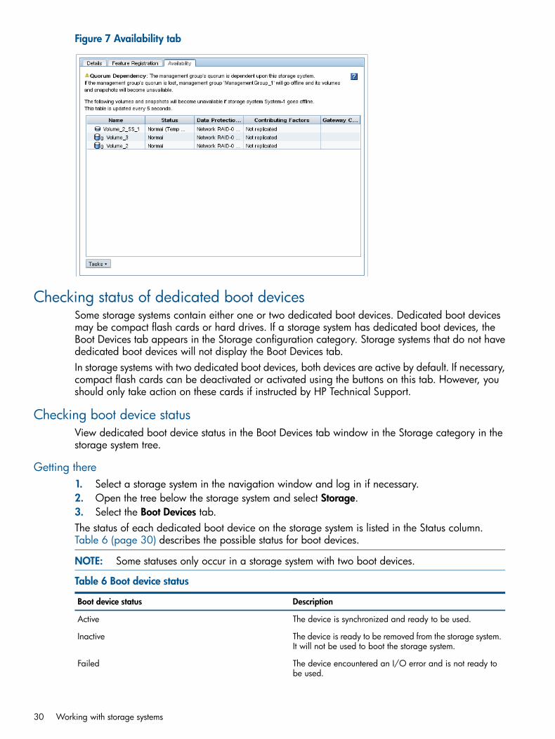
Figure 7 Availability tab
Checking status of dedicated boot devicesSome storage systems contain either one or two dedicated boot devices. Dedicated boot devicesmay be compact flash cards or hard drives. If a storage system has dedicated boot devices, theBoot Devices tab appears in the Storage configuration category. Storage systems that do not havededicated boot devices will not display the Boot Devices tab.In storage systems with two dedicated boot devices, both devices are active by default. If necessary,compact flash cards can be deactivated or activated using the buttons on this tab. However, youshould only take action on these cards if instructed by HP Technical Support.
Checking boot device statusView dedicated boot device status in the Boot Devices tab window in the Storage category in thestorage system tree.
Getting there1. Select a storage system in the navigation window and log in if necessary.2. Open the tree below the storage system and select Storage.3. Select the Boot Devices tab.The status of each dedicated boot device on the storage system is listed in the Status column.Table 6 (page 30) describes the possible status for boot devices.
NOTE: Some statuses only occur in a storage system with two boot devices.
Table 6 Boot device status
DescriptionBoot device status
The device is synchronized and ready to be used.Active
The device is ready to be removed from the storage system.It will not be used to boot the storage system.
Inactive
The device encountered an I/O error and is not ready tobe used.
Failed
30 Working with storage systems

Table 6 Boot device status (continued)
DescriptionBoot device status
The device has not yet been used in a storage system. It isready to be activated.
Unformatted
The device is not recognized as a boot device.Not Recognized
The device cannot be used. (For example, the compactflash card is the wrong size or type.)
Unsupported
NOTE: When the status of a boot device changes, an event is generated. See “Alarms and eventsoverview” (page 86).
Replacing a dedicated boot deviceIf a boot hard drive fails, you will see an event that the boot device is faulty. Replace it with a newdrive. The boot device drives support hot swapping and do not require activation.
Checking status of dedicated boot devices 31
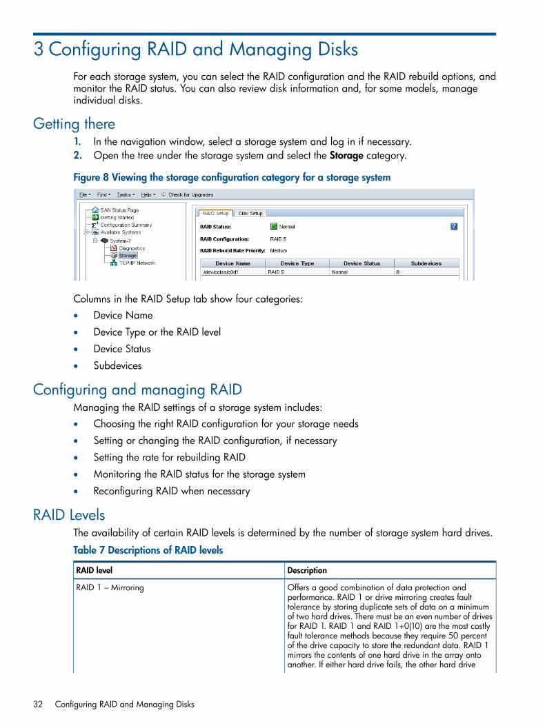
3 Configuring RAID and Managing DisksFor each storage system, you can select the RAID configuration and the RAID rebuild options, andmonitor the RAID status. You can also review disk information and, for some models, manageindividual disks.
Getting there1. In the navigation window, select a storage system and log in if necessary.2. Open the tree under the storage system and select the Storage category.
Figure 8 Viewing the storage configuration category for a storage system
Columns in the RAID Setup tab show four categories:• Device Name
• Device Type or the RAID level
• Device Status
• Subdevices
Configuring and managing RAIDManaging the RAID settings of a storage system includes:• Choosing the right RAID configuration for your storage needs
• Setting or changing the RAID configuration, if necessary
• Setting the rate for rebuilding RAID
• Monitoring the RAID status for the storage system
• Reconfiguring RAID when necessary
RAID LevelsThe availability of certain RAID levels is determined by the number of storage system hard drives.
Table 7 Descriptions of RAID levels
DescriptionRAID level
Offers a good combination of data protection andperformance. RAID 1 or drive mirroring creates fault
RAID 1 – Mirroring
tolerance by storing duplicate sets of data on a minimumof two hard drives. There must be an even number of drivesfor RAID 1. RAID 1 and RAID 1+0(10) are the most costlyfault tolerance methods because they require 50 percentof the drive capacity to store the redundant data. RAID 1mirrors the contents of one hard drive in the array ontoanother. If either hard drive fails, the other hard drive
32 Configuring RAID and Managing Disks

Table 7 Descriptions of RAID levels (continued)
DescriptionRAID level
provides a backup copy of the files and normal systemoperations are not interrupted.
Offers the best combination of data protection andperformance. RAID 1+0 or drive mirroring creates fault
RAID 1+0 – Mirroring and Striping
tolerance by storing duplicate sets of data on a minimumof four hard drives. There must be an even number of drivesfor RAID 1+0. RAID 1+0(10) and RAID 1 are the mostcostly fault tolerance methods because they require 50percent of the drive capacity to store the redundant data.RAID 1+0(10) first mirrors each drive in the array toanother, and then stripes the data across the mirrored pair.If a physical drive fails, the mirror drive provides a backupcopy of the files and normal system operations are notinterrupted. RAID 1+0(10) can withstand multiplesimultaneous drive failures, as long as the failed drives arenot mirrored to each other.
Offers the best combination of data protection and usablecapacity while also improving performance over RAID 6.
RAID 5
RAID 5 stores parity data across all the physical drives inthe array and allows more simultaneous read operationsand higher performance. If a drive fails, the controller usesthe parity data and the data on the remaining drives toreconstruct data from the failed drive. The system continuesoperating with a slightly reduced performance until youreplace the failed drive. RAID 5 can only withstand theloss of one drive without total array failure. It requires anarray with a minimum of three physical drives. Usablecapacity is N-1 where N is the number of physical drivesin the logical array.
Offers the best data protection and is an extension of RAID5. RAID 6 uses multiple parity sets to store data and can
RAID 6
therefore tolerate up to 2 drive failures simultaneously.RAID 6 requires a minimum of 4 drives. Performance islower than RAID 5 due to parity data updating on multipledrives. RAID 6 uses two disk for parity; its fault toleranceallows two disks to fail simultaneously. Usable capacity isN-2 where N is the number of physical drives in the logicalarray.
Explaining RAID devices in the RAID setup reportIn the Storage category, the RAID Setup tab lists the RAID devices in the storage system and providesinformation about them. An example of the RAID setup report is shown in Figure 9 (page 33).Information listed in the report is described in Table 8 (page 34).
Figure 9 RAID setup report
Explaining RAID devices in the RAID setup report 33

RAID devices by RAID typeEach RAID type creates different sets of RAID devices. Table 8 (page 34) contains a descriptionof the variety of RAID devices created by the different RAID types as implemented on variousstorage systems.
Table 8 Information in the RAID setup report
Describes thisThis item
The disk sets used in RAID. The number and names ofdevices varies by storage system and RAID level.
Device Name
The RAID level of the device. For example, in a P4300G2, RAID 5 displays a Device Type of RAID 5 andsubdevices as 8.
Device Type
The RAID status of the device.Status is one of the following:
Device Status
• Normal—green
• Degraded—yellow
• Off—red
• Rebuilding—blue
The number of disks included in the device.Subdevices
Virtual RAID devicesIf you are using the VSA, the only RAID available is virtual RAID. After installing the VSA, virtualRAID is configured automatically if you first configured the data disk in the VI Client.HP recommends installing VMware ESX Server on top of a server with a RAID 5 or RAID 6configuration.
Planning the RAID configurationPlan the RAID configuration for storage systems based on a balance between data high availabilityor fault tolerance, I/O performance, and usable capacity.
CAUTION: Plan your RAID configuration carefully. After you have configured RAID, you cannotchange the RAID configuration without deleting all data on the storage system.
Data protectionKeeping multiple copies of your data ensures that data is safe and remains available in the caseof disk failure. HP recommends using both disk RAID and Network RAID to insure high availability:• Configure RAID 1, RAID 10, RAID 5, or RAID 6 within each storage system to ensure data
redundancy.• Always use Network RAID to mirror data volumes across storage systems in a cluster, regardless
of RAID level, for added data protection and high availability .
Using RAID for data redundancyWithin each storage system, RAID 1 or RAID 10 ensures that two copies of all data exist. If oneof the disks in a RAID pair goes down, data reads and writes continue on the other disk. Similarly,RAID 5 or RAID 6 provides redundancy by spreading parity evenly across the disks in the set.If one disk in a RAID 5 set, or two disks in a RAID 6 set goes down, data reads and writes continueon the remaining disks in the set.
34 Configuring RAID and Managing Disks
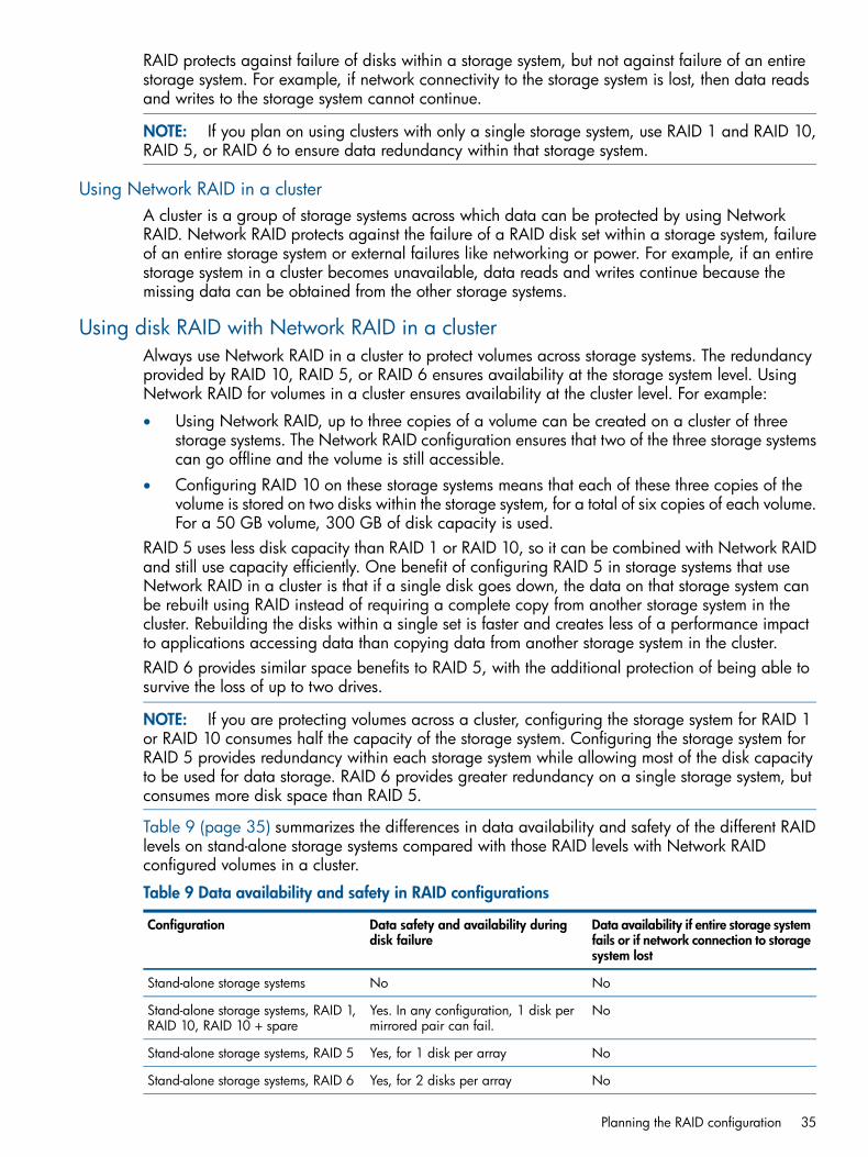
RAID protects against failure of disks within a storage system, but not against failure of an entirestorage system. For example, if network connectivity to the storage system is lost, then data readsand writes to the storage system cannot continue.
NOTE: If you plan on using clusters with only a single storage system, use RAID 1 and RAID 10,RAID 5, or RAID 6 to ensure data redundancy within that storage system.
Using Network RAID in a clusterA cluster is a group of storage systems across which data can be protected by using NetworkRAID. Network RAID protects against the failure of a RAID disk set within a storage system, failureof an entire storage system or external failures like networking or power. For example, if an entirestorage system in a cluster becomes unavailable, data reads and writes continue because themissing data can be obtained from the other storage systems.
Using disk RAID with Network RAID in a clusterAlways use Network RAID in a cluster to protect volumes across storage systems. The redundancyprovided by RAID 10, RAID 5, or RAID 6 ensures availability at the storage system level. UsingNetwork RAID for volumes in a cluster ensures availability at the cluster level. For example:
• Using Network RAID, up to three copies of a volume can be created on a cluster of threestorage systems. The Network RAID configuration ensures that two of the three storage systemscan go offline and the volume is still accessible.
• Configuring RAID 10 on these storage systems means that each of these three copies of thevolume is stored on two disks within the storage system, for a total of six copies of each volume.For a 50 GB volume, 300 GB of disk capacity is used.
RAID 5 uses less disk capacity than RAID 1 or RAID 10, so it can be combined with Network RAIDand still use capacity efficiently. One benefit of configuring RAID 5 in storage systems that useNetwork RAID in a cluster is that if a single disk goes down, the data on that storage system canbe rebuilt using RAID instead of requiring a complete copy from another storage system in thecluster. Rebuilding the disks within a single set is faster and creates less of a performance impactto applications accessing data than copying data from another storage system in the cluster.RAID 6 provides similar space benefits to RAID 5, with the additional protection of being able tosurvive the loss of up to two drives.
NOTE: If you are protecting volumes across a cluster, configuring the storage system for RAID 1or RAID 10 consumes half the capacity of the storage system. Configuring the storage system forRAID 5 provides redundancy within each storage system while allowing most of the disk capacityto be used for data storage. RAID 6 provides greater redundancy on a single storage system, butconsumes more disk space than RAID 5.
Table 9 (page 35) summarizes the differences in data availability and safety of the different RAIDlevels on stand-alone storage systems compared with those RAID levels with Network RAIDconfigured volumes in a cluster.
Table 9 Data availability and safety in RAID configurations
Data availability if entire storage systemfails or if network connection to storagesystem lost
Data safety and availability duringdisk failure
Configuration
NoNoStand-alone storage systems
NoYes. In any configuration, 1 disk permirrored pair can fail.
Stand-alone storage systems, RAID 1,RAID 10, RAID 10 + spare
NoYes, for 1 disk per arrayStand-alone storage systems, RAID 5
NoYes, for 2 disks per arrayStand-alone storage systems, RAID 6
Planning the RAID configuration 35

Table 9 Data availability and safety in RAID configurations (continued)
Data availability if entire storage systemfails or if network connection to storagesystem lost
Data safety and availability duringdisk failure
Configuration
YesYes. However, if any disk in thestorage system fails, the entire storage
Volumes configured with NetworkRAID-10 or greater on clusteredstorage systems system must be copied from another
storage system in the cluster.
YesYes. 1 disk per RAID set can failwithout copying from another storagesystem in the cluster.
Volumes configured with NetworkRAID-10 or greater on clusteredstorage systems, RAID 5
YesYes. 2 disks per RAID set can failwithout copying from another storagesystem in the cluster.
Volumes configured with NetworkRAID-10 or greater on clusteredstorage systems, RAID 6
YesDepends on the underlying RAIDconfiguration of the storage system on
Volumes configured with NetworkRAID-10 or greater on clustered VSAswith virtual RAID which the VSA is installed. HP
recommends configuring RAID 5 orRAID 6.
Mixing RAID configurationsYou may mix storage systems with different configurations of RAID within a cluster. This allows youto add new storage systems with different RAID levels. However, be certain to calculate the capacityof additional storage systems configured with the desired RAID level, because the cluster operatesat the smallest usable per-storage system capacity.For instance, your SAN uses four 12 TB HP LeftHand P4500s configured with RAID 10. Youpurchase two additional 12 TB HP LeftHand P4500s which you want to configure with RAID 5.In the existing cluster, a single 12 TB HP LeftHand P4500 configured with RAID 10 provides 6 TBof usable storage. A single 12 TB HP LeftHand P4500 configured with RAID 5 provides 9 TB ofusable storage. However, due to the restrictions of how the cluster uses capacity, the 12 TB HPLeftHand P4500 configured with RAID 5 will be limited to 6 TB per storage system.In general, the best practice is to avoid mixing configurations of various numbers or capacities ofdrives, so that the SAN fully utilizes the available capacity of each cluster.
Setting RAID rebuild rateChoose the rate at which the RAID configuration rebuilds if a disk is replaced.
NOTE: The RAID rebuild rate cannot be set on a VSA, since there is no physical hardware torebuild.
General guidelines for setting the RAID rebuild rateUse the following guidelines when deciding where to set the RAID rebuild rate:
• Setting the rate high is preferred for rebuilding RAID quickly and protecting data. However,it slows down user access to data.
• Setting the rate low allows users quicker access to data during the rebuild, but slows therebuild rate.
Setting the RAID rebuild rate1. In the navigation window, log in to a storage system and select the Storage category.2. On the RAID Setup tab, click RAID Setup Tasks and select the RAID Rebuild Rate Priority choice.
36 Configuring RAID and Managing Disks
3. Change the rebuild settings as desired on the RAID Rebuild Rate Priority window.4. Click OK.
The settings are then ready when a RAID rebuild takes place.
Reconfiguring RAIDReconfiguring RAID on a storage system or a VSA destroys any data stored on that storage system.For VSAs, there is no alternate RAID choice, so the only outcome for reconfiguring RAID is to wipeout all data.
• Changing preconfigured RAID on a new storage systemRAID must be configured on individual storage systems before they are added to a managementgroup. To change the preconfigured RAID level of a storage system, make the change beforeyou add the storage system to a management group.
• Changing RAID on storage systems in management groupsYou cannot reconfigure RAID on a storage system that is already in a management group. Tochange the RAID configuration for a storage system that is in a management group, you mustfirst remove it from the management group.
CAUTION: Changing the RAID configuration will erase all the data on the disks.
To reconfigure RAID1. In the navigation window, log in to the storage system and select the Storage category.2. On the RAID Setup tab, click RAID Setup Tasks and select Reconfigure RAID.3. Select the RAID configuration from the list.4. Click OK.5. Click OK on the message that opens.
RAID starts configuring.
NOTE: A storage system may take several hours for the disks to synchronize in a RAID 10, RAID5, or RAID 6 configuration. During this time, performance will be degraded. When the RAID statuson the RAID Setup tab shows Normal, the disks provide fully operational data redundancy, andperformance returns to normal.
Configuring RAID for a P4800 G2 with 2 TB drivesRAID 6 is the default configuration for P4800 G2 storage blades with 2 TB capacity or greater.HP recommends using the default configuration.
• Configuring the disks to RAID 5 takes a few minutes in the CMC. You must first remove thestorage system from the management group. Once configuration is complete, you can addthe storage system to the management group, while RAID 5 initialization occurs in thebackground. The CMC is available during initialization and you can track the status of theinitialization using the Hardware Information tab in the CMC. The RAID 5 initialization takesa number of days, depending upon how much I/O is going to the storage system. Systemperformance is impacted if the system is actively participating in a cluster that is hosting storagevolumes.
• If reconfiguring the disks to RAID 6 is necessary, the process takes approximately six hours.You must first remove the storage system from the management group. RAID 6 initializationmust finish before adding the storage system to the management group. During initialization,the CMC is unavailable. However, you should leave the CMC open while RAID initializationcontinues, and track the status of the initialization on the status bar at the bottom of the CMC.
Reconfiguring RAID 37

When RAID 6 initialization has finished, the CMC becomes available again, and you canadd the storage system to the management group.
Monitoring RAID statusRAID is critical to the operation of the storage system. If RAID has not been configured, the storagesystem cannot be used. Monitor the RAID status of a storage system to ensure that it remains normal.If the RAID status changes, a CMC event is generated. For more information about events andevent notification, see “Alarms and events overview” (page 86).
Data reads and writes and RAID statusA RAID status of Normal, Rebuild, or Degraded all allow data reads and writes. The only timedata cannot be written to and read from the storage system is if the RAID status shows Off.
Data redundancy and RAID statusIn a RAID 1, RAID 10, or RAID 5 configuration, when RAID is degraded, there is no full dataredundancy. Therefore, data is at additional risk if there is a disk failure when RAID is degraded.In RAID 6, when RAID is degraded due to a single drive failure, the data is still not at risk for asecond failure. However, if it is degraded due to the failure of two drives, then data would be atrisk if another drive failed.
CAUTION: In a degraded RAID 1 or RAID 10 configuration, loss of a second disk within a pairresults in data loss. In a degraded RAID 5 configuration, loss of a second disk results in data loss.In a degraded RAID 6 configuration, the loss of three drives results in data loss.
The RAID status is located at the top of the RAID Setup tab in Storage. RAID status also appearsin the Details tab on the main CMC window when a storage system is selected in the navigationwindow.
Figure 10 Monitoring RAID status on the main CMC window
1. RAID status
The status displays one of five RAID states.
• Normal—RAID is synchronized and running. No action is required.
• Rebuilding—A new disk has been inserted in a drive bay, or a hot spare has been activated,and RAID is currently rebuilding. No action is required.
• Degraded—RAID is degraded. A disk may have failed or have been removed from its bay.For hot-swap storage systems, simply replace the faulty, inactive, uninitialized, or missing disk.
• Off—Data cannot be stored on the storage system. The storage system is offline and flashesin the navigation window.
• None—RAID is unconfigured.
38 Configuring RAID and Managing Disks

Managing disksUse the Disk Setup tab to monitor disk information and perform disk management tasks as listedin Table 10 (page 39).
Table 10 Disk management tasks for storage systems
Model where availableDisk setup function
AllMonitor disk information
Getting there1. In the navigation window, select a storage system.2. Select the Storage category in the tree below it.3. Select the Disk Setup tab.
Reading the disk report on the Disk Setup tabThe Disk Setup tab provides a status report of the individual disks in a storage system.Figure 11 (page 39) shows the Disk Setup tab and Table 11 (page 40) describes the correspondingdisk report.
Figure 11 Example of columns in the Disk Setup tab
Managing disks 39

Table 11 Description of items on the disk report
DescriptionColumn
Corresponds to the physical slot in the storage system.Disk
Status is one of the following:Status• Active—green (on and participating in RAID)
• Uninitialized—yellow (is not part of an array)
• Inactive—yellow (is part of an array, and on, but notparticipating in RAID)
• Marginal—yellow
• Off or removed—red
• Hot spare—green (for RAID configurations that supporthot spares)
• Hot spare down—red
Drive health is one of the following:Health• Normal
• Marginal (predictive failure status indicating “replaceas soon as convenient”)
• Faulty (predictive failure status indicating “replaceimmediately”)
Indicates if it is safe to hot-remove a disk.Safe to Remove
The model of the disk.Model
The serial number of the disk.Serial Number
The class (type) of disk, for example, SATA 3.0 GB.Class
Indicates the estimated wear life remaining for SSD drives.Status is one of the following:
Wear Life Remaining (P4900 G2 only)
• Normal—Green; drive is good
• Aging—Yellow; drive is at 5% of remaining estimatedlife
• Degraded—Yellow; drive is at 2% of remainingestimated life
• Failing—Red; drive has estimated an 90 days ofremaining life
• Worn out—Red; drive is at 0% of remaining estimatedlife
• Failed—Red; drive has failed and writes are notpermitted
The data storage capacity of the disk.Capacity
SSD drives and wear lifeThe wear life statistics for SSD drives report drive usage so that drives can be replaced before theywear out. See “Replacing disks appendix” (page 241) for more information.If all the SSD drives approach the end of their wear life at the same time, and you plan to replaceall the drives in the storage system, use one of the following methods to preserve the data whilereplacing the drives:• Migrate the volumes and snapshots from the cluster containing the storage system with the
SSD drives to a different cluster in the management group. Remove the storage system fromthe cluster and the management group, replace the drives and rebuild RAID. Then return the
40 Configuring RAID and Managing Disks

storage system to the cluster and migrate the volumes and snapshots back to the originalcluster. “Changing the cluster—migrating a volume to a different cluster” (page 160).
• Perform a cluster swap, replacing the storage systems with the worn out SSD drives withstorage systems with new SSD drives. See “Upgrading the storage systems in a cluster usingcluster swap” (page 136).
NOTE: If replacing the SSD drives due to the wear life remaining status, the Repair StorageSystem feature is not available because there is not a disk failure, indicated by a disk inactive ordisk off event in the Events list.
Verifying disk statusCheck the Disk Setup window to determine the status of disks and to take appropriate action onindividual disks when preparing to replace them.
Viewing disk status for the DL320s (NSM 2120)The disks are labeled 1 through 12 in the Disk Setup window(Figure 12 (page 41)), and correspondto the disk drives top to bottom, from left to right ( Figure 13 (page 41)) when looking at the frontof the DL320s (NSM 2120).For the DL320s (NSM 2120), the columns Health and Safe to Remove help assess the health of adisk and tell you whether you can replace it without losing data.
Figure 12 Viewing the Disk Setup tab in a DL320s (NSM 2120)
Figure 13 Diagram of the drive bays in a DL320s (NSM 2120)
Viewing disk status for the VSAFor the VSA, the Disk Setup window shows 1 virtual disk.
Managing disks 41

Figure 14 Viewing the disk status of a VSA
NOTE: To change the size of the data disk in a VSA, see the HP P4000 VSA Installation andConfiguration Guide for instructions about recreating the disk in the VI Client.
Viewing disk status for the HP LeftHand P4500 and HP P4500 G2The disks are labeled 1 through 12 in the Disk Setup window, shown in Figure 15 (page 42),andcorrespond to the disk drives from top to bottom, left to right (Figure 16 (page 42)), when you arelooking at the front of the HP LeftHand P4500 and HP P4500 G2.For the HP LeftHand P4500 and HP P4500 G2, the columns Health and Safe to Remove help youassess the health of a disk and tell you whether or not you can replace it without losing data.
Figure 15 Viewing the Disk Setup tab in a HP LeftHand P4500 and HP P4500 G2
Figure 16 Diagram of the drive bays in a HP LeftHand P4500 and HP P4500 G2
Viewing disk status for the HP LeftHand P4300 and HP P4300 G2The disks are labeled 1 through 8 in the Disk Setup window, shown in Figure 17 (page 43), andcorrespond to the disk drives from top to bottom, left to right ( Figure 18 (page 43)), when youare looking at the front of the HP LeftHand P4300 and HP P4300 G2.For the P4300 and the P4300 G2, the columns Health and Safe to Remove help you assess thehealth of a disk and tell you whether or not you can replace it without losing data.
42 Configuring RAID and Managing Disks

Figure 17 Viewing the Disk Setup tab in a HP LeftHand P4300 and HP P4300 G2
Figure 18 Diagram of the drive bays in a HP LeftHand P4300 and HP P4300 G2
Viewing disk status for the HP P4800 and HP P4800 G2The disks are labeled 1 through 35 in the Disk Setup window( Figure 19 (page 43)), and correspondto the disk drives from top to bottom, left to right, (Figure 20 (page 44)), when you are looking atthe front of the HP P4800 and HP P4800 G2.
Figure 19 Viewing the Disk Setup tab in a HP P4800 and HP P4800 G2
Managing disks 43

Figure 20 Diagram of the drive bays in a HP P4800 and HP P4800 G2
Viewing disk status for the HP P4900 G2The disks are labeled 1 through 8 in the Disk Setup window (Figure 21 (page 44)), and correspondto the disk drives from top to bottom, left to right (Figure 22 (page 44)), when you are looking atthe front of the HP P4900 G2.
Figure 21 Viewing the Disk Setup tab in a HP P4900 G2
Figure 22 Diagram of the drive bays in a HP P4900 G2
Replacing a diskThe correct procedure for replacing a disk in a storage system depends upon a number of factors,including the RAID configuration, the data protection level of volumes and snapshots, and thenumber of disks being replaced. Replacing a disk in a storage system that is in a cluster requiresrebuilding data on the replaced disk.Replacing a disk in a storage system includes the following basic steps.
• Planning for rebuilding data on either the disk or the entire storage system (all storage systems)
• Powering the disk off in the CMC (non-hot-swap storage systems)
• Physically replacing the disk in the storage system (all storage systems)
44 Configuring RAID and Managing Disks

• Powering the disk on in the CMC (non-hot-swap storage systems)
• Rebuilding RAID on the disk or on the storage system (all storage systems)
NOTE: Because of the nature of the SSD drive wear management and reporting, it is likely thatall the SSD drives in a system will wear out around the same time.
Table 12 (page 45) lists disk replacement requirements for specific configurations and storagesystems.
Table 12 Disk replacement requirements
RequirementsStorage system or configuration
RAID is normal and Safe to Remove status is yes. See“Replacing disks in hot-swap storage systems” (page 45).
Hot-swap storage systems configured for RAID 1, 10, 5,50, or 6
Replace disk on host server according to manufacturer'sinstructions.
VSA
Additional information about preparing for disk replacement is included in the following sectionsbelow:• “Preparing for a disk replacement” (page 46)
• “Best practice checklist for single disk replacement in RAID 1, RAID 10, RAID 5, and RAID 6” (page 46)
Using Repair Storage SystemRepair Storage System is a procedure that allows you to replace a disk and trigger only one resyncof data, rather than a complete restripe. Repair Storage System creates a place-holder system inthe cluster, while allowing the storage system needing repair to be removed for the disk replacement.See “Repairing a storage system” (page 139) for more information.In the following circumstances, you may have to use the Repair Storage System feature whenreplacing disks.
• When replacing multiple disks on a storage system with RAID 5 or RAID 6
• When multiple disks on the same mirror set need to be replaced on a storage system withRAID 10.
Replacing disks in hot-swap storage systemsIn hot-swap storage systems configured with RAID 1, RAID 10, RAID 5, or RAID 6, a faulty or faileddisk can be removed and replaced with a new one. RAID will rebuild and the drive will return toNormal status.
CAUTION: Before replacing a drive in a hot-swap storage system, always check the Safe toRemove status to verify that the drive can be removed without causing RAID to go Off.
When RAID is Normal in RAID 1, RAID 10, RAID 5, or RAID 6, all drives indicate they are safeto remove. However, you should only replace one drive at a time. If it is necessary to replace morethan one drive, always check the Safe to Remove status again. Wait up to two minutes for thestatus to fully update before checking it again. If the status indicates the second drive is safe toremove, then it can be replaced.For example, if an array is Rebuilding, no other drives in the array (except for unused hot-sparedrives) are safe to remove. However, if the configuration includes two or more arrays and thosearrays are Normal, the Safe To Remove status indicates that drives in those other arrays may bereplaced.
Replacing a disk 45

Preparing for a disk replacementUse this section to replace a single disk under the following conditions:• You know which disk needs to be replaced through SAN/iQ monitoring.
• When viewed in the Disk Setup tab, the Drive Health column shows Marginal (replace assoon as possible) or Faulty (replace right away).
• RAID is still on, though it may be degraded and a drive is inactive.Use the instructions in “Replacing disks appendix” (page 241) for these situations:• If RAID is off
• If you are unsure which disk to replaceThe instructions in the appendix include contacting HP Support for assistance in either identifyingthe disk that needs to be replaced or, for replacing more than one disk, the sequence in whichthey should be replaced.
To prepare for disk replacementPreparing for a disk replacement differs according to the RAID level of the storage system andwhether it is a hot-swap storage system. Carefully plan any disk replacement to ensure data safety,regardless of whether the storage system is hot-swap. The following checklists outline steps to helpensure data remains safe while replacing a disk.
Identify physical location of storage system and diskBefore beginning the disk replacement process, identify the physical location of both the storagesystem in the rack and the disk in the storage system.
• Know the name and physical location of the storage system that needs the disk replacement.
• Know the physical position of the disk in the storage system. See “Verifying disk status”(page 41) for diagrams of disk layout in the various storage systems.
• Have the replacement disk ready and confirm that it is of the right size and has the rightcarrier.
Best practice checklist for single disk replacement in RAID 1, RAID 10, RAID 5, and RAID 6There are no prerequisites for this case; however, HP recommends that:• All volumes and snapshots show a status of Normal.
• Any volumes or snapshots that were being deleted have completed deletion.
• One of the following:RAID status is Normal◦
◦ If RAID is Rebuilding or Degraded, for storage systems that support hot-swapping ofdrives, the Safe to Remove column indicates Yes (the drive can safely be replaced).
Replacing a disk in a hot-swap storage systemThe hot-swap storage systems are:• DL320s [NSM 2120]
• HP LeftHand P4300 and P4500
• HP P4300 G2 and P4500 G2
• HP P4800 and P4800 G2
• HP P4900 G2
46 Configuring RAID and Managing Disks

Complete the checklist for replacing a disk in RAID 1, RAID 10, RAID 5, or RAID 6. Then followthe appropriate procedures for the storage system.
Replace the diskYou may remove and replace a disk from these hot-swap storage systems after checking that theSafe to Remove status indicates “Yes” for the drive to be replaced.
Physically replace the disk drive in the storage systemSee the hardware documentation that came with your storage system for information about physicallyreplacing disk drives in the storage system.
RAID rebuildingAfter the disk is replaced, RAID starts rebuilding on the replaced disk. There may be a delay ofup to a couple of minutes before you can see that RAID is rebuilding on the RAID Setup or DiskSetup tabs.
Figure 23 RAID rebuilding on the RAID Setup tab
Figure 24 Disk rebuilding on the Disk Setup tab
Replacing a disk 47

4 Managing the networkA physical storage system has two TCP/IP network interfaces (NICs). For each physical storagesystem you can:• Configure the individual TCP/IP interfaces, including settings for speed and duplex, frame
size, and NIC flow control.• Bond NICs to ensure continuous network access or to improve bandwidth.
• Set up and manage DNS servers, and a network routing table.
• Manage the SAN/iQ communication interface, and update the list of managers running inthe management group to which a storage system belongs.
NOTE: The VSA has only one network interface and does not support changing the followingitems:• NIC bonding
• NIC flow control
• Frame size
• TCP interface speed or duplex
Network best practices• Isolate the SAN, including CMC traffic, on a separate network. If the SAN must run on a
public network, use a VPN to secure data and CMC traffic.• Configure all the network characteristics on a storage system before creating a management
group, or before adding the storage system to a management group and cluster.• Use static IP addresses, or reserved addresses if using DHCP.
• Configure storage system settings for speed and duplex, frame size, and flow control BEFOREbonding NICs and before putting the storage system into a management group and cluster.
• If adding a second IP address to a storage system, the second IP address must be on a separatesubnet. If the two IP addresses are on the same subnet, they must be bonded.
Split network configurationsImplement a split network configuration to use the CMC on a management network separate fromthe storage or iSCSI network. HP recommends that you only configure a management networkwhen the storage systems are equipped with a sufficient number of network adapters so that thestorage systems can support both bonded NICs for optimal redundancy and performance on thestorage network, along with a separate management interface. Keep in mind the followingrequirements when considering the creation of a management network.
• Configure a management network only if your storage systems have two or more NICs. TwoNICs are the minimum number required to create a bonded interface for the storage networkto provide maximum redundancy and performance.
• Use only available P4000 upgrade kits to alter the hardware configuration of a P4000 storagesystem. Alterations using any other hardware are not supported.
• Be aware that the CMC can manage storage systems via a routed network or by installationof a second NIC on the storage network on the CMC host. This is the most common methodfor CMC management.
48 Managing the network

• When configuring a management interface on a P4000 storage system, make sure thatinterface is on a separate network. Configuring two separate interfaces on the same IP networkis not supported and will result in communication problems in the cluster.
• When configuring a management interface on a P4000 storage system, be aware that onlyone interface can be configured with a default gateway, and that interface should be themanagement interface. Configuring two default gateways will result in communication problemsin the cluster.
• When configuring a management interface on a P4000 storage system, you must designatethe storage interface as the SAN/iQ interface for that storage system in the CMC. This is doneon the Communications tab in the TCP/IP configuration category for that storage system.
Changing network configurationsChanging the network configuration of a storage system may affect connectivity with the networkand application servers. Consequently, we recommend that you configure network characteristicson individual storage systems before creating a management group or adding them to existingclusters.If you do need to change the network characteristics of a storage system while it is in a cluster, besure to follow HP's recommendations. See “Best practices when changing network characteristics”(page 49).
Best practices when changing network characteristics• Plan to make network changes during off-peak hours to minimize the impact of those changes.
• Make changes on one storage system at a time.
• Some network changes cause the storage server to restart the SAN/iQ services, making thestorage system unavailable for a short time. Check the Availability tab for each storage systemto see if any volumes will become unavailable if the services restart on the storage system.Volumes and snapshots may become temporarily unavailable while services restart. Examplesinclude unreplicated volumes, or snapshots that are causing a restripe of the data.
• After the changes are in place, verify the iSCSI sessions. You may need to update the sessions.
Getting there1. In the navigation window, select a storage system.2. Open the tree under the storage system, and select TCP/IP Network.
Figure 25 Viewing the TCP/IP Network category for a storage system
Changing network configurations 49

Managing settings on network interfacesConfigure or change the settings of the network interfaces in the storage systems. See “Networkbest practices” (page 48) for more information.
RequirementsThese settings must be configured before creating NIC bonds.
TCP status tabReview the status of the TCP interfaces. Change the speed and duplex, frame size, and NIC flowcontrol of an interface. Changing the speed and duplex and NIC flow control can only be performedon interfaces that are not in a bond. The frame size can be changed on interfaces individually oron a bonded interface.
NOTE: You cannot change the speed, duplex, or flow control of a VSA.
Review the status of the network interfaces on the TCP Status tab.
Table 13 Status of and information about network interfaces
DescriptionColumn
Name of the interface. Entries vary depending on thestorage system.
Name
• bond0—The bonded interface(s) (appears only ifstorage system is configured for bonding)
• Motherboard:Port1
• Motherboard:Port2
• G4-Motherboard:Port1
• G4-Motherboard:Port2
• Eth0
Describes each interface listed. For example, the bond0is the Logical Failover Device.
Description
Lists the actual operating speed reported by the interface.Speed/Method
Lists duplex as reported by the interface.Duplex/Method
Describes the state of the interface. See “NIC status inActive-Passive configuration” (page 58) for a detaileddescription of individual NIC status.
Status
Lists the frame size setting for the interface.Frame Size
(For Active-Passive bonds) Indicates whether the interfaceis set as preferred. The preferred interface is the interface
Preferred
within an Active-Passive bond that is used for data transferduring normal operation.
Changing speed and duplex settingsThe settings for the storage system and the switch must be the same. Available settings are listedin Table 14 (page 50).
Table 14 Setting storage system speed and duplex settings
Switch setting speed/duplexStorage system setting speed/duplex
Auto/AutoAuto/Auto
1000/Full1000/Full
50 Managing the network

Table 14 Setting storage system speed and duplex settings (continued)
Switch setting speed/duplexStorage system setting speed/duplex
100/Full100/Full
100/Half100/Half
10/Full10/Full
10/Half10/Half
NOTE: The VSA does not support changing the speed and duplex settings.
Requirements
• These settings must be configured before creating NIC bonds.
• If you change these settings, you must ensure that both sides of the NIC cable are configuredin the same manner. For example, if the storage system is set for Auto/Auto, the switch mustbe set the same.
• If you edit the speed or duplex on a disabled or failed NIC, the new setting will not be applieduntil the NIC is enabled or connectivity is restored.
Best practiceChange the speed and duplex settings while the storage system is in the Available Systems pooland not in a management group.
To change the speed and duplex1. In the navigation window, select the storage system and log in.2. Open the tree, and select TCP/IP Network.3. Select the TCP Status tab in the tab window.4. Select the interface to edit.5. Click TCP/IP Status Tasks, and select Edit.6. Select the combination of speed and duplex that you want.7. Click OK.
A series of status messages appears. Then the changed setting appears in the TCP statusreport.
NOTE: You can also use the Configuration Interface to edit the TCP speed and duplex. See“Setting the TCP speed, duplex, and frame size” (page 237).
Changing NIC frame sizeNetwork frame size affects management data traffic and replication. Use the same network framesize in all storage systems in a cluster to ensure consistent data traffic and replication.
Best practicesChange the frame size while the storage system is in the Available Systems pool and not in amanagement group.The frame size specifies the size of data packets that are transferred over the network. The defaultEthernet standard frame size is 1500 bytes. The maximum allowed frame size is 9000 bytes.Increasing the frame size improves data transfer speed by allowing larger packets to be transferredover the network and by decreasing the CPU processing time required to transfer data. However,
Managing settings on network interfaces 51

increasing the frame size requires that routers, switches, and other devices on your network supportthat frame size.
NOTE: Increasing the frame size can cause decreased performance and other network problemsif routers, switches, or other devices on your network do not support frame sizes greater than 1500bytes. If you are unsure about whether your routers and other devices support larger frame sizes,keep the frame size at the default setting.If you edit the frame size on a disabled or failed NIC, the new setting will not be applied until theNIC is enabled or connectivity is restored.
To avoid potential connectivity and performance problems with other devices on your network,keep the frame size at the default setting. The frame size on the storage system should correspondto the frame size on Windows and Linux application servers. If you decide to change the framesize, set the same frame size on all storage systems on the network, and set compatible framesizes on all clients that access the storage systems.Consult with your network administrator for recommended storage system frame sizes and thecorresponding frame sizes in bytes for Windows and Linux clients in your environment.
Jumbo framesFrame sizes that are greater than 1500 bytes are called jumbo frames. Jumbo frames must besupported and configured on each Windows or Linux client accessing the storage system and alsoon each network switch between the storage system and the Windows or Linux clients.Jumbo frames can co-exist with 1500 byte frames on the same subnet if the following conditionsare met:
• Every device downstream of the storage system on the subnet must support jumbo frames.
• If you are using 802.1q virtual LANs, jumbo frames and nonjumbo frames must be segregatedinto separate VLANs.
NOTE: The frame size for a bonded logical interface must be equal to the frame size of theNICs in the bond.
Editing the NIC frame sizeTo edit the frame size:1. In the navigation window, select a storage system and log in.2. Open the tree, and select the TCP/IP Network category.3. Select the TCP Status tab.4. Select the interface to edit.5. Click TCP Status Tasks, and select Edit.6. Select Set To in the Frame Size section.7. Enter a value between 1500 and 9000 bytes in the Set To field.8. Click OK.
A series of status messages display. Then the changed setting appears in the TCP status report.
NOTE: You can also use the Configuration Interface to edit the frame size.
Changing NIC flow controlFlow control on the NICs prevents data transmission overruns that result in packets being dropped.With flow-control enabled, network packets that would otherwise be dropped will not have to beretransmitted. Auto-negotiate is the default setting for NIC flow control. You can change the settingto manually choose the transmit and receive settings for the NIC.
52 Managing the network

NOTE: The VSA does not support changing flow control settings.
Requirements
• These settings must be configured before creating NIC bonds.
• All NICs should have (or must have, if they are bonded) the same flow control settings. Youcan bond NICs with different flow control settings. However, the bond changes both NICs tothe same flow control settings, using the settings of the preferred NIC.
• Flow control cannot be changed when the port is disabled.
Changing NIC flow control settingsTo change NIC flow control settings:1. In the navigation window, select a storage system, and log in.2. Open the tree, and select the TCP/IP Network category.3. Select the TCP Status tab.4. Select the interface to edit.5. Click TCP Status Tasks, and select Edit.6. Change the flow control setting on the Edit window.7. Click OK.8. Repeat steps 4 through 7 for all the NICs you want to change .On the TCP Status tab window, for bonded NICs, the NIC flow control column shows the flowcontrol settings for the physical NICs, and the bond0 as blank. Flow control is enabled and workingin this case
The TCP/IP tabLists the network interfaces on the storage system. On the TCP/IP tab, you can bond interfaces,disable an interface, configure an IP address, and ping servers from the storage system.The TCP/IP tab
Identifying the network interfacesA storage system comes with two or four Ethernet interfaces. To use either interface, you mustconnect an Ethernet cable to one of the ports and configure the interface in the ConfigurationInterface or the CMC. These ports are named and labeled on the back of the storage system.Table 15 (page 54) lists the methods to identify the NICs. You can work with the NICs in the CMCor through the Configuration Interface which is accessed through the storage system’s serial port,as described in “Using the Configuration Interface” (page 235).
The TCP/IP tab 53

Table 15 Identifying the network interfaces on the storage system
Ethernet interfaces
LabelWhere labeled
In the TCP/IP Network configuration category in the CMC • eth0, eth1• TCP/IP tab • Motherboard:Port0, Motherboard:Port1• TCP Status tab • G4-Motherboard:Port1, G4-Motherboard:Port2
• Motherboard:Port1, Motherboard:Port2For bonded interfaces:• BondN or Bond0
In the Configuration Interface available through the storagesystem’s serial port
• Intel Gigabit Ethernet
• Broadcom Gigabit Ethernet
On the label on the back of the storage system • Eth0, Eth1
• Represented by a graphical symbol similar to thesymbols below:
or
Pinging an IP addressBecause the SAN should be on a private network, you can ping target IP addresses from a storagesystem using the CMC. You can ping from any enabled interface listed on the TCP/IP tab. Youcan ping any IP address, such as an iSCSI server or an SNMP monitor server.
To ping an IP address1. Select a storage system, and open the tree below it.2. Select the TCP/IP Network category.3. Select the TCP/IP Tasks menu, and select Ping from the menu.4. Select which Network Interface to ping from, if you have more than one enabled.
A bonded interface has only one interface from which to ping.5. Enter the IP address to ping, and click Ping.
If the server is available, the ping is returned in the Ping Results window.If the server is not available, the ping fails in the Ping Results window.
Configuring the IP address manuallyUse the TCP/IP Network category to add or change the IP address for a network interface.1. Select a storage system, and open the tree below it.2. Select TCP/IP Network category, and click the TCP/IP tab.3. Select the interface from the list for which to configure or change the IP address.4. Click Edit.5. Select IP address, and complete the fields for IP address, Subnet mask, and Default gateway.6. Click OK.7. Click OK on the confirmation message.8. Click OK on the message notifying you of the automatic log out.
NOTE: Wait a few moments for the IP address change to take effect.
9. Log in to the newly addressed storage system.
54 Managing the network

Using DHCPA DHCP server becomes a single point of failure in your system configuration. If the DHCP servergoes offline, then IP addresses may be lost.
CAUTION: If you use DHCP, be sure to reserve statically assigned IP addresses for all storagesystems on the DHCP server. This is required, because management groups use unicastcommunication.
NOTE: If you plan to bond the NICs, you must use a static IP address.
To set IP address using DHCP1. Select from the list the interface to configure for use with DHCP.2. Click Edit.3. Select Obtain an address automatically using the DHCP/BOOTP protocol.4. Click OK.5. Click OK on the confirmation message.6. Click OK on the message notifying you of the automatic log out.
NOTE: Wait a few moments for the IP address change to take effect.
Configuring network interface bondsTo ensure consistent failover characteristics and traffic distribution, use the same network bondtype in all the storage systems in a cluster. Network interface bonding provides high availability,fault tolerance, load balancing and/or bandwidth aggregation for the network interface cards inthe storage system. Bonds are created by joining physical NICs into a single logical interface. Thislogical interface acts as the master interface, controlling and monitoring the physical slave interfaces.Bonding two interfaces for failover provides fault tolerance at the local hardware level for networkcommunication. Failures of NICs, Ethernet cables, individual switch ports, and/or entire switchescan be tolerated while maintaining data availability. Bonding two interfaces for aggregationprovides bandwidth aggregation and localized fault tolerance. Bonding the interfaces for loadbalancing provides both load balancing and localized fault tolerance.
NOTE: The VSA does not support NIC bonding.
Depending on your storage system hardware, network infrastructure design, and Ethernet switchcapabilities, you can bond NICs in one of three ways:
• Active-Passive. You specify a preferred NIC for the bonded logical interface to use. If thepreferred NIC fails, then the logical interface begins using another NIC in the bond until thepreferred NIC resumes operation. When the preferred NIC resumes operation, data transferresumes on the preferred NIC.
• Link Aggregation Dynamic Mode. The logical interface uses both NICs simultaneously for datatransfer. This configuration increases network bandwidth, and if one NIC fails, the other
Using DHCP 55
continues operating normally. To use Link Aggregation Dynamic Mode, your switch mustsupport 802.3ad.
CAUTION: Link Aggregation Dynamic Mode requires plugging both NICs into the sameswitch. This bonding method does not protect against switch failure.
• Adaptive Load Balancing (ALB). The logical interface balances data transmissions through bothNICs to enhance the functionality of the server and the network. Adaptive Load Balancingautomatically incorporates fault tolerance features as well.
Best practices• HP recommends bonding network interfaces for performance and failover. The best bond to
use depends on your network and SAN configuration.• Adaptive Load Balancing is the recommended bonding method, as it combines the benefits
of the increased transmission rates of 802.3ad with the network redundancy of Active-Passive.Adaptive Load Balancing does not require additional switch configurations.
• Verify and, if necessary, change the Speed, Duplex, Frame Size, and Flow Control settingsfor both interfaces that you plan to bond.
• Link Aggregation Dynamic Mode does not protect against switch failure, because both NICsmust be plugged into the same switch. Link Aggregation Dynamic Mode provides bandwidthgains, because data is transferred over both NICs simultaneously. For Link AggregationDynamic Mode, both NICs must be plugged into the same switch, and that switch must beLACP-capable, and both support and be configured for 802.3ad aggregation.
• For Active-Passive, plug the two NICs on the storage system into separate switches. WhileLink Aggregation Dynamic Mode will only survive a port failure, Active-Passive will survive aswitch failure.
Bonding with 10 GbE interfacesIn storage systems with both 1 GbE and 10 GbE interfaces, users see four Ethernet interfaces listedin the CMC TCP/IP Network tab window. These four interfaces can be bonded a number of ways.Note that not all the bond configurations which are supported by the HP P4000 SAN are supportedwith 10 GbE NICs.
Supported bonds with 10 GbEThe P4000 SAN Solution with 10 GbE NICs installed and configured supports these bond types.• Adaptive Load Balancing (ALB) bond with the two 10 GbE Ethernet NICs
• Active-Passive bond with two 10 GbE Ethernet NICs
• Active-Passive bond with 1 GbE NIC and 10 GbE NIC
• Link Aggregation Dynamic Mode (802.3ad) bond with two 10 GbE Ethernet NICs
Unsupported bonds with 10 GbEThe P4000 SAN Solution with 10 GbE NICs installed and configured does not support these bondtypes.• Bonding two bonds
• ALB bond with 1 GbE NIC and 10 GbE NIC
• Link Aggregation Dynamic Mode bond with 1 GbE NIC and 10 GbE NIC
56 Managing the network

Table 16 HP P4000 SAN Solution—possible bonds with 1 GbE and 10 GbE NICs
SAN/iQ softwareinterface
eth3 (10 GbE)eth2 (10 GbE)Motherboard:Port2 (1GbE)
Motherboard:Port1 (1GbE)
eth2DisabledEnabledDisabledDisabled
eth3EnabledDisabledDisabledDisabled
eth2EnabledEnabledDisabledDisabled
eth3EnabledEnabledDisabledDisabled
BondALB BondALB BondDisabledDisabled
Bond802.3ad bond802.3ad bondDisabledDisabled
BondBond (Passive)Bond (Active)DisabledDisabled
BondBond (Active)Bond (Passive)DisabledDisabled
BondDisabledBond (Active)DisabledBond (Passive)
BondBond (Active)DisabledDisabledBond (Passive)
BondDisabledBond (Active)Bond (Passive)Disabled
BondBond (Active)DisabledBond (Passive)Disabled
Bond-10 GbEBond-10 GbEBond-10 GbEBond-1 GbEBond-1 GbE
IP address for NIC bondsAllocate a static IP address for the logical bond interface (bond0). You cannot use DHCP for thebond IP.
NIC bonding and speed, duplex, frame size, and flow control settingsThese settings are controlled on the TCP/IP and TCP Status tabs of the TCP/IP Network configurationcategory. If you change these settings, you must ensure that both sides of the NIC cable areconfigured in the same manner. For example, if the storage system is set for Auto/Auto, the switchmust be set the same. See “TCP status tab” (page 50) for more information.
Table 17 Comparison of Active-Passive, link aggregation dynamic mode, and Adaptive LoadBalancing bonding
Adaptive load balancingLink aggregation dynamicmode
Active-PassiveFeature
Simultaneous use of both NICsincreases bandwidth.
Simultaneous use of bothNICs increases bandwidth.
Use of 1 NIC at a timeprovides normalbandwidth.
Bandwidth
YesYesYesProtection during portfailure
Yes. NICs can be plugged intodifferent switches.
No. Both NICs are pluggedinto the same switch.
Yes. NICs can be pluggedinto different switches.
Protection during switchfailure
NoYesNoRequires support for802.3ad linkaggregation?
How Active-Passive bonding worksBonding NICs for Active-Passive allows you to specify a preferred interface that will be used fordata transfer. This is the active interface. The other interface acts as a backup, and its status is“Passive (Ready).”
Configuring network interface bonds 57

Physical and logical interfacesThe two NICs in the storage system are labeled as listed in Table 18 (page 58). If both interfacesare bonded for failover, the logical interface is labeled bond0 and acts as the master interface.As the master interface, bond0 controls and monitors the two slave interfaces which are the physicalinterfaces.
Table 18 Bonded network interfaces
Failover descriptionFailover name
Logical interface acting as masterbond0
Physical interface acting as slaveeth0 or Motherboard:Port1
Physical interface acting as slaveeth1 or Motherboard:Port2
The logical master interface monitors each physical slave interface to determine if its link to thedevice to which it is connected, such as a router, switch, or repeater, is up. As long as the interfacelink remains up, the interface status is preserved.
Table 19 NIC status in Active-Passive configuration
The NIC isIf the NIC status is
Currently enabled and in useActive
Slave to a bond and available for failoverPassive (Ready)
Slave to a bond and no longer has a linkPassive (Failed)
If the active NIC fails, or if its link is broken due to a cable failure or a failure in a local device towhich the NIC cable is connected, then the status of the NIC becomes Passive (Failed) and theother NIC in the bond, if it has a status of Passive (Ready), becomes active.This configuration remains until the failed preferred interface is brought back online. When thefailed interface is brought back online, it becomes Active. The other NIC returns to the Passive(Ready) state.
Requirements for Active-PassiveTo configure Active-Passive:
• Both NICs should be enabled.
• NICs should be connected to separate switches.
Which physical interface is preferredWhen the Active-Passive bond is created, if both NICs are plugged in, the SAN/iQ softwareinterface becomes the active interface. The other interface is Passive (Ready).For example, if Eth0 is the preferred interface, it will be active and Eth1 will be Passive (Ready).Then, if Eth0 fails, Eth1 changes from Passive (Ready) to active. Eth0 changes to Passive (Failed).Once the link is fixed and Eth0 is operational, there is a 30–second delay and then Eth0 becomesthe active interface. Eth1 returns to the Passive (Ready) state.
NOTE: When the active interface comes back up, there is a 30–second delay before it becomesactive.
58 Managing the network

Table 20 Example Active-Passive failover scenario and corresponding NIC status
NIC statusExample failover scenario
1. Active-Passive bond0 is created. The active (preferred)interface is Eth0.
• Bond0 is the master logical interface.
• Eth0 is Active.
• Eth1 is connected and is Passive (Ready).
2. Active interface fails. Bond0 detects the failure and Eth1takes over.
• Eth0 status becomes Passive (Failed).
• Eth1 status changes to Active.
3. The Eth0 link is restored. • Eth0 status changes to Active after a 30 second delay.
• Eth1 status changes to Passive (Ready).
Summary of NIC status during failoverTable 21 (page 59) shows the states of Eth0 and Eth1 when configured for Active-Passive.
Table 21 NIC status during failover with Active-Passive
Status of Eth1Status of Eth0Failover status
Preferred: NoPreferred: YesNormal OperationStatus: Passive (Ready)Status: ActiveData Transfer: NoData Transfer: Yes
Preferred: NoPreferred: YesEth0 Fails, Data Transfer Fails Over toEth1 Status: ActiveStatus: Passive (Failed)
Data Transfer: YesData Transfer: No
Preferred: NoPreferred: YesEth0 RestoredStatus: Passive (Ready)Status: ActiveData Transfer: NoData Transfer: Yes
Example network cabling topologies with Active-PassiveTwo simple network cabling topologies using Active-Passive in high availability environments areshown in Figure 26 (page 60).
Configuring network interface bonds 59

Figure 26 Active-Passive in a two-switch topology with server failover
1. Servers
2. HP P4000
3. Storage cluster
4. GigE trunk
5. Active path
6. Passive path
The two-switch scenario in Figure 26 (page 60) is a basic, yet effective, method for ensuring highavailability. If either switch fails, or a cable or NIC on one of the storage systems fails, theActive-Passive bond causes the secondary connection to become active and take over.
60 Managing the network

Figure 27 Active-Passive failover in a four-switch topology
1. Servers
2. HP P4000
3. Storage cluster
4. GigE trunk
5. Active path
6. Passive path
Figure 27 (page 61) illustrates the Active-Passive configuration in a four-switch topology.
How link aggregation dynamic mode bonding worksLink Aggregation Dynamic Mode allows the storage system to use both interfaces simultaneouslyfor data transfer. Both interfaces have an active status. If the interface link to one NIC goes offline,the other interface continues operating. Using both NICs also increases network bandwidth.
Requirements for link aggregation dynamic modeTo configure Link Aggregation Dynamic Mode:
• Both NICs should be enabled.
• NICs must be configured to the same subnet.
• NICs must be connected to a single switch that is LACP-capable and supports 802.3ad linkaggregation. If the storage system is directly connected to a server, then the server must support802.3ad link aggregation.
Which physical interface is preferredBecause the logical interface uses both NICs simultaneously for data transfer, neither of the NICsin an aggregation bond is designated as preferred.
Which physical interface is activeWhen the Link Aggregation Dynamic Mode bond is created, if both NICs are plugged in, bothinterfaces are active. If one interface fails, the other interface continues operating. For example,suppose Eth0 and Eth1 are bonded in a Link Aggregation Dynamic Mode bond. If Eth0 fails, thenEth1 remains active.Once the link is fixed and Eth0 is operational, it becomes active again. Eth1 remains active.
Configuring network interface bonds 61
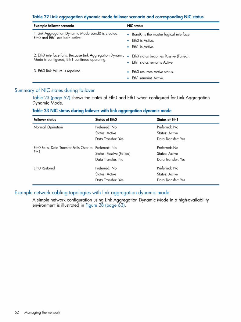
Table 22 Link aggregation dynamic mode failover scenario and corresponding NIC status
NIC statusExample failover scenario
1. Link Aggregation Dynamic Mode bond0 is created.Eth0 and Eth1 are both active.
• Bond0 is the master logical interface.
• Eth0 is Active.
• Eth1 is Active.
2. Eth0 interface fails. Because Link Aggregation DynamicMode is configured, Eth1 continues operating.
• Eth0 status becomes Passive (Failed).
• Eth1 status remains Active.
3. Eth0 link failure is repaired. • Eth0 resumes Active status.
• Eth1 remains Active.
Summary of NIC states during failoverTable 23 (page 62) shows the states of Eth0 and Eth1 when configured for Link AggregationDynamic Mode.
Table 23 NIC status during failover with link aggregation dynamic mode
Status of Eth1Status of Eth0Failover status
Preferred: NoPreferred: NoNormal OperationStatus: ActiveStatus: ActiveData Transfer: YesData Transfer: Yes
Preferred: NoPreferred: NoEth0 Fails, Data Transfer Fails Over toEth1 Status: ActiveStatus: Passive (Failed)
Data Transfer: YesData Transfer: No
Preferred: NoPreferred: NoEth0 RestoredStatus: ActiveStatus: ActiveData Transfer: YesData Transfer: Yes
Example network cabling topologies with link aggregation dynamic modeA simple network configuration using Link Aggregation Dynamic Mode in a high-availabilityenvironment is illustrated in Figure 28 (page 63).
62 Managing the network

Figure 28 Link aggregation dynamic mode in a single-switch topology
1. Servers
2. HP P4000
3. Storage cluster
How Adaptive Load Balancing worksAdaptive Load Balancing allows the storage system to use both interfaces simultaneously for datatransfer. Both interfaces have an active status. If the interface link to one NIC goes offline, the otherinterface continues operating. Using both NICs also increases network bandwidth.
Requirements for Adaptive Load BalancingTo configure Adaptive Load Balancing:
• Both NICs must be enabled.
• NICs must be configured to the same subnet.
• NICs can be connected to separate switches.
Which physical interface is preferredBecause the logical interface uses both NICs for data transfer, neither of the NICs in an AdaptiveLoad Balancing bond is designated as preferred.
Which physical interface is activeWhen the Adaptive Load Balancing bond is created, if both NICs are plugged in, both interfacesare active. If one interface fails, the other interface continues operating. For example, supposeMotherboard:Port1 and Motherboard:Port2 are bonded in an Adaptive Load Balancing bond. IfMotherboard:Port1 fails, then Motherboard:Port2 remains active.Once the link is fixed and Motherboard:Port1 is operational, it becomes active again.Motherboard:Port2 remains active.
Configuring network interface bonds 63

Table 24 Example Adaptive Load Balancing failover scenario and corresponding NIC status
NIC statusExample failover scenario
1. Adaptive Load Balancing bond0 is created.Motherboard:Port1 and Motherboard:Port2 are both active.
• Bond0 is the master logical interface.
• Motherboard:Port1 is Active.
• Motherboard:Port2 is Active.
2. Motherboard:Port1 interface fails. Because AdaptiveLoad Balancing is configured, Motherboard:Port2 continuesoperating.
• Motherboard:Port1 status becomes Passive (Failed).
• Motherboard:Port2 status remains Active.
3. Motherboard:Port1 link failure is repaired. • Motherboard:Port1 resumes Active status.
• Motherboard:Port2 remains Active.
Summary of NIC states during failoverTable 25 (page 64) shows the states of Motherboard:Port1 and Motherboard:Port2 when configuredfor Adaptive Load Balancing.
Table 25 NIC status during failover with Adaptive Load Balancing
Status of Motherboard:Port2Status of Motherboard:Port1Failover status
Preferred: NoPreferred: NoNormal OperationStatus: ActiveStatus: ActiveData Transfer: YesData Transfer: Yes
Preferred: NoPreferred: NoMotherboard:Port1 Fails, DataTransfer Fails Over toMotherboard:Port2
Status: ActiveData Transfer: Yes
Status: Passive (Failed)Data Transfer: No
Preferred: NoPreferred: NoMotherboard:Port1 RestoredStatus: ActiveStatus: ActiveData Transfer: YesData Transfer: Yes
Example network cabling topologies with Adaptive Load BalancingA simple network configuration using Adaptive Load Balancing in a high availability environmentis illustrated in Figure 29 (page 65).
64 Managing the network

Figure 29 Adaptive Load Balancing in a two-switch topology
1. Servers
2. HP P4000
3. Storage cluster
4. GigE trunk
Creating a NIC bondFollow these guidelines when creating NIC bonds:
PrerequisitesVerify that the speed, duplex, flow control, and frame size are all set properly on both interfacesthat are being bonded. These settings cannot be changed on a bonded interface or on either ofthe supporting interfaces.For detailed instructions about properly configuring these settings, see “Managing settings onnetwork interfaces” (page 50).
Bond guidelines
• Create a bond on a storage system before you add the storage system to a managementgroup.
• Create bonds of two interfaces.
• An interface can only be in one bond.
• Record the configuration information of each interface before you create the bond. Then, ifyou delete the bond, you can return to the original configuration if desired.◦ When you delete an Active-Passive bond, the preferred interface assumes the IP address
and configuration of the deleted logical interface.◦ When you delete a Link Aggregation Dynamic Mode or an Adaptive Load Balancing
bond, one of the interfaces retains the IP address of the deleted logical interface. TheIP address of the other interface is set to 0.0.0.0.
Configuring network interface bonds 65

• Ensure that the bond has a static IP address for the logical bond interface. The default valuesfor the IP address, subnet mask and default gateway are those of one of the physical interfaces.
• Verify on the Communication tab that the SAN/iQ interface is communicating with the bondedinterface.
CAUTION: To ensure that the bond works correctly, you should configure it as follows:• Create the bond on the storage system before you add it to a management group.
• Verify that the bond is created.If you create the bond on the storage system after it is in a management group, and if it doesnot work correctly, you might- Lose the storage system from the network- Lose quorum in the management group for a while.
See “Deleting a NIC bond” (page 237) for information about deleting NIC bonds using theConfiguration Interface.
Creating the bond1. Log in to the storage system.2. Select the TCP/IP category from the tree.3. On the TCP/IP tab, select both NICs to bond.4. Click TCP/IP Tasks, and select New Bond.5. Select a bond type from the drop-down list.6. Enter an IP address for the bond or accept the default.7. Enter the Subnet mask.8. (Optional) Enter the default gateway.9. Click OK.
NOTE: The storage system drops off the network while the bonding takes place. The changesmay take 2 to 3 minutes, during which time you cannot find or access the storage system.
10. Click OK to confirm the TCP/IP changes.A message opens, prompting you to search for the bonded storage system on the network.
Figure 30 Searching for the bonded storage system on the network
11. Search for the storage system by Host Name or IP address, or by Subnet/mask.
66 Managing the network

NOTE: Because it can take a few minutes for the storage system to re-initialize, the searchmay fail the first time. If the search fails, wait a minute or two and choose Try Again on theNetwork Search Failed message.
12. Verify the new bond interface.
Figure 31 Viewing a new Active-Passive bond
1. Bonded logical network interface
2. Physical interfaces shown as slaves
The bond interface shows as “bond0” and has a static IP address. The two physical NICsnow show as slaves in the Mode column.
13. (Optional, for Active-Passive bonds only) To change which interface is the preferred interfacein an Active-Passive bond, on the TCP Status tab select one of the NICs in the bond, and clickSet Preferred.
Verify communication setting for new bond1. Select a storage system, and open the tree below it.2. Select the TCP/IP Network category, and click the Communication tab.
Configuring network interface bonds 67

Figure 32 Verifying interface used for SAN/iQ communication
3. Verify that the SAN/iQ communication port is correct.
Viewing the status of a NIC bondYou can view the status of the interfaces on the TCP Status tab. Notice that in the Active-Passivebond, one of the NICs is the preferred NIC. In both the Link Aggregation Dynamic Mode bondand the Adaptive Load Balancing bond, neither physical interface is preferred.Figure 33 (page 68) shows the status of interfaces in an Active-Passive bond. Figure 34 (page 69)shows the status of interfaces in a Link Aggregation Dynamic Mode bond.
Figure 33 Viewing the status of an Active-Passive bond
1. Preferred interface
68 Managing the network

Figure 34 Viewing the status of a link aggregation dynamic mode bond
1. Neither interface is preferred
NOTE: If the bonded NIC experiences rapid, sequential Ethernet failures, the CMC may displaythe storage system as failed (flashing red) and access to data on that storage system fails. However,as soon as the Ethernet connection is reestablished, the storage system and the CMC display thecorrect information.
Deleting a NIC bondWhen you delete an Active-Passive bond, the preferred interface assumes the IP address andconfiguration of the deleted logical interface. The other NIC is disabled, and its IP address is setto 0.0.0.0.When you delete either a Link Aggregation Dynamic Mode or an Adaptive Load Balancing bond,one of the active interfaces in the bond retains the IP address of the deleted logical interface. Theother NIC is disabled, and its IP address is set to 0.0.0.0.1. Log in to the storage system, and expand the tree.2. Select the TCP/IP category from the tree.3. On the TCP/IP tab, select the bond interface or physical bond to delete.4. Click TCP/IP Tasks, and select Delete Bond.
Because the IP addresses changes, the Search Network window opens.
Configuring network interface bonds 69
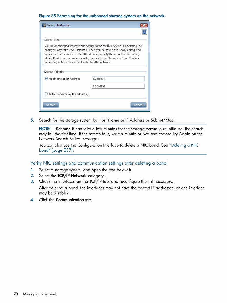
Figure 35 Searching for the unbonded storage system on the network
5. Search for the storage system by Host Name or IP Address or Subnet/Mask.
NOTE: Because it can take a few minutes for the storage system to re-initialize, the searchmay fail the first time. If the search fails, wait a minute or two and choose Try Again on theNetwork Search Failed message.You can also use the Configuration Interface to delete a NIC bond. See “Deleting a NICbond” (page 237).
Verify NIC settings and communication settings after deleting a bond1. Select a storage system, and open the tree below it.2. Select the TCP/IP Network category.3. Check the interfaces on the TCP/IP tab, and reconfigure them if necessary.
After deleting a bond, the interfaces may not have the correct IP addresses, or one interfacemay be disabled.
4. Click the Communication tab.
70 Managing the network

Figure 36 Verifying interface used for SAN/iQ communication
5. Verify that the SAN/iQ communication port is correct.
Disabling a network interfaceYou can disable the network interfaces on the storage system.
• You can only disable top-level interfaces. This includes bonded interfaces and NICs that arenot part of bonded interfaces.
• To ensure that you always have access to the storage system, do not disable the last interface.If you want to disable the last interface, first enable another interface.
CAUTION: If you disable an interface, be sure you enable another interface first. That way youalways have access to the storage system. If you disable all the interfaces, you must reconfigureat least one interface using the Configuration Interface to access the storage system. See“Configuring a network connection” (page 236).
To disable a network interface1. Log in to the storage system, and open the tree.2. Select the TCP/IP Network category.3. Select from the list on the TCP/IP tab window the interface to disable.4. Click TCP/IP Tasks, and select Edit.5. Click Disable Interface.6. Click OK.
A confirmation message opens. If you are disabling the only interface, the message warnsthat the storage system may be inaccessible if you continue.
7. Click OK.If the storage system for which you are disabling the interface is a manager in a managementgroup, a window opens which displays all the IP addresses of the managers in the managementgroup and a reminder to reconfigure the application servers that are affected by the update.
Disabling a network interface 71

Configuring a disabled interfaceIf one interface is still connected to the storage system but another interface is disconnected, youcan reconnect to the second interface using the CMC. See “Configuring the IP address manually”(page 54).If both interfaces to the storage system are disconnected, you must attach a terminal, or PC orlaptop to the storage system with a null modem cable and configure at least one interface usingthe Configuration Interface. See “Configuring a network connection” (page 236).
Using a DNS serverYou configure DNS at the management group level for all storage systems in the managementgroup. Use the DNS tab for the management group to change the settings.The storage system can use a DNS server to resolve host names. For example, if you enter a hostname to specify an NTP time server, the storage system will use DNS to resolve the host name toits IP address. For example, the time server in Boulder, Colorado has a host name oftime.nist.gov. DNS resolves this host name to its IP address of 192.43.244.18.
DNS and DHCPIf you configure the storage system to use DHCP to obtain an IP address, and if the DHCP serveris configured to provide the IP addresses of the DNS servers, then a maximum of three DNS serverswill automatically be added to the management group. These DNS servers are listed as IP addressesin the management group on the DNS tab. You can remove these DNS servers, but storage systemswill not be able to resolve host names until you enter a new DNS server.
DNS and static IP addressesIf you assigned a static IP address to the storage system and you want the storage system torecognize host names, you must manually add a DNS server to the management group DNS tab.
NOTE: If you initially set up the storage system to use DHCP, and then change the configurationto use a static IP address, the DNS server provided by DHCP will remain on the DNS tab. You canremove or change this DNS server.
Getting there1. In the navigation window, select a management group and log in.2. Select the DNS tab.
Adding the DNS domain nameAdd the name of the DNS domain in which the management group resides.1. Click DNS Tasks, and select Edit DNS Domain Name.2. Enter the DNS domain name.3. Click OK when you are finished.
Adding the DNS serverAdd up to three DNS servers for use with the management group.1. Click DNS Tasks, and select Edit DNS Servers.2. Click Add, and enter the IP address for the DNS server.3. Click OK.4. Repeat steps 1 through 3 to add up to three servers.
72 Managing the network
5. Use the arrows on the Edit DNS Servers window to order the servers.The servers will be accessed in the order they appear in the list.
6. Click OK when you are finished.
Adding domain names to the DNS suffixesAdd up to six domain names to the DNS suffix list (also known as the look-up zone). The storagesystem searches the suffixes first and then uses the DNS server to resolve host names.1. On the DNS tab, click DNS Tasks, and select Edit DNS Suffixes.2. Click Add to display the Add DNS Suffixes window.3. Enter the DNS suffix name. Use the domain name format.4. Click OK.5. Repeat steps 1 through4 to add up to six domain names.6. Click OK when you are finished.
Editing a DNS serverChange the IP address for a DNS Server in the list.1. In the navigation window, select a management group and log in.2. Select the DNS tab.3. Select the server to edit.4. Click DNS Tasks, and select Edit DNS Servers.5. Select the server again, and click Edit.6. Enter the new IP address for the DNS server, and click OK.
Editing a domain name in the DNS suffixes listChange a domain name of a management group.1. In the navigation window, select a management group and log in.2. Select the DNS tab.3. Click DNS Tasks, and select Edit DNS Domain Name.4. Enter the change to the domain name.5. Click OK.
Removing a DNS serverRemove a DNS server from the list.1. In the navigation window, select a management group and log in.2. Select the DNS tab.3. Select the server to remove from the DNS Servers list.4. Click DNS Tasks, and select Edit DNS Servers.5. Select the name again in the Edit DNS Servers window.6. Click Remove.7. Click OK to remove the DNS server from the list.
Removing a domain suffix from the DNS suffixes list1. In the navigation window, select a management group and log in.2. Select the DNS tab.3. Select the suffix to remove.4. Click DNS Tasks, and select Edit DNS Suffixes.5. Select the name again in the Edit DNS Suffixes window.
Using a DNS server 73

6. Click Remove.7. Click OK to remove the DNS suffix from the list.
Setting up routingThe Routing tab displays the routing table. You can specify static routes and/or a default route.
NOTE: If you specify a default route here, it will not survive a reboot or shutdown of the storagesystem. To create a route that will survive a storage system reboot or shut down, you must enter adefault gateway on the TCP/IP tab. See “Configuring the IP address manually” (page 54).
Information for each route listed includes the device, the network, gateway, mask, and flags.
Adding routing information1. In the navigation window, select a storage system and log in.2. Open the tree, and select the TCP/IP Network category.3. Select the Routing tab.4. Click Routing Tasks, and select Edit Routing Information.5. Click Add.6. Select the port to use for routing in the Device list.7. Enter the IP address portion of the network address in the Net field.8. Enter the IP address of the router in the Gateway field.9. Select the netmask.10. Click OK.11. Use the arrows on the routing table panel to order devices according to the configuration of
your network.The storage system attempts to use the routes in the order in which they are listed.
Editing routing informationYou can only edit optional routes you have added.1. In the navigation window, select a storage system, and log in.2. Open the tree, and select the TCP/IP Network category.3. Select the Routing tab.4. On the Routing tab, select the optional route to change.5. Click Routing Tasks, and select Edit Routing Information.6. Select a Route, and click Edit.7. Change the relevant information.8. Click OK.
Deleting routing informationYou can only delete optional routes you have added.1. In the navigation window, select a storage system, and log in.2. Open the tree, and select the TCP/IP Network category.3. Select the Routing tab.4. On the Routing tab, select the optional route to delete.5. Click Routing Tasks, and select Edit Routing Information.6. Select the routing information row to delete.7. Click Delete.8. Click OK on the confirmation message.
74 Managing the network

Configuring storage system communicationUse the Communication tab to configure the network interface used by the storage system tocommunicate with other storage systems on the network and to update the list of managers thatthe storage system can communicate with.
Selecting the interface used by the SAN/iQ softwareThe SAN/iQ software uses one network interface for communication with other storage systemson the network. In order for clustering to work correctly, the SAN/iQ software communicationinterface must be designated on each storage system. The interface can be
• A single NIC that is not part of a bond
• A bonded interface consisting of two bonded NICs
NOTE: Only NICs that are in the Active or Passive (Ready) state can be designated as thecommunication interface. You cannot make a disabled NIC the communication interface.
When you initially set up a storage system using the Configuration Interface, the first interface thatyou configure becomes the interface used for the SAN/iQ software communication.To select a different communication interface:1. In the navigation window, select the storage system, and log in.2. Open the tree, and select the TCP/IP Network category.3. Select the Communication tab to bring that window to the front.
Figure 37 Selecting the SAN/iQ software network interface and updating the list of managers
4. Select an IP address from the list of Manager IP Addresses.5. Click Communication Tasks, and select Select SAN/iQ Address.6. Select an Ethernet port for this address.7. Click OK.
Now, this storage system connects to the IP address through the Ethernet port you selected.
Configuring storage system communication 75

Updating the list of manager IP addressesUpdate the list of manager IP addresses to ensure that a manager running on this storage systemis communicating correctly with all managers in the management group.
RequirementsEach time you update the list of managers, you must reconfigure application servers that use themanagement group to which this storage system belongs. Only update the list mode if you havereason to believe that there is a problem with the communication between the other managers inthe group and the manager on this storage system.To update the list of IP addresses1. In the navigation window, select a storage system, and log in.2. Open the tree, and select the TCP/IP Network category.3. Select the Communication tab.
Figure 38 Viewing the list of manager IP addresses
4. Click Communication Tasks, and select Update Communications List.The list is updated with the current storage system in the management group and a list of IPswith every manager’s enabled network interfaces.A window opens which displays the manager IP addresses in the management group and areminder to reconfigure the application servers that are affected by the update.
76 Managing the network
5 Setting the date and timeThe storage systems within management groups use the date and time settings to create a timestamp when data is stored. You set the time zone and the date and time in the management group,and the storage systems inherit those management group settings.
• Using network time protocolConfigure the storage system to use a time service, either external or internal to your network.
• Setting the time zoneSet the time zone for the storage system. The time zone controls the time stamp on volumesand snapshots.If you use NTP, decide what time zone you will use. You can use either GMT on all of yourmanagement groups, or you can set each management group to its local time.If you do not set the time zone for each management group, the management group uses theGMT time zone, whether or not you use NTP.
• Setting date and timeSet the date and time on the management group(s) if not using an NTP time service.
Management group timeWhen you create a management group, you set the time zone and the date and time while goingthrough the Management Groups, Clusters and Volumes wizard. This ensures that all the storagesystems in the management group have the same time setting.
Getting there1. In the network window, select a management group and log in.2. Click the Time tab.
Refreshing the management group timeUse Refresh All to update the view of the time on all storage systems in the management group.This view is not updated automatically, so you must refresh the view to verify that the time settingson the storage systems are what you expect.1. Select a management group.2. Click the Time tab.3. Select Time Tasks, and select Refresh All.
After processing, all storage systems display the current time.
Using NTPNetwork time protocol servers (NTP) can manage the time for the management group instead ofusing the local system time. NTP updates occur at five-minute intervals. If you do not set the timezone for the management group, it uses GMT.
Management group time 77
NOTE: When using a Windows server as an external time source for an storage system, youmust configure W32Time (the Windows Time service) to also use an external time source. Thestorage system does not recognize the Windows server as an NTP server if W32Time is configuredto use an internal hardware clock.1. Click Time Tasks, and select Add NTP Server.2. Enter the IP address of the NTP server you want to use.3. Decide whether you want this NTP server to be designated preferred or not preferred.
NOTE: A preferred NTP server is one that is more reliable, such as a server that is on alocal network. An NTP server on a local network would have a reliable and fast connectionto the storage system. Not preferred designates an NTP server to be used as a backup if apreferred NTP server is not available. An NTP server that is not preferred might be one thatis located elsewhere or has a less reliable connection.
4. Click OK.The NTP server is added to the list on the NTP tab.The NTP servers are accessed in the order you add them, and preferred servers are accessedbefore non-preferred servers. The first server you add, if it is marked preferred, has the highestorder of precedence. The second server you add takes over as a time server if the preferredserver fails.
Editing NTP serversChange whether an NTP server is preferred or not.1. Select an NTP server in the list.2. Click Time Tasks, and select Edit NTP Server.3. Change the preference of the NTP server.4. Click OK.
The list of NTP servers displays the changed NTP server in the list.
NOTE: To change the IP address of an NTP server, you must remove the server no longerin use and add a new NTP server.
Deleting an NTP serverYou may need to delete an NTP server:
• If the IP address of that server becomes invalid
• If you no longer want to use that server
• If you want to change the order of servers in the list
Delete an NTP server1. Select an NTP server in the list on the Time tab window.2. Click Time Tasks, and select Delete NTP Server.3. Click OK on the confirmation window.
The list of NTP servers refreshes the list of available servers.
Changing the order of NTP serversThe window displays the NTP servers in the order you added them.
78 Setting the date and time

The server you added first is the one accessed first when time needs to be established. If this NTPserver is not available for some reason, the next NTP server that was added, and is preferred, isused for time serving.To change the order of access for time servers1. Delete the server whose place in the list you want to change.2. Add that same server back into the list.
It is placed at the bottom of the list, and is the last to be accessed.
Editing the date and timeYou initially set the date and time when you create the management group using the ManagementGroups, Clusters and Volumes wizard. If necessary, you can edit these settings later.1. Select the management group.2. Select the Time tab to bring it to the front.3. Click Time Tasks, and select Edit Date, Time, Time Zone.4. Change the date and time to the correct date and time for that time zone.
• In the Date group box, set the year, month, and day.
• In the Time group box, highlight a portion of the time and increase or decrease it withthe arrows. You may also enter in the time directly.
• Select a time zone for the Time Zone drop-down list.
NOTE: If you use an NTP server, you have the option of setting the time zone only.
5. Click OK.A warning message informs you that there may be a slight time lag for a reset to take effect.
6. Click OK.
Editing the time zone onlyYou initially set the time zone when you create the management group. You can change the timezone later, if necessary.If you do not set the time zone for each management group, the management group uses GMT,whether or not you use NTP. Files display the time stamp according to this local time zone.1. Click Time Tasks, and select Edit Time Zone.
2. From the drop-down list, select the time zone in which this management group resides.
3. Click OK.Note the change in the Time column of the Time tab window.
Editing the date and time 79

6 Administrative users and groupsWhen you create a management group, the SAN/iQ software configures two default administrativegroups and one default administrative user. You can add, edit, and delete additional administrativeusers and groups. All administrative users and groups are managed at the management grouplevel.
Getting thereIn the navigation window, log in to the management group, and select the Administration node.
Managing administrative usersWhen you create a management group, one default administrative user is created. Use the defaultuser and/or create new ones.
Default administrative userThe user who is created when you create a management group becomes a member of the FullAdministrator group by default.
Adding a new administrative userAdd administrative users as necessary to provide access to the management functions of theSAN/iQ software.1. Log in to the management group, and select the Administration node.2. Click Administration Tasks in the tab window, and select New User.3. Enter a User Name and Description.4. Enter a password, and confirm that password.5. Click Add in the Member Groups section.6. Select one or more groups to which you want the new user to belong.7. Click OK.8. Click OK to finish adding the administrative user.
Editing administrative usersEach management group has an administration node in the tree below it. You can add, edit, andremove administrative users here. Editing administrative users includes changing passwords andgroup memberships of administrative users.
Changing a user’s description1. Log in to the management group, and select the Administration node.2. Click Administration Tasks in the tab window, and select Edit User.3. Change the User Description as necessary.4. Click OK to finish.
Changing a user’s password1. Log in to the management group, and select the Administration node.2. Click Administration Tasks in the tab window, and select Edit User.3. Enter a new password, and confirm that password.4. Click OK to finish.
80 Administrative users and groups

Adding group membership to a user1. Log in to the management group, and select the Administration node.2. Select a user in the Users table.3. Click Administration Tasks in the tab window, and select Edit User.4. Click Add in the Member Groups section.5. Select the groups to which to add the new user.6. Click OK.7. Click OK to finish editing the administrative user.
Removing group membership from a user1. Log in to the management group, and select the Administration node.2. Select a user in the Users table.3. Click Administration Tasks in the tab window, and select Edit User.4. In the Member Groups section, select the group from which to remove the user.5. Click Remove.6. Click OK to finish editing the administrative user.
Deleting an administrative user1. Log in to the management group, and select the Administration node.2. Select a user in the Users table.3. Click Administration Tasks in the tab window, and select Delete User.4. Click OK.
NOTE: If you delete an administrative user, that user is automatically removed from anyadministrative groups.
Managing administrative groupsWhen you create a management group, two default administrative groups are created. Use thesegroups and/or create new ones.
Default administrative groupsThe two default administrative groups and the permissions granted to those groups are listed inTable 26 (page 81). Users assigned to either of these groups assume the privileges associatedwith that group.
Table 26 Using default administrative groups
Management capabilities assigned to groupName of group
Manage all functions (read/write access to all functions)Full_Administrator
View-only capability to all functions (read only)View_Only_Administrator
Administrative groups can have:
• Different levels of access to the storage system, such as read/write
• Access to different management capabilities for the SAN, such as configuring networkcapabilities
Adding administrative groupsWhen you create a group, you also set the management permissions for the users assigned to thatgroup. The default setting for a new group is Read Only for each category.
Managing administrative groups 81

1. Log in to the management group, and select the Administration node.2. Click Administration Tasks in the tab window, and select New Group.3. Enter a Group Name and optional Description.4. Select the permission level for each function for the group you are creating. See Table 27
(page 82).
Table 27 Descriptions of group permissions
Activities controlled by this areaManagement area
User can change other administrative users’ passwords.Change Password
User can set the RAID configuration for the storagesystem. Shut down disks, restart RAID, and hot-swapdisks. Create management groups.
Management Groups, RAID, Drive Hot Swap
User can choose type of network connection, set thetime and time zone for the management group, identifythe Domain Name Server, and use SNMP.
Network
User can add administrators and upgrade the SAN/iQsoftware.
Storage System Administration, Boot, Upgrade
User can view reports about the status of the storagesystem.
System and Disk Report
What the permission levels mean
• Read Only—User can only view the information about these functions.
• Read-Modify—User can view and modify existing settings for these functions.
• Full—User can perform all actions (view, modify, add new, delete) in all functions.1. Add a user to the group.
• Click Add in the Users section.
• Select one or more users to add to the group.
• Click Add.2. Click OK to finish creating a new group.
Editing administrative groupsEach management group has an administration node in the tree below it. You can add, edit, andremove administrative groups here. Editing an administrative group includes changing thedescription, permissions, and users for the group.
Change the description of a group1. Log in to the management group, and select the Administration node.2. Click Administration Tasks in the tab window, and select Edit Group.3. Change the Description as necessary.4. Click OK to finish.
Changing administrative group permissionsChange the management capabilities available to members of a group.1. Log in to the management group, and select the Administration node.2. Click Administration Tasks in the tab window, and select Edit Group.
Administrative groups can have:
82 Administrative users and groups

• Different levels of access to the storage system, such as read/write
• Access to different management capabilities for the storage system, such as creatingvolumesWhen you create a group, you also set the management capabilities available to membersof a group. The default setting for a new group is Read Only for each category.
3. Click the permission level for each function for the group you are creating.See “Descriptions of group permissions” (page 82) for a description of the permission levels.
4. Click OK to finish.
Adding users to an existing group1. Log in to the management group, and select the Administration node.2. Click Administration Tasks in the tab window, and select Edit Group.3. Click Add in the Users section.4. Select one or more users from list of administrative users to add to the group.5. Click Add.6. Click OK to finish creating a new group.
Removing users from a group1. Log in to the management group, and select the Administration node.2. Click Administration Tasks in the tab window, and select Edit Group.3. Select one or more users to remove from the group.4. Click Remove.5. Click OK to finish.
Deleting administrative groupsDelete all users from a group before you delete the group.1. Log in to the management group, and select the Administration node.2. Click Administration Tasks in the tab window, and select Delete Group.3. Click OK on the confirmation window.4. Click OK to finish.
Managing administrative groups 83

7 Monitoring the SANMonitor the SAN for usage; to ensure that best practices are followed when changes are made,such as adding additional storage systems to clusters; and maintain the overall health of the SAN.Tools for monitoring the SAN include the SAN Status Page, the Configuration Summary and theBest Practice table, the Alarms and Events features, including customized notification methods, anddiagnostic tests and log files available for the storage systems.
Monitoring SAN statusAfter you have created at least one management group in the CMC, the CMC searches for storagesystems, and then opens to the SAN Status Page, shown in Figure 39 (page 85). The SAN StatusPage brings together multiple categories of information to provide one location from which tomonitor multiple features of the SAN at one time. Use the SAN Status Page to monitor the followingitems:
• Best Practices—Ensure that the SAN configurations meet best practice recommendations fordata protection, SAN and data availability, and network connectivity, failover, andperformance.
• Configurations—Monitor SAN configurations to ensure optimum capacity management,performance, availability, and ease of management.
• Utilization—Track cluster use, space on the SAN, and summary information about configurationsthat affect performance and scalability.
• Data protection—Ensure that the SAN is configured for ongoing maximum data protectionwhile scaling capacity and performing system maintenance.
• Alarms—Manage the SAN health by easily tracking issues that may arise.
Configuring the SAN Status PageCustomize the information displayed on the Status Page.
84 Monitoring the SAN

Figure 39 SAN Status Page
1. Status Page toolbar
2. Content panes
Customizing the Status Page contentThe SAN Status Page includes seven categories of information, displayed in content panes. Youcan customize the layout of the content panes, as well customize the information displayed in eachcontent pane.
• Best Practice Summary—includes all the best practice items that appear on the ConfigurationSummary node. View the information by management group. Select Show Details to turn onand off the pop-up descriptions of the best practices.
• Cluster Utilization Summary—displays cluster utilization information by management groupor by utilization percentage by cluster.
• Alarms—summarizes alarms by management group
• Configuration Summary—displays configuration summary information about the SAN bymanagement group. Additional views on the Status Page content pane include summary byconfiguration type and summary by optimum number. Optimum number refers to number ofitems by category, displayed in descending order, according to the relative number for acategory. For example, six storage systems in a cluster are closer to the optimum number forthat cluster (10) than they are for the number of storage systems in a management group (20).Therefore, as displayed in the Optimum Number view, the six storage systems in the clusterwill be above those same six storage systems in the management group.
• Volume Data Protection Level—lists volumes by their Network RAID level. Network RAID 0provides no data protection, while the other Network RAID levels offer varying levels of dataprotection. Filter volumes by name to control the view by grouping volumes that share namingconventions.
• Upgrades Summary—identifies which components of the SAN are up-to-date and which needupgrading.
• SAN Summary—provides a comprehensive overview of the entire SAN, including aggregatedcluster space.
Monitoring SAN status 85

Customizing the Status Page layoutCustomize the layout of the SAN Status Page to highlight the information most important to you.All customizations are retained when the CMC is closed and restarted. If the Status Page is undockedwhen the CMC is closed, it will be undocked when the CMC is started again.Drag-and-drop content panes to change their position on the page. The layout is three columns bydefault. Drag a content pane and drop it on another content pane. The two panes switch places.Move all the panes to a two-column layout, or rearrange the three-column layout.
TIP: If you have changed the layout to fewer than three columns, and you want to re-create anadditional column, drag a content pane to the top right corner of the page.
Minimize and expand panes to control which information is given priority. As priorities change,change which content panes are minimized and expanded.
Using the SAN Status PageWhen you log into a management group, the Status Page shows the current information for thatmanagement group. After the initial log in, the Status Page refreshes frequently, but not immediately.For example, after creating a new volume in a cluster, it takes several seconds for the new volumeto appear on the Status Page.When reviewing information in the content panes, many items will display an arrow to the left ofthe item. Clicking on that arrow jumps to that item in the CMC, or, in a few cases, to the mostclosely related category. For example, clicking the arrow next to any of the Best Practice Summaryitems jumps to the management group containing those Best Practice items.The SAN Status Page contains toolbar buttons to dock and undock the Status Page from the CMC,and to log into management groups. If the Status Page is undocked, and you close the CMC, whenyou open it next time, you must log into the management groups to retrieve the information for theStatus Page. Use the button on the Status Page toolbar to log in to the management groups.
Alarms and events overviewThe CMC displays the following types of events, based on their severity:
• Informational—Provides status information about user activities (such as, creating a volume)and system actions and status (such as, a storage system is up). These types of events do notrequire taking action and are available only from the Events node for each managementgroup.
• Warning—Provides important information about a system component that may requiretaking action. These types of events are visible in both the Alarms window (for all managementgroups) and the Events node (for the management group where the alarm occurred).
• Critical—Provides vital information about a system component that requires user action.These types of events are considered to be alarms and are visible in both the Alarms window(for all management groups) and the Events node (for the management group where the alarmoccurred).
The system monitors over 400 different events and can send notification of events using email orSNMP or both.
NOTE: Be sure to set up notification of events for each management group. See “Setting up emailnotification” (page 92).
For more information about working with alarms and events, see “Working with alarms” (page 88)and “Configuring events” (page 89).Figure 40 (page 87) shows the Events node and its parts.
86 Monitoring the SAN
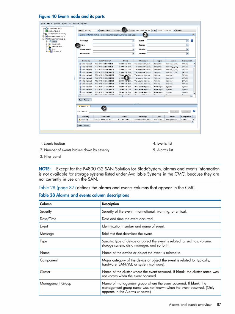
Figure 40 Events node and its parts
4. Events list1. Events toolbar
5. Alarms list2. Number of events broken down by severity
3. Filter panel
NOTE: Except for the P4800 G2 SAN Solution for BladeSystem, alarms and events informationis not available for storage systems listed under Available Systems in the CMC, because they arenot currently in use on the SAN.
Table 28 (page 87) defines the alarms and events columns that appear in the CMC.
Table 28 Alarms and events column descriptions
DescriptionColumn
Severity of the event: informational, warning, or critical.Severity
Date and time the event occurred.Date/Time
Identification number and name of event.Event
Brief text that describes the event.Message
Specific type of device or object the event is related to, such as, volume,storage system, disk, manager, and so forth.
Type
Name of the device or object the event is related to.Name
Major category of the device or object the event is related to, typically,hardware, SAN/iQ, or system (software).
Component
Name of the cluster where the event occurred. If blank, the cluster name wasnot known when the event occurred.
Cluster
Name of management group where the event occurred. If blank, themanagement group name was not known when the event occurred. (Onlyappears in the Alarms window.)
Management Group
Alarms and events overview 87
Table 28 Alarms and events column descriptions (continued)
DescriptionColumn
Name of the storage system that posted the event.Hostname
User that generated the event, such as system (software) or a user name.Source
Working with alarmsThe Alarms window is always visible at the bottom of the CMC and displays all warning andcritical events for all management groups you are logged in to. Use the column headings to sortthe list of alarms. Double-click an alarm to see more details.Review alarms regularly, especially the critical ones, and take the appropriate action to resolvethe alarm. Alarms stay in the Alarms window until the situation is resolved. A warning or criticalicon also appears in the navigation window tree next to the item that has the warning or criticalevent.For definitions of the event types and columns, see “Alarms and events overview” (page 86).
NOTE: An Alerts tab will also appear in two configurations: if storage systems in a managementgroup are running a mix of SAN/iQ software versions, including pre-9.0 versions, or if monitoringmultiple management groups, at least one of which is running pre-9.0 software. In these cases,only the Alerts tab will display alarms and events for the management group. When all storagesystems are upgraded to 9.0 or later, the Alerts tab is not shown, and the Events node and Alarmstab will reflect all alarms and events.
Filtering the alarms list1. In the navigation window, log in to the management group.2. In the Alarms window, enter text to use as a filter in the Alarm Filter field.
The text must appear somewhere in one or more alarms and is case sensitive.3. Click Filter.
The list of alarms changes to display only those that contain the filter text.4. To display all alarms, click Clear to remove the filter.
Viewing and copying alarm details1. In the navigation window, log in to the management group.2. In the Alarms window, double-click an alarm.3. For assistance with resolving the alarm, click the link in either the Event field or the Resolution
field.The link opens to a database that contains advisories and documents that may have additionalinformation about the event and how to resolve it. If no results are found, no advisories thatdirectly apply to that event have been published yet.
4. Click Previous Alarm or Next Alarm to view the details of other alarms.5. To paste the event details into a document or email message, click Copy to copy the details
to the clipboard.6. Click Close to close the Alarm details window.
Viewing alarms in a separate windowView the alarms in a separate window that you can resize and move to a convenient location onthe screen. Filter alarms, view alarm details, and export alarms from this window.
88 Monitoring the SAN

1. In the navigation window, log in to the management group.2. In the Alarms window, click Alarm Tasks, and select Open Alarms in Window.3. To close the window, click Close.
Exporting alarm data to a .csv file1. In the navigation window, log in to the management group.2. In the Alarms window, click Alarm Tasks, and select Export Alarms.3. In the Filename field, enter a path and file name.
If you enter just a file name, the file is stored in the directory that the CMC is installed in.4. Click OK.
Configuring eventsThe Events node displays all events for the current management group, according to the dates inthe From and To fields in the toolbar. By default, the system displays about 1,000 events, brokendown into pages of 100 events. Scroll through the current page of events and use the << and >>buttons to display different pages. The title bar of the Filters panel lists the number and severity ofthe events, shown in Figure 40 (page 87).For definitions of the event types and columns, see “Alarms and events overview” (page 86).
Changing the event retention period
NOTE: Because of space constraints, retention periods longer than one month are not guaranteed.
1. In the navigation window, log in to the management group.2. Select Events in the tree.3. Click Event Tasks, and select Edit Event Log Policy.4. Change the event retention period. The default is one month.5. Click OK.
Setting up remote log destinationsUse remote log destinations to automatically write all events for the management group to acomputer other than the storage system. For example, direct the event data to a single log serverin a remote location.You must also configure the destination computer to receive the log files by configuring syslog onthe destination computer. The syslog facility to use is local5, and the syslog levels are LOG_INFO,LOG_WARNING, LOG_CRIT. See the syslog documentation for that computer for informationabout configuring syslog.To set up remote log destinations:1. In the navigation window, log in to the management group.2. Select Events in the tree.3. Click Event Tasks, and select Edit Remote Log Destinations.4. In the Destinations field, enter the IP address or host name of the computer that will receive
the events.5. Select the event severities to include.6. To set up a second remote destination, enter the appropriate information.7. Click OK.
Viewing events in a separate windowView the events in a separate window. Resize and move the window to a convenient location onyour screen.
Configuring events 89

1. In the navigation window, log in to the management group.2. Select Events in the tree.3. Click Event Tasks, and select Open Events in Window.
The events open in a separate window. Use this window to filter, view details, and exportevents.
4. To close the window, click Close.
Working with eventsThe Events node offers multiple ways to manage and use event data. Filter events to control theinformation displayed, and export the data for use in a spreadsheet or other analysis tool.
Viewing new eventsWhen new events occur after you log in to a management group, (New) appears next to the Eventsnode.To view new events:1. Click New Events on the toolbar to bring in the newest events.2. Sort by the Date/Time column to view the newest events.
Filtering the events listTo filter events you must first log in to the management group and select Events in the tree. Filterevents listed in the Events node the following ways:• Using the Filters list
• Changing the date range
• Using the filters panelTo use the Filters list:1. From the Filters list, select an option to filter on.
Options in bold are predefined filters you cannot change. Options that are not bold are customfilters that you have saved from the filters panel, described in “Saving filter views” (page 91).
2. Click Apply.To remove the filter, click Reset.
To change the date range:1. In the From list, select Choose From, and select the date.2. Click OK.3. In the To list, select Choose To, and select the date.4. Click OK.5. Click Update.
Combine these date range filters with the options available in the filters panel described below.
To use the filters panel:
1. In the Events window, open the filters panel by clicking the expand button (right sidebelow the toolbar).
2. Use the filter lists to narrow the list of events.If you select options from more than one filter list, the system does an “and,” so that all of theselected options must apply to an event for the event to stay in the Events list.
3. Click Apply on the Events toolbar.The events list displays only those events matching the selected criteria.
90 Monitoring the SAN

To remove the filters and view all events, click Reset.
Saving filter viewsSave filter views for later use. Custom filters appear in the Filters list in the toolbar below theboldface list of generic filters. Custom filters are available for use with any management groupfrom this installation of the CMC.1. Click Events Tasks, and select Save Current View as Filter.2. Give the filter settings a name and click Save.
Deleting custom filters1. Click Event Tasks, and select Delete Filter.2. Select the custom filters to delete.3. Click OK.4. Click Delete to delete the selected custom filters.
Viewing event details1. In the navigation window, log in to the management group.2. Select Events in the tree.3. In the Events list, double-click an event.4. For assistance with resolving the event, click the link in either the Event field or the Resolution
field.The link opens a database that contains advisories and documents that may have additionalinformation about the event and how to resolve it. If no results are found, no advisories thatdirectly apply to that event have been published yet.
5. Click Previous Event or Next Event to display the details of other events.6. (Optional) To paste the event details into a document or email message, click Copy to copy
the details to the clipboard.7. Click Close to close the Event Details window.
Copying events to the clipboard1. In the navigation window, log in to the management group.2. Select Events in the tree.3. Do one of the following:
• Select one or more events, click Event Tasks, and select Copy Selected to Clipboard.
• Click Event Tasks, and select Copy All to Clipboard.
Exporting event data to a .csv or .txt file1. In the navigation window, log in to the management group.2. Select Events in the tree.3. Click Event Tasks, and select Export Events.4. In the Filename field, enter a path and file name.
If you enter just a file name, the file is stored in the directory that the CMC is installed in.To select a different location or .txt format, click Browse.
5. Click OK.
Working with events 91

Setting up email notificationTo set up email notification of events, you must set up the following:• Email server
• Email recipients
Setting up the email serverWhen you configure a management group, you configure email notification for events by settingup the email server to send events and then adding email recipients to receive notification basedon event severity. Change these settings later, if necessary, by using the Email window found underthe Events node in the management group tree.1. In the navigation window, log in to the management group.2. In the tree, select Events→Email.3. Click Email Tasks, and select Edit Email Settings.4. In the Server IP/Hostname field, enter the IP address or host name of your email (SMTP) server.5. In the Server Port field, enter the email port.
The standard port is 25.6. In the Sender Address field, enter the email address, including the domain name, to use as
the sender for notifications.The system automatically adds the host name of the storage system in the email From field,which appears in many email systems. This host name helps identify where the event occurred.
7. Do one of the following:• To save your changes and close the window, click Apply.
• To save your changes, close the window, and send a test email message, click Applyand Test.
If you do not complete the email configuration, an alarm appears until you do so. Your changesare saved, but the test function does not work until you complete the configuration, including atleast one email recipient.
NOTE: In some configurations designed to prevent spam, mail servers may start dropping multipleemails if too many are being sent from a single source. During some SAN/iQ operations, multiplealarms may be generated while the operation progresses. If you have a mail server configured tofilter spam, you may not receive some emails.
TIP: Add the sender email address to your safe senders list to ensure the system emails arereceived.
Setting up email recipientsSet up email notification for events for each management group. After setting up the email server,add email recipients to receive notification based on event severity.
NOTE: To temporarily disable email notification to a recipient, possibly because you are doingsomething that would cause many event emails, you can deselect all of the severities. This generatesan alarm that persists until you set at least one severity again for the recipient.
To set up email recipients:1. In the navigation window, log in to the management group.2. In the tree, select Events→Email.3. Click Email Tasks, and select Edit Email Settings.
92 Monitoring the SAN
4. Click Add Recipient.5. In the Address field, enter the email address.6. Select the following:
• Severity of the events
• Message type
• Language7. Click OK.8. Click Apply or Apply and Test.
Setting up SNMPThe management group can be monitored using an SNMP client. You can also enable SNMP trapsto receive system alerts. The Management Information Base (MIB) is read-only and supports SNMPversions 1 and 2c. See “Installing the LeftHand Networks MIB” (page 96) for a list of MIBs.After installing SAN/iQ version 9.0, the SNMP agent on the storage system is enabled by defaultand allows read-only access using the community string public. You can change this configuration,unless you are using HP Insight Remote Support, which requires the community string must be setto public. To receive notification of events, you must configure SNMP traps.If using the HP System Management Homepage, view the SNMP settings there. You can also startSNMP and send test v1 traps.
Enabling SNMP agentsMost storage systems allow enabling and disabling SNMP agents. After installing version 9.0,SNMP will be enabled on the storage system by default.Configuring SNMP includes these tasks:
• Enabling the SNMP Agent and adding a community string, if necessaryThe community string acts as an authentication password. It identifies hosts that are allowedread-only access to the SNMP data. The community public typically denotes a read-onlycommunity. This string is entered into an SNMP client when attempting to access the system.
• Configuring access control
Enabling the SNMP agent1. In the navigation window, log in to the management group.2. In the tree, select Events→SNMP.3. Click SNMP Tasks and select Edit SNMP General Settings.4. Select the Enabled radio button to activate the SNMP Agent fields.5. Enter the Community String. If using Insight Remote Support, the community string must be set
to Public.6. [Optional] Enter System Location information for the storage system.
For example, this information may include the address, building name, room number, and soon.
7. [Optional] Enter System Contact information.Normally this will be the SAN/iQ administrator information, such as email address or phonenumber for the person to contact about the storage system.
8. Click OK.9. Continue with configuring access control for SNMP clients.
Setting up SNMP 93

Configuring access control for SNMP clientsEnable the SNMP agent and configure access control for SNMP clients. Enter either a specific IPaddress and the IP Netmask as None to allow a specific host to access SNMP, or specify theNetwork Address with its netmask value so that all hosts matching that IP and netmask combinationcan access SNMP.
NOTE: Use the CMC ping feature to verify IP addresses while configuring access control. See“Pinging an IP address” (page 54).
Adding an SNMP client1. In the navigation window, log in to the management group.2. In the tree, select Events→SNMP.3. Click SNMP Tasks, and select Edit SNMP General Settings.4. In the Access Control section, click Add to add an SNMP client that to use for viewing SNMP.
Add SNMP clients by specifying either IP addresses or host names.For HP remote support, add the CMS for HP Insight Remote Support.
5. Do one of the following:• Select By Address and enter the IP address, then select an IP Netmask from the list. Select
Single Host if adding only one SNMP client.• Select By Name and enter a host name.
That host name must exist in DNS and the management group must be configured withDNS for the client to be recognized by the host name.
6. Click OK to add the entry to the Access Control list.7. Click OK in the Edit SNMP Settings window to finish.
Editing access control entriesAfter installing version 8.5 or later, by default, access control is open from any system using the“public” community string. This access control entry is listed as “default.” If you delete this entryand want to add it back in, use the By Name option and enter “default” as the name.1. In the navigation window, log in to the management group.2. In the tree, select Events→SNMP.3. Click SNMP Tasks, and select Edit SNMP General Settings.4. Select the Access Control entry from the list.5. Click Edit.6. Change the appropriate information.7. Click OK.8. Click OK on the Edit SNMP Settings window when finished.
Deleting access control entries1. In the navigation window, log in to the management group.2. In the tree, select Events→SNMP.3. Click SNMP Tasks and select Edit SNMP General Settings.4. Select a client listed in the Access Control list and click Delete.5. Click OK to confirm.6. Click OK on the Edit SNMP Settings window when finished.
94 Monitoring the SAN

Disabling the SNMP agentDisable the SNMP Agent if no longer using SNMP applications to monitor the network of storagesystems.
Disabling SNMP1. In the navigation window, log in to the management group.2. In the tree, select Events→SNMP.3. Click SNMP Tasks, and select Edit SNMP General Settings.4. Select Disable SNMP Agent.
Note that the Agent Status field now shows disabled. The SNMP client information remainslisted, but cannot be used.
Adding SNMP trapsVerify that SNMP is enabled, which it is by default.Add a Trap Community String, which is used for client-side authentication, and trap recipients.1. In the navigation window, log in to the management group.2. In the tree, select Events→SNMP.3. Click SNMP Tasks and select Edit SNMP Traps Settings.4. Enter the Trap Community String.
The trap community string does not have to be the same as the community string used foraccess control, but it can be.
5. Click Add to add trap recipients.6. Enter the IP address or host name for the SNMP client that is receiving the traps.
For HP remote support, add the CMS for HP Insight Remote Support.7. Select the Trap Version.
Version 1 is required for HP remote support.8. Click OK.9. Repeat steps 5 through 8 for each trap recipient.10. Click OK on the Edit SNMP Traps window when finished adding hosts.
Editing trap recipients1. Log in to the storage system and expand the tree.2. In the navigation window, log in to the management group.3. In the tree, select Events→SNMP.4. Click SNMP Tasks, and select Edit SNMP Traps Settings.5. Select one of the Trap Recipients, and click Edit.6. Change the information as needed.
Trap Version 1 is required for HP remote support.7. Click OK.8. Click OK when finished editing trap recipients.
Removing trap recipients1. In the navigation window, log in to the management group.2. In the tree, select Events→SNMP.3. Click SNMP Tasks, and select Edit SNMP Traps Settings.4. Select one of the Trap Recipients, and click Remove.5. Click OK on the SNMP Traps tab when finished removing trap recipients.
Setting up SNMP 95

Sending a test trapSend a test trap to verify that your trap recipients are working.1. In the navigation window, log in to the management group.2. In the tree, select Events→SNMP.3. Click SNMP Tasks, and select Send Test Trap.4. Click OK on the Test SNMP Traps message window.
Disabling SNMP trapsTo disable SNMP traps, you must delete all of the settings in the SNMP Traps window.1. Remove the Trap Recipient hosts.2. Delete the Trap Community String.3. Click OK.
Using the SNMP MIBsThe LeftHand Networks MIBs provide read-only access to the storage system. The SNMPimplementation in the storage system supports MIB-II compliant objects.These files, when loaded in the SNMP client, allow you to see storage system-specific informationsuch as model number, serial number, hard disk capacity, network characteristics, RAIDconfiguration, DNS server configuration details, and more.
NOTE: With version 8.5 and later, traps no longer all use a single OID. TheLEFTHAND-NETWORKS-NOTIFICATION-MIB defines the OIDs now in use.
Installing the LeftHand Networks MIBThe complete set of standard SNMP MIB files and the LeftHand Networks MIB files are installedwhen installing the CMC using the Complete option. The installer places the MIBs in the followingdirectory by default: C:\Program Files\HP\P4000\UI\mibs. Your SNMP client may require thatyou copy the MIBs to another location, or you may need to copy them to the system where yourSNMP client is installed.On the system where your SNMP client is installed, load the LeftHand Networks MIBs as outlinedbelow, using the SNMP client. The complete set of standard SNMP MIBs must also be loaded.Load the MIBs as follows:1. If you do not have the standard SNMP MIBs loaded, load them.2. If you do not have HCNUM-TC.MIB loaded, load it.3. Load LEFTHAND-NETWORKS-GLOBAL-REG-MIB.4. Load LEFTHAND-NETWORKS-NSM-MIB.5. The following MIB files can be loaded in any sequence.
LEFTHAND-NETWORKS-NSM-CLUSTERING-MIBLEFTHAND-NETWORKS-NSM-DNS-MIBLEFTHAND-NETWORKS-NSM-INFO-MIBLEFTHAND-NETWORKS-NSM-NETWORK-MIBLEFTHAND-NETWORKS-NSM-NOTIFICATION-MIBLEFTHAND-NETWORKS-NSM-NTP-MIBLEFTHAND-NETWORKS-NSM-SECURITY-MIBLEFTHAND-NETWORKS-NSM-STATUS-MIBLEFTHAND-NETWORKS-NSM-STORAGE-MIB
96 Monitoring the SAN

The supported MIBsThe following are the supported standard MIBs, though not every function in each MIB is supported.
• DISMAN-EVENT-MIB
• HOST-RESOURCES-MIB
• IF-MIB
• IP-FORWARD-MIB
• IP-MIB
• NET-SNMP-AGENT-MIB
• NET-SNMP-EXTEND-MIB
• NETWORK-SERVICES-MIB
• NOTIFICATION-LOG-MIB
• RFC1213-MIB
• SNMP-TARGET-MIB
• SNMP-VIEW-BASED-ACM-MIB
• SNMPv2-MIB
• UCD-DLMOD-MIB
• UCD-SNMP-MIB
Running diagnostic reportsUse diagnostics to check the health of the storage system hardware. Different storage systems offerdifferent sets of diagnostic tests.
NOTE: Running diagnostics helps monitor the health of the storage system or to troubleshoothardware problems.
1. Select a storage system in the navigation window.2. Open the tree below the storage system and select Diagnostics.3. On the Diagnostics tab, review the list of diagnostic tests available.
The default setting is to run all tests. Customize the set of tests to run by changing which testsare selected. Clear the check box next to a test to stop that test from running. Click DiagnosticsTasks and select Check All or Clear All to streamline the selection process.
NOTE: Running all of the diagnostic tests will take several minutes. To shorten the timerequired to run tests, clear the check boxes for any unneeded tests.
4. Click Diagnostic Tasks and select Run Tests.A progress message appears. When the tests complete, the results of each test appear in theResult column.
5. (Optional) When the tests complete, to view a report of test results, click Diagnostic Tasks andselect Save to File.
6. Select a location for the diagnostic report file and click Save.
NOTE: If any of the diagnostics show a result of “Failed,” call Customer Support.
Running diagnostic reports 97

List of diagnostic testsTable 29 (page 98) shows a sample of the diagnostic tests that are available for the storage system,including the description of that test and the pass/fail criteria.For each test, lists the following information:• A description of the test
• Pass / fail criteria
NOTE: Available diagnostic tests depend on the storage system.For VSA, only the Disk Status Test is available.
Table 29 Example list of hardware diagnostic tests and pass/fail criteria
Fail criteriaPass criteriaDescriptionDiagnostic test
Fan is faulty or missingFan is normalChecks the status of all fans.Fan Test
Supply is faulty or missingSupply is normalChecks the status of allpower supplies.
Power Test
Temperature is outsidenormal operating range
Temperature is within normaloperating range
Checks the status of alltemperature sensors.
Temperature Test
Cache is corruptCache is normalChecks the status of the diskcontroller caches.
Cache Status
The BBU is charging, testingor faulty
The BBU is normal and notcharging or testing
Checks the status of thebattery backed-up cache.
Cache BBU Status
One or more drives aremissing
All disk drives are presentChecks for the presence ofall disk drives.
Disk Status Test
The temperature is outsidenormal operating range
The temperature is withinnormal operating range
Checks the temperature ofall disk drives.
Disk Temperature Test
Warning or Failed if one ormore drives fails health test
All drives pass health testS.M.A.R.T. (Self-Monitoring,Analysis, and Reporting
Disk SMART Health Test
Technology) is implementedin all modern disks.
The report was notgenerated
The report was successfullygenerated
Generates a drive healthreport.
Generate SMART logs (foranalysis contact CustomerSupport)
The report was notgenerated
The report was successfullygenerated
Generates a drive healthreport.
Generate DSET Report &Perc Event Logs (for analysiscontact Customer Support)
The report was notgenerated
The report was successfullygenerated
Generates a drive healthreport.
Generate Platform or HPDiagnostic Report (foranalysis contact CustomerSupport)
The logs were not generatedThe logs were successfullygenerated
Generates IBM Support logswhen requested by CustomerSupport.
Generate IBM Support logs(for analysis contact IBMSupport)
Generating a hardware information reportHardware information reports display statistics about the performance of the storage system, itsdrives and configuration. Statistics in the hardware reports are point-in-time data, gathered byclicking the Refresh button on the Hardware Information tab.1. Select the Hardware Information tab.
98 Monitoring the SAN

Figure 41 Opening the hardware information window
1. Link to obtain hardware statistics
2. On the Hardware table, use the link Click to Refresh to obtain the latest hardware statistics.
Figure 42 Viewing the hardware information for a storage system
Saving a hardware information report1. Click Hardware Information Tasks and select Save to File to download a text file of the reported
statistics.2. Choose the location and name for the report.3. Click Save.
The report is saved with an .html extension.
Hardware information report detailsAvailable hardware report statistics vary depending on the storage system.
Generating a hardware information report 99
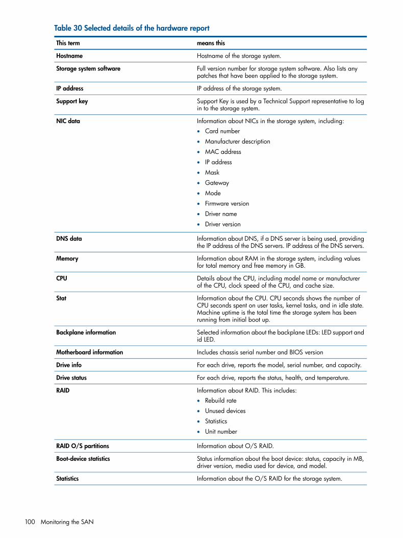
Table 30 Selected details of the hardware report
means thisThis term
Hostname of the storage system.Hostname
Full version number for storage system software. Also lists anypatches that have been applied to the storage system.
Storage system software
IP address of the storage system.IP address
Support Key is used by a Technical Support representative to login to the storage system.
Support key
Information about NICs in the storage system, including:NIC data• Card number
• Manufacturer description
• MAC address
• IP address
• Mask
• Gateway
• Mode
• Firmware version
• Driver name
• Driver version
Information about DNS, if a DNS server is being used, providingthe IP address of the DNS servers. IP address of the DNS servers.
DNS data
Information about RAM in the storage system, including valuesfor total memory and free memory in GB.
Memory
Details about the CPU, including model name or manufacturerof the CPU, clock speed of the CPU, and cache size.
CPU
Information about the CPU. CPU seconds shows the number ofCPU seconds spent on user tasks, kernel tasks, and in idle state.
Stat
Machine uptime is the total time the storage system has beenrunning from initial boot up.
Selected information about the backplane LEDs: LED support andid LED.
Backplane information
Includes chassis serial number and BIOS versionMotherboard information
For each drive, reports the model, serial number, and capacity.Drive info
For each drive, reports the status, health, and temperature.Drive status
Information about RAID. This includes:RAID• Rebuild rate
• Unused devices
• Statistics
• Unit number
Information about O/S RAID.RAID O/S partitions
Status information about the boot device: status, capacity in MB,driver version, media used for device, and model.
Boot-device statistics
Information about the O/S RAID for the storage system.Statistics
100 Monitoring the SAN

Table 30 Selected details of the hardware report (continued)
means thisThis term
Identifies devices that make up the O/S RAID configuration,including:
Unit number
• Type of storage (BOOT, LOG, SANIQ, DATA)
• RAID level (0, 1, 5)
• Status (Normal, Rebuilding, Degraded, Off)
• Capacity
• Rebuild statistics (% complete, time remaining)
Depending on the storage system, this can include:Controller/cache items• Information about the RAID controller card and Battery Backup
Unit (BBU)• Information about RAM.
Shows the type or number of power supplies.Power supply
Status information about the power supplies.Power supplies
Shows for the hardware listed, the status, real measured value,minimum and maximum values.
Sensors
Using log filesIf Technical Support requests that you send a copy of a log file, use the Log Files tab to save thatlog file as a text file.The Log Files tab lists two types of logs:
• Log files that are stored locally on the storage system (displayed on the left side of the tab).
• Log files that are written to a remote log server (displayed on the right side of the tab). Thislist is empty until you configure remote log files and the remote log target computer.
Saving log files locally1. Select a storage system in the navigation window.2. Open the tree below the storage system and select Diagnostics.3. Select the Log Files tab.4. To retrieve the latest data, click Log File Tasks and select Refresh Log File List.5. Scroll down the list of log files in the Log Files list and select the file or files to save.
To select multiple files, press Ctrl or Ctrl+Shift.6. Click Log Files Tasks and select Save Log Files.7. Select a location for the file or files.8. Click Save.
Exporting the System SummaryThe System Summary has information about all of the storage systems on the network. Export thesummary to a .csv file for use in a spreadsheet or database.Information in the summary includes:• Storage system information, “Working with storage systems” (page 21)
• Management group information, “Working with management groups” (page 104)
• Network information, “Managing the network” (page 48)
• RAID information, “Configuring RAID and Managing Disks” (page 32)
Using log files 101
To export the summary:1. From the CMC menu bar, select Tasks→System Summary.2. Click Export.3. Select a location for the file, and rename it if desired.4. Click Export.
Configuring a remote log and remote log destinationUse remote log files to automatically write log files to a computer other than the storage system.For example, direct the log files for one or more storage systems to a single log server in a remotelocation. The computer that receives the log files is called the Remote Log Target.You must also configure the target computer to receive the log files.1. Select a storage system in the navigation window.2. Open the tree below the storage system and select Diagnostics.3. Select the Log Files tab.4. Click Log File Tasks and select Add Remote Log Destination.5. In the Log Type list, select the log to direct to a remote computer.
The Log Type list only contains logs that support syslog.6. In the Destination field, enter the IP address or host name of the computer that will receive the
logs.For a Windows operating system, find out the name of the remote computer with Control Panel> System Properties > Computer Name.
7. Click OK.The remote log appears in the Remote logs list on the Log Files window.
Configuring the remote log target computerConfigure syslog on the remote log target computer. Refer to the syslog product documentation forinformation about configuring syslog.
NOTE: The string in parentheses next to the remote log name on the Log Files tab includes thefacility and level information that you will configure in syslog. For example, in the log file name:auth error (auth.warning) the facility is “auth” and the level is “warning.”
Editing remote log targetsSelect a different log file or change the target computer for a remote log:1. Select a storage system in the navigation window.2. Open the tree below the storage system and select Diagnostics.3. Select the Log Files tab.4. Select the log in the Remote logs list.5. Click Log File Tasks and select Edit Remote Log Destination.6. Change the log type or destination and click OK.7. Ensure that the remote computer has the proper syslog configuration.
Deleting remote logs1. Select a storage system in the navigation window.2. Open the tree below the storage system and select Diagnostics.3. Select the Log Files tab.4. Click Log File Tasks and select Delete Remote Log Destination.5. Click OK on the confirmation window.
102 Monitoring the SAN

NOTE: After deleting a remote log file from the storage system, remove references to this log filefrom the syslog configuration on the target computer.
Exporting support logsIf asked to do so by Customer Support, export support logs for a management group or storagesystem. The logs are saved as a zip file.1. Select a management group or storage system in the navigation window.2. Do one of the following depending on what you selected:
Click Management Group Tasks and select Export Management Group Support Bundle.Click Storage System Tasks and select Export Storage System Support Bundle.
3. Select the location to save the file.You cannot change the name of the zip file.
4. Click Save.
Using log files 103

8 Working with management groupsA management group is a collection of one or more storage systems. It is the container withinwhich you cluster storage systems and create volumes for storage. Creating a management groupis the first step in creating an IP SAN with the SAN/iQ software.
Functions of management groupsManagement groups serve several purposes:
• Management groups are the highest administrative domain for the SAN. Typically, storageadministrators will configure at least one management group within their data center.
• Organize storage systems into different groups for categories of applications and data. Forexample, you might create a management group for Oracle applications and a separatemanagement group for Exchange.
• Ensure added administrative security. For example, you could give the system administratorin charge of Exchange access to the Exchange management group but not the Oraclemanagement group.
• Prevent some storage resources from being used unintentionally. If a storage system is not ina management group, the management group cannot use that storage system as a storageresource. For example, all of the storage systems in a management group can be pooled intoclusters for use by volumes in that group. To prevent a new storage system from being includedin this pool of storage, put it in a separate management group.
• Contain clustering managers. Within a management group, one or more of the storage systemsacts as the managers that control data transfer and replication.
Guide for management groupsWhen using the Management Groups, Clusters and Volumes wizard, you must configure thecharacteristics described in Table 31 (page 104). When the management group is created, checkthe Best Practice Summary to verify that the configuration is following best practices for availabilityand data protection. See “Best Practice summary overview” (page 112).
Table 31 Management group requirements
What it meansManagement group requirement
Before you create a management group, make sure youknow the IP addresses for the storage systems for the
Configure storage systems
cluster. Also, make sure they are configured for networkbonding as best fits your network environment.
CAUTION: [VSA] You cannot clone a VSA after it is ina management group. You must clone a VSA while it is inthe Available Systems pool.
When you create a management group, you must add thefirst administrative user. This user has full administrative
Plan administrative users
permissions. Add additional users after the managementgroup is created. See “Adding a new administrative user”(page 80).
You can use an NTP server or manually set the date, time,and time zone for the management group. You should
Plan date and time configuration
know the configuration you want to use before beginningthe wizard. See “Setting the date and time” (page 77).
You can configure DNS at the management group levelfor all storage systems in the management group. The
Plan DNS configuration
storage system can use a DNS server to resolve host names.
104 Working with management groups

Table 31 Management group requirements (continued)
What it meansManagement group requirement
You need the DNS domain name, suffix, and server IPaddress. See “Using a DNS server” (page 72).
You can set up email notification for events for eachmanagement group. You must set up the email server to
Plan email notification
send events. You need the email (SMTP) server IP or hostname, server port, a valid email address to use as thesender address. See “Setting up email notification”(page 92).
A cluster can be standard or Multi-Site. If you want to createa Multi-Site configuration, you need the physical sites andthe storage systems that go in them already created.
Plan type of cluster
Plan a unique VIP for each cluster. VIPs ensure fault-tolerantserver access to the cluster and enable iSCSI load
Plan virtual IP addresses (VIPs)
balancing. You need the IP address and subnet mask. See“Virtual IP addresses” (page 230).
If you create a volume in the wizard, you need the volumesize and data protection level. See “Guide for volumes”(page 155).
[Optional] Plan volume size and data protection
Creating a management groupCreating a management group is the first step in the process of creating clusters and volumes forstorage. Tasks included in creating a management group are:
• Planning the management group configuration
• Creating the management group by using the Management Groups, Clusters and Volumeswizard
• Ensuring you have the proper configuration of managers
Creating a new management group1. Select Getting Started in the navigation window to access the Getting Started Launch Pad.2. Select the Management Groups, Clusters and Volumes Wizard.3. [Optional] Click the link to review the information you will need to have ready to create the
management group and cluster.4. Click Next to start creating the management group.5. Select New to create a new management group and click Next.
Create management group and add storage systems1. Enter a name for the new management group.
This name cannot be changed later without destroying the management group.2. Select the storage system(s) to add to the management group.
Use Ctrl+Click to select more than one.
IMPORTANT: Using two storage systems in a management group requires a Failover Managerfor the highest level of data availability. If you are creating a management group with twostorage systems and you do not add a FOM, you must select the checkbox acknowledgingthe risk before you can continue.
Creating a management group 105

Add administrative user1. Click Next to add an administrative user.2. Enter the administrative user’s name, a description, and a password.
The first administrator is always at full administrator level.3. Click Next to set the time for the management group.
Set management group time1. Select the method by which to set the management group time.
• [Recommended] To use an NTP server, know the URL of the server, or its IP address,before you begin.Note: if using a URL, DNS must be configured on the storage systems in the group.
• To set the time manually, select Edit to display the Date and Time Configuration window.Check each field on this window to set the time for all storage systems in this managementgroup.
2. Click Next to set the DNS server.
Set DNS server1. Enter the DNS domain, suffix, and server IP address.2. Click Next to set up email for notification.
Set up email for notification1. Enter the email (SMTP) server IP address or host name, port number, and email address to
use for the sender for event notification.2. Click Next to create a cluster.
Create cluster and assign a VIPThe following steps are for creating a standard cluster. If you are creating a Multi-Site cluster, see“Creating Multi-Site Clusters and Volumes” in Chapter 2 of the HP P4000 Multi-Site HA/DR SolutionPack User Guide.1. Select Standard Cluster on the Create a Cluster window, and click Next.2. Enter a cluster name in the Create Cluster window.3. From the list, select the storage systems to include in the cluster.4. Click Next to assign a Virtual IP.5. Add the VIP and subnet mask.6. Click Next to create a volume and finish creating the management group.
Create a volume and finish creating management group1. Enter a name, description, data protection level, size, and provisioning type for the volume.2. Click Finish.3. Review the details on the summary window and click Close.4. A message opens notifying you to register and receive license keys.5. Click OK.6. As a last step, save a .txt file of the configuration information for the entire management group.
See “Saving management group configuration information” (page 117).
Management group map view tabAfter you create the management group and finish setting up the SAN, use the Map View tab forviewing the relationships between servers, sites, clusters, volumes, snapshots, and remote copies
106 Working with management groups

in the management group. For more information on using the map view tools, see “Using the MapView ” (page 14).
Best practice for managers in a management groupWhen creating a management group, the wizard creates an optimal manager configuration forthe number of storage systems used to create the group. See Table 32 (page 107) for the defaultmanager configurations.After you have finished creating the management group, be certain to reconfigure managers asnecessary to optimize your particular SAN configuration. The Best Practice analyzer for themanagement group indicates if the manager configuration is satisfactory. For more informationabout managers, see “Managers overview” (page 107).
Table 32 Default number of managers added when a management group is created
Manager configurationNumber of storage systems
1 manager1
2 managers and a Virtual Manager2
3 managers3 or more
Managers overviewWithin a management group, managers are storage systems that govern the activity of all of thestorage systems in the group. All storage systems contain the management software, but you mustdesignate which storage systems run that software by starting managers on them. These storagesystems then “run” managers, much as a PC runs various services.
Functions of managersManagers have the following functions:
• Control data replication. (Note: managers are not directly in the data path.)
• Manage communication between storage systems in the cluster.
• Resynchronize data when storage systems change states.
• Coordinate reconfigurations as storage systems are brought up and taken off line.One storage system has the coordinating manager. You can determine which storage systemis the coordinating manager by selecting the management group, then clicking the Detailstab. The Status field at the top shows the coordinating manager.
Managers and quorumManagers use a voting algorithm to coordinate storage system behavior. In this voting algorithm,a strict majority of managers (a quorum) must be running and communicating with each other inorder for the SAN/iQ software to function. An odd number of managers is recommended to ensurethat a majority is easily maintained. An even number of managers can get into a state where nomajority exists—one-half of the managers do not agree with the other one-half. This state, knownas a “split-brain,” may cause the management group to become unavailable.For optimal fault tolerance in a single-site configuration, you should have 3 or 5 managers in yourmanagement group to provide the best balance between fault tolerance and performance. Themaximum supported number of managers is 5. See Table 33 (page 108).
Managers overview 107

Table 33 Managers and quorum
ExplanationFault toleranceNumber for a quorumNumber of Managers
If the manager fails, no datacontrol takes place. This
None11
arrangement is notrecommended.
Even number of managersnot recommended, except in
None22
specific configurations.Contact Customer Supportfor more information.
If one manager fails, 2remain, so there is still a
High23
quorum. (Note: 2 managersare not fault tolerant. Seeabove.)
Even number of managersnot recommended, except in
High34
specific configurations.Contact Customer Supportfor more information.
If one or two managers fail,3 remain so there is still aquorum.
High35
Regular managers and specialized managersRegular managers run on storage systems in a management group. The SAN/iQ software has twoother types of specialized managers, Failover Managers and Virtual Managers, described below.For detailed information about specialized managers and the how to use them, see “Usingspecialized managers” (page 121).
Failover ManagersThe Failover Manager is used in two-system and in Multi-Site SAN configurations to supportautomatic quorum management in the SAN. Configuring a Failover Manager in the managementgroup enables the SAN to have automated failover without requiring a regular manager runningon a storage system. A Failover Manager runs as a virtual machine on a VMware Server or onESX and must be installed on network hardware other than the storage systems in the SAN.Figure 43 (page 108) shows the Failover Manager installed, configured, and appearing in theCMC.
Figure 43 Failover Manager in the available systems pool
108 Working with management groups

Once installed and configured, the Failover Manager operates as a storage system in how youadd it to a management group where it serves solely as a quorum tie-breaking manager.
Virtual ManagersA Virtual Manager is added to a management group, as shown in Figure 44 (page 109), but is notstarted on a storage system until a failure in the system causes a loss of quorum. Unlike the FailoverManager, which is always running, the Virtual Manager must be started manually on a storagesystem after quorum is lost. It is designed to be used in two-system or two-site system configurationswhich are at risk for a loss of quorum.
Figure 44 Virtual Manager added to a management group
Configuration Summary overviewThe Configuration Summary provides an easy-to-use reference for managing the size and optimumconfiguration of your SAN. The first time you create a management group, a configuration summarytable is created that resides immediately below the Getting Started Launch Pad in the navigationwindow. Subsequent management groups are added to this Configuration Summary, shown inFigure 45 (page 110). For each management group, the Configuration Summary displays anoverview of the volumes, snapshots, and storage systems in that management group. The Summaryroll-ups display configuration information and guide you to optimal configurations for volumes andsnapshots, iSCSI sessions, and the number of storage systems in the management group and ineach cluster.
Summary roll-upThe summary roll-up provided on the Configuration Summary panel is organized by managementgroup. Within each management group is listed the total number of volumes and snapshots, storagesystems, and iSCSI sessions contained in the management group.
Configuration Summary overview 109

Figure 45 Configuration Summary created when the first management group is configured
Configuration guidanceAs the Configuration Summary reports the numbers of the storage items, it provides warnings aboutthe safe limits for each category, based on performance and scalability. These warnings first alertyou that the category is nearing the limits by turning the category orange. When an individualcategory turns orange, the Configuration Summary category in the navigation window turns orangeas well. When an individual category reaches the maximum recommended configuration it turnsred. When the number in that category is reduced, the color changes immediately to reflect thenew state. For example, if you have a large number of volumes that have numerous schedules thatare creating and deleting snapshots, the snapshots may increase to a number that changes thesummary bar from green to orange. As soon as enough snapshots from the schedules are deleted,reducing the overall total, the summary bar returns to green.
Best practicesThe optimal and recommended number of storage items in a management group depend largelyon the network environment, the configuration of the SAN, the applications accessing the volumes,and what you are using snapshots for. However, we can provide some broad guidelines that helpyou manage your SAN to obtain the best and safest performance and scalability for yourcircumstances. These guidelines are in line with our tested limits for common SAN configurationsand uses. Exceeding these guidelines does not necessarily cause any problems. However, yourperformance may not be optimal, or in some failover and recovery situations may cause issueswith volume availability.
Volumes and snapshotsThe optimum number of combined volumes and snapshots ranges up to 1,000. If the managementgroup contains 1,001 to 1,500 volumes and snapshots, the Configuration Summary appearsorange for that line of the management group. Exceeding 1,500 volumes and snapshots triggersa warning by turning that line red. As soon as the total number reduces below the boundary, thesummary bar returns to the previous indicator, either orange or green.
iSCSI sessionsThe optimum number of iSCSI sessions connected to volumes in a management group ranges upto 4,000. If the management group contains 4,001 to 5,000 iSCSI sessions, the ConfigurationSummary appears orange for that line of the management group. Exceeding 5,001 iSCSI sessionstriggers a warning by turning that line red. As soon as the total number of iSCSI sessions reducesbelow the boundary, the summary bar returns to the previous indicator, either orange or green.
Storage systems in the management groupThe optimum number of storage systems in a management group ranges up to 20. If the managementgroup contains 21 to 30 storage systems, the Configuration Summary appears orange for that line
110 Working with management groups

of the management group. Exceeding 30 storage systems triggers a warning by turning that linered. As soon as the total number of storage systems reduces below the boundary, the summarybar returns to the previous indicator, either orange or green.
Storage systems in the clusterThe optimum number of storage systems in a cluster ranges up to 10. If the cluster contains 11 to16 storage systems, the Configuration Summary appears orange for that line of the managementgroup. Exceeding 16 storage systems in a cluster triggers a warning by turning that line red. Assoon as the total number of storage systems reduces below the boundary, the summary bar returnsto the previous indicator, either orange or green.
Reading the configuration summaryEach management group in the SAN is listed on the Configuration Summary. Underneath eachmanagement group is a list of the storage items tracked, such as storage systems, volumes, oriSCSI sessions. As items are added to the management group, the Summary graph fills in and thecount is displayed in the graph. The Summary graph fills in proportionally to the optimum numberfor that item in a management group, as described in the “Best practices” (page 110).
Optimal configurationsOptimal configurations are indicated in green. For example, in Figure 46 (page 111), there are 15storage systems in the management group “CJS1.” Those 15 storage systems are divided amongthe clusters “c” “c2” and “c3.” The length of the graph is relative to the recommended maximumsin each category. For example, 3 storage systems in cluster c3 are closer to the cluster recommendedmaximum for storage systems than the 43 iSCSI sessions are to the maximum recommended iSCSIsessions for a management group.
Figure 46 Summary graph
1. The items in the management group are all within optimum limits. The display is proportional to the optimum limits.
Configuration warningsWhen any item nears a recommended maximum, it turns orange, and remains orange until thenumber is reduced to the optimal range. See Figure 47 (page 112).
Configuration Summary overview 111
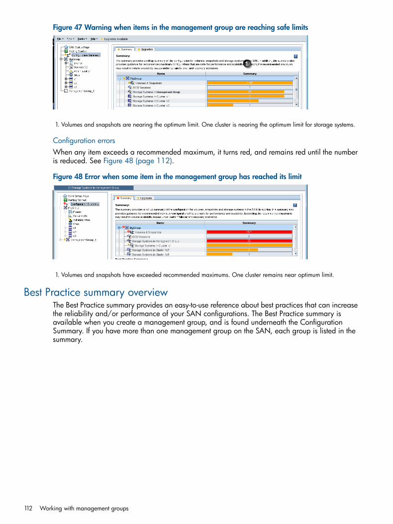
Figure 47 Warning when items in the management group are reaching safe limits
1. Volumes and snapshots are nearing the optimum limit. One cluster is nearing the optimum limit for storage systems.
Configuration errorsWhen any item exceeds a recommended maximum, it turns red, and remains red until the numberis reduced. See Figure 48 (page 112).
Figure 48 Error when some item in the management group has reached its limit
1. Volumes and snapshots have exceeded recommended maximums. One cluster remains near optimum limit.
Best Practice summary overviewThe Best Practice summary provides an easy-to-use reference about best practices that can increasethe reliability and/or performance of your SAN configurations. The Best Practice summary isavailable when you create a management group, and is found underneath the ConfigurationSummary. If you have more than one management group on the SAN, each group is listed in thesummary.
112 Working with management groups

Figure 49 Best Practice Summary for well-configured SAN
Expand the management group in the summary to see the individual categories that haverecommended best practices. The summary displays the status of each category and identifies anyconditions that fall outside the best practice. Click on a row to see details about that item's bestpractice.
Disk level data protectionDisk level data protection indicates whether the storage system has an appropriate disk RAID levelset. For more information about configuring disk RAID levels, see “Planning the RAID configuration”(page 34).
Disk protection using RAIDData protection is provided on an individual storage system by configuring RAID at any level otherthan 0. For a description of RAID levels, see “RAID Levels” (page 32).
Large single-system SATA clusterIf you are using a single large SATA storage system in a cluster, data protection is provided byconfiguring RAID 6 on that system. In addition to redundancy during normal operation, RAID 6further protects the RAID array against data loss during degraded mode by tolerating one additionaldrive failure during this vulnerable stage.
Disk RAID ConsistencyThe best results for availability, reliability, and performance are achieved by using the same diskRAID level for all storage systems in a cluster. Mixed RAID levels in clusters are allowed to supporta variety of administrative tasks. However, using the same RAID settings on all storage systems ina cluster ensures optimum availability and performance. For more information, see “Managersoverview” (page 107).
Cluster-level data protectionClusters of two or more systems provide the highest data availability. Clustered storage systemscreate the storage capacity for data volumes. Clusters are recommended to contain between 2and 10 storage systems. See “Storage systems in the cluster” (page 111).
Best Practice summary overview 113

Volume-level data protectionUse a data protection level greater than Network RAID-0 to ensure optimum data availability if astorage system fails. For information about data protection, see “Planning data protection”(page 142).
Volume accessUse iSCSI load balancing to ensure better performance and better utilization of cluster resources.For more information about iSCSI load balancing, see “iSCSI load balancing” (page 231).
Systems running managersUse the recommended number and type of managers to ensure optimum availability of yourmanagement group and volumes. Configurations with 3 or 5 managers are recommended for mostsingle site installations. Three or five storage systems running managers is optimum. For fewerstorage systems, use a Failover Manager as the third manager if possible. The Virtual Manager isalso available for specific configurations. For a detailed discussion of managers and quorum, see“Managers and quorum” (page 107).
Network bondingBonding the available NIC cards in each storage system improves SAN performance and reliability.In most instances, Adaptive Load Balancing is the recommended bond. See “Best practices”(page 56).
Network bond consistencyTo ensure consistent failover characteristics and traffic distribution, use the same network bondtype in all the storage systems in a cluster. Inconsistent network bonds in storage systems in thesame cluster may cause inconsistent traffic across NICs, and unexpected failover behavior dependingon which system in the cluster fails. For more information, see “Configuring network interfacebonds” (page 55).
Network flow control consistencySet the network flow control settings the same on every storage system in the cluster. Inconsistentnetwork flow control settings in storage systems in the same cluster may impact the connectivitybetween the systems. For more information, see “Changing NIC flow control” (page 52).
Network frame size consistencyNetwork frame size affects management data traffic and replication. Use the same network framesize in all storage systems in a cluster to ensure consistent data traffic and replication. Inconsistentnetwork frame size may impact data traffic and replication in the cluster. For more information,see “Changing NIC frame size” (page 51).
Management group maintenance tasksWhen you have an established management group, you may need to perform maintenance activitieson the group.
Logging in to a management groupYou must log in to a management group to administer the functions of that group.
114 Working with management groups
1. In the navigation window, select a management group.2. Log in by any of the following methods.
• Double-click the management group.
• Open the Management Group Tasks menu, and select Log in to Management Group. Youcan also open this menu from a right-click on the management group.
• Click any of the Log in to view links on the Details tab.3. Enter the user name and password, and click Log In.
When you log in to one storage system in a management group, you are logged in to allstorage systems in that group.
Choosing which storage system to log in toYou can control which of the storage systems in a management group you log in to.1. When the Log in to System window opens, click Cancel.
A message opens, asking if you want to log in to a different storage system.2. Click OK.3. The Log in to System window opens with a different storage system listed.4. If that is the storage system you want, go ahead and log in. If you want to log in to a different
storage system, repeat steps 1 and 2 until you see the storage system you want.
Logging out of a management groupLogging out of a management group prevents unauthorized access to that management group andthe storage systems in that group.1. In the navigation window, select a management group to log out of.2. Click Management Group Tasks on the Details tab, and select Log Out of Management Group.
Adding a storage system to an existing management groupStorage systems can be added to management groups at any time. Add a storage system to amanagement group in preparation for adding it to a cluster.1. In the navigation window, select an available storage system that you want to add to a
management group.2. Click Storage System Tasks on the Details tab, and select Add to Existing Management Group.3. Select the desired management group from the drop-down list of existing management groups.4. Click Add.5. (Optional) If you want the storage system to run a manager, select the storage system in the
management group, right-click, and select Start Manager.6. Repeat steps 1 through 4 to add additional storage systems.
Starting and stopping managersAfter adding the storage systems to the management group, start managers on the additionalstorage systems in the management group. The number of managers you start depends upon theoverall design of your storage system. See “Managers overview” (page 107) for more informationabout how many managers to add.
Starting additional managers1. In the navigation window select a storage system in the management group on which to start
a manager.2. Click Storage System Tasks on the Details tab, and select Start Manager.Repeat these steps to start managers on additional storage systems.
Management group maintenance tasks 115

Stopping managersUnder normal circumstances, you stop a manager when you are removing a storage system froma management group. You cannot stop the last manager in a management group. If you stop amanager that compromises fault tolerance, the Best Practice details identify an issue with systemsthat are running managers.Deleting the management group is the only way to stop the last manager.
Implications of stopping managers
• Quorum of the storage systems may be decreased.
• Fewer copies of configuration data are maintained.
• Fault tolerance of the configuration data may be lost.
• Data integrity and availability may be compromised.
CAUTION: Stopping a manager can result in the loss of fault tolerance.
1. In the navigation window, select a management group, and log in.2. Select the storage system for which you want to stop the manager.3. Click Storage System Tasks on the Details tab, and select Stop Manager.
A confirmation message opens.4. Click OK to confirm stopping the manager.
Editing a management groupEditing management group tasks include the following items:
• Changing local bandwidth priority.
• Editing Remote Bandwidth, done on the management group containing the remote snapshot.(See the HP P4000 Remote Copy User Guide, in “Chapter 2, Using Remote Copy,” the sectionabout setting the remote bandwidth.)
Specialized editing tasks include:
• Disassociating management groups
• Setting Group Mode to normalAfter making any changes to the management group, be sure to save the configuration data ofthe edited management group. See “Saving management group configuration information”(page 117).
Setting or changing the local bandwidth priorityAfter a management group has been created, edit the management group to change the localbandwidth priority. This is the maximum rate per second that a manager devotes to non-applicationprocessing, such as moving data. The default rate is 4 MB per second. You cannot set the rangebelow 0.25 MB/sec.
Local bandwidth priority settingsThe bandwidth setting is in MB per second. Use Table 34 (page 117) as a guide for setting thelocal bandwidth.
116 Working with management groups

Table 34 Guide to local bandwidth priority settings
Throughput ratingThroughput (MB/sec)Network type
2 Mbps0.25Minimum
10 Mbps1.25Ethernet
32 Mbps4.00Factory Default
100 Mbps12.50Fast-Ethernet
500 Mbps62.50Half Gigabit-Ethernet
1 Gbps128.00Gigabit-Ethernet
2 Gbps256.00Bonded Gigabit-Ethernet (2)
4 Gbps512.00Bonded Gigabit-Ethernet (4)
Set or change local bandwidth priority1. In the navigation window, select a management group and log in.2. Click Management Group Tasks on the Details tab, and select Edit Management Group.3. Change the local bandwidth priority using the slider.
A default setting of 4, at the Application Access end of the slider, is more appropriate foreveryday situations where many servers are busy with the volume. A setting of 40, at the DataRebuild end of the slider, is most commonly used for quick data migration or copies whenrebuilding or moving damaged volumes.
4. Click OK.The new rate appears on the Details tab in the management group tab window.
Saving management group configuration informationUse View Management Group Configuration to save the configuration description. This creates a.txt file that lists the details of the management group configuration.1. From the Tasks menu, select Management Group→View Management Group Configuration.2. Select the management group if necessary.3. Click Save in the Management Group Configuration window to save the configuration details
in a .txt. file.
Safely shutting down a management groupSafely shut down a management group to ensure the safety of your data. Shutting down lets you:
• Perform maintenance on storage systems in that group
• Move storage systems around in your data center
• Perform maintenance on other equipment such as switches or UPS units
• Prepare for a pending natural disasterAlso, use a script to configure a safe shut down in the case of a controlled power down by a UPS.See “Working with scripting” (page 196). Sample scripts are available from the Customer ResourceCenter.Shutting down a management group also relates to powering off individual storage systems andmaintaining access to volumes. See the command line documentation, the HP P4000 SAN/iQCommand Line Interface User Guide, installed in the documentation directory of the program files.
Safely shutting down a management group 117

Prerequisites• Disconnect any hosts or servers that are accessing volumes in the management group.
• Wait for any restriping of volumes or snapshots to complete.
• Stop managers on storage systems that you plan to remove from the management group. Youmay want to add a FOM or start a Virtual Manager on a different storage system to maintainquorum and the best fault tolerance. See “Stopping managers” (page 116).
Shut down the management group1. Log in to the management group that you want to shut down.2. Click Management Group Tasks on the Details tab, and select Shut DownManagement Group.3. Click Shut Down Group.
If volumes are still connected to servers or hostsAfter you click Shut Down Group, a confirmation window opens, listing volumes that are stillconnected and that will become unavailable if you continue shutting down the management group.
Figure 50 Notification of taking volumes offline
1. Stop server or host access to the volumes in the list.2. Click Shut Down Group.
Start the management group back upWhen you are ready to start up the management group, simply power on the storage systems forthat group.1. Power on the storage systems that were shut down.2. Use Find in the CMC to discover the storage systems.
When the storage systems are all operating properly, the volumes become available and canbe reconnected with the hosts or servers.
Restarted management group in maintenance modeIn certain cases the management group may start up in maintenance mode. Maintenance modestatus usually indicates that either the management group is not completely restarted or the volumesare resynchronizing. When the management group is completely operational and theresynchronizing is complete, the management group status changes to normal mode.Some situations which might cause a management group to start up in maintenance mode includethe following:
• A storage system becomes unavailable, and the management group is shut down while thatstorage system is repaired or replaced. After the storage system is repaired or replaced and
118 Working with management groups

the management group is started up, the management group remains in maintenance modewhile the repaired or replaced storage system is resynchronizing with the rest of themanagement group.
• After a management group is shut down, a subset of storage systems is powered on. Themanagement group remains in maintenance mode until the remaining storage systems arepowered on and rediscovered in the CMC.
• For some reason, a storage system comes up, but it is not fully functional.
Manually change management group to normal modeWhile the management group is in maintenance mode, volumes and snapshots are unavailable.You may get volumes and snapshots back online if you manually change the status from maintenancemode to normal mode, depending upon how your cluster and volumes are configured. However,manually changing from maintenance mode to normal mode causes the volumes in the managementgroup to run in degraded mode while it continues resynchronizing, or until all the storage systemsare up, or the reason for the problem is corrected.
CAUTION: If you are not certain that manually setting the management group to normal modewill bring your data online, or if it is not imperative to gain access to your data, do not changethis setting.
1. In the navigation window, select the management group, and log in.2. Click Management Group Tasks on the Details tab, and select Edit Management Group.
Figure 51 Manually setting management group to normal mode
3. Click Set To Normal.
Removing a storage system from a management groupWhen a storage system needs to be repaired or upgraded, remove it from the management groupbefore beginning the repair or upgrade. Also remove a storage system from a management groupif you are replacing it with another system.
Prerequisites• Stop the manager on the storage system if it is running a manager. You may want to start a
manager or Virtual Manager on a different storage system to maintain quorum and the bestfault tolerance. See “Stopping managers” (page 116).
• (Optional) If the resultant number of storage systems in the cluster is fewer than the numberrequired for the data protection level, you may have to change the data protection level ofthe volume(s) before removing the storage system from the cluster.
Removing a storage system from a management group 119

• Remove the storage system from the cluster. See “Removing a storage system from a cluster”(page 137).
• Let any restripe operations finish completely.
Remove the storage system1. Log in to the management group from which you want to remove a storage system.2. In the navigation window, select the storage system to remove.3. Click Storage System Tasks on the Details tab, and select Remove from Management Group.4. Click OK on the confirmation message.
In the navigation window, the storage system is removed from the management group andmoved to Available Systems pool.
Deleting a management groupDelete a management group when you are completely reconfiguring your SAN and you intend todelete all data on the SAN.
CAUTION: When a management group is deleted, all data stored on storage systems in thatmanagement group is lost.
Prerequisites• Log in to the management group.
• Remove all volumes and snapshots.
• Delete all clusters.
Delete the management group1. In the navigation window, log in to the management group.2. Click Management Group Tasks on the Details tab, and select Delete Management Group.3. In the Delete Management Window, enter the management group name, and click OK.
After the management group is deleted, the storage systems return to the Available Systemspool.
Setting the management group versionIf instructed by customer support, you can set the management group version back to a previousversion of the software. Setting the version back requires using a special command line optionbefore opening the CMC. Customer support will instruct you on using the command line option.
120 Working with management groups

9 Using specialized managersThe SAN/iQ software provides two specialized managers that are used in specific situations. TheFailover Manager is used in two-system and in Multi-Site SAN configurations to support automaticquorum management in the SAN. A virtual manager is added to a management group but is onlystarted manually on a storage system if needed to maintain or regain quorum.
NOTE: You can only use one type of specialized manager in a management group. The FailoverManager is recommended for two-system configurations and in Multi-Site SAN configurations. TheVirtual Manager is automatically added to two-system configurations if a Failover Manager is notadded. However, the Failover Manager is the recommended solution for maintaining fault-toleranceon the SAN.
DefinitionsTerms used in this chapter:
• Failover Manager (FOM)—A specialized manager running as a VMware guest operatingsystem that can act as a quorum tie-breaker system when installed into a third location in thenetwork to provide for automated failover/failback of the Multi-Site SAN clusters. It also addedto two-system management groups to provide the optimum quorum configuration.
• Virtual manager—A manager which is added to a management group but is only started ona storage system if needed to regain or maintain quorum.
• Regular manager—A manager which is started on a storage system and operates accordingto the description of managers found in “Managers overview” (page 107).
• Manager—Any of these managers.
Failover ManagerThe Failover Manager is a specialized version of the SAN/iQ software designed to run as a virtualappliance in either a VMware or Microsoft Hyper-V Server environment. The Failover Managerparticipates in the management group as a real manager in the system; however, it performsquorum operations only, not data movement operations. It is especially useful in a Multi-Site SANconfiguration to manage quorum for the multi-site configuration without requiring additional storagesystems to act as managers in the sites.
Planning the virtual network configurationBefore you install the Failover Manager on the network, plan the virtual network configuration,including the following areas:
• Design and configuration of the virtual switches and network adapters.
• Windows Server or ESX Server on which to install Failover Manager files, and a designatedhost name, and IP address.
• An iSCSI network for the virtual machine. The Failover Manager should be on the iSCSInetwork. If you do not have an existing virtual machine network configured on the iSCSInetwork/vswitch, create a new virtual machine network for the Failover Manager.
Failover Manager requirements• Static IP address, or a reserved IP address if using DHCP.
• Server—not on the P4000 SAN—on which to install the Failover Manager.
• Only one Failover Manager per management group.
• Only a Failover Manager or a virtual manager in the a management group, not both.
Failover Manager 121

• Failover Manager not inside a virtual Windows machine with VMware Server running.
• Failover Manager configured to start last after storage systems in the management group inserver startup/shutdown list.
Using the Failover Manager on Microsoft Hyper-V ServerInstall the Failover Manager on a Windows Server 2008 from the DVD, or from the DVD .isoimage downloaded from the website:
http://www.hp.com/go/P4000downloads
The installer for the Failover Manager for Hyper-V Server includes a wizard that guides you throughconfiguring the virtual machine on the network and powering on the Failover Manager.
CAUTION: Do not install the Failover Manager on the HP P4000 SAN Solution, since this woulddefeat the purpose of the Failover Manager.
Minimum system requirements for using with Microsoft Hyper-V Server• Supported versions of Windows Server
Windows Server 2008 R2 Standard◦◦ Windows Server 2008 R2 Enterprise
◦ Windows Server 2008 R2 Datacenter
◦ Windows Server 2008 R2 Server Core
◦ Windows Server 2008 SP2, except for Core, which is not supported
• 15 GB available drive space on Windows server for the Failover Manager
• Hyper-V role installed and running.
• At least 1 GB of memory reserved for the Failover Manager.
• A single virtual CPU with at least 2000 MHz reserved.
Installing the Failover Manager for Hyper-V Server1. Begin the installer one of the following ways:
• Insert the in the DVD drive.
• Double-click the executable that you downloaded to start the installation.2. Accept the terms of the License Agreement.3. Choose a location for the Failover Manager virtual machine and a location for the virtual hard
disks, and click Next.4. Enter a name for the Failover Manager, select whether you want it powered on after it is
installed, and click Next.5. Enter the network information, including the host name and network addressing information,
and click Next.6. Finish the installation, reviewing the configuration summary, and click Next.
When the installer is finished, the Failover Manager is ready to be used in the HP P4000SAN Solution
Next, use the Find function in the CMC to discover the Failover Manager, and then add it to amanagement group. See “Adding a storage system to an existing management group” (page 115)for more information.
122 Using specialized managers

Using the Failover Manager for VMwareInstall the Failover Manager from the DVD, or from the DVD .iso image downloaded from thewebsite:
http://www.hp.com/go/P4000downloads
The installer offers three choices for installing the Failover Manager for VMware.
• Failover Manager for ESX—The installer for the Failover Manager for ESX includes a wizardthat guides you through configuring the virtual machine on the network and powering on theFailover Manager.
• Failover Manager for other VMware platforms—The installer for the Failover Manager forother VMware platforms includes a wizard that installs the Failover Manager. Then you findthe Failover Manager, boot the system, and configure it for the P4000 SAN network.
• Failover Manager OVF files—If you choose to use the OVF package, you configure the datadisk for the Failover Manager, and then configure the Failover Manager for the P4000 SANnetwork.
CAUTION: Do not install the Failover Manager on the HP P4000 SAN Solution, since this woulddefeat the purpose of the Failover Manager.
Minimum system requirements for using the Failover Manager with VMwareESX Server• VMware ESX Server version 4.x or later.
• Microsoft .Net 2.0 or later on the installer client
• 1024 MB of RAM
• Bridged connection through the VMware Console, or assigned network in VI Client.
• 15 GB of disk space
Installing the Failover Manager for ESX Server1. Begin the installer one of the following ways:
• Insert the in the DVD drive.
• Double-click the executable that you downloaded to start the installation.2. Accept the terms of the License Agreement.3. Click Install FOM for ESX to begin the wizard.4. In the Meta Launcher command line window that opens, enter 1 to run the installer CLI, or
enter 2 to run the installer GUI. Both versions require the same information and perform thesame installation.• If you selected the GUI installation in the Meta Launcher CLI window, the GUI installer
window opens again and you click Install FOM for ESX again to begin the wizard.5. Enter the login credentials for the ESX Server that will host the Failover Manager, and click
Next.6. Select the ESX Server host, verify the health status and configuration details, and click Next.7. Select Failover Manager as the type of installation and click Next.8. Select a datastore, not on the SAN, to store the virtual appliance files, and click Next.9. Enter a name for the Failover Manager and enter the IP address or choose to use DHCP. Select
the network interface to use and add multiple NICs if desired. Click Next.10. Enter a name for the virtual machine, and whether to use VMDK or raw disk mapping, and
click Next.
Using the Failover Manager for VMware 123

11. Select No, I am done, unless you plan to install another Failover Manager, and click Next.If you want to install another Failover Manager, the wizard repeats the steps, using informationyou already entered, as appropriate.
12. Finish the installation, reviewing the configuration summary, and click Deploy.When the installer is finished, the Failover Manager is ready to be used in the HP P4000SAN Solution.
Next, use the Find function in the CMC to discover the Failover Manager, and then add it to amanagement group. See “Adding a storage system to an existing management group” (page 115)for more information.
Installing the Failover Manager using the OVF files with the VI Client1. Begin the installer one of the following ways:
• Insert the in the DVD drive.
• Double-click the executable that you downloaded to start the installation.2. Click Agree to accept the terms of the License Agreement.3. Click the link for OVF files to open a window from which you can copy the files to the ESX
Server.
Configure the IP address and host name1. In the inventory panel, select the new Failover Manager and power it on.2. Select the Console tab and wait for the Failover Manager to boot.3. When the Failover Manager finishes booting, enter Start and press Enter to log in to the
Configuration Interface.4. On the main menu, tab to Network TCP/IP Settings and press Enter.5. On the Available Network Devices window, tab to the network interface and press Enter.6. On the Network Settings window, tab to the Hostname field and enter a host name for the
Failover Manager. Use backspace to erase an entry if necessary.This host name displays in the only. It does not change the name of the original .VMX file orthe name of the virtual machine in the VMware interface.
7. Tab to the method for setting the IP address.If entering a static IP address, note that Gateway is a required field. If you do not have agateway, enter 0.0.0.0.
8. Tab to OK and press Enter.9. Press Enter again to confirm the action.10. After the settings are configured, press Enter to confirm the IP address change.11. On the Available Network Devices window, tab to Back and press Enter.12. On the Configuration Interface, tab to Log Out and press Enter.
Finishing up with VI Client1. In the VI Client Information Panel, click the Summary tab.2. In the General section on the Summary tab, verify that the IP address and host name are
correct, and that VMware Tools are running.
NOTE: If VMware Tools show “out of date” or “Unmanaged,” they are running correctly.The “out of date” or “Unmanaged” status is not a problem. VMware Tools are updated witheach SAN/iQ software upgrade.
124 Using specialized managers

Next, use the Find function in the CMC to discover the Failover Manager, and then add it to amanagement group. See “Adding a storage system to an existing management group” (page 115)for more information.
Installing the Failover Manager for VMware Server or VMware Workstation1. Begin the installer one of the following ways:
• Insert the in the DVD drive.
• Double-click the executable that you downloaded to start the installation.2. Click Agree to accept the terms of the License Agreement.3. Click Install FOM for other VMware platforms to begin the wizard.4. Accept the terms of the License Agreement, and click Next.5. Accept the default location to install the files, or change the location, and click Next.6. After the Failover Manager is installed, click Finish to complete the wizard.
Configuring the IP address and host name1. In the VMware application, navigate to the location of the Failover Manager and start the
virtual machine.2. Wait for the Failover Manager to boot.3. When the Failover Manager finishes booting, enter Start and press Enter to log in to the
Configuration Interface.4. On the main menu, tab to Network TCP/IP Settings and press Enter.5. On the Available Network Devices window, tab to the network interface and press Enter.6. On the Network Settings window, tab to the Hostname field. Use backspace to erase an entry
if necessary. Enter a host name for the Failover Manager.This host name displays in the only. It does not change the name of the original .VMX file orthe name of the virtual machine in the VMware interface.
7. Tab to the method for setting the IP address.If entering a static IP address, Gateway is a required field. If you do not have a gateway,enter 0.0.0.0.
8. Tab to OK and press Enter.9. Press Enter again to confirm the action.10. After the settings are configured, press Enter to confirm the IP address change.11. On the Available Network Devices window, tab to Back and press Enter.12. On the Configuration Interface, tab to Log Out and press Enter.Next, use the Find function in the CMC to discover the Failover Manager, and then add it to amanagement group. See “Adding a storage system to an existing management group” (page 115)for more information.
Troubleshooting the Failover Manager on ESX ServerUse the following solutions to possible issues you encounter with the Failover Manager on an ESXServer.
Table 35 Troubleshooting for ESX Server installation
SolutionIssue
You want to reinstall the Failover Manager 1. Close your CMC session.2. In the VI Client, power off the Failover Manager.3. Right-click, and select Delete from Disk.
Using the Failover Manager for VMware 125

Table 35 Troubleshooting for ESX Server installation (continued)
SolutionIssue
4. Copy fresh files into the virtual machine folder from thedownloaded zip file or distribution media.
5. Open the VI Client, and begin again.
You cannot find the Failover Manager with the CMC, andcannot recall its IP address.
• The CMC displays the IP address of a system if it canbe found.
• Open a VI Client session and select the Summary tabfor the system you want. The IP address and DNS nameare displayed in the General information section.
In Linux
Run CMC_Installer.bin again.If the installer does not start automatically
In the VI Client
You don’t have the cursor available, or you don’t have thekeyboard available.
• If your cursor is missing, you are in console mode. PressCtrl-Alt to regain the cursor.
• If your keyboard is missing, move the mouse to theconsole window, and click once.
Your console window has timed out. Click in the windowwith your mouse, and press any key.
You want to see your Failover Manager, but the windowis black.
Uninstalling the Failover Manager from VMware ESX Server1. Remove the Failover Manager from the management group.2. Power off the Failover Manager virtual machine in the VI Client.3. Right-click the powered-off Failover Manager, and select Delete from Disk.
Virtual managerA virtual manager is a manager that is added to a management group, but is not started on astorage system until it is needed to regain quorum. A virtual manager provides disaster recoveryfor one of two configurations:
• Configurations with only two storage systems. (A virtual manager will automatically be addedwhen creating a management group using two storage systems.)
• Configurations in which a management group spans two geographic sites.See “Managers and quorum” (page 107) for detailed information about quorum, fault tolerance,and the number of managers.Because a virtual manager is available to maintain quorum in a management group when a storagesystem goes offline, it can also be used for maintaining quorum during maintenance procedures.
CAUTION: A virtual manager requires a manual intervention to recover quorum and can haveundesirable effects when left running after quorum is recovered. That is why HP highly recommendsthat you use the Failover Manager rather than the virtual manager.
When to use a virtual managerUse a virtual manager for disaster recovery in a two-site configuration, or a two-system configuration.You can also use a virtual manager to maintain quorum during storage system maintenanceprocedures, such as firmware upgrades.
126 Using specialized managers

Disaster recovery using a virtual managerThe virtual manager functions as an on-demand manager in a disaster-recovery situation. As anon-demand manager, it can be used to regain quorum and maintain access to data.
Management group across two sites with shared dataUsing a virtual manager allows one site to continue operating if the other site fails. The virtualmanager provides the ability to regain quorum in the operating site if one site becomes unavailable,or in one selected site if communication between the sites is lost. Such capability is necessary ifvolumes in the management group reside on storage systems in both locations.
Management group in a single location with two storage systemsIf you create a management group with only two storage systems and do not have a FailoverManager, a virtual manager will be automatically added to the management group. The additionof the virtual manager provides the capability of regaining quorum if one manager becomesunavailable.
Storage system maintenance using a virtual managerA virtual manager can also be used during maintenance to prevent loss of quorum. Adding avirtual manager to a management group enables you to start the virtual manager when you needto take a storage system offline for maintenance.
Requirements for using a virtual managerIt is critical to use a virtual manager correctly. A virtual manager is added to the managementgroup, but not started on a storage system until the management group experiences a failure anda loss of quorum. To regain quorum, you start the virtual manager on a storage system that isoperating and in the site that is operational or primary.
Table 36 Requirements for using a virtual manager
What it meansRequirement
Total number ofmanagers, including thevirtual manager
Number of regularmanagers running
Disaster recovery scenarioUse a virtual manager with an evennumber of regular managers runningon storage systems
54Two separate sites withshared data
32Two storage systems inmanagement group
You cannot add a virtual manager after quorum has been lost. The virtualmanager must be added to the management group before any failure occurs.
Add a virtual manager when creatingmanagement group.
The virtual manager should run only until the site is restored and data isresynchronized, or until communication is restored and data is resynchronized.
A virtual manager must run only untilthe site is restored or communicationis restored.
Correct uses of a virtual manager are shown in Figure 52 (page 128).
Virtual manager 127

Figure 52 Two-site failure scenarios that are correctly using a virtual manager
Configuring a cluster for disaster recoveryIn addition to using a virtual manager, you must configure your cluster and volumes correctly fordisaster recovery. This section describes how to configure your system, including the virtual manager.
Best PracticeThe following example describes configuring a management group with four storage systems inone cluster. The cluster spans two geographic sites with two storage systems at each site. Thecluster contains a single volume with Network RAID-10 that spans both sites.
Configuration stepsThe following configuration steps ensure that all the data is replicated at each site and the managersare configured correctly to handle disaster recovery.
1. Name storage systems with site-identifying host names.To ensure that you can easily identify which storage systems reside at each site, use host namesthat identify the storage system location. See “Changing the storage system hostname” (page 22).Management Group Name—ManagementGroup_2Storage System Names
• Boulder-1
• Golden-1
• Boulder-2
• Golden-2
128 Using specialized managers

2. Create management group—plan the managers and virtual manager.When you create the management group in the two-site scenario, plan to start two managers persite and add a virtual manager to the management group. You now have five managers for faulttolerance. See “Managers overview” (page 107).
3. Reorder the storage systems in the cluster alternating by site.Create the cluster. Reorder the storage systems to the cluster in alternating order by site, as shownin the bulleted list. The order in which the storage systems are configured in the cluster determinesthe order in which copies of data are written to the volume. Alternating the storage systems by sitelocation ensures that data is written to each site as part of the Network RAID-10 configured whenyou create the volume. See “Creating a cluster” (page 133).
Cluster Name—Cluster-1Ensure that the storage systems are in the cluster in the following order, as shown in Figure 53(page 129).
• 1st storage system—Boulder-1
• 2nd storage system—Golden-1
• 3rd storage system—Boulder-2
• 4th storage system—Golden-2
CAUTION: If storage systems are listed in the cluster in any order other than alternating orderby site, you will not have a complete copy of data on each site.
Figure 53 Moving storage systems in the cluster to alternating site order
4. Create the volume with Network RAID-10.Network RAID-10 causes two copies of the data to be written to the volume. Because you addedthe storage systems to the cluster in alternating order, a complete copy of the data exists on eachsite. See “Planning data protection” (page 142).
Virtual manager 129

Figure 54 Network RAID-10 volume on two-site cluster
Adding a virtual managerIf a two-system management group is created without a Failover Manager, a virtual manager isadded automatically to the group to ensure fault-tolerance.
NOTE: Best practice is to use a Failover Manager for a two-system management group.
1. Select the management group in the navigation window and log in.2. Click Management Group Tasks on the Details tab, and select Add virtual manager.3. Click OK to confirm the action.
The virtual manager is added to the management group. The Details tab lists the virtual manageras added, and the virtual manager icon appears in the management group.
Figure 55 Management group with virtual manager added
1. Virtual manager added
130 Using specialized managers

Starting a virtual manager to regain quorumOnly start a virtual manager when it is needed to regain quorum in a management group. “Two-sitefailure scenarios that are correctly using a virtual manager” (page 128) illustrates the correct wayto start a virtual manager when necessary to regain quorum.Two-site scenario, one site becomes unavailableFor example, in the two-site disaster recovery model, one of the sites becomes unavailable. Onthe site that remains up, all managers must be running. Select one of the storage systems at thatsite and start the virtual manager on it. That site then regains quorum and can continue to operateuntil the other site recovers. When the other site recovers, the managers in both sites re-establishcommunication and ensure that the data in both sites is resynchronized. When the data isresynchronized, stop the virtual manager to return to the disaster-tolerant configuration.
NOTE: If the unavailable site is not recoverable, you can create a new site with new storagesystems and reconstruct the cluster. Contact Customer Support for help with cluster recovery. Youmust have the serial number of one of your storage systems when making a support call.
Two-site scenario, communication between the sites is lostIn this scenario, the sites are both operating independently. On the appropriate site, dependingupon your configuration, select one of the storage systems, and start the virtual manager on it.That site then recovers quorum and operates as the primary site. When communication betweenthe sites is restored, the managers in both sites reestablish communication and ensure that the datain both sites is resynchronized. When the data is resynchronized, stop the virtual manager to returnto the disaster-tolerant configuration.
To start a virtual managerA virtual manager must be started on a storage system, ideally one that isn’t already running amanager. However, if necessary, you can start a virtual manager on a storage system that isalready running a manager, as shown in Figure 56 (page 131).1. Select the storage system on which you want to start the virtual manager.2. Click Storage System Tasks on the Details tab, and select Start Virtual Manager.
Figure 56 Starting a virtual manager when storage system running a manager becomesunavailable
1. Unavailable Manager
2. Virtual manager started
Virtual manager 131
NOTE: If you attempt to start a virtual manager on a storage system that appears to be normalin the CMC, and you receive a message that the storage system is unavailable, start the virtualmanager on a different storage system. This situation can occur when quorum is lost, because theCMC may still display the storage system in a normal state, even though the storage system isunavailable.
Verifying virtual manager statusVerify whether a virtual manager has been started, and if so, which storage system it is startedon.Select the virtual manager icon in the navigation window. The Details tab displays the locationand status of the virtual manager.
Stopping a virtual managerWhen the situation requiring the virtual manager is resolved—either the unavailable site recoversor the communication link is restored—you must stop the virtual manager. Stopping the virtualmanager returns the management group to a fault tolerant configuration.1. Select the storage system with the virtual manager.2. Click Storage System Tasks on the Details tab, and select Stop Virtual Manager.3. Click OK to confirm the action.
The virtual manager is stopped. However, it remains part of the management group and partof the quorum.
Removing a virtual manager from a management group1. Log into the management group from which you want to remove the virtual manager.2. Click Management Group Tasks on the Details tab, and select Delete Virtual Manager.3. Click OK to confirm the action.
NOTE: The CMC will not allow you to delete a virtual manager if that deletion causes a loss ofquorum.
132 Using specialized managers

10 Working with clustersClusters are groups of storage systems created in a management group. Clusters create a pool ofstorage from which to create volumes. The volumes seamlessly span the storage systems in thecluster. Expand the capacity of the storage pool by adding storage systems to the cluster.
Prerequisites• An existing management group
• At least one storage system in the management group that is not already in a cluster
• A designated VIP address for the clusterVIPs are required for iSCSI load balancing and fault tolerance, and for using HP DSM for MPIO.For more information, see “iSCSI and the HP P4000 SAN Solution” (page 230).
Clusters and storage systemsWhen creating clusters and when adding storage systems to clusters, consider storage systemcapacity and the number of storage systems planned.
• Storage system capacity—Typically you create clusters with storage systems of the samecapacity. While clusters can contain storage systems with different capacities, all storagesystems in a cluster operate at a capacity equal to that of the smallest-capacity storage system.The capacity limitation applies to the available capacity as determined by the disk RAID level,not the raw disk capacity. While you can mix storage systems with different RAID levels in acluster, the capacity will be determined by the mix of RAID levels.This capacity impact is particularly important to consider when planning to add additionalstorage systems to an existing cluster. If you add a storage system with a smaller capacity,the capacity of the entire cluster will be reduced. For example, If you have three storagesystems, two of which have a RAID-determined capacity of 1 TB, and one of which has aRAID-determined capacity of 2 TB, all three storage systems operate at the 1 TB capacity.
• Number of storage systems in clusters—The optimum number of storage systems in a clusterranges up to 10. For more information about the recommended maximum number of storagesystems that can be added safely to a cluster, see “Configuration Summary overview” (page 109)or “Working with management groups” (page 104).
Creating a clusterCreating a management group using the Management Group, Clusters, and Volumes wizardcreates the first cluster in that management group. Use the following steps to create additionalclusters in existing management groups.1. Log in to the management group in which to create a cluster.2. Right-click the storage system, and select Add to New Cluster.3. Select New Cluster→Standard Cluster, and click Next.4. Enter a meaningful name for the cluster.
A cluster name is case sensitive and must be from 1 to 127 characters.5. Select one or more storage systems from the list to include in the cluster, and click Next.6. Click Add in the Assign Virtual IPs and Subnet Masks window to add the VIP for the new
cluster.7. Enter the VIP and the Subnet Mask and click OK, and then click Next.8. (Optional) Enter information for creating the first volume in the cluster, or select Skip Volume
Creation.
Clusters and storage systems 133

9. Click Finish.10. Review the summary information in the next window. Click Close when finished.
Adding an iSNS server (option)Add an iSNS server.
NOTE: If using an iSNS server, you may not need to add Target Portals in the Microsoft iSCSIInitiator.
1. Select the new cluster in the tree. Click iSCSI Tasks menu, and select Add iSNS Server.2. Right-click on the cluster or click Cluster Tasks and select Edit Cluster.3. Select Edit Cluster→Edit iSNS Servers.4. In the Edit iSNS Server window, click Add Server.5. Enter the IP address of the iSNS server.6. Click OK.7. Click OK when finished.
Cluster Map ViewAfter creating clusters and volumes and finish setting up the SAN, use the Map View tab for viewingthe relationships between clusters, sites, volumes and systems. For more information on using themap view tools, see “Using the display tools” (page 14).
Monitoring cluster usageThe Use Summary, Volume Use, and System Use tabs provide detailed information aboutprovisioning of volumes and snapshots and space usage in the cluster. See “Ongoing capacitymanagement” (page 148) for information about the information reported on these tabs.
Editing a clusterEditing a cluster comprises a group of tasks that include managing the storage systems in a clusteras well as changing a VIP, an iSNS server, or the cluster description.
Editing cluster propertiesChange the cluster name or description.1. Right-click the cluster or click Cluster Tasks.2. Select Edit Cluster→Edit Cluster Properties.3. In the Edit Cluster Properties change the name, or add or change the cluster description.4. Click OK to save.
Editing iSNS serversAdd or change the iSNS servers for a cluster. If you change the IP address of an iSNS server, orremove the server, you may need to change the configuration that clients are using. Therefore,you may need to disconnect any clients before making this change.
Preparing clients
• Quiesce any applications that are accessing volumes in the cluster.
• Log off the active sessions in the iSCSI initiator for those volumes.
Editing iSNS servers from the Cluster Tasks menu1. Right-click the cluster or click Cluster Tasks.2. Select Edit Cluster→Edit iSNS Servers.
134 Working with clusters

3. In the Edit iSNS Servers window, select the VIP to change or delete, or click Add to add anew VIP.
4. Make the necessary changes and click OK to save.
Editing iSNS servers from the iSCSI Tasks menu1. Select the cluster and click the iSCSI tab to bring it to the front.2. Select the iSNS server IP to change and click iSCSI Tasks.3. Select the appropriate menu item and make the desired changes.4. Click OK to save.
Editing cluster VIP addressesAnytime you add, change or remove the virtual IP address for iSCSI volumes, you are changingthe configuration that servers are using. You should rebalance the iSCSI sessions after making thechange. A command for rebalancing iSCSI sessions is available through the HP P4000Command-Line Interface, CLIQ. The command syntax is in the HP P4000 SAN/iQ Command-LineInterface User Guide, which is installed with the CLI.
Preparing servers
• Quiesce any applications that are accessing volumes in the cluster.
• Log off the active sessions in the iSCSI initiator for those volumes.
Editing cluster VIPs from the Cluster Tasks menuAdd, change, or delete the VIPs for a cluster, usually as part of a network reconfiguration.1. Right-click the cluster or click Cluster Tasks.2. Select Edit Cluster→Edit Virtual IP addresses.3. In the Edit Virtual IPs window, select the VIP to change or delete, or click Add to add a new
VIP.4. Make the necessary changes and click OK to save.
Editing cluster VIP addresses from the iSCSI Tasks menu1. Select the cluster and click the iSCSI tab to bring it to the front.2. Select the VIP to change and click iSCSI Tasks.3. Select the appropriate menu item for your task and make the desired changes.4. Click OK to save.
Removing the virtual IP addressYou can only remove a VIP if there is more than one VIP assigned to the cluster.1. In the Edit Cluster window, click the iSCSI tab.2. Select the VIP and click Delete.3. Click OK to confirm the deletion.
Reconnecting volumes and applications after changing VIPs or iSNS servers1. Reconfigure the iSCSI initiator with the changes.2. Reconnect to the volumes.3. Restart the applications that use the volumes.
Editing a cluster 135

Maintaining storage systems in clustersUse the Edit Cluster menu to perform cluster maintenance tasks such as increasing capacity byadding a storage system, upgrading the cluster by swapping in new storage systems, or updatingcluster VIPs and iSNS servers when necessary.
Adding a new storage system to a clusterAdd a new storage system to an existing cluster to expand the storage for that cluster. If the clustercontains a single storage system, adding a second storage system triggers a change for the volumesin the cluster to go from Network RAID 0 to Network RAID 10, which offers better data protectionand volume availability. The window which opens describes the data protection offered by thischange, and allows you to override the change for selected volumes, if necessary.
NOTE: Adding a storage system to a cluster causes a restripe of the data in that cluster. A restripemay take several hours or longer.
Adding a new storage system is not the same as replacing a repaired storage system with a newone. If you have repaired a storage system and want to replace it in the cluster, see “Repairing astorage system” (page 139).
PrerequisteFirst add the storage system to the management group that contains the cluster.
To add a storage system1. Select the cluster in the navigation window.2. Click Cluster Tasks, and select Edit Cluster→Add Storage Systems.
If there are no storage systems in the management group available to add to the cluster, theAdd Storage Systems menu item will be disabled.
3. Select one or more storage systems from the list.4. Click OK.5. Click OK again in the Edit Clusters window.
A confirmation message opens, describing the restripe that happens when a storage systemis added to a cluster.
6. Click OK to confirm adding the storage system to the cluster.
Upgrading the storage systems in a cluster using cluster swapUse cluster swap to upgrade all the systems in a cluster at one time. Using cluster swap allowsupgrading the cluster with only one restripe of the data.
PrerequisiteAdd the storage systems to swap to the management group that contains the cluster.
To swap storage systems1. Select the cluster in the navigation window.2. Click Cluster Tasks, and select Edit Cluster→Swap Storage Systems.3. Select from the list all the storage systems to remove from the cluster and click Remove Storage
Systems.The selected storage systems disappear from the list.
4. Click Add Storage Systems.The Add Storage Systems to Swap window opens with all the available storage systems inthe management group.
136 Working with clusters

5. Select the storage systems to swap into the cluster and click OK.6. Click OK to complete the swap.
The swap operation may take some time, depending upon the number of storage systemsswapped and the amount of data being restriped.
Reordering storage systems in a clusterReorder the systems in a cluster to control the stripe patterns, especially in a multi-site cluster.1. Select the cluster in the navigation window.2. Click Cluster Tasks, and select Edit Cluster→Reorder Storage Systems.3. In the Reorder Storage Systems window, select a storage system and click the up or down
arrow to move it to the desired position.4. Click OK when the storage systems are in the desired order.
Exchange a storage system in a clusterUse the Exchange storage system when you are ready to return a repaired storage system to thecluster. Exchanging a storage system is preferred to simply adding the repaired storage system tothe cluster. Exchanging the storage system requires only a resync of the data in the cluster, ratherthan a restripe, which minimizes the time required to bring the cluster back to full operation. See“How repair storage system works” (page 139).1. Select the cluster in the navigation window.2. Click Cluster Tasks, and select Edit Cluster→Exchange Storage Systems.3. In the Exchange Cluster Storage Systems window, select from the list the storage system to
exchange and click Exchange Storage Systems.4. Select the storage system from the list and click OK.5. Click OK to complete the exchange.
Removing a storage system from a clusterYou can remove a storage system from a cluster only if the cluster contains sufficient storage systemsto maintain the existing volumes and their data protection level. See “Guide for volumes” (page 155)for more information about editing volumes.1. In the Edit Cluster window, select a storage system from the list.2. Click Remove Systems.
In the navigation window, that storage system moves out of the cluster, but remains in themanagement group.
3. Click OK when you are finished.
NOTE: Removing a storage system causes a full cluster restripe.
Troubleshooting a clusterAuto Performance Protection monitors individual storage system health related to performanceissues that affect the volumes in the cluster.Repairing a storage system provides a way to replace a failed disk in a storage system andminimize the time required to bring the storage system back to normal operation in the cluster withfully synchronized data.
Auto Performance ProtectionIf you notice performance issues in a cluster, a particular storage system may be experiencing slowI/O performance, overload, or latency issues. Identify whether Auto Performance Protection isoperating by checking the storage system status on the storage system Details tab.
Troubleshooting a cluster 137

Auto Performance Protection is indicated by two unique statuses reported on the Details tab. Youwill also receive event notifications on these statuses. For information about setting up eventnotification, see “Configuring events” (page 89).
• Storage System Overloaded. The Overloaded status indicates that operations to the storagesystem are completing too slowly. During the overloaded state, volume availability is maintainedwhile the storage system is quarantined in the cluster. While the storage system is quarantinedit does not participate in I/O, which should relieve the performance degradation.After the operations return to normal (in 10 minutes), the storage system is returned to activeduty and resynced with the data that has changed since its quarantine. Volumes that dependon this storage system will then show “Resyncing” on the volume Details tab.
• Storage System Inoperable. The Inoperable status indicates that the storage system is unableto repair the slow I/Os, which may indicate a potential hardware problem. Volumes thatdepend on this storage system are unavailable. For information about how to determine volumeavailability, see the section “Determining volume and snapshot availability” (page 29).Rebooting the storage system may return the status to Normal.
Auto Performance Protection and the VSAThe VSA will not report the Overloaded status, because there is no way to determine what maybe affecting I/O on the underlying hardware. However, the VSA can accurately report when I/Osare not completing, and can return the Inoperable status.
Auto Performance Protection and other clustersAuto Performance Protection operating on a storage system in one cluster will not affect performancefor other clusters in the management group.
Checking storage system statusEasily identify whether Auto Performance Protection is active on a storage system in a cluster withperformance issues.1. Select the affected storage system in the navigation window.
The storage system icon will be blinking in the navigation tree.2. Check the Status line on the Details tab.
Figure 57 Checking the storage system status on the Details tab
1. Status line
If status is Storage System OverloadedWait up to 10 minutes and check the status again. The status may return to Normal and the storagesystem will be resyncing.
138 Working with clusters

If status is Storage System InoperableReboot the storage system and see if it returns to Normal, when it comes back up.
If these statuses recurThis may be an indication that the underlying hardware problem still exists.
Repairing a storage systemRepairing a storage system allows you to replace a failed disk in a storage system that containsvolumes configured for data protection levels other than Network RAID-0, and trigger only oneresync of the data, rather than a complete restripe. Resyncing the data is a shorter operation thana restripe.
Prerequisites
• Volume must have Network RAID-10, Network RAID-10+1, Network RAID-10+2, NetworkRAID-5, or Network RAID-6.
• Storage system must have the blinking red and yellow triangle in the navigation window.
• If the storage system is running a manager, stopping that manager must not break quorum.
How repair storage system worksUsing Repair Storage System to replace a failed disk includes the following steps:
• Using Repair Storage System from the Storage System Tasks menu to remove the storagesystem from the cluster
• Replacing the disk in the storage system
• Returning the storage system to the clusterBecause of the data protection level, removing and returning the storage system to the cluster wouldnormally cause the remaining storage systems in the cluster to restripe the data twice—once whenthe storage system is removed from the cluster and once when it is returned.The Repair Storage System command creates a placeholder in the cluster, in the form of a “ghost”storage system. This ghost storage system keeps the cluster intact while you remove the storagesystem, replace the disk, configure RAID, and return the storage system to the cluster. The returnedstorage system only has to resynchronize with the other two storage systems in the cluster.
Using the repair storage system commandWhen a storage system in a cluster has a disk failure, the navigation window displays the storagesystem and the cluster with a blinking triangle next to them in the tree. A disk inactive or disk offevent appears in the Events list, and the Status label in the tab window shows the failure.1. If the storage system is running a manager, stop the manager. See “Stopping managers”
(page 116).2. Right-click the storage system, and select Repair Storage System.
Troubleshooting a cluster 139

3. From the Repair Storage System window, select the item that describes the problem to solve.Click More for more detail about each selection.• Repair a disk problem
If the storage system has a bad disk, be sure to read “Replacing a disk” (page 44) beforebeginning the process.
• Storage system problemSelect this choice if you have verified that the storage system must be removed from themanagement group to fix the problem. For more information about using Repair StorageSystem with a disk replacement, see “Replacing disks” (page 241).
• Not sureThis choice offers the opportunity to confirm whether the storage system has a disk problemby opening the Disk Setup window so that you can verify disk status. As in the first choice,be sure to plan carefully for a disk replacement.
4. Click OK.The storage system leaves the management group and moves to the Available Systems pool.A placeholder, or “ghost” storage system remains in the cluster. It is labeled with the IP addressinstead of the host name, and a special icon .
5. Replace the disk in the storage system and perform any other physical repairs.Depending on the model, you may need to power on the disk and reconfigure RAID. See“Replacing a disk” (page 44).
6. Return the repaired storage system to the management group.The ghost storage system remains in the cluster.
NOTE: The repaired storage system will be returned to the cluster in the same place itoriginally occupied to ensure that the cluster resyncs, rather than restripes. See “Glossary”(page 256) for definitions of restripe and resync.
7. [Optional] Start a the manager on the repaired storage system.
To return the repaired storage system to the clusterUse the Exchange Storage System procedure to replace the ghost storage system with the repairedstorage system. See “Exchange a storage system in a cluster” (page 137).
Deleting a clusterVolumes and snapshots must be deleted or moved to a different cluster before deleting the cluster.For more information, see “Deleting a volume” (page 161) and “Deleting a snapshot” (page 176).1. Log in to the management group that contains the cluster to delete.2. In the navigation window, select the cluster to delete.3. If there are any schedules to snapshot a volume or schedules to remote snapshot a volume for
this cluster, delete them. See “Deleting schedules to snapshot a volume” (page 169).4. From Cluster Tasks, select Delete Cluster.
A confirmation message opens. If the message says that the cluster is in use, you must deletethe snapshots and volumes on the cluster.a. Delete any volumes and snapshots, if necessary.
The cluster is deleted, and the storage systems return to the management group as available.
140 Working with clusters

11 Provisioning storageThe SAN/iQ software uses volumes, including SmartClone volumes, and snapshots to provisionstorage to application servers and to back up data for recovery or other uses. Before you createvolumes or configure schedules to snapshot a volume, plan the configuration you want for thevolumes and snapshots.Planning your storage configuration requires understanding how the capacity of the SAN is affectedby the RAID level of the storage systems and the features of the SAN/iQ software. You also wantto plan the level of data protection that is right for your configuration and storage requirements.For example, if you are provisioning storage for MS Exchange, you will be planning the numberand size of volumes you need for the databases and the log files. The capacity of the cluster thatcontains the volumes and snapshots is determined by the number of storage systems and the RAIDlevel on them. The level of data protection takes into account the needs for data availability anddata redundancy in your environment.
Understanding how the capacity of the SAN is usedThe capacity of the SAN is a combination of factors.
• The first factor is the clustered capacity of the storage systems which is determined by the diskcapacity and the RAID level.See “Planning the RAID configuration” (page 34).
• The second factor is the effect of the data protection of the volumes and snapshots.See “Planning data protection” (page 142).
• The third factor is the snapshot configuration, including schedules and retention policies.See “Managing capacity using volume size and snapshots” (page 148).
• The fourth capacity factor is the impact of using Remote Copy as part of your backup andrecovery strategy. Copying data to a remote cluster using remote snapshots, and then deletingthat data from the application storage cluster, allows you to free up space on the applicationstorage cluster more rapidly.See the chapter “Understanding and Planning Remote Copy” in the HP P4000 Remote CopyUser Guide.
Provisioning storageProvisioning storage with the SAN/iQ software entails first deciding on the size of the volumepresented to the operating system and to the applications. Next, decide on the configuration ofsnapshots, including schedules and retention policies.
Provisioning volumesConfigure volume size based on your data needs, how you plan to provision your volumes, andwhether you plan to use snapshots. The SAN/iQ software offers both full and thin provisioning forvolumes.
Table 37 Volume provisioning methods
SettingsMethod
Volume size x Network RAID level factor = amount of spaceallocated on the SAN
Full provisioning
Volume size x Network RAID level factor >= amount ofspace allocated on the SAN
Thin provisioning
Understanding how the capacity of the SAN is used 141
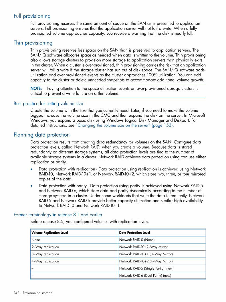
Full provisioningFull provisioning reserves the same amount of space on the SAN as is presented to applicationservers. Full provisioning ensures that the application server will not fail a write. When a fullyprovisioned volume approaches capacity, you receive a warning that the disk is nearly full.
Thin provisioningThin provisioning reserves less space on the SAN than is presented to application servers. TheSAN/iQ software allocates space as needed when data is written to the volume. Thin provisioningalso allows storage clusters to provision more storage to application servers than physically exitsin the cluster. When a cluster is over-provisioned, thin provisioning carries the risk that an applicationserver will fail a write if the storage cluster has run out of disk space. The SAN/iQ software addsutilization and over-provisioned events as the cluster approaches 100% utilization. You can addcapacity to the cluster or delete unneeded snapshots to accommodate additional volume growth.
NOTE: Paying attention to the space utilization events on over-provisioned storage clusters iscritical to prevent a write failure on a thin volume.
Best practice for setting volume sizeCreate the volume with the size that you currently need. Later, if you need to make the volumebigger, increase the volume size in the CMC and then expand the disk on the server. In MicrosoftWindows, you expand a basic disk using Windows Logical Disk Manager and Diskpart. Fordetailed instructions, see “Changing the volume size on the server” (page 153).
Planning data protectionData protection results from creating data redundancy for volumes on the SAN. Configure dataprotection levels, called Network RAID, when you create a volume. Because data is storedredundantly on different storage systems, all data protection levels are tied to the number ofavailable storage systems in a cluster. Network RAID achieves data protection using can use eitherreplication or parity.
• Data protection with replication - Data protection using replication is achieved using NetworkRAID-10, Network RAID-10+1, or Network RAID-10+2, which store two, three, or four mirroredcopies of the data.
• Data protection with parity - Data protection using parity is achieved using Network RAID-5and Network RAID-6, which store data and parity dynamically according to the number ofstorage systems in a cluster. Under some workloads that write the data infrequently, NetworkRAID-5 and Network RAID-6 provide better capacity utilization and similar high availabilityto Network RAID-10 and Network RAID-10+1.
Former terminology in release 8.1 and earlierBefore release 8.5, you configured volumes with replication levels.
Data Protection LevelVolume Replication Level
Network RAID-0 (None)None
Network RAID-10 (2–Way Mirror)2–Way replication
Network RAID-10+1 (3–Way Mirror)3–Way replication
Network RAID-10+2 (4–Way Mirror)4–Way replication
Network RAID-5 (Single Parity) (new)–
Network RAID-6 (Dual Parity) (new)–
142 Provisioning storage

Data protection levelSeven data protection levels are available, depending upon the number of available storagesystems in the cluster.
Table 38 Setting a data protection level for a volume
For this number of copiesSelect any of these data protection levelsWith this number ofavailable storage systemsin cluster
• One copy of data in the cluster.• Network RAID-0 (None)1
2 • One copy of data in the cluster.• Network RAID-0 (None)
• •Network RAID-10 (2–Way Mirror) Two copies of data in the cluster.
3 • One copy• Network RAID-0 (None)
• •Network RAID-10 (2-Way Mirror) Two copies
•• Three copiesNetwork RAID-10+1 (3-Way Mirror)
• •Network RAID-5 (Single Parity) Data striped on three storage systemsincluding single parity.
At least 4 • One copy• Network RAID-0 (None)
• •Network RAID-10 (2-Way Mirror) Two copies
•• Three copiesNetwork RAID-10+1 (3-Way Mirror)
• •Network RAID-10+2 (4-Way Mirror) Four copies
•• Data striped on four storage systemsincluding single parity.
Network RAID-5 (Single Parity)
At least 5 • One copy• Network RAID-0 (None)
• •Network RAID-10 Two copies
•• Three copiesNetwork RAID-10+1 (3-Way Mirror)
• •Network RAID-10+2 (4-Way Mirror) Four copies
•• Data striped on five storage systemsincluding single parity.
Network RAID-5 (Single Parity)
• Network RAID-6 (Dual Parity)• Data striped on five storage systems
including dual parity.
At least 6 • One copy• Network RAID-0 (None)
• •Network RAID-10 Two copies
•• Three copiesNetwork RAID-10+1 (3-Way Mirror)
• •Network RAID-10+2 (4-Way Mirror) Four copies
•• Data striped on five storage systemsincluding single parity.
Network RAID-5 (Single Parity)
• Network RAID-6 (Dual Parity)• Data striped on six storage systems
including dual parity.
At least 7 • One copy• Network RAID-0 (None)
• •Network RAID-10 Two copies
•• Three copiesNetwork RAID-10+1 (3-Way Mirror)
• •Network RAID-10+2 (4-Way Mirror) Four copies
•• Data striped on five storage systemsincluding single parity.
Network RAID-5 (Single Parity)
• Network RAID-6 (Dual Parity)• Data striped on seven storage systems
including dual parity.
Provisioning volumes 143
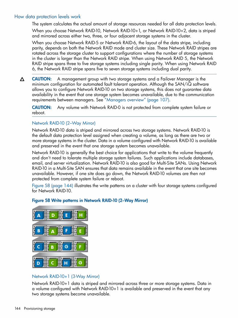
How data protection levels workThe system calculates the actual amount of storage resources needed for all data protection levels.When you choose Network RAID-10, Network RAID-10+1, or Network RAID-10+2, data is stripedand mirrored across either two, three, or four adjacent storage systems in the cluster.When you choose Network RAID-5 or Network RAID-6, the layout of the data stripe, includingparity, depends on both the Network RAID mode and cluster size. These Network RAID stripes arerotated across the storage cluster to support configurations where the number of storage systemsin the cluster is larger than the Network RAID stripe. When using Network RAID 5, the NetworkRAID stripe spans three to five storage systems including single parity. When using Network RAID6, the Network RAID stripe spans five to seven storage systems including dual parity.
CAUTION: A management group with two storage systems and a Failover Manager is theminimum configuration for automated fault tolerant operation. Although the SAN/iQ softwareallows you to configure Network RAID-10 on two storage systems, this does not guarantee dataavailability in the event that one storage system becomes unavailable, due to the communicationrequirements between managers. See “Managers overview” (page 107).
CAUTION: Any volume with Network RAID-0 is not protected from complete system failure orreboot.
Network RAID-10 (2–Way Mirror)Network RAID-10 data is striped and mirrored across two storage systems. Network RAID-10 isthe default data protection level assigned when creating a volume, as long as there are two ormore storage systems in the cluster. Data in a volume configured with Network RAID-10 is availableand preserved in the event that one storage system becomes unavailable.Network RAID-10 is generally the best choice for applications that write to the volume frequentlyand don't need to tolerate multiple storage system failures. Such applications include databases,email, and server virtualization. Network RAID-10 is also good for Multi-Site SANs. Using NetworkRAID-10 in a Multi-Site SAN ensures that data remains available in the event that one site becomesunavailable. However, if one site does go down, the Network RAID-10 volumes are then notprotected from complete system failure or reboot.Figure 58 (page 144) illustrates the write patterns on a cluster with four storage systems configuredfor Network RAID-10.
Figure 58 Write patterns in Network RAID-10 (2–Way Mirror)
Network RAID-10+1 (3-Way Mirror)Network RAID-10+1 data is striped and mirrored across three or more storage systems. Data ina volume configured with Network RAID-10+1 is available and preserved in the event that anytwo storage systems become unavailable.
144 Provisioning storage

Best applications for Network RAID-10+1 are those that require data availability even if two storagesystems in a cluster become unavailable.Figure 59 (page 145) illustrates the write patterns on a cluster with four storage systems configuredfor Network RAID-10+1.
Figure 59 Write patterns in Network RAID-10+1 (3-Way Mirror)
Network RAID-10+2 (4-Way Mirror)Network RAID-10+2 data is striped and mirrored across four or more storage systems. Data in avolume configured with Network RAID-10+2 is preserved in the event that any three storage systemsbecome unavailable. Network RAID-10+2 is designed for Multi-Site SANs to preserve data in theevent of an entire site becoming unavailable.Best use for Network RAID-10+2 volumes is for data that must be synchronously replicated betweentwo locations and that must remain fully redundant in the case of an entire site failure. UsingNetwork RAID-10+2 ensures that data remains available after half of the SAN is unavailable, andcontinues to remain available even with the loss of a single storage system in the remaining site.Figure 60 (page 145) illustrates the write patterns on a cluster with four storage systems configuredfor Network RAID-10+2.
Figure 60 Write patterns in Network RAID-10+2 (4-Way Mirror)
Network RAID-5 (Single Parity)Network RAID-5 divides the data into stripes and adds parity. Network RAID stripe spans three tofive storage systems including single parity. Data in a volume configured with Network RAID-5 isavailable and preserved in the event that any single storage system becomes unavailable.Network RAID-5 volumes are configured as thin provisioned by default.Best applications for using Network RAID-5 volumes include applications with mostly read, sequentialworkloads, such as file shares and archiving.
Provisioning volumes 145
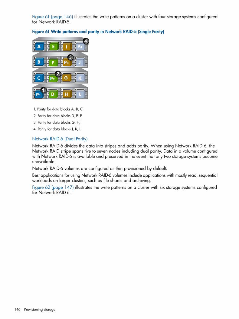
Figure 61 (page 146) illustrates the write patterns on a cluster with four storage systems configuredfor Network RAID-5.
Figure 61 Write patterns and parity in Network RAID-5 (Single Parity)
1. Parity for data blocks A, B, C
2. Parity for data blocks D, E, F
3. Parity for data blocks G, H, I
4. Parity for data blocks J, K, L
Network RAID-6 (Dual Parity)Network RAID-6 divides the data into stripes and adds parity. When using Network RAID 6, theNetwork RAID stripe spans five to seven nodes including dual parity. Data in a volume configuredwith Network RAID-6 is available and preserved in the event that any two storage systems becomeunavailable.Network RAID-6 volumes are configured as thin provisioned by default.Best applications for using Network RAID-6 volumes include applications with mostly read, sequentialworkloads on larger clusters, such as file shares and archiving.Figure 62 (page 147) illustrates the write patterns on a cluster with six storage systems configuredfor Network RAID-6.
146 Provisioning storage

Figure 62 Write patterns and parity in Network RAID-6 (Dual Parity)
1. P1 is parity for data blocks A, B, C, D
2. P2 is parity for data blocks E, F, G, H
3. P3 is parity for data blocks I, J, K, L
4. P4 is parity for data blocks M, N, O, P
Provisioning snapshotsSnapshots provide a copy of a volume for use with backup and other applications. You createsnapshots from a volume on the cluster.Snapshots are always thin provisioned. Thin provisioning snapshots saves actual space in the SAN,while letting you have more snapshots without the concern of running out of cluster space.Snapshots can be used for multiple purposes, including:
• Source volumes for data mining and other data use
• Source volumes for creating backups
• Data or file system preservation before upgrading software
• Protection against data deletion
• File-level restore without tape or backup software
Snapshots versus backupsBackups are typically stored on different physical devices such as tapes. Snapshots are stored inthe same cluster as the volume. Therefore, snapshots protect against data deletion, but not deviceor storage media failure. Use snapshots along with backups to improve your overall data backupstrategy.At any time you can roll back to a specific snapshot. When you do roll back, you must delete allthe snapshots created after that snapshot. Also, using an iSCSI initiator, you can mount a snapshotto a different server and recover data from the snapshot to that server.
The effect of snapshots on cluster spaceSnapshots take up space on the cluster. Because snapshots are a thin provisioned space, they savespace compared to a full provisioned space.
Provisioning snapshots 147

Plan how you intend to use snapshots, and the schedule and retention policy for schedules tosnapshot a volume. Snapshots record changes in data on the volume, so calculating the rate ofchanged data in the client applications is important for planning schedules to snapshot a volume.
NOTE: Volume size, provisioning, and using snapshots should be planned together. If you intendto use snapshots, review “Using snapshots” (page 162).
Managing capacity using volume size and snapshotsWhen you create a snapshot of a volume, the original volume is actually saved as the snapshot,and a new volume (the “writable” volume) with the original name is created to record any changesmade to the volume’s data after the snapshot was created. Subsequent snapshots record onlychanges made to the volume since the previous snapshot. Snapshots are always created as a thinprovisioned space, no matter whether its original volume is full or thin provisioned.
Volume size and snapshotsOne implication of the relationship between volumes and snapshots is that the space used by thewritable volume can become very small when it records only the changes that have occurred sincethe last snapshot was taken. This means that less space may be required for the writable volume.Over time, you may find that space allocated for snapshots becomes larger, and the volume itselfbecomes relatively small.
Schedules to snapshot a volume and capacityWhen you have schedules to snapshot a volume, the recurrence or frequency, and the retentionpolicy for the schedules affect the amount of space used in the cluster. For example, it is possiblefor a new snapshot and one snapshot scheduled for deletion to coexist in the cluster for someperiod of time. If there is not sufficient room in the cluster for both snapshots, the scheduled snapshotwill not be created, and the schedule will not continue until an existing snapshot is deleted.Therefore, if you want to retain (n) snapshots, the cluster should have space for (n+1).
Deleting snapshotsAnother factor to note in planning capacity is the fact that when a snapshot is deleted, thatsnapshot’s data is added to the snapshot or volume directly above it (the next newer snapshot).The amount of space allocated for the volume or snapshot directly above the deleted snapshotincreases. See “Ongoing capacity management” (page 148) for detailed information about reviewingcapacity.
Ongoing capacity managementOne of the critical functions of managing a SAN is monitoring usage and capacity. The CMCprovides detailed information about overall cluster capacity and usage, as well as detail aboutprovisioning and storage system capacity.
Number of volumes and snapshotsFor information about the recommended maximum number of volumes and snapshots that can becreated in a management group, see “Configuration Summary overview” (page 109) .
Reviewing SAN capacity and usageYou can review detailed information about the capacity of your cluster, the volumes it contains,and the provisioning of the storage systems in the cluster. This information is presented in a seriesof tab windows displayed at the cluster level.
148 Provisioning storage

Figure 63 Cluster tab view
Cluster use summaryThe Use Summary window presents information about the storage space available in the cluster.
Figure 64 Reviewing the Use Summary tab
In the Use Summary window, the Storage Space section lists the space available on the storagesystems in the cluster. Saved space lists the space saved in the cluster by using thin provisioningand the SmartClone feature. The graphical display illustrates the amount of space in the clusterand its allocation as provisioned and available. Storage space is broken down as shown inTable 39 (page 149).
Table 39 Information on the Use Summary tab
DescriptionCategory
Table information
Storage Space
Combined space available in the cluster for storagevolumes and snapshots.
Total
Amount of space allocated for storage, including bothvolumes and snapshots. This value increases as snapshotsare taken, or as a thinly provisioned volume grows.
Provisioned
Amount of space remaining in the cluster that has not beenallocated for storage. This value decreases as volumes and
Available
Ongoing capacity management 149

Table 39 Information on the Use Summary tab (continued)
DescriptionCategory
snapshots are created, or as thinly provisioned volumesgrow.
Saved Space
The space saved by thin provisioning volumes. This spaceis calculated by the system.
Thin Provisioning
Space saved by using SmartClone volumes is calculatedusing the amount of data in the clone point and any
SmartClone Feature
snapshots below the clone point. Only as data is addedto an individual SmartClone volume does it consume spaceon the SAN.
Approximate total amount of space saved by using thinprovisioning and SmartClone volumes.
Total
Graph information
Amount of space allocated for volumes and snapshots.Provisioned
Amount of space remaining in the cluster that has not beenallocated for storage. This value decreases as volumes and
Available
snapshots are created, or as thinly provisioned volumesgrow.
Combined space available in the cluster for storagevolumes and snapshots.
Total
This graph appears only if the cluster is over-provisioned.It displays the total space that volumes and snapshots can
Provisionable
grow to fill, and this value can exceed the physical capacityof the SAN. As an over-provisioned cluster approaches thephysical capacity of the SAN, a series of warnings displayson the Use Summary window.
Volume use summaryThe Volume Use window presents detailed information about the volume characteristics that affectthe utilization of the cluster.
Table 40 Information on the Volume Use tab
DescriptionCategory
Name of the volume or snapshot.Name
The level of data protection configured for the volume.Snapshots inherit the data protection level of the parentvolume.
Data Protection Level
Volumes can be either full or thin provisioned. TheProvisioning column also details space saving options for
Provisioning
the different types of volumes you can create on the SAN,as shown in Figure 65 (page 151). The space calculationstake into account both the type of volume and the dataprotection level. Use this information to help you managespace use on the SAN.• Thin provisioning saves space on the SAN by only
allocating a fraction of the configured volume size.Therefore, the space saved on the SAN is reflected inthis column. As data is added to the volume, thinprovisioning grows the allocated space. You can expect
150 Provisioning storage

Table 40 Information on the Volume Use tab (continued)
DescriptionCategory
to see the space saved number decrease as data onthe volume increases.
• Full provisioning allocates the full amount of space forthe size of the volume. Reclaimable space is the amountof space that you can get back if this fully provisionedvolume is changed to thinly provisioned.
Amount of space used by actual data volumes or snapshots.The consumed space is the amount you can regain if you
Consumed Space
delete the volume and its snapshots. If the volume hasSmartClone clone points below it, the clone point and anysnapshot below it comprise the Shared Space listed nextto the consumed space. To regain the Shared Space, youmust delete the clone point and any snapshots below it.For instructions on deleting clone points, see “Deleting theclone point ” (page 194)Deleting files or data from client applications does notdecrease the used space. For more information, see“Measuring disk capacity and volume size” (page 152).
Figure 65 Viewing the space saved or reclaimable in the Volume Use tab
1. Space saved or reclaimable displayed here
System Use summaryThe System Use window presents a representation of the space provisioned on the storage systemsin the cluster.
Figure 66 Viewing the System Use tab
Ongoing capacity management 151

Table 41 Information on the System Use tab
DescriptionCategory
Host name of the storage system.Name
Total amount of disk capacity on the storage system. Note:Storage systems with greater capacity will only operate to
Raw space
the capacity of the lowest capacity storage system in thecluster.
RAID level configured on the storage system.RAID configuration
Space available for storage after RAID has beenconfigured.
Usable space
Amount of space allocated for volumes and snapshots.Provisioned space
Measuring disk capacity and volume sizeAll operating systems that are capable of connecting to the SAN via iSCSI interact with two diskspace accounting systems—the block system and the native file system (on Windows, this is usuallyNTFS).
Table 42 Common native file systems
File System NamesOS
NTFS, FATWindows
EXT2, EXT3Linux
NWFSNetware
UFSSolaris
VMFSVMware
Block systems and file systemsOperating systems see hard drives (both directly connected [DAS] and iSCSI connected [SAN])as abstractions known as “block devices”: arbitrary arrays of storage space that can be read fromand written to as needed.Files on disks are handled by a different abstraction: the file system. File systems are placed onblock devices. File systems are given authority over reads and writes to block devices.iSCSI does not operate at the file system level of abstraction. Instead, it presents the iSCSI SANvolume to an OS such as Microsoft Windows as a block device. Typically, then, a file system iscreated on top of this block device so that it can be used for storage. In contrast, an Oracledatabase can use an iSCSI SAN volume as a raw block device.
Storing file system data on a block systemThe Windows file system treats the iSCSI block device as simply another hard drive. That is, theblock device is treated as an array of blocks which the file system can use for storing data. As theiSCSI initiator passes writes from the file system, the SAN/iQ software simply writes those blocksinto the volume on the SAN. When you look at the CMC, the used space displayed is based onhow many physical blocks have been written for this volume.When you delete a file, typically the file system updates the directory information which removesthat file. Then the file system notes that the blocks which that file previously occupied are nowfreed. Subsequently, when you query the file system about how much free space is available, thespace occupied by the deleted files appears as part of the free space, since the file system knowsit can overwrite that space.
152 Provisioning storage

However, the file system does not inform the block device underneath (the SAN/iQ volume) thatthere is freed-up space. In fact, no mechanism exists to transmit that information. There is no SCSIcommand which says “Block 198646 can be safely forgotten.” At the block device level, thereare only reads and writes.So, to ensure that our iSCSI block devices work correctly with file systems, any time a block iswritten to, that block is forever marked as allocated. The file system reviews its “available blocks”list and reuses blocks that have been freed. Consequently, the file system view (such as WindowsDisk Management) may show you have X amount of free space, and the CMC view may showthe Used Space as 100% used.
CAUTION: Some file systems support defragmenting which essentially reorders the data on theblock device. This can result in the SAN allocating new storage to the volume unnecessarily.Therefore, do not defragment a file system on the SAN unless the file system requires it.
Changing the volume size on the server
CAUTION: Decreasing the volume size is not recommended. If you shrink the volume in the CMCbefore shrinking it from the server file system, your data will be corrupted or lost.
When you increase the size of the volume on the SAN, you must also increase the correspondingvolume, or LUN, on the server side.
Increasing the volume size in Microsoft WindowsAfter you have increased the volume size on the SAN, you must next expand the Windows partitionto use the full space available on the disk.Windows Logical Disk Manager, the default disk management program that is included in anyWindows installation, uses a tool called Diskpart.exe to grow volumes from within Windows.Diskpart.exe is an interactive command line executable which allows administrators to select andmanipulate disks and partitions. This executable and its corresponding documentation can bedownloaded from Microsoft if necessary.Follow the steps below to extend the volume you just increased in the SAN.1. Launch Windows Logical Disk Manager to rescan the disk and present the new volume size.2. Open a Windows command line and run diskpart.exe.3. List the volumes that appear to this host by typing the command list volume.4. Select the volume to extend by typing select volume # (where # is the corresponding
number of the volume in the list).5. Enter extend to grow the volume to the size of the full disk that has been expanded.
Notice the asterisk by the volume and the new size of the volume. The disk has been extendedand is now ready for use.
All of the above operations are performed while the volumes are online and available to users.
Increasing the volume size in other environmentsEnvironments other than Windows use alternative disk management tools, which use a utility calledExtpart.exe. The only major difference is that instead of selecting the volume number, as inDiskpart.exe, you select the drive letter instead.
Ongoing capacity management 153

Changing configuration characteristics to manage spaceOptions for managing space on the cluster include
• Changing snapshot retention—retaining fewer snapshots requires less space
• Changing schedules to snapshot a volume—taking snapshots less frequently requires lessspace
• Deleting volumes or moving them to a different cluster
NOTE: Deleting files on a file system does not free up space on the SAN volume. For moreinformation, see “Block systems and file systems” (page 152). For file-level capacity management,use application or file system-level tools.
154 Provisioning storage

12 Using volumesA volume is a logical entity that is made up of storage on one or more storage systems. It can beused as raw data storage or it can be formatted with a file system and used by a host or file server.Create volumes on clusters that contain one or more storage systems.Before creating volumes, plan your strategies for using the volume: how you plan to use it, its size,how servers will access it, and how you will manage backups of the data, whether through RemoteCopy or third-party applications, or both.
Volumes and server accessAfter you create a volume, assign it to one or more servers to provide access to volumes byapplication servers. For detailed information, see “Controlling server access to volumes” (page 197).
PrerequisitesBefore you create a volume, you must have created a management group and at least one cluster.For more information, see the following:
• “Working with management groups” (page 104)
• “Creating a cluster” (page 133)
Planning volumesPlanning volumes takes into account multiple factors.
• The number of volumes you need
• The type of volumes you are creating - primary or remote
• The size for each volume
• Whether you plan to use snapshots
• The level of data protection required
• Whether you plan to grow the volume, or leave it the same size
NOTE: If you plan to mount file systems, create a volume for each file system you plan to mount.Then grow each file system independently.
Planning how many volumesFor information about the recommended maximum number of volumes and snapshots that can becreated in a management group, see “Configuration Summary overview” (page 109).
Planning volume types• Primary volumes are volumes used for data storage.
• Remote volumes are used as targets for Remote Copy for business continuance, backup andrecovery, and data mining/migration configurations. See the Remote Copy User Guide fordetailed information about remote volumes.
• A SmartClone volume is a type of volume that is created from an existing volume or snapshot.SmartClone volumes are described in “SmartClone volumes” (page 178).
Guide for volumesWhen creating a volume, you define the following characteristics.
Volumes and server access 155

Table 43 Characteristics for new volumes
What it meansConfigurable for Primaryor Remote Volume
Volume characteristic
Basic Tab
The name of the volume that is displayed in the CMC. Avolume name is from 1 to 127 characters and is case
BothVolume Name
sensitive. The volume name cannot be changed. You canenable and customize a default naming convention forvolumes. See “Setting naming conventions” (page 15) formore information.
[Optional] A description of the volume.BothDescription
The logical block storage size of the volume. Hosts and filesystems operate as if storage space equal to the volume size
PrimarySize
is available in the cluster. This volume size may exceed thetrue allocated disk space on the cluster for data storage,which facilitates adding more storage systems to the clusterlater for seamless storage growth. However, if the volumesize does exceed true allocated disk space, the ability tomake snapshots may be impacted. See “Using snapshots”(page 162).Remote volumes contain no data, since they serve as pointersto tell the system where to make a copy of a primarysnapshot. Therefore, remote volumes do not have a size.
[Optional] Servers are set up in the management group toconnect application hosts to volumes. Select the server thatyou want to have access to the volume you are creating.
BothServers
Advanced Tab
If the management group contains more than one cluster, youmust specify the cluster on which the volume resides.
BothCluster
The data protection level indicates the number andconfiguration of data copies created on storage systems inthe cluster.
BothData Protection Level
There are six levels of data protection• Network RAID-0 (None)
• Network RAID-5 (Single Parity)
• Network RAID-6 (Dual Parity)
• Network RAID-10 (2–Way Mirror)
• Network RAID-10+1 (3–Way Mirror)
• Network RAID-10+2 (4–Way Mirror)The default value = Network RAID-10. For information aboutthe data protection levels, see “Planning data protection”(page 142).
156 Using volumes

Table 43 Characteristics for new volumes (continued)
What it meansConfigurable for Primaryor Remote Volume
Volume characteristic
BothType • Primary volumes are used for data storage.
• Remote volumes are used for configuring Remote Copyfor business continuance, backup and recovery, or datamining/migration.
Default value = Primary
PrimaryProvisioning • Fully provisioned volumes are the same size on the SANas the size presented to the application server.
• Thinly provisioned volumes have less space reserved onthe SAN than the size presented to the application server.As data is stored on the volume, the SAN/iQ softwareautomatically increases the amount of space allocated onthe SAN.
The default value = Full for the following data protectionlevels.
• Network RAID-0 (None)
• Network RAID-10 (2–Way Mirror)
• Network RAID-10+1 (3–Way Mirror)
• Network RAID-10+2 (4–Way Mirror)
The default value = Thin for the following data protectionlevels.
• Network RAID-5 (Single Parity)
• Network RAID-6 (Dual Parity)
Thin provisioning is the best practice configuration forNetwork RAID-5 and Network RAID-6 volumes.
NOTE: The SAN/iQ software allocates space as needed.However, thin provisioning carries the risk that, if all warningsare ignored, an application server will fail a write becausethe SAN has run out of disk space.
Creating a volumeA volume resides on the storage systems contained in a cluster. You can easily create a basicvolume, or customize the Advanced settings. Both options are described in the following steps.1. Log in to the management group in which you want to create a volume.2. In the navigation window, select the cluster in which you want to create a volume.3. Click Cluster Tasks, and select New Volume.
Creating a basic volumeYou can create a basic volume simply by entering a name and a size for the volume.1. Enter a name for the volume.2. [Optional] Enter a description of the volume.3. Designate a size for the volume.4. [Optional] Assign a server to the volume.5. Click OK.
The SAN/iQ software creates the volume. The volume is selected in the navigation windowand the Volume tab view displays the Details tab.
Creating a volume 157

NOTE: The system automatically factors data protection levels into the settings. For example, ifyou create a fully provisioned 500 GB volume and the data protection level is Network RAID-10(2–Way Mirror), the system automatically allocates 1000 GB for the volume.
To set advanced characteristics for a volume, continue on the Advanced tab of the New Volumewindow.
Configuring advanced volume settings [optional]Set additional characteristics for a volume in the Advanced tab in the New Volume window.Advanced settings include the following:
• Cluster (changing the cluster is typically used to migrate volumes to a different cluster at somelater time)
• Data protection level
• Volume type
• ProvisioningDescriptions of these characteristics are found in “Characteristics for new volumes” (page 156).
Configuring advanced volume settingsConfigure the Advanced settings when you create the new volume if you do not want to use thedefault settings.1. Click the Advanced tab on the New Volume window.2. Change the desired characteristics and click OK when you are finished.Configuring a volume for either Network RAID-5 or Network RAID-6 automatically creates asnapshot schedule. This default schedule is named VolumeName_Schedule, recurs once daily, andretains 1 copy. The first snapshot is created one day after the schedule is created. You can editthis schedule as desired, as described in “Editing scheduled snapshots” (page 168).
Volumes map viewAfter you create volumes and finish setting up the SAN, use the Map View tab for viewing therelationships between volumes, snapshots, servers, and remote copies. For more information onusing the map view tools, see “Using the display tools” (page 14).Volumes map views include the following:• Volume Hierarchy
• Remote Copies
• Remote Copies (Volume Hierarchies)
• Servers to Volumes
Editing a volumeWhen editing a primary volume, you can change the description, size, and advanced characteristicssuch as the cluster, data protection level, type and provisioning.
NOTE: Moving the volume to a different cluster requires restriping the data in both clusters.Restriping can take hours, or even days.
158 Using volumes

Table 44 Requirements for changing volume characteristics
Requirements for ChangingItem
Must be from 1 to 127 characters.Description
Server must have already been created in the managementgroup.
Server
Migrating a volume to a different cluster requires the targetcluster to:
Cluster
• Reside in the same management group
• Have sufficient storage systems and unallocated spacefor the size and data protection level of the volumebeing moved
The volume resides on both clusters until all of the data ismoved to the new cluster. This causes a restripe of the dataon both clusters. For example, you create a new cluster inthe management group to expand the storage capacity inthe management group. You want to migrate an existingvolume to the new cluster as part of the capacitymanagement.
NOTE: The volume remains fault-tolerant while beingmoved.The rate of the data migration and the resulting impact onperformance can be controlled by the Local BandwidthPriority setting for the management group. See “Editing amanagement group” (page 116) for information about localbandwidth priority settings.
The cluster must have sufficient storage systems andunallocated space to support the new data protection level.
Data protection level
For example, you just added more storage to a cluster andhave more capacity. You decide to change the dataprotection level for a volume from Network RAID-0 toNetwork RAID-10 to ensure you have redundancy for yourdata.
Before changing the size of a volume, refer to “Changingthe volume size on the server” (page 153)To increase the size of the volume:
Size
• If you have enough free space in the cluster, simplyenter the new size
• If you do not have enough free space in the cluster,delete volumes and/or snapshots, or add a storagesystem to the cluster
To decrease the size of the volume (not recommended)
• If the volume has been or is mounted by any operatingsystem, you must shrink the file system on the volumebefore shrinking the volume in the CMC.
• You also should not decrease the size of the volumebelow the size needed for data currently stored on thevolume.
CAUTION: HP recommends that you do not decrease the volume size. If you shrink the volumein the CMC before shrinking it from the server file system, your data will be corrupted or lost.
To edit a volume1. In the navigation window, select the volume you want to edit.2. Click Volume Tasks and select Edit Volume.
Editing a volume 159
Changing the volume description1. In the Description field, edit the description.2. Click OK when you are finished.
Changing the cluster—migrating a volume to a different clusterEditing the volume to change the cluster causes the volume to migrate to the target cluster. TheSAN/iQ software allows the online migration of volumes between storage clusters in the samemanagement group. This migration can be used to manage both storage capacity and performancebetween clusters. For example, move a large volume from Cluster A to Cluster B to free up spacein Cluster A, or improve the performance of a volume by moving it from a cluster of MDL-SASstorage systems to a cluster of 15K SAS storage systems.See Table 44 (page 159) for the requirements for migrating a volume.
iSCSI sessions and volume migrationiSCSI sessions are rebalanced during volume migration. While data is being migrated the volumeis still accessible and fully functional. The rebalancing affects systems using the DSM for MPIOdifferently than systems that are not using the DSM for MPIO.
• Using DSM for MPIO—Administrative sessions are rebalanced to the new cluster immediatelyupon volume migration. DSM sessions go into an unknown/failed state and are thenre-established on the second cluster within a short period of time.
• No DSM for MPIO—iSCSI session is rebalanced to the new cluster immediately on volumemigration.
As soon as possible after beginning the migration, the iSCSI initiators configured to access thisvolume must be re-configured to connect to the VIP of the new cluster. Most initiators require youto disconnect the volume, re-configure the initiator to use the new cluster VIP as a target address,and then connect to the volume again. Since this volume is disconnected, administrators shouldschedule a maintenance window for the re-configuration of the initiator.
NOTE: Moving the volume to a different cluster requires restriping the data in both clusters.Restriping can take hours, or even days.
To change the cluster—migrate the volume1. On the Edit Volume window, select the Advanced tab.2. In the Cluster drop-down list, select a different cluster.3. Click OK.
Changing the data protection level1. In the Data Protection Level drop-down list, select the level of Network RAID you want.
Changing a volume to either Network RAID-5 or Network RAID-6 requires that volume to havea snapshot schedule. If the volume does not already have a snapshot schedule related to it,one will be created automatically. This default schedule is named VolumeName_Schedule,recurs once daily, and retains 1 copy. You can edit this schedule as desired, as described in“Editing scheduled snapshots” (page 168).
2. Click OK when you are finished.
Changing the size1. In the Size field, change the number and change the units if necessary.2. Click OK when you are finished.
CAUTION: Decreasing the volume size is not recommended. If you shrink the volume in the CMCbefore shrinking it from the server file system, your data will be corrupted or lost.
160 Using volumes
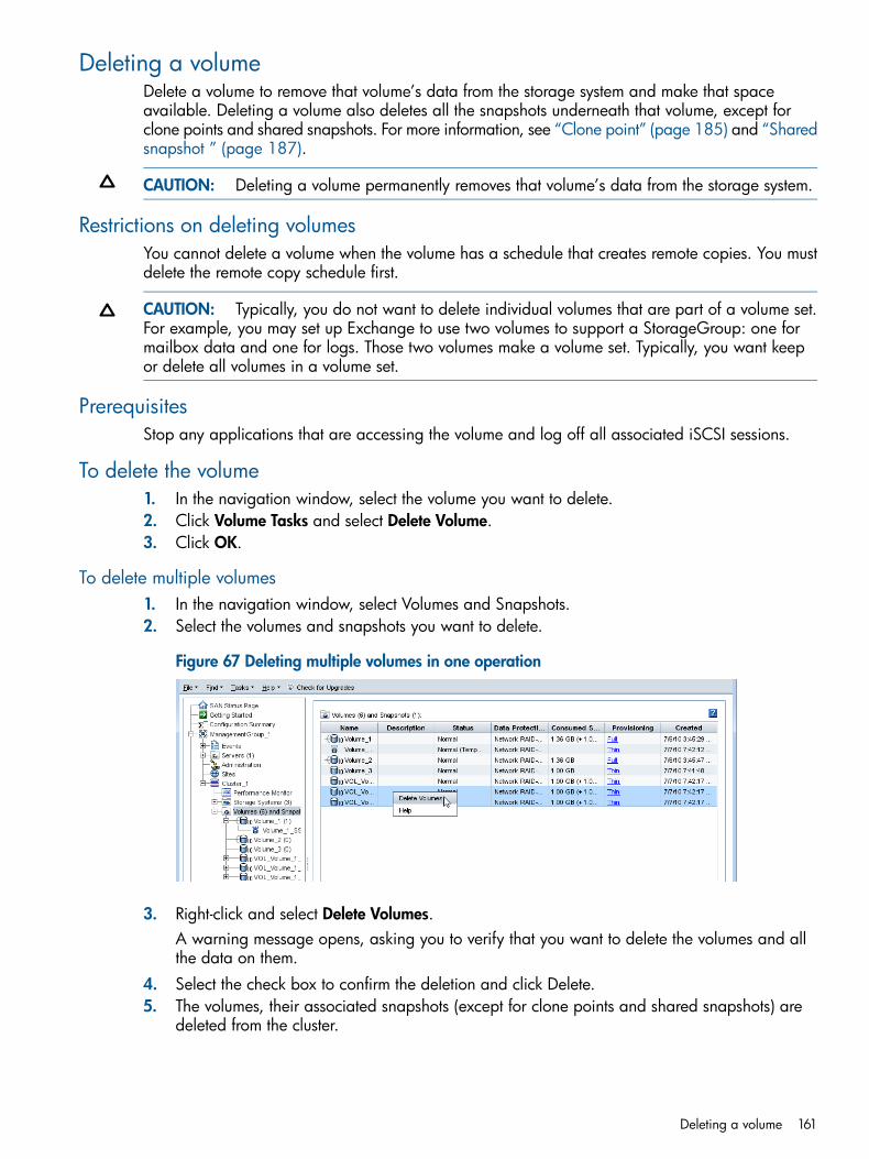
Deleting a volumeDelete a volume to remove that volume’s data from the storage system and make that spaceavailable. Deleting a volume also deletes all the snapshots underneath that volume, except forclone points and shared snapshots. For more information, see “Clone point” (page 185) and “Sharedsnapshot ” (page 187).
CAUTION: Deleting a volume permanently removes that volume’s data from the storage system.
Restrictions on deleting volumesYou cannot delete a volume when the volume has a schedule that creates remote copies. You mustdelete the remote copy schedule first.
CAUTION: Typically, you do not want to delete individual volumes that are part of a volume set.For example, you may set up Exchange to use two volumes to support a StorageGroup: one formailbox data and one for logs. Those two volumes make a volume set. Typically, you want keepor delete all volumes in a volume set.
PrerequisitesStop any applications that are accessing the volume and log off all associated iSCSI sessions.
To delete the volume1. In the navigation window, select the volume you want to delete.2. Click Volume Tasks and select Delete Volume.3. Click OK.
To delete multiple volumes1. In the navigation window, select Volumes and Snapshots.2. Select the volumes and snapshots you want to delete.
Figure 67 Deleting multiple volumes in one operation
3. Right-click and select Delete Volumes.A warning message opens, asking you to verify that you want to delete the volumes and allthe data on them.
4. Select the check box to confirm the deletion and click Delete.5. The volumes, their associated snapshots (except for clone points and shared snapshots) are
deleted from the cluster.
Deleting a volume 161

13 Using snapshotsSnapshots are a copy of a volume for use with backup and other applications.
Types of snapshotsSnapshots are one of the following types:
• Regular or point-in-time —Snapshot that is taken at a specific point in time. However, anapplication writing to that volume may not be quiesced. Thus, data may be in flight or cachedand the actual data on the volume may not be consistent with the application's view of thedata.
• Application-managed —Snapshot of a volume that is taken while the application that isserving that volume is quiesced. Because the application is quiesced, the data in the snapshotis consistent with the application's view of the data. That is, no data was in flight or cachedwaiting to be written. This type requires the use of the HP P4000 Application Aware SnapshotManager. For more information, see “Prerequisites for application-managed snapshots”(page 164).When an application uses two or more volumes, those associated volumes are called a volumeset. For example, you may set up Exchange to use two volumes to support a StorageGroup:one for mailbox data and one for logs. Those two volumes make a volume set.
Snapshots versus backupsBackups are typically stored on different physical devices, such as tapes. Snapshots are stored inthe same cluster as the volume. Therefore, snapshots protect against data deletion, but not deviceor storage media failure. Use snapshots along with backups to improve your overall data backupstrategy.
Uses and best practices for snapshotsYou create snapshots from a volume on the cluster. At any time you can roll a volume back to aspecific snapshot, create a SmartClone volume, or use Remote Copy from a snapshot. You canmount a snapshot to a different server and recover data from the snapshot to that server. Whenplanning to use snapshots, ensure that there is space available on the cluster to create the snapshot.For information about snapshots and cluster space, see “The effect of snapshots on cluster space”(page 147)Snapshots can be used for these cases:
• Source for creating backupsBest Practice—Plan to use a single snapshot and delete it when you are finished.
• Data or file system preservation before upgrading softwareBest Practice—Plan to use a single snapshot and delete it when you are finished.
• Protection against data deletionBest Practice—Plan to use a series of snapshots, deleting the oldest on a scheduled basis.When planning this schedule, consider the following questions:◦ Is space available on the cluster to create the snapshots?
◦ What is the optimum schedule and retention policy for this schedule to snapshot a volume?See “Planning snapshots” (page 163) for the average daily change rates for some commonapplications.For example, if you are using these backups as part of a disaster recovery plan, youmight schedule a daily snapshot of the volume and retain 7 copies. A second schedule
162 Using snapshots

would run weekly and retain 5 copies. A third schedule would run monthly and keep 4copies.
• File-level restore without tape or backup software
• Source volumes for data mining, test and development, and other data use.Best Practice—Use SmartClone volumes. See “SmartClone volumes” (page 178) .
Planning snapshotsWhen planning to use snapshots, consider their purpose and size. If you are planning to useschedules to snapshot a volume, see “Clusters and storage systems” (page 133) and Table 45(page 163) for approximate data change rates for some common applications.
Table 45 Common applications’ daily change rates
Daily Change RatesApplication
1 - 3%Fileshare
10 - 20%Email/Exchange
10%Database
NOTE: When considering the size of snapshots in the cluster, remember that the data protectionlevel of the volume is duplicated in the snapshot.
Also consider how many volumes and snapshots you want to create and manage. For informationabout the recommended maximum number of volumes and snapshots that can be created in amanagement group, see “Configuration Summary overview” (page 109) and “Working withmanagement groups” (page 104).
Configuring snapshotsWhen creating a snapshot, you define the following characteristics or options.
Table 46 Snapshot characteristics
What it meansSnapshot parameter
This option quiesces applications on the server before theSAN/iQ software creates the snapshot. This option requires
Application-Managed Snapshot
the use of the Application Aware Snapshot Manager. Formore information, see “Prerequisites forapplication-managed snapshots” (page 164). If theApplication Aware Snapshot Manager is not installed, theSAN/iQ software creates a point-in-time snapshot (notusing the Application Aware Snapshot Manager).
The name of the snapshot that is displayed in the CMC. Asnapshot name must be from 1 to 127 characters and is
Snapshot Name
case sensitive. Snapshots have a default naming conventionenabled when the CMC is installed. You can change ordisable this naming convention. See “Setting namingconventions” (page 15) for information about this namingconvention. The following are illegal characters: , ' “ ; : =.
(Optional) A description of the snapshot – from 0 to 127characters.
Description
(Optional for Windows) Configure server access to thesnapshot.Required for VMware: In the CMC, first configure a serverwith the controlling IP address. The controlling IP address
Assign and Unassign Servers
is the IP address of the application server on which the
Planning snapshots 163
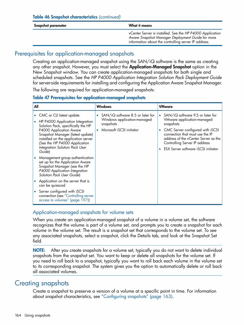
Table 46 Snapshot characteristics (continued)
What it meansSnapshot parameter
vCenter Server is installed. See the HP P4000 ApplicationAware Snapshot Manager Deployment Guide for moreinformation about the controlling server IP address.
Prerequisites for application-managed snapshotsCreating an application-managed snapshot using the SAN/iQ software is the same as creatingany other snapshot. However, you must select the Application-Managed Snapshot option in theNew Snapshot window. You can create application-managed snapshots for both single andscheduled snapshots. See the HP P4000 Application Integration Solution Pack Deployment Guidefor server-side requirements for installing and configuring the Application Aware Snapshot Manager.The following are required for application-managed snapshots:
Table 47 Prerequisites for application-managed snapshots
VMwareWindowsAll
• SAN/iQ software 9.5 or later forVMware application-managedsnapshots
• SAN/iQ software 8.5 or later forWindows application-managedsnapshots
• CMC or CLI latest update
• HP P4000 Application IntegrationSolution Pack, specifically the HP
•• CMC Server configured with iSCSIconnection that must use the IP
Microsoft iSCSI initiatorP4000 Application AwareSnapshot Manager (latest update)
address of the vCenter Server as theControlling Server IP address
installed on the application server(See the HP P4000 ApplicationIntegration Solution Pack UserGuide)
• ESX Server software iSCSI initiator
• Management group authenticationset up for the Application AwareSnapshot Manager (see the HPP4000 Application IntegrationSolution Pack User Guide)
• Application on the server that iscan be quiesced
• Server configured with iSCSIconnection (see “Controlling serveraccess to volumes” (page 197))
Application-managed snapshots for volume setsWhen you create an application-managed snapshot of a volume in a volume set, the softwarerecognizes that the volume is part of a volume set, and prompts you to create a snapshot for eachvolume in the volume set. The result is a snapshot set that corresponds to the volume set. To seeany associated snapshots, select a snapshot, click the Details tab, and look at the Snapshot Setfield.
NOTE: After you create snapshots for a volume set, typically you do not want to delete individualsnapshots from the snapshot set. You want to keep or delete all snapshots for the volume set. Ifyou need to roll back to a snapshot, typically you want to roll back each volume in the volume setto its corresponding snapshot. The system gives you the option to automatically delete or roll backall associated volumes.
Creating snapshotsCreate a snapshot to preserve a version of a volume at a specific point in time. For informationabout snapshot characteristics, see “Configuring snapshots” (page 163).
164 Using snapshots

Creating an application-managed snapshot, with or without volume sets, requires the use of theApplication Aware Snapshot Manager. The application-managed snapshot option quiescesWindows and VMware applications on the server before creating the snapshot. For moreinformation, see “Prerequisites for application-managed snapshots” (page 164). If the ApplicationAware Snapshot Manager is not installed, the SAN/iQ software creates a regular, point-in-timesnapshot.
Creating regular or application-managed snapshotsThe snapshot creation process for application-managed snapshots differs when a Windowsapplication has associated volumes. See “Creating snapshots for volume sets” (page 165). Whenusing application-managed snapshots with VMware vCenter Server, you must first create a serverin the CMC and use the IP address of the application server on which the vCenter Server is installedas the controlling server IP address in the New Server window.1. Log in to the management group that contains the volume for which you want to create a new
snapshot.2. Right-click the volume, and select New Snapshot.3. (Optional) If you are using the Application Aware Snapshot Manager and want to quiesce
the application before creating the snapshot, select Application-Managed Snapshot.The system fills in the Description field and disables the Assign and Unassign Servers buttonautomatically. You can assign servers after the snapshot is created.
4. Enter a name for the snapshot, or accept the default.5. (Optional) Enter a description of the snapshot.6. (Optional) Assign a server to the snapshot.7. Click OK when you are finished.
NOTE: In the navigation window, snapshots are listed below the volume in descending dateorder, from newest to oldest.
Creating snapshots for volume sets1. Log in to the management group that contains the volume for which you want to create a new
snapshot.2. Right-click the volume, and select New Snapshot.3. Select Application-Managed Snapshot.
The software fills in the Description field and disables the Assign and Unassign Servers buttonautomatically. You can assign servers after the snapshot is created.
4. Enter a name for the snapshot or accept the default.5. Click OK.
The New Snapshot – Associated Volumes window opens with a list of all volumes in the volumeset.
6. (Optional) Edit the Snapshot Name and Description for each snapshot.
NOTE: Be sure to leave the Application-Managed Snapshots check box selected. This optionmaintains the association of the volumes and snapshots and quiesces the application beforecreating the snapshots. If you clear the check box, the system creates a point-in-time snapshotof each volume listed.
7. Click Create Snapshots to create a snapshot of each volume.The snapshots appear in the CMC. To see the associated snapshots, select a snapshot, clickthe Details tab, and look at the Snapshot Set field.
Creating snapshots 165

Editing a snapshotYou can edit both the description of a snapshot and its server assignment. The description must befrom 0 to 127 characters.1. Log in to the management group that contains the snapshot that you want to edit.2. In the navigation window, select the snapshot.3. Click Snapshot Tasks on the Details tab, and select Edit Snapshot.4. Change the description as necessary.5. Change the server assignment as necessary.6. Click OK when you are finished.
Scheduling snapshotsUse schedules to create a series of snapshots up to a specified number, or for a specified timeperiod. After the specified time period, or accumulated number of snapshots, the earliest snapshotis deleted when the new one is created. For example, you plan to keep a series of daily snapshotsfor one week, up to five snapshots. After creating the sixth snapshot, the earliest snapshot is deleted,thereby keeping the number of snapshots on the volume at five. A schedule can also create a singlesnapshot and then delete it when it is no longer needed. Snapshot schedules can also be pausedand resumed.Scripting snapshots, either recurring or single snapshots, can also take place on the server side.Scripted snapshots offer greater flexibility for quiescing hosts while taking snapshots, and forautomating tasks associated with volumes and their snapshots.
Best practices for scheduling snapshots of volumes• If you do not have an NTP server configured, before you create the schedule, you should
refresh the time setting of the management group to ensure that the storage systems are allset to the correct time.
• Configure schedules to snapshot a volume during off-peak hours. If setting schedules for multiplevolumes, stagger the schedules with at least an hour between start times for best results.
Table 48 Planning the scheduling for snapshots
What it meansRequirement
Scheduling snapshots should be planned with carefulconsideration for capacity management as described in
Plan for capacity management
“Managing capacity using volume size and snapshots”(page 148). Pay attention to how you want to retainsnapshots and the capacity in the cluster. If you want toretain <n> snapshots, the cluster should have space for<n+1>.It is possible for the new snapshot and the one to bedeleted to coexist in the cluster for some period of time.If there is not sufficient room in the cluster for bothsnapshots, the scheduled snapshot will not be created, andthe snapshot schedule will not continue until an existingsnapshot is deleted or space is otherwise made available.
The minimum recurrence you can set for snapshots is 30minutes. The maximum number of snapshots (scheduled
Plan scheduling and retention policies
and manual combined) you can retain is 50 snapshots pervolume. There are practical limits to the number ofsnapshots that a particular SAN can support and stillmaintain adequate performance. For information onoptimum configuration limits, performance, and scalability,see “Configuration Summary overview” (page 109).
166 Using snapshots

Requirements for snapshot schedulesTable 49 Characteristics for creating a schedule to snapshot a volume
Description and requirementsItem
The name of the schedule that is displayed in the CMC. Ascheduled snapshot name must be from 1 to 127 characters
Name
and is case sensitive. Snapshots created by a schedulehave a default naming convention enabled when the CMCis installed. You can change or disable this namingconvention. See “Setting naming conventions” (page 15)for information about this naming convention.The name you enter in the Create Schedule to Snapshot aVolume window will be used with sequential numbering.For example, if the name is Backup, the list of snapshotscreated by this schedule will be named Backup.1,Backup.2, Backup.3.
[Optional] Must be from 0 to 127 characters.Description
The start date and time is usually set for the future.However, it can be set to occur in the past. If set for a past
Start at
time and date, a snapshot is created immediately with theparameters set in the schedule.
The recurrence can be set to every n number of minutes,hours, days, or weeks, or to never recur. The minimumrecurrence is 30 minutes.
Recurrence
[Optional] This option quiesces applications on theapplication server before the SAN/iQ software creates thesnapshot.
Application-managed snapshot
The retention criteria can be for a specified number ofsnapshots, up to 50, or for a designated period of time.
Retention
Scheduling snapshots for volume setsWhen you create a schedule to snapshot a volume that has associated volumes, the systemautomatically creates snapshots for each associated volume. For information about volume sets,see “Application-managed snapshots for volume sets” (page 164).The schedule also reflects the volume associations based on the volume you select when you createthe schedule. That volume becomes the “owning” volume. The Volume Set field of the scheduledisplays (O) next to the owning volume. You should check that the field displays all of the volumesthat you want to snapshot. It is possible that the owning volume is not aware of all associatedvolumes. If it is not, select a volume that is aware of all associated volumes, and create the schedulethere.
Updating schedule for volume setsWhen you first create the schedule, the system stores information about the volume set as it existsat that time. If you add volumes to or remove volumes from the volume set using the application,you must update the schedule. To update it, you only need to edit the schedule and click OK. Thesystem automatically updates the volume set information when you click OK. If you want to see theupdated information, you can click Verify Volume Associations, then click OK. For more information,see “Editing scheduled snapshots” (page 168).
NOTE: If you have a schedule to remote snapshot a volume and you add a volume to the volumeset using the application, the system cannot update the volume set information as described above.You must delete the schedule and create a new one to reflect the current volume set.
Scheduling snapshots 167
Creating a schedule to snapshot a volume1. In the navigation window, select volume for which you want to create a schedule for snapshots.2. Click Volume Tasks on the Details tab and select New Schedule to Snapshot a Volume.3. Enter a name for the schedule.4. (Optional) Enter a snapshot description.5. Click Edit to specify a start date and time.
The Date and Time Configuration window opens. Use this window to set the date and timefor the first snapshot created by this schedule.
6. Click OK when you are finished setting the date and time.7. Select a recurrence schedule.8. If you want to to quiesce the application before creating the snapshot, select
Application-Managed Snapshot.This option requires the use of the Application Aware Snapshot Manager. For more information,see “Prerequisites for application-managed snapshots” (page 164). If the Application AwareSnapshot Manager is not installed, the SAN/iQ software creates a point-in-time snapshot.
9. Specify the retention criteria for the snapshot.10. Click OK when you have finished creating the schedule.
If the volume is part of a volume setIf the volume is not part of a volume set
The Volume Associations Found window opens. This window informsyou that the volume you are creating a schedule for has one or
To view the schedule, select the Schedulestab view.
more associated volumes. The system will create snapshots for eachassociated volume. For information about volume sets, see“Application-managed snapshots for volume sets” (page 164).Click Create Schedule to complete the process and create scheduledsnapshots for each volume.When you edit the schedule, the Volume Set field lists the volumesthat are part of the set, and displays (O) next to the volume thatowns the schedule. For more information, see “Scheduling snapshotsfor volume sets” (page 167).If you do not want to create scheduled snapshots for each volumein the volume set, click Cancel.
NOTE: If the volumes associated with this schedule change (addor remove volumes), you can update the volume information byediting the schedule. For more information, see “Editing scheduledsnapshots” (page 168)
Editing scheduled snapshotsYou can edit everything in the scheduled snapshot window except the name.If the snapshot is part of a snapshot set, you can also verify that the volumes included in the scheduleare the current volumes in the volume set. For more information, see “Scheduling snapshots forvolume sets” (page 167).1. In the navigation window, select the volume for which you want to edit the scheduled snapshot.2. In the tab window, click the Schedules tab to bring it to the front.3. Select the schedule you want to edit.4. Click Schedule Tasks on the Details tab, and select Edit Schedule.5. Change the desired information.
168 Using snapshots

6. (Optional) If displayed, click Verify Volume Associations to see if the volume set included inthe snapshot set is up to date.The Verify Volume Associations window opens, showing the volumes currently associated withthe schedule. Any volumes that have been added to or removed from the volume set arereflected. Click Close to return to the Edit Schedule to a Snapshot Volume window. The updatedlist of volumes is populated in the Volume Set field. For more information, see “Schedulingsnapshots for volume sets” (page 167).This lets you see the current volume set information. The information is automatically updatedwhen you click OK.
7. Click OK.
Pausing and resuming scheduled snapshotsAt times it may be convenient to prevent a scheduled snapshot from taking place. When you pausea snapshot schedule, the snapshot deletions for that schedule are paused as well. When you resumethe schedule, both the snapshots and the snapshot deletions resume according to the schedule.
Pause a schedule1. In the navigation window, select the volume for which you want to pause the snapshot schedule.2. Click the Schedules tab to bring it to the front.3. Select the schedule you want.4. Click Schedule Tasks on the Details tab, and select Pause Schedule.5. In the Confirm window, click OK.
In the Next Occurrence column of the Schedules tab window, this snapshot schedule is markedas paused.
6. Make a note to resume this snapshot schedule at a convenient time.
Resume a schedule1. In the navigation window, select the volume for which you want to resume the snapshot
schedule.2. Click the Schedules tab to bring it to the front.3. Select the schedule you want.4. Click Schedule Tasks on the Details tab, and select Resume Snapshot Schedule.5. In the Confirm window, click OK.
In the Next Occurrence column of the tab window, this snapshot schedule shows the date andtime the next snapshot will be created.
Deleting schedules to snapshot a volume
NOTE: After you delete a snapshot schedule, if you want to delete snapshots created by thatschedule, you must do so manually.
1. In the navigation window, select the volume for which you want to delete the snapshot schedule.2. Click the Schedules tab to bring it to the front.3. Select the schedule you want to delete.4. Click Schedule Tasks on the Details tab, and select Delete Schedule.5. To confirm the deletion, click OK.
The Schedules tab refreshes without the deleted snapshot schedule.6. [Optional] To delete snapshots related to that schedule, select the Volumes and Snapshots
node where you can delete multiple snapshots from a list.
Scheduling snapshots 169

Figure 68 Delete multiple snapshots from the volumes and snapshots node
Scripting snapshotsApplication-based scripting allows automatic snapshots of a volume. For detailed information, see“Working with scripting” (page 196) and the HP CLIQ - The SAN/iQ Command-Line Interface UserGuide, for information about the SAN/iQ software command-line interface.
Mounting a snapshotA snapshot is a copy of a volume. To access data in the snapshot, you have two choices:
• Create a SmartClone volume from the snapshot to use for data mining, development andtesting, or creating multiple copies. See “Create a new SmartClone volume from the snapshot”(page 175).
• Mount the snapshot for backing up or data recovery. You assign the snapshot to a server asa read/write volume and connect to it with an iSCSI initiator.Mounting a snapshot on a server adds temporary space to the snapshot. See “Managingsnapshot temporary space” (page 173) for more detailed information about temporary space.
Mounting the snapshot on a hostYou can add a server to the snapshot when it is created, or add the server later.1. If it is not already added, add the server on which you want to mount the snapshot to the
management group.2. Assign the snapshot to the server, and configure the snapshot for read/write access.3. Configure server access to the snapshot4. If you mount a Windows application-managed snapshot as a volume, use diskpart.exe
to change the resulting volume's attributes, as described in “Making a Windowsapplication-managed snapshot available” (page 171).
When you have mounted the snapshot on a host, you can do the following:
• Recover individual files or folders and restore to an alternate location
• Use the data for creating backups
170 Using snapshots

Making a Windows application-managed snapshot availableIf you do any of the following using a Windows application-managed snapshot, you must usediskpart.exe to make the resulting volume available:• Convert temporary space
• Create a SmartClone
• Promote a remote volume to a primary volumeFailover/Failback Volume Wizard and selecting the “Failover the Primary Volume to theSelected Remote Volume Below” option
◦
◦ Edit Volume and changing a remote snapshot to a primary volume
Making a Windows application-managed snapshot available on a stand-alone serverUse this procedure to make a Windows application-managed snapshot available on a stand-aloneserver (not part of a Microsoft cluster).1. Disconnect the iSCSI sessions.2. Do one of the following (based on what you want to do with the application-managed
snapshot):• Convert temporary space.
• Create a SmartClone.
• Promote a remote volume to a primary volume using:◦ Failover/Failback Volume Wizard and selecting the “Failover the Primary Volume
to the Selected Remote Volume Below” option.◦ Edit Volume and changing a remote snapshot to a primary volume.
3. Connect the iSCSI sessions to the new target volume.4. Launch Windows Logical Disk Manager.5. Bring the disk online.6. Open a Windows command line and run diskpart.exe.7. List the disks that appear to this server by typing the command list disk.8. Select the disk you are working with by typing select disk # (where # is the corresponding
number of the disk in the list).9. Display the options set at the disk level by typing detail disk.
If the disk is listed as read-only, change it by typing att disk clear readonly.
10. Select the volume you are working with by typing select volume # (where # is thecorresponding number of the volume in the list).
11. Display the volume's attributes by typing att vol.The volume will show that it is hidden, read-only, and shadow copy.
12. Change these attributes by typing att vol clear readonly hidden shadowcopy.13. Exit diskpart by typing exit.14. Reboot the server.15. Verify that the disk is available by launching Windows Logical Disk Manager.
You may need to assign a drive letter, but the disk should be online and available for use.16. If the server is running Windows 2008 or later and you promoted a remote
application-managed snapshot to a primary volume, start the HP P4000 CLI and clear theVSS volume flag by typing clearvssvolumeflags volumename=[drive_letter](where[drive_letter] is the corresponding drive letter, such as G:).
17. Reboot the server.
Mounting a snapshot 171

Making a Windows application-managed snapshot available on a server in a MicrosoftclusterUse this procedure to make an application-managed snapshot available on servers that are in aMicrosoft cluster.
NOTE: We recommend contacting Customer Support before performing this procedure.
1. Disconnect the iSCSI sessions.2. Do one of the following (based on what you need to do with the application-managed
snapshot):• Convert temporary space.
• Create a SmartClone.
• Promote a remote volume to a primary volume.◦ Failover/Failback Volume Wizard and selecting the “Failover the Primary Volume
to the Selected Remote Volume Below” option.◦ Edit Volume and changing a remote snapshot to a primary volume.
3. Connect the iSCSI sessions to the new target volume.4. Launch Windows Logical Disk Manager.5. Bring the disk online.6. Open the system event log and find the IDs for the disks you are working with.
The disks will have new disk IDs. The log will show errors for the disks, along with the IDs thecluster was expecting to see for each disk.
7. Open a Windows command line and run diskpart.exe.8. List the disks that appear to this server by typing the command list disk.9. Select the disk you are working with by typing select disk # (where # is the corresponding
number of the disk in the list).10. Display the options set at the disk level by typing detail disk.
If the disk is listed as read-only, change it by typing att disk clear readonly.The details show the expected ID for each disk. If the server is running Windows 2003, seeMicrosoft KB 280425 for how to change the disk IDs.
11. On Windows 2008 and later, change the disk ID to the expected ID by typing uniqueiddisk ID=[expected_ID] (where [expected_ID] is the corresponding number of the diskin the list).
12. Select the volume you are working with by typing select volume # (where # is thecorresponding number of the volume in the list).
13. Display the volume's attributes typing att vol.The volume will show that it is hidden, read-only, and shadow copy.
14. Change these attributes by typing att vol clear readonly hidden shadowcopy.15. Exit diskpart by typing exit.16. Reboot the server.17. Verify that the disk is available by launching Windows Logical Disk Manager.
You may need to assign a drive letter, but the disk should be online and available for use.18. If the server is running Windows 2008 or later and you promoted a remote
application-managed snapshot to a primary volume, start the HP P4000 CLI and clear theVSS volume flag by typing clearvssvolumeflags volumename=[drive_letter](where[drive_letter] is the corresponding drive letter, such as G:).
19. Reboot the server.
172 Using snapshots

Managing snapshot temporary spaceYou can either delete the temporary space to free up space on the cluster, or, if you need datathat may have been written to the temporary space, convert that temporary space to a SmartClonevolume.
Convert the temporary space to access dataConvert the snapshot temporary space if you have written data to a mounted snapshot and youneed to permanently save or access that data. Converting the temporary space creates a SmartClonevolume that contains the original snapshot data plus any additional data written after the snapshotwas mounted.
PrerequisitesStop any applications that are accessing the snapshot, and log off all related iSCSI sessionsTo convert the temporary space:1. Right-click the snapshot for which you want to save the additional data.2. Select Convert Temporary Space from the menu.3. Enter a name for the volume and an optional description.4. Click OK.
The temporary space becomes a volume with the name you assigned. The original snapshotbecomes a clone point under the new volume. For more information about clone points, see“Rolling back a volume to a snapshot or clone point” (page 173).
5. If you converted temporary space from an application-managed snapshot, use diskpart.exeto change the resulting volume's attributes.For more information, see “Making a Windows application-managed snapshot available”(page 171).
Delete the temporary spaceThe snapshot temporary space is deleted when the snapshot is deleted. However, you can manuallydelete the snapshot temporary space if you need to free up space on the cluster. Note that if youhave written any data to the snapshot, that data will be deleted along with the temporary space.If you want to save that data, convert the temporary space to a volume.
PrerequisiteStop any applications that are accessing the snapshot, and log off all related iSCSI sessions.To delete the temporary space:1. In the navigation window, select snapshot for which you want to delete the temporary space.2. Right-click, and select Delete Temporary Space.
A warning message opens.3. Click OK to confirm the delete.
Rolling back a volume to a snapshot or clone pointRolling back a volume to a snapshot or a clone point replaces the original volume with a read/writecopy of the selected snapshot. Rolling back a volume to a snapshot deletes any new snapshotsthat may be present, so you have some options to preserve data in those snapshots.
• Instead of rolling back, use a SmartClone volume to create a new volume from the targetsnapshot. This volume gets a new name and the target snapshot becomes a clone point, shared
Rolling back a volume to a snapshot or clone point 173
between the original volume and the new SmartClone volume. For detailed information aboutSmartClone volumes, see “What are SmartClone volumes?” (page 178).
• Use Remote Copy to copy the newer snapshots that you want to keep, before performing therollback. See the HP P4000 Remote Copy User Guide for more information about copyingdata.
Best practices for rolling back a volume• Stop any applications that are accessing the volume, and log off all related iSCSI sessions.
• If a volume is part of a volume set, typically you want to roll back each volume using itscorresponding snapshot. The system gives you the option to automatically roll back allassociated volumes. To see any associated snapshots, select a snapshot, click the Details tab,and look at the Snapshot Set field. For more information, see “Creating snapshots for volumesets” (page 165).
Restrictions on rolling back a volumeYou cannot roll back a volume when a clone point exists that is newer than the snapshot you wantto use for rolling back. You can create a SmartClone from the snapshot you want to use, or youmust delete all but one volume that depends on that clone point. Once you delete all but one volumethat depends on a clone point, the clone point returns to being a standard snapshot.
Rolling back a volume to a snapshot or clone pointYou can roll back a specific volume from a clone point. The clone point selected will roll back tothe parent volume it is listed under in the navigation view.
CAUTION: During a rollback, snapshots that are newer than the one you intend to roll back aredeleted. You will lose all data stored since the rolled-back snapshot was created. Consider creatinga SmartClone volume, or a Remote Copy, before the roll back to preserve that data.
1. Log in to the management group that contains the volume that you want to roll back.2. In the navigation window, select the snapshot to which you want to roll back.
Review the snapshot Details tab to ensure you have selected the correct snapshot.3. Click Snapshot Tasks on the Details tab, and select Roll Back Volume.
A warning message opens that illustrates the possible consequences of performing a rollback,including
• Existing iSCSI sessions present a risk of data inconsistencies.
• All newer snapshots will be deleted.
• Changes to the original volume since the snapshot was created will be lost.If you do not have connected iSCSI sessions or newer snapshots, those issues will not bereflected in the message.
If the snapshot is part of a snapshot setIf the snapshot is not part of a snapshot set
You have the following possible choices for continuingfrom this message window:
You have three choices for continuing from thismessage window:
• Click Roll Back ALL Associated Volumes. This isrecommended. See “Roll back all associated volumes”(page 176).
• Click OK. See “Continue with standard roll back”(page 175).
• Click New SmartClone Volume. See “Create a newSmartClone volume from the snapshot” (page 175). • Click Roll Back Selected Volume Only. See “Continue
with standard roll back” (page 175).• Click Cancel. See “Cancel the rollback operation”(page 176). NOTE: This will only the roll back the volume of the
selected snapshot. Click OK. This is not recommended.
174 Using snapshots

If the snapshot is part of a snapshot setIf the snapshot is not part of a snapshot set
• Click Roll Back Volume. See “Continue with standardroll back” (page 175).
NOTE: This will leave some snapshot setsincomplete. This is not recommended.
• Click Cancel. See “Cancel the rollback operation”(page 176).
Continue with standard roll backThe following steps result with the original volume, with its original name, returned to the state ofthe rolled back snapshot. If the snapshot is part of a snapshot set, this is not recommended.The volume rolls back to the snapshot, deleting any newer snapshots. The rolled back snapshotremains intact underneath the volume and retains the data. Any data that had been added to thevolume since the snapshot was created is deleted.1. If you rolled back an application-managed snapshot, use diskpart.exe to change the
resulting volume's attributes.For more information, see “Making a Windows application-managed snapshot available”(page 171).
2. Reconnect iSCSI sessions to the volume, and restart the applications.
Create a new SmartClone volume from the snapshotInstead of continuing with a standard roll back, you can create a new SmartClone volume, witha new name, from the selected snapshot. This choice preserves any newer snapshots and any newdata in the original volume.1. Click New SmartClone Volume.2. Enter a name, and configure the additional settings.
For more information about characteristics of SmartClone volumes, see “Defining SmartClonevolume characteristics” (page 181).
3. Click OK when you have finished setting up the SmartClone volume and updated the table.The new volume appears in the navigation window, with the snapshot now a designated clonepoint for both volumes.
4. Assign a server, and configure hosts to access the new volume, if desired.
Rolling back a volume to a snapshot or clone point 175

Figure 69 New volume with shared clone point
1. Original volume
2. New SmartClone volume from snapshot
3. Shared clone point
5. If you created the SmartClone from an application-managed snapshot, use diskpart.exeto change the resulting volume's attributes.For more information, see “Making a Windows application-managed snapshot available”(page 171).
Roll back all associated volumesThe recommended method for rolling back a snapshot that is part of a snapshot set is to roll backeach volume to its corresponding snapshot. For more information about snapshot sets, see“Application-managed snapshots for volume sets” (page 164).1. Click Roll Back ALL Associated Volumes.
Each associated volume rolls back to its corresponding snapshot.2. Use diskpart.exe to change the resulting volume's attributes.
For more information, see “Making a Windows application-managed snapshot available”(page 171).
3. Reconnect iSCSI sessions to the volume, and restart the applications.
Cancel the rollback operationIf you need to log off iSCSI sessions, stop application servers, or other actions, cancel the operation,perform the necessary tasks, and then do the rollback.1. Click Cancel.2. Perform necessary actions.3. Start the rollback again.
Deleting a snapshotWhen you delete a snapshot, the data necessary to maintain volume consistency are moved upto the next snapshot or to the volume (if it is a primary volume), and the snapshot is removed fromthe navigation window. The temporary space associated with the snapshot is deleted.
176 Using snapshots

Restrictions on deleting snapshotsYou cannot delete a snapshot when the snapshot is:• A clone point.
• In the process of being deleted or being copied to a remote management group.
• The primary snapshot that is copied using Remote Copy, and you are not logged into theremote management group that it is copied to.
CAUTION: Typically, you do not want to delete individual snapshots that are part of a snapshotset. To see any associated snapshots, select a snapshot, click the Details tab, and look at theSnapshot Set field. For information about snapshot sets, see “Prerequisites for application-managedsnapshots” (page 164). Typically, you want to keep or delete all snapshots for a volume set. If youneed to roll back to a snapshot, you want to roll back each volume in the volume set to itscorresponding snapshot. The system gives you the option to automatically delete or roll back allassociated volumes.
CAUTION: Network RAID-5 and Network RAID-6 volumes require snapshots in order to achievespace utilization benefits. This means that deleting the last snapshot of a Network RAID-5 volumecauses its space requirement to be the same as a Network RAID-10 (2-Way Mirror) volume. Similarlydeleting the last snapshot of a Network RAID-6 volume causes its space requirement to be the sameas a Network RAID-10+1 (3-Way Mirror) volume. It is possible, therefore, for the storage clusternot to have enough space to accommodate the snapshot deletion. Deleting the last snapshot of aNetwork RAID-5 or Network RAID-6 volume is not recommended.
PrerequisitesStop any applications that are accessing the snapshot, and log off all related iSCSI sessionsTo delete the snapshot:1. Log in to the management group that contains the snapshot that you want to delete.2. In the navigation window, select the snapshot that you want to delete.3. Review the Details tab to ensure you have selected the correct snapshot.4. Click Snapshots Tasks on the Details tab, and select Delete Snapshot.
If the snapshot is part of a snapshot setIf the snapshot is not part of a snapshot set
A warning message opens.A confirmation message opens.Click OK. • To delete all snapshots in the snapshot set, click
Delete All Associated Snapshots.• To delete only the snapshot you selected, click Delete
Selected Snapshot Only.• To cancel the deletion, click Cancel.
Deleting a snapshot 177

14 SmartClone volumesSmartClone are space-efficient copies of existing volumes or snapshots. They appear as multiplevolumes that share a common snapshot, called a clone point. They share this snapshot data onthe SAN. SmartClone volumes can be used to duplicate configurations or environments forwidespread use, quickly and without consuming disk space for duplicated data. Use the SmartCloneprocess to create up to 25 volumes in a single operation. Repeat the process to create morevolumes, or use the CLI to create larger quantities in a single scripted operation.volumes
What are SmartClone volumes?SmartClone volumes can be created instantaneously and are fully featured, writable volumes. Theonly difference between regular volumes, snapshots, and SmartClone volumes is that SmartClonevolumes are dependent on the clone point, that is, the snapshot they are created from. Additionally,they may minimize space used on the SAN. For example, you create a volume with a specific OSconfiguration. Then, using the SmartClone process, you create multiple volumes with access to thatsame OS configuration, and yet you only need a single instance of the configuration. Only asadditional data is written to the different SmartClone volumes do those volumes consume additionalspace on the SAN. The space you save is reflected on the Use Summary tab in the Cluster tabwindow, described in “Cluster use summary” (page 149).Multiple SmartClone volumes can be individually managed just like other volumes. SmartClonevolumes can be used long term in production environments. Examples of common uses forSmartClone volumes:
• Deploy large quantities of virtual machine clones, including virtual servers and virtual desktops
• Copy production data for use in test and development environments
• Clone database volumes for data mining
• Create and deploy boot-from-SAN images
Prerequisites• You must have created a management group, cluster, and at least one volume.
• You must have enough space on the SAN for the configuration you are planning.
• You must be running SAN/iQ software version 8.0 or later.
SmartClone volume terminologyTable 50 (page 178) lists terms and definitions used for the SmartClone volumes feature. Theillustration in Figure 70 (page 179) shows how the SmartClone volumes and related elements lookin the CMC.
Table 50 Terms used for SmartClone features
DefinitionTerm
A volume created using the SmartClone process. InFigure 70 (page 179), the volume Volume_2 is a SmartClonevolume.
SmartClone Volume
The snapshot from which the SmartClone volumes arecreated. The clone point cannot be deleted. In Figure 70(page 179), the snapshot Volume_1_SS_3 is the clone point.
Clone point
Shared snapshots occur when a clone point is created froma newer snapshot that has older snapshots below it in the
Shared snapshot
tree. Shared snapshots can be deleted. In Figure 70
178 SmartClone volumes
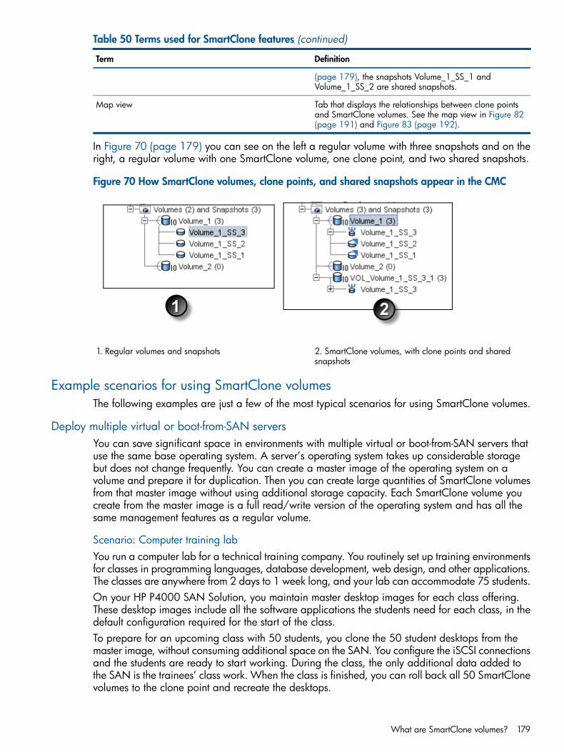
Table 50 Terms used for SmartClone features (continued)
DefinitionTerm
(page 179), the snapshots Volume_1_SS_1 andVolume_1_SS_2 are shared snapshots.
Tab that displays the relationships between clone pointsand SmartClone volumes. See the map view in Figure 82(page 191) and Figure 83 (page 192).
Map view
In Figure 70 (page 179) you can see on the left a regular volume with three snapshots and on theright, a regular volume with one SmartClone volume, one clone point, and two shared snapshots.
Figure 70 How SmartClone volumes, clone points, and shared snapshots appear in the CMC
2. SmartClone volumes, with clone points and sharedsnapshots
1. Regular volumes and snapshots
Example scenarios for using SmartClone volumesThe following examples are just a few of the most typical scenarios for using SmartClone volumes.
Deploy multiple virtual or boot-from-SAN serversYou can save significant space in environments with multiple virtual or boot-from-SAN servers thatuse the same base operating system. A server’s operating system takes up considerable storagebut does not change frequently. You can create a master image of the operating system on avolume and prepare it for duplication. Then you can create large quantities of SmartClone volumesfrom that master image without using additional storage capacity. Each SmartClone volume youcreate from the master image is a full read/write version of the operating system and has all thesame management features as a regular volume.
Scenario: Computer training labYou run a computer lab for a technical training company. You routinely set up training environmentsfor classes in programming languages, database development, web design, and other applications.The classes are anywhere from 2 days to 1 week long, and your lab can accommodate 75 students.On your HP P4000 SAN Solution, you maintain master desktop images for each class offering.These desktop images include all the software applications the students need for each class, in thedefault configuration required for the start of the class.To prepare for an upcoming class with 50 students, you clone the 50 student desktops from themaster image, without consuming additional space on the SAN. You configure the iSCSI connectionsand the students are ready to start working. During the class, the only additional data added tothe SAN is the trainees’ class work. When the class is finished, you can roll back all 50 SmartClonevolumes to the clone point and recreate the desktops.
What are SmartClone volumes? 179

Safely use production data for test, development, and data miningUse SmartClone volumes to safely work with your production environment in a test and developmentenvironment, before going live with new applications or upgrades to current applications. Or,clone copies of your production data for data mining and analysis.
Test and developmentUsing the SmartClone process, you can instantly clone copies of your production LUNs and mountthem in another environment. Then you can run new software, install upgrades, and perform othermaintenance tasks. When the new software or upgrades testing is complete, either redirect yourapplication to the SmartClone volume you have been using, or delete the SmartClone volume andproceed with the installation or upgrades in the production environment.
Data miningAssume you want to track monthly trends in web requests for certain types of information. Oncea month, you create a SmartClone volume of the web server transaction, mount the volume to adifferent server, and analyze and track usage or other trends over time. This monthly SmartClonevolume takes minimal additional space on the SAN, while providing all the data from the webserver database.
Clone a volumeIn addition to the cases described above, SmartClone volumes can be created as needed for anypurpose. These volumes provide exact copies of existing volumes without the need to provisionadditional space, until and unless you want to write new data.
Planning SmartClone volumesPlanning SmartClone volumes takes into account multiple factors, such as space requirements,server access, and naming conventions for SmartClone volumes.
Space requirementsSmartClone volumes inherit the size and data protection level of the source volume and snapshot.(When creating a SmartClone volume, you first create a snapshot of the source volume and createthe SmartClone volumes from that snapshot, which is then called the “clone point.”) You can selectthe provisioning method when creating SmartClone volumes. See “Provisioning storage” (page 141)for a complete discussion of volume and snapshot characteristics and space planning.
• The space required for the volumes created using the SmartClone process is the same as forany other volumes on the SAN. SmartClone volumes can have schedules to snapshot a volumeand remote snapshot a volume, just like other volumes, so the space requirements forSmartClone volumes should take into account the space needed for their local and remotesnapshots.
• Number of SmartClone volumes—Plan the total number of SmartClone volumes you intend tocreate as part of your space requirements.Note that you can create up to 25 SmartClone volumes as one operation in the HP P4000Centralized Management Console, and then repeat the process to create the desired numberof SmartClone volumes.Use the CLI to create larger quantities of SmartClone volumes in a single operation.
• Thin or full provisioning—The type of provisioning you select affects the amount of spacerequired on the SAN, just as it does for regular volumes.
• Data protection level—The data protection level of the source volume must be retained whencreating SmartClone volumes, though you can change the data protection level after theSmartClone volumes are created. However, if you change the data protection level for anySmartClone volume, the data protection level for all replicated volumes automatically changes.
180 SmartClone volumes

Naming convention for SmartClone volumesA well-planned naming convention helps when you have many SmartClone volumes. Plan thenaming ahead of time, since you cannot change volume or snapshot names after they have beencreated. You can design a custom naming convention when you create SmartClone volumes.
Naming and multiple identical disks in a serverMounting multiple identical disks to servers typically requires that servers write new disk signaturesto them. For example, VMware ESX servers require that resignaturing be enabled and willautomatically name duplicate datastores. Most servers allow the duplicate disks to be renamed.
Figure 71 Duplicate names on duplicate datastores in ESX Server
Server accessPlan the servers you intend to assign to the SmartClone volumes. Configure the servers beforecreating the volumes, and you can then assign the servers when you create the volumes. See“Controlling server access to volumes” (page 197).
Defining SmartClone volume characteristicsWhen creating SmartClone volumes, you define the following characteristics.
Table 51 Characteristics for new SmartClone volumes
What it meansSmartClone volume characteristic
The number of SmartClone volumes you want to create.You can create up to 25 as one operation in the CMC,
Quantity
and then repeat the process to create the desired numberof SmartClone volumes. Use the CLI to create largerquantities of SmartClone volumes in a single operation.
The name of the SmartClone volume that is displayed inthe CMC. A volume name is from 1 to 127 characters and
SmartClone Name
is case sensitive. The name cannot be changed after thevolume is created.
SmartClone volumes default to Thin Provisioning. You canselect Full Provisioning when you create them. You can
Provisioning
also edit the individual volumes after they are created andchange the type of provisioning.
Server assigned to the volume. While you can only assignone server when you create SmartClone volumes, you can
Server
go back and add additional clustered servers later. For
Defining SmartClone volume characteristics 181

Table 51 Characteristics for new SmartClone volumes (continued)
What it meansSmartClone volume characteristic
more information, see “Assigning server connections accessto volumes” (page 203).
Type of access to the volume: Read, Read/Write, NonePermission
Naming SmartClone volumesBecause you may create dozens or even hundreds of SmartClone volumes, you need to plan thenaming convention for them. For information about the default naming conventions built into theSAN/iQ software, see “Setting naming conventions” (page 15).When you create a SmartClone volume, you can designate the base name for the volume. Thisbase name is then used with numbers appended, incrementing to the total number of SmartClonevolumes you create. For example, Figure 72 (page 182) shows a SmartClone volume with the basename of “C#” and 10 clones. (The number in parentheses indicates how many snapshots areunder that volume.)
Figure 72 Example of using a base name with 10 SmartClone volumes
After you designate a base name for the SmartClone volumes while you are creating them, youcan then edit individual names of SmartClone volumes in the table list, before you finish creatingthem.
NOTE: Rename the SmartClone volume at the bottom of the list. Then the numbering sequenceis not disrupted.
182 SmartClone volumes

Figure 73 Rename SmartClone volume from base name
1. Rename SmartClone volume in list
Shared versus individual characteristicsCharacteristics for SmartClone volumes are the same as for regular volumes. However, certaincharacteristics are shared among all the SmartClone volumes and snapshots created from a commonclone point. If you want to change one of these shared characteristics for one SmartClone volume,that change will apply to all related volumes and snapshots, including the original volume andsnapshot from which you created the SmartClone volumes. Simply use Edit Volume on the selectedvolume, and make the change to the volume. A message opens, stating that the change will applyto all of the related volumes, which are noted in the message.For example, in Figure 74 (page 184), in the cluster Programming, there are 10 SmartClone volumescreated from one source volume and its clone point. You want to move the first of the SmartClonevolumes, to the cluster SysAdm2.
Shared versus individual characteristics 183

Figure 74 Programming cluster with SmartClone volumes, clone point, and the source volume
1. Source volume
2. Clone point
3. SmartCLone volumes (5)
In this example, you edit the SmartClone volume, and on the Advanced tab you change the clusterto SysAdm. The confirmation message lists all the volumes and snapshots that will change clustersas a result of changing the edited volume.
Figure 75 Changing one SmartClone volume changes all related volumes and snapshots
When you click OK on the message, all the volumes and snapshots move to the cluster SysAdm.
184 SmartClone volumes

Figure 76 SysAdm cluster now has the SmartClone volumes, clone point, and the source volume
Table 52 (page 185) shows the shared and individual characteristics of SmartClone volumes. Notethat if you change the cluster or the data protection level of one SmartClone volume, the clusterand data protection level of all the related volumes and snapshots will change.
Table 52 Characteristics of SmartClone volumes
Individual characteristicsShared characteristics
NameCluster
DescriptionData protection level
Size
Type (Primary or Remote)
Provisioning (Thin or Full)
Server
NOTE: Snapshot schedules and remote copy schedules are also individual to a single SmartClonevolume.
Clone point
The icon shown here represents the clone point in the navigation window. The clone point is thesnapshot from which the SmartClone volumes are created. The clone point contains the snapshotdata that is shared among the multiple volumes. Because the SmartClone volumes and their snapshotsdepend on the clone point, it cannot be deleted until it is no longer a clone point. A clone pointceases to be a clone point when only one SmartClone volume remains that was created from that
Clone point 185

clone point. That is, you can delete all but one of the SmartClone volumes, and then you can deletethe clone point.
Figure 77 Navigation window with clone point
1. Original volume
2. Clone point
3. SmartClone volume
In Figure 77 (page 186), the original volume is “C#.”
• Creating a SmartClone volume of C# first creates a snapshot, C#_SCsnap.
• After the snapshot is created, you create at least one SmartClone volume, C#class_1.
Table 53 How it works—clone point
C#First, a volume
C#_SCsnapNext, a snapshot
C#class_1Next, SmartClone from the snapshot
Snapshot becomes a clone point
Because the SmartClone volumes depend on the clone point from which they were created, theclone point appears underneath each SmartClone volume in the navigation window. While theclone point may appear many times, it only exists as a single snapshot in the SAN. Therefore, itonly uses the space of that single snapshot. The display in the navigation window depicts this bythe multiple highlights of the clone point underneath each SmartClone volume that was createdfrom it.
186 SmartClone volumes

Figure 78 Clone point appears under each SmartClone volume
1. Clone point appears multiple times. Note that it is exactly the same in each spot
NOTE: Remember that a clone point only takes up space on the SAN once.
Shared snapshot
Shared snapshots occur when a clone point is created from a newer snapshot that has oldersnapshots below it in the tree. They are designated in the navigation window with the icon shownhere.
Shared snapshot 187

Figure 79 Navigation window with shared snapshots
1. Original volume
2. Clone point
3. Shared snapshots
In Figure 79 (page 188), the original volume is C#. Three snapshots were created from C#:
• C#_snap1
• C#_snap2
• C#_SCsnapThen a SmartClone volume was created from the latest snapshot, C#_SCsnap. That volume has abase name of C#_class. The older two snapshots, C#_snap1 and C#_snap2, become sharedsnapshots, because the SmartClone volume depends on the shared data in both those snapshots.
Table 54 How it works—shared snapshots
C#First, a volume
C#_snap1C#_snap2C#_SCsnapNext, 3 snapshots
C#class_xFinally, SmartClone volumes from the latest snapshot
Latest snapshot becomes clone point
Older two snapshots become shared between clone pointand SmartClone volume.
The shared snapshots also appear under all the volumes which share them. In Figure 79 (page 188),they are displayed under the original volume from which they were created, and under the singleSmartClone volume that shares them. The selected shared snapshot is highlighted in the navigationwindow, under both the volumes with which it is shared. Shared snapshots can be deleted.
188 SmartClone volumes

Creating SmartClone volumesYou create SmartClone volumes from existing volumes or snapshots. When you create a SmartClonevolume from another volume, you first take a snapshot of the original volume. When you create aSmartClone volume from a snapshot, you do not take another snapshot.
To create a SmartClone volumeWhen you create SmartClone volumes, you either set the characteristics for the entire group or setthem individually.
Figure 80 Setting characteristics for SmartClone volumes
1. Set characteristics for multiples here
2. Edit individual clones here
For details about the characteristics of SmartClone volumes, see “Defining SmartClone volumecharacteristics” (page 181).1. Log in to the management group in which you want to create a SmartClone volume.2. Select the volume or snapshot from which to create a SmartClone volume.
• From the main menu you can select Tasks→Volume→New SmartClone orTasks→Snapshot→New SmartClone.Select the desired volume or snapshot from the list that opens.
• In the navigation window, select the cluster and volume or snapshot from which to createa SmartClone volume.
3. Right-click on the volume or snapshot, and select New SmartClone Volumes.4. If you are creating a SmartClone volume from a volume, click New Snapshot to first create a
snapshot of the volume.For more information, see “Creating snapshots” (page 164).If you are creating a SmartClone volume from a snapshot, you do not create another snapshot.
Creating SmartClone volumes 189

5. Next you select the following characteristics:• Base name for the SmartClone volumes
• Type of provisioning
• Server you want connected to the volumes, and
• Appropriate permission.6. In the Quantity field, select the number of SmartClone volumes you want to create.7. Click Update Table to populate the table with the number of SmartClone volumes you selected.8. If you want to modify any individual characteristic, do it in the list before you click OK to
create the SmartClone volumes.For example, you might want to change the assigned server of some of the SmartClone volumes.In the list you can change individual volumes’ server assignments.
9. Click OK to create the volumes.The new SmartClone volumes appear in the navigation window under the volume folder.
Figure 81 New SmartClone volumes in Navigation window
1. Clone point
2. New SmartClone volumes
Viewing SmartClone volumesAs you create multiple SmartClone volumes, you can view them and their related volumes andsnapshots in both the navigation window and in the Map View tab, shown in Figure 82 (page 191).Because a SmartClone volume is the same as any other volume, the icon is the standard volumeicon. However, the clone point and the shared snapshot have unique icons, as illustrated inFigure 77 (page 186).
Map viewThe Map View tab is useful for viewing the relationships between clone point snapshots, sharedsnapshots, and their related volumes. For example, when you want to make changes such asmoving a volume to a different cluster, or deleting shared snapshots, the Map View tab allows youto easily identify how many snapshots and volumes are affected by such changes.
190 SmartClone volumes

Figure 82 Viewing SmartClone volumes and snapshots as a tree in the Map View
Using viewsThe default view is the tree layout, displayed in Figure 82 (page 191). The tree layout is the mosteffective view for smaller, more complex hierarchies with multiple clone points, such as clones ofclones, or shared snapshots.You may also display the Map view in the organic layout. The organic layout is more useful whenyou have a single clone point with many volumes, such as large numbers in a virtual desktopimplementation. In such a case, the tree quickly becomes difficult to view, and it is much easier todistinguish the multiple volumes in the organic layout.See “Using the Map View ” (page 14) for more information on using the map view display tools.
Viewing SmartClone volumes 191

Figure 83 Viewing the organic layout of SmartClone volumes and related snapshots in the MapView
Viewing clone points, volumes, and snapshotsThe navigation window view of SmartClone volumes, clone points, and snapshots includeshighlighting that shows the relationship between related items. For example, in Figure 84 (page 193),the clone point is selected in the tree. The clone point supports the SmartClone volumes, so it isdisplayed under those volumes. The highlight shows the relationship of the clone point to the originalvolume plus the SmartClone volumes created from the original volume.
192 SmartClone volumes
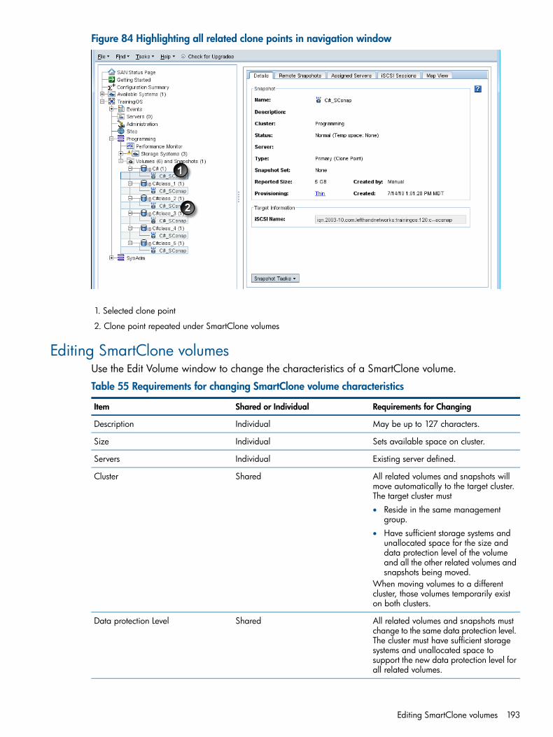
Figure 84 Highlighting all related clone points in navigation window
1. Selected clone point
2. Clone point repeated under SmartClone volumes
Editing SmartClone volumesUse the Edit Volume window to change the characteristics of a SmartClone volume.
Table 55 Requirements for changing SmartClone volume characteristics
Requirements for ChangingShared or IndividualItem
May be up to 127 characters.IndividualDescription
Sets available space on cluster.IndividualSize
Existing server defined.IndividualServers
All related volumes and snapshots willmove automatically to the target cluster.The target cluster must
SharedCluster
• Reside in the same managementgroup.
• Have sufficient storage systems andunallocated space for the size anddata protection level of the volumeand all the other related volumes andsnapshots being moved.
When moving volumes to a differentcluster, those volumes temporarily existon both clusters.
All related volumes and snapshots mustchange to the same data protection level.
SharedData protection Level
The cluster must have sufficient storagesystems and unallocated space tosupport the new data protection level forall related volumes.
Editing SmartClone volumes 193

Table 55 Requirements for changing SmartClone volume characteristics (continued)
Requirements for ChangingShared or IndividualItem
Determines whether the volume isprimary or remote.
IndividualType
Determines whether the volume is fullyprovisioned or thinly provisioned.
IndividualProvisioning
To edit the SmartClone volumes1. In the navigation window, select the SmartClone volume for which you want to make changes.2. Click Volume Tasks, and select Edit Volume.
See “Requirements for changing SmartClone volume characteristics” (page 193) for detailedinformation about making changes to the SmartClone volume characteristics.
3. Make the desired changes to the volume, and click OK.If you change a SmartClone volume characteristic that will change other related volumes andsnapshots, a warning opens that lists the volumes that will be affected by the change. If thereare too many volumes to list, a subset will be listed with a note indicating how many additionalvolumes will be affected.
Deleting SmartClone volumesAny volumes or snapshots that are part of a SmartClone network can be deleted just like any othervolumes or snapshots. The only exception is the clone point, which cannot be deleted until it is nolonger a clone point.
CAUTION: Before deleting any volumes or snapshots, you must first stop any applications thatare accessing the volumes and log off any iSCSI sessions that are connected to the volumes.
Deleting the clone pointYou can delete a clone point if you delete all but one volume that depends on that clone point.After you delete all but one volume that depends on a clone point, the clone point returns to beinga standard snapshot and can be managed just like any other snapshot.For example, in Figure 85 (page 194), you must delete any four of the five C#class_x volumesbefore you can delete the clone point.
Figure 85 Viewing volumes that depend on a clone point
194 SmartClone volumes
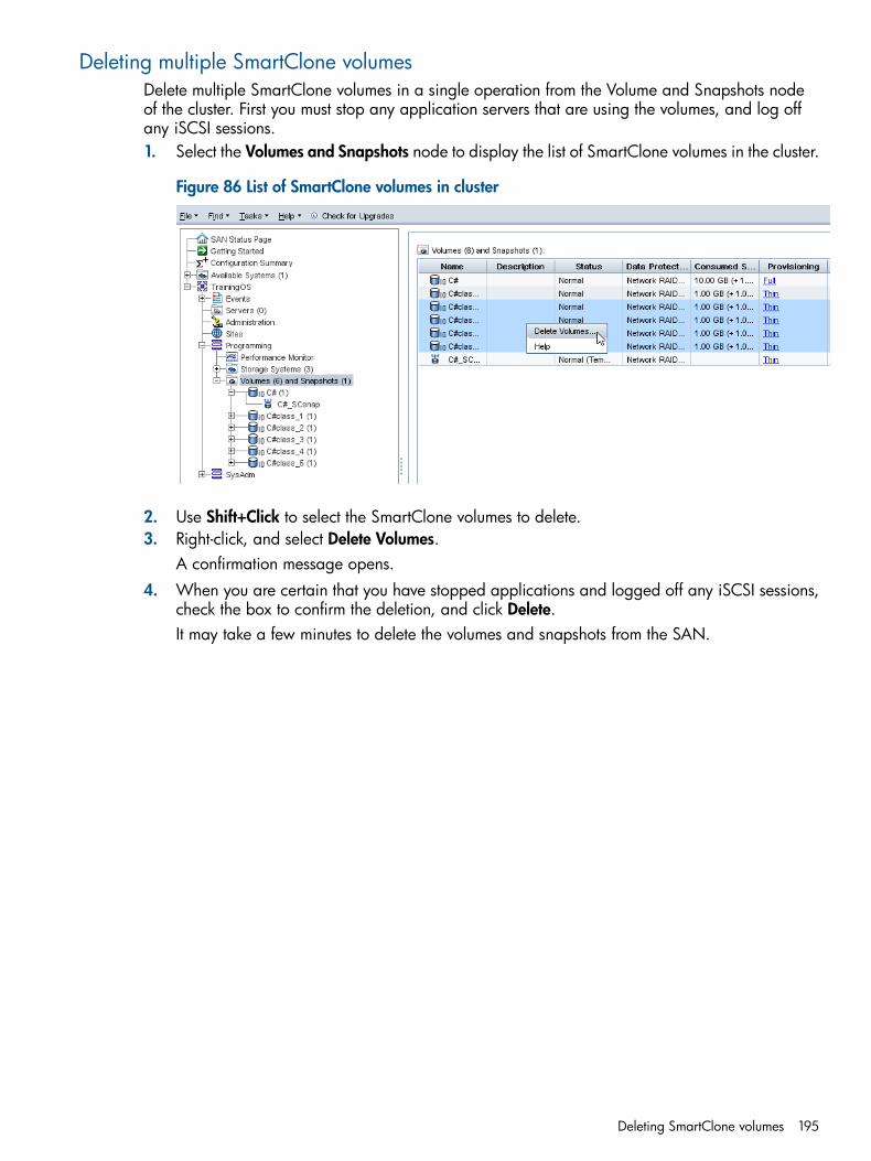
Deleting multiple SmartClone volumesDelete multiple SmartClone volumes in a single operation from the Volume and Snapshots nodeof the cluster. First you must stop any application servers that are using the volumes, and log offany iSCSI sessions.1. Select the Volumes and Snapshots node to display the list of SmartClone volumes in the cluster.
Figure 86 List of SmartClone volumes in cluster
2. Use Shift+Click to select the SmartClone volumes to delete.3. Right-click, and select Delete Volumes.
A confirmation message opens.4. When you are certain that you have stopped applications and logged off any iSCSI sessions,
check the box to confirm the deletion, and click Delete.It may take a few minutes to delete the volumes and snapshots from the SAN.
Deleting SmartClone volumes 195

15 Working with scriptingScripting in the SAN/iQ software through release 7.0 was accomplished by thejava.commandline.CommandLine scripting tool.In SAN/iQ software release 8.0, the java.commandline.CommandLine scripting tool wasreplaced by the HP P4000 Command-Line Interface. The CLI takes advantage of the new SAN/iQAPI that provides comprehensive coverage of SAN/iQ software functionality to support scripting,integration and automation.The java.commandline.CommandLine scripting tool will be supported after the 8.0 releaseto allow time for converting existing scripts that use java.commandline.CommandLine to thenew CLI syntax.
Scripting documentation• The HP CLIQ - The SAN/iQ Command-Line Interface User Guide is available from the HP
website, and it is installed with the CLI.• A SAN/iQ 8.0 Readme is available that describes the changes from
java.commandline.CommandLine to the new CLI syntax.• Sample scripts using the CLI are also available on the HP website.
196 Working with scripting

16 Controlling server access to volumesApplication servers (servers), also called clients or hosts, access storage volumes on the SAN usingthe iSCSI protocol. You set up each server that needs to connect to volumes in a managementgroup in the CMC. We refer to this setup as a “server connection.” Server connections can besingle servers or server clusters. Use server clusters in the CMC to easily assign volumes to theclustered application servers that are accessing the SAN storage volumes. For example, createtwo servers and cluster them to assign two volumes to a Microsoft Exchange cluster or VMwareESX Server simultaneously.You can set up servers to connect to volumes in three ways. All three ways use the virtual IP (VIP)for discovery and to log in to the volume from a server’s iSCSI initiator:
• iSCSI with VIP and load balancing—Use the load balancing option when you set up a serverconnection in the CMC to balance connections to the SAN.
• Microsoft DSM or HP P4000 DSM for MPIO (if using)—Automatically establishes multipleconnections to the SAN.
• iSCSI with VIP only.
NOTE: Before setting up a server connection, make sure you are familiar with the iSCSIinformation in “iSCSI and the HP P4000 SAN Solution” (page 230).
Setting up server connections to volumes requires the general tasks outlined below.
Table 56 Overview of configuring server access to volumes
For More InformationTask
If you are using the HP P4000 DSM for MPIO, ensure thatboth the Microsoft MPIO and the DSM for MPIO are
Ensure that an iSCSI initiator is installed on the server.
installed on the server. Refer to the HP P4000 ApplicationIntegration Solution Pack User Guide.
See “Adding server connections to management groups”(page 198).
In the CMC, add the server connection to the managementgroup and configure iSCSI access for that server.
See “Creating a server cluster” (page 201).[Optional] Cluster multiple servers in the CMC to connectmultiple volumes to clustered application servers.
See“Assigning server connections access to volumes”(page 203)
In the CMC, assign volumes to the server or server cluster.
“Assigning server connections access to volumes”(page 203).
See “Completing the iSCSI Initiator and disk setup”(page 205).
In the iSCSI initiator on the server, log on to the volume.
See “Completing the iSCSI Initiator and disk setup”(page 205).
On the server, configure the volume using disk managementtools.
Change in server access control from version 7.0 and earlierBefore release 8.0, you controlled server access to volumes using authentication groups and volumelists. Starting with release 8.0, you control access with server and volume connections.With release 8.0 and later, you add each server to a management group and assign serverconnections to volumes or snapshots. You can make the assignment from either the volume or theserver.The CMC displays the updated servers feature in management groups running SAN/iQ softwareversion 7.x and earlier. However, these servers show the IQN number as their name.
Change in server access control from version 7.0 and earlier 197

Figure 87 Server assignments in the navigation window and the Volumes and Snapshots tab
1. Servers from a version 7.0 management group in the navigation window
2. Volumes and Snapshots tab shows the assigned volume that the server can access
Adding server connections to management groupsAdd each server connection that needs access to a volume to the management group containingthe volume. After you add a server connection to a management group, you can assign the serverconnection to one or more volumes or snapshots. For more information, see “Assigning serverconnections access to volumes” (page 203).
Prerequisites• Each server must have an iSCSI initiator installed.
• The initiator node name, or iqn string, for the iSCSI initiator. See “iSCSI and CHAPterminology” (page 232).
• To use iSCSI load balancing, you must use a compliant iSCSI initiator. Verify the initiatorcompliance by going to the HP P4000 SAN Solutions Compatibility Matrix at:
http://www.hp.com/go/P4000compatibility
CAUTION: Using a noncompliant iSCSI initiator with load balancing can compromise volumeavailability during iSCSI failover events.
Guide for serversFor detailed information about using iSCSI with the P4000 SAN Solution, including load balancingand CHAP authentication, see “iSCSI and the HP P4000 SAN Solution” (page 230).
Table 57 Characteristics for servers
Description and requirementsItem
Name of the server that is displayed in the CMC. The servername is case sensitive and cannot be changed after theserver is created.
Name
[Optional] Description of the server.Description
Not used for the Application Aware Snapshot Manageron Windows.
Controlling Server IP Address
Required for the Application Aware Snapshot Manageron VMware. IP address of the Microsoft Windows serverthat is hosting the vCenter Server.Optional for using VSS on Windows servers.
Allows the server to connect to the client using an iSCSIinitiator.
Allow access via iSCSI
198 Controlling server access to volumes

Table 57 Characteristics for servers (continued)
Description and requirementsItem
The name, or iqn string, of the iSCSI initiator. Open theiSCSI initiator and look for the string there. You can copythe string and paste it into the field.
Initiator Node Name
Configures iSCSI load balancing for the server connections.Enable load balancing
Enables initiators to log on to a volume withoutauthenticating their identity.
CHAP not required
Requires initiators to authenticate before they can log onto a volume.
CHAP required
Adding a server connection1. In the navigation window, log in to the management group.2. Click Management Group Tasks, and select New Server.3. Enter a name and description (optional) for the server connection.4. If you are taking VMware application-managed snapshots, enter the Controlling Server IP
Address.5. Select Allow access via iSCSI.6. If you want to use iSCSI load balancing and your initiator is compliant, select Enable load
balancing.7. In the Authentication section, select CHAP not required.
If later, you decide you want to use CHAP, you can edit the server connection (see “Editingserver connections” (page 200)). For more information, see “Authentication (CHAP)” (page 231).
8. In the Initiator Node Name field, enter the iqn string.9. Click OK.10. [Optional] To use CHAP, edit the server connection you just configured and complete the
fields necessary for the type of CHAP you intend to configure, as shown in Table 58 (page 199).
Table 58 Entering CHAP information in a new server
Complete these fieldsFor this CHAP Mode
1-way CHAP • CHAP name
• Target secret—minimum of 12 characters
2-way CHAP • CHAP name
• Target secret—minimum of 12 characters
• Initiator secret—minimum of 12 characters; must bealphanumeric
11. Click OK.The server connection appears in the management group in the navigation window.You can now assign this server connection to volumes, giving the server access to the volumes.For more information, see “Assigning server connections access to volumes” (page 203).
Managing server connectionsManage your server connections:• “Editing server connections” (page 200)
• “Deleting server connections” (page 200)
Managing server connections 199
Editing server connectionsYou can edit the following fields for a server connection:
• Description
• Controlling Server IP Address
• Load balancing
• CHAP options
CAUTION: If you change the load balancing or CHAP options, you must log off and log backon to the target in the iSCSI initiator for the changes to take effect.
You can also delete a server connection from the management group. For more information, see“Deleting server connections” (page 200).
CAUTION: Editing the iqn or CHAP server settings may interrupt access to volumes. If necessary,or if the server is sensitive to disconnections, stop server access before editing a server.1. In the navigation window, select the server connection you want to edit.2. Click the Details tab.3. Click Server Tasks, and select Edit Server.4. Change the appropriate information.5. Click OK when you are finished.6. If you have changed the Enable Load Balancing option, a message opens, notifying you to
log servers off and back on to the volumes.This may entail stopping the applications, disconnecting them, reconnecting the applicationsto the volumes, and then restarting them.
Deleting server connectionsDeleting a server connection stops access to volumes by servers using that server connection.Access to the same volume by other servers continues.1. In the navigation window, select the server connection you want to delete.2. Click the Details tab.3. Click Server Tasks, and select Delete Server.4. Click OK to delete the server.
Clustering server connectionsYou can cluster servers to easily assign multiple server connections to multiple volumes in a singleoperation. Cluster existing servers or you can create new servers to add to the server cluster fromthe New Server Cluster window. If you cluster servers that already have volumes assigned to them,all the servers in the cluster gain access to all the volumes, and inherit the access permissions ofthe original pair.All clustered servers must have the same load balancing and volume access permission settings.You can verify and update these settings when you create the server cluster. For information aboutvolume access permissions, see “Server connection permission levels” (page 204). For moreinformation about iSCSI load balancing, see “iSCSI load balancing” (page 231).
Requirements for clustering servers• Minimum of two servers for a cluster
• Same load balancing setting for all servers
• Same access level settings for all volumes assigned to the server cluster
200 Controlling server access to volumes

Creating a server cluster1. In the navigation window, select the Servers category.2. Right-click and select New Server Cluster.3. Enter a name and description (optional) for the server cluster.4. Do one of the following:
• Click Add Server and select the server from the list of available servers that opens.
• Click New Server and follow the instructions found in “Adding server connections tomanagement groups” (page 198).
5. Add the additional servers required for the server cluster, using either of the above methods.6. [Optional] Next, click Edit Server Cluster Settings to verify that the server cluster settings are
the same for all servers and volumes.
NOTE: The Server cluster Settings window opens automatically if inconsistencies are detectedin the settings for the servers and volumes.
7. On the Server cluster Settings window, choose the proper settings for the server cluster. SeeFigure 88 (page 201).a. Select the appropriate radio button for the load balancing setting on each server.b. Ensure that each volume listed has the same access permissions.
Figure 88 Verify the server cluster settings
When the server cluster is created, you can view the results on the Servers Details tab and on MapView tab shown in Figure 89 (page 202).
Clustering server connections 201

Figure 89 Completed server cluster and the assigned volumes
1. Green solid line indicates active connection. The two-way arrows indicate the volume permission levels are read-write.Black dotted line indicates an inactive iSCSI session.
2. Volumes have active iSCSI sessions, indicated by the line to the left of the volume icon
Server cluster map viewAfter you create a server cluster and connect volumes, use the Map View tab for viewing therelationships between systems, volumes and servers. For more information on using the map viewtools, see “Using the display tools” (page 14).Server cluster map views include the following:
• Servers to volumes
• Servers to systems
Working with a server clusterMake any of the following changes to a server cluster:
• Add or remove servers.
• Edit a server to change iSCSI access or authentication, including settings for CHAP.
• Edit the server cluster settings for load balancing and volume access permissions. See“Clustering server connections” (page 200) for more information.
Editing a server clusterThe Edit Server Cluster window includes sections for adding, editing, or removing servers, andmanaging load balancing and volume access permissions.1. In the navigation window, select the Servers category, and select the server cluster to edit.2. Right-click on the server cluster, and select Edit Server Cluster.3. Make the desired changes to the server cluster in the Edit Server Cluster window.4. Click OK when you have finished making the changes.
Deleting a server clusterDeleting a server cluster removes the cluster associations among the servers. However, theassociations remain between all of the volumes and servers that were in the cluster, shown inFigure 90 (page 203). You must manually change the server and volume associations to the desiredconfiguration after deleting the server cluster.
202 Controlling server access to volumes

Figure 90 Servers and volumes retain connections after server cluster is deleted
1. Each volume remains connected to each server after the server cluster is deleted
To delete a server cluster and remove connections:1. In the navigation window, select the Servers category and select the server cluster to delete.2. Right-click on the server cluster and select Delete Server Cluster.3. Select a server to change associations.4. Right-click and select Assign and Unassign Volumes and Snapshots.5. Select the appropriate volume and permission level for that server, and click OK.6. Repeat these steps for the remaining servers, until the appropriate server and volume
connections are in place.
Assigning server connections access to volumesAfter you add a server connection to your management group, you can assign one or more volumesor snapshots to the server connection, giving the server access to those volumes or snapshots.
CAUTION: Without the use of shared storage access (host clustering or clustered file system)technology, allowing more than one iSCSI application server to connect to a volume at the sametime, without cluster-aware applications and/or file systems in read/write mode, could result indata corruption.
You can make the assignments in two ways:
• “Assigning server connections from a volume” (page 204)
• “Assigning volumes from a server connection” (page 204)Prerequisites
• The server connections you want to assign must already exist in the management group. See“Adding server connections to management groups” (page 198).
• The volumes or snapshots you want to assign must already exist in the management group.When you assign the server connections and volumes or snapshots, you set the permissions thateach server connection will have for each volume or snapshot. The available permissions aredescribed in Table 59 (page 204).
Assigning server connections access to volumes 203
Table 59 Server connection permission levels
Allows ThisType of Access
Prevents the server from accessing the volume or snapshot.No access
Restricts the server to read-only access to the data on thevolume or snapshot.
Read access
Allows the server read and write permissions to the volume.Read/write access
NOTE: Microsoft Windows requires read/write access to volumes.
Assigning server connections from a volumeYou can assign one or more server connections to any volume or snapshot. For the prerequisites,see “Assigning server connections access to volumes” (page 203).1. In the navigation window, right-click the volume you want to assign server connections to.2. Select Assign and Unassign Servers.3. Select the Assigned check box for each server connection you want to assign to the volume
or snapshot.4. From the Permission list, select the permission each server connection should have to the
volume or snapshot.5. Click OK.
You can now log on to the volume from the server’s iSCSI initiator. See “Completing the iSCSIInitiator and disk setup” (page 205).
Assigning volumes from a server connectionYou can assign one or more volumes or snapshots to any server connection. For the prerequisites,see “Assigning server connections access to volumes” (page 203).1. In the navigation window, right-click the server connection you want to assign.2. Select Assign and Unassign Volumes and Snapshots.3. Select the Assigned check box for each volume or snapshot you want to assign to the server
connection.4. From the Permission list, select the permission the server should have.5. Click OK.
You can now connect to the volume from the server’s iSCSI initiator. See “Completing theiSCSI Initiator and disk setup” (page 205).
Editing server connection and volume assignmentsYou can edit the assignment of volumes and server connections to:
• Unassign the volume or server connection
• Change the permissions
CAUTION: If you are going to unassign a server connection or restrict permissions, stop anyapplications from accessing the volume or snapshot, and log off the iSCSI session from the hostbefore making the change.
Editing server connection assignments from a volumeYou can edit the assignment of one or more server connections to any volume or snapshot.
204 Controlling server access to volumes

1. In the navigation window, right-click the volume whose server connection assignments youwant to edit.
2. Select Assign and Unassign Servers.3. Change the settings as needed.4. Click OK.
Editing server assignments from a server connectionYou can edit the assignment of one or more volumes or snapshots to any server connection.1. In the navigation window, right-click the server connection you want to edit.2. Select Assign and Unassign Volumes and Snapshots.3. Change the settings as needed.4. Click OK.
Completing the iSCSI Initiator and disk setupAfter you have assigned a server connection to one or more volumes, you must configure theappropriate iSCSI settings on the server. For information about iSCSI, see “iSCSI and the HP P4000SAN Solution” (page 230).For more information about setting up volumes and iSCSI, see the operating system-specificdocuments in the HP P4000 Manuals page of the HP Business Support Center website.
http://www.hp.com/support/manuals
In the Storage section, navigate to Disk Storage Systems→P4000 SAN Solutions→HP LeftHandP4000 SAN Solutions or HP P4000 G2 SAN Solutions, depending upon your product.
Persistent targets or favorite targetsAfter you configure the iSCSI initiator, you can log on to the volumes. When you log on, selectthe option to automatically restore connections. This sets up persistent targets that automaticallyreconnect after a reboot.For persistent targets, you also need to set up dependencies to ensure that the applications on theserver start only after the iSCSI service starts and the sessions are connected.
HP P4000 DSM for MPIO settingsIf you are using HP P4000 DSM for MPIO and your server has two NICs, select the Enable multi-pathoption when logging on to the volume, and log on from each NIC.For more information about DSM for MPIO, refer to the HP P4000 Application Integration SolutionPack User Guide.
Disk managementYou must also format, configure, and label the volumes from the server using the operating system’sdisk management tools.
Completing the iSCSI Initiator and disk setup 205

17 Monitoring performanceThe Performance Monitor provides performance statistics for iSCSI and storage system I/Os tohelp you and HP support and engineering staff understand the load that the SAN is servicing.The Performance Monitor presents real-time performance data in both tabular and graphical formas an integrated feature in the CMC. The CMC can also log the data for short periods of time(hours or days) to get a longer view of activity. The data will also be available via SNMP, so youcan integrate with your current environment or archive the data for capacity planning. See “Settingup SNMP” (page 93).As a real-time performance monitor, this feature helps you understand the current load on the SANto provide additional data to support decisions on issues such as the following:
• Configuration options (Would network bonding help me?)
• Capacity expansion (Should I add more storage systems?)
• Data placement (Should this volume be on my SATA or SAS cluster?).The performance data does not directly provide answers, but will let you analyze what is happeningand provide support for these types of decisions.These performance statistics are available on a cluster, volume, and storage system basis, lettingyou look at the workload on a specific volume and providing data like throughput, average I/Osize, read/write mix, and number of outstanding I/Os. Having this data helps you better understandwhat performance you should expect in a given configuration. Storage system performance datawill allow you to easily isolate, for example, a specific storage system with higher latencies thanthe other storage systems in the cluster.
Prerequisites• You must have a cluster with one or more storage systems and one or more volumes connected
via iSCSI sessions.• All storage systems in the management group must have SAN/iQ software version 8.0 or
later installed. The management group version on the Registration tab must show 8.0.• A server must be accessing a volume to read data, write data, or both.
Introduction to using performance informationThe Performance Monitor can monitor dozens of statistics related to each cluster.The following sections offer some ideas about the statistics that are available to help you manageyour SAN effectively. These sections cover just a few examples of common questions and issues,but they are not an exhaustive discussion of the possibilities the Performance Monitor offers.For general concepts related to performance monitoring and analysis, see “Performance monitoringand analysis concepts” (page 216).
What can I learn about my SAN?If you have questions such as these about your SAN, the Performance Monitor can help:
• What kind of load is the SAN under right now?
• How much more load can be added to an existing cluster?
• What is the impact of my nightly backups on the SAN?
• I think the SAN is idle, but the drive lights are blinking a lot. What is causing that?
206 Monitoring performance

Generally, the Performance Monitor can help you determine:
• Current SAN activities
• Workload characterization
• Fault isolation
Current SAN activities exampleThis example shows that the Denver cluster is handling an average of more than 747 IOPS withan average throughput of more than 6 million bytes per second and an average queue depth of31.76.
Figure 91 Example showing overview of cluster activity
Workload characterization exampleThis example lets you analyze the workload generated by a server (ExchServer-1) including IOPSreads, writes, and total and the average IO size.
Figure 92 Example showing volume’s type of workload
Fault isolation exampleThis example shows that the Denver-1 storage system (dotted line pegged at the top of the graph)has a much higher IO read latency than the Denver-3 storage system. Such a large difference maybe due to a RAID rebuild on Denver-1. To improve the latency, you can lower the rebuild rate.
Introduction to using performance information 207

Figure 93 Example showing fault isolation
What can I learn about my volumes?If you have questions such as these about your volumes, the Performance Monitor can help:
• Which volumes are accessed the most?
• What is the load being generated on a specific volume?The Performance Monitor can let you see the following:
• Most active volumes
• Activity generated by a specific server
Most active volumes examplesThis example shows two volumes (DB1 and Log1) and compares their total IOPS. You can see thatLog1 averages about 2 times the IOPS of DB1. This might be helpful if you want to know whichvolume is busier.
Figure 94 Example showing IOPS of two volumes
This example shows two volumes (DB1 and Log1) and compares their total throughput. You cansee that Log1 averages nearly 18 times the throughput of DB1. This might be helpful if you wantto know which volume is busier.
208 Monitoring performance

Figure 95 Example showing throughput of two volumes
Activity generated by a specific server exampleThis example shows the total IOPS and throughput generated by the server (ExchServer-1) on twovolumes.
Figure 96 Example showing activity generated by a specific server
Planning for SAN improvementsIf you have questions such as these about planning for SAN improvements, the Performance Monitorcan help:
• Would enabling NIC bonding on the storage systems improve performance?
• Is the load between two clusters balanced? If not, what should I do?
• I have budget to purchase two new storage systems.Which volumes should I move to them to improve performance?◦
◦ Which cluster should I add them to?
The Performance Monitor can let you see the following:
• Network utilization to determine if NIC bonding on the storage systems could improveperformance
• Load comparison of two clusters
• Load comparison of two volumes
Network utilization to determine if NIC bonding could improve performance exampleThis example shows the network utilization of three storage systems. You can see that Denver-1averages more than 79% utilization. You can increase the networking capacity available to thatstorage system by enabling NIC bonding on the storage system. You can also spread the load outacross the storage systems using iSCSI load balancing.
Planning for SAN improvements 209

Figure 97 Example showing network utilization of three storage systems
Load comparison of two clusters exampleThis example illustrates the total IOPS, throughput, and queue depth of two different clusters (Denverand Boulder), letting you compare the usage of those clusters. You can also monitor one cluster ina separate window while doing other tasks in the CMC.
Figure 98 Example comparing two clusters
Load comparison of two volumes exampleThis example shows the total throughput for a cluster and the total throughput of each volume inthat cluster. You can see that the Log1 volume generates most of the cluster’s throughput.
210 Monitoring performance

Figure 99 Example comparing two volumes
Accessing and understanding the Performance Monitor windowThe Performance Monitor is available as a tree system below each cluster.To display the Performance Monitor window:1. In the navigation window, log in to the management group.2. Select the Performance Monitor system for the cluster you want.
The Performance Monitor window opens. By default, it displays the cluster total IOPS, clustertotal throughput, and cluster total queue depth.
Figure 100 Performance Monitor window and its parts
2. Graph1. Toolbar
4. Statistics table3. Default statistics
You can set up the Performance Monitor with the statistics you need. The system continues to monitorthose statistics until you pause monitoring or change the statistics.The system maintains any changes you make to the statistics graph or table only for your currentCMC session. It reverts to the defaults the next time you log in to the CMC.
Accessing and understanding the Performance Monitor window 211
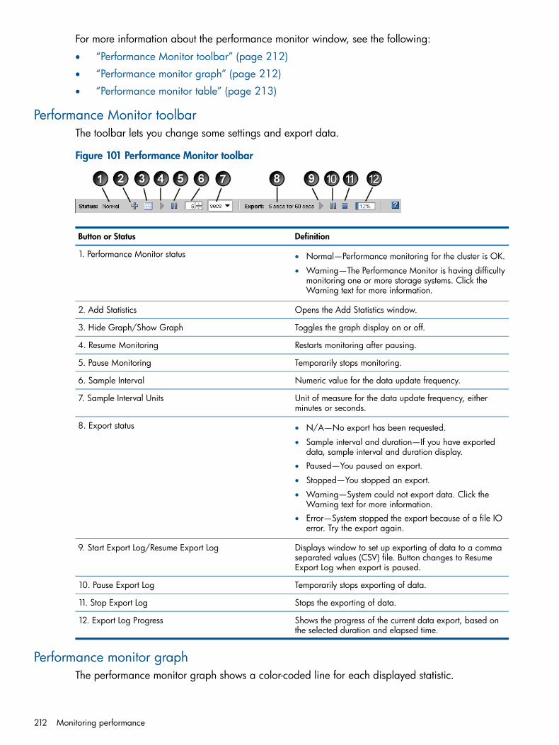
For more information about the performance monitor window, see the following:
• “Performance Monitor toolbar” (page 212)
• “Performance monitor graph” (page 212)
• “Performance monitor table” (page 213)
Performance Monitor toolbarThe toolbar lets you change some settings and export data.
Figure 101 Performance Monitor toolbar
DefinitionButton or Status
1. Performance Monitor status • Normal—Performance monitoring for the cluster is OK.
• Warning—The Performance Monitor is having difficultymonitoring one or more storage systems. Click theWarning text for more information.
Opens the Add Statistics window.2. Add Statistics
Toggles the graph display on or off.3. Hide Graph/Show Graph
Restarts monitoring after pausing.4. Resume Monitoring
Temporarily stops monitoring.5. Pause Monitoring
Numeric value for the data update frequency.6. Sample Interval
Unit of measure for the data update frequency, eitherminutes or seconds.
7. Sample Interval Units
8. Export status • N/A—No export has been requested.
• Sample interval and duration—If you have exporteddata, sample interval and duration display.
• Paused—You paused an export.
• Stopped—You stopped an export.
• Warning—System could not export data. Click theWarning text for more information.
• Error—System stopped the export because of a file IOerror. Try the export again.
Displays window to set up exporting of data to a commaseparated values (CSV) file. Button changes to ResumeExport Log when export is paused.
9. Start Export Log/Resume Export Log
Temporarily stops exporting of data.10. Pause Export Log
Stops the exporting of data.11. Stop Export Log
Shows the progress of the current data export, based onthe selected duration and elapsed time.
12. Export Log Progress
Performance monitor graphThe performance monitor graph shows a color-coded line for each displayed statistic.
212 Monitoring performance

Figure 102 Performance Monitor graph
The graph shows the last 100 data samples and updates the samples based on the sample intervalsetting.The vertical axis uses a scale of 0 to 100. Graph data is automatically adjusted to fit the scale.For example, if a statistic value was larger than 100, say 4,000.0, the system would scale it downto 40.0 using a scaling factor of 0.01. If the statistic value is smaller than 10.0, for example 7.5,the system would scale it up to 75 using a scaling factor of 10. The Scale column of the statisticstable shows the current scaling factor. If needed, you can change the scaling factor. For moreinformation, see “Changing the scaling factor” (page 221).The horizontal axis shows either the local time or Greenwich Mean Time. The default setting is thelocal time of the computer that is running the CMC. You can change this default to GMT. See“Changing the sample interval and time zone” (page 217). (This time zone setting is not related tothe management group time zone.)For information about controlling the look of the graph, see “Changing the graph” (page 220).
Performance monitor tableThe performance monitor table displays a row for each selected statistic.
Figure 103 Performance Monitor table
The table shows information about the statistics selected for monitoring. The table values updatebased on the sample interval setting.To view the statistic definition, hold your mouse pointer over a table row.Table 60 (page 213) defines each column of the Performance Monitor table.
Table 60 Performance Monitor table columns
DefinitionColumn
Check box where you toggle the display of the graph lineon or off.
Display
Shows the current color and style for the statistic’s line onthe graph.
Line
Name of the cluster, storage system, or volume beingmonitored.
Name
For volumes and snapshots, the server that has access.Server
The statistic you selected for monitoring.Statistic
Accessing and understanding the Performance Monitor window 213

Table 60 Performance Monitor table columns (continued)
DefinitionColumn
Unit of measure for the statistic.Units
Current sample value for the statistic.Value
Lowest recorded sample value of the last 100 samples.Minimum
Highest recorded sample value of the last 100 samples.Maximum
Average of the last 100 recorded sample values.Average
Scaling factor used to fit the data on the graph’s 0 to 100scale. Only the line on the graph is scaled; the values in
Scale
the table are not scaled. The values in the log file, if youexport the file, are also not scaled.
For information about adding statistics, see “Adding statistics” (page 217).
Understanding the performance statisticsYou can select the performance statistics that you want to monitor.For clusters, volumes, and snapshots, the statistics being reported are based on client IO. This isthe iSCSI traffic and does not include other traffic such as replication, remote snapshots, andmanagement functions.For storage systems and devices, the statistics report the total traffic, including iSCSI traffic alongwith replication, remote snapshots, and management functions.The difference between what the cluster, volumes, and snapshots are reporting and what the storagesystems and devices are reporting is the overhead (replication, remote snapshots, and managementfunctions).
Figure 104 Performance statistics and where they are measured
The following statistics are available:
214 Monitoring performance
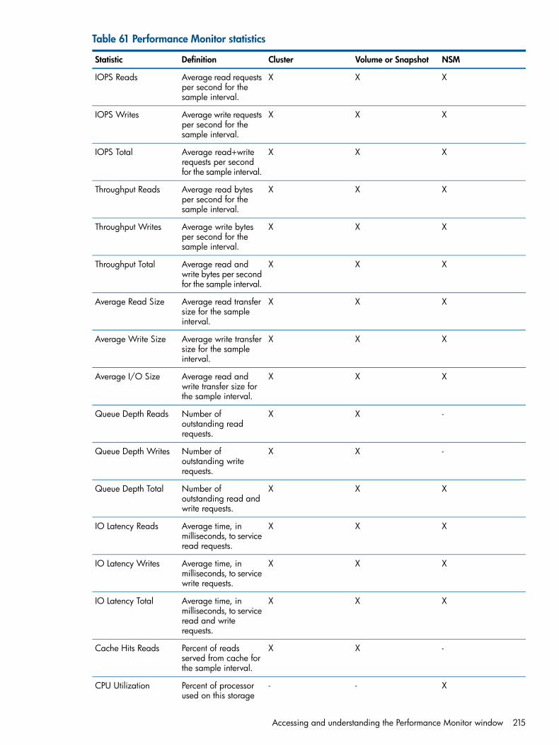
Table 61 Performance Monitor statistics
NSMVolume or SnapshotClusterDefinitionStatistic
XXXAverage read requestsper second for thesample interval.
IOPS Reads
XXXAverage write requestsper second for thesample interval.
IOPS Writes
XXXAverage read+writerequests per secondfor the sample interval.
IOPS Total
XXXAverage read bytesper second for thesample interval.
Throughput Reads
XXXAverage write bytesper second for thesample interval.
Throughput Writes
XXXAverage read andwrite bytes per secondfor the sample interval.
Throughput Total
XXXAverage read transfersize for the sampleinterval.
Average Read Size
XXXAverage write transfersize for the sampleinterval.
Average Write Size
XXXAverage read andwrite transfer size forthe sample interval.
Average I/O Size
-XXNumber ofoutstanding readrequests.
Queue Depth Reads
-XXNumber ofoutstanding writerequests.
Queue Depth Writes
XXXNumber ofoutstanding read andwrite requests.
Queue Depth Total
XXXAverage time, inmilliseconds, to serviceread requests.
IO Latency Reads
XXXAverage time, inmilliseconds, to servicewrite requests.
IO Latency Writes
XXXAverage time, inmilliseconds, to service
IO Latency Total
read and writerequests.
-XXPercent of readsserved from cache forthe sample interval.
Cache Hits Reads
X--Percent of processorused on this storage
CPU Utilization
Accessing and understanding the Performance Monitor window 215

Table 61 Performance Monitor statistics (continued)
NSMVolume or SnapshotClusterDefinitionStatistic
system for the sampleinterval.
X--Percent of totalmemory used on this
Memory Utilization
storage system for thesample interval.
X--Percent ofbidirectional network
Network Utilization
capacity used on thisnetwork interface onthis storage system forthe sample interval.
X--Bytes read from thenetwork for the sampleinterval.
Network Bytes Read
X--Bytes written to thenetwork for the sampleinterval.
Network Bytes Write
X--Bytes read and writtenover the network forthe sample interval.
Network Bytes Total
X--Average time, inmilliseconds, for the
Storage Server TotalLatency
RAID controller toservice read and writerequests.
Monitoring and comparing multiple clustersYou can open the Performance Monitor for a cluster in a separate window. This lets you monitorand compare multiple clusters at the same time. You can open one window per cluster and rearrangethe windows to suit your needs.1. From the Performance Monitor window, right-click anywhere, and select Open in Window.
The Performance Monitor window opens as a separate window.Use the Performance Monitor Tasks menu to change the window settings.
2. When you no longer need the separate window, click Close.
Performance monitoring and analysis conceptsThe following general concepts are related to performance monitoring and analysis.
WorkloadsA workload defines a specific characterization of disk activity. These characteristics are accesstype, access size, access pattern, and queue depth. Application and system workloads can beanalyzed, then described using these characteristics. Given these workload characterizations, testtools like iometer can be used to simulate these workloads.
Access typeDisk accesses are either read or write operations. In the absence of disk or controller caching,reads and writes operate at the same speed.
216 Monitoring performance

Access sizeThe size of a read or write operation. As this size increases, throughput usually increases becausea disk access consists of a seek and a data transfer. With more data to transfer, the relative costof the seek decreases. Some applications allow tuning the size of read and write buffers, but thereare practical limits to this.
Access patternDisk accesses can be sequential or random. In general, sequential accesses are faster than randomaccesses, because every random access usually requires a disk seek.
Queue depthQueue depth is a measure of concurrency. If queue depth is one (q=1), it is called serial. In serialaccesses, disk operations are issued one after another with only one outstanding request at anygiven time. In general, throughput increases with queue depth. Usually, only database applicationsallow the tuning of queue depth.
Changing the sample interval and time zoneYou can set the sample interval to any value between 5 seconds and 60 minutes, in increments ofeither seconds or minutes.The time zone comes from the local computer where you are running the CMC.You can change the sample interval in the following ways:
• Using the toolbar
• In the Edit Monitoring Interval window, where you can also change the time zoneTo change the sample interval from the toolbar:1. In the navigation window, log in to the management group.2. Select the Performance Monitor node for the cluster you want.3. In the toolbar, change the Sample Interval value.4. In the toolbar, select the Sample Interval Units you want.
The Performance Monitor starts using the new interval immediately.
To change the sample interval and time zone:1. In the navigation window, log in to the management group.2. Select the Performance Monitor node for the cluster you want.3. Click Performance Monitoring Tasks, and select Edit Monitoring Interval.4. In the Sample Every fields, enter the interval, and select the units you want.5. Select Local or Greenwich Mean Time.6. Click OK.
The Performance Monitor starts using the new interval and time zone immediately.
Adding statisticsYou can change the monitored statistics for the Performance Monitor as needed. To limit theperformance impact on the cluster, you can add up to 50 statistics.The system maintains any changes you make to the statistics only for your current CMC session. Itreverts to the defaults the next time you log in to the CMC.For definitions of the available statistics, see “Understanding the performance statistics” (page 214).1. In the navigation window, log in to the management group.2. Select the Performance Monitor node for the cluster you want.
Changing the sample interval and time zone 217

3. Click .
Figure 105 Add Statistics window
4. From the Select Object list, select the cluster, volumes, and storage systems you want to monitor.Use the CTRL key to select multiple objects from the list.
5. From the Select Statistics options, select the option you want.• All Statistics—Adds all available statistics for each selected object.
• Selected Statistics from List—Lets you select the statistics you want from the list below. Thelist is populated with the statistics that relate to the selected objects.
Use the CTRL key to select multiple statistics from the list.6. If you selected the Selected Statistics from List option, select the statistics you want to monitor.7. Click Add Statistics.
If you selected a statistic that is already being monitored, a message appears letting you knowthat the statistics will not be added again.
8. Click OK.
Viewing statistic detailsIn addition to what you see in a table row, you can see all of the details for a specific statistic inthe table, including the statistic definition.1. In the navigation window, log in to the management group.2. Select the Performance Monitor node for the cluster you want.
218 Monitoring performance

3. Right-click a row in the table and select View Statistic Details.The Statistic Details window opens, with all of the information for the selected statistic that isin the table, plus the statistic definition.
4. Click Close.
Removing and clearing statisticsYou can remove or clear statistics in any of the following ways:
• Remove one or more statistics from the table and graph
• Clear the sample data, but retain the statistics in the table
• Clear the graph display, but retain the statistics in the table
• Reset to the default statistics
Removing a statisticYou can remove one or more statistics from the table and graph.1. In the navigation window, log in to the management group.2. Select the Performance Monitor node for the cluster you want.3. Right-click a row in the table, and select Remove Statistics.
Use the CTRL key to select multiple statistics from the table.4. Click OK to confirm.
Clearing the sample dataYou can clear all the sample data, which sets all table values to zero and removes all lines fromthe graph. This leaves all of the statistics in the table and selected for display. The graph and tabledata repopulate with the latest values after the next sample interval elapses.1. In the navigation window, log in to the management group.2. Select the Performance Monitor node for the cluster you want.3. Right-click anywhere in the Performance Monitor window, and select Clear Samples.
Clearing the displayYou can clear the display, which removes all lines from the graph and deselects the Display optionfor each statistic in the table. This leaves all of the statistics in the table, along with their data,which continue to update.1. In the navigation window, log in to the management group.2. Select the Performance Monitor node for the cluster you want.3. Right-click anywhere in the Performance Monitor window, and select Clear Display.
Resetting defaultsYou can reset the statistics to the defaults, which removes all lines from the graph and sets the threedefault statistics (cluster total IOPS, cluster total throughput, and cluster total queue depth) to zeroin the table. The default statistics are set to display and their data update when the next sampleinterval elapses.1. In the navigation window, log in to the management group.2. Select the Performance Monitor node for the cluster you want.3. Right-click anywhere in the Performance Monitor window, and select Reset to Defaults.
Removing and clearing statistics 219

Pausing and restarting monitoringIf you are currently monitoring one or more statistics, you can pause the monitoring and restart it.For example, you may want to pause monitoring during planned maintenance windows orproduction downtime.
1. From the Performance Monitor window, click to pause the monitoring.All data remain as they were when you paused.
2. To restart the monitoring, click .Data updates when the next sample interval elapses. The graph will have a gap in the time.
Changing the graphYou can change the graph and its lines in the following ways:
• “Hiding and showing the graph” (page 220)
• “Displaying or hiding a line” (page 220)
• “Changing the color or style of a line” (page 220)
• “Highlighting a line” (page 220)
• “Changing the scaling factor” (page 221)
Hiding and showing the graphBy default, the performance monitor graph appears in the Performance Monitor window. If youwant more space to display the performance monitor table, you can hide the graph.
1. From the Performance Monitor window, click to hide the graph.
2. To redisplay the graph, click to show the graph.
Displaying or hiding a lineWhen you add statistics to monitor, by default, they are set to display in the graph. You can controlwhich statistics display in the graph, as needed.1. From the Performance Monitor window, deselect the Display check box for the statistic in the
table.2. To redisplay the line, select the Display check box for the statistic.
If you want to display all of the statistics from the table, right-click anywhere in the PerformanceMonitor window, and select Display All.
Changing the color or style of a lineYou can change the color and style of any line on the graph.1. From the Performance Monitor window, select one or more statistics in the table that you want
to change.2. Right-click, and select Edit Line.3. Select the color and line style options you want.4. To see the changes and leave the window open, click Apply.5. When you finish the changes, click OK.
Highlighting a lineYou can highlight one or more lines on the graph to make them easier to distinguish.
220 Monitoring performance
1. From the Performance Monitor window, right-click the statistic in the table that you want tohighlight, and select Highlight.The line turns white.
2. To remove the highlight, right-click the statistic, and select Remove Highlight.
Changing the scaling factorThe vertical axis uses a scale of 0 to 100. Graph data is automatically adjusted to fit the scale.For example, if a statistic value was larger than 100, say 4,000.0, the system would scale it downto 40.0 using a scaling factor of 0.01. If the statistic value is smaller than 10.0, for example 7.5,the system would scale it up to 75 using a scaling factor of 10. The Scale column of the statisticstable shows the current scaling factor. If needed, you can change the scaling factor. For example,if you are looking at similar items, you might change the scaling factor to change the emphasison one item.
• From the statistics table on the Performance Monitor window, select the scaling factor youwant from Scale drop-down list for the statistic you want to change.The line moves up or down the graph based on the new scaling factor.If the line is at the very top or bottom of the graph, the scaling factor is too large or too smallto fit on the graph. It is possible for more than one line to be “pegged” to the top or bottomof the graph in this way, resulting in one or more lines being hidden behind another line. Setthe Scale back to Auto to display the line.
Exporting dataYou can export performance statistics to a CSV file or save the current graph to an image file.
Exporting statistics to a CSV fileYou can export performance statistics to a CSV file. You select which statistics to export. They canbe different from the statistics you are currently monitoring.You also select the sample interval and the duration of the sampled data for export. Typical durationsare from 10 minutes to 24 hours. The maximum duration is 999 hours, which is about 41 days.
1. From the Performance Monitor window, click to start the export.2. In the Log File field, enter the name of the file.
By default, the system saves the file to the My Documents folder (Windows) or your homedirectory (Linux) with a file name that starts with Performance and includes the cluster name,along with the date and time.To select a different location, click Browse.
3. Set the Sample Every fields to the value and units you want for the sample interval.4. Set the For Duration Of fields to the value and units you want for the monitoring period.5. Click Add Statistics.6. In the Add Statistics window, from the Select Object list, select the cluster, volumes, and storage
systems you want to monitor.Use the CTRL key to select multiple objects from the list.
7. From the Select Statistics options, select the option you want.• All Statistics—Adds all available statistics for each selected object.
• Selected Statistics from List—Lets you select the statistics you want from the list below. Thelist is populated with the statistics that relate to the selected objects.Use the CTRL key to select multiple statistics from the list.
8. If you selected the Selected Statistics from List option, select the statistics you want to monitor.
Exporting data 221

9. Click Add Statistics.The statistics you selected are listed in the Added Statistics list.
10. Click OK.The File Size field displays an estimated file size, based on the sample interval, duration, andselected statistics.
11. When the export information is set the way you want it, click OK to start the export.The export progress appears in the Performance Monitor window, based on the duration andelapsed time.
To pause the export, click , then click to resume the export.
To stop the export, click . Data already exported is saved in the CSV file.
Saving the graph to an image fileYou can save the graph and the currently visible portion of the statistics table to an image file. Thismay be helpful if you are working with technical support or internal personnel to troubleshoot anissue.1. From the Performance Monitor window, make sure the graph and table display the data you
want.2. Right-click anywhere in the Performance Monitor window, and select Save Image.3. Navigate to where you want to save the file.4. Change the file name, if needed.
The file name defaults to include the name of the object being monitored and the date andtime.
5. Change the file type, if needed.6. Click Save.
222 Monitoring performance

18 Registering advanced featuresAdvanced features expand the capabilities of the SAN/iQ software and are enabled by licensingthe storage systems through the HP License Key Delivery Service website, using the license entitlementcertificate that is packaged with each storage system. However, you can use the advanced featuresimmediately by agreeing to enter an evaluation period when you begin using the SAN/iQ softwarefor clustered storage. Throughout the evaluation period you receive reminders to register and obtaina license for the advanced features. Create the SAN and begin using all the available featuresbefore obtaining the licenses, and then apply the license keys when you obtain them.The advanced features that require licensing are listed below.
• Multi-System Virtualization and Clustering—clustered storage systems that create a single poolof storage
• Managed Snapshots—recurring scheduled snapshots of volumes
• Remote Copy—scheduled or manual asynchronous replication of data to remote sites
• Multi-Site SAN—automatic synchronous data mirroring between sites
Evaluation period for using advanced featuresWhen you use any feature that requires a license key, a message opens, asking you to verify thatyou want to enter the evaluation period. During this evaluation period you may configure, test,and modify any feature. At the end of the evaluation period, if you do not obtain a license key,all volumes and snapshots related to the feature become unavailable to any clients. The data issafe, and you can continue to manage the volumes and snapshots in the CMC. You can restorethe entire configuration to availability by obtaining the license keys and applying them to thestorage systems in the management group that contains the configured advanced features.
Starting the evaluation periodYou start the evaluation period for an advanced feature when you configure that feature in theCMC.
Table 62 Descriptions of advanced features
And enters the license evaluation periodwhen
Provides this functionalityAdvanced Feature
You add two or more storage systemsto a cluster in a management group.
Clustering multiple storage systems tocreate pools of storage
Multi-Node Virtualization andClustering
You create a remote volume inpreparation for making a remotesnapshot.
Creating secondary volumes andsnapshots in remote locations
Remote Copy
You create a schedule to snapshot avolume.
Creating schedules to snapshotvolumes
Managed Snapshot
You create a cluster with multiple sites.Multi-site clusters which synchronouslyand automatically mirror data betweensites
Multi-Site SAN
Tracking the time remaining in the evaluation periodTrack the time left on your evaluation period by using either the management group Registrationtab or the reminder notices that open periodically.
Evaluation period for using advanced features 223

Identifying licensing statusYou can check the status of licensing on individual advanced features by the icons displayed. Theviolation icon appears throughout the evaluation period.
Figure 106 Identifying the license status for advanced features
Backing out of Remote Copy evaluationIf you decide not to use Remote Copy and you have not obtained license keys by the end of theevaluation period, you must delete any remote volumes and snapshots you have configured.However, you can save the data in the remote snapshots before you delete them.1. First, back up any volumes you plan to retain.2. Next, safely back out of the Remote Copy evaluation as described in Table 63 (page 224),
according to how you want to handle the data.
Table 63 Safely backing out of Remote Copy evaluation
Steps to Back OutFate of Data in Remote Snapshots
Removing data from the remote target • Delete the remote snapshots.
• Delete the remote volume.
Retaining the data on the remote target • Make the remote volume into a primary volume.
• Disassociate the primary and remote managementgroups, if the remote copy was between managementgroups.
Scripting evaluationApplication-based scripting is available for volume and snapshot features. You can create scriptsto:
• Create snapshots
• Create remote volumes and snapshotsBecause using scripts with advanced features starts the evaluation period without requiring thatyou use the CMC, you must first verify that you are aware of starting the evaluation clock whenusing scripting. If you do not enable the scripting evaluation period, any scripts you have running(licensed or not) will fail.
Turn on scripting evaluationTo use scripting while evaluating advanced features, enable the scripting evaluation period.1. In the navigation window, select a management group.2. Select the Registration tab.3. Click Registration Tasks, and select Feature Registration from the menu.4. Select the Scripting Evaluation tab.
224 Registering advanced features

5. Read the text, and select the box to enable the use of scripts during a license evaluation period.6. Click OK.
Turn off scripting evaluationTurn off the scripting evaluation period when you take either one of these actions:
• You obtain license keys for the feature you were evaluating.
• You complete the evaluation and decide not to license any advanced features.Turning off the scripting evaluation ensures that no scripts continue to push the evaluation clock.To turn off the scripting evaluation:1. Select the management group.2. Select the Registration tab.3. Click Registration Tasks, and select Feature Registration from the menu.4. Select the Scripting Evaluation tab.5. Clear the check box.6. Click OK.
Table 64 (page 225) describes additional steps to safely back out of the scripting evaluation.
Table 64 Safely backing out of scripting evaluation
Steps to Back OutFeature Being Evaluated
Remote copy volumes and snapshots • Back out of any remote copy operation.
• Delete any scripts.
• Delete any primary or remote snapshots created bythe scripts, as indicated by viewing Created By: onthe snapshot Details tab.
Registering advanced featuresWhen registering storage systems for advanced features, you must have your license entitlementcertificate and submit to the website the appropriate storage system feature key(s) to obtain thelicense key(s). You then receive the license key(s) and apply them to the storage system(s).
Using license keysLicense keys are assigned to individual storage systems. License keys can be added to storagesystems either when they are in the Available Systems pool or after they are in a managementgroup. One license key is issued per storage system, and that key licenses all the advanced featuresrequested for that storage system.
NOTE: If you remove a storage system from a management group, the license key remains withthat storage system. See for more information about removing storage systems from a managementgroup.
Registering available storage systems for license keysStorage systems that are in the Available Systems pool are licensed individually. You license anindividual storage system on the Feature Registration tab for that system.The Feature Registration tab displays the following information:
• The storage system feature key, used to obtain a license key
• The license key for that storage system, if one has been obtained
• The license status of all the advanced features
Registering advanced features 225

Submitting storage system feature keys1. In the navigation window, select the storage system from the Available Systems pool for which
you want to register advanced features.2. Select the Feature Registration tab.3. Select the Feature Key.4. Right-click, and select Copy.5. Use Ctrl+V to paste the feature key into a text editing program, such as Notepad.6. Register and generate the license key at the Webware website:
https://webware.hp.com
Entering license keys to storage systemsWhen you receive the license keys, add them to the storage systems.1. In the navigation window, select the storage system from the Available Systems pool.2. Select the Feature Registration tab.3. Click Feature Registration Tasks, and select Edit License Key from the menu.4. Copy and paste the Feature Key into the Edit License Key window.
NOTE: When you paste the license key into the window, be sure there are no leading ortrailing spaces in the box. Such spaces prevent the license key from being recognized.
5. Click OK.The license key appears in the Feature Registration window.
Figure 107 Storage system with a license key
Registering storage systems in a management groupStorage systems that are in a management group can be licensed through the management group.License the storage systems on the Registration tab for the management group.
226 Registering advanced features
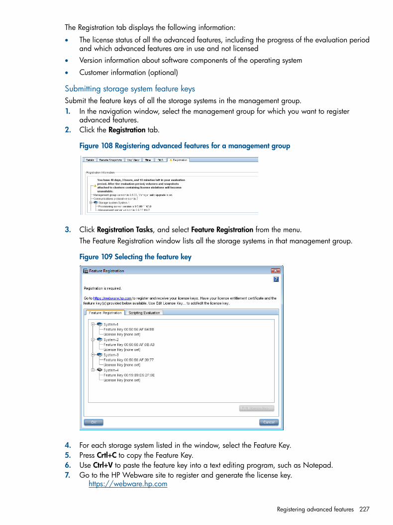
The Registration tab displays the following information:
• The license status of all the advanced features, including the progress of the evaluation periodand which advanced features are in use and not licensed
• Version information about software components of the operating system
• Customer information (optional)
Submitting storage system feature keysSubmit the feature keys of all the storage systems in the management group.1. In the navigation window, select the management group for which you want to register
advanced features.2. Click the Registration tab.
Figure 108 Registering advanced features for a management group
3. Click Registration Tasks, and select Feature Registration from the menu.The Feature Registration window lists all the storage systems in that management group.
Figure 109 Selecting the feature key
4. For each storage system listed in the window, select the Feature Key.5. Press Crtl+C to copy the Feature Key.6. Use Ctrl+V to paste the feature key into a text editing program, such as Notepad.7. Go to the HP Webware site to register and generate the license key.
https://webware.hp.com
Registering advanced features 227

NOTE: Record the host name or IP address of the storage system along with the feature key. Thisrecord will make it easier to add the license key to the correct storage system when you receiveit.
Entering license keysWhen you receive the license keys, add them to the storage systems in the Feature Registrationwindow.1. In the navigation window, select the management group.2. Select the Registration tab.3. Click Registration Tasks, and select Feature Registration from the menu.4. Do one of the following.
To enter license keys for multiple storage systems in themanagement group
To enter a license key for one storage system in themanagement group
a. Click Import License Keys.a. Select a storage system, and click Edit License Key.b. b.Copy and paste the appropriate license key for that
storage system into the window.Click Browse to navigate to the license key files youdownloaded from https://webware.hp.com.
NOTE: When you cut and paste the license keyinto the window, ensure that there are no leading ortrailing spaces in the box. Such spaces prevent thelicense key from being recognized.
c. Select each .dat file that corresponds to the storagesystems in the management group, and click Open.Each license key is in a separate .dat file. The filename has the storage system’s feature key in the filename, as follows:c. Click OK.
The license key appears in the Feature Registrationwindow.
xxxxxxxxxxxx_xxxxxxx_AA.BB.CC.DD.EE.FF_x.dat.Be sure the AA.BB.CC.DD.EE.FF part of each filename matches the feature key of a storage system.If an error message appears, the error text describesthe problem.
d. Click OK again to exit the Feature Registrationwindow.
d. Click Apply License Keys.e. Check the Import Summary window for any errors.
The error messages explain the problem. A greencheck mark shows the license key has been applied.
f. Click Close.If the import process had errors, you return to theImport License Key window. Click Browse to selecta different license key file. If you click Cancel to exitthe window, any license keys with a green checkmark were applied. If the import process completedsuccessfully, click Close to exit the window.
Saving license key informationFor record-keeping, save the license information to a .txt file when you have entered all the licensekeys.1. Click Registration Tasks on the management group Registration tab.2. Select Save Information to File from the menu.3. Navigate to the location where you want to save the license key information.4. Enter a name for the registration information file, and click Save.
Saving and editing your customer informationSave your customer profile, registrations, and licensing information as a text file. Then, if you losea storage system, the information can help you rebuild a new storage system.
228 Registering advanced features

Make a customer information file for each management group in your SAN.
• Create or edit your customer profile.
• Save the customer profile to a computer that is not part of your SAN.
Editing your customer information fileOccasionally, you may want to change some of the information in your customer profile. Forexample, if your company moves, or contact information changes.1. In the navigation window, select a management group.2. Click the Registration tab.3. Click Registration Tasks, and select Edit Customer Information from the menu.4. Fill in or change any of the information on this window.5. Click OK when you are finished.
Saving your customer informationBe sure you have filled in the customer profile window correctly before saving this file. In additionto the customer information, the file you save contains registration and licence key information.Save a customer information file for each management group in your storage system.1. In the navigation window, select a management group.2. Click the Registration tab.3. Click Registration Tasks, and select Save Information to File from the menu.4. In the Save window, navigate to the directory where you want to save the license key and
customer information file.5. In the File Name field, enter a name for the file, which defaults to a .txt file.6. Click Save.
Verify the information by viewing the saved .txt file.
Saving and editing your customer information 229
19 iSCSI and the HP P4000 SAN SolutionThe SAN/iQ software uses the iSCSI protocol to let servers access volumes. For fault toleranceand improved performance, use a VIP and iSCSI load balancing when configuring server accessto volumes.The following concepts are important when setting up clusters and servers in the SAN/iQ software:
• “Virtual IP addresses” (page 230)
• “iSNS server” (page 230)
• “iSCSI load balancing” (page 231)
• “Authentication (CHAP)” (page 231)
• “iSCSI and CHAP terminology” (page 232)
• “About HP DSM for MPIO” (page 234)
Number of iSCSI sessionsFor information about the recommended maximum number of iSCSI sessions that can be createdin a management group, see “Configuration Summary overview” (page 109).
Virtual IP addressesA virtual IP (VIP) address is a highly available IP address which ensures that if a storage system ina cluster becomes unavailable, servers can still access a volume through the other storage systemsin the cluster.Your servers use the VIP to discover volumes on the SAN. The SAN uses the iqn from the iSCSIinitiator to associate volumes with the server.A VIP is required for a fault tolerant iSCSI cluster configuration, using VIP load balancing or theHP DSM for MPIO.When using a VIP, one storage system in the cluster hosts the VIP. All I/O goes through the VIPhost. You can determine which storage system hosts the VIP by selecting the cluster, then clickingthe iSCSI tab.
Requirements for using a virtual IP address• For standard clusters (not multi-site clusters), storage systems occupying the same cluster must
be in the same subnet address range as the VIP.• The VIP must be routable regardless of which storage system it is assigned to.
• iSCSI servers must be able to ping the VIP when it is enabled in a cluster.
• The VIP address must be different than any storage system IPs on the network.
• The VIP address must be a static IP address reserved for this purpose.
• All iSCSI initiators must be configured to connect to the VIP address for the iSCSI failover towork properly.
iSNS serverAn iSNS server simplifies the discovery of iSCSI targets on multiple clusters on a network. If youuse an iSNS server, configure your cluster to register the iSCSI target with the iSNS server. Youcan use up to 3 iSNS servers, but none are required.
230 iSCSI and the HP P4000 SAN Solution

iSCSI load balancingUse iSCSI load balancing to improve iSCSI performance and scalability by distributing iSCSIsessions for different volumes evenly across storage systems in a cluster. iSCSI load balancing usesiSCSI Login-Redirect. Only initiators that support Login-Redirect should be used.When using VIP and load balancing, one iSCSI session acts as the gateway session. All I/O goesthrough this iSCSI session. You can determine which iSCSI session is the gateway by selecting thecluster, then clicking the iSCSI Sessions tab. The Gateway Connection column displays the IPaddress of the storage system hosting the load balancing iSCSI session.Configure iSCSI load balancing when setting up servers. See “iSCSI and the HP P4000 SANSolution” (page 230).
Requirements• Cluster configured with a virtual IP address. See “Virtual IP addresses” (page 230).
• A compliant iSCSI initiator.
Compliant iSCSI initiatorsA compliant initiator supports iSCSI Login-Redirect AND has passed HP’ test criteria for iSCSIfailover in a load balanced configuration.Find information about which iSCSI initiators are compliant by clicking the link in the New or EditServer window.The link opens to the http://www.hp.com/go/P4000compatibility where you log in and searchfor the HP P4000 SAN Solutions Compatibility Matrix.If your initiator is not on the list, do not enable load balancing.
Authentication (CHAP)Server access with iSCSI can use the following authentication methods:
• Initiator node name (single host)
• CHAP (Challenge-Handshake Authentication Protocol), which can support single or multiplehosts.
NOTE: The iSCSI terminology in this discussion is based on the Microsoft iSCSI Initiatorterminology. For the terms used in other common operating systems, see “iSCSI and CHAPterminology” (page 232).
CHAP is a standard authentication protocol. The SAN/iQ software supports the followingconfigurations:
• No CHAP—Authorized initiators can log in to the volume without proving their identity. Thetarget does not challenge the server.
• 1-way CHAP—Initiators must log in with a target secret to access the volume. This secret provesthe identity of the initiator to the target.
• 2-way CHAP—Initiators must log in with a target secret to access the volume as in 1-wayCHAP. In addition, the target must prove its identity to the initiator using the initiator secret.This second step prevents target spoofing.
iSCSI load balancing 231

Figure 110 Differentiating types of CHAP
CHAP is optional. However, if you configure 1-way or 2-way CHAP, you must remember to configureboth the server and the iSCSI initiator with the appropriate characteristics. Table 65 (page 232)lists the requirements for configuring CHAP.
Requirements for configuring CHAPTable 65 Configuring iSCSI CHAP
What to Configure in the iSCSI InitiatorWhat to Configure for the Server inthe SAN/iQ Software
CHAP Level
No configuration requirementsInitiator node name onlyCHAP not required
Enter the target secret (12-characterminimum) when logging on to availabletarget.
1-way CHAP • CHAP name*
• Target secret
2-way CHAP • Enter the initiator secret(12-character minimum).
• CHAP name*
• Target secret• Enter the target secret (12-character
minimum).• Initiator secret
* If using CHAP with a single node only, use the initiator node name as the CHAP name.
iSCSI and CHAP terminologyThe iSCSI and CHAP terms used vary based on the operating system and iSCSI initiator you areusing. The table below lists the terms for two common iSCSI initiators.
Table 66 iSCSI terminology
LinuxVMWareMicrosoftSAN/iQ CMC
Refer to the documentationfor the iSCSI initiator you are
iSCSI NameInitiator Node NameInitiator Node Name
using. Linux iSCSI initiatorsmay use a command lineinterface or a configurationfile.
CHAP NameNot usedCHAP Name
CHAP SecretTarget SecretTarget Secret
N/ASecretInitiator Secret
232 iSCSI and the HP P4000 SAN Solution

NOTE: The initiator node name and secrets set in the SAN/iQ CMC must match what you enterin the server’s iSCSI initiator exactly.
Sample iSCSI configurationsFigure 111 (page 233) illustrates the configuration for a single host authentication with CHAP notrequired with Microsoft iSCSI.
Figure 111 Viewing the MS iSCSI initiator to copy the initiator node name
Figure 112 (page 233) illustrates the configuration for a single host authentication with 1-way CHAPrequired.
Figure 112 Configuring iSCSI (shown in the MS iSCSI initiator) for a single host with CHAP
iSCSI and CHAP terminology 233

Figure 113 (page 234) illustrates the configuration for a single host authentication with 2-way CHAPrequired.
Figure 113 Adding an initiator secret for 2-way CHAP (shown in the MS iSCSI initiator)
CAUTION: Without the use of shared storage access (host clustering or clustered file system)technology, allowing more than one iSCSI application server to connect to a volume concurrentlywithout cluster-aware applications and/or file systems in read/write mode could result in datacorruption.
NOTE: If you enable CHAP on a server, it will apply to all volumes for that server.
Best practiceIn the Microsoft iSCSI Initiator, target and initiator secrets are not displayed. Keep a separaterecord of the iSCSI Initiator CHAP information and the corresponding server information.
About HP DSM for MPIOIf you are using the HP DSM for MPIO, you can use HP DSM for MPIO to access volumes. Formore information about HP DSM for MPIO, refer to the HP P4000 DSM for MPIO DeploymentGuide.You can see if you are using HP DSM for MPIO in the CMC by selecting a server in a managementgroup, then clicking the Volumes and Snapshots tab. The Gateway Connection column showsmultiple connections labeled as DSM.When accessing volumes from a server using HP DSM for MPIO, keep in mind the following:
• HP DSM for MPIO and the Microsoft MPIO must be installed on the server.
• With these installed, servers automatically use HP DSM for MPIO when you log on to volumesfrom the iSCSI initiator.
• If you have dual storage NICs in your server, you can select the Enable multi-path option whenlogging on to the volume, and log on from each NIC.
234 iSCSI and the HP P4000 SAN Solution

20 Using the Configuration InterfaceThe Configuration Interface is the command line interface that uses a direct connection with thestorage system.You may need to access the Configuration Interface if all network connections to the storage systemare disabled. Use the Configuration Interface to perform the following tasks.
• Add storage system administrators and change passwords
• Access and configure network interfaces
• Delete a NIC bond
• Set the TCP speed and duplex, or edit the frame size
• Remove the storage system from a management group
• Reset the storage system configuration to factory defaults
Connecting to the Configuration InterfaceAccessing the Configuration Interface is accomplished by
• Attaching a keyboard and monitor (KVM) to the storage system serial port (preferred) or
• Attaching a PC or a laptop using a null modem cable and connecting to the ConfigurationInterface with a terminal emulation program.
Establishing a terminal emulation session on a Windows systemOn the PC or laptop attached directly to the storage system with a null modem cable, open asession with a terminal emulation program such as HyperTerminal or ProComm Plus.Use the following settings: 19200, 8-N-1When the session is established, the Configuration Interface window opens.
Establishing a terminal emulation session on a Linux/UNIX systemIf using Linux, create the following configuration file. You must create the file as root, or root mustchange permissions for /dev/cua0 in order to create the config file in /etc/.1. Create the /etc/minirc.NSM with the following parameters:
# Begin HP LeftHand Networks NSM configuration# Machine-generated file – use “minicom –s” to# change parameterspr port = /dev/cua0pu baudrate = 19200pu bits = 8pu parity = Npu stopbits = 1pu mautobaud = Yespu backspace = DELpu hasdcd = Nopu rtscts = Nopu xonxoff = Yespu askdndir = Yes# End HP LeftHand Networks NSM configuration
2. Start xterm as follows:
Connecting to the Configuration Interface 235

$ xterm
3. In the xterm window, start minicom as follows:$ minicom -c on -l NSM
Opening the Configuration Interface from the terminal emulation session1. Press Enter when the terminal emulation session is established.2. Enter start, and press Enter at the log in prompt.3. When the session is connected to the storage system, the Configuration Interface window
opens.
Logging in to the Configuration InterfaceOnce you have established a connection to the storage system, log in to the Configuration Interface.
Table 67 Logging in depends on where the storage system is
From Configuration Interface entry windowIf the storage system is in
Press Enter to log in. The Configuration Interface main menuopens.
Available Systems pool
Management group 1. Press Enter to log in.2. Enter the user name and password of the administrative
user created for the management group.3. Tab to Login, and press Enter.
NOTE: This user is viewable in the CMC under the management group Administration category.
Configuring administrative usersUse the Configuration Interface to add new administrative users or to change administrativepasswords. You can only change the password for the administrative user that you used to log into the Configuration Interface.1. On the Configuration Interface main menu, tab to General Settings, and press Enter.2. To add an administrative user, tab to Add Administrator, and press Enter. Then enter the new
user’s name and password. Confirm password, tab to OK, and press Enter.3. To change the password for the user that you are currently logged in as, tab to Change
Password, and press Enter. Then enter the new password. Confirm password, tab to OK, andpress Enter.
4. On the General window, tab to Done, and press Enter.
Configuring a network connectionThe storage system comes with two Ethernet interfaces. Table 68 (page 236) lists where interfacesare labeled and the label name.
Table 68 Identifying Ethernet interfaces on the storage system
Ethernet Interfaces
What the label saysWhere labeled
Name:TCP/IP Network configuration category in the CMC• TCP/IP tab eth0, eth1
Motherboard:Port0, Motherboard:Port1• TCP Status tab G4-Motherboard:Port1, G4-Motherboard:Port2
236 Using the Configuration Interface

Table 68 Identifying Ethernet interfaces on the storage system (continued)
Ethernet Interfaces
What the label saysWhere labeled
Motherboard:Port1, Motherboard:Port2
Intel Gigabit Ethernet or Broadcom Gigabit EthernetConfiguration Interface
Eth0, Eth1, or a graphical symbol similar to the following:
or
Label on the back of the storage system
Once you have established a connection to the storage system using a terminal emulation program,you can configure an interface connection using the Configuration Interface.1. On the Configuration Interface main menu, tab to Network TCP/IP Settings, and press Enter.2. Tab to select the network interface that you want to configure, and press Enter.3. Enter the host name, and tab to the next section to configure the network settings.
NOTE: If you specify an IP address, Gateway is a required field. If you do not have aGateway, enter 0.0.0.0 for the Gateway address.
4. Tab to OK, and press Enter to complete the network configuration.5. Press Enter on the confirmation window.6. Open the CMC, and locate the storage system using the Find function.
Deleting a NIC bondYou can delete the following NIC bonds using the Configuration Interface:
• Active-Passive bond
• Link Aggregation Dynamic Mode bond
• Adaptive Load Balancing bondFor more information about creating and configuring NIC bonds, see “Configuring network interfacebonds” (page 55).When you delete an Active-Passive bond, the primary interface assumes the IP address andconfiguration of the deleted logical interface. The other NIC is disabled and its IP address is setto 0.0.0.0.When you delete a Link Aggregation Dynamic Mode or an Adaptive Load Balancing bond, eth0or motherboard: port 1 retains the IP address of the deleted logical interface. The other NIC isdisabled, and its IP address is set to 0.0.0.0.1. On the Configuration Interface main menu, tab to Network TCP/IP, Settings and press Enter.
In the Available Network Devices window that opens, the logical bond is the only interfacelisted.
2. Tab to select the bond, and press Enter.3. Tab to Delete Bond, and press Enter.4. Press Enter on the confirmation window.5. On the Available Network Devices window, tab to Back, and press Enter.
Setting the TCP speed, duplex, and frame sizeYou can use the Configuration Interface to set the TCP speed, duplex, and frame size of a networkinterface.
Deleting a NIC bond 237

TCP speed and duplex. You can change the speed and duplex of an interface. If you change thesesettings, you must ensure that both sides of the NIC cable are configured in the same manner. Forexample, if the storage system is set for Auto/Auto, the switch must be set the same. For moreinformation about TCP speed and duplex settings, see “Managing settings on network interfaces”(page 50).Frame size. The frame size specifies the size of data packets that are transferred over the network.The default Ethernet standard frame size is 1500 bytes. The maximum allowed frame size is 9000bytes.Increasing the frame size improves data transfer speed by allowing larger packets to be transferredover the network and by decreasing the CPU processing time required to transfer data. However,increasing the frame size requires that routers, switches, and other devices on your network supportthat frame size.For more information about setting a frame size that corresponds to the frame size used by routers,switches, and other devices on your network, see “Changing NIC frame size” (page 51).1. On the Configuration Interface main menu, tab to Network TCP Status and press Enter.2. Tab to select the network interface for which you want to set the TCP speed and duplex, and
press Enter.3. To change the speed and duplex of an interface, tab to a setting in the Speed / Duplex list.4. To change the frame size, select Set To in the Frame Size list. Then tab to the field to the right
of Set To, and enter a frame size.The frame size value must be between 1500 bytes and 9000 bytes.
5. On the Network TCP Status window, tab to OK, and press Enter.6. On the Available Network Devices window, tab to Back, and press Enter.
Removing a storage system from a management group
CAUTION: Removing a storage system from a management group deletes all data from thestorage system, clears all information about the management group, and reboots the storagesystem.
1. On the Configuration Interface main menu, tab to Config Management, and press Enter.2. Tab to Remove from management group, and press Enter.3. Tab to OK, and press Enter to confirm.4. On the Configuration Management window, tab to Done, and press Enter.
Resetting the storage system to factory defaults
CAUTION: Resetting the storage system to factory defaults deletes all data and erases theconfiguration of the storage system, including administrative users and network settings.
1. On the Configuration Interface main menu, tab to Config Management, and press Enter.2. Tab to Reset to factory defaults, and press Enter.3. Tab to OK, and press Enter to confirm the reset.4. On the Configuration Management window, tab to Done, and press Enter.
238 Using the Configuration Interface

21 Support and other resourcesContacting HP
For worldwide technical support information, see the HP support website:http://www.hp.com/support
Before contacting HP, collect the following information:
• Product model names and numbers
• Technical support registration number (if applicable)
• Product serial numbers
• Error messages
• Operating system type and revision level
• Detailed questions
Subscription serviceHP recommends that you register your product at the Subscriber's Choice for Business website:
http://www.hp.com/go/e-updates
After registering, you will receive email notification of product enhancements, new driver versions,firmware updates, and other product resources.
HP Insight Remote Support SoftwareHP strongly recommends that you install HP Insight Remote Support software to complete theinstallation or upgrade of your product and to enable enhanced delivery of your HP Warranty,HP Care Pack Service or HP contractual support agreement. HP Insight Remote Support supplementsyour monitoring, 24x7 to ensure maximum system availability by providing intelligent eventdiagnosis, and automatic, secure submission of hardware event notifications to HP, which willinitiate a fast and accurate resolution, based on your product’s service level. Notifications may besent to your authorized HP Channel Partner for on-site service, if configured and available in yourcountry. The software is available in two variants:
• HP Insight Remote Support Standard: This software supports server and storage devices andis optimized for environments with 1-50 servers. Ideal for customers who can benefit fromproactive notification, but do not need proactive service delivery and integration with amanagement platform.
• HP Insight Remote Support Advanced: This software provides comprehensive remote monitoringand proactive service support for nearly all HP servers, storage, network, and SANenvironments, plus selected non-HP servers that have a support obligation with HP. It isintegrated with HP Systems Insight Manager. A dedicated server is recommended to host bothHP Systems Insight Manager and HP Insight Remote Support Advanced.
Details for both versions are available at: http://h18004.www1.hp.com/products/servers/management/insight-remote-support/overview.htmlTo download the software, go to Software Depot:https://h20392.www2.hp.com/portal/swdepot/index.do.Select Insight Remote Support from the menu on the right.
Contacting HP 239

New and changed information in this editionThe following additions and changes have been made for this edition:
• The following information has been updated:◦ P4000 SAN Solution and user documentation have been rebranded
◦ New SAN Status Home page is added to the CMC, providing a graphic view formonitoring the SAN
◦ New Best Practice analyzers have been added
◦ Management Groups, Clusters and Volume wizard has been updated with elements toensure a highly available SAN configuration
◦ New snapshot functionality to quiesce application servers on VMware Servers beforetaking snapshots
Related informationThe following documents [and websites] provide related information:You can find the documents referenced in this guide from the Manuals page of the HP BusinessSupport Center website:
http://www.hp.com/support/manuals
In the Storage section, select Disk Storage Systems→P4000 SAN Solutions→HP P4000 G2 SANSolutions.
HP websitesFor additional information, see the following HP websites:
• http://www.hp.com
• http://www.hp.com/go/storage
• http://www.hp.com/service_locator
• http://www.hp.com/support/manuals
• http://www.hp.com/support/downloads
• http://www.hp.com/storage/whitepapers
Customer self repairHP customer self repair (CSR) programs allow you to repair your P4000 product. If a CSR partneeds replacing, HP ships the part directly to you so that you can install it at your convenience.Some parts do not qualify for CSR. Your HP-authorized service provider will determine whether arepair can be accomplished by CSR.For more information about CSR, contact your local service provider, or see the CSR website:
http://www.hp.com/go/selfrepair
240 Support and other resources

A Replacing hardwareThis chapter describes the disk replacement procedures for cases in which you do not know whichdisk to replace and/or you must rebuild RAID on the entire storage system. For example, if RAIDhas gone off unexpectedly, you need HP Support to help determine the cause, and if it is a diskfailure, to identify which disk must be replaced. It also describes how to identify and replace theRAID controller in the P4900 G2 storage system.
Replacing disks and rebuilding dataTo replace individual disks for which RAID is running, but may be degraded, see “Replacing disks”(page 241).
NOTE: RAID refers to the disk level RAID set on an individual storage system. Network RAIDrefers to the data protection level set on volumes when they are created. The data protection levelis always referred to as Network RAID. Disk RAID is always referred to as RAID.
The following situations may require consulting with HP Support to identify bad disks before diskreplacement to rebuild the data (when configured for data protection) on the storage system:• RAID 5—If multiple disks need to be replaced, they must be identified and replaced, and the
data on the entire storage system rebuilt.• RAID 10/1+0 (Mirror and Stripe)—Can sustain multiple disk replacements. However, HP
Support must identify if any two disks are from the same mirror set, and then the data on theentire storage system needs to be rebuilt.
• RAID 6 (Stripe with dual parity)—If 3 or more disks need to be replaced, they must be identifiedand replaced, and the data on the entire storage system rebuilt.
Before you begin1. Know the name and physical location of the storage system that needs the disk replacement.2. Know the physical position of the disk in the storage system.3. Have the replacement disk ready, and confirm that it is the right size and has the right carrier.
For confirmation on which disks need to be replaced, contact HP Support.
Prerequisites• All Network RAID-10, Network RAID-10+1, Network RAID-10+2, Network RAID-5, and
Network RAID-6 volumes and snapshots should show a status of Normal.• If the cluster does not have enough space for the replication, create a backup of the volumes
or snapshots, and then delete them from the cluster. After the disk replacement is complete,recreate the volumes, and restore the data from the backup.
• Any volumes or snapshots that were being deleted should have finished deleting.• Record the order in which the storage systems are listed in the Edit Cluster window. You must
ensure that they are all returned to that order when the repair is completed.
Replacing disksUse this procedure when any of the following occurs:• Multiple disks need to be replaced on a storage system with RAID 5.• Three or more disks need to be replaced on a storage system with RAID 6.• Multiple disks on the same mirror set need to be replaced on a storage system with RAID 10.
Verify the storage system is not running a managerVerify that the storage system that needs the disk replacement is not running a manager.
Replacing disks and rebuilding data 241

1. Log in to the management group.2. Select the storage system in the navigation window, and review the Details tab information.
If the Storage System Status shows Manager Normal, and the Management Group Managershows Normal, then a manager is running and needs to be stopped.
To stop a manager:1. Right-click the storage system in the navigation window and select Stop Manager.
When the process completes successfully, the manager is removed from the Status line in theStorage System box, and Manager changes to No in the Management Group box.
2. If you stop a manager, the cluster will be left with an even number of managers. To ensurethat the cluster has an odd number of managers, do one of these tasks:• Start a manager on another storage system.• Add a virtual manager to the management group by right-clicking on the management
group name in the navigation window and selecting Add Virtual Manager.
Repair the storage systemUse the Repair Storage System function to replace a disk and trigger only one resynchronizationof the data.
NOTE: If there are Network RAID-0 volumes that are offline, the message shown in Figure 114(page 242) is displayed. You must either replicate or delete these volumes before you can proceed.You see the message shown in in this case.
Figure 114 Warning if volumes are Network RAID-0
Right-click the storage system in the navigation window, and select Repair Storage System. A“ghost” image takes the place of the storage system in the cluster, with the IP address serving asa place holder. The storage system moves from the management group to the Available Systemspool.If the storage system does not appear in the Available Systems pool, use the Find menu option torelocate it.
To replace the diskFor the DL320s (NSM 2120), HP LeftHand P4300, HP LeftHand P4500, and HP P4900 G2 see“Replacing a disk in a hot-swap storage system ” (page 46).
242 Replacing hardware

Rebuilding dataThe following steps take you through the steps to first reconfigure RAID on the storage system andthen to rebuild data on the storage system after it is added to the management group and cluster.
Reconfigure RAID1. Select the Storage category, and select the RAID Setup tab.2. Click RAID Setup Tasks, and select Reconfigure RAID.
The RAID Status changes from Off to Normal.
NOTE: If RAID reconfigure reports an error, reboot the storage system, and try reconfiguring theRAID again. If this second attempt is not successful, call HP Support.
Checking the progress of the RAID reconfigurationUse the Hardware Information report to check the status of the RAID rebuild.1. Select the Diagnostics category, and select the Hardware Information tab.2. Select Click to Refresh, and scroll to the RAID section of the Hardware report(Figure 115
(page 243)) to review the RAID rebuild rate and the percent complete.3. Click Hardware Information Tasks and select Refresh to monitor the ongoing progress.
Figure 115 Checking RAID rebuild status
Returning the storage system to the cluster1. In the navigation window, right-click the storage system, and select Add to Existing Management
Group.2. Select the Group Name that the storage system used to belong to and click Add.
The storage system appears in the management group and the icon in the navigation windowflashes for a few minutes as it initializes.
Replacing disks and rebuilding data 243

Restarting a manager
NOTE: Before proceeding, verify that the storage system has finished initializing and is completelyadded to the management group.
If necessary, ensure that after the repair you have the appropriate configuration of managers. Ifthere was a manager running on the storage system before you began the repair process, youmay start a manager on the repaired storage system as necessary to finish with the correct numberof managers in the management group.If you added a virtual manager to the management group, you must first delete the virtual managerbefore you can start a regular manager.1. Right-click the virtual manager, and select Stop Virtual Manager.2. Right-click the virtual manager, and select Delete Virtual Manager.3. Right-click the storage system, and select Start Manager.
Adding the repaired storage system to cluster1. After the initialization completes, right-click the cluster, and select Edit Cluster. The list of the
storage systems in the cluster should include the ghost IP address.Add the repaired storage system to the cluster in the spot held by the ghost IP address. SeeTable 69 (page 244).
2. Select the ghost storage system (the IP address in the list) and click Exchange System.3. In the Exchange Storage System window, select the repaired storage system to exchange for
the ghost storage system and then click OK.4. To ensure that only the repaired storage system goes through the rebuild, verify that the order
of the storage systems in the cluster list matches the original order and then click OK.The storage system returns to its original position in the cluster and volumes in the clusterproceed to resynchronize.
NOTE: If you do not arrange the storage systems to match their original order, the data inthe cluster is rebuilt across all the storage systems instead of just the repaired storage system.This total data rebuild takes longer to complete and increases the chance of a second failureduring this period.
Table 69 Replacing the ghost storage system with the repaired storage system
Storage Systems in Cluster
Before rearranging • Storage system A
• <IP Address>
• Storage system C
After rearranging • Storage system A
• Storage system B
• Storage system C
Rebuilding volume dataAfter the storage system is successfully added back to the cluster, the adjacent storage systemsstart rebuilding data on the repaired storage system. To verify progress:1. Select the cluster, and select the Disk Usage tab.2. Verify that the disk usage on the repaired storage system starts increasing.3. Verify that the status of the volumes and snapshots is Restriping.
Depending on the usage, it may take anywhere from a few hours to a day for the data to berebuilt on the repaired storage system.
244 Replacing hardware

Controlling server accessUse the Local Bandwidth Priority setting to control server access to data during the rebuild process:• When the data is being rebuilt, the servers that are accessing the data on the volumes might
experience slowness. Reduce the Local Bandwidth Priority to half of its current value forimmediate results.
• Alternatively, if server access performance is not a concern, raise the Local Bandwidth Priorityto increase the data rebuild speed.
To change local bandwidth priority:1. Right-click the management group, and select Edit Management Group.
The current Bandwidth Priority value indicates that each manager in that management groupwill use that much bandwidth to transfer data to the repaired storage system. Make a note ofthe current value so it can be restored after the data rebuild completes.
2. Change the bandwidth value as desired, and click OK.
Removing the ghost storage systemYou can remove the ghost storage system after the data is rebuilt on the repaired storage system.Data is rebuilt on the storage system when two conditions are met:• The repaired storage system's disk usage matches the usage of the other storage systems in
the cluster.• The status of the volume and snapshots goes back to Normal.To remove the ghost storage system:1. Right-click the ghost IP address and select Remove from Management Group.2. If you have changed the Local Bandwidth Priority of the management group while the data
was being rebuilt, change it back to the original value.At this point, the disk in the storage system is successfully replaced, the data is fully rebuilt on thatstorage system, and the management group configuration (number of managers, quorum, localbandwidth, and so on) are restored to the original settings.
Returning the failed disk1. Contact HP Support for an RA number.2. Return the original disks for failure analysis using the prepaid packing slip in the replacement
package. Put the RA number on the package as instructed by HP Support.
Replacing the RAID controllerBefore you begin, have the following items ready:• T-10 wrench (stored on the rear of the storage server)• Replacement RAID controller
CAUTION: When handling system components, there is a danger to equipment from electrostaticdischarge (ESD). Use proper anti-static protection at all times:• Keep the replacement component in the ESD bag until needed.• Wear an ESD wrist strap grounded to an unpainted surface of the chassis.• If an ESD wrist strap is unavailable, touch an unpainted surface of the chassis before handling
the component.• Never touch connector pins.
Verifying component failureLook at the system health LED for the controller cards (2, Figure 116 (page 246)) to determine ifthere is a problem.
Replacing the RAID controller 245
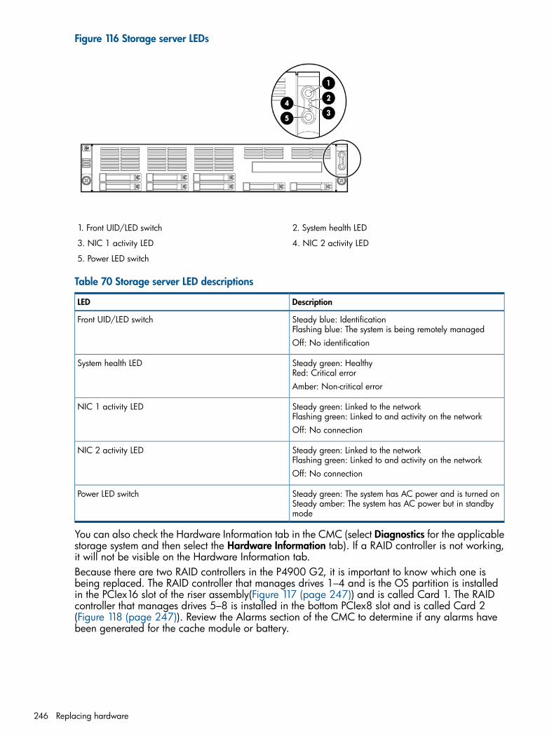
Figure 116 Storage server LEDs
2. System health LED1. Front UID/LED switch
4. NIC 2 activity LED3. NIC 1 activity LED
5. Power LED switch
Table 70 Storage server LED descriptions
DescriptionLED
Steady blue: IdentificationFlashing blue: The system is being remotely managed
Front UID/LED switch
Off: No identification
Steady green: HealthyRed: Critical error
System health LED
Amber: Non-critical error
Steady green: Linked to the networkFlashing green: Linked to and activity on the network
NIC 1 activity LED
Off: No connection
Steady green: Linked to the networkFlashing green: Linked to and activity on the network
NIC 2 activity LED
Off: No connection
Steady green: The system has AC power and is turned onSteady amber: The system has AC power but in standbymode
Power LED switch
You can also check the Hardware Information tab in the CMC (select Diagnostics for the applicablestorage system and then select the Hardware Information tab). If a RAID controller is not working,it will not be visible on the Hardware Information tab.Because there are two RAID controllers in the P4900 G2, it is important to know which one isbeing replaced. The RAID controller that manages drives 1–4 and is the OS partition is installedin the PCIex16 slot of the riser assembly(Figure 117 (page 247)) and is called Card 1. The RAIDcontroller that manages drives 5–8 is installed in the bottom PCIex8 slot and is called Card 2(Figure 118 (page 247)). Review the Alarms section of the CMC to determine if any alarms havebeen generated for the cache module or battery.
246 Replacing hardware

Figure 117 Card 1 location
Figure 118 Card 2 location
A cache module is attached to each RAID controller and each cache module is connected to abattery. The unit is called a backup battery with cache (BBWC). BBWC 1 connects to Card 1 andBBWC 2 connects to Card 2.
Removing the RAID controller1. Power off the storage system:
a. Use the CMC to power off the system controller as described in “Powering off the storagesystem” (page 24).
b. Manually power off the disk enclosure.2. Unplug all cables from the power outlets.3. Remove the storage system from the rack and place it on a flat surface.
Replacing the RAID controller 247

4. Remove the top cover (Figure 119 (page 248)):a. Loosen the screw on the top cover with the T-10 wrench.b. Press the latch on the top cover.c. Slide the cover toward the rear of the server and then lift the top cover to remove it from
the chassis. Lift the top cover away from the chassis.
Figure 119 Removing the cover
5. Locate and remove the PCI cage:a. Loosen the thumbscrews that secure the PCI cage to the system board and remove the
screw that secures the PCI cage to the rear of the server (1, Figure 120 (page 248)).b. Lift the PCI cage away from the system board (2, Figure 120 (page 248)).
Figure 120 Removing the PCI cage
248 Replacing hardware
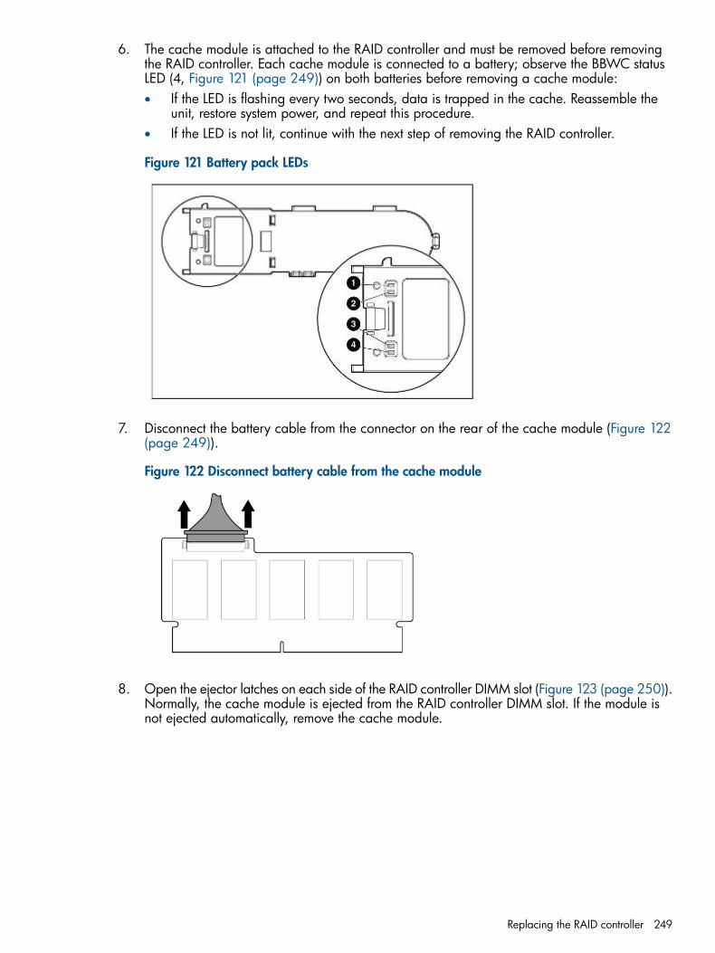
6. The cache module is attached to the RAID controller and must be removed before removingthe RAID controller. Each cache module is connected to a battery; observe the BBWC statusLED (4, Figure 121 (page 249)) on both batteries before removing a cache module:• If the LED is flashing every two seconds, data is trapped in the cache. Reassemble the
unit, restore system power, and repeat this procedure.• If the LED is not lit, continue with the next step of removing the RAID controller.
Figure 121 Battery pack LEDs
7. Disconnect the battery cable from the connector on the rear of the cache module (Figure 122(page 249)).
Figure 122 Disconnect battery cable from the cache module
8. Open the ejector latches on each side of the RAID controller DIMM slot (Figure 123 (page 250)).Normally, the cache module is ejected from the RAID controller DIMM slot. If the module isnot ejected automatically, remove the cache module.
Replacing the RAID controller 249
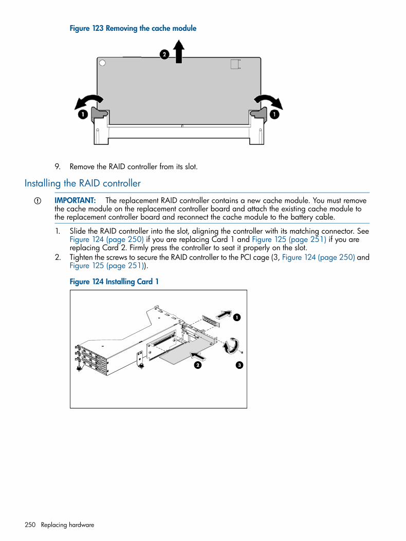
Figure 123 Removing the cache module
9. Remove the RAID controller from its slot.
Installing the RAID controller
IMPORTANT: The replacement RAID controller contains a new cache module. You must removethe cache module on the replacement controller board and attach the existing cache module tothe replacement controller board and reconnect the cache module to the battery cable.
1. Slide the RAID controller into the slot, aligning the controller with its matching connector. SeeFigure 124 (page 250) if you are replacing Card 1 and Figure 125 (page 251) if you arereplacing Card 2. Firmly press the controller to seat it properly on the slot.
2. Tighten the screws to secure the RAID controller to the PCI cage (3, Figure 124 (page 250) andFigure 125 (page 251)).
Figure 124 Installing Card 1
250 Replacing hardware
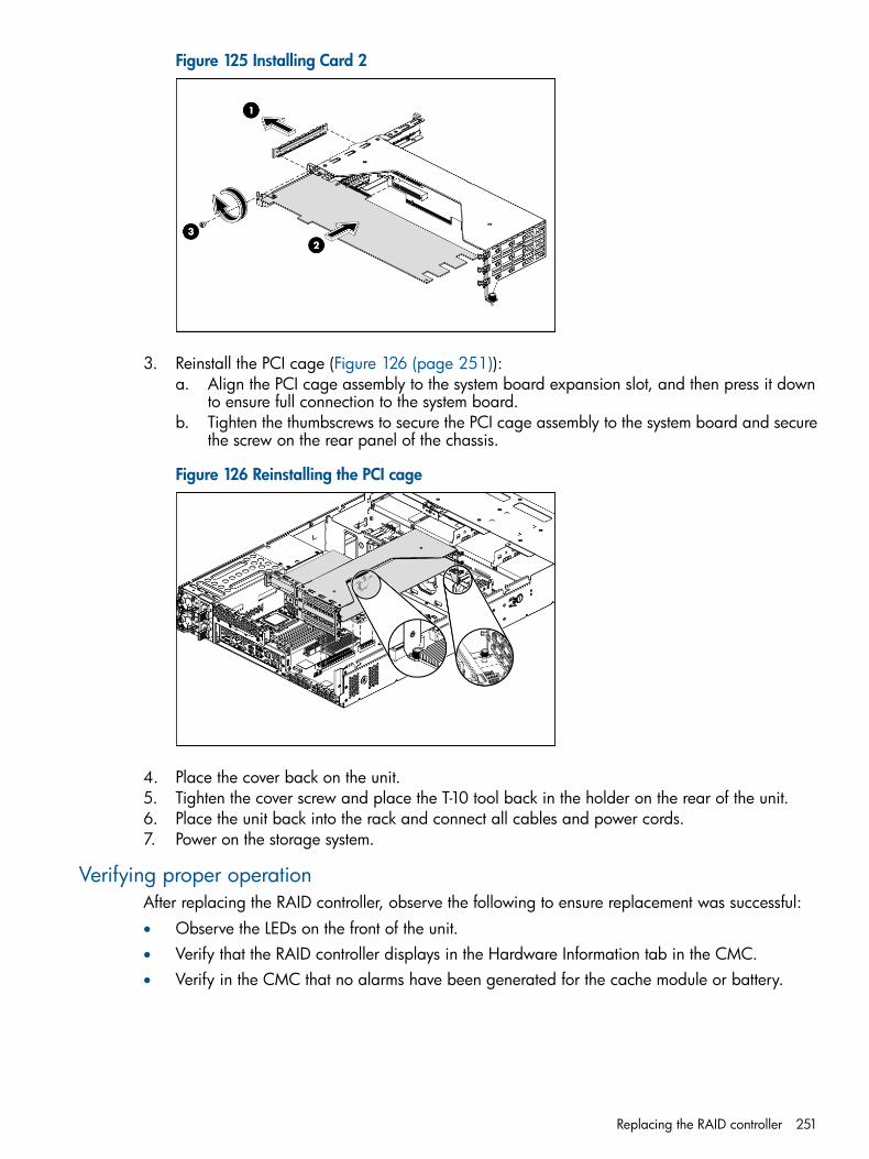
Figure 125 Installing Card 2
3. Reinstall the PCI cage (Figure 126 (page 251)):a. Align the PCI cage assembly to the system board expansion slot, and then press it down
to ensure full connection to the system board.b. Tighten the thumbscrews to secure the PCI cage assembly to the system board and secure
the screw on the rear panel of the chassis.
Figure 126 Reinstalling the PCI cage
4. Place the cover back on the unit.5. Tighten the cover screw and place the T-10 tool back in the holder on the rear of the unit.6. Place the unit back into the rack and connect all cables and power cords.7. Power on the storage system.
Verifying proper operationAfter replacing the RAID controller, observe the following to ensure replacement was successful:• Observe the LEDs on the front of the unit.• Verify that the RAID controller displays in the Hardware Information tab in the CMC.• Verify in the CMC that no alarms have been generated for the cache module or battery.
Replacing the RAID controller 251

B Third-party licensesThe software distributed to you by HP includes certain software packages indicated to be subjectto one of the following open source software licenses: GNU General Public License (“GPL”), theGNU Lesser General Public License (“LGPL”), or the BSD License (each, an “OSS Package”). Referto the license_readme file included with the software for additional information regarding theapplication of these licenses to the OSS Packages and your rights and responsibilities under theselicenses.In addition, the software described in this manual includes open source software developed bythe Apache Software Foundation, The Legion of the Bouncy Castle, Free Software Foundation,Inc., and OpenPegasus.Other included software is under license agreements with Hewlett-Packard Development Company,L.P.; IBM Corp.; EMC Corporation; Symantec Corporation; and The Open Group.In addition, the software described in this manual includes open source software developed by:Copyright (c) 2005-2008, Kirill Grouchnikov and contributors All rights reserved.Redistribution and use in source and binary forms, with or without modification, are permittedprovided that the following conditions are met:• Redistributions of source code must retain the above copyright notice, this list of conditions
and the following disclaimer.• Redistributions in binary form must reproduce the above copyright notice, this list of conditions
and the following disclaimer in the documentation and/or other materials provided with thedistribution.
• Neither the name of the Kirill Grouchnikov and contributors nor the names of its contributorsmay be used to endorse or promote products derived from this software without specific priorwritten permission.
252 Third-party licenses

C SANiQ TCP and UDP Port UsageA P4000 SAN uses a list of well-known TCP/UDP ports to operate, see Table 71 (page 253).
Management applications in SAN/iQ softwareManagement applications include the Centralized Management Console and the scripting interface.These applications all use the ports described as management applications in the descriptioncolumn.
Networking best practices With SAN/iQ softwareFor information on networking best practices, see Application Note - Building High PerformanceHigh Availability IP Storage Networks with SANiQ at the following link on the Resource Center:http://bizsupport2.austin.hp.com/bc/docs/support/SupportManual/c01750150/c01750150.pdf
Table 71 TCP/UDP ports used for normal SAN operations with SAN/iQ
DescriptionNamePort(s)IP Protocol
Secure Shell access forSAN/iQ Support only. Not
SSH22TCP
required for normalday-to-day operations.
Outgoing from storagesystems for email basedalerts.
SMTP25TCP
Outgoing from storagesystems for hostnameresolution.
DNS53TCP, UDP
Used only if DHCP isenabled.
bootps67, 68TCP, UDP
Outgoing from storagesystems for timesynchronization.
NTP123UDP
SNMP Agent on the storagesystem. Incoming from
SNMP161, 162UDP
SNMP clients. Outgoingfrom the storage systems forSNMP Traps.
Outgoing from the storagesystems for remote logging.
Syslog514UDP
Outgoing from the storagesystems for iSNS services
iSNS3205TCP, UDP
iSCSI initiators connect onthis port.
iSCSI3260TCP
Used for internal SAN/iQdiscovery.
SAN/iQ Internal8453, 8454, 8455UDP
Incoming to storage systems.Used for upgrading the
SAN/iQ Upgrade11120TCP
storage systems. Notrequired for normalday-to-day operations.
Outgoing from managementapplications. Incoming to
SAN/iQ Internal13838, 13841, 13843TCP, UDP
253

Table 71 TCP/UDP ports used for normal SAN operations with SAN/iQ (continued)
DescriptionNamePort(s)IP Protocol
storage systems. Used formanagement and control.
Outgoing from managementapplications. Incoming to
SAN/iQ Internal13840, 13850, 13851TCP
storage systems. Used formanagement and control.
Trace Ports for SAN/iQSupport only. Not required
SAN/iQ Support13846, 13850, 13946,13847
TCP
for normal day-to-dayoperations.
Used for Virtual Managercommunication
SAN/iQ Internal13847TCP
Used for internal datadistribution andresynchronization.
SAN/iQ Internal13848TCP
iSCSI initiators connect tothis port when using theP4000 DSM for MPIO.
iSCSI13849TCP
Outgoing from managementapplications. Incoming to
Console Discovery27491UDP
storage systems. Used bymanagement applications todiscover storage systems.
Used for HTTP requests tothe CIM gateway. Outgoing
CIM Server2003, 5988, 5989TCP, HTTP/HTTPS
from managementapplications. Incoming tostorage systems. Used formanagement control. Portsused for PerformanceDashboard, Global Configrequest to Mgmt Gateway.
Ports for CMC notificationsfor Alarms Events from MgmtGateway
CIM13990 - 13999TCP
Used for heart-beating anddistributing configuration
SAN/iQ Database13891, 13893UDP
changes betweenmanagement nodes.
Used for internal controlcommunication.
SAN/iQ Control13888, 13889UDP
Used as iSCSI targets wherexx is the number of initiators
SAN/iQ Internal14000 – 140xxUDP
Communication to and fromthe Failover Manager, whenapplicable.
Failover Manager13887, 13892TCP
Communication to and fromthe Failover Manager, whenapplicable.
Failover Manager13947UDP
Used by the SAN/iQDiagnostic tool -DiagiQ that
SAN/iQ Diagnostics4443TCP
is run by P4000 Support toget advanced diagnostics
254 SANiQ TCP and UDP Port Usage

Table 71 TCP/UDP ports used for normal SAN operations with SAN/iQ (continued)
DescriptionNamePort(s)IP Protocol
information using a webinterface.
Used by the HP SystemInsight Manager tool to
HP System Insight Manager2301, 2302, 2381, 2382TCP
display configurationinformation of HP platformslike DL380, DL320S using aweb interface.
Ports used for connecting tothe CLI
16022SSH
Incoming to storage systems.Used for upgrading the
SAN/iQ Upgrade11120TCP
storage systems. Notrequired for normalday-to-day operations.
Outgoing from managementapplications. Incoming to
SAN/iQ Internal13838, 13841, 13843TCP, UDP
storage systems. Used formanagement and control.
Outgoing from managementapplications. Incoming to
SAN/iQ Internal13840, 13850, 13851TCP
storage systems. Used formanagement and control.
Outgoing from managementapplications. Incoming to
Console Discovery27491UDP
storage systems. Used bymanagement applicationsfor node discovery.
255
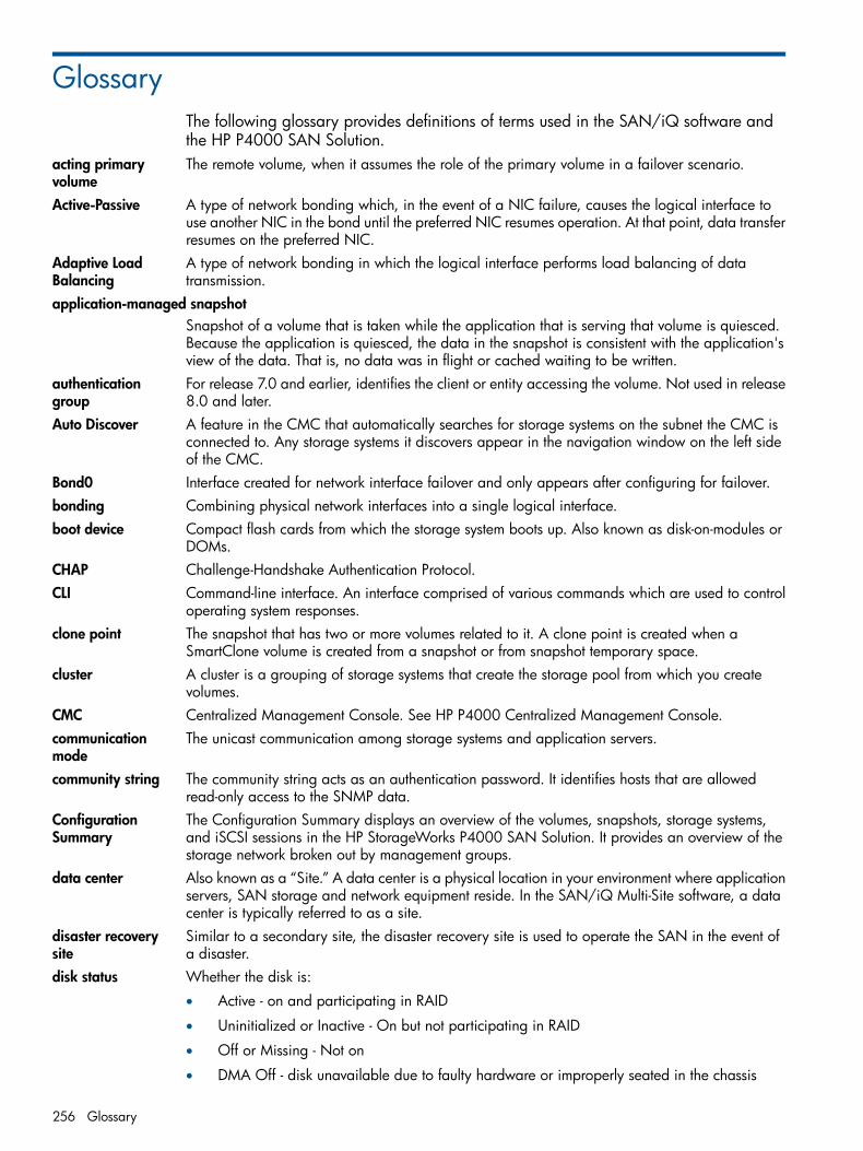
GlossaryThe following glossary provides definitions of terms used in the SAN/iQ software andthe HP P4000 SAN Solution.
acting primaryvolume
The remote volume, when it assumes the role of the primary volume in a failover scenario.
Active-Passive A type of network bonding which, in the event of a NIC failure, causes the logical interface touse another NIC in the bond until the preferred NIC resumes operation. At that point, data transferresumes on the preferred NIC.
Adaptive LoadBalancing
A type of network bonding in which the logical interface performs load balancing of datatransmission.
application-managed snapshotSnapshot of a volume that is taken while the application that is serving that volume is quiesced.Because the application is quiesced, the data in the snapshot is consistent with the application'sview of the data. That is, no data was in flight or cached waiting to be written.
authenticationgroup
For release 7.0 and earlier, identifies the client or entity accessing the volume. Not used in release8.0 and later.
Auto Discover A feature in the CMC that automatically searches for storage systems on the subnet the CMC isconnected to. Any storage systems it discovers appear in the navigation window on the left sideof the CMC.
Bond0 Interface created for network interface failover and only appears after configuring for failover.bonding Combining physical network interfaces into a single logical interface.boot device Compact flash cards from which the storage system boots up. Also known as disk-on-modules or
DOMs.CHAP Challenge-Handshake Authentication Protocol.CLI Command-line interface. An interface comprised of various commands which are used to control
operating system responses.clone point The snapshot that has two or more volumes related to it. A clone point is created when a
SmartClone volume is created from a snapshot or from snapshot temporary space.cluster A cluster is a grouping of storage systems that create the storage pool from which you create
volumes.CMC Centralized Management Console. See HP P4000 Centralized Management Console.communicationmode
The unicast communication among storage systems and application servers.
community string The community string acts as an authentication password. It identifies hosts that are allowedread-only access to the SNMP data.
ConfigurationSummary
The Configuration Summary displays an overview of the volumes, snapshots, storage systems,and iSCSI sessions in the HP StorageWorks P4000 SAN Solution. It provides an overview of thestorage network broken out by management groups.
data center Also known as a “Site.” A data center is a physical location in your environment where applicationservers, SAN storage and network equipment reside. In the SAN/iQ Multi-Site software, a datacenter is typically referred to as a site.
disaster recoverysite
Similar to a secondary site, the disaster recovery site is used to operate the SAN in the event ofa disaster.
disk status Whether the disk is:
• Active - on and participating in RAID
• Uninitialized or Inactive - On but not participating in RAID
• Off or Missing - Not on
• DMA Off - disk unavailable due to faulty hardware or improperly seated in the chassis
256 Glossary

DSM Device Specific Module.DSM for MPIO The HP P4000 DSM for MPIO vendor-specific DSM that interfaces with the Microsoft MPIO
framework.failback After failover, the process by which you restore the primary volume and turn the acting primary
back into a remote volume.failover The process by which the user transfers operation of the application server over to the remote
volume. This can be a manual operation, a scripted operation, or VMware enabled.Failover Manager A specialized manager running as a VMware appliance that allows you to place a quorum
tie-breaker system into a 3rd location in the network to provide for automated failover/failbackof the Multi-Site SAN clusters. The Failover Manager is designed to run on VMware ESX Server,VMware Server, and VMware Player. It is installed on hardware separate from the SAN hardware.
failover recovery After failover, the process by which the user chooses to fail back to the primary volume or tomake the acting primary into a permanent primary volume.
frame size The frame size specifies the size of data packets that are transferred over the network.full provisioning Full provisioning reserves the same amount of space on the SAN as is presented to application
servers.ghost storagesystem
When using Repair Storage System, a “ghost” storage system acts as a placeholder in the cluster,keeping the cluster intact, while you repair or replace the storage system.
Graphical Legend Describes all the icons used in the CMC:
• Items tab - displays the icons used to represent virtual items displayed in the CMC
• Hardware tab - displays the icons that represent the physical storage units.
hardware reports Hardware reports display point-in-time statistics about the performance and health of the storagesystem, its drives, and configuration.
hostname The hostname on a storage system is the user-definable name that displays below the storagesystem icon in the network window. It is also visible when the users browse the network.
HP StorageWorksP4000 CentralizedManagementConsole
Management interface for the SAN/iQ software.
ID LED LED lights on the physical storage system so that you can find that system in a rack.iSCSI Internet small computer system interface. Like an ordinary SCSI interface, iSCSI is standards-based
and efficiently transmits block-level data between a host computer (such as a server that hostsExchange or SQL Server) and a target device (such as the HP All-in-One Storage System). Bycarrying SCSI commands over IP networks, iSCSI is used to facilitate data transfers over intranetsand to manage storage over long distances.
iSCSI loadbalancing
Improves iSCSI performance and scalability by distributing iSCSI sessions for different volumesevenly across storage systems in a cluster.
license key A WWN-encoded sequence that is obtained from the license key fulfillment website.Link AggregationDynamic Mode
A type of network bonding in which the logical interface uses both NICs simultaneously for datatransfer.
log files Log files for the storage system are stored both locally on the storage system and are also writtento a remote log server.
logical site This site is on an isolated network and power connection than the other sites. However, it canbe in the same physical location as one of the real sites. Also, a site for a Failover Manager.
managementgroup
A collection of one or more storage systems which serves as the container within which you clusterstorage systems and create volumes for storage.
managers Manager software runs on storage systems within a management group. You start managers ondesignated storage systems to govern the activity of all of the storage systems in the group.
MIB Management information base. A database of managed objects accessed by network managementprotocols. An SNMP MIB is a set of parameters that an SNMP management station can queryor set in the SNMP agent of a network device (for example, a router).
257

Multi-Site cluster A cluster of storage that spans multiple sites (up to three). A Multi-Site cluster must meet at leastone of the following conditions:
• Contain storage systems that reside in two or more sites
• Contain storage systems that span subnets
• Contain multiple VIPs. The cluster can have a single site, and the multiple VIPs make it amulti-site cluster.
network RAID Synchronous replication, mirroring or parity protection on a volume-by-volume basis. Protectingdata for a volume across all storage systems in the cluster. Network RAID-10, 10+1 or 10+2 isrequired to protect data in an HP P4000 SAN solution.
network window Graphically depicts the status of each storage system. Storage systems on the network are eitheravailable or part of a management group.
NTP Network Time Protocoloriginal primaryvolume
The primary volume that fails and then is returned to service.
overprovisionedcluster
An overprovisioned cluster occurs when the total provisioned space of all volumes and snapshotsis greater than the physical space available on the cluster. This can occur when there are snapshotschedules and/or thinly provisioned volumes related to the cluster.
parity In RAID 5, redundant information is stored as parity distributed across the disks. Parity allows thestorage system to use more disk capacity for data storage.
peer site Absence of a primary site designation makes all the sites peer sites.point-in-timesnapshot
Snapshots that are taken at a specific point in time, but an application writing to that volume maynot be quiesced. Thus, data may be in flight or cached and the actual data on the volume maynot be consistent with the application's view of the data.
preferred interface A preferred interface is the interface within an active backup bond that is used for data transferduring normal operation.
primary site A site designation assigned by the administrator in the HP P4000 Centralized ManagementConsole. A primary site is more important than a secondary site. In this setup, you would run amajority of managers in the primary site. In a two-site setup, this allows the primary site to stayonline even if the network link between the primary and secondary sites fails. Typically, theprimary site has majority/all of the application servers. In configurations that do not designatea primary site, the sites are referred to as “peer” sites.
primary snapshot A snapshot of the primary volume which is created in the process of creating a remote snapshot.The primary snapshot is located on the same cluster as the primary volume.
primary volume The volume which is being accessed (read/write) by the application server. The primary volumeis the volume that is backed up with Remote Copy.
quorum A majority of managers required to be running and communicating with each other in order forthe SAN/iQ software to function.
RAID device RAID (originally redundant array of inexpensive disks, now redundant array of independent disks)refers to a data storage scheme using multiple hard drives to share or replicate data among thedrives.
RAID levels Type of RAID configuration:
• RAID 0 - data striped across disk set
• RAID 1 - data mirrored from one disk onto a second disk
• RAID 10 - mirrored sets of RAID 1 disks
• RAID 5 - data blocks are distributed across all disks in a RAID set. Redundant informationis stored as parity distributed across the disks.
RAID quorum Number of intact disks required to maintain data integrity in a RAID set.RAID rebuild rate The rate at which the RAID configuration rebuilds if a disk is replaced.
258 Glossary

RAID status Condition of RAID on the storage system:
• Normal - RAID is synchronized and running. No action is required.
• Rebuild - A new disk has been inserted in a drive bay and RAID is currently rebuilding. Noaction is required.
• Degraded - RAID is not functioning properly. Either a disk needs to be replaced or areplacement disk has been inserted in a drive.
• Off - Data cannot be stored on the storage system. The storage system is offline and flashesred in the network window.
register Register individual storage systems to use add-on applications. Registration requires sending inthe storage system serial numbers to purchase the license keys, which are then applied to thestorage system.
remote copy pair The primary volume and its related remote volume.remote snapshot An identical copy of a primary snapshot. The remote snapshot is located on the same cluster as
the remote volume.remote volume The volume that resides in the Remote Copy location where the remote snapshots are created.
The remote volume contains no data. It acts as a pointer to tell the system where to make thecopy of the primary snapshot. The remote volume can be stored in these ways:
• In the same cluster in the same management group
• In a different cluster in a different management group
• In a different cluster in the same management group
Repair storagesystem
Creates a placeholder in the cluster, in the form of a “ghost” storage system, that keeps the clusterintact while you remove the storage system to replace a disk or replace the storage system itself,and return it to the cluster.
replication level In Release 8.5 this changes to data protection level. Prior to release 8.5, replication level is theterm that designated how many copies of data to keep in the cluster.
replication priority Removed in Release 8.5. Prior to Release 8.5, replication priority allowed you to designatewhether data availability or redundancy is more important in your configuration. Release 8.5forward defaults to availability. This default can be changed using the Cliq Command LineInterface.
restripe Striped data is stored across all disks in the cluster. You might change the configuration of avolume, for example, change data protection level, add a storage system, or remove a storagesystem. Because of your change, the pages in the volume must be reorganized across the newconfiguration. The system can keep track of several configuration changes at once. This meansyou can change configurations, even while a volume is in the midst of a different reconfiguration.In particular, if a reconfiguration was done by accident, you don't have to wait until it finishesto change back to the original configuration. See “Stripe”.
resync When a storage system goes down, and writes continue to a second storage system, and theoriginal store comes back up, the original storage system needs to recoup the exact data capturedby the second storage system.
rolling back Replaces the original volume with a read/write copy of a selected snapshot. Starting with release8.0, he new volume retains the same name.
SAN/iQ interface When you initially set up a storage system using the Configuration Interface, the first interfacethat you configure becomes the interface used for the SAN/iQ software communication.
secondary site A site that is less important than the primary site. In this setup a minority of managers runs in thesecondary site. In a two-site setup, this allows the secondary site to go offline if the network linkbetween the Primary and secondary sites fails. Typically, the secondary site has a minority, ornone, of the application servers. If the primary site fails, customers can manually recover quorumin the secondary site.
server An application server that you set up in a management group and then assign volumes to it toprovide access to those volumes.
259

shared snapshot Shared snapshots occur when a clone point is created from a newer snapshot that has oldersnapshots below it in the tree. All the volumes created from the clone point will display theseolder snapshots that they share, as well as the clone point.
site A user-designated location in which storage systems are installed. Multi-Site SAN configurationshave multiple sites with storage systems in each site, and each site has its own subnet. A site canbe a logical configuration, such as a subnet within the same data center, department, orapplication.
SmartClonevolume
SmartClone volumes are space-efficient copies of existing volumes or snapshots. They appear asmultiple volumes that share a common snapshot, called a clone point. They share this snapshotdata on the SAN.
snapshot set Application-managed snapshots created for a volume set.snapshot A fixed version of a volume for use with backup and other applications.SNMP traps Use traps to have an SNMP tool send alerts when a monitoring threshold is reached.solution pack HP P4000 Windows Solution Packsplit mirror A full copy of data that has been split off from the original and is no longer being updated.standard cluster Also known as a “cluster.” A standard cluster is one that does not use any of the Multi-Site features
within the SAN/iQ software. Standard clusters:
• Cannot contain storage systems that are designated to reside in a site.
• Cannot contain storage systems that span subnets.
• Can only have a single VIP.
storage server Storage server software maintains the customer's data. It reads to and writes from disks in responseto customer reads and writes of SANiQ volumes.
stripe Striped data is stored across all disks in the array, which increases performance but does notprovide fault tolerance.
synchronize The process of copying the most recent snapshot from the primary volume to a new remotesnapshot. On failback, synchronization is the process of copying the most recent remote snapshotback to the primary volume. The CMC displays the progress of this synchronization. Also, youcan manually synchronize if necessary to include data that is on the remote volume but not theprimary.
target secret Target secret is used in both 1-way and 2-way CHAP when the target (volume) challenges theiSCSI initiator.
temporary space Temporary space is created when a snapshot is mounted for use by applications and operatingsystems that need to write to the snapshot when they access it. Temporary space can be convertedto a volume using the SmartClone process.
thin provisioning Thin provisioning reserves less space on the SAN than is presented to application servers.trap A type of SNMP message used to signal that an event has occurred. (SNIA)Trap CommunityString
The Trap Community String is used for client-side authentication when using SNMP.
unicast Communication between a single sender and a single receiver over a network.VIP virtual IP addressvirtual IP address A highly available address that ensures that if a storage system in a cluster becomes unavailable,
servers can still access the volume through the other storage systems in the cluster.virtual machine A virtual storage appliance that provides one or more simultaneous storage environments in which
SAN/iQ may execute as though they were running on the bare iron.virtual manager A manager that is added to a management group but is not started on a storage system until it
is needed to regain quorum.volume A logical entity that is made up of storage on one or more storage systems. It can be used as
raw data storage or it can be formatted with a file system and used by a host or file server.volume lists For release 7.0 and earlier, provide the link between designated volumes and the authentication
groups that can access those volumes. Not used in release 8.0 and later.
260 Glossary

volume set Two or more volumes used by an application. For example, you may set up Exchange to use twovolumes to support a StorageGroup: one for mailbox data and one for logs. Those two volumesmake a volume set.
volume size The size of the virtual device communicated to the operating system and the applications.VSS Provider HP P4000 VSS Provider is the hardware provider that supports the Volume Shadow Copy Service
on the HP P4000 SAN Solution.VSS Volume Shadow Copy Servicewritable space See temporary space .
261

Index
Symbols1000BASE T interface, 53802.3ad , LACP, 61
Aaccess control
SNMP, 94access rights see permission levelsaccessing
volumes from servers, 197active interface
in active-passive bond, 58in adaptive load balancing bond, 63in link aggregation dynamic mode bond, 61
Active-Passive bond, 57active interface, 58during failover, 59example configurations, 59requirements, 58
Adaptive Load Balancing bondactive interface, 63during failover, 64example configurations, 64preferred interface, 63requirements, 63
add-on applicationsoverview, 223registering for, 225
addinga remote log, 102administrative groups, 81administrative users, 80clusters, 133DNS domain name, 72DNS servers, 72domain names to DNS suffixes, 73iSNS server, 134management groups, 105managers to management group, 115requirements for snapshots, 163requirements for volumes, 155routes, 74servers to management groups, 198snapshots, 164SNMP clients, 94statistics, 217storage for the first time, 16storage systems to existing cluster, 136storage systems to management group, 115storage to clusters, 136users to a group, 83virtual manager, 130volumes, 157
administrative groups, 81adding, 81
adding users, 83changing, 82deleting, 83permission levels, 82permissions descriptions, 82, 83removing users, 83
administrative security, 104administrative users, 80
adding, 80deleting, 81
agentsdisabling SNMP, 95enabling for SNMP, 93
alarmsdisplaying details, 88displaying in a separate window, 88exporting, 89filtering, 88overview, 86window for viewing, 13working with, 88
analyzerBest Practice, 112Configuration, 109
application servers, clustering, 197, 200application-managed snapshots
converting temporary space from, 173creating, 165, 168creating for volume sets, 165creating schedules for volume sets, 167creating SmartClone volumes from, 176defined, 162deleting, 177making available, 172requirements for, 164rolling back from, 175, 176
Assign Volume and Snapshot wizardservers, 18
assigning servers to volumes and snapshots, 203, 204, 205
authentication groupsand volume lists, 197
auto discover, 13systems on network, 19turning off, 19
auto performance protection, 137storage system inoperable, 138storage system overloaded, 138volume availability and, 138
availability of volumes and snapshots, 29, 138Availability tab, 29available storage systems see available systemsavailable system pool, 104available systems
defined, 14upgrading software, 28
262 Index

Bbacking out
of Remote Copy evaluation, 224of scripting evaluation, 225
bandwidth, changing local settings, 117best practice
configuring cluster for disaster recovery, 128frame size, 52link aggregation dynamic mode, 56network, 48NIC bonds, 65recommended numbers for management group storage
items, 110setting volume size, 142speed and duplex settings, 51using snapshots for protection against data deletion,
162Best Practice Summary
cluster-level data protection, 113disk level data protection, 113disk protection using RAID, 113disk RAID consistency, 113large single-system SATA cluster, 113network bond consistency, 114network bonding, 114network flow control consistency, 114network frame size consistency, 114overview, 112systems running managers, 114volume access, 114volume-level data protection, 114
block device, iSCSI as, 152block storage system, 152bonds
network interface, 55using 1 GbE and 10 GbE interfaces, 56with 10 GbE interfaces, 56
boot deviceschecking status of dedicated, 30dedicated, 30status of dedicated, 30
Boot Devices tab, 30BOOTP, 55
Ccapacity
clusters, 133clusters and usable space in, 151disk capacity and volume size, 152of the SAN, 141planning thin provisioning, 142planning volume size, 141planning, full provisioning, 142storage systems, 133
capacity managementand deleting snapshots, 148and scheduled snapshots, 148, 166monitoring SAN for, 148viewing SAN capacity and usage, 148
volume size and snapshots, 148caution
logging into management group, 13Centralized Management Console
features of, 12finding systems on network, 19graphical legend, 13icons used in, 13menu bar, 13navigation window, 19overview, 12setting up for remote support, 20turning off auto discover in, 19upgrading, 25, 27
Challenge Handshake Authentication Protocol see CHAPchanging
administrative group description, 82administrative group permissions, 82changing RAID erases data, 37cluster configuration, 134clusters, for volumes, 160data protection levels, 160host names, 22IP address of storage system, 54local bandwidth, 116maintenance mode to normal, 119management groups, 116network configuration, 49order of NTP server access, 78snapshots, 166thresholds in a snapshot, 166user password, 80volume descriptions, 159volume size, 160
CHAP1-way, 2312-way, 231editing, 200iSCSI, 231requirements for configuring, 199, 232terminology in different initiators, 232using, 231volumes and, 231
characteristics of SmartClone volumes, 181checklist for disk replacement, 46choosing a RAID configuration, 32clearing
items in navigation window, 19statistics sample data, 219
client access to volumes using Assign Volume and Snapshotwizard, 18
clients, adding SNMP, 94clone see SmartClone volumesclone a volume, 180clone point
and shared snapshots, 187deleting, 194SmartClone volumes, 186
cluster
263
changing for volumes, 160cluster-level data protection
Best Practice Summary, 113clustered application servers
changing volume associations after deleting servercluster, 203
creating, 201deleting cluster, 202editing, 202
clustering application servers, 197, 200requirements for, 200
clustering managers, 104clustering servers, 197, 200clusters
adding, 133adding storage system, 136capacity, 133comparing the load of two, 210, 216data protection levels, 143deleting, 140editing, 134map view, 134overview, 133removing storage systems from, 137reorder storage systems within, 137repairing storage system in, 139space reporting in, 149swapping storage systems, 136System Use window, 151troubleshooting, 137usable space in, 151Use Summary window, 149viewing capacity and useage of, 148Volume Use window, 150
CMC see Centralized Management Consolecommunication interface for SAN/iQ communication, 75compliant iSCSI initiators, 231configuration
best practice summary, 112changing network, 49
configuration categoriesstorage system, defined, 21storage systems, 21
Configuration Interfaceconfiguring frame size in, 237configuring network connection in, 236configuring TCP speed and duplex in, 237connecting to, 235creating administrative users in, 236deleting NIC bond in, 237resetting DSM configuration in, 238resetting storage system to factory defaults in, 238
Configuration Summaryconfiguration guidance, 110management group summary roll-up, 109overview, 109reading for management group, 111
configuringdisabled network interface, 72
frame size in Configuration Interface, 237IP address manually, 54iSCSI single host, 233network connection in Configuration Interface, 236network interface bonds, 65network interfaces, 54NIC speed and duplex, 50RAID, 32split network, 48storage systems, 17TCP speed and duplex in Configuration Interface, 237virtual IP address, 133virtual manager, 130
connecting to the Configuration Interface, 235consumed space by volume, 150contacting HP, 239converting temporary space
from application-managed snapshots, 173copying, volumes from snapshots, 170creating see adding
administrative users in Configuration Interface, 236new administrative group, 83NIC bond, 66server cluster, 201SmartClone volumes, 189storage, 141volumes using the wizard, 17
critical eventsdefined, 86
CSV file, exporting performance statistics to, 221custom event filters
creating, 90deleting, 91
customer self repair, 240customer support
registering Remote Copy, 225
Ddata
and deleting volumes, 161clearing statistics sample, 219stripe patterns in clusters, 137
data mining using SmartClone volumes, 180data protection
changing levels for volumes, 160requirements for setting levels, 156
data protection levelallowed in clusters, 143for volumes, 143Network RAID-10, 144Network RAID-10+2, 145Network RAID-6, 146Network RAID–10+1, 144repairing storage system in cluster with data protection
level, 139requirements for setting, 156
data reads and writes and RAID status, 38data redundancy
and degraded RAID status, 38
264 Index

using RAID for, 34data transmission, 52date
setting with NTP, 77setting without NTP, 79
date and time for scheduled snapshot, 168decreasing volume size, 160defaults
font size in CMC, 15language displayed in CMC, 15naming conventions in CMC, 15restoring for the Performance Monitor, 219
definitionRAID configurations, 32SmartClone volumes, 178
degraded RAID, 38deleting
administrative groups, 83administrative users, 81an administrative group, 83clone point, 194clusters, 140custom event filters, 91DNS servers, 73management groups, 120multiple SmartClone volumes, 195network interface bonds, 69Network RAID-5 and Network RAID-6 snapshots, space
considerations for, 177NIC bond in Configuration Interface, 237NTP server, 78prerequisites for volumes, 174, 177restrictions on for snapshots, 177restrictions on for volumes, 161routing information, 74server cluster, 202server cluster and change volume associations, 203servers, 200SmartClone volumes, 194snapshot schedules, 169snapshots, 176snapshots, and capacity management, 148volumes, 161
descriptionschanging for clusters, 134changing for volumes, 159
details, viewing for statistics, 218DHCP
using, 55warnings when using, 55
diagnosticshardware, 97list of diagnostic tests, 98viewing reports, 97
disabled network interface, configuring, 72disabling
network interfaces, 71SNMP agent, 95SNMP traps, 96
disassociating management groups, 116see also HP P4000 Remote Copy User Guide
disaster recoverybest practice, 128starting virtual manager, 131using a virtual manager, 126
diskarrangement in storage systems, 41disk setup report, 39health, 40managing, 39managing in storage system, 39replacement, 47replacement checklist, 46replacing in RAID 1 or RAID 10, and RAID 5, 46replacing in replicated cluster, 139replacing in storage system, 44status, 40using Repair Storage System when replacing, 45VSA, recreating, 42
disk capacity in cluster, 151disk drive see diskDisk drives
wear life for SSD, 40disk level data protection
Best Practice Summary, 113disk protection using RAID
Best Practice Summary, 113disk RAID consistency
Best Practice Summary, 113disk report, 39disk setup
DL320s, 41P4300, 42P4500, 42report, 39tab, 39
disk space usage, 152disk status
DL320s, 41P4500, 42P4800, 43P4900, 44VSA, 41
displaydefault naming conventions, 15font size, 15languages, 15
display toolsfor using map view, 14
DL320sdisk setup, 41disk status, 41
DNSadding domain name, 72and DHCP, 72and static IP addresses, 72
DNS serveradding, 72
265

and static IP addresses, 72editing IP or domain name, 73removing, 73using, 72
documentrelated information, 240
documentationHP website, 240
Domain Name Server see DNS Serverdomain names
adding to DNS suffixes, 73editing in DNS suffixes list, 73removing from DNS suffixes list, 73
downloadingupgrades, 25
DSM for MPIO, 230how to see if using, 234tips for using to access volumes from servers, 234when using two NICs, 205
duplex, configuring, 50Dynamic Host Configuration Protocol see DHCP
Eediting
clusters, 134DNS server domain names, 73DNS server IP addresses, 73domain name in DNS suffixes list, 73frame size, 52group name, 82management groups, 116network interface frame size, 51network interface speed and duplex, 50NTP server, 78routes, 74server cluster, 202servers, 200SmartClone volumes, 194snapshot schedules, 168snapshots, 166SNMP trap recipient, 95volumes, 158
emailsetting up for event notification, 92
enablingNIC flow control, 53SNMP traps, 95
establishing network interfaces, 53eth0 and eth1, 53Ethernet interfaces, 53evaluating
backing out of Remote Copy, 224backing out of scripting, 225Remote Copy, 223scripting, 224
event notificationconfiguring access control for SNMP clients, 94enabling SNMP agents for, 93setting up email for, 92
setting up email recipients for, 92setting up email server for, 92setting up SNMP for, 93
eventschanging the retention period, 89copying to the clipboard, 91deleting custom filters, 91displaying details, 91displaying in a separate window, 89displaying new, 90exporting, 91filtering, 90overview, 86setting up remote log destinations, 89types defined, 86working with, 89
events listcolumn descriptions, 87
example scenarios for using SmartClone volumes, 179exchanging
storage systems in clusters, 137exporting
alarms, 89events, 91performance data, 221performance statistics to a CSV file, 221support logs, 103
FFailover Manager, 108, 109
and Multi-Site SAN, 108requirements for, 121
fault tolerance, 230data protection level for volumes, 143network interface bonding, 55quorum and managers, 107stopping managers, 116
faults, isolating, 207Feature Registration tab, 225, 227features
of Centralized Management Console, 12file systems, 152
mounting on volumes, 155filtering
alarms, 88events, 90
finding storage systems, 17auto discover, 13on the network, 19troubleshooting, 19
first storage system, 105flow control, 52font size
setting in preferences, 15formatting volumes for use, 205frame size
NIC, 51VSA, 48
frames, editing size, 52
266 Index

full permissions, 82
Ggateway session for VIP with load balancing, 231Getting Started Launch Pad, 16ghost storage system, 139
removing after data is rebuilt, 245Gigabit Ethernet, 53
see also GBeglossary
for SAN/iQ software and HP P4000 SAN, 256SmartClone volumes, 178
graphical legendCentralized Management Console, 13
group nameediting, 82
groupsadministrative, 81administrative default groups, 81deleting administrative, 83
Hhardware diagnostics, 97
list of diagnostic tests, 98tab window, 97
hardware information report, 98saving to a file, 99
helpobtaining, 239
highlighting lines, 220host names
access SNMP by, 94changing, 22resolution, 22
host storage system for virtual IP address, 230hot swap
RAID degraded, 38safe to remove status, 45
HPtechnical support, 239
HP DSM for MPIO, 230
II/O performance, 137icons
licensing, 224used in Centralized Management Console, 13
identifying network interfaces, 53increasing volume size, 160informational events
defined, 86Insight Remote Support software, 239installing
SNMP MIB, 96interface
administrative users in, 236configuration, 235configuring network connection in, 236connecting to, 235
deleting NIC bond in, 237resetting storage system to factory defaults, 238
IP addresseschanging, iSNS server, 134configuring for storage system, 54NTP server, 78pinging, 54removing iSNS server, 134using DHCP/BOOTP, 55
iSCSIand CHAP, 231and fault tolerance, 230and iSNS servers, 230and virtual IP address, 230as block device, 152authentication, 231changing or removing virtual IP, 135CHAP, 231clusters and VIP, 230configuring CHAP, 199, 232load balancing, 231load balancing and compliant initiators, 231logging on to volumes, 205performance, 231setting up volumes as persistent targets, 205single host configuration, 233terminology in different initiators, 232volumes and, 231
iSCSI initiatorsconfiguring virtual IP addresses for, 133
iSNS serveradding, 134and iSCSI targets, 230changing or removing IP address, 134
LLACP, 802.3ad, 61layout of disks in storage systems, 41license keys, 225licensing icons, 224lines
changing the color of in the Performance Monitor, 220changing the style of in the Performance Monitor, 220displaying or hiding in the Performance Monitor, 220highlighting, 220
Link Aggregation Dynamic Mode bond, 61active interface, 61during failover, 62example configurations, 62preferred interface, 61requirements, 61
list of diagnostic tests, 98load balancing
compliant iSCSI initiators, 231editing, 200gateway session when using, 231iSCSI, 231
local bandwidth, setting, 116locale
267
setting in preferences, 15locating a storage system in a rack, 22log files
saving for technical support, 101log in
to a storage system in a management group, 21to management group, 13, 114to storage systems in Available Systems pool, 13
log outof management group, 115
logging on to volumes in iSCSI, 205logs
exporting support, 103
Mmaintenance mode
changing to normal mode, 119management group in, 118
management groupcaution for logging into, 13
management group timerefreshing, 77
management groupsadding, 105adding servers to, 198adding storage systems, 105, 115best practice recommendations, 110configuration guidance, 110Configuration Summary roll-up, 109deleting, 120editing, 116function, 104functions of managers, 107logging in, 114logging out, 115maintenance mode, 118normal mode, 119overview, 104prerequisites for removing storage systems, 119reading Configuration Summary, 111removing storage systems, 119requirements for adding, 104saving configuration information, 117setting local bandwidth, 116shutdown procedure, 118shutting down, 117starting managers, 115starting up, 118using virtual manager configuration for, 126using virtual manager in disaster recovery, 126
Management Information Base see MIBmanager IP addresses
updating, 76managers
Failover, 108, 109functions of, 107implications of stopping, 116overview, 107quorum and fault tolerance, 107
starting, 115stopping, 116virtual, 126
managers on storage systemsBest Practice Summary, 114
managing disks, 39Map View, 190
for SmartClone volumes, 191map view
changing the view, 14display tools, 14for clusters, 134for volumes, 158possible views and layouts for network elements, 15using, 14
menu barCentralized Management Console, 13
MIBfor SNMP, 96installing, 96locating, 96versions, 96
migrating RAID, 36migrating volumes, 160mixed RAID, 36monitoring
performance, 206RAID status, 38
monitoring interval in the Performance Monitor, 217Motherboard Port1 and Motherboard Port2, 53mounting snapshots, 170move
storage systems within cluster, 137Multi-Site SAN
and Failover Manager, 108
Nnaming conventions
setting in preferences, 15naming SmartClone volumes, 181, 182navigation window
clearing items in, 19overview, 13
networkbest practices, 48change configuration of, 49finding storage systems on, 13, 19managing settings, 48overview, 48ping IP address, 54split configurations for, 48
network bond consistencyBest Practice Summary, 114
network bondingBest Practice Summary, 114
network flow control consistencyBest Practice Summary, 114
network frame size consistencyBest Practice Summary, 114
268 Index

network interface bonds, 55active-passive, 57adaptive load balancing, 63best practices, 65communication after deleting, 70configuring, 65creating, 66deleting, 69, 237determining if use would improve performance, 209link aggregation dynamic mode, 61physical and logical interface, 58requirements, 56requirements for Adaptive Load Balancing, 63setting flow control, and, 53settings, 57status of, 68using 1 GbE and 10 GbE interfaces, 56verifying, 67VSA, 48with 10 GbE interfaces, 56
network interfaces, 61attaching Ethernet cables, 53bonding, 55configuring, 54, 72disabling or disconnecting, 71establishing, 53identifying, 53speed and duplex settings, 50used for SAN/iQ communication, 75VSA, 48
Network RAID-10description of, 144
Network RAID-10+1description of, 144
Network RAID-10+2description of, 145
Network RAID-6description of, 146
Network Time Protocol see NTPnetwork window see navigation windowNIC see network interfacesNIC flow control, 52
enabling, 53requirements, 53VSA, 48
normal RAIDstatus, 38
not foundstorage systems, 20
not preferred NTP server, 78NTP
selecting, 77server, 77server, deleting, 78servers, changing list order, 78
Ooff RAID
status, 38
ordering NTP access list, 78overview
add-on applications, 223Centralized Management Console, 12clusters, 133disk replacement in special cases, 241management groups, 104managers, 107network, 48provisioning storage, 141setting date and time, 77SmartClone volumes, 178snapshots, 147, 162SNMP, 93volumes, 155
PP4300
disk setup, 42P4500
disk setup, 42disk status, 42
P4800disk setup, 43powering off the system controller and disk enclosure,
correct order, 23powering on the system controller and disk enclosure,
correct order, 23P4900
disk setup, 44passwords
changing in Configuration Interface, 236pausing
monitoring, 220performance see I/O performanceperformance and iSCSI, 231Performance Monitor
current SAN activity example, 207exporting data from, 221fault isolation example, 207learning about applications on the SAN, 208learning about SAN performance, 206load comparison of two clusters example, 210load comparison of two volumes example, 210NIC bonding example, 209overview, 206pausing, 220planning for SAN improvements, 209prerequisites, 206restarting, 220statistics, defined, 214understanding and using, 206workload characterization example, 207
Performance Monitor graphchanging, 220changing line color, 220changing line style, 220changing the scaling factor for, 221displaying a line, 220
269

hiding, 220hiding a line, 220showing, 220
Performance Monitor windowaccessing, 211graph, 212parts defined, 211saving to an image file, 222table, 213toolbar, 212
permissionsadministrative group, 82effect of levels, 204full, 82read modify, 82read only, 82
ping IP address, 54planning
SmartClone volumes, 180snapshots, 147, 163volume size, 141volumes, 141, 155
planning capacityfull provisioning method, 142thin provisioning method, 142
point-in-time snapshotsdefined, 162
pool of storage, 104positioning
storage systems in cluster, 137powering off
P4800 system controller and disk enclosure, correctorder, 23
storage systems, 24powering on
P4800 system controller and disk enclosure, correctorder, 23
preferencessetting font size, 15setting for upgrades, 25setting locale, 15setting naming conventions, 15
preferred interfacein active-passive bond, 58in adaptive load balancing, 63in link aggregation dynamic mode bond, 61
preferred NTP server, 78prerequisites
deleting volumes, 161prerequisites for
adding volumes, 155assigning servers to volumes, 203deleting volumes, 161, 174, 177Performance Monitor, 206removing storage systems from management group,
119servers, 198SmartClone volumes, 178
primary interface, NICs, 75
primary type see volumesprimary volumes, 155protection
RAID vs. volume protection, 34protocols, DHCP, 55provisionable space in cluster, 149provisioned space in cluster, 149provisioning storage, 141
and space allocation, 141
Qquorum
and managers, 107starting virtual manager to recover, 131stopping managers, 116
RRAID
and data protection, 34and data redundancy, 34changing RAID erases data, 37configurations defined, 32configuring, 32definitions, 32degraded status and data redundancy, 38device, 33device status, 34managing, 32procedure for reconfiguring, 37rebuild rate, 36rebuilding, 47reconfiguring, 37replacing a disk, 47replication in a cluster, 35requirements for configuring, 37resyncing, 138setting rebuild rate, 36status, 38status and data reads and writes, 38
RAID (virtual), devices, 34RAID 1 or RAID 10
single disk replacement, 46RAID 5
single disk replacement, 46RAID 6
single disk replacement, 46RAID consistency
Best Practice Summary, 113RAID levels defined, 241RAID status
status, 38raw space in cluster, 151raw storage, 152read only permissions, 82read only volumes, 170read-modify permissions, 82rebooting
storage systems, 23rebuild data
270 Index

when not running manager, 241rebuild volume data, 244rebuilding
RAID, 47rate for RAID, 36
reclaimable space in volumes, 150reconfiguring RAID, 37recreate the RAID array, 243redundant array of independent disks see RAIDregistering add-on applications, 225registering features
Feature Registration tab, 225, 227for a storage system, 29
related documentation, 240Remote Copy
backing out of evaluation, 224evaluating, 223registering, 225remote volumes, 155
remote destinationssetting up for events, 89
remote log files, 102adding, 102changing remote log file target computer, 102configuring target computer, 102removing old logs, 102
remote supportsetting up CMC for, 20
remote support software, 239remote volumes, 155
see also HP P4000 Remote Copy User Guideremoving
administrative users from a Group, 83DNS server, 73domain name from DNS suffixes list, 73ghost storage system after the data is rebuilt, 245old log files, 102prerequisites for storage systems from management
groups, 119SNMP trap recipient, 95statistics, 219storage systems from cluster, 137storage systems from management groups, 119systems from view in CMC, 19users from administrative groups, 83virtual manager, 132
reorderstorage systems in clusters, 137
repair storage system, 139prerequisites, 139replacing a disk, 45
replacingdisks, 44storage systems in clusters, 137
reportsdiagnostic, 97disk, 39disk setup for RAID, 39Hardware Information, 98
RAID setup, 33saving Hardware Report to a file, 99storage system statistics, 98
requirements foradding management group, 104adding volumes, 155application-managed snapshots, 164changing SmartClone volumes, 193changing volumes, 159configuring CHAP for iSCSI, 199, 232editing snapshots, 166Failover Manager, 121network interface bonding, 56rolling back volumes, 174scheduling snapshots, 166server clusters, 200split network, 48system for Failover Manager on ESX Server, 123virtual manager, 127
resettingDSM in Configuration Interface, 238storage system to factory defaults, 238
resolving host names, 22restarting monitoring, 220restoring
defaults for the Performance Monitor, 219volumes, 173
resyncingRAID, 138
rolling back a volume, 173from application-managed snapshots, 175, 176restrictions on, 174
routingadding network, 74deleting, 74editing network, 74
routing tablesmanaging, 74
Ssafe to remove status, 45sample interval
changing for the Performance Monitor, 217SAN
capacity of, 141comparing the load of two clusters, 210, 216comparing the load of two volumes, 210current activity performance example, 207determining if NIC bonding would improve
performance, 209fault isolation example, 207learning about applications on the SAN, 208learning about SAN performance, 206monitoring performance, 206planning for SAN improvements, 209using Performance Monitor, 206workload characterization example, 207
SAN configurationbest practice summary, 112
271

SAN/iQupgrading, 25, 28
saved space in cluster, 149saved space in volumes, 150saving
diagnostic reports, 97log files for technical support, 101management group configuration information, 117
scaling factorchanging, 221
scheduled snapshotsrequirements for, 166
scripting evaluation, 224backing out of, 225turning off, 225turning on, 224
searching for storage systems, 13, 19security
administrative, 104of storage resources, 104
server accessSmartClone volumes, 181
server cluster, 197, 200change volume associations after deleting, 203creating, 201deleting, 202editing, 202requirements for, 200
serversaccess to volumes and snapshots, 197access using Assign Volume and Snapshot wizard, 18adding DNS, 72adding iSNS, 134adding to management groups, 198assigning to volumes and snapshots, 203, 204clustering, 197, 200deleting, 200editing, 200editing assignments to volumes and snapshots, 204,
205editing IP or domain name for DNS, 73editing NTP, 78NTP, 77preferred, not preferred for NTP, 78prerequisites for, 198prerequisites for assigning to volumes, 203removing DNS, 73
service bundlesexporting, 103
set ID LED, 22setting
IP address, 54local bandwidth, 116RAID rebuild rate, 36
setting date and time, 77for management group, 77overview, 77procedure, 77, 79refreshing for management group, 77
setting time zone, 79time zone on storage system, 77, 79with NTP, 77without NTP, 79
setting up a RAID disk, 39shared snapshots, 187shutting down a management group, 117, 118Single Host Configuration in iSCSI, 233single system, large cluster using SATA
Best Practice Summary, 113size
changing for volumes, 160for snapshots, 148planning for snapshots, 163planning for volumes, 141requirements for volumes, 156
slow I/O, 137SmartClone volumes
assigning server access, 181characteristics of, 181characteristics of, shared versus individual, 183clone point, 186creating from application-managed snapshots, 176definition of, 178deleting, 194deleting multiple, 195editing, 194examples for using, 179glossary for, 178making application-managed snapshot available after
creating, 172overview, 178planning, 180planning naming convention, 181planning space requirements, 180requirements for changing, 193uses for, 180viewing with Map View, 191
snapshotsadding, 164application-managed, 162as opposed to backups, 147assigning to servers, 203, 204changing thresholds, 166controlling server access to, 197copying a volume from, 170creating application-managed, 165, 168creating application-managed for volume sets, 165deleting, 176deleting Network RAID-5 and Network RAID-6, space
considerations for, 177deleting schedules, 169editing, 166editing schedules, 168editing server assignments, 204, 205managing capacity and scheduled snapshots, 166mounting, 170overview, 147, 162planning, 147, 163
272 Index
planning size, 163point-in-time, 162read/write and deleting temporary space, 173requirements for editing, 166restrictions on deleting, 177rolling back a volume from, 173shared, 187size, 148temporary space for read/write snapshots, 173understanding schedules for volume sets, 167using, 162versus backups, 162
SNMPaccess control, 94clients, adding, 94configuring access control for SNMP clients, 94disabling agents, 95disabling traps, 96editing trap recipients, 95enabling agents, 93enabling agents for event notification, 93enabling traps, 95overview, 93removing trap recipient, 95setting up for event notification, 93using MIB, 96using traps, 95
softwareupgrading storage systems, 25
space allocation, 141space requirements
planning for SmartClone volumes, 180speed/duplex
configuring, 50VSA, 48
split network configuration, 48spoofing, 231starting
management group, 118managers on storage systems, 115virtual manager to recover quorum, 131
static IP addresses and DNS, 72statistics
adding, 217exporting performance to a CSV file, 221in the Performance Monitor defined, 214removing, 219viewing details of, 218
statistics sample dataclearing, 219
statusdedicated boot devices, 30disk, 40NIC bond, 68RAID, 34, 38safe to remove disk, 45storage system, 138storage system inoperable, 138storage system overloaded, 138
stoppingmanagers, 116managers, implications of, 116virtual manager, 132
storageadding to a cluster, 136configuration on storage systems, 32configuring, 32provisioning, 141upgrading in a cluster, 136
storage pool, 104storage space
raw space, 152storage system inoperable, 138storage system overloaded, 138storage system status and VSA, 138storage systems
adding first one, 16, 105adding to existing cluster, 136adding to management group, 115and raw space, 151and space provisioned in cluster, 151configuration categories, 21configuration overview, 21configuring, 17exchanging in a cluster, 137finding on network, 13, 17, 19ghost storage system, 139locating in a rack, 22locating in rack, 22logging in to an additional, 21not found, 20powering off, 24prerequisites for removing from management group,
119rebooting, 23registering, 29removing, 120removing from cluster, 137removing from management group, 119reorder position in a cluster, 137repacing disks, 44repairing in clusters, 139saving statistics to a file, 99statistics, 98status of, 138storage configuration of, 32upgrading software, 25, 28
Subscriber's Choice, HP, 239support
setting up CMC for remote support, 20support bundles
exporting, 103support logs
exporting, 103support software, remote, 239swap
storage systems, 136synchronizing time on storage systems, 166
273

system requirementsfor Failover Manager on ESX Server, 123
systemsfinding on network, 13, 19
TTCP
frame size, 51speed and duplex, 50status, 50status tab, 50
TCP/IP tab, 53technical support
HP, 239saving log files for, 101service locator website, 240
temporary spacedeleting, 173for read/write snapshots, 173making application-managed snapshot available after
converting, 172thresholds
changing for a snapshot, 166requirements for changing in snapshots, 166
timeediting NTP server, 78NTP servers, preferred, not preferred, 78selecting NTP, 77setting with NTP, 77setting without NTP, 79synchronizing on storage systems, 166zone, setting on storage system, 77, 79
time remaining on evaluation period, 223time zone
changing for the Performance Monitor, 217setting, 79
toolbarmap view, 14Performance Monitor window, 212
total storage space in cluster, 149trap recipient
removing, 95traps
disabling SNMP, 96editing SNMP recipient, 95enabling SNMP, 95sending test, 96SNMP, 95
troubleshooting clustersrepair storage system, 137slow I/O, 137
troubleshooting storage systems, finding, 19
Uupdating
manager IP addresses, 76upgrades
checking for available, 25downloading, 25
setting preferences for, 25upgrading
available storage systems software, 28SAN/iQ, 25, 28storage system software, 25, 28storage systems in clusters, 136the CMC, 25, 27
Use Summary window, 149user
adding a group to a user, 81administrative, 80administrative default user, 80changing a user name, 80deleting administrative, 81editing, 81password, 80
Vverifying NIC bond, 67VI Client
recreating disk for VSA, 42viewing
clone points, volumes, and snapshots, 192disk report, 39disk setup reportdisk, 39RAID setup report, 33SmartClone volumes, 190statistics details, 218
virtual IP address, 230and iSCSI, 230changing, iSCSI, 135configuring for iSCSI for, 133gateway session when using load balancing, 231host storage system, 230removing, iSCSI volume, 135
virtual machine, 108virtual manager
adding, 130configurations for using, 126configuring, 130function of, 126overview, 126removing, 132starting to recover quorum, 131stopping, 132
virtual RAIDdata safety and availability, 36
virtual storage systemdata protection, 34RAID device, 34
VMware ESX Server, 34VMware Server, 108volume access
Best Practice Summary, 114volume availability, 138volume migration, 160volume sets
creating application-managed snapshots for, 165creating schedules to snapshots for, 167
274 Index
deleting application-managed snapshots for, 161, 177volume size
best practice for setting, 142volume use window, 150volume-level data protection
Best Practice Summary, 114volumes
adding, 157application server requirements for rolling back, 174Assign Volume and Snapshot wizard, 18assigning to servers, 203, 204changing clusters, 160changing data protection levels, 160changing descriptions, 159changing size, 160comparing the load of two, 210consumed space, 150controlling server access to, 197creating SmartClone, 189creating using the Wizard, 17data protection level, 143deleting, 161editing, 158editing server assignments, 204, 205formatting for use, 205iSCSI, 231iSCSI and CHAP, 231logging on to, 205map view, 158mounting file systems on, 155overview, 155planning, 141, 155planning size, 141planning type, 155prerequisites for adding, 155prerequisites for deleting, 161, 174, 177primary type, 155reclaimable space, 150remote type, 155requirements for adding, 155requirements for changing, 159restrictions on deleting, 161restrictions on rolling back, 174rolling back, 173saved space, 150setting as persistent targets, 205
volumes and snapshotsavailability, 29
VSAcloning, 104disk status, 41frame size, 48network interface, 48NIC bonding, 48NIC flow control, 48RAID rebuild rate, 36reconfiguring RAID, 37recreate disk, 42speed/duplex, 48
storage system overloaded, 138virtual RAID and data safety and availability, 36
Wwarning events
defined, 86warnings
all storage systems in a cluster operate at a capacityequal to that of the smallest capacity, 133
changing RAID erases data, 37check Safe to Remove status, 45cloning VSA, 104configure network correctly, 66deleting management group causes data loss, 120DHCP static IP addresses, 55DHCP unicast communication, 55disabling network interface, 71plugging NICs into same switch for Link Aggregation
Dynamic Mode, 55return repaired system to same place, 140stopping manager can cause data loss, 116
Wear life, 40websites
customer self repair, 240HP, 240HP Subscriber's Choice for Business, 239product manuals, 240
windowsalarms window, 13navigation window, 13tabs window, 13
write failure warnings, 142
275