Embed Size (px)
Citation preview
HP G7000 Notebook PC andCompaq Presario C700 Notebook PCMaintenance and Service Guide
© Copyright 2007 Hewlett-PackardDevelopment Company, L.P.
Intel, Celeron, and Core are trademarks orregistered trademarks of Intel Corporation orits subsidiaries in the United States and othercountries. Microsoft, Windows, andWindows Vista are either trademarks orregistered trademarks of MicrosoftCorporation in the United States and/or othercountries. SD Logo is a trademark of itsproprietor.
The information contained herein is subject tochange without notice. The only warrantiesfor HP products and services are set forth inthe express warranty statementsaccompanying such products and services.Nothing herein should be construed asconstituting an additional warranty. HP shallnot be liable for technical or editorial errorsor omissions contained herein.
Second Edition: December 2007
First Edition: July 2007
Document Part Number: 447381-002

Safety warning noticeWARNING! To reduce the possibility of heat-related injuries or of overheating the computer, do notplace the computer directly on your lap or obstruct the computer air vents. Use the computer only on ahard, flat surface. Do not allow another hard surface, such as an adjoining optional printer, or a softsurface, such as pillows or rugs or clothing, to block airflow. Also, do not allow the AC adapter to contactthe skin or a soft surface, such as pillows or rugs or clothing, during operation. The computer and the ACadapter comply with the user-accessible surface temperature limits defined by the International Standardfor Safety of Information Technology Equipment (IEC 60950).
iii

iv Safety warning notice
Table of contents
1 Product description
2 External component identificationTop components ...................................................................................................................... 5
Display components .................................................................................................. 5Buttons and speakers ................................................................................................. 6Keys ........................................................................................................................ 7Lights ....................................................................................................................... 8TouchPad ................................................................................................................. 9
Front components ................................................................................................................... 10Right-side components ............................................................................................................ 10Left-side components ............................................................................................................... 11Bottom components ................................................................................................................ 12
3 Illustrated parts catalogSerial number location ............................................................................................................ 13Computer major components ................................................................................................... 14Display assembly components ................................................................................................. 20Plastics Kit ............................................................................................................................. 22Mass storage devices ............................................................................................................. 23Miscellaneous parts ................................................................................................................ 24Sequential part number listing .................................................................................................. 26
4 Removal and replacement proceduresPreliminary replacement requirements ....................................................................................... 32
Tools required ......................................................................................................... 32Service considerations ............................................................................................. 32
Plastic parts ............................................................................................. 32Cables and connectors ............................................................................. 33Drive handling ......................................................................................... 33
Grounding guidelines .............................................................................................. 34Electrostatic discharge damage .................................................................. 34
Packaging and transporting guidelines ........................................ 35
v
Workstation guidelines .............................................................. 35Equipment guidelines ................................................................. 36
Unknown user password .......................................................................................... 37Component replacement procedures ........................................................................................ 38
Serial number ......................................................................................................... 38Computer feet ......................................................................................................... 39Battery ................................................................................................................... 40Hard drive ............................................................................................................. 41Memory module ...................................................................................................... 43WLAN module ........................................................................................................ 45Optical drive .......................................................................................................... 48Keyboard ............................................................................................................... 50Switch cover ........................................................................................................... 53Display assembly .................................................................................................... 55Camera module ...................................................................................................... 60Top cover ............................................................................................................... 62Caps lock LED board ............................................................................................... 64USB board ............................................................................................................. 66Fan ....................................................................................................................... 68Speakers ................................................................................................................ 70System board ......................................................................................................... 72RTC battery ............................................................................................................ 75Card reader board .................................................................................................. 77Heat sink ............................................................................................................... 79Processor ............................................................................................................... 81Power connector cable ............................................................................................ 83
5 Setup UtilityStarting the Setup Utility .......................................................................................................... 84Changing the language of the Setup Utility ............................................................................... 84Navigating and selecting in the Setup Utility .............................................................................. 85Displaying system information .................................................................................................. 85Restoring default settings in the Setup Utility .............................................................................. 85Using advanced Setup Utility features ....................................................................................... 86Closing the Setup Utility .......................................................................................................... 86Setup Utility menus ................................................................................................................. 86
6 SpecificationsComputer specifications .......................................................................................................... 8815.4-inch, WSXGA, BrightView display specifications ................................................................ 89Hard drive specifications ........................................................................................................ 90DVD±RW and CD-RW Super Multi Double-Layer Combo Drive specifications ................................ 91System DMA specifications ...................................................................................................... 92
vi
System memory map specifications .......................................................................................... 92System interrupt specifications ................................................................................................. 93System I/O address specifications ............................................................................................ 94
7 Screw listingPhillips PM2.0×5.0 captive screw ............................................................................................ 97Phillips PM3.0×3.0 screw ....................................................................................................... 98Black Phillips PM2.0×3.0 screw ............................................................................................... 99Black Phillips PM2.0×4.0 screw ............................................................................................. 100Phillips PM2.5×9.0 screw ..................................................................................................... 102Phillips PM2.5×4.0 screw ..................................................................................................... 104Phillips PM2.5×7.0 screw ..................................................................................................... 107Silver Phillips PM2.0×4.0 screw ............................................................................................ 108Phillips PM2.5×6.0 captive screw .......................................................................................... 109
8 Backup and recoveryRecovering system information ............................................................................................... 110
Backing up your information ................................................................................... 110When to back up ................................................................................... 110Backup suggestions ................................................................................ 111
Using system restore points ..................................................................................... 111When to create restore points .................................................................. 111Create a system restore point ................................................................... 111Restore to a previous date and time .......................................................... 113
Creating recovery discs ......................................................................................... 113Performing a recovery ........................................................................................... 114
Recovering from the recovery discs ........................................................... 114Recovering from the partition on the hard drive .......................................... 114
9 Connector pin assignmentsAudio-out (headphone) ......................................................................................................... 115Audio-in (microphone) .......................................................................................................... 115External monitor ................................................................................................................... 116RJ-11 (modem) ..................................................................................................................... 117RJ-45 (network) .................................................................................................................... 117S-Video-out .......................................................................................................................... 118Universal Serial Bus .............................................................................................................. 118
10 Power cord set requirementsRequirements for all countries or regions ................................................................................. 119Requirements for specific countries or regions .......................................................................... 120
vii

11 RecyclingBattery ................................................................................................................................ 121Display ............................................................................................................................... 121
Index ............................................................................................................................... 127
viii
1 Product description
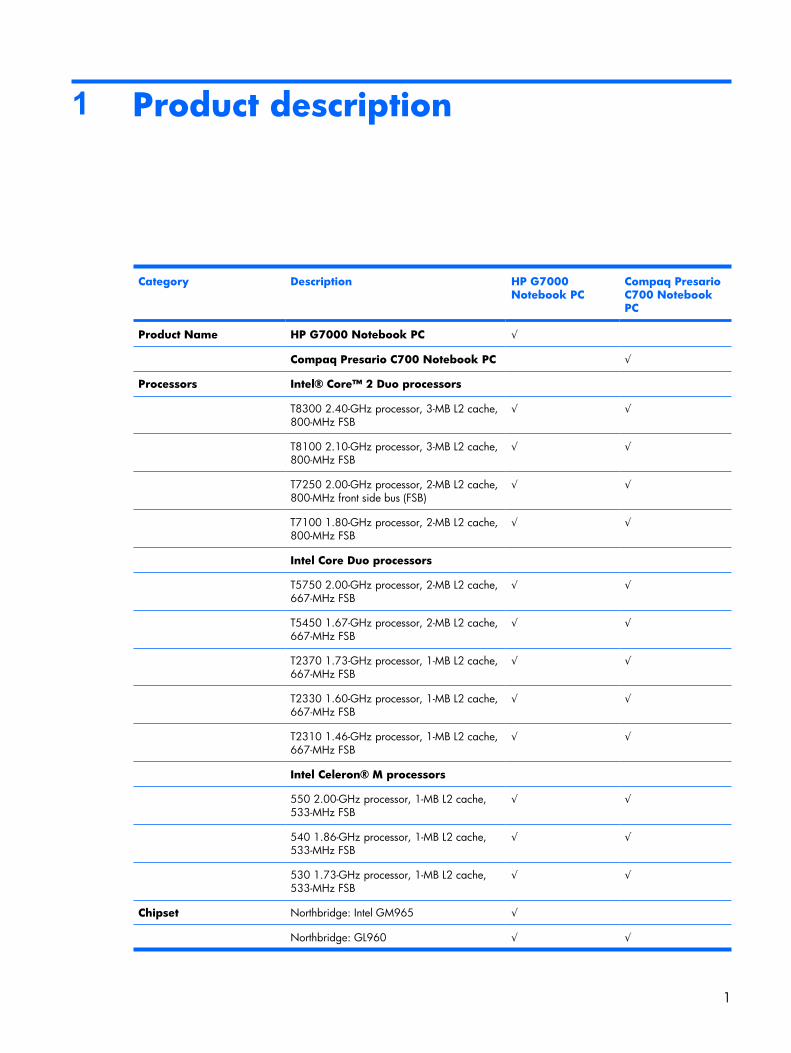
Category Description HP G7000Notebook PC
Compaq PresarioC700 NotebookPC
Product Name HP G7000 Notebook PC √
Compaq Presario C700 Notebook PC √
Processors Intel® Core™ 2 Duo processors
T8300 2.40-GHz processor, 3-MB L2 cache,800-MHz FSB
√ √
T8100 2.10-GHz processor, 3-MB L2 cache,800-MHz FSB
√ √
T7250 2.00-GHz processor, 2-MB L2 cache,800-MHz front side bus (FSB)
√ √
T7100 1.80-GHz processor, 2-MB L2 cache,800-MHz FSB
√ √
Intel Core Duo processors
T5750 2.00-GHz processor, 2-MB L2 cache,667-MHz FSB
√ √
T5450 1.67-GHz processor, 2-MB L2 cache,667-MHz FSB
√ √
T2370 1.73-GHz processor, 1-MB L2 cache,667-MHz FSB
√ √
T2330 1.60-GHz processor, 1-MB L2 cache,667-MHz FSB
√ √
T2310 1.46-GHz processor, 1-MB L2 cache,667-MHz FSB
√ √
Intel Celeron® M processors
550 2.00-GHz processor, 1-MB L2 cache,533-MHz FSB
√ √
540 1.86-GHz processor, 1-MB L2 cache,533-MHz FSB
√ √
530 1.73-GHz processor, 1-MB L2 cache,533-MHz FSB
√ √
Chipset Northbridge: Intel GM965 √
Northbridge: GL960 √ √
1
Category Description HP G7000Notebook PC
Compaq PresarioC700 NotebookPC
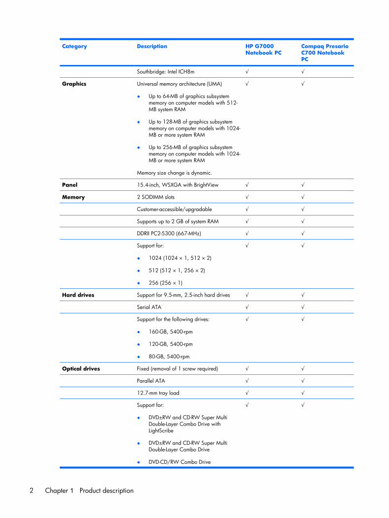
Southbridge: Intel ICH8m √ √
Graphics Universal memory architecture (UMA)
● Up to 64-MB of graphics subsystemmemory on computer models with 512-MB system RAM
● Up to 128-MB of graphics subsystemmemory on computer models with 1024-MB or more system RAM
● Up to 256-MB of graphics subsystemmemory on computer models with 1024-MB or more system RAM
Memory size change is dynamic.
√ √
Panel 15.4-inch, WSXGA with BrightView √ √
Memory 2 SODIMM slots √ √
Customer-accessible/upgradable √ √
Supports up to 2 GB of system RAM √ √
DDRII PC2-5300 (667-MHz) √ √
Support for:
● 1024 (1024 × 1, 512 × 2)
● 512 (512 × 1, 256 × 2)
● 256 (256 × 1)
√ √
Hard drives Support for 9.5-mm, 2.5-inch hard drives √ √
Serial ATA √ √
Support for the following drives:
● 160-GB, 5400-rpm
● 120-GB, 5400-rpm
● 80-GB, 5400-rpm
√ √
Optical drives Fixed (removal of 1 screw required) √ √
Parallel ATA √ √
12.7-mm tray load √ √
Support for:
● DVD±RW and CD-RW Super MultiDouble-Layer Combo Drive withLightScribe
● DVD±RW and CD-RW Super MultiDouble-Layer Combo Drive
● DVD-CD/RW Combo Drive
√ √
2 Chapter 1 Product description
Category Description HP G7000Notebook PC
Compaq PresarioC700 NotebookPC
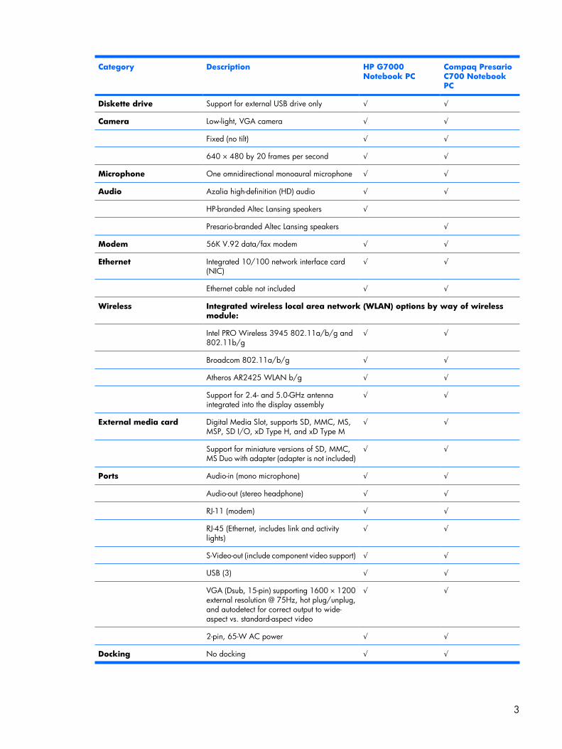
Diskette drive Support for external USB drive only √ √
Camera Low-light, VGA camera √ √
Fixed (no tilt) √ √
640 × 480 by 20 frames per second √ √
Microphone One omnidirectional monoaural microphone √ √
Audio Azalia high-definition (HD) audio √ √
HP-branded Altec Lansing speakers √
Presario-branded Altec Lansing speakers √
Modem 56K V.92 data/fax modem √ √
Ethernet Integrated 10/100 network interface card(NIC)
√ √
Ethernet cable not included √ √
Wireless Integrated wireless local area network (WLAN) options by way of wirelessmodule:
Intel PRO Wireless 3945 802.11a/b/g and802.11b/g
√ √
Broadcom 802.11a/b/g √ √
Atheros AR2425 WLAN b/g √ √
Support for 2.4- and 5.0-GHz antennaintegrated into the display assembly
√ √
External media card Digital Media Slot, supports SD, MMC, MS,MSP, SD I/O, xD Type H, and xD Type M
√ √
Support for miniature versions of SD, MMC,MS Duo with adapter (adapter is not included)
√ √
Ports Audio-in (mono microphone) √ √
Audio-out (stereo headphone) √ √
RJ-11 (modem) √ √
RJ-45 (Ethernet, includes link and activitylights)
√ √
S-Video-out (include component video support) √ √
USB (3) √ √
VGA (Dsub, 15-pin) supporting 1600 × 1200external resolution @ 75Hz, hot plug/unplug,and autodetect for correct output to wide-aspect vs. standard-aspect video
√ √
2-pin, 65-W AC power √ √
Docking No docking √ √
3
Category Description HP G7000Notebook PC
Compaq PresarioC700 NotebookPC
Keyboard/pointingdevices
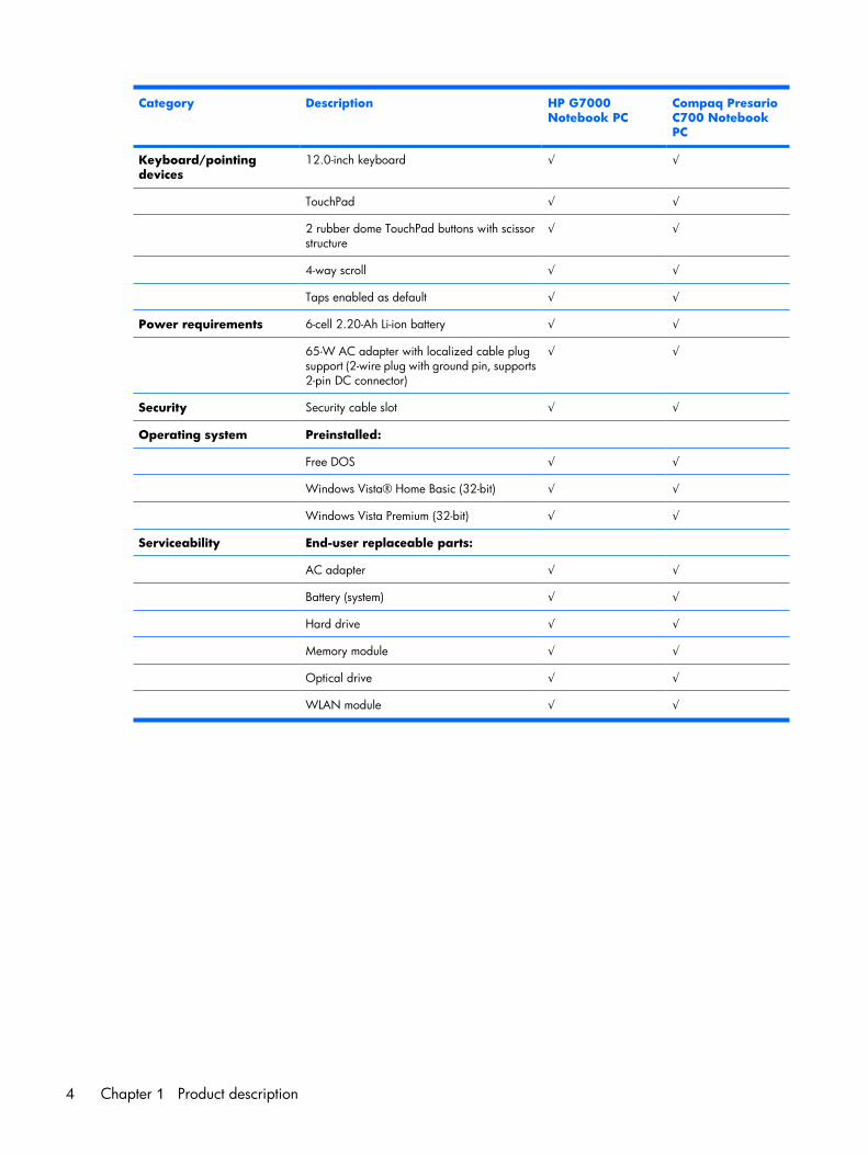
12.0-inch keyboard √ √
TouchPad √ √
2 rubber dome TouchPad buttons with scissorstructure
√ √
4-way scroll √ √
Taps enabled as default √ √
Power requirements 6-cell 2.20-Ah Li-ion battery √ √
65-W AC adapter with localized cable plugsupport (2-wire plug with ground pin, supports2-pin DC connector)
√ √
Security Security cable slot √ √
Operating system Preinstalled:
Free DOS √ √
Windows Vista® Home Basic (32-bit) √ √
Windows Vista Premium (32-bit) √ √
Serviceability End-user replaceable parts:
AC adapter √ √
Battery (system) √ √
Hard drive √ √
Memory module √ √
Optical drive √ √
WLAN module √ √
4 Chapter 1 Product description
2 External component identification
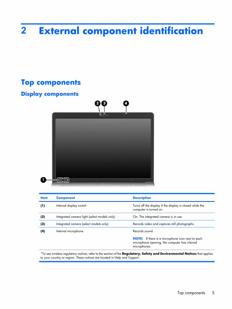
Top componentsDisplay components
Item Component Description
(1) Internal display switch Turns off the display if the display is closed while thecomputer is turned on.
(2) Integrated camera light (select models only) On: The integrated camera is in use.
(3) Integrated camera (select models only) Records video and captures still photographs.
(4) Internal microphone Records sound.
NOTE: If there is a microphone icon next to eachmicrophone opening, the computer has internalmicrophones.
*To see wireless regulatory notices, refer to the section of the Regulatory, Safety and Environmental Notices that appliesto your country or region. These notices are located in Help and Support.
Top components 5
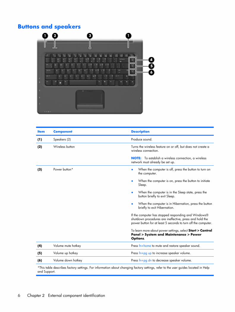
Buttons and speakers
Item Component Description
(1) Speakers (2) Produce sound.
(2) Wireless button Turns the wireless feature on or off, but does not create awireless connection.
NOTE: To establish a wireless connection, a wirelessnetwork must already be set up.
(3) Power button* ● When the computer is off, press the button to turn onthe computer.
● When the computer is on, press the button to initiateSleep.
● When the computer is in the Sleep state, press thebutton briefly to exit Sleep.
● When the computer is in Hibernation, press the buttonbriefly to exit Hibernation.
If the computer has stopped responding and Windows®shutdown procedures are ineffective, press and hold thepower button for at least 5 seconds to turn off the computer.
To learn more about power settings, select Start > ControlPanel > System and Maintenance > PowerOptions.
(4) Volume mute hotkey Press fn+home to mute and restore speaker sound.
(5) Volume up hotkey Press fn+pg up to increase speaker volume.
(6) Volume down hotkey Press fn+pg dn to decrease speaker volume.
*This table describes factory settings. For information about changing factory settings, refer to the user guides located in Helpand Support.
6 Chapter 2 External component identification
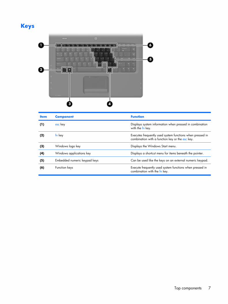
Keys
Item Component Function
(1) esc key Displays system information when pressed in combinationwith the fn key.
(2) fn key Executes frequently used system functions when pressed incombination with a function key or the esc key.
(3) Windows logo key Displays the Windows Start menu.
(4) Windows applications key Displays a shortcut menu for items beneath the pointer.
(5) Embedded numeric keypad keys Can be used like the keys on an external numeric keypad.
(6) Function keys Execute frequently used system functions when pressed incombination with the fn key.
Top components 7
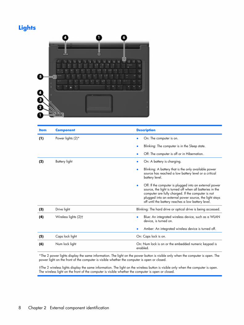
Lights
Item Component Description
(1) Power lights (2)* ● On: The computer is on.
● Blinking: The computer is in the Sleep state.
● Off: The computer is off or in Hibernation.
(2) Battery light ● On: A battery is charging.
● Blinking: A battery that is the only available powersource has reached a low battery level or a criticalbattery level.
● Off: If the computer is plugged into an external powersource, the light is turned off when all batteries in thecomputer are fully charged. If the computer is notplugged into an external power source, the light staysoff until the battery reaches a low battery level.
(3) Drive light Blinking: The hard drive or optical drive is being accessed.
(4) Wireless lights (2)† ● Blue: An integrated wireless device, such as a WLANdevice, is turned on.
● Amber: An integrated wireless device is turned off.
(5) Caps lock light On: Caps lock is on.
(6) Num lock light On: Num lock is on or the embedded numeric keypad isenabled.
*The 2 power lights display the same information. The light on the power button is visible only when the computer is open. Thepower light on the front of the computer is visible whether the computer is open or closed.
†The 2 wireless lights display the same information. The light on the wireless button is visible only when the computer is open.The wireless light on the front of the computer is visible whether the computer is open or closed.
8 Chapter 2 External component identification
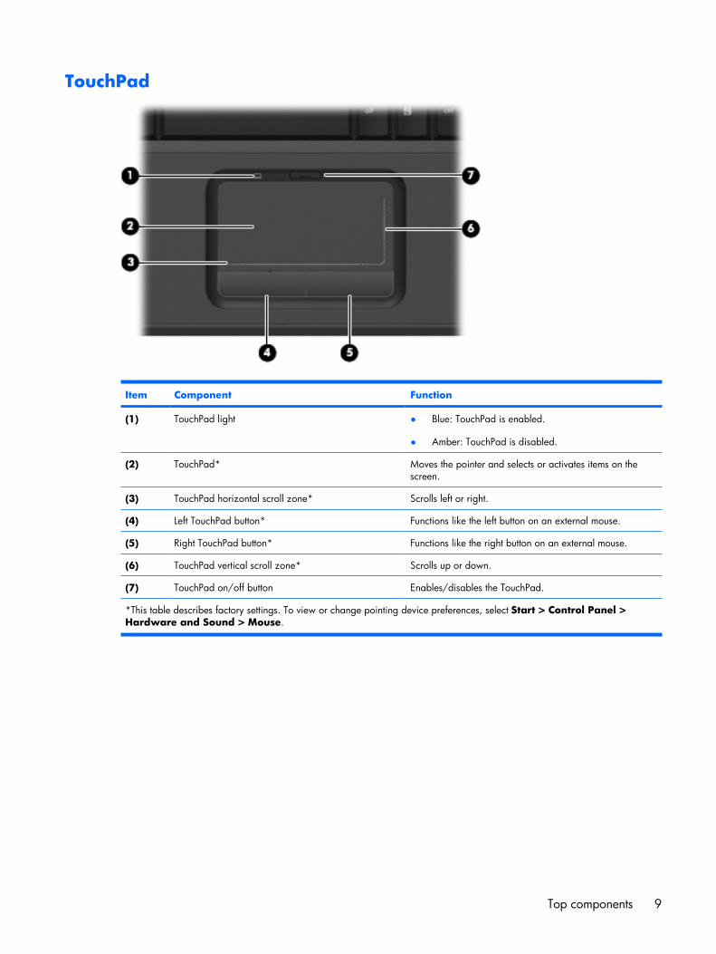
TouchPad
Item Component Function
(1) TouchPad light ● Blue: TouchPad is enabled.
● Amber: TouchPad is disabled.
(2) TouchPad* Moves the pointer and selects or activates items on thescreen.
(3) TouchPad horizontal scroll zone* Scrolls left or right.
(4) Left TouchPad button* Functions like the left button on an external mouse.
(5) Right TouchPad button* Functions like the right button on an external mouse.
(6) TouchPad vertical scroll zone* Scrolls up or down.
(7) TouchPad on/off button Enables/disables the TouchPad.
*This table describes factory settings. To view or change pointing device preferences, select Start > Control Panel >Hardware and Sound > Mouse.
Top components 9
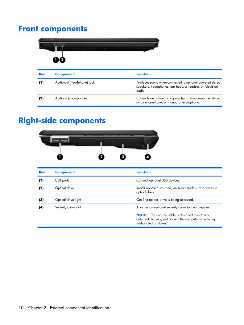
Front components
Item Component Function
(1) Audio-out (headphone) jack Produces sound when connected to optional powered stereospeakers, headphones, ear buds, a headset, or televisionaudio.
(2) Audio-in (microphone) Connects an optional computer headset microphone, stereoarray microphone, or monaural microphone.
Right-side components
Item Component Function
(1) USB ports Connect optional USB devices.
(2) Optical drive Reads optical discs, and, on select models, also writes tooptical discs.
(3) Optical drive light On: The optical drive is being accessed.
(4) Security cable slot Attaches an optional security cable to the computer.
NOTE: The security cable is designed to act as adeterrent, but may not prevent the computer from beingmishandled or stolen.
10 Chapter 2 External component identification
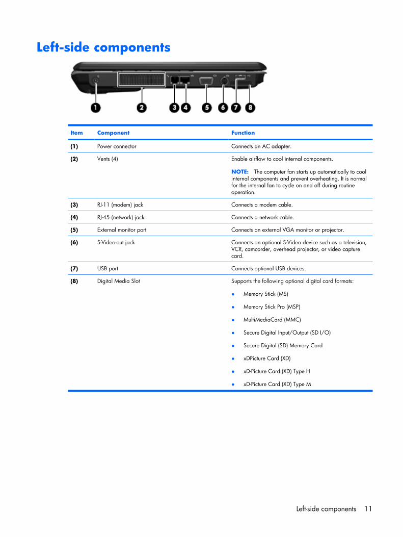
Left-side components
Item Component Function
(1) Power connector Connects an AC adapter.
(2) Vents (4) Enable airflow to cool internal components.
NOTE: The computer fan starts up automatically to coolinternal components and prevent overheating. It is normalfor the internal fan to cycle on and off during routineoperation.
(3) RJ-11 (modem) jack Connects a modem cable.
(4) RJ-45 (network) jack Connects a network cable.
(5) External monitor port Connects an external VGA monitor or projector.
(6) S-Video-out jack Connects an optional S-Video device such as a television,VCR, camcorder, overhead projector, or video capturecard.
(7) USB port Connects optional USB devices.
(8) Digital Media Slot Supports the following optional digital card formats:
● Memory Stick (MS)
● Memory Stick Pro (MSP)
● MultiMediaCard (MMC)
● Secure Digital Input/Output (SD I/O)
● Secure Digital (SD) Memory Card
● xDPicture Card (XD)
● xD-Picture Card (XD) Type H
● xD-Picture Card (XD) Type M
Left-side components 11
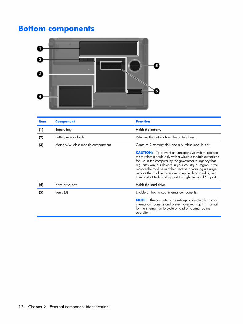
Bottom components
Item Component Function
(1) Battery bay Holds the battery.
(2) Battery release latch Releases the battery from the battery bay.
(3) Memory/wireless module compartment Contains 2 memory slots and a wireless module slot.
CAUTION: To prevent an unresponsive system, replacethe wireless module only with a wireless module authorizedfor use in the computer by the governmental agency thatregulates wireless devices in your country or region. If youreplace the module and then receive a warning message,remove the module to restore computer functionality, andthen contact technical support through Help and Support.
(4) Hard drive bay Holds the hard drive.
(5) Vents (3) Enable airflow to cool internal components.
NOTE: The computer fan starts up automatically to coolinternal components and prevent overheating. It is normalfor the internal fan to cycle on and off during routineoperation.
12 Chapter 2 External component identification
3 Illustrated parts catalog
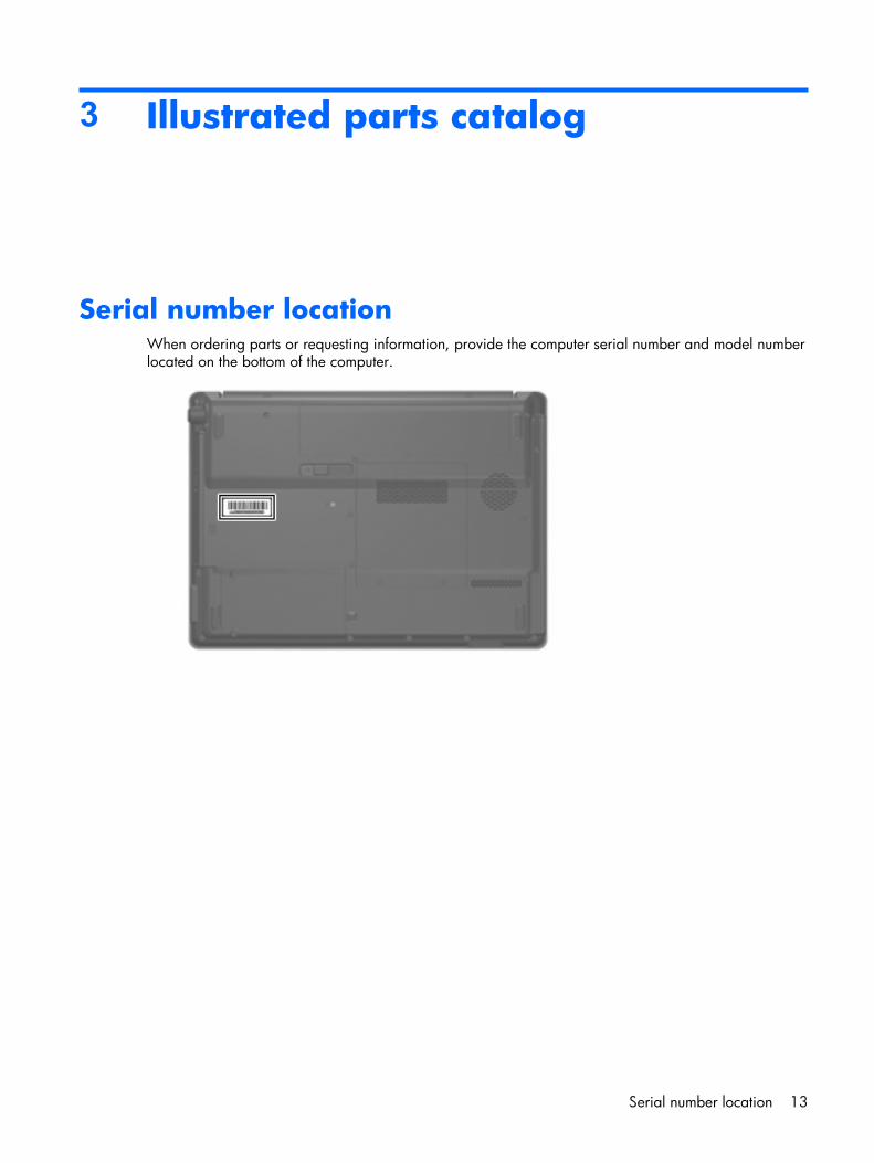
Serial number locationWhen ordering parts or requesting information, provide the computer serial number and model numberlocated on the bottom of the computer.
Serial number location 13
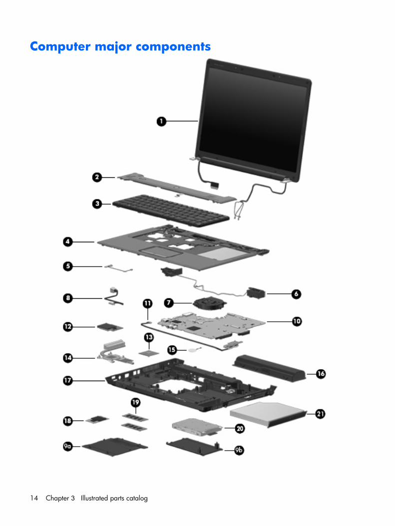
Computer major components
14 Chapter 3 Illustrated parts catalog
Item Description Spare part number
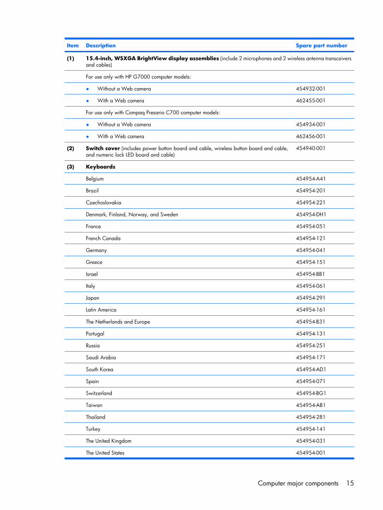
(1) 15.4-inch, WSXGA BrightView display assemblies (include 2 microphones and 2 wireless antenna transceiversand cables)
For use only with HP G7000 computer models:
● Without a Web camera 454932-001
● With a Web camera 462455-001
For use only with Compaq Presario C700 computer models:
● Without a Web camera 454934-001
● With a Web camera 462456-001
(2) Switch cover (includes power button board and cable, wireless button board and cable,and numeric lock LED board and cable)
454940-001
(3) Keyboards
Belgium 454954-A41
Brazil 454954-201
Czechoslovakia 454954-221
Denmark, Finland, Norway, and Sweden 454954-DH1
France 454954-051
French Canada 454954-121
Germany 454954-041
Greece 454954-151
Israel 454954-BB1
Italy 454954-061
Japan 454954-291
Latin America 454954-161
The Netherlands and Europe 454954-B31
Portugal 454954-131
Russia 454954-251
Saudi Arabia 454954-171
South Korea 454954-AD1
Spain 454954-071
Switzerland 454954-BG1
Taiwan 454954-AB1
Thailand 454954-281
Turkey 454954-141
The United Kingdom 454954-031
The United States 454954-001
Computer major components 15
Item Description Spare part number
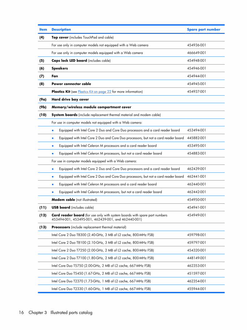
(4) Top cover (includes TouchPad and cable)
For use only in computer models not equipped with a Web camera 454936-001
For use only in computer models equipped with a Web camera 466649-001
(5) Caps lock LED board (includes cable) 454948-001
(6) Speakers 454946-001
(7) Fan 454944-001
(8) Power connector cable 454945-001
Plastics Kit (see Plastics Kit on page 22 for more information) 454937-001
(9a) Hard drive bay cover
(9b) Memory/wireless module compartment cover
(10) System boards (include replacement thermal material and modem cable)
For use in computer models not equipped with a Web camera:
● Equipped with Intel Core 2 Duo and Core Duo processors and a card reader board 453494-001
● Equipped with Intel Core 2 Duo and Core Duo processors, but not a card reader board 445882-001
● Equipped with Intel Celeron M processors and a card reader board 453495-001
● Equipped with Intel Celeron M processors, but not a card reader board 454883-001
For use in computer models equipped with a Web camera:
● Equipped with Intel Core 2 Duo and Core Duo processors and a card reader board 462439-001
● Equipped with Intel Core 2 Duo and Core Duo processors, but not a card reader board 462441-001
● Equipped with Intel Celeron M processors and a card reader board 462440-001
● Equipped with Intel Celeron M processors, but not a card reader board 462442-001
Modem cable (not illustrated) 454950-001
(11) USB board (includes cable) 454941-001
(12) Card reader board (for use only with system boards with spare part numbers453494-001, 453495-001, 462439-001, and 462440-001)
454949-001
(13) Processors (include replacement thermal material)
Intel Core 2 Duo T8300 (2.40-GHz, 3 MB of L2 cache, 800-MHz FSB) 459798-001
Intel Core 2 Duo T8100 (2.10-GHz, 3 MB of L2 cache, 800-MHz FSB) 459797-001
Intel Core 2 Duo T7250 (2.00-GHz, 2 MB of L2 cache, 800-MHz FSB) 454320-001
Intel Core 2 Duo T7100 (1.80-GHz, 2 MB of L2 cache, 800-MHz FSB) 448149-001
Intel Core Duo T5750 (2.00-GHz, 2 MB of L2 cache, 667-MHz FSB) 462353-001
Intel Core Duo T5450 (1.67-GHz, 2 MB of L2 cache, 667-MHz FSB) 451597-001
Intel Core Duo T2370 (1.73-GHz, 1 MB of L2 cache, 667-MHz FSB) 462354-001
Intel Core Duo T2330 (1.60-GHz, 1 MB of L2 cache, 667-MHz FSB) 455944-001
16 Chapter 3 Illustrated parts catalog
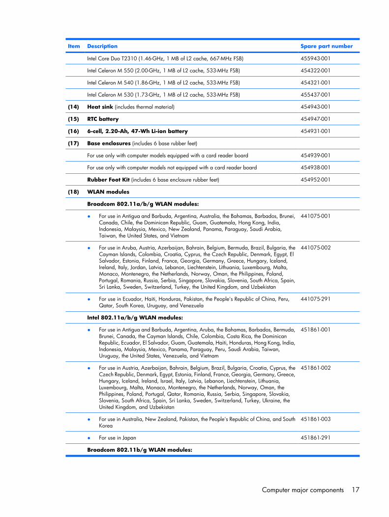
Item Description Spare part number
Intel Core Duo T2310 (1.46-GHz, 1 MB of L2 cache, 667-MHz FSB) 455943-001
Intel Celeron M 550 (2.00-GHz, 1 MB of L2 cache, 533-MHz FSB) 454322-001
Intel Celeron M 540 (1.86-GHz, 1 MB of L2 cache, 533-MHz FSB) 454321-001
Intel Celeron M 530 (1.73-GHz, 1 MB of L2 cache, 533-MHz FSB) 455437-001
(14) Heat sink (includes thermal material) 454943-001
(15) RTC battery 454947-001
(16) 6-cell, 2.20-Ah, 47-Wh Li-ion battery 454931-001
(17) Base enclosures (includes 6 base rubber feet)
For use only with computer models equipped with a card reader board 454939-001
For use only with computer models not equipped with a card reader board 454938-001
Rubber Foot Kit (includes 6 base enclosure rubber feet) 454952-001
(18) WLAN modules
Broadcom 802.11a/b/g WLAN modules:
● For use in Antigua and Barbuda, Argentina, Australia, the Bahamas, Barbados, Brunei,Canada, Chile, the Dominican Republic, Guam, Guatemala, Hong Kong, India,Indonesia, Malaysia, Mexico, New Zealand, Panama, Paraguay, Saudi Arabia,Taiwan, the United States, and Vietnam
441075-001
● For use in Aruba, Austria, Azerbaijan, Bahrain, Belgium, Bermuda, Brazil, Bulgaria, theCayman Islands, Colombia, Croatia, Cyprus, the Czech Republic, Denmark, Egypt, ElSalvador, Estonia, Finland, France, Georgia, Germany, Greece, Hungary, Iceland,Ireland, Italy, Jordan, Latvia, Lebanon, Liechtenstein, Lithuania, Luxembourg, Malta,Monaco, Montenegro, the Netherlands, Norway, Oman, the Philippines, Poland,Portugal, Romania, Russia, Serbia, Singapore, Slovakia, Slovenia, South Africa, Spain,Sri Lanka, Sweden, Switzerland, Turkey, the United Kingdom, and Uzbekistan
441075-002
● For use in Ecuador, Haiti, Honduras, Pakistan, the People's Republic of China, Peru,Qatar, South Korea, Uruguay, and Venezuela
441075-291
Intel 802.11a/b/g WLAN modules:
● For use in Antigua and Barbuda, Argentina, Aruba, the Bahamas, Barbados, Bermuda,Brunei, Canada, the Cayman Islands, Chile, Colombia, Costa Rica, the DominicanRepublic, Ecuador, El Salvador, Guam, Guatemala, Haiti, Honduras, Hong Kong, India,Indonesia, Malaysia, Mexico, Panama, Paraguay, Peru, Saudi Arabia, Taiwan,Uruguay, the United States, Venezuela, and Vietnam
451861-001
● For use in Austria, Azerbaijan, Bahrain, Belgium, Brazil, Bulgaria, Croatia, Cyprus, theCzech Republic, Denmark, Egypt, Estonia, Finland, France, Georgia, Germany, Greece,Hungary, Iceland, Ireland, Israel, Italy, Latvia, Lebanon, Liechtenstein, Lithuania,Luxembourg, Malta, Monaco, Montenegro, the Netherlands, Norway, Oman, thePhilippines, Poland, Portugal, Qatar, Romania, Russia, Serbia, Singapore, Slovakia,Slovenia, South Africa, Spain, Sri Lanka, Sweden, Switzerland, Turkey, Ukraine, theUnited Kingdom, and Uzbekistan
451861-002
● For use in Australia, New Zealand, Pakistan, the People's Republic of China, and SouthKorea
451861-003
● For use in Japan 451861-291
Broadcom 802.11b/g WLAN modules:
Computer major components 17
Item Description Spare part number
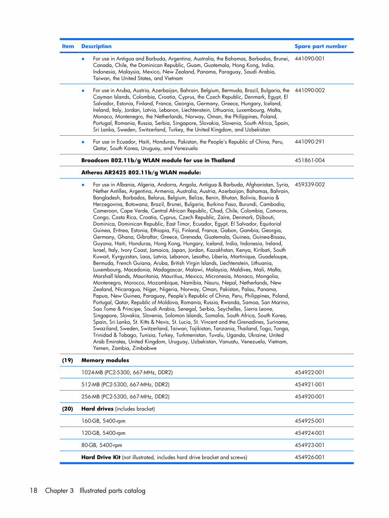
● For use in Antigua and Barbuda, Argentina, Australia, the Bahamas, Barbados, Brunei,Canada, Chile, the Dominican Republic, Guam, Guatemala, Hong Kong, India,Indonesia, Malaysia, Mexico, New Zealand, Panama, Paraguay, Saudi Arabia,Taiwan, the United States, and Vietnam
441090-001
● For use in Aruba, Austria, Azerbaijan, Bahrain, Belgium, Bermuda, Brazil, Bulgaria, theCayman Islands, Colombia, Croatia, Cyprus, the Czech Republic, Denmark, Egypt, ElSalvador, Estonia, Finland, France, Georgia, Germany, Greece, Hungary, Iceland,Ireland, Italy, Jordan, Latvia, Lebanon, Liechtenstein, Lithuania, Luxembourg, Malta,Monaco, Montenegro, the Netherlands, Norway, Oman, the Philippines, Poland,Portugal, Romania, Russia, Serbia, Singapore, Slovakia, Slovenia, South Africa, Spain,Sri Lanka, Sweden, Switzerland, Turkey, the United Kingdom, and Uzbekistan
441090-002
● For use in Ecuador, Haiti, Honduras, Pakistan, the People's Republic of China, Peru,Qatar, South Korea, Uruguay, and Venezuela
441090-291
Broadcom 802.11b/g WLAN module for use in Thailand 451861-004
Atheros AR2425 802.11b/g WLAN module:
● For use in Albania, Algeria, Andorra, Angola, Antigua & Barbuda, Afghanistan, Syria,Nether Antilles, Argentina, Armenia, Australia, Austria, Azerbaijan, Bahamas, Bahrain,Bangladesh, Barbados, Belarus, Belgium, Belize, Benin, Bhutan, Bolivia, Bosnia &Herzegovina, Botswana, Brazil, Brunei, Bulgaria, Burkina Faso, Burundi, Cambodia,Cameroon, Cape Verde, Central African Republic, Chad, Chile, Colombia, Comoros,Congo, Costa Rica, Croatia, Cyprus, Czech Republic, Zaire, Denmark, Djibouti,Dominica, Dominican Republic, East Timor, Ecuador, Egypt, El Salvador, EquitorialGuinea, Eritrea, Estonia, Ethiopia, Fiji, Finland, France, Gabon, Gambia, Georgia,Germany, Ghana, Gibraltar, Greece, Grenada, Guatemala, Guinea, Guinea-Bissau,Guyana, Haiti, Honduras, Hong Kong, Hungary, Iceland, India, Indonesia, Ireland,Israel, Italy, Ivory Coast, Jamaica, Japan, Jordan, Kazakhstan, Kenya, Kiribati, SouthKuwait, Kyrgyzstan, Laos, Latvia, Lebanon, Lesotho, Liberia, Martinique, Guadeloupe,Bermuda, French Guiana, Aruba, British Virgin Islands, Liechtenstein, Lithuania,Luxembourg, Macedonia, Madagascar, Malawi, Malaysia, Maldives, Mali, Malta,Marshall Islands, Mauritania, Mauritius, Mexico, Micronesia, Monaco, Mongolia,Montenegro, Morocco, Mozambique, Namibia, Nauru, Nepal, Netherlands, NewZealand, Nicaragua, Niger, Nigeria, Norway, Oman, Pakistan, Palau, Panama,Papua, New Guinea, Paraguay, People's Republic of China, Peru, Philippines, Poland,Portugal, Qatar, Republic of Moldova, Romania, Russia, Rwanda, Samoa, San Marino,Sao Tome & Principe, Saudi Arabia, Senegal, Serbia, Seychelles, Sierra Leone,Singapore, Slovakia, Slovenia, Solomon Islands, Somalia, South Africa, South Korea,Spain, Sri Lanka, St. Kitts & Nevis, St. Lucia, St. Vincent and the Grenadines, Suriname,Swaziland, Sweden, Switzerland, Taiwan, Tajikistan, Tanzania, Thailand, Togo, Tonga,Trinidad & Tobago, Tunisia, Turkey, Turkmenistan, Tuvalu, Uganda, Ukraine, UnitedArab Emirates, United Kingdom, Uruguay, Uzbekistan, Vanuatu, Venezuela, Vietnam,Yemen, Zambia, Zimbabwe
459339-002
(19) Memory modules
1024-MB (PC2-5300, 667-MHz, DDR2) 454922-001
512-MB (PC2-5300, 667-MHz, DDR2) 454921-001
256-MB (PC2-5300, 667-MHz, DDR2) 454920-001
(20) Hard drives (includes bracket)
160-GB, 5400-rpm 454925-001
120-GB, 5400-rpm 454924-001
80-GB, 5400-rpm 454923-001
Hard Drive Kit (not illustrated, includes hard drive bracket and screws) 454926-001
18 Chapter 3 Illustrated parts catalog
Item Description Spare part number
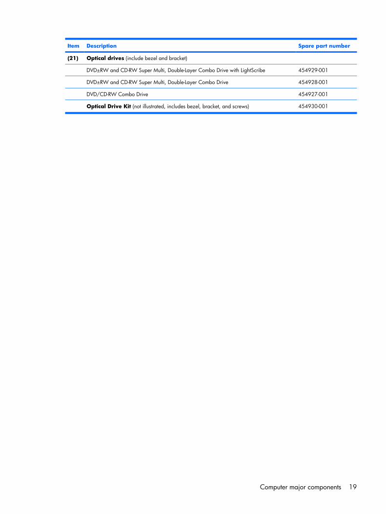
(21) Optical drives (include bezel and bracket)
DVD±RW and CD-RW Super Multi, Double-Layer Combo Drive with LightScribe 454929-001
DVD±RW and CD-RW Super Multi, Double-Layer Combo Drive 454928-001
DVD/CD-RW Combo Drive 454927-001
Optical Drive Kit (not illustrated, includes bezel, bracket, and screws) 454930-001
Computer major components 19
Display assembly components
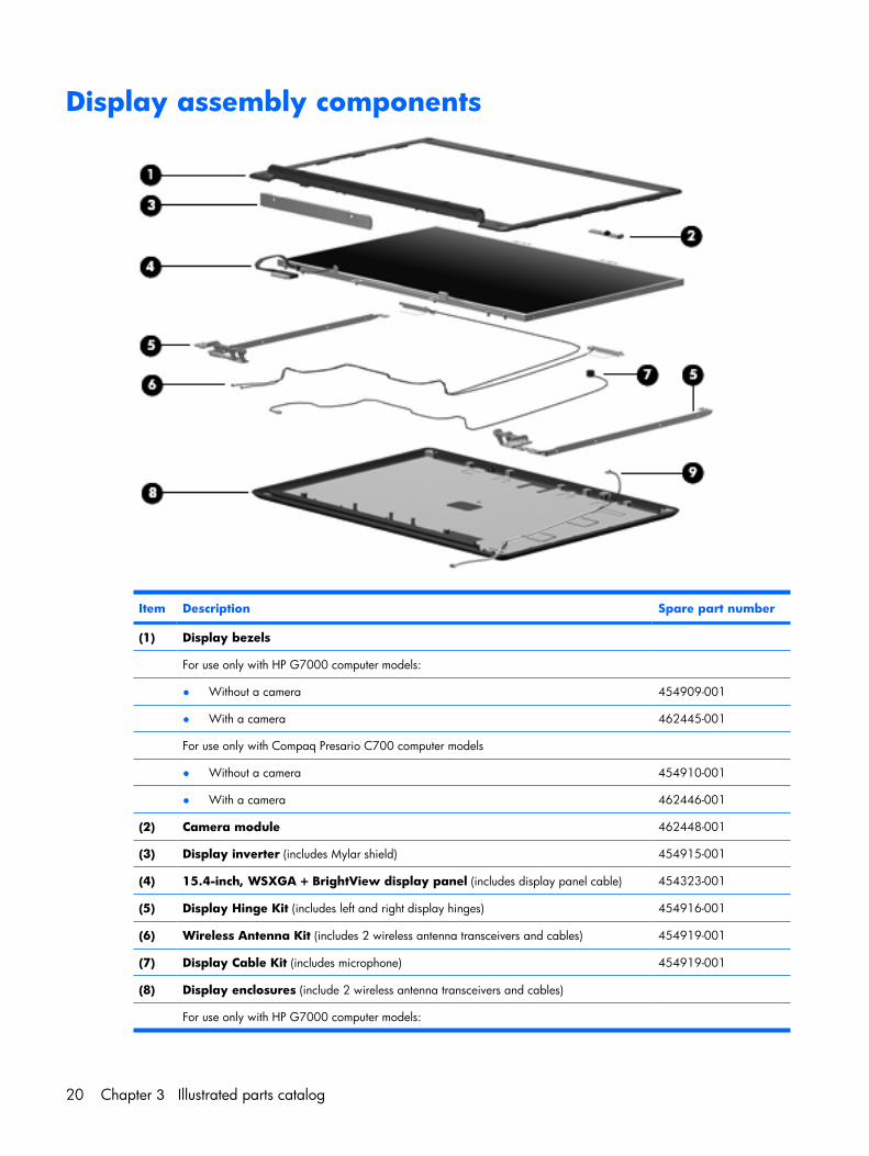
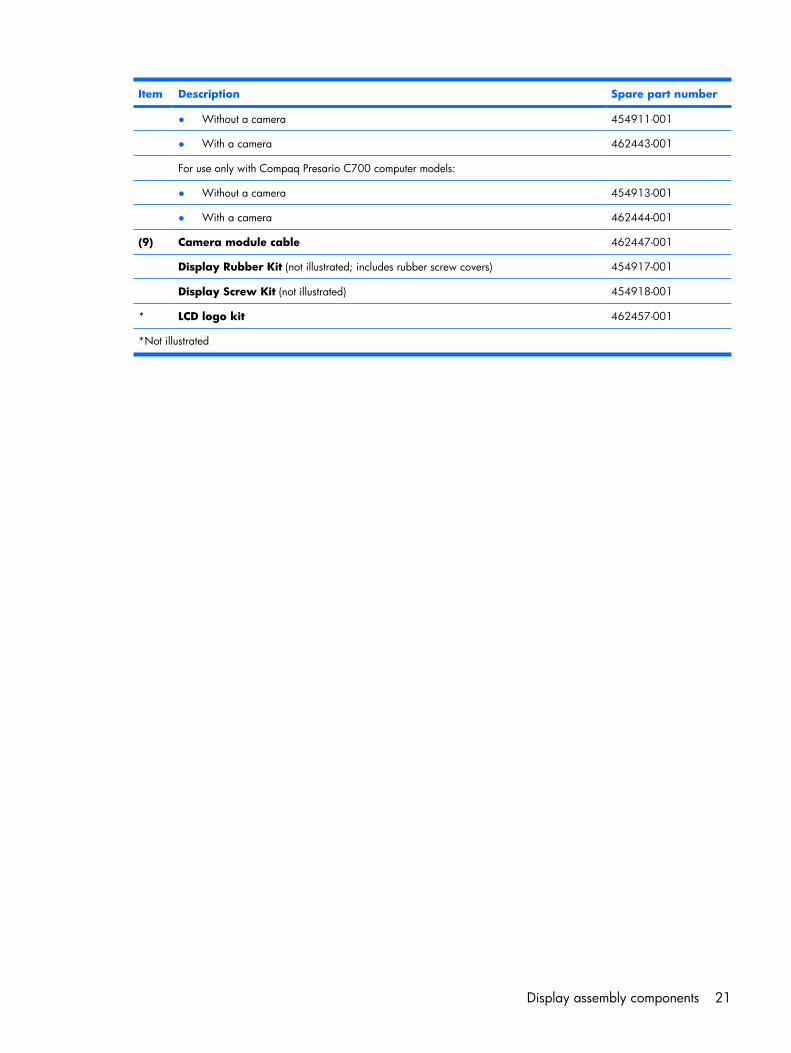
Item Description Spare part number
(1) Display bezels
For use only with HP G7000 computer models:
● Without a camera 454909-001
● With a camera 462445-001
For use only with Compaq Presario C700 computer models
● Without a camera 454910-001
● With a camera 462446-001
(2) Camera module 462448-001
(3) Display inverter (includes Mylar shield) 454915-001
(4) 15.4-inch, WSXGA + BrightView display panel (includes display panel cable) 454323-001
(5) Display Hinge Kit (includes left and right display hinges) 454916-001
(6) Wireless Antenna Kit (includes 2 wireless antenna transceivers and cables) 454919-001
(7) Display Cable Kit (includes microphone) 454919-001
(8) Display enclosures (include 2 wireless antenna transceivers and cables)
For use only with HP G7000 computer models:
20 Chapter 3 Illustrated parts catalog
Item Description Spare part number
● Without a camera 454911-001
● With a camera 462443-001
For use only with Compaq Presario C700 computer models:
● Without a camera 454913-001
● With a camera 462444-001
(9) Camera module cable 462447-001
Display Rubber Kit (not illustrated; includes rubber screw covers) 454917-001
Display Screw Kit (not illustrated) 454918-001
* LCD logo kit 462457-001
*Not illustrated
Display assembly components 21
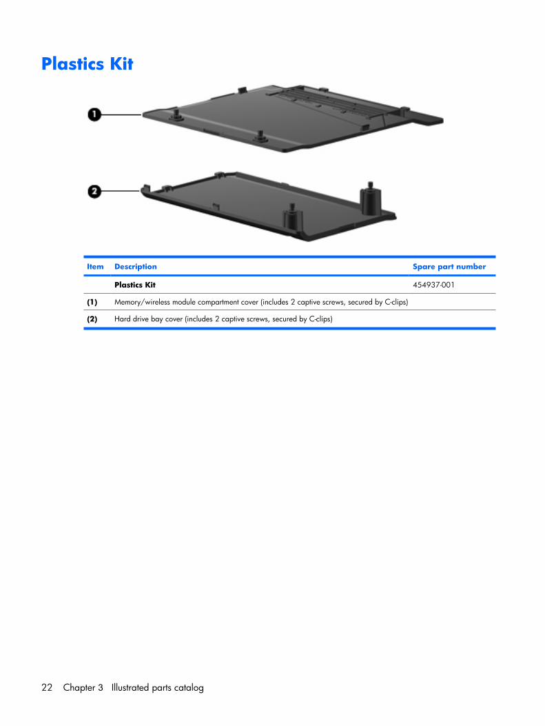
Plastics Kit
Item Description Spare part number
Plastics Kit 454937-001
(1) Memory/wireless module compartment cover (includes 2 captive screws, secured by C-clips)
(2) Hard drive bay cover (includes 2 captive screws, secured by C-clips)
22 Chapter 3 Illustrated parts catalog
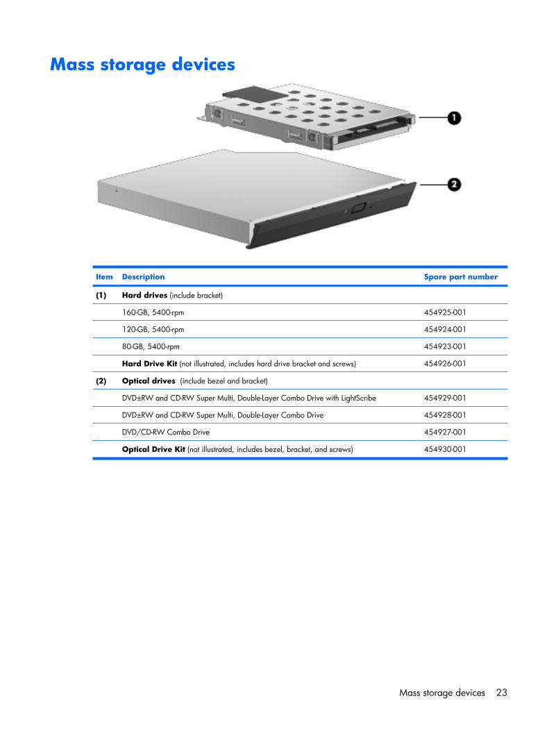
Mass storage devices
Item Description Spare part number
(1) Hard drives (include bracket)
160-GB, 5400-rpm 454925-001
120-GB, 5400-rpm 454924-001
80-GB, 5400-rpm 454923-001
Hard Drive Kit (not illustrated, includes hard drive bracket and screws) 454926-001
(2) Optical drives (include bezel and bracket)
DVD±RW and CD-RW Super Multi, Double-Layer Combo Drive with LightScribe 454929-001
DVD±RW and CD-RW Super Multi, Double-Layer Combo Drive 454928-001
DVD/CD-RW Combo Drive 454927-001
Optical Drive Kit (not illustrated, includes bezel, bracket, and screws) 454930-001
Mass storage devices 23
Miscellaneous partsDescription Spare part number
65-W PFC AC adapter 457685-001
ATSC/NTSC/PAL TV tuner 439130-001
ATSC/NTSC TV tuner antenna 439131-001
Composite audio and S-Video cable 407939-001
DVB-T tuner 412175-001
DVB-T antenna adapter 412176-001
Earbud headset 371693-003
HP backpack 405527-001
HP carrying case 418162-001
HP Remote Control 407313-001
Infrared emitter with cable 439129-001
Optical wired mouse 436238-001
RF input adapter cable (without ferrite) 407940-001
Windows Vista remote control (fits inside ExpressCard slot) 439128-001
Windows Vista remote control (does not fit inside ExpressCard slot) 439254-001
Wireless laser mouse (includes cable adapter) 430958-001
Power cords:
Argentina 403811-D01
Australia and New Zealand 403811-011
Brazil 403811-201
Canada, French Canada, Latin America, Thailand, and the United States 403811-001
Denmark 403811-081
India 403811-D61
Israel 403811-BB1
Italy 403811-061
Japan 403811-291
The Netherlands and Europe 403811-B31
The People's Republic of China 403811-AA1
South Africa 403811-AR1
South Korea 403811-AD1
Switzerland 403811-111
Taiwan 403811-AB1
24 Chapter 3 Illustrated parts catalog
Description Spare part number
Hong Kong and the United Kingdom 403811-031
Screw Kit
● Phillips PM3.0×3.0 screw
● Phillips PM2.5×9.0 screw
● Phillips PM2.5×7.0 screw
● Phillips PM2.5×6.0 captive screw
● Phillips PM2.5×4.0 screw
● Phillips PM2.0×5.0 captive screw
● Black Phillips PM2.0×4.0 screw
● Silver Phillips PM2.0×4.0 screw
454951-001
Miscellaneous parts 25
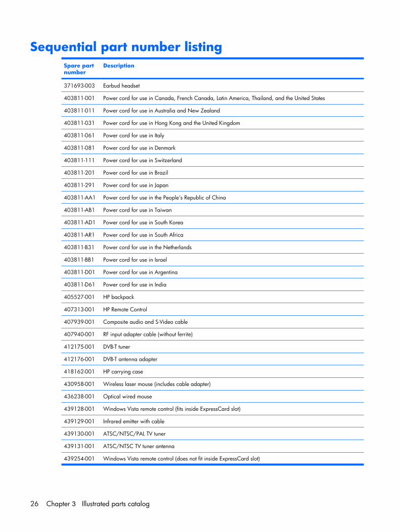
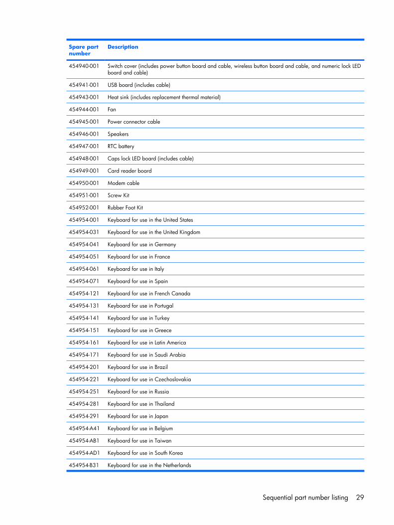
Sequential part number listingSpare partnumber
Description
371693-003 Earbud headset
403811-001 Power cord for use in Canada, French Canada, Latin America, Thailand, and the United States
403811-011 Power cord for use in Australia and New Zealand
403811-031 Power cord for use in Hong Kong and the United Kingdom
403811-061 Power cord for use in Italy
403811-081 Power cord for use in Denmark
403811-111 Power cord for use in Switzerland
403811-201 Power cord for use in Brazil
403811-291 Power cord for use in Japan
403811-AA1 Power cord for use in the People's Republic of China
403811-AB1 Power cord for use in Taiwan
403811-AD1 Power cord for use in South Korea
403811-AR1 Power cord for use in South Africa
403811-B31 Power cord for use in the Netherlands
403811-BB1 Power cord for use in Israel
403811-D01 Power cord for use in Argentina
403811-D61 Power cord for use in India
405527-001 HP backpack
407313-001 HP Remote Control
407939-001 Composite audio and S-Video cable
407940-001 RF input adapter cable (without ferrite)
412175-001 DVB-T tuner
412176-001 DVB-T antenna adapter
418162-001 HP carrying case
430958-001 Wireless laser mouse (includes cable adapter)
436238-001 Optical wired mouse
439128-001 Windows Vista remote control (fits inside ExpressCard slot)
439129-001 Infrared emitter with cable
439130-001 ATSC/NTSC/PAL TV tuner
439131-001 ATSC/NTSC TV tuner antenna
439254-001 Windows Vista remote control (does not fit inside ExpressCard slot)
26 Chapter 3 Illustrated parts catalog
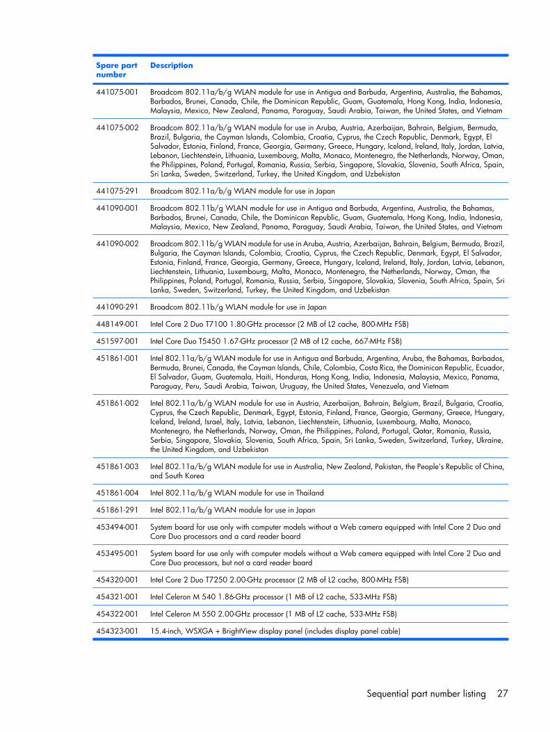
Spare partnumber
Description
441075-001 Broadcom 802.11a/b/g WLAN module for use in Antigua and Barbuda, Argentina, Australia, the Bahamas,Barbados, Brunei, Canada, Chile, the Dominican Republic, Guam, Guatemala, Hong Kong, India, Indonesia,Malaysia, Mexico, New Zealand, Panama, Paraguay, Saudi Arabia, Taiwan, the United States, and Vietnam
441075-002 Broadcom 802.11a/b/g WLAN module for use in Aruba, Austria, Azerbaijan, Bahrain, Belgium, Bermuda,Brazil, Bulgaria, the Cayman Islands, Colombia, Croatia, Cyprus, the Czech Republic, Denmark, Egypt, ElSalvador, Estonia, Finland, France, Georgia, Germany, Greece, Hungary, Iceland, Ireland, Italy, Jordan, Latvia,Lebanon, Liechtenstein, Lithuania, Luxembourg, Malta, Monaco, Montenegro, the Netherlands, Norway, Oman,the Philippines, Poland, Portugal, Romania, Russia, Serbia, Singapore, Slovakia, Slovenia, South Africa, Spain,Sri Lanka, Sweden, Switzerland, Turkey, the United Kingdom, and Uzbekistan
441075-291 Broadcom 802.11a/b/g WLAN module for use in Japan
441090-001 Broadcom 802.11b/g WLAN module for use in Antigua and Barbuda, Argentina, Australia, the Bahamas,Barbados, Brunei, Canada, Chile, the Dominican Republic, Guam, Guatemala, Hong Kong, India, Indonesia,Malaysia, Mexico, New Zealand, Panama, Paraguay, Saudi Arabia, Taiwan, the United States, and Vietnam
441090-002 Broadcom 802.11b/g WLAN module for use in Aruba, Austria, Azerbaijan, Bahrain, Belgium, Bermuda, Brazil,Bulgaria, the Cayman Islands, Colombia, Croatia, Cyprus, the Czech Republic, Denmark, Egypt, El Salvador,Estonia, Finland, France, Georgia, Germany, Greece, Hungary, Iceland, Ireland, Italy, Jordan, Latvia, Lebanon,Liechtenstein, Lithuania, Luxembourg, Malta, Monaco, Montenegro, the Netherlands, Norway, Oman, thePhilippines, Poland, Portugal, Romania, Russia, Serbia, Singapore, Slovakia, Slovenia, South Africa, Spain, SriLanka, Sweden, Switzerland, Turkey, the United Kingdom, and Uzbekistan
441090-291 Broadcom 802.11b/g WLAN module for use in Japan
448149-001 Intel Core 2 Duo T7100 1.80-GHz processor (2 MB of L2 cache, 800-MHz FSB)
451597-001 Intel Core Duo T5450 1.67-GHz processor (2 MB of L2 cache, 667-MHz FSB)
451861-001 Intel 802.11a/b/g WLAN module for use in Antigua and Barbuda, Argentina, Aruba, the Bahamas, Barbados,Bermuda, Brunei, Canada, the Cayman Islands, Chile, Colombia, Costa Rica, the Dominican Republic, Ecuador,El Salvador, Guam, Guatemala, Haiti, Honduras, Hong Kong, India, Indonesia, Malaysia, Mexico, Panama,Paraguay, Peru, Saudi Arabia, Taiwan, Uruguay, the United States, Venezuela, and Vietnam
451861-002 Intel 802.11a/b/g WLAN module for use in Austria, Azerbaijan, Bahrain, Belgium, Brazil, Bulgaria, Croatia,Cyprus, the Czech Republic, Denmark, Egypt, Estonia, Finland, France, Georgia, Germany, Greece, Hungary,Iceland, Ireland, Israel, Italy, Latvia, Lebanon, Liechtenstein, Lithuania, Luxembourg, Malta, Monaco,Montenegro, the Netherlands, Norway, Oman, the Philippines, Poland, Portugal, Qatar, Romania, Russia,Serbia, Singapore, Slovakia, Slovenia, South Africa, Spain, Sri Lanka, Sweden, Switzerland, Turkey, Ukraine,the United Kingdom, and Uzbekistan
451861-003 Intel 802.11a/b/g WLAN module for use in Australia, New Zealand, Pakistan, the People's Republic of China,and South Korea
451861-004 Intel 802.11a/b/g WLAN module for use in Thailand
451861-291 Intel 802.11a/b/g WLAN module for use in Japan
453494-001 System board for use only with computer models without a Web camera equipped with Intel Core 2 Duo andCore Duo processors and a card reader board
453495-001 System board for use only with computer models without a Web camera equipped with Intel Core 2 Duo andCore Duo processors, but not a card reader board
454320-001 Intel Core 2 Duo T7250 2.00-GHz processor (2 MB of L2 cache, 800-MHz FSB)
454321-001 Intel Celeron M 540 1.86-GHz processor (1 MB of L2 cache, 533-MHz FSB)
454322-001 Intel Celeron M 550 2.00-GHz processor (1 MB of L2 cache, 533-MHz FSB)
454323-001 15.4-inch, WSXGA + BrightView display panel (includes display panel cable)
Sequential part number listing 27
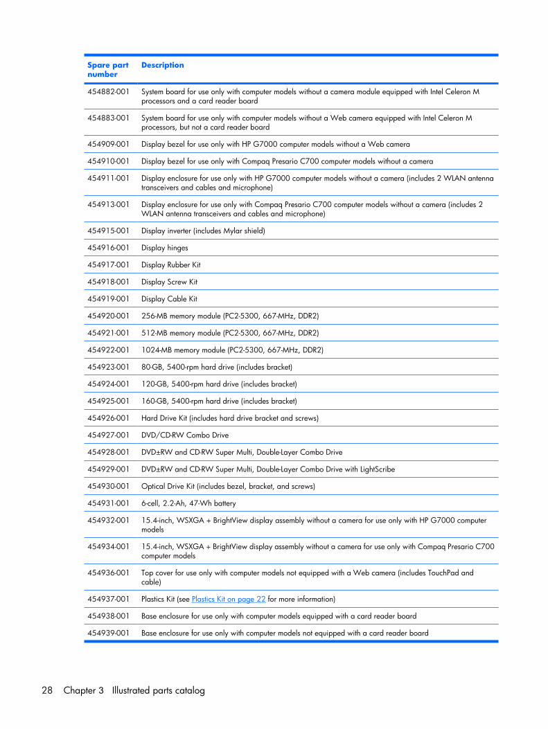
Spare partnumber
Description
454882-001 System board for use only with computer models without a camera module equipped with Intel Celeron Mprocessors and a card reader board
454883-001 System board for use only with computer models without a Web camera equipped with Intel Celeron Mprocessors, but not a card reader board
454909-001 Display bezel for use only with HP G7000 computer models without a Web camera
454910-001 Display bezel for use only with Compaq Presario C700 computer models without a camera
454911-001 Display enclosure for use only with HP G7000 computer models without a camera (includes 2 WLAN antennatransceivers and cables and microphone)
454913-001 Display enclosure for use only with Compaq Presario C700 computer models without a camera (includes 2WLAN antenna transceivers and cables and microphone)
454915-001 Display inverter (includes Mylar shield)
454916-001 Display hinges
454917-001 Display Rubber Kit
454918-001 Display Screw Kit
454919-001 Display Cable Kit
454920-001 256-MB memory module (PC2-5300, 667-MHz, DDR2)
454921-001 512-MB memory module (PC2-5300, 667-MHz, DDR2)
454922-001 1024-MB memory module (PC2-5300, 667-MHz, DDR2)
454923-001 80-GB, 5400-rpm hard drive (includes bracket)
454924-001 120-GB, 5400-rpm hard drive (includes bracket)
454925-001 160-GB, 5400-rpm hard drive (includes bracket)
454926-001 Hard Drive Kit (includes hard drive bracket and screws)
454927-001 DVD/CD-RW Combo Drive
454928-001 DVD±RW and CD-RW Super Multi, Double-Layer Combo Drive
454929-001 DVD±RW and CD-RW Super Multi, Double-Layer Combo Drive with LightScribe
454930-001 Optical Drive Kit (includes bezel, bracket, and screws)
454931-001 6-cell, 2.2-Ah, 47-Wh battery
454932-001 15.4-inch, WSXGA + BrightView display assembly without a camera for use only with HP G7000 computermodels
454934-001 15.4-inch, WSXGA + BrightView display assembly without a camera for use only with Compaq Presario C700computer models
454936-001 Top cover for use only with computer models not equipped with a Web camera (includes TouchPad andcable)
454937-001 Plastics Kit (see Plastics Kit on page 22 for more information)
454938-001 Base enclosure for use only with computer models equipped with a card reader board
454939-001 Base enclosure for use only with computer models not equipped with a card reader board
28 Chapter 3 Illustrated parts catalog
Spare partnumber
Description
454940-001 Switch cover (includes power button board and cable, wireless button board and cable, and numeric lock LEDboard and cable)
454941-001 USB board (includes cable)
454943-001 Heat sink (includes replacement thermal material)
454944-001 Fan
454945-001 Power connector cable
454946-001 Speakers
454947-001 RTC battery
454948-001 Caps lock LED board (includes cable)
454949-001 Card reader board
454950-001 Modem cable
454951-001 Screw Kit
454952-001 Rubber Foot Kit
454954-001 Keyboard for use in the United States
454954-031 Keyboard for use in the United Kingdom
454954-041 Keyboard for use in Germany
454954-051 Keyboard for use in France
454954-061 Keyboard for use in Italy
454954-071 Keyboard for use in Spain
454954-121 Keyboard for use in French Canada
454954-131 Keyboard for use in Portugal
454954-141 Keyboard for use in Turkey
454954-151 Keyboard for use in Greece
454954-161 Keyboard for use in Latin America
454954-171 Keyboard for use in Saudi Arabia
454954-201 Keyboard for use in Brazil
454954-221 Keyboard for use in Czechoslovakia
454954-251 Keyboard for use in Russia
454954-281 Keyboard for use in Thailand
454954-291 Keyboard for use in Japan
454954-A41 Keyboard for use in Belgium
454954-AB1 Keyboard for use in Taiwan
454954-AD1 Keyboard for use in South Korea
454954-B31 Keyboard for use in the Netherlands
Sequential part number listing 29
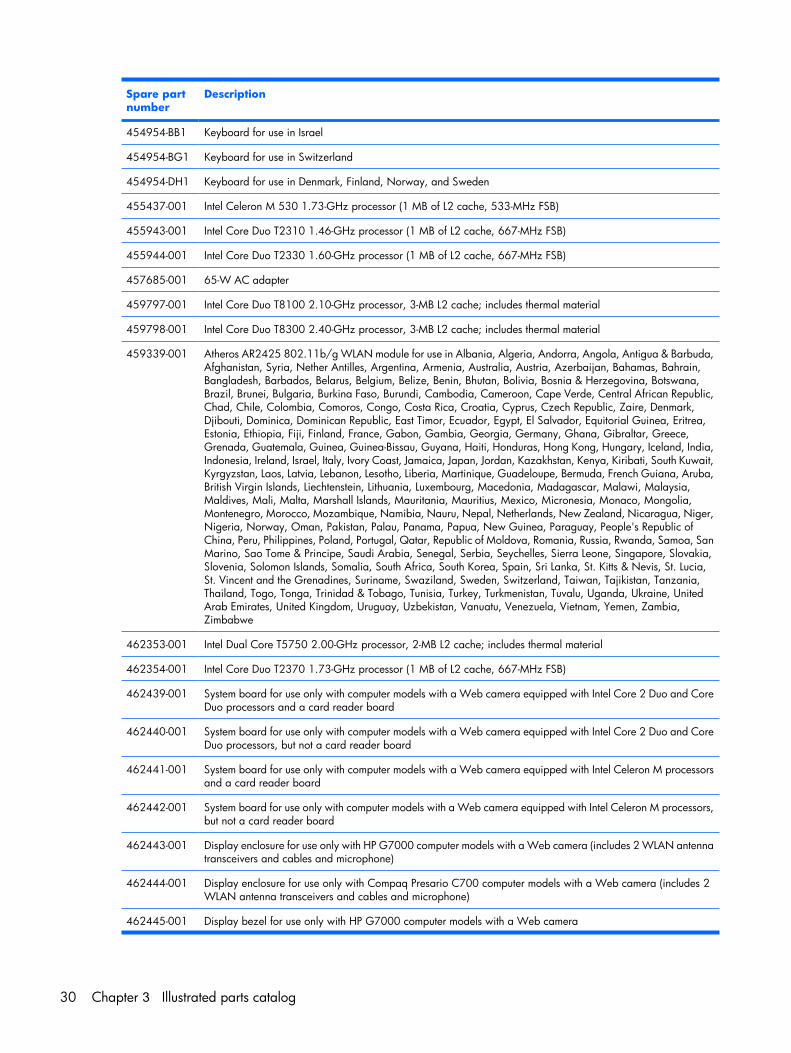
Spare partnumber
Description
454954-BB1 Keyboard for use in Israel
454954-BG1 Keyboard for use in Switzerland
454954-DH1 Keyboard for use in Denmark, Finland, Norway, and Sweden
455437-001 Intel Celeron M 530 1.73-GHz processor (1 MB of L2 cache, 533-MHz FSB)
455943-001 Intel Core Duo T2310 1.46-GHz processor (1 MB of L2 cache, 667-MHz FSB)
455944-001 Intel Core Duo T2330 1.60-GHz processor (1 MB of L2 cache, 667-MHz FSB)
457685-001 65-W AC adapter
459797-001 Intel Core Duo T8100 2.10-GHz processor, 3-MB L2 cache; includes thermal material
459798-001 Intel Core Duo T8300 2.40-GHz processor, 3-MB L2 cache; includes thermal material
459339-001 Atheros AR2425 802.11b/g WLAN module for use in Albania, Algeria, Andorra, Angola, Antigua & Barbuda,Afghanistan, Syria, Nether Antilles, Argentina, Armenia, Australia, Austria, Azerbaijan, Bahamas, Bahrain,Bangladesh, Barbados, Belarus, Belgium, Belize, Benin, Bhutan, Bolivia, Bosnia & Herzegovina, Botswana,Brazil, Brunei, Bulgaria, Burkina Faso, Burundi, Cambodia, Cameroon, Cape Verde, Central African Republic,Chad, Chile, Colombia, Comoros, Congo, Costa Rica, Croatia, Cyprus, Czech Republic, Zaire, Denmark,Djibouti, Dominica, Dominican Republic, East Timor, Ecuador, Egypt, El Salvador, Equitorial Guinea, Eritrea,Estonia, Ethiopia, Fiji, Finland, France, Gabon, Gambia, Georgia, Germany, Ghana, Gibraltar, Greece,Grenada, Guatemala, Guinea, Guinea-Bissau, Guyana, Haiti, Honduras, Hong Kong, Hungary, Iceland, India,Indonesia, Ireland, Israel, Italy, Ivory Coast, Jamaica, Japan, Jordan, Kazakhstan, Kenya, Kiribati, South Kuwait,Kyrgyzstan, Laos, Latvia, Lebanon, Lesotho, Liberia, Martinique, Guadeloupe, Bermuda, French Guiana, Aruba,British Virgin Islands, Liechtenstein, Lithuania, Luxembourg, Macedonia, Madagascar, Malawi, Malaysia,Maldives, Mali, Malta, Marshall Islands, Mauritania, Mauritius, Mexico, Micronesia, Monaco, Mongolia,Montenegro, Morocco, Mozambique, Namibia, Nauru, Nepal, Netherlands, New Zealand, Nicaragua, Niger,Nigeria, Norway, Oman, Pakistan, Palau, Panama, Papua, New Guinea, Paraguay, People's Republic ofChina, Peru, Philippines, Poland, Portugal, Qatar, Republic of Moldova, Romania, Russia, Rwanda, Samoa, SanMarino, Sao Tome & Principe, Saudi Arabia, Senegal, Serbia, Seychelles, Sierra Leone, Singapore, Slovakia,Slovenia, Solomon Islands, Somalia, South Africa, South Korea, Spain, Sri Lanka, St. Kitts & Nevis, St. Lucia,St. Vincent and the Grenadines, Suriname, Swaziland, Sweden, Switzerland, Taiwan, Tajikistan, Tanzania,Thailand, Togo, Tonga, Trinidad & Tobago, Tunisia, Turkey, Turkmenistan, Tuvalu, Uganda, Ukraine, UnitedArab Emirates, United Kingdom, Uruguay, Uzbekistan, Vanuatu, Venezuela, Vietnam, Yemen, Zambia,Zimbabwe
462353-001 Intel Dual Core T5750 2.00-GHz processor, 2-MB L2 cache; includes thermal material
462354-001 Intel Core Duo T2370 1.73-GHz processor (1 MB of L2 cache, 667-MHz FSB)
462439-001 System board for use only with computer models with a Web camera equipped with Intel Core 2 Duo and CoreDuo processors and a card reader board
462440-001 System board for use only with computer models with a Web camera equipped with Intel Core 2 Duo and CoreDuo processors, but not a card reader board
462441-001 System board for use only with computer models with a Web camera equipped with Intel Celeron M processorsand a card reader board
462442-001 System board for use only with computer models with a Web camera equipped with Intel Celeron M processors,but not a card reader board
462443-001 Display enclosure for use only with HP G7000 computer models with a Web camera (includes 2 WLAN antennatransceivers and cables and microphone)
462444-001 Display enclosure for use only with Compaq Presario C700 computer models with a Web camera (includes 2WLAN antenna transceivers and cables and microphone)
462445-001 Display bezel for use only with HP G7000 computer models with a Web camera
30 Chapter 3 Illustrated parts catalog
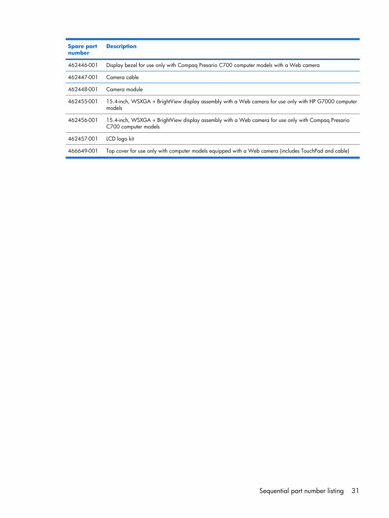
Spare partnumber
Description
462446-001 Display bezel for use only with Compaq Presario C700 computer models with a Web camera
462447-001 Camera cable
462448-001 Camera module
462455-001 15.4-inch, WSXGA + BrightView display assembly with a Web camera for use only with HP G7000 computermodels
462456-001 15.4-inch, WSXGA + BrightView display assembly with a Web camera for use only with Compaq PresarioC700 computer models
462457-001 LCD logo kit
466649-001 Top cover for use only with computer models equipped with a Web camera (includes TouchPad and cable)
Sequential part number listing 31
4 Removal and replacementprocedures
Preliminary replacement requirementsTools required
You will need the following tools to complete the removal and replacement procedures:
● Flat-bladed screwdriver
● Magnetic screwdriver
● Phillips P0 and P1 screwdrivers
Service considerationsThe following sections include some of the considerations that you must keep in mind during disassemblyand assembly procedures.
NOTE: As you remove each subassembly from the computer, place the subassembly (and allaccompanying screws) away from the work area to prevent damage.
Plastic partsUsing excessive force during disassembly and reassembly can damage plastic parts. Use care whenhandling the plastic parts. Apply pressure only at the points designated in the maintenance instructions.
32 Chapter 4 Removal and replacement procedures
Cables and connectors
CAUTION: When servicing the computer, be sure that cables are placed in their proper locationsduring the reassembly process. Improper cable placement can damage the computer.
Cables must be handled with extreme care to avoid damage. Apply only the tension required to unseator seat the cables during removal and insertion. Handle cables by the connector whenever possible. Inall cases, avoid bending, twisting, or tearing cables. Be sure that cables are routed in such a way thatthey cannot be caught or snagged by parts being removed or replaced. Handle flex cables with extremecare; these cables tear easily.
Drive handling
CAUTION: Drives are fragile components that must be handled with care. To prevent damage to thecomputer, damage to a drive, or loss of information, observe these precautions:
Before removing or inserting a hard drive, shut down the computer. If you are unsure whether the computeris off or in Hibernation, turn the computer on, and then shut it down through the operating system.
Before handling a drive, be sure that you are discharged of static electricity. While handling a drive,avoid touching the connector.
Before removing a diskette drive or optical drive, be sure that a diskette or disc is not in the drive and besure that the optical drive tray is closed.
Handle drives on surfaces covered with at least one inch of shock-proof foam.
Avoid dropping drives from any height onto any surface.
After removing a hard drive, an optical drive, or a diskette drive, place it in a static-proof bag.
Avoid exposing a hard drive to products that have magnetic fields, such as monitors or speakers.
Avoid exposing a drive to temperature extremes or liquids.
If a drive must be mailed, place the drive in a bubble pack mailer or other suitable form of protectivepackaging and label the package “FRAGILE.”
Preliminary replacement requirements 33
Grounding guidelines
Electrostatic discharge damageElectronic components are sensitive to electrostatic discharge (ESD). Circuitry design and structuredetermine the degree of sensitivity. Networks built into many integrated circuits provide some protection,but in many cases, ESD contains enough power to alter device parameters or melt silicon junctions.
A discharge of static electricity from a finger or other conductor can destroy static-sensitive devices ormicrocircuitry. Even if the spark is neither felt nor heard, damage may have occurred.
An electronic device exposed to ESD may not be affected at all and can work perfectly throughout anormal cycle. Or the device may function normally for a while, then degrade in the internal layers,reducing its life expectancy.
CAUTION: To prevent damage to the computer when you are removing or installing internalcomponents, observe these precautions:
Keep components in their electrostatic-safe containers until you area ready to install them.
Use nonmagnetic tools.
Before touching an electronic component, discharge static electricity by using the guidelines described inthis section.
Avoid touching pins, leads, and circuitry. Handle electronic components as little as possible.
If you remove a component, place it in an electrostatic-safe container.
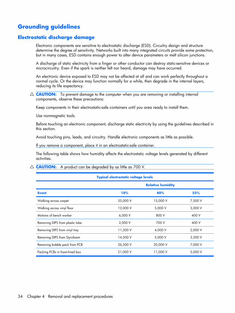
The following table shows how humidity affects the electrostatic voltage levels generated by differentactivities.
CAUTION: A product can be degraded by as little as 700 V.
Typical electrostatic voltage levels
Relative humidity
Event 10% 40% 55%
Walking across carpet 35,000 V 15,000 V 7,500 V
Walking across vinyl floor 12,000 V 5,000 V 3,000 V
Motions of bench worker 6,000 V 800 V 400 V
Removing DIPS from plastic tube 2,000 V 700 V 400 V
Removing DIPS from vinyl tray 11,500 V 4,000 V 2,000 V
Removing DIPS from Styrofoam 14,500 V 5,000 V 3,500 V
Removing bubble pack from PCB 26,500 V 20,000 V 7,000 V
Packing PCBs in foam-lined box 21,000 V 11,000 V 5,000 V
34 Chapter 4 Removal and replacement procedures
Packaging and transporting guidelines
Follow these grounding guidelines when packaging and transporting equipment:
● To avoid hand contact, transport products in static-safe tubes, bags, or boxes.
● Protect ESD-sensitive parts and assemblies with conductive or approved containers or packaging.
● Keep ESD-sensitive parts in their containers until the parts arrive at static-free workstations.
● Place items on a grounded surface before removing items from their containers.
● Always be properly grounded when touching a component or assembly.
● Store reusable ESD-sensitive parts from assemblies in protective packaging or nonconductive foam.
● Use transporters and conveyors made of antistatic belts and roller bushings. Be sure that mechanizedequipment used for moving materials is wired to ground and that proper materials are selected toavoid static charging. When grounding is not possible, use an ionizer to dissipate electric charges.
Workstation guidelines
Follow these grounding workstation guidelines:
● Cover the workstation with approved static-shielding material.
● Use a wrist strap connected to a properly grounded work surface and use properly grounded toolsand equipment.
● Use conductive field service tools, such as cutters, screwdrivers, and vacuums.
● When fixtures must directly contact dissipative surfaces, use fixtures made only of static-safematerials.
● Keep the work area free of nonconductive materials, such as ordinary plastic assembly aids andStyrofoam.
● Handle ESD-sensitive components, parts, and assemblies by the case or PCM laminate. Handle theseitems only at static-free workstations.
● Avoid contact with pins, leads, or circuitry.
● Turn off power and input signals before inserting or removing connectors or test equipment.
Preliminary replacement requirements 35
Equipment guidelines
Grounding equipment must include either a wrist strap or a foot strap at a grounded workstation.
● When seated, wear a wrist strap connected to a grounded system. Wrist straps are flexible strapswith a minimum of one megohm ±10% resistance in the ground cords. To provide proper ground,wear a strap snugly against the skin at all times. On grounded mats with banana-plug connectors,use alligator clips to connect a wrist strap.
● When standing, use foot straps and a grounded floor mat. Foot straps (heel, toe, or boot straps) canbe used at standing workstations and are compatible with most types of shoes or boots. Onconductive floors or dissipative floor mats, use foot straps on both feet with a minimum of one megohmresistance between the operator and ground. To be effective, the conductive strips must be worn incontact with the skin.
The following grounding equipment is recommended to prevent electrostatic damage:
● Antistatic tape
● Antistatic smocks, aprons, and sleeve protectors
● Conductive bins and other assembly or soldering aids
● Nonconductive foam
● Conductive tabletop workstations with ground cords of one megohm resistance
● Static-dissipative tables or floor mats with hard ties to the ground
● Field service kits
● Static awareness labels
● Material-handling packages
● Nonconductive plastic bags, tubes, or boxes
● Metal tote boxes
● Electrostatic voltage levels and protective materials
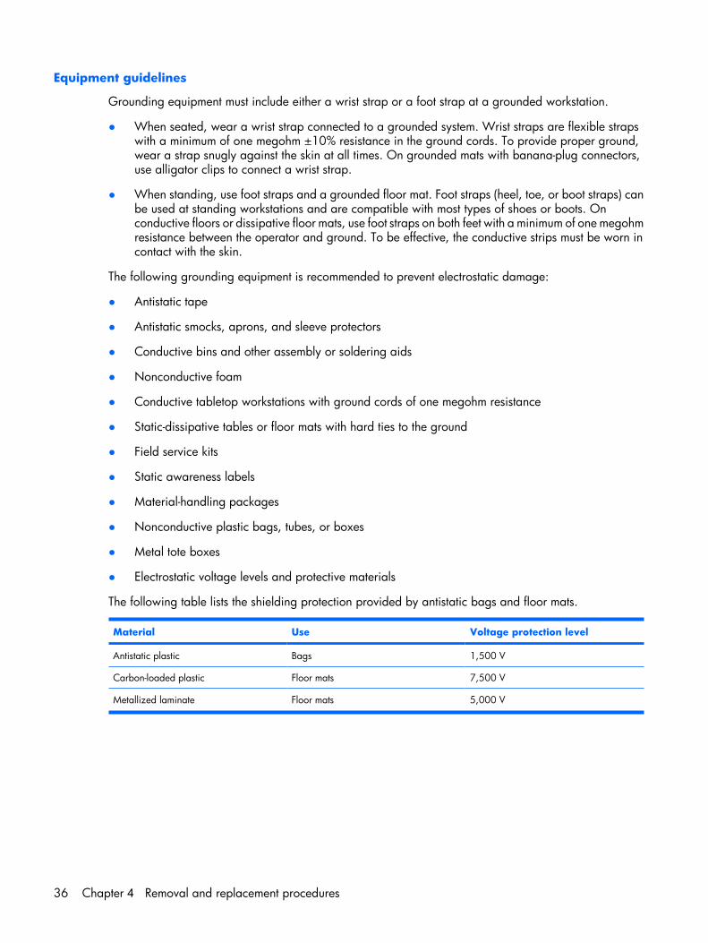
The following table lists the shielding protection provided by antistatic bags and floor mats.
Material Use Voltage protection level
Antistatic plastic Bags 1,500 V
Carbon-loaded plastic Floor mats 7,500 V
Metallized laminate Floor mats 5,000 V
36 Chapter 4 Removal and replacement procedures
Unknown user passwordIf the computer you are servicing has an unknown user password, follow these steps to clear the password.
NOTE: These steps also clear CMOS.
Before disassembling the computer, follow these steps:
1. Shut down the computer. If you are unsure whether the computer is off or in Hibernation, turn thecomputer on, and then shut it down through the operating system.
2. Disconnect all external devices connected to the computer.
3. Disconnect the power from the computer by first unplugging the power cord from the AC outlet andthen unplugging the AC adapter from the computer.
4. Remove the battery (see Battery on page 40).
5. Remove the RTC battery (see RTC battery on page 75).
6. Wait approximately 5 minutes.
7. Replace the RTC battery and reassemble the computer.
8. Connect AC power to the computer. Do not reinsert any batteries at this time.
9. Turn on the computer.
All passwords and all CMOS settings have been cleared.
Preliminary replacement requirements 37
Component replacement proceduresThis chapter provides removal and replacement procedures.
There are as many as 79 screws, in 9 different sizes, that must be removed, replaced, or loosened whenservicing the computer. Make special note of each screw size and location during removal andreplacement.
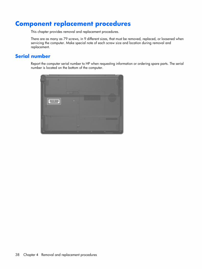
Serial numberReport the computer serial number to HP when requesting information or ordering spare parts. The serialnumber is located on the bottom of the computer.
38 Chapter 4 Removal and replacement procedures
Computer feet
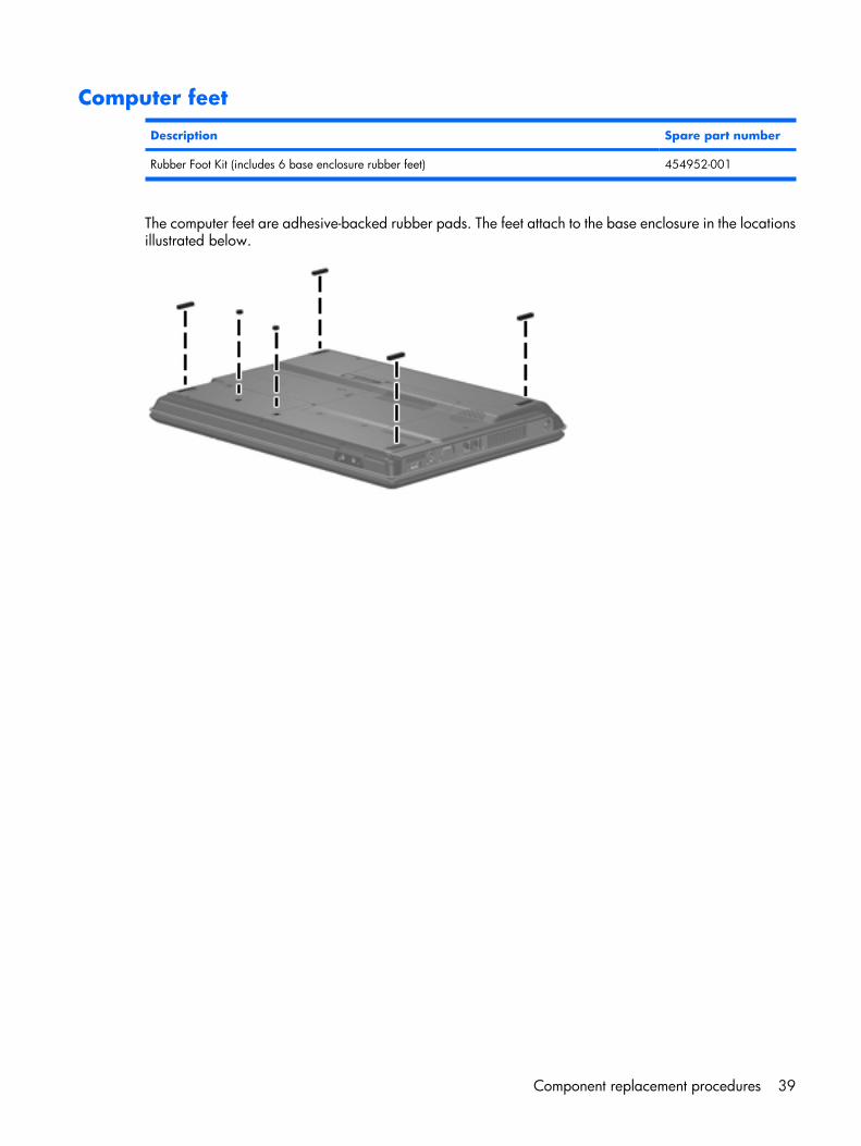
Description Spare part number
Rubber Foot Kit (includes 6 base enclosure rubber feet) 454952-001
The computer feet are adhesive-backed rubber pads. The feet attach to the base enclosure in the locationsillustrated below.
Component replacement procedures 39
Battery
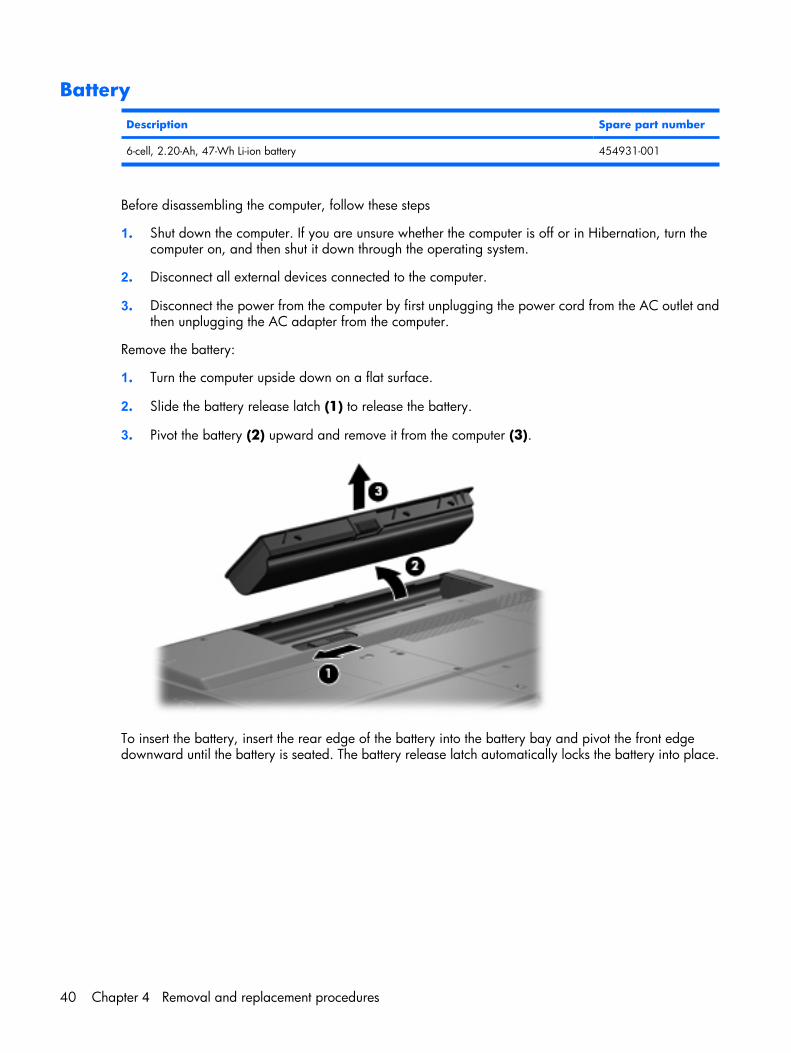
Description Spare part number
6-cell, 2.20-Ah, 47-Wh Li-ion battery 454931-001
Before disassembling the computer, follow these steps
1. Shut down the computer. If you are unsure whether the computer is off or in Hibernation, turn thecomputer on, and then shut it down through the operating system.
2. Disconnect all external devices connected to the computer.
3. Disconnect the power from the computer by first unplugging the power cord from the AC outlet andthen unplugging the AC adapter from the computer.
Remove the battery:
1. Turn the computer upside down on a flat surface.
2. Slide the battery release latch (1) to release the battery.
3. Pivot the battery (2) upward and remove it from the computer (3).
To insert the battery, insert the rear edge of the battery into the battery bay and pivot the front edgedownward until the battery is seated. The battery release latch automatically locks the battery into place.
40 Chapter 4 Removal and replacement procedures
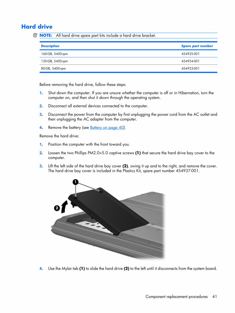
Hard driveNOTE: All hard drive spare part kits include a hard drive bracket.
Description Spare part number
160-GB, 5400-rpm 454925-001
120-GB, 5400-rpm 454924-001
80-GB, 5400-rpm 454923-001
Before removing the hard drive, follow these steps:
1. Shut down the computer. If you are unsure whether the computer is off or in Hibernation, turn thecomputer on, and then shut it down through the operating system.
2. Disconnect all external devices connected to the computer.
3. Disconnect the power from the computer by first unplugging the power cord from the AC outlet andthen unplugging the AC adapter from the computer.
4. Remove the battery (see Battery on page 40).
Remove the hard drive:
1. Position the computer with the front toward you.
2. Loosen the two Phillips PM2.0×5.0 captive screws (1) that secure the hard drive bay cover to thecomputer.
3. Lift the left side of the hard drive bay cover (2), swing it up and to the right, and remove the cover.The hard drive bay cover is included in the Plastics Kit, spare part number 454937-001.
4. Use the Mylar tab (1) to slide the hard drive (2) to the left until it disconnects from the system board.
Component replacement procedures 41
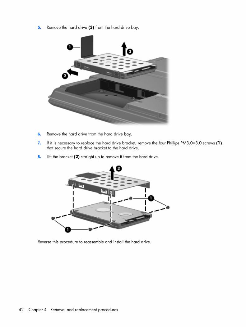
5. Remove the hard drive (3) from the hard drive bay.
6. Remove the hard drive from the hard drive bay.
7. If it is necessary to replace the hard drive bracket, remove the four Phillips PM3.0×3.0 screws (1)that secure the hard drive bracket to the hard drive.
8. Lift the bracket (2) straight up to remove it from the hard drive.
Reverse this procedure to reassemble and install the hard drive.
42 Chapter 4 Removal and replacement procedures
Memory module
Description Spare part number
1024-MB (667-MHz, PC2-5300, DDR2) 454922-001
512-MB (667-MHz, PC2-5300, DDR2) 454920-001
256-MB (667-MHz, PC2-5300, DDR2) 454921-001
Before removing the memory module, follow these steps:
1. Shut down the computer. If you are unsure whether the computer is off or in Hibernation, turn thecomputer on, and then shut it down through the operating system.
2. Disconnect all external devices connected to the computer.
3. Disconnect the power from the computer by first unplugging the power cord from the AC outlet andthen unplugging the AC adapter from the computer.
4. Remove the battery (see Battery on page 40).
Remove the memory module:
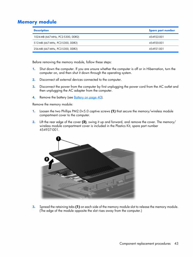
1. Loosen the two Phillips PM2.0×5.0 captive screws (1) that secure the memory/wireless modulecompartment cover to the computer.
2. Lift the rear edge of the cover (2), swing it up and forward, and remove the cover. The memory/wireless module compartment cover is included in the Plastics Kit, spare part number454937-001.
3. Spread the retaining tabs (1) on each side of the memory module slot to release the memory module.(The edge of the module opposite the slot rises away from the computer.)
Component replacement procedures 43
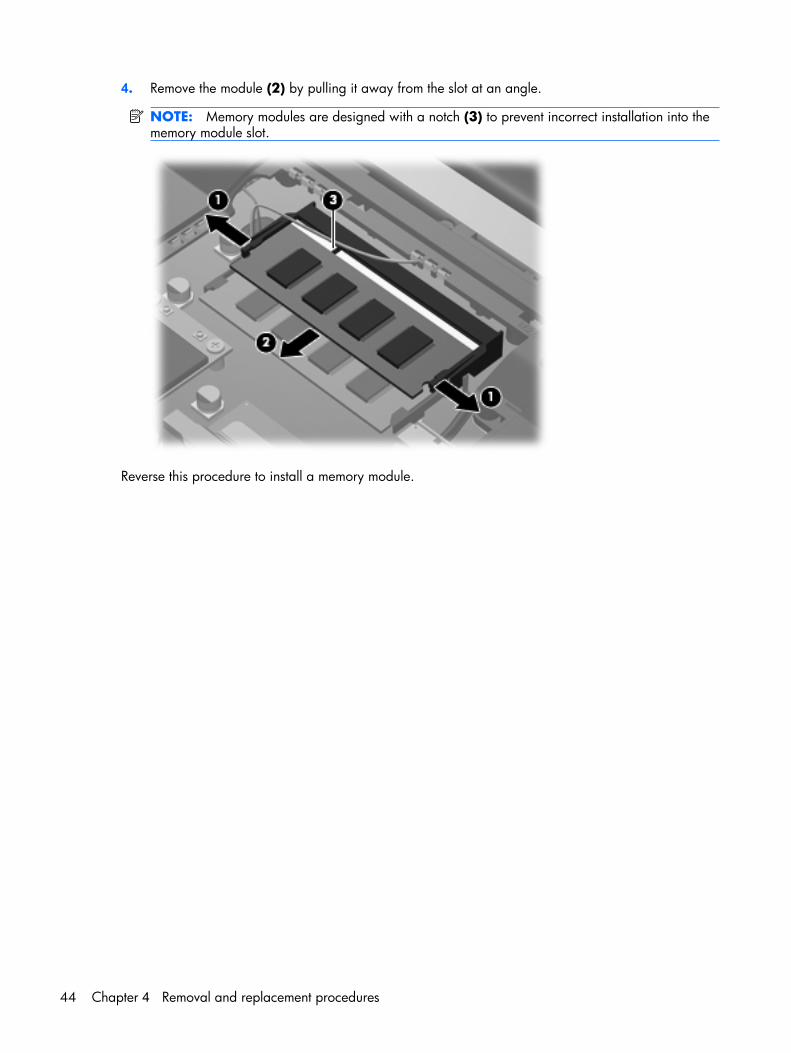
4. Remove the module (2) by pulling it away from the slot at an angle.
NOTE: Memory modules are designed with a notch (3) to prevent incorrect installation into thememory module slot.
Reverse this procedure to install a memory module.
44 Chapter 4 Removal and replacement procedures
WLAN module
Description Spare part number
Broadcom 802.11a/b/g WLAN modules:
● For use in Antigua and Barbuda, Argentina, Australia, the Bahamas, Barbados, Brunei, Canada,Chile, the Dominican Republic, Guam, Guatemala, Hong Kong, India, Indonesia, Malaysia,Mexico, New Zealand, Panama, Paraguay, Saudi Arabia, Taiwan, the United States, andVietnam
441075-001
● For use in Aruba, Austria, Azerbaijan, Bahrain, Belgium, Bermuda, Brazil, Bulgaria, the CaymanIslands, Colombia, Croatia, Cyprus, the Czech Republic, Denmark, Egypt, El Salvador, Estonia,Finland, France, Georgia, Germany, Greece, Hungary, Iceland, Ireland, Italy, Jordan, Latvia,Lebanon, Liechtenstein, Lithuania, Luxembourg, Malta, Monaco, Montenegro, the Netherlands,Norway, Oman, the Philippines, Poland, Portugal, Romania, Russia, Serbia, Singapore,Slovakia, Slovenia, South Africa, Spain, Sri Lanka, Sweden, Switzerland, Turkey, the UnitedKingdom, and Uzbekistan
441075-002
● For use in Japan 441075-291
Intel 802.11a/b/g WLAN modules:
● For use in Antigua and Barbuda, Argentina, Australia, the Bahamas, Barbados, Brunei, Canada,Chile, the Dominican Republic, Guam, Guatemala, Hong Kong, India, Indonesia, Malaysia,Mexico, New Zealand, Panama, Paraguay, Saudi Arabia, Taiwan, the United States, andVietnam
451861-001
● For use in Aruba, Austria, Azerbaijan, Bahrain, Belgium, Bermuda, Brazil, Bulgaria, the CaymanIslands, Colombia, Croatia, Cyprus, the Czech Republic, Denmark, Egypt, El Salvador, Estonia,Finland, France, Georgia, Germany, Greece, Hungary, Iceland, Ireland, Italy, Jordan, Latvia,Lebanon, Liechtenstein, Lithuania, Luxembourg, Malta, Monaco, Montenegro, the Netherlands,Norway, Oman, the Philippines, Poland, Portugal, Romania, Russia, Serbia, Singapore,Slovakia, Slovenia, South Africa, Spain, Sri Lanka, Sweden, Switzerland, Turkey, the UnitedKingdom, and Uzbekistan
451861-002
● For use in Ecuador, Haiti, Honduras, Pakistan, the People's Republic of China, Peru, Qatar, SouthKorea, Uruguay, and Venezuela
451861-003
● For use in Japan 451861-291
Broadcom 802.11b/g WLAN modules:
● For use in Antigua and Barbuda, Argentina, Australia, the Bahamas, Barbados, Brunei, Canada,Chile, the Dominican Republic, Guam, Guatemala, Hong Kong, India, Indonesia, Malaysia,Mexico, New Zealand, Panama, Paraguay, Saudi Arabia, Taiwan, the United States, andVietnam
441090-001
● For use in Aruba, Austria, Azerbaijan, Bahrain, Belgium, Bermuda, Brazil, Bulgaria, the CaymanIslands, Colombia, Croatia, Cyprus, the Czech Republic, Denmark, Egypt, El Salvador, Estonia,Finland, France, Georgia, Germany, Greece, Hungary, Iceland, Ireland, Italy, Jordan, Latvia,Lebanon, Liechtenstein, Lithuania, Luxembourg, Malta, Monaco, Montenegro, the Netherlands,Norway, Oman, the Philippines, Poland, Portugal, Romania, Russia, Serbia, Singapore,Slovakia, Slovenia, South Africa, Spain, Sri Lanka, Sweden, Switzerland, Turkey, the UnitedKingdom, and Uzbekistan
441090-002
● For use in Japan 441090-291
802.11b/g WLAN module for use in Thailand 451861-004
Atheros AR2425 802.11b/g WLAN module:
● For use in Albania, Algeria, Andorra, Angola, Antigua & Barbuda, Afghanistan, Syria, NetherAntilles, Argentina, Armenia, Australia, Austria, Azerbaijan, Bahamas, Bahrain, Bangladesh,Barbados, Belarus, Belgium, Belize, Benin, Bhutan, Bolivia, Bosnia & Herzegovina, Botswana,Brazil, Brunei, Bulgaria, Burkina Faso, Burundi, Cambodia, Cameroon, Cape Verde, Central
459339-002
Component replacement procedures 45
Description Spare part number
African Republic, Chad, Chile, Colombia, Comoros, Congo, Costa Rica, Croatia, Cyprus, CzechRepublic, Zaire, Denmark, Djibouti, Dominica, Dominican Republic, East Timor, Ecuador, Egypt,El Salvador, Equitorial Guinea, Eritrea, Estonia, Ethiopia, Fiji, Finland, France, Gabon, Gambia,Georgia, Germany, Ghana, Gibraltar, Greece, Grenada, Guatemala, Guinea, Guinea-Bissau,Guyana, Haiti, Honduras, Hong Kong, Hungary, Iceland, India, Indonesia, Ireland, Israel, Italy,Ivory Coast, Jamaica, Japan, Jordan, Kazakhstan, Kenya, Kiribati, South Kuwait, Kyrgyzstan,Laos, Latvia, Lebanon, Lesotho, Liberia, Martinique, Guadeloupe, Bermuda, French Guiana,Aruba, British Virgin Islands, Liechtenstein, Lithuania, Luxembourg, Macedonia, Madagascar,Malawi, Malaysia, Maldives, Mali, Malta, Marshall Islands, Mauritania, Mauritius, Mexico,Micronesia, Monaco, Mongolia, Montenegro, Morocco, Mozambique, Namibia, Nauru,Nepal, Netherlands, New Zealand, Nicaragua, Niger, Nigeria, Norway, Oman, Pakistan,Palau, Panama, Papua, New Guinea, Paraguay, People's Republic of China, Peru, Philippines,Poland, Portugal, Qatar, Republic of Moldova, Romania, Russia, Rwanda, Samoa, San Marino,Sao Tome & Principe, Saudi Arabia, Senegal, Serbia, Seychelles, Sierra Leone, Singapore,Slovakia, Slovenia, Solomon Islands, Somalia, South Africa, South Korea, Spain, Sri Lanka, St.Kitts & Nevis, St. Lucia, St. Vincent and the Grenadines, Suriname, Swaziland, Sweden,Switzerland, Taiwan, Tajikistan, Tanzania, Thailand, Togo, Tonga, Trinidad & Tobago, Tunisia,Turkey, Turkmenistan, Tuvalu, Uganda, Ukraine, United Arab Emirates, United Kingdom,Uruguay, Uzbekistan, Vanuatu, Venezuela, Vietnam, Yemen, Zambia, Zimbabwe
CAUTION: To prevent an unresponsive system, replace the wireless module only with a wireless moduleauthorized for use in the computer by the governmental agency that regulates wireless devices in yourcountry or region. If you replace the module and then receive a warning message, remove the module torestore computer functionality, and then contact technical support through Help and Support.
Before removing the WLAN module, follow these steps:
1. Shut down the computer. If you are unsure whether the computer is off or in Hibernation, turn thecomputer on, and then shut it down through the operating system.
2. Disconnect all external devices connected to the computer.
3. Disconnect the power from the computer by first unplugging the power cord from the AC outlet andthen unplugging the AC adapter from the computer.
4. Remove the battery (see Battery on page 40).
5. Remove the hard drive bay cover (see Hard drive on page 41).
Remove the WLAN module:
1. Position the computer with the front toward you.
2. Disconnect the two WLAN antenna cables (1) from the WLAN module.
NOTE: The black WLAN antenna cable is connected to the WLAN module “Main” terminal. Thewhite WLAN antenna cable is connected to the WLAN module “Aux” terminal.
3. Remove the two Phillips PM2.0×4.0 screws (2) that secure the WLAN module to the computer. (Theedge of the module opposite the slot rises away from the computer.)
46 Chapter 4 Removal and replacement procedures
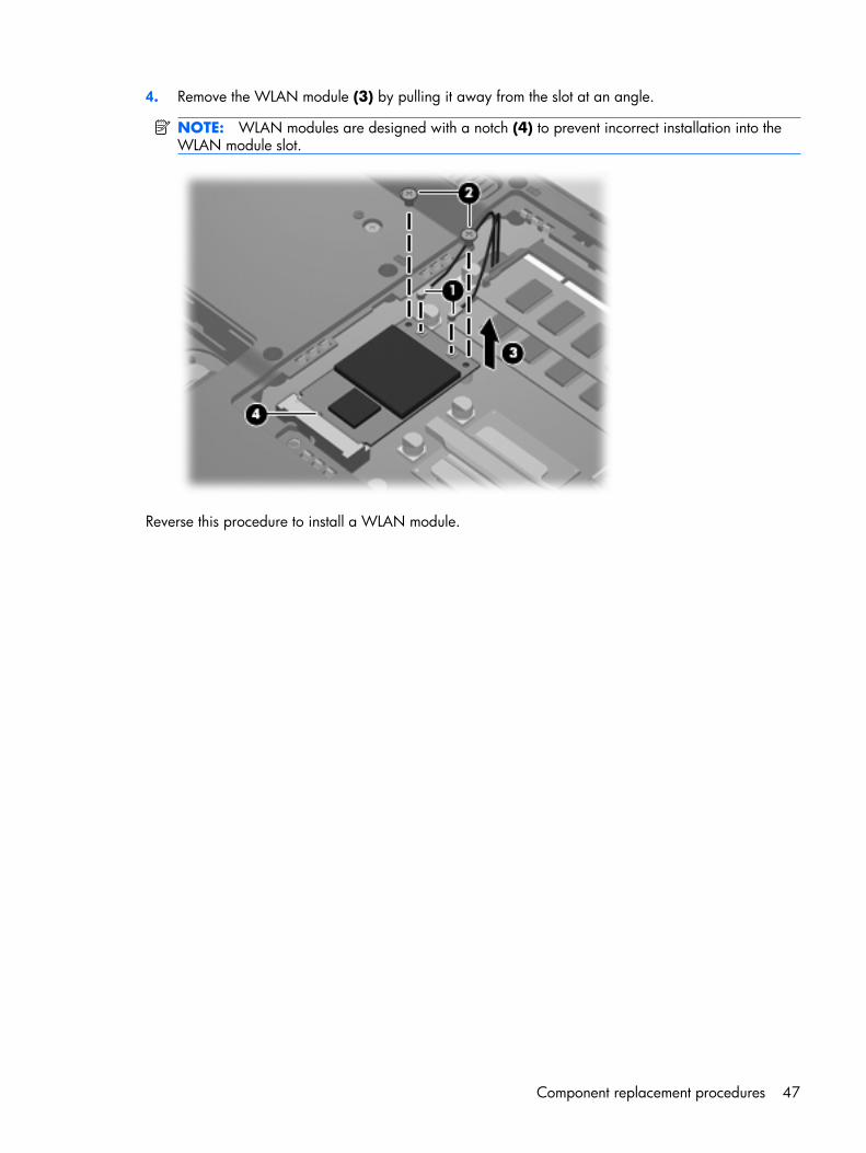
4. Remove the WLAN module (3) by pulling it away from the slot at an angle.
NOTE: WLAN modules are designed with a notch (4) to prevent incorrect installation into theWLAN module slot.
Reverse this procedure to install a WLAN module.
Component replacement procedures 47
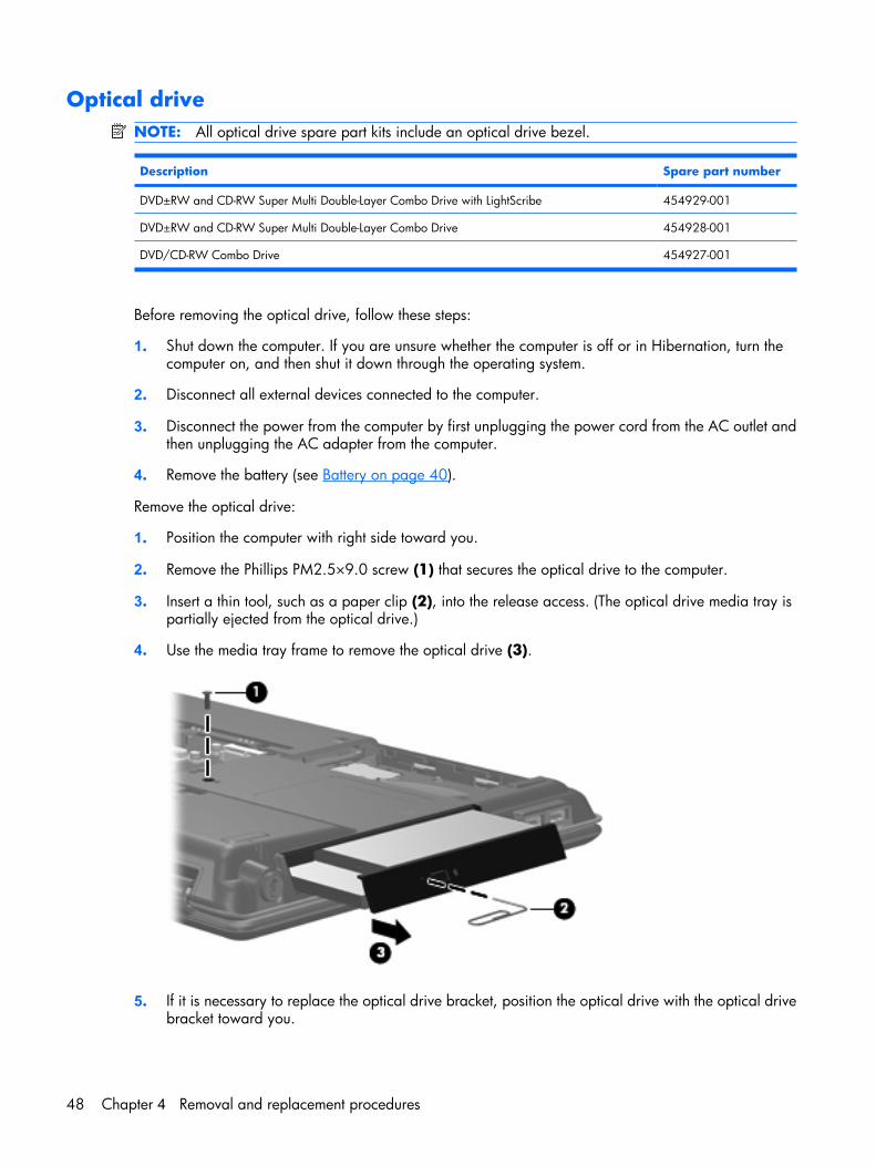
Optical driveNOTE: All optical drive spare part kits include an optical drive bezel.
Description Spare part number
DVD±RW and CD-RW Super Multi Double-Layer Combo Drive with LightScribe 454929-001
DVD±RW and CD-RW Super Multi Double-Layer Combo Drive 454928-001
DVD/CD-RW Combo Drive 454927-001
Before removing the optical drive, follow these steps:
1. Shut down the computer. If you are unsure whether the computer is off or in Hibernation, turn thecomputer on, and then shut it down through the operating system.
2. Disconnect all external devices connected to the computer.
3. Disconnect the power from the computer by first unplugging the power cord from the AC outlet andthen unplugging the AC adapter from the computer.
4. Remove the battery (see Battery on page 40).
Remove the optical drive:
1. Position the computer with right side toward you.
2. Remove the Phillips PM2.5×9.0 screw (1) that secures the optical drive to the computer.
3. Insert a thin tool, such as a paper clip (2), into the release access. (The optical drive media tray ispartially ejected from the optical drive.)
4. Use the media tray frame to remove the optical drive (3).
5. If it is necessary to replace the optical drive bracket, position the optical drive with the optical drivebracket toward you.
48 Chapter 4 Removal and replacement procedures
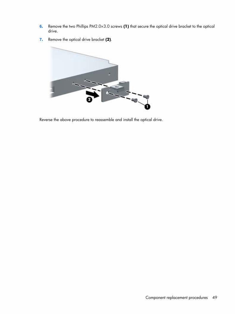
6. Remove the two Phillips PM2.0×3.0 screws (1) that secure the optical drive bracket to the opticaldrive.
7. Remove the optical drive bracket (2).
Reverse the above procedure to reassemble and install the optical drive.
Component replacement procedures 49
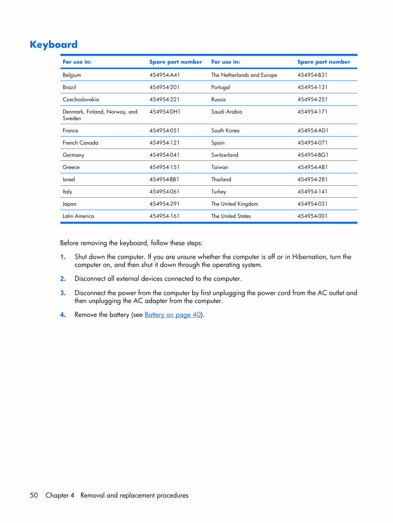
Keyboard
For use in: Spare part number For use in: Spare part number
Belgium 454954-A41 The Netherlands and Europe 454954-B31
Brazil 454954-201 Portugal 454954-131
Czechoslovakia 454954-221 Russia 454954-251
Denmark, Finland, Norway, andSweden
454954-DH1 Saudi Arabia 454954-171
France 454954-051 South Korea 454954-AD1
French Canada 454954-121 Spain 454954-071
Germany 454954-041 Switzerland 454954-BG1
Greece 454954-151 Taiwan 454954-AB1
Israel 454954-BB1 Thailand 454954-281
Italy 454954-061 Turkey 454954-141
Japan 454954-291 The United Kingdom 454954-031
Latin America 454954-161 The United States 454954-001
Before removing the keyboard, follow these steps:
1. Shut down the computer. If you are unsure whether the computer is off or in Hibernation, turn thecomputer on, and then shut it down through the operating system.
2. Disconnect all external devices connected to the computer.
3. Disconnect the power from the computer by first unplugging the power cord from the AC outlet andthen unplugging the AC adapter from the computer.
4. Remove the battery (see Battery on page 40).
50 Chapter 4 Removal and replacement procedures
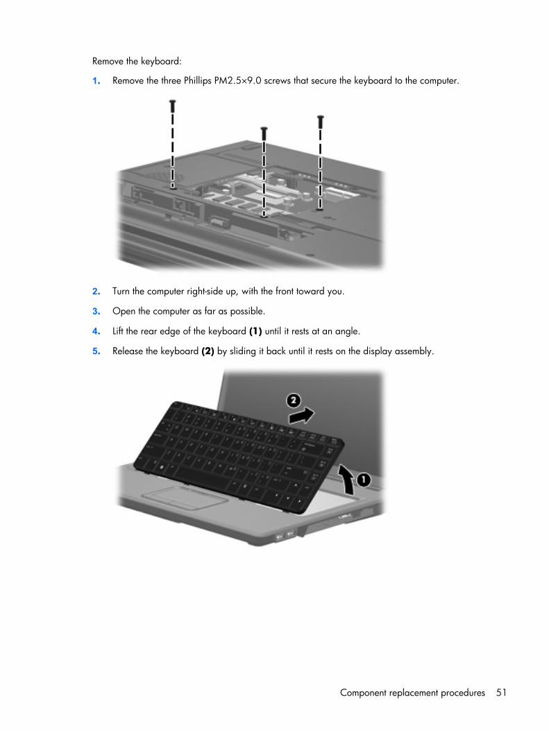
Remove the keyboard:
1. Remove the three Phillips PM2.5×9.0 screws that secure the keyboard to the computer.
2. Turn the computer right-side up, with the front toward you.
3. Open the computer as far as possible.
4. Lift the rear edge of the keyboard (1) until it rests at an angle.
5. Release the keyboard (2) by sliding it back until it rests on the display assembly.
Component replacement procedures 51
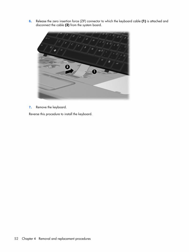
6. Release the zero insertion force (ZIF) connector to which the keyboard cable (1) is attached anddisconnect the cable (2) from the system board.
7. Remove the keyboard.
Reverse this procedure to install the keyboard.
52 Chapter 4 Removal and replacement procedures
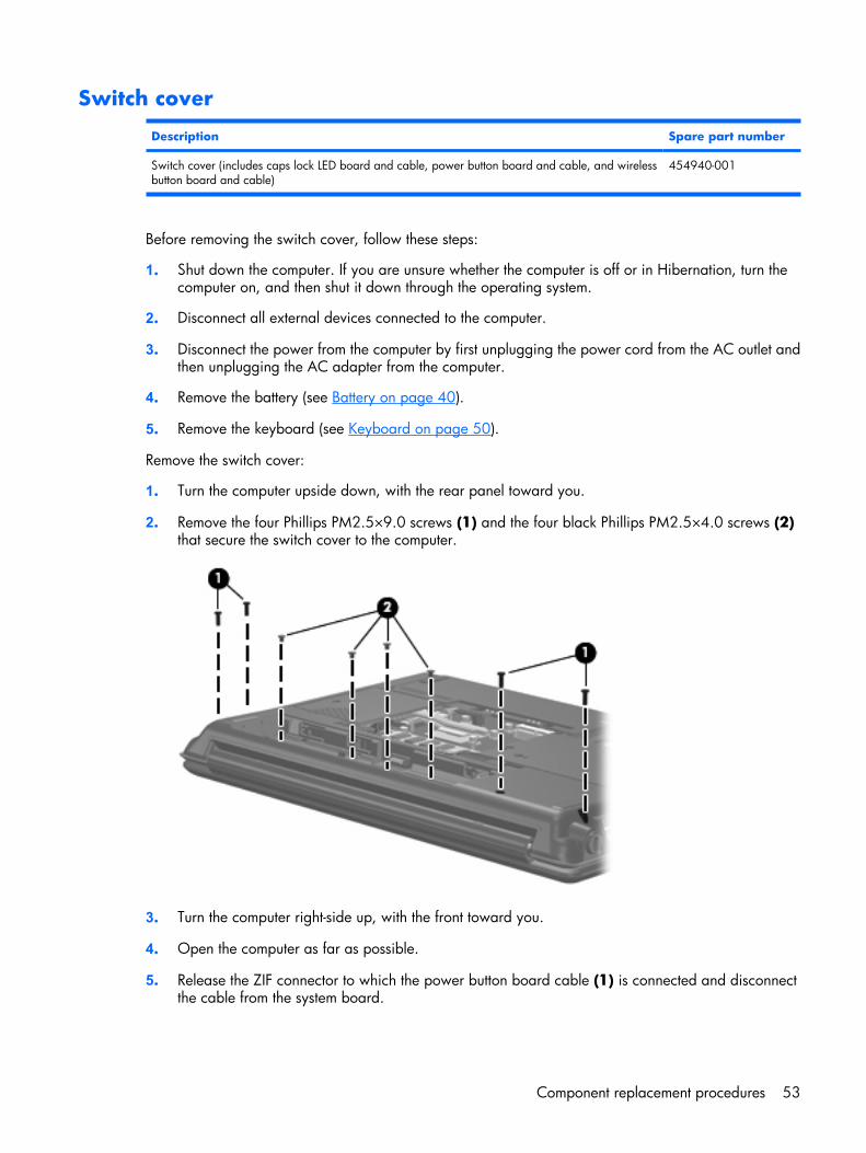
Switch cover
Description Spare part number
Switch cover (includes caps lock LED board and cable, power button board and cable, and wirelessbutton board and cable)
454940-001
Before removing the switch cover, follow these steps:
1. Shut down the computer. If you are unsure whether the computer is off or in Hibernation, turn thecomputer on, and then shut it down through the operating system.
2. Disconnect all external devices connected to the computer.
3. Disconnect the power from the computer by first unplugging the power cord from the AC outlet andthen unplugging the AC adapter from the computer.
4. Remove the battery (see Battery on page 40).
5. Remove the keyboard (see Keyboard on page 50).
Remove the switch cover:
1. Turn the computer upside down, with the rear panel toward you.
2. Remove the four Phillips PM2.5×9.0 screws (1) and the four black Phillips PM2.5×4.0 screws (2)that secure the switch cover to the computer.
3. Turn the computer right-side up, with the front toward you.
4. Open the computer as far as possible.
5. Release the ZIF connector to which the power button board cable (1) is connected and disconnectthe cable from the system board.
Component replacement procedures 53
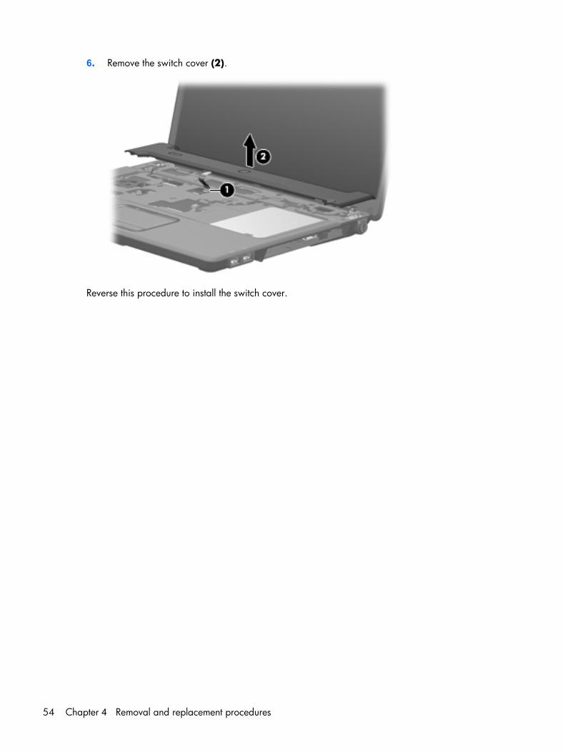
6. Remove the switch cover (2).
Reverse this procedure to install the switch cover.
54 Chapter 4 Removal and replacement procedures
Display assembly
Description Spare part number
For use only with HP G7000 computer models:
15.4-inch, WSXGA+BrightView display assembly without a camera 454932-001
15.4-inch, WSXGA+BrightView display assembly with a camera 462455-001
For use only with Compaq Presario C700 computer models:
15.4-inch, WSXGA+BrightView display assembly without a camera 454934-001
15.4-inch, WSXGA+BrightView display assembly with a camera 462456-001
Before removing the display assembly, follow these steps:
1. Shut down the computer. If you are unsure whether the computer is off or in Hibernation, turn thecomputer on, and then shut it down through the operating system.
2. Disconnect all external devices connected to the computer.
3. Disconnect the power from the computer by first unplugging the power cord from the AC outlet andthen unplugging the AC adapter from the computer.
4. Remove the battery (see Battery on page 40).
5. Disconnect the wireless antenna cables from the WLAN module (see WLAN module on page 45).
6. Remove the keyboard (see Keyboard on page 50).
7. Remove the switch cover (see Switch cover on page 53).
Remove the display assembly:
1. Disconnect the display panel cable (1) from the system board and remove the cable from theclips (2) and routing channel built into the top cover.
2. Disconnect the microphone cable (3) from the system board .
Component replacement procedures 55
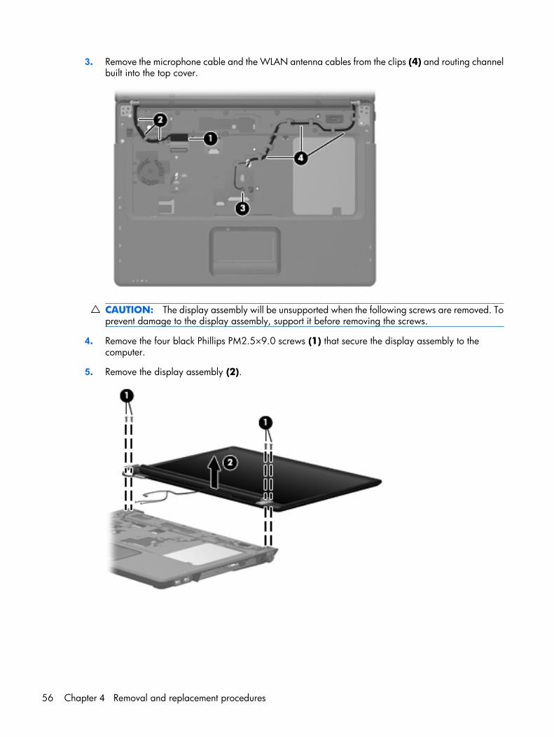
3. Remove the microphone cable and the WLAN antenna cables from the clips (4) and routing channelbuilt into the top cover.
CAUTION: The display assembly will be unsupported when the following screws are removed. Toprevent damage to the display assembly, support it before removing the screws.
4. Remove the four black Phillips PM2.5×9.0 screws (1) that secure the display assembly to thecomputer.
5. Remove the display assembly (2).
56 Chapter 4 Removal and replacement procedures
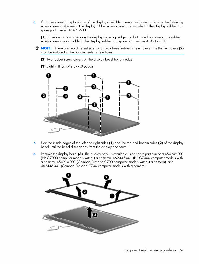
6. If it is necessary to replace any of the display assembly internal components, remove the followingscrew covers and screws. The display rubber screw covers are included in the Display Rubber Kit,spare part number 454917-001.
(1) Six rubber screw covers on the display bezel top edge and bottom edge corners. The rubberscrew covers are available in the Display Rubber Kit, spare part number 454917-001.
NOTE: There are two different sizes of display bezel rubber screw covers. The thicker covers (2)must be installed in the bottom center screw holes.
(2) Two rubber screw covers on the display bezel bottom edge.
(3) Eight Phillips PM2.5×7.0 screws.
7. Flex the inside edges of the left and right sides (1) and the top and bottom sides (2) of the displaybezel until the bezel disengages from the display enclosure.
8. Remove the display bezel (3). The display bezel is available using spare part numbers 454909-001(HP G7000 computer models without a camera), 462445-001 (HP G7000 computer models witha camera, 454910-001 (Compaq Presario C700 computer models without a camera), and462446-001 (Compaq Presario C700 computer models with a camera).
Component replacement procedures 57
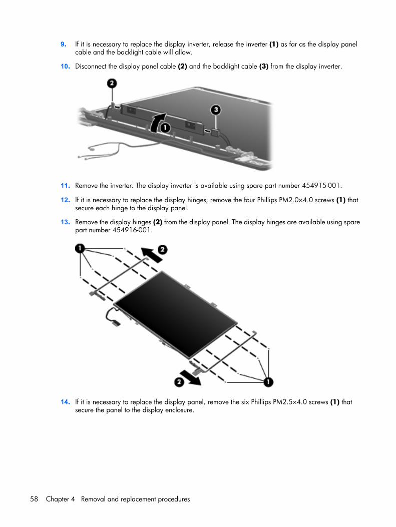
9. If it is necessary to replace the display inverter, release the inverter (1) as far as the display panelcable and the backlight cable will allow.
10. Disconnect the display panel cable (2) and the backlight cable (3) from the display inverter.
11. Remove the inverter. The display inverter is available using spare part number 454915-001.
12. If it is necessary to replace the display hinges, remove the four Phillips PM2.0×4.0 screws (1) thatsecure each hinge to the display panel.
13. Remove the display hinges (2) from the display panel. The display hinges are available using sparepart number 454916-001.
14. If it is necessary to replace the display panel, remove the six Phillips PM2.5×4.0 screws (1) thatsecure the panel to the display enclosure.
58 Chapter 4 Removal and replacement procedures
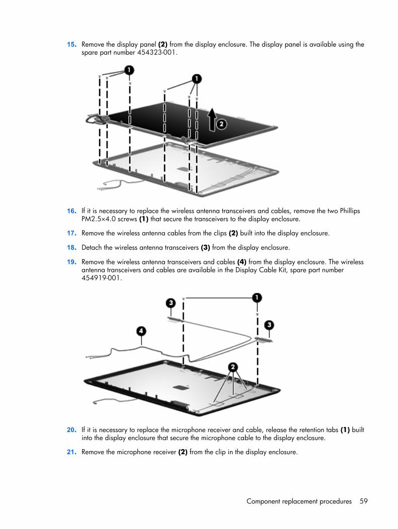
15. Remove the display panel (2) from the display enclosure. The display panel is available using thespare part number 454323-001.
16. If it is necessary to replace the wireless antenna transceivers and cables, remove the two PhillipsPM2.5×4.0 screws (1) that secure the transceivers to the display enclosure.
17. Remove the wireless antenna cables from the clips (2) built into the display enclosure.
18. Detach the wireless antenna transceivers (3) from the display enclosure.
19. Remove the wireless antenna transceivers and cables (4) from the display enclosure. The wirelessantenna transceivers and cables are available in the Display Cable Kit, spare part number454919-001.
20. If it is necessary to replace the microphone receiver and cable, release the retention tabs (1) builtinto the display enclosure that secure the microphone cable to the display enclosure.
21. Remove the microphone receiver (2) from the clip in the display enclosure.
Component replacement procedures 59
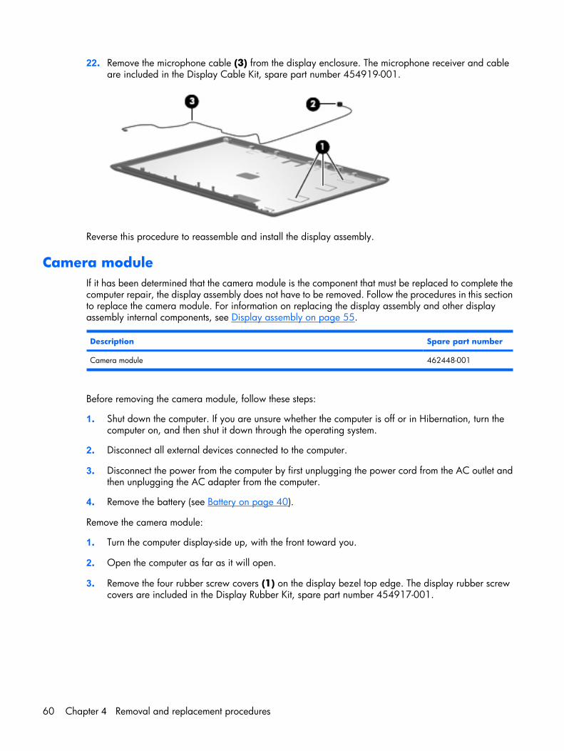
22. Remove the microphone cable (3) from the display enclosure. The microphone receiver and cableare included in the Display Cable Kit, spare part number 454919-001.
Reverse this procedure to reassemble and install the display assembly.
Camera moduleIf it has been determined that the camera module is the component that must be replaced to complete thecomputer repair, the display assembly does not have to be removed. Follow the procedures in this sectionto replace the camera module. For information on replacing the display assembly and other displayassembly internal components, see Display assembly on page 55.
Description Spare part number
Camera module 462448-001
Before removing the camera module, follow these steps:
1. Shut down the computer. If you are unsure whether the computer is off or in Hibernation, turn thecomputer on, and then shut it down through the operating system.
2. Disconnect all external devices connected to the computer.
3. Disconnect the power from the computer by first unplugging the power cord from the AC outlet andthen unplugging the AC adapter from the computer.
4. Remove the battery (see Battery on page 40).
Remove the camera module:
1. Turn the computer display-side up, with the front toward you.
2. Open the computer as far as it will open.
3. Remove the four rubber screw covers (1) on the display bezel top edge. The display rubber screwcovers are included in the Display Rubber Kit, spare part number 454917-001.
60 Chapter 4 Removal and replacement procedures
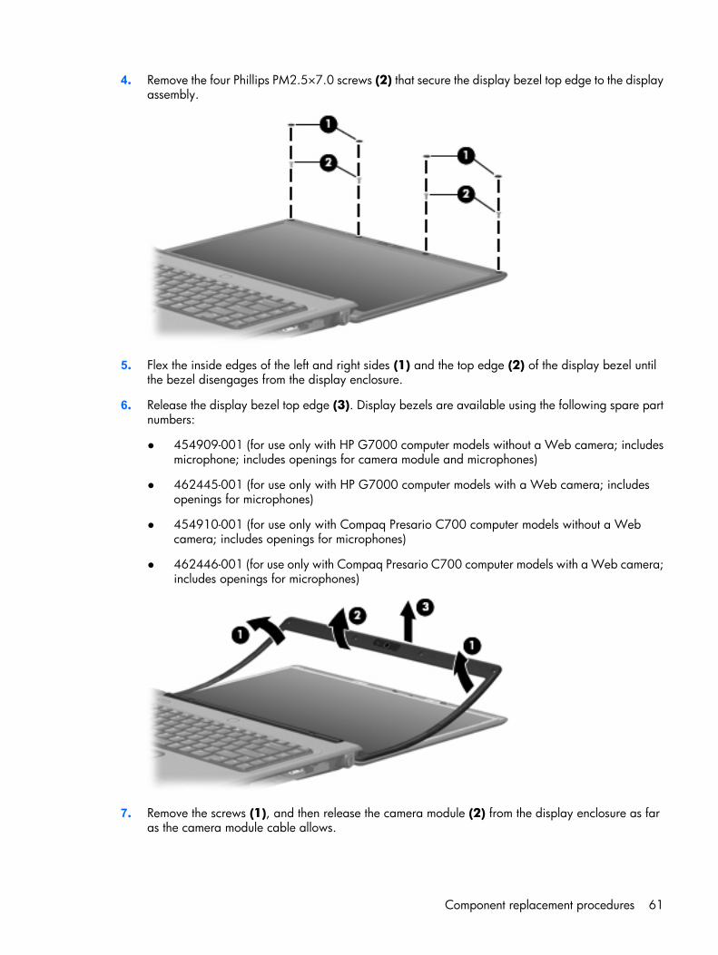
4. Remove the four Phillips PM2.5×7.0 screws (2) that secure the display bezel top edge to the displayassembly.
5. Flex the inside edges of the left and right sides (1) and the top edge (2) of the display bezel untilthe bezel disengages from the display enclosure.
6. Release the display bezel top edge (3). Display bezels are available using the following spare partnumbers:
● 454909-001 (for use only with HP G7000 computer models without a Web camera; includesmicrophone; includes openings for camera module and microphones)
● 462445-001 (for use only with HP G7000 computer models with a Web camera; includesopenings for microphones)
● 454910-001 (for use only with Compaq Presario C700 computer models without a Webcamera; includes openings for microphones)
● 462446-001 (for use only with Compaq Presario C700 computer models with a Web camera;includes openings for microphones)
7. Remove the screws (1), and then release the camera module (2) from the display enclosure as faras the camera module cable allows.
Component replacement procedures 61
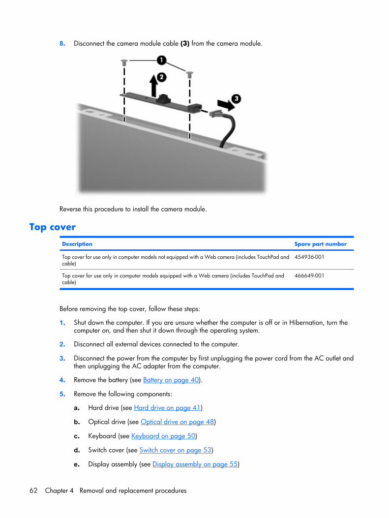
8. Disconnect the camera module cable (3) from the camera module.
Reverse this procedure to install the camera module.
Top cover
Description Spare part number
Top cover for use only in computer models not equipped with a Web camera (includes TouchPad andcable)
454936-001
Top cover for use only in computer models equipped with a Web camera (includes TouchPad andcable)
466649-001
Before removing the top cover, follow these steps:
1. Shut down the computer. If you are unsure whether the computer is off or in Hibernation, turn thecomputer on, and then shut it down through the operating system.
2. Disconnect all external devices connected to the computer.
3. Disconnect the power from the computer by first unplugging the power cord from the AC outlet andthen unplugging the AC adapter from the computer.
4. Remove the battery (see Battery on page 40).
5. Remove the following components:
a. Hard drive (see Hard drive on page 41)
b. Optical drive (see Optical drive on page 48)
c. Keyboard (see Keyboard on page 50)
d. Switch cover (see Switch cover on page 53)
e. Display assembly (see Display assembly on page 55)
62 Chapter 4 Removal and replacement procedures
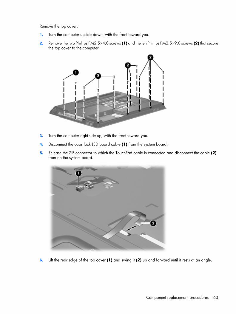
Remove the top cover:
1. Turn the computer upside down, with the front toward you.
2. Remove the two Phillips PM2.5×4.0 screws (1) and the ten Phillips PM2.5×9.0 screws (2) that securethe top cover to the computer.
3. Turn the computer right-side up, with the front toward you.
4. Disconnect the caps lock LED board cable (1) from the system board.
5. Release the ZIF connector to which the TouchPad cable is connected and disconnect the cable (2)from on the system board.
6. Lift the rear edge of the top cover (1) and swing it (2) up and forward until it rests at an angle.
Component replacement procedures 63
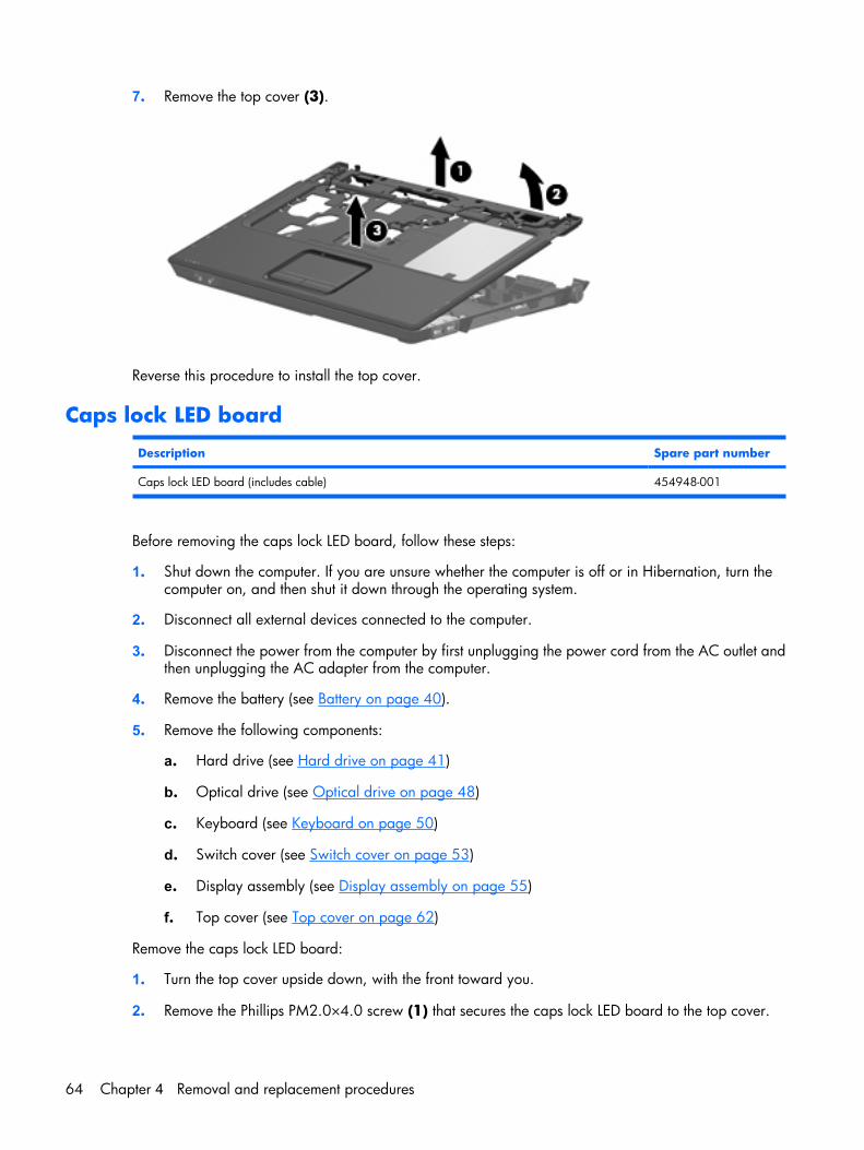
7. Remove the top cover (3).
Reverse this procedure to install the top cover.
Caps lock LED board
Description Spare part number
Caps lock LED board (includes cable) 454948-001
Before removing the caps lock LED board, follow these steps:
1. Shut down the computer. If you are unsure whether the computer is off or in Hibernation, turn thecomputer on, and then shut it down through the operating system.
2. Disconnect all external devices connected to the computer.
3. Disconnect the power from the computer by first unplugging the power cord from the AC outlet andthen unplugging the AC adapter from the computer.
4. Remove the battery (see Battery on page 40).
5. Remove the following components:
a. Hard drive (see Hard drive on page 41)
b. Optical drive (see Optical drive on page 48)
c. Keyboard (see Keyboard on page 50)
d. Switch cover (see Switch cover on page 53)
e. Display assembly (see Display assembly on page 55)
f. Top cover (see Top cover on page 62)
Remove the caps lock LED board:
1. Turn the top cover upside down, with the front toward you.
2. Remove the Phillips PM2.0×4.0 screw (1) that secures the caps lock LED board to the top cover.
64 Chapter 4 Removal and replacement procedures
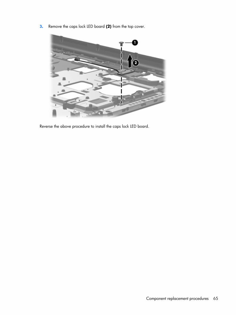
3. Remove the caps lock LED board (2) from the top cover.
Reverse the above procedure to install the caps lock LED board.
Component replacement procedures 65
USB board
Description Spare part number
USB board (includes USB board cable) 454941-001
Before removing the USB board, follow these steps:
1. Shut down the computer. If you are unsure whether the computer is off or in Hibernation, turn thecomputer on, and then shut it down through the operating system.
2. Disconnect all external devices connected to the computer.
3. Disconnect the power from the computer by first unplugging the power cord from the AC outlet andthen unplugging the AC adapter from the computer.
4. Remove the battery (see Battery on page 40).
5. Remove the following components:
a. Hard drive (see Hard drive on page 41)
b. Optical drive (see Optical drive on page 48)
c. Keyboard (see Keyboard on page 50)
d. Switch cover (see Switch cover on page 53)
e. Display assembly (see Display assembly on page 55)
f. Top cover (see Top cover on page 62)
Remove the USB board:
1. Disconnect the USB board cable (1) from the system board.
2. Remove the Phillips PM2.5×4.0 screw (2) that secures the USB board to the base enclosure.
66 Chapter 4 Removal and replacement procedures
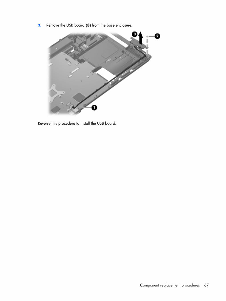
3. Remove the USB board (3) from the base enclosure.
Reverse this procedure to install the USB board.
Component replacement procedures 67
Fan
Description Spare part number
Fan 454944-001
NOTE: To properly ventilate the computer, allow at least a 7.6-cm (3-inch) clearance on the left side ofthe computer. The computer uses an electric fan for ventilation. The fan is controlled by a temperaturesensor and is designed to turn on automatically when high temperature conditions exist. These conditionsare affected by high external temperatures, system power consumption, power management/batteryconservation configurations, battery fast charging, and software requirements. Exhaust air is displacedthrough the ventilation grill located on the left side of the computer.
Before removing the fan, follow these steps:
1. Shut down the computer. If you are unsure whether the computer is off or in Hibernation, turn thecomputer on, and then shut it down through the operating system.
2. Disconnect all external devices connected to the computer.
3. Disconnect the power from the computer by first unplugging the power cord from the AC outlet andthen unplugging the AC adapter from the computer.
4. Remove the battery (see Battery on page 40).
5. Remove the following components:
a. Hard drive (see Hard drive on page 41)
b. Optical drive (see Optical drive on page 48)
c. Keyboard (see Keyboard on page 50)
d. Switch cover (see Switch cover on page 53)
e. Display assembly (see Display assembly on page 55)
f. Top cover (see Top cover on page 62)
Remove the fan:
1. Disconnect the fan cable (1) from the system board.
2. Remove the Phillips PM2.0×9.0 screw (2) that secures the fan to the base enclosure.
68 Chapter 4 Removal and replacement procedures
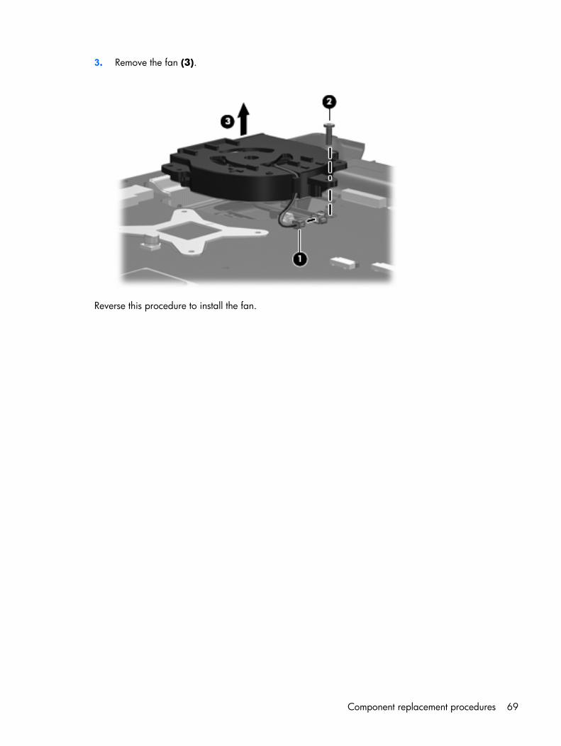
3. Remove the fan (3).
Reverse this procedure to install the fan.
Component replacement procedures 69
Speakers
Description Spare part number
Speakers 454946-001
Before removing the speakers, follow these steps:
1. Shut down the computer. If you are unsure whether the computer is off or in Hibernation, turn thecomputer on, and then shut it down through the operating system.
2. Disconnect all external devices connected to the computer.
3. Disconnect the power from the computer by first unplugging the power cord from the AC outlet andthen unplugging the AC adapter from the computer.
4. Remove the battery (see Battery on page 40).
5. Remove the following components:
a. Hard drive (see Hard drive on page 41)
b. Optical drive (see Optical drive on page 48)
c. Keyboard (see Keyboard on page 50)
d. Switch cover (see Switch cover on page 53)
e. Display assembly (see Display assembly on page 55)
f. Top cover (see Top cover on page 62)
Remove the speakers:
1. Disconnect the speaker cable (1) from the system board.
2. Remove the speaker cables (2) from the clip in the system board and the clips built into the baseenclosure.
3. Remove the two Phillips PM2.5×4.0 screws (3) that secure the speakers to the base enclosure.
70 Chapter 4 Removal and replacement procedures
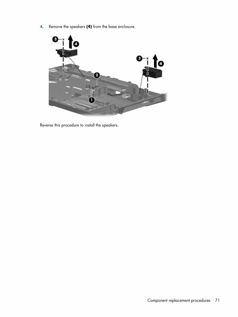
4. Remove the speakers (4) from the base enclosure.
Reverse this procedure to install the speakers.
Component replacement procedures 71
System boardNOTE: All system board spare part kits include replacement thermal material.
Description Spare part number
For use in computer models not equipped with a Web camera:
● For use only with computer models equipped with Intel Core 2 Duo and Core Duo processorsand a card reader board
453494-001
● For use only with computer models equipped with Intel Core 2 Duo and Core Duo processors,but not a card reader board
454882-001
● For use only with computer models equipped with Intel Celeron M processors and a card readerboard
453495-001
● For use only with computer models equipped with Intel Celeron M processors, but not a cardreader board
454883-001
For use in computer models equipped with a Web camera:
● Equipped with Intel Core 2 Duo and Core Duo processors and a card reader board 462439-001
● Equipped with Intel Core 2 Duo and Core Duo processors, but not a card reader board 462441-001
● Equipped with Intel Celeron M processors and a card reader board 462440-001
● Equipped with Intel Celeron M processors, but not a card reader board 462442-001
Before removing the system board, follow these steps:
1. Shut down the computer. If you are unsure whether the computer is off or in Hibernation, turn thecomputer on, and then shut it down through the operating system.
2. Disconnect all external devices connected to the computer.
3. Disconnect the power from the computer by first unplugging the power cord from the AC outlet andthen unplugging the AC adapter from the computer.
4. Remove the battery (see Battery on page 40).
5. Remove the following components:
a. Hard drive (see Hard drive on page 41)
b. Optical drive (see Optical drive on page 48)
c. Keyboard (see Keyboard on page 50)
d. Switch cover (see Switch cover on page 53)
e. Display assembly (see Display assembly on page 55)
f. Top cover (see Top cover on page 62)
72 Chapter 4 Removal and replacement procedures
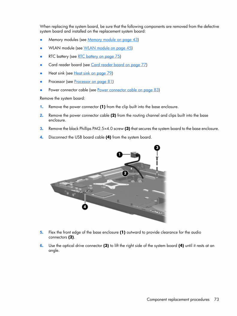
When replacing the system board, be sure that the following components are removed from the defectivesystem board and installed on the replacement system board:
● Memory modules (see Memory module on page 43)
● WLAN module (see WLAN module on page 45)
● RTC battery (see RTC battery on page 75)
● Card reader board (see Card reader board on page 77)
● Heat sink (see Heat sink on page 79)
● Processor (see Processor on page 81)
● Power connector cable (see Power connector cable on page 83)
Remove the system board:
1. Remove the power connector (1) from the clip built into the base enclosure.
2. Remove the power connector cable (2) from the routing channel and clips built into the baseenclosure.
3. Remove the black Phillips PM2.5×4.0 screw (3) that secures the system board to the base enclosure.
4. Disconnect the USB board cable (4) from the system board.
5. Flex the front edge of the base enclosure (1) outward to provide clearance for the audioconnectors (2).
6. Use the optical drive connector (3) to lift the right side of the system board (4) until it rests at anangle.
Component replacement procedures 73
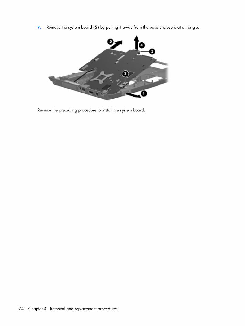
7. Remove the system board (5) by pulling it away from the base enclosure at an angle.
Reverse the preceding procedure to install the system board.
74 Chapter 4 Removal and replacement procedures
RTC batteryNOTE: Removing the RTC battery and leaving it uninstalled for 5 or more minutes causes all passwordsand CMOS settings to be cleared.
Description Spare part number
RTC battery (includes double-sided tape) 454947-001
Before removing the RTC battery, follow these steps:
1. Shut down the computer. If you are unsure whether the computer is off or in Hibernation, turn thecomputer on, and then shut it down through the operating system.
2. Disconnect all external devices connected to the computer.
3. Disconnect the power from the computer by first unplugging the power cord from the AC outlet andthen unplugging the AC adapter from the computer.
4. Remove the battery (see Battery on page 40).
5. Remove the following components:
a. Hard drive (see Hard drive on page 41)
b. Optical drive (see Optical drive on page 48)
c. Keyboard (see Keyboard on page 50)
d. Switch cover (see Switch cover on page 53)
e. Display assembly (see Display assembly on page 55)
f. Top cover (see Top cover on page 62)
g. System board (see System board on page 72)
Remove the RTC battery:
1. Turn the system board upside down, with the audio connectors toward you.
2. Disconnect the RTC battery cable (1) from the system board.
Component replacement procedures 75
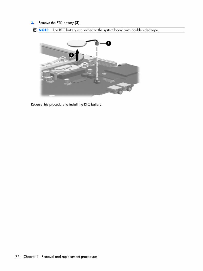
3. Remove the RTC battery (2).
NOTE: The RTC battery is attached to the system board with double-sided tape.
Reverse this procedure to install the RTC battery.
76 Chapter 4 Removal and replacement procedures
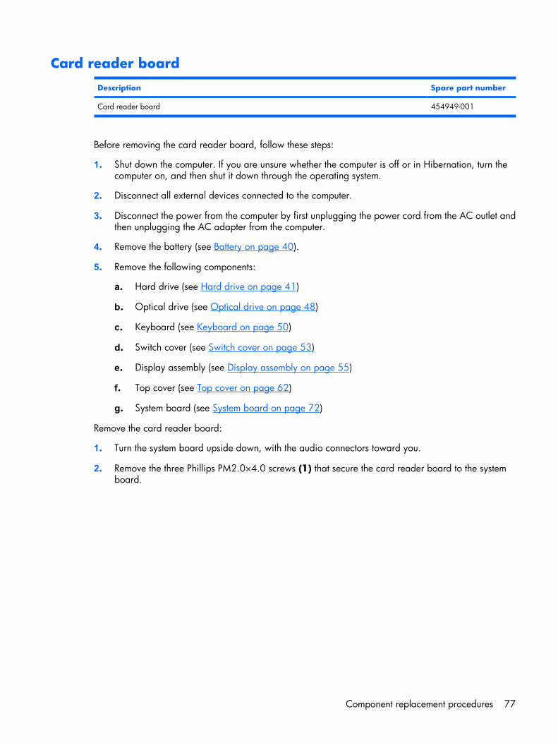
Card reader board
Description Spare part number
Card reader board 454949-001
Before removing the card reader board, follow these steps:
1. Shut down the computer. If you are unsure whether the computer is off or in Hibernation, turn thecomputer on, and then shut it down through the operating system.
2. Disconnect all external devices connected to the computer.
3. Disconnect the power from the computer by first unplugging the power cord from the AC outlet andthen unplugging the AC adapter from the computer.
4. Remove the battery (see Battery on page 40).
5. Remove the following components:
a. Hard drive (see Hard drive on page 41)
b. Optical drive (see Optical drive on page 48)
c. Keyboard (see Keyboard on page 50)
d. Switch cover (see Switch cover on page 53)
e. Display assembly (see Display assembly on page 55)
f. Top cover (see Top cover on page 62)
g. System board (see System board on page 72)
Remove the card reader board:
1. Turn the system board upside down, with the audio connectors toward you.
2. Remove the three Phillips PM2.0×4.0 screws (1) that secure the card reader board to the systemboard.
Component replacement procedures 77
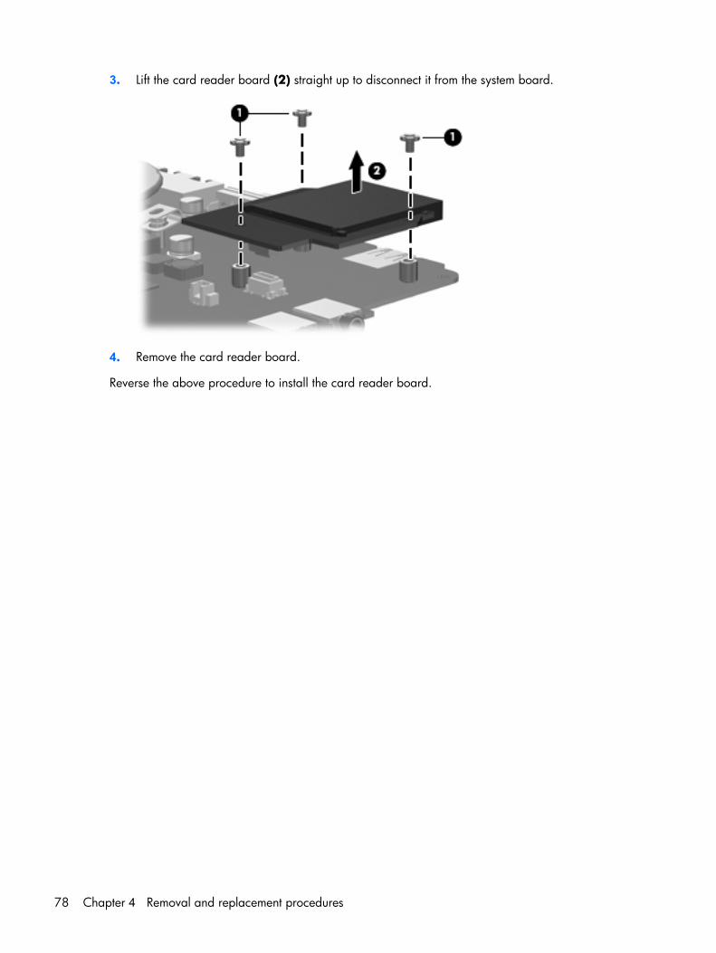
3. Lift the card reader board (2) straight up to disconnect it from the system board.
4. Remove the card reader board.
Reverse the above procedure to install the card reader board.
78 Chapter 4 Removal and replacement procedures
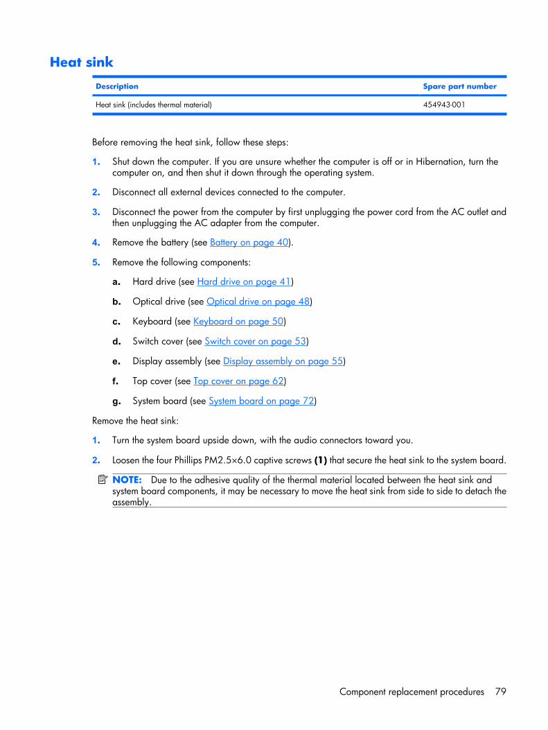
Heat sink
Description Spare part number
Heat sink (includes thermal material) 454943-001
Before removing the heat sink, follow these steps:
1. Shut down the computer. If you are unsure whether the computer is off or in Hibernation, turn thecomputer on, and then shut it down through the operating system.
2. Disconnect all external devices connected to the computer.
3. Disconnect the power from the computer by first unplugging the power cord from the AC outlet andthen unplugging the AC adapter from the computer.
4. Remove the battery (see Battery on page 40).
5. Remove the following components:
a. Hard drive (see Hard drive on page 41)
b. Optical drive (see Optical drive on page 48)
c. Keyboard (see Keyboard on page 50)
d. Switch cover (see Switch cover on page 53)
e. Display assembly (see Display assembly on page 55)
f. Top cover (see Top cover on page 62)
g. System board (see System board on page 72)
Remove the heat sink:
1. Turn the system board upside down, with the audio connectors toward you.
2. Loosen the four Phillips PM2.5×6.0 captive screws (1) that secure the heat sink to the system board.
NOTE: Due to the adhesive quality of the thermal material located between the heat sink andsystem board components, it may be necessary to move the heat sink from side to side to detach theassembly.
Component replacement procedures 79
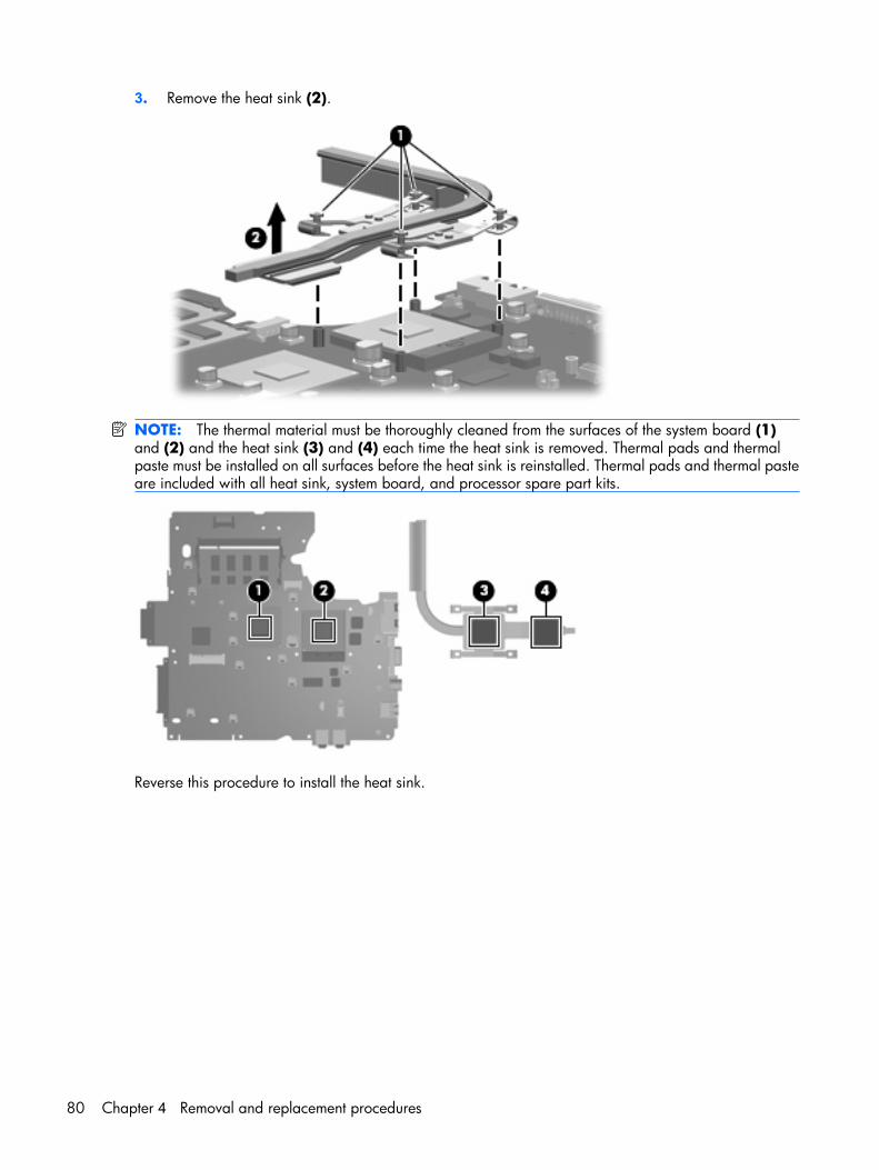
3. Remove the heat sink (2).
NOTE: The thermal material must be thoroughly cleaned from the surfaces of the system board (1)and (2) and the heat sink (3) and (4) each time the heat sink is removed. Thermal pads and thermalpaste must be installed on all surfaces before the heat sink is reinstalled. Thermal pads and thermal pasteare included with all heat sink, system board, and processor spare part kits.
Reverse this procedure to install the heat sink.
80 Chapter 4 Removal and replacement procedures
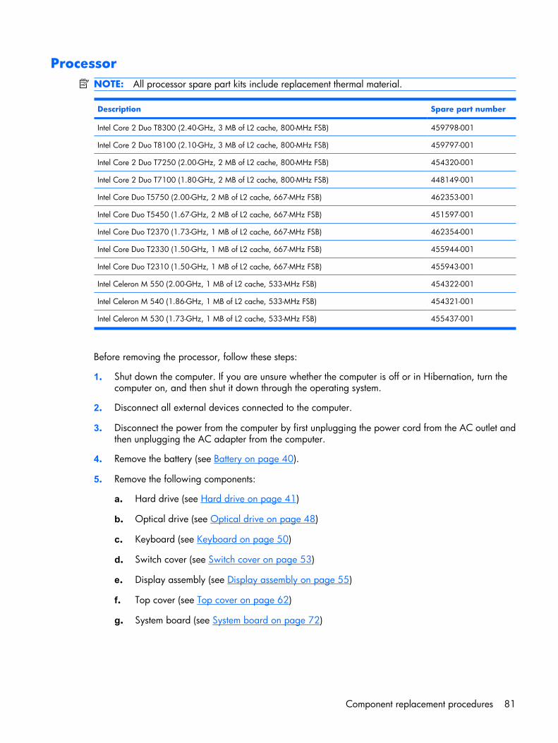
ProcessorNOTE: All processor spare part kits include replacement thermal material.
Description Spare part number
Intel Core 2 Duo T8300 (2.40-GHz, 3 MB of L2 cache, 800-MHz FSB) 459798-001
Intel Core 2 Duo T8100 (2.10-GHz, 3 MB of L2 cache, 800-MHz FSB) 459797-001
Intel Core 2 Duo T7250 (2.00-GHz, 2 MB of L2 cache, 800-MHz FSB) 454320-001
Intel Core 2 Duo T7100 (1.80-GHz, 2 MB of L2 cache, 800-MHz FSB) 448149-001
Intel Core Duo T5750 (2.00-GHz, 2 MB of L2 cache, 667-MHz FSB) 462353-001
Intel Core Duo T5450 (1.67-GHz, 2 MB of L2 cache, 667-MHz FSB) 451597-001
Intel Core Duo T2370 (1.73-GHz, 1 MB of L2 cache, 667-MHz FSB) 462354-001
Intel Core Duo T2330 (1.50-GHz, 1 MB of L2 cache, 667-MHz FSB) 455944-001
Intel Core Duo T2310 (1.50-GHz, 1 MB of L2 cache, 667-MHz FSB) 455943-001
Intel Celeron M 550 (2.00-GHz, 1 MB of L2 cache, 533-MHz FSB) 454322-001
Intel Celeron M 540 (1.86-GHz, 1 MB of L2 cache, 533-MHz FSB) 454321-001
Intel Celeron M 530 (1.73-GHz, 1 MB of L2 cache, 533-MHz FSB) 455437-001
Before removing the processor, follow these steps:
1. Shut down the computer. If you are unsure whether the computer is off or in Hibernation, turn thecomputer on, and then shut it down through the operating system.
2. Disconnect all external devices connected to the computer.
3. Disconnect the power from the computer by first unplugging the power cord from the AC outlet andthen unplugging the AC adapter from the computer.
4. Remove the battery (see Battery on page 40).
5. Remove the following components:
a. Hard drive (see Hard drive on page 41)
b. Optical drive (see Optical drive on page 48)
c. Keyboard (see Keyboard on page 50)
d. Switch cover (see Switch cover on page 53)
e. Display assembly (see Display assembly on page 55)
f. Top cover (see Top cover on page 62)
g. System board (see System board on page 72)
Component replacement procedures 81
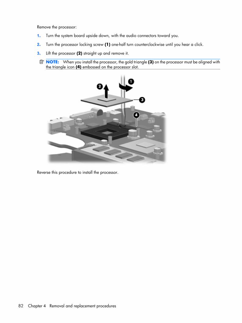
Remove the processor:
1. Turn the system board upside down, with the audio connectors toward you.
2. Turn the processor locking screw (1) one-half turn counterclockwise until you hear a click.
3. Lift the processor (2) straight up and remove it.
NOTE: When you install the processor, the gold triangle (3) on the processor must be aligned withthe triangle icon (4) embossed on the processor slot.
Reverse this procedure to install the processor.
82 Chapter 4 Removal and replacement procedures
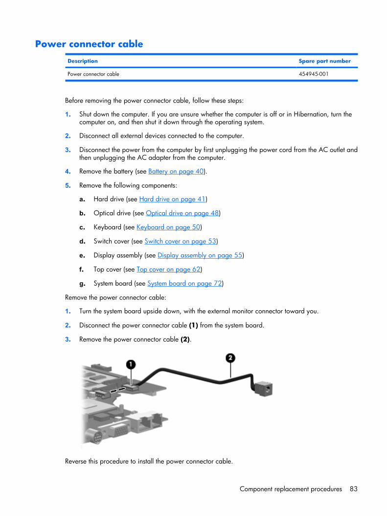
Power connector cable
Description Spare part number
Power connector cable 454945-001
Before removing the power connector cable, follow these steps:
1. Shut down the computer. If you are unsure whether the computer is off or in Hibernation, turn thecomputer on, and then shut it down through the operating system.
2. Disconnect all external devices connected to the computer.
3. Disconnect the power from the computer by first unplugging the power cord from the AC outlet andthen unplugging the AC adapter from the computer.
4. Remove the battery (see Battery on page 40).
5. Remove the following components:
a. Hard drive (see Hard drive on page 41)
b. Optical drive (see Optical drive on page 48)
c. Keyboard (see Keyboard on page 50)
d. Switch cover (see Switch cover on page 53)
e. Display assembly (see Display assembly on page 55)
f. Top cover (see Top cover on page 62)
g. System board (see System board on page 72)
Remove the power connector cable:
1. Turn the system board upside down, with the external monitor connector toward you.
2. Disconnect the power connector cable (1) from the system board.
3. Remove the power connector cable (2).
Reverse this procedure to install the power connector cable.
Component replacement procedures 83

5 Setup Utility
WARNING! Only authorized technicians trained by HP must repair this equipment. All troubleshootingand repair procedures are detailed to allow repair at only the subassembly or module level. Because ofthe complexity of the individual boards and subassemblies, do not attempt to make repairs at thecomponent level or modify any printed wiring board. Improper repairs can create a safety hazard. Anyindication of component replacement or printed wiring board modification may void any warranty orexchange allowances.
Starting the Setup UtilityThe Setup Utility is a ROM-based information and customization utility that can be used even when yourWindows® operating system is not working or will not load.
NOTE: The fingerprint reader (select models only) does not work when accessing the Setup Utility.
The utility reports information about the computer and provides settings for startup, security, and otherpreferences.
To start the Setup Utility:
1. Turn on or restart the computer.
2. Before Windows opens and while “Press <F10> to enter setup” is displayed in the lower-left cornerof the screen, press f10.
Changing the language of the Setup UtilityThe following procedure explains how to change the language of the Setup Utility. If the Setup Utility isnot already running, begin at step 1. If the Setup Utility is already running, begin at step 2.
1. To start the Setup Utility, turn on or restart the computer, and then press f10 while “Press <F10> toenter setup” is displayed in the lower-left corner of the screen.
2. Use the arrow keys to select System Configuration > Language, and then press enter.
3. Press f5 or f6 (or use the arrow keys) to select a language, and then press enter to select a language.
4. When a confirmation prompt with your preference selected is displayed, press enter to save yourpreference.
5. To set your preferences and exit the Setup Utility, press f10 and then follow the instructions on thescreen.
Your preferences go into effect when the computer restarts in Windows.
84 Chapter 5 Setup Utility
Navigating and selecting in the Setup UtilityBecause the Setup Utility is not Windows-based, it does not support the TouchPad. Navigation andselection are by keystroke.
● To choose a menu or a menu item, use the arrow keys.
● To choose an item in a drop-down list or to toggle a field, for example an Enable/Disable field, useeither the arrow keys or f5 or f6.
● To select an item, press enter.
● To close a text box or return to the menu display, press esc.
● To display additional navigation and selection information while the Setup Utility is open, press f1.
Displaying system informationThe following procedure explains how to display system information in the Setup Utility. If the Setup Utilityis not open, begin at step 1. If the Setup Utility is open, begin at step 2.
1. To start the Setup Utility, turn on or restart the computer, and then press f10 while “Press <F10>toenter setup” is displayed in the lower-left corner of the screen.
2. Access the system information by using the Main menu.
3. To exit the Setup Utility without changing any settings, use the arrow keys to select Exit > ExitDiscarding Changes, and then press enter. (The computer restarts in Windows.)
Restoring default settings in the Setup UtilityThe following procedure explains how to restore the Setup Utility default settings. If the Setup Utility is notalready running, begin at step 1. If the Setup Utility is already running, begin at step 2.
1. To start the Setup Utility, turn on or restart the computer, and then press f10 while “Press <F10>toenter setup” is displayed in the lower-left corner of the screen.
2. Select Exit > Load Setup Defaults, and then press enter.
3. When the Setup Confirmation is displayed, press enter to save your preferences.
4. To set your preferences and exit the Setup Utility, press f10, and then follow the instructions on thescreen.
The Setup Utility default settings are set when you exit the Setup Utility and go into effect when the computerrestarts.
NOTE: Your password, security, and language settings are not changed when you restore the factorydefault settings.
Navigating and selecting in the Setup Utility 85
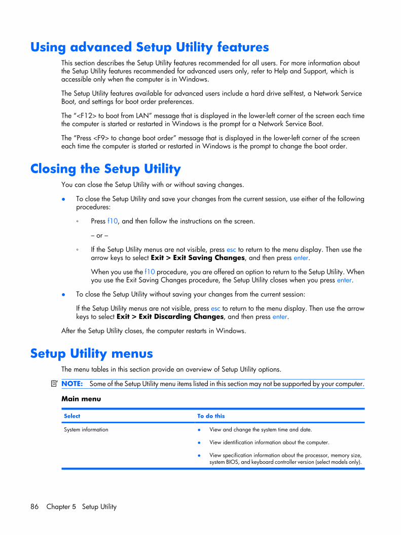
Using advanced Setup Utility featuresThis section describes the Setup Utility features recommended for all users. For more information aboutthe Setup Utility features recommended for advanced users only, refer to Help and Support, which isaccessible only when the computer is in Windows.
The Setup Utility features available for advanced users include a hard drive self-test, a Network ServiceBoot, and settings for boot order preferences.
The “<F12> to boot from LAN” message that is displayed in the lower-left corner of the screen each timethe computer is started or restarted in Windows is the prompt for a Network Service Boot.
The “Press <F9> to change boot order” message that is displayed in the lower-left corner of the screeneach time the computer is started or restarted in Windows is the prompt to change the boot order.
Closing the Setup UtilityYou can close the Setup Utility with or without saving changes.
● To close the Setup Utility and save your changes from the current session, use either of the followingprocedures:
◦ Press f10, and then follow the instructions on the screen.
– or –
◦ If the Setup Utility menus are not visible, press esc to return to the menu display. Then use thearrow keys to select Exit > Exit Saving Changes, and then press enter.
When you use the f10 procedure, you are offered an option to return to the Setup Utility. Whenyou use the Exit Saving Changes procedure, the Setup Utility closes when you press enter.
● To close the Setup Utility without saving your changes from the current session:
If the Setup Utility menus are not visible, press esc to return to the menu display. Then use the arrowkeys to select Exit > Exit Discarding Changes, and then press enter.
After the Setup Utility closes, the computer restarts in Windows.
Setup Utility menusThe menu tables in this section provide an overview of Setup Utility options.
NOTE: Some of the Setup Utility menu items listed in this section may not be supported by your computer.
Main menu
Select To do this
System information ● View and change the system time and date.
● View identification information about the computer.
● View specification information about the processor, memory size,system BIOS, and keyboard controller version (select models only).
86 Chapter 5 Setup Utility
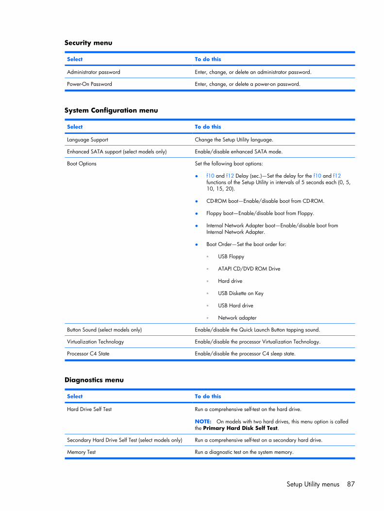
Security menu
Select To do this
Administrator password Enter, change, or delete an administrator password.
Power-On Password Enter, change, or delete a power-on password.
System Configuration menu
Select To do this
Language Support Change the Setup Utility language.
Enhanced SATA support (select models only) Enable/disable enhanced SATA mode.
Boot Options Set the following boot options:
● f10 and f12 Delay (sec.)―Set the delay for the f10 and f12functions of the Setup Utility in intervals of 5 seconds each (0, 5,10, 15, 20).
● CD-ROM boot―Enable/disable boot from CD-ROM.
● Floppy boot―Enable/disable boot from Floppy.
● Internal Network Adapter boot―Enable/disable boot fromInternal Network Adapter.
● Boot Order―Set the boot order for:
◦ USB Floppy
◦ ATAPI CD/DVD ROM Drive
◦ Hard drive
◦ USB Diskette on Key
◦ USB Hard drive
◦ Network adapter
Button Sound (select models only) Enable/disable the Quick Launch Button tapping sound.
Virtualization Technology Enable/disable the processor Virtualization Technology.
Processor C4 State Enable/disable the processor C4 sleep state.
Diagnostics menu
Select To do this
Hard Drive Self Test Run a comprehensive self-test on the hard drive.
NOTE: On models with two hard drives, this menu option is calledthe Primary Hard Disk Self Test.
Secondary Hard Drive Self Test (select models only) Run a comprehensive self-test on a secondary hard drive.
Memory Test Run a diagnostic test on the system memory.
Setup Utility menus 87
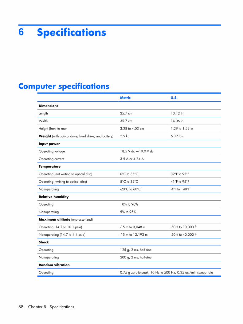
6 Specifications
Computer specifications Metric U.S.
Dimensions
Length 25.7 cm 10.12 in
Width 35.7 cm 14.06 in
Height (front to rear 3.28 to 4.03 cm 1.29 to 1.59 in
Weight (with optical drive, hard drive, and battery) 2.9 kg 6.39 lbs
Input power
Operating voltage 18.5 V dc —19.0 V dc
Operating current 3.5 A or 4.74 A
Temperature
Operating (not writing to optical disc) 0°C to 35°C 32°F to 95°F
Operating (writing to optical disc) 5°C to 35°C 41°F to 95°F
Nonoperating -20°C to 60°C -4°F to 140°F
Relative humidity
Operating 10% to 90%
Nonoperating 5% to 95%
Maximum altitude (unpressurized)
Operating (14.7 to 10.1 psia) -15 m to 3,048 m -50 ft to 10,000 ft
Nonoperating (14.7 to 4.4 psia) -15 m to 12,192 m -50 ft to 40,000 ft
Shock
Operating 125 g, 2 ms, half-sine
Nonoperating 200 g, 2 ms, half-sine
Random vibration
Operating 0.75 g zero-to-peak, 10 Hz to 500 Hz, 0.25 oct/min sweep rate
88 Chapter 6 Specifications
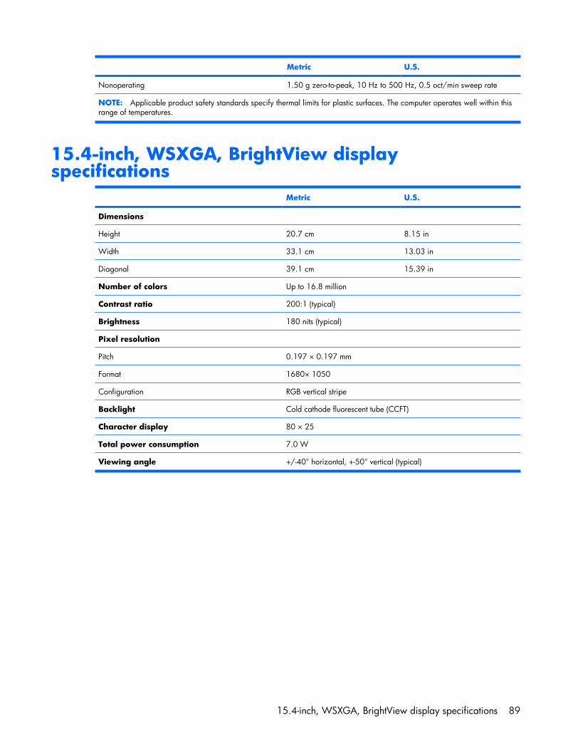
Metric U.S.
Nonoperating 1.50 g zero-to-peak, 10 Hz to 500 Hz, 0.5 oct/min sweep rate
NOTE: Applicable product safety standards specify thermal limits for plastic surfaces. The computer operates well within thisrange of temperatures.
15.4-inch, WSXGA, BrightView displayspecifications
Metric U.S.
Dimensions
Height 20.7 cm 8.15 in
Width 33.1 cm 13.03 in
Diagonal 39.1 cm 15.39 in
Number of colors Up to 16.8 million
Contrast ratio 200:1 (typical)
Brightness 180 nits (typical)
Pixel resolution
Pitch 0.197 × 0.197 mm
Format 1680× 1050
Configuration RGB vertical stripe
Backlight Cold cathode fluorescent tube (CCFT)
Character display 80 × 25
Total power consumption 7.0 W
Viewing angle +/-40° horizontal, +-50° vertical (typical)
15.4-inch, WSXGA, BrightView display specifications 89
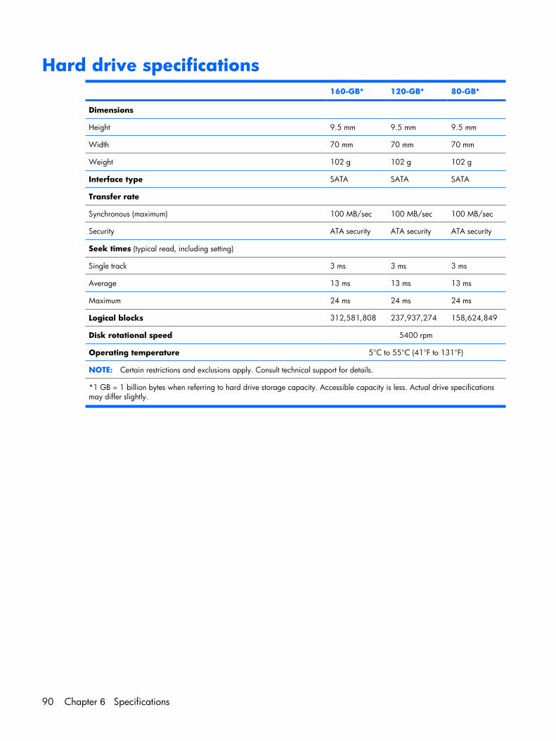
Hard drive specifications 160-GB* 120-GB* 80-GB*
Dimensions
Height 9.5 mm 9.5 mm 9.5 mm
Width 70 mm 70 mm 70 mm
Weight 102 g 102 g 102 g
Interface type SATA SATA SATA
Transfer rate
Synchronous (maximum) 100 MB/sec 100 MB/sec 100 MB/sec
Security ATA security ATA security ATA security
Seek times (typical read, including setting)
Single track 3 ms 3 ms 3 ms
Average 13 ms 13 ms 13 ms
Maximum 24 ms 24 ms 24 ms
Logical blocks 312,581,808 237,937,274 158,624,849
Disk rotational speed 5400 rpm
Operating temperature 5°C to 55°C (41°F to 131°F)
NOTE: Certain restrictions and exclusions apply. Consult technical support for details.
*1 GB = 1 billion bytes when referring to hard drive storage capacity. Accessible capacity is less. Actual drive specificationsmay differ slightly.
90 Chapter 6 Specifications
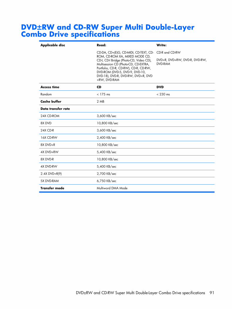
DVD±RW and CD-RW Super Multi Double-LayerCombo Drive specifications
Applicable disc Read:
CD-DA, CD+(E)G, CD-MIDI, CD-TEXT, CD-ROM, CD-ROM XA, MIXED MODE CD,CD-I, CD-I Bridge (Photo-CD, Video CD),Multisession CD (Photo-CD, CD-EXTRA,Portfolio, CD-R, CD-RW), CD-R, CD-RW,DVD-ROM (DVD-5, DVD-9, DVD-10,DVD-18), DVD-R, DVD-RW, DVD+R, DVD+RW, DVD-RAM
Write:
CD-R and CD-RW
DVD+R, DVD+RW, DVD-R, DVD-RW,DVD-RAM
Access time CD DVD
Random < 175 ms < 230 ms
Cache buffer 2 MB
Data transfer rate
24X CD-ROM 3,600 KB/sec
8X DVD 10,800 KB/sec
24X CD-R 3,600 KB/sec
16X CD-RW 2,400 KB/sec
8X DVD+R 10,800 KB/sec
4X DVD+RW 5,400 KB/sec
8X DVD-R 10,800 KB/sec
4X DVD-RW 5,400 KB/sec
2.4X DVD+R(9) 2,700 KB/sec
5X DVD-RAM 6,750 KB/sec
Transfer mode Multiword DMA Mode
DVD±RW and CD-RW Super Multi Double-Layer Combo Drive specifications 91
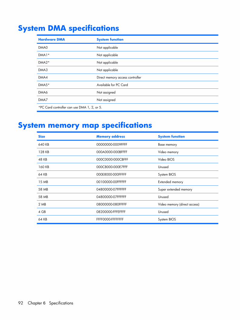
System DMA specificationsHardware DMA System function
DMA0 Not applicable
DMA1* Not applicable
DMA2* Not applicable
DMA3 Not applicable
DMA4 Direct memory access controller
DMA5* Available for PC Card
DMA6 Not assigned
DMA7 Not assigned
*PC Card controller can use DMA 1, 2, or 5.
System memory map specificationsSize Memory address System function
640 KB 00000000-0009FFFF Base memory
128 KB 000A0000-000BFFFF Video memory
48 KB 000C0000-000CBFFF Video BIOS
160 KB 000C8000-000E7FFF Unused
64 KB 000E8000-000FFFFF System BIOS
15 MB 00100000-00FFFFFF Extended memory
58 MB 04800000-07FFFFFF Super extended memory
58 MB 04800000-07FFFFFF Unused
2 MB 08000000-080FFFFF Video memory (direct access)
4 GB 08200000-FFFEFFFF Unused
64 KB FFFF0000-FFFFFFFF System BIOS
92 Chapter 6 Specifications
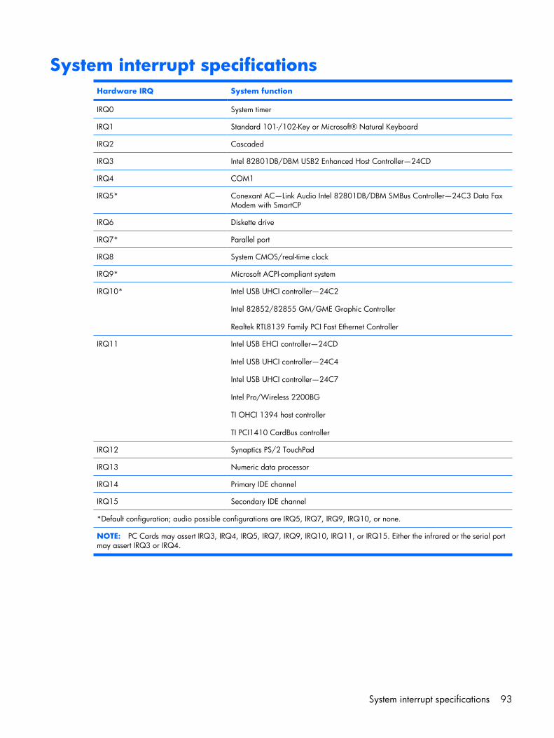
System interrupt specificationsHardware IRQ System function
IRQ0 System timer
IRQ1 Standard 101-/102-Key or Microsoft® Natural Keyboard
IRQ2 Cascaded
IRQ3 Intel 82801DB/DBM USB2 Enhanced Host Controller—24CD
IRQ4 COM1
IRQ5* Conexant AC—Link Audio Intel 82801DB/DBM SMBus Controller—24C3 Data FaxModem with SmartCP
IRQ6 Diskette drive
IRQ7* Parallel port
IRQ8 System CMOS/real-time clock
IRQ9* Microsoft ACPI-compliant system
IRQ10* Intel USB UHCI controller—24C2
Intel 82852/82855 GM/GME Graphic Controller
Realtek RTL8139 Family PCI Fast Ethernet Controller
IRQ11 Intel USB EHCI controller—24CD
Intel USB UHCI controller—24C4
Intel USB UHCI controller—24C7
Intel Pro/Wireless 2200BG
TI OHCI 1394 host controller
TI PCI1410 CardBus controller
IRQ12 Synaptics PS/2 TouchPad
IRQ13 Numeric data processor
IRQ14 Primary IDE channel
IRQ15 Secondary IDE channel
*Default configuration; audio possible configurations are IRQ5, IRQ7, IRQ9, IRQ10, or none.
NOTE: PC Cards may assert IRQ3, IRQ4, IRQ5, IRQ7, IRQ9, IRQ10, IRQ11, or IRQ15. Either the infrared or the serial portmay assert IRQ3 or IRQ4.
System interrupt specifications 93
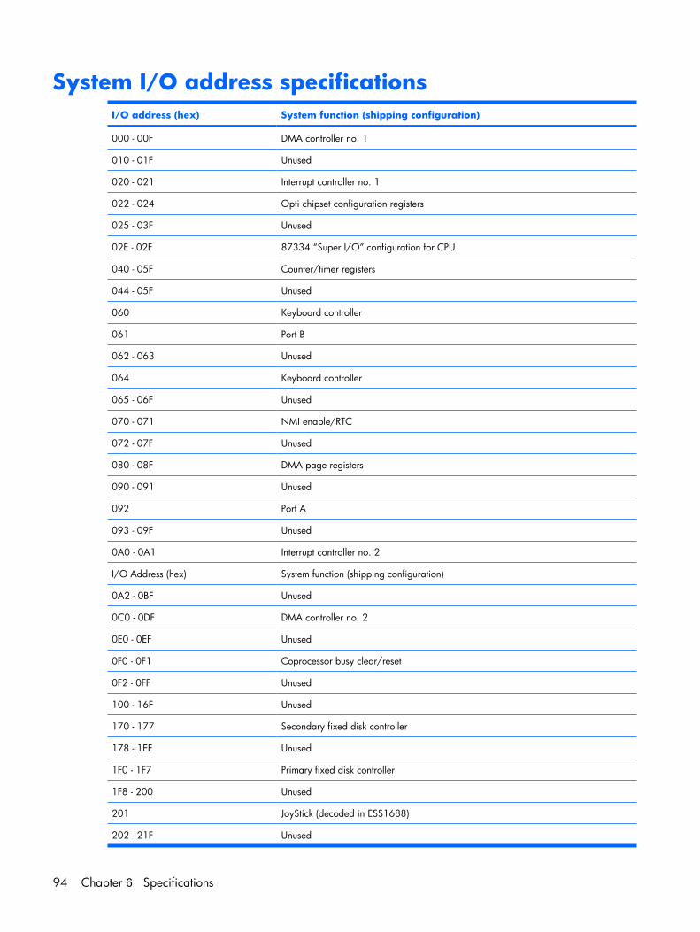
System I/O address specificationsI/O address (hex) System function (shipping configuration)
000 - 00F DMA controller no. 1
010 - 01F Unused
020 - 021 Interrupt controller no. 1
022 - 024 Opti chipset configuration registers
025 - 03F Unused
02E - 02F 87334 “Super I/O” configuration for CPU
040 - 05F Counter/timer registers
044 - 05F Unused
060 Keyboard controller
061 Port B
062 - 063 Unused
064 Keyboard controller
065 - 06F Unused
070 - 071 NMI enable/RTC
072 - 07F Unused
080 - 08F DMA page registers
090 - 091 Unused
092 Port A
093 - 09F Unused
0A0 - 0A1 Interrupt controller no. 2
I/O Address (hex) System function (shipping configuration)
0A2 - 0BF Unused
0C0 - 0DF DMA controller no. 2
0E0 - 0EF Unused
0F0 - 0F1 Coprocessor busy clear/reset
0F2 - 0FF Unused
100 - 16F Unused
170 - 177 Secondary fixed disk controller
178 - 1EF Unused
1F0 - 1F7 Primary fixed disk controller
1F8 - 200 Unused
201 JoyStick (decoded in ESS1688)
202 - 21F Unused
94 Chapter 6 Specifications
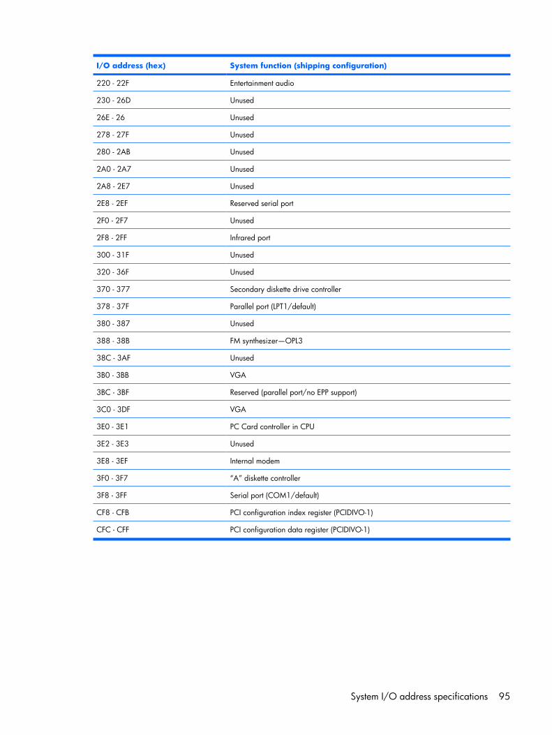
I/O address (hex) System function (shipping configuration)
220 - 22F Entertainment audio
230 - 26D Unused
26E - 26 Unused
278 - 27F Unused
280 - 2AB Unused
2A0 - 2A7 Unused
2A8 - 2E7 Unused
2E8 - 2EF Reserved serial port
2F0 - 2F7 Unused
2F8 - 2FF Infrared port
300 - 31F Unused
320 - 36F Unused
370 - 377 Secondary diskette drive controller
378 - 37F Parallel port (LPT1/default)
380 - 387 Unused
388 - 38B FM synthesizer—OPL3
38C - 3AF Unused
3B0 - 3BB VGA
3BC - 3BF Reserved (parallel port/no EPP support)
3C0 - 3DF VGA
3E0 - 3E1 PC Card controller in CPU
3E2 - 3E3 Unused
3E8 - 3EF Internal modem
3F0 - 3F7 “A” diskette controller
3F8 - 3FF Serial port (COM1/default)
CF8 - CFB PCI configuration index register (PCIDIVO-1)
CFC - CFF PCI configuration data register (PCIDIVO-1)
System I/O address specifications 95
7 Screw listing
This section provides specification and reference information for the screws and screw locks used in thecomputer. All screws and screw locks listed in this section are available in the Screw Kit, spare part number454951-001, and the Display Screw Kit, spare part number 454918-001.
96 Chapter 7 Screw listing
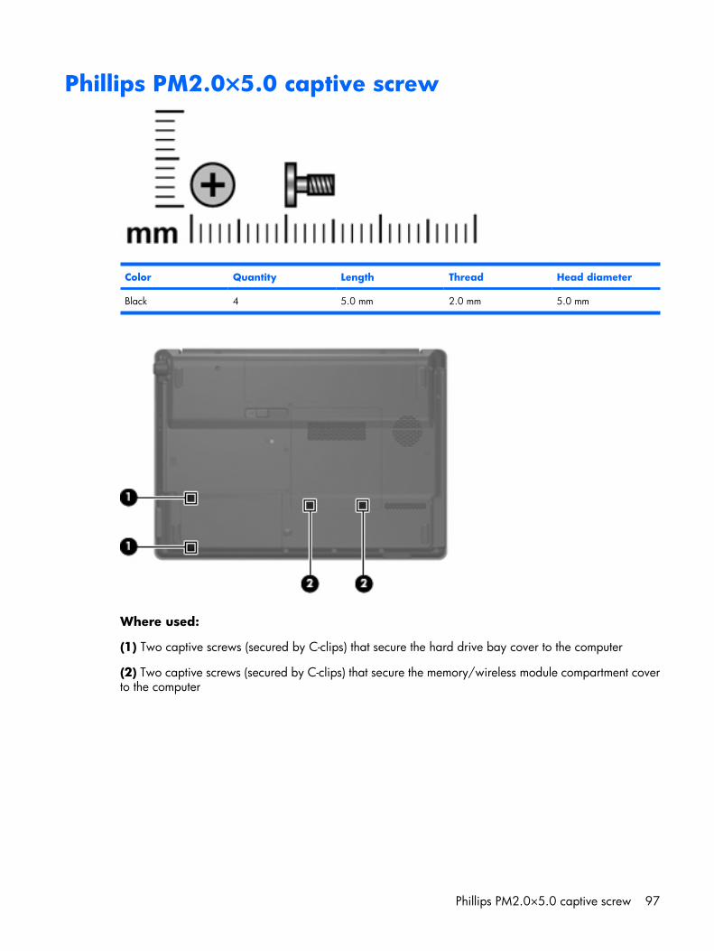
Phillips PM2.0×5.0 captive screw
Color Quantity Length Thread Head diameter
Black 4 5.0 mm 2.0 mm 5.0 mm
Where used:
(1) Two captive screws (secured by C-clips) that secure the hard drive bay cover to the computer
(2) Two captive screws (secured by C-clips) that secure the memory/wireless module compartment coverto the computer
Phillips PM2.0×5.0 captive screw 97
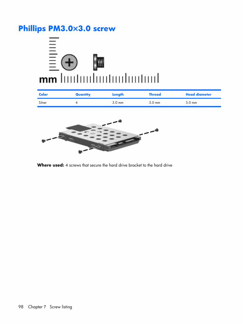
Phillips PM3.0×3.0 screw
Color Quantity Length Thread Head diameter
Silver 4 3.0 mm 3.0 mm 5.0 mm
Where used: 4 screws that secure the hard drive bracket to the hard drive
98 Chapter 7 Screw listing
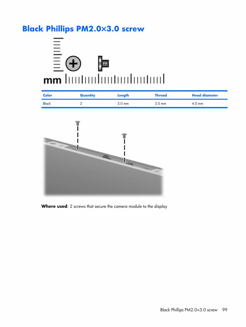
Black Phillips PM2.0×3.0 screw
Color Quantity Length Thread Head diameter
Black 2 3.0 mm 2.0 mm 4.0 mm
Where used: 2 screws that secure the camera module to the display
Black Phillips PM2.0×3.0 screw 99
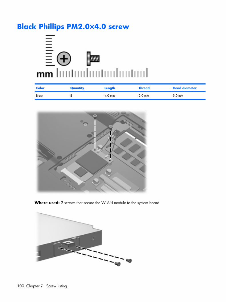
Black Phillips PM2.0×4.0 screw
Color Quantity Length Thread Head diameter
Black 8 4.0 mm 2.0 mm 5.0 mm
Where used: 2 screws that secure the WLAN module to the system board
100 Chapter 7 Screw listing
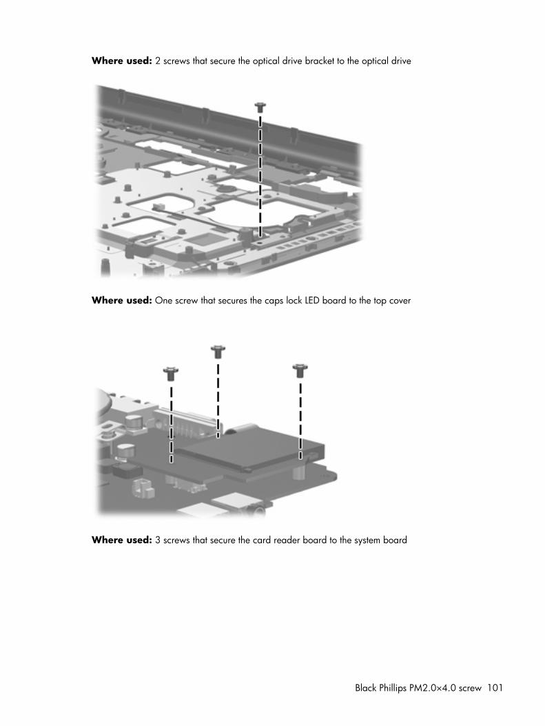
Where used: 2 screws that secure the optical drive bracket to the optical drive
Where used: One screw that secures the caps lock LED board to the top cover
Where used: 3 screws that secure the card reader board to the system board
Black Phillips PM2.0×4.0 screw 101
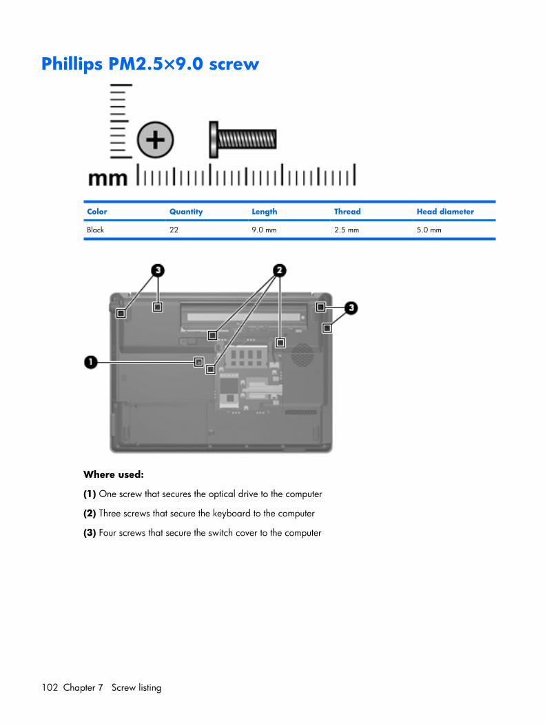
Phillips PM2.5×9.0 screw
Color Quantity Length Thread Head diameter
Black 22 9.0 mm 2.5 mm 5.0 mm
Where used:
(1) One screw that secures the optical drive to the computer
(2) Three screws that secure the keyboard to the computer
(3) Four screws that secure the switch cover to the computer
102 Chapter 7 Screw listing
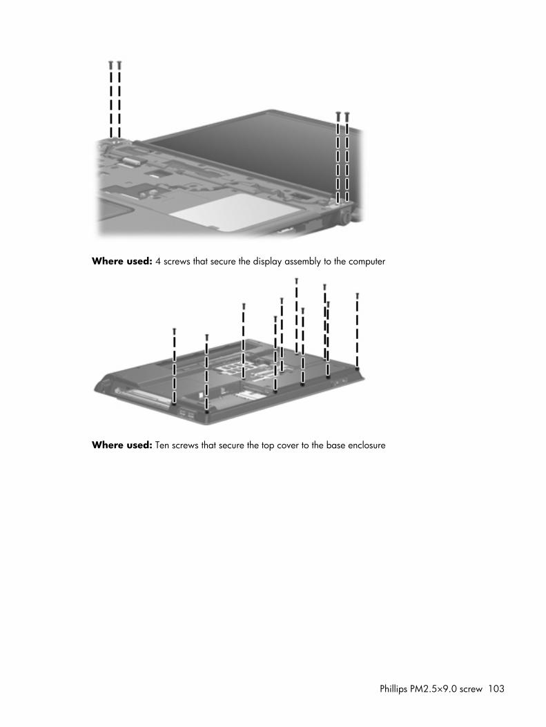
Where used: 4 screws that secure the display assembly to the computer
Where used: Ten screws that secure the top cover to the base enclosure
Phillips PM2.5×9.0 screw 103
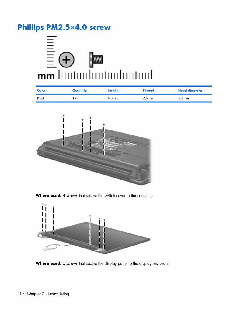
Phillips PM2.5×4.0 screw
Color Quantity Length Thread Head diameter
Black 19 4.0 mm 2.5 mm 5.0 mm
Where used: 4 screws that secure the switch cover to the computer
Where used: 6 screws that secure the display panel to the display enclosure
104 Chapter 7 Screw listing
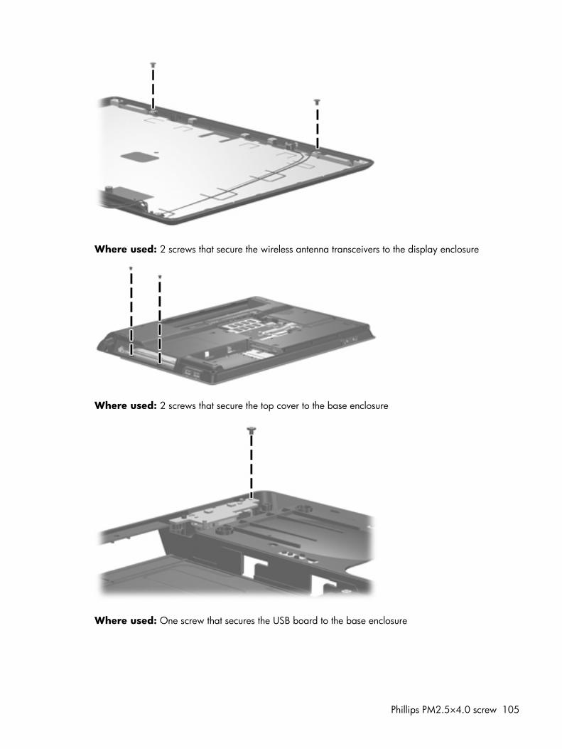
Where used: 2 screws that secure the wireless antenna transceivers to the display enclosure
Where used: 2 screws that secure the top cover to the base enclosure
Where used: One screw that secures the USB board to the base enclosure
Phillips PM2.5×4.0 screw 105
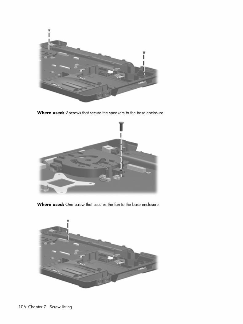
Where used: 2 screws that secure the speakers to the base enclosure
Where used: One screw that secures the fan to the base enclosure
106 Chapter 7 Screw listing
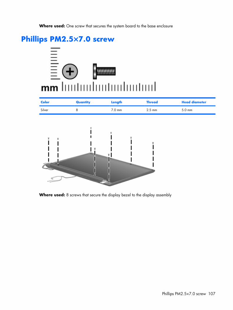
Where used: One screw that secures the system board to the base enclosure
Phillips PM2.5×7.0 screw
Color Quantity Length Thread Head diameter
Silver 8 7.0 mm 2.5 mm 5.0 mm
Where used: 8 screws that secure the display bezel to the display assembly
Phillips PM2.5×7.0 screw 107
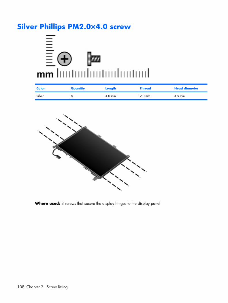
Silver Phillips PM2.0×4.0 screw
Color Quantity Length Thread Head diameter
Silver 8 4.0 mm 2.0 mm 4.5 mm
Where used: 8 screws that secure the display hinges to the display panel
108 Chapter 7 Screw listing
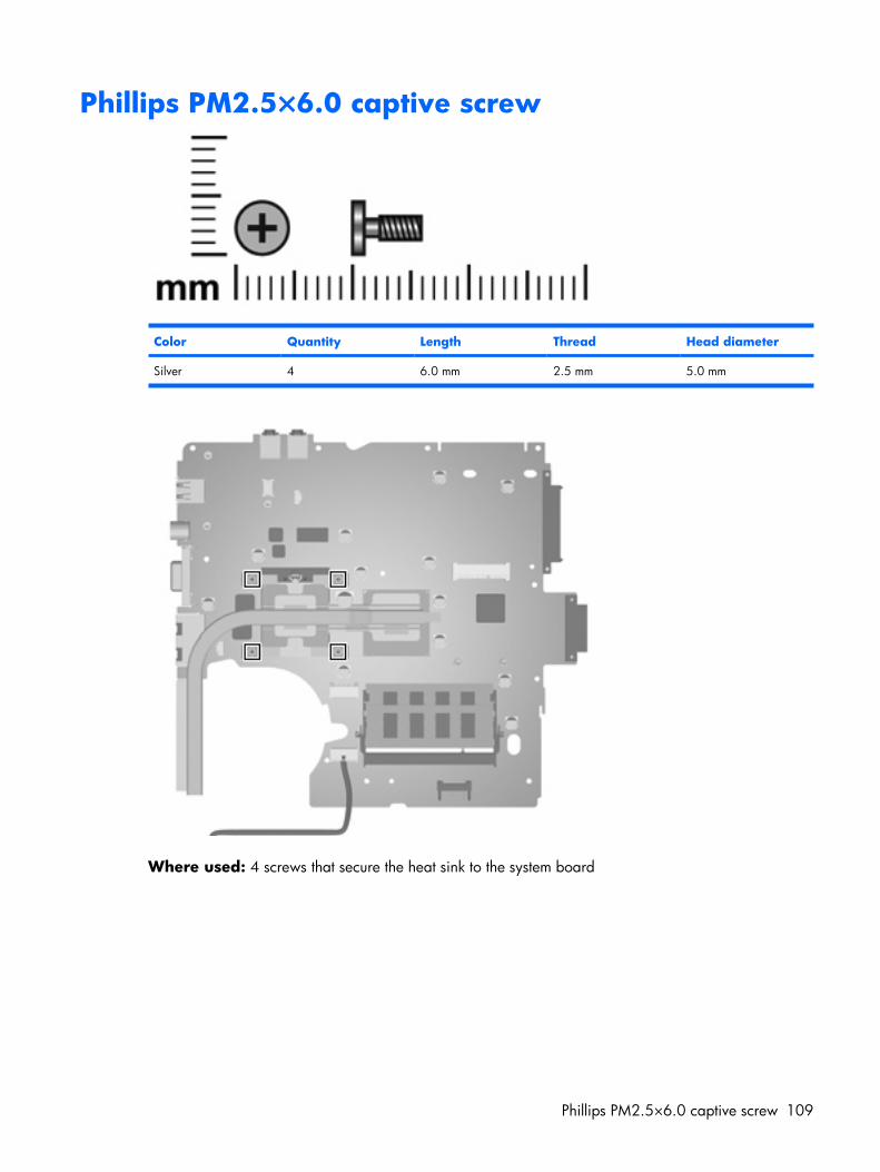
Phillips PM2.5×6.0 captive screw
Color Quantity Length Thread Head diameter
Silver 4 6.0 mm 2.5 mm 5.0 mm
Where used: 4 screws that secure the heat sink to the system board
Phillips PM2.5×6.0 captive screw 109
8 Backup and recovery
Recovering system informationTools provided by the operating system and Recovery Manager software are designed to help you withthe following tasks for safeguarding your information and restoring it in case of a system failure:
● Backing up your information regularly to protect your important system files.
● Making a set of recovery discs (Recovery Manager software feature). Recovery discs are used tostart up (boot) your computer and restore the operating system and software programs to factorysettings in case of system failure or instability.
● Creating system restore points (operating system feature). System restore points allow you to reverseundesirable changes to your computer by restoring the computer to an earlier state.
● Recovering a program or driver (Recovery Manager software feature). This feature helps you reinstalla program or driver without performing a full system recovery.
● Performing a full system recovery (Recovery Manager software feature). With Recovery Manager,you can recover your full factory image if you experience system failure or instability. RecoveryManager works from a dedicated recovery partition on the hard drive or from recovery discs youcreate.
Backing up your information
When to back up● On a regularly scheduled basis
NOTE: Set reminders to back up your information periodically.
● Before the computer is repaired or restored
● Before you add or modify hardware or software
110 Chapter 8 Backup and recovery
Backup suggestions● Create a set of recovery discs using Recovery Manager.
● Create system restore points using the Windows® System Restore feature, and periodically copythem to disc.
● Store personal files in the Documents folder and back up these folders periodically.
● Back up templates stored in their associated programs.
● Save customized settings in a window, toolbar, or menu bar by taking a screen shot of your settings.
The screen shot can be a time saver if you have to reset your preferences.
To copy the screen and paste it into a word-processing document:
a. Display the screen.
b. Copy the screen:
To copy only the active window, press alt+fn+prt sc.
To copy the entire screen, press fn+prt sc.
c. Open a word-processing document, and then select Edit > Paste.
Using system restore pointsWhen you back up your system, you are creating a system restore point. A system restore point allowsyou to save and name a snapshot of your hard drive at a specific point in time. You can then recoverback to that point if you want to reverse subsequent changes made to your system.
NOTE: Recovering to an earlier restore point does not affect data files saved or e-mails created sincethe last restore point.
You also can create additional restore points to provide increased protection for your system files andsettings.
When to create restore points● Before you add or extensively modify software or hardware.
● Periodically, whenever the system is performing optimally.
NOTE: If you revert to a restore point and then change your mind, you can reverse the restoration.
Create a system restore point
1. Select Start > Control Panel > System and Maintenance > System.
2. In the left pane, click System protection.
3. Click the System Protection tab.
4. Under Automatic restore points, select the disk for which you want to create a restore point.
5. Click Create.
Recovering system information 111
The System Protection window opens.
6. Follow the on-screen instructions.
112 Chapter 8 Backup and recovery
Restore to a previous date and timeTo revert to a restore point (created at a previous date and time), when the computer was functioningoptimally, follow these steps:
1. Select Start > Control Panel > System and Maintenance > System.
2. In the left pane, click System protection.
3. Click the System Protection tab.
4. Click the System Restore button, and then click Next.
The System Restore window opens.
5. Follow the on-screen instructions.
Creating recovery discsAfter setting up the computer for the first time, be sure to create a set of recovery discs of the full factoryimage. The recovery discs are used to start up (boot) the computer and recover the operating system andsoftware to factory settings in case of system instability or failure.
NOTE: Handle these discs carefully and keep them in a safe place. The software allows the creation ofonly one set of recovery discs.
Note the following guidelines before creating recovery discs:
● Use any of the following types of discs: CD-R, DVD+R, DVD+R DL, DVD-R, or DVD-R DL (purchasedseparately). The discs you use will depend on the type of optical drive installed in your computer.Because DVDs store more information than CDs, DVDs and DVDs with double-layer (DL) supportreduce the number of discs required.
NOTE: Read-write discs, such as CD-RW, DVD+RW, and DVD-RW, are not compatible with theRecovery Manager software.
● The computer must be connected to AC power during this process.
● Only one set of recovery discs can be created per computer.
● Number each disc before inserting it into the computer optical drive.
● If necessary, you can exit the program before you have finished creating the recovery discs. The nexttime you open Recovery Manager, you will be prompted to continue the disc creation process.
To create a set of recovery discs:
1. Select Start > All Programs > Recovery Manager > Recovery Manager.
Recovery Manager opens.
2. Click Advanced Options.
NOTE: If you are operating the computer on battery power, you will be prompted to connect toAC power before you can go to the next step.
3. Click Recovery disc creation, and then click Next.
4. Follow the on-screen instructions.
Recovering system information 113
Performing a recoveryNOTE: You can only recover files that you have previously backed up. HP recommends that you useRecovery Manager to create an entire drive backup as soon as you set up your computer.
Recovery Manager software allows you to repair or restore the system if you experience system failure orinstability. Recovery Manager works from recovery discs that you create or from a dedicated recoverypartition on the hard drive.
NOTE: Windows has its own built-in repair features, such as System Restore and driver rollbackcapabilities. If you have not already tried these features, try them before using Recovery Manager.
NOTE: Recovery Manager only recovers software that was preinstalled at the factory. Software notprovided with this computer must be reinstalled from the disc provided by the manufacturer or downloadedfrom the manufacturer's Web site.
Recovering from the recovery discsTo restore the system from the recovery discs:
1. Back up all personal files.
2. Insert the first recovery disc into the optical drive and restart the computer.
3. Follow the on-screen instructions.
Recovering from the partition on the hard driveYou can perform a recovery from the partition on the hard drive from either the Start button or f11.
To restore the system from the partition, follow these steps:
1. Access Recovery Manager in either of the following ways:
● Select Start > All Programs > Recovery Manager > Recovery Manager.
– or –
● Restart the computer and press f11 while the “Press <F11> for recovery” message is displayedon the screen. Then select Recovery Manager.
Recovery Manager opens.
2. Click Advanced Options.
3. Click System recovery, and then click Next.
4. Follow the on-screen instructions.
114 Chapter 8 Backup and recovery
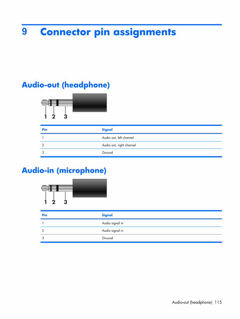
9 Connector pin assignments
Audio-out (headphone)
Pin Signal
1 Audio out, left channel
2 Audio out, right channel
3 Ground
Audio-in (microphone)
Pin Signal
1 Audio signal in
2 Audio signal in
3 Ground
Audio-out (headphone) 115
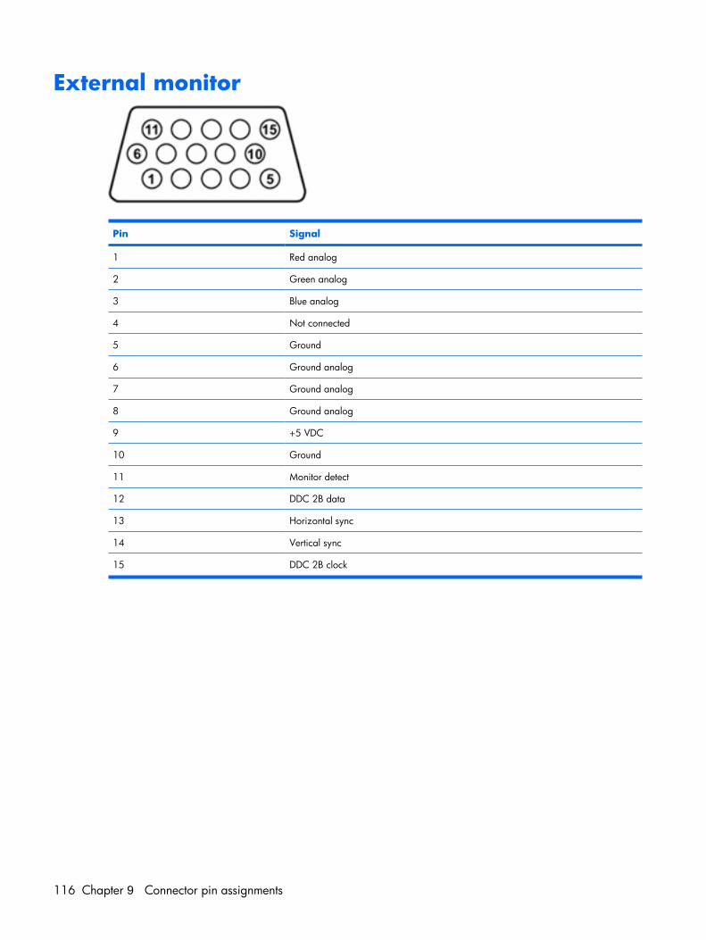
External monitor
Pin Signal
1 Red analog
2 Green analog
3 Blue analog
4 Not connected
5 Ground
6 Ground analog
7 Ground analog
8 Ground analog
9 +5 VDC
10 Ground
11 Monitor detect
12 DDC 2B data
13 Horizontal sync
14 Vertical sync
15 DDC 2B clock
116 Chapter 9 Connector pin assignments
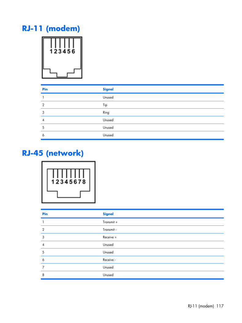
RJ-11 (modem)
Pin Signal
1 Unused
2 Tip
3 Ring
4 Unused
5 Unused
6 Unused
RJ-45 (network)
Pin Signal
1 Transmit +
2 Transmit -
3 Receive +
4 Unused
5 Unused
6 Receive -
7 Unused
8 Unused
RJ-11 (modem) 117
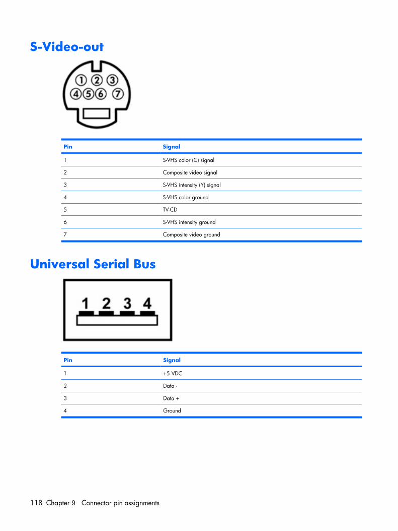
S-Video-out
Pin Signal
1 S-VHS color (C) signal
2 Composite video signal
3 S-VHS intensity (Y) signal
4 S-VHS color ground
5 TV-CD
6 S-VHS intensity ground
7 Composite video ground
Universal Serial Bus
Pin Signal
1 +5 VDC
2 Data -
3 Data +
4 Ground
118 Chapter 9 Connector pin assignments
10 Power cord set requirements
The wide range input feature of the computer permits it to operate from any line voltage from 100 to 120volts AC or from 220 to 240 volts AC.
The 3-conductor power cord set included with the computer meets the requirements for use in the countryor region where the equipment is purchased.
Power cord sets for use in other countries or regions must meet the requirements of the country or regionwhere the computer is used.
Requirements for all countries or regionsThe requirements listed below are applicable to all countries or regions:
● The length of the power cord set must be at least 1.5 m (5.0 ft) and no more than 2.0 m (6.5 ft).
● All power cord sets must be approved by an acceptable accredited agency responsible for evaluationin the country or region where the power cord set will be used.
● The power cord sets must have a minimum current capacity of 10 amps and a nominal voltage ratingof 125 or 250 V AC, as required by each country or region’s power system.
● The appliance coupler must meet the mechanical configuration of an EN 60 320/IEC 320 StandardSheet C13 connector for mating with the appliance inlet on the back of the computer.
Requirements for all countries or regions 119
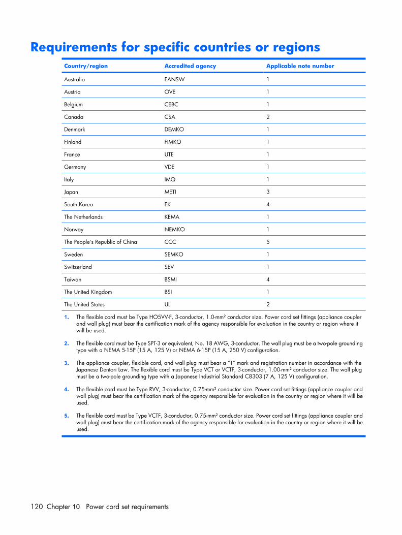
Requirements for specific countries or regionsCountry/region Accredited agency Applicable note number
Australia EANSW 1
Austria OVE 1
Belgium CEBC 1
Canada CSA 2
Denmark DEMKO 1
Finland FIMKO 1
France UTE 1
Germany VDE 1
Italy IMQ 1
Japan METI 3
South Korea EK 4
The Netherlands KEMA 1
Norway NEMKO 1
The People's Republic of China CCC 5
Sweden SEMKO 1
Switzerland SEV 1
Taiwan BSMI 4
The United Kingdom BSI 1
The United States UL 2
1. The flexible cord must be Type HO5VV-F, 3-conductor, 1.0-mm² conductor size. Power cord set fittings (appliance couplerand wall plug) must bear the certification mark of the agency responsible for evaluation in the country or region where itwill be used.
2. The flexible cord must be Type SPT-3 or equivalent, No. 18 AWG, 3-conductor. The wall plug must be a two-pole groundingtype with a NEMA 5-15P (15 A, 125 V) or NEMA 6-15P (15 A, 250 V) configuration.
3. The appliance coupler, flexible cord, and wall plug must bear a “T” mark and registration number in accordance with theJapanese Dentori Law. The flexible cord must be Type VCT or VCTF, 3-conductor, 1.00-mm² conductor size. The wall plugmust be a two-pole grounding type with a Japanese Industrial Standard C8303 (7 A, 125 V) configuration.
4. The flexible cord must be Type RVV, 3-conductor, 0.75-mm² conductor size. Power cord set fittings (appliance coupler andwall plug) must bear the certification mark of the agency responsible for evaluation in the country or region where it will beused.
5. The flexible cord must be Type VCTF, 3-conductor, 0.75-mm² conductor size. Power cord set fittings (appliance coupler andwall plug) must bear the certification mark of the agency responsible for evaluation in the country or region where it will beused.
120 Chapter 10 Power cord set requirements
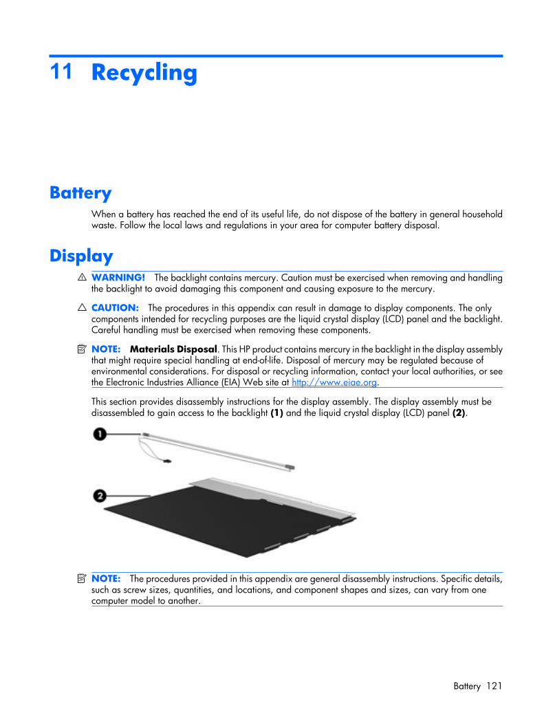
11 Recycling
BatteryWhen a battery has reached the end of its useful life, do not dispose of the battery in general householdwaste. Follow the local laws and regulations in your area for computer battery disposal.
DisplayWARNING! The backlight contains mercury. Caution must be exercised when removing and handlingthe backlight to avoid damaging this component and causing exposure to the mercury.
CAUTION: The procedures in this appendix can result in damage to display components. The onlycomponents intended for recycling purposes are the liquid crystal display (LCD) panel and the backlight.Careful handling must be exercised when removing these components.
NOTE: Materials Disposal. This HP product contains mercury in the backlight in the display assemblythat might require special handling at end-of-life. Disposal of mercury may be regulated because ofenvironmental considerations. For disposal or recycling information, contact your local authorities, or seethe Electronic Industries Alliance (EIA) Web site at http://www.eiae.org.
This section provides disassembly instructions for the display assembly. The display assembly must bedisassembled to gain access to the backlight (1) and the liquid crystal display (LCD) panel (2).
NOTE: The procedures provided in this appendix are general disassembly instructions. Specific details,such as screw sizes, quantities, and locations, and component shapes and sizes, can vary from onecomputer model to another.
Battery 121
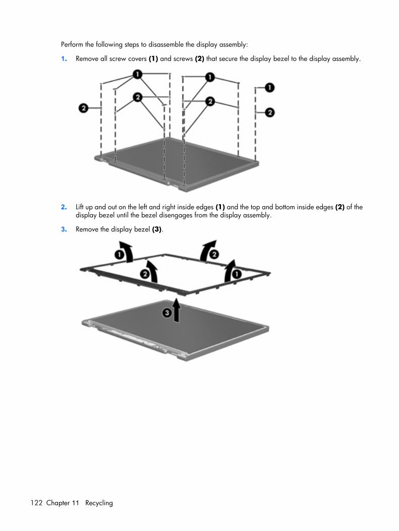
Perform the following steps to disassemble the display assembly:
1. Remove all screw covers (1) and screws (2) that secure the display bezel to the display assembly.
2. Lift up and out on the left and right inside edges (1) and the top and bottom inside edges (2) of thedisplay bezel until the bezel disengages from the display assembly.
3. Remove the display bezel (3).
122 Chapter 11 Recycling
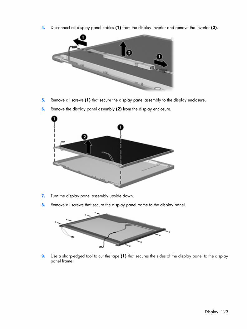
4. Disconnect all display panel cables (1) from the display inverter and remove the inverter (2).
5. Remove all screws (1) that secure the display panel assembly to the display enclosure.
6. Remove the display panel assembly (2) from the display enclosure.
7. Turn the display panel assembly upside down.
8. Remove all screws that secure the display panel frame to the display panel.
9. Use a sharp-edged tool to cut the tape (1) that secures the sides of the display panel to the displaypanel frame.
Display 123
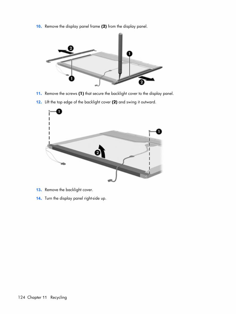
10. Remove the display panel frame (2) from the display panel.
11. Remove the screws (1) that secure the backlight cover to the display panel.
12. Lift the top edge of the backlight cover (2) and swing it outward.
13. Remove the backlight cover.
14. Turn the display panel right-side up.
124 Chapter 11 Recycling
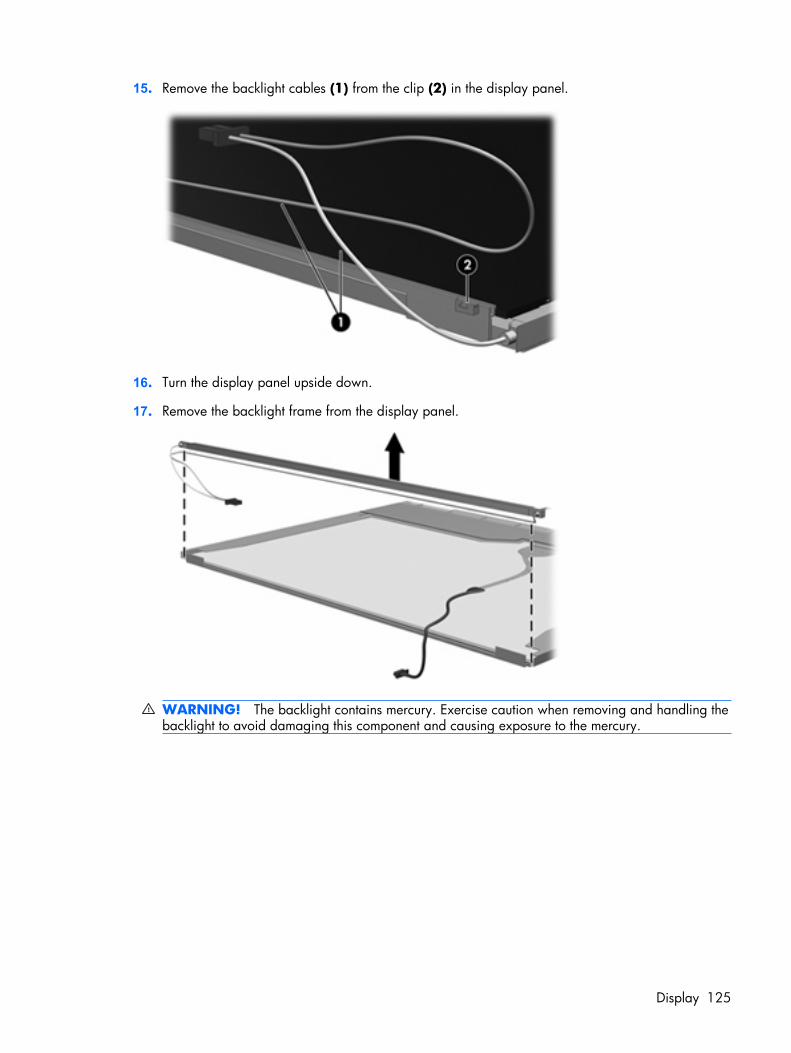
15. Remove the backlight cables (1) from the clip (2) in the display panel.
16. Turn the display panel upside down.
17. Remove the backlight frame from the display panel.
WARNING! The backlight contains mercury. Exercise caution when removing and handling thebacklight to avoid damaging this component and causing exposure to the mercury.
Display 125
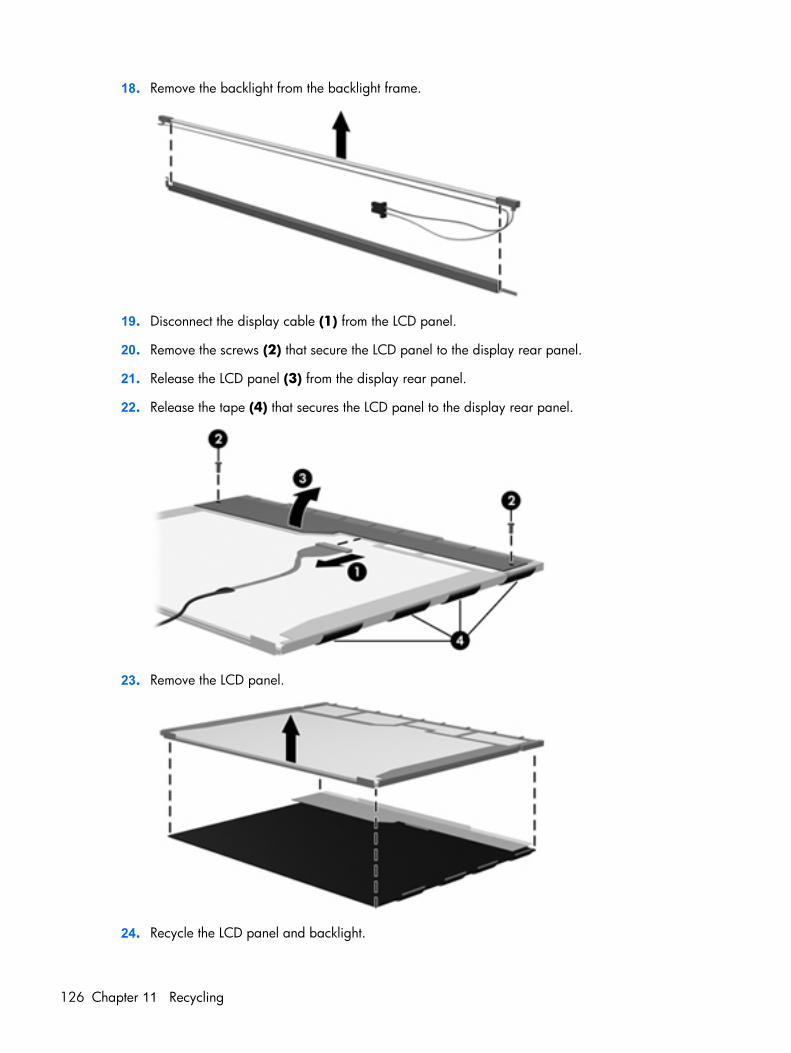
18. Remove the backlight from the backlight frame.
19. Disconnect the display cable (1) from the LCD panel.
20. Remove the screws (2) that secure the LCD panel to the display rear panel.
21. Release the LCD panel (3) from the display rear panel.
22. Release the tape (4) that secures the LCD panel to the display rear panel.
23. Remove the LCD panel.
24. Recycle the LCD panel and backlight.
126 Chapter 11 Recycling
Index
AAC adapter, spare part
number 24, 30administrator password 87advanced Setup Utility
features 86antenna
illustrated 20removal 59spare part number 20
applications key, Windows 7audio, product description 3audio-in jack
location 10pin assignments 115
audio-out jacklocation 10pin assignments 115
Bbackpack, spare part
number 24, 26backup 110base enclosure, spare part
numbers 17, 28battery
location 12removal 40spare part number 17, 28,
40battery bay 12battery light 8battery release latch 12boot options 87boot order 87bottom components 12button components 6button sound 87
buttonspower 6wireless 6
Ccables, service considerations 33camera cable
spare part numbers 31camera light location 5camera location 5camera module
removal 60spare part number 60spare part numbers 31
caps lock LED boardremoval 64spare part number 16, 29,
64caps lock light 8card reader board
removal 77spare part number 16, 29,
77carrying case, spare part
number 24, 26changing the Setup Utility
language 84chipset, product description 1closing the Setup Utility 86CMOS clearing 37components
bottom 12buttons 6display 5front 5, 10key 7left-side 11lights 8right-side 10TouchPad 9
composite audio and S-Video cable,spare part number 24, 26
computer feetlocations 39spare part number 39
computer specifications 88connector pin assignments
audio-in 115audio-out 115external monitor 116headphone 115microphone 115modem 117monitor 116network 117RJ-11 117RJ-45 117S-Video-out 118Universal Serial Bus (USB) 118
connectors, serviceconsiderations 33
DDiagnostics menu 87Digital Media Slot 11diskette drive
precautions 33product description 3
display assemblyremoval 55spare part numbers 15, 28,
31, 55display bezel
illustrated 20removal 57spare part numbers 20, 28,
30, 31, 57Display Cable Kit, spare part
number 20, 28, 59
Index 127
display componentsillustrated 20recycling 121spare part numbers 20
display enclosureillustrated 20spare part numbers 20, 28,
30display hinge
illustrated 20removal 58spare part number 20, 28,
58Display Hinge Kit, spare part
number 20display inverter
illustrated 20spare part number 20, 28
display panelillustrated 20product description 2removal 58, 59spare part number 20, 27,
59Display Rubber Kit, spare part
number 21, 28Display Screw Kit, spare part
number 21, 28display specifications 89display switch 5docking support, product
description 3drive light 8drives
boot order 87preventing damage 33
DVB-T antenna adapter, spare partnumber 24, 26
DVB-T tuner, spare partnumber 24, 26
DVD/CD-RW Combo Driveprecautions 33removal 48spare part number 19, 23,
28, 48specifications 91
DVD±RW and CD-RW Combo Driveprecautions 33removal 48
spare part numbers 19, 23, 28, 48
specifications 91
Eelectrostatic discharge 34enhanced SATA support 87esc key 7Ethernet, product description 3external media cards, product
description 3external monitor port
location 11pin assignments 116
Ffan
removal 68spare part number 16, 29,
68feet
locations 39spare part number 39
fingerprint reader 84fn key 7front components 5, 10function keys 7
Ggraphics, product description 2grounding equipment and
methods 36
Hhard drive
precautions 33product description 2removal 41spare part numbers 18, 23,
28, 41specifications 90
hard drive bay 12hard drive bay cover
illustrated 22removal 41
Hard Drive Kit, spare partnumber 18, 23, 28
hard drive self test 87headphone jack
location 10pin assignments 115
headset, spare part number 24, 26
heat sinkremoval 79spare part number 17, 29,
79
II/O address specifications 94infrared emitter, spare part
number 24, 26interrupt specifications 93inverter
removal 58spare part number 20, 28,
58
Jjacks
audio-in 10audio-out 10headphone 10microphone 10modem 11network 11RJ-11 11RJ-45 11S-Video-out jack 11
Kkey components 7keyboard
product description 4removal 50spare part numbers 15, 29,
50keypad keys 7keys
esc 7fn 7function 7Windows applications 7Windows logo 7
Llanguage support 84, 87LCD logo kit
spare part number 31left-side components 11light components 8
128 Index
lightsbattery 8caps lock 8drive 8num lock 8optical drive 10power 8wireless 8
Mmain menu 86mass storage devices, spare part
numbers 23memory map specifications 92memory module
product description 2removal 43spare part numbers 18, 28,
43memory/wireless module
compartment 12memory/wireless module
compartment coverillustrated 22removal 43spare part number 43
microphoneillustrated 20location 5product description 3removal 59
microphone jacklocation 10pin assignments 115
model name 1modem cable, spare part
number 16, 29modem jack
location 11pin assignments 117
modem, product description 3monitor port
location 11pin assignments 116
mouse, spare part numbers 24, 26
Nnavigating in the Setup Utility 85
network jacklocation 11pin assignments 117
num lock light 8
Ooperating system, product
description 4optical drive
location 10precautions 33product description 2removal 48spare part numbers 19, 23,
28, 48specifications 91
Optical Drive Kit, spare partnumber 19, 23, 28
optical drive light, location 10
Ppacking guidelines 35password clearing 37passwords 87plastic parts 32Plastics Kit
contents 22spare part number 16, 22,
28pointing device
components 9product description 4
portsexternal monitor port 11monitor port 11product description 3Universal Serial Bus (USB) 10,
11power button 6power connector 11power connector cable
removal 83spare part number 16, 29,
83power cord
set requirements 119spare part numbers 24, 26
power light 8power requirements, product
description 4
power-on password 87processor
product description 1removal 81spare part numbers 16, 27,
30, 81Processor C4 State 87product description
audio 3chipset 1diskette drive 3display panel 2docking support 3Ethernet 3external media cards 3graphics 2hard drives 2keyboard 4memory module 2microphone 3modem 3operating system 4optical drives 2pointing devices 4ports 3power requirements 4processors 1product name 1security 4serviceability 4wireless 3
product name 1
Rrecovery discs 113recovery, system 114remote control, spare part
numbers 24, 26removal/replacement
preliminaries 32procedures 38
restore points 111RF input adapter cable, spare part
number 24, 26right-side components 10RJ-11 jack
location 11pin assignments 117
Index 129
RJ-45 jacklocation 11pin assignments 117
RTC batteryremoval 75spare part number 17, 29,
75Rubber Foot Kit, spare part
number 17, 29, 39
SS-Video-out jack
location 11pin assignments 118
Screw Kitcontents 96spare part number 25, 29
screw listing 96secondary hard drive self test 87security cable slot 10Security menu 87security, product description 4selecting in the Setup Utility 85serial number 13, 38service considerations 32serviceability, product
description 4Setup Utility
changing the language 84Diagnostics menu 87displaying system
information 85Main menu 86navigating 85overview 84Security menu 87selecting 85starting 84System Configuration menu 87using advanced features 86
speakersremoval 70spare part number 16, 29,
70specifications
computer 88display 89DVD/CD-RW Combo Drive 91DVD±RW and CD-RW Combo
Drive 91
hard drive 90I/O addresses 94interrupts 93memory map 92optical drive 91system DMA 92
static-shielding materials 36switch cover
removal 53spare part number 15, 29,
53system board
removal 72spare part numbers 16, 27,
28, 30, 72System Configuration menu 87system DMA 92system information 85, 86system memory map 92
Tthermal paste, replacement 80tools required 32top components 6top cover
removal 62spare part number 16, 28,
31, 62TouchPad components
buttons 9left button 9light 9on/off button 9right button 9scroll zone 9TouchPad 9
transporting guidelines 35TV tuner antenna, spare part
number 24, 26TV tuner, spare part number 24,
26
UUniversal Serial Bus (USB) port
locations 10, 11pin assignments 118
unknown password 37
USB boardremoval 66spare part number 16, 29,
66
Vvents 11, 12Virtualization Technology 87volume hotkeys 6
WWindows applications key 7Windows logo key 7wireless antenna
illustrated 20removal 59spare part number 20
Wireless Antenna Kit, spare partnumber 20
wireless button 6wireless light 8wireless, product description 3WLAN module
removal 45spare part numbers 17, 27,
45workstation guidelines 35
130 Index