Embed Size (px)
Citation preview

HP Color LaserJet 1600Service Manual


HP Color LaserJet 1600
Service Manual

Copyright and License
© 2006 Copyright Hewlett-PackardDevelopment Company, L.P.
Reproduction, adaptation, or translationwithout prior written permission isprohibited, except as allowed under thecopyright laws.
The information contained in this documentis subject to change without notice.
The only warranties for HP products andservices are set forth in the expresswarranty statements accompanying suchproducts and services. Nothing hereinshould be construed as constituting anadditional warranty. HP shall not be liablefor technical or editorial errors or omissionscontained herein.
CB373-90930
Edition 1, 3/2006
FCC Class A Statement
This equipment has been tested and foundto comply with the limits for a Class Adigital device, pursuant to Part 15 of theFCC Rules. These limits are designed toprovide reasonable protection againstharmful interference when the equipment isoperated in a commercial environment.This equipment generates, uses and canradiate radio frequency energy and, if notinstalled and used in accordance with theinstruction manual, may cause harmfulinterference to radio communications.Operation of this equipment in a residentialarea is likely to cause harmful interference,in which case the user will be required tocorrect the interference at his ownexpense. The end user of this productshould be aware that any changes ormodifications made to this equipmentwithout the approval of Hewlett-Packardcould result in the product not meeting theClass A limits, in which case the FCCcould void the user’s authority to operatethe equipment.
Trademark Credits
Adobe Photoshop® and PostScript aretrademarks of Adobe Systems Incorporated.
CorelDRAW™ is a trademark or registeredtrademark of Corel Corporation or CorelCorporation Limited.
Microsoft®, Windows®, MS-DOS®, andWindows NT® are U.S. registeredtrademarks of Microsoft Corporation.
Netscape™ and Netscape Navigator™ areU.S. trademarks of NetscapeCommunications Corporation.
TrueType™ is a U.S. trademark of AppleComputer, Inc.
ENERGY STAR® and the ENERGY STARlogo® are U.S. registered marks of theUnited States Environmental ProtectionAgency. Details on the proper use of themarks are explained in the "Guidelines forProper use of the ENERGY STAR® Nameand International Logo."

Table of contents
1 Product informationQuick access to printer information.........................................................................................................2Printer configuration................................................................................................................................3Printer features........................................................................................................................................4Walk around.............................................................................................................................................6
Front view (shown with optional Tray 3).................................................................................6Back and side view.................................................................................................................7Control panel...........................................................................................................................8
Understanding supplies status...............................................................................8Understanding printer status..................................................................................8Understanding control panel layout.......................................................................9
Software.................................................................................................................................................11Supported drivers..................................................................................................................11
Software and supported operating systems........................................................11Software for Windows...........................................................................................................11Uninstalling Windows software.............................................................................................12
Print-media specifications......................................................................................................................13General guidelines................................................................................................................13Paper and print media...........................................................................................................13Printing and storage environment.........................................................................................13Envelopes.............................................................................................................................14Labels....................................................................................................................................16Transparencies.....................................................................................................................16Media support tables.............................................................................................................16
Supported print media for Tray 1, Tray 2, and optional Tray 3............................16Unsupported media (media to avoid)...................................................................17
2 InstallationSite preparation.....................................................................................................................................20
Operating environment.........................................................................................................20Minimum system requirements.............................................................................................21
Requirements for PC systems.............................................................................21Package contents..................................................................................................................................22Install input devices...............................................................................................................................23
Installing optional Tray 3.......................................................................................................23Loading Tray 1......................................................................................................................23Installing supplies..................................................................................................................25
Print cartridges.....................................................................................................25
ENWW iii

3 Managing and maintenanceManaging supplies.................................................................................................................................30
Life expectancies of replacement supplies...........................................................................30Checking and ordering supplies...........................................................................................30
To check status using the control panel..............................................................30To check and order supplies using HP Toolbox..................................................30
Storing supplies....................................................................................................................31Replacing and recycling supplies.........................................................................................31
Replacing the print cartridges..............................................................................31HP policy on non-HP supplies..............................................................................................31HP anti-counterfeit Web site.................................................................................................31
Cleaning the printer...............................................................................................................................32To clean the printer at the printer..........................................................................................32To clean the fuser using HP Toolbox...................................................................................33Cleaning spilled toner...........................................................................................................33
Calibrating the printer............................................................................................................................34To calibrate the printer at the printer....................................................................................34To calibrate the printer from the HP Toolbox........................................................................34
4 Operational theoryEngine control system...........................................................................................................................36
Basic sequence of operation................................................................................................36Power-on sequence..............................................................................................................37Motors and fans....................................................................................................................37
Main motor failure detection.................................................................................38Fan motor failure detection..................................................................................38
Image formation system........................................................................................................................39Image formation process......................................................................................................41
Latent image formation........................................................................................42Laser/scanner system..........................................................................................43
Developing stage..................................................................................................................43Print cartridge.......................................................................................................44Transfer belt (ETB)...............................................................................................45
Transfer stage.......................................................................................................................46Separation stage...................................................................................................................47Fusing stage.........................................................................................................................47
Pickup and feed system........................................................................................................................49Manual feed slot pickup mechanism....................................................................................51Paper feed mechanism.........................................................................................................51Skew correction by the registration shutter..........................................................................51Jam detection........................................................................................................................52Solenoid, motor, and fan locations.......................................................................................53Printed circuit assembly locations.........................................................................................53250-sheet tray solenoid and printed circuit locations...........................................................54
Service-only tools (service only)............................................................................................................56General timing chart..............................................................................................................56Printer calibration..................................................................................................................57
5 Removal and replacementOverview................................................................................................................................................60
iv ENWW

Service approach...................................................................................................................................61Pre-service procedures.........................................................................................................61
Removal and replacement procedures.................................................................................................62Print cartridge replacement...................................................................................................62ETB removal and replacement.............................................................................................64Fuser removal and replacement...........................................................................................73Formatter removal and replacement....................................................................................81DC controller removal and replacement...............................................................................85Separation pad removal and replacement............................................................................88Paper pickup roller removal and replacement......................................................................89Control panel removal and replacement...............................................................................91
6 TroubleshootingTroubleshooting process.......................................................................................................................98
Troubleshooting checklist.....................................................................................................98Clearing jams ......................................................................................................................................100
Paper path..........................................................................................................................100Common causes of paper jams..........................................................................................101Where to look for jams........................................................................................................102Jams inside the printer........................................................................................................103Input jams...........................................................................................................................104
Tray 1.................................................................................................................104Tray 2.................................................................................................................105
Output jams.........................................................................................................................105Jams in the top bin.............................................................................................105Pickup delay jam................................................................................................106Pickup stationary jam.........................................................................................106Delivery delay jam..............................................................................................106
Wrapping jam......................................................................................................................106Delivery stationary jam.......................................................................................................106Start-up residual paper jam................................................................................................106Door open jam....................................................................................................................107
Print problems......................................................................................................................................108Getting information..............................................................................................................108
Control panel messages....................................................................................108Alert and warning messages.............................................................108Critical error messages.....................................................................109Supplies messages...........................................................................110Status messages...............................................................................113Status log only messages.................................................................113
Reports menu.....................................................................................................114Configuration page.............................................................................................115Supplies Status page.........................................................................................117Menu map..........................................................................................................117Status log...........................................................................................................118Service menu settings........................................................................................120Secondary service menu....................................................................................120
Printed image quality problems..........................................................................................121Improving print quality........................................................................................121
Paper Types menu............................................................................121
ENWW v

Print Modes menu.............................................................................122Print quality menu..............................................................................122
Understanding print-quality settings...................................................................123To temporarily change print-quality settings.....................................123To change print-quality settings for all future jobs............................123
Identifying and correcting printed image defects...............................................124Print-quality checklist.........................................................................124
Paper handling issues........................................................................................................124Wrong size/type media.......................................................................................124Cannot select a tray or feature to use................................................................125
Performance problems.......................................................................................................125Functional tests (service only).............................................................................................................127
Engine test print..................................................................................................................127Service mode functions (service only).................................................................................................128
Cold reset............................................................................................................................128NVRAM initializer................................................................................................................128Super NVRAM initializer.....................................................................................................128Restoring page counts and serial number..........................................................................129Cleaning the ETB................................................................................................................129
Troubleshooting tools..........................................................................................................................130Printer pages and reports...................................................................................................130
Demo page.........................................................................................................130Configuration page.............................................................................................131Event log............................................................................................................132Supplies Status page.........................................................................................132Fuser cleaning page...........................................................................................133Print quality troubleshooting pages....................................................................133Control panel messages (error codes)..............................................................133
Alert and warning messages.............................................................133Critical error messages.....................................................................135Supplies messages...........................................................................135
Status messages................................................................................................................138Status log only messages...................................................................................................139Service menu......................................................................................................................139
Restoring the factory-set defaults......................................................................139To restore the factory-set defaults....................................................139
General print quality issues................................................................................................139Solving issues with color documents..................................................................................143
HP Toolbox..........................................................................................................................................146HP Toolbox.........................................................................................................................146
To view HP Toolbox...........................................................................................146Troubleshooting tab...........................................................................................146
Print quality troubleshooting pages....................................................................................146Printer calibration................................................................................................................146Cleaning page.....................................................................................................................146Configuration page..............................................................................................................147
Diagnostic resources...........................................................................................................................148Reports menu.....................................................................................................................148Web diagnostics tools.........................................................................................................148
Repetitive image defect ruler...............................................................................................................149
vi ENWW

Firmware and software updates..........................................................................................................150
7 Parts and diagramsOverview..............................................................................................................................................152Assembly locations..............................................................................................................................156Covers.................................................................................................................................................162Internal assemblies..............................................................................................................................164Input devices........................................................................................................................................188Diagrams.............................................................................................................................................210Alphabetical parts list...........................................................................................................................211Numerical parts list..............................................................................................................................240
Appendix A Product specificationsPhysical specifications.........................................................................................................................270Replacement supplies specifications..................................................................................................271
Print cartridge life................................................................................................................271Electrical specifications.......................................................................................................................272Environmental specifications...............................................................................................................273Acoustical specifications......................................................................................................................274
Appendix B Product warranty statementsHewlett-Packard limited warranty statement.......................................................................................276Print Cartridge Limited Warranty Statement.......................................................................................277
Appendix C Regulatory statementsDeclaration of Conformity....................................................................................................................280Laser safety statement........................................................................................................................281Canadian DOC statement...................................................................................................................281VCCI statement (Japan)......................................................................................................................281Korean EMI statement.........................................................................................................................281Finnish laser statement.......................................................................................................................282
Index....................................................................................................................................................................283
ENWW vii

viii ENWW

1 Product information
This section provides information about the following topics:
● Quick access to printer information
● Printer configuration
● Printer features
● Walk around
● Software
● Print-media specifications
ENWW 1

Quick access to printer informationUser guide
Contains detailed information for using the printer and troubleshooting problems. This guide isavailable in two formats on the CD-ROM that came with the printer: in PDF format for printing andHTML format for online viewing. It is also available through the HP Toolbox software.
Getting started guide
Provides step-by-step instructions for installing and setting up the printer.
HP Toolbox
Use to check the printer status and settings and to view troubleshooting information and onlinedocumentation.
2 Chapter 1 Product information ENWW

Printer configurationHP Color LaserJet 1600
The HP Color LaserJet 1600 printer is available in the configuration described below.
Figure 1-1 HP Color LaserJet 1600 printer
The HP Color LaserJet 1600 printer is a four-color laser printer that prints eight pages per minute(ppm) in both monochrome (black and white) and color.
● Trays. The printer comes with a single sheet priority feed slot (Tray 1) and a universal tray(Tray 2) that holds up to 250 sheets of various paper types and sizes or 10 envelopes. Itsupports an optional 250-sheet paper tray (optional Tray 3).
● Connectivity. The printer provides a Hi-Speed Universal Serial Bus (USB) 2.0 port forconnectivity.
● Memory. The printer contains 16 megabytes (MB) of synchronous dynamic random accessmemory (SDRAM). No additional memory can be added.
ENWW Printer configuration 3

Printer featuresTable 1-1 Printer features
Feature HP Color LaserJet 1600 printer
Color printing ● Provides laser printing in full color by using the fourprocess colors: cyan, magenta, yellow, and black(CMYK).
Fast print speed ● Prints in black on letter-size paper up to 8 ppm and onA4-size paper up to 8 ppm. Prints in color on A4/letterat 8 ppm.
Excellent print quality ● ImageREt 2400 provides 2400 dpi equivalent colorquality through a multilevel printing process.
● True 600 by 600 dots per inch (dpi) text and graphics.
● Adjustable settings to optimize print quality.
● The HP UltraPrecise print cartridge has a finer tonerformulation that provides sharper text and graphics.
Ease of use ● Few supplies to order. Supplies are easy to install.
● Convenient access to printer information and settingsby using the HP Toolbox software.
● Convenient access to all supplies and to the paper paththrough the front door.
Flexible paper handling ● Trays 1 and 2 for letterhead, envelopes, labels,transparencies, custom-sized media, postcards,HP LaserJet glossy paper, HP LaserJet Tough paper,heavy paper, and HP Laser Photo paper.
● A 125-sheet top output bin.
● Print on Both Sides (manually).
Interface connections ● Hi-Speed USB 2.0 port.
Energy savings ● The printer automatically conserves electricity bysubstantially reducing power consumption when it isnot printing.
● As an ENERGY STAR® partner, Hewlett-PackardCompany has determined that this product meetsENERGY STAR® guidelines for energy efficiency.ENERGY STAR® is a U.S. registered service mark ofthe United States Environmental Protection Agency.
Economical printing ● N-up printing (printing more than one page on a sheet)and Printing on Both Sides features save paper.
Supplies ● A Supplies Status page with print cartridge gauges thatshow the supply levels that remain. For HP suppliesonly.
● No-shake cartridge design.
● Authentication for HP print cartridges.
4 Chapter 1 Product information ENWW

Feature HP Color LaserJet 1600 printer
● Internet-enabled, supplies-ordering capability.
● Introductory black, yellow, cyan, and magenta printcartridges — approximately 1,000 pages each basedon approximately 5% coverage per color. SeeManaging supplies on page 30.
Accessibility ● Online user guide that is compatible with text screen-readers.
● All doors and covers can be opened by using one hand.
Expandability ● Optional Tray 3. This 250-sheet universal tray reduceshow often you have to add paper to the printer. Onlyone additional 250-sheet tray can be installed on theprinter.
Memory ● 16 MB of DRAM.
NOTE No additional memory can be added.
Table 1-1 Printer features (continued)
ENWW Printer features 5

Walk aroundThe following illustrations identify the locations and names of key components of this printer.
Front view (shown with optional Tray 3)
Figure 1-2 Front view (shown with optional Tray 3)
1 Output bin
2 Printer control panel
3 Front door
4 Tray 2 (250 sheets)
5 Tray 1 (single sheet priority feed slot)
6 Tray 3 (optional; 250 sheets)
6 Chapter 1 Product information ENWW

Back and side view
Figure 1-3 Back and side view
1 On/off switch
2 Power connection
3 Engine test button access door
4 Access door
5 Dust cover
7 USB connection
Figure 1-4 Transfer belt (ETB) and print cartridges
1 Transfer belt (ETB)
2 Print cartridges
CAUTION Do not place anything on the transfer belt, which is located on the inside of thefront door. Otherwise, the printer may be damaged, adversely affecting print quality.
ENWW Walk around 7

Model and serial number location
The model number and serial numbers are listed on identification labels located on the rear of theprinter. The model number is alphanumeric, such as Q6455A, for the HP Color LaserJet 1600printer. The serial number contains information about the country/region of origin, the printer version,production code, and the production number of the printer.
Figure 1-5 Model and serial number information
Control panel
Understanding supplies statusThe supplies gauges show the consumption levels of print cartridges (black, yellow, cyan, andmagenta).
Black, yellow, cyan, and magenta supplies status gauges
A ? appears instead of the consumption level when the level is not known. This can occur in thefollowing circumstances:
● Missing cartridges
● Incorrectly placed cartridges
● Cartridges with an error
● Some non-HP cartridges
The supplies gauge appears whenever the printer shows the Ready state with no warnings. It willalso appear when the printer shows a warning or error message concerning a print cartridge ormultiple supplies. If a supply is empty, the gauge will flash.
Understanding printer status
Cancel Job button
● When the Ready light is blinking, pressing (Cancel Job) cancels the current job.
● When a supplies status gauge is blinking and the Attention light is on (indicating that a non-HPsupply has been installed), pressing (Select) allows you to continue printing.
8 Chapter 1 Product information ENWW

CAUTION You might not receive any indication when a non-HP supply is empty. For moreinformation about using non-HP print cartridges, see HP policy on non-HP supplieson page 31. If you continue printing after the supply is empty, damage to the printer can occur.See Hewlett-Packard limited warranty statement on page 276.
Attention light
Generally, the Attention light blinks when the printer is out of paper, when a jam has occurred, orwhen other problems that need attention occur.
The Attention light is on and one of the Supplies Status gauges is blinking the first time a non-HPsupply is installed.
Ready light
The Ready light is on when the printer is ready to print (experiencing no errors that prevent printing)and blinks when it is receiving data to be printed.
Ready light and Select button
● When the Ready light is on and the Attention light is blinking, pressing (Select) continues theprint job after you load print media for a manual feed, or clears some errors.
● When the Ready light is blinking, the front door has been opened and then closed. Press (Select) to return the printer to the Ready state. If you do not press (Select), the printerreturns to the Ready state on its own.
Left and Right arrow buttons
Use the (Left arrow) and (Right arrow) buttons to navigate through the printer control panelmenus.
A Demo page can be printed by pressing the (Left arrow) and (Right arrow) buttonssimultaneously.
Understanding control panel layoutThis section provides information about printer status and control panel layout.
Control panel layout
The printer contains the following lights and buttons on the control panel:
ENWW Walk around 9
1Figure 1-6 Control panel layout
1 Color print cartridge indicators
2 Attention light (amber)
3 Ready light (green)
4Cancel Job button
5 Message area
6 Right arrow button
7 Select button
8 Left arrow button
Display
Figure 1-7 Control panel display
The printer display gives you information about the printer, job status, and levels of supplies.
1 Message area
2 Supplies gauges
3 Print cartridge colors are indicated from left to right: black, yellow, cyan, and magenta
10 Chapter 1 Product information ENWW

SoftwareThis section contains information about the software used with the HP Color LaserJet 1600 printer.
Supported drivers
Software and supported operating systemsFor easy printer setup and access to the full range of printer features, HP strongly recommends thatyou install the software that is provided. Not all software is available in all languages. See the GettingStarted Guide for installation instructions, and see the Readme file for the latest software information.
The most recent drivers, additional drivers, and other software are available from the Internet andother sources.
The printer supports the following operating systems:
● Microsoft® Windows® 98 Second Edition and Windows Millennium Edition (Me) (Add Printerinstallation)
● Microsoft® Windows® 2000 and Windows XP
● Microsoft® Windows® Server 2003
The following table lists the software that is available for your operating system.
Table 1-2 HP Color LaserJet 1600 printer software
Feature Windows 98 SecondEdition, Me
Windows 2000 Windows XP
Windows Installer
Windows printer driver
HP Toolbox software
Software for WindowsWhen you install the software for Windows, you can directly connect the printer to a computer byusing a USB cable. See the Getting Started Guide for installation instructions, and see the Readmefile for the latest software information.
The following software is available to all users of the printer.
Printer drivers
A printer driver is a software component that provides access to printer features and provides themeans for the computer to communicate with the printer.
Using Help
The printer driver has Help dialog boxes that can be activated from the Help button in the printerdriver, the F1 key on the computer keyboard, or the question mark symbol (?) in the upper-right
ENWW Software 11

corner of the printer driver. These Help dialog boxes give detailed information about the specificprinter driver. Help for the printer driver is separate from the Help for your program.
HP Toolbox
You must perform a complete software installation to use the HP Toolbox.
The HP Toolbox provides links to printer status information and help information, such as the userguide; and tools for diagnosing and solving problems. You can also view explanations andanimations on the control panel. See Managing and maintenance on page 29 for more information.
Uninstalling Windows softwareAfter a printing system installation, use the uninstall icon in the HP Color LaserJet 1600 printerprogram group to select and remove any or all of the HP printing system components.
Starting the Uninstaller
1. Click Start, select Programs (All Programs for Windows XP) and choose HP.
2. In the HP Color LaserJet 1600 program group, click the HP Color LaserJet 1600 uninstallicon.
3. The uninstaller guides you through removing the printing system components.
NOTE For driver-only (Add Printer/New Driver) installations, delete the printer icon from thePrinters folder (Windows 98 Second Edition, Windows Me, Windows 2000, and Windows XP).
12 Chapter 1 Product information ENWW

Print-media specificationsThis section contains information about specifications for the quality of print media, guidelines forprint media usage, and guidelines for print media storage.
General guidelinesSome print media might meet all of the guidelines in this manual and still not produce satisfactoryresults. This problem might be the result of improper handling, unacceptable temperature andhumidity levels, or other variables over which Hewlett-Packard has no control.
Before purchasing large quantities of print media, always test a sample and make sure that the printmedia meets the requirements specified in the HP LaserJet Printer Family Print Media Guideavailable at http://www.hp.com/support/ljpaperguide.
CAUTION Using print media that does not meet HP specifications can cause problems forthe printer, requiring repair. This repair is not covered by the Hewlett-Packard warranty orservice agreements.
CAUTION Use only paper designed for laser printers. Paper for inkjet printers may damagethe printer.
This printer accepts a variety of media, such as cut-sheet paper (including up to 100% recycled-fiber-content paper), envelopes, labels, transparencies, HP LaserJet glossy paper, HP LaserJet Toughpaper, HP LaserJet Photo paper, and custom-size paper. Properties such as weight, composition,grain, and moisture content are important factors that affect printer performance and output quality.Print media that does not meet the guidelines outlined in this manual can cause the followingproblems:
● Poor print quality
● Increased jams
● Premature wear on the printer, requiring repair
Paper and print mediaFor print-media specifications, see Media support tables on page 16.
Printing and storage environmentIdeally, the printing and media-storage environment should be at or near room temperature, and nottoo dry or too humid. Remember that paper is hygroscopic; it absorbs and loses moisture rapidly.
Heat works with humidity to damage paper. Heat causes the moisture in paper to evaporate, whilecold causes it to condense on the sheets. Heating systems and air conditioners remove most of thehumidity from a room. As paper is opened and used, it loses moisture, causing streaks andsmudging. Humid weather or water coolers can cause the humidity to increase in a room. As paper isopened and used it absorbs any excess moisture, causing light print and dropouts. Also, as paperloses and gains moisture it can distort. This issue can cause jams.
As a result, paper storage and handling are as important as the paper-making process itself. Paperstorage environmental conditions directly affect the feed operation and print quality.
ENWW Print-media specifications 13

Care should be taken not to purchase more paper than can be easily used in a short time (aboutthree months). Paper stored for long periods can experience heat and moisture extremes, which cancause damage. Planning is important to prevent damage to a large supply of paper.
Unopened paper in sealed reams can remain stable for several months before use. Openedpackages of paper have more potential for environmental damage, especially if they are not wrappedwith a moisture-proof barrier.
The media-storage environment should be properly maintained to ensure optimum printerperformance. The required condition is 20° to 24°C (68° to 75°F), with a relative humidity of 45% to55%. The following guidelines should be helpful when evaluating the paper's storage environment:
● Print media should be stored at or near room temperature.
● The air should not be too dry or too humid (to moderate the hygroscopic properties of paper).
● The best way to store an opened ream of paper is to rewrap it tightly in its moisture-proofwrapping. If the printer environment is subject to extremes, unwrap only the amount of paper tobe used during the day's operation to prevent unwanted moisture changes.
● Avoid storing paper and print media near heating and air conditioning vents or near windowsand doors that are frequently open.
EnvelopesEnvelopes can be printed from Tray 1 or Tray 2. Select the type of envelope that you are using fromthe Print dialog box or the printer driver.
In your program, set the margins for the envelope. The following table gives typical address marginsfor a commercial #10 or DL envelope.
Table 1-3 Envelope specifications
Type of address Top margin Left margin
Return address 15 mm (0.6 inch) 15 mm (0.6 inch)
Delivery address 51 mm (2 inches) 89 mm (3.5 inches)
● For the best print quality, position margins no closer than 15 mm (0.6 inch) from the edges ofthe envelope.
● Avoid printing over the area where the envelope seams meet.
Envelope storage
Proper storage of envelopes helps contribute to print quality. Envelopes should be stored flat. If air istrapped in an envelope and creates an air bubble, then the envelope might wrinkle during printing.
Envelope construction
Envelope construction is critical. Envelope fold lines can vary considerably, not only betweenmanufacturers, but also within a box from the same manufacturer. Successful printing on envelopes
14 Chapter 1 Product information ENWW

depends upon the quality of the envelopes. When selecting envelopes, consider the followingcomponents:
● Weight: The weight of the envelope paper should not exceed 90 g/m2 (24 lb) or jamming mightoccur.
● Construction: Before printing, envelopes should lie flat with less than 6 mm (0.25 inch) curl,and should not contain air.
● Condition: Envelopes should not be wrinkled, nicked, or otherwise damaged.
● Temperature: Use envelopes that are compatible with the heat and pressure of the printer. Thisprinter fusing temperature is 210°C (410°F).
● Size: Use only envelopes that are within the following size ranges.
Table 1-4 Envelope size ranges
Tray Minimum Maximum
Tray 1 or Tray 2 76 x 127 mm (3 x 5 inches) 216 x 356 mm (8.5 x 14 inches)
Envelopes with double side-seams
Double side-seam construction has vertical seams at both ends of the envelope rather than diagonalseams. This style might be more likely to wrinkle. Be sure the seam extends all the way to the cornerof the envelope as illustrated below.
1
2
Figure 1-8 Envelope double side-seam construction
1 Acceptable
2 Unacceptable
Envelopes with adhesive strips or flaps
Envelopes with a peel-off adhesive strip or with more than one flap that folds over to seal must useadhesives that are compatible with the heat and pressure in the printer. The extra flaps and stripsmight cause wrinkling, creasing, or even jams and might damage the fuser.
ENWW Print-media specifications 15

LabelsSelect the type of label that you are using from the Print dialog box or the printer driver.
CAUTION To avoid damaging the printer, use only labels that are recommended for laserprinters. To prevent serious jams, always use Tray 1 or Tray 2 to print on labels. Never printon the same sheet of labels more than once or print on a partial sheet of labels.
When selecting labels, consider the quality of each component:
● Adhesives: The adhesive material should be stable at 210°C (410°F), which is the printerfusing temperature.
● Arrangement: Only use labels with no exposed backing between them. Labels can peel offsheets with spaces between the labels, causing serious jams.
● Curl: Before printing, labels must lie flat with no more than 13 mm (0.5 inch) of curl in anydirection.
● Condition: Do not use labels that have wrinkles, bubbles, or other indications of separation.
TransparenciesUse only Tray 1 or Tray 2 to print on transparencies. Select Transparencies from the Print dialogbox or the printer driver.
The printer supports printing on color transparencies. Use only transparencies that arerecommended for use in laser printers.
Transparencies that are used in the printer must be able to withstand 210°C (410°F), which is theprinter fusing temperature.
CAUTION To avoid damage to the printer, use only transparencies that are recommendedfor use in laser printers.
Media support tablesThis section contains information about the sizes, weights, and capacities of paper and other printmedia that each tray supports.
Supported print media for Tray 1, Tray 2, and optional Tray 3This section contains information about the sizes, weights, and capacities of paper and other printmedia that each tray supports.
Tray 1 and Tray 2 specifications
Table 1-5 Tray 1 and Tray 2 specifications
Tray 1 and Tray 2 Dimensions1 Weight Capacity2
Paper Minimum: 76 x 127 mm(3 x 5 inches)
Maximum: 216 x 356 mm(8.5 x 14 inches)
60 to 163 g/m2 (16 to 43 lb) Single sheet of 75 g/m2
(20 lb) paper for Tray 1
Up to 250 sheets for Tray 2
16 Chapter 1 Product information ENWW

Tray 1 and Tray 2 Dimensions1 Weight Capacity2
HP LaserJet glossy paperand HP LaserJet photo paper
Same as the precedinglisted minimum andmaximum sizes.
75 to 163 g/m2 (20 to 43 lb) Single sheet of HP LaserJetglossy paper or HP LaserJetphoto paper for Tray 1
Up to 25 mm (0.99 inch)stack height for Tray 2
HP Premium Cover paper3 200 g/m2 (75 lb) cover Single sheet of HP Coverpaper for Tray 1
Up to 25 mm (0.99 inch)stack height for Tray 2
Transparencies and opaquefilm
Thickness: 0.10 to 0.13 mm(3.9 to 5.1 mils)
Single sheet of transparencyor opaque film for Tray 1
Up to 50 sheets for Tray 2
Labels Thickness: up to 0.23 mm(up to 9 mils)
Single sheet of labels forTray 1
Up to 25 mm (0.99 inch)stack height for Tray 2
Envelopes Up to 90 g/m2 (16 to 24 lb) Single envelope for Tray 1
Up to ten envelopes forTray 2
1 The printer supports a wide range of standard and custom sizes of print media. Check the printer driver for supported sizes.2 Capacity can vary depending on media weight and thickness, and environmental conditions.3 Hewlett-Packard does not guarantee results when printing with other types of heavy paper.
Optional Tray 3 specifications
Table 1-6 Optional Tray 3 specifications
Optional Tray 3 (250–sheettray)
Dimensions1 Weight Capacity2
Paper Minimum: 76 x 127 mm(3 x 5 inches)
Maximum: 216 x 356 mm(8.5 x 14 inches)
60 to 163 g/m2 (16 to 43 lb) Up to 250 sheets
1 The printer supports a wide range of standard and custom sizes of print media. Check the printer driver for supported sizes.2 Capacity can vary depending on media weight and thickness, and environmental conditions.
Unsupported media (media to avoid)Avoid using the following media:
● Paper that has been stapled. Staples left in reused paper will cause printer damage that willrequire repairs that may not be covered under the warranty.
● Sheets of labels that have been used more than once or partial sheets of labels
● Labels that are not specifically recommended for laser printers
Table 1-5 Tray 1 and Tray 2 specifications (continued)
ENWW Print-media specifications 17

● Labels that are separating from the backing sheet or are wrinkled or damaged in any way
● Transparencies that are not specifically recommended for laser printers
● Media that has been stored in a high-humidity environment
● Labels with exposed glue or adhesive
18 Chapter 1 Product information ENWW

2 Installation
This chapter contains information about the following topics.
● Site preparation
● Package contents
● Install input devices
ENWW 19

Site preparationBelow are recommendations for the printer location and placement.
Operating environmentThe printer must be kept in a proper location to maintain the performance level that has been set atthe factory. In particular, be sure that the environment adheres to the specifications listed in thischapter.
The printer must have 2 inches of space above and around it.
Figure 2-1 Printer dimensions
1 Front view
2 Side view
Make sure the printer has the following:
● A well-ventilated, dust-free area
● As surface that will support up to 18 kg (40 lbs)
● A constant temperature and humidity (Do not install near water sources, humidifiers, airconditioners, refrigerators, or other major appliances.)
● A hard level surface (not more than a 2° angle)
Make sure to keep the printer away from the following:
● Direct sunlight, dust, open flames, or water
● Direct flow of exhaust from air ventilation systems
● Magnets and devices that emit a magnetic field
20 Chapter 2 Installation ENWW

● Areas subject to vibration
● Walls or other objects. There must be enough space around the printer for proper access andventilation
Minimum system requirementsThe minimum system requirements for the HP Color LaserJet 1600 printer are listed below:
● 150 MB of free hard disk space
● CD-ROM drive
● Available USB port
Requirements for PC systems● Windows 98 SE and Me (driver only)
● Windows 2000 and XP (32-bit Home and Professional)
● 233 MHz processor with 64 MB RAM
ENWW Site preparation 21
Package contentsFigure 2-2 Package contents on page 22 lists the package contents for the HP Color LaserJet 1600.
Figure 2-2 Package contents
1 HP Color LaserJet 1600
2 Output tray
3 Power cable
4 Dust cover
5 Getting Started Guide
6 Software and user documentation CD-ROM
22 Chapter 2 Installation ENWW

Install input devicesInstalling optional Tray 31. Turn off the power switch on the printer.
2. Unplug the power cable.
3. Place the printer on optional Tray 3, aligning the three (3) pegs on Tray 3 with the holes on theprinter.
Loading Tray 1Tray 1 (the single sheet priority feed slot) prints single sheets of print media or a single envelope.Use Tray 1 when feeding one sheet of paper, or one envelope, postcard, label, HP LaserJet glossypaper, HP LaserJet Photo paper, or transparency. You can also use Tray 1 to print the first page ondifferent media than the rest of the document.
ENWW Install input devices 23

For information about loading special print media such as envelopes, labels, and transparencies, seePrint-media specifications on page 13.
To load Tray 1
1. Media guides ensure that the media is correctly fed into the printer and that the print is notskewed. Slide the media-width guides slightly wider than the print media.
2. Feed print media into Tray 1 with the side to be printed down, and the top, short edge in first.Make sure that the media is inserted far enough into the printer for the paper feed mechanismto grab the media. The paper will reach the sensor after 140 mm (5.5 inches) has been inserted.The printer will then pause for .5 second before it pulls the paper into the printer. HPrecommends holding the paper on both sides when inserting.
NOTE Light weight paper may buckle if held only on the short (far) edge as it isinserted. As paper is inserted, it trips the registration shutter. For light weight paper,holding it on both sides near the slot increases the ability for the paper to appropriatelytrip this shutter.
24 Chapter 2 Installation ENWW

Installing supplies
Print cartridgesWhen a print cartridge approaches the end of useful life, the control panel displays a messagerecommending that you order a replacement. The printer can continue to print using the current printcartridge until the control panel displays a message instructing you to replace the cartridge.
The printer uses four colors and has a different print cartridge for each color: black (K), cyan (C),magenta (M), and yellow (Y).
Replace a print cartridge when the printer control panel displays one of the following messages:Replace yellow cartridge, Replace magenta cartridge, Replace cyan cartridge, Replace blackcartridge. The control panel display also indicates the color that should be replaced (unless agenuine HP cartridge is not currently installed).
To change the print cartridge
1. Turn off the printer.
2. Open the front door.
CAUTION Do not place anything on the transfer belt (ETB), which is located onthe inside of the front door.
3. Remove the used print cartridge from the printer.
ENWW Install input devices 25

4. Remove the new print cartridge from the bag. Place the used print cartridge in the bag forrecycling.
5. Grasp both sides of the print cartridge by the blue handles and distribute the toner by gentlyrocking the print cartridge from front to back.
CAUTION Do not touch the shutter or the surface of the roller.
6. Remove the orange shipping locks and the orange shipping tape from the new print cartridge.Discard the shipping tape and shipping locks according to local regulations.
26 Chapter 2 Installation ENWW

7. Align the print cartridge with the tracks inside the printer, and using the handles, insert the printcartridge until it is firmly seated.
8. Firmly close the front door.
9. Turn on the printer. After a short time, the control panel should display Ready.
NOTE If a cartridge is in the wrong slot or is the wrong type for the printer, the controlpanel will display one of the following messages: Incorrect yellow, Incorrect magenta,Incorrect cyan, Incorrect black.
10. Installation is complete. Place the used print cartridge in the box in which the new cartridgearrived. See the enclosed recycling guide for recycling instructions.
11. If you are using a non-HP print cartridge, check the printer control panel for further instructions.For more information about using non-HP print cartridges, see HP policy on non-HP supplieson page 31.
NOTE When replacing or changing a black print cartridge, a cleaning page willautomatically print. This helps prevent speckles on the front or back of printeddocuments. A cleaning page can also be generated using the control panel or theHP Toolbox. For information, see To clean the printer at the printer on page 32 or Toclean the fuser using HP Toolbox on page 33.
ENWW Install input devices 27

28 Chapter 2 Installation ENWW

3 Managing and maintenance
This chapter contains information about the following topics.
● Managing supplies
● Cleaning the printer
● Calibrating the printer
ENWW 29

Managing suppliesLife expectancies of replacement suppliesTable 3-1 Replacement print cartridge life
Replacement print-cartridge life (based on approximately 5%coverage)
Black: 2,500 pages
Yellow, cyan, and magenta: 2,000 pages each
Checking and ordering suppliesYou can check the supplies status by using the printer control panel, printing a Supplies Status page,or viewing the HP Toolbox. Hewlett-Packard recommends that you place an order for a replacementprint cartridge when you first receive the Order message for a print cartridge. For typical use, theOrder message indicates that approximately two weeks of life remains. When you use a new,authentic HP print cartridge, you can obtain the following types of supplies information:
● Amount of cartridge remaining
● Estimated number of pages remaining
● Number of pages printed
● Other supplies information
NOTE When the printer is directly connected to a computer, you can set HP Toolbox tonotify you when supplies are low.
To check status using the control panelDo one of the following:
● Check the supplies status gauges on the printer control panel. These gauges indicate when aprint cartridge is low or empty. The lights also indicate when a non-HP print cartridge is firstinstalled.
● To print the Supplies Status page from the printer, on the printer control panel, select Reports,Supplies Status, and then (Select). See Supplies Status page on page 132 for moreinformation.
If the supplies levels are low, you can order supplies through your local HP dealer, by telephone, oronline.
To check and order supplies using HP ToolboxYou can configure HP Toolbox to notify you when the supplies are low. You can choose to receivealerts by e-mail or as a pop-up message or taskbar icon. To order supplies using the HP Toolbox, inthe Other Links area, click Order supplies. You must have Internet access to connect to the Website.
30 Chapter 3 Managing and maintenance ENWW
Storing suppliesFollow these guidelines for storing print cartridges:
● Do not remove the print cartridge from its package until you are ready to use it.
CAUTION To prevent damage, do not expose the print cartridge to light for more than afew minutes.
● See Environmental specifications on page 273 for operating and storage temperature ranges.
● Store the supply in a horizontal position.
● Store the supply in a dark, dry location away from heat and magnetic sources.
Replacing and recycling supplies
Replacing the print cartridgesTo install a new HP print cartridge, follow the instructions that are included on the box that containsthe new supply, or see the Getting Started Guide.
To recycle supplies, place the used supply in the box in which the new supply arrived. Use theenclosed return label to send the used supply to HP for recycling. For complete information, see therecycling guide that is included with each new HP supply item. Go to http://www.hp.com/go/recyclefor more information about HP's recycling program.
HP policy on non-HP suppliesHewlett-Packard Company cannot recommend the use of non-HP supplies, either new orremanufactured. Because they are not HP products, HP cannot influence their design or control theirquality. Service or repairs required as a result of using a non-HP supply will not be covered underthe printer warranty.
When you insert a supply into the printer, the printer will inform you if the supply is not a genuine HPsupply. If you insert a genuine HP supply that has reached the low state from another HP printer, theprinter identifies the supply as non-HP. Simply return the supply to the original printer to reactivateHP features and functionality.
HP anti-counterfeit Web siteVisit the HP anti-counterfeit Web site at http://www.hp.com/go/anticounterfeit if the supplies statusgauges or HP Toolbox indicates that the print cartridge is not an HP print cartridge and you think thatit is genuine.
ENWW Managing supplies 31

Cleaning the printerDuring the printing process, paper, toner and dust particles can accumulate inside the printer. Overtime, this buildup can cause print-quality problems such as toner specks or smearing. This printerhas a cleaning mode that can correct and prevent these types of problems.
This printer has two processes for generating cleaning pages: one is automatically generated andone is manually generated. When a new black print cartridge is installed, a cleaning page will beautomatically generated prior to calibration. To manually generate a cleaning page, see To clean thefuser using HP Toolbox on page 33.
To clean the printer at the printer
NOTE If you have access to HP Toolbox, HP recommends cleaning the paper path by usingHP Toolbox.
Use the following procedure to clean the printer at the printer.
1. Use the (Left arrow) or (Right arrow) button to select Service, and then press (Select).
2. Use the (Left arrow) or (Right arrow) button to select Cleaning Mode, and then press (Select).
A page feeds through the printer slowly. Discard the page when the process is completed.
32 Chapter 3 Managing and maintenance ENWW

To clean the fuser using HP Toolbox
NOTE Use the following procedure to clean the fuser using the HP Toolbox. To clean theengine when the computer is running an operating system that does not support HP Toolbox,see the late-breaking Readme on the root of the CD-ROM, or visit http://www.hp.com/support/clj1600.
1. Make sure that the printer is turned on and in the Ready state.
2. Open the HP Toolbox.
3. On the Troubleshooting tab, click Troubleshooting Tools, and then click Print. A page with apattern prints from the printer.
4. At the printer, remove any print media in Tray 2 or optional Tray 3.
5. Remove the page that printed and load it face-down into Tray 2 or optional Tray 3.
6. On the Troubleshooting Tools page, click the Clean button.
Cleaning spilled tonerDefective print cartridges can develop leaks. Also, after a paper jam has occurred, some toner mightremain on the rollers and guides inside the printer. The pages that print immediately after the jamcan pick up this toner.
CAUTION When cleaning the printer, do not touch the ETB with a damp cloth or with yourfingers.
ENWW Cleaning the printer 33

Calibrating the printerThe printer automatically calibrates at various times. You can adjust the calibration settings by usingthe HP Toolbox.
Environmental differences or aging print cartridges might cause fluctuations in image density. Theprinter accounts for this with image stabilization control. The printer automatically calibrates atvarious times to maintain the highest level of print quality. You can also request a calibration by usingthe HP Toolbox.
The printer does not interrupt a print job to calibrate. It waits until the job is complete beforecalibrating or cleaning. While the printer is calibrating, it pauses printing for the time that is requiredto complete the calibration.
To calibrate the printer at the printer1. To calibrate from the printer, press (Left arrow) or (Right arrow) until the display reads
SYSTEM SETUP.
2. Press (Select).
3. Press (Left arrow) or (Right arrow) until the display reads PRINT QUALITY.
4. Press (Select).
5. Press (Left arrow) or (Right arrow) until the display reads CALIBRATE COLOR.
6. Press (Select).
7. Press (Left arrow) or (Right arrow) until the display reads CALIBRATE NOW.
8. Press (Select).
9. Press (Select) to confirm CALIBRATE NOW.
To calibrate the printer from the HP Toolbox1. Open the HP Toolbox in one of these ways:
● On the desktop, double-click the HP Toolbox icon.
● On the Start menu, point to Programs, point to HP, point to HP Color LaserJet 1600, andclick HP Color LaserJet 1600 Toolbox.
2. Click the Troubleshooting tab and then click Troubleshooting Tools (on the left side of thescreen).
3. In the Calibration section, click CALIBRATE NOW.
34 Chapter 3 Managing and maintenance ENWW

4 Operational theory
This chapter contains information about the following topics.
● Engine control system
● Image formation system
● Pickup and feed system
● Service-only tools (service only)
ENWW 35

Engine control systemBasic sequence of operationThe operational sequence of the printer is controlled by the microcomputer on the DC controllerprinted circuit board (PCB). The purposes of each period, from power-on until the main motor stopsafter the completion of printing, are listed below. See General timing chart on page 56 for a detailedtiming chart.
Table 4-1 Basic operational sequence
Period Purpose Remarks
WAIT (wait period) From power-on until the endof the main motor initial drive.
To clear the drum surfacepotential and to clean theETB.
Detects whether or not theprint cartridge is installed.
STBY (standby period) From the end of WAIT orLSTR until the input of printcommand from theformatter. Or, from the endof LSTR until power-off.
To keep the printer ready toprint.
INTR (initial rotation period) From the input of printcommand from the formatteruntil the pick-up solenoid isturned on.
To stablize thephotosensitive drumsensitivity for printpreparation.
PRINT (print period) From the end of INTR untilthe developing high-voltageis off.
To form the image on thephotosensitive drum basedon the VIDEO signals inputfrom the formatter, and totransfer the toner imageonto paper.
LSTR (last rotation period From the developing high-voltage off until the mainmotor stops rotating.
To deliver the last pagecompletely. Also used toclean the ETB.
The printer enters INTR afterthe end of LSTR, when theprint command is input fromthe formatter.
The engine control system coordinates all printer functions. It drives the laser/scanner system, theimage formation system, and the pickup and feed system. The engine control system contains thefollowing components:
● DC controller PCB
● Low-voltage power supply unit
● High-voltage power supply PCB
36 Chapter 4 Operational theory ENWW

Figure 4-1 Engine control system
Power-on sequenceThe power-on sequence is for the purpose of the printer initialization and checking for possiblemalfunctions.
The following is the sequence from when the printer is turned on until it enters STBY mode.
1. Power on
2. Central processing unit (CPU) initialization
3. ASIC initialization
4. Video interface communication start
5. Residual paper check by each sensor signaling paper presence
6. Initial drive for main motor, pickup motor, and fuser/delivery motor
7. Fuser heater initial drive by controlling fuser temperature targeting for 100°C
8. Initial drive for scanner motor
9. Failure/Abnormality check
● Detect scanner failure
● Fuser failure
● Door open during the above periods
10. Communication with memory tag
11. Cartridge presence detection
Motors and fansThe DC controller PCB controls four motors.
ENWW Engine control system 37

The specifications of each motor are listed in the following table.
Table 4-2 Motor specifications
Name Purpose Type Direction ofrotation
Failure detection
Motor Main motor (M1) Drive ETB belt,photosensitivedrum anddeveloping cylinder
DC motor CW Yes
Fuser/deliverymotor (M2)
Drive fuserpressure roller,delivery roller andautomatic releaseof fuser pressure
Stepping motor CW/CCW No
Pickup motor (M3) Drive pickup rollerand registrationroller
Stepping motor CW No
Fan (FM1) Cool down aroundcartridge
DC motor — Yes
Main motor failure detectionThe CPU determines the main motor failure, stops the printer, and notifies the formatter of errorstatus, when it encounters the following conditions.
● Main motor start-up abnormality
The interval of the MAIN MOTOR SPEED DETECTION signal (/MAINMFG) does not becomethe specified interval after 1000 ms of the main motor drive start.
● Main motor rotation abnormality
The interval of the /MAINMFG signal stays at an irregular interval for 100 ms and longer afteronce it has become the specified interval.
Fan motor failure detectionThe CPU determines the fan motor failure and notifies the formatter when it encounters the followingcondition.
The FAN LOCK signal (FANLCK) is “H” for approximately 10 seconds and longer during fan motorrotation.
38 Chapter 4 Operational theory ENWW

Image formation systemThe image formation system serves as the nerve center of the printer and forms a toner image onpaper. It is controlled by the DC controller. The DC controller controls the laser/scanner unit and thehigh-voltage power supply PCB to form an image on paper according to the VIDEO signals (VDO, /VDO) upon reception of a print command from the formatter. There is a memory tag inside eachcartridge. The memory tags read and write data according to the command from the DC controller.
The following figure illustrates the image formation system.
ENWW Image formation system 39

Figure 4-2 Image formation system
40 Chapter 4 Operational theory ENWW

Image formation process
Figure 4-3 Image formation process
ENWW Image formation system 41
The principal process of image formation is described here. The print process can be broadly dividedinto 5 stages with 7 steps. A toner image is formed on paper as it goes through each process. Thefollowing figure illustrates the stages and steps of the print process as follows.
1. Electrostatic latent image formation stage
Forms an electrostatic latent image on the photosensitive drum.
Step 1: Primary charging
Step 2: Laser beam exposure
2. Developing stage
Makes the electrostatic latent image on the photosensitive drum surface visible by applying toner.
Step 3: Development
3. Transfer stage
Transfers a toner image on the photosensitive drum onto paper.
Step 4: Transfer
Step 5: Separation
4. Fuser stage
Fuses the toner image on paper.
Step 6: Fuser
5. ETB cleaning stage
Cleans the residual toner on the photosensitive drum.
Step 7: ETB cleaning
Latent image formationThis stage consists of two steps and forms an electrostatic latent image on the photosensitive drum.
When the last step in this stage is completed, a negative electrical charge remains in the unexposeddrum surface area by the laser beam and is removed from the exposed area. The image withnegative charge on the drum is called an “electrostatic latent image” as it is invisible to human eyes.
42 Chapter 4 Operational theory ENWW

Figure 4-4 Latent image formation
Laser/scanner systemThe laser/scanner system forms latent images on the photosensitive drum according to the VIDEOsignals sent from the formatter. It consists of the laser driver PCB, the scanner motor, and so forth.The figure below illustrates the laser/scanner unit.
Figure 4-5 Laser beam exposure
Developing stageThe electrostatic latent image on the photosensitive drum surface is visualized by applying the tonerin this process. This printer utilizes the projection development method by the non-magnetic, single-component toner.
ENWW Image formation system 43

Figure 4-6 Developing stage
The toner has an insulating property and has negative charge potential from friction with the rotatingdeveloping cylinder and the developing blade surface.
The area of the photosensitive drum, where the laser beam is exposed, has higher potential than thetoner, which is charged negatively on the cylinder. When this area contacts the toner layer(negatively charged), the toner jumps onto the drum surface by the potential difference between thedrum surface and the cylinder (higher potential on drum side). This is called the projectiondevelopment and it visualizes the electrostatic latent image on the drum. The developing cylinder isapplied the AC bias in order to make the toner jump easier onto the drum surface and improve thecontrast of the output image.
This printer is able to adjust the image density by changing the potential difference between thecylinder and the photosensitive drum surface according to changes of the developing DC bias basedon the IMAGE DENSITY INFORMATION signal sent from the formatter.
The developing sheet improves the print quality and also prevents toner scattering.
Print cartridgeThe cartridge forms a visible toner image on the photosensitive drum. There are four print cartridges:magenta, cyan, yellow, and black; each having identical structure.
44 Chapter 4 Operational theory ENWW

Figure 4-7 Print cartridge structure
Transfer belt (ETB)The ETB unit feeds paper as well as transfers toner onto the paper.
The ETB unit consists of the ETB, ETB feed roller, ETB driven roller, and color misregistration/density sensor unit.
As the main motor rotates the ETB feed roller, the ETB feed roller rotates the ETB belt. The transferroller and the ETB driven roller are engaged with the ETB.
During printing, the picked up paper is conveyed in between the ETB and the photosensitive drum,and simultaneously the toner image is transferred onto the paper. The ETB is also used for colormisregistration corrective control and the image stabilization control. The pattern image for the colormisregistration or image density determination is transferred onto the belt. This pattern image is readin the color misregistration/density sensor unit.
The following is the diagrammatic sketch of the ETB unit.
ENWW Image formation system 45

Figure 4-8 ETB unit
Transfer stageThe transfer stage is to transfer the toner image on the photosensitive drum surface onto paper.
Figure 4-9 Transfer stage
46 Chapter 4 Operational theory ENWW

The toner on the photosensitive drum surface is transferred onto the paper according to the positivecharge from the back side of the paper. Each color’s toner image is transferred in order of M, C, Y,and K, and forms one toner image overlaying one color’s image on another.
Separation stage
Figure 4-10 Separation stage
The paper is separated from the drum by its elasticity (Curvature Separation). The static charge onthe back side of the paper is decreased with the electrostatic eliminator in order to stablize thefeeding operation and prevent the crescent spots of printing image under the low temperature andlow humidity environment.
Fusing stageThe toner image is fused onto the paper in this stage. The toner image transferred onto the paperthrough the transfer stage can be smeared easily by hands since it is only attracted to the paper bythe static electricity. The paper and the toner on it are fused by pressure, fused and secondarycolored by heat to be a permanent image.
Figure 4-11 Fusing stage
The toner image on the paper is fused onto the paper by using the on-demand fuser method in thisstep. This printer utilizes the ceramic heater with lower heat capacity, which warms up quickly, does
ENWW Image formation system 47

not require the power supply during STBY mode, and saves energy. As for the printer, the DCpositive bias is applied to the fuser pressure roller, so the transferred toner stays harder on the paperand toner scattering to the fuser film (offset) is prevented.
48 Chapter 4 Operational theory ENWW

Pickup and feed systemThe pickup/feed system, which picks up and feeds paper, consists of the various feed rollers. Thisprinter has two pickup sources: the cassette and the manual feed slot, and one delivery source: theface-down tray. The following components are part of the pickup and feed system:
● Manual feed slot paper sensor (SR3): detects the presence of paper in the manual feed slot
● Cassette paper sensor (SR2): detects the presence of paper in the cassette
● DC controller controls the following to drive each feed roller:
● Main motor (M1)
● Fuser/delivery motor (M2)
● Pickup motor (M3)
● Solenoid (SL1)
● Solenoid (SL2)
● Solenoid (SL3)
● Photo sensors:
● SR1, SR4, and SR5 on the paper transport path detect the arrival and passage of paper
● SR9 detects the fuser pressure roller alienation in the fuser
● SR8 detects the paper width
The figure below illustrates the motors, solenoids, and sensors.
NOTE There is a short pause before the paper is picked up.
ENWW Pickup and feed system 49

Figure 4-12 Paper pickup and feed system
SR1 Registration paper sensor
SR2 Cassette paper sensor
SR3 Manual feed slot paper sensor
50 Chapter 4 Operational theory ENWW

SR4 Fuser delivery paper sensor
SR5 Pre-fuser paper sensor
SR8 Paper width sensor
SR9 Pressure alienation sensor
M1 Main motor
M2 Fuser/Delivery motor
M3 Pickup motor
SL1 Cassette pickup solenoid
SL2 Magenta, cyan, and yellow developing cylinder drive solenoid
SL3 Black developing cylinder drive solenoid
Manual feed slot pickup mechanismThis mechanism picks up one sheet of paper only that is inserted into the manual feed slot and theninto the printer. This printer does not have a pickup roller in the manual feed slot. Instead of a pickuproller, the registration roller picks up paper. The presence of paper in the manual feed slot isdetected by the manual feed slot paper sensor (SR3). The following is the operational sequence ofthe manual feed slot pickup.
1. If paper is set into the manual feed slot during STBY mode, the manual feed slot paper sensor(SR3) detects it.
2. When the paper is detected, the DC controller drives the pickup motor (M3) for 5 seconds. Thepaper is fed approximately 5 mm (0.2 inch) and is then caught by the registration roller.
3. After the above operational sequence, the paper is fed by the drive of the registration roller.
Paper feed mechanismThis mechanism feeds one sheet of picked up paper to the fuser. There is a paper width sensor inthe paper transport path to prevent temperature rise at the end of the fuser. It detects paper withwidths of shorter than 190 mm (7.5 inches). The following is the operational sequence of paper feed.
1. Paper skew is corrected by the registration shutter when the paper is fed into the printer.
2. Toner is transfered to the paper from the photosensitive drum and then the paper is fed to thefuser/delivery stage.
Skew correction by the registration shutterIf the paper fed into the printer is skewed, when it hits the registration shutter, it will be adjusted.Figure 4-13 Skew correction on page 52 illustrates how skewed paper is corrected by the registrationshutter.
ENWW Pickup and feed system 51

Figure 4-13 Skew correction
Jam detectionThis printer is provided with the following paper detection sensors to detect the presence of paperand whether or not the paper feed is operating normally.
● Registration paper sensor (SR1)
● Pre-fuser paper sensor (SR5)
● Fuser delivery paper sensor (SR4)
The CPU determines a paper jam by checking whether or not paper is present at the sensor at thecheck timing. The check timing is stored in the memory of the CPU. If the CPU determines a jam, itstops the print operation and notifies the formatter of a jam occurrence.
For more information, see Clearing jams on page 100.
52 Chapter 4 Operational theory ENWW

Solenoid, motor, and fan locationsThe following illustration shows the locations of the solenoids, motor, and fan.
Figure 4-14 Location of solenoids, motors, and fans
1 Pickup solenoid (SL1)
2 Magenta, cyan, and yellow developing cylinder drive solenoid (SL2)
3 Black developing cylinder drive solenoid (SL3)
4 Main motor (M1)
5 Fusing/delivery motor (M2)
6 Pickup motor (M3)
7 Fan (FM1)
Printed circuit assembly locationsThe following illustration shows the locations of the printed circuit assemblies. Location of the printedcircuit assemblies and list of parts are also identified in Figure 7-11 PCB assembly location (Tray 2)on page 186.
ENWW Pickup and feed system 53

Figure 4-15 Location of printed circuit assemblies
1 DC controller PCB
2 Low-voltage power supply PCB
3 High-voltage power supply PCB
4 Memory controller PCB
250-sheet tray solenoid and printed circuit locationsThe following illustration shows the locations of the 250-sheet tray solenoid and printed circuitassembly.
54 Chapter 4 Operational theory ENWW

Figure 4-16 Location of 250-sheet tray solenoid and printed circuit assembly
1 Paper feeder PCB
2 Paper feeder pickup solenoid (SL-4)
3 Paper pickup feeder unit
ENWW Pickup and feed system 55

Service-only tools (service only)General timing chart
56 Chapter 4 Operational theory ENWW

Printer calibrationCalibration settings are configured with Printer Management Language (PML)/Printer Job Language(PJL) commands, except for new cartridge installation. Calibration can also be configured using theHP Toolbox. Calibration occurs during the following conditions and intervals:
● Power-on calibration
Calibration during power-on can be configured for the following intervals:
● Always calibrate at power-on
● Never calibrate at power-on
● Calibrate after 1-6 minutes (default is 15 minutes) of idle time after the first job since theprinter was turned on or 12, 24, 48, 96, or 168 hours (default is 48 hours) of idle time.
● Page count calibration
Calibration occurs at the end of the first job that passes 150 color pages since the previouscalibration occurred. Page count calibration settings can be configured for the following intervals:
● Do not do page count calibrations
● Calibrate after 150 pages have been printed since the last calibration. This is the defaultsetting.
● Elapsed time calibration
Elapsed time calibration will occur when the first job is sent after the elapsed time is exceeded.Use PML/PJL commands to configure the following intervals:
● Do not perform elapsed time calibration
● After 12, 24, 48, 96, or 168 hours (default is 48 hours) or more have elapsed since the lastcalibration (or power-on), and after 1-6 minutes (default is 15 minutes) of idle time from thefirst job after 12, 24, 48, 96, or 168 hours (default is 48 hours) have elapsed.
● On-demand calibration
Calibrate the printer using the printer control panel. For more information about printercalibration, see Printer calibration on page 146.
● New consumable calibration
When a new print cartridge is installed, the printer will calibrate.
NOTE When a new black print cartridge is replaced, a cleaning page will print beforethe printer calibrates.
If printing stops when the cartridge is out, requiring the user to either install a new cartridge orselect to print with toner out override, a calibration will not occur until the depleted cartridge isreplaced, printing resumes, and all jobs currently in the queue are finished or cancelled. Thiscould result in an interval of several pages where a new cartridge is using the old cartridge’scalibration data.
ENWW Service-only tools (service only) 57

Calibrating the printer at the control panel
Use the following steps to calibrate the printer using the printer control panel.
1. Use the (Left arrow) or the (Right arrow) button to select SYSTEM SETUP and then press (Select).
2. Use the (Left arrow) or the (Right arrow) button to select PRINT QUALITY and then press (Select). CALIBRATE COLOR will display on the control panel.
3. Press (Select).
4. Use the (Left arrow) or the (Right arrow) button to select CALIBRATE NOW and thenpress (Select).
5. Press (Select) to start the calibration.
58 Chapter 4 Operational theory ENWW

5 Removal and replacement
This chapter contains information about the following topics.
● Overview
● Service approach
● Removal and replacement procedures
ENWW 59

OverviewRemoval and replacement strategy
Replace parts in the reverse order of their removal. Directions for difficult or critical replacementprocedures are included in this section.
WARNING! The sheet-metal edges of the product can be sharp. Use caution when workingon the product.
NOTE Note the length, diameter, color, type, and location of each screw. Be sure to returneach screw to its original location during reassembly. Incorrectly routed or loose wireharnesses can interfere with other internal components and can become damaged or broken.Frayed or pinched harness wires can be difficult to locate. When replacing wire harnesses,always use the provided wire loops, lance points, or wire harness guides.
Electrostatic discharge
The printer contains parts that are sensitive to electrostatic discharge (ESD). Watch for the ESDreminder shown at the left when removing printer parts. Protect the parts that are sensitive to ESDwith protective ESD pouches.
User-replaceable parts
Table 5-1 User-replaceable parts
Product name Description Part number
Separation pad and pickup rollers Replace when the printer is picking upmultiple sheets or no sheets. Tryingdifferent paper did not resolve theproblem.
Q5956-67902
Paper tray A 250-sheet paper cassette. Q5956-67901
Dust cover Protects the output of paper cassettefrom dust.
Q5956-67903
Output tray extender An extension for supporting paper inthe output bin.
Q5956-67904
Required tools
Before servicing the printer, gather the following tools:
● Phillips #2 magnetized screwdriver (152 mm (6 inch) shaft)
● Small flat-blade screwdriver
● Small needle-nose pliers
● ESD strap
● Penlight (optional)
60 Chapter 5 Removal and replacement ENWW

Service approachField Service on this printer is limited to a recommended time of 30 minutes, which includestroubleshooting, teardown, and repair. Repairs that require more time should not be made and theprinter should be replaced.
The following are the major internal assemblies that can be replaced on this printer.
● Fuser
● ETB
● DC Controller
● Formatter
● Control Panel display
If troubleshooting or a Control Panel message determines that the failure is not associated with oneof these parts, do not attempt to repair the printer, but replace the unit. For more information onmessages that would indicate a printer needs to be replaced, refer to the Critical error messageson page 109 table and the Replaceable parts on page *** table.
Pre-service proceduresFollow the pre-service procedures before you perform service.
1. Turn off the printer.
2. Remove all media from the product.
3. Place the product on an ESD mat. If an ESD mat or an ESD-protected workstation is notavailable, discharge body static and ground the product chassis before servicing the product.
4. Remove the print cartridges.
5. Unplug the power cord and the interface cable.
6. Lift the printer off of optional Tray 3 (if it is installed).
ENWW Service approach 61

Removal and replacement proceduresPrint cartridge replacement1. Open the front door.
CAUTION Do not place anything on the transfer belt (ETB), which is located onthe inside of the front door.
2. Remove the used print cartridge from the printer.
3. Remove the new print cartridge from the bag. Place the used print cartridge in the bag forrecycling.
62 Chapter 5 Removal and replacement ENWW

4. Grasp both sides of the print cartridge by the blue handles and distribute the toner by gentlyrocking the print cartridge from back to front.
CAUTION Do not touch the shutter or the surface of the roller.
5. Remove the orange shipping locks and the orange shipping tape from the new print cartridge.Discard the shipping tape and shipping locks according to local regulations.
6. Align the print cartridge with the tracks inside the printer, and using the handles, insert the printcartridge until it is firmly seated.
ENWW Removal and replacement procedures 63

7. Firmly close the front door.
After a short time, the control panel should display Ready.
NOTE If a cartridge is in the wrong slot or is the wrong type for the printer, the controlpanel will display one of the following messages: Incorrect yellow, Incorrect magenta,Incorrect cyan, or Incorrect black.
8. Installation is complete. Place the used print cartridge in the box in which the new cartridgearrived. See the enclosed recycling guide for recycling instructions.
9. If you are using a non-HP print cartridge, check the printer control panel for further instructions.
NOTE When replacing or changing a black print cartridge, a cleaning page will automaticallyprint. This helps prevent speckles on the front or back of printed documents. For a morethorough cleaning, see Cleaning the printer on page 32.
ETB removal and replacementUse the following procedure to remove the ETB (RM1–1881–000CN).
1. Remove or slightly pull out Tray 2 (RM1–1916–000CN).
64 Chapter 5 Removal and replacement ENWW

2. Remove three (3) screws, two (2) from the right cover assembly and one (1) from the left coverassembly.
1 Two (2) screws on right cover assembly
1 One (1) screw on left cover assembly
ENWW Removal and replacement procedures 65

3. Open the front door.
66 Chapter 5 Removal and replacement ENWW

4. Remove the right cover (RM1–1858–000CN), carefully twisting the front edges of the sidecovers outward to remove.
NOTE To make the removal of the right cover assembly easier, release the tab on theinside of the cover.
1 Release tab
ENWW Removal and replacement procedures 67

5. Remove the left cover.
6. Squeeze the white link lever on the left side.
68 Chapter 5 Removal and replacement ENWW

7. Remove the screw on the right white plastic catch, and then remove the plastic catch.
8. Close the ETB.
ENWW Removal and replacement procedures 69

9. Remove the small black cable cover (RC1–5147–000CN) on the left side of the printer bycarefully snapping it out of place.
10. Remove one (1) grounding screw from the ETB harness.
11. Pull out the white wire holder by pushing it up.
1 White wire holder
70 Chapter 5 Removal and replacement ENWW
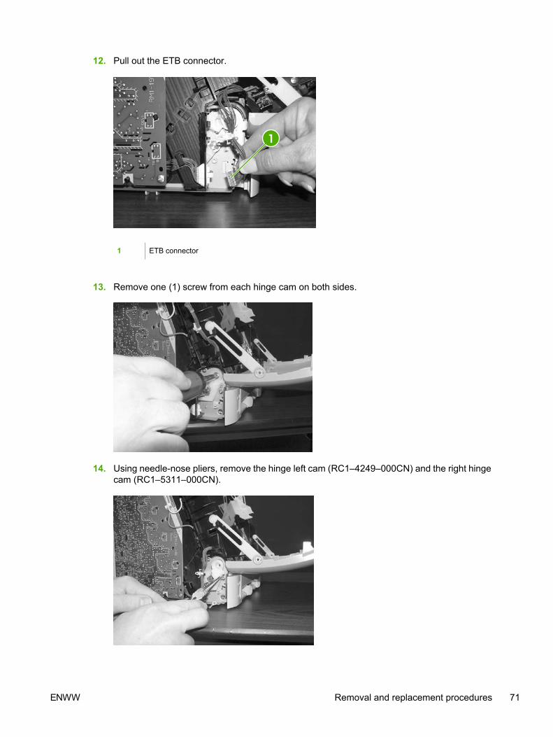
12. Pull out the ETB connector.
1 ETB connector
13. Remove one (1) screw from each hinge cam on both sides.
14. Using needle-nose pliers, remove the hinge left cam (RC1–4249–000CN) and the right hingecam (RC1–5311–000CN).
ENWW Removal and replacement procedures 71

15. Remove the ETB.
Use the following procedure to replace the ETB.
1. Align each foot of the ETB with the respective holes, securing the right side first, and then theleft side.
1 Alignment location
2. Complete replacement by following steps 1 through 14 above in reverse order.
NOTE When replacing the right cover, align the tabs on the upper edge of the right coverand lower edge of the face-down cover with their respective slots.
72 Chapter 5 Removal and replacement ENWW

1 Tabs
Fuser removal and replacementUse the following procedure to remove the fuser.
1. Unplug the power cable.
2. Remove the paper delivery tray assembly (RM1–1859–000CN).
ENWW Removal and replacement procedures 73

3. Remove two (2) screws from the right cover assembly (RM1–1858–000CN).
1 Two (2) screws
4. Remove the right cover assembly, carefully disengaging the catches.
5. Unplug the control panel cable.
74 Chapter 5 Removal and replacement ENWW

6. Insert a screwdriver to loosen the release tab on each side of the upper face cover.
7. Remove the upper face cover (RC1–5174–000CN).
8. Remove four (4) screws from the upper cover (RC1–5176–000CN).
ENWW Removal and replacement procedures 75
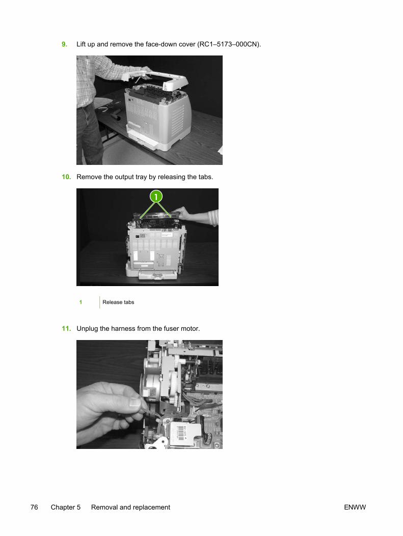
9. Lift up and remove the face-down cover (RC1–5173–000CN).
10. Remove the output tray by releasing the tabs.
1 Release tabs
11. Unplug the harness from the fuser motor.
76 Chapter 5 Removal and replacement ENWW
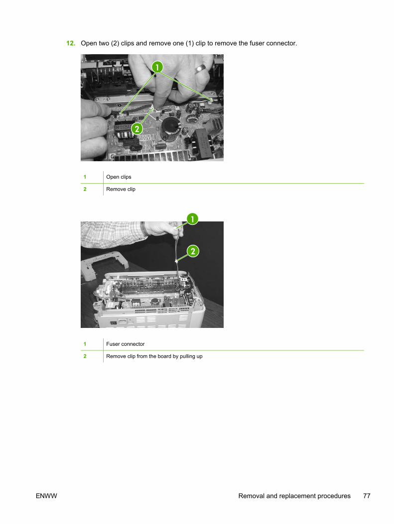
12. Open two (2) clips and remove one (1) clip to remove the fuser connector.
1 Open clips
2 Remove clip
1 Fuser connector
2 Remove clip from the board by pulling up
ENWW Removal and replacement procedures 77

13. Unplug two (2) 3-pin optical encoder wires.
14. Unplug the red high-voltage bias wire.
15. Remove the thermistor wire.
78 Chapter 5 Removal and replacement ENWW

16. Remove the wiring harness.
17. Remove three (3) screws from the fuser chassis.
1 Three (3) screws
18. Gently rocking if necessary, roll the fuser (RM1–1820–00CN for 110V) or (RM1–1821–000CBfor 220V) forward to remove.
ENWW Removal and replacement procedures 79

Use the following procedure to replace the fuser.
1. Align the fuser tabs with their respective holes.
2. Complete replacement by following steps 1 through 18 above in reverse order.
NOTE When replacing the right cover, align the tabs on the upper edge of the right coverand lower edge of the face-down cover with their respective slots.
1 Tabs
NOTE Connect the control panel cable before replacing the right cover.
80 Chapter 5 Removal and replacement ENWW

Formatter removal and replacementUse the following procedure to remove the formatter.
1. Remove the cassette dust cover (RC1–5200–000CN).
2. Remove nine (9) screws from the rear plate (RC1–5227–000CN).
ENWW Removal and replacement procedures 81

3. Remove the rear plate.
82 Chapter 5 Removal and replacement ENWW

4. Unplug three (3) connectors: two (2) data connectors and one (1) power connector.
1 Flat cable
2 Power cables
3 VW-1 flat cable
ENWW Removal and replacement procedures 83

5. Remove four (4) screws from the formatter.
6. Lifting it up, remove the formatter.
To replace the formatter, follow steps 1 through 6 above in reverse order.
NOTE When replacing the right cover, align the tabs on the upper edge of the right coverand lower edge of the face-down cover with their respective slots.
84 Chapter 5 Removal and replacement ENWW
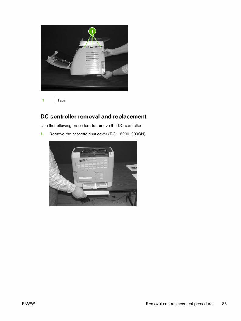
1 Tabs
DC controller removal and replacementUse the following procedure to remove the DC controller.
1. Remove the cassette dust cover (RC1–5200–000CN).
ENWW Removal and replacement procedures 85

2. Remove nine (9) screws from the rear plate (RC1–5227–000CN).
3. Remove the rear plate.
4. Gently unplug 16 connectors.
86 Chapter 5 Removal and replacement ENWW

5. Remove four (4) screws from the DC controller.
1 Four (4) screws
6. Remove the DC controller PCB assembly (RM1–1975–000CN).
To replace the DC controller, follow steps 1 through 6 above in reverse order.
ENWW Removal and replacement procedures 87

Separation pad removal and replacementUse the following procedure to remove the separation pad.
1. Remove Tray 2 (shown) or optional Tray 3.
2. Remove two (2) screws that attach the separation pad.
3. Remove the separation pad assembly (RC1–5356–000CN).
To replace the separation pad, follow steps 1 through 3 above in reverse order.
NOTE Align the tabs with the two (2) slots and then replace the separation pad.
88 Chapter 5 Removal and replacement ENWW

Paper pickup roller removal and replacementUse the following procedures to remove the paper pickup roller.
1. Open the front door.
2. Remove the print cartridges.
ENWW Removal and replacement procedures 89

3. Remove two (2) screws.
1 Two (2) screws
4. Remove the pre-transfer guide (RC1–5419–000CN).
5. Use a small screwdriver to pull back on the tabs.
90 Chapter 5 Removal and replacement ENWW

6. Rotating it towards the back, remove the paper pickup roller (RC1-5440-000CN).
To replace the paper pickup roller, follow steps 1 through 6 above in reverse order.
Control panel removal and replacementUse the following procedure to remove the control panel.
1. Remove two (2) screws from the right cover assembly.
1 Two (2) screws
ENWW Removal and replacement procedures 91

2. Remove the paper delivery tray assembly (RM1–1859–000CN).
3. Remove the right cover assembly (RM1–1858–000CN), carefully twisting the front edges of theside covers outward to remove.
4. Unplug the control panel cable.
92 Chapter 5 Removal and replacement ENWW

5. Lift up and remove the upper face cover (RC1-5173-000CN).
6. Remove four (4) screws from the upper cover (RC1–5176–000CN).
ENWW Removal and replacement procedures 93

7. Remove one (1) screw from the inside upper cover (RC1–5178–000CN) and then remove theblack output guide.
8. Remove two (2) screws from the control panel.
94 Chapter 5 Removal and replacement ENWW
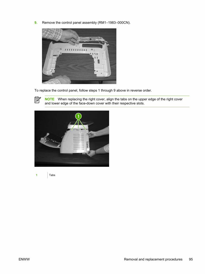
9. Remove the control panel assembly (RM1–1983–000CN).
To replace the control panel, follow steps 1 through 9 above in reverse order.
NOTE When replacing the right cover, align the tabs on the upper edge of the right coverand lower edge of the face-down cover with their respective slots.
1 Tabs
ENWW Removal and replacement procedures 95

96 Chapter 5 Removal and replacement ENWW

6 Troubleshooting
This troubleshooting information is organized to help you resolve printing problems. Choose thegeneral topic or type of problem from the following list.
● Troubleshooting process
● Clearing jams
● Print problems
● Functional tests (service only)
● Service mode functions (service only)
● Troubleshooting tools
● HP Toolbox
● Diagnostic resources
● Repetitive image defect ruler
● Firmware and software updates
ENWW 97

Troubleshooting processUse the troubleshooting checklist to solve issues with the device.
Troubleshooting checklistFollow the steps in the following table when trying to solve a problem with the device.
98 Chapter 6 Troubleshooting ENWW

Table 6-1 Troubleshooting checklist
Stepnumber
Verification step Possible problems Solutions
1 Is the power on?
When the device isconnected to a groundedpower source, the controlpanel shows Hewlett-Packard with both theReady and Attention lightsblinking. The control panelwill then displayInitializing and thenReady, at which time onlythe green light will be on.
No power due to failed power source,cable, switch, or fuse.
1. Verify that the device is pluggedin.
2. Verify that the power cable isfunctional and that the powerswitch is on.
3. Check the power source byplugging the device directly intothe wall or into a different outlet.
4. Test the outlet or connectanother device to the outlet toverify that the outlet is functioning.
2 Does Ready appear inthe device control panel?
The control panel shouldfunction without errormessages.
Control panel shows an error. See Control panel messageson page 108 for a list of commonmessages that will help you correctthe error.
3 Do information pagesprint?
Print a Configuration page.
Control panel displays an errormessage.
See Control panel messageson page 108 for a list of commonmessages that will help you correctthe error.
Media does not move smoothlythrough the device paper path.
Clean the paper path.
Poor print quality. For information, see General printquality issues on page 139.
4 Does the device printfrom the computer?
Connect the USB cable tothe device and thecomputer. Use a word-processing application tosend a print job to thedevice.
Software is not installed correctly or anerror occurred during softwareinstallation.
Uninstall and then reinstall the devicesoftware. Verify that you are using thecorrect installation procedure and thecorrect port setting.
The cable is not connected correctly. Reconnect the cable.
An incorrect driver is selected. Select the proper driver.
Other devices are connected to theUSB port.
Disconnect the other devices and tryagain to print.
There is a port driver problem inMicrosoft Windows.
Uninstall and then reinstall the devicesoftware. Verify that you are using thecorrect installation procedure and thecorrect port setting.
If the error persists, see the support flyer that came in the device box.
ENWW Troubleshooting process 99

Clearing jams This section contains information about clearing jams.
Paper path
Figure 6-1 Paper path
For paper path sensor locations, see Figure 4-12 Paper pickup and feed system on page 50.
100 Chapter 6 Troubleshooting ENWW

Common causes of paper jamsOccasionally, paper or other print media can become jammed during a print job. Some causesinclude the following events:
Cause Solution
The input trays are loaded improperly or overfilled. Remove any excess paper from the input tray. Make surethat the paper does not exceed the maximum stack heightmark in the input tray.
Tray 2 or optional Tray 3 is opened during a print job. Make sure that Tray 2 or optional Tray 3 is closed.
Too many sheets accumulated in the output area or sheetsblocked the output area.
Remove any accumulated sheets and clear the output area.For information about clearing jams from the output area,see Output jams on page 105.
The print media that is being used does not meet HPspecifications.
Use only paper that meets HP specifications. For moreinformation, see the HP LaserJet Printer Family Print MediaGuide or go to http://www.hp.com/support/ljpaperguide.
The environment in which the print media was stored is toohumid or too dry.
Make sure that the printer environment is within humidityspecifications. For more information, see Printing andstorage environment on page 13.
A supply item is installed incorrectly, causing repeated jams. Verify that all print cartridges and the ETB are correctlyinstalled.
Print media is skewed. Input tray guides are not adjusted correctly. Adjust input trayguides so they hold the print media firmly in place withoutbending it.
NOTE Do not fan paper. Fanning can create staticelectricity, which can cause the paper to sticktogether.
Print media is binding or sticking together. Remove paper, flex it, rotate it 180 degrees, or flip it over.Reload paper into the input tray.
Print media is removed before it settles into the output bin. Reset the printer. Wait until the page completely settles inthe output bin before removing it.
Print media is in poor condition. Replace the paper.
Print media is not picked up by the internal rollers fromTray 2 or Tray 3.
Remove the top sheet of paper. If the paper is heavier than163 g/m2 (43 lb), it may not be picked from the tray.
Print media has rough or jagged edges. Replace the paper.
Print media is perforated or embossed. This paper does not separate easily. Feed single sheetsfrom Tray 1.
The printer supply items have reached the end of life.Check the printer control panel for messages prompting areplacement of supplies, or print a supplies status page toverify the remaining life of the supplies.
Print media was not stored correctly. Replace the print media. Print media should be stored in theoriginal packaging in a controlled environment.
ENWW Clearing jams 101

Where to look for jamsJams can occur in these locations:
● Inside the printer
● In input areas
● In the output area
● Paper path
The following illustration identifies the stages when jams can occur.
Figure 6-2 Jam locations and stages
1 Pickup stage
2 Feeder stage
3 Transfer/feed stage
4 Fusing/delivery stage
102 Chapter 6 Troubleshooting ENWW

Find and remove the jam by using the instructions on the following pages. If the location of the jam isnot obvious, first look inside the printer.
Loose toner might remain in the printer after a jam. This problem should resolve itself after a fewsheets have been printed.
Each section below corresponds to an area where a paper jam could occur. Use the followingprocedures to clear the jam. In all cases, grasp the jammed paper by both corners and pull slowly toremove the paper.
Jams inside the printerUse the following instructions to clear jams from inside the printer.
CAUTION Jams in this area might result in loose toner on the page. If you get toner on yourclothes or hands, wash them in cold water. (Hot water will set the toner into the fabric.)
1. Open the front door.
CAUTION Do not place anything on the transfer belt, which is located on theinside of the front door. Otherwise, the printer may be damaged, adverselyaffecting print quality.
ENWW Clearing jams 103

2. Carefully grasp the jammed paper by both corners and pull slowly to remove the paper.
3. Close the front door.
Input jams
Tray 1If the jammed paper is easily accessible from the outside of the printer, grasp both edges of thepaper and firmly pull to remove. Otherwise, follow the directions for Tray 2.
104 Chapter 6 Troubleshooting ENWW

Tray 2Open the front door of the printer and remove paper as indicated on the jam instruction label, locatedon the interior right side of the printer. Input jams are indicated on the label with the number 3.
Figure 6-3 Tray 2 input jam label
Output jams
Jams in the top bin
CAUTION Jams in these areas might result in loose toner on the page. If you get toner onyour clothes or hands, wash them in cold water. (Hot water will set the toner into the fabric.)
1. Carefully grasp the jammed paper by both corners and pull slowly to remove the paper from thetop bin.
ENWW Clearing jams 105

2. Open and close the front door.
Pickup delay jamThe printer performs the retry control, which executes the pickup operation three times, to retrievethe pickup delay jam caused by the pickup error. When the registration paper sensor (SR1) does notdetect the leading edge of the paper within approximately 2.5 seconds (4.5 seconds for optionalcassette) after the pickup solenoid (SL1) is turned ON, the CPU tries to pick up the paper three times.
Pickup stationary jamThe CPU determines the pickup stationary jam when the registration paper sensor (SR1) does notdetect the trailing edge of the paper within approximately 8.6 seconds after it detects the leading edge.
Delivery delay jamThe CPU determines the delivery delay jam when the fuser delivery paper sensor (SR4) does notdetect the leading edge of the paper within approximately 6.6 seconds after the registration papersensor (SR1) detects the leading edge.
Wrapping jamThe CPU executes the wrapping jam detection after it assesses no delivery delay jam. The CPUdetermines the wrapping jam, when the fusing delivery paper sensor (SR4) detects the paperabsence before the time equivalent to paper passage of its length minus 40 mm (1.6 inches) after theSR4 detected the leading.
Delivery stationary jamThe CPU executes the delivery stationary jam detection after it assesses no wrapping jam. The CPUdetermines the delivery stationary jam, when the fuser delivery paper sensor (SR4) detects the paperpresence after the time equivalent to paper passage of its length plus 50 mm (1.9 inches) from whenit detected the trailing edge.
Start-up residual paper jamThe CPU determines the start-up residual paper jam when either the pre-fuser paper sensor (SR5)or the fuser delivery paper width sensor (SR4) detects the paper when the initial rotation is started.
106 Chapter 6 Troubleshooting ENWW

Door open jamThe CPU determines the door open jam, when either the pre-fuser paper sensor (SR5) or the fuserdelivery paper width sensor (SR4) detects paper when a door open is detected.
ENWW Clearing jams 107

Print problemsGetting informationThe following sections contain information about control panel messages, error reports, and availableservice menus.
Control panel messagesThe majority of the control-panel messages are intended to guide the user through typical operation.The control-panel messages indicate the status of the current operation, and include a page count onthe second line of the display, if appropriate. When the device is printing data, control-panelmessages indicate this status. In addition, alert messages, warning messages, and critical errormessages indicate situations that might require some action.
Alert and warning messages
Control panel message Description Recommended action
Device error
Press
An internal error occurred in the device. Press (Select) to resume the job.
Door open The printer door is open. The door must be closed before printingcan continue.
Engine comm.
error
The device experienced an internalcommunication error.
This is a warning message only. Job outputmight be affected.
Invalid driver You are using the incorrect printer driver. Reselect the printer driver appropriate foryour device.
Invalid entry Invalid data or response. Correct the entry.
Jam in
Cartridge area
A paper jam has occurred in the print path. Open the door and clear the jam. Then
press the (Select) button on the controlpanel.
Jam in
Output bin
A paper jam has occurred in the output area. Clear the jam, and then press the (Select) button on the control panel.
Jam in
print paper path
A paper jam has occurred in the print path. Open the door and clear the jam. Then
press the (Select) button on the controlpanel.
Jam in
tray 2
A paper jam has occurred in Tray 2. Clear the jam, and then press the (Select) button on the control panel.
Jam in
tray 3
A paper jam has occurred in Tray 3. Clear the jam, and then press the (Select) button on the control panel.
Load paper The HP Color LaserJet 1600 printer is outof paper.
Please load specified paper type into thetray indicated.
Load Tray X
[TYPE] [SIZE]
The printer is processing job, but the trayindicated is empty.
Please load specified paper type and sizeinto the tray indicated.
108 Chapter 6 Troubleshooting ENWW
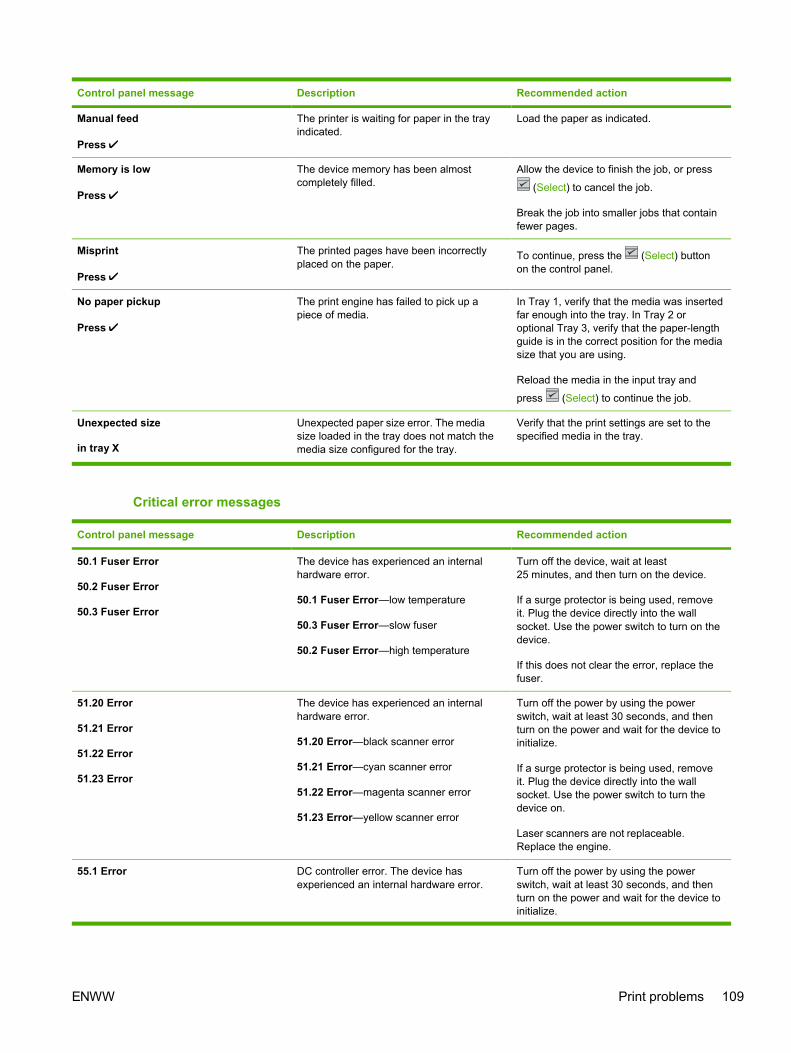
Control panel message Description Recommended action
Manual feed
Press
The printer is waiting for paper in the trayindicated.
Load the paper as indicated.
Memory is low
Press
The device memory has been almostcompletely filled.
Allow the device to finish the job, or press
(Select) to cancel the job.
Break the job into smaller jobs that containfewer pages.
Misprint
Press
The printed pages have been incorrectlyplaced on the paper.
To continue, press the (Select) buttonon the control panel.
No paper pickup
Press
The print engine has failed to pick up apiece of media.
In Tray 1, verify that the media was insertedfar enough into the tray. In Tray 2 oroptional Tray 3, verify that the paper-lengthguide is in the correct position for the mediasize that you are using.
Reload the media in the input tray and
press (Select) to continue the job.
Unexpected size
in tray X
Unexpected paper size error. The mediasize loaded in the tray does not match themedia size configured for the tray.
Verify that the print settings are set to thespecified media in the tray.
Critical error messages
Control panel message Description Recommended action
50.1 Fuser Error
50.2 Fuser Error
50.3 Fuser Error
The device has experienced an internalhardware error.
50.1 Fuser Error—low temperature
50.3 Fuser Error—slow fuser
50.2 Fuser Error—high temperature
Turn off the device, wait at least25 minutes, and then turn on the device.
If a surge protector is being used, removeit. Plug the device directly into the wallsocket. Use the power switch to turn on thedevice.
If this does not clear the error, replace thefuser.
51.20 Error
51.21 Error
51.22 Error
51.23 Error
The device has experienced an internalhardware error.
51.20 Error—black scanner error
51.21 Error—cyan scanner error
51.22 Error—magenta scanner error
51.23 Error—yellow scanner error
Turn off the power by using the powerswitch, wait at least 30 seconds, and thenturn on the power and wait for the device toinitialize.
If a surge protector is being used, removeit. Plug the device directly into the wallsocket. Use the power switch to turn thedevice on.
Laser scanners are not replaceable.Replace the engine.
55.1 Error DC controller error. The device hasexperienced an internal hardware error.
Turn off the power by using the powerswitch, wait at least 30 seconds, and thenturn on the power and wait for the device toinitialize.
ENWW Print problems 109

Control panel message Description Recommended action
If a surge protector is being used, removeit. Plug the device directly into the wallsocket. Use the power switch to turn thedevice on.
Check the engine (DCC) firmware version.Update if needed. Replace the DCC if afirmware upgrade does not resolve the issue.
57 Fan Error
Turn off then on
The device has experienced a problem withits internal fan.
Turn off the power by using the powerswitch, wait at least 30 seconds, and thenturn on the power and wait for the device toinitialize.
The fan is not replaceable. Replace theengine.
Supplies messages
Control panel message Description Recommended action
One of the following messages may display:
Incorrect black
Incorrect cyan
Incorrect magenta
Incorrect yellow
The <color> print cartridge not installedcorrectly.
Reinstall the <color> print cartridge.
One of the following messages may display:
Install black cartridge
Install cyan cartridge
Install magenta cartridge
Install yellow cartridge
The supplies gauge will display theconsumption levels of print cartridges.
The out threshold has been reached. The supply must be replaced beforeprinting can continue.
One of the following messages may display:
Non HP black
installed
Non HP cyan
installed
Non HP magenta
installed
Non HP yellow
installed
A non-HP <color> cartridge is installed. NOTE Any printer repair requiredas a result of using a non-HP orunauthorized supply is not coveredunder warranty.
To use this cartridge, override by pressing
the (Select) button on the control panel.
110 Chapter 6 Troubleshooting ENWW
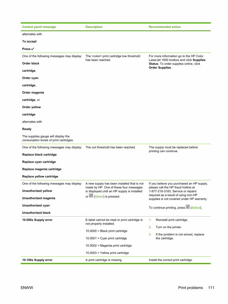
Control panel message Description Recommended action
alternates with
To accept
Press
One of the following messages may display:
Order black
cartridge,
Order cyan
cartridge,
Order magenta
cartridge, or
Order yellow
cartridge
alternates with
Ready
The supplies gauge will display theconsumption levels of print cartridges.
The <color> print cartridge low thresholdhas been reached.
For more information go to the HP ColorLaserJet 1600 toolbox and click SuppliesStatus. To order supplies online, clickOrder Supplies.
One of the following messages may display:
Replace black cartridge
Replace cyan cartridge
Replace magenta cartridge
Replace yellow cartridge
The out threshold has been reached. The supply must be replaced beforeprinting can continue.
One of the following messages may display:
Unauthorized yellow
Unauthorized magenta
Unauthorized cyan
Unauthorized black
A new supply has been installed that is notmade by HP. One of these four messagesis displayed until an HP supply is installed
or (Select) is pressed.
If you believe you purchased an HP supply,please call the HP fraud hotline at1-877-219-3183. Service or repairsrequired as a result of using non-HPsupplies is not covered under HP warranty.
To continue printing, press (Select).
10.000x Supply error E-label cannot be read or print cartridge isnot properly installed.
10.0000 = Black print cartridge
10.0001 = Cyan print cartridge
10.0002 = Magenta print cartridge
10.0003 = Yellow print cartridge
1. Reinstall print cartridge.
2. Turn on the printer.
3. If the problem is not solved, replacethe cartridge.
10.100x Supply error A print cartridge is missing. Install the correct print cartridge.
ENWW Print problems 111

Control panel message Description Recommended action
alternates with
Reinstall
The supplies gauge will display theconsumption levels of print cartridges.
10.1000 = Black print cartridge
10.1001 = Cyan print cartridge
10.1002 = Magenta print cartridge
10.1003 = Yellow print cartridge
HP supplies
installed
The printer transitioned from having one ormore non-HP supplies to having all HPsupplies installed.
No action required.
Install supplies
The supplies gauge will display theconsumption levels of print cartridges.
Multiple supplies are not installed. Install correct print cartridges.
Non HP supply
in use
alternates with
Ready
The supplies gauge will display theconsumption levels of print cartridges.
A non HP (cloned or refilled) supply hasbeen installed that is not made by HP andwas overridden.
If you believe you purchased an HP supply,please call the HP fraud hotline at1-877-219-3183. Service or repairsrequired as a result of using non-HPsupplies is not covered under HP warranty.
ORDER SUPPLIES
alternates with
Ready
The supplies gauge will display theconsumption levels of print cartridges.
Multiple supplies are low. For more information go to the HP ColorLaserJet 1600 toolbox and click SuppliesStatus. To order supplies online, clickOrder Supplies.
Replace Supplies
The supplies gauge will display theconsumption levels of print cartridges.
The out threshold has been reached. The supply must be replaced beforeprinting can continue.
Replace supplies
Override in use
alternates with
Ready
The supplies gauge will display theconsumption levels of print cartridges.
Supply override in use. The user hasdecided to continue printing beyond the outpoint. A supply is low and using Overridemay result in unsatisfactory print quality.
Replace the supply that is low.
112 Chapter 6 Troubleshooting ENWW

Control panel message Description Recommended action
Replace supply.
Override in use
alternates with
Ready
The supplies gauge will display theconsumption levels of print cartridges.
Supply override in use. The user hasdecided to continue printing beyond the outpoint. A supply is low and using Overridemay result in unsatisfactory print quality.
Replace the supply that is low.
Unauthorized
supply in use
alternates with
Ready
The supplies gauge will display theconsumption levels of print cartridges.
A new supply has been installed that is notmade by HP and was overridden.
If you believe you purchased an HP supply,please call the HP fraud hotline at1-877-219-3183. Service or repairsrequired as a result of using non-HPsupplies is not covered under HP warranty.
Status messages
Status messages are used to inform the user of the current state of the system. Status messages donot require user action or acknowledgement, and are for information only.
Control panel message Description Recommended action
Calibrating... The printer is calibrating. No action is required.
Cleaning... The printer is in cleaning mode. No action is required.
Status log only messages
The following messages are not displayed on the control panel. They are printed on the Status log.
Table 6-2 Status log only messages
Error log code Description
54.06 Color density sensor error
54.10 Color plane registration sensor(s) error
54.11 Yellow density out of range
54.12 Magenta density out of range
54.13 Cyan density out of range
54.14 Black density out of range
ENWW Print problems 113

Reports menuThe following reports are available from the Reports menu.
● Demo Page—used to help market the product at retail stores
● Menu structure—highlights the control panel menu layout
● Config report—details all default device settings
● Supplies Status—provides information on each of the print cartridges, including estimatedpages remaining, cartridge serial number, and pages printed
114 Chapter 6 Troubleshooting ENWW

Configuration pageThe Configuration page lists the current settings and properties of the printer. You can print aConfiguration page from the printer or HP Toolbox. To print the Configuration page from the printer,see Configuration page on page 131.
Table 6-3 Configuration page
1 Product information. This section contains the following basic information about the printer:
● Product name
● Formatter number
● Serial number
● Service ID
● Firmware version
● Maximum print resolution
2 Memory. This section lists memory-related information, such as the total memory that is installed.
3 Paper settings. This section lists information about the media type for each tray and about the type settings forall the media that the printer supports.
4 Page counts. This section lists the total number of pages printed, the number of color pages printed, andinformation about paper jams.
5 Product Settings. This section lists information that is gathered during software installation, including thelanguage and the company name.
6 Paper Type. This section contains information about paper types that can be configured by the user.
8 Status log. This section contains information about printer errors, including an error code and the page count atwhich the error occurred. For a list of status log messages, see Table 6-5 Status log messages on page 118.
ENWW Print problems 115

NOTE The color bars on the sides of the Configuration page represent 100%, 75%, 50%,and 25% coverage.
116 Chapter 6 Troubleshooting ENWW

Supplies Status pageThe Supplies Status page lists the remaining life of HP print cartridges. It also lists the estimatedpages remaining, number of pages printed, and other supplies information. You can print a SuppliesStatus page from the printer or the HP Toolbox.
To print the Supplies Status page from the printer control panel
1. Press (Left arrow) or (Right arrow) to select the Reports menu.
2. Press (Select).
3. Press (Left arrow) or (Right arrow) to select Supplies Status.
4. Press (Select) to print the Supplies Status page.
NOTE Supplies information is also available through the HP Toolbox.
Table 6-4 Supplies Status page
1 Print cartridge area. This area contains a section for each of the print cartridges and provides information aboutHP print cartridges. This information includes the part number for each print cartridge, whether each printcartridge is low, and the life remaining for each print cartridge, which is expressed as a percentage, as a graphic,and as the estimated number of pages remaining. This information might not be provided for non-HP supplies. Insome cases, if a non- HP supply is installed, you will see an alert message instead.
2 Ordering information. This section contains basic information about how to order new HP supplies.
3 Return and recycling information. This section contains a link to the Web site that you can visit for informationabout recycling.
Menu mapThe menu map lists the menu structure for each option available on the printer. Use the followingsteps to print a menu map.
ENWW Print problems 117

To print the menu map from the printer control panel
1. Press (Left arrow) or (Right arrow) to select the Reports menu.
2. Press (Select).
3. Press (Left arrow) or (Right arrow) to select Menu structure.
4. Press (Select) to print the menu map.
NOTE The menu map prints as two pages.
Status logThe status log for this printer is located on the Configuration page and lists the last five events. Formore information, see Configuration page on page 131.
Table 6-5 Status log messages
Error log code Description
10.0000 Black e-label error
10.0001 Cyan e-label error
10.0002 Magenta e-label error
10.0003 Yellow e-label error
10.1000 Black e-label missing
10.1001 Cyan e-label missing
10.1002 Magenta e-label missing
10.1003 Yellow e-label missing
118 Chapter 6 Troubleshooting ENWW

Error log code Description
10.3000 Non-HP black
10.3001 Non-HP cyan
10.3002 Non-HP magenta
10.3003 Non-HP yellow
13.0000 Paper jam, Tray 1 area
13.0001 Paper jam, Tray 2 area
13.0002 Paper jam, Tray 3 area
13.0003 Paper jam, registration drum area
13.0004 Paper jam, drum fuser area
13.0005 Paper jam, fuser output area
20.0000 Memory out
21.0000 Video under run
50.1000 Low temperature fuser error
50.2000 Slow fuser error
50.3000 High temperature fuser error
50.4000 Fuser heater wire failure
50.5000 Fuser low temperature subtherm failure
50.6000 Fuser high temperature subtherm failure
52.0000 Scanner error, black laser failure
52.0100 Scanner error, cyan laser failure
52.0200 Scanner error, magenta laser failure
52.0300 Scanner error, yellow laser failure
54.0600 Density sensor error
54.1000 Color plane registration sensor error
54.2800 Sensor density contaminated
54.2801 Sensor color plane registration contaminated
55.0000 Engine comm fatal error
55.0001 Engine comm critical error
55.1000 DC controller memory error
57.0000 Fan motor error
57.0001 Fan cartridge failure
59.0000 Paper path/ETB rotation failure
59.0001 Paper path/ETB ramp up failure
101.0000 Color plane registration error
Table 6-5 Status log messages (continued)
ENWW Print problems 119

Error log code Description
102.0000 DMAX calibration error
103.0000 DHALF calibration error
Service menu settingsThe service menu is used to calibrate, restore factory default settings, and clean the print paper path.
The following service menu items are available:
● Restore defaults—used to reset all customer-accessible menu settings back to the factorydefault settings (except language) via the control panel or software
NOTE This service menu item does not reset factory-settable settings, includingformatter number, page counts, factory paper settings, language, and so on.
● PowerSave—used to configure the amount of idle time before the engine enters sleep mode
● Cleaning mode—used to remove dust and toner from the print paper path
Secondary service menuThe secondary service menu is intended for use by manufacturing engineers, service engineers,developers, and support personnel. This menu provides options to perform various tests and printout special reports.
The following secondary service menu items are available:
● Service Reports—used to print out a continuous configuration report, translation report, anderror report
● USB Speed—enables or disables the ability for the printer to operate in high speed.
The following USB Speed setting options are available:
● Auto
● Hi speed
● Full speed
● Display test—verifies that all of the characters on the display function correctly by allowing youto manually scroll through the characters
● Clean ETB—used to clean the ETB
● Calibrations
● All Cals
● CPR Cal
● DMAX/DHALF Cal
Table 6-5 Status log messages (continued)
120 Chapter 6 Troubleshooting ENWW

● DHALF Only Cal
● Test Page
To enter the secondary service menu, use the following procedure:
1. Confirm that the device is in a Ready state.
2. Press the button (Select) to enter the main menu system.
3. Press the button (Left arrow) and the button (Cancel Job) simultaneously.
4. Press the button (Select) to confirm 2ndary Service.
5. Press the (Left arrow) button and button (Right arrow) to navigate to the secondaryservice menu.
Printed image quality problems
Improving print qualityUse the print-quality settings in the HP Toolbox to improve print-quality problems. To access theHP Toolbox, see HP Toolbox on page 146. The following menus contain paper type, print mode, andprint-quality settings. To restore the default settings, open the HP Toolbox and click DeviceSettings. Then click Settings, Service, and in Restore Factory Settings, click Restore.
Paper Types menu
The purpose of this menu is to specify the print mode for paper types which are non-specific.
To make changes in the Paper Types menu, make the desired selections and click Apply.
Table 6-6 Print modes for paper types
Print Modes for paper types Weight Default media types
Normal mode 75-89 g/m2 Plain, color, preprinted, prepunched,recycled
Transparency Transparencies
Labels Labels
Light 75-89 g/m2 Light
Heavy 90-105 g/m2 Heavy
Cardstock 106-163 g/m2 Cardstock, bond
Light Glossy 75-105 g/m2 Light Glossy
Glossy 106-120 g/m2 Glossy
Heavy Glossy 121-163 g/m2 Heavy Glossy
HP Tough paper HP Tough paper
Envelope Envelopes
ENWW Print problems 121

Print Modes menu
Under the Print Modes menu in HP Toolbox, each Media Type will have a Fusing menu, a Transfermenu, and a Toner menu. Select a setting for each menu item.
Media types are listed with the plain papers together, glossy papers together, and special media atthe end. To make changes in the Print Modes menu, make the desired selections and click Apply.
Table 6-7 Extended print modes
HP Toolbox extended print mode Printer adjustment Change in printer setting
Paper curl Fusing adjustment Reduced fuser temperature for lessnegative paper curl
Heavy coverage Fusing adjustment Increased fuser temperature for lesspositive paper curl with heavy tonercoverage
Toner offset Fusing adjustment Reduced fuser temperature for lesstoner offset
Flap sealing Fusing adjustment Reduced fuser temperature to keepenvelope flaps from sealing
Less fusing Fusing adjustment Reduced fuser temperature
More fusing Fusing adjustment Increased fuser temperature
Dry paper Transfer adjustment Increased transfer bias for highresistivity paper
Humid paper Transfer adjustment Decreased transfer bias for highresistivity paper
Rough paper Transfer adjustment Increased transfer bias for highresistivity paper
Less transfer current Transfer adjustment Reduced transfer bias
More transfer current Transfer adjustment Increased transfer bias
Less toner Toner adjustment Tone curve is scaled back so that solidis not 100% halftone
Print quality menu
Under the Print Quality menu in HP Toolbox, there will be an Optimize section containing a numberof On/Off adjustments which will apply to all media types.
Table 6-8 Optimize menu
Adjustment type Default setting Extended print mode Description
Background Toner Off EEC95-9 Will reduce the developerDC bias
Extra Cleaning Off EEC93-11 Increases rotations of theETB
Trailing Edge Over-development (full-speed)
Off EEC95-14
122 Chapter 6 Troubleshooting ENWW

Adjustment type Default setting Extended print mode Description
Trailing Edge Over-development (half-speed)
Off EEC95-14
Mottle Prevention Off EEC96-12 Will increase the developerDC bias
Less Duplex Transfer Current Off EEC68-10
EEC91>16h*
EEC92>-1**
Decreases transfer bias onthe 2nd side of duplex jobs.For media that has lowresistivity after fusing.
More Duplex Transfer Current Off EEC68-10
EEC91>16h*
EEC92>+1**
Increases transfer bias onthe 2nd side of duplex jobs.For media that has highresistivity after fusing.
* > means write xxh to bits 11–15** > means +/-y to bits 9–15
Understanding print-quality settingsPrint-quality settings affect how light or dark the print is on the page and the style in which thegraphics are printed. You can also use the print-quality settings to optimize the print quality for aspecific media type.
You can change the settings in the device properties to accommodate the types of jobs that you areprinting. The following settings are available, depending on the printer driver that you are using:
● Draft (600 dpi)
● Normal (Image REt 2400)
NOTE Changing the resolution can change the formatting of your text.
To temporarily change print-quality settings
To change the print-quality settings only for the current software program, open the propertiesthrough the Print Setup menu in the program that you are using to print.
To change print-quality settings for all future jobs
For Windows 98, Windows 2000, and Windows Me:
1. In the Windows system tray, click Start, select Settings, and then click Printers.
2. Right-click the device icon.
3. Click Properties (in Windows 2000, you can also click Printing Preferences).
4. Change the settings, and click OK.
Table 6-8 Optimize menu (continued)
ENWW Print problems 123

For Windows XP (Classic view):
1. In the Windows system tray, click Start, and then click Printers and Faxes.
2. Right-click the device icon.
3. Click Properties, or click Printing Preferences.
4. Change the settings, and click OK.
Identifying and correcting printed image defectsUse the checklist and print-quality issues charts in this section to solve print-quality problems.
Print-quality checklist
General print-quality problems can be solved by using the following checklist:
1. Make sure that the paper or print media that you are using meets specifications. Generally,smoother paper provides better results.
2. If you are using a special print media such as labels, transparencies, glossy, or letterhead,ensure that you have printed by type.
3. Print a Configuration page and Supplies Status page at the device.
● Check the Supplies Status page to see if any supplies are low or empty. No information isprovided for non-HP print cartridges.
● If the pages do not print correctly, the problem is with the hardware.
4. Print a Demo page from the HP Toolbox. If the page prints, the problem is with the printer driver.
5. Try printing from a different program. If the page prints correctly, the problem is with theprogram from which you were printing.
6. Restart the computer and the device and try printing again. If the problem is not resolved,choose one of these options:
● If the problem is affecting all printed pages, see General print quality issues on page 139.
● If the problem is affecting only pages printed in color, see Solving issues with colordocuments on page 143.
Paper handling issuesThe following sections contains information about paper handling issues.
Wrong size/type mediaUse the following procedure to troubleshoot and resolve wrong size or type media problems.
1. Make sure that the software program is selecting the correct media size or type.
2. Make sure that the printer driver for the software program is correctly installed, configured, andcapable of requesting the desired media size and type.
124 Chapter 6 Troubleshooting ENWW

3. Make sure that the paper guides are touching the edges of the stack of media.
4. If the size of media requested is not loaded in the tray selected, the printer draws media fromthe next default tray that contains the correct size. Load the correct media in the tray and makesure that the tray is adjusted correctly. Load the tray with enough media to complete the printjob. (See the HP Color LaserJet 1600 User Guide for information about configuring the inputtrays.)
Cannot select a tray or feature to useWhen you cannot select a tray or feature to use, use the following procedure to troubleshoot andresolve problems.
1. When the size of media requested is not loaded in the tray selected, the printer draws mediafrom the next default tray that contains the correct size. Load the correct media in the tray andmake sure that the tray is adjusted correctly. Load the tray with enough media to complete theprint job. (See the HP Color LaserJet 1600 User Guide for information about configuring theinput trays.)
2. Make sure that the driver for the software program is correctly installed, configured, and capableof requesting the desired media size and type, or feature.
Performance problemsTry the tips in this section if pages exit the device, but have nothing printed on them, or when thedevice does not print any pages.
Table 6-9 Performance issues
Problem Cause Solution
Pages print but are totally blank. The sealing tape might still be in theprint cartridges.
Verify that the sealing tape has beencompletely removed from the printcartridges.
The document might contain blankpages.
Check the document that you areprinting to see if content appears on allof the pages.
The device might be malfunctioning. To check the device, print aConfiguration page.
Pages print very slowly. Heavier media types can slow the printjob.
Print on a different type of media.
Complex pages will print slower. Proper fusing may require a slowerprint speed to ensure the best printquality.
Pages did not print. The device might not be pulling mediacorrectly.
See Paper handling issues on page 124.
The media is jamming in the device. Clear the jam.
ENWW Print problems 125

Problem Cause Solution
The USB cable might be defective orincorrectly connected.
● Disconnect the USB cable at bothends and reconnect it.
● Try printing a job that has printedin the past.
● Try using a different USB cable.
Other devices are running on yourcomputer.
The device might not share a USBport. If you have an external hard drivethat is connected to the same port asthe device, the other device might beinterfering. To connect and use thedevice, you must disconnect the otherdevice or you must use two USB portson the computer.
Table 6-9 Performance issues (continued)
126 Chapter 6 Troubleshooting ENWW

Functional tests (service only)Engine test printThe engine test print is used to confirm whether the printer operates correctly or not. It is performedby the engine controller.
If a malfunction occurs in the printer, perform an engine test print while the printer is in STBY modeand then press the test print switch (on the rear side of the printer) once. A one-page test pattern ofhorizontal lines will print as shown below.
Figure 6-4 Engine test print switch
1 Engine test print switch
ENWW Functional tests (service only) 127

Service mode functions (service only)Cold resetCold-reset, which power-cycles the engine with a special button press, is not supported for thisprinter. Instead, use the feature “Restore defaults” located in the Service menu to reset defaultsettings. For more information, see Service menu on page 139.
NVRAM initializerNVRAM init will perform the following functions:
● Resets all customer-accessible menu settings via control panel and software back to the factorydefault settings
● Resets the language to the value set at the factory
● Resets the default media size to cold reset media size
● Resets the symbol set to PC-8
Use the following procedure to execute an NVRAM-init.
1. Turn off the printer.
2. Press and hold the (Select) and (Cancel Job) buttons simultaneously.
3. Turn on the printer.
4. When you see the message Permanent storage init displays, release the (Select) and (Cancel Job) buttons.
When the NVRAM init is complete, the printer will return to the Ready state.
Super NVRAM initializerWhen a super NVRAM init is performed, the printer enters the Generic Product Mode, whichchanges the language and country/region settings to “undefined.”
NOTE Super NVRAM init will erase all data stored in the protected NVRAM settings.
Use the following procedure to execute a super NVRAM init.
1. Turn off the printer.
2. Press and hold the (Left arrow) and (Right arrow) buttons simultaneously.
3. Turn on the printer.
4. When you see the message Permanent storage init displays, release the (Left arrow) and (Right arrow) buttons.
When the super NVRAM init is complete, the printer will return to the Ready state.
128 Chapter 6 Troubleshooting ENWW

Restoring page counts and serial numberA software utility is available on the Service and Support CD-ROM to restore page counts and serialnumbers when the formatter is replaced or when any of the following settings are lost:
● Color page count
● Total page count
● Formatter number
● Service ID
● USB serial number
To access the utility on the Service and Support CD-ROM, in the Library folder, double-click the1600config.exe program. You can run the utility from the CD-ROM or copy it to your computer.
NOTE To use this program, the printer must be directly connected to your computer with aUSB cable.
Cleaning the ETBTo clean the ETB, use the following procedure:
1. Enter the Secondary service menu. For more information, see Secondary service menuon page 120.
2. Scroll through the menu and select Clean ETB.
3. Press the (Select) button to start the cleaning mode.
ENWW Service mode functions (service only) 129

Troubleshooting toolsThe section describes the tools that can help you solve problems with your device.
Printer pages and reportsThis section describes the pages and reports that help you diagnose and solve problems with thedevice.
Demo page
To print the Demo page, press the (Left arrow) and (Right arrow) buttons on the printer controlpanel simultaneously. You can also print this page from the HP Toolbox.
130 Chapter 6 Troubleshooting ENWW

Configuration pageThe Configuration page lists the current settings and properties of the printer. You can print aConfiguration page from the printer or HP Toolbox. To print the Configuration page from the printer,complete the following steps.
1. Press the (Left arrow) or the (Right arrow) buttons to select the Reports menu.
2. Press the button (Select).
3. Press the (Left arrow) or the (Right arrow) buttons to select Config report.
4. Press the button (Select) to print the Configuration page.
Table 6-10 Configuration page
1 Product information. This section contains the following basic information about the printer, such as the productname and the serial number.
● Product name
● Formatter number
● Serial number
● Service ID
● Firmware version
● Maximum print resolution
2 Memory. This section lists memory-related information, such as the total memory that is installed.
3 Paper settings. This section lists information about the media type for each tray and about the type settings forall the media that the printer supports.
4 Page counts. This section lists the total number of pages printed, the number of color pages printed, andinformation about paper jams.
ENWW Troubleshooting tools 131

11 Product settings. This section lists the following information that is gathered during software installation:
● Language
● Company name
● Jam recovery settings (if set to ON, the last page will reprint if there is a paper jam)
● I/O timeout information (default is 120 seconds)
9 Paper types. This section contains information about paper types that can be configured by the user. The defaultsettings are Plain.
8 Status log. This section contains information about printer errors, including an error log code and the page countat which the error occurred. For a list of status log messages, see Table 6-5 Status log messages on page 118.
NOTE The color bars on the sides of the Configuration page represent 100%, 75%, 50%,and 25% coverage.
Event logInformation for the last five events is available on the Configuration page under the Status logsection. For more information, see Configuration page on page 131.
For a list of messages that only appear in the event log, see Status log only messages on page 113.
Supplies Status pageThe Supplies Status page lists the remaining life of the HP print cartridges. It also lists the estimatedpages remaining, number of pages printed, and other supplies information. You can print a SuppliesStatus page from the device or HP Toolbox. To print from the device, complete the following steps.
1. Press the (Left arrow) or the (Right arrow) buttons to select the Reports.
2. Press (Select).
3. Use the (Left arrow) or the (Right arrow) buttons to select Supplies Status.
4. Press (Select) button to print the Supplies Status page.
132 Chapter 6 Troubleshooting ENWW

Table 6-11 Supplies Status page
1 Print cartridge area
2 Ordering information
3 Return and recycling information
Fuser cleaning pageFor information about fuser cleaning pages, see Cleaning page on page 146 and To clean the fuserusing HP Toolbox on page 33.
Print quality troubleshooting pagesFor more information about print quality troubleshooting pages, see HP Toolbox on page 146.
Control panel messages (error codes)The majority of the control-panel messages are intended to guide the user through typical operation.The control-panel messages indicate the status of the current operation, and include a page count onthe second line of the display, if appropriate. When the device is printing data, control-panelmessages indicate this status. In addition, alert messages, warning messages, and critical errormessages indicate situations that might require some action.
Alert and warning messages
Control panel message Description Recommended action
Device error
Press
An internal error occurred in the device. Press (Select) to resume the job.
ENWW Troubleshooting tools 133

Control panel message Description Recommended action
Door open The printer door is open. The door must be closed before printingcan continue.
Engine comm.
error
The device experienced an internalcommunication error.
This is a warning message only. Job outputmight be affected.
Invalid driver You are using the incorrect printer driver. Reselect the printer driver appropriate foryour device.
Invalid entry Invalid data or response. Correct the entry.
Jam in
Cartridge area
A paper jam has occurred in the print path. Open the door and clear the jam. Then
press the (Select) button on the controlpanel.
Jam in
Output bin
A paper jam has occurred in the output area. Clear the jam, and then press the (Select) button on the control panel.
Jam in
print paper path
A paper jam has occurred in the print path. Open the door and clear the jam. Then
press the (Select) button on the controlpanel.
Jam in
tray 2
A paper jam has occurred in Tray 2. Clear the jam, and then press the (Select) button on the control panel.
Jam in
tray 3
A paper jam has occurred in Tray 3. Clear the jam, and then press the (Select) button on the control panel.
Load paper The HP Color LaserJet 1600 printer is outof paper.
Please load specified paper type into thetray indicated.
Load Tray X
[TYPE] [SIZE]
The printer is processing job, but the trayindicated is empty.
Please load specified paper type and sizeinto the tray indicated.
Manual feed
Press
The printer is waiting for paper in the trayindicated.
Load the paper as indicated.
Memory is low
Press
The device memory has been almostcompletely filled.
Allow the device to finish the job, or press
(Select) to cancel the job.
Break the job into smaller jobs that containfewer pages.
Misprint
Press
The printed pages have been incorrectlyplaced on the paper.
To continue, press the (Select) buttonon the control panel.
No paper pickup
Press
The print engine has failed to pick up apiece of media.
In Tray 1, verify that the media was insertedfar enough into the tray. In Tray 2 oroptional Tray 3, verify that the paper-lengthguide is in the correct position for the mediasize that you are using.
Reload the media in the input tray and
press (Select) to continue the job.
Unexpected size Unexpected paper size error. The mediasize loaded in the tray does not match themedia size configured for the tray.
Verify that the print settings are set to thespecified media in the tray.
134 Chapter 6 Troubleshooting ENWW

Control panel message Description Recommended action
in tray X
Critical error messages
Control panel message Description Recommended action
50.1 Fuser Error
50.2 Fuser Error
50.3 Fuser Error
The device has experienced an internalhardware error.
50.1 Fuser Error—low temperature
50.3 Fuser Error—slow fuser
50.2 Fuser Error—high temperature
Turn off the device, wait at least25 minutes, and then turn on the device.
If a surge protector is being used, removeit. Plug the device directly into the wallsocket. Use the power switch to turn on thedevice.
If this does not clear the error, replace thefuser.
51.20 Error
51.21 Error
51.22 Error
51.23 Error
The device has experienced an internalhardware error.
51.20 Error—black scanner error
51.21 Error—cyan scanner error
51.22 Error—magenta scanner error
51.23 Error—yellow scanner error
Turn off the power by using the powerswitch, wait at least 30 seconds, and thenturn on the power and wait for the device toinitialize.
If a surge protector is being used, removeit. Plug the device directly into the wallsocket. Use the power switch to turn thedevice on.
Laser scanners are not replaceable.Replace the engine.
55.1 Error DC controller error. The device hasexperienced an internal hardware error.
Turn off the power by using the powerswitch, wait at least 30 seconds, and thenturn on the power and wait for the device toinitialize.
If a surge protector is being used, removeit. Plug the device directly into the wallsocket. Use the power switch to turn thedevice on.
Check the engine (DCC) firmware version.Update if needed. Replace the DCC if afirmware upgrade does not resolve the issue.
57 Fan Error
Turn off then on
The device has experienced a problem withits internal fan.
Turn off the power by using the powerswitch, wait at least 30 seconds, and thenturn on the power and wait for the device toinitialize.
The fan is not replaceable. Replace theengine.
Supplies messages
Control panel message Description Recommended action
One of the following messages may display: The <color> print cartridge not installedcorrectly.
Reinstall the <color> print cartridge.
ENWW Troubleshooting tools 135

Control panel message Description Recommended action
Incorrect black
Incorrect cyan
Incorrect magenta
Incorrect yellow
One of the following messages may display:
Install black cartridge
Install cyan cartridge
Install magenta cartridge
Install yellow cartridge
The supplies gauge will display theconsumption levels of print cartridges.
The out threshold has been reached. The supply must be replaced beforeprinting can continue.
One of the following messages may display:
Non HP black
installed
Non HP cyan
installed
Non HP magenta
installed
Non HP yellow
installed
alternates with
To accept
Press
A non-HP <color> cartridge is installed. NOTE Any printer repair requiredas a result of using a non-HP orunauthorized supply is not coveredunder warranty.
To use this cartridge, override by pressing
the (Select) button on the control panel.
One of the following messages may display:
Order black
cartridge,
Order cyan
cartridge,
Order magenta
cartridge, or
Order yellow
cartridge
alternates with
The <color> print cartridge low thresholdhas been reached.
For more information go to the HP ColorLaserJet 1600 toolbox and click SuppliesStatus. To order supplies online, clickOrder Supplies.
136 Chapter 6 Troubleshooting ENWW

Control panel message Description Recommended action
Ready
The supplies gauge will display theconsumption levels of print cartridges.
One of the following messages may display:
Replace black cartridge
Replace cyan cartridge
Replace magenta cartridge
Replace yellow cartridge
The out threshold has been reached. The supply must be replaced beforeprinting can continue.
One of the following messages may display:
Unauthorized yellow
Unauthorized magenta
Unauthorized cyan
Unauthorized black
A new supply has been installed that is notmade by HP. One of these four messagesis displayed until an HP supply is installed
or (Select) is pressed.
If you believe you purchased an HP supply,please call the HP fraud hotline at1-877-219-3183. Service or repairsrequired as a result of using non-HPsupplies is not covered under HP warranty.
To continue printing, press (Select).
10.000x Supply error E-label cannot be read or print cartridge isnot properly installed.
10.0000 = Black print cartridge
10.0001 = Cyan print cartridge
10.0002 = Magenta print cartridge
10.0003 = Yellow print cartridge
1. Reinstall print cartridge.
2. Power cycle device.
3. If the problem is not solved, replacethe cartridge.
10.100x Supply error
alternates with
Reinstall
The supplies gauge will display theconsumption levels of print cartridges.
A print cartridge is missing.
10.1000 = Black print cartridge
10.1001 = Cyan print cartridge
10.1002 = Magenta print cartridge
10.1003 = Yellow print cartridge
Install the correct print cartridge.
HP supplies
installed
The printer transitioned from having one ormore non-HP supplies to having all HPsupplies installed.
No action required.
Install supplies
The supplies gauge will display theconsumption levels of print cartridges.
Multiple supplies are not installed. Install correct print cartridges.
Non HP supply
in use
alternates with
Ready
The supplies gauge will display theconsumption levels of print cartridges.
A non-HP (cloned or refilled) supply hasbeen installed that is not made by HP andwas overridden.
If you believe you purchased an HP supply,please call the HP fraud hotline at1-877-219-3183 or go to the HP anti-counterfeit Web site at http://www.hp.com/go/anticounterfeit. Service or repairsrequired as a result of using non-HPsupplies is not covered under HP warranty.
ENWW Troubleshooting tools 137

Control panel message Description Recommended action
ORDER SUPPLIES
alternates with
Ready
The supplies gauge will display theconsumption levels of print cartridges.
Multiple supplies are low. For more information go to the HP ColorLaserJet 1600 toolbox and click SuppliesStatus. To order supplies online, clickOrder Supplies.
Replace Supplies
The supplies gauge will display theconsumption levels of print cartridges.
The out threshold has been reached. The supply must be replaced beforeprinting can continue.
Replace supplies
Override in use
alternates with
Ready
The supplies gauge will display theconsumption levels of print cartridges.
Supply override in use. The user hasdecided to continue printing beyond the outpoint. A supply is low and using Overridemay result in unsatisfactory print quality.
Replace the supply that is low.
Replace supply.
Override in use
alternates with
Ready
The supplies gauge will display theconsumption levels of print cartridges.
Supply override in use. The user hasdecided to continue printing beyond the outpoint. A supply is low and using Overridemay result in unsatisfactory print quality.
Replace the supply that is low.
Unauthorized
supply in use
alternates with
Ready
The supplies gauge will display theconsumption levels of print cartridges.
A new supply has been installed that is notmade by HP and was overridden.
If you believe you purchased an HP supply,please call the HP fraud hotline at1-877-219-3183. Service or repairsrequired as a result of using non-HPsupplies is not covered under HP warranty.
Status messagesStatus messages are used to inform the user of the current state of the system. Status messages donot require user action or acknowledgement, and are for information only.
Control panel message Description Recommended action
Calibrating... The printer is calibrating. No action is required.
Cleaning... The printer is in cleaning mode. No action is required.
138 Chapter 6 Troubleshooting ENWW

Status log only messagesThe following messages are not displayed on the control panel. They are printed on the Status log.
Table 6-12 Status log only messages
Error log code Description
54.06 Color density sensor error
54.10 Color plane registration sensor(s) error
54.11 Yellow density out of range
54.12 Magenta density out of range
54.13 Cyan density out of range
54.14 Black density out of range
Service menuUse the control-panel Service menu to troubleshoot device problems.
Restoring the factory-set defaultsRestoring the factory-set defaults returns all of the settings to the factory defaults.
To restore the factory-set defaults
1. Use the (Left arrow) or the (Right arrow) button to select Service, and then press (Select).
2. Use the (Left arrow) or the (Right arrow) button to select Restore defaults, and thenpress (Select).
The device automatically restarts.
General print quality issuesThe following examples depict letter-size paper that has passed through the device short edge first.These examples illustrate problems that would affect all of the pages that you print, whether you printin color or in black only. The topics that follow list the typical cause and solution for each of theseexamples.
Table 6-13 General print quality issues
Problem Cause Solution
Print is light or faded. The media might not meetHP specifications.
Use media that meets HP specifications.
One or more print cartridges might below. If you are using non-HP printcartridges, no messages appear on thedevice control panel or in theHP Toolbox.
Replace any low print cartridges.
If none of the print cartridges is low orempty, remove the print cartridges oneat a time and inspect the toner roller in
ENWW Troubleshooting tools 139

Problem Cause Solution
each to see if the roller is damaged. Ifso, replace the print cartridge.
Print the Supplies Status page to checkthe remaining life.
Toner specks appear. The media might not meet HPspecifications.
Use media that meets HP specifications.
The paper path might need cleaning. Clean the paper path. See theHP Toolbox online Help.
Dropouts appear. A single sheet of print media might bedefective.
Try reprinting the job.
The moisture content of the paper isuneven or the paper has moist spotson its surface.
Try different paper, such as high-quality paper that is intended for colorlaser printers.
The paper lot is flawed. Themanufacturing processes can causesome areas to reject toner.
Try different paper, such as high-quality paper that is intended for colorlaser printers.
Vertical streaks or bands appear on thepage.
One or more print cartridges might below or defective. If you are using non-HP print cartridges, no messagesappear on the device control panel orin the HP Toolbox.
Replace any low print cartridges.
The amount of background tonershading becomes unacceptable.
The media might not meet HPspecifications.
Use a different paper with a lighterbasis weight.
Very dry (low humidity) conditions canincrease the amount of backgroundshading.
Check the device environment.
Table 6-13 General print quality issues (continued)
140 Chapter 6 Troubleshooting ENWW

Problem Cause Solution
One or more print cartridges might below. If you are using non-HP printcartridges, no messages appear on thedevice control panel or in theHP Toolbox.
Replace any low print cartridges.
Toner smears appear on the media. The media might not meet HPspecifications.
Use media that meets HP specifications.
If toner smears appear on the leadingedge of the paper, the media guidesare dirty, or debris has accumulated inthe print path.
Clean the media guides and the paperpath.
The toner smears easily when touched. The device is not set to print on thetype of media on which you want toprint.
In the printer driver, select the Papertab and set Type is to match the typeof media on which you are printing.Print speed might be slower if you areusing heavy paper.
The media might not meet HPspecifications.
Use media that meets HP specifications.
The paper path might need cleaning. Clean the device.
Marks repeatedly appear at evenintervals on the printed side of the page.
The device is not set to print on thetype of media on which you want toprint.
In the printer driver, select the Papertab and set Type is to match the typeof paper on which you are printing.Print speed might be slower if you areusing heavy paper.
For more information, see Repetitiveimage defect ruler on page 149.
Internal parts might have toner on them. The problem typically corrects itselfafter a few more pages.
The paper path might need cleaning. Clean the device.
The fuser might be damaged or dirty. Clean using instructions in HP Toolbox.
A print cartridge may have a problem. To determine which cartridge has aproblem, print the PQ diagnostics pagefrom HP Toolbox.
Marks repeatedly appear at evenintervals on the unprinted side of thepage.
Internal parts might have toner on them. The problem typically corrects itselfafter a few more pages.
The paper path might need cleaning. Clean the device.
Table 6-13 General print quality issues (continued)
ENWW Troubleshooting tools 141

Problem Cause Solution
The fuser might be damaged or dirty. Clean using instructions in HP Toolbox.
For more information, see Repetitiveimage defect ruler on page 149.
Aaa
The printed page contains misformedcharacters.
The media might not meet HPspecifications.
Use a different paper, such as high-quality paper that is intended for colorlaser printers.
If characters are incorrectly formed sothat they produce a wavy effect, thelaser scanner might need service.
Verify that the problem also occurs onthe Configuration page.
The printed page is curled or wavy. The device is not set to print on thetype of media on which you want toprint.
In the printer driver, select the Papertab and set Type is to match the typeof paper on which you are printing.Print speed might be slower if you areusing heavy paper.
The media might not meet HPspecifications.
Use a different paper, such as high-quality paper that is intended for colorlaser printers.
Both high temperature and humiditycan cause paper curl.
Check the device environment.
Text or graphics are skewed on theprinted page.
The media might be loaded incorrectly. Make sure that the paper or other printmedia is loaded correctly and that themedia guides are not too tight or tooloose against the stack.
The media might not meet HPspecifications.
Use a different paper, such as high-quality paper that is intended for colorlaser printers.
The printed page contains wrinkles orcreases.
The media might be loaded incorrectly. Verify that the media is loadedcorrectly and that the media guides arenot too tight or too loose against thestack.
Table 6-13 General print quality issues (continued)
142 Chapter 6 Troubleshooting ENWW
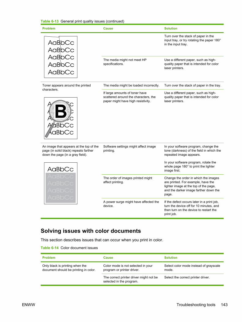
Problem Cause Solution
Turn over the stack of paper in theinput tray, or try rotating the paper 180°in the input tray.
The media might not meet HPspecifications.
Use a different paper, such as high-quality paper that is intended for colorlaser printers.
Toner appears around the printedcharacters.
The media might be loaded incorrectly. Turn over the stack of paper in the tray.
If large amounts of toner havescattered around the characters, thepaper might have high resistivity.
Use a different paper, such as high-quality paper that is intended for colorlaser printers.
An image that appears at the top of thepage (in solid black) repeats fartherdown the page (in a gray field).
Software settings might affect imageprinting.
In your software program, change thetone (darkness) of the field in which therepeated image appears.
In your software program, rotate thewhole page 180° to print the lighterimage first.
The order of images printed mightaffect printing.
Change the order in which the imagesare printed. For example, have thelighter image at the top of the page,and the darker image farther down thepage.
A power surge might have affected thedevice.
If the defect occurs later in a print job,turn the device off for 10 minutes, andthen turn on the device to restart theprint job.
Solving issues with color documentsThis section describes issues that can occur when you print in color.
Table 6-14 Color document issues
Problem Cause Solution
Only black is printing when thedocument should be printing in color.
Color mode is not selected in yourprogram or printer driver.
Select color mode instead of grayscalemode.
The correct printer driver might not beselected in the program.
Select the correct printer driver.
Table 6-13 General print quality issues (continued)
ENWW Troubleshooting tools 143

Problem Cause Solution
The device might not be correctlyconfigured.
Print a Configuration page.
One or more colors are not printing, orare inaccurate.
Sealing tape might be on the printcartridges.
Verify that the sealing tape has beencompletely removed from the printcartridges.
The media might not meet HPspecifications.
Use a different paper, such as high-quality paper that is intended for colorlaser printers.
The device might be operating inexcessively humid conditions.
Verify that the device environment iswithin humidity specifications.
One or more print cartridges might below. If you are using non-HP printcartridges, no messages appear on thedevice control panel or in theHP Toolbox.
Replace any low print cartridges.
The control panel is set for override. Replace low or empty print cartridges.
A color is printing inconsistently afteryou load a new print cartridge.
AaBbCc
AaBbCc
AaBbCc
AaBbCc
AaBbCc
Another print cartridge might be low. Ifyou are using a non-HP print cartridge,it might be low or empty but you willreceive no indication.
Remove the print cartridge for the colorthat is printing inconsistently andreinstall it.
The control panel is set for override. Replace low or empty print cartridges.
The colors on the printed page do notmatch the colors as they appear on thescreen.
The colors on your computer monitormight differ from the device output.
Click the Color tab of the printer driver.Under Color Options click Settings,and select sRGB default.
If extremely light colors or extremelydark colors on screen are not printing,your software program might interpretextremely light colors as white orextremely dark colors as black.
If possible, avoid using extremely lightor extremely dark colors.
Table 6-14 Color document issues (continued)
144 Chapter 6 Troubleshooting ENWW

Problem Cause Solution
The media might not meet HPspecifications.
Use a different paper, such as high-quality paper that is intended for colorlaser printers.
AaBbCc
AaBbCc
AaBbCc
AaBbCc
AaBbCc
The finish on the printed color page isinconsistent.
The media might be too rough. Use a smooth paper or print media,such as a high-quality paper that ismade for color laser printers.Generally, smoother media producesbetter results.
Table 6-14 Color document issues (continued)
ENWW Troubleshooting tools 145

HP ToolboxHP ToolboxHP Toolbox is a Web application that you can use for troubleshooting tasks.
To view HP ToolboxOpen HP Toolbox in one of these ways:
● On the Windows desktop, double-click the HP Toolbox icon.
● On the Windows Start menu, click Programs (All Programs in Windows XP), click HP, clickHP Color LaserJet 1600, and then click HP Color LaserJet 1600 toolbox.
Troubleshooting tabHP Toolbox includes a Troubleshooting tab that contains links to the following main pages:
● Clearing Jams. View information about locating and clearing jams.
● Print Problems. View Help topics that can help you solve print problems.
● Troubleshooting Tools. Employ such troubleshooting tools as a cleaning page or a colortroubleshooting page to maintain the device.
● Animated Demonstrations. View animated Help demonstrations for the device.
NOTE Other tabs on HP Toolbox might be helpful in troubleshooting device problems.
Print quality troubleshooting pagesThe following features are available from the HP Toolbox.
Printer calibrationCalibrations are performed at regular intervals. For best print quality, a calibration can be performedfrom the control panel. For information about calibrating the printer at the control panel, see Printercalibration on page 57.
Calibrating the printer using HP Toolbox
Use the following steps to calibrate the printer using HP Toolbox.
1. Open the HP Toolbox.
2. On the Troubleshooting tab, click Calibrate now.
Cleaning pageThe device features a special cleaning mode to clean the paper path.
146 Chapter 6 Troubleshooting ENWW

NOTE If you have access to HP Toolbox, HP recommends cleaning the paper path by usingHP Toolbox.
1. Make sure that the printer is turned on and in the Ready state.
2. Open the HP Toolbox.
3. On the Troubleshooting tab, click Troubleshooting Tools, and then click Print. A page with apattern prints from the printer.
4. At the printer, remove any print media in Tray 2 or optional Tray 3.
5. Remove the page that printed and load it face-down into Tray 2 or optional Tray 3.
6. At the computer, press the Clean button.
Configuration pageThe Configuration page lists the current settings and properties of the printer. You can print aConfiguration page from the printer or HP Toolbox. To print the Configuration page from the printer,see Configuration page on page 131.
ENWW HP Toolbox 147

Diagnostic resourcesReports menuThe Reports menu contains the following diagnostic tools:
● Demo page
● Menu structure report
● Configuration report
● Color supplies status
For a more detailed description about the diagnostic tools available from the Reports menu, seeReports menu on page 114 in the Print problems on page 108 section.
Web diagnostics toolsFor information on available Web diagnostic tools, go to http://www.hp.com/support/clj1600.
148 Chapter 6 Troubleshooting ENWW

Repetitive image defect rulerUse a repetitive image defect ruler to measure occurrences of repetitive image defects to help solveimage quality problems. Place the ruler next to the first occurrence of the defect on the page. Findthe distance between identical defects and see the Table 6-15 Repetitive image defects on page 149table to identify the component that is causing the defect.
Table 6-15 Repetitive image defects
Measurement Component
24.7 mm (0.97 inch) Developer sleeve
26.7 mm (1.05 inches) Charge roller
32.9 mm (1.3 inches) RS roller
37.7 mm (1.48 inches) Transfer roller
54.5 mm (2.15 inches) ETB rollers
56.6 mm (2.22 inches) Fuser sleeve
62.8 mm (2.47 inches) Pressure roller
75.4 mm (2.97 inches) OPC
ENWW Repetitive image defect ruler 149

Firmware and software updatesUse the following procedure to periodically check for firmware and software updates.
1. Go to http://www.hp.com/support/clj1600.
2. Select Download drivers and software and then select the appropriate operating system foryou computer.
3. Follow the instructions provided on the download pages.
150 Chapter 6 Troubleshooting ENWW

7 Parts and diagrams
NOTE In this chapter, part numbers are only listed for available replaceable parts.References to non-replaceable parts are provided for identification.
This section contains the following information.
● Overview
● Assembly locations
● Covers
● Internal assemblies
● Input devices
● Diagrams
● Alphabetical parts list
● Numerical parts list
ENWW 151

OverviewReplaceable parts
The following table lists the replaceable parts available for this printer.
Table 7-1 Available replaceable parts
Description Part number Diagram
FORMATTER PCB (replacement) CB374-60001
FLAT FLEX CABLE DCC-FORMATTER Q6456-60101
ARM, PAPER RETAINER, LEFT RC1-5096-000CN See Figure 7-6 Internal components (2of 3) on page 168.
ARM, PAPER RETAINER, RIGHT RC1-5097-000CN See Figure 7-6 Internal components (2of 3) on page 168.
RETAINER, PAPER RC1-5062-000CN See Figure 7-6 Internal components (2of 3) on page 168.
CABLE COVER UNIT RC1-5147-000CN See Figure 7-6 Internal components (2of 3) on page 168.
COVER, LEFT RC1-5183-000CN See Figure 7-3 External panels andcovers (2 of 2) on page 160.
COVER, CASSETTE, LEFT RC1-5184-000CN See Figure 7-3 External panels andcovers (2 of 2) on page 160.
COVER, CASSETTE, RIGHT RC1-5188-000CN See Figure 7-3 External panels andcovers (2 of 2) on page 160.
COVER, CASSETTE, DUST RC1-5200-000CN See Figure 7-3 External panels andcovers (2 of 2) on page 160. and Figure7-14 Tray 2 input tray internalcomponents on page 194.
PLATE, REAR RC1-5227-000CN See Figure 7-3 External panels andcovers (2 of 2) on page 160.
ROLLER, PICK UP RC1-5440-000CN See Figure 7-15 Paper pick-up feederassembly for Tray 2 on page 198 andFigure 7-17 Paper pickup feederassembly (Tray 3) on page 206.
COVER, FACE DOWN RC1-5173-000CN See Assembly locations on page 156.
COVER, UPPER FACE S RC1-5174-000CN See Assembly locations on page 156.
FUSER ASSY RM1-1820-000CN
110-127V
See Figure 7-10 Fuser assemblyon page 182.
FUSER ASSY RM1-1821-000CN
220-240V
See Figure 7-10 Fuser assemblyon page 182.
FRONT DOOR ASSY RM1-1856-000CN See Figure 7-3 External panels andcovers (2 of 2) on page 160.
RIGHT COVER ASSY RM1-1858-000CN See Figure 7-3 External panels andcovers (2 of 2) on page 160.
152 Chapter 7 Parts and diagrams ENWW

Description Part number Diagram
PAPER DELIVERY TRAY ASSY RM1-1859-000CN See Figure 7-3 External panels andcovers (2 of 2) on page 160.
COVER, INSIDE, UPPER RC1-5178-000CN See Figure 7-4 Upper cover assemblyon page 162.
ETB UNIT RM1-1885-000CN See Figure 7-6 Internal components (2of 3) on page 168.
TRAY 1 & 2 CASSETTE (tray only) RM1-1916-000CN See Figure 7-12 Tray 2 input tray(cassette) on page 188.
SEPARATION ASSY RM1-1922-000CN See Figure 7-12 Tray 2 input tray(cassette) on page 188 and Figure 7-16Tray 3 input tray (cassette) on page 202.
FEED ASSY RM1-1923-000CN See Figure 7-12 Tray 2 input tray(cassette) on page 188.
TRAY 3 CASSETTE (tray only) RM1-1945-000CN See Figure 7-16 Tray 3 input tray(cassette) on page 202.
UPPER COVER RC1-5176-000CN See Figure 7-4 Upper cover assemblyon page 162.
DC CONTROLLER PCB ASSY RM1-1975-000CN See Figure 7-7 Internal components (3of 3) on page 172 and Figure 7-11 PCBassembly location (Tray 2) on page 186.
CONTROL PANEL ASSY RM1-1983-000CN See Figure 7-8 Control panel assemblyon page 176.
Black Toner Cartridge Q6000A
Cyan Toner Cartridge Q6001A
Yellow Toner Cartridge Q6002A
Magenta Toner Cartridge Q6003A
Replacement-Toner-Black Q6000–67901
Replacement-Toner-Cyan Q6001–67901
Replacement-Toner-Yellow Q6002–67901
Replacement-Toner-Magenta Q6003–67901
Tray 3 paper feeder Q6459–69001
Replacement Whole printer units 110v Q6455-67056
Replacement Whole printer units 220v Q6455-67055
Refurbished Whole printer units 110v Q6455-69056
Refurbished Whole printer units 220v Q6455-69055
Optional Tray 3 Q6459A
Replacement Tray 3 (tray andassembly)
Q6459-69001
Order replacement parts from the following Web site:
Table 7-1 Available replaceable parts (continued)
ENWW Overview 153

http://www.partsdirect.hp.com
Related documentation and software
Order documentation and software from the companies listed in the following table; somedocumentation and software is available at the following Web sites.
Table 7-2 Technical support Web sites
HP Customer Care Online
Software drivers, support documentation, and answers tofrequently asked questions
http://www.hp.com/support
HP Technical Training http://www.hp.com/education
Supplies
Printer supplies are listed in Life expectancies of replacement supplies on page 30. Consumablesare available directly from HP at the following numbers.
● US: 1-800-538-8787
● Canada: 1-800-387-3154
Contact your local HP Parts Coordinator for other local phone numbers.
Accessories
Table 7-3 Accessories
Product name Description Product number Part number Exchange number(replacementnumber)
Optional 250-sheet tray Optional Tray 3 Q6459A Q6459–69001 RM1–1945–000CN
154 Chapter 7 Parts and diagrams ENWW

ENWW Overview 155

Assembly locations
Figure 7-1 Assembly location diagram
156 Chapter 7 Parts and diagrams ENWW

Table 7-4 Assembly locations
Ref Description Part number Qty
* Not set up as a service part
1 UPPER COVER *
2 CONTROL PANEL ASSEMBLY RM1-1983-000CN
3 FUSER ASSEMBLY RM1-1820-000CN (110v) orRM1-1821-000CN (220v)
4 MAIN DRIVE ASSEMBLY *
5 PAPER PICKUP FEEDER ASSEMBLY *
6 CASSETTE RM1-1916-000CN
ENWW Assembly locations 157

Figure 7-2 External panels and covers (1 of 2)
158 Chapter 7 Parts and diagrams ENWW

Table 7-5 External panels and covers (1 of 2)
Ref Description Part number Qty
* Not set up as a service part
EXTERNAL COVERS, PANELS, ETC. * RF
CONNECTOR, SNAP TIGHT * 1
CONNECTOR, SNAP TIGHT, BK * 1
CLIP, CABLE * 1
SADDLE, WIRE * 1
1 COVER, FACE-DOWN RC1-5173-000CN 1
2 COVER, UPPER FACE, S RC1-5174-000CN 1
3 COVER, LEFT RC1-5183-000CN 1
4 COVER, CASSETTE, LEFT RC1-5184-000CN 1
9 COVER, CASSETTE DUST RC1-5200-000CN 1
10 PLATE, REAR RC1-5227-000CN 1
14 PAPER DELIVERY TRAY ASS'Y RM1-1859-000CN 1
16 PLATE, GROUNDING * 1
501 SCREW, TAPPING,TRUSS HEAD,M3X8 * 2
A18 TRAY, EXTENSION * 1
A19 TRAY, FACE-DOWN * 1
A20 PLATE, DELIVERY BACK END LIMIT * 1
ENWW Assembly locations 159
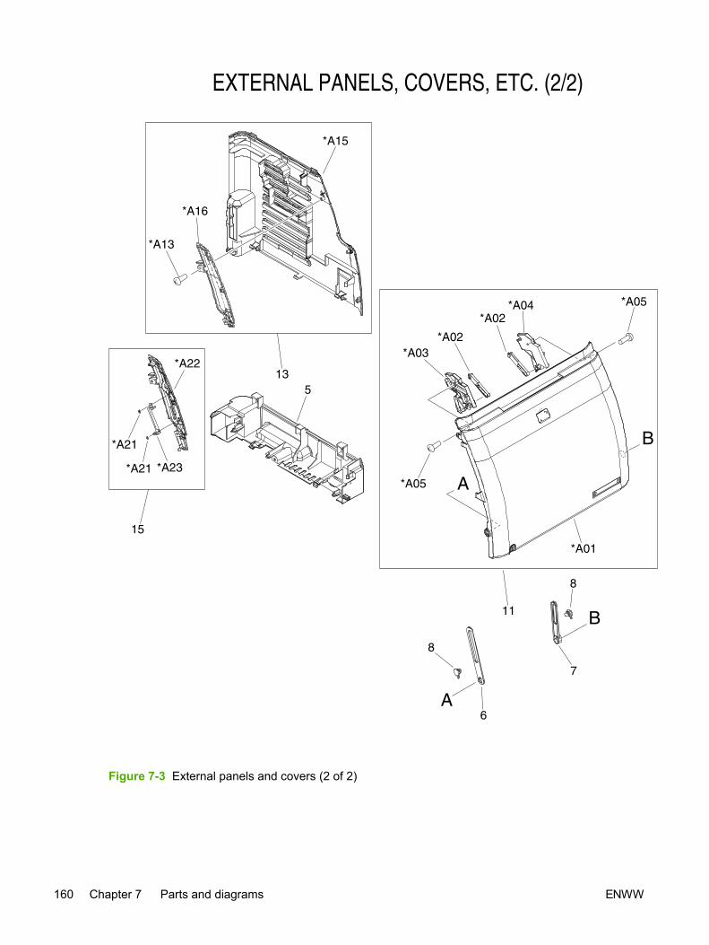
Figure 7-3 External panels and covers (2 of 2)
160 Chapter 7 Parts and diagrams ENWW

Table 7-6 External panels and covers (2 of 2)
Ref Description Part number Qty
* Not set up as a service part
EXTERNAL COVERS, PANELS, ETC. * RF
CONNECTOR, SNAP TIGHT * 1
CONNECTOR, SNAP TIGHT, BK * 1
CLIP, CABLE * 1
SADDLE, WIRE * 1
5 COVER, CASSETTE, RIGHT RC1-5188-000CN 1
6 ARM, FRONT DOOR, LEFT * 1
7 ARM, FRONT DOOR, RIGHT * 1
8 SHAFT, FRONT DOOR ARM * 2
9 COVER, CASSETTE DUST RC1-5200-000CN 1
10 PLATE, REAR RC1-5227-000CN 1
11 FRONT DOOR ASS'Y RM1-1856-000CN 1
13 RIGHT COVER ASS'Y RM1-1858-000CN 1
15 COVER, RIGHT FRONT * 1
A01 DOOR, FRONT * 1
A02 LEVER, LINK * 2
A03 LEVER, TOGGLE, LEFT * 1
A04 LEVER, TOGGLE, RIGHT * 1
A05 SCREW, TAPPING,TRUSS HEAD,M4X8 * 2
A13 SCREW, TP * 2
A15 COVER, RIGHT * 1
A16 COVER, RIGHT FRONT * 1
A21 BUSHING * 2
A22 COVER, RIGHT FRONT * 1
A23 GUIDE, LIGHT * 1
ENWW Assembly locations 161

Covers
Figure 7-4 Upper cover assembly
162 Chapter 7 Parts and diagrams ENWW

Table 7-7 Upper assembly cover
Ref Description Part number Qty
* Not set up as a service part
A01 COVER, UPPER RC1-5176-000CN 1
A02 COVER, INSIDE, UPPER RC1-5178-000CN 1
A03 SCREW, TAPPING,TRUSS HEAD,M4X8 * 1
ENWW Covers 163

Internal assemblies
Figure 7-5 Internal components (1 of 3)
164 Chapter 7 Parts and diagrams ENWW

Table 7-8 Internal components (1 of 3)
Ref Description Part number Qty
* Not set up as a service part
INTERNAL COMPONENTS 1 * RF
1 CROSSMEMBER, TOP COVER * 1
2 BRACKET, LEFT REAR * 1
3 BRACKET, RIGHT REAR * 1
4 COVER, INSIDE, RIGHT * 1
5 BRACKET, CARD READER * 1
6 HOLDER, FAN RETAINER * 1
7 LATCH, LEFT * 1
8 BUSHING * 1
9 LATCH, RIGHT * 1
10 LEVER, ETB RELEASE * 1
11 FAN * 1
12 GEAR, 54T * 1
13 SPRING, TENSION * 2
14 SPRING, COMPRESSION * 1
15 LEFT INTERNAL COVER ASS'Y * 1
16 GUIDE, CARTRIDGE, RIGHT * 1
17 HOLDER, DRUM * 1
18 BUSHING * 1
19 PLATE, PRESSURE, RIGHT * 4
20 BUSHING * 4
21 GUIDE, CASSETTE, REAR RIGHT * 1
22 GUIDE, CASSETTE, FRONT RIGHT * 1
23 GEAR, 20T * 2
24 GEAR, 36T * 4
25 GEAR, 36T * 2
26 SPRING, TORSION * 4
27 SCREW, RS, M3X8 * 15
27 SCREW, RS, M3X8 * 14
27 SCREW, RS, M3X8 * 1
27 SCREW, RS, M3X8 * 4
28 GUIDE, CARTRIDGE, LEFT * 1
29 HOLDER, DRUM * 1
ENWW Internal assemblies 165

Ref Description Part number Qty
30 LINK, SHUTTER * 1
31 PLATE, PRESSURE, LEFT * 4
32 SPRING, TORSION * 4
33 PLATE, SHAFT * 4
34 ARM, OPEN/CLOSE * 3
35 ARM, OPEN/CLOSE * 1
36 SPRING, TORSION * 4
37 ROD, LEFT * 1
38 SPRING, GROUNDING * 1
39 GUIDE, CASSETTE, FRONT LEFT * 1
40 GUIDE, CASSETTE, REAR LEFT * 1
41 RING, E * 2
42 ARM, LASER SHUTTER * 1
43 DUCT, FAN * 1
44 SPRING, TENSION * 1
45 MEMORY CONTROLLER PCB ASS'Y * 1
46 DUCT, FAN, UPPER * 1
47 DUCT, FAN, LOWER * 1
48 HOLDER, MEMORY CONTROLLER * 1
49 FLAG, PRESSURE RELEASE SENSOR * 1
50 CLAMP, FFC * 2
501 SCREW, TAPPING,TRUSS HEAD,M4X8 * 1
A01 SHAFT, TOGGLE * 1
A02 SHAFT, ETB DRIVE * 1
A03 SPRING, GROUNDING * 4
A04 SPRING, GROUNDING * 4
A05 SPRING, GROUNDING * 1
A06 SPRING, GROUNDING * 3
A07 COVER, INSIDE, LEFT * 1
A08 ARM, INTERLOCK SWITCH * 1
A09 SPRING, COMPRESSION * 1
A10 PHOTO INTERRUPTER (SENSOR) * 1
A11 FOOT, RUBBER * 1
A12 GUIDE, CASSETTE, REAR RIGHT * 1
A13 GUIDE, CASSETTE, FRONT RIGHT * 1
166 Chapter 7 Parts and diagrams ENWW

ENWW Internal assemblies 167

Figure 7-6 Internal components (2 of 3)
168 Chapter 7 Parts and diagrams ENWW
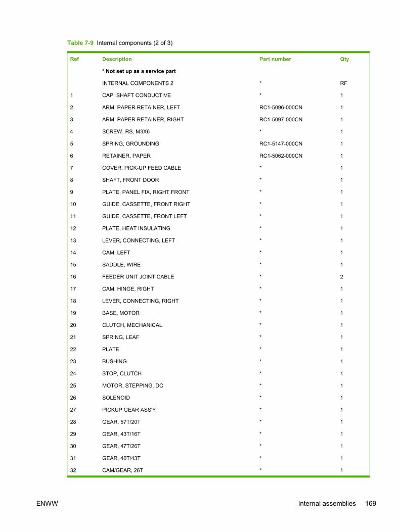
Table 7-9 Internal components (2 of 3)
Ref Description Part number Qty
* Not set up as a service part
INTERNAL COMPONENTS 2 * RF
1 CAP, SHAFT CONDUCTIVE * 1
2 ARM, PAPER RETAINER, LEFT RC1-5096-000CN 1
3 ARM, PAPER RETAINER, RIGHT RC1-5097-000CN 1
4 SCREW, RS, M3X6 * 1
5 SPRING, GROUNDING RC1-5147-000CN 1
6 RETAINER, PAPER RC1-5062-000CN 1
7 COVER, PICK-UP FEED CABLE * 1
8 SHAFT, FRONT DOOR * 1
9 PLATE, PANEL FIX, RIGHT FRONT * 1
10 GUIDE, CASSETTE, FRONT RIGHT * 1
11 GUIDE, CASSETTE, FRONT LEFT * 1
12 PLATE, HEAT INSULATING * 1
13 LEVER, CONNECTING, LEFT * 1
14 CAM, LEFT * 1
15 SADDLE, WIRE * 1
16 FEEDER UNIT JOINT CABLE * 2
17 CAM, HINGE, RIGHT * 1
18 LEVER, CONNECTING, RIGHT * 1
19 BASE, MOTOR * 1
20 CLUTCH, MECHANICAL * 1
21 SPRING, LEAF * 1
22 PLATE * 1
23 BUSHING * 1
24 STOP, CLUTCH * 1
25 MOTOR, STEPPING, DC * 1
26 SOLENOID * 1
27 PICKUP GEAR ASS'Y * 1
28 GEAR, 57T/20T * 1
29 GEAR, 43T/16T * 1
30 GEAR, 47T/26T * 1
31 GEAR, 40T/43T * 1
32 CAM/GEAR, 26T * 1
ENWW Internal assemblies 169

Ref Description Part number Qty
33 SPRING, COMPRESSION * 1
34 ELECT.TRANSPORT BELT ASS'Y RM1-1885-000CN 1
35 RING, E * 2
36 SCREW, RS, M3X6 * 2
37 SCREW, RS, M3X8 * 19
38 SCREW, W/WASHER, M4X18 * 2
501 SCREW, TAPPING, TRUSS HEAD, M4X8 * 2
A01 GEAR, 29T * 1
A02 GEAR, 29T * 1
A03 SPRING, COMPRESSION * 1
170 Chapter 7 Parts and diagrams ENWW

ENWW Internal assemblies 171

Figure 7-7 Internal components (3 of 3)
172 Chapter 7 Parts and diagrams ENWW

Table 7-10 Internal components (3 of 3)
Ref Description Part number Qty
* Not set up as a service part
INTERNAL COMPONENTS 3 * RF
1 GUIDE, CABLE, UPPER * 1
3 PLATE, SHIELD * 1
4 PLATE, SHIELD, FRONT * 1
5 PLATE, CONNECTOR * 1
6 COVER, CONTROLLER * 1
7 LID, CONTROLLER * 1
8 HOLDER, CABLE, LEFT * 1
9 HOLDER, DC CABLE * 1
10 HOLDER, CABLE, UPPER * 1
11 HOLDER, DRAWER * 1
12 CONNECTOR, DRAWER * 1
15 SCANNER UNIT * 1
16 DC CONTROLLER PCB ASS'Y RM1-1975-000CN 1
17 POWER SUPPLY PCB ASS'Y * 1
17 POWER SUPPLY PCB ASS'Y * 2
17 POWER SUPPLY PCB ASS'Y * 1
18 HIGH-VOLTAGE PCB ASS'Y * 1
20 POWER CABLE * 1
21 POWER CONTROLLER CABLE * 1
22 FIXING SENSOR CABLE * 1
23 DRIVE CABLE * 1
23A CONNECTOR, SNAP TIGHT, BK * 1
23B CONNECTOR, SNAP TIGHT, BK * 1
24 CABLE, CPR * 1
25 FEEDER UNIT JOINT CABLE * 1
28 SCREW, W/WASHER, M3X8 * 1
29 SCREW, RS, M3X10 * 4
30 SCREW, RS, M3X8 * 10
32 ROD, BEARING SUPPORT * 3
33 CABLE, FLAT * 1
34 CABLE, FLAT * 1
35 CABLE, FLAT * 1
ENWW Internal assemblies 173

Ref Description Part number Qty
37 CLAMP, FFC * 2
502 SCREW, TAPPING, TRUSS HEAD, M4X8 * 2
174 Chapter 7 Parts and diagrams ENWW

ENWW Internal assemblies 175

Figure 7-8 Control panel assembly
176 Chapter 7 Parts and diagrams ENWW

Table 7-11 Control panel assembly
Ref Description Part number Qty
* Not set up as a service part
CONTROL PANEL ASS'Y RM1-1983-000CN 1
1 CONTROL PANEL PCB ASS'Y * 1
1 CONTROL PANEL PCB ASS'Y * 1
A01 PANEL, CONTROL PANEL * 1
A02 PLATE, CONTROL PANEL RETAINING * 1
A03 GUIDE, CONTROL PANEL LIGHT * 1
A04 BUTTON, CONTROL PANEL, 1 * 1
A05 BUTTON, CONTROL PANEL, 2 * 2
A06 BUTTON, CONTROL PANEL, 3 * 1
A07 SPACER, CONTROL PANEL * 1
A09 SCREW, RS, M3X8 * 2
ENWW Internal assemblies 177

Figure 7-9 Main drive assembly
178 Chapter 7 Parts and diagrams ENWW

Table 7-12 Main drive assembly
Ref Description Part number Qty
* Not set up as a service part
MAIN DRIVE ASS'Y * 1
1 F.F.C. CONNECT PCB UNIT * 1
A01 COLLAR, SPRING * 2
A02 BUSHING * 1
A03 FLANGE, CAM GEAR * 2
A04 COVER, DRUM * 4
A05 BUSHING * 4
A06 BUSHING * 2
A07 CAM, RELEASE * 4
A08 ROD, RELEASE, RIGHT * 1
A09 FAN * 1
A10 DUCT, FAN * 1
A11 PULLEY * 1
A12 BELT, TRANSMISSION * 1
A13 STOP, CAM GEAR * 2
A14 BUSHING * 1
A15 GUIDE, DRIVE CABLE * 1
A16 MOTOR, DC * 1
A17 SOLENOID * 2
A18 PLATE, DRIVE INSIDE * 1
A19 SIDE PLATE, DRIVE * 1
A20 PLATE, FAN * 1
A21 GEAR, 81T * 1
A22 GEAR, 81T/32T * 1
A23 GEAR, 96T * 2
A24 GEAR, 53T/96T * 2
A25 GEAR, 98T * 4
A26 GEAR, 89T/53T * 1
A27 GEAR, 134T * 1
A28 GEAR, 86T * 2
A29 GEAR, 64T * 2
A30 GEAR, 64T * 2
A31 GEAR, 37T * 2
ENWW Internal assemblies 179

Ref Description Part number Qty
A32 GEAR, 27T/64T * 1
A33 GEAR, 64T * 1
A34 GEAR, 54T * 1
A35 GEAR, 54T * 1
A36 GEAR, 18T * 1
A37 SPRING, COMPRESSION * 4
A38 SPRING, COMPRESSION * 2
A39 SPRING, TENSION * 2
A40 SHAFT, DRUM GEAR * 4
A41 CONNECTOR, 2P * 2
A42 CONNECTOR, SNAP TIGHT, BK * 2
A43 CLIP, CABLE * 5
A44 CLIP, EDGE * 1
A45 SCREW, RS, M3X8 * 18
A46 SCREW, TAPPING,TRUSS HEAD,M4X8 * 2
A47 SE RING * 1
A48 RING, E * 2
180 Chapter 7 Parts and diagrams ENWW

ENWW Internal assemblies 181

Figure 7-10 Fuser assembly
182 Chapter 7 Parts and diagrams ENWW

Table 7-13 Fuser assembly
Ref Description Part number Qty
* Not set up as a service part
FUSER ASS'Y (110v) RM1-1820-000CN 1
FUSER ASS'Y (220v) RM1-1821-000CN 1
1 SPRING, TORSION * 1
2 BUSHING * 1
3 BUSHING * 1
4 RIB, ENTRANCE GUIDE * 4
5 FLAG, INLET * 1
6 GUIDE, PAPER DELIVERY UPPER * 1
7 FLAG, PAPER DELIVERY * 1
8 FILM GUIDE ASS'Y (110v) * 1
8 FILM GUIDE ASS'Y (220v) * 1
9 GUIDE, PAPER DELIVERY LOWER * 1
10 FLAG, INTERTWINE PREVENTION * 3
11 BUSHING * 1
12 PLATE, PRESSURE, LEFT * 1
13 PLATE, PRESSURE, RIGHT * 1
14 HOLDER, RESISTOR * 1
15 SPRING, GROUNDING * 1
16 SPRING, GROUNDING * 1
17 SPRING, GROUNDING * 1
18 GUIDE, CONTACT/SENSOR SUPPORT * 1
19 ROLLER, PRESSURE * 1
20 ROLLER, FACE-DOWN BENDING * 2
21 PIN,DOWEL * 3
22 CAM, PRESSURE RELEASE * 2
23 FLAG, PRESSURE RELEASE * 1
24 HOLDER, PRESSURE RELEASE GEAR * 1
25 SPRING, LEAF * 1
26 BUSHING * 1
27 BUSHING * 1
28 SPRING, COMPRESSION * 1
29 RING, E * 2
30 RING, E 1
ENWW Internal assemblies 183

Ref Description Part number Qty
31 SPRING, GROUNDING * 1
32 ROLLER, DELIVERY * 2
33 MOTOR, STEPPING, DC * 1
34 SCREW, RS, M3X6 * 2
35 SHAFT, FACE-DOWN ROLLER * 1
36 SCREW, RS, M3X8 * 17
37 GEAR, 30T * 1
38 GEAR, 19T * 1
39 GEAR, 16T * 1
40 GEAR, 49T * 1
41 GEAR, 19T/71T * 1
42 GEAR, 27T * 1
43 GEAR, 26T * 1
44 GEAR, 20T/44T * 1
45 GEAR, 22T/38T * 1
46 SPRING, TENSION * 2
47 SPRING, TORSION * 2
48 SOLID RESISTOR, 20MOHM, 1/4W * 1
49 PHOTO INTERRUPTER (SENSOR) * 2
50 SCREW, RS, M3X8 * 1
51 CLIP, ENTRANCE GUIDE * 8
52 PLATE, GROUNDING * 1
53 GUIDE, FIXING ENTRANCE * 1
A01 FRAME, FIXING * 1
A02 SIDE PLATE, FIXING, RIGHT * 1
A03 SIDE PLATE, FIXING, LEFT * 1
A04 SHAFT, PRESSURE RELEASE * 2
A05 PLATE, PRESSURE RELEASE, LEFT * 1
A06 PLATE, PRESSURE RELEASE, RIGHT * 1
A07 SIDE PLATE, FIXING, LEFT, 2 * 1
A08 SIDE PLATE, FIXING, RIGHT, 2 * 1
A09 SHAFT, PRESSURE RELEASE CAM * 1
A10 PLATE, MOTOR ANTI-MAGNETIC * 1
A11 SIDE PLATE, GEAR * 1
A12 BASE PLATE, FIXING * 1
184 Chapter 7 Parts and diagrams ENWW

ENWW Internal assemblies 185

Figure 7-11 PCB assembly location (Tray 2)
186 Chapter 7 Parts and diagrams ENWW

Table 7-14 PCB assembly location Tray 2
Ref Description Part number Qty
* Not set up as a service part
PCB ASS'Y LOCATION DIAGRAM * RF
1 MEMORY CONTROLLER PCB ASS'Y * 1
2 DC CONTROLLER PCB ASS'Y RM1-1975-000CN 1
3 POWER SUPPLY PCB ASS'Y * 1
3 POWER SUPPLY PCB ASS'Y * 1
4 HIGH-VOLTAGE PCB ASS'Y * 1
ENWW Internal assemblies 187

Input devices
Figure 7-12 Tray 2 input tray (cassette)
188 Chapter 7 Parts and diagrams ENWW

Table 7-15 Tray 2 input tray (cassette)
Ref Description Part number Qty
* Not set up as a service part
CASSETTE RM1-1916-000CN 1
1 PANEL, FRONT * 1
2 GUIDE, CASSETTE DUPLEX, LOWER * 1
3 STOPPER, CASSETTE, LEFT * 1
4 STOPPER, CASSETTE, RIGHT * 1
5 ARM, CLAW RELEASE, LEFT * 1
6 ARM, CLAW RELEASE, RIGHT * 1
7 ARM, REMNANT INDICATION * 1
8 ARM, PLATE LOCK RELEASE, MD. * 1
9 SIZE PLATE, PAPER * 1
10 SPRING, GROUNDING * 1
11 SPRING, GROUNDING * 1
12 PLATE, CASSETTE REINFORCEMENT * 1
13 ARM, MD. PLATE RELEASE, LEFT * 1
14 CLAW, MD. PLATE RELEASE, LEFT * 1
15 ARM, MD. PLATE RELEASE, RIGHT * 1
16 CLAW, MD. PLATE RELEASE, RIGHT * 1
17 SPRING, COMPRESSION * 2
18 SPRING, COMPRESSION * 2
19 SPRING, TENSION * 2
20 SPRING, COMPRESSION * 1
21 SPRING, COMPRESSION * 2
22 SPRING, COMPRESSION * 2
23 BACK END LIMIT PLATE ASS'Y * 1
24 MIDDLE PLATE ASS'Y * 1
24A LEFT PAPER SIDE END ASS'Y * 1
24B RIGHT PAPER SIDE END ASS'Y * 1
25 SEPARATION ASS'Y RM1-1922-000CN 1
26 GUIDE, CASSETTE DUPLEX, UPPER * 1
27 FEED ASS'Y RM1-1923-000CN 1
501 SCREW, TAPPING,TRUSS HEAD,M4X8 * 2
A01 CASSETTE BODY ASS'Y * 1
A02 BODY, CASSETTE * 1
ENWW Input devices 189

Ref Description Part number Qty
A03 PLATE, BACK END LIMIT, LARGE * 1
A04 ARM, BACK END LOCK * 1
A05 PLATE, BACK END LIMIT, SMALL * 1
A06 LEVER, BACK END LOCK RELEASE * 1
A07 STOPPER, BACK END LIMIT * 1
A08 SPRING, COMPRESSION * 1
A09 SHEET, SEPARATION * 1
A10 PLATE, MIDDLE * 1
A11 PLATE, REINFORCEMENT * 1
A12 CLAW, MIDDLE PLATE, LEFT * 1
A13 CLAW, MIDDLE PLATE, RIGHT * 1
A14 RACK * 2
A15 GEAR, 22T * 1
A16 SPRING, COMPRESSION * 1
A17 SCREW, TAPPING,TRUSS HEAD,M3X6 * 2
A17 SCREW, TAPPING,TRUSS HEAD,M3X6 * 2
A19 HOLDER, PAPER RETAINING * 2
A20 SPRING, COMPRESSION * 2
A21 PLATE, PAPER SIDE END, RIGHT * 1
A22 LEVER, SIDE END LOCK RELEASE * 1
A23 STOPPER, PAPER SIDE END * 2
A24 SPRING, COMPRESSION * 2
A25 HOLDER, PAD * 1
A26 HOLDER, SEPARATION * 1
A27 PLATE, PAPER GUIDE * 1
A28 HOLDER, PAD * 1
A29 WEIGHT, PAD * 2
A30 HOLDER, PAD * 1
A31 SPRING, COMPRESSION * 1
A32 RACK, MANUAL FEED * 2
A33 GUIDE, MANUAL FEED * 1
A34 GUIDE, FEED WIDTH, LEFT * 1
A35 GUIDE, FEED WIDTH, RIGHT * 1
A36 GEAR, 16T * 1
190 Chapter 7 Parts and diagrams ENWW

ENWW Input devices 191

Figure 7-13 250-sheet input tray (cassette)
192 Chapter 7 Parts and diagrams ENWW

Table 7-16 250-sheet input tray (cassette)
Ref Description Part number Qty
* Not set up as a service part
R30 CASSETTE RM1-1945-000CN RF
R40 PAPER PICKUP ROLLER RC1-5440-000CN RF
ENWW Input devices 193

Figure 7-14 Tray 2 input tray internal components
194 Chapter 7 Parts and diagrams ENWW

Table 7-17 Tray 2 sheet input tray internal components
Ref Description Part number Qty
* Not set up as a service part
INTERNAL COMPONENTS * RF
1 CAP, CONTINUITY * 1
2 COVER, CASSETTE DUST RC1-5200-000CN 1
3 BASE, MOTOR * 1
4 CLUTCH, MECHANICAL * 1
5 SPRING, LEAF * 1
6 BUSHING * 1
7 HOLDER, DRAWER CONNECTOR * 1
8 HOLDER, SWING GEAR * 1
9 PLATE, GROUNDING * 1
10 COVER, OPTION FRONT * 1
11 COVER, OPTION LEFT * 1
12 COVER, PCB * 1
13 SHAFT, POSITIONING * 3
14 COVER, SWING GEAR * 1
15 STOP, CLUTCH * 1
16 SOLENOID * 1
17 PICKUP GEAR ASS'Y * 1
18 COVER, OPTION RIGHT * 1
19 GEAR, 47T/26T * 1
20 GEAR, 40T/43T * 1
21 CAM/GEAR, 26T * 1
22 GEAR, 19T * 1
23 GEAR, 18T * 1
24 SPRING, COMPRESSION * 1
25 SPRING, TENSION * 1
26 CONNECTOR, DRAWER * 1
27 SADDLE, WIRE * 1
28 SCREW, RS, M3X8 * 32
29 SPRING, GROUNDING * 1
30 GUIDE, CASSETTE, FRONT LEFT * 1
31 GUIDE, CASSETTE, REAR LEFT * 1
32 SCREW, RS, M3X8 * 3
ENWW Input devices 195

Ref Description Part number Qty
33 GUIDE, CASSETTE, REAR RIGHT * 1
34 GUIDE, CASSETTE, FRONT RIGHT * 1
35 SCREW, RS, M3X8 * 3
36 PAPER FEEDER PCB ASS'Y * 1
501 SCREW, TAPPING,TRUSS HEAD, M4X8 * 2
A01 CROSSMEMBER, FRONT * 1
A02 CROSSMEMBER, REAR * 1
A03 CROSSMEMBER, MIDDLE * 1
A04 CROSSMEMBER, LOWER, REAR * 2
A05 GUIDE, PAPER SENSOR CABLE, 1 * 1
A06 GUIDE, PAPER SENSOR CABLE, 2 * 1
A07 GEAR, 29T * 1
A08 GEAR, 29T * 1
A09 SPRING, COMPRESSION * 1
A10 FOOT, RUBBER * 2
A11 COVER, OPTION RIGHT * 1
A12 OPTION FRAME LEFT ASS'Y * 1
A13 FRAME, OPTION, LEFT * 1
A14 OPTION FRAME RIGHT ASS'Y * 1
A15 FRAME, OPTION, RIGHT * 1
196 Chapter 7 Parts and diagrams ENWW

ENWW Input devices 197

Figure 7-15 Paper pick-up feeder assembly for Tray 2
198 Chapter 7 Parts and diagrams ENWW

Table 7-18 Paper pick-up feeder assembly for Tray 2
Ref Description Part number Qty
* Not set up as a service part
PAPER PICKUP FEEDER ASS'Y * 1
1 GUIDE, REGISTRATION * 1
2 PLATE, REG. GROUNDING, 1 * 1
3 PLATE, REG. GROUNDING, 2 * 1
4 FLAG, SENSOR * 1
5 SPRING, TORSION * 1
6 COVER, SENSOR, TOP * 1
7 GUIDE, PRE-TRANSFER * 1
8 ROLLER, REGISTRATION DRIVE * 1
9 BUSHING * 2
10 SHUTTER, REGISTRATION * 1
11 SPRING, TORSION * 1
12 ROLLER, REGISTRATION, A * 2
13 ROLLER, REGISTRATION, B * 2
14 ROLLER, REGISTRATION, C * 2
15 BUSHING * 1
16 BUSHING * 1
17 ROLLER, PAPER PICKUP RC1-5440-000CN 1
18 HOLDER, PAPER WIDTH SENSOR * 1
19 FLAG, PAPER WIDTH SENSOR * 1
20 SPRING, TORSION * 1
21 RESISTOR, 400 OHM, 0.5W * 1
22 COVER, PICKUP FEED FRAME * 1
23 SPRING, TENSION * 2
24 PHOTO INTERRUPTER (SENSOR) * 4
25 PAPER PICKUP DRIVE ASS'Y * 1
26 FEEDER UNIT CABLE * 1
501 SCREW, TAPPING,TRUSS HEAD,M4X8 * 4
A01 FRAME, PAPER PICKUP FEEDER * 1
A02 SHAFT, REGISTRATION ROLLER * 1
A03 COVER, PICKUP FEED FRAME * 1
A04 SHEET, SCRAPER, 1 * 1
A05 SHEET, SCRAPER, 2 * 1
ENWW Input devices 199

Ref Description Part number Qty
A06 SHAFT, PAPER PICKUP DRIVE * 1
A07 BUSHING * 1
A08 BUSHING * 1
A09 ARM, CST. PAPER SENSING, 1 * 1
A10 ARM, CST. PAPER SENSING, 2 * 1
A11 HOLDER, PAPER PICKUP ROLLER * 1
A12 ROLLER, CASSETTE PAPER PICKUP * 2
A13 BUSHING * 1
A14 SPRING, COMPRESSION * 1
200 Chapter 7 Parts and diagrams ENWW

ENWW Input devices 201

Figure 7-16 Tray 3 input tray (cassette)
202 Chapter 7 Parts and diagrams ENWW

Table 7-19 Tray 3 input tray (cassette)
Ref Description Part number Qty
* Not set up as a service part
CASSETTE RM1-1945-000CN 1
PAPER PICKUP ROLLER RC1-5440-000CN
1 PANEL, FRONT * 1
2 FRAME, FRONT * 1
3 STOPPER, CASSETTE, LEFT * 1
4 STOPPER, CASSETTE, RIGHT * 1
5 ARM, CLAW RELEASE, LEFT * 1
6 ARM, CLAW RELEASE, RIGHT * 1
7 ARM, REMNANT INDICATION * 1
8 ARM, PLATE LOCK RELEASE, MD * 1
9 SIZE PLATE, PAPER * 1
10 SPRING, GROUNDING * 1
11 SPRING, GROUNDING * 1
12 PLATE, CASSETTE REINFORCEMENT * 1
13 ARM, MD. PLATE RELEASE, LEFT * 1
14 CLAW, MD. PLATE RELEASE, LEFT * 1
15 ARM, MD. PLATE RELEASE, RIGHT * 1
16 CLAW, MD. PLATE RELEASE, RIGHT * 1
17 SPRING, COMPRESSION * 2
18 SPRING, COMPRESSION * 2
19 SPRING, TENSION * 2
20 SPRING, COMPRESSION * 1
21 SPRING, COMPRESSION * 2
22 SPRING, COMPRESSION * 2
23 BACK END LIMIT PLATE ASS'Y * 1
24 MIDDLE PLATE ASS'Y * 1
24A LEFT PAPER SIDE END ASS'Y * 1
24B RIGHT PAPER SIDE END ASS'Y * 1
25 SEPARATION ASS'Y RM1-1922-000CN 1
501 SCREW, TAPPING,TRUSS HEAD,M4X8 * 2
A01 CASSETTE BODY ASS'Y * 1
A02 BODY, CASSETTE * 1
A03 PLATE, BACK END LIMIT, LARGE * 1
ENWW Input devices 203

Ref Description Part number Qty
A04 ARM, BACK END LOCK * 1
A05 PLATE, BACK END LIMIT, SMALL * 1
A06 LEVER, BACK END LOCK RELEASE * 1
A07 STOPPER, BACK END LIMIT * 1
A08 SPRING, COMPRESSION * 1
A09 SHEET, SEPARATION * 1
A10 PLATE, MIDDLE * 1
A11 PLATE, REINFORCEMENT * 1
A12 CLAW, MIDDLE PLATE, LEFT * 1
A13 CLAW, MIDDLE PLATE, RIGHT * 1
A14 RACK * 2
A15 GEAR, 22T * 1
A16 SPRING, COMPRESSION * 1
A17 SCREW, TAPPING,TRUSS HEAD,M3X6 * 2
A18 PLATE, PAPER SIDE END, LEFT * 1
A19 HOLDER, PAPER RETAINING * 2
A20 SPRING, COMPRESSION * 2
A21 PLATE, PAPER SIDE END, RIGHT * 1
A22 LEVER, SIDE END LOCK RELEASE * 1
A23 STOPPER, PAPER SIDE END * 2
A24 SPRING, COMPRESSION * 2
A25 HOLDER, PAD * 1
A26 HOLDER, SEPARATION * 1
A27 PLATE, PAPER GUIDE * 1
A28 HOLDER, PAD * 1
A29 WEIGHT, PAD * 2
A30 HOLDER, PAD * 1
A31 SPRING, COMPRESSION * 1
204 Chapter 7 Parts and diagrams ENWW

ENWW Input devices 205

Figure 7-17 Paper pickup feeder assembly (Tray 3)
206 Chapter 7 Parts and diagrams ENWW

Table 7-20 Paper pickup feeder assembly (Tray 3)
Ref Description Part number Qty
* Not set up as a service part
PAPER PICKUP ROLLER RC1-5440-000CN 1
1 GUIDE, REGISTRATION * 1
2 PLATE, REG. GROUNDING, 1 * 1
3 PLATE, REG. GROUNDING, 2 * 1
4 COVER, PICKUP FEED FRAME * 1
5 GUIDE, PRE-TRANSFER * 1
6 ROLLER, REGISTRATION DRIVE * 1
7 BUSHING * 2
8 ROLLER, REGISTRATION, A * 2
9 ROLLER, REGISTRATION, B * 2
10 ROLLER, REGISTRATION, C * 2
11 BUSHING * 1
12 BUSHING * 1
13 ROLLER, PAPER PICKUP RC1-5440-000CN 1
14 RESISTOR, 400 OHM, 0.5W * 1
15 SPRING, TENSION * 2
16 PHOTO INTERRUPTER (SENSOR) * 1
17 CABLE, OPTION SENSOR * 1
18 PAPER PICKUP DRIVE ASS'Y * 1
501 SCREW, TAPPING,TRUSS HEAD,M4X8 * 4
A01 FRAME, PAPER PICKUP FEEDER * 1
A02 SHAFT, REGISTRATION ROLLER * 1
A03 SHAFT, PAPER PICKUP DRIVE * 1
A04 BUSHING * 1
A05 BUSHING * 1
A06 ARM, CST. PAPER SENSING, 1 * 1
A07 ARM, CST. PAPER SENSING, 2 * 1
A08 HOLDER, PAPER PICKUP ROLLER * 1
A09 ROLLER, CASSETTE PAPER PICKUP * 2
A10 BUSHING * 1
A11 SPRING, COMPRESSION * 1
ENWW Input devices 207

Figure 7-18 PCB assembly location optional Tray 3
208 Chapter 7 Parts and diagrams ENWW

Table 7-21 Paper pickup feeder assembly (Tray 3)
Ref Description Part number Qty
* Not set up as a service part
PCB ASS'Y LOCATION DIAGRAM * RF
1 PAPER FEEDER PCB ASS'Y * 1
ENWW Input devices 209

Diagrams
Figure 7-19 General circuit diagram
210 Chapter 7 Parts and diagrams ENWW

Alphabetical parts listTable 7-22 Alphabetical parts list
Description Part number Table and page
* Not set up as a service part Assembly locationson page 157
* Not set up as a service part External panels and covers (1of 2) on page 159
* Not set up as a service part External panels and covers (2of 2) on page 161
* Not set up as a service part Upper assembly coveron page 163
* Not set up as a service part Internal components (1 of 3)on page 165
* Not set up as a service part Internal components (2 of 3)on page 169
* Not set up as a service part Internal components (3 of 3)on page 173
* Not set up as a service part Control panel assemblyon page 177
* Not set up as a service part Main drive assemblyon page 179
* Not set up as a service part Fuser assembly on page 183
* Not set up as a service part PCB assembly location Tray 2on page 187
* Not set up as a service part Tray 2 input tray (cassette)on page 189
* Not set up as a service part 250-sheet input tray(cassette) on page 193
* Not set up as a service part Tray 2 sheet input trayinternal componentson page 195
* Not set up as a service part Paper pick-up feederassembly for Tray 2on page 199
* Not set up as a service part Tray 3 input tray (cassette)on page 203
* Not set up as a service part Paper pickup feederassembly (Tray 3) on page 207
* Not set up as a service part Paper pickup feederassembly (Tray 3) on page 209
ARM, BACK END LOCK * Tray 2 input tray (cassette)on page 189
ARM, BACK END LOCK * Tray 3 input tray (cassette)on page 203
ENWW Alphabetical parts list 211

Description Part number Table and page
ARM, CLAW RELEASE, LEFT * Tray 2 input tray (cassette)on page 189
ARM, CLAW RELEASE, LEFT * Tray 3 input tray (cassette)on page 203
ARM, CLAW RELEASE, RIGHT * Tray 2 input tray (cassette)on page 189
ARM, CLAW RELEASE, RIGHT * Tray 3 input tray (cassette)on page 203
ARM, CST. PAPER SENSING, 1 * Paper pick-up feederassembly for Tray 2on page 199
ARM, CST. PAPER SENSING, 1 * Paper pickup feederassembly (Tray 3) on page 207
ARM, CST. PAPER SENSING, 2 * Paper pick-up feederassembly for Tray 2on page 199
ARM, CST. PAPER SENSING, 2 * Paper pickup feederassembly (Tray 3) on page 207
ARM, FRONT DOOR, LEFT * External panels and covers (2of 2) on page 161
ARM, FRONT DOOR, RIGHT * External panels and covers (2of 2) on page 161
ARM, INTERLOCK SWITCH * Internal components (1 of 3)on page 165
ARM, LASER SHUTTER * Internal components (1 of 3)on page 165
ARM, MD. PLATE RELEASE, LEFT * Tray 2 input tray (cassette)on page 189
ARM, MD. PLATE RELEASE, LEFT * Tray 3 input tray (cassette)on page 203
ARM, MD. PLATE RELEASE, RIGHT * Tray 2 input tray (cassette)on page 189
ARM, MD. PLATE RELEASE, RIGHT * Tray 3 input tray (cassette)on page 203
ARM, OPEN/CLOSE * Internal components (1 of 3)on page 165
ARM, OPEN/CLOSE * Internal components (1 of 3)on page 165
ARM, PAPER RETAINER, LEFT RC1-5096-000CN Internal components (2 of 3)on page 169
ARM, PAPER RETAINER, RIGHT RC1-5097-000CN Internal components (2 of 3)on page 169
ARM, PLATE LOCK RELEASE, MD * Tray 3 input tray (cassette)on page 203
Table 7-22 Alphabetical parts list (continued)
212 Chapter 7 Parts and diagrams ENWW

Description Part number Table and page
ARM, PLATE LOCK RELEASE, MD. * Tray 2 input tray (cassette)on page 189
ARM, REMNANT INDICATION * Tray 2 input tray (cassette)on page 189
ARM, REMNANT INDICATION * Tray 3 input tray (cassette)on page 203
BACK END LIMIT PLATE ASS'Y * Tray 2 input tray (cassette)on page 189
BACK END LIMIT PLATE ASS'Y * Tray 3 input tray (cassette)on page 203
BASE PLATE, FIXING * Fuser assembly on page 183
BASE, MOTOR * Internal components (2 of 3)on page 169
BASE, MOTOR * Tray 2 sheet input trayinternal componentson page 195
BELT, TRANSMISSION * Main drive assemblyon page 179
BODY, CASSETTE * Tray 2 input tray (cassette)on page 189
BODY, CASSETTE * Tray 3 input tray (cassette)on page 203
BRACKET, CARD READER * Internal components (1 of 3)on page 165
BRACKET, LEFT REAR * Internal components (1 of 3)on page 165
BRACKET, RIGHT REAR * Internal components (1 of 3)on page 165
BUSHING * External panels and covers (2of 2) on page 161
BUSHING * Internal components (1 of 3)on page 165
BUSHING * Internal components (1 of 3)on page 165
BUSHING * Internal components (1 of 3)on page 165
BUSHING * Internal components (2 of 3)on page 169
BUSHING * Main drive assemblyon page 179
BUSHING * Main drive assemblyon page 179
BUSHING * Main drive assemblyon page 179
Table 7-22 Alphabetical parts list (continued)
ENWW Alphabetical parts list 213

Description Part number Table and page
BUSHING * Main drive assemblyon page 179
BUSHING * Fuser assembly on page 183
BUSHING * Fuser assembly on page 183
BUSHING * Fuser assembly on page 183
BUSHING * Fuser assembly on page 183
BUSHING * Fuser assembly on page 183
BUSHING * Tray 2 sheet input trayinternal componentson page 195
BUSHING * Paper pick-up feederassembly for Tray 2on page 199
BUSHING * Paper pick-up feederassembly for Tray 2on page 199
BUSHING * Paper pick-up feederassembly for Tray 2on page 199
BUSHING * Paper pick-up feederassembly for Tray 2on page 199
BUSHING * Paper pick-up feederassembly for Tray 2on page 199
BUSHING * Paper pick-up feederassembly for Tray 2on page 199
BUSHING * Paper pickup feederassembly (Tray 3) on page 207
BUSHING * Paper pickup feederassembly (Tray 3) on page 207
BUSHING * Paper pickup feederassembly (Tray 3) on page 207
BUSHING * Paper pickup feederassembly (Tray 3) on page 207
BUSHING * Paper pickup feederassembly (Tray 3) on page 207
BUSHING * Paper pickup feederassembly (Tray 3) on page 207
BUTTON, CONTROL PANEL, 1 * Control panel assemblyon page 177
BUTTON, CONTROL PANEL, 2 * Control panel assemblyon page 177
Table 7-22 Alphabetical parts list (continued)
214 Chapter 7 Parts and diagrams ENWW

Description Part number Table and page
BUTTON, CONTROL PANEL, 3 * Control panel assemblyon page 177
CABLE, CPR * Internal components (3 of 3)on page 173
CABLE, FLAT * Internal components (3 of 3)on page 173
CABLE, FLAT * Internal components (3 of 3)on page 173
CABLE, FLAT * Internal components (3 of 3)on page 173
CABLE, OPTION SENSOR * Paper pickup feederassembly (Tray 3) on page 207
CAM, HINGE, RIGHT * Internal components (2 of 3)on page 169
CAM, LEFT * Internal components (2 of 3)on page 169
CAM, PRESSURE RELEASE * Fuser assembly on page 183
CAM, RELEASE * Main drive assemblyon page 179
CAM/GEAR, 26T * Internal components (2 of 3)on page 169
CAM/GEAR, 26T * Tray 2 sheet input trayinternal componentson page 195
CAP, CONTINUITY * Tray 2 sheet input trayinternal componentson page 195
CAP, SHAFT CONDUCTIVE * Internal components (2 of 3)on page 169
CASSETTE RM1-1916-000CN Assembly locationson page 157
CASSETTE RM1-1916-000CN Tray 2 input tray (cassette)on page 189
CASSETTE RM1-1945-000CN 250-sheet input tray(cassette) on page 193
CASSETTE RM1-1945-000CN Tray 3 input tray (cassette)on page 203
CASSETTE BODY ASS'Y * Tray 2 input tray (cassette)on page 189
CASSETTE BODY ASS'Y * Tray 3 input tray (cassette)on page 203
CLAMP, FFC * Internal components (1 of 3)on page 165
Table 7-22 Alphabetical parts list (continued)
ENWW Alphabetical parts list 215

Description Part number Table and page
CLAMP, FFC * Internal components (3 of 3)on page 173
CLAW, MD. PLATE RELEASE, LEFT * Tray 2 input tray (cassette)on page 189
CLAW, MD. PLATE RELEASE, LEFT * Tray 3 input tray (cassette)on page 203
CLAW, MD. PLATE RELEASE, RIGHT * Tray 2 input tray (cassette)on page 189
CLAW, MD. PLATE RELEASE, RIGHT * Tray 3 input tray (cassette)on page 203
CLAW, MIDDLE PLATE, LEFT * Tray 2 input tray (cassette)on page 189
CLAW, MIDDLE PLATE, LEFT * Tray 3 input tray (cassette)on page 203
CLAW, MIDDLE PLATE, RIGHT * Tray 2 input tray (cassette)on page 189
CLAW, MIDDLE PLATE, RIGHT * Tray 3 input tray (cassette)on page 203
CLIP, CABLE * External panels and covers (1of 2) on page 159
CLIP, CABLE * External panels and covers (2of 2) on page 161
CLIP, CABLE * Main drive assemblyon page 179
CLIP, EDGE * Main drive assemblyon page 179
CLIP, ENTRANCE GUIDE * Fuser assembly on page 183
CLUTCH, MECHANICAL * Internal components (2 of 3)on page 169
CLUTCH, MECHANICAL * Tray 2 sheet input trayinternal componentson page 195
COLLAR, SPRING * Main drive assemblyon page 179
CONNECTOR, 2P * Main drive assemblyon page 179
CONNECTOR, DRAWER * Internal components (3 of 3)on page 173
CONNECTOR, DRAWER * Tray 2 sheet input trayinternal componentson page 195
CONNECTOR, SNAP TIGHT * External panels and covers (1of 2) on page 159
Table 7-22 Alphabetical parts list (continued)
216 Chapter 7 Parts and diagrams ENWW

Description Part number Table and page
CONNECTOR, SNAP TIGHT * External panels and covers (2of 2) on page 161
CONNECTOR, SNAP TIGHT, BK * External panels and covers (1of 2) on page 159
CONNECTOR, SNAP TIGHT, BK * External panels and covers (2of 2) on page 161
CONNECTOR, SNAP TIGHT, BK * Internal components (3 of 3)on page 173
CONNECTOR, SNAP TIGHT, BK * Internal components (3 of 3)on page 173
CONNECTOR, SNAP TIGHT, BK * Main drive assemblyon page 179
CONTROL PANEL ASS'Y RM1-1983-000CN Control panel assemblyon page 177
CONTROL PANEL ASSEMBLY RM1-1983-000CN Assembly locationson page 157
CONTROL PANEL PCB ASS'Y * Control panel assemblyon page 177
CONTROL PANEL PCB ASS'Y * Control panel assemblyon page 177
COVER, CASSETTE DUST RC1-5200-000CN External panels and covers (1of 2) on page 159
COVER, CASSETTE DUST RC1-5200-000CN External panels and covers (2of 2) on page 161
COVER, CASSETTE DUST RC1-5200-000CN Tray 2 sheet input trayinternal componentson page 195
COVER, CASSETTE, LEFT RC1-5184-000CN External panels and covers (1of 2) on page 159
COVER, CASSETTE, RIGHT RC1-5188-000CN External panels and covers (2of 2) on page 161
COVER, CONTROLLER * Internal components (3 of 3)on page 173
COVER, DRUM * Main drive assemblyon page 179
COVER, FACE-DOWN RC1-5173-000CN External panels and covers (1of 2) on page 159
COVER, INSIDE, LEFT * Internal components (1 of 3)on page 165
COVER, INSIDE, RIGHT * Internal components (1 of 3)on page 165
COVER, INSIDE, UPPER RC1-5178-000CN Upper assembly coveron page 163
Table 7-22 Alphabetical parts list (continued)
ENWW Alphabetical parts list 217

Description Part number Table and page
COVER, LEFT RC1-5183-000CN External panels and covers (1of 2) on page 159
COVER, OPTION FRONT * Tray 2 sheet input trayinternal componentson page 195
COVER, OPTION LEFT * Tray 2 sheet input trayinternal componentson page 195
COVER, OPTION RIGHT * Tray 2 sheet input trayinternal componentson page 195
COVER, OPTION RIGHT * Tray 2 sheet input trayinternal componentson page 195
COVER, PCB * Tray 2 sheet input trayinternal componentson page 195
COVER, PICK-UP FEED CABLE * Internal components (2 of 3)on page 169
COVER, PICKUP FEED FRAME * Paper pick-up feederassembly for Tray 2on page 199
COVER, PICKUP FEED FRAME * Paper pick-up feederassembly for Tray 2on page 199
COVER, PICKUP FEED FRAME * Paper pickup feederassembly (Tray 3) on page 207
COVER, RIGHT * External panels and covers (2of 2) on page 161
COVER, RIGHT FRONT * External panels and covers (2of 2) on page 161
COVER, RIGHT FRONT * External panels and covers (2of 2) on page 161
COVER, RIGHT FRONT * External panels and covers (2of 2) on page 161
COVER, SENSOR, TOP * Paper pick-up feederassembly for Tray 2on page 199
COVER, SWING GEAR * Tray 2 sheet input trayinternal componentson page 195
COVER, UPPER RC1-5176-000CN Upper assembly coveron page 163
COVER, UPPER FACE, S RC1-5174-000CN External panels and covers (1of 2) on page 159
Table 7-22 Alphabetical parts list (continued)
218 Chapter 7 Parts and diagrams ENWW

Description Part number Table and page
CROSSMEMBER, FRONT * Tray 2 sheet input trayinternal componentson page 195
CROSSMEMBER, LOWER, REAR * Tray 2 sheet input trayinternal componentson page 195
CROSSMEMBER, MIDDLE * Tray 2 sheet input trayinternal componentson page 195
CROSSMEMBER, REAR * Tray 2 sheet input trayinternal componentson page 195
CROSSMEMBER, TOP COVER * Internal components (1 of 3)on page 165
DC CONTROLLER PCB ASS'Y RM1-1975-000CN Internal components (3 of 3)on page 173
DC CONTROLLER PCB ASS'Y RM1-1975-000CN PCB assembly location Tray 2on page 187
DOOR, FRONT * External panels and covers (2of 2) on page 161
DRIVE CABLE * Internal components (3 of 3)on page 173
DUCT, FAN * Internal components (1 of 3)on page 165
DUCT, FAN * Main drive assemblyon page 179
DUCT, FAN, LOWER * Internal components (1 of 3)on page 165
DUCT, FAN, UPPER * Internal components (1 of 3)on page 165
ELECT.TRANSPORT BELT ASS'Y RM1-1885-000CN Internal components (2 of 3)on page 169
EXTERNAL COVERS, PANELS, ETC. * External panels and covers (1of 2) on page 159
EXTERNAL COVERS, PANELS, ETC. * External panels and covers (2of 2) on page 161
F.F.C. CONNECT PCB UNIT * Main drive assemblyon page 179
FAN * Internal components (1 of 3)on page 165
FAN * Main drive assemblyon page 179
FEED ASS'Y RM1-1923-000CN Tray 2 input tray (cassette)on page 189
Table 7-22 Alphabetical parts list (continued)
ENWW Alphabetical parts list 219

Description Part number Table and page
FEEDER UNIT CABLE * Paper pick-up feederassembly for Tray 2on page 199
FEEDER UNIT JOINT CABLE * Internal components (2 of 3)on page 169
FEEDER UNIT JOINT CABLE * Internal components (3 of 3)on page 173
FILM GUIDE ASS'Y (110v) * Fuser assembly on page 183
FILM GUIDE ASS'Y (220v) * Fuser assembly on page 183
FIXING SENSOR CABLE * Internal components (3 of 3)on page 173
FLAG, INLET * Fuser assembly on page 183
FLAG, INTERTWINE PREVENTION * Fuser assembly on page 183
FLAG, PAPER DELIVERY * Fuser assembly on page 183
FLAG, PAPER WIDTH SENSOR * Paper pick-up feederassembly for Tray 2on page 199
FLAG, PRESSURE RELEASE * Fuser assembly on page 183
FLAG, PRESSURE RELEASE SENSOR * Internal components (1 of 3)on page 165
FLAG, SENSOR * Paper pick-up feederassembly for Tray 2on page 199
FLANGE, CAM GEAR * Main drive assemblyon page 179
FOOT, RUBBER * Internal components (1 of 3)on page 165
FOOT, RUBBER * Tray 2 sheet input trayinternal componentson page 195
FRAME, FIXING * Fuser assembly on page 183
FRAME, FRONT * Tray 3 input tray (cassette)on page 203
FRAME, OPTION, LEFT * Tray 2 sheet input trayinternal componentson page 195
FRAME, OPTION, RIGHT * Tray 2 sheet input trayinternal componentson page 195
FRAME, PAPER PICKUP FEEDER * Paper pick-up feederassembly for Tray 2on page 199
FRAME, PAPER PICKUP FEEDER * Paper pickup feederassembly (Tray 3) on page 207
Table 7-22 Alphabetical parts list (continued)
220 Chapter 7 Parts and diagrams ENWW

Description Part number Table and page
FRONT DOOR ASS'Y RM1-1856-000CN External panels and covers (2of 2) on page 161
FUSER ASS'Y (110v) RM1-1820-000CN Fuser assembly on page 183
FUSER ASS'Y (220v) RM1-1821-000CN Fuser assembly on page 183
FUSER ASSEMBLY RM1-1820-000CN(110v) orRM1-1821-000CN (220v)
Assembly locationson page 157
GEAR, 134T * Main drive assemblyon page 179
GEAR, 16T * Fuser assembly on page 183
GEAR, 16T * Tray 2 input tray (cassette)on page 189
GEAR, 18T * Main drive assemblyon page 179
GEAR, 18T * Tray 2 sheet input trayinternal componentson page 195
GEAR, 19T * Fuser assembly on page 183
GEAR, 19T * Tray 2 sheet input trayinternal componentson page 195
GEAR, 19T/71T * Fuser assembly on page 183
GEAR, 20T * Internal components (1 of 3)on page 165
GEAR, 20T/44T * Fuser assembly on page 183
GEAR, 22T * Tray 2 input tray (cassette)on page 189
GEAR, 22T * Tray 3 input tray (cassette)on page 203
GEAR, 22T/38T * Fuser assembly on page 183
GEAR, 26T * Fuser assembly on page 183
GEAR, 27T * Fuser assembly on page 183
GEAR, 27T/64T * Main drive assemblyon page 179
GEAR, 29T * Internal components (2 of 3)on page 169
GEAR, 29T * Internal components (2 of 3)on page 169
GEAR, 29T * Tray 2 sheet input trayinternal componentson page 195
Table 7-22 Alphabetical parts list (continued)
ENWW Alphabetical parts list 221

Description Part number Table and page
GEAR, 29T * Tray 2 sheet input trayinternal componentson page 195
GEAR, 30T * Fuser assembly on page 183
GEAR, 36T * Internal components (1 of 3)on page 165
GEAR, 36T * Internal components (1 of 3)on page 165
GEAR, 37T * Main drive assemblyon page 179
GEAR, 40T/43T * Internal components (2 of 3)on page 169
GEAR, 40T/43T * Tray 2 sheet input trayinternal componentson page 195
GEAR, 43T/16T * Internal components (2 of 3)on page 169
GEAR, 47T/26T * Internal components (2 of 3)on page 169
GEAR, 47T/26T * Tray 2 sheet input trayinternal componentson page 195
GEAR, 49T * Fuser assembly on page 183
GEAR, 53T/96T * Main drive assemblyon page 179
GEAR, 54T * Internal components (1 of 3)on page 165
GEAR, 54T * Main drive assemblyon page 179
GEAR, 54T * Main drive assemblyon page 179
GEAR, 57T/20T * Internal components (2 of 3)on page 169
GEAR, 64T * Main drive assemblyon page 179
GEAR, 64T * Main drive assemblyon page 179
GEAR, 64T * Main drive assemblyon page 179
GEAR, 81T * Main drive assemblyon page 179
GEAR, 81T/32T * Main drive assemblyon page 179
Table 7-22 Alphabetical parts list (continued)
222 Chapter 7 Parts and diagrams ENWW

Description Part number Table and page
GEAR, 86T * Main drive assemblyon page 179
GEAR, 89T/53T * Main drive assemblyon page 179
GEAR, 96T * Main drive assemblyon page 179
GEAR, 98T * Main drive assemblyon page 179
GUIDE, CABLE, UPPER * Internal components (3 of 3)on page 173
GUIDE, CARTRIDGE, LEFT * Internal components (1 of 3)on page 165
GUIDE, CARTRIDGE, RIGHT * Internal components (1 of 3)on page 165
GUIDE, CASSETTE DUPLEX, LOWER * Tray 2 input tray (cassette)on page 189
GUIDE, CASSETTE DUPLEX, UPPER * Tray 2 input tray (cassette)on page 189
GUIDE, CASSETTE, FRONT LEFT * Internal components (1 of 3)on page 165
GUIDE, CASSETTE, FRONT LEFT * Internal components (2 of 3)on page 169
GUIDE, CASSETTE, FRONT LEFT * Tray 2 sheet input trayinternal componentson page 195
GUIDE, CASSETTE, FRONT RIGHT * Internal components (1 of 3)on page 165
GUIDE, CASSETTE, FRONT RIGHT * Internal components (1 of 3)on page 165
GUIDE, CASSETTE, FRONT RIGHT * Internal components (2 of 3)on page 169
GUIDE, CASSETTE, FRONT RIGHT * Tray 2 sheet input trayinternal componentson page 195
GUIDE, CASSETTE, REAR LEFT * Internal components (1 of 3)on page 165
GUIDE, CASSETTE, REAR LEFT * Tray 2 sheet input trayinternal componentson page 195
GUIDE, CASSETTE, REAR RIGHT * Internal components (1 of 3)on page 165
GUIDE, CASSETTE, REAR RIGHT * Internal components (1 of 3)on page 165
Table 7-22 Alphabetical parts list (continued)
ENWW Alphabetical parts list 223

Description Part number Table and page
GUIDE, CASSETTE, REAR RIGHT * Tray 2 sheet input trayinternal componentson page 195
GUIDE, CONTACT/SENSOR SUPPORT * Fuser assembly on page 183
GUIDE, CONTROL PANEL LIGHT * Control panel assemblyon page 177
GUIDE, DRIVE CABLE * Main drive assemblyon page 179
GUIDE, FEED WIDTH, LEFT * Tray 2 input tray (cassette)on page 189
GUIDE, FEED WIDTH, RIGHT * Tray 2 input tray (cassette)on page 189
GUIDE, FIXING ENTRANCE * Fuser assembly on page 183
GUIDE, LIGHT * External panels and covers (2of 2) on page 161
GUIDE, MANUAL FEED * Tray 2 input tray (cassette)on page 189
GUIDE, PAPER DELIVERY LOWER * Fuser assembly on page 183
GUIDE, PAPER DELIVERY UPPER * Fuser assembly on page 183
GUIDE, PAPER SENSOR CABLE, 1 * Tray 2 sheet input trayinternal componentson page 195
GUIDE, PAPER SENSOR CABLE, 2 * Tray 2 sheet input trayinternal componentson page 195
GUIDE, PRE-TRANSFER * Paper pick-up feederassembly for Tray 2on page 199
GUIDE, PRE-TRANSFER * Paper pickup feederassembly (Tray 3) on page 207
GUIDE, REGISTRATION * Paper pick-up feederassembly for Tray 2on page 199
GUIDE, REGISTRATION * Paper pickup feederassembly (Tray 3) on page 207
HIGH-VOLTAGE PCB ASS'Y * Internal components (3 of 3)on page 173
HIGH-VOLTAGE PCB ASS'Y * PCB assembly location Tray 2on page 187
HOLDER, CABLE, LEFT * Internal components (3 of 3)on page 173
HOLDER, CABLE, UPPER * Internal components (3 of 3)on page 173
Table 7-22 Alphabetical parts list (continued)
224 Chapter 7 Parts and diagrams ENWW

Description Part number Table and page
HOLDER, DC CABLE * Internal components (3 of 3)on page 173
HOLDER, DRAWER * Internal components (3 of 3)on page 173
HOLDER, DRAWER CONNECTOR * Tray 2 sheet input trayinternal componentson page 195
HOLDER, DRUM * Internal components (1 of 3)on page 165
HOLDER, DRUM * Internal components (1 of 3)on page 165
HOLDER, FAN RETAINER * Internal components (1 of 3)on page 165
HOLDER, MEMORY CONTROLLER * Internal components (1 of 3)on page 165
HOLDER, PAD * Tray 2 input tray (cassette)on page 189
HOLDER, PAD * Tray 2 input tray (cassette)on page 189
HOLDER, PAD * Tray 2 input tray (cassette)on page 189
HOLDER, PAD * Tray 3 input tray (cassette)on page 203
HOLDER, PAD * Tray 3 input tray (cassette)on page 203
HOLDER, PAD * Tray 3 input tray (cassette)on page 203
HOLDER, PAPER PICKUP ROLLER * Paper pick-up feederassembly for Tray 2on page 199
HOLDER, PAPER PICKUP ROLLER * Paper pickup feederassembly (Tray 3) on page 207
HOLDER, PAPER RETAINING * Tray 2 input tray (cassette)on page 189
HOLDER, PAPER RETAINING * Tray 3 input tray (cassette)on page 203
HOLDER, PAPER WIDTH SENSOR * Paper pick-up feederassembly for Tray 2on page 199
HOLDER, PRESSURE RELEASE GEAR * Fuser assembly on page 183
HOLDER, RESISTOR * Fuser assembly on page 183
HOLDER, SEPARATION * Tray 2 input tray (cassette)on page 189
Table 7-22 Alphabetical parts list (continued)
ENWW Alphabetical parts list 225

Description Part number Table and page
HOLDER, SEPARATION * Tray 3 input tray (cassette)on page 203
HOLDER, SWING GEAR * Tray 2 sheet input trayinternal componentson page 195
INTERNAL COMPONENTS * Tray 2 sheet input trayinternal componentson page 195
INTERNAL COMPONENTS 1 * Internal components (1 of 3)on page 165
INTERNAL COMPONENTS 2 * Internal components (2 of 3)on page 169
INTERNAL COMPONENTS 3 * Internal components (3 of 3)on page 173
LATCH, LEFT * Internal components (1 of 3)on page 165
LATCH, RIGHT * Internal components (1 of 3)on page 165
LEFT INTERNAL COVER ASS'Y * Internal components (1 of 3)on page 165
LEFT PAPER SIDE END ASS'Y * Tray 2 input tray (cassette)on page 189
LEFT PAPER SIDE END ASS'Y * Tray 3 input tray (cassette)on page 203
LEVER, BACK END LOCK RELEASE * Tray 2 input tray (cassette)on page 189
LEVER, BACK END LOCK RELEASE * Tray 3 input tray (cassette)on page 203
LEVER, CONNECTING, LEFT * Internal components (2 of 3)on page 169
LEVER, CONNECTING, RIGHT * Internal components (2 of 3)on page 169
LEVER, ETB RELEASE * Internal components (1 of 3)on page 165
LEVER, LINK * External panels and covers (2of 2) on page 161
LEVER, SIDE END LOCK RELEASE * Tray 2 input tray (cassette)on page 189
LEVER, SIDE END LOCK RELEASE * Tray 3 input tray (cassette)on page 203
LEVER, TOGGLE, LEFT * External panels and covers (2of 2) on page 161
LEVER, TOGGLE, RIGHT * External panels and covers (2of 2) on page 161
Table 7-22 Alphabetical parts list (continued)
226 Chapter 7 Parts and diagrams ENWW

Description Part number Table and page
LID, CONTROLLER * Internal components (3 of 3)on page 173
LINK, SHUTTER * Internal components (1 of 3)on page 165
MAIN DRIVE ASS'Y * Main drive assemblyon page 179
MAIN DRIVE ASSEMBLY * Assembly locationson page 157
MEMORY CONTROLLER PCB ASS'Y * Internal components (1 of 3)on page 165
MEMORY CONTROLLER PCB ASS'Y * PCB assembly location Tray 2on page 187
MIDDLE PLATE ASS'Y * Tray 2 input tray (cassette)on page 189
MIDDLE PLATE ASS'Y * Tray 3 input tray (cassette)on page 203
MOTOR, DC * Main drive assemblyon page 179
MOTOR, STEPPING, DC * Internal components (2 of 3)on page 169
MOTOR, STEPPING, DC * Fuser assembly on page 183
OPTION FRAME LEFT ASS'Y * Tray 2 sheet input trayinternal componentson page 195
OPTION FRAME RIGHT ASS'Y * Tray 2 sheet input trayinternal componentson page 195
PANEL, CONTROL PANEL * Control panel assemblyon page 177
PANEL, FRONT * Tray 2 input tray (cassette)on page 189
PANEL, FRONT * Tray 3 input tray (cassette)on page 203
PAPER DELIVERY TRAY ASS'Y RM1-1859-000CN External panels and covers (1of 2) on page 159
PAPER FEEDER PCB ASS'Y * Tray 2 sheet input trayinternal componentson page 195
PAPER FEEDER PCB ASS'Y * Paper pickup feederassembly (Tray 3) on page 209
PAPER PICKUP DRIVE ASS'Y * Paper pick-up feederassembly for Tray 2on page 199
PAPER PICKUP DRIVE ASS'Y * Paper pickup feederassembly (Tray 3) on page 207
Table 7-22 Alphabetical parts list (continued)
ENWW Alphabetical parts list 227

Description Part number Table and page
PAPER PICKUP FEEDER ASS'Y * Paper pick-up feederassembly for Tray 2on page 199
PAPER PICKUP FEEDER ASSEMBLY * Assembly locationson page 157
PAPER PICKUP ROLLER RC1-5440-000CN 250-sheet input tray(cassette) on page 193
PAPER PICKUP ROLLER RC1-5440-000CN Tray 3 input tray (cassette)on page 203
PAPER PICKUP ROLLER RC1-5440-000CN Paper pickup feederassembly (Tray 3) on page 207
PCB ASS'Y LOCATION DIAGRAM * PCB assembly location Tray 2on page 187
PCB ASS'Y LOCATION DIAGRAM * Paper pickup feederassembly (Tray 3) on page 209
PHOTO INTERRUPTER (SENSOR) * Internal components (1 of 3)on page 165
PHOTO INTERRUPTER (SENSOR) * Fuser assembly on page 183
PHOTO INTERRUPTER (SENSOR) * Paper pick-up feederassembly for Tray 2on page 199
PHOTO INTERRUPTER (SENSOR) * Paper pickup feederassembly (Tray 3) on page 207
PICKUP GEAR ASS'Y * Internal components (2 of 3)on page 169
PICKUP GEAR ASS'Y * Tray 2 sheet input trayinternal componentson page 195
PIN,DOWEL * Fuser assembly on page 183
PLATE * Internal components (2 of 3)on page 169
PLATE, BACK END LIMIT, LARGE * Tray 2 input tray (cassette)on page 189
PLATE, BACK END LIMIT, LARGE * Tray 3 input tray (cassette)on page 203
PLATE, BACK END LIMIT, SMALL * Tray 2 input tray (cassette)on page 189
PLATE, BACK END LIMIT, SMALL * Tray 3 input tray (cassette)on page 203
PLATE, CASSETTE REINFORCEMENT * Tray 2 input tray (cassette)on page 189
PLATE, CASSETTE REINFORCEMENT * Tray 3 input tray (cassette)on page 203
Table 7-22 Alphabetical parts list (continued)
228 Chapter 7 Parts and diagrams ENWW
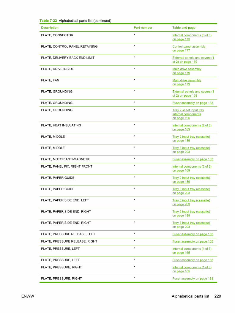
Description Part number Table and page
PLATE, CONNECTOR * Internal components (3 of 3)on page 173
PLATE, CONTROL PANEL RETAINING * Control panel assemblyon page 177
PLATE, DELIVERY BACK END LIMIT * External panels and covers (1of 2) on page 159
PLATE, DRIVE INSIDE * Main drive assemblyon page 179
PLATE, FAN * Main drive assemblyon page 179
PLATE, GROUNDING * External panels and covers (1of 2) on page 159
PLATE, GROUNDING * Fuser assembly on page 183
PLATE, GROUNDING * Tray 2 sheet input trayinternal componentson page 195
PLATE, HEAT INSULATING * Internal components (2 of 3)on page 169
PLATE, MIDDLE * Tray 2 input tray (cassette)on page 189
PLATE, MIDDLE * Tray 3 input tray (cassette)on page 203
PLATE, MOTOR ANTI-MAGNETIC * Fuser assembly on page 183
PLATE, PANEL FIX, RIGHT FRONT * Internal components (2 of 3)on page 169
PLATE, PAPER GUIDE * Tray 2 input tray (cassette)on page 189
PLATE, PAPER GUIDE * Tray 3 input tray (cassette)on page 203
PLATE, PAPER SIDE END, LEFT * Tray 3 input tray (cassette)on page 203
PLATE, PAPER SIDE END, RIGHT * Tray 2 input tray (cassette)on page 189
PLATE, PAPER SIDE END, RIGHT * Tray 3 input tray (cassette)on page 203
PLATE, PRESSURE RELEASE, LEFT * Fuser assembly on page 183
PLATE, PRESSURE RELEASE, RIGHT * Fuser assembly on page 183
PLATE, PRESSURE, LEFT * Internal components (1 of 3)on page 165
PLATE, PRESSURE, LEFT * Fuser assembly on page 183
PLATE, PRESSURE, RIGHT * Internal components (1 of 3)on page 165
PLATE, PRESSURE, RIGHT * Fuser assembly on page 183
Table 7-22 Alphabetical parts list (continued)
ENWW Alphabetical parts list 229

Description Part number Table and page
PLATE, REAR RC1-5227-000CN External panels and covers (1of 2) on page 159
PLATE, REAR RC1-5227-000CN External panels and covers (2of 2) on page 161
PLATE, REG. GROUNDING, 1 * Paper pick-up feederassembly for Tray 2on page 199
PLATE, REG. GROUNDING, 1 * Paper pickup feederassembly (Tray 3) on page 207
PLATE, REG. GROUNDING, 2 * Paper pick-up feederassembly for Tray 2on page 199
PLATE, REG. GROUNDING, 2 * Paper pickup feederassembly (Tray 3) on page 207
PLATE, REINFORCEMENT * Tray 2 input tray (cassette)on page 189
PLATE, REINFORCEMENT * Tray 3 input tray (cassette)on page 203
PLATE, SHAFT * Internal components (1 of 3)on page 165
PLATE, SHIELD * Internal components (3 of 3)on page 173
PLATE, SHIELD, FRONT * Internal components (3 of 3)on page 173
POWER CABLE * Internal components (3 of 3)on page 173
POWER CONTROLLER CABLE * Internal components (3 of 3)on page 173
POWER SUPPLY PCB ASS'Y * Internal components (3 of 3)on page 173
POWER SUPPLY PCB ASS'Y * Internal components (3 of 3)on page 173
POWER SUPPLY PCB ASS'Y * Internal components (3 of 3)on page 173
POWER SUPPLY PCB ASS'Y * PCB assembly location Tray 2on page 187
POWER SUPPLY PCB ASS'Y * PCB assembly location Tray 2on page 187
PULLEY * Main drive assemblyon page 179
RACK * Tray 2 input tray (cassette)on page 189
RACK * Tray 3 input tray (cassette)on page 203
Table 7-22 Alphabetical parts list (continued)
230 Chapter 7 Parts and diagrams ENWW
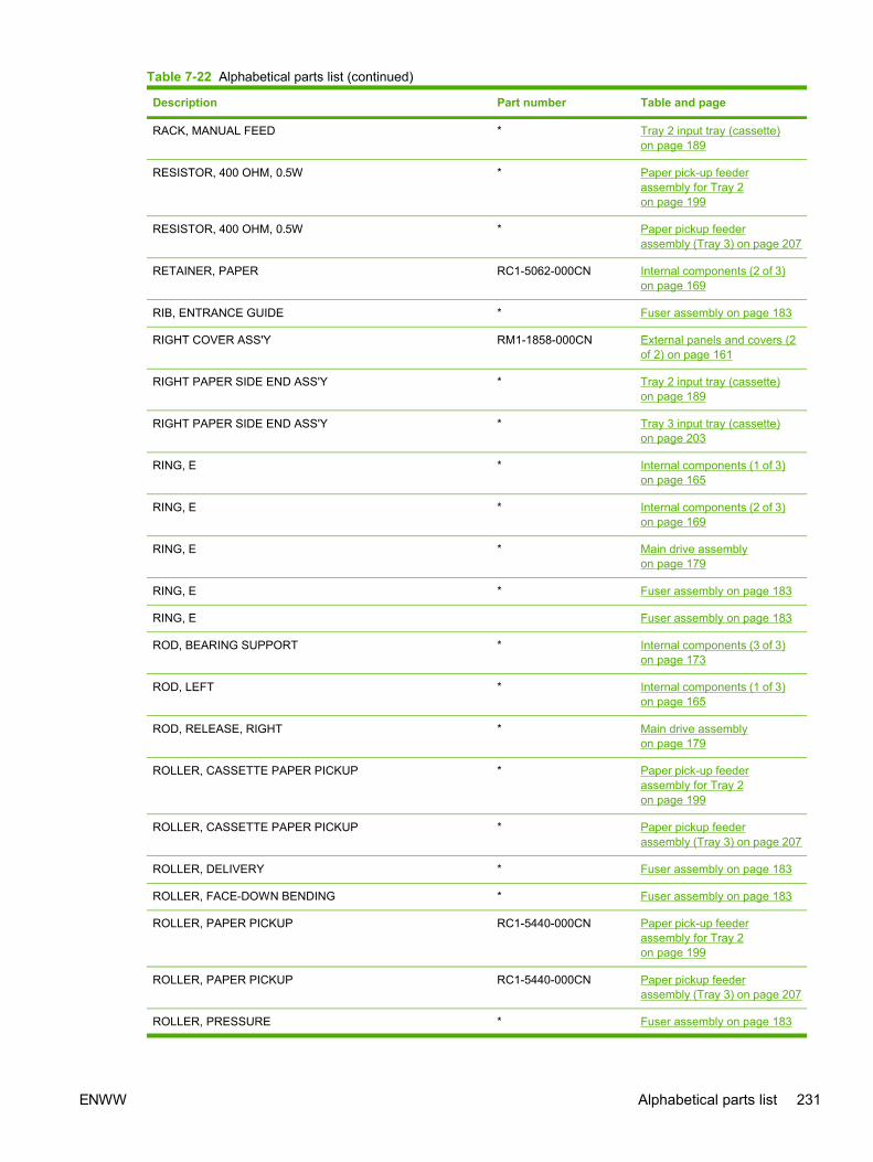
Description Part number Table and page
RACK, MANUAL FEED * Tray 2 input tray (cassette)on page 189
RESISTOR, 400 OHM, 0.5W * Paper pick-up feederassembly for Tray 2on page 199
RESISTOR, 400 OHM, 0.5W * Paper pickup feederassembly (Tray 3) on page 207
RETAINER, PAPER RC1-5062-000CN Internal components (2 of 3)on page 169
RIB, ENTRANCE GUIDE * Fuser assembly on page 183
RIGHT COVER ASS'Y RM1-1858-000CN External panels and covers (2of 2) on page 161
RIGHT PAPER SIDE END ASS'Y * Tray 2 input tray (cassette)on page 189
RIGHT PAPER SIDE END ASS'Y * Tray 3 input tray (cassette)on page 203
RING, E * Internal components (1 of 3)on page 165
RING, E * Internal components (2 of 3)on page 169
RING, E * Main drive assemblyon page 179
RING, E * Fuser assembly on page 183
RING, E Fuser assembly on page 183
ROD, BEARING SUPPORT * Internal components (3 of 3)on page 173
ROD, LEFT * Internal components (1 of 3)on page 165
ROD, RELEASE, RIGHT * Main drive assemblyon page 179
ROLLER, CASSETTE PAPER PICKUP * Paper pick-up feederassembly for Tray 2on page 199
ROLLER, CASSETTE PAPER PICKUP * Paper pickup feederassembly (Tray 3) on page 207
ROLLER, DELIVERY * Fuser assembly on page 183
ROLLER, FACE-DOWN BENDING * Fuser assembly on page 183
ROLLER, PAPER PICKUP RC1-5440-000CN Paper pick-up feederassembly for Tray 2on page 199
ROLLER, PAPER PICKUP RC1-5440-000CN Paper pickup feederassembly (Tray 3) on page 207
ROLLER, PRESSURE * Fuser assembly on page 183
Table 7-22 Alphabetical parts list (continued)
ENWW Alphabetical parts list 231

Description Part number Table and page
ROLLER, REGISTRATION DRIVE * Paper pick-up feederassembly for Tray 2on page 199
ROLLER, REGISTRATION DRIVE * Paper pickup feederassembly (Tray 3) on page 207
ROLLER, REGISTRATION, A * Paper pick-up feederassembly for Tray 2on page 199
ROLLER, REGISTRATION, A * Paper pickup feederassembly (Tray 3) on page 207
ROLLER, REGISTRATION, B * Paper pick-up feederassembly for Tray 2on page 199
ROLLER, REGISTRATION, B * Paper pickup feederassembly (Tray 3) on page 207
ROLLER, REGISTRATION, C * Paper pick-up feederassembly for Tray 2on page 199
ROLLER, REGISTRATION, C * Paper pickup feederassembly (Tray 3) on page 207
SADDLE, WIRE * External panels and covers (1of 2) on page 159
SADDLE, WIRE * External panels and covers (2of 2) on page 161
SADDLE, WIRE * Internal components (2 of 3)on page 169
SADDLE, WIRE * Tray 2 sheet input trayinternal componentson page 195
SCANNER UNIT * Internal components (3 of 3)on page 173
SCREW, RS, M3X10 * Internal components (3 of 3)on page 173
SCREW, RS, M3X6 * Internal components (2 of 3)on page 169
SCREW, RS, M3X6 * Internal components (2 of 3)on page 169
SCREW, RS, M3X6 * Fuser assembly on page 183
SCREW, RS, M3X8 * Internal components (1 of 3)on page 165
SCREW, RS, M3X8 * Internal components (1 of 3)on page 165
SCREW, RS, M3X8 * Internal components (1 of 3)on page 165
Table 7-22 Alphabetical parts list (continued)
232 Chapter 7 Parts and diagrams ENWW

Description Part number Table and page
SCREW, RS, M3X8 * Internal components (1 of 3)on page 165
SCREW, RS, M3X8 * Internal components (2 of 3)on page 169
SCREW, RS, M3X8 * Internal components (3 of 3)on page 173
SCREW, RS, M3X8 * Control panel assemblyon page 177
SCREW, RS, M3X8 * Main drive assemblyon page 179
SCREW, RS, M3X8 * Fuser assembly on page 183
SCREW, RS, M3X8 * Fuser assembly on page 183
SCREW, RS, M3X8 * Tray 2 sheet input trayinternal componentson page 195
SCREW, RS, M3X8 * Tray 2 sheet input trayinternal componentson page 195
SCREW, RS, M3X8 * Tray 2 sheet input trayinternal componentson page 195
SCREW, TAPPING, TRUSS HEAD, M4X8 * Internal components (2 of 3)on page 169
SCREW, TAPPING, TRUSS HEAD, M4X8 * Internal components (3 of 3)on page 173
SCREW, TAPPING,TRUSS HEAD, M4X8 * Tray 2 sheet input trayinternal componentson page 195
SCREW, TAPPING,TRUSS HEAD,M3X6 * Tray 2 input tray (cassette)on page 189
SCREW, TAPPING,TRUSS HEAD,M3X6 * Tray 2 input tray (cassette)on page 189
SCREW, TAPPING,TRUSS HEAD,M3X6 * Tray 3 input tray (cassette)on page 203
SCREW, TAPPING,TRUSS HEAD,M3X8 * External panels and covers (1of 2) on page 159
SCREW, TAPPING,TRUSS HEAD,M4X8 * External panels and covers (2of 2) on page 161
SCREW, TAPPING,TRUSS HEAD,M4X8 * Upper assembly coveron page 163
SCREW, TAPPING,TRUSS HEAD,M4X8 * Internal components (1 of 3)on page 165
SCREW, TAPPING,TRUSS HEAD,M4X8 * Main drive assemblyon page 179
Table 7-22 Alphabetical parts list (continued)
ENWW Alphabetical parts list 233

Description Part number Table and page
SCREW, TAPPING,TRUSS HEAD,M4X8 * Tray 2 input tray (cassette)on page 189
SCREW, TAPPING,TRUSS HEAD,M4X8 * Paper pick-up feederassembly for Tray 2on page 199
SCREW, TAPPING,TRUSS HEAD,M4X8 * Tray 3 input tray (cassette)on page 203
SCREW, TAPPING,TRUSS HEAD,M4X8 * Paper pickup feederassembly (Tray 3) on page 207
SCREW, TP * External panels and covers (2of 2) on page 161
SCREW, W/WASHER, M3X8 * Internal components (3 of 3)on page 173
SCREW, W/WASHER, M4X18 * Internal components (2 of 3)on page 169
SE RING * Main drive assemblyon page 179
SEPARATION ASS'Y RM1-1922-000CN Tray 2 input tray (cassette)on page 189
SEPARATION ASS'Y RM1-1922-000CN Tray 3 input tray (cassette)on page 203
SHAFT, DRUM GEAR * Main drive assemblyon page 179
SHAFT, ETB DRIVE * Internal components (1 of 3)on page 165
SHAFT, FACE-DOWN ROLLER * Fuser assembly on page 183
SHAFT, FRONT DOOR * Internal components (2 of 3)on page 169
SHAFT, FRONT DOOR ARM * External panels and covers (2of 2) on page 161
SHAFT, PAPER PICKUP DRIVE * Paper pick-up feederassembly for Tray 2on page 199
SHAFT, PAPER PICKUP DRIVE * Paper pickup feederassembly (Tray 3) on page 207
SHAFT, POSITIONING * Tray 2 sheet input trayinternal componentson page 195
SHAFT, PRESSURE RELEASE * Fuser assembly on page 183
SHAFT, PRESSURE RELEASE CAM * Fuser assembly on page 183
SHAFT, REGISTRATION ROLLER * Paper pick-up feederassembly for Tray 2on page 199
Table 7-22 Alphabetical parts list (continued)
234 Chapter 7 Parts and diagrams ENWW

Description Part number Table and page
SHAFT, REGISTRATION ROLLER * Paper pickup feederassembly (Tray 3) on page 207
SHAFT, TOGGLE * Internal components (1 of 3)on page 165
SHEET, SCRAPER, 1 * Paper pick-up feederassembly for Tray 2on page 199
SHEET, SCRAPER, 2 * Paper pick-up feederassembly for Tray 2on page 199
SHEET, SEPARATION * Tray 2 input tray (cassette)on page 189
SHEET, SEPARATION * Tray 3 input tray (cassette)on page 203
SHUTTER, REGISTRATION * Paper pick-up feederassembly for Tray 2on page 199
SIDE PLATE, DRIVE * Main drive assemblyon page 179
SIDE PLATE, FIXING, LEFT * Fuser assembly on page 183
SIDE PLATE, FIXING, LEFT, 2 * Fuser assembly on page 183
SIDE PLATE, FIXING, RIGHT * Fuser assembly on page 183
SIDE PLATE, FIXING, RIGHT, 2 * Fuser assembly on page 183
SIDE PLATE, GEAR * Fuser assembly on page 183
SIZE PLATE, PAPER * Tray 2 input tray (cassette)on page 189
SIZE PLATE, PAPER * Tray 3 input tray (cassette)on page 203
SOLENOID * Internal components (2 of 3)on page 169
SOLENOID * Main drive assemblyon page 179
SOLENOID * Tray 2 sheet input trayinternal componentson page 195
SOLID RESISTOR, 20MOHM, 1/4W * Fuser assembly on page 183
SPACER, CONTROL PANEL * Control panel assemblyon page 177
SPRING, COMPRESSION * Internal components (1 of 3)on page 165
SPRING, COMPRESSION * Internal components (1 of 3)on page 165
SPRING, COMPRESSION * Internal components (2 of 3)on page 169
Table 7-22 Alphabetical parts list (continued)
ENWW Alphabetical parts list 235

Description Part number Table and page
SPRING, COMPRESSION * Internal components (2 of 3)on page 169
SPRING, COMPRESSION * Main drive assemblyon page 179
SPRING, COMPRESSION * Main drive assemblyon page 179
SPRING, COMPRESSION * Fuser assembly on page 183
SPRING, COMPRESSION * Tray 2 input tray (cassette)on page 189
SPRING, COMPRESSION * Tray 2 input tray (cassette)on page 189
SPRING, COMPRESSION * Tray 2 input tray (cassette)on page 189
SPRING, COMPRESSION * Tray 2 input tray (cassette)on page 189
SPRING, COMPRESSION * Tray 2 input tray (cassette)on page 189
SPRING, COMPRESSION * Tray 2 input tray (cassette)on page 189
SPRING, COMPRESSION * Tray 2 input tray (cassette)on page 189
SPRING, COMPRESSION * Tray 2 input tray (cassette)on page 189
SPRING, COMPRESSION * Tray 2 input tray (cassette)on page 189
SPRING, COMPRESSION * Tray 2 input tray (cassette)on page 189
SPRING, COMPRESSION * Tray 2 sheet input trayinternal componentson page 195
SPRING, COMPRESSION * Tray 2 sheet input trayinternal componentson page 195
SPRING, COMPRESSION * Paper pick-up feederassembly for Tray 2on page 199
SPRING, COMPRESSION * Tray 3 input tray (cassette)on page 203
SPRING, COMPRESSION * Tray 3 input tray (cassette)on page 203
SPRING, COMPRESSION * Tray 3 input tray (cassette)on page 203
SPRING, COMPRESSION * Tray 3 input tray (cassette)on page 203
Table 7-22 Alphabetical parts list (continued)
236 Chapter 7 Parts and diagrams ENWW

Description Part number Table and page
SPRING, COMPRESSION * Tray 3 input tray (cassette)on page 203
SPRING, COMPRESSION * Tray 3 input tray (cassette)on page 203
SPRING, COMPRESSION * Tray 3 input tray (cassette)on page 203
SPRING, COMPRESSION * Tray 3 input tray (cassette)on page 203
SPRING, COMPRESSION * Tray 3 input tray (cassette)on page 203
SPRING, COMPRESSION * Tray 3 input tray (cassette)on page 203
SPRING, COMPRESSION * Paper pickup feederassembly (Tray 3) on page 207
SPRING, GROUNDING * Internal components (1 of 3)on page 165
SPRING, GROUNDING * Internal components (1 of 3)on page 165
SPRING, GROUNDING * Internal components (1 of 3)on page 165
SPRING, GROUNDING * Internal components (1 of 3)on page 165
SPRING, GROUNDING * Internal components (1 of 3)on page 165
SPRING, GROUNDING RC1-5147-000CN Internal components (2 of 3)on page 169
SPRING, GROUNDING * Fuser assembly on page 183
SPRING, GROUNDING * Fuser assembly on page 183
SPRING, GROUNDING * Fuser assembly on page 183
SPRING, GROUNDING * Fuser assembly on page 183
SPRING, GROUNDING * Tray 2 input tray (cassette)on page 189
SPRING, GROUNDING * Tray 2 input tray (cassette)on page 189
SPRING, GROUNDING * Tray 2 sheet input trayinternal componentson page 195
SPRING, GROUNDING * Tray 3 input tray (cassette)on page 203
SPRING, GROUNDING * Tray 3 input tray (cassette)on page 203
SPRING, LEAF * Internal components (2 of 3)on page 169
Table 7-22 Alphabetical parts list (continued)
ENWW Alphabetical parts list 237

Description Part number Table and page
SPRING, LEAF * Fuser assembly on page 183
SPRING, LEAF * Tray 2 sheet input trayinternal componentson page 195
SPRING, TENSION * Internal components (1 of 3)on page 165
SPRING, TENSION * Internal components (1 of 3)on page 165
SPRING, TENSION * Main drive assemblyon page 179
SPRING, TENSION * Fuser assembly on page 183
SPRING, TENSION * Tray 2 input tray (cassette)on page 189
SPRING, TENSION * Tray 2 sheet input trayinternal componentson page 195
SPRING, TENSION * Paper pick-up feederassembly for Tray 2on page 199
SPRING, TENSION * Tray 3 input tray (cassette)on page 203
SPRING, TENSION * Paper pickup feederassembly (Tray 3) on page 207
SPRING, TORSION * Internal components (1 of 3)on page 165
SPRING, TORSION * Internal components (1 of 3)on page 165
SPRING, TORSION * Internal components (1 of 3)on page 165
SPRING, TORSION * Fuser assembly on page 183
SPRING, TORSION * Fuser assembly on page 183
SPRING, TORSION * Paper pick-up feederassembly for Tray 2on page 199
SPRING, TORSION * Paper pick-up feederassembly for Tray 2on page 199
SPRING, TORSION * Paper pick-up feederassembly for Tray 2on page 199
STOP, CAM GEAR * Main drive assemblyon page 179
STOP, CLUTCH * Internal components (2 of 3)on page 169
Table 7-22 Alphabetical parts list (continued)
238 Chapter 7 Parts and diagrams ENWW

Description Part number Table and page
STOP, CLUTCH * Tray 2 sheet input trayinternal componentson page 195
STOPPER, BACK END LIMIT * Tray 2 input tray (cassette)on page 189
STOPPER, BACK END LIMIT * Tray 3 input tray (cassette)on page 203
STOPPER, CASSETTE, LEFT * Tray 2 input tray (cassette)on page 189
STOPPER, CASSETTE, LEFT * Tray 3 input tray (cassette)on page 203
STOPPER, CASSETTE, RIGHT * Tray 2 input tray (cassette)on page 189
STOPPER, CASSETTE, RIGHT * Tray 3 input tray (cassette)on page 203
STOPPER, PAPER SIDE END * Tray 2 input tray (cassette)on page 189
STOPPER, PAPER SIDE END * Tray 3 input tray (cassette)on page 203
TRAY, EXTENSION * External panels and covers (1of 2) on page 159
TRAY, FACE-DOWN * External panels and covers (1of 2) on page 159
UPPER COVER * Assembly locationson page 157
WEIGHT, PAD * Tray 2 input tray (cassette)on page 189
WEIGHT, PAD * Tray 3 input tray (cassette)on page 203
Table 7-22 Alphabetical parts list (continued)
ENWW Alphabetical parts list 239

Numerical parts listTable 7-23 Numerical parts list
Part number Description Table and page
* Not set up as a service part Assembly locationson page 157
* Not set up as a service part External panels and covers (1of 2) on page 159
* Not set up as a service part External panels and covers (2of 2) on page 161
* Not set up as a service part Upper assembly coveron page 163
* Not set up as a service part Internal components (1 of 3)on page 165
* Not set up as a service part Internal components (2 of 3)on page 169
* Not set up as a service part Internal components (3 of 3)on page 173
* Not set up as a service part Control panel assemblyon page 177
* Not set up as a service part Main drive assemblyon page 179
* Not set up as a service part Fuser assembly on page 183
RING, E Fuser assembly on page 183
* Not set up as a service part PCB assembly location Tray 2on page 187
* Not set up as a service part Tray 2 input tray (cassette)on page 189
* Not set up as a service part 250-sheet input tray(cassette) on page 193
* Not set up as a service part Tray 2 sheet input trayinternal componentson page 195
* Not set up as a service part Paper pick-up feederassembly for Tray 2on page 199
* Not set up as a service part Tray 3 input tray (cassette)on page 203
* Not set up as a service part Paper pickup feederassembly (Tray 3) on page 207
* Not set up as a service part Paper pickup feederassembly (Tray 3) on page 209
* UPPER COVER Assembly locationson page 157
240 Chapter 7 Parts and diagrams ENWW

Part number Description Table and page
* MAIN DRIVE ASSEMBLY Assembly locationson page 157
* PAPER PICKUP FEEDER ASSEMBLY Assembly locationson page 157
* EXTERNAL COVERS, PANELS, ETC. External panels and covers (1of 2) on page 159
* CONNECTOR, SNAP TIGHT External panels and covers (1of 2) on page 159
* CONNECTOR, SNAP TIGHT, BK External panels and covers (1of 2) on page 159
* CLIP, CABLE External panels and covers (1of 2) on page 159
* SADDLE, WIRE External panels and covers (1of 2) on page 159
* PLATE, GROUNDING External panels and covers (1of 2) on page 159
* SCREW, TAPPING,TRUSS HEAD,M3X8 External panels and covers (1of 2) on page 159
* TRAY, EXTENSION External panels and covers (1of 2) on page 159
* TRAY, FACE-DOWN External panels and covers (1of 2) on page 159
* PLATE, DELIVERY BACK END LIMIT External panels and covers (1of 2) on page 159
* EXTERNAL COVERS, PANELS, ETC. External panels and covers (2of 2) on page 161
* CONNECTOR, SNAP TIGHT External panels and covers (2of 2) on page 161
* CONNECTOR, SNAP TIGHT, BK External panels and covers (2of 2) on page 161
* CLIP, CABLE External panels and covers (2of 2) on page 161
* SADDLE, WIRE External panels and covers (2of 2) on page 161
* ARM, FRONT DOOR, LEFT External panels and covers (2of 2) on page 161
* ARM, FRONT DOOR, RIGHT External panels and covers (2of 2) on page 161
* SHAFT, FRONT DOOR ARM External panels and covers (2of 2) on page 161
* COVER, RIGHT FRONT External panels and covers (2of 2) on page 161
* DOOR, FRONT External panels and covers (2of 2) on page 161
Table 7-23 Numerical parts list (continued)
ENWW Numerical parts list 241

Part number Description Table and page
* LEVER, LINK External panels and covers (2of 2) on page 161
* LEVER, TOGGLE, LEFT External panels and covers (2of 2) on page 161
* LEVER, TOGGLE, RIGHT External panels and covers (2of 2) on page 161
* SCREW, TAPPING,TRUSS HEAD,M4X8 External panels and covers (2of 2) on page 161
* SCREW, TP External panels and covers (2of 2) on page 161
* COVER, RIGHT External panels and covers (2of 2) on page 161
* COVER, RIGHT FRONT External panels and covers (2of 2) on page 161
* BUSHING External panels and covers (2of 2) on page 161
* COVER, RIGHT FRONT External panels and covers (2of 2) on page 161
* GUIDE, LIGHT External panels and covers (2of 2) on page 161
* SCREW, TAPPING,TRUSS HEAD,M4X8 Upper assembly coveron page 163
* INTERNAL COMPONENTS 1 Internal components (1 of 3)on page 165
* CROSSMEMBER, TOP COVER Internal components (1 of 3)on page 165
* BRACKET, LEFT REAR Internal components (1 of 3)on page 165
* BRACKET, RIGHT REAR Internal components (1 of 3)on page 165
* COVER, INSIDE, RIGHT Internal components (1 of 3)on page 165
* BRACKET, CARD READER Internal components (1 of 3)on page 165
* HOLDER, FAN RETAINER Internal components (1 of 3)on page 165
* LATCH, LEFT Internal components (1 of 3)on page 165
* BUSHING Internal components (1 of 3)on page 165
* LATCH, RIGHT Internal components (1 of 3)on page 165
* LEVER, ETB RELEASE Internal components (1 of 3)on page 165
Table 7-23 Numerical parts list (continued)
242 Chapter 7 Parts and diagrams ENWW

Part number Description Table and page
* FAN Internal components (1 of 3)on page 165
* GEAR, 54T Internal components (1 of 3)on page 165
* SPRING, TENSION Internal components (1 of 3)on page 165
* SPRING, COMPRESSION Internal components (1 of 3)on page 165
* LEFT INTERNAL COVER ASS'Y Internal components (1 of 3)on page 165
* GUIDE, CARTRIDGE, RIGHT Internal components (1 of 3)on page 165
* HOLDER, DRUM Internal components (1 of 3)on page 165
* BUSHING Internal components (1 of 3)on page 165
* PLATE, PRESSURE, RIGHT Internal components (1 of 3)on page 165
* BUSHING Internal components (1 of 3)on page 165
* GUIDE, CASSETTE, REAR RIGHT Internal components (1 of 3)on page 165
* GUIDE, CASSETTE, FRONT RIGHT Internal components (1 of 3)on page 165
* GEAR, 20T Internal components (1 of 3)on page 165
* GEAR, 36T Internal components (1 of 3)on page 165
* GEAR, 36T Internal components (1 of 3)on page 165
* SPRING, TORSION Internal components (1 of 3)on page 165
* SCREW, RS, M3X8 Internal components (1 of 3)on page 165
* SCREW, RS, M3X8 Internal components (1 of 3)on page 165
* SCREW, RS, M3X8 Internal components (1 of 3)on page 165
* SCREW, RS, M3X8 Internal components (1 of 3)on page 165
* GUIDE, CARTRIDGE, LEFT Internal components (1 of 3)on page 165
* HOLDER, DRUM Internal components (1 of 3)on page 165
Table 7-23 Numerical parts list (continued)
ENWW Numerical parts list 243

Part number Description Table and page
* LINK, SHUTTER Internal components (1 of 3)on page 165
* PLATE, PRESSURE, LEFT Internal components (1 of 3)on page 165
* SPRING, TORSION Internal components (1 of 3)on page 165
* PLATE, SHAFT Internal components (1 of 3)on page 165
* ARM, OPEN/CLOSE Internal components (1 of 3)on page 165
* ARM, OPEN/CLOSE Internal components (1 of 3)on page 165
* SPRING, TORSION Internal components (1 of 3)on page 165
* ROD, LEFT Internal components (1 of 3)on page 165
* SPRING, GROUNDING Internal components (1 of 3)on page 165
* GUIDE, CASSETTE, FRONT LEFT Internal components (1 of 3)on page 165
* GUIDE, CASSETTE, REAR LEFT Internal components (1 of 3)on page 165
* RING, E Internal components (1 of 3)on page 165
* ARM, LASER SHUTTER Internal components (1 of 3)on page 165
* DUCT, FAN Internal components (1 of 3)on page 165
* SPRING, TENSION Internal components (1 of 3)on page 165
* MEMORY CONTROLLER PCB ASS'Y Internal components (1 of 3)on page 165
* DUCT, FAN, UPPER Internal components (1 of 3)on page 165
* DUCT, FAN, LOWER Internal components (1 of 3)on page 165
* HOLDER, MEMORY CONTROLLER Internal components (1 of 3)on page 165
* FLAG, PRESSURE RELEASE SENSOR Internal components (1 of 3)on page 165
* CLAMP, FFC Internal components (1 of 3)on page 165
* SCREW, TAPPING,TRUSS HEAD,M4X8 Internal components (1 of 3)on page 165
Table 7-23 Numerical parts list (continued)
244 Chapter 7 Parts and diagrams ENWW

Part number Description Table and page
* SHAFT, TOGGLE Internal components (1 of 3)on page 165
* SHAFT, ETB DRIVE Internal components (1 of 3)on page 165
* SPRING, GROUNDING Internal components (1 of 3)on page 165
* SPRING, GROUNDING Internal components (1 of 3)on page 165
* SPRING, GROUNDING Internal components (1 of 3)on page 165
* SPRING, GROUNDING Internal components (1 of 3)on page 165
* COVER, INSIDE, LEFT Internal components (1 of 3)on page 165
* ARM, INTERLOCK SWITCH Internal components (1 of 3)on page 165
* SPRING, COMPRESSION Internal components (1 of 3)on page 165
* PHOTO INTERRUPTER (SENSOR) Internal components (1 of 3)on page 165
* FOOT, RUBBER Internal components (1 of 3)on page 165
* GUIDE, CASSETTE, REAR RIGHT Internal components (1 of 3)on page 165
* GUIDE, CASSETTE, FRONT RIGHT Internal components (1 of 3)on page 165
* INTERNAL COMPONENTS 2 Internal components (2 of 3)on page 169
* CAP, SHAFT CONDUCTIVE Internal components (2 of 3)on page 169
* SCREW, RS, M3X6 Internal components (2 of 3)on page 169
* COVER, PICK-UP FEED CABLE Internal components (2 of 3)on page 169
* SHAFT, FRONT DOOR Internal components (2 of 3)on page 169
* PLATE, PANEL FIX, RIGHT FRONT Internal components (2 of 3)on page 169
* GUIDE, CASSETTE, FRONT RIGHT Internal components (2 of 3)on page 169
* GUIDE, CASSETTE, FRONT LEFT Internal components (2 of 3)on page 169
* PLATE, HEAT INSULATING Internal components (2 of 3)on page 169
Table 7-23 Numerical parts list (continued)
ENWW Numerical parts list 245

Part number Description Table and page
* LEVER, CONNECTING, LEFT Internal components (2 of 3)on page 169
* CAM, LEFT Internal components (2 of 3)on page 169
* SADDLE, WIRE Internal components (2 of 3)on page 169
* FEEDER UNIT JOINT CABLE Internal components (2 of 3)on page 169
* CAM, HINGE, RIGHT Internal components (2 of 3)on page 169
* LEVER, CONNECTING, RIGHT Internal components (2 of 3)on page 169
* BASE, MOTOR Internal components (2 of 3)on page 169
* CLUTCH, MECHANICAL Internal components (2 of 3)on page 169
* SPRING, LEAF Internal components (2 of 3)on page 169
* PLATE Internal components (2 of 3)on page 169
* BUSHING Internal components (2 of 3)on page 169
* STOP, CLUTCH Internal components (2 of 3)on page 169
* MOTOR, STEPPING, DC Internal components (2 of 3)on page 169
* SOLENOID Internal components (2 of 3)on page 169
* PICKUP GEAR ASS'Y Internal components (2 of 3)on page 169
* GEAR, 57T/20T Internal components (2 of 3)on page 169
* GEAR, 43T/16T Internal components (2 of 3)on page 169
* GEAR, 47T/26T Internal components (2 of 3)on page 169
* GEAR, 40T/43T Internal components (2 of 3)on page 169
* CAM/GEAR, 26T Internal components (2 of 3)on page 169
* SPRING, COMPRESSION Internal components (2 of 3)on page 169
* RING, E Internal components (2 of 3)on page 169
Table 7-23 Numerical parts list (continued)
246 Chapter 7 Parts and diagrams ENWW

Part number Description Table and page
* SCREW, RS, M3X6 Internal components (2 of 3)on page 169
* SCREW, RS, M3X8 Internal components (2 of 3)on page 169
* SCREW, W/WASHER, M4X18 Internal components (2 of 3)on page 169
* SCREW, TAPPING, TRUSS HEAD, M4X8 Internal components (2 of 3)on page 169
* GEAR, 29T Internal components (2 of 3)on page 169
* GEAR, 29T Internal components (2 of 3)on page 169
* SPRING, COMPRESSION Internal components (2 of 3)on page 169
* INTERNAL COMPONENTS 3 Internal components (3 of 3)on page 173
* GUIDE, CABLE, UPPER Internal components (3 of 3)on page 173
* PLATE, SHIELD Internal components (3 of 3)on page 173
* PLATE, SHIELD, FRONT Internal components (3 of 3)on page 173
* PLATE, CONNECTOR Internal components (3 of 3)on page 173
* COVER, CONTROLLER Internal components (3 of 3)on page 173
* LID, CONTROLLER Internal components (3 of 3)on page 173
* HOLDER, CABLE, LEFT Internal components (3 of 3)on page 173
* HOLDER, DC CABLE Internal components (3 of 3)on page 173
* HOLDER, CABLE, UPPER Internal components (3 of 3)on page 173
* HOLDER, DRAWER Internal components (3 of 3)on page 173
* CONNECTOR, DRAWER Internal components (3 of 3)on page 173
* SCANNER UNIT Internal components (3 of 3)on page 173
* POWER SUPPLY PCB ASS'Y Internal components (3 of 3)on page 173
* POWER SUPPLY PCB ASS'Y Internal components (3 of 3)on page 173
Table 7-23 Numerical parts list (continued)
ENWW Numerical parts list 247

Part number Description Table and page
* POWER SUPPLY PCB ASS'Y Internal components (3 of 3)on page 173
* HIGH-VOLTAGE PCB ASS'Y Internal components (3 of 3)on page 173
* POWER CABLE Internal components (3 of 3)on page 173
* POWER CONTROLLER CABLE Internal components (3 of 3)on page 173
* FIXING SENSOR CABLE Internal components (3 of 3)on page 173
* DRIVE CABLE Internal components (3 of 3)on page 173
* CONNECTOR, SNAP TIGHT, BK Internal components (3 of 3)on page 173
* CONNECTOR, SNAP TIGHT, BK Internal components (3 of 3)on page 173
* CABLE, CPR Internal components (3 of 3)on page 173
* FEEDER UNIT JOINT CABLE Internal components (3 of 3)on page 173
* SCREW, W/WASHER, M3X8 Internal components (3 of 3)on page 173
* SCREW, RS, M3X10 Internal components (3 of 3)on page 173
* SCREW, RS, M3X8 Internal components (3 of 3)on page 173
* ROD, BEARING SUPPORT Internal components (3 of 3)on page 173
* CABLE, FLAT Internal components (3 of 3)on page 173
* CABLE, FLAT Internal components (3 of 3)on page 173
* CABLE, FLAT Internal components (3 of 3)on page 173
* CLAMP, FFC Internal components (3 of 3)on page 173
* SCREW, TAPPING, TRUSS HEAD, M4X8 Internal components (3 of 3)on page 173
* CONTROL PANEL PCB ASS'Y Control panel assemblyon page 177
* CONTROL PANEL PCB ASS'Y Control panel assemblyon page 177
* PANEL, CONTROL PANEL Control panel assemblyon page 177
Table 7-23 Numerical parts list (continued)
248 Chapter 7 Parts and diagrams ENWW

Part number Description Table and page
* PLATE, CONTROL PANEL RETAINING Control panel assemblyon page 177
* GUIDE, CONTROL PANEL LIGHT Control panel assemblyon page 177
* BUTTON, CONTROL PANEL, 1 Control panel assemblyon page 177
* BUTTON, CONTROL PANEL, 2 Control panel assemblyon page 177
* BUTTON, CONTROL PANEL, 3 Control panel assemblyon page 177
* SPACER, CONTROL PANEL Control panel assemblyon page 177
* SCREW, RS, M3X8 Control panel assemblyon page 177
* MAIN DRIVE ASS'Y Main drive assemblyon page 179
* F.F.C. CONNECT PCB UNIT Main drive assemblyon page 179
* COLLAR, SPRING Main drive assemblyon page 179
* BUSHING Main drive assemblyon page 179
* FLANGE, CAM GEAR Main drive assemblyon page 179
* COVER, DRUM Main drive assemblyon page 179
* BUSHING Main drive assemblyon page 179
* BUSHING Main drive assemblyon page 179
* CAM, RELEASE Main drive assemblyon page 179
* ROD, RELEASE, RIGHT Main drive assemblyon page 179
* FAN Main drive assemblyon page 179
* DUCT, FAN Main drive assemblyon page 179
* PULLEY Main drive assemblyon page 179
* BELT, TRANSMISSION Main drive assemblyon page 179
* STOP, CAM GEAR Main drive assemblyon page 179
Table 7-23 Numerical parts list (continued)
ENWW Numerical parts list 249
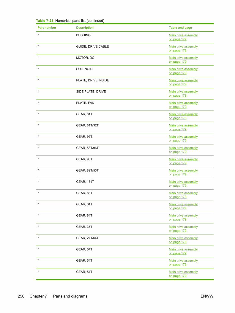
Part number Description Table and page
* BUSHING Main drive assemblyon page 179
* GUIDE, DRIVE CABLE Main drive assemblyon page 179
* MOTOR, DC Main drive assemblyon page 179
* SOLENOID Main drive assemblyon page 179
* PLATE, DRIVE INSIDE Main drive assemblyon page 179
* SIDE PLATE, DRIVE Main drive assemblyon page 179
* PLATE, FAN Main drive assemblyon page 179
* GEAR, 81T Main drive assemblyon page 179
* GEAR, 81T/32T Main drive assemblyon page 179
* GEAR, 96T Main drive assemblyon page 179
* GEAR, 53T/96T Main drive assemblyon page 179
* GEAR, 98T Main drive assemblyon page 179
* GEAR, 89T/53T Main drive assemblyon page 179
* GEAR, 134T Main drive assemblyon page 179
* GEAR, 86T Main drive assemblyon page 179
* GEAR, 64T Main drive assemblyon page 179
* GEAR, 64T Main drive assemblyon page 179
* GEAR, 37T Main drive assemblyon page 179
* GEAR, 27T/64T Main drive assemblyon page 179
* GEAR, 64T Main drive assemblyon page 179
* GEAR, 54T Main drive assemblyon page 179
* GEAR, 54T Main drive assemblyon page 179
Table 7-23 Numerical parts list (continued)
250 Chapter 7 Parts and diagrams ENWW

Part number Description Table and page
* GEAR, 18T Main drive assemblyon page 179
* SPRING, COMPRESSION Main drive assemblyon page 179
* SPRING, COMPRESSION Main drive assemblyon page 179
* SPRING, TENSION Main drive assemblyon page 179
* SHAFT, DRUM GEAR Main drive assemblyon page 179
* CONNECTOR, 2P Main drive assemblyon page 179
* CONNECTOR, SNAP TIGHT, BK Main drive assemblyon page 179
* CLIP, CABLE Main drive assemblyon page 179
* CLIP, EDGE Main drive assemblyon page 179
* SCREW, RS, M3X8 Main drive assemblyon page 179
* SCREW, TAPPING,TRUSS HEAD,M4X8 Main drive assemblyon page 179
* SE RING Main drive assemblyon page 179
* RING, E Main drive assemblyon page 179
* SPRING, TORSION Fuser assembly on page 183
* BUSHING Fuser assembly on page 183
* BUSHING Fuser assembly on page 183
* RIB, ENTRANCE GUIDE Fuser assembly on page 183
* FLAG, INLET Fuser assembly on page 183
* GUIDE, PAPER DELIVERY UPPER Fuser assembly on page 183
* FLAG, PAPER DELIVERY Fuser assembly on page 183
* FILM GUIDE ASS'Y (110v) Fuser assembly on page 183
* FILM GUIDE ASS'Y (220v) Fuser assembly on page 183
* GUIDE, PAPER DELIVERY LOWER Fuser assembly on page 183
* FLAG, INTERTWINE PREVENTION Fuser assembly on page 183
* BUSHING Fuser assembly on page 183
* PLATE, PRESSURE, LEFT Fuser assembly on page 183
* PLATE, PRESSURE, RIGHT Fuser assembly on page 183
Table 7-23 Numerical parts list (continued)
ENWW Numerical parts list 251

Part number Description Table and page
* HOLDER, RESISTOR Fuser assembly on page 183
* SPRING, GROUNDING Fuser assembly on page 183
* SPRING, GROUNDING Fuser assembly on page 183
* SPRING, GROUNDING Fuser assembly on page 183
* GUIDE, CONTACT/SENSOR SUPPORT Fuser assembly on page 183
* ROLLER, PRESSURE Fuser assembly on page 183
* ROLLER, FACE-DOWN BENDING Fuser assembly on page 183
* PIN,DOWEL Fuser assembly on page 183
* CAM, PRESSURE RELEASE Fuser assembly on page 183
* FLAG, PRESSURE RELEASE Fuser assembly on page 183
* HOLDER, PRESSURE RELEASE GEAR Fuser assembly on page 183
* SPRING, LEAF Fuser assembly on page 183
* BUSHING Fuser assembly on page 183
* BUSHING Fuser assembly on page 183
* SPRING, COMPRESSION Fuser assembly on page 183
* RING, E Fuser assembly on page 183
* SPRING, GROUNDING Fuser assembly on page 183
* ROLLER, DELIVERY Fuser assembly on page 183
* MOTOR, STEPPING, DC Fuser assembly on page 183
* SCREW, RS, M3X6 Fuser assembly on page 183
* SHAFT, FACE-DOWN ROLLER Fuser assembly on page 183
* SCREW, RS, M3X8 Fuser assembly on page 183
* GEAR, 30T Fuser assembly on page 183
* GEAR, 19T Fuser assembly on page 183
* GEAR, 16T Fuser assembly on page 183
* GEAR, 49T Fuser assembly on page 183
* GEAR, 19T/71T Fuser assembly on page 183
* GEAR, 27T Fuser assembly on page 183
* GEAR, 26T Fuser assembly on page 183
* GEAR, 20T/44T Fuser assembly on page 183
* GEAR, 22T/38T Fuser assembly on page 183
* SPRING, TENSION Fuser assembly on page 183
* SPRING, TORSION Fuser assembly on page 183
* SOLID RESISTOR, 20MOHM, 1/4W Fuser assembly on page 183
Table 7-23 Numerical parts list (continued)
252 Chapter 7 Parts and diagrams ENWW

Part number Description Table and page
* PHOTO INTERRUPTER (SENSOR) Fuser assembly on page 183
* SCREW, RS, M3X8 Fuser assembly on page 183
* CLIP, ENTRANCE GUIDE Fuser assembly on page 183
* PLATE, GROUNDING Fuser assembly on page 183
* GUIDE, FIXING ENTRANCE Fuser assembly on page 183
* FRAME, FIXING Fuser assembly on page 183
* SIDE PLATE, FIXING, RIGHT Fuser assembly on page 183
* SIDE PLATE, FIXING, LEFT Fuser assembly on page 183
* SHAFT, PRESSURE RELEASE Fuser assembly on page 183
* PLATE, PRESSURE RELEASE, LEFT Fuser assembly on page 183
* PLATE, PRESSURE RELEASE, RIGHT Fuser assembly on page 183
* SIDE PLATE, FIXING, LEFT, 2 Fuser assembly on page 183
* SIDE PLATE, FIXING, RIGHT, 2 Fuser assembly on page 183
* SHAFT, PRESSURE RELEASE CAM Fuser assembly on page 183
* PLATE, MOTOR ANTI-MAGNETIC Fuser assembly on page 183
* SIDE PLATE, GEAR Fuser assembly on page 183
* BASE PLATE, FIXING Fuser assembly on page 183
* PCB ASS'Y LOCATION DIAGRAM PCB assembly location Tray 2on page 187
* MEMORY CONTROLLER PCB ASS'Y PCB assembly location Tray 2on page 187
* POWER SUPPLY PCB ASS'Y PCB assembly location Tray 2on page 187
* POWER SUPPLY PCB ASS'Y PCB assembly location Tray 2on page 187
* HIGH-VOLTAGE PCB ASS'Y PCB assembly location Tray 2on page 187
* PANEL, FRONT Tray 2 input tray (cassette)on page 189
* GUIDE, CASSETTE DUPLEX, LOWER Tray 2 input tray (cassette)on page 189
* STOPPER, CASSETTE, LEFT Tray 2 input tray (cassette)on page 189
* STOPPER, CASSETTE, RIGHT Tray 2 input tray (cassette)on page 189
* ARM, CLAW RELEASE, LEFT Tray 2 input tray (cassette)on page 189
* ARM, CLAW RELEASE, RIGHT Tray 2 input tray (cassette)on page 189
Table 7-23 Numerical parts list (continued)
ENWW Numerical parts list 253

Part number Description Table and page
* ARM, REMNANT INDICATION Tray 2 input tray (cassette)on page 189
* ARM, PLATE LOCK RELEASE, MD. Tray 2 input tray (cassette)on page 189
* SIZE PLATE, PAPER Tray 2 input tray (cassette)on page 189
* SPRING, GROUNDING Tray 2 input tray (cassette)on page 189
* SPRING, GROUNDING Tray 2 input tray (cassette)on page 189
* PLATE, CASSETTE REINFORCEMENT Tray 2 input tray (cassette)on page 189
* ARM, MD. PLATE RELEASE, LEFT Tray 2 input tray (cassette)on page 189
* CLAW, MD. PLATE RELEASE, LEFT Tray 2 input tray (cassette)on page 189
* ARM, MD. PLATE RELEASE, RIGHT Tray 2 input tray (cassette)on page 189
* CLAW, MD. PLATE RELEASE, RIGHT Tray 2 input tray (cassette)on page 189
* SPRING, COMPRESSION Tray 2 input tray (cassette)on page 189
* SPRING, COMPRESSION Tray 2 input tray (cassette)on page 189
* SPRING, TENSION Tray 2 input tray (cassette)on page 189
* SPRING, COMPRESSION Tray 2 input tray (cassette)on page 189
* SPRING, COMPRESSION Tray 2 input tray (cassette)on page 189
* SPRING, COMPRESSION Tray 2 input tray (cassette)on page 189
* BACK END LIMIT PLATE ASS'Y Tray 2 input tray (cassette)on page 189
* MIDDLE PLATE ASS'Y Tray 2 input tray (cassette)on page 189
* LEFT PAPER SIDE END ASS'Y Tray 2 input tray (cassette)on page 189
* RIGHT PAPER SIDE END ASS'Y Tray 2 input tray (cassette)on page 189
* GUIDE, CASSETTE DUPLEX, UPPER Tray 2 input tray (cassette)on page 189
* SCREW, TAPPING,TRUSS HEAD,M4X8 Tray 2 input tray (cassette)on page 189
Table 7-23 Numerical parts list (continued)
254 Chapter 7 Parts and diagrams ENWW
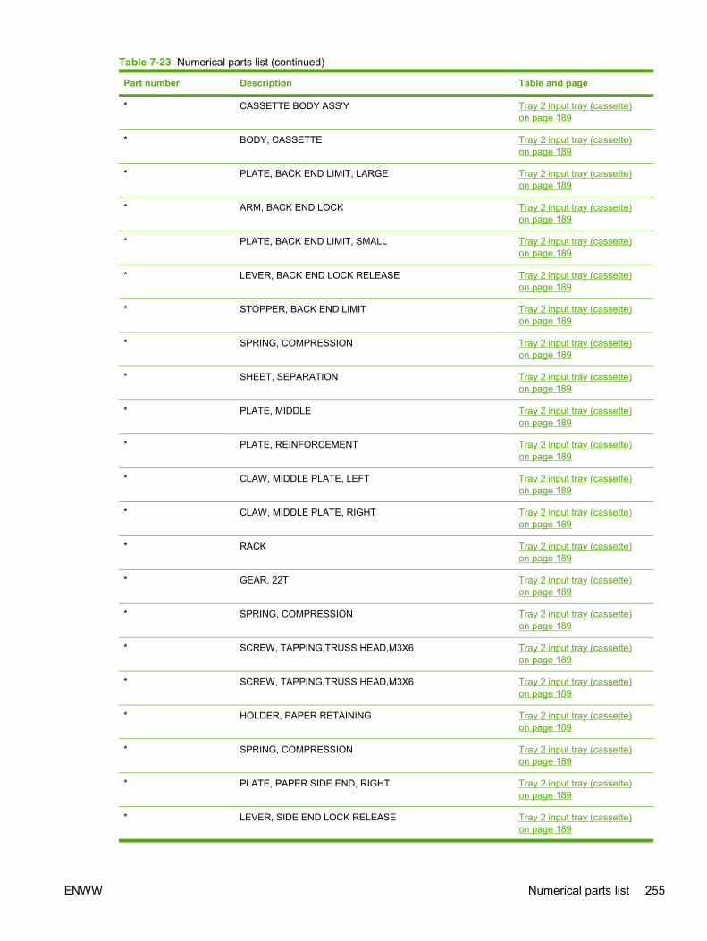
Part number Description Table and page
* CASSETTE BODY ASS'Y Tray 2 input tray (cassette)on page 189
* BODY, CASSETTE Tray 2 input tray (cassette)on page 189
* PLATE, BACK END LIMIT, LARGE Tray 2 input tray (cassette)on page 189
* ARM, BACK END LOCK Tray 2 input tray (cassette)on page 189
* PLATE, BACK END LIMIT, SMALL Tray 2 input tray (cassette)on page 189
* LEVER, BACK END LOCK RELEASE Tray 2 input tray (cassette)on page 189
* STOPPER, BACK END LIMIT Tray 2 input tray (cassette)on page 189
* SPRING, COMPRESSION Tray 2 input tray (cassette)on page 189
* SHEET, SEPARATION Tray 2 input tray (cassette)on page 189
* PLATE, MIDDLE Tray 2 input tray (cassette)on page 189
* PLATE, REINFORCEMENT Tray 2 input tray (cassette)on page 189
* CLAW, MIDDLE PLATE, LEFT Tray 2 input tray (cassette)on page 189
* CLAW, MIDDLE PLATE, RIGHT Tray 2 input tray (cassette)on page 189
* RACK Tray 2 input tray (cassette)on page 189
* GEAR, 22T Tray 2 input tray (cassette)on page 189
* SPRING, COMPRESSION Tray 2 input tray (cassette)on page 189
* SCREW, TAPPING,TRUSS HEAD,M3X6 Tray 2 input tray (cassette)on page 189
* SCREW, TAPPING,TRUSS HEAD,M3X6 Tray 2 input tray (cassette)on page 189
* HOLDER, PAPER RETAINING Tray 2 input tray (cassette)on page 189
* SPRING, COMPRESSION Tray 2 input tray (cassette)on page 189
* PLATE, PAPER SIDE END, RIGHT Tray 2 input tray (cassette)on page 189
* LEVER, SIDE END LOCK RELEASE Tray 2 input tray (cassette)on page 189
Table 7-23 Numerical parts list (continued)
ENWW Numerical parts list 255

Part number Description Table and page
* STOPPER, PAPER SIDE END Tray 2 input tray (cassette)on page 189
* SPRING, COMPRESSION Tray 2 input tray (cassette)on page 189
* HOLDER, PAD Tray 2 input tray (cassette)on page 189
* HOLDER, SEPARATION Tray 2 input tray (cassette)on page 189
* PLATE, PAPER GUIDE Tray 2 input tray (cassette)on page 189
* HOLDER, PAD Tray 2 input tray (cassette)on page 189
* WEIGHT, PAD Tray 2 input tray (cassette)on page 189
* HOLDER, PAD Tray 2 input tray (cassette)on page 189
* SPRING, COMPRESSION Tray 2 input tray (cassette)on page 189
* RACK, MANUAL FEED Tray 2 input tray (cassette)on page 189
* GUIDE, MANUAL FEED Tray 2 input tray (cassette)on page 189
* GUIDE, FEED WIDTH, LEFT Tray 2 input tray (cassette)on page 189
* GUIDE, FEED WIDTH, RIGHT Tray 2 input tray (cassette)on page 189
* GEAR, 16T Tray 2 input tray (cassette)on page 189
* INTERNAL COMPONENTS Tray 2 sheet input trayinternal componentson page 195
* CAP, CONTINUITY Tray 2 sheet input trayinternal componentson page 195
* BASE, MOTOR Tray 2 sheet input trayinternal componentson page 195
* CLUTCH, MECHANICAL Tray 2 sheet input trayinternal componentson page 195
* SPRING, LEAF Tray 2 sheet input trayinternal componentson page 195
* BUSHING Tray 2 sheet input trayinternal componentson page 195
Table 7-23 Numerical parts list (continued)
256 Chapter 7 Parts and diagrams ENWW

Part number Description Table and page
* HOLDER, DRAWER CONNECTOR Tray 2 sheet input trayinternal componentson page 195
* HOLDER, SWING GEAR Tray 2 sheet input trayinternal componentson page 195
* PLATE, GROUNDING Tray 2 sheet input trayinternal componentson page 195
* COVER, OPTION FRONT Tray 2 sheet input trayinternal componentson page 195
* COVER, OPTION LEFT Tray 2 sheet input trayinternal componentson page 195
* COVER, PCB Tray 2 sheet input trayinternal componentson page 195
* SHAFT, POSITIONING Tray 2 sheet input trayinternal componentson page 195
* COVER, SWING GEAR Tray 2 sheet input trayinternal componentson page 195
* STOP, CLUTCH Tray 2 sheet input trayinternal componentson page 195
* SOLENOID Tray 2 sheet input trayinternal componentson page 195
* PICKUP GEAR ASS'Y Tray 2 sheet input trayinternal componentson page 195
* COVER, OPTION RIGHT Tray 2 sheet input trayinternal componentson page 195
* GEAR, 47T/26T Tray 2 sheet input trayinternal componentson page 195
* GEAR, 40T/43T Tray 2 sheet input trayinternal componentson page 195
* CAM/GEAR, 26T Tray 2 sheet input trayinternal componentson page 195
* GEAR, 19T Tray 2 sheet input trayinternal componentson page 195
Table 7-23 Numerical parts list (continued)
ENWW Numerical parts list 257

Part number Description Table and page
* GEAR, 18T Tray 2 sheet input trayinternal componentson page 195
* SPRING, COMPRESSION Tray 2 sheet input trayinternal componentson page 195
* SPRING, TENSION Tray 2 sheet input trayinternal componentson page 195
* CONNECTOR, DRAWER Tray 2 sheet input trayinternal componentson page 195
* SADDLE, WIRE Tray 2 sheet input trayinternal componentson page 195
* SCREW, RS, M3X8 Tray 2 sheet input trayinternal componentson page 195
* SPRING, GROUNDING Tray 2 sheet input trayinternal componentson page 195
* GUIDE, CASSETTE, FRONT LEFT Tray 2 sheet input trayinternal componentson page 195
* GUIDE, CASSETTE, REAR LEFT Tray 2 sheet input trayinternal componentson page 195
* SCREW, RS, M3X8 Tray 2 sheet input trayinternal componentson page 195
* GUIDE, CASSETTE, REAR RIGHT Tray 2 sheet input trayinternal componentson page 195
* GUIDE, CASSETTE, FRONT RIGHT Tray 2 sheet input trayinternal componentson page 195
* SCREW, RS, M3X8 Tray 2 sheet input trayinternal componentson page 195
* PAPER FEEDER PCB ASS'Y Tray 2 sheet input trayinternal componentson page 195
* SCREW, TAPPING,TRUSS HEAD, M4X8 Tray 2 sheet input trayinternal componentson page 195
* CROSSMEMBER, FRONT Tray 2 sheet input trayinternal componentson page 195
Table 7-23 Numerical parts list (continued)
258 Chapter 7 Parts and diagrams ENWW

Part number Description Table and page
* CROSSMEMBER, REAR Tray 2 sheet input trayinternal componentson page 195
* CROSSMEMBER, MIDDLE Tray 2 sheet input trayinternal componentson page 195
* CROSSMEMBER, LOWER, REAR Tray 2 sheet input trayinternal componentson page 195
* GUIDE, PAPER SENSOR CABLE, 1 Tray 2 sheet input trayinternal componentson page 195
* GUIDE, PAPER SENSOR CABLE, 2 Tray 2 sheet input trayinternal componentson page 195
* GEAR, 29T Tray 2 sheet input trayinternal componentson page 195
* GEAR, 29T Tray 2 sheet input trayinternal componentson page 195
* SPRING, COMPRESSION Tray 2 sheet input trayinternal componentson page 195
* FOOT, RUBBER Tray 2 sheet input trayinternal componentson page 195
* COVER, OPTION RIGHT Tray 2 sheet input trayinternal componentson page 195
* OPTION FRAME LEFT ASS'Y Tray 2 sheet input trayinternal componentson page 195
* FRAME, OPTION, LEFT Tray 2 sheet input trayinternal componentson page 195
* OPTION FRAME RIGHT ASS'Y Tray 2 sheet input trayinternal componentson page 195
* FRAME, OPTION, RIGHT Tray 2 sheet input trayinternal componentson page 195
* PAPER PICKUP FEEDER ASS'Y Paper pick-up feederassembly for Tray 2on page 199
* GUIDE, REGISTRATION Paper pick-up feederassembly for Tray 2on page 199
Table 7-23 Numerical parts list (continued)
ENWW Numerical parts list 259

Part number Description Table and page
* PLATE, REG. GROUNDING, 1 Paper pick-up feederassembly for Tray 2on page 199
* PLATE, REG. GROUNDING, 2 Paper pick-up feederassembly for Tray 2on page 199
* FLAG, SENSOR Paper pick-up feederassembly for Tray 2on page 199
* SPRING, TORSION Paper pick-up feederassembly for Tray 2on page 199
* COVER, SENSOR, TOP Paper pick-up feederassembly for Tray 2on page 199
* GUIDE, PRE-TRANSFER Paper pick-up feederassembly for Tray 2on page 199
* ROLLER, REGISTRATION DRIVE Paper pick-up feederassembly for Tray 2on page 199
* BUSHING Paper pick-up feederassembly for Tray 2on page 199
* SHUTTER, REGISTRATION Paper pick-up feederassembly for Tray 2on page 199
* SPRING, TORSION Paper pick-up feederassembly for Tray 2on page 199
* ROLLER, REGISTRATION, A Paper pick-up feederassembly for Tray 2on page 199
* ROLLER, REGISTRATION, B Paper pick-up feederassembly for Tray 2on page 199
* ROLLER, REGISTRATION, C Paper pick-up feederassembly for Tray 2on page 199
* BUSHING Paper pick-up feederassembly for Tray 2on page 199
* BUSHING Paper pick-up feederassembly for Tray 2on page 199
* HOLDER, PAPER WIDTH SENSOR Paper pick-up feederassembly for Tray 2on page 199
Table 7-23 Numerical parts list (continued)
260 Chapter 7 Parts and diagrams ENWW

Part number Description Table and page
* FLAG, PAPER WIDTH SENSOR Paper pick-up feederassembly for Tray 2on page 199
* SPRING, TORSION Paper pick-up feederassembly for Tray 2on page 199
* RESISTOR, 400 OHM, 0.5W Paper pick-up feederassembly for Tray 2on page 199
* COVER, PICKUP FEED FRAME Paper pick-up feederassembly for Tray 2on page 199
* SPRING, TENSION Paper pick-up feederassembly for Tray 2on page 199
* PHOTO INTERRUPTER (SENSOR) Paper pick-up feederassembly for Tray 2on page 199
* PAPER PICKUP DRIVE ASS'Y Paper pick-up feederassembly for Tray 2on page 199
* FEEDER UNIT CABLE Paper pick-up feederassembly for Tray 2on page 199
* SCREW, TAPPING,TRUSS HEAD,M4X8 Paper pick-up feederassembly for Tray 2on page 199
* FRAME, PAPER PICKUP FEEDER Paper pick-up feederassembly for Tray 2on page 199
* SHAFT, REGISTRATION ROLLER Paper pick-up feederassembly for Tray 2on page 199
* COVER, PICKUP FEED FRAME Paper pick-up feederassembly for Tray 2on page 199
* SHEET, SCRAPER, 1 Paper pick-up feederassembly for Tray 2on page 199
* SHEET, SCRAPER, 2 Paper pick-up feederassembly for Tray 2on page 199
* SHAFT, PAPER PICKUP DRIVE Paper pick-up feederassembly for Tray 2on page 199
* BUSHING Paper pick-up feederassembly for Tray 2on page 199
Table 7-23 Numerical parts list (continued)
ENWW Numerical parts list 261

Part number Description Table and page
* BUSHING Paper pick-up feederassembly for Tray 2on page 199
* ARM, CST. PAPER SENSING, 1 Paper pick-up feederassembly for Tray 2on page 199
* ARM, CST. PAPER SENSING, 2 Paper pick-up feederassembly for Tray 2on page 199
* HOLDER, PAPER PICKUP ROLLER Paper pick-up feederassembly for Tray 2on page 199
* ROLLER, CASSETTE PAPER PICKUP Paper pick-up feederassembly for Tray 2on page 199
* BUSHING Paper pick-up feederassembly for Tray 2on page 199
* SPRING, COMPRESSION Paper pick-up feederassembly for Tray 2on page 199
* PANEL, FRONT Tray 3 input tray (cassette)on page 203
* FRAME, FRONT Tray 3 input tray (cassette)on page 203
* STOPPER, CASSETTE, LEFT Tray 3 input tray (cassette)on page 203
* STOPPER, CASSETTE, RIGHT Tray 3 input tray (cassette)on page 203
* ARM, CLAW RELEASE, LEFT Tray 3 input tray (cassette)on page 203
* ARM, CLAW RELEASE, RIGHT Tray 3 input tray (cassette)on page 203
* ARM, REMNANT INDICATION Tray 3 input tray (cassette)on page 203
* ARM, PLATE LOCK RELEASE, MD Tray 3 input tray (cassette)on page 203
* SIZE PLATE, PAPER Tray 3 input tray (cassette)on page 203
* SPRING, GROUNDING Tray 3 input tray (cassette)on page 203
* SPRING, GROUNDING Tray 3 input tray (cassette)on page 203
* PLATE, CASSETTE REINFORCEMENT Tray 3 input tray (cassette)on page 203
Table 7-23 Numerical parts list (continued)
262 Chapter 7 Parts and diagrams ENWW

Part number Description Table and page
* ARM, MD. PLATE RELEASE, LEFT Tray 3 input tray (cassette)on page 203
* CLAW, MD. PLATE RELEASE, LEFT Tray 3 input tray (cassette)on page 203
* ARM, MD. PLATE RELEASE, RIGHT Tray 3 input tray (cassette)on page 203
* CLAW, MD. PLATE RELEASE, RIGHT Tray 3 input tray (cassette)on page 203
* SPRING, COMPRESSION Tray 3 input tray (cassette)on page 203
* SPRING, COMPRESSION Tray 3 input tray (cassette)on page 203
* SPRING, TENSION Tray 3 input tray (cassette)on page 203
* SPRING, COMPRESSION Tray 3 input tray (cassette)on page 203
* SPRING, COMPRESSION Tray 3 input tray (cassette)on page 203
* SPRING, COMPRESSION Tray 3 input tray (cassette)on page 203
* BACK END LIMIT PLATE ASS'Y Tray 3 input tray (cassette)on page 203
* MIDDLE PLATE ASS'Y Tray 3 input tray (cassette)on page 203
* LEFT PAPER SIDE END ASS'Y Tray 3 input tray (cassette)on page 203
* RIGHT PAPER SIDE END ASS'Y Tray 3 input tray (cassette)on page 203
* SCREW, TAPPING,TRUSS HEAD,M4X8 Tray 3 input tray (cassette)on page 203
* CASSETTE BODY ASS'Y Tray 3 input tray (cassette)on page 203
* BODY, CASSETTE Tray 3 input tray (cassette)on page 203
* PLATE, BACK END LIMIT, LARGE Tray 3 input tray (cassette)on page 203
* ARM, BACK END LOCK Tray 3 input tray (cassette)on page 203
* PLATE, BACK END LIMIT, SMALL Tray 3 input tray (cassette)on page 203
* LEVER, BACK END LOCK RELEASE Tray 3 input tray (cassette)on page 203
* STOPPER, BACK END LIMIT Tray 3 input tray (cassette)on page 203
Table 7-23 Numerical parts list (continued)
ENWW Numerical parts list 263

Part number Description Table and page
* SPRING, COMPRESSION Tray 3 input tray (cassette)on page 203
* SHEET, SEPARATION Tray 3 input tray (cassette)on page 203
* PLATE, MIDDLE Tray 3 input tray (cassette)on page 203
* PLATE, REINFORCEMENT Tray 3 input tray (cassette)on page 203
* CLAW, MIDDLE PLATE, LEFT Tray 3 input tray (cassette)on page 203
* CLAW, MIDDLE PLATE, RIGHT Tray 3 input tray (cassette)on page 203
* RACK Tray 3 input tray (cassette)on page 203
* GEAR, 22T Tray 3 input tray (cassette)on page 203
* SPRING, COMPRESSION Tray 3 input tray (cassette)on page 203
* SCREW, TAPPING,TRUSS HEAD,M3X6 Tray 3 input tray (cassette)on page 203
* PLATE, PAPER SIDE END, LEFT Tray 3 input tray (cassette)on page 203
* HOLDER, PAPER RETAINING Tray 3 input tray (cassette)on page 203
* SPRING, COMPRESSION Tray 3 input tray (cassette)on page 203
* PLATE, PAPER SIDE END, RIGHT Tray 3 input tray (cassette)on page 203
* LEVER, SIDE END LOCK RELEASE Tray 3 input tray (cassette)on page 203
* STOPPER, PAPER SIDE END Tray 3 input tray (cassette)on page 203
* SPRING, COMPRESSION Tray 3 input tray (cassette)on page 203
* HOLDER, PAD Tray 3 input tray (cassette)on page 203
* HOLDER, SEPARATION Tray 3 input tray (cassette)on page 203
* PLATE, PAPER GUIDE Tray 3 input tray (cassette)on page 203
* HOLDER, PAD Tray 3 input tray (cassette)on page 203
* WEIGHT, PAD Tray 3 input tray (cassette)on page 203
Table 7-23 Numerical parts list (continued)
264 Chapter 7 Parts and diagrams ENWW

Part number Description Table and page
* HOLDER, PAD Tray 3 input tray (cassette)on page 203
* SPRING, COMPRESSION Tray 3 input tray (cassette)on page 203
* GUIDE, REGISTRATION Paper pickup feederassembly (Tray 3) on page 207
* PLATE, REG. GROUNDING, 1 Paper pickup feederassembly (Tray 3) on page 207
* PLATE, REG. GROUNDING, 2 Paper pickup feederassembly (Tray 3) on page 207
* COVER, PICKUP FEED FRAME Paper pickup feederassembly (Tray 3) on page 207
* GUIDE, PRE-TRANSFER Paper pickup feederassembly (Tray 3) on page 207
* ROLLER, REGISTRATION DRIVE Paper pickup feederassembly (Tray 3) on page 207
* BUSHING Paper pickup feederassembly (Tray 3) on page 207
* ROLLER, REGISTRATION, A Paper pickup feederassembly (Tray 3) on page 207
* ROLLER, REGISTRATION, B Paper pickup feederassembly (Tray 3) on page 207
* ROLLER, REGISTRATION, C Paper pickup feederassembly (Tray 3) on page 207
* BUSHING Paper pickup feederassembly (Tray 3) on page 207
* BUSHING Paper pickup feederassembly (Tray 3) on page 207
* RESISTOR, 400 OHM, 0.5W Paper pickup feederassembly (Tray 3) on page 207
* SPRING, TENSION Paper pickup feederassembly (Tray 3) on page 207
* PHOTO INTERRUPTER (SENSOR) Paper pickup feederassembly (Tray 3) on page 207
* CABLE, OPTION SENSOR Paper pickup feederassembly (Tray 3) on page 207
* PAPER PICKUP DRIVE ASS'Y Paper pickup feederassembly (Tray 3) on page 207
* SCREW, TAPPING,TRUSS HEAD,M4X8 Paper pickup feederassembly (Tray 3) on page 207
* FRAME, PAPER PICKUP FEEDER Paper pickup feederassembly (Tray 3) on page 207
* SHAFT, REGISTRATION ROLLER Paper pickup feederassembly (Tray 3) on page 207
Table 7-23 Numerical parts list (continued)
ENWW Numerical parts list 265

Part number Description Table and page
* SHAFT, PAPER PICKUP DRIVE Paper pickup feederassembly (Tray 3) on page 207
* BUSHING Paper pickup feederassembly (Tray 3) on page 207
* BUSHING Paper pickup feederassembly (Tray 3) on page 207
* ARM, CST. PAPER SENSING, 1 Paper pickup feederassembly (Tray 3) on page 207
* ARM, CST. PAPER SENSING, 2 Paper pickup feederassembly (Tray 3) on page 207
* HOLDER, PAPER PICKUP ROLLER Paper pickup feederassembly (Tray 3) on page 207
* ROLLER, CASSETTE PAPER PICKUP Paper pickup feederassembly (Tray 3) on page 207
* BUSHING Paper pickup feederassembly (Tray 3) on page 207
* SPRING, COMPRESSION Paper pickup feederassembly (Tray 3) on page 207
* PCB ASS'Y LOCATION DIAGRAM Paper pickup feederassembly (Tray 3) on page 209
* PAPER FEEDER PCB ASS'Y Paper pickup feederassembly (Tray 3) on page 209
RC1-5062-000CN RETAINER, PAPER Internal components (2 of 3)on page 169
RC1-5096-000CN ARM, PAPER RETAINER, LEFT Internal components (2 of 3)on page 169
RC1-5097-000CN ARM, PAPER RETAINER, RIGHT Internal components (2 of 3)on page 169
RC1-5147-000CN SPRING, GROUNDING Internal components (2 of 3)on page 169
RC1-5173-000CN COVER, FACE-DOWN External panels and covers (1of 2) on page 159
RC1-5174-000CN COVER, UPPER FACE, S External panels and covers (1of 2) on page 159
RC1-5176-000CN COVER, UPPER Upper assembly coveron page 163
RC1-5178-000CN COVER, INSIDE, UPPER Upper assembly coveron page 163
RC1-5183-000CN COVER, LEFT External panels and covers (1of 2) on page 159
RC1-5184-000CN COVER, CASSETTE, LEFT External panels and covers (1of 2) on page 159
RC1-5188-000CN COVER, CASSETTE, RIGHT External panels and covers (2of 2) on page 161
Table 7-23 Numerical parts list (continued)
266 Chapter 7 Parts and diagrams ENWW

Part number Description Table and page
RC1-5200-000CN COVER, CASSETTE DUST External panels and covers (1of 2) on page 159
RC1-5200-000CN COVER, CASSETTE DUST External panels and covers (2of 2) on page 161
RC1-5200-000CN COVER, CASSETTE DUST Tray 2 sheet input trayinternal componentson page 195
RC1-5227-000CN PLATE, REAR External panels and covers (1of 2) on page 159
RC1-5227-000CN PLATE, REAR External panels and covers (2of 2) on page 161
RC1-5440-000CN PAPER PICKUP ROLLER 250-sheet input tray(cassette) on page 193
RC1-5440-000CN ROLLER, PAPER PICKUP Paper pick-up feederassembly for Tray 2on page 199
RC1-5440-000CN PAPER PICKUP ROLLER Tray 3 input tray (cassette)on page 203
RC1-5440-000CN PAPER PICKUP ROLLER Paper pickup feederassembly (Tray 3) on page 207
RC1-5440-000CN ROLLER, PAPER PICKUP Paper pickup feederassembly (Tray 3) on page 207
RM1-1820-000CN FUSER ASS'Y (110v) Fuser assembly on page 183
RM1-1820-000CN(110v) orRM1-1821-000CN (220v)
FUSER ASSEMBLY Assembly locationson page 157
RM1-1821-000CN FUSER ASS'Y (220v) Fuser assembly on page 183
RM1-1856-000CN FRONT DOOR ASS'Y External panels and covers (2of 2) on page 161
RM1-1858-000CN RIGHT COVER ASS'Y External panels and covers (2of 2) on page 161
RM1-1859-000CN PAPER DELIVERY TRAY ASS'Y External panels and covers (1of 2) on page 159
RM1-1885-000CN ELECT.TRANSPORT BELT ASS'Y Internal components (2 of 3)on page 169
RM1-1916-000CN CASSETTE Assembly locationson page 157
RM1-1916-000CN CASSETTE Tray 2 input tray (cassette)on page 189
RM1-1922-000CN SEPARATION ASS'Y Tray 2 input tray (cassette)on page 189
RM1-1922-000CN SEPARATION ASS'Y Tray 3 input tray (cassette)on page 203
Table 7-23 Numerical parts list (continued)
ENWW Numerical parts list 267

Part number Description Table and page
RM1-1923-000CN FEED ASS'Y Tray 2 input tray (cassette)on page 189
RM1-1945-000CN CASSETTE 250-sheet input tray(cassette) on page 193
RM1-1945-000CN CASSETTE Tray 3 input tray (cassette)on page 203
RM1-1975-000CN DC CONTROLLER PCB ASS'Y Internal components (3 of 3)on page 173
RM1-1975-000CN DC CONTROLLER PCB ASS'Y PCB assembly location Tray 2on page 187
RM1-1983-000CN CONTROL PANEL ASSEMBLY Assembly locationson page 157
RM1-1983-000CN CONTROL PANEL ASS'Y Control panel assemblyon page 177
Table 7-23 Numerical parts list (continued)
268 Chapter 7 Parts and diagrams ENWW

A Product specifications
This chapter contains information about the following topics.
● Physical specifications
● Replacement supplies specifications
● Electrical specifications
● Environmental specifications
● Acoustical specifications
ENWW 269

Physical specificationsTable A-1 Printer specifications
Product Height Depth Width Weight
HP Color LaserJet1600 printer withoutoptional Tray 3 orconsumables
370 mm (14.6 inches) 453 mm (17.83 inches) 407 mm (16.02 inches) 15.67 kg (34.54 lbs)
HP Color LaserJet1600 printer withoptional Tray 3 (250-sheet), withoutconsumables
460 mm (18.1 inches) 451 mm (17.76 inches) 485 mm (18.98 inches) 20.16 kg (44.43 lbs)
270 Appendix A Product specifications ENWW

Replacement supplies specificationsTable A-2 Replacement supplies specifications
Replacement print-cartridge life (based on approximately 5%coverage)
Black: 2,500 pages
Yellow, cyan, and magenta: 2,000 pages each
Print cartridge lifeTable A-3 Print cartridge specifications
Product name Description Part number
Black print cartridge Life of 2,500 pages at approximately5% coverage.
Q6000A
Cyan print cartridge Life of 2,000 pages at approximately5% coverage.
Q6001A
Yellow print cartridge Life of 2,000 pages at approximately5% coverage.
Q6002A
Magenta print cartridge Life of 2,000 pages at approximately5% coverage.
Q6003A
NOTE Actual yields may vary according to usage.
ENWW Replacement supplies specifications 271

Electrical specificationsTable A-4 Electrical specifications
Item 110-volt models 220-volt models
Power supply 115-127V (+/-10%)
50/60 Hz (+/- 2 Hz)
220-240V (+/-10%)
50/60 Hz (+/- 2 Hz)
Power consumption (typical)
During printing (color) 185 W (average) 185 W (average)
During printing (black and white) 185 W (average) 185 W (average)
During standby 15 W (average) 19 W (average)
Off mode 0 W (average) 0 W (average)
Heat output
Idle 51 BTU/hr 61 BTU/hr
Rated current 12 A 6 A
CAUTION Power requirements are based on the country/region where the printer is sold. Donot convert operating voltages. This will damage the printer and void the product warranty.
272 Appendix A Product specifications ENWW

Environmental specificationsTable A-5 Environmental specifications
Recommended1 Operating1 Storage1
(Printer and print cartridge)
Temperature
20° to 27°C (68° to 81°F) 15° to 32.5°C (59° to 90.5°F) -20° to 40°C (-4° to 104°F)
Relative humidity 20% to 70% 10% to 80% 95% or less
1 Values are subject to change. See http://www.hp.com/support/clj1600 for current information.
ENWW Environmental specifications 273

Acoustical specificationsTable A-6 Acoustical specifications
Sound Power Level Declared per ISO 92961
Printing (8 ppm) LWAd = 6.6 Bels (A) [66 dB (A)]
SPL-Bystander Position Declared per ISO 92961
Printing (8 ppm) LpAm = 52 dB(A)
1 Values are subject to change. See http://www.hp.com/support/clj1600 for current information.
274 Appendix A Product specifications ENWW

B Product warranty statements
ENWW 275

Hewlett-Packard limited warranty statementHP PRODUCT DURATION OF LIMITED WARRANTY
HP Color LaserJet 1600 Six-month, Limited Warranty
HP warrants to you, the end-user customer, that HP hardware and accessories will be free from defects inmaterials and workmanship after the date of purchase, for the period specified above. If HP receives notice ofsuch defects during the warranty period, HP will, at its option, either repair or replace products which prove tobe defective. Replacement products may be either new or equivalent in performance to new.
HP warrants to you that HP software will not fail to execute its programming instructions after the date ofpurchase, for the period specified above, due to defects in material and workmanship when properly installedand used. If HP receives notice of such defects during the warranty period, HP will replace software which doesnot execute its programming instructions due to such defects.
HP does not warrant that the operation of HP products will be uninterrupted or error free. If HP is unable, withina reasonable time, to repair or replace any product to a condition as warranted, you will be entitled to a refundof the purchase price upon prompt return of the product.
HP products may contain remanufactured parts equivalent to new in performance or may have been subject toincidental use.
Warranty does not apply to defects resulting from (a) improper or inadequate maintenance or calibration, (b)software, interfacing, parts or supplies not supplied by HP, (c) unauthorized modification or misuse, (d)operation outside of the published environmental specifications for the product, or (e) improper site preparationor maintenance.
TO THE EXTENT ALLOWED BY LOCAL LAW, THE ABOVE WARRANTIES ARE EXCLUSIVE AND NOOTHER WARRANTY OR CONDITION, WHETHER WRITTEN OR ORAL, IS EXPRESSED OR IMPLIED ANDHP SPECIFICALLY DISCLAIMS ANY IMPLIED WARRANTIES OR CONDITIONS OF MERCHANTABILITY,SATISFACTORY QUALITY, AND FITNESS FOR A PARTICULAR PURPOSE. Some countries/regions, statesor provinces do not allow limitations on the duration of an implied warranty, so the above limitation or exclusionmight not apply to you. This warranty gives you specific legal rights and you might also have other rights thatvary from country/region to country/region, state to state, or province to province. HP's limited warranty is validin any country/region or locality where HP has a support presence for this product and where HP has marketedthis product. The level of warranty service you receive may vary according to local standards. HP will not alterform, fit or function of the product to make it operate in a country/region for which it was never intended tofunction for legal or regulatory reasons.
TO THE EXTENT ALLOWED BY LOCAL LAW, THE REMEDIES IN THIS WARRANTY STATEMENT AREYOUR SOLE AND EXCLUSIVE REMEDIES. EXCEPT AS INDICATED ABOVE, IN NO EVENT WILL HP ORITS SUPPLIERS BE LIABLE FOR LOSS OF DATA OR FOR DIRECT, SPECIAL, INCIDENTAL,CONSEQUENTIAL (INCLUDING LOST PROFIT OR DATA), OR OTHER DAMAGE, WHETHER BASED INCONTRACT, TORT, OR OTHERWISE. Some countries/regions, states or provinces do not allow the exclusionor limitation of incidental or consequential damages, so the above limitation or exclusion may not apply to you.
THE WARRANTY TERMS CONTAINED IN THIS STATEMENT, EXCEPT TO THE EXTENT LAWFULLYPERMITTED, DO NOT EXCLUDE, RESTRICT OR MODIFY AND ARE IN ADDITION TO THE MANDATORYSTATUTORY RIGHTS APPLICABLE TO THE SALE OF THIS PRODUCT TO YOU.
276 Appendix B Product warranty statements ENWW

Print Cartridge Limited Warranty StatementThis HP product is warranted to be free from defects in materials and workmanship.
This warranty does not apply to products that (a) have been refilled, refurbished, remanufactured ortampered with in any way, (b) experience problems resulting from misuse, improper storage, oroperation outside of the published environmental specifications for the printer product or (c) exhibitwear from ordinary use.
To obtain warranty service, please return the product to place of purchase (with a written descriptionof the problem and print samples) or contact HP Customer Support. At HP's option, HP will eitherreplace products that prove to be defective or refund your purchase price.
TO THE EXTENT ALLOWED BY LOCAL LAW, THE ABOVE WARRANTY IS EXCLUSIVE AND NOOTHER WARRANTY OR CONDITION, WHETHER WRITTEN OR ORAL, IS EXPRESSED ORIMPLIED AND HP SPECIFICALLY DISCLAIMS ANY IMPLIED WARRANTIES OR CONDITIONS OFMERCHANTABILITY, SATISFACTORY QUALITY, AND FITNESS FOR A PARTICULAR PURPOSE.
TO THE EXTENT ALLOWED BY LOCAL LAW, IN NO EVENT WILL HP OR ITS SUPPLIERS BELIABLE FOR DIRECT, SPECIAL, INCIDENTAL, CONSEQUENTIAL (INCLUDING LOST PROFITOR DATA), OR OTHER DAMAGE, WHETHER BASED IN CONTRACT, TORT, OR OTHERWISE.
THE WARRANTY TERMS CONTAINED IN THIS STATEMENT, EXCEPT TO THE EXTENTLAWFULLY PERMITTED, DO NOT EXCLUDE, RESTRICT OR MODIFY AND ARE IN ADDITIONTO THE MANDATORY STATUTORY RIGHTS APPLICABLE TO THE SALE OF THIS PRODUCTTO YOU.
ENWW Print Cartridge Limited Warranty Statement 277

278 Appendix B Product warranty statements ENWW

C Regulatory statements
This chapter contains information about the following topics.
● Declaration of Conformity
● Laser safety statement
● Canadian DOC statement
● VCCI statement (Japan)
● Korean EMI statement
● Finnish laser statement
ENWW 279

Declaration of ConformityDeclaration of Conformityaccording to ISO/IEC Guide 22 and EN 45014Manufacturer's Name: Hewlett-Packard CompanyManufacturer's Address: 11311 Chinden Boulevard,
Boise, Idaho 83714-1021, USAdeclares, that the product
Product Name: HP Color LaserJet 1600 SeriesRegulatory Model Number3): BOISB-0409–00Product Options AllToner Cartridges: Q6000A, Q6001A, Q6002A, Q6003Aconforms to the following Product Specifications:
Safety: IEC 60950-1:2001 / EN60950-1: 2001 + A11IEC 60825-1:1993 +A1: +A2/EN 60825-1:1994 +A1 +A2 (Class 1 Laser/LED Product)GB4943-2001
EMC: CISPR 22:1993 +A1 +A2 / EN 55022:1994 +A1 +A2 - Class B1)
EN 61000-3-2:2000EN 61000-3-3:1995 +A1EN 55024:1998 +A1 +A2FCC Title 47 CFR, Part 15 Class B2) / ICES-003, Issue 4/ GB9254-1998, GB17625.1-2003
Supplementary Information:
The product herewith complies with the requirements of the EMC Directive 89/336/EEC and the Low Voltage Directive 73/23/EEC, andcarries the CE-Marking accordingly.
1) The product was tested in a typical configuration with Hewlett-Packard Personal Computer Systems. Compliance testing of product tostandard with exception of Clause 9.5, which is not yet in effect.
2) This Device complies with Part 15 of the FCC Rules. Operation is subject to the following two conditions: (1) this device may not causeharmful interference, and (2) this device must accept any interference received, including interference that may cause undesired operation.
3) For regulatory purposes, this product is assigned a Regulatory model number. This number should not be confused with the productname or the product number(s).
Boise, Idaho USA
October 2005
For regulatory topics only:
Australia Contact: Product Regulations Manager, Hewlett-Packard Australia Ltd., 31-41 Joseph Street, Blackburn, Victoria 3130,Australia
European Contact: Your Local Hewlett-Packard Sales and Service Office or Hewlett-Packard GmbH, Department HQ-TRE /Standards Europe, Herrenberger Strasse 140, Böblingen D-71034, Germany, (FAX: +49-7031-14-3143)
USA Contact: Product Regulations Manager, Hewlett-Packard Company, PO Box 15, Mail Stop 160, Boise, Idaho 83707-0015,USA, (Phone: 208-396-6000)
280 Appendix C Regulatory statements ENWW

Laser safety statementThe Center for Devices and Radiological Health (CDRH) of the U.S. Food and Drug Administrationhas implemented regulations for laser products manufactured since August 1, 1976. Compliance ismandatory for products marketed in the United States. The printer is certified as a "Class 1" laserproduct under the U.S. Department of Health and Human Services (DHHS) Radiation PerformanceStandard according to the Radiation Control for Health and Safety Act of 1968.
Since radiation emitted inside the printer is completely confined within protective housings andexternal covers, the laser beam cannot escape during any phase of normal user operation.
WARNING! Using controls, making adjustments, or performing procedures other than thosespecified in this user guide may result in exposure to hazardous radiation.
Canadian DOC statementComplies with Canadian EMC Class B requirements.
« Conforme à la classe B des normes canadiennes de compatibilité électromagnétiques (CEM). »
VCCI statement (Japan)
Figure C-1 VCCI statement
Korean EMI statement
Figure C-2 Korean EMI statement
ENWW Laser safety statement 281

Finnish laser statementLASERTURVALLISUUS
LUOKAN 1 LASERLAITE
KLASS 1 LASER APPARAT
HP Color LaserJet 1600 -laserkirjoitin on käyttäjän kannalta turvallinen luokan 1 laserlaite.Normaalissa käytössä kirjoittimen suojakotelointi estää lasersäteen pääsyn laitteenulkopuolelle.
Laitteen turvallisuusluokka on määritetty standardin EN60825-1 (1994) mukaisesti.
VAROITUS!
Laitteen käyttäminen muulla kuin käyttöohjeessa mainitulla tavalla saattaa altistaakäyttäjän turvallisuusluokan 1 ylittävälle näkymättömälle lasersäteilylle.
VARNING!
Om apparaten används på annat sätt än i bruksanvisning specificerats, kan användarenutsättas för osynlig laserstrålning, som överskrider gränsen för laserklass 1.
HUOLTO
HP Color LaserJet 1600 -kirjoittimen sisällä ei ole käyttäjän huollettavissa olevia kohteita.Laitteen saa avata ja huoltaa ainoastaan sen huoltamiseen koulutettu henkilö. Tällaiseksihuoltotoimenpiteeksi ei katsota väriainekasetin vaihtamista, paperiradan puhdistusta taimuita käyttäjän käsikirjassa lueteltuja, käyttäjän tehtäväksi tarkoitettuja ylläpitotoimia, jotkavoidaan suorittaa ilman erikoistyökaluja.
VARO!
Mikäli kirjoittimen suojakotelo avataan, olet alttiina näkymättömälle lasersäteilylle laitteenollessa toiminnassa. Älä katso säteeseen.
VARNING!
Om laserprinterns skyddshölje öppnas då apparaten är i funktion, utsättas användaren förosynlig laserstrålning. Betrakta ej strålen.
Tiedot laitteessa käytettävän laserdiodin säteilyominaisuuksista:
Aallonpituus 770-800 nm
Teho 5 mW
Luokan 3B laser
282 Appendix C Regulatory statements ENWW

Index
Symbols/Numerics600 dpi print-quality setting 123
Aaccessibility 5accessories
ordering 154part numbers 271
acoustical specifications 274adhesive labels
specifications 16, 17alert messages 108, 133arrow buttons 9assembly
locations 156parts list 156
attention light 9
Bbackground, gray 140bands, troubleshooting 140bins, output
features 4jams, clearing 105
black and white printingtroubleshooting 143
black cartridgepart number 271status gauge 8
blank pages, troubleshooting 125buttons, control panel 9
Ccables
USB, troubleshooting 126calibrating printer
using HP Toolbox 146Canadian DOC statement 281cancel Job button 8cardstock
specifications 16, 17cartridges
part numbers 271recycling 31replacing 31, 62status gauge 8status page, printing 117storage specifications 273
characters, troubleshooting 142checklist, troubleshooting 98cleaning
ETB 120, 129fuser 133mode 120printer 32using HP Toolbox 33, 146
clearing jamscommon locations 100input area 104inside printer 103output area 105
cold reset 128color
calibration 34troubleshooting 143
componentslocating 6
configuration page 115, 130, 131configurations, printer 3consumables
part numbers 271specifications 271status gauge 8status page, printing 117
control panellayout 9lights and buttons, description
9messages 108, 133removal and replacement 91
control panel display test 120covers
locations 162parts list 162
covers, documentpaper specifications 16, 17
creases, troubleshooting 142critical error messages 109, 135crooked pages 142curled media 142cyan cartridge
part number 271status gauge 8
DDC controller
removal and replacement 85declaration of conformity 280defaults
restoring 120, 139defects
correcting 124repetitive image defects 149
demo page 114, 130diagnostic tools
repetitive image defect ruler149
diagramsassemblies 156covers 162general circuit 210input devices 188internal assemblies 164
dimensions, printer 270display
control panel 10documentation
ordering 154dots per inch (dpi)
print settings 123
ENWW Index 283

specifications 4dots, troubleshooting 140dpi (dots per inch)
print settings 123specifications 4
driversoperating systems supported
11uninstalling 12Windows, features 11
Eelectrical specifications 272energy
consumption 272savings 4
engine cleaning 32engine control system 36engine test print 127envelopes
construction 14sizes 15specifications 14, 17
environmentalpaper specifications 13printer specifications 273
error messages 108, 133ETB
removal and replacement 64event log 130, 132
Ffaded print 139Finnish laser statement 282firmware updates 150formatter
removal and replacement 81fraud hotline 31fuser
cleaning page 133removal and replacement 73
Ggeneral circuit diagram 210general timing chart 56gray background, troubleshooting
140grayscale
troubleshooting 143
Hheavy paper
specifications 16, 17HP fraud hotline 31HP Toolbox
calibrating printer 34calibrating the printer 146cleaning page 146configuration page 147extended print modes 122operating systems supported
11print quality menu 122print quality troubleshooting
pages 146print types 121toner level, checking from 30
humidity specificationspaper, storing 13printer environment 273
Iimage formation system 39image quality
print, troubleshooting 124input devices
locations 188parts list 188
input traysfeatures 4installing 23media supported 16
installinginput trays 23print cartridges 25supplies 25
interface portstypes included 4
internal assemblylocations 164parts list 164
Jjams
causes 101causes of 100delivery delay 106delivery stationary 106door open 107input area 104
inside printer 103output area 105pickup delay 106pickup stationary 106start-up residual 106troubleshooting 102wrapping 106
Kkeys, control panel 9Korean EMI statement 281
Llabels
specifications 16, 17laser safety statements 281light print, troubleshooting 139lightness
faded print, troubleshooting139
lightslocating 9
lines, troubleshootingprinted pages 140
locationfan 53model and serial number 8printed circuit assemblies 53,
54solenoid 54solenoids 53
loose toner, troubleshooting 141
Mmagenta cartridge
part number 271status gauge 8
mailing labelsspecifications 16, 17
margins, envelopes 14media
curled, troubleshooting 142envelopes 14jams 100labels 16selecting 13specifications 13transparencies 16tray 1, types supported 16tray 2, types supported 16tray 3, types supported 16
284 Index ENWW

unsupported 17wrinkled 142wrong size 124wrong type 124
memory 5menu structure report 114messages
alert and warning 108, 133critical error 109, 135error 108, 133event log 132event log only 113, 139status 113, 138status log 118supplies 110, 135
model number 8motors 53
NNVRAM initializer
super 128
Ooperating environment,
specifications 273operating systems supported 11ordering
accessories 154parts 153supplies and accessories 271
output binsfeatures 4jams, clearing 105
output qualityprint, troubleshooting 124
overhead transparenciesspecifications 16, 17
Ppage counts
restoring 129pages
blank 125not printing 125printing slowly 125skewed 142
pages per minute 4paper
curled, troubleshooting 142jams 100jams, delivery delay 106
jams, delivery stationary 106jams, door open 107jams, input areas 104jams, inside the printer 103jams, output area 105jams, pickup delay 106jams, pickup stationary 106jams, start-up residual 106jams, top bin 105jams, wrapping 106selecting 13tray 1, types supported 16tray 2, types supported 16tray 3, types supported 16unsupported 17wrinkled 142
paper handling issues 124paper input trays
features 4media supported 16
paper output binsfeatures 4jams, clearing 105
paper pickup rollerremoval and replacement 89
partsassembly locations 156cover locations 162input devices 188internal assembly locations 164ordering 153part numbers 271removal and replacement 59replaceable 152user replaceable 60
paused printing 9performance problems 125pickup and feed system 49pickup rollers, ordering 60platforms supported 11power
requirements 272powersave 120print cartridges
checking 30HP fraud hotline 31installing 25life expectancy 30ordering 30part numbers 271
recycling 31replacing 25, 31status gauge 8status page, printing 117storage specifications 273
print modesextended 122HP Toolbox 122
print qualityidentifying defects 124improving 121issues 139menu 122settings 123specifications 4troubleshooting 124, 133
print quality defectscorrecting 124
print typesHP Toolbox 121
printercalibrating 57dimensions 20performance problems 125
printer driversoperating systems supported
11uninstalling 12Windows, features 11
printingtroubleshooting 125
printing a configuration pageusing HP Toolbox 147
procedurepre-servicre 61
Qquality
print settings 123print, troubleshooting 124specifications 4
Rready light 9ready light and select button 9rear output door
features 4regulatory statements
Canadian DOC statement 281declaration of conformity 280
ENWW Index 285

Finnish laser statement 282Korean EMI statement 281laser safety 281VCCI statement 281
removalcontrol panel 91DC controller 85ETB 64formatter 81fuser 73paper pickup roller 89print cartridges 62separation pad 88
removal and replacement 59repetitive defects, troubleshooting
143repetitive image defect ruler 149replaceable parts 152replacing
control panel 91DC controller 85ETB 64formatter 81fuser 73paper pickup roller 89print cartridges 31, 62separation pad 88
reportsconfiguration 114, 115secondary service 120status 114, 118supplies status 117supplies status page 132
reports menu 148reset, cold 128resolution
print settings 123specifications 4
restoringdefaults 120factory defaults 139page counts 128, 129serial number 128
restoring serial number 129resuming printing 9rollers, ordering 60
Sscatter, troubleshooting 143secondary service menu
clean ETB 120control panel display test 120reports 120
separation padordering 60removal and replacement 88
sequence of operation 36serial number
restoring 129service
part numbers 271service approach 61service menu 139service menu settings
cleaning mode 120powersave 120restoring defaults 120
service mode functionscleaning mode 128, 129cold reset 128NVRAM initializer 128super NVRAM initializer 128
site preparation 20size, printer 270skewed pages 142smeared toner, troubleshooting
141software
operating systems supported11
ordering 154supported drivers 11uninstalling 12updates 150Windows systems 11Windows, features 11
solenoid 54solenoids 53space requirements 20special media
envelopes 14labels 16specifications 16, 17transparencies 16
specificationsacoustical 274envelopes 14environmental 273labels 16motors and fans 37
print cartridge 271print media 13printer features 4transparencies 16trays, media supported 16
specks, troubleshooting 140speed
specifications 4spots, troubleshooting 140status
printer 8Supplies Status page, printing
117status log 118status page 130storing
envelopes 14paper 13print cartridges 31printer 273supplies 31
streaks, troubleshooting 140super NVRAM initializer 128supplies
checking 30life expectancy 30messages 110, 135ordering 30, 154specifications 271status gauge 8status page 117
supplies statusHP Toolbox 117
supplies status page 132support
part numbers 271system requirements 21systems
engine control 36image formation 39pickup and feed 49
Ttechnical support
part numbers 271web sites 154
temperature specificationspaper, storing 13printer environment 273
text, troubleshooting
286 Index ENWW

misformed characters 142timing chart 56toner
loose, troubleshooting 141scatter, troubleshooting 143smeared, troubleshooting 141specks, troubleshooting 140status gauge 8
Toolboxoperating systems supported
11top output bin
features 4transparencies
specifications 16, 17tray 1
loading 23trays
features 4media supported 16
troubleshootingblank pages 125calibrating printer 34checklist 98color 143configuration page 130curled media 142demo page 130event log 130faded print 139jams 100lines, printed pages 140loose toner 141pages not printing 125pages printing slowly 125print quality issues 139process 98repetitive defects 143replacing print cartridges 31reports and tools 130skewed pages 142status page 130text 142toner scatter 143toner smear 141toner specks 140USB cables 126using HP Toolbox 146wrinkles 142
Uuninstalling software 12updates
software and firmware 150USB port
troubleshooting 126type included 4
user replaceable parts 60
VVCCI statement 281vertical lines, troubleshooting 140voltage requirements 272
Wwarning messages 108, 133warranty
print cartridge 277product 276
wavy paper, troubleshooting 142Web
diagnostic tools 148weight
printer 270Windows
software features 11uninstalling software 12versions supported 11
wrinkles, troubleshooting 142
Yyellow cartridge
part number 271status gauge 8
ENWW Index 287

288 Index ENWW


*CB373-90930**CB373-90930*CB373-90930
© 2006 Hewlett-Packard Development Company, L.P.
www.hp.com