Embed Size (px)
Citation preview

HP Business Service Management
for the Windows/Linux operating system
Software Version: 9.20
HP NNMi – HP BSM Topology Integration Best Practices
Executive Summary .............................................................................................................................. 2
NNMi Integration to BSM: Which Method to Use? .................................................................................. 3
Configuring the NNMi – BSM Topology Integration ................................................................................. 4
BSM Topology Created by NNMi ......................................................................................................... 6
Network Topology Views ...................................................................................................................... 8 Layer 2 Topology View ..................................................................................................................... 8 Service Health Views ...................................................................................................................... 13 OMi Health Perspectives ................................................................................................................. 14
CI Lifecycle ....................................................................................................................................... 15
Appendix A: Comparing Methods of Integrating NNMi with BSM/UCMDB ............................................. 16
Appendix B: Creating a New RTSM User ............................................................................................. 17
Appendix C: NNMi – CI Attribute Mapping ......................................................................................... 19
For More Information ......................................................................................................................... 27
2
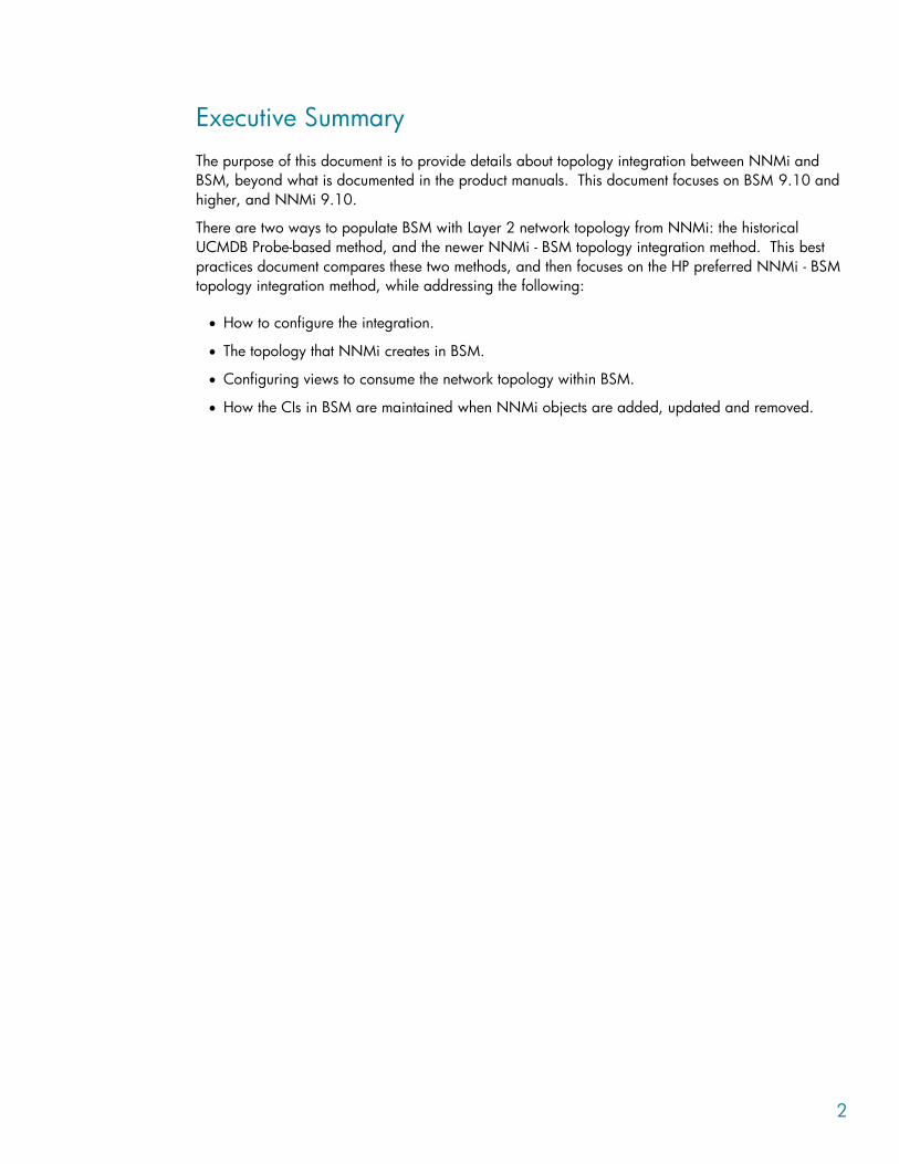
Executive Summary
The purpose of this document is to provide details about topology integration between NNMi and
BSM, beyond what is documented in the product manuals. This document focuses on BSM 9.10 and
higher, and NNMi 9.10.
There are two ways to populate BSM with Layer 2 network topology from NNMi: the historical
UCMDB Probe-based method, and the newer NNMi - BSM topology integration method. This best
practices document compares these two methods, and then focuses on the HP preferred NNMi - BSM
topology integration method, while addressing the following:
How to configure the integration.
The topology that NNMi creates in BSM.
Configuring views to consume the network topology within BSM.
How the CIs in BSM are maintained when NNMi objects are added, updated and removed.

3
NNMi Integration to BSM: Which Method to Use?
NNMi is the authoritative source for Layer 2 network topology. There are two methods for integrating
NNMi topology into BSM/UCMDB:
NNMi – BSM topology integration.
NNMi – UCMDB integration.
HP recommends using the NNMi - BSM topology integration method. The other integration method
which uses the Data Flow Probe (formerly called DDM Probe) is still supported, but it is used more for
backward compatibility with older product versions (for example NNMi 8.11).
The NNMi - BSM topology integration method is documented in the NNMi Deployment Reference.
The Probe-based method is documented in the UCMDB Discovery and Integration Content Guide.
Refer to the table in Appendix A for a comparison of these two methods.

4
Configuring the NNMi – BSM Topology Integration
This section summarises how to configure the NNMi – BSM topology integration and expands on
some key points. Refer to the NNMi 9.10 Deployment Reference for details.
In the NNMi console, open the HP NNMi–HP BSM Topology Integration Configuration form
(Integration Module Configuration > HP BSM Topology). Select the “Enable Integration” check box
and complete the form.
When connecting NNMi to a multi-server BSM deployment, the “BSM Host” field needs to point to the
BSM Gateway server.
Please note that although the fields in the form are labelled "BSM User" and "BSM Password", these
fields are actually the “RTSM User” and “RTSM Password”. RTSM users are different from BSM users;
the RTSM user and password are used for RTSM integrations. By default, installing BSM 9.1x creates
an RTSM user called admin, with the password set to admin.
To perform the NNMi – BSM topology integration, create and use a new RTSM user for better
accountability and auditing. The CIs that are created or updated by this integration set the attributes
“Created By” and “Updated By”. By using a different user for the integration, these attributes will be
set to “UCMDB: User:<integration_user>” instead of the more generic “UCMDB: User:admin”,
making it easier to discern the source responsible for the CI. The steps to create a new user are
outlined in Appendix B, “Creating a new RTSM user“.
The NNMi 9.10 Deployment Reference suggests setting the Interface CI display label to prefer
interface_name over mac_address. This results in a more user friendly display. To make this change,
open the CI Type Manager in RTSM Administration, and select the Interface CI Type. Select the
Default Label tab and set the format to:
interface_name | mac_address
Note that although the NNMi 9.10 Deployment Reference suggests changing the Node Name
Resolution order to First Choice = Full DNS Name and Second Choice = Short DNS Name, this
cannot be done in NNMi 9.10 (see QCCR1B90169). You can use the default Node Name
Resolution order.

5
Figure 1. NNMi – BSM Topology Integration form

6
BSM Topology Created by NNMi
The NNMi - BSM topology integration creates the following CIs:
Node
Interface
IpAddress
IpSubnet
Layer2Connection
HardwareBoard
PhysicalPort
Devices such as switches, routers, and servers are all defined as Node CI Types. The device type is
identified by the Node CI’s NodeRole attribute. In NNMi 9.10, the NodeRole array attribute is set to
one or more of these values: "hub", "load_balancer", "printer", "router", "server", "lan_switch",
"voice_gateway" and/or "desktop". This is because it is possible for a network device to change its
role (such as from a switch to a switch-router), and this method provides simple tracking via the CI’s
NodeRole attribute.
A single node can have multiple node roles. NNMi decides, based on the node’s Device Category
and the node's capabilities as discovered by NNMi, which NodeRole(s) to set. The following table
shows the mapping of NNMi Device Category to NodeRole attribute.
Table 1. Mapping of NNMi Device Category to Node CIT’s NodeRole attribute
NNMi Device Category NodeRole Attribute
Hub hub
Load Balancer load_balancer
Printer printer
Router router
Server server
Switch lan_switch
Switch-Router router, lan_switch
Voice Gateway voice_gateway
Workstation desktop
In addition to the Device Category mapping, if a node has IP forwarding capability
(com.hp.nnm.capability.node.ipforwarding), the NodeRole "router" is applied. If a node has
switching capability (com.hp.nnm.capability.node.lan_switching), the NodeRole "lan_switch" is
applied.

7
The NNMi - BSM topology integration creates the following relationships:
Membership: IpSubnet -> IpAddress
Membership: Layer2Connection -> Interface
Composition: Node -> Interface
Containment: Node -> IpAddress
Composition: Node -> HardwareBoard
Composition: HardwareBoard -> HardwareBoard
Composition: HardwareBoard -> PhysicalPort
Realization: PhysicalPort -> Interface
Refer to Appendix C for the mapping of NNMi attributes to the equivalent CI attributes for each CI
type.
8
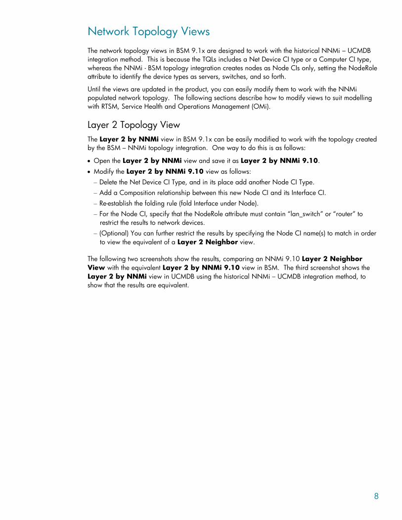
Network Topology Views
The network topology views in BSM 9.1x are designed to work with the historical NNMi – UCMDB
integration method. This is because the TQLs includes a Net Device CI type or a Computer CI type,
whereas the NNMi - BSM topology integration creates nodes as Node CIs only, setting the NodeRole
attribute to identify the device types as servers, switches, and so forth.
Until the views are updated in the product, you can easily modify them to work with the NNMi
populated network topology. The following sections describe how to modify views to suit modelling
with RTSM, Service Health and Operations Management (OMi).
Layer 2 Topology View
The Layer 2 by NNMi view in BSM 9.1x can be easily modified to work with the topology created
by the BSM – NNMi topology integration. One way to do this is as follows:
Open the Layer 2 by NNMi view and save it as Layer 2 by NNMi 9.10.
Modify the Layer 2 by NNMi 9.10 view as follows:
– Delete the Net Device CI Type, and in its place add another Node CI Type.
– Add a Composition relationship between this new Node CI and its Interface CI.
– Re-establish the folding rule (fold Interface under Node).
– For the Node CI, specify that the NodeRole attribute must contain “lan_switch” or “router” to
restrict the results to network devices.
– (Optional) You can further restrict the results by specifying the Node CI name(s) to match in order
to view the equivalent of a Layer 2 Neighbor view.
The following two screenshots show the results, comparing an NNMi 9.10 Layer 2 Neighbor
View with the equivalent Layer 2 by NNMi 9.10 view in BSM. The third screenshot shows the
Layer 2 by NNMi view in UCMDB using the historical NNMi – UCMDB integration method, to
show that the results are equivalent.

9
Figure 2. NNMi Layer 2 Neighbor View

10
Figure 3. BSM 9.1x Layer 2 by NNMi 9.10 view

11
Figure 4. UCMDB 9.03 Layer 2 by NNMi view
This type of view (Layer 2 by NNMi 9.10) is primarily useful as a basis for a TBEC rule, or to filter
OMi events in View Selector. It is not optimal for use in Service Health; refer to the Service Health
Views section for recommendations on creating views that include network devices. However, if you
do want to display this view in Service Health, you need to modify the View Definition Properties and
set the Bundles to Service_Health.
For a view that is used in the View Selector to filter OMi events, you might want to include all CIs that
may have network events associated with them. NNMi events resolve to Node, Interface, Layer 2
Connection or IP Address CI Types; you therefore might add IP Address to the view. The following
two screenshots show an example view containing the network elements associated with the “OBA1”
business application.

12
Figure 5. Example of Layer 2 topology applied to a business application

13
Figure 6. View definition
Service Health Views
It is difficult to display traditional network topology within Service Health. A relationship of "Node ->
Interface -> Layer2Connection -> Interface -> Node" is meaningless, since (for example) there is no
impact relationship (i.e. KPI status propagation) between Layer2Connection and Interface.
If you need to include network devices in a Service Health view, it is therefore best to show them in a
flat structure rather than to attempt to reproduce a traditional network topology. Since there is an
impact relationship between Interface and Node, one approach is to create a view that contains
Node -> Interface, possibly grouped together as "Network"; refer to the screenshot below.
14
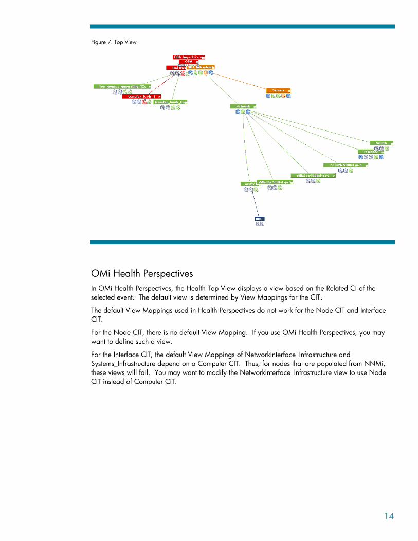
Figure 7. Top View
OMi Health Perspectives
In OMi Health Perspectives, the Health Top View displays a view based on the Related CI of the
selected event. The default view is determined by View Mappings for the CIT.
The default View Mappings used in Health Perspectives do not work for the Node CIT and Interface
CIT.
For the Node CIT, there is no default View Mapping. If you use OMi Health Perspectives, you may
want to define such a view.
For the Interface CIT, the default View Mappings of NetworkInterface_Infrastructure and
Systems_Infrastructure depend on a Computer CIT. Thus, for nodes that are populated from NNMi,
these views will fail. You may want to modify the NetworkInterface_Infrastructure view to use Node
CIT instead of Computer CIT.

15
CI Lifecycle
When NNMi objects (Node, Interface, IP Address, IP Subnet, Layer 2 Connection, Card and Port) are
added or changed, they are dynamically updated in BSM. In addition, the full topology is re-
synchronised periodically, as specified in the user-defined “Topology Synchronization Interval (hrs)”
setting in the “HP NNMi - HP BSM Topology Integration Configuration” screen. NNMi ensures that
the data is processed in manageable chunks, to avoid a negative impact on the performance of
NNMi or BSM.
Periodic topology synchronization has the effect of updating the “Last Access Time” attribute for CIs
that already exist in BSM, and prevents them from becoming candidates for deletion. If an object no
longer exists in NNMi, the aging mechanism in BSM deletes the corresponding CI when its “Last
Access Time” exceeds the time threshold (default is 40 days).
Note that the CI may also be monitored by another application such as HP SiteScope or HP
Operations Manager, in which case “Last Access Time” may continue to be updated if the object
remains monitored by another application.

16
Appendix A: Comparing Methods of Integrating NNMi
with BSM/UCMDB
The following table provides a summary comparison of the two methods.
Table 2. NNMi – BSM Topology integration vs. “Layer 2 by NNM” discovery job
NNMi BSM Topology Integration “Layer 2 by NNM” Discovery Job (Probe-based)
Can filter objects to sync from NNMi to BSM based on
NNMi Node Group.
Currently no ability to filter NNMi objects to sync into
BSM.
Performs incremental discovery and scheduled full
topology sync.
Performs full topology sync only.
Creates all NNMi nodes as Node CIs *. Creates NNMi nodes as various CI types (Router, Switch,
Switch Router, Chassis, Computer, ATM Switch, Firewall,
Load Balancer, and Printer).
Creates these other CIs: Interface, IpAddress, IpSubnet,
Layer2Connection, HardwareBoard, and PhysicalPort.
Creates these other CIs: Interface, IpAddress, IpSubnet,
Layer2Connection, HardwareBoard+, PhysicalPort+, and
VLAN+.
Node CI attributes populated by BSM but not by Probe
method:
Host is Route.
Host is Virtual.
NodeModel.
PrimaryDnsName.
Node CI attributes populated by Probe but not by BSM
method:
Description (populated from Device Profile Description)
Node CI attributes with different values from BSM method:
DiscoveredVendor (more user-friendly format in BSM
method; for example “Hewlett-Packard” rather than
“hewlettpackard”).
NodeFamily (more user-friendly format in BSM
method).
Host NNM UID.
Host Key.
Layer 2 Connection CI attribute Display Label is set to the
Layer 2 Connection Name as shown in NNMi.
Layer 2 Connection CI attribute Display Label is hard-
coded to “Layer2Connection”.
Other CIs with different attributes when populated by
Probe:
HardwareBoard CI includes SoftwareVersion attribute.
PhysicalPort CI includes DuplexSetting and Port Name
(same value as Name) attributes.
Can easily adapt the out-of-the-box Layer 2 Network view. Out-of-the-box Layer 2 Network view.
+ NNMi 9 is required for these CIs to be created.
* Nodes are identified by the NodeRole attribute.
Note: UCMDB Content Pack 9 enhances NNMi integration support of large NNMi environments,
allowing you to control the number of Layer2Connections, VLANs and Nodes to get from NNMi per
query.

17
Appendix B: Creating a New RTSM User
The following steps show how to create a new RTSM user for the NNMi – BSM topology integration.
1. Log in to the RTSM:
http://<BSM Data Processing Server>:21212/ucmdb
Username: admin
Password: admin (default password)
2. From the menu, select Managers > Administration > Users and Roles.
Note: Although this screen says Universal CMDB, you are actually using the RTSM user interface.
3. Click on the “*” button to add a new user. Enter the new user’s name and password. Click Next.

18
4. Enter the user’s details (optional). Click Next.
5. Select the three CmdbOpenApi related roles for this user, as shown in the following screen shot.
Click Finish.

19
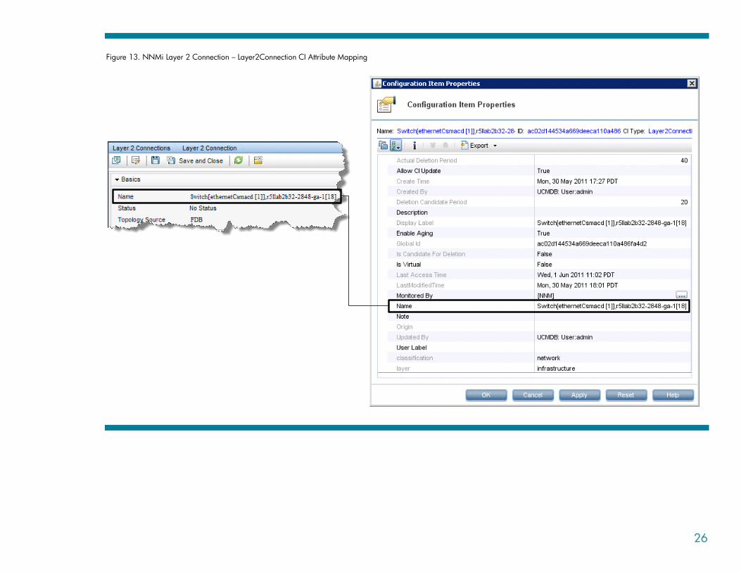
Appendix C: NNMi – CI Attribute Mapping
The following diagrams show the mapping of NNMi object attributes to the equivalent CI attributes in
BSM. Note that the Monitored By attribute is set to include NNM for each of the CI types.

20
Figure 7. NNMi Node – Node CI Attribute Mapping

21
Figure 8. NNMi Interface – Interface CI Attribute Mapping
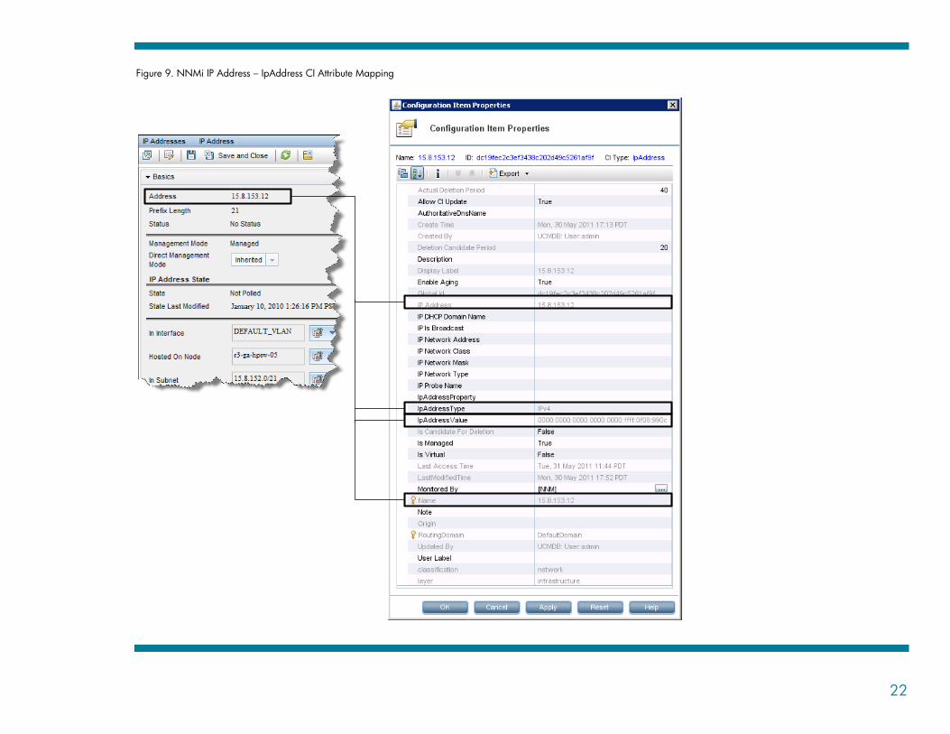
22
Figure 9. NNMi IP Address – IpAddress CI Attribute Mapping

23
Figure 10. NNMi IP Subnet – IpSubnet CI Attribute Mapping

24
Figure 11. NNMi Card – HardwareBoard CI Attribute Mapping

25
Figure 12. NNMi Port – PhysicalPort CI Attribute Mapping
26
Figure 13. NNMi Layer 2 Connection – Layer2Connection CI Attribute Mapping

27
For More Information
http://support.openview.hp.com/selfsolve/manuals
HP Network Node Manager i Software: Deployment Reference
HP Universal CMDB: Discovery and Integration Content Guide
© 2012 Hewlett-Packard Development Company, L.P. The information contained herein is subject to change without notice. The only warranties for HP products and services are set forth in the express warranty statements accompanying such products and services. Nothing herein should be construed as constituting an additional warranty. HP shall not be liable for technical or editorial errors or omissions contained herein.
Microsoft® and Windows® are U.S. registered trademarks of Microsoft Corporation.
Oracle® is a registered US trademark of Oracle Corporation, Redwood City, California.
UNIX® is a registered trademark of The Open Group.
August 2012
Version 1.7