Embed Size (px)
Citation preview
HP 15 Laptop PC (Intel)HP 15g Laptop PCHP 15q Laptop PC
Maintenance and Service Guide
© Copyright 2017 HP Development Company, L.P.
AMD is a trademark of Advanced Micro Devices, Inc. Bluetooth is a trademark owned by its proprietor and used by HP Inc. under license. Intel, Celeron, and Pentium are trademarks of Intel Corporation in the U.S. and other countries. Microsoft and Windows are U.S. registered trademarks of the Microsoft group of companies.
In accordance with Microsoft’s support policy, HP does not support the Windows 8 or Windows 7 operating system on products configured with Intel and AMD 7th generation and forward processors or provide any Windows 8 or Windows 7 drivers on http://www.support.hp.com.
The information contained herein is subject to change without notice. The only warranties for HP products and services are set forth in the express warranty statements accompanying such products and services. Nothing herein should be construed as constituting an additional warranty. HP shall not be liable for technical or editorial errors or omissions contained herein.
Second Edition: August 2017
First Edition: April 2017
Document Part Number: 923865-002
Product notice
This guide describes features that are common to most models. Some features may not be available on your computer.
Not all features are available in all editions or versions of Windows. Systems may require upgraded and/or separately purchased hardware, drivers, software or BIOS update to take full advantage of Windows functionality. Windows 10 is automatically updated, which is always enabled. ISP fees may apply and additional requirements may apply over time for updates. Go to http://www.microsoft.com for details.
To access the latest user guides or manuals for your product, go to http://www.hp.com/support, and select your country. Select Find your product, and then follow the on-screen instructions.
Software terms
By installing, copying, downloading, or otherwise using any software product preinstalled on this computer, you agree to be bound by the terms of the HP End User License Agreement (EULA). If you do not accept these license terms, your sole remedy is to return the entire unused product (hardware and software) within 14 days for a full refund subject to the refund policy of your seller.
For any further information or to request a full refund of the price of the computer, please contact your seller.

Safety warning notice
WARNING! To reduce the possibility of heat-related injuries or of overheating the device, do not place the device directly on your lap or obstruct the device air vents. Use the device only on a hard, flat surface. Do not allow another hard surface, such as an adjoining optional printer, or a soft surface, such as pillows or rugs or clothing, to block airflow. Also, do not allow the AC adapter to contact the skin or a soft surface, such as pillows or rugs or clothing, during operation. The device and the AC adapter comply with the user-accessible surface temperature limits defined by the International Standard for Safety of Information Technology Equipment (IEC 60950-1).
iii

iv Safety warning notice
Table of contents
1 Product description ....................................................................................................................................... 1
2 Getting to know your computer .................................................................................................................... 11
Right side ............................................................................................................................................................. 11
Left side ............................................................................................................................................................... 12
Display ................................................................................................................................................................. 13
Keyboard area ...................................................................................................................................................... 14
TouchPad ........................................................................................................................................... 14
Lights ................................................................................................................................................. 15
Button ................................................................................................................................................ 16
Special keys ....................................................................................................................................... 17
Action keys ........................................................................................................................................ 18
Bottom ................................................................................................................................................................. 19
Labels ................................................................................................................................................................... 20
3 Illustrated parts catalog .............................................................................................................................. 21
Computer major components .............................................................................................................................. 21
Display assembly subcomponents ...................................................................................................................... 26
Cables ................................................................................................................................................................... 28
Mass storage devices ........................................................................................................................................... 29
Miscellaneous parts ............................................................................................................................................. 30
4 Removal and replacement procedures preliminary requirements .................................................................... 33
Tools required ...................................................................................................................................................... 33
Service considerations ......................................................................................................................................... 33
Plastic parts ....................................................................................................................................... 33
Cables and connectors ...................................................................................................................... 33
Drive handling ................................................................................................................................... 34
Grounding guidelines ........................................................................................................................................... 34
Electrostatic discharge damage ........................................................................................................ 34
Packaging and transporting guidelines .......................................................................... 35
Workstation guidelines ................................................................................ 35
5 Removal and replacement procedures for Customer Self-Repair parts ............................................................. 37
Component replacement procedures .................................................................................................................. 37
Battery ............................................................................................................................................... 38
v
Optical drive ....................................................................................................................................... 40
6 Removal and replacement procedures for Authorized Service Provider parts ................................................... 43
Component replacement procedures .................................................................................................................. 43
Display subcomponents (bezel, panel, camera) ............................................................................... 43
Rubber feet ........................................................................................................................................ 47
Bottom cover ..................................................................................................................................... 49
WLAN module .................................................................................................................................... 52
Memory module ................................................................................................................................ 54
Optical drive connector board ........................................................................................................... 56
Hard drive and hard drive connector board ...................................................................................... 57
M.2 solid-state drive adapter bracket and connector board ............................................................ 60
Solid-state drive (SSD) ...................................................................................................................... 62
RTC battery ........................................................................................................................................ 63
Speakers ............................................................................................................................................ 64
USB board .......................................................................................................................................... 65
Fan ..................................................................................................................................................... 66
Heat sink assembly ........................................................................................................................... 68
TouchPad button board ..................................................................................................................... 72
System board .................................................................................................................................... 73
Display assembly ............................................................................................................................... 76
Power connector cable ...................................................................................................................... 87
Power button board .......................................................................................................................... 88
Cable locations .................................................................................................................................. 89
Top cover/keyboard ........................................................................................................................... 90
7 Using Setup Utility (BIOS) ............................................................................................................................. 91
Starting Setup Utility (BIOS) ................................................................................................................................ 91
Updating Setup Utility (BIOS) .............................................................................................................................. 91
Determining the BIOS version ........................................................................................................... 91
Downloading a BIOS update .............................................................................................................. 92
8 Backing up, restoring, and recovering ........................................................................................................... 93
Creating recovery media and backups ................................................................................................................ 93
Creating HP Recovery media (select products only) ......................................................................... 93
Using Windows tools ........................................................................................................................................... 94
Restore and recovery ........................................................................................................................................... 95
Recovering using HP Recovery Manager ........................................................................................... 95
What you need to know before you get started ............................................................. 95
Using the HP Recovery partition (select products only) ................................................. 96
vi
Using HP Recovery media to recover .............................................................................. 96
Changing the computer boot order ................................................................................ 97
Removing the HP Recovery partition (select products only) ......................................... 98
9 Using HP PC Hardware Diagnostics (UEFI) ....................................................................................................... 99
Downloading HP PC Hardware Diagnostics (UEFI) to a USB device .................................................................... 99
10 Specifications .......................................................................................................................................... 101
Computer specifications .................................................................................................................................... 101
39.6-cm (15.6-in) display specifications .......................................................................................................... 102
Hard drive specifications ................................................................................................................................... 103
M.2 solid-state drive specifications .................................................................................................................. 104
DVD±RW SuperMulti DL Drive specifications .................................................................................................... 105
11 Power cord set requirements .................................................................................................................... 107
Requirements for all countries .......................................................................................................................... 107
Requirements for specific countries and regions ............................................................................................. 108
12 Recycling ................................................................................................................................................ 111
Index ........................................................................................................................................................... 113
vii

viii
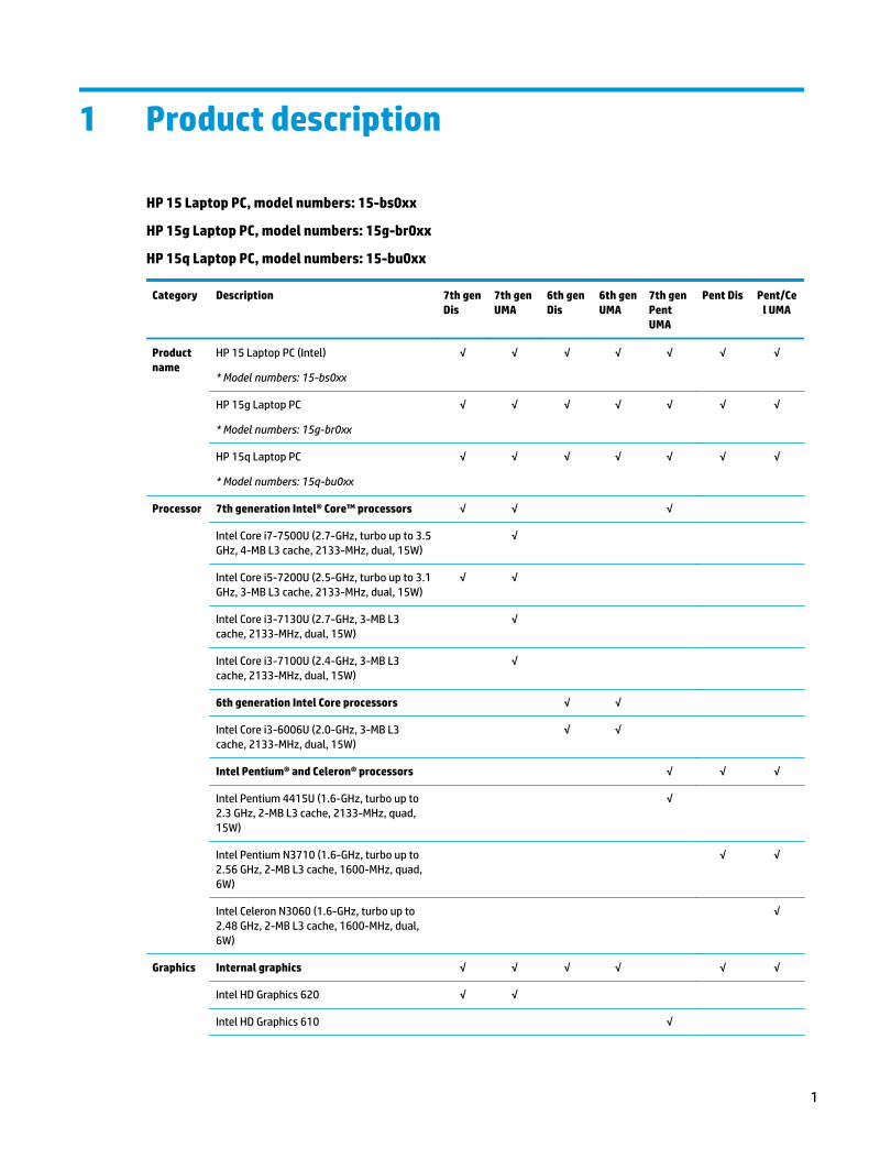
1 Product description
HP 15 Laptop PC, model numbers: 15-bs0xx
HP 15g Laptop PC, model numbers: 15g-br0xx
HP 15q Laptop PC, model numbers: 15-bu0xx
Category Description 7th gen Dis
7th gen UMA
6th gen Dis
6th gen UMA
7th gen Pent UMA
Pent Dis Pent/Cel UMA
Product name
HP 15 Laptop PC (Intel)
* Model numbers: 15-bs0xx
√ √ √ √ √ √ √
HP 15g Laptop PC
* Model numbers: 15g-br0xx
√ √ √ √ √ √ √
HP 15q Laptop PC
* Model numbers: 15q-bu0xx
√ √ √ √ √ √ √
Processor 7th generation Intel® Core™ processors √ √ √
Intel Core i7-7500U (2.7-GHz, turbo up to 3.5 GHz, 4-MB L3 cache, 2133-MHz, dual, 15W)
√
Intel Core i5-7200U (2.5-GHz, turbo up to 3.1 GHz, 3-MB L3 cache, 2133-MHz, dual, 15W)
√ √
Intel Core i3-7130U (2.7-GHz, 3-MB L3 cache, 2133-MHz, dual, 15W)
√
Intel Core i3-7100U (2.4-GHz, 3-MB L3 cache, 2133-MHz, dual, 15W)
√
6th generation Intel Core processors √ √
Intel Core i3-6006U (2.0-GHz, 3-MB L3 cache, 2133-MHz, dual, 15W)
√ √
Intel Pentium® and Celeron® processors √ √ √
Intel Pentium 4415U (1.6-GHz, turbo up to 2.3 GHz, 2-MB L3 cache, 2133-MHz, quad, 15W)
√
Intel Pentium N3710 (1.6-GHz, turbo up to 2.56 GHz, 2-MB L3 cache, 1600-MHz, quad, 6W)
√ √
Intel Celeron N3060 (1.6-GHz, turbo up to 2.48 GHz, 2-MB L3 cache, 1600-MHz, dual, 6W)
√
Graphics Internal graphics √ √ √ √ √ √
Intel HD Graphics 620 √ √
Intel HD Graphics 610 √
1
Category Description 7th gen Dis
7th gen UMA
6th gen Dis
6th gen UMA
7th gen Pent UMA
Pent Dis Pent/Cel UMA
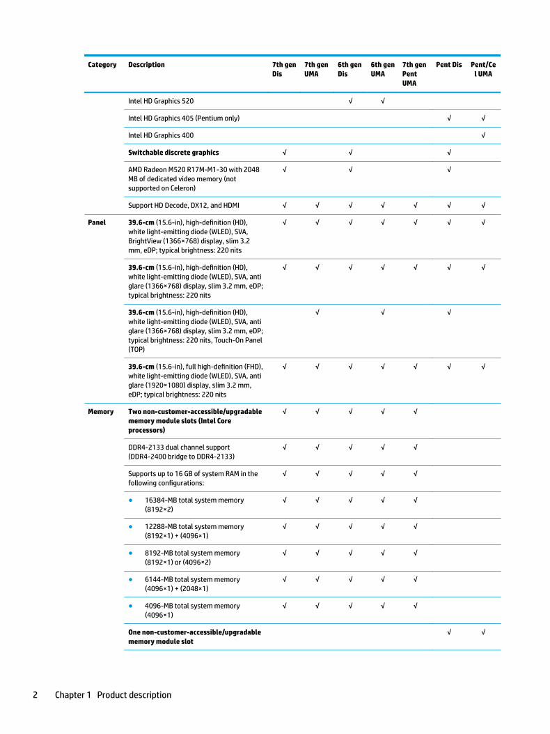
Intel HD Graphics 520 √ √
Intel HD Graphics 405 (Pentium only) √ √
Intel HD Graphics 400 √
Switchable discrete graphics √ √ √
AMD Radeon M520 R17M-M1-30 with 2048 MB of dedicated video memory (not supported on Celeron)
√ √ √
Support HD Decode, DX12, and HDMI √ √ √ √ √ √ √
Panel 39.6-cm (15.6-in), high-definition (HD), white light-emitting diode (WLED), SVA, BrightView (1366×768) display, slim 3.2 mm, eDP; typical brightness: 220 nits
√ √ √ √ √ √ √
39.6-cm (15.6-in), high-definition (HD), white light-emitting diode (WLED), SVA, anti glare (1366×768) display, slim 3.2 mm, eDP; typical brightness: 220 nits
√ √ √ √ √ √ √
39.6-cm (15.6-in), high-definition (HD), white light-emitting diode (WLED), SVA, anti glare (1366×768) display, slim 3.2 mm, eDP; typical brightness: 220 nits, Touch-On Panel (TOP)
√ √ √
39.6-cm (15.6-in), full high-definition (FHD), white light-emitting diode (WLED), SVA, anti glare (1920×1080) display, slim 3.2 mm, eDP; typical brightness: 220 nits
√ √ √ √ √ √ √
Memory Two non-customer-accessible/upgradable memory module slots (Intel Core processors)
√ √ √ √ √
DDR4-2133 dual channel support (DDR4-2400 bridge to DDR4-2133)
√ √ √ √ √
Supports up to 16 GB of system RAM in the following configurations:
√ √ √ √ √
● 16384-MB total system memory (8192×2)
√ √ √ √ √
● 12288-MB total system memory (8192×1) + (4096×1)
√ √ √ √ √
● 8192-MB total system memory (8192×1) or (4096×2)
√ √ √ √ √
● 6144-MB total system memory (4096×1) + (2048×1)
√ √ √ √ √
● 4096-MB total system memory (4096×1)
√ √ √ √ √
One non-customer-accessible/upgradable memory module slot
√ √
2 Chapter 1 Product description
Category Description 7th gen Dis
7th gen UMA
6th gen Dis
6th gen UMA
7th gen Pent UMA
Pent Dis Pent/Cel UMA
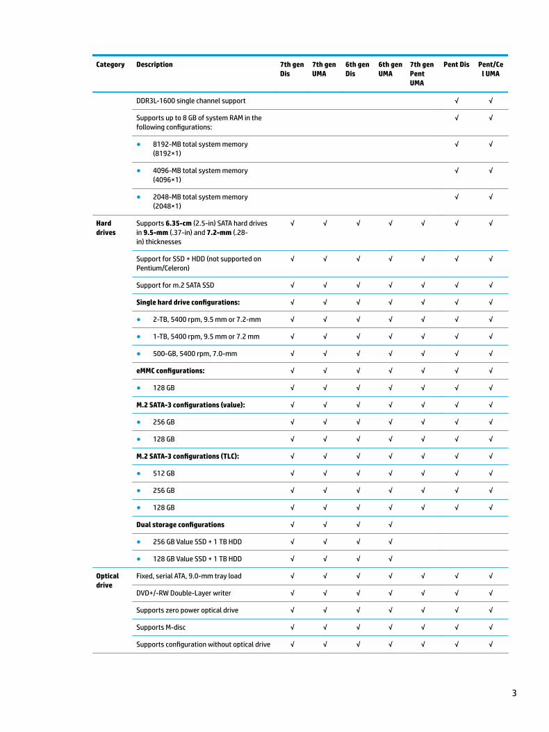
DDR3L-1600 single channel support √ √
Supports up to 8 GB of system RAM in the following configurations:
√ √
● 8192-MB total system memory (8192×1)
√ √
● 4096-MB total system memory (4096×1)
√ √
● 2048-MB total system memory (2048×1)
√ √
Hard drives
Supports 6.35-cm (2.5-in) SATA hard drives in 9.5-mm (.37-in) and 7.2-mm (.28-in) thicknesses
√ √ √ √ √ √ √
Support for SSD + HDD (not supported on Pentium/Celeron)
√ √ √ √ √ √ √
Support for m.2 SATA SSD √ √ √ √ √ √ √
Single hard drive configurations: √ √ √ √ √ √ √
● 2-TB, 5400 rpm, 9.5 mm or 7.2-mm √ √ √ √ √ √ √
● 1-TB, 5400 rpm, 9.5 mm or 7.2 mm √ √ √ √ √ √ √
● 500-GB, 5400 rpm, 7.0-mm √ √ √ √ √ √ √
eMMC configurations: √ √ √ √ √ √ √
● 128 GB √ √ √ √ √ √ √
M.2 SATA-3 configurations (value): √ √ √ √ √ √ √
● 256 GB √ √ √ √ √ √ √
● 128 GB √ √ √ √ √ √ √
M.2 SATA-3 configurations (TLC): √ √ √ √ √ √ √
● 512 GB √ √ √ √ √ √ √
● 256 GB √ √ √ √ √ √ √
● 128 GB √ √ √ √ √ √ √
Dual storage configurations √ √ √ √
● 256 GB Value SSD + 1 TB HDD √ √ √ √
● 128 GB Value SSD + 1 TB HDD √ √ √ √
Optical drive
Fixed, serial ATA, 9.0-mm tray load √ √ √ √ √ √ √
DVD+/-RW Double-Layer writer √ √ √ √ √ √ √
Supports zero power optical drive √ √ √ √ √ √ √
Supports M-disc √ √ √ √ √ √ √
Supports configuration without optical drive √ √ √ √ √ √ √
3
Category Description 7th gen Dis
7th gen UMA
6th gen Dis
6th gen UMA
7th gen Pent UMA
Pent Dis Pent/Cel UMA
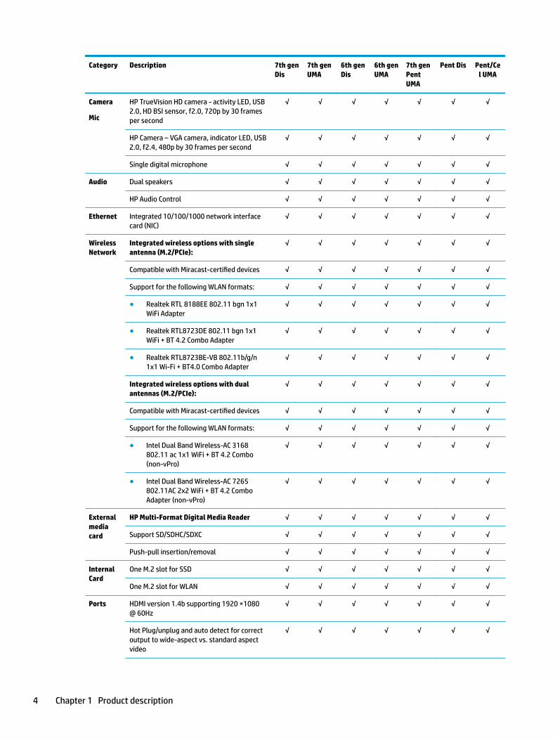
Camera
Mic
HP TrueVision HD camera - activity LED, USB 2.0, HD BSI sensor, f2.0, 720p by 30 frames per second
√ √ √ √ √ √ √
HP Camera – VGA camera, indicator LED, USB 2.0, f2.4, 480p by 30 frames per second
√ √ √ √ √ √ √
Single digital microphone √ √ √ √ √ √ √
Audio Dual speakers √ √ √ √ √ √ √
HP Audio Control √ √ √ √ √ √ √
Ethernet Integrated 10/100/1000 network interface card (NIC)
√ √ √ √ √ √ √
Wireless Network
Integrated wireless options with single antenna (M.2/PCIe):
√ √ √ √ √ √ √
Compatible with Miracast-certified devices √ √ √ √ √ √ √
Support for the following WLAN formats: √ √ √ √ √ √ √
● Realtek RTL 8188EE 802.11 bgn 1x1 WiFi Adapter
√ √ √ √ √ √ √
● Realtek RTL8723DE 802.11 bgn 1x1 WiFi + BT 4.2 Combo Adapter
√ √ √ √ √ √ √
● Realtek RTL8723BE-VB 802.11b/g/n 1x1 Wi-Fi + BT4.0 Combo Adapter
√ √ √ √ √ √ √
Integrated wireless options with dual antennas (M.2/PCIe):
√ √ √ √ √ √ √
Compatible with Miracast-certified devices √ √ √ √ √ √ √
Support for the following WLAN formats: √ √ √ √ √ √ √
● Intel Dual Band Wireless-AC 3168 802.11 ac 1x1 WiFi + BT 4.2 Combo (non-vPro)
√ √ √ √ √ √ √
● Intel Dual Band Wireless-AC 7265 802.11AC 2x2 WiFi + BT 4.2 Combo Adapter (non-vPro)
√ √ √ √ √ √ √
External media card
HP Multi-Format Digital Media Reader √ √ √ √ √ √ √
Support SD/SDHC/SDXC √ √ √ √ √ √ √
Push-pull insertion/removal √ √ √ √ √ √ √
Internal Card
One M.2 slot for SSD √ √ √ √ √ √ √
One M.2 slot for WLAN √ √ √ √ √ √ √
Ports HDMI version 1.4b supporting 1920 ×1080 @ 60Hz
√ √ √ √ √ √ √
Hot Plug/unplug and auto detect for correct output to wide-aspect vs. standard aspect video
√ √ √ √ √ √ √
4 Chapter 1 Product description
Category Description 7th gen Dis
7th gen UMA
6th gen Dis
6th gen UMA
7th gen Pent UMA
Pent Dis Pent/Cel UMA
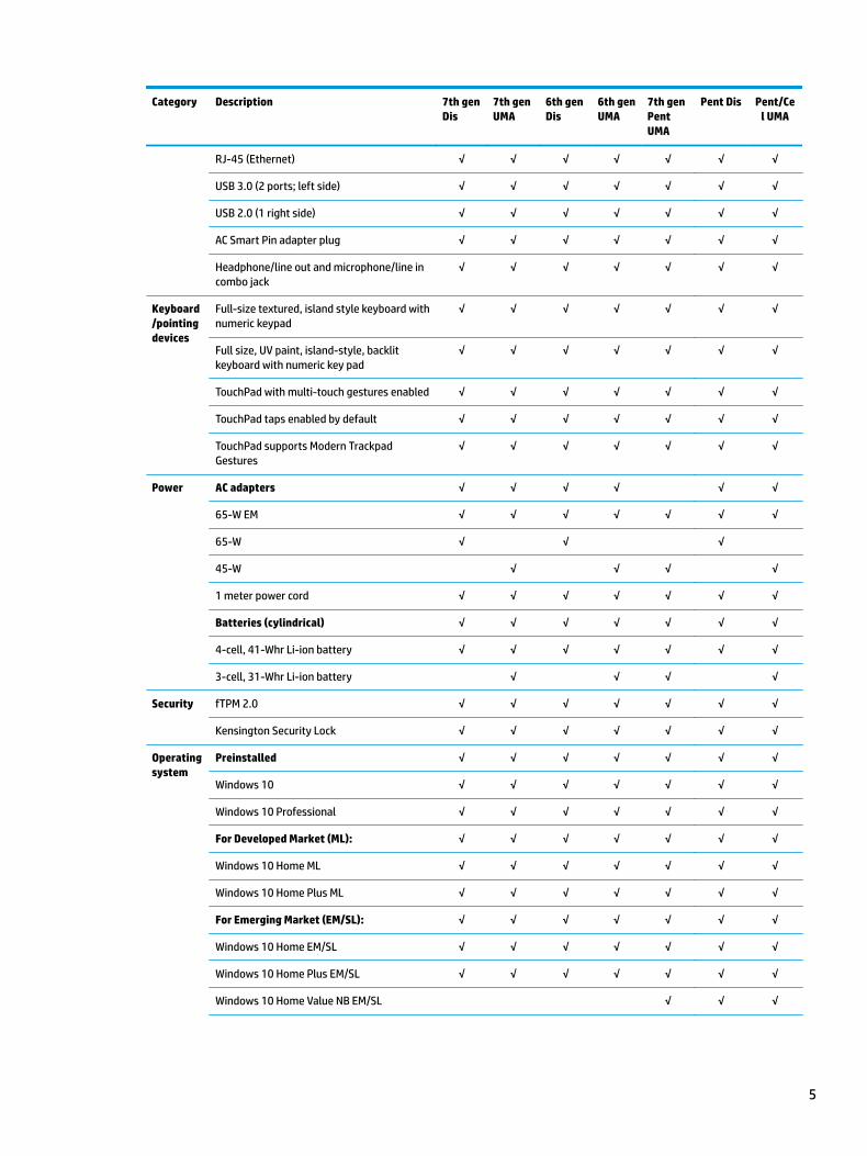
RJ-45 (Ethernet) √ √ √ √ √ √ √
USB 3.0 (2 ports; left side) √ √ √ √ √ √ √
USB 2.0 (1 right side) √ √ √ √ √ √ √
AC Smart Pin adapter plug √ √ √ √ √ √ √
Headphone/line out and microphone/line in combo jack
√ √ √ √ √ √ √
Keyboard/pointing devices
Full-size textured, island style keyboard with numeric keypad
√ √ √ √ √ √ √
Full size, UV paint, island-style, backlit keyboard with numeric key pad
√ √ √ √ √ √ √
TouchPad with multi-touch gestures enabled √ √ √ √ √ √ √
TouchPad taps enabled by default √ √ √ √ √ √ √
TouchPad supports Modern Trackpad Gestures
√ √ √ √ √ √ √
Power AC adapters √ √ √ √ √ √
65-W EM √ √ √ √ √ √ √
65-W √ √ √
45-W √ √ √ √
1 meter power cord √ √ √ √ √ √ √
Batteries (cylindrical) √ √ √ √ √ √ √
4-cell, 41-Whr Li-ion battery √ √ √ √ √ √ √
3-cell, 31-Whr Li-ion battery √ √ √ √
Security fTPM 2.0 √ √ √ √ √ √ √
Kensington Security Lock √ √ √ √ √ √ √
Operating system
Preinstalled √ √ √ √ √ √ √
Windows 10 √ √ √ √ √ √ √
Windows 10 Professional √ √ √ √ √ √ √
For Developed Market (ML): √ √ √ √ √ √ √
Windows 10 Home ML √ √ √ √ √ √ √
Windows 10 Home Plus ML √ √ √ √ √ √ √
For Emerging Market (EM/SL): √ √ √ √ √ √ √
Windows 10 Home EM/SL √ √ √ √ √ √ √
Windows 10 Home Plus EM/SL √ √ √ √ √ √ √
Windows 10 Home Value NB EM/SL √ √ √
5
Category Description 7th gen Dis
7th gen UMA
6th gen Dis
6th gen UMA
7th gen Pent UMA
Pent Dis Pent/Cel UMA
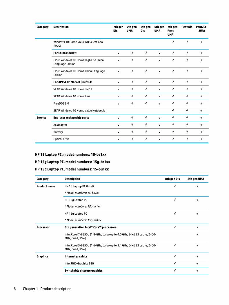
Windows 10 Home Value NB Select Geo EM/SL
√ √ √
For China Market: √ √ √ √ √ √ √
CPPP Windows 10 Home High End China Language Edition
√ √ √ √ √ √ √
CPPP Windows 10 Home China Language Edition
√ √ √ √ √ √ √
For APJ SEAP Market (EM/SL): √ √ √ √ √ √ √
SEAP Windows 10 Home EM/SL √ √ √ √ √ √ √
SEAP Windows 10 Home Plus √ √ √ √ √ √ √
FreeDOS 2.0 √ √ √ √ √ √ √
SEAP Windows 10 Home Value Notebook √ √ √
Service End-user replaceable parts √ √ √ √ √ √ √
AC adapter √ √ √ √ √ √ √
Battery √ √ √ √ √ √ √
Optical drive √ √ √ √ √ √ √
HP 15 Laptop PC, model numbers: 15-bs1xx
HP 15g Laptop PC, model numbers: 15g-br1xx
HP 15q Laptop PC, model numbers: 15-bu1xx
Category Description 8th gen Dis 8th gen UMA
Product name HP 15 Laptop PC (Intel)
* Model numbers: 15-bs1xx
√ √
HP 15g Laptop PC
* Model numbers: 15g-br1xx
√ √
HP 15q Laptop PC
* Model numbers: 15q-bu1xx
√ √
Processor 8th generation Intel® Core™ processors √ √
Intel Core i7-8550U (1.8-GHz, turbo up to 4.0 GHz, 8-MB L3 cache, 2400-MHz, quad, 15W)
√
Intel Core i5-8250U (1.6-GHz, turbo up to 3.4 GHz, 6-MB L3 cache, 2400-MHz, quad, 15W)
√ √
Graphics Internal graphics √ √
Intel UHD Graphics 620 √ √
Switchable discrete graphics √ √
6 Chapter 1 Product description
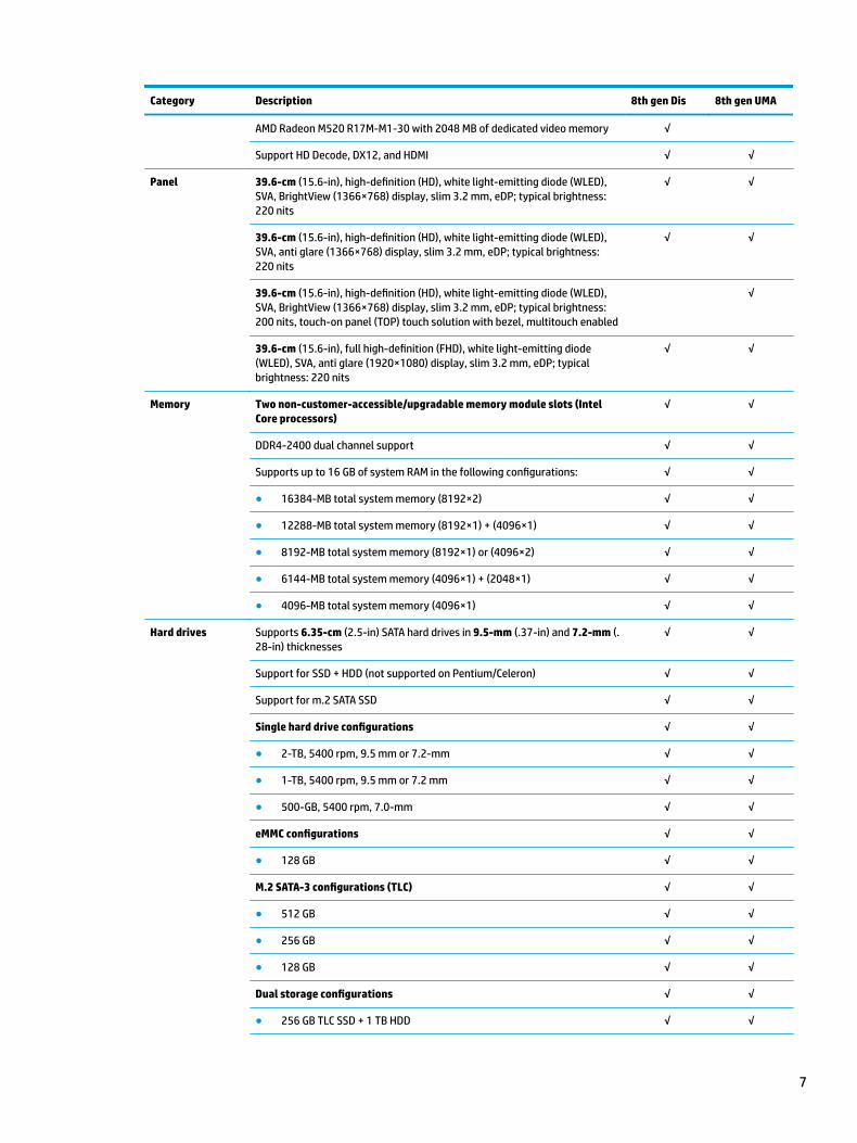
Category Description 8th gen Dis 8th gen UMA
AMD Radeon M520 R17M-M1-30 with 2048 MB of dedicated video memory √
Support HD Decode, DX12, and HDMI √ √
Panel 39.6-cm (15.6-in), high-definition (HD), white light-emitting diode (WLED), SVA, BrightView (1366×768) display, slim 3.2 mm, eDP; typical brightness: 220 nits
√ √
39.6-cm (15.6-in), high-definition (HD), white light-emitting diode (WLED), SVA, anti glare (1366×768) display, slim 3.2 mm, eDP; typical brightness: 220 nits
√ √
39.6-cm (15.6-in), high-definition (HD), white light-emitting diode (WLED), SVA, BrightView (1366×768) display, slim 3.2 mm, eDP; typical brightness: 200 nits, touch-on panel (TOP) touch solution with bezel, multitouch enabled
√
39.6-cm (15.6-in), full high-definition (FHD), white light-emitting diode (WLED), SVA, anti glare (1920×1080) display, slim 3.2 mm, eDP; typical brightness: 220 nits
√ √
Memory Two non-customer-accessible/upgradable memory module slots (Intel Core processors)
√ √
DDR4-2400 dual channel support √ √
Supports up to 16 GB of system RAM in the following configurations: √ √
● 16384-MB total system memory (8192×2) √ √
● 12288-MB total system memory (8192×1) + (4096×1) √ √
● 8192-MB total system memory (8192×1) or (4096×2) √ √
● 6144-MB total system memory (4096×1) + (2048×1) √ √
● 4096-MB total system memory (4096×1) √ √
Hard drives Supports 6.35-cm (2.5-in) SATA hard drives in 9.5-mm (.37-in) and 7.2-mm (.28-in) thicknesses
√ √
Support for SSD + HDD (not supported on Pentium/Celeron) √ √
Support for m.2 SATA SSD √ √
Single hard drive configurations √ √
● 2-TB, 5400 rpm, 9.5 mm or 7.2-mm √ √
● 1-TB, 5400 rpm, 9.5 mm or 7.2 mm √ √
● 500-GB, 5400 rpm, 7.0-mm √ √
eMMC configurations √ √
● 128 GB √ √
M.2 SATA-3 configurations (TLC) √ √
● 512 GB √ √
● 256 GB √ √
● 128 GB √ √
Dual storage configurations √ √
● 256 GB TLC SSD + 1 TB HDD √ √
7
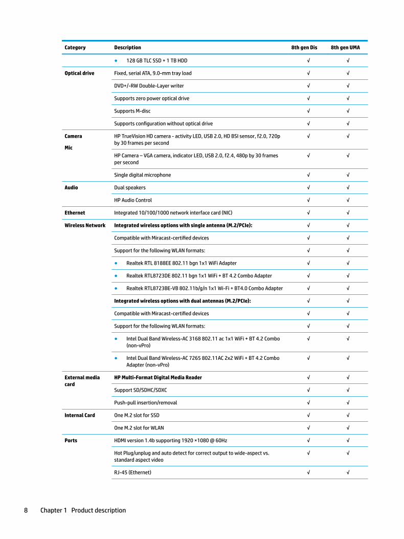
Category Description 8th gen Dis 8th gen UMA
● 128 GB TLC SSD + 1 TB HDD √ √
Optical drive Fixed, serial ATA, 9.0-mm tray load √ √
DVD+/-RW Double-Layer writer √ √
Supports zero power optical drive √ √
Supports M-disc √ √
Supports configuration without optical drive √ √
Camera
Mic
HP TrueVision HD camera - activity LED, USB 2.0, HD BSI sensor, f2.0, 720p by 30 frames per second
√ √
HP Camera – VGA camera, indicator LED, USB 2.0, f2.4, 480p by 30 frames per second
√ √
Single digital microphone √ √
Audio Dual speakers √ √
HP Audio Control √ √
Ethernet Integrated 10/100/1000 network interface card (NIC) √ √
Wireless Network Integrated wireless options with single antenna (M.2/PCIe): √ √
Compatible with Miracast-certified devices √ √
Support for the following WLAN formats: √ √
● Realtek RTL 8188EE 802.11 bgn 1x1 WiFi Adapter √ √
● Realtek RTL8723DE 802.11 bgn 1x1 WiFi + BT 4.2 Combo Adapter √ √
● Realtek RTL8723BE-VB 802.11b/g/n 1x1 Wi-Fi + BT4.0 Combo Adapter √ √
Integrated wireless options with dual antennas (M.2/PCIe): √ √
Compatible with Miracast-certified devices √ √
Support for the following WLAN formats: √ √
● Intel Dual Band Wireless-AC 3168 802.11 ac 1x1 WiFi + BT 4.2 Combo (non-vPro)
√ √
● Intel Dual Band Wireless-AC 7265 802.11AC 2x2 WiFi + BT 4.2 Combo Adapter (non-vPro)
√ √
External media card
HP Multi-Format Digital Media Reader √ √
Support SD/SDHC/SDXC √ √
Push-pull insertion/removal √ √
Internal Card One M.2 slot for SSD √ √
One M.2 slot for WLAN √ √
Ports HDMI version 1.4b supporting 1920 ×1080 @ 60Hz √ √
Hot Plug/unplug and auto detect for correct output to wide-aspect vs. standard aspect video
√ √
RJ-45 (Ethernet) √ √
8 Chapter 1 Product description
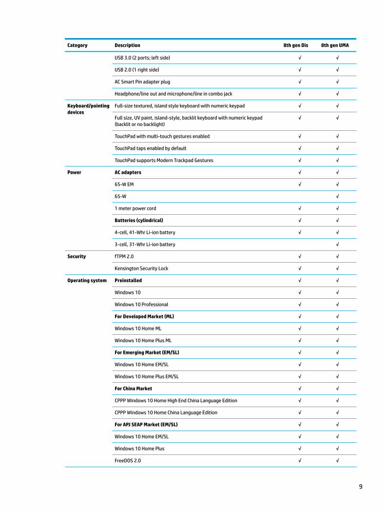
Category Description 8th gen Dis 8th gen UMA
USB 3.0 (2 ports; left side) √ √
USB 2.0 (1 right side) √ √
AC Smart Pin adapter plug √ √
Headphone/line out and microphone/line in combo jack √ √
Keyboard/pointing devices
Full-size textured, island style keyboard with numeric keypad √ √
Full size, UV paint, island-style, backlit keyboard with numeric keypad (backlit or no backlight)
√ √
TouchPad with multi-touch gestures enabled √ √
TouchPad taps enabled by default √ √
TouchPad supports Modern Trackpad Gestures √ √
Power AC adapters √ √
65-W EM √ √
65-W √
1 meter power cord √ √
Batteries (cylindrical) √ √
4-cell, 41-Whr Li-ion battery √ √
3-cell, 31-Whr Li-ion battery √
Security fTPM 2.0 √ √
Kensington Security Lock √ √
Operating system Preinstalled √ √
Windows 10 √ √
Windows 10 Professional √ √
For Developed Market (ML) √ √
Windows 10 Home ML √ √
Windows 10 Home Plus ML √ √
For Emerging Market (EM/SL) √ √
Windows 10 Home EM/SL √ √
Windows 10 Home Plus EM/SL √ √
For China Market √ √
CPPP Windows 10 Home High End China Language Edition √ √
CPPP Windows 10 Home China Language Edition √ √
For APJ SEAP Market (EM/SL) √ √
Windows 10 Home EM/SL √ √
Windows 10 Home Plus √ √
FreeDOS 2.0 √ √
9
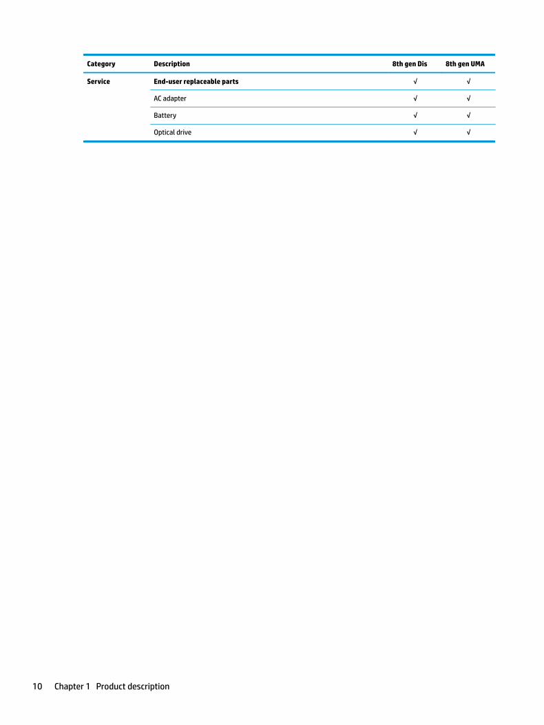
Category Description 8th gen Dis 8th gen UMA
Service End-user replaceable parts √ √
AC adapter √ √
Battery √ √
Optical drive √ √
10 Chapter 1 Product description
2 Getting to know your computer
Your computer features top-rated components. This chapter provides details about your components, where they're located, and how they work.
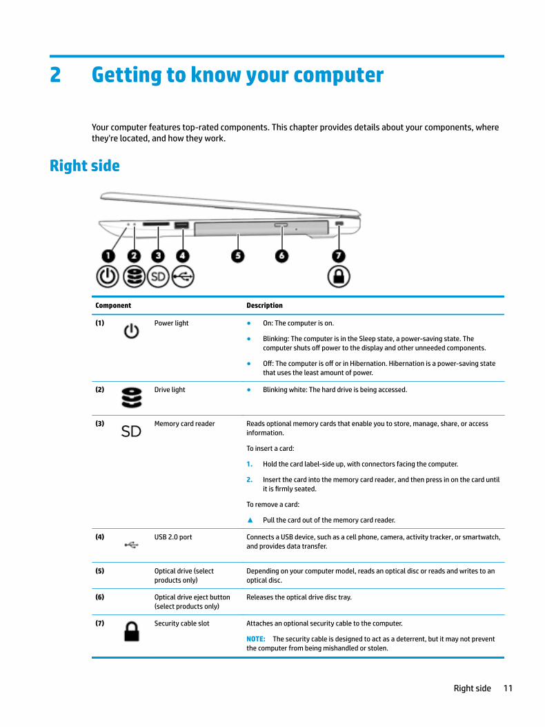
Right side
Component Description
(1) Power light ● On: The computer is on.
● Blinking: The computer is in the Sleep state, a power-saving state. The computer shuts off power to the display and other unneeded components.
● Off: The computer is off or in Hibernation. Hibernation is a power-saving state that uses the least amount of power.
(2) Drive light ● Blinking white: The hard drive is being accessed.
(3) Memory card reader Reads optional memory cards that enable you to store, manage, share, or access information.
To insert a card:
1. Hold the card label-side up, with connectors facing the computer.
2. Insert the card into the memory card reader, and then press in on the card until it is firmly seated.
To remove a card:
▲ Pull the card out of the memory card reader.
(4) USB 2.0 port Connects a USB device, such as a cell phone, camera, activity tracker, or smartwatch, and provides data transfer.
(5) Optical drive (select products only)
Depending on your computer model, reads an optical disc or reads and writes to an optical disc.
(6) Optical drive eject button (select products only)
Releases the optical drive disc tray.
(7) Security cable slot Attaches an optional security cable to the computer.
NOTE: The security cable is designed to act as a deterrent, but it may not prevent the computer from being mishandled or stolen.
Right side 11
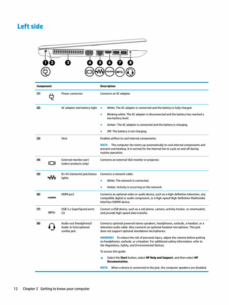
Left side
Component Description
(1) Power connector Connects an AC adapter.
(2) AC adapter and battery light ● White: The AC adapter is connected and the battery is fully charged.
● Blinking white: The AC adapter is disconnected and the battery has reached a low battery level.
● Amber: The AC adapter is connected and the battery is charging.
● Off: The battery is not charging.
(3) Vent Enables airflow to cool internal components.
NOTE: The computer fan starts up automatically to cool internal components and prevent overheating. It is normal for the internal fan to cycle on and off during routine operation.
(4) External monitor port (select products only)
Connects an external VGA monitor or projector.
(5) RJ-45 (network) jack/status lights
Connects a network cable.
● White: The network is connected.
● Amber: Activity is occurring on the network.
(6) HDMI port Connects an optional video or audio device, such as a high-definition television, any compatible digital or audio component, or a high-speed High-Definition Multimedia Interface (HDMI) device.
(7) USB 3.x SuperSpeed ports (2)
Connect a USB device, such as a cell phone, camera, activity tracker, or smartwatch, and provide high-speed data transfer.
(8) Audio-out (headphone)/Audio-in (microphone) combo jack
Connects optional powered stereo speakers, headphones, earbuds, a headset, or a television audio cable. Also connects an optional headset microphone. This jack does not support optional standalone microphones.
WARNING! To reduce the risk of personal injury, adjust the volume before putting on headphones, earbuds, or a headset. For additional safety information, refer to the Regulatory, Safety, and Environmental Notices.
To access this guide:
▲ Select the Start button, select HP Help and Support, and then select HP Documentation.
NOTE: When a device is connected to the jack, the computer speakers are disabled.
12 Chapter 2 Getting to know your computer
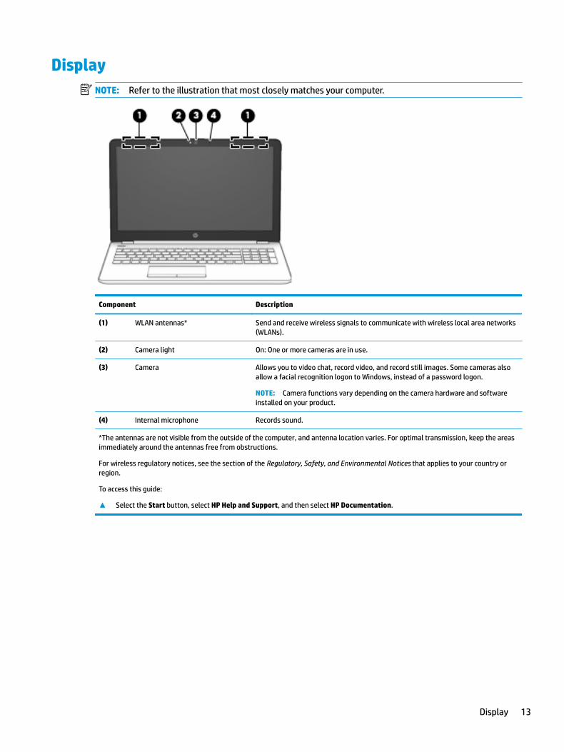
DisplayNOTE: Refer to the illustration that most closely matches your computer.
Component Description
(1) WLAN antennas* Send and receive wireless signals to communicate with wireless local area networks (WLANs).
(2) Camera light On: One or more cameras are in use.
(3) Camera Allows you to video chat, record video, and record still images. Some cameras also allow a facial recognition logon to Windows, instead of a password logon.
NOTE: Camera functions vary depending on the camera hardware and software installed on your product.
(4) Internal microphone Records sound.
*The antennas are not visible from the outside of the computer, and antenna location varies. For optimal transmission, keep the areas immediately around the antennas free from obstructions.
For wireless regulatory notices, see the section of the Regulatory, Safety, and Environmental Notices that applies to your country or region.
To access this guide:
▲ Select the Start button, select HP Help and Support, and then select HP Documentation.
Display 13
Keyboard area
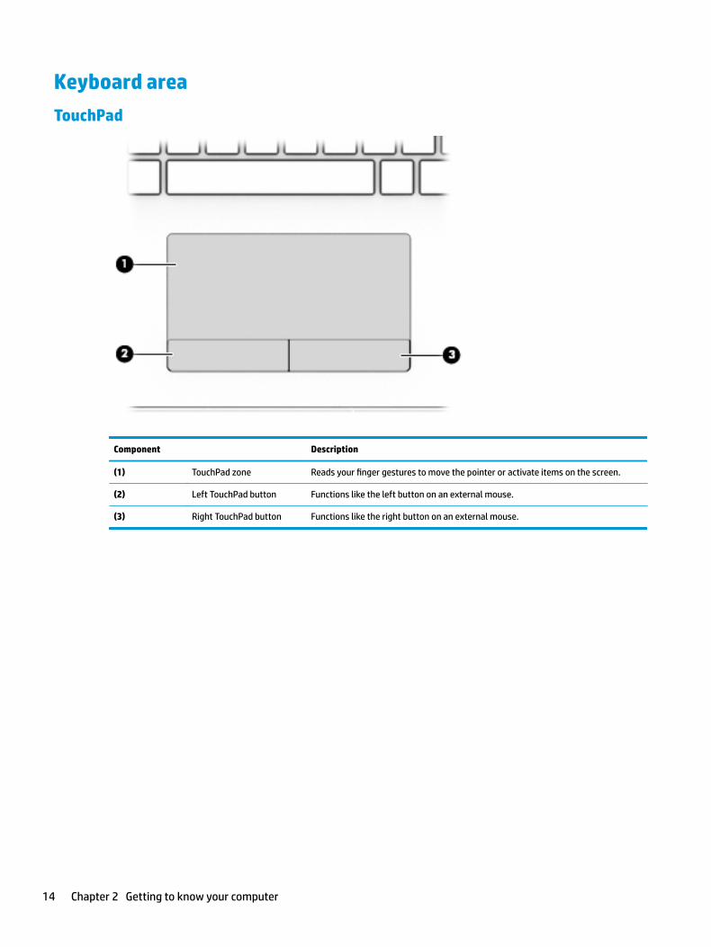
TouchPad
Component Description
(1) TouchPad zone Reads your finger gestures to move the pointer or activate items on the screen.
(2) Left TouchPad button Functions like the left button on an external mouse.
(3) Right TouchPad button Functions like the right button on an external mouse.
14 Chapter 2 Getting to know your computer
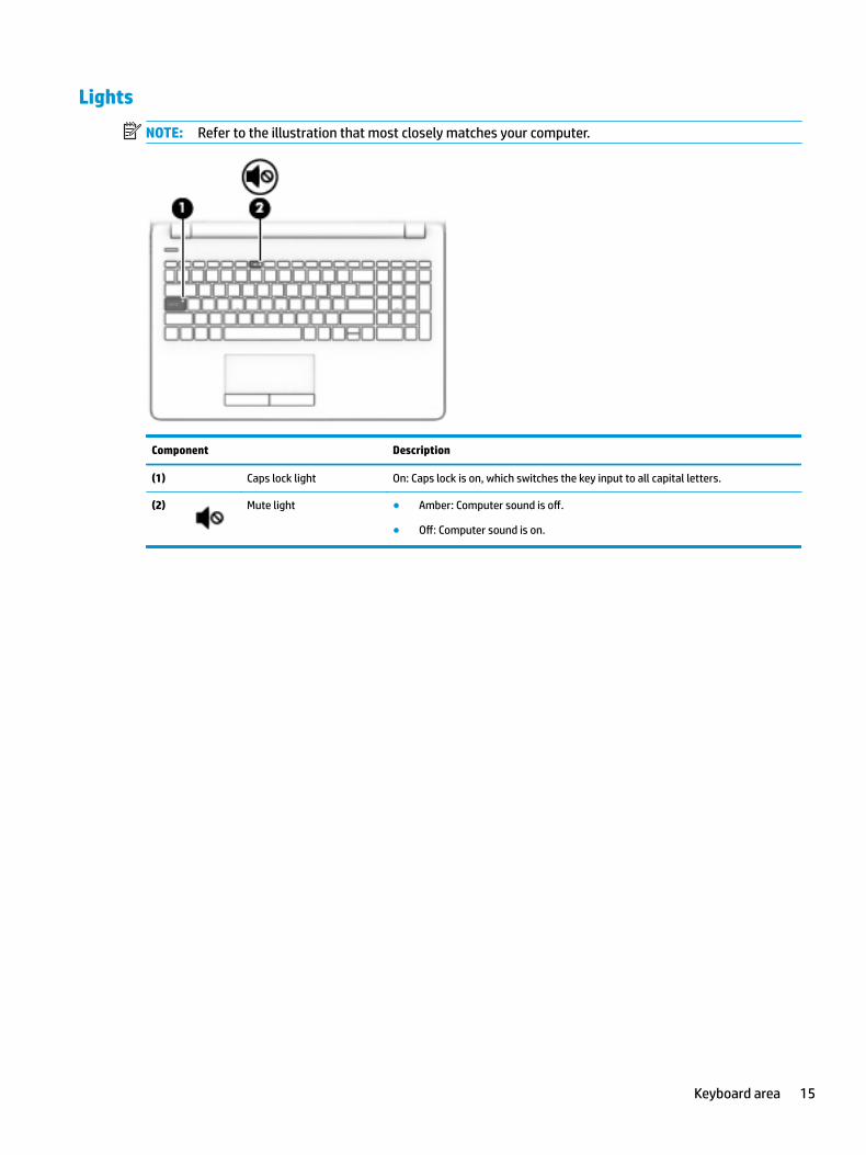
Lights
NOTE: Refer to the illustration that most closely matches your computer.
Component Description
(1) Caps lock light On: Caps lock is on, which switches the key input to all capital letters.
(2) Mute light ● Amber: Computer sound is off.
● Off: Computer sound is on.
Keyboard area 15
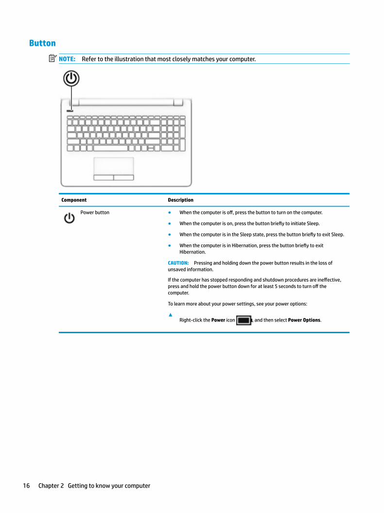
Button
NOTE: Refer to the illustration that most closely matches your computer.
Component Description
Power button ● When the computer is off, press the button to turn on the computer.
● When the computer is on, press the button briefly to initiate Sleep.
● When the computer is in the Sleep state, press the button briefly to exit Sleep.
● When the computer is in Hibernation, press the button briefly to exit Hibernation.
CAUTION: Pressing and holding down the power button results in the loss of unsaved information.
If the computer has stopped responding and shutdown procedures are ineffective, press and hold the power button down for at least 5 seconds to turn off the computer.
To learn more about your power settings, see your power options:
▲Right-click the Power icon , and then select Power Options.
16 Chapter 2 Getting to know your computer
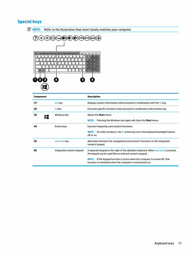
Special keys
NOTE: Refer to the illustration that most closely matches your computer.
Component Description
(1) esc key Displays system information when pressed in combination with the fn key.
(2) fn key Executes specific functions when pressed in combination with another key.
(3) Windows key Opens the Start menu.
NOTE: Pressing the Windows key again will close the Start menu.
(4) Action keys Execute frequently used system functions.
NOTE: On select products, the f5 action key turns the keyboard backlight feature off or on.
(5) num lock key Alternates between the navigational and numeric functions on the integrated numeric keypad.
(6) Integrated numeric keypad A separate keypad to the right of the alphabet keyboard. When num lock is pressed, the keypad can be used like an external numeric keypad.
NOTE: If the keypad function is active when the computer is turned off, that function is reinstated when the computer is turned back on.
Keyboard area 17
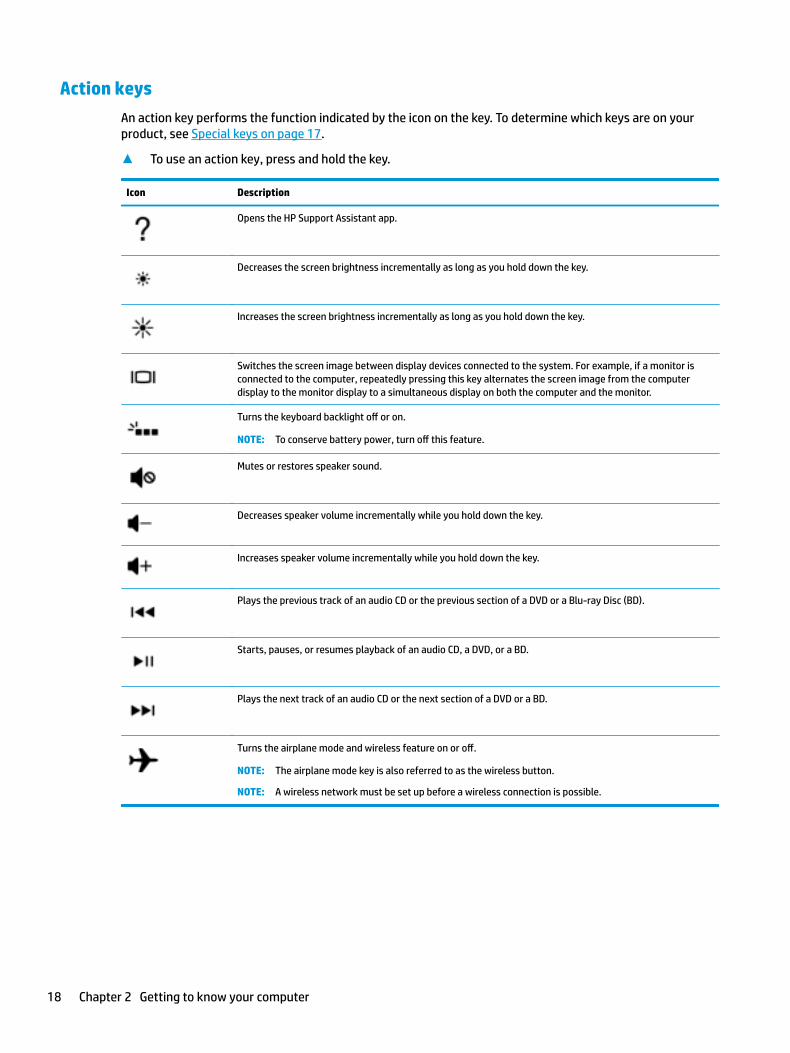
Action keys
An action key performs the function indicated by the icon on the key. To determine which keys are on your product, see Special keys on page 17.
▲ To use an action key, press and hold the key.
Icon Description
Opens the HP Support Assistant app.
Decreases the screen brightness incrementally as long as you hold down the key.
Increases the screen brightness incrementally as long as you hold down the key.
Switches the screen image between display devices connected to the system. For example, if a monitor is connected to the computer, repeatedly pressing this key alternates the screen image from the computer display to the monitor display to a simultaneous display on both the computer and the monitor.
Turns the keyboard backlight off or on.
NOTE: To conserve battery power, turn off this feature.
Mutes or restores speaker sound.
Decreases speaker volume incrementally while you hold down the key.
Increases speaker volume incrementally while you hold down the key.
Plays the previous track of an audio CD or the previous section of a DVD or a Blu-ray Disc (BD).
Starts, pauses, or resumes playback of an audio CD, a DVD, or a BD.
Plays the next track of an audio CD or the next section of a DVD or a BD.
Turns the airplane mode and wireless feature on or off.
NOTE: The airplane mode key is also referred to as the wireless button.
NOTE: A wireless network must be set up before a wireless connection is possible.
18 Chapter 2 Getting to know your computer
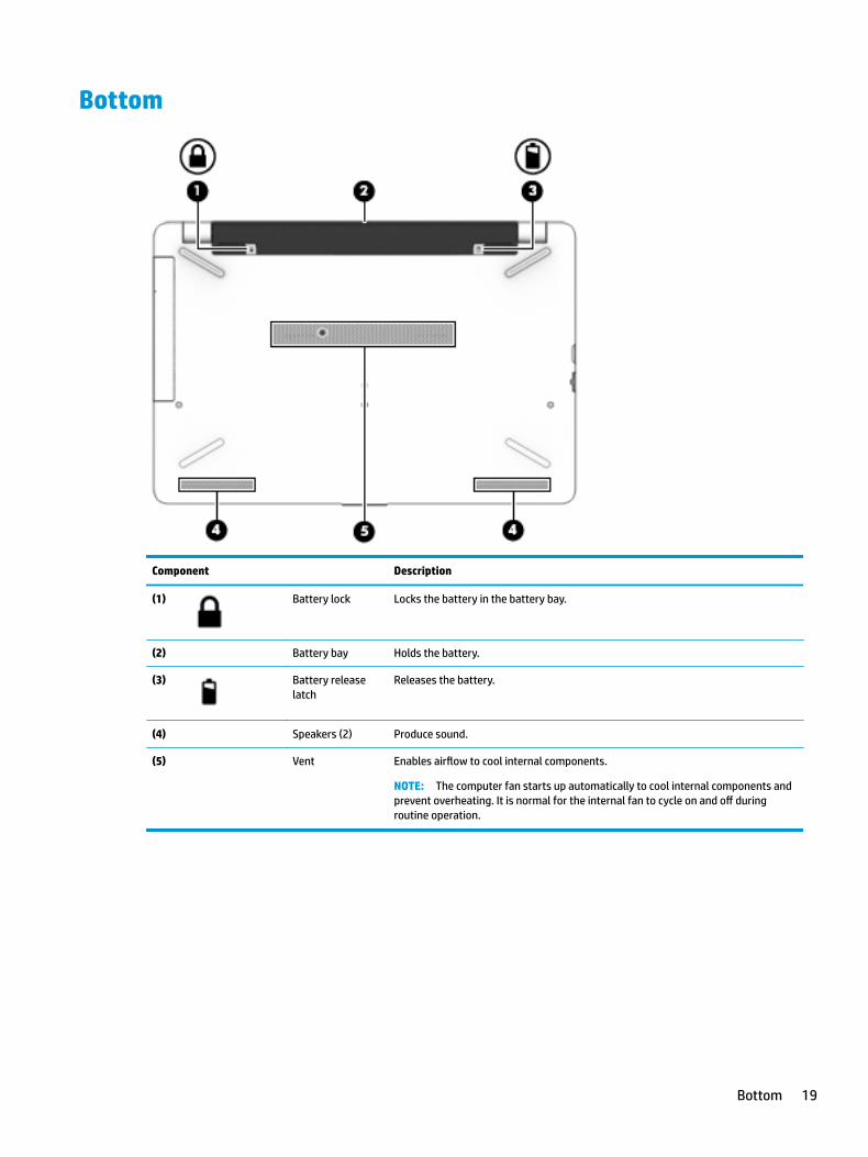
Bottom
Component Description
(1) Battery lock Locks the battery in the battery bay.
(2) Battery bay Holds the battery.
(3) Battery release latch
Releases the battery.
(4) Speakers (2) Produce sound.
(5) Vent Enables airflow to cool internal components.
NOTE: The computer fan starts up automatically to cool internal components and prevent overheating. It is normal for the internal fan to cycle on and off during routine operation.
Bottom 19
LabelsThe labels affixed to the computer provide information you may need when you troubleshoot system problems or travel internationally with the computer.
IMPORTANT: Check the following locations for the labels described in this section: the bottom of the computer, inside the battery bay, under the service door, or on the back of the display.
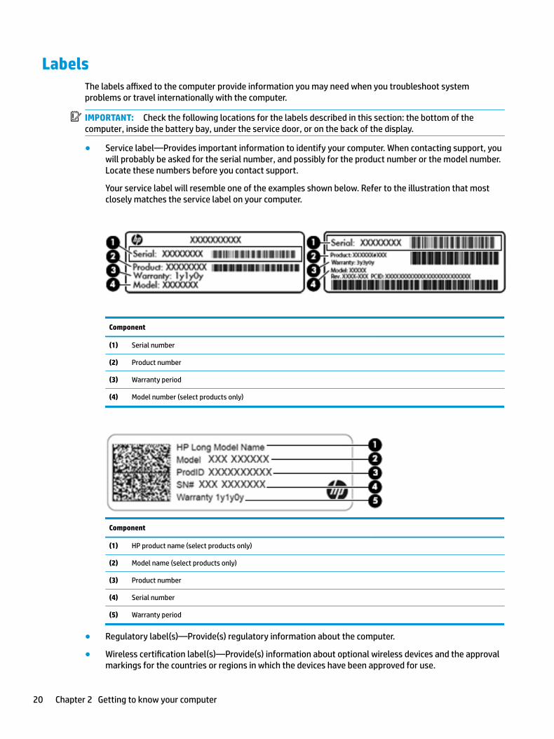
● Service label—Provides important information to identify your computer. When contacting support, you will probably be asked for the serial number, and possibly for the product number or the model number. Locate these numbers before you contact support.
Your service label will resemble one of the examples shown below. Refer to the illustration that most closely matches the service label on your computer.
Component
(1) Serial number
(2) Product number
(3) Warranty period
(4) Model number (select products only)
Component
(1) HP product name (select products only)
(2) Model name (select products only)
(3) Product number
(4) Serial number
(5) Warranty period
● Regulatory label(s)—Provide(s) regulatory information about the computer.
● Wireless certification label(s)—Provide(s) information about optional wireless devices and the approval markings for the countries or regions in which the devices have been approved for use.
20 Chapter 2 Getting to know your computer
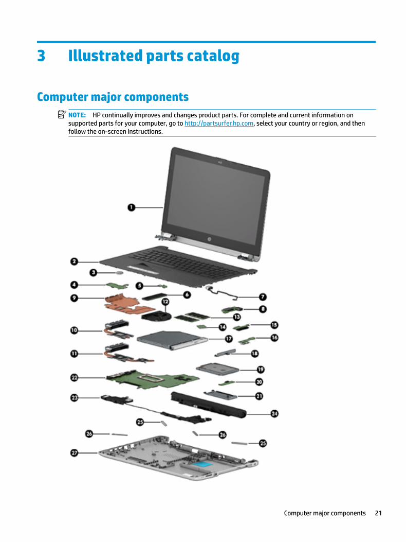
3 Illustrated parts catalog
Computer major componentsNOTE: HP continually improves and changes product parts. For complete and current information on supported parts for your computer, go to http://partsurfer.hp.com, select your country or region, and then follow the on-screen instructions.
Computer major components 21
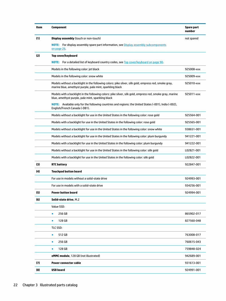
Item Component Spare part number
(1) Display assembly (touch or non-touch)
NOTE: For display assembly spare part information, see Display assembly subcomponents on page 26.
not spared
(2) Top cover/keyboard
NOTE: For a detailed list of keyboard country codes, see Top cover/keyboard on page 90.
Models in the following color: jet black 925008-xxx
Models in the following color: snow white 925009-xxx
Models without a backlight in the following colors: pike silver, silk gold, empress red, smoke gray, marine blue, amethyst purple, pale mint, sparkling black
925010-xxx
Models with a backlight in the following colors: pike silver, silk gold, empress red, smoke gray, marine blue, amethyst purple, pale mint, sparkling black
NOTE: Available only for the following countries and regions: the United States (-001), India (-002), English/French Canada (-DB1).
925011-xxx
Models without a backlight for use in the United States in the following color: rose gold 925564-001
Models with a backlight for use in the United States in the following color: rose gold 925565-001
Models without a backlight for use in the United States in the following color: snow white 938651-001
Models without a backlight for use in the United States in the following color: plum burgundy 941221-001
Models with a backlight for use in the United States in the following color: plum burgundy 941222-001
Models without a backlight for use in the United States in the following color: silk gold L02821-001
Models with a backlight for use in the United States in the following color: silk gold L02822-001
(3) RTC battery 922847-001
(4) Touchpad button board
For use in models without a solid-state drive 924993-001
For use in models with a solid-state drive 934256-001
(5) Power button board 924994-001
(6) Solid-state drive, M.2
Value SSD:
● 256 GB 865902-017
● 128 GB 827560-048
TLC SSD:
● 512 GB 763008-017
● 256 GB 760615-043
● 128 GB 759848-024
eMMC module, 128 GB (not illustrated) 942689-001
(7) Power connector cable 931613-001
(8) USB board 924991-001
22 Chapter 3 Illustrated parts catalog
Item Component Spare part number
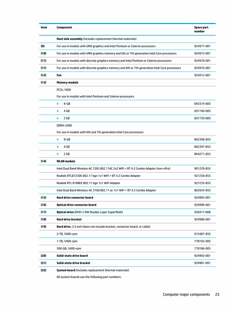
Heat sink assembly (includes replacement thermal materials)
(9) For use in models with UMA graphics and Intel Pentium or Celeron processors 924977-001
(10) For use in models with UMA graphics memory and 6th or 7th generation Intel Core processors 924975-001
(11) For use in models with discrete graphics memory and Intel Pentium or Celeron processors 924978-001
(11) For use in models with discrete graphics memory and 6th or 7th generation Intel Core processors 924976-001
(12) Fan 925012-001
(13) Memory module
PC3L-1600
For use in models with Intel Pentium and Celeron processors
● 8-GB 693374-005
● 4 GB 691740-005
● 2 GB 691739-005
DDR4-2400
For use in models with 6th and 7th generation Intel Core processors
● 8-GB 862398-855
● 4 GB 862397-855
● 2 GB 864271-855
(14) WLAN module
Intel Dual Band Wireless-AC 7265 802.11AC 2x2 WiFi + BT 4.2 Combo Adapter (non-vPro) 901229-855
Realtek RTL8723DE 802.11 bgn 1x1 WiFi + BT 4.2 Combo Adapter 927230-855
Realtek RTL 8188EE 802.11 bgn 1x1 WiFi Adapter 927235-855
Intel Dual Band Wireless-AC 3168 802.11 ac 1x1 WiFi + BT 4.2 Combo Adapter 863934-855
(15) Hard drive connector board 924995-001
(16) Optical drive connector board 924990-001
(17) Optical drive (DVD+/-RW Double-Layer SuperMulti) 920417-008
(18) Hard drive bracket 924980-001
(19) Hard drive, 2.5 inch (does not include bracket, connector board, or cable)
2-TB, 5400-rpm 912487-855
1-TB, 5400-rpm 778192-005
500-GB, 5400-rpm 778186-005
(20) Solid-state drive board 924992-001
(21) Solid-state drive bracket 924981-001
(22) System board (includes replacement thermal materials)
All system boards use the following part numbers:
Computer major components 23
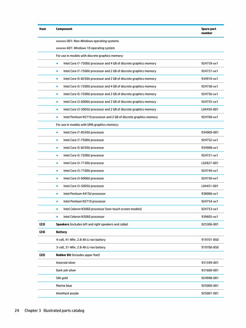
Item Component Spare part number
xxxxxx-001: Non-Windows operating systems
xxxxxx-601: Windows 10 operating system
For use in models with discrete graphics memory:
● Intel Core i7-7500U processor and 4 GB of discrete graphics memory 924759-xx1
● Intel Core i7-7500U processor and 2 GB of discrete graphics memory 924757-xx1
● Intel Core i5-8250U processor and 2 GB of discrete graphics memory 934910-xx1
● Intel Core i5-7200U processor and 4 GB of discrete graphics memory 924758-xx1
● Intel Core i5-7200U processor and 2 GB of discrete graphics memory 924756-xx1
● Intel Core i3-6006U processor and 2 GB of discrete graphics memory 924755-xx1
● Intel Core i3-5005U processor and 2 GB of discrete graphics memory L04450-001
● Intel Pentium N3710 processor and 2 GB of discrete graphics memory 924760-xx1
For use in models with UMA graphics memory:
● Intel Core i7-8550U processor 934909-001
● Intel Core i7-7500U processor 924752-xx1
● Intel Core i5-8250U processor 934908-xx1
● Intel Core i5-7200U processor 924751-xx1
● Intel Core i3-7130U processor L02827-001
● Intel Core i3-7100U processor 924749-xx1
● Intel Core i3-6006U processor 924750-xx1
● Intel Core i3-5005U processor L04451-001
● Intel Pentium 4415U processor 938006-xx1
● Intel Pentium N3710 processor 924754-xx1
● Intel Celeron N3060 processor (non-touch screen models) 924753-xx1
● Intel Celeron N3060 processor 939605-xx1
(23) Speakers (includes left and right speakers and cable) 925306-001
(24) Battery
4-cell, 41-Whr, 2.8-Ah Li-ion battery 919701-850
3-cell, 31-Whr, 2.8-Ah Li-ion battery 919700-850
(25) Rubber Kit (includes upper feet)
Asteroid silver 931599-001
Dark ash silver 931600-001
Silk gold 924998-001
Marine blue 925000-001
Amethyst purple 925001-001
24 Chapter 3 Illustrated parts catalog
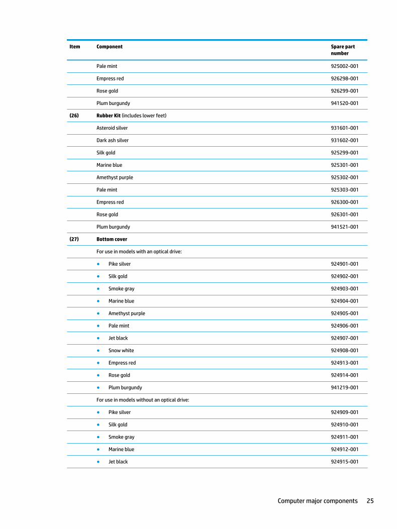
Item Component Spare part number
Pale mint 925002-001
Empress red 926298-001
Rose gold 926299-001
Plum burgundy 941520-001
(26) Rubber Kit (includes lower feet)
Asteroid silver 931601-001
Dark ash silver 931602-001
Silk gold 925299-001
Marine blue 925301-001
Amethyst purple 925302-001
Pale mint 925303-001
Empress red 926300-001
Rose gold 926301-001
Plum burgundy 941521-001
(27) Bottom cover
For use in models with an optical drive:
● Pike silver 924901-001
● Silk gold 924902-001
● Smoke gray 924903-001
● Marine blue 924904-001
● Amethyst purple 924905-001
● Pale mint 924906-001
● Jet black 924907-001
● Snow white 924908-001
● Empress red 924913-001
● Rose gold 924914-001
● Plum burgundy 941219-001
For use in models without an optical drive:
● Pike silver 924909-001
● Silk gold 924910-001
● Smoke gray 924911-001
● Marine blue 924912-001
● Jet black 924915-001
Computer major components 25
Item Component Spare part number
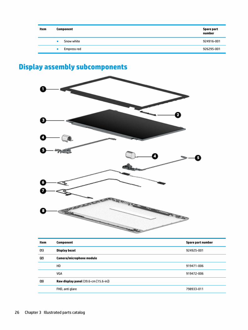
● Snow white 924916-001
● Empress red 926295-001
Display assembly subcomponents
Item Component Spare part number
(1) Display bezel 924925-001
(2) Camera/microphone module
HD 919471-006
VGA 919472-006
(3) Raw display panel (39.6-cm [15.6-in])
FHD, anti glare 798933-011
26 Chapter 3 Illustrated parts catalog
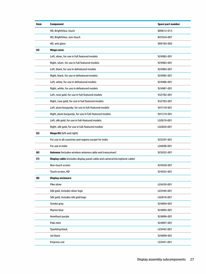
Item Component Spare part number
HD, BrightView, touch 809612-013
HD, BrightView, non-touch 847654-007
HD, anti glare 909185-005
(4) Hinge cover
Left, silver, for use in full featured models 924982-001
Right, silver, for use in full featured models 924983-001
Left, black, for use in defeatured models 924984-001
Right, black, for use in defeatured models 924985-001
Left, white, for use in defeatured models 924986-001
Right, white, for use in defeatured models 924987-001
Left, rose gold, for use in full featured models 932782-001
Right, rose gold, for use in full featured models 932783-001
Left, plum burgundy, for use in full-featured models 941518-001
Right, plum burgundy, for use in full-featured models 941519-001
Left, silk gold, for use in full-featured models L02819-001
Right, silk gold, for use in full-featured models L02820-001
(5) Hinge Kit (left and right)
For use in all countries and regions except for India 925297-001
For use in India L04698-001
(6) Antenna (includes wireless antenna cable and transceiver) 925032-001
(7) Display cable (includes display panel cable and camera/microphone cable)
Non-touch screen 924930-001
Touch screen, HD 924932-001
(8) Display enclosure:
Pike silver L03439-001
Silk gold, includes silver logo L03440-001
Silk gold, includes silk gold logo L02818-001
Smoke gray 924894-001
Marine blue 924895-001
Amethyst purple 924896-001
Pale mint 924897-001
Sparkling black L03442-001
Jet black 924899-001
Empress red L03441-001
Display assembly subcomponents 27
Item Component Spare part number
Rose gold L03443-001
Snow white, for use in full-featured models 938652-001
Snow white, for use in defeatured models 924900-001
Plum burgundy 941218-001
Display cover support kit (includes washers; not illustrated; for more information, see Display assembly on page 76)
L04332-001
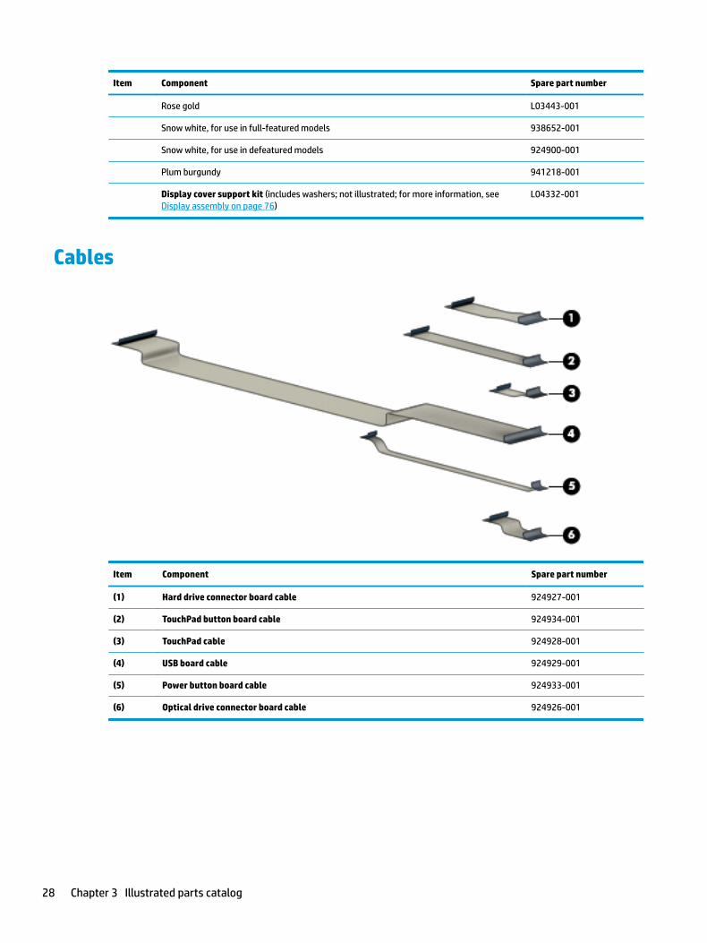
Cables
Item Component Spare part number
(1) Hard drive connector board cable 924927-001
(2) TouchPad button board cable 924934-001
(3) TouchPad cable 924928-001
(4) USB board cable 924929-001
(5) Power button board cable 924933-001
(6) Optical drive connector board cable 924926-001
28 Chapter 3 Illustrated parts catalog
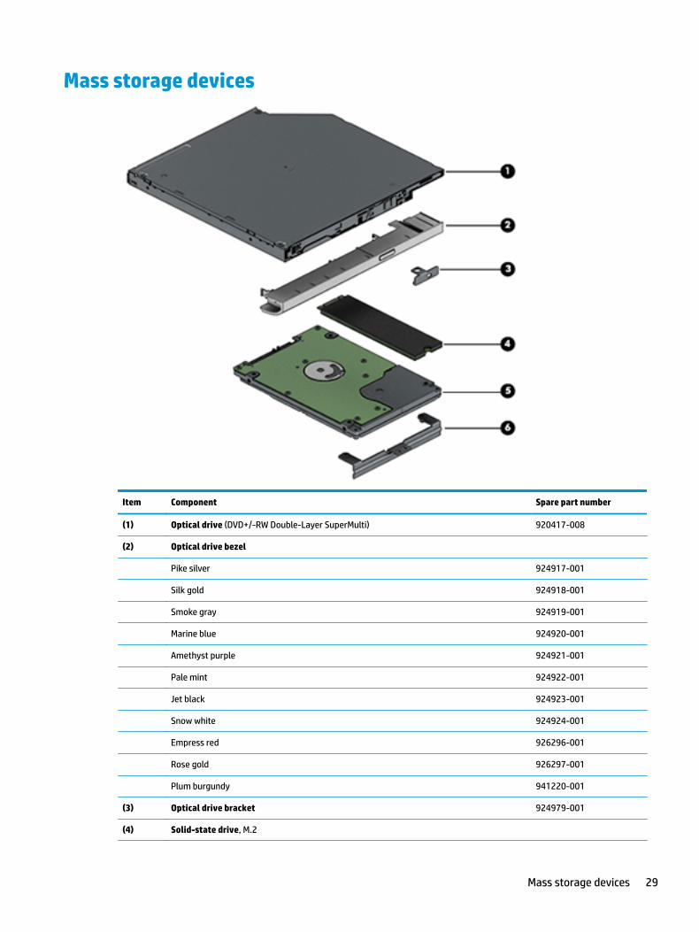
Mass storage devices
Item Component Spare part number
(1) Optical drive (DVD+/-RW Double-Layer SuperMulti) 920417-008
(2) Optical drive bezel
Pike silver 924917-001
Silk gold 924918-001
Smoke gray 924919-001
Marine blue 924920-001
Amethyst purple 924921-001
Pale mint 924922-001
Jet black 924923-001
Snow white 924924-001
Empress red 926296-001
Rose gold 926297-001
Plum burgundy 941220-001
(3) Optical drive bracket 924979-001
(4) Solid-state drive, M.2
Mass storage devices 29
Item Component Spare part number
Value SSD:
● 256 GB 865902-017
● 128 GB 827560-048
TLC SSD:
● 512 GB 763008-017
● 256 GB 760615-043
● 128 GB 759848-024
(5) Hard drive, SATA; does not include brackets, connector board, or cable):
2-TB, 5400-rpm 912487-855
1-TB, 5400-rpm 778192-005
500-GB, 5400-rpm 778186-005
(6) Hard drive bracket 924980-001
Miscellaneous parts
Component Spare part number
HP Smart AC adapter (4.5 mm, non-PFC)
90-W 710413-001
65-W 710412-001
65-W, for use in Argentina 710340-850
65-W, EM, for use in India and the People’s Republic of China 913691-850
45-W 741553-850
45-W, for use in Argentina 741553-852
Power cord:
For use in Argentina 920688-003
For use in Australia 920688-011
For use in Denmark 920688-007
For use in Europe 920688-005
For use in India 920688-016
For use in Israel 920688-008
For use in Italy 920688-002
For use in Japan 920688-017
For use in North America 920688-001
For use in the People’s Republic of China 920688-014
30 Chapter 3 Illustrated parts catalog
Component Spare part number
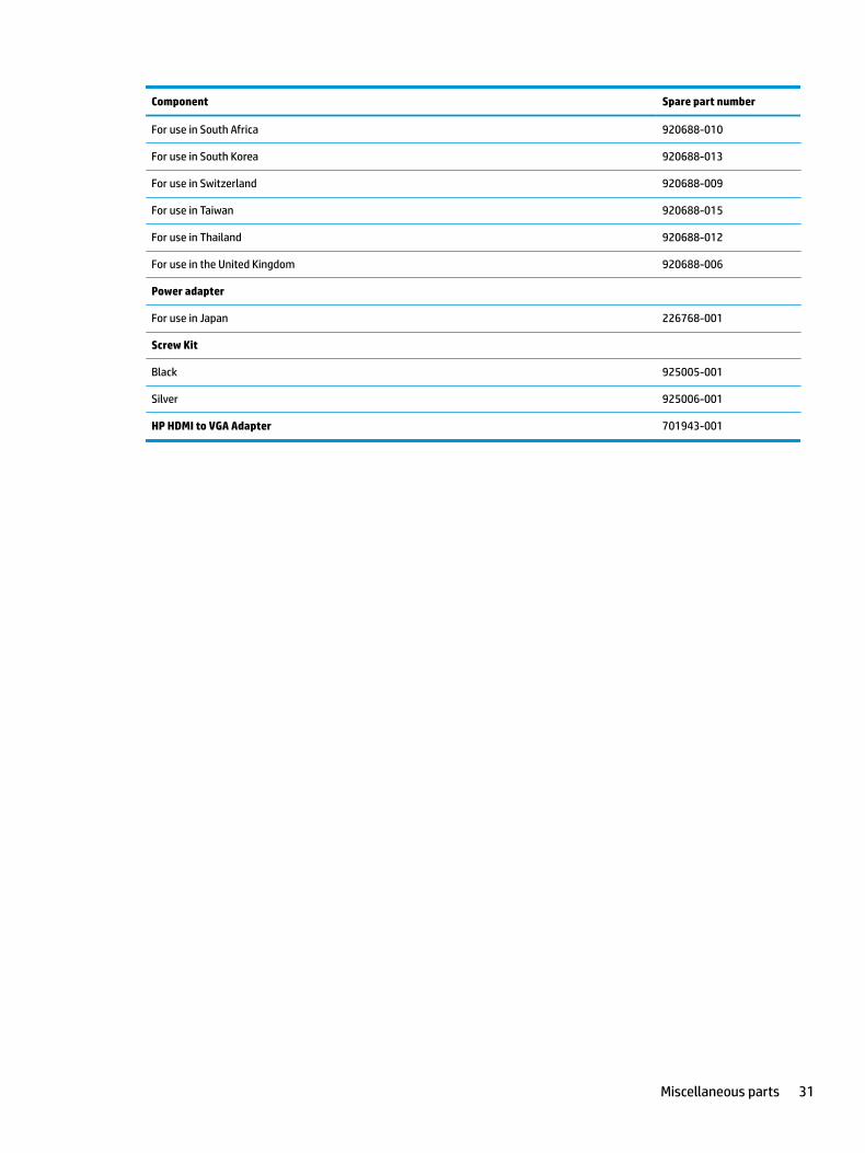
For use in South Africa 920688-010
For use in South Korea 920688-013
For use in Switzerland 920688-009
For use in Taiwan 920688-015
For use in Thailand 920688-012
For use in the United Kingdom 920688-006
Power adapter
For use in Japan 226768-001
Screw Kit
Black 925005-001
Silver 925006-001
HP HDMI to VGA Adapter 701943-001
Miscellaneous parts 31

32 Chapter 3 Illustrated parts catalog
4 Removal and replacement procedures preliminary requirements
Tools requiredYou will need the following tools to complete the removal and replacement procedures:
● Flat-bladed screwdriver
● Magnetic screwdriver
● Phillips P0 and P1 screwdrivers
Service considerationsThe following sections include some of the considerations that you must keep in mind during disassembly and assembly procedures.
NOTE: As you remove each subassembly from the computer, place the subassembly (and all accompanying screws) away from the work area to prevent damage.
Plastic parts
CAUTION: Using excessive force during disassembly and reassembly can damage plastic parts. Use care when handling the plastic parts. Apply pressure only at the points designated in the maintenance instructions.
Cables and connectors
CAUTION: When servicing the computer, be sure that cables are placed in their proper locations during the reassembly process. Improper cable placement can damage the computer.
Cables must be handled with extreme care to avoid damage. Apply only the tension required to unseat or seat the cables during removal and insertion. Handle cables by the connector whenever possible. In all cases, avoid bending, twisting, or tearing cables. Be sure that cables are routed in such a way that they cannot be caught or snagged by parts being removed or replaced. Handle flex cables with extreme care; these cables tear easily.
Tools required 33
Drive handling
CAUTION: Drives are fragile components that must be handled with care. To prevent damage to the computer, damage to a drive, or loss of information, observe these precautions:
Before removing or inserting a hard drive, shut down the computer. If you are unsure whether the computer is off or in Hibernation, turn the computer on, and then shut it down through the operating system.
Before handling a drive, be sure that you are discharged of static electricity. While handling a drive, avoid touching the connector.
Before removing a diskette drive or optical drive, be sure that a diskette or disc is not in the drive and be sure that the optical drive tray is closed.
Handle drives on surfaces covered with at least one inch of shock-proof foam.
Avoid dropping drives from any height onto any surface.
After removing a hard drive, an optical drive, or a diskette drive, place it in a static-proof bag.
Avoid exposing an internal hard drive to products that have magnetic fields, such as monitors or speakers.
Avoid exposing a drive to temperature extremes or liquids.
If a drive must be mailed, place the drive in a bubble pack mailer or other suitable form of protective packaging and label the package “FRAGILE.”
Grounding guidelines
Electrostatic discharge damage
Electronic components are sensitive to electrostatic discharge (ESD). Circuitry design and structure determine the degree of sensitivity. Networks built into many integrated circuits provide some protection, but in many cases, ESD contains enough power to alter device parameters or melt silicon junctions.
A discharge of static electricity from a finger or other conductor can destroy static-sensitive devices or microcircuitry. Even if the spark is neither felt nor heard, damage may have occurred.
An electronic device exposed to ESD may not be affected at all and can work perfectly throughout a normal cycle. Or the device may function normally for a while, then degrade in the internal layers, reducing its life expectancy.
CAUTION: To prevent damage to the computer when you are removing or installing internal components, observe these precautions:
Keep components in their electrostatic-safe containers until you are ready to install them.
Before touching an electronic component, discharge static electricity by using the guidelines described in this section.
Avoid touching pins, leads, and circuitry. Handle electronic components as little as possible.
If you remove a component, place it in an electrostatic-safe container.
The following table shows how humidity affects the electrostatic voltage levels generated by different activities.
CAUTION: A product can be degraded by as little as 700 V.
34 Chapter 4 Removal and replacement procedures preliminary requirements
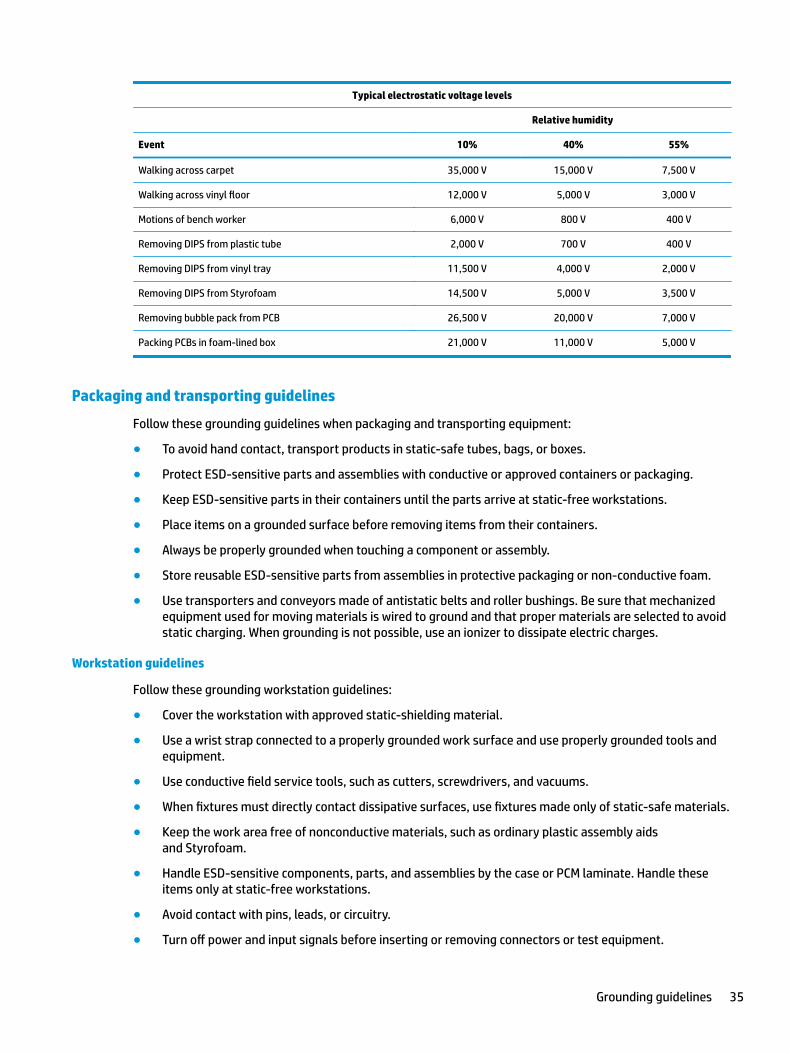
Typical electrostatic voltage levels
Relative humidity
Event 10% 40% 55%
Walking across carpet 35,000 V 15,000 V 7,500 V
Walking across vinyl floor 12,000 V 5,000 V 3,000 V
Motions of bench worker 6,000 V 800 V 400 V
Removing DIPS from plastic tube 2,000 V 700 V 400 V
Removing DIPS from vinyl tray 11,500 V 4,000 V 2,000 V
Removing DIPS from Styrofoam 14,500 V 5,000 V 3,500 V
Removing bubble pack from PCB 26,500 V 20,000 V 7,000 V
Packing PCBs in foam-lined box 21,000 V 11,000 V 5,000 V
Packaging and transporting guidelines
Follow these grounding guidelines when packaging and transporting equipment:
● To avoid hand contact, transport products in static-safe tubes, bags, or boxes.
● Protect ESD-sensitive parts and assemblies with conductive or approved containers or packaging.
● Keep ESD-sensitive parts in their containers until the parts arrive at static-free workstations.
● Place items on a grounded surface before removing items from their containers.
● Always be properly grounded when touching a component or assembly.
● Store reusable ESD-sensitive parts from assemblies in protective packaging or non-conductive foam.
● Use transporters and conveyors made of antistatic belts and roller bushings. Be sure that mechanized equipment used for moving materials is wired to ground and that proper materials are selected to avoid static charging. When grounding is not possible, use an ionizer to dissipate electric charges.
Workstation guidelines
Follow these grounding workstation guidelines:
● Cover the workstation with approved static-shielding material.
● Use a wrist strap connected to a properly grounded work surface and use properly grounded tools and equipment.
● Use conductive field service tools, such as cutters, screwdrivers, and vacuums.
● When fixtures must directly contact dissipative surfaces, use fixtures made only of static-safe materials.
● Keep the work area free of nonconductive materials, such as ordinary plastic assembly aids and Styrofoam.
● Handle ESD-sensitive components, parts, and assemblies by the case or PCM laminate. Handle these items only at static-free workstations.
● Avoid contact with pins, leads, or circuitry.
● Turn off power and input signals before inserting or removing connectors or test equipment.
Grounding guidelines 35
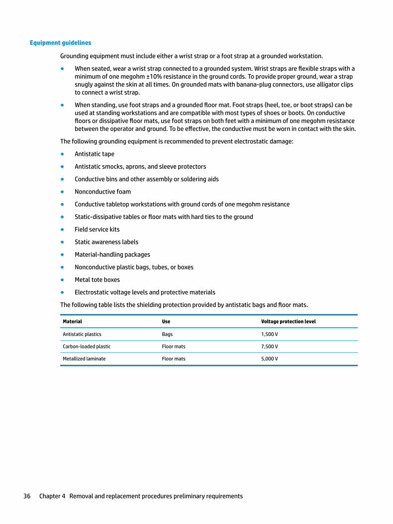
Equipment guidelines
Grounding equipment must include either a wrist strap or a foot strap at a grounded workstation.
● When seated, wear a wrist strap connected to a grounded system. Wrist straps are flexible straps with a minimum of one megohm ±10% resistance in the ground cords. To provide proper ground, wear a strap snugly against the skin at all times. On grounded mats with banana-plug connectors, use alligator clips to connect a wrist strap.
● When standing, use foot straps and a grounded floor mat. Foot straps (heel, toe, or boot straps) can be used at standing workstations and are compatible with most types of shoes or boots. On conductive floors or dissipative floor mats, use foot straps on both feet with a minimum of one megohm resistance between the operator and ground. To be effective, the conductive must be worn in contact with the skin.
The following grounding equipment is recommended to prevent electrostatic damage:
● Antistatic tape
● Antistatic smocks, aprons, and sleeve protectors
● Conductive bins and other assembly or soldering aids
● Nonconductive foam
● Conductive tabletop workstations with ground cords of one megohm resistance
● Static-dissipative tables or floor mats with hard ties to the ground
● Field service kits
● Static awareness labels
● Material-handling packages
● Nonconductive plastic bags, tubes, or boxes
● Metal tote boxes
● Electrostatic voltage levels and protective materials
The following table lists the shielding protection provided by antistatic bags and floor mats.
Material Use Voltage protection level
Antistatic plastics Bags 1,500 V
Carbon-loaded plastic Floor mats 7,500 V
Metallized laminate Floor mats 5,000 V
36 Chapter 4 Removal and replacement procedures preliminary requirements
5 Removal and replacement procedures for Customer Self-Repair parts
CAUTION: The Customer Self-Repair program is not available in all locations. Installing a part not supported by the Customer Self-Repair program may void your warranty. Check your warranty to determine if Customer Self-Repair is supported in your location.
NOTE: HP continually improves and changes product parts. For complete and current information on supported parts for your computer, go to http://partsurfer.hp.com, select your country or region, and then follow the on-screen instructions.
Component replacement proceduresNOTE: Please read and follow the procedures described here to access and replace Customer Self-Repair parts successfully.
NOTE: Details about your computer, including model, serial number, product key, and length of warranty, are on the service tag at the bottom of your computer. See Labels on page 20 for details.
This chapter provides removal and replacement procedures for Customer Self-Repair parts.
There are as many as 3 screws that must be removed, replaced, or loosened when servicing Customer Self- Repair parts. Make special note of each screw size and location during removal and replacement.
Component replacement procedures 37
Battery
Description Spare part number
4-cell, 41-Whr, 2.8-Ah Li-ion battery 919701-850
3-cell, 31-Whr, 2.8-Ah Li-ion battery 919700-850
Before disassembling the computer, follow these steps:
1. Shut down the computer. If you are unsure whether the computer is off or in Hibernation, turn the computer on, and then shut it down through the operating system.
2. Disconnect all external devices connected to the computer.
3. Disconnect the power from the computer by first unplugging the power cord from the AC outlet and then unplugging the AC adapter from the computer.
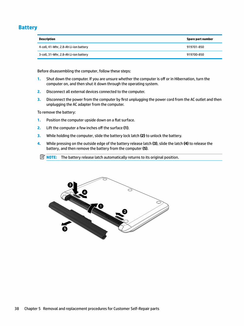
To remove the battery:
1. Position the computer upside down on a flat surface.
2. Lift the computer a few inches off the surface (1).
3. While holding the computer, slide the battery lock latch (2) to unlock the battery.
4. While pressing on the outside edge of the battery release latch (3), slide the latch (4) to release the battery, and then remove the battery from the computer (5).
NOTE: The battery release latch automatically returns to its original position.
38 Chapter 5 Removal and replacement procedures for Customer Self-Repair parts
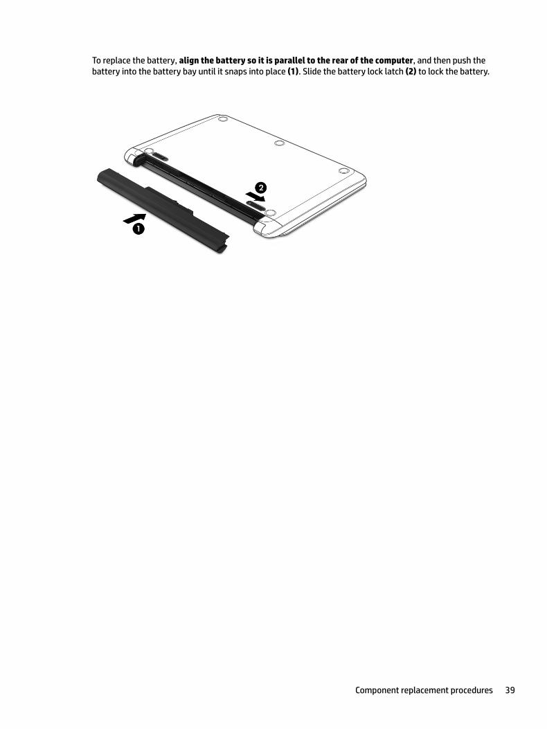
To replace the battery, align the battery so it is parallel to the rear of the computer, and then push the battery into the battery bay until it snaps into place (1). Slide the battery lock latch (2) to lock the battery.
Component replacement procedures 39
Optical drive
Description Spare part number
DVD+/-RW Double-Layer SuperMulti Drive 920417-008
Optical drive bracket 924979-001
Optical drive bezel
Pike silver 924917-001
Silk gold 924918-001
Smoke gray 924919-001
Marine blue 924920-001
Amethyst purple 924921-001
Pale mint 924922-001
Jet black 924923-001
Snow white 924924-001
Empress red 924296-001
Rose gold 924297-001
Before removing the optical drive, follow these steps:
1. Shut down the computer. If you are unsure whether the computer is off or in Hibernation, turn the computer on, and then shut it down through the operating system.
2. Disconnect all external devices connected to the computer.
3. Disconnect the power from the computer by first unplugging the power cord from the AC outlet and then unplugging the AC adapter from the computer.
4. Remove the battery (see Battery on page 38).
To remove the optical drive:
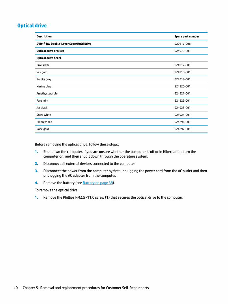
1. Remove the Phillips PM2.5×11.0 screw (1) that secures the optical drive to the computer.
40 Chapter 5 Removal and replacement procedures for Customer Self-Repair parts
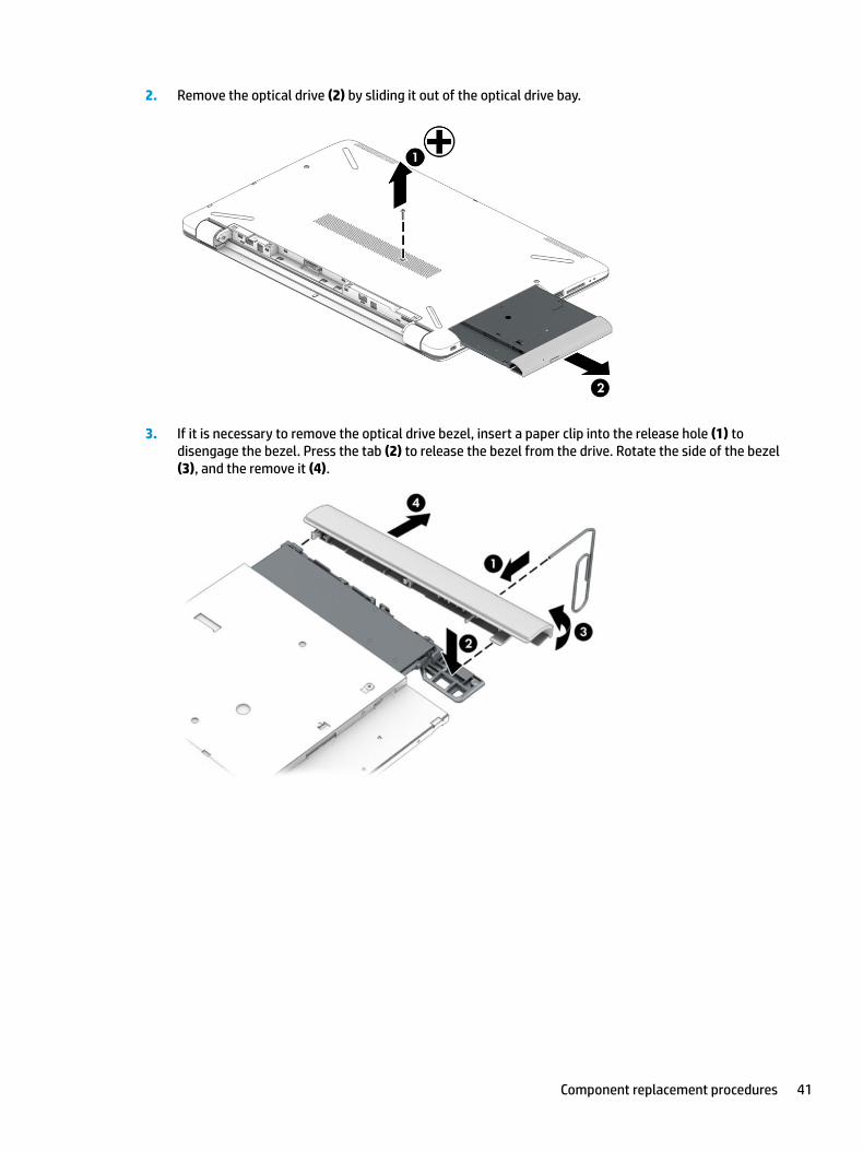
2. Remove the optical drive (2) by sliding it out of the optical drive bay.
3. If it is necessary to remove the optical drive bezel, insert a paper clip into the release hole (1) to disengage the bezel. Press the tab (2) to release the bezel from the drive. Rotate the side of the bezel (3), and the remove it (4).
Component replacement procedures 41
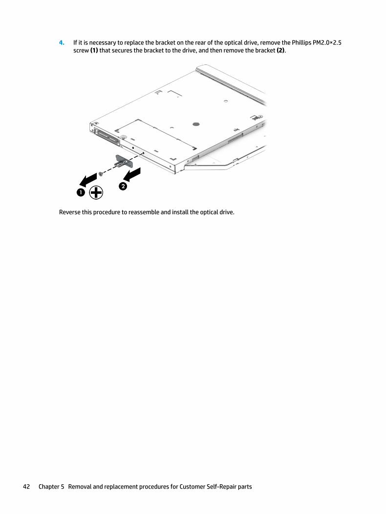
4. If it is necessary to replace the bracket on the rear of the optical drive, remove the Phillips PM2.0×2.5 screw (1) that secures the bracket to the drive, and then remove the bracket (2).
Reverse this procedure to reassemble and install the optical drive.
42 Chapter 5 Removal and replacement procedures for Customer Self-Repair parts
6 Removal and replacement procedures for Authorized Service Provider parts
CAUTION: Components described in this chapter should only be accessed by an authorized service provider. Accessing these parts can damage the computer or void the warranty.
NOTE: HP continually improves and changes product parts. For complete and current information on supported parts for your computer, go to http://partsurfer.hp.com, select your country or region, and then follow the on-screen instructions.
Component replacement proceduresNOTE: Details about your computer, including model, serial number, product key, and length of warranty, are on the service tag at the bottom of your computer. See Labels on page 20 for details.
This chapter provides removal and replacement procedures for Authorized Service Provider only parts.
There are as many as 54 screws that must be removed, replaced, or loosened when servicing Authorized Service Provider only parts. Make special note of each screw size and location during removal and replacement.
Display subcomponents (bezel, panel, camera)
NOTE: Display assemblies are spared at the subcomponent level only.
This section illustrates how to remove the display bezel, display panel, and camera module without removing the display from the computer. The Display assembly on page 76 section illustrates removing all display subcomponents.
To remove the display assembly subcomponents, follow these steps:
1. Shut down the computer. If you are unsure whether the computer is off or in Hibernation, turn the computer on, and then shut it down through the operating system.
2. Disconnect all external devices connected to the computer.
3. Disconnect the power from the computer by first unplugging the power cord from the AC outlet and then unplugging the AC adapter from the computer.
Remove the display assembly subcomponents:
1. Open the computer as far as it will open.
2. To remove the display bezel:
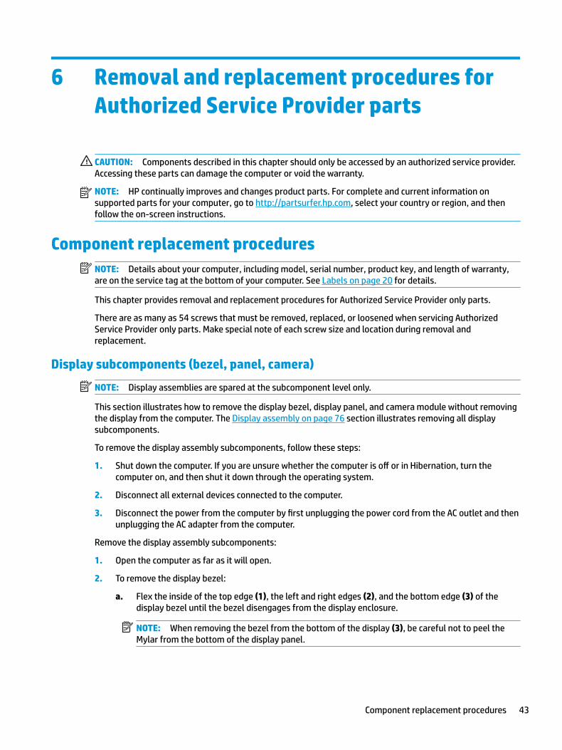
a. Flex the inside of the top edge (1), the left and right edges (2), and the bottom edge (3) of the display bezel until the bezel disengages from the display enclosure.
NOTE: When removing the bezel from the bottom of the display (3), be careful not to peel the Mylar from the bottom of the display panel.
Component replacement procedures 43
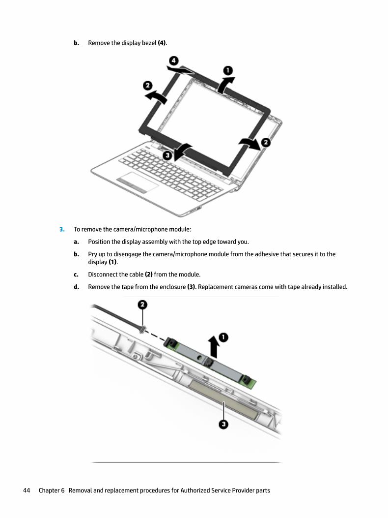
b. Remove the display bezel (4).
3. To remove the camera/microphone module:
a. Position the display assembly with the top edge toward you.
b. Pry up to disengage the camera/microphone module from the adhesive that secures it to the display (1).
c. Disconnect the cable (2) from the module.
d. Remove the tape from the enclosure (3). Replacement cameras come with tape already installed.
44 Chapter 6 Removal and replacement procedures for Authorized Service Provider parts
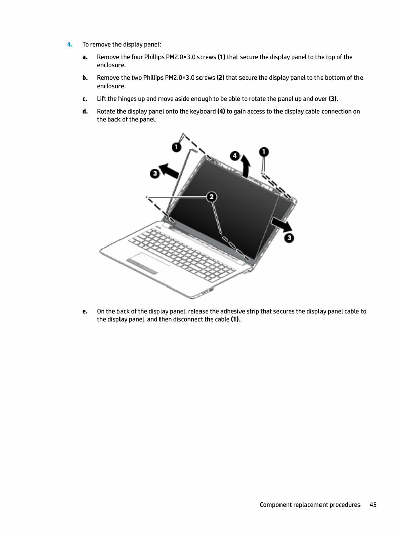
4. To remove the display panel:
a. Remove the four Phillips PM2.0×3.0 screws (1) that secure the display panel to the top of the enclosure.
b. Remove the two Phillips PM2.0×3.0 screws (2) that secure the display panel to the bottom of the enclosure.
c. Lift the hinges up and move aside enough to be able to rotate the panel up and over (3).
d. Rotate the display panel onto the keyboard (4) to gain access to the display cable connection on the back of the panel.
e. On the back of the display panel, release the adhesive strip that secures the display panel cable to the display panel, and then disconnect the cable (1).
Component replacement procedures 45
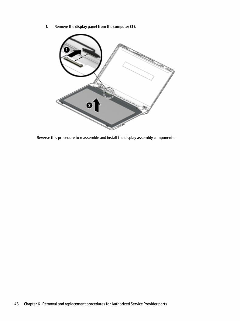
f. Remove the display panel from the computer (2).
Reverse this procedure to reassemble and install the display assembly components.
46 Chapter 6 Removal and replacement procedures for Authorized Service Provider parts
Rubber feet
Description Spare part number
Rubber feet, upper
Asteroid silver 931599-001
Dark ash silver 931600-001
Silk gold 924998-001
Marine blue 925000-001
Amethyst purple 925001-001
Pale mint 925002-001
Empress red 926298-001
Rose gold 926299-001
Plum burgundy 941520-001
Rubber feet, lower
Asteroid silver 931601-001
Dark ash silver 931602-001
Silk gold 925299-001
Marine blue 925301-001
Amethyst purple 925302-001
Pale mint 925303-001
Empress red 926300-001
Rose gold 926301-001
Plum burgundy 941521-001
Before removing the rubber feet, follow these steps:
1. Shut down the computer. If you are unsure whether the computer is off or in Hibernation, turn the computer on, and then shut it down through the operating system.
2. Disconnect all external devices connected to the computer.
3. Disconnect the power from the computer by first unplugging the power cord from the AC outlet and then unplugging the AC adapter from the computer.
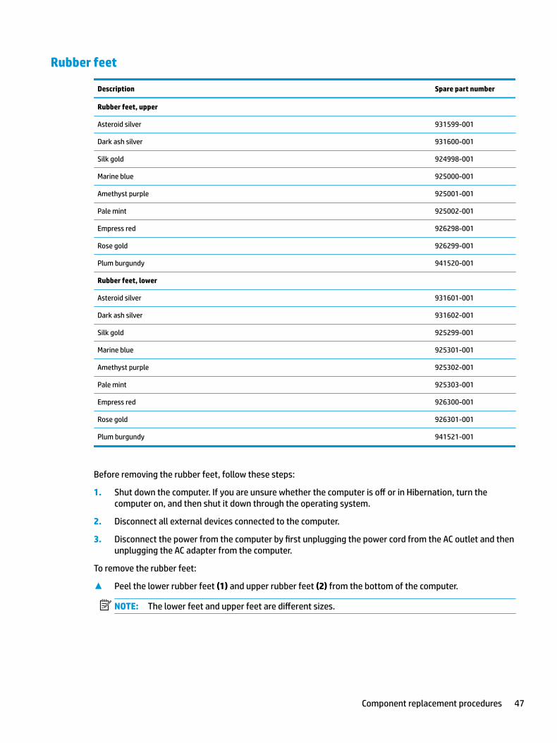
To remove the rubber feet:
▲ Peel the lower rubber feet (1) and upper rubber feet (2) from the bottom of the computer.
NOTE: The lower feet and upper feet are different sizes.
Component replacement procedures 47
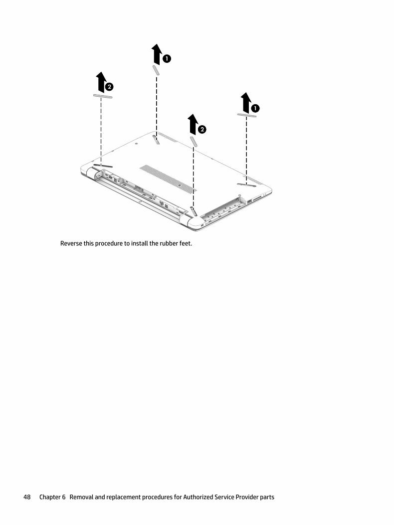
Reverse this procedure to install the rubber feet.
48 Chapter 6 Removal and replacement procedures for Authorized Service Provider parts
Bottom cover
Description Spare part number
Bottom cover for use in models with an optical drive:
● Pike silver 924901-001
● Silk gold 924902-001
● Smoke gray 924903-001
● Marine blue 924904-001
● Amethyst purple 924905-001
● Pale mint 924906-001
● Jet black 924907-001
● Snow white 924908-001
● Empress red 924913-001
● Rose gold 924914-001
● Plum burgundy 941219-001
Bottom cover for use in models without an optical drive:
● Pike silver 924909-001
● Silk gold 924910-001
● Smoke gray 924911-001
● Marine blue 924912-001
● Jet black 924915-001
● Snow white 924916-001
● Empress red 926295-001
Before removing the bottom cover, follow these steps:
1. Shut down the computer. If you are unsure whether the computer is off or in Hibernation, turn the computer on, and then shut it down through the operating system.
2. Disconnect all external devices connected to the computer.
3. Disconnect the power from the computer by first unplugging the power cord from the AC outlet and then unplugging the AC adapter from the computer.
4. Remove the battery (see Battery on page 38).
5. Remove the optical drive (see Optical drive on page 40), if installed.
To remove the bottom cover:
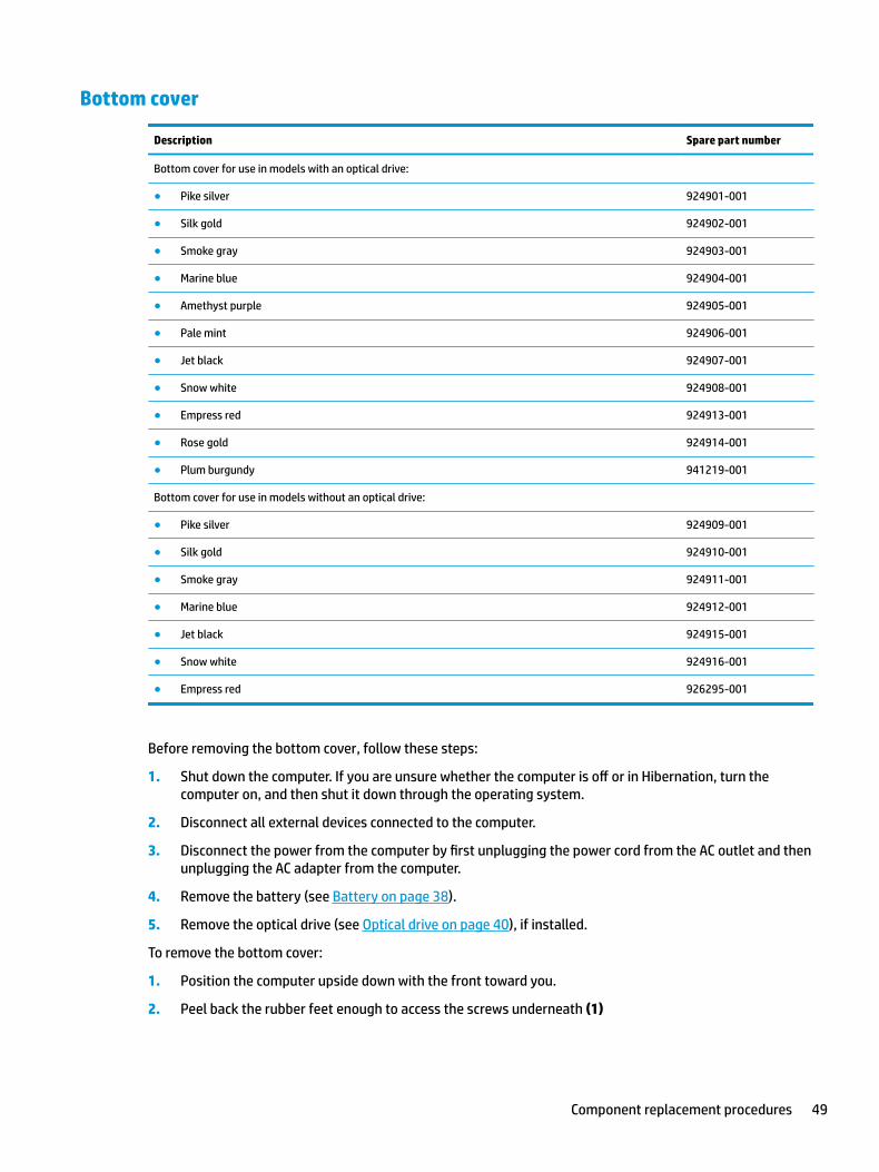
1. Position the computer upside down with the front toward you.
2. Peel back the rubber feet enough to access the screws underneath (1)
Component replacement procedures 49
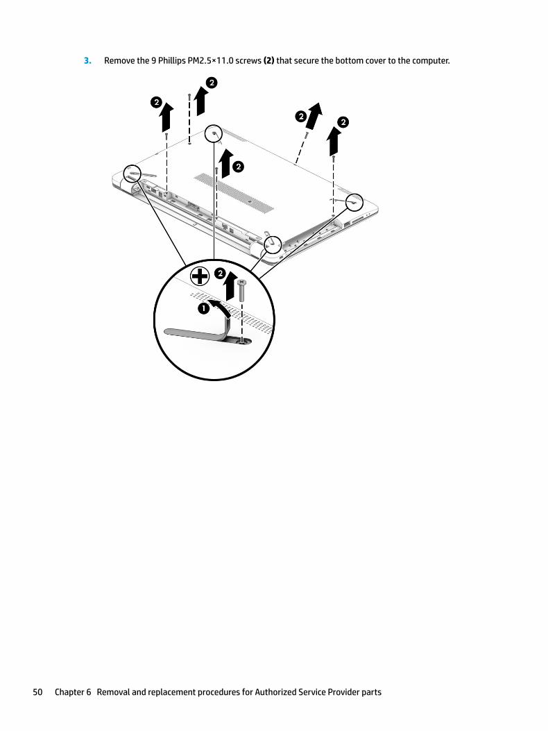
3. Remove the 9 Phillips PM2.5×11.0 screws (2) that secure the bottom cover to the computer.
50 Chapter 6 Removal and replacement procedures for Authorized Service Provider parts
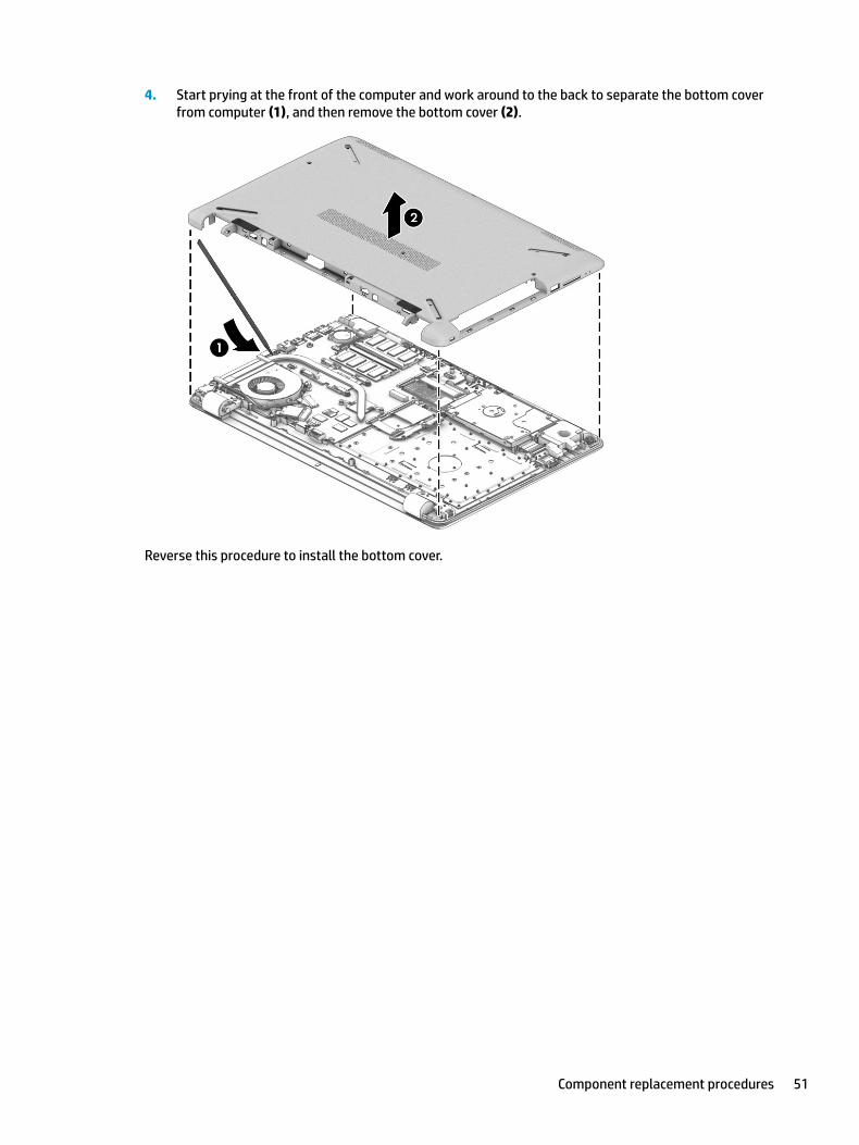
4. Start prying at the front of the computer and work around to the back to separate the bottom cover from computer (1), and then remove the bottom cover (2).
Reverse this procedure to install the bottom cover.
Component replacement procedures 51
WLAN module
Description Spare part number
Intel Dual Band Wireless-AC 7265 802.11AC 2x2 WiFi + BT 4.2 Combo Adapter (non-vPro) 901229-855
Realtek RTL8723DE 802.11 bgn 1x1 WiFi + BT 4.2 Combo Adapter 927230-855
Realtek RTL 8188EE 802.11 bgn 1x1 WiFi Adapter 927235-855
Intel Dual Band Wireless-AC 3168 802.11 ac 1x1 WiFi + BT 4.2 Combo Adapter 863934-855
CAUTION: To prevent an unresponsive system, replace the wireless module only with a wireless module authorized for use in the computer by the governmental agency that regulates wireless devices in your country or region. If you replace the module and then receive a warning message, remove the module to restore device functionality, and then contact support.
Before removing the WLAN module, follow these steps:
1. Shut down the computer. If you are unsure whether the computer is off or in Hibernation, turn the computer on, and then shut it down through the operating system.
2. Disconnect all external devices connected to the computer.
3. Disconnect the power from the computer by first unplugging the power cord from the AC outlet and then unplugging the AC adapter from the computer.
4. Remove the battery (see Battery on page 38).
5. Remove the optical drive (see Optical drive on page 40), if installed.
6. Remove the bottom cover (see Bottom cover on page 49).
To remove the WLAN module:
1. Disconnect the WLAN antenna cables (1) from the terminals on the WLAN module.
NOTE: The WLAN antenna cable labeled “1” connects to the WLAN module “Main” terminal labeled “1”. The WLAN antenna cable labeled “2” connects to the WLAN module “Aux” terminal labeled “2” (if applicable).
2. Remove the Phillips PM2.0×3.0 screw (2) that secures the WLAN module to the system board. (The WLAN module tilts up.)
52 Chapter 6 Removal and replacement procedures for Authorized Service Provider parts
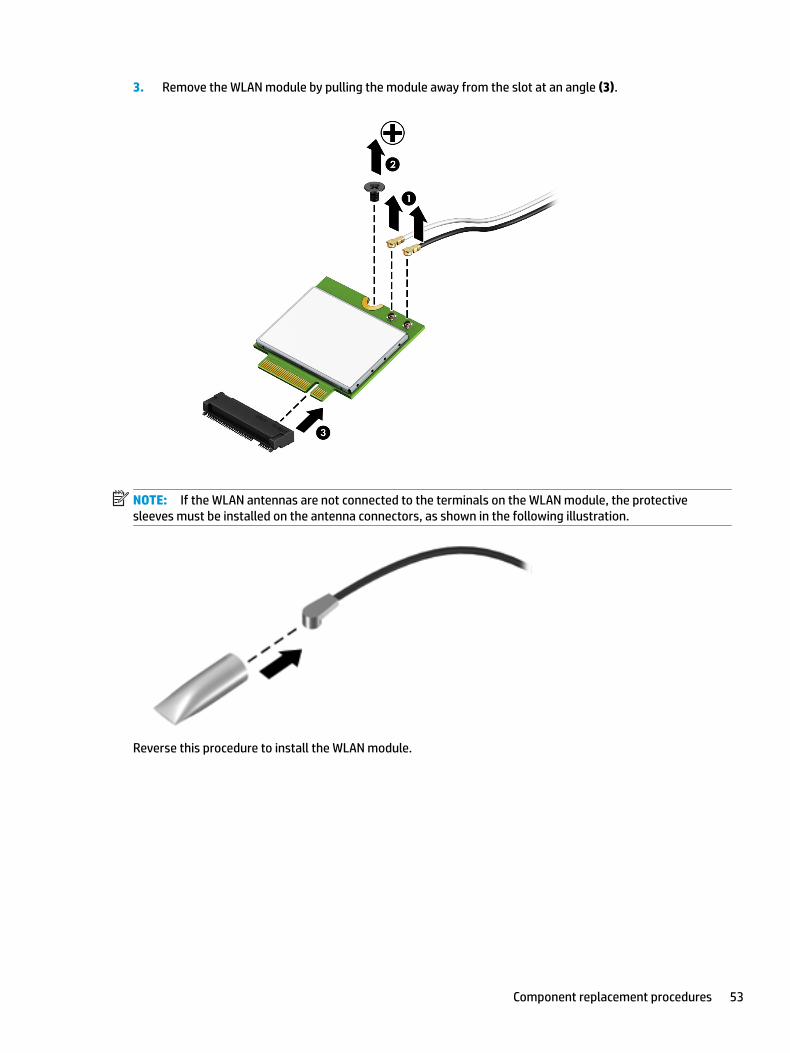
3. Remove the WLAN module by pulling the module away from the slot at an angle (3).
NOTE: If the WLAN antennas are not connected to the terminals on the WLAN module, the protective sleeves must be installed on the antenna connectors, as shown in the following illustration.
Reverse this procedure to install the WLAN module.
Component replacement procedures 53
Memory module
Description Spare part number
Memory module (PC3L-1600)
For use in models with Intel Pentium and Celeron processors:
8-GB 693374-005
4-GB 691740-005
2-GB 691739-005
Memory module (PC4-2400)
For use in models with 6th and 7th generation Intel Core processors:
8-GB 862398-855
4-GB 862397-855
2-GB 864271-855
Before removing a memory module, follow these steps:
1. Shut down the computer. If you are unsure whether the computer is off or in Hibernation, turn the computer on, and then shut it down through the operating system.
2. Disconnect all external devices connected to the computer.
3. Disconnect the power from the computer by first unplugging the power cord from the AC outlet and then unplugging the AC adapter from the computer.
4. Remove the battery (see Battery on page 38).
5. Remove the optical drive (see Optical drive on page 40), if installed.
6. Remove the bottom cover (see Bottom cover on page 49).
To remove a memory module:
1. Spread the retaining tabs (1) on each side of the memory module slot to release the memory module. (The memory module tilts up.)
54 Chapter 6 Removal and replacement procedures for Authorized Service Provider parts
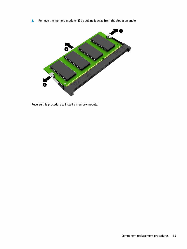
2. Remove the memory module (2) by pulling it away from the slot at an angle.
Reverse this procedure to install a memory module.
Component replacement procedures 55
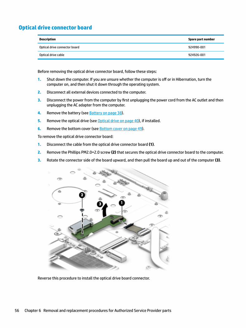
Optical drive connector board
Description Spare part number
Optical drive connector board 924990-001
Optical drive cable 924926-001
Before removing the optical drive connector board, follow these steps:
1. Shut down the computer. If you are unsure whether the computer is off or in Hibernation, turn the computer on, and then shut it down through the operating system.
2. Disconnect all external devices connected to the computer.
3. Disconnect the power from the computer by first unplugging the power cord from the AC outlet and then unplugging the AC adapter from the computer.
4. Remove the battery (see Battery on page 38).
5. Remove the optical drive (see Optical drive on page 40), if installed.
6. Remove the bottom cover (see Bottom cover on page 49).
To remove the optical drive connector board:
1. Disconnect the cable from the optical drive connector board (1).
2. Remove the Phillips PM2.0×2.0 screw (2) that secures the optical drive connector board to the computer.
3. Rotate the connector side of the board upward, and then pull the board up and out of the computer (3).
Reverse this procedure to install the optical drive board connector.
56 Chapter 6 Removal and replacement procedures for Authorized Service Provider parts
Hard drive and hard drive connector board
NOTE: The hard drive spare part kit does not include the hard drive bracket, cable, or connector board.
Description Spare part number
Hard drives:
2-TB, 5400-rpm 912487-855
1-TB, 5400-rpm 778192-005
500-GB, 5400-rpm 778186-005
Hard drive bracket 924980-001
Before removing the hard drive, follow these steps:
1. Shut down the computer. If you are unsure whether the computer is off or in Hibernation, turn the computer on, and then shut it down through the operating system.
2. Disconnect all external devices connected to the computer.
3. Disconnect the power from the computer by first unplugging the power cord from the AC outlet and then unplugging the AC adapter from the computer.
4. Remove the battery (see Battery on page 38).
5. Remove the optical drive (see Optical drive on page 40), if installed.
6. Remove the bottom cover (see Bottom cover on page 49).
To remove the hard drive:
1. Remove the Phillips PM2.0×3.0 screw (1) that secures the hard drive assembly to the computer.
2. Lift the rear of the hard drive upward (2).
Component replacement procedures 57
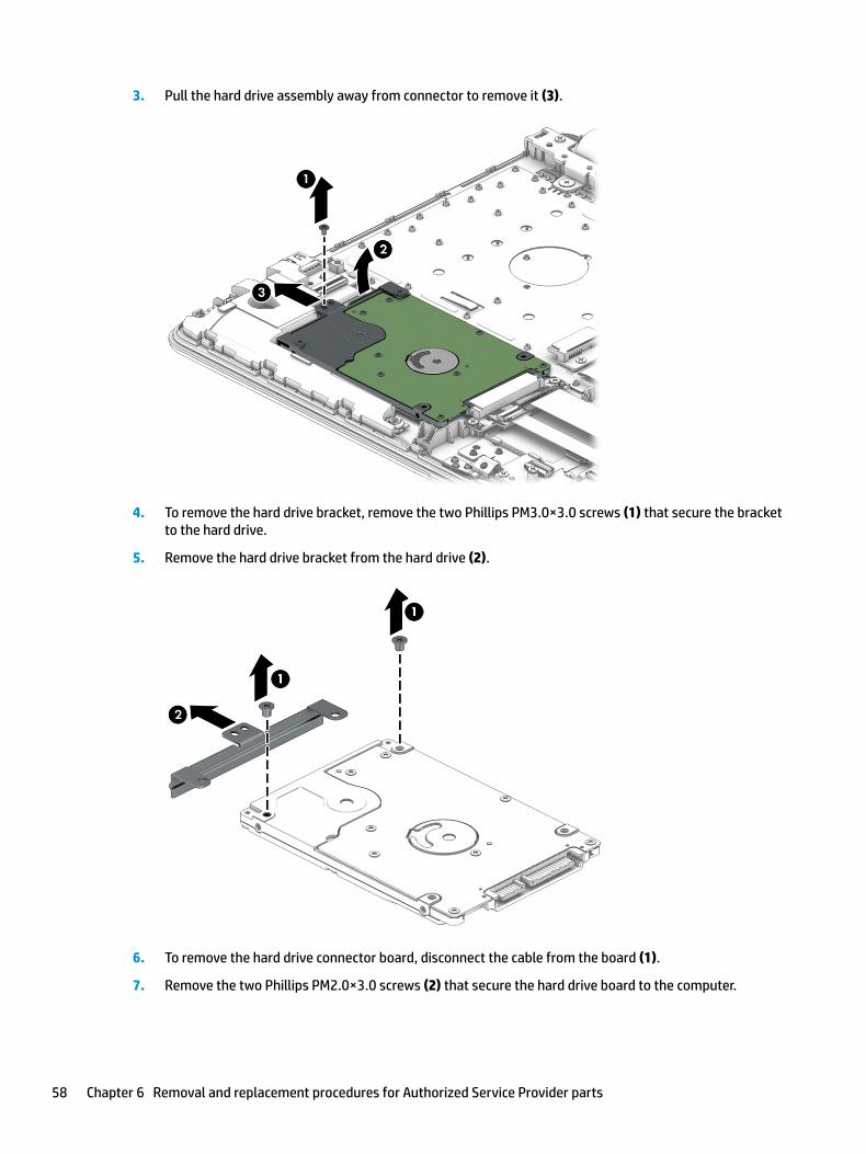
3. Pull the hard drive assembly away from connector to remove it (3).
4. To remove the hard drive bracket, remove the two Phillips PM3.0×3.0 screws (1) that secure the bracket to the hard drive.
5. Remove the hard drive bracket from the hard drive (2).
6. To remove the hard drive connector board, disconnect the cable from the board (1).
7. Remove the two Phillips PM2.0×3.0 screws (2) that secure the hard drive board to the computer.
58 Chapter 6 Removal and replacement procedures for Authorized Service Provider parts
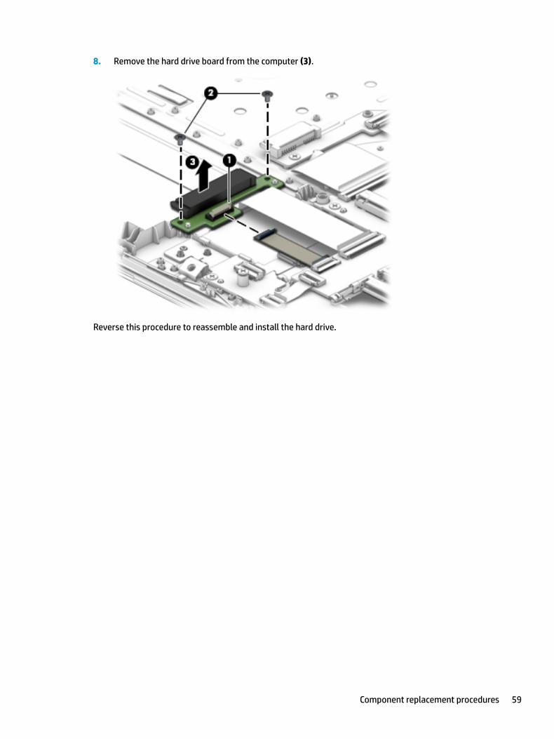
8. Remove the hard drive board from the computer (3).
Reverse this procedure to reassemble and install the hard drive.
Component replacement procedures 59
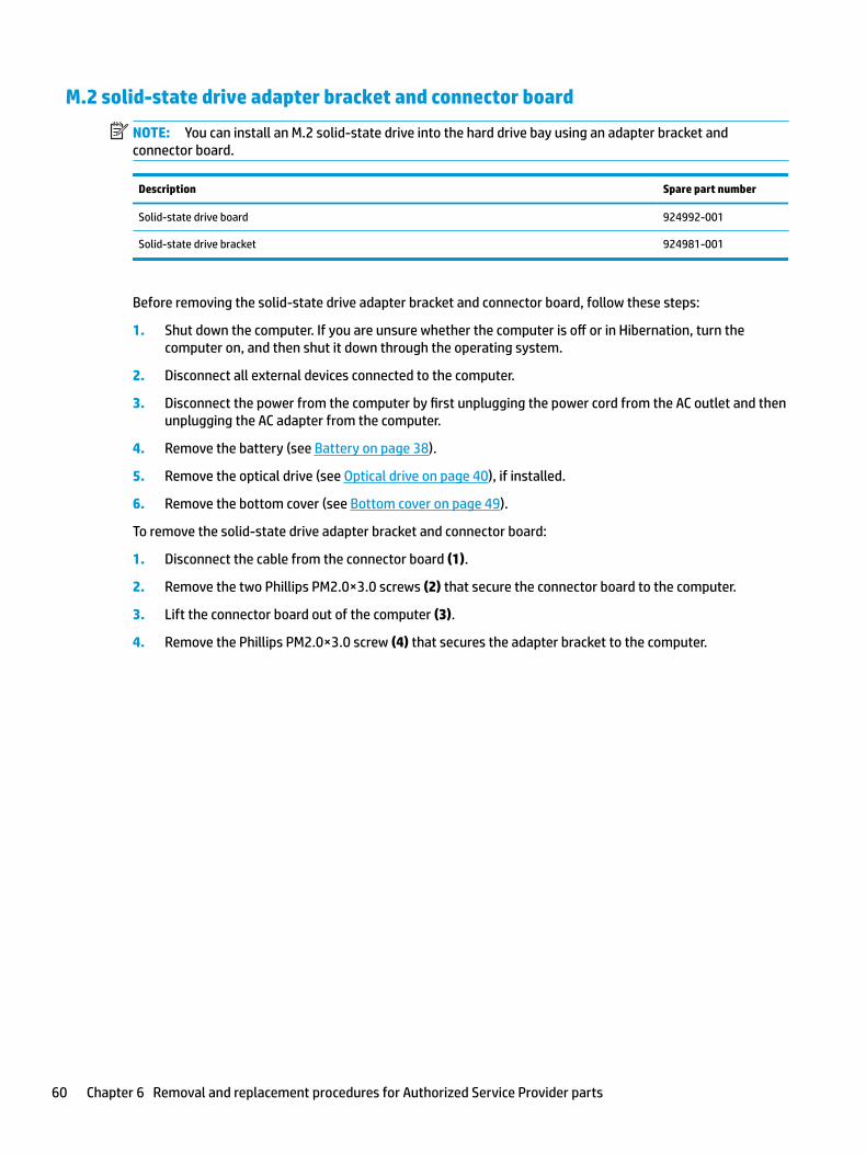
M.2 solid-state drive adapter bracket and connector board
NOTE: You can install an M.2 solid-state drive into the hard drive bay using an adapter bracket and connector board.
Description Spare part number
Solid-state drive board 924992-001
Solid-state drive bracket 924981-001
Before removing the solid-state drive adapter bracket and connector board, follow these steps:
1. Shut down the computer. If you are unsure whether the computer is off or in Hibernation, turn the computer on, and then shut it down through the operating system.
2. Disconnect all external devices connected to the computer.
3. Disconnect the power from the computer by first unplugging the power cord from the AC outlet and then unplugging the AC adapter from the computer.
4. Remove the battery (see Battery on page 38).
5. Remove the optical drive (see Optical drive on page 40), if installed.
6. Remove the bottom cover (see Bottom cover on page 49).
To remove the solid-state drive adapter bracket and connector board:
1. Disconnect the cable from the connector board (1).
2. Remove the two Phillips PM2.0×3.0 screws (2) that secure the connector board to the computer.
3. Lift the connector board out of the computer (3).
4. Remove the Phillips PM2.0×3.0 screw (4) that secures the adapter bracket to the computer.
60 Chapter 6 Removal and replacement procedures for Authorized Service Provider parts
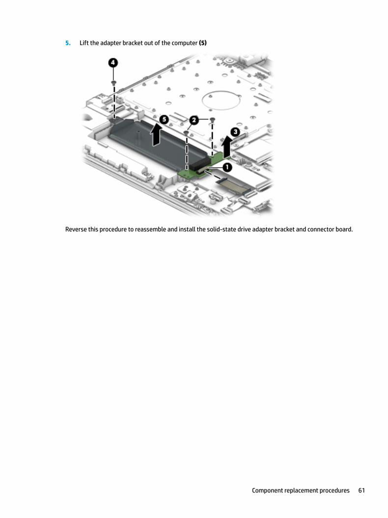
5. Lift the adapter bracket out of the computer (5)
Reverse this procedure to reassemble and install the solid-state drive adapter bracket and connector board.
Component replacement procedures 61
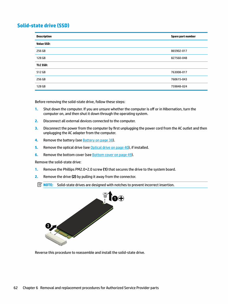
Solid-state drive (SSD)
Description Spare part number
Value SSD:
256 GB 865902-017
128 GB 827560-048
TLC SSD:
512 GB 763008-017
256 GB 760615-043
128 GB 759848-024
Before removing the solid-state drive, follow these steps:
1. Shut down the computer. If you are unsure whether the computer is off or in Hibernation, turn the computer on, and then shut it down through the operating system.
2. Disconnect all external devices connected to the computer.
3. Disconnect the power from the computer by first unplugging the power cord from the AC outlet and then unplugging the AC adapter from the computer.
4. Remove the battery (see Battery on page 38).
5. Remove the optical drive (see Optical drive on page 40), if installed.
6. Remove the bottom cover (see Bottom cover on page 49).
Remove the solid-state drive:
1. Remove the Phillips PM2.0×2.0 screw (1) that secures the drive to the system board.
2. Remove the drive (2) by pulling it away from the connector.
NOTE: Solid-state drives are designed with notches to prevent incorrect insertion.
Reverse this procedure to reassemble and install the solid-state drive.
62 Chapter 6 Removal and replacement procedures for Authorized Service Provider parts
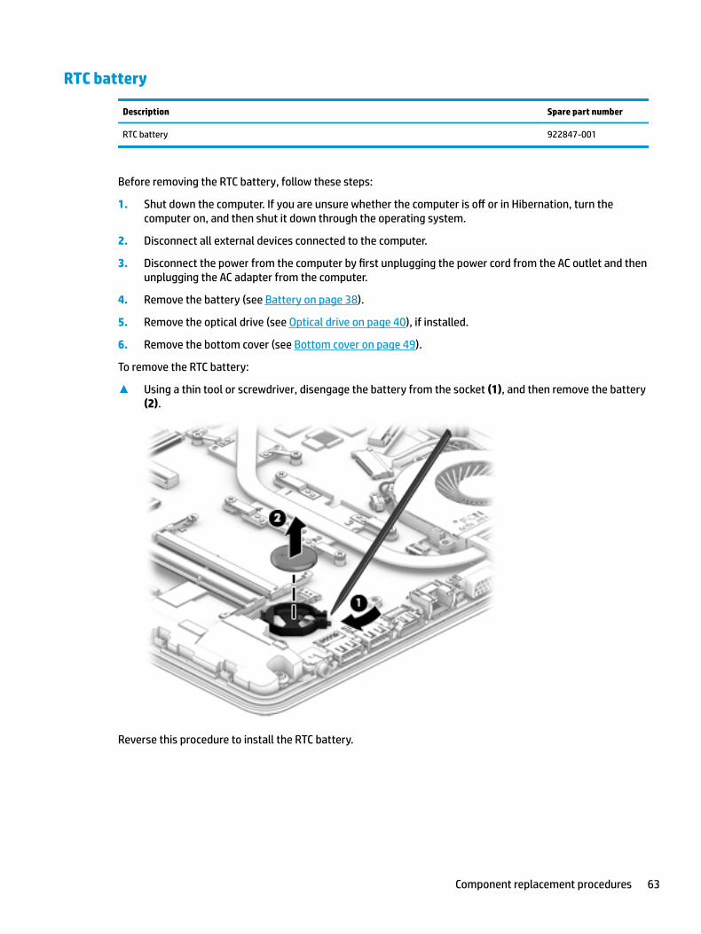
RTC battery
Description Spare part number
RTC battery 922847-001
Before removing the RTC battery, follow these steps:
1. Shut down the computer. If you are unsure whether the computer is off or in Hibernation, turn the computer on, and then shut it down through the operating system.
2. Disconnect all external devices connected to the computer.
3. Disconnect the power from the computer by first unplugging the power cord from the AC outlet and then unplugging the AC adapter from the computer.
4. Remove the battery (see Battery on page 38).
5. Remove the optical drive (see Optical drive on page 40), if installed.
6. Remove the bottom cover (see Bottom cover on page 49).
To remove the RTC battery:
▲ Using a thin tool or screwdriver, disengage the battery from the socket (1), and then remove the battery (2).
Reverse this procedure to install the RTC battery.
Component replacement procedures 63
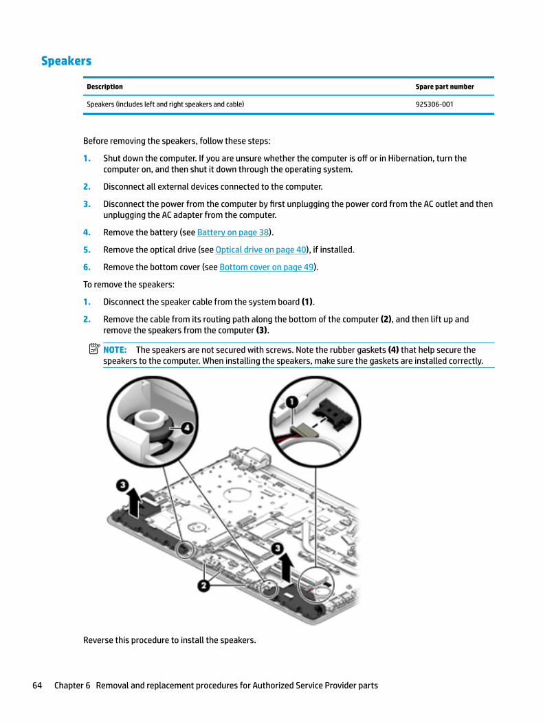
Speakers
Description Spare part number
Speakers (includes left and right speakers and cable) 925306-001
Before removing the speakers, follow these steps:
1. Shut down the computer. If you are unsure whether the computer is off or in Hibernation, turn the computer on, and then shut it down through the operating system.
2. Disconnect all external devices connected to the computer.
3. Disconnect the power from the computer by first unplugging the power cord from the AC outlet and then unplugging the AC adapter from the computer.
4. Remove the battery (see Battery on page 38).
5. Remove the optical drive (see Optical drive on page 40), if installed.
6. Remove the bottom cover (see Bottom cover on page 49).
To remove the speakers:
1. Disconnect the speaker cable from the system board (1).
2. Remove the cable from its routing path along the bottom of the computer (2), and then lift up and remove the speakers from the computer (3).
NOTE: The speakers are not secured with screws. Note the rubber gaskets (4) that help secure the speakers to the computer. When installing the speakers, make sure the gaskets are installed correctly.
Reverse this procedure to install the speakers.
64 Chapter 6 Removal and replacement procedures for Authorized Service Provider parts
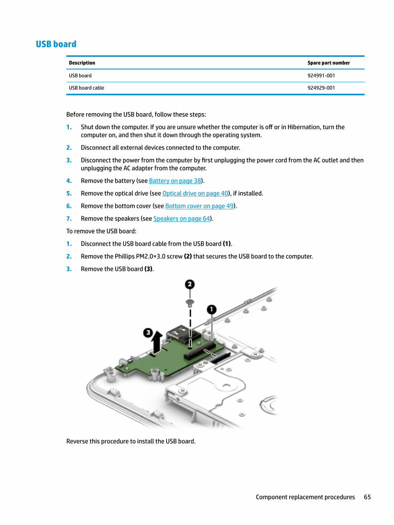
USB board
Description Spare part number
USB board 924991-001
USB board cable 924929-001
Before removing the USB board, follow these steps:
1. Shut down the computer. If you are unsure whether the computer is off or in Hibernation, turn the computer on, and then shut it down through the operating system.
2. Disconnect all external devices connected to the computer.
3. Disconnect the power from the computer by first unplugging the power cord from the AC outlet and then unplugging the AC adapter from the computer.
4. Remove the battery (see Battery on page 38).
5. Remove the optical drive (see Optical drive on page 40), if installed.
6. Remove the bottom cover (see Bottom cover on page 49).
7. Remove the speakers (see Speakers on page 64).
To remove the USB board:
1. Disconnect the USB board cable from the USB board (1).
2. Remove the Phillips PM2.0×3.0 screw (2) that secures the USB board to the computer.
3. Remove the USB board (3).
Reverse this procedure to install the USB board.
Component replacement procedures 65
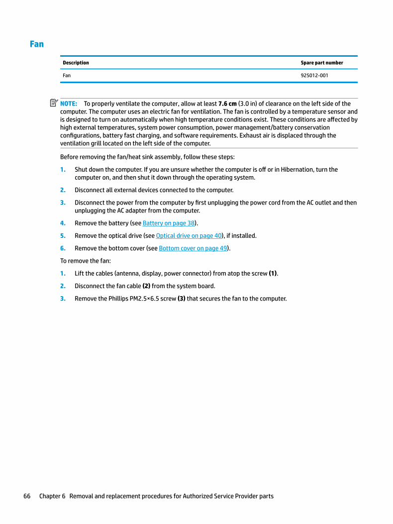
Fan
Description Spare part number
Fan 925012-001
NOTE: To properly ventilate the computer, allow at least 7.6 cm (3.0 in) of clearance on the left side of the computer. The computer uses an electric fan for ventilation. The fan is controlled by a temperature sensor and is designed to turn on automatically when high temperature conditions exist. These conditions are affected by high external temperatures, system power consumption, power management/battery conservation configurations, battery fast charging, and software requirements. Exhaust air is displaced through the ventilation grill located on the left side of the computer.
Before removing the fan/heat sink assembly, follow these steps:
1. Shut down the computer. If you are unsure whether the computer is off or in Hibernation, turn the computer on, and then shut it down through the operating system.
2. Disconnect all external devices connected to the computer.
3. Disconnect the power from the computer by first unplugging the power cord from the AC outlet and then unplugging the AC adapter from the computer.
4. Remove the battery (see Battery on page 38).
5. Remove the optical drive (see Optical drive on page 40), if installed.
6. Remove the bottom cover (see Bottom cover on page 49).
To remove the fan:
1. Lift the cables (antenna, display, power connector) from atop the screw (1).
2. Disconnect the fan cable (2) from the system board.
3. Remove the Phillips PM2.5×6.5 screw (3) that secures the fan to the computer.
66 Chapter 6 Removal and replacement procedures for Authorized Service Provider parts
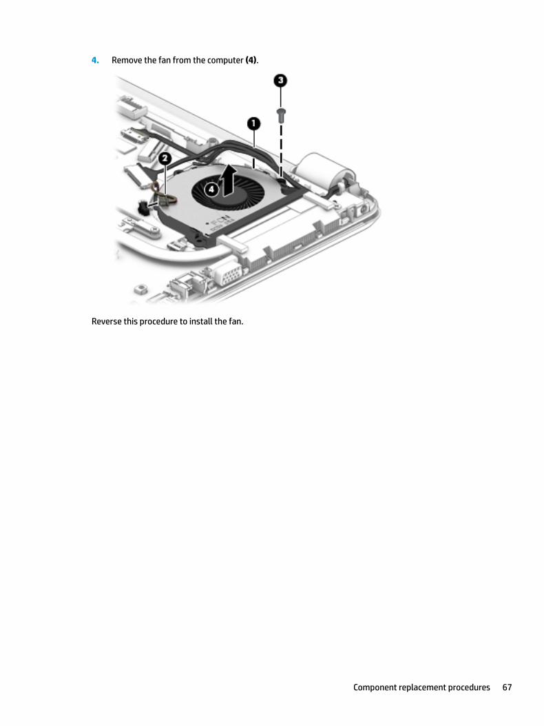
4. Remove the fan from the computer (4).
Reverse this procedure to install the fan.
Component replacement procedures 67
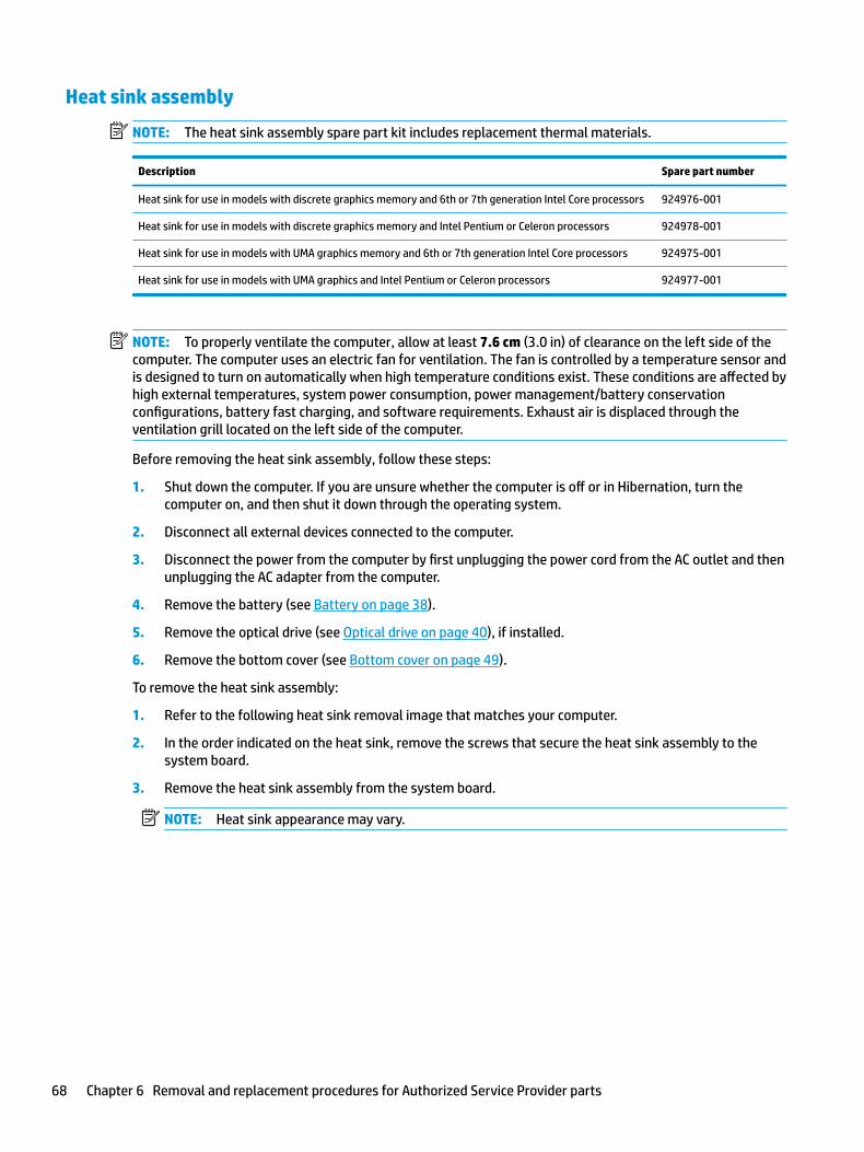
Heat sink assembly
NOTE: The heat sink assembly spare part kit includes replacement thermal materials.
Description Spare part number
Heat sink for use in models with discrete graphics memory and 6th or 7th generation Intel Core processors 924976-001
Heat sink for use in models with discrete graphics memory and Intel Pentium or Celeron processors 924978-001
Heat sink for use in models with UMA graphics memory and 6th or 7th generation Intel Core processors 924975-001
Heat sink for use in models with UMA graphics and Intel Pentium or Celeron processors 924977-001
NOTE: To properly ventilate the computer, allow at least 7.6 cm (3.0 in) of clearance on the left side of the computer. The computer uses an electric fan for ventilation. The fan is controlled by a temperature sensor and is designed to turn on automatically when high temperature conditions exist. These conditions are affected by high external temperatures, system power consumption, power management/battery conservation configurations, battery fast charging, and software requirements. Exhaust air is displaced through the ventilation grill located on the left side of the computer.
Before removing the heat sink assembly, follow these steps:
1. Shut down the computer. If you are unsure whether the computer is off or in Hibernation, turn the computer on, and then shut it down through the operating system.
2. Disconnect all external devices connected to the computer.
3. Disconnect the power from the computer by first unplugging the power cord from the AC outlet and then unplugging the AC adapter from the computer.
4. Remove the battery (see Battery on page 38).
5. Remove the optical drive (see Optical drive on page 40), if installed.
6. Remove the bottom cover (see Bottom cover on page 49).
To remove the heat sink assembly:
1. Refer to the following heat sink removal image that matches your computer.
2. In the order indicated on the heat sink, remove the screws that secure the heat sink assembly to the system board.
3. Remove the heat sink assembly from the system board.
NOTE: Heat sink appearance may vary.
68 Chapter 6 Removal and replacement procedures for Authorized Service Provider parts
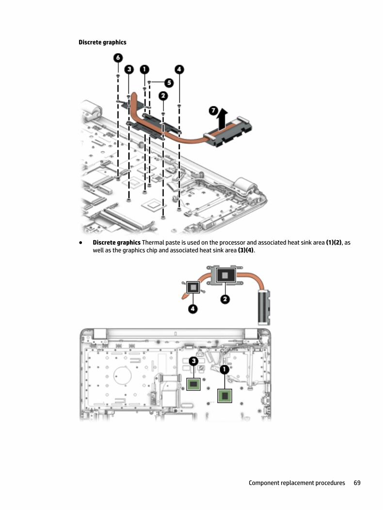
Discrete graphics
● Discrete graphics Thermal paste is used on the processor and associated heat sink area (1)(2), as well as the graphics chip and associated heat sink area (3)(4).
Component replacement procedures 69
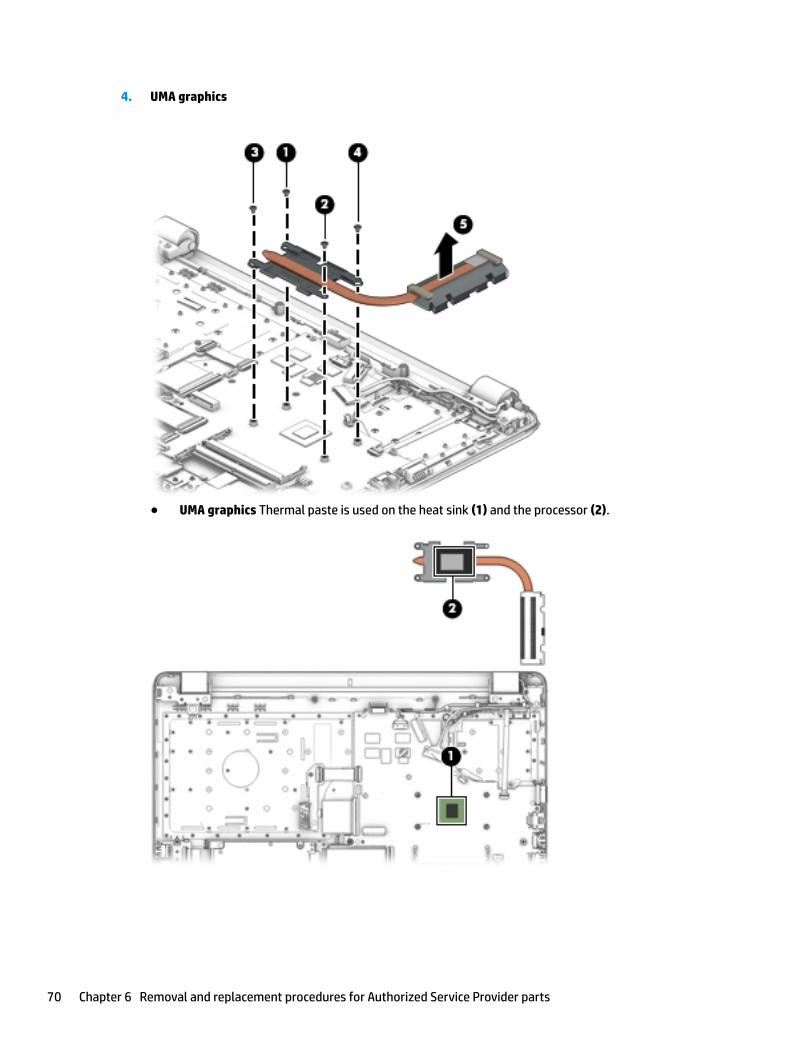
4. UMA graphics
● UMA graphics Thermal paste is used on the heat sink (1) and the processor (2).
70 Chapter 6 Removal and replacement procedures for Authorized Service Provider parts
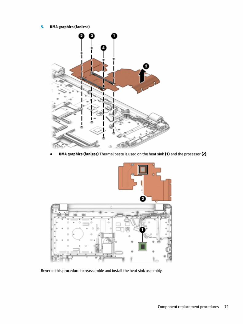
5. UMA graphics (fanless)
● UMA graphics (fanless) Thermal paste is used on the heat sink (1) and the processor (2).
Reverse this procedure to reassemble and install the heat sink assembly.
Component replacement procedures 71
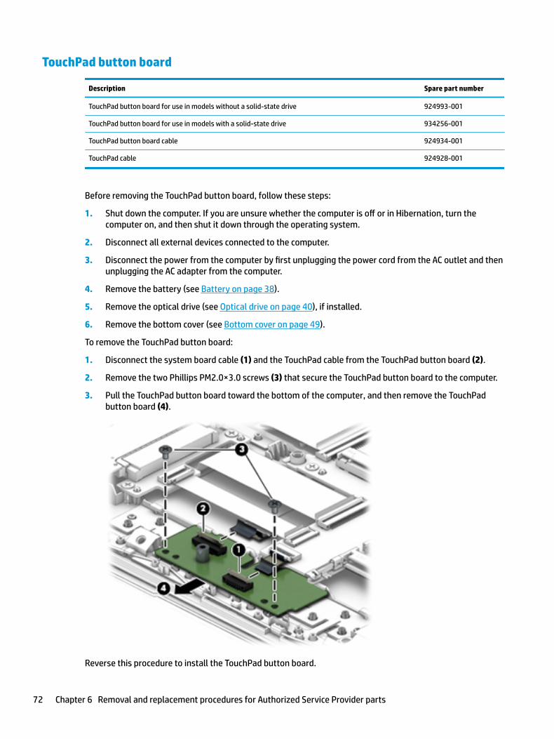
TouchPad button board
Description Spare part number
TouchPad button board for use in models without a solid-state drive 924993-001
TouchPad button board for use in models with a solid-state drive 934256-001
TouchPad button board cable 924934-001
TouchPad cable 924928-001
Before removing the TouchPad button board, follow these steps:
1. Shut down the computer. If you are unsure whether the computer is off or in Hibernation, turn the computer on, and then shut it down through the operating system.
2. Disconnect all external devices connected to the computer.
3. Disconnect the power from the computer by first unplugging the power cord from the AC outlet and then unplugging the AC adapter from the computer.
4. Remove the battery (see Battery on page 38).
5. Remove the optical drive (see Optical drive on page 40), if installed.
6. Remove the bottom cover (see Bottom cover on page 49).
To remove the TouchPad button board:
1. Disconnect the system board cable (1) and the TouchPad cable from the TouchPad button board (2).
2. Remove the two Phillips PM2.0×3.0 screws (3) that secure the TouchPad button board to the computer.
3. Pull the TouchPad button board toward the bottom of the computer, and then remove the TouchPad button board (4).
Reverse this procedure to install the TouchPad button board.
72 Chapter 6 Removal and replacement procedures for Authorized Service Provider parts

System board
NOTE: The system board spare part kit includes replacement thermal materials.
Description Spare part number
System board (includes replacement thermal materials):
All system boards use the following part numbers:
xxxxxx-001: Non-Windows operating systems
xxxxxx-601: Windows 10 operating system
For use in models with discrete graphics memory:
● Intel Core i7-7500U processor and 4 GB of discrete graphics memory 924759-xx1
● Intel Core i7-7500U processor and 2 GB of discrete graphics memory 924757-xx1
● Intel Core i5-8250U processor and 2 GB of discrete graphics memory 934910-xx1
● Intel Core i5-7200U processor and 4 GB of discrete graphics memory 924758-xx1
● Intel Core i5-7200U processor and 2 GB of discrete graphics memory 924756-xx1
● Intel Core i3-6006U processor and 2 GB of discrete graphics memory 924755-xx1
● Intel Core i3-5005U processor and 2 GB of discrete graphics memory L04450-001
● Intel Pentium N3710 processor and 2 GB of discrete graphics memory 924760-xx1
For use in models with UMA graphics memory:
● Intel Core i7-8550U processor 934909-001
● Intel Core i7-7500U processor 924752-xx1
● Intel Core i5-8250U processor 934908-xx1
● Intel Core i5-7200U processor 924751-xx1
● Intel Core i3-7130U processor L02827-001
● Intel Core i3-7100U processor 924749-xx1
● Intel Core i3-6006U processor 924750-xx1
● Intel Core i3-5005U processor L04451-001
● Intel Pentium 4415U processor 938006-xx1
● Intel Pentium N3710 processor 924754-xx1
● Intel Celeron N3060 processor 924753-xx1
939605-xx1
Before removing the system board, follow these steps:
1. Shut down the computer. If you are unsure whether the computer is off or in Hibernation, turn the computer on, and then shut it down through the operating system.
2. Disconnect all external devices connected to the computer.
Component replacement procedures 73
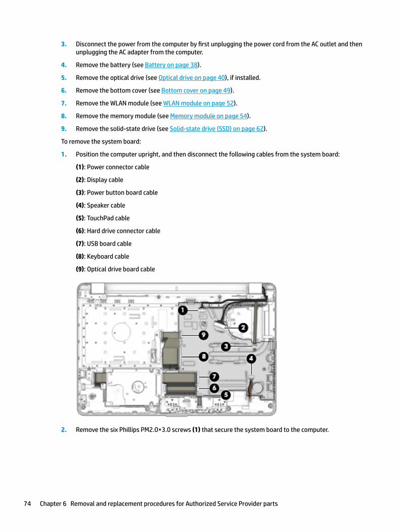
3. Disconnect the power from the computer by first unplugging the power cord from the AC outlet and then unplugging the AC adapter from the computer.
4. Remove the battery (see Battery on page 38).
5. Remove the optical drive (see Optical drive on page 40), if installed.
6. Remove the bottom cover (see Bottom cover on page 49).
7. Remove the WLAN module (see WLAN module on page 52).
8. Remove the memory module (see Memory module on page 54).
9. Remove the solid-state drive (see Solid-state drive (SSD) on page 62).
To remove the system board:
1. Position the computer upright, and then disconnect the following cables from the system board:
(1): Power connector cable
(2): Display cable
(3): Power button board cable
(4): Speaker cable
(5): TouchPad cable
(6): Hard drive connector cable
(7): USB board cable
(8): Keyboard cable
(9): Optical drive board cable
2. Remove the six Phillips PM2.0×3.0 screws (1) that secure the system board to the computer.
74 Chapter 6 Removal and replacement procedures for Authorized Service Provider parts
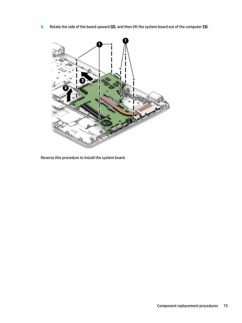
3. Rotate the side of the board upward (2), and then lift the system board out of the computer (3).
Reverse this procedure to install the system board.
Component replacement procedures 75
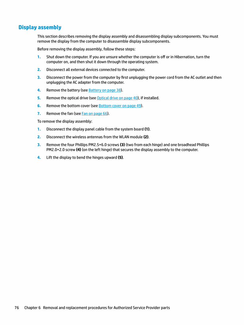
Display assembly
This section describes removing the display assembly and disassembling display subcomponents. You must remove the display from the computer to disassemble display subcomponents.
Before removing the display assembly, follow these steps:
1. Shut down the computer. If you are unsure whether the computer is off or in Hibernation, turn the computer on, and then shut it down through the operating system.
2. Disconnect all external devices connected to the computer.
3. Disconnect the power from the computer by first unplugging the power cord from the AC outlet and then unplugging the AC adapter from the computer.
4. Remove the battery (see Battery on page 38).
5. Remove the optical drive (see Optical drive on page 40), if installed.
6. Remove the bottom cover (see Bottom cover on page 49).
7. Remove the fan (see Fan on page 66).
To remove the display assembly:
1. Disconnect the display panel cable from the system board (1).
2. Disconnect the wireless antennas from the WLAN module (2).
3. Remove the four Phillips PM2.5×6.0 screws (3) (two from each hinge) and one broadhead Phillips PM2.0×2.0 screw (4) (on the left hinge) that secures the display assembly to the computer.
4. Lift the display to bend the hinges upward (5).
76 Chapter 6 Removal and replacement procedures for Authorized Service Provider parts
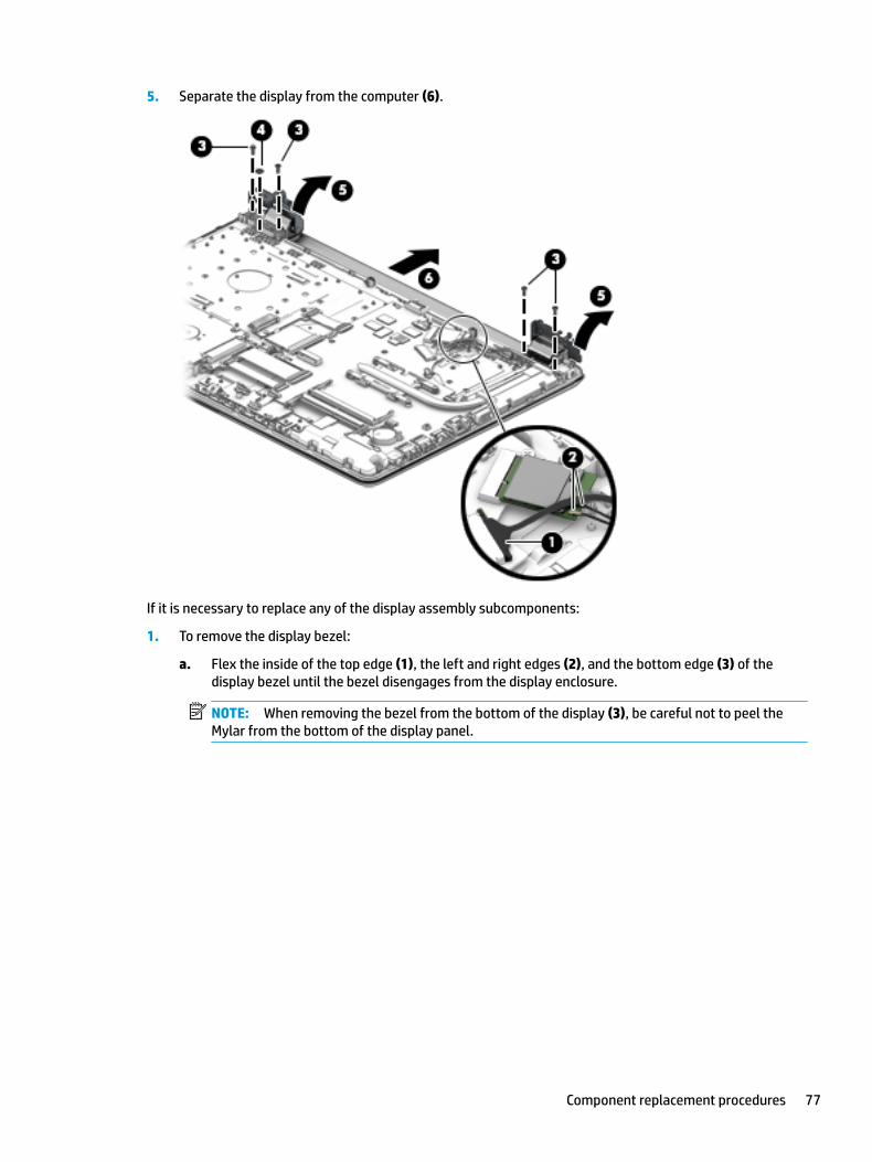
5. Separate the display from the computer (6).
If it is necessary to replace any of the display assembly subcomponents:
1. To remove the display bezel:
a. Flex the inside of the top edge (1), the left and right edges (2), and the bottom edge (3) of the display bezel until the bezel disengages from the display enclosure.
NOTE: When removing the bezel from the bottom of the display (3), be careful not to peel the Mylar from the bottom of the display panel.
Component replacement procedures 77
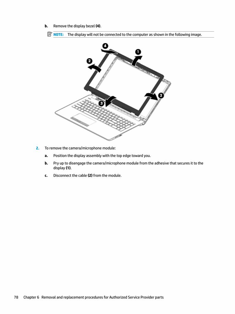
b. Remove the display bezel (4).
NOTE: The display will not be connected to the computer as shown in the following image.
2. To remove the camera/microphone module:
a. Position the display assembly with the top edge toward you.
b. Pry up to disengage the camera/microphone module from the adhesive that secures it to the display (1).
c. Disconnect the cable (2) from the module.
78 Chapter 6 Removal and replacement procedures for Authorized Service Provider parts
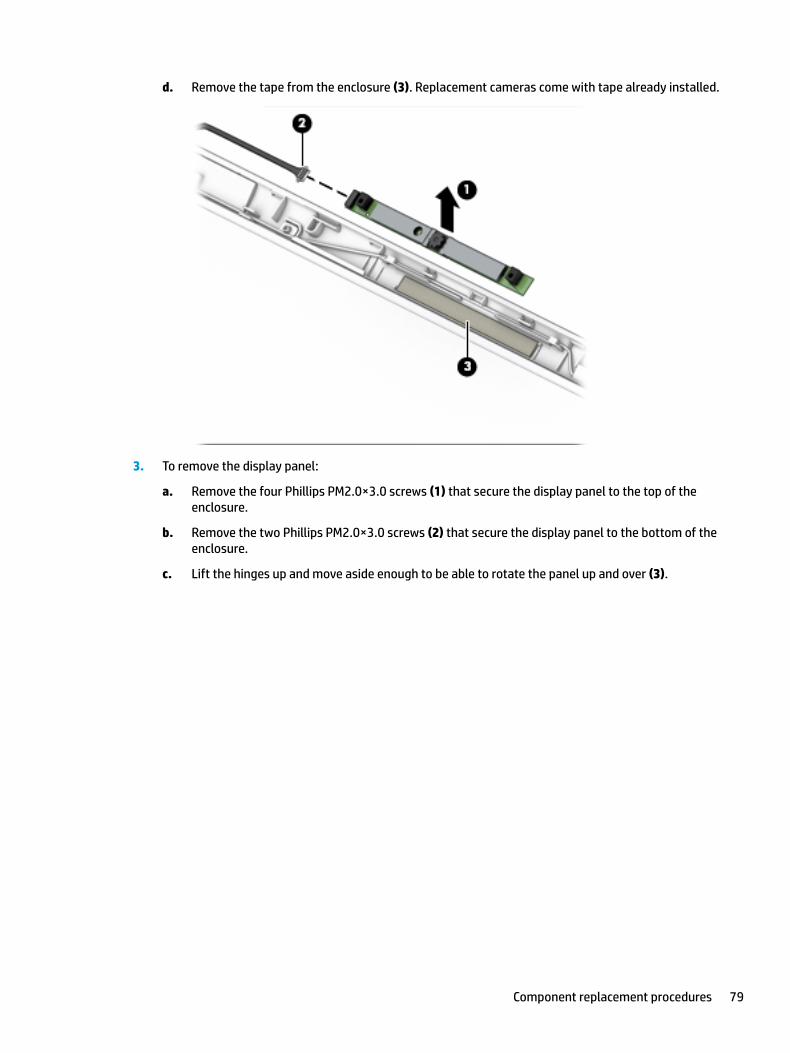
d. Remove the tape from the enclosure (3). Replacement cameras come with tape already installed.
3. To remove the display panel:
a. Remove the four Phillips PM2.0×3.0 screws (1) that secure the display panel to the top of the enclosure.
b. Remove the two Phillips PM2.0×3.0 screws (2) that secure the display panel to the bottom of the enclosure.
c. Lift the hinges up and move aside enough to be able to rotate the panel up and over (3).
Component replacement procedures 79
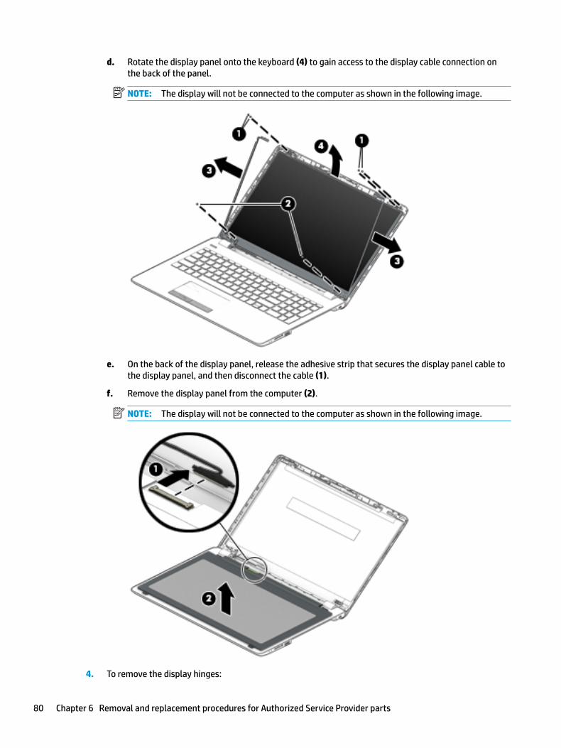
d. Rotate the display panel onto the keyboard (4) to gain access to the display cable connection on the back of the panel.
NOTE: The display will not be connected to the computer as shown in the following image.
e. On the back of the display panel, release the adhesive strip that secures the display panel cable to the display panel, and then disconnect the cable (1).
f. Remove the display panel from the computer (2).
NOTE: The display will not be connected to the computer as shown in the following image.
4. To remove the display hinges:
80 Chapter 6 Removal and replacement procedures for Authorized Service Provider parts
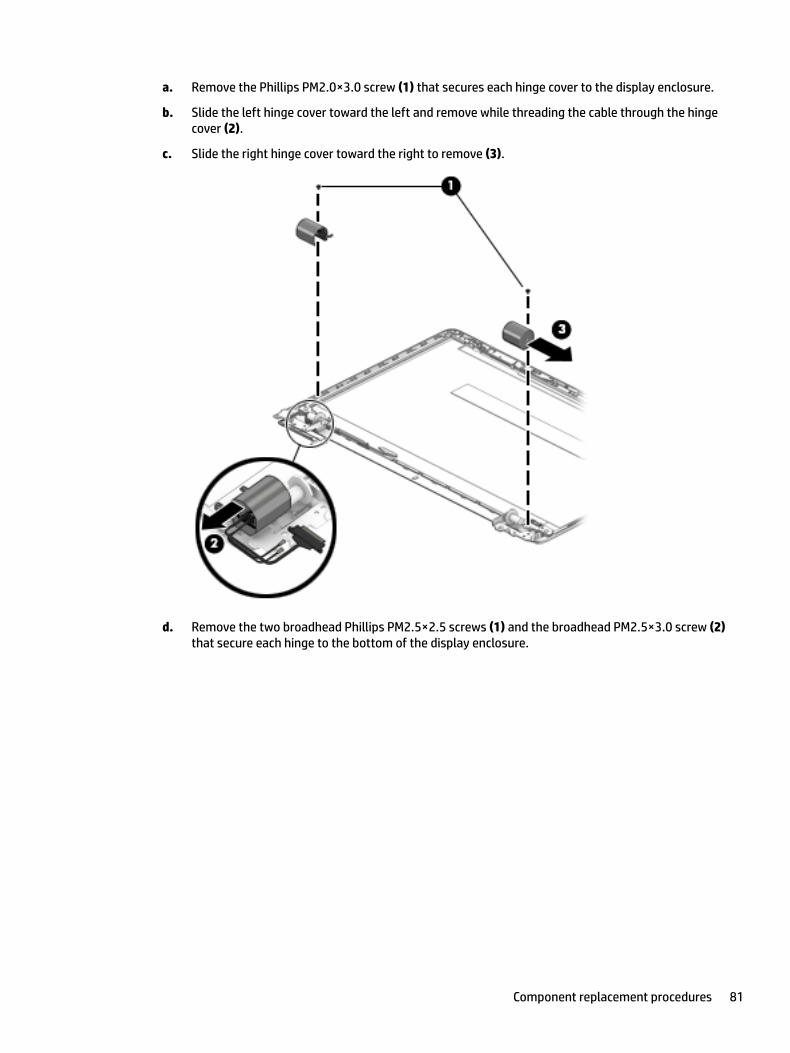
a. Remove the Phillips PM2.0×3.0 screw (1) that secures each hinge cover to the display enclosure.
b. Slide the left hinge cover toward the left and remove while threading the cable through the hinge cover (2).
c. Slide the right hinge cover toward the right to remove (3).
d. Remove the two broadhead Phillips PM2.5×2.5 screws (1) and the broadhead PM2.5×3.0 screw (2) that secure each hinge to the bottom of the display enclosure.
Component replacement procedures 81
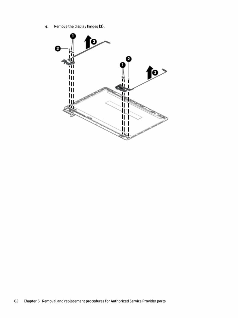
e. Remove the display hinges (3).
82 Chapter 6 Removal and replacement procedures for Authorized Service Provider parts
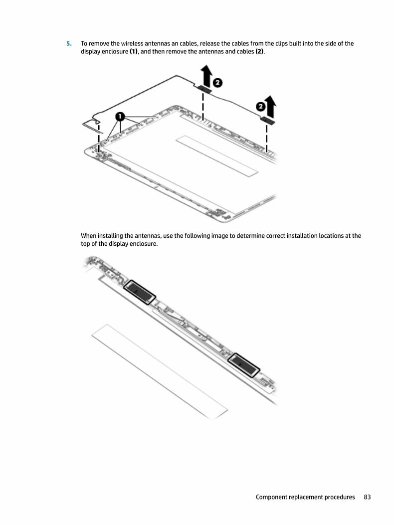
5. To remove the wireless antennas an cables, release the cables from the clips built into the side of the display enclosure (1), and then remove the antennas and cables (2).
When installing the antennas, use the following image to determine correct installation locations at the top of the display enclosure.
Component replacement procedures 83
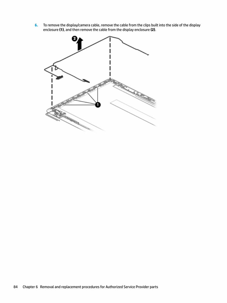
6. To remove the display/camera cable, remove the cable from the clips built into the side of the display enclosure (1), and then remove the cable from the display enclosure (2).
84 Chapter 6 Removal and replacement procedures for Authorized Service Provider parts
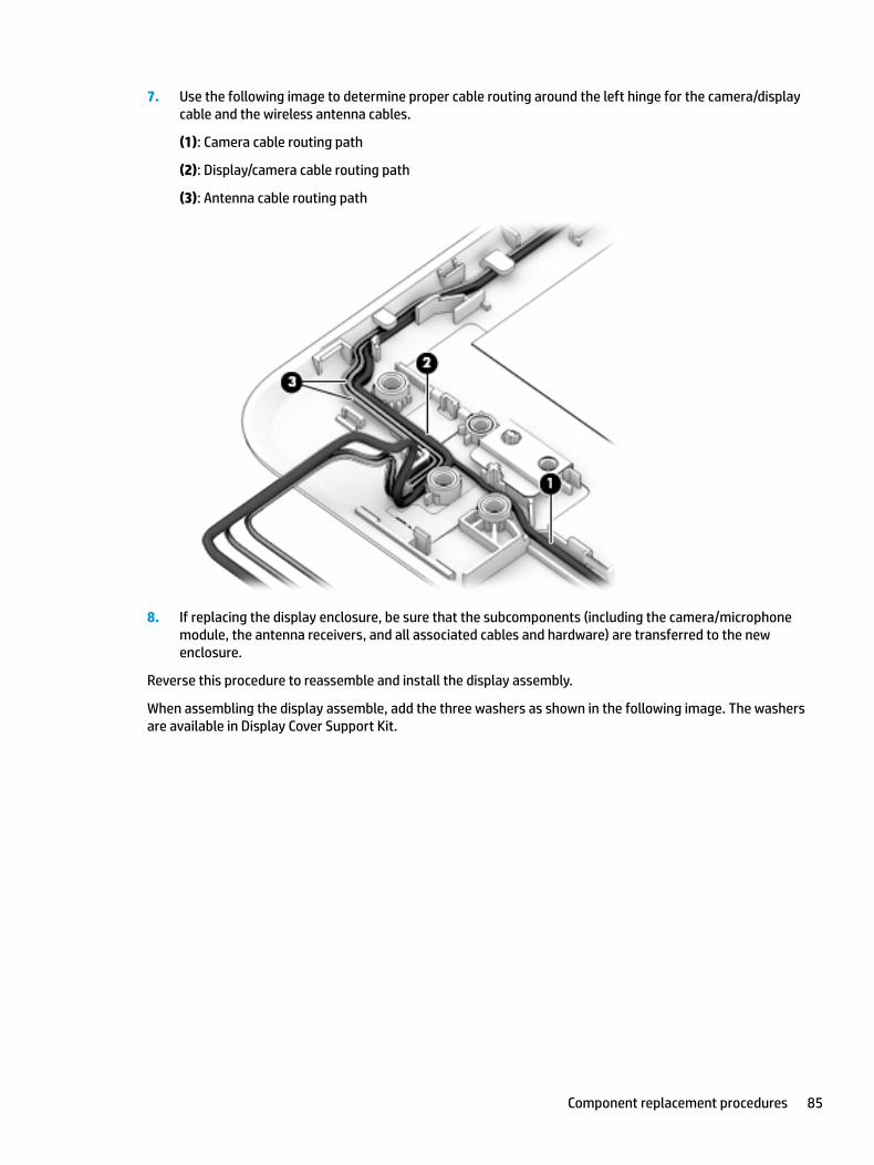
7. Use the following image to determine proper cable routing around the left hinge for the camera/display cable and the wireless antenna cables.
(1): Camera cable routing path
(2): Display/camera cable routing path
(3): Antenna cable routing path
8. If replacing the display enclosure, be sure that the subcomponents (including the camera/microphone module, the antenna receivers, and all associated cables and hardware) are transferred to the new enclosure.
Reverse this procedure to reassemble and install the display assembly.
When assembling the display assemble, add the three washers as shown in the following image. The washers are available in Display Cover Support Kit.
Component replacement procedures 85
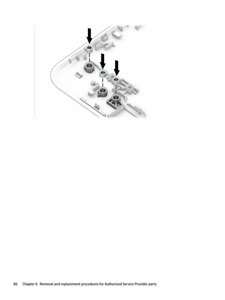
86 Chapter 6 Removal and replacement procedures for Authorized Service Provider parts
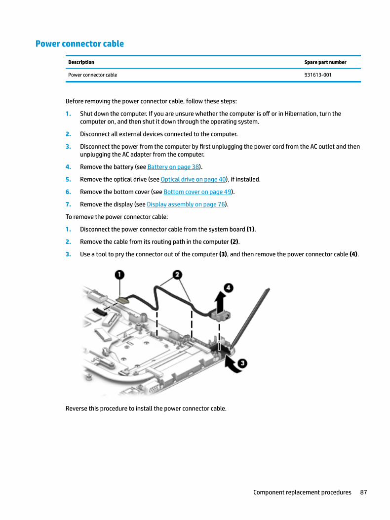
Power connector cable
Description Spare part number
Power connector cable 931613-001
Before removing the power connector cable, follow these steps:
1. Shut down the computer. If you are unsure whether the computer is off or in Hibernation, turn the computer on, and then shut it down through the operating system.
2. Disconnect all external devices connected to the computer.
3. Disconnect the power from the computer by first unplugging the power cord from the AC outlet and then unplugging the AC adapter from the computer.
4. Remove the battery (see Battery on page 38).
5. Remove the optical drive (see Optical drive on page 40), if installed.
6. Remove the bottom cover (see Bottom cover on page 49).
7. Remove the display (see Display assembly on page 76).
To remove the power connector cable:
1. Disconnect the power connector cable from the system board (1).
2. Remove the cable from its routing path in the computer (2).
3. Use a tool to pry the connector out of the computer (3), and then remove the power connector cable (4).
Reverse this procedure to install the power connector cable.
Component replacement procedures 87
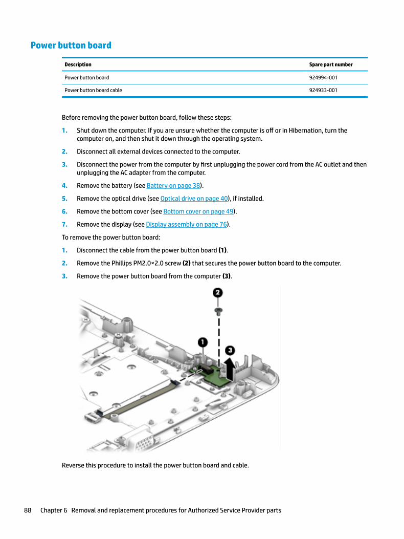
Power button board
Description Spare part number
Power button board 924994-001
Power button board cable 924933-001
Before removing the power button board, follow these steps:
1. Shut down the computer. If you are unsure whether the computer is off or in Hibernation, turn the computer on, and then shut it down through the operating system.
2. Disconnect all external devices connected to the computer.
3. Disconnect the power from the computer by first unplugging the power cord from the AC outlet and then unplugging the AC adapter from the computer.
4. Remove the battery (see Battery on page 38).
5. Remove the optical drive (see Optical drive on page 40), if installed.
6. Remove the bottom cover (see Bottom cover on page 49).
7. Remove the display (see Display assembly on page 76).
To remove the power button board:
1. Disconnect the cable from the power button board (1).
2. Remove the Phillips PM2.0×2.0 screw (2) that secures the power button board to the computer.
3. Remove the power button board from the computer (3).
Reverse this procedure to install the power button board and cable.
88 Chapter 6 Removal and replacement procedures for Authorized Service Provider parts
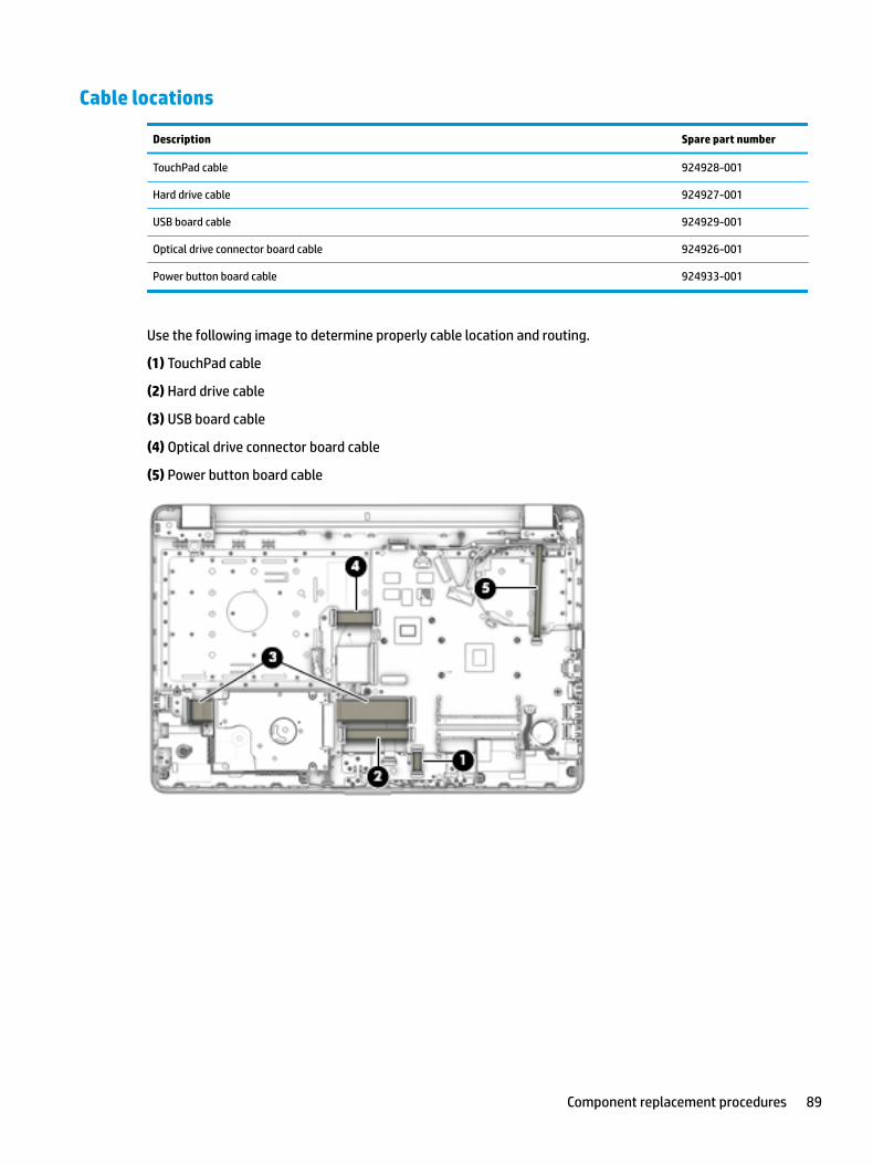
Cable locations
Description Spare part number
TouchPad cable 924928-001
Hard drive cable 924927-001
USB board cable 924929-001
Optical drive connector board cable 924926-001
Power button board cable 924933-001
Use the following image to determine properly cable location and routing.
(1) TouchPad cable
(2) Hard drive cable
(3) USB board cable
(4) Optical drive connector board cable
(5) Power button board cable
Component replacement procedures 89
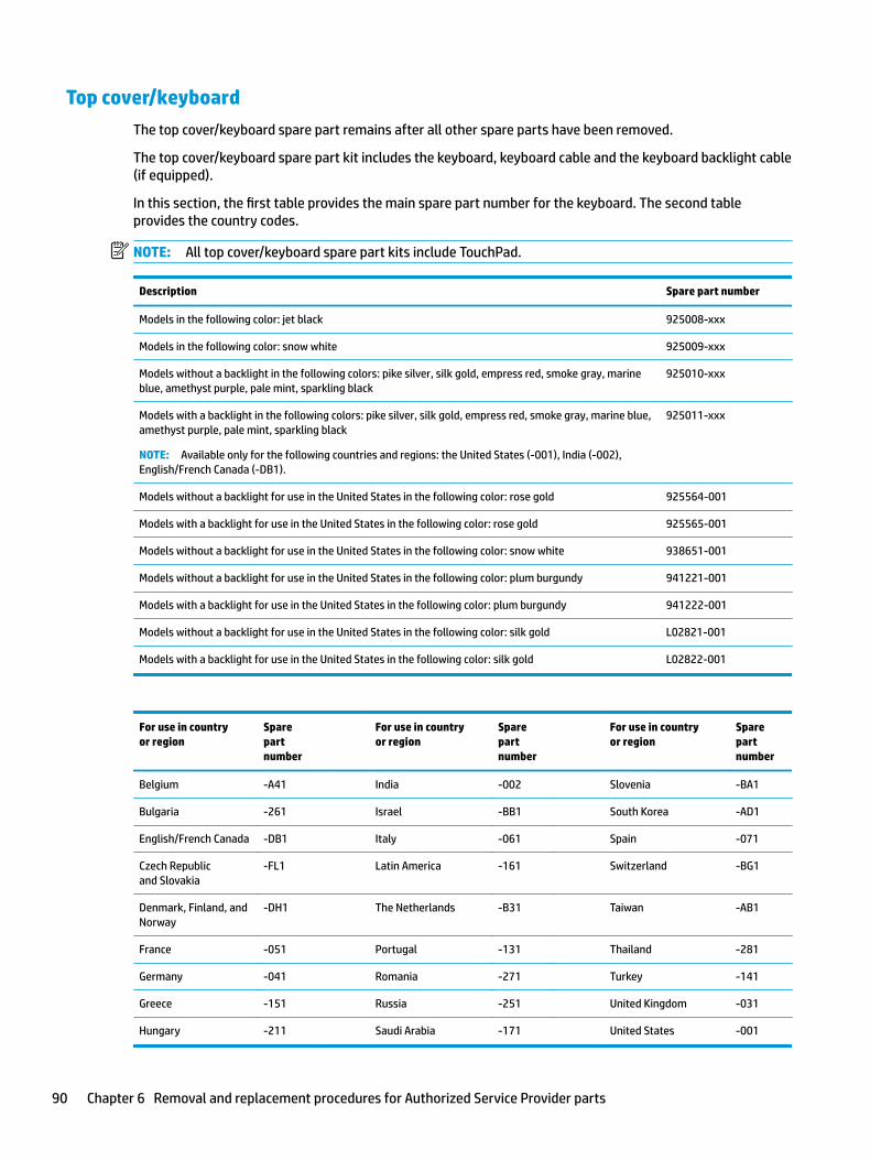
Top cover/keyboard
The top cover/keyboard spare part remains after all other spare parts have been removed.
The top cover/keyboard spare part kit includes the keyboard, keyboard cable and the keyboard backlight cable (if equipped).
In this section, the first table provides the main spare part number for the keyboard. The second table provides the country codes.
NOTE: All top cover/keyboard spare part kits include TouchPad.
Description Spare part number
Models in the following color: jet black 925008-xxx
Models in the following color: snow white 925009-xxx
Models without a backlight in the following colors: pike silver, silk gold, empress red, smoke gray, marine blue, amethyst purple, pale mint, sparkling black
925010-xxx
Models with a backlight in the following colors: pike silver, silk gold, empress red, smoke gray, marine blue, amethyst purple, pale mint, sparkling black
NOTE: Available only for the following countries and regions: the United States (-001), India (-002), English/French Canada (-DB1).
925011-xxx
Models without a backlight for use in the United States in the following color: rose gold 925564-001
Models with a backlight for use in the United States in the following color: rose gold 925565-001
Models without a backlight for use in the United States in the following color: snow white 938651-001
Models without a backlight for use in the United States in the following color: plum burgundy 941221-001
Models with a backlight for use in the United States in the following color: plum burgundy 941222-001
Models without a backlight for use in the United States in the following color: silk gold L02821-001
Models with a backlight for use in the United States in the following color: silk gold L02822-001
For use in country or region
Spare part number
For use in country or region
Spare part number
For use in country or region
Spare part number
Belgium -A41 India -002 Slovenia -BA1
Bulgaria -261 Israel -BB1 South Korea -AD1
English/French Canada -DB1 Italy -061 Spain -071
Czech Republic and Slovakia
-FL1 Latin America -161 Switzerland -BG1
Denmark, Finland, and Norway
-DH1 The Netherlands -B31 Taiwan -AB1
France -051 Portugal -131 Thailand -281
Germany -041 Romania -271 Turkey -141
Greece -151 Russia -251 United Kingdom -031
Hungary -211 Saudi Arabia -171 United States -001
90 Chapter 6 Removal and replacement procedures for Authorized Service Provider parts
7 Using Setup Utility (BIOS)
Setup Utility, or Basic Input/Output System (BIOS), controls communication between all the input and output devices on the system (such as disk drives, display, keyboard, mouse, and printer). Setup Utility (BIOS) includes settings for the types of devices installed, the startup sequence of the computer, and the amount of system and extended memory.
NOTE: To start Setup Utility on convertible computers, your computer must be in notebook mode and you must use the keyboard attached to your notebook.
Starting Setup Utility (BIOS)CAUTION: Use extreme care when making changes in Setup Utility (BIOS). Errors can prevent the computer from operating properly.
▲ Turn on or restart the computer, quickly press esc, and then press f10.
Updating Setup Utility (BIOS)Updated versions of Setup Utility (BIOS) may be available on the HP website.
Most BIOS updates on the HP website are packaged in compressed files called SoftPaqs.
Some download packages contain a file named Readme.txt, which contains information regarding installing and troubleshooting the file.
Determining the BIOS version
To decide whether you need to update Setup Utility (BIOS), first determine the BIOS version on your computer.
To reveal the BIOS version information (also known as ROM date and System BIOS), use one of these options.
● HP Support Assistant
1. Type support in the taskbar search box, and then select the HP Support Assistant app.
– or –
Click the question mark icon in the taskbar.
2. Select My PC, and then select Specifications.
● Setup Utility (BIOS)
1. Start Setup Utility (BIOS) (see Starting Setup Utility (BIOS) on page 91).
2. Select Main, select System Information, and then make note of the BIOS version.
3. Select Exit, select No, and then follow the on-screen instructions.
To check for later BIOS versions, see Downloading a BIOS update on page 92.
Starting Setup Utility (BIOS) 91
Downloading a BIOS update
CAUTION: To reduce the risk of damage to the computer or an unsuccessful installation, download and install a BIOS update only when the computer is connected to reliable external power using the AC adapter. Do not download or install a BIOS update while the computer is running on battery power, docked in an optional docking device, or connected to an optional power source. During the download and installation, follow these instructions:
● Do not disconnect power from the computer by unplugging the power cord from the AC outlet.
● Do not shut down the computer or initiate Sleep.
● Do not insert, remove, connect, or disconnect any device, cable, or cord.
NOTE: If your computer is connected to a network, consult the network administrator before installing any software updates, especially system BIOS updates.
1. Type support in the taskbar search box, and then select the HP Support Assistant app.
– or –
Click the question mark icon in the taskbar.
2. Click Updates, and then click Check for updates and messages.
3. Follow the on-screen instructions.
4. At the download area, follow these steps:
a. Identify the most recent BIOS update and compare it to the BIOS version currently installed on your computer. If the update is more recent than your BIOS version, make a note of the date, name, or other identifier. You may need this information to locate the update later, after it has been downloaded to your hard drive.
b. Follow the on-screen instructions to download your selection to the hard drive.
Make a note of the path to the location on your hard drive where the BIOS update is downloaded. You will need to access this path when you are ready to install the update.
BIOS installation procedures vary. Follow any instructions that appear on the screen after the download is complete. If no instructions appear, follow these steps:
1. Type file in the taskbar search box, and then select File Explorer.
2. Click your hard drive designation. The hard drive designation is typically Local Disk (C:).
3. Using the hard drive path you recorded earlier, open the folder that contains the update.
4. Double-click the file that has an .exe extension (for example, filename.exe).
The BIOS installation begins.
5. Complete the installation by following the on-screen instructions.
NOTE: After a message on the screen reports a successful installation, you can delete the downloaded file from your hard drive.
92 Chapter 7 Using Setup Utility (BIOS)
8 Backing up, restoring, and recovering
This chapter provides information about the following processes. The information in the chapter is standard procedure for most products.
● Creating recovery media and backups
● Restoring and recovering your system
For additional information, refer to the HP Support Assistant app.
▲ Type support in the taskbar search box, and then select the HP Support Assistant app.
‒ or –
Select the question mark icon in the taskbar.
IMPORTANT: If you will be performing recovery procedures on a tablet, the tablet battery must be at least 70% charged before you start the recovery process.
IMPORTANT: For a tablet with a detachable keyboard, connect the tablet to the keyboard base before beginning any recovery process.
Creating recovery media and backupsThe following methods of creating recovery media and backups are available on select products only. Choose the available method according to your computer model.
● Use HP Recovery Manager to create HP Recovery media after you successfully set up the computer. This step creates a backup of the HP Recovery partition on the computer. The backup can be used to reinstall the original operating system in cases where the hard drive is corrupted or has been replaced. For information on creating recovery media, see Creating HP Recovery media (select products only) on page 93. For information on the recovery options that are available using the recovery media, see Using Windows tools on page 94.
● Use Windows tools to create system restore points and create backups of personal information.
For more information, see Recovering using HP Recovery Manager on page 95.
NOTE: If storage is 32 GB or less, Microsoft System Restore is disabled by default.
Creating HP Recovery media (select products only)
If possible, check for the presence of the Recovery partition and the Windows partition. From the Start menu, select File Explorer, and then select This PC.
● If your computer does not list the Windows partition and the Recovery partition, you can obtain recovery media for your system from support. See the Worldwide Telephone Numbers booklet included with the computer. You can also find contact information on the HP website. Go to http://www.hp.com/support, select your country or region, and follow the on-screen instructions.
Creating recovery media and backups 93
You can use Windows tools to create system restore points and create backups of personal information, see Using Windows tools on page 94.
● If your computer does list the Recovery partition and the Windows partition, you can use HP Recovery Manager to create recovery media after you successfully set up the computer. HP Recovery media can be used to perform system recovery if the hard drive becomes corrupted. System recovery reinstalls the original operating system and software programs that were installed at the factory and then configures the settings for the programs. HP Recovery media can also be used to customize the system or restore the factory image if you replace the hard drive.
– Only one set of recovery media can be created. Handle these recovery tools carefully, and keep them in a safe place.
– HP Recovery Manager examines the computer and determines the required storage capacity for the media that will be required.
– To create recovery discs, your computer must have an optical drive with DVD writer capability, and you must use only high-quality blank DVD-R, DVD+R, DVD-R DL, or DVD+R DL discs. Do not use rewritable discs such as CD±RW, DVD±RW, double-layer DVD±RW, or BD-RE (rewritable Blu-ray) discs; they are not compatible with HP Recovery Manager software. Or, instead, you can use a high-quality blank USB flash drive.
– If your computer does not include an integrated optical drive with DVD writer capability, but you would like to create DVD recovery media, you can use an external optical drive (purchased separately) to create recovery discs. If you use an external optical drive, it must be connected directly to a USB port on the computer; the drive cannot be connected to a USB port on an external device, such as a USB hub. If you cannot create DVD media yourself, you can obtain recovery discs for your computer from HP. See the Worldwide Telephone Numbers booklet included with the computer. You can also find contact information on the HP website. Go to http://www.hp.com/support, select your country or region, and follow the on-screen instructions.
– Be sure that the computer is connected to AC power before you begin creating the recovery media.
– The creation process can take an hour or more. Do not interrupt the creation process.
– If necessary, you can exit the program before you have finished creating all of the recovery DVDs. HP Recovery Manager will finish burning the current DVD. The next time you start HP Recovery Manager, you will be prompted to continue.
To create HP Recovery media:
IMPORTANT: For a tablet with a detachable keyboard, connect the tablet to the keyboard base before beginning these steps.
1. Type recovery in the taskbar search box, and then select HP Recovery Manager.
2. Select Create recovery media, and then follow the on-screen instructions.
If you ever need to recover the system, see Recovering using HP Recovery Manager on page 95.
Using Windows toolsYou can create recovery media, system restore points, and backups of personal information using Windows tools.
NOTE: If storage is 32 GB or less, Microsoft System Restore is disabled by default.
For more information and steps, see the Get started app.
▲ Select the Start button, and then select the Get started app.
94 Chapter 8 Backing up, restoring, and recovering
Restore and recoveryThere are several options for recovering your system. Choose the method that best matches your situation and level of expertise:
IMPORTANT: Not all methods are available on all products.
● Windows offers several options for restoring from backup, refreshing the computer, and resetting the computer to its original state. For more information see the Get started app.
▲ Select the Start button, and then select the Get started app.
● If you need to correct a problem with a preinstalled application or driver, use the Reinstall drivers and/or applications option (select products only) of HP Recovery Manager to reinstall the individual application or driver.
▲ Type recovery in the taskbar search box, select HP Recovery Manager, select Reinstall drivers and/or applications, and then follow the on-screen instructions.
● If you want to recover the Windows partition to original factory content, you can choose the System Recovery option from the HP Recovery partition (select products only) or use the HP Recovery media. For more information, see Recovering using HP Recovery Manager on page 95. If you have not already created recovery media, see Creating HP Recovery media (select products only) on page 93.
● On select products, if you want to recover the computer's original factory partition and content, or if you have replaced the hard drive, you can use the Factory Reset option of HP Recovery media. For more information, see Recovering using HP Recovery Manager on page 95.
● On select products, if you want to remove the Recovery partition to reclaim hard drive space, HP Recovery Manager offers the Remove Recovery Partition option.
For more information, see Removing the HP Recovery partition (select products only) on page 98.
Recovering using HP Recovery Manager
HP Recovery Manager software allows you to recover the computer to its original factory state by using the HP Recovery media that you either created or that you obtained from HP, or by using the HP Recovery partition (select products only). If you have not already created recovery media, see Creating HP Recovery media (select products only) on page 93.
What you need to know before you get started
● HP Recovery Manager recovers only software that was installed at the factory. For software not provided with this computer, you must either download the software from the manufacturer's website or reinstall the software from the media provided by the manufacturer.
IMPORTANT: Recovery through HP Recovery Manager should be used as a final attempt to correct computer issues.
● HP Recovery media must be used if the computer hard drive fails. If you have not already created recovery media, see Creating HP Recovery media (select products only) on page 93.
● To use the Factory Reset option (select products only), you must use HP Recovery media. If you have not already created recovery media, see Creating HP Recovery media (select products only) on page 93.
● If your computer does not allow the creation of HP Recovery media or if the HP Recovery media does not work, you can obtain recovery media for your system from support. See the Worldwide Telephone Numbers booklet included with the computer. You can also find contact information from the HP
Restore and recovery 95
website. Go to http://www.hp.com/support, select your country or region, and follow the on-screen instructions.
IMPORTANT: HP Recovery Manager does not automatically provide backups of your personal data. Before beginning recovery, back up any personal data you want to retain.
Using HP Recovery media, you can choose from one of the following recovery options:
NOTE: Only the options available for your computer display when you start the recovery process.
● System Recovery—Reinstalls the original operating system, and then configures the settings for the programs that were installed at the factory.
● Factory Reset—Restores the computer to its original factory state by deleting all information from the hard drive and re-creating the partitions. Then it reinstalls the operating system and the software that was installed at the factory.
The HP Recovery partition (select products only) allows System Recovery only.
Using the HP Recovery partition (select products only)
The HP Recovery partition allows you to perform a system recovery without the need for recovery discs or a recovery USB flash drive. This type of recovery can be used only if the hard drive is still working.
To start HP Recovery Manager from the HP Recovery partition:
IMPORTANT: For a tablet with a detachable keyboard, connect the tablet to the keyboard base before beginning these steps (select products only).
1. Type recovery in the taskbar search box, select Recovery Manager, and then select HP Recovery Environment.
‒ or –
For computers or tablets with keyboards attached, press f11 while the computer boots, or press and hold f11 as you press the power button.
For tablets without keyboards:
● Turn on or restart the tablet, and then quickly hold down the volume up button; then select f11.
‒ or –
● Turn on or restart the tablet, and then quickly hold down the volume down button; then select f11.
2. Select Troubleshoot from the boot options menu.
3. Select Recovery Manager, and then follow the on-screen instructions.
Using HP Recovery media to recover
You can use HP Recovery media to recover the original system. This method can be used if your system does not have an HP Recovery partition or if the hard drive is not working properly.
1. If possible, back up all personal files.
2. Insert the HP Recovery media, and then restart the computer.
NOTE: If the computer does not automatically restart in HP Recovery Manager, change the computer boot order. See Changing the computer boot order on page 97.
3. Follow the on-screen instructions.
96 Chapter 8 Backing up, restoring, and recovering
Changing the computer boot order
If your computer does not restart in HP Recovery Manager, you can change the computer boot order, which is the order of devices listed in BIOS where the computer looks for startup information. You can change the selection to an optical drive or a USB flash drive.
To change the boot order:
IMPORTANT: For a tablet with a detachable keyboard, connect the tablet to the keyboard base before beginning these steps.
1. Insert the HP Recovery media.
2. Access the system Startup menu.
For computers or tablets with keyboards attached:
▲ Turn on or restart the computer or tablet, quickly press esc, and then press f9 for boot options.
For tablets without keyboards:
▲ Turn on or restart the tablet, and then quickly hold down the volume up button; then select f9.
‒ or –
Turn on or restart the tablet, and then quickly hold down the volume down button; then select f9.
3. Select the optical drive or USB flash drive from which you want to boot.
4. Follow the on-screen instructions.
Restore and recovery 97
Removing the HP Recovery partition (select products only)
HP Recovery Manager software allows you to remove the HP Recovery partition to free up hard drive space.
IMPORTANT: After you remove the HP Recovery partition, you will not be able to perform System Recovery or create HP Recovery media from the HP Recovery partition. So before you remove the Recovery partition, create HP Recovery media; see Creating HP Recovery media (select products only) on page 93.
NOTE: The Remove Recovery Partition option is only available on products that support this function.
Follow these steps to remove the HP Recovery partition:
1. Type recovery in the taskbar search box, and then select HP Recovery Manager.
2. Select Remove Recovery Partition, and then follow the on-screen instructions.
98 Chapter 8 Backing up, restoring, and recovering
9 Using HP PC Hardware Diagnostics (UEFI)
HP PC Hardware Diagnostics is a Unified Extensible Firmware Interface (UEFI) that allows you to run diagnostic tests to determine whether the computer hardware is functioning properly. The tool runs outside the operating system so that it can isolate hardware failures from issues that are caused by the operating system or other software components.
When HP PC Hardware Diagnostics (UEFI) detects a failure that requires hardware replacement, a 24-digit Failure ID code is generated. This ID code can then be provided to support to help determine how to correct the problem.
NOTE: To start diagnostics on a convertible computer, your computer must be in notebook mode and you must use the keyboard attached.
To start HP PC Hardware Diagnostics (UEFI), follow these steps:
1. Turn on or restart the computer, and quickly press esc.
2. Press f2.
The BIOS searches three places for the diagnostic tools, in the following order:
a. Connected USB drive
NOTE: To download the HP PC Hardware Diagnostics (UEFI) tool to a USB drive, see Downloading HP PC Hardware Diagnostics (UEFI) to a USB device on page 99.
b. Hard drive
c. BIOS
3. When the diagnostic tool opens, select the type of diagnostic test you want to run, and then follow the on-screen instructions.
NOTE: If you need to stop a diagnostic test, press esc.
Downloading HP PC Hardware Diagnostics (UEFI) to a USB deviceNOTE: The HP PC Hardware Diagnostics (UEFI) download instructions are provided in English only, and you must use a Windows computer to download and create the HP UEFI support environment because only .exe files are offered.
There are two options to download HP PC Hardware Diagnostics to a USB device.
Download the latest UEFI version
1. Go to http://www.hp.com/go/techcenter/pcdiags. The HP PC Diagnostics home page is displayed.
2. In the HP PC Hardware Diagnostics section, select the Download link, and then select Run.
Download any version of UEFI for a specific product
1. Go to http://www.hp.com/support.
2. Select Get software and drivers.
Downloading HP PC Hardware Diagnostics (UEFI) to a USB device 99
3. Enter the product name or number.
– or –
Select Identify now to let HP automatically detect your product.
4. Select your computer, and then select your operating system.
5. In the Diagnostic section, follow the on-screen instructions to select and download the UEFI version you want.
Additional BIOS crisis recovery tool
HP provides a BIOS crisis recovery tool through the HP PC Hardware Diagnostics 3-in-1 USB key. This tool can be used by HP authorized service providers to recover systems that have failed due to a corrupted BIOS. For more information about using the 3-in-1 USB key for BIOS crisis recovery, go to http://www.hp.com/go/techcenter/pcdiags. Additional information is included in the web-based training offered by HP University. See the modules that cover HP PC Hardware Diagnostics (UEFI).
100 Chapter 9 Using HP PC Hardware Diagnostics (UEFI)
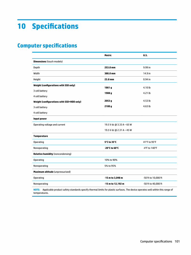
10 Specifications
Computer specifications
Metric U.S.
Dimensions (touch models)
Depth 253.8 mm 9.99 in
Width 380.0 mm 14.9 in
Height 23.8 mm 0.94 in
Weight (configurations with SSD only)
3 cell battery
4 cell battery
Weight (configurations with SSD+HDD only)
3 cell battery
4 cell battery
1861 g
1908 g
2053 g
2100 g
4.10 lb
4.21 lb
4.53 lb
4.63 lb
Input power
Operating voltage and current 19.5 V dc @ 3.33 A – 65 W
19.5 V dc @ 2.31 A – 45 W
Temperature
Operating 5°C to 35°C 41°F to 95°F
Nonoperating ‑20°C to 60°C ‑4°F to 140°F
Relative humidity (noncondensing)
Operating 10% to 90%
Nonoperating 5% to 95%
Maximum altitude (unpressurized)
Operating ‑15 m to 3,048 m ‑50 ft to 10,000 ft
Nonoperating ‑15 m to 12,192 m ‑50 ft to 40,000 ft
NOTE: Applicable product safety standards specify thermal limits for plastic surfaces. The device operates well within this range of temperatures.
Computer specifications 101
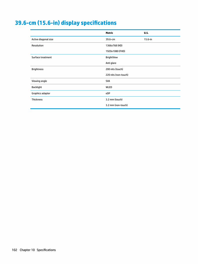
39.6-cm (15.6-in) display specifications
Metric U.S.
Active diagonal size 39.6-cm 15.6-in
Resolution 1366x768 (HD)
1920x1080 (FHD)
Surface treatment BrightView
Anti glare
Brightness 200 nits (touch)
220 nits (non-touch)
Viewing angle SVA
Backlight WLED
Graphics adapter eDP
Thickness 3.2 mm (touch)
3.2 mm (non-touch)
102 Chapter 10 Specifications
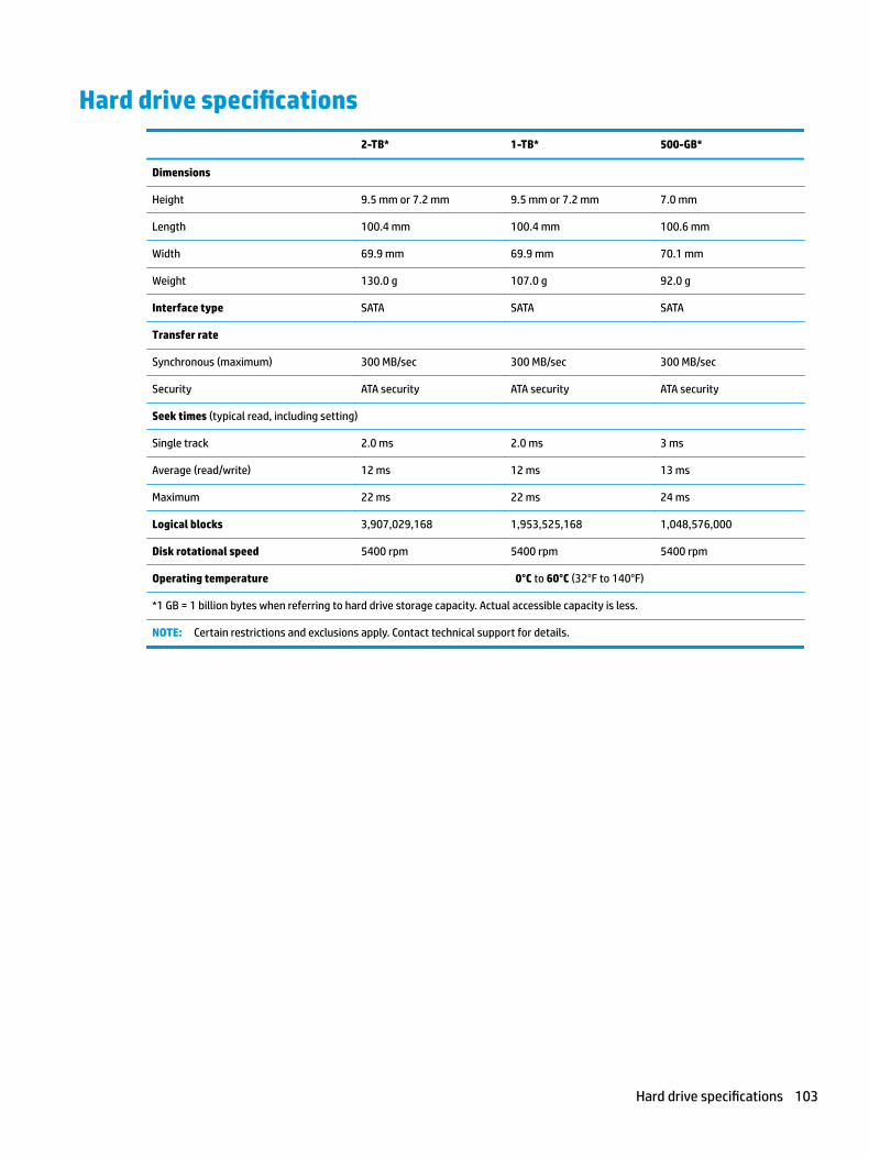
Hard drive specifications
2-TB* 1-TB* 500-GB*
Dimensions
Height 9.5 mm or 7.2 mm 9.5 mm or 7.2 mm 7.0 mm
Length 100.4 mm 100.4 mm 100.6 mm
Width 69.9 mm 69.9 mm 70.1 mm
Weight 130.0 g 107.0 g 92.0 g
Interface type SATA SATA SATA
Transfer rate
Synchronous (maximum) 300 MB/sec 300 MB/sec 300 MB/sec
Security ATA security ATA security ATA security
Seek times (typical read, including setting)
Single track 2.0 ms 2.0 ms 3 ms
Average (read/write) 12 ms 12 ms 13 ms
Maximum 22 ms 22 ms 24 ms
Logical blocks 3,907,029,168 1,953,525,168 1,048,576,000
Disk rotational speed 5400 rpm 5400 rpm 5400 rpm
Operating temperature 0°C to 60°C (32°F to 140°F)
*1 GB = 1 billion bytes when referring to hard drive storage capacity. Actual accessible capacity is less.
NOTE: Certain restrictions and exclusions apply. Contact technical support for details.
Hard drive specifications 103
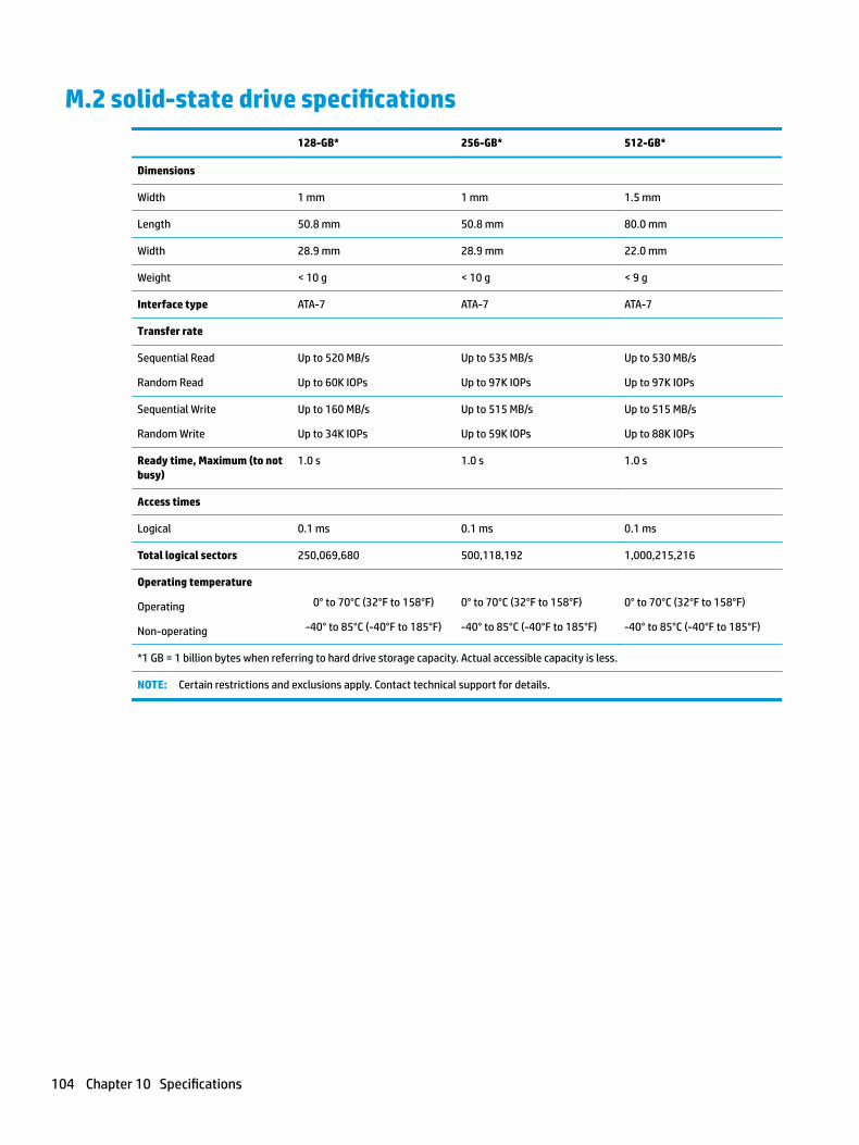
M.2 solid-state drive specifications
128-GB* 256-GB* 512-GB*
Dimensions
Width 1 mm 1 mm 1.5 mm
Length 50.8 mm 50.8 mm 80.0 mm
Width 28.9 mm 28.9 mm 22.0 mm
Weight < 10 g < 10 g < 9 g
Interface type ATA-7 ATA-7 ATA-7
Transfer rate
Sequential Read
Random Read
Up to 520 MB/s
Up to 60K IOPs
Up to 535 MB/s
Up to 97K IOPs
Up to 530 MB/s
Up to 97K IOPs
Sequential Write
Random Write
Up to 160 MB/s
Up to 34K IOPs
Up to 515 MB/s
Up to 59K IOPs
Up to 515 MB/s
Up to 88K IOPs
Ready time, Maximum (to not busy)
1.0 s 1.0 s 1.0 s
Access times
Logical 0.1 ms 0.1 ms 0.1 ms
Total logical sectors 250,069,680 500,118,192 1,000,215,216
Operating temperature
Operating
Non-operating
0° to 70°C (32°F to 158°F)
-40° to 85°C (-40°F to 185°F)
0° to 70°C (32°F to 158°F)
-40° to 85°C (-40°F to 185°F)
0° to 70°C (32°F to 158°F)
-40° to 85°C (-40°F to 185°F)
*1 GB = 1 billion bytes when referring to hard drive storage capacity. Actual accessible capacity is less.
NOTE: Certain restrictions and exclusions apply. Contact technical support for details.
104 Chapter 10 Specifications
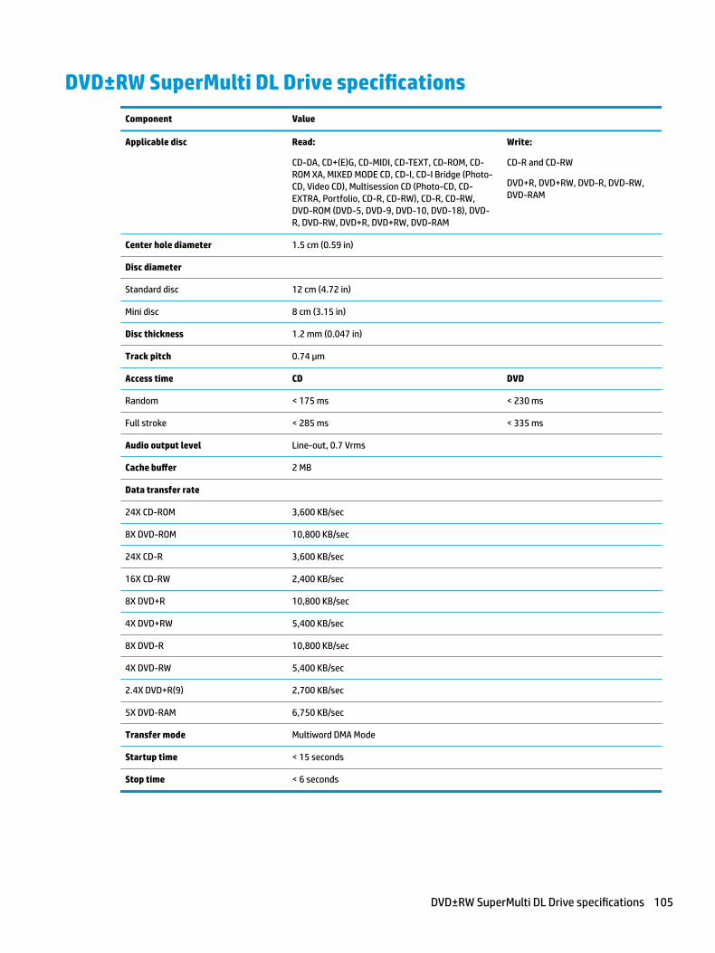
DVD±RW SuperMulti DL Drive specifications
Component Value
Applicable disc Read:
CD-DA, CD+(E)G, CD-MIDI, CD-TEXT, CD-ROM, CD-ROM XA, MIXED MODE CD, CD-I, CD-I Bridge (Photo-CD, Video CD), Multisession CD (Photo-CD, CD-EXTRA, Portfolio, CD-R, CD-RW), CD-R, CD-RW, DVD-ROM (DVD-5, DVD-9, DVD-10, DVD-18), DVD-R, DVD-RW, DVD+R, DVD+RW, DVD-RAM
Write:
CD-R and CD-RW
DVD+R, DVD+RW, DVD-R, DVD-RW, DVD-RAM
Center hole diameter 1.5 cm (0.59 in)
Disc diameter
Standard disc 12 cm (4.72 in)
Mini disc 8 cm (3.15 in)
Disc thickness 1.2 mm (0.047 in)
Track pitch 0.74 µm
Access time CD DVD
Random < 175 ms < 230 ms
Full stroke < 285 ms < 335 ms
Audio output level Line-out, 0.7 Vrms
Cache buffer 2 MB
Data transfer rate
24X CD-ROM 3,600 KB/sec
8X DVD-ROM 10,800 KB/sec
24X CD-R 3,600 KB/sec
16X CD-RW 2,400 KB/sec
8X DVD+R 10,800 KB/sec
4X DVD+RW 5,400 KB/sec
8X DVD-R 10,800 KB/sec
4X DVD-RW 5,400 KB/sec
2.4X DVD+R(9) 2,700 KB/sec
5X DVD-RAM 6,750 KB/sec
Transfer mode Multiword DMA Mode
Startup time < 15 seconds
Stop time < 6 seconds
DVD±RW SuperMulti DL Drive specifications 105

106 Chapter 10 Specifications
11 Power cord set requirements
The wide-range input feature of the computer permits it to operate from any line voltage from 100 to 120 volts ac, or from 220 to 240 volts ac.
The 3-conductor power cord set included with the computer meets the requirements for use in the country or region where the equipment is purchased.
Power cord sets for use in other countries and regions must meet the requirements of the country or region where the computer is used.
Requirements for all countriesThe following requirements are applicable to all countries and regions:
● The length of the power cord set must be at least 1.5 m (5.0 ft) and no more than 2.0 m (6.5 ft).
● All power cord sets must be approved by an acceptable accredited agency responsible for evaluation in the country or region where the power cord set will be used.
● The power cord sets must have a minimum current capacity of 10 A and a nominal voltage rating of 125 or 250 V ac, as required by the power system of each country or region.
● The appliance coupler must meet the mechanical configuration of an EN 60 320/IEC 320 Standard Sheet C13 connector for mating with the appliance inlet on the back of the computer.
Requirements for all countries 107
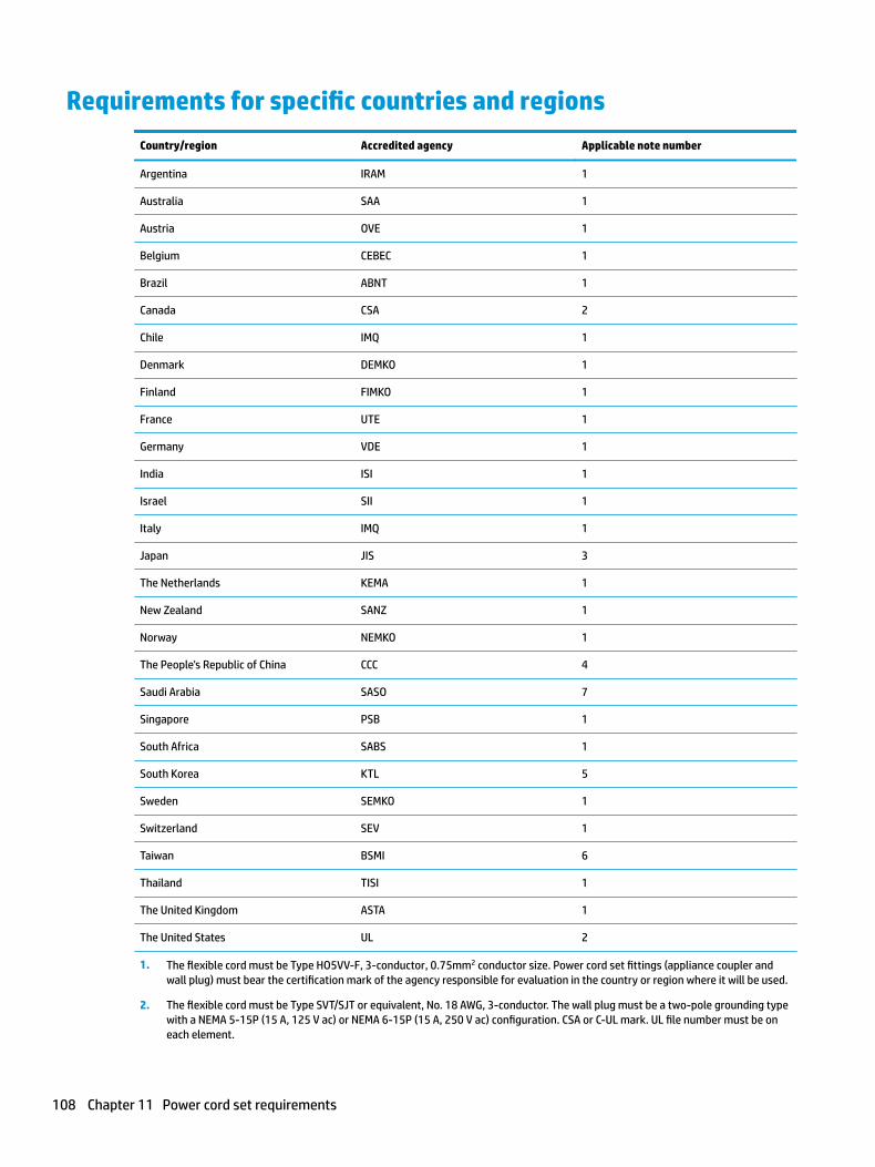
Requirements for specific countries and regions
Country/region Accredited agency Applicable note number
Argentina IRAM 1
Australia SAA 1
Austria OVE 1
Belgium CEBEC 1
Brazil ABNT 1
Canada CSA 2
Chile IMQ 1
Denmark DEMKO 1
Finland FIMKO 1
France UTE 1
Germany VDE 1
India ISI 1
Israel SII 1
Italy IMQ 1
Japan JIS 3
The Netherlands KEMA 1
New Zealand SANZ 1
Norway NEMKO 1
The People's Republic of China CCC 4
Saudi Arabia SASO 7
Singapore PSB 1
South Africa SABS 1
South Korea KTL 5
Sweden SEMKO 1
Switzerland SEV 1
Taiwan BSMI 6
Thailand TISI 1
The United Kingdom ASTA 1
The United States UL 2
1. The flexible cord must be Type HO5VV-F, 3-conductor, 0.75mm2 conductor size. Power cord set fittings (appliance coupler and wall plug) must bear the certification mark of the agency responsible for evaluation in the country or region where it will be used.
2. The flexible cord must be Type SVT/SJT or equivalent, No. 18 AWG, 3-conductor. The wall plug must be a two-pole grounding type with a NEMA 5-15P (15 A, 125 V ac) or NEMA 6-15P (15 A, 250 V ac) configuration. CSA or C-UL mark. UL file number must be on each element.
108 Chapter 11 Power cord set requirements
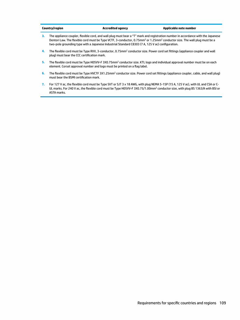
Country/region Accredited agency Applicable note number
3. The appliance coupler, flexible cord, and wall plug must bear a “T” mark and registration number in accordance with the Japanese Dentori Law. The flexible cord must be Type VCTF, 3-conductor, 0.75mm2 or 1.25mm2 conductor size. The wall plug must be a two-pole grounding type with a Japanese Industrial Standard C8303 (7 A, 125 V ac) configuration.
4. The flexible cord must be Type RVV, 3-conductor, 0.75mm2 conductor size. Power cord set fittings (appliance coupler and wall plug) must bear the CCC certification mark.
5. The flexible cord must be Type H05VV-F 3X0.75mm2 conductor size. KTL logo and individual approval number must be on each element. Corset approval number and logo must be printed on a flag label.
6. The flexible cord must be Type HVCTF 3X1.25mm2 conductor size. Power cord set fittings (appliance coupler, cable, and wall plug) must bear the BSMI certification mark.
7. For 127 V ac, the flexible cord must be Type SVT or SJT 3 x 18 AWG, with plug NEMA 5-15P (15 A, 125 V ac), with UL and CSA or C-UL marks. For 240 V ac, the flexible cord must be Type H05VV-F 3X0.75/1.00mm2 conductor size, with plug BS 1363/A with BSI or ASTA marks.
Requirements for specific countries and regions 109

110 Chapter 11 Power cord set requirements

12 Recycling
When a non-rechargeable or rechargeable battery has reached the end of its useful life, do not dispose of the battery in general household waste. Follow the local laws and regulations in your area for battery disposal.
HP encourages customers to recycle used electronic hardware, HP original print cartridges, and rechargeable batteries. For more information about recycling programs, see the HP Web site at http://www.hp.com/recycle.
111

112 Chapter 12 Recycling
Index
AAC adapter and battery light,
identifying 12action keys
identifying 17using 18
airplane mode key 18antenna
illustrated 27antennas
removing 83, 84audio, product description 4, 8audio-out (headphone)/audio-in
(microphone) combo jack, identifying 12
Bbackups 93battery
illustrated 24removing 38
battery cover, identifying 19battery lock, identifying 19BIOS
determining version 91downloading an update 92starting the Setup Utility 91updating 91
Bluetooth label 20boot order
changing 97bottom 20bottom cover
illustrated 25removing 49
buttonsleft TouchPad 14optical drive eject 11power 16right TouchPad 14
Ccable locations
removing 89
cablesillustrated 28
cables, service considerations 33camera
identifying 13camera light, identifying 13camera/microphone cable
illustrated 27removing 45, 79, 80
camera/microphone moduleillustrated 26removing 44, 78
caps lock light, identifying 15components
bottom 19display 13left side 12right side 11
computer major components, illustrated 21
computer specifications 101connector, power 12connectors, service considerations
33
Ddisplay assembly
illustrated 22removing 76
display assembly subcomponentsillustrated 26removing 76
display bezelillustrated 26removing 43, 77
display cableillustrated 27removing 80
display enclosureillustrated 27removing 85
display panelillustrated 26product description 2, 7removing 45, 79, 80
display specifications 102display subcomponents
removal 43spare part numbers 43
drive light, identifying 11DVD±RW SuperMulti DL Drive
specifications 105
Eelectrostatic discharge 34eMMC module
spare part number 22equipment guidelines 36esc key, identifying 17Ethernet, product description 4, 8external media cards 4, 8external monitor port
identifying 12
Ffan
illustrated 23removing 66
fn key, identifying 17
Ggraphics, product description 1, 6grounding guidelines 34guidelines
equipment 36grounding 34packaging 35transporting 35workstation 35
Hhard drive
illustrated 23, 30precautions 34product description 3, 7removing 57specifications 103
hard drive boardillustrated 23
Index 113
hard drive bracketillustrated 23, 30
hard drive bracketsremoving 58
hard drive connectorremoving 59
hard drive connector and cableremoving 58
hard drive connector boardremoving 57
hard drive connector board cableillustrated 28
HDMI portidentifying 12
heat sink assemblyillustrated 23removing 23, 68
hinge coverillustrated 27
hingesillustrated 27removing 45, 79, 80
HP PC Hardware Diagnostics (UEFI)using 99
HP Recovery Managercorrecting boot problems 97starting 96
HP Recovery mediacreating 93recovery 96
HP Recovery partitionrecovery 96removing 98
Iintegrated numeric keypad,
identifying 17internal card
product description 4, 8internal microphones, identifying
13
Jjacks
audio-out (headphone)/audio-in (microphone) 12
network 12RJ-45 (network) 12
Kkeyboard
illustrated 22product description 5, 9
keysaction 17airplane mode 18esc 17fn 17Windows 17
Llabels
Bluetooth 20regulatory 20serial number 20service 20wireless certification 20WLAN 20
latchesbattery release 19
lightsAC adapter and battery light 12caps lock 15drive 11mute 15power 11RJ-45 (network) status 12
MM.2 solid-state drive
specifications 104M.2 solid-state drive adapter bracket
and connector boardremoving 60
mass storage devicesillustrated 29precautions 34
memory card reader, identifying 11memory card, identifying 11memory module
illustrated 23product description 2, 7removing 54
microphone 4, 8minimized image recovery 96minimized image, creating 95model name 1, 6mute light, identifying 15
Nnetwork jack, identifying 12
Ooperating system 5, 9optical drive
illustrated 23, 29precautions 34product description 3, 8removing 40specifications 105
optical drive bezelillustrated 29
optical drive bracketillustrated 29
optical drive connector boardillustrated 23, 56removing 56
optical drive connector board cableillustrated 28
optical drive eject button, identifying 11
optical drive rear bracketremoving 41, 42
optical drive, identifying 11original system recovery 95
Ppackaging guidelines 35plastic parts, service
considerations 33pointing device 5, 9ports
external monitor 12HDMI 12product description 4, 8USB 2.0 11USB 3.x SuperSpeed 12
power button boardillustrated 22removing 88
power button board cableillustrated 28
power button, identifying 16power connector cable
illustrated 22removing 87
power connector, identifying 12
114 Index
power cordrequirements for all countries
107requirements for specific
countries and regions 108set requirements 107
power lights, identifying 11power requirements 5, 9processor
product description 1, 6product description
audio 4, 8display panel 2, 7Ethernet 4, 8external media cards 4, 8graphics 1, 6hard drive 3, 7internal card 4, 8keyboard 5, 9memory module 2, 7microphone 4, 8operating system 5, 9optical drive 3, 8pointing device 5, 9ports 4, 8power requirements 5, 9processor 1, 6product name 1, 6security 5, 9serviceability 6, 10video 4, 8wireless 4, 8
product name 1, 6product name and number,
computer 20
Rrecover
options 95recovery
discs 94, 96HP Recovery Manager 95media 96starting 96supported discs 94system 95USB flash drive 96using HP Recovery media 94
recovery mediacreating 93creating using HP Recovery
Manager 94recovery partition
removing 98regulatory information
regulatory label 20wireless certification labels 20
removal/replacementpreliminaries 33procedures 37, 43
RJ-45 (network) jack, identifying 12RJ-45 (network) status lights,
identifying 12RTC battery
illustrated 22removing 63
rubber feetremoving 47
Ssecurity cable slot, identifying 11security, product description 5, 9serial number, computer 20service considerations
cables 33connectors 33plastic parts 33
service labels, locating 20serviceability, product description
6, 10slots
memory card reader 11security cable 11
solid-state driveillustrated 29removal 62spare part number 22, 30, 62
solid-state drive boardillustrated 23, 60
solid-state drive bracketillustrated 23, 60
speakersillustrated 24removing 64
speakers, identifying 19special keys, using 17specifications
computer 101
display 102DVD±RW SuperMulti DL Drive
105hard drive 103M.2 solid-state drive 104optical drive 105
supported discs, recovery 94system board
removing 73spare part number 23, 73
system recovery 95system restore point
creating 94system restore point, creating 93
Ttools required 33top cover/keyboard
removing 90TouchPad
buttons 14TouchPad button board
removing 72spare part number 22, 72
TouchPad button board cableillustrated 28
TouchPad cableillustrated 28
TouchPad zone, identifying 14transporting guidelines 35traveling with the computer 20
UUSB 2.0 port, identifying 11USB 3.x SuperSpeed port,
identifying 12USB board
removing 65spare part number 22
USB board cableillustrated 28
Vvents, identifying 12, 19video, product description 4, 8
WWindows
system restore point 93, 94Windows key, identifying 17
Index 115
Windows toolsusing 94
wireless antennaillustrated 27
wireless antennasremoving 83, 84
wireless certification label 20wireless, product description 4, 8WLAN antennas, identifying 13WLAN device 20WLAN label 20WLAN module
illustrated 23removing 52
workstation guidelines 35
116 Index