Embed Size (px)
Citation preview

David Miller
National Grid, Asset Integrity Manager
How well do you know your assets?
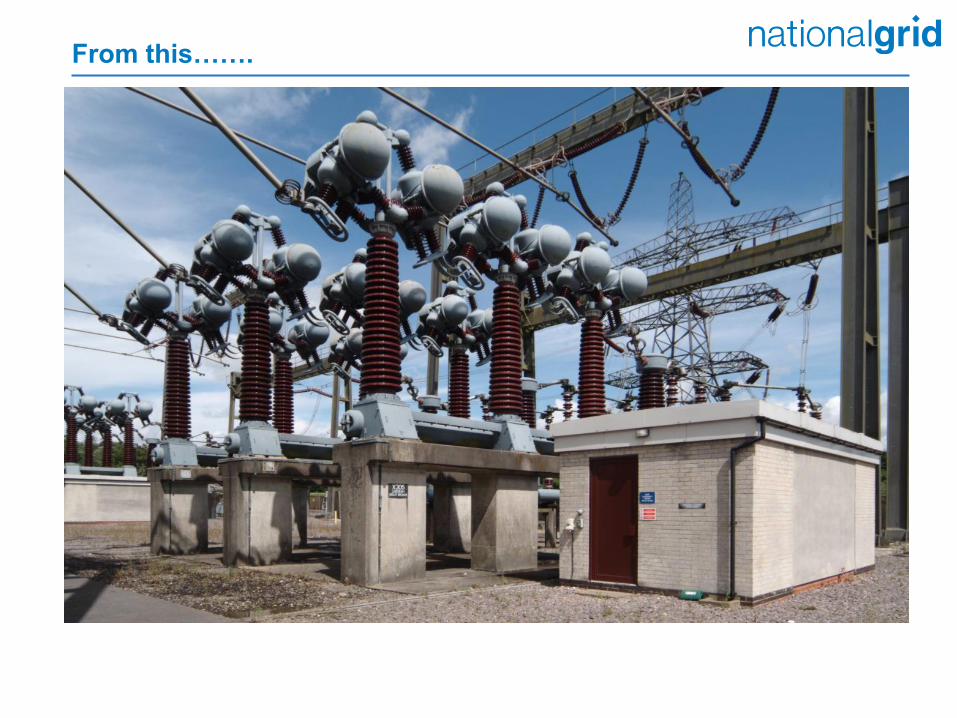
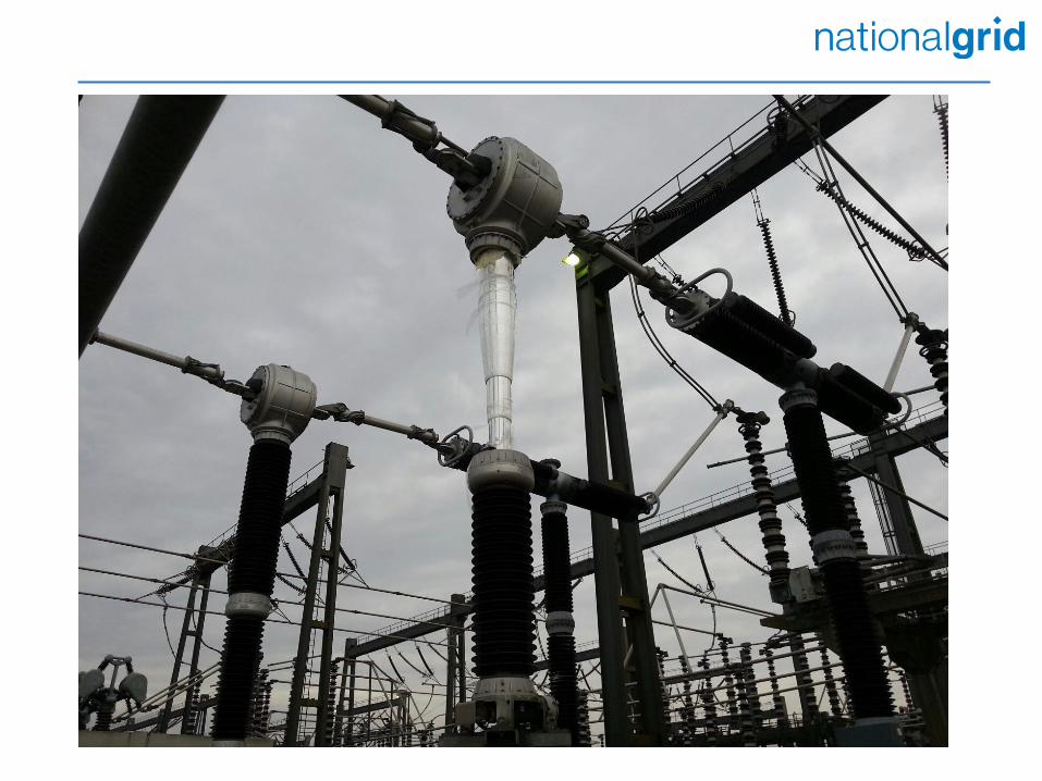
From this…….
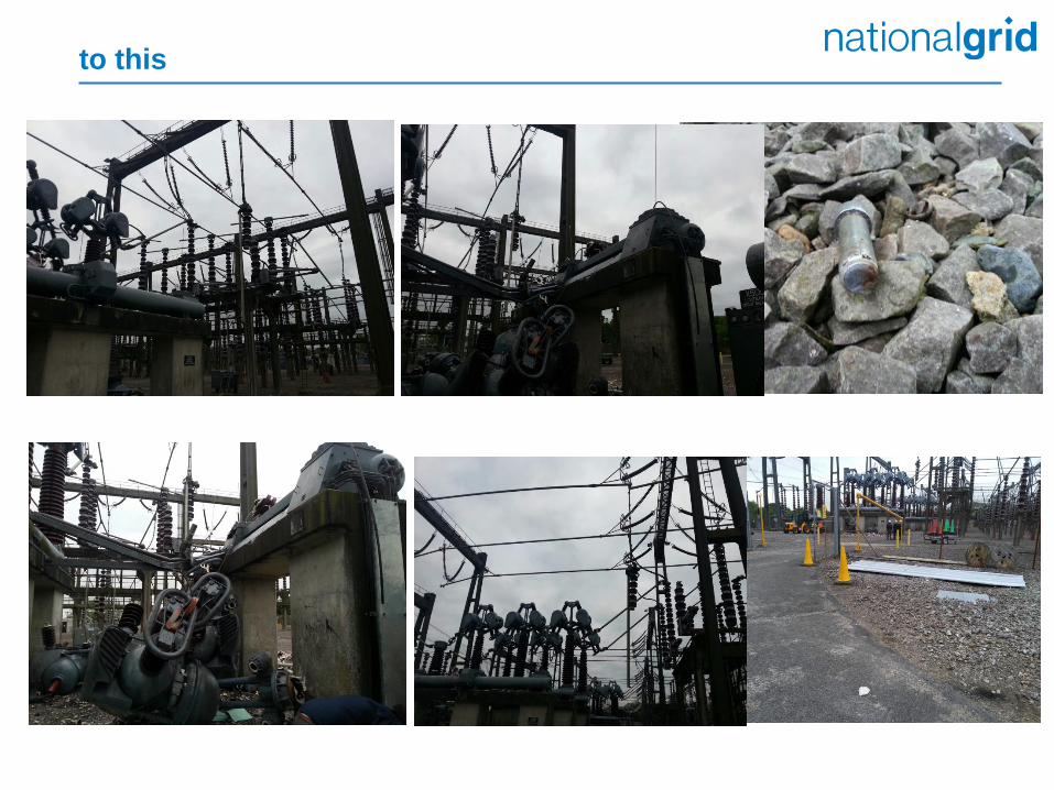
to this
On the morning of Wednesday 2nd April 2014 Standby staff had been called to investigate protection and control alarms on SGT1 cct.
On arrival at site the engineer advised that SGT1 needed to be switched out of service as the bay controller had failed.
Circuit Breaker 180 on the LV side of SGT1 was opened at 04:40 to offload SGT1, and SGT5 was selected to Main Bar 2 and switched into service at 04:41. Circuit breaker X110 was opened at 04:53 to complete the switch-out of SGT1.
At 04:53, 400kV X110 OIBR (SGT1 cct) catastrophically failed following the instructed open operation to remove SGT1 from service.
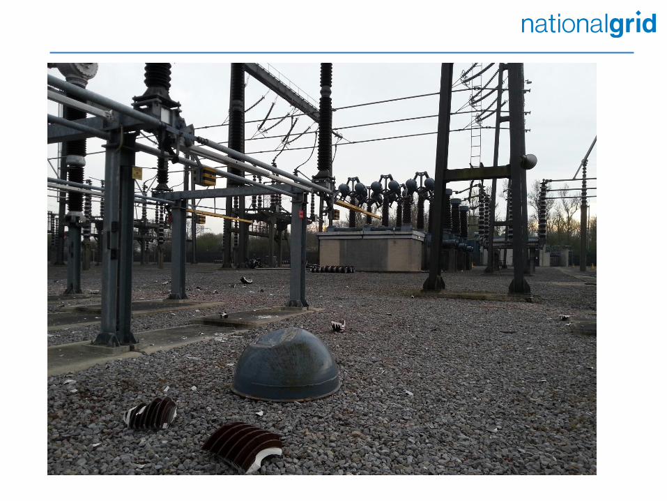
The failure of X110 projected debris (including a silencer dome cover) in a 40m radius. The dome cover (60Kg) impacted and destroyed a yellow phase Current Transformer on the adjacent SGT5 cct.
The damage to the CT caused the main busbar protection to operate, removing from service all breakers connected to that busbar.
There were no injuries sustained and there was no loss of supply from the
Transmission System resulting from this incident.
Background
Draft
2 13456
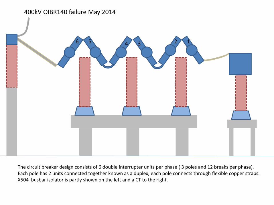
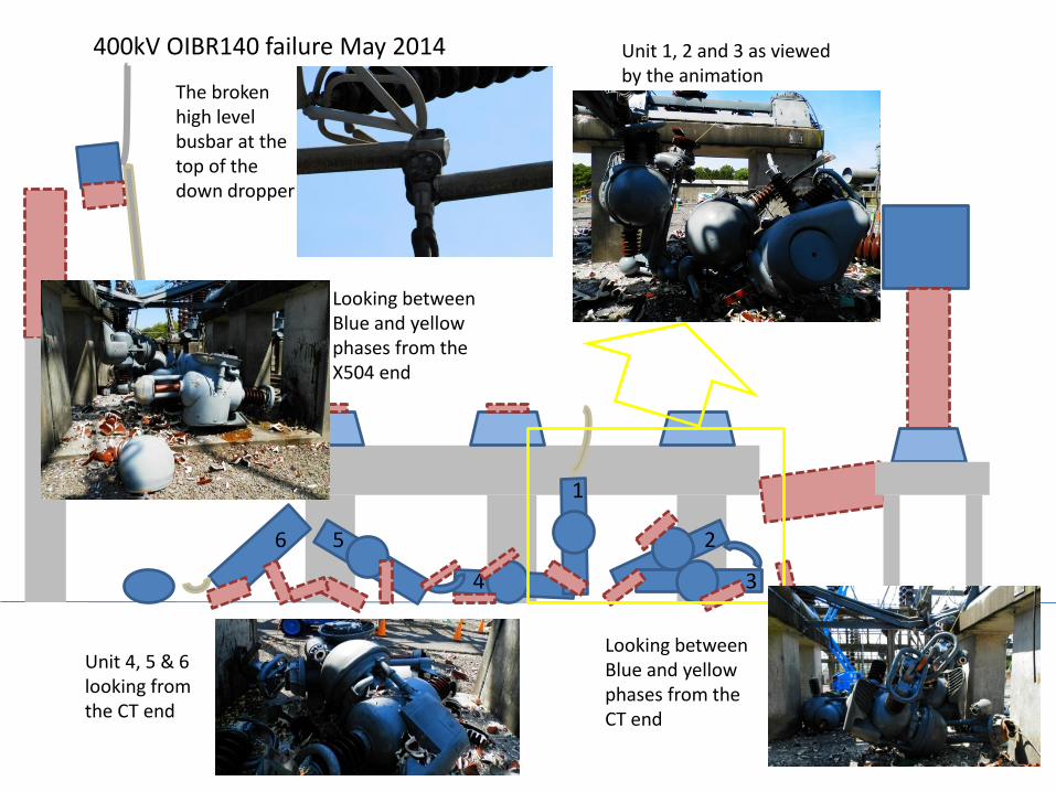
400kV OIBR140 failure May 2014
The circuit breaker design consists of 6 double interrupter units per phase ( 3 poles and 12 breaks per phase). Each pole has 2 units connected together known as a duplex, each pole connects through flexible copper straps. X504 busbar isolator is partly shown on the left and a CT to the right.
123456
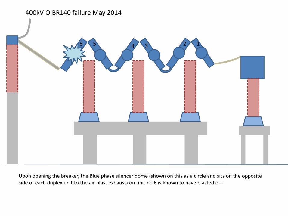
400kV OIBR140 failure May 2014
Upon opening the breaker, the Blue phase silencer dome (shown on this as a circle and sits on the opposite side of each duplex unit to the air blast exhaust) on unit no 6 is known to have blasted off.
123456
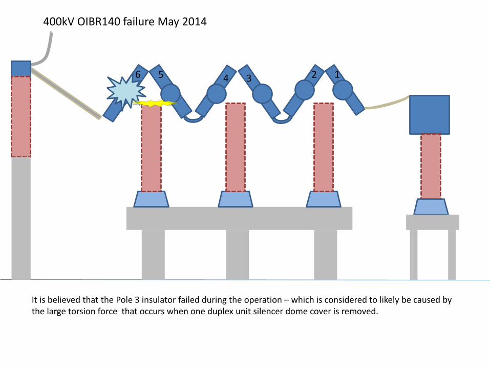
400kV OIBR140 failure May 2014
It is believed that the Pole 3 insulator failed during the operation – which is considered to likely be caused by the large torsion force that occurs when one duplex unit silencer dome cover is removed.
123456
400kV OIBR140 failure May 2014
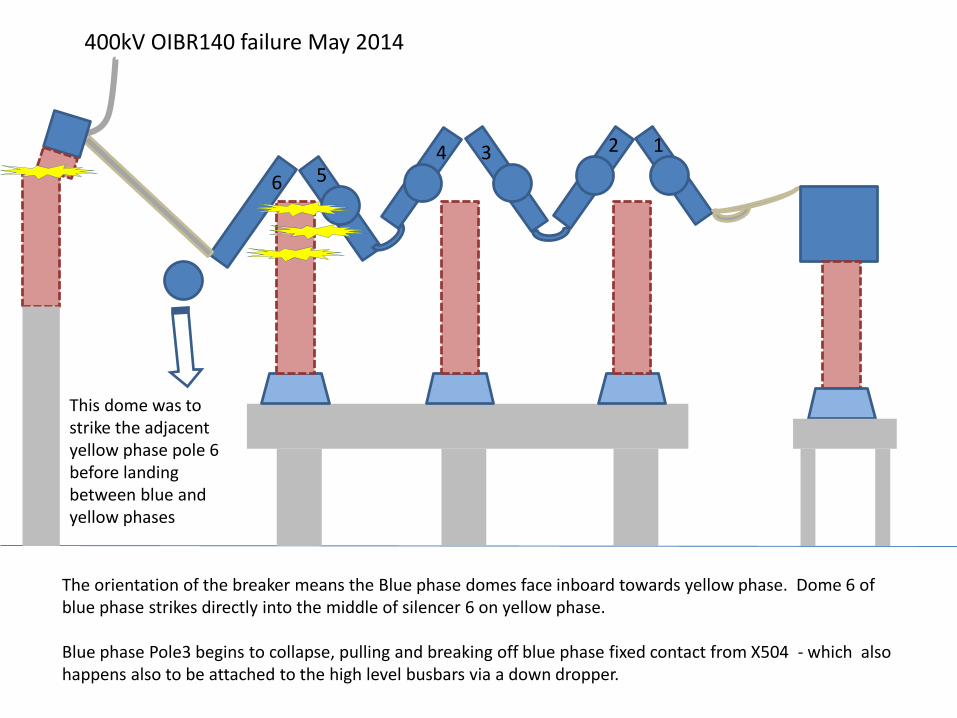
The orientation of the breaker means the Blue phase domes face inboard towards yellow phase. Dome 6 of blue phase strikes directly into the middle of silencer 6 on yellow phase.
Blue phase Pole3 begins to collapse, pulling and breaking off blue phase fixed contact from X504 - which also happens also to be attached to the high level busbars via a down dropper.
This dome was to strike the adjacent yellow phase pole 6 before landing between blue and yellow phases
12
3
4
5
6
400kV OIBR140 failure May 2014
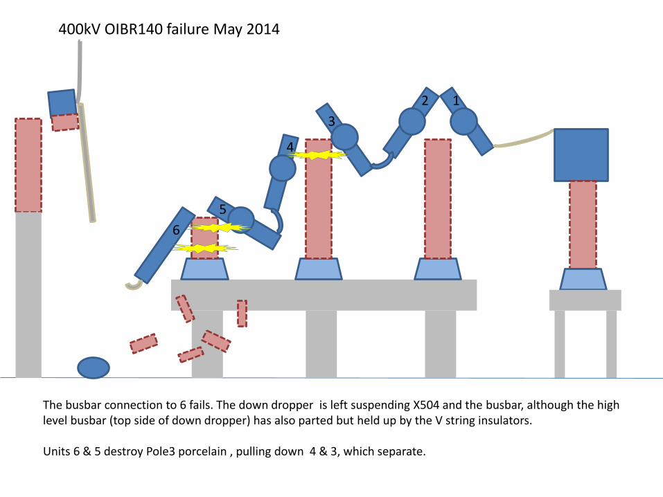
The busbar connection to 6 fails. The down dropper is left suspending X504 and the busbar, although the high level busbar (top side of down dropper) has also parted but held up by the V string insulators.
Units 6 & 5 destroy Pole3 porcelain , pulling down 4 & 3, which separate.
12
3
456
400kV OIBR140 failure May 2014
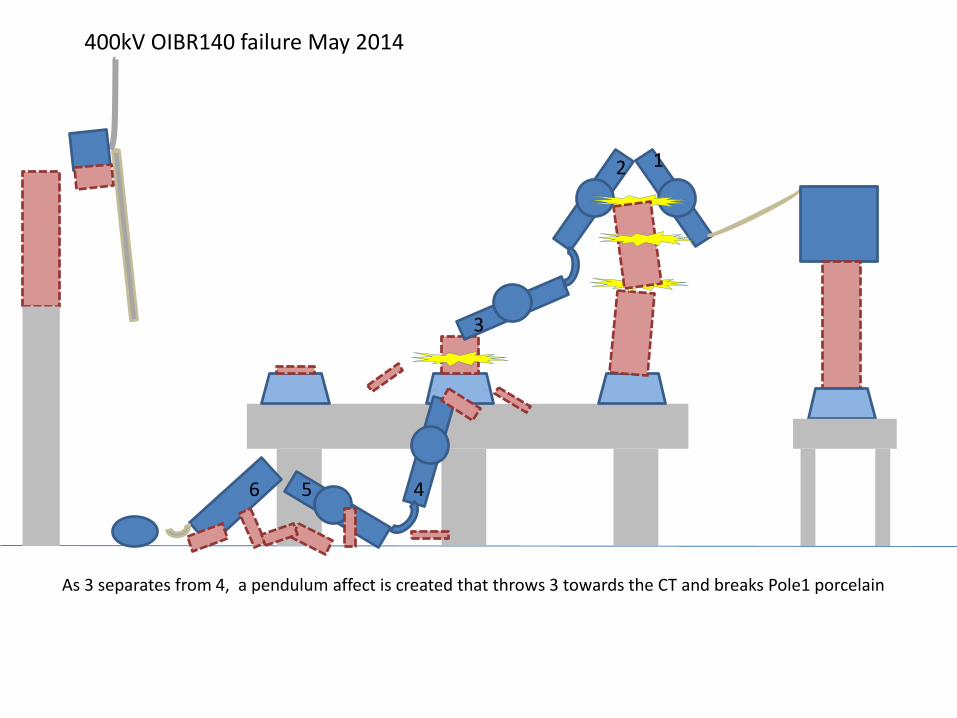
As 3 separates from 4, a pendulum affect is created that throws 3 towards the CT and breaks Pole1 porcelain

1
2
3
4
56
400kV OIBR140 failure May 2014
This pendulum has the opposite affect on 1, pulling it towards Pole2 and collapsing Pole 3 porcelain towards the CT, breaking the busbar connection between 1 and the CT as it collapses.
1
2
34
56
400kV OIBR140 failure May 2014
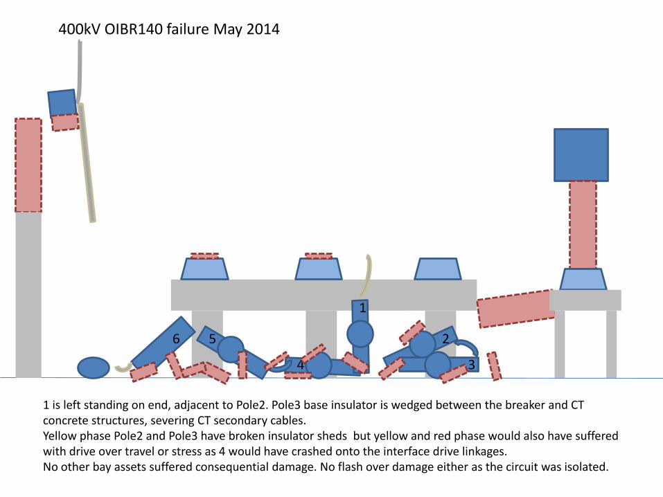
1 is left standing on end, adjacent to Pole2. Pole3 base insulator is wedged between the breaker and CT concrete structures, severing CT secondary cables.Yellow phase Pole2 and Pole3 have broken insulator sheds but yellow and red phase would also have suffered with drive over travel or stress as 4 would have crashed onto the interface drive linkages.No other bay assets suffered consequential damage. No flash over damage either as the circuit was isolated.
1
2
34
56
400kV OIBR140 failure May 2014 Unit 1, 2 and 3 as viewed by the animation
Unit 4, 5 & 6 looking from the CT end
Looking between Blue and yellow phases from the CT end
Looking between Blue and yellow phases from the X504 end
The broken high level busbar at the top of the down dropper
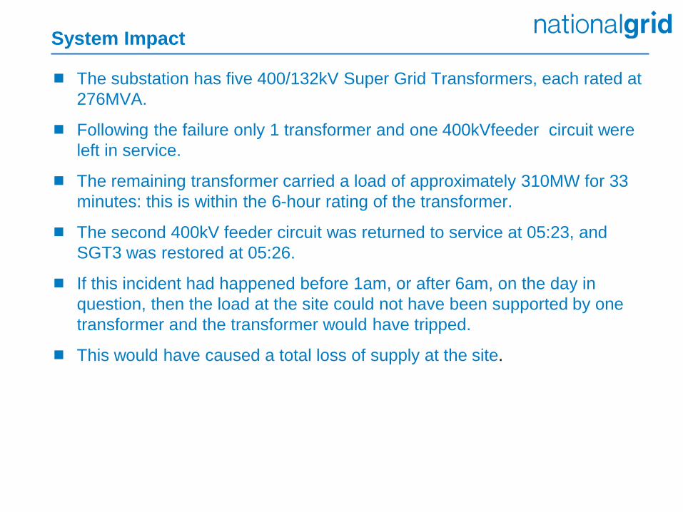
System Impact
The substation has five 400/132kV Super Grid Transformers, each rated at
276MVA.
Following the failure only 1 transformer and one 400kVfeeder circuit were
left in service.
The remaining transformer carried a load of approximately 310MW for 33
minutes: this is within the 6-hour rating of the transformer.
The second 400kV feeder circuit was returned to service at 05:23, and
SGT3 was restored at 05:26.
If this incident had happened before 1am, or after 6am, on the day in
question, then the load at the site could not have been supported by one
transformer and the transformer would have tripped.
This would have caused a total loss of supply at the site.
Immediate Action Taken To Keep People Safe
Initial OESB (Operational & Engineering Safety Bulletin) issued requiring
90m Risk Management Hazard Zone to be established around all
OIBR140 ABCB’s (11 sites) with no access until failure mode understood.
Subsequently OESB updated (Issue 2) to 90m Risk Management Hazard
Zone with access restricted at all times for planned switching.
Access was also restricted during inclement weather and / or lightning
risk 1 at all times with the following exception:
Where it is essential to transit through the RHMZ for operational access,
this is acceptable subject to a no loiter policy.
Public exposure greater than 1 hour per day required local management
controls (physical screens or barriers).
Consequence – big impact on site routines, site maintenance and capital
replacement works.
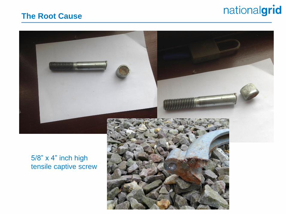
The Root Cause
5/8” x 4” inch high
tensile captive screw
Analysis of Failure Mode
Metallurgical analysis of the dome cap screws by Edif ERA Technology
Ltd determined that failure was due to high stress fatigue cracking
compounded by hydrogen embrittlement.
The consequence of hydrogen was ‘probably introduced during either the
cleaning or bright zinc plating process and was not removed by the
specified dehydrogenation heat treatment’.
This led to a significant reduction in the tensile strength of the cap screw.
Original ‘Unbrako’ cap screw were cadmium plated and specified by the
original circuit breaker manufacturer (Reyrolle) in the 1960s to provide
corrosion resistance.
Later replacement cap screws (not Unbrako) manufactured to the same
tensile strength as per original specification but were Bright Zinc Plated to
provide corrosion resistance as cadmium plating coatings are no longer
desirable (expensive introduce a carcinogenic risk).
Cap screws considered in the following populations:
Original ‘Unbrako’ – no failures
First batch replacements mid 90’s to mid 00’s – 1 failure
Second batch replacements 2010 BZP 2010 – 0 failures
Second batch replacements 2010 BZP 2014 – 2 failures
All locations with first batch fasteners had approximately 1200 Circuit Breaker years service and managed as per issue 2 of OESB 15/2014 (restricted access).
The 7 ABCB refurbishments carried out since 2010 using second batch 2010 BZP fasteners had approximately 12 circuit breaker years service and whilst this was a relatively small service experience no failures have occurred we therefore managed this population as per issue 2 of OESB 15/2014 (restricted access).
5 locations with second batch 2014 BZP fasteners were isolated from the power system in a controlled manner without operating the ABCB and the ABCB to be isolated and the compressed air drained with the ABCB in the closed position. Emergency switching procedure issued on 8 May by Asset Integrity.
Initial Incident Management
Reverted back to using original replacement ‘Unbrako’ fasteners even though more expensive than the replacements we had been using.
Introduced requirement for Certificate of Conformity for each batch to ensure we were getting the required quality.
Decided against any form of corrosion protection as this was considered the greatest area for introducing quality issues.
Phase 1 programme developed to replace all cap screw bolts on affected population with unplated/uncoated cap screws which would allow operation and access restrictions to be removed.(Completed end 2014).
Phase 2 will see each circuit breaker revisited and uncoated cap screws replaced with suitably treated alternatives unless the circuit breaker has minimum life left i.e. replacement within next 5 years.
Recovery Strategy

Moral of the story
Do you really know the impact of some of
the decisions you are taking on the ability of
your assets to perform their designed
function?