Embed Size (px)
Citation preview
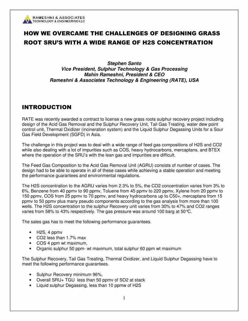
1
HOW WE OVERCAME THE CHALLENGES OF DESIGNING GRASS
ROOT SRU’S WITH A WIDE RANGE OF H2S CONCENTRATION
Stephen Santo Vice President, Sulphur Technology & Gas Processing
Mahin Rameshni, President & CEO Rameshni & Associates Technology & Engineering (RATE), USA
INTRODUCTION
RATE was recently awarded a contract to license a new grass roots sulphur recovery project including design of the Acid Gas Removal and the Sulphur Recovery Unit, Tail Gas Treating, water dew point control unit, Thermal Oxidizer (incineration system) and the Liquid Sulphur Degassing Units for a Sour Gas Field Development (SGFD) in Asia. The challenge in this project was to deal with a wide range of feed gas compositions of H2S and CO2 while also dealing with a lot of impurities such as COS, heavy hydrocarbons, mercaptans, and BTEX where the operation of the SRU’s with the lean gas and impurities are difficult. The Feed Gas Composition to the Acid Gas Removal Unit (AGRU) consists of number of cases. The design had to be able to operate in all of these cases while achieving a stable operation and meeting the performance guarantees and environmental regulations. The H2S concentration to the AGRU varies from 2.3% to 5%, the CO2 concentration varies from 3% to 6%, Benzene from 40 ppmv to 90 ppmv, Toluene from 45 ppmv to 220 ppmv, Xylene from 20 ppmv to 150 ppmv, COS from 25 ppmv to 70 ppmv, and heavy hydrocarbons up to C50+, mercaptans from 15 ppmv to 50 ppmv plus many pseudo components according to the gas analysis from more than 100 wells. The H2S concentration to the sulphur Recovery unit varies from 30% to 47% and CO2 ranges varies from 58% to 43% respectively. The gas pressure was around 100 barg at 50°C. The sales gas has to meet the following performance guarantees.
• H2S, 4 ppmv
• CO2 less than 1.7% max
• COS 4 ppm wt maximum,
• Organic sulphur 50 ppm- wt maximum, total sulphur 60 ppm wt maximum The Sulphur Recovery, Tail Gas Treating, Thermal Oxidizer, and Liquid Sulphur Degassing have to meet the following performance guarantees.
• Sulphur Recovery minimum 96%,
• Overall SRU+ TGU less than 50 ppmv of SO2 at stack
• Liquid sulphur Degassing, less than 10 ppmw of H2S

2
In this paper, we will discuss the some design features of the units and reasons why they were selected. We will discuss the options that we considered to design this unit, including the solvent evaluation & selection, the impact of H2S /CO2 ratio on the AGRU and the SRU design, and the selected optimum scheme of the Sulphur Recovery Units, and the TGU to meet the performance guarantees for all 10 cases including the operating and the capital costs comparison.
DETAIL DESCRIPTION
RATE executed a new sour gas field development project by developing new schemes to meet all high
H2S cases of the feed compositions and to achieve a stable operation by evaluating all commercial
solvents and the most economical schemes by using the best possible technologies.
ACID GAS REMOVAL – the highest H2S case in the design basis concentration was selected as the
design controlling case. In order to meet the specification of the treated gas that is shown below, we needed to select a proper solvent. We looked at all generic solvents such as MDEA and all formulated selective solvents chemical, physical, and hybrid solvents commercially available to meet the following specifications.
• H2S, 4 ppmv
• CO2 less than 1.7% max
• COS 4 ppm wt maximum,
• organic sulphur 50 ppm- wt maximum, total sulphur 60 ppm wt maximum
As part of the acid gas removal scheme configuration, we also evaluated Hot Flash
configuration, 2-stage regeneration system and lean /semi lean configuration.
The hot flash gas configuration evaluation was conducted by heating the amine further before entering the flash drum. This feature has been used to flash the amine and to recover the hydrocarbons. In this scheme after the first flash drum, the rich amine enters the lean/rich exchanger and then enters to another heater to heats up then enters to the second flash drum to flash the gas. The gas leaving the second flash drum is cooled and enters an additional flash absorber to separate the hydrocarbon using lean solvent. Adding several pieces of equipment to the amine unit, would result higher capital cost thus we concluded that the hydrocarbon recovery is not significant and it is not cost effective. In addition, by selecting the proper solvent, there is no need for the 2-stage regeneration scheme and there is no need for lean /semi lean scheme which additional equipment would increase the capital cost. After extensive technical and cost evaluation, we concluded that formulated based MDEA chemical solvent can meet all of the project requirements and will remove CO2, H2S and COS to meet requested specifications to less than 150 ppmv CO2, H2S less than 1 ppmv and COS to less than 4 ppmv in the treated gas. We performed the extended evaluation on the solvent selection from generic to formulated or selective solvents by all solvent suppliers and our recommendation was formulated MDEA based chemical solvent versus hybrid solvent where this solvent has the flexibility to meet the product specification for all cases.

3
The proposed solvent unit resembles a conventional amine-type acid gas removal flow scheme, but
utilizes a formulated MDEA-based solvent (45%wt), and employs proprietary RATE technology. The
thermal or flash regenerated solvent process removes CO2, H2S and other sulphur components.
Hydrocarbon losses are minimal in the process due to their low solubility in the selected solvent.
The advantages of the formulated MDEA based chemical solvent versus hybrid are described below:
• Meet the project specification for all cases
• No need for polishing unit before or after amine unit
• Less circulation and less capital cost
• A Proven technology and optimized design based on over 50 years operating experience
• Ability to handle a wide range of inlet H2S and CO2 concentrations with minor operating
adjustments and no hardware modifications
• No need for 2-stage regeneration, and no need for lean/semi-lean configuration, no need for hot
flash configuration
• System designed for high reliability, flexibility and required design turndown without the need for
hardware modifications
• Availability of the solvents at regional supply facilities for fast response to customer needs
• Capability and availability of sharing operational data from other facilities using the same solvent
Figure 1 and 2 represents the simplified Amine unit process flow diagram.
4
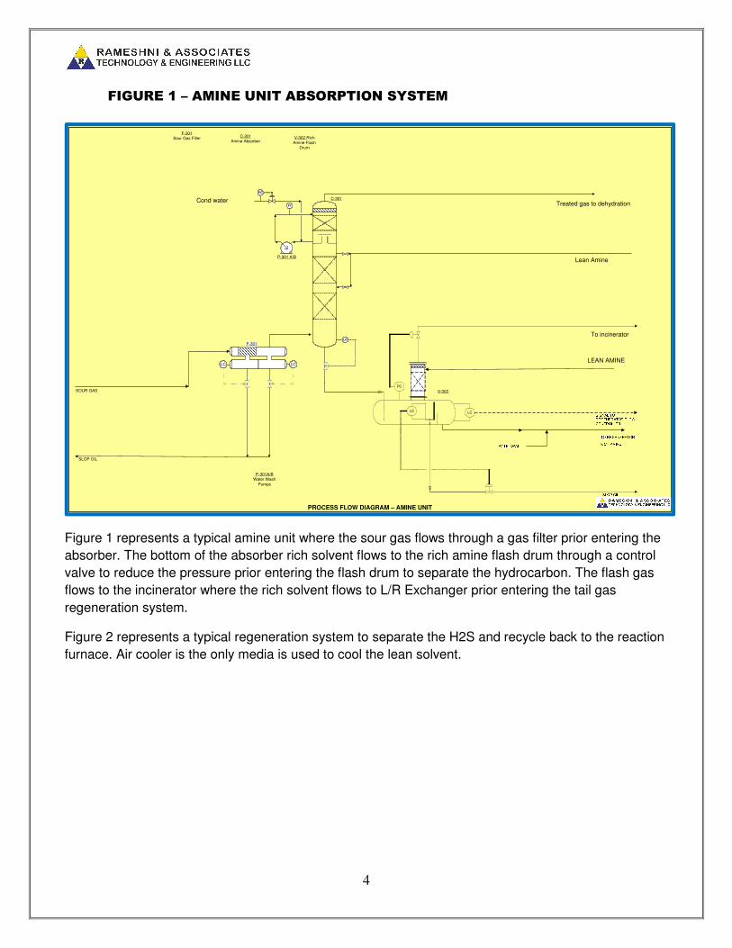
FIGURE 1 – AMINE UNIT ABSORPTION SYSTEM
Figure 1 represents a typical amine unit where the sour gas flows through a gas filter prior entering the
absorber. The bottom of the absorber rich solvent flows to the rich amine flash drum through a control
valve to reduce the pressure prior entering the flash drum to separate the hydrocarbon. The flash gas
flows to the incinerator where the rich solvent flows to L/R Exchanger prior entering the tail gas
regeneration system.
Figure 2 represents a typical regeneration system to separate the H2S and recycle back to the reaction
furnace. Air cooler is the only media is used to cool the lean solvent.
F-301
LCLC
PROCESS FLOW DIAGRAM – AMINE UNIT
SOUR GAS
SLOP OIL
LC
C-301
P-301 A/B
FC
FI
PC
LS
SLOP OILLC ANTI-FOAM RICH AMINETO REGENERATORSIGNAL TOREGENERATOR FLOW CONTROLLER
Lean Amine
To incinerator
Treated gas to dehydrationCond water
F-301Sour Gas Filter
C-301Amine Absorber
V-302 Rich
Amine Flash Drum
V-302
P-301A/BWater Wash
Pumps
LEAN AMINE

5
FIGURE 2 – AMINE UNIT REGENERATION SYSTEM
SULPHUR RECOVERY & TAIL GAS TREATING
The duty specification for the SRU represents different feed compositions where the H2S varies between (31-68) % and CO2 varies between (58-21) % respectively. We also have mercaptans and possible hydrocarbons that can have a significant impact on the sulphur recovery operation. BTEX / Mercaptans are removed from acid gas feed upstream are fed to the sulphur plant. The low concentration of H2S will make it difficult for the reaction furnace of the sulphur plant to attain and sustain a stable flame. In addition, the high concentration of hydrocarbons in the acid gas feed would require a flame of high temperature to ensure complete hydrocarbon destruction. The actual amount of these contaminants will depend on the type of acid gas removal solvent to be used upstream of the sulphur plant. These hydrocarbon contaminants tend to crack in low flame temperatures, and causes carbon lay down problem in the catalyst bed of the first sulphur converter. Carbon laydown associated with cracking of heavy hydrocarbons has caused a significant number of unplanned shutdowns. A minimum temperature of 1050°C is required to assure that the mercaptans are destroyed; therefore, our design reflected such requirements.
LC
FC
FC
FC
C-302
Amine Regenerator
E-306
Regenerator Reboiler
E-306
Regenerator Overhead Air
Cooler
F-303
Amine Carbon Filter
E-305A/B
Lean/Rich Amine Exchanger
V-304
Reboiler Condensate
Drum
P-302A/B
Lean Amine Pumps
P-304A/B
Regenerator Reflux Pumps
C-302
V-304
E-303
PC
E-304
F-302
FC
FC
V-305
Amine Sump
P-303A/B
E-305
P-304A/B
Make-Up Amine
E-305
Lean Amine Air Cooler
F-302
Lean Amine Filter
F-303 F-304
F-304
Amine Particulate Filter
MLC
Amine Drains
P-305 A/B
V-305
PC
To Incinerator
P-305 A/BAmine Sump
Pump
LEAN AMINE TO ARU ABSORBER
P-302A/B
RICH AMINE FROM FUEL GAS ABSORBER
Nitrogen
E-303A/B
LP STEAM
CONDENATE
SOUR WATER
ACID GAS TO SRU
PROCESS FLOW DIAGRAM – AMINE REGENERATION
LC
P-303A/B
Lean Amine Booster Pumps
V-303
From flash drum
V-303
Regenerator Reflux Drum
F-305Sump Filter
F-305
Make up Water
TK-301
P-306 A/B
NITROGEN
PCTo incineration
LEAN AMINE TO FLASH SECTION
TK-301 Amine
Surge Tank
LC
FC
TC

6
We assumed the following features as part of our design.
1. Three stage versus two stage Claus
It was required to achieve 96% sulphur recovery for all 10 cases. Due to the lean H2S concentration, in order to achieve and to guarantee 96% recovery, the calculated sulphur recovery should be above 96%; therefore, we needed a three stage Claus to meet the recovery for all cases. Please refer to the sulphur recovery chart as shown above.
2. Start of Run (SOR) and End of Run (EOR)
As the sulphur recovery operates, the catalyst ages and become less active, therefore, throughout the life of the Claus catalyst (4-6 years) the sulphur recovery will be decrease from SOR to EOR. In order to maintain a reliable operation, it is our normal practice to design the tail gas unit based on EOR operation of the sulphur plant assuming more H2S enters the tail gas unit.
3. Acid gas feed preheat and combustion air preheat
Preheating acid gas feed and combustion air will certainly help to increase the flame temperature of the Claus reaction furnace. However, these design measures are not capable of raising the flame temperature to the desired level. A combination of these techniques with another technology is required to achieve the desired stable and high temperature flame in accommodating the specified acid gas feeds of various levels of H2S and heavy hydrocarbons contents.
FEATURES EVALUATED BUT NOT USED
We performed the simulation for all cases in order to achieve the desired combustion temperature; we had to come up with the most cost effective option as part of our evaluations.
7
There are key elements that we considered and we explain the reasons what and why these features were not selected.
• Conventional Acid Gas Enrichment - Acid gas amine type enrichment unit upstream of
SRU common regeneration unit with the TGU/amine unit will consist of a common acid
gas pretreatment step with selective solvent based MDEA formulated solvent, and a
three stage Claus units followed by a common tail gas/amine tail gas treating unit, to
enrich the gas to the SRU and to reduce the SRU equipment. The acid gas enrichment
works very well where the H2S concentration are very low, for this project, the H2S
concentration for high H2S cases varies from 46% to 68% and the CO2 concentration
varies from 43% to 21%, corresponding from all cases H2S varies between (31-68)%
and CO2 varies between (58-21)%.
Acid gas enrichment is very effective where the H2S/CO2 ratio is low and will achieve
high CO2 slip. The H2S is enriched and SRU unit will be smaller. In this project, we had
high H2S/CO2 ratio and CO2 slip will decline therefore, the SRU will not be smaller and
the acid gas enrichment are not very effective. In other words, after a detailed
evaluation, we concluded that adding conventional acid gas enrichment would be not as
effective as generally expected.
• Supplemental fuel gas burning -Supplemental natural gas burning is a technique often
employed to raise the flame temperature while processing acid gas feed of low H2S
concentrations in a sulphur plant, where we did not have natural gas available in this
project, and using fuel gas will cause soot formation.
• Oxygen Enrichment, Oxygen enrichment technology is an ideal technology for raising
the flame temperature of the Claus reaction furnace especially for acid gas of low H2S
concentration, however, Oxygen was not available in the project.
• Using cooling water is not practical in summer due to hot climate weather temperature;
therefore, water cooler usage in the tail gas unit would not help in summer.
Proprietary Acid Gas Enrichment & SRU Schemes
We developed a unique acid gas enrichment process called (Rich “S-MAX”), and a unique proprietary
scheme of the reaction furnace which are described below.
We used a proprietary “S-MAX” 2-zone reaction furnace, which is different with the conventional
scheme, with high intensity burner. In the conventional scheme of the 2-zone reaction furnace,
hydrocarbons and mercaptans will be bypassed to the second zone where the combustion temperature
would not be adequate for the heavy impurities destruction, which will cause soot formation and
catalyst deactivation.
The combustion temperature is always higher in the first zone than the second zone. From the above
evaluation, we concluded that we could use exclusive schemes by RATE – For the high H2S cases,
where the H2S concentration is higher as described below. In addition in order to meet the tight stack

8
SO2 specification, the tail gas unit should be designed with formulated selective solvent MDEA based
formulated solvent.
We split the acid gas from the amine unit where up to 75% of the amine gas entered the first zone of
the reaction furnace and up to 25% of the acid gas is routed to the tail gas absorber in addition to the
quench overhead that flows to the tail gas absorber. The tail gas amine unit is designed with the much
higher amine loading similar to the amine unit, so in Summary:
• 25% of the amine acid gas is sent to the tail gas absorber
• 75% of the amine acid gas is sent to the FIRST ZONE OF THE REACTION FURNACE
• The tail gas absorber operates at higher rich loading (0.2-0.3 mol/mol)
• The tail gas recycle from the tail gas regeneration unit is recycled to the SRU but not to the first
zone, instead:
� The acid gas from the tail gas regeneration column, which is hydrocarbon / mercaptan
free, is recycled back to the SRU. It is preheated and flows to the second zone of the
reaction furnace. The combusted gas from the zone 1 reaction furnace flows to the
second zone through choke ring where the temperature is above ignition temperature,
and burn the acid gas in the second zone and the combusted temperature leaving the
reaction furnace is 990 C according to our simulation for the high H2S cases.
• Our tail gas absorber was designed with 0.2 to 0.3 mol/mol loading.
� The acid gas loading in the tail gas absorber is normally 0.1 mol/mol maximum, and the
acid gas loading for the amine absorber is normally 0.3 mol/mol, it means there is
significant free amine in the tail gas absorber to process the portion of the acid gas. The
tail gas absorber acts not only as a tail gas absorber but also as an enriched absorber
without adding significant cost to the project. This scheme also removes the
hydrocarbons / mercaptans, which cause problems in the second zone of the reaction
furnace. As H2S concentration increases for case 2 through case 6, the 25% slipstream
from the SRU feed to the tail gas absorber may be reduced as long as we achieved
1100 C -1150°C combustion temperature in the first zone of the reaction furnace.
For cost estimate purposes we also evaluated if the tail gas absorber would be designed with 0.1
mol/mol rich loading instead of 0.3 and it is obvious that we needed to have much higher solvent
circulation and much higher capital cost.
In addition to above challenges, due to hot temperature in summer using cooling water is not
adequate to achieve low H2S concentration less than 10 ppmv from the absorber overhead therefore
we evaluated 2 options tail gas design with or without chiller.
9
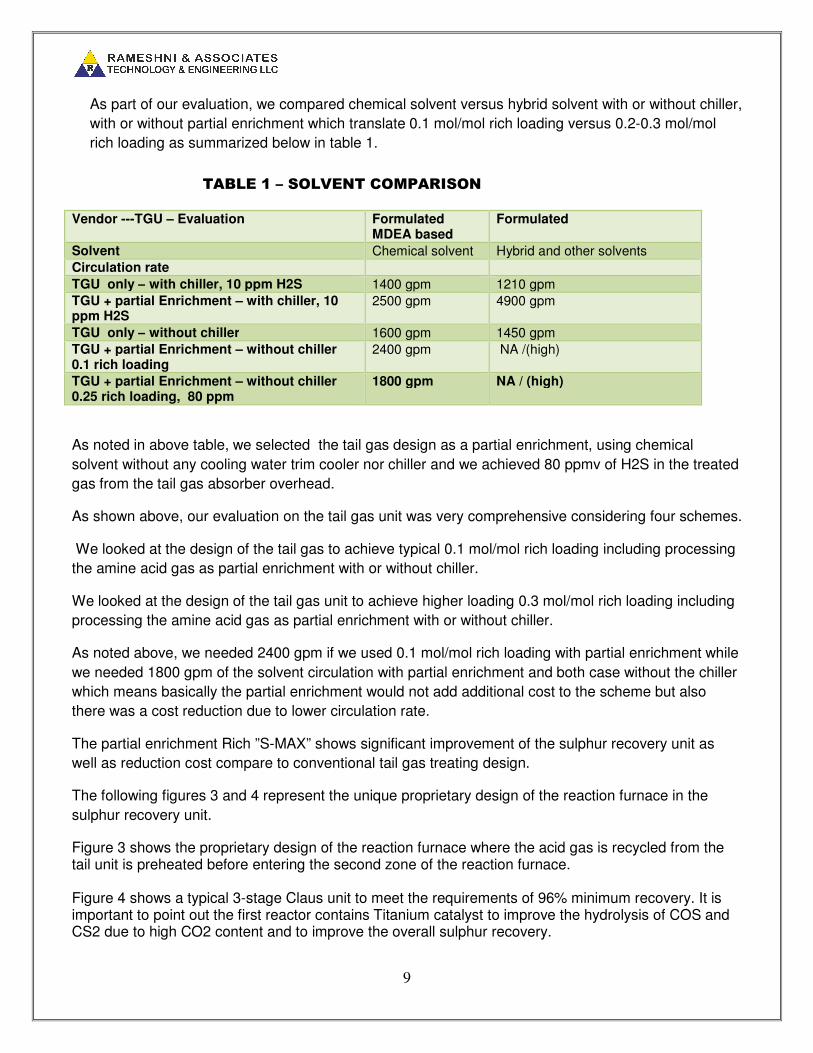
As part of our evaluation, we compared chemical solvent versus hybrid solvent with or without chiller,
with or without partial enrichment which translate 0.1 mol/mol rich loading versus 0.2-0.3 mol/mol
rich loading as summarized below in table 1.
TABLE 1 – SOLVENT COMPARISON
Vendor ---TGU – Evaluation Formulated MDEA based
Formulated
Solvent Chemical solvent Hybrid and other solvents
Circulation rate
TGU only – with chiller, 10 ppm H2S 1400 gpm 1210 gpm
TGU + partial Enrichment – with chiller, 10 ppm H2S
2500 gpm 4900 gpm
TGU only – without chiller 1600 gpm 1450 gpm
TGU + partial Enrichment – without chiller 0.1 rich loading
2400 gpm NA /(high)
TGU + partial Enrichment – without chiller 0.25 rich loading, 80 ppm
1800 gpm NA / (high)
As noted in above table, we selected the tail gas design as a partial enrichment, using chemical
solvent without any cooling water trim cooler nor chiller and we achieved 80 ppmv of H2S in the treated
gas from the tail gas absorber overhead.
As shown above, our evaluation on the tail gas unit was very comprehensive considering four schemes.
We looked at the design of the tail gas to achieve typical 0.1 mol/mol rich loading including processing
the amine acid gas as partial enrichment with or without chiller.
We looked at the design of the tail gas unit to achieve higher loading 0.3 mol/mol rich loading including
processing the amine acid gas as partial enrichment with or without chiller.
As noted above, we needed 2400 gpm if we used 0.1 mol/mol rich loading with partial enrichment while
we needed 1800 gpm of the solvent circulation with partial enrichment and both case without the chiller
which means basically the partial enrichment would not add additional cost to the scheme but also
there was a cost reduction due to lower circulation rate.
The partial enrichment Rich ”S-MAX” shows significant improvement of the sulphur recovery unit as
well as reduction cost compare to conventional tail gas treating design.
The following figures 3 and 4 represent the unique proprietary design of the reaction furnace in the
sulphur recovery unit.
Figure 3 shows the proprietary design of the reaction furnace where the acid gas is recycled from the tail unit is preheated before entering the second zone of the reaction furnace. Figure 4 shows a typical 3-stage Claus unit to meet the requirements of 96% minimum recovery. It is important to point out the first reactor contains Titanium catalyst to improve the hydrolysis of COS and CS2 due to high CO2 content and to improve the overall sulphur recovery.

10
FIGUIRE 3 – PROPRIETARY DESIGN OF THE REACTION FURNACE
CLIENT APPROVAL
COMPANY APPROVAL
CKDBYREV DATE DESCRIPTION
DRAWING SPECIFIC NOTES
GENERAL NOTES
REFERENCE DRAWINGS
A
B
C
D
E
F
G
H
A
B
C
D
E
F
G
H
1 2 3 4 5 6 7 8
1 2 3 4 5 6 7 8
SCALE: NONE
RATE DRAWING NUMBER
RATE PROJECT NUMBER
DRAWING NUMBER REV
A
ACID GAS FROM
AGRU
V-101
LS
SOUR WATER TO
SWS UNIT
M
PC
FC
SRU-002
TAIL GAS TO NO. 1
CONDENSER
FC
SRU-002
H2S/SO2 RATIO CONTROL
LC
FC
BFW
HPS
PC
V-103
H-101
HB-101
P-101A/B
E-101
HB-101
REACTION
FURNACE
BURNER
V-101
AMINEl ACID
GAS KO DRUM
E-101
WASTE HEAT
BOILER
V-103
STEAM DRUM
H-101
REACTION
FURNACE
P-101A/B
AMINE ACID
GAS KO DRUM
PUMP
SUM
PFD – SRU - 001
B-101 A/B/C
Common spare
M
FC
RATIO
B-101
COMBUSTION
AIR BLOWER
FC
FC
RATIO
FC
RATIO
LPS
(START-UP)
FG
(START-UP)
Fuel Gas
V-102
SWS ACID GAS
KO DRUM
PCFC
RECYCLE ACID GAS
FROM REGENERATION
FC
TC
TGU-002
SRU-002
HPSTC
HPC
E-111
ST NOTE 1
HPS
TC
HPC
STNOTE 1
TC
ST
E-112
E-113
HPC
HPS
VENT FROM SULFUR PIT
TO TGU ABSORBER
E-112
RECYCLE GAS
PREHEATER
E-111
ACID GAS
PREHEATER
E-113
AIR
PREHEATER

11
FIGURE 4 – CATALYTIC STAGES OF THE CLAUS UNIT
However, according to the project specification, the Our stack emission should be less than 50 ppmv of
SO2, we concluded that if we have chiller with formulated solvent we can meet 50 ppmv of SO2 and
without the chiller we need the caustic scrubber after incineration to meet the SO2 emissions as
summarized below in table 2.
CLIENT APPROVAL
COMPANY APPROVAL
CKDBYREV DATE DESCRIPTION
DRAWING SPECIFIC NOTES
GENERAL NOTES
REFERENCE DRAWINGS
A
B
C
D
E
F
G
H
A
B
C
D
E
F
G
H
1 2 3 4 5 6 7 8
1 2 3 4 5 6 7 8
SCALE: NONE
RATE DRAWING NUMBER
RATE PROJECT NUMBER
DRAWING NUMBER REV
A
LC
BFW
HPS
LC
BFW
HPS
TCTC
E-103E-105
HPC
LC
BFW
E-102
R-101 R-103
SRU-001
TGU-001
LLPSLLPS
AC (H2S/SO2)
SRU-001
R-101
NO. 1
CONVERTER
R-102
NO. 2
CONVERTER
E-102
NO. 1
CONDENSER
E-103
NO. 2
CONDENSER
E-104
NO. 3
CONDENSER
E-106
NO. 1
REHEATER
E-107
NO. 2
REHEATER
E-108E-106
ST
HPC
ST NOTE 1 NOTE 1
1. HIGH PRESSURE STEAM TRAP: STEAMLOC OR EQUAL.
NOTE 2
S-101
NOTE 2
S-102
NOTE 2
S-104
S-101
NO. 1 SULFUR
SEAL
S-102
NO. 2 SULFUR
SEAL
S-103
NO. 3 SULFUR
SEAL
PROCESS GAS FROM
WASTE HEAT BOILER
H2S/SO2 RATIO CONTROL
2. SULFUR SEAL: SULTRAP OR EQUAL.
TAIL GAS
TO TGU
SULFUR TO
SULFUR PIT
PFD – SRU - 002
PC
E-109
E-109
WASTE STEAM
CONDENSER
HPS
TCHPC
R-102
E-107
ST NOTE 1
LC
BFW
E-104
LLPS
NOTE 2
S-103
E-105
NO. 4
CONDENSER
E-108
NO. 3
REHEATER
R-103
NO. 3
CONVERTER

12
TABLE 2 - CAUSTIC SCRUBBER VERSUS CONVENTIONAL STACK
Case Case 1 Case 2
Chiller NO YES
Incineration type Caustic Scrubber Stack
COS hydrolysis reactor NO YES
Tail Gas Amine circulation Lower, with higher loading Higher, lower lean loading
Recovery 99.99% 99.9%
Reliability, operability High Mid
Capital / operating cost Lower ( no chiller, less power, less circulation)
Higher (chiller, more power, more circulation)
In the quench system, we could reduce the water circulation rate from 2300 gpm to 1500 gpm due to adding a chiller to cool the water to 37°C (100°F). In the amine section of the tail gas unit, we needed to increase the circulation rate from 1800 gpm to 2500 gpm, to meet the H2S overhead of 10 ppm even though we had a chiller on the lean amine circuit we needed more circulation. The total Chiller duty is 35 x 10^6 kcal/hr (140 MMBtu/hr) with the 2500 KW chiller system for one train. The following figures 5, 6, and 7 represent the Rich” S-MAX” partial enrichment tail gas unit and the forced draft incineration with Caustic Scrubber.
FIGURE 5 – TAIL GAS UNIT RICH”S-MAX” & HYDROGENATION SCHEME
CLIENT APPROVAL
COMPANY APPROVAL
CKDBYREV DATE DESCRIPTION
DRAWING SPECIFIC NOTES
GENERAL NOTES
REFERENCE DRAWINGS
A
B
C
D
E
F
G
H
A
B
C
D
E
F
G
H
1 2 3 4 5 6 7 8
1 2 3 4 5 6 7 8
SCALE: NONE
RATE DRAWING NUMBER
RATE PROJECT NUMBER
DRAWING NUMBER REV
A
M
P-202A/B
LC
C-201
FC
R-201
HYDROGENATION
REACTOR
E-204
SPENT
CAUSTIC
COOLER
E-201
TAIL GAS
HEATER
E-202
REACTOR
EFFLUENT
COOLER
J-201
TGU START-
UP VENT
EJECTOR
C-201
CONTACT
CONDENSER
COLUMN
LC
BFW
MPS
TC
E-202
R-201
SRU-002
LLPS
E-201
MPC
ST NOTE 1
TAIL GAS FROM NO. 4
CONDENSER
LPS
J-201
P-202A/B
CONTACT
CONDENSER PUMP
FC
CAUSTIC
MAKE-UP
PFD – TGU - 001
TGU-003
TGU-002
C-202
AMINE
ABSORBER
C-202
P-203A/B
RICH AMINE
PUMP
M
P-203A/B
TREATED GAS TO
INCINERATOR
LEAN AMINE FROM
REGENERATOR
RICH AMINE TO
REGENERATOR
FC
LC
FC
AI (H2) AI (H2S)
E-204
SRU FEED ACID GAS
pH
FC
M
P-201A/B
TC
SPENT
CAUSTIC
E-203
TC
LC
SOUR
WATER
P-201A/B
DESUPERHEATER
PUMP

13
Figure 5 represents the tail gas treating unit which starts with indirect steam reheater with the low temperature hydrogenation catalyst, then it is followed by the quench system where the gas is cooled off and then is routed to the Rich ”S-MAX” absorber. Cooling is only by air cooler since cooling water would not be effective in summer. The Rich ”S-MAX” absorber receives the cooled gas from the quench tower overhead plus up to 25% amine acid gas from the amine unit.
FIGURE 6 – RICH”S-MAX” TAIL GAS UNIT REGENERATION SYSTEM WITHOUT
CHILLER
CLIENT APPROVAL
COMPANY APPROVAL
CKDBYREV DATE DESCRIPTION
DRAWING SPECIFIC NOTES
GENERAL NOTES
REFERENCE DRAWINGS
A
B
C
D
E
F
G
H
A
B
C
D
E
F
G
H
1 2 3 4 5 6 7 8
1 2 3 4 5 6 7 8
SCALE: NONE
RATE DRAWING NUMBER
RATE PROJECT NUMBER
DRAWING NUMBER REV
A
LC
FC
FC
LC
FC
ACID GAS RECYCLE TO
SRU
SOUR WATER
COND
LP STM
C-203
AMINE
REGENERATOR
E-206
REGENERATOR
REBOILER
E-207
REGENERATOR
OVERHEAD CONDENSER
F-202
LEAN AMINE
FILTER
E-205A/B
LEAN / RICH
AMINE EXCHANGER
V-202
REBOILER
CONDENSATE DRUM
P-204A/B
LEAN AMINE PUMP
P-205A/B
REGENERATOR REFLUX PUMP
P-205A/B
E-205A/B
C-203
V-202
E-206
PC
V-201
F-202
P-204A/B
FC
FC
RICH AMINE FROM ABSORBER
MLC
AMINE DRAINS
P-207 A/B
V-204
T-202
P-206 A/B
F-205
T-201
AMINE MAKE-UP
CONDENSATE
NITROGEN
PC
PC
NITROGEN
PC
NITROGEN
P-207 A/B
AMINE SUMP PUMP
P-206 A/B
AMINE MAKE UP PUMP
T-202
FRESH AMINE
TANK
T-201
LEAN AMINE
SURGE TANK
F-205
AMINE SUMP
FILTER
V-203
AMINE SUMP
F-204
F-203
F-203
AMINE
CARBON FILTER
F-204
AMINE
PARTICULATE FILTER
E-207
E-208
E-208
LEAN AMINE COOLER
LEAN AMINE TO ABSORBER
FC
VENT TO INCINERATOR
VENTO TO INCINERATOR
VENT TO INCINERATOR
LC
V-201
REGENERATO
R REFLUX DRUM
TC
FC
PFD – TGU - 002
PA-201
ANTIFOAM
INJECTION PACKAGE

14
FIGURE 7- FORCED DRAFT INCINERATION WITH CAUSTIC SCRUBBER
Figure 7 represents the forced draft incinerator with the incinerator waste heat boiler to recover the heat for energy efficiency followed by the venturi scrubber and caustic scrubber tower, which was designed by RATE. The remaining H2S and sulphur species were directed to incinerator and converted to SO2. This scheme provides ZERO SO2 emissions. Caustic is known as the best absorbent to absorb the SO2. The gas leaving the caustic overhead is H2S free, SO2 free and sulphur free. The bottom of the caustic scrubber contains sodium bisulfite is cooled and pumped to waste water treatment.
Hydrolysis Reactor in Tail Gas Design
We had also to add the hydrolysis reactor after the hydrogenation reactor in the tail gas unit; because overtime the tail gas hydrogenation catalyst loses efficiency and the COS & CS2 hydrolysis will decline resulting emission increase and would have impact on the unit performance.
CLIENT APPROVAL
COMPANY APPROVAL
CKDBYREV DATE DESCRIPTION
DRAWING SPECIFIC NOTES
GENERAL NOTES
REFERENCE DRAWINGS
A
B
C
D
E
F
G
H
A
B
C
D
E
F
G
H
1 2 3 4 5 6 7 8
1 2 3 4 5 6 7 8
SCALE: NONE
RATE DRAWING NUMBER
RATE PROJECT NUMBER
DRAWING NUMBER REV
A
TREATED GAS FROM ABSORBER
H-201INCINERATOR
H-202INCINERATOR
STACK
FC
FUEL GAS
TC
H-201
B-202A/B
FC
AI
O2
BLOWDOWN
FC
HP BFW
LC
PC
FI
FY
TC
HP BFW
HP STEAM FROM REACTION FURNACE WASTE HEAT BOILER
SUPERHEATED HP STEAM
E-210
E-210/211INCINERATOR
WASTE HEAT
BOILER AND SUPERHEATER
TAIL GAS FROM SRU
MAKE-UP CAUSTIC
LC
P-209A/B
C-204
FC
FC
SPENT CAUSTIC
pH
AI
X-201
MAKE-UP WATER
C-204
CAUSTIC
SCRUBBER
E-209
SPENT CAUSTIC
COOLER
FROM DEHYDRATION UNIT
E-209
TC
E-211
X-201
VENTURI
SCRUBBER
15
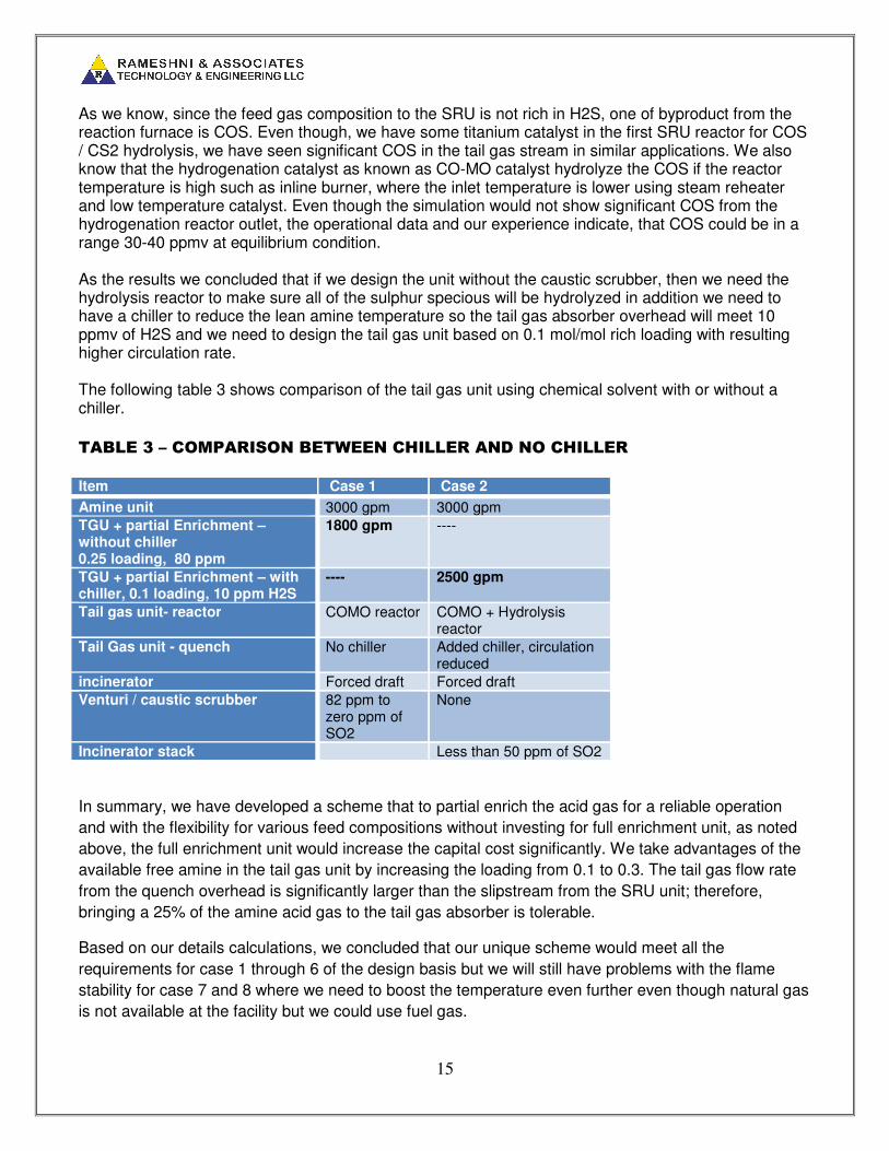
As we know, since the feed gas composition to the SRU is not rich in H2S, one of byproduct from the reaction furnace is COS. Even though, we have some titanium catalyst in the first SRU reactor for COS / CS2 hydrolysis, we have seen significant COS in the tail gas stream in similar applications. We also know that the hydrogenation catalyst as known as CO-MO catalyst hydrolyze the COS if the reactor temperature is high such as inline burner, where the inlet temperature is lower using steam reheater and low temperature catalyst. Even though the simulation would not show significant COS from the hydrogenation reactor outlet, the operational data and our experience indicate, that COS could be in a range 30-40 ppmv at equilibrium condition. As the results we concluded that if we design the unit without the caustic scrubber, then we need the hydrolysis reactor to make sure all of the sulphur specious will be hydrolyzed in addition we need to have a chiller to reduce the lean amine temperature so the tail gas absorber overhead will meet 10 ppmv of H2S and we need to design the tail gas unit based on 0.1 mol/mol rich loading with resulting higher circulation rate. The following table 3 shows comparison of the tail gas unit using chemical solvent with or without a chiller.
TABLE 3 – COMPARISON BETWEEN CHILLER AND NO CHILLER
Item Case 1 Case 2
Amine unit 3000 gpm 3000 gpm
TGU + partial Enrichment – without chiller 0.25 loading, 80 ppm
1800 gpm ----
TGU + partial Enrichment – with chiller, 0.1 loading, 10 ppm H2S
---- 2500 gpm
Tail gas unit- reactor COMO reactor COMO + Hydrolysis reactor
Tail Gas unit - quench No chiller Added chiller, circulation reduced
incinerator Forced draft Forced draft
Venturi / caustic scrubber 82 ppm to zero ppm of SO2
None
Incinerator stack Less than 50 ppm of SO2
In summary, we have developed a scheme that to partial enrich the acid gas for a reliable operation
and with the flexibility for various feed compositions without investing for full enrichment unit, as noted
above, the full enrichment unit would increase the capital cost significantly. We take advantages of the
available free amine in the tail gas unit by increasing the loading from 0.1 to 0.3. The tail gas flow rate
from the quench overhead is significantly larger than the slipstream from the SRU unit; therefore,
bringing a 25% of the amine acid gas to the tail gas absorber is tolerable.
Based on our details calculations, we concluded that our unique scheme would meet all the
requirements for case 1 through 6 of the design basis but we will still have problems with the flame
stability for case 7 and 8 where we need to boost the temperature even further even though natural gas
is not available at the facility but we could use fuel gas.

16
Figures 8, 9, and 10 represent Rich ”S-MAX” partial enrichment with the chiller, and the hydrolysis
reactor plus the forced draft incineration with the conventional stack.
FIGURE 8 – RICH “S-MAX” PARTIAL ENRICHMENT WITH CHILLER AND
HYDROLYSIS REACTOR
MRSSRS
CLIENT APPROVAL
COMPANY APPROVAL
CKDBY
A
REV
16-OCT-12
DATE
ISSUED FOR PROPOSAL
DESCRIPTION
DRAWING SPECIFIC NOTES
GENERAL NOTES
REFERENCE DRAWINGS
A
B
C
D
E
F
G
H
A
B
C
D
E
F
G
H
1 2 3 4 5 6 7 8
1 2 3 4 5 6 7 8
SCALE: NONE
RATE DRAWING NUMBER
RATE PROJECT NUMBER
DRAWING NUMBER REV
A
M
P-202A/B
LC
C-201
FC
R-201
HYDROGENATION
REACTOR
E-204A/B
QUENCH
WATER
TRIM
COOLER
E-204
SPENT
CAUSTIC
COOLER
E-201
TAIL GAS
HEATER
E-202
REACTOR
EFFLUENT
COOLER
J-201
TGU START-
UP VENT
EJECTOR
C-201
QUENCH
COLUMN
LC
BFW
MPS
TC
E-202
R-201
SRU-002
LLPS
E-201
MPC
ST NOTE 1
TAIL GAS FROM NO. 4
CONDENSER
LPS
J-201
P-202A/B
DESUPERHEATER
PUMP
FC
CAUSTIC
MAKE-UP
PFD – TGU - 001
TGU-003
TGU-002
C-202
AMINE
ABSORBER
C-202
P-203A/B
RICH AMINE
PUMP
M
P-203A/B
TREATED GAS TO
INCINERATOR
LEAN AMINE FROM
REGENERATOR
RICH AMINE TO
REGENERATOR
FC
LC
FC
AI (H2) AI (H2S)
E-204
SRU FEED ACID GAS
pH
FC
M
P-20xA/B
TC
SPENT
CAUSTIC
E-203
TC
LC
SOUR
WATER
P-20XA/B
QUENCH
WATER PUMP
CH-201
CH-201
QUECH
CHILLER
R-202
R-202
COS HYDROLYSIS
REACTOR

17
FIGURE 9 - RICH”S-MAX” TAIL GAS UNIT REGENERATION SYSTEM WITH
CHILLER
MRSSRS
CLIENT APPROVAL
COMPANY APPROVAL
CKDBY
A
REV
16-OCT-12
DATE
ISSUED FOR PROPOSAL
DESCRIPTION
DRAWING SPECIFIC NOTES
GENERAL NOTES
REFERENCE DRAWINGS
A
B
C
D
E
F
G
H
A
B
C
D
E
F
G
H
1 2 3 4 5 6 7 8
1 2 3 4 5 6 7 8
SCALE: NONE
RATE DRAWING NUMBER
RATE PROJECT NUMBER
DRAWING NUMBER REV
A
LC
FC
FC
LC
FC
ACID GAS RECYCLE TO
SRU
SOUR WATER
COND
LP STM
C-203
AMINEREGENERATOR
E-206
REGENERATORREBOILER
E-207
REGENERATOR OVERHEAD
CONDENSER
F-202
LEAN AMINE FILTER
E-205A/B
LEAN / RICHAMINE
EXCHANGER
V-202
REBOILER CONDENSATE
DRUM
P-204A/B
LEAN AMINE
PUMP
P-205A/B
REGENERATOR
REFLUX PUMP
P-205A/B
E-205A/B
C-203
V-202
E-206
PC
V-201
F-202
P-204A/B
FC
CH-202
AMINE CHILLER
FC
RICH AMINE FROM ABSORBER
MLC
AMINE DRAINS
P-207 A/B
V-204
T-202
P-206 A/B
F-205
T-201
AMINE MAKE-UP
CONDENSATE
NITROGEN
PC
PC
NITROGEN
PC
NITROGEN
P-207 A/B
AMINE SUMP
PUMP
P-206 A/B
AMINE MAKE
UP PUMP
T-202
FRESH AMINE TANK
T-201
LEAN AMINE SURGE TANK
F-205
AMINE SUMP FILTER
V-203
AMINE SUMP
F-204
F-203
F-203
AMINE CARBON
FILTER
F-204
AMINE PARTICULATE
FILTER
E-207
E-208
E-208LEAN AMINE
COOLER
LEAN AMINE TO ABSORBER FC
VENT TO INCINERATOR
VENTO TO INCINERATOR
VENT TO INCINERATOR
LC
V-201
REGENERATOR REFLUX
DRUM
TC
FC
PFD – TGU - 002
PA-201
ANTIFOAM INJECTION
PACKAGE
CH-202

18
FIGURE 10 – FORCED DRAFT INCINERATION WITH STACK
RATE special scheme & Proprietary Burner lean gas application
In this scheme only for cases with very lean H2S, we developed the scheme to burn the fuel gas (NOT NATURAL GAS) with excess air first in the high intensity burner with zero to small portion of the acid gas in the burner. Most or all of the acid gas goes to the first zone of the reaction furnace not to the burner for the lean acid gas cases.
The concept is in this configuration the fuel gas and excess air burns stoichiometric (while conventional SRU is sub- stoichiometric) so there is no soot formation and the composition of the fuel gas is not important because we have excess air while we process the lean gas. As the acid gas changes to higher H2S concentration, we reduce the fuel and air and more acid gas goes to the burner. In this configuration, our reaction furnace will have with more residence time than the conventional design twice or more even though there is no ammonia but for destruction of BTEX. The remaining scheme would be the same, spike of fuel gas with excess air as needed.
MRSSRS
CLIENT APPROVAL
COMPANY APPROVAL
CKDBY
A
REV
16-OCT-12
DATE
ISSUED FOR PROPOSAL
DESCRIPTION
DRAWING SPECIFIC NOTES
GENERAL NOTES
REFERENCE DRAWINGS
A
B
C
D
E
F
G
H
A
B
C
D
E
F
G
H
1 2 3 4 5 6 7 8
1 2 3 4 5 6 7 8
SCALE: NONE
RATE DRAWING NUMBER
RATE PROJECT NUMBER
DRAWING NUMBER REV
A
TREATED GAS FROM ABSORBER
H-201INCINERATOR
FC
FUEL GAS
TC
H-201
B-201 A/B
FC
AI
O2
BLOWDOWN
FC
HP BFW
LC
PC
FI
FY
TC
HP BFW
HP STEAM FROM REACTION FURNACE WASTE HEAT BOILER
SUPERHEATED HP STEAM
E-210 / 211
INCINERATOR WASTE
HEAT BOILER AND SUPERHEATER
TAIL GAS FROM SRU
H-202Incinerator Stack
H-202
SRU-002
B-201 A/BINCINERATOR AIR BLOWER
PFD – TGU - 003
E-210/211
FROM DEHYDRATION UNIT

19
Adding all these features together, would allow us to have stable flame temperature for all cases of operation.
TAIL GAS TREATING SYSTEM - The tail gas unit is designed based on low temperature
hydrogenation catalyst so a steam reheater is used to heat the tail gas instead of an inline/RGG burner.
The quench system could be one stage column using ammonia bottle injection or it could be design with 2-sections using caustic the first section de-superheats the gas and scrub any SO2 may breakthrough from hydrogenation reactor, and the second section cools the gas and condensate the water. The tail gas absorber is also designed for partial H2S enrichment for up to a 25% slipstream of the SRU feed without any additional circulation rate.
INCINERATION – it is a forced draft incineration with the heat recovery.
Option 1 - As we noted above we are using formulated amine solvent for the tail gas amine unit. If we will have a chiller, then the quench water, and the lean amine could be cooled where we can meet 10 ppmv of H2S from the tail gas absorber, plus the unconverted COS from the hydrogenation reactor, plus a COS hydrolysis reactor, we would be able to meet the 50 ppmv of SO2 in the stack without caustic scrubber. In this case, having a chiller is a MUST. Option 2 - As we noted above we are using formulated amine solvent for the tail gas amine unit. If we don’t have a chiller, then the H2S from the absorber OVHD would be more than 10 ppmv, plus the unconverted COS from the hydrogenation reactor goes to the incinerator without COS hydrolysis reactor and the caustic scrubber has to be provided to meet the emission of 50 ppmv of SO2. In this case, the caustic scrubber is a MUST. Please note the followings:
• In order to eliminate the caustic scrubber, we needed to have chiller to the quench system and
lean amine circuit in the tail gas unit
• In order to eliminate the caustic scrubber, the rich / lean loading had to be kept very low to meet
the absorber overhead below 10 ppmv of H2S
LIQUID SULPHUR DEGASSING
Liquid sulphur degassing inside of the pit and outside of the pit was evaluated to achieve 10
ppmw of H2S in liquid sulphur. External degassing outside of the sulphur pit was selected to
reduce the sulphur pit sizing.
COST ESTIMATE COMPARISON
After we completed the technical evaluation and we selected the tail gas partial enrichment we
did the cost estimate for 2 cases, case 1 without the chiller and with caustic scrubber versus
case 2 with the chiller, hydrolysis reactor and the regular stack and the results are provided
below in table 4.

20
TABLE 4 – CAPITAL AND OPERATING COST COMPARISON
Case Case 1
(Rich S-Max) without chiller,
without hydrolysis reactor,
with caustic scrubber, rich
loading 0.25 mol/mol
Case 2
(Rich S-Max) with chiller,
hydrolysis reactor and
without caustic scrubber
Rich loading of 0.1 mol/mol
Capital Cost 100 115
Utility, based on 5 years
operation
100 125
Catalysts and Chemicals
based on 5 years operation
100 116
CONCLUSIONS
The drivers for the development of Sour Gas Field Development (SGFD) are based on:
a) Increasing energy costs
b) Growing demand for the natural gas
c) Higher demand to treat sour gas fields
d) 40% of the world natural gas reserves are in form of H2S and CO2 and undesired components
e) Economics
According to the design base discussed in this paper, the sour gas field development was designed considering special proprietary schemes and features to handle a wide range of operating cases and to maintain the stable operation while meeting the required performance. We concluded that the formulated chemical solvent MDEA based are more effective than hybrid solvents. In addition the tail gas absorber could be designed with a higher rich amine loading to achieve better results. RATE offered the following technologies and features for this project.
• AGRU – Acid Gas Removal – formulated MDEA based Chemical Solvent
• Dehydration unit – TEG solvent was used with gas stripping configuration to achieve water
content, of 7lb/ MMscf maximum
• Sulphur Recovery Unit
1. Acid gas and air preheater for more stability
21
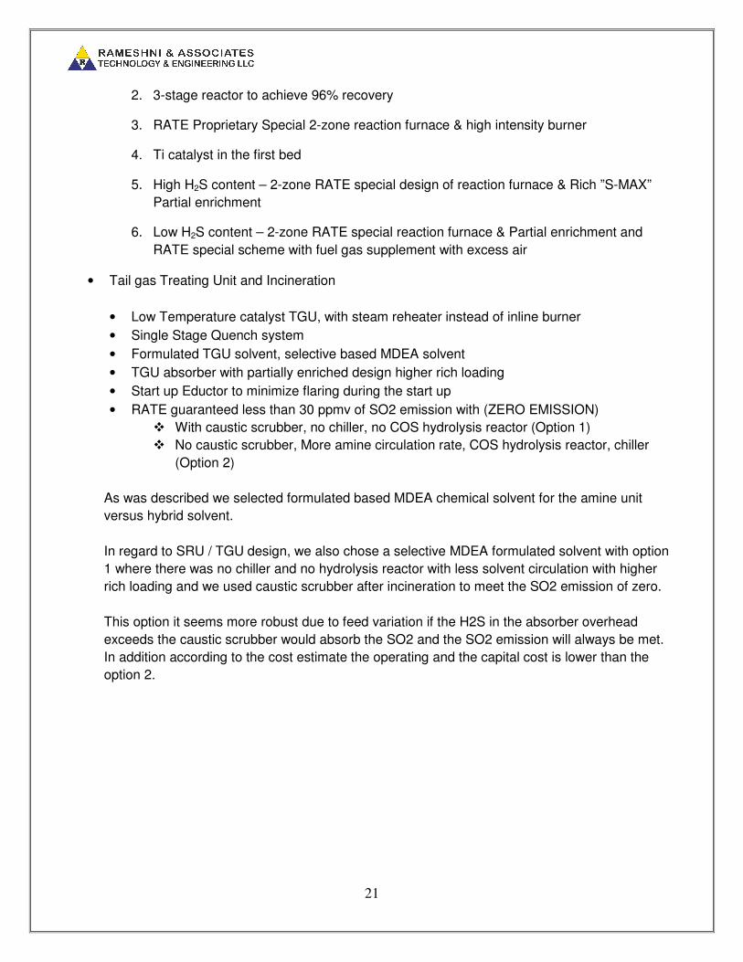
2. 3-stage reactor to achieve 96% recovery
3. RATE Proprietary Special 2-zone reaction furnace & high intensity burner
4. Ti catalyst in the first bed
5. High H2S content – 2-zone RATE special design of reaction furnace & Rich ”S-MAX”
Partial enrichment
6. Low H2S content – 2-zone RATE special reaction furnace & Partial enrichment and
RATE special scheme with fuel gas supplement with excess air
• Tail gas Treating Unit and Incineration
• Low Temperature catalyst TGU, with steam reheater instead of inline burner
• Single Stage Quench system
• Formulated TGU solvent, selective based MDEA solvent
• TGU absorber with partially enriched design higher rich loading
• Start up Eductor to minimize flaring during the start up
• RATE guaranteed less than 30 ppmv of SO2 emission with (ZERO EMISSION)
� With caustic scrubber, no chiller, no COS hydrolysis reactor (Option 1)
� No caustic scrubber, More amine circulation rate, COS hydrolysis reactor, chiller
(Option 2)
As was described we selected formulated based MDEA chemical solvent for the amine unit
versus hybrid solvent.
In regard to SRU / TGU design, we also chose a selective MDEA formulated solvent with option
1 where there was no chiller and no hydrolysis reactor with less solvent circulation with higher
rich loading and we used caustic scrubber after incineration to meet the SO2 emission of zero.
This option it seems more robust due to feed variation if the H2S in the absorber overhead
exceeds the caustic scrubber would absorb the SO2 and the SO2 emission will always be met.
In addition according to the cost estimate the operating and the capital cost is lower than the
option 2.