Embed Size (px)
Citation preview

How to use this file...(Operators Manuals)————————————————————————————————————————————–––
Instructions forPrint Vendors (Paper Manuals)
Paper Size: * 11 x 17* Body—50 lbs brilliant white offset or equivalent.* Cover—on pre-printed two-tone “Swash” stock.
Press : * Body—1-color, 2-sided* Cover imprint —1-color, 1-sided
Bindery: * Saddle Stitch, Face Trim, 3-Hole Drill* Face Trim
COVERS: * This file contains several manuals, which differ only in their covers.* Covers are all present at the beginning of this file.* Back cover for a particular manual is the page IMMEDIATELY AFTER the front cover.• Check the front cover for the individual part number (typically a 171xxxx number).
BODY: • The body of the manual is identical, regardless of the cover used.* REMEMBER: ODD number pages are ALWAYS right hand pages, and EVEN number are ALWAYS
left hand pages.
General : * This instruction page is NOT part of the manual and must NOT be printed.• Pages labeled with the text “THIS PAGE INTENTIONALLY BLANK” are placement pages ONLY,
and should NOT be printed.
————————————————————————————————————————————–––
If you have further questions on how to utilize this file, please contact Simplicity Technical Publications Department at (414) 284-8650.

THIS PAGE INTENTIONALLY BLANK

Replacement
OPERATOR’SMANUAL
Coronet / 400 / 2400 Series8HP Gear RidersMfg. No. Description1692380 Coronet, 8HP Gear1692389 2408G, 8HP Gear1692394 408G, 8HP Gear
12HP Gear RidersMfg. No. Description1692382 Coronet, 12HP Gear1692396 412G, 12HP Gear
12HP Hydro RidersMfg. No. Description1692515 Coronet, 12HP Hydro1692519 412H, 12HP Hydro
13HP Hydro RidersMfg. No. Description1692385 Coronet, 13HP Hydro1692399 413H, 13HP Hydro1692491 2413H, 13HP Hydro
Mower DecksMfg. No. Description1692126 30” Mower Deck1692172 30” Mower Deck1692128 36” Mower Deck1692174 36” Mower Deck
1714294-021714303-021714384-02
Rev 2/1995TP 100-2002-02-CO-SMA
Note: This Replacement Operator’s Manual is a reprint of a manual no longer in production, butcontains the same information as the Operator’s Manual furnished with the original tractor.

M A N U F A C T U R I N G , I N C .500 N Spring Street / PO Box 997Port Washington, WI 53074-0997
www.simplicitymfg.com
© Copyright 1995, Simplicity Manufacturing, Inc.All Rights Reserved. Printed in USA.

RIDER & MOWER IDENTIFICATION ............................2
SAFETY RULES ............................................................3
SAFETY DECALS .........................................................5
FEATURES & CONTROLS ...........................................6Rider Features & Controls ....................................................6Engine Compartment............................................................7Safety Interlock System........................................................8
OPERATION ..................................................................9General .................................................................................9Mower Removal & Installation ..............................................9Operating The Mower.........................................................10Checks Before Starting.......................................................10Clutch/Brake Pedal Operation ............................................11Starting The Engine............................................................11Selecting Ground Speed & Engine Speed .........................11Stopping the Rider .............................................................12Pushing the Rider by Hand ................................................13
MOWING PATTERN & TIPS .......................................14
NORMAL CARE ..........................................................16Schedule.............................................................................16Raising the Seat Deck ........................................................16Checking/Adding Gasoline .................................................16Checking Tire Pressure ......................................................16Checking the Fuel Filter......................................................16Lubrication ..........................................................................17Battery Maintenance...........................................................18
Checking the Battery Fluid ..............................................18Cleaning the Battery and Cables.....................................18
Servicing the Mower Blades ...............................................18
STORAGE ...................................................................20Temporary Storage.............................................................20
Long Term Storage.............................................................20
Starting After Long Term Storage.......................................21
TROUBLESHOOTING & REPAIR ...............................22General ...............................................................................22
Troubleshooting The Rider ................................................22
Troubleshooting The Mower...............................................23
Checking the Battery ..........................................................23
Charging A Completely
Discharged Battery ..........................................................23
Jump Starting with
Auxiliary (Booster) Battery ...............................................24
ADJUSTMENTS ..........................................................26Seat Adjustment .................................................................26
Brake Adjustment ..............................................................26
Neutral Adjustment .............................................................27
Return-To-Neutral Adjustment - Hydro Models ..................27
Idler Pulley Adjustment - Hydro Models..............................27
Steering Gear Adjustment ..................................................28
Steering Wheel Adjustment ................................................28
Mower Adjustments ............................................................28
BELT REPLACEMENT ................................................31Rider Drive Belt..................................................................31
Mower Belt - 30” ................................................................31
Mower Belt - 34” ................................................................31
SPECIFICATIONS .......................................................32
PARTS & ACCESSORIES ..........................................34Common Replacement Parts..............................................34
Maintenance Items .............................................................34
Optional Accessories..........................................................34
Technical Literature ............................................................35
International Symbols .........................................................36
1
Table Of Contents
NOTE: In this manual, “left” and “right” are referred to as seenfrom the operating position.
WARNING
Engine exhaust from this product contains chemi-cals known, in certain quantities, to cause cancer,birth defects, or other reproductive harm.
© Copyright 1996 by Simplicity Manufacturing, Inc.All Rights Reserved.
TP 100-2002-02-CO-SMA

2
Rider & Mower Identification
IDENTIFICATION NUMBERSRecord your model number, manufacturer number andengine serial number in the space provided for easy ref-erence. The models and manufacturer numbers coveredin this manual are listed on the front cover. The rider I.D.tag is located on the left-side of the frame, in front of therear tire, as shown below. The mower deck I.D. tag isalso on the left side, on top of the mower deck.
Refer to the engine Owner’s Manual for location ofengine serial number.
Be sure to fill out and return the Warranty RegistrationCard supplied with your rider .
MODEL REFERENCE
Model Number:
Manufacturer Number:
Engine I.D. Number:
Dealer Name/Date Purchased:
Figure 1. Rider & Mower Identification Tags
Mower Identification Tag
Rider Identification Tag

GENERAL OPERATION• Read, understand, and follow all instructions in the
manual and on the unit before starting.
• Only allow responsible adults, who are familiar withthe instructions, to operate the unit.
• Clear the area of objects such as rocks, toys, wire,etc., which could be picked up and thrown by theblade(s).
• Be sure the area is clear of other people before mow-ing. Stop unit if anyone enters the area.
• Never carry passengers.
• Do not mow in reverse unless absolutely necessary.Always look down and behind before and while trav-elling in reverse.
• Be aware of the mower discharge direction and donot point it at anyone. Do not operate the mowerwithout either the entire grass catcher or the deflectorin place.
• Slow down before turning.
• Never leave a running unit unattended. Alwaysdisengage the PTO, set parking brake, stop engine,and remove keys before dismounting.
• Turn off the PTO switch to disengage the bladeswhen not mowing.
• Stop engine before removing grass catcher orunclogging chute.
• Mow only in daylight or good artificial light.
• Do not operate the unit while under the influence ofalcohol or drugs.
• Watch for traffic when operating near or crossingroadways.
• Use extra care when loading or unloading the unitinto a trailer or truck.
SLOPE OPERATIONSlopes are a major factor related to loss-of-control andtip-over accidents, which can result in severe injury ordeath. All slopes require extra caution. If you cannotback up the slope or if you feel uneasy on it, do not mow it.
Do• See your authorized dealer for recommendations of
wheel weights or counterweights to improve stability.
• Mow up and down slopes, not across.
• Remove obstacles such as rocks, tree limbs, etc.
• Watch for holes, ruts, or bumps. Uneven terrain couldoverturn the unit. Tall grass can hide obstacles.
• Use slow speed. Choose a low gear so that you willnot have to stop or shift while on the slope.
• Use extra care with grass catchers or other attach-ments. These can change the stability of the unit.
• Keep all movement on the slopes slow and gradual.Do not make sudden changes in speed or direction.
Do Not• Do not start or stop on a slope. If tires lose traction,
disengage the blade(s) and proceed slowly straightdown the slope.
• Do not turn on slopes unless necessary, and then,turn slowly and gradually downhill, if possible.
• Do not mow near drop-offs, ditches, or embank-ments. The mower could suddenly turn over if awheel is over the edge of a cliff or ditch, or if an edgecaves in.
• Do not mow on wet grass. Reduced traction couldcause sliding.
• Do not try to stabilize the unit by putting your foot onthe ground.
• Do not use grass catcher on steep slopes.
3
Safety Rules
Read these safety rules and follow them closely. Failure to obey these rules could result in loss of control ofrider, severe personal injury or death to you, or bystanders, or damage to property or equipment. Thismowing deck is capable of amputating hands and feet and throwing objects. The triangle in textsignifies important cautions or warnings which must be followed.
WARNING - SLOPE OPERATIONNever operate on slopes greater than 30 percent(16.7°) which is a rise of three feet vertically in 10 feethorizontally. When operating on slopes that aregreater than 15 percent (8.5°) but less than 30 percentuse front counterweights and rear wheel weights (seeyour dealer). Select slow ground speed before drivingonto slope. In addition to front and rear weights, useextra caution when operating on slopes with rear-mounted grass catcher. Mow UP and DOWN the slope,never across the face, use caution when changingdirections and DO NOT START OR STOP ON SLOPE.

4
CHILDRENTragic accidents can occur if the operator is not alert tothe presence of children. Children are often attracted tothe unit and the mowing activity. Never assume that chil-dren will remain where you last saw them.
• Keep children out of the mowing area and under thewatchful care of another responsible adult.
• Be alert and turn unit off if children enter the area.
• Before and when backing, look behind and down forsmall children.
• Never carry children. They may fall off and be seri-ously injured or interfere with safe unit operation.
• Never allow children to operate the unit.
• Use extra care when approaching blind corners, shrubs,trees, or other objects that may obscure vision.
TRANSPORTING AND STORAGE• Always observe safe refueling and fuel handling prac-
tices when refueling the rider after transportation orstorage.
• Always follow the engine manual instructions forstorage preparations before storing the rider for bothshort and long term periods.
• Always follow the engine manual instructions forproper start-up procedures when returning the unit toservice.
• Never store the unit or fuel container inside wherethere is an open flame or pilot light, such as in awater heater. Allow unit to cool before storing.
SERVICE AND MAINTENANCE• Use extra care in handling gasoline and other fuels.
They are flammable and vapors are explosive.
a) Use only an approved container.
b) Never remove gas cap or add fuel with the engine
Safety Rules
running. Allow engine to cool before refueling. Donot smoke.
c) Never refuel the unit indoors.
• Never run a unit inside a closed area.
• Keep nuts and bolts, especially blade attachmentbolts, tight and keep equipment in good condition.
• Never tamper with safety devices. Check their properoperation regularly.
• Keep unit free of grass, leaves, or other debris build-up. Clean up oil or fuel spillage.
• Stop and inspect the equipment if you strike anobject. Repair, if necessary, before restarting.
• Never make adjustments or repairs with the enginerunning unless specified otherwise in the enginemanufacturer’s manual.
• Grass catcher components are subject to wear, dam-age, and deterioration, which could expose movingparts or allow objects to be thrown. Frequently checkcomponents and replace with manufacturer’s recom-mended parts, when necessary.
• Mower blades are sharp and can cut. Wrap theblade(s) or wear gloves, and use extra caution whenservicing them.
• Check brake operation frequently. Adjust and serviceas required.
• Use only factory authorized replacement parts whenmaking repairs.
• Always comply with factory specifications on allsettings and adjustments.
• Only authorized service locations should be utilizedfor major service and repair requirements.
• Never attempt to make major repairs on this unitunless you have been properly trained. Improper ser-vice procedures can result in hazardous operation,equipment damage and voiding of manufacturer’swarranty.

5
Safety DecalsThis unit has been designed and manufactured to pro-vide you with the safety and reliability you would expectfrom an industry leader in outdoor power equipmentmanufacturing.
Although reading this manual and the safety instructionsit contains will provide you with the necessary basicknowledge to operate this equipment safely and effec-tively, we have placed several safety labels on the unit toremind you of this important information while you areoperating your rider.
All WARNING, CAUTION and instructional messages on
your rider and mower should be carefully read andobeyed. Personal bodily injury can result when theseinstructions are not followed. The information is for yoursafety and it is important! The safety decals shown beloware on your rider and mower.
If any of these decals are lost or damaged, replace themat once. See your local dealer for replacements.
These labels are easily applied and will act as a constantvisual reminder to you, and others who may use theequipment, to follow the safety instructions necessary forsafe, effective operation.
Decal - Operating Information Part No. 1713490
Decal - DangerPart No. 1704276
Decal - DangerPart No. 1704277
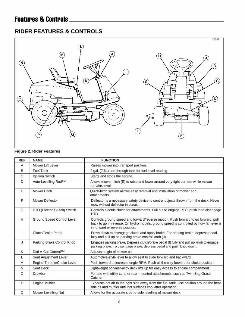
REF NAME FUNCTIONA Mower Lift Lever Raises mower into transport position.
B Fuel Tank 2 gal. (7.6L) see-through tank for fuel level reading.
C Ignition Switch Starts and stops the engine.
D Auto-Levelling RodTM Allows mower hitch (E) to raise and lower around very tight corners while mower remains level.
E Mower Hitch Quick-hitch system allows easy removal and installation of mower and attachments
F Mower Deflector Deflector is a necessary safety device to control objects thrown from the deck. Never mow without deflector in place.
G PTO (Electric Clutch) Switch Controls electric clutch for attachments. Pull out to engage PTO; push in to disengagePTO.
H Ground Speed Control Lever Controls ground speed and forward/reverse motion. Push forward to go forward; pull back to go in reverse. On hydro models, ground speed is controlled by how far lever isin forward or reverse position.
I Clutch/Brake Pedal Press down to disengage clutch and apply brake. For parking brake, depress pedal fully and pull up on parking brake control knob (J).
J Parking Brake Control Knob Engages parking brake. Depress clutch/brake pedal (I) fully and pull up knob to engage parking brake. To disengage brake, depress pedal and push knob down.
K Dial-A-Cut ControlTM Adjusts height of mower cut.
L Seat Adjustment Lever Automotive-style lever to allow seat to slide forward and backward.
M Engine Throttle/Choke Lever Push forward to increase engie RPM. Push all the way forward for choke position.
N Seat Deck Lightweight polymer-alloy deck lifts up for easy access to engine compartment.
O Drawbar For use with utility carts or rear-mounted attachments, such as Twin Bag Grass Catcher.
P Engine Muffler Exhausts hot air to the right side away from the fuel tank. Use caution around the heatshields and muffler until hot surfaces cool after operation.
Q Mower Levelling Nut Allows for the accurate side-to-side levelling of mower deck.
6
RIDER FEATURES & CONTROLS
Features & Controls
Figure 2. Rider Features
*2395

7
Features & Controls
REF NAME FUNCTIONA Fuel Tank 2 gal. (7.6L) see-through tank for fuel level reading.
B Ignition Switch Starts and stops the engine.
C Battery 12 volt, 340 amp battery recharged by engine alternator
D Throttle/Choke Cable Controls engine speed and choke position. See engine manual for adjustment.
E PTO Switch (Electric Clutch) Controls electric clutch for attachments. Pull out to engage clutch; push in to disen-gage.
F Air Filter See engine manual for maintenance instructions.
G Seat Switch Safety interlock switch to prevent travel or mowing without operator.
H Oil Drain Attach clear plastic tube to drain outlet and open valve to drain oil.
I Oil Fill/Dipstick Turn and remove to check or add oil. See engine manual for dipstick instruction.
Not Fuel Filter In-line filter for straining particles in fuel lines and fuel tank.Shown
ENGINE COMPARTMENT
Figure 3. Engine Compartment
*2387

8
Figure 4. Seat SwitchA. Switch C. Switch ActivatorB. Harness Plug
WARNINGIf the rider does not pass the test, do not oper-ate rider . See your authorized dealer. Under nocircumstance should you attempt to defeat thepurpose of the safety system.
Features & Controls
SAFETY INTERLOCK SYSTEMYour rider is equipped with a seat switch safety systemthat will automatically shut the engine off when the oper-ator leaves the seat with the ground speed control leverin gear or PTO engaged. Once the engine has stopped,the electric PTO switch must be turned off after operatorreturns to the seat in order to start the engine.
Make sure there is 1/8” clearance between switch activa-tor (C, figure 5) and switch plunger.
On hydro models, the clutch/brake pedal (I, figure 2)must be fully depressed to start engine.
Check the seat switch (A, figure 5) every fall and springwith the tests listed below.
With operator in seat and ignition switch turned to ON(engine not running):
Test 1 - Engine should NOT crank if:A. seat is not occupied or
B. transmission lever out of neutral or
C. PTO switch engaged or
D. clutch/brake pedal not fully depressed.
Test 2 - Engine should crank if:A. seat is occupied and
B. transmission lever is in neutral and
C. PTO switch is disengaged and
D. clutch/brake pedal is fully depressed.
Test 3 - Engine should shut off if:A. operator rises off seat with transmission lever in
gear or
B. operator rises off seat with clutch/brake pedal notdepressed (parking brake on) or
C. operator rises off seat with PTO engaged.
NOTE: If operator returns to seat before engine stops,the engine will re-start and electric PTO clutch will re-engage.
Test 4 - PTO will disengage if:A. operator rises off seat with engine running.
NOTE: If operator returns to seat before engine stops,the engine will resume speed and electric PTO clutch willre-engage.
*2387

9
Operation
GENERALBefore operating this rider for the first time, the ownershould operate in an open area without mowing, tobecome accustomed to the unit. The left side of themower can be used to trim close to objects. Be sure toread all information in the Safety and Operation sectionsbefore attempting to operate this rider and mower.
MOWER REMOVAL AND INSTALLATION
WARNINGNever allow passengers to ride on the unit.
WARNING
To reduce fire hazard, keep the engine andmower free of grass, leaves and excess grease.
WARNING
Stop engine and remove key. Do not engage PTOuntil mower is completely removed or installedand operator is seated.
WARNING
The interlock safety switches are for your safety.Do not attempt to bypass them.
WARNING
Towing the rider will cause transmission dam-age. Do not use another vehicle to push or pullrider .
Figure 5. Mower Removal/Installation (34” mower shown)A. Idler Pulley Arm D. Lift CableB. Idler Pulley E. Lift HookC. PTO (Electric Clutch) Pulley F. Rear Trailing Arms
*2396
WARNING - SLOPE OPERATIONNever operate on slopes greater than 30 percent(16.7°) which is a rise of three feet vertically in 10 feethorizontally. When operating on slopes that aregreater than 15 percent (8.5°) but less than 30 percentuse front counterweights and rear wheel weights (seeyour dealer). Select slow ground speed before drivingonto slope. In addition to front and rear weights, useextra caution when operating on slopes with rear-mounted grass catcher. Mow UP and DOWN the slope,never across the face, use caution when changingdirections and DO NOT START OR STOP ON SLOPE.
NOTE: Perform mower installation on a hard, level sur-face such as a concrete floor. For easier mower removaland installation, rear trailing arms (F, figure 5) can beremoved by removing spring clips and clevis pins.
1. Park rider and turn off PTO switch and engine,remove the key and apply parking brake. Turn thewheels fully to the left.

10
CHECKS BEFORE STARTING1. Make sure you have proper wheel or counterweights
if required. See SLOPE OPERATION in the SafetyRules section. Make sure any slopes are withinrequired limits.
2. Check that crankcase is filled to full mark on dipstick.See the engine Operator’s Manual for instructionsand oil recommendations.
3. Make sure all nuts, bolts, screws and pins are inplace and tight.
4. Make sure you can reach all controls from operator’spositions. If not, see SEAT ADJUSTMENT.
5. Fill the gasoline tank with fresh gasoline. Fill to bot-tom of filler neck to avoid spillage and overflow. DONOT mix oil with gasoline. Refer to engine manual forgasoline recommendations.
2. On left-hand side of 34” mower, push idler pulley arm(A, figure 5) to relieve belt tension.
On right-hand side of 30” mower, pull idler pulley armto relieve belt tension.
3. With belt tension relieved, remove belt from idler pul-ley (B, figure 5) and PTO pulley (C). Removing beltrelieves tension on the front hitch assembly.
4. With lift lever down and Dial-A-CutTM control set tothe lowest setting, remove lift cable (D, figure 5) frommower hook (see inset illustration, figure 5).
5. Remove mower hitch (B, figure 6) from rider hitchbrackets (C) by pulling spring-loaded lever (A, figure6) forward and lifting up on hitch. Place mower hitchon ground.
6. With wheels turned fully left, remove mower fromunderneath right-hand side of rider.
7. To install mower, reverse above steps. Check mowerbelt pattern as shown in figure 7. Make sure that themower lift cable is installed with hook torward the rearand rear trailing arms (F, figure 5) are positionedabove rear torsion bar.
OPERATING THE MOWER1. When traveling to or from the work site, fully raise the
mower using the mower lift lever (A, figure 11 ). Atthe work site, lower mower using the lift lever.
2. Use the Dial-A-CutTM control (E, figure 11) to adjustthe height of the mower. Pull back slightly on mowerlift lever (A, figure 10) to relieve pressure and turnclockwise to raise mower cutting height, or counter-clockwise to lower cutting height.
NOTE: Cutting height scale is located on the quadrant atbase of lift lever. Scale is numbered 1 thru 4, with 4 rep-resenting the highest cutting height.
Figure 6. Mower Belt PatternA. PTO (Electric Clutch (Pulley)B. Arbor Pulley (30”)
Right Arbor Pulley (34”)C. Idler PulleyD. Front Idler Pulley (30”)
Left Arbor Pulley (34”)E. Idler Pulley Arm
Operation
Figure 6. Mower HitchA. Lever C. Rider Hitch BracketsB. Mower Hitch
*2390
*2392

11
Operation
WARNING
Gasoline is highly flammable and must be han-dled with care. Never fill the tank when theengine is still hot from recent operation. Do notallow open flame, smoking or matches in thearea. Avoid over-filling and wipe up any spills.
CLUTCH/BRAKE PEDAL OPERATION - HYDRO MODELS1. See figure 10. Depressing the pedal from position A to
B disengages the transmission drive and also returnsthe transmission control lever to neutral (from forwardspeeds). Fully depressing the pedal to position Bapplies the rider brake.
2. Parking brake is applied at pedal position B whenparking brake control knob (C, figure 10) is pulled upwith pedal fully depressed.
CLUTCH/BRAKE PEDAL OPERATION - GEAR MODELS1. See figure 10. Depressing the clutch pedal from posi-
tion A to B activates neutral start circuit, disengagesthe transmission drive belt and allows the gear leverto be shifted.
2. Fully depressing the clutch/brake pedal from positionA to B applies the rider brake. Parking brake isapplied at position B when parking brake control knob(C, figure 10) is pulled up with pedal depressed.
STARTING THE ENGINE1. Seat yourself on the rider seat in the operating posi-
tion. Set the parking brake using the clutch/brakepedal (D, figure 11) and parking brake knob (B).
2. Push down on the switch (G, figure 2) to disengagethe PTO and place the ground speed control lever (C,figure 11) in neutral.
3. For cold starts, set the engine speed control (M, fig-ure 2) to the choke position. For warm starts, setengine speed control lever at 1/2 throttle position .
4. Turn the key (C, figure 2) to start and release whenengine has started.
5. Move the engine speed control lever (M, figure 2) tothe slow position. Warm up the engine by running itfor at least a minute before engaging the PTO or dri-ving the rider .
SELECTING GROUND & ENGINE SPEEDOn hydro models, ground speed is infinitely variable
Figure 11. ControlsA. Mower Lift LeverB. Parking Brake KnobC. Ground Speed Control LeverD. Clutch/Brake PedalE. Dial-A-Cut TM Control
*2394
Figure 10. Clutch/Brake Pedal
according to how far the control lever (C, figure 11) ismoved in the forward or reverse position.
On gear models, ground speed is selected by depress-ing the clutch/brake pedal (D, figure 11) and moving thecontrol lever (C, figure 11) to the appropriate gear selec-tion. Most mowing is done in 3rd or 4th gear with engineset at full speed. If the terrain is rough, hilly or sloping,use first or second gear. If the grass is wet or over 3”(76mm) high, use full engine speed (with low gear) sothe mower will have enough power to cut the grass.

12
WARNING
Before leaving the operator’s position for anyreason, engage the parking brake, disengage thePTO, stop the engine and remove the key.
WARNING
To reduce fire hazard, keep the engine, rider andmower free of grass, leaves and excess grease.Do not stop or park rider over dry leaves, grassor combustible materials.
1. If you are ready to mow, lower the mower from thetransport position using lever (A, figure 11) and setthe mowing height using the Dial-A-CutTM Control (E,figure 11).
2. Set the engine speed control lever (M, figure 2) forfull speed.
3. Use the PTO switch (G, figure 2) to engage the PTO.
4. Release the parking brake by depressingclutch/brake pedal (D, figure 11) and pushing knob(B) down.
5. On hydro models , move the ground speed controllever (C, figure 11) to the desired direction and speedof travel to set the rider in motion.
On gear models, depress clutch/brake pedal, usethe ground speed control lever to select the propergear for conditions, then slowly release clutch/brakepedal to set the rider in motion.
6. Adjust engine speed control lever (M, figure 2) to thedesired speed. Between 3/4 and full speed is recom-mended for mowing.
STOPPING THE RIDER 1. On hydro models , move the ground speed control
lever (C, figure 11) into the NEUTRAL position tomake a gradual stop. To make a more rapid stop,depress the clutch/brake pedal (D, figure 11).
Operation
WARNING
Make sure desired direction of travel is clear ofobjects, people and animals.
NOTE: On hydro models, the ground speed controllever will return to neutral from forward automaticallywhen the clutch/brake pedal is depressed.
On gear models, press the clutch/brake pedal (D,figure 11) down only far enough to disengage theclutch to make a gradual stop. For a more rapid stop,press pedal down farther to apply the brake. Movethe ground speed control lever to NEUTRAL beforereleasing the pedal.
2. Engage the parking brake by fully depressingclutch/brake pedal and pulling up on parking brakeknob (B, figure 11).
3. Use the PTO switch (G, figure 2) to disengage thePTO.
4. Set the engine speed control lever (M, figure 2) to 1/2throttle setting and allow the engine to idle for 20seconds. Stopping a hot engine too fast may causeengine damage.
5. Turn key (C, figure 2) to OFF and remove it.

13
PUSHING THE RIDER BY HAND
Hydro Models1. Engine should be off and ignition key removed.
2. Place the mower in the transport position (up) usingthe mower lift lever (A, figure 11).
3. See figure 12. To push the rider by hand, the releaselever must be placed in the PUSH position.
4. To drive the rider, release lever must be moved to theDRIVE position.
Gear Model1. Engine should be off and ignition key removed.
2. Place the mower in the transport position (up) usingthe mower lift lever (A, figure 11).
3. Depress the clutch/’brake pedal and place the groundspeed control lever (C, figure 11) in the neutral posi-tion.
4. Unlock the parking brake.
Operation
WARNING
Do not tow the rider. Damage will result to thetransmission/transaxle.
Figure 12. Transaxle Release Lever - Hydro Models
*2511
Move forward for driveposition, pull rearwardfor push position.
Forward
14
Mowing Patterns & Tips
GENERALFor the first use of the mower, choose a smooth levelarea. Cut long straight strips overlapping slightly.The size and type of area to be mowed determines thebest mowing pattern to use. Obstructions such as trees,fences and buildings must also be considered. Wherepossible, make one or two passes in a counterclockwisedirection around the outside of the area to keep the cutgrass off fences and walks. The remainder of the mow-ing should be done in a clockwise direction so the clip-pings are dispersed on the cut area.Keep in mind the following lawn care and mowing tips:
• Too much maintenance is as detrimental to your lawnas neglect.
• Mow when grass is 3-5 inches tall. Don’t cut shorterthan 2 to 2-1/2 inches. Cut only the top one-third of thegrass blade. Cutting below this level can lead to thatchproblems. Your mower has a cutting height adjustmentthat can help you maintain a proper length.
• For extremely tall grass, set the cutting height atmaximum for the first pass, and then reset to thedesired height and mow again.
• Mow often. Short clippings of an inch or less decom-pose more quickly than longer blades.
• Keep the blades on your mower sharp for finer clip-pings.
• Let grass grow a bit longer when it is hot to reduceheat build-up and protect grass from heat damage.
• Use slow-release fertilizer for slow, even growth.• Don’t cover grass surface with a heavy layer of clip-
pings. Consider using a grass collection system andstarting a compost pile.
• Aerate lawn in spring, consider renting an aeratorwhich removes cores of soil from the lawn. Thisincreases the speed of clipping decomposition anddeep root growth by opening up the soil and permittinggreater movement of water, fertilizer and air.
• Don’t over-water. Too much water can encouragedisease development.
• Mow when the grass is dry, preferably in the lateafternoon when the temperatures are cooler.
• Where possible, change patterns occasionally toeliminate matting, graining or a corrugated appear-ance.
• For wet grasses, grasses prone to wheel tracking andfor collecting clippings:a. Use sharp blades.
b. Raise deck 1/4” higher in front than in rear.
c. Run at maximum engine speed but slow groundspeed.
d. Clean deck of built-up material/caked-on grass.
e. Check for free movement of mower idler pulley.
• For dry conditions where grass blow-out is a problem:a. Use sharp blades.
b. Raise deck so the front is even with, or 1/8” lowerthan, rear.
c. Use 3/4 engine speed.
d. Clean deck of built-up material/caked-on grass.
MULCHING MOWER OPERATION(OPTIONAL KIT ATTACHMENT)
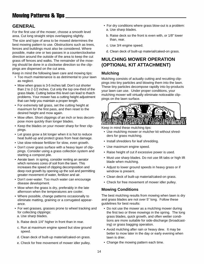
MulchingMulching consists of actually cutting and recutting clip-pings into tiny particles and blowing them into the lawn.These tiny particles decompose rapidly into by-productsyour lawn can use. Under proper conditions, yourmulching mower will virtually eliminate noticeable clip-pings on the lawn surface.
Keep in mind these mulching tips:• Use mulching mower or mulcher kit without shred-
ders for grass mulching.
• Install shredders for leaf shredding.
• Use maximum engine speed.
• Raise height of cut if excessive power is used.
• Must use sharp blades. Do not use lift tabs or high liftblade when mulching.
• Adjust to lower ground speeds in heavy grass or ifwindrow is present.
• Clean deck of built-up material/caked-on grass.
• Check for free movement of mower idler pulley.
Mowing ConditionsThe best mulching results from mowing when lawn is dryand grass blades are not over 5” long. Follow theseguidelines for best results:
• Do not use the mower as a mulching mower duringthe first two or three mowings in the spring. The longgrass blades, quick growth, and often wetter condi-tions are more suitable for side-discharge (broadcast-ing) or grass bagging operation.
• Avoid mulching after rain or heavy dew. It may bebetter to mow later in the day or early evening whenlawn is drier.
• Change the mowing pattern each time.

15
• If mulching baffles are removed, the original deflectormust be in operating position for safe side-dischargemowing.
How Much Grass To Cut OffRemoving too much grass height in one cutting mayresult in an unsatisfactory cut: windrowing, clumping, oruneven dispersal of clippings may result. It is best tomow when the grass is between 3”- 5” tall, although thiswill depend on your personal preference for lawn appear-ance. A good rule to follow is to cut only the top one-third of the grass blade at a time (maximum of 1-1/2”).Cutting more off the grass blade, particularly in wetspring conditions, can lead to thatch problems.
Engine Speed & Ground Speed Use full engine throttle matched with a slower groundspeed so that clippings will be finely cut. A better cutmay result from cutting the same area in two passes,each time cutting only 3/4” of grass blade. Short clip-pings of 1” or less decompose more quickly than longerblades.
NOTE: When mulching under heavy cutting conditions, arumbling sound may be present and is normal.
The Proper EquipmentAlways keep the mower blades sharp and balanced.Blades should be sharpened at the beginning of everymowing season. If the tips of grass blades brown aftercutting, this may be a sign of dull blades tearing, ratherthan cutting, the grass blades.
Keep the underside of the mower deck and baffles cleanso that clippings are properly circulated, chopped, anddischarged back into the lawn.
The Best CombinationWe recommend that you experiment with the height ofcut position and rider ground speed that will give you thebest cut. Start with a higher cutting height and tryincreasing lower settings until you find a cutting heightthat is matched to your mowing conditions and prefer-ences. Since mulching requires more horsepower thanside-discharging, using a slower ground speed is impor-tant for proper mulching operation.
Clippings Are BeneficialA common misconception about clippings is that theyautomatically lead to thatch. However, clippings pro-duced by mulching methods actually contribute to ahealthy lawn because they:
• Act as a safe, non-polluting and inexpensive fertilizerthat nourishes your lawn. Fresh cut blades are a richsource of nitrogen which is essential to lush growth.And one garbage bag of clippings contains about 1/4lb. of usable organic nitrogen.
• Reduce the evaporation of water from your lawn.
• Provide a cushioning layer to reduce lawn wear.
• Moderate soil temperature.
• Save money normally spent on trash bags.
Leaf Shredding - 34” Mower Deck Only(For use with Mulcher Kit Only)
Patented Shredder Blades virtually eliminate rakingleaves. Up to 512 cutting edges pulverize leaves into tinyparticles, which quickly and naturally decompose intofood for your lawn. Shredder Blades must be removedwhen you choose to mulch grass clippings.
Mowing Patterns & Tips
Leaf Shredder KitPart No. 1686609(Contains Qty. 8 shredders)
Optimal cutting point
This area can contributeto thatch

16
RAISING THE SEAT DECKTo gain access to the engine compartment, simply raisethe seat deck forward.
CHECKING/ADDING GASOLINECheck the gas gauge/cap to be sure there is enoughgasoline to complete the job. To add gasoline, removethe gas gauge/cap. Do not overfill. Leave room in thetank for fuel expansion. Refer to your engine manual forgasoline recommendations. Install and hand tighten thegas gauge/cap.
CHECKING TIRE PRESSUREFront and rear tire pressure should be 10 to12 psi (68 to82 kPa)
CHECKING FUEL FILTER
The fuel filter is located in fuel line between fuel tank andcarburetor. If filter is dirty or clogged, replace as follows.Place a container below filter to catch spilled gasoline.
1. Using a pliers, open and slide hose clamps from fuelfilter.
2. Remove hoses from filter.
3. Install new filter in proper flow direction in fuel line.Secure with hose clamps. See warning at beginningof procedure.
Normal Care
See Before Before Every Every 25 Every 100 SpringSafety Items Page First Use Each Use 5 Hours Hours Hours & Fall
Check safety interlock system. 8 ● ●
Check rider brakes. 26 ● ●
Check mower blade stopping time. 30 ● ●
Normal Care ItemsCheck rider & mower for loose hardware. – ● ● ●
Check engine oil level. * ● ● ● ●
Check engine & air filter. * ***●
Change engine oil and filter.** * ***Every 50 hrs. ***●
Lubricate rider & mower. 17 ***●
Check fluid levels & tire pressure 16 ● ● **●
Change transmission fluid. (Hydro only)**** – Only if transaxle is serviced.Check fuel filter. 16 ●
Clean battery & cables 18 ●
Clean/sharpen blades. 18 ●
Inspect spark plug(s). * ●
* See the engine manufacturer's owner's manual.** Change original engine oil after first 5 hours of operation.*** More often in hot (over 85° F: 30° C) weather or dusty operating conditions.**** Transaxle is a sealed unit and requires no regular interval fluid changes.
SCHEDULEThe following schedule should be followed for normal care of your rider and mower. You will need to keep a record ofyour operating time. Determining operating time is easily accomplished by multiplying the time it takes to do one jobby the number of times you’ve done the job, or you can install the optional hour meter.
CAUTION
Never use gasoline containing METHANOL, gaso-hol containing more than 10% ethanol, gasolineadditives, premium gasoline, or white gas becauseengine/fuel system damage could result.
WARNING
Do not remove fuel filter when engine is hot, asspilled gasoline may ignite. DO NOT spread hoseclamps further than necessary. Ensure clampsgrip hoses firmly over filter after installation.
17
*2397
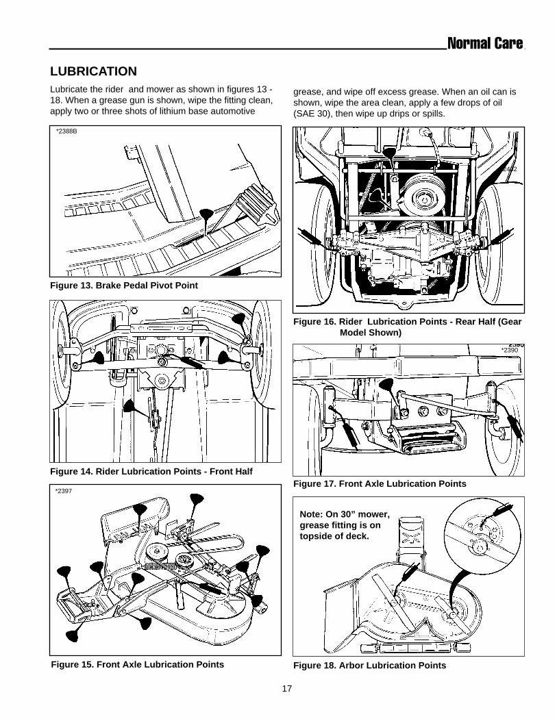
LUBRICATIONLubricate the rider and mower as shown in figures 13 -18. When a grease gun is shown, wipe the fitting clean,apply two or three shots of lithium base automotive
Normal Care
*2388B
Figure 13. Brake Pedal Pivot Point
Figure 17. Front Axle Lubrication Points
Figure 16. Rider Lubrication Points - Rear Half (GearModel Shown)
Figure 15. Front Axle Lubrication Points
Figure 14. Rider Lubrication Points - Front Half
*2402
grease, and wipe off excess grease. When an oil can isshown, wipe the area clean, apply a few drops of oil(SAE 30), then wipe up drips or spills.
*2390
Figure 18. Arbor Lubrication Points
Note: On 30” mower,grease fitting is ontopside of deck.
18
*2542
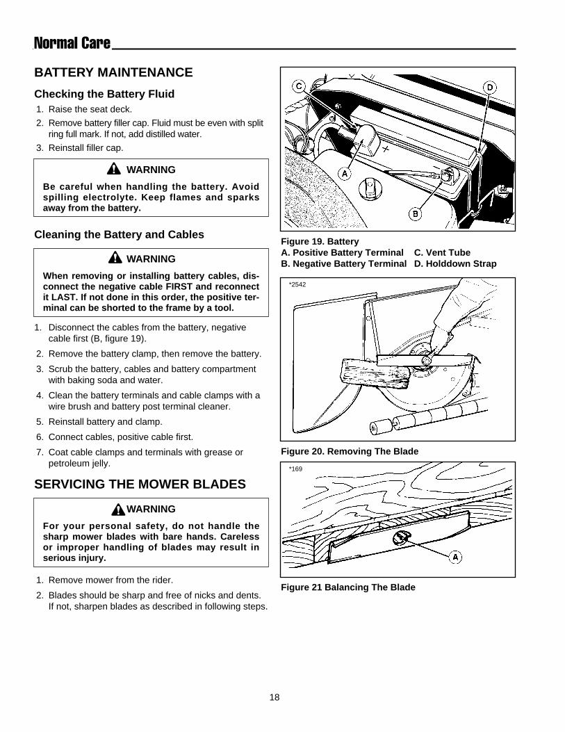
Figure 19. BatteryA. Positive Battery Terminal C. Vent TubeB. Negative Battery Terminal D. Holddown Strap
Figure 20. Removing The Blade
Figure 21 Balancing The Blade
*169
Normal Care
BATTERY MAINTENANCE
Checking the Battery Fluid1. Raise the seat deck.
2. Remove battery filler cap. Fluid must be even with splitring full mark. If not, add distilled water.
3. Reinstall filler cap.
Cleaning the Battery and Cables
1. Disconnect the cables from the battery, negativecable first (B, figure 19).
2. Remove the battery clamp, then remove the battery.
3. Scrub the battery, cables and battery compartmentwith baking soda and water.
4. Clean the battery terminals and cable clamps with awire brush and battery post terminal cleaner.
5. Reinstall battery and clamp.
6. Connect cables, positive cable first.
7. Coat cable clamps and terminals with grease orpetroleum jelly.
SERVICING THE MOWER BLADES
1. Remove mower from the rider.
2. Blades should be sharp and free of nicks and dents.If not, sharpen blades as described in following steps.
WARNING
Be careful when handling the battery. Avoidspilling electrolyte. Keep flames and sparksaway from the battery.
WARNING
When removing or installing battery cables, dis-connect the negative cable FIRST and reconnectit LAST. If not done in this order, the positive ter-minal can be shorted to the frame by a tool.
WARNING
For your personal safety, do not handle thesharp mower blades with bare hands. Carelessor improper handling of blades may result inserious injury.

19
3. To remove blade for sharpening, use wooden blockto hold blade while removing the blade mounting cap-screw (figure 20).
4. Use a file to sharpen blade to fine edge. Remove allnicks and dents in blade edge. If blade is severelydamaged, it should be replaced.
5. Balance the blade as shown in figure 21. Center theblades’ hole on a nail lubricated with a drop of oil. Abalanced blade will remain level.
6.Reinstall each blade with the tabs pointing up towarddeck as shown in figure 22. Secure with a capscrew(D), cup washer (C) and spline washer (B). Use awooden block to prevent blade rotation and torquecapscrews to 50-70 ft.lbs. (67-95 N.m.).
Normal Care
Figure 22. Installing The BladeA. Wooden Block C. Cup WasherB. Spline Washer D. Capscrew
*5
TIGHTEN
A
B
D
C
WARNING
For your personal safety, blade mounting cap-screws must each be installed with a cup washerand spline washer, then securely tightened.Torque blade mounting capscrew to 50-70 ft.lbs.(67-95 N.m.)

20
Storage
TEMPORARY STORAGE(30 Days Or Less)Remember, the fuel tank will still contain some gasoline,so never store the rider indoors or in any other areawhere fuel vapor could travel to any ignition source. Fuelvapor is also toxic if inhaled, so never store the rider inany structure used for human or animal habitation.
Here is a checklist of things to do when storing your ridertemporarily or in between uses:
• Keep the rider in an area away from where childrenmay come into contact with it. If there’s any chance ofunauthorized use, remove the spark plug (s) and putin a safe place. Be sure the spark plug opening isprotected from foreign objects with a suitable cover.
• If the rider can’t be stored on a reasonable level sur-face, chock the wheels.
• Clean all grass and dirt from the mower.
NOTE: If storing your rider between winter snow removaljobs in a cold area, we suggest that you fill the fuel tankat the completion of each job to prevent water condensa-tion in the fuel tank. Wait for engine to cool before fillingtank.
LONG TERM STORAGE(Longer Than 30 Days)Before you store your rider for the off-season, read theMaintenance and Storage instructions in the SafetyRules section, then perform the following steps:
1. Drain crankcase oil while engine is hot and refill witha grade of oil that will be required when rider is usedagain.
2. Prepare the mower deck for storage as follows:
a. Remove mower deck from the rider.
b. Clean underside of mower deck.
c. Coat all bare metal surfaces with paint or light coatof oil to prevent rusting.
3. Clean external surfaces and engine.
4. Prepare engine for storage. See engine owner’smanual.
5. Clean any dirt or grass from cylinder head coolingfins,engine housing and air cleaner element.
6. Cover air cleaner and exhaust outlet tightly with plas-tic or other waterproof material to keep out moisture,dirt and insects.
7. Completely grease and oil rider as outlined in theNormal Care section.
8. Clean up rider and apply paint or rust preventative toany areas where paint is chipped or damaged.
9. Be sure the battery is filled to the proper level withwater and is fully charged. Battery life will beincreased if it is removed, put in a cool, dry place andfully charged about once a month. If battery is left inrider, disconnect the negative cable.
10. Drain fuel system completely or add a gasoline stabi-lizer to the fuel system. If you have chosen to use afuel stabilizer and have not drained the fuel system,follow all safety instructions and storage precautionsin this manual to prevent the possibility of fire fromthe ignition of gasoline fumes. Remember, gasolinefumes can travel to distant sources of ignition andignite, causing risk of explosion and fire.
NOTE: Gasoline, if permitted to stand unused for extend-ed periods (30 days or more), may develop gummydeposits which can adversely affect the engine carbure-tor and cause engine malfunction. To avoid this condi-tion, add a gasoline stabilizer to the fuel tank or drain allfuel from the system before placing unit in storage.
WARNING
Never store the rider, with gasoline in engine or fuel tank, in a heated shelter or in enclosed, poorly venti-lated enclosures. Gasoline fumes may reach an open flame, spark or pilot light (such as a furnace, waterheater, clothes dryer, etc.) and cause an explosion.
Handle gasoline carefully. It is highly flammable and careless use could result in serious fire damage toyour person or property.
Drain fuel into an approved container outdoors away from open flame or sparks.

21
11. Transport the riderto a suitable, dry, indoor location. Ifthe rider is to be stored 6 months or longer, block therider up off the wheels to relieve weight and also tokeep the tires off a damp floor. Protect tires from pro-longed exposure to direct sunlight.
STARTING AFTER LONG TERM STORAGEBefore starting the rider after it has been stored for along period of time, perform the following steps.
1. Remove the blocks from under the rider.
2. Install the battery if it was removed.
3. Unplug the exhaust outlet and air cleaner.
4. Fill the fuel tank with fresh gasoline. See enginemanual for recommendations.
5. Check crankcase oil level and add proper oil ifnecessary.
6. Inflate tires to proper pressure. Check fluid levels.
7. Start the engine and let it run slowly. DO NOT run athigh speed immediately after starting. Be sure to runengine only outdoors or in well ventilated area.
Storage

22
GENERAL
This section of the manual provides troubleshooting andrepair instructions for the more common and easily cor-rected problems. For other problems, it is recommendedthat you contact your dealer.Locate the problem that bestdescribes the trouble that you have encountered. Checkthe possible causes one at a time, in the order that theyare listed.
TROUBLESHOOTING THE RIDEREngine will not turnover or start.1. Ground speed control lever not in neutral-start position.
Shift into neutral.
2. PTO (electric clutch) switch in ON position. Place inOFF position.
3. Out of fuel. If engine is hot, allow it to cool, then refill thefuel tank.
4. Engine flooded. Push choke knob in (twin cylinder mod-els) or move throttle control out of CHOKE position(single cylinder models).
5. Circuit breaker tripped. Wait one minute for automaticreset. Replace if defective (see your dealer).
6. Battery terminals require cleaning. See Normal Caresection.
7. Battery discharged or dead. Recharge or replace.
8. Wiring loose or broken. Visually check wiring & replacebroken or frayed wires. Tighten loose connections.
9. Solenoid or starter motor faulty. Repair or replace.
10. Safety interlock switch or module faulty. Replace ifneeded (see your dealer.)
11. Spark plug(s) faulty, fouled or incorrectly gapped. Cleanand gap or replace. See engine manual.
12. Water in fuel. Drain fuel & refill with fresh fuel.
13. Old stale gas. Drain fuel & replace with fresh fuel.
14. Foot pedal not depressed.
Engine starts hard or runs poorly.1. Fuel mixture too rich. Clean air filter. Check choke
adjustment (engine speed control). See engine manual.
2. Carburetor adjusted incorrectly. See engine manual.
3. Spark plug(s) faulty, fouled, or incorrectly gapped.Clean and gap or replace. See engine manual.
Engine knocks.1. Low oil level. Check/add oil as required.
2. Using wrong grade oil. See engine manual.
Excessive oil consumption.1. Engine running too hot. Clean engine fins, blower
screen and air cleaner.
2. Using wrong weight oil. See engine manual.
3. Too much oil in crankcase. Drain excessive oil.
Engine exhaust is black.1. Dirty air filter. Clean air filter. See engine manual.
2. Check engine speed control adjustment (choke).
See engine manual.
Engine runs, but rider will not drive.1. Ground speed control lever in neutral. Shift in forward
or reverse.
2. (Hydro models only) Transmission release lever in“push” position. Move into drive position.
3. Belt is broken. See Drive Belt Replacement.
4. Drive belt slips. See problem and cause below.
5. Brake is not fully released. See Brake Adjustment.
Rider drive belt slips.1. Clutch is out of adjustment. See your dealer.
2. Pulleys or belt greasy or oily. Clean as required.
3. Belt stretched or worn. Replace with correct belt.
4. Idler pulley pivot bracket “frozen” in declutched posi-tion. Remove idler pulley, clean and lubricate.
Brake will not hold.1. Brake is incorrectly adjusted. See Brake Adjustment.
2. Internal brake disc on transaxle worn. See your dealer.
Rider steers hard or handles poorly.1. Steering linkage is loose. Check and tighten any
loose connections. See Steering Gear Adjustment.
2. Improper tire inflation. Check and correct.
3. Spindle bearings dry. Grease spindles. SeeLubricating the rider.
22
Troubleshooting & Repair
WARNING
To avoid serious injury, perform maintenance onthe rider or mower only when the engine isstopped and the parking brake engaged. Alwaysremove the ignition key, disconnect spark plugwire and fasten away from the plug before begin-ning the maintenance, to prevent accidentalstarting of the engine.

23
TROUBLESHOOTING THE MOWER
Mower will not raise.1. Lift cable not properly attached or damaged. Attach
or repair.
Mower cut is uneven.1. Mower not leveled properly. See Mower Adjustment.
2. Rider tires not inflated equally or properly. SeeNormal Care.
Mower cut is rough looking.1. Engine speed too slow. Set for three-fourths to full
speed.
2. Ground speed too fast. Set ground speed controllever at a slower ground speed.
3. Blades dull and require sharpening. See Servicingthe Mower Blades.
4. Mower drive belt slipping. Belt oily or worn. Clean orreplace belt as necessary.
5. Check PTO (Electric Clutch) Adjustment. Clutch mayneed to be adjusted.
6. Blades not properly fastened to arbors. See Servicingthe Mower Blades.
Engine stalls easily with mower engaged.1. Engine speed too slow. Set for 3/4 to full throttle.
2. Ground speed too fast.
3. Carburetor not adjusted properly.
4. Cutting height set too low when mowing tall grass.Cut tall grass at maximum cutting height during firstpass.
5. Discharge chute jamming with cut grass. Cut grasswith discharge pointing toward previously cut area.
Excessive mower vibration.1. Blade mounting screws are loose. Tighten to 50-70
ft.lbs. (67-95 N.m.).
2. Mower blade(s), arbors, or pulleys are bent. Checkand replace as necessary.
3. Mower blade(s) out of balance. Remove, sharpenand balance blade(s). See Servicing the MowerBlade(s).
4. Belt installed incorrectly. See Belt Replacement.
Excessive belt breakage.1. Bent or rough pulleys. Repair or replace.
2. Using incorrect belt. See your dealer.
Mower drive belt slips or fails to drive.1. Idler pulley spring broken or not properly attached.
See your dealer.
2. Mower drive belt broken. Replace.
CHECKING THE BATTERYThe voltmeter can be used to determine condition of bat-tery. When engine is off, the voltmeter shows batteryvoltage, which should be 12 volts. When engine is run-ning, the voltmeter shows voltage of charging circuitwhich normally is 13 to 14 volts.
A dead battery or one too weak to start the engine maynot mean the battery needs to be replaced. It may, as anexample, mean that the alternator is not charging thebattery properly. If there is any doubt about the cause ofthe problem, see your dealer. If you need to replace thebattery, follow the steps under Cleaning the Battery &Cables in the Normal Care Section.
CHARGING A COMPLETELYDISCHARGED BATTERY
1. Be aware of all the safety precautions you shouldobserve during the charging operation. If you areunfamiliar with the use of a battery charger andhydrometer, have the battery serviced by your dealer.
2. Add water sufficient to cover the plate (fill to the prop-er level near the end of the charge). If the battery isextremely cold, allow it to warm before adding waterbecause the water level will rise as it warms. Also, anextremely cold battery will not accept a normalcharge until it becomes warm.
3. Always unplug or turn the charger off before attach-ing or removing the clamp connections.
4. Carefully attach the clamps to the battery in properpolarity (usually red to [+] positive and black to [-]negative).
5. While charging, periodically measure the temperatureof the electrolyte. If the temperature exceeds 125° F(51.6° C), or if violent gassing or spewing of elec-trolyte occurs, the charging rate must be reduced ortemporarily halted to prevent battery damage.
6. Charge the battery until fully charged (i.e. until the
Troubleshooting & Repair
WARNING
Do not attempt to charge a frozen battery. Allowthe battery to warm to 60° F (15.5° C) before plac-ing on charge.

24
specific gravity of the electrolyte is 1.250 or higherand the electrolyte temperature is at least 60° F). Thebest method of making certain a battery is fullycharged, but not over charged, is to measure thespecific gravity of a cell once per hour. The battery isfully charged when the cells are gassing freely at lowcharging rate and less than 0.003 change in specificgravity occurs over a three hour period.
JUMP STARTING WITH AUXILIARY(BOOSTER) BATTERY
Jump starting is not recommended. However, if it mustbe done, follow these directions. Both booster and dis-charged batteries should be treated carefully when usingjumper cables. Follow the steps below EXACTLY, beingcareful not to cause sparks. Refer to figure 23.
1. Both batteries must be of the same voltage (6, 12,etc.).
2. Position the vehicle with the booster battery adjacentto the vehicle with the discharged battery so thatbooster cables can be connected easily to the batter-ies in both vehicles. Make certain vehicles do nottouch each other.
3. Wear safety glasses and shield eyes and face frombatteries at all times. Be sure vent caps are tight.Place damp cloth over vent caps on both batteries.
4. Connect positive (+) cable to positive post of dis-charged battery (wired to starter or solenoid).
5. Connect the other end of same cable to same postmarked positive (+) on booster battery.
6. Connect the second cable negative (-) to other postof booster battery.
7. Make final connection on engine block of stalled vehi-cle away from battery. Do not lean over batteries.
8. Start the engine of the vehicle with the booster bat-tery. Wait a few minutes, then attempt to start theengine of the vehicle with the discharged battery.
9. If the vehicle does not start after cranking for thirtyseconds, STOP PROCEDURE. More than thirty sec-onds seldom starts the engine unless some mechani-cal adjustment is made.
10. After starting, allow the engine to return to idle speed.Remove the cable connection at the engine or frame.Then remove the other end of the same cable fromthe booster battery.
11. Remove the other cable by disconnecting at the dis-charged battery first and then disconnect the oppo-site end from the booster battery.
12. Discard the damp cloths that were placed over thebattery vent caps.
Troubleshooting & Repair
WARNING
For your personal safety, use extreme care whenjump starting. Never expose battery to openflame or electric spark – battery action generateshydrogen gas which is flammable and explosive.Do not allow battery acid to contact skin, eyes,fabrics, or painted surfaces. Batteries contain asulfuric acid solution which can cause seriouspersonal injury or property damage.
WARNING
To avoid engine damage, do not disconnect bat-tery while engine is running. Be sure terminalconnections are tight before starting.
WARNING
Keep open flames and sparks away from the bat-tery; the gasses coming from it are highly explo-sive. Ventilate the battery well during charging.
WARNING
Any procedure other than the preceding couldresult in: (1) personal injury caused by elec-trolyte squirting out the battery vents, (2) per-sonal injury or property damage due to batteryexplosion, (3) damage to the charging system ofthe booster vehicle or of the immobilized vehicle.
Do not attempt to jump start a vehicle having afrozen battery because the battery may ruptureor explode. If a frozen battery is suspected,examine all fill vents on the battery. If ice can beseen or if the electrolyte fluid cannot be seen, donot attempt to start with jumper cables as longas the battery remains frozen.

25
Troubleshooting & Repair
THIS HOOK-UP FOR NEGATIVE GROUND VEHICLES
MAKE CERTAIN VEHICLES DO NOT TOUCH
ToStarterSwitch
ToStarterSwitch
Jumper Cable
Jumper Cable
DischargedVehicleBattery
StartingVehicleBattery
EngineBlock
To Ground
**1582
Figure 23. Battery Jump Starting Diagram

26
SEAT ADJUSTMENTUse the lever to adjust the seat forward or rearward forbest ridercomfort.
BRAKE ADJUSTMENTBrake Adjustment - Gear Models
1. Place the transmission in gear and release the park-ing brake.
2. Move the brake lever (B) forward. There should be a1/8" gap between the lever (B) and the stop (C) asshown in figure 24.
3. To adjust clearance, turn nut (D) clockwise todecrease the gap or turn nut counterclockwise toincrease the gap.
4. Set the parking brake. Loosen or tighten adjustmentnut (E) to achieve a 2 9/16"–2 5/8" compressedspring length as shown in figure 24.
Brake Adjustment - Hydro Models
1. Release the parking brake.
2. Place a .025" feeler gauge (A, figure 25) between thetwo outer brake stators (refer to inset illustration).The gap should be between .025"–.030". To adjust:
a. Remove cotter pin from castellated nut if present.
b. To decrease gap, hold feeler gauge in gap andturn nut (B) clockwise until resistance is felt on thefeeler gauge. To increase gap, turn nut (B)counter-clockwise and recheck gap.
c. If cotter pin was removed, back off nut (counter-clockwise) until the nearest slot is aligned with holein threads. Replace cotter pin.
3. Set the parking brake. Loosen or tighten adjustmentnut (C) to achieve a 2 11/16"–2 13/32" compressedspring length as shown in figure 25.
Adjustments
WARNING
To avoid serious injury, perform adjustmentsonly with engine stopped, key removed and rideron level ground.
CHECK GAP with .025" FEELER GAUGE
OUTER BRAKE
OUTSIDE(Axle)
INSIDE(Trans.)
INNERBRAKE
OUTERSTATORS
B
C
2 11/16" – 2 13/32"
A
Figure 25. Brake Adjustment (Hydro Model)A. Feeler GaugeB. NutC. Adjustment Nut
Figure 24. Brake Adjustment (Gear model)A. Compressed Spring D. NutB. Brake Lever E. Adjustment NutC. Stop
*2393
2 9/16" – 2 5/8"
E

27
3. On gear models, see figure 26. Loosen the nut (A)that secures the front control rod (B) to the rear con-trol bar (C). Control rod must move freely. Move theground speed control lever into the neutral gate andtighten nut (A) securely to 17 ft. lbs.
On hydro models, see figure 27. Loosen the nut (A)that secures the front control rod (B) to the rear con-trol rod (C). Control rod must move freely. Move theground speed control lever into the neutral gate andtighten nut (A) securely to 17 ft. lbs. Perform the fol-lowing Return-To-Neutral Adjustment procedure.
4. Check operation of rider for any movement with shiftlever in neutral gate.
RETURN-TO-NEUTRAL ADJUSTMENT- HYDRO MODELSPerform this adjustment if the ground speed control leverdoes not return to the neutral gate from forward when theclutch/brake pedal is fully depressed. Make sure thehydro control rod (B, figure 27) is lubricated and does notbind in the carrier frame hole.
1. Make sure the Neutral Adjustment is correct asdescribed in the preceeding procedure.
2. See figure 28. Loosen the two nuts (A) that securethe front return-to-neutral rod (B) to the rear rod (C).Return-to-neutral rod must move freely.
3. Place the ground speed control lever in the full for-ward position.
4. Move the front return-to-neutral rod all the way rear-ward in the slot to shorten the length of the assem-bled rods (B & C). Tighten the two nuts (A).
5. Start the riderand check the return-to-neutral opera-tion of the ground speed control lever.
IDLER PULLEY ADJUSTMENT- HYDRO MODELSPerform the following adjustment if the rider drive beltdoes not completely declutch when the clutch/brakepedal is depressed.
(continued on page 28)
Adjustments
*2510
*2425
Figure 26. Neutral Adjustment - Gear ModelsA. Nut C. Rear Control BarB. Front Control Rod
Figure 27. Neutral Adjustment - Hydro ModelsA. Nut C. Rear Control RodB. Front Control Rod
NEUTRAL ADJUSTMENT Perform the following adjustment if the rider travels for-ward or backward with the ground speed control leverpositioned in the neutral gate.
1. Position the rider on flat, level ground and start theengine.
2. Position shift lever so that the rider has no forward orreverse movement. Shift lever may not necessarilybe in the the neutral gate. Shut off the engine. Do notdepress the clutch/brake pedal or move the groundspeed control lever.
Figure 28. Return-To-Neutral Adjustment - Hydro Models
A. Nut B. Front Return-To-Neutral RodC. Rear Return-To- Neutral Rod
*2425Move rod (B) to rearof slot
28
Figure 30. Steering Gear Adjustment
*2401
WARNING
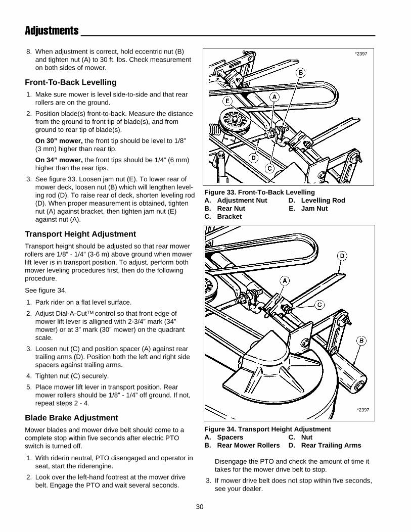
Mower blades are sharp. Turn the mower drivebelt to rotate blades into position or wear protec-tive gloves to protect against injury.
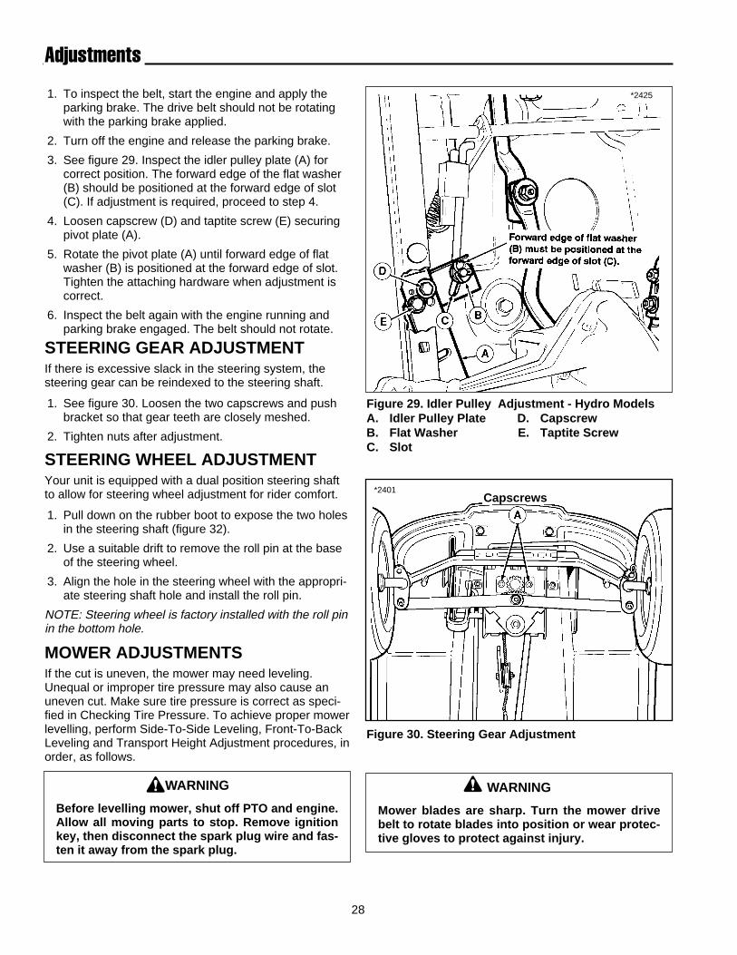
1. To inspect the belt, start the engine and apply theparking brake. The drive belt should not be rotatingwith the parking brake applied.
2. Turn off the engine and release the parking brake.
3. See figure 29. Inspect the idler pulley plate (A) forcorrect position. The forward edge of the flat washer(B) should be positioned at the forward edge of slot(C). If adjustment is required, proceed to step 4.
4. Loosen capscrew (D) and taptite screw (E) securingpivot plate (A).
5. Rotate the pivot plate (A) until forward edge of flatwasher (B) is positioned at the forward edge of slot.Tighten the attaching hardware when adjustment iscorrect.
6. Inspect the belt again with the engine running andparking brake engaged. The belt should not rotate.
STEERING GEAR ADJUSTMENTIf there is excessive slack in the steering system, thesteering gear can be reindexed to the steering shaft.
1. See figure 30. Loosen the two capscrews and pushbracket so that gear teeth are closely meshed.
2. Tighten nuts after adjustment.
STEERING WHEEL ADJUSTMENTYour unit is equipped with a dual position steering shaftto allow for steering wheel adjustment for rider comfort.
1. Pull down on the rubber boot to expose the two holesin the steering shaft (figure 32).
2. Use a suitable drift to remove the roll pin at the baseof the steering wheel.
3. Align the hole in the steering wheel with the appropri-ate steering shaft hole and install the roll pin.
NOTE: Steering wheel is factory installed with the roll pinin the bottom hole.
MOWER ADJUSTMENTSIf the cut is uneven, the mower may need leveling.Unequal or improper tire pressure may also cause anuneven cut. Make sure tire pressure is correct as speci-fied in Checking Tire Pressure. To achieve proper mowerlevelling, perform Side-To-Side Leveling, Front-To-BackLeveling and Transport Height Adjustment procedures, inorder, as follows.
Adjustments
Figure 29. Idler Pulley Adjustment - Hydro ModelsA. Idler Pulley Plate D. CapscrewB. Flat Washer E. Taptite ScrewC. Slot
*2425
Capscrews
WARNING
Before levelling mower, shut off PTO and engine.Allow all moving parts to stop. Remove ignitionkey, then disconnect the spark plug wire and fas-ten it away from the spark plug.

29
Adjustments
Figure 32. Dash Controls (shown with steering wheelremoved)
A. Mower Lift Lever D. Clutch/Brake PedalB. Parking Brake Knob E. Dial-A-Cut TM ControlC. Ground Speed Lever F. Steering Shaft
*2394
Side-To-Side Leveling1. With the mower installed, place the rider on a
smooth, level surface such as a concrete floor. Turnthe front wheels straight forward.
2. Check for bent blades and replace if necessary.
3. Loosen nut (C, figure 34) so trailing arms are loose.Mower must be resting on rollers with no weight ontrailing arms.
4. Use the Dial-A-CutTM Control (E, figure 32) andplace mower in mid-cut position by aligning frontedge of mower lift lever (A) with number 2 or 3 onquadrant scale. Make sure mower lift lever is in downposition.
5. Make sure rear rollers (C, figure 31) are on theground. If not, refer to Transport Height Adjustment.
NOTE: If rollers do not rest on the ground and it isnecessary to perform transport height adjustment, itis necessary to perform transport height adjustmentagain after all leveling procedures are completed.
5. Position blade(s) side-to-side and measure distanceform outside tip of blade(s) to ground. Measurementshould be equal (within 1/8”).
6. See figure 31. On left side of mower, make sureeccentric nut is in correct position as shown. Loosenoutside nut (A) and rotate eccentric nut (B) so that flatside with hole closest to it is towards the rear. Tightenouside nut (A) while holding eccentric nut (B).
7. On right side of mower, loosen outside nut (A). Turn
eccentric nut (B) counterclockwise to raise side ofmower, or clockwise to lower right hand side ofmower.
NOTE: Do not turn eccentric nut more than 1/4 turn ineither direction. When adjusted beyond 1/4 turn, nut willmove mower in opposite direction than when startingadjustment.
Figure 31. Leveling The Mower Side-to-SideA. NutB. Eccentric NutC. Rear Rollers
*2399
F
30
Adjustments
*2397
Figure 34. Transport Height AdjustmentA. Spacers C. NutB. Rear Mower Rollers D. Rear Trailing Arms
Figure 33. Front-To-Back LevellingA. Adjustment Nut D. Levelling RodB. Rear Nut E. Jam NutC. Bracket
8. When adjustment is correct, hold eccentric nut (B)and tighten nut (A) to 30 ft. lbs. Check measurementon both sides of mower.
Front-To-Back Levelling1. Make sure mower is level side-to-side and that rear
rollers are on the ground.
2. Position blade(s) front-to-back. Measure the distancefrom the ground to front tip of blade(s), and fromground to rear tip of blade(s).
On 30” mower, the front tip should be level to 1/8” (3 mm) higher than rear tip.
On 34” mower, the front tips should be 1/4” (6 mm)higher than the rear tips.
3. See figure 33. Loosen jam nut (E). To lower rear ofmower deck, loosen nut (B) which will lengthen level-ing rod (D). To raise rear of deck, shorten leveling rod(D). When proper measurement is obtained, tightennut (A) against bracket, then tighten jam nut (E)against nut (A).
Transport Height AdjustmentTransport height should be adjusted so that rear mowerrollers are 1/8” - 1/4” (3-6 m) above ground when mowerlift lever is in transport position. To adjust, perform bothmower leveling procedures first, then do the followingprocedure.
See figure 34.
1. Park rider on a flat level surface.
2. Adjust Dial-A-CutTM control so that front edge ofmower lift lever is alligned with 2-3/4” mark (34”mower) or at 3” mark (30” mower) on the quadrantscale.
3. Loosen nut (C) and position spacer (A) against reartrailing arms (D). Position both the left and right sidespacers against trailing arms.
4. Tighten nut (C) securely.
5. Place mower lift lever in transport position. Rearmower rollers should be 1/8” - 1/4” off ground. If not,repeat steps 2 - 4.
Blade Brake AdjustmentMower blades and mower drive belt should come to acomplete stop within five seconds after electric PTOswitch is turned off.
1. With riderin neutral, PTO disengaged and operator inseat, start the riderengine.
2. Look over the left-hand footrest at the mower drivebelt. Engage the PTO and wait several seconds.
*2397
Disengage the PTO and check the amount of time ittakes for the mower drive belt to stop.
3. If mower drive belt does not stop within five seconds,see your dealer.

31
CAUTION
To avoid damaging belts, do not pry belts overpulleys.
Belt Replacement
Figure 37. Belt Pattern - 34” MowerA. Idler Arm Pulley D. Right Arbor PulleyB. Idler Pulley E. Left Arbor PulleyC. PTO Pulley
Figure 35. Belt Pattern - 30” MowerA. Idler Pulley Arm D. Front Idler PulleyB. Idler Pulley E. PTO PulleyC. Center Arbor Pulley (Electric Clutch)
*2391
RIDER DRIVE BELTReplacement of the riderdrive belt requires removal ofthe transmission and carrier frame. Should the drive beltever fail, contact your dealer for replacement.
MOWER BELT - 30”See figure 35.
1. Mower does not need to be removed to install a newbelt. However, for easier access, mower can beremoved following steps in “Mower Removal andInstallation.
2. If mower is not removed, place mower in lowest cut-ting position. Pull idler pulley arm (A) towards you torelieve belt tension. Remove belt from idler pulley (B)and center arbor pulley (C).
3. Remove belt from front idler pulley (D) and PTO pul-ley (E).
4. Replace old belt with new belt. Make sure V-side ofbelt runs in all pulley grooves except for idler pulley(B). Check belt pattern as shown.
5. Install mower if it was removed, and install belt onPTO pulley (E).
MOWER BELT - 34”1. Mower does not need to be removed to install a new
belt. However, for easier access, mower can beremoved following steps in “Mower Removal andInstallation.
2. If mower is not removed, place mower in lowest cut-ting position. Push idler pulley arm (A, figure 36)away from you to relieve belt tension. Remove beltfrom idler pulley (B) and PTO pulley (C).
3. Remove the three capscrews (D, figure 36) securingthe left-hand arbor cover.
4. Remove old belt from arbor pulleys and replace withnew belt. Make sure V-side of belt runs in all arborpulley grooves and flat side of belt runs against idlerpulley. See figure 37 for belt pattern
5. Install mower if it was removed, and install belt toPTO pulley (C, figure 36). Push idler arm and installbelt around idler pulley. *2392
Figure 36. Mower Belt Replacement - 34”A. Idler Pulley Arm D. CapscrewsB. Idler Pulley E. Arbor CoverC. PTO Pulley

32
Specifications
ENGINE
8.5 & 12 HP Briggs & StrattonHorsepower 8.5 HP (6.3 Kw)
12 HP (9.3)Cylinders 1Bore 8.5 HP: 3.00 In. (76.2 mm)
12 HP: 3.44 In. (87 mm)Stroke 8.5 HP: 2.75 In. (69.8 mm)
12 HP: 2.62 In. (66 mm)Displacement 8.5 HP: 19.44 Cu. In. (319 cc)
12 HP: 24.36 Cu. In. (400 cc)Construction Cast Iron Sleeves, Aluminum CrankcaseElectrical 12 Volt, 3 Amp D.C. Unregulated Battery:System 240 Cold Cranking Amps, 23 min. Reserve
CapacityIgnition Magnetron Electronic IgnitionAir Cleaner Reusable Foam ElementLubrication Crankcase Oil BathOil Capacity 8.5 HP: 2.25 Pints (1.06 L)
12 HP: 3 Pints (1.4 L)Muffler Quiet Compact, Low Back Pressure
12 HP TecumsehHorsepower 12.5 HP @ 3600 rpmCylinders 1Bore 3.31 In. (94.14 mm)Stroke 2.53 In. (64.31 mm)Displacement 21.82 Cu. In. (357.6 cc)Construction Cast Iron Sleeves,
Aluminum CrankcaseElectrical 12 Volt, 15 Amp Alternator Regulated Battery:System 340 Cold Cranking Amps, 41 min. Reserve
Capacity, Industrial Rated Starter MotorIgnition Electronic, Solid State, Maintenance FreeAir Cleaner Replaceable Paper with Oiled Foam
PrecleanerLubrication Positive displacement pumpOil Capacity 2 Pints (1.9 L)Muffler Quiet Compact, Low Back Pressure
13 HP KohlerHorsepower 12.5 HP @ 3600 rpmCylinders 1Bore 3.43 In. (87 mm)Stroke 2.64 In. (67 mm)Displacement 24.3 Cu. In. (398 cc)Construction Cast Iron Sleeves,
Aluminum CrankcaseElectrical 12 Volt, 15 Amp Alternator Regulated Battery:System 340 Cold Cranking Amps, 41 min. Reserve
Capacity, Industrial Rated Starter MotorIgnition Electronic, Solid State, Maintenance Free
Air Cleaner Replaceable Paper with Oiled Foam Precleaner
Lubrication Full Pressure Lube with Oil FilterOil Capacity 2 Quarts (1.9 L)Muffler Quiet Compact, Low Back Pressure
TRANSMISSIONGear ModelsType Spur GearMaterial Gear: Powered Metal
Shaft: HardenedBearings: Needle Roller and Bushings
Lubrication Bentonite Grease. Transmission is a sealed unit.Differential Bevel Gear TypeGear Range Five Forward, One ReverseGround Speeds lst: 1.2 MPH (1.9 km/h)
2nd: 2.4 MPH (3.9 km/h)3rd: 3.5 MPH (5.6 km/h)4th: 4.4 MPH (7.1 km/h)5th: 5.6 MPH (9.0 km/h)Reverse: 2..0 MPH (3.2 km/h)
Hydro ModelsType HydrostaticLubrication Transmission is a Sealed UnitDifferential Bevel Gear TypeGround Speeds Infinite Forward: 0-5.0 MPH (8.1 km/h)
Reverse: 0 -2..0 MPH (3.2 km/h)
CONTROLSSteering Full Circle Steering Wheel
System Gear and SectorClutch/Brake Location Right FrontPedal Combination Clutch/Brake PedalParking Brake Dash Lock Finger ReleaseGround Speed Dash MountedShift LeverThrottle Control Combination Speed & Choke Control on right side
of seat deckKey Switch Starter and Magneto ON/OFF Switch located on
left side of seat deckMower Drive Electric Clutch PTO Switch located on right side of
seat deckMower Cutting Infinite Height Control on Steering ColumnHeight
CHASSISFrame Heavy Gauge , Deep Drawn SteelFront Axle Self-Leveling Quick HitchSeat Deck Lightweight Polymer Alloy
NOTE: Specifications are correct at time of printing and are subject to change without notice.

33
SpecificationsSeat Molded Type with Foam Cushion and Spring
ConstructionFront Wheels Tire Size 13 x 5.00-6
Pneumatic Inflation Pressure 10 -12 psi (68 - 82 kPa)
Rear Wheels Tire Size 16 x 6.50-8Pneumatic Inflation Pressure 10 -12 psi (82 - 103 kPa)
Accessibility Seat Deck Tips ForwardSeat Type Bucket, High Back, Adjustable w/
Spring Suspension, Fore and Aft AdjustableFuel Tank Material: Non-Corrosive Polyethylene Alloy
Capacity: 2 Gallons (7.5 L)
Turning Radius Inside Rear Tire 12 In. (30.2 cm)
DIMENSIONS
Rider Overall Length 61 In. (155 cm)Overall Width- w/30 mower 38.5 In. (97.8 cm)- w/34 mower 45.5 In. (115.6 cm)- at rear wheels 33 In. (83.8 cm)Height at- steering wheel 41 In. (104.1 cm)- seat back 35 In. (88.9 cm)- engine cover 28 In. (71.1 cm)Wheel Base 43 In. (109.2 cm)Weight (approx.)- 8.5 HP w/30”mower Net: 405 lbs. (183 kg)
Shipping: 530 Ibs. (241 kg)- 12 HP w/30”mower Net: 405 lbs. (183 kg)
Shipping: 530 Ibs. (241 kg)- 12 HP w/34”mower Net: 405 lbs. (183 kg)
Shipping: 530 Ibs. (241 kg)- 13 HP w/34”mower Net: 405 lbs. (183 kg)
Shipping: 530 Ibs. (241 kg)
Mower
Type: 30” Single Blade34” Dual Blade
Height of Cut 1.0 - 3.75 In. (2.45- 9.53 cm)
Cutting Positions Infinite
Level Adjustments Side-to-Side & Front-to-Back
Spindles Sealed Ball Bearings w/Lube Fitting
Blade Mounting Center Bolt With Spring Positioning
Discharge Deflector Hinged with Spring Positioning
Mounting At Front Axle - Quick Hitch with Auto-LevelerTM
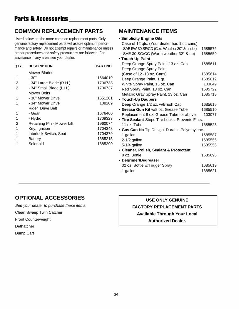
34
OPTIONAL ACCESSORIESSee your dealer to purchase these items.
Clean Sweep Twin Catcher
Front Counterweight
Dethatcher
Dump Cart
Parts & Accessories
COMMON REPLACEMENT PARTSListed below are the more common replacement parts. Onlygenuine factory replacement parts will assure optimum perfor-mance and safety. Do not attempt repairs or maintenance unlessproper procedures and safety precautions are followed. Forassistance in any area, see your dealer.
QTY. DESCRIPTION PART NO.
Mower Blades1 - 30" 16640192 - 34" Large Blade (R.H.) 17067382 - 34" Small Blade (L.H.) 1706737
Mower Belts1 - 30" Mower Drive 16512011 - 34" Mower Drive 108209
Rider Drive Belt1 - Gear 16764601 - Hydro 17093232 Retaining Pin - Mower Lift 19600741 Key, Ignition 17043481 Interlock Switch, Seat 17043791 Battery 16852151 Solenoid 1685290
MAINTENANCE ITEMS• Simplicity Engine Oils
Case of 12 qts. (Your dealer has 1 qt. cans)-SAE 5W-30 SF/CD (Cold Weather 30° & under) 1685576-SAE 30 SG/CC (Warm weather 32° & up) 1685659
• Touch-Up PaintDeep Orange Spray Paint, 13 oz. Can 1685611Deep Orange Spray Paint(Case of 12 -13 oz. Cans) 1685614Deep Orange Paint, 1 qt. 1685612White Spray Paint, 13 oz. Can 103049Red Spray Paint, 13 oz. Can 1685722Metallic Gray Spray Paint, 13 oz. Can 1685718
• Touch-Up DaubersDeep Orange 1/2 oz. w/Brush Cap 1685615
• Grease Gun Kit w/8 oz. Grease Tube 1685510Replacement 8 oz. Grease Tube for above 103077
• Tire Sealant -Stops Tire Leaks. Prevents Flats.11 oz. Tube 1685523
• Gas Can -No Tip Design. Durable Polyethylene.1 gallon 16855872-1/2 gallon 16855555-1/4 gallon 1685556
• Cleaner, Polish, Sealant & Protectant8 oz. Bottle 1685696
• Degrimer/Degreaser32 oz. Bottle w/Trigger Spray 16856191 gallon 1685621
USE ONLY GENUINE
FACTORY REPLACEMENT PARTS
Available Through Your Local
Authorized Dealer.

35
Parts & Accessories
TECHNICAL LITERATUREManuals are fully illustrated. All of the assemblies are shown in exploded views which show the relationship of theparts and how they go together. Important assembly notes and special torque values are included in the illustrations.Standard hardware and torque specification charts are also included.
For the manuals applicable for your model, contact the Customer Publications Department at 414-284-8519. Havethe following information available when phoning in your request.
Model:
Mfg. No.:
Your Name:
Address:
City, State, Zip:
Visa/Mastercard No.:
Card Expiration Date:
VISA ®
®

36
International Symbols
Fast
Slow
Operator PresentSwitch (Seat)
PTO Engaged
Parking Brake
Choke
Engine Running
Lights
Oil Pressure
Forward
Reverse


![Operators Manual - PDF.TEXTFILES.COMpdf.textfiles.com/manuals/ARCADE/A-J/Alpine Racer (52in) [Operator's] [English].pdf · part no. 90500085 operators manual it is the responsibility](https://img.pdfslide.us/doc/110x75/5d536bc788c993795a8b5f56/operators-manual-pdf-racer-52in-operators-englishpdf-part-no-90500085.jpg)