Embed Size (px)
Citation preview
How to Tune a 1G V3 SD ECM LINK with no MAF
Version - 1.5
By Aaron Ruppert AKA Dr Turbo
Last updated 1.29.2012
ECM link tuning is just like painting a car, 90% prep 10% paint. In this article 90%
of it is going to be explaining setup, and the actual tuning is very easy and a small
part.
Step 0 – Get your head right
Getting started with ECMLink is a LOT easier if you begin with the basics. And
there are a number of pages on the ECMLink support wiki and on the ECMTuning
website that can help with that.
For starters, here’s the top-level “ECMLink 101” page on the wiki.
http://www.ecmtuning.com/wiki/ecmlink101
You really should read through that if you have absolutely no idea where to even
begin with ECMLink. It walks you through the process of installing the application
and setting up your initial connection as well as how to start datalogging.
In addition, that page contains links to other high-level concept pages you may
find useful. For example, the following is the “engine theory 101” page that many
beginners may find useful.
http://www.ecmtuning.com/wiki/engineandecu101
And, of course, there are several demo videos on the ECMTuning website as well.
Those can be accessed here:
http://www.ecmtuning.com/demos.php
By ALL means, watch those videos and read up on the basics first. If you do not
have a good basis on which to build your knowledge, then you will probably find
yourself frustrated and confused a lot when, in fact, everything is actually pretty
simple.
The following is a more complete list of the topics available on the wiki if you
want to start browsing through sections.
http://www.ecmtuning.com/wiki/start?do=index
Now that you know WTF is going on with V3 we can continue.
This first thing is the car has to be mechanically sound. Bad lifters, a bad turbo, a
blown head gasket, shady plugs, leaky exhaust before the wideband are all things
I can guarantee to you to be problems. Fix your car, if you don’t have the time or
money then you don’t have the time to tune it and fix more broken parts. I can’t
tell you how many post I have read where people have known problems and are
still trying to diagnose/tune ECMLink, we can’t help you until you help yourself
first.
Step 1 – Mechanical setup
Set your fuel pressure, stock for the 1g is 37psi, but nobody runs that, set it to
43.5psi with the line off, either ground the relay to you fuel pump or if you are
already connected to ECM link you can turn the FP on by selecting the activate FP
box under the MISC tab. I prefer setting the FP with the car not running because
there are no vibrations and the mechanical FP gauge is easier to read therefore
easier to set and make sure is right.
TEST FOR BOOST LEAKS, TEST FOR BOOST LEAKS, TEST FOR
BOOST LEAKS. TEST FOR BOOST LEAKS,
I can’t tell you how important this is, you can tune an entire SD setup fine with
boost leaks, unless it is an intake manifold leak, and you will never know it
because unlike a mass air car it won’t care about a leak.
Make sure engine timing is set to a proper 5degrees BTDC with the grounding
connector grounded, if the car has never ran just set the CAS in the middle of the
spectrum, this will be good to start the car. Ultimately you have to set it after the
car is running and is up to proper operating temp.
Make sure physical cam timing is correct, also make sure the cam sensor itself is
indexed correctly, what that means if the motor is at TDC and you look at the cam
sensor with it off of the head there is a notched end, this notched end should be
lined up with a mark on the cam sensor itself.
Step 2 - Wiring in the sensors:
You will need an IAT, MAP sensor, and wide band sensor. ECM link sells the IAT
and MAP sensors with pig tails and I would suggest just buying theirs since they
are new and work well with their program. This article is based using an AEMwb
however the guys at ECMTuning actually strongly recommend *against* the AEM
because so many people have so many issues with them. They tend to prefer
something like the Innovate LC-1 or NGK AFX. But I haven’t had any problems
with the AEM, so that’s what this article covers.
Here is a discussion where to put the MAP sensor
http://www.ecmtuning.com/wiki/sdhose?s=vacuum
Here is a discussion where to put the IAT sensor
http://www.dsmlink.com/forums/showthread.php?t=37575&highlight=put+IAT
IAT: There are two wires for the IAT which are interchangeable, they go to ECU
pin #s 8 & 24.
MAP:
(+)5V reference goes to ECU pin # 23 which is Grn wire w/ red stripe.
(-)ECU sensor ground goes to ECU pin # 24 which is Grn w/ a black stripe
Sensor input wire goes to ECU pin # 15 which is Blue w/ a yellow stripe the EGR
temp wire.
Wide Band: The AEMwb’s white wire goes to ECU pin # 16 a Grn w/ yellow stripe
wire the Baro sensor.
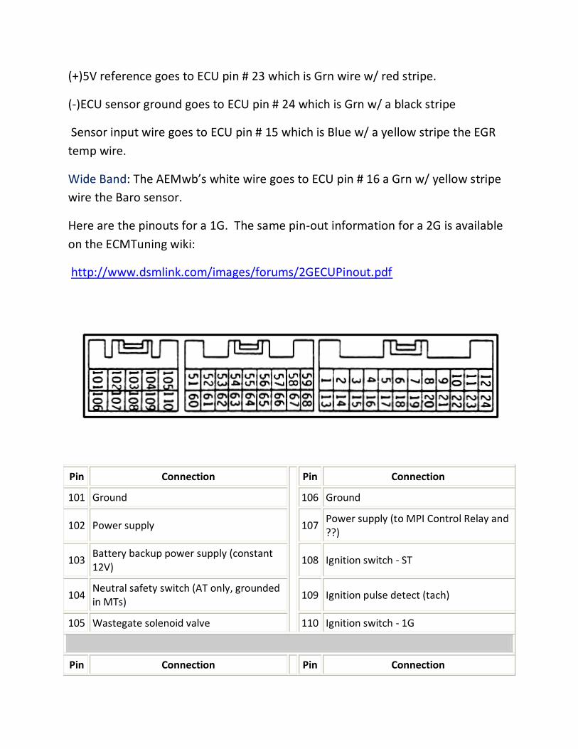
Here are the pinouts for a 1G. The same pin-out information for a 2G is available
on the ECMTuning wiki:
http://www.dsmlink.com/images/forums/2GECUPinout.pdf
Pin Connection
Pin Connection
101 Ground 106 Ground
102 Power supply 107 Power supply (to MPI Control Relay and ??)
103 Battery backup power supply (constant 12V)
108 Ignition switch - ST
104 Neutral safety switch (AT only, grounded in MTs)
109 Ignition pulse detect (tach)
105 Wastegate solenoid valve 110 Ignition switch - 1G
Pin Connection Pin Connection
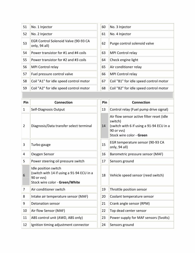
51 No. 1 Injector 60 No. 3 Injector
52 No. 2 Injector 61 No. 4 Injector
53 EGR Control Solenoid Valve (90-93 CA only, 94 all)
62 Purge control solenoid valve
54 Power transistor for #1 and #4 coils 63 MPI Control relay
55 Power transistor for #2 and #3 coils 64 Check engine light
56 MPI Control relay 65 Air conditioner relay
57 Fuel pressure control valve 66 MPI Control relay
58 Coil "A1" for idle speed control motor 67 Coil "B1" for idle speed control motor
59 Coil "A2" for idle speed control motor 68 Coil "B2" for idle speed control motor
Pin Connection
Pin Connection
1 Self-Diagnosis Output 13 Control relay (Fuel pump drive signal)
2 Diagnosis/Data transfer select terminal 14
Air flow sensor active filter reset (idle switch) (switch with 6 if using a 91-94 ECU in a 90 or vvs) Stock wire color - Green
3 Turbo gauge 15 EGR temperature sensor (90-93 CA only, 94 all)
4 Oxygen Sensor 16 Barometric pressure sensor (MAF)
5 Power steering oil pressure switch 17 Sensors ground
6
Idle position switch (switch with 14 if using a 91-94 ECU in a 90 or vvs) Stock wire color - Green/White
18 Vehicle speed sensor (reed switch)
7 Air conditioner switch 19 Throttle position sensor
8 Intake air temperature sensor (MAF) 20 Coolant temperature sensor
9 Detonation sensor 21 Crank angle sensor (RPM)
10 Air flow Sensor (MAF) 22 Top dead center sensor
11 ABS control unit (AWD, ABS only) 23 Power supply for MAF sensors (5volts)
12 Ignition timing adjustment connector 24 Sensors ground
Step 3 - Connecting to the ECU:
I recommend before connecting removing whatever version of V3 you have on
your computer and then redownloading it off the web site to make sure you have
the most up to date version available. Also, if you buy a used ECU that somebody
else already used, the previous owner’s tune will still be in there so you will want
to check that. Note** you will see firmware updates that need to be done on
occasions (these are changes to the programming that ECMTuning is continually
making), please review this link on how to do a firm ware update,
http://www.dsmlink.com/forums/showthread.php?t=36992&highlight=firmware
+updates
Hook up the provided cable from the diagnostic port near the interior fuse panel
to a USB port on your laptop. Run the program, turn the key to the “start”
position (don’t actually start the car), and hit the connect button. It will run
through a few things and will say connected if everything works out, if not refer
here http://www.ecmtuning.com/wiki/connectionproblem
Step 4 - Setting up parameters:
If connected, click on ECU configure live. I am going to run through setting up
each tab.
RPM/TPS tab:
Idle: Select your desired idle.
Launch: Rev limit imposed when speed is UNDER “Launch Spd”. Input what RPM
you want to launch the car at.
Rev Limit: Once past the “Launch Spd” your car will now shift to this set RPM
limit. You do have Kiggly valve springs, RIGHT? Otherwise I wouldn’t go past 8K
on the stock valve train.
Enable Clutch Cut: Select Enabled clutch cut if you have connected the clutch
switch to the ECU as outlined in the DSMLink instruction sheet that came with the
wire (if you have a 1990 DSM you will need to follow the instructions located on
the 90 clutch cut wire page instead). Once enabled and connected properly, you
can select a shift rev limit that will be active anytime the clutch pedal is in and
vehicle speed is greater than “Launch Spd”. If you installed a clutch switch select
the NLTS and select an appropriate RPM. This is where you want the ECU to hold
the RPMs even though the throttle is floored between shifts.
Launch Spd: Used to determine the point at which the rev limit changes from
launching revs to the ECU fuel shut off limit. Enter a value slightly lower than the
speed at which you’d expect the car to be moving in 1st gear. Entering a launch
speed value that’s too high will effectively make the Launch limit your new Rev
limit in 1st gear because the car won’t reach the shut off speed under normal
conditions by the time the Launch rev limit is reached. Disable launch should be
set at about 8 mph.
Coast FC adj: Used to tweak the lower limit on coasting fuel cut. Enter a value in here when you select an idle point greater than 900 RPM and observe any odd behavior while coasting down or letting the revs drop. As a general rule of thumb, you should enter the difference between your selected idle point and 900. So if you select an idle of 1100 RPM, you might try entering 200 into the Coast FC adj box.
For right now just skip over the TPS stuff, we will come back to it later.
Fuel tab: I personally do not use the fuel sliders, changing them will change your
target A/F already dictated by the direct access table just making things more
confusing, however they can be used for quick tuning adjustments that can be
used to make adjustments in the OpenloopmaxOct table, but I would lean toward
never using the fuel sliders.
Input your injector’s global and dead time info in at this time. Click here to help
you decide what they should be
http://www.ecmtuning.com/wiki/baseinjectordata?s=injector%20data
If running E85 read this:
http://www.ecmtuning.com/wiki/e85fuel?s=running%20e85
The usec thing is the increment number at which the dead time will adjust each
time the up/down arrows are clicked.
Timing: The same holds true for the timing sliders as the fuel sliders, it can be
used for quick changes but I ultimately let the TimingMaxOct table dictate my
timing and never touch it.
Maf comp and Maf clamp tabs are completely ignored on true SD cars, just ignore
them and don’t use them. However in the Maf comp tab you need to select
“speed density” under base maf type.
Speed Density tab: This will be used in dialing in your setup later but can be
ignored for now. If you are using a stroker motor then input your engine’s
displacement size.
Aux maps tab: This can be used to give you more global range for use with huge
injectors (2150)s running pump gas, this link
http://www.dsmlink.com/forums/showthread.php?t=46305&highlight=2150 talks
about it and how to use it, but it won’t be necessary for this write up.
Idle air: Skip
NBO2 sim tab: Skip, unless you are going to be using your WB O2 to simulate the
normal O2 sensor, if so read this to set it up:
http://www.ecmtuning.com/wiki/v3narrowbandsim
Anti/lag tab: Antilag is tool to help build boost at the line while waiting to launch
your car in a drag race. If you choose to do this some basic rules of thumb are set
the activate RPM about 500RPMs less than you launch RPMs. As for timing and
fuel enrichment, the more you increase them the more they will build boost. I
would try each in increments of 3 and then see what happens. However keep in
mind this is not the best thing for the turbo itself. Last, if your clutch switch is
hooked up you can select the “During Shifts” box and this will help keep the turbo
spooled between shifts, but your NLTS RPM will still be used.
I use the knock part to ignore phantom knock, I set it to 2200 -3500 rpm
depending on the size of the turbo and over 50%. Here are two links for setting
up the clutch switch http://www.ecmtuning.com/wiki/cltchsw
http://www.ecmtuning.com/wiki/clutchcutwire
and if you have a 90 for the clutch wiring read this:
http://www.ecmtuning.com/wiki/90clutchcut
FPS tab: Skip
EGR tab: Skip
Bst/WG tab: This is not necessary to do tuning, so I am not going to talk about it
but if you must do it read here:
http://www.ecmtuning.com/wiki/boostcontrol?s=boost%20control
Dash tab:
**Knock: 1 degree of knock = 3 counts, I hate knock… all knock, so I set mine at 1
degree.
**Coolant: Should be set based on yours car thermostat and coolant temps. I
would think you would want to be warned if the car got hotter than around 220
degrees.
**Coolant offset: leave at 0.
**Boost gauge: If you want it can show a few different things other than the
useless stock estimated boost. Here is what is available:
http://www.ecmtuning.com/wiki/dsmlinkdashgaugeranges
Misc tab: There is nothing to activate here, I would suggest that pure E85 cars
probably do not need the hot start enrichment box selected but this isn’t a biggie.
DTC tab: You shouldn’t have any at this point, but if you do, please address.
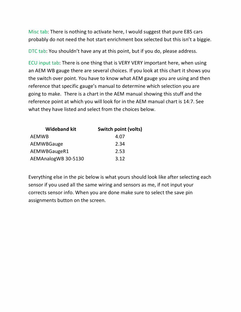
ECU input tab: There is one thing that is VERY VERY important here, when using
an AEM WB gauge there are several choices. If you look at this chart it shows you
the switch over point. You have to know what AEM gauge you are using and then
reference that specific gauge’s manual to determine which selection you are
going to make. There is a chart in the AEM manual showing this stuff and the
reference point at which you will look for in the AEM manual chart is 14:7. See
what they have listed and select from the choices below.
Wideband kit Switch point (volts)
AEMWB 4.07
AEMWBGauge 2.34
AEMWBGaugeR1 2.53
AEMAnalogWB 30-5130 3.12
Everything else in the pic below is what yours should look like after selecting each
sensor if you used all the same wiring and sensors as me, if not input your
corrects sensor info. When you are done make sure to select the save pin
assignments button on the screen.
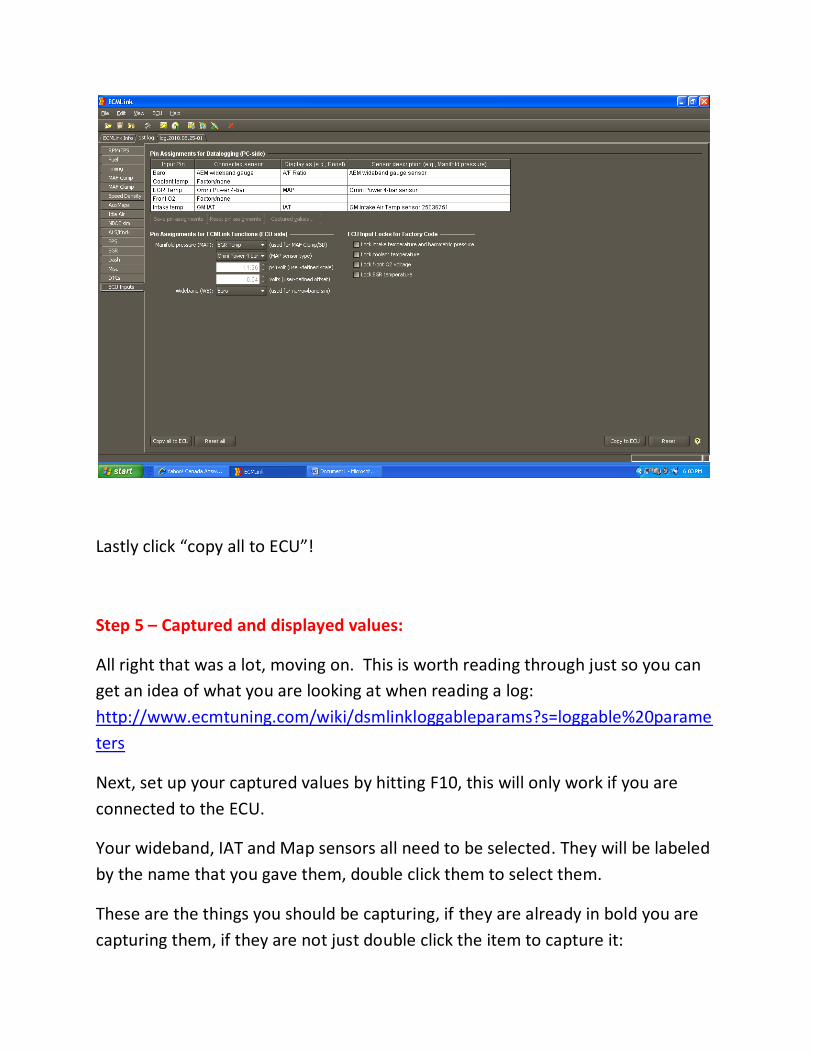
Lastly click “copy all to ECU”!
Step 5 – Captured and displayed values:
All right that was a lot, moving on. This is worth reading through just so you can
get an idea of what you are looking at when reading a log:
http://www.ecmtuning.com/wiki/dsmlinkloggableparams?s=loggable%20parame
ters
Next, set up your captured values by hitting F10, this will only work if you are
connected to the ECU.
Your wideband, IAT and Map sensors all need to be selected. They will be labeled
by the name that you gave them, double click them to select them.
These are the things you should be capturing, if they are already in bold you are
capturing them, if they are not just double click the item to capture it:
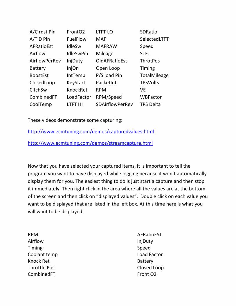
A/C rqst Pin FrontO2 LTFT LO SDRatio
A/T D Pin FuelFlow MAF SelectedLTFT
AFRatioEst IdleSw MAFRAW Speed
Airflow IdleSwPin Mileage STFT
AirflowPerRev InjDuty OldAFRatioEst ThrotPos
Battery InjOn Open Loop Timing
BoostEst IntTemp P/S load Pin TotalMileage
ClosedLoop KeyStart PacketInt TPSVolts
CltchSw KnockRet RPM VE
CombinedFT LoadFactor RPM/Speed WBFactor
CoolTemp LTFT HI SDAirflowPerRev TPS Delta
These videos demonstrate some capturing:
http://www.ecmtuning.com/demos/capturedvalues.html
http://www.ecmtuning.com/demos/streamcapture.html
Now that you have selected your captured items, it is important to tell the
program you want to have displayed while logging because it won’t automatically
display them for you. The easiest thing to do is just start a capture and then stop
it immediately. Then right click in the area where all the values are at the bottom
of the screen and then click on “displayed values”. Double click on each value you
want to be displayed that are listed in the left box. At this time here is what you
will want to be displayed:
RPM AFRatioEST Airflow InjDuty Timing Speed Coolant temp Load Factor Knock Ret Battery Throttle Pos Closed Loop CombinedFT Front O2
BoostEst TPS Volts LTFT STFT TPS Delta
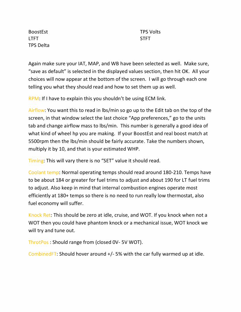
Again make sure your IAT, MAP, and WB have been selected as well. Make sure,
“save as default” is selected in the displayed values section, then hit OK. All your
choices will now appear at the bottom of the screen. I will go through each one
telling you what they should read and how to set them up as well.
RPM: If I have to explain this you shouldn’t be using ECM link.
Airflow: You want this to read in lbs/min so go up to the Edit tab on the top of the
screen, in that window select the last choice “App preferences,” go to the units
tab and change airflow mass to lbs/min. This number is generally a good idea of
what kind of wheel hp you are making. If your BoostEst and real boost match at
5500rpm then the lbs/min should be fairly accurate. Take the numbers shown,
multiply it by 10, and that is your estimated WHP.
Timing: This will vary there is no “SET” value it should read.
Coolant temp: Normal operating temps should read around 180-210. Temps have
to be about 184 or greater for fuel trims to adjust and about 190 for LT fuel trims
to adjust. Also keep in mind that internal combustion engines operate most
efficiently at 180+ temps so there is no need to run really low thermostat, also
fuel economy will suffer.
Knock Ret: This should be zero at idle, cruise, and WOT. If you knock when not a
WOT then you could have phantom knock or a mechanical issue, WOT knock we
will try and tune out.
ThrotPos : Should range from (closed 0V- 5V WOT).
CombinedFT: Should hover around +/- 5% with the car fully warmed up at idle.
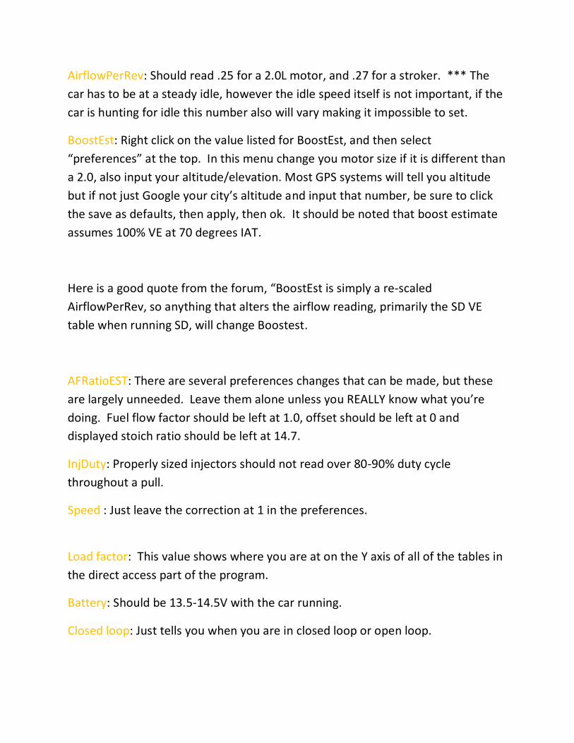
AirflowPerRev: Should read .25 for a 2.0L motor, and .27 for a stroker. *** The
car has to be at a steady idle, however the idle speed itself is not important, if the
car is hunting for idle this number also will vary making it impossible to set.
BoostEst: Right click on the value listed for BoostEst, and then select
“preferences” at the top. In this menu change you motor size if it is different than
a 2.0, also input your altitude/elevation. Most GPS systems will tell you altitude
but if not just Google your city’s altitude and input that number, be sure to click
the save as defaults, then apply, then ok. It should be noted that boost estimate
assumes 100% VE at 70 degrees IAT.
Here is a good quote from the forum, “BoostEst is simply a re-scaled
AirflowPerRev, so anything that alters the airflow reading, primarily the SD VE
table when running SD, will change Boostest.
AFRatioEST: There are several preferences changes that can be made, but these
are largely unneeded. Leave them alone unless you REALLY know what you’re
doing. Fuel flow factor should be left at 1.0, offset should be left at 0 and
displayed stoich ratio should be left at 14.7.
InjDuty: Properly sized injectors should not read over 80-90% duty cycle
throughout a pull.
Speed : Just leave the correction at 1 in the preferences.
Load factor: This value shows where you are at on the Y axis of all of the tables in
the direct access part of the program.
Battery: Should be 13.5-14.5V with the car running.
Closed loop: Just tells you when you are in closed loop or open loop.
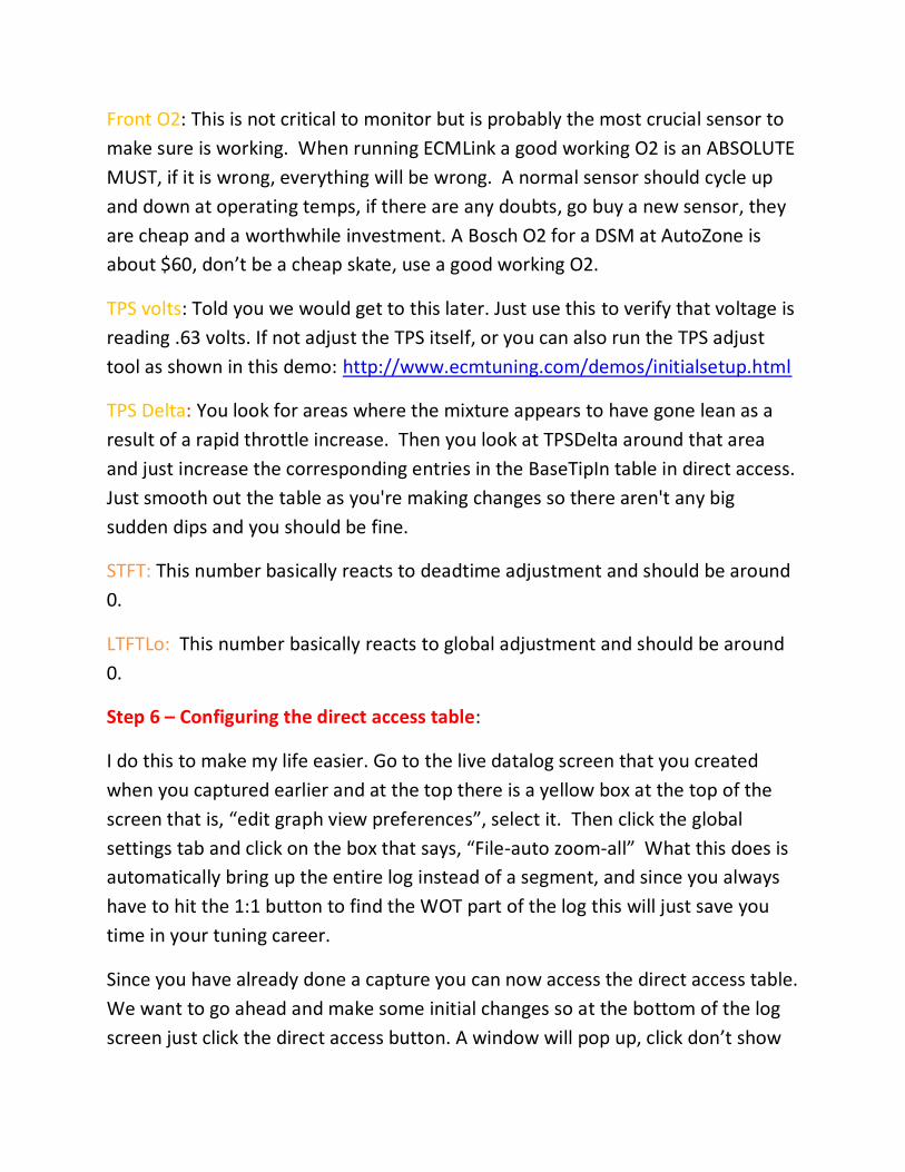
Front O2: This is not critical to monitor but is probably the most crucial sensor to
make sure is working. When running ECMLink a good working O2 is an ABSOLUTE
MUST, if it is wrong, everything will be wrong. A normal sensor should cycle up
and down at operating temps, if there are any doubts, go buy a new sensor, they
are cheap and a worthwhile investment. A Bosch O2 for a DSM at AutoZone is
about $60, don’t be a cheap skate, use a good working O2.
TPS volts: Told you we would get to this later. Just use this to verify that voltage is
reading .63 volts. If not adjust the TPS itself, or you can also run the TPS adjust
tool as shown in this demo: http://www.ecmtuning.com/demos/initialsetup.html
TPS Delta: You look for areas where the mixture appears to have gone lean as a
result of a rapid throttle increase. Then you look at TPSDelta around that area
and just increase the corresponding entries in the BaseTipIn table in direct access.
Just smooth out the table as you're making changes so there aren't any big
sudden dips and you should be fine.
STFT: This number basically reacts to deadtime adjustment and should be around
0.
LTFTLo: This number basically reacts to global adjustment and should be around
0.
Step 6 – Configuring the direct access table:
I do this to make my life easier. Go to the live datalog screen that you created
when you captured earlier and at the top there is a yellow box at the top of the
screen that is, “edit graph view preferences”, select it. Then click the global
settings tab and click on the box that says, “File-auto zoom-all” What this does is
automatically bring up the entire log instead of a segment, and since you always
have to hit the 1:1 button to find the WOT part of the log this will just save you
time in your tuning career.
Since you have already done a capture you can now access the direct access table.
We want to go ahead and make some initial changes so at the bottom of the log
screen just click the direct access button. A window will pop up, click don’t show
me again (after you carefully read it and understand what it’s saying, of course),
and then the direct access table is going to pop up… starting from the top.
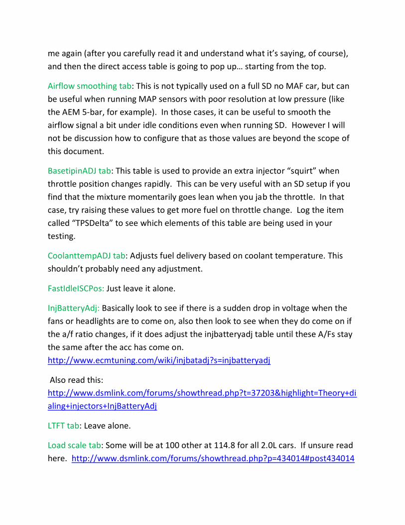
Airflow smoothing tab: This is not typically used on a full SD no MAF car, but can
be useful when running MAP sensors with poor resolution at low pressure (like
the AEM 5-bar, for example). In those cases, it can be useful to smooth the
airflow signal a bit under idle conditions even when running SD. However I will
not be discussion how to configure that as those values are beyond the scope of
this document.
BasetipinADJ tab: This table is used to provide an extra injector “squirt” when
throttle position changes rapidly. This can be very useful with an SD setup if you
find that the mixture momentarily goes lean when you jab the throttle. In that
case, try raising these values to get more fuel on throttle change. Log the item
called “TPSDelta” to see which elements of this table are being used in your
testing.
CoolanttempADJ tab: Adjusts fuel delivery based on coolant temperature. This
shouldn’t probably need any adjustment.
FastIdleISCPos: Just leave it alone.
InjBatteryAdj: Basically look to see if there is a sudden drop in voltage when the
fans or headlights are to come on, also then look to see when they do come on if
the a/f ratio changes, if it does adjust the injbatteryadj table until these A/Fs stay
the same after the acc has come on.
http://www.ecmtuning.com/wiki/injbatadj?s=injbatteryadj
Also read this:
http://www.dsmlink.com/forums/showthread.php?t=37203&highlight=Theory+di
aling+injectors+InjBatteryAdj
LTFT tab: Leave alone.
Load scale tab: Some will be at 100 other at 114.8 for all 2.0L cars. If unsure read
here. http://www.dsmlink.com/forums/showthread.php?p=434014#post434014
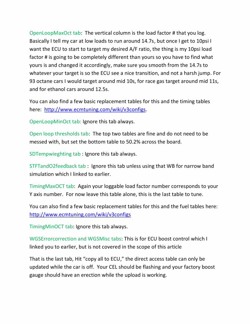
OpenLoopMaxOct tab: The vertical column is the load factor # that you log.
Basically I tell my car at low loads to run around 14.7s, but once I get to 10psi I
want the ECU to start to target my desired A/F ratio, the thing is my 10psi load
factor # is going to be completely different than yours so you have to find what
yours is and changed it accordingly, make sure you smooth from the 14.7s to
whatever your target is so the ECU see a nice transition, and not a harsh jump. For
93 octane cars I would target around mid 10s, for race gas target around mid 11s,
and for ethanol cars around 12.5s.
You can also find a few basic replacement tables for this and the timing tables
here: http://www.ecmtuning.com/wiki/v3configs.
OpenLoopMinOct tab: Ignore this tab always.
Open loop thresholds tab: The top two tables are fine and do not need to be
messed with, but set the bottom table to 50.2% across the board.
SDTempwieghting tab : Ignore this tab always.
STFTandO2feedback tab : Ignore this tab unless using that WB for narrow band
simulation which I linked to earlier.
TimingMaxOCT tab: Again your loggable load factor number corresponds to your
Y axis number. For now leave this table alone, this is the last table to tune.
You can also find a few basic replacement tables for this and the fuel tables here:
http://www.ecmtuning.com/wiki/v3configs
TimingMinOCT tab: Ignore this tab always.
WGSErrorcorrection and WGSMisc tabs: This is for ECU boost control which I
linked you to earlier, but is not covered in the scope of this article
That is the last tab, Hit “copy all to ECU,” the direct access table can only be
updated while the car is off. Your CEL should be flashing and your factory boost
gauge should have an erection while the upload is working.
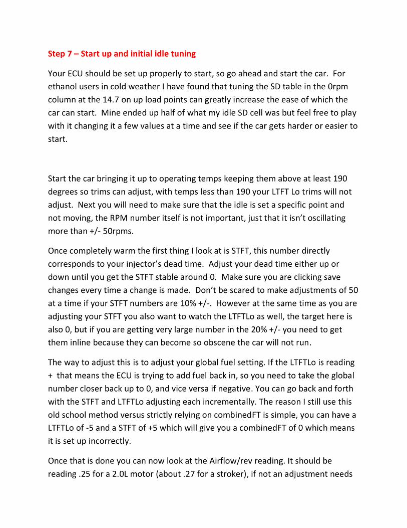
Step 7 – Start up and initial idle tuning
Your ECU should be set up properly to start, so go ahead and start the car. For
ethanol users in cold weather I have found that tuning the SD table in the 0rpm
column at the 14.7 on up load points can greatly increase the ease of which the
car can start. Mine ended up half of what my idle SD cell was but feel free to play
with it changing it a few values at a time and see if the car gets harder or easier to
start.
Start the car bringing it up to operating temps keeping them above at least 190
degrees so trims can adjust, with temps less than 190 your LTFT Lo trims will not
adjust. Next you will need to make sure that the idle is set a specific point and
not moving, the RPM number itself is not important, just that it isn’t oscillating
more than +/- 50rpms.
Once completely warm the first thing I look at is STFT, this number directly
corresponds to your injector’s dead time. Adjust your dead time either up or
down until you get the STFT stable around 0. Make sure you are clicking save
changes every time a change is made. Don’t be scared to make adjustments of 50
at a time if your STFT numbers are 10% +/-. However at the same time as you are
adjusting your STFT you also want to watch the LTFTLo as well, the target here is
also 0, but if you are getting very large number in the 20% +/- you need to get
them inline because they can become so obscene the car will not run.
The way to adjust this is to adjust your global fuel setting. If the LTFTLo is reading
+ that means the ECU is trying to add fuel back in, so you need to take the global
number closer back up to 0, and vice versa if negative. You can go back and forth
with the STFT and LTFTLo adjusting each incrementally. The reason I still use this
old school method versus strictly relying on combinedFT is simple, you can have a
LTFTLo of -5 and a STFT of +5 which will give you a combinedFT of 0 which means
it is set up incorrectly.
Once that is done you can now look at the Airflow/rev reading. It should be
reading .25 for a 2.0L motor (about .27 for a stroker), if not an adjustment needs
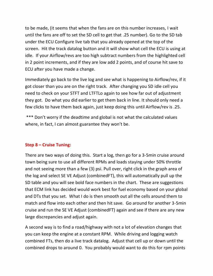
to be made, (it seems that when the fans are on this number increases, I wait
until the fans are off to set the SD cell to get that .25 number). Go to the SD tab
under the ECU Configure live tab that you already opened at the top of the
screen. Hit the track datalog button and it will show what cell the ECU is using at
idle. If your Airflow/revs are too high subtract numbers from the highlighted cell
in 2 point increments, and if they are low add 2 points, and of course hit save to
ECU after you have made a change.
Immediately go back to the live log and see what is happening to Airflow/rev, if it
got closer than you are on the right track. After changing you SD idle cell you
need to check on your STFT and LTFTLo again to see how far out of adjustment
they got. Do what you did earlier to get them back in line. It should only need a
few clicks to have them back again, just keep doing this until Airflow/rev is .25.
*** Don’t worry if the deadtime and global is not what the calculated values
where, in fact, I can almost guarantee they won’t be.
Step 8 – Cruise Tuning:
There are two ways of doing this. Start a log, then go for a 3-5min cruise around
town being sure to use all different RPMs and loads staying under 50% throttle
and not seeing more than a few (3) psi. Pull over, right click in the graph area of
the log and select SE VE Adjust (combinedFT), this will automatically pull up the
SD table and you will see bold face numbers in the chart. These are suggestions
that ECM link has decided would work best for fuel economy based on your global
and DTs that you set. What I do is then smooth out all the cells around them to
match and flow into each other and then hit save. Go around for another 3-5min
cruise and run the SE VE Adjust (combinedFT) again and see if there are any new
large discrepancies and adjust again.
A second way is to find a road/highway with not a lot of elevation changes that
you can keep the engine at a constant RPM. While driving and logging watch
combined FTs, then do a live track datalog. Adjust that cell up or down until the
combined drops to around 0. You probably would want to do this for rpm points
between 2000-4000rpms. This method I use for more highway gas mileage
tuning as you are usually at a constant speed and elevation, where as the other
method is much better for stop light to stop light cruise tuning.
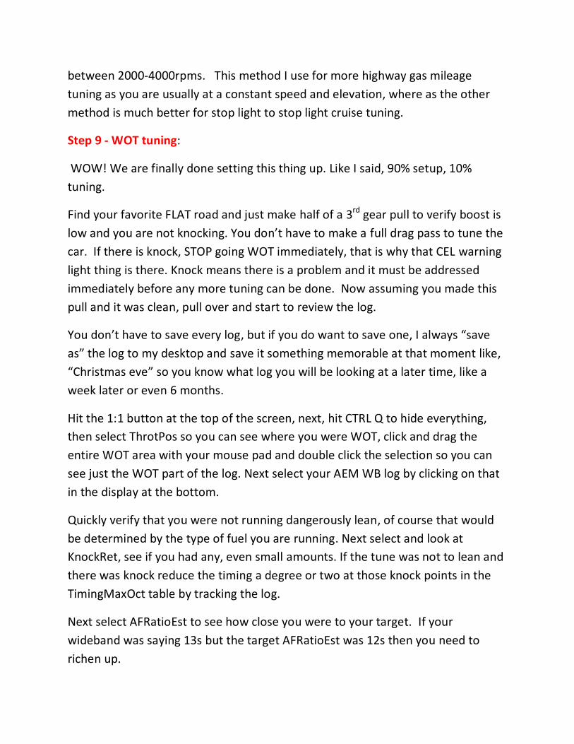
Step 9 - WOT tuning:
WOW! We are finally done setting this thing up. Like I said, 90% setup, 10%
tuning.
Find your favorite FLAT road and just make half of a 3rd gear pull to verify boost is
low and you are not knocking. You don’t have to make a full drag pass to tune the
car. If there is knock, STOP going WOT immediately, that is why that CEL warning
light thing is there. Knock means there is a problem and it must be addressed
immediately before any more tuning can be done. Now assuming you made this
pull and it was clean, pull over and start to review the log.
You don’t have to save every log, but if you do want to save one, I always “save
as” the log to my desktop and save it something memorable at that moment like,
“Christmas eve” so you know what log you will be looking at a later time, like a
week later or even 6 months.
Hit the 1:1 button at the top of the screen, next, hit CTRL Q to hide everything,
then select ThrotPos so you can see where you were WOT, click and drag the
entire WOT area with your mouse pad and double click the selection so you can
see just the WOT part of the log. Next select your AEM WB log by clicking on that
in the display at the bottom.
Quickly verify that you were not running dangerously lean, of course that would
be determined by the type of fuel you are running. Next select and look at
KnockRet, see if you had any, even small amounts. If the tune was not to lean and
there was knock reduce the timing a degree or two at those knock points in the
TimingMaxOct table by tracking the log.
Next select AFRatioEst to see how close you were to your target. If your
wideband was saying 13s but the target AFRatioEst was 12s then you need to
richen up.
Let’s use this above as an example. I would add fuel by taking the global closer to
0 if the entire pull was lean just to get the A/F somewhat close to that magic 12
A/F number. Keep adding fuel until you have a split between half rich and half
lean at the WOT rpm range of full boost. You could be lucky enough that your SD
table is correct and the curve is already flat and the global adjustments get your
real A/F and AFRatioEst to match up perfectly, but I doubt it.
Keeping with the same example, say after adding fuel via global you graph starts
to look rich between 4-6K, then crosses at 6K, and finally leans out between the 6-
8K range. If you keep adjusting global up the rich points will only get richer while
the lean areas will become what you want. Now you will want to adjust just those
cells in the SD table in the 6-8K range up so they start to mimic the same A/F
ratios as those in the 4-6K range. You are trying to get the flattest A/F curve as
possible. Once it is flat you can adjust the entire curve up or down via the global
to get real A/Fs to match your AFRatioEst. Of course adjusting you global will
affect your fuel trims so you will need to possibly touch up your Deadtime and
idle SD table cell to get trims and the .25 airlfow/rev back in line.
Next, select your (BoostEst) and MAP sensor to see how well they lined up. If
your (BoostEst) and MAP are not coinciding at 5-6Krpm, then I would adjust the
SD table to get them to. But don’t just richen or lean out the cells between 5-6K
rpm. Select the whole chart below the point where you are into boost say past
10psi (this is going to depend on your load point at 10psi) and raise the SD values
if you are trying to increase (BoostEst), and down for the opposite. Take it slow, it
isn’t a race, change those maybe 3 values at a time and see where it is going. Just
make sure that if you are knocking, stop immediately and recheck your real A/Fs,
you could possibly need to adjust the global to get to A/F back in line with your
AFRatioEst. Of course adjusting you global will affect your fuel trims so you will
need to possibly touch up your Deadtime and idle SD table cell to get trims and
the .25 airlfow/rev back in line. Continue to do this until you get your real boost
to match your (BoostEst) within 1psi between the 5-6K rpm range.
This is kind of how you have to do it, play with it back and forth until each
compliments itself. I can’t say tune it in a 1,2, 3 order, sometimes you have to
make an adjustment then head back and readjust between the SD table and the
global and Deadtimes.
The key here is to get the wide band reading to mimic your AFRatioEst as well as
your MAP sensor and (BoosteEst) to match between 5-6Krpm with a LTFT Lo near
0 a STFT near 0 with a .25airflow/rev : ) Good luck.
It is possible for you to continue to knock because your boost is too high, timing is
too much, the values you have selected in the (OpenLoopMaxOct) table are
incorrect for the type of fuel you are running, or simply that as you are adjusting
the global and SD table your A/Fs are getting out of whack causing you to knock.
This is just a reminder.
Now that you have idle and WOT set, there is that in the middle transition area.
Try now to smooth out the table from the last point where your SD VE
CombinedFT Adjust tool left off at (highest load point and rpm) and (the lowest
load point and rpm) where you got your WOT settings lined up. I try to never
jump more than 3 values from cell to cell whether it is left, right, up, or down. This
keeps for a smooth and easy fuel distribution.
Remember this is not an AFC you are tuning with. We do not tune knock via fuel
per say, although an incorrect A/F ratio can cause knock. We are telling the car
what A/F we want it to run, so when there is knock we have to adjust timing via
the TmingMaxOct tab to get rid of that knock. If all of the above criteria were met
start adding timing until there is some knock and then back off. Reduce timing at
those cells in the TmingMaxOct table where knock is present until it goes away.
Keep in mind that ethanol is VERY knock resistant, so I would use some caution as
far as turning timing all the way up to the point of knock with ethanol, however to
each their own.
Once you think you got everything in line and you are not knocking during your
3rd gear pulls, go ahead and make a 1st-4th gear pull and see how your tune looks
and make small adjustments. The entire tuning process can take several hours if
not days depending on your level of skill. It’s a very slow process, but time well
spent to make maximum power and RELIABILITY.