Embed Size (px)
Citation preview
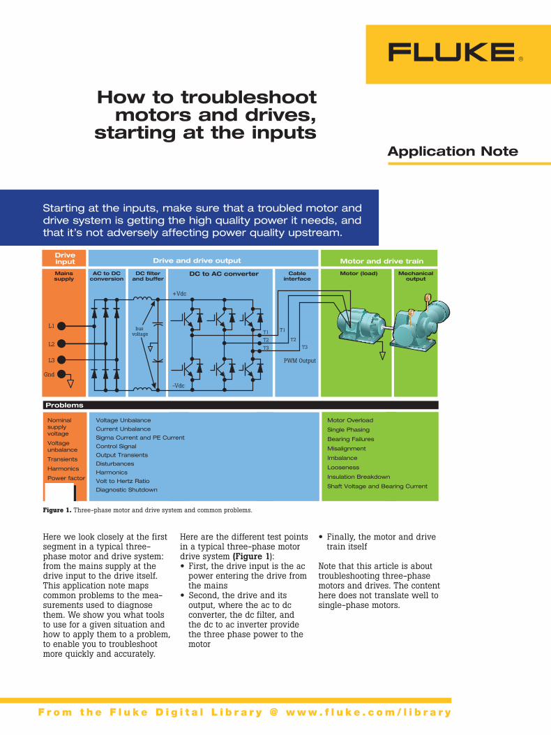
• Finally, the motor and drive train itself
Note that this article is about troubleshooting three-phase motors and drives. The content here does not translate well to single-phase motors.
Here are the different test points in a typical three-phase motor drive system (Figure 1): • First, the drive input is the ac power entering the drive from the mains
• Second, the drive and its output, where the ac to dc converter, the dc filter, and the dc to ac inverter provide the three phase power to the motor
How to troubleshoot motors and drives,
starting at the inputs
Figure 1. Three-phase motor and drive system and common problems.
Application Note
F r o m t h e F l u k e D i g i t a l L i b r a r y @ w w w . f l u k e . c o m / l i b r a r y
Starting at the inputs, make sure that a troubled motor and drive system is getting the high quality power it needs, and that it’s not adversely affecting power quality upstream.
AC to DCconversion
Mainssupply
Mechanicaloutput
Motor (load)Cableinterface
DC to AC converterDC �lterand buffer
bus voltage
L1
T3
PWM Output
L2T2
L3
Gnd
T1
+Vdc
-Vdc
T3
T2T1
Driveinput
Problems
Motor and drive train Drive and drive output
Here we look closely at the first segment in a typical three-phase motor and drive system: from the mains supply at the drive input to the drive itself. This application note maps common problems to the mea-surements used to diagnose them. We show you what tools to use for a given situation and how to apply them to a problem, to enable you to troubleshoot more quickly and accurately.
AC to DCconversion
Mainssupply
Mechanicaloutput
Motor (load)Cableinterface
DC to AC converterDC �lterand buffer
bus voltage
L1
T3
PWM Output
L2T2
L3
Gnd
T1
+Vdc
-Vdc
T3
T2T1
Driveinput
Problems
Motor and drive train Drive and drive output
Nominal supply voltage
Voltage unbalance Transients
Harmonics Power factor
Voltage Unbalance
Current Unbalance
Sigma Current and PE Current
Control Signal
Output Transients
Disturbances
Harmonics
Volt to Hertz Ratio
Diagnostic Shutdown
Motor Overload
Single Phasing
Bearing Failures
Misalignment
Imbalance
Looseness
Insulation Breakdown
Shaft Voltage and Bearing Current
2 Fluke Corporation How to troubleshoot motors and drives, starting at the inputs
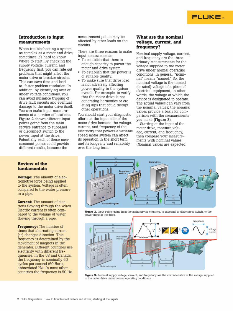
Introduction to input measurementsWhen troubleshooting a system as complex as a motor and drive, sometimes it’s hard to know where to start. By checking the supply voltage, current, and frequency first, you can rule out problems that might affect the motor drive or breaker circuits. This can save time and lead to faster problem resolution. In addition, by identifying over or under voltage conditions, you can avoid nuisance tripping of drive fault circuits and eventual damage to the motor drive itself.You can make input measure-ments at a number of locations. Figure 2 shows different input points going from the main service entrance to subpanel or disconnect switch to the power input at the drive. Potentially each of these mea-surement points could provide different results, because the
measurement points may be affected by other loads on the circuits.
There are three reasons to make input measurements: • To establish that there is enough capacity to power the motor and drive system.
• To establish that the power is of suitable quality.
• To make sure that drive load is not adversely affecting power quality in the system overall. For example, to verify that the motor drive is not generating harmonics or cre-ating dips that could disrupt other operations.
You should start your diagnostic efforts at the input side of the motor drive because the voltage, current, and frequency of the electricity that powers a variable speed motor system can affect its operation in the short term and its longevity and reliability over the long term.
What are the nominal voltage, current, and frequency?Nominal supply voltage, current, and frequency are the three primary measurements for the voltage supplied to the motor drive under normal operating conditions. In general, “nomi-nal” means “named.” So, the nominal voltage is the named (or rated) voltage of a piece of electrical equipment; in other words, the voltage at which the device is designated to operate. The actual values can vary from the nominal values; the nominal values provide a basis for com-parison with the measurements you make (Figure 3). Starting at the input of the motor drive, measure volt-age, current, and frequency, then compare your measure-ments with nominal values. (Nominal values are expected
Review of the fundamentals
Voltage: The amount of elec-tromotive force being applied to the system. Voltage is often compared to the water pressure in a pipe.
Current: The amount of elec-trons flowing through the wires. Electric current is often com-pared to the volume of water flowing through a pipe.
Frequency: The number of times that alternating current (ac) changes direction. This frequency is determined by the movement of magnets in the generator. Different countries use electricity with different fre-quencies. In the US and Canada, the frequency is nominally 60 cycles per second (60 Hertz, abbreviated Hz). In most other countries the frequency is 50 Hz.
Main switchgear
Disconnectswitch
Motor drive
Motor Load
L1
L2
L3
T1
T2
T3
L1
L2
L3
Main switchgear
Disconnectswitch
Motor drive
Motor Load
L1
L2
L3
T1
T2
T3
L1
L2
L3 V
I frequency
3 voltagecurrentM3
Figure 3. Nominal supply voltage, current, and frequency are the characteristics of the voltage supplied to the motor drive under normal operating conditions.
Figure 2. Input points going from the main service entrance, to subpanel or disconnect switch, to the power input at the drive.
3 Fluke Corporation How to troubleshoot motors and drives, starting at the inputs
Main switchgear
Disconnectswitch
Motor drive
Motor Load
L1
L2
L3
T1
T2
T3
L1
L2
L3
values—for example, 480 volts for a 480-volt line, the current listed on motor’s nameplate, and a frequency of 50 or 60 Hz, depending on your locale). You can make these measure-ments with a digital multimeter and a current clamp, just as you would on a single-phase circuit, but making the measurements with a three-phase power qual-ity analyzer makes the job easier (Figure 4). Measuring three phases at the same time can also reveal interactions between the phases that can’t be seen with single-phase measure-ments. Be sure to connect the power quality analyzer correctly for the circuit type (wye or delta). The amount of deviation from nominal that is considered acceptable varies by locale, but as a rule:
• Voltage should be within plus or minus 10 percent of nominal
• Current should never exceed the nameplate rating of the load
• Frequency should be within 0.5 Hz of nominal
Evaluating the measurements • If the voltage is consistently too high, consult with the electric utility (Figure 5).
• If the voltage is too low, check whether the local circuit is overloaded. Do this by comparing your current measurements with the circuit breaker rating. If the measured current is within the range of the breaker, check the size of the cable that supplies the drive to make sure it conforms to NEC requirements.
• If your voltage measurements are within an acceptable range and the circuit appears to be correctly configured, but there are still problems (such as the motor drive resetting or circuit breakers opening), there may be intermittent
Main switchgear
Disconnectswitch
Motor drive
Motor Load
L1
L2
L3
T1
T2
T3
L1
L2
L3
power supply problems. To detect problems that are hap-pening over a longer time period than your initial mea-surements, use your power quality analyzer or a power quality recorder to log any power quality disturbances on the circuit over a longer measurement period or until the next fault occurs.
• If all voltage, current, and frequency measurements are within an acceptable range, check for voltage and current unbalance.
Voltage and current unbalanceIdeally, the voltages that you measure in each phase of a three-phase system should be the same. This is also true for current measurements. Because voltage or current unbalance can
cause downtime or damage to a motor drive, learning how to interpret these measurements is important (Figure 6). Expressing the amount of voltage or current unbalance as a percentage enables you to describe the size of the problem simply and quickly with a single number. To get the percentage of unbalance, divide the big-gest deviation measured on one phase by the average of three phases and multiply by 100. For example, if you measured 480 v, 485 v, and 490 v, the average voltage is 485 volts and the biggest deviation is 5 volts. Five volts divided by 485 volts is .01, which gives a 1 percent voltage unbalance when multi-plied by 100.
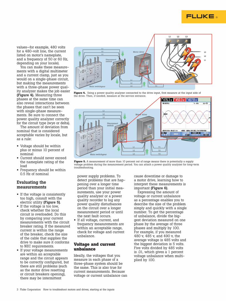
Figure 4. Using a power quality analyzer connected to the drive input, first measure at the input side of the drive. Then, if needed, measure at the service entrance.
Figure 5. A measurement of more than 10 percent out of range means there is potentially a supply voltage problem during the measurement period. You can attach a power quality analyzer for long-term troubleshooting.
L1 L2 L3
L1
L2
L3
4 Fluke Corporation How to troubleshoot motors and drives, starting at the inputs
As little as a two percent volt-age unbalance at the input of a motor drive can cause voltage notching and excessive cur-rent flow in one or more phases going to the motor. Voltage unbalance can also cause trip-ping of the motor drive’s current overload fault protection. Current unbalance is a mea-sure of difference in current drawn by a motor on each leg of a three-phase system. Correct-ing current unbalance helps prevent overheating and the deterioration of motor-winding insulation. The draw on each leg should be equal or close to equal. One cause of current unbalance is voltage unbal-ance, which can cause current unbalance far out of propor-tion to the voltage unbalance itself. When current unbalance occurs in the absence of volt-age unbalance, look for another cause of the current unbalance; for example, faulty insulation or a phase shorted to ground. Cur-rent unbalance is calculated the same way as voltage unbalance. It is 100 times the maximum current variation from average divided by the average current of the three phases. So, if the measured current is 30 amps,
35 amps, and 30 amps, the average is 31.7 amps, and the current unbalance is:
[(35 – 31.7) x 100] ÷ 31.7 = 10.4 %
Current unbalance for three-phase motors should not exceed 10 percent. High neutral current can indicate unbalance. Unbalance current will flow in neutral con-ductors in 3-phase wye systems.
HarmonicsThe 50 Hz or 60 Hz frequency of the voltage supplied by the utility is called the fundamental frequency. In a perfect world, the fundamental frequency is the only one present. Unfor-tunately, some electrical loads (such as computers, controls, drives, and energy-saving light-ing systems) can cause other frequencies to appear in your measurements. These other frequencies, which are multiples of the fundamental (so 120 Hz, 180 Hz, and so on for a 60 Hz fundamental frequency), are called harmonics. The power at the service entrance of your facility will usually be low in harmonic frequencies (unless they are leaking onto the power lines from a nearby facility). Inside
your facility, however, harmonics may be high if there are a lot of harmonic-generating devices in the facility.
Although motor drives can be affected by harmonics, they are often the source of harmonics that affect other devices in the facility. If you detect significant levels of harmonics in your drive measurements, you may need to consider adding filtering to block those harmonics.
TransientsTransients are, as their name suggests, brief events (less than one half cycle, so less than 1/120th of a second in a 60 Hz system) on the ac line. Many people associate transients with external events, such as lightning surges, but transients can also originate within a system or building. Detecting, troubleshooting, and addressing transients is important because transients can damage motors and other parts of the motor circuitry. Troubleshooting transients typically requires using a test tool with a fault “capture” rate, such as a power quality ana-lyzer or a ScopeMeter® Portable Oscilloscope. For more informa-tion on detecting transients, refer to “Six simple ways to reduce costs with a Fluke 434 Power Quality Analyzer.”
Main switchgear
Disconnectswitch
Motor drive
Motor Load
L1
L2
L3
T1
T2
T3
L1
L2
L3
ΔV1
ΔV2
ΔV3
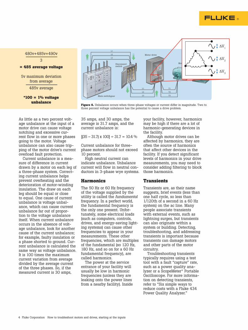
Figure 6. Unbalance occurs when three-phase voltages or current differ in magnitude. Two to three percent voltage unbalance has the potential to cause a drive problem.
480v+485v+490v
3
= 485 average voltage
5v maximum deviation from average
485v average
*100 = 1% voltage unbalance

5 Fluke Corporation How to troubleshoot motors and drives, starting at the inputs
Diagnostic benefits
By checking the supply voltage, current, and frequency first, you can rule out issues that might affect the motor drive or breaker circuits. This can save you time and lead to a faster prob-lem resolution. In addition, by identifying over or under volt-age conditions, you can avoid nuisance tripping of drive fault circuits, and eventual damage to the motor drive itself.
Fluke Corporation PO Box 9090, Everett, WA 98206 U.S.A.
Fluke. The Most Trusted Tools in the World.
Fluke Europe B.V. PO Box 1186, 5602 BD Eindhoven, The Netherlands
For more information call: In the U.S.A. (800) 443-5853 or Fax (425) 446-5116 In Europe/M-East/Africa +31 (0) 40 2675 200 or Fax +31 (0) 40 2675 222 In Canada (800)-36-FLUKE or Fax (905) 890-6866 From other countries +1 (425) 446-5500 or Fax +1 (425) 446-5116 Web access: http://www.fluke.com
©2012 Fluke Corporation. Specifications subject to change without notice. Printed in U.S.A. 6/2012 4234148A_EN
Modification of this document is not permitted without written permission from Fluke Corporation.