Embed Size (px)
Citation preview
G 2
TOOLING SYSTEMS How to select tool holding
B
Gen
eral
Tur
ning
Par
ting
and
Gro
ovin
g
C
Thre
adin
g
G
Tool
ing
syst
ems
Mul
ti-ta
sk m
achi
ning
I
Cor
oTur
n® S
L
J
Gen
eral
info
rmat
ion
A
H
G
Tool
ing
syst
ems
TOOLING SYSTEMS How to select tool holding
For more technical information, see our Metalcutting Technical guide
Symbols for page references:
How to choose tool, overview Tool holding systems overview
Spare parts/accessories
Conversion table, formulas and definitions
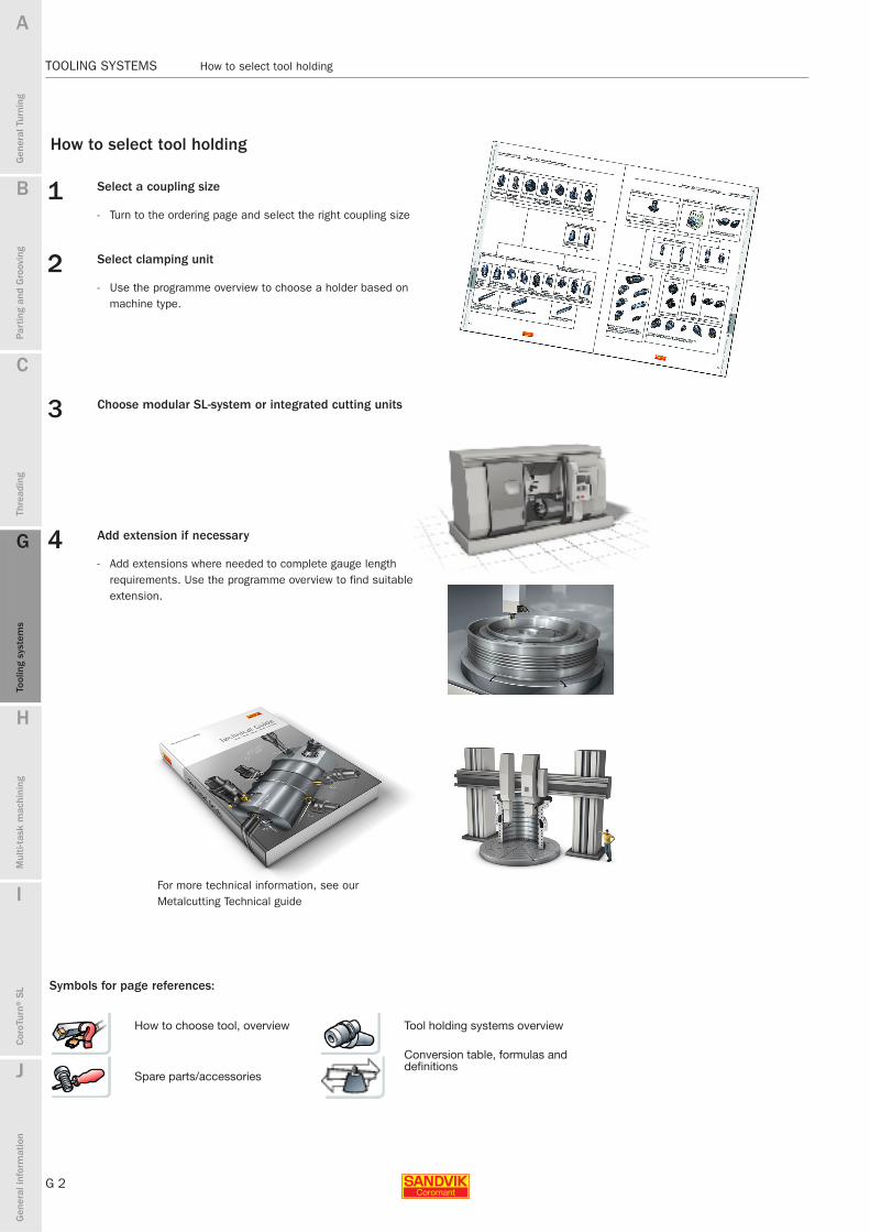
How to select tool holding
1 Select a coupling size
- Turn to the ordering page and select the right coupling size
2 Select clamping unit
- Use the programme overview to choose a holder based on machine type.
3 Choose modular SL-system or integrated cutting units
4 Add extension if necessary
- Add extensions where needed to complete gauge length requirements. Use the programme overview to find suitable extension.

B
G 3
Gen
eral
Tur
ning
Par
ting
and
Gro
ovin
g
C
Thre
adin
g
G
Tool
ing
syst
ems
Mul
ti-ta
sk m
achi
ning
I
Cor
oTur
n® S
L
J
Gen
eral
info
rmat
ion
A
H
G
Tool
ing
syst
ems
Content TOOLING SYSTEMS
TOOLING SYSTEMS Content
TOOLING SYSTEMS
Tooling guideTurning centres G10
ProductsFor turning centres - non rotating tools
Coromant Capto® G4Tool holder overview G6
Manual clamping units G11Automatic clamping units G23
Boring bar adaptor G26Extension/reduction adaptors G28
Coromant Capto® short adaptor for exchangeable head G31ER-collet chuck adaptor, short G32
Tap adaptor G33
Spare parts and accessories G35
CoroTurn® SL flexible system I1
Tools for Multi-task machining H1
Tooling systems for rotatingSee Main catalogue for milling, drilling and boring tools.
G 3

G 4
TOOLING SYSTEMS Coromant Capto®
B
Gen
eral
Tur
ning
Par
ting
and
Gro
ovin
g
C
Thre
adin
g
G
Tool
ing
syst
ems
Mul
ti-ta
sk m
achi
ning
I
Cor
oTur
n® S
L
J
Gen
eral
info
rmat
ion
A
H
G
Tool
ing
syst
ems
TOOLING SYSTEMS Coromant Capto®
Coromant Capto®Tooling system
Turning centre applications
Coromant Capto® can be integrated directly into the turret using the standard clamping mechanism.
Standard lathes can easily be converted to Coromant Capto® quick-change tools using standard clamping units.
CDI - Coromant Capto Disc InterfaceNew solution to replace VDI turretsSame adaptors fit multiple machine brands and modelsCam actuation screw inside turret
Turret evolutionTurrets have evolved into two main groups where Coromant Capto applications are typical for both static and driven applications.
CBI - Coromant Capto ’Bolt on’ Interface’Bolt on’ solutionUnique hole pattern for each machine brandCam actuation screw-in bolt on unit
Coromant Capto is widely used in turning centres with manual clamping via a CAM-shaft actuated clamp set. Quick changing of tools maximizes machine efficiency with an average of 25% more time for producing chips.
B
G 5
Gen
eral
Tur
ning
Par
ting
and
Gro
ovin
g
C
Thre
adin
g
G
Tool
ing
syst
ems
Mul
ti-ta
sk m
achi
ning
I
Cor
oTur
n® S
L
J
Gen
eral
info
rmat
ion
A
H
G
Tool
ing
syst
ems
Coromant Capto® - Tooling alternatives TOOLING SYSTEMS
TOOLING SYSTEMS Coromant Capto® - Tooling alternatives
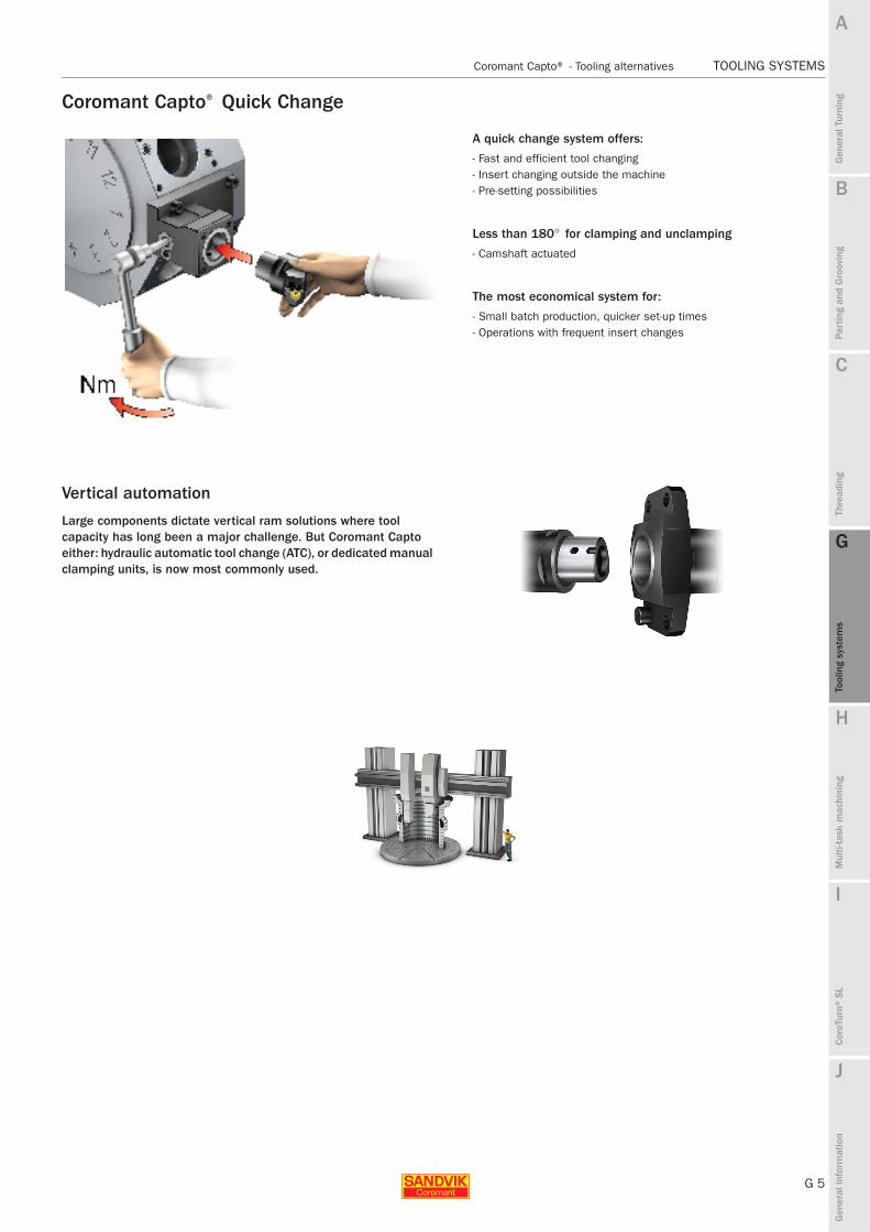
Coromant Capto® Quick Change
A quick change system offers:
- Fast and efficient tool changing- Insert changing outside the machine- Pre-setting possibilities
Less than 180° for clamping and unclamping
- Camshaft actuated
The most economical system for:
- Small batch production, quicker set-up times- Operations with frequent insert changes
Vertical automation
Large components dictate vertical ram solutions where tool capacity has long been a major challenge. But Coromant Capto either: hydraulic automatic tool change (ATC), or dedicated manual clamping units, is now most commonly used.
G 6
TOOLING SYSTEMS Coromant Capto® − Overview for non-rotating tools
B
Gen
eral
Tur
ning
Par
ting
and
Gro
ovin
g
C
Thre
adin
g
G
Tool
ing
syst
ems
Mul
ti-ta
sk m
achi
ning
I
Cor
oTur
n® S
L
J
Gen
eral
info
rmat
ion
A
H
G
Tool
ing
syst
ems
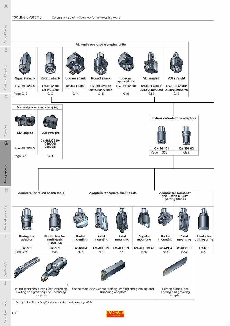
TOOLING SYSTEMS Coromant Capto® − Overview for non-rotating tools
Manually operated clamping units
Square shank Round shank Square shank Round shank Special applications
VDI angled VDI straight
Cx-R/LC2085 Cx-NC2000 Cx-R/LC2080 Cx-R/LC2035/ Cx-R/LC2090 Cx-R/LC2030/ Cx-R/LC2030/Cx-NC3000 2045/2055/2065 2040/2050/2060 2040/2050/2060
Page G13 G12 G14 G15 G16 G18 G18
Extension/reduction adaptors
Cx-391.01 Cx-391.02Page G28 G29
Adaptors for round shank tools Adaptors for square shank tools Adaptor for CoroCut® and T-Max Q-Cut®
parting blades
Boring bar adaptor
Boring bar for multi-task machines
Radial mounting
Axial mounting
Axial mounting
Angular mounting
Radial mounting
Axial mounting
Blanks for cutting units
Cx-131 Cx-131 Cx-ASHA Cx-ASHR/L Cx-ASHR/L3 Cx-ASHR/L45 Cx-APBA Cx-APBR/L Cx-NRPage G26 H33 H28 H29 H31 H30 B33 B33 G27
1)
Round shank tools, see General turning, Parting and grooving and Threading
chapters
Shank tools, see General turning, Parting and grooving and Threading chapters
Parting blades, see Parting and grooving
chapter
1) For cylindrical bars EasyFix sleeve can be used, see page A304
Manually operated clamping
CDI angled CDI straight
Cx-R/LC2085
Cx-R/LCE80-040000/028082/
Page G20 G21

B
G 7
Gen
eral
Tur
ning
Par
ting
and
Gro
ovin
g
C
Thre
adin
g
G
Tool
ing
syst
ems
Mul
ti-ta
sk m
achi
ning
I
Cor
oTur
n® S
L
J
Gen
eral
info
rmat
ion
A
H
G
Tool
ing
syst
ems
Coromant Capto® − Overview for non-rotating tools TOOLING SYSTEMS
TOOLING SYSTEMS Coromant Capto® − Overview for non-rotating tools
Automatic clamping units Multi-task machines Coromant Capto® driven tool holders
Cx-NC5010 Cx-NC5110 Cx-NC5210 For information on how to order, please contact your local Sandvik Coromant office.
With probe contact Jetbreak™Page G24 G24 G25
CoroTurn® SL boring bars
Steel shank Dampened boring bars
Cx-A570/Cx-570 Cx-A570/Cx-570Page I56 I57
CoroTurn® SL70
Cx-391.01RPage I98
External and internal Coromant Capto® cutting units, see General turning, Parting and grooving, Threading and Multi-task machining chapters.
Mini-turret CoroTurn® SL system
Boring bar adaptor External adaptor
Cx-A570/Cx-570 Cx-A570/Cx-570 Cx-A570/Cx-570Page H14 Page I60 I68
CoroTurn® SL cutting heads, see General turning, Parting and grooving, Threading, CoroTurn SL and Multi-task machining chapters.
Extension/reduction adaptors
180° rotated polygon
Cx-391.01R Cx-391.02RPage G30 G30

G 8
TOOLING SYSTEMS Manual clamping units
B
Gen
eral
Tur
ning
Par
ting
and
Gro
ovin
g
C
Thre
adin
g
G
Tool
ing
syst
ems
Mul
ti-ta
sk m
achi
ning
I
Cor
oTur
n® S
L
J
Gen
eral
info
rmat
ion
A
H
G
Tool
ing
syst
ems
TOOLING SYSTEMS Manual clamping units
The manual clamping unitsOn manually activated units both camshaft, drawbars and centre-bolt mechanisms are used. Always use a torque wrench when clamping
Cam shaft activated drawbarThe movement of the drawbar is generated by a cam acting from the side of the unit which rotates in a slot in the drawbar.A hexagon key is used to lock/unlock the cutting head (less than a half turn is required).
Screw activated drawbarThe movement of the drawbar is controlled by a screw acting from the rear of the unit.A hexagon key is used to lock/unlock the cutting head (one turn is required).
Centre bolt clampingA rear activated centre bolt is used to clamp/unclamp the cutting head.A hexagon key is used to lock/unlock the cutting head (six turns are required).
Shank type clamping units for conventional turretsRound shank units for internal operations:
The 2000 type features
- Expandable segmented bushing clamp design.- Screw activated drawbar.- Less than 180° for clamping and unclamping
The 3000 type features
- Centre bolt clamping- 4-5 revs for clamping and unclamping
Installation is simple
- Both mount in the turret like a standard boring bar.
Shank units for external operations:Easily adaptable to most machines using 20, 25, 32 or 40 mm square shank tools.
The 2085 type features
- The expandable segmented bushing- Cam shaft activated drawbar.
Installation is simple
- Remove the square shank tool and machine wedge.- Slide the Coromant Capto 2085 clamping unit into place and tighten the wedge.
These tools feature
- No special adaptation to tool or turret.- Through tool coolant.- Minimum overhang allowing maximum working envelope.- Same key for clamping external and internal units.- Adjustable shank length (cut off if necessary).

B
G 9
Gen
eral
Tur
ning
Par
ting
and
Gro
ovin
g
C
Thre
adin
g
G
Tool
ing
syst
ems
Mul
ti-ta
sk m
achi
ning
I
Cor
oTur
n® S
L
J
Gen
eral
info
rmat
ion
A
H
G
Tool
ing
syst
ems
Manual clamping units TOOLING SYSTEMS
TOOLING SYSTEMS Manual clamping units
Manual clamping units for special applications
Clamping units for DIN 69880 (VDI) turrets
The 2090 type clamping unit is designed for special adaptation to the machine.Design instructions for the application of these units are shown on the ordering page.
These tools feature:- No special adaptation to tool or turret.- Through tool coolant.- Minimum overhang allowing maximum working envelope.- Same key for clamping external and internal units.
VDI clamping units for external and internal operations
- Expandable segmented bushing clamp design.- Quick change – 1/2 turn to lock/unlock.- Same length dimension for corresponding angular ltz and straight l1z
units to avoid risk of collision.- Two different l1x dimensions available on angular units.
CDI - Coromant Capto Disc Interface
- New solution to replace VDI turrets- Same adaptors fit multiple machine brands and models- Cam actuation screw inside turret

G 10
TOOLING SYSTEMS Manual clamping units
B
Gen
eral
Tur
ning
Par
ting
and
Gro
ovin
g
C
Thre
adin
g
G
Tool
ing
syst
ems
Mul
ti-ta
sk m
achi
ning
I
Cor
oTur
n® S
L
J
Gen
eral
info
rmat
ion
A
H
G
Tool
ing
syst
ems
TOOLING SYSTEMS Manual clamping units
Manually operated Coromant Capto® clamping units
- Camshaft activated- Screw activated- Centre bolt activated
Shank type clamping units
- Square and round shank tools as well as Coromant Capto units for external and internal operations
Coromant Capto® clamping units for DIN 69880 (VDI) turrets
- Angled and straight clamping units for external and internal operations
Hydraulically operated clamping units
- Manual push-button tool changing- Fully automatic tool changing possible
A
B
C
Tooling alternativesConventional turrets
B
G 11
Gen
eral
Tur
ning
Par
ting
and
Gro
ovin
g
C
Thre
adin
g
G
Tool
ing
syst
ems
Mul
ti-ta
sk m
achi
ning
I
Cor
oTur
n® S
L
J
Gen
eral
info
rmat
ion
A
H
G
Tool
ing
syst
ems
Coromant Capto® − Clamping units TOOLING SYSTEMS
TOOLING SYSTEMS Coromant Capto® − Clamping units
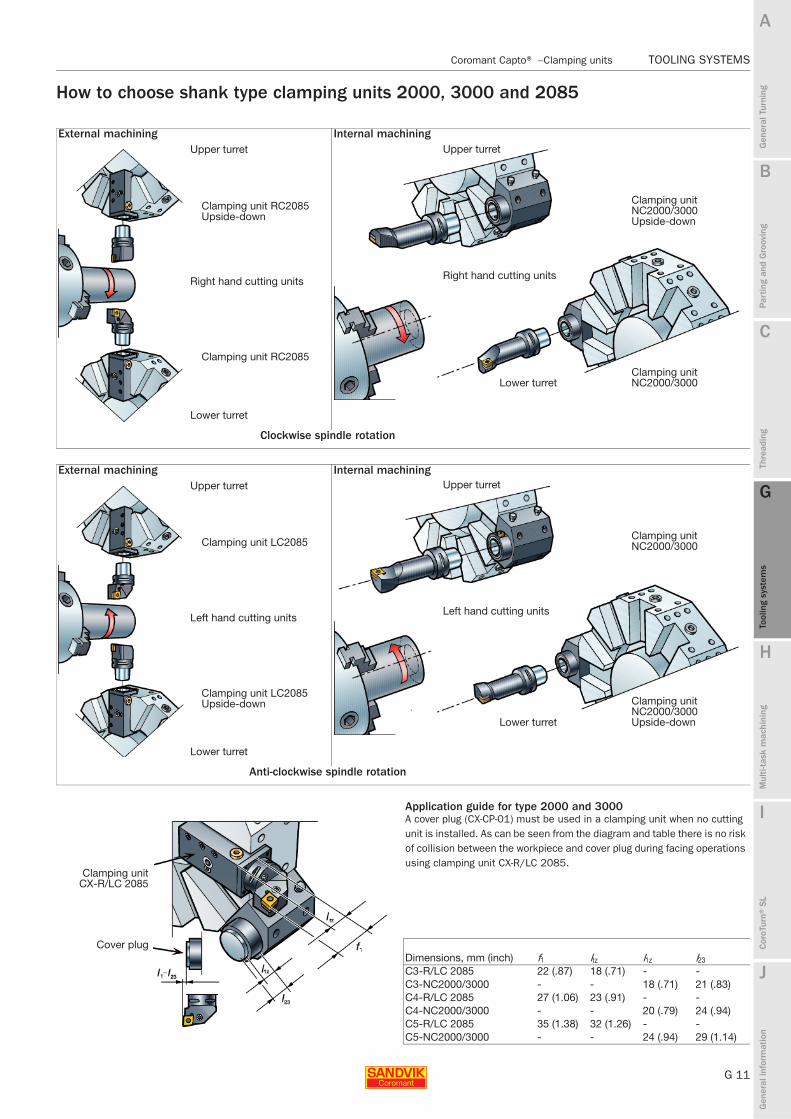
How to choose shank type clamping units 2000, 3000 and 2085
External machining Internal machiningUpper turret
Clamping unit RC2085 Upside-down
Right hand cutting units
Clamping unit RC2085
Lower turret
Clockwise spindle rotation
External machining Internal machiningUpper turret
Clamping unit LC2085
Left hand cutting units
Clamping unit LC2085 Upside-down
Lower turret
Anti-clockwise spindle rotation
Application guide for type 2000 and 3000A cover plug (CX-CP-01) must be used in a clamping unit when no cutting unit is installed. As can be seen from the diagram and table there is no risk of collision between the workpiece and cover plug during facing operations using clamping unit CX-R/LC 2085.
Clamping unitCX-R/LC 2085
Cover plugDimensions, mm (inch) f1 ltz l1z l23
C3-R/LC 2085 22 (.87) 18 (.71) - -C3-NC2000/3000 - - 18 (.71) 21 (.83)C4-R/LC 2085 27 (1.06) 23 (.91) - -C4-NC2000/3000 - - 20 (.79) 24 (.94)C5-R/LC 2085 35 (1.38) 32 (1.26) - -C5-NC2000/3000 - - 24 (.94) 29 (1.14)
Upper turret
Clamping unit NC2000/3000 Upside-down
Right hand cutting units
Clamping unit NC2000/3000Lower turret
Upper turret
Clamping unit NC2000/3000
Left hand cutting units
Clamping unit NC2000/3000 Upside-downLower turret

G 12
TOOLING SYSTEMS Coromant Capto® − Clamping units
B
Gen
eral
Tur
ning
Par
ting
and
Gro
ovin
g
C
Thre
adin
g
G
Tool
ing
syst
ems
Mul
ti-ta
sk m
achi
ning
I
Cor
oTur
n® S
L
J
Gen
eral
info
rmat
ion
A
H
G
Tool
ing
syst
ems
TOOLING SYSTEMS Coromant Capto® − Clamping units
Manually operated clamping units
Round shank
Metric version
Inch version
Metric version
Inch version
Segment clamping Turret type Type 2000Segment clamping
Note: Maximum coolant pressure is 80 bar (PSI 1160)
Turret type Dimensions, mm
dmm, size, mm Coupling size Ordering code D1 h hry lc l1z l21 Th
32 C3 C3-NC2000-08018-32 45.5 30 26 80 18 G1/840 C4 C4-NC2000-10020-40 51.5 37 28 100 20 8 G1/850 C4 C4-NC2000-12020-50 51.5 47 28 120 20 28 G1/850 C5 C5-NC2000-12024-50 61.5 47 33 120 24 G1/860 C5 C5-NC2000-14024-60 61.5 57 33 140 24 20 G1/8
Turret type Dimensions, inch
dmm, size, inch Coupling size Ordering code D1 h hry lc l1z l21 Th
1.250 C3 C3-NC2000-08018-A20 1.790 1.180 .930 3.150 .710 G1/81.500 C4 C4-NC2000-10020-A24 2.028 1.457 1.024 3.937 .787 .315 G1/82.000 C4 C4-NC2000-12020-A32 2.028 1.850 1.004 4.724 .787 1.102 G1/82.000 C5 C5-NC2000-12024-A32 2.421 1.850 1.220 4.724 .945 G1/8
Centre bolt activated Turret type Type 3000Centre bolt clamping
Note: Maximum coolant pressure is 80 bar (PSI 1160)
Turret type Dimensions, mm
dmm, size, mm Coupling size Ordering code D1 h hry lc l1z l21 Th
32 C3 C3-NC3000-08018-32 45.5 30 26 80 18 G1/840 C3 C3-NC3000-10018-40 45.5 37 26 100 18 20 G1/840 C4 C4-NC3000-10020-40 51.5 37 28 100 20 10 G1/850 C5 C5-NC3000-12024-50 61.5 47 33 120 24 20 G1/8
Turret type Dimensions, inch
dmm, size, inch Coupling size Ordering code D1 h hry lc l1z l21 Th
1.250 C3 C3-NC3000-08018-A20 1.791 1.181 .933 3.150 .709 G1/81.500 C4 C4-NC3000-10020-A24 2.028 1.378 1.024 3.937 .787 .394 G1/82.000 C4 C4-NC3000-12020-A32 2.028 1.850 1.004 4.724 .787 1.181 G1/82.000 C5 C5-NC3000-12024-A32 2.421 1.850 1.220 4.724 .945 G1/8
G48 G6 G2 J2

B
G 13
Gen
eral
Tur
ning
Par
ting
and
Gro
ovin
g
C
Thre
adin
g
G
Tool
ing
syst
ems
Mul
ti-ta
sk m
achi
ning
I
Cor
oTur
n® S
L
J
Gen
eral
info
rmat
ion
A
H
G
Tool
ing
syst
ems
Coromant Capto® − Clamping units TOOLING SYSTEMS
TOOLING SYSTEMS Coromant Capto® − Clamping units
Manually operated clamping unitsSquare shankCamshaft activated
Metric version
Inch version
Coromant Capto® tightening torque:
Type 2085Turret type Inch version
Metric version
Right hand style shown.
Note: Maximum coolant pressure is 80 bar (PSI 1160)
Turret type Dimensions, mm
h, size, mmCoupling size Ordering code bc b2 h1y h2 l1x l1z l21 l22 l23 Th
40 C3 C3-R/LC2085-4038M 20 38 20 62 95 19 16.5 78.5 25 G1/850 C4 C4-R/LC2085-5048 25 48 25 54 125 24 24 101 30.5 G1/864 C5 C5-R/LC2085-6464 32 64 32 68 145 32 27 118 36 G1/8
Turret type Dimensions, inch
h, size, inchCoupling size Ordering code bc b2 h1y h2 l1x l1z l21 l22 l23 Th
2.000 C4 C4-R/LC2085-24102-16M 1.000 1.890 1.000 2.323 5.035 .945 1.000 4.035 1.201 G1/82.500 C5 C5-R/LC2085-32130-20M 2.520 1.250 2.835 5.138 1.260 1.472 G1/8
Manual clamping units and driven tool holders with camshaft mechanism
Coupling size Torque (Nm) ft-lbs
C3 35 25.8C4 50 36.9C5 70 51.2C6 90 66.4C8 130 95.9C10 285 210
Coromant Capto® tightening torque:Manual clamping units type NC2000 and NC3000
Coupling size Torque (Nm) ft-lbsC3 35 25.8C4 50 36.9C5 70 51.6
For torque wrenches, see page G39
G47 G6 G2 J2

G 14
TOOLING SYSTEMS Coromant Capto® − Clamping units
B
Gen
eral
Tur
ning
Par
ting
and
Gro
ovin
g
C
Thre
adin
g
G
Tool
ing
syst
ems
Mul
ti-ta
sk m
achi
ning
I
Cor
oTur
n® S
L
J
Gen
eral
info
rmat
ion
A
H
G
Tool
ing
syst
ems
TOOLING SYSTEMS Coromant Capto® − Clamping units
Manually operated clamping unitsSquare shankCamshaft activated
Metric version
Inch version
Coromant Capto® tightening torque:
Turret type Type 2080
Right hand style shown.Note: Maximum coolant pressure is 80 bar (PSI 1160)
Turret type Dimensions, mm
h, size, mm Coupling size Ordering code bc b21 hwx h1y h2 l1x ltz l1z
25 C4 C4-R/LC2080-59110A 26 48 86 25 77 110 57 5932 C5 C5-R/LC2080-77110A 33.5 64 100 32 92 110 75.5 7740 C6 C6-R/LC2080-93140 40 122 40 105 140 95 93
Turret type Dimensions, inch
h, size, inch Coupling size Ordering code bc b21 hwx h1y h2 l1x ltz l1z
1.250 C5 C5-R/LC2080-76118-20A 1.310 2.520 3.940 1.250 3.230 4.640 2.990 2.940
Manual clamping units and driven tool holders with camshaft mechanism
Coupling size Torque (Nm) ft-lbs
C3 35 25.8C4 50 36.9C5 70 51.2C6 90 66.4C8 130 95.9C10 285 210
For torque wrenches, see page G39
G49 G6 G2 J2

B
G 15
Gen
eral
Tur
ning
Par
ting
and
Gro
ovin
g
C
Thre
adin
g
G
Tool
ing
syst
ems
Mul
ti-ta
sk m
achi
ning
I
Cor
oTur
n® S
L
J
Gen
eral
info
rmat
ion
A
H
G
Tool
ing
syst
ems
Coromant Capto® − Clamping units TOOLING SYSTEMS
TOOLING SYSTEMS Coromant Capto® − Clamping units
Manually operated clamping unitsRound shankCamshaft activated
Metric version
Inch version
Coromant Capto® tightening torque:
Turret type
Right hand style shown.
Note: Maximum coolant pressure is 80 bar (PSI 1160) Left hand: hexagon clamping socket on opposite side of the tool.
Turret type Dimensions, mm
dmm, size, mm Coupling size Ordering code D1 b21 h lc l1z
40 C4 C4-R/LC2045-00075M 67 48 37 81 7550 C5 C5-R/LC2055-00085M 82 64 47 100 8560 C6 C6-R/LC2065-00095 105 84 57 120 95
Turret type Dimensions, inch
dmm, size, inch Coupling size Ordering code D1 b21 h lc l1z
2.500 C6 C6-LC2065-00095-40 4.130 3.310 2.360 4.720 3.740
Manual clamping units and driven tool holders with camshaft mechanism
Coupling size Torque (Nm) ft-lbs
C3 35 25.8C4 50 36.9C5 70 51.2C6 90 66.4C8 130 95.9C10 285 210
For torque wrenches, see page G39
G51 G6 G2 J2
G 16
TOOLING SYSTEMS Coromant Capto® − Clamping units
B
Gen
eral
Tur
ning
Par
ting
and
Gro
ovin
g
C
Thre
adin
g
G
Tool
ing
syst
ems
Mul
ti-ta
sk m
achi
ning
I
Cor
oTur
n® S
L
J
Gen
eral
info
rmat
ion
A
H
G
Tool
ing
syst
ems
TOOLING SYSTEMS Coromant Capto® − Clamping units
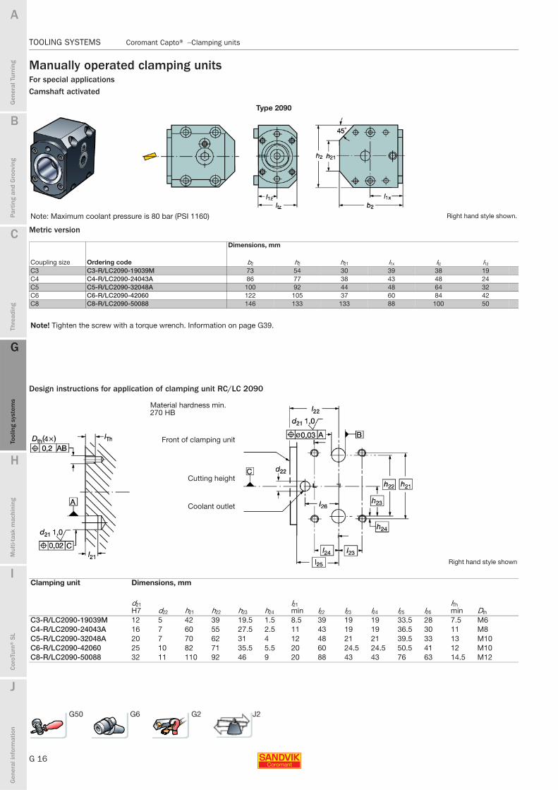
Manually operated clamping unitsFor special applicationsCamshaft activated
Metric version
Design instructions for application of clamping unit RC/LC 2090
Type 2090
Note: Maximum coolant pressure is 80 bar (PSI 1160) Right hand style shown.
Dimensions, mm
Coupling size Ordering code b2 h2 h21 l1x ltz l1z
C3 C3-R/LC2090-19039M 73 54 30 39 38 19C4 C4-R/LC2090-24043A 86 77 38 43 48 24C5 C5-R/LC2090-32048A 100 92 44 48 64 32C6 C6-R/LC2090-42060 122 105 37 60 84 42C8 C8-R/LC2090-50088 146 133 133 88 100 50
Note! Tighten the screw with a torque wrench. Information on page G39.
Material hardness min. 270 HB
Front of clamping unit
Cutting height
Coolant outlet
Right hand style shown
Clamping unit Dimensions, mm
d21H7 d22 h21 h22 h23 h24
l21min l22 l23 l24 l25 l26
lThmin Dth
C3-R/LC2090-19039M 12 5 42 39 19.5 1.5 8.5 39 19 19 33.5 28 7.5 M6C4-R/LC2090-24043A 16 7 60 55 27.5 2.5 11 43 19 19 36.5 30 11 M8C5-R/LC2090-32048A 20 7 70 62 31 4 12 48 21 21 39.5 33 13 M10C6-R/LC2090-42060 25 10 82 71 35.5 5.5 20 60 24.5 24.5 50.5 41 12 M10C8-R/LC2090-50088 32 11 110 92 46 9 20 88 43 43 76 63 14.5 M12
G50 G6 G2 J2

B
G 17
Gen
eral
Tur
ning
Par
ting
and
Gro
ovin
g
C
Thre
adin
g
G
Tool
ing
syst
ems
Mul
ti-ta
sk m
achi
ning
I
Cor
oTur
n® S
L
J
Gen
eral
info
rmat
ion
A
H
G
Tool
ing
syst
ems
Coromant Capto® − Clamping units TOOLING SYSTEMS
TOOLING SYSTEMS Coromant Capto® − Clamping units
How to choose VDI clamping units
External machining
Note: Polygon sleeve must be turned 180° . See Metal cutting technical guide.
Note: Polygon sleeve must be turned 180° . See Metal cutting technical guide.
Clockwise spindle direction Anti-clockwise spindle direction
Internal machining
Note: Polygon sleeve must be turned 180° . See Metal cutting technical guide.
Note: Polygon sleeve must be turned 180° . See Metal cutting technical guide.
Clockwise spindle direction Anti-clockwise spindle direction

G 18
TOOLING SYSTEMS Coromant Capto® − Clamping units
B
Gen
eral
Tur
ning
Par
ting
and
Gro
ovin
g
C
Thre
adin
g
G
Tool
ing
syst
ems
Mul
ti-ta
sk m
achi
ning
I
Cor
oTur
n® S
L
J
Gen
eral
info
rmat
ion
A
H
G
Tool
ing
syst
ems
TOOLING SYSTEMS Coromant Capto® − Clamping units
Manually operated clamping unitsVDI angledCamshaft activated
Metric version
VDI straight
Camshaft activated
Metric version
DIN 69880Turret type
Right hand style shown.Note: Maximum coolant pressure is 80 bar (PSI 1160) Left hand style reflected.
Turret type Dimensions, mm
dmm, size, mm Coupling size Ordering code b2 hry h2 h21 l1x ltz l1z
30 C3 C3-R/LC2030-41020M 74 30 57 38 20 60 41C3 C3-R/LC2030-41030M 73 30 57 41 30 60 41
40 C4 C4-R/LC2040-51030M 86 38 75 54 30 75 51C4 C4-R/LC2040-51040M 86 38 75 60 40 75 51C5 C5-R/LC2040-53030M 99 41 82 47 30 85 53C5 C5-R/LC2040-53040M 99 41 82 53 40 85 53
50 C5 C5-R/LC2050-53030M 99 43 86 59 30 85 53C5 C5-R/LC2050-53040M 99 43 86 65 40 85 53
60 C5 C5-R/LC2060-43040M 99 53 94 76 40 75 43C6 C6-R/LC2060-53040 122 53 105 70 40 95 53
DIN 69880Turret type
Right hand style shown.Left hand: hexagon clamping socket on opposite side of the tool.
Note: Maximum coolant pressure is 80 bar (PSI 1160)
Turret type Dimensions, mm
dmm, size, mm Coupling size Ordering code b2 b21 hry h2 l1z l430 C3 C3-R/LC2030-00060M 50 38 34 61 60 4440 C4 C4-R/LC2040-00075M 75 48 41 75 75 53
C5 C5-R/LC2040-00085M 75 64 41 82 85 7250 C4 C4-LC2050-00065M 70 48 49 83 65 39
C4 C4-RC2050-00065M 70 48 49 83 65 39C5 C5-LC2050-00085M 83 64 49 91 85 62
60 C5 C5-R/LC2060-00075M 80 64 58 100 75 16C6 C6-R/LC2060-00095 84 84 58 111 95 50
Note! Tighten the screw with a torque wrench. Information on page G39.
G52 G6 G2 J2

B
G 19
Gen
eral
Tur
ning
Par
ting
and
Gro
ovin
g
C
Thre
adin
g
G
Tool
ing
syst
ems
Mul
ti-ta
sk m
achi
ning
I
Cor
oTur
n® S
L
J
Gen
eral
info
rmat
ion
A
H
G
Tool
ing
syst
ems
Coromant Capto® − Clamping units TOOLING SYSTEMS
TOOLING SYSTEMS Coromant Capto® − Clamping units
Coromant Capto® Disc Interface
High performance now as standardThe Coromant Capto disk interface (CDI) offers full quick-change tooling capabilities for turning centres. As a dedicated interface for driven and static turning tool holders, it enables many benefits over similar turret systems as an optimized method of fixing holders to the turret disk.
Quick-change tooling is more effective with CDI. It offers higher rigidity, faster set-ups and reduced machine downtime from secure clamping and Coromant Capto - the market-leading quick-change tooling solution.
Machining benefitsBetter cutting performance
The CDI carries larger loads (compared to VDI turrets) thanks to larger Coromant Capto sizes and shorter swing diameter.
Workpiece surface improved
Increased stability reduces vibration and tool chatter to give higher component quality.
Longer tool life
Stable tooling increases tool life.
More cutting tool length
The clamping mechanism is built in to the turret, to provide more space for cutting tool length.
Shorter gauge-line swing diameter
CDI is compatible mainly with European machine tools and follows the standard turret configuration of many lathe producers. CDI also fits multi-task machines having a lower turret with static and/or driven tools.Note: For CDI version TN340 0001
Quicker tool changes
The CDI turret system is designed for Coromant Capto® quick change tooling systems.
Short tool holder projection
The design of CDI with short swing diameter provides added space for tool changing, longer tools, or bigger components.
Stable and rigid tooling
The CDI is securely bolt-on mounted to the turret to give secure positioning.
Flexible symmetric interface
Achieve more with fewer tools, as interchangeable tool holders can be mounted to face the main- or sub-spindle.
Fine adjustment possibility
All CDI tools can be fine-adjusted

G 20
TOOLING SYSTEMS Coromant Capto® − Clamping units
B
Gen
eral
Tur
ning
Par
ting
and
Gro
ovin
g
C
Thre
adin
g
G
Tool
ing
syst
ems
Mul
ti-ta
sk m
achi
ning
I
Cor
oTur
n® S
L
J
Gen
eral
info
rmat
ion
A
H
G
Tool
ing
syst
ems
TOOLING SYSTEMS Coromant Capto® − Clamping units
Manually operated clamping unitsCDI angledCamshaft activated
Metric version
CDI straight
Camshaft activated
Metric version
Right hand style shown.Note: Maximum coolant pressure is 80 bar (PSI 1160) Left hand style reflected.
Dimensions, mm, inch
dmm, size, mm Coupling size Ordering code b2 b21 h2 l1z l21 ltz l1x
80 C5 C5-R/LCI80-000110 140 64 98 110 60 142 05.512 2.520 3.858 4.331 2.362 5.591 0
Right hand style shown.Note: Maximum coolant pressure is 80 bar (PSI 1160) Left hand style reflected.
Dimensions, mm, inch
dmm, size, mm Coupling size Ordering code b2 b21 h2 l1x l1z
80 C5 C5-R/LCE80-040000 135 64 98 0 405.315 2.520 3.858 .000 1.575
Note! Tighten the screw with a torque wrench. Information on page G39.
G55 G6 G2 J2
B
G 21
Gen
eral
Tur
ning
Par
ting
and
Gro
ovin
g
C
Thre
adin
g
G
Tool
ing
syst
ems
Mul
ti-ta
sk m
achi
ning
I
Cor
oTur
n® S
L
J
Gen
eral
info
rmat
ion
A
H
G
Tool
ing
syst
ems
Coromant Capto® − Clamping units TOOLING SYSTEMS
TOOLING SYSTEMS Coromant Capto® − Clamping units
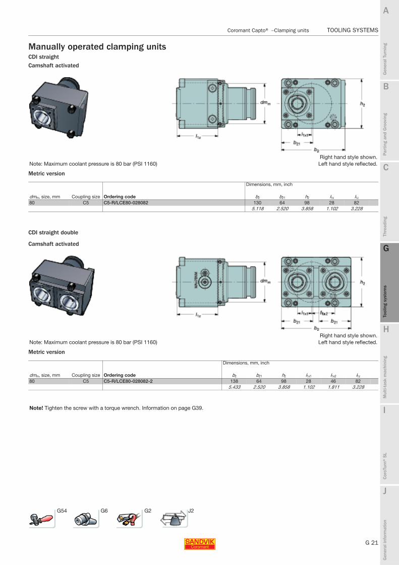
Manually operated clamping unitsCDI straightCamshaft activated
Metric version
CDI straight double
Camshaft activated
Metric version
Right hand style shown.Note: Maximum coolant pressure is 80 bar (PSI 1160) Left hand style reflected.
Dimensions, mm, inch
dmm, size, mm Coupling size Ordering code b2 b21 h2 l1x l1z
80 C5 C5-R/LCE80-028082 130 64 98 28 825.118 2.520 3.858 1.102 3.228
Right hand style shown.Note: Maximum coolant pressure is 80 bar (PSI 1160) Left hand style reflected.
Dimensions, mm, inch
dmm, size, mm Coupling size Ordering code b2 b21 h2 l1x1 l1x2 l1z
80 C5 C5-R/LCE80-028082-2 138 64 98 28 46 825.433 2.520 3.858 1.102 1.811 3.228
Note! Tighten the screw with a torque wrench. Information on page G39.
G54 G6 G2 J2

G 22
TOOLING SYSTEMS Coromant Capto® − Clamping units
B
Gen
eral
Tur
ning
Par
ting
and
Gro
ovin
g
C
Thre
adin
g
G
Tool
ing
syst
ems
Mul
ti-ta
sk m
achi
ning
I
Cor
oTur
n® S
L
J
Gen
eral
info
rmat
ion
A
H
G
Tool
ing
syst
ems
TOOLING SYSTEMS Coromant Capto® − Clamping units
AccessoriesCover plug for clamping unit
Cover plug for adaptor
1. 2. 3. 4. 5. 6.
Ordering codeScrew Locking washer Set screw
O-ring O-ringKantseal
(4x) (4x) (2x) (2x)CDI80-CP-01 3212 010-460 5541 041-02 3214 010-410 5641 005-104 5641 001-79 5641 070-04
1. 2.
Ordering codeScrew
O-ring(2x)CDI80-CP-02 5512 060-23 5641 005-103

B
G 23
Gen
eral
Tur
ning
Par
ting
and
Gro
ovin
g
C
Thre
adin
g
G
Tool
ing
syst
ems
Mul
ti-ta
sk m
achi
ning
I
Cor
oTur
n® S
L
J
Gen
eral
info
rmat
ion
A
H
G
Tool
ing
syst
ems
Coromant Capto® − Clamping units TOOLING SYSTEMS
TOOLING SYSTEMS Coromant Capto® − Clamping units
Automatic clamping units
On automatic clamping units, hydraulic pressure is used to activate the forward and backwards movement of the drawbar. It also gives the cutting unit a “kick” to free it from the clamping unit when it is to be changed.The clamping mechanism is mechanically self-locking i.e., the oil pressure is not applied during the cutting process. The units operate with a hydraulic pressure of 100 bar for size C4, 80 bar for sizes C5, C6, C8 and C10.
All NC 5000 clamping units use segment clamping.
The 5000 type clamping unit is designed for special adaptation to the machine. It is used in connection with manual push-button tool changing and in fully automatic installations with magazines and tool changers.
Push button valveThe push button operated valve is delivered ready to be installed in pockets on turret discs or tool blocks designed for hydraulically operated clamping units.As the valve is produced as a cartridge in one size, it is possible to machine the pocket and simply assemble the valve and lock it with a screw.For ordering, see spare parts and accessories.
Build-in instructionsRegarding detailed build-in instructions see the Metal cutting Technical guide, and/or contact your local Sandvik office.
1. Tool presence air
2. Probe contact
3. Air blast
4. Coolant
5. Probe contact
6. Coolant inlet
7. Air inlet tool presence system
8. Air blast inlet

G 24
TOOLING SYSTEMS Coromant Capto® − Clamping units
B
Gen
eral
Tur
ning
Par
ting
and
Gro
ovin
g
C
Thre
adin
g
G
Tool
ing
syst
ems
Mul
ti-ta
sk m
achi
ning
I
Cor
oTur
n® S
L
J
Gen
eral
info
rmat
ion
A
H
G
Tool
ing
syst
ems
TOOLING SYSTEMS Coromant Capto® − Clamping units
Hydraulically operated clamping units
Metric version
Hydraulically operated clamping units with probe contact
Metric version
Neutral style shown.
Type NC5010 for coolant pressure up to 80 bar (1160 PSI).
Dimensions, mm
Coupling size Ordering code b2 dmm Dm min h2 h21 lc l1z l3 l22 α21 α22 U
C4 C4-NC5010-00025 48 42 260 92 56 74 25 10 22 15° 11° 1.4C5 C5-NC5010-00035 64 55 300 112 70 88 35 12 30 16° 10° 2.7C6 C6-NC5010-00040 84 70 400 143 90 105 40 16 45 15° 10° 5.4C8 C8-NC5010-00050 100 90 500 180 110 120 50 18 59 15° 10° 9.4
C10 C10-NC5010-00050 126 105 530 220 130 160 50 24 65 15° 15° 15.5
Neutral style shown.
Type NC5110 for coolant pressure up to 80 bar (1160 PSI), and equipped with probe contacts
Dimensions, mm
Coupling size Ordering code b2 dmm Dm min h2 h21 lc l1z l3 l22 α21 α22
C4 C4-NC5110-00025 48 42 260 92 56 74 25 10 22 15° 11°C5 C5-NC5110-00035 64 55 300 112 70 88 35 12 30 16° 10°C6 C6-NC5110-00040 84 70 400 143 90 105 39.5 16 45 15° 10°C8 C8-NC5110-00050 100 90 500 180 110 120 50 18 59 15° 10°
Dm min
Dm min
G56 G6 G2 J2

B
G 25
Gen
eral
Tur
ning
Par
ting
and
Gro
ovin
g
C
Thre
adin
g
G
Tool
ing
syst
ems
Mul
ti-ta
sk m
achi
ning
I
Cor
oTur
n® S
L
J
Gen
eral
info
rmat
ion
A
H
G
Tool
ing
syst
ems
Coromant Capto® − Clamping units TOOLING SYSTEMS
TOOLING SYSTEMS Coromant Capto® − Clamping units
Hydraulically operated clamping units with Jetbreak™
Metric version
Coromant Capto® required pressure:
Neutral style shown.
Type NC5210 for coolant pressure over 100 bar (1450 PSI).
Dimensions, mm
Coupling size Ordering code b2 dmm Dm min h2 h21 lc l1z l3 l22 α21 α22
C6 C6-NC5210-00040 84 70 400 143 90 105 40 16 45 15° 10°C8 C8-NC5210-00050 100 90 500 180 110 120 50 18 59 15° 10°
Hydro-mechanical clamping units type 5000
Clamping pressure
Coupling size Bar PSIC4 100 1450C5 80 1160C6 80 1160C8 80 1160C10 80 1160Required oil flow in all cases: 6 l/min (1.6 gal/min)
Dm min
G57 G6 G2 J2

G 26
TOOLING SYSTEMS Coromant Capto® − Adaptors for turning tools
B
Gen
eral
Tur
ning
Par
ting
and
Gro
ovin
g
C
Thre
adin
g
G
Tool
ing
syst
ems
Mul
ti-ta
sk m
achi
ning
I
Cor
oTur
n® S
L
J
Gen
eral
info
rmat
ion
A
H
G
Tool
ing
syst
ems
TOOLING SYSTEMS Coromant Capto® − Adaptors for turning tools
Adaptors for solid boring bars131
Metric pilot
Inch pilot
l1 = programming length
Dimensions, mm
Coupling size Ordering code Coolant1) dmt D5m D1 l1 l3 l21
C3 C3-131-00035-10 1 10 32 36 15 20 35C3-131-00040-12 1 12 32 36 16 24 40
C4 C4-131-00040-10 1 10 40 36 20 19 40C4-131-00045-12 1 12 40 36 21 24 45C4-131-00050-16 1 16 40 36 18 29 50
C5 C5-131-00045-10 1 10 50 36 25 21 45C5-131-00045-12 1 12 50 36 25 22.5 45C5-131-00055-16 1 16 50 36 23 31 55
1) 1 = coolant through centre2) Tolerance = H8131
l1 = programming length
Dimensions, inch
Coupling size Ordering code Coolant1) dmt D5m D1 l1 l3 l21
C3 C3-131-00050-250 1 .250 1.260 1.180 .901 .790 1.970C3-131-00050-500 1 .500 1.260 1.420 .591 1.020 1.970C3-131-00050-625 1 .625 1.260 1.420 .591 1.260 1.970
C4 C4-131-00050-250 1 .250 1.575 1.420 1.181 1.070 1.970C4-131-00050-375 1 .375 1.575 1.420 1.181 1.130 1.970C4-131-00050-500 1 .500 1.575 1.420 95.000 1.130 1.970C4-131-00050-625 1 .625 1.575 1.420 .709 1.130 1.970C4-131-00060-750 1 .750 1.575 1.420 .830 1.420 2.360C4-131-00091-1000 1 1.000 1.575 2.284 .772 2.811 3.583
C5 C5-131-00060-375 1 .375 1.968 1.420 1.575 1.575 2.360C5-131-00060-500 1 .500 1.968 1.420 1.340 1.575 2.360C5-131-00060-625 1 .625 1.968 1.420 1.100 1.575 2.360C5-131-00060-750 1 .750 1.968 1.420 .830 1.575 2.360C5-131-00070-1000 1 1.000 1.968 2.130 .790 1.970 2.760C5-131-00115-1500 1 1.500 1.968 2.870 1.090 3.440 4.528
C6 C6-131-00065-375 1 .375 2.480 1.420 1.170 .790 2.560C6-131-00065-500 1 .500 2.480 1.420 1.170 1.020 2.560C6-131-00065-625 1 .625 2.480 1.420 1.170 1.260 2.560C6-131-00065-750 1 .750 2.480 1.420 1.270 1.540 2.660C6-131-00075-1000 1 1.000 2.480 2.130 .950 2.040 2.950C6-131-00105-1500 1 1.500 2.480 2.870 .690 3.440 4.130
1) 1 = coolant through centre2) Tolerance = H8
G59 G6 G2 J2
B
G 27
Gen
eral
Tur
ning
Par
ting
and
Gro
ovin
g
C
Thre
adin
g
G
Tool
ing
syst
ems
Mul
ti-ta
sk m
achi
ning
I
Cor
oTur
n® S
L
J
Gen
eral
info
rmat
ion
A
H
G
Tool
ing
syst
ems
Coromant Capto® − Adaptors for turning tools TOOLING SYSTEMS
TOOLING SYSTEMS Coromant Capto® − Adaptors for turning tools
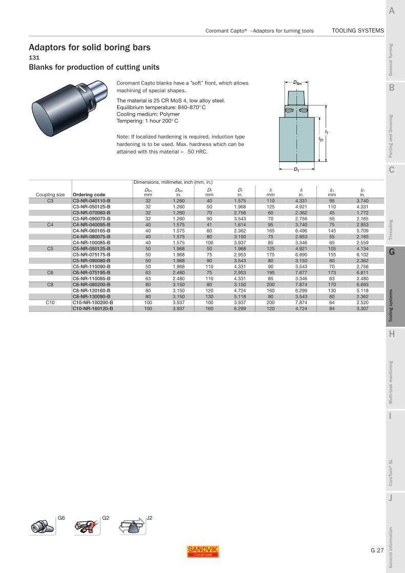
Adaptors for solid boring bars131
Blanks for production of cutting units
Coromant Capto blanks have a ’’soft’’ front, which allows machining of special shapes.
The material is 25 CR MoS 4, low alloy steel.Equilibrium temperature: 840–870° CCooling medium: PolymerTempering: 1 hour 200° C
Note: If localized hardening is required, induction type hardening is to be used. Max. hardness which can be attained with this material ≈ 50 HRC.
Dimensions, millimeter, inch (mm, in.)
Coupling size Ordering codeD5mmm
D5min.
D1mm
D1in.
l7mm
l7in.
l21 mm
l21 in.
C3 C3-NR-040110-B 32 1.260 40 1.575 110 4.331 95 3.740C3-NR-050125-B 32 1.260 50 1.968 125 4.921 110 4.331C3-NR-070060-B 32 1.260 70 2.756 60 2.362 45 1.772C3-NR-090070-B 32 1.260 90 3.543 70 2.756 55 2.165
C4 C4-NR-040095-B 40 1.575 41 1.614 95 3.740 75 2.953C4-NR-060165-B 40 1.575 60 2.362 165 6.496 145 5.709C4-NR-080075-B 40 1.575 80 3.150 75 2.953 55 2.165C4-NR-100085-B 40 1.575 100 3.937 85 3.346 65 2.559
C5 C5-NR-050125-B 50 1.968 50 1.968 125 4.921 105 4.134C5-NR-075175-B 50 1.968 75 2.953 175 6.890 155 6.102C5-NR-090080-B 50 1.968 90 3.543 80 3.150 60 2.362C5-NR-110090-B 50 1.968 110 4.331 90 3.543 70 2.756
C6 C6-NR-075195-B 63 2.480 75 2.953 195 7.677 173 6.811C6-NR-110085-B 63 2.480 110 4.331 85 3.346 63 2.480
C8 C8-NR-080200-B 80 3.150 80 3.150 200 7.874 170 6.693C8-NR-120160-B 80 3.150 120 4.724 160 6.299 130 5.118C8-NR-130090-B 80 3.150 130 5.118 90 3.543 60 2.362
C10 C10-NR-100200-B 100 3.937 100 3.937 200 7.874 64 2.520C10-NR-160120-B 100 3.937 160 6.299 120 4.724 84 3.307
G6 G2 J2
G 28
TOOLING SYSTEMS Coromant Capto® − Adaptors for rotating tools
B
Gen
eral
Tur
ning
Par
ting
and
Gro
ovin
g
C
Thre
adin
g
G
Tool
ing
syst
ems
Mul
ti-ta
sk m
achi
ning
I
Cor
oTur
n® S
L
J
Gen
eral
info
rmat
ion
A
H
G
Tool
ing
syst
ems
TOOLING SYSTEMS Coromant Capto® − Adaptors for rotating tools
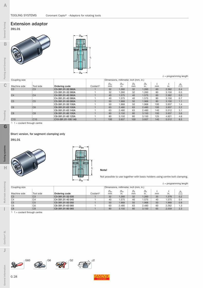
Extension adaptor391.01
Short version, for segment clamping only
391.01
l1 = programming length
Coupling size Dimensions, millimeter, inch (mm, in.)
Machine side Tool side Ordering code Coolant1)D5mmm
D5min.
D5tmm
D5tin.
l1mm
l1in. U
C3 C3 C3-391.01-32 060A 1 32 1.260 32 1.260 60 2.362 0.4C3-391.01-32 080A 1 32 1.260 32 1.260 80 3.150 0.5
C4 C4 C4-391.01-40 060A 1 40 1.575 40 1.575 60 2.362 0.5C4-391.01-40 080A 1 40 1.575 40 1.575 80 3.150 0.7
C5 C5 C5-391.01-50 080A 1 50 1.968 50 1.968 80 3.150 1.1C5-391.01-50 100A 1 50 1.968 50 1.968 100 3.937 1.4
C6 C6 C6-391.01-63 100A 1 63 2.480 63 2.480 100 3.937 2.2C6-391.01-63 140A 1 63 2.480 63 2.480 140 5.512 3.1
C8 C8 C8-391.01-80 100A 1 80 3.150 80 3.150 100 3.937 3.6C8-391.01-80 125A 1 80 3.150 80 3.150 125 4.921 4.6
C10 C10 C10-391.01-100 140 1 100 3.937 100 3.937 140 5.512 8.51) 1 = coolant through centre
Note!
Not possible to use together with basic holders using centre bolt clamping.
l1 = programming length
Coupling size Dimensions, millimeter, inch (mm, in.)
Machine side Tool side Ordering code Coolant1)D5mmm
D5min.
D5tmm
D5tin.
l1mm
l1in. U
C3 C3 C3-391.01-32 035 1 32 1.260 32 1.260 35 1.378 0.2C4 C4 C4-391.01-40 040 1 40 1.575 40 1.575 40 1.575 0.4C5 C5 C5-391.01-50 050 1 50 1.968 50 1.968 50 1.968 0.9C6 C6 C6-391.01-63 060 1 63 2.480 63 2.480 60 2.262 1.3C8 C8 C8-391.01-80 065 1 80 3.150 80 3.150 65 2.559 2.31) 1 = coolant through centre
G60 G6 G2 J2
B
G 29
Gen
eral
Tur
ning
Par
ting
and
Gro
ovin
g
C
Thre
adin
g
G
Tool
ing
syst
ems
Mul
ti-ta
sk m
achi
ning
I
Cor
oTur
n® S
L
J
Gen
eral
info
rmat
ion
A
H
G
Tool
ing
syst
ems
Coromant Capto® − Adaptors for rotating tools TOOLING SYSTEMS
TOOLING SYSTEMS Coromant Capto® − Adaptors for rotating tools
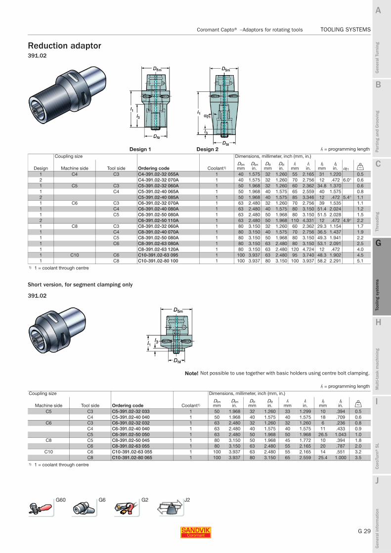
Reduction adaptor391.02
Short version, for segment clamping only
391.02
Design 1 Design 2 l1 = programming length
Coupling size Dimensions, millimeter, inch (mm, in.)
Design Machine side Tool side Ordering code Coolant1)D5mmm
D5min.
D5tmm
D5tin.
l1mm
l1in.
l3mm
l3in. α21 U
1 C4 C3 C4-391.02-32 055A 1 40 1.575 32 1.260 55 2.165 31 1.220 0.52 C4-391.02-32 070A 1 40 1.575 32 1.260 70 2.756 12 .472 6.0° 0.61 C5 C3 C5-391.02-32 060A 1 50 1.968 32 1.260 60 2.362 34.8 1.370 0.61 C4 C5-391.02-40 065A 1 50 1.968 40 1.575 65 2.559 40 1.575 0.82 C5-391.02-40 085A 1 50 1.968 40 1.575 85 3.346 12 .472 5.4° 1.11 C6 C3 C6-391.02-32 070A 1 63 2.480 32 1.260 70 2.756 39 1.535 1.11 C4 C6-391.02-40 080A 1 63 2.480 40 1.575 80 3.150 51.4 2.024 1.21 C5 C6-391.02-50 080A 1 63 2.480 50 1.968 80 3.150 51.5 2.028 1.52 C6-391.02-50 110A 1 63 2.480 50 1.968 110 4.331 12 .472 4.9° 2.21 C8 C3 C8-391.02-32 060A 1 80 3.150 32 1.260 60 2.362 29.3 1.154 1.71 C4 C8-391.02-40 070A 1 80 3.150 40 1.575 70 2.756 36.5 1.437 1.91 C5 C8-391.02-50 080A 1 80 3.150 50 1.968 80 3.150 49.3 1.941 2.21 C6 C8-391.02-63 080A 1 80 3.150 63 2.480 80 3.150 53.1 2.091 2.51 C8-391.02-63 120A 1 80 3.150 63 2.480 120 4.724 12 .472 4.01 C10 C6 C10-391.02-63 095 1 100 3.937 63 2.480 95 3.740 48.3 1.902 4.51 C8 C10-391.02-80 100 1 100 3.937 80 3.150 100 3.937 58.2 2.291 5.1
1) 1 = coolant through centre
Note! Not possible to use together with basic holders using centre bolt clamping.
l1 = programming length
Coupling size Dimensions, millimeter, inch (mm, in.)
Machine side Tool side Ordering code Coolant1)D5mmm
D5min.
D5tmm
D5tin.
l1mm
l1in.
l3mm
l3in. U
C5 C3 C5-391.02-32 033 1 50 1.968 32 1.260 33 1.299 10 .394 0.5C4 C5-391.02-40 040 1 50 1.968 40 1.575 40 1.575 18 .709 0.6
C6 C3 C6-391.02-32 032 1 63 2.480 32 1.260 32 1.260 6 .236 0.8C4 C6-391.02-40 040 1 63 2.480 40 1.575 40 1.575 11 .433 0.9C5 C6-391.02-50 050 1 63 2.480 50 1.968 50 1.968 26.5 1.043 1.0
C8 C5 C8-391.02-50 045 1 80 3.150 50 1.968 45 1.772 10 .394 1.8C6 C8-391.02-63 055 1 80 3.150 63 2.480 55 2.165 20 .787 2.0
C10 C6 C10-391.02-63 055 1 100 3.937 63 2.480 55 2.165 14 .551 3.2C8 C10-391.02-80 065 1 100 3.937 80 3.150 65 2.559 25.4 1.000 3.5
1) 1 = coolant through centre
G60 G6 G2 J2

G 30
TOOLING SYSTEMS Coromant Capto® − Adaptors for rotating tools
B
Gen
eral
Tur
ning
Par
ting
and
Gro
ovin
g
C
Thre
adin
g
G
Tool
ing
syst
ems
Mul
ti-ta
sk m
achi
ning
I
Cor
oTur
n® S
L
J
Gen
eral
info
rmat
ion
A
H
G
Tool
ing
syst
ems
TOOLING SYSTEMS Coromant Capto® − Adaptors for rotating tools
Reduction adaptor180° rotated polygonShort version, for segment clamping only
Reduction adaptor
391.01R
Note!
Not possible to use together with basic holders using centre bolt clamping.
l1 = programming length
Coupling size Dimensions, mm, inch
Machine side Tool side Ordering code Coolant1) D5m D5t l1 U
C5 C5 C5-391.01R-50 050 1 50 50 50 0.91.968 1.968 1.968
C6 C6 C6-391.01R-63 060 1 63 63 60 1.32.480 2.480 2.362
C8 C8 C8-391.01R-80 065 1 80 80 65 2.33.150 3.150 2.559
1) 1 = coolant through centre
180° rotated polygonShort version, for segment clamping only
391.02R
Note!
Not possible to use together with basic holders using centre bolt clamping.
l1 = programming length
Coupling size Dimensions, mm, inch
Machine side Tool side Ordering code Coolant1) D5m D5t l1 l3 U
C8 C6 C8-391.02R-63 055 1 80 63 55 20 2.03.150 2.480 2.165 .787
1) 1 = coolant through centre
G60 G2 J2

B
G 31
Gen
eral
Tur
ning
Par
ting
and
Gro
ovin
g
C
Thre
adin
g
G
Tool
ing
syst
ems
Mul
ti-ta
sk m
achi
ning
I
Cor
oTur
n® S
L
J
Gen
eral
info
rmat
ion
A
H
G
Tool
ing
syst
ems
Coromant Capto® − Adaptors for rotating tools TOOLING SYSTEMS
TOOLING SYSTEMS Coromant Capto® − Adaptors for rotating tools
Coromant Capto® short adaptor for exchangeable headWithout gripper grooves for manual tool change in turning centres
Metric version
Inch version
Cx-391.EHCx-A391.EH
l1 = programming length
Dimensions, mm
CoromantCapto size Coupling size Ordering code Coolant1) D5m D5t l1 l3 U
C3 E10 C3-391.EH-10 026 1 32 9.6 26 13 0.1E12 C3-391.EH-12 029 1 32 11.6 29 16 0.1
C4 E10 C4-391.EH-10 026 1 40 9.6 26 13 0.2E12 C4-391.EH-12 029 1 40 11.6 29 16 0.2E16 C4-391.EH-16 035 1 40 15.4 35 22 0.2
C5 E10 C5-391.EH-10 026 1 50 9.6 26 13 0.3E12 C5-391.EH-12 029 1 50 11.6 29 16 0.3E16 C5-391.EH-16 035 1 50 15.4 35 22 0.3
Dimensions, inch
CoromantCapto size Coupling size Ordering code Coolant1) D5m D5t l1 l3 V
C3 E10 C3-A391.EH-10 025 1 1.260 .360 .984 .472 0.2E12 C3-A391.EH-12 031 1 1.260 .480 1.220 .709 0.2
C4 E10 C4-A391.EH-10 025 1 1.575 .360 .984 .472 0.4E12 C4-A391.EH-12 031 1 1.575 .480 1.220 .709 0.4E16 C4-A391.EH-16 034 1 1.575 .606 1.339 .827 0.4
C5 E10 C5-A391.EH-10 025 1 1.968 .360 .984 .472 0.6E12 C5-A391.EH-12 031 1 1.968 .480 1.220 .709 0.6
1) 1 = coolant through centre
For complete assortment of adaptors and cutting heads for CoroMill® 316, see chapter D and G in Main catalogue for milling, drilling and boring tools.
Main spare parts
Torque value Torque range
Coupling size Key Torque wrench head1) Nm In-lbs Torque wrench1) Nm In-lbsE10 5680 093-01 5680 089-01 12 106 5680 088-01 10-20 88-177E12 5680 093-02 5680 089-02 15 132 5680 088-01 10-20 88-177E16 5680 093-03 5680 089-03 30 265 5680 088-02 25-65 221-575E20 5680 093-04 5680 089-04 50 442 5680 088-02 25-65 221-575E25 5680 093-05 5680 089-05 65 575 5680 088-02 25-65 221-5751) Accessories, must be ordered separately
G6 G2 J2

G 32
TOOLING SYSTEMS Coromant Capto® − Adaptors for rotating tools
B
Gen
eral
Tur
ning
Par
ting
and
Gro
ovin
g
C
Thre
adin
g
G
Tool
ing
syst
ems
Mul
ti-ta
sk m
achi
ning
I
Cor
oTur
n® S
L
J
Gen
eral
info
rmat
ion
A
H
G
Tool
ing
syst
ems
TOOLING SYSTEMS Coromant Capto® − Adaptors for rotating tools
ER-collet chuck adaptor, shortFor driven tool holdersNo gripper grooves
Coromant Capto® short (for manual tool change in turning centres)
DIN 6499/ 391.14 Accessories393.14
Not delivered with the tool, must be ordered separately.
See Main catalogue for milling, drilling and boring tools.
Short design
Note: For segment clamping only. Can’t be used in basic holders and extensions/reductions.
Not for automatic tool change as have no gripper grooves
Dimensions, millimeter, inch (mm, in.)
Coupling size Ordering code Coolant1)
D5mmm
D5min.
dmtminmm
dmtmin in.
dmt maxmm
dmtmaxin.
D21mm
D21in.
l3mm
l3in.
l21 mm
l21 in. U
Collet size
Balanced by design
C3 C3-391.14-20 036 1 32 1.260 1 .039 13 .512 35 1.378 36 1.417 0.3 ER 20 PC4 C4-391.14-20 035 1 40 1.575 1 .039 13 .512 35 1.378 27 1.063 35 1.378 0.2 ER 20 P
C4-391.14-25 038 1 40 1.575 1 .039 16 .630 42 1.654 38 1.496 0.3 ER 25 PC5 C5-391.14-32 045 1 50 1.968 2 .079 20 .787 50 1.968 45 1.772 0.5 ER 32 P
1) 1 = coolant through centre
P Balanced by design
G61 G6 G2 J2

B
G 33
Gen
eral
Tur
ning
Par
ting
and
Gro
ovin
g
C
Thre
adin
g
G
Tool
ing
syst
ems
Mul
ti-ta
sk m
achi
ning
I
Cor
oTur
n® S
L
J
Gen
eral
info
rmat
ion
A
H
G
Tool
ing
syst
ems
Coromant Capto® − Adaptors for rotating tools TOOLING SYSTEMS
TOOLING SYSTEMS Coromant Capto® − Adaptors for rotating tools
Tap adaptorsCollet type with external coolant supply391.60B
Collets
Short design, floating for turning centres Without gripper grooves for manual tool change
Note: Only for segment clamping. l1 = programming length
Tap range Tap shank dimensions, mm, inch
Dimensions, mm, inch
min maxCoupling
size Ordering code Coolant3)dmm min max
Bk min max D5m D1 D21 l1 l3 l21 - z + z U
Torque Nm2)
M4 M12 C3 C3-391.60B-01 062A1) 0 3.5 10 2 8 32 50 31 25.5 18 62 2 10 0.7 35M4 M12 0 .138 .394 .079 .315 1.260 1.968 1.220 1.004 .709 2.441 .079 .394 35M4 M12 C4 C4-391.60B-01 062A1) 0 3.5 10 2 8 40 50 31 25.5 18 62 2 10 0.9 35M4 M12 0 .138 .394 .079 .315 1.575 1.968 1.220 1.004 .709 2.441 .079 .394 35M4 M12 C4-391.60B-01 079A 0 3.5 10 2 8 40 50 31 42 18 79 2 10 0.7 35M4 M12 0 .138 .394 .079 .315 1.575 1.968 1.220 1.654 .709 3.110 .079 .394 35M5 M16 C5 C5-391.60B-02 062A1) 0 2.8 13 2 10 50 50 40 22 19 62 2 10 1 60M5 M16 0 .110 .512 .079 .394 1.968 1.968 1.575 .866 .748 2.441 .079 .394 60M5 M16 C5-391.60B-02 074A 0 2.8 13 2 10 50 50 40 34 19 74 2 10 1 60M5 M16 0 .110 .512 .079 .394 1.968 1.968 1.575 1.339 .748 2.913 .079 .394 60
1) For Driven Tool Holders. Without slots for gripper.2) Max allowed tightening torque3) 0 = no coolant
Collets must be ordered separately, see below.
Ordering code
dmm mm (inch) Shank 1) DIN 374 Suitable for:3.5-6.5 (.138-.256) 391.60A-OZ J421 M4-M8 (0-1/4) Cx-391.60B -..01 xxxA6.5-10 (.256-.394) 391.60A-OZ J422 M6-M12 (1/4-9/16) ...01 xxxA2.8-7 (.110-.276) 391.60A-OZ J440 M5-M10 (0-1/4) ...02 xxxA7-13 (.276-.512) 391.60A-OZ J443 M7-M16 (5/16-5/8) ...02 xxxA10-16 (.394-.630) 391.60A-OZ J461 M10-M16 (9/16-3/4) ...03 xxxA16-23 (.630-.906) 391.60A-OZ J462 M20-M30 (13/16-1 1/8) ...03 xxxA1) For other standards, check shank dimensions Bk and dmm
G62 G6 G2 J2

Turning_Utfyllnadssidor.indd 2 2010-12-09 12:30:56

B
G 35
Gen
eral
Tur
ning
Par
ting
and
Gro
ovin
g
C
Thre
adin
g
G
Tool
ing
syst
ems
Mul
ti-ta
sk m
achi
ning
I
Cor
oTur
n® S
L
J
Gen
eral
info
rmat
ion
A
H
G
Tool
ing
syst
ems
Index for accessories and spare parts TOOLING SYSTEMS
TOOLING SYSTEMS Index for accessories and spare parts
Accessories Page
Fixtures G36
Grease nipple G38
Push button operated valve G38
Assembly tool G38
Hexagon key G38
Torque wrench for tool changing G39
Tightening torque recommendations G40
Extracting tool for clamping units G41
Tools for disassembling polygon socket G41
Cover plug G41
Cassettes with tapered polygon seating G43
Coolant tubes for Coromant Capto® G42
Spare parts Page
Manually operated clamping units
Type 2085 G47
Type 2000 G48
Type 3000 G48
Type 2080 G48
Type 2090 G50
Round shank type G51
VDI Angled design, DIN 69880 G52
VDI Straight design, DIN 69880 G53
CDI straight G54
CDI angled G55
Hydraulically operated clamping units
Type 5010 G56
Type 5110 G58
Type 5210 G57
Coromant Capto® adaptors
Coromant Capto® adaptor for solid boring bar G59
Extension/reduction adaptors G60
Collet chuck adaptors G61
Tap adaptors G62
PagePre-measuring fixture G45
Master setting gauges G46
Alignment tool G46
For spare parts for Coromant Capto® multi-task machining tools, see chapter H

G 36
TOOLING SYSTEMS Accessories
B
Gen
eral
Tur
ning
Par
ting
and
Gro
ovin
g
C
Thre
adin
g
G
Tool
ing
syst
ems
Mul
ti-ta
sk m
achi
ning
I
Cor
oTur
n® S
L
J
Gen
eral
info
rmat
ion
A
H
G
Tool
ing
syst
ems
TOOLING SYSTEMS Accessories
Assembly fixturefor mounting and dismounting of modular tools
391.500 391.501
Fixture body Fixture body
Ordering code: 391.500 Ordering code: 391.501
Ordering code Ordering code
Sleeve For holder type, size Flange Collar For holder type, size391.540-C3 Coromant Capto Size C3 391.510-140 50 391.530-C3 Coromant Capto Size C3391.540-C4 Coromant Capto Size C4 391.510-140 50 391.530-C4 Coromant Capto Size C4391.540-C5 Coromant Capto Size C5 391.510-140 50 391.530-C5 Coromant Capto Size C5391.540-C6 Coromant Capto Size C6 391.510-140 50 391.530-C6 Coromant Capto Size C6391.540-C8 Coromant Capto Size C8 391.510-140 50 391.530-C8 Coromant Capto Size C8391.540-C10 Coromant Capto Size C10 391.530-C10* Coromant Capto Size C10 and C8X391.540-HA05 HSK 50 Form A/C 391.510-HA05 391.530-50 HSK 50 Form A391.540-HA06 HSK 63 Form A/C 391.510-HA06 391.530-63 HSK 63 Form A391.540-HA08 HSK 80 Form A/C 391.510-HA08 391.530-80 HSK 80 Form A391.540-HA10 HSK 100 Form A/C 391.510-HA10 HSK 100 Form A391.540-50 MAS-BT 50/CAT/ISO 391.510-HA13 HSK 125 Form A391.540-30 MAS-BT 30/CAT/ISO 391.510-55 30 MAS-BT 30391.540-40 MAS-BT 40/CAT/ISO 391.510-55 40 MAS-BT 40
391.510-55 50 MAS-BT 50391.510-562-40 BIG PLUS, MAS BT 40391.510-562-50 BIG PLUS, MAS BT 50391.510-140 40 DIN 69871/40, ANSIB 5.50-40. ISO7388/1-40, CAT 40391.510-140 50 DIN 69871/50, ANSIB 5.50-40. ISO7388/1-50, CAT 50391.510-540 40 BIG PLUS DIN69871/1-40, BIG PLUS 7388/1-40391.510-540 50 BIG PLUS DIN69871/1-50, BIG PLUS 7388/1-50391.510-00 40 DIN 2080-40391.510-00 50 DIN 2080-50391.510-140 50 Varilock size 50391.510-140 50 Varilock size 63391.510-140 50 Varilock size 80* Combined collar/flange for C10 and C8X
Note: Key is delivered with the sleeve.Assembly fixture 391.500 Fixture 391.501 for maintenance of tools with Coromant
Capto® and HSK couplings
Choose flange, collar and sleeve to suit tool to be assembled.
Choose sleeve to suit coupling.The fixture should be fastened to the bench with three socket head screws (not delivered with fixture)

B
G 37
Gen
eral
Tur
ning
Par
ting
and
Gro
ovin
g
C
Thre
adin
g
G
Tool
ing
syst
ems
Mul
ti-ta
sk m
achi
ning
I
Cor
oTur
n® S
L
J
Gen
eral
info
rmat
ion
A
H
G
Tool
ing
syst
ems
Accessories TOOLING SYSTEMS
TOOLING SYSTEMS Accessories
Assembly fixture
For assembling and dismantling basic holdersPneumatically operated391.200
Note!Assembly fixture 391.200-xx includes foot pedal.Instructions are enclosed with fixture.Air supply of 6 bar (85 lbs/in2) is required.
Size Ordering code Dimensions, mm, inch
Taper HSK db D21 D22 l21 l22 l23 l24 l25 lx1 lx2 ly1 ly2 Weight40 – 391.200-40 11 160 180 370 150 120 30 67 135 100 15 105 20
.433 6.299 7.087 14.567 5.906 4.724 1.181 2.637 5.315 3.737 .590 4.134 4445 – 391.200-45 11 160 180 370 150 120 30 67 135 100 15 105 20
.433 6.299 7.087 14.567 5.906 4.724 1.181 2.637 5.315 3.737 .590 4.134 4450 – 391.200-50 11 160 180 370 150 120 30 67 135 100 15 105 20
.433 6.299 7.087 14.567 5.906 4.724 1.181 2.637 5.315 3.737 .590 4.134 44– 50 391.200-H050 11 160 180 370 150 120 30 67 135 100 15 105 20
.433 6.299 7.087 14.567 5.906 4.724 1.181 2.637 5.315 3.737 .590 4.134 44– 63 391.200-H063 11 160 180 370 150 120 30 67 135 100 15 105 20
.433 6.299 7.087 14.567 5.906 4.724 1.181 2.637 5.315 3.737 .590 4.134 44– 100 391.200-H100 11 160 180 370 150 120 30 67 135 100 15 105 20
.433 6.299 7.087 14.567 5.906 4.724 1.181 2.637 5.315 3.737 .590 4.134 44

G 38
TOOLING SYSTEMS Accessories
B
Gen
eral
Tur
ning
Par
ting
and
Gro
ovin
g
C
Thre
adin
g
G
Tool
ing
syst
ems
Mul
ti-ta
sk m
achi
ning
I
Cor
oTur
n® S
L
J
Gen
eral
info
rmat
ion
A
H
G
Tool
ing
syst
ems
TOOLING SYSTEMS Accessories
Assembly tool
Assembly tools
Extension key, Centre bolt clamping
Grease nipple Push button operated valve
Size Ordering code Requirement specifications:Working pressure: max. 100 bar
C3 – C8 5692 012-01For information about pocket dimensions, see Metalcutting Technical guide or contact your nearest Sandvik Coromant representative.
Ordering code: C-PBOV-01
Tool for assembly/disassembly of clamping mechanism for clamping unit type NC2000
Coromant Capto® size Ordering codeC3 C3-AT2000-01C4 C4-AT2000-01C5 C5-AT2000-01
All these accessories are supplied to separate order, and we recommend that they are ordered with the first Coromant Capto parts.
Coupling size Retaining nut spanner Extension key Torque wrench C3 5680 065-13 5680 015-05 C-TK-02C4 5680 065-10 5680 015-05 C-TK-02C5 5680 065-11 5680 015-01 C-TK-02C6-C8 5680 065-12 5680 015-02 C-TK-02C10 5680 065-14 5680 015-06 C-TK-04
C-TK-04
Ordering code Spare partsTorque wrench
Coupling size Nm ft-lbsLength, mm (inch) Size mm Key adaptor
C10 280 207 C-TK-04 683 (26.9) 17 5680 015-06

B
G 39
Gen
eral
Tur
ning
Par
ting
and
Gro
ovin
g
C
Thre
adin
g
G
Tool
ing
syst
ems
Mul
ti-ta
sk m
achi
ning
I
Cor
oTur
n® S
L
J
Gen
eral
info
rmat
ion
A
H
G
Tool
ing
syst
ems
Accessories TOOLING SYSTEMS
TOOLING SYSTEMS Accessories
Torque wrench for tool changing
Ordering code Spare partsTorque wrench
Coupling size Nm ft-lbs Length
Size mm Key adaptor
C3 50 37 BT-TK-02 10 5680 035-05C4 50 37 C-TK-01 345 10 5680 035-06C5 70 52 C-TK-01 345 12 5680 035-07C6 90 66 C-TK-01 345 12 5680 035-07C8 130 96 C-TK-02 440 12 5680 035-07C10 285 210 C-TK-03 548 17 5680 035-10
To be calibrated according to ISO 6789, accuracy within 4%
C-TK-0120-100Nm15-74 ft-lbs
C-TK-0240-200Nm30-148 ft-lbs
C-TK-03

G 40
TOOLING SYSTEMS Accessories
B
Gen
eral
Tur
ning
Par
ting
and
Gro
ovin
g
C
Thre
adin
g
G
Tool
ing
syst
ems
Mul
ti-ta
sk m
achi
ning
I
Cor
oTur
n® S
L
J
Gen
eral
info
rmat
ion
A
H
G
Tool
ing
syst
ems
TOOLING SYSTEMS Accessories
Tightening torque recommendations
Coromant Capto® tightening torque:
Coromant Capto® tightening torque:
Coromant Capto® required pressure:
Coromant Capto® basic holders
Manual clamping units type NC2000 and NC3000
Coupling size Torque Nm
ft-lbs
C3 35 26C4 50 37C5 70 52
Manual clamping units and driven tool holders with camshaft
Coupling size Torque Nm
ft-lbs
C3 35 26C4 50 37C5 70 52C6 90 66C8 130 96C10 285 210
Hydro-mechanical clamping units type 5000
Clamping EjectingCoupling size Pressure bar (PSI) Pressure bar (PSI)
C4 100 (1450) 100 (1450)C5 80 (1160) 80 (1160)C6 80 (1160) 80 (1160) C8 80 (1160) 80 (1160)C10 80 (1160) 80 (1160)Required oil flow in all cases: 6 l/min
Centre bolt clamping
Coupling size Torque Nm
ft-lbs
C3 45 33C4 55 40C5 95 70C6 170 125C8 170 125C10 380 277

B
G 41
Gen
eral
Tur
ning
Par
ting
and
Gro
ovin
g
C
Thre
adin
g
G
Tool
ing
syst
ems
Mul
ti-ta
sk m
achi
ning
I
Cor
oTur
n® S
L
J
Gen
eral
info
rmat
ion
A
H
G
Tool
ing
syst
ems
Accessories TOOLING SYSTEMS
TOOLING SYSTEMS Accessories
Extracting toolfor disassembling the polygon socket on manual and automatic clamping units
Withdrawal toolTo remove polygone sleeve from clamping units can be used together with CC-ET-01/02
Cover plug
Balancing tool
Coupling size Ordering
C3 CC-ET-01C4 CC-ET-01C5 CC-ET-02
Extracting tool Withdrawal tool C6 CC-ET-02C8 CC-ET-02
Note: Withdrawal tool to be ordered separately.
Coupling size Ordering codeSpare parts
Centre screw Peripheral screwC3 C3-WDT-01M 3214 030-463 5512 040-03C4 C4-WDT-01M 3214 030-464 5512 040-04C5 C5-WDT-01M 3214 030-516 5512 040-05C6 C6-WDT-01M 3214 030-516 5512 040-06C8 C8-WDT-01 3214 030-516 5512 072-01
Coupling size Ordering code
Manual unit Automatic unit Type 3000C3 C3-CP-01 - C3-CP-11C4 C4-CP-01 C4-CPA-01 C4-CP-11C5 C5-CP-01 C5-CPA-01 C5-CP-11C6 C6-CP-01 C6-CPA-01 -C8 C8-CP-01 C8-CPA-01 -C10 - C10-CPA-01 -
Coupling size Ordering code
C3 C3 - BAT - 01C4 C4 - BAT - 01C5 C5 - BAT - 01C6 C6 - BAT - 01C8 C8 - BAT - 01C10 C10 - BAT - 01
G 42
TOOLING SYSTEMS Accessories
B
Gen
eral
Tur
ning
Par
ting
and
Gro
ovin
g
C
Thre
adin
g
G
Tool
ing
syst
ems
Mul
ti-ta
sk m
achi
ning
I
Cor
oTur
n® S
L
J
Gen
eral
info
rmat
ion
A
H
G
Tool
ing
syst
ems
TOOLING SYSTEMS Accessories
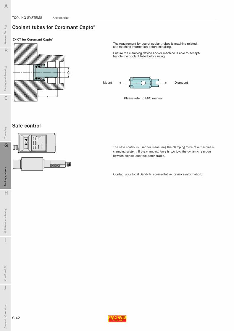
Coolant tubes for Coromant Capto®
Safe control
Cx-CT for Coromant Capto®
The requirement for use of coolant tubes is machine related, see machine information before installing.
Ensure the clamping device and/or machine is able to accept/handle the coolant tube before using.
Mount Dismount
Please refer to M/C manual
The safe control is used for measuring the clamping force of a machine’s clamping system. If the clamping force is too low, the dynamic reaction beween spindle and tool deteriorates.
Contact your local Sandvik representative for more information.
B
G 43
Gen
eral
Tur
ning
Par
ting
and
Gro
ovin
g
C
Thre
adin
g
G
Tool
ing
syst
ems
Mul
ti-ta
sk m
achi
ning
I
Cor
oTur
n® S
L
J
Gen
eral
info
rmat
ion
A
H
G
Tool
ing
syst
ems
Accessories TOOLING SYSTEMS
TOOLING SYSTEMS Accessories
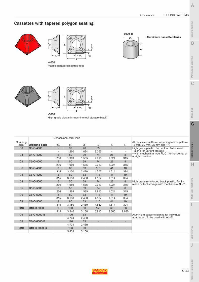
Cassettes with tapered polygon seating
-6000-BAluminium cassette blanks
-4000Plastic storage cassettes (red)
-5000High grade plastic in-machine tool storage (black)
Coupling size Ordering code
Dimensions, mm, inch
All plastic cassettes conforming to hole pattern 17 mm, 20 mm, 25 mm and 1’’.b21 D21 h2 l2 l21 l22
C3 C3-C-4000 - 32 26 65 - - High grade plastic. Red colour. To be used:– alone for upright storage – with mechanism type PL-01 for horizontal or upright position.
- 1.260 1.024 2.065 - -C4 C4-C-4000 6 50 39 74 26 8
.236 1.969 1.535 2.913 1.024 .315C5 C5-C-4000 6 50 39 74 26 8
.236 1.969 1.535 2.913 1.024 .315C6 C6-C-4000 8 80 63 116 41 10
.315 3.150 2.480 4.567 1.614 .394C8 C8-C-4000 8 80 63 116 41 10
.315 3.150 2.480 4.567 1.614 .394C4 C4-C-5000 6 50 39 74 26 8 High grade re-inforced black plastic. For in-
machine tool storage with mechanism AL-01..236 1.969 1.535 2.913 1.024 .315C5 C5-C-5000 6 50 39 74 26 8
.236 1.969 1.535 2.913 1.024 .315C6 C6-C-5000 8 80 63 116 41 10
.315 3.150 2.480 4.567 1.614 .394C8 C8-C-5000 8 80 63 116 41 10
.315 3.150 2.480 4.567 1.614 .394C10 C10-C-5000 8 100 80 150 60 68
.315 3.940 3.150 5.910 2.360 2.630C6 C6-C-6000-B - 120 63 - - - Aluminium cassette blanks for individual
adaptation. To be used with AL-01.4.724 2.480C8 C8-C-6000-B 120 63 - - -
4.724 2.480C10 C10-C-6000-B 138 80 - - -
5.433 3.150

G 44
TOOLING SYSTEMS Accessories
B
Gen
eral
Tur
ning
Par
ting
and
Gro
ovin
g
C
Thre
adin
g
G
Tool
ing
syst
ems
Mul
ti-ta
sk m
achi
ning
I
Cor
oTur
n® S
L
J
Gen
eral
info
rmat
ion
A
H
G
Tool
ing
syst
ems
TOOLING SYSTEMS Accessories
Locking mechanism for casettes
-PL-01
Passive locking mechanism
For vertical upwards and horizontal storage. NEVER upside down storage.
-AL-01
Active locking mechanismFor storage at all angles: vertical upwards and downwords or horizontal.
Coupling size Ordering code Pull action force, N Pull action force, lbsC4 C4-PL-01 55 12.36 Central passive locking mechanism. Spring loaded
clamping. Fits directly into all cassettes type 4000.C5 C5-PL-01 120 26.98C6 C6-PL-01 150 33.72C8 C8-PL-01 240 53.95
Coupling size Ordering code Rec. max. tool weight, kg Rec. max. tool weight, lbsC4 C4-AL-01 40 88 Active locking mechanism – mechanical push action.
Fits directly into all cassettes type 5000/6000.C5 C5-AL-01 60 132C6 C6-AL-01 75 165C8 C8-AL-01 110 243C10 C10-AL-01 150 330.7

B
G 45
Gen
eral
Tur
ning
Par
ting
and
Gro
ovin
g
C
Thre
adin
g
G
Tool
ing
syst
ems
Mul
ti-ta
sk m
achi
ning
I
Cor
oTur
n® S
L
J
Gen
eral
info
rmat
ion
A
H
G
Tool
ing
syst
ems
Accessories TOOLING SYSTEMS
TOOLING SYSTEMS Accessories
Pre-measuring fixture for Coromant Capto® cutting units
Basic package
You may already have the required measuring equipment in your shop – all you need is the measuring kit:– Pre-measuring unit– Holding plate (anchor for tightening)– Master
Pre-measuring unit
Holding plate
The precision of the Coromant Capto coupling ensures excellent repeatability when changing the same tool unit. This accuracy can be utilized in many ways, for example, in manual changing, the cutting edge indexing takes place outside the machine, where the edge positions can be checked in two co-ordinates on Sandvik’s new pre-measuring fixture.
When the pre-measured unit is returned to the clamping unit in the turret, the edge deviation is compensated for through the machine control offset.
The fixture can be used with any dial indicator and preferably, a surface plate, but Sandvik recommend an indicator with a zero-set switch and a contact stylus.
Coupling size Ordering code
Dimensions, mm (inch)
A B CC3 C3-PMU-01M 65 (2.56) 85 (3.35) 44 (1.79)C4 C4-PMU-01M 77 (3.03) 94 (3.70) 54 (2.13)C5 C5-PMU-01M 94 (3.70) 130 (5.12) 70 (2.76)C6 C6-PMU-01 114 (4.40) 135 (5.31) 90 (3.54)C8 C8-PMU-01 133 (5.24) 150 (5.91) 106 (4.17)
Coupling size Ordering code
Spare parts1 2Stud Screw
C3 – C8 C-HP-01 5638 060-01 3212 020-409

G 46
TOOLING SYSTEMS Accessories
B
Gen
eral
Tur
ning
Par
ting
and
Gro
ovin
g
C
Thre
adin
g
G
Tool
ing
syst
ems
Mul
ti-ta
sk m
achi
ning
I
Cor
oTur
n® S
L
J
Gen
eral
info
rmat
ion
A
H
G
Tool
ing
syst
ems
TOOLING SYSTEMS Accessories
Master setting gauges
Axial gauge
Centre height gauge
Alignment tool
Checking position for grippers
Spindle orientation
The Coromant Capto system guarantees exceptional, repeatable accuracy but this is of little use unless the various other components in the total machining process are correctly and accurately positioned.Sandvik Coromant offers a range of axial and centre height master setting gauges for the various coupling sizes which are strongly recommended for setting important parameters such as:
Tool post centre line- The centre line of the tool post - Spindle orientation- The position of the tool for grippers- Tool centre height and cutting edge position (f1 and l1 dimensions). Gauges
can be used in a pre-measuring fixture- Component fixtures
Tool presetting Component fixture geometric control
Master setting gauges MAS-11
Coupling size
Ordering code Dimensions, mm (inch)
Dg lgC3 C3-MAS-11 25 (.98) 160 (6.30)C4 C4-MAS-11 25 (.98) 160 (6.30)C5 C5-MAS-11 32 (1.26) 210 (8.27)C6 C6-MAS-11 40 (1.57) 315 (12.40)C8 C8-MAS-11 40 (1.57) 315 (12.40)C10 C10-MAS-11 60 (2.362) 420 (16.535)
Master setting gauges MAS-01
Coupling size
Ordering code Dimensions, mm (inch)(Polygon) Gripper groove
fg lg Dg
C3 C3-MAS-01 22 (.87) 40 (1.57) 34 (1.34)C4 C4-MAS-01 27 (1.06) 50 (1.97) 42 (1.65)C5 C5-MAS-01 35 (1.38) 60 (2.36) 52 (2.05)C6 C6-MAS-01 45 (1.77) 65 (2.56) 65 (2.56)C8 C8-MAS-01 55 (2.17) 80 (3.15) 82 (3.23)C10 C10-MAS-01 65 (2.559) 10 (3.937) 10 (4.016)
Coupling size
Ordering code Spare parts1 2
Tool Gauge pin Gauge pin
This tool is used to check the Automatic Tool Change positioning tolerance between the gripper arm and magazine and the clamping unit/spindle. If the tolerance is not achieved the result can be abnormal wear on cutting tool or Coromant Capto interface, wrong clamping, dropped tools, personal injuries etc. Instructions and tolerances are available in the box together with the tool.
C4 C4-AMT-01 5552 069-03 5552 069-01C5 C5-AMT-01 5552 069-04 5552 069-01C6 C6-AMT-01 5552 069-05 5552 069-02C8 C8-AMT-01 5552 069-05 5552 069-02C10 C10-AMT-01 5552 069-09 5552 069-08

B
G 47
Gen
eral
Tur
ning
Par
ting
and
Gro
ovin
g
C
Thre
adin
g
G
Tool
ing
syst
ems
Mul
ti-ta
sk m
achi
ning
I
Cor
oTur
n® S
L
J
Gen
eral
info
rmat
ion
A
H
G
Tool
ing
syst
ems
Spare parts − Coromant Capto® − Turning TOOLING SYSTEMS
TOOLING SYSTEMS Spare parts − Coromant Capto® − Turning
Manually operated clamping unitsType 2085
Inch version Metric version
The spring, item 15g, should be used only when mounting draw bar set in old design clamping units, where the spring must be placed inside the plain bearing as shown on the picture.
Plain bearing
Draw bar hole, old design
1 2 3 4 5 6 7
Coupling size Sleeve Screw (4 x) Plain bearing Locking washer Screw Plain bearing Cam shaftC3 5252 015-01 416.1-834 3823 010-101 5541 030-01 416.1-834 5638 022-01 5333 025-01C4 5252 015-02 5513 020-26 3823 010-122 5541 030-02 416.1-834 5638 022-02 5333 025-02C5 5252 015-03 5513 020-14 3823 010-162 5541 030-03 5513 020-14 5638 022-03 5333 025-03
8 9 10 10 11 11
Coupling size Screw Plug
Wedge inch version
Wedge metric version
Screw inch version
Screw metric version
C3 3214 010-355 3611 005-180 5431 100-03 5431 115-01 3212 010-362 3212 010-362C4 3214 010-355 3611 005-180 5431 100-01 5431 115-02 3212 010-363 3212 010-364C5 3214 010-355 3611 005-180 5431 100-02 5431 115-03 3212 010-415 3212 010-416
12 13 14 15
Coupling size Torque wrench2)
Compression spring
Lock screw inch
Rest button 1)
inch version Draw bar setC3 BT-TK-02 5561 001-71 3214 010-360 - 5461 100-101C4 C-TK-01 5561 001-41 3214 010-360 5511 052-01 5461 100-111C5 C-TK-01 5561 001-41 3214 010-360 - 5461 100-121
Draw bar set parts15a 15b 15c 15d 15e 15f 15g
Coupling size
Spiral retaining ring Holder set (set of 2) Segment (set of 6) O-ring Flat wire spring O-ring Compression spring
C3 5545 039-01 5546 001-16 5549 120-08 5641 005-01 5561 015-02 5641 005-15 5561 001-81C4 5545 039-03 5546 001-20 5549 120-06 5641 005-05 5561 015-03 5641 005-19 5561 001-82C5 5545 039-02 5546 001-17 5549 120-07 5641 005-06 5561 015-04 5641 005-16 5561 001-831) Not shown on picture.2) Accessories, must be ordered separately

G 48
TOOLING SYSTEMS Spare parts − Coromant Capto® − Turning
B
Gen
eral
Tur
ning
Par
ting
and
Gro
ovin
g
C
Thre
adin
g
G
Tool
ing
syst
ems
Mul
ti-ta
sk m
achi
ning
I
Cor
oTur
n® S
L
J
Gen
eral
info
rmat
ion
A
H
G
Tool
ing
syst
ems
TOOLING SYSTEMS Spare parts − Coromant Capto® − Turning
Manually operated clamping unitsType 2000
Type 3000
1 2 3 4 5 6 7 8
Size Drawbar Clamping screwHolder set (set of 2) Ring Support pin
Segment (set of 6) Thread ring O-ring
C3 5461 105-01 5519 105-01 5546 002-01 5541 028-01 5552 032-01 5549 120-08 5512 091-03 5641 005-01C4 5461 105-02 5519 105-02 5546 002-02 5541 028-02 5552 032-02 5549 120-06 5512 091-01 5641 005-05C5 5461 105-03 5519 105-03 5546 002-03 5541 028-03 5552 032-03 5549 120-07 5512 091-02 5641 005-06
9 10 11 12 13 14
Size O-ring O-ring Screw Blind plug Circlip width Spring Key for clamping screw (mm)C3 3671 010-118 3671 010-124 3214 020-204 3611 005-180 5545 042-01 5561 001-52 3021 013-080 (8.0)C4 3671 010-120 3671 010-126 3214 020-255 3611 005-180 3421 105-026 5561 001-53 5680 010-03 (10.0)C5 3671 010-124 3671 010-128 3214 020-255 3611 005-180 3421 105-032 5561 001-54 5680 010-04 (12.0)
1 2 3 4
Size Shank code Clamping screw Plug O-ring Retaining ring Key for clamping screw (mm)C3 5512 096-01 3611 005-180 3671 010-020 5545 040-03 3021 013-080 (8.0)C4 -10020 5512 096-02 3611 005-180 3671 010-022 5545 040-05 5680 010-03 (10.0)C4 -12020 5512 096-041) 3611 005-180 3671 010-022 5545 040-05 5680 010-03 (10.0)C5 5512 096-03 3611 005-180 3671 010-024 5545 040-06 5680 010-04 (12.0)1) If you shorten the clamping unit C4-12020-50 use clamping screw 5512 096-02

B
G 49
Gen
eral
Tur
ning
Par
ting
and
Gro
ovin
g
C
Thre
adin
g
G
Tool
ing
syst
ems
Mul
ti-ta
sk m
achi
ning
I
Cor
oTur
n® S
L
J
Gen
eral
info
rmat
ion
A
H
G
Tool
ing
syst
ems
Spare parts − Coromant Capto® − Turning TOOLING SYSTEMS
TOOLING SYSTEMS Spare parts − Coromant Capto® − Turning
Manually operated clamping unitsType 2080
The spring, item 17g, should be used only when mounting draw bar set in old design clamping units, where the spring must be placed inside the plain bearing as shown on the picture.
Plain bearing
Draw bar hole, old design
1 2 3 4 5 6 7 8
Size Sleeve Screw (4 x) Parallel pin Plain bearing Locking washer Screw Plain bearing Cam shaftC3 5252 010-01 416.1-834 3111 050-558 3823 010-101 5541 030-01 416.1-834 5638 022-01 5333 025-01C4 5252 010-02 5513 020-26 3111 050-610 3823 010-122 5541 030-02 416.1-834 5638 022-02 5333 025-02C5 5252 010-03 5513 020-14 3111 050-661 3823 010-162 5541 030-03 5513 020-14 5638 022-03 5333 025-03C6 5252 010-04 3213 010-410 3111 050-715 3823 010-183 5541 030-04 5513 020-14 5638 022-04 5333 025-04
9 10 11 12Inch clamping unit
Size Screw Locating pin Dowel pin(Right hand clamping unit) Adaptor
(Left hand clamping unit) Adaptor
C3 3214 010-355 5552 063-05 5552 061-07 RC 2080-47074-12M 5253 105-09 LC 2080-47074-12M 5253 105-10C4 3214 010-355 5552 063-07 5552 061-09 RC 2080-59102-16A 5253 105-19 LC 2080-59102-16A 5253 105-20
RC 2080-66102-20A 5253 105-21 LC 2080-66102-20A 5253 105-22C5 3214 010-355 5552 063-06 5552 061-08 RC 2080-77118-20A 5253 105-15 LC 2080-77118-20A 5253 105-17
RC 2080-85118-24A 5253 105-15 LC 2080-85118-24A 5253 105-18C6 3214 010-355 - - - - - -
12 13 14 15 16Metric clamping unit
Size(Right hand clamping unit) Adaptor
(Left hand clamping unit) Adaptor Screw Plug Torque wrench1)
Compression spring
C3 RC 2080-48090 5253 005-01 LC 2080-48090 5253 005-02 3212 010-363 3611 005-180 BT-TK-02 5561 001-71C4 RC 2080-59110A 5253 005-15 LC 2080-59110A 5253 005-16 3212 010-414 3611 005-140 C-TK-01 5561 001-41C5 RC 2080-77110A 5253 005-11 LC 2080-77110A 5253 005-12 3212 010-466 3611 005-140 C-TK-01 5561 001-41C6 RC 2080-93140 - LC 2080-93140 - - 3611 005-140 C-TK-01 5561 001-41
Draw bar set parts17 17a 17b 17c 17d 17e 17f 17g
Size Draw bar setSpiral retaining ring
Holder set (set of 2)
Segment (set of 6) O-ring Flat wire spring O-ring
Compression spring
C3 5461 100-101 5545 039-01 5546 001-16 5549 120-08 5641 005-01 5561 015-02 5641 005-15 5561 001-81C4 5461 100-111 5545 039-03 5546 001-20 5549 120-06 5641 005-05 5561 015-03 5641 005-19 5561 001-82C5 5461 100-121 5545 039-02 5546 001-17 5549 120-07 5641 005-06 5561 015-04 5641 005-16 5561 001-83C6 5461 100-131 5545 039-04 5546 001-18 5549 120-04 5641 005-04 5561 015-05 5641 005-17 5561 001-831) Accessories, must be ordered separately

G 50
TOOLING SYSTEMS Spare parts − Coromant Capto® − Turning
B
Gen
eral
Tur
ning
Par
ting
and
Gro
ovin
g
C
Thre
adin
g
G
Tool
ing
syst
ems
Mul
ti-ta
sk m
achi
ning
I
Cor
oTur
n® S
L
J
Gen
eral
info
rmat
ion
A
H
G
Tool
ing
syst
ems
TOOLING SYSTEMS Spare parts − Coromant Capto® − Turning
Manually operated clamping unitsType 2090
The spring, item 16g, should be used only when mounting draw bar set in old design clamping units, where the spring must be placed inside the plain bearing as shown on the picture.
Plain bearing
Draw bar hole, old design
1 2 3 4 5 6 7
Size Sleeve Screw (4 x) Parallel pin Plain bearing Locking washer Screw Plain bearingC3 5252 010-01 416.1-834 3111 050-558 3823 010-101 5541 030-01 416.1-834 5638 022-01C4 5252 010-02 5513 020-26 3111 050-610 3823 010-122 5541 030-02 416.1-834 5638 022-02C5 5252 010-03 5513 020-14 3111 050-661 3823 010-162 5541 030-03 5513 020-14 5638 022-03C6 5252 010-04 3213 010-410 3111 050-715 3823 010-183 5541 030-04 5513 020-14 5638 022-04C8 5252 010-05 3213 010-462 3111 050-769 3823 010-225 5541 030-05 5513 020-14 5638 022-05
8 9 10 11 12 13 14
Size Cam shaft Screw Locating pin Dowel pin Screw O-ring Torque wrench1)
C3 5333 025-01 3214 010-355 5552 063-05 5552 061-07 3212 010-363 5641 001-22 BT-TK-02C4 5333 025-02 3214 010-355 5552 063-07 5552 061-09 3212 010-414 3671 010-114 C-TK-01C5 5333 025-03 3214 010-355 5552 063-06 5552 061-08 3212 010-466 3671 010-114 C-TK-01C6 5333 025-04 3214 010-355 5552 063-03 5552 061-05 3212 010-469 3671 010-119 C-TK-01C8 5333 025-05 3214 010-355 5552 063-04 5552 061-06 3212 010-521 3671 010-119 C-TK-02
15 16
SizeCompression spring Draw bar set
C3 5561 001-71 5461 100-101C4 5561 001-41 5461 100-111C5 5561 001-41 5461 100-121C6 5561 001-41 5461 100-131C8 5561 001-43 5461 100-141
Draw bar set parts16a 16b 16c 16d 16e 16f 16g
SizeSpiral retaining ring
Holder set (set of 2)
Segment (set of 6) O-ring Flat wire spring O-ring Compression spring
C3 5545 039-01 5546 001-16 5549 120-08 5641 005-01 5561 015-02 5641 005-15 5561 001-81C4 5545 039-03 5546 001-20 5549 120-06 5641 005-05 5561 015-03 5641 005-19 5561 001-82C5 5545 039-02 5546 001-17 5549 120-07 5641 005-06 5561 015-04 5641 005-16 5561 001-83C6 5545 039-04 5546 001-18 5549 120-04 5641 005-04 5561 015-05 5641 005-17 5561 001-83C8 5545 039-05 5546 001-19 5549 120-05 5641 005-07 5561 015-06 5641 005-18 5561 001-841) Accessories, must be ordered separately

B
G 51
Gen
eral
Tur
ning
Par
ting
and
Gro
ovin
g
C
Thre
adin
g
G
Tool
ing
syst
ems
Mul
ti-ta
sk m
achi
ning
I
Cor
oTur
n® S
L
J
Gen
eral
info
rmat
ion
A
H
G
Tool
ing
syst
ems
Spare parts − Coromant Capto® − Turning TOOLING SYSTEMS
TOOLING SYSTEMS Spare parts − Coromant Capto® − Turning
Manually operated clamping unitsRound shank
Type 2035/ 2045/ 2055/ 2065
The spring, item 14g, should be used only when mounting draw bar set in old design clamping units, where the spring must be placed inside the plain bearing as shown on the picture.
Plain bearing
Draw bar hole, old design
1 2 3 4 5 6 7
Size Sleeve Screw (4 x) Parallel pin Plain bearing Bush Locking washer ScrewC3 5252 010-01 416.1-834 3111 050-558 3823 010-101 5638 024-01 5541 030-01 416.1-834C4 5252 010-02 5513 020-26 3111 050-610 3823 010-122 5638 024-02 5541 030-02 416.1-834C5 5252 010-03 5513 020-14 3111 050-661 3823 010-162 5638 024-03 5541 030-03 5513 020-14C6 5252 010-04 3213 010-410 3111 050-715 3823 010-183 5638 024-04 5541 030-04 5513 020-14
8 9 10 11 12 13 14
Size Plain bearing Cam shaft Screw Plug Torque wrench1)Compression spring Draw bar set
C3 5638 022-01 5333 025-01 3214 010-355 3611 005-180 BT-TK-02 5561 001-71 5461 100-101C4 5638 022-02 5333 025-02 3214 010-355 3611 005-180 C-TK-01 5561 001-41 5461 100-111C5 5638 022-03 5333 025-03 3214 010-355 3611 005-180 C-TK-01 5561 001-41 5461 100-121C6 5638 022-04 5333 025-04 3214 010-355 3611 005-140 C-TK-01 5561 001-41 5461 100-131
Draw bar set parts14a 14b 14c 14d 14e 14f 14g
SizeSpiral retaining ring
Holder set (set of 2)
Segment (set of 6) O-ring Flat wire spring O-ring Compression spring
C3 5545 039-01 5546 001-16 5549 120-08 5641 005-01 5561 015-02 5641 005-15 5561 001-81C4 5545 039-03 5546 001-20 5549 120-06 5641 005-05 5561 015-03 5641 005-19 5561 001-82C5 5545 039-02 5546 001-17 5549 120-07 5641 005-06 5561 015-04 5641 005-16 5561 001-83C6 5545 039-04 5546 001-18 5549 120-04 5641 005-04 5561 015-05 5641 005-17 5561 001-831) Accessories, must be ordered separately
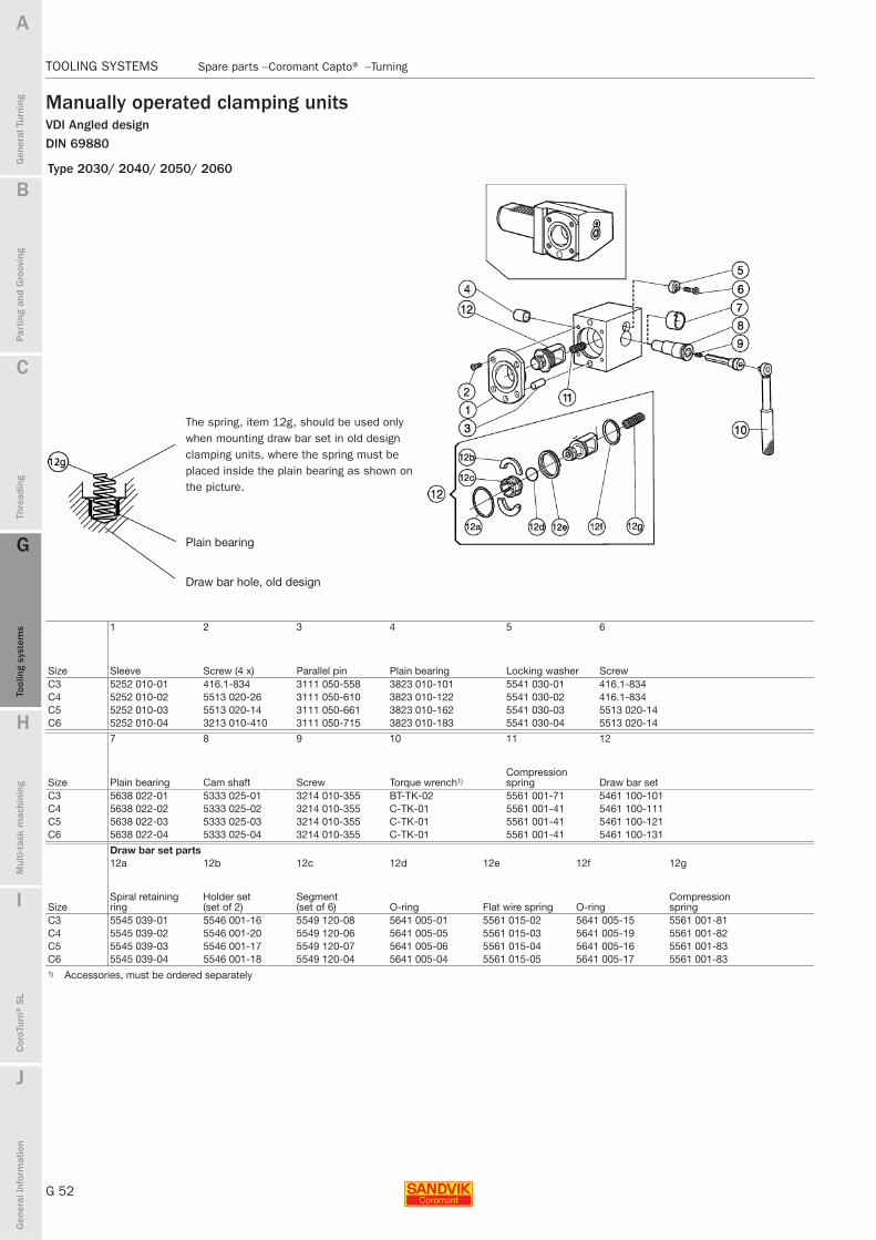
G 52
TOOLING SYSTEMS Spare parts − Coromant Capto® − Turning
B
Gen
eral
Tur
ning
Par
ting
and
Gro
ovin
g
C
Thre
adin
g
G
Tool
ing
syst
ems
Mul
ti-ta
sk m
achi
ning
I
Cor
oTur
n® S
L
J
Gen
eral
info
rmat
ion
A
H
G
Tool
ing
syst
ems
TOOLING SYSTEMS Spare parts − Coromant Capto® − Turning
Manually operated clamping unitsVDI Angled designDIN 69880
Type 2030/ 2040/ 2050/ 2060
The spring, item 12g, should be used only when mounting draw bar set in old design clamping units, where the spring must be placed inside the plain bearing as shown on the picture.
Plain bearing
Draw bar hole, old design
1 2 3 4 5 6
Size Sleeve Screw (4 x) Parallel pin Plain bearing Locking washer ScrewC3 5252 010-01 416.1-834 3111 050-558 3823 010-101 5541 030-01 416.1-834C4 5252 010-02 5513 020-26 3111 050-610 3823 010-122 5541 030-02 416.1-834C5 5252 010-03 5513 020-14 3111 050-661 3823 010-162 5541 030-03 5513 020-14C6 5252 010-04 3213 010-410 3111 050-715 3823 010-183 5541 030-04 5513 020-14
7 8 9 10 11 12
Size Plain bearing Cam shaft Screw Torque wrench1)Compression spring Draw bar set
C3 5638 022-01 5333 025-01 3214 010-355 BT-TK-02 5561 001-71 5461 100-101C4 5638 022-02 5333 025-02 3214 010-355 C-TK-01 5561 001-41 5461 100-111C5 5638 022-03 5333 025-03 3214 010-355 C-TK-01 5561 001-41 5461 100-121C6 5638 022-04 5333 025-04 3214 010-355 C-TK-01 5561 001-41 5461 100-131
Draw bar set parts12a 12b 12c 12d 12e 12f 12g
SizeSpiral retaining ring
Holder set (set of 2)
Segment (set of 6) O-ring Flat wire spring O-ring
Compression spring
C3 5545 039-01 5546 001-16 5549 120-08 5641 005-01 5561 015-02 5641 005-15 5561 001-81C4 5545 039-02 5546 001-20 5549 120-06 5641 005-05 5561 015-03 5641 005-19 5561 001-82C5 5545 039-03 5546 001-17 5549 120-07 5641 005-06 5561 015-04 5641 005-16 5561 001-83C6 5545 039-04 5546 001-18 5549 120-04 5641 005-04 5561 015-05 5641 005-17 5561 001-831) Accessories, must be ordered separately

B
G 53
Gen
eral
Tur
ning
Par
ting
and
Gro
ovin
g
C
Thre
adin
g
G
Tool
ing
syst
ems
Mul
ti-ta
sk m
achi
ning
I
Cor
oTur
n® S
L
J
Gen
eral
info
rmat
ion
A
H
G
Tool
ing
syst
ems
Spare parts − Coromant Capto® − Turning TOOLING SYSTEMS
TOOLING SYSTEMS Spare parts − Coromant Capto® − Turning
Manually operated clamping unitsVDI Straight designDIN 69880
Type 2030/ 2040/ 2050/ 2060
The spring, item 14g, should be used only when mounting draw bar set in old design clamping units, where the spring must be placed inside the plain bearing as shown on the picture.
Plain bearing
Draw bar hole, old design
1 2 3 4 5 6 7
Size Sleeve Screw (4 x) Parallel pin Plain bearing Bush Locking washer ScrewC3 5252 010-01 416.1-834 3111 050-558 3823 010-101 5638 024-01 5541 030-01 416.1-834C4 5252 010-02 5513 020-26 3111 050-610 3823 010-122 5638 024-02 5541 030-02 416.1-834C5 5252 010-03 5513 020-14 3111 050-661 3823 010-162 5638 024-03 5541 030-03 5513 020-14C6 5252 010-04 3213 010-410 3111 050-715 3823 010-183 5638 024-04 5541 030-04 5513 020-14
8 9 10 11 12 13 14
Size Plain bearing Cam shaft Screw Plug Torque wrench1)Compression spring Draw bar set
C3 5638 022-01 5333 025-01 3214 010-355 3611 005-180 BT-TK-02 5561 001-71 5461 100-101C4 5638 022-02 5333 025-02 3214 010-355 3611 005-180 C-TK-01 5561 001-41 5461 100-111C5 5638 022-03 5333 025-03 3214 010-355 3611 005-180 C-TK-01 5561 001-41 5461 100-121C6 5638 022-04 5333 025-04 3214 010-355 3611 005-140 C-TK-01 5561 001-41 5461 100-131
Draw bar set parts14a 14b 14c 14d 14e 14f 14g
SizeSpiral retaining ring
Holder set (set of 2)
Segment (set of 6) O-ring Flat wire spring O-ring
Compression spring
C3 5545 039-01 5546 001-16 5549 120-08 5641 005-01 5561 015-02 5641 005-15 5561 001-81C4 5545 039-03 5546 001-20 5549 120-06 5641 005-05 5561 015-03 5641 005-19 5561 001-82C5 5545 039-02 5546 001-17 5549 120-07 5641 005-06 5561 015-04 5641 005-16 5561 001-83C6 5545 039-04 5546 001-18 5549 120-04 5641 005-04 5561 015-05 5641 005-17 5561 001-831) Accessories, must be ordered separately

G 54
TOOLING SYSTEMS Spare parts − Coromant Capto® − Turning
B
Gen
eral
Tur
ning
Par
ting
and
Gro
ovin
g
C
Thre
adin
g
G
Tool
ing
syst
ems
Mul
ti-ta
sk m
achi
ning
I
Cor
oTur
n® S
L
J
Gen
eral
info
rmat
ion
A
H
G
Tool
ing
syst
ems
TOOLING SYSTEMS Spare parts − Coromant Capto® − Turning
Manually operated clamping units
CDI straight CDI straight doubleR/LCE80-028 082 R/LCE80-028 082-2
1 2 3 4 5 6 7
Type Sleeve Screw (4 x) Plain bearing Locking washer Screw Plain bearing Cam shaftC5-R/LCE80-028082 5252 015-03 5513 020-14 3823 010-162 5541 030-03 5513 020-14 5638 022-03 5333 025-03C5-R/LCE80-028082-2 5252 015-03 5513 020-14 3823 010-162 5541 030-03 5513 020-14 5638 022-03 5333 025-03
8 9 10 11
Type Screw Torque wrench1)Compression spring Draw bar set
C5-R/LCE80-028082 3214 010-355 C-TK-01 5561 001-41 5461 100-121 (1x)C5-R/LCE80-028082-2 3214 010-355 C-TK-01 5561 001-41 5461 100-121 (2x)
Draw bar set parts11a 11b 11c 11d 11e 11f
Type Spiral retaining ring
Holder set (set of 2)
Segment (set of 6) O-ring Flat wire spring O-ring
C5-R/LCE80-028082 5545 039-02 5546 001-17 5549 120-07 5641 005-06 5561 015-04 5641 005-16C5-R/LCE80-028082-2 5545 039-02 5546 001-17 5549 120-07 5641 005-06 5561 015-04 5641 005-16
12 13 14 15
Type Adjustment plateCap screw Locking washer Set screw(4x) (4x) (4x)
C5-R/LCE80-028082 5336 002-02 3212 010-471 5541 041-02 3214 010-418C5-R/LCE80-028082-2 5336 002-01 3212 010-471 5541 041-02 3214 010-418
16 17 18
Type O-ring O-ringKantseal(2x)
C5-R/LCE80-028082 5641 005-104 5641 001-79 5641 070-04C5-R/LCE80-028082-2 5641 005-104 5641 001-79 5641 070-041) Accessories, must be ordered separately

B
G 55
Gen
eral
Tur
ning
Par
ting
and
Gro
ovin
g
C
Thre
adin
g
G
Tool
ing
syst
ems
Mul
ti-ta
sk m
achi
ning
I
Cor
oTur
n® S
L
J
Gen
eral
info
rmat
ion
A
H
G
Tool
ing
syst
ems
Spare parts − Coromant Capto® − Turning TOOLING SYSTEMS
TOOLING SYSTEMS Spare parts − Coromant Capto® − Turning
Manually operated clamping units
CDI angled CDI straightR/LCI80-000110 R/LCE040000
1 2 3 4 5 6
Type Sleeve Screw (4 x) Parallel pin Plain bearing Locking washer ScrewC5-R/LCI80-000110 5252 010-03 5513 020-14 3111 050-661 3823 010-162 5541 030-03 5513 020-14C5-R/LCE80-040000 5252 010-03 5513 020-14 3111 050-661 3823 010-162 5541 030-10 5513 020-14
7 8 9 10 11 12
Type Plain bearing Cam shaft Screw Torque wrench1)Compression spring Draw bar set
C5-R/LCI80-000110 5638 022-03 5333 025-03 3214 010-355 C-TK-01 5561 001-41 5461 100-121C5-R/LCE80-040000 5638 022-03 5333 025-03 3214 010-355 C-TK-01 5561 001-41 5461 100-121
Draw bar set parts12a 12b 12c 12d 12e 12f
Type Spiral retaining ring
Holder set (set of 2)
Segment (set of 6) O-ring Flat wire spring O-ring
C5-R/LCI80-000110 5545 039-02 5546 001-17 5549 120-07 5641 005-06 5561 015-04 5641 005-16C5-R/LCE80-040000 5545 039-02 5546 001-17 5549 120-07 5641 005-06 5561 015-04 5641 005-16
13 14 15 16
Type Adjustment plateCap screw
Locking washerSet screw
(4x) (4x)C5-R/LCI80-000110 5336 002-02 3212 010-463 5541 041-02 (4x) 3214 010-410C5-R/LCE80-040000 5336 001-01 3212 010-463 5541 041-01 (2x) 3214 010-410
17 18 19 20 21
Type O-ring O-ringKantseal
AdaptorScrew
(2x) (2x)C5-R/LCI80-000110 5641 005-104 5641 001-79 5641 070-04 - -C5-R/LCE80-040000 5641 005-104 5641 001-79 5641 070-04 5253 006-03 5512 060-241) Accessories, must be ordered separately

G 56
TOOLING SYSTEMS Spare parts − Coromant Capto® − Turning
B
Gen
eral
Tur
ning
Par
ting
and
Gro
ovin
g
C
Thre
adin
g
G
Tool
ing
syst
ems
Mul
ti-ta
sk m
achi
ning
I
Cor
oTur
n® S
L
J
Gen
eral
info
rmat
ion
A
H
G
Tool
ing
syst
ems
TOOLING SYSTEMS Spare parts − Coromant Capto® − Turning
Hydraulically operated clamping unitsType 5010Straight design
Straight design
NC5010 NC5000
Clamping unit NC5010To be able to maintain the min. bore, the new clamping unit has a modified front and hole pattern, which means that NC5010 and NC5000 not are interchangeable.
Spare parts for NC5000 are the same as for NC5010 except for part 1, the front.
1 2 3 4 5 6 7NC5010 NC5010/NC5000
Size Front BarrelClamping mechanism
Segment (set of 6)
Holder set (set of 2) Ring Flat wire spring
C4 5252 033-11 5257 001-01 5651 065-01 5549 120-06 5546 001-14 5541 024-01 5561 012-01C5 5252 033-12 5257 001-02 5651 065-02 5549 120-07 5546 001-11 5541 024-02 5561 012-02C6 5252 033-13 5257 001-03 5651 065-03 5549 120-04 5546 001-09 5541 024-03 5561 012-03C8 5252 033-14 5257 001-04 5651 065-04 5549 120-05 5546 001-10 5541 024-04 5561 012-04C8X 5252 033-15 5257 001-04 5651 065-04 5549 120-05 5546 001-10 5541 024-04 5561 012-04C10 5252 033-16 5257 001-05 5651 065-05 5549 120-09 5546 001-13 5541 025-04 5561 012-04
8 9 10 11 12 13 1NC5000
Size Dowel Screw (4 x) Plug O-ring (6 x) O-ring (3 x) O-ring FrontC4 5552 055-02 3212 010-411 3611 007-180 3671 010-112 5641 001-21 5641 005-05 5252 030-11C5 5552 055-03 3212 010-462 3611 007-180 3671 010-112 3671 010-134 5641 005-06 5252 030-12C6 5552 055-04 3212 010-514 3611 007-180 3671 010-114 3671 010-137 5641 005-04 5252 030-13C8 5552 055-05 3212 010-514 3611 007-180 3671 010-116 3671 010-141 5641 005-04 5252 030-14C8X 5552 055-05 3212 010-514 3611 007-180 3671 010-116 3671 010-141 5641 005-04C10 5552 055-07 3212 010-616 3611 007-180 3671 010-019 5641 010-141 5641 005-95
NC5000 units can be ordered as specials. Contact your local Sandvik Coromant representative

B
G 57
Gen
eral
Tur
ning
Par
ting
and
Gro
ovin
g
C
Thre
adin
g
G
Tool
ing
syst
ems
Mul
ti-ta
sk m
achi
ning
I
Cor
oTur
n® S
L
J
Gen
eral
info
rmat
ion
A
H
G
Tool
ing
syst
ems
Spare parts − Coromant Capto® − Turning TOOLING SYSTEMS
TOOLING SYSTEMS Spare parts − Coromant Capto® − Turning
Hydraulically operated clamping units with probe contactJetbreak™Type 5210
Straight design
Straight design
1 2 3 4 5 6 7
Size Front BarrelClamping mechanism
Segment (set of 6)
Holder set (set of 2) Ring Flat wire spring
C5 5252 034-12 5257 001-02 5651 065-02 5549 120-07 5546 001-11 5541 024-02 5561 012-02C6 5252 034-13 5257 001-03 5651 065-03 5549 120-04 5546 001-09 5541 024-03 5561 012-03C8 5252 034-14 5257 001-04 5651 065-04 5549 120-05 5546 001-10 5541 024-04 5561 012-04
8 9 10 11 12 13 14
Size Dowel Screw (4 x) Plug O-ring (6 x) O-ring (3 x) O-ring Sealing (4 x)C5 5552 055-03 3212 010-462 3611 007-180 3671 010-112 3671 010-134 5641 005-06 5641 070-01C6 5552 055-04 3212 010-514 3611 007-180 3671 010-114 3671 010-137 5641 005-04 5641 070-04C8 5552 055-05 3212 010-514 3611 007-180 3671 010-116 3671 010-141 5641 005-04 5641 070-03
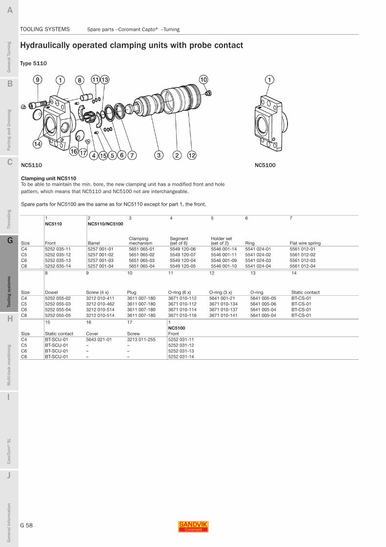
G 58
TOOLING SYSTEMS Spare parts − Coromant Capto® − Turning
B
Gen
eral
Tur
ning
Par
ting
and
Gro
ovin
g
C
Thre
adin
g
G
Tool
ing
syst
ems
Mul
ti-ta
sk m
achi
ning
I
Cor
oTur
n® S
L
J
Gen
eral
info
rmat
ion
A
H
G
Tool
ing
syst
ems
TOOLING SYSTEMS Spare parts − Coromant Capto® − Turning
Hydraulically operated clamping units with probe contact
Type 5110
NC5110 NC5100
Clamping unit NC5110 To be able to maintain the min. bore, the new clamping unit has a modified front and hole pattern, which means that NC5110 and NC5100 not are interchangeable.
Spare parts for NC5100 are the same as for NC5110 except for part 1, the front.
1 2 3 4 5 6 7NC5110 NC5110/NC5100
Size Front BarrelClamping mechanism
Segment (set of 6)
Holder set (set of 2) Ring Flat wire spring
C4 5252 035-11 5257 001-01 5651 065-01 5549 120-06 5546 001-14 5541 024-01 5561 012-01C5 5252 035-12 5257 001-02 5651 065-02 5549 120-07 5546 001-11 5541 024-02 5561 012-02C6 5252 035-13 5257 001-03 5651 065-03 5549 120-04 5546 001-09 5541 024-03 5561 012-03C8 5252 035-14 5257 001-04 5651 065-04 5549 120-05 5546 001-10 5541 024-04 5561 012-04
8 9 10 11 12 13 14
Size Dowel Screw (4 x) Plug O-ring (6 x) O-ring (3 x) O-ring Static contactC4 5252 055-02 3212 010-411 3611 007-180 3671 010-112 5641 001-21 5641 005-05 BT-CS-01C5 5252 055-03 3212 010-462 3611 007-180 3671 010-112 3671 010-134 5641 005-06 BT-CS-01C6 5252 055-04 3212 010-514 3611 007-180 3671 010-114 3671 010-137 5641 005-04 BT-CS-01C8 5252 055-05 3212 010-514 3611 007-180 3671 010-116 3671 010-141 5641 005-04 BT-CS-01
15 16 17 1NC5100
Size Static contact Cover Screw FrontC4 BT-SCU-01 5643 021-01 3213 011-255 5252 031-11C5 BT-SCU-01 – – 5252 031-12C6 BT-SCU-01 – – 5252 031-13C8 BT-SCU-01 – – 5252 031-14

B
G 59
Gen
eral
Tur
ning
Par
ting
and
Gro
ovin
g
C
Thre
adin
g
G
Tool
ing
syst
ems
Mul
ti-ta
sk m
achi
ning
I
Cor
oTur
n® S
L
J
Gen
eral
info
rmat
ion
A
H
G
Tool
ing
syst
ems
Spare parts − Coromant Capto® − Turning TOOLING SYSTEMS
TOOLING SYSTEMS Spare parts − Coromant Capto® − Turning
Adaptor for solid boring bars
Cx-1311 2
Screw Key inch/mm
Metric Screw codesC3-131-00035-10 5514 020-04 174.1-864 3.0C3-131-00040-12 5514 020-04 174.1-864 3.0C4-131-00040-10 5514 020-04 174.1-864 3.0C4-131-00045-12 5514 020-04 174.1-864 3.0C4-131-00050-16 5514 020-02 3021 010-040 4.0C5-131-00045-10 5514 020-04 174.1-864 3.0C5-131-00045-12 5514 020-04 174.1-864 3.0C5-131-00055-16 5514 020-02 3021 010-040 4.0
Inch Screwspecification1)
C3-131-00050-250 10-32UNF x .500 265.2-818 3/32C3-131-00050-500 1/4-2832UNF x .500 174.1-871 1/8C3-131-00050-625 3/8-2432UNF x .500 174.1-872 3/16C4-131-00050-250 10-32UNF x .500 265.2-818 3/32C4-131-00050-375 1/4-28UNF x .500 174.1-871 1/8C4-131-00050-500 1/4-28UNF x .500 174.1-871 1/8C4-131-00050-625 3/8-24UNF x .500 174.1-872 3/16C4-131-00060-750 3/8-24UNF x .500 174.1-872 3/16C4-131-00091-1000 M10-1.5 x 25 3021 010-050 5.0C5-131-00060-375 1/4-28UNF x .500 174.1-871 1/8C5-131-00060-500 1/4-28UNF x .500 174.1-871 1/8C5-131-00060-625 3/8-24UNF x .500 174.1-872 3/16C5-131-00060-750 3/8-24UNF x .500 174.1-872 3/16C5-131-00070-1000 1/2-20UNF x .500 174.1-873 1/4C5-131-00115-1500 M10-1.5 x 25 3021 010-050 5.0C6-131-00065-375 1/4-28UNF x .500 174.1-871 1/8C6-131-00065-500 1/4-28UNF x .500 174.1-871 1/8C6-131-00065-625 3/8-24UNF x .500 174.1-872 3/16C6-131-00065-750 3/8-24UNF x .500 174.1-872 3/16C6-131-00075-1000 1/2-20UNF x .500 174.1-873 1/4C6-131-00105-1500 M10-1.5 x 25 3021 010-050 5.01) Standard screws to be purchased from outside vendor.

G 60
TOOLING SYSTEMS Spare parts − Coromant Capto® − Rotating
B
Gen
eral
Tur
ning
Par
ting
and
Gro
ovin
g
C
Thre
adin
g
G
Tool
ing
syst
ems
Mul
ti-ta
sk m
achi
ning
I
Cor
oTur
n® S
L
J
Gen
eral
info
rmat
ion
A
H
G
Tool
ing
syst
ems
TOOLING SYSTEMS Spare parts − Coromant Capto® − Rotating
Extension/reduction adaptors
Cx-391.01A/ Cx-391.01HD 1 2 31) 41) 5Cx-391.02/ Cx-391.02HD
Centre screw Retaining ringExtension key (mm) Key Pin
C3-391.01-32 xxxA 5512 067-01 5512 091-04 5680 015-05 (8.0) 5680 065-13 3113 020-304C4-391.01-40 xxxA 5512 067-02 5512 091-03 5680 015-05 (8.0) 5680 065-10 3113 020-355C5-391.01-50 xxxA 5512 067-03 5512 091-01 5680 015-01 (10.0) 5680 065-11 3113 020-406C6-391.01-63 xxxA 5512 067-04 5512 091-02 5680 015-02 (14.0) 5680 065-12 3113 020-457C8-391.01-80 xxxA 5512 067-04 5512 091-02 5680 015-02 (14.0) 5680 065-12 3113 020-509C8x-391.01-100 xxx 5512 067-04 5512 091-02 5680 015-02 (14.0) 5680 065-12 3113 020-509C4-391.02-32 055A 5512 067-01 5512 091-04 5680 015-05 (8.0) 5680 065-13 3113 020-304C4-391.02-32 070A 5512 067-01 5512 091-04 5680 015-05 (8.0) 5680 065-13 3113 020-304C5-391.02-32 060A 5512 067-01 5512 091-04 5680 015-05 (8.0) 5680 065-13 3113 020-304C5-391.02-40 065A 5512 067-02 5512 091-03 5680 015-05 (8.0) 5680 065-10 3113 020-355C5-391.02-40 085A 5512 067-02 5512 091-03 5680 015-05 (8.0) 5680 065-10 3113 020-355C6-391.02-32 070A 5512 067-01 5512 091-04 5680 015-05 (8.0) 5680 065-13 3113 020-304C6-391.02-40 080A 5512 067-02 5512 091-03 5680 015-05 (8.0) 5680 065-10 3113 020-355C6-391.02-50 080A 5512 067-03 5512 091-01 5680 015-01 (10.0) 5680 065-11 3113 020-406C6-391.02-50 110A 5512 067-03 5512 091-01 5680 015-01 (10.0) 5680 065-11 3113 020-406C8-391.02-32 060A 5512 067-01 5512 091-04 5680 015-05 (8.0) 5680 065-13 3113 020-304C8-391.02-40 070A 5512 067-02 5512 091-03 5680 015-05 (8.0) 5680 065-10 3113 020-355C8-391.02-50 080A 5512 067-03 5512 091-01 5680 015-01 (10.0) 5680 065-11 3113 020-406C8-391.02-63 080A 5512 067-04 5512 091-02 5680 015-02 (14.0) 5680 065-12 3113 020-457C8-391.02-63 120A 5512 067-04 5512 091-02 5680 015-02 (14.0) 5680 065-12 3113 020-457C8X-391.02-63 080 5512 067-04 5512 091-02 5680 015-02 (14.0) 5680 065-12 3113 020-457C8X-391.02-80 100 5512 067-04 5512 091-02 5680 015-02 (14.0) 5680 065-12 3113 020-509C8X-391.02-80 150 5512 067-04 5512 091-02 5680 015-02 (14.0) 5680 065-12 3113 020-509C10-39.01-100 140 5512 063- 14 5512 091-05 5680 015-06 (17) 5680 065-14 3113 020-561C10-39.02- 63 095 5512 067- 04 5512 091-02 5680 015-02 (14.0) 5680 065-12 3113 020-457C10-39.01-80 100 5512 067- 04 5512 091-02 5680 015-02 (14.0) 5680 065-12 3113 020-5091) Accessories, must be ordered separately
Short versionCx-391.01/ Cx-391.02 1 2 31) 4Cx-391.01R/Cx-391.02R
Centre screw Retaining ringExtension key (mm) Pin
C3-391.01-32 035 5512 068-01 5545 040-02 5680 015-05 ( 8.0) 3113 020-304C4-391.01-40 040 5512 068-02 5545 040-03 5680 015-05 ( 8.0) 3113 020-355C5-391.01-50 050 5512 068-03 5545 040-07 5680 015-05 ( 8.0) 3113 020-406C6-391.01-63 060 5512 068-04 5545 040-08 5680 015-02 (14.0) 3113 020-457C8-391.01-80 065 5512 068-05 5545 040-08 5680 015-02 (14.0) 3113 020-509C5-391.02-32 033 5512 068-01 5545 040-02 5680 015-05 ( 8.0) –C5-391.02-40 040 5512 068-06 5545 040-07 5680 015-05 ( 8.0) –C6-391.02-32 032 5512 068-01 5545 040-02 5680 015-05 ( 8.0) –C6-391.02-40 040 5512 068-02 5545 040-03 5680 015-05 ( 8.0) –C6-391.02-50 050 5512 068-07 5545 040-08 5680 015-01 (10.0) –C8-391.02-50 045 5512 068-08 5545 040-08 5680 015-01 (10.0) –C8-391.02-63 055 5512 068-05 5545 040-08 5680 015-02 (14.0) –C8X-391.02-63 055 5512 068-05 5545 040-08 5680 015-02 (14.0) –C8X-391.02-80 065 5512 068-05 5545 040-08 5680 015-02 (14.0) –C10-391.02-63 055 5512 068-05 5545 040-08 5680 015-02 (14.0) 3113 020-457C10-391.02-80 065 5512 068-05 5545 040-08 5680 015-05 (8.0) 3113 020-509C5-391.01R-50 050 5512 068-03 5545 040-07 5680 015-02 (14.0) 3113 020-409C8-391.01R-63 060 5512 068-04 5545 040-08 5680 015-02 (14.0) 3113 020-457C8-391.01R-80 065 5512 068-05 5545 040-08 5680 015-02 (14.0) 3113 020-509C8-391.02R-63 055 5512 068-05 5545 040-08 5680 015-02 (14.0)1) Accessories, must be ordered separately
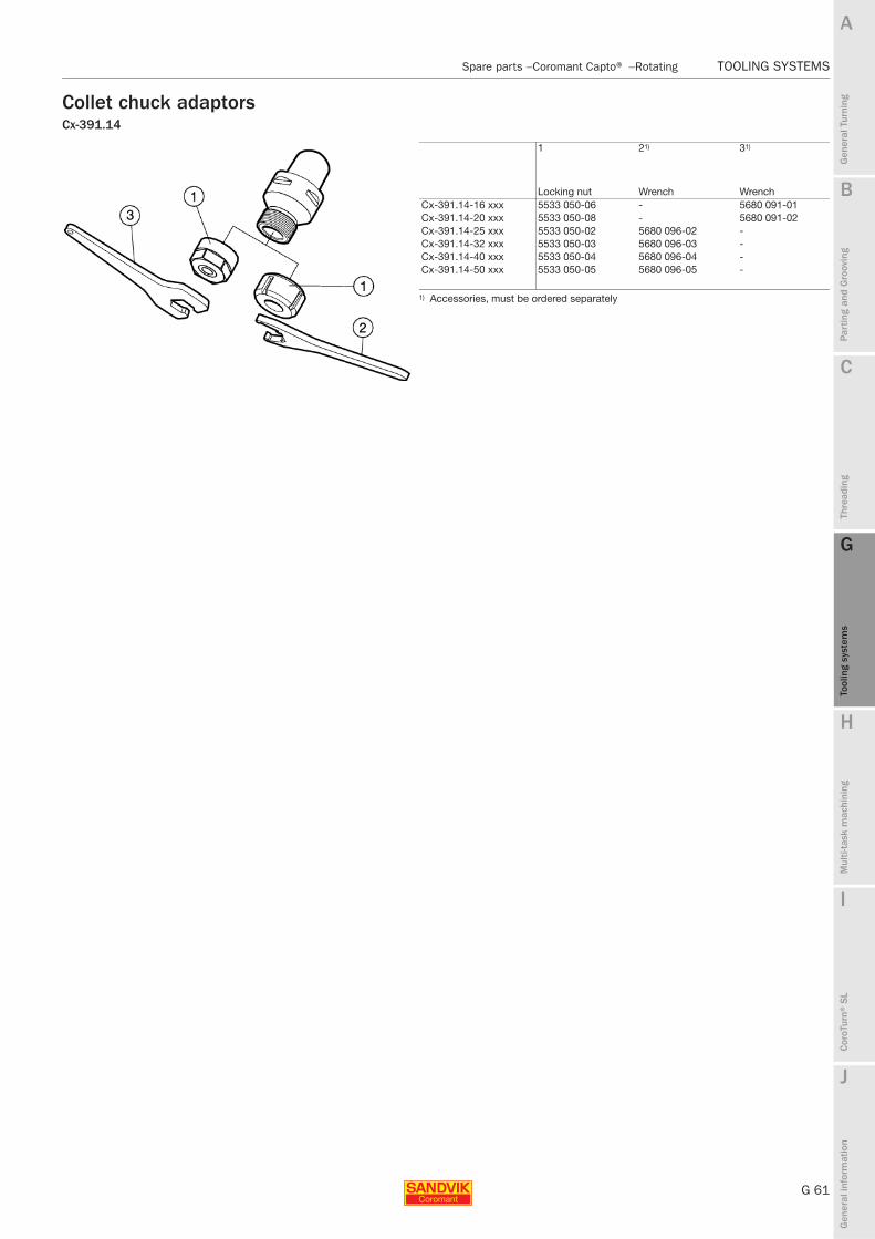
B
G 61
Gen
eral
Tur
ning
Par
ting
and
Gro
ovin
g
C
Thre
adin
g
G
Tool
ing
syst
ems
Mul
ti-ta
sk m
achi
ning
I
Cor
oTur
n® S
L
J
Gen
eral
info
rmat
ion
A
H
G
Tool
ing
syst
ems
Spare parts − Coromant Capto® − Rotating TOOLING SYSTEMS
TOOLING SYSTEMS Spare parts − Coromant Capto® − Rotating
Collet chuck adaptorsCx-391.14
1 21) 31)
Locking nut Wrench WrenchCx-391.14-16 xxx 5533 050-06 - 5680 091-01Cx-391.14-20 xxx 5533 050-08 - 5680 091-02Cx-391.14-25 xxx 5533 050-02 5680 096-02 -Cx-391.14-32 xxx 5533 050-03 5680 096-03 -Cx-391.14-40 xxx 5533 050-04 5680 096-04 -Cx-391.14-50 xxx 5533 050-05 5680 096-05 -
1) Accessories, must be ordered separately
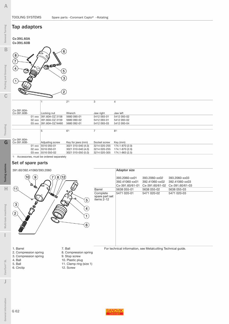
G 62
TOOLING SYSTEMS Spare parts − Coromant Capto® − Rotating
B
Gen
eral
Tur
ning
Par
ting
and
Gro
ovin
g
C
Thre
adin
g
G
Tool
ing
syst
ems
Mul
ti-ta
sk m
achi
ning
I
Cor
oTur
n® S
L
J
Gen
eral
info
rmat
ion
A
H
G
Tool
ing
syst
ems
TOOLING SYSTEMS Spare parts − Coromant Capto® − Rotating
Tap adaptors
Set of spare parts
Cx-391.60ACx-391.60B
1 21) 3 4
Cx-391.60A-Cx-391.60B- Locking nut Wrench Jaw right Jaw left
01 xxx 391.60A-OZ 3158 5680 090-01 5412 093-01 5412 093-0202 xxx 391.60A-OZ 3159 5680 090-02 5412 093-01 5412 093-0203 xxx 391.60A-OZ N460 5680 092-01 5412 093-03 5412 093-04
5 61) 7 81)
Cx-391.60A-Cx-391.60B- Adjusting screw Key for jaws (mm) Socket screw Key (mm)
01 xxx 5516 050-01 3021 010-040 (4.0) 3214 020-255 174.1-870 (2.0)02 xxx 5516 050-01 3021 010-040 (4.0) 3214 020-255 174.1-870 (2.0)03 xxx 5516 050-02 3021 010-050 (5.0) 3214 020-305 174.1-863 (2.5)
1) Accessories, must be ordered separately
391.60/392.41060/393.2060 Adaptor size
393.2060-xx01 393.2060-xx02 393.2060-xx03392.41060-xx01 392.41060-xx02 392.41060-xx03Cx-391.60/61-01 Cx-391.60/61-02 Cx-391.60/61-03
Barrel 5638 055-01 5638 055-02 5638 055-03Complete spare part set items 2-12
5471 020-01 5471 020-02 5471 020-03
1. Barrel 7. Ball For technical information, see Metalcutting Technical guide.2. Compression spring 8. Compression spring3. Compression spring 9. Stop screw4. Ball 10. Plastic plug5. Ball 11. Clamp ring (size 1)6. Circlip 12. Screw