Embed Size (px)
Citation preview
J000
J048
a
MS2SS
e e u u u
DC<3
DC=0.1 DC>0.1 0- 0.010
0- 0.020
DCON=12 0- 0.008
0- 0.009
0- 0.011
DC APMX LF DCON
MS2SSD0010 0.1 0.15 40 4 2 a 1MS2SSD0020 0.2 0.3 40 4 2 a 1MS2SSD0030 0.3 0.45 40 4 2 a 1MS2SSD0040 0.4 0.6 40 4 2 a 1MS2SSD0050 0.5 0.75 40 4 2 a 1MS2SSD0060 0.6 0.9 40 4 2 a 1MS2SSD0070 0.7 1.1 40 4 2 a 1MS2SSD0080 0.8 1.2 40 4 2 a 1MS2SSD0090 0.9 1.4 40 4 2 a 1MS2SSD0100 1 1.5 40 4 2 a 1MS2SSD0120 1.2 1.8 40 4 2 a 1MS2SSD0150 1.5 2.3 40 4 2 a 1MS2SSD0180 1.8 2.7 40 4 2 a 1MS2SSD0200 2 3 40 4 2 a 1MS2SSD0250 2.5 3.8 40 4 2 a 1MS2SSD0300 3 4.5 45 6 2 a 1MS2SSD0400 4 6 50 6 2 a 1MS2SSD0500 5 7.5 50 6 2 a 1MS2SSD0600 6 9 50 6 2 a 2MS2SSD0700 7 10.5 60 8 2 a 1MS2SSD0800 8 12 60 8 2 a 2MS2SSD0900 9 13.5 70 10 2 a 1MS2SSD1000 10 15 70 10 2 a 2MS2SSD1100 11 16.5 75 12 2 a 1MS2SSD1200 12 18 75 12 2 a 2
UWC MS 30°
h6
APMX
15°
LF
DC
DC
ON
(h6)
APMXLF
DC
DC
ON
(h6)
aHow this section page is organizedzOrganized according to cutting mode for milling. (Refer to END MILL LIST.)
PHOTO OF PRODUCTPRODUCT TITLEITEM NUMBERPRODUCT BLOCK
GEOMETRY
PRODUCT FEATURES
LEGEND FOR STOCK STATUS MARKis shown on the left hand page ofeach double-page spread.
PRODUCT STANDARDSindicates order numbers, dimensions, and stock status.
aTo Order: For solid-carbide drill or brazed drill, please specify zorder number.
HOW TO READ THE STANDARDOF SOLID END MILLS
CARBIDE
a : Inventory maintained in Japan.
BA
LLR
AD
IUS
TAPE
RSO
LID
EN
D M
ILLS
SQU
AR
E
Unit : mm
Carbon Steel, Alloy Steel, Cast Iron(<30HRC)
Tool Steel, Pre-Hardened Steel,Hardened Steel(<45HRC)
Hardened Steel(<55HRC)
Hardened Steel(>55HRC)
AusteniticStainless Steel
Titanium Alloy,Heat Resistant Alloy Copper Alloy Aluminium Alloy
MSTAR END MILLS
2 fl ute end mill for general use.
End mill, Short cut length, 2 fl ute
Type1
(10° for ø0.1)
Order Number
No.
of
Flut
es
Stoc
k
Type
DC>3
Type2
4<DCON<6 8<DCON<10
J001
J002J003J004J006J024
J436
J378J434
J048J205J287J355J367J377
J095J100J096J098J269J104J092J102J091J124J304J174J175J173J267J302J123J195J254J298J081J083J256J300J166J193J306J260J261J278J167J168J171J172J345J086J265J387J410J404J192J428J414J436J431
J399J432J207J206J205J209J430J434J065J054J056J219J052J287J049J355J367J217J048J058J062J221J290J110J141J135J360J369J133J308J132J137J130J127J311J108J126J385J396J408J402J089J088J106J177
J179J426J381J380J400J422J424J418J397J420J416J377J243J079J248J249J076J245J246J074J276J162J337J285J160J335J373J189J191J339J188J164J121J342J292J202J251J067J069J229J232J233J228J227J071
J237J236J271J281J143J145J279J183J187J348J353J204J190J354J314J315J148J185J351J199J146J150J325J327J184J350J197J201J283J155J151J328J333J112J118J180J157J379J378J391J394J389J383J412J406
C2JSC2LAC2LSC2MAC2MBC2MHAC2MSC2SAC2SSC3SAC3SARBC4JCC4LCC4MCCBN2XLBCBN2XLRBCMHCMRACRN2MBCRN2MRBCRN2MSCRN2XLCRN2XLBCRN2XLRBCRN4JCCSRACSRARBDF2MBDF2XLBDF3XBDF4JCDF4XLDFC4JCDFCJRTDFPSRBDLC2MADLC2MBG2MSG4LCG4MCGBEGMRGSFPRIMXJR
KMHLRMP2MBMP2SBMP2SSBMP2XLBMRMRBMS2ESMS2JSMS2LSMS2MBMS2MDMS2MRBMS2MSMS2MTMS2MTBMS2SBMS2SSMS2XLMS2XL6MS2XLBMS2XLRBMS3ESMS4ECMS4JCMS4LTMS4LTBMS4MCMS4MRBMS4SCMS4XLMSJHDMSMHDMSMHDRBMSMHZDMSSHDS2MDS2SDAS4JCS4MDSED2KMGSED2KPGSEE2LSEE4L
SEG4SASRVA2MSVA2SSVA4MCVAJRVALRVAMFPRVAMHVAMRVASFPRVC2CVC2ESBVC2JSVC2MBVC2MDBVC2MSVC2PSBVC2PSBPVC2SSVC3MBVC4JCVC4JRBVC4MBVC4MCVC4SRBVC4STBVC6MHVC8MHVCHFRBVCLDVCMDSCVCMHVCMHDRBVCPSRBVCSFPRVCXBVF2MDVF2MVVF2SBVF2SDBVF2SDBLVF2SSBVF2WBVF2XL
VF2XLBVF2XLBSVF3XBVF4MBVF4MDVF4MVVF4SVBVF6MHVVF6MHVCHVF6MHVRBVF6MHVRBCHVF6SVRCHVF8MHVCHVF8MHVRBCHVFFDRBVFHVRBVFJHVVFMDVFMDRBVFMFPRVFMHVVFMHVCHVFMHVRBVFMHVRBCHVFSDVFSDRBVFSFPRVFSFPRCHVQ4SVBVQJHVVQMHVVQMHVRBVQMHVRBFVQMHZVVQMHZVOHVQSVRVQXL1LA1MA2LS2MK2MS2SS4LC4MC
MILLING TOOLS
SOLID END MILLSIDENTIFICATION ..............................................SYMBOL DESCRIPTIONS ...............................COATING TECHNOLOGY ................................
..................................................END MILLS SELECTION CHART ....................
CARBIDE INDEXABLE HEAD END MILLS ...HSS SQUARE .................................... BALL .........................................
SOLID END MILLS STANDARDCARBIDE SQUARE .................................... BALL ......................................... RADIUS ..................................... TAPER ....................................... TAPER BALL ............................ CHAMFERING ...........................
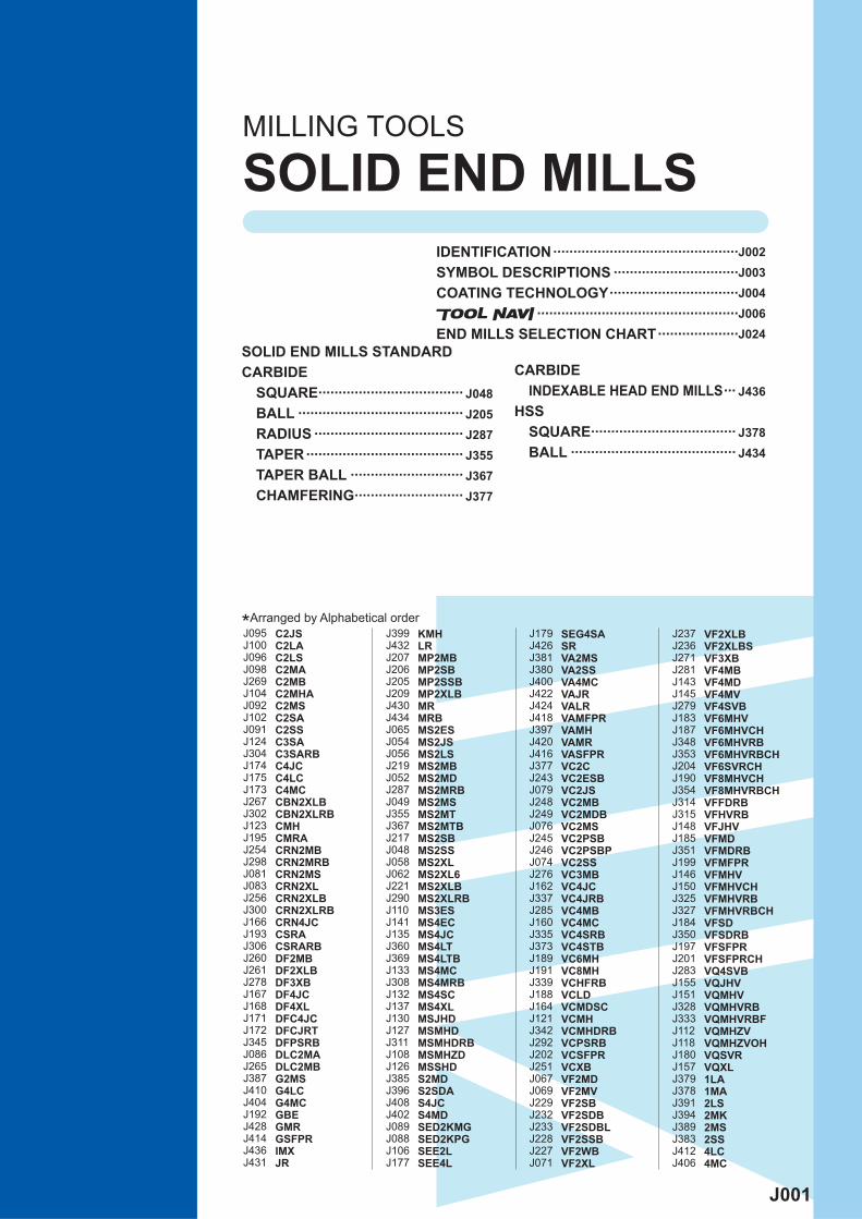
*Arranged by Alphabetical order
J002
MS
SE E 2 040 S G
S D0100 ***M2
SOLI
D E
ND
MIL
LSSOLID END MILLS
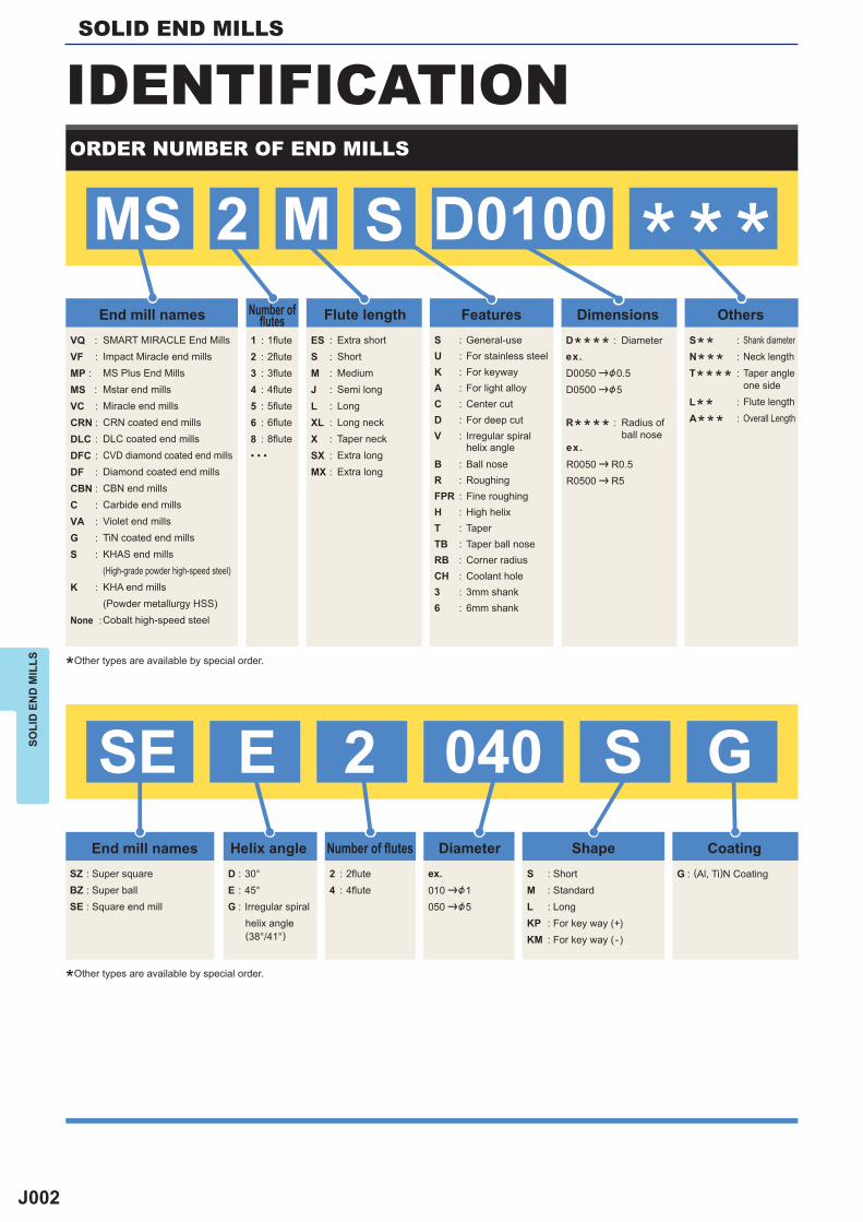
IDENTIFICATIONORDER NUMBER OF END MILLS
End mill names
End mill names Helix angle Number of fl utes Diameter Shape Coating
Number offl utes Flute length Features Dimensions Others
VQ : VF :MP : MS : VC :CRN : DLC :DFC :DF :CBN :C :VA :G : S :
K :
None :
ES : S :M :J : L :XL :X :SX : MX :
S : U :K :A : C :D : V :
B :R : FPR : H :T : TB :RB :CH :3 :6 :
1 :2 :3 :4 :5 :6 :8 :• • •
1fl ute2fl ute3fl ute4fl ute5fl ute6fl ute8fl ute
SMART MIRACLE End MillsImpact Miracle end millsMS Plus End MillsMstar end millsMiracle end millsCRN coated end millsDLC coated end millsCVD diamond coated end millsDiamond coated end millsCBN end millsCarbide end millsViolet end millsTiN coated end millsKHAS end mills(High-grade powder high-speed steel)KHA end mills(Powder metallurgy HSS)Cobalt high-speed steel
SZ : Super squareBZ : Super ballSE : Square end mill
2 : 2flute4 : 4flute
S : ShortM : StandardL : LongKP : For key way (+)KM : For key way ( -)
G : (Al, Ti)N CoatingD : 30°E : 45°G : Irregular spiral
helix angle(38°/41°)
Extra shortShortMediumSemi longLongLong neckTaper neckExtra longExtra long
General-useFor stainless steelFor keywayFor light alloyCenter cutFor deep cutIrregular spiralhelix angleBall noseRoughingFine roughingHigh helixTaperTaper ball noseCorner radiusCoolant hole3mm shank6mm shank
Shank diameterNeck lengthTaper angleone sideFlute lengthOverall Length
S** :N*** :T**** :
L** :A*** :
D**** : Diameter
R**** : Radius ofball nose
D0050 |&0.5D0500 |&5
R0050 | R0.5R0500 | R5
010 |&1050 |&5
ex.
ex.
ex.
*Other types are available by special order.
*Other types are available by special order.
J003
UWC
CBN
KHA S
KHA
CO HSS
HSS
VQ
VF
VC
CRN
DLC
DFC
DF
V
G
10°
h6
SOLI
D E
ND
MIL
LS
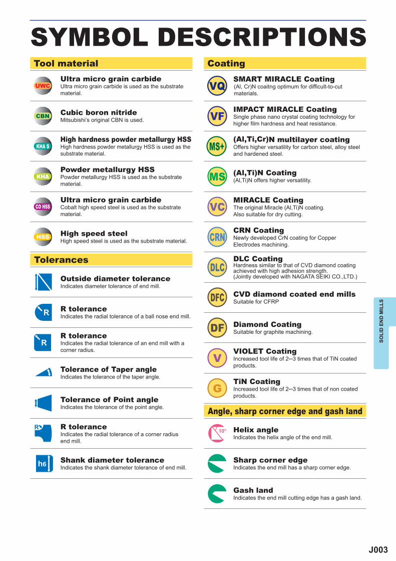
SYMBOL DESCRIPTIONSTool material
Tolerances
Angle, sharp corner edge and gash land
CoatingUltra micro grain carbideUltra micro grain carbide is used as the substrate material.
Cubic boron nitrideMitsubishi’s original CBN is used.
High hardness powder metallurgy HSSHigh hardness powder metallurgy HSS is used as thesubstrate material.
Powder metallurgy HSSPowder metallurgy HSS is used as the substrate material.
Ultra micro grain carbideCobalt high speed steel is used as the substrate material.
High speed steelHigh speed steel is used as the substrate material.
SMART MIRACLE Coating(Al, Cr)N coaitng optimum for difficult-to-cut materials.
IMPACT MIRACLE CoatingSingle phase nano crystal coating technology for higher film hardness and heat resistance.
(Al,Ti,Cr)N multilayer coatingOffers higher versatility for carbon steel, alloy steel and hardened steel.
(Al,Ti)N Coating(Al,Ti)N offers higher versatility.
MIRACLE CoatingThe original Miracle (Al,Ti)N coating.Also suitable for dry cutting.
CRN CoatingNewly developed CrN coating for CopperElectrodes machining.
DLC CoatingHardness similar to that of CVD diamond coating achieved with high adhesion strength. (Jointly developed with NAGATA SEIKI CO.,LTD.)
CVD diamond coated end millsSuitable for CFRP
Diamond CoatingSuitable for graphite machining.
VIOLET CoatingIncreased tool life of 2─3 times that of TiN coated products.
TiN CoatingIncreased tool life of 2─3 times that of non coated products.
Helix angleIndicates the helix angle of the end mill.
Sharp corner edgeIndicates the end mill has a sharp corner edge.
Gash landIndicates the end mill cutting edge has a gash land.
Outside diameter toleranceIndicates diameter tolerance of end mill.
R toleranceIndicates the radial tolerance of a ball nose end mill.
R toleranceIndicates the radial tolerance of an end mill with a corner radius.
Tolerance of Taper angleIndicates the tolerance of the taper angle.
Tolerance of Point angleIndicates the tolerance of the point angle.
R toleranceIndicates the radial tolerance of a corner radius end mill.
Shank diameter toleranceIndicates the shank diameter tolerance of end mill.
J004
(Al,Ti,Si)N (Al,Ti)N
3700 3200 2800
1300 1100 840
100 80 80
0.48 0.53 0.58
VQ
VF
VC
SOLI
D E
ND
MIL
LSSOLID END MILLS
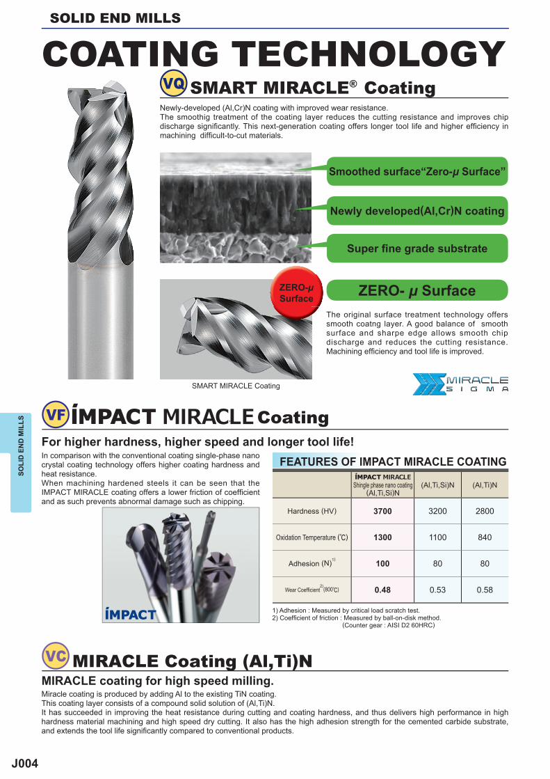
For higher hardness, higher speed and longer tool life!
COATING TECHNOLOGY
In comparison with the conventional coating single-phase nano crystal coating technology offers higher coating hardness and heat resistance.When machining hardened steels it can be seen that the IMPACT MIRACLE coating offers a lower friction of coeffi cient and as such prevents abnormal damage such as chipping.
MIRACLE Coating (Al,Ti)NMIRACLE coating for high speed milling.Miracle coating is produced by adding Al to the existing TiN coating.This coating layer consists of a compound solid solution of (Al,Ti)N.It has succeeded in improving the heat resistance during cutting and coating hardness, and thus delivers high performance in high hardness material machining and high speed dry cutting. It also has the high adhesion strength for the cemented carbide substrate, and extends the tool life signifi cantly compared to conventional products.
1) Adhesion : Measured by critical load scratch test.2) Coeffi cient of friction : Measured by ball-on-disk method. (Counter gear : AISI D2 60HRC)
FEATURES OF IMPACT MIRACLE COATING
Hardness (HV)
Oxidation Temperature (r)
Adhesion (N)1)
Wear Coeffi cient2)
(800r)
Shingle phase nano coating(Al,Ti,Si)N
Coating
The original surface treatment technology offers smooth coatng layer. A good balance of smooth surface and sharpe edge allows smooth chip discharge and reduces the cutting resistance. Machining effi ciency and tool life is improved.
SMART MIRACLE® CoatingNewly-developed (Al,Cr)N coating with improved wear resistance.The smoothig treatment of the coating layer reduces the cutting resistance and improves chip discharge signifi cantly. This next-generation coating offers longer tool life and higher effi ciency in machining diffi cult-to-cut materials.
SMART MIRACLE Coating
Smoothed surface“Zero-μ Surface”
Newly developed(Al,Cr)N coating
Super fi ne grade substrate
ZERO- μ SurfaceZERO-μSurface
J005
DFC
CRN
DLC
DF
V
(Al,Ti)N (Al,Cr)N
3200 2800 3100
1100 800 1100
100 80 80
SOLI
D E
ND
MIL
LS
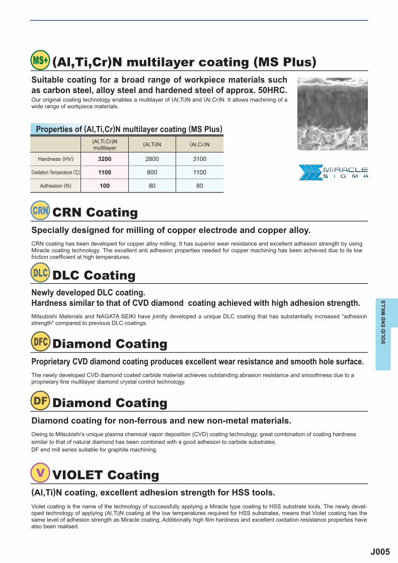
(Al,Ti,Cr)N multilayer coating (MS Plus)Suitable coating for a broad range of workpiece materials such as carbon steel, alloy steel and hardened steel of approx. 50HRC.Our original coating technology enables a multilayer of (Al,Ti)N and (Al,Cr)N. It allows machining of a wide range of workpiece materials.
Properties of (Al,Ti,Cr)N multilayer coating (MS Plus)
DLC CoatingNewly developed DLC coating.Hardness similar to that of CVD diamond coating achieved with high adhesion strength.Mitsubishi Materials and NAGATA SEIKI have jointly developed a unique DLC coating that has substantially increased "adhesion strength" compared to previous DLC coatings.
Diamond Coating
Diamond Coating
Proprietary CVD diamond coating produces excellent wear resistance and smooth hole surface.
Diamond coating for non-ferrous and new non-metal materials.
The newly developed CVD diamond coated carbide material achieves outstanding abrasion resistance and smoothness due to a proprietary fine multilayer diamond crystal control technology.
Owing to Mitsubishi’s unique plasma chemical vapor deposition (CVD) coating technology, great combination of coating hardness similar to that of natural diamond has been combined with a good adhesion to carbide substrates.DF end mill series suitable for graphite machining.
VIOLET Coating(Al,Ti)N coating, excellent adhesion strength for HSS tools.Violet coating is the name of the technology of successfully applying a Miracle type coating to HSS substrate tools. The newly devel-oped technology of applying (Al,Ti)N coating at the low temperatures required for HSS substrates, means that Violet coating has the same level of adhesion strength as Miracle coating. Additionally high fi lm hardness and excellent oxidation resistance properties have also been realised.
(Al,Ti,Cr)N multilayer
Hardness (HV)
Oxidation Temperature (r)
CRN CoatingSpecially designed for milling of copper electrode and copper alloy.CRN coating has been developed for copper alloy milling. It has superior wear resistance and excellent adhesion strength by using Miracle coating technology. The excellent anti adhesion properties needed for copper machining has been achieved due to its low friction coeffi cient at high temperatures.
Adhesion (N)
J006
y
*1
*2
P
H
J008J008J009J009
J010J010
J011J012
J013J013J013
P
MS2ES MS DC3 12 0.51xDC 2 J065
30°
MS2SS MS DC0.112 1.5xDC 2 J048
30°
DC<3
MS3ES MS DC3 12 0.51xDC 3 J110
30°
MS4EC MS DC3 14 0.51xDC 4 J141
30°
J065
a
e e u u u
MS2ES
DC APMX LF DCON
MS2ESD0300L45S04 3 3 45 4 2 a 1MS2ESD0350L45S04 3.5 3.5 45 4 2 a 1MS2ESD0400L45S04 4 4 45 4 2 a 2MS2ESD0500L45S06 5 5 45 6 2 a 1MS2ESD0600L45S06 6 6 45 6 2 a 2MS2ESD0700L45S07 7 7 45 7 2 a 2MS2ESD0800L45S07 8 8 45 7 2 a 3MS2ESD0800L45S08 8 8 45 8 2 a 2MS2ESD1000L45S07 10 10 45 7 2 a 3MS2ESD1000L45S10 10 10 45 10 2 a 2MS2ESD1200L45S10 12 12 45 10 2 a 3
DC APMX LF DCON
MS2ESD0300L35S04 3 3 35 4 2 a 1MS2ESD0350L35S04 3.5 3.5 35 4 2 a 1MS2ESD0400L35S04 4 4 35 4 2 a 2MS2ESD0500L35S05 5 5 35 5 2 a 2MS2ESD0500L35S06 5 5 35 6 2 a 1MS2ESD0600L35S05 6 6 35 5 2 a 3MS2ESD0600L35S06 6 6 35 6 2 a 2MS2ESD0700L35S07 7 6 35 7 2 a 2MS2ESD0800L35S07 8 6 35 7 2 a 3MS2ESD0800L35S08 8 6 35 8 2 a 2MS2ESD1000L35S07 10 6 35 7 2 a 3MS2ESD1000L35S10 10 6 35 10 2 a 2MS2ESD1200L35S10 12 6 35 10 2 a 3
0- 0.020
0- 0.008
0- 0.009
UWC MS 30°
h6
APMXLF
DC
DC
ON
(h6)15°
LF
DC
DC
ON
(h6)
APMX
LF
DC
DC
ON
(h6)
APMX
J066
3 10000 600 7000 400 6000 300 5000 1204 7500 600 5200 400 4500 300 4000 1205 6000 600 4200 400 3600 300 3200 1206 5000 600 3500 400 3000 300 2700 1207 4500 560 3000 360 2700 280 2300 1108 4000 520 2800 350 2400 260 2000 110
10 3200 450 2200 300 1900 230 1600 10012 2700 410 1900 270 1600 210 1300 100
DC DC
MS2ES
SOLID END MILLSSO
LID
EN
D M
ILLS
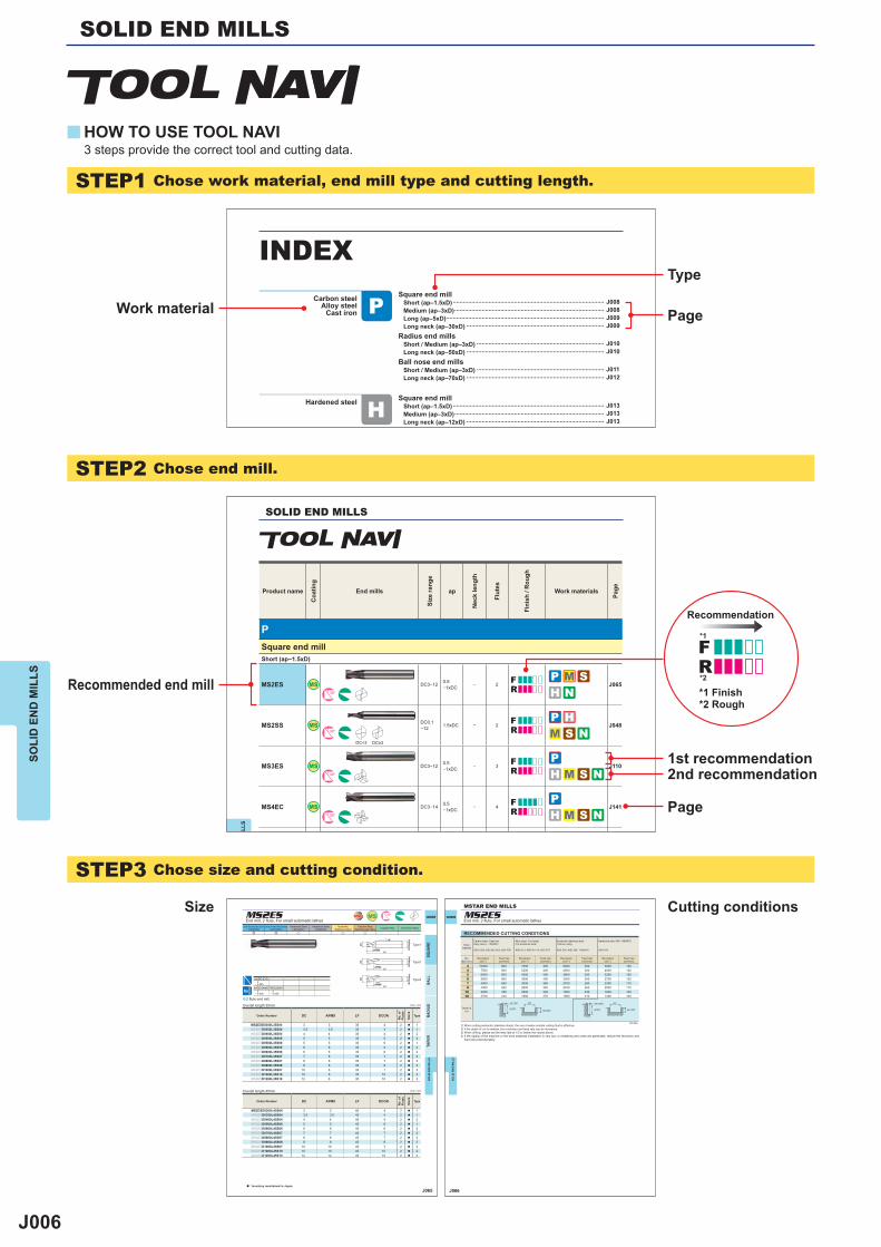
STEP1 Chose work material, end mill type and cutting length.
STEP2 Chose end mill.
STEP3 Chose size and cutting condition.
HOW TO USE TOOL NAVI
Work material
Type
Page
Page
1st recommendation2nd recommendation
Recommended end mill
Size Cutting conditions
3 steps provide the correct tool and cutting data.
Recommendation
*1 Finish*2 Rough
Carbon steelAlloy steel
Cast iron
Hardened steel
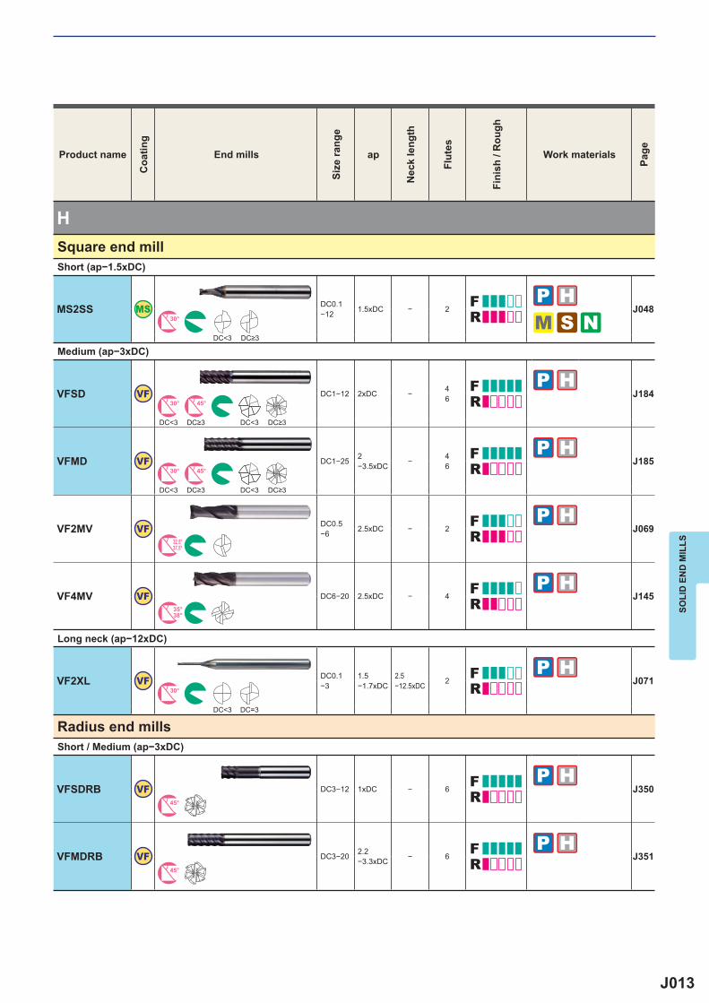
INDEXSquare end mill Short (ap‒1.5xD) ......................................................................................... Medium (ap‒3xD) ........................................................................................ Long (ap‒5xD) ............................................................................................. Long neck (ap‒30xD) .................................................................................
Radius end mills Short / Medium (ap‒3xD) ........................................................................... Long neck (ap‒50xD) .................................................................................
Ball nose end mills Short / Medium (ap‒3xD) ........................................................................... Long neck (ap‒70xD) .................................................................................
Square end mill Short (ap‒1.5xD) ......................................................................................... Medium (ap‒3xD) ........................................................................................ Long neck (ap‒12xD) .................................................................................
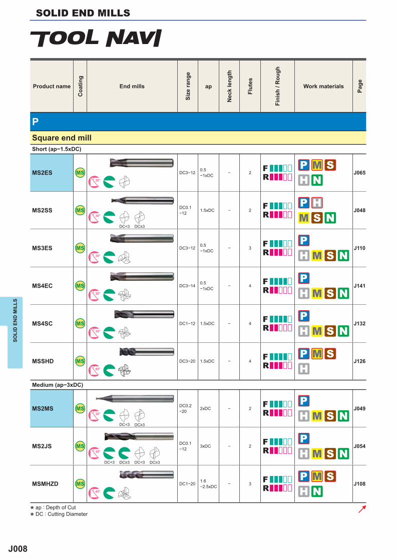
SOLID END MILLS
ILLS
Product name
Coa
ting
End mills
Size
rang
e
ap
Nec
k le
ngth
Flut
es
Fini
sh /
Rou
gh
Work materials
Page
Square end millShort (ap−1.5xD)
DC≥3
CARBIDE
SQU
AR
EB
ALL
RA
DIU
STA
PER
SOLI
D E
ND
MIL
LS
Unit : mm
Carbon Steel, Alloy Steel, Cast Iron(<30HRC)
Tool Steel, Pre-Hardened Steel,Hardened Steel(<45HRC)
Hardened Steel(<55HRC)
Hardened Steel(>55HRC)
AusteniticStainless Steel
Titanium Alloy,Heat Resistant Alloy Copper Alloy Aluminium Alloy
2 fl ute end mill.
End mill, 2 fl ute, For small automatic lathes
Overall length 35mm
Overall length 45mm
Type1
Type2
Type3
Unit : mm
Order Number
No.
of
Flut
es
Stoc
k
Type
Order Number
No.
of
Flut
es
Stoc
k
Type
4<DCON<6 7<DCON<10
3<DC<12
a : Inventory maintained in Japan.
CARBIDE
SOLI
D E
ND
MIL
LS
RECOMMENDED CUTTING CONDITIONS
1) When cutting austenitic stainless steels, the use of water-soluble cutting fl uid is effective.2) If the depth of cut is shallow, the revolution and feed rate can be increased.3) When drilling, please set the feed rate at 1/3 or below the values above.4) If the rigidity of the machine or the work materials installation is very low, or chattering and noise are generated, reduce the revolution and
feed rate proportionately.
DC:Dia.
Workmaterial
Carbon steel, Cast iron, Alloy steel (─30HRC)
AISI 1050, AISI No 35 B, AISI P20
Alloy steel, Tool steel,Pre-hardened steel
AISI H13, AISI W1-10, AISI P21
Austenitic stainless steel,Titanium alloy
AISI 304, AISI 306, Ti-6Al-4V
Hardened steel (45─ 55HRC)
AISI H13
Dia.DC (mm)
Revolution(min-1)
Feed rate(mm/min)
Revolution(min-1)
Feed rate(mm/min)
Revolution(min-1)
Feed rate(mm/min)
Revolution(min-1)
Feed rate(mm/min)
Depth ofcut
<0.2DC <0.05DC
<1DC <1DC<0.2DC <0.1DC
End mill, 2 fl ute, For small automatic lathes
MSTAR END MILLS
J007
P
MS
N
G
H
J008J008J009J009
J010J010
J011J012
J016J016J017J018
J018J019
J019J019
J020J020J020J021
J021J021
J022J022
J022J023
J023
J023J023
J013J013J013
J013J014
J014J015
SOLI
D E
ND
MIL
LS
Carbon steelAlloy steel
Cast iron
Hardened steel
Copper alloyAluminium alloy
GraphiteFRP
Austenitic Stainless steel
Ti alloyHeat resistant alloys
INDEXSquare end mill Short (ap‒1.5xDC) ...................................................................................... Medium (ap‒3xDC) ..................................................................................... Long (ap‒5xDC) .......................................................................................... Long neck (ap‒30xDC) ...............................................................................
Radius end mills Short / Medium (ap‒3xDC) ......................................................................... Long neck (ap‒50xDC) ...............................................................................
Ball nose end mills Short / Medium (ap‒3xDC) ......................................................................... Long neck (ap‒70xDC) ...............................................................................
Square end mill Short (ap‒1.5xDC) ...................................................................................... Medium (ap‒3xDC) ..................................................................................... Long (ap‒5xDC) .......................................................................................... Long neck (ap‒30xDC) ...............................................................................
Radius end mills Short / Medium (ap‒3xDC) ......................................................................... Long neck (ap‒50xDC) ...............................................................................
Ball nose end mills Short / Medium (ap‒3xDC) ......................................................................... Long neck (ap‒20xDC) ...............................................................................
Square end mill Short (ap‒1.5xDC) ...................................................................................... Medium (ap‒3xDC) ..................................................................................... Long (ap‒5xDC) .......................................................................................... Long neck (ap‒16xDC) ...............................................................................
Radius end mills Short / Medium (ap‒3xDC) ......................................................................... Long neck (ap‒30xDC) ...............................................................................
Ball nose end mills Short / Medium (ap‒3xDC) ......................................................................... Long neck (ap‒50xDC) ...............................................................................
Square end mill Long (ap‒5xDC) .......................................................................................... Long neck (ap‒10xDC) ...............................................................................
Radius end mills Long neck (ap‒30xDC) ...............................................................................
Ball nose end mills Short / Medium (ap‒3xDC) ......................................................................... Long neck (ap‒50xDC) ...............................................................................
Square end mill Short (ap‒1.5xDC) ...................................................................................... Medium (ap‒3xDC) ..................................................................................... Long neck (ap‒12xDC) ...............................................................................
Radius end mills Short / Medium (ap‒3xDC) ......................................................................... Long neck (ap‒50xDC) ...............................................................................
Ball nose end mills Short / Medium (ap‒3xDC) ......................................................................... Long neck (ap‒70xDC) ...............................................................................
* ap : Depth of Cut
* DC : Cutting Diameter
J008
P
MS2ES MS DC3−12 0.5−1xDC − 2 J065
30°
MS2SS MS DC0.1−12 1.5xDC − 2 J048
30°
DC<3
MS3ES MS DC3−12 0.5−1xDC − 3 J110
30°
MS4EC MS DC3−14 0.5−1xDC − 4 J141
30°
MS4SC MS DC1−12 1.5xDC − 4 J13230°
MSSHD MS DC3−20 1.5xDC − 4 J12645°
MS2MS MS DC0.2−20 2xDC − 2 J049
30°
DC<3
MS2JS MS DC0.1−12 3xDC − 2 J054
30°
DC<3 DC<3
MSMHZD MS DC1−20 1.6−2.5xDC − 3 J108
45°
SOLID END MILLSSO
LID
EN
D M
ILLS
Product nameC
oatin
gEnd mills
Size
rang
e
ap
Nec
k le
ngth
Flut
es
Fini
sh /
Rou
gh
Work materials
Page
Square end millShort (ap−1.5xDC)
DC≥3
Medium (ap−3xDC)
DC≥3
DC≥3 DC≥3
* ap : Depth of Cut
* DC : Cutting Diameter
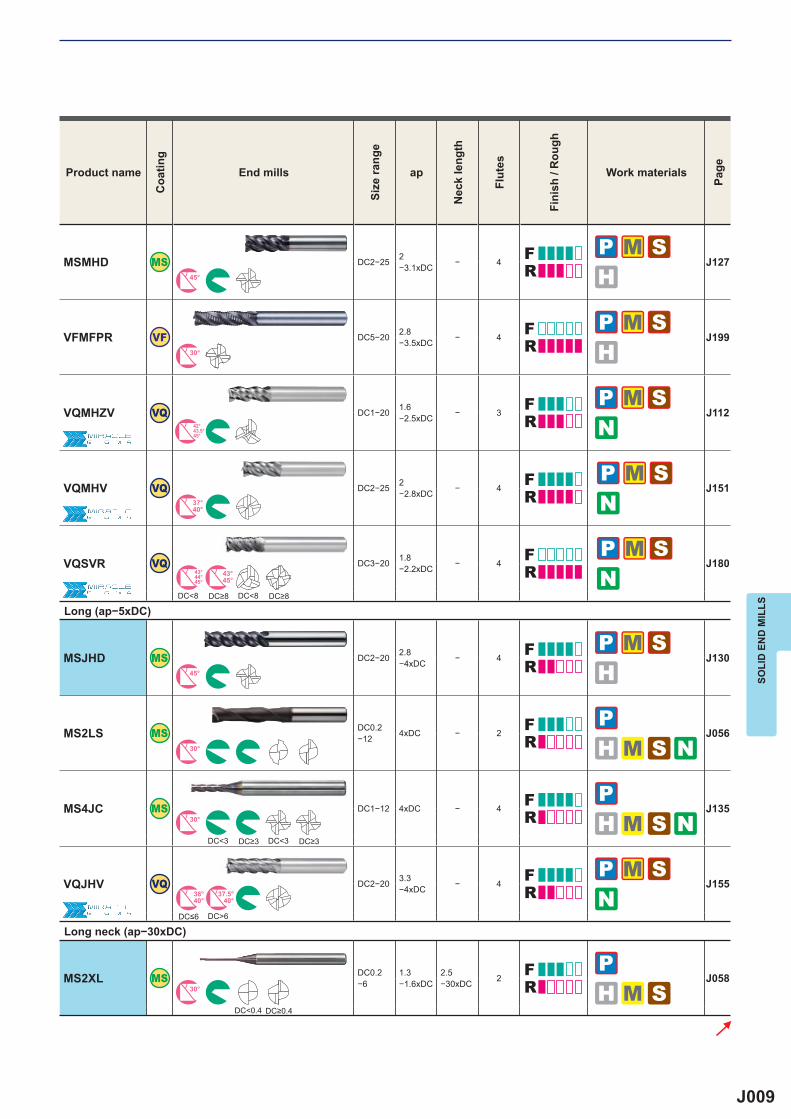
J009
MSMHD MS DC2−25 2−3.1xDC − 4 J127
45°
VFMFPR VF DC5−20 2.8−3.5xDC − 4 J199
30°
VQMHZV VQ DC1−20 1.6−2.5xDC − 3 J112
42°43.5°45°
VQMHV VQ DC2−25 2−2.8xDC − 4 J151
37°40°
VQSVR VQ DC3−20 1.8−2.2xDC − 4 J180
43°44°45°
43°45°
DC<8 DC<8
MSJHD MS DC2−20 2.8−4xDC − 4 J130
45°
MS2LS MS DC0.2−12 4xDC − 2 J056
30°
MS4JC MS DC1−12 4xDC − 4 J13530°
DC<3 DC<3
VQJHV VQ DC2−20 3.3−4xDC − 4 J155
38°40°
37.5°40°
DC>6
MS2XL MS DC0.2−6
1.3−1.6xDC
2.5−30xDC 2 J058
30°
DC<0.4
SOLI
D E
ND
MIL
LS
Product nameC
oatin
gEnd mills
Size
rang
e
ap
Nec
k le
ngth
Flut
es
Fini
sh /
Rou
gh
Work materials
Page
DC≥8 DC≥8
Long (ap−5xDC)
DC≥3 DC≥3
DC≤6
Long neck (ap−30xDC)
DC≥0.4
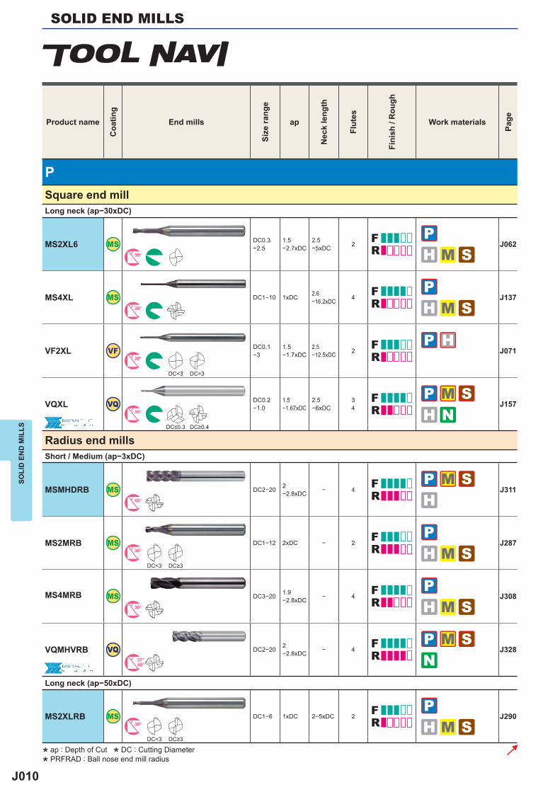
J010
P
MS2XL6 MS DC0.3−2.5
1.5−2.7xDC
2.5−5xDC 2 J062
30°
MS4XL MS DC1−10 1xDC 2.6−16.2xDC 4 J137
30°
VF2XL VF DC0.1−3
1.5−1.7xDC
2.5−12.5xDC 2 J071
30°
DC<3 DC=3
VQXL VQ DC0.2−1.0
1.5−1.67xDC
2.5−6xDC
34 J157
35°
MSMHDRB MS DC2−20 2−2.8xDC − 4 J311
45°
MS2MRB MS DC1−12 2xDC − 2 J28730°
DC<3
MS4MRB MS DC3−20 1.9−2.8xDC − 4 J308
30°
VQMHVRB VQ DC2−20 2−2.8xDC − 4 J328
37°40°
MS2XLRB MS DC1−6 1xDC 2−5xDC 2 J29030°
DC<3
SOLID END MILLSSO
LID
EN
D M
ILLS
Product nameC
oatin
gEnd mills
Size
rang
e
ap
Nec
k le
ngth
Flut
es
Fini
sh /
Rou
gh
Work materials
Page
Square end millLong neck (ap−30xDC)
DC≤0.3 DC≥0.4
Radius end millsShort / Medium (ap−3xDC)
DC≥3
Long neck (ap−50xDC)
DC≥3
* ap : Depth of Cut * DC : Cutting Diameter
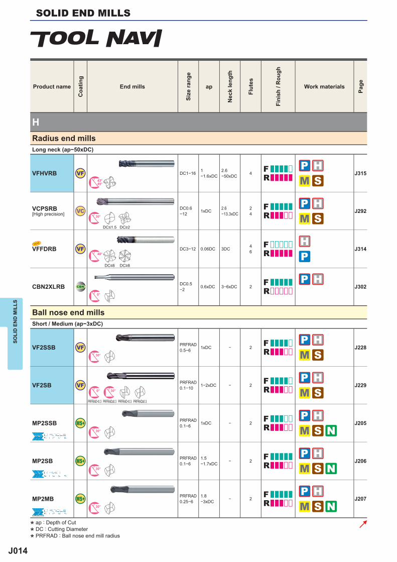
* PRFRAD : Ball nose end mill radius
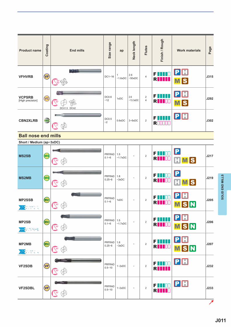
J011
VFHVRB VF DC1−16 1−1.6xDC
2.6−50xDC 4 J315
43°45°
VC DC0.6−12 1xDC 2.6
−13.3xDC24 J292
30°
CBN2XLRB CBNDC0.5−2 0.6xDC 3−6xDC 2 J302
0°
MS2SB MS PRFRAD0.1−6
1.5−1.7xDC − 2 J217
30°
MS2MB MS PRFRAD0.25−6
1.8−3xDC − 2 J219
30°
MP2SSB PRFRAD0.1−6 1xDC − 2 J205
30°
MP2SB PRFRAD0.1−6
1.5−1.7xDC − 2 J206
30°
MP2MB PRFRAD0.25−6
1.8−3xDC − 2 J207
30°
VF2SDB VF PRFRAD0.5−10 1−2xDC − 2 J232
30°
VF2SDBL VF PRFRAD0.5−10 1−2xDC − 2 J233
30°
SOLI
D E
ND
MIL
LS
Product nameC
oatin
gEnd mills
Size
rang
e
ap
Nec
k le
ngth
Flut
es
Fini
sh /
Rou
gh
Work materials
Page
VCPSRB[High precision]
DC≤1.5 DC≥2
Ball nose end millsShort / Medium (ap−3xDC)
J012
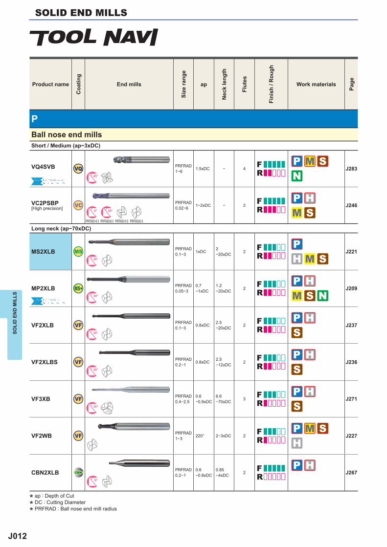
P
VQ4SVB VQ PRFRAD1−6 1.5xDC − 4 J283
45°
VC PRFRAD0.02−6 1−2xDC − 2 J246
0° 30°
PRFRAD<0.5 PRFRAD<0.5
MS2XLB MS PRFRAD0.1−3 1xDC 2
−20xDC 2 J22130°
MP2XLB PRFRAD0.05−3
0.7−1xDC
1.2−20xDC 2 J209
30°
VF2XLB VF PRFRAD0.1−3 0.8xDC 2.5
−20xDC 2 J23730°
VF2XLBS VF PRFRAD0.2−1 0.8xDC 2.5
−12xDC 2 J23630°
VF3XB VF PRFRAD0.4−2.5
0.6−0.9xDC
6.6−70xDC 3 J271
30°
VF2WB VF PRFRAD1−3 220° 2−3xDC 2 J227
CBN2XLB CBNPRFRAD0.2−1
0.6−0.8xDC
0.85−4xDC 2 J267
0°
SOLID END MILLSSO
LID
EN
D M
ILLS
Product nameC
oatin
gEnd mills
Size
rang
e
ap
Nec
k le
ngth
Flut
es
Fini
sh /
Rou
gh
Work materials
Page
Ball nose end millsShort / Medium (ap−3xDC)
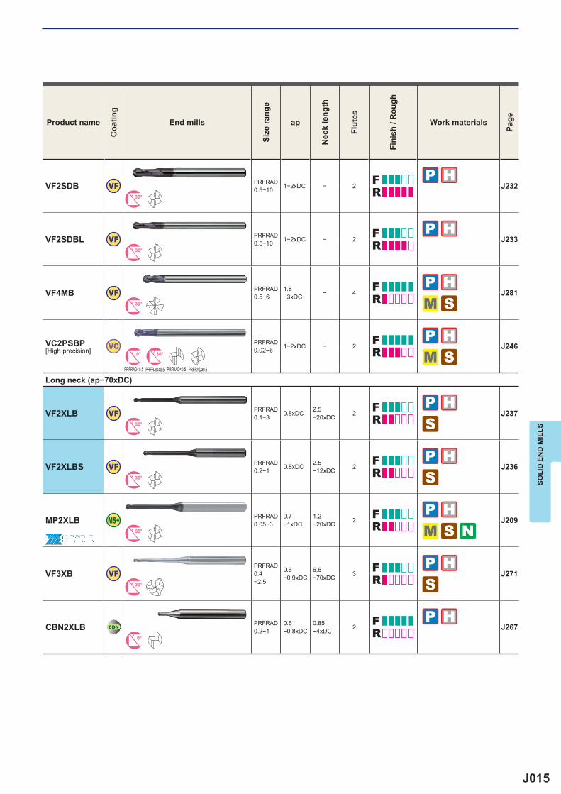
VC2PSBP[High precision]
PRFRAD≥0.5 PRFRAD≥0.5
Long neck (ap−70xDC)
* ap : Depth of Cut
* DC : Cutting Diameter
* PRFRAD : Ball nose end mill radius
J013
H
MS2SS MS DC0.1−12 1.5xDC − 2 J048
30°
DC<3
VFSD VF DC1−12 2xDC − 46 J184
30° 45°
DC<3 DC<3
VFMD VF DC1−25 2−3.5xDC − 4
6 J18530° 45°
DC<3 DC<3
VF2MV VF DC0.5−6 2.5xDC − 2 J069
32.5°37.5°
VF4MV VF DC6−20 2.5xDC − 4 J14535°38°
VF2XL VF DC0.1−3
1.5−1.7xDC
2.5−12.5xDC 2 J071
30°
DC<3 DC=3
VFSDRB VF DC3−12 1xDC − 6 J35045°
VFMDRB VF DC3−20 2.2−3.3xDC − 6 J351
45°
SOLI
D E
ND
MIL
LS
Product nameC
oatin
gEnd mills
Size
rang
e
ap
Nec
k le
ngth
Flut
es
Fini
sh /
Rou
gh
Work materials
Page
Square end millShort (ap−1.5xDC)
DC≥3
Medium (ap−3xDC)
DC≥3 DC≥3
DC≥3 DC≥3
Long neck (ap−12xDC)
Radius end millsShort / Medium (ap−3xDC)
J014
H
VFHVRB VF DC1−16 1−1.6xDC
2.6−50xDC 4 J315
43°45°
VC DC0.6−12 1xDC 2.6
−13.3xDC24 J292
30°
VFFDRB VF DC3−12 0.06DC 3DC 46 J314
40°
CBN2XLRB CBNDC0.5−2 0.6xDC 3−6xDC 2 J302
0°
VF2SSB VF PRFRAD0.5−6 1xDC − 2 J228
30°
VF2SB VF PRFRAD0.1−10 1−2xDC − 2 J229
0° 30°
PRFRAD<0.3 PRFRAD<0.3
MP2SSB PRFRAD0.1−6 1xDC − 2 J205
30°
MP2SB PRFRAD0.1−6
1.5−1.7xDC − 2 J206
30°
MP2MB PRFRAD0.25−6
1.8−3xDC − 2 J207
30°
NEW
SOLID END MILLSSO
LID
EN
D M
ILLS
Product nameC
oatin
gEnd mills
Size
rang
e
ap
Nec
k le
ngth
Flut
es
Fini
sh /
Rou
gh
Work materials
Page
Radius end millsLong neck (ap−50xDC)
VCPSRB[High precision]
DC≤1.5 DC≥2
DC≤6 DC≥8
Ball nose end millsShort / Medium (ap−3xDC)
PRFRAD≥0.3 PRFRAD≥0.3
* ap : Depth of Cut
* DC : Cutting Diameter
* PRFRAD : Ball nose end mill radius
J015
VF2SDB VF PRFRAD0.5−10 1−2xDC − 2 J232
30°
VF2SDBL VF PRFRAD0.5−10 1−2xDC − 2 J233
30°
VF4MB VF PRFRAD0.5−6
1.8−3xDC − 4 J281
30°
VC PRFRAD0.02−6 1−2xDC − 2 J246
0° 30°
PRFRAD<0.5 PRFRAD<0.5
VF2XLB VF PRFRAD0.1−3 0.8xDC 2.5
−20xDC 2 J23730°
VF2XLBS VF PRFRAD0.2−1 0.8xDC 2.5
−12xDC 2 J23630°
MP2XLB PRFRAD0.05−3
0.7−1xDC
1.2−20xDC 2 J209
30°
VF3XB VFPRFRAD0.4−2.5
0.6−0.9xDC
6.6−70xDC 3 J271
30°
CBN2XLB CBNPRFRAD0.2−1
0.6−0.8xDC
0.85−4xDC 2 J267
0°
SOLI
D E
ND
MIL
LS
Product nameC
oatin
gEnd mills
Size
rang
e
ap
Nec
k le
ngth
Flut
es
Fini
sh /
Rou
gh
Work materials
Page
VC2PSBP[High precision]
PRFRAD≥0.5 PRFRAD≥0.5
Long neck (ap−70xDC)
J016
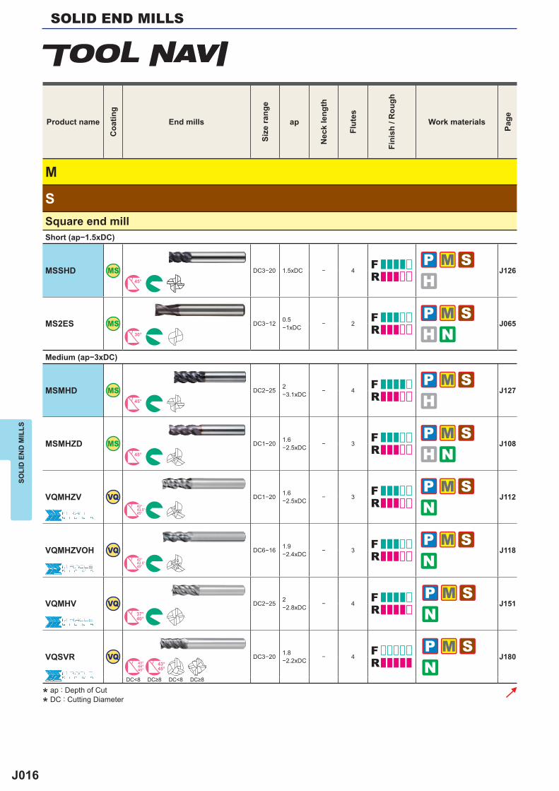
M
S
MSSHD MS DC3−20 1.5xDC − 4 J12645°
MS2ES MS DC3−12 0.5−1xDC − 2 J065
30°
MSMHD MS DC2−25 2−3.1xDC − 4 J127
45°
MSMHZD MS DC1−20 1.6−2.5xDC − 3 J108
45°
VQMHZV VQ DC1−20 1.6−2.5xDC − 3 J112
42°43.5°45°
VQMHZVOH VQ DC6−16 1.9−2.4xDC − 3 J118
42°43.5°45°
VQMHV VQ DC2−25 2−2.8xDC − 4 J151
37°40°
VQSVR VQ DC3−20 1.8−2.2xDC − 4 J180
43°44°45°
43°45°
DC<8 DC<8
SOLID END MILLSSO
LID
EN
D M
ILLS
Product nameC
oatin
gEnd mills
Size
rang
e
ap
Nec
k le
ngth
Flut
es
Fini
sh /
Rou
gh
Work materials
Page
Square end millShort (ap−1.5xDC)
Medium (ap−3xDC)
DC≥8 DC≥8
* ap : Depth of Cut
* DC : Cutting Diameter
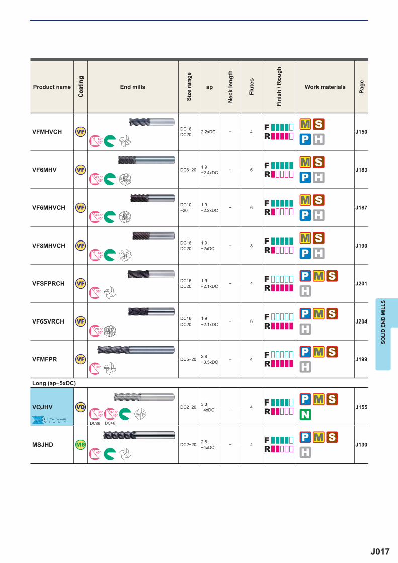
J017
VFMHVCH VF DC16,DC20 2.2xDC − 4 J150
42°45°
VF6MHV VF DC6−20 1.9−2.4xDC − 6 J183
43.5°45°
VF6MHVCH VF DC10−20
1.9−2.2xDC − 6 J187
43.5°45°
VF8MHVCH VF DC16,DC20
1.9−2xDC − 8 J190
44°45°
VFSFPRCH VF DC16,DC20
1.9−2.1xDC − 4 J201
30°
VF6SVRCH VF DC16,DC20
1.9−2.1xDC − 6 J204
28.5°30°
VFMFPR VF DC5−20 2.8−3.5xDC − 4 J199
30°
VQJHV VQ DC2−20 3.3−4xDC − 4 J155
38°40°
37.5°40°
DC>6
MSJHD MS DC2−20 2.8−4xDC − 4 J130
45°
SOLI
D E
ND
MIL
LS
Product nameC
oatin
gEnd mills
Size
rang
e
ap
Nec
k le
ngth
Flut
es
Fini
sh /
Rou
gh
Work materials
Page
Long (ap−5xDC)
DC≤6
J018
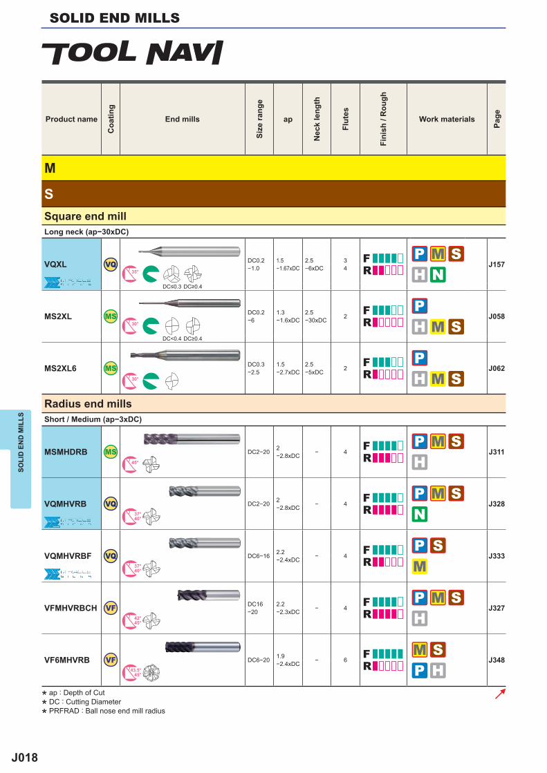
M
S
VQXL VQ DC0.2−1.0
1.5−1.67xDC
2.5−6xDC
34 J157
35°
MS2XL MS DC0.2−6
1.3−1.6xDC
2.5−30xDC 2 J058
30°
DC<0.4
MS2XL6 MS DC0.3−2.5
1.5−2.7xDC
2.5−5xDC 2 J062
30°
MSMHDRB MS DC2−20 2−2.8xDC − 4 J311
45°
VQMHVRB VQ DC2−20 2−2.8xDC − 4 J328
37°40°
VQMHVRBF VQ DC6−16 2.2−2.4xDC − 4 J333
37°40°
VFMHVRBCH VF DC16−20
2.2−2.3xDC − 4 J327
42°45°
VF6MHVRB VF DC6−20 1.9−2.4xDC − 6 J348
43.5°45°
SOLID END MILLSSO
LID
EN
D M
ILLS
Product nameC
oatin
gEnd mills
Size
rang
e
ap
Nec
k le
ngth
Flut
es
Fini
sh /
Rou
gh
Work materials
Page
Square end millLong neck (ap−30xDC)
DC≤0.3 DC≥0.4
DC≥0.4
Radius end millsShort / Medium (ap−3xDC)
* ap : Depth of Cut
* DC : Cutting Diameter
* PRFRAD : Ball nose end mill radius
J019
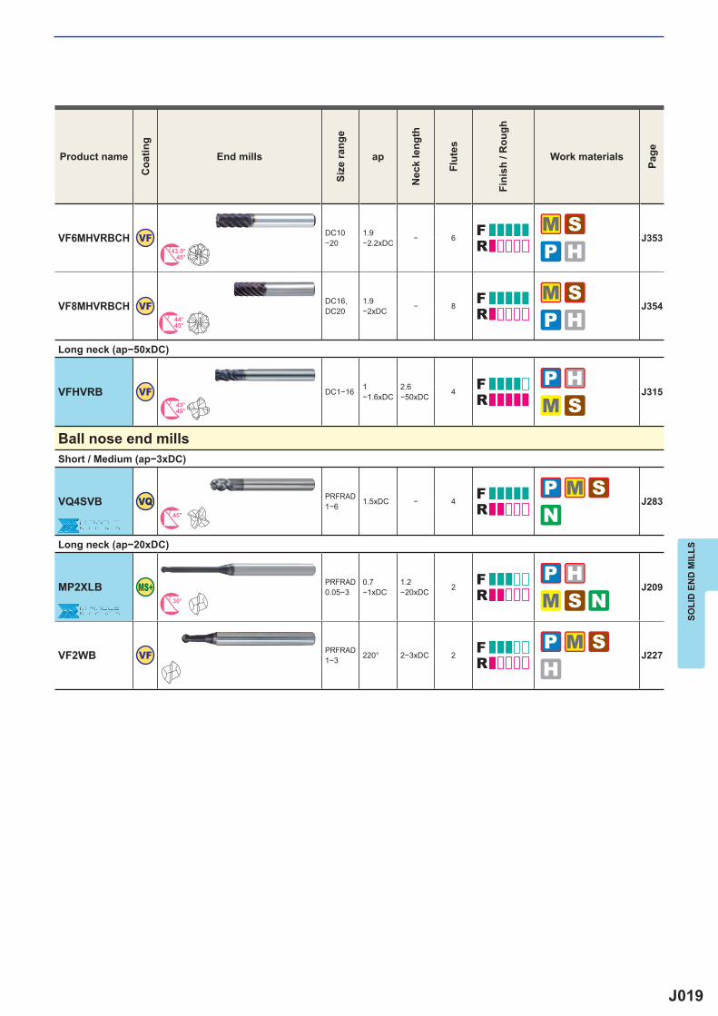
VF6MHVRBCH VF DC10−20
1.9−2.2xDC − 6 J353
43.5°45°
VF8MHVRBCH VF DC16,DC20
1.9−2xDC − 8 J354
44°45°
VFHVRB VF DC1−16 1−1.6xDC
2.6−50xDC 4 J315
43°45°
VQ4SVB VQ PRFRAD1−6 1.5xDC − 4 J283
45°
MP2XLB PRFRAD0.05−3
0.7−1xDC
1.2−20xDC 2 J209
30°
VF2WB VF PRFRAD1−3 220° 2−3xDC 2 J227
SOLI
D E
ND
MIL
LS
Product nameC
oatin
gEnd mills
Size
rang
e
ap
Nec
k le
ngth
Flut
es
Fini
sh /
Rou
gh
Work materials
Page
Long neck (ap−50xDC)
Ball nose end millsShort / Medium (ap−3xDC)
Long neck (ap−20xDC)
J020
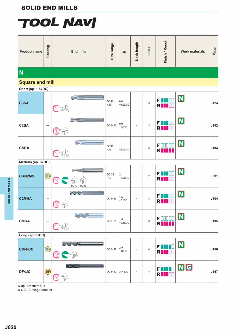
N
C3SA ─ DC10−26
0.8−1.3xDC − 3 J124
37.5°
C2SA ─ DC3−20 0.9−2xDC − 2 J102
37.5°
CSRA ─ DC10−25
1.1−1.3xDC − 3 J193
37.5°
CRN2MS CRN DC0.2−12
2−3.2xDC − 2 J081
30°
DC<3
C2MHA ─ DC3−25 1.5−3xDC − 2 J104
55°
CMRA ─ DC3−25 1.8−2.8xDC − 3 J195
37.5°
CRN4JC CRN DC3−12 2.5−4xDC − 4 J166
30°
DF4JC DF DC3−12 3−4xDC − 4 J16730°
SOLID END MILLSSO
LID
EN
D M
ILLS
Product nameC
oatin
gEnd mills
Size
rang
e
ap
Nec
k le
ngth
Flut
es
Fini
sh /
Rou
gh
Work materials
Page
Square end millShort (ap−1.5xDC)
Medium (ap−3xDC)
DC≥3
Long (ap−5xDC)
* ap : Depth of Cut
* DC : Cutting Diameter
J021
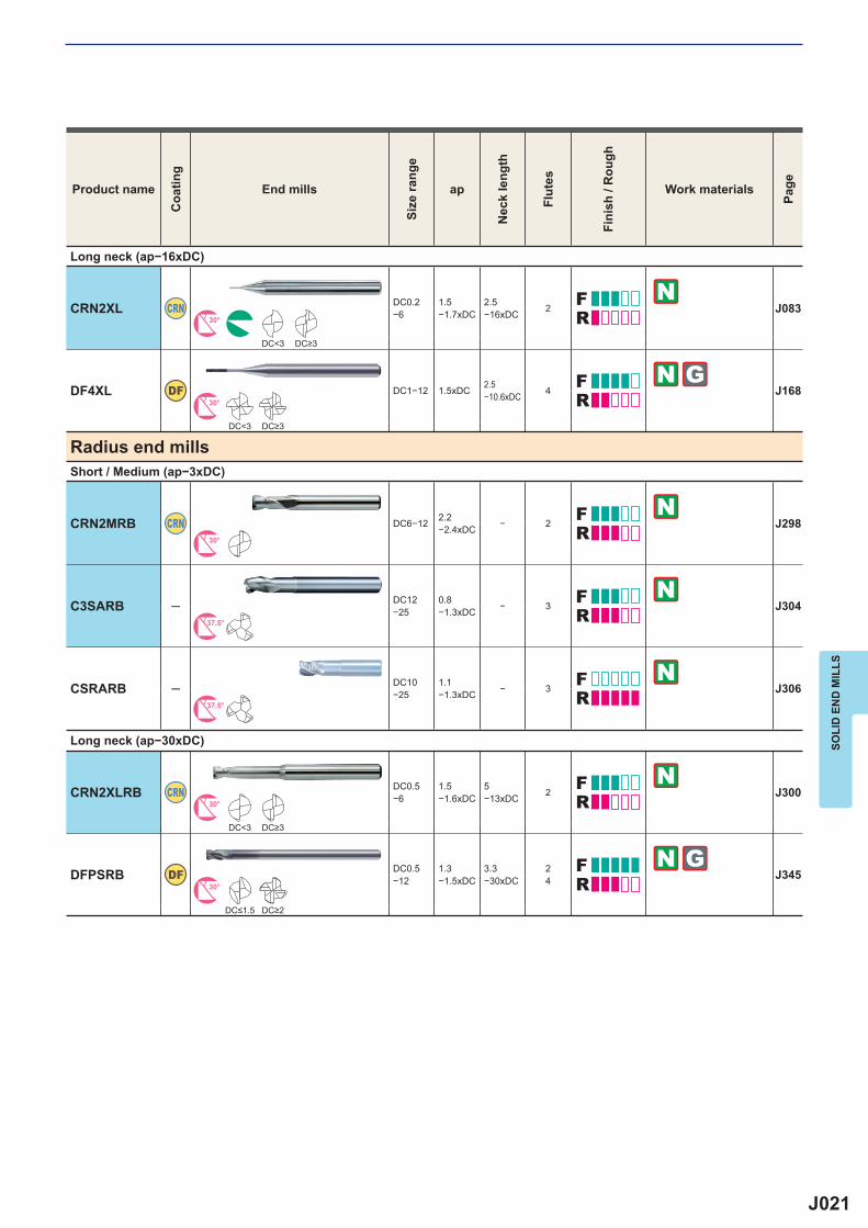
CRN2XL CRN DC0.2−6
1.5−1.7xDC
2.5−16xDC 2 J083
30°
DC<3
DF4XL DF DC1−12 1.5xDC 2.5−10.6xDC 4 J168
30°
DC<3
CRN2MRB CRN DC6−12 2.2−2.4xDC − 2 J298
30°
C3SARB ─ DC12−25
0.8−1.3xDC − 3 J304
37.5°
CSRARB ─ DC10−25
1.1−1.3xDC − 3 J306
37.5°
CRN2XLRB CRN DC0.5−6
1.5−1.6xDC
5−13xDC 2 J300
30°
DC<3
DFPSRB DF DC0.5−12
1.3−1.5xDC
3.3−30xDC
24 J345
30°
SOLI
D E
ND
MIL
LS
Product nameC
oatin
gEnd mills
Size
rang
e
ap
Nec
k le
ngth
Flut
es
Fini
sh /
Rou
gh
Work materials
Page
Long neck (ap−16xDC)
DC≥3
DC≥3
Radius end millsShort / Medium (ap−3xDC)
Long neck (ap−30xDC)
DC≥3
DC≤1.5 DC≥2
J022
N
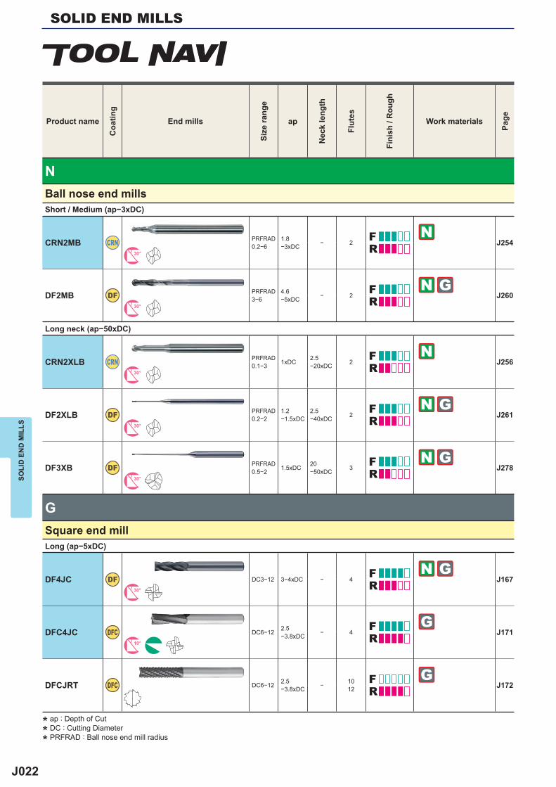
CRN2MB CRN PRFRAD0.2−6
1.8−3xDC − 2 J254
30°
DF2MB DF PRFRAD3−6
4.6−5xDC − 2 J260
30°
CRN2XLB CRN PRFRAD0.1−3 1xDC 2.5
−20xDC 2 J25630°
DF2XLB DF PRFRAD0.2−2
1.2−1.5xDC
2.5−40xDC 2 J261
30°
DF3XB DF PRFRAD0.5−2 1.5xDC 20
−50xDC 3 J27830°
G
DF4JC DF DC3−12 3−4xDC − 4 J16730°
DFC4JC DFC DC6−12 2.5−3.8xDC − 4 J171
10°
DFCJRT DFC DC6−12 2.5−3.8xDC − 10
12 J172
SOLID END MILLSSO
LID
EN
D M
ILLS
Product nameC
oatin
gEnd mills
Size
rang
e
ap
Nec
k le
ngth
Flut
es
Fini
sh /
Rou
gh
Work materials
Page
Ball nose end millsShort / Medium (ap−3xDC)
Long neck (ap−50xDC)
Square end millLong (ap−5xDC)
* ap : Depth of Cut
* DC : Cutting Diameter
* PRFRAD : Ball nose end mill radius
J023
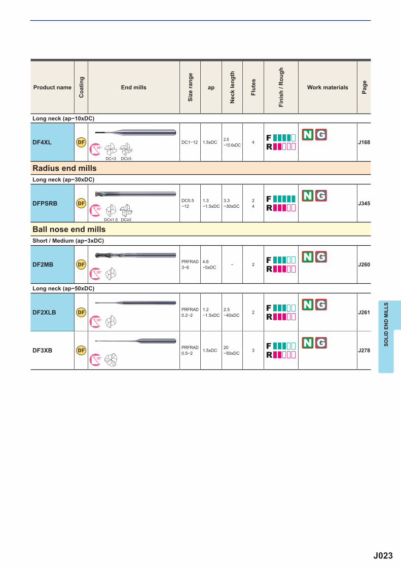
DF4XL DF DC1−12 1.5xDC 2.5−10.6xDC 4 J168
30°
DC<3
DFPSRB DF DC0.5−12
1.3−1.5xDC
3.3−30xDC
24 J345
30°
DF2MB DF PRFRAD3−6
4.6−5xDC − 2 J260
30°
DF2XLB DF PRFRAD0.2−2
1.2−1.5xDC
2.5−40xDC 2 J261
30°
DF3XB DF PRFRAD0.5−2 1.5xDC 20
−50xDC 3 J27830°
SOLI
D E
ND
MIL
LS
Product nameC
oatin
gEnd mills
Size
rang
e
ap
Nec
k le
ngth
Flut
es
Fini
sh /
Rou
gh
Work materials
Page
Long neck (ap−10xDC)
DC≥3
Radius end millsLong neck (ap−30xDC)
DC≤1.5 DC≥2
Ball nose end millsShort / Medium (ap−3xDC)
Long neck (ap−50xDC)
J024
P H M S N
2
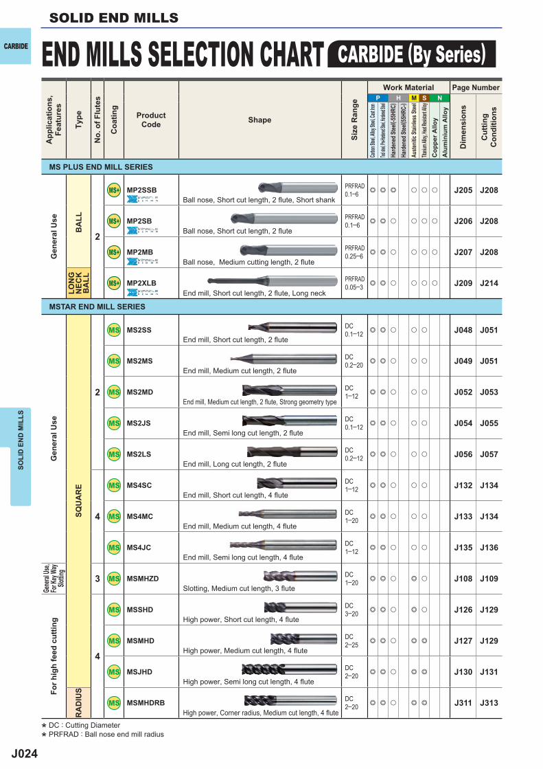
MP2SSB PRFRAD0.1─6 e e e u u u J205 J208
MP2SB PRFRAD0.1─6 e e u u u u J206 J208
MP2MB PRFRAD0.25─6 e e u u u u J207 J208
MP2XLB PRFRAD0.05─3 e e u u u u J209 J214
2
MS2SS DC0.1─12 e e u u u J048 J051
MS2MS DC0.2─20 e e u u u J049 J051
MS2MD DC1─12 e e u u u J052 J053
MS2JS DC0.1─12 e e u u u J054 J055
MS2LS DC0.2─12 e e u u u J056 J057
4
MS4SC DC1─12 e e u u u J132 J134
MS4MC DC1─20 e e u u u J133 J134
MS4JC DC1─12 e e u u u J135 J136
3 MSMHZD DC1─20 e e u e u J108 J109
4
MSSHD DC3─20 e e u e u J126 J129
MSMHD DC2─25 e e u e e J127 J129
MSJHD DC2─20 e e u e e J130 J131
MSMHDRB DC2─20 e e u e e J311 J313
SOLI
D E
ND
MIL
LSSOLID END MILLS
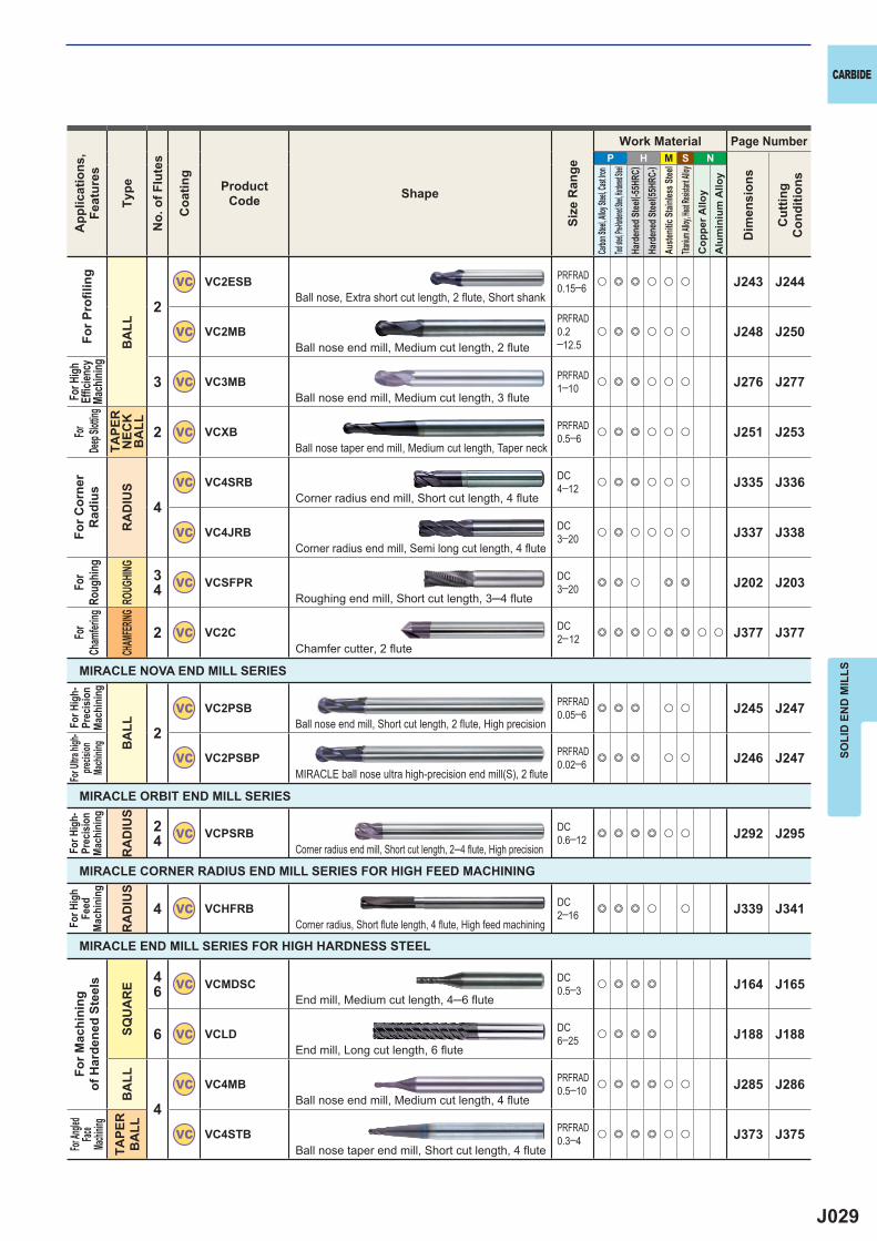
END MILLS SELECTION CHART CARBIDE (By Series)CARBIDEA
pplic
atio
ns,
Feat
ures
Type
No.
of F
lute
s
Coa
ting
ProductCode Shape
Size
Ran
ge
Work Material Page Number
Dim
ensi
ons
Cut
ting
Con
ditio
ns
Carbon
Steel, A
lloy Ste
el, Cast
Iron
Tool stee
l, Pre-Ha
rdened S
teel, Har
dened St
eelHa
rden
ed St
eel( -5
5HRC
)Ha
rden
ed St
eel( 5
5HRC
-)Au
stenit
ic St
ainles
s Stee
lTita
nium A
lloy, He
at Resis
tant Al
loyC
oppe
r Allo
yA
lum
iniu
m A
lloy
Ball nose, Short cut length, 2 fl ute, Short shank
Ball nose, Short cut length, 2 fl ute
Ball nose, Medium cutting length, 2 fl ute
End mill, Short cut length, 2 fl ute, Long neck
End mill, Short cut length, 2 flute
End mill, Medium cut length, 2 flute
End mill, Medium cut length, 2 flute, Strong geometry type
End mill, Semi long cut length, 2 flute
End mill, Long cut length, 2 flute
End mill, Short cut length, 4 flute
End mill, Medium cut length, 4 flute
End mill, Semi long cut length, 4 flute
Slotting, Medium cut length, 3 flute
High power, Short cut length, 4 flute
High power, Medium cut length, 4 flute
High power, Semi long cut length, 4 flute
High power, Corner radius, Medium cut length, 4 flute
MS PLUS END MILL SERIES
MSTAR END MILL SERIES
Gen
eral
Use
BA
LLLO
NG
N
ECK
BA
LL
Gen
eral
Use
SQU
AR
E
Gene
ral Us
e,Fo
r Key
Way
Slottin
gFo
r hig
h fe
ed c
uttin
g
RA
DIU
S
* DC : Cutting Diameter
* PRFRAD : Ball nose end mill radius
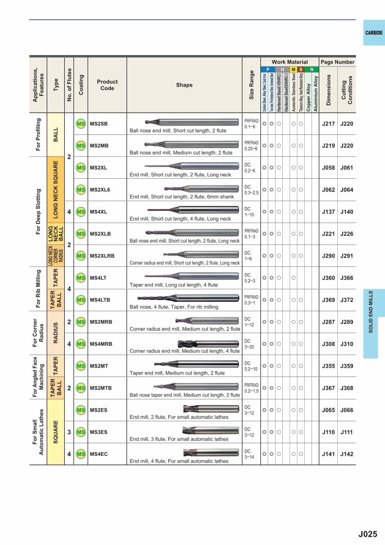
J025
P H M S N
2
MS2SB PRFRAD0.1─6 e e u u u J217 J220
MS2MB PRFRAD0.25─6 e e u u u J219 J220
MS2XL DC0.2─6 e e u u u J058 J061
MS2XL6 DC0.3─2.5 e e u u u J062 J064
4 MS4XL DC1─10 e e u u u J137 J140
2
MS2XLB PRFRAD0.1─3 e e u u u J221 J226
MS2XLRB DC1─6 e e u u u J290 J291
4
MS4LT DC0.2─3 e e u u J360 J366
MS4LTB PRFRAD0.3─1 e e u u u J369 J372
2 MS2MRB DC1─12 e e u u u J287 J289
4 MS4MRB DC3─20 e e u u u J308 J310
2
MS2MT DC0.2─10 e e u u u J355 J359
MS2MTB PRFRAD0.2─1.5 e e u u u J367 J368
MS2ES DC3─12 e e u u u J065 J066
3 MS3ES DC3─12 e e u u u J110 J111
4 MS4EC DC3─14 e e u u u J141 J142
SOLI
D E
ND
MIL
LS
CARBIDEA
pplic
atio
ns,
Feat
ures
Type
No.
of F
lute
s
Coa
ting
ProductCode Shape
Size
Ran
ge
Work Material Page Number
Dim
ensi
ons
Cut
ting
Con
ditio
ns
Carbon
Steel, A
lloy Ste
el, Cast
Iron
Tool stee
l, Pre-Ha
rdened S
teel, Har
dened St
eelHa
rden
ed St
eel( -5
5HRC
)Ha
rden
ed St
eel( 5
5HRC
-)Au
stenit
ic St
ainles
s Stee
lTita
nium A
lloy, He
at Resis
tant Al
loyC
oppe
r Allo
yA
lum
iniu
m A
lloy
For P
rofi l
ing
BA
LL
For D
eep
Slot
ting
LON
G N
ECK
SQ
UA
RE
LON
G
NEC
KB
ALL
LONG
NECK
CORN
ER
RADIU
S
For R
ib M
illin
g
TAPE
RTA
PER
B
ALL
For C
orne
rR
adiu
s
RA
DIU
S
For A
ngle
d Fa
ceM
achi
ning
TAPE
RTA
PER
B
ALL
For S
mal
l A
utom
atic
Lat
hes
SQU
AR
E
Ball nose end mill, Short cut length, 2 flute
Ball nose end mill, Medium cut length, 2 flute
End mill, Short cut length, 2 flute, Long neck
End mill, Short cut length, 2 flute, 6mm shank
End mill, Short cut length, 4 flute, Long neck
Ball nose end mill, Short cut length, 2 flute, Long neck
Corner radius end mill, Short cut length, 2 flute, Long neck
Taper end mill, Long cut length, 4 flute
Ball nose, 4 flute, Taper, For rib milling
Corner radius end mill, Medium cut length, 2 flute
Corner radius end mill, Medium cut length, 4 flute
Taper end mill, Medium cut length, 2 flute
Ball nose taper end mill, Medium cut length, 2 flute
End mill, 2 flute, For small automatic lathes
End mill, 3 flute, For small automatic lathes
End mill, 4 flute, For small automatic lathes
J026
P H M S N
34
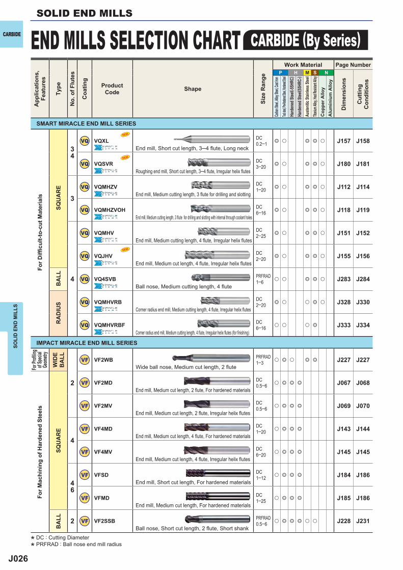
VQ VQXL DC0.2─1 e u e e u J157 J158
VQ VQSVR DC3─20 e u e e u J180 J181
3
VQ VQMHZV DC1─20 e u e e u J112 J114
VQ VQMHZVOH DC6─16 e u e e u J118 J119
4
VQ VQMHV DC2─25 e u e e u J151 J152
VQ VQJHV DC2─20 e u e e u J155 J156
VQ VQ4SVB PRFRAD1─6 u u e e u J283 J284
VQ VQMHVRB DC2─20 e u u e u J328 J330
VQ VQMHVRBF DC6─16 u u u e J333 J334
2
VF VF2WB PRFRAD1─3 u e u e e J227 J227
VF VF2MD DC0.5─6 u e e e J067 J068
VF VF2MV DC0.5─6 u e e e J069 J070
4
VF VF4MD DC1─20 u e e e J143 J144
VF VF4MV DC6─20 u e e e J145 J145
46
VF VFSD DC1─12 u e e e J184 J186
VF VFMD DC1─25 u e e e J185 J186
2 VF VF2SSB PRFRAD0.5─6 u e e e u u J228 J231
NEW
NEW
NEW
SOLI
D E
ND
MIL
LSSOLID END MILLS
END MILLS SELECTION CHART CARBIDE (By Series)CARBIDEA
pplic
atio
ns,
Feat
ures
Type
No.
of F
lute
s
Coa
ting
ProductCode Shape
Size
Ran
ge
Work Material Page Number
Dim
ensi
ons
Cut
ting
Con
ditio
ns
Carbon
Steel, A
lloy Ste
el, Cast
Iron
Tool stee
l, Pre-Ha
rdened S
teel, Har
dened St
eelHa
rden
ed St
eel( -5
5HRC
)Ha
rden
ed St
eel( 5
5HRC
-)Au
stenit
ic St
ainles
s Stee
lTita
nium A
lloy, He
at Resis
tant Al
loyC
oppe
r Allo
yA
lum
iniu
m A
lloy
For D
iffi c
ult-t
o-cu
t Mat
eria
ls
SQU
AR
EB
ALL
RA
DIU
S
For P
rofi lin
gof
Speci
alGe
ometr
y
WID
E B
ALL
For M
achi
ning
of H
arde
ned
Stee
ls
SQU
AR
EB
ALL
End mill, Short cut length, 3─4 flute, Long neck
Roughing end mill, Short cut length, 3─4 flute, Irregular helix flutes
End mill, Medium cutting length, 3 flute for drilling and slotting
End mill, Medium cutting length, 3 flute for drilling and slotting with internal through coolant holes
End mill, Medium cutting length, 4 flute, Irregular helix flutes
End mill, Medium cut length, 4 flute, Irregular helix flutes
Ball nose, Medium cutting length, 4 flute
Corner radius end mill, Medium cutting length, 4 flute, Irregular helix flutes
Corner radius end mill, Medium cutting length, 4 flute, Irregular helix flutes (for finishing)
Wide ball nose, Medium cut length, 2 flute
End mill, Medium cut length, 2 flute, For hardened materials
End mill, Medium cut length, 2 flute, Irregular helix flutes
End mill, Medium cut length, 4 flute, For hardened materials
End mill, Medium cut length, 4 flute, Irregular helix flutes
End mill, Short cut length, For hardened materials
End mill, Medium cut length, For hardened materials
Ball nose, Short cut length, 2 flute, Short shank
SMART MIRACLE END MILL SERIES
IMPACT MIRACLE END MILL SERIES
* DC : Cutting Diameter
* PRFRAD : Ball nose end mill radius
J027
P H M S N
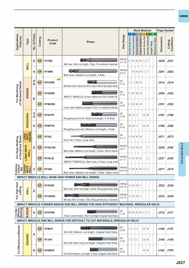
2 VF VF2SB PRFRAD0.1─10 u e e e u u J229 J231
4 VF VF4MB PRFRAD0.5─6 e e e u u J281 J282
46 VF VFFDRB DC
3─12 u u e e J314 J314
6
VF VFSDRB DC3─12 u e e e J350 J352
VF VFMDRB DC3─20 u e e e J351 J352
34 VF VFSFPR DC
3─20 e e u e e J197 J198
4 VF VFMFPR DC5─20 e e u e e J199 J200
2
VF VF2XL DC0.1─3 u e e e J071 J073
VF VF2XLBS PRFRAD0.2─1 u e e e u J236 J242
VF VF2XLB PRFRAD0.1─3 u e e e u J237 J242
3 VF VF3XB PRFRAD0.4─2.5 u e e e u u J271 J274
2VF VF2SDB PRFRAD
0.5─10 u e e u J232 J234
VF VF2SDBL PRFRAD0.5─10 u e e u J233 J234
4 VF VFHVRB DC1─16 e e e e u u J315 J317
4
VF VFMHV DC2─20 u u u e e J146 J147
VF VFJHV DC2─20 u u u e e J148 J149
6 VF VF6MHV DC6─20 e e J183 J183
NEW
SOLI
D E
ND
MIL
LS
CARBIDEA
pplic
atio
ns,
Feat
ures
Type
No.
of F
lute
s
Coa
ting
ProductCode Shape
Size
Ran
ge
Work Material Page Number
Dim
ensi
ons
Cut
ting
Con
ditio
ns
Carbon
Steel, A
lloy Ste
el, Cast
Iron
Tool stee
l, Pre-Ha
rdened S
teel, Har
dened St
eelHa
rden
ed St
eel( -5
5HRC
)Ha
rden
ed St
eel( 5
5HRC
-)Au
stenit
ic St
ainles
s Stee
lTita
nium A
lloy, He
at Resis
tant Al
loyC
oppe
r Allo
yA
lum
iniu
m A
lloy
For M
achi
ning
of
Har
dene
d St
eels
BA
LLR
AD
IUS
RO
UG
HIN
G
For D
eep
Slot
ting
of H
arde
ned
Stee
lsLO
NG
NECK
SQUA
RELO
NG
NEC
KB
ALL
For Ma
chinin
g of H
ardene
d Ste
elsTA
PER
N
ECK
B
ALL
For H
igh
Effi c
iency
Ma
chini
ng
RAD
IUS
For D
iffi cu
lt-to
-cut
Mat
erial
s
SQU
AR
E
For h
igh
feed
cu
tting
BA
LL
IMPACT MIRACLE BALL NOSE HIGH POWER END MILL SERIES
IMPACT MIRACLE CORNER RADIUS END MILL SERIES FOR HIGH EFFICIENCY MACHINIG, IRREGULAR HELIX
IMPACT MIRACLE END MILL SERIES FOR DIFFICULT TO CUT MATERIALS, IRREGULAR HELIX
Ball nose, Short cut length, 2 flute, For hardened materials
Ball nose, Medium cut length, 4 flute
Multi-task corner radius end mill for impact miracle high speed cutting
IMPACT MIRACLE Corner radius end mill, 6 fl ute (S)
Corner radius, Medium cut length, 6 flute, For hardened materials
Roughing end mill, Short cut length, 3─4 flute
Roughing end mill, Medium cut length, 4 flute
End mill, 2 flute, Long neck
Ball nose, Medium cut length, 2 flute, Short shank
IMPACT MIRACLE, Ball nose, 2 flute, Long neck
Ball nose, Medium cut length, 3 flute, Taper neck
Ball nose, Short cut length, 2 flute, Strong geometry type
Ball nose, Short cut length, 2 flute, Strong geometry type, Long shank
4 fl ute, Corner radius, Short cut length,Irregular helix fl utes
End mill, Medium cut length, Irregular helix flutes
End mill, Semi long cut length, Irregular helix flutes
End mill, Medium cut length, 6 flute, Irregular helix flutes
J028
P H M S N
4
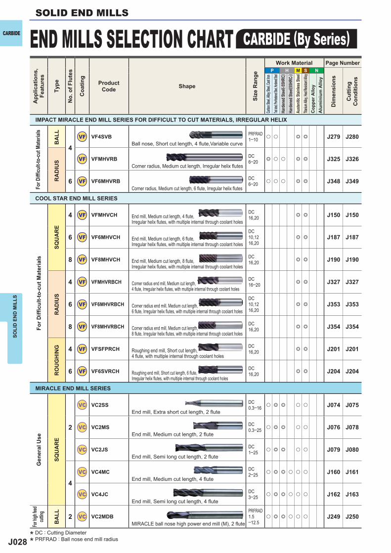
VF VF4SVB PRFRAD1─10 u u e e J279 J280
VF VFMHVRB DC6─20 e u u e e J325 J326
6 VF VF6MHVRB
DC6─20 u u u e e J348 J349
4 VF VFMHVCH DC16,20 e e J150 J150
6 VF VF6MHVCHDC10,1216,20
e e J187 J187
8 VF VF8MHVCH DC16,20 e e J190 J190
4 VF VFMHVRBCH DC16─20 e e J327 J327
6 VF VF6MHVRBCHDC10,1216,20
e e J353 J353
8 VF VF8MHVRBCH DC16,20 e e J354 J354
4 VF VFSFPRCH DC16,20 e e J201 J201
6 VF VF6SVRCH DC16,20 e e J204 J204
2
VC VC2SS DC0.3─16 u e e u u J074 J075
VC VC2MS DC0.3─25 u e e u u J076 J078
VC VC2JS DC1─25 u e e u u J079 J080
4
VC VC4MC DC2─25 u e e u u u J160 J161
VC VC4JC DC3─25 u e e u u u J162 J163
2 VC VC2MDBPRFRAD1.5─12.5
u e e u u u J249 J250
SOLI
D E
ND
MIL
LSSOLID END MILLS
END MILLS SELECTION CHART CARBIDE (By Series)CARBIDEA
pplic
atio
ns,
Feat
ures
Type
No.
of F
lute
s
Coa
ting
ProductCode Shape
Size
Ran
ge
Work Material Page Number
Dim
ensi
ons
Cut
ting
Con
ditio
ns
Carbon
Steel, A
lloy Ste
el, Cast
Iron
Tool stee
l, Pre-Ha
rdened S
teel, Har
dened St
eelHa
rden
ed St
eel( -5
5HRC
)Ha
rden
ed St
eel( 5
5HRC
-)Au
stenit
ic St
ainles
s Stee
lTita
nium A
lloy, He
at Resis
tant Al
loyC
oppe
r Allo
yA
lum
iniu
m A
lloy
For D
iffi c
ult-t
o-cu
t Mat
eria
ls
SQU
AR
ER
AD
IUS
RO
UG
HIN
G
Gen
eral
Use
SQU
AR
E
For h
igh fee
d cut
ting
BA
LL
End mill, Medium cut length, 4 flute, Irregular helix flutes, with multiple internal through coolant holes
End mill, Medium cut length, 6 flute, Irregular helix flutes, with multiple internal through coolant holes
End mill, Medium cut length, 8 flute, Irregular helix flutes, with multiple internal through coolant holes
Corner radius end mill, Medium cut length, 4 fl ute, Irregular helix fl utes, with multiple internal through coolant holes
Corner radius end mill, Medium cut length, 6 fl ute, Irregular helix fl utes, with multiple internal through coolant holes
Corner radius end mill, Medium cut length, 8 fl ute, Irregular helix fl utes, with multiple internal through coolant holes
Roughing end mill, Short cut length, 4 fl ute, with multiple internal through coolant holes
Roughing end mill, Short cut length, 6 fl ute, Irregular helix fl utes, with multiple internal through coolant holes
End mill, Extra short cut length, 2 flute
End mill, Medium cut length, 2 flute
End mill, Semi long cut length, 2 flute
End mill, Medium cut length, 4 flute
End mill, Semi long cut length, 4 flute
MIRACLE ball nose high power end mill (M), 2 flute
COOL STAR END MILL SERIES
MIRACLE END MILL SERIES
For D
iffi cu
lt-to
-cut
Mat
erial
s
BA
LLR
AD
IUS
IMPACT MIRACLE END MILL SERIES FOR DIFFICULT TO CUT MATERIALS, IRREGULAR HELIX
Ball nose, Short cut length, 4 fl ute,Variable curve
Corner radius, Medium cut length, Irregular helix flutes
Corner radius, Medium cut length, 6 flute, Irregular helix flutes
* DC : Cutting Diameter
* PRFRAD : Ball nose end mill radius
J029
P H M S N
2
VC VC2ESB PRFRAD0.15─6 u e e u u u J243 J244
VC VC2MBPRFRAD0.2─12.5
u e e u u u J248 J250
3 VC VC3MB PRFRAD1─10 u e e u u u J276 J277
2 VC VCXB PRFRAD0.5─6 u e e u u u J251 J253
4
VC VC4SRB DC4─12 u e e u u u J335 J336
VC VC4JRB DC3─20 u e u u u u J337 J338
34 VC VCSFPR DC
3─20 e e u e e J202 J203
2 VC VC2C DC2─12 e e e u e e u u J377 J377
2VC VC2PSB PRFRAD
0.05─6 e e e u u J245 J247
VC VC2PSBP PRFRAD0.02─6 e e e u u J246 J247
24 VC VCPSRB DC
0.6─12 e e e e u u J292 J295
4 VC VCHFRB DC2─16 e e e u u J339 J341
46 VC VCMDSC DC
0.5─3 u e e e J164 J165
6 VC VCLD DC6─25 u e e e J188 J188
4VC VC4MB PRFRAD
0.5─10 u e e e u u J285 J286
VC VC4STB PRFRAD0.3─4 u e e e u u J373 J375
SOLI
D E
ND
MIL
LS
CARBIDEA
pplic
atio
ns,
Feat
ures
Type
No.
of F
lute
s
Coa
ting
ProductCode Shape
Size
Ran
ge
Work Material Page Number
Dim
ensi
ons
Cut
ting
Con
ditio
ns
Carbon
Steel, A
lloy Ste
el, Cast
Iron
Tool stee
l, Pre-Ha
rdened S
teel, Har
dened St
eelHa
rden
ed St
eel( -5
5HRC
)Ha
rden
ed St
eel( 5
5HRC
-)Au
stenit
ic St
ainles
s Stee
lTita
nium A
lloy, He
at Resis
tant Al
loyC
oppe
r Allo
yA
lum
iniu
m A
lloy
For P
rofi l
ing
BA
LL
For H
igh
Effi c
iency
Ma
chini
ngFor
Deep
Slottin
gTA
PER
N
ECK
B
ALL
For C
orne
rR
adiu
s
RA
DIU
S
For
Roug
hing
ROUG
HING
For
Cham
fering
CHAM
FERING
For H
igh-
Prec
ision
Ma
chin
ing
BA
LL
For U
ltra hi
gh-
precis
ion
Mach
ining
For H
igh-
Prec
ision
Ma
chin
ing
RA
DIU
S
For H
igh
Feed
Mach
inin
g
RA
DIU
S
For M
achi
ning
of
Har
dene
d St
eels
SQU
AR
EB
ALL
For An
gled
Face
Machin
ingTA
PER
B
ALL
MIRACLE NOVA END MILL SERIES
MIRACLE ORBIT END MILL SERIES
MIRACLE CORNER RADIUS END MILL SERIES FOR HIGH FEED MACHINING
MIRACLE END MILL SERIES FOR HIGH HARDNESS STEEL
Ball nose, Extra short cut length, 2 flute, Short shank
Ball nose end mill, Medium cut length, 2 flute
Ball nose end mill, Medium cut length, 3 flute
Ball nose taper end mill, Medium cut length, Taper neck
Corner radius end mill, Short cut length, 4 flute
Corner radius end mill, Semi long cut length, 4 flute
Roughing end mill, Short cut length, 3─4 flute
Chamfer cutter, 2 flute
Ball nose end mill, Short cut length, 2 flute, High precision
MIRACLE ball nose ultra high-precision end mill(S), 2 flute
Corner radius end mill, Short cut length, 2─4 flute, High precision
Corner radius, Short flute length, 4 flute, High feed machining
End mill, Medium cut length, 4─6 flute
End mill, Long cut length, 6 flute
Ball nose end mill, Medium cut length, 4 flute
Ball nose taper end mill, Short cut length, 4 flute
J030
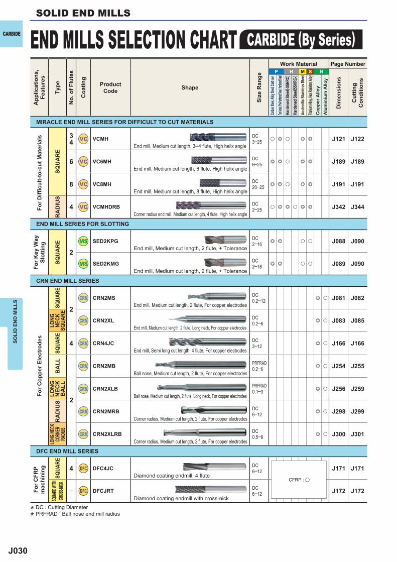
P H M S N
34 VC VCMH DC
3─25 u e u e e J121 J122
6 VC VC6MH DC6─25 e e u e e J189 J189
8 VC VC8MH DC20─25 e e u e e J191 J191
4 VC VCMHDRB DC2─25 u e e u e e J342 J344
2
SED2KPG DC2─16 e e u u J088 J090
SED2KMG DC2─16 e e u u J089 J090
2
CRN CRN2MS DC0.2─12 e u J081 J082
CRN CRN2XL DC0.2─6 e u J083 J085
4 CRN CRN4JC DC3─12 e u J166 J166
2
CRN CRN2MB PRFRAD0.2─6 e u J254 J255
CRN CRN2XLB PRFRAD0.1─3 e u J256 J259
CRN CRN2MRB DC6─12 e u J298 J299
CRN CRN2XLRB DC0.5─6 e u J300 J301
4 DFC DFC4JC DC6─12 J171 J171
― DFC DFCJRT DC6─12 J172 J172
SOLI
D E
ND
MIL
LSSOLID END MILLS
END MILLS SELECTION CHART CARBIDE (By Series)CARBIDEA
pplic
atio
ns,
Feat
ures
Type
No.
of F
lute
s
Coa
ting
ProductCode Shape
Size
Ran
ge
Work Material Page Number
Dim
ensi
ons
Cut
ting
Con
ditio
ns
Carbon
Steel, A
lloy Ste
el, Cast
Iron
Tool stee
l, Pre-Ha
rdened S
teel, Har
dened St
eelHa
rden
ed St
eel( -5
5HRC
)Ha
rden
ed St
eel( 5
5HRC
-)Au
stenit
ic St
ainles
s Stee
lTita
nium A
lloy, He
at Resis
tant Al
loyC
oppe
r Allo
yA
lum
iniu
m A
lloy
For D
iffi c
ult-t
o-cu
t Mat
eria
ls
SQU
AR
ER
AD
IUS
For K
ey W
aySl
ottin
g
SQU
AR
E
For C
oppe
r Ele
ctro
des
SQUA
RELO
NG
NECK
SQUA
RESQ
UARE
BA
LLLO
NG
N
ECK
BA
LLR
AD
IUS
LONG
NECK
CORN
ER
RADIU
S
For C
FRP
mac
hini
ng
SQUA
RESQ
UARE
WITH
CROS
S-NICK
END MILL SERIES FOR SLOTTING
CRN END MILL SERIES
DFC END MILL SERIES
End mill, Medium cut length, 3─4 flute, High helix angle
End mill, Medium cut length, 6 flute, High helix angle
End mill, Medium cut length, 8 flute, High helix angle
Corner radius end mill, Medium cut length, 4 flute, High helix angle
End mill, Medium cut length, 2 flute, For copper electrodes
End mill, Medium cut length, 2 flute, Long neck, For copper electrodes
End mill, Semi long cut length, 4 flute, For copper electrodes
End mill, Medium cut length, 2 fl ute, + Tolerance
End mill, Medium cut length, 2 fl ute, + Tolerance
Ball nose, Medium cut length, 2 flute, For copper electrodes
Ball nose, Medium cut length, 2 flute, Long neck, For copper electrodes
Corner radius, Medium cut length, 2 flute, For copper electrodes
Corner radius, Medium cut length, 2 flute, For copper electrodes
Diamond coating endmill, 4 fl ute
Diamond coating endmill with cross-nick
MIRACLE END MILL SERIES FOR DIFFICULT TO CUT MATERIALS
CFRP : u
* DC : Cutting Diameter
* PRFRAD : Ball nose end mill radius
J031
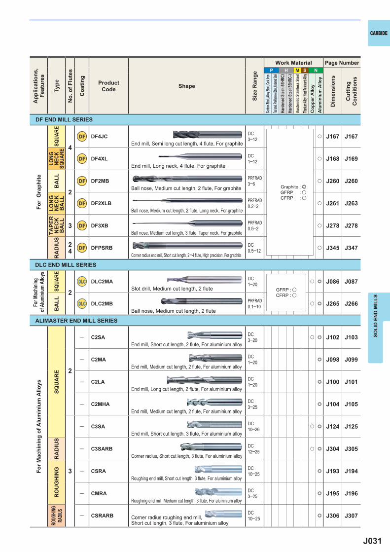
P H M S N
4
DF DF4JC DC3─12 u J167 J167
DF DF4XL DC1─12 u J168 J169
2
DF DF2MB PRFRAD3─6 u J260 J260
DF DF2XLB PRFRAD0.2─2 u J261 J263
3 DF DF3XB PRFRAD0.5─2 u J278 J278
24 DF DFPSRB DC
0.5─12 u J345 J347
2DLC DLC2MA DC
1─20 u e J086 J087
DLC DLC2MB PRFRAD0.1─10 u e J265 J266
2
― C2SA DC3─20 u e J102 J103
― C2MA DC1─20 e J098 J099
― C2LA DC1─20 e J100 J101
― C2MHA DC3─25 e J104 J105
3
― C3SA DC10─26 u e J124 J125
― C3SARB DC12─25 u e J304 J305
― CSRA DC10─25 e J193 J194
― CMRA DC3─25 e J195 J196
― CSRARB DC10─25 e J306 J307
SOLI
D E
ND
MIL
LS
CARBIDEA
pplic
atio
ns,
Feat
ures
Type
No.
of F
lute
s
Coa
ting
ProductCode Shape
Size
Ran
ge
Work Material Page Number
Dim
ensi
ons
Cut
ting
Con
ditio
ns
Carbon
Steel, A
lloy Ste
el, Cast
Iron
Tool stee
l, Pre-Ha
rdened S
teel, Har
dened St
eelHa
rden
ed St
eel( -5
5HRC
)Ha
rden
ed St
eel( 5
5HRC
-)Au
stenit
ic St
ainles
s Stee
lTita
nium A
lloy, He
at Resis
tant Al
loyC
oppe
r Allo
yA
lum
iniu
m A
lloy
DLC END MILL SERIES
ALIMASTER END MILL SERIES
For
Gra
phite
SQUA
RELO
NG
NECK
SQUA
REB
ALL
LON
G
NEC
KB
ALL
TAPE
R
NEC
K
BA
LLR
AD
IUS
For M
achin
ing of
Alum
inium
Allo
ys
SQUA
REB
ALL
For M
achi
ning
of A
lum
iniu
m A
lloys
SQU
AR
ER
AD
IUS
RO
UG
HIN
GRO
UGHIN
GRA
DIUS
DF END MILL SERIES
End mill, Semi long cut length, 4 fl ute, For graphite
End mill, Long neck, 4 fl ute, For graphite
Ball nose, Medium cut length, 2 flute, For graphite
Ball nose, Medium cut length, 2 flute, Long neck, For graphite
Ball nose, Medium cut length, 3 flute, Taper neck, For graphite
Corner radius end mill, Short cut length, 2─4 fl ute, High precision, For graphite
Slot drill, Medium cut length, 2 flute
Ball nose, Medium cut length, 2 flute
End mill, Short cut length, 2 flute, For aluminium alloy
End mill, Medium cut length, 2 flute, For aluminium alloy
End mill, Long cut length, 2 flute, For aluminium alloy
End mill, Medium cut length, 2 flute, For aluminium alloy
End mill, Short cut length, 3 flute, For aluminium alloy
Corner radius, Short cut length, 3 flute, For aluminium alloy
Roughing end mill, Short cut length, 3 flute, For aluminium alloy
Roughing end mill, Medium cut length, 3 flute, For aluminium alloy
Corner radius roughing end mill, Short cut length, 3 flute, For aluminium alloy
GFRP : uCFRP : u
Graphite : eGFRP : uCFRP : u
J032
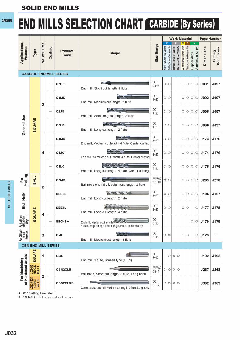
P H M S N
2
― C2SS DC0.4─6 u u u u u u J091 J097
― C2MS DC1─20 u u u u u u J092 J097
― C2JS DC1─25 u u u u u u J095 J097
― C2LS DC1─20 u u u u u u J096 J097
4
― C4MC DC3─20 u u u u u u J173 J176
― C4JC DC3─25 u u u u u u J174 J176
― C4LC DC3─20 u u u u u u J175 J176
2
― C2MB PRFRAD0.5─10 e u u u u u J269 J270
― SEE2L DC3─20 e u u u u u J106 J107
4
― SEE4L DC3─25 e u u u u J177 J178
― SEG4SA DC6─25 u e J179 J179
3 ― CMH DC6─16 u e u u u J123 ―
1 ― GBE DC6─12 u e e J192 J192
2
― CBN2XLB PRFRAD0.2─1 u e e e J267 J268
― CBN2XLRB DC0.5─2 u e e e J302 J303
SOLI
D E
ND
MIL
LSSOLID END MILLS
END MILLS SELECTION CHART CARBIDE (By Series)CARBIDEA
pplic
atio
ns,
Feat
ures
Type
No.
of F
lute
s
Coa
ting
ProductCode Shape
Size
Ran
ge
Work Material Page Number
Dim
ensi
ons
Cut
ting
Con
ditio
ns
Carbon
Steel, A
lloy Ste
el, Cast
Iron
Tool stee
l, Pre-Ha
rdened S
teel, Har
dened St
eelHa
rden
ed St
eel( -5
5HRC
)Ha
rden
ed St
eel( 5
5HRC
-)Au
stenit
ic St
ainles
s Stee
lTita
nium A
lloy, He
at Resis
tant Al
loyC
oppe
r Allo
yA
lum
iniu
m A
lloy
Gen
eral
Use
SQU
AR
E
For
Profi
ling
BA
LL
Hig
h H
elix
SQU
AR
E
For Ma
chinin
g of A
luminiu
m Allo
ys
For D
iffi cu
lt-to-
cut
Mater
ialsFo
r Mac
hini
ngof
Har
dene
d St
eels
SQUA
RELO
NG
N
ECK
BA
LL
LONG
NECK
CORN
ER
RADIU
S
CARBIDE END MILL SERIES
CBN END MILL SERIES
End mill, Short cut length, 2 flute
End mill, Medium cut length, 2 flute
End mill, Semi long cut length, 2 flute
End mill, Long cut length, 2 flute
End mill, Medium cut length, 4 flute, Center cutting
End mill, Semi long cut length, 4 flute, Center cutting
End mill, Long cut length, 4 flute, Center cutting
Ball nose end mill, Medium cut length, 2 flute
End mill, Long cut length, 2 flute
End mill, Long cut length, 4 flute
End mill, Medium cut length, 4 flute, Irregular spiral helix angle, For aluminium alloy
End mill, Medium cut length, 3 flute
End mill, 1 flute, Brazed type (CBN)
Ball nose, Short cut length, 2 flute, Long neck
Corner radius end mill, Medium cut length, 2 flute, Long neck
* DC : Cutting Diameter
* PRFRAD : Ball nose end mill radius
J033
P H M S N
1 ― GBE DC6─12 u e e J192 J192
2
MS2SS DC0.1─12 e e u u u J048 J051
MS2MS DC0.2─20 e e u u u J049 J051
MS2MD DC1─12 e e u u u J052 J053
MS2JS DC0.1─12 e e u u u J054 J055
MS2LS DC0.2─12 e e u u u J056 J057
VC VC2SS DC0.3─16 u e e u u J074 J075
VC VC2MS DC0.3─25 u e e u u J076 J078
VC VC2JS DC1─25 u e e u u J079 J080
― C2SS DC0.4─6 u u u u u u J091 J097
― C2MS DC1─20 u u u u u u J092 J097
― C2JS DC1─25 u u u u u u J095 J097
― C2LS DC1─20 u u u u u u J096 J097
SED2KPG DC2─16 e e u u J088 J090
SED2KMG DC2─16 e e u u J089 J090
― SEE2L DC3─20 e u u u u u J106 J107
MS2ES DC3─12 e e u u u J065 J066
SOLI
D E
ND
MIL
LS
CARBIDETy
pe
No.
of F
lute
s
App
licat
ions
,Fe
atur
es
Coa
ting
ProductCode Shape
Size
Ran
ge
Work Material Page Number
Dim
ensi
ons
Cut
ting
Con
ditio
ns
Carbon
Steel, A
lloy Ste
el, Cast
Iron
Tool stee
l, Pre-Har
dened St
eel, Hard
ened Stee
lHa
rden
ed St
eel( -5
5HRC
)Ha
rden
ed St
eel( 5
5HRC
-)Au
stenit
ic Sta
inles
s Stee
lTita
nium A
lloy, He
at Resis
tant Al
loyC
oppe
r Allo
yA
lum
iniu
m A
lloy
For Ma
chinin
gof H
ardene
dSte
elsG
ener
al U
seFo
r Key
Way
Slot
ting
Hig
h he
lixFo
r Sma
llAu
toma
tic
Lath
es
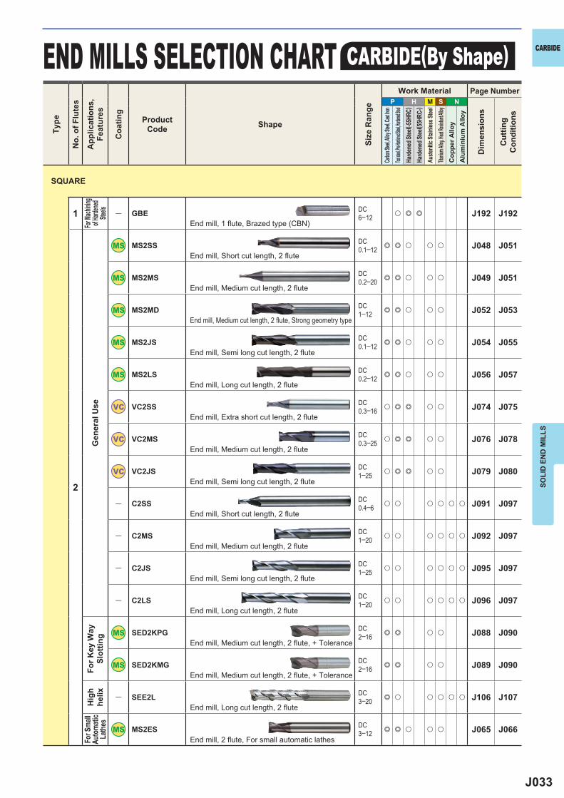
End mill, 1 flute, Brazed type (CBN)
End mill, Short cut length, 2 flute
End mill, Medium cut length, 2 flute
End mill, Medium cut length, 2 flute, Strong geometry type
End mill, Semi long cut length, 2 flute
End mill, Long cut length, 2 flute
End mill, Extra short cut length, 2 flute
End mill, Medium cut length, 2 flute
End mill, Semi long cut length, 2 flute
End mill, Short cut length, 2 flute
End mill, Medium cut length, 2 flute
End mill, Semi long cut length, 2 flute
End mill, Long cut length, 2 flute
End mill, Medium cut length, 2 flute, + Tolerance
End mill, Medium cut length, 2 flute, + Tolerance
End mill, Long cut length, 2 flute
End mill, 2 flute, For small automatic lathes
SQUARE
END MILLS SELECTION CHART CARBIDE(By Shape)
J034
P H M S N
2
VF VF2MD DC0.5─6 u e e e J067 J068
VF VF2MV DC0.5─6 u e e e J069 J070
CRN CRN2MS DC0.2─12 e u J081 J082
DLC DLC2MA DC1─20 u e J086 J087
― C2SA DC3─20 u e J102 J103
― C2MA DC1─20 e J098 J099
― C2LA DC1─20 e J100 J101
― C2MHA DC3─25 e J104 J105
3
MSMHZD DC1─20 e e u e u J108 J109
MS3ES DC3─12 e e u u u J110 J111
VQ VQMHZV DC1─20 e u e e u J112 J114
VQ VQMHZVOH DC6─16 e u e e u J118 J119
― CMH DC6─16 u e u u u J123 ―
― C3SA DC10─26 u e J124 J125
34
VQ VQXL DC0.2─1 e u e e u J157 J158
VQ VQSVR DC3─20 e u e e u J180 J181
VC VCMH DC3─25 u e u e e J121 J122
NEW
NEW
SOLI
D E
ND
MIL
LSSOLID END MILLS
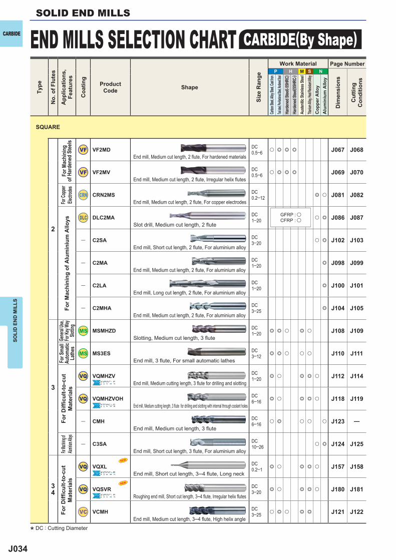
END MILLS SELECTION CHART CARBIDE(By Shape)CARBIDE
SQUARE
For M
achi
ning
of
Har
dene
d St
eels
For M
achi
ning
of A
lum
iniu
m A
lloys
Gene
ral Us
e,Fo
r Key
Way
Slottin
g
For S
mall
Auto
matic
La
thes
For D
iffi c
ult-t
o-cu
t M
ater
ials
For Mac
hining of
Alumini
um Alloys
For D
iffi c
ult-t
o-cu
t M
ater
ials
End mill, Medium cut length, 2 flute, For hardened materials
End mill, Medium cut length, 2 flute, Irregular helix flutes
End mill, Medium cut length, 2 flute, For copper electrodes
Slot drill, Medium cut length, 2 flute
End mill, Short cut length, 2 flute, For aluminium alloy
End mill, Medium cut length, 2 flute, For aluminium alloy
End mill, Long cut length, 2 flute, For aluminium alloy
End mill, Medium cut length, 2 flute, For aluminium alloy
Slotting, Medium cut length, 3 flute
End mill, 3 flute, For small automatic lathes
End mill, Medium cutting length, 3 flute for drilling and slotting
End mill, Medium cutting length, 3 flute for drilling and slotting with internal through coolant holes
End mill, Medium cut length, 3 flute
End mill, Short cut length, 3 flute, For aluminium alloy
End mill, Short cut length, 3─4 flute, Long neck
Roughing end mill, Short cut length, 3─4 flute, Irregular helix flutes
End mill, Medium cut length, 3─4 flute, High helix angle
Type
No.
of F
lute
s
App
licat
ions
,Fe
atur
es
Coa
ting
ProductCode Shape
Size
Ran
ge
Work Material Page Number
Dim
ensi
ons
Cut
ting
Con
ditio
ns
Carbon
Steel, A
lloy Ste
el, Cast
Iron
Tool stee
l, Pre-Har
dened St
eel, Hard
ened Stee
lHa
rden
ed St
eel( -5
5HRC
)Ha
rden
ed St
eel( 5
5HRC
-)Au
stenit
ic Sta
inles
s Stee
lTita
nium A
lloy, He
at Resis
tant Al
loyC
oppe
r Allo
yA
lum
iniu
m A
lloy
GFRP : uCFRP : u
For C
oppe
r Ele
ctrod
es
* DC : Cutting Diameter
J035
P H M S N
4
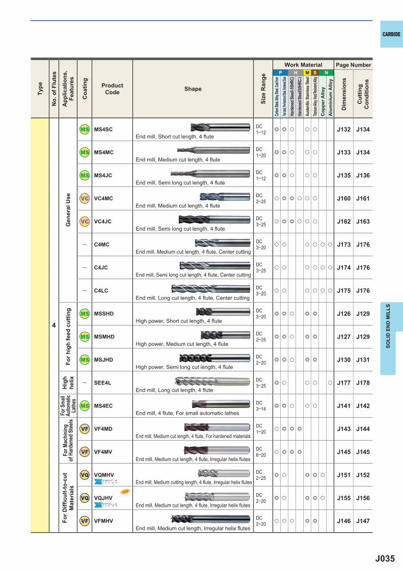
MS4SC DC1─12 e e u u u J132 J134
MS4MC DC1─20 e e u u u J133 J134
MS4JC DC1─12 e e u u u J135 J136
VC VC4MC DC2─25 u e e u u u J160 J161
VC VC4JC DC3─25 u e e u u u J162 J163
― C4MC DC3─20 u u u u u u J173 J176
― C4JC DC3─25 u u u u u u J174 J176
― C4LC DC3─20 u u u u u u J175 J176
MSSHD DC3─20 e e u e e J126 J129
MSMHD DC2─25 e e u e e J127 J129
MSJHD DC2─20 e e u e e J130 J131
― SEE4L DC3─25 e u u u u J177 J178
MS4EC DC3─14 e e u u u J141 J142
VF VF4MD DC1─20 u e e e J143 J144
VF VF4MV DC6─20 u e e e J145 J145
VQ VQMHV DC2─25 e u e e u J151 J152
VQ VQJHV DC2─20 e u e e u J155 J156
VF VFMHV DC2─20 u u u e e J146 J147
NEW
SOLI
D E
ND
MIL
LS
CARBIDETy
pe
No.
of F
lute
s
App
licat
ions
,Fe
atur
es
Coa
ting
ProductCode Shape
Size
Ran
ge
Work Material Page Number
Dim
ensi
ons
Cut
ting
Con
ditio
ns
Carbon
Steel, A
lloy Ste
el, Cast
Iron
Tool stee
l, Pre-Har
dened St
eel, Hard
ened Stee
lHa
rden
ed St
eel( -5
5HRC
)Ha
rden
ed St
eel( 5
5HRC
-)Au
stenit
ic Sta
inles
s Stee
lTita
nium A
lloy, He
at Resis
tant Al
loyC
oppe
r Allo
yA
lum
iniu
m A
lloy
Gen
eral
Use
For h
igh
feed
cut
ting
Hig
h he
lixFo
r Sma
llAu
toma
tic
Lath
esFo
r Mac
hini
ng
of H
arde
ned
Stee
lsFo
r Diffi
cul
t-to-
cut
Mat
eria
ls
End mill, Short cut length, 4 flute
End mill, Medium cut length, 4 flute
End mill, Semi long cut length, 4 flute
End mill, Medium cut length, 4 flute
End mill, Semi long cut length, 4 flute
End mill, Medium cut length, 4 flute, Center cutting
End mill, Semi long cut length, 4 flute, Center cutting
End mill, Long cut length, 4 flute, Center cutting
High power, Short cut length, 4 flute
High power, Medium cut length, 4 flute
High power, Semi long cut length, 4 flute
End mill, Long cut length, 4 flute
End mill, 4 flute, For small automatic lathes
End mill, Medium cut length, 4 flute, For hardened materials
End mill, Medium cut length, 4 flute, Irregular helix flutes
End mill, Medium cutting length, 4 fl ute, Irregular helix fl utes
End mill, Medium cut length, 4 flute, Irregular helix flutes
End mill, Medium cut length, Irregular helix flutes
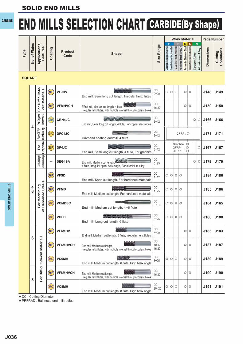
J036
P H M S N
4
VF VFJHV DC2─20 u u u e e J148 J149
VF VFMHVCH DC16,20 e e J150 J150
CRN CRN4JC DC3─12 e u J166 J166
DFC DFC4JC DC6─12 J171 J171
DF DF4JC DC3─12 u J167 J167
― SEG4SA DC6─25 u e J179 J179
46
VF VFSD DC1─12 u e e e J184 J186
VF VFMD DC1─25 u e e e J185 J186
VC VCMDSC DC0.5─3 u e e e J164 J165
6
VC VCLD DC6─25 u e e e J188 J188
VF VF6MHV DC6─20 e e J183 J183
VF VF6MHVCHDC10,1216,20
e e J187 J187
VC VC6MH DC6─25 e e u e e J189 J189
8VF VF8MHVCH DC
16,20 e e J190 J190
VC VC8MH DC20─25 e e u e e J191 J191
SOLI
D E
ND
MIL
LSSOLID END MILLS
END MILLS SELECTION CHART CARBIDE(By Shape)CARBIDETy
pe
No.
of F
lute
s
App
licat
ions
,Fe
atur
es
Coa
ting
ProductCode Shape
Size
Ran
ge
Work Material Page Number
Dim
ensi
ons
Cut
ting
Con
ditio
ns
Carbon
Steel, A
lloy Ste
el, Cast
Iron
Tool stee
l, Pre-Har
dened St
eel, Hard
ened Stee
lHa
rden
ed St
eel( -5
5HRC
)Ha
rden
ed St
eel( 5
5HRC
-)Au
stenit
ic Sta
inles
s Stee
lTita
nium A
lloy, He
at Resis
tant Al
loyC
oppe
r Allo
yA
lum
iniu
m A
lloy
For D
iffi c
ult-t
o-cu
t Mat
eria
lsFo
r Cop
per
Electr
odes
For C
FRP
mach
ining
For
Grap
hite
For Mac
hining o
f Alum
inium A
lloys
For M
achi
ning
of
Har
dene
d St
eels
For D
iffi c
ult-t
o-cu
t Mat
eria
ls
End mill, Semi long cut length, Irregular helix flutes
EEnd mill, Medium cut length, 4 flute, Irregular helix flutes, with multiple internal through coolant holes
End mill, Semi long cut length, 4 flute, For copper electrodes
Diamond coating endmill, 4 fl ute
End mill, Semi long cut length, 4 fl ute, For graphite
End mill, Medium cut length, 4 flute, Irregular spiral helix angle, For aluminium alloy
End mill, Short cut length, For hardened materials
End mill, Medium cut length, For hardened materials
End mill, Medium cut length, 4─6 flute
End mill, Long cut length, 6 flute
End mill, Medium cut length, 6 flute, Irregular helix flutes
End mill, Medium cut length, Irregular helix flutes, with multiple internal through coolant holes
End mill, Medium cut length, 6 flute, High helix angle
End mill, Medium cut length, Irregular helix flutes, with multiple internal through coolant holes
End mill, Medium cut length, 8 flute, High helix angle
CFRP : u
Graphite : eGFRP : uCFRP : u
SQUARE
* DC : Cutting Diameter
* PRFRAD : Ball nose end mill radius
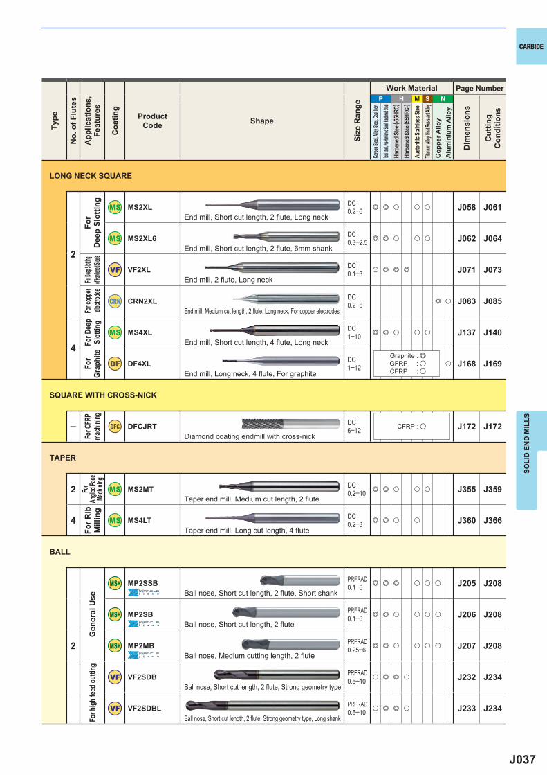
J037
P H M S N
2
MS2XL DC0.2─6 e e u u u J058 J061
MS2XL6 DC0.3─2.5 e e u u u J062 J064
VF VF2XL DC0.1─3 u e e e J071 J073
CRN CRN2XL DC0.2─6 e u J083 J085
4
MS4XL DC1─10 e e u u u J137 J140
DF DF4XL DC1─12 u J168 J169
― DFC DFCJRT DC6─12 J172 J172
2 MS2MT DC0.2─10 e e u u u J355 J359
4 MS4LT DC0.2─3 e e u u J360 J366
2
MP2SSB PRFRAD0.1─6 e e e u u u J205 J208
MP2SB PRFRAD0.1─6 e e u u u u J206 J208
MP2MB PRFRAD0.25─6 e e u u u u J207 J208
VF VF2SDB PRFRAD0.5─10 u e e u J232 J234
VF VF2SDBL PRFRAD0.5─10 u e e u J233 J234
SOLI
D E
ND
MIL
LS
CARBIDETy
pe
No.
of F
lute
s
App
licat
ions
,Fe
atur
es
Coa
ting
ProductCode Shape
Size
Ran
ge
Work Material Page Number
Dim
ensi
ons
Cut
ting
Con
ditio
ns
Carbon
Steel, A
lloy Ste
el, Cast
Iron
Tool stee
l, Pre-Har
dened St
eel, Hard
ened Stee
lHa
rden
ed St
eel( -5
5HRC
)Ha
rden
ed St
eel( 5
5HRC
-)Au
stenit
ic Sta
inles
s Stee
lTita
nium A
lloy, He
at Resis
tant Al
loyC
oppe
r Allo
yA
lum
iniu
m A
lloy
For
Dee
p Sl
ottin
gFor
Deep Sl
otting
of Harde
ned Ste
elsFo
r cop
per
electr
odes
For D
eep
Slot
ting
For
Grap
hite
For C
FRP
mach
ining
For
Angle
d Face
Mach
ining
For R
ib
Mill
ing
Gen
eral
Use
For h
igh fe
ed cu
tting
End mill, Short cut length, 2 flute, Long neck
End mill, Short cut length, 2 flute, 6mm shank
End mill, 2 flute, Long neck
End mill, Medium cut length, 2 flute, Long neck, For copper electrodes
End mill, Short cut length, 4 flute, Long neck
End mill, Long neck, 4 fl ute, For graphite
Diamond coating endmill with cross-nick
Taper end mill, Medium cut length, 2 flute
Taper end mill, Long cut length, 4 flute
Ball nose, Short cut length, 2 fl ute, Short shank
Ball nose, Short cut length, 2 flute
Ball nose, Medium cutting length, 2 flute
Ball nose, Short cut length, 2 flute, Strong geometry type
Ball nose, Short cut length, 2 flute, Strong geometry type, Long shank
SQUARE WITH CROSS-NICK
TAPER
BALL
CFRP : u
Graphite : eGFRP : uCFRP : u
LONG NECK SQUARE
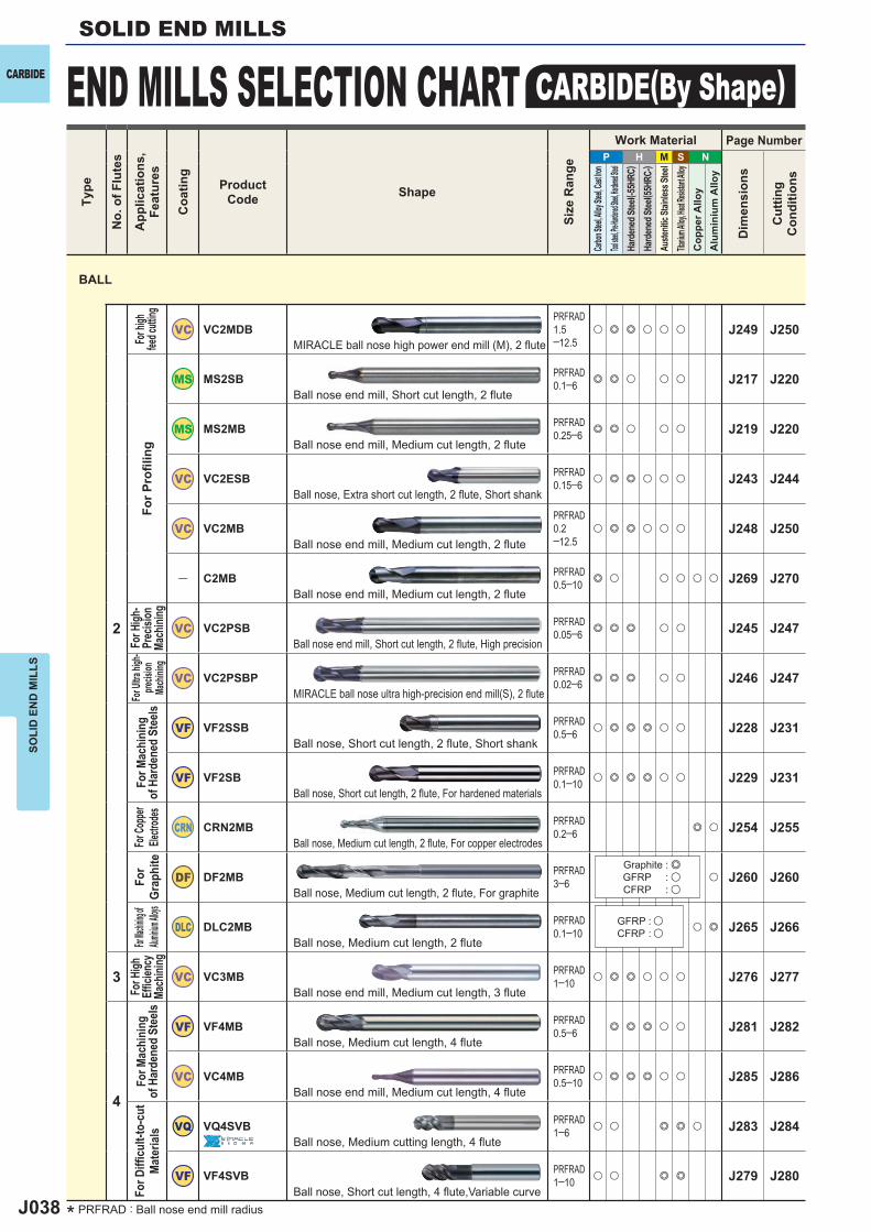
J038
P H M S N
2
VC VC2MDBPRFRAD1.5─12.5
u e e u u u J249 J250
MS2SB PRFRAD0.1─6 e e u u u J217 J220
MS2MB PRFRAD0.25─6 e e u u u J219 J220
VC VC2ESB PRFRAD0.15─6 u e e u u u J243 J244
VC VC2MBPRFRAD0.2─12.5
u e e u u u J248 J250
― C2MB PRFRAD0.5─10 e u u u u u J269 J270
VC VC2PSB PRFRAD0.05─6 e e e u u J245 J247
VC VC2PSBP PRFRAD0.02─6 e e e u u J246 J247
VF VF2SSB PRFRAD0.5─6 u e e e u u J228 J231
VF VF2SB PRFRAD0.1─10 u e e e u u J229 J231
CRN CRN2MB PRFRAD0.2─6 e u J254 J255
DF DF2MB PRFRAD3─6 u J260 J260
DLC DLC2MB PRFRAD0.1─10 u e J265 J266
3 VC VC3MB PRFRAD1─10 u e e u u u J276 J277
4
VF VF4MB PRFRAD0.5─6 e e e u u J281 J282
VC VC4MB PRFRAD0.5─10 u e e e u u J285 J286
VQ VQ4SVB PRFRAD1─6 u u e e u J283 J284
VF VF4SVB PRFRAD1─10 u u e e J279 J280
SOLI
D E
ND
MIL
LSSOLID END MILLS
END MILLS SELECTION CHART CARBIDE(By Shape)CARBIDETy
pe
No.
of F
lute
s
App
licat
ions
,Fe
atur
es
Coa
ting
ProductCode Shape
Size
Ran
ge
Work Material Page Number
Dim
ensi
ons
Cut
ting
Con
ditio
ns
Carbon
Steel, A
lloy Ste
el, Cast
Iron
Tool stee
l, Pre-Har
dened St
eel, Hard
ened Stee
lHa
rden
ed St
eel( -5
5HRC
)Ha
rden
ed St
eel( 5
5HRC
-)Au
stenit
ic Sta
inles
s Stee
lTita
nium A
lloy, He
at Resis
tant Al
loyC
oppe
r Allo
yA
lum
iniu
m A
lloy
For h
igh
feed c
utting
For P
rofi l
ing
For H
igh-
Prec
ision
Ma
chini
ng
For U
ltra hi
gh-
precis
ion
Mach
ining
For M
achi
ning
of
Har
dene
d St
eels
For C
oppe
r Ele
ctrod
esFo
r Gr
aphi
teFor
Machinin
g of Alu
minium A
lloysFo
r High
Effi c
iency
Ma
chini
ngFo
r Mac
hini
ng
of H
arde
ned
Stee
lsFo
r Diffi
cul
t-to-
cut
Mat
eria
ls
MIRACLE ball nose high power end mill (M), 2 flute
Ball nose end mill, Short cut length, 2 flute
Ball nose end mill, Medium cut length, 2 flute
Ball nose, Extra short cut length, 2 flute, Short shank
Ball nose end mill, Medium cut length, 2 flute
Ball nose end mill, Medium cut length, 2 flute
Ball nose end mill, Short cut length, 2 flute, High precision
MIRACLE ball nose ultra high-precision end mill(S), 2 flute
Ball nose, Short cut length, 2 flute, Short shank
Ball nose, Short cut length, 2 flute, For hardened materials
Ball nose, Medium cut length, 2 flute, For copper electrodes
Ball nose, Medium cut length, 2 flute, For graphite
Ball nose, Medium cut length, 2 flute
Ball nose end mill, Medium cut length, 3 flute
Ball nose, Medium cut length, 4 flute
Ball nose end mill, Medium cut length, 4 flute
Ball nose, Medium cutting length, 4 flute
Ball nose, Short cut length, 4 fl ute,Variable curve
Graphite : eGFRP : uCFRP : u
GFRP : uCFRP : u
BALL
* PRFRAD : Ball nose end mill radius
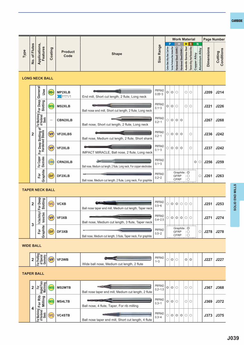
J039
P H M S N
2
MP2XLB PRFRAD0.05─3 e e u u u J209 J214
MS2XLB PRFRAD0.1─3 e e u u u J221 J226
― CBN2XLB
PRFRAD0.2─1 u e e e J267 J268
VF VF2XLBS PRFRAD0.2─1 u e e e u J236 J242
VF VF2XLB PRFRAD0.1─3 u e e e u J237 J242
CRN CRN2XLB PRFRAD0.1─3 e u J256 J259
DF DF2XLB PRFRAD0.2─2 u J261 J263
2 VC VCXB PRFRAD0.5─6 u e e u u u J251 J253
3VF VF3XB PRFRAD
0.4─2.5 u e e e u u J271 J274
DF DF3XB PRFRAD0.5─2 u J278 J278
2 VF VF2WB PRFRAD1─3 u e u e e J227 J227
2 MS2MTB PRFRAD0.2─1.5 e e u u u J367 J368
4
MS4LTB PRFRAD0.3─1 e e u u u J369 J372
VC VC4STB PRFRAD0.3─4 u e e e u u J373 J375
SOLI
D E
ND
MIL
LS
CARBIDETy
pe
No.
of F
lute
s
App
licat
ions
,Fe
atur
es
Coa
ting
ProductCode Shape
Size
Ran
ge
Work Material Page Number
Dim
ensi
ons
Cut
ting
Con
ditio
ns
Carbon
Steel, A
lloy Ste
el, Cast
Iron
Tool stee
l, Pre-Har
dened St
eel, Hard
ened Stee
lHa
rden
ed St
eel( -5
5HRC
)Ha
rden
ed St
eel( 5
5HRC
-)Au
stenit
ic Sta
inles
s Stee
lTita
nium A
lloy, He
at Resis
tant Al
loyC
oppe
r Allo
yA
lum
iniu
m A
lloy
End mill, Short cut length, 2 fl ute, Long neck
Ball nose end mill, Short cut length, 2 flute, Long neck
Ball nose, Short cut length, 2 flute, Long neck
Ball nose, Medium cut length, 2 flute, Short shank
IMPACT MIRACLE, Ball nose, 2 flute, Long neck
Ball nose, Medium cut length, 2 flute, Long neck, For copper electrodes
Ball nose, Medium cut length, 2 flute, Long neck, For graphite
Ball nose taper end mill, Medium cut length, Taper neck
Ball nose, Medium cut length, 3 flute, Taper neck
Ball nose, Medium cut length, 3 flute, Taper neck, For graphite
Wide ball nose, Medium cut length, 2 flute
Ball nose taper end mill, Medium cut length, 2 flute
Ball nose, 4 flute, Taper, For rib milling
Ball nose taper end mill, Short cut length, 4 flute
Gen
eral
U
seFo
r Dee
p S
lotti
ngFor
Machi
ning
of Hard
ened
Steels
For D
eep
Slot
ting
of
Hard
ened
Ste
elsFo
r Cop
per
Electr
odes
For
Grap
hite
For D
eep
Slot
ting
For Deep
Slotting
of Har
dened St
eelsFo
r Gr
aphi
teFo
r Profi
ling
of Sp
ecial
Geom
etry
For
Angle
d Face
Mach
ining
For R
ib
Mill
ing
For Ma
chinin
g of H
ardene
d Ste
els
TAPER BALL
WIDE BALL
TAPER NECK BALL
Graphite : eGFRP : uCFRP : u
LONG NECK BALL
Graphite : eGFRP : uCFRP : u
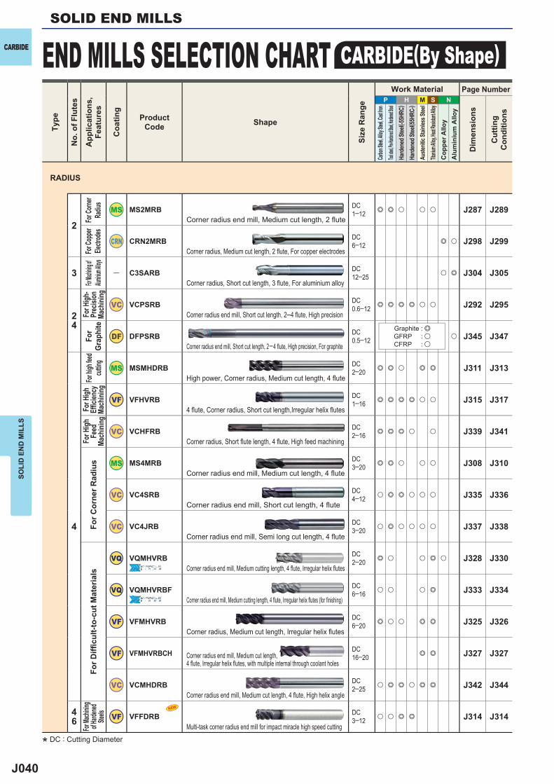
J040
P H M S N
2
MS2MRB DC1─12 e e u u u J287 J289
CRN CRN2MRB DC6─12 e u J298 J299
3 ― C3SARB DC12─25 u e J304 J305
24
VC VCPSRB DC0.6─12 e e e e u u J292 J295
DF DFPSRB DC0.5─12 u J345 J347
4
MSMHDRB DC2─20 e e u e e J311 J313
VF VFHVRB DC1─16 e e e e u u J315 J317
VC VCHFRB DC2─16 e e e u u J339 J341
MS4MRB DC3─20 e e u u u J308 J310
VC VC4SRB DC4─12 u e e u u u J335 J336
VC VC4JRB DC3─20 u e u u u u J337 J338
VQ VQMHVRB DC2─20 e u u e u J328 J330
VQ VQMHVRBF DC6─16 u u u e J333 J334
VF VFMHVRB DC6─20 e u u e e J325 J326
VF VFMHVRBCH DC16─20 e e J327 J327
VC VCMHDRB DC2─25 u e e u e e J342 J344
46 VF VFFDRB DC
3─12 u u e e J314 J314NEW
SOLI
D E
ND
MIL
LSSOLID END MILLS
END MILLS SELECTION CHART CARBIDE(By Shape)CARBIDETy
pe
No.
of F
lute
s
App
licat
ions
,Fe
atur
es
Coa
ting
ProductCode Shape
Size
Ran
ge
Work Material Page Number
Dim
ensi
ons
Cut
ting
Con
ditio
ns
Carbon
Steel, A
lloy Ste
el, Cast
Iron
Tool stee
l, Pre-Har
dened St
eel, Hard
ened Stee
lHa
rden
ed St
eel( -5
5HRC
)Ha
rden
ed St
eel( 5
5HRC
-)Au
stenit
ic Sta
inles
s Stee
lTita
nium A
lloy, He
at Resis
tant Al
loyC
oppe
r Allo
yA
lum
iniu
m A
lloy
Corner radius end mill, Medium cut length, 2 flute
Corner radius, Medium cut length, 2 flute, For copper electrodes
Corner radius, Short cut length, 3 flute, For aluminium alloy
Corner radius end mill, Short cut length, 2─4 flute, High precision
Corner radius end mill, Short cut length, 2─4 fl ute, High precision, For graphite
High power, Corner radius, Medium cut length, 4 flute
4 fl ute, Corner radius, Short cut length,Irregular helix fl utes
Corner radius, Short flute length, 4 flute, High feed machining
Corner radius end mill, Medium cut length, 4 flute
Corner radius end mill, Short cut length, 4 flute
Corner radius end mill, Semi long cut length, 4 flute
Corner radius end mill, Medium cutting length, 4 fl ute, Irregular helix fl utes
Corner radius end mill, Medium cutting length, 4 fl ute, Irregular helix fl utes (for fi nishing)
Corner radius, Medium cut length, Irregular helix flutes
Corner radius end mill, Medium cut length, 4 fl ute, Irregular helix fl utes, with multiple internal through coolant holes
Corner radius end mill, Medium cut length, 4 flute, High helix angle
Multi-task corner radius end mill for impact miracle high speed cutting
For C
orner
Radiu
sFo
r Cop
per
Electr
odes
For Mac
hining of
Alumini
um Alloys
For H
igh-
Prec
ision
Ma
chini
ngFo
r Gr
aphi
teFo
r high
feed
cuttin
gFo
r High
Effi c
iency
Ma
chini
ng
For H
ighFe
edMa
chini
ngFo
r Cor
ner R
adiu
sFo
r Diffi
cul
t-to-
cut M
ater
ials
For Ma
chinin
g of H
ardene
d Ste
els
RADIUS
Graphite : eGFRP : uCFRP : u
* DC : Cutting Diameter
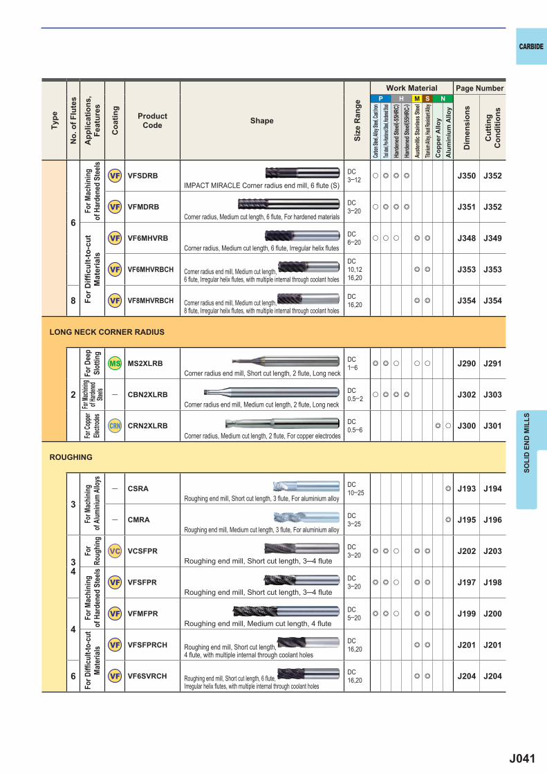
J041
P H M S N
6
VF VFSDRB DC3─12 u e e e J350 J352
VF VFMDRB DC3─20 u e e e J351 J352
VF VF6MHVRB DC6─20 u u u e e J348 J349
VF VF6MHVRBCHDC10,1216,20
e e J353 J353
8 VF VF8MHVRBCH DC16,20 e e J354 J354
2
MS2XLRB DC1─6 e e u u u J290 J291
― CBN2XLRB DC0.5─2 u e e e J302 J303
CRN CRN2XLRB DC0.5─6 e u J300 J301
3
― CSRA DC10─25 e J193 J194
― CMRA DC3─25 e J195 J196
34
VC VCSFPR DC3─20 e e u e e J202 J203
VF VFSFPR DC3─20 e e u e e J197 J198
4
VF VFMFPR DC5─20 e e u e e J199 J200
VF VFSFPRCH DC16,20 e e J201 J201
6 VF VF6SVRCH DC16,20 e e J204 J204
SOLI
D E
ND
MIL
LS
CARBIDETy
pe
No.
of F
lute
s
App
licat
ions
,Fe
atur
es
Coa
ting
ProductCode Shape
Size
Ran
ge
Work Material Page Number
Dim
ensi
ons
Cut
ting
Con
ditio
ns
Carbon
Steel, A
lloy Ste
el, Cast
Iron
Tool stee
l, Pre-Har
dened St
eel, Hard
ened Stee
lHa
rden
ed St
eel( -5
5HRC
)Ha
rden
ed St
eel( 5
5HRC
-)Au
stenit
ic Sta
inles
s Stee
lTita
nium A
lloy, He
at Resis
tant Al
loyC
oppe
r Allo
yA
lum
iniu
m A
lloy
Corner radius end mill, Short cut length, 2 flute, Long neck
Corner radius end mill, Medium cut length, 2 flute, Long neck
Corner radius, Medium cut length, 2 flute, For copper electrodes
Roughing end mill, Short cut length, 3 flute, For aluminium alloy
Roughing end mill, Medium cut length, 3 flute, For aluminium alloy
Roughing end mill, Short cut length, 3─4 flute
Roughing end mill, Short cut length, 3─4 flute
Roughing end mill, Medium cut length, 4 flute
Roughing end mill, Short cut length, 4 fl ute, with multiple internal through coolant holes
Roughing end mill, Short cut length, 6 fl ute, Irregular helix fl utes, with multiple internal through coolant holes
For D
eep
Slot
ting
For Ma
chinin
g of H
ardene
d Ste
elsFo
r Cop
per
Electr
odes
For M
achin
ing of
Alum
inium
Allo
ysFo
r Ro
ughin
gFo
r Mac
hini
ng
of H
arde
ned
Stee
lsFo
r Diffi
cul
t-to-
cut
Mat
eria
ls
LONG NECK CORNER RADIUS
ROUGHING
IMPACT MIRACLE Corner radius end mill, 6 fl ute (S)
Corner radius, Medium cut length, 6 flute, For hardened materials
Corner radius, Medium cut length, 6 flute, Irregular helix flutes
Corner radius end mill, Medium cut length, 6 fl ute, Irregular helix fl utes, with multiple internal through coolant holes
Corner radius end mill, Medium cut length, 8 fl ute, Irregular helix fl utes, with multiple internal through coolant holes
For M
achi
ning
of
Har
dene
d St
eels
For D
iffi c
ult-t
o-cu
t M
ater
ials
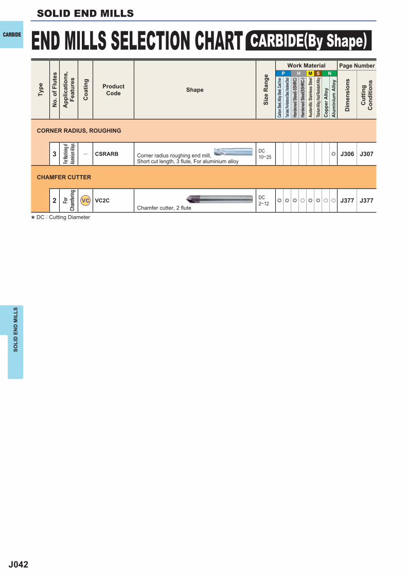
J042
P H M S N
3 ― CSRARB DC10─25 e J306 J307
2 VC VC2C DC2─12 e e e u e e u u J377 J377
SOLI
D E
ND
MIL
LSSOLID END MILLS
END MILLS SELECTION CHART CARBIDE(By Shape)CARBIDETy
pe
No.
of F
lute
s
App
licat
ions
,Fe
atur
es
Coa
ting
ProductCode Shape
Size
Ran
ge
Work Material Page Number
Dim
ensi
ons
Cut
ting
Con
ditio
ns
Carbon
Steel, A
lloy Ste
el, Cast
Iron
Tool stee
l, Pre-Har
dened St
eel, Hard
ened Stee
lHa
rden
ed St
eel( -5
5HRC
)Ha
rden
ed St
eel( 5
5HRC
-)Au
stenit
ic Sta
inles
s Stee
lTita
nium A
lloy, He
at Resis
tant Al
loyC
oppe
r Allo
yA
lum
iniu
m A
lloy
Corner radius roughing end mill, Short cut length, 3 flute, For aluminium alloy
Chamfer cutter, 2 flute
CORNER RADIUS, ROUGHING
CHAMFER CUTTER
For Mac
hining o
f Alum
inium A
lloys
For
Cham
fering
* DC : Cutting Diameter
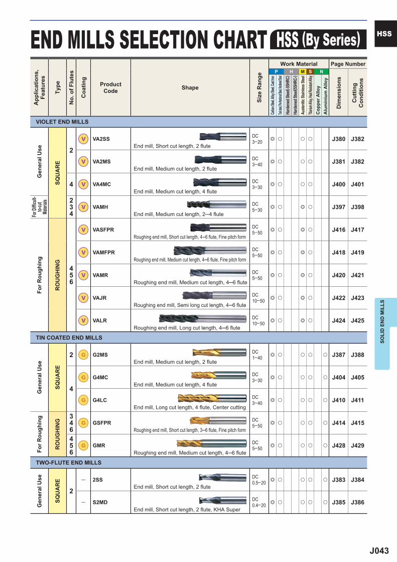
J043
P H M S N
2
V VA2SS DC3─20 e u u u J380 J382
V VA2MS DC3─40 e u u u J381 J382
4 V VA4MC DC3─30 e u u u J400 J401
234
V VAMH DC5─30 e u e u J397 J398
456
V VASFPR DC5─50 e u e u J416 J417
V VAMFPR DC5─50 e u e u J418 J419
V VAMR DC5─50 e u e u J420 J421
V VAJR DC10─50 e u e u J422 J423
V VALR DC10─50 e u e u J424 J425
2 G G2MS DC1─40 e u u u u J387 J388
4
G G4MC DC3─30 e u u u u J404 J405
G G4LC DC3─40 e u u u u J410 J411
346
G GSFPR DC5─50 e u u u u J414 J415
456
G GMR DC5─50 e u u u u J428 J429
2
― 2SS DC0.5─20 e u u u u J383 J384
― S2MD DC0.4─20 e u u u u J385 J386
SOLI
D E
ND
MIL
LS
HSSEND MILLS SELECTION CHART HSS (By Series)
VIOLET END MILLS
Gen
eral
Use
SQU
AR
E
For R
ough
ing
RO
UG
HIN
G
Gen
eral
Use
SQU
AR
E
For D
iffi cu
lt-to-
cut
Mater
ialsFo
r Rou
ghin
g
RO
UG
HIN
G
Gen
eral
Use
SQU
AR
E
TIN COATED END MILLS
TWO-FLUTE END MILLS
End mill, Short cut length, 2 flute
End mill, Medium cut length, 2 flute
End mill, Medium cut length, 4 flute
End mill, Medium cut length, 2─4 flute
Roughing end mill, Short cut length, 4─6 flute, Fine pitch form
Roughing end mill, Medium cut length, 4─6 flute, Fine pitch form
Roughing end mill, Medium cut length, 4─6 flute
Roughing end mill, Semi long cut length, 4─6 flute
Roughing end mill, Long cut length, 4─6 flute
End mill, Medium cut length, 2 flute
End mill, Medium cut length, 4 flute
End mill, Long cut length, 4 flute, Center cutting
Roughing end mill, Short cut length, 3─6 flute, Fine pitch form
Roughing end mill, Medium cut length, 4─6 flute
End mill, Short cut length, 2 flute
End mill, Short cut length, 2 flute, KHA Super
App
licat
ions
,Fe
atur
es
Type
No.
of F
lute
s
Coa
ting
ProductCode Shape
Size
Ran
ge
Work Material Page Number
Dim
ensi
ons
Cut
ting
Con
ditio
ns
Carbon
Steel, A
lloy Ste
el, Cast
Iron
Tool stee
l, Pre-Har
dened St
eel, Hard
ened Stee
lHa
rden
ed St
eel( -5
5HRC
)Ha
rden
ed St
eel( 5
5HRC
-)Au
stenit
ic Sta
inles
s Stee
lTita
nium A
lloy, He
at Resis
tant Al
loyC
oppe
r Allo
yA
lum
iniu
m A
lloy
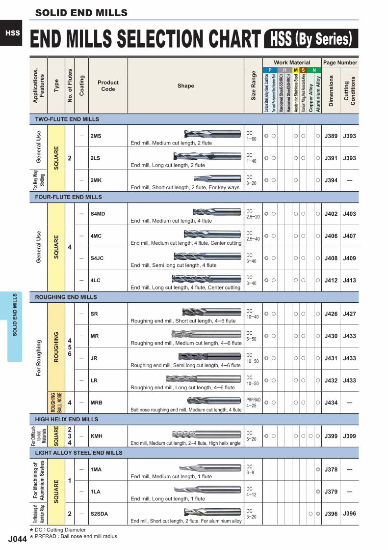
J044
P H M S N
2
― 2MS DC1─60 e u u u u J389 J393
― 2LS DC1─40 e u u u u J391 J393
― 2MK DC3─20 e u u u J394 ―
4
― S4MD DC2.5─20 e u u u u J402 J403
― 4MC DC2.5─40 e u u u u J406 J407
― S4JC DC3─40 e u u u u J408 J409
― 4LC DC3─40 e u u u u J412 J413
456
― SR DC10─40 e u u u u J426 J427
― MR DC5─50 e u u u u J430 J433
― JR DC10─50 e u u u u J431 J433
― LR DC10─50 e u u u u J432 J433
4 ― MRB PRFRAD4─25 e u u u u J434 ―
234
― KMH DC5─20 e u u u u u J399 J399
1
― 1MA DC3─8 e J378 ―
― 1LA DC4─12 e J379 ―
2 ― S2SDA DC3─20 u e J396 J396
SOLI
D E
ND
MIL
LSSOLID END MILLS
HSS END MILLS SELECTION CHART HSS (By Series)A
pplic
atio
ns,
Feat
ures
Type
No.
of F
lute
s
Coa
ting
ProductCode Shape
Size
Ran
ge
Work Material Page Number
Dim
ensi
ons
Cut
ting
Con
ditio
ns
Carbon
Steel, A
lloy Ste
el, Cast
Iron
Tool stee
l, Pre-Har
dened St
eel, Hard
ened Stee
lHa
rden
ed St
eel( -5
5HRC
)Ha
rden
ed St
eel( 5
5HRC
-)Au
stenit
ic Sta
inles
s Stee
lTita
nium A
lloy, He
at Resis
tant Al
loyC
oppe
r Allo
yA
lum
iniu
m A
lloy
For D
iffi cu
lt-to-
cut
Mater
ials
SQUA
RE
Gen
eral
Use
SQU
AR
E
For K
ey Wa
ySlo
tting
FOUR-FLUTE END MILLS
Gen
eral
Use
SQU
AR
E
ROUGHING END MILLS
For R
ough
ing
RO
UG
HIN
GRO
UGHIN
GBA
LL NO
SE
HIGH HELIX END MILLS
End mill, Medium cut length, 2 flute
End mill, Long cut length, 2 flute
End mill, Short cut length, 2 flute, For key ways
End mill, Medium cut length, 4 flute
End mill, Medium cut length, 4 flute, Center cutting
End mill, Semi long cut length, 4 flute
End mill, Long cut length, 4 flute, Center cutting
Roughing end mill, Short cut length, 4─6 flute
Roughing end mill, Medium cut length, 4─6 flute
Roughing end mill, Semi long cut length, 4─6 flute
Roughing end mill, Long cut length, 4─6 flute
Ball nose roughing end mill, Medium cut length, 4 flute
End mill, Medium cut length, 2─4 flute, High helix angle
LIGHT ALLOY STEEL END MILLS
For M
achi
ning
of
Alum
iniu
m S
ashe
s
SQU
AR
E
For Mac
hining of
Alumini
um Alloys
End mill, Medium cut length, 1 flute
End mill, Long cut length, 1 flute
End mill, Short cut length, 2 flute, For aluminium alloy
TWO-FLUTE END MILLS
* DC : Cutting Diameter
* PRFRAD : Ball nose end mill radius
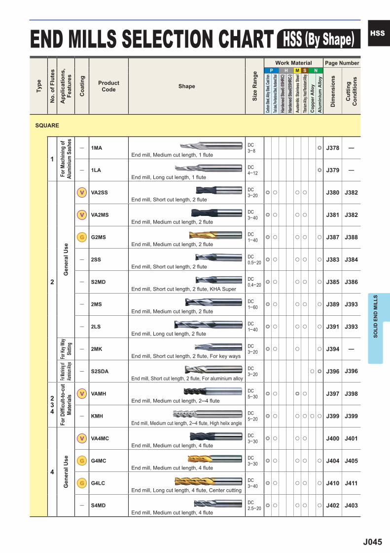
J045
P H M S N
1
― 1MA DC3─8 e J378 ―
― 1LA DC4─12 e J379 ―
2
V VA2SS DC3─20 e u u u J380 J382
V VA2MS DC3─40 e u u u J381 J382
G G2MS DC1─40 e u u u u J387 J388
― 2SS DC0.5─20 e u u u u J383 J384
― S2MD DC0.4─20 e u u u u J385 J386
― 2MS DC1─60 e u u u u J389 J393
― 2LS DC1─40 e u u u u J391 J393
― 2MK DC3─20 e u u u J394 ―
― S2SDA DC3─20 u e J396 J396
234
V VAMH DC5─30 e u e u J397 J398
― KMH DC5─20 e u u u u u J399 J399
4
V VA4MC DC3─30 e u u u J400 J401
G G4MC DC3─30 e u u u u J404 J405
G G4LC DC3─40 e u u u u J410 J411
― S4MD DC2.5─20 e u u u u J402 J403
SOLI
D E
ND
MIL
LS
HSSEND MILLS SELECTION CHART HSS (By Shape)
SQUARE
For M
achi
ning
of
Alum
iniu
m S
ashe
sG
ener
al U
seFo
r Key
Way
Slottin
gFor
Machinin
g of Alu
minium A
lloysFo
r Diffi
cul
t-to-
cut
Mat
eria
lsG
ener
al U
se
End mill, Medium cut length, 1 flute
End mill, Long cut length, 1 flute
End mill, Short cut length, 2 flute
End mill, Medium cut length, 2 flute
End mill, Medium cut length, 2 flute
End mill, Short cut length, 2 flute
End mill, Short cut length, 2 flute, KHA Super
End mill, Medium cut length, 2 flute
End mill, Long cut length, 2 flute
End mill, Short cut length, 2 flute, For key ways
End mill, Short cut length, 2 flute, For aluminium alloy
End mill, Medium cut length, 2─4 flute
End mill, Medium cut length, 2─4 flute, High helix angle
End mill, Medium cut length, 4 flute
End mill, Medium cut length, 4 flute
End mill, Long cut length, 4 flute, Center cutting
End mill, Medium cut length, 4 flute
Type
No.
of F
lute
s
App
licat
ions
,Fe
atur
es
Coa
ting
ProductCode Shape
Size
Ran
ge
Work Material Page Number
Dim
ensi
ons
Cut
ting
Con
ditio
ns
Carbon
Steel, A
lloy Ste
el, Cast
Iron
Tool stee
l, Pre-Har
dened St
eel, Hard
ened Stee
lHa
rden
ed St
eel( -5
5HRC
)Ha
rden
ed St
eel( 5
5HRC
-)Au
stenit
ic Sta
inles
s Stee
lTita
nium A
lloy, He
at Resis
tant Al
loyC
oppe
r Allo
yA
lum
iniu
m A
lloy
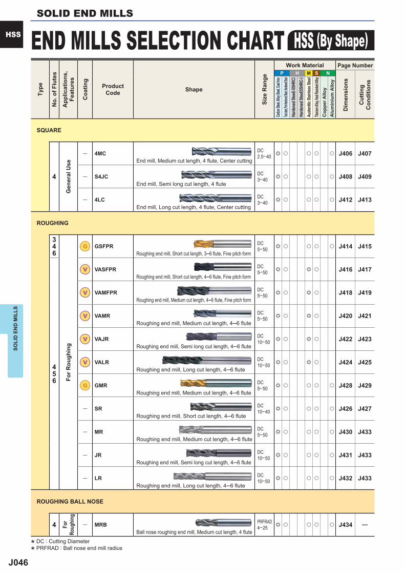
J046
P H M S N
4
― 4MC DC2.5─40 e u u u u J406 J407
― S4JC DC3─40 e u u u u J408 J409
― 4LC DC3─40 e u u u u J412 J413
346
G GSFPR DC5─50 e u u u u J414 J415
456
V VASFPR DC5─50 e u e u J416 J417
V VAMFPR DC5─50 e u e u J418 J419
V VAMR DC5─50 e u e u J420 J421
V VAJR DC10─50 e u e u J422 J423
V VALR DC10─50 e u e u J424 J425
G GMR DC5─50 e u u u u J428 J429
― SR DC10─40 e u u u u J426 J427
― MR DC5─50 e u u u u J430 J433
― JR DC10─50 e u u u u J431 J433
― LR DC10─50 e u u u u J432 J433
4 ― MRB PRFRAD4─25 e u u u u J434 ―
SOLI
D E
ND
MIL
LSSOLID END MILLS
HSS END MILLS SELECTION CHART HSS (By Shape)Ty
pe
No.
of F
lute
s
App
licat
ions
,Fe
atur
es
Coa
ting
ProductCode Shape
Size
Ran
ge
Work Material Page Number
Dim
ensi
ons
Cut
ting
Con
ditio
ns
Carbon
Steel, A
lloy Ste
el, Cast
Iron
Tool stee
l, Pre-Har
dened St
eel, Hard
ened Stee
lHa
rden
ed St
eel( -5
5HRC
)Ha
rden
ed St
eel( 5
5HRC
-)Au
stenit
ic Sta
inles
s Stee
lTita
nium A
lloy, He
at Resis
tant Al
loyC
oppe
r Allo
yA
lum
iniu
m A
lloy
Gen
eral
Use End mill, Medium cut length, 4 flute, Center cutting
End mill, Semi long cut length, 4 flute
End mill, Long cut length, 4 flute, Center cutting
ROUGHING
For R
ough
ing
Roughing end mill, Short cut length, 3─6 flute, Fine pitch form
Roughing end mill, Short cut length, 4─6 flute, Fine pitch form
Roughing end mill, Medium cut length, 4─6 flute, Fine pitch form
Roughing end mill, Medium cut length, 4─6 flute
Roughing end mill, Semi long cut length, 4─6 flute
Roughing end mill, Long cut length, 4─6 flute
Roughing end mill, Medium cut length, 4─6 flute
Roughing end mill, Short cut length, 4─6 flute
Roughing end mill, Medium cut length, 4─6 flute
Roughing end mill, Semi long cut length, 4─6 flute
Roughing end mill, Long cut length, 4─6 flute
ROUGHING BALL NOSE
For
Roug
hing
Ball nose roughing end mill, Medium cut length, 4 flute
SQUARE
* DC : Cutting Diameter
* PRFRAD : Ball nose end mill radius

J047
Memo
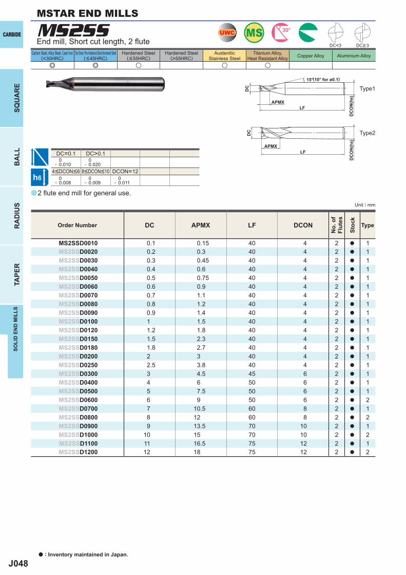
J048
a
MS2SS
e e u u u
DC<3
DC=0.1 DC>0.1 0- 0.010
0- 0.020
DCON=12 0- 0.008
0- 0.009
0- 0.011
DC APMX LF DCON
MS2SSD0010 0.1 0.15 40 4 2 a 1MS2SSD0020 0.2 0.3 40 4 2 a 1MS2SSD0030 0.3 0.45 40 4 2 a 1MS2SSD0040 0.4 0.6 40 4 2 a 1MS2SSD0050 0.5 0.75 40 4 2 a 1MS2SSD0060 0.6 0.9 40 4 2 a 1MS2SSD0070 0.7 1.1 40 4 2 a 1MS2SSD0080 0.8 1.2 40 4 2 a 1MS2SSD0090 0.9 1.4 40 4 2 a 1MS2SSD0100 1 1.5 40 4 2 a 1MS2SSD0120 1.2 1.8 40 4 2 a 1MS2SSD0150 1.5 2.3 40 4 2 a 1MS2SSD0180 1.8 2.7 40 4 2 a 1MS2SSD0200 2 3 40 4 2 a 1MS2SSD0250 2.5 3.8 40 4 2 a 1MS2SSD0300 3 4.5 45 6 2 a 1MS2SSD0400 4 6 50 6 2 a 1MS2SSD0500 5 7.5 50 6 2 a 1MS2SSD0600 6 9 50 6 2 a 2MS2SSD0700 7 10.5 60 8 2 a 1MS2SSD0800 8 12 60 8 2 a 2MS2SSD0900 9 13.5 70 10 2 a 1MS2SSD1000 10 15 70 10 2 a 2MS2SSD1100 11 16.5 75 12 2 a 1MS2SSD1200 12 18 75 12 2 a 2
UWC MS 30°
h6
APMX
15°
LF
DC
DC
ON
(h6)
APMXLF
DC
DC
ON
(h6)
CARBIDE
a : Inventory maintained in Japan.
BA
LLR
AD
IUS
TAPE
RSO
LID
EN
D M
ILLS
SQU
AR
E
Unit : mm
Carbon Steel, Alloy Steel, Cast Iron(<30HRC)
Tool Steel, Pre-Hardened Steel,Hardened Steel(<45HRC)
Hardened Steel(<55HRC)
Hardened Steel(>55HRC)
AusteniticStainless Steel
Titanium Alloy,Heat Resistant Alloy Copper Alloy Aluminium Alloy
MSTAR END MILLS
2 fl ute end mill for general use.
End mill, Short cut length, 2 fl ute
Type1
(10° for ø0.1)
Order Number
No.
of
Flut
es
Stoc
k
Type
DC>3
Type2
4<DCON<6 8<DCON<10
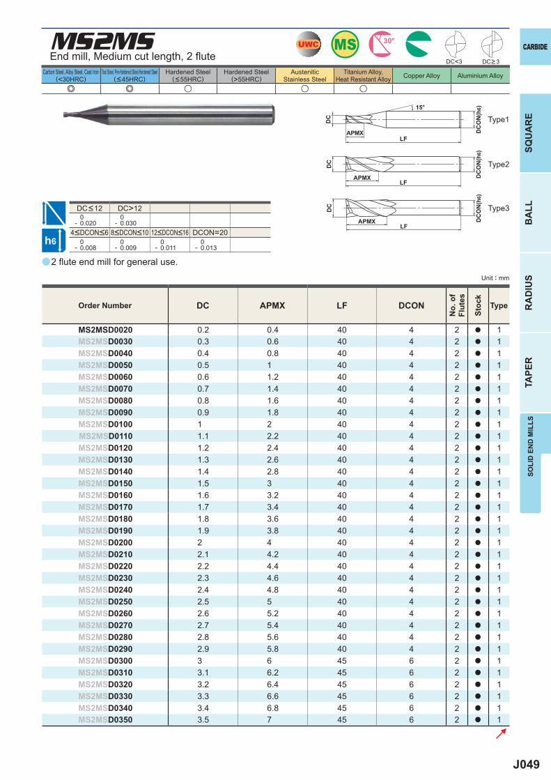
J049
a
e e u u u
MS2MS
DC APMX LF DCON
MS2MSD0020 0.2 0.4 40 4 2 a 1MS2MSD0030 0.3 0.6 40 4 2 a 1MS2MSD0040 0.4 0.8 40 4 2 a 1MS2MSD0050 0.5 1 40 4 2 a 1MS2MSD0060 0.6 1.2 40 4 2 a 1MS2MSD0070 0.7 1.4 40 4 2 a 1MS2MSD0080 0.8 1.6 40 4 2 a 1MS2MSD0090 0.9 1.8 40 4 2 a 1MS2MSD0100 1 2 40 4 2 a 1MS2MSD0110 1.1 2.2 40 4 2 a 1MS2MSD0120 1.2 2.4 40 4 2 a 1MS2MSD0130 1.3 2.6 40 4 2 a 1MS2MSD0140 1.4 2.8 40 4 2 a 1MS2MSD0150 1.5 3 40 4 2 a 1MS2MSD0160 1.6 3.2 40 4 2 a 1MS2MSD0170 1.7 3.4 40 4 2 a 1MS2MSD0180 1.8 3.6 40 4 2 a 1MS2MSD0190 1.9 3.8 40 4 2 a 1MS2MSD0200 2 4 40 4 2 a 1MS2MSD0210 2.1 4.2 40 4 2 a 1MS2MSD0220 2.2 4.4 40 4 2 a 1MS2MSD0230 2.3 4.6 40 4 2 a 1MS2MSD0240 2.4 4.8 40 4 2 a 1MS2MSD0250 2.5 5 40 4 2 a 1MS2MSD0260 2.6 5.2 40 4 2 a 1MS2MSD0270 2.7 5.4 40 4 2 a 1MS2MSD0280 2.8 5.6 40 4 2 a 1MS2MSD0290 2.9 5.8 40 4 2 a 1MS2MSD0300 3 6 45 6 2 a 1MS2MSD0310 3.1 6.2 45 6 2 a 1MS2MSD0320 3.2 6.4 45 6 2 a 1MS2MSD0330 3.3 6.6 45 6 2 a 1MS2MSD0340 3.4 6.8 45 6 2 a 1MS2MSD0350 3.5 7 45 6 2 a 1
DC>12 0- 0.020
0- 0.030
DCON=20 0- 0.008
0- 0.009
0- 0.011
0- 0.013
DC<3
UWC MS 30°
h6
APMX
15°
LF
DC
DC
ON
(h6)
APMXLF
DC
DC
ON
(h6)
APMXLF
DC
DC
ON
(h6)
CARBIDE
SQU
AR
EB
ALL
RA
DIU
STA
PER
SOLI
D E
ND
MIL
LS
Unit : mm
Carbon Steel, Alloy Steel, Cast Iron(<30HRC)
Tool Steel, Pre-Hardened Steel,Hardened Steel(<45HRC)
Hardened Steel(<55HRC)
Hardened Steel(>55HRC)
AusteniticStainless Steel
Titanium Alloy,Heat Resistant Alloy Copper Alloy Aluminium Alloy
2 fl ute end mill for general use.
End mill, Medium cut length, 2 fl ute
Type2
Type3
Type1
Order Number
No.
of
Flut
es
Stoc
k
Type
DC>3
4<DCON<6 8<DCON<10 12<DCON<16
DC<12
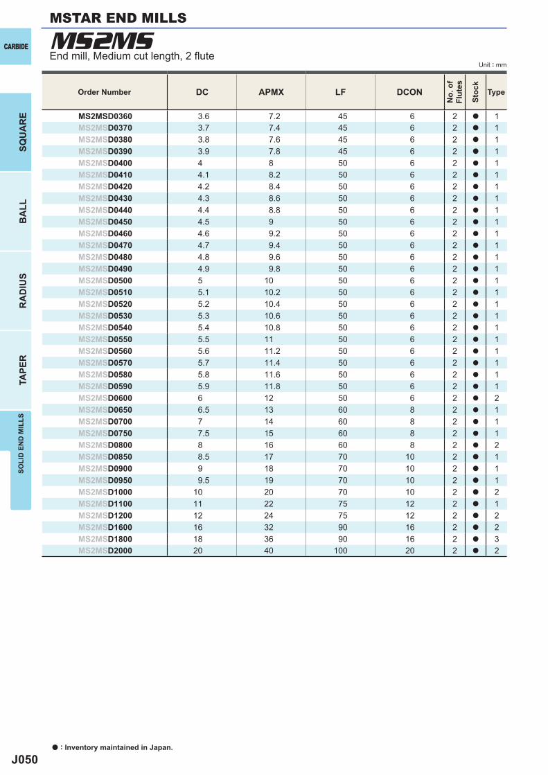
J050
DC APMX LF DCON
MS2MSD0360 3.6 7.2 45 6 2 a 1MS2MSD0370 3.7 7.4 45 6 2 a 1MS2MSD0380 3.8 7.6 45 6 2 a 1MS2MSD0390 3.9 7.8 45 6 2 a 1MS2MSD0400 4 8 50 6 2 a 1MS2MSD0410 4.1 8.2 50 6 2 a 1MS2MSD0420 4.2 8.4 50 6 2 a 1MS2MSD0430 4.3 8.6 50 6 2 a 1MS2MSD0440 4.4 8.8 50 6 2 a 1MS2MSD0450 4.5 9 50 6 2 a 1MS2MSD0460 4.6 9.2 50 6 2 a 1MS2MSD0470 4.7 9.4 50 6 2 a 1MS2MSD0480 4.8 9.6 50 6 2 a 1MS2MSD0490 4.9 9.8 50 6 2 a 1MS2MSD0500 5 10 50 6 2 a 1MS2MSD0510 5.1 10.2 50 6 2 a 1MS2MSD0520 5.2 10.4 50 6 2 a 1MS2MSD0530 5.3 10.6 50 6 2 a 1MS2MSD0540 5.4 10.8 50 6 2 a 1MS2MSD0550 5.5 11 50 6 2 a 1MS2MSD0560 5.6 11.2 50 6 2 a 1MS2MSD0570 5.7 11.4 50 6 2 a 1MS2MSD0580 5.8 11.6 50 6 2 a 1MS2MSD0590 5.9 11.8 50 6 2 a 1MS2MSD0600 6 12 50 6 2 a 2MS2MSD0650 6.5 13 60 8 2 a 1MS2MSD0700 7 14 60 8 2 a 1MS2MSD0750 7.5 15 60 8 2 a 1MS2MSD0800 8 16 60 8 2 a 2MS2MSD0850 8.5 17 70 10 2 a 1MS2MSD0900 9 18 70 10 2 a 1MS2MSD0950 9.5 19 70 10 2 a 1MS2MSD1000 10 20 70 10 2 a 2MS2MSD1100 11 22 75 12 2 a 1MS2MSD1200 12 24 75 12 2 a 2MS2MSD1600 16 32 90 16 2 a 2MS2MSD1800 18 36 90 16 2 a 3MS2MSD2000 20 40 100 20 2 a 2
MS2MSCARBIDE
a : Inventory maintained in Japan.
BA
LLR
AD
IUS
TAPE
RSO
LID
EN
D M
ILLS
SQU
AR
E
Unit : mm
MSTAR END MILLS
End mill, Medium cut length, 2 fl ute
Order Number
No.
of
Flut
es
Stoc
k
Type
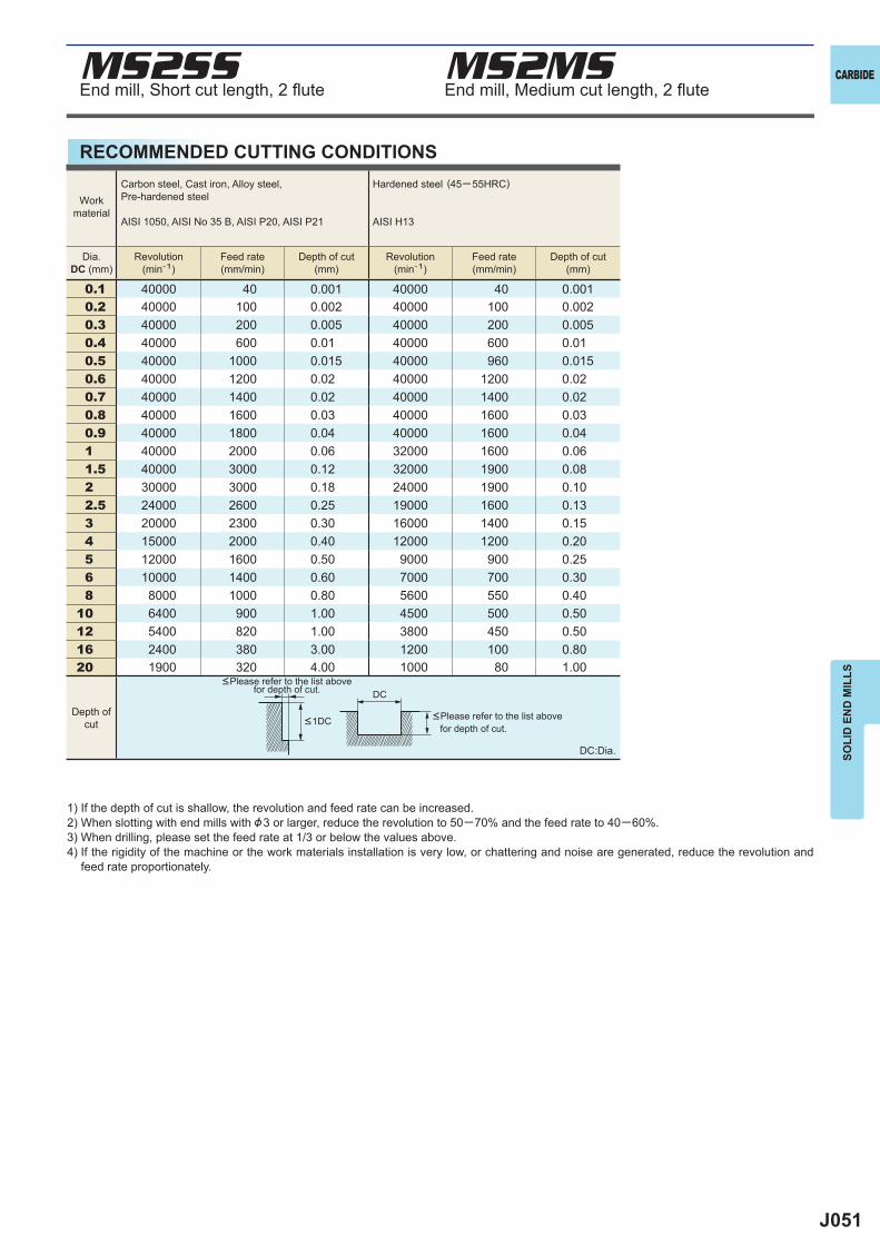
J051
0.1 40000 40 0.001 40000 40 0.0010.2 40000 100 0.002 40000 100 0.0020.3 40000 200 0.005 40000 200 0.0050.4 40000 600 0.01 40000 600 0.010.5 40000 1000 0.015 40000 960 0.0150.6 40000 1200 0.02 40000 1200 0.020.7 40000 1400 0.02 40000 1400 0.020.8 40000 1600 0.03 40000 1600 0.030.9 40000 1800 0.04 40000 1600 0.041 40000 2000 0.06 32000 1600 0.061.5 40000 3000 0.12 32000 1900 0.082 30000 3000 0.18 24000 1900 0.102.5 24000 2600 0.25 19000 1600 0.133 20000 2300 0.30 16000 1400 0.154 15000 2000 0.40 12000 1200 0.205 12000 1600 0.50 9000 900 0.256 10000 1400 0.60 7000 700 0.308 8000 1000 0.80 5600 550 0.40
10 6400 900 1.00 4500 500 0.5012 5400 820 1.00 3800 450 0.5016 2400 380 3.00 1200 100 0.8020 1900 320 4.00 1000 80 1.00
DC
MS2SS MS2MS CARBIDE
SOLI
D E
ND
MIL
LS
1) If the depth of cut is shallow, the revolution and feed rate can be increased.2) When slotting with end mills with &3 or larger, reduce the revolution to 50─70% and the feed rate to 40─60%.3) When drilling, please set the feed rate at 1/3 or below the values above.4) If the rigidity of the machine or the work materials installation is very low, or chattering and noise are generated, reduce the revolution and
feed rate proportionately.
DC:Dia.
<Please refer to the list above for depth of cut.
<Please refer to the list above for depth of cut.
Workmaterial
Carbon steel, Cast iron, Alloy steel,Pre-hardened steel
AISI 1050, AISI No 35 B, AISI P20, AISI P21
Hardened steel (45─ 55HRC)
AISI H13
Dia.DC (mm)
Revolution(min-1)
Feed rate(mm/min)
Depth of cut(mm)
Revolution(min-1)
Feed rate(mm/min)
Depth of cut(mm)
Depth ofcut <1DC
RECOMMENDED CUTTING CONDITIONS
End mill, Short cut length, 2 fl ute End mill, Medium cut length, 2 fl ute
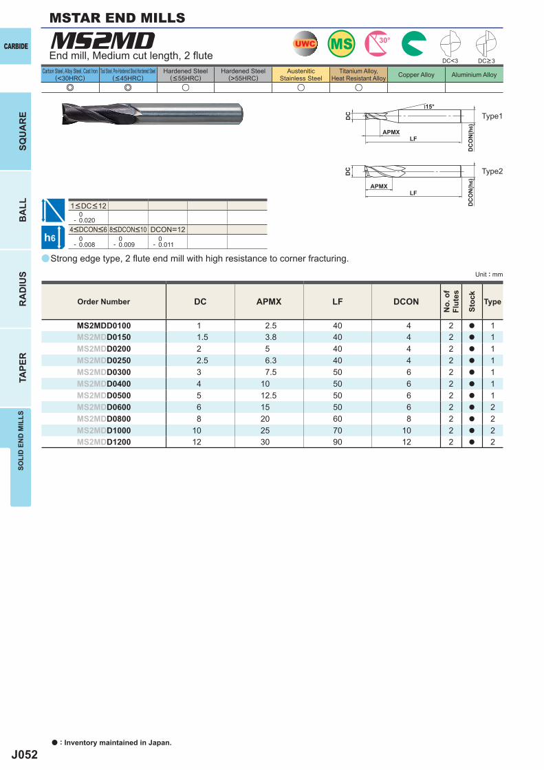
J052
a
e e u u u
MS2MD
DC APMX LF DCON
MS2MDD0100 1 2.5 40 4 2 a 1MS2MDD0150 1.5 3.8 40 4 2 a 1MS2MDD0200 2 5 40 4 2 a 1MS2MDD0250 2.5 6.3 40 4 2 a 1MS2MDD0300 3 7.5 50 6 2 a 1MS2MDD0400 4 10 50 6 2 a 1MS2MDD0500 5 12.5 50 6 2 a 1MS2MDD0600 6 15 50 6 2 a 2MS2MDD0800 8 20 60 8 2 a 2MS2MDD1000 10 25 70 10 2 a 2MS2MDD1200 12 30 90 12 2 a 2
0- 0.020
DCON=12 0- 0.008
0- 0.009
0- 0.011
DC<3
MSUWC 30°
h6
APMXLF
DC
DC
ON
(h6)
15°
APMXLF
DC
DC
ON
(h6)
CARBIDE
a : Inventory maintained in Japan.
BA
LLR
AD
IUS
TAPE
RSO
LID
EN
D M
ILLS
SQU
AR
E
Unit : mm
Carbon Steel, Alloy Steel, Cast Iron(<30HRC)
Tool Steel, Pre-Hardened Steel,Hardened Steel(<45HRC)
Hardened Steel(<55HRC)
Hardened Steel(>55HRC)
AusteniticStainless Steel
Titanium Alloy,Heat Resistant Alloy Copper Alloy Aluminium Alloy
Strong edge type, 2 fl ute end mill with high resistance to corner fracturing.
End mill, Medium cut length, 2 fl ute
Type2
Type1
Order Number
No.
of
Flut
es
Stoc
k
Type
DC>3
4<DCON<6 8<DCON<10
1<DC<12
MSTAR END MILLS
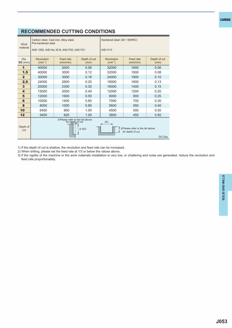
J053
1 40000 2000 0.06 32000 1600 0.061.5 40000 3000 0.12 32000 1900 0.082 30000 3000 0.18 24000 1900 0.102.5 24000 2600 0.25 19000 1600 0.133 20000 2300 0.30 16000 1400 0.154 15000 2000 0.40 12000 1200 0.205 12000 1600 0.50 9000 900 0.256 10000 1400 0.60 7000 700 0.308 8000 1000 0.80 5600 550 0.40
10 6400 900 1.00 4500 500 0.5012 5400 820 1.00 3800 450 0.50
DC
CARBIDE
SOLI
D E
ND
MIL
LS
1) If the depth of cut is shallow, the revolution and feed rate can be increased.2) When drilling, please set the feed rate at 1/3 or below the values above.3) If the rigidity of the machine or the work materials installation is very low, or chattering and noise are generated, reduce the revolution and
feed rate proportionately.
DC:Dia.
<Please refer to the list above for depth of cut.
<Please refer to the list above for depth of cut.
Workmaterial
Carbon steel, Cast iron, Alloy steel,Pre-hardened steel
AISI 1050, AISI No 35 B, AISI P20, AISI P21
Hardened steel (45─ 55HRC)
AISI H13
Dia.DC (mm)
Revolution(min-1)
Feed rate(mm/min)
Depth of cut(mm)
Revolution(min-1)
Feed rate(mm/min)
Depth of cut(mm)
Depth ofcut <1DC
RECOMMENDED CUTTING CONDITIONS
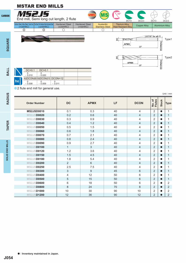
J054
a
e e u u u
MS2JS
DC APMX LF DCON
MS2JSD0010 0.1 0.3 40 4 2 a 1MS2JSD0020 0.2 0.6 40 4 2 a 1MS2JSD0030 0.3 0.9 40 4 2 a 1MS2JSD0040 0.4 1.2 40 4 2 a 1MS2JSD0050 0.5 1.5 40 4 2 a 1MS2JSD0060 0.6 1.8 40 4 2 a 1MS2JSD0070 0.7 2.1 40 4 2 a 1MS2JSD0080 0.8 2.4 40 4 2 a 1MS2JSD0090 0.9 2.7 40 4 2 a 1MS2JSD0100 1 3 40 4 2 a 1MS2JSD0120 1.2 3.6 40 4 2 a 1MS2JSD0150 1.5 4.5 40 4 2 a 1MS2JSD0180 1.8 5.4 40 4 2 a 1MS2JSD0200 2 6 40 4 2 a 1MS2JSD0250 2.5 7.5 40 4 2 a 1MS2JSD0300 3 9 45 6 2 a 1MS2JSD0400 4 12 50 6 2 a 1MS2JSD0500 5 15 50 6 2 a 1MS2JSD0600 6 18 50 6 2 a 2MS2JSD0800 8 24 70 8 2 a 2MS2JSD1000 10 30 90 10 2 a 2MS2JSD1200 12 36 90 12 2 a 2
DC<3 DC<3
DC=0.1 DC>0.1 0- 0.010
0- 0.020
DCON=12 0- 0.008
0- 0.009
0- 0.011
UWC MS 30°
h6
APMXLF
DC
DC
ON
(h6)
15°
APMXLF
DC
DC
ON
(h6)
CARBIDE
a : Inventory maintained in Japan.
BA
LLR
AD
IUS
TAPE
RSO
LID
EN
D M
ILLS
SQU
AR
E
Unit : mm
Carbon Steel, Alloy Steel, Cast Iron(<30HRC)
Tool Steel, Pre-Hardened Steel,Hardened Steel(<45HRC)
Hardened Steel(<55HRC)
Hardened Steel(>55HRC)
AusteniticStainless Steel
Titanium Alloy,Heat Resistant Alloy Copper Alloy Aluminium Alloy
MSTAR END MILLS
2 fl ute end mill for general use.
End mill, Semi long cut length, 2 fl ute
Type2
Type1(10° for ø0.1)
Order Number
No.
of
Flut
es
Stoc
k
Type
DC>3 DC>3
4<DCON<6 8<DCON<10
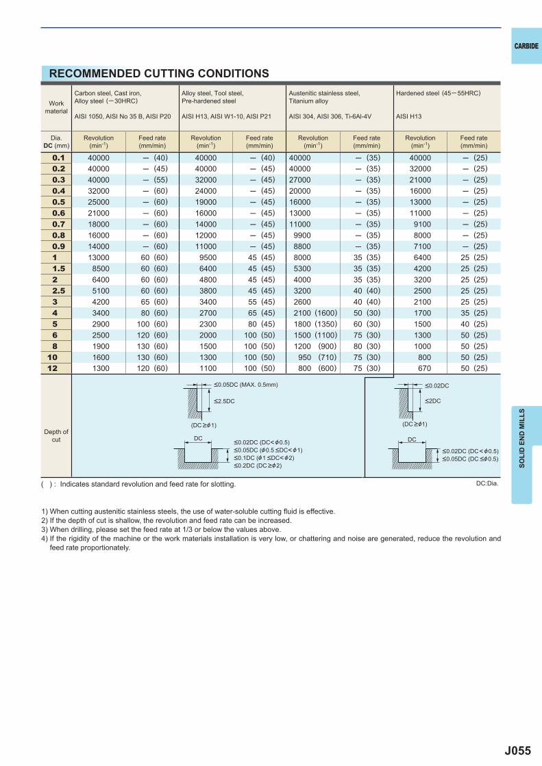
J055
0.1 40000 ─ (40) 40000 ─ (40) 40000 ─ (35) 40000 ─ (25)0.2 40000 ─ (45) 40000 ─ (45) 40000 ─ (35) 32000 ─ (25)0.3 40000 ─ (55) 32000 ─ (45) 27000 ─ (35) 21000 ─ (25)0.4 32000 ─ (60) 24000 ─ (45) 20000 ─ (35) 16000 ─ (25)0.5 25000 ─ (60) 19000 ─ (45) 16000 ─ (35) 13000 ─ (25)0.6 21000 ─ (60) 16000 ─ (45) 13000 ─ (35) 11000 ─ (25)0.7 18000 ─ (60) 14000 ─ (45) 11000 ─ (35) 9100 ─ (25)0.8 16000 ─ (60) 12000 ─ (45) 9900 ─ (35) 8000 ─ (25)0.9 14000 ─ (60) 11000 ─ (45) 8800 ─ (35) 7100 ─ (25)1 13000 60 (60) 9500 45 (45) 8000 35 (35) 6400 25 (25)1.5 8500 60 (60) 6400 45 (45) 5300 35 (35) 4200 25 (25)2 6400 60 (60) 4800 45 (45) 4000 35 (35) 3200 25 (25)2.5 5100 60 (60) 3800 45 (45) 3200 40 (40) 2500 25 (25)3 4200 65 (60) 3400 55 (45) 2600 40 (40) 2100 25 (25)4 3400 80 (60) 2700 65 (45) 2100 (1600) 50 (30) 1700 35 (25)5 2900 100 (60) 2300 80 (45) 1800 (1350) 60 (30) 1500 40 (25)6 2500 120 (60) 2000 100 (50) 1500 (1100) 75 (30) 1300 50 (25)8 1900 130 (60) 1500 100 (50) 1200 (900) 80 (30) 1000 50 (25)
10 1600 130 (60) 1300 100 (50) 950 (710) 75 (30) 800 50 (25)12 1300 120 (60) 1100 100 (50) 800 (600) 75 (30) 670 50 (25)
DC DC
CARBIDE
SOLI
D E
ND
MIL
LS1) When cutting austenitic stainless steels, the use of water-soluble cutting fl uid is effective.2) If the depth of cut is shallow, the revolution and feed rate can be increased.3) When drilling, please set the feed rate at 1/3 or below the values above.4) If the rigidity of the machine or the work materials installation is very low, or chattering and noise are generated, reduce the revolution and
feed rate proportionately.
DC:Dia.( ) : Indicates standard revolution and feed rate for slotting.
Workmaterial
Carbon steel, Cast iron, Alloy steel (─30HRC)
AISI 1050, AISI No 35 B, AISI P20
Alloy steel, Tool steel,Pre-hardened steel
AISI H13, AISI W1-10, AISI P21
Austenitic stainless steel,Titanium alloy
AISI 304, AISI 306, Ti-6Al-4V
Hardened steel (45─ 55HRC)
AISI H13
Dia.DC (mm)
Revolution(min-1)
Feed rate(mm/min)
Revolution(min-1)
Feed rate(mm/min)
Revolution(min-1)
Feed rate(mm/min)
Revolution(min-1)
Feed rate(mm/min)
Depth ofcut
<0.05DC (MAX. 0.5mm)
<2.5DC
<0.02DC (DC<&0.5)<0.05DC (&0.5 <DC<&1)<0.1DC (&1 <DC<&2)<0.2DC (DC >&2)
<0.02DC (DC<&0.5)<0.05DC (DC <&0.5)
<2DC
<0.02DC
(DC >&1) (DC >&1)
RECOMMENDED CUTTING CONDITIONS
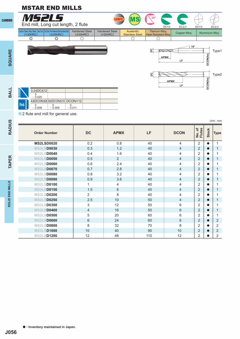
J056
a
e e u u u
MS2LS
DC APMX LF DCON
MS2LSD0020 0.2 0.8 40 4 2 a 1MS2LSD0030 0.3 1.2 40 4 2 a 1MS2LSD0040 0.4 1.6 40 4 2 a 1MS2LSD0050 0.5 2 40 4 2 a 1MS2LSD0060 0.6 2.4 40 4 2 a 1MS2LSD0070 0.7 2.8 40 4 2 a 1MS2LSD0080 0.8 3.2 40 4 2 a 1MS2LSD0090 0.9 3.6 40 4 2 a 1MS2LSD0100 1 4 40 4 2 a 1MS2LSD0150 1.5 6 40 4 2 a 1MS2LSD0200 2 8 40 4 2 a 1MS2LSD0250 2.5 10 50 4 2 a 1MS2LSD0300 3 12 50 6 2 a 1MS2LSD0400 4 16 50 6 2 a 1MS2LSD0500 5 20 60 6 2 a 1MS2LSD0600 6 24 60 6 2 a 2MS2LSD0800 8 32 70 8 2 a 2MS2LSD1000 10 40 90 10 2 a 2MS2LSD1200 12 48 110 12 2 a 2
0- 0.020
DCON=12 0- 0.008
0- 0.009
0- 0.011
DC<3 DC<3
MSUWC 30°
h6
APMXLF
DC
DC
ON
(h6)
15°
APMXLF
DC
DC
ON
(h6)
CARBIDE
a : Inventory maintained in Japan.
BA
LLR
AD
IUS
TAPE
RSO
LID
EN
D M
ILLS
SQU
AR
E
Unit : mm
Carbon Steel, Alloy Steel, Cast Iron(<30HRC)
Tool Steel, Pre-Hardened Steel,Hardened Steel(<45HRC)
Hardened Steel(<55HRC)
Hardened Steel(>55HRC)
AusteniticStainless Steel
Titanium Alloy,Heat Resistant Alloy Copper Alloy Aluminium Alloy
2 fl ute end mill for general use.
End mill, Long cut length, 2 fl ute
Type2
Type1
Order Number
No.
of
Flut
es
Stoc
k
Type
DC>3 DC>3
4<DCON<6 8<DCON<10
0.2<DC<12
MSTAR END MILLS
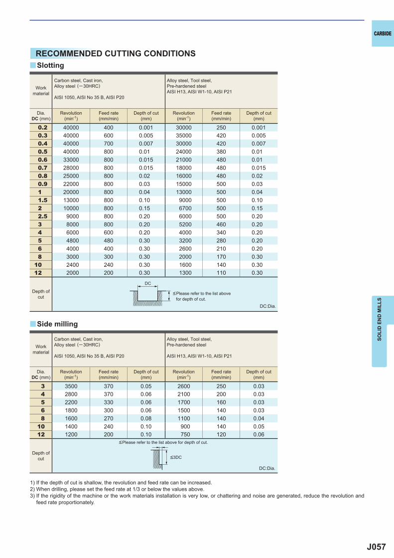
J057
0.2 40000 400 0.001 30000 250 0.0010.3 40000 600 0.005 35000 420 0.0050.4 40000 700 0.007 30000 420 0.0070.5 40000 800 0.01 24000 380 0.010.6 33000 800 0.015 21000 480 0.010.7 28000 800 0.015 18000 480 0.0150.8 25000 800 0.02 16000 480 0.020.9 22000 800 0.03 15000 500 0.031 20000 800 0.04 13000 500 0.041.5 13000 800 0.10 9000 500 0.102 10000 800 0.15 6700 500 0.152.5 9000 800 0.20 6000 500 0.203 8000 800 0.20 5200 460 0.204 6000 600 0.20 4000 340 0.205 4800 480 0.30 3200 280 0.206 4000 400 0.30 2600 210 0.208 3000 300 0.30 2000 170 0.30
10 2400 240 0.30 1600 140 0.3012 2000 200 0.30 1300 110 0.30
3 3500 370 0.05 2600 250 0.034 2800 370 0.06 2100 200 0.035 2200 330 0.06 1700 160 0.036 1800 300 0.06 1500 140 0.038 1600 270 0.08 1100 140 0.04
10 1400 240 0.10 900 140 0.0512 1200 200 0.10 750 120 0.06
DC
y
y
CARBIDE
SOLI
D E
ND
MIL
LS
RECOMMENDED CUTTING CONDITIONS
1) If the depth of cut is shallow, the revolution and feed rate can be increased.2) When drilling, please set the feed rate at 1/3 or below the values above.3) If the rigidity of the machine or the work materials installation is very low, or chattering and noise are generated, reduce the revolution and
feed rate proportionately.
DC:Dia.
DC:Dia.
<Please refer to the list above for depth of cut.
<Please refer to the list above for depth of cut.
Slotting
Side milling
Workmaterial
Carbon steel, Cast iron, Alloy steel (─30HRC)
AISI 1050, AISI No 35 B, AISI P20
Alloy steel, Tool steel,Pre-hardened steelAISI H13, AISI W1-10, AISI P21
Dia.DC (mm)
Revolution(min-1)
Feed rate(mm/min)
Depth of cut(mm)
Revolution(min-1)
Feed rate(mm/min)
Depth of cut(mm)
Depth ofcut
Workmaterial
Carbon steel, Cast iron, Alloy steel (─30HRC)
AISI 1050, AISI No 35 B, AISI P20
Alloy steel, Tool steel,Pre-hardened steel
AISI H13, AISI W1-10, AISI P21
Dia.DC (mm)
Revolution(min-1)
Feed rate(mm/min)
Depth of cut(mm)
Revolution(min-1)
Feed rate(mm/min)
Depth of cut(mm)
Depth ofcut <3DC
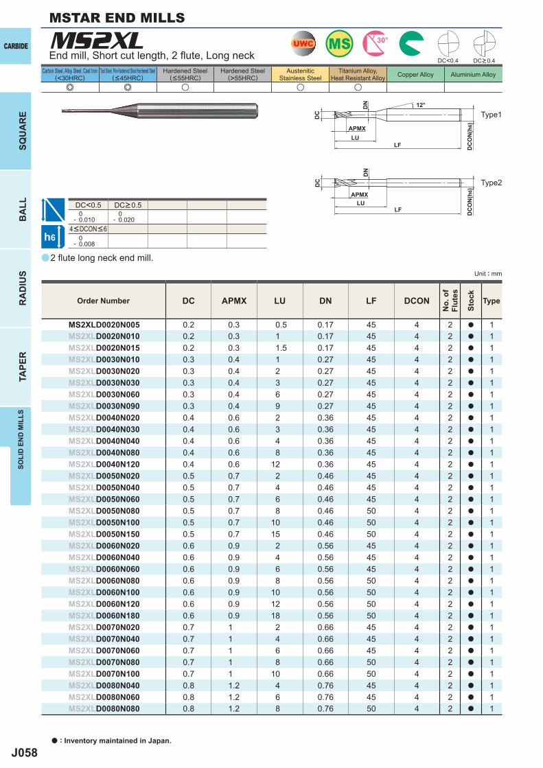
J058
a
e e u u u
MS2XL
DC APMX LU DN LF DCON
MS2XLD0020N005 0.2 0.3 0.5 0.17 45 4 2 a 1MS2XLD0020N010 0.2 0.3 1 0.17 45 4 2 a 1MS2XLD0020N015 0.2 0.3 1.5 0.17 45 4 2 a 1MS2XLD0030N010 0.3 0.4 1 0.27 45 4 2 a 1MS2XLD0030N020 0.3 0.4 2 0.27 45 4 2 a 1MS2XLD0030N030 0.3 0.4 3 0.27 45 4 2 a 1MS2XLD0030N060 0.3 0.4 6 0.27 45 4 2 a 1MS2XLD0030N090 0.3 0.4 9 0.27 45 4 2 a 1MS2XLD0040N020 0.4 0.6 2 0.36 45 4 2 a 1MS2XLD0040N030 0.4 0.6 3 0.36 45 4 2 a 1MS2XLD0040N040 0.4 0.6 4 0.36 45 4 2 a 1MS2XLD0040N080 0.4 0.6 8 0.36 45 4 2 a 1MS2XLD0040N120 0.4 0.6 12 0.36 45 4 2 a 1MS2XLD0050N020 0.5 0.7 2 0.46 45 4 2 a 1MS2XLD0050N040 0.5 0.7 4 0.46 45 4 2 a 1MS2XLD0050N060 0.5 0.7 6 0.46 45 4 2 a 1MS2XLD0050N080 0.5 0.7 8 0.46 50 4 2 a 1MS2XLD0050N100 0.5 0.7 10 0.46 50 4 2 a 1MS2XLD0050N150 0.5 0.7 15 0.46 50 4 2 a 1MS2XLD0060N020 0.6 0.9 2 0.56 45 4 2 a 1MS2XLD0060N040 0.6 0.9 4 0.56 45 4 2 a 1MS2XLD0060N060 0.6 0.9 6 0.56 45 4 2 a 1MS2XLD0060N080 0.6 0.9 8 0.56 50 4 2 a 1MS2XLD0060N100 0.6 0.9 10 0.56 50 4 2 a 1MS2XLD0060N120 0.6 0.9 12 0.56 50 4 2 a 1MS2XLD0060N180 0.6 0.9 18 0.56 50 4 2 a 1MS2XLD0070N020 0.7 1 2 0.66 45 4 2 a 1MS2XLD0070N040 0.7 1 4 0.66 45 4 2 a 1MS2XLD0070N060 0.7 1 6 0.66 45 4 2 a 1MS2XLD0070N080 0.7 1 8 0.66 50 4 2 a 1MS2XLD0070N100 0.7 1 10 0.66 50 4 2 a 1MS2XLD0080N040 0.8 1.2 4 0.76 45 4 2 a 1MS2XLD0080N060 0.8 1.2 6 0.76 45 4 2 a 1MS2XLD0080N080 0.8 1.2 8 0.76 50 4 2 a 1
DC<0.4
DC<0.5 0- 0.010
0- 0.020
0- 0.008
UWC MS 30°
h6
APMX
LF
DC
DC
ON
(h6)
12°
LF
DC
DC
ON
(h6)
LU
DN
LU
DN
APMX
CARBIDE
a : Inventory maintained in Japan.
BA
LLR
AD
IUS
TAPE
RSO
LID
EN
D M
ILLS
SQU
AR
E
Unit : mm
Carbon Steel, Alloy Steel, Cast Iron(<30HRC)
Tool Steel, Pre-Hardened Steel,Hardened Steel(<45HRC)
Hardened Steel(<55HRC)
Hardened Steel(>55HRC)
AusteniticStainless Steel
Titanium Alloy,Heat Resistant Alloy Copper Alloy Aluminium Alloy
MSTAR END MILLS
2 fl ute long neck end mill.
End mill, Short cut length, 2 fl ute, Long neck
Type2
Type1
Order Number
No.
of
Flut
es
Stoc
k
Type
DC>0.4
4<DCON<6
DC>0.5
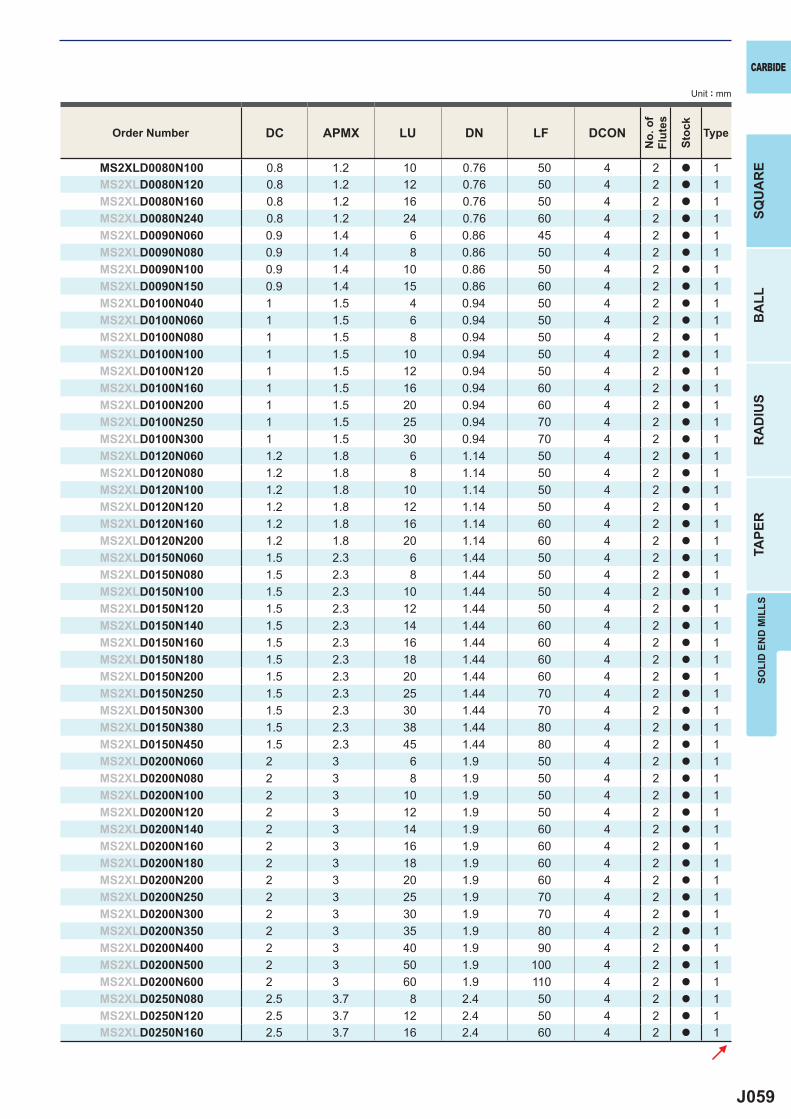
J059
DC APMX LU DN LF DCON
MS2XLD0080N100 0.8 1.2 10 0.76 50 4 2 a 1MS2XLD0080N120 0.8 1.2 12 0.76 50 4 2 a 1MS2XLD0080N160 0.8 1.2 16 0.76 50 4 2 a 1MS2XLD0080N240 0.8 1.2 24 0.76 60 4 2 a 1MS2XLD0090N060 0.9 1.4 6 0.86 45 4 2 a 1MS2XLD0090N080 0.9 1.4 8 0.86 50 4 2 a 1MS2XLD0090N100 0.9 1.4 10 0.86 50 4 2 a 1MS2XLD0090N150 0.9 1.4 15 0.86 60 4 2 a 1MS2XLD0100N040 1 1.5 4 0.94 50 4 2 a 1MS2XLD0100N060 1 1.5 6 0.94 50 4 2 a 1MS2XLD0100N080 1 1.5 8 0.94 50 4 2 a 1MS2XLD0100N100 1 1.5 10 0.94 50 4 2 a 1MS2XLD0100N120 1 1.5 12 0.94 50 4 2 a 1MS2XLD0100N160 1 1.5 16 0.94 60 4 2 a 1MS2XLD0100N200 1 1.5 20 0.94 60 4 2 a 1MS2XLD0100N250 1 1.5 25 0.94 70 4 2 a 1MS2XLD0100N300 1 1.5 30 0.94 70 4 2 a 1MS2XLD0120N060 1.2 1.8 6 1.14 50 4 2 a 1MS2XLD0120N080 1.2 1.8 8 1.14 50 4 2 a 1MS2XLD0120N100 1.2 1.8 10 1.14 50 4 2 a 1MS2XLD0120N120 1.2 1.8 12 1.14 50 4 2 a 1MS2XLD0120N160 1.2 1.8 16 1.14 60 4 2 a 1MS2XLD0120N200 1.2 1.8 20 1.14 60 4 2 a 1MS2XLD0150N060 1.5 2.3 6 1.44 50 4 2 a 1MS2XLD0150N080 1.5 2.3 8 1.44 50 4 2 a 1MS2XLD0150N100 1.5 2.3 10 1.44 50 4 2 a 1MS2XLD0150N120 1.5 2.3 12 1.44 50 4 2 a 1MS2XLD0150N140 1.5 2.3 14 1.44 60 4 2 a 1MS2XLD0150N160 1.5 2.3 16 1.44 60 4 2 a 1MS2XLD0150N180 1.5 2.3 18 1.44 60 4 2 a 1MS2XLD0150N200 1.5 2.3 20 1.44 60 4 2 a 1MS2XLD0150N250 1.5 2.3 25 1.44 70 4 2 a 1MS2XLD0150N300 1.5 2.3 30 1.44 70 4 2 a 1MS2XLD0150N380 1.5 2.3 38 1.44 80 4 2 a 1MS2XLD0150N450 1.5 2.3 45 1.44 80 4 2 a 1MS2XLD0200N060 2 3 6 1.9 50 4 2 a 1MS2XLD0200N080 2 3 8 1.9 50 4 2 a 1MS2XLD0200N100 2 3 10 1.9 50 4 2 a 1MS2XLD0200N120 2 3 12 1.9 50 4 2 a 1MS2XLD0200N140 2 3 14 1.9 60 4 2 a 1MS2XLD0200N160 2 3 16 1.9 60 4 2 a 1MS2XLD0200N180 2 3 18 1.9 60 4 2 a 1MS2XLD0200N200 2 3 20 1.9 60 4 2 a 1MS2XLD0200N250 2 3 25 1.9 70 4 2 a 1MS2XLD0200N300 2 3 30 1.9 70 4 2 a 1MS2XLD0200N350 2 3 35 1.9 80 4 2 a 1MS2XLD0200N400 2 3 40 1.9 90 4 2 a 1MS2XLD0200N500 2 3 50 1.9 100 4 2 a 1MS2XLD0200N600 2 3 60 1.9 110 4 2 a 1MS2XLD0250N080 2.5 3.7 8 2.4 50 4 2 a 1MS2XLD0250N120 2.5 3.7 12 2.4 50 4 2 a 1MS2XLD0250N160 2.5 3.7 16 2.4 60 4 2 a 1
CARBIDE
SQU
AR
EB
ALL
RA
DIU
STA
PER
SOLI
D E
ND
MIL
LS
Unit : mm
Order Number
No.
of
Flut
es
Stoc
k
Type
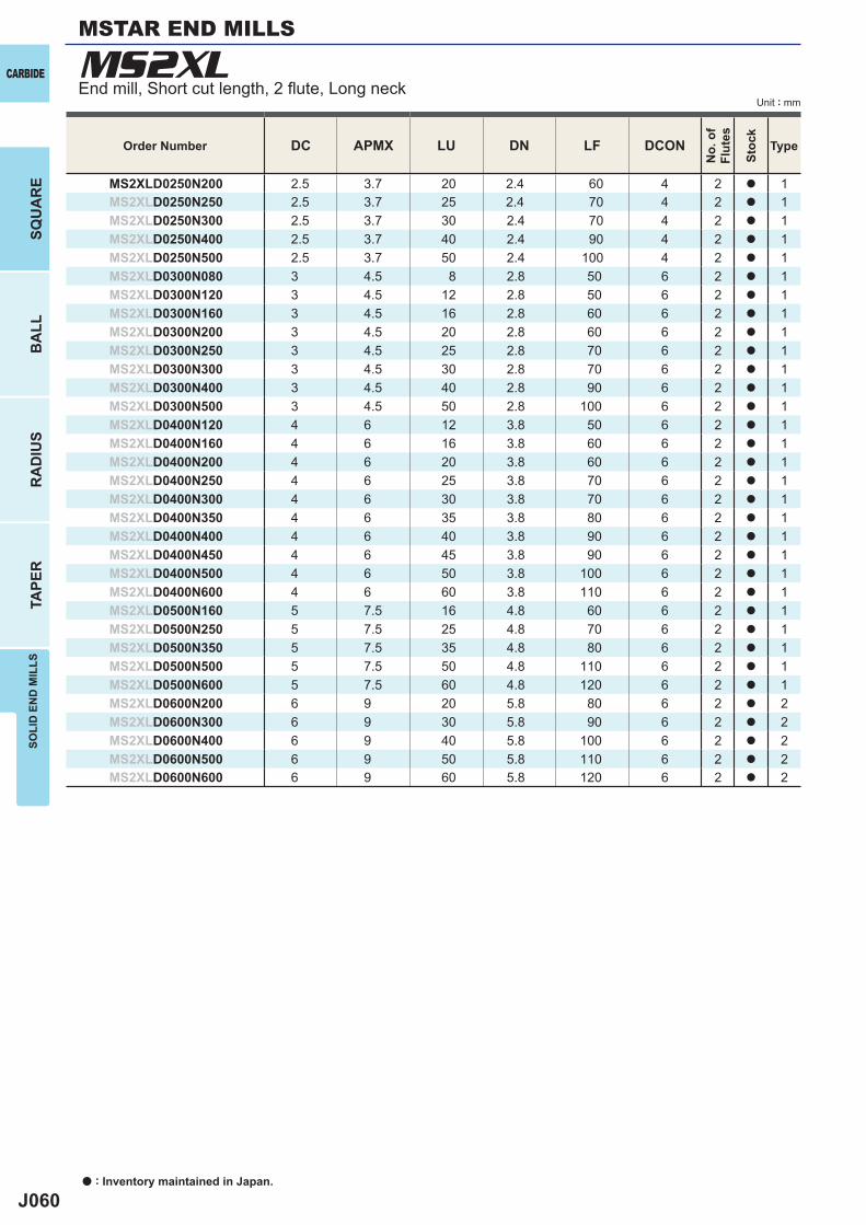
J060
DC APMX LU DN LF DCON
MS2XLD0250N200 2.5 3.7 20 2.4 60 4 2 a 1MS2XLD0250N250 2.5 3.7 25 2.4 70 4 2 a 1MS2XLD0250N300 2.5 3.7 30 2.4 70 4 2 a 1MS2XLD0250N400 2.5 3.7 40 2.4 90 4 2 a 1MS2XLD0250N500 2.5 3.7 50 2.4 100 4 2 a 1MS2XLD0300N080 3 4.5 8 2.8 50 6 2 a 1MS2XLD0300N120 3 4.5 12 2.8 50 6 2 a 1MS2XLD0300N160 3 4.5 16 2.8 60 6 2 a 1MS2XLD0300N200 3 4.5 20 2.8 60 6 2 a 1MS2XLD0300N250 3 4.5 25 2.8 70 6 2 a 1MS2XLD0300N300 3 4.5 30 2.8 70 6 2 a 1MS2XLD0300N400 3 4.5 40 2.8 90 6 2 a 1MS2XLD0300N500 3 4.5 50 2.8 100 6 2 a 1MS2XLD0400N120 4 6 12 3.8 50 6 2 a 1MS2XLD0400N160 4 6 16 3.8 60 6 2 a 1MS2XLD0400N200 4 6 20 3.8 60 6 2 a 1MS2XLD0400N250 4 6 25 3.8 70 6 2 a 1MS2XLD0400N300 4 6 30 3.8 70 6 2 a 1MS2XLD0400N350 4 6 35 3.8 80 6 2 a 1MS2XLD0400N400 4 6 40 3.8 90 6 2 a 1MS2XLD0400N450 4 6 45 3.8 90 6 2 a 1MS2XLD0400N500 4 6 50 3.8 100 6 2 a 1MS2XLD0400N600 4 6 60 3.8 110 6 2 a 1MS2XLD0500N160 5 7.5 16 4.8 60 6 2 a 1MS2XLD0500N250 5 7.5 25 4.8 70 6 2 a 1MS2XLD0500N350 5 7.5 35 4.8 80 6 2 a 1MS2XLD0500N500 5 7.5 50 4.8 110 6 2 a 1MS2XLD0500N600 5 7.5 60 4.8 120 6 2 a 1MS2XLD0600N200 6 9 20 5.8 80 6 2 a 2MS2XLD0600N300 6 9 30 5.8 90 6 2 a 2MS2XLD0600N400 6 9 40 5.8 100 6 2 a 2MS2XLD0600N500 6 9 50 5.8 110 6 2 a 2MS2XLD0600N600 6 9 60 5.8 120 6 2 a 2
MS2XLCARBIDE
a : Inventory maintained in Japan.
BA
LLR
AD
IUS
TAPE
RSO
LID
EN
D M
ILLS
SQU
AR
E
Unit : mm
MSTAR END MILLS
End mill, Short cut length, 2 fl ute, Long neck
Order Number
No.
of
Flut
es
Stoc
k
Type
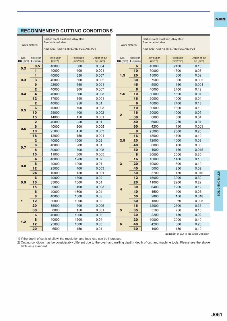
J061
0.20.5 40000 600 0.0041 40000 400 0.001
0.31 40000 650 0.0073 40000 500 0.0029 22000 150 0.001
0.42 40000 800 0.0074 40000 800 0.003
12 17000 150 0.001
0.5
2 40000 950 0.016 40000 700 0.003
10 25000 400 0.00215 14000 150 0.001
0.6
2 40000 950 0.016 40000 800 0.005
10 25000 450 0.00318 12000 150 0.001
0.7
2 40000 1000 0.026 40000 900 0.018 30000 700 0.005
10 11000 300 0.005
0.8
4 40000 1200 0.028 40000 1000 0.01
12 25000 400 0.00324 10000 150 0.001
0.96 40000 1300 0.02
10 35000 1000 0.0115 9000 400 0.003
1
6 40000 1600 0.048 40000 1600 0.03
12 30000 1000 0.0220 15000 400 0.00530 8000 150 0.001
1.2
6 40000 1900 0.068 40000 1900 0.04
12 25000 1000 0.0320 6500 150 0.01
1.5
6 40000 2400 0.1010 30000 1800 0.0520 15000 600 0.0230 7500 300 0.00545 5000 150 0.001
1.66 40000 2400 0.12
10 30000 1800 0.0716 20000 1000 0.04
2
6 40000 2400 0.1810 30000 1800 0.1016 20000 1000 0.0630 8000 500 0.0440 6000 250 0.0160 4200 150 0.003
2.5
8 25000 2500 0.2016 18000 1700 0.1020 12000 1000 0.0840 8000 400 0.0350 4000 150 0.015
3
8 20000 2000 0.3016 15000 1400 0.1520 10000 800 0.1040 5000 250 0.0250 3700 150 0.010
4
12 15000 3000 0.3020 11000 2200 0.2230 6400 1200 0.1240 4500 400 0.0550 2800 150 0.01860 1800 60 0.005
516 12000 2500 0.3535 5100 750 0.1560 2200 150 0.02
620 10000 2000 0.4040 4200 800 0.2060 1900 150 0.10
CARBIDE
SOLI
D E
ND
MIL
LS
1) If the depth of cut is shallow, the revolution and feed rate can be increased.2) Cutting condition may be considerably different due to the overhang (milling depth), depth of cut, and machine tools. Please see the above
table as a standard.
ap:Depth of Cut in the Axial Direction
Work material
Carbon steel, Cast iron, Alloy steel,Pre-hardened steel
AISI 1050, AISI No 35 B, AISI P20, AISI P21
Dia.DC (mm)
Neck lengthLU (mm)
Revolution(min-1)
Feed rate(mm/min)
Depth of cutap (mm)
Work material
Carbon steel, Cast iron, Alloy steel,Pre-hardened steel
AISI 1050, AISI No 35 B, AISI P20, AISI P21
Dia.DC (mm)
Neck lengthLU (mm)
Revolution(min-1)
Feed rate(mm/min)
Depth of cutap (mm)
RECOMMENDED CUTTING CONDITIONS
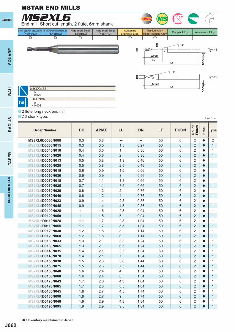
J062
aa
a
e e u u u
MS2XL6
DC APMX LU DN LF DCON
MS2XL6D0030N008 0.3 0.8 ─ ─ 50 6 2 a 2MS2XL6D0030N015 0.3 0.5 1.5 0.27 50 6 2 a 1MS2XL6D0040N010 0.4 0.6 1 0.36 50 6 2 a 1MS2XL6D0040N020 0.4 0.6 2 0.36 50 6 2 a 1MS2XL6D0050N013 0.5 0.8 1.3 0.46 50 6 2 a 1MS2XL6D0050N025 0.5 0.8 2.5 0.46 50 6 2 a 1MS2XL6D0060N015 0.6 0.9 1.5 0.56 50 6 2 a 1MS2XL6D0060N030 0.6 0.9 3 0.56 50 6 2 a 1MS2XL6D0070N018 0.7 1.1 1.8 0.66 50 6 2 a 1MS2XL6D0070N035 0.7 1.1 3.5 0.66 50 6 2 a 1MS2XL6D0080N020 0.8 1.2 2 0.76 50 6 2 a 1MS2XL6D0080N040 0.8 1.2 4 0.76 50 6 2 a 1MS2XL6D0090N023 0.9 1.4 2.3 0.86 50 6 2 a 1MS2XL6D0090N045 0.9 1.4 4.5 0.86 50 6 2 a 1MS2XL6D0100N025 1 1.5 2.5 0.94 50 6 2 a 1MS2XL6D0100N050 1 1.5 5 0.94 50 6 2 a 1MS2XL6D0110N028 1.1 1.7 2.8 1.04 50 6 2 a 1MS2XL6D0110N055 1.1 1.7 5.5 1.04 50 6 2 a 1MS2XL6D0120N030 1.2 1.8 3 1.14 50 6 2 a 1MS2XL6D0120N060 1.2 1.8 6 1.14 50 6 2 a 1MS2XL6D0130N033 1.3 2 3.3 1.24 50 6 2 a 1MS2XL6D0130N065 1.3 2 6.5 1.24 50 6 2 a 1MS2XL6D0140N035 1.4 2.1 3.5 1.34 50 6 2 a 1MS2XL6D0140N070 1.4 2.1 7 1.34 50 6 2 a 1MS2XL6D0150N038 1.5 2.3 3.8 1.44 50 6 2 a 1MS2XL6D0150N075 1.5 2.3 7.5 1.44 50 6 2 a 1MS2XL6D0160N040 1.6 2.4 4 1.54 50 6 2 a 1MS2XL6D0160N080 1.6 2.4 8 1.54 50 6 2 a 1MS2XL6D0170N043 1.7 2.6 4.3 1.64 50 6 2 a 1MS2XL6D0170N085 1.7 2.6 8.5 1.64 50 6 2 a 1MS2XL6D0180N045 1.8 2.7 4.5 1.74 50 6 2 a 1MS2XL6D0180N090 1.8 2.7 9 1.74 50 6 2 a 1MS2XL6D0190N048 1.9 2.9 4.8 1.84 50 6 2 a 1MS2XL6D0190N095 1.9 2.9 9.5 1.84 50 6 2 a 1
0- 0.020DCON=6 0- 0.008
UWC MS 30°
h6
APMX
LF
DC
DC
ON
(h6)
15°
LF
DC
DC
ON
(h6)
LU
DN
APMX
15°
CARBIDE
a : Inventory maintained in Japan.
BA
LLR
AD
IUS
TAPE
RSO
LID
EN
D M
ILLS
SQU
AR
E
Unit : mm
Carbon Steel, Alloy Steel, Cast Iron(<30HRC)
Tool Steel, Pre-Hardened Steel,Hardened Steel(<45HRC)
Hardened Steel(<55HRC)
Hardened Steel(>55HRC)
AusteniticStainless Steel
Titanium Alloy,Heat Resistant Alloy Copper Alloy Aluminium Alloy
2 fl ute long neck end mill.&6 shank type.
End mill, Short cut length, 2 fl ute, 6mm shank
Type2
Type1
Order Number
No.
of
Flut
es
Stoc
k
Type
0.3<DC<2.5
MSTAR END MILLS
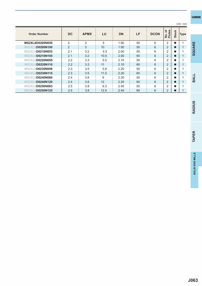
J063
DC APMX LU DN LF DCON
MS2XL6D0200N050 2 3 5 1.90 50 6 2 a 1MS2XL6D0200N100 2 3 10 1.90 50 6 2 a 1MS2XL6D0210N053 2.1 3.2 5.3 2.00 50 6 2 a 1MS2XL6D0210N105 2.1 3.2 10.5 2.00 60 6 2 a 1MS2XL6D0220N055 2.2 3.3 5.5 2.10 50 6 2 a 1MS2XL6D0220N110 2.2 3.3 11 2.10 60 6 2 a 1MS2XL6D0230N058 2.3 3.5 5.8 2.20 50 6 2 a 1MS2XL6D0230N115 2.3 3.5 11.5 2.20 60 6 2 a 1MS2XL6D0240N060 2.4 3.6 6 2.30 50 6 2 a 1MS2XL6D0240N120 2.4 3.6 12 2.30 60 6 2 a 1MS2XL6D0250N063 2.5 3.8 6.3 2.40 50 6 2 a 1MS2XL6D0250N125 2.5 3.8 12.5 2.40 60 6 2 a 1
CARBIDE
SQU
AR
EB
ALL
RA
DIU
STA
PER
SOLI
D E
ND
MIL
LS
Unit : mm
Order Number
No.
of
Flut
es
Stoc
k
Type
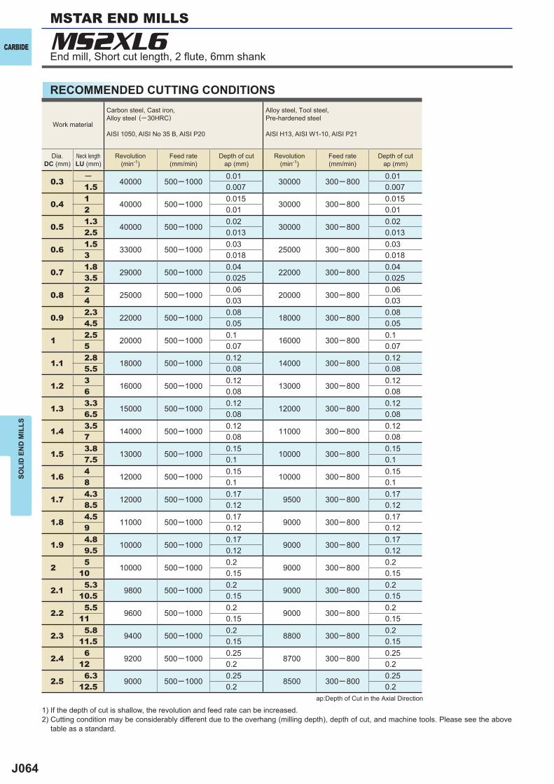
J064
0.3─
40000 500─10000.01
30000 300─ 8000.01
1.5 0.007 0.007
0.41
40000 500─10000.015
30000 300─ 8000.015
2 0.01 0.01
0.51.3
40000 500─10000.02
30000 300─ 8000.02
2.5 0.013 0.013
0.61.5
33000 500─10000.03
25000 300─ 8000.03
3 0.018 0.018
0.71.8
29000 500─10000.04
22000 300─ 8000.04
3.5 0.025 0.025
0.82
25000 500─10000.06
20000 300─ 8000.06
4 0.03 0.03
0.92.3
22000 500─10000.08
18000 300─ 8000.08
4.5 0.05 0.05
12.5
20000 500─10000.1
16000 300─ 8000.1
5 0.07 0.07
1.12.8
18000 500─10000.12
14000 300─ 8000.12
5.5 0.08 0.08
1.23
16000 500─10000.12
13000 300─ 8000.12
6 0.08 0.08
1.33.3
15000 500─10000.12
12000 300─ 8000.12
6.5 0.08 0.08
1.43.5
14000 500─10000.12
11000 300─ 8000.12
7 0.08 0.08
1.53.8
13000 500─10000.15
10000 300─ 8000.15
7.5 0.1 0.1
1.64
12000 500─10000.15
10000 300─ 8000.15
8 0.1 0.1
1.74.3
12000 500─10000.17
9500 300─ 8000.17
8.5 0.12 0.12
1.84.5
11000 500─10000.17
9000 300─ 8000.17
9 0.12 0.12
1.94.8
10000 500─10000.17
9000 300─ 8000.17
9.5 0.12 0.12
25
10000 500─10000.2
9000 300─ 8000.2
10 0.15 0.15
2.15.3
9800 500─10000.2
9000 300─ 8000.2
10.5 0.15 0.15
2.25.5
9600 500─10000.2
9000 300─ 8000.2
11 0.15 0.15
2.35.8
9400 500─10000.2
8800 300─ 8000.2
11.5 0.15 0.15
2.46
9200 500─10000.25
8700 300─ 8000.25
12 0.2 0.2
2.56.3
9000 500─10000.25
8500 300─ 8000.25
12.5 0.2 0.2
MS2XL6CARBIDE
SOLI
D E
ND
MIL
LSMSTAR END MILLS
1) If the depth of cut is shallow, the revolution and feed rate can be increased.2) Cutting condition may be considerably different due to the overhang (milling depth), depth of cut, and machine tools. Please see the above
table as a standard.
ap:Depth of Cut in the Axial Direction
Work material
Carbon steel, Cast iron, Alloy steel (─30HRC)
AISI 1050, AISI No 35 B, AISI P20
Alloy steel, Tool steel,Pre-hardened steel
AISI H13, AISI W1-10, AISI P21
Dia.DC (mm)
Neck lengthLU (mm)
Revolution(min-1)
Feed rate(mm/min)
Depth of cutap (mm)
Revolution(min-1)
Feed rate(mm/min)
Depth of cutap (mm)
End mill, Short cut length, 2 fl ute, 6mm shank
RECOMMENDED CUTTING CONDITIONS
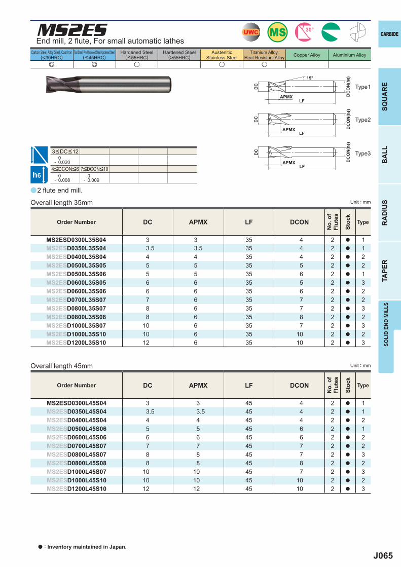
J065
a
e e u u u
MS2ES
DC APMX LF DCON
MS2ESD0300L45S04 3 3 45 4 2 a 1MS2ESD0350L45S04 3.5 3.5 45 4 2 a 1MS2ESD0400L45S04 4 4 45 4 2 a 2MS2ESD0500L45S06 5 5 45 6 2 a 1MS2ESD0600L45S06 6 6 45 6 2 a 2MS2ESD0700L45S07 7 7 45 7 2 a 2MS2ESD0800L45S07 8 8 45 7 2 a 3MS2ESD0800L45S08 8 8 45 8 2 a 2MS2ESD1000L45S07 10 10 45 7 2 a 3MS2ESD1000L45S10 10 10 45 10 2 a 2MS2ESD1200L45S10 12 12 45 10 2 a 3
DC APMX LF DCON
MS2ESD0300L35S04 3 3 35 4 2 a 1MS2ESD0350L35S04 3.5 3.5 35 4 2 a 1MS2ESD0400L35S04 4 4 35 4 2 a 2MS2ESD0500L35S05 5 5 35 5 2 a 2MS2ESD0500L35S06 5 5 35 6 2 a 1MS2ESD0600L35S05 6 6 35 5 2 a 3MS2ESD0600L35S06 6 6 35 6 2 a 2MS2ESD0700L35S07 7 6 35 7 2 a 2MS2ESD0800L35S07 8 6 35 7 2 a 3MS2ESD0800L35S08 8 6 35 8 2 a 2MS2ESD1000L35S07 10 6 35 7 2 a 3MS2ESD1000L35S10 10 6 35 10 2 a 2MS2ESD1200L35S10 12 6 35 10 2 a 3
0- 0.020
0- 0.008
0- 0.009
UWC MS 30°
h6
APMXLF
DC
DC
ON
(h6)15°
LF
DC
DC
ON
(h6)
APMX
LF
DC
DC
ON
(h6)
APMX
CARBIDE
SQU
AR
EB
ALL
RA
DIU
STA
PER
SOLI
D E
ND
MIL
LS
Unit : mm
Carbon Steel, Alloy Steel, Cast Iron(<30HRC)
Tool Steel, Pre-Hardened Steel,Hardened Steel(<45HRC)
Hardened Steel(<55HRC)
Hardened Steel(>55HRC)
AusteniticStainless Steel
Titanium Alloy,Heat Resistant Alloy Copper Alloy Aluminium Alloy
2 fl ute end mill.
End mill, 2 fl ute, For small automatic lathes
Overall length 35mm
Overall length 45mm
Type1
Type2
Type3
Unit : mm
Order Number
No.
of
Flut
es
Stoc
k
Type
Order Number
No.
of
Flut
es
Stoc
k
Type
4<DCON<6 7<DCON<10
3<DC<12
a : Inventory maintained in Japan.
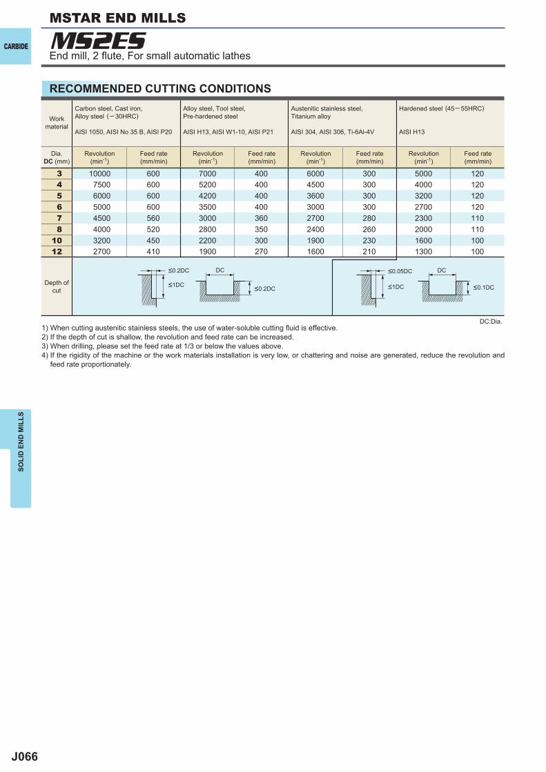
J066
3 10000 600 7000 400 6000 300 5000 1204 7500 600 5200 400 4500 300 4000 1205 6000 600 4200 400 3600 300 3200 1206 5000 600 3500 400 3000 300 2700 1207 4500 560 3000 360 2700 280 2300 1108 4000 520 2800 350 2400 260 2000 110
10 3200 450 2200 300 1900 230 1600 10012 2700 410 1900 270 1600 210 1300 100
DC DC
MS2ESCARBIDE
SOLI
D E
ND
MIL
LS
RECOMMENDED CUTTING CONDITIONS
1) When cutting austenitic stainless steels, the use of water-soluble cutting fl uid is effective.2) If the depth of cut is shallow, the revolution and feed rate can be increased.3) When drilling, please set the feed rate at 1/3 or below the values above.4) If the rigidity of the machine or the work materials installation is very low, or chattering and noise are generated, reduce the revolution and
feed rate proportionately.
DC:Dia.
Workmaterial
Carbon steel, Cast iron, Alloy steel (─30HRC)
AISI 1050, AISI No 35 B, AISI P20
Alloy steel, Tool steel,Pre-hardened steel
AISI H13, AISI W1-10, AISI P21
Austenitic stainless steel,Titanium alloy
AISI 304, AISI 306, Ti-6Al-4V
Hardened steel (45─ 55HRC)
AISI H13
Dia.DC (mm)
Revolution(min-1)
Feed rate(mm/min)
Revolution(min-1)
Feed rate(mm/min)
Revolution(min-1)
Feed rate(mm/min)
Revolution(min-1)
Feed rate(mm/min)
Depth ofcut
<0.2DC <0.05DC
<1DC <1DC<0.2DC <0.1DC
End mill, 2 fl ute, For small automatic lathes
MSTAR END MILLS
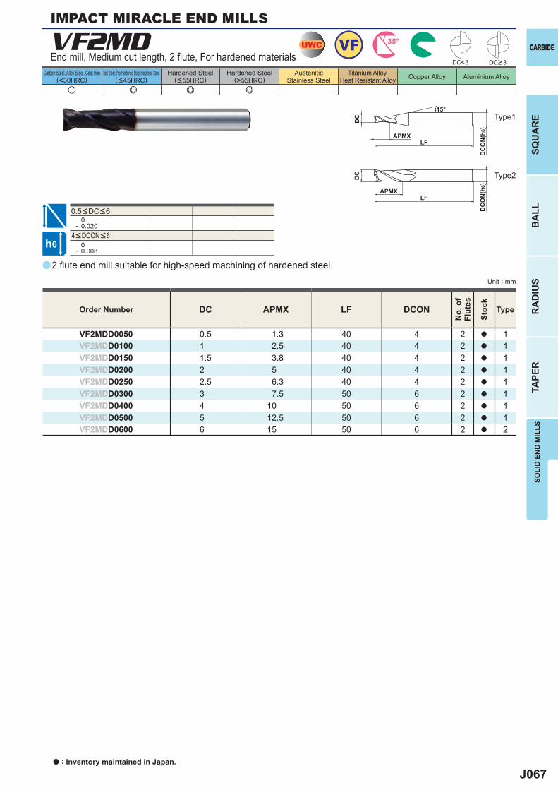
J067
a
VF2MD
u e e e
DC APMX LF DCON
VF2MDD0050 0.5 1.3 40 4 2 a 1VF2MDD0100 1 2.5 40 4 2 a 1VF2MDD0150 1.5 3.8 40 4 2 a 1VF2MDD0200 2 5 40 4 2 a 1VF2MDD0250 2.5 6.3 40 4 2 a 1VF2MDD0300 3 7.5 50 6 2 a 1VF2MDD0400 4 10 50 6 2 a 1VF2MDD0500 5 12.5 50 6 2 a 1VF2MDD0600 6 15 50 6 2 a 2
0- 0.020
0- 0.008
UWC 35°VF
h6
APMXLF
DC
DC
ON
(h6)
15°
APMXLF
DC
DC
ON
(h6)
DC<3
CARBIDE
SQU
AR
EB
ALL
RA
DIU
STA
PER
SOLI
D E
ND
MIL
LS
Unit : mm
Carbon Steel, Alloy Steel, Cast Iron(<30HRC)
Tool Steel, Pre-Hardened Steel,Hardened Steel(<45HRC)
Hardened Steel(<55HRC)
Hardened Steel(>55HRC)
AusteniticStainless Steel
Titanium Alloy,Heat Resistant Alloy Copper Alloy Aluminium Alloy
2 fl ute end mill suitable for high-speed machining of hardened steel.
End mill, Medium cut length, 2 fl ute, For hardened materials
IMPACT MIRACLE END MILLS
Type2
Type1
Order Number
No.
of
Flut
es
Stoc
k
Type
DC>3
4<DCON<6
0.5<DC<6
a : Inventory maintained in Japan.
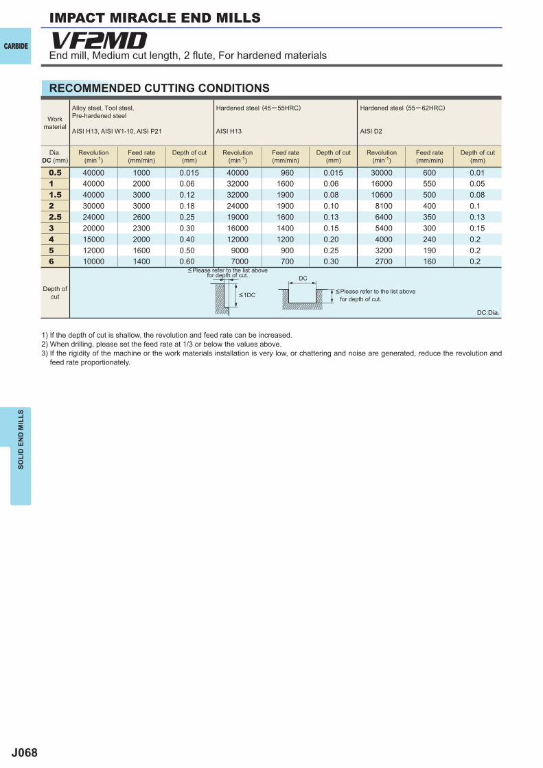
J068
VF2MD
0.5 40000 1000 0.015 40000 960 0.015 30000 600 0.011 40000 2000 0.06 32000 1600 0.06 16000 550 0.051.5 40000 3000 0.12 32000 1900 0.08 10600 500 0.082 30000 3000 0.18 24000 1900 0.10 8100 400 0.12.5 24000 2600 0.25 19000 1600 0.13 6400 350 0.133 20000 2300 0.30 16000 1400 0.15 5400 300 0.154 15000 2000 0.40 12000 1200 0.20 4000 240 0.25 12000 1600 0.50 9000 900 0.25 3200 190 0.26 10000 1400 0.60 7000 700 0.30 2700 160 0.2
DC
CARBIDE
SOLI
D E
ND
MIL
LS
End mill, Medium cut length, 2 fl ute, For hardened materials
IMPACT MIRACLE END MILLS
RECOMMENDED CUTTING CONDITIONS
DC:Dia.
1) If the depth of cut is shallow, the revolution and feed rate can be increased.2) When drilling, please set the feed rate at 1/3 or below the values above.3) If the rigidity of the machine or the work materials installation is very low, or chattering and noise are generated, reduce the revolution and
feed rate proportionately.
<Please refer to the list above for depth of cut.
<Please refer to the list above for depth of cut.
Workmaterial
Dia.DC (mm)
Depth ofcut <1DC
Alloy steel, Tool steel,Pre-hardened steel
AISI H13, AISI W1-10, AISI P21
Hardened steel (45─ 55HRC)
AISI H13
Hardened steel (55─ 62HRC)
AISI D2
Revolution(min-1)
Revolution(min-1)
Revolution(min-1)
Feed rate(mm/min)
Feed rate(mm/min)
Feed rate(mm/min)
Depth of cut(mm)
Depth of cut(mm)
Depth of cut(mm)
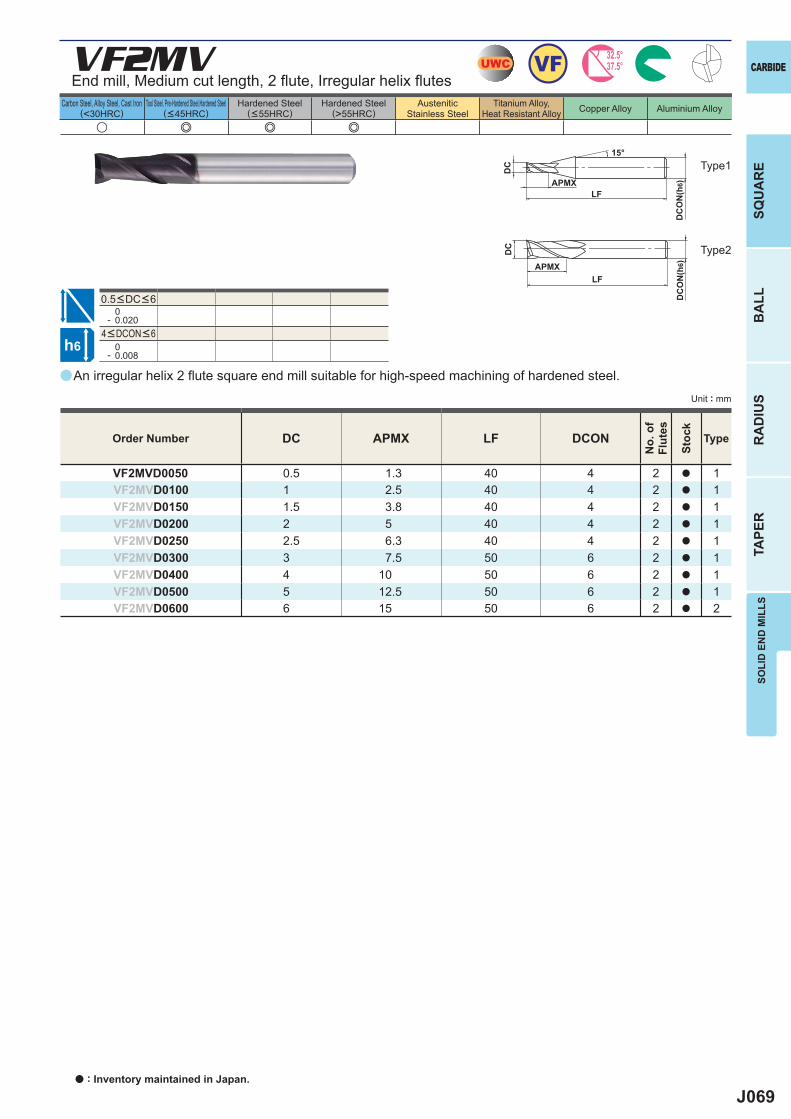
J069
a
VF2MV
u e e e
DC APMX LF DCON
VF2MVD0050 0.5 1.3 40 4 2 a 1VF2MVD0100 1 2.5 40 4 2 a 1VF2MVD0150 1.5 3.8 40 4 2 a 1VF2MVD0200 2 5 40 4 2 a 1VF2MVD0250 2.5 6.3 40 4 2 a 1VF2MVD0300 3 7.5 50 6 2 a 1VF2MVD0400 4 10 50 6 2 a 1VF2MVD0500 5 12.5 50 6 2 a 1VF2MVD0600 6 15 50 6 2 a 2
0- 0.020
0- 0.008
UWC VF 32.5°37.5°
h6
APMXLF
DC
DC
ON
(h6)
15°
APMXLF
DC
DC
ON
(h6)
CARBIDE
SQU
AR
EB
ALL
RA
DIU
STA
PER
SOLI
D E
ND
MIL
LS
Unit : mm
Carbon Steel, Alloy Steel, Cast Iron(<30HRC)
Tool Steel, Pre-Hardened Steel,Hardened Steel(<45HRC)
Hardened Steel(<55HRC)
Hardened Steel(>55HRC)
AusteniticStainless Steel
Titanium Alloy,Heat Resistant Alloy Copper Alloy Aluminium Alloy
An irregular helix 2 fl ute square end mill suitable for high-speed machining of hardened steel.
End mill, Medium cut length, 2 fl ute, Irregular helix fl utes
Type2
Type1
Order Number
No.
of
Flut
es
Stoc
k
Type
4<DCON<6
0.5<DC<6
a : Inventory maintained in Japan.
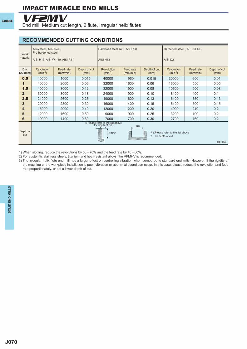
J070
VF2MV
0.5 40000 1000 0.015 40000 960 0.015 30000 600 0.011 40000 2000 0.06 32000 1600 0.06 16000 550 0.051.5 40000 3000 0.12 32000 1900 0.08 10600 500 0.082 30000 3000 0.18 24000 1900 0.10 8100 400 0.12.5 24000 2600 0.25 19000 1600 0.13 6400 350 0.133 20000 2300 0.30 16000 1400 0.15 5400 300 0.154 15000 2000 0.40 12000 1200 0.20 4000 240 0.25 12000 1600 0.50 9000 900 0.25 3200 190 0.26 10000 1400 0.60 7000 700 0.30 2700 160 0.2
DC
CARBIDE
SOLI
D E
ND
MIL
LSIMPACT MIRACLE END MILLS
RECOMMENDED CUTTING CONDITIONS
End mill, Medium cut length, 2 fl ute, Irregular helix fl utes
DC:Dia.
1) When slotting, reduce the revolutions by 50─70% and the feed rate by 40─60%.2) For austenitic stainless steels, titanium and heat-resistant alloys, the VFMHV is recommended. 3) The irregular helix fl ute end mill has a larger effect on controlling vibration when compared to standard end mills. However, if the rigidity of
the machine or the workpiece installation is poor, vibration or abonrmal sound can occur. In this case, please reduce the revolution and feed rate proportionately, or set a lower depth of cut.
<Please refer to the list above for depth of cut.
<Please refer to the list above for depth of cut.
Workmaterial
Dia.DC (mm)
Depth ofcut <1DC
Alloy steel, Tool steel,Pre-hardened steel
AISI H13, AISI W1-10, AISI P21
Hardened steel (45─ 55HRC)
AISI H13
Hardened steel (55─ 62HRC)
AISI D2
Revolution(min-1)
Revolution(min-1)
Revolution(min-1)
Feed rate(mm/min)
Feed rate(mm/min)
Feed rate(mm/min)
Depth of cut(mm)
Depth of cut(mm)
Depth of cut(mm)
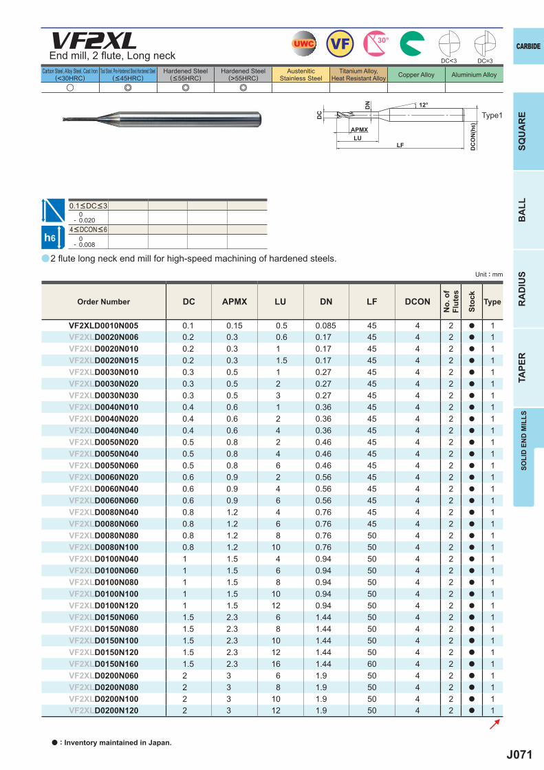
J071
a
VF2XL
u e e e
DC APMX LU DN LF DCON
VF2XLD0010N005 0.1 0.15 0.5 0.085 45 4 2 a 1VF2XLD0020N006 0.2 0.3 0.6 0.17 45 4 2 a 1VF2XLD0020N010 0.2 0.3 1 0.17 45 4 2 a 1VF2XLD0020N015 0.2 0.3 1.5 0.17 45 4 2 a 1VF2XLD0030N010 0.3 0.5 1 0.27 45 4 2 a 1VF2XLD0030N020 0.3 0.5 2 0.27 45 4 2 a 1VF2XLD0030N030 0.3 0.5 3 0.27 45 4 2 a 1VF2XLD0040N010 0.4 0.6 1 0.36 45 4 2 a 1VF2XLD0040N020 0.4 0.6 2 0.36 45 4 2 a 1VF2XLD0040N040 0.4 0.6 4 0.36 45 4 2 a 1VF2XLD0050N020 0.5 0.8 2 0.46 45 4 2 a 1VF2XLD0050N040 0.5 0.8 4 0.46 45 4 2 a 1VF2XLD0050N060 0.5 0.8 6 0.46 45 4 2 a 1VF2XLD0060N020 0.6 0.9 2 0.56 45 4 2 a 1VF2XLD0060N040 0.6 0.9 4 0.56 45 4 2 a 1VF2XLD0060N060 0.6 0.9 6 0.56 45 4 2 a 1VF2XLD0080N040 0.8 1.2 4 0.76 45 4 2 a 1VF2XLD0080N060 0.8 1.2 6 0.76 45 4 2 a 1VF2XLD0080N080 0.8 1.2 8 0.76 50 4 2 a 1VF2XLD0080N100 0.8 1.2 10 0.76 50 4 2 a 1VF2XLD0100N040 1 1.5 4 0.94 50 4 2 a 1VF2XLD0100N060 1 1.5 6 0.94 50 4 2 a 1VF2XLD0100N080 1 1.5 8 0.94 50 4 2 a 1VF2XLD0100N100 1 1.5 10 0.94 50 4 2 a 1VF2XLD0100N120 1 1.5 12 0.94 50 4 2 a 1VF2XLD0150N060 1.5 2.3 6 1.44 50 4 2 a 1VF2XLD0150N080 1.5 2.3 8 1.44 50 4 2 a 1VF2XLD0150N100 1.5 2.3 10 1.44 50 4 2 a 1VF2XLD0150N120 1.5 2.3 12 1.44 50 4 2 a 1VF2XLD0150N160 1.5 2.3 16 1.44 60 4 2 a 1VF2XLD0200N060 2 3 6 1.9 50 4 2 a 1VF2XLD0200N080 2 3 8 1.9 50 4 2 a 1VF2XLD0200N100 2 3 10 1.9 50 4 2 a 1VF2XLD0200N120 2 3 12 1.9 50 4 2 a 1
0- 0.020
0- 0.008
DC<3 DC=3
UWC VF 30°
h6
LU
DC
DC
ON
(h6)
12°
APMX
LF
DN
CARBIDE
SQU
AR
EB
ALL
RA
DIU
STA
PER
SOLI
D E
ND
MIL
LS
Unit : mm
Carbon Steel, Alloy Steel, Cast Iron(<30HRC)
Tool Steel, Pre-Hardened Steel,Hardened Steel(<45HRC)
Hardened Steel(<55HRC)
Hardened Steel(>55HRC)
AusteniticStainless Steel
Titanium Alloy,Heat Resistant Alloy Copper Alloy Aluminium Alloy
2 fl ute long neck end mill for high-speed machining of hardened steels.
End mill, 2 fl ute, Long neck
Type1
Order Number
No.
of
Flut
es
Stoc
k
Type
4<DCON<6
0.1<DC<3
a : Inventory maintained in Japan.
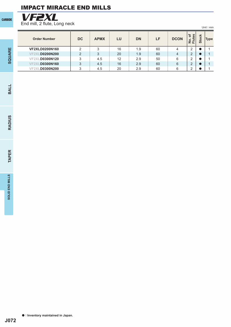
J072
DC APMX LU DN LF DCON
VF2XLD0200N160 2 3 16 1.9 60 4 2 a 1VF2XLD0200N200 2 3 20 1.9 60 4 2 a 1VF2XLD0300N120 3 4.5 12 2.9 50 6 2 a 1VF2XLD0300N160 3 4.5 16 2.9 60 6 2 a 1VF2XLD0300N200 3 4.5 20 2.9 60 6 2 a 1
VF2XLCARBIDE
a : Inventory maintained in Japan.
BA
LLR
AD
IUS
TAPE
RSO
LID
EN
D M
ILLS
SQU
AR
E
Unit : mm
Order Number
No.
of
Flut
es
Stoc
k
Type
End mill, 2 fl ute, Long neck
IMPACT MIRACLE END MILLS
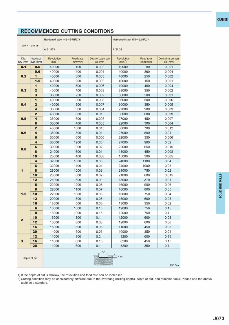
J073
0.1 0.5 40000 100 0.002 40000 80 0.001
0.20.6 40000 400 0.004 40000 360 0.0041 40000 300 0.003 40000 250 0.0021.5 40000 200 0.002 40000 150 0.001
0.31 40000 500 0.006 40000 450 0.0042 40000 400 0.003 38000 350 0.0023 38000 250 0.002 36000 200 0.001
0.41 40000 800 0.008 36000 500 0.0062 40000 500 0.007 30000 350 0.0054 36000 300 0.004 27000 200 0.003
0.52 40000 800 0.01 30000 600 0.0094 36000 600 0.008 27000 450 0.0076 30000 400 0.005 22000 300 0.004
0.62 40000 1000 0.015 30000 700 0.0124 36000 800 0.01 27000 500 0.016 30000 600 0.006 22000 350 0.006
0.8
4 36000 1200 0.03 27000 900 0.026 30000 900 0.02 22000 650 0.0158 24000 600 0.01 18000 450 0.008
10 20000 400 0.008 15000 300 0.005
1
4 32000 1600 0.05 24000 1100 0.046 32000 1400 0.04 24000 1000 0.038 28000 1000 0.03 21000 750 0.02
10 28000 800 0.02 21000 600 0.01512 24000 500 0.02 18000 370 0.01
1.5
6 22000 1200 0.08 16000 900 0.068 22000 1100 0.07 16000 800 0.05
10 22000 1000 0.06 16000 750 0.0412 20000 800 0.05 15000 600 0.0316 18000 500 0.03 13000 350 0.02
2
6 16000 1000 0.15 12000 750 0.158 16000 1000 0.15 12000 750 0.1
10 16000 800 0.1 12000 600 0.0812 16000 800 0.08 12000 600 0.0616 15000 600 0.06 11000 450 0.0520 14000 500 0.05 10000 350 0.04
312 11000 800 0.2 8200 600 0.1516 11000 600 0.15 8200 450 0.1520 11000 500 0.1 8200 350 0.1
DC
CARBIDE
SOLI
D E
ND
MIL
LS
RECOMMENDED CUTTING CONDITIONS
1) If the depth of cut is shallow, the revolution and feed rate can be increased.2) Cutting condition may be considerably different due to the overhang (milling depth), depth of cut, and machine tools. Please see the above
table as a standard.
DC:Dia.
Depth of cut <ap
Work material
Hardened steel (45─ 55HRC)
AISI H13
Hardened steel (55─ 62HRC)
AISI D2
Dia.DC (mm)
Neck lengthLU (mm)
Revolution(min-1)
Feed rate(mm/min)
Depth of cut per passap (mm)
Revolution(min-1)
Feed rate(mm/min)
Depth of cut per passap (mm)
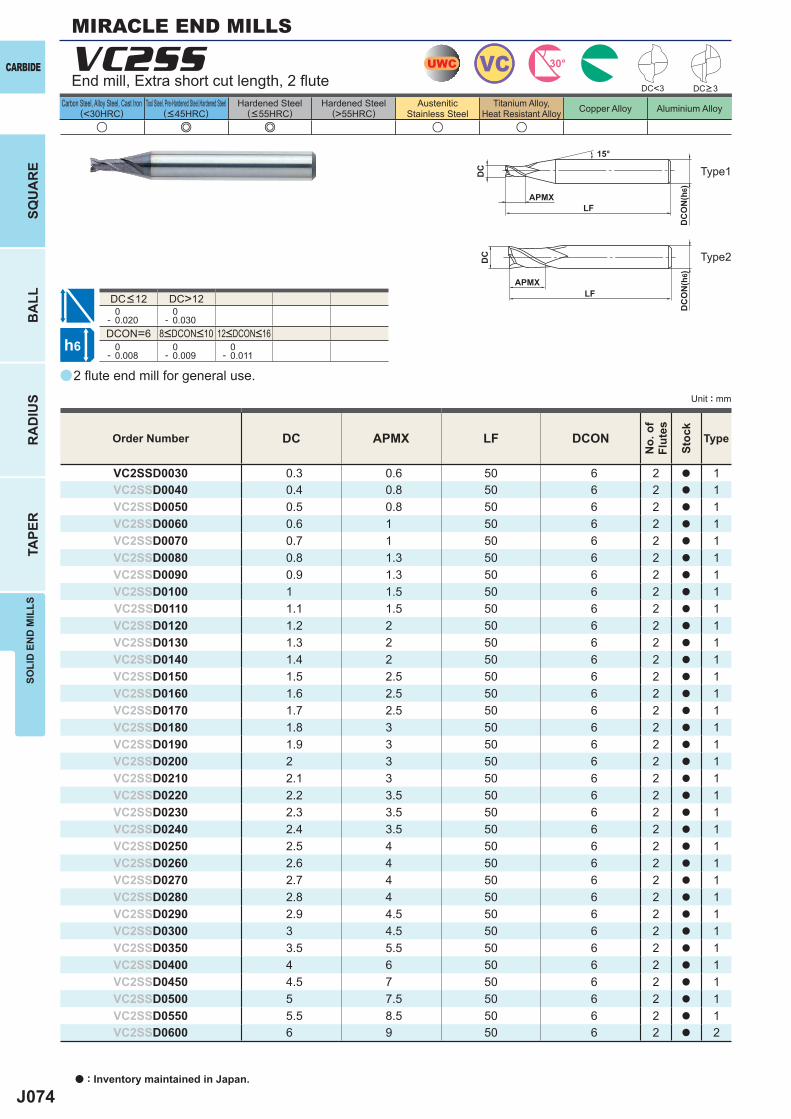
J074
a
u e e u u
VC2SS
DC APMX LF DCON
VC2SSD0030 0.3 0.6 50 6 2 a 1VC2SSD0040 0.4 0.8 50 6 2 a 1VC2SSD0050 0.5 0.8 50 6 2 a 1VC2SSD0060 0.6 1 50 6 2 a 1VC2SSD0070 0.7 1 50 6 2 a 1VC2SSD0080 0.8 1.3 50 6 2 a 1VC2SSD0090 0.9 1.3 50 6 2 a 1VC2SSD0100 1 1.5 50 6 2 a 1VC2SSD0110 1.1 1.5 50 6 2 a 1VC2SSD0120 1.2 2 50 6 2 a 1VC2SSD0130 1.3 2 50 6 2 a 1VC2SSD0140 1.4 2 50 6 2 a 1VC2SSD0150 1.5 2.5 50 6 2 a 1VC2SSD0160 1.6 2.5 50 6 2 a 1VC2SSD0170 1.7 2.5 50 6 2 a 1VC2SSD0180 1.8 3 50 6 2 a 1VC2SSD0190 1.9 3 50 6 2 a 1VC2SSD0200 2 3 50 6 2 a 1VC2SSD0210 2.1 3 50 6 2 a 1VC2SSD0220 2.2 3.5 50 6 2 a 1VC2SSD0230 2.3 3.5 50 6 2 a 1VC2SSD0240 2.4 3.5 50 6 2 a 1VC2SSD0250 2.5 4 50 6 2 a 1VC2SSD0260 2.6 4 50 6 2 a 1VC2SSD0270 2.7 4 50 6 2 a 1VC2SSD0280 2.8 4 50 6 2 a 1VC2SSD0290 2.9 4.5 50 6 2 a 1VC2SSD0300 3 4.5 50 6 2 a 1VC2SSD0350 3.5 5.5 50 6 2 a 1VC2SSD0400 4 6 50 6 2 a 1VC2SSD0450 4.5 7 50 6 2 a 1VC2SSD0500 5 7.5 50 6 2 a 1VC2SSD0550 5.5 8.5 50 6 2 a 1VC2SSD0600 6 9 50 6 2 a 2
DC>12 0- 0.020
0- 0.030
DCON=6 0- 0.008
0- 0.009
0- 0.011
UWC VC 30°
h6
APMXLF
DC
DC
ON
(h6)
15°
APMXLF
DC
DC
ON
(h6)
DC<3
CARBIDE
a : Inventory maintained in Japan.
BA
LLR
AD
IUS
TAPE
RSO
LID
EN
D M
ILLS
SQU
AR
E
Unit : mm
Carbon Steel, Alloy Steel, Cast Iron(<30HRC)
Tool Steel, Pre-Hardened Steel,Hardened Steel(<45HRC)
Hardened Steel(<55HRC)
Hardened Steel(>55HRC)
AusteniticStainless Steel
Titanium Alloy,Heat Resistant Alloy Copper Alloy Aluminium Alloy
MIRACLE END MILLS
2 fl ute end mill for general use.
End mill, Extra short cut length, 2 fl ute
Type2
Type1
Order Number
No.
of
Flut
es
Stoc
k
Type
DC>3
8<DCON<10 12<DCON<16
DC<12
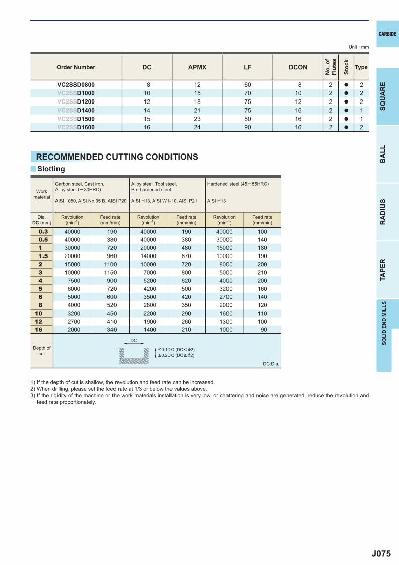
J075
DC APMX LF DCON
VC2SSD0800 8 12 60 8 2 a 2VC2SSD1000 10 15 70 10 2 a 2VC2SSD1200 12 18 75 12 2 a 2VC2SSD1400 14 21 75 16 2 a 1VC2SSD1500 15 23 80 16 2 a 1VC2SSD1600 16 24 90 16 2 a 2
0.3 40000 190 40000 190 40000 1000.5 40000 380 40000 380 30000 1401 30000 720 20000 480 15000 1801.5 20000 960 14000 670 10000 1902 15000 1100 10000 720 8000 2003 10000 1150 7000 800 5000 2104 7500 900 5200 620 4000 2005 6000 720 4200 500 3200 1606 5000 600 3500 420 2700 1408 4000 520 2800 350 2000 120
10 3200 450 2200 290 1600 11012 2700 410 1900 260 1300 10016 2000 340 1400 210 1000 90
y
DC
CARBIDE
SQU
AR
EB
ALL
RA
DIU
STA
PER
SOLI
D E
ND
MIL
LS
Unit : mm
Order Number
No.
of
Flut
es
Stoc
k
Type
RECOMMENDED CUTTING CONDITIONS
1) If the depth of cut is shallow, the revolution and feed rate can be increased.2) When drilling, please set the feed rate at 1/3 or below the values above.3) If the rigidity of the machine or the work materials installation is very low, or chattering and noise are generated, reduce the revolution and
feed rate proportionately.
DC:Dia.
Slotting
Workmaterial
Carbon steel, Cast iron, Alloy steel (─30HRC)
AISI 1050, AISI No 35 B, AISI P20
Alloy steel, Tool steel,Pre-hardened steel
AISI H13, AISI W1-10, AISI P21
Hardened steel (45─ 55HRC)
AISI H13
Dia.DC (mm)
Revolution(min-1)
Feed rate(mm/min)
Revolution(min-1)
Feed rate(mm/min)
Revolution(min-1)
Feed rate(mm/min)
<0.1DC (DC< &2)<0.2DC (DC > &2)
Depth ofcut

J076
a
u e e u u
VC2MS
DC APMX LF DCON
VC2MSD0030 0.3 0.6 38 3 2 a 1VC2MSD0040 0.4 0.8 38 3 2 a 1VC2MSD0050 0.5 1 38 3 2 a 1VC2MSD0060 0.6 1.2 38 3 2 a 1VC2MSD0070 0.7 1.4 38 3 2 a 1VC2MSD0080 0.8 1.6 38 3 2 a 1VC2MSD0090 0.9 2 38 3 2 a 1VC2MSD0100 1 2.5 40 4 2 a 1VC2MSD0110 1.1 2.5 40 4 2 a 1VC2MSD0120 1.2 3 40 4 2 a 1VC2MSD0130 1.3 3 40 4 2 a 1VC2MSD0140 1.4 3 40 4 2 a 1VC2MSD0150 1.5 4 40 4 2 a 1VC2MSD0160 1.6 4 40 4 2 a 1VC2MSD0170 1.7 4 40 4 2 a 1VC2MSD0180 1.8 5 40 4 2 a 1VC2MSD0190 1.9 5 40 4 2 a 1VC2MSD0200 2 6 40 4 2 a 1VC2MSD0210 2.1 6 40 4 2 a 1VC2MSD0220 2.2 6 40 4 2 a 1VC2MSD0230 2.3 6 40 4 2 a 1VC2MSD0240 2.4 8 40 4 2 a 1VC2MSD0250 2.5 8 40 4 2 a 1VC2MSD0260 2.6 8 40 4 2 a 1VC2MSD0270 2.7 8 40 4 2 a 1VC2MSD0280 2.8 8 40 4 2 a 1VC2MSD0290 2.9 8 40 4 2 a 1VC2MSD0300 3 8 45 6 2 a 1VC2MSD0350 3.5 10 45 6 2 a 1VC2MSD0400 4 11 45 6 2 a 1VC2MSD0450 4.5 11 45 6 2 a 1VC2MSD0500 5 13 50 6 2 a 1VC2MSD0550 5.5 13 50 6 2 a 1VC2MSD0600 6 13 50 6 2 a 2
DC>12 0- 0.020
0- 0.030
DCON=3 0- 0.006
0- 0.008
0- 0.009
0- 0.011
0- 0.013
DC<3
UWC VC 30°
h6
APMXLF
DC
DC
ON
(h6)15°
APMXLF
DC
DC
ON
(h6)
APMXLF
DC
DC
ON
(h6)
CARBIDE
a : Inventory maintained in Japan.
BA
LLR
AD
IUS
TAPE
RSO
LID
EN
D M
ILLS
SQU
AR
E
Unit : mm
Carbon Steel, Alloy Steel, Cast Iron(<30HRC)
Tool Steel, Pre-Hardened Steel,Hardened Steel(<45HRC)
Hardened Steel(<55HRC)
Hardened Steel(>55HRC)
AusteniticStainless Steel
Titanium Alloy,Heat Resistant Alloy Copper Alloy Aluminium Alloy
MIRACLE END MILLS
2 fl ute end mill for general use.
End mill, Medium cut length, 2 fl ute
Type2
Type3
Type1
Order Number
No.
of
Flut
es
Stoc
k
Type
DC>3
4<DCON<6 8<DCON<10 12<DCON<16 20<DCON<25
DC<12
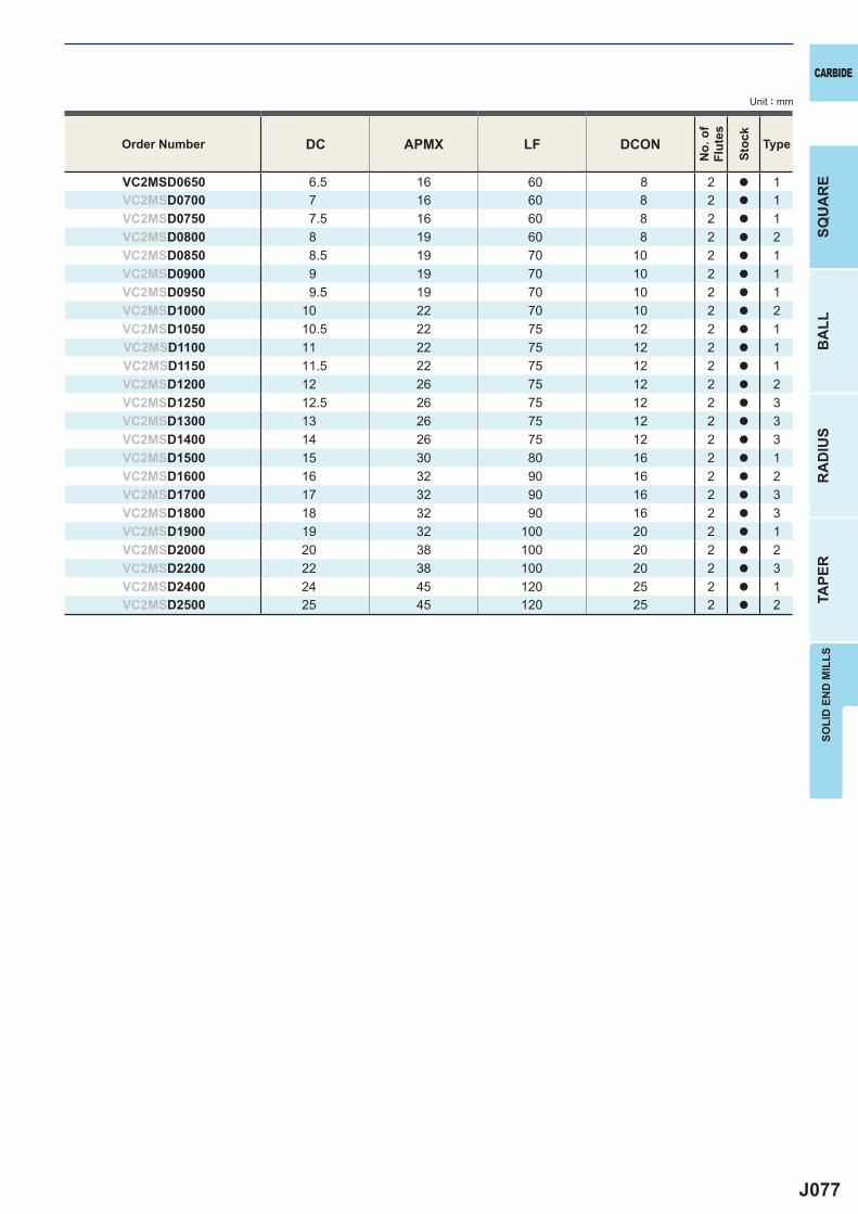
J077
DC APMX LF DCON
VC2MSD0650 6.5 16 60 8 2 a 1VC2MSD0700 7 16 60 8 2 a 1VC2MSD0750 7.5 16 60 8 2 a 1VC2MSD0800 8 19 60 8 2 a 2VC2MSD0850 8.5 19 70 10 2 a 1VC2MSD0900 9 19 70 10 2 a 1VC2MSD0950 9.5 19 70 10 2 a 1VC2MSD1000 10 22 70 10 2 a 2VC2MSD1050 10.5 22 75 12 2 a 1VC2MSD1100 11 22 75 12 2 a 1VC2MSD1150 11.5 22 75 12 2 a 1VC2MSD1200 12 26 75 12 2 a 2VC2MSD1250 12.5 26 75 12 2 a 3VC2MSD1300 13 26 75 12 2 a 3VC2MSD1400 14 26 75 12 2 a 3VC2MSD1500 15 30 80 16 2 a 1VC2MSD1600 16 32 90 16 2 a 2VC2MSD1700 17 32 90 16 2 a 3VC2MSD1800 18 32 90 16 2 a 3VC2MSD1900 19 32 100 20 2 a 1VC2MSD2000 20 38 100 20 2 a 2VC2MSD2200 22 38 100 20 2 a 3VC2MSD2400 24 45 120 25 2 a 1VC2MSD2500 25 45 120 25 2 a 2
CARBIDE
SQU
AR
EB
ALL
RA
DIU
STA
PER
SOLI
D E
ND
MIL
LS
Unit : mm
Order Number
No.
of
Flut
es
Stoc
k
Type
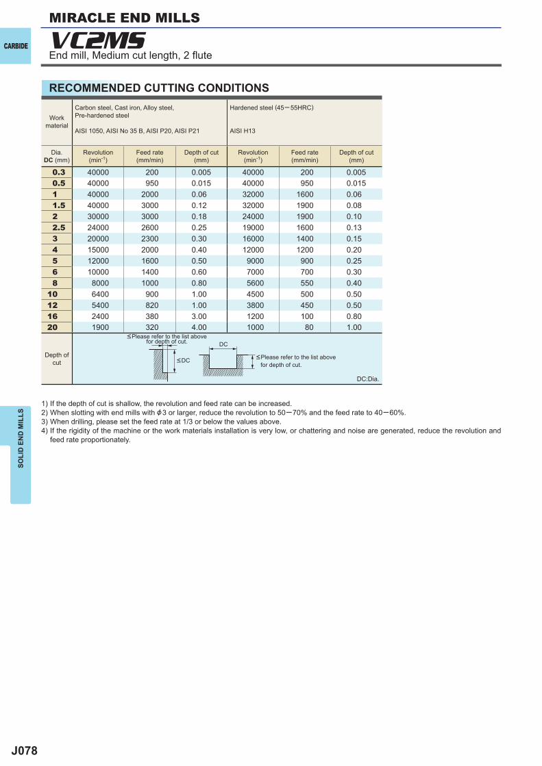
J078
0.3 40000 200 0.005 40000 200 0.0050.5 40000 950 0.015 40000 950 0.0151 40000 2000 0.06 32000 1600 0.061.5 40000 3000 0.12 32000 1900 0.082 30000 3000 0.18 24000 1900 0.102.5 24000 2600 0.25 19000 1600 0.133 20000 2300 0.30 16000 1400 0.154 15000 2000 0.40 12000 1200 0.205 12000 1600 0.50 9000 900 0.256 10000 1400 0.60 7000 700 0.308 8000 1000 0.80 5600 550 0.40
10 6400 900 1.00 4500 500 0.5012 5400 820 1.00 3800 450 0.5016 2400 380 3.00 1200 100 0.8020 1900 320 4.00 1000 80 1.00
VC2MS
DC
CARBIDE
SOLI
D E
ND
MIL
LSMIRACLE END MILLS
RECOMMENDED CUTTING CONDITIONS
1) If the depth of cut is shallow, the revolution and feed rate can be increased.2) When slotting with end mills with &3 or larger, reduce the revolution to 50─70% and the feed rate to 40─60%.3) When drilling, please set the feed rate at 1/3 or below the values above.4) If the rigidity of the machine or the work materials installation is very low, or chattering and noise are generated, reduce the revolution and
feed rate proportionately.
DC:Dia.
<Please refer to the list above for depth of cut.
<Please refer to the list above for depth of cut.
Workmaterial
Carbon steel, Cast iron, Alloy steel,Pre-hardened steel
AISI 1050, AISI No 35 B, AISI P20, AISI P21
Hardened steel (45─ 55HRC)
AISI H13
Dia.DC (mm)
Revolution(min-1)
Feed rate(mm/min)
Depth of cut(mm)
Revolution(min-1)
Feed rate(mm/min)
Depth of cut(mm)
Depth ofcut <DC
End mill, Medium cut length, 2 fl ute
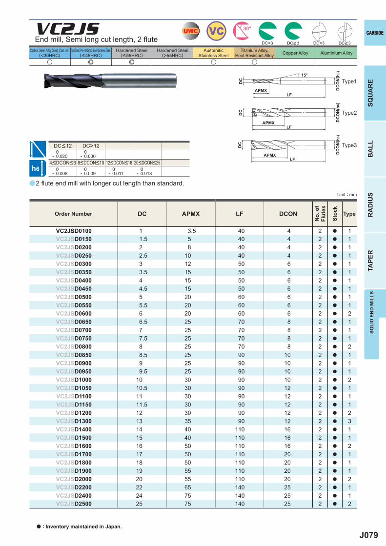
J079
a
u e e u u
VC2JS
DC APMX LF DCON
VC2JSD0100 1 3.5 40 4 2 a 1VC2JSD0150 1.5 5 40 4 2 a 1VC2JSD0200 2 8 40 4 2 a 1VC2JSD0250 2.5 10 40 4 2 a 1VC2JSD0300 3 12 50 6 2 a 1VC2JSD0350 3.5 15 50 6 2 a 1VC2JSD0400 4 15 50 6 2 a 1VC2JSD0450 4.5 15 50 6 2 a 1VC2JSD0500 5 20 60 6 2 a 1VC2JSD0550 5.5 20 60 6 2 a 1VC2JSD0600 6 20 60 6 2 a 2VC2JSD0650 6.5 25 70 8 2 a 1VC2JSD0700 7 25 70 8 2 a 1VC2JSD0750 7.5 25 70 8 2 a 1VC2JSD0800 8 25 70 8 2 a 2VC2JSD0850 8.5 25 90 10 2 a 1VC2JSD0900 9 25 90 10 2 a 1VC2JSD0950 9.5 25 90 10 2 a 1VC2JSD1000 10 30 90 10 2 a 2VC2JSD1050 10.5 30 90 12 2 a 1VC2JSD1100 11 30 90 12 2 a 1VC2JSD1150 11.5 30 90 12 2 a 1VC2JSD1200 12 30 90 12 2 a 2VC2JSD1300 13 35 90 12 2 a 3VC2JSD1400 14 40 110 16 2 a 1VC2JSD1500 15 40 110 16 2 a 1VC2JSD1600 16 50 110 16 2 a 2VC2JSD1700 17 50 110 20 2 a 1VC2JSD1800 18 50 110 20 2 a 1VC2JSD1900 19 55 110 20 2 a 1VC2JSD2000 20 55 110 20 2 a 2VC2JSD2200 22 65 140 25 2 a 1VC2JSD2400 24 75 140 25 2 a 1VC2JSD2500 25 75 140 25 2 a 2
DC>12 0- 0.020
0- 0.030
0- 0.008
0- 0.009
0- 0.011
0- 0.013
DC<3 DC<3
UWC VC 30°
h6
APMXLF
DC
DC
ON
(h6)15°
APMXLF
DC
DC
ON
(h6)
APMXLF
DC
DC
ON
(h6)
CARBIDE
SQU
AR
EB
ALL
RA
DIU
STA
PER
SOLI
D E
ND
MIL
LS
Unit : mm
Carbon Steel, Alloy Steel, Cast Iron(<30HRC)
Tool Steel, Pre-Hardened Steel,Hardened Steel(<45HRC)
Hardened Steel(<55HRC)
Hardened Steel(>55HRC)
AusteniticStainless Steel
Titanium Alloy,Heat Resistant Alloy Copper Alloy Aluminium Alloy
2 fl ute end mill with longer cut length than standard.
End mill, Semi long cut length, 2 fl ute
Type2
Type3
Type1
Order Number
No.
of
Flut
es
Stoc
k
Type
DC>3 DC>3
4<DCON<6 8<DCON<10 12<DCON<16 20<DCON<25
DC<12
a : Inventory maintained in Japan.
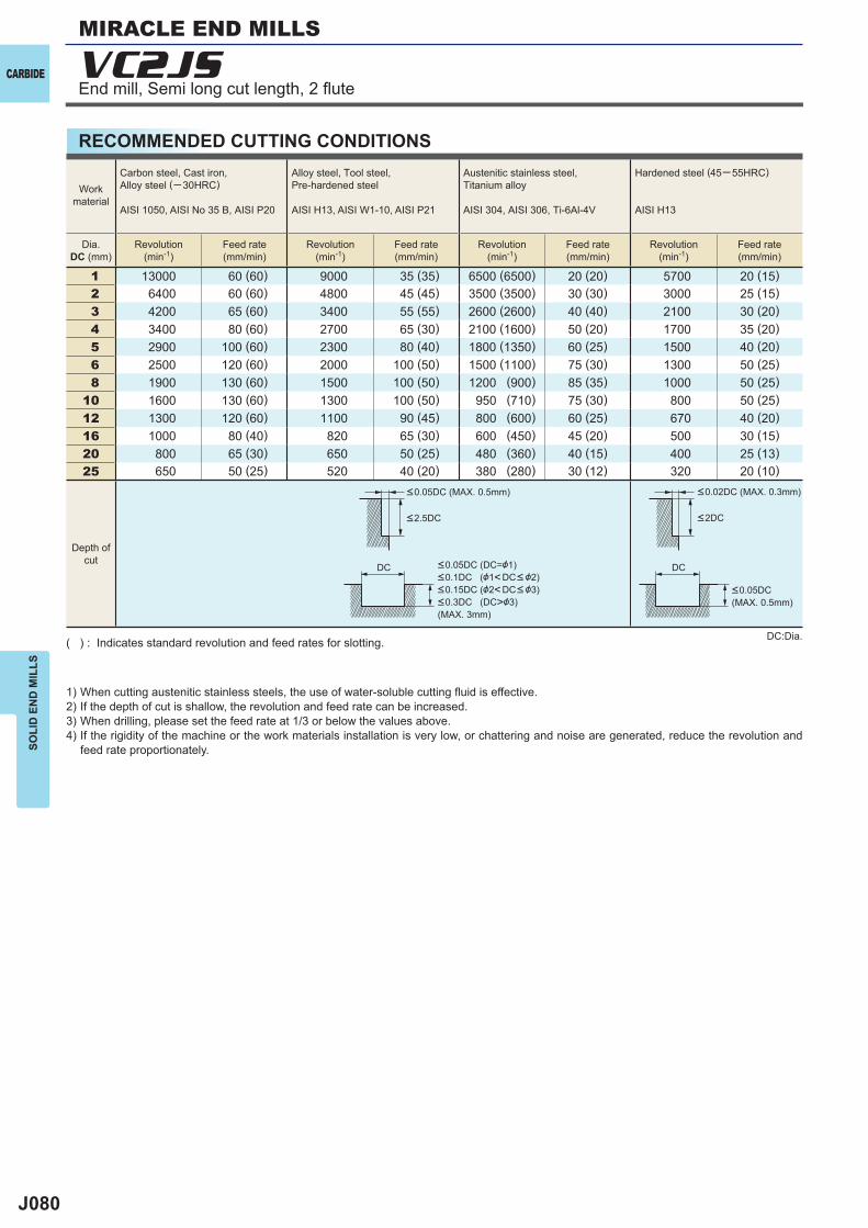
J080
VC2JS
1 13000 60 (60) 9000 35 (35) 6500 (6500) 20 (20) 5700 20 (15)2 6400 60 (60) 4800 45 (45) 3500 (3500) 30 (30) 3000 25 (15)3 4200 65 (60) 3400 55 (55) 2600 (2600) 40 (40) 2100 30 (20)4 3400 80 (60) 2700 65 (30) 2100 (1600) 50 (20) 1700 35 (20)5 2900 100 (60) 2300 80 (40) 1800 (1350) 60 (25) 1500 40 (20)6 2500 120 (60) 2000 100 (50) 1500 (1100) 75 (30) 1300 50 (25)8 1900 130 (60) 1500 100 (50) 1200 (900) 85 (35) 1000 50 (25)
10 1600 130 (60) 1300 100 (50) 950 (710) 75 (30) 800 50 (25)12 1300 120 (60) 1100 90 (45) 800 (600) 60 (25) 670 40 (20)16 1000 80 (40) 820 65 (30) 600 (450) 45 (20) 500 30 (15)20 800 65 (30) 650 50 (25) 480 (360) 40 (15) 400 25 (13)25 650 50 (25) 520 40 (20) 380 (280) 30 (12) 320 20 (10)
DC DC
CARBIDE
SOLI
D E
ND
MIL
LSMIRACLE END MILLS
RECOMMENDED CUTTING CONDITIONS
End mill, Semi long cut length, 2 fl ute
1) When cutting austenitic stainless steels, the use of water-soluble cutting fl uid is effective.2) If the depth of cut is shallow, the revolution and feed rate can be increased.3) When drilling, please set the feed rate at 1/3 or below the values above.4) If the rigidity of the machine or the work materials installation is very low, or chattering and noise are generated, reduce the revolution and
feed rate proportionately.
DC:Dia.( ) : Indicates standard revolution and feed rates for slotting.
Depth ofcut
Workmaterial
Carbon steel, Cast iron, Alloy steel (─30HRC)
AISI 1050, AISI No 35 B, AISI P20
Alloy steel, Tool steel,Pre-hardened steel
AISI H13, AISI W1-10, AISI P21
Austenitic stainless steel,Titanium alloy
AISI 304, AISI 306, Ti-6Al-4V
Hardened steel (45─ 55HRC)
AISI H13
Dia.DC (mm)
Revolution(min-1)
Feed rate(mm/min)
Revolution(min-1)
Feed rate(mm/min)
Revolution(min-1)
Feed rate(mm/min)
Revolution(min-1)
Feed rate(mm/min)
<2.5DC
<0.05DC (MAX. 0.5mm) <0.02DC (MAX. 0.3mm)
<0.05DC (MAX. 0.5mm)
<0.05DC (DC=&1)<0.1DC (&1<DC< &2)<0.15DC (&2<DC< &3)<0.3DC (DC>&3)(MAX. 3mm)
<2DC
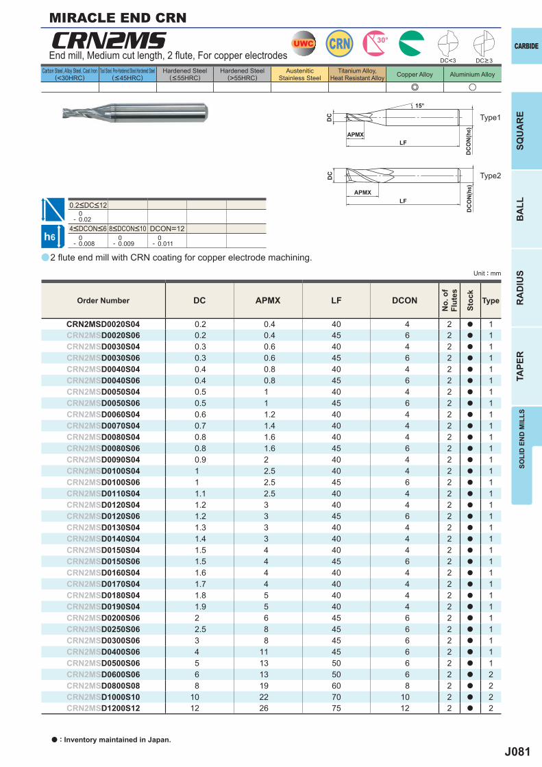
J081
a
e u
CRN2MS
DC APMX LF DCON
CRN2MSD0020S04 0.2 0.4 40 4 2 a 1CRN2MSD0020S06 0.2 0.4 45 6 2 a 1CRN2MSD0030S04 0.3 0.6 40 4 2 a 1CRN2MSD0030S06 0.3 0.6 45 6 2 a 1CRN2MSD0040S04 0.4 0.8 40 4 2 a 1CRN2MSD0040S06 0.4 0.8 45 6 2 a 1CRN2MSD0050S04 0.5 1 40 4 2 a 1CRN2MSD0050S06 0.5 1 45 6 2 a 1CRN2MSD0060S04 0.6 1.2 40 4 2 a 1CRN2MSD0070S04 0.7 1.4 40 4 2 a 1CRN2MSD0080S04 0.8 1.6 40 4 2 a 1CRN2MSD0080S06 0.8 1.6 45 6 2 a 1CRN2MSD0090S04 0.9 2 40 4 2 a 1CRN2MSD0100S04 1 2.5 40 4 2 a 1CRN2MSD0100S06 1 2.5 45 6 2 a 1CRN2MSD0110S04 1.1 2.5 40 4 2 a 1CRN2MSD0120S04 1.2 3 40 4 2 a 1CRN2MSD0120S06 1.2 3 45 6 2 a 1CRN2MSD0130S04 1.3 3 40 4 2 a 1CRN2MSD0140S04 1.4 3 40 4 2 a 1CRN2MSD0150S04 1.5 4 40 4 2 a 1CRN2MSD0150S06 1.5 4 45 6 2 a 1CRN2MSD0160S04 1.6 4 40 4 2 a 1CRN2MSD0170S04 1.7 4 40 4 2 a 1CRN2MSD0180S04 1.8 5 40 4 2 a 1CRN2MSD0190S04 1.9 5 40 4 2 a 1CRN2MSD0200S06 2 6 45 6 2 a 1CRN2MSD0250S06 2.5 8 45 6 2 a 1CRN2MSD0300S06 3 8 45 6 2 a 1CRN2MSD0400S06 4 11 45 6 2 a 1CRN2MSD0500S06 5 13 50 6 2 a 1CRN2MSD0600S06 6 13 50 6 2 a 2CRN2MSD0800S08 8 19 60 8 2 a 2CRN2MSD1000S10 10 22 70 10 2 a 2CRN2MSD1200S12 12 26 75 12 2 a 2
0- 0.02
DCON=12 0- 0.008
0- 0.009
0- 0.011
DC<3
UWC CRN 30°
h6
APMXLF
DC
DC
ON
(h6)
15°
APMXLF
DC
DC
ON
(h6)
CARBIDE
SQU
AR
EB
ALL
RA
DIU
STA
PER
SOLI
D E
ND
MIL
LS
Unit : mm
Carbon Steel, Alloy Steel, Cast Iron(<30HRC)
Tool Steel, Pre-Hardened Steel,Hardened Steel(<45HRC)
Hardened Steel(<55HRC)
Hardened Steel(>55HRC)
AusteniticStainless Steel
Titanium Alloy,Heat Resistant Alloy Copper Alloy Aluminium Alloy
2 fl ute end mill with CRN coating for copper electrode machining.
End mill, Medium cut length, 2 fl ute, For copper electrodes
MIRACLE END CRN
Type2
Type1
DC>3
Order Number
No.
of
Flut
es
Stoc
k
Type
4<DCON<6 8<DCON<10
0.2<DC<12
a : Inventory maintained in Japan.
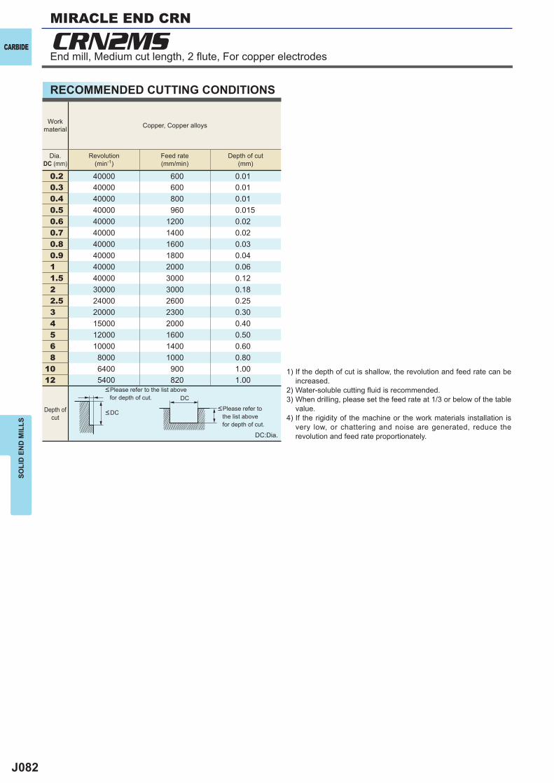
J082
CRN2MS
0.2 40000 600 0.010.3 40000 600 0.010.4 40000 800 0.010.5 40000 960 0.0150.6 40000 1200 0.020.7 40000 1400 0.020.8 40000 1600 0.030.9 40000 1800 0.041 40000 2000 0.061.5 40000 3000 0.122 30000 3000 0.182.5 24000 2600 0.253 20000 2300 0.304 15000 2000 0.405 12000 1600 0.506 10000 1400 0.608 8000 1000 0.80
10 6400 900 1.0012 5400 820 1.00
DC
CARBIDE
SOLI
D E
ND
MIL
LSMIRACLE END CRN
RECOMMENDED CUTTING CONDITIONS
End mill, Medium cut length, 2 fl ute, For copper electrodes
Workmaterial Copper, Copper alloys
Dia.DC (mm)
Revolution(min-1)
Feed rate(mm/min)
Depth of cut(mm)
Depth ofcut
<DC
<Please refer to the list above for depth of cut.
<Please refer to the list above for depth of cut.
DC:Dia.
1) If the depth of cut is shallow, the revolution and feed rate can be increased.
2) Water-soluble cutting fl uid is recommended.3) When drilling, please set the feed rate at 1/3 or below of the table
value.4) If the rigidity of the machine or the work materials installation is
very low, or chattering and noise are generated, reduce the revolution and feed rate proportionately.
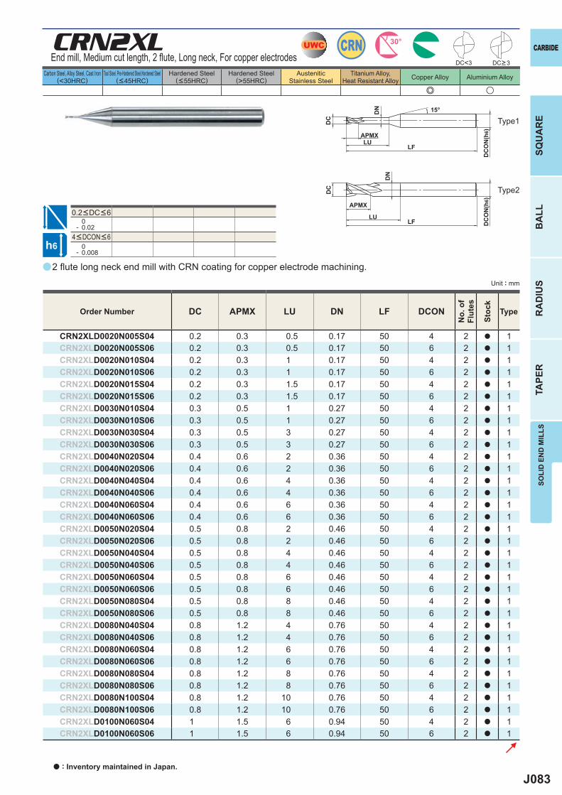
J083
a
e u
CRN2XL
DC APMX LU DN LF DCON
CRN2XLD0020N005S04 0.2 0.3 0.5 0.17 50 4 2 a 1CRN2XLD0020N005S06 0.2 0.3 0.5 0.17 50 6 2 a 1CRN2XLD0020N010S04 0.2 0.3 1 0.17 50 4 2 a 1CRN2XLD0020N010S06 0.2 0.3 1 0.17 50 6 2 a 1CRN2XLD0020N015S04 0.2 0.3 1.5 0.17 50 4 2 a 1CRN2XLD0020N015S06 0.2 0.3 1.5 0.17 50 6 2 a 1CRN2XLD0030N010S04 0.3 0.5 1 0.27 50 4 2 a 1CRN2XLD0030N010S06 0.3 0.5 1 0.27 50 6 2 a 1CRN2XLD0030N030S04 0.3 0.5 3 0.27 50 4 2 a 1CRN2XLD0030N030S06 0.3 0.5 3 0.27 50 6 2 a 1CRN2XLD0040N020S04 0.4 0.6 2 0.36 50 4 2 a 1CRN2XLD0040N020S06 0.4 0.6 2 0.36 50 6 2 a 1CRN2XLD0040N040S04 0.4 0.6 4 0.36 50 4 2 a 1CRN2XLD0040N040S06 0.4 0.6 4 0.36 50 6 2 a 1CRN2XLD0040N060S04 0.4 0.6 6 0.36 50 4 2 a 1CRN2XLD0040N060S06 0.4 0.6 6 0.36 50 6 2 a 1CRN2XLD0050N020S04 0.5 0.8 2 0.46 50 4 2 a 1CRN2XLD0050N020S06 0.5 0.8 2 0.46 50 6 2 a 1CRN2XLD0050N040S04 0.5 0.8 4 0.46 50 4 2 a 1CRN2XLD0050N040S06 0.5 0.8 4 0.46 50 6 2 a 1CRN2XLD0050N060S04 0.5 0.8 6 0.46 50 4 2 a 1CRN2XLD0050N060S06 0.5 0.8 6 0.46 50 6 2 a 1CRN2XLD0050N080S04 0.5 0.8 8 0.46 50 4 2 a 1CRN2XLD0050N080S06 0.5 0.8 8 0.46 50 6 2 a 1CRN2XLD0080N040S04 0.8 1.2 4 0.76 50 4 2 a 1CRN2XLD0080N040S06 0.8 1.2 4 0.76 50 6 2 a 1CRN2XLD0080N060S04 0.8 1.2 6 0.76 50 4 2 a 1CRN2XLD0080N060S06 0.8 1.2 6 0.76 50 6 2 a 1CRN2XLD0080N080S04 0.8 1.2 8 0.76 50 4 2 a 1CRN2XLD0080N080S06 0.8 1.2 8 0.76 50 6 2 a 1CRN2XLD0080N100S04 0.8 1.2 10 0.76 50 4 2 a 1CRN2XLD0080N100S06 0.8 1.2 10 0.76 50 6 2 a 1CRN2XLD0100N060S04 1 1.5 6 0.94 50 4 2 a 1CRN2XLD0100N060S06 1 1.5 6 0.94 50 6 2 a 1
DC<3
0- 0.02
0- 0.008
UWC CRN 30°
h6
APMXLU
DC
DC
ON
(h6)
15°
APMX
LF
DC
DC
ON
(h6)
LF
DN
LU
DN
CARBIDE
SQU
AR
EB
ALL
RA
DIU
STA
PER
SOLI
D E
ND
MIL
LS
Unit : mm
Carbon Steel, Alloy Steel, Cast Iron(<30HRC)
Tool Steel, Pre-Hardened Steel,Hardened Steel(<45HRC)
Hardened Steel(<55HRC)
Hardened Steel(>55HRC)
AusteniticStainless Steel
Titanium Alloy,Heat Resistant Alloy Copper Alloy Aluminium Alloy
2 fl ute long neck end mill with CRN coating for copper electrode machining.
End mill, Medium cut length, 2 fl ute, Long neck, For copper electrodes
Type2
Type1
DC>3
Order Number
No.
of
Flut
es
Stoc
k
Type
4<DCON<6
0.2<DC<6
a : Inventory maintained in Japan.
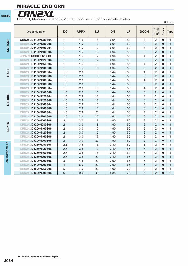
J084
DC APMX LU DN LF DCON
CRN2XLD0100N080S04 1 1.5 8 0.94 50 4 2 a 1CRN2XLD0100N080S06 1 1.5 8 0.94 50 6 2 a 1CRN2XLD0100N100S04 1 1.5 10 0.94 50 4 2 a 1CRN2XLD0100N100S06 1 1.5 10 0.94 50 6 2 a 1CRN2XLD0100N120S04 1 1.5 12 0.94 50 4 2 a 1CRN2XLD0100N120S06 1 1.5 12 0.94 50 6 2 a 1CRN2XLD0100N160S04 1 1.5 16 0.94 55 4 2 a 1CRN2XLD0100N160S06 1 1.5 16 0.94 55 6 2 a 1CRN2XLD0150N060S04 1.5 2.3 6 1.44 50 4 2 a 1CRN2XLD0150N060S06 1.5 2.3 6 1.44 50 6 2 a 1CRN2XLD0150N080S04 1.5 2.3 8 1.44 50 4 2 a 1CRN2XLD0150N080S06 1.5 2.3 8 1.44 50 6 2 a 1CRN2XLD0150N100S04 1.5 2.3 10 1.44 50 4 2 a 1CRN2XLD0150N100S06 1.5 2.3 10 1.44 50 6 2 a 1CRN2XLD0150N120S04 1.5 2.3 12 1.44 50 4 2 a 1CRN2XLD0150N120S06 1.5 2.3 12 1.44 50 6 2 a 1CRN2XLD0150N160S04 1.5 2.3 16 1.44 55 4 2 a 1CRN2XLD0150N160S06 1.5 2.3 16 1.44 55 6 2 a 1CRN2XLD0150N200S04 1.5 2.3 20 1.44 60 4 2 a 1CRN2XLD0150N200S06 1.5 2.3 20 1.44 60 6 2 a 1CRN2XLD0200N060S06 2 3.0 6 1.90 50 6 2 a 1CRN2XLD0200N080S06 2 3.0 8 1.90 50 6 2 a 1CRN2XLD0200N100S06 2 3.0 10 1.90 50 6 2 a 1CRN2XLD0200N120S06 2 3.0 12 1.90 50 6 2 a 1CRN2XLD0200N160S06 2 3.0 16 1.90 55 6 2 a 1CRN2XLD0200N200S06 2 3.0 20 1.90 60 6 2 a 1CRN2XLD0250N080S06 2.5 3.8 8 2.40 50 6 2 a 1CRN2XLD0250N120S06 2.5 3.8 12 2.40 55 6 2 a 1CRN2XLD0250N160S06 2.5 3.8 16 2.40 60 6 2 a 1CRN2XLD0250N200S06 2.5 3.8 20 2.40 65 6 2 a 1CRN2XLD0300N200S06 3 4.5 20 2.90 65 6 2 a 1CRN2XLD0400N200S06 4 6.0 20 3.90 65 6 2 a 1CRN2XLD0500N250S06 5 7.5 25 4.90 70 6 2 a 1CRN2XLD0600N300S06 6 9.0 30 5.85 70 6 2 a 2
CRN2XLCARBIDE
a : Inventory maintained in Japan.
BA
LLR
AD
IUS
TAPE
RSO
LID
EN
D M
ILLS
SQU
AR
E
Unit : mm
Order Number
No.
of
Flut
es
Stoc
k
Type
End mill, Medium cut length, 2 fl ute, Long neck, For copper electrodes
MIRACLE END CRN
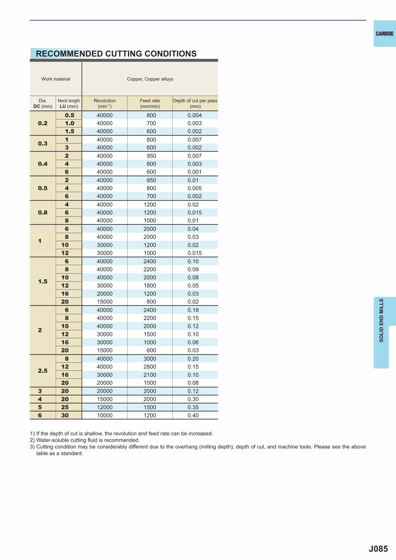
J085
0.20.5 40000 800 0.0041.0 40000 700 0.0031.5 40000 600 0.002
0.31 40000 800 0.0073 40000 600 0.002
0.42 40000 950 0.0074 40000 800 0.0036 40000 600 0.001
0.52 40000 950 0.014 40000 800 0.0056 40000 700 0.002
0.84 40000 1200 0.026 40000 1200 0.0158 40000 1000 0.01
1
6 40000 2000 0.048 40000 2000 0.03
10 30000 1200 0.0212 30000 1000 0.015
1.5
6 40000 2400 0.108 40000 2200 0.09
10 40000 2000 0.0812 30000 1800 0.0516 20000 1200 0.0320 15000 800 0.02
2
6 40000 2400 0.188 40000 2200 0.15
10 40000 2000 0.1212 30000 1500 0.1016 30000 1000 0.0620 15000 600 0.03
2.5
8 40000 3000 0.2012 40000 2800 0.1516 30000 2100 0.1020 20000 1000 0.08
3 20 20000 2000 0.124 20 15000 2000 0.305 25 12000 1500 0.356 30 10000 1200 0.40
CARBIDE
SOLI
D E
ND
MIL
LS
RECOMMENDED CUTTING CONDITIONS
1) If the depth of cut is shallow, the revolution and feed rate can be increased.2) Water-soluble cutting fl uid is recommended.3) Cutting condition may be considerably different due to the overhang (milling depth), depth of cut, and machine tools. Please see the above
table as a standard.
Work material Copper, Copper alloys
Dia.DC (mm)
Neck lengthLU (mm)
Revolution(min-1)
Feed rate(mm/min)
Depth of cut per pass(mm)
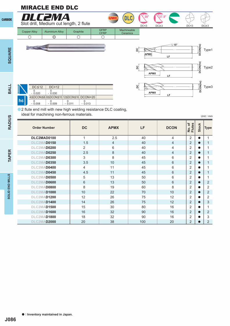
J086
a
DLC2MA
u e u u
DC APMX LF DCON
DLC2MAD0100 1 2.5 40 4 2 a 1DLC2MAD0150 1.5 4 40 4 2 a 1DLC2MAD0200 2 6 40 4 2 a 1DLC2MAD0250 2.5 8 40 4 2 a 1DLC2MAD0300 3 8 45 6 2 a 1DLC2MAD0350 3.5 10 45 6 2 a 1DLC2MAD0400 4 11 45 6 2 a 1DLC2MAD0450 4.5 11 45 6 2 a 1DLC2MAD0500 5 13 50 6 2 a 1DLC2MAD0600 6 13 50 6 2 a 2DLC2MAD0800 8 19 60 8 2 a 2DLC2MAD1000 10 22 70 10 2 a 2DLC2MAD1200 12 26 75 12 2 a 2DLC2MAD1400 14 26 75 12 2 a 3DLC2MAD1500 15 30 80 16 2 a 1DLC2MAD1600 16 32 90 16 2 a 2DLC2MAD1800 18 32 90 16 2 a 3DLC2MAD2000 20 38 100 20 2 a 2
DC<3 DC<3
DC>12 0- 0.020
0- 0.030
DCON=20 0- 0.008
0- 0.009
0- 0.011
0- 0.013
UWC DLC 30° 37.5°
h6
APMX
DC
DC
ON
(h6)15°
APMXLF
DC
DC
ON
(h6)
LF
APMXLF
DC
DC
ON
(h6)
CARBIDE
a : Inventory maintained in Japan.
BA
LLR
AD
IUS
TAPE
RSO
LID
EN
D M
ILLS
SQU
AR
E
Unit : mm
Copper Alloy Aluminium Alloy Graphite GFRPCFRP
MachineableCeramics
2 fl ute end mill with new high welding resistance DLC coating, ideal for machining non-ferrous materials.
Slot drill, Medium cut length, 2 fl ute
Type2
Type1
Type3
Order Number
No.
of
Flut
es
Stoc
k
Type
DC>3 DC>3
4<DCON<6 8<DCON<10 12<DCON<16
DC<12
MIRACLE END DLC
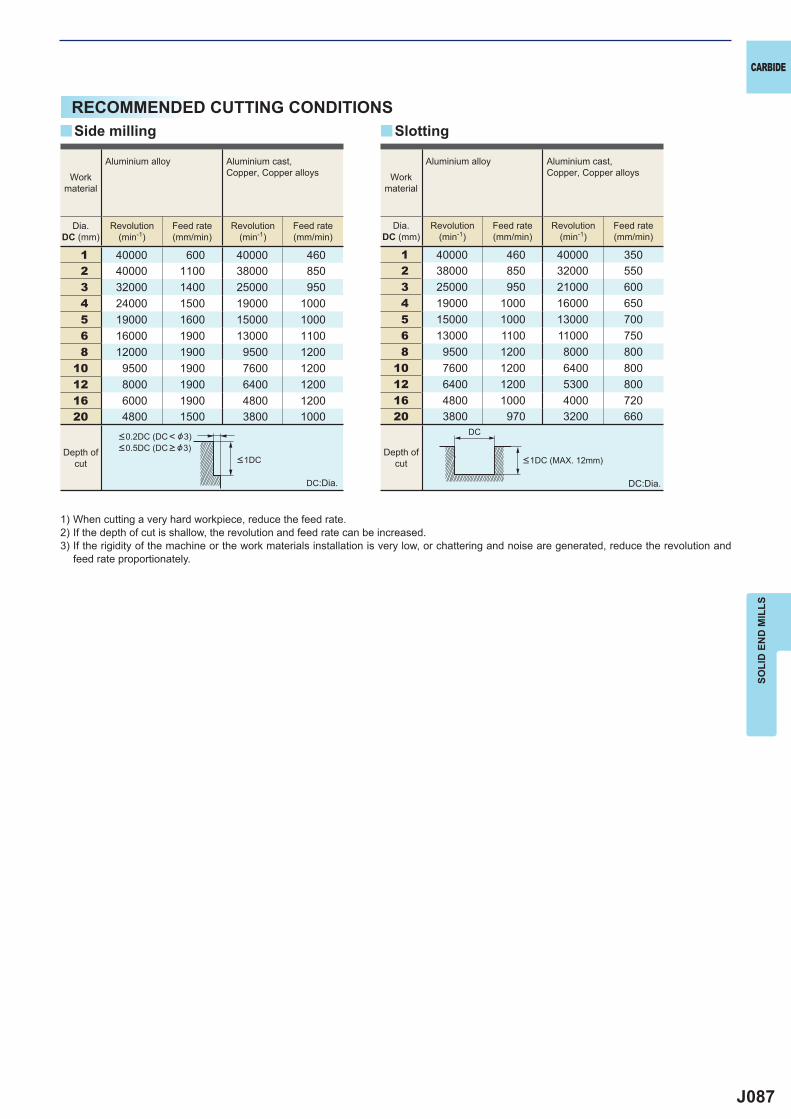
J087
1 40000 600 40000 4602 40000 1100 38000 8503 32000 1400 25000 9504 24000 1500 19000 10005 19000 1600 15000 10006 16000 1900 13000 11008 12000 1900 9500 1200
10 9500 1900 7600 120012 8000 1900 6400 120016 6000 1900 4800 120020 4800 1500 3800 1000
1 40000 460 40000 3502 38000 850 32000 5503 25000 950 21000 6004 19000 1000 16000 6505 15000 1000 13000 7006 13000 1100 11000 7508 9500 1200 8000 800
10 7600 1200 6400 80012 6400 1200 5300 80016 4800 1000 4000 72020 3800 970 3200 660
yy
DC
CARBIDE
SOLI
D E
ND
MIL
LS
RECOMMENDED CUTTING CONDITIONS
1) When cutting a very hard workpiece, reduce the feed rate.2) If the depth of cut is shallow, the revolution and feed rate can be increased.3) If the rigidity of the machine or the work materials installation is very low, or chattering and noise are generated, reduce the revolution and
feed rate proportionately.
DC:Dia.
Depth ofcut
Depth ofcut
DC:Dia.
SlottingSide milling
Dia.DC (mm)
Revolution(min-1)
Feed rate(mm/min)
Revolution(min-1)
Feed rate(mm/min)
Dia.DC (mm)
Revolution(min-1)
Feed rate(mm/min)
Revolution(min-1)
Feed rate(mm/min)
Workmaterial
Aluminium alloy Aluminium cast, Copper, Copper alloys Work
material
Aluminium alloy Aluminium cast, Copper, Copper alloys
<1DC (MAX. 12mm)
<0.2DC (DC< &3)<0.5DC (DC > &3)
<1DC
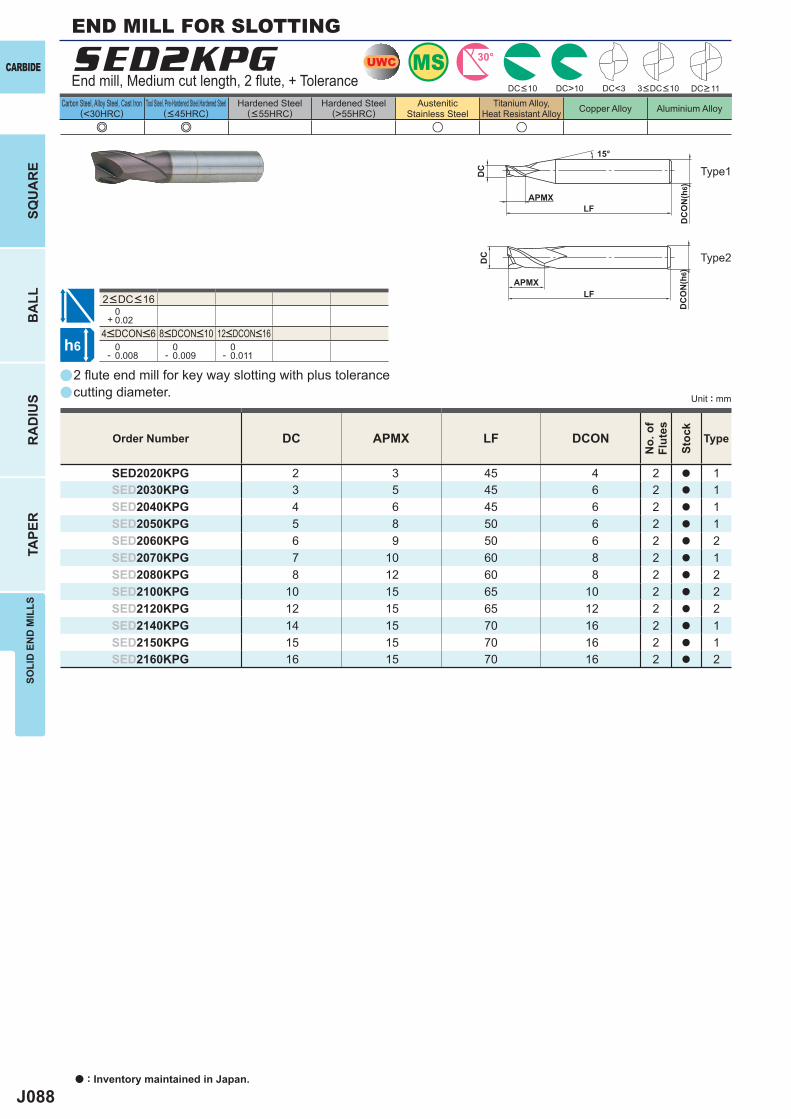
J088
aa
a
e e u u
SED2KPG
DC APMX LF DCON
SED2020KPG 2 3 45 4 2 a 1SED2030KPG 3 5 45 6 2 a 1SED2040KPG 4 6 45 6 2 a 1SED2050KPG 5 8 50 6 2 a 1SED2060KPG 6 9 50 6 2 a 2SED2070KPG 7 10 60 8 2 a 1SED2080KPG 8 12 60 8 2 a 2SED2100KPG 10 15 65 10 2 a 2SED2120KPG 12 15 65 12 2 a 2SED2140KPG 14 15 70 16 2 a 1SED2150KPG 15 15 70 16 2 a 1SED2160KPG 16 15 70 16 2 a 2
0+ 0.02
0- 0.008
0- 0.009
0- 0.011
DC<3DC>10
MSUWC 30°
h6
APMX
DC
DC
ON
(h6)
15°
APMXLF
DC
DC
ON
(h6)
LF
CARBIDE
a : Inventory maintained in Japan.
BA
LLR
AD
IUS
TAPE
RSO
LID
EN
D M
ILLS
SQU
AR
E
Unit : mm
Carbon Steel, Alloy Steel, Cast Iron(<30HRC)
Tool Steel, Pre-Hardened Steel,Hardened Steel(<45HRC)
Hardened Steel(<55HRC)
Hardened Steel(>55HRC)
AusteniticStainless Steel
Titanium Alloy,Heat Resistant Alloy Copper Alloy Aluminium Alloy
2 fl ute end mill for key way slotting with plus tolerancecutting diameter.
End mill, Medium cut length, 2 fl ute, + Tolerance
END MILL FOR SLOTTING
Type2
Type1
Order Number
No.
of
Flut
es
Stoc
k
Type
DC<10 3<DC<10 DC>11
4<DCON<6 8<DCON<10 12<DCON<16
2<DC<16
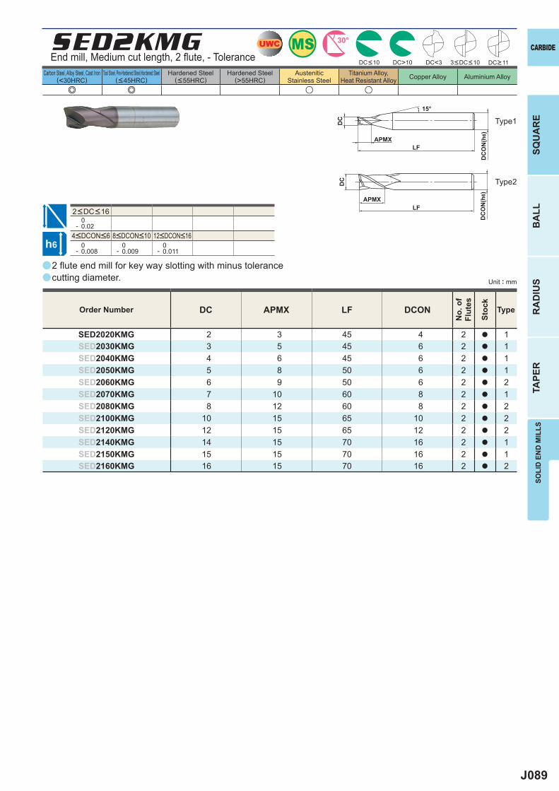
J089
aa
a
e e u u
SED2KMG
DC APMX LF DCON
SED2020KMG 2 3 45 4 2 a 1SED2030KMG 3 5 45 6 2 a 1SED2040KMG 4 6 45 6 2 a 1SED2050KMG 5 8 50 6 2 a 1SED2060KMG 6 9 50 6 2 a 2SED2070KMG 7 10 60 8 2 a 1SED2080KMG 8 12 60 8 2 a 2SED2100KMG 10 15 65 10 2 a 2SED2120KMG 12 15 65 12 2 a 2SED2140KMG 14 15 70 16 2 a 1SED2150KMG 15 15 70 16 2 a 1SED2160KMG 16 15 70 16 2 a 2
0- 0.02
0- 0.008
0- 0.009
0- 0.011
DC<3DC>10
MSUWC 30°
h6
APMX
DC
DC
ON
(h6)
15°
APMXLF
DC
DC
ON
(h6)
LF
CARBIDE
SQU
AR
EB
ALL
RA
DIU
STA
PER
SOLI
D E
ND
MIL
LS
Unit : mm
Carbon Steel, Alloy Steel, Cast Iron(<30HRC)
Tool Steel, Pre-Hardened Steel,Hardened Steel(<45HRC)
Hardened Steel(<55HRC)
Hardened Steel(>55HRC)
AusteniticStainless Steel
Titanium Alloy,Heat Resistant Alloy Copper Alloy Aluminium Alloy
2 fl ute end mill for key way slotting with minus tolerance cutting diameter.
End mill, Medium cut length, 2 fl ute, - Tolerance
Type2
Type1
Order Number
No.
of
Flut
es
Stoc
k
Type
DC<10 3<DC<10 DC>11
4<DCON<6 8<DCON<10 12<DCON<16
2<DC<16
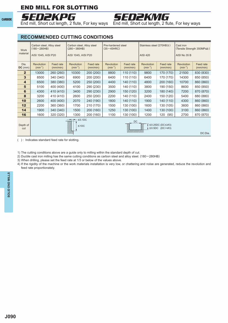
J090
2 13000 260 (260) 10300 200 (200) 8800 110 (110) 9800 170 (170) 21500 830 (830) 3 8500 340 (340) 6900 200 (200) 6400 110 (110) 6400 170 (170) 14300 850 (850) 4 6500 380 (380) 5200 250 (200) 4400 140 (110) 4800 200 (160) 10700 860 (860) 5 5100 400 (400) 4100 290 (230) 3500 140 (110) 3800 190 (150) 8600 850 (850) 6 4300 410 (410) 3400 290 (230) 2900 150 (120) 3200 180 (140) 7200 870 (870) 8 3200 410 (410) 2600 250 (200) 2200 140 (110) 2400 150 (120) 5400 880 (880)10 2600 400 (400) 2070 240 (190) 1800 140 (110) 1900 140 (110) 4300 860 (860)12 2200 360 (360) 1700 210 (170) 1500 130 (100) 1600 130 (105) 3600 860 (860)14 1900 340 (340) 1500 200 (160) 1250 130 (100) 1400 130 (100) 3100 860 (860)16 1600 320 (320) 1300 200 (160) 1100 130 (100) 1200 120 (95) 2700 870 (870)
SED2KPG SED2KMG
DC
CARBIDE
SOLI
D E
ND
MIL
LS
RECOMMENDED CUTTING CONDITIONS
1) The cutting conditions above are a guide only to milling within the standard depth of cut.2) Ductile cast iron milling has the same cutting conditions as carbon steel and alloy steel. (180─280HB)3) When drilling, please set the feed rate at 1/3 or below of the values above.4) If the rigidity of the machine or the work materials installation is very low, or chattering and noise are generated, reduce the revolution and
feed rate proportionately.
( ) : Indicates standard feed rate for slotting.
DC:Dia.
End mill, Short cut length, 2 fl ute, For key ways End mill, Short cut length, 2 fl ute, For key ways
<0.25DC (DC< &3)<0.5DC (DC>&3)
<1DC
<0.1DC
Workmaterial
Carbon steel, Alloy steel(180─280HB)
AISI 1045, AISI P20
Carbon steel, Alloy steel(280─380HB)
AISI 1045, AISI P20
Pre-hardened steel(35─45HRC)
Stainless steel (270HB> )
AISI 420
Cast iron (Tensile Strength 350MPa> )
AISI No 35 B
Dia.DC (mm)
Revolution(min-1)
Feed rate(mm/min)
Revolution(min-1)
Feed rate(mm/min)
Revolution(min-1)
Feed rate(mm/min)
Revolution(min-1)
Feed rate(mm/min)
Revolution(min-1)
Feed rate(mm/min)
Depth ofcut
END MILL FOR SLOTTING
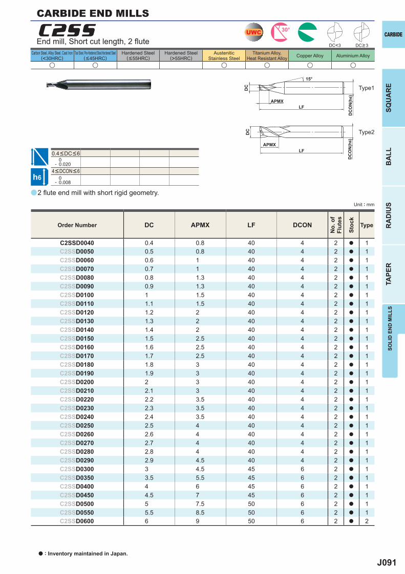
J091
a
u u u u u u
C2SS
DC APMX LF DCON
C2SSD0040 0.4 0.8 40 4 2 a 1C2SSD0050 0.5 0.8 40 4 2 a 1C2SSD0060 0.6 1 40 4 2 a 1C2SSD0070 0.7 1 40 4 2 a 1C2SSD0080 0.8 1.3 40 4 2 a 1C2SSD0090 0.9 1.3 40 4 2 a 1C2SSD0100 1 1.5 40 4 2 a 1C2SSD0110 1.1 1.5 40 4 2 a 1C2SSD0120 1.2 2 40 4 2 a 1C2SSD0130 1.3 2 40 4 2 a 1C2SSD0140 1.4 2 40 4 2 a 1C2SSD0150 1.5 2.5 40 4 2 a 1C2SSD0160 1.6 2.5 40 4 2 a 1C2SSD0170 1.7 2.5 40 4 2 a 1C2SSD0180 1.8 3 40 4 2 a 1C2SSD0190 1.9 3 40 4 2 a 1C2SSD0200 2 3 40 4 2 a 1C2SSD0210 2.1 3 40 4 2 a 1C2SSD0220 2.2 3.5 40 4 2 a 1C2SSD0230 2.3 3.5 40 4 2 a 1C2SSD0240 2.4 3.5 40 4 2 a 1C2SSD0250 2.5 4 40 4 2 a 1C2SSD0260 2.6 4 40 4 2 a 1C2SSD0270 2.7 4 40 4 2 a 1C2SSD0280 2.8 4 40 4 2 a 1C2SSD0290 2.9 4.5 40 4 2 a 1C2SSD0300 3 4.5 45 6 2 a 1C2SSD0350 3.5 5.5 45 6 2 a 1C2SSD0400 4 6 45 6 2 a 1C2SSD0450 4.5 7 45 6 2 a 1C2SSD0500 5 7.5 50 6 2 a 1C2SSD0550 5.5 8.5 50 6 2 a 1C2SSD0600 6 9 50 6 2 a 2
0- 0.020
0- 0.008
UWC 30°
h6
APMX
DC
DC
ON
(h6)
15°
APMXLF
DC
DC
ON
(h6)
LF
DC<3
CARBIDE
SQU
AR
EB
ALL
RA
DIU
STA
PER
SOLI
D E
ND
MIL
LS
Unit : mm
Carbon Steel, Alloy Steel, Cast Iron(<30HRC)
Tool Steel, Pre-Hardened Steel,Hardened Steel(<45HRC)
Hardened Steel(<55HRC)
Hardened Steel(>55HRC)
AusteniticStainless Steel
Titanium Alloy,Heat Resistant Alloy Copper Alloy Aluminium Alloy
0.4<DC<6
2 fl ute end mill with short rigid geometry.
End mill, Short cut length, 2 fl ute
CARBIDE END MILLS
Type2
Type1
Order Number
No.
of
Flut
es
Stoc
k
Type
DC>3
4<DCON<6
a : Inventory maintained in Japan.
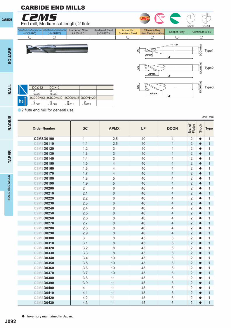
J092
a
u u u u u u
C2MS
DC APMX LF DCON
C2MSD0100 1 2.5 40 4 2 a 1C2MSD0110 1.1 2.5 40 4 2 a 1C2MSD0120 1.2 3 40 4 2 a 1C2MSD0130 1.3 3 40 4 2 a 1C2MSD0140 1.4 3 40 4 2 a 1C2MSD0150 1.5 4 40 4 2 a 1C2MSD0160 1.6 4 40 4 2 a 1C2MSD0170 1.7 4 40 4 2 a 1C2MSD0180 1.8 5 40 4 2 a 1C2MSD0190 1.9 5 40 4 2 a 1C2MSD0200 2 6 40 4 2 a 1C2MSD0210 2.1 6 40 4 2 a 1C2MSD0220 2.2 6 40 4 2 a 1C2MSD0230 2.3 6 40 4 2 a 1C2MSD0240 2.4 8 40 4 2 a 1C2MSD0250 2.5 8 40 4 2 a 1C2MSD0260 2.6 8 40 4 2 a 1C2MSD0270 2.7 8 40 4 2 a 1C2MSD0280 2.8 8 40 4 2 a 1C2MSD0290 2.9 8 40 4 2 a 1C2MSD0300 3 8 45 6 2 a 1C2MSD0310 3.1 8 45 6 2 a 1C2MSD0320 3.2 8 45 6 2 a 1C2MSD0330 3.3 8 45 6 2 a 1C2MSD0340 3.4 10 45 6 2 a 1C2MSD0350 3.5 10 45 6 2 a 1C2MSD0360 3.6 10 45 6 2 a 1C2MSD0370 3.7 10 45 6 2 a 1C2MSD0380 3.8 11 45 6 2 a 1C2MSD0390 3.9 11 45 6 2 a 1C2MSD0400 4 11 45 6 2 a 1C2MSD0410 4.1 11 45 6 2 a 1C2MSD0420 4.2 11 45 6 2 a 1C2MSD0430 4.3 11 45 6 2 a 1
DC>12 0- 0.020
0- 0.030
DCON=20 0- 0.008
0- 0.009
0- 0.011
0- 0.013
DC<3
UWC 30°
h6
APMX
DC
DC
ON
(h6)15°
APMXLF
DC
DC
ON
(h6)
LF
APMXLF
DC
DC
ON
(h6)
CARBIDE
a : Inventory maintained in Japan.
BA
LLR
AD
IUS
TAPE
RSO
LID
EN
D M
ILLS
SQU
AR
E
Unit : mm
Carbon Steel, Alloy Steel, Cast Iron(<30HRC)
Tool Steel, Pre-Hardened Steel,Hardened Steel(<45HRC)
Hardened Steel(<55HRC)
Hardened Steel(>55HRC)
AusteniticStainless Steel
Titanium Alloy,Heat Resistant Alloy Copper Alloy Aluminium Alloy
2 fl ute end mill for general use.
End mill, Medium cut length, 2 fl ute
Type2
Type3
Type1
Order Number
No.
of
Flut
es
Stoc
k
Type
DC>3
4<DCON<6 8<DCON<10 12<DCON<16
DC<12
CARBIDE END MILLS
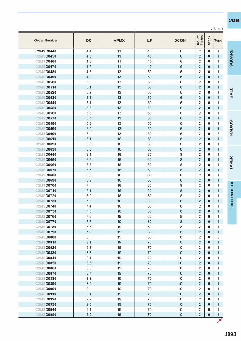
J093
DC APMX LF DCON
C2MSD0440 4.4 11 45 6 2 a 1C2MSD0450 4.5 11 45 6 2 a 1C2MSD0460 4.6 11 45 6 2 a 1C2MSD0470 4.7 11 45 6 2 a 1C2MSD0480 4.8 13 50 6 2 a 1C2MSD0490 4.9 13 50 6 2 a 1C2MSD0500 5 13 50 6 2 a 1C2MSD0510 5.1 13 50 6 2 a 1C2MSD0520 5.2 13 50 6 2 a 1C2MSD0530 5.3 13 50 6 2 a 1C2MSD0540 5.4 13 50 6 2 a 1C2MSD0550 5.5 13 50 6 2 a 1C2MSD0560 5.6 13 50 6 2 a 1C2MSD0570 5.7 13 50 6 2 a 1C2MSD0580 5.8 13 50 6 2 a 1C2MSD0590 5.9 13 50 6 2 a 1C2MSD0600 6 13 50 6 2 a 2C2MSD0610 6.1 16 60 8 2 a 1C2MSD0620 6.2 16 60 8 2 a 1C2MSD0630 6.3 16 60 8 2 a 1C2MSD0640 6.4 16 60 8 2 a 1C2MSD0650 6.5 16 60 8 2 a 1C2MSD0660 6.6 16 60 8 2 a 1C2MSD0670 6.7 16 60 8 2 a 1C2MSD0680 6.8 16 60 8 2 a 1C2MSD0690 6.9 16 60 8 2 a 1C2MSD0700 7 16 60 8 2 a 1C2MSD0710 7.1 16 60 8 2 a 1C2MSD0720 7.2 16 60 8 2 a 1C2MSD0730 7.3 16 60 8 2 a 1C2MSD0740 7.4 16 60 8 2 a 1C2MSD0750 7.5 16 60 8 2 a 1C2MSD0760 7.6 19 60 8 2 a 1C2MSD0770 7.7 19 60 8 2 a 1C2MSD0780 7.8 19 60 8 2 a 1C2MSD0790 7.9 19 60 8 2 a 1C2MSD0800 8 19 60 8 2 a 2C2MSD0810 8.1 19 70 10 2 a 1C2MSD0820 8.2 19 70 10 2 a 1C2MSD0830 8.3 19 70 10 2 a 1C2MSD0840 8.4 19 70 10 2 a 1C2MSD0850 8.5 19 70 10 2 a 1C2MSD0860 8.6 19 70 10 2 a 1C2MSD0870 8.7 19 70 10 2 a 1C2MSD0880 8.8 19 70 10 2 a 1C2MSD0890 8.9 19 70 10 2 a 1C2MSD0900 9 19 70 10 2 a 1C2MSD0910 9.1 19 70 10 2 a 1C2MSD0920 9.2 19 70 10 2 a 1C2MSD0930 9.3 19 70 10 2 a 1C2MSD0940 9.4 19 70 10 2 a 1C2MSD0950 9.5 19 70 10 2 a 1
CARBIDE
SQU
AR
EB
ALL
RA
DIU
STA
PER
SOLI
D E
ND
MIL
LS
Unit : mm
Order Number
No.
of
Flut
es
Stoc
k
Type
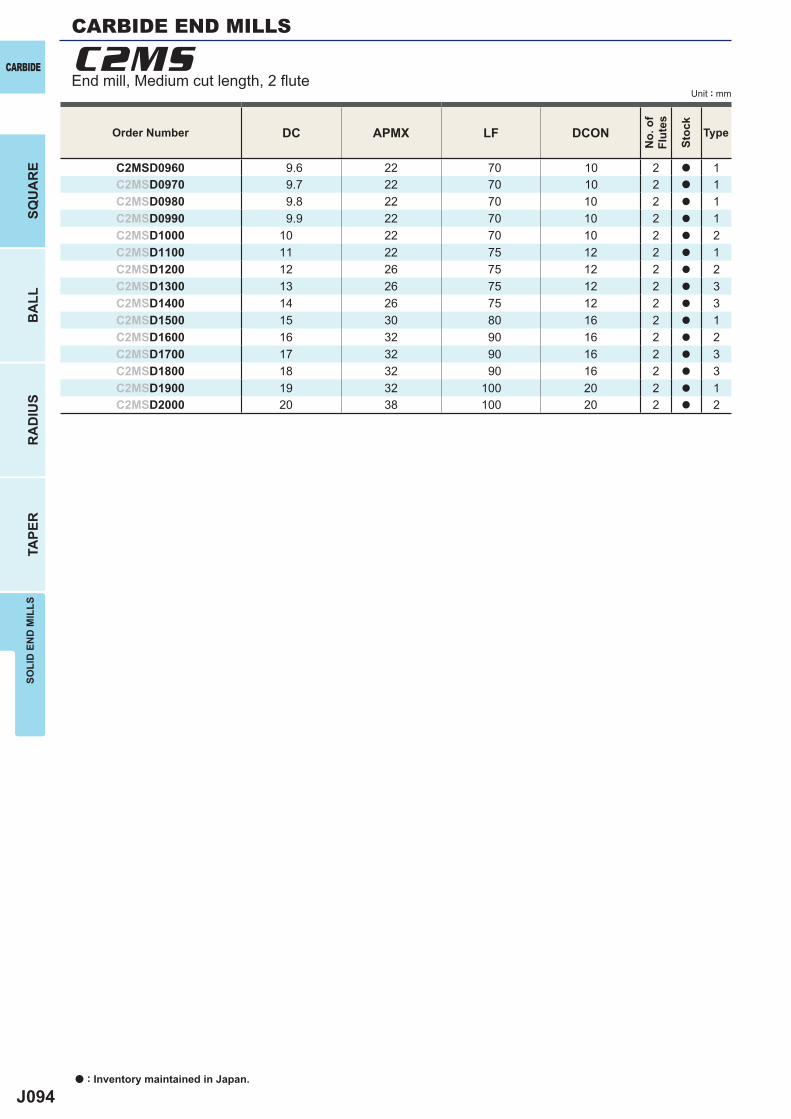
J094
DC APMX LF DCON
C2MSD0960 9.6 22 70 10 2 a 1C2MSD0970 9.7 22 70 10 2 a 1C2MSD0980 9.8 22 70 10 2 a 1C2MSD0990 9.9 22 70 10 2 a 1C2MSD1000 10 22 70 10 2 a 2C2MSD1100 11 22 75 12 2 a 1C2MSD1200 12 26 75 12 2 a 2C2MSD1300 13 26 75 12 2 a 3C2MSD1400 14 26 75 12 2 a 3C2MSD1500 15 30 80 16 2 a 1C2MSD1600 16 32 90 16 2 a 2C2MSD1700 17 32 90 16 2 a 3C2MSD1800 18 32 90 16 2 a 3C2MSD1900 19 32 100 20 2 a 1C2MSD2000 20 38 100 20 2 a 2
C2MSCARBIDE
a : Inventory maintained in Japan.
BA
LLR
AD
IUS
TAPE
RSO
LID
EN
D M
ILLS
SQU
AR
E
Unit : mm
Order Number
No.
of
Flut
es
Stoc
k
Type
End mill, Medium cut length, 2 fl ute
CARBIDE END MILLS
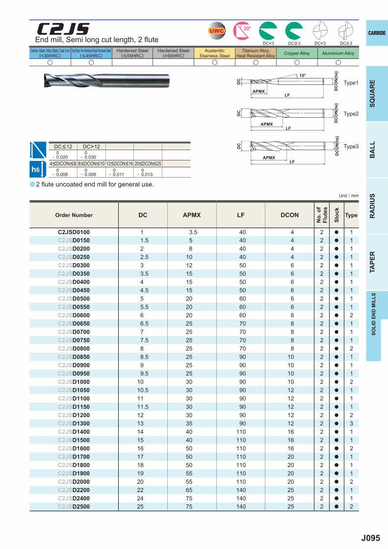
J095
a
u u u u u u
C2JS
DC APMX LF DCON
C2JSD0100 1 3.5 40 4 2 a 1C2JSD0150 1.5 5 40 4 2 a 1C2JSD0200 2 8 40 4 2 a 1C2JSD0250 2.5 10 40 4 2 a 1C2JSD0300 3 12 50 6 2 a 1C2JSD0350 3.5 15 50 6 2 a 1C2JSD0400 4 15 50 6 2 a 1C2JSD0450 4.5 15 50 6 2 a 1C2JSD0500 5 20 60 6 2 a 1C2JSD0550 5.5 20 60 6 2 a 1C2JSD0600 6 20 60 6 2 a 2C2JSD0650 6.5 25 70 8 2 a 1C2JSD0700 7 25 70 8 2 a 1C2JSD0750 7.5 25 70 8 2 a 1C2JSD0800 8 25 70 8 2 a 2C2JSD0850 8.5 25 90 10 2 a 1C2JSD0900 9 25 90 10 2 a 1C2JSD0950 9.5 25 90 10 2 a 1C2JSD1000 10 30 90 10 2 a 2C2JSD1050 10.5 30 90 12 2 a 1C2JSD1100 11 30 90 12 2 a 1C2JSD1150 11.5 30 90 12 2 a 1C2JSD1200 12 30 90 12 2 a 2C2JSD1300 13 35 90 12 2 a 3C2JSD1400 14 40 110 16 2 a 1C2JSD1500 15 40 110 16 2 a 1C2JSD1600 16 50 110 16 2 a 2C2JSD1700 17 50 110 20 2 a 1C2JSD1800 18 50 110 20 2 a 1C2JSD1900 19 55 110 20 2 a 1C2JSD2000 20 55 110 20 2 a 2C2JSD2200 22 65 140 25 2 a 1C2JSD2400 24 75 140 25 2 a 1C2JSD2500 25 75 140 25 2 a 2
DC>12 0- 0.020
0- 0.030
0- 0.008
0- 0.009
0- 0.011
0- 0.013
DC<3 DC<3
UWC 30°
h6
APMX
DC
DC
ON
(h6)15°
APMXLF
DC
DC
ON
(h6)
LF
APMXLF
DC
DC
ON
(h6)
CARBIDE
SQU
AR
EB
ALL
RA
DIU
STA
PER
SOLI
D E
ND
MIL
LS
Unit : mm
Carbon Steel, Alloy Steel, Cast Iron(<30HRC)
Tool Steel, Pre-Hardened Steel,Hardened Steel(<45HRC)
Hardened Steel(<55HRC)
Hardened Steel(>55HRC)
AusteniticStainless Steel
Titanium Alloy,Heat Resistant Alloy Copper Alloy Aluminium Alloy
2 fl ute uncoated end mill for general use.
End mill, Semi long cut length, 2 fl ute
Type1
Type2
Type3
Order Number
No.
of
Flut
es
Stoc
k
Type
DC>3 DC>3
4<DCON<6 8<DCON<10 12<DCON<16 20<DCON<25
DC<12
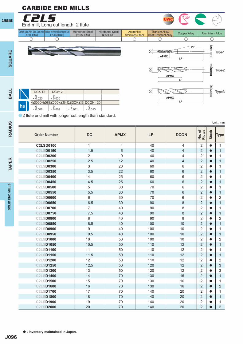
J096
a
u u u u u u
C2LS
DC APMX LF DCON
C2LSD0100 1 4 40 4 2 a 1C2LSD0150 1.5 6 40 4 2 a 1C2LSD0200 2 9 40 4 2 a 1C2LSD0250 2.5 12 40 4 2 a 1C2LSD0300 3 20 60 6 2 a 1C2LSD0350 3.5 22 60 6 2 a 1C2LSD0400 4 25 60 6 2 a 1C2LSD0450 4.5 25 60 6 2 a 1C2LSD0500 5 30 70 6 2 a 1C2LSD0550 5.5 30 70 6 2 a 1C2LSD0600 6 30 70 6 2 a 2C2LSD0650 6.5 30 90 8 2 a 1C2LSD0700 7 40 90 8 2 a 1C2LSD0750 7.5 40 90 8 2 a 1C2LSD0800 8 40 90 8 2 a 2C2LSD0850 8.5 40 100 10 2 a 1C2LSD0900 9 40 100 10 2 a 1C2LSD0950 9.5 40 100 10 2 a 1C2LSD1000 10 50 100 10 2 a 2C2LSD1050 10.5 50 110 12 2 a 1C2LSD1100 11 50 110 12 2 a 1C2LSD1150 11.5 50 110 12 2 a 1C2LSD1200 12 50 110 12 2 a 2C2LSD1250 12.5 50 120 12 2 a 3C2LSD1300 13 50 120 12 2 a 3C2LSD1400 14 70 130 16 2 a 1C2LSD1500 15 70 130 16 2 a 1C2LSD1600 16 70 130 16 2 a 2C2LSD1700 17 70 140 20 2 a 1C2LSD1800 18 70 140 20 2 a 1C2LSD1900 19 70 140 20 2 a 1C2LSD2000 20 70 140 20 2 a 2
DC>12 0- 0.020
0- 0.030
DCON=20 0- 0.008
0- 0.009
0- 0.011
0- 0.013
UWC 30°
h6
APMX
DC
DC
ON
(h6)15°
APMXLF
DC
DC
ON
(h6)
LF
APMXLF
DC
DC
ON
(h6)
CARBIDE
a : Inventory maintained in Japan.
BA
LLR
AD
IUS
TAPE
RSO
LID
EN
D M
ILLS
SQU
AR
E
Unit : mm
Carbon Steel, Alloy Steel, Cast Iron(<30HRC)
Tool Steel, Pre-Hardened Steel,Hardened Steel(<45HRC)
Hardened Steel(<55HRC)
Hardened Steel(>55HRC)
AusteniticStainless Steel
Titanium Alloy,Heat Resistant Alloy Copper Alloy Aluminium Alloy
2 fl ute end mill with longer cut length than standard.
End mill, Long cut length, 2 fl ute
Type2
Type1
Type3
Order Number
No.
of
Flut
es
Stoc
k
Type
4<DCON<6 8<DCON<10 12<DCON<16
DC<12
CARBIDE END MILLS
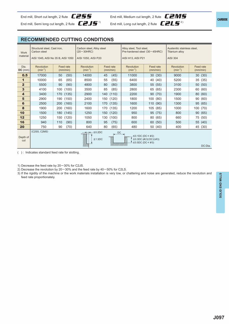
J097
0.5 17000 50 (50) 14000 45 (45) 11000 30 (30) 9000 30 (30)1 10000 65 (65) 8500 55 (55) 6400 40 (40) 5200 35 (35)2 5500 90 (90) 4800 80 (80) 3800 55 (55) 3100 50 (50)3 4100 100 (100) 3500 85 (85) 2800 65 (65) 2300 60 (60)4 3400 170 (135) 2900 140 (110) 2200 90 (70) 1900 80 (60)5 2900 190 (150) 2400 150 (120) 1800 100 (80) 1500 90 (60)6 2500 200 (160) 2100 170 (135) 1600 110 (90) 1300 95 (65)8 1900 200 (160) 1600 170 (135) 1200 105 (85) 1000 100 (70)
10 1500 180 (145) 1250 150 (120) 950 95 (75) 800 90 (65)12 1250 150 (120) 1050 130 (100) 800 80 (65) 660 75 (50)16 940 110 (90) 800 95 (75) 600 60 (50) 500 55 (40)20 750 90 (70) 640 80 (65) 480 50 (40) 400 45 (30)
(C2SS, C2MS) DC
CARBIDE
SOLI
D E
ND
MIL
LS
RECOMMENDED CUTTING CONDITIONS
1) Decrease the feed rate by 20─30% for C2JS.2) Decrease the revolution by 20─30% and the feed rate by 40─50% for C2LS.3) If the rigidity of the machine or the work materials installation is very low, or chattering and noise are generated, reduce the revolution and
feed rate proportionately.
( ) : Indicates standard feed rate for slotting.
DC:Dia.
Workmaterial
Structural steel, Cast iron, Carbon steel
AISI 1045, AISI No 35 B, AISI 1050
Carbon steel, Alloy steel(20─30HRC)
AISI 1050, AISI P20
Alloy steel, Tool steel, Pre-hardened steel (30─45HRC)
AISI H13, AISI P21
Austenitic stainless steel,Titanium alloy
AISI 304
Dia.DC (mm)
Revolution(min-1)
Feed rate(mm/min)
Revolution(min-1)
Feed rate(mm/min)
Revolution(min-1)
Feed rate(mm/min)
Revolution(min-1)
Feed rate(mm/min)
Depth ofcut
<0.2DC
<1.5DC<0.1DC (DC< &2)<0.3DC (&2< DC< &3)<0.5DC (DC< &3)
End mill, Short cut length, 2 fl ute C2SS End mill, Medium cut length, 2 fl ute C2MSEnd mill, Semi long cut length, 2 fl ute C2JS 1)
End mill, Long cut length, 2 fl ute C2LS 2 )
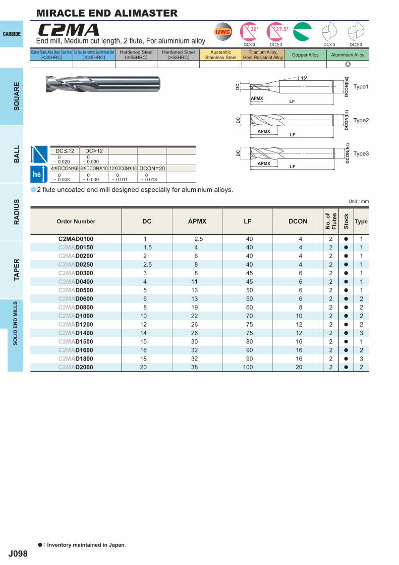
J098
a
e
C2MA
DC APMX LF DCON
C2MAD0100 1 2.5 40 4 2 a 1C2MAD0150 1.5 4 40 4 2 a 1C2MAD0200 2 6 40 4 2 a 1C2MAD0250 2.5 8 40 4 2 a 1C2MAD0300 3 8 45 6 2 a 1C2MAD0400 4 11 45 6 2 a 1C2MAD0500 5 13 50 6 2 a 1C2MAD0600 6 13 50 6 2 a 2C2MAD0800 8 19 60 8 2 a 2C2MAD1000 10 22 70 10 2 a 2C2MAD1200 12 26 75 12 2 a 2C2MAD1400 14 26 75 12 2 a 3C2MAD1500 15 30 80 16 2 a 1C2MAD1600 16 32 90 16 2 a 2C2MAD1800 18 32 90 16 2 a 3C2MAD2000 20 38 100 20 2 a 2
DC>12 0- 0.020
0- 0.030
DCON=20 0- 0.008
0- 0.009
0- 0.011
0- 0.013
DC<3 DC<3
UWC 30° 37.5°
h6
APMX
DC
DC
ON
(h6)15°
APMXLF
DC
DC
ON
(h6)
LF
APMXLF
DC
DC
ON
(h6)
CARBIDE
a : Inventory maintained in Japan.
BA
LLR
AD
IUS
TAPE
RSO
LID
EN
D M
ILLS
SQU
AR
E
Unit : mm
Carbon Steel, Alloy Steel, Cast Iron(<30HRC)
Tool Steel, Pre-Hardened Steel,Hardened Steel(<45HRC)
Hardened Steel(<55HRC)
Hardened Steel(>55HRC)
AusteniticStainless Steel
Titanium Alloy,Heat Resistant Alloy Copper Alloy Aluminium Alloy
2 fl ute uncoated end mill designed especially for aluminium alloys.
End mill, Medium cut length, 2 fl ute, For aluminium alloy
Type2
Type3
Type1
Order Number
No.
of
Flut
es
Stoc
k
Type
DC>3 DC>3
4<DCON<6 8<DCON<10 12<DCON<16
DC<12
MIRACLE END ALIMASTER
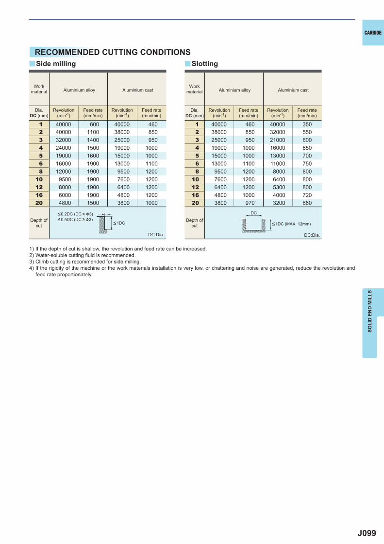
J099
1 40000 600 40000 4602 40000 1100 38000 8503 32000 1400 25000 9504 24000 1500 19000 10005 19000 1600 15000 10006 16000 1900 13000 11008 12000 1900 9500 1200
10 9500 1900 7600 120012 8000 1900 6400 120016 6000 1900 4800 120020 4800 1500 3800 1000
1 40000 460 40000 3502 38000 850 32000 5503 25000 950 21000 6004 19000 1000 16000 6505 15000 1000 13000 7006 13000 1100 11000 7508 9500 1200 8000 800
10 7600 1200 6400 80012 6400 1200 5300 80016 4800 1000 4000 72020 3800 970 3200 660
y y
DC
CARBIDE
SOLI
D E
ND
MIL
LS
RECOMMENDED CUTTING CONDITIONS
1) If the depth of cut is shallow, the revolution and feed rate can be increased.2) Water-soluble cutting fl uid is recommended.3) Climb cutting is recommended for side milling.4) If the rigidity of the machine or the work materials installation is very low, or chattering and noise are generated, reduce the revolution and
feed rate proportionately.
DC:Dia. DC:Dia.
Side milling Slotting
Workmaterial Aluminium alloy Aluminium cast
Workmaterial Aluminium alloy Aluminium cast
Dia.DC (mm)
Revolution(min-1)
Feed rate(mm/min)
Revolution(min-1)
Feed rate(mm/min)
Dia.DC (mm)
Revolution(min-1)
Feed rate(mm/min)
Revolution(min-1)
Feed rate(mm/min)
Depth ofcut
Depth ofcut <1DC (MAX. 12mm)<1DC
<0.2DC (DC< &3)<0.5DC (DC > &3)
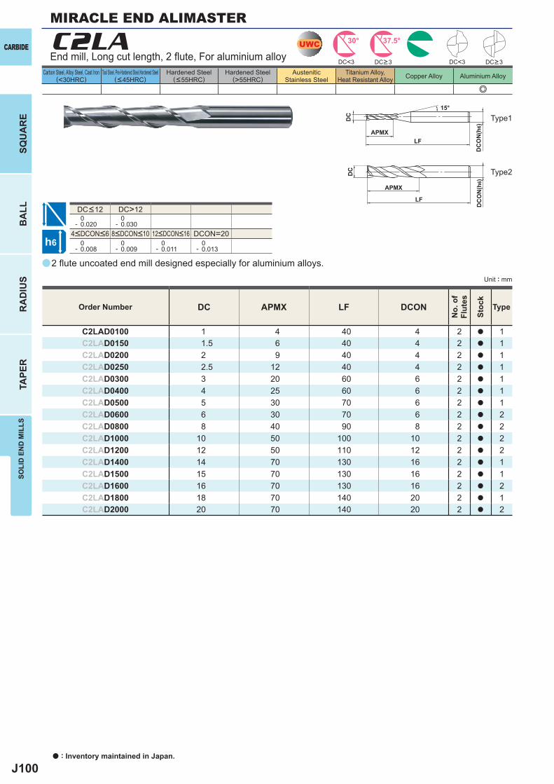
J100
a
e
C2LA
DC APMX LF DCON
C2LAD0100 1 4 40 4 2 a 1C2LAD0150 1.5 6 40 4 2 a 1C2LAD0200 2 9 40 4 2 a 1C2LAD0250 2.5 12 40 4 2 a 1C2LAD0300 3 20 60 6 2 a 1C2LAD0400 4 25 60 6 2 a 1C2LAD0500 5 30 70 6 2 a 1C2LAD0600 6 30 70 6 2 a 2C2LAD0800 8 40 90 8 2 a 2C2LAD1000 10 50 100 10 2 a 2C2LAD1200 12 50 110 12 2 a 2C2LAD1400 14 70 130 16 2 a 1C2LAD1500 15 70 130 16 2 a 1C2LAD1600 16 70 130 16 2 a 2C2LAD1800 18 70 140 20 2 a 1C2LAD2000 20 70 140 20 2 a 2
DC>12 0- 0.020
0- 0.030
DCON=20 0- 0.008
0- 0.009
0- 0.011
0- 0.013
DC<3 DC<3
UWC 30° 37.5°
h6
APMX
DC
DC
ON
(h6)
15°
APMX
LF
DC
DC
ON
(h6)
LF
CARBIDE
a : Inventory maintained in Japan.
BA
LLR
AD
IUS
TAPE
RSO
LID
EN
D M
ILLS
SQU
AR
E
Unit : mm
Carbon Steel, Alloy Steel, Cast Iron(<30HRC)
Tool Steel, Pre-Hardened Steel,Hardened Steel(<45HRC)
Hardened Steel(<55HRC)
Hardened Steel(>55HRC)
AusteniticStainless Steel
Titanium Alloy,Heat Resistant Alloy Copper Alloy Aluminium Alloy
2 fl ute uncoated end mill designed especially for aluminium alloys.
End mill, Long cut length, 2 fl ute, For aluminium alloy
Type2
Type1
Order Number
No.
of
Flut
es
Stoc
k
Type
DC>3 DC>3
4<DCON<6 8<DCON<10 12<DCON<16
DC<12
MIRACLE END ALIMASTER
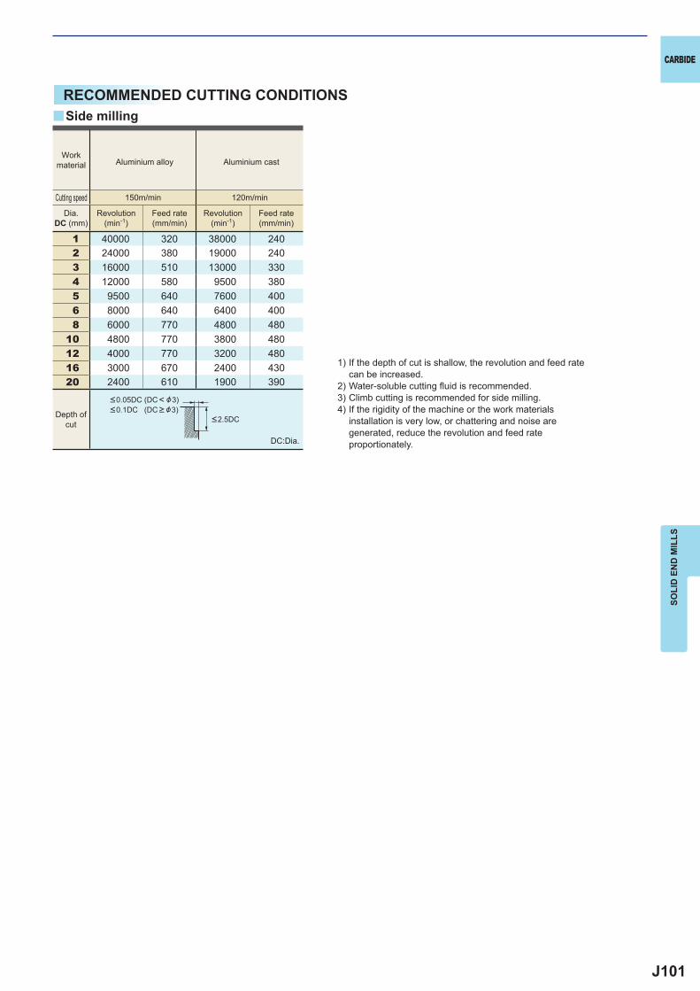
J101
1 40000 320 38000 2402 24000 380 19000 2403 16000 510 13000 3304 12000 580 9500 3805 9500 640 7600 4006 8000 640 6400 4008 6000 770 4800 480
10 4800 770 3800 48012 4000 770 3200 48016 3000 670 2400 43020 2400 610 1900 390
y
CARBIDE
SOLI
D E
ND
MIL
LS
RECOMMENDED CUTTING CONDITIONS
1) If the depth of cut is shallow, the revolution and feed rate can be increased.
2) Water-soluble cutting fl uid is recommended.3) Climb cutting is recommended for side milling.4) If the rigidity of the machine or the work materials
installation is very low, or chattering and noise are generated, reduce the revolution and feed rate proportionately.DC:Dia.
Side milling
Workmaterial Aluminium alloy Aluminium cast
Dia.DC (mm)
Revolution(min-1)
Feed rate(mm/min)
Revolution(min-1)
Feed rate(mm/min)
Cutting speed 150m/min 120m/min
Depth ofcut
<0.05DC (DC< &3)<0.1DC (DC > &3)
<2.5DC
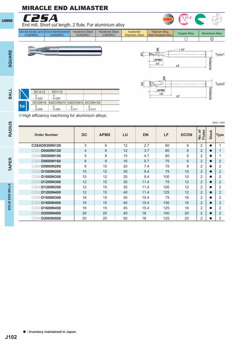
J102
a
u e
C2SA
DC APMX LU DN LF DCON
C2SAD0300N120 3 6 12 2.7 60 6 2 a 1C2SAD0400N120 4 6 12 3.7 60 6 2 a 1C2SAD0500N150 5 8 15 4.7 60 6 2 a 1C2SAD0600N160 6 8 16 5.7 75 6 2 a 2C2SAD0800N200 8 10 20 7.4 75 8 2 a 2C2SAD1000N300 10 12 30 9.4 75 10 2 a 2C2SAD1000N350 10 12 35 9.4 100 10 2 a 2C2SAD1200N300 12 15 30 11.4 75 12 2 a 2C2SAD1200N350 12 15 35 11.4 100 12 2 a 2C2SAD1200N400 12 15 40 11.4 125 12 2 a 2C2SAD1600N300 16 15 30 15.4 75 16 2 a 2C2SAD1600N400 16 15 40 15.4 100 16 2 a 2C2SAD1600N450 16 15 45 15.4 125 16 2 a 2C2SAD2000N400 20 20 40 18 100 20 2 a 2C2SAD2000N500 20 20 50 18 125 20 2 a 2
DC>12 0- 0.020
0- 0.030
DCON=6 DCON=20 0- 0.008
0- 0.009
0- 0.011
0- 0.013
UWC 37.5°
h6
APMXLU
DC
DC
ON
(h6)
15°
APMX
LF
DC
DC
ON
(h6)
LF
DN
LU
DN
CARBIDE
a : Inventory maintained in Japan.
BA
LLR
AD
IUS
TAPE
RSO
LID
EN
D M
ILLS
SQU
AR
E
Unit : mm
Carbon Steel, Alloy Steel, Cast Iron(<30HRC)
Tool Steel, Pre-Hardened Steel,Hardened Steel(<45HRC)
Hardened Steel(<55HRC)
Hardened Steel(>55HRC)
AusteniticStainless Steel
Titanium Alloy,Heat Resistant Alloy Copper Alloy Aluminium Alloy
High effi ciency machining for aluminium alloys.
End mill, Short cut length, 2 fl ute, For aluminium alloy
Type2
Type1
Order Number
No.
of
Flut
es
Stoc
k
Type
8<DCON<10 12<DCON<16
DC<12
MIRACLE END ALIMASTER
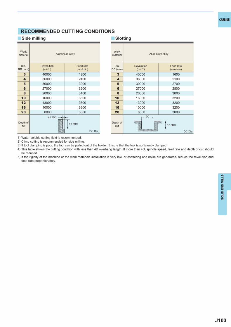
J103
3 40000 18004 36000 24005 30000 30006 27000 32008 20000 3400
10 16000 360012 13000 360016 10000 360020 8000 3300
3 40000 16004 36000 21005 30000 27006 27000 28008 20000 3000
10 16000 320012 13000 320016 10000 320020 8000 3000
y y
DC
CARBIDE
SOLI
D E
ND
MIL
LS
RECOMMENDED CUTTING CONDITIONS
1) Water-soluble cutting fl uid is recommended.2) Climb cutting is recommended for side milling.3) If tool clamping is poor, the tool can be pulled out of the holder. Ensure that the tool is suffi ciently clamped.4) This table shows the cutting condition with less than 4D overhang length. If more than 4D, spindle speed, feed rate and depth of cut should
be reduced.5) If the rigidity of the machine or the work materials installation is very low, or chattering and noise are generated, reduce the revolution and
feed rate proportionately.
DC:Dia. DC:Dia.
Side milling Slotting
Depth ofcut
Workmaterial Aluminium alloy
Workmaterial Aluminium alloy
Dia.DC (mm)
Revolution(min-1)
Feed rate(mm/min)
Dia.DC (mm)
Revolution(min-1)
Feed rate(mm/min)
Depth ofcut
<0.5DC
<0.8DC <0.8DC
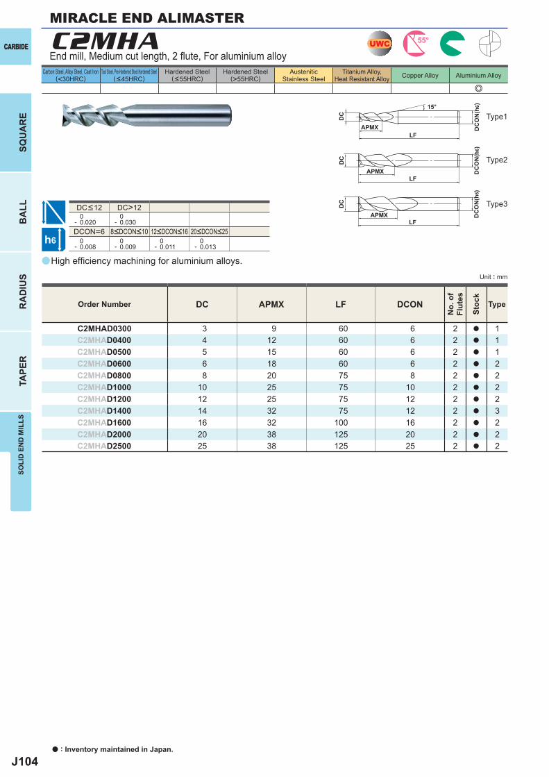
J104
a
e
C2MHA
DC APMX LF DCON
C2MHAD0300 3 9 60 6 2 a 1C2MHAD0400 4 12 60 6 2 a 1C2MHAD0500 5 15 60 6 2 a 1C2MHAD0600 6 18 60 6 2 a 2C2MHAD0800 8 20 75 8 2 a 2C2MHAD1000 10 25 75 10 2 a 2C2MHAD1200 12 25 75 12 2 a 2C2MHAD1400 14 32 75 12 2 a 3C2MHAD1600 16 32 100 16 2 a 2C2MHAD2000 20 38 125 20 2 a 2C2MHAD2500 25 38 125 25 2 a 2
DC>12 0- 0.020
0- 0.030
DCON=6 0- 0.008
0- 0.009
0- 0.011
0- 0.013
UWC 55°
h6
APMX
DC
DC
ON
(h6)15°
APMXLF
DC
DC
ON
(h6)
LF
APMXLF
DC
DC
ON
(h6)
CARBIDE
a : Inventory maintained in Japan.
BA
LLR
AD
IUS
TAPE
RSO
LID
EN
D M
ILLS
SQU
AR
E
Unit : mm
Carbon Steel, Alloy Steel, Cast Iron(<30HRC)
Tool Steel, Pre-Hardened Steel,Hardened Steel(<45HRC)
Hardened Steel(<55HRC)
Hardened Steel(>55HRC)
AusteniticStainless Steel
Titanium Alloy,Heat Resistant Alloy Copper Alloy Aluminium Alloy
High effi ciency machining for aluminium alloys.
End mill, Medium cut length, 2 fl ute, For aluminium alloy
Type2
Type1
Type3
Order Number
No.
of
Flut
es
Stoc
k
Type
8<DCON<10 12<DCON<16 20<DCON<25
DC<12
MIRACLE END ALIMASTER
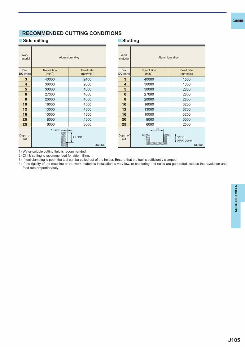
J105
3 40000 24004 36000 26005 30000 40006 27000 40008 20000 4000
10 16000 450012 13000 450016 10000 450020 8000 430025 6000 3600
3 40000 15004 36000 18005 30000 28006 27000 28008 20000 2800
10 16000 320012 13000 320016 10000 320020 8000 300025 6000 2500
y y
DC
CARBIDE
SOLI
D E
ND
MIL
LS
RECOMMENDED CUTTING CONDITIONS
1) Water-soluble cutting fl uid is recommended.2) Climb cutting is recommended for side milling.3) If tool clamping is poor, the tool can be pulled out of the holder. Ensure that the tool is suffi ciently clamped.4) If the rigidity of the machine or the work materials installation is very low, or chattering and noise are generated, reduce the revolution and
feed rate proportionately.
DC:Dia. DC:Dia.
Side milling Slotting
Depth ofcut
Depth ofcut
Workmaterial Aluminium alloy
Workmaterial Aluminium alloy
Dia.DC (mm)
Revolution(min-1)
Feed rate(mm/min)
Dia.DC (mm)
Revolution(min-1)
Feed rate(mm/min)
<0.2DC
<1.5DC <1DC (MAX. 20mm)
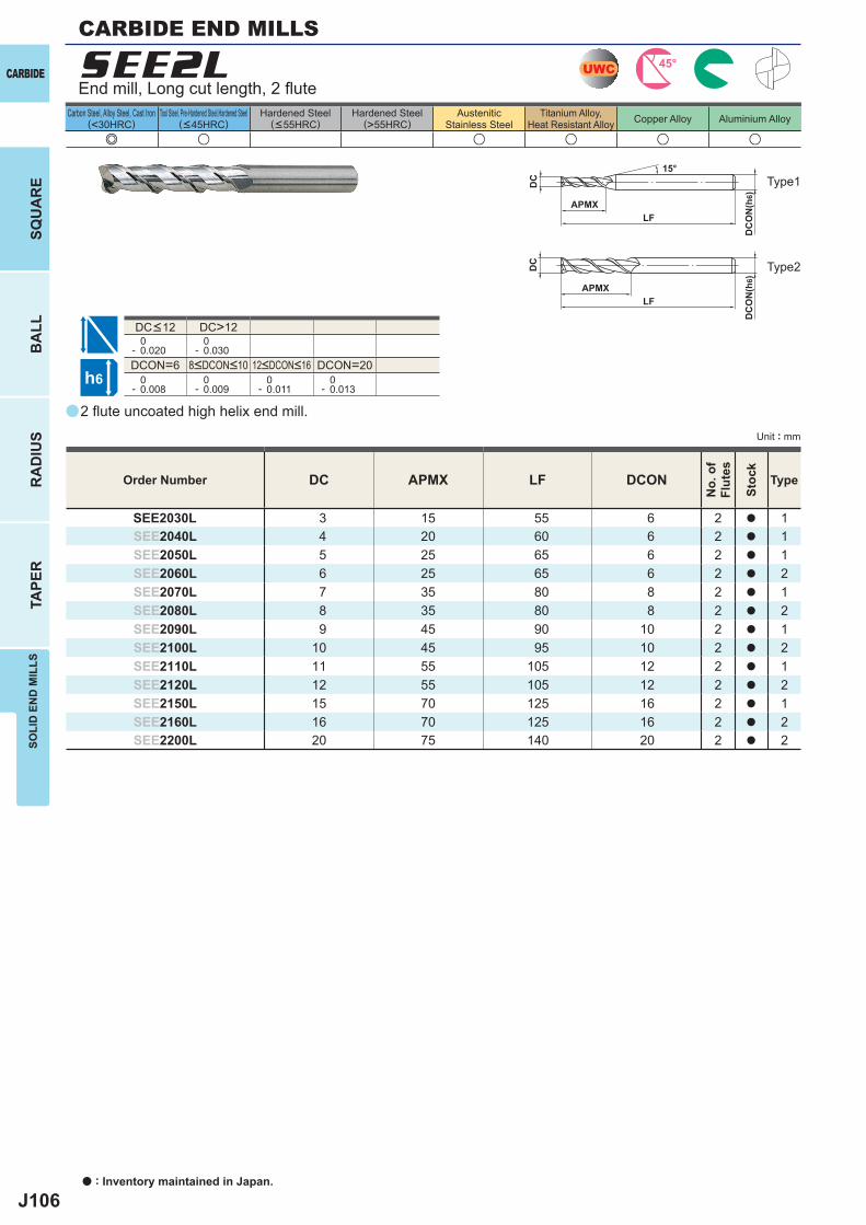
J106
a
e u u u u u
SEE2L
DC APMX LF DCON
SEE2030L 3 15 55 6 2 a 1SEE2040L 4 20 60 6 2 a 1SEE2050L 5 25 65 6 2 a 1SEE2060L 6 25 65 6 2 a 2SEE2070L 7 35 80 8 2 a 1SEE2080L 8 35 80 8 2 a 2SEE2090L 9 45 90 10 2 a 1SEE2100L 10 45 95 10 2 a 2SEE2110L 11 55 105 12 2 a 1SEE2120L 12 55 105 12 2 a 2SEE2150L 15 70 125 16 2 a 1SEE2160L 16 70 125 16 2 a 2SEE2200L 20 75 140 20 2 a 2
DC>12 0- 0.020
0- 0.030
DCON=6 DCON=20 0- 0.008
0- 0.009
0- 0.011
0- 0.013
UWC 45°
h6
APMX
DC
DC
ON
(h6)
15°
APMXLF
DC
DC
ON
(h6)
LF
CARBIDE
a : Inventory maintained in Japan.
BA
LLR
AD
IUS
TAPE
RSO
LID
EN
D M
ILLS
SQU
AR
E
Unit : mm
Carbon Steel, Alloy Steel, Cast Iron(<30HRC)
Tool Steel, Pre-Hardened Steel,Hardened Steel(<45HRC)
Hardened Steel(<55HRC)
Hardened Steel(>55HRC)
AusteniticStainless Steel
Titanium Alloy,Heat Resistant Alloy Copper Alloy Aluminium Alloy
2 fl ute uncoated high helix end mill.
End mill, Long cut length, 2 fl ute
Type2
Type1
Order Number
No.
of
Flut
es
Stoc
k
Type
8<DCON<10 12<DCON<16
DC<12
CARBIDE END MILLS
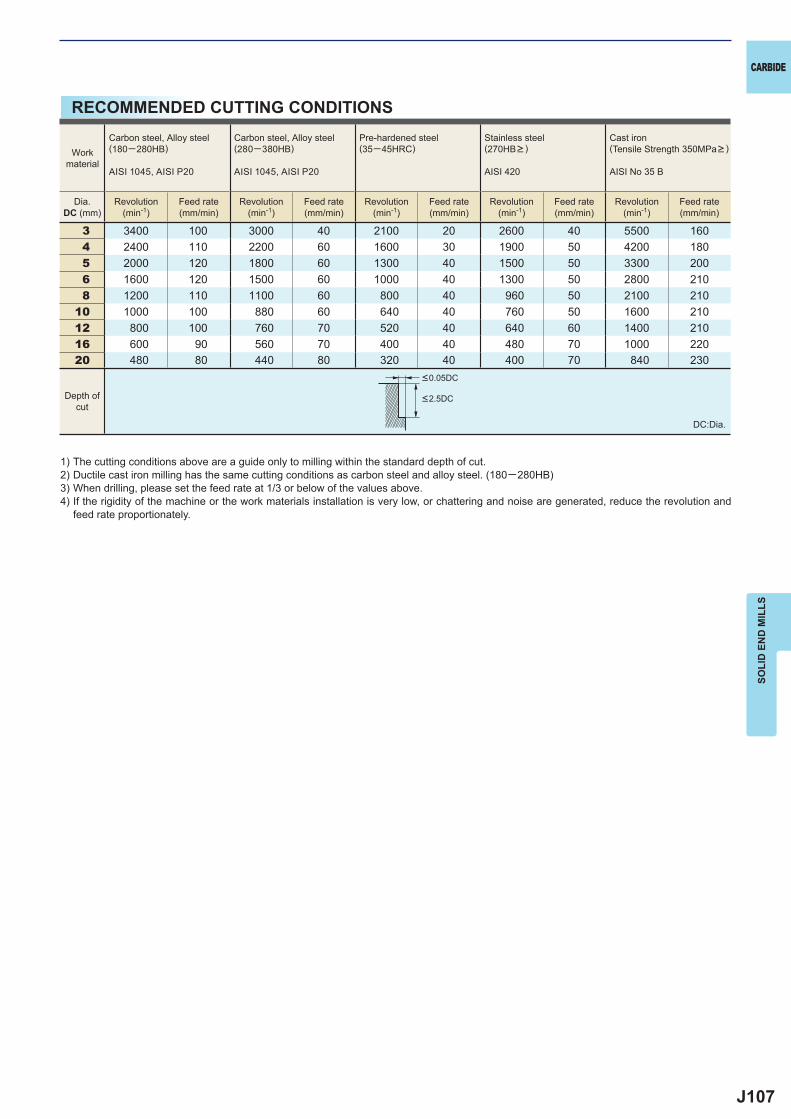
J107
3 3400 100 3000 40 2100 20 2600 40 5500 1604 2400 110 2200 60 1600 30 1900 50 4200 1805 2000 120 1800 60 1300 40 1500 50 3300 2006 1600 120 1500 60 1000 40 1300 50 2800 2108 1200 110 1100 60 800 40 960 50 2100 210
10 1000 100 880 60 640 40 760 50 1600 21012 800 100 760 70 520 40 640 60 1400 21016 600 90 560 70 400 40 480 70 1000 22020 480 80 440 80 320 40 400 70 840 230
CARBIDE
SOLI
D E
ND
MIL
LS
RECOMMENDED CUTTING CONDITIONS
1) The cutting conditions above are a guide only to milling within the standard depth of cut.2) Ductile cast iron milling has the same cutting conditions as carbon steel and alloy steel. (180─280HB)3) When drilling, please set the feed rate at 1/3 or below of the values above.4) If the rigidity of the machine or the work materials installation is very low, or chattering and noise are generated, reduce the revolution and
feed rate proportionately.
DC:Dia.
Depth ofcut
Workmaterial
Carbon steel, Alloy steel(180─280HB)
AISI 1045, AISI P20
Carbon steel, Alloy steel(280─380HB)
AISI 1045, AISI P20
Pre-hardened steel(35─45HRC)
Stainless steel (270HB> )
AISI 420
Cast iron(Tensile Strength 350MPa> )
AISI No 35 B
Dia.DC (mm)
Revolution(min-1)
Feed rate(mm/min)
Revolution(min-1)
Feed rate(mm/min)
Revolution(min-1)
Feed rate(mm/min)
Revolution(min-1)
Feed rate(mm/min)
Revolution(min-1)
Feed rate(mm/min)
<0.05DC
<2.5DC
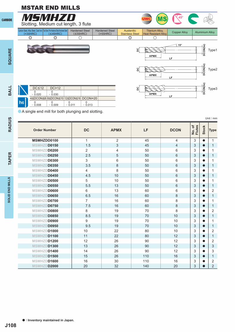
J108
a
e e u e u
MSMHZD
DC APMX LF DCON
MSMHZDD0100 1 2 45 4 3 a 1MSMHZDD0150 1.5 3 45 4 3 a 1MSMHZDD0200 2 4 50 6 3 a 1MSMHZDD0250 2.5 5 50 6 3 a 1MSMHZDD0300 3 6 50 6 3 a 1MSMHZDD0350 3.5 8 50 6 3 a 1MSMHZDD0400 4 8 50 6 3 a 1MSMHZDD0450 4.5 10 50 6 3 a 1MSMHZDD0500 5 10 50 6 3 a 1MSMHZDD0550 5.5 13 50 6 3 a 1MSMHZDD0600 6 13 60 6 3 a 2MSMHZDD0650 6.5 16 60 8 3 a 1MSMHZDD0700 7 16 60 8 3 a 1MSMHZDD0750 7.5 16 60 8 3 a 1MSMHZDD0800 8 19 70 8 3 a 2MSMHZDD0850 8.5 19 70 10 3 a 1MSMHZDD0900 9 19 70 10 3 a 1MSMHZDD0950 9.5 19 70 10 3 a 1MSMHZDD1000 10 22 80 10 3 a 2MSMHZDD1100 11 22 80 12 3 a 1MSMHZDD1200 12 26 90 12 3 a 2MSMHZDD1300 13 26 90 12 3 a 3MSMHZDD1400 14 26 90 12 3 a 3MSMHZDD1500 15 26 110 16 3 a 1MSMHZDD1600 16 30 110 16 3 a 2MSMHZDD2000 20 32 140 20 3 a 2
DC>12 0- 0.020
0- 0.030
DCON=20 0- 0.008
0- 0.009
0- 0.011
0- 0.013
UWC MS 45°
h6
APMX
DC
DC
ON
(h6)15°
APMXLF
DC
DC
ON
(h6)
LF
APMXLF
DC
DC
ON
(h6)
CARBIDE
a : Inventory maintained in Japan.
BA
LLR
AD
IUS
TAPE
RSO
LID
EN
D M
ILLS
SQU
AR
E
Unit : mm
Carbon Steel, Alloy Steel, Cast Iron(<30HRC)
Tool Steel, Pre-Hardened Steel,Hardened Steel(<45HRC)
Hardened Steel(<55HRC)
Hardened Steel(>55HRC)
AusteniticStainless Steel
Titanium Alloy,Heat Resistant Alloy Copper Alloy Aluminium Alloy
A single end mill for both plunging and slotting.
Slotting, Medium cut length, 3 fl ute
Type2
Type1
Type3
MSTAR END MILLS
Order Number
No.
of
Flut
es
Stoc
k
Type
4<DCON<6 8<DCON<10 12<DCON<16
DC<12
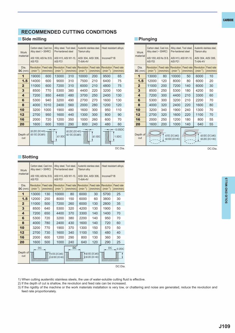
J109
1 19000 600 13000 310 10000 200 9500 651.5 14000 600 9000 310 7500 210 6400 752 11000 600 7200 310 6000 210 4800 753 8500 770 5300 380 4400 220 3200 1004 7200 850 4400 480 3700 250 2400 1306 5300 940 3200 490 2700 270 1600 1308 4000 1010 2400 560 2000 280 1200 120
10 3200 1000 1900 480 1600 300 950 11012 2700 950 1600 440 1300 300 800 9016 2000 720 1200 350 1000 260 600 7020 1600 600 1000 290 800 240 480 60
1 13000 130 10000 80 6000 30 5700 251.5 12000 250 8000 150 6000 60 3800 302 11000 500 7200 260 6000 130 2800 353 8500 640 5300 320 4200 130 1900 504 7200 650 4400 370 3300 140 1400 706 5300 720 3200 380 2200 140 950 708 4000 780 2400 430 1600 140 720 60
10 3200 770 1900 370 1300 150 570 5012 2700 730 1600 340 1100 150 480 4016 2000 600 1200 290 800 130 360 3020 1600 500 1000 240 640 120 290 25
1 13000 80 10000 50 6000 101.5 12000 120 8000 80 6000 202 11000 200 7200 140 6000 303 8500 250 5300 180 4200 504 7200 300 4400 210 3300 606 5300 300 3200 210 2200 708 4000 320 2400 220 1600 80
10 3200 340 1900 240 1300 7012 2700 320 1600 220 1100 7016 2000 250 1200 180 800 5520 1600 200 1000 140 640 55
0.05DC
1.5DC
0.2DCDC
y
y y
DCDC DC
CARBIDE
SOLI
D E
ND
MIL
LS
1) When cutting austenitic stainless steels, the use of water-soluble cutting fl uid is effective.2) If the depth of cut is shallow, the revolution and feed rate can be increased.3) If the rigidity of the machine or the work materials installation is very low, or chattering and noise are generated, reduce the revolution and
feed rate proportionately.
DC:Dia.
DC:Dia.
DC:Dia.
Slotting
Side milling Plunging
Workmaterial
Carbon steel, Cast iron, Alloy steel (─30HRC)
AISI 1050, AISI No 35 B,AISI P20
Alloy steel, Tool steel,Pre-hardened steel
AISI H13, AISI W1-10, AISI P21
Austenitic stainless steel,Titanium alloy
AISI 304, AISI 306, Ti-6Al-4V
Heat resistant alloys
Inconel718
Dia.DC (mm)
Revolution(min-1)
Feed rate(mm/min)
Revolution(min-1)
Feed rate(mm/min)
Revolution(min-1)
Feed rate(mm/min)
Revolution(min-1)
Feed rate(mm/min)
Workmaterial
Carbon steel, Cast iron, Alloy steel (─30HRC)
AISI 1050, AISI No 35 B,AISI P20
Alloy steel, Tool steel,Pre-hardened steel
AISI H13, AISI W1-10, AISI P21
Austenitic stainless steel,Titanium alloy
AISI 304, AISI 306, Ti-6Al-4V
Dia.DC (mm)
Revolution(min-1)
Feed rate(mm/min)
Revolution(min-1)
Feed rate(mm/min)
Revolution(min-1)
Feed rate(mm/min)
<0.2DC (DC>&3)<0.1DC (DC<&3)
<0.2DC (DC>&3)<0.1DC (DC<&3)
<1.5DC <1.5DCDepth of
cutDepth of
cut<1DC (DC >&2)<0.5DC (DC<&2)
<0.5DC (DC >&2)<0.2DC (DC <&2)
Workmaterial
Carbon steel, Cast iron, Alloy steel (─30HRC)
AISI 1050, AISI No 35 B,AISI P20
Alloy steel, Tool steel,Pre-hardened steel
AISI H13, AISI W1-10, AISI P21
Austenitic stainless steel,Titanium alloy
AISI 304, AISI 306, Ti-6Al-4V
Heat resistant alloys
Inconel718
Dia.DC (mm)
Revolution(min-1)
Feed rate(mm/min)
Revolution(min-1)
Feed rate(mm/min)
Revolution(min-1)
Feed rate(mm/min)
Revolution(min-1)
Feed rate(mm/min)
<1DC (DC >&2)<0.5DC (DC<&2)
<0.5DC (DC >&2)<0.2DC (DC <&2)
Depth ofcut
RECOMMENDED CUTTING CONDITIONS
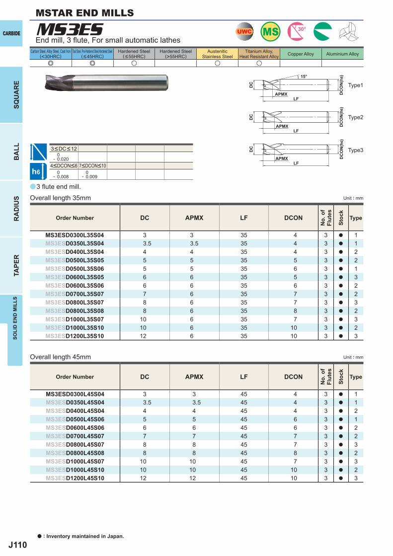
J110
a
e e u u u
MS3ES
DC APMX LF DCON
MS3ESD0300L35S04 3 3 35 4 3 a 1MS3ESD0350L35S04 3.5 3.5 35 4 3 a 1MS3ESD0400L35S04 4 4 35 4 3 a 2MS3ESD0500L35S05 5 5 35 5 3 a 2MS3ESD0500L35S06 5 5 35 6 3 a 1MS3ESD0600L35S05 6 6 35 5 3 a 3MS3ESD0600L35S06 6 6 35 6 3 a 2MS3ESD0700L35S07 7 6 35 7 3 a 2MS3ESD0800L35S07 8 6 35 7 3 a 3MS3ESD0800L35S08 8 6 35 8 3 a 2MS3ESD1000L35S07 10 6 35 7 3 a 3MS3ESD1000L35S10 10 6 35 10 3 a 2MS3ESD1200L35S10 12 6 35 10 3 a 3
DC APMX LF DCON
MS3ESD0300L45S04 3 3 45 4 3 a 1MS3ESD0350L45S04 3.5 3.5 45 4 3 a 1MS3ESD0400L45S04 4 4 45 4 3 a 2MS3ESD0500L45S06 5 5 45 6 3 a 1MS3ESD0600L45S06 6 6 45 6 3 a 2MS3ESD0700L45S07 7 7 45 7 3 a 2MS3ESD0800L45S07 8 8 45 7 3 a 3MS3ESD0800L45S08 8 8 45 8 3 a 2MS3ESD1000L45S07 10 10 45 7 3 a 3MS3ESD1000L45S10 10 10 45 10 3 a 2MS3ESD1200L45S10 12 12 45 10 3 a 3
0- 0.020
0- 0.008
0- 0.009
UWC MS 30°
h6
APMX
DC
DC
ON
(h6)15°
APMXLF
DC
DC
ON
(h6)
LF
APMXLF
DC
DC
ON
(h6)
CARBIDE
a : Inventory maintained in Japan.
BA
LLR
AD
IUS
TAPE
RSO
LID
EN
D M
ILLS
SQU
AR
E
Unit : mm
Carbon Steel, Alloy Steel, Cast Iron(<30HRC)
Tool Steel, Pre-Hardened Steel,Hardened Steel(<45HRC)
Hardened Steel(<55HRC)
Hardened Steel(>55HRC)
AusteniticStainless Steel
Titanium Alloy,Heat Resistant Alloy Copper Alloy Aluminium Alloy
3 fl ute end mill.
End mill, 3 fl ute, For small automatic lathes
Overall length 35mm
Overall length 45mm
Type2
Type1
Type3
Unit : mm
Order Number
No.
of
Flut
es
Stoc
k
Type
Order Number
No.
of
Flut
es
Stoc
k
Type
4<DCON<6 7<DCON<10
3<DC<12
MSTAR END MILLS
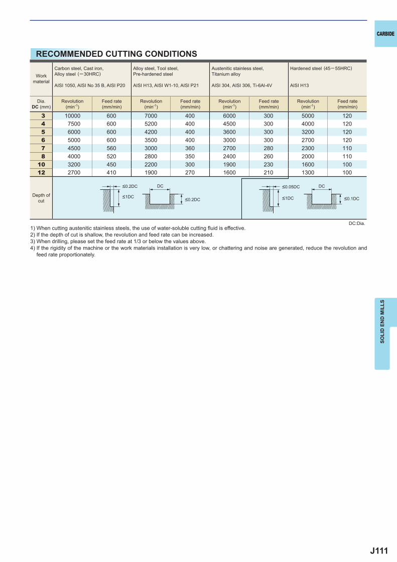
J111
3 10000 600 7000 400 6000 300 5000 1204 7500 600 5200 400 4500 300 4000 1205 6000 600 4200 400 3600 300 3200 1206 5000 600 3500 400 3000 300 2700 1207 4500 560 3000 360 2700 280 2300 1108 4000 520 2800 350 2400 260 2000 110
10 3200 450 2200 300 1900 230 1600 10012 2700 410 1900 270 1600 210 1300 100
DC DC
CARBIDE
SOLI
D E
ND
MIL
LS
RECOMMENDED CUTTING CONDITIONS
1) When cutting austenitic stainless steels, the use of water-soluble cutting fl uid is effective.2) If the depth of cut is shallow, the revolution and feed rate can be increased.3) When drilling, please set the feed rate at 1/3 or below the values above.4) If the rigidity of the machine or the work materials installation is very low, or chattering and noise are generated, reduce the revolution and
feed rate proportionately.
DC:Dia.
Workmaterial
Carbon steel, Cast iron, Alloy steel (─30HRC)
AISI 1050, AISI No 35 B, AISI P20
Alloy steel, Tool steel,Pre-hardened steel
AISI H13, AISI W1-10, AISI P21
Austenitic stainless steel,Titanium alloy
AISI 304, AISI 306, Ti-6Al-4V
Hardened steel (45─ 55HRC)
AISI H13
Dia.DC (mm)
Revolution(min-1)
Feed rate(mm/min)
Revolution(min-1)
Feed rate(mm/min)
Revolution(min-1)
Feed rate(mm/min)
Revolution(min-1)
Feed rate(mm/min)
Depth ofcut
<0.2DC <0.05DC
<1DC <1DC<0.2DC <0.1DC
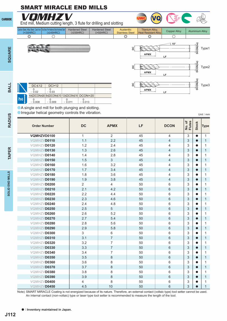
J112
a
a
VQMHZV
e u e e u
DC APMX LF DCON
VQMHZVD0100 1 2 45 4 3 a 1VQMHZVD0110 1.1 2.2 45 4 3 a 1VQMHZVD0120 1.2 2.4 45 4 3 a 1VQMHZVD0130 1.3 2.6 45 4 3 a 1VQMHZVD0140 1.4 2.8 45 4 3 a 1VQMHZVD0150 1.5 3 45 4 3 a 1VQMHZVD0160 1.6 3.2 45 4 3 a 1VQMHZVD0170 1.7 3.4 45 4 3 a 1VQMHZVD0180 1.8 3.6 45 4 3 a 1VQMHZVD0190 1.9 3.8 45 4 3 a 1VQMHZVD0200 2 4 50 6 3 a 1VQMHZVD0210 2.1 4.2 50 6 3 a 1VQMHZVD0220 2.2 4.4 50 6 3 a 1VQMHZVD0230 2.3 4.6 50 6 3 a 1VQMHZVD0240 2.4 4.8 50 6 3 a 1VQMHZVD0250 2.5 5 50 6 3 a 1VQMHZVD0260 2.6 5.2 50 6 3 a 1VQMHZVD0270 2.7 5.4 50 6 3 a 1VQMHZVD0280 2.8 5.6 50 6 3 a 1VQMHZVD0290 2.9 5.8 50 6 3 a 1VQMHZVD0300 3 6 50 6 3 a 1VQMHZVD0310 3.1 7 50 6 3 a 1VQMHZVD0320 3.2 7 50 6 3 a 1VQMHZVD0330 3.3 7 50 6 3 a 1VQMHZVD0340 3.4 7 50 6 3 a 1VQMHZVD0350 3.5 8 50 6 3 a 1VQMHZVD0360 3.6 8 50 6 3 a 1VQMHZVD0370 3.7 8 50 6 3 a 1VQMHZVD0380 3.8 8 50 6 3 a 1VQMHZVD0390 3.9 8 50 6 3 a 1VQMHZVD0400 4 8 50 6 3 a 1VQMHZVD0450 4.5 10 50 6 3 a 1
DC>12 0- 0.02
0- 0.03
DCON=20 0- 0.008
0- 0.009
0- 0.011
0- 0.013
UWC VQ 45°43.5°42°
h6
APMX
DC
DC
ON
(h6)15°
APMXLF
DC
DC
ON
(h6)
LF
APMXLF
DC
DC
ON
(h6)
CARBIDE
a : Inventory maintained in Japan.
BA
LLR
AD
IUS
TAPE
RSO
LID
EN
D M
ILLS
SQU
AR
E
Unit : mm
Carbon Steel, Alloy Steel, Cast Iron(<30HRC)
Tool Steel, Pre-Hardened Steel,Hardened Steel(<45HRC)
Hardened Steel(<55HRC)
Hardened Steel(>55HRC)
AusteniticStainless Steel
Titanium Alloy,Heat Resistant Alloy Copper Alloy Aluminium Alloy
End mill, Medium cutting length, 3 flute for drilling and slotting
A single end mill for both plunging and slotting.Irregular helical geometry controls the vibration.
Type2
Type1
Type3
Order Number
No.
of
Flut
es
Stoc
k
Type
SMART MIRACLE END MILLS
4<DCON<6 8<DCON<10 12<DCON<16
DC<12
Note) SMART MIRACLE Coating is not energized because of its nature. Therefore, an external contact (voltaic type) tool setter cannot be used. An internal contact (non-voltaic) type or laser type tool setter is recommended to measure the length of the tool.
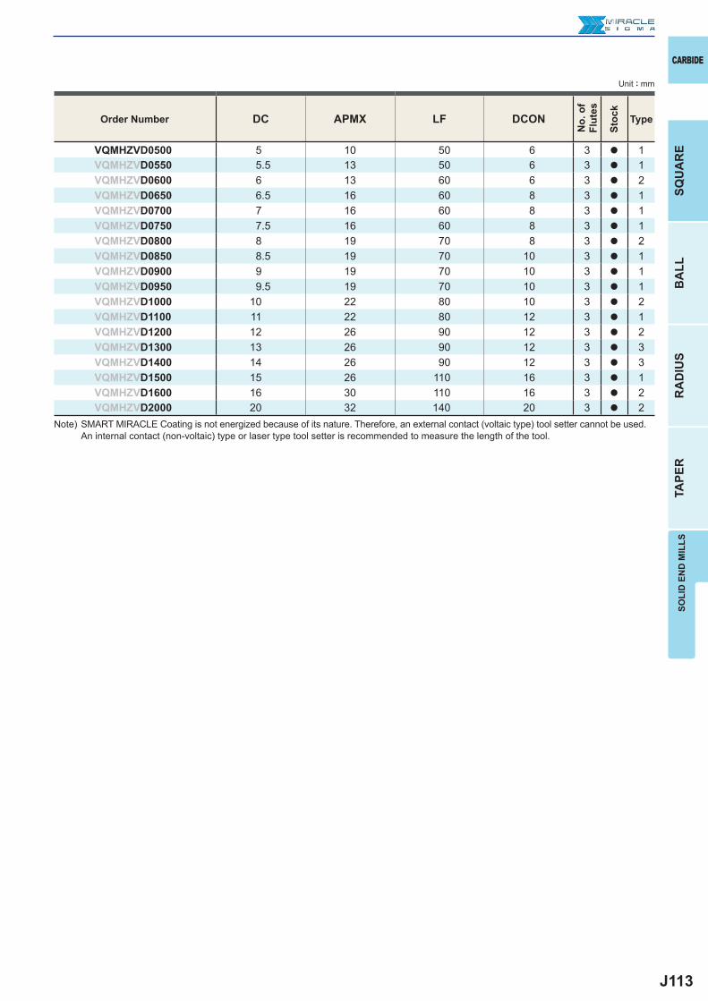
J113
DC APMX LF DCON
VQMHZVD0500 5 10 50 6 3 a 1VQMHZVD0550 5.5 13 50 6 3 a 1VQMHZVD0600 6 13 60 6 3 a 2VQMHZVD0650 6.5 16 60 8 3 a 1VQMHZVD0700 7 16 60 8 3 a 1VQMHZVD0750 7.5 16 60 8 3 a 1VQMHZVD0800 8 19 70 8 3 a 2VQMHZVD0850 8.5 19 70 10 3 a 1VQMHZVD0900 9 19 70 10 3 a 1VQMHZVD0950 9.5 19 70 10 3 a 1VQMHZVD1000 10 22 80 10 3 a 2VQMHZVD1100 11 22 80 12 3 a 1VQMHZVD1200 12 26 90 12 3 a 2VQMHZVD1300 13 26 90 12 3 a 3VQMHZVD1400 14 26 90 12 3 a 3VQMHZVD1500 15 26 110 16 3 a 1VQMHZVD1600 16 30 110 16 3 a 2VQMHZVD2000 20 32 140 20 3 a 2
CARBIDE
SQU
AR
EB
ALL
RA
DIU
STA
PER
SOLI
D E
ND
MIL
LS
Unit : mm
Order Number
No.
of
Flut
es
Stoc
k
Type
Note) SMART MIRACLE Coating is not energized because of its nature. Therefore, an external contact (voltaic type) tool setter cannot be used. An internal contact (non-voltaic) type or laser type tool setter is recommended to measure the length of the tool.
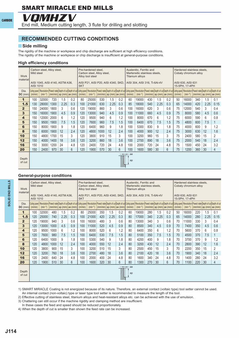
J114
y
VQMHZV
1 100 32000 720 1.5 0.2 80 25000 530 1.5 0.2 60 19000 430 1.5 0.2 50 16000 340 1.5 0.11.5 130 28000 1300 2.25 0.3 100 21000 630 2.25 0.3 85 18000 540 2.25 0.3 65 14000 420 2.25 0.152 150 24000 1800 3 0.6 120 19000 860 3 0.6 100 16000 620 3 0.6 75 12000 540 3 0.43 150 16000 1900 4.5 0.9 120 13000 940 4.5 0.9 100 11000 660 4.5 0.9 75 8000 580 4.5 0.64 150 12000 2000 6 1.2 120 9500 940 6 1.2 100 8000 670 6 1.2 75 6000 590 6 0.85 150 9500 1900 7.5 1.5 120 7600 960 7.5 1.5 100 6400 670 7.5 1.5 75 4800 600 7.5 16 150 8000 1900 9 1.8 120 6400 960 9 1.8 100 5300 830 9 1.8 75 4000 600 9 1.28 150 6000 1900 12 2.4 120 4800 1000 12 2.4 100 4000 900 12 2.4 75 3000 630 12 1.6
10 150 4800 1700 15 3 120 3800 910 15 3 100 3200 960 15 3 75 2400 580 15 212 150 4000 1400 18 3.6 120 3200 860 18 3.6 100 2700 890 18 3.6 75 2000 540 18 2.416 150 3000 1200 24 4.8 120 2400 720 24 4.8 100 2000 720 24 4.8 75 1500 450 24 3.220 150 2400 970 30 6 120 1900 570 30 6 100 1600 580 30 6 75 1200 360 30 4
1 100 32000 480 1.5 0.2 80 25000 350 1.5 0.2 60 19000 280 1.5 0.2 50 16000 220 1.5 0.11.5 120 25000 740 2.25 0.3 100 21000 420 2.25 0.3 80 17000 340 2.25 0.3 65 14000 280 2.25 0.152 120 19000 940 3 0.6 100 16000 480 3 0.6 80 13000 340 3 0.6 70 11000 330 3 0.43 120 13000 1000 4.5 0.9 100 11000 520 4.5 0.9 80 8500 340 4.5 0.9 70 7400 350 4.5 0.64 120 9500 1000 6 1.2 100 8000 520 6 1.2 80 6400 350 6 1.2 70 5600 370 6 0.85 120 7600 980 7.5 1.5 100 6400 530 7.5 1.5 80 5100 350 7.5 1.5 70 4500 370 7.5 16 120 6400 1000 9 1.8 100 5300 540 9 1.8 80 4200 400 9 1.8 70 3700 370 9 1.28 120 4800 1000 12 2.4 100 4000 550 12 2.4 80 3200 430 12 2.4 70 2800 390 12 1.6
10 120 3800 900 15 3 100 3200 510 15 3 80 2500 450 15 3 70 2200 350 15 212 120 3200 760 18 3.6 100 2700 480 18 3.6 80 2100 420 18 3.6 70 1900 340 18 2.416 120 2400 640 24 4.8 100 2000 400 24 4.8 80 1600 340 24 4.8 70 1400 280 24 3.220 120 1900 510 30 6 100 1600 320 30 6 80 1300 270 30 6 70 1100 220 30 4
ae
ap
ae
ap
CARBIDE
SOLI
D E
ND
MIL
LS
RECOMMENDED CUTTING CONDITIONS
SMART MIRACLE END MILLS
Side milling
End mill, Medium cutting length, 3 flute for drilling and slotting
High effi ciency conditions
General-purpose conditions
The rigidity of the machine or workpiece and chip discharge are suffi cient at high effi ciency conditions. The rigidity of the machine or workpiece or chip discharge is insuffi cient at general-purpose conditions.
Work material
Carbon steel, Alloy steel,Mild steel
AISI 1045, AISI 4140, ASTM A36, AISI 1010
Pre-hardened steel,Carbon steel, Alloy steel,Alloy tool steel
AISI P21, AISI P20, AISI 4340, SKD, SKT
Austenitic, Ferritic and Martensitic stainless steels,Titanium alloys
AISI 304, AISI 316, Ti-6Al-4V
Hardened stainless steels,Cobaly chromium alloy
AISI 630, AISI 63115-5PH, 17-4PH
Dia.DC (mm)
Cutting speed (m/min)
Revolution (min-1)
Feed rate (mm/min)
Depth of cut ap (mm)
Depth of cut ae (mm)
Cutting speed (m/min)
Revolution (min-1)
Feed rate (mm/min)
Depth of cut ap (mm)
Depth of cut ae (mm)
Cutting speed (m/min)
Revolution (min-1)
Feed rate (mm/min)
Depth of cut ap (mm)
Depth of cut ae (mm)
Cutting speed (m/min)
Revolution (min-1)
Feed rate (mm/min)
Depth of cut ap (mm)
Depth of cut ae (mm)
Depth of cut
1) SMART MIRACLE Coating is not energized because of its nature. Therefore, an external contact (voltaic type) tool setter cannot be used. An internal contact (non-voltaic) type or laser type tool setter is recommended to measure the length of the tool.
2) Effective cutting of stainless steel, titanium alloys and heat-resistant alloys etc. can be achieved with the use of emulsion.3) Chattering can still occur if the machine rigidity and clamping method are insuffi cient.
In these cases the feed and speed should be reduced proportionately.4) When the depth of cut is smaller than shown the feed rate can be increased.
J115
1 120 38000 860 1.5 0.2 40 13000 160 1.5 0.051.5 150 32000 1400 2.25 0.3 40 8500 170 2.25 0.082 180 29000 2200 3 0.6 40 6400 170 3 0.23 180 19000 2300 4.5 0.9 40 4200 180 4.5 0.34 180 14000 2300 6 1.2 40 3200 180 6 0.45 180 11000 2300 7.5 1.5 40 2500 180 7.5 0.56 180 9500 2300 9 1.8 40 2100 190 9 0.68 180 7200 2300 12 2.4 40 1600 190 12 0.8
10 180 5700 2100 15 3 40 1300 220 15 112 180 4800 1700 18 3.6 40 1100 210 18 1.216 180 3600 1500 24 4.8 40 800 150 24 1.620 180 2900 1200 30 6 40 640 120 30 2
1 120 38000 560 1.5 0.2 30 9500 75 1.5 0.051.5 140 30000 890 2.25 0.3 30 6400 82 2.25 0.072 140 22000 1100 3 0.6 30 4800 86 3 0.23 140 15000 1200 4.5 0.9 30 3200 89 4.5 0.34 140 11000 1200 6 1.2 30 2400 90 6 0.45 140 8900 1200 7.5 1.5 30 1900 90 7.5 0.56 140 7400 1200 9 1.8 30 1600 95 9 0.68 140 5600 1200 12 2.4 30 1200 95 12 0.8
10 140 4500 1100 15 3 30 950 110 15 112 140 3700 880 18 3.6 30 800 100 18 1.216 140 2800 750 24 4.8 30 600 76 24 1.620 140 2200 590 30 6 30 480 61 30 2
y
ae
ap
ae
ap
CARBIDE
SOLI
D E
ND
MIL
LS
High effi ciency cutting conditions
General-purpose conditions
The rigidity of the machine or workpiece and chip discharge are suffi cient at high effi ciency conditions. The rigidity of the machine or workpiece or chip discharge is insuffi cient at general-purpose conditions.
Work material
Copper, Copper alloy Heat resistant alloys
Inconel718
Dia.DC (mm)
Cutting speed (m/min)
Revolution (min-1)
Feed rate (mm/min)
Depth of cut ap (mm)
Depth of cut ae (mm)
Cutting speed (m/min)
Revolution (min-1)
Feed rate (mm/min)
Depth of cut ap (mm)
Depth of cut ae (mm)
Depth of cut
Work material
Copper, Copper alloy Heat resistant alloys
Inconel718
Dia.DC (mm)
Cutting speed (m/min)
Revolution (min-1)
Feed rate (mm/min)
Depth of cut ap (mm)
Depth of cut ae (mm)
Cutting speed (m/min)
Revolution (min-1)
Feed rate (mm/min)
Depth of cut ap (mm)
Depth of cut ae (mm)
Depth of cut
1) SMART MIRACLE Coating is not energized because of its nature. Therefore, an external contact (voltaic type) tool setter cannot be used. An internal contact (non-voltaic) type or laser type tool setter is recommended to measure the length of the tool.
2) Effective cutting of stainless steel, titanium alloys and heat-resistant alloys etc. can be achieved with the use of emulsion.3) Chattering can still occur if the machine rigidity and clamping method are insuffi cient.
In these cases the feed and speed should be reduced proportionately.4) When the depth of cut is smaller than shown the revolution and feed rate can be increased.
Side milling
J116
VQMHZV
1 100 32000 380 0.5 80 25000 150 0.5 60 19000 100 0.5 45 14000 80 0.3 120 38000 460 0.5 30 9500 60 0.21.5 130 28000 590 0.75 100 21000 250 0.75 85 18000 220 0.75 60 12000 140 0.4 150 32000 670 0.75 30 6400 80 0.32 150 24000 940 2 120 19000 460 2 100 16000 480 2 60 9500 230 1 180 29000 1100 2 30 4800 100 0.63 150 16000 1100 3 120 13000 550 3 100 11000 500 3 60 6400 270 1.5 180 19000 1300 3 30 3200 120 0.94 150 12000 1400 4 120 9500 680 4 100 8000 530 4 60 4800 350 2 180 14000 1700 4 30 2400 130 1.25 150 9500 1400 5 120 7600 680 5 100 6400 540 5 60 3800 350 2.5 180 11000 1700 5 30 1900 130 1.56 150 8000 1400 6 120 6400 770 6 100 5300 560 6 60 3200 380 3 180 9500 1700 6 30 1600 130 1.88 150 6000 1300 8 120 4800 720 8 100 4000 600 8 60 2400 360 4 180 7200 1500 8 30 1200 140 2.4
10 150 4800 1200 10 120 3800 630 10 100 3200 670 10 60 1900 310 5 180 5700 1400 10 30 950 160 312 150 4000 960 12 120 3200 580 12 100 2700 650 12 60 1600 290 6 180 4800 1200 12 30 800 150 3.616 150 3000 810 12 120 2400 500 12 100 2000 480 12 60 1200 250 8 180 3600 970 12 30 600 120 4.820 150 2400 650 12 120 1900 400 12 100 1600 380 12 60 950 200 10 180 2900 780 12 30 480 90 6
1 100 32000 250 0.5 80 25000 99 0.5 60 19000 80 0.5 45 14000 60 0.3 120 38000 300 0.5 25 8000 30 0.21.5 100 21000 290 0.75 80 17000 130 0.75 60 13000 100 0.75 50 11000 87 0.4 120 25000 350 0.75 25 5300 40 0.32 100 16000 410 2 80 13000 210 2 60 9500 190 2 50 8000 130 1 120 19000 490 2 25 4000 55 0.63 100 11000 500 3 80 8500 240 3 60 6400 190 3 50 5300 150 1.5 120 13000 590 3 25 2700 64 0.94 100 8000 630 4 80 6400 300 4 60 4800 210 4 50 4000 190 2 120 9500 750 4 25 2000 70 1.25 100 6400 630 5 80 5100 300 5 60 3800 210 5 50 3200 190 2.5 120 7600 750 5 25 1600 71 1.56 100 5300 630 6 80 4200 330 6 60 3200 220 6 50 2700 210 3 120 6400 760 6 25 1300 72 1.88 100 4000 550 8 80 3200 320 8 60 2400 240 8 50 2000 200 4 120 4800 670 8 25 990 78 2.4
10 100 3200 510 10 80 2500 270 10 60 1900 260 10 50 1600 170 5 120 3800 600 10 25 800 89 312 100 2700 430 12 80 2100 250 12 60 1600 250 12 50 1300 150 6 120 3200 510 12 25 660 84 3.616 100 2000 360 12 80 1600 220 12 60 1200 190 12 50 990 140 8 120 2400 430 12 25 500 63 4.820 100 1600 290 12 80 1300 180 12 60 950 150 12 50 800 110 10 120 1900 340 12 25 400 50 6
y
ap
ap
DC
DC
CARBIDE
SOLI
D E
ND
MIL
LSSMART MIRACLE END MILLS
End mill, Medium cutting length, 3 flute for drilling and slotting
High effi ciency conditions
General-purpose conditions
The rigidity of the machine or workpiece and chip discharge are suffi cient at high effi ciency conditions. The rigidity of the machine or workpiece or chip discharge is insuffi cient at general-purpose conditions.
Work material
Carbon steel, Alloy steel,Mild steel
AISI 1045, AISI 4140, ASTM A36, AISI 1010
Pre-hardened steel,Carbon steel, Alloy steel,Alloy tool steel
AISI P21, AISI P20, AISI 4340, SKD, SKT
Austenitic, Ferritic and Martensitic stainless steels, Titanium alloys
AISI 304, AISI 316, Ti-6Al-4V
Hardened stainless steels,Cobaly chromium alloy
AISI 630, AISI 63115-5PH, 17-4PH
Copper, Copper alloy Heat resistant alloys
Inconel718
Dia.DC (mm)
Cutting speed (m/min)
Revolution (min-1)
Feed rate (mm/min)
Depth of cut ap (mm)
Cutting speed (m/min)
Revolution (min-1)
Feed rate (mm/min)
Depth of cut ap (mm)
Cutting speed (m/min)
Revolution (min-1)
Feed rate (mm/min)
Depth of cut ap (mm)
Cutting speed (m/min)
Revolution (min-1)
Feed rate (mm/min)
Depth of cut ap (mm)
Cutting speed (m/min)
Revolution (min-1)
Feed rate (mm/min)
Depth of cut ap (mm)
Cutting speed (m/min)
Revolution (min-1)
Feed rate (mm/min)
Depth of cut ap (mm)
Depth of cut
1) SMART MIRACLE Coating is not energized because of its nature. Therefore, an external contact (voltaic type) tool setter cannot be used. An internal contact (non-voltaic) type or laser type tool setter is recommended to measure the length of the tool.
2) Effective cutting of stainless steel, titanium alloys and heat-resistant alloys etc. can be achieved with the use of emulsion.3) Chattering can still occur if the machine rigidity and clamping method are insuffi cient.
In these cases the feed and speed should be reduced proportionately.4) When the depth of cut is smaller than shown the feed rate can be increased.
Slotting
DC:Dia.
DC:Dia.
J117
1 65 20000 160 0.5 0.1 50 16000 100 0.5 0.1 50 16000 50 0.5 0.05 30 9500 30 0.5 0.05 75 24000 190 0.5 0.11.5 85 18000 270 0.75 0.3 60 13000 120 0.75 0.3 60 13000 80 0.75 0.1 35 7400 40 0.75 0.1 100 21000 320 0.75 0.32 100 16000 480 2 0.5 70 11000 200 2 0.4 60 9500 90 1 0.15 40 6400 60 1 0.1 120 19000 570 2 0.53 100 11000 660 3 1 70 7400 270 3 0.6 60 6400 100 1.5 0.2 40 4200 60 1.5 0.2 120 13000 780 3 1.04 100 8000 800 4 2 70 5600 340 4 0.8 60 4800 100 2 0.4 40 3200 60 2 0.4 120 9500 950 4 25 100 6400 960 5 2.5 70 4500 410 5 1 60 3800 100 2.5 0.5 40 2500 60 2.5 0.5 120 7600 1100 5 2.56 100 5300 950 6 3 70 3700 440 6 1.2 60 3200 100 3 0.6 40 2100 60 3 0.6 120 6400 1200 6 38 100 4000 720 8 4 70 2800 340 8 1.6 60 2400 70 4 0.6 40 1600 50 4 0.6 120 4800 860 8 4
10 100 3200 580 10 5 70 2200 260 10 2.5 60 1900 60 5 0.6 40 1300 40 5 0.6 120 3800 680 10 512 100 2700 490 12 5 70 1900 230 12 3 60 1600 50 6 0.6 40 1100 30 6 0.6 120 3200 580 12 516 100 2000 360 16 5 70 1400 170 16 4 60 1200 40 8 0.6 40 800 20 8 0.6 120 2400 430 16 520 100 1600 290 20 5 70 1100 130 20 5 60 950 30 10 0.6 40 640 20 10 0.6 120 1900 340 20 5
1 65 20000 160 0.5 0.05 50 16000 100 0.5 0.05 50 16000 50 0.5 0.05 30 9500 30 0.5 0.05 75 24000 190 0.5 0.051.5 85 18000 270 0.75 0.15 60 13000 120 0.75 0.1 60 13000 80 0.75 0.05 35 7400 40 0.75 0.05 100 21000 320 0.75 0.152 100 16000 480 2 0.25 70 11000 200 2 0.2 60 9500 90 1 0.05 40 6400 60 1 0.05 120 19000 570 2 0.253 100 11000 660 3 0.3 70 7400 270 3 0.3 60 6400 100 1.5 0.1 40 4200 60 1.5 0.1 120 13000 780 3 0.34 100 8000 800 4 0.4 70 5600 340 4 0.4 60 4800 100 2 0.2 40 3200 60 2 0.2 120 9500 950 4 0.45 100 6400 960 5 0.5 70 4500 410 5 0.5 60 3800 100 2.5 0.25 40 2500 60 2.5 0.25 120 7600 1100 5 0.56 100 5300 950 6 0.6 70 3700 440 6 0.6 60 3200 100 3 0.3 40 2100 60 3 0.3 120 6400 1200 6 0.68 100 4000 720 8 0.7 70 2800 340 8 0.7 60 2400 70 4 0.3 40 1600 50 4 0.3 120 4800 860 8 0.7
10 100 3200 580 10 0.75 70 2200 260 10 0.75 60 1900 60 5 0.3 40 1300 40 5 0.3 120 3800 680 10 0.7512 100 2700 490 12 0.75 70 1900 230 12 0.75 60 1600 50 6 0.3 40 1100 30 6 0.3 120 3200 580 12 0.7516 100 2000 360 16 0.75 70 1400 170 16 0.75 60 1200 40 8 0.3 40 800 20 8 0.3 120 2400 430 16 0.7520 100 1600 290 20 0.75 70 1100 130 20 0.75 60 950 30 10 0.3 40 640 20 10 0.3 120 1900 340 20 0.75
y
ap
ap
CARBIDE
SOLI
D E
ND
MIL
LS
High effi ciency conditions
General-purpose conditions
The rigidity of the machine or workpiece and chip discharge are suffi cient at high effi ciency conditions. The rigidity of the machine or workpiece or chip discharge is insuffi cient at general-purpose conditions.
1) SMART MIRACLE Coating is not energized because of its nature. Therefore, an external contact (voltaic type) tool setter cannot be used. An internal contact (non-voltaic) type or laser type tool setter is recommended to measure the length of the tool.
2) Effective cutting of stainless steel, titanium alloys and heat-resistant alloys etc. can be achieved with the use of emulsion.3) Chattering can still occur if the machine rigidity and clamping method are insuffi cient.
In these cases the feed and speed should be reduced proportionately.
Work material
Carbon steel, Alloy steel,Mild steel
AISI 1045, AISI 4140, ASTM A36, AISI 1010
Pre-hardened steel,Carbon steel, Alloy steel,Alloy tool steel
AISI P21, AISI P20, AISI 4340, SKD, SKT
Austenitic, Ferritic and Martensitic stainless steels, Titanium alloys
AISI 304, AISI 316, Ti-6Al-4V
Hardened stainless steels,Cobaly chromium alloy
AISI 630, AISI 63115-5PH, 17-4PH
Copper, Copper alloy
Dia.DC (mm)
Cutting speed (mm/min)
Revolution (min-1)
Feed rate (mm/min)
Hole Depth ap (mm)
Step (mm)
Cutting speed (mm/min)
Revolution (min-1)
Feed rate (mm/min)
Hole Depth ap (mm)
Step (mm)
Cutting speed (mm/min)
Revolution (min-1)
Feed rate (mm/min)
Hole Depth ap (mm)
Step (mm)
Cutting speed (mm/min)
Revolution (min-1)
Feed rate (mm/min)
Hole Depth ap (mm)
Step (mm)
Cutting speed (mm/min)
Revolution (min-1)
Feed rate (mm/min)
Hole Depth ap (mm)
Step (mm)
Depth of cut
Plunging
J118
aa
a
e u e e u
DC APMX LF DCON
VQMHZVOHD0600 6 13 60 6 3 a 1VQMHZVOHD0800 8 19 70 8 3 a 1VQMHZVOHD1000 10 22 80 10 3 a 1VQMHZVOHD1200 12 26 90 12 3 a 1VQMHZVOHD1600 16 30 110 16 3 a 1
VQMHZVOH
DC=16 0- 0.02
0- 0.03
DCON=6 0- 0.008
0- 0.009
0- 0.011
UWC VQ 45°43.5°42°
h6
APMXLF
DC
DC
ON
(h6)
CARBIDE
a : Inventory maintained in Japan.
BA
LLR
AD
IUS
TAPE
RSO
LID
EN
D M
ILLS
SQU
AR
E
Unit : mm
Carbon Steel, Alloy Steel, Cast Iron(<30HRC)
Tool Steel, Pre-Hardened Steel,Hardened Steel(<45HRC)
Hardened Steel(<55HRC)
Hardened Steel(>55HRC)
AusteniticStainless Steel
Titanium Alloy,Heat Resistant Alloy Copper Alloy Aluminium Alloy
End mill, Medium cutting length, 3 flute for drilling and slotting with internal through coolant holes
A single end mill for both plunging and slotting.Excellent peformance in slotting and pocketing with oil supply from the end cutting edge.
Type1
Order Number
No.
of
Flut
es
Stoc
k
Type
8<DCON<10 12<DCON<16
DC<12
SMART MIRACLE END MILLS
Note) SMART MIRACLE Coating is not energized because of its nature. Therefore, an external contact (voltaic type) tool setter cannot be used. An internal contact (non-voltaic) type or laser type tool setter is recommended to measure the length of the tool.
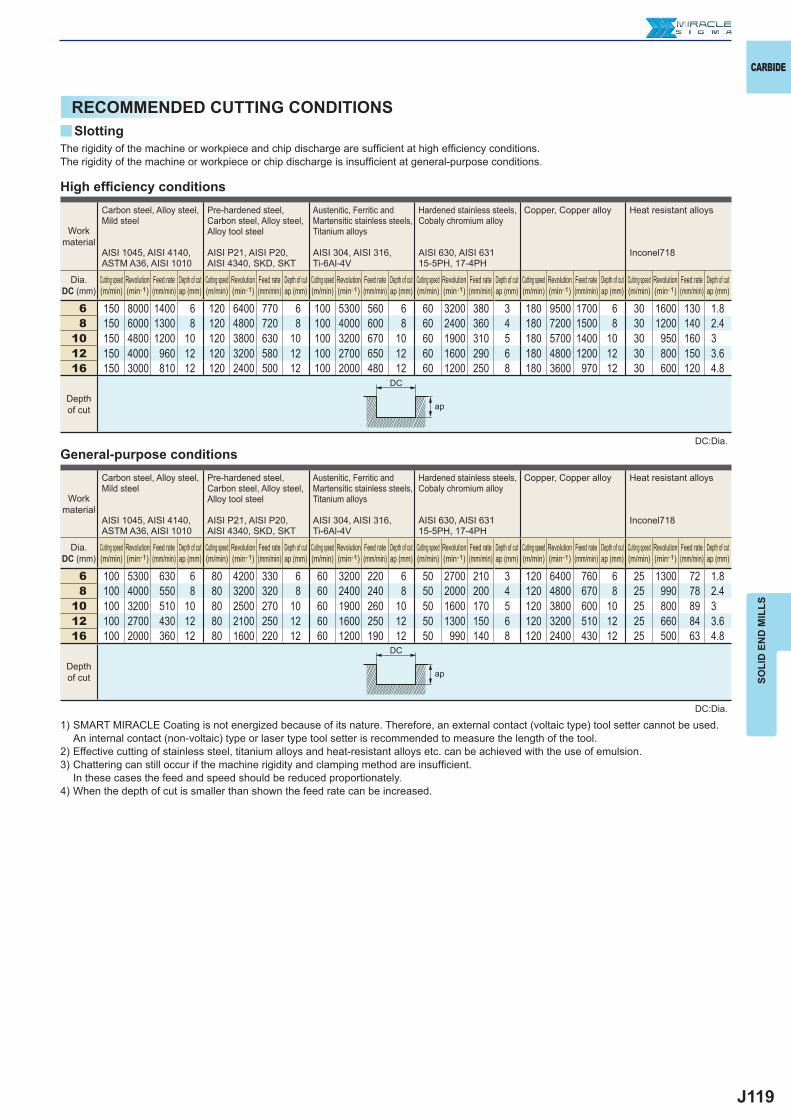
J119
y
6 150 8000 1400 6 120 6400 770 6 100 5300 560 6 60 3200 380 3 180 9500 1700 6 30 1600 130 1.88 150 6000 1300 8 120 4800 720 8 100 4000 600 8 60 2400 360 4 180 7200 1500 8 30 1200 140 2.4
10 150 4800 1200 10 120 3800 630 10 100 3200 670 10 60 1900 310 5 180 5700 1400 10 30 950 160 312 150 4000 960 12 120 3200 580 12 100 2700 650 12 60 1600 290 6 180 4800 1200 12 30 800 150 3.616 150 3000 810 12 120 2400 500 12 100 2000 480 12 60 1200 250 8 180 3600 970 12 30 600 120 4.8
6 100 5300 630 6 80 4200 330 6 60 3200 220 6 50 2700 210 3 120 6400 760 6 25 1300 72 1.88 100 4000 550 8 80 3200 320 8 60 2400 240 8 50 2000 200 4 120 4800 670 8 25 990 78 2.4
10 100 3200 510 10 80 2500 270 10 60 1900 260 10 50 1600 170 5 120 3800 600 10 25 800 89 312 100 2700 430 12 80 2100 250 12 60 1600 250 12 50 1300 150 6 120 3200 510 12 25 660 84 3.616 100 2000 360 12 80 1600 220 12 60 1200 190 12 50 990 140 8 120 2400 430 12 25 500 63 4.8
ap
ap
DC
DC
CARBIDE
SOLI
D E
ND
MIL
LS
RECOMMENDED CUTTING CONDITIONSSlotting
High effi ciency conditions
General-purpose conditions
The rigidity of the machine or workpiece and chip discharge are suffi cient at high effi ciency conditions. The rigidity of the machine or workpiece or chip discharge is insuffi cient at general-purpose conditions.
Work material
Carbon steel, Alloy steel,Mild steel
AISI 1045, AISI 4140, ASTM A36, AISI 1010
Pre-hardened steel,Carbon steel, Alloy steel,Alloy tool steel
AISI P21, AISI P20, AISI 4340, SKD, SKT
Austenitic, Ferritic and Martensitic stainless steels, Titanium alloys
AISI 304, AISI 316, Ti-6Al-4V
Hardened stainless steels,Cobaly chromium alloy
AISI 630, AISI 63115-5PH, 17-4PH
Copper, Copper alloy Heat resistant alloys
Inconel718
Dia. DC (mm)
Cutting speed (m/min)
Revolution (min-1)
Feed rate (mm/min)
Depth of cut ap (mm)
Cutting speed (m/min)
Revolution (min-1)
Feed rate (mm/min)
Depth of cut ap (mm)
Cutting speed (m/min)
Revolution (min-1)
Feed rate (mm/min)
Depth of cut ap (mm)
Cutting speed (m/min)
Revolution (min-1)
Feed rate (mm/min)
Depth of cut ap (mm)
Cutting speed (m/min)
Revolution (min-1)
Feed rate (mm/min)
Depth of cut ap (mm)
Cutting speed (m/min)
Revolution (min-1)
Feed rate (mm/min)
Depth of cut ap (mm)
Depth of cut
1) SMART MIRACLE Coating is not energized because of its nature. Therefore, an external contact (voltaic type) tool setter cannot be used. An internal contact (non-voltaic) type or laser type tool setter is recommended to measure the length of the tool.
2) Effective cutting of stainless steel, titanium alloys and heat-resistant alloys etc. can be achieved with the use of emulsion.3) Chattering can still occur if the machine rigidity and clamping method are insuffi cient.
In these cases the feed and speed should be reduced proportionately.4) When the depth of cut is smaller than shown the feed rate can be increased.
DC:Dia.
DC:Dia.
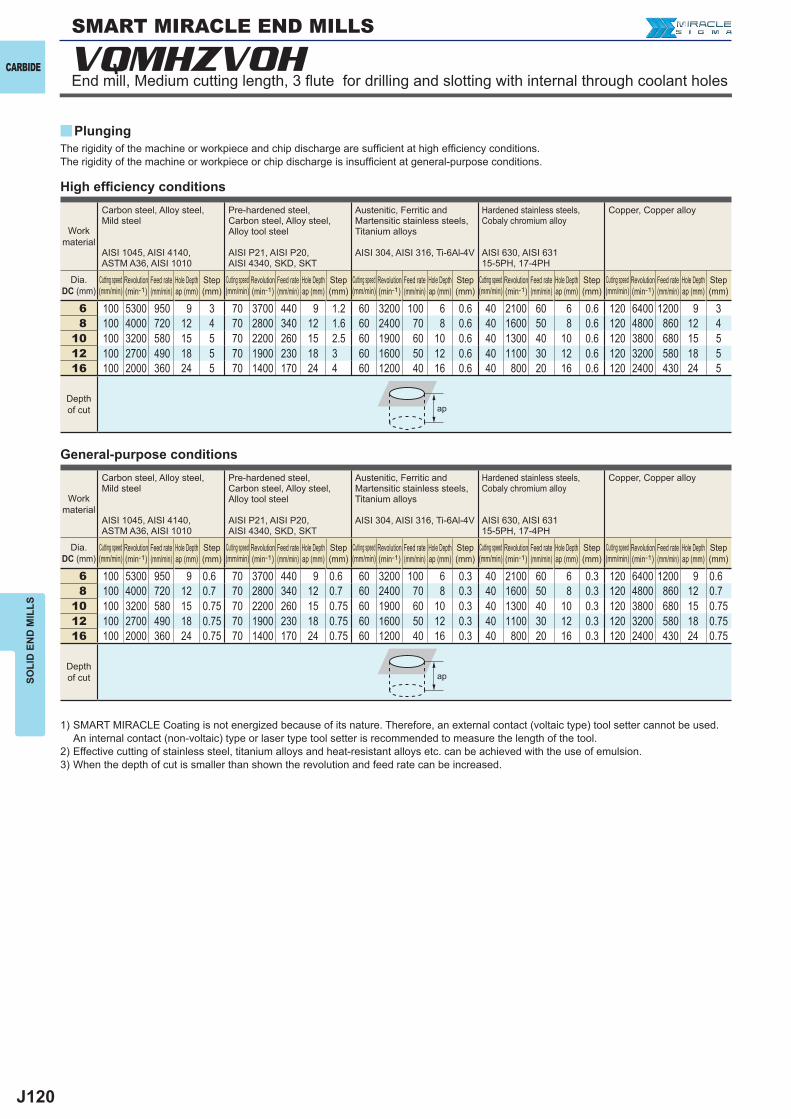
J120
6 100 5300 950 9 3 70 3700 440 9 1.2 60 3200 100 6 0.6 40 2100 60 6 0.6 120 6400 1200 9 38 100 4000 720 12 4 70 2800 340 12 1.6 60 2400 70 8 0.6 40 1600 50 8 0.6 120 4800 860 12 4
10 100 3200 580 15 5 70 2200 260 15 2.5 60 1900 60 10 0.6 40 1300 40 10 0.6 120 3800 680 15 512 100 2700 490 18 5 70 1900 230 18 3 60 1600 50 12 0.6 40 1100 30 12 0.6 120 3200 580 18 516 100 2000 360 24 5 70 1400 170 24 4 60 1200 40 16 0.6 40 800 20 16 0.6 120 2400 430 24 5
6 100 5300 950 9 0.6 70 3700 440 9 0.6 60 3200 100 6 0.3 40 2100 60 6 0.3 120 6400 1200 9 0.68 100 4000 720 12 0.7 70 2800 340 12 0.7 60 2400 70 8 0.3 40 1600 50 8 0.3 120 4800 860 12 0.7
10 100 3200 580 15 0.75 70 2200 260 15 0.75 60 1900 60 10 0.3 40 1300 40 10 0.3 120 3800 680 15 0.7512 100 2700 490 18 0.75 70 1900 230 18 0.75 60 1600 50 12 0.3 40 1100 30 12 0.3 120 3200 580 18 0.7516 100 2000 360 24 0.75 70 1400 170 24 0.75 60 1200 40 16 0.3 40 800 20 16 0.3 120 2400 430 24 0.75
VQMHZVOH
y
ap
ap
CARBIDE
SOLI
D E
ND
MIL
LS
High effi ciency conditions
General-purpose conditions
The rigidity of the machine or workpiece and chip discharge are suffi cient at high effi ciency conditions. The rigidity of the machine or workpiece or chip discharge is insuffi cient at general-purpose conditions.
Work material
Carbon steel, Alloy steel,Mild steel
AISI 1045, AISI 4140, ASTM A36, AISI 1010
Pre-hardened steel,Carbon steel, Alloy steel,Alloy tool steel
AISI P21, AISI P20, AISI 4340, SKD, SKT
Austenitic, Ferritic and Martensitic stainless steels, Titanium alloys
AISI 304, AISI 316, Ti-6Al-4V
Hardened stainless steels,Cobaly chromium alloy
AISI 630, AISI 63115-5PH, 17-4PH
Copper, Copper alloy
Dia.DC (mm)
Cutting speed (mm/min)
Revolution (min-1)
Feed rate (mm/min)
Hole Depth ap (mm)
Step (mm)
Cutting speed (mm/min)
Revolution (min-1)
Feed rate (mm/min)
Hole Depth ap (mm)
Step (mm)
Cutting speed (mm/min)
Revolution (min-1)
Feed rate (mm/min)
Hole Depth ap (mm)
Step (mm)
Cutting speed (mm/min)
Revolution (min-1)
Feed rate (mm/min)
Hole Depth ap (mm)
Step (mm)
Cutting speed (mm/min)
Revolution (min-1)
Feed rate (mm/min)
Hole Depth ap (mm)
Step (mm)
Depth of cut
1) SMART MIRACLE Coating is not energized because of its nature. Therefore, an external contact (voltaic type) tool setter cannot be used. An internal contact (non-voltaic) type or laser type tool setter is recommended to measure the length of the tool.
2) Effective cutting of stainless steel, titanium alloys and heat-resistant alloys etc. can be achieved with the use of emulsion.3) When the depth of cut is smaller than shown the revolution and feed rate can be increased.
End mill, Medium cutting length, 3 flute for drilling and slotting with internal through coolant holes
SMART MIRACLE END MILLS
Plunging
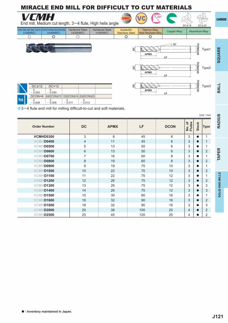
J121
a
u e u e e
VCMH
DC APMX LF DCON
VCMHD0300 3 8 45 6 3 a 1VCMHD0400 4 11 45 6 3 a 1VCMHD0500 5 13 50 6 3 a 1VCMHD0600 6 13 50 6 3 a 2VCMHD0700 7 16 60 8 3 a 1VCMHD0800 8 19 60 8 3 a 2VCMHD0900 9 19 70 10 3 a 1VCMHD1000 10 22 70 10 3 a 2VCMHD1100 11 22 75 12 3 a 1VCMHD1200 12 26 75 12 3 a 2VCMHD1300 13 26 75 12 3 a 3VCMHD1400 14 26 75 12 3 a 3VCMHD1500 15 30 80 16 3 a 1VCMHD1600 16 32 90 16 3 a 2VCMHD1800 18 32 90 16 3 a 3VCMHD2000 20 38 100 20 4 a 2VCMHD2500 25 45 120 25 4 a 2
DC>12 0- 0.020
0- 0.030
DCON=6 0- 0.008
0- 0.009
0- 0.011
0- 0.013
UWC VC 50°
h6
APMX
DC
DC
ON
(h6)15°
APMXLF
DC
DC
ON
(h6)
LF
APMXLF
DC
DC
ON
(h6)
CARBIDE
SQU
AR
EB
ALL
RA
DIU
STA
PER
SOLI
D E
ND
MIL
LS
Unit : mm
Carbon Steel, Alloy Steel, Cast Iron(<30HRC)
Tool Steel, Pre-Hardened Steel,Hardened Steel(<45HRC)
Hardened Steel(<55HRC)
Hardened Steel(>55HRC)
AusteniticStainless Steel
Titanium Alloy,Heat Resistant Alloy Copper Alloy Aluminium Alloy
End mill, Medium cut length, 3─4 fl ute, High helix angle
3─4 fl ute end mill for milling diffi cult-to-cut and soft materials.
Type2
Type3
Type1
Order Number
No.
of
Flut
es
Stoc
k
Type
DC<18 DC>20
8<DCON<10 12<DCON<16 20<DCON<25
DC<12
MIRACLE END MILL FOR DIFFICULT TO CUT MATERIALS
a : Inventory maintained in Japan.
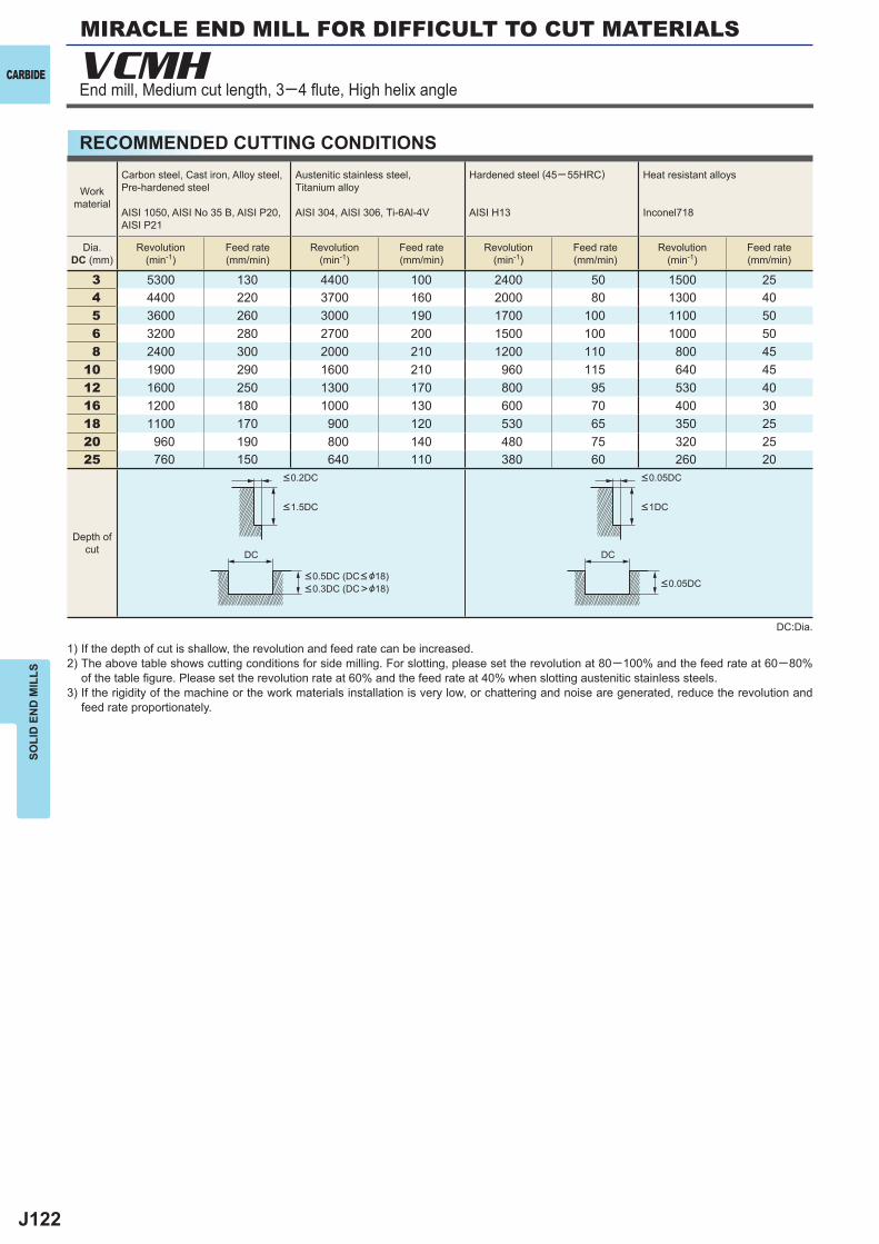
J122
3 5300 130 4400 100 2400 50 1500 254 4400 220 3700 160 2000 80 1300 405 3600 260 3000 190 1700 100 1100 506 3200 280 2700 200 1500 100 1000 508 2400 300 2000 210 1200 110 800 45
10 1900 290 1600 210 960 115 640 4512 1600 250 1300 170 800 95 530 4016 1200 180 1000 130 600 70 400 3018 1100 170 900 120 530 65 350 2520 960 190 800 140 480 75 320 2525 760 150 640 110 380 60 260 20
VCMH
DC DC
CARBIDE
SOLI
D E
ND
MIL
LS
RECOMMENDED CUTTING CONDITIONS
Workmaterial
Carbon steel, Cast iron, Alloy steel,Pre-hardened steel
AISI 1050, AISI No 35 B, AISI P20, AISI P21
Austenitic stainless steel,Titanium alloy
AISI 304, AISI 306, Ti-6Al-4V
Hardened steel (45─ 55HRC)
AISI H13
Heat resistant alloys
Inconel718
Dia.DC (mm)
Revolution(min-1)
Feed rate(mm/min)
Revolution(min-1)
Feed rate(mm/min)
Revolution(min-1)
Feed rate(mm/min)
Revolution(min-1)
Feed rate(mm/min)
Depth ofcut
<0.2DC <0.05DC
<1.5DC <1DC
<0.05DC<0.5DC (DC< &18)<0.3DC (DC>&18)
1) If the depth of cut is shallow, the revolution and feed rate can be increased.2) The above table shows cutting conditions for side milling. For slotting, please set the revolution at 80─100% and the feed rate at 60─80%
of the table fi gure. Please set the revolution rate at 60% and the feed rate at 40% when slotting austenitic stainless steels.3) If the rigidity of the machine or the work materials installation is very low, or chattering and noise are generated, reduce the revolution and
feed rate proportionately.
DC:Dia.
End mill, Medium cut length, 3─4 fl ute, High helix angle
MIRACLE END MILL FOR DIFFICULT TO CUT MATERIALS
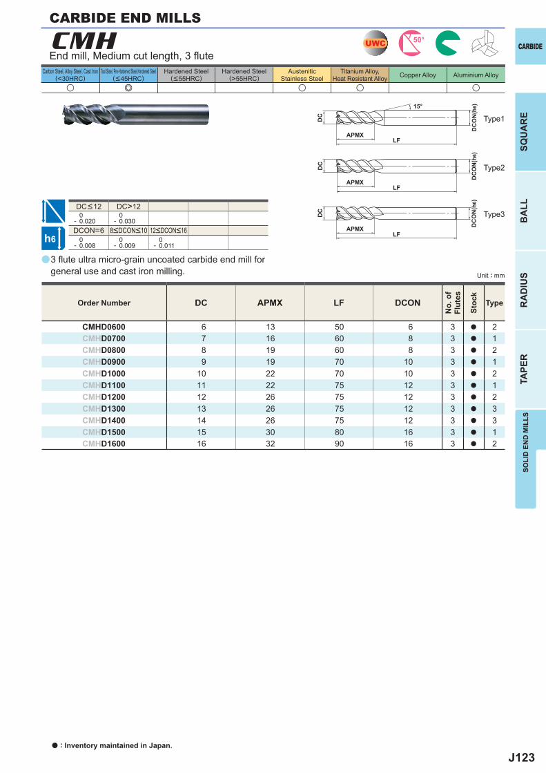
J123
a
u e u u u
CMH
DC APMX LF DCON
CMHD0600 6 13 50 6 3 a 2CMHD0700 7 16 60 8 3 a 1CMHD0800 8 19 60 8 3 a 2CMHD0900 9 19 70 10 3 a 1CMHD1000 10 22 70 10 3 a 2CMHD1100 11 22 75 12 3 a 1CMHD1200 12 26 75 12 3 a 2CMHD1300 13 26 75 12 3 a 3CMHD1400 14 26 75 12 3 a 3CMHD1500 15 30 80 16 3 a 1CMHD1600 16 32 90 16 3 a 2
DC>12 0- 0.020
0- 0.030
DCON=6 0- 0.008
0- 0.009
0- 0.011
UWC 50°
h6
APMX
DC
DC
ON
(h6)15°
APMXLF
DC
DC
ON
(h6)
LF
APMXLF
DC
DC
ON
(h6)
CARBIDE
SQU
AR
EB
ALL
RA
DIU
STA
PER
SOLI
D E
ND
MIL
LS
Unit : mm
Carbon Steel, Alloy Steel, Cast Iron(<30HRC)
Tool Steel, Pre-Hardened Steel,Hardened Steel(<45HRC)
Hardened Steel(<55HRC)
Hardened Steel(>55HRC)
AusteniticStainless Steel
Titanium Alloy,Heat Resistant Alloy Copper Alloy Aluminium Alloy
3 fl ute ultra micro-grain uncoated carbide end mill for general use and cast iron milling.
End mill, Medium cut length, 3 fl ute
Type2
Type3
Type1
CARBIDE END MILLS
Order Number
No.
of
Flut
es
Stoc
k
Type
8<DCON<10 12<DCON<16
DC<12
a : Inventory maintained in Japan.
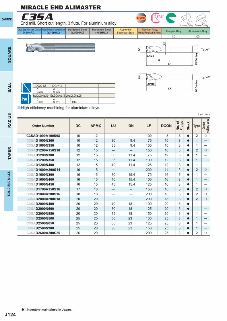
J124
a
u e
C3SA
DC APMX LU DN LF DCON
C3SAD1000A100S08 10 12 ─ ─ 100 8 3 a 2 u
C3SAD1000N300 10 12 30 9.4 75 10 3 a 1 ─C3SAD1000N350 10 12 35 9.4 100 10 3 a 1 ─C3SAD1200A150S10 12 15 ─ ─ 150 10 3 a 2 u
C3SAD1200N300 12 15 30 11.4 75 12 3 a 1 ─C3SAD1200N350 12 15 35 11.4 100 12 3 a 1 ─C3SAD1200N400 12 15 40 11.4 125 12 3 a 1 ─C3SAD1600A200S14 16 15 ─ ─ 200 14 3 a 2 u
C3SAD1600N300 16 15 30 15.4 75 16 3 a 1 ─C3SAD1600N400 16 15 40 15.4 100 16 3 a 1 ─C3SAD1600N450 16 15 45 15.4 125 16 3 a 1 ─C3SAD1700A150S16 17 18 ─ ─ 150 16 3 a 2 u
C3SAD1800A200S16 18 18 ─ ─ 200 16 3 a 2 u
C3SAD2000A200S18 20 20 ─ ─ 200 18 3 a 2 u
C3SAD2000N400 20 20 40 18 100 20 3 a 1 ─C3SAD2000N600 20 20 60 18 125 20 3 a 1 ─C3SAD2000N850 20 20 85 18 150 20 3 a 1 ─C3SAD2500N500 25 20 50 23 100 25 3 a 1 ─C3SAD2500N650 25 20 65 23 125 25 3 a 1 ─C3SAD2500N900 25 20 90 23 150 25 3 a 1 ─C3SAD2600A200S25 26 20 ─ ─ 200 25 3 a 2 u
DC>12 0- 0.020
0- 0.030
0- 0.009
0- 0.011
0- 0.013
UWC 37.5°
h6
APMXLU
DC
DC
ON
(h6)
APMX
LF
DC
DC
ON
(h6)
LF
DN
CARBIDE
a : Inventory maintained in Japan.
BA
LLR
AD
IUS
TAPE
RSO
LID
EN
D M
ILLS
SQU
AR
E
Unit : mm
Carbon Steel, Alloy Steel, Cast Iron(<30HRC)
Tool Steel, Pre-Hardened Steel,Hardened Steel(<45HRC)
Hardened Steel(<55HRC)
Hardened Steel(>55HRC)
AusteniticStainless Steel
Titanium Alloy,Heat Resistant Alloy Copper Alloy Aluminium Alloy
High effi ciency machining for aluminium alloys.
End mill, Short cut length, 3 fl ute, For aluminium alloy
Type2
Type1
Order Number
No.
of
Flut
es
Stoc
k
Type
Cente
r cu
tting e
dge
8<DCON<10 12<DCON<16 20<DCON<25
DC<12
MIRACLE END ALIMASTER
Non-center Cutting Center Cutting
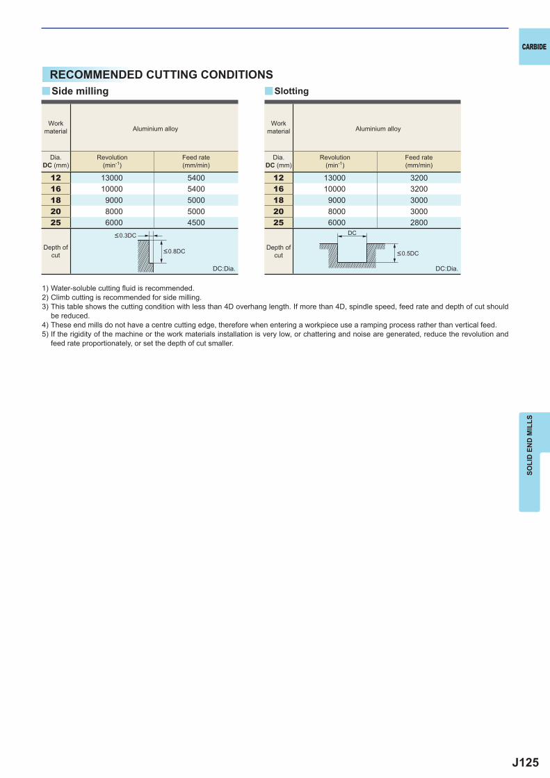
J125
12 13000 540016 10000 540018 9000 500020 8000 500025 6000 4500
12 13000 320016 10000 320018 9000 300020 8000 300025 6000 2800
y y
DC
CARBIDE
SOLI
D E
ND
MIL
LS
RECOMMENDED CUTTING CONDITIONS
1) Water-soluble cutting fl uid is recommended.2) Climb cutting is recommended for side milling.3) This table shows the cutting condition with less than 4D overhang length. If more than 4D, spindle speed, feed rate and depth of cut should
be reduced.4) These end mills do not have a centre cutting edge, therefore when entering a workpiece use a ramping process rather than vertical feed.5) If the rigidity of the machine or the work materials installation is very low, or chattering and noise are generated, reduce the revolution and
feed rate proportionately, or set the depth of cut smaller.
DC:Dia. DC:Dia.
Side milling Slotting
Depth ofcut
Depth ofcut
<0.3DC
<0.8DC <0.5DC
Workmaterial Aluminium alloy
Workmaterial Aluminium alloy
Dia.DC (mm)
Revolution(min-1)
Feed rate(mm/min)
Dia.DC (mm)
Revolution(min-1)
Feed rate(mm/min)
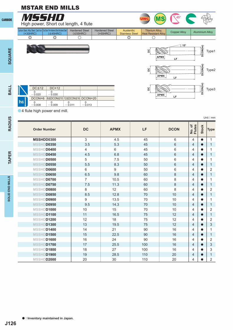
J126
a
e e u e u
MSSHD
DC APMX LF DCON
MSSHDD0300 3 4.5 45 6 4 a 1MSSHDD0350 3.5 5.3 45 6 4 a 1MSSHDD0400 4 6 45 6 4 a 1MSSHDD0450 4.5 6.8 45 6 4 a 1MSSHDD0500 5 7.5 50 6 4 a 1MSSHDD0550 5.5 8.3 50 6 4 a 1MSSHDD0600 6 9 50 6 4 a 2MSSHDD0650 6.5 9.8 60 8 4 a 1MSSHDD0700 7 10.5 60 8 4 a 1MSSHDD0750 7.5 11.3 60 8 4 a 1MSSHDD0800 8 12 60 8 4 a 2MSSHDD0850 8.5 12.8 70 10 4 a 1MSSHDD0900 9 13.5 70 10 4 a 1MSSHDD0950 9.5 14.3 70 10 4 a 1MSSHDD1000 10 15 70 10 4 a 2MSSHDD1100 11 16.5 75 12 4 a 1MSSHDD1200 12 18 75 12 4 a 2MSSHDD1300 13 19.5 75 12 4 a 3MSSHDD1400 14 21 90 16 4 a 1MSSHDD1500 15 22.5 90 16 4 a 1MSSHDD1600 16 24 90 16 4 a 2MSSHDD1700 17 25.5 100 16 4 a 3MSSHDD1800 18 27 100 16 4 a 3MSSHDD1900 19 28.5 110 20 4 a 1MSSHDD2000 20 30 110 20 4 a 2
DC>12 0- 0.020
0- 0.030
DCON=6 DCON=20 0- 0.008
0- 0.009
0- 0.011
0- 0.013
MSUWC 45°
h6
APMX
DC
DC
ON
(h6)15°
APMXLF
DC
DC
ON
(h6)
LF
APMXLF
DC
DC
ON
(h6)
CARBIDE
a : Inventory maintained in Japan.
BA
LLR
AD
IUS
TAPE
RSO
LID
EN
D M
ILLS
SQU
AR
E
Unit : mm
Carbon Steel, Alloy Steel, Cast Iron(<30HRC)
Tool Steel, Pre-Hardened Steel,Hardened Steel(<45HRC)
Hardened Steel(<55HRC)
Hardened Steel(>55HRC)
AusteniticStainless Steel
Titanium Alloy,Heat Resistant Alloy Copper Alloy Aluminium Alloy
MSTAR END MILLS
4 fl ute high power end mill.
High power, Short cut length, 4 fl ute
Type2
Type1
Type3
Order Number
No.
of
Flut
es
Stoc
k
Type
8<DCON<10 12<DCON<16
DC<12
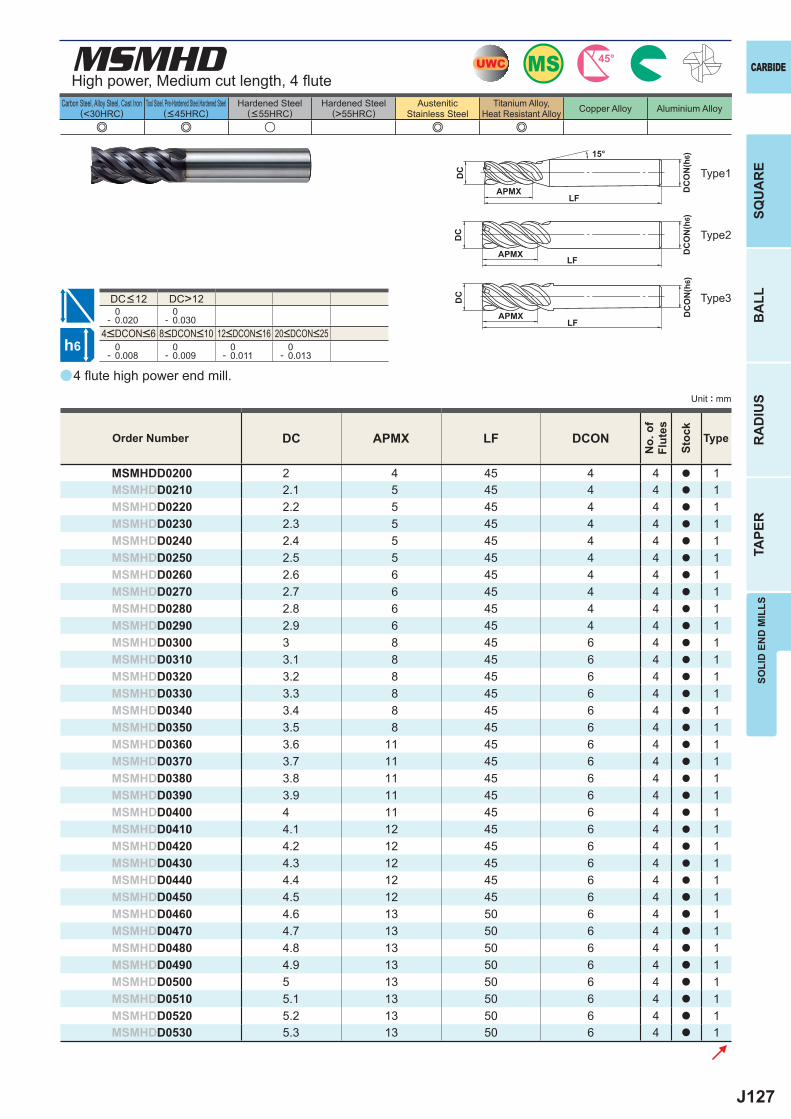
J127
a
e e u e e
MSMHD
DC APMX LF DCON
MSMHDD0200 2 4 45 4 4 a 1MSMHDD0210 2.1 5 45 4 4 a 1MSMHDD0220 2.2 5 45 4 4 a 1MSMHDD0230 2.3 5 45 4 4 a 1MSMHDD0240 2.4 5 45 4 4 a 1MSMHDD0250 2.5 5 45 4 4 a 1MSMHDD0260 2.6 6 45 4 4 a 1MSMHDD0270 2.7 6 45 4 4 a 1MSMHDD0280 2.8 6 45 4 4 a 1MSMHDD0290 2.9 6 45 4 4 a 1MSMHDD0300 3 8 45 6 4 a 1MSMHDD0310 3.1 8 45 6 4 a 1MSMHDD0320 3.2 8 45 6 4 a 1MSMHDD0330 3.3 8 45 6 4 a 1MSMHDD0340 3.4 8 45 6 4 a 1MSMHDD0350 3.5 8 45 6 4 a 1MSMHDD0360 3.6 11 45 6 4 a 1MSMHDD0370 3.7 11 45 6 4 a 1MSMHDD0380 3.8 11 45 6 4 a 1MSMHDD0390 3.9 11 45 6 4 a 1MSMHDD0400 4 11 45 6 4 a 1MSMHDD0410 4.1 12 45 6 4 a 1MSMHDD0420 4.2 12 45 6 4 a 1MSMHDD0430 4.3 12 45 6 4 a 1MSMHDD0440 4.4 12 45 6 4 a 1MSMHDD0450 4.5 12 45 6 4 a 1MSMHDD0460 4.6 13 50 6 4 a 1MSMHDD0470 4.7 13 50 6 4 a 1MSMHDD0480 4.8 13 50 6 4 a 1MSMHDD0490 4.9 13 50 6 4 a 1MSMHDD0500 5 13 50 6 4 a 1MSMHDD0510 5.1 13 50 6 4 a 1MSMHDD0520 5.2 13 50 6 4 a 1MSMHDD0530 5.3 13 50 6 4 a 1
DC>12 0- 0.020
0- 0.030
0- 0.008
0- 0.009
0- 0.011
0- 0.013
MSUWC 45°
h6
APMX
DC
DC
ON
(h6)15°
APMXLF
DC
DC
ON
(h6)
LF
APMXLF
DC
DC
ON
(h6)
CARBIDE
SQU
AR
EB
ALL
RA
DIU
STA
PER
SOLI
D E
ND
MIL
LS
Unit : mm
Carbon Steel, Alloy Steel, Cast Iron(<30HRC)
Tool Steel, Pre-Hardened Steel,Hardened Steel(<45HRC)
Hardened Steel(<55HRC)
Hardened Steel(>55HRC)
AusteniticStainless Steel
Titanium Alloy,Heat Resistant Alloy Copper Alloy Aluminium Alloy
4 fl ute high power end mill.
High power, Medium cut length, 4 fl ute
Type1
Type2
Type3
Order Number
No.
of
Flut
es
Stoc
k
Type
4<DCON<6 8<DCON<10 12<DCON<16 20<DCON<25
DC<12
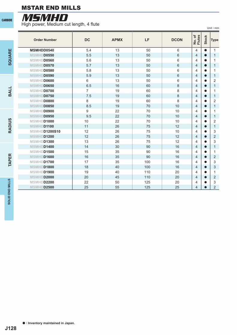
J128
DC APMX LF DCON
MSMHDD0540 5.4 13 50 6 4 a 1MSMHDD0550 5.5 13 50 6 4 a 1MSMHDD0560 5.6 13 50 6 4 a 1MSMHDD0570 5.7 13 50 6 4 a 1MSMHDD0580 5.8 13 50 6 4 a 1MSMHDD0590 5.9 13 50 6 4 a 1MSMHDD0600 6 13 50 6 4 a 2MSMHDD0650 6.5 16 60 8 4 a 1MSMHDD0700 7 19 60 8 4 a 1MSMHDD0750 7.5 19 60 8 4 a 1MSMHDD0800 8 19 60 8 4 a 2MSMHDD0850 8.5 19 70 10 4 a 1MSMHDD0900 9 22 70 10 4 a 1MSMHDD0950 9.5 22 70 10 4 a 1MSMHDD1000 10 22 70 10 4 a 2MSMHDD1100 11 26 75 12 4 a 1MSMHDD1200S10 12 26 75 10 4 a 3MSMHDD1200 12 26 75 12 4 a 2MSMHDD1300 13 26 75 12 4 a 3MSMHDD1400 14 30 90 16 4 a 1MSMHDD1500 15 35 90 16 4 a 1MSMHDD1600 16 35 90 16 4 a 2MSMHDD1700 17 35 100 16 4 a 3MSMHDD1800 18 40 100 16 4 a 3MSMHDD1900 19 40 110 20 4 a 1MSMHDD2000 20 45 110 20 4 a 2MSMHDD2200 22 50 125 20 4 a 3MSMHDD2500 25 55 125 25 4 a 2
MSMHDCARBIDE
a : Inventory maintained in Japan.
BA
LLR
AD
IUS
TAPE
RSO
LID
EN
D M
ILLS
SQU
AR
E
Unit : mm
Order Number
No.
of
Flut
es
Stoc
k
Type
High power, Medium cut length, 4 fl ute
MSTAR END MILLS
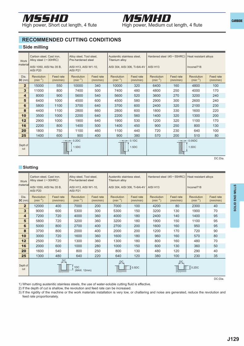
J129
MSSHD MSMHD
2 15000 550 10000 340 10000 320 6400 160 4800 1003 11000 800 7400 500 7400 480 4800 250 4000 1704 8000 900 5600 540 5600 520 3600 270 3200 2405 6400 1000 4500 600 4500 580 2900 300 2600 2406 5800 1100 3700 640 3700 600 2400 320 2100 2308 4400 1100 2800 660 2800 600 1800 330 1600 220
10 3500 1000 2200 640 2200 560 1400 320 1300 20012 2900 1000 1900 640 1900 530 1200 320 1100 17016 2200 800 1400 500 1400 450 900 250 800 13020 1800 750 1100 460 1100 440 720 230 640 10025 1400 600 900 400 900 380 570 200 510 80
2 12000 400 7000 200 7000 100 4200 80 2300 403 9000 600 5300 300 5300 150 3200 130 1900 704 7200 720 4000 360 4000 180 2400 140 1400 955 5800 720 3200 360 3200 180 1900 150 1100 956 5000 800 2700 400 2700 200 1600 160 950 958 3700 800 2000 400 2000 200 1200 170 720 90
10 3000 720 1600 360 1600 180 960 160 570 8012 2500 720 1300 360 1300 180 800 160 480 7016 2000 600 1000 280 1000 150 600 130 360 5020 1600 540 800 250 800 130 480 120 290 4025 1300 480 640 220 640 120 380 100 230 35
0.2DC 0.1DC 0.05DC
1.5DC 1.5DC 1.5DC
DC DC DC
1DC 0.5DC 0.2DC
y
y
CARBIDE
SOLI
D E
ND
MIL
LS
High power, Short cut length, 4 fl ute High power, Medium cut length, 4 fl ute
RECOMMENDED CUTTING CONDITIONS
1) When cutting austenitic stainless steels, the use of water-soluble cutting fl uid is effective.2) If the depth of cut is shallow, the revolution and feed rate can be increased.3) If the rigidity of the machine or the work materials installation is very low, or chattering and noise are generated, reduce the revolution and
feed rate proportionately.
DC:Dia.
DC:Dia.
Slotting
Side milling
Workmaterial
Carbon steel, Cast iron, Alloy steel (─30HRC)
AISI 1050, AISI No 35 B,AISI P20
Alloy steel, Tool steel,Pre-hardened steel
AISI H13, AISI W1-10, AISI P21
Austenitic stainless steel,Titanium alloy
AISI 304, AISI 306, Ti-6Al-4V
Hardened steel (45─ 55HRC)
AISI H13
Heat resistant alloys
Inconel718
Dia.DC (mm)
Revolution(min-1)
Feed rate(mm/min)
Revolution(min-1)
Feed rate(mm/min)
Revolution(min-1)
Feed rate(mm/min)
Revolution(min-1)
Feed rate(mm/min)
Revolution(min-1)
Feed rate(mm/min)
Depth ofcut
Workmaterial
Carbon steel, Cast iron, Alloy steel (─30HRC)
AISI 1050, AISI No 35 B,AISI P20
Alloy steel, Tool steel,Pre-hardened steel
AISI H13, AISI W1-10, AISI P21
Austenitic stainless steel,Titanium alloy
AISI 304, AISI 306, Ti-6Al-4V
Hardened steel (45─ 55HRC)
AISI H13
Heat resistant alloys
Inconel718
Dia.DC (mm)
Revolution(min-1)
Feed rate(mm/min)
Revolution(min-1)
Feed rate(mm/min)
Revolution(min-1)
Feed rate(mm/min)
Revolution(min-1)
Feed rate(mm/min)
Revolution(min-1)
Feed rate(mm/min)
(MAX. 12mm)
Depth ofcut
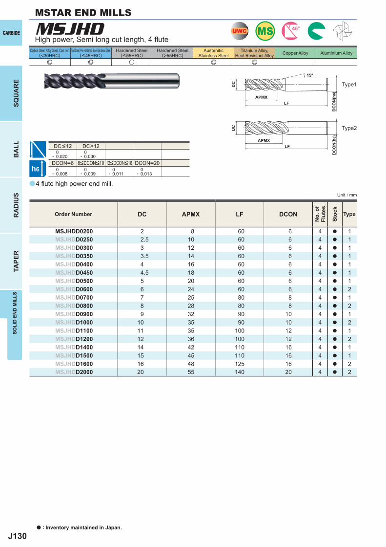
J130
a
e e u e e
MSJHD
DC APMX LF DCON
MSJHDD0200 2 8 60 6 4 a 1MSJHDD0250 2.5 10 60 6 4 a 1MSJHDD0300 3 12 60 6 4 a 1MSJHDD0350 3.5 14 60 6 4 a 1MSJHDD0400 4 16 60 6 4 a 1MSJHDD0450 4.5 18 60 6 4 a 1MSJHDD0500 5 20 60 6 4 a 1MSJHDD0600 6 24 60 6 4 a 2MSJHDD0700 7 25 80 8 4 a 1MSJHDD0800 8 28 80 8 4 a 2MSJHDD0900 9 32 90 10 4 a 1MSJHDD1000 10 35 90 10 4 a 2MSJHDD1100 11 35 100 12 4 a 1MSJHDD1200 12 36 100 12 4 a 2MSJHDD1400 14 42 110 16 4 a 1MSJHDD1500 15 45 110 16 4 a 1MSJHDD1600 16 48 125 16 4 a 2MSJHDD2000 20 55 140 20 4 a 2
DC>12 0- 0.020
0- 0.030
DCON=6 DCON=20 0- 0.008
0- 0.009
0- 0.011
0- 0.013
MSUWC 45°
h6
APMX
DC
DC
ON
(h6)
15°
APMXLF
DC
DC
ON
(h6)
LF
CARBIDE
a : Inventory maintained in Japan.
BA
LLR
AD
IUS
TAPE
RSO
LID
EN
D M
ILLS
SQU
AR
E
Unit : mm
Carbon Steel, Alloy Steel, Cast Iron(<30HRC)
Tool Steel, Pre-Hardened Steel,Hardened Steel(<45HRC)
Hardened Steel(<55HRC)
Hardened Steel(>55HRC)
AusteniticStainless Steel
Titanium Alloy,Heat Resistant Alloy Copper Alloy Aluminium Alloy
4 fl ute high power end mill.
High power, Semi long cut length, 4 fl ute
Type2
Type1
Order Number
No.
of
Flut
es
Stoc
k
Type
8<DCON<10 12<DCON<16
DC<12
MSTAR END MILLS
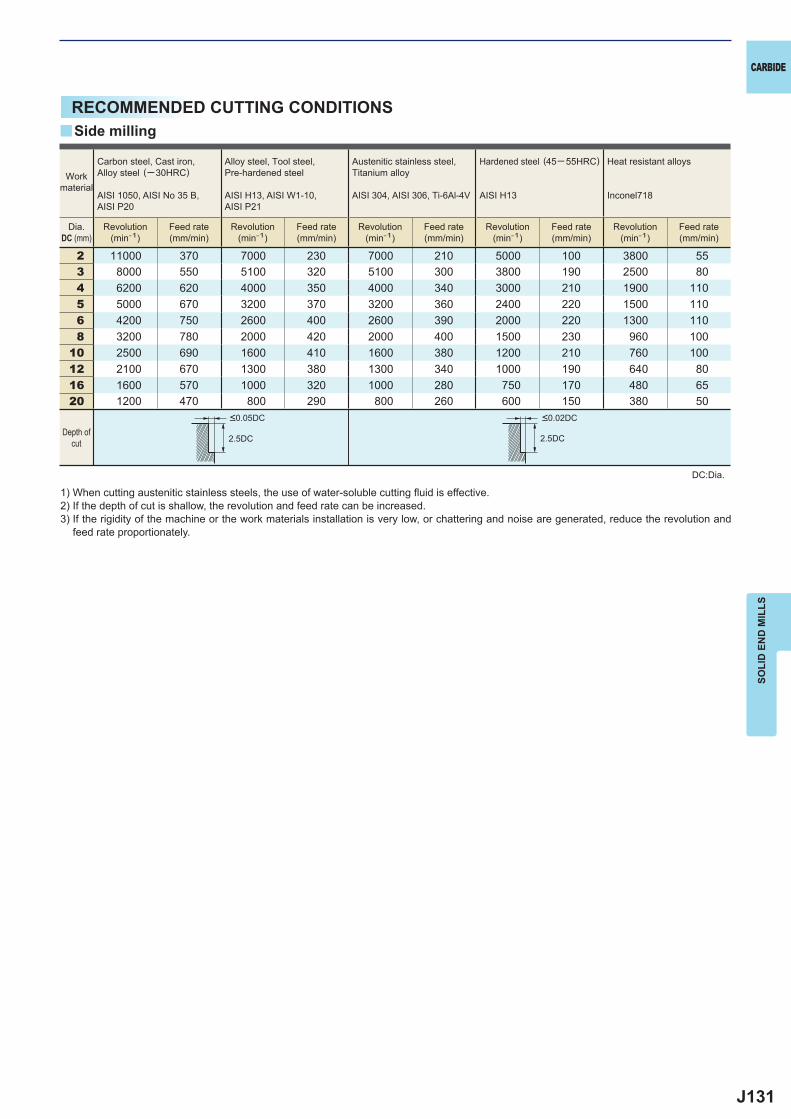
J131
2 11000 370 7000 230 7000 210 5000 100 3800 553 8000 550 5100 320 5100 300 3800 190 2500 804 6200 620 4000 350 4000 340 3000 210 1900 1105 5000 670 3200 370 3200 360 2400 220 1500 1106 4200 750 2600 400 2600 390 2000 220 1300 1108 3200 780 2000 420 2000 400 1500 230 960 100
10 2500 690 1600 410 1600 380 1200 210 760 10012 2100 670 1300 380 1300 340 1000 190 640 8016 1600 570 1000 320 1000 280 750 170 480 6520 1200 470 800 290 800 260 600 150 380 50
2.5DC 2.5DC
y
CARBIDE
SOLI
D E
ND
MIL
LS
RECOMMENDED CUTTING CONDITIONS
1) When cutting austenitic stainless steels, the use of water-soluble cutting fl uid is effective.2) If the depth of cut is shallow, the revolution and feed rate can be increased.3) If the rigidity of the machine or the work materials installation is very low, or chattering and noise are generated, reduce the revolution and
feed rate proportionately.
DC:Dia.
Side milling
Workmaterial
Carbon steel, Cast iron, Alloy steel (─30HRC)
AISI 1050, AISI No 35 B,AISI P20
Alloy steel, Tool steel,Pre-hardened steel
AISI H13, AISI W1-10, AISI P21
Austenitic stainless steel,Titanium alloy
AISI 304, AISI 306, Ti-6Al-4V
Hardened steel (45─ 55HRC)
AISI H13
Heat resistant alloys
Inconel718
Dia.DC (mm)
Revolution(min-1)
Feed rate(mm/min)
Revolution(min-1)
Feed rate(mm/min)
Revolution(min-1)
Feed rate(mm/min)
Revolution(min-1)
Feed rate(mm/min)
Revolution(min-1)
Feed rate(mm/min)
Depth ofcut
<0.05DC <0.02DC
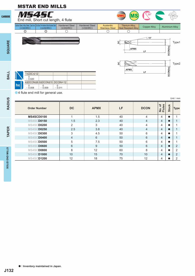
J132
a
e e u u u
MS4SC
DC APMX LF DCON
MS4SCD0100 1 1.5 40 4 4 a 1MS4SCD0150 1.5 2.3 40 4 4 a 1MS4SCD0200 2 3 40 4 4 a 1MS4SCD0250 2.5 3.8 40 4 4 a 1MS4SCD0300 3 4.5 50 6 4 a 1MS4SCD0400 4 6 50 6 4 a 1MS4SCD0500 5 7.5 50 6 4 a 1MS4SCD0600 6 9 50 6 4 a 2MS4SCD0800 8 12 60 8 4 a 2MS4SCD1000 10 15 70 10 4 a 2MS4SCD1200 12 18 75 12 4 a 2
0- 0.020
DCON=12 0- 0.008
0- 0.009
0- 0.011
UWC MS 30°
h6
APMX
DC
DC
ON
(h6)
15°
APMXLF
DC
DC
ON
(h6)
LF
CARBIDE
a : Inventory maintained in Japan.
BA
LLR
AD
IUS
TAPE
RSO
LID
EN
D M
ILLS
SQU
AR
E
Unit : mm
Carbon Steel, Alloy Steel, Cast Iron(<30HRC)
Tool Steel, Pre-Hardened Steel,Hardened Steel(<45HRC)
Hardened Steel(<55HRC)
Hardened Steel(>55HRC)
AusteniticStainless Steel
Titanium Alloy,Heat Resistant Alloy Copper Alloy Aluminium Alloy
4 fl ute end mill for general use.
End mill, Short cut length, 4 fl ute
Type2
Type1
Order Number
No.
of
Flut
es
Stoc
k
Type
4<DCON<6 8<DCON<10
1<DC<12
MSTAR END MILLS
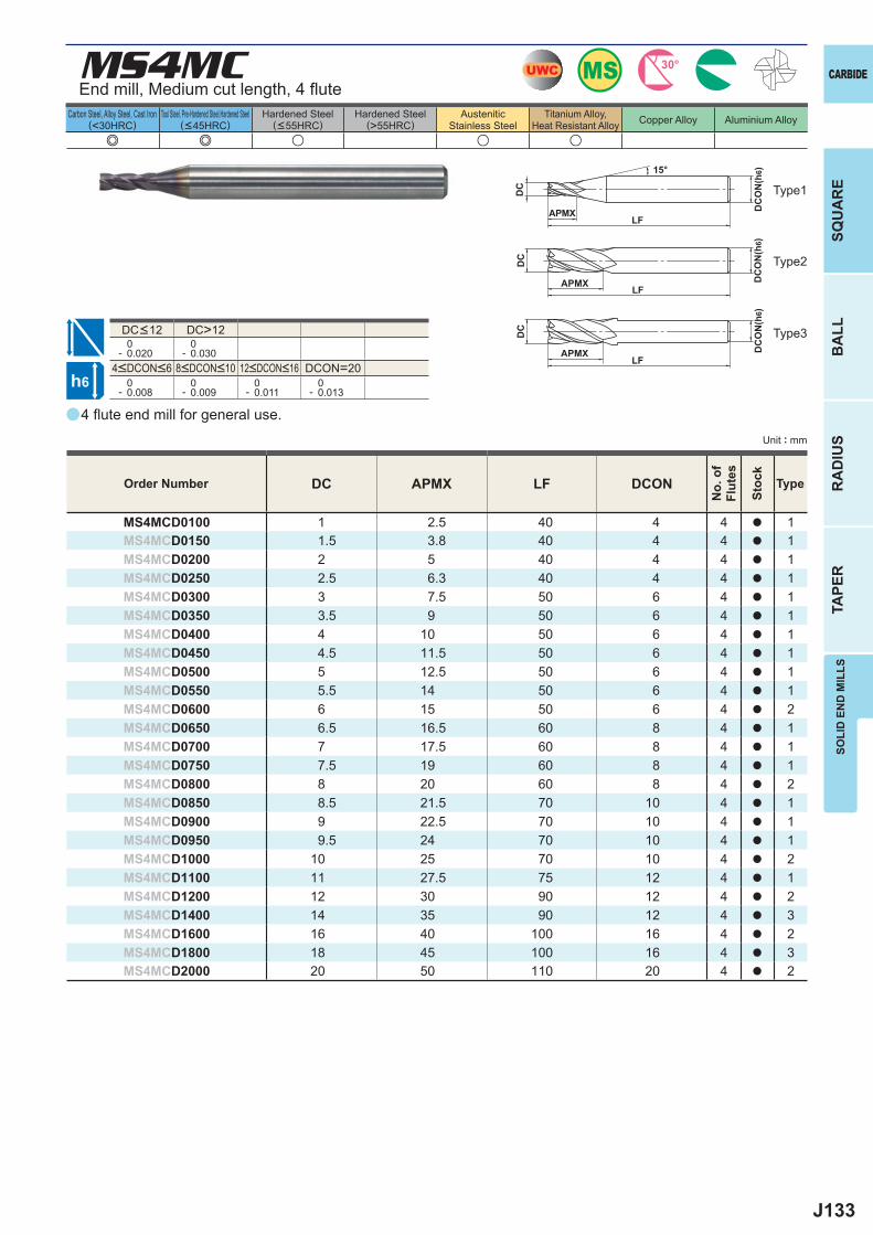
J133
aa
e e u u u
MS4MC
DC APMX LF DCON
MS4MCD0100 1 2.5 40 4 4 a 1MS4MCD0150 1.5 3.8 40 4 4 a 1MS4MCD0200 2 5 40 4 4 a 1MS4MCD0250 2.5 6.3 40 4 4 a 1MS4MCD0300 3 7.5 50 6 4 a 1MS4MCD0350 3.5 9 50 6 4 a 1MS4MCD0400 4 10 50 6 4 a 1MS4MCD0450 4.5 11.5 50 6 4 a 1MS4MCD0500 5 12.5 50 6 4 a 1MS4MCD0550 5.5 14 50 6 4 a 1MS4MCD0600 6 15 50 6 4 a 2MS4MCD0650 6.5 16.5 60 8 4 a 1MS4MCD0700 7 17.5 60 8 4 a 1MS4MCD0750 7.5 19 60 8 4 a 1MS4MCD0800 8 20 60 8 4 a 2MS4MCD0850 8.5 21.5 70 10 4 a 1MS4MCD0900 9 22.5 70 10 4 a 1MS4MCD0950 9.5 24 70 10 4 a 1MS4MCD1000 10 25 70 10 4 a 2MS4MCD1100 11 27.5 75 12 4 a 1MS4MCD1200 12 30 90 12 4 a 2MS4MCD1400 14 35 90 12 4 a 3MS4MCD1600 16 40 100 16 4 a 2MS4MCD1800 18 45 100 16 4 a 3MS4MCD2000 20 50 110 20 4 a 2
DC>12 0- 0.020
0- 0.030
DCON=20 0- 0.008
0- 0.009
0- 0.011
0- 0.013
UWC MS 30°
h6
APMX
DC
DC
ON
(h6)15°
APMXLF
DC
DC
ON
(h6)
LF
APMXLF
DC
DC
ON
(h6)
CARBIDE
SQU
AR
EB
ALL
RA
DIU
STA
PER
SOLI
D E
ND
MIL
LS
Unit : mm
Carbon Steel, Alloy Steel, Cast Iron(<30HRC)
Tool Steel, Pre-Hardened Steel,Hardened Steel(<45HRC)
Hardened Steel(<55HRC)
Hardened Steel(>55HRC)
AusteniticStainless Steel
Titanium Alloy,Heat Resistant Alloy Copper Alloy Aluminium Alloy
4 fl ute end mill for general use.
End mill, Medium cut length, 4 fl ute
Type2
Type1
Type3
Order Number
No.
of
Flut
es
Stoc
k
Type
4<DCON<6 8<DCON<10 12<DCON<16
DC<12
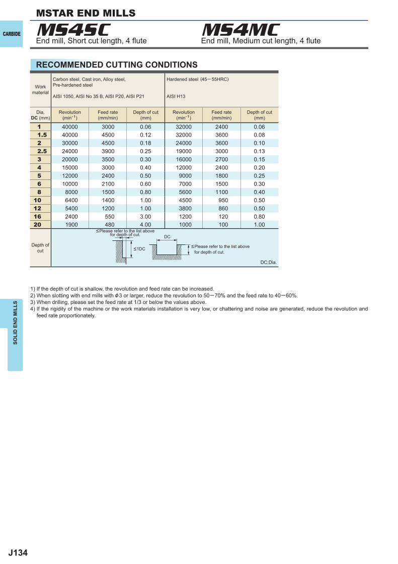
J134
MS4SC MS4MC
1 40000 3000 0.06 32000 2400 0.061.5 40000 4500 0.12 32000 3600 0.082 30000 4500 0.18 24000 3600 0.102.5 24000 3900 0.25 19000 3000 0.133 20000 3500 0.30 16000 2700 0.154 15000 3000 0.40 12000 2400 0.205 12000 2400 0.50 9000 1800 0.256 10000 2100 0.60 7000 1500 0.308 8000 1500 0.80 5600 1100 0.40
10 6400 1400 1.00 4500 950 0.5012 5400 1200 1.00 3800 860 0.5016 2400 550 3.00 1200 120 0.8020 1900 480 4.00 1000 100 1.00
DC
CARBIDE
SOLI
D E
ND
MIL
LS
RECOMMENDED CUTTING CONDITIONS
End mill, Short cut length, 4 fl ute End mill, Medium cut length, 4 fl ute
1) If the depth of cut is shallow, the revolution and feed rate can be increased.2) When slotting with end mills with &3 or larger, reduce the revolution to 50─70% and the feed rate to 40─60%.3) When drilling, please set the feed rate at 1/3 or below the values above.4) If the rigidity of the machine or the work materials installation is very low, or chattering and noise are generated, reduce the revolution and
feed rate proportionately.
DC:Dia.
<Please refer to the list above for depth of cut.
<Please refer to the list above for depth of cut.
Workmaterial
Carbon steel, Cast iron, Alloy steel,Pre-hardened steel
AISI 1050, AISI No 35 B, AISI P20, AISI P21
Hardened steel (45─ 55HRC)
AISI H13
Dia.DC (mm)
Revolution(min-1)
Feed rate(mm/min)
Depth of cut(mm)
Revolution(min-1)
Feed rate(mm/min)
Depth of cut(mm)
Depth ofcut <1DC
MSTAR END MILLS
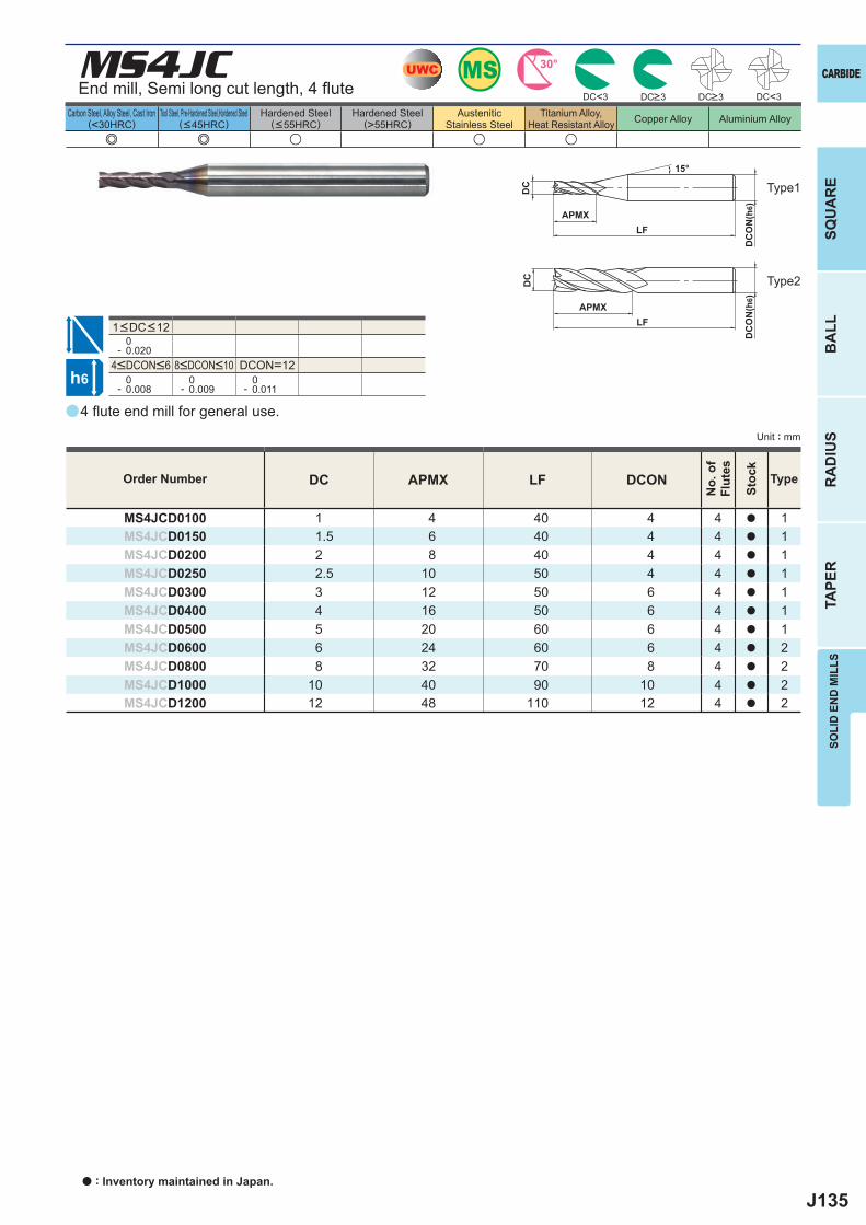
J135
a
e e u u u
MS4JC
DC APMX LF DCON
MS4JCD0100 1 4 40 4 4 a 1MS4JCD0150 1.5 6 40 4 4 a 1MS4JCD0200 2 8 40 4 4 a 1MS4JCD0250 2.5 10 50 4 4 a 1MS4JCD0300 3 12 50 6 4 a 1MS4JCD0400 4 16 50 6 4 a 1MS4JCD0500 5 20 60 6 4 a 1MS4JCD0600 6 24 60 6 4 a 2MS4JCD0800 8 32 70 8 4 a 2MS4JCD1000 10 40 90 10 4 a 2MS4JCD1200 12 48 110 12 4 a 2
DC<3 DC<3
0- 0.020
DCON=12 0- 0.008
0- 0.009
0- 0.011
UWC MS 30°
h6
APMX
DC
DC
ON
(h6)
15°
APMXLF
DC
DC
ON
(h6)
LF
SOLI
D E
ND
MIL
LSSQ
UA
RE
BA
LLR
AD
IUS
TAPE
R
CARBIDE
Carbon Steel, Alloy Steel, Cast Iron(<30HRC)
Tool Steel, Pre-Hardened Steel,Hardened Steel(<45HRC)
Hardened Steel(<55HRC)
Hardened Steel(>55HRC)
AusteniticStainless Steel
Titanium Alloy,Heat Resistant Alloy Copper Alloy Aluminium Alloy
Unit : mm
DC>3 DC>3
Type1
Type2
4<DCON<6 8<DCON<10
1<DC<12
4 fl ute end mill for general use.
Order Number
No.
of
Flut
es
Stoc
k
Type
End mill, Semi long cut length, 4 fl ute
a : Inventory maintained in Japan.

J136
1 11100 85 9500 65 8000 50 6400 351.5 7400 85 6400 90 5300 50 4200 352 5600 85 4800 90 4000 50 3200 352.5 4500 85 3800 90 3200 55 2500 353 3700 90 3400 90 2600 60 2100 354 3000 110 2700 90 2100 70 1700 505 2600 140 2300 110 1800 85 1500 556 2300 170 2000 140 1500 110 1300 708 1700 180 1500 140 1200 110 1000 70
10 1400 180 1300 140 950 110 800 7012 1200 170 1100 140 800 110 670 70
DC DC
MS4JCCARBIDE
SOLI
D E
ND
MIL
LS
RECOMMENDED CUTTING CONDITIONS
1) When cutting austenitic stainless steels, the use of water-soluble cutting fl uid is effective.2) If the depth of cut is shallow, the revolution and feed rate can be increased.3) When drilling, please set the feed rate at 1/3 or below the values above.4) If the rigidity of the machine or the work materials installation is very low, or chattering and noise are generated, reduce the revolution and
feed rate proportionately.
DC:Dia.
Workmaterial
Carbon steel, Cast iron, Alloy steel (─30HRC)
AISI 1050, AISI No 35 B, AISI P20
Alloy steel, Tool steel,Pre-hardened steel
AISI H13, AISI W1-10, AISI P21
Austenitic stainless steel,Titanium alloy
AISI 304, AISI 306, Ti-6Al-4V
Hardened steel (45─ 55HRC)
AISI H13
Dia.DC (mm)
Revolution(min-1)
Feed rate(mm/min)
Revolution(min-1)
Feed rate(mm/min)
Revolution(min-1)
Feed rate(mm/min)
Revolution(min-1)
Feed rate(mm/min)
<2.5DC
<0.05DC (MAX. 0.5mm)
<0.1DC (DC< &2)<0.2DC (DC >&2)
<2DC
<0.02DC
<0.05DC
Depth ofcut
End mill, Semi long cut length, 4 fl ute
MSTAR END MILLS
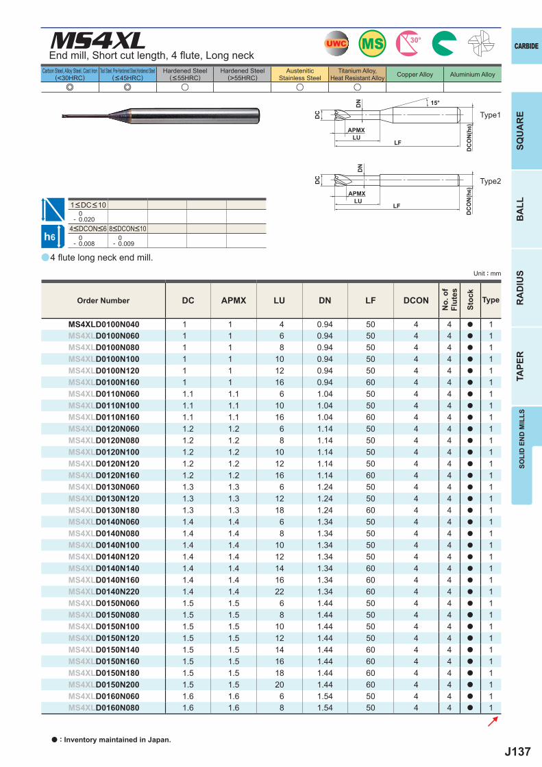
J137
a
e e u u u
MS4XL
DC APMX LU DN LF DCON
MS4XLD0100N040 1 1 4 0.94 50 4 4 a 1MS4XLD0100N060 1 1 6 0.94 50 4 4 a 1MS4XLD0100N080 1 1 8 0.94 50 4 4 a 1MS4XLD0100N100 1 1 10 0.94 50 4 4 a 1MS4XLD0100N120 1 1 12 0.94 50 4 4 a 1MS4XLD0100N160 1 1 16 0.94 60 4 4 a 1MS4XLD0110N060 1.1 1.1 6 1.04 50 4 4 a 1MS4XLD0110N100 1.1 1.1 10 1.04 50 4 4 a 1MS4XLD0110N160 1.1 1.1 16 1.04 60 4 4 a 1MS4XLD0120N060 1.2 1.2 6 1.14 50 4 4 a 1MS4XLD0120N080 1.2 1.2 8 1.14 50 4 4 a 1MS4XLD0120N100 1.2 1.2 10 1.14 50 4 4 a 1MS4XLD0120N120 1.2 1.2 12 1.14 50 4 4 a 1MS4XLD0120N160 1.2 1.2 16 1.14 60 4 4 a 1MS4XLD0130N060 1.3 1.3 6 1.24 50 4 4 a 1MS4XLD0130N120 1.3 1.3 12 1.24 50 4 4 a 1MS4XLD0130N180 1.3 1.3 18 1.24 60 4 4 a 1MS4XLD0140N060 1.4 1.4 6 1.34 50 4 4 a 1MS4XLD0140N080 1.4 1.4 8 1.34 50 4 4 a 1MS4XLD0140N100 1.4 1.4 10 1.34 50 4 4 a 1MS4XLD0140N120 1.4 1.4 12 1.34 50 4 4 a 1MS4XLD0140N140 1.4 1.4 14 1.34 60 4 4 a 1MS4XLD0140N160 1.4 1.4 16 1.34 60 4 4 a 1MS4XLD0140N220 1.4 1.4 22 1.34 60 4 4 a 1MS4XLD0150N060 1.5 1.5 6 1.44 50 4 4 a 1MS4XLD0150N080 1.5 1.5 8 1.44 50 4 4 a 1MS4XLD0150N100 1.5 1.5 10 1.44 50 4 4 a 1MS4XLD0150N120 1.5 1.5 12 1.44 50 4 4 a 1MS4XLD0150N140 1.5 1.5 14 1.44 60 4 4 a 1MS4XLD0150N160 1.5 1.5 16 1.44 60 4 4 a 1MS4XLD0150N180 1.5 1.5 18 1.44 60 4 4 a 1MS4XLD0150N200 1.5 1.5 20 1.44 60 4 4 a 1MS4XLD0160N060 1.6 1.6 6 1.54 50 4 4 a 1MS4XLD0160N080 1.6 1.6 8 1.54 50 4 4 a 1
0- 0.020
0- 0.008
0- 0.009
UWC MS 30°
h6
APMXLU
DC
DC
ON
(h6)
APMX
LF
DC
DC
ON
(h6)
LF
DN
LU
DN
15°
SOLI
D E
ND
MIL
LSSQ
UA
RE
BA
LLR
AD
IUS
TAPE
R
CARBIDE
Carbon Steel, Alloy Steel, Cast Iron(<30HRC)
Tool Steel, Pre-Hardened Steel,Hardened Steel(<45HRC)
Hardened Steel(<55HRC)
Hardened Steel(>55HRC)
AusteniticStainless Steel
Titanium Alloy,Heat Resistant Alloy Copper Alloy Aluminium Alloy
Unit : mm
End mill, Short cut length, 4 fl ute, Long neck
Type2
Type1
4<DCON<6 8<DCON<10
4 fl ute long neck end mill.
Order Number
No.
of
Flut
es
Stoc
k
Type
1<DC<10
a : Inventory maintained in Japan.
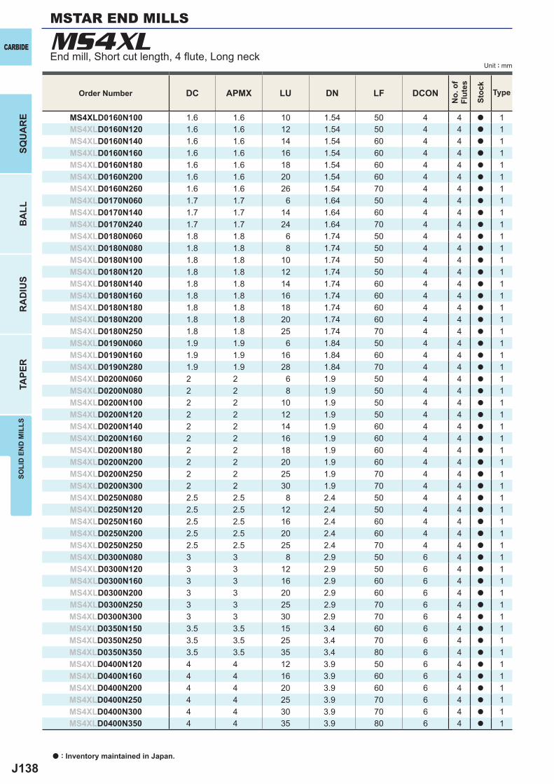
J138
DC APMX LU DN LF DCON
MS4XLD0160N100 1.6 1.6 10 1.54 50 4 4 a 1MS4XLD0160N120 1.6 1.6 12 1.54 50 4 4 a 1MS4XLD0160N140 1.6 1.6 14 1.54 60 4 4 a 1MS4XLD0160N160 1.6 1.6 16 1.54 60 4 4 a 1MS4XLD0160N180 1.6 1.6 18 1.54 60 4 4 a 1MS4XLD0160N200 1.6 1.6 20 1.54 60 4 4 a 1MS4XLD0160N260 1.6 1.6 26 1.54 70 4 4 a 1MS4XLD0170N060 1.7 1.7 6 1.64 50 4 4 a 1MS4XLD0170N140 1.7 1.7 14 1.64 60 4 4 a 1MS4XLD0170N240 1.7 1.7 24 1.64 70 4 4 a 1MS4XLD0180N060 1.8 1.8 6 1.74 50 4 4 a 1MS4XLD0180N080 1.8 1.8 8 1.74 50 4 4 a 1MS4XLD0180N100 1.8 1.8 10 1.74 50 4 4 a 1MS4XLD0180N120 1.8 1.8 12 1.74 50 4 4 a 1MS4XLD0180N140 1.8 1.8 14 1.74 60 4 4 a 1MS4XLD0180N160 1.8 1.8 16 1.74 60 4 4 a 1MS4XLD0180N180 1.8 1.8 18 1.74 60 4 4 a 1MS4XLD0180N200 1.8 1.8 20 1.74 60 4 4 a 1MS4XLD0180N250 1.8 1.8 25 1.74 70 4 4 a 1MS4XLD0190N060 1.9 1.9 6 1.84 50 4 4 a 1MS4XLD0190N160 1.9 1.9 16 1.84 60 4 4 a 1MS4XLD0190N280 1.9 1.9 28 1.84 70 4 4 a 1MS4XLD0200N060 2 2 6 1.9 50 4 4 a 1MS4XLD0200N080 2 2 8 1.9 50 4 4 a 1MS4XLD0200N100 2 2 10 1.9 50 4 4 a 1MS4XLD0200N120 2 2 12 1.9 50 4 4 a 1MS4XLD0200N140 2 2 14 1.9 60 4 4 a 1MS4XLD0200N160 2 2 16 1.9 60 4 4 a 1MS4XLD0200N180 2 2 18 1.9 60 4 4 a 1MS4XLD0200N200 2 2 20 1.9 60 4 4 a 1MS4XLD0200N250 2 2 25 1.9 70 4 4 a 1MS4XLD0200N300 2 2 30 1.9 70 4 4 a 1MS4XLD0250N080 2.5 2.5 8 2.4 50 4 4 a 1MS4XLD0250N120 2.5 2.5 12 2.4 50 4 4 a 1MS4XLD0250N160 2.5 2.5 16 2.4 60 4 4 a 1MS4XLD0250N200 2.5 2.5 20 2.4 60 4 4 a 1MS4XLD0250N250 2.5 2.5 25 2.4 70 4 4 a 1MS4XLD0300N080 3 3 8 2.9 50 6 4 a 1MS4XLD0300N120 3 3 12 2.9 50 6 4 a 1MS4XLD0300N160 3 3 16 2.9 60 6 4 a 1MS4XLD0300N200 3 3 20 2.9 60 6 4 a 1MS4XLD0300N250 3 3 25 2.9 70 6 4 a 1MS4XLD0300N300 3 3 30 2.9 70 6 4 a 1MS4XLD0350N150 3.5 3.5 15 3.4 60 6 4 a 1MS4XLD0350N250 3.5 3.5 25 3.4 70 6 4 a 1MS4XLD0350N350 3.5 3.5 35 3.4 80 6 4 a 1MS4XLD0400N120 4 4 12 3.9 50 6 4 a 1MS4XLD0400N160 4 4 16 3.9 60 6 4 a 1MS4XLD0400N200 4 4 20 3.9 60 6 4 a 1MS4XLD0400N250 4 4 25 3.9 70 6 4 a 1MS4XLD0400N300 4 4 30 3.9 70 6 4 a 1MS4XLD0400N350 4 4 35 3.9 80 6 4 a 1
MS4XLCARBIDE
SQU
AR
EB
ALL
RA
DIU
STA
PER
SOLI
D E
ND
MIL
LS
a : Inventory maintained in Japan.
Unit : mm
Order Number
No.
of
Flut
es
Stoc
k
Type
MSTAR END MILLS
End mill, Short cut length, 4 fl ute, Long neck
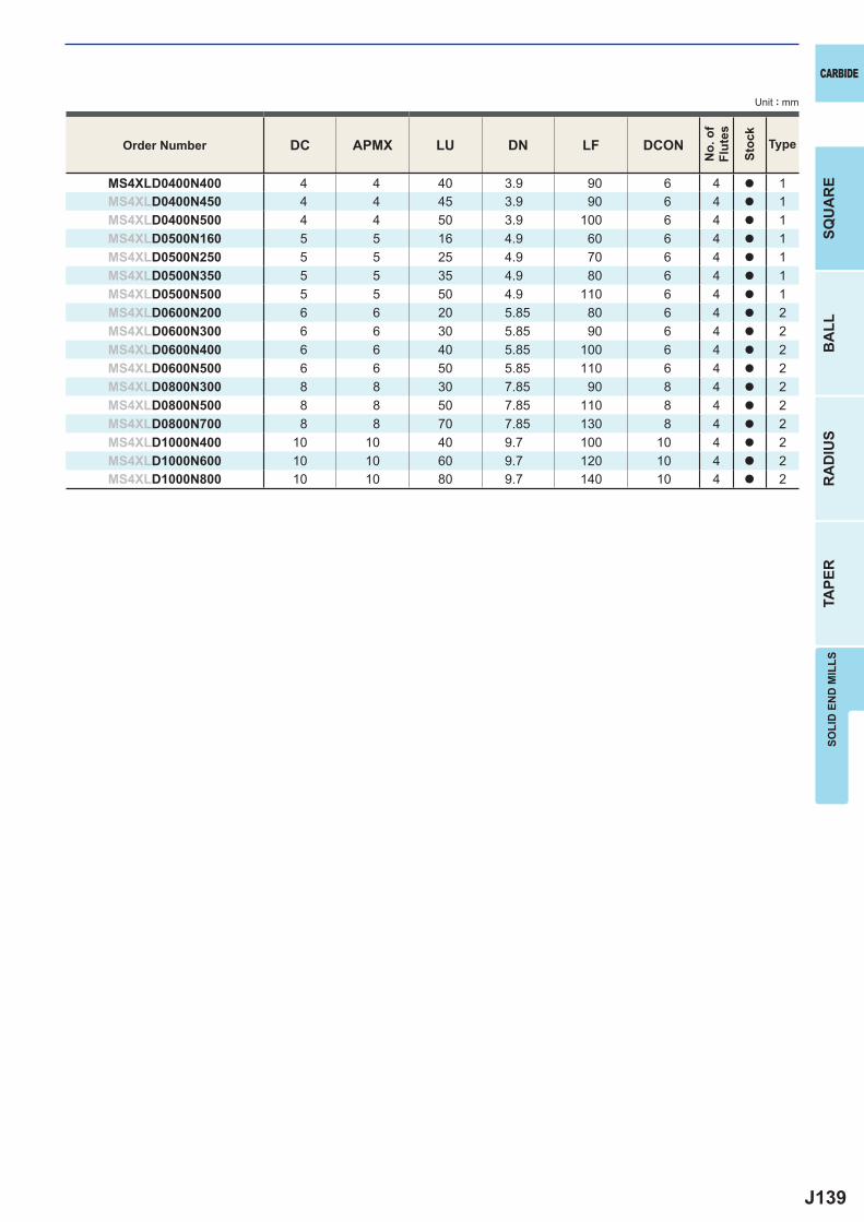
J139
DC APMX LU DN LF DCON
MS4XLD0400N400 4 4 40 3.9 90 6 4 a 1MS4XLD0400N450 4 4 45 3.9 90 6 4 a 1MS4XLD0400N500 4 4 50 3.9 100 6 4 a 1MS4XLD0500N160 5 5 16 4.9 60 6 4 a 1MS4XLD0500N250 5 5 25 4.9 70 6 4 a 1MS4XLD0500N350 5 5 35 4.9 80 6 4 a 1MS4XLD0500N500 5 5 50 4.9 110 6 4 a 1MS4XLD0600N200 6 6 20 5.85 80 6 4 a 2MS4XLD0600N300 6 6 30 5.85 90 6 4 a 2MS4XLD0600N400 6 6 40 5.85 100 6 4 a 2MS4XLD0600N500 6 6 50 5.85 110 6 4 a 2MS4XLD0800N300 8 8 30 7.85 90 8 4 a 2MS4XLD0800N500 8 8 50 7.85 110 8 4 a 2MS4XLD0800N700 8 8 70 7.85 130 8 4 a 2MS4XLD1000N400 10 10 40 9.7 100 10 4 a 2MS4XLD1000N600 10 10 60 9.7 120 10 4 a 2MS4XLD1000N800 10 10 80 9.7 140 10 4 a 2
SOLI
D E
ND
MIL
LSSQ
UA
RE
BA
LLR
AD
IUS
TAPE
R
CARBIDE
Unit : mm
Order Number
No.
of
Flut
es
Stoc
k
Type
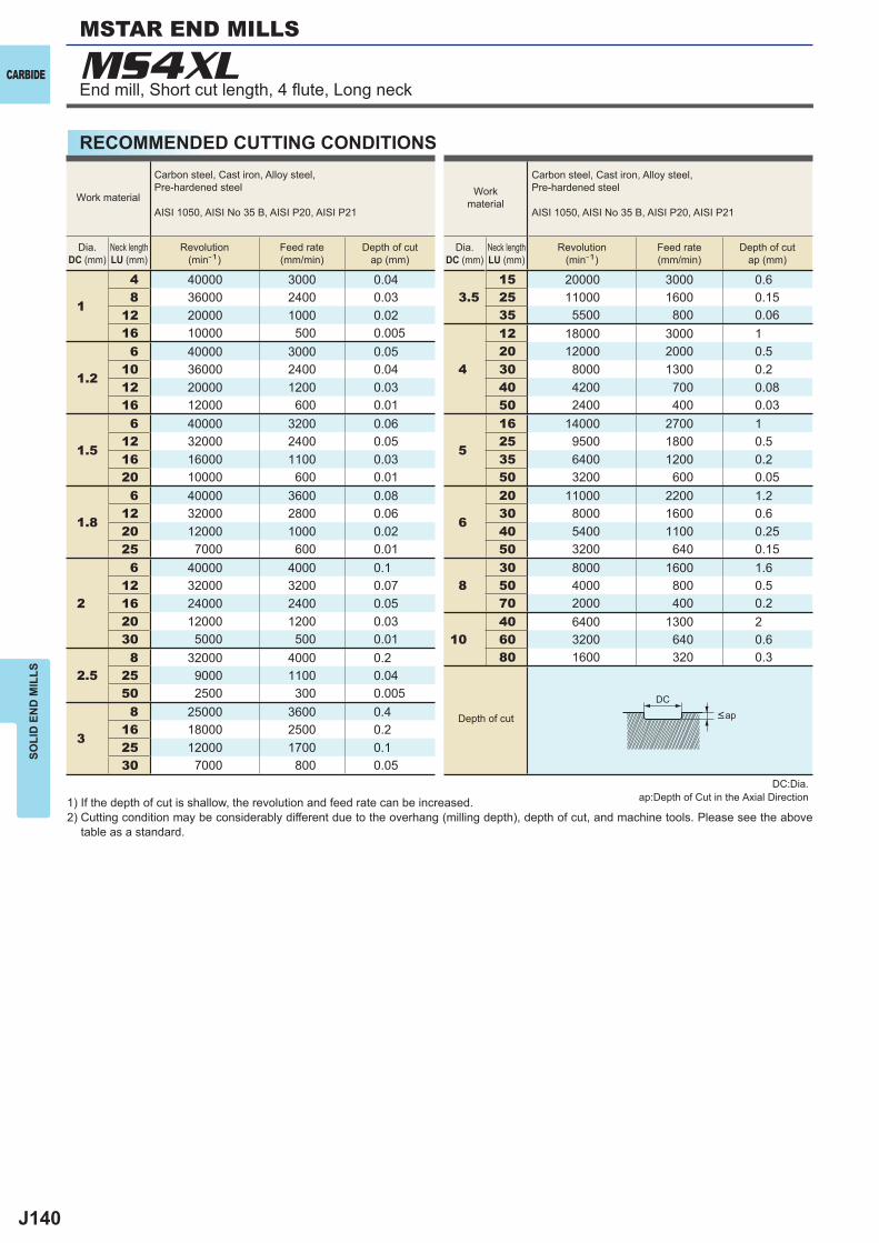
J140
1
4 40000 3000 0.048 36000 2400 0.03
12 20000 1000 0.0216 10000 500 0.005
1.2
6 40000 3000 0.0510 36000 2400 0.0412 20000 1200 0.0316 12000 600 0.01
1.5
6 40000 3200 0.0612 32000 2400 0.0516 16000 1100 0.0320 10000 600 0.01
1.8
6 40000 3600 0.0812 32000 2800 0.0620 12000 1000 0.0225 7000 600 0.01
2
6 40000 4000 0.112 32000 3200 0.0716 24000 2400 0.0520 12000 1200 0.0330 5000 500 0.01
2.58 32000 4000 0.2
25 9000 1100 0.0450 2500 300 0.005
3
8 25000 3600 0.416 18000 2500 0.225 12000 1700 0.130 7000 800 0.05
3.515 20000 3000 0.625 11000 1600 0.1535 5500 800 0.06
4
12 18000 3000 120 12000 2000 0.530 8000 1300 0.240 4200 700 0.0850 2400 400 0.03
5
16 14000 2700 125 9500 1800 0.535 6400 1200 0.250 3200 600 0.05
6
20 11000 2200 1.230 8000 1600 0.640 5400 1100 0.2550 3200 640 0.15
830 8000 1600 1.650 4000 800 0.570 2000 400 0.2
1040 6400 1300 260 3200 640 0.680 1600 320 0.3
MS4XL
DC
CARBIDE
SOLI
D E
ND
MIL
LS
RECOMMENDED CUTTING CONDITIONS
1) If the depth of cut is shallow, the revolution and feed rate can be increased.2) Cutting condition may be considerably different due to the overhang (milling depth), depth of cut, and machine tools. Please see the above
table as a standard.
Workmaterial
Carbon steel, Cast iron, Alloy steel,Pre-hardened steel
AISI 1050, AISI No 35 B, AISI P20, AISI P21
Dia.DC (mm)
Neck lengthLU (mm)
Revolution(min-1)
Feed rate(mm/min)
Depth of cutap (mm)
Work material
Carbon steel, Cast iron, Alloy steel,Pre-hardened steel
AISI 1050, AISI No 35 B, AISI P20, AISI P21
Dia.DC (mm)
Neck lengthLU (mm)
Revolution(min-1)
Feed rate(mm/min)
Depth of cutap (mm)
MSTAR END MILLS
End mill, Short cut length, 4 fl ute, Long neck
DC:Dia.ap:Depth of Cut in the Axial Direction
Depth of cut <ap
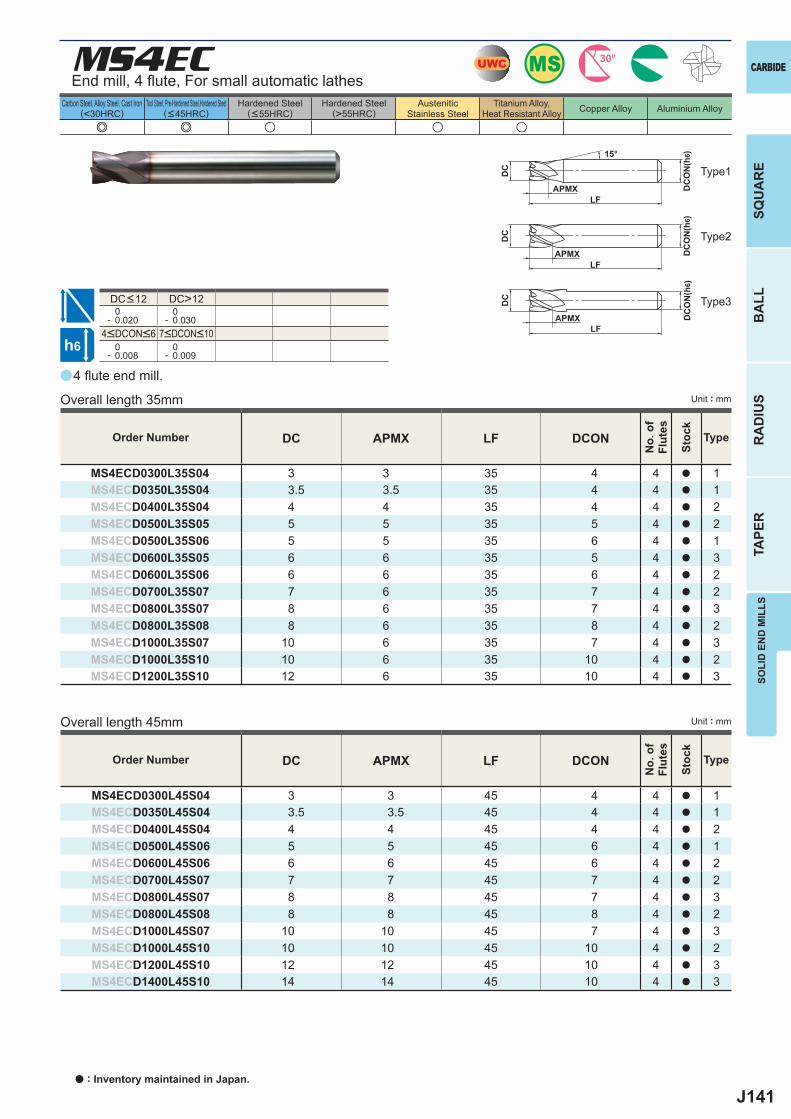
J141
a
e e u u u
MS4EC
DC APMX LF DCON
MS4ECD0300L45S04 3 3 45 4 4 a 1MS4ECD0350L45S04 3.5 3.5 45 4 4 a 1MS4ECD0400L45S04 4 4 45 4 4 a 2MS4ECD0500L45S06 5 5 45 6 4 a 1MS4ECD0600L45S06 6 6 45 6 4 a 2MS4ECD0700L45S07 7 7 45 7 4 a 2MS4ECD0800L45S07 8 8 45 7 4 a 3MS4ECD0800L45S08 8 8 45 8 4 a 2MS4ECD1000L45S07 10 10 45 7 4 a 3MS4ECD1000L45S10 10 10 45 10 4 a 2MS4ECD1200L45S10 12 12 45 10 4 a 3MS4ECD1400L45S10 14 14 45 10 4 a 3
DC APMX LF DCON
MS4ECD0300L35S04 3 3 35 4 4 a 1MS4ECD0350L35S04 3.5 3.5 35 4 4 a 1MS4ECD0400L35S04 4 4 35 4 4 a 2MS4ECD0500L35S05 5 5 35 5 4 a 2MS4ECD0500L35S06 5 5 35 6 4 a 1MS4ECD0600L35S05 6 6 35 5 4 a 3MS4ECD0600L35S06 6 6 35 6 4 a 2MS4ECD0700L35S07 7 6 35 7 4 a 2MS4ECD0800L35S07 8 6 35 7 4 a 3MS4ECD0800L35S08 8 6 35 8 4 a 2MS4ECD1000L35S07 10 6 35 7 4 a 3MS4ECD1000L35S10 10 6 35 10 4 a 2MS4ECD1200L35S10 12 6 35 10 4 a 3
DC>12 0- 0.020
0- 0.030
0- 0.008
0- 0.009
UWC MS 30°
h6
APMX
DC
DC
ON
(h6)15°
APMXLF
DC
DC
ON
(h6)
LF
APMXLF
DC
DC
ON
(h6)
SOLI
D E
ND
MIL
LSSQ
UA
RE
BA
LLR
AD
IUS
TAPE
R
CARBIDE
Carbon Steel, Alloy Steel, Cast Iron(<30HRC)
Tool Steel, Pre-Hardened Steel,Hardened Steel(<45HRC)
Hardened Steel(<55HRC)
Hardened Steel(>55HRC)
AusteniticStainless Steel
Titanium Alloy,Heat Resistant Alloy Copper Alloy Aluminium Alloy
Unit : mm
End mill, 4 fl ute, For small automatic lathes
Type1
Type2
Type3
4 fl ute end mill.
Overall length 35mm
4<DCON<6 7<DCON<10
DC<12
Order Number
No.
of
Flut
es
Stoc
k
Type
Order Number
No.
of
Flut
es
Stoc
k
Type
Overall length 45mm Unit : mm
a : Inventory maintained in Japan.
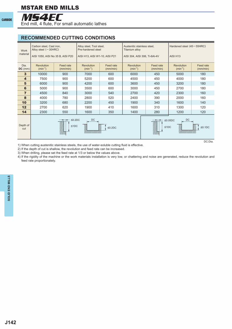
J142
3 10000 900 7000 600 6000 450 5000 1804 7500 900 5200 600 4500 450 4000 1805 6000 900 4200 600 3600 450 3200 1806 5000 900 3500 600 3000 450 2700 1807 4500 840 3000 540 2700 420 2300 1608 4000 780 2800 520 2400 390 2000 160
10 3200 680 2200 450 1900 340 1600 14012 2700 620 1900 410 1600 310 1300 12014 2300 550 1600 350 1400 280 1200 120
DC DC
MS4ECCARBIDE
SOLI
D E
ND
MIL
LS
RECOMMENDED CUTTING CONDITIONS
1) When cutting austenitic stainless steels, the use of water-soluble cutting fl uid is effective.2) If the depth of cut is shallow, the revolution and feed rate can be increased.3) When drilling, please set the feed rate at 1/3 or below the values above.4) If the rigidity of the machine or the work materials installation is very low, or chattering and noise are generated, reduce the revolution and
feed rate proportionately.
DC:Dia.
Workmaterial
Carbon steel, Cast iron, Alloy steel (─30HRC)
AISI 1050, AISI No 35 B, AISI P20
Alloy steel, Tool steel,Pre-hardened steel
AISI H13, AISI W1-10, AISI P21
Austenitic stainless steel,Titanium alloy
AISI 304, AISI 306, Ti-6Al-4V
Hardened steel (45─ 55HRC)
AISI H13
Dia.DC (mm)
Revolution(min-1)
Feed rate(mm/min)
Revolution(min-1)
Feed rate(mm/min)
Revolution(min-1)
Feed rate(mm/min)
Revolution(min-1)
Feed rate(mm/min)
Depth ofcut
<0.2DC <0.05DC
<1DC <1DC<0.2DC <0.1DC
End mill, 4 fl ute, For small automatic lathes
MSTAR END MILLS
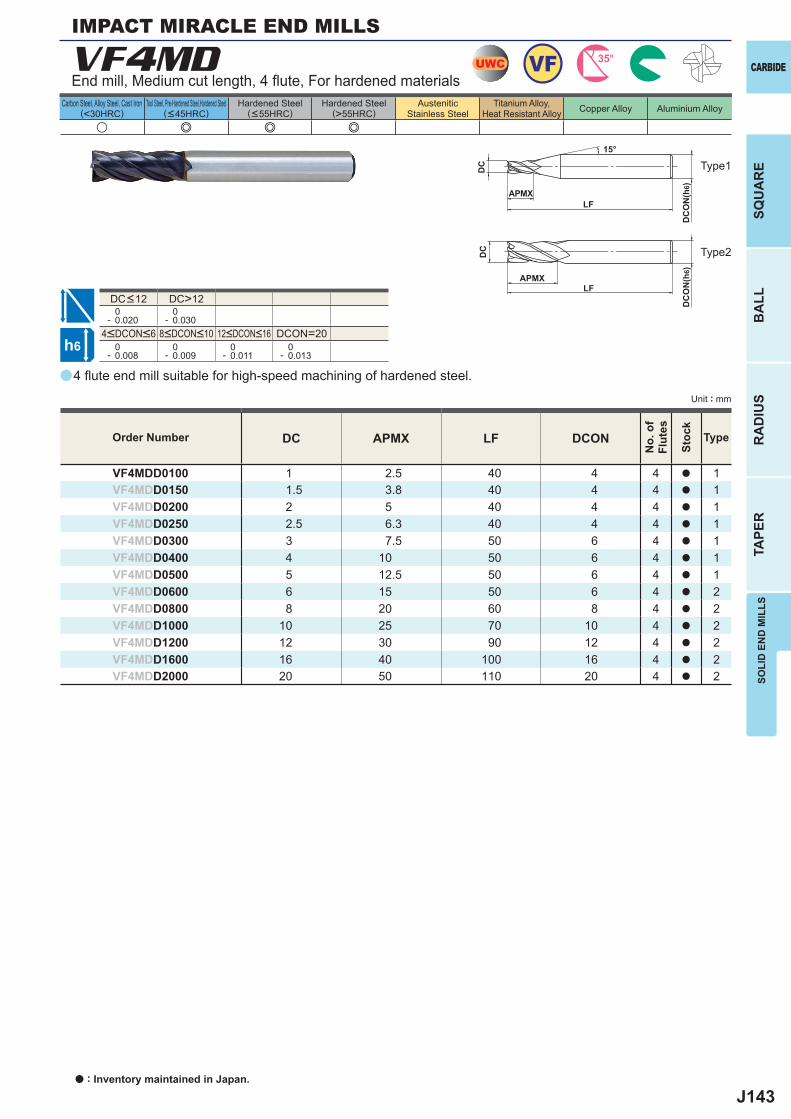
J143
a
VF4MD
u e e e
DC APMX LF DCON
VF4MDD0100 1 2.5 40 4 4 a 1VF4MDD0150 1.5 3.8 40 4 4 a 1VF4MDD0200 2 5 40 4 4 a 1VF4MDD0250 2.5 6.3 40 4 4 a 1VF4MDD0300 3 7.5 50 6 4 a 1VF4MDD0400 4 10 50 6 4 a 1VF4MDD0500 5 12.5 50 6 4 a 1VF4MDD0600 6 15 50 6 4 a 2VF4MDD0800 8 20 60 8 4 a 2VF4MDD1000 10 25 70 10 4 a 2VF4MDD1200 12 30 90 12 4 a 2VF4MDD1600 16 40 100 16 4 a 2VF4MDD2000 20 50 110 20 4 a 2
DC>12 0- 0.020
0- 0.030
DCON=20 0- 0.008
0- 0.009
0- 0.011
0- 0.013
UWC 35°VF
h6
APMX
DC
DC
ON
(h6)
15°
APMXLF
DC
DC
ON
(h6)
LF
SOLI
D E
ND
MIL
LSSQ
UA
RE
BA
LLR
AD
IUS
TAPE
R
CARBIDE
Carbon Steel, Alloy Steel, Cast Iron(<30HRC)
Tool Steel, Pre-Hardened Steel,Hardened Steel(<45HRC)
Hardened Steel(<55HRC)
Hardened Steel(>55HRC)
AusteniticStainless Steel
Titanium Alloy,Heat Resistant Alloy Copper Alloy Aluminium Alloy
Unit : mm
Type1
Type2
Order Number
No.
of
Flut
es
Stoc
k
Type
IMPACT MIRACLE END MILLS
End mill, Medium cut length, 4 fl ute, For hardened materials
4<DCON<6 8<DCON<10 12<DCON<16
DC<12
4 fl ute end mill suitable for high-speed machining of hardened steel.
a : Inventory maintained in Japan.
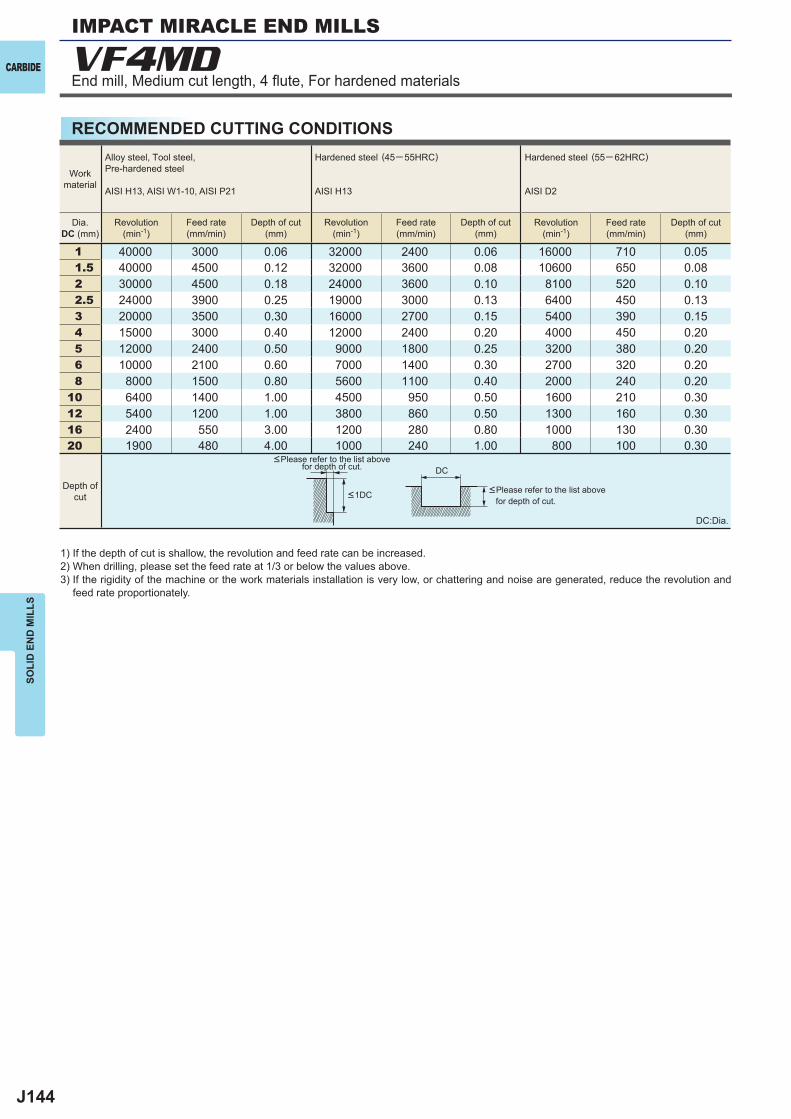
J144
1 40000 3000 0.06 32000 2400 0.06 16000 710 0.051.5 40000 4500 0.12 32000 3600 0.08 10600 650 0.082 30000 4500 0.18 24000 3600 0.10 8100 520 0.102.5 24000 3900 0.25 19000 3000 0.13 6400 450 0.133 20000 3500 0.30 16000 2700 0.15 5400 390 0.154 15000 3000 0.40 12000 2400 0.20 4000 450 0.205 12000 2400 0.50 9000 1800 0.25 3200 380 0.206 10000 2100 0.60 7000 1400 0.30 2700 320 0.208 8000 1500 0.80 5600 1100 0.40 2000 240 0.20
10 6400 1400 1.00 4500 950 0.50 1600 210 0.3012 5400 1200 1.00 3800 860 0.50 1300 160 0.3016 2400 550 3.00 1200 280 0.80 1000 130 0.3020 1900 480 4.00 1000 240 1.00 800 100 0.30
VF4MD
DC
CARBIDE
SOLI
D E
ND
MIL
LS
RECOMMENDED CUTTING CONDITIONS
DC:Dia.
1) If the depth of cut is shallow, the revolution and feed rate can be increased.2) When drilling, please set the feed rate at 1/3 or below the values above.3) If the rigidity of the machine or the work materials installation is very low, or chattering and noise are generated, reduce the revolution and
feed rate proportionately.
<Please refer to the list above for depth of cut.
<Please refer to the list above for depth of cut.
Workmaterial
Dia.DC (mm)
Depth ofcut <1DC
Alloy steel, Tool steel,Pre-hardened steel
AISI H13, AISI W1-10, AISI P21
Hardened steel (45─ 55HRC)
AISI H13
Hardened steel (55─ 62HRC)
AISI D2
Revolution(min-1)
Revolution(min-1)
Revolution(min-1)
Feed rate(mm/min)
Feed rate(mm/min)
Feed rate(mm/min)
Depth of cut(mm)
Depth of cut(mm)
Depth of cut(mm)
IMPACT MIRACLE END MILLS
End mill, Medium cut length, 4 fl ute, For hardened materials
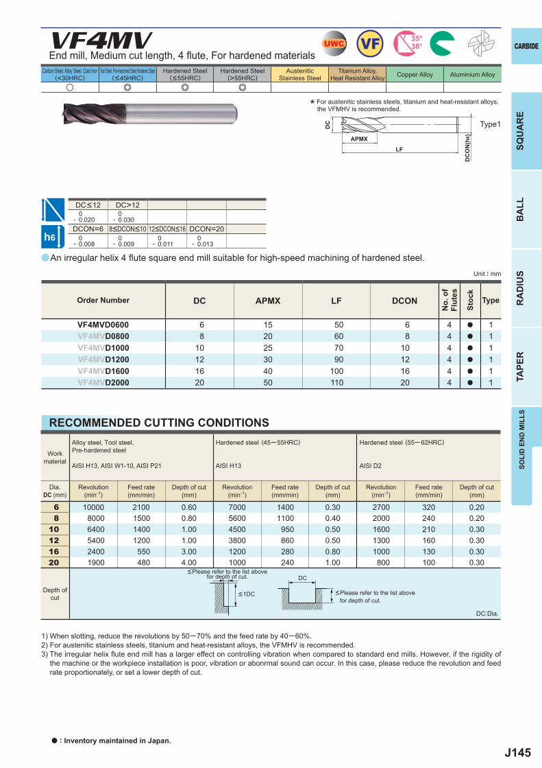
J145
a
VF4MV
u e e e
DC APMX LF DCON
VF4MVD0600 6 15 50 6 4 a 1VF4MVD0800 8 20 60 8 4 a 1VF4MVD1000 10 25 70 10 4 a 1VF4MVD1200 12 30 90 12 4 a 1VF4MVD1600 16 40 100 16 4 a 1VF4MVD2000 20 50 110 20 4 a 1
DC>12 0- 0.020
0- 0.030
DCON=6 DCON=20 0- 0.008
0- 0.009
0- 0.011
0- 0.013
6 10000 2100 0.60 7000 1400 0.30 2700 320 0.20 8 8000 1500 0.80 5600 1100 0.40 2000 240 0.20 10 6400 1400 1.00 4500 950 0.50 1600 210 0.30 12 5400 1200 1.00 3800 860 0.50 1300 160 0.30 16 2400 550 3.00 1200 280 0.80 1000 130 0.30 20 1900 480 4.00 1000 240 1.00 800 100 0.30
UWC VF 35°38°
h6
APMX
LF
DC
DC
ON
(h6)
DC
SOLI
D E
ND
MIL
LSSQ
UA
RE
BA
LLR
AD
IUS
TAPE
R
CARBIDE
Carbon Steel, Alloy Steel, Cast Iron(<30HRC)
Tool Steel, Pre-Hardened Steel,Hardened Steel(<45HRC)
Hardened Steel(<55HRC)
Hardened Steel(>55HRC)
AusteniticStainless Steel
Titanium Alloy,Heat Resistant Alloy Copper Alloy Aluminium Alloy
Unit : mm
End mill, Medium cut length, 4 fl ute, For hardened materials
* For austenitic stainless steels, titanium and heat-resistant alloys, the VFMHV is recommended.
Type1
8<DCON<10 12<DCON<16
DC<12
An irregular helix 4 fl ute square end mill suitable for high-speed machining of hardened steel.
Order Number
No.
of
Flut
es
Stoc
k
Type
RECOMMENDED CUTTING CONDITIONS
DC:Dia.
1) When slotting, reduce the revolutions by 50─70% and the feed rate by 40─60%.2) For austenitic stainless steels, titanium and heat-resistant alloys, the VFMHV is recommended. 3) The irregular helix fl ute end mill has a larger effect on controlling vibration when compared to standard end mills. However, if the rigidity of
the machine or the workpiece installation is poor, vibration or abonrmal sound can occur. In this case, please reduce the revolution and feed rate proportionately, or set a lower depth of cut.
<Please refer to the list above for depth of cut.
<Please refer to the list above for depth of cut.
Workmaterial
Dia.DC (mm)
Depth ofcut <1DC
Alloy steel, Tool steel,Pre-hardened steel
AISI H13, AISI W1-10, AISI P21
Hardened steel (45─ 55HRC)
AISI H13
Hardened steel (55─ 62HRC)
AISI D2
Revolution(min-1)
Revolution(min-1)
Revolution(min-1)
Feed rate(mm/min)
Feed rate(mm/min)
Feed rate(mm/min)
Depth of cut(mm)
Depth of cut(mm)
Depth of cut(mm)
a : Inventory maintained in Japan.
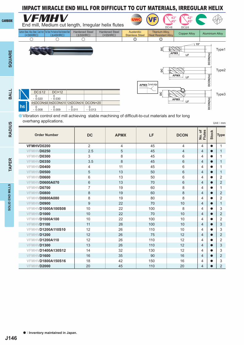
J146
a
VFMHV
u u u e e
DC APMX LF DCON
VFMHVD0200 2 4 45 4 4 a 1VFMHVD0250 2.5 5 45 4 4 a 1VFMHVD0300 3 8 45 6 4 a 1VFMHVD0350 3.5 8 45 6 4 a 1VFMHVD0400 4 11 45 6 4 a 1VFMHVD0500 5 13 50 6 4 a 1VFMHVD0600 6 13 50 6 4 a 2VFMHVD0600A070 6 13 70 6 4 a 2VFMHVD0700 7 19 60 8 4 a 1VFMHVD0800 8 19 60 8 4 a 2VFMHVD0800A080 8 19 80 8 4 a 2VFMHVD0900 9 22 70 10 4 a 1VFMHVD1000A100S08 10 22 100 8 4 a 3VFMHVD1000 10 22 70 10 4 a 2VFMHVD1000A100 10 22 100 10 4 a 2VFMHVD1100 11 26 100 10 4 a 3VFMHVD1200A110S10 12 26 110 10 4 a 3VFMHVD1200 12 26 75 12 4 a 2VFMHVD1200A110 12 26 110 12 4 a 2VFMHVD1300 13 26 110 12 4 a 3VFMHVD1400A130S12 14 32 130 12 4 a 3VFMHVD1600 16 35 90 16 4 a 2VFMHVD1800A150S16 18 42 150 16 4 a 3VFMHVD2000 20 45 110 20 4 a 2
DC>12 0- 0.020
0- 0.030
DCON=20 0- 0.008
0- 0.009
0- 0.011
0- 0.013
DC<6
UWC VF 43°45°
42°45°
h6
APMX
DC
DC
ON
(h6)
15°
APMXLF
DC
DC
ON
(h6)
LF
APMXLF
DC
DC
ON
(h6)
APMX
CARBIDE
SQU
AR
EB
ALL
RA
DIU
STA
PER
SOLI
D E
ND
MIL
LS
a : Inventory maintained in Japan.
Carbon Steel, Alloy Steel, Cast Iron(<30HRC)
Tool Steel, Pre-Hardened Steel,Hardened Steel(<45HRC)
Hardened Steel(<55HRC)
Hardened Steel(>55HRC)
AusteniticStainless Steel
Titanium Alloy,Heat Resistant Alloy Copper Alloy Aluminium Alloy
Unit : mm
Type1
Type2
Type3
Order Number
No.
of
Flut
es
Stoc
k
Type
End mill, Medium cut length, Irregular helix fl utes
Curved edge
DC<12
4<DCON<6 8<DCON<10 12<DCON<16
Vibration control end mill achieving stable machining of diffi cult-to-cut materials and for long overhang applications.
DC>6
IMPACT MIRACLE END MILL FOR DIFFICULT TO CUT MATERIALS, IRREGULAR HELIX
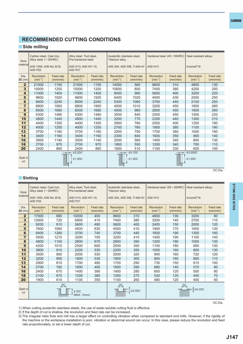
J147
2 21000 1100 21000 1100 14000 560 9600 310 4800 1303 15000 1250 15000 1250 10600 850 7400 380 4200 2004 11000 1400 11000 1400 8000 960 5600 400 3200 2205 9600 1920 9600 1920 6400 1020 4500 430 2500 2506 8000 2240 8000 2240 5300 1060 3700 440 2100 2507 6800 1900 6800 1900 4500 1010 3200 450 1800 2608 6000 1680 6000 1680 4000 960 2800 450 1600 2609 5300 1480 5300 1480 3500 840 2500 450 1400 220
10 4800 1440 4800 1440 3200 770 2200 440 1300 21011 4400 1350 4400 1350 2900 760 2000 400 1200 19012 4000 1250 4000 1250 2700 760 1900 380 1100 18013 3700 1180 3700 1180 2500 700 1700 360 1000 16014 3400 1160 3400 1160 2300 640 1600 350 900 14016 3000 1140 3000 1140 2000 560 1400 340 800 13018 2700 970 2700 970 1800 550 1200 340 700 11020 2400 860 2400 860 1600 510 1100 330 600 100
2 17000 680 10000 400 9600 310 4800 130 3200 803 12000 720 6900 410 7400 380 3200 140 2700 1104 9200 810 5600 490 5600 400 2400 150 2000 1205 7600 1060 4500 630 4500 410 1900 170 1600 1306 6400 1280 3700 740 3700 440 1600 190 1300 1607 5500 1210 3200 700 3200 410 1400 190 1100 1408 4800 1150 2800 670 2800 390 1200 190 1000 1309 4200 1010 2500 600 2500 350 1100 180 900 130
10 3800 910 2200 530 2200 350 1000 160 800 13011 3500 900 2000 530 2000 320 900 160 720 12012 3200 900 1900 530 1900 300 800 160 660 11013 2900 810 1700 480 1700 290 730 150 610 10014 2700 760 1600 450 1600 290 680 140 570 9016 2400 670 1400 390 1400 280 600 120 500 8018 2100 670 1200 380 1200 270 530 120 440 7020 1900 610 1100 350 1100 260 480 120 400 60
y
y
DC DC DC
CARBIDE
SOLI
D E
ND
MIL
LS
RECOMMENDED CUTTING CONDITIONS
1) When cutting austenitic stainless steels, the use of water-soluble cutting fl uid is effective.2) If the depth of cut is shallow, the revolution and feed rate can be increased.3) The irregular helix fl ute end mill has a larger effect on controlling vibration when compared to standard end mills. However, if the rigidity of
the machine or the workpiece installation is poor, vibration or abonrmal sound can occur. In this case, please reduce the revolution and feed rate proportionately, or set a lower depth of cut.
DC:Dia.
DC:Dia.
Slotting
Side milling
Workmaterial
Workmaterial
Dia.DC (mm)
Dia.DC (mm)
Depth ofcut
Depth ofcut
<0.2DC <0.1DC <0.05DC
<1.5DC <1.5DC <1.5DC
Carbon steel, Cast iron, Alloy steel (─30HRC)
AISI 1050, AISI No 35 B,AISI P20
Alloy steel, Tool steel,Pre-hardened steel
AISI H13, AISI W1-10, AISI P21
Austenitic stainless steel,Titanium alloy
AISI 304, AISI 306, Ti-6Al-4V
Hardened steel (45─ 55HRC)
AISI H13
Heat resistant alloys
Inconel718
Carbon steel, Cast iron, Alloy steel (─30HRC)
AISI 1050, AISI No 35 B,AISI P20
Alloy steel, Tool steel,Pre-hardened steel
AISI H13, AISI W1-10, AISI P21
Austenitic stainless steel,Titanium alloy
AISI 304, AISI 306, Ti-6Al-4V
Hardened steel (45─ 55HRC)
AISI H13
Heat resistant alloys
Inconel718
Revolution(min-1)
Revolution(min-1)
Revolution(min-1)
Revolution(min-1)
Revolution(min-1)
Revolution(min-1)
Revolution(min-1)
Revolution(min-1)
Revolution(min-1)
Revolution(min-1)
Feed rate(mm/min)
Feed rate(mm/min)
Feed rate(mm/min)
Feed rate(mm/min)
Feed rate(mm/min)
Feed rate(mm/min)
Feed rate(mm/min)
Feed rate(mm/min)
Feed rate(mm/min)
Feed rate(mm/min)
<1DC <0.5DC <0.2DC
(MAX. 12mm)
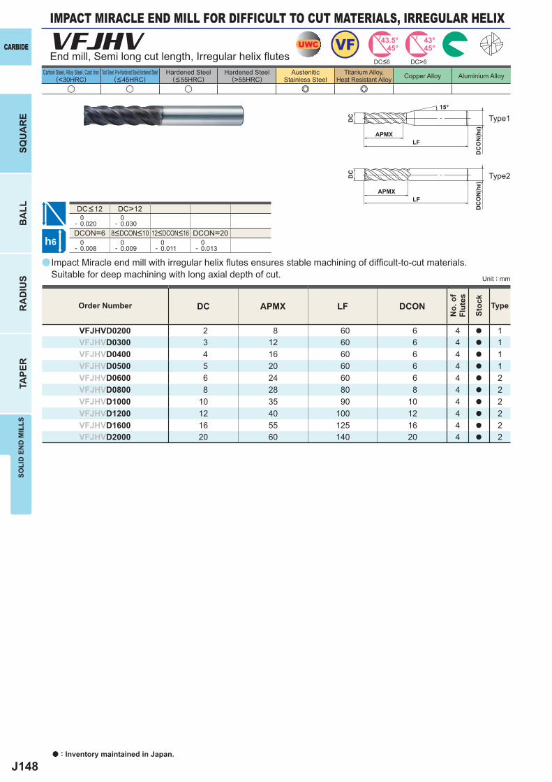
J148
a
VFJHV
u u u e e
DC APMX LF DCON
VFJHVD0200 2 8 60 6 4 a 1VFJHVD0300 3 12 60 6 4 a 1VFJHVD0400 4 16 60 6 4 a 1VFJHVD0500 5 20 60 6 4 a 1VFJHVD0600 6 24 60 6 4 a 2VFJHVD0800 8 28 80 8 4 a 2VFJHVD1000 10 35 90 10 4 a 2VFJHVD1200 12 40 100 12 4 a 2VFJHVD1600 16 55 125 16 4 a 2VFJHVD2000 20 60 140 20 4 a 2
DC>6
DC>12 0- 0.020
0- 0.030
DCON=6 DCON=20 0- 0.008
0- 0.009
0- 0.011
0- 0.013
UWC VF 43.5°45°
43°45°
h6
APMXLF
DC
DC
ON
(h6)
APMXLF
DC
DC
ON
(h6)
15°
CARBIDE
SQU
AR
EB
ALL
RA
DIU
STA
PER
SOLI
D E
ND
MIL
LS
a : Inventory maintained in Japan.
Carbon Steel, Alloy Steel, Cast Iron(<30HRC)
Tool Steel, Pre-Hardened Steel,Hardened Steel(<45HRC)
Hardened Steel(<55HRC)
Hardened Steel(>55HRC)
AusteniticStainless Steel
Titanium Alloy,Heat Resistant Alloy Copper Alloy Aluminium Alloy
Unit : mm
End mill, Semi long cut length, Irregular helix fl utes
Type1
Type2
8<DCON<10 12<DCON<16
DC<12
Impact Miracle end mill with irregular helix fl utes ensures stable machining of diffi cult-to-cut materials. Suitable for deep machining with long axial depth of cut.
Order Number
No.
of
Flut
es
Stoc
k
Type
DC<6
IMPACT MIRACLE END MILL FOR DIFFICULT TO CUT MATERIALS, IRREGULAR HELIX
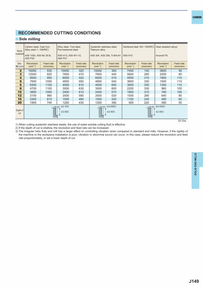
J149
2 16000 530 10000 320 10000 300 7400 140 3800 553 12000 820 7600 470 7600 440 5600 280 2500 804 9500 950 6000 520 6000 510 4500 310 1900 1105 7600 1000 4800 550 4800 540 3600 330 1500 1106 6300 1100 4000 610 4000 600 3000 330 1300 1108 4700 1100 3000 630 3000 600 2200 330 960 100
10 3800 1000 2400 610 2400 570 1800 310 760 10012 3100 980 2000 580 2000 520 1500 280 640 8016 2300 810 1500 480 1500 420 1100 240 480 6520 1900 740 1200 430 1200 390 900 220 380 50
y
CARBIDE
SOLI
D E
ND
MIL
LS
RECOMMENDED CUTTING CONDITIONS
DC:Dia.1) When cutting austenitic stainless steels, the use of water-soluble cutting fl uid is effective.2) If the depth of cut is shallow, the revolution and feed rate can be increased.3) The irregular helix fl ute end mill has a larger effect on controlling vibration when compared to standard end mills. However, if the rigidity of
the machine or the workpiece installation is poor, vibration or abonrmal sound can occur. In this case, please reduce the revolution and feed rate proportionately, or set a lower depth of cut.
Side milling
Workmaterial
Dia.DC (mm)
Carbon steel, Cast iron, Alloy steel (─30HRC)
AISI 1050, AISI No 35 B,AISI P20
Alloy steel, Tool steel,Pre-hardened steel
AISI H13, AISI W1-10, AISI P21
Austenitic stainless steel,Titanium alloy
AISI 304, AISI 306, Ti-6Al-4V
Hardened steel (45─ 55HRC)
AISI H13
Heat resistant alloys
Inconel718
Revolution(min-1)
Revolution(min-1)
Revolution(min-1)
Revolution(min-1)
Revolution(min-1)
Feed rate(mm/min)
Feed rate(mm/min)
Feed rate(mm/min)
Feed rate(mm/min)
Feed rate(mm/min)
Depth ofcut
<0.1DC <0.05DC <0.02DC
<2.5DC <2.5DC <2.5DC
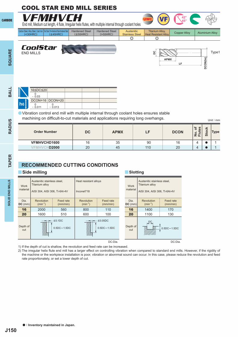
J150
a
VFMHVCH
e e
DC APMX LF DCON
VFMHVCHD1600 16 35 90 16 4 a 1VFMHVCHD2000 20 45 110 20 4 a 1
0- 0.03
DCON=16 DCON=20 0- 0.011
0- 0.013
16 2000 560 800 11020 1600 510 600 100
16 1400 17020 1100 130
0.5DC─1.5DC 0.5DC─1.5DC 0.5DC─1.5DC
yy
UWC VF 42°45°
h6
APMXLF
DC
DC
ON
(h6)
DC
CARBIDE
SQU
AR
EB
ALL
RA
DIU
STA
PER
SOLI
D E
ND
MIL
LS
a : Inventory maintained in Japan.
Carbon Steel, Alloy Steel, Cast Iron(<30HRC)
Tool Steel, Pre-Hardened Steel,Hardened Steel(<45HRC)
Hardened Steel(<55HRC)
Hardened Steel(>55HRC)
AusteniticStainless Steel
Titanium Alloy,Heat Resistant Alloy Copper Alloy Aluminium Alloy
Unit : mm
Type1
Order Number
No.
of
Flut
es
Stoc
k
Type
COOL STAR END MILL SERIES
End mill, Medium cut length, 4 fl ute, Irregular helix fl utes, with multiple internal through coolant holes
CoolStarEND MILLS
16<DC<20
Vibration control end mill with multiple internal through coolant holes ensures stable machining on diffi cult-to-cut materials and applications requiring long overhangs.
RECOMMENDED CUTTING CONDITIONS
DC:Dia. DC:Dia.
1) If the depth of cut is shallow, the revolution and feed rate can be increased.2) The irregular helix fl ute end mill has a larger effect on controlling vibration when compared to standard end mills. However, if the rigidity of
the machine or the workpiece installation is poor, vibration or abonrmal sound can occur. In this case, please reduce the revolution and feed rate proportionately, or set a lower depth of cut.
SlottingSide milling
Workmaterial
Austenitic stainless steel,Titanium alloy
AISI 304, AISI 306, Ti-6Al-4V
Heat resistant alloys
Inconel718
Dia.DC (mm)
Revolution(min-1)
Revolution(min-1)
Feed rate(mm/min)
Feed rate(mm/min)
Workmaterial
Austenitic stainless steel,Titanium alloy
AISI 304, AISI 306, Ti-6Al-4V
Dia.DC (mm)
Revolution(min-1)
Feed rate(mm/min)
Depth ofcut
Depth ofcut
<0.1DC <0.05DC
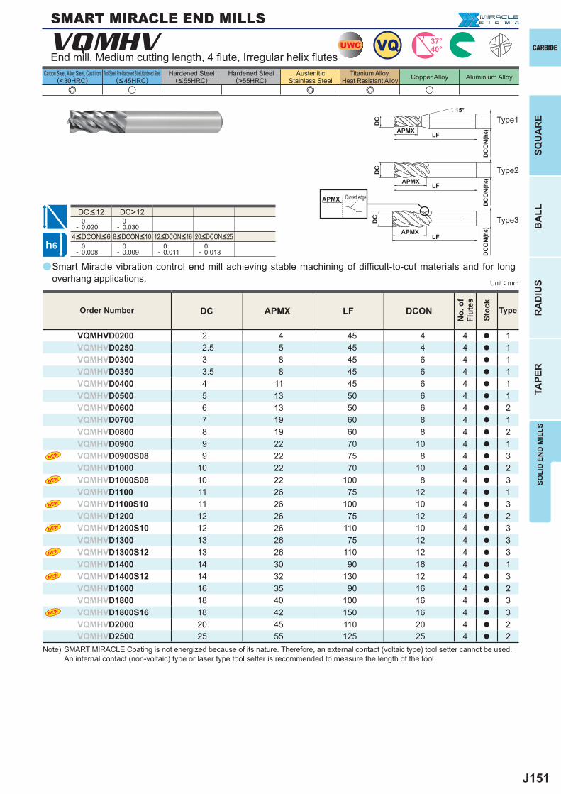
J151
a
VQMHV
e u e e u
DC>12 0- 0.020
0- 0.030
0- 0.008
0- 0.009
0- 0.011
0- 0.013
DC APMX LF DCON
VQMHVD0200 2 4 45 4 4 a 1VQMHVD0250 2.5 5 45 4 4 a 1VQMHVD0300 3 8 45 6 4 a 1VQMHVD0350 3.5 8 45 6 4 a 1VQMHVD0400 4 11 45 6 4 a 1VQMHVD0500 5 13 50 6 4 a 1VQMHVD0600 6 13 50 6 4 a 2VQMHVD0700 7 19 60 8 4 a 1VQMHVD0800 8 19 60 8 4 a 2VQMHVD0900 9 22 70 10 4 a 1VQMHVD0900S08 9 22 75 8 4 a 3VQMHVD1000 10 22 70 10 4 a 2VQMHVD1000S08 10 22 100 8 4 a 3VQMHVD1100 11 26 75 12 4 a 1VQMHVD1100S10 11 26 100 10 4 a 3VQMHVD1200 12 26 75 12 4 a 2VQMHVD1200S10 12 26 110 10 4 a 3VQMHVD1300 13 26 75 12 4 a 3VQMHVD1300S12 13 26 110 12 4 a 3VQMHVD1400 14 30 90 16 4 a 1VQMHVD1400S12 14 32 130 12 4 a 3VQMHVD1600 16 35 90 16 4 a 2VQMHVD1800 18 40 100 16 4 a 3VQMHVD1800S16 18 42 150 16 4 a 3VQMHVD2000 20 45 110 20 4 a 2VQMHVD2500 25 55 125 25 4 a 2
UWC VQ 37°40°
h6
APMX
DC
DC
ON
(h6)
15°
APMXLF
DC
DC
ON
(h6)
LF
APMXLF
DC
DC
ON
(h6)
APMX
SOLI
D E
ND
MIL
LSSQ
UA
RE
BA
LLR
AD
IUS
TAPE
R
CARBIDE
Carbon Steel, Alloy Steel, Cast Iron(<30HRC)
Tool Steel, Pre-Hardened Steel,Hardened Steel(<45HRC)
Hardened Steel(<55HRC)
Hardened Steel(>55HRC)
AusteniticStainless Steel
Titanium Alloy,Heat Resistant Alloy Copper Alloy Aluminium Alloy
Unit : mm
Type1
Type2
Type3
8<DCON<10 12<DCON<164<DCON<6 20<DCON<25
DC<12
SMART MIRACLE END MILLS
End mill, Medium cutting length, 4 fl ute, Irregular helix fl utes
Smart Miracle vibration control end mill achieving stable machining of difficult-to-cut materials and for long overhang applications.
Order Number
No.
of
Flut
es
Stoc
k
Type
Curved edge
Note) SMART MIRACLE Coating is not energized because of its nature. Therefore, an external contact (voltaic type) tool setter cannot be used. An internal contact (non-voltaic) type or laser type tool setter is recommended to measure the length of the tool.
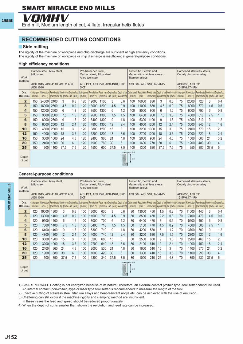
J152
y
VQMHV
2 150 24000 2400 3 0.6 120 19000 1100 3 0.6 100 16000 830 3 0.6 75 12000 720 3 0.43 150 16000 2600 4.5 0.9 120 13000 1200 4.5 0.9 100 11000 880 4.5 0.9 75 8000 770 4.5 0.64 150 12000 2600 6 1.2 120 9500 1300 6 1.2 100 8000 900 6 1.2 75 6000 790 6 0.85 150 9500 2600 7.5 1.5 120 7600 1300 7.5 1.5 100 6400 900 7.5 1.5 75 4800 810 7.5 16 150 8000 2600 9 1.8 120 6400 1300 9 1.8 100 5300 1100 9 1.8 75 4000 810 9 1.28 150 6000 2500 12 2.4 120 4800 1300 12 2.4 100 4000 1200 12 2.4 75 3000 840 12 1.6
10 150 4800 2300 15 3 120 3800 1200 15 3 100 3200 1300 15 3 75 2400 770 15 212 150 4000 1900 18 3.6 120 3200 1200 18 3.6 100 2700 1200 18 3.6 75 2000 720 18 2.416 150 3000 1600 24 4.8 120 2400 960 24 4.8 100 2000 960 24 4.8 75 1500 600 24 3.220 150 2400 1300 30 6 120 1900 760 30 6 100 1600 770 30 6 75 1200 480 30 425 150 1900 1100 37.5 7.5 120 1500 600 37.5 7.5 100 1300 620 37.5 7.5 75 950 380 37.5 5
2 120 19000 1300 3 0.6 100 16000 630 3 0.6 80 13000 450 1.5 0.2 70 11000 440 3 0.43 120 13000 1400 4.5 0.9 100 11000 700 4.5 0.9 80 8500 450 2.2 0.3 70 7400 470 4.5 0.64 120 9500 1400 6 1.2 100 8000 700 6 1.2 80 6400 470 3 0.6 70 5600 490 6 0.85 120 7600 1400 7.5 1.5 100 6400 710 7.5 1.5 80 5100 470 4.5 0.9 70 4500 500 7.5 16 120 6400 1400 9 1.8 100 5300 710 9 1.8 80 4200 580 6 1.2 70 3700 500 9 1.28 120 4800 1300 12 2.4 100 4000 740 12 2.4 80 3200 630 7.5 1.5 70 2800 520 12 1.6
10 120 3800 1200 15 3 100 3200 680 15 3 80 2500 660 9 1.8 70 2200 460 15 212 120 3200 1000 18 3.6 100 2700 640 18 3.6 80 2100 610 12 2.4 70 1900 450 18 2.416 120 2400 860 24 4.8 100 2000 530 24 4.8 80 1600 510 15 3 70 1400 370 24 3.220 120 1900 680 30 6 100 1600 420 30 6 80 1300 410 18 3.6 70 1100 290 30 425 120 1500 390 37.5 7.5 100 1300 340 37.5 7.5 80 1000 210 24 4.8 70 890 230 37.5 5
ae
ap
ae
ap
CARBIDE
SOLI
D E
ND
MIL
LS
RECOMMENDED CUTTING CONDITIONSSide milling
End mill, Medium length of cut, 4 fl ute, Irregular helix fl utes
High effi ciency conditions
General-purpose conditions
The rigidity of the machine or workpiece and chip discharge are suffi cient at high effi ciency conditions. The rigidity of the machine or workpiece or chip discharge is insuffi cient at general-purpose conditions.
Work material
Carbon steel, Alloy steel,Mild steel
AISI 1045, AISI 4140, ASTM A36, AISI 1010
Pre-hardened steel,Carbon steel, Alloy steel,Alloy tool steel
AISI P21, AISI P20, AISI 4340, SKD, SKT
Austenitic, Ferritic and Martensitic stainless steels, Titanium alloys
AISI 304, AISI 316, Ti-6Al-4V
Hardened stainless steels,Cobaly chromium alloy
AISI 630, AISI 63115-5PH,17-4PH
Dia.DC (mm)
Cutting speed (m/min)
Revolution (min-1)
Feed rate (mm/min)
Depth of cut ap (mm)
Depth of cut ae (mm)
Cutting speed (m/min)
Revolution (min-1)
Feed rate (mm/min)
Depth of cut ap (mm)
Depth of cut ae (mm)
Cutting speed (m/min)
Revolution (min-1)
Feed rate (mm/min)
Depth of cut ap (mm)
Depth of cut ae (mm)
Cutting speed (m/min)
Revolution (min-1)
Feed rate (mm/min)
Depth of cut ap (mm)
Depth of cut ae (mm)
Depth of cut
1) SMART MIRACLE Coating is not energized because of its nature. Therefore, an external contact (voltaic type) tool setter cannot be used. An internal contact (non-voltaic) type or laser type tool setter is recommended to measure the length of the tool.
2) Effective cutting of stainless steel, titanium alloys and heat-resistant alloys etc. can be achieved with the use of emulsion.3) Chattering can still occur if the machine rigidity and clamping method are insuffi cient.
In these cases the feed and speed should be reduced proportionately.4) When the depth of cut is smaller than shown the revolution and feed rate can be increased.
SMART MIRACLE END MILLS

J153
2 180 29000 2900 3 0.6 40 6400 230 3 0.23 180 19000 3000 4.5 0.9 40 4200 240 4.5 0.34 180 14000 3000 6 1.2 40 3200 240 6 0.45 180 11000 3000 7.5 1.5 40 2500 240 7.5 0.56 180 9500 3000 9 1.8 40 2100 250 9 0.68 180 7200 3000 12 2.4 40 1600 260 12 0.8
10 180 5700 2700 15 3 40 1300 290 15 112 180 4800 2300 18 3.6 40 1100 280 18 1.216 180 3600 1900 24 4.8 40 800 200 24 1.620 180 2900 1600 30 6 40 640 160 30 225 180 2300 1300 37 7.5 40 510 130 37.5 2.5
2 140 22000 1500 3 0.6 30 4800 110 3 0.23 140 15000 1600 4.5 0.9 30 3200 120 4.5 0.34 140 11000 1600 6 1.2 30 2400 120 6 0.45 140 8900 1600 7.5 1.5 30 1900 120 7.5 0.56 140 7400 1600 9 1.8 30 1600 130 9 0.68 140 5600 1600 12 2.4 30 1200 130 12 0.8
10 140 4500 1400 15 3 30 950 140 15 112 140 3700 1200 18 3.6 30 800 140 18 1.216 140 2800 1000 24 4.8 30 600 100 24 1.620 140 2200 780 30 6 30 480 81 30 225 140 1800 670 37.5 7.5 30 380 64 37.5 2.5
y
ae
ap
ae
ap
CARBIDE
SOLI
D E
ND
MIL
LS
High effi ciency conditions
General-purpose conditions
The rigidity of the machine or workpiece and chip discharge are suffi cient at high effi ciency conditions. The rigidity of the machine or workpiece or chip discharge is insuffi cient at general-purpose conditions.
Work material
Copper, Copper alloy Heat resistant alloys
Inconel718
Dia.DC (mm)
Cutting speed (m/min)
Revolution (min-1)
Feed rate (mm/min)
Depth of cut ap (mm)
Depth of cut ae (mm)
Cutting speed (m/min)
Revolution (min-1)
Feed rate (mm/min)
Depth of cut ap (mm)
Depth of cut ae (mm)
Depth of cut
Work material
Copper, Copper alloy Heat resistant alloys
Inconel718
Dia.DC (mm)
Cutting speed (m/min)
Revolution (min-1)
Feed rate (mm/min)
Depth of cut ap (mm)
Depth of cut ae (mm)
Cutting speed (m/min)
Revolution (min-1)
Feed rate (mm/min)
Depth of cut ap (mm)
Depth of cut ae (mm)
Depth of cut
1) SMART MIRACLE Coating is not energized because of its nature. Therefore, an external contact (voltaic type) tool setter cannot be used. An internal contact (non-voltaic) type or laser type tool setter is recommended to measure the length of the tool.
2) Effective cutting of stainless steel, titanium alloys and heat-resistant alloys etc. can be achieved with the use of emulsion.3) Chattering can still occur if the machine rigidity and clamping method are insuffi cient.
In these cases the feed and speed should be reduced proportionately.4) When the depth of cut is smaller than shown the revolution and feed rate can be increased.
Side milling
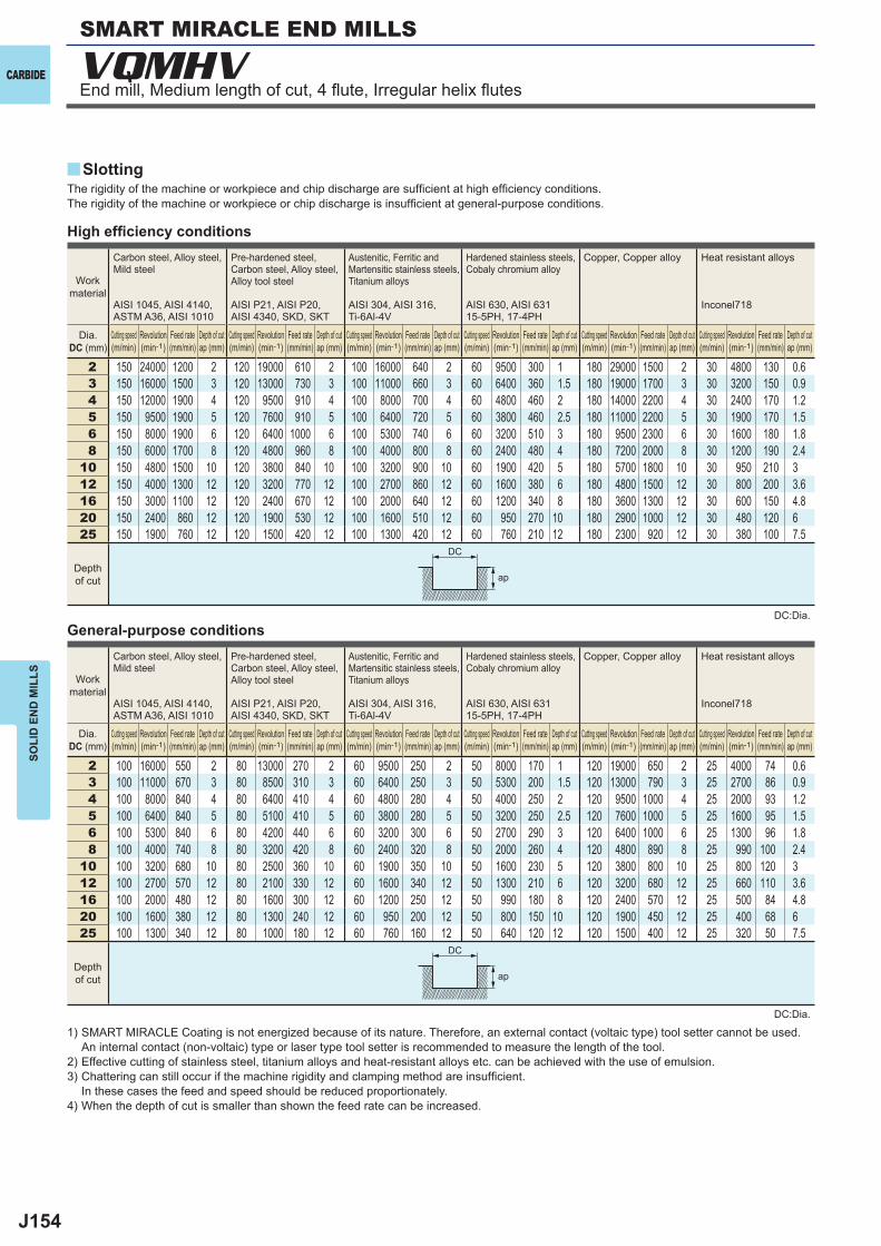
J154
2 150 24000 1200 2 120 19000 610 2 100 16000 640 2 60 9500 300 1 180 29000 1500 2 30 4800 130 0.63 150 16000 1500 3 120 13000 730 3 100 11000 660 3 60 6400 360 1.5 180 19000 1700 3 30 3200 150 0.94 150 12000 1900 4 120 9500 910 4 100 8000 700 4 60 4800 460 2 180 14000 2200 4 30 2400 170 1.25 150 9500 1900 5 120 7600 910 5 100 6400 720 5 60 3800 460 2.5 180 11000 2200 5 30 1900 170 1.56 150 8000 1900 6 120 6400 1000 6 100 5300 740 6 60 3200 510 3 180 9500 2300 6 30 1600 180 1.88 150 6000 1700 8 120 4800 960 8 100 4000 800 8 60 2400 480 4 180 7200 2000 8 30 1200 190 2.4
10 150 4800 1500 10 120 3800 840 10 100 3200 900 10 60 1900 420 5 180 5700 1800 10 30 950 210 312 150 4000 1300 12 120 3200 770 12 100 2700 860 12 60 1600 380 6 180 4800 1500 12 30 800 200 3.616 150 3000 1100 12 120 2400 670 12 100 2000 640 12 60 1200 340 8 180 3600 1300 12 30 600 150 4.820 150 2400 860 12 120 1900 530 12 100 1600 510 12 60 950 270 10 180 2900 1000 12 30 480 120 625 150 1900 760 12 120 1500 420 12 100 1300 420 12 60 760 210 12 180 2300 920 12 30 380 100 7.5
2 100 16000 550 2 80 13000 270 2 60 9500 250 2 50 8000 170 1 120 19000 650 2 25 4000 74 0.63 100 11000 670 3 80 8500 310 3 60 6400 250 3 50 5300 200 1.5 120 13000 790 3 25 2700 86 0.94 100 8000 840 4 80 6400 410 4 60 4800 280 4 50 4000 250 2 120 9500 1000 4 25 2000 93 1.25 100 6400 840 5 80 5100 410 5 60 3800 280 5 50 3200 250 2.5 120 7600 1000 5 25 1600 95 1.56 100 5300 840 6 80 4200 440 6 60 3200 300 6 50 2700 290 3 120 6400 1000 6 25 1300 96 1.88 100 4000 740 8 80 3200 420 8 60 2400 320 8 50 2000 260 4 120 4800 890 8 25 990 100 2.4
10 100 3200 680 10 80 2500 360 10 60 1900 350 10 50 1600 230 5 120 3800 800 10 25 800 120 312 100 2700 570 12 80 2100 330 12 60 1600 340 12 50 1300 210 6 120 3200 680 12 25 660 110 3.616 100 2000 480 12 80 1600 300 12 60 1200 250 12 50 990 180 8 120 2400 570 12 25 500 84 4.820 100 1600 380 12 80 1300 240 12 60 950 200 12 50 800 150 10 120 1900 450 12 25 400 68 625 100 1300 340 12 80 1000 180 12 60 760 160 12 50 640 120 12 120 1500 400 12 25 320 50 7.5
y
VQMHV
ap
ap
DC
DC
CARBIDE
SOLI
D E
ND
MIL
LS
High effi ciency conditions
General-purpose conditions
The rigidity of the machine or workpiece and chip discharge are suffi cient at high effi ciency conditions. The rigidity of the machine or workpiece or chip discharge is insuffi cient at general-purpose conditions.
1) SMART MIRACLE Coating is not energized because of its nature. Therefore, an external contact (voltaic type) tool setter cannot be used. An internal contact (non-voltaic) type or laser type tool setter is recommended to measure the length of the tool.
2) Effective cutting of stainless steel, titanium alloys and heat-resistant alloys etc. can be achieved with the use of emulsion.3) Chattering can still occur if the machine rigidity and clamping method are insuffi cient.
In these cases the feed and speed should be reduced proportionately.4) When the depth of cut is smaller than shown the feed rate can be increased.
Work material
Carbon steel, Alloy steel,Mild steel
AISI 1045, AISI 4140, ASTM A36, AISI 1010
Pre-hardened steel,Carbon steel, Alloy steel,Alloy tool steel
AISI P21, AISI P20, AISI 4340, SKD, SKT
Austenitic, Ferritic and Martensitic stainless steels, Titanium alloys
AISI 304, AISI 316, Ti-6Al-4V
Hardened stainless steels,Cobaly chromium alloy
AISI 630, AISI 63115-5PH, 17-4PH
Copper, Copper alloy Heat resistant alloys
Inconel718
Dia.DC (mm)
Cutting speed (m/min)
Revolution (min-1)
Feed rate (mm/min)
Depth of cut ap (mm)
Cutting speed (m/min)
Revolution (min-1)
Feed rate (mm/min)
Depth of cut ap (mm)
Cutting speed (m/min)
Revolution (min-1)
Feed rate (mm/min)
Depth of cut ap (mm)
Cutting speed (m/min)
Revolution (min-1)
Feed rate (mm/min)
Depth of cut ap (mm)
Cutting speed (m/min)
Revolution (min-1)
Feed rate (mm/min)
Depth of cut ap (mm)
Cutting speed (m/min)
Revolution (min-1)
Feed rate (mm/min)
Depth of cut ap (mm)
Depth of cut
Slotting
SMART MIRACLE END MILLS
End mill, Medium length of cut, 4 fl ute, Irregular helix fl utes
DC:Dia.
DC:Dia.
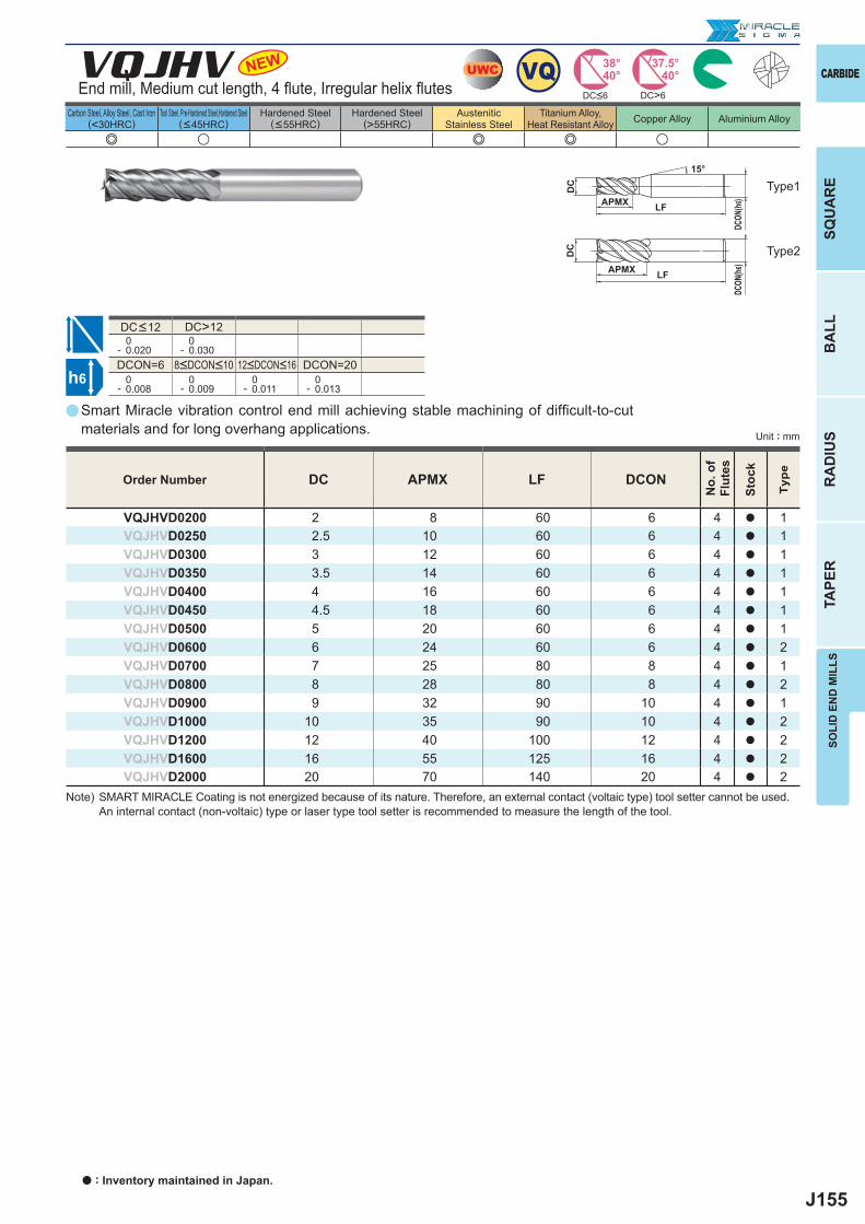
J155
a
e u e e u
VQJHV
DC APMX LF DCON
VQJHVD0200 2 8 60 6 4 a 1VQJHVD0250 2.5 10 60 6 4 a 1VQJHVD0300 3 12 60 6 4 a 1VQJHVD0350 3.5 14 60 6 4 a 1VQJHVD0400 4 16 60 6 4 a 1VQJHVD0450 4.5 18 60 6 4 a 1VQJHVD0500 5 20 60 6 4 a 1VQJHVD0600 6 24 60 6 4 a 2VQJHVD0700 7 25 80 8 4 a 1VQJHVD0800 8 28 80 8 4 a 2VQJHVD0900 9 32 90 10 4 a 1VQJHVD1000 10 35 90 10 4 a 2VQJHVD1200 12 40 100 12 4 a 2VQJHVD1600 16 55 125 16 4 a 2VQJHVD2000 20 70 140 20 4 a 2
DC>12 0- 0.020
0- 0.030
DCON=6 DCON=20 0- 0.008
0- 0.009
0- 0.011
0- 0.013
NEW
h6
UWC VQ 38°40°
37.5°40°
DC>6
APMX
APMX
DC
DC
DCON
(h6)
DCON
(h 6)
LF
LF
15°
SOLI
D E
ND
MIL
LSSQ
UA
RE
BA
LLR
AD
IUS
TAPE
R
CARBIDE
Carbon Steel, Alloy Steel, Cast Iron(<30HRC)
Tool Steel, Pre-Hardened Steel,Hardened Steel(<45HRC)
Hardened Steel(<55HRC)
Hardened Steel(>55HRC)
AusteniticStainless Steel
Titanium Alloy,Heat Resistant Alloy Copper Alloy Aluminium Alloy
Unit : mm
End mill, Medium cut length, 4 fl ute, Irregular helix fl utes
Smart Miracle vibration control end mill achieving stable machining of diffi cult-to-cut materials and for long overhang applications.
Order Number
No.
of
Flut
es
Stoc
k
Type
Type2
Type1
8<DCON<10 12<DCON<16
DC<12
DC<6
Note) SMART MIRACLE Coating is not energized because of its nature. Therefore, an external contact (voltaic type) tool setter cannot be used. An internal contact (non-voltaic) type or laser type tool setter is recommended to measure the length of the tool.
a : Inventory maintained in Japan.
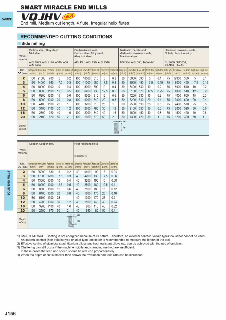
J156
y
2 130 21000 700 5 0.2 100 16000 510 5 0.2 80 13000 390 5 0.1 75 12000 360 5 0.13 130 14000 960 7.5 0.3 100 11000 680 7.5 0.3 80 8500 490 7.5 0.15 75 8000 460 7.5 0.154 130 10000 1000 10 0.4 100 8000 690 10 0.4 80 6400 540 10 0.2 75 6000 510 10 0.25 130 8300 1100 12.5 0.5 100 6400 730 12.5 0.5 80 5100 570 12.5 0.25 75 4800 540 12.5 0.256 130 6900 1200 15 0.6 100 5300 810 15 0.6 80 4200 630 15 0.3 75 4000 600 15 0.38 130 5200 1200 20 0.8 100 4000 840 20 0.8 80 3200 640 20 0.4 75 3000 600 20 0.4
10 130 4100 1100 25 1 100 3200 810 25 1 80 2500 590 25 0.5 75 2400 570 25 0.512 130 3400 1100 30 1.2 100 2700 780 30 1.2 80 2100 550 30 0.6 75 2000 520 30 0.616 130 2600 920 40 1.6 100 2000 640 40 1.6 80 1600 450 40 0.8 75 1500 420 40 0.820 130 2100 820 50 2 100 1600 570 50 2 80 1300 420 50 1 75 1200 390 50 1
2 160 25000 830 5 0.2 40 6400 90 5 0.043 160 17000 1200 7.5 0.3 40 4200 130 7.5 0.064 160 13000 1300 10 0.4 40 3200 190 10 0.085 160 10000 1300 12.5 0.5 40 2500 180 12.5 0.16 160 8500 1500 15 0.6 40 2100 180 15 0.128 160 6400 1500 20 0.8 40 1600 170 20 0.16
10 160 5100 1300 25 1 40 1300 170 25 0.212 160 4200 1300 30 1.2 40 1100 140 30 0.2416 160 3200 1100 40 1.6 40 800 110 40 0.3220 160 2500 970 50 2 40 640 80 50 0.4
VQJHV NEW
ae
ap
ae
ap
CARBIDE
SOLI
D E
ND
MIL
LS
RECOMMENDED CUTTING CONDITIONSSide milling
1) SMART MIRACLE Coating is not energized because of its nature. Therefore, an external contact (voltaic type) tool setter cannot be used. An internal contact (non-voltaic) type or laser type tool setter is recommended to measure the length of the tool.
2) Effective cutting of stainless steel, titanium alloys and heat-resistant alloys etc. can be achieved with the use of emulsion.3) Chattering can still occur if the machine rigidity and clamping method are insuffi cient.
In these cases the feed and speed should be reduced proportionately.4) When the depth of cut is smaller than shown the revolution and feed rate can be increased.
Work material
Carbon steel, Alloy steel,Mild steel
AISI 1045, AISI 4140, ASTM A36, AISI 1010
Pre-hardened steel,Carbon steel, Alloy steel,Alloy tool steel
AISI P21, AISI P20, AISI 4340
Austenitic, Ferritic and Martensitic stainless steels,Titanium alloys
AISI 304, AISI 306, Ti-6Al-4V
Hardened stainless steels,Cobaly chromium alloy
SUS630, SUS631,15-5PH, 17-4PH
Dia.DC (mm)
Cutting speed (m/min)
Revolution (min-1)
Feed rate (mm/min)
Depth of cut ap (mm)
Depth of cut ae (mm)
Cutting speed (m/min)
Revolution (min-1)
Feed rate (mm/min)
Depth of cut ap (mm)
Depth of cut ae (mm)
Cutting speed (m/min)
Revolution (min-1)
Feed rate (mm/min)
Depth of cut ap (mm)
Depth of cut ae (mm)
Cutting speed (m/min)
Revolution (min-1)
Feed rate (mm/min)
Depth of cut ap (mm)
Depth of cut ae (mm)
Depth of cut
Work material
Copper, Copper alloy Heat resistant alloys
Inconel718
Dia.DC (mm)
Cutting speed (m/min)
Revolution (min-1)
Feed rate (mm/min)
Depth of cut ap (mm)
Depth of cut ae (mm)
Cutting speed (m/min)
Revolution (min-1)
Feed rate (mm/min)
Depth of cut ap (mm)
Depth of cut ae (mm)
Depth of cut
End mill, Medium cut length, 4 fl ute, Irregular helix fl utes
SMART MIRACLE END MILLS
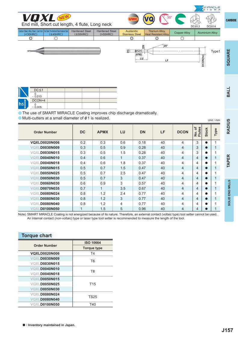
J157
a
e u e e u
VQXL
0- 0.010DCON=4 0- 0.005
DC APMX LU DN LF DCON
VQXLD0020N006 0.2 0.3 0.6 0.18 40 4 3 a 1VQXLD0030N009 0.3 0.5 0.9 0.28 40 4 3 a 1VQXLD0030N015 0.3 0.5 1.5 0.28 40 4 3 a 1VQXLD0040N010 0.4 0.6 1 0.37 40 4 4 a 1VQXLD0040N018 0.4 0.6 1.8 0.37 40 4 4 a 1VQXLD0050N015 0.5 0.7 1.5 0.47 40 4 4 a 1VQXLD0050N025 0.5 0.7 2.5 0.47 40 4 4 a 1VQXLD0050N030 0.5 0.7 3 0.47 40 4 4 a 1VQXLD0060N030 0.6 0.9 3 0.57 40 4 4 a 1VQXLD0070N035 0.7 1 3.5 0.67 40 4 4 a 1VQXLD0080N024 0.8 1.2 2.4 0.77 40 4 4 a 1VQXLD0080N030 0.8 1.2 3 0.77 40 4 4 a 1VQXLD0080N040 0.8 1.2 4 0.77 40 4 4 a 1VQXLD0100N050 1 1.5 5 0.96 40 4 4 a 1
NEW
ISO 10664
VQXLD0020N006 T4VQXLD0030N009
T6VQXLD0030N015VQXLD0040N010
T8VQXLD0040N018VQXLD0050N015
T15VQXLD0050N025VQXLD0050N030VQXLD0080N024
TS25VQXLD0080N040VQXLD0100N050 T40
a
UWC VQ 35°
h5
APMX
DC
DC
ON
(h6)
LF
20°
DN
LU
SOLI
D E
ND
MIL
LSSQ
UA
RE
BA
LLR
AD
IUS
TAPE
R
CARBIDE
Carbon Steel, Alloy Steel, Cast Iron(<30HRC)
Tool Steel, Pre-Hardened Steel,Hardened Steel(<45HRC)
Hardened Steel(<55HRC)
Hardened Steel(>55HRC)
AusteniticStainless Steel
Titanium Alloy,Heat Resistant Alloy Copper Alloy Aluminium Alloy
Unit : mm
End mill, Short cut length, 4 fl ute, Long neck
The use of SMART MIRACLE Coating improves chip discharge dramatically.Multi-cutters at a small diameter of &1 is realized.
Type1
DC<1
Order Number
No.
of
Flut
es
Stoc
k
Type
DC<0.3 DC>0.4
Note) SMART MIRACLE Coating is not energized because of its nature. Therefore, an external contact (voltaic type) tool setter cannot be used. An internal contact (non-voltaic) type or laser type tool setter is recommended to measure the length of the tool.
Order NumberTorque type
Torque chart
a : Inventory maintained in Japan.
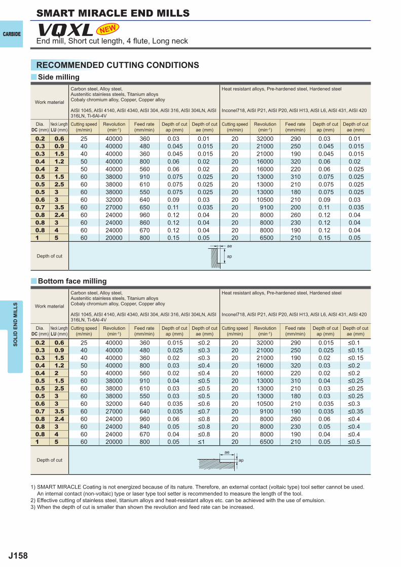
J158
y
y
0.2 0.6 25 40000 360 0.03 0.01 20 32000 290 0.03 0.010.3 0.9 40 40000 480 0.045 0.015 20 21000 250 0.045 0.0150.3 1.5 40 40000 360 0.045 0.015 20 21000 190 0.045 0.0150.4 1.2 50 40000 800 0.06 0.02 20 16000 320 0.06 0.020.4 2 50 40000 560 0.06 0.02 20 16000 220 0.06 0.0250.5 1.5 60 38000 910 0.075 0.025 20 13000 310 0.075 0.0250.5 2.5 60 38000 610 0.075 0.025 20 13000 210 0.075 0.0250.5 3 60 38000 550 0.075 0.025 20 13000 180 0.075 0.0250.6 3 60 32000 640 0.09 0.03 20 10500 210 0.09 0.030.7 3.5 60 27000 650 0.11 0.035 20 9100 200 0.11 0.0350.8 2.4 60 24000 960 0.12 0.04 20 8000 260 0.12 0.040.8 3 60 24000 860 0.12 0.04 20 8000 230 0.12 0.040.8 4 60 24000 670 0.12 0.04 20 8000 190 0.12 0.041 5 60 20000 800 0.15 0.05 20 6500 210 0.15 0.05
0.2 0.6 25 40000 360 0.015 20 32000 290 0.0150.3 0.9 40 40000 480 0.025 20 21000 250 0.0250.3 1.5 40 40000 360 0.02 20 21000 190 0.020.4 1.2 50 40000 800 0.03 20 16000 320 0.030.4 2 50 40000 560 0.02 20 16000 220 0.020.5 1.5 60 38000 910 0.04 20 13000 310 0.040.5 2.5 60 38000 610 0.03 20 13000 210 0.030.5 3 60 38000 550 0.03 20 13000 180 0.030.6 3 60 32000 640 0.035 20 10500 210 0.0350.7 3.5 60 27000 640 0.035 20 9100 190 0.0350.8 2.4 60 24000 960 0.06 20 8000 260 0.060.8 3 60 24000 840 0.05 20 8000 230 0.050.8 4 60 24000 670 0.04 20 8000 190 0.041 5 60 20000 800 0.05 20 6500 210 0.05
VQXL NEW
ae
ap
ae
ap
CARBIDE
SOLI
D E
ND
MIL
LS
RECOMMENDED CUTTING CONDITIONSSide milling
Work material
Carbon steel, Alloy steel,Austenitic stainless steels, Titanium alloysCobaly chromium alloy, Copper, Copper alloy
AISI 1045, AISI 4140, AISI 4340, AISI 304, AISI 316, AISI 304LN, AISI 316LN, Ti-6Al-4V
Heat resistant alloys, Pre-hardened steel, Hardened steel
Inconel718, AISI P21, AISI P20, AISI H13, AISI L6, AISI 431, AISI 420
Dia.DC (mm)
Neck LengthLU (mm)
Cutting speed (m/min)
Revolution (min-1)
Feed rate (mm/min)
Depth of cut ap (mm)
Depth of cut ae (mm)
Cutting speed (m/min)
Revolution (min-1)
Feed rate (mm/min)
Depth of cut ap (mm)
Depth of cut ae (mm)
Depth of cut
Work material
Carbon steel, Alloy steel,Austenitic stainless steels, Titanium alloysCobaly chromium alloy, Copper, Copper alloy
AISI 1045, AISI 4140, AISI 4340, AISI 304, AISI 316, AISI 304LN, AISI 316LN, Ti-6Al-4V
Heat resistant alloys, Pre-hardened steel, Hardened steel
Inconel718, AISI P21, AISI P20, AISI H13, AISI L6, AISI 431, AISI 420
Dia.DC (mm)
Neck LengthLU (mm)
Cutting speed (m/min)
Revolution (min-1)
Feed rate (mm/min)
Depth of cut ap (mm)
Depth of cut ae (mm)
Cutting speed (m/min)
Revolution (min-1)
Feed rate (mm/min)
Depth of cut ap (mm)
Depth of cut ae (mm)
<0.2 <0.1<0.3 <0.15<0.3 <0.15<0.4 <0.2<0.4 <0.2<0.5 <0.25<0.5 <0.25<0.5 <0.25<0.6 <0.3<0.7 <0.35<0.8 <0.4<0.8 <0.4<0.8 <0.4<1 <0.5
Depth of cut
1) SMART MIRACLE Coating is not energized because of its nature. Therefore, an external contact (voltaic type) tool setter cannot be used. An internal contact (non-voltaic) type or laser type tool setter is recommended to measure the length of the tool.
2) Effective cutting of stainless steel, titanium alloys and heat-resistant alloys etc. can be achieved with the use of emulsion.3) When the depth of cut is smaller than shown the revolution and feed rate can be increased.
Bottom face milling
SMART MIRACLE END MILLS
End mill, Short cut length, 4 fl ute, Long neck
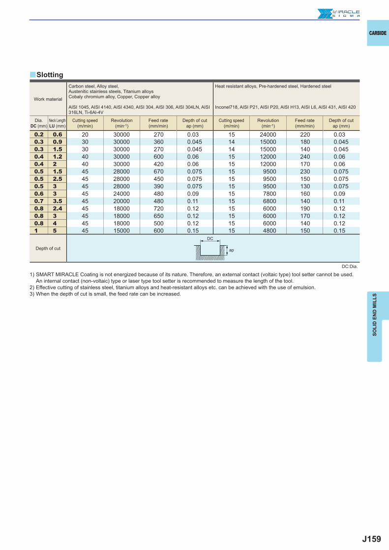
J159
0.2 0.6 20 30000 270 0.03 15 24000 220 0.030.3 0.9 30 30000 360 0.045 14 15000 180 0.0450.3 1.5 30 30000 270 0.045 14 15000 140 0.0450.4 1.2 40 30000 600 0.06 15 12000 240 0.060.4 2 40 30000 420 0.06 15 12000 170 0.060.5 1.5 45 28000 670 0.075 15 9500 230 0.0750.5 2.5 45 28000 450 0.075 15 9500 150 0.0750.5 3 45 28000 390 0.075 15 9500 130 0.0750.6 3 45 24000 480 0.09 15 7800 160 0.090.7 3.5 45 20000 480 0.11 15 6800 140 0.110.8 2.4 45 18000 720 0.12 15 6000 190 0.120.8 3 45 18000 650 0.12 15 6000 170 0.120.8 4 45 18000 500 0.12 15 6000 140 0.121 5 45 15000 600 0.15 15 4800 150 0.15
y
ap
DC
CARBIDE
SOLI
D E
ND
MIL
LS
Work material
Carbon steel, Alloy steel,Austenitic stainless steels, Titanium alloysCobaly chromium alloy, Copper, Copper alloy
AISI 1045, AISI 4140, AISI 4340, AISI 304, AISI 306, AISI 304LN, AISI 316LN, Ti-6Al-4V
Heat resistant alloys, Pre-hardened steel, Hardened steel
Inconel718, AISI P21, AISI P20, AISI H13, AISI L6, AISI 431, AISI 420
Dia.DC (mm)
Neck LengthLU (mm)
Cutting speed (m/min)
Revolution (min-1)
Feed rate (mm/min)
Depth of cut ap (mm)
Cutting speed (m/min)
Revolution (min-1)
Feed rate (mm/min)
Depth of cut ap (mm)
Depth of cut
1) SMART MIRACLE Coating is not energized because of its nature. Therefore, an external contact (voltaic type) tool setter cannot be used. An internal contact (non-voltaic) type or laser type tool setter is recommended to measure the length of the tool.
2) Effective cutting of stainless steel, titanium alloys and heat-resistant alloys etc. can be achieved with the use of emulsion.3) When the depth of cut is small, the feed rate can be increased.
Slotting
DC:Dia.
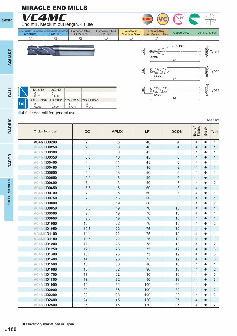
J160
a
u e e u u u
VC4MC
DC APMX LF DCON
VC4MCD0200 2 6 40 4 4 a 1VC4MCD0250 2.5 8 40 4 4 a 1VC4MCD0300 3 8 45 6 4 a 1VC4MCD0350 3.5 10 45 6 4 a 1VC4MCD0400 4 11 45 6 4 a 1VC4MCD0450 4.5 11 45 6 4 a 1VC4MCD0500 5 13 50 6 4 a 1VC4MCD0550 5.5 13 50 6 4 a 1VC4MCD0600 6 13 50 6 4 a 2VC4MCD0650 6.5 16 60 8 4 a 1VC4MCD0700 7 16 60 8 4 a 1VC4MCD0750 7.5 16 60 8 4 a 1VC4MCD0800 8 19 60 8 4 a 2VC4MCD0850 8.5 19 70 10 4 a 1VC4MCD0900 9 19 70 10 4 a 1VC4MCD0950 9.5 19 70 10 4 a 1VC4MCD1000 10 22 70 10 4 a 2VC4MCD1050 10.5 22 75 12 4 a 1VC4MCD1100 11 22 75 12 4 a 1VC4MCD1150 11.5 22 75 12 4 a 1VC4MCD1200 12 26 75 12 4 a 2VC4MCD1250 12.5 26 75 12 4 a 3VC4MCD1300 13 26 75 12 4 a 3VC4MCD1400 14 26 75 12 4 a 3VC4MCD1500 15 30 80 16 4 a 1VC4MCD1600 16 32 90 16 4 a 2VC4MCD1700 17 32 90 16 4 a 3VC4MCD1800 18 32 90 16 4 a 3VC4MCD1900 19 32 100 20 4 a 1VC4MCD2000 20 38 100 20 4 a 2VC4MCD2200 22 38 100 20 4 a 3VC4MCD2400 24 45 120 25 4 a 1VC4MCD2500 25 45 120 25 4 a 2
DC>12 0- 0.020
0- 0.030
0- 0.008
0- 0.009
0- 0.011
0- 0.013
UWC VC 30°
h6
APMX
DC
DC
ON
(h6)15°
APMXLF
DC
DC
ON
(h6)
LF
APMXLF
DC
DC
ON
(h6)
CARBIDE
SQU
AR
EB
ALL
RA
DIU
STA
PER
SOLI
D E
ND
MIL
LS
a : Inventory maintained in Japan.
Carbon Steel, Alloy Steel, Cast Iron(<30HRC)
Tool Steel, Pre-Hardened Steel,Hardened Steel(<45HRC)
Hardened Steel(<55HRC)
Hardened Steel(>55HRC)
AusteniticStainless Steel
Titanium Alloy,Heat Resistant Alloy Copper Alloy Aluminium Alloy
Unit : mm
Type1
Type2
Type3
Order Number
No.
of
Flut
es
Stoc
k
Type
MIRACLE END MILLS
End mill, Medium cut length, 4 fl ute
4<DCON<6 8<DCON<10 12<DCON<16 20<DCON<25
DC<12
4 fl ute end mill for general use.
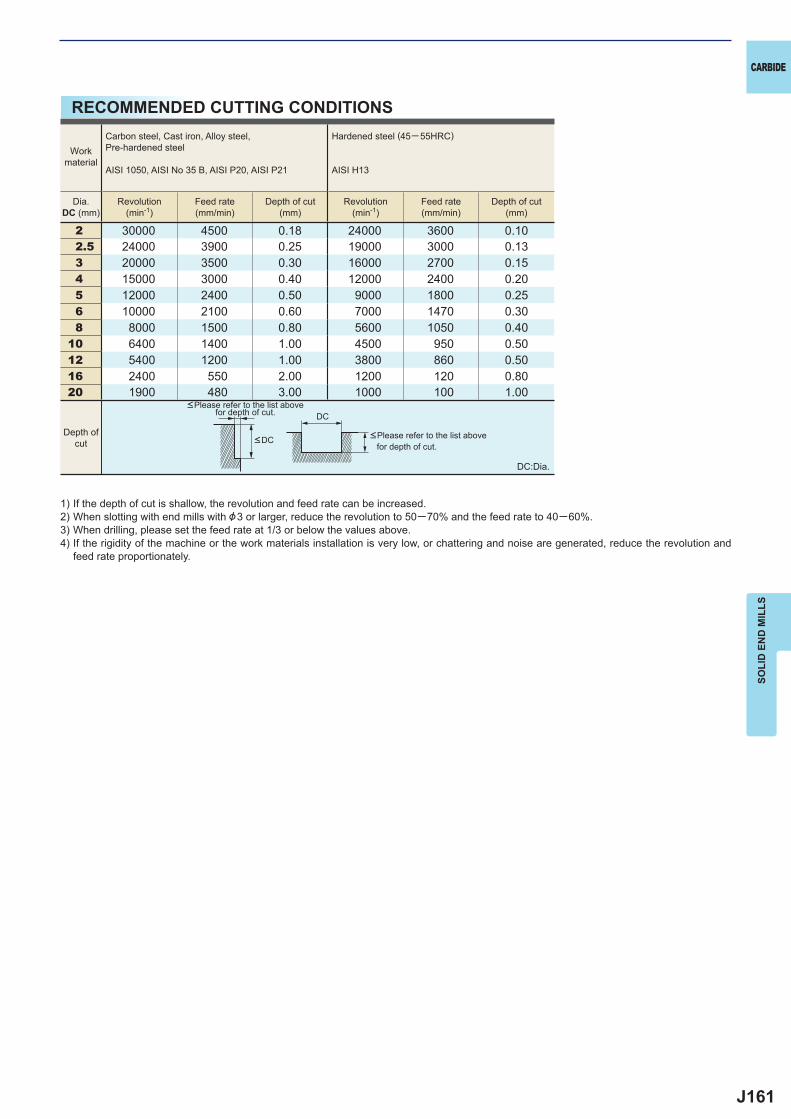
J161
2 30000 4500 0.18 24000 3600 0.10 2.5 24000 3900 0.25 19000 3000 0.13 3 20000 3500 0.30 16000 2700 0.15 4 15000 3000 0.40 12000 2400 0.20 5 12000 2400 0.50 9000 1800 0.25 6 10000 2100 0.60 7000 1470 0.30 8 8000 1500 0.80 5600 1050 0.4010 6400 1400 1.00 4500 950 0.5012 5400 1200 1.00 3800 860 0.5016 2400 550 2.00 1200 120 0.8020 1900 480 3.00 1000 100 1.00
DC
CARBIDE
SOLI
D E
ND
MIL
LS
RECOMMENDED CUTTING CONDITIONS
1) If the depth of cut is shallow, the revolution and feed rate can be increased.2) When slotting with end mills with &3 or larger, reduce the revolution to 50─70% and the feed rate to 40─60%.3) When drilling, please set the feed rate at 1/3 or below the values above.4) If the rigidity of the machine or the work materials installation is very low, or chattering and noise are generated, reduce the revolution and
feed rate proportionately.
DC:Dia.
<Please refer to the list above for depth of cut.
<Please refer to the list above for depth of cut.
Workmaterial
Carbon steel, Cast iron, Alloy steel,Pre-hardened steel
AISI 1050, AISI No 35 B, AISI P20, AISI P21
Hardened steel (45─ 55HRC)
AISI H13
Dia.DC (mm)
Revolution(min-1)
Feed rate(mm/min)
Depth of cut(mm)
Revolution(min-1)
Feed rate(mm/min)
Depth of cut(mm)
Depth ofcut <DC
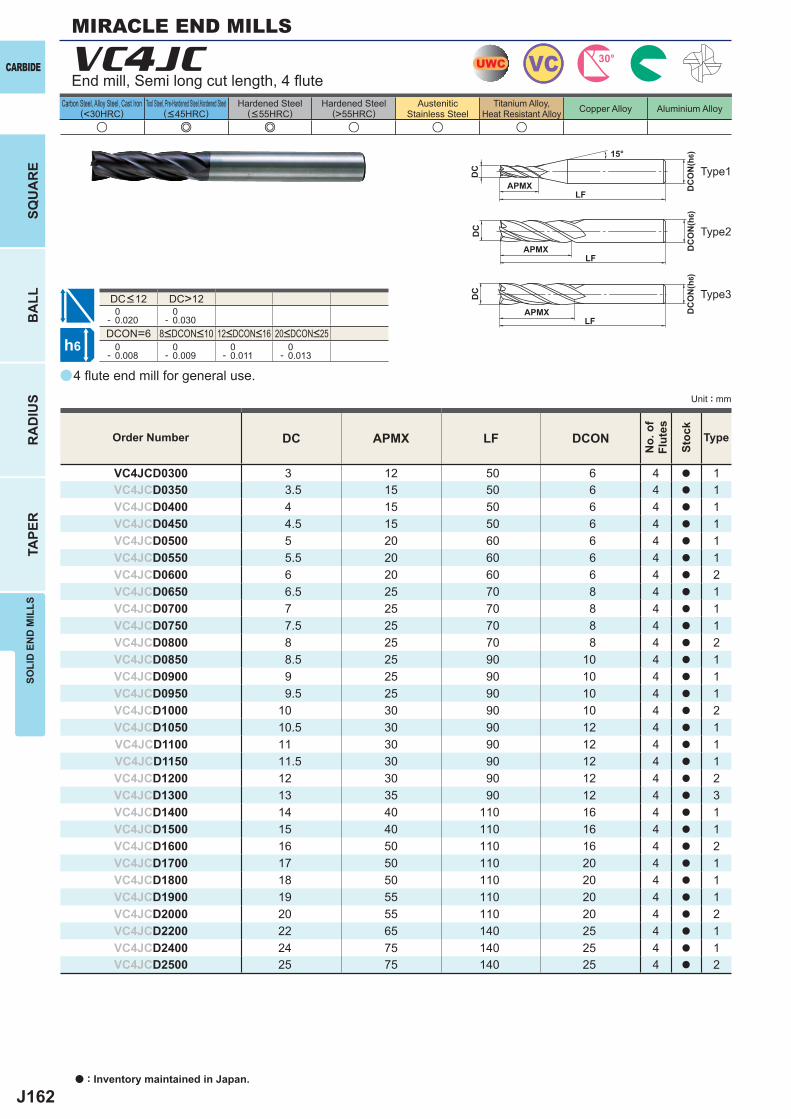
J162
a
u e e u u u
VC4JC
DC APMX LF DCON
VC4JCD0300 3 12 50 6 4 a 1VC4JCD0350 3.5 15 50 6 4 a 1VC4JCD0400 4 15 50 6 4 a 1VC4JCD0450 4.5 15 50 6 4 a 1VC4JCD0500 5 20 60 6 4 a 1VC4JCD0550 5.5 20 60 6 4 a 1VC4JCD0600 6 20 60 6 4 a 2VC4JCD0650 6.5 25 70 8 4 a 1VC4JCD0700 7 25 70 8 4 a 1VC4JCD0750 7.5 25 70 8 4 a 1VC4JCD0800 8 25 70 8 4 a 2VC4JCD0850 8.5 25 90 10 4 a 1VC4JCD0900 9 25 90 10 4 a 1VC4JCD0950 9.5 25 90 10 4 a 1VC4JCD1000 10 30 90 10 4 a 2VC4JCD1050 10.5 30 90 12 4 a 1VC4JCD1100 11 30 90 12 4 a 1VC4JCD1150 11.5 30 90 12 4 a 1VC4JCD1200 12 30 90 12 4 a 2VC4JCD1300 13 35 90 12 4 a 3VC4JCD1400 14 40 110 16 4 a 1VC4JCD1500 15 40 110 16 4 a 1VC4JCD1600 16 50 110 16 4 a 2VC4JCD1700 17 50 110 20 4 a 1VC4JCD1800 18 50 110 20 4 a 1VC4JCD1900 19 55 110 20 4 a 1VC4JCD2000 20 55 110 20 4 a 2VC4JCD2200 22 65 140 25 4 a 1VC4JCD2400 24 75 140 25 4 a 1VC4JCD2500 25 75 140 25 4 a 2
DC>12 0- 0.020
0- 0.030
DCON=6 0- 0.008
0- 0.009
0- 0.011
0- 0.013
UWC VC 30°
h6
APMX
DC
DC
ON
(h6)15°
APMXLF
DC
DC
ON
(h6)
LF
APMXLF
DC
DC
ON
(h6)
CARBIDE
SQU
AR
EB
ALL
RA
DIU
STA
PER
SOLI
D E
ND
MIL
LS
a : Inventory maintained in Japan.
Carbon Steel, Alloy Steel, Cast Iron(<30HRC)
Tool Steel, Pre-Hardened Steel,Hardened Steel(<45HRC)
Hardened Steel(<55HRC)
Hardened Steel(>55HRC)
AusteniticStainless Steel
Titanium Alloy,Heat Resistant Alloy Copper Alloy Aluminium Alloy
Unit : mm
End mill, Semi long cut length, 4 fl ute
Type3
Type2
Type1
8<DCON<10 12<DCON<16 20<DCON<25
DC<12
Order Number
No.
of
Flut
es
Stoc
k
Type
4 fl ute end mill for general use.
MIRACLE END MILLS
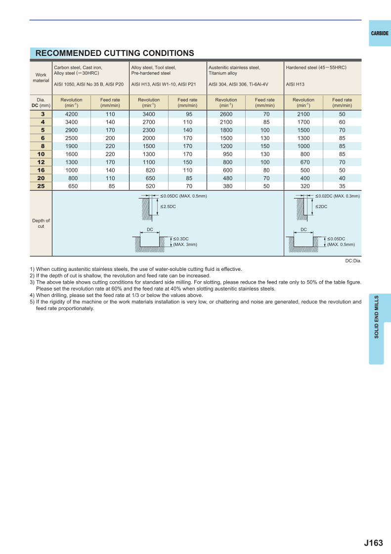
J163
3 4200 110 3400 95 2600 70 2100 504 3400 140 2700 110 2100 85 1700 605 2900 170 2300 140 1800 100 1500 706 2500 200 2000 170 1500 130 1300 858 1900 220 1500 170 1200 150 1000 85
10 1600 220 1300 170 950 130 800 8512 1300 170 1100 150 800 100 670 7016 1000 140 820 110 600 80 500 5020 800 110 650 85 480 70 400 4025 650 85 520 70 380 50 320 35
DC DC
CARBIDE
SOLI
D E
ND
MIL
LS
RECOMMENDED CUTTING CONDITIONS
1) When cutting austenitic stainless steels, the use of water-soluble cutting fl uid is effective.2) If the depth of cut is shallow, the revolution and feed rate can be increased.3) The above table shows cutting conditions for standard side milling. For slotting, please reduce the feed rate only to 50% of the table fi gure.
Please set the revolution rate at 60% and the feed rate at 40% when slotting austenitic stainless steels.4) When drilling, please set the feed rate at 1/3 or below the values above.5) If the rigidity of the machine or the work materials installation is very low, or chattering and noise are generated, reduce the revolution and
feed rate proportionately.
DC:Dia.
Workmaterial
Carbon steel, Cast iron, Alloy steel (─30HRC)
AISI 1050, AISI No 35 B, AISI P20
Alloy steel, Tool steel,Pre-hardened steel
AISI H13, AISI W1-10, AISI P21
Austenitic stainless steel,Titanium alloy
AISI 304, AISI 306, Ti-6Al-4V
Hardened steel (45─ 55HRC)
AISI H13
Dia.DC (mm)
Revolution(min-1)
Feed rate(mm/min)
Revolution(min-1)
Feed rate(mm/min)
Revolution(min-1)
Feed rate(mm/min)
Revolution(min-1)
Feed rate(mm/min)
Depth ofcut
<0.05DC (MAX. 0.5mm) <0.02DC (MAX. 0.3mm)
<0.3DC (MAX. 3mm)
<0.05DC (MAX. 0.5mm)
<2.5DC <2DC
J164
a
u e e e
VCMDSC
DC APMX LF DCON
VCMDSCD0050 0.5 1 45 6 4 a 1VCMDSCD0100 1 2.5 45 6 4 a 1VCMDSCD0150 1.5 4 45 6 4 a 1VCMDSCD0200 2 6 45 6 4 a 1VCMDSCD0250 2.5 8 45 6 4 a 1VCMDSCD0300 3 8 45 6 6 a 1
0- 0.020DCON=6 0- 0.008
DC<3 DC=3
UWC VC 30°
h6
APMX
DC
DC
ON
(h6)
15°
LF
CARBIDE
SQU
AR
EB
ALL
RA
DIU
STA
PER
SOLI
D E
ND
MIL
LS
a : Inventory maintained in Japan.
Carbon Steel, Alloy Steel, Cast Iron(<30HRC)
Tool Steel, Pre-Hardened Steel,Hardened Steel(<45HRC)
Hardened Steel(<55HRC)
Hardened Steel(>55HRC)
AusteniticStainless Steel
Titanium Alloy,Heat Resistant Alloy Copper Alloy Aluminium Alloy
Unit : mm
Type1
Order Number
No.
of
Flut
es
Stoc
k
Type
End mill, Medium cut length, 4─6 fl ute
0.5<DC<3
Ideal for tool steel and hardened materials machining
MIRACLE END MILL FOR HIGH HARDNESS STEEL
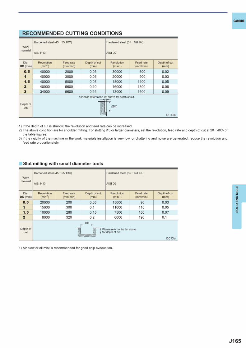
J165
0.5 40000 2000 0.03 30000 600 0.02 1 40000 3000 0.05 20000 900 0.03 1.5 40000 5000 0.08 18000 1100 0.05 2 40000 5600 0.10 16000 1300 0.06 3 34000 5600 0.15 13000 1600 0.09
0.5 20000 200 0.05 15000 90 0.031 15000 300 0.1 11000 110 0.051.5 10000 280 0.15 7500 150 0.072 8000 320 0.2 6000 190 0.1
y
DC
CARBIDE
SOLI
D E
ND
MIL
LS
RECOMMENDED CUTTING CONDITIONS
1) If the depth of cut is shallow, the revolution and feed rate can be increased.2) The above condition are for shoulder milling. For slotting &3 or larger diameters, set the revolution, feed rate and depth of cut at 20─40% of
the table fi gures.3) If the rigidity of the machine or the work materials installation is very low, or chattering and noise are generated, reduce the revolution and
feed rate proportionately.
DC:Dia.
1) Air blow or oil mist is recommended for good chip evacuation.
DC:Dia.
<Please refer to the list above for depth of cut.
Please refer to the list abovefor depth of cut.
Slot milling with small diameter tools
Workmaterial
Hardened steel (45─ 55HRC)
AISI H13
Hardened steel (55─ 62HRC)
AISI D2
Dia.DC (mm)
Revolution(min-1)
Feed rate(mm/min)
Depth of cut(mm)
Revolution(min-1)
Feed rate(mm/min)
Depth of cut(mm)
Workmaterial
Hardened steel (45─ 55HRC)
AISI H13
Hardened steel (55─ 62HRC)
AISI D2
Dia.DC (mm)
Revolution(min-1)
Feed rate(mm/min)
Depth of cut(mm)
Revolution(min-1)
Feed rate(mm/min)
Depth of cut(mm)
Depth ofcut
Depth ofcut
<DC
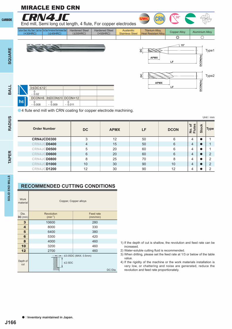
J166
a
e u
CRN4JC
DC APMX LF DCON
CRN4JCD0300 3 12 50 6 4 a 1CRN4JCD0400 4 15 50 6 4 a 1CRN4JCD0500 5 20 60 6 4 a 1CRN4JCD0600 6 20 60 6 4 a 2CRN4JCD0800 8 25 70 8 4 a 2CRN4JCD1000 10 30 90 10 4 a 2CRN4JCD1200 12 30 90 12 4 a 2
0- 0.02DCON=6 DCON=12 0- 0.008
0- 0.009
0- 0.011
3 10600 2804 8000 3305 6400 3806 5300 4208 4000 460
10 3200 46012 2700 460
UWC CRN 30°
h6
APMX
DC
DC
ON
(h6)
15°
APMXLF
DC
DC
ON
(h6)
LF
CARBIDE
SQU
AR
EB
ALL
RA
DIU
STA
PER
SOLI
D E
ND
MIL
LS
a : Inventory maintained in Japan.
Carbon Steel, Alloy Steel, Cast Iron(<30HRC)
Tool Steel, Pre-Hardened Steel,Hardened Steel(<45HRC)
Hardened Steel(<55HRC)
Hardened Steel(>55HRC)
AusteniticStainless Steel
Titanium Alloy,Heat Resistant Alloy Copper Alloy Aluminium Alloy
Unit : mm
End mill, Semi long cut length, 4 fl ute, For copper electrodes
Type1
Type2
8<DCON<10
3<DC<12
4 fl ute end mill with CRN coating for copper electrode machining.
Order Number
No.
of
Flut
es
Stoc
k
Type
MIRACLE END CRN
RECOMMENDED CUTTING CONDITIONS
Workmaterial Copper, Copper alloys
Dia.DC (mm)
Revolution(min-1)
Feed rate(mm/min)
Depth ofcut <2.5DC
<0.05DC (MAX. 0.5mm)
1) If the depth of cut is shallow, the revolution and feed rate can be increased.
2) Water-soluble cutting fl uid is recommended.3) When drilling, please set the feed rate at 1/3 or below of the table
value.4) If the rigidity of the machine or the work materials installation is
very low, or chattering and noise are generated, reduce the revolution and feed rate proportionately.DC:Dia.
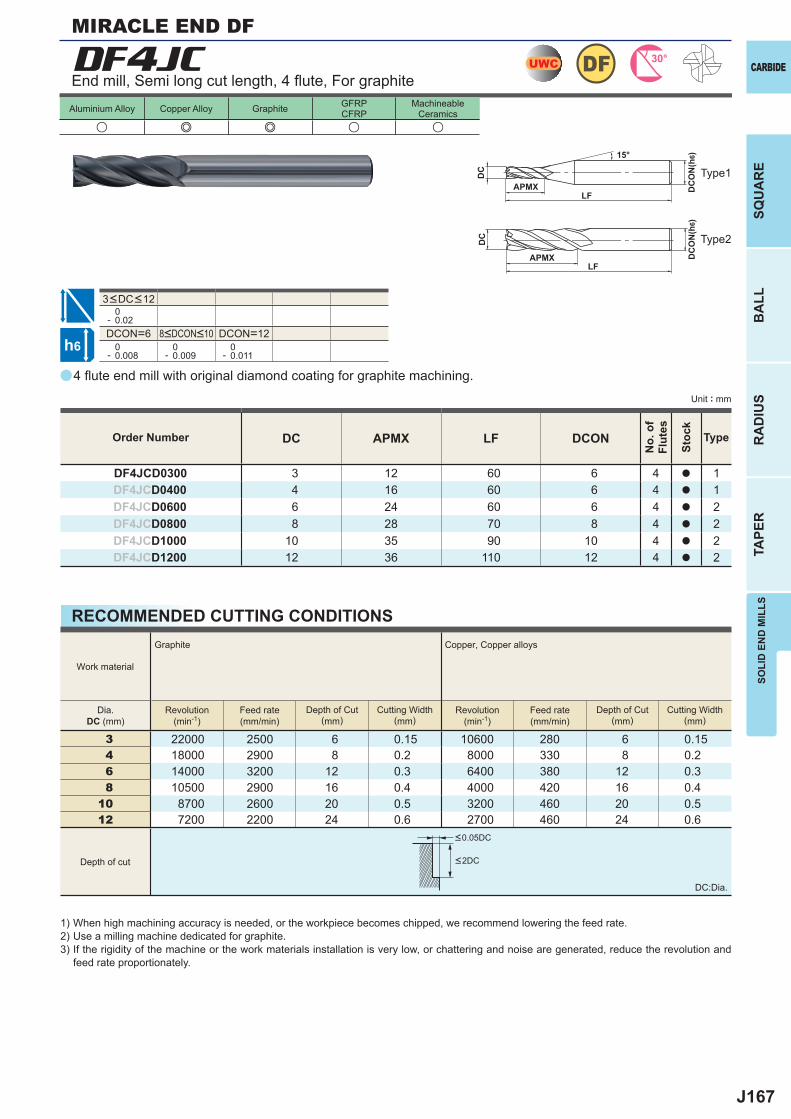
J167
a
DF4JC
DC APMX LF DCON
DF4JCD0300 3 12 60 6 4 a 1DF4JCD0400 4 16 60 6 4 a 1DF4JCD0600 6 24 60 6 4 a 2DF4JCD0800 8 28 70 8 4 a 2DF4JCD1000 10 35 90 10 4 a 2DF4JCD1200 12 36 110 12 4 a 2
u e e u u
0- 0.02DCON=6 DCON=12 0- 0.008
0- 0.009
0- 0.011
3 22000 2500 6 0.15 10600 280 6 0.154 18000 2900 8 0.2 8000 330 8 0.26 14000 3200 12 0.3 6400 380 12 0.38 10500 2900 16 0.4 4000 420 16 0.4
10 8700 2600 20 0.5 3200 460 20 0.512 7200 2200 24 0.6 2700 460 24 0.6
UWC 30°DF
h6
APMX
DC
DC
ON
(h6)15°
APMXLF
DC
DC
ON
(h6)
LF
SOLI
D E
ND
MIL
LSSQ
UA
RE
BA
LLR
AD
IUS
TAPE
R
CARBIDE
Unit : mm
Aluminium Alloy Copper Alloy Graphite GFRPCFRP
MachineableCeramics
Type1
Type2
Order Number
No.
of
Flut
es
Stoc
k
Type
End mill, Semi long cut length, 4 fl ute, For graphite
3<DC<12
8<DCON<10
4 fl ute end mill with original diamond coating for graphite machining.
MIRACLE END DF
RECOMMENDED CUTTING CONDITIONS
1) When high machining accuracy is needed, or the workpiece becomes chipped, we recommend lowering the feed rate.2) Use a milling machine dedicated for graphite.3) If the rigidity of the machine or the work materials installation is very low, or chattering and noise are generated, reduce the revolution and
feed rate proportionately.
DC:Dia.
<0.05DC
<2DC
Work material
Graphite Copper, Copper alloys
Dia.DC (mm)
Revolution(min-1)
Feed rate(mm/min)
Depth of Cut(mm)
Cutting Width(mm)
Revolution(min-1)
Feed rate(mm/min)
Depth of Cut(mm)
Cutting Width(mm)
Depth of cut
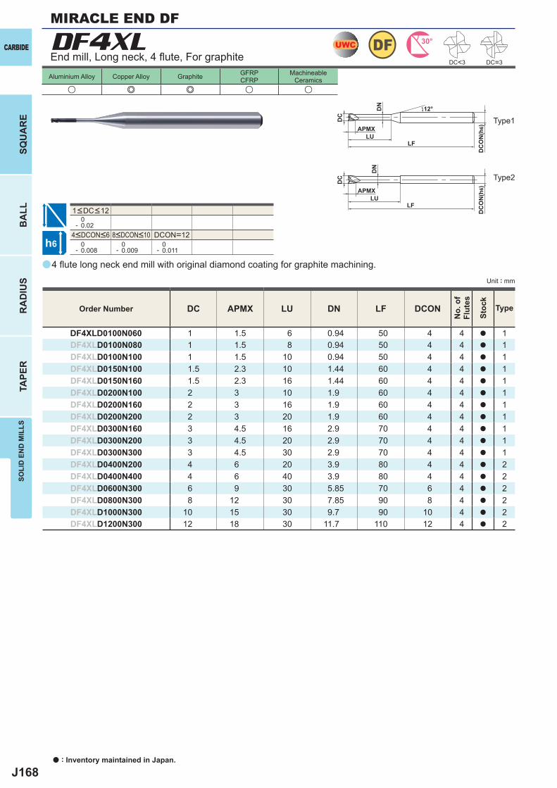
J168
a
DF4XL
u e e u u
DC APMX LU DN LF DCON
DF4XLD0100N060 1 1.5 6 0.94 50 4 4 a 1DF4XLD0100N080 1 1.5 8 0.94 50 4 4 a 1DF4XLD0100N100 1 1.5 10 0.94 50 4 4 a 1DF4XLD0150N100 1.5 2.3 10 1.44 60 4 4 a 1DF4XLD0150N160 1.5 2.3 16 1.44 60 4 4 a 1DF4XLD0200N100 2 3 10 1.9 60 4 4 a 1DF4XLD0200N160 2 3 16 1.9 60 4 4 a 1DF4XLD0200N200 2 3 20 1.9 60 4 4 a 1DF4XLD0300N160 3 4.5 16 2.9 70 4 4 a 1DF4XLD0300N200 3 4.5 20 2.9 70 4 4 a 1DF4XLD0300N300 3 4.5 30 2.9 70 4 4 a 1DF4XLD0400N200 4 6 20 3.9 80 4 4 a 2DF4XLD0400N400 4 6 40 3.9 80 4 4 a 2DF4XLD0600N300 6 9 30 5.85 70 6 4 a 2DF4XLD0800N300 8 12 30 7.85 90 8 4 a 2DF4XLD1000N300 10 15 30 9.7 90 10 4 a 2DF4XLD1200N300 12 18 30 11.7 110 12 4 a 2
DC=3
0- 0.02
DCON=12 0- 0.008
0- 0.009
0- 0.011
UWC 30°DF
h6
APMXLU
DC
DC
ON
(h6)
12°
APMX
LF
DC
DC
ON
(h6)
LF
DN
LU
DN
DC<3
CARBIDE
SQU
AR
EB
ALL
RA
DIU
STA
PER
SOLI
D E
ND
MIL
LS
a : Inventory maintained in Japan.
Unit : mm
Aluminium Alloy Copper Alloy Graphite GFRPCFRP
MachineableCeramics
End mill, Long neck, 4 fl ute, For graphite
Type1
Type2
4<DCON<6 8<DCON<10
1<DC<12
Order Number
No.
of
Flut
es
Stoc
k
Type
4 fl ute long neck end mill with original diamond coating for graphite machining.
MIRACLE END DF
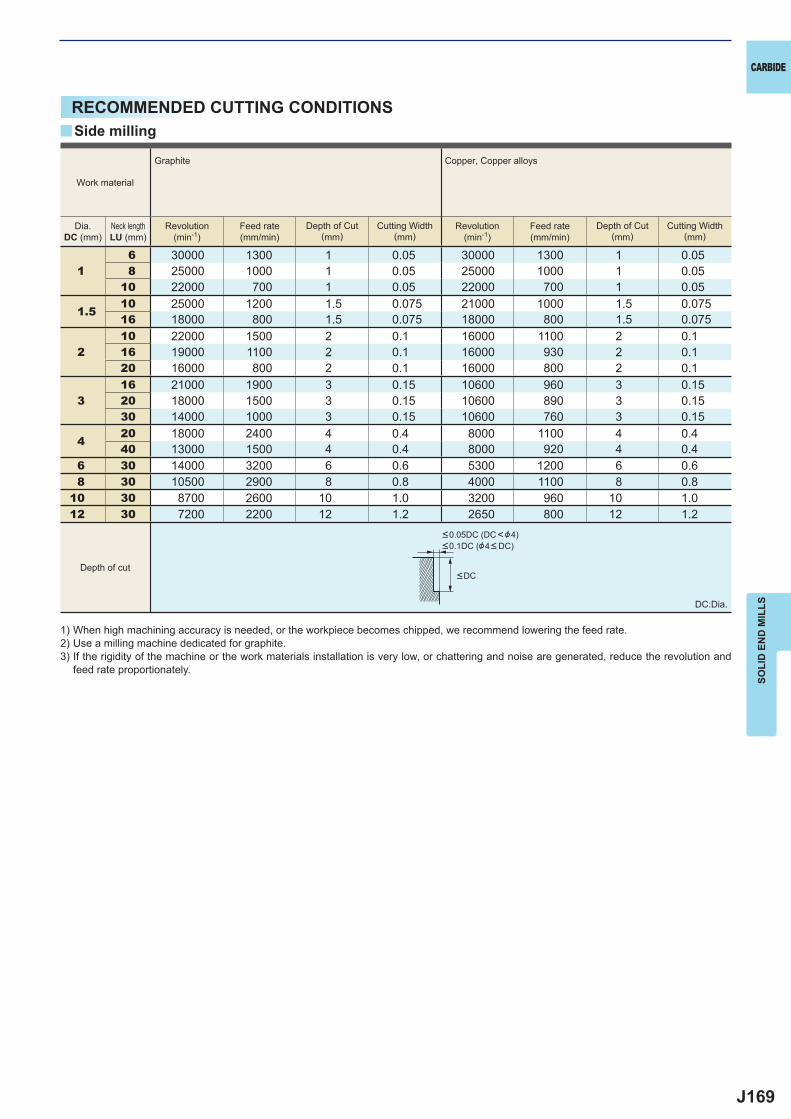
J169
y
16 30000 1300 1 0.05 30000 1300 1 0.058 25000 1000 1 0.05 25000 1000 1 0.05
10 22000 700 1 0.05 22000 700 1 0.05
1.510 25000 1200 1.5 0.075 21000 1000 1.5 0.07516 18000 800 1.5 0.075 18000 800 1.5 0.075
210 22000 1500 2 0.1 16000 1100 2 0.116 19000 1100 2 0.1 16000 930 2 0.120 16000 800 2 0.1 16000 800 2 0.1
316 21000 1900 3 0.15 10600 960 3 0.1520 18000 1500 3 0.15 10600 890 3 0.1530 14000 1000 3 0.15 10600 760 3 0.15
420 18000 2400 4 0.4 8000 1100 4 0.440 13000 1500 4 0.4 8000 920 4 0.4
6 30 14000 3200 6 0.6 5300 1200 6 0.68 30 10500 2900 8 0.8 4000 1100 8 0.8
10 30 8700 2600 10 1.0 3200 960 10 1.012 30 7200 2200 12 1.2 2650 800 12 1.2
CARBIDE
SOLI
D E
ND
MIL
LS
RECOMMENDED CUTTING CONDITIONS
1) When high machining accuracy is needed, or the workpiece becomes chipped, we recommend lowering the feed rate.2) Use a milling machine dedicated for graphite.3) If the rigidity of the machine or the work materials installation is very low, or chattering and noise are generated, reduce the revolution and
feed rate proportionately.
Side milling
DC:Dia.
<DC
<0.05DC (DC<&4)<0.1DC (&4< DC)
Work material
Graphite Copper, Copper alloys
Dia.DC (mm)
Neck lengthLU (mm)
Revolution(min-1)
Feed rate(mm/min)
Depth of Cut(mm)
Cutting Width(mm)
Revolution(min-1)
Feed rate(mm/min)
Depth of Cut(mm)
Cutting Width(mm)
Depth of cut
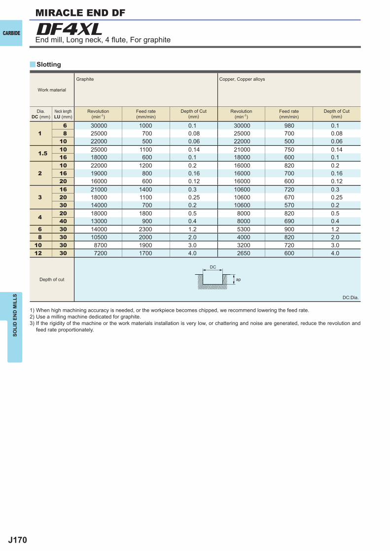
J170
16 30000 1000 0.1 30000 980 0.18 25000 700 0.08 25000 700 0.08
10 22000 500 0.06 22000 500 0.06
1.510 25000 1100 0.14 21000 750 0.1416 18000 600 0.1 18000 600 0.1
210 22000 1200 0.2 16000 820 0.216 19000 800 0.16 16000 700 0.1620 16000 600 0.12 16000 600 0.12
316 21000 1400 0.3 10600 720 0.320 18000 1100 0.25 10600 670 0.2530 14000 700 0.2 10600 570 0.2
420 18000 1800 0.5 8000 820 0.540 13000 900 0.4 8000 690 0.4
6 30 14000 2300 1.2 5300 900 1.28 30 10500 2000 2.0 4000 820 2.0
10 30 8700 1900 3.0 3200 720 3.012 30 7200 1700 4.0 2650 600 4.0
y
DF4XL
DC
ap
CARBIDE
SOLI
D E
ND
MIL
LS DC:Dia.
Work material
Graphite Copper, Copper alloys
Dia.DC (mm)
Neck lengthLU (mm)
Revolution(min-1)
Feed rate(mm/min)
Depth of Cut(mm)
Revolution(min-1)
Feed rate(mm/min)
Depth of Cut(mm)
Depth of cut
Slotting
1) When high machining accuracy is needed, or the workpiece becomes chipped, we recommend lowering the feed rate.2) Use a milling machine dedicated for graphite.3) If the rigidity of the machine or the work materials installation is very low, or chattering and noise are generated, reduce the revolution and
feed rate proportionately.
End mill, Long neck, 4 fl ute, For graphite
MIRACLE END DF
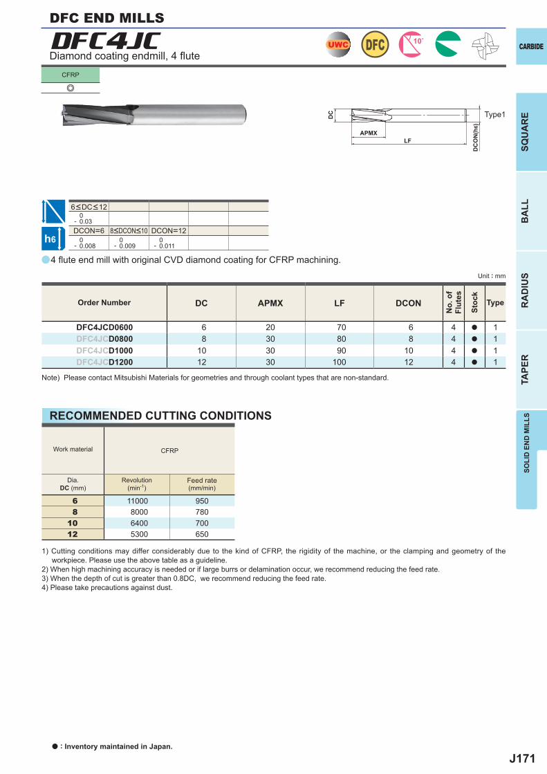
J171
a
e
a
DFC4JC
DC APMX LF DCON
DFC4JCD0600 6 20 70 6 4 a 1DFC4JCD0800 8 30 80 8 4 a 1DFC4JCD1000 10 30 90 10 4 a 1DFC4JCD1200 12 30 100 12 4 a 1
0- 0.03DCON=6 DCON=12 0- 0.008
0- 0.009
0- 0.011
CFRP
6 11000 9508 8000 780
10 6400 70012 5300 650
DFCUWC
h6
APMX
DC
DC
ON
(h6)
LF
SOLI
D E
ND
MIL
LSSQ
UA
RE
BA
LLR
AD
IUS
TAPE
R
CARBIDE
CFRP
Unit : mm
Type1
Order Number
No.
of
Flut
es
Stoc
k
Type
DFC END MILLS
Diamond coating endmill, 4 fl ute
8<DCON<10
6<DC<12
4 fl ute end mill with original CVD diamond coating for CFRP machining.
Note) Please contact Mitsubishi Materials for geometries and through coolant types that are non-standard.
RECOMMENDED CUTTING CONDITIONS
Work material
Dia.DC (mm)
Revolution(min-1)
Feed rate(mm/min)
1) Cutting conditions may differ considerably due to the kind of CFRP, the rigidity of the machine, or the clamping and geometry of the workpiece. Please use the above table as a guideline.
2) When high machining accuracy is needed or if large burrs or delamination occur, we recommend reducing the feed rate.3) When the depth of cut is greater than 0.8DC, we recommend reducing the feed rate.4) Please take precautions against dust.
a : Inventory maintained in Japan.
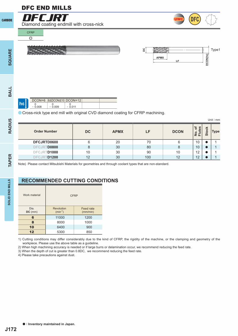
J172
a
e
a
DFCJRT
DC APMX LF DCON
DFCJRTD0600 6 20 70 6 10 a 1DFCJRTD0800 8 30 80 8 10 a 1DFCJRTD1000 10 30 90 10 12 a 1DFCJRTD1200 12 30 100 12 12 a 1
DCON=6 DCON=12 0- 0.008
0- 0.009
0- 0.011
CFRP
6 11000 12008 8000 1000
10 6400 90012 5300 850
DFCUWC
h6
APMX
DC
DC
ON
(h6)
LF
CARBIDE
SQU
AR
EB
ALL
RA
DIU
STA
PER
SOLI
D E
ND
MIL
LS
a : Inventory maintained in Japan.
CFRP
Unit : mm
Diamond coating endmill with cross-nick
Type1
8<DCON<10
Cross-nick type end mill with original CVD diamond coating for CFRP machining.
Order Number
No.
of
Flut
es
Stoc
k
Type
Note) Please contact Mitsubishi Materials for geometries and through coolant types that are non-standard.
RECOMMENDED CUTTING CONDITIONS
Work material
Dia.DC (mm)
Revolution(min-1)
Feed rate(mm/min)
1) Cutting conditions may differ considerably due to the kind of CFRP, the rigidity of the machine, or the clamping and geometry of the workpiece. Please use the above table as a guideline.
2) When high machining accuracy is needed or if large burrs or delamination occur, we recommend reducing the feed rate.3) When the depth of cut is greater than 0.8DC, we recommend reducing the feed rate.4) Please take precautions against dust.
DFC END MILLS
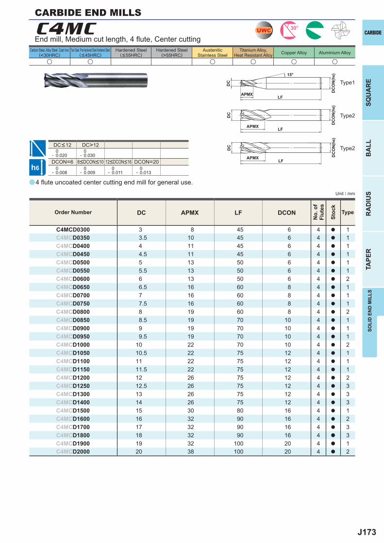
J173
a
u u u u u u
C4MC
DC APMX LF DCON
C4MCD0300 3 8 45 6 4 a 1C4MCD0350 3.5 10 45 6 4 a 1C4MCD0400 4 11 45 6 4 a 1C4MCD0450 4.5 11 45 6 4 a 1C4MCD0500 5 13 50 6 4 a 1C4MCD0550 5.5 13 50 6 4 a 1C4MCD0600 6 13 50 6 4 a 2C4MCD0650 6.5 16 60 8 4 a 1C4MCD0700 7 16 60 8 4 a 1C4MCD0750 7.5 16 60 8 4 a 1C4MCD0800 8 19 60 8 4 a 2C4MCD0850 8.5 19 70 10 4 a 1C4MCD0900 9 19 70 10 4 a 1C4MCD0950 9.5 19 70 10 4 a 1C4MCD1000 10 22 70 10 4 a 2C4MCD1050 10.5 22 75 12 4 a 1C4MCD1100 11 22 75 12 4 a 1C4MCD1150 11.5 22 75 12 4 a 1C4MCD1200 12 26 75 12 4 a 2C4MCD1250 12.5 26 75 12 4 a 3C4MCD1300 13 26 75 12 4 a 3C4MCD1400 14 26 75 12 4 a 3C4MCD1500 15 30 80 16 4 a 1C4MCD1600 16 32 90 16 4 a 2C4MCD1700 17 32 90 16 4 a 3C4MCD1800 18 32 90 16 4 a 3C4MCD1900 19 32 100 20 4 a 1C4MCD2000 20 38 100 20 4 a 2
DC>12 0- 0.020
0- 0.030
DCON=6 DCON=20 0- 0.008
0- 0.009
0- 0.011
0- 0.013
UWC 30°
h6
APMX
DC
DC
ON
(h6)15°
APMX LF
DC
DC
ON
(h6)
LF
APMXLF
DC
DC
ON
(h6)
SOLI
D E
ND
MIL
LSSQ
UA
RE
BA
LLR
AD
IUS
TAPE
R
CARBIDE
Carbon Steel, Alloy Steel, Cast Iron(<30HRC)
Tool Steel, Pre-Hardened Steel,Hardened Steel(<45HRC)
Hardened Steel(<55HRC)
Hardened Steel(>55HRC)
AusteniticStainless Steel
Titanium Alloy,Heat Resistant Alloy Copper Alloy Aluminium Alloy
Unit : mm
Type1
Type2
Type2
Order Number
No.
of
Flut
es
Stoc
k
Type
CARBIDE END MILLS
End mill, Medium cut length, 4 fl ute, Center cutting
8<DCON<10 12<DCON<16
DC<12
4 fl ute uncoated center cutting end mill for general use.
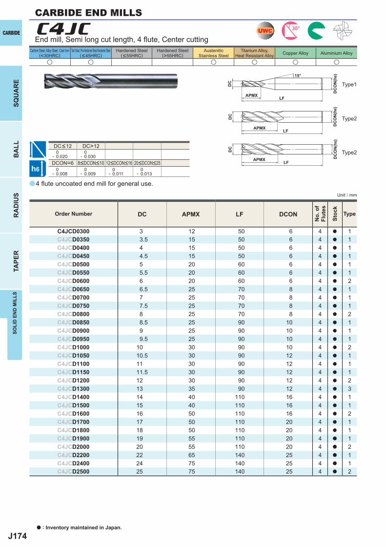
J174
a
u u u u u u
C4JC
DC APMX LF DCON
C4JCD0300 3 12 50 6 4 a 1C4JCD0350 3.5 15 50 6 4 a 1C4JCD0400 4 15 50 6 4 a 1C4JCD0450 4.5 15 50 6 4 a 1C4JCD0500 5 20 60 6 4 a 1C4JCD0550 5.5 20 60 6 4 a 1C4JCD0600 6 20 60 6 4 a 2C4JCD0650 6.5 25 70 8 4 a 1C4JCD0700 7 25 70 8 4 a 1C4JCD0750 7.5 25 70 8 4 a 1C4JCD0800 8 25 70 8 4 a 2C4JCD0850 8.5 25 90 10 4 a 1C4JCD0900 9 25 90 10 4 a 1C4JCD0950 9.5 25 90 10 4 a 1C4JCD1000 10 30 90 10 4 a 2C4JCD1050 10.5 30 90 12 4 a 1C4JCD1100 11 30 90 12 4 a 1C4JCD1150 11.5 30 90 12 4 a 1C4JCD1200 12 30 90 12 4 a 2C4JCD1300 13 35 90 12 4 a 3C4JCD1400 14 40 110 16 4 a 1C4JCD1500 15 40 110 16 4 a 1C4JCD1600 16 50 110 16 4 a 2C4JCD1700 17 50 110 20 4 a 1C4JCD1800 18 50 110 20 4 a 1C4JCD1900 19 55 110 20 4 a 1C4JCD2000 20 55 110 20 4 a 2C4JCD2200 22 65 140 25 4 a 1C4JCD2400 24 75 140 25 4 a 1C4JCD2500 25 75 140 25 4 a 2
DC>12 0- 0.020
0- 0.030
DCON=6 0- 0.008
0- 0.009
0- 0.011
0- 0.013
UWC 30°
h6
APMX
DC
DC
ON
(h6)15°
APMX LF
DC
DC
ON
(h6)
LF
APMX LF
DC
DC
ON
(h6)
CARBIDE
SQU
AR
EB
ALL
RA
DIU
STA
PER
SOLI
D E
ND
MIL
LS
a : Inventory maintained in Japan.
Carbon Steel, Alloy Steel, Cast Iron(<30HRC)
Tool Steel, Pre-Hardened Steel,Hardened Steel(<45HRC)
Hardened Steel(<55HRC)
Hardened Steel(>55HRC)
AusteniticStainless Steel
Titanium Alloy,Heat Resistant Alloy Copper Alloy Aluminium Alloy
Unit : mm
End mill, Semi long cut length, 4 fl ute, Center cutting
Type1
Type2
Type2
8<DCON<10 12<DCON<16 20<DCON<25
DC<12
4 fl ute uncoated end mill for general use.
Order Number
No.
of
Flut
es
Stoc
k
Type
CARBIDE END MILLS
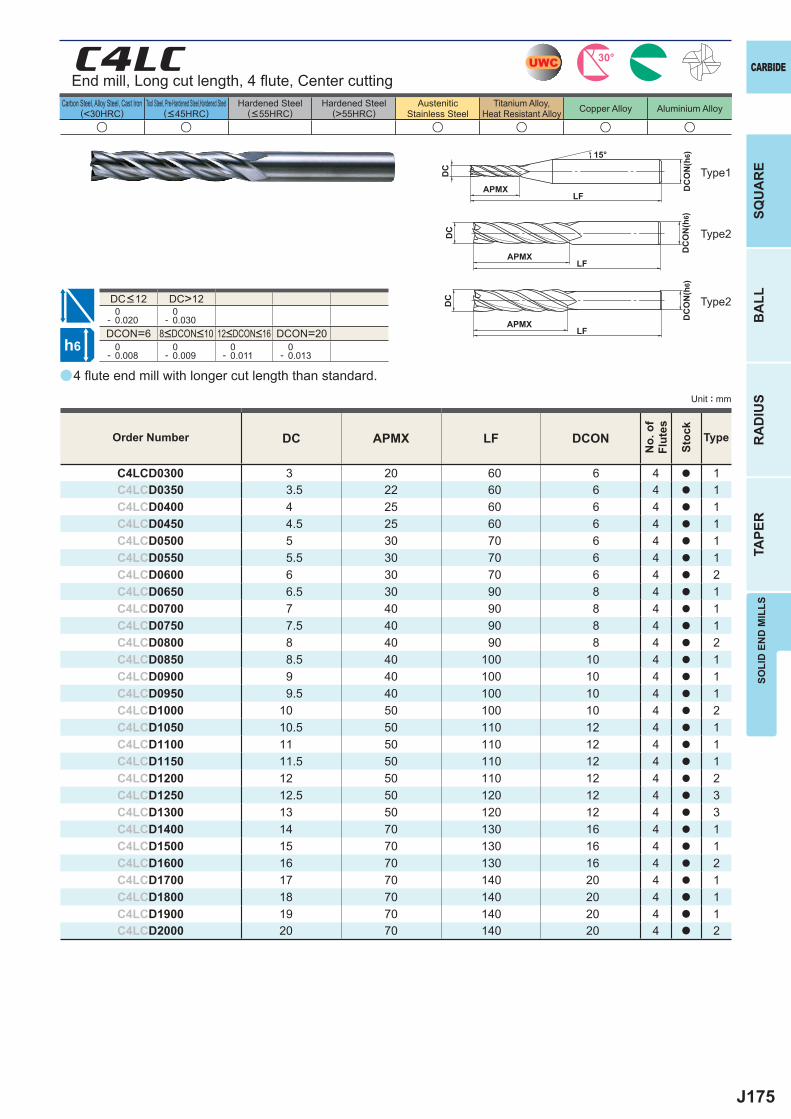
J175
a
u u u u u u
C4LC
DC APMX LF DCON
C4LCD0300 3 20 60 6 4 a 1C4LCD0350 3.5 22 60 6 4 a 1C4LCD0400 4 25 60 6 4 a 1C4LCD0450 4.5 25 60 6 4 a 1C4LCD0500 5 30 70 6 4 a 1C4LCD0550 5.5 30 70 6 4 a 1C4LCD0600 6 30 70 6 4 a 2C4LCD0650 6.5 30 90 8 4 a 1C4LCD0700 7 40 90 8 4 a 1C4LCD0750 7.5 40 90 8 4 a 1C4LCD0800 8 40 90 8 4 a 2C4LCD0850 8.5 40 100 10 4 a 1C4LCD0900 9 40 100 10 4 a 1C4LCD0950 9.5 40 100 10 4 a 1C4LCD1000 10 50 100 10 4 a 2C4LCD1050 10.5 50 110 12 4 a 1C4LCD1100 11 50 110 12 4 a 1C4LCD1150 11.5 50 110 12 4 a 1C4LCD1200 12 50 110 12 4 a 2C4LCD1250 12.5 50 120 12 4 a 3C4LCD1300 13 50 120 12 4 a 3C4LCD1400 14 70 130 16 4 a 1C4LCD1500 15 70 130 16 4 a 1C4LCD1600 16 70 130 16 4 a 2C4LCD1700 17 70 140 20 4 a 1C4LCD1800 18 70 140 20 4 a 1C4LCD1900 19 70 140 20 4 a 1C4LCD2000 20 70 140 20 4 a 2
DC>12 0- 0.020
0- 0.030
DCON=6 DCON=20 0- 0.008
0- 0.009
0- 0.011
0- 0.013
UWC 30°
h6
APMX
DC
DC
ON
(h6)15°
APMXLF
DC
DC
ON
(h6)
LF
APMXLF
DC
DC
ON
(h6)
SOLI
D E
ND
MIL
LSSQ
UA
RE
BA
LLR
AD
IUS
TAPE
R
CARBIDE
Carbon Steel, Alloy Steel, Cast Iron(<30HRC)
Tool Steel, Pre-Hardened Steel,Hardened Steel(<45HRC)
Hardened Steel(<55HRC)
Hardened Steel(>55HRC)
AusteniticStainless Steel
Titanium Alloy,Heat Resistant Alloy Copper Alloy Aluminium Alloy
Unit : mm
Type1
Type2
Type2
Order Number
No.
of
Flut
es
Stoc
k
Type
End mill, Long cut length, 4 fl ute, Center cutting
8<DCON<10 12<DCON<16
DC<12
4 fl ute end mill with longer cut length than standard.
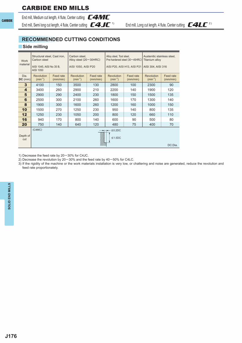
J176
3 4100 150 3500 130 2800 100 2300 904 3400 260 2900 210 2200 140 1900 1205 2900 290 2400 230 1800 150 1500 1356 2500 300 2100 260 1600 170 1300 1408 1900 300 1600 260 1200 160 1000 150
10 1500 270 1250 230 950 140 800 13512 1250 230 1050 200 800 120 660 11016 940 170 800 140 600 90 500 8020 750 140 640 120 480 75 400 70
(C4MC)
y
CARBIDE
SOLI
D E
ND
MIL
LS
End mill, Medium cut length, 4 fl ute, Center cutting C4MC End mill, Semi long cut length, 4 fl ute, Center cutting C4JC 1) End mill, Long cut length, 4 fl ute, Center cutting C4LC 2 )
RECOMMENDED CUTTING CONDITIONS
1) Decrease the feed rate by 20─30% for C4JC.2) Decrease the revolution by 20─30% and the feed rate by 40─50% for C4LC.3) If the rigidity of the machine or the work materials installation is very low, or chattering and noise are generated, reduce the revolution and
feed rate proportionately.
DC:Dia.
Side milling
Depth ofcut
<0.2DC
<1.5DC
Workmaterial
Structural steel, Cast iron, Carbon steel
AISI 1045, AISI No 35 B, AISI 1050
Carbon steel, Alloy steel (20─30HRC)
AISI 1050, AISI P20
Alloy steel, Tool steel, Pre-hardened steel (30─45HRC)
AISI P20, AISI H13, AISI P21
Austenitic stainless steel,Titanium alloy
AISI 304, AISI 316
Dia.DC (mm)
Revolution(min-1)
Feed rate(mm/min)
Revolution(min-1)
Feed rate(mm/min)
Revolution(min-1)
Feed rate(mm/min)
Revolution(min-1)
Feed rate(mm/min)
CARBIDE END MILLS
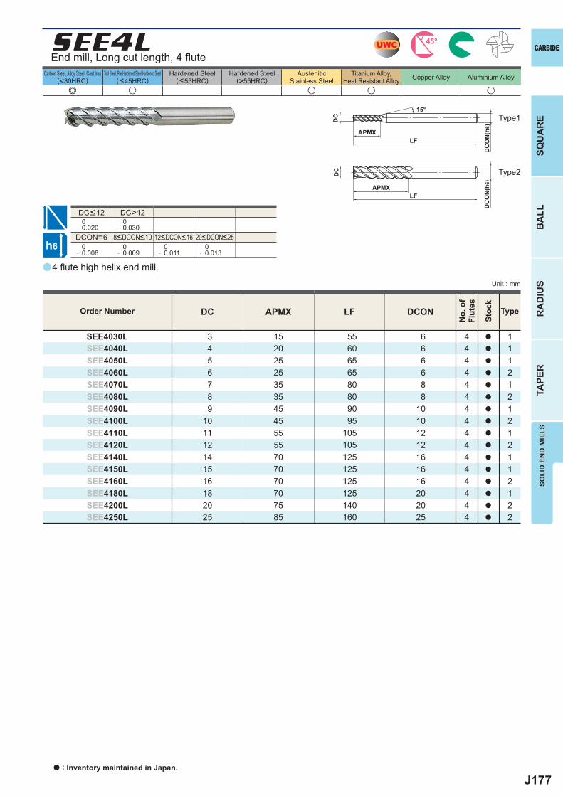
J177
a
SEE4L
e u u u u
DC APMX LF DCON
SEE4030L 3 15 55 6 4 a 1SEE4040L 4 20 60 6 4 a 1SEE4050L 5 25 65 6 4 a 1SEE4060L 6 25 65 6 4 a 2SEE4070L 7 35 80 8 4 a 1SEE4080L 8 35 80 8 4 a 2SEE4090L 9 45 90 10 4 a 1SEE4100L 10 45 95 10 4 a 2SEE4110L 11 55 105 12 4 a 1SEE4120L 12 55 105 12 4 a 2SEE4140L 14 70 125 16 4 a 1SEE4150L 15 70 125 16 4 a 1SEE4160L 16 70 125 16 4 a 2SEE4180L 18 70 125 20 4 a 1SEE4200L 20 75 140 20 4 a 2SEE4250L 25 85 160 25 4 a 2
DC>12 0- 0.020
0- 0.030
DCON=6 0- 0.008
0- 0.009
0- 0.011
0- 0.013
UWC 45°
h6
APMX
DC
DC
ON
(h6)
15°
APMXLF
DC
DC
ON
(h6)
LF
SOLI
D E
ND
MIL
LSSQ
UA
RE
BA
LLR
AD
IUS
TAPE
R
CARBIDE
Carbon Steel, Alloy Steel, Cast Iron(<30HRC)
Tool Steel, Pre-Hardened Steel,Hardened Steel(<45HRC)
Hardened Steel(<55HRC)
Hardened Steel(>55HRC)
AusteniticStainless Steel
Titanium Alloy,Heat Resistant Alloy Copper Alloy Aluminium Alloy
Unit : mm
End mill, Long cut length, 4 fl ute
Type1
Type2
8<DCON<10 12<DCON<16 20<DCON<25
DC<12
4 fl ute high helix end mill.
Order Number
No.
of
Flut
es
Stoc
k
Type
a : Inventory maintained in Japan.
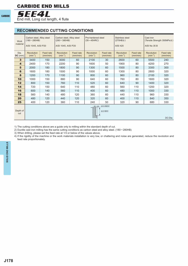
J178
3 3400 150 3000 60 2100 30 2600 60 5500 240 4 2400 170 2200 90 1600 50 1900 80 4200 270 5 2000 180 1800 90 1300 60 1500 80 3300 300 6 1600 180 1500 90 1000 60 1300 80 2800 320 8 1200 170 1100 90 800 60 960 80 2100 320
10 1000 150 880 90 640 60 760 80 1600 32012 800 150 760 110 520 60 640 90 1400 32014 720 150 640 110 480 60 560 110 1200 32016 600 140 560 110 400 60 480 110 1000 33018 560 140 480 120 360 60 440 110 960 33020 480 120 440 120 320 60 400 110 840 35025 400 120 360 110 240 50 320 90 680 330
SEE4LCARBIDE
SOLI
D E
ND
MIL
LS
RECOMMENDED CUTTING CONDITIONS
1) The cutting conditions above are a guide only to milling within the standard depth of cut.2) Ductile cast iron milling has the same cutting conditions as carbon steel and alloy steel. (180─280HB)3) When drilling, please set the feed rate at 1/3 or below of the values above.4) If the rigidity of the machine or the work materials installation is very low, or chattering and noise are generated, reduce the revolution and
feed rate proportionately.
DC:Dia.
Workmaterial
Carbon steel, Alloy steel(180─280HB)
AISI 1045, AISI P20
Carbon steel, Alloy steel(280─380HB)
AISI 1045, AISI P20
Pre-hardened steel(35─45HRC)
Stainless steel(270HB> )
AISI 420
Cast iron(Tensile Strength 350MPa> )
AISI No 35 B
Dia.DC (mm)
Revolution(min-1)
Feed rate(mm/min)
Revolution(min-1)
Feed rate(mm/min)
Revolution(min-1)
Feed rate(mm/min)
Revolution(min-1)
Feed rate(mm/min)
Revolution(min-1)
Feed rate(mm/min)
<0.05DC
<2.5DCDepth ofcut
CARBIDE END MILLS
End mill, Long cut length, 4 fl ute
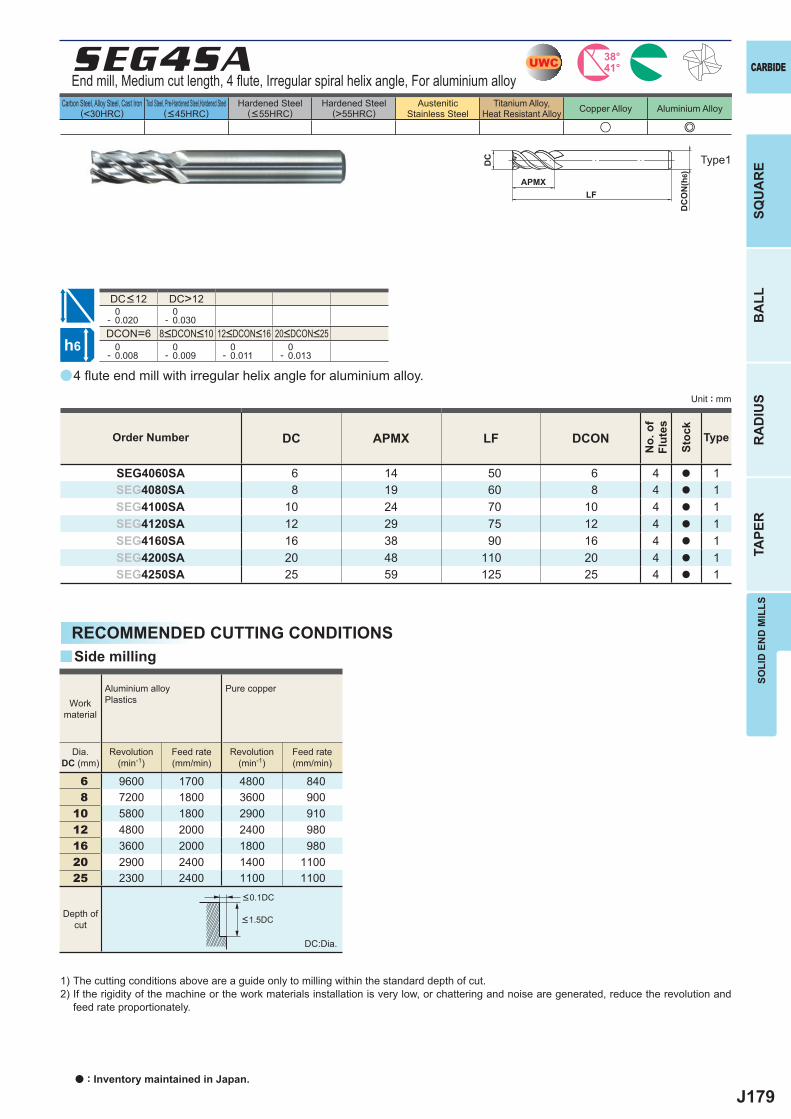
J179
a
u e
SEG4SA
DC APMX LF DCON
SEG4060SA 6 14 50 6 4 a 1SEG4080SA 8 19 60 8 4 a 1SEG4100SA 10 24 70 10 4 a 1SEG4120SA 12 29 75 12 4 a 1SEG4160SA 16 38 90 16 4 a 1SEG4200SA 20 48 110 20 4 a 1SEG4250SA 25 59 125 25 4 a 1
DC>12 0- 0.020
0- 0.030
DCON=6 0- 0.008
0- 0.009
0- 0.011
0- 0.013
6 9600 1700 4800 8408 7200 1800 3600 900
10 5800 1800 2900 91012 4800 2000 2400 98016 3600 2000 1800 98020 2900 2400 1400 110025 2300 2400 1100 1100
y
UWC 38°41°
h6
APMX
DC
DC
ON
(h6)
LF
SOLI
D E
ND
MIL
LSSQ
UA
RE
BA
LLR
AD
IUS
TAPE
R
CARBIDE
Carbon Steel, Alloy Steel, Cast Iron(<30HRC)
Tool Steel, Pre-Hardened Steel,Hardened Steel(<45HRC)
Hardened Steel(<55HRC)
Hardened Steel(>55HRC)
AusteniticStainless Steel
Titanium Alloy,Heat Resistant Alloy Copper Alloy Aluminium Alloy
Unit : mm
Type1
Order Number
No.
of
Flut
es
Stoc
k
Type
End mill, Medium cut length, 4 fl ute, Irregular spiral helix angle, For aluminium alloy
8<DCON<10 12<DCON<16 20<DCON<25
DC<12
4 fl ute end mill with irregular helix angle for aluminium alloy.
RECOMMENDED CUTTING CONDITIONS
1) The cutting conditions above are a guide only to milling within the standard depth of cut.2) If the rigidity of the machine or the work materials installation is very low, or chattering and noise are generated, reduce the revolution and
feed rate proportionately.
DC:Dia.
Side milling
Dia.DC (mm)
Revolution(min-1)
Feed rate(mm/min)
Revolution(min-1)
Feed rate(mm/min)
Workmaterial
Aluminium alloyPlastics
Pure copper
<0.1DC
<1.5DCDepth of
cut
a : Inventory maintained in Japan.
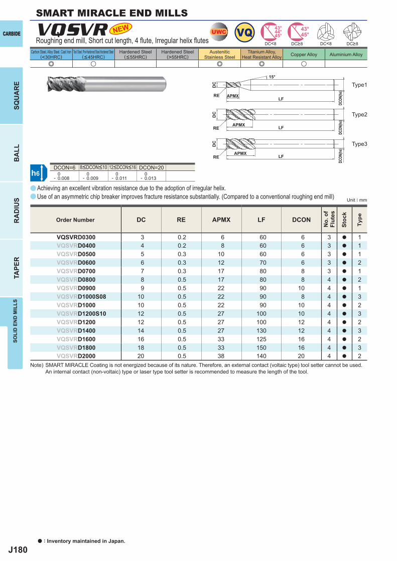
J180
a
e u e e u
VQSVR
DC RE APMX LF DCON
VQSVRD0300 3 0.2 6 60 6 3 a 1VQSVRD0400 4 0.2 8 60 6 3 a 1VQSVRD0500 5 0.3 10 60 6 3 a 1VQSVRD0600 6 0.3 12 70 6 3 a 2VQSVRD0700 7 0.3 17 80 8 3 a 1VQSVRD0800 8 0.5 17 80 8 4 a 2VQSVRD0900 9 0.5 22 90 10 4 a 1VQSVRD1000S08 10 0.5 22 90 8 4 a 3VQSVRD1000 10 0.5 22 90 10 4 a 2VQSVRD1200S10 12 0.5 27 100 10 4 a 3VQSVRD1200 12 0.5 27 100 12 4 a 2VQSVRD1400 14 0.5 27 130 12 4 a 3VQSVRD1600 16 0.5 33 125 16 4 a 2VQSVRD1800 18 0.5 33 150 16 4 a 3VQSVRD2000 20 0.5 38 140 20 4 a 2
DCON=6 DCON=20 0- 0.008
0- 0.009
0- 0.011
0- 0.013
NEW
a
h6
UWC VQ 45°44°43° 43°
45°DC<8 DC<8
APMX
APMX
APMX
DC
DC
DC
DCON
(h6)
DCON
(h6)
DCON
(h6)
LF
LF
LF
RE
RE
RE
15°
CARBIDE
SQU
AR
EB
ALL
RA
DIU
STA
PER
SOLI
D E
ND
MIL
LS
a : Inventory maintained in Japan.
Carbon Steel, Alloy Steel, Cast Iron(<30HRC)
Tool Steel, Pre-Hardened Steel,Hardened Steel(<45HRC)
Hardened Steel(<55HRC)
Hardened Steel(>55HRC)
AusteniticStainless Steel
Titanium Alloy,Heat Resistant Alloy Copper Alloy Aluminium Alloy
Unit : mm
Order Number
No.
of
Flut
es
Stoc
k
Type
Roughing end mill, Short cut length, 4 fl ute, Irregular helix fl utes
Achieving an excellent vibration resistance due to the adoption of irregular helix.Use of an asymmetric chip breaker improves fracture resistance substantially. (Compared to a conventional roughing end mill)
8<DCON<10 12<DCON<16
Type2
Type3
Type1
DC>8DC>8
Note) SMART MIRACLE Coating is not energized because of its nature. Therefore, an external contact (voltaic type) tool setter cannot be used. An internal contact (non-voltaic) type or laser type tool setter is recommended to measure the length of the tool.
SMART MIRACLE END MILLS
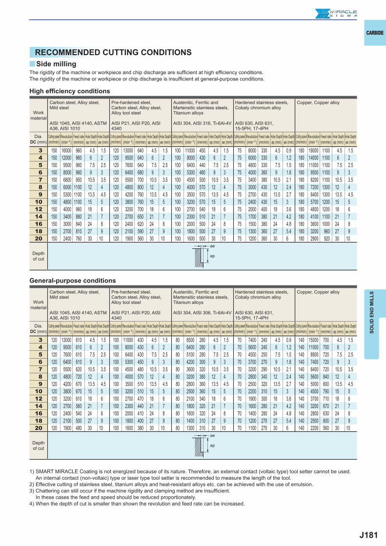
J181
y
3 150 16000 960 4.5 1.5 120 13000 640 4.5 1.5 100 11000 450 4.5 1.5 75 8000 330 4.5 0.9 180 19000 1100 4.5 1.54 150 12000 960 6 2 120 9500 640 6 2 100 8000 430 6 2 75 6000 330 6 1.2 180 14000 1100 6 25 150 9500 960 7.5 2.5 120 7600 640 7.5 2.5 100 6400 440 7.5 2.5 75 4800 330 7.5 1.5 180 11000 1100 7.5 2.56 150 8000 960 9 3 120 6400 680 9 3 100 5300 480 9 3 75 4000 360 9 1.8 180 9500 1100 9 37 150 6800 950 10.5 3.5 120 5500 700 10.5 3.5 100 4500 500 10.5 3.5 75 3400 380 10.5 2.1 180 8200 1100 10.5 3.58 150 6000 1100 12 4 120 4800 800 12 4 100 4000 570 12 4 75 3000 430 12 2.4 180 7200 1300 12 49 150 5300 1100 13.5 4.5 120 4200 760 13.5 4.5 100 3500 570 13.5 4.5 75 2700 430 13.5 2.7 180 6400 1300 13.5 4.5
10 150 4800 1100 15 5 120 3800 760 15 5 100 3200 570 15 5 75 2400 430 15 3 180 5700 1200 15 512 150 4000 960 18 6 120 3200 700 18 6 100 2700 540 18 6 75 2000 400 18 3.6 180 4800 1200 18 614 150 3400 880 21 7 120 2700 650 21 7 100 2300 510 21 7 75 1700 380 21 4.2 180 4100 1100 21 716 150 3000 840 24 8 120 2400 620 24 8 100 2000 500 24 8 75 1500 380 24 4.8 180 3600 1000 24 818 150 2700 810 27 9 120 2100 590 27 9 100 1800 500 27 9 75 1300 360 27 5.4 180 3200 960 27 920 150 2400 760 30 10 120 1900 560 30 10 100 1600 500 30 10 75 1200 360 30 6 180 2900 920 30 10
3 120 13000 610 4.5 1.5 100 11000 430 4.5 1.5 80 8500 280 4.5 1.5 70 7400 240 4.5 0.9 140 15000 700 4.5 1.54 120 9500 610 6 2 100 8000 430 6 2 80 6400 280 6 2 70 5600 240 6 1.2 140 11000 700 6 25 120 7600 610 7.5 2.5 100 6400 430 7.5 2.5 80 5100 280 7.5 2.5 70 4500 250 7.5 1.5 140 8900 720 7.5 2.56 120 6400 610 9 3 100 5300 450 9 3 80 4200 300 9 3 70 3700 270 9 1.8 140 7400 720 9 37 120 5500 620 10.5 3.5 100 4500 480 10.5 3.5 80 3600 320 10.5 3.5 70 3200 290 10.5 2.1 140 6400 720 10.5 3.58 120 4800 720 12 4 100 4000 570 12 4 80 3200 380 12 4 70 2800 340 12 2.4 140 5600 840 12 49 120 4200 670 13.5 4.5 100 3500 510 13.5 4.5 80 2800 360 13.5 4.5 70 2500 320 13.5 2.7 140 5000 800 13.5 4.5
10 120 3800 670 15 5 100 3200 510 15 5 80 2500 360 15 5 70 2200 310 15 3 140 4500 790 15 512 120 3200 610 18 6 100 2700 470 18 6 80 2100 340 18 6 70 1900 300 18 3.6 140 3700 710 18 614 120 2700 560 21 7 100 2300 440 21 7 80 1800 320 21 7 70 1600 280 21 4.2 140 3200 670 21 716 120 2400 540 24 8 100 2000 410 24 8 80 1600 320 24 8 70 1400 280 24 4.8 140 2800 630 24 818 120 2100 500 27 9 100 1800 400 27 9 80 1400 310 27 9 70 1200 270 27 5.4 140 2500 600 27 920 120 1900 480 30 10 100 1600 380 30 10 80 1300 310 30 10 70 1100 270 30 6 140 2200 560 30 10
ae
ap
ae
ap
CARBIDE
SOLI
D E
ND
MIL
LS
RECOMMENDED CUTTING CONDITIONSSide milling
The rigidity of the machine or workpiece and chip discharge are suffi cient at high effi ciency conditions. The rigidity of the machine or workpiece or chip discharge is insuffi cient at general-purpose conditions.
Work material
Carbon steel, Alloy steel,Mild steel
AISI 1045, AISI 4140, ASTM A36, AISI 1010
Pre-hardened steel,Carbon steel, Alloy steel,Alloy tool steel
AISI P21, AISI P20, AISI 4340
Austenitic, Ferritic and Martensitic stainless steels,Titanium alloys
AISI 304, AISI 316, Ti-6Al-4V
Hardened stainless steels,Cobaly chromium alloy
AISI 630, AISI 631,15-5PH, 17-4PH
Copper, Copper alloy
Dia.DC (mm)
Cutting speed (m/min)
Revolution (min-1)
Feed rate (mm/min)
Hole Depth ap (mm)
Hole Depth ae (mm)
Cutting speed (m/min)
Revolution (min-1)
Feed rate (mm/min)
Hole Depth ap (mm)
Hole Depth ae (mm)
Cutting speed (m/min)
Revolution (min-1)
Feed rate (mm/min)
Hole Depth ap (mm)
Hole Depth ae (mm)
Cutting speed (m/min)
Revolution (min-1)
Feed rate (mm/min)
Hole Depth ap (mm)
Hole Depth ae (mm)
Cutting speed (m/min)
Revolution (min-1)
Feed rate (mm/min)
Hole Depth ap (mm)
Hole Depth ae (mm)
Depth of cut
Work material
Carbon steel, Alloy steel,Mild steel
AISI 1045, AISI 4140, ASTM A36, AISI 1010
Pre-hardened steel,Carbon steel, Alloy steel,Alloy tool steel
AISI P21, AISI P20, AISI 4340
Austenitic, Ferritic and Martensitic stainless steels,Titanium alloys
AISI 304, AISI 306, Ti-6Al-4V
Hardened stainless steels,Cobaly chromium alloy
AISI 630, AISI 631,15-5PH, 17-4PH
Copper, Copper alloy
Dia.DC (mm)
Cutting speed (m/min)
Revolution (min-1)
Feed rate (mm/min)
Hole Depth ap (mm)
Hole Depth ae (mm)
Cutting speed (m/min)
Revolution (min-1)
Feed rate (mm/min)
Hole Depth ap (mm)
Hole Depth ae (mm)
Cutting speed (m/min)
Revolution (min-1)
Feed rate (mm/min)
Hole Depth ap (mm)
Hole Depth ae (mm)
Cutting speed (m/min)
Revolution (min-1)
Feed rate (mm/min)
Hole Depth ap (mm)
Hole Depth ae (mm)
Cutting speed (m/min)
Revolution (min-1)
Feed rate (mm/min)
Hole Depth ap (mm)
Hole Depth ae (mm)
Depth of cut
1) SMART MIRACLE Coating is not energized because of its nature. Therefore, an external contact (voltaic type) tool setter cannot be used. An internal contact (non-voltaic) type or laser type tool setter is recommended to measure the length of the tool.
2) Effective cutting of stainless steel, titanium alloys and heat-resistant alloys etc. can be achieved with the use of emulsion.3) Chattering can still occur if the machine rigidity and clamping method are insuffi cient.
In these cases the feed and speed should be reduced proportionately.4) When the depth of cut is smaller than shown the revolution and feed rate can be increased.
High effi ciency conditions
General-purpose conditions
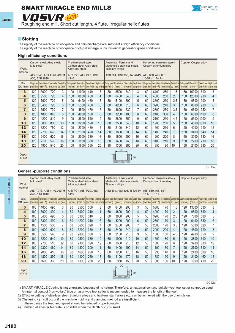
J182
VQSVR NEW
y
3 120 13000 720 3 100 11000 440 3 80 8500 340 3 60 6400 250 1.5 150 16000 890 34 120 9500 720 4 100 8000 450 4 80 6400 340 4 60 4800 250 2 150 12000 900 45 120 7600 720 5 100 6400 460 5 80 5100 300 5 60 3800 230 2.5 150 9500 900 56 120 6400 720 6 100 5300 460 6 80 4200 310 6 60 3200 240 3 150 8000 900 67 120 5500 730 7 100 4500 470 7 80 3600 330 7 60 2700 250 3.5 150 6800 950 78 120 4800 840 8 100 4000 560 8 80 3200 400 8 60 2400 300 4 150 6000 1100 89 120 4200 810 9 100 3500 540 9 80 2800 350 9 60 2100 260 4.5 150 5300 1000 9
10 120 3800 800 10 100 3200 520 10 80 2500 340 10 60 1900 260 5 150 4800 1000 1012 120 3200 750 12 100 2700 480 12 80 2100 340 12 60 1600 260 6 150 4000 940 1214 120 2700 670 14 100 2300 420 14 80 1800 300 14 60 1400 240 7 150 3400 840 1416 120 2400 620 16 100 2000 380 16 80 1600 290 16 60 1200 220 8 150 3000 780 1618 120 2100 570 18 100 1800 380 18 80 1400 260 18 60 1100 210 9 150 2700 730 1820 120 1900 540 20 100 1600 350 20 80 1300 260 20 60 950 190 10 150 2400 680 20
3 100 11000 490 3 80 8500 300 3 60 6400 200 3 50 5300 170 1.5 120 13000 580 34 100 8000 490 4 80 6400 310 4 60 4800 200 4 50 4000 170 2 120 9500 580 45 100 6400 490 5 80 5100 310 5 60 3800 200 5 50 3200 170 2.5 120 7600 580 56 100 5300 490 6 80 4200 310 6 60 3200 200 6 50 2700 170 3 120 6400 580 67 100 4500 500 7 80 3600 320 7 60 2700 200 7 50 2300 170 3.5 120 5500 620 78 100 4000 600 8 80 3200 380 8 60 2400 240 8 50 2000 200 4 120 4800 720 89 100 3500 540 9 80 2800 330 9 60 2100 210 9 50 1800 180 4.5 120 4200 650 9
10 100 3200 540 10 80 2500 330 10 60 1900 210 10 50 1600 180 5 120 3800 640 1012 100 2700 510 12 80 2100 320 12 60 1600 210 12 50 1300 170 6 120 3200 600 1214 100 2300 460 14 80 1800 300 14 60 1400 190 14 50 1100 150 7 120 2700 540 1416 100 2000 410 16 80 1600 290 16 60 1200 170 16 50 990 140 8 120 2400 500 1618 100 1800 390 18 80 1400 260 18 60 1100 170 18 50 880 130 9 120 2100 460 1820 100 1600 360 20 80 1300 260 20 60 950 150 20 50 800 130 10 120 1900 430 20
ap
ap
DC
DC
CARBIDE
SOLI
D E
ND
MIL
LS
Roughing end mill, Short cut length, 4 fl ute, Irregular helix fl utes
SlottingThe rigidity of the machine or workpiece and chip discharge are suffi cient at high effi ciency conditions. The rigidity of the machine or workpiece or chip discharge is insuffi cient at general-purpose conditions.
Work material
Carbon steel, Alloy steel,Mild steel
AISI 1045, AISI 4140, ASTM A36, AISI 1010
Pre-hardened steel,Carbon steel, Alloy steel,Alloy tool steel
AISI P21, AISI P20, AISI 4340
Austenitic, Ferritic and Martensitic stainless steels,Titanium alloys
AISI 304, AISI 306, Ti-6Al-4V
Hardened stainless steels,Cobaly chromium alloy
AISI 630, AISI 631,15-5PH, 17-4PH
Copper, Copper alloy
Dia.DC (mm)
Cutting speed (m/min)
Revolution (min-1)
Feed rate (mm/min)
Depth of cut ap (mm)
Cutting speed (m/min)
Revolution (min-1)
Feed rate (mm/min)
Depth of cut ap (mm)
Cutting speed (m/min)
Revolution (min-1)
Feed rate (mm/min)
Depth of cut ap (mm)
Cutting speed (m/min)
Revolution (min-1)
Feed rate (mm/min)
Depth of cut ap (mm)
Cutting speed (m/min)
Revolution (min-1)
Feed rate (mm/min)
Depth of cut ap (mm)
Depth of cut
1) SMART MIRACLE Coating is not energized because of its nature. Therefore, an external contact (voltaic type) tool setter cannot be used. An internal contact (non-voltaic) type or laser type tool setter is recommended to measure the length of the tool.
2) Effective cutting of stainless steel, titanium alloys and heat-resistant alloys etc. can be achieved with the use of emulsion.3) Chattering can still occur if the machine rigidity and clamping method are insuffi cient.
In these cases the feed and speed should be reduced proportionately.4) Finishing at a faster feedrate is possible when the depth of cut is small.
High effi ciency conditions
General-purpose conditions
SMART MIRACLE END MILLS
DC:Dia.
DC:Dia.
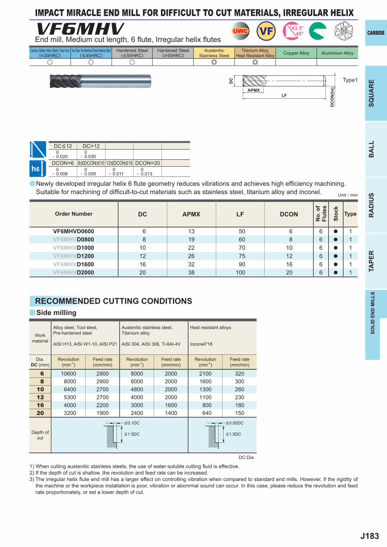
J183
a
u u u e e
VF6MHV
DC APMX LF DCON
VF6MHVD0600 6 13 50 6 6 a 1VF6MHVD0800 8 19 60 8 6 a 1VF6MHVD1000 10 22 70 10 6 a 1VF6MHVD1200 12 26 75 12 6 a 1VF6MHVD1600 16 32 90 16 6 a 1VF6MHVD2000 20 38 100 20 6 a 1
DC>12 0- 0.020
0- 0.030
DCON=6 DCON=20 0- 0.008
0- 0.009
0- 0.011
0- 0.013
6 10600 2900 8000 2000 2100 3208 8000 2900 6000 2000 1600 300
10 6400 2700 4800 2000 1300 26012 5300 2700 4000 2000 1100 23016 4000 2200 3000 1600 800 18020 3200 1900 2400 1400 640 150
y
UWC VF 43.5°45°
h6
APMX
DC
DC
ON
(h6)
LF
SOLI
D E
ND
MIL
LSSQ
UA
RE
BA
LLR
AD
IUS
TAPE
R
CARBIDE
Carbon Steel, Alloy Steel, Cast Iron(<30HRC)
Tool Steel, Pre-Hardened Steel,Hardened Steel(<45HRC)
Hardened Steel(<55HRC)
Hardened Steel(>55HRC)
AusteniticStainless Steel
Titanium Alloy,Heat Resistant Alloy Copper Alloy Aluminium Alloy
Unit : mm
IMPACT MIRACLE END MILL FOR DIFFICULT TO CUT MATERIALS, IRREGULAR HELIX
End mill, Medium cut length, 6 fl ute, Irregular helix fl utes
Type1
8<DCON<10 12<DCON<16
DC<12
Order Number
No.
of
Flut
es
Stoc
k
Type
Newly developed irregular helix 6 fl ute geometry reduces vibrations and achieves high effi ciency machining. Suitable for machining of diffi cult-to-cut materials such as stainless steel, titanium alloy and inconel.
RECOMMENDED CUTTING CONDITIONS
1) When cutting austenitic stainless steels, the use of water-soluble cutting fl uid is effective.2) If the depth of cut is shallow, the revolution and feed rate can be increased.3) The irregular helix fl ute end mill has a larger effect on controlling vibration when compared to standard end mills. However, if the rigidity of
the machine or the workpiece installation is poor, vibration or abonrmal sound can occur. In this case, please reduce the revolution and feed rate proportionately, or set a lower depth of cut.
DC:Dia.
Side milling
Workmaterial
Alloy steel, Tool steel,Pre-hardened steel
AISI H13, AISI W1-10, AISI P21
Austenitic stainless steel,Titanium alloy
AISI 304, AISI 306, Ti-6Al-4V
Heat resistant alloys
Inconel718
Dia.DC (mm)
Revolution(min-1)
Revolution(min-1)
Revolution(min-1)
Feed rate(mm/min)
Feed rate(mm/min)
Feed rate(mm/min)
Depth ofcut
<0.1DC <0.05DC
<1.5DC <1.5DC
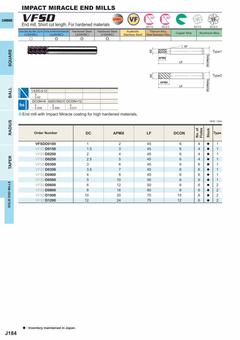
J184
a
VFSD
DC APMX LF DCON
VFSDD0100 1 2 45 6 4 a 1VFSDD0150 1.5 3 45 6 4 a 1VFSDD0200 2 4 45 6 4 a 1VFSDD0250 2.5 5 45 6 4 a 1VFSDD0300 3 6 45 6 6 a 1VFSDD0350 3.5 7 45 6 6 a 1VFSDD0400 4 8 45 6 6 a 1VFSDD0500 5 10 50 6 6 a 1VFSDD0600 6 12 50 6 6 a 2VFSDD0800 8 16 60 8 6 a 2VFSDD1000 10 20 70 10 6 a 2VFSDD1200 12 24 75 12 6 a 2
u e e e
DC<3 DC<3
0- 0.02DCON=6 DCON=12 0- 0.008
0- 0.009
0- 0.011
UWC VF 45°30°
h6
APMX
DC
DC
ON
(h6)
15°
APMXLF
DC
DC
ON
(h6)
LF
CARBIDE
SQU
AR
EB
ALL
RA
DIU
STA
PER
SOLI
D E
ND
MIL
LS
a : Inventory maintained in Japan.
Carbon Steel, Alloy Steel, Cast Iron(<30HRC)
Tool Steel, Pre-Hardened Steel,Hardened Steel(<45HRC)
Hardened Steel(<55HRC)
Hardened Steel(>55HRC)
AusteniticStainless Steel
Titanium Alloy,Heat Resistant Alloy Copper Alloy Aluminium Alloy
Unit : mm
Order Number
No.
of
Flut
es
Stoc
k
Type
DC>3 DC>3End mill, Short cut length, For hardened materials
Type1
Type2
8<DCON<10
1<DC<12
End mill with Impact Miracle coating for high hardened materials.
IMPACT MIRACLE END MILLS
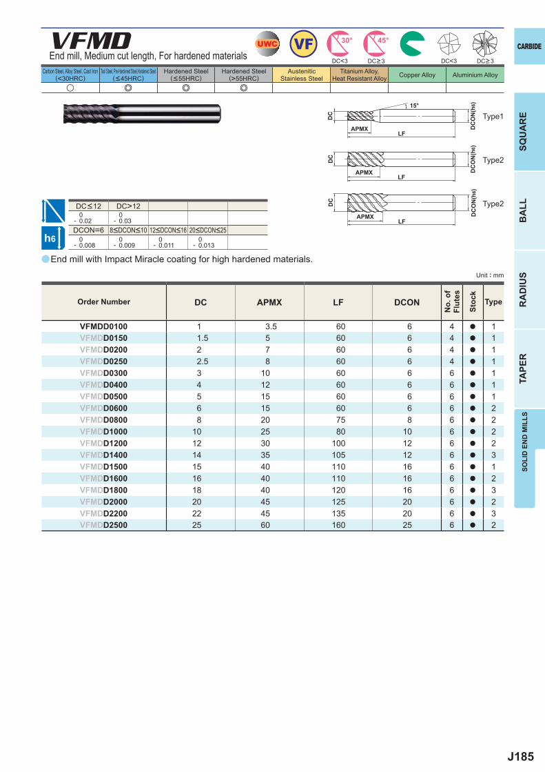
J185
a
VFMD
DC APMX LF DCON
VFMDD0100 1 3.5 60 6 4 a 1VFMDD0150 1.5 5 60 6 4 a 1VFMDD0200 2 7 60 6 4 a 1VFMDD0250 2.5 8 60 6 4 a 1VFMDD0300 3 10 60 6 6 a 1VFMDD0400 4 12 60 6 6 a 1VFMDD0500 5 15 60 6 6 a 1VFMDD0600 6 15 60 6 6 a 2VFMDD0800 8 20 75 8 6 a 2VFMDD1000 10 25 80 10 6 a 2VFMDD1200 12 30 100 12 6 a 2VFMDD1400 14 35 105 12 6 a 3VFMDD1500 15 40 110 16 6 a 1VFMDD1600 16 40 110 16 6 a 2VFMDD1800 18 40 120 16 6 a 3VFMDD2000 20 45 125 20 6 a 2VFMDD2200 22 45 135 20 6 a 3VFMDD2500 25 60 160 25 6 a 2
u e e e
DC<3 DC<3
DC>12 0- 0.02
0- 0.03
DCON=6 0- 0.008
0- 0.009
0- 0.011
0- 0.013
UWC VF 45°30°
h6
APMX
DC
DC
ON
(h6)15°
APMXLF
DC
DC
ON
(h6)
LF
APMXLF
DC
DC
ON
(h6)
SOLI
D E
ND
MIL
LSSQ
UA
RE
BA
LLR
AD
IUS
TAPE
R
CARBIDE
Carbon Steel, Alloy Steel, Cast Iron(<30HRC)
Tool Steel, Pre-Hardened Steel,Hardened Steel(<45HRC)
Hardened Steel(<55HRC)
Hardened Steel(>55HRC)
AusteniticStainless Steel
Titanium Alloy,Heat Resistant Alloy Copper Alloy Aluminium Alloy
Unit : mm
DC>3 DC>3End mill, Medium cut length, For hardened materials
Type1
Type2
Type2
8<DCON<10 12<DCON<16 20<DCON<25
DC<12
End mill with Impact Miracle coating for high hardened materials.
Order Number
No.
of
Flut
es
Stoc
k
Type
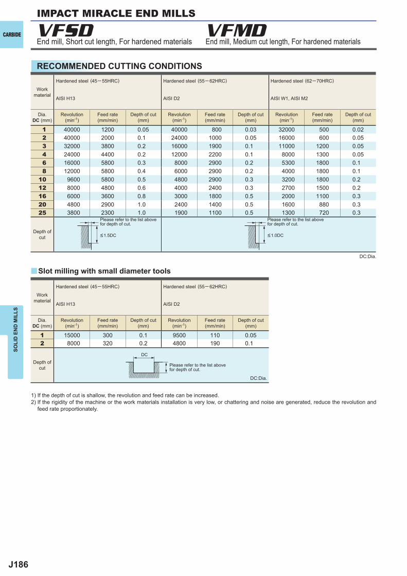
J186
VFSD VFMD
1 40000 1200 0.05 40000 800 0.03 32000 500 0.022 40000 2000 0.1 24000 1000 0.05 16000 600 0.053 32000 3800 0.2 16000 1900 0.1 11000 1200 0.054 24000 4400 0.2 12000 2200 0.1 8000 1300 0.056 16000 5800 0.3 8000 2900 0.2 5300 1800 0.1 8 12000 5800 0.4 6000 2900 0.2 4000 1800 0.1
10 9600 5800 0.5 4800 2900 0.3 3200 1800 0.2 12 8000 4800 0.6 4000 2400 0.3 2700 1500 0.2 16 6000 3600 0.8 3000 1800 0.5 2000 1100 0.3 20 4800 2900 1.0 2400 1400 0.5 1600 880 0.3 25 3800 2300 1.0 1900 1100 0.5 1300 720 0.3
1 15000 300 0.1 9500 110 0.052 8000 320 0.2 4800 190 0.1
y
DC
CARBIDE
SOLI
D E
ND
MIL
LS
RECOMMENDED CUTTING CONDITIONS
End mill, Short cut length, For hardened materials End mill, Medium cut length, For hardened materials
1) If the depth of cut is shallow, the revolution and feed rate can be increased.2) If the rigidity of the machine or the work materials installation is very low, or chattering and noise are generated, reduce the revolution and
feed rate proportionately.
DC:Dia.
DC:Dia.
Please refer to the list abovefor depth of cut.
Please refer to the list abovefor depth of cut.
Please refer to the list abovefor depth of cut.
Slot milling with small diameter tools
Workmaterial
Hardened steel (45─ 55HRC)
AISI H13
Hardened steel (55─ 62HRC)
AISI D2
Hardened steel (62─70HRC)
AISI W1, AISI M2
Dia.DC (mm)
Dia.DC (mm)
Revolution(min-1)
Revolution(min-1)
Revolution(min-1)
Revolution(min-1)
Revolution(min-1)
Feed rate(mm/min)
Feed rate(mm/min)
Feed rate(mm/min)
Feed rate(mm/min)
Feed rate(mm/min)
Depth of cut(mm)
Depth of cut(mm)
Depth of cut(mm)
Depth of cut(mm)
Depth of cut(mm)
Depth ofcut
Depth ofcut
<1.5DC <1.0DC
Workmaterial
Hardened steel (45─ 55HRC)
AISI H13
Hardened steel (55─ 62HRC)
AISI D2
IMPACT MIRACLE END MILLS
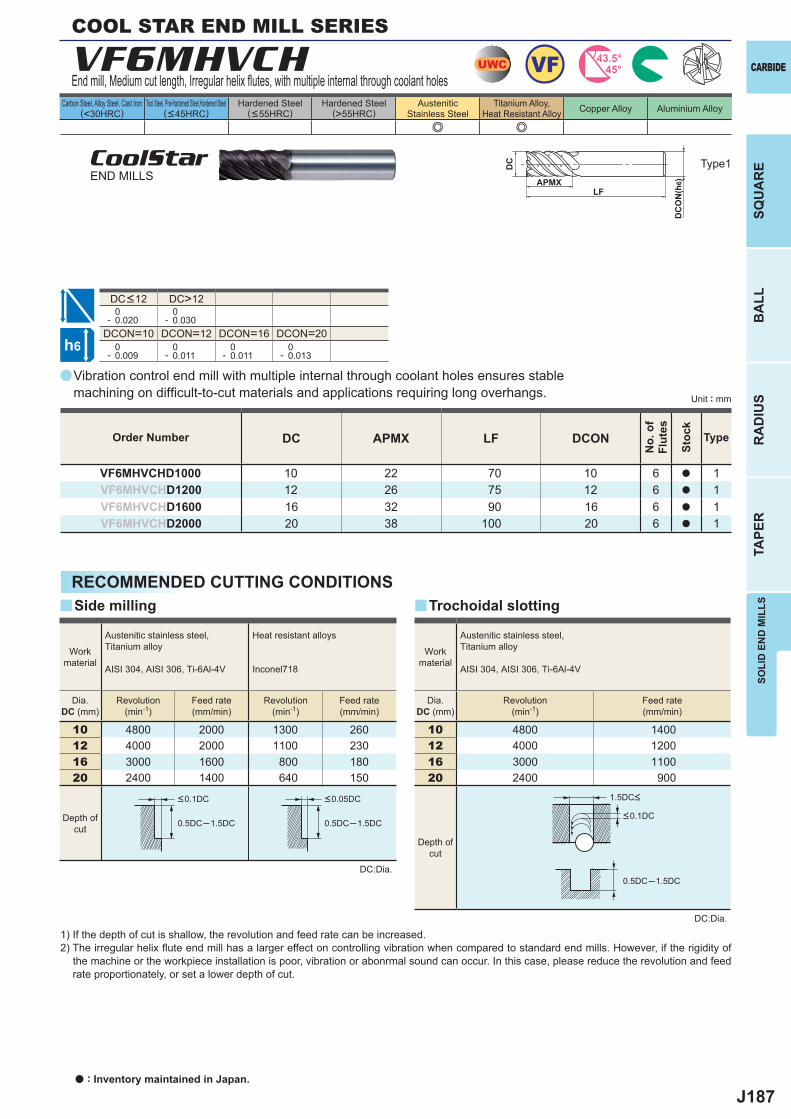
J187
a
e e
VF6MHVCH
DC APMX LF DCON
VF6MHVCHD1000 10 22 70 10 6 a 1VF6MHVCHD1200 12 26 75 12 6 a 1VF6MHVCHD1600 16 32 90 16 6 a 1VF6MHVCHD2000 20 38 100 20 6 a 1
DC>12 0- 0.020
0- 0.030
DCON=10 DCON=12 DCON=16 DCON=20 0- 0.009
0- 0.011
0- 0.011
0- 0.013
10 4800 2000 1300 26012 4000 2000 1100 23016 3000 1600 800 18020 2400 1400 640 150
0.5DC─1.5DC 0.5DC─1.5DC
y y
10 4800 140012 4000 120016 3000 110020 2400 900
0.5DC─1.5DC
UWC VF 43.5°45°
h6
APMX
DC
DC
ON
(h6)
LF
SOLI
D E
ND
MIL
LSSQ
UA
RE
BA
LLR
AD
IUS
TAPE
R
CARBIDE
Carbon Steel, Alloy Steel, Cast Iron(<30HRC)
Tool Steel, Pre-Hardened Steel,Hardened Steel(<45HRC)
Hardened Steel(<55HRC)
Hardened Steel(>55HRC)
AusteniticStainless Steel
Titanium Alloy,Heat Resistant Alloy Copper Alloy Aluminium Alloy
Unit : mm
Type1
Order Number
No.
of
Flut
es
Stoc
k
Type
COOL STAR END MILL SERIES
End mill, Medium cut length, Irregular helix fl utes, with multiple internal through coolant holes
CoolStarEND MILLS
DC<12
Vibration control end mill with multiple internal through coolant holes ensures stable machining on diffi cult-to-cut materials and applications requiring long overhangs.
RECOMMENDED CUTTING CONDITIONS
DC:Dia.
1) If the depth of cut is shallow, the revolution and feed rate can be increased.2) The irregular helix fl ute end mill has a larger effect on controlling vibration when compared to standard end mills. However, if the rigidity of
the machine or the workpiece installation is poor, vibration or abonrmal sound can occur. In this case, please reduce the revolution and feed rate proportionately, or set a lower depth of cut.
Side milling
Workmaterial
Austenitic stainless steel,Titanium alloy
AISI 304, AISI 306, Ti-6Al-4V
Heat resistant alloys
Inconel718
Dia.DC (mm)
Revolution(min-1)
Revolution(min-1)
Feed rate(mm/min)
Feed rate(mm/min)
Depth ofcut
<0.1DC <0.05DC
Trochoidal slotting
<0.1DC
1.5DC<
Workmaterial
Austenitic stainless steel,Titanium alloy
AISI 304, AISI 306, Ti-6Al-4V
Dia.DC (mm)
Revolution(min-1)
Feed rate(mm/min)
Depth ofcut
DC:Dia.
a : Inventory maintained in Japan.
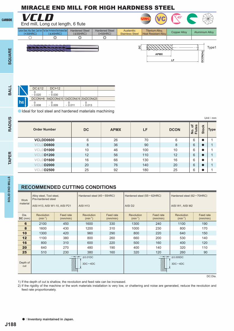
J188
a
u e e e
VCLD
DC APMX LF DCON
VCLDD0600 6 26 70 6 6 a 1VCLDD0800 8 36 90 8 6 a 1VCLDD1000 10 46 100 10 6 a 1VCLDD1200 12 56 110 12 6 a 1VCLDD1600 16 66 130 16 6 a 1VCLDD2000 20 76 140 20 6 a 1VCLDD2500 25 92 180 25 6 a 1
DC>12 0- 0.020
0- 0.030
DCON=6 0- 0.008
0- 0.009
0- 0.011
0- 0.013
6 2100 450 1600 330 1300 240 1100 1908 1600 430 1200 310 1000 230 800 170
10 1300 420 960 290 800 220 640 15012 1100 380 800 260 660 200 530 14016 800 310 600 220 500 160 400 12020 640 270 480 190 400 140 320 11025 510 230 380 160 320 120 260 90
UWC VC 45°
h6
APMX
DC
DC
ON
(h6)
LF
3DC─4DC 3DC─4DC
CARBIDE
SQU
AR
EB
ALL
RA
DIU
STA
PER
SOLI
D E
ND
MIL
LS
a : Inventory maintained in Japan.
Carbon Steel, Alloy Steel, Cast Iron(<30HRC)
Tool Steel, Pre-Hardened Steel,Hardened Steel(<45HRC)
Hardened Steel(<55HRC)
Hardened Steel(>55HRC)
AusteniticStainless Steel
Titanium Alloy,Heat Resistant Alloy Copper Alloy Aluminium Alloy
Unit : mm
MIRACLE END MILL FOR HIGH HARDNESS STEEL
End mill, Long cut length, 6 fl ute
Type1
8<DCON<10 12<DCON<16 20<DCON<25
DC<12
Order Number
No.
of
Flut
es
Stoc
k
Type
Ideal for tool steel and hardened materials machining
RECOMMENDED CUTTING CONDITIONS
1) If the depth of cut is shallow, the revolution and feed rate can be increased.2) If the rigidity of the machine or the work materials installation is very low, or chattering and noise are generated, reduce the revolution and
feed rate proportionately.
DC:Dia.
Workmaterial
Alloy steel, Tool steel,Pre-hardened steel
AISI H13, AISI W1-10, AISI P21
Hardened steel (45─ 55HRC)
AISI H13
Hardened steel (55─ 62HRC)
AISI D2
Hardened steel (62─70HRC)
AISI W1, AISI M2
Dia.DC (mm)
Revolution(min-1)
Feed rate(mm/min)
Revolution(min-1)
Feed rate(mm/min)
Revolution(min-1)
Feed rate(mm/min)
Revolution(min-1)
Feed rate(mm/min)
Depth ofcut
<0.01DC <0.005DC
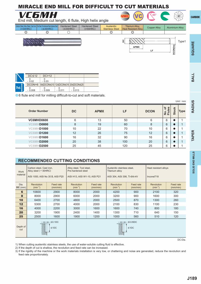
J189
a
e e u e e
VC6MH
DC APMX LF DCON
VC6MHD0600 6 13 50 6 6 a 1VC6MHD0800 8 19 60 8 6 a 1VC6MHD1000 10 22 70 10 6 a 1VC6MHD1200 12 26 75 12 6 a 1VC6MHD1600 16 32 90 16 6 a 1VC6MHD2000 20 38 100 20 6 a 1VC6MHD2500 25 45 120 25 6 a 1
DC>12 0- 0.02
0- 0.03
DCON=6 0- 0.008
0- 0.009
0- 0.011
0- 0.013
6 10600 2900 8000 2000 4200 900 2100 3208 8000 2900 6000 2000 3200 900 1600 300
10 6400 2700 4800 2000 2500 870 1300 26012 5300 2700 4000 2000 2100 830 1100 23016 4000 2200 3000 1600 1600 740 800 18020 3200 1900 2400 1400 1300 710 640 15025 2500 1600 1900 1200 1000 560 510 120
UWC VC 45°
h6
APMX
DC
DC
ON
(h6)
LF
SOLI
D E
ND
MIL
LSSQ
UA
RE
BA
LLR
AD
IUS
TAPE
R
CARBIDE
Carbon Steel, Alloy Steel, Cast Iron(<30HRC)
Tool Steel, Pre-Hardened Steel,Hardened Steel(<45HRC)
Hardened Steel(<55HRC)
Hardened Steel(>55HRC)
AusteniticStainless Steel
Titanium Alloy,Heat Resistant Alloy Copper Alloy Aluminium Alloy
Unit : mm
Type1
Order Number
No.
of
Flut
es
Stoc
k
Type
MIRACLE END MILL FOR DIFFICULT TO CUT MATERIALS
End mill, Medium cut length, 6 fl ute, High helix angle
8<DCON<10 12<DCON<16 20<DCON<25
DC<12
6 fl ute end mill for milling diffi cult-to-cut and soft materials.
RECOMMENDED CUTTING CONDITIONS
Workmaterial
Carbon steel, Cast iron, Alloy steel (─30HRC)
AISI 1050, AISI No 35 B, AISI P20
Alloy steel, Tool steel,Pre-hardened steel
AISI H13, AISI W1-10, AISI P21
Austenitic stainless steel,Titanium alloy
AISI 304, AISI 306, Ti-6Al-4V
Heat resistant alloys
Inconel718
Dia.DC (mm)
Revolution(min-1)
Feed rate(mm/min)
Revolution(min-1)
Feed rate(mm/min)
Revolution(min-1)
Feed rate(mm/min)
Revolution(min-1)
Feed rate(mm/min)
Depth ofcut
1) When cutting austenitic stainless steels, the use of water-soluble cutting fl uid is effective.2) If the depth of cut is shallow, the revolution and feed rate can be increased.3) If the rigidity of the machine or the work materials installation is very low, or chattering and noise are generated, reduce the revolution and
feed rate proportionately.
DC:Dia.
<0.1DC <0.05DC
<1DC <1DC
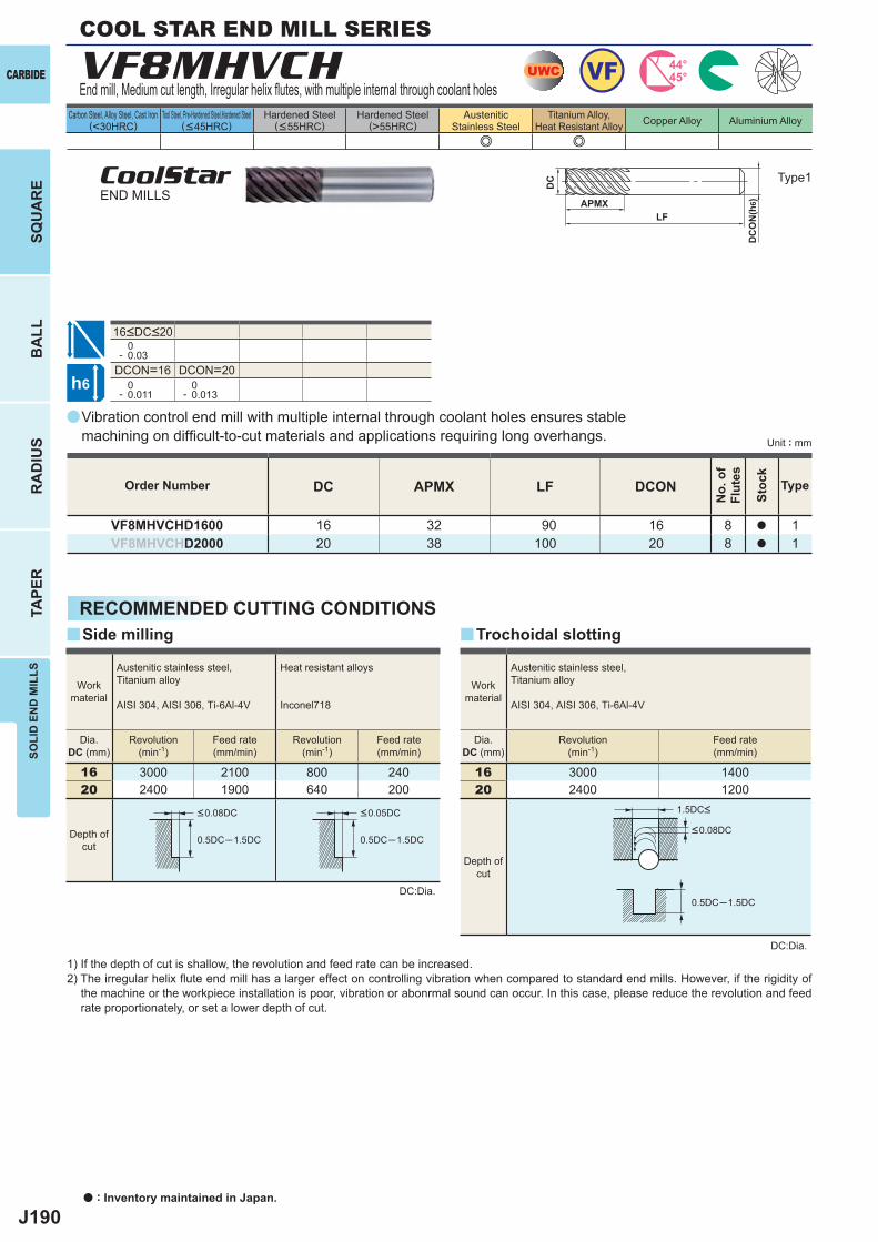
J190
a
e e
VF8MHVCH
DC APMX LF DCON
VF8MHVCHD1600 16 32 90 16 8 a 1VF8MHVCHD2000 20 38 100 20 8 a 1
0- 0.03
DCON=16 DCON=20 0- 0.011
0- 0.013
16 3000 2100 800 24020 2400 1900 640 200
0.5DC─1.5DC 0.5DC─1.5DC
y y
16 3000 140020 2400 1200
0.5DC─1.5DC
UWC VF 44°45°
h6
APMX
DC
DC
ON
(h6)
LF
CARBIDE
SQU
AR
EB
ALL
RA
DIU
STA
PER
SOLI
D E
ND
MIL
LS
a : Inventory maintained in Japan.
Carbon Steel, Alloy Steel, Cast Iron(<30HRC)
Tool Steel, Pre-Hardened Steel,Hardened Steel(<45HRC)
Hardened Steel(<55HRC)
Hardened Steel(>55HRC)
AusteniticStainless Steel
Titanium Alloy,Heat Resistant Alloy Copper Alloy Aluminium Alloy
Unit : mm
COOL STAR END MILL SERIES
End mill, Medium cut length, Irregular helix fl utes, with multiple internal through coolant holes
Type1CoolStarEND MILLS
16<DC<20
Vibration control end mill with multiple internal through coolant holes ensures stable machining on diffi cult-to-cut materials and applications requiring long overhangs.
Order Number
No.
of
Flut
es
Stoc
k
Type
RECOMMENDED CUTTING CONDITIONS
DC:Dia.
1) If the depth of cut is shallow, the revolution and feed rate can be increased.2) The irregular helix fl ute end mill has a larger effect on controlling vibration when compared to standard end mills. However, if the rigidity of
the machine or the workpiece installation is poor, vibration or abonrmal sound can occur. In this case, please reduce the revolution and feed rate proportionately, or set a lower depth of cut.
Side milling
Workmaterial
Austenitic stainless steel,Titanium alloy
AISI 304, AISI 306, Ti-6Al-4V
Heat resistant alloys
Inconel718
Dia.DC (mm)
Revolution(min-1)
Revolution(min-1)
Feed rate(mm/min)
Feed rate(mm/min)
Depth ofcut
<0.08DC <0.05DC
Trochoidal slotting
DC:Dia.
Workmaterial
Austenitic stainless steel,Titanium alloy
AISI 304, AISI 306, Ti-6Al-4V
Dia.DC (mm)
Revolution(min-1)
Feed rate(mm/min)
Depth ofcut
<0.08DC
1.5DC<
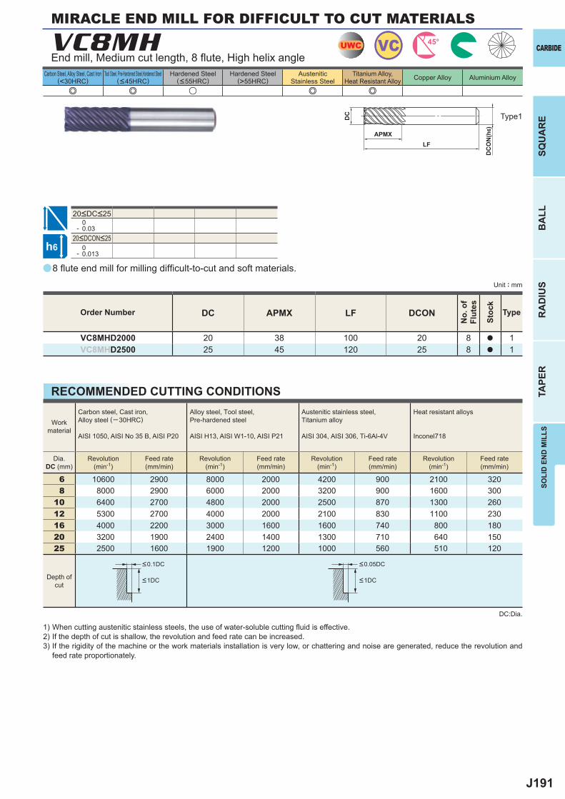
J191
a
e e u e e
VC8MH
DC APMX LF DCON
VC8MHD2000 20 38 100 20 8 a 1VC8MHD2500 25 45 120 25 8 a 1
0- 0.03
0- 0.013
6 10600 2900 8000 2000 4200 900 2100 3208 8000 2900 6000 2000 3200 900 1600 300
10 6400 2700 4800 2000 2500 870 1300 26012 5300 2700 4000 2000 2100 830 1100 23016 4000 2200 3000 1600 1600 740 800 18020 3200 1900 2400 1400 1300 710 640 15025 2500 1600 1900 1200 1000 560 510 120
UWC VC 45°
h6
APMX
DC
DC
ON
(h6)
LF
SOLI
D E
ND
MIL
LSSQ
UA
RE
BA
LLR
AD
IUS
TAPE
R
CARBIDE
Carbon Steel, Alloy Steel, Cast Iron(<30HRC)
Tool Steel, Pre-Hardened Steel,Hardened Steel(<45HRC)
Hardened Steel(<55HRC)
Hardened Steel(>55HRC)
AusteniticStainless Steel
Titanium Alloy,Heat Resistant Alloy Copper Alloy Aluminium Alloy
Unit : mm
Type1
Order Number
No.
of
Flut
es
Stoc
k
Type
MIRACLE END MILL FOR DIFFICULT TO CUT MATERIALS
End mill, Medium cut length, 8 fl ute, High helix angle
20<DCON<25
20<DC<25
8 fl ute end mill for milling diffi cult-to-cut and soft materials.
RECOMMENDED CUTTING CONDITIONS
Workmaterial
Carbon steel, Cast iron, Alloy steel (─30HRC)
AISI 1050, AISI No 35 B, AISI P20
Alloy steel, Tool steel,Pre-hardened steel
AISI H13, AISI W1-10, AISI P21
Austenitic stainless steel,Titanium alloy
AISI 304, AISI 306, Ti-6Al-4V
Heat resistant alloys
Inconel718
Dia.DC (mm)
Revolution(min-1)
Feed rate(mm/min)
Revolution(min-1)
Feed rate(mm/min)
Revolution(min-1)
Feed rate(mm/min)
Revolution(min-1)
Feed rate(mm/min)
Depth ofcut
1) When cutting austenitic stainless steels, the use of water-soluble cutting fl uid is effective.2) If the depth of cut is shallow, the revolution and feed rate can be increased.3) If the rigidity of the machine or the work materials installation is very low, or chattering and noise are generated, reduce the revolution and
feed rate proportionately.
DC:Dia.
<0.1DC <0.05DC
<1DC <1DC
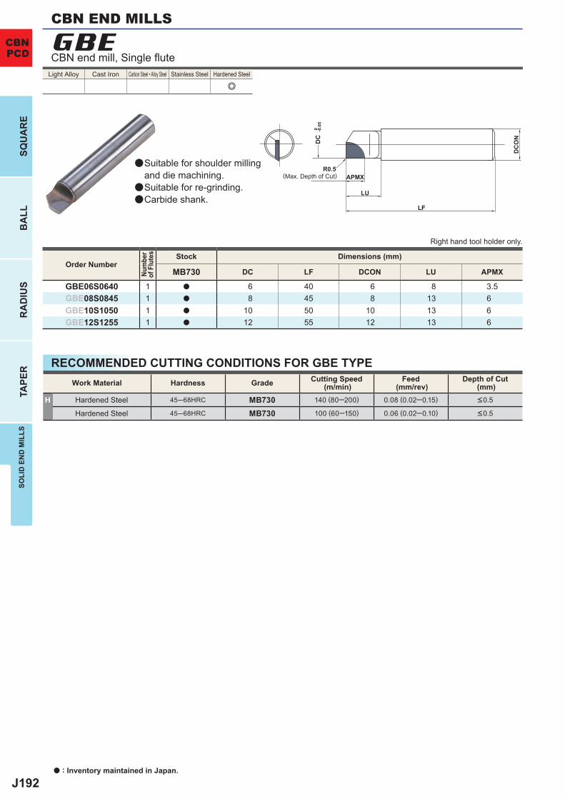
J192
e
MB730 DC LF DCON LU APMX
GBE06S0640 1 a 6 40 6 8 3.5GBE08S0845 1 a 8 45 8 13 6GBE10S1050 1 a 10 50 10 13 6GBE12S1255 1 a 12 55 12 13 6
H 45─68HRC MB730 140 (80─200) 0.08 (0.02─0.15)
45─68HRC MB730 100 (60─150) 0.06 (0.02─0.10)
GBE
R0.5
LU
DC
DC
ON
LF
APMX
0 -0.0
5
a : Inventory maintained in Japan.
SQU
AR
EB
ALL
RA
DIU
STA
PER
SOLI
D E
ND
MIL
LS
CBNPCD
CBN END MILLS
CBN end mill, Single fl ute
(Max. Depth of Cut)
Suitable for shoulder millingand die machining.Suitable for re-grinding.Carbide shank.
Light Alloy Cast Iron Carbon Steel • Alloy Steel Stainless Steel Hardened Steel
a
a
a
Right hand tool holder only.
Order Number
Num
ber
of F
lute
s Stock Dimensions (mm)
RECOMMENDED CUTTING CONDITIONS FOR GBE TYPEWork Material Hardness Grade Cutting Speed
(m/min)Feed
(mm/rev)Depth of Cut
(mm)Hardened Steel <0.5
Hardened Steel <0.5
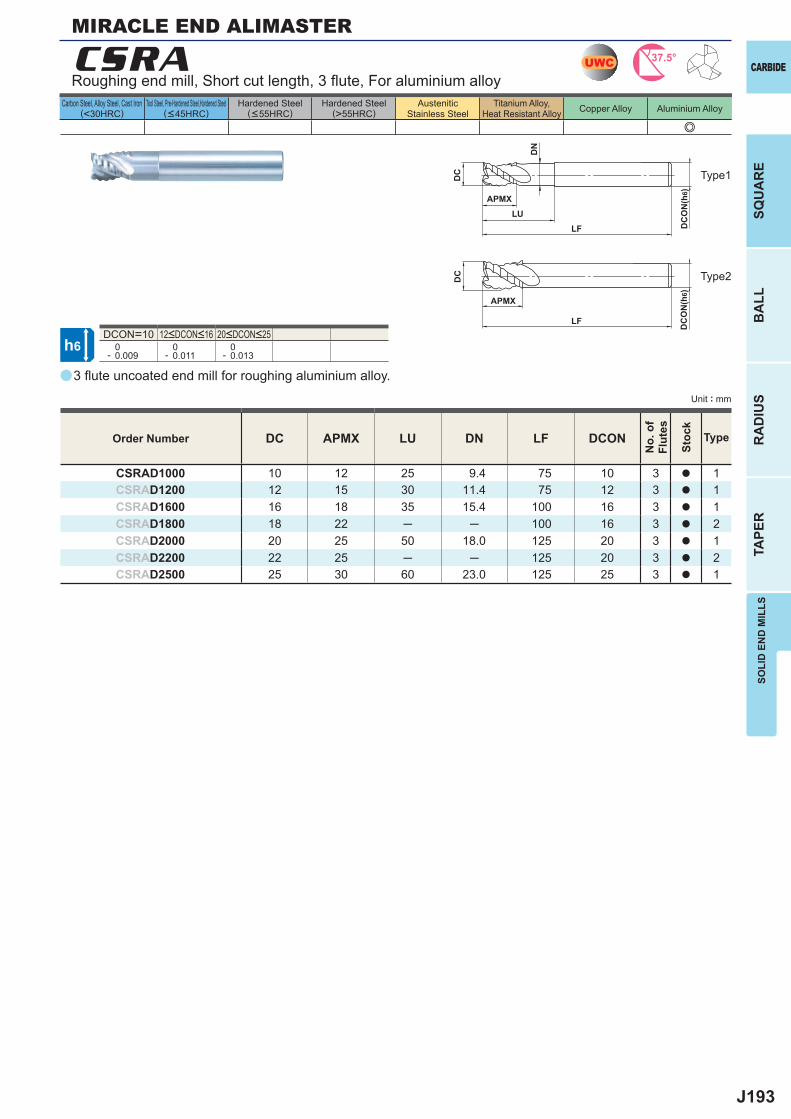
J193
a
e
CSRA
DC APMX LU DN LF DCON
CSRAD1000 10 12 25 9.4 75 10 3 a 1CSRAD1200 12 15 30 11.4 75 12 3 a 1CSRAD1600 16 18 35 15.4 100 16 3 a 1CSRAD1800 18 22 ─ ─ 100 16 3 a 2CSRAD2000 20 25 50 18.0 125 20 3 a 1CSRAD2200 22 25 ─ ─ 125 20 3 a 2CSRAD2500 25 30 60 23.0 125 25 3 a 1
DCON=10 0- 0.009
0- 0.011
0- 0.013
UWC 37.5°
h6
APMXLU
DC
DC
ON
(h6)
APMX
LF
DC
DC
ON
(h6)
LF
DN
SOLI
D E
ND
MIL
LSSQ
UA
RE
BA
LLR
AD
IUS
TAPE
R
CARBIDE
Carbon Steel, Alloy Steel, Cast Iron(<30HRC)
Tool Steel, Pre-Hardened Steel,Hardened Steel(<45HRC)
Hardened Steel(<55HRC)
Hardened Steel(>55HRC)
AusteniticStainless Steel
Titanium Alloy,Heat Resistant Alloy Copper Alloy Aluminium Alloy
Unit : mm
Roughing end mill, Short cut length, 3 fl ute, For aluminium alloy
Type1
Type2
12<DCON<16 20<DCON<25
3 fl ute uncoated end mill for roughing aluminium alloy.
Order Number
No.
of
Flut
es
Stoc
k
Type
MIRACLE END ALIMASTER
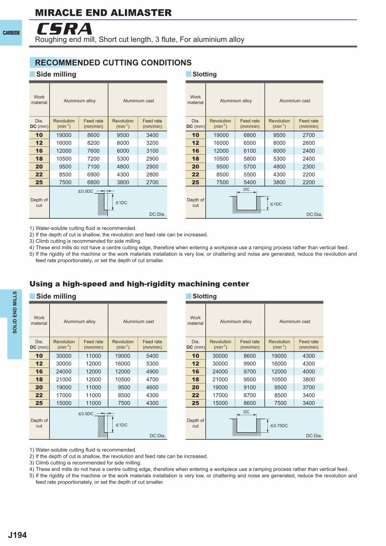
J194
10 19000 8600 9500 340012 16000 8200 8000 320016 12000 7600 6000 310018 10500 7200 5300 290020 9500 7100 4800 290022 8500 6900 4300 280025 7500 6800 3800 2700
10 30000 11000 19000 540012 30000 12000 16000 530016 24000 12000 12000 490018 21000 12000 10500 470020 19000 11000 9500 460022 17000 11000 8500 430025 15000 11000 7500 4300
10 19000 6800 9500 270012 16000 6500 8000 260016 12000 6100 6000 240018 10500 5800 5300 240020 9500 5700 4800 230022 8500 5500 4300 220025 7500 5400 3800 2200
10 30000 8600 19000 430012 30000 9900 16000 430016 24000 9700 12000 400018 21000 9500 10500 380020 19000 9100 9500 370022 17000 8700 8500 340025 15000 8600 7500 3400
y
y
y
y
CSRA
DC
DC
CARBIDE
SOLI
D E
ND
MIL
LS
RECOMMENDED CUTTING CONDITIONS
1) Water-soluble cutting fl uid is recommended.2) If the depth of cut is shallow, the revolution and feed rate can be increased.3) Climb cutting is recommended for side milling.4) These end mills do not have a centre cutting edge, therefore when entering a workpiece use a ramping process rather than vertical feed.5) If the rigidity of the machine or the work materials installation is very low, or chattering and noise are generated, reduce the revolution and
feed rate proportionately, or set the depth of cut smaller.
DC:Dia.
DC:Dia.
DC:Dia.
DC:Dia.
Using a high-speed and high-rigidity machining center
Side milling
Side milling
Slotting
Slotting
Workmaterial Aluminium alloy Aluminium cast
Workmaterial Aluminium alloy Aluminium cast
Workmaterial Aluminium alloy Aluminium cast
Workmaterial Aluminium alloy Aluminium cast
Dia.DC (mm)
Revolution(min-1)
Feed rate(mm/min)
Revolution(min-1)
Feed rate(mm/min)
Dia.DC (mm)
Revolution(min-1)
Feed rate(mm/min)
Revolution(min-1)
Feed rate(mm/min)
Dia.DC (mm)
Revolution(min-1)
Feed rate(mm/min)
Revolution(min-1)
Feed rate(mm/min)
Dia.DC (mm)
Revolution(min-1)
Feed rate(mm/min)
Revolution(min-1)
Feed rate(mm/min)
Depth ofcut
Depth ofcut
Depth ofcut
Depth ofcut
<0.5DC
<0.5DC
<0.75DC<1DC
<1DC <1DC
MIRACLE END ALIMASTER
Roughing end mill, Short cut length, 3 fl ute, For aluminium alloy
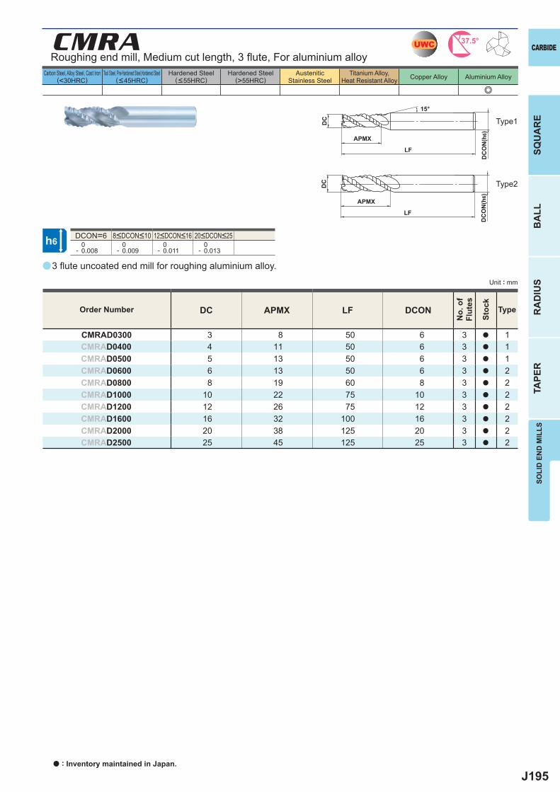
J195
a
e
CMRA
DC APMX LF DCON
CMRAD0300 3 8 50 6 3 a 1CMRAD0400 4 11 50 6 3 a 1CMRAD0500 5 13 50 6 3 a 1CMRAD0600 6 13 50 6 3 a 2CMRAD0800 8 19 60 8 3 a 2CMRAD1000 10 22 75 10 3 a 2CMRAD1200 12 26 75 12 3 a 2CMRAD1600 16 32 100 16 3 a 2CMRAD2000 20 38 125 20 3 a 2CMRAD2500 25 45 125 25 3 a 2
DCON=6 0- 0.008
0- 0.009
0- 0.011
0- 0.013
UWC 37.5°
h6
APMX
DC
DC
ON
(h6)
15°
APMX
LF
DC
DC
ON
(h6)
LF
SOLI
D E
ND
MIL
LSSQ
UA
RE
BA
LLR
AD
IUS
TAPE
R
CARBIDE
Carbon Steel, Alloy Steel, Cast Iron(<30HRC)
Tool Steel, Pre-Hardened Steel,Hardened Steel(<45HRC)
Hardened Steel(<55HRC)
Hardened Steel(>55HRC)
AusteniticStainless Steel
Titanium Alloy,Heat Resistant Alloy Copper Alloy Aluminium Alloy
Unit : mm
Roughing end mill, Medium cut length, 3 fl ute, For aluminium alloy
Type1
Type2
8<DCON<10 12<DCON<16 20<DCON<25
3 fl ute uncoated end mill for roughing aluminium alloy.
Order Number
No.
of
Flut
es
Stoc
k
Type
a : Inventory maintained in Japan.
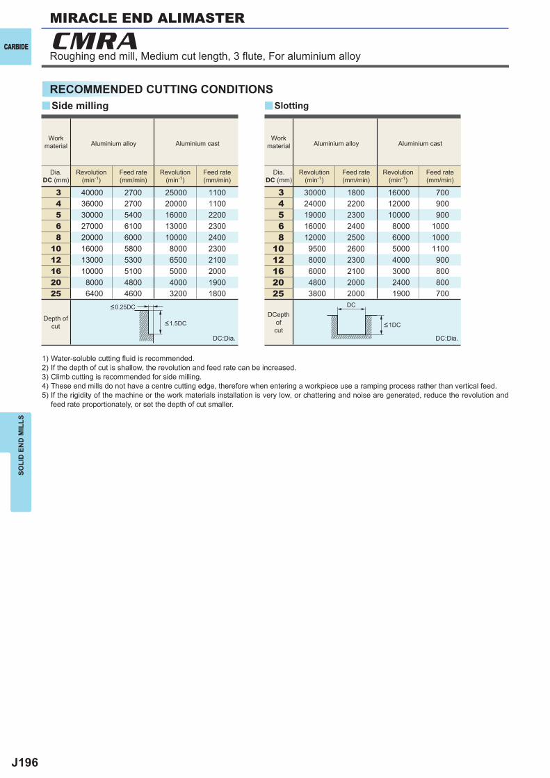
J196
3 40000 2700 25000 11004 36000 2700 20000 11005 30000 5400 16000 22006 27000 6100 13000 23008 20000 6000 10000 2400
10 16000 5800 8000 230012 13000 5300 6500 210016 10000 5100 5000 200020 8000 4800 4000 190025 6400 4600 3200 1800
3 30000 1800 16000 7004 24000 2200 12000 9005 19000 2300 10000 9006 16000 2400 8000 10008 12000 2500 6000 1000
10 9500 2600 5000 110012 8000 2300 4000 90016 6000 2100 3000 80020 4800 2000 2400 80025 3800 2000 1900 700
y y
CMRA
DC
CARBIDE
SOLI
D E
ND
MIL
LS
RECOMMENDED CUTTING CONDITIONS
1) Water-soluble cutting fl uid is recommended.2) If the depth of cut is shallow, the revolution and feed rate can be increased.3) Climb cutting is recommended for side milling.4) These end mills do not have a centre cutting edge, therefore when entering a workpiece use a ramping process rather than vertical feed.5) If the rigidity of the machine or the work materials installation is very low, or chattering and noise are generated, reduce the revolution and
feed rate proportionately, or set the depth of cut smaller.
DC:Dia. DC:Dia.
Side milling Slotting
Workmaterial Aluminium alloy Aluminium cast
Workmaterial Aluminium alloy Aluminium cast
Dia.DC (mm)
Revolution(min-1)
Feed rate(mm/min)
Revolution(min-1)
Feed rate(mm/min)
Dia.DC (mm)
Revolution(min-1)
Feed rate(mm/min)
Revolution(min-1)
Feed rate(mm/min)
Depth ofcut
DCepth ofcut
<1DC<1.5DC
<0.25DC
Roughing end mill, Medium cut length, 3 fl ute, For aluminium alloy
MIRACLE END ALIMASTER
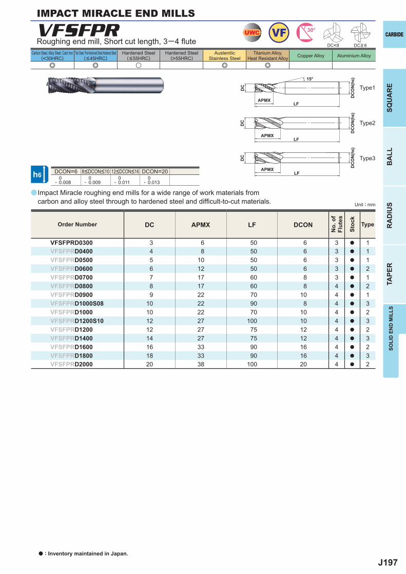
J197
a
VFSFPR
DC APMX LF DCON
VFSFPRD0300 3 6 50 6 3 a 1VFSFPRD0400 4 8 50 6 3 a 1VFSFPRD0500 5 10 50 6 3 a 1VFSFPRD0600 6 12 50 6 3 a 2VFSFPRD0700 7 17 60 8 3 a 1VFSFPRD0800 8 17 60 8 4 a 2VFSFPRD0900 9 22 70 10 4 a 1VFSFPRD1000S08 10 22 90 8 4 a 3VFSFPRD1000 10 22 70 10 4 a 2VFSFPRD1200S10 12 27 100 10 4 a 3VFSFPRD1200 12 27 75 12 4 a 2VFSFPRD1400 14 27 75 12 4 a 3VFSFPRD1600 16 33 90 16 4 a 2VFSFPRD1800 18 33 90 16 4 a 3VFSFPRD2000 20 38 100 20 4 a 2
e e u e e
DCON=6 DCON=20 0- 0.008
0- 0.009
0- 0.011
0- 0.013
UWC VF 30°
h6
APMX
DC
DC
ON
(h6)15°
APMXLF
DC
DC
ON
(h6)
LF
APMXLF
DC
DC
ON
(h6)
DC<8
SOLI
D E
ND
MIL
LSSQ
UA
RE
BA
LLR
AD
IUS
TAPE
R
CARBIDE
Carbon Steel, Alloy Steel, Cast Iron(<30HRC)
Tool Steel, Pre-Hardened Steel,Hardened Steel(<45HRC)
Hardened Steel(<55HRC)
Hardened Steel(>55HRC)
AusteniticStainless Steel
Titanium Alloy,Heat Resistant Alloy Copper Alloy Aluminium Alloy
Unit : mm
DC>8
Type1
Type2
Type3
Order Number
No.
of
Flut
es
Stoc
k
Type
IMPACT MIRACLE END MILLS
Roughing end mill, Short cut length, 3─4 fl ute
8<DCON<10 12<DCON<16
Impact Miracle roughing end mills for a wide range of work materials from carbon and alloy steel through to hardened steel and diffi cult-to-cut materials.
a : Inventory maintained in Japan.
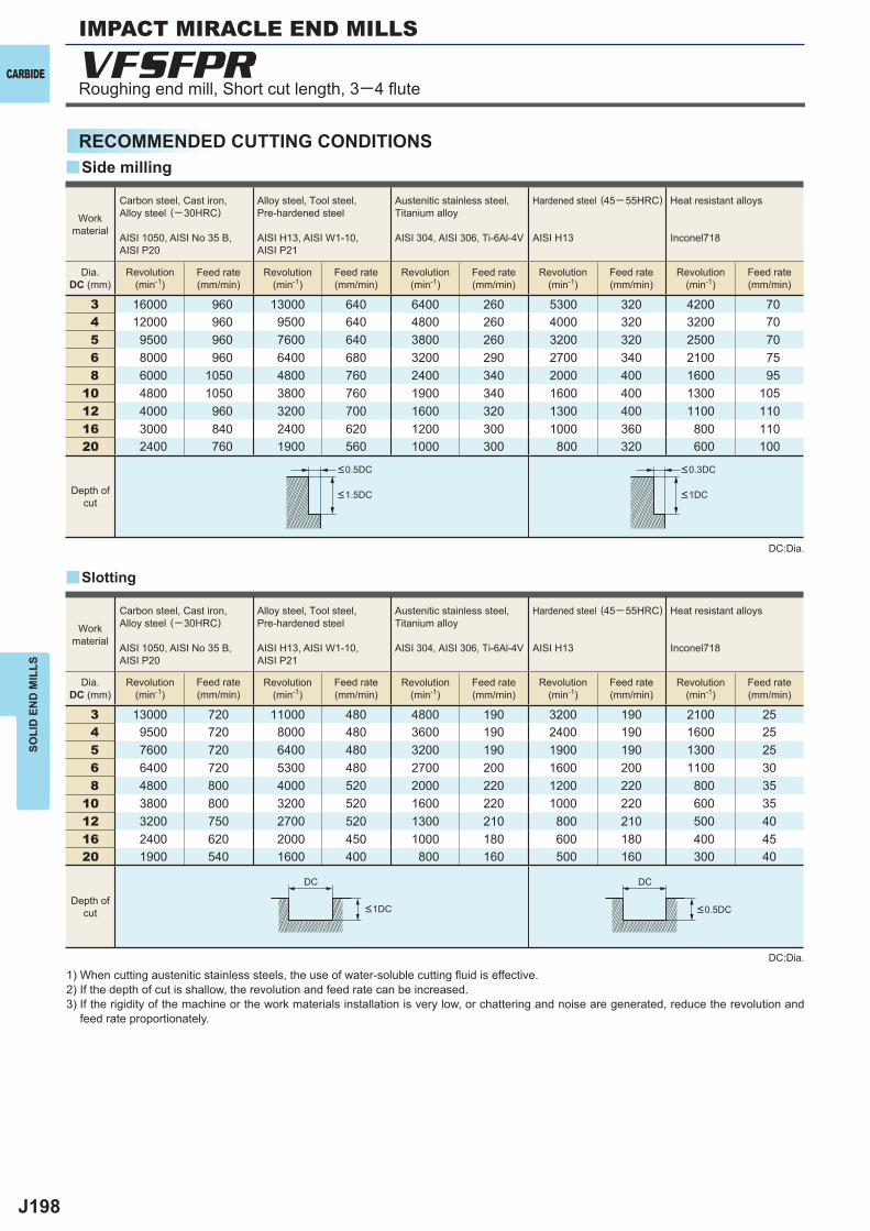
J198
3 16000 960 13000 640 6400 260 5300 320 4200 704 12000 960 9500 640 4800 260 4000 320 3200 705 9500 960 7600 640 3800 260 3200 320 2500 706 8000 960 6400 680 3200 290 2700 340 2100 758 6000 1050 4800 760 2400 340 2000 400 1600 95
10 4800 1050 3800 760 1900 340 1600 400 1300 10512 4000 960 3200 700 1600 320 1300 400 1100 11016 3000 840 2400 620 1200 300 1000 360 800 11020 2400 760 1900 560 1000 300 800 320 600 100
3 13000 720 11000 480 4800 190 3200 190 2100 254 9500 720 8000 480 3600 190 2400 190 1600 255 7600 720 6400 480 3200 190 1900 190 1300 256 6400 720 5300 480 2700 200 1600 200 1100 308 4800 800 4000 520 2000 220 1200 220 800 35
10 3800 800 3200 520 1600 220 1000 220 600 3512 3200 750 2700 520 1300 210 800 210 500 4016 2400 620 2000 450 1000 180 600 180 400 4520 1900 540 1600 400 800 160 500 160 300 40
y
y
VFSFPR
DC DC
CARBIDE
SOLI
D E
ND
MIL
LS
RECOMMENDED CUTTING CONDITIONS
DC:Dia.
DC:Dia.
1) When cutting austenitic stainless steels, the use of water-soluble cutting fl uid is effective.2) If the depth of cut is shallow, the revolution and feed rate can be increased.3) If the rigidity of the machine or the work materials installation is very low, or chattering and noise are generated, reduce the revolution and
feed rate proportionately.
Slotting
Side milling
Workmaterial
Workmaterial
Carbon steel, Cast iron, Alloy steel (─30HRC)
AISI 1050, AISI No 35 B,AISI P20
Alloy steel, Tool steel,Pre-hardened steel
AISI H13, AISI W1-10, AISI P21
Austenitic stainless steel,Titanium alloy
AISI 304, AISI 306, Ti-6Al-4V
Hardened steel (45─ 55HRC)
AISI H13
Heat resistant alloys
Inconel718
Carbon steel, Cast iron, Alloy steel (─30HRC)
AISI 1050, AISI No 35 B,AISI P20
Alloy steel, Tool steel,Pre-hardened steel
AISI H13, AISI W1-10, AISI P21
Austenitic stainless steel,Titanium alloy
AISI 304, AISI 306, Ti-6Al-4V
Hardened steel (45─ 55HRC)
AISI H13
Heat resistant alloys
Inconel718
Dia.DC (mm)
Dia.DC (mm)
Revolution(min-1)
Revolution(min-1)
Revolution(min-1)
Revolution(min-1)
Revolution(min-1)
Revolution(min-1)
Revolution(min-1)
Revolution(min-1)
Revolution(min-1)
Revolution(min-1)
Feed rate(mm/min)
Feed rate(mm/min)
Feed rate(mm/min)
Feed rate(mm/min)
Feed rate(mm/min)
Feed rate(mm/min)
Feed rate(mm/min)
Feed rate(mm/min)
Feed rate(mm/min)
Feed rate(mm/min)
Depth ofcut
Depth ofcut
<0.5DC <0.3DC
<1.5DC <1DC
<0.5DC<1DC
IMPACT MIRACLE END MILLS
Roughing end mill, Short cut length, 3─4 fl ute
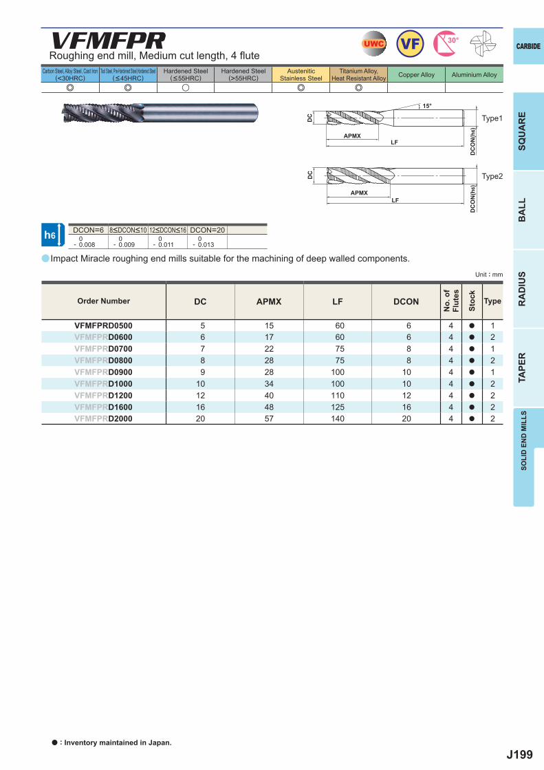
J199
a
VFMFPR
DC APMX LF DCON
VFMFPRD0500 5 15 60 6 4 a 1VFMFPRD0600 6 17 60 6 4 a 2VFMFPRD0700 7 22 75 8 4 a 1VFMFPRD0800 8 28 75 8 4 a 2VFMFPRD0900 9 28 100 10 4 a 1VFMFPRD1000 10 34 100 10 4 a 2VFMFPRD1200 12 40 110 12 4 a 2VFMFPRD1600 16 48 125 16 4 a 2VFMFPRD2000 20 57 140 20 4 a 2
e e u e e
DCON=6 DCON=20 0- 0.008
0- 0.009
0- 0.011
0- 0.013
UWC VF 30°
h6
APMX
DC
DC
ON
(h6)
15°
APMXLF
DC
DC
ON
(h6)
LF
SOLI
D E
ND
MIL
LSSQ
UA
RE
BA
LLR
AD
IUS
TAPE
R
CARBIDE
Carbon Steel, Alloy Steel, Cast Iron(<30HRC)
Tool Steel, Pre-Hardened Steel,Hardened Steel(<45HRC)
Hardened Steel(<55HRC)
Hardened Steel(>55HRC)
AusteniticStainless Steel
Titanium Alloy,Heat Resistant Alloy Copper Alloy Aluminium Alloy
Unit : mm
Roughing end mill, Medium cut length, 4 fl ute
Type1
Type2
8<DCON<10 12<DCON<16
Impact Miracle roughing end mills suitable for the machining of deep walled components.
Order Number
No.
of
Flut
es
Stoc
k
Type
a : Inventory maintained in Japan.
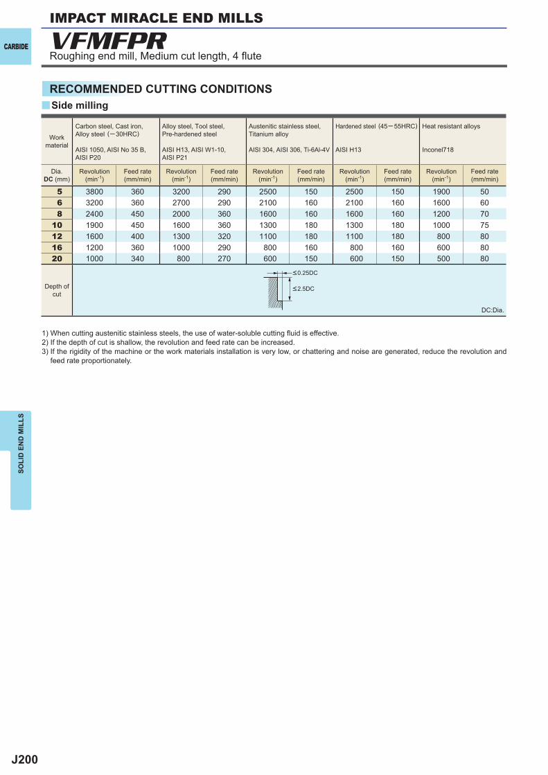
J200
5 3800 360 3200 290 2500 150 2500 150 1900 506 3200 360 2700 290 2100 160 2100 160 1600 608 2400 450 2000 360 1600 160 1600 160 1200 70
10 1900 450 1600 360 1300 180 1300 180 1000 7512 1600 400 1300 320 1100 180 1100 180 800 8016 1200 360 1000 290 800 160 800 160 600 8020 1000 340 800 270 600 150 600 150 500 80
y
VFMFPRCARBIDE
SOLI
D E
ND
MIL
LS
RECOMMENDED CUTTING CONDITIONS
1) When cutting austenitic stainless steels, the use of water-soluble cutting fl uid is effective.2) If the depth of cut is shallow, the revolution and feed rate can be increased.3) If the rigidity of the machine or the work materials installation is very low, or chattering and noise are generated, reduce the revolution and
feed rate proportionately.
DC:Dia.
Side milling
Workmaterial
Carbon steel, Cast iron, Alloy steel (─30HRC)
AISI 1050, AISI No 35 B,AISI P20
Alloy steel, Tool steel,Pre-hardened steel
AISI H13, AISI W1-10, AISI P21
Austenitic stainless steel,Titanium alloy
AISI 304, AISI 306, Ti-6Al-4V
Hardened steel (45─ 55HRC)
AISI H13
Heat resistant alloys
Inconel718
Dia.DC (mm)
Revolution(min-1)
Revolution(min-1)
Revolution(min-1)
Revolution(min-1)
Revolution(min-1)
Feed rate(mm/min)
Feed rate(mm/min)
Feed rate(mm/min)
Feed rate(mm/min)
Feed rate(mm/min)
Depth ofcut
<0.25DC
<2.5DC
Roughing end mill, Medium cut length, 4 fl ute
IMPACT MIRACLE END MILLS
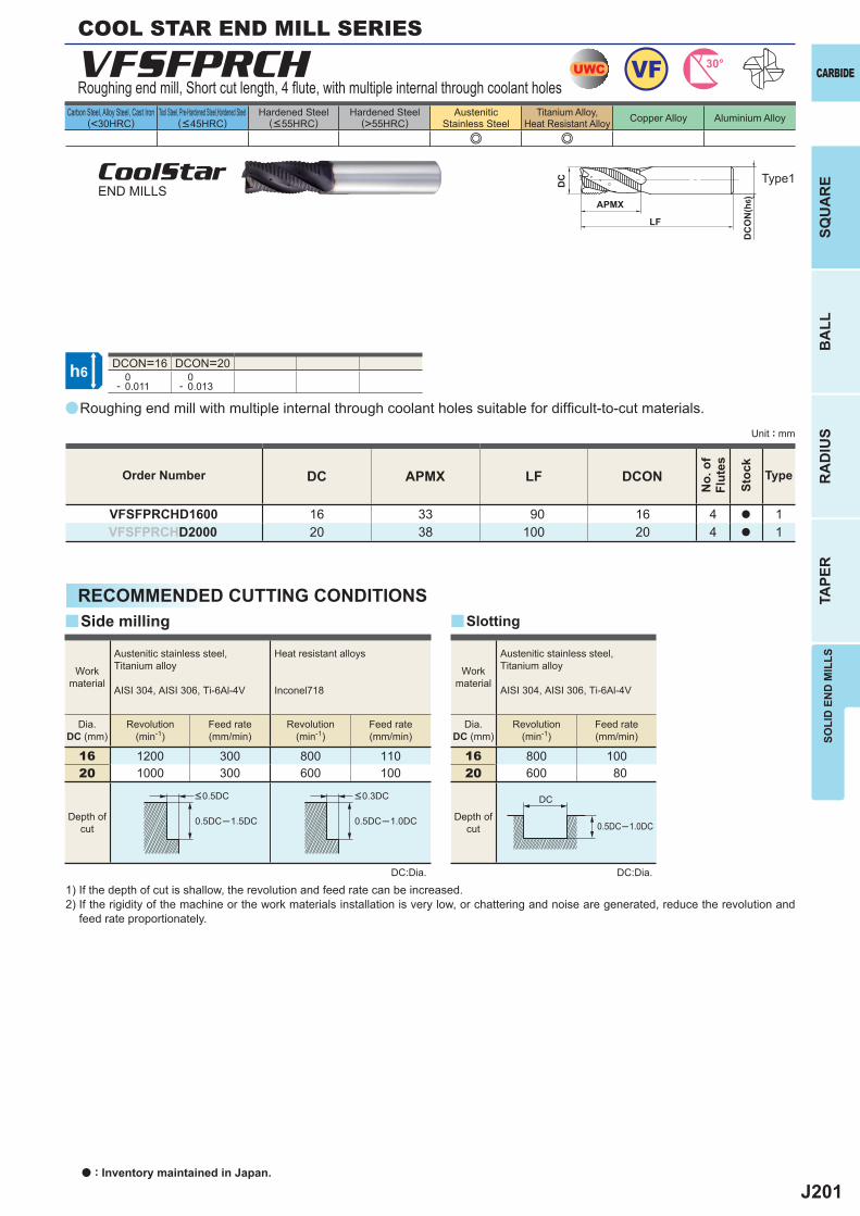
J201
a
VFSFPRCH
DC APMX LF DCON
VFSFPRCHD1600 16 33 90 16 4 a 1VFSFPRCHD2000 20 38 100 20 4 a 1
e e
DCON=16 DCON=20 0- 0.011
0- 0.013
16 1200 300 800 11020 1000 300 600 100
16 800 10020 600 80
0.5DC─1.5DC 0.5DC─1.0DC 0.5DC─1.0DC
yy
UWC VF 30°
h6
APMX
LF
DC
DC
ON
(h6)
DC
SOLI
D E
ND
MIL
LSSQ
UA
RE
BA
LLR
AD
IUS
TAPE
R
CARBIDE
Carbon Steel, Alloy Steel, Cast Iron(<30HRC)
Tool Steel, Pre-Hardened Steel,Hardened Steel(<45HRC)
Hardened Steel(<55HRC)
Hardened Steel(>55HRC)
AusteniticStainless Steel
Titanium Alloy,Heat Resistant Alloy Copper Alloy Aluminium Alloy
Unit : mm
Type1
Order Number
No.
of
Flut
es
Stoc
k
Type
COOL STAR END MILL SERIES
Roughing end mill, Short cut length, 4 fl ute, with multiple internal through coolant holes
CoolStarEND MILLS
Roughing end mill with multiple internal through coolant holes suitable for diffi cult-to-cut materials.
RECOMMENDED CUTTING CONDITIONS
DC:Dia. DC:Dia.
1) If the depth of cut is shallow, the revolution and feed rate can be increased.2) If the rigidity of the machine or the work materials installation is very low, or chattering and noise are generated, reduce the revolution and
feed rate proportionately.
SlottingSide milling
Workmaterial
Austenitic stainless steel,Titanium alloy
AISI 304, AISI 306, Ti-6Al-4V
Heat resistant alloys
Inconel718
Dia.DC (mm)
Revolution(min-1)
Revolution(min-1)
Feed rate(mm/min)
Feed rate(mm/min)
Workmaterial
Austenitic stainless steel,Titanium alloy
AISI 304, AISI 306, Ti-6Al-4V
Dia.DC (mm)
Revolution(min-1)
Feed rate(mm/min)
Depth ofcut
Depth ofcut
<0.5DC <0.3DC
a : Inventory maintained in Japan.
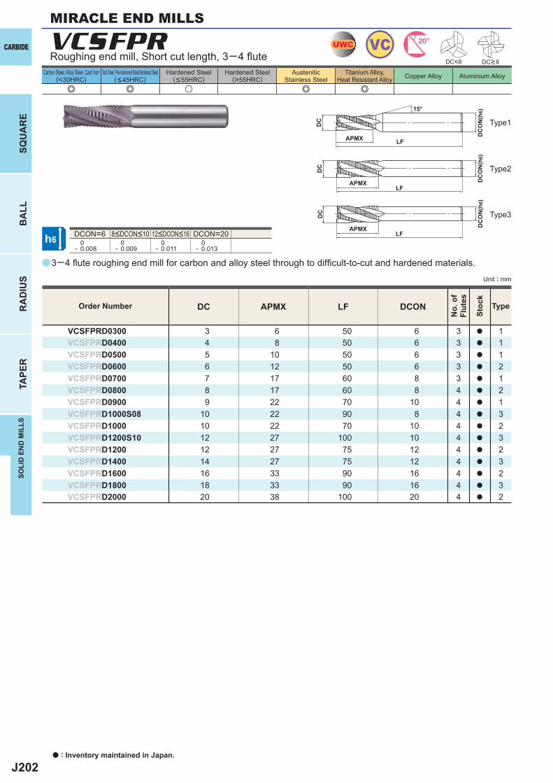
J202
a
e e u e e
VCSFPR
DC APMX LF DCON
VCSFPRD0300 3 6 50 6 3 a 1VCSFPRD0400 4 8 50 6 3 a 1VCSFPRD0500 5 10 50 6 3 a 1VCSFPRD0600 6 12 50 6 3 a 2VCSFPRD0700 7 17 60 8 3 a 1VCSFPRD0800 8 17 60 8 4 a 2VCSFPRD0900 9 22 70 10 4 a 1VCSFPRD1000S08 10 22 90 8 4 a 3VCSFPRD1000 10 22 70 10 4 a 2VCSFPRD1200S10 12 27 100 10 4 a 3VCSFPRD1200 12 27 75 12 4 a 2VCSFPRD1400 14 27 75 12 4 a 3VCSFPRD1600 16 33 90 16 4 a 2VCSFPRD1800 18 33 90 16 4 a 3VCSFPRD2000 20 38 100 20 4 a 2
DCON=6 DCON=20 0- 0.008
0- 0.009
0- 0.011
0- 0.013
DC<8
UWC VC 20°
h6
APMX
DC
DC
ON
(h6)15°
APMXLF
DC
DC
ON
(h6)
LF
APMXLF
DC
DC
ON
(h6)
CARBIDE
SQU
AR
EB
ALL
RA
DIU
STA
PER
SOLI
D E
ND
MIL
LS
a : Inventory maintained in Japan.
Carbon Steel, Alloy Steel, Cast Iron(<30HRC)
Tool Steel, Pre-Hardened Steel,Hardened Steel(<45HRC)
Hardened Steel(<55HRC)
Hardened Steel(>55HRC)
AusteniticStainless Steel
Titanium Alloy,Heat Resistant Alloy Copper Alloy Aluminium Alloy
Unit : mm
DC>8Roughing end mill, Short cut length, 3─4 fl ute
MIRACLE END MILLS
Type1
Type2
Type3
8<DCON<10 12<DCON<16
3─4 fl ute roughing end mill for carbon and alloy steel through to diffi cult-to-cut and hardened materials.
Order Number
No.
of
Flut
es
Stoc
k
Type
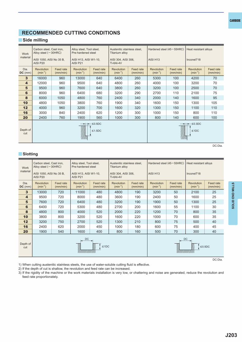
J203
3 16000 960 13000 640 6400 260 5300 100 4200 704 12000 960 9500 640 4800 260 4000 100 3200 705 9500 960 7600 640 3800 260 3200 100 2500 706 8000 960 6400 680 3200 290 2700 110 2100 758 6000 1050 4800 760 2400 340 2000 140 1600 95
10 4800 1050 3800 760 1900 340 1600 150 1300 10512 4000 960 3200 700 1600 320 1300 150 1100 11016 3000 840 2400 620 1200 300 1000 150 800 11020 2400 760 1900 560 1000 300 800 140 600 100
3 13000 720 11000 480 4800 190 3200 50 2100 254 9500 720 8000 480 3600 190 2400 50 1600 255 7600 720 6400 480 3200 190 1900 50 1300 256 6400 720 5300 480 2700 200 1600 55 1100 308 4800 800 4000 520 2000 220 1200 70 800 35
10 3800 800 3200 520 1600 220 1000 70 600 3512 3200 750 2700 520 1300 210 800 75 500 4016 2400 620 2000 450 1000 180 600 75 400 4520 1900 540 1600 400 800 160 500 70 300 40
y
y
DC DC
CARBIDE
SOLI
D E
ND
MIL
LS
RECOMMENDED CUTTING CONDITIONS
DC:Dia.
DC:Dia.
1) When cutting austenitic stainless steels, the use of water-soluble cutting fl uid is effective.2) If the depth of cut is shallow, the revolution and feed rate can be increased.3) If the rigidity of the machine or the work materials installation is very low, or chattering and noise are generated, reduce the revolution and
feed rate proportionately.
Depth ofcut
Depth ofcut
Workmaterial
Carbon steel, Cast iron, Alloy steel (─30HRC)
AISI 1050, AISI No 35 B,AISI P20
Alloy steel, Tool steel,Pre-hardened steel
AISI H13, AISI W1-10, AISI P21
Austenitic stainless steel,Titanium alloy
AISI 304, AISI 306, Ti-6Al-4V
Hardened steel (45─ 55HRC)
AISI H13
Heat resistant alloys
Inconel718
Dia.DC (mm)
Revolution(min-1)
Feed rate(mm/min)
Revolution(min-1)
Feed rate(mm/min)
Revolution(min-1)
Feed rate(mm/min)
Revolution(min-1)
Feed rate(mm/min)
Revolution(min-1)
Feed rate(mm/min)
Side milling
Slotting
<0.5DC <0.3DC
<1.5DC <1DC
<0.5DC<1DC
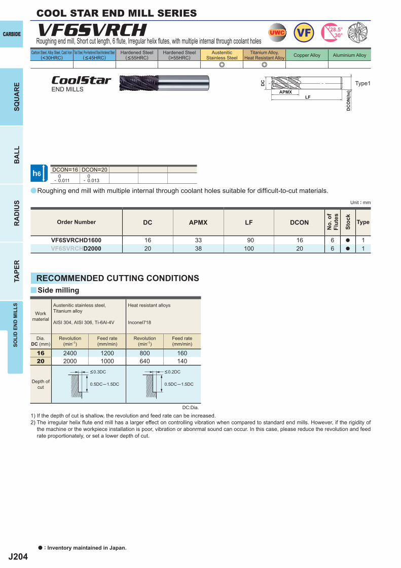
J204
a
VF6SVRCH
DC APMX LF DCON
VF6SVRCHD1600 16 33 90 16 6 a 1VF6SVRCHD2000 20 38 100 20 6 a 1
e e
DCON=16 DCON=20 0- 0.011
0- 0.013
16 2400 1200 800 16020 2000 1000 640 140
0.5DC─1.5DC 0.5DC─1.5DC
y
UWC VF 28.5°30°
h6
APMXLF
DC
DC
ON
(h6)
CARBIDE
SQU
AR
EB
ALL
RA
DIU
STA
PER
SOLI
D E
ND
MIL
LS
a : Inventory maintained in Japan.
Carbon Steel, Alloy Steel, Cast Iron(<30HRC)
Tool Steel, Pre-Hardened Steel,Hardened Steel(<45HRC)
Hardened Steel(<55HRC)
Hardened Steel(>55HRC)
AusteniticStainless Steel
Titanium Alloy,Heat Resistant Alloy Copper Alloy Aluminium Alloy
Unit : mm
Type1
Order Number
No.
of
Flut
es
Stoc
k
Type
COOL STAR END MILL SERIES
Roughing end mill, Short cut length, 6 fl ute, Irregular helix fl utes, with multiple internal through coolant holes
CoolStarEND MILLS
Roughing end mill with multiple internal through coolant holes suitable for diffi cult-to-cut materials.
RECOMMENDED CUTTING CONDITIONS
DC:Dia.
1) If the depth of cut is shallow, the revolution and feed rate can be increased.2) The irregular helix fl ute end mill has a larger effect on controlling vibration when compared to standard end mills. However, if the rigidity of
the machine or the workpiece installation is poor, vibration or abonrmal sound can occur. In this case, please reduce the revolution and feed rate proportionately, or set a lower depth of cut.
Side milling
Workmaterial
Austenitic stainless steel,Titanium alloy
AISI 304, AISI 306, Ti-6Al-4V
Heat resistant alloys
Inconel718
Dia.DC (mm)
Revolution(min-1)
Revolution(min-1)
Feed rate(mm/min)
Feed rate(mm/min)
Depth ofcut
<0.3DC <0.2DC
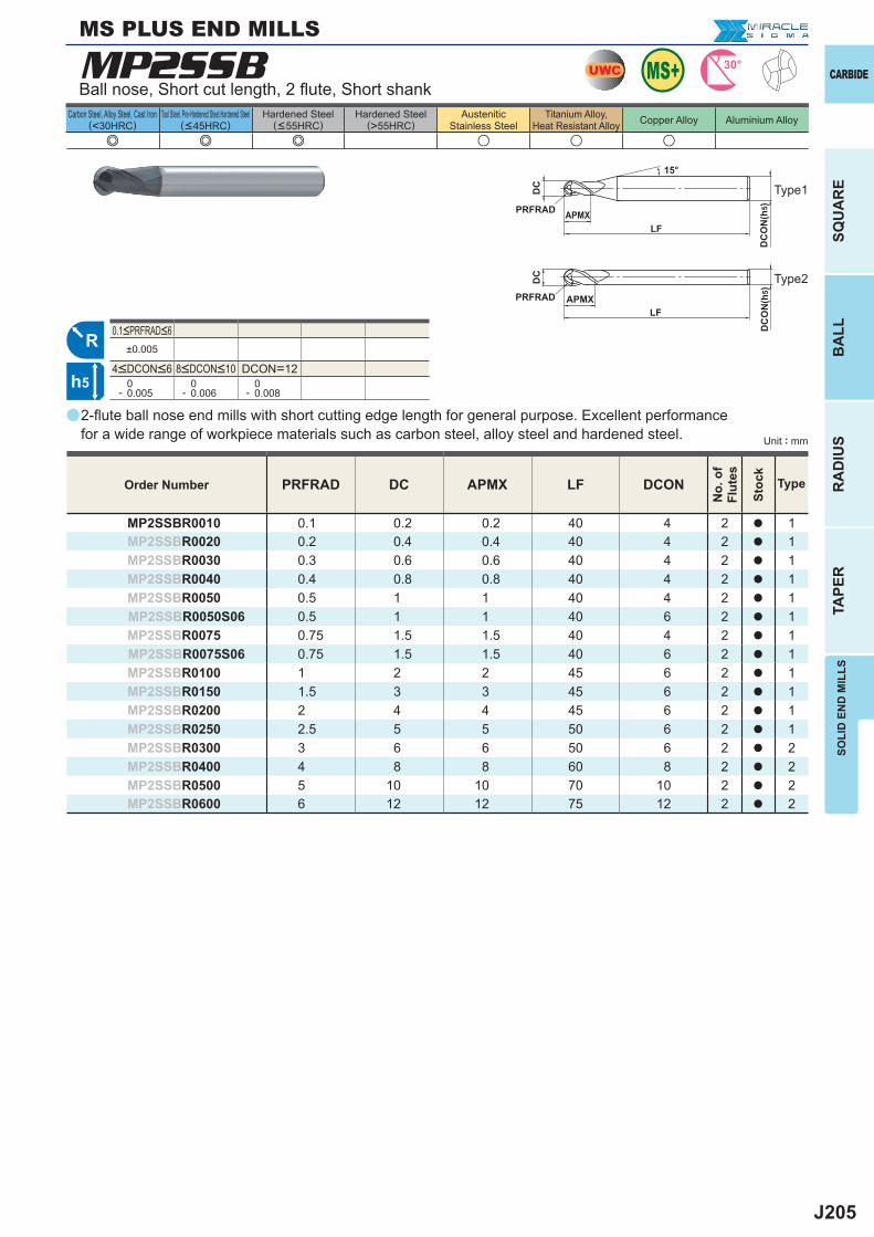
J205
a
e e e u u u
MP2SSB
PRFRAD DC APMX LF DCON
MP2SSBR0010 0.1 0.2 0.2 40 4 2 a 1MP2SSBR0020 0.2 0.4 0.4 40 4 2 a 1MP2SSBR0030 0.3 0.6 0.6 40 4 2 a 1MP2SSBR0040 0.4 0.8 0.8 40 4 2 a 1MP2SSBR0050 0.5 1 1 40 4 2 a 1MP2SSBR0050S06 0.5 1 1 40 6 2 a 1MP2SSBR0075 0.75 1.5 1.5 40 4 2 a 1MP2SSBR0075S06 0.75 1.5 1.5 40 6 2 a 1MP2SSBR0100 1 2 2 45 6 2 a 1MP2SSBR0150 1.5 3 3 45 6 2 a 1MP2SSBR0200 2 4 4 45 6 2 a 1MP2SSBR0250 2.5 5 5 50 6 2 a 1MP2SSBR0300 3 6 6 50 6 2 a 2MP2SSBR0400 4 8 8 60 8 2 a 2MP2SSBR0500 5 10 10 70 10 2 a 2MP2SSBR0600 6 12 12 75 12 2 a 2
±0.005
DCON=12 0- 0.005
0- 0.006
0- 0.008
UWC 30°
R
h5
APMX
DC
DC
ON
(h5)
15°
APMXLF
DC
DC
ON
(h5)
LF
PRFRAD
PRFRAD
SOLI
D E
ND
MIL
LS
CARBIDE
SQU
AR
EB
ALL
RA
DIU
STA
PER
Carbon Steel, Alloy Steel, Cast Iron(<30HRC)
Tool Steel, Pre-Hardened Steel,Hardened Steel(<45HRC)
Hardened Steel(<55HRC)
Hardened Steel(>55HRC)
AusteniticStainless Steel
Titanium Alloy,Heat Resistant Alloy Copper Alloy Aluminium Alloy
Unit : mm
Order Number
No.
of
Flut
es
Stoc
k
Type
Ball nose, Short cut length, 2 fl ute, Short shank
2-fl ute ball nose end mills with short cutting edge length for general purpose. Excellent performance for a wide range of workpiece materials such as carbon steel, alloy steel and hardened steel.
Type2
4<DCON<6 8<DCON<10
0.1<PRFRAD<6
Type1
MS PLUS END MILLS
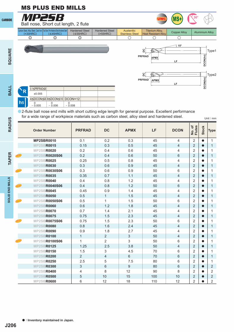
J206
a
e e e u u u
MP2SB
PRFRAD DC APMX LF DCON
MP2SBR0010 0.1 0.2 0.3 45 4 2 a 1MP2SBR0015 0.15 0.3 0.5 45 4 2 a 1MP2SBR0020 0.2 0.4 0.6 45 4 2 a 1MP2SBR0020S06 0.2 0.4 0.6 50 6 2 a 1MP2SBR0025 0.25 0.5 0.8 45 4 2 a 1MP2SBR0030 0.3 0.6 0.9 45 4 2 a 1MP2SBR0030S06 0.3 0.6 0.9 50 6 2 a 1MP2SBR0035 0.35 0.7 1.1 45 4 2 a 1MP2SBR0040 0.4 0.8 1.2 45 4 2 a 1MP2SBR0040S06 0.4 0.8 1.2 50 6 2 a 1MP2SBR0045 0.45 0.9 1.4 45 4 2 a 1MP2SBR0050 0.5 1 1.5 45 4 2 a 1MP2SBR0050S06 0.5 1 1.5 50 6 2 a 1MP2SBR0060 0.6 1.2 1.8 45 4 2 a 1MP2SBR0070 0.7 1.4 2.1 45 4 2 a 1MP2SBR0075 0.75 1.5 2.3 45 4 2 a 1MP2SBR0075S06 0.75 1.5 2.3 50 6 2 a 1MP2SBR0080 0.8 1.6 2.4 45 4 2 a 1MP2SBR0090 0.9 1.8 2.7 45 4 2 a 1MP2SBR0100 1 2 3 50 4 2 a 1MP2SBR0100S06 1 2 3 50 6 2 a 1MP2SBR0125 1.25 2.5 3.8 50 4 2 a 1MP2SBR0150 1.5 3 4.5 70 6 2 a 1MP2SBR0200 2 4 6 70 6 2 a 1MP2SBR0250 2.5 5 7.5 80 6 2 a 1MP2SBR0300 3 6 9 80 6 2 a 2MP2SBR0400 4 8 12 90 8 2 a 2MP2SBR0500 5 10 15 100 10 2 a 2MP2SBR0600 6 12 18 110 12 2 a 2
±0.005
DCON=12 0- 0.005
0- 0.006
0- 0.008
UWC 30°
R
h5
APMX
DC
DC
ON
(h5)
15°
APMXLF
DC
DC
ON
(h5)
LF
PRFRAD
PRFRAD
a : Inventory maintained in Japan.
CARBIDE
SQU
AR
EB
ALL
RA
DIU
STA
PER
SOLI
D E
ND
MIL
LSMS PLUS END MILLS
Carbon Steel, Alloy Steel, Cast Iron(<30HRC)
Tool Steel, Pre-Hardened Steel,Hardened Steel(<45HRC)
Hardened Steel(<55HRC)
Hardened Steel(>55HRC)
AusteniticStainless Steel
Titanium Alloy,Heat Resistant Alloy Copper Alloy Aluminium Alloy
Unit : mm
Order Number
No.
of
Flut
es
Stoc
k
Type
Ball nose, Short cut length, 2 fl ute
2-fl ute ball nose end mills with short cutting edge length for general purpose. Excellent performance for a wide range of workpiece materials such as carbon steel, alloy steel and hardened steel.
4<DCON<6 8<DCON<10
0.1<PRFRAD<6
Type1
Type2
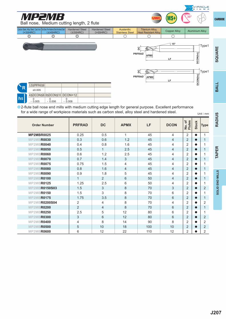
J207
a
e e e u u u
MP2MB
PRFRAD DC APMX LF DCON
MP2MBR0025 0.25 0.5 1 45 4 2 a 1MP2MBR0030 0.3 0.6 1.2 45 4 2 a 1MP2MBR0040 0.4 0.8 1.6 45 4 2 a 1MP2MBR0050 0.5 1 2.5 45 4 2 a 1MP2MBR0060 0.6 1.2 2.5 45 4 2 a 1MP2MBR0070 0.7 1.4 3 45 4 2 a 1MP2MBR0075 0.75 1.5 4 45 4 2 a 1MP2MBR0080 0.8 1.6 4 45 4 2 a 1MP2MBR0090 0.9 1.8 5 45 4 2 a 1MP2MBR0100 1 2 6 50 4 2 a 1MP2MBR0125 1.25 2.5 6 50 4 2 a 1MP2MBR0150S03 1.5 3 8 70 3 2 a 2MP2MBR0150 1.5 3 8 70 6 2 a 1MP2MBR0175 1.75 3.5 8 70 6 2 a 1MP2MBR0200S04 2 4 8 70 4 2 a 2MP2MBR0200 2 4 8 70 6 2 a 1MP2MBR0250 2.5 5 12 80 6 2 a 1MP2MBR0300 3 6 12 80 6 2 a 2MP2MBR0400 4 8 14 90 8 2 a 2MP2MBR0500 5 10 18 100 10 2 a 2MP2MBR0600 6 12 22 110 12 2 a 2
±0.005
DCON=12 0- 0.005
0- 0.006
0- 0.008
UWC 30°
R
h5
APMX
DC
DC
ON
(h5)
15°
APMXLF
DC
DC
ON
(h5)
LF
PRFRAD
PRFRAD
SOLI
D E
ND
MIL
LS
CARBIDE
SQU
AR
EB
ALL
RA
DIU
STA
PER
Carbon Steel, Alloy Steel, Cast Iron(<30HRC)
Tool Steel, Pre-Hardened Steel,Hardened Steel(<45HRC)
Hardened Steel(<55HRC)
Hardened Steel(>55HRC)
AusteniticStainless Steel
Titanium Alloy,Heat Resistant Alloy Copper Alloy Aluminium Alloy
Unit : mm
Order Number
No.
of
Flut
es
Stoc
k
Type
Ball nose, Medium cutting length, 2 fl ute
2-fl ute ball nose end mills with medium cutting edge length for general purpose. Excellent performance for a wide range of workpiece materials such as carbon steel, alloy steel and hardened steel.
4<DCON<6 8<DCON<10
0.25<PRFRAD<6
Type1
Type1
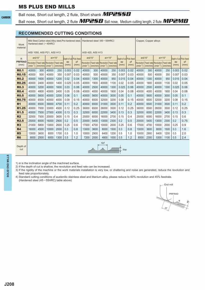
J208
%>15° %>15° %>15°
R0.1 40000 300 40000 250 0.003 0.02 40000 300 40000 250 0.003 0.02 40000 300 40000 250 0.003 0.02R0.15 40000 500 40000 350 0.007 0.03 40000 500 40000 350 0.007 0.03 40000 500 40000 350 0.007 0.03R0.2 40000 1600 40000 1200 0.02 0.04 40000 1300 40000 950 0.015 0.04 40000 1300 40000 950 0.015 0.04R0.25 40000 2400 40000 1400 0.025 0.05 40000 1900 40000 1100 0.02 0.05 40000 1900 40000 1100 0.02 0.05R0.3 40000 3200 40000 1600 0.03 0.06 40000 2500 40000 1300 0.025 0.06 40000 2500 40000 1300 0.025 0.06R0.4 40000 4800 40000 2400 0.05 0.08 40000 4000 40000 1900 0.04 0.08 40000 4000 40000 1900 0.04 0.08R0.5 40000 5600 40000 3200 0.06 0.1 40000 5600 40000 3000 0.05 0.1 40000 5600 40000 3000 0.05 0.1R0.75 40000 6500 40000 4000 0.09 0.15 40000 6500 32000 3200 0.08 0.15 40000 6500 32000 3200 0.08 0.15R1 40000 6500 39000 4700 0.11 0.2 40000 6500 31000 3500 0.11 0.2 40000 6500 31000 3500 0.11 0.2R1.25 40000 7000 33000 4500 0.12 0.25 36000 6500 26000 3500 0.12 0.25 36000 6500 26000 3500 0.12 0.25R1.5 40000 7500 27000 4300 0.13 0.3 32000 6000 22000 3400 0.13 0.3 32000 6000 22000 3400 0.13 0.3R2 32000 7500 20000 3600 0.15 0.4 25000 6000 16000 2700 0.15 0.4 25000 6000 16000 2700 0.15 0.6R2.5 25000 6000 16000 2900 0.2 0.5 20000 5400 13000 2300 0.2 0.5 20000 5400 13000 2300 0.2 0.75R3 21000 5800 13000 2600 0.25 0.6 17000 4700 10000 2000 0.25 0.6 17000 4700 10000 2000 0.25 0.9R4 16000 4500 10000 2000 0.3 0.8 13000 3600 8000 1500 0.3 0.8 13000 3600 8000 1500 0.3 1.6R5 13000 3600 8000 1700 0.5 1.0 10000 2900 6400 1200 0.5 1.0 10000 2900 6400 1200 0.5 2.0R6 9000 2500 6000 1300 0.5 1.2 7200 2000 4800 1000 0.5 1.2 8500 2300 5300 1100 0.5 2.4
ap
PRFRAD
pf
%
CARBIDE
SOLI
D E
ND
MIL
LSMS PLUS END MILLS
RECOMMENDED CUTTING CONDITIONS
<ap
<pf
1) % is the inclination angle of the machined surface. 2) If the depth of cut is shallow, the revolution and feed rate can be increased.3) If the rigidity of the machine or the work materials installation is very low, or chattering and noise are generated, reduce the revolution and
feed rate proportionately.4) Standard cutting conditions of austenitic stainless steel and titanium alloy, please reduce to 60% revolution and 45% feedrate.
(Hardened steel (45─55HRC) table above)
Workmaterial
Mild Steel,Carbon steel,Alloy steel,Pre-hardened steel,Hardened steel (─ 45HRC)
AISI 1050, AISI P21, AISI H13
Hardened steel (45─ 55HRC)
AISI 420, AISI H13
Copper, Copper alloys
RPRFRAD
(mm)
%<15° Depth of cutap
(mm)
Pick feedpf
(mm)
%<15° Depth of cutap
(mm)
Pick feedpf
(mm)
%<15° Depth of cutap
(mm)
Pick feedpf
(mm)Revolution(min-1)
Feed rate(mm/min)
Revolution(min-1)
Feed rate(mm/min)
Revolution(min-1)
Feed rate(mm/min)
Revolution(min-1)
Feed rate(mm/min)
Revolution(min-1)
Feed rate(mm/min)
Revolution(min-1)
Feed rate(mm/min)
Depth ofcut
End mill
Ball nose, Short cut length, 2 fl ute, Short shank MP2SSBBall nose, Short cut length, 2 fl ute MP2SB Ball nose, Medium cutting length, 2 fl ute MP2MB
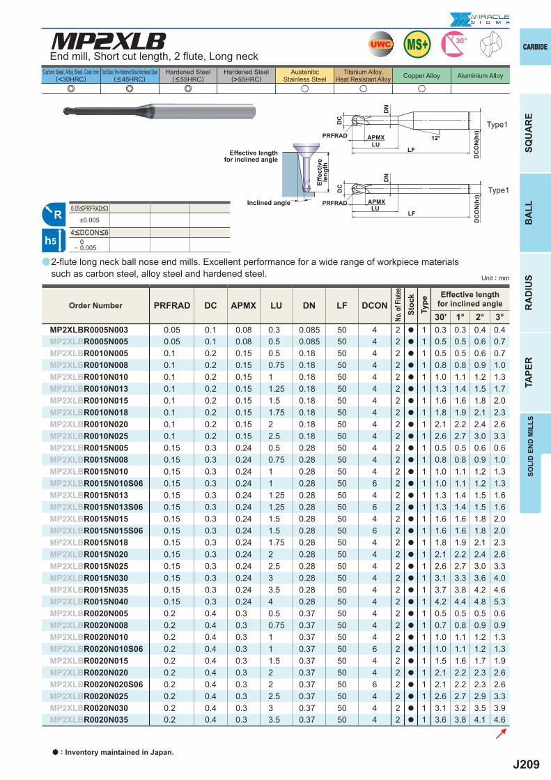
J209
a
e e e u u u
MP2XLB
PRFRAD DC APMX LU DN LF DCON30' 1° 2° 3°
MP2XLBR0005N003 0.05 0.1 0.08 0.3 0.085 50 4 2 a 1 0.3 0.3 0.4 0.4MP2XLBR0005N005 0.05 0.1 0.08 0.5 0.085 50 4 2 a 1 0.5 0.5 0.6 0.7MP2XLBR0010N005 0.1 0.2 0.15 0.5 0.18 50 4 2 a 1 0.5 0.5 0.6 0.7MP2XLBR0010N008 0.1 0.2 0.15 0.75 0.18 50 4 2 a 1 0.8 0.8 0.9 1.0MP2XLBR0010N010 0.1 0.2 0.15 1 0.18 50 4 2 a 1 1.0 1.1 1.2 1.3MP2XLBR0010N013 0.1 0.2 0.15 1.25 0.18 50 4 2 a 1 1.3 1.4 1.5 1.7MP2XLBR0010N015 0.1 0.2 0.15 1.5 0.18 50 4 2 a 1 1.6 1.6 1.8 2.0MP2XLBR0010N018 0.1 0.2 0.15 1.75 0.18 50 4 2 a 1 1.8 1.9 2.1 2.3MP2XLBR0010N020 0.1 0.2 0.15 2 0.18 50 4 2 a 1 2.1 2.2 2.4 2.6MP2XLBR0010N025 0.1 0.2 0.15 2.5 0.18 50 4 2 a 1 2.6 2.7 3.0 3.3MP2XLBR0015N005 0.15 0.3 0.24 0.5 0.28 50 4 2 a 1 0.5 0.5 0.6 0.6MP2XLBR0015N008 0.15 0.3 0.24 0.75 0.28 50 4 2 a 1 0.8 0.8 0.9 1.0MP2XLBR0015N010 0.15 0.3 0.24 1 0.28 50 4 2 a 1 1.0 1.1 1.2 1.3MP2XLBR0015N010S06 0.15 0.3 0.24 1 0.28 50 6 2 a 1 1.0 1.1 1.2 1.3MP2XLBR0015N013 0.15 0.3 0.24 1.25 0.28 50 4 2 a 1 1.3 1.4 1.5 1.6MP2XLBR0015N013S06 0.15 0.3 0.24 1.25 0.28 50 6 2 a 1 1.3 1.4 1.5 1.6MP2XLBR0015N015 0.15 0.3 0.24 1.5 0.28 50 4 2 a 1 1.6 1.6 1.8 2.0MP2XLBR0015N015S06 0.15 0.3 0.24 1.5 0.28 50 6 2 a 1 1.6 1.6 1.8 2.0MP2XLBR0015N018 0.15 0.3 0.24 1.75 0.28 50 4 2 a 1 1.8 1.9 2.1 2.3MP2XLBR0015N020 0.15 0.3 0.24 2 0.28 50 4 2 a 1 2.1 2.2 2.4 2.6MP2XLBR0015N025 0.15 0.3 0.24 2.5 0.28 50 4 2 a 1 2.6 2.7 3.0 3.3MP2XLBR0015N030 0.15 0.3 0.24 3 0.28 50 4 2 a 1 3.1 3.3 3.6 4.0MP2XLBR0015N035 0.15 0.3 0.24 3.5 0.28 50 4 2 a 1 3.7 3.8 4.2 4.6MP2XLBR0015N040 0.15 0.3 0.24 4 0.28 50 4 2 a 1 4.2 4.4 4.8 5.3MP2XLBR0020N005 0.2 0.4 0.3 0.5 0.37 50 4 2 a 1 0.5 0.5 0.5 0.6MP2XLBR0020N008 0.2 0.4 0.3 0.75 0.37 50 4 2 a 1 0.7 0.8 0.9 0.9MP2XLBR0020N010 0.2 0.4 0.3 1 0.37 50 4 2 a 1 1.0 1.1 1.2 1.3MP2XLBR0020N010S06 0.2 0.4 0.3 1 0.37 50 6 2 a 1 1.0 1.1 1.2 1.3MP2XLBR0020N015 0.2 0.4 0.3 1.5 0.37 50 4 2 a 1 1.5 1.6 1.7 1.9MP2XLBR0020N020 0.2 0.4 0.3 2 0.37 50 4 2 a 1 2.1 2.2 2.3 2.6MP2XLBR0020N020S06 0.2 0.4 0.3 2 0.37 50 6 2 a 1 2.1 2.2 2.3 2.6MP2XLBR0020N025 0.2 0.4 0.3 2.5 0.37 50 4 2 a 1 2.6 2.7 2.9 3.3MP2XLBR0020N030 0.2 0.4 0.3 3 0.37 50 4 2 a 1 3.1 3.2 3.5 3.9MP2XLBR0020N035 0.2 0.4 0.3 3.5 0.37 50 4 2 a 1 3.6 3.8 4.1 4.6
±0.005
0- 0.005
UWC 30°
R
h5
APMX
DC
DC
ON
(h5)
12°
APMX
LF
DC
DC
ON
(h5)
LF
PRFRAD
PRFRADLU
LU
DN
DN
SOLI
D E
ND
MIL
LS
CARBIDE
SQU
AR
EB
ALL
RA
DIU
STA
PER
Carbon Steel, Alloy Steel, Cast Iron(<30HRC)
Tool Steel, Pre-Hardened Steel,Hardened Steel(<45HRC)
Hardened Steel(<55HRC)
Hardened Steel(>55HRC)
AusteniticStainless Steel
Titanium Alloy,Heat Resistant Alloy Copper Alloy Aluminium Alloy
Unit : mm
Order Number
No. o
f Flut
esSt
ock
Type
Effective lengthfor inclined angle
End mill, Short cut length, 2 fl ute, Long neck
2-fl ute long neck ball nose end mills. Excellent performance for a wide range of workpiece materials such as carbon steel, alloy steel and hardened steel.
Effective lengthfor inclined angle
Inclined angle
Effe
ctiv
ele
ngth
4<DCON<6
0.05<PRFRAD<3
Type1
Type1
a : Inventory maintained in Japan.
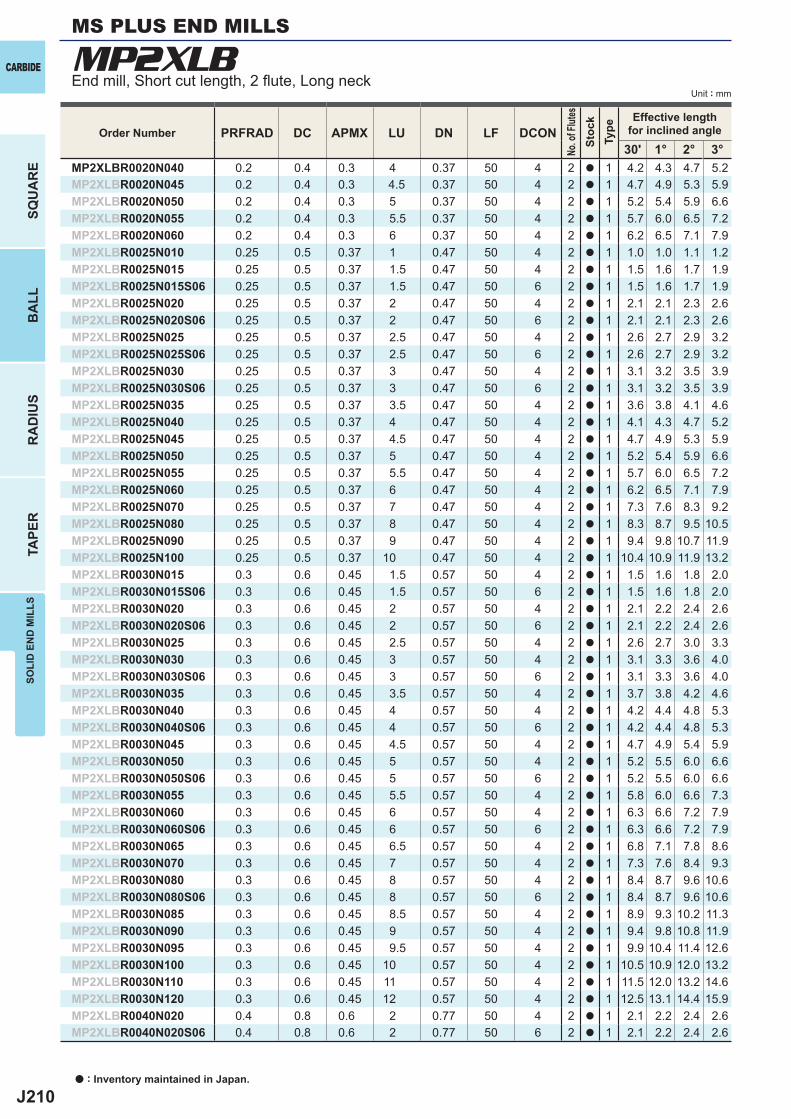
J210
MP2XLB
PRFRAD DC APMX LU DN LF DCON30' 1° 2° 3°
MP2XLBR0020N040 0.2 0.4 0.3 4 0.37 50 4 2 a 1 4.2 4.3 4.7 5.2MP2XLBR0020N045 0.2 0.4 0.3 4.5 0.37 50 4 2 a 1 4.7 4.9 5.3 5.9MP2XLBR0020N050 0.2 0.4 0.3 5 0.37 50 4 2 a 1 5.2 5.4 5.9 6.6MP2XLBR0020N055 0.2 0.4 0.3 5.5 0.37 50 4 2 a 1 5.7 6.0 6.5 7.2MP2XLBR0020N060 0.2 0.4 0.3 6 0.37 50 4 2 a 1 6.2 6.5 7.1 7.9MP2XLBR0025N010 0.25 0.5 0.37 1 0.47 50 4 2 a 1 1.0 1.0 1.1 1.2MP2XLBR0025N015 0.25 0.5 0.37 1.5 0.47 50 4 2 a 1 1.5 1.6 1.7 1.9MP2XLBR0025N015S06 0.25 0.5 0.37 1.5 0.47 50 6 2 a 1 1.5 1.6 1.7 1.9MP2XLBR0025N020 0.25 0.5 0.37 2 0.47 50 4 2 a 1 2.1 2.1 2.3 2.6MP2XLBR0025N020S06 0.25 0.5 0.37 2 0.47 50 6 2 a 1 2.1 2.1 2.3 2.6MP2XLBR0025N025 0.25 0.5 0.37 2.5 0.47 50 4 2 a 1 2.6 2.7 2.9 3.2MP2XLBR0025N025S06 0.25 0.5 0.37 2.5 0.47 50 6 2 a 1 2.6 2.7 2.9 3.2MP2XLBR0025N030 0.25 0.5 0.37 3 0.47 50 4 2 a 1 3.1 3.2 3.5 3.9MP2XLBR0025N030S06 0.25 0.5 0.37 3 0.47 50 6 2 a 1 3.1 3.2 3.5 3.9MP2XLBR0025N035 0.25 0.5 0.37 3.5 0.47 50 4 2 a 1 3.6 3.8 4.1 4.6MP2XLBR0025N040 0.25 0.5 0.37 4 0.47 50 4 2 a 1 4.1 4.3 4.7 5.2MP2XLBR0025N045 0.25 0.5 0.37 4.5 0.47 50 4 2 a 1 4.7 4.9 5.3 5.9MP2XLBR0025N050 0.25 0.5 0.37 5 0.47 50 4 2 a 1 5.2 5.4 5.9 6.6MP2XLBR0025N055 0.25 0.5 0.37 5.5 0.47 50 4 2 a 1 5.7 6.0 6.5 7.2MP2XLBR0025N060 0.25 0.5 0.37 6 0.47 50 4 2 a 1 6.2 6.5 7.1 7.9MP2XLBR0025N070 0.25 0.5 0.37 7 0.47 50 4 2 a 1 7.3 7.6 8.3 9.2MP2XLBR0025N080 0.25 0.5 0.37 8 0.47 50 4 2 a 1 8.3 8.7 9.5 10.5MP2XLBR0025N090 0.25 0.5 0.37 9 0.47 50 4 2 a 1 9.4 9.8 10.7 11.9MP2XLBR0025N100 0.25 0.5 0.37 10 0.47 50 4 2 a 1 10.4 10.9 11.9 13.2MP2XLBR0030N015 0.3 0.6 0.45 1.5 0.57 50 4 2 a 1 1.5 1.6 1.8 2.0MP2XLBR0030N015S06 0.3 0.6 0.45 1.5 0.57 50 6 2 a 1 1.5 1.6 1.8 2.0MP2XLBR0030N020 0.3 0.6 0.45 2 0.57 50 4 2 a 1 2.1 2.2 2.4 2.6MP2XLBR0030N020S06 0.3 0.6 0.45 2 0.57 50 6 2 a 1 2.1 2.2 2.4 2.6MP2XLBR0030N025 0.3 0.6 0.45 2.5 0.57 50 4 2 a 1 2.6 2.7 3.0 3.3MP2XLBR0030N030 0.3 0.6 0.45 3 0.57 50 4 2 a 1 3.1 3.3 3.6 4.0MP2XLBR0030N030S06 0.3 0.6 0.45 3 0.57 50 6 2 a 1 3.1 3.3 3.6 4.0MP2XLBR0030N035 0.3 0.6 0.45 3.5 0.57 50 4 2 a 1 3.7 3.8 4.2 4.6MP2XLBR0030N040 0.3 0.6 0.45 4 0.57 50 4 2 a 1 4.2 4.4 4.8 5.3MP2XLBR0030N040S06 0.3 0.6 0.45 4 0.57 50 6 2 a 1 4.2 4.4 4.8 5.3MP2XLBR0030N045 0.3 0.6 0.45 4.5 0.57 50 4 2 a 1 4.7 4.9 5.4 5.9MP2XLBR0030N050 0.3 0.6 0.45 5 0.57 50 4 2 a 1 5.2 5.5 6.0 6.6MP2XLBR0030N050S06 0.3 0.6 0.45 5 0.57 50 6 2 a 1 5.2 5.5 6.0 6.6MP2XLBR0030N055 0.3 0.6 0.45 5.5 0.57 50 4 2 a 1 5.8 6.0 6.6 7.3MP2XLBR0030N060 0.3 0.6 0.45 6 0.57 50 4 2 a 1 6.3 6.6 7.2 7.9MP2XLBR0030N060S06 0.3 0.6 0.45 6 0.57 50 6 2 a 1 6.3 6.6 7.2 7.9MP2XLBR0030N065 0.3 0.6 0.45 6.5 0.57 50 4 2 a 1 6.8 7.1 7.8 8.6MP2XLBR0030N070 0.3 0.6 0.45 7 0.57 50 4 2 a 1 7.3 7.6 8.4 9.3MP2XLBR0030N080 0.3 0.6 0.45 8 0.57 50 4 2 a 1 8.4 8.7 9.6 10.6MP2XLBR0030N080S06 0.3 0.6 0.45 8 0.57 50 6 2 a 1 8.4 8.7 9.6 10.6MP2XLBR0030N085 0.3 0.6 0.45 8.5 0.57 50 4 2 a 1 8.9 9.3 10.2 11.3MP2XLBR0030N090 0.3 0.6 0.45 9 0.57 50 4 2 a 1 9.4 9.8 10.8 11.9MP2XLBR0030N095 0.3 0.6 0.45 9.5 0.57 50 4 2 a 1 9.9 10.4 11.4 12.6MP2XLBR0030N100 0.3 0.6 0.45 10 0.57 50 4 2 a 1 10.5 10.9 12.0 13.2MP2XLBR0030N110 0.3 0.6 0.45 11 0.57 50 4 2 a 1 11.5 12.0 13.2 14.6MP2XLBR0030N120 0.3 0.6 0.45 12 0.57 50 4 2 a 1 12.5 13.1 14.4 15.9MP2XLBR0040N020 0.4 0.8 0.6 2 0.77 50 4 2 a 1 2.1 2.2 2.4 2.6MP2XLBR0040N020S06 0.4 0.8 0.6 2 0.77 50 6 2 a 1 2.1 2.2 2.4 2.6
a : Inventory maintained in Japan.
CARBIDE
SQU
AR
EB
ALL
RA
DIU
STA
PER
SOLI
D E
ND
MIL
LSMS PLUS END MILLS
Unit : mmEnd mill, Short cut length, 2 fl ute, Long neck
Order Number
No. o
f Flut
esSt
ock
Type
Effective lengthfor inclined angle
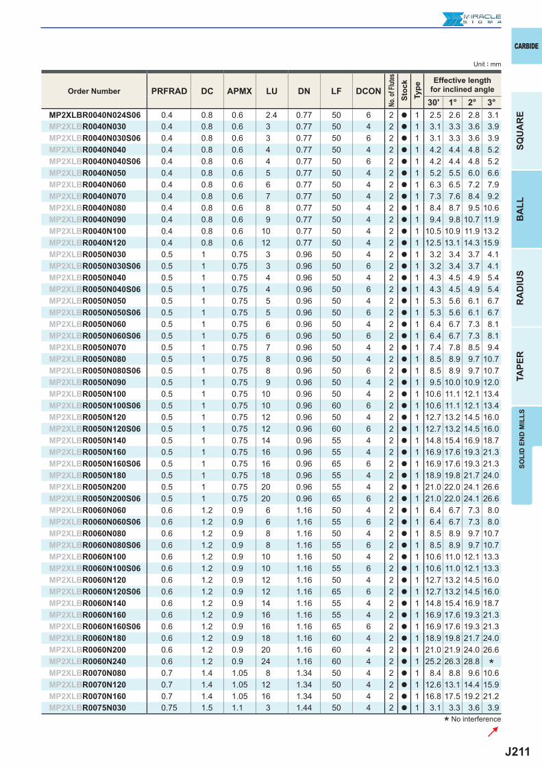
J211
PRFRAD DC APMX LU DN LF DCON30' 1° 2° 3°
MP2XLBR0040N024S06 0.4 0.8 0.6 2.4 0.77 50 6 2 a 1 2.5 2.6 2.8 3.1MP2XLBR0040N030 0.4 0.8 0.6 3 0.77 50 4 2 a 1 3.1 3.3 3.6 3.9MP2XLBR0040N030S06 0.4 0.8 0.6 3 0.77 50 6 2 a 1 3.1 3.3 3.6 3.9MP2XLBR0040N040 0.4 0.8 0.6 4 0.77 50 4 2 a 1 4.2 4.4 4.8 5.2MP2XLBR0040N040S06 0.4 0.8 0.6 4 0.77 50 6 2 a 1 4.2 4.4 4.8 5.2MP2XLBR0040N050 0.4 0.8 0.6 5 0.77 50 4 2 a 1 5.2 5.5 6.0 6.6MP2XLBR0040N060 0.4 0.8 0.6 6 0.77 50 4 2 a 1 6.3 6.5 7.2 7.9MP2XLBR0040N070 0.4 0.8 0.6 7 0.77 50 4 2 a 1 7.3 7.6 8.4 9.2MP2XLBR0040N080 0.4 0.8 0.6 8 0.77 50 4 2 a 1 8.4 8.7 9.5 10.6MP2XLBR0040N090 0.4 0.8 0.6 9 0.77 50 4 2 a 1 9.4 9.8 10.7 11.9MP2XLBR0040N100 0.4 0.8 0.6 10 0.77 50 4 2 a 1 10.5 10.9 11.9 13.2MP2XLBR0040N120 0.4 0.8 0.6 12 0.77 50 4 2 a 1 12.5 13.1 14.3 15.9MP2XLBR0050N030 0.5 1 0.75 3 0.96 50 4 2 a 1 3.2 3.4 3.7 4.1MP2XLBR0050N030S06 0.5 1 0.75 3 0.96 50 6 2 a 1 3.2 3.4 3.7 4.1MP2XLBR0050N040 0.5 1 0.75 4 0.96 50 4 2 a 1 4.3 4.5 4.9 5.4MP2XLBR0050N040S06 0.5 1 0.75 4 0.96 50 6 2 a 1 4.3 4.5 4.9 5.4MP2XLBR0050N050 0.5 1 0.75 5 0.96 50 4 2 a 1 5.3 5.6 6.1 6.7MP2XLBR0050N050S06 0.5 1 0.75 5 0.96 50 6 2 a 1 5.3 5.6 6.1 6.7MP2XLBR0050N060 0.5 1 0.75 6 0.96 50 4 2 a 1 6.4 6.7 7.3 8.1MP2XLBR0050N060S06 0.5 1 0.75 6 0.96 50 6 2 a 1 6.4 6.7 7.3 8.1MP2XLBR0050N070 0.5 1 0.75 7 0.96 50 4 2 a 1 7.4 7.8 8.5 9.4MP2XLBR0050N080 0.5 1 0.75 8 0.96 50 4 2 a 1 8.5 8.9 9.7 10.7MP2XLBR0050N080S06 0.5 1 0.75 8 0.96 50 6 2 a 1 8.5 8.9 9.7 10.7MP2XLBR0050N090 0.5 1 0.75 9 0.96 50 4 2 a 1 9.5 10.0 10.9 12.0MP2XLBR0050N100 0.5 1 0.75 10 0.96 50 4 2 a 1 10.6 11.1 12.1 13.4MP2XLBR0050N100S06 0.5 1 0.75 10 0.96 60 6 2 a 1 10.6 11.1 12.1 13.4MP2XLBR0050N120 0.5 1 0.75 12 0.96 50 4 2 a 1 12.7 13.2 14.5 16.0MP2XLBR0050N120S06 0.5 1 0.75 12 0.96 60 6 2 a 1 12.7 13.2 14.5 16.0MP2XLBR0050N140 0.5 1 0.75 14 0.96 55 4 2 a 1 14.8 15.4 16.9 18.7MP2XLBR0050N160 0.5 1 0.75 16 0.96 55 4 2 a 1 16.9 17.6 19.3 21.3MP2XLBR0050N160S06 0.5 1 0.75 16 0.96 65 6 2 a 1 16.9 17.6 19.3 21.3MP2XLBR0050N180 0.5 1 0.75 18 0.96 55 4 2 a 1 18.9 19.8 21.7 24.0MP2XLBR0050N200 0.5 1 0.75 20 0.96 55 4 2 a 1 21.0 22.0 24.1 26.6MP2XLBR0050N200S06 0.5 1 0.75 20 0.96 65 6 2 a 1 21.0 22.0 24.1 26.6MP2XLBR0060N060 0.6 1.2 0.9 6 1.16 50 4 2 a 1 6.4 6.7 7.3 8.0MP2XLBR0060N060S06 0.6 1.2 0.9 6 1.16 55 6 2 a 1 6.4 6.7 7.3 8.0MP2XLBR0060N080 0.6 1.2 0.9 8 1.16 50 4 2 a 1 8.5 8.9 9.7 10.7MP2XLBR0060N080S06 0.6 1.2 0.9 8 1.16 55 6 2 a 1 8.5 8.9 9.7 10.7MP2XLBR0060N100 0.6 1.2 0.9 10 1.16 50 4 2 a 1 10.6 11.0 12.1 13.3MP2XLBR0060N100S06 0.6 1.2 0.9 10 1.16 55 6 2 a 1 10.6 11.0 12.1 13.3MP2XLBR0060N120 0.6 1.2 0.9 12 1.16 50 4 2 a 1 12.7 13.2 14.5 16.0MP2XLBR0060N120S06 0.6 1.2 0.9 12 1.16 65 6 2 a 1 12.7 13.2 14.5 16.0MP2XLBR0060N140 0.6 1.2 0.9 14 1.16 55 4 2 a 1 14.8 15.4 16.9 18.7MP2XLBR0060N160 0.6 1.2 0.9 16 1.16 55 4 2 a 1 16.9 17.6 19.3 21.3MP2XLBR0060N160S06 0.6 1.2 0.9 16 1.16 65 6 2 a 1 16.9 17.6 19.3 21.3MP2XLBR0060N180 0.6 1.2 0.9 18 1.16 60 4 2 a 1 18.9 19.8 21.7 24.0MP2XLBR0060N200 0.6 1.2 0.9 20 1.16 60 4 2 a 1 21.0 21.9 24.0 26.6MP2XLBR0060N240 0.6 1.2 0.9 24 1.16 60 4 2 a 1 25.2 26.3 28.8MP2XLBR0070N080 0.7 1.4 1.05 8 1.34 50 4 2 a 1 8.4 8.8 9.6 10.6MP2XLBR0070N120 0.7 1.4 1.05 12 1.34 50 4 2 a 1 12.6 13.1 14.4 15.9MP2XLBR0070N160 0.7 1.4 1.05 16 1.34 50 4 2 a 1 16.8 17.5 19.2 21.2MP2XLBR0075N030 0.75 1.5 1.1 3 1.44 50 4 2 a 1 3.1 3.3 3.6 3.9
SOLI
D E
ND
MIL
LS
CARBIDE
SQU
AR
EB
ALL
RA
DIU
STA
PER
Unit : mm
Order Number
No. o
f Flut
esSt
ock
Type
Effective lengthfor inclined angle
*
* No interference
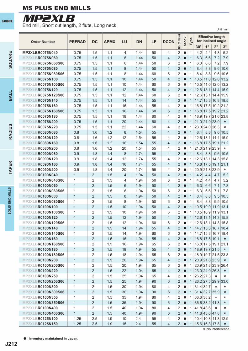
J212
MP2XLB
PRFRAD DC APMX LU DN LF DCON30' 1° 2° 3°
MP2XLBR0075N040 0.75 1.5 1.1 4 1.44 50 4 2 a 1 4.2 4.4 4.8 5.2MP2XLBR0075N060 0.75 1.5 1.1 6 1.44 50 4 2 a 1 6.3 6.6 7.2 7.9MP2XLBR0075N060S06 0.75 1.5 1.1 6 1.44 50 6 2 a 1 6.3 6.6 7.2 7.9MP2XLBR0075N080 0.75 1.5 1.1 8 1.44 50 4 2 a 1 8.4 8.8 9.6 10.6MP2XLBR0075N080S06 0.75 1.5 1.1 8 1.44 60 6 2 a 1 8.4 8.8 9.6 10.6MP2XLBR0075N100 0.75 1.5 1.1 10 1.44 50 4 2 a 1 10.5 11.0 12.0 13.2MP2XLBR0075N100S06 0.75 1.5 1.1 10 1.44 60 6 2 a 1 10.5 11.0 12.0 13.2MP2XLBR0075N120 0.75 1.5 1.1 12 1.44 50 4 2 a 1 12.6 13.1 14.4 15.9MP2XLBR0075N120S06 0.75 1.5 1.1 12 1.44 60 6 2 a 1 12.6 13.1 14.4 15.9MP2XLBR0075N140 0.75 1.5 1.1 14 1.44 55 4 2 a 1 14.7 15.3 16.8 18.5MP2XLBR0075N160 0.75 1.5 1.1 16 1.44 55 4 2 a 1 16.8 17.5 19.2 21.2MP2XLBR0075N160S06 0.75 1.5 1.1 16 1.44 60 6 2 a 1 16.8 17.5 19.2 21.2MP2XLBR0075N180 0.75 1.5 1.1 18 1.44 60 4 2 a 1 18.9 19.7 21.6 23.8MP2XLBR0075N200 0.75 1.5 1.1 20 1.44 60 4 2 a 1 21.0 21.9 23.9MP2XLBR0075N220 0.75 1.5 1.1 22 1.44 60 4 2 a 1 23.0 24.0 26.3MP2XLBR0080N080 0.8 1.6 1.2 8 1.54 55 4 2 a 1 8.4 8.8 9.6 10.5MP2XLBR0080N120 0.8 1.6 1.2 12 1.54 55 4 2 a 1 12.6 13.1 14.4 15.9MP2XLBR0080N160 0.8 1.6 1.2 16 1.54 55 4 2 a 1 16.8 17.5 19.1 21.2MP2XLBR0080N200 0.8 1.6 1.2 20 1.54 55 4 2 a 1 21.0 21.9 23.9MP2XLBR0090N080 0.9 1.8 1.4 8 1.74 55 4 2 a 1 8.4 8.8 9.6 10.5MP2XLBR0090N120 0.9 1.8 1.4 12 1.74 55 4 2 a 1 12.6 13.1 14.3 15.8MP2XLBR0090N160 0.9 1.8 1.4 16 1.74 55 4 2 a 1 16.8 17.5 19.1 21.1MP2XLBR0090N200 0.9 1.8 1.4 20 1.74 55 4 2 a 1 20.9 21.8 23.9MP2XLBR0100N040 1 2 1.5 4 1.94 50 4 2 a 1 4.2 4.4 4.7 5.2MP2XLBR0100N040S06 1 2 1.5 4 1.94 50 6 2 a 1 4.2 4.4 4.7 5.2MP2XLBR0100N060 1 2 1.5 6 1.94 50 4 2 a 1 6.3 6.6 7.1 7.8MP2XLBR0100N060S06 1 2 1.5 6 1.94 50 6 2 a 1 6.3 6.6 7.1 7.8MP2XLBR0100N080 1 2 1.5 8 1.94 50 4 2 a 1 8.4 8.8 9.5 10.5MP2XLBR0100N080S06 1 2 1.5 8 1.94 50 6 2 a 1 8.4 8.8 9.5 10.5MP2XLBR0100N100 1 2 1.5 10 1.94 50 4 2 a 1 10.5 10.9 11.9 13.1MP2XLBR0100N100S06 1 2 1.5 10 1.94 50 6 2 a 1 10.5 10.9 11.9 13.1MP2XLBR0100N120 1 2 1.5 12 1.94 50 4 2 a 1 12.6 13.1 14.3 15.8MP2XLBR0100N120S06 1 2 1.5 12 1.94 60 6 2 a 1 12.6 13.1 14.3 15.8MP2XLBR0100N140 1 2 1.5 14 1.94 55 4 2 a 1 14.7 15.3 16.7 18.4MP2XLBR0100N140S06 1 2 1.5 14 1.94 60 6 2 a 1 14.7 15.3 16.7 18.4MP2XLBR0100N160 1 2 1.5 16 1.94 55 4 2 a 1 16.8 17.5 19.1MP2XLBR0100N160S06 1 2 1.5 16 1.94 65 6 2 a 1 16.8 17.5 19.1 21.1MP2XLBR0100N180 1 2 1.5 18 1.94 55 4 2 a 1 18.9 19.7 21.5MP2XLBR0100N180S06 1 2 1.5 18 1.94 65 6 2 a 1 18.9 19.7 21.5 23.8MP2XLBR0100N200 1 2 1.5 20 1.94 65 4 2 a 1 20.9 21.8 23.9MP2XLBR0100N200S06 1 2 1.5 20 1.94 65 6 2 a 1 20.9 21.8 23.9 26.4MP2XLBR0100N220 1 2 1.5 22 1.94 65 4 2 a 1 23.0 24.0 26.3MP2XLBR0100N250 1 2 1.5 25 1.94 65 4 2 a 1 26.2 27.3MP2XLBR0100N250S06 1 2 1.5 25 1.94 90 6 2 a 1 26.2 27.3 29.9 33.0MP2XLBR0100N300 1 2 1.5 30 1.94 80 4 2 a 1 31.4 32.7MP2XLBR0100N300S06 1 2 1.5 30 1.94 90 6 2 a 1 31.4 32.7 35.9MP2XLBR0100N350 1 2 1.5 35 1.94 80 4 2 a 1 36.6 38.2MP2XLBR0100N350S06 1 2 1.5 35 1.94 90 6 2 a 1 36.6 38.2 41.8MP2XLBR0100N400 1 2 1.5 40 1.94 80 4 2 a 1 41.8 43.6MP2XLBR0100N400S06 1 2 1.5 40 1.94 90 6 2 a 1 41.8 43.6 47.8MP2XLBR0125N100 1.25 2.5 1.9 10 2.4 55 4 2 a 1 10.4 10.8 11.8 12.9MP2XLBR0125N150 1.25 2.5 1.9 15 2.4 55 4 2 a 1 15.6 16.3 17.8
a : Inventory maintained in Japan.
CARBIDE
SQU
AR
EB
ALL
RA
DIU
STA
PER
SOLI
D E
ND
MIL
LSMS PLUS END MILLS
Unit : mmEnd mill, Short cut length, 2 fl ute, Long neck
Order Number
No. o
f Flut
esSt
ock
Type
Effective lengthfor inclined angle
**
*
*
*
*
*
** *
* **
* **
* **
** No interference
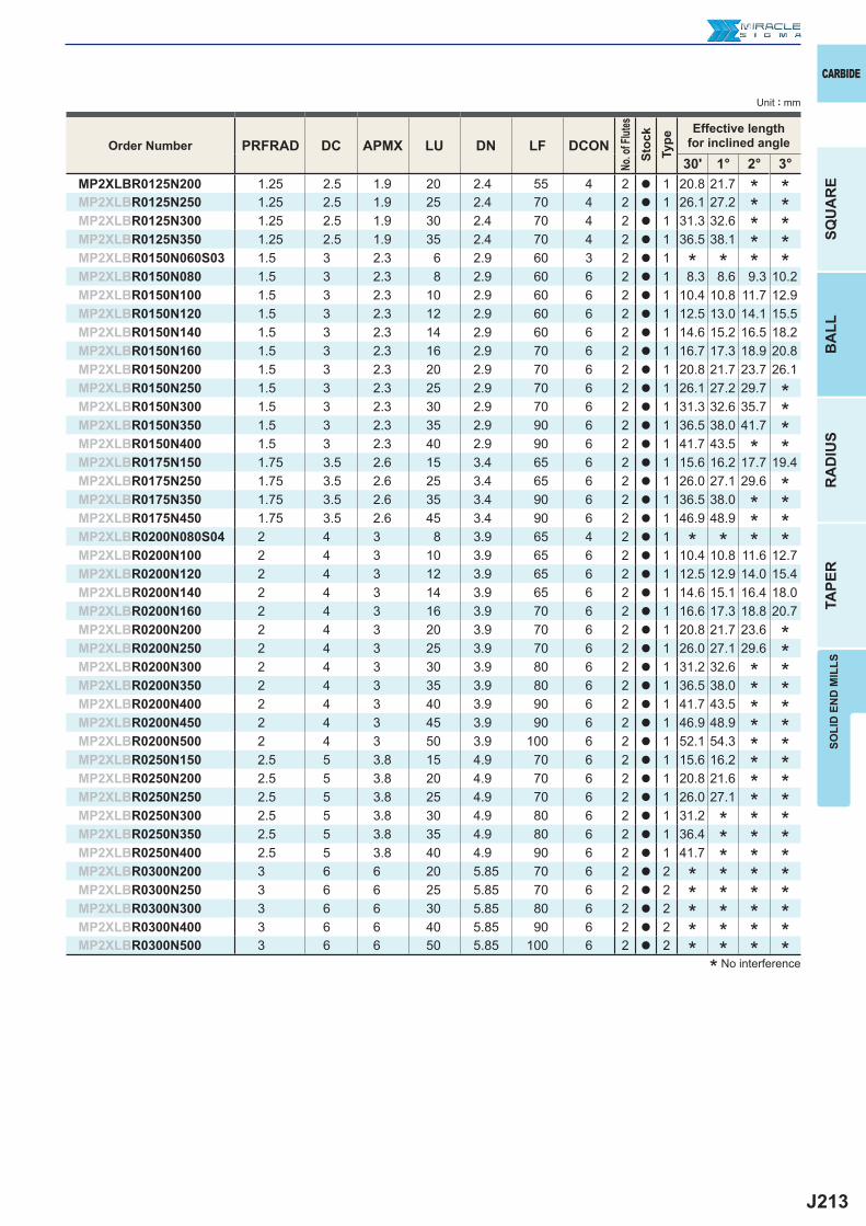
J213
PRFRAD DC APMX LU DN LF DCON30' 1° 2° 3°
MP2XLBR0125N200 1.25 2.5 1.9 20 2.4 55 4 2 a 1 20.8 21.7MP2XLBR0125N250 1.25 2.5 1.9 25 2.4 70 4 2 a 1 26.1 27.2MP2XLBR0125N300 1.25 2.5 1.9 30 2.4 70 4 2 a 1 31.3 32.6MP2XLBR0125N350 1.25 2.5 1.9 35 2.4 70 4 2 a 1 36.5 38.1MP2XLBR0150N060S03 1.5 3 2.3 6 2.9 60 3 2 a 1MP2XLBR0150N080 1.5 3 2.3 8 2.9 60 6 2 a 1 8.3 8.6 9.3 10.2MP2XLBR0150N100 1.5 3 2.3 10 2.9 60 6 2 a 1 10.4 10.8 11.7 12.9MP2XLBR0150N120 1.5 3 2.3 12 2.9 60 6 2 a 1 12.5 13.0 14.1 15.5MP2XLBR0150N140 1.5 3 2.3 14 2.9 60 6 2 a 1 14.6 15.2 16.5 18.2MP2XLBR0150N160 1.5 3 2.3 16 2.9 70 6 2 a 1 16.7 17.3 18.9 20.8MP2XLBR0150N200 1.5 3 2.3 20 2.9 70 6 2 a 1 20.8 21.7 23.7 26.1MP2XLBR0150N250 1.5 3 2.3 25 2.9 70 6 2 a 1 26.1 27.2 29.7MP2XLBR0150N300 1.5 3 2.3 30 2.9 70 6 2 a 1 31.3 32.6 35.7MP2XLBR0150N350 1.5 3 2.3 35 2.9 90 6 2 a 1 36.5 38.0 41.7MP2XLBR0150N400 1.5 3 2.3 40 2.9 90 6 2 a 1 41.7 43.5MP2XLBR0175N150 1.75 3.5 2.6 15 3.4 65 6 2 a 1 15.6 16.2 17.7 19.4MP2XLBR0175N250 1.75 3.5 2.6 25 3.4 65 6 2 a 1 26.0 27.1 29.6MP2XLBR0175N350 1.75 3.5 2.6 35 3.4 90 6 2 a 1 36.5 38.0MP2XLBR0175N450 1.75 3.5 2.6 45 3.4 90 6 2 a 1 46.9 48.9MP2XLBR0200N080S04 2 4 3 8 3.9 65 4 2 a 1MP2XLBR0200N100 2 4 3 10 3.9 65 6 2 a 1 10.4 10.8 11.6 12.7MP2XLBR0200N120 2 4 3 12 3.9 65 6 2 a 1 12.5 12.9 14.0 15.4MP2XLBR0200N140 2 4 3 14 3.9 65 6 2 a 1 14.6 15.1 16.4 18.0MP2XLBR0200N160 2 4 3 16 3.9 70 6 2 a 1 16.6 17.3 18.8 20.7MP2XLBR0200N200 2 4 3 20 3.9 70 6 2 a 1 20.8 21.7 23.6MP2XLBR0200N250 2 4 3 25 3.9 70 6 2 a 1 26.0 27.1 29.6MP2XLBR0200N300 2 4 3 30 3.9 80 6 2 a 1 31.2 32.6MP2XLBR0200N350 2 4 3 35 3.9 80 6 2 a 1 36.5 38.0MP2XLBR0200N400 2 4 3 40 3.9 90 6 2 a 1 41.7 43.5MP2XLBR0200N450 2 4 3 45 3.9 90 6 2 a 1 46.9 48.9MP2XLBR0200N500 2 4 3 50 3.9 100 6 2 a 1 52.1 54.3MP2XLBR0250N150 2.5 5 3.8 15 4.9 70 6 2 a 1 15.6 16.2MP2XLBR0250N200 2.5 5 3.8 20 4.9 70 6 2 a 1 20.8 21.6MP2XLBR0250N250 2.5 5 3.8 25 4.9 70 6 2 a 1 26.0 27.1MP2XLBR0250N300 2.5 5 3.8 30 4.9 80 6 2 a 1 31.2MP2XLBR0250N350 2.5 5 3.8 35 4.9 80 6 2 a 1 36.4MP2XLBR0250N400 2.5 5 3.8 40 4.9 90 6 2 a 1 41.7MP2XLBR0300N200 3 6 6 20 5.85 70 6 2 a 2MP2XLBR0300N250 3 6 6 25 5.85 70 6 2 a 2MP2XLBR0300N300 3 6 6 30 5.85 80 6 2 a 2MP2XLBR0300N400 3 6 6 40 5.85 90 6 2 a 2MP2XLBR0300N500 3 6 6 50 5.85 100 6 2 a 2
SOLI
D E
ND
MIL
LS
CARBIDE
SQU
AR
EB
ALL
RA
DIU
STA
PER
Unit : mm
Order Number
No. o
f Flut
esSt
ock
Type
Effective lengthfor inclined angle
***
* *
** ** *
* * * *
**
* ** ** ** ** ** ** ** *
* * ** * ** * *
* * * ** * * ** * * ** * * ** * * *
* ** ** ** *
* * * *
* No interference
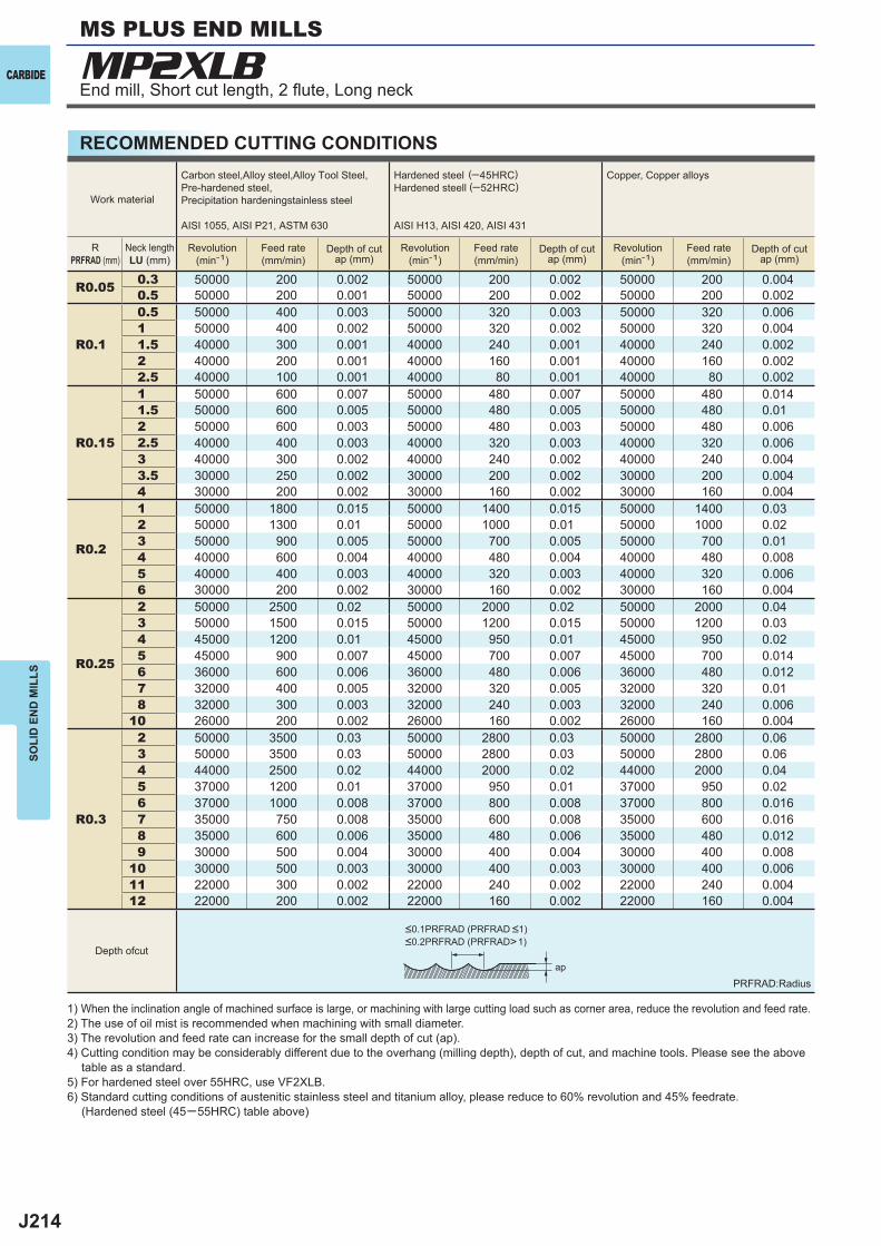
J214
MP2XLB
R0.05 0.3 50000 200 0.002 50000 200 0.002 50000 200 0.0040.5 50000 200 0.001 50000 200 0.002 50000 200 0.002
R0.1
0.5 50000 400 0.003 50000 320 0.003 50000 320 0.0061 50000 400 0.002 50000 320 0.002 50000 320 0.0041.5 40000 300 0.001 40000 240 0.001 40000 240 0.0022 40000 200 0.001 40000 160 0.001 40000 160 0.0022.5 40000 100 0.001 40000 80 0.001 40000 80 0.002
R0.15
1 50000 600 0.007 50000 480 0.007 50000 480 0.0141.5 50000 600 0.005 50000 480 0.005 50000 480 0.012 50000 600 0.003 50000 480 0.003 50000 480 0.0062.5 40000 400 0.003 40000 320 0.003 40000 320 0.0063 40000 300 0.002 40000 240 0.002 40000 240 0.0043.5 30000 250 0.002 30000 200 0.002 30000 200 0.0044 30000 200 0.002 30000 160 0.002 30000 160 0.004
R0.2
1 50000 1800 0.015 50000 1400 0.015 50000 1400 0.032 50000 1300 0.01 50000 1000 0.01 50000 1000 0.023 50000 900 0.005 50000 700 0.005 50000 700 0.014 40000 600 0.004 40000 480 0.004 40000 480 0.0085 40000 400 0.003 40000 320 0.003 40000 320 0.0066 30000 200 0.002 30000 160 0.002 30000 160 0.004
R0.25
2 50000 2500 0.02 50000 2000 0.02 50000 2000 0.043 50000 1500 0.015 50000 1200 0.015 50000 1200 0.034 45000 1200 0.01 45000 950 0.01 45000 950 0.025 45000 900 0.007 45000 700 0.007 45000 700 0.0146 36000 600 0.006 36000 480 0.006 36000 480 0.0127 32000 400 0.005 32000 320 0.005 32000 320 0.018 32000 300 0.003 32000 240 0.003 32000 240 0.006
10 26000 200 0.002 26000 160 0.002 26000 160 0.004
R0.3
2 50000 3500 0.03 50000 2800 0.03 50000 2800 0.063 50000 3500 0.03 50000 2800 0.03 50000 2800 0.064 44000 2500 0.02 44000 2000 0.02 44000 2000 0.045 37000 1200 0.01 37000 950 0.01 37000 950 0.026 37000 1000 0.008 37000 800 0.008 37000 800 0.0167 35000 750 0.008 35000 600 0.008 35000 600 0.0168 35000 600 0.006 35000 480 0.006 35000 480 0.0129 30000 500 0.004 30000 400 0.004 30000 400 0.008
10 30000 500 0.003 30000 400 0.003 30000 400 0.00611 22000 300 0.002 22000 240 0.002 22000 240 0.00412 22000 200 0.002 22000 160 0.002 22000 160 0.004
ap
CARBIDE
SOLI
D E
ND
MIL
LSMS PLUS END MILLS
End mill, Short cut length, 2 fl ute, Long neck
RECOMMENDED CUTTING CONDITIONS
Work material
Carbon steel,Alloy steel,Alloy Tool Steel,Pre-hardened steel,Precipitation hardeningstainless steel
AISI 1055, AISI P21, ASTM 630
Hardened steel (─45HRC)Hardened steell (─52HRC)
AISI H13, AISI 420, AISI 431
Copper, Copper alloys
RPRFRAD (mm)
Neck lengthLU (mm)
Revolution(min-1)
Feed rate(mm/min)
Depth of cutap (mm)
Revolution(min-1)
Feed rate(mm/min)
Depth of cutap (mm)
Revolution(min-1)
Feed rate(mm/min)
Depth of cutap (mm)
Depth ofcut
PRFRAD:Radius
1) When the inclination angle of machined surface is large, or machining with large cutting load such as corner area, reduce the revolution and feed rate.2) The use of oil mist is recommended when machining with small diameter.3) The revolution and feed rate can increase for the small depth of cut (ap).4) Cutting condition may be considerably different due to the overhang (milling depth), depth of cut, and machine tools. Please see the above table as a standard.5) For hardened steel over 55HRC, use VF2XLB.6) Standard cutting conditions of austenitic stainless steel and titanium alloy, please reduce to 60% revolution and 45% feedrate. (Hardened steel (45─55HRC) table above)
<0.1PRFRAD (PRFRAD <1)<0.2PRFRAD (PRFRAD>1)
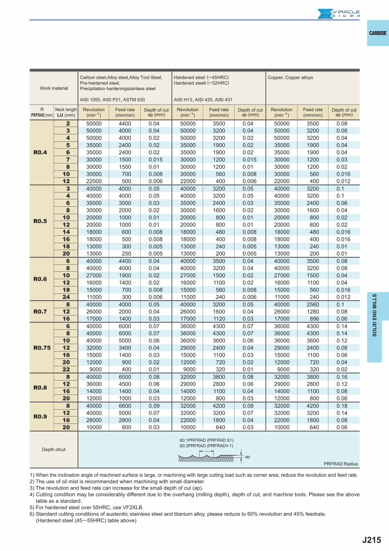
J215
R0.4
2 50000 4400 0.04 50000 3500 0.04 50000 3500 0.083 50000 4000 0.04 50000 3200 0.04 50000 3200 0.084 50000 4000 0.02 50000 3200 0.02 50000 3200 0.045 35000 2400 0.02 35000 1900 0.02 35000 1900 0.046 35000 2400 0.02 35000 1900 0.02 35000 1900 0.047 30000 1500 0.015 30000 1200 0.015 30000 1200 0.038 30000 1500 0.01 30000 1200 0.01 30000 1200 0.02
10 30000 700 0.008 30000 560 0.008 30000 560 0.01612 22000 500 0.006 22000 400 0.006 22000 400 0.012
R0.5
3 40000 4000 0.05 40000 3200 0.05 40000 3200 0.14 40000 4000 0.05 40000 3200 0.05 40000 3200 0.16 35000 3000 0.03 35000 2400 0.03 35000 2400 0.068 30000 2000 0.02 30000 1600 0.02 30000 1600 0.04
10 20000 1000 0.01 20000 800 0.01 20000 800 0.0212 20000 1000 0.01 20000 800 0.01 20000 800 0.0214 18000 600 0.008 18000 480 0.008 18000 480 0.01616 18000 500 0.008 18000 400 0.008 18000 400 0.01618 13000 300 0.005 13000 240 0.005 13000 240 0.0120 13000 250 0.005 13000 200 0.005 13000 200 0.01
R0.6
6 40000 4400 0.04 40000 3500 0.04 40000 3500 0.088 40000 4000 0.04 40000 3200 0.04 40000 3200 0.08
10 27000 1900 0.02 27000 1500 0.02 27000 1500 0.0412 16000 1400 0.02 16000 1100 0.02 16000 1100 0.0418 15000 700 0.008 15000 560 0.008 15000 560 0.01624 11000 300 0.006 11000 240 0.006 11000 240 0.012
R0.78 40000 4000 0.05 40000 3200 0.05 40000 2560 0.1
12 26000 2000 0.04 26000 1600 0.04 26000 1280 0.0816 17000 1400 0.03 17000 1120 0.03 17000 896 0.06
R0.75
6 40000 6000 0.07 36000 4300 0.07 36000 4300 0.148 40000 6000 0.07 36000 4300 0.07 36000 4300 0.14
10 40000 5000 0.06 36000 3600 0.06 36000 3600 0.1212 32000 3400 0.04 29000 2400 0.04 29000 2400 0.0816 15000 1400 0.03 15000 1100 0.03 15000 1100 0.0620 12000 900 0.02 12000 720 0.02 12000 720 0.0422 9000 400 0.01 9000 320 0.01 9000 320 0.02
R0.8
8 40000 6000 0.08 32000 3800 0.08 32000 3800 0.1612 36000 4500 0.06 29000 2800 0.06 29000 2800 0.1216 14000 1400 0.04 14000 1100 0.04 14000 1100 0.0820 12000 1000 0.03 12000 800 0.03 12000 800 0.06
R0.9
8 40000 6600 0.09 32000 4200 0.09 32000 4200 0.1812 40000 5000 0.07 32000 3200 0.07 32000 3200 0.1416 28000 2800 0.04 22000 1800 0.04 22000 1800 0.0820 10000 800 0.03 10000 640 0.03 10000 640 0.06
ap
CARBIDE
SOLI
D E
ND
MIL
LS
Work material
Carbon steel,Alloy steel,Alloy Tool Steel,Pre-hardened steel,Precipitation hardeningstainless steel
AISI 1055, AISI P21, ASTM 630
Hardened steel (─45HRC)Hardened steell (─52HRC)
AISI H13, AISI 420, AISI 431
Copper, Copper alloys
RPRFRAD (mm)
Neck lengthLU (mm)
Revolution(min-1)
Feed rate(mm/min)
Depth of cutap (mm)
Revolution(min-1)
Feed rate(mm/min)
Depth of cutap (mm)
Revolution(min-1)
Feed rate(mm/min)
Depth of cutap (mm)
Depth ofcut
PRFRAD:Radius
1) When the inclination angle of machined surface is large, or machining with large cutting load such as corner area, reduce the revolution and feed rate.2) The use of oil mist is recommended when machining with small diameter.3) The revolution and feed rate can increase for the small depth of cut (ap).4) Cutting condition may be considerably different due to the overhang (milling depth), depth of cut, and machine tools. Please see the above table as a standard.5) For hardened steel over 55HRC, use VF2XLB.6) Standard cutting conditions of austenitic stainless steel and titanium alloy, please reduce to 60% revolution and 45% feedrate. (Hardened steel (45─55HRC) table above)
<0.1PRFRAD (PRFRAD <1)<0.2PRFRAD (PRFRAD>1)
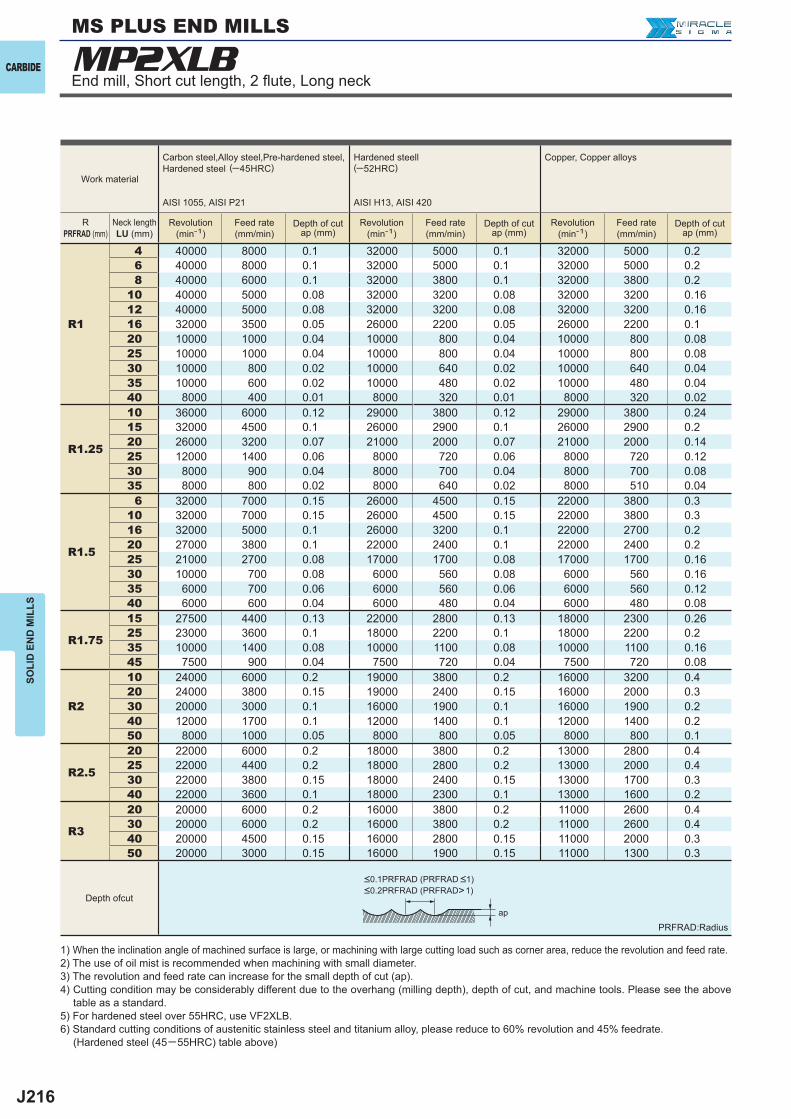
J216
MP2XLB
R1
4 40000 8000 0.1 32000 5000 0.1 32000 5000 0.26 40000 8000 0.1 32000 5000 0.1 32000 5000 0.28 40000 6000 0.1 32000 3800 0.1 32000 3800 0.2
10 40000 5000 0.08 32000 3200 0.08 32000 3200 0.1612 40000 5000 0.08 32000 3200 0.08 32000 3200 0.1616 32000 3500 0.05 26000 2200 0.05 26000 2200 0.120 10000 1000 0.04 10000 800 0.04 10000 800 0.0825 10000 1000 0.04 10000 800 0.04 10000 800 0.0830 10000 800 0.02 10000 640 0.02 10000 640 0.0435 10000 600 0.02 10000 480 0.02 10000 480 0.0440 8000 400 0.01 8000 320 0.01 8000 320 0.02
R1.25
10 36000 6000 0.12 29000 3800 0.12 29000 3800 0.2415 32000 4500 0.1 26000 2900 0.1 26000 2900 0.220 26000 3200 0.07 21000 2000 0.07 21000 2000 0.1425 12000 1400 0.06 8000 720 0.06 8000 720 0.1230 8000 900 0.04 8000 700 0.04 8000 700 0.0835 8000 800 0.02 8000 640 0.02 8000 510 0.04
R1.5
6 32000 7000 0.15 26000 4500 0.15 22000 3800 0.310 32000 7000 0.15 26000 4500 0.15 22000 3800 0.316 32000 5000 0.1 26000 3200 0.1 22000 2700 0.220 27000 3800 0.1 22000 2400 0.1 22000 2400 0.225 21000 2700 0.08 17000 1700 0.08 17000 1700 0.1630 10000 700 0.08 6000 560 0.08 6000 560 0.1635 6000 700 0.06 6000 560 0.06 6000 560 0.1240 6000 600 0.04 6000 480 0.04 6000 480 0.08
R1.75
15 27500 4400 0.13 22000 2800 0.13 18000 2300 0.2625 23000 3600 0.1 18000 2200 0.1 18000 2200 0.235 10000 1400 0.08 10000 1100 0.08 10000 1100 0.1645 7500 900 0.04 7500 720 0.04 7500 720 0.08
R2
10 24000 6000 0.2 19000 3800 0.2 16000 3200 0.420 24000 3800 0.15 19000 2400 0.15 16000 2000 0.330 20000 3000 0.1 16000 1900 0.1 16000 1900 0.240 12000 1700 0.1 12000 1400 0.1 12000 1400 0.250 8000 1000 0.05 8000 800 0.05 8000 800 0.1
R2.5
20 22000 6000 0.2 18000 3800 0.2 13000 2800 0.425 22000 4400 0.2 18000 2800 0.2 13000 2000 0.430 22000 3800 0.15 18000 2400 0.15 13000 1700 0.340 22000 3600 0.1 18000 2300 0.1 13000 1600 0.2
R3
20 20000 6000 0.2 16000 3800 0.2 11000 2600 0.430 20000 6000 0.2 16000 3800 0.2 11000 2600 0.440 20000 4500 0.15 16000 2800 0.15 11000 2000 0.350 20000 3000 0.15 16000 1900 0.15 11000 1300 0.3
ap
CARBIDE
SOLI
D E
ND
MIL
LSMS PLUS END MILLS
Depth ofcut
Work material
Carbon steel,Alloy steel,Pre-hardened steel,Hardened steel (─45HRC)
AISI 1055, AISI P21
Hardened steell(─52HRC)
AISI H13, AISI 420
Copper, Copper alloys
RPRFRAD (mm)
Neck lengthLU (mm)
Revolution(min-1)
Feed rate(mm/min)
Depth of cutap (mm)
Revolution(min-1)
Feed rate(mm/min)
Depth of cutap (mm)
Revolution(min-1)
Feed rate(mm/min)
Depth of cutap (mm)
PRFRAD:Radius
<0.1PRFRAD (PRFRAD <1)<0.2PRFRAD (PRFRAD>1)
End mill, Short cut length, 2 fl ute, Long neck
1) When the inclination angle of machined surface is large, or machining with large cutting load such as corner area, reduce the revolution and feed rate.2) The use of oil mist is recommended when machining with small diameter.3) The revolution and feed rate can increase for the small depth of cut (ap).4) Cutting condition may be considerably different due to the overhang (milling depth), depth of cut, and machine tools. Please see the above table as a standard.5) For hardened steel over 55HRC, use VF2XLB.6) Standard cutting conditions of austenitic stainless steel and titanium alloy, please reduce to 60% revolution and 45% feedrate. (Hardened steel (45─55HRC) table above)
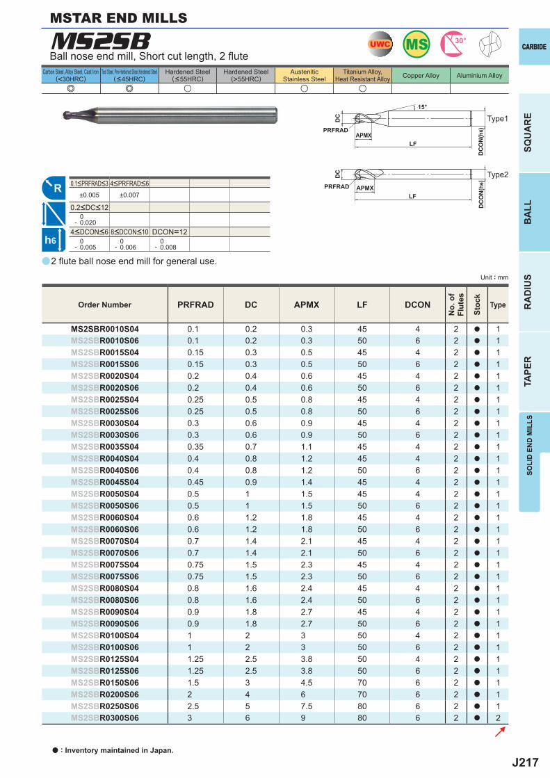
J217
a
e e u u u
±0.005 ±0.007
0- 0.020
DCON=12 0- 0.005
0- 0.006
0- 0.008
PRFRAD DC APMX LF DCON
MS2SBR0010S04 0.1 0.2 0.3 45 4 2 a 1MS2SBR0010S06 0.1 0.2 0.3 50 6 2 a 1MS2SBR0015S04 0.15 0.3 0.5 45 4 2 a 1MS2SBR0015S06 0.15 0.3 0.5 50 6 2 a 1MS2SBR0020S04 0.2 0.4 0.6 45 4 2 a 1MS2SBR0020S06 0.2 0.4 0.6 50 6 2 a 1MS2SBR0025S04 0.25 0.5 0.8 45 4 2 a 1MS2SBR0025S06 0.25 0.5 0.8 50 6 2 a 1MS2SBR0030S04 0.3 0.6 0.9 45 4 2 a 1MS2SBR0030S06 0.3 0.6 0.9 50 6 2 a 1MS2SBR0035S04 0.35 0.7 1.1 45 4 2 a 1MS2SBR0040S04 0.4 0.8 1.2 45 4 2 a 1MS2SBR0040S06 0.4 0.8 1.2 50 6 2 a 1MS2SBR0045S04 0.45 0.9 1.4 45 4 2 a 1MS2SBR0050S04 0.5 1 1.5 45 4 2 a 1MS2SBR0050S06 0.5 1 1.5 50 6 2 a 1MS2SBR0060S04 0.6 1.2 1.8 45 4 2 a 1MS2SBR0060S06 0.6 1.2 1.8 50 6 2 a 1MS2SBR0070S04 0.7 1.4 2.1 45 4 2 a 1MS2SBR0070S06 0.7 1.4 2.1 50 6 2 a 1MS2SBR0075S04 0.75 1.5 2.3 45 4 2 a 1MS2SBR0075S06 0.75 1.5 2.3 50 6 2 a 1MS2SBR0080S04 0.8 1.6 2.4 45 4 2 a 1MS2SBR0080S06 0.8 1.6 2.4 50 6 2 a 1MS2SBR0090S04 0.9 1.8 2.7 45 4 2 a 1MS2SBR0090S06 0.9 1.8 2.7 50 6 2 a 1MS2SBR0100S04 1 2 3 50 4 2 a 1MS2SBR0100S06 1 2 3 50 6 2 a 1MS2SBR0125S04 1.25 2.5 3.8 50 4 2 a 1MS2SBR0125S06 1.25 2.5 3.8 50 6 2 a 1MS2SBR0150S06 1.5 3 4.5 70 6 2 a 1MS2SBR0200S06 2 4 6 70 6 2 a 1MS2SBR0250S06 2.5 5 7.5 80 6 2 a 1MS2SBR0300S06 3 6 9 80 6 2 a 2
MS2SB UWC MS 30°
R
h6
APMX
DC
DC
ON
(h6)
15°
APMXLF
DC
DC
ON
(h6)
LF
PRFRAD
PRFRAD
SOLI
D E
ND
MIL
LS
CARBIDE
SQU
AR
EB
ALL
RA
DIU
STA
PER
Unit : mm
Carbon Steel, Alloy Steel, Cast Iron(<30HRC)
Tool Steel, Pre-Hardened Steel,Hardened Steel(<45HRC)
Hardened Steel(<55HRC)
Hardened Steel(>55HRC)
AusteniticStainless Steel
Titanium Alloy,Heat Resistant Alloy Copper Alloy Aluminium Alloy
MSTAR END MILLS
2 fl ute ball nose end mill for general use.
Ball nose end mill, Short cut length, 2 fl ute
Order Number
No.
of
Flut
es
Stoc
k
Type
4<DCON<6 8<DCON<10
0.1<PRFRAD<3 4<PRFRAD<6
0.2<DC<12
Type1
Type2
a : Inventory maintained in Japan.
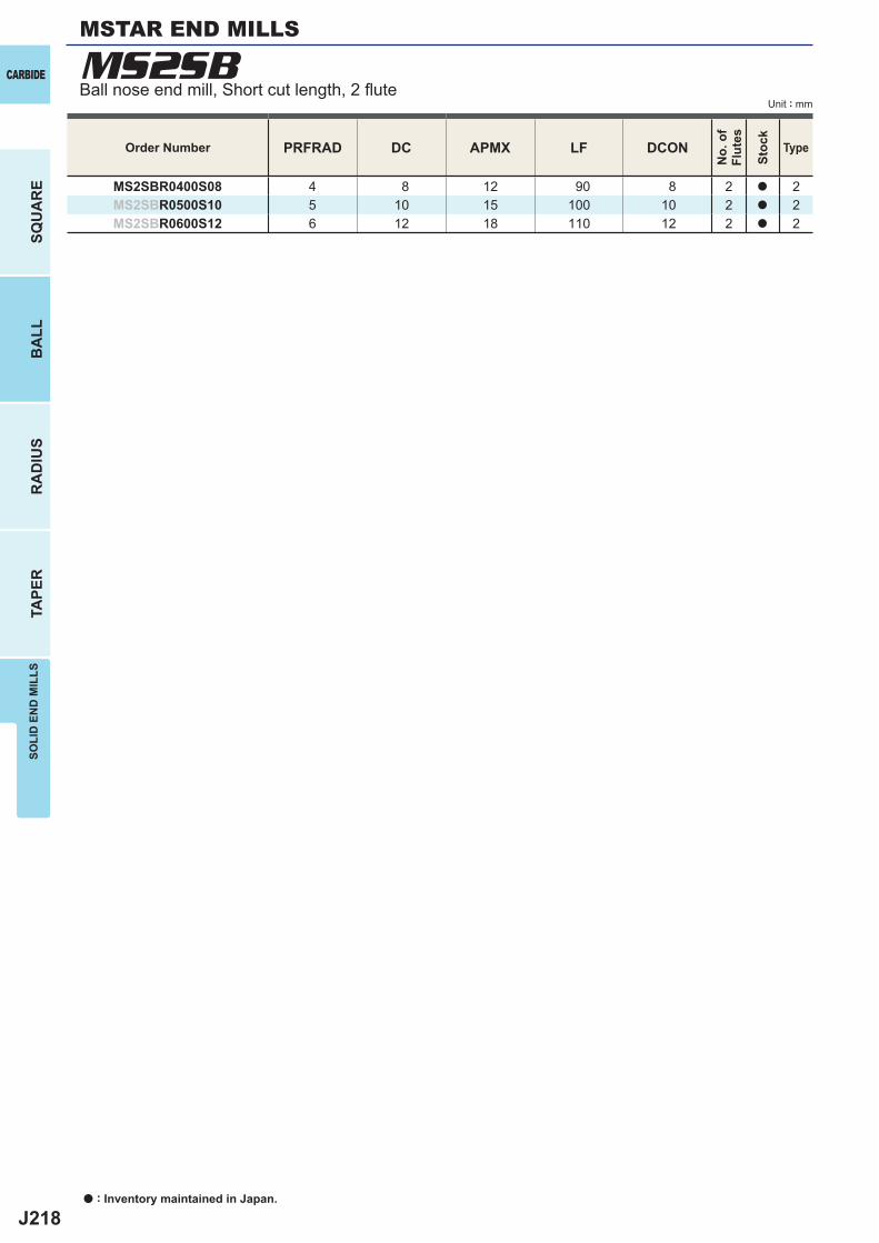
J218
PRFRAD DC APMX LF DCON
MS2SBR0400S08 4 8 12 90 8 2 a 2MS2SBR0500S10 5 10 15 100 10 2 a 2MS2SBR0600S12 6 12 18 110 12 2 a 2
MS2SBCARBIDE
SQU
AR
EB
ALL
RA
DIU
STA
PER
SOLI
D E
ND
MIL
LS
Unit : mm
a : Inventory maintained in Japan.
Order Number
No.
of
Flut
es
Stoc
k
Type
MSTAR END MILLS
Ball nose end mill, Short cut length, 2 fl ute
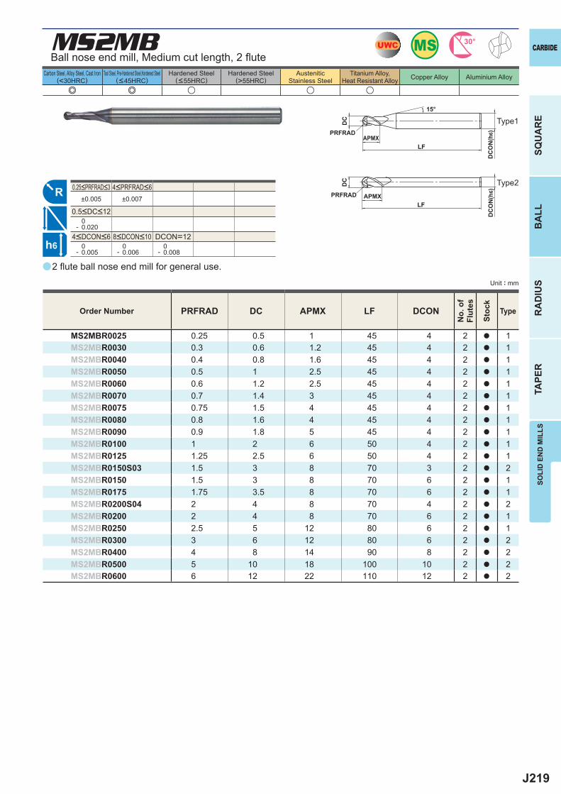
J219
a
e e u u u
MS2MB
PRFRAD DC APMX LF DCON
MS2MBR0025 0.25 0.5 1 45 4 2 a 1MS2MBR0030 0.3 0.6 1.2 45 4 2 a 1MS2MBR0040 0.4 0.8 1.6 45 4 2 a 1MS2MBR0050 0.5 1 2.5 45 4 2 a 1MS2MBR0060 0.6 1.2 2.5 45 4 2 a 1MS2MBR0070 0.7 1.4 3 45 4 2 a 1MS2MBR0075 0.75 1.5 4 45 4 2 a 1MS2MBR0080 0.8 1.6 4 45 4 2 a 1MS2MBR0090 0.9 1.8 5 45 4 2 a 1MS2MBR0100 1 2 6 50 4 2 a 1MS2MBR0125 1.25 2.5 6 50 4 2 a 1MS2MBR0150S03 1.5 3 8 70 3 2 a 2MS2MBR0150 1.5 3 8 70 6 2 a 1MS2MBR0175 1.75 3.5 8 70 6 2 a 1MS2MBR0200S04 2 4 8 70 4 2 a 2MS2MBR0200 2 4 8 70 6 2 a 1MS2MBR0250 2.5 5 12 80 6 2 a 1MS2MBR0300 3 6 12 80 6 2 a 2MS2MBR0400 4 8 14 90 8 2 a 2MS2MBR0500 5 10 18 100 10 2 a 2MS2MBR0600 6 12 22 110 12 2 a 2
±0.005 ±0.007
0- 0.020
DCON=12 0- 0.005
0- 0.006
0- 0.008
UWC MS 30°
R
h6
APMX
DC
DC
ON
(h6)
15°
APMXLF
DC
DC
ON
(h6)
LF
PRFRAD
PRFRAD
SOLI
D E
ND
MIL
LS
CARBIDE
SQU
AR
EB
ALL
RA
DIU
STA
PER
Unit : mm
Carbon Steel, Alloy Steel, Cast Iron(<30HRC)
Tool Steel, Pre-Hardened Steel,Hardened Steel(<45HRC)
Hardened Steel(<55HRC)
Hardened Steel(>55HRC)
AusteniticStainless Steel
Titanium Alloy,Heat Resistant Alloy Copper Alloy Aluminium Alloy
2 fl ute ball nose end mill for general use.
Ball nose end mill, Medium cut length, 2 fl ute
Order Number
No.
of
Flut
es
Stoc
k
Type
4<DCON<6 8<DCON<10
0.25<PRFRAD<3 4<PRFRAD<6
0.5<DC<12
Type1
Type2
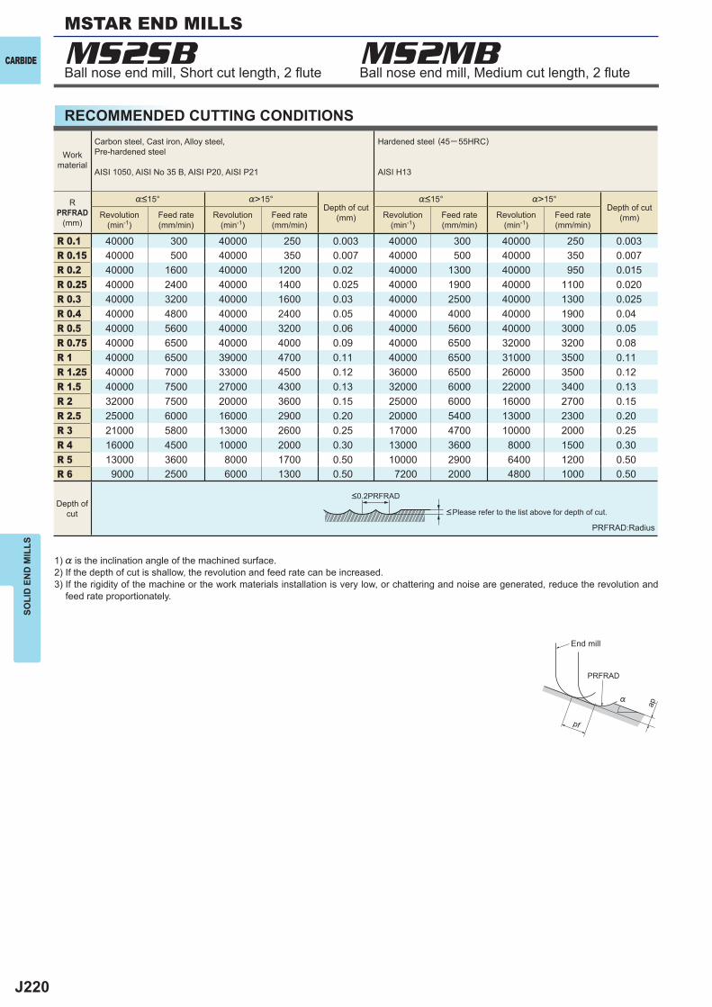
J220
MS2SB MS2MB
%>15° %>15°
R 0.1 40000 300 40000 250 0.003 40000 300 40000 250 0.003R 0.15 40000 500 40000 350 0.007 40000 500 40000 350 0.007R 0.2 40000 1600 40000 1200 0.02 40000 1300 40000 950 0.015R 0.25 40000 2400 40000 1400 0.025 40000 1900 40000 1100 0.020R 0.3 40000 3200 40000 1600 0.03 40000 2500 40000 1300 0.025R 0.4 40000 4800 40000 2400 0.05 40000 4000 40000 1900 0.04R 0.5 40000 5600 40000 3200 0.06 40000 5600 40000 3000 0.05R 0.75 40000 6500 40000 4000 0.09 40000 6500 32000 3200 0.08R 1 40000 6500 39000 4700 0.11 40000 6500 31000 3500 0.11R 1.25 40000 7000 33000 4500 0.12 36000 6500 26000 3500 0.12R 1.5 40000 7500 27000 4300 0.13 32000 6000 22000 3400 0.13R 2 32000 7500 20000 3600 0.15 25000 6000 16000 2700 0.15R 2.5 25000 6000 16000 2900 0.20 20000 5400 13000 2300 0.20R 3 21000 5800 13000 2600 0.25 17000 4700 10000 2000 0.25R 4 16000 4500 10000 2000 0.30 13000 3600 8000 1500 0.30R 5 13000 3600 8000 1700 0.50 10000 2900 6400 1200 0.50R 6 9000 2500 6000 1300 0.50 7200 2000 4800 1000 0.50
ap
PRFRAD
pf
%
CARBIDE
SOLI
D E
ND
MIL
LSMSTAR END MILLS
RECOMMENDED CUTTING CONDITIONS
Ball nose end mill, Short cut length, 2 fl ute Ball nose end mill, Medium cut length, 2 fl ute
1) % is the inclination angle of the machined surface. 2) If the depth of cut is shallow, the revolution and feed rate can be increased.3) If the rigidity of the machine or the work materials installation is very low, or chattering and noise are generated, reduce the revolution and
feed rate proportionately.
PRFRAD:Radius
<Please refer to the list above for depth of cut.
Workmaterial
Carbon steel, Cast iron, Alloy steel,Pre-hardened steel
AISI 1050, AISI No 35 B, AISI P20, AISI P21
Hardened steel (45─ 55HRC)
AISI H13
RPRFRAD
(mm)
%<15°Depth of cut
(mm)
%<15°Depth of cut
(mm)Revolution(min-1)
Feed rate(mm/min)
Revolution(min-1)
Feed rate(mm/min)
Revolution(min-1)
Feed rate(mm/min)
Revolution(min-1)
Feed rate(mm/min)
Depth ofcut
<0.2PRFRAD
End mill
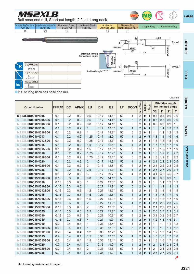
J221
a
e e u u u
MS2XLB
PRFRAD DC APMX LU DN B2 LF DCON30' 1° 2° 3°
MS2XLBR0010N005 0.1 0.2 0.2 0.5 0.17 14.1° 50 4 2 a 1 0.5 0.5 0.6 0.6MS2XLBR0010N005S06 0.1 0.2 0.2 0.5 0.17 14.4° 50 6 2 a 1 0.5 0.5 0.6 0.6MS2XLBR0010N008S06 0.1 0.2 0.2 0.8 0.17 14.1° 50 6 2 a 1 0.8 0.8 0.9 1MS2XLBR0010N010 0.1 0.2 0.2 1 0.17 13.3° 50 4 2 a 1 1 1.1 1.2 1.3MS2XLBR0010N010S06 0.1 0.2 0.2 1 0.17 13.8° 50 6 2 a 1 1 1.1 1.2 1.3MS2XLBR0010N013 0.1 0.2 0.2 1.25 0.17 12.9° 50 4 2 a 1 1.3 1.3 1.5 1.6MS2XLBR0010N013S06 0.1 0.2 0.2 1.25 0.17 13.6° 50 6 2 a 1 1.3 1.3 1.5 1.6MS2XLBR0010N015 0.1 0.2 0.2 1.5 0.17 12.5° 50 4 2 a 1 1.5 1.6 1.7 1.9MS2XLBR0010N015S06 0.1 0.2 0.2 1.5 0.17 13.3° 50 6 2 a 1 1.5 1.6 1.7 1.9MS2XLBR0010N018 0.1 0.2 0.2 1.75 0.17 12.2° 50 4 2 a 1 1.8 1.9 2 2.2MS2XLBR0010N018S06 0.1 0.2 0.2 1.75 0.17 13.1° 50 6 2 a 1 1.8 1.9 2 2.2MS2XLBR0010N020 0.1 0.2 0.2 2 0.17 11.9° 50 4 2 a 1 2.1 2.2 2.3 2.5MS2XLBR0010N020S06 0.1 0.2 0.2 2 0.17 12.8° 50 6 2 a 1 2.1 2.2 2.3 2.5MS2XLBR0010N025 0.1 0.2 0.2 2.5 0.17 11.3° 50 4 2 a 1 2.6 2.7 2.9 3.1MS2XLBR0010N030 0.1 0.2 0.2 3 0.17 10.7° 50 4 2 a 1 3.1 3.2 3.5 3.7MS2XLBR0015N008S06 0.15 0.3 0.3 0.8 0.27 14.1° 50 6 2 a 1 0.8 0.8 0.9 1MS2XLBR0015N010 0.15 0.3 0.3 1 0.27 13.3° 50 4 2 a 1 1 1.1 1.2 1.3MS2XLBR0015N010S06 0.15 0.3 0.3 1 0.27 13.9° 50 6 2 a 1 1 1.1 1.2 1.3MS2XLBR0015N012S06 0.15 0.3 0.3 1.2 0.27 13.7° 50 6 2 a 1 1.2 1.3 1.4 1.5MS2XLBR0015N015 0.15 0.3 0.3 1.5 0.27 12.5° 50 4 2 a 1 1.5 1.6 1.7 1.9MS2XLBR0015N015S06 0.15 0.3 0.3 1.5 0.27 13.3° 50 6 2 a 1 1.5 1.6 1.7 1.9MS2XLBR0015N020 0.15 0.3 0.3 2 0.27 11.9° 50 4 2 a 1 2.1 2.2 2.3 2.5MS2XLBR0015N020S06 0.15 0.3 0.3 2 0.27 12.8° 50 6 2 a 1 2.1 2.2 2.3 2.5MS2XLBR0015N025 0.15 0.3 0.3 2.5 0.27 11.2° 50 4 2 a 1 2.6 2.7 2.9 3.1MS2XLBR0015N030 0.15 0.3 0.3 3 0.27 10.7° 50 4 2 a 1 3.1 3.2 3.5 3.7MS2XLBR0015N040 0.15 0.3 0.3 4 0.27 9.7° 50 4 2 a 1 4.2 4.3 4.6 5MS2XLBR0020N010 0.2 0.4 0.4 1 0.36 13.4° 50 4 2 a 1 1 1 1.1 1.2MS2XLBR0020N010S06 0.2 0.4 0.4 1 0.36 13.9° 50 6 2 a 1 1 1 1.1 1.2MS2XLBR0020N012S06 0.2 0.4 0.4 1.2 0.36 13.7° 50 6 2 a 1 1.2 1.3 1.4 1.5MS2XLBR0020N015 0.2 0.4 0.4 1.5 0.36 12.6° 50 4 2 a 1 1.5 1.6 1.7 1.8MS2XLBR0020N015S06 0.2 0.4 0.4 1.5 0.36 13.4° 50 6 2 a 1 1.5 1.6 1.7 1.8MS2XLBR0020N020 0.2 0.4 0.4 2 0.36 11.9° 50 4 2 a 1 2 2.1 2.3 2.5MS2XLBR0020N020S06 0.2 0.4 0.4 2 0.36 12.8° 50 6 2 a 1 2 2.1 2.3 2.5MS2XLBR0020N025 0.2 0.4 0.4 2.5 0.36 11.2° 50 4 2 a 1 2.6 2.7 2.9 3.1
±0.005
0- 0.020
0- 0.005
UWC MS 30°
R
h6
APMX
DC
DC
ON
(h6)
15°
B2
APMX
LF
DC
DC
ON
(h6)
LF
PRFRAD
PRFRADLU
LU
DN
DN
SOLI
D E
ND
MIL
LS
CARBIDE
SQU
AR
EB
ALL
RA
DIU
STA
PER
Unit : mm
Carbon Steel, Alloy Steel, Cast Iron(<30HRC)
Tool Steel, Pre-Hardened Steel,Hardened Steel(<45HRC)
Hardened Steel(<55HRC)
Hardened Steel(>55HRC)
AusteniticStainless Steel
Titanium Alloy,Heat Resistant Alloy Copper Alloy Aluminium Alloy
0.1<PRFRAD<3
0.2<DC<6
Ball nose end mill, Short cut length, 2 fl ute, Long neck
2 fl ute long neck ball nose end mill.
Effective lengthfor inclined angle
Inclined angle
Effe
ctiv
ele
ngth
Order Number
No. o
f Flut
esSt
ock
Type
Effective lengthfor inclined angle
4<DCON<6
Type1
Type2
a : Inventory maintained in Japan.
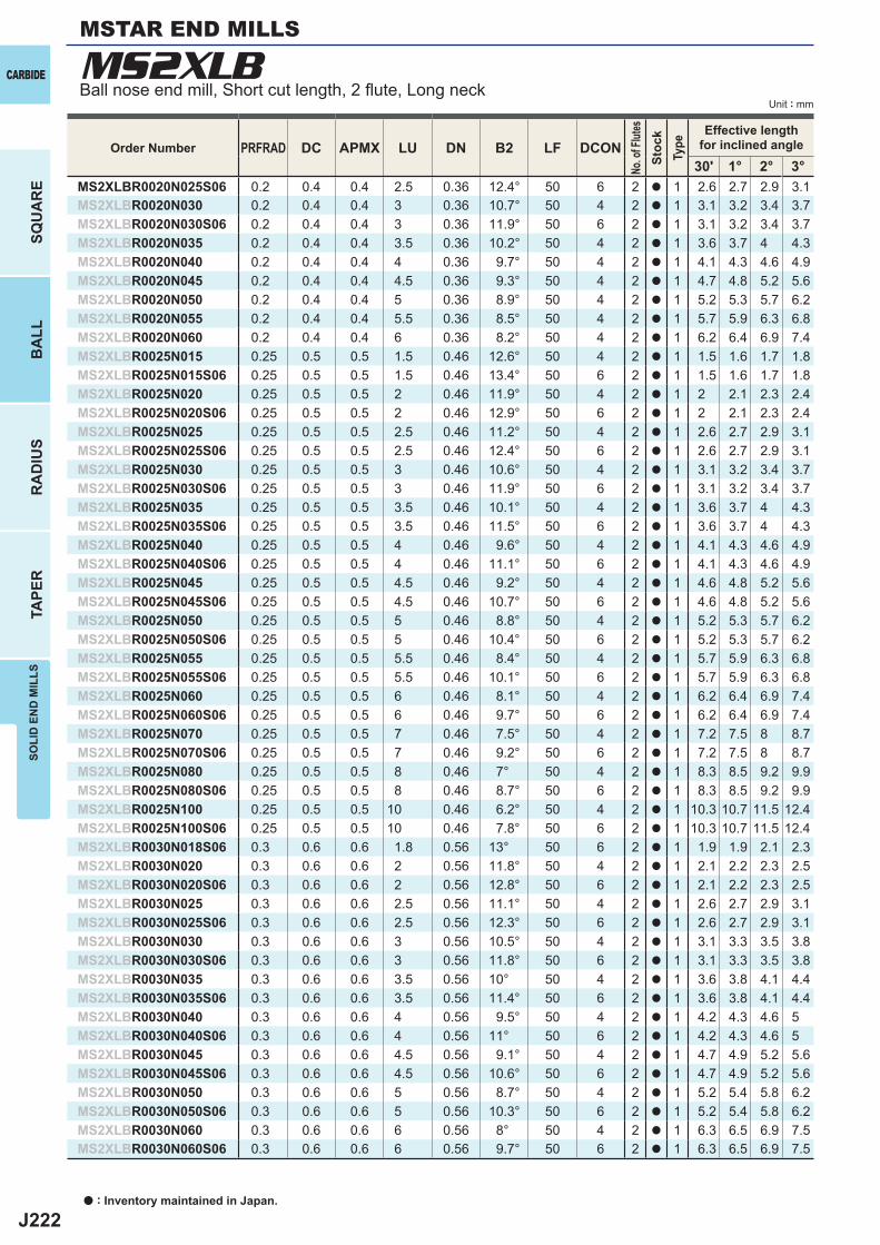
J222
MS2XLB
PRFRAD DC APMX LU DN B2 LF DCON30' 1° 2° 3°
MS2XLBR0020N025S06 0.2 0.4 0.4 2.5 0.36 12.4° 50 6 2 a 1 2.6 2.7 2.9 3.1MS2XLBR0020N030 0.2 0.4 0.4 3 0.36 10.7° 50 4 2 a 1 3.1 3.2 3.4 3.7MS2XLBR0020N030S06 0.2 0.4 0.4 3 0.36 11.9° 50 6 2 a 1 3.1 3.2 3.4 3.7MS2XLBR0020N035 0.2 0.4 0.4 3.5 0.36 10.2° 50 4 2 a 1 3.6 3.7 4 4.3MS2XLBR0020N040 0.2 0.4 0.4 4 0.36 9.7° 50 4 2 a 1 4.1 4.3 4.6 4.9MS2XLBR0020N045 0.2 0.4 0.4 4.5 0.36 9.3° 50 4 2 a 1 4.7 4.8 5.2 5.6MS2XLBR0020N050 0.2 0.4 0.4 5 0.36 8.9° 50 4 2 a 1 5.2 5.3 5.7 6.2MS2XLBR0020N055 0.2 0.4 0.4 5.5 0.36 8.5° 50 4 2 a 1 5.7 5.9 6.3 6.8MS2XLBR0020N060 0.2 0.4 0.4 6 0.36 8.2° 50 4 2 a 1 6.2 6.4 6.9 7.4MS2XLBR0025N015 0.25 0.5 0.5 1.5 0.46 12.6° 50 4 2 a 1 1.5 1.6 1.7 1.8MS2XLBR0025N015S06 0.25 0.5 0.5 1.5 0.46 13.4° 50 6 2 a 1 1.5 1.6 1.7 1.8MS2XLBR0025N020 0.25 0.5 0.5 2 0.46 11.9° 50 4 2 a 1 2 2.1 2.3 2.4MS2XLBR0025N020S06 0.25 0.5 0.5 2 0.46 12.9° 50 6 2 a 1 2 2.1 2.3 2.4MS2XLBR0025N025 0.25 0.5 0.5 2.5 0.46 11.2° 50 4 2 a 1 2.6 2.7 2.9 3.1MS2XLBR0025N025S06 0.25 0.5 0.5 2.5 0.46 12.4° 50 6 2 a 1 2.6 2.7 2.9 3.1MS2XLBR0025N030 0.25 0.5 0.5 3 0.46 10.6° 50 4 2 a 1 3.1 3.2 3.4 3.7MS2XLBR0025N030S06 0.25 0.5 0.5 3 0.46 11.9° 50 6 2 a 1 3.1 3.2 3.4 3.7MS2XLBR0025N035 0.25 0.5 0.5 3.5 0.46 10.1° 50 4 2 a 1 3.6 3.7 4 4.3MS2XLBR0025N035S06 0.25 0.5 0.5 3.5 0.46 11.5° 50 6 2 a 1 3.6 3.7 4 4.3MS2XLBR0025N040 0.25 0.5 0.5 4 0.46 9.6° 50 4 2 a 1 4.1 4.3 4.6 4.9MS2XLBR0025N040S06 0.25 0.5 0.5 4 0.46 11.1° 50 6 2 a 1 4.1 4.3 4.6 4.9MS2XLBR0025N045 0.25 0.5 0.5 4.5 0.46 9.2° 50 4 2 a 1 4.6 4.8 5.2 5.6MS2XLBR0025N045S06 0.25 0.5 0.5 4.5 0.46 10.7° 50 6 2 a 1 4.6 4.8 5.2 5.6MS2XLBR0025N050 0.25 0.5 0.5 5 0.46 8.8° 50 4 2 a 1 5.2 5.3 5.7 6.2MS2XLBR0025N050S06 0.25 0.5 0.5 5 0.46 10.4° 50 6 2 a 1 5.2 5.3 5.7 6.2MS2XLBR0025N055 0.25 0.5 0.5 5.5 0.46 8.4° 50 4 2 a 1 5.7 5.9 6.3 6.8MS2XLBR0025N055S06 0.25 0.5 0.5 5.5 0.46 10.1° 50 6 2 a 1 5.7 5.9 6.3 6.8MS2XLBR0025N060 0.25 0.5 0.5 6 0.46 8.1° 50 4 2 a 1 6.2 6.4 6.9 7.4MS2XLBR0025N060S06 0.25 0.5 0.5 6 0.46 9.7° 50 6 2 a 1 6.2 6.4 6.9 7.4MS2XLBR0025N070 0.25 0.5 0.5 7 0.46 7.5° 50 4 2 a 1 7.2 7.5 8 8.7MS2XLBR0025N070S06 0.25 0.5 0.5 7 0.46 9.2° 50 6 2 a 1 7.2 7.5 8 8.7MS2XLBR0025N080 0.25 0.5 0.5 8 0.46 7° 50 4 2 a 1 8.3 8.5 9.2 9.9MS2XLBR0025N080S06 0.25 0.5 0.5 8 0.46 8.7° 50 6 2 a 1 8.3 8.5 9.2 9.9MS2XLBR0025N100 0.25 0.5 0.5 10 0.46 6.2° 50 4 2 a 1 10.3 10.7 11.5 12.4MS2XLBR0025N100S06 0.25 0.5 0.5 10 0.46 7.8° 50 6 2 a 1 10.3 10.7 11.5 12.4MS2XLBR0030N018S06 0.3 0.6 0.6 1.8 0.56 13° 50 6 2 a 1 1.9 1.9 2.1 2.3MS2XLBR0030N020 0.3 0.6 0.6 2 0.56 11.8° 50 4 2 a 1 2.1 2.2 2.3 2.5MS2XLBR0030N020S06 0.3 0.6 0.6 2 0.56 12.8° 50 6 2 a 1 2.1 2.2 2.3 2.5MS2XLBR0030N025 0.3 0.6 0.6 2.5 0.56 11.1° 50 4 2 a 1 2.6 2.7 2.9 3.1MS2XLBR0030N025S06 0.3 0.6 0.6 2.5 0.56 12.3° 50 6 2 a 1 2.6 2.7 2.9 3.1MS2XLBR0030N030 0.3 0.6 0.6 3 0.56 10.5° 50 4 2 a 1 3.1 3.3 3.5 3.8MS2XLBR0030N030S06 0.3 0.6 0.6 3 0.56 11.8° 50 6 2 a 1 3.1 3.3 3.5 3.8MS2XLBR0030N035 0.3 0.6 0.6 3.5 0.56 10° 50 4 2 a 1 3.6 3.8 4.1 4.4MS2XLBR0030N035S06 0.3 0.6 0.6 3.5 0.56 11.4° 50 6 2 a 1 3.6 3.8 4.1 4.4MS2XLBR0030N040 0.3 0.6 0.6 4 0.56 9.5° 50 4 2 a 1 4.2 4.3 4.6 5MS2XLBR0030N040S06 0.3 0.6 0.6 4 0.56 11° 50 6 2 a 1 4.2 4.3 4.6 5MS2XLBR0030N045 0.3 0.6 0.6 4.5 0.56 9.1° 50 4 2 a 1 4.7 4.9 5.2 5.6MS2XLBR0030N045S06 0.3 0.6 0.6 4.5 0.56 10.6° 50 6 2 a 1 4.7 4.9 5.2 5.6MS2XLBR0030N050 0.3 0.6 0.6 5 0.56 8.7° 50 4 2 a 1 5.2 5.4 5.8 6.2MS2XLBR0030N050S06 0.3 0.6 0.6 5 0.56 10.3° 50 6 2 a 1 5.2 5.4 5.8 6.2MS2XLBR0030N060 0.3 0.6 0.6 6 0.56 8° 50 4 2 a 1 6.3 6.5 6.9 7.5MS2XLBR0030N060S06 0.3 0.6 0.6 6 0.56 9.7° 50 6 2 a 1 6.3 6.5 6.9 7.5
CARBIDE
SQU
AR
EB
ALL
RA
DIU
STA
PER
SOLI
D E
ND
MIL
LS
Unit : mm
MSTAR END MILLS
Ball nose end mill, Short cut length, 2 fl ute, Long neck
a : Inventory maintained in Japan.
Order Number
No. o
f Flut
esSt
ock
Type
Effective lengthfor inclined angle

J223
PRFRAD DC APMX LU DN B2 LF DCON30' 1° 2° 3°
MS2XLBR0030N070 0.3 0.6 0.6 7 0.56 7.4° 50 4 2 a 1 7.3 7.5 8.1 8.7MS2XLBR0030N080 0.3 0.6 0.6 8 0.56 6.9° 50 4 2 a 1 8.3 8.6 9.2 10MS2XLBR0030N080S06 0.3 0.6 0.6 8 0.56 8.6° 50 6 2 a 1 8.3 8.6 9.2 10MS2XLBR0030N090 0.3 0.6 0.6 9 0.56 6.4° 50 4 2 a 1 9.4 9.7 10.4 11.2MS2XLBR0030N100 0.3 0.6 0.6 10 0.56 6° 50 4 2 a 1 10.4 10.8 11.5 12.5MS2XLBR0030N100S06 0.3 0.6 0.6 10 0.56 7.8° 50 6 2 a 1 10.4 10.8 11.5 12.5MS2XLBR0030N110 0.3 0.6 0.6 11 0.56 5.7° 50 4 2 a 1 11.4 11.8 12.7 13.7MS2XLBR0030N120 0.3 0.6 0.6 12 0.56 5.4° 50 4 2 a 1 12.5 12.9 13.8 15MS2XLBR0040N020 0.4 0.8 0.8 2 0.76 11.7° 50 4 2 a 1 2.1 2.2 2.3 2.5MS2XLBR0040N020S06 0.4 0.8 0.8 2 0.76 12.8° 50 6 2 a 1 2.1 2.2 2.3 2.5MS2XLBR0040N024S06 0.4 0.8 0.8 2.4 0.76 12.4° 50 6 2 a 1 2.5 2.6 2.8 3MS2XLBR0040N030 0.4 0.8 0.8 3 0.76 10.4° 50 4 2 a 1 3.1 3.3 3.5 3.7MS2XLBR0040N030S06 0.4 0.8 0.8 3 0.76 11.8° 50 6 2 a 1 3.1 3.3 3.5 3.7MS2XLBR0040N040 0.4 0.8 0.8 4 0.76 9.4° 50 4 2 a 1 4.2 4.3 4.6 5MS2XLBR0040N040S06 0.4 0.8 0.8 4 0.76 11° 50 6 2 a 1 4.2 4.3 4.6 5MS2XLBR0040N050 0.4 0.8 0.8 5 0.76 8.5° 50 4 2 a 1 5.2 5.4 5.8 6.2MS2XLBR0040N060 0.4 0.8 0.8 6 0.76 7.8° 50 4 2 a 1 6.3 6.5 6.9 7.5MS2XLBR0040N060S06 0.4 0.8 0.8 6 0.76 9.6° 50 6 2 a 1 6.3 6.5 6.9 7.5MS2XLBR0040N070 0.4 0.8 0.8 7 0.76 7.2° 50 4 2 a 1 7.3 7.5 8.1 8.7MS2XLBR0040N080 0.4 0.8 0.8 8 0.76 6.7° 50 4 2 a 1 8.3 8.6 9.2 10MS2XLBR0040N080S06 0.4 0.8 0.8 8 0.76 8.5° 50 6 2 a 1 8.3 8.6 9.2 10MS2XLBR0040N100 0.4 0.8 0.8 10 0.76 5.9° 50 4 2 a 1 10.4 10.8 11.5 12.4MS2XLBR0040N100S06 0.4 0.8 0.8 10 0.76 7.7° 50 6 2 a 1 10.4 10.8 11.5 12.4MS2XLBR0040N120 0.4 0.8 0.8 12 0.76 5.2° 50 4 2 a 1 12.5 12.9 13.8 14.9MS2XLBR0050N030 0.5 1 1 3 0.94 10.1° 50 4 2 a 1 3.2 3.3 3.6 3.9MS2XLBR0050N030S06 0.5 1 1 3 0.94 11.6° 50 6 2 a 1 3.2 3.3 3.6 3.9MS2XLBR0050N040 0.5 1 1 4 0.94 9.1° 50 4 2 a 1 4.2 4.4 4.8 5.2MS2XLBR0050N040S06 0.5 1 1 4 0.94 10.8° 50 6 2 a 1 4.2 4.4 4.8 5.2MS2XLBR0050N050 0.5 1 1 5 0.94 8.2° 50 4 2 a 1 5.3 5.5 6 6.4MS2XLBR0050N050S06 0.5 1 1 5 0.94 10.1° 50 6 2 a 1 5.3 5.5 6 6.4MS2XLBR0050N060 0.5 1 1 6 0.94 7.5° 50 4 2 a 1 6.3 6.6 7.1 7.7MS2XLBR0050N060S06 0.5 1 1 6 0.94 9.4° 50 6 2 a 1 6.3 6.6 7.1 7.7MS2XLBR0050N070 0.5 1 1 7 0.94 6.9° 50 4 2 a 1 7.4 7.7 8.3 8.9MS2XLBR0050N080 0.5 1 1 8 0.94 6.4° 50 4 2 a 1 8.4 8.8 9.4 10.2MS2XLBR0050N080S06 0.5 1 1 8 0.94 8.3° 50 6 2 a 1 8.4 8.8 9.4 10.2MS2XLBR0050N090 0.5 1 1 9 0.94 6° 50 4 2 a 1 9.5 9.9 10.6 11.4MS2XLBR0050N100 0.5 1 1 10 0.94 5.6° 50 4 2 a 1 10.5 10.9 11.7 12.6MS2XLBR0050N100S06 0.5 1 1 10 0.94 7.5° 50 6 2 a 1 10.5 10.9 11.7 12.6MS2XLBR0050N120 0.5 1 1 12 0.94 5° 50 4 2 a 1 12.6 13.1 14 15.1MS2XLBR0050N120S06 0.5 1 1 12 0.94 6.8° 55 6 2 a 1 12.6 13.1 14 15.1MS2XLBR0050N140 0.5 1 1 14 0.94 4.5° 50 4 2 a 1 14.7 15.2 16.3 17.6MS2XLBR0050N160 0.5 1 1 16 0.94 4.1° 55 4 2 a 1 16.8 17.4 18.6 20.1MS2XLBR0050N160S06 0.5 1 1 16 0.94 5.7° 60 6 2 a 1 16.8 17.4 18.6 20.1MS2XLBR0050N180 0.5 1 1 18 0.94 3.7° 55 4 2 a 1 18.9 19.5 20.9 22.6MS2XLBR0050N200 0.5 1 1 20 0.94 3.4° 55 4 2 a 1 20.9 21.6 23.2 25.1MS2XLBR0050N200S06 0.5 1 1 20 0.94 5° 60 6 2 a 1 20.9 21.6 23.2 25.1MS2XLBR0060N036S06 0.6 1.2 1.2 3.6 1.14 11.1° 50 6 2 a 1 3.8 4 4.3 4.7MS2XLBR0060N060 0.6 1.2 1.2 6 1.14 7.3° 50 4 2 a 1 6.3 6.6 7.1 7.6MS2XLBR0060N060S06 0.6 1.2 1.2 6 1.14 9.3° 50 6 2 a 1 6.3 6.6 7.1 7.6MS2XLBR0060N080 0.6 1.2 1.2 8 1.14 6.2° 50 4 2 a 1 8.4 8.8 9.4 10.1MS2XLBR0060N080S06 0.6 1.2 1.2 8 1.14 8.2° 50 6 2 a 1 8.4 8.8 9.4 10.1MS2XLBR0060N100 0.6 1.2 1.2 10 1.14 5.4° 50 4 2 a 1 10.5 10.9 11.7 12.6
SOLI
D E
ND
MIL
LS
CARBIDE
SQU
AR
EB
ALL
RA
DIU
STA
PER
Unit : mm
Order Number
No. o
f Flut
esSt
ock
Type
Effective lengthfor inclined angle
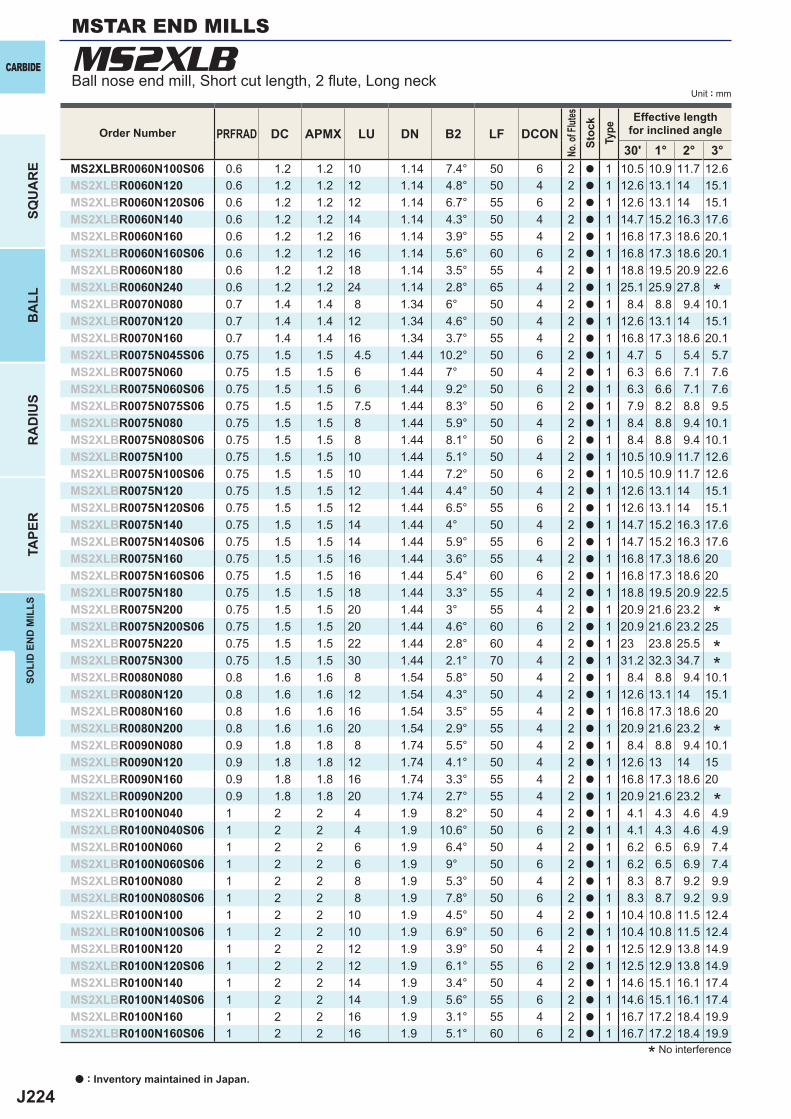
J224
MS2XLB
PRFRAD DC APMX LU DN B2 LF DCON30' 1° 2° 3°
MS2XLBR0060N100S06 0.6 1.2 1.2 10 1.14 7.4° 50 6 2 a 1 10.5 10.9 11.7 12.6MS2XLBR0060N120 0.6 1.2 1.2 12 1.14 4.8° 50 4 2 a 1 12.6 13.1 14 15.1MS2XLBR0060N120S06 0.6 1.2 1.2 12 1.14 6.7° 55 6 2 a 1 12.6 13.1 14 15.1MS2XLBR0060N140 0.6 1.2 1.2 14 1.14 4.3° 50 4 2 a 1 14.7 15.2 16.3 17.6MS2XLBR0060N160 0.6 1.2 1.2 16 1.14 3.9° 55 4 2 a 1 16.8 17.3 18.6 20.1MS2XLBR0060N160S06 0.6 1.2 1.2 16 1.14 5.6° 60 6 2 a 1 16.8 17.3 18.6 20.1MS2XLBR0060N180 0.6 1.2 1.2 18 1.14 3.5° 55 4 2 a 1 18.8 19.5 20.9 22.6MS2XLBR0060N240 0.6 1.2 1.2 24 1.14 2.8° 65 4 2 a 1 25.1 25.9 27.8MS2XLBR0070N080 0.7 1.4 1.4 8 1.34 6° 50 4 2 a 1 8.4 8.8 9.4 10.1MS2XLBR0070N120 0.7 1.4 1.4 12 1.34 4.6° 50 4 2 a 1 12.6 13.1 14 15.1MS2XLBR0070N160 0.7 1.4 1.4 16 1.34 3.7° 55 4 2 a 1 16.8 17.3 18.6 20.1MS2XLBR0075N045S06 0.75 1.5 1.5 4.5 1.44 10.2° 50 6 2 a 1 4.7 5 5.4 5.7MS2XLBR0075N060 0.75 1.5 1.5 6 1.44 7° 50 4 2 a 1 6.3 6.6 7.1 7.6MS2XLBR0075N060S06 0.75 1.5 1.5 6 1.44 9.2° 50 6 2 a 1 6.3 6.6 7.1 7.6MS2XLBR0075N075S06 0.75 1.5 1.5 7.5 1.44 8.3° 50 6 2 a 1 7.9 8.2 8.8 9.5MS2XLBR0075N080 0.75 1.5 1.5 8 1.44 5.9° 50 4 2 a 1 8.4 8.8 9.4 10.1MS2XLBR0075N080S06 0.75 1.5 1.5 8 1.44 8.1° 50 6 2 a 1 8.4 8.8 9.4 10.1MS2XLBR0075N100 0.75 1.5 1.5 10 1.44 5.1° 50 4 2 a 1 10.5 10.9 11.7 12.6MS2XLBR0075N100S06 0.75 1.5 1.5 10 1.44 7.2° 50 6 2 a 1 10.5 10.9 11.7 12.6MS2XLBR0075N120 0.75 1.5 1.5 12 1.44 4.4° 50 4 2 a 1 12.6 13.1 14 15.1MS2XLBR0075N120S06 0.75 1.5 1.5 12 1.44 6.5° 55 6 2 a 1 12.6 13.1 14 15.1MS2XLBR0075N140 0.75 1.5 1.5 14 1.44 4° 50 4 2 a 1 14.7 15.2 16.3 17.6MS2XLBR0075N140S06 0.75 1.5 1.5 14 1.44 5.9° 55 6 2 a 1 14.7 15.2 16.3 17.6MS2XLBR0075N160 0.75 1.5 1.5 16 1.44 3.6° 55 4 2 a 1 16.8 17.3 18.6 20MS2XLBR0075N160S06 0.75 1.5 1.5 16 1.44 5.4° 60 6 2 a 1 16.8 17.3 18.6 20MS2XLBR0075N180 0.75 1.5 1.5 18 1.44 3.3° 55 4 2 a 1 18.8 19.5 20.9 22.5MS2XLBR0075N200 0.75 1.5 1.5 20 1.44 3° 55 4 2 a 1 20.9 21.6 23.2MS2XLBR0075N200S06 0.75 1.5 1.5 20 1.44 4.6° 60 6 2 a 1 20.9 21.6 23.2 25MS2XLBR0075N220 0.75 1.5 1.5 22 1.44 2.8° 60 4 2 a 1 23 23.8 25.5MS2XLBR0075N300 0.75 1.5 1.5 30 1.44 2.1° 70 4 2 a 1 31.2 32.3 34.7MS2XLBR0080N080 0.8 1.6 1.6 8 1.54 5.8° 50 4 2 a 1 8.4 8.8 9.4 10.1MS2XLBR0080N120 0.8 1.6 1.6 12 1.54 4.3° 50 4 2 a 1 12.6 13.1 14 15.1MS2XLBR0080N160 0.8 1.6 1.6 16 1.54 3.5° 55 4 2 a 1 16.8 17.3 18.6 20MS2XLBR0080N200 0.8 1.6 1.6 20 1.54 2.9° 55 4 2 a 1 20.9 21.6 23.2MS2XLBR0090N080 0.9 1.8 1.8 8 1.74 5.5° 50 4 2 a 1 8.4 8.8 9.4 10.1MS2XLBR0090N120 0.9 1.8 1.8 12 1.74 4.1° 50 4 2 a 1 12.6 13 14 15MS2XLBR0090N160 0.9 1.8 1.8 16 1.74 3.3° 55 4 2 a 1 16.8 17.3 18.6 20MS2XLBR0090N200 0.9 1.8 1.8 20 1.74 2.7° 55 4 2 a 1 20.9 21.6 23.2MS2XLBR0100N040 1 2 2 4 1.9 8.2° 50 4 2 a 1 4.1 4.3 4.6 4.9MS2XLBR0100N040S06 1 2 2 4 1.9 10.6° 50 6 2 a 1 4.1 4.3 4.6 4.9MS2XLBR0100N060 1 2 2 6 1.9 6.4° 50 4 2 a 1 6.2 6.5 6.9 7.4MS2XLBR0100N060S06 1 2 2 6 1.9 9° 50 6 2 a 1 6.2 6.5 6.9 7.4MS2XLBR0100N080 1 2 2 8 1.9 5.3° 50 4 2 a 1 8.3 8.7 9.2 9.9MS2XLBR0100N080S06 1 2 2 8 1.9 7.8° 50 6 2 a 1 8.3 8.7 9.2 9.9MS2XLBR0100N100 1 2 2 10 1.9 4.5° 50 4 2 a 1 10.4 10.8 11.5 12.4MS2XLBR0100N100S06 1 2 2 10 1.9 6.9° 50 6 2 a 1 10.4 10.8 11.5 12.4MS2XLBR0100N120 1 2 2 12 1.9 3.9° 50 4 2 a 1 12.5 12.9 13.8 14.9MS2XLBR0100N120S06 1 2 2 12 1.9 6.1° 55 6 2 a 1 12.5 12.9 13.8 14.9MS2XLBR0100N140 1 2 2 14 1.9 3.4° 50 4 2 a 1 14.6 15.1 16.1 17.4MS2XLBR0100N140S06 1 2 2 14 1.9 5.6° 55 6 2 a 1 14.6 15.1 16.1 17.4MS2XLBR0100N160 1 2 2 16 1.9 3.1° 55 4 2 a 1 16.7 17.2 18.4 19.9MS2XLBR0100N160S06 1 2 2 16 1.9 5.1° 60 6 2 a 1 16.7 17.2 18.4 19.9
CARBIDE
SQU
AR
EB
ALL
RA
DIU
STA
PER
SOLI
D E
ND
MIL
LS
Unit : mm
MSTAR END MILLS
Ball nose end mill, Short cut length, 2 fl ute, Long neck
a : Inventory maintained in Japan.
* No interference
*
**
*
*
*
Order Number
No. o
f Flut
esSt
ock
Type
Effective lengthfor inclined angle
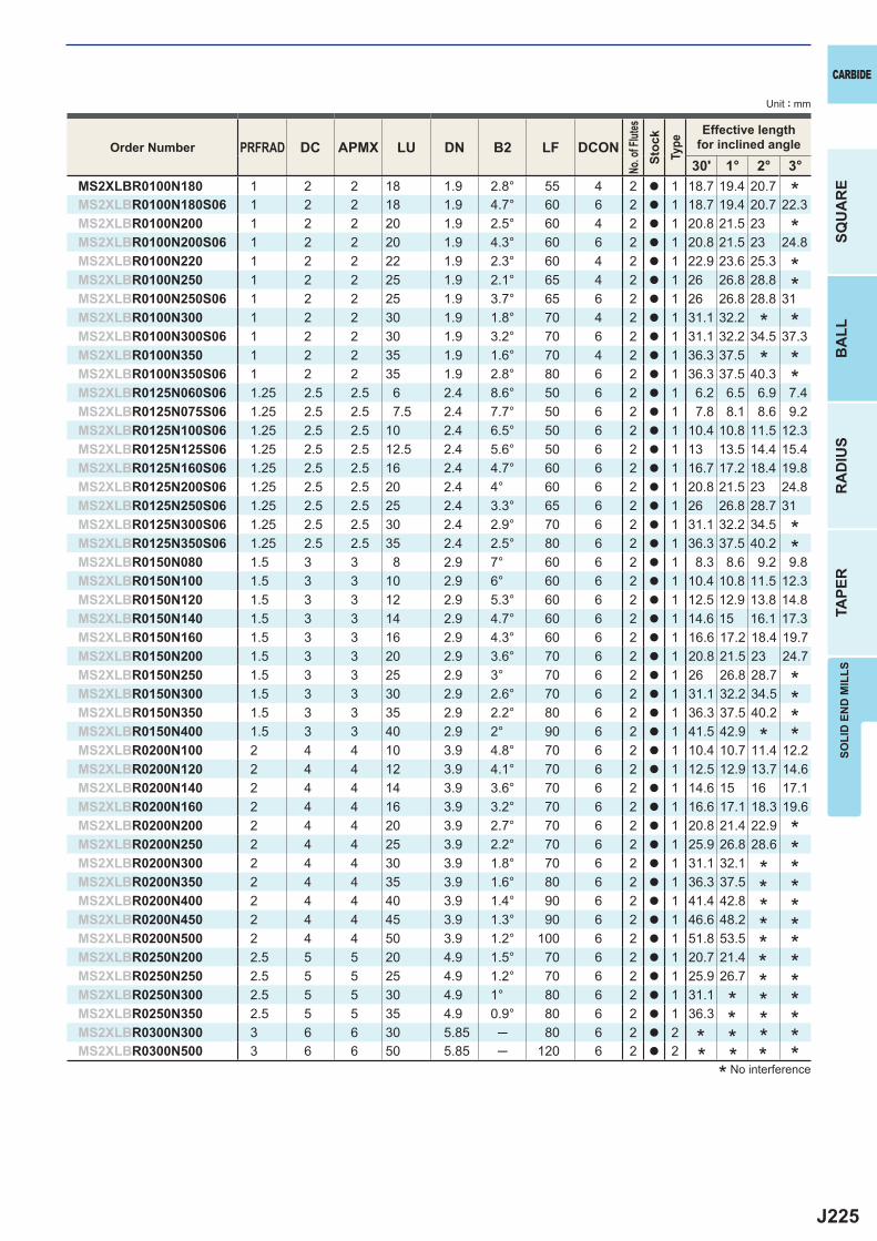
J225
PRFRAD DC APMX LU DN B2 LF DCON30' 1° 2° 3°
MS2XLBR0100N180 1 2 2 18 1.9 2.8° 55 4 2 a 1 18.7 19.4 20.7MS2XLBR0100N180S06 1 2 2 18 1.9 4.7° 60 6 2 a 1 18.7 19.4 20.7 22.3MS2XLBR0100N200 1 2 2 20 1.9 2.5° 60 4 2 a 1 20.8 21.5 23MS2XLBR0100N200S06 1 2 2 20 1.9 4.3° 60 6 2 a 1 20.8 21.5 23 24.8MS2XLBR0100N220 1 2 2 22 1.9 2.3° 60 4 2 a 1 22.9 23.6 25.3MS2XLBR0100N250 1 2 2 25 1.9 2.1° 65 4 2 a 1 26 26.8 28.8MS2XLBR0100N250S06 1 2 2 25 1.9 3.7° 65 6 2 a 1 26 26.8 28.8 31MS2XLBR0100N300 1 2 2 30 1.9 1.8° 70 4 2 a 1 31.1 32.2MS2XLBR0100N300S06 1 2 2 30 1.9 3.2° 70 6 2 a 1 31.1 32.2 34.5 37.3MS2XLBR0100N350 1 2 2 35 1.9 1.6° 70 4 2 a 1 36.3 37.5MS2XLBR0100N350S06 1 2 2 35 1.9 2.8° 80 6 2 a 1 36.3 37.5 40.3MS2XLBR0125N060S06 1.25 2.5 2.5 6 2.4 8.6° 50 6 2 a 1 6.2 6.5 6.9 7.4MS2XLBR0125N075S06 1.25 2.5 2.5 7.5 2.4 7.7° 50 6 2 a 1 7.8 8.1 8.6 9.2MS2XLBR0125N100S06 1.25 2.5 2.5 10 2.4 6.5° 50 6 2 a 1 10.4 10.8 11.5 12.3MS2XLBR0125N125S06 1.25 2.5 2.5 12.5 2.4 5.6° 50 6 2 a 1 13 13.5 14.4 15.4MS2XLBR0125N160S06 1.25 2.5 2.5 16 2.4 4.7° 60 6 2 a 1 16.7 17.2 18.4 19.8MS2XLBR0125N200S06 1.25 2.5 2.5 20 2.4 4° 60 6 2 a 1 20.8 21.5 23 24.8MS2XLBR0125N250S06 1.25 2.5 2.5 25 2.4 3.3° 65 6 2 a 1 26 26.8 28.7 31MS2XLBR0125N300S06 1.25 2.5 2.5 30 2.4 2.9° 70 6 2 a 1 31.1 32.2 34.5MS2XLBR0125N350S06 1.25 2.5 2.5 35 2.4 2.5° 80 6 2 a 1 36.3 37.5 40.2MS2XLBR0150N080 1.5 3 3 8 2.9 7° 60 6 2 a 1 8.3 8.6 9.2 9.8MS2XLBR0150N100 1.5 3 3 10 2.9 6° 60 6 2 a 1 10.4 10.8 11.5 12.3MS2XLBR0150N120 1.5 3 3 12 2.9 5.3° 60 6 2 a 1 12.5 12.9 13.8 14.8MS2XLBR0150N140 1.5 3 3 14 2.9 4.7° 60 6 2 a 1 14.6 15 16.1 17.3MS2XLBR0150N160 1.5 3 3 16 2.9 4.3° 60 6 2 a 1 16.6 17.2 18.4 19.7MS2XLBR0150N200 1.5 3 3 20 2.9 3.6° 70 6 2 a 1 20.8 21.5 23 24.7MS2XLBR0150N250 1.5 3 3 25 2.9 3° 70 6 2 a 1 26 26.8 28.7MS2XLBR0150N300 1.5 3 3 30 2.9 2.6° 70 6 2 a 1 31.1 32.2 34.5MS2XLBR0150N350 1.5 3 3 35 2.9 2.2° 80 6 2 a 1 36.3 37.5 40.2MS2XLBR0150N400 1.5 3 3 40 2.9 2° 90 6 2 a 1 41.5 42.9MS2XLBR0200N100 2 4 4 10 3.9 4.8° 70 6 2 a 1 10.4 10.7 11.4 12.2MS2XLBR0200N120 2 4 4 12 3.9 4.1° 70 6 2 a 1 12.5 12.9 13.7 14.6MS2XLBR0200N140 2 4 4 14 3.9 3.6° 70 6 2 a 1 14.6 15 16 17.1MS2XLBR0200N160 2 4 4 16 3.9 3.2° 70 6 2 a 1 16.6 17.1 18.3 19.6MS2XLBR0200N200 2 4 4 20 3.9 2.7° 70 6 2 a 1 20.8 21.4 22.9MS2XLBR0200N250 2 4 4 25 3.9 2.2° 70 6 2 a 1 25.9 26.8 28.6MS2XLBR0200N300 2 4 4 30 3.9 1.8° 70 6 2 a 1 31.1 32.1MS2XLBR0200N350 2 4 4 35 3.9 1.6° 80 6 2 a 1 36.3 37.5MS2XLBR0200N400 2 4 4 40 3.9 1.4° 90 6 2 a 1 41.4 42.8MS2XLBR0200N450 2 4 4 45 3.9 1.3° 90 6 2 a 1 46.6 48.2MS2XLBR0200N500 2 4 4 50 3.9 1.2° 100 6 2 a 1 51.8 53.5MS2XLBR0250N200 2.5 5 5 20 4.9 1.5° 70 6 2 a 1 20.7 21.4MS2XLBR0250N250 2.5 5 5 25 4.9 1.2° 70 6 2 a 1 25.9 26.7MS2XLBR0250N300 2.5 5 5 30 4.9 1° 80 6 2 a 1 31.1MS2XLBR0250N350 2.5 5 5 35 4.9 0.9° 80 6 2 a 1 36.3MS2XLBR0300N300 3 6 6 30 5.85 ─ 80 6 2 a 2MS2XLBR0300N500 3 6 6 50 5.85 ─ 120 6 2 a 2
SOLI
D E
ND
MIL
LS
CARBIDE
SQU
AR
EB
ALL
RA
DIU
STA
PER
Unit : mm
* No interference
*
*
* *
**
**
****
************
*** ** *
*** *
**
*****
*
*
*
*
*
Order Number
No. o
f Flut
esSt
ock
Type
Effective lengthfor inclined angle
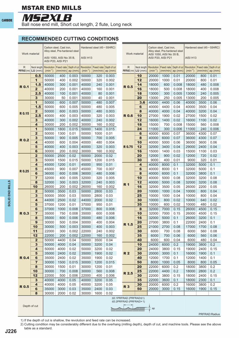
J226
R 0.1
0.5 50000 400 0.003 50000 320 0.003
R 0.5
10 20000 1000 0.01 20000 800 0.011 50000 400 0.002 50000 320 0.002 12 20000 1000 0.01 20000 800 0.011.5 40000 300 0.001 40000 240 0.001 14 18000 600 0.008 18000 480 0.0082 40000 200 0.001 40000 160 0.001 16 18000 500 0.008 18000 400 0.0082.5 40000 100 0.001 40000 80 0.001 18 13000 300 0.005 13000 240 0.0053 30000 50 0.001 30000 40 0.001 20 13000 250 0.005 13000 200 0.005
R 0.15
1 50000 600 0.007 50000 480 0.007
R 0.6
3.6 40000 4400 0.06 40000 3500 0.061.5 50000 600 0.005 50000 480 0.005 6 40000 4400 0.04 40000 3500 0.042 50000 600 0.003 50000 480 0.003 8 40000 4000 0.04 40000 3200 0.042.5 40000 400 0.003 40000 320 0.003 10 27000 1900 0.02 27000 1500 0.023 40000 300 0.002 40000 240 0.002 12 16000 1400 0.02 16000 1100 0.024 30000 200 0.002 30000 160 0.002 18 15000 700 0.008 15000 560 0.008
R 0.2
1 50000 1800 0.015 50000 1400 0.015 24 11000 300 0.006 11000 240 0.0062 50000 1300 0.01 50000 1000 0.01
R 0.75
6 40000 6000 0.07 36000 4300 0.073 50000 900 0.005 50000 700 0.005 8 40000 6000 0.07 36000 4300 0.074 40000 600 0.004 40000 480 0.004 10 40000 5000 0.06 36000 3600 0.065 40000 400 0.003 40000 320 0.003 12 32000 3400 0.04 29000 2400 0.046 30000 200 0.002 30000 160 0.002 16 15000 1400 0.03 15000 1100 0.03
R 0.25
2 50000 2500 0.02 50000 2000 0.02 20 12000 900 0.02 12000 720 0.023 50000 1500 0.015 50000 1200 0.015 30 9000 400 0.01 9000 320 0.014 45000 1200 0.01 45000 950 0.01
R 1
4 40000 8000 0.1 32000 5000 0.15 45000 900 0.007 45000 700 0.007 6 40000 8000 0.1 32000 5000 0.16 36000 600 0.006 36000 480 0.006 8 40000 6000 0.1 32000 3800 0.17 32000 400 0.005 32000 320 0.005 10 40000 5000 0.08 32000 3200 0.088 32000 300 0.003 32000 240 0.003 12 40000 5000 0.08 32000 3200 0.08
10 26000 200 0.002 26000 160 0.002 16 32000 3500 0.05 26000 2200 0.05
R 0.3
2 50000 3500 0.03 50000 2800 0.03 20 10000 1000 0.04 10000 800 0.043 50000 3500 0.03 50000 2800 0.03 25 10000 1000 0.04 10000 800 0.044 44000 2500 0.02 44000 2000 0.02 30 10000 800 0.02 10000 640 0.025 37000 1200 0.01 37000 950 0.01 35 10000 600 0.02 10000 480 0.026 37000 1000 0.008 37000 800 0.008
R 1.5
8 32000 7000 0.15 26000 4500 0.157 35000 750 0.008 35000 600 0.008 10 32000 7000 0.15 26000 4500 0.158 35000 600 0.006 35000 480 0.006 16 32000 5000 0.1 26000 3200 0.19 30000 500 0.004 30000 400 0.004 20 27000 3800 0.1 22000 2400 0.1
10 30000 500 0.003 30000 400 0.003 25 21000 2700 0.08 17000 1700 0.0811 22000 300 0.002 22000 240 0.002 30 6000 700 0.08 6000 560 0.0812 22000 200 0.002 22000 160 0.002 35 6000 700 0.06 6000 560 0.06
R 0.4
2 50000 4400 0.04 50000 3500 0.04 40 6000 600 0.04 6000 480 0.043 50000 4000 0.04 50000 3200 0.04
R 2
10 24000 6000 0.2 19000 3800 0.24 50000 4000 0.02 50000 3200 0.02 20 24000 3800 0.15 19000 2400 0.155 35000 2400 0.02 35000 1900 0.02 30 20000 3000 0.1 16000 1900 0.16 35000 2400 0.02 35000 1900 0.02 40 12000 1700 0.1 12000 1400 0.17 30000 1500 0.015 30000 1200 0.015 50 8000 1000 0.05 8000 800 0.058 30000 1500 0.01 30000 1200 0.01
R 2.5
20 22000 6000 0.2 18000 3800 0.210 30000 700 0.008 30000 560 0.008 25 22000 4400 0.2 18000 2800 0.212 22000 500 0.006 22000 400 0.006 30 22000 3800 0.15 18000 2400 0.15
R 0.5
3 40000 4000 0.05 40000 3200 0.05 35 22000 3600 0.1 18000 2300 0.14 40000 4000 0.05 40000 3200 0.05 R 3 30 20000 6000 0.2 16000 3800 0.26 35000 3000 0.03 35000 2400 0.03 50 20000 3000 0.15 16000 1900 0.158 30000 2000 0.02 30000 1600 0.02
ap
MS2XLBCARBIDE
SOLI
D E
ND
MIL
LS
RECOMMENDED CUTTING CONDITIONS
1) If the depth of cut is shallow, the revolution and feed rate can be increased.2) Cutting condition may be considerably different due to the overhang (milling depth), depth of cut, and machine tools. Please see the above
table as a standard.
PRFRAD:Radius
Work material
Carbon steel, Cast iron, Alloy steel, Pre-hardened steel
AISI 1050, AISI No 35 B, AISI P20, AISI P21
Hardened steel (45─ 55HRC)
AISI H13
RPRFRAD (mm)
Neck lengthLU (mm)
Revolution(min-1)
Feed rate(mm/min)
Depth of cutap (mm)
Revolution(min-1)
Feed rate(mm/min)
Depth of cutap (mm)
Work material
Carbon steel, Cast iron, Alloy steel, Pre-hardened steelAISI 1050, AISI No 35 B, AISI P20, AISI P21
Hardened steel (45─ 55HRC)
AISI H13
RPRFRAD (mm)
Neck lengthLU (mm)
Revolution(min-1)
Feed rate(mm/min)
Depth of cutap (mm)
Revolution(min-1)
Feed rate(mm/min)
Depth of cutap (mm)
Depth of cut
<0.1PRFRAD (PRFRAD<1)<0.2PRFRAD (PRFRAD>1)
MSTAR END MILLS
Ball nose end mill, Short cut length, 2 fl ute, Long neck
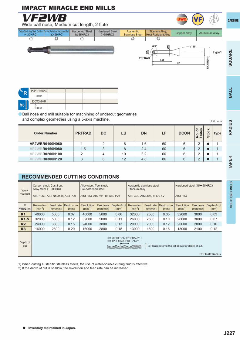
J227
a
VF2WB
PRFRAD DC LU DN LF DCON
VF2WBR0100N060 1 2 6 1.6 60 6 2 a 1VF2WBR0150N080 1.5 3 8 2.4 60 6 2 a 1VF2WBR0200N100 2 4 10 3.2 60 6 2 a 1VF2WBR0300N120 3 6 12 4.8 80 6 2 a 1
u e u e e
±0.01
DCON=6 0- 0.008
R1 40000 5000 0.07 40000 5000 0.06 32000 2500 0.05 32000 3000 0.03R1.5 32000 5000 0.12 32000 5000 0.11 26000 2500 0.10 26000 3000 0.07R2 24000 3800 0.15 24000 3800 0.13 20000 2000 0.12 20000 2800 0.10R3 16000 2800 0.20 16000 2800 0.18 13000 1500 0.15 13000 2100 0.12
UWC VF
R
h6
LU
DC
DC
ON
(h6)
15°
LF
PRFRAD
220°
DN
SOLI
D E
ND
MIL
LS
CARBIDE
SQU
AR
EB
ALL
RA
DIU
STA
PER
Unit : mm
Carbon Steel, Alloy Steel, Cast Iron(<30HRC)
Tool Steel, Pre-Hardened Steel,Hardened Steel(<45HRC)
Hardened Steel(<55HRC)
Hardened Steel(>55HRC)
AusteniticStainless Steel
Titanium Alloy,Heat Resistant Alloy Copper Alloy Aluminium Alloy
Ball nose end mill suitable for machining of undercut geometriesand complex geometries using a 5-axis machine.
Wide ball nose, Medium cut length, 2 fl ute
IMPACT MIRACLE END MILLS
Type1
Order Number
No.
of
Flut
es
Stoc
k
Type
1<PRFRAD<3
a : Inventory maintained in Japan.
RECOMMENDED CUTTING CONDITIONS
1) When cutting austenitic stainless steels, the use of water-soluble cutting fl uid is effective.2) If the depth of cut is shallow, the revolution and feed rate can be increased.
PRFRAD:Radius
<Please refer to the list above for depth of cut.
Workmaterial
Carbon steel, Cast iron, Alloy steel (─30HRC)
AISI 1050, AISI No 35 B, AISI P20
Alloy steel, Tool steel,Pre-hardened steel
AISI H13, AISI W1-10, AISI P21
Austenitic stainless steel,Titanium alloy
AISI 304, AISI 306, Ti-6Al-4V
Hardened steel (45─ 55HRC)
AISI H13
RPRFRAD (mm)
Revolution(min-1)
Revolution(min-1)
Revolution(min-1)
Revolution(min-1)
Feed rate(mm/min)
Feed rate(mm/min)
Feed rate(mm/min)
Feed rate(mm/min)
Depth of cut(mm)
Depth of cut(mm)
Depth of cut(mm)
Depth of cut(mm)
Depth ofcut
<0.05PRFRAD (PRFRAD=1)<0.1PRFRAD (PRFRAD>1)
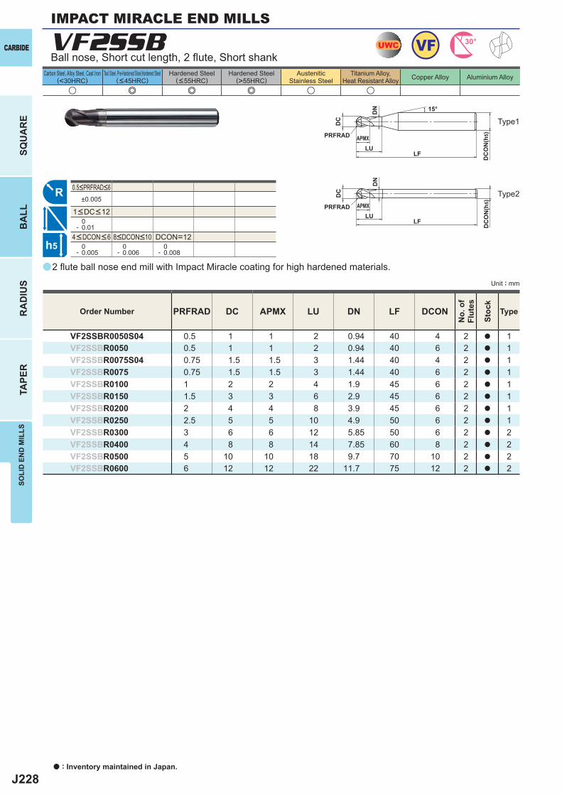
J228
a
VF2SSB
PRFRAD DC APMX LU DN LF DCON
VF2SSBR0050S04 0.5 1 1 2 0.94 40 4 2 a 1VF2SSBR0050 0.5 1 1 2 0.94 40 6 2 a 1VF2SSBR0075S04 0.75 1.5 1.5 3 1.44 40 4 2 a 1VF2SSBR0075 0.75 1.5 1.5 3 1.44 40 6 2 a 1VF2SSBR0100 1 2 2 4 1.9 45 6 2 a 1VF2SSBR0150 1.5 3 3 6 2.9 45 6 2 a 1VF2SSBR0200 2 4 4 8 3.9 45 6 2 a 1VF2SSBR0250 2.5 5 5 10 4.9 50 6 2 a 1VF2SSBR0300 3 6 6 12 5.85 50 6 2 a 2VF2SSBR0400 4 8 8 14 7.85 60 8 2 a 2VF2SSBR0500 5 10 10 18 9.7 70 10 2 a 2VF2SSBR0600 6 12 12 22 11.7 75 12 2 a 2
u e e e u u
±0.005
0- 0.01
DCON=12 0- 0.005
0- 0.006
0- 0.008
UWC VF 30°
R
h5
APMX
DC
DC
ON
(h5)
15°
APMX
LF
DC
DC
ON
(h5)
LF
PRFRAD
PRFRADLU
LU
DN
DN
CARBIDE
SQU
AR
EB
ALL
RA
DIU
STA
PER
SOLI
D E
ND
MIL
LS
Unit : mm
Carbon Steel, Alloy Steel, Cast Iron(<30HRC)
Tool Steel, Pre-Hardened Steel,Hardened Steel(<45HRC)
Hardened Steel(<55HRC)
Hardened Steel(>55HRC)
AusteniticStainless Steel
Titanium Alloy,Heat Resistant Alloy Copper Alloy Aluminium Alloy
IMPACT MIRACLE END MILLS
a : Inventory maintained in Japan.
2 fl ute ball nose end mill with Impact Miracle coating for high hardened materials.
Ball nose, Short cut length, 2 fl ute, Short shank
Type2
Type1
Order Number
No.
of
Flut
es
Stoc
k
Type
4<DCON<6 8<DCON<10
1<DC<12
0.5<PRFRAD<6
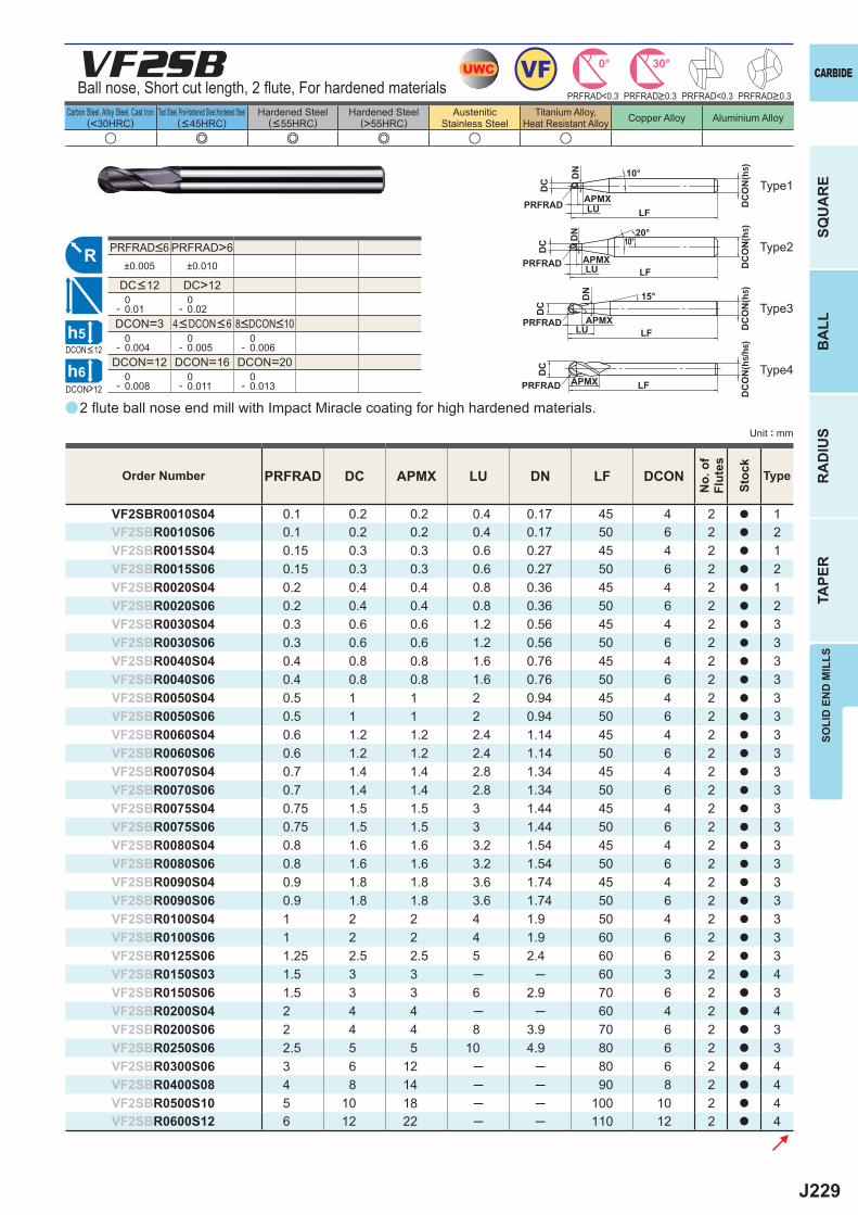
J229
a
VF2SB
PRFRAD DC APMX LU DN LF DCON
VF2SBR0010S04 0.1 0.2 0.2 0.4 0.17 45 4 2 a 1VF2SBR0010S06 0.1 0.2 0.2 0.4 0.17 50 6 2 a 2VF2SBR0015S04 0.15 0.3 0.3 0.6 0.27 45 4 2 a 1VF2SBR0015S06 0.15 0.3 0.3 0.6 0.27 50 6 2 a 2VF2SBR0020S04 0.2 0.4 0.4 0.8 0.36 45 4 2 a 1VF2SBR0020S06 0.2 0.4 0.4 0.8 0.36 50 6 2 a 2VF2SBR0030S04 0.3 0.6 0.6 1.2 0.56 45 4 2 a 3VF2SBR0030S06 0.3 0.6 0.6 1.2 0.56 50 6 2 a 3VF2SBR0040S04 0.4 0.8 0.8 1.6 0.76 45 4 2 a 3VF2SBR0040S06 0.4 0.8 0.8 1.6 0.76 50 6 2 a 3VF2SBR0050S04 0.5 1 1 2 0.94 45 4 2 a 3VF2SBR0050S06 0.5 1 1 2 0.94 50 6 2 a 3VF2SBR0060S04 0.6 1.2 1.2 2.4 1.14 45 4 2 a 3VF2SBR0060S06 0.6 1.2 1.2 2.4 1.14 50 6 2 a 3VF2SBR0070S04 0.7 1.4 1.4 2.8 1.34 45 4 2 a 3VF2SBR0070S06 0.7 1.4 1.4 2.8 1.34 50 6 2 a 3VF2SBR0075S04 0.75 1.5 1.5 3 1.44 45 4 2 a 3VF2SBR0075S06 0.75 1.5 1.5 3 1.44 50 6 2 a 3VF2SBR0080S04 0.8 1.6 1.6 3.2 1.54 45 4 2 a 3VF2SBR0080S06 0.8 1.6 1.6 3.2 1.54 50 6 2 a 3VF2SBR0090S04 0.9 1.8 1.8 3.6 1.74 45 4 2 a 3VF2SBR0090S06 0.9 1.8 1.8 3.6 1.74 50 6 2 a 3VF2SBR0100S04 1 2 2 4 1.9 50 4 2 a 3VF2SBR0100S06 1 2 2 4 1.9 60 6 2 a 3VF2SBR0125S06 1.25 2.5 2.5 5 2.4 60 6 2 a 3VF2SBR0150S03 1.5 3 3 ─ ─ 60 3 2 a 4VF2SBR0150S06 1.5 3 3 6 2.9 70 6 2 a 3VF2SBR0200S04 2 4 4 ─ ─ 60 4 2 a 4VF2SBR0200S06 2 4 4 8 3.9 70 6 2 a 3VF2SBR0250S06 2.5 5 5 10 4.9 80 6 2 a 3VF2SBR0300S06 3 6 12 ─ ─ 80 6 2 a 4VF2SBR0400S08 4 8 14 ─ ─ 90 8 2 a 4VF2SBR0500S10 5 10 18 ─ ─ 100 10 2 a 4VF2SBR0600S12 6 12 22 ─ ─ 110 12 2 a 4
u e e e u u
PRFRAD>6±0.005 ±0.010
DC>12 0- 0.01
0- 0.02
DCON=3 0- 0.004
0- 0.005
0- 0.006
DCON=12 DCON=16 DCON=20 0- 0.008
0- 0.011
0- 0.013
UWC VF 30°0°
R
DCON>12
h5
h6
APMX
DC
DC
ON
(h5)10°
APMXLF
DC
DC
ON
(h5)
LFPRFRAD
PRFRAD LU
LU
DN
DN 20°
10°
APMX
DC
DC
ON
(h5)15°
LFPRFRAD
LU
DN
APMX
DC
DC
ON
(h5/
h6)
LFPRFRAD
PRFRAD<0.3 PRFRAD<0.3
SOLI
D E
ND
MIL
LS
CARBIDE
SQU
AR
EB
ALL
RA
DIU
STA
PER
Unit : mm
Carbon Steel, Alloy Steel, Cast Iron(<30HRC)
Tool Steel, Pre-Hardened Steel,Hardened Steel(<45HRC)
Hardened Steel(<55HRC)
Hardened Steel(>55HRC)
AusteniticStainless Steel
Titanium Alloy,Heat Resistant Alloy Copper Alloy Aluminium Alloy
2 fl ute ball nose end mill with Impact Miracle coating for high hardened materials.
Ball nose, Short cut length, 2 fl ute, For hardened materials
Order Number
No.
of
Flut
es
Stoc
k
Type
PRFRAD>0.3 PRFRAD>0.3
DCON<12
Type2
Type3
Type4
Type1
4<DCON<6 8<DCON<10
PRFRAD<6
DC<12
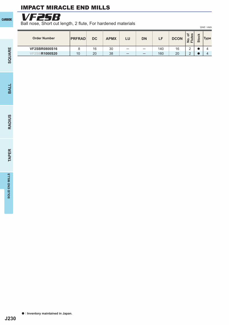
J230
PRFRAD DC APMX LU DN LF DCON
VF2SBR0800S16 8 16 30 ─ ─ 140 16 2 a 4VF2SBR1000S20 10 20 38 ─ ─ 160 20 2 a 4
VF2SBCARBIDE
SQU
AR
EB
ALL
RA
DIU
STA
PER
SOLI
D E
ND
MIL
LS
Unit : mm
IMPACT MIRACLE END MILLS
Order Number
No.
of
Flut
es
Stoc
k
Type
Ball nose, Short cut length, 2 fl ute, For hardened materials
a : Inventory maintained in Japan.
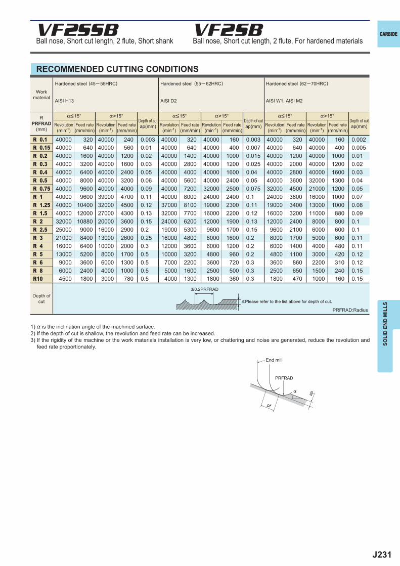
J231
%>15° %>15° %>15°
R 0.1 40000 320 40000 240 0.003 40000 320 40000 160 0.003 40000 320 40000 160 0.002R 0.15 40000 640 40000 560 0.01 40000 640 40000 400 0.007 40000 640 40000 400 0.005R 0.2 40000 1600 40000 1200 0.02 40000 1400 40000 1000 0.015 40000 1200 40000 1000 0.01R 0.3 40000 3200 40000 1600 0.03 40000 2800 40000 1200 0.025 40000 2000 40000 1200 0.02R 0.4 40000 6400 40000 2400 0.05 40000 4000 40000 1600 0.04 40000 2800 40000 1600 0.03R 0.5 40000 8000 40000 3200 0.06 40000 5600 40000 2400 0.05 40000 3600 32000 1300 0.04R 0.75 40000 9600 40000 4000 0.09 40000 7200 32000 2500 0.075 32000 4500 21000 1200 0.05R 1 40000 9600 39000 4700 0.11 40000 8000 24000 2400 0.1 24000 3800 16000 1000 0.07R 1.25 40000 10400 32000 4500 0.12 37000 8100 19000 2300 0.11 19000 3400 13000 1000 0.08R 1.5 40000 12000 27000 4300 0.13 32000 7700 16000 2200 0.12 16000 3200 11000 880 0.09R 2 32000 10880 20000 3600 0.15 24000 6200 12000 1900 0.13 12000 2400 8000 800 0.1R 2.5 25000 9000 16000 2900 0.2 19000 5300 9600 1700 0.15 9600 2100 6000 600 0.1R 3 21000 8400 13000 2600 0.25 16000 4800 8000 1600 0.2 8000 1700 5000 600 0.11R 4 16000 6400 10000 2000 0.3 12000 3600 6000 1200 0.2 6000 1400 4000 480 0.11R 5 13000 5200 8000 1700 0.5 10000 3200 4800 960 0.2 4800 1100 3000 420 0.12R 6 9000 3600 6000 1300 0.5 7000 2200 3600 720 0.3 3600 860 2200 310 0.12R 8 6000 2400 4000 1000 0.5 5000 1600 2500 500 0.3 2500 650 1500 240 0.15R10 4500 1800 3000 780 0.5 4000 1300 1800 360 0.3 1800 470 1000 160 0.15
VF2SSB
ap
PRFRAD
pf
%
CARBIDE
SOLI
D E
ND
MIL
LS
RECOMMENDED CUTTING CONDITIONS
1) % is the inclination angle of the machined surface. 2) If the depth of cut is shallow, the revolution and feed rate can be increased.3) If the rigidity of the machine or the work materials installation is very low, or chattering and noise are generated, reduce the revolution and
feed rate proportionately.
PRFRAD:Radius
<Please refer to the list above for depth of cut.
Workmaterial
Hardened steel (45─ 55HRC)
AISI H13
Hardened steel (55─ 62HRC)
AISI D2
Hardened steel (62─70HRC)
AISI W1, AISI M2
RPRFRAD
(mm)
%<15° %<15° %<15°
Revolution(min-1)
Revolution(min-1)
Revolution(min-1)
Revolution(min-1)
Revolution(min-1)
Revolution(min-1)
Feed rate(mm/min)
Feed rate(mm/min)
Feed rate(mm/min)
Feed rate(mm/min)
Feed rate(mm/min)
Feed rate(mm/min)
Depth of cutap(mm)
Depth of cutap(mm)
Depth of cutap(mm)
Depth ofcut
<0.2PRFRAD
End mill
Ball nose, Short cut length, 2 fl ute, Short shank Ball nose, Short cut length, 2 fl ute, For hardened materialsVF2SB
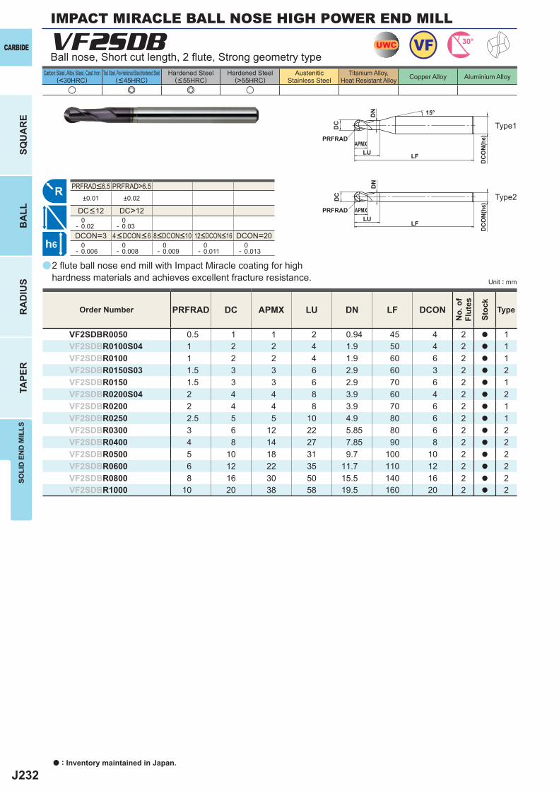
J232
a
VF2SDB
PRFRAD DC APMX LU DN LF DCON
VF2SDBR0050 0.5 1 1 2 0.94 45 4 2 a 1VF2SDBR0100S04 1 2 2 4 1.9 50 4 2 a 1VF2SDBR0100 1 2 2 4 1.9 60 6 2 a 1VF2SDBR0150S03 1.5 3 3 6 2.9 60 3 2 a 2VF2SDBR0150 1.5 3 3 6 2.9 70 6 2 a 1VF2SDBR0200S04 2 4 4 8 3.9 60 4 2 a 2VF2SDBR0200 2 4 4 8 3.9 70 6 2 a 1VF2SDBR0250 2.5 5 5 10 4.9 80 6 2 a 1VF2SDBR0300 3 6 12 22 5.85 80 6 2 a 2VF2SDBR0400 4 8 14 27 7.85 90 8 2 a 2VF2SDBR0500 5 10 18 31 9.7 100 10 2 a 2VF2SDBR0600 6 12 22 35 11.7 110 12 2 a 2VF2SDBR0800 8 16 30 50 15.5 140 16 2 a 2VF2SDBR1000 10 20 38 58 19.5 160 20 2 a 2
u e e u
PRFRAD>6.5±0.01 ±0.02
DC>12 0- 0.02
0- 0.03
DCON=3 DCON=20 0- 0.006
0- 0.008
0- 0.009
0- 0.011
0- 0.013
UWC VF 30°
R
h6
APMX
DC
DC
ON
(h6)
15°
APMX
LF
DC
DC
ON
(h6)
LF
PRFRAD
PRFRADLU
LU
DN
DN
CARBIDE
SQU
AR
EB
ALL
RA
DIU
STA
PER
SOLI
D E
ND
MIL
LS
Unit : mm
Carbon Steel, Alloy Steel, Cast Iron(<30HRC)
Tool Steel, Pre-Hardened Steel,Hardened Steel(<45HRC)
Hardened Steel(<55HRC)
Hardened Steel(>55HRC)
AusteniticStainless Steel
Titanium Alloy,Heat Resistant Alloy Copper Alloy Aluminium Alloy
2 fl ute ball nose end mill with Impact Miracle coating for high hardness materials and achieves excellent fracture resistance.
Ball nose, Short cut length, 2 fl ute, Strong geometry type
Type1
Order Number
No.
of
Flut
es
Stoc
k
Type
4<DCON<6 8<DCON<10 12<DCON<16
PRFRAD<6.5
DC<12
Type2
IMPACT MIRACLE BALL NOSE HIGH POWER END MILL
a : Inventory maintained in Japan.
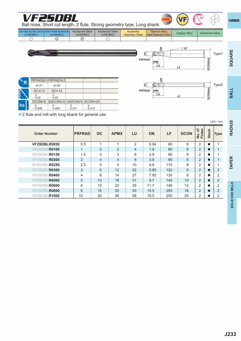
J233
a
VF2SDBL
PRFRAD DC APMX LU DN LF DCON
VF2SDBLR0050 0.5 1 1 2 0.94 60 6 2 a 1VF2SDBLR0100 1 2 2 4 1.9 80 6 2 a 1VF2SDBLR0150 1.5 3 3 6 2.9 90 6 2 a 1VF2SDBLR0200 2 4 4 8 3.9 90 6 2 a 1VF2SDBLR0250 2.5 5 5 10 4.9 110 8 2 a 1VF2SDBLR0300 3 6 12 22 5.85 120 6 2 a 2VF2SDBLR0400 4 8 14 27 7.85 130 8 2 a 2VF2SDBLR0500 5 10 18 31 9.7 140 10 2 a 2VF2SDBLR0600 6 12 22 35 11.7 140 12 2 a 2VF2SDBLR0800 8 16 30 50 15.5 200 16 2 a 2VF2SDBLR1000 10 20 38 58 19.5 200 20 2 a 2
u e e u
PRFRAD>6.5±0.01 ±0.02
DC>12 0- 0.02
0- 0.03
DCON=6 DCON=20 0- 0.008
0- 0.009
0- 0.011
0- 0.013
UWC VF 30°
R
h6
APMX
DC
DC
ON
(h6)
10°
APMX
LF
DC
DC
ON
(h6)
LF
PRFRAD
PRFRADLU
LU
DN
DN
SOLI
D E
ND
MIL
LS
CARBIDE
SQU
AR
EB
ALL
RA
DIU
STA
PER
Unit : mm
Carbon Steel, Alloy Steel, Cast Iron(<30HRC)
Tool Steel, Pre-Hardened Steel,Hardened Steel(<45HRC)
Hardened Steel(<55HRC)
Hardened Steel(>55HRC)
AusteniticStainless Steel
Titanium Alloy,Heat Resistant Alloy Copper Alloy Aluminium Alloy
2 fl ute end mill with long shank for general use.
Ball nose, Short cut length, 2 fl ute, Strong geometry type, Long shank
Type1
Order Number
No.
of
Flut
es
Stoc
k
Type
8<DCON<10 12<DCON<16
PRFRAD<6.5
DC<12
Type2
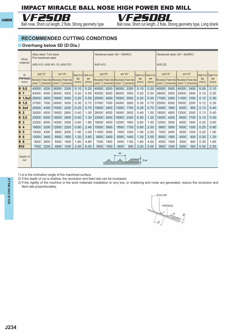
J234
VF2SDB VF2SDBL
%>15° %>15° %>15°
R 0.5 40000 5200 36000 2300 0.10 0.25 40000 5200 36000 2300 0.10 0.25 40000 5000 40000 2400 0.05 0.10R 1 40000 6000 36000 3500 0.20 0.50 40000 6000 36000 3500 0.20 0.50 36000 5000 24000 2400 0.10 0.20R 1.5x3 29000 4600 19000 2400 0.20 0.50 25000 4000 16000 2000 0.20 0.50 17000 2400 11000 1000 0.12 0.30R 1.5 37000 7000 24000 3000 0.30 0.75 37000 7000 24000 3000 0.30 0.75 25000 6000 16000 2200 0.12 0.30R 2x4 24000 4300 15000 2200 0.25 0.70 19000 3400 13000 1700 0.25 0.70 12000 1900 8200 900 0.13 0.40R 2 30000 6500 19000 2800 0.40 1.00 28000 6000 19000 2600 0.40 1.00 18000 4800 12000 2000 0.13 0.40R 2.5 25000 6000 16000 2600 0.50 1.30 22000 5000 16000 2300 0.50 1.25 15000 4200 9500 1700 0.15 0.50R 3 22000 6000 14000 2400 0.60 1.80 18000 4500 12000 1900 0.60 1.50 12000 3500 8000 1600 0.20 0.60R 4 19000 5200 12000 2200 0.80 2.40 15000 3800 9500 1700 0.80 2.00 9800 3000 6500 1300 0.20 0.80R 5 15000 4300 9500 2000 1.00 3.00 11000 3000 7000 1500 1.00 2.50 7500 2400 5000 1000 0.20 1.00R 6 12000 3400 8000 1800 1.20 3.60 9000 2400 6000 1400 1.20 3.00 6000 1900 4000 800 0.30 1.20R 8 9000 2600 6000 1500 1.60 4.80 7000 1900 4500 1100 1.60 4.00 4500 1500 3000 600 0.30 1.60R10 7500 2200 4800 1200 2.00 6.00 5500 1500 3600 900 2.00 5.00 3600 1200 2500 500 0.30 2.00
y
ap
PRFRAD
ae
pf
%
CARBIDE
SOLI
D E
ND
MIL
LS
RECOMMENDED CUTTING CONDITIONS
Ball nose, Short cut length, 2 fl ute, Strong geometry type Ball nose, Short cut length, 2 fl ute, Strong geometry type, Long shank
1) % is the inclination angle of the machined surface. 2) If the depth of cut is shallow, the revolution and feed rate can be increased.3) If the rigidity of the machine or the work materials installation is very low, or chattering and noise are generated, reduce the revolution and
feed rate proportionately.
Overhang below 5D (D:Dia.)
Workmaterial
Alloy steel, Tool steel,Pre-hardened steel
AISI H13, AISI W1-10, AISI P21
Hardened steel (45─ 55HRC)
AISI H13
Hardened steel (55─ 62HRC)
AISI D2
RPRFRAD
(mm)
%<15° %<15° %<15°
Revolution(min-1)
Revolution(min-1)
Revolution(min-1)
Feed rate(mm/min)
Feed rate(mm/min)
Feed rate(mm/min)
Depth of cutap
(mm)
Depth of cutap
(mm)
Depth of cutap
(mm)
Depth of cutae
(mm)
Depth of cutae
(mm)
Depth of cutae
(mm)
Depth ofcut <ap
Revolution(min-1)
Feed rate(mm/min)
Revolution(min-1)
Revolution(min-1)
Feed rate(mm/min)
Feed rate(mm/min)
End mill
IMPACT MIRACLE BALL NOSE HIGH POWER END MILL
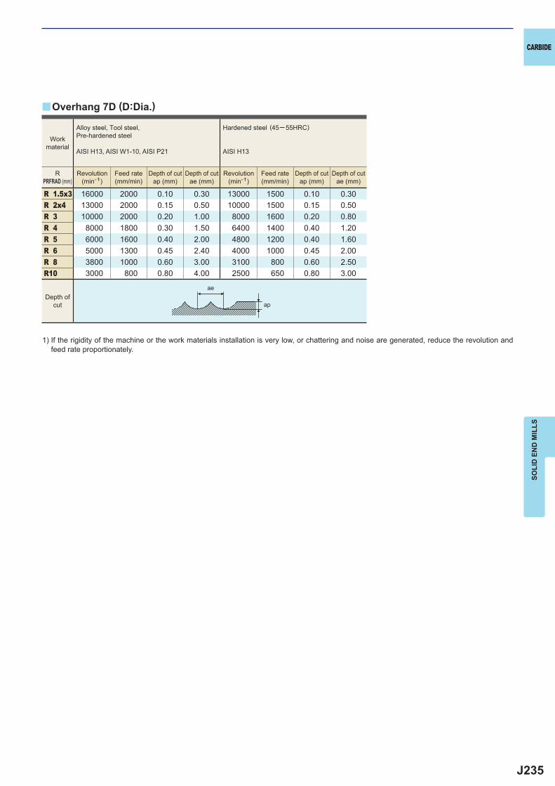
J235
R 1.5x3 16000 2000 0.10 0.30 13000 1500 0.10 0.30R 2x4 13000 2000 0.15 0.50 10000 1500 0.15 0.50R 3 10000 2000 0.20 1.00 8000 1600 0.20 0.80R 4 8000 1800 0.30 1.50 6400 1400 0.40 1.20R 5 6000 1600 0.40 2.00 4800 1200 0.40 1.60R 6 5000 1300 0.45 2.40 4000 1000 0.45 2.00R 8 3800 1000 0.60 3.00 3100 800 0.60 2.50R10 3000 800 0.80 4.00 2500 650 0.80 3.00
y
ae
ap
CARBIDE
SOLI
D E
ND
MIL
LS
1) If the rigidity of the machine or the work materials installation is very low, or chattering and noise are generated, reduce the revolution and feed rate proportionately.
Overhang 7D (D:Dia.)
Workmaterial
Alloy steel, Tool steel,Pre-hardened steel
AISI H13, AISI W1-10, AISI P21
Hardened steel (45─ 55HRC)
AISI H13
RPRFRAD (mm)
Revolution(min-1)
Revolution(min-1)
Feed rate(mm/min)
Feed rate(mm/min)
Depth of cutap (mm)
Depth of cutap (mm)
Depth of cutae (mm)
Depth of cutae (mm)
Depth ofcut
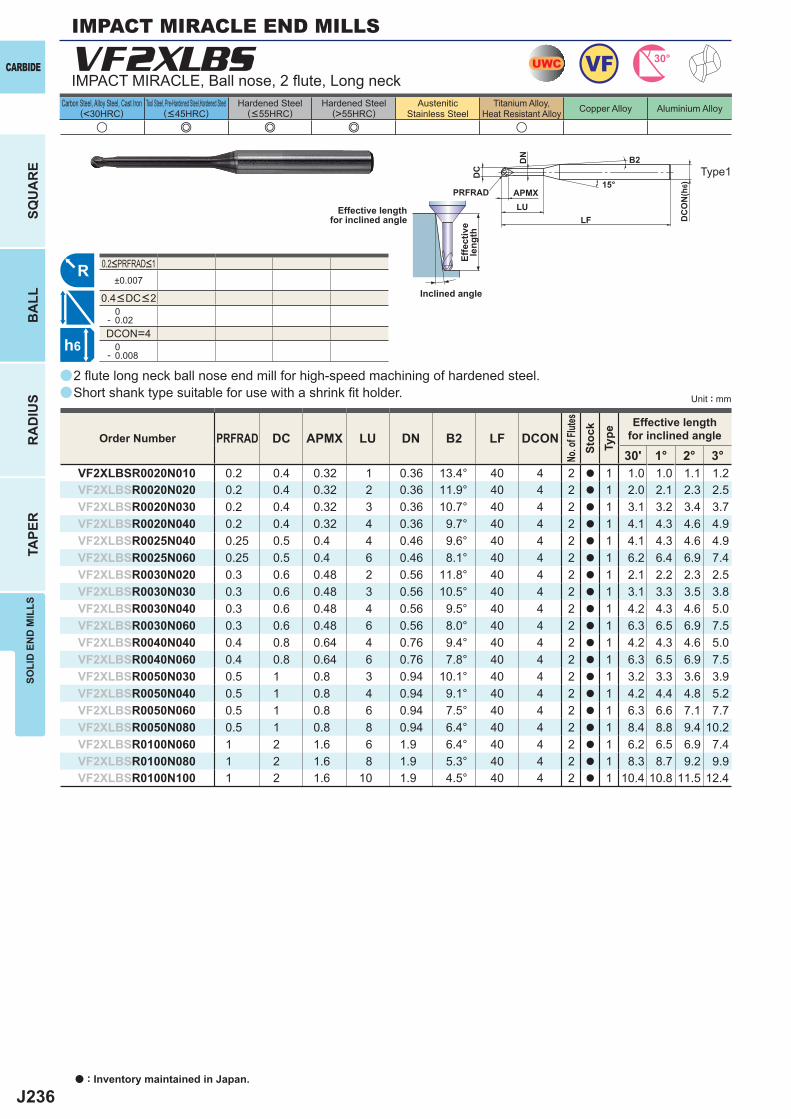
J236
a
a
VF2XLBS
PRFRAD DC APMX LU DN B2 LF DCON30' 1° 2° 3°
VF2XLBSR0020N010 0.2 0.4 0.32 1 0.36 13.4° 40 4 2 a 1 1.0 1.0 1.1 1.2VF2XLBSR0020N020 0.2 0.4 0.32 2 0.36 11.9° 40 4 2 a 1 2.0 2.1 2.3 2.5VF2XLBSR0020N030 0.2 0.4 0.32 3 0.36 10.7° 40 4 2 a 1 3.1 3.2 3.4 3.7VF2XLBSR0020N040 0.2 0.4 0.32 4 0.36 9.7° 40 4 2 a 1 4.1 4.3 4.6 4.9VF2XLBSR0025N040 0.25 0.5 0.4 4 0.46 9.6° 40 4 2 a 1 4.1 4.3 4.6 4.9VF2XLBSR0025N060 0.25 0.5 0.4 6 0.46 8.1° 40 4 2 a 1 6.2 6.4 6.9 7.4VF2XLBSR0030N020 0.3 0.6 0.48 2 0.56 11.8° 40 4 2 a 1 2.1 2.2 2.3 2.5VF2XLBSR0030N030 0.3 0.6 0.48 3 0.56 10.5° 40 4 2 a 1 3.1 3.3 3.5 3.8VF2XLBSR0030N040 0.3 0.6 0.48 4 0.56 9.5° 40 4 2 a 1 4.2 4.3 4.6 5.0VF2XLBSR0030N060 0.3 0.6 0.48 6 0.56 8.0° 40 4 2 a 1 6.3 6.5 6.9 7.5VF2XLBSR0040N040 0.4 0.8 0.64 4 0.76 9.4° 40 4 2 a 1 4.2 4.3 4.6 5.0VF2XLBSR0040N060 0.4 0.8 0.64 6 0.76 7.8° 40 4 2 a 1 6.3 6.5 6.9 7.5VF2XLBSR0050N030 0.5 1 0.8 3 0.94 10.1° 40 4 2 a 1 3.2 3.3 3.6 3.9VF2XLBSR0050N040 0.5 1 0.8 4 0.94 9.1° 40 4 2 a 1 4.2 4.4 4.8 5.2VF2XLBSR0050N060 0.5 1 0.8 6 0.94 7.5° 40 4 2 a 1 6.3 6.6 7.1 7.7VF2XLBSR0050N080 0.5 1 0.8 8 0.94 6.4° 40 4 2 a 1 8.4 8.8 9.4 10.2VF2XLBSR0100N060 1 2 1.6 6 1.9 6.4° 40 4 2 a 1 6.2 6.5 6.9 7.4VF2XLBSR0100N080 1 2 1.6 8 1.9 5.3° 40 4 2 a 1 8.3 8.7 9.2 9.9VF2XLBSR0100N100 1 2 1.6 10 1.9 4.5° 40 4 2 a 1 10.4 10.8 11.5 12.4
u e e e u
±0.007
0- 0.02DCON=4 0- 0.008
UWC VF 30°
R
h6
APMX
DC
DC
ON
(h6)15°
LF
PRFRADLU
DN B2
CARBIDE
SQU
AR
EB
ALL
RA
DIU
STA
PER
SOLI
D E
ND
MIL
LS
Unit : mm
Carbon Steel, Alloy Steel, Cast Iron(<30HRC)
Tool Steel, Pre-Hardened Steel,Hardened Steel(<45HRC)
Hardened Steel(<55HRC)
Hardened Steel(>55HRC)
AusteniticStainless Steel
Titanium Alloy,Heat Resistant Alloy Copper Alloy Aluminium Alloy
0.2<PRFRAD<1
0.4<DC<2
2 fl ute long neck ball nose end mill for high-speed machining of hardened steel.Short shank type suitable for use with a shrink fi t holder.
IMPACT MIRACLE, Ball nose, 2 fl ute, Long neck
Type1
Effective lengthfor inclined angle
Inclined angle
Effe
ctiv
ele
ngth
Order Number
No. o
f Flut
esSt
ock
Type
Effective lengthfor inclined angle
IMPACT MIRACLE END MILLS
a : Inventory maintained in Japan.
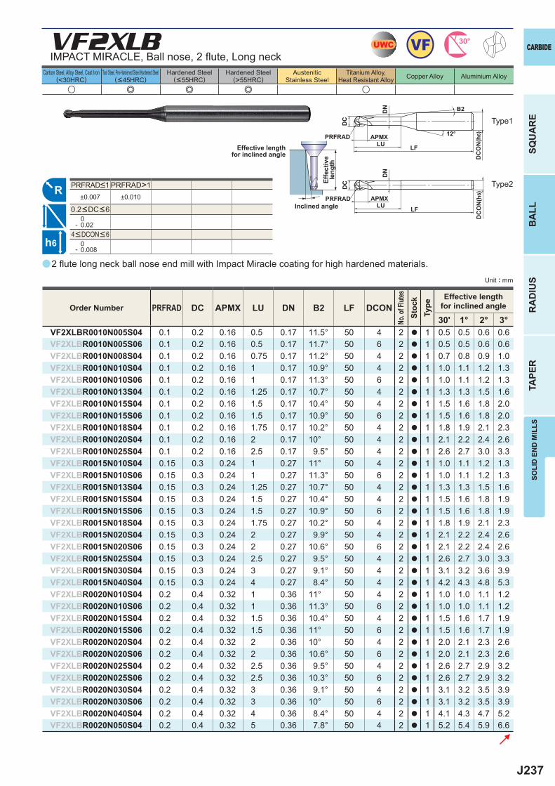
J237
a
VF2XLB
u e e e u
PRFRAD DC APMX LU DN B2 LF DCON30' 1° 2° 3°
VF2XLBR0010N005S04 0.1 0.2 0.16 0.5 0.17 11.5° 50 4 2 a 1 0.5 0.5 0.6 0.6VF2XLBR0010N005S06 0.1 0.2 0.16 0.5 0.17 11.7° 50 6 2 a 1 0.5 0.5 0.6 0.6VF2XLBR0010N008S04 0.1 0.2 0.16 0.75 0.17 11.2° 50 4 2 a 1 0.7 0.8 0.9 1.0VF2XLBR0010N010S04 0.1 0.2 0.16 1 0.17 10.9° 50 4 2 a 1 1.0 1.1 1.2 1.3VF2XLBR0010N010S06 0.1 0.2 0.16 1 0.17 11.3° 50 6 2 a 1 1.0 1.1 1.2 1.3VF2XLBR0010N013S04 0.1 0.2 0.16 1.25 0.17 10.7° 50 4 2 a 1 1.3 1.3 1.5 1.6VF2XLBR0010N015S04 0.1 0.2 0.16 1.5 0.17 10.4° 50 4 2 a 1 1.5 1.6 1.8 2.0VF2XLBR0010N015S06 0.1 0.2 0.16 1.5 0.17 10.9° 50 6 2 a 1 1.5 1.6 1.8 2.0VF2XLBR0010N018S04 0.1 0.2 0.16 1.75 0.17 10.2° 50 4 2 a 1 1.8 1.9 2.1 2.3VF2XLBR0010N020S04 0.1 0.2 0.16 2 0.17 10° 50 4 2 a 1 2.1 2.2 2.4 2.6VF2XLBR0010N025S04 0.1 0.2 0.16 2.5 0.17 9.5° 50 4 2 a 1 2.6 2.7 3.0 3.3VF2XLBR0015N010S04 0.15 0.3 0.24 1 0.27 11° 50 4 2 a 1 1.0 1.1 1.2 1.3VF2XLBR0015N010S06 0.15 0.3 0.24 1 0.27 11.3° 50 6 2 a 1 1.0 1.1 1.2 1.3VF2XLBR0015N013S04 0.15 0.3 0.24 1.25 0.27 10.7° 50 4 2 a 1 1.3 1.3 1.5 1.6VF2XLBR0015N015S04 0.15 0.3 0.24 1.5 0.27 10.4° 50 4 2 a 1 1.5 1.6 1.8 1.9VF2XLBR0015N015S06 0.15 0.3 0.24 1.5 0.27 10.9° 50 6 2 a 1 1.5 1.6 1.8 1.9VF2XLBR0015N018S04 0.15 0.3 0.24 1.75 0.27 10.2° 50 4 2 a 1 1.8 1.9 2.1 2.3VF2XLBR0015N020S04 0.15 0.3 0.24 2 0.27 9.9° 50 4 2 a 1 2.1 2.2 2.4 2.6VF2XLBR0015N020S06 0.15 0.3 0.24 2 0.27 10.6° 50 6 2 a 1 2.1 2.2 2.4 2.6VF2XLBR0015N025S04 0.15 0.3 0.24 2.5 0.27 9.5° 50 4 2 a 1 2.6 2.7 3.0 3.3VF2XLBR0015N030S04 0.15 0.3 0.24 3 0.27 9.1° 50 4 2 a 1 3.1 3.2 3.6 3.9VF2XLBR0015N040S04 0.15 0.3 0.24 4 0.27 8.4° 50 4 2 a 1 4.2 4.3 4.8 5.3VF2XLBR0020N010S04 0.2 0.4 0.32 1 0.36 11° 50 4 2 a 1 1.0 1.0 1.1 1.2VF2XLBR0020N010S06 0.2 0.4 0.32 1 0.36 11.3° 50 6 2 a 1 1.0 1.0 1.1 1.2VF2XLBR0020N015S04 0.2 0.4 0.32 1.5 0.36 10.4° 50 4 2 a 1 1.5 1.6 1.7 1.9VF2XLBR0020N015S06 0.2 0.4 0.32 1.5 0.36 11° 50 6 2 a 1 1.5 1.6 1.7 1.9VF2XLBR0020N020S04 0.2 0.4 0.32 2 0.36 10° 50 4 2 a 1 2.0 2.1 2.3 2.6VF2XLBR0020N020S06 0.2 0.4 0.32 2 0.36 10.6° 50 6 2 a 1 2.0 2.1 2.3 2.6VF2XLBR0020N025S04 0.2 0.4 0.32 2.5 0.36 9.5° 50 4 2 a 1 2.6 2.7 2.9 3.2VF2XLBR0020N025S06 0.2 0.4 0.32 2.5 0.36 10.3° 50 6 2 a 1 2.6 2.7 2.9 3.2VF2XLBR0020N030S04 0.2 0.4 0.32 3 0.36 9.1° 50 4 2 a 1 3.1 3.2 3.5 3.9VF2XLBR0020N030S06 0.2 0.4 0.32 3 0.36 10° 50 6 2 a 1 3.1 3.2 3.5 3.9VF2XLBR0020N040S04 0.2 0.4 0.32 4 0.36 8.4° 50 4 2 a 1 4.1 4.3 4.7 5.2VF2XLBR0020N050S04 0.2 0.4 0.32 5 0.36 7.8° 50 4 2 a 1 5.2 5.4 5.9 6.6
PRFRAD>1±0.007 ±0.010
0- 0.02
0- 0.008
UWC VF 30°
R
h6
APMX
DC
DC
ON
(h6)12°
LF
PRFRADLU
DN
APMX
DC
DC
ON
(h6)
LF
PRFRADLU
DN
B2
SOLI
D E
ND
MIL
LS
CARBIDE
SQU
AR
EB
ALL
RA
DIU
STA
PER
Unit : mm
Carbon Steel, Alloy Steel, Cast Iron(<30HRC)
Tool Steel, Pre-Hardened Steel,Hardened Steel(<45HRC)
Hardened Steel(<55HRC)
Hardened Steel(>55HRC)
AusteniticStainless Steel
Titanium Alloy,Heat Resistant Alloy Copper Alloy Aluminium Alloy
2 fl ute long neck ball nose end mill with Impact Miracle coating for high hardened materials.
IMPACT MIRACLE, Ball nose, 2 fl ute, Long neck
Type2
Type1
Effective lengthfor inclined angle
Inclined angle
Order Number
No. o
f Flut
esSt
ock
Type
Effective lengthfor inclined angle
4<DCON<6
PRFRAD<1
0.2<DC<6
Effe
ctiv
ele
ngth
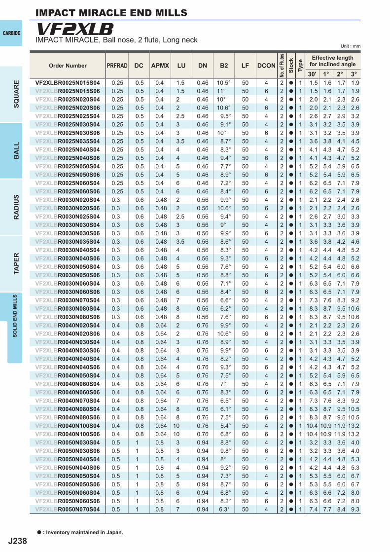
J238
VF2XLB
PRFRAD DC APMX LU DN B2 LF DCON30' 1° 2° 3°
VF2XLBR0025N015S04 0.25 0.5 0.4 1.5 0.46 10.5° 50 4 2 a 1 1.5 1.6 1.7 1.9VF2XLBR0025N015S06 0.25 0.5 0.4 1.5 0.46 11° 50 6 2 a 1 1.5 1.6 1.7 1.9VF2XLBR0025N020S04 0.25 0.5 0.4 2 0.46 10° 50 4 2 a 1 2.0 2.1 2.3 2.6VF2XLBR0025N020S06 0.25 0.5 0.4 2 0.46 10.6° 50 6 2 a 1 2.0 2.1 2.3 2.6VF2XLBR0025N025S04 0.25 0.5 0.4 2.5 0.46 9.5° 50 4 2 a 1 2.6 2.7 2.9 3.2VF2XLBR0025N030S04 0.25 0.5 0.4 3 0.46 9.1° 50 4 2 a 1 3.1 3.2 3.5 3.9VF2XLBR0025N030S06 0.25 0.5 0.4 3 0.46 10° 50 6 2 a 1 3.1 3.2 3.5 3.9VF2XLBR0025N035S04 0.25 0.5 0.4 3.5 0.46 8.7° 50 4 2 a 1 3.6 3.8 4.1 4.5VF2XLBR0025N040S04 0.25 0.5 0.4 4 0.46 8.3° 50 4 2 a 1 4.1 4.3 4.7 5.2VF2XLBR0025N040S06 0.25 0.5 0.4 4 0.46 9.4° 50 6 2 a 1 4.1 4.3 4.7 5.2VF2XLBR0025N050S04 0.25 0.5 0.4 5 0.46 7.7° 50 4 2 a 1 5.2 5.4 5.9 6.5VF2XLBR0025N050S06 0.25 0.5 0.4 5 0.46 8.9° 50 6 2 a 1 5.2 5.4 5.9 6.5VF2XLBR0025N060S04 0.25 0.5 0.4 6 0.46 7.2° 50 4 2 a 1 6.2 6.5 7.1 7.9VF2XLBR0025N060S06 0.25 0.5 0.4 6 0.46 8.4° 60 6 2 a 1 6.2 6.5 7.1 7.9VF2XLBR0030N020S04 0.3 0.6 0.48 2 0.56 9.9° 50 4 2 a 1 2.1 2.2 2.4 2.6VF2XLBR0030N020S06 0.3 0.6 0.48 2 0.56 10.6° 50 6 2 a 1 2.1 2.2 2.4 2.6VF2XLBR0030N025S04 0.3 0.6 0.48 2.5 0.56 9.4° 50 4 2 a 1 2.6 2.7 3.0 3.3VF2XLBR0030N030S04 0.3 0.6 0.48 3 0.56 9° 50 4 2 a 1 3.1 3.3 3.6 3.9VF2XLBR0030N030S06 0.3 0.6 0.48 3 0.56 9.9° 50 6 2 a 1 3.1 3.3 3.6 3.9VF2XLBR0030N035S04 0.3 0.6 0.48 3.5 0.56 8.6° 50 4 2 a 1 3.6 3.8 4.2 4.6VF2XLBR0030N040S04 0.3 0.6 0.48 4 0.56 8.3° 50 4 2 a 1 4.2 4.4 4.8 5.2VF2XLBR0030N040S06 0.3 0.6 0.48 4 0.56 9.3° 50 6 2 a 1 4.2 4.4 4.8 5.2VF2XLBR0030N050S04 0.3 0.6 0.48 5 0.56 7.6° 50 4 2 a 1 5.2 5.4 6.0 6.6VF2XLBR0030N050S06 0.3 0.6 0.48 5 0.56 8.8° 50 6 2 a 1 5.2 5.4 6.0 6.6VF2XLBR0030N060S04 0.3 0.6 0.48 6 0.56 7.1° 50 4 2 a 1 6.3 6.5 7.1 7.9VF2XLBR0030N060S06 0.3 0.6 0.48 6 0.56 8.4° 50 6 2 a 1 6.3 6.5 7.1 7.9VF2XLBR0030N070S04 0.3 0.6 0.48 7 0.56 6.6° 50 4 2 a 1 7.3 7.6 8.3 9.2VF2XLBR0030N080S04 0.3 0.6 0.48 8 0.56 6.2° 50 4 2 a 1 8.3 8.7 9.5 10.6VF2XLBR0030N080S06 0.3 0.6 0.48 8 0.56 7.6° 60 6 2 a 1 8.3 8.7 9.5 10.6VF2XLBR0040N020S04 0.4 0.8 0.64 2 0.76 9.9° 50 4 2 a 1 2.1 2.2 2.3 2.6VF2XLBR0040N020S06 0.4 0.8 0.64 2 0.76 10.6° 50 6 2 a 1 2.1 2.2 2.3 2.6VF2XLBR0040N030S04 0.4 0.8 0.64 3 0.76 8.9° 50 4 2 a 1 3.1 3.3 3.5 3.9VF2XLBR0040N030S06 0.4 0.8 0.64 3 0.76 9.9° 50 6 2 a 1 3.1 3.3 3.5 3.9VF2XLBR0040N040S04 0.4 0.8 0.64 4 0.76 8.2° 50 4 2 a 1 4.2 4.3 4.7 5.2VF2XLBR0040N040S06 0.4 0.8 0.64 4 0.76 9.3° 50 6 2 a 1 4.2 4.3 4.7 5.2VF2XLBR0040N050S04 0.4 0.8 0.64 5 0.76 7.5° 50 4 2 a 1 5.2 5.4 5.9 6.5VF2XLBR0040N060S04 0.4 0.8 0.64 6 0.76 7° 50 4 2 a 1 6.3 6.5 7.1 7.9VF2XLBR0040N060S06 0.4 0.8 0.64 6 0.76 8.3° 50 6 2 a 1 6.3 6.5 7.1 7.9VF2XLBR0040N070S04 0.4 0.8 0.64 7 0.76 6.5° 50 4 2 a 1 7.3 7.6 8.3 9.2VF2XLBR0040N080S04 0.4 0.8 0.64 8 0.76 6.1° 50 4 2 a 1 8.3 8.7 9.5 10.5VF2XLBR0040N080S06 0.4 0.8 0.64 8 0.76 7.5° 50 6 2 a 1 8.3 8.7 9.5 10.5VF2XLBR0040N100S04 0.4 0.8 0.64 10 0.76 5.4° 50 4 2 a 1 10.4 10.9 11.9 13.2VF2XLBR0040N100S06 0.4 0.8 0.64 10 0.76 6.8° 60 6 2 a 1 10.4 10.9 11.9 13.2VF2XLBR0050N030S04 0.5 1 0.8 3 0.94 8.8° 50 4 2 a 1 3.2 3.3 3.6 4.0VF2XLBR0050N030S06 0.5 1 0.8 3 0.94 9.8° 50 6 2 a 1 3.2 3.3 3.6 4.0VF2XLBR0050N040S04 0.5 1 0.8 4 0.94 8° 50 4 2 a 1 4.2 4.4 4.8 5.3VF2XLBR0050N040S06 0.5 1 0.8 4 0.94 9.2° 50 6 2 a 1 4.2 4.4 4.8 5.3VF2XLBR0050N050S04 0.5 1 0.8 5 0.94 7.3° 50 4 2 a 1 5.3 5.5 6.0 6.7VF2XLBR0050N050S06 0.5 1 0.8 5 0.94 8.7° 50 6 2 a 1 5.3 5.5 6.0 6.7VF2XLBR0050N060S04 0.5 1 0.8 6 0.94 6.8° 50 4 2 a 1 6.3 6.6 7.2 8.0VF2XLBR0050N060S06 0.5 1 0.8 6 0.94 8.2° 50 6 2 a 1 6.3 6.6 7.2 8.0VF2XLBR0050N070S04 0.5 1 0.8 7 0.94 6.3° 50 4 2 a 1 7.4 7.7 8.4 9.3
CARBIDE
SQU
AR
EB
ALL
RA
DIU
STA
PER
SOLI
D E
ND
MIL
LS
Unit : mm
IMPACT MIRACLE END MILLS
IMPACT MIRACLE, Ball nose, 2 fl ute, Long neck
a : Inventory maintained in Japan.
Order Number
No. o
f Flut
esSt
ock
Type
Effective lengthfor inclined angle
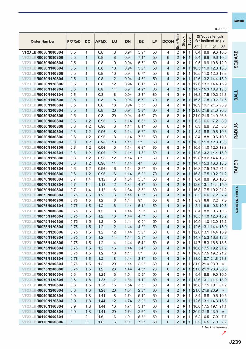
J239
PRFRAD DC APMX LU DN B2 LF DCON30' 1° 2° 3°
VF2XLBR0050N080S04 0.5 1 0.8 8 0.94 5.9° 50 4 2 a 1 8.4 8.8 9.6 10.6VF2XLBR0050N080S06 0.5 1 0.8 8 0.94 7.4° 50 6 2 a 1 8.4 8.8 9.6 10.6VF2XLBR0050N090S04 0.5 1 0.8 9 0.94 5.5° 50 4 2 a 1 9.5 9.9 10.8 12.0VF2XLBR0050N100S04 0.5 1 0.8 10 0.94 5.2° 50 4 2 a 1 10.5 11.0 12.0 13.3VF2XLBR0050N100S06 0.5 1 0.8 10 0.94 6.7° 50 6 2 a 1 10.5 11.0 12.0 13.3VF2XLBR0050N120S04 0.5 1 0.8 12 0.94 4.6° 50 4 2 a 1 12.6 13.2 14.4 15.9VF2XLBR0050N120S06 0.5 1 0.8 12 0.94 6.1° 60 6 2 a 1 12.6 13.2 14.4 15.9VF2XLBR0050N140S04 0.5 1 0.8 14 0.94 4.2° 60 4 2 a 1 14.7 15.3 16.8 18.6VF2XLBR0050N160S04 0.5 1 0.8 16 0.94 3.8° 60 4 2 a 1 16.8 17.5 19.2 21.3VF2XLBR0050N160S06 0.5 1 0.8 16 0.94 5.3° 70 6 2 a 1 16.8 17.5 19.2 21.3VF2XLBR0050N180S04 0.5 1 0.8 18 0.94 3.5° 60 4 2 a 1 18.9 19.7 21.6 23.9VF2XLBR0050N200S04 0.5 1 0.8 20 0.94 3.3° 60 4 2 a 1 21.0 21.9 24.0 26.6VF2XLBR0050N200S06 0.5 1 0.8 20 0.94 4.6° 70 6 2 a 1 21.0 21.9 24.0 26.6VF2XLBR0060N060S04 0.6 1.2 0.96 6 1.14 6.6° 50 4 2 a 1 6.3 6.6 7.2 8.0VF2XLBR0060N060S06 0.6 1.2 0.96 6 1.14 8.1° 50 6 2 a 1 6.3 6.6 7.2 8.0VF2XLBR0060N080S04 0.6 1.2 0.96 8 1.14 5.7° 50 4 2 a 1 8.4 8.8 9.6 10.6VF2XLBR0060N080S06 0.6 1.2 0.96 8 1.14 7.3° 50 6 2 a 1 8.4 8.8 9.6 10.6VF2XLBR0060N100S04 0.6 1.2 0.96 10 1.14 5° 50 4 2 a 1 10.5 11.0 12.0 13.3VF2XLBR0060N100S06 0.6 1.2 0.96 10 1.14 6.6° 50 6 2 a 1 10.5 11.0 12.0 13.3VF2XLBR0060N120S04 0.6 1.2 0.96 12 1.14 4.5° 50 4 2 a 1 12.6 13.2 14.4 15.9VF2XLBR0060N120S06 0.6 1.2 0.96 12 1.14 6° 50 6 2 a 1 12.6 13.2 14.4 15.9VF2XLBR0060N140S04 0.6 1.2 0.96 14 1.14 4° 60 4 2 a 1 14.7 15.3 16.8 18.6VF2XLBR0060N160S04 0.6 1.2 0.96 16 1.14 3.7° 60 4 2 a 1 16.8 17.5 19.2 21.2VF2XLBR0060N160S06 0.6 1.2 0.96 16 1.14 5.2° 70 6 2 a 1 16.8 17.5 19.2 21.2VF2XLBR0070N080S04 0.7 1.4 1.12 8 1.34 5.5° 50 4 2 a 1 8.4 8.8 9.6 10.6VF2XLBR0070N120S04 0.7 1.4 1.12 12 1.34 4.3° 50 4 2 a 1 12.6 13.1 14.4 15.9VF2XLBR0070N160S04 0.7 1.4 1.12 16 1.34 3.5° 60 4 2 a 1 16.8 17.5 19.2 21.2VF2XLBR0075N060S04 0.75 1.5 1.2 6 1.44 6.3° 50 4 2 a 1 6.3 6.6 7.2 7.9VF2XLBR0075N060S06 0.75 1.5 1.2 6 1.44 8° 50 6 2 a 1 6.3 6.6 7.2 7.9VF2XLBR0075N080S04 0.75 1.5 1.2 8 1.44 5.4° 50 4 2 a 1 8.4 8.8 9.6 10.6VF2XLBR0075N080S06 0.75 1.5 1.2 8 1.44 7.2° 50 6 2 a 1 8.4 8.8 9.6 10.6VF2XLBR0075N100S04 0.75 1.5 1.2 10 1.44 4.7° 50 4 2 a 1 10.5 11.0 12.0 13.2VF2XLBR0075N100S06 0.75 1.5 1.2 10 1.44 6.5° 50 6 2 a 1 10.5 11.0 12.0 13.2VF2XLBR0075N120S04 0.75 1.5 1.2 12 1.44 4.2° 50 4 2 a 1 12.6 13.1 14.4 15.9VF2XLBR0075N120S06 0.75 1.5 1.2 12 1.44 5.9° 50 6 2 a 1 12.6 13.1 14.4 15.9VF2XLBR0075N140S04 0.75 1.5 1.2 14 1.44 3.8° 50 4 2 a 1 14.7 15.3 16.8 18.5VF2XLBR0075N140S06 0.75 1.5 1.2 14 1.44 5.4° 50 6 2 a 1 14.7 15.3 16.8 18.5VF2XLBR0075N160S04 0.75 1.5 1.2 16 1.44 3.4° 60 4 2 a 1 16.8 17.5 19.2 21.2VF2XLBR0075N160S06 0.75 1.5 1.2 16 1.44 5° 60 6 2 a 1 16.8 17.5 19.2 21.2VF2XLBR0075N180S04 0.75 1.5 1.2 18 1.44 3.1° 60 4 2 a 1 18.9 19.7 21.6 23.8VF2XLBR0075N200S04 0.75 1.5 1.2 20 1.44 2.9° 60 4 2 a 1 21.0 21.9 23.9VF2XLBR0075N200S06 0.75 1.5 1.2 20 1.44 4.3° 70 6 2 a 1 21.0 21.9 23.9 26.5VF2XLBR0080N080S04 0.8 1.6 1.28 8 1.54 5.3° 50 4 2 a 1 8.4 8.8 9.6 10.5VF2XLBR0080N120S04 0.8 1.6 1.28 12 1.54 4.1° 50 4 2 a 1 12.6 13.1 14.4 15.9VF2XLBR0080N160S04 0.8 1.6 1.28 16 1.54 3.3° 60 4 2 a 1 16.8 17.5 19.1 21.2VF2XLBR0080N200S04 0.8 1.6 1.28 20 1.54 2.8° 60 4 2 a 1 21.0 21.9 23.9VF2XLBR0090N080S04 0.9 1.8 1.44 8 1.74 5.1° 50 4 2 a 1 8.4 8.8 9.6 10.5VF2XLBR0090N120S04 0.9 1.8 1.44 12 1.74 3.9° 50 4 2 a 1 12.6 13.1 14.3 15.8VF2XLBR0090N160S04 0.9 1.8 1.44 16 1.74 3.1° 60 4 2 a 1 16.8 17.5 19.1 21.1VF2XLBR0090N200S04 0.9 1.8 1.44 20 1.74 2.6° 60 4 2 a 1 20.9 21.8 23.9VF2XLBR0100N060S04 1 2 1.6 6 1.9 5.8° 50 4 2 a 1 6.2 6.5 7.0 7.7VF2XLBR0100N060S06 1 2 1.6 6 1.9 7.9° 50 6 2 a 1 6.2 6.5 7.0 7.7
SOLI
D E
ND
MIL
LS
CARBIDE
SQU
AR
EB
ALL
RA
DIU
STA
PER
Unit : mm
* No interference
*
*
*
Order Number
No. o
f Flut
esSt
ock
Type
Effective lengthfor inclined angle
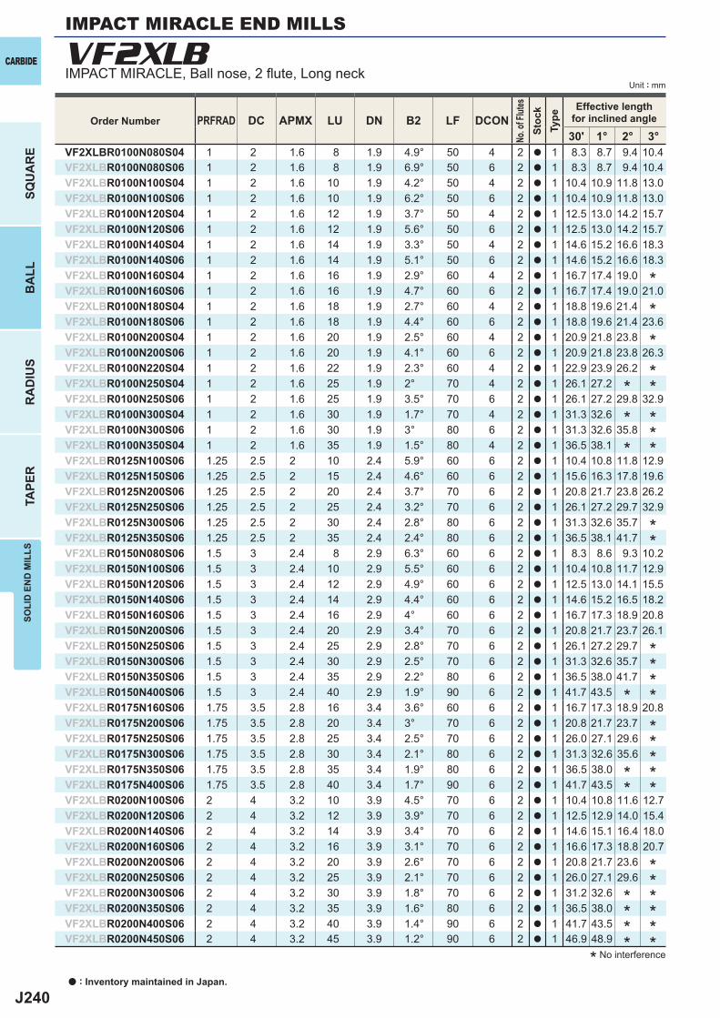
J240
VF2XLB
PRFRAD DC APMX LU DN B2 LF DCON30' 1° 2° 3°
VF2XLBR0100N080S04 1 2 1.6 8 1.9 4.9° 50 4 2 a 1 8.3 8.7 9.4 10.4VF2XLBR0100N080S06 1 2 1.6 8 1.9 6.9° 50 6 2 a 1 8.3 8.7 9.4 10.4VF2XLBR0100N100S04 1 2 1.6 10 1.9 4.2° 50 4 2 a 1 10.4 10.9 11.8 13.0VF2XLBR0100N100S06 1 2 1.6 10 1.9 6.2° 50 6 2 a 1 10.4 10.9 11.8 13.0VF2XLBR0100N120S04 1 2 1.6 12 1.9 3.7° 50 4 2 a 1 12.5 13.0 14.2 15.7VF2XLBR0100N120S06 1 2 1.6 12 1.9 5.6° 50 6 2 a 1 12.5 13.0 14.2 15.7VF2XLBR0100N140S04 1 2 1.6 14 1.9 3.3° 50 4 2 a 1 14.6 15.2 16.6 18.3VF2XLBR0100N140S06 1 2 1.6 14 1.9 5.1° 50 6 2 a 1 14.6 15.2 16.6 18.3VF2XLBR0100N160S04 1 2 1.6 16 1.9 2.9° 60 4 2 a 1 16.7 17.4 19.0VF2XLBR0100N160S06 1 2 1.6 16 1.9 4.7° 60 6 2 a 1 16.7 17.4 19.0 21.0VF2XLBR0100N180S04 1 2 1.6 18 1.9 2.7° 60 4 2 a 1 18.8 19.6 21.4VF2XLBR0100N180S06 1 2 1.6 18 1.9 4.4° 60 6 2 a 1 18.8 19.6 21.4 23.6VF2XLBR0100N200S04 1 2 1.6 20 1.9 2.5° 60 4 2 a 1 20.9 21.8 23.8VF2XLBR0100N200S06 1 2 1.6 20 1.9 4.1° 60 6 2 a 1 20.9 21.8 23.8 26.3VF2XLBR0100N220S04 1 2 1.6 22 1.9 2.3° 60 4 2 a 1 22.9 23.9 26.2VF2XLBR0100N250S04 1 2 1.6 25 1.9 2° 70 4 2 a 1 26.1 27.2VF2XLBR0100N250S06 1 2 1.6 25 1.9 3.5° 70 6 2 a 1 26.1 27.2 29.8 32.9VF2XLBR0100N300S04 1 2 1.6 30 1.9 1.7° 70 4 2 a 1 31.3 32.6VF2XLBR0100N300S06 1 2 1.6 30 1.9 3° 80 6 2 a 1 31.3 32.6 35.8VF2XLBR0100N350S04 1 2 1.6 35 1.9 1.5° 80 4 2 a 1 36.5 38.1VF2XLBR0125N100S06 1.25 2.5 2 10 2.4 5.9° 60 6 2 a 1 10.4 10.8 11.8 12.9VF2XLBR0125N150S06 1.25 2.5 2 15 2.4 4.6° 60 6 2 a 1 15.6 16.3 17.8 19.6VF2XLBR0125N200S06 1.25 2.5 2 20 2.4 3.7° 70 6 2 a 1 20.8 21.7 23.8 26.2VF2XLBR0125N250S06 1.25 2.5 2 25 2.4 3.2° 70 6 2 a 1 26.1 27.2 29.7 32.9VF2XLBR0125N300S06 1.25 2.5 2 30 2.4 2.8° 80 6 2 a 1 31.3 32.6 35.7VF2XLBR0125N350S06 1.25 2.5 2 35 2.4 2.4° 80 6 2 a 1 36.5 38.1 41.7VF2XLBR0150N080S06 1.5 3 2.4 8 2.9 6.3° 60 6 2 a 1 8.3 8.6 9.3 10.2VF2XLBR0150N100S06 1.5 3 2.4 10 2.9 5.5° 60 6 2 a 1 10.4 10.8 11.7 12.9VF2XLBR0150N120S06 1.5 3 2.4 12 2.9 4.9° 60 6 2 a 1 12.5 13.0 14.1 15.5VF2XLBR0150N140S06 1.5 3 2.4 14 2.9 4.4° 60 6 2 a 1 14.6 15.2 16.5 18.2VF2XLBR0150N160S06 1.5 3 2.4 16 2.9 4° 60 6 2 a 1 16.7 17.3 18.9 20.8VF2XLBR0150N200S06 1.5 3 2.4 20 2.9 3.4° 70 6 2 a 1 20.8 21.7 23.7 26.1VF2XLBR0150N250S06 1.5 3 2.4 25 2.9 2.8° 70 6 2 a 1 26.1 27.2 29.7VF2XLBR0150N300S06 1.5 3 2.4 30 2.9 2.5° 70 6 2 a 1 31.3 32.6 35.7VF2XLBR0150N350S06 1.5 3 2.4 35 2.9 2.2° 80 6 2 a 1 36.5 38.0 41.7VF2XLBR0150N400S06 1.5 3 2.4 40 2.9 1.9° 90 6 2 a 1 41.7 43.5VF2XLBR0175N160S06 1.75 3.5 2.8 16 3.4 3.6° 60 6 2 a 1 16.7 17.3 18.9 20.8VF2XLBR0175N200S06 1.75 3.5 2.8 20 3.4 3° 70 6 2 a 1 20.8 21.7 23.7VF2XLBR0175N250S06 1.75 3.5 2.8 25 3.4 2.5° 70 6 2 a 1 26.0 27.1 29.6VF2XLBR0175N300S06 1.75 3.5 2.8 30 3.4 2.1° 80 6 2 a 1 31.3 32.6 35.6VF2XLBR0175N350S06 1.75 3.5 2.8 35 3.4 1.9° 80 6 2 a 1 36.5 38.0VF2XLBR0175N400S06 1.75 3.5 2.8 40 3.4 1.7° 90 6 2 a 1 41.7 43.5VF2XLBR0200N100S06 2 4 3.2 10 3.9 4.5° 70 6 2 a 1 10.4 10.8 11.6 12.7VF2XLBR0200N120S06 2 4 3.2 12 3.9 3.9° 70 6 2 a 1 12.5 12.9 14.0 15.4VF2XLBR0200N140S06 2 4 3.2 14 3.9 3.4° 70 6 2 a 1 14.6 15.1 16.4 18.0VF2XLBR0200N160S06 2 4 3.2 16 3.9 3.1° 70 6 2 a 1 16.6 17.3 18.8 20.7VF2XLBR0200N200S06 2 4 3.2 20 3.9 2.6° 70 6 2 a 1 20.8 21.7 23.6VF2XLBR0200N250S06 2 4 3.2 25 3.9 2.1° 70 6 2 a 1 26.0 27.1 29.6VF2XLBR0200N300S06 2 4 3.2 30 3.9 1.8° 70 6 2 a 1 31.2 32.6VF2XLBR0200N350S06 2 4 3.2 35 3.9 1.6° 80 6 2 a 1 36.5 38.0VF2XLBR0200N400S06 2 4 3.2 40 3.9 1.4° 90 6 2 a 1 41.7 43.5VF2XLBR0200N450S06 2 4 3.2 45 3.9 1.2° 90 6 2 a 1 46.9 48.9
CARBIDE
SQU
AR
EB
ALL
RA
DIU
STA
PER
SOLI
D E
ND
MIL
LS
Unit : mm
IMPACT MIRACLE END MILLS
IMPACT MIRACLE, Ball nose, 2 fl ute, Long neck
a : Inventory maintained in Japan.
* No interference
*
*
*
***
*****
*
*
*
*
*
*
**
*
*
**
*
*
**
**
**
****
Order Number
No. o
f Flut
esSt
ock
Type
Effective lengthfor inclined angle
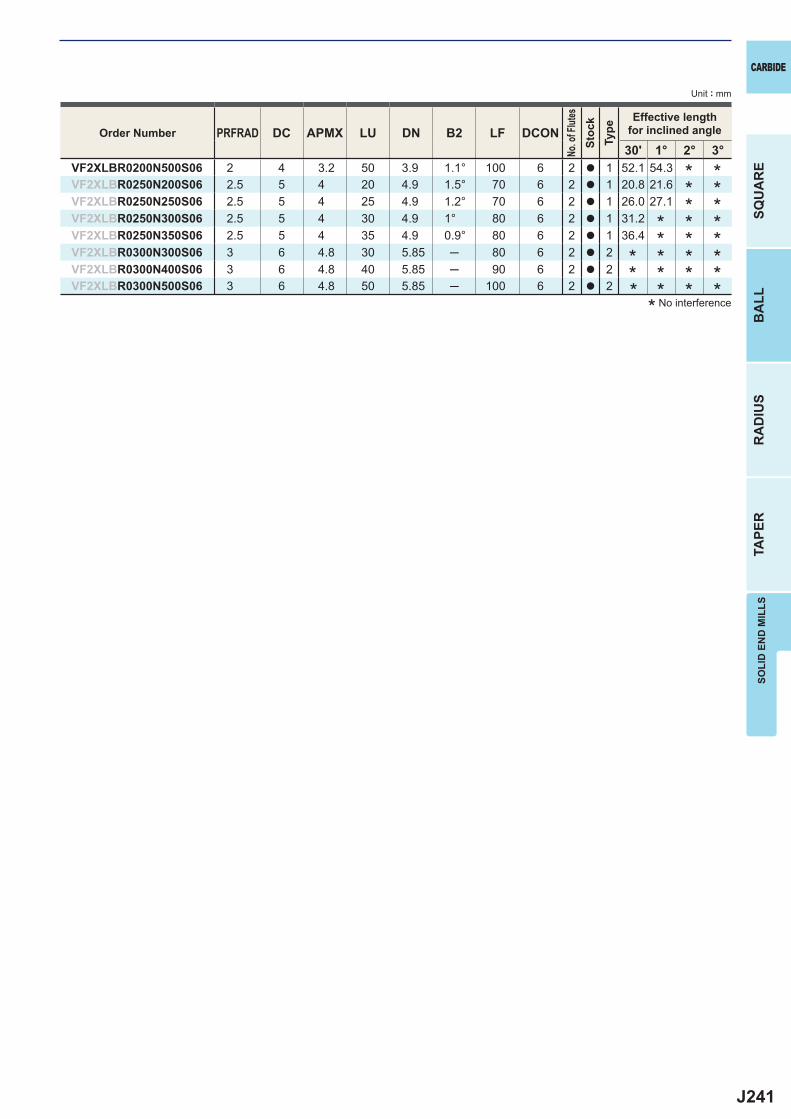
J241
PRFRAD DC APMX LU DN B2 LF DCON30' 1° 2° 3°
VF2XLBR0200N500S06 2 4 3.2 50 3.9 1.1° 100 6 2 a 1 52.1 54.3VF2XLBR0250N200S06 2.5 5 4 20 4.9 1.5° 70 6 2 a 1 20.8 21.6VF2XLBR0250N250S06 2.5 5 4 25 4.9 1.2° 70 6 2 a 1 26.0 27.1VF2XLBR0250N300S06 2.5 5 4 30 4.9 1° 80 6 2 a 1 31.2VF2XLBR0250N350S06 2.5 5 4 35 4.9 0.9° 80 6 2 a 1 36.4VF2XLBR0300N300S06 3 6 4.8 30 5.85 ─ 80 6 2 a 2VF2XLBR0300N400S06 3 6 4.8 40 5.85 ─ 90 6 2 a 2VF2XLBR0300N500S06 3 6 4.8 50 5.85 ─ 100 6 2 a 2
SOLI
D E
ND
MIL
LS
CARBIDE
SQU
AR
EB
ALL
RA
DIU
STA
PER
Unit : mm
* No interference
************
****
********
Order Number
No. o
f Flut
esSt
ock
Type
Effective lengthfor inclined angle
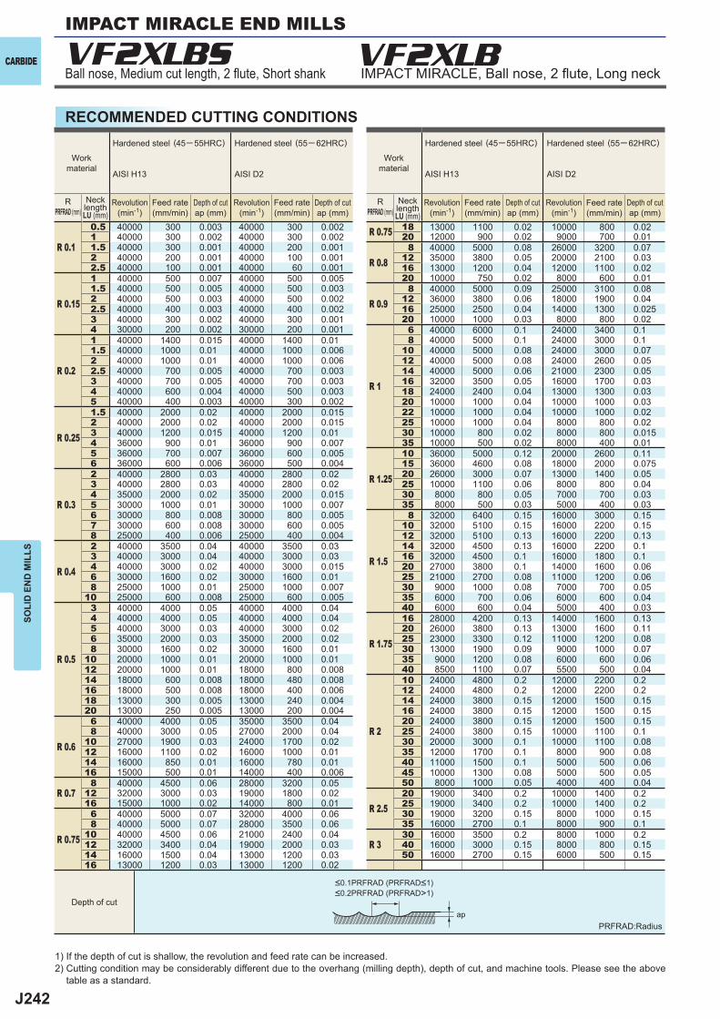
J242
VF2XLBS
R 0.1
0.5 40000 300 0.003 40000 300 0.002 R 0.75 18 13000 1100 0.02 10000 800 0.02 1 40000 300 0.002 40000 300 0.002 20 12000 900 0.02 9000 700 0.01 1.5 40000 300 0.001 40000 200 0.001
R 0.88 40000 5000 0.08 26000 3200 0.07
2 40000 200 0.001 40000 100 0.001 12 35000 3800 0.05 20000 2100 0.03 2.5 40000 100 0.001 40000 60 0.001 16 13000 1200 0.04 12000 1100 0.02
R 0.15
1 40000 500 0.007 40000 500 0.005 20 10000 750 0.02 8000 600 0.01 1.5 40000 500 0.005 40000 500 0.003
R 0.98 40000 5000 0.09 25000 3100 0.08
2 40000 500 0.003 40000 500 0.002 12 36000 3800 0.06 18000 1900 0.04 2.5 40000 400 0.003 40000 400 0.002 16 25000 2500 0.04 14000 1300 0.025 3 40000 300 0.002 40000 300 0.001 20 10000 1000 0.03 8000 800 0.02 4 30000 200 0.002 30000 200 0.001
R 1
6 40000 6000 0.1 24000 3400 0.1
R 0.2
1 40000 1400 0.015 40000 1400 0.01 8 40000 5000 0.1 24000 3000 0.1 1.5 40000 1000 0.01 40000 1000 0.006 10 40000 5000 0.08 24000 3000 0.07 2 40000 1000 0.01 40000 1000 0.006 12 40000 5000 0.08 24000 2600 0.05 2.5 40000 700 0.005 40000 700 0.003 14 40000 5000 0.06 21000 2300 0.05 3 40000 700 0.005 40000 700 0.003 16 32000 3500 0.05 16000 1700 0.03 4 40000 600 0.004 40000 500 0.003 18 24000 2400 0.04 13000 1300 0.03 5 40000 400 0.003 40000 300 0.002 20 10000 1000 0.04 10000 1000 0.03
R 0.25
1.5 40000 2000 0.02 40000 2000 0.015 22 10000 1000 0.04 10000 1000 0.02 2 40000 2000 0.02 40000 2000 0.015 25 10000 1000 0.04 8000 800 0.02 3 40000 1200 0.015 40000 1200 0.01 30 10000 800 0.02 8000 800 0.015 4 36000 900 0.01 36000 900 0.007 35 10000 500 0.02 8000 400 0.01 5 36000 700 0.007 36000 600 0.005
R 1.25
10 36000 5000 0.12 20000 2600 0.11 6 36000 600 0.006 36000 500 0.004 15 36000 4600 0.08 18000 2000 0.075
R 0.3
2 40000 2800 0.03 40000 2800 0.02 20 26000 3000 0.07 13000 1400 0.05 3 40000 2800 0.03 40000 2800 0.02 25 10000 1100 0.06 8000 800 0.04 4 35000 2000 0.02 35000 2000 0.015 30 8000 800 0.05 7000 700 0.03 5 30000 1000 0.01 30000 1000 0.007 35 8000 500 0.03 5000 400 0.03 6 30000 800 0.008 30000 800 0.005
R 1.5
8 32000 6400 0.15 16000 3000 0.15 7 30000 600 0.008 30000 600 0.005 10 32000 5100 0.15 16000 2200 0.15 8 25000 400 0.006 25000 400 0.004 12 32000 5100 0.13 16000 2200 0.13
R 0.4
2 40000 3500 0.04 40000 3500 0.03 14 32000 4500 0.13 16000 2200 0.1 3 40000 3000 0.04 40000 3000 0.03 16 32000 4500 0.1 16000 1800 0.1 4 40000 3000 0.02 40000 3000 0.015 20 27000 3800 0.1 14000 1600 0.06 6 30000 1600 0.02 30000 1600 0.01 25 21000 2700 0.08 11000 1200 0.06 8 25000 1000 0.01 25000 1000 0.007 30 9000 1000 0.08 7000 700 0.0510 25000 600 0.008 25000 600 0.005 35 6000 700 0.06 6000 600 0.04
R 0.5
3 40000 4000 0.05 40000 4000 0.04 40 6000 600 0.04 5000 400 0.03 4 40000 4000 0.05 40000 4000 0.04
R 1.75
16 28000 4200 0.13 14000 1600 0.13 5 40000 3000 0.03 40000 3000 0.02 20 26000 3800 0.13 13000 1600 0.11 6 35000 2000 0.03 35000 2000 0.02 25 23000 3300 0.12 11000 1200 0.08 8 30000 1600 0.02 30000 1600 0.01 30 13000 1900 0.09 9000 1000 0.0710 20000 1000 0.01 20000 1000 0.01 35 9000 1200 0.08 6000 600 0.0612 20000 1000 0.01 18000 800 0.008 40 8500 1100 0.07 5500 500 0.0414 18000 600 0.008 18000 480 0.008
R 2
10 24000 4800 0.2 12000 2200 0.216 18000 500 0.008 18000 400 0.006 12 24000 4800 0.2 12000 2200 0.218 13000 300 0.005 13000 240 0.004 14 24000 3800 0.15 12000 1500 0.1520 13000 250 0.005 13000 200 0.004 16 24000 3800 0.15 12000 1500 0.15
R 0.6
6 40000 4000 0.05 35000 3500 0.04 20 24000 3800 0.15 12000 1500 0.15 8 40000 3000 0.05 27000 2000 0.04 25 24000 3800 0.15 10000 1100 0.110 27000 1900 0.03 24000 1700 0.02 30 20000 3000 0.1 10000 1100 0.0812 16000 1100 0.02 16000 1000 0.01 35 12000 1700 0.1 8000 900 0.0814 16000 850 0.01 16000 780 0.01 40 11000 1500 0.1 5000 500 0.0616 15000 500 0.01 14000 400 0.006 45 10000 1300 0.08 5000 500 0.05
R 0.7 8 40000 4500 0.06 28000 3200 0.05 50 8000 1000 0.05 4000 400 0.0412 32000 3000 0.03 19000 1800 0.02
R 2.520 19000 3400 0.2 10000 1400 0.2
16 15000 1000 0.02 14000 800 0.01 25 19000 3400 0.2 10000 1400 0.2
R 0.75
6 40000 5000 0.07 32000 4000 0.06 30 19000 3200 0.15 8000 1000 0.15 8 40000 5000 0.07 28000 3500 0.06 35 16000 2700 0.1 8000 900 0.110 40000 4500 0.06 21000 2400 0.04
R 330 16000 3500 0.2 8000 1000 0.2
12 32000 3400 0.04 19000 2000 0.03 40 16000 3000 0.15 8000 800 0.1514 16000 1500 0.04 13000 1200 0.03 50 16000 2700 0.15 6000 500 0.1516 13000 1200 0.03 13000 1200 0.02
ap
CARBIDE
SOLI
D E
ND
MIL
LS
RECOMMENDED CUTTING CONDITIONS
Ball nose, Medium cut length, 2 fl ute, Short shank IMPACT MIRACLE, Ball nose, 2 fl ute, Long neckVF2XLB
1) If the depth of cut is shallow, the revolution and feed rate can be increased.2) Cutting condition may be considerably different due to the overhang (milling depth), depth of cut, and machine tools. Please see the above
table as a standard.
PRFRAD:Radius
Workmaterial
Workmaterial
Hardened steel (45─ 55HRC)
AISI H13
Hardened steel (55─ 62HRC)
AISI D2
Hardened steel (45─ 55HRC)
AISI H13
Hardened steel (55─ 62HRC)
AISI D2
RPRFRAD (mm)
RPRFRAD (mm)
NecklengthLU (mm)
NecklengthLU (mm)
Revolution(min-1)
Revolution(min-1)
Revolution(min-1)
Revolution(min-1)
Feed rate(mm/min)
Feed rate(mm/min)
Feed rate(mm/min)
Feed rate(mm/min)
Depth of cutap (mm)
Depth of cutap (mm)
Depth of cutap (mm)
Depth of cutap (mm)
Depth of cut
<0.1PRFRAD (PRFRAD<1)<0.2PRFRAD (PRFRAD>1)
IMPACT MIRACLE END MILLS
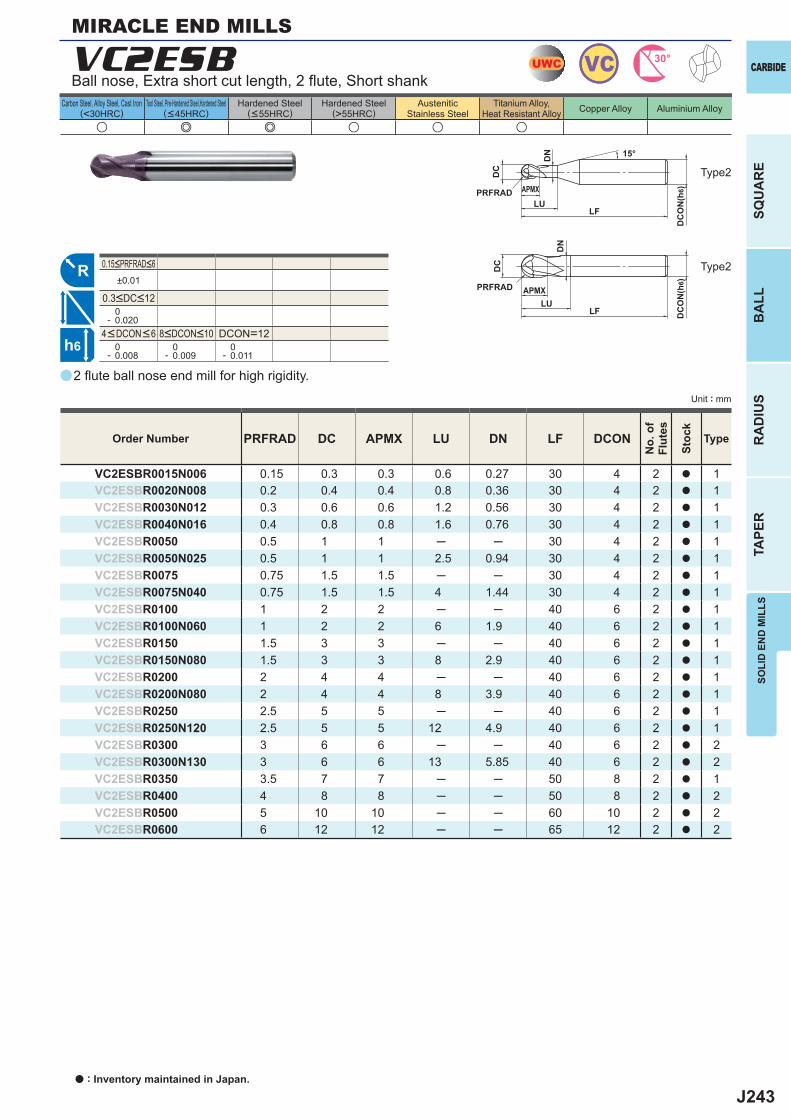
J243
u e e u u u
a
VC2ESB
PRFRAD DC APMX LU DN LF DCON
VC2ESBR0015N006 0.15 0.3 0.3 0.6 0.27 30 4 2 a 1VC2ESBR0020N008 0.2 0.4 0.4 0.8 0.36 30 4 2 a 1VC2ESBR0030N012 0.3 0.6 0.6 1.2 0.56 30 4 2 a 1VC2ESBR0040N016 0.4 0.8 0.8 1.6 0.76 30 4 2 a 1VC2ESBR0050 0.5 1 1 ─ ─ 30 4 2 a 1VC2ESBR0050N025 0.5 1 1 2.5 0.94 30 4 2 a 1VC2ESBR0075 0.75 1.5 1.5 ─ ─ 30 4 2 a 1VC2ESBR0075N040 0.75 1.5 1.5 4 1.44 30 4 2 a 1VC2ESBR0100 1 2 2 ─ ─ 40 6 2 a 1VC2ESBR0100N060 1 2 2 6 1.9 40 6 2 a 1VC2ESBR0150 1.5 3 3 ─ ─ 40 6 2 a 1VC2ESBR0150N080 1.5 3 3 8 2.9 40 6 2 a 1VC2ESBR0200 2 4 4 ─ ─ 40 6 2 a 1VC2ESBR0200N080 2 4 4 8 3.9 40 6 2 a 1VC2ESBR0250 2.5 5 5 ─ ─ 40 6 2 a 1VC2ESBR0250N120 2.5 5 5 12 4.9 40 6 2 a 1VC2ESBR0300 3 6 6 ─ ─ 40 6 2 a 2VC2ESBR0300N130 3 6 6 13 5.85 40 6 2 a 2VC2ESBR0350 3.5 7 7 ─ ─ 50 8 2 a 1VC2ESBR0400 4 8 8 ─ ─ 50 8 2 a 2VC2ESBR0500 5 10 10 ─ ─ 60 10 2 a 2VC2ESBR0600 6 12 12 ─ ─ 65 12 2 a 2
±0.01
0- 0.020
DCON=12 0- 0.008
0- 0.009
0- 0.011
UWC VC 30°
R
h6
APMX
DC
DC
ON
(h6)
15°
LF
PRFRADLU
DN
APMX
DC
DC
ON
(h6)
LF
PRFRAD
LU
DN
SOLI
D E
ND
MIL
LS
CARBIDE
SQU
AR
EB
ALL
RA
DIU
STA
PER
Unit : mm
Carbon Steel, Alloy Steel, Cast Iron(<30HRC)
Tool Steel, Pre-Hardened Steel,Hardened Steel(<45HRC)
Hardened Steel(<55HRC)
Hardened Steel(>55HRC)
AusteniticStainless Steel
Titanium Alloy,Heat Resistant Alloy Copper Alloy Aluminium Alloy
2 fl ute ball nose end mill for high rigidity.
Type2
Type2
MIRACLE END MILLS
Order Number
No.
of
Flut
es
Stoc
k
Type
4<DCON<6 8<DCON<10
0.15<PRFRAD<6
0.3<DC<12
Ball nose, Extra short cut length, 2 fl ute, Short shank
a : Inventory maintained in Japan.
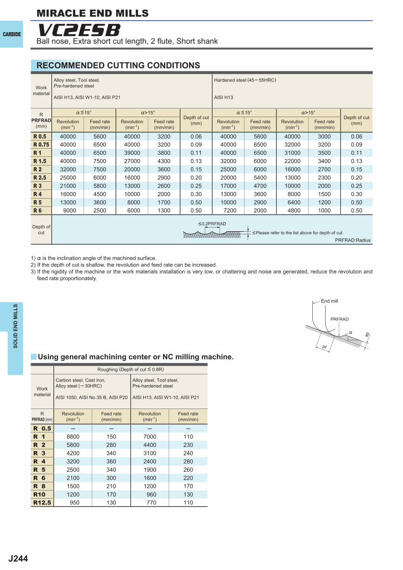
J244
%>15° %>15°
R 0.5 40000 5600 40000 3200 0.06 40000 5600 40000 3000 0.06R 0.75 40000 6500 40000 3200 0.09 40000 6500 32000 3200 0.09R 1 40000 6500 39000 3800 0.11 40000 6500 31000 3500 0.11R 1.5 40000 7500 27000 4300 0.13 32000 6000 22000 3400 0.13R 2 32000 7500 20000 3600 0.15 25000 6000 16000 2700 0.15R 2.5 25000 6000 16000 2900 0.20 20000 5400 13000 2300 0.20R 3 21000 5800 13000 2600 0.25 17000 4700 10000 2000 0.25R 4 16000 4500 10000 2000 0.30 13000 3600 8000 1500 0.30R 5 13000 3600 8000 1700 0.50 10000 2900 6400 1200 0.50R 6 9000 2500 6000 1300 0.50 7200 2000 4800 1000 0.50
R 0.5 ─ ─ ─ ─R 1 8800 150 7000 110R 2 5800 280 4400 230R 3 4200 340 3100 240R 4 3200 360 2400 280R 5 2500 340 1900 260R 6 2100 300 1600 220R 8 1500 210 1200 170R10 1200 170 960 130R12.5 950 130 770 110
y
VC2ESB
ap
PRFRAD
pf
%
CARBIDE
SOLI
D E
ND
MIL
LS
RECOMMENDED CUTTING CONDITIONS
Depth ofcut
Workmaterial
Alloy steel, Tool steel,Pre-hardened steel
AISI H13, AISI W1-10, AISI P21
Hardened steel (45─ 55HRC)
AISI H13
RPRFRAD
(mm)
%<15°Depth of cut
(mm)
%<15°Depth of cut
(mm)Revolution(min-1)
Feed rate(mm/min)
Revolution(min-1)
Feed rate(mm/min)
Revolution(min-1)
Feed rate(mm/min)
Revolution(min-1)
Feed rate(mm/min)
Roughing (Depth of cut < 0.8R)
Workmaterial
Carbon steel, Cast iron, Alloy steel (─30HRC)
AISI 1050, AISI No 35 B, AISI P20
Alloy steel, Tool steel,Pre-hardened steel
AISI H13, AISI W1-10, AISI P21
RPRFRAD (mm)
Revolution(min-1)
Feed rate(mm/min)
Revolution(min-1)
Feed rate(mm/min)
<0.2PRFRAD
PRFRAD:Radius<Please refer to the list above for depth of cut.
1) % is the inclination angle of the machined surface. 2) If the depth of cut is shallow, the revolution and feed rate can be increased.3) If the rigidity of the machine or the work materials installation is very low, or chattering and noise are generated, reduce the revolution and
feed rate proportionately.
Using general machining center or NC milling machine.
End mill
MIRACLE END MILLS
Ball nose, Extra short cut length, 2 fl ute, Short shank
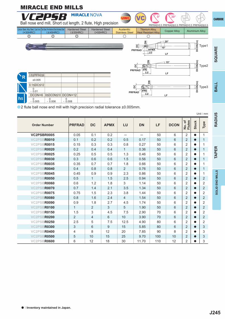
J245
e e e u u
a
VC2PSB
PRFRAD DC APMX LU DN LF DCON
VC2PSBR0005 0.05 0.1 0.2 ─ ─ 50 6 2 a 1VC2PSBR0010 0.1 0.2 0.2 0.5 0.17 50 6 2 a 1VC2PSBR0015 0.15 0.3 0.3 0.8 0.27 50 6 2 a 1VC2PSBR0020 0.2 0.4 0.4 1 0.36 50 6 2 a 1VC2PSBR0025 0.25 0.5 0.5 1.3 0.46 50 6 2 a 1VC2PSBR0030 0.3 0.6 0.6 1.5 0.56 50 6 2 a 1VC2PSBR0035 0.35 0.7 0.7 1.8 0.66 50 6 2 a 1VC2PSBR0040 0.4 0.8 0.8 2 0.76 50 6 2 a 1VC2PSBR0045 0.45 0.9 0.9 2.3 0.86 50 6 2 a 1VC2PSBR0050 0.5 1 1.5 2.5 0.94 50 6 2 a 2VC2PSBR0060 0.6 1.2 1.8 3 1.14 50 6 2 a 2VC2PSBR0070 0.7 1.4 2.1 3.5 1.34 50 6 2 a 2VC2PSBR0075 0.75 1.5 2.3 3.8 1.44 50 6 2 a 2VC2PSBR0080 0.8 1.6 2.4 4 1.54 50 6 2 a 2VC2PSBR0090 0.9 1.8 2.7 4.5 1.74 50 6 2 a 2VC2PSBR0100 1 2 3 5 1.90 50 6 2 a 2VC2PSBR0150 1.5 3 4.5 7.5 2.90 70 6 2 a 2VC2PSBR0200 2 4 6 10 3.90 70 6 2 a 2VC2PSBR0250 2.5 5 7.5 12.5 4.90 80 6 2 a 2VC2PSBR0300 3 6 9 15 5.85 80 6 2 a 3VC2PSBR0400 4 8 12 20 7.85 90 8 2 a 3VC2PSBR0500 5 10 15 25 9.70 100 10 2 a 3VC2PSBR0600 6 12 18 30 11.70 110 12 2 a 3
±0.005
0- 0.01DCON=6 DCON=12 0- 0.005
0- 0.006
0- 0.008
UWC VC 0° 30°
R
h5
APMX
DC
DC
ON
(h5)20°
LFPRFRAD
LU
DN
APMX
DC
DC
ON
(h5)
LFPRFRAD LU
DN
APMX
DC
DC
ON
(h5)
LFPRFRAD
LU
DN 15°
10°
PRFRAD<0.5 PRFRAD<0.5
SOLI
D E
ND
MIL
LS
CARBIDE
SQU
AR
EB
ALL
RA
DIU
STA
PER
Unit : mm
Carbon Steel, Alloy Steel, Cast Iron(<30HRC)
Tool Steel, Pre-Hardened Steel,Hardened Steel(<45HRC)
Hardened Steel(<55HRC)
Hardened Steel(>55HRC)
AusteniticStainless Steel
Titanium Alloy,Heat Resistant Alloy Copper Alloy Aluminium Alloy
2 fl ute ball nose end mill with high precision radial tolerance ±0.005mm.
Type1
MIRACLE END MILLS
Order Number
No.
of
Flut
es
Stoc
k
Type
PRFRAD>0.5 PRFRAD>0.5
8<DCON<10
0.05<PRFRAD<6
0.1<DC<12
Ball nose end mill, Short cut length, 2 fl ute, High precision
Type2
Type3
a : Inventory maintained in Japan.
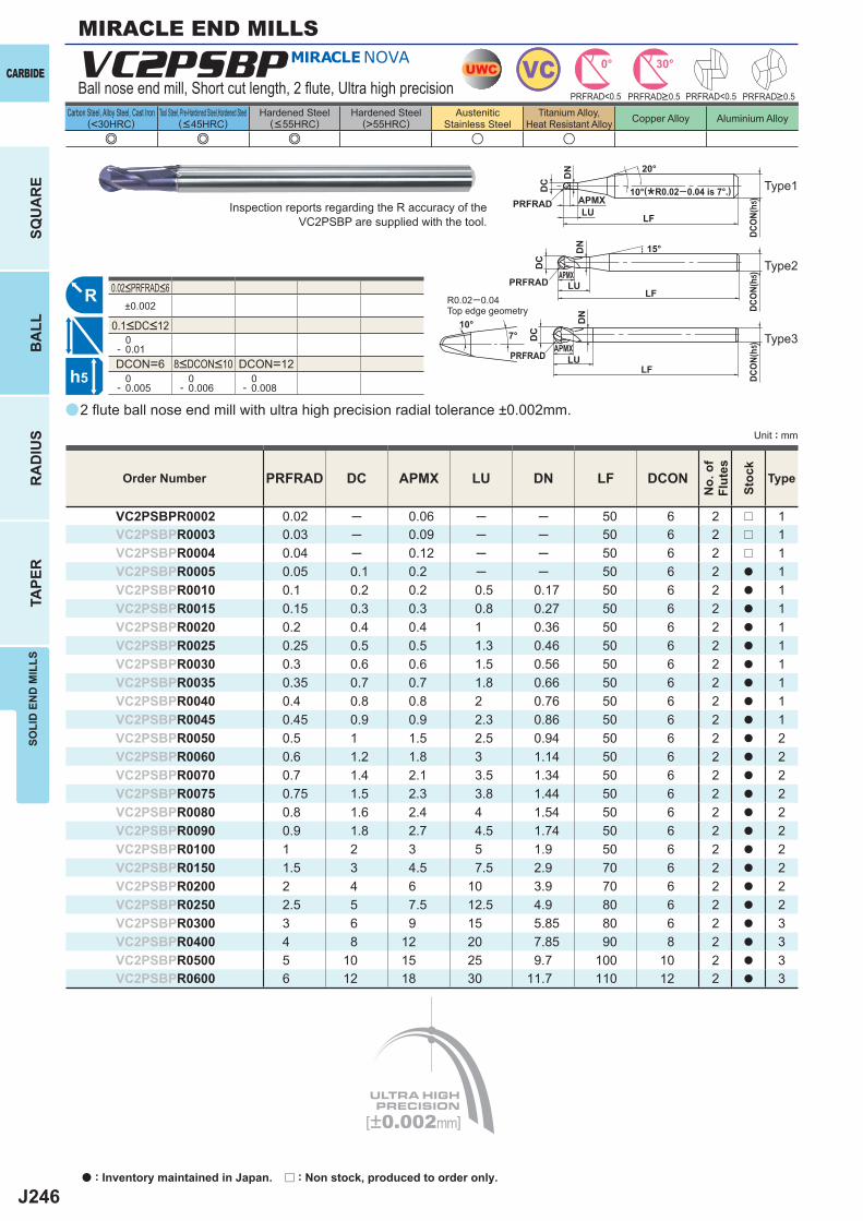
J246
e e e u u
a
VC2PSBP
PRFRAD DC APMX LU DN LF DCON
VC2PSBPR0002 0.02 ─ 0.06 ─ ─ 50 6 2 r 1VC2PSBPR0003 0.03 ─ 0.09 ─ ─ 50 6 2 r 1VC2PSBPR0004 0.04 ─ 0.12 ─ ─ 50 6 2 r 1VC2PSBPR0005 0.05 0.1 0.2 ─ ─ 50 6 2 a 1VC2PSBPR0010 0.1 0.2 0.2 0.5 0.17 50 6 2 a 1VC2PSBPR0015 0.15 0.3 0.3 0.8 0.27 50 6 2 a 1VC2PSBPR0020 0.2 0.4 0.4 1 0.36 50 6 2 a 1VC2PSBPR0025 0.25 0.5 0.5 1.3 0.46 50 6 2 a 1VC2PSBPR0030 0.3 0.6 0.6 1.5 0.56 50 6 2 a 1VC2PSBPR0035 0.35 0.7 0.7 1.8 0.66 50 6 2 a 1VC2PSBPR0040 0.4 0.8 0.8 2 0.76 50 6 2 a 1VC2PSBPR0045 0.45 0.9 0.9 2.3 0.86 50 6 2 a 1VC2PSBPR0050 0.5 1 1.5 2.5 0.94 50 6 2 a 2VC2PSBPR0060 0.6 1.2 1.8 3 1.14 50 6 2 a 2VC2PSBPR0070 0.7 1.4 2.1 3.5 1.34 50 6 2 a 2VC2PSBPR0075 0.75 1.5 2.3 3.8 1.44 50 6 2 a 2VC2PSBPR0080 0.8 1.6 2.4 4 1.54 50 6 2 a 2VC2PSBPR0090 0.9 1.8 2.7 4.5 1.74 50 6 2 a 2VC2PSBPR0100 1 2 3 5 1.9 50 6 2 a 2VC2PSBPR0150 1.5 3 4.5 7.5 2.9 70 6 2 a 2VC2PSBPR0200 2 4 6 10 3.9 70 6 2 a 2VC2PSBPR0250 2.5 5 7.5 12.5 4.9 80 6 2 a 2VC2PSBPR0300 3 6 9 15 5.85 80 6 2 a 3VC2PSBPR0400 4 8 12 20 7.85 90 8 2 a 3VC2PSBPR0500 5 10 15 25 9.7 100 10 2 a 3VC2PSBPR0600 6 12 18 30 11.7 110 12 2 a 3
±0.002
0- 0.01DCON=6 DCON=12 0- 0.005
0- 0.006
0- 0.008
UWC VC 30°0°
[±0.002mm]
R
h5
APMX
DC
DCO
N(h5
)
20°
LFPRFRAD
LU
DN
APMX
DC
DCO
N(h5
)
LFPRFRAD LU
DN
APMX
DC
DCO
N(h5
)
LFPRFRAD LU
DN 15°
10°
10°7°
PRFRAD<0.5 PRFRAD<0.5
CARBIDE
SQU
AR
EB
ALL
RA
DIU
STA
PER
SOLI
D E
ND
MIL
LS
Unit : mm
Carbon Steel, Alloy Steel, Cast Iron(<30HRC)
Tool Steel, Pre-Hardened Steel,Hardened Steel(<45HRC)
Hardened Steel(<55HRC)
Hardened Steel(>55HRC)
AusteniticStainless Steel
Titanium Alloy,Heat Resistant Alloy Copper Alloy Aluminium Alloy
MIRACLE END MILLS
0.02<PRFRAD<6
0.1<DC<12
2 fl ute ball nose end mill with ultra high precision radial tolerance ±0.002mm.
Inspection reports regarding the R accuracy of the VC2PSBP are supplied with the tool.
R0.02─0.04Top edge geometry
(*R0.02─0.04 is 7°.)
Order Number
No.
of
Flut
es
Stoc
k
Type
PRFRAD>0.5 PRFRAD>0.5
8<DCON<10
Ball nose end mill, Short cut length, 2 fl ute, Ultra high precision
Type1
Type2
Type3
a : Inventory maintained in Japan. r : Non stock, produced to order only.
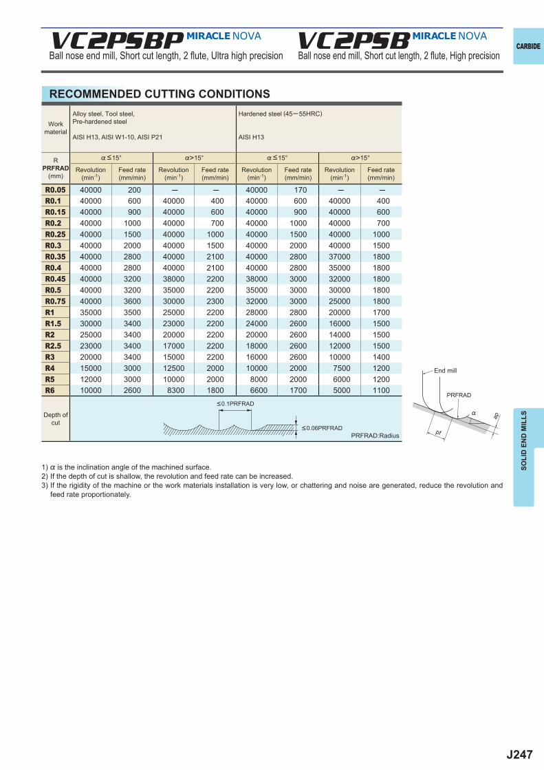
J247
VC2PSBP VC2PSB
%>15° %>15°
R0.05 40000 200 ─ ─ 40000 170 ─ ─R0.1 40000 600 40000 400 40000 600 40000 400R0.15 40000 900 40000 600 40000 900 40000 600R0.2 40000 1000 40000 700 40000 1000 40000 700R0.25 40000 1500 40000 1000 40000 1500 40000 1000R0.3 40000 2000 40000 1500 40000 2000 40000 1500R0.35 40000 2800 40000 2100 40000 2800 37000 1800R0.4 40000 2800 40000 2100 40000 2800 35000 1800R0.45 40000 3200 38000 2200 38000 3000 32000 1800R0.5 40000 3200 35000 2200 35000 3000 30000 1800R0.75 40000 3600 30000 2300 32000 3000 25000 1800R1 35000 3500 25000 2200 28000 2800 20000 1700R1.5 30000 3400 23000 2200 24000 2600 16000 1500R2 25000 3400 20000 2200 20000 2600 14000 1500R2.5 23000 3400 17000 2200 18000 2600 12000 1500R3 20000 3400 15000 2200 16000 2600 10000 1400R4 15000 3000 12500 2000 10000 2000 7500 1200R5 12000 3000 10000 2000 8000 2000 6000 1200R6 10000 2600 8300 1800 6600 1700 5000 1100
ap
PRFRAD
pf
%
CARBIDE
SOLI
D E
ND
MIL
LS
Ball nose end mill, Short cut length, 2 fl ute, Ultra high precision Ball nose end mill, Short cut length, 2 fl ute, High precision
RECOMMENDED CUTTING CONDITIONS
Workmaterial
Alloy steel, Tool steel,Pre-hardened steel
AISI H13, AISI W1-10, AISI P21
Hardened steel (45─ 55HRC)
AISI H13
RPRFRAD
(mm)
%<15° %<15°
Revolution(min-1)
Feed rate(mm/min)
Revolution(min-1)
Feed rate(mm/min)
Revolution(min-1)
Feed rate(mm/min)
Revolution(min-1)
Feed rate(mm/min)
Depth ofcut
<0.1PRFRAD
<0.06PRFRADPRFRAD:Radius
1) % is the inclination angle of the machined surface. 2) If the depth of cut is shallow, the revolution and feed rate can be increased.3) If the rigidity of the machine or the work materials installation is very low, or chattering and noise are generated, reduce the revolution and
feed rate proportionately.
End mill
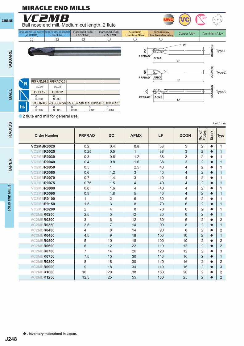
J248
u e e u u u
a
VC2MB
PRFRAD DC APMX LF DCON
VC2MBR0020 0.2 0.4 0.8 38 3 2 a 1VC2MBR0025 0.25 0.5 1 38 3 2 a 1VC2MBR0030 0.3 0.6 1.2 38 3 2 a 1VC2MBR0040 0.4 0.8 1.6 38 3 2 a 1VC2MBR0050 0.5 1 2.5 40 4 2 a 1VC2MBR0060 0.6 1.2 3 40 4 2 a 1VC2MBR0070 0.7 1.4 3 40 4 2 a 1VC2MBR0075 0.75 1.5 4 40 4 2 a 1VC2MBR0080 0.8 1.6 4 40 4 2 a 1VC2MBR0090 0.9 1.8 5 40 4 2 a 1VC2MBR0100 1 2 6 60 6 2 a 1VC2MBR0150 1.5 3 8 70 6 2 a 1VC2MBR0200 2 4 8 70 6 2 a 1VC2MBR0250 2.5 5 12 80 6 2 a 1VC2MBR0300 3 6 12 80 6 2 a 2VC2MBR0350 3.5 7 14 90 8 2 a 1VC2MBR0400 4 8 14 90 8 2 a 2VC2MBR0450 4.5 9 18 100 10 2 a 1VC2MBR0500 5 10 18 100 10 2 a 2VC2MBR0600 6 12 22 110 12 2 a 2VC2MBR0700 7 14 26 120 12 2 a 3VC2MBR0750 7.5 15 30 140 16 2 a 1VC2MBR0800 8 16 30 140 16 2 a 2VC2MBR0900 9 18 34 140 16 2 a 3VC2MBR1000 10 20 38 160 20 2 a 2VC2MBR1250 12.5 25 55 180 25 2 a 2
PRFRAD>6.5±0.01 ±0.02
DC>12 0- 0.020
0- 0.030
DCON=3 0- 0.006
0- 0.008
0- 0.009
0- 0.011
0- 0.013
UWC VC 30°
R
h6
APMX
DC
DC
ON
(h6)15°
APMXLF
DC
DC
ON
(h6)
LFPRFRAD
PRFRAD
APMXLF
DC
DC
ON
(h6)
PRFRAD
CARBIDE
SQU
AR
EB
ALL
RA
DIU
STA
PER
SOLI
D E
ND
MIL
LS
Unit : mm
Carbon Steel, Alloy Steel, Cast Iron(<30HRC)
Tool Steel, Pre-Hardened Steel,Hardened Steel(<45HRC)
Hardened Steel(<55HRC)
Hardened Steel(>55HRC)
AusteniticStainless Steel
Titanium Alloy,Heat Resistant Alloy Copper Alloy Aluminium Alloy
MIRACLE END MILLS
2 fl ute end mill for general use.
Type1
Order Number
No.
of
Flut
es
Stoc
k
Type
4<DCON<6 8<DCON<10 12<DCON<16 20<DCON<25
PRFRAD<6.5
DC<12
Ball nose end mill, Medium cut length, 2 fl ute
Type2
Type3
a : Inventory maintained in Japan.
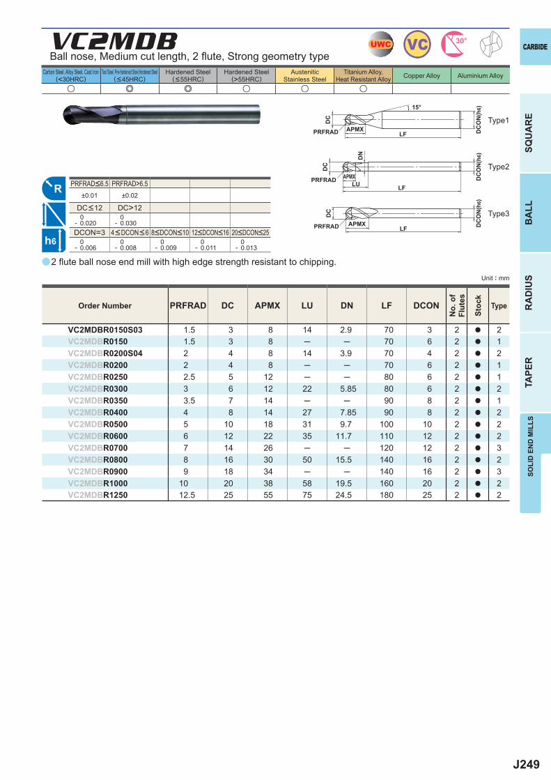
J249
a
u e e u u u
VC2MDB
PRFRAD DC APMX LU DN LF DCON
VC2MDBR0150S03 1.5 3 8 14 2.9 70 3 2 a 2VC2MDBR0150 1.5 3 8 ─ ─ 70 6 2 a 1VC2MDBR0200S04 2 4 8 14 3.9 70 4 2 a 2VC2MDBR0200 2 4 8 ─ ─ 70 6 2 a 1VC2MDBR0250 2.5 5 12 ─ ─ 80 6 2 a 1VC2MDBR0300 3 6 12 22 5.85 80 6 2 a 2VC2MDBR0350 3.5 7 14 ─ ─ 90 8 2 a 1VC2MDBR0400 4 8 14 27 7.85 90 8 2 a 2VC2MDBR0500 5 10 18 31 9.7 100 10 2 a 2VC2MDBR0600 6 12 22 35 11.7 110 12 2 a 2VC2MDBR0700 7 14 26 ─ ─ 120 12 2 a 3VC2MDBR0800 8 16 30 50 15.5 140 16 2 a 2VC2MDBR0900 9 18 34 ─ ─ 140 16 2 a 3VC2MDBR1000 10 20 38 58 19.5 160 20 2 a 2VC2MDBR1250 12.5 25 55 75 24.5 180 25 2 a 2
PRFRAD>6.5±0.01 ±0.02
DC>12 0- 0.020
0- 0.030
DCON=3 0- 0.006
0- 0.008
0- 0.009
0- 0.011
0- 0.013
UWC VC 30°
R
h6
APMX
DC
DC
ON
(h6)15°
APMX
LF
DC
DC
ON
(h6)
LFPRFRAD
PRFRAD
APMXLF
DC
DC
ON
(h6)
PRFRAD
DN
LU
SOLI
D E
ND
MIL
LS
CARBIDE
SQU
AR
EB
ALL
RA
DIU
STA
PER
Unit : mm
Carbon Steel, Alloy Steel, Cast Iron(<30HRC)
Tool Steel, Pre-Hardened Steel,Hardened Steel(<45HRC)
Hardened Steel(<55HRC)
Hardened Steel(>55HRC)
AusteniticStainless Steel
Titanium Alloy,Heat Resistant Alloy Copper Alloy Aluminium Alloy
Type1
2 fl ute ball nose end mill with high edge strength resistant to chipping.
Order Number
No.
of
Flut
es
Stoc
k
Type
4<DCON<6 8<DCON<10 12<DCON<16 20<DCON<25
PRFRAD<6.5
DC<12
Type2
Type3
Ball nose, Medium cut length, 2 fl ute, Strong geometry type
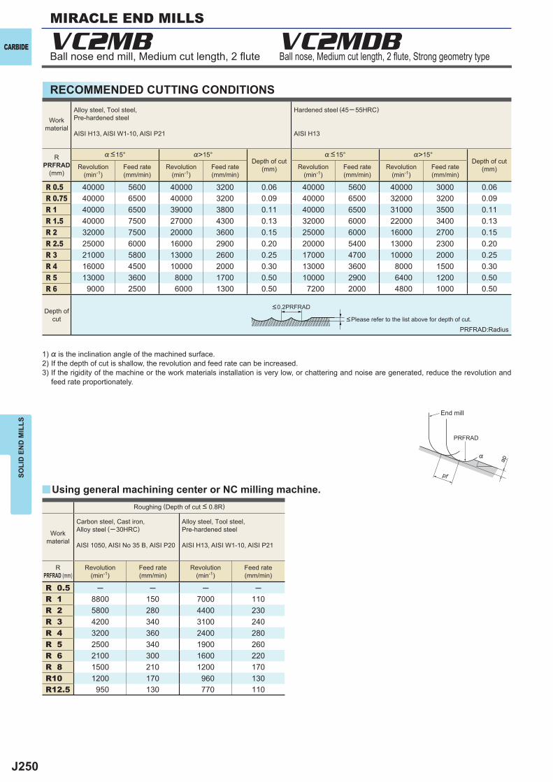
J250
VC2MB VC2MDB
%>15° %>15°
R 0.5 40000 5600 40000 3200 0.06 40000 5600 40000 3000 0.06R 0.75 40000 6500 40000 3200 0.09 40000 6500 32000 3200 0.09R 1 40000 6500 39000 3800 0.11 40000 6500 31000 3500 0.11R 1.5 40000 7500 27000 4300 0.13 32000 6000 22000 3400 0.13R 2 32000 7500 20000 3600 0.15 25000 6000 16000 2700 0.15R 2.5 25000 6000 16000 2900 0.20 20000 5400 13000 2300 0.20R 3 21000 5800 13000 2600 0.25 17000 4700 10000 2000 0.25R 4 16000 4500 10000 2000 0.30 13000 3600 8000 1500 0.30R 5 13000 3600 8000 1700 0.50 10000 2900 6400 1200 0.50R 6 9000 2500 6000 1300 0.50 7200 2000 4800 1000 0.50
R 0.5 ─ ─ ─ ─R 1 8800 150 7000 110R 2 5800 280 4400 230R 3 4200 340 3100 240R 4 3200 360 2400 280R 5 2500 340 1900 260R 6 2100 300 1600 220R 8 1500 210 1200 170R10 1200 170 960 130R12.5 950 130 770 110
yap
PRFRAD
pf
%
CARBIDE
SOLI
D E
ND
MIL
LSMIRACLE END MILLS
Ball nose, Medium cut length, 2 fl ute, Strong geometry type
RECOMMENDED CUTTING CONDITIONS
Depth ofcut
Workmaterial
Alloy steel, Tool steel,Pre-hardened steel
AISI H13, AISI W1-10, AISI P21
Hardened steel (45─ 55HRC)
AISI H13
RPRFRAD
(mm)
%<15°Depth of cut
(mm)
%<15°Depth of cut
(mm)Revolution(min-1)
Feed rate(mm/min)
Revolution(min-1)
Feed rate(mm/min)
Revolution(min-1)
Feed rate(mm/min)
Revolution(min-1)
Feed rate(mm/min)
Roughing (Depth of cut < 0.8R)
Workmaterial
Carbon steel, Cast iron, Alloy steel (─30HRC)
AISI 1050, AISI No 35 B, AISI P20
Alloy steel, Tool steel,Pre-hardened steel
AISI H13, AISI W1-10, AISI P21
RPRFRAD (mm)
Revolution(min-1)
Feed rate(mm/min)
Revolution(min-1)
Feed rate(mm/min)
<0.2PRFRAD
PRFRAD:Radius<Please refer to the list above for depth of cut.
1) % is the inclination angle of the machined surface. 2) If the depth of cut is shallow, the revolution and feed rate can be increased.3) If the rigidity of the machine or the work materials installation is very low, or chattering and noise are generated, reduce the revolution and
feed rate proportionately.
Using general machining center or NC milling machine.
End mill
Ball nose end mill, Medium cut length, 2 fl ute
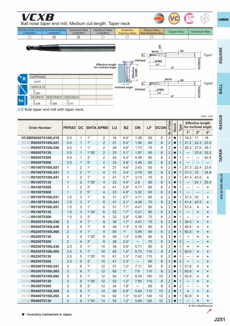
J251
a
u e e u u u
VCXB
PRFRAD DC BHTA APMX LU B2 DN LF DCON1° 2° 3°
VCXBR0050T0100L016 0.5 1 1° 2 16 6.6° 1.38 50 6 2 a 1 16.2 17 18VCXBR0050T0100L021 0.5 1 1° 2 21 5.4° 1.56 60 6 2 a 1 21.2 22.3 23.5VCXBR0050T0100L026 0.5 1 1° 2 26 4.6° 1.73 70 6 2 a 1 26.2 27.6 29.1VCXBR0050T0130 0.5 1 1°30' 2 23 5.1° 1.97 60 6 2 a 1 ─ 23.9 25.2VCXBR0050T0300 0.5 1 3° 2 42 3.4° 5.08 80 6 2 a 1 ─ ─ 42.4VCXBR0050T0500 0.5 1 5° 2 23 5.8° 4.46 60 6 2 a 1 ─ ─ ─VCXBR0100T0100L021 1 2 1° 4 21 4.6° 2.43 50 6 2 a 1 21.3 22.4 23.6VCXBR0100T0100L031 1 2 1° 4 31 3.4° 2.78 60 6 2 a 1 31.3 33 34.8VCXBR0100T0100L041 1 2 1° 4 41 2.7° 3.13 70 6 2 a 1 41.3 43.5VCXBR0100T0130 1 2 1°30' 4 23 4.4° 2.8 60 6 2 a 1 ─ 24.1 25.4VCXBR0100T0300 1 2 3° 4 41 2.9° 5.71 80 6 2 a 1 ─ ─VCXBR0100T0500 1 2 5° 4 23 4.9° 5.02 60 6 2 a 1 ─ ─ ─VCXBR0150T0100L031 1.5 3 1° 6 31 2.7° 3.71 60 6 2 a 1 31.4 33VCXBR0150T0100L041 1.5 3 1° 6 41 2.1° 4.06 70 6 2 a 1 41.4 43.5VCXBR0150T0100L051 1.5 3 1° 6 51 1.7° 4.41 80 6 2 a 1 51.4VCXBR0150T0130 1.5 3 1°30' 6 52 1.7° 5.21 90 6 2 a 1 ─VCXBR0150T0300 1.5 3 3° 6 32 2.8° 5.56 70 6 2 a 1 ─ ─VCXBR0200T0100L036 2 4 1° 8 36 1.7° 4.81 70 6 2 a 1 36.5VCXBR0200T0100L046 2 4 1° 8 46 1.3° 5.16 80 6 2 a 1 46.5VCXBR0200T0100L060 2 4 1° 8 60 1° 5.65 90 6 2 a 1 60.5VCXBR0200T0130 2 4 1°30' 8 49 1.3° 5.95 90 6 2 a 1 ─VCXBR0200T0300 2 4 3° 8 28 2.2° ─ 70 6 2 a 2 ─ ─VCXBR0250T0100L036 2.5 5 1° 10 36 0.9° 5.71 80 6 2 a 1VCXBR0250T0100L065 2.5 5 1° 10 65 1.4° 6.72 110 8 2 a 1 65.6VCXBR0250T0130 2.5 5 1°30' 10 61 1.5° 7.42 110 8 2 a 1 ─VCXBR0250T0300 2.5 5 3° 10 41 2.3° ─ 90 8 2 a 2 ─ ─VCXBR0300T0100L051 3 6 1° 12 51 1.2° 7.11 90 8 2 a 1 51.8VCXBR0300T0100L065 3 6 1° 12 65 1° 7.6 110 8 2 a 1 65.8VCXBR0300T0100L092 3 6 1° 12 92 1.3° 8.54 140 10 2 a 1 92.8VCXBR0300T0130 3 6 1°30' 12 53 1.2° 7.85 110 8 2 a 1 ─VCXBR0300T0300 3 6 3° 12 34 1.9° ─ 90 8 2 a 2 ─ ─VCXBR0400T0100L068 4 8 1° 14 68 0.9° 9.64 110 10 2 a 1VCXBR0400T0100L092 4 8 1° 14 92 1.3° 10.47 140 12 2 a 1 92.8VCXBR0400T0130 4 8 1°30' 14 55 1.2° 9.85 120 10 2 a 1 ─
±0.01
0- 0.020DCON=6 0- 0.008
0- 0.009
0- 0.011
UWC VC 30°
R
h6
APMX
DC
DC
ON
(h6)
APMX
LF
DC
DC
ON
(h6)
LF
PRFRAD
PRFRAD
B2
LU
BHTA
DN
B2
LU
BHTA
SOLI
D E
ND
MIL
LS
CARBIDE
SQU
AR
EB
ALL
RA
DIU
STA
PER
Unit : mm
Carbon Steel, Alloy Steel, Cast Iron(<30HRC)
Tool Steel, Pre-Hardened Steel,Hardened Steel(<45HRC)
Hardened Steel(<55HRC)
Hardened Steel(>55HRC)
AusteniticStainless Steel
Titanium Alloy,Heat Resistant Alloy Copper Alloy Aluminium Alloy
a : Inventory maintained in Japan.
2 fl ute taper end mill with taper neck.
* No interference
Effective lengthfor inclined angle
Inclined angle
Effe
ctiv
ele
ngth
Order Number
No. o
f Flut
esSt
ock
Type
Effective lengthfor inclined angle
*
*
*
**
**
**
**
**
**
*
**
**
**
**
*
**
*
*
**
*
***
***
****
8<DCON<10 12<DCON<16
0.5<PRFRAD<6
1<DC<12
Type1
Type2
Ball nose taper end mill, Medium cut length, Taper neck
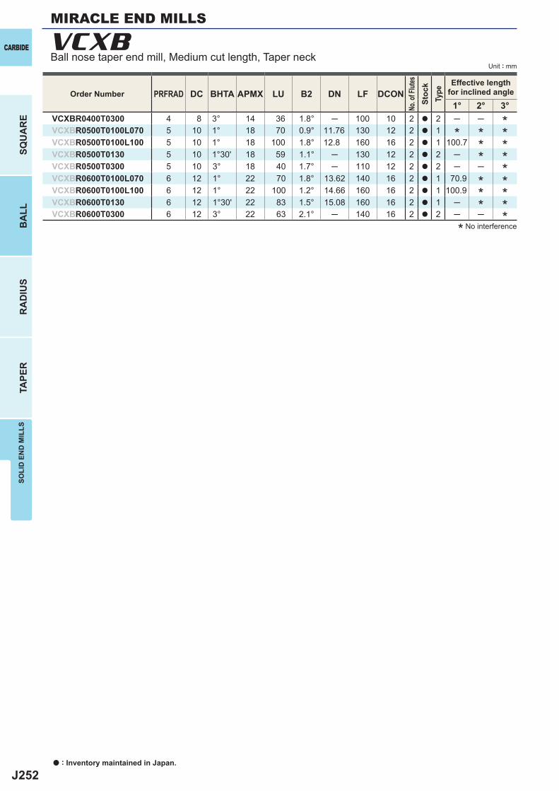
J252
PRFRAD DC BHTA APMX LU B2 DN LF DCON1° 2° 3°
VCXBR0400T0300 4 8 3° 14 36 1.8° ─ 100 10 2 a 2 ─ ─VCXBR0500T0100L070 5 10 1° 18 70 0.9° 11.76 130 12 2 a 1VCXBR0500T0100L100 5 10 1° 18 100 1.8° 12.8 160 16 2 a 1 100.7VCXBR0500T0130 5 10 1°30' 18 59 1.1° ─ 130 12 2 a 2 ─VCXBR0500T0300 5 10 3° 18 40 1.7° ─ 110 12 2 a 2 ─ ─VCXBR0600T0100L070 6 12 1° 22 70 1.8° 13.62 140 16 2 a 1 70.9VCXBR0600T0100L100 6 12 1° 22 100 1.2° 14.66 160 16 2 a 1 100.9VCXBR0600T0130 6 12 1°30' 22 83 1.5° 15.08 160 16 2 a 1 ─VCXBR0600T0300 6 12 3° 22 63 2.1° ─ 140 16 2 a 2 ─ ─
VCXBCARBIDE
SQU
AR
EB
ALL
RA
DIU
STA
PER
SOLI
D E
ND
MIL
LS
Unit : mm
Order Number
No. o
f Flut
esSt
ock
Type
Effective lengthfor inclined angle
* No interference
****
***
****
*****
MIRACLE END MILLS
Ball nose taper end mill, Medium cut length, Taper neck
a : Inventory maintained in Japan.
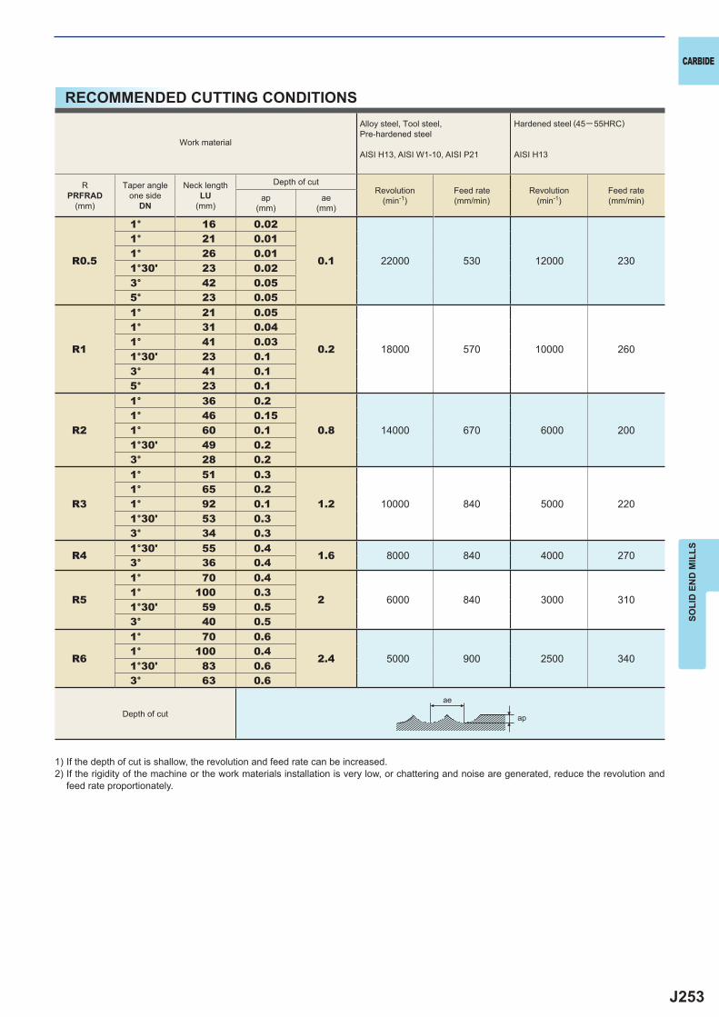
J253
R0.5
1° 16 0.02
0.1 22000 530 12000 230
1° 21 0.011° 26 0.011°30' 23 0.023° 42 0.055° 23 0.05
R1
1° 21 0.05
0.2 18000 570 10000 260
1° 31 0.041° 41 0.031°30' 23 0.13° 41 0.15° 23 0.1
R2
1° 36 0.2
0.8 14000 670 6000 2001° 46 0.151° 60 0.11°30' 49 0.23° 28 0.2
R3
1° 51 0.3
1.2 10000 840 5000 2201° 65 0.21° 92 0.11°30' 53 0.33° 34 0.3
R41°30' 55 0.4
1.6 8000 840 4000 2703° 36 0.4
R5
1° 70 0.4
2 6000 840 3000 3101° 100 0.31°30' 59 0.53° 40 0.5
R6
1° 70 0.6
2.4 5000 900 2500 3401° 100 0.41°30' 83 0.63° 63 0.6
ae
ap
CARBIDE
SOLI
D E
ND
MIL
LS
RECOMMENDED CUTTING CONDITIONS
1) If the depth of cut is shallow, the revolution and feed rate can be increased.2) If the rigidity of the machine or the work materials installation is very low, or chattering and noise are generated, reduce the revolution and
feed rate proportionately.
Work material
Alloy steel, Tool steel,Pre-hardened steel
AISI H13, AISI W1-10, AISI P21
Hardened steel (45─ 55HRC)
AISI H13
RPRFRAD
(mm)
Taper angleone side
DN
Neck lengthLU
(mm)
Depth of cutRevolution
(min-1)Feed rate(mm/min)
Revolution(min-1)
Feed rate(mm/min)ap
(mm)ae
(mm)
Depth of cut
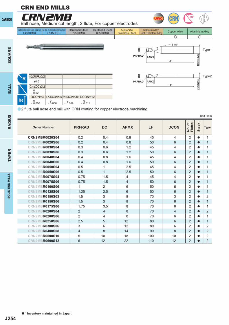
J254
e u
CRN2MB
PRFRAD DC APMX LF DCON
CRN2MBR0020S04 0.2 0.4 0.8 45 4 2 a 1CRN2MBR0020S06 0.2 0.4 0.8 50 6 2 a 1CRN2MBR0030S04 0.3 0.6 1.2 45 4 2 a 1CRN2MBR0030S06 0.3 0.6 1.2 50 6 2 a 1CRN2MBR0040S04 0.4 0.8 1.6 45 4 2 a 1CRN2MBR0040S06 0.4 0.8 1.6 50 6 2 a 1CRN2MBR0050S04 0.5 1 2.5 45 4 2 a 1CRN2MBR0050S06 0.5 1 2.5 50 6 2 a 1CRN2MBR0075S04 0.75 1.5 4 45 4 2 a 1CRN2MBR0075S06 0.75 1.5 4 50 6 2 a 1CRN2MBR0100S06 1 2 6 50 6 2 a 1CRN2MBR0125S06 1.25 2.5 6 50 6 2 a 1CRN2MBR0150S03 1.5 3 8 70 3 2 a 2CRN2MBR0150S06 1.5 3 8 70 6 2 a 1CRN2MBR0175S06 1.75 3.5 8 70 6 2 a 1CRN2MBR0200S04 2 4 8 70 4 2 a 2CRN2MBR0200S06 2 4 8 70 6 2 a 1CRN2MBR0250S06 2.5 5 12 80 6 2 a 1CRN2MBR0300S06 3 6 12 80 6 2 a 2CRN2MBR0400S08 4 8 14 90 8 2 a 2CRN2MBR0500S10 5 10 18 100 10 2 a 2CRN2MBR0600S12 6 12 22 110 12 2 a 2
a
±0.01
0- 0.02DCON=3 DCON=12 0- 0.006
0- 0.008
0- 0.009
0- 0.011
UWC CRN 30°
R
h6
APMX
DC
DC
ON
(h6)
15°
APMXLF
DC
DC
ON
(h6)
LF
PRFRAD
PRFRAD
CARBIDE
SQU
AR
EB
ALL
RA
DIU
STA
PER
SOLI
D E
ND
MIL
LS
Unit : mm
Carbon Steel, Alloy Steel, Cast Iron(<30HRC)
Tool Steel, Pre-Hardened Steel,Hardened Steel(<45HRC)
Hardened Steel(<55HRC)
Hardened Steel(>55HRC)
AusteniticStainless Steel
Titanium Alloy,Heat Resistant Alloy Copper Alloy Aluminium Alloy
2 fl ute ball nose end mill with CRN coating for copper electrode machining.
Ball nose, Medium cut length, 2 fl ute, For copper electrodes
Order Number
No.
of
Flut
es
Stoc
k
Type
4<DCON<6 8<DCON<10
0.2<PRFRAD<6
0.4<DC<12
Type1
Type2
CRN END MILLS
a : Inventory maintained in Japan.
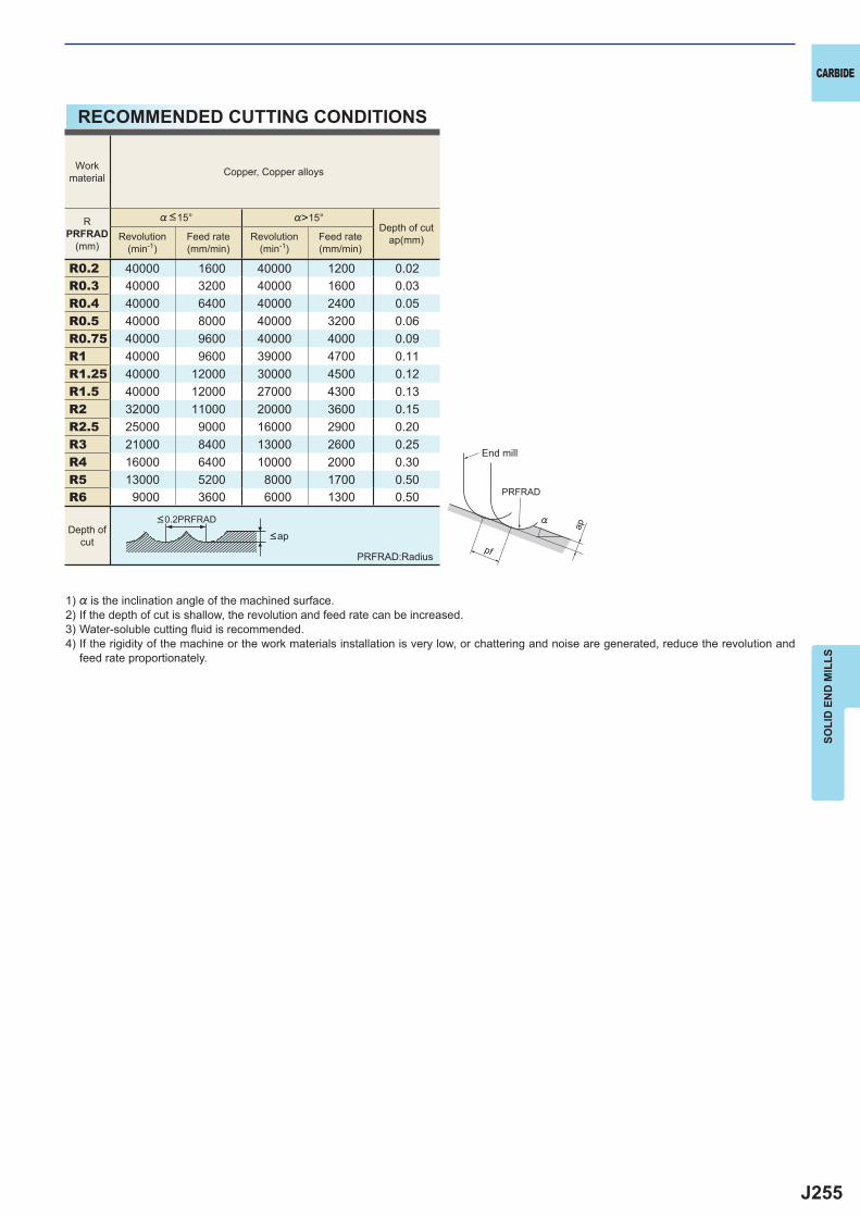
J255
R0.2 40000 1600 40000 1200 0.02R0.3 40000 3200 40000 1600 0.03R0.4 40000 6400 40000 2400 0.05R0.5 40000 8000 40000 3200 0.06R0.75 40000 9600 40000 4000 0.09R1 40000 9600 39000 4700 0.11R1.25 40000 12000 30000 4500 0.12R1.5 40000 12000 27000 4300 0.13R2 32000 11000 20000 3600 0.15R2.5 25000 9000 16000 2900 0.20R3 21000 8400 13000 2600 0.25R4 16000 6400 10000 2000 0.30R5 13000 5200 8000 1700 0.50R6 9000 3600 6000 1300 0.50
ap
PRFRAD
pf
%
CARBIDE
SOLI
D E
ND
MIL
LS
RECOMMENDED CUTTING CONDITIONS
1) % is the inclination angle of the machined surface. 2) If the depth of cut is shallow, the revolution and feed rate can be increased.3) Water-soluble cutting fl uid is recommended.4) If the rigidity of the machine or the work materials installation is very low, or chattering and noise are generated, reduce the revolution and
feed rate proportionately.
PRFRAD:Radius
<ap
<0.2PRFRAD
Workmaterial Copper, Copper alloys
RPRFRAD
(mm)
%<15° %>15°Depth of cut
ap(mm)Revolution(min-1)
Feed rate(mm/min)
Revolution(min-1)
Feed rate(mm/min)
Depth ofcut
End mill
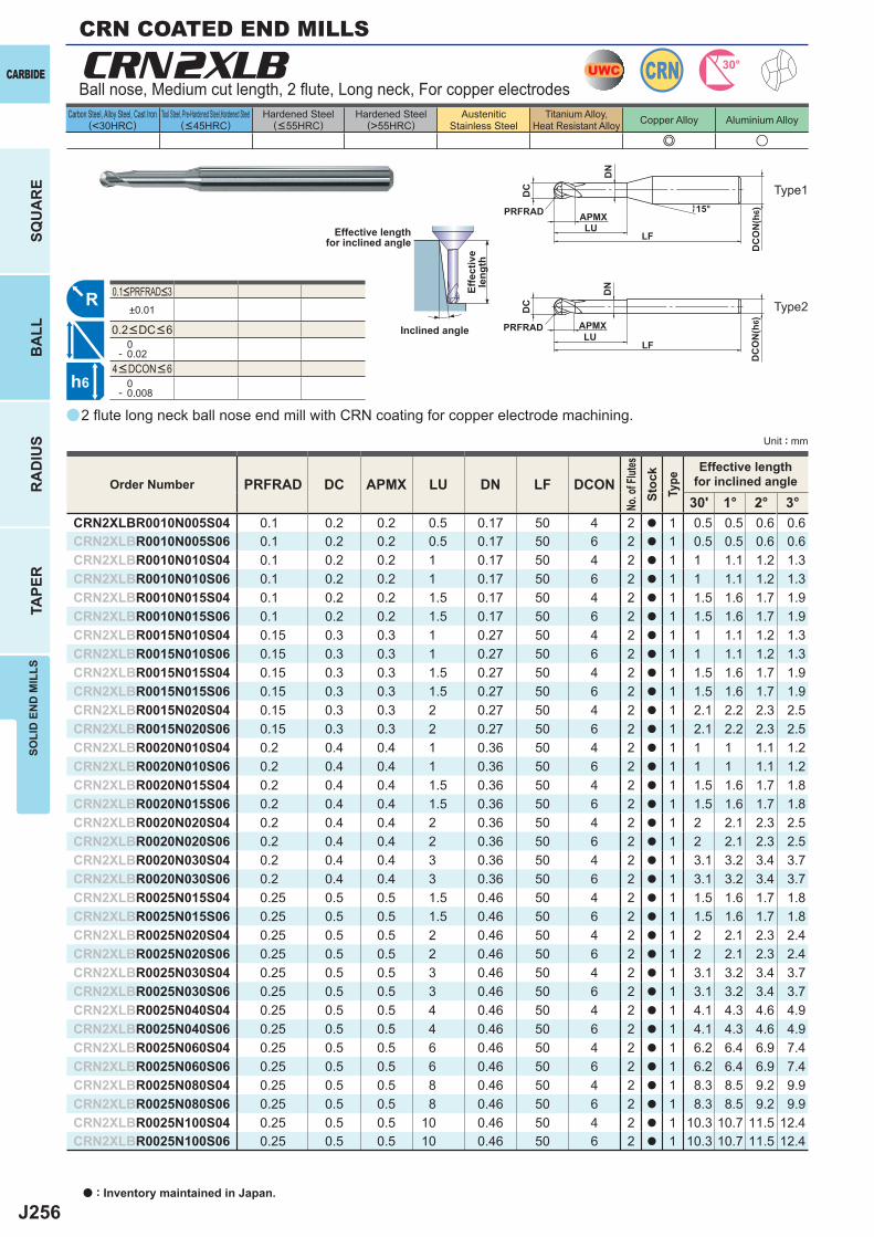
J256
a
e u
CRN2XLB
PRFRAD DC APMX LU DN LF DCON30' 1° 2° 3°
CRN2XLBR0010N005S04 0.1 0.2 0.2 0.5 0.17 50 4 2 a 1 0.5 0.5 0.6 0.6CRN2XLBR0010N005S06 0.1 0.2 0.2 0.5 0.17 50 6 2 a 1 0.5 0.5 0.6 0.6CRN2XLBR0010N010S04 0.1 0.2 0.2 1 0.17 50 4 2 a 1 1 1.1 1.2 1.3CRN2XLBR0010N010S06 0.1 0.2 0.2 1 0.17 50 6 2 a 1 1 1.1 1.2 1.3CRN2XLBR0010N015S04 0.1 0.2 0.2 1.5 0.17 50 4 2 a 1 1.5 1.6 1.7 1.9CRN2XLBR0010N015S06 0.1 0.2 0.2 1.5 0.17 50 6 2 a 1 1.5 1.6 1.7 1.9CRN2XLBR0015N010S04 0.15 0.3 0.3 1 0.27 50 4 2 a 1 1 1.1 1.2 1.3CRN2XLBR0015N010S06 0.15 0.3 0.3 1 0.27 50 6 2 a 1 1 1.1 1.2 1.3CRN2XLBR0015N015S04 0.15 0.3 0.3 1.5 0.27 50 4 2 a 1 1.5 1.6 1.7 1.9CRN2XLBR0015N015S06 0.15 0.3 0.3 1.5 0.27 50 6 2 a 1 1.5 1.6 1.7 1.9CRN2XLBR0015N020S04 0.15 0.3 0.3 2 0.27 50 4 2 a 1 2.1 2.2 2.3 2.5CRN2XLBR0015N020S06 0.15 0.3 0.3 2 0.27 50 6 2 a 1 2.1 2.2 2.3 2.5CRN2XLBR0020N010S04 0.2 0.4 0.4 1 0.36 50 4 2 a 1 1 1 1.1 1.2CRN2XLBR0020N010S06 0.2 0.4 0.4 1 0.36 50 6 2 a 1 1 1 1.1 1.2CRN2XLBR0020N015S04 0.2 0.4 0.4 1.5 0.36 50 4 2 a 1 1.5 1.6 1.7 1.8CRN2XLBR0020N015S06 0.2 0.4 0.4 1.5 0.36 50 6 2 a 1 1.5 1.6 1.7 1.8CRN2XLBR0020N020S04 0.2 0.4 0.4 2 0.36 50 4 2 a 1 2 2.1 2.3 2.5CRN2XLBR0020N020S06 0.2 0.4 0.4 2 0.36 50 6 2 a 1 2 2.1 2.3 2.5CRN2XLBR0020N030S04 0.2 0.4 0.4 3 0.36 50 4 2 a 1 3.1 3.2 3.4 3.7CRN2XLBR0020N030S06 0.2 0.4 0.4 3 0.36 50 6 2 a 1 3.1 3.2 3.4 3.7CRN2XLBR0025N015S04 0.25 0.5 0.5 1.5 0.46 50 4 2 a 1 1.5 1.6 1.7 1.8CRN2XLBR0025N015S06 0.25 0.5 0.5 1.5 0.46 50 6 2 a 1 1.5 1.6 1.7 1.8CRN2XLBR0025N020S04 0.25 0.5 0.5 2 0.46 50 4 2 a 1 2 2.1 2.3 2.4CRN2XLBR0025N020S06 0.25 0.5 0.5 2 0.46 50 6 2 a 1 2 2.1 2.3 2.4CRN2XLBR0025N030S04 0.25 0.5 0.5 3 0.46 50 4 2 a 1 3.1 3.2 3.4 3.7CRN2XLBR0025N030S06 0.25 0.5 0.5 3 0.46 50 6 2 a 1 3.1 3.2 3.4 3.7CRN2XLBR0025N040S04 0.25 0.5 0.5 4 0.46 50 4 2 a 1 4.1 4.3 4.6 4.9CRN2XLBR0025N040S06 0.25 0.5 0.5 4 0.46 50 6 2 a 1 4.1 4.3 4.6 4.9CRN2XLBR0025N060S04 0.25 0.5 0.5 6 0.46 50 4 2 a 1 6.2 6.4 6.9 7.4CRN2XLBR0025N060S06 0.25 0.5 0.5 6 0.46 50 6 2 a 1 6.2 6.4 6.9 7.4CRN2XLBR0025N080S04 0.25 0.5 0.5 8 0.46 50 4 2 a 1 8.3 8.5 9.2 9.9CRN2XLBR0025N080S06 0.25 0.5 0.5 8 0.46 50 6 2 a 1 8.3 8.5 9.2 9.9CRN2XLBR0025N100S04 0.25 0.5 0.5 10 0.46 50 4 2 a 1 10.3 10.7 11.5 12.4CRN2XLBR0025N100S06 0.25 0.5 0.5 10 0.46 50 6 2 a 1 10.3 10.7 11.5 12.4
±0.01
0- 0.02
0- 0.008
UWC CRN 30°
R
h6
APMX
DC
DC
ON
(h6)
LF
PRFRADLU
DN
15°
APMX
DC
DC
ON
(h6)
LF
PRFRADLU
DN
CARBIDE
SQU
AR
EB
ALL
RA
DIU
STA
PER
SOLI
D E
ND
MIL
LS
Unit : mm
Carbon Steel, Alloy Steel, Cast Iron(<30HRC)
Tool Steel, Pre-Hardened Steel,Hardened Steel(<45HRC)
Hardened Steel(<55HRC)
Hardened Steel(>55HRC)
AusteniticStainless Steel
Titanium Alloy,Heat Resistant Alloy Copper Alloy Aluminium Alloy
2 fl ute long neck ball nose end mill with CRN coating for copper electrode machining.
Ball nose, Medium cut length, 2 fl ute, Long neck, For copper electrodes
Effective lengthfor inclined angle
Inclined angle
Effe
ctiv
ele
ngth
Order Number
No. o
f Flut
esSt
ock
Type
Effective lengthfor inclined angle
4<DCON<6
0.1<PRFRAD<3
0.2<DC<6
Type1
Type2
a : Inventory maintained in Japan.
CRN COATED END MILLS
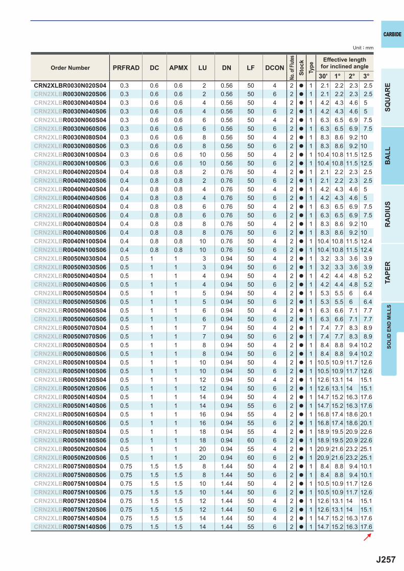
J257
PRFRAD DC APMX LU DN LF DCON30' 1° 2° 3°
CRN2XLBR0030N020S04 0.3 0.6 0.6 2 0.56 50 4 2 a 1 2.1 2.2 2.3 2.5CRN2XLBR0030N020S06 0.3 0.6 0.6 2 0.56 50 6 2 a 1 2.1 2.2 2.3 2.5CRN2XLBR0030N040S04 0.3 0.6 0.6 4 0.56 50 4 2 a 1 4.2 4.3 4.6 5CRN2XLBR0030N040S06 0.3 0.6 0.6 4 0.56 50 6 2 a 1 4.2 4.3 4.6 5CRN2XLBR0030N060S04 0.3 0.6 0.6 6 0.56 50 4 2 a 1 6.3 6.5 6.9 7.5CRN2XLBR0030N060S06 0.3 0.6 0.6 6 0.56 50 6 2 a 1 6.3 6.5 6.9 7.5CRN2XLBR0030N080S04 0.3 0.6 0.6 8 0.56 50 4 2 a 1 8.3 8.6 9.2 10CRN2XLBR0030N080S06 0.3 0.6 0.6 8 0.56 50 6 2 a 1 8.3 8.6 9.2 10CRN2XLBR0030N100S04 0.3 0.6 0.6 10 0.56 50 4 2 a 1 10.4 10.8 11.5 12.5CRN2XLBR0030N100S06 0.3 0.6 0.6 10 0.56 50 6 2 a 1 10.4 10.8 11.5 12.5CRN2XLBR0040N020S04 0.4 0.8 0.8 2 0.76 50 4 2 a 1 2.1 2.2 2.3 2.5CRN2XLBR0040N020S06 0.4 0.8 0.8 2 0.76 50 6 2 a 1 2.1 2.2 2.3 2.5CRN2XLBR0040N040S04 0.4 0.8 0.8 4 0.76 50 4 2 a 1 4.2 4.3 4.6 5CRN2XLBR0040N040S06 0.4 0.8 0.8 4 0.76 50 6 2 a 1 4.2 4.3 4.6 5CRN2XLBR0040N060S04 0.4 0.8 0.8 6 0.76 50 4 2 a 1 6.3 6.5 6.9 7.5CRN2XLBR0040N060S06 0.4 0.8 0.8 6 0.76 50 6 2 a 1 6.3 6.5 6.9 7.5CRN2XLBR0040N080S04 0.4 0.8 0.8 8 0.76 50 4 2 a 1 8.3 8.6 9.2 10CRN2XLBR0040N080S06 0.4 0.8 0.8 8 0.76 50 6 2 a 1 8.3 8.6 9.2 10CRN2XLBR0040N100S04 0.4 0.8 0.8 10 0.76 50 4 2 a 1 10.4 10.8 11.5 12.4CRN2XLBR0040N100S06 0.4 0.8 0.8 10 0.76 50 6 2 a 1 10.4 10.8 11.5 12.4CRN2XLBR0050N030S04 0.5 1 1 3 0.94 50 4 2 a 1 3.2 3.3 3.6 3.9CRN2XLBR0050N030S06 0.5 1 1 3 0.94 50 6 2 a 1 3.2 3.3 3.6 3.9CRN2XLBR0050N040S04 0.5 1 1 4 0.94 50 4 2 a 1 4.2 4.4 4.8 5.2CRN2XLBR0050N040S06 0.5 1 1 4 0.94 50 6 2 a 1 4.2 4.4 4.8 5.2CRN2XLBR0050N050S04 0.5 1 1 5 0.94 50 4 2 a 1 5.3 5.5 6 6.4CRN2XLBR0050N050S06 0.5 1 1 5 0.94 50 6 2 a 1 5.3 5.5 6 6.4CRN2XLBR0050N060S04 0.5 1 1 6 0.94 50 4 2 a 1 6.3 6.6 7.1 7.7CRN2XLBR0050N060S06 0.5 1 1 6 0.94 50 6 2 a 1 6.3 6.6 7.1 7.7CRN2XLBR0050N070S04 0.5 1 1 7 0.94 50 4 2 a 1 7.4 7.7 8.3 8.9CRN2XLBR0050N070S06 0.5 1 1 7 0.94 50 6 2 a 1 7.4 7.7 8.3 8.9CRN2XLBR0050N080S04 0.5 1 1 8 0.94 50 4 2 a 1 8.4 8.8 9.4 10.2CRN2XLBR0050N080S06 0.5 1 1 8 0.94 50 6 2 a 1 8.4 8.8 9.4 10.2CRN2XLBR0050N100S04 0.5 1 1 10 0.94 50 4 2 a 1 10.5 10.9 11.7 12.6CRN2XLBR0050N100S06 0.5 1 1 10 0.94 50 6 2 a 1 10.5 10.9 11.7 12.6CRN2XLBR0050N120S04 0.5 1 1 12 0.94 50 4 2 a 1 12.6 13.1 14 15.1CRN2XLBR0050N120S06 0.5 1 1 12 0.94 50 6 2 a 1 12.6 13.1 14 15.1CRN2XLBR0050N140S04 0.5 1 1 14 0.94 50 4 2 a 1 14.7 15.2 16.3 17.6CRN2XLBR0050N140S06 0.5 1 1 14 0.94 55 6 2 a 1 14.7 15.2 16.3 17.6CRN2XLBR0050N160S04 0.5 1 1 16 0.94 55 4 2 a 1 16.8 17.4 18.6 20.1CRN2XLBR0050N160S06 0.5 1 1 16 0.94 55 6 2 a 1 16.8 17.4 18.6 20.1CRN2XLBR0050N180S04 0.5 1 1 18 0.94 55 4 2 a 1 18.9 19.5 20.9 22.6CRN2XLBR0050N180S06 0.5 1 1 18 0.94 60 6 2 a 1 18.9 19.5 20.9 22.6CRN2XLBR0050N200S04 0.5 1 1 20 0.94 55 4 2 a 1 20.9 21.6 23.2 25.1CRN2XLBR0050N200S06 0.5 1 1 20 0.94 60 6 2 a 1 20.9 21.6 23.2 25.1CRN2XLBR0075N080S04 0.75 1.5 1.5 8 1.44 50 4 2 a 1 8.4 8.8 9.4 10.1CRN2XLBR0075N080S06 0.75 1.5 1.5 8 1.44 50 6 2 a 1 8.4 8.8 9.4 10.1CRN2XLBR0075N100S04 0.75 1.5 1.5 10 1.44 50 4 2 a 1 10.5 10.9 11.7 12.6CRN2XLBR0075N100S06 0.75 1.5 1.5 10 1.44 50 6 2 a 1 10.5 10.9 11.7 12.6CRN2XLBR0075N120S04 0.75 1.5 1.5 12 1.44 50 4 2 a 1 12.6 13.1 14 15.1CRN2XLBR0075N120S06 0.75 1.5 1.5 12 1.44 50 6 2 a 1 12.6 13.1 14 15.1CRN2XLBR0075N140S04 0.75 1.5 1.5 14 1.44 50 4 2 a 1 14.7 15.2 16.3 17.6CRN2XLBR0075N140S06 0.75 1.5 1.5 14 1.44 55 6 2 a 1 14.7 15.2 16.3 17.6
SOLI
D E
ND
MIL
LS
CARBIDE
SQU
AR
EB
ALL
RA
DIU
STA
PER
Unit : mm
Order Number
No. o
f Flut
esSt
ock
Type
Effective lengthfor inclined angle
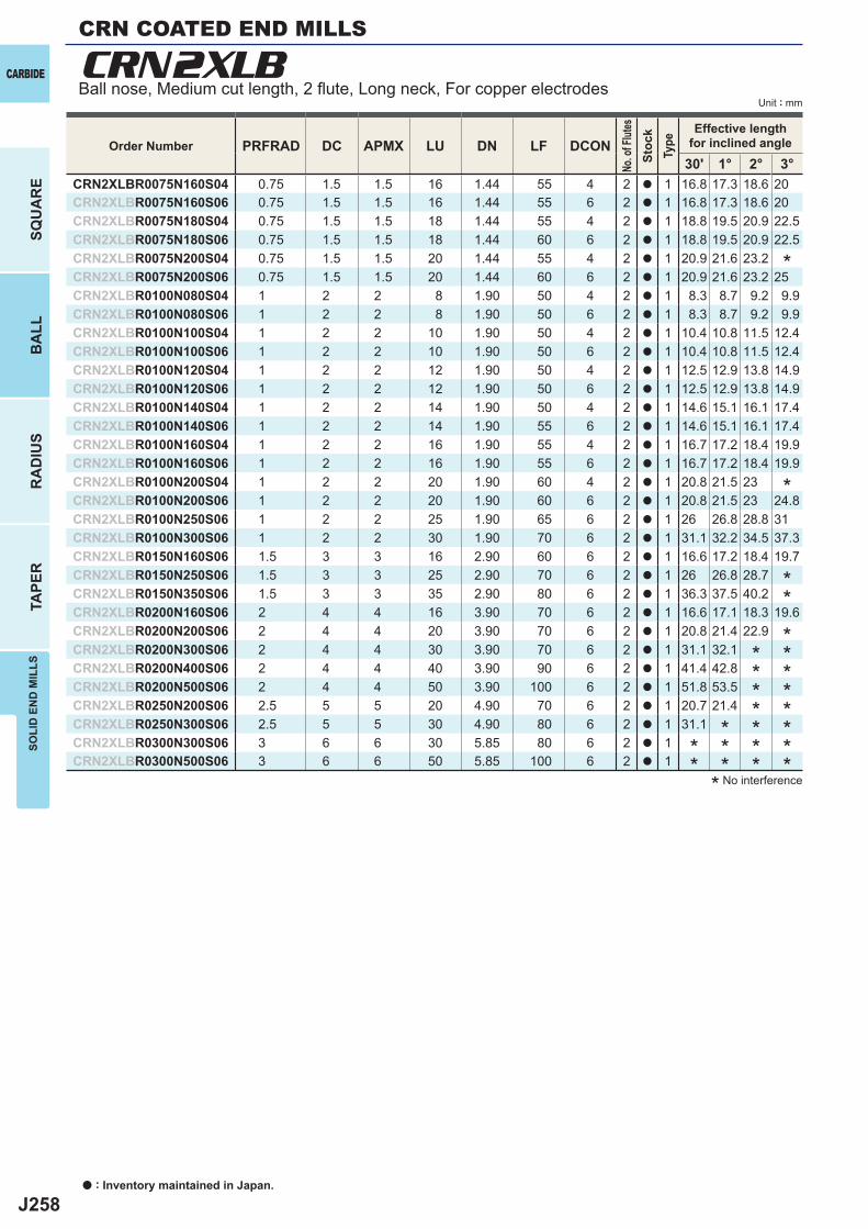
J258
PRFRAD DC APMX LU DN LF DCON30' 1° 2° 3°
CRN2XLBR0075N160S04 0.75 1.5 1.5 16 1.44 55 4 2 a 1 16.8 17.3 18.6 20CRN2XLBR0075N160S06 0.75 1.5 1.5 16 1.44 55 6 2 a 1 16.8 17.3 18.6 20CRN2XLBR0075N180S04 0.75 1.5 1.5 18 1.44 55 4 2 a 1 18.8 19.5 20.9 22.5CRN2XLBR0075N180S06 0.75 1.5 1.5 18 1.44 60 6 2 a 1 18.8 19.5 20.9 22.5CRN2XLBR0075N200S04 0.75 1.5 1.5 20 1.44 55 4 2 a 1 20.9 21.6 23.2CRN2XLBR0075N200S06 0.75 1.5 1.5 20 1.44 60 6 2 a 1 20.9 21.6 23.2 25CRN2XLBR0100N080S04 1 2 2 8 1.90 50 4 2 a 1 8.3 8.7 9.2 9.9CRN2XLBR0100N080S06 1 2 2 8 1.90 50 6 2 a 1 8.3 8.7 9.2 9.9CRN2XLBR0100N100S04 1 2 2 10 1.90 50 4 2 a 1 10.4 10.8 11.5 12.4CRN2XLBR0100N100S06 1 2 2 10 1.90 50 6 2 a 1 10.4 10.8 11.5 12.4CRN2XLBR0100N120S04 1 2 2 12 1.90 50 4 2 a 1 12.5 12.9 13.8 14.9CRN2XLBR0100N120S06 1 2 2 12 1.90 50 6 2 a 1 12.5 12.9 13.8 14.9CRN2XLBR0100N140S04 1 2 2 14 1.90 50 4 2 a 1 14.6 15.1 16.1 17.4CRN2XLBR0100N140S06 1 2 2 14 1.90 55 6 2 a 1 14.6 15.1 16.1 17.4CRN2XLBR0100N160S04 1 2 2 16 1.90 55 4 2 a 1 16.7 17.2 18.4 19.9CRN2XLBR0100N160S06 1 2 2 16 1.90 55 6 2 a 1 16.7 17.2 18.4 19.9CRN2XLBR0100N200S04 1 2 2 20 1.90 60 4 2 a 1 20.8 21.5 23CRN2XLBR0100N200S06 1 2 2 20 1.90 60 6 2 a 1 20.8 21.5 23 24.8CRN2XLBR0100N250S06 1 2 2 25 1.90 65 6 2 a 1 26 26.8 28.8 31CRN2XLBR0100N300S06 1 2 2 30 1.90 70 6 2 a 1 31.1 32.2 34.5 37.3CRN2XLBR0150N160S06 1.5 3 3 16 2.90 60 6 2 a 1 16.6 17.2 18.4 19.7CRN2XLBR0150N250S06 1.5 3 3 25 2.90 70 6 2 a 1 26 26.8 28.7CRN2XLBR0150N350S06 1.5 3 3 35 2.90 80 6 2 a 1 36.3 37.5 40.2CRN2XLBR0200N160S06 2 4 4 16 3.90 70 6 2 a 1 16.6 17.1 18.3 19.6CRN2XLBR0200N200S06 2 4 4 20 3.90 70 6 2 a 1 20.8 21.4 22.9CRN2XLBR0200N300S06 2 4 4 30 3.90 70 6 2 a 1 31.1 32.1CRN2XLBR0200N400S06 2 4 4 40 3.90 90 6 2 a 1 41.4 42.8CRN2XLBR0200N500S06 2 4 4 50 3.90 100 6 2 a 1 51.8 53.5CRN2XLBR0250N200S06 2.5 5 5 20 4.90 70 6 2 a 1 20.7 21.4CRN2XLBR0250N300S06 2.5 5 5 30 4.90 80 6 2 a 1 31.1CRN2XLBR0300N300S06 3 6 6 30 5.85 80 6 2 a 1CRN2XLBR0300N500S06 3 6 6 50 5.85 100 6 2 a 1
CRN2XLBCARBIDE
SQU
AR
EB
ALL
RA
DIU
STA
PER
SOLI
D E
ND
MIL
LS
Unit : mm
Order Number
No. o
f Flut
esSt
ock
Type
Effective lengthfor inclined angle
* No interference
*
**
********************
*
CRN COATED END MILLS
Ball nose, Medium cut length, 2 fl ute, Long neck, For copper electrodes
a : Inventory maintained in Japan.
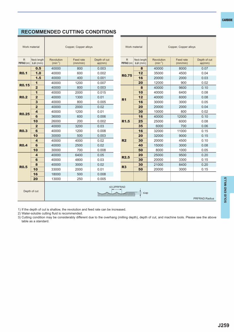
J259
R0.10.5 40000 800 0.003
R0.75
8 40000 8000 0.071.0 40000 600 0.002 12 35000 4500 0.041.5 40000 400 0.001 16 20000 2000 0.03
R0.151 40000 1200 0.007 20 12000 900 0.022 40000 800 0.003
R1
8 40000 9600 0.10
R0.21 40000 2000 0.015 10 40000 6400 0.082 40000 1300 0.01 12 40000 6000 0.083 40000 800 0.005 16 30000 3000 0.05
R0.25
2 40000 2000 0.02 20 20000 2000 0.044 40000 1200 0.01 30 10000 800 0.026 36000 600 0.006
R1.516 40000 12000 0.10
10 26000 200 0.002 25 25000 6000 0.08
R0.32 40000 3200 0.03 35 6000 700 0.066 40000 1200 0.008
R2
16 32000 11000 0.1510 30000 500 0.003 20 32000 9000 0.15
R0.44 40000 4000 0.02 30 20000 4500 0.106 40000 2500 0.02 40 15000 3000 0.08
10 30000 700 0.008 50 8000 1000 0.05
R0.5
4 40000 6400 0.05 R2.520 25000 9500 0.20
6 40000 4800 0.03 30 20000 3300 0.158 40000 3000 0.02
R330 21000 8400 0.20
10 33000 2000 0.01 50 20000 3000 0.1516 18000 500 0.00820 13000 250 0.005
CARBIDE
SOLI
D E
ND
MIL
LS
RECOMMENDED CUTTING CONDITIONS
1) If the depth of cut is shallow, the revolution and feed rate can be increased.2) Water-soluble cutting fl uid is recommended.3) Cutting condition may be considerably different due to the overhang (milling depth), depth of cut, and machine tools. Please see the above
table as a standard.
PRFRAD:Radius
<ap
<0.2PRFRAD
Depth of cut
Work material Copper, Copper alloys Work material Copper, Copper alloys
RPRFRAD (mm)
Neck lengthLU (mm)
Revolution(min-1)
Feed rate(mm/min)
Depth of cutap(mm)
RPRFRAD (mm)
Neck lengthLU (mm)
Revolution(min-1)
Feed rate(mm/min)
Depth of cutap(mm)
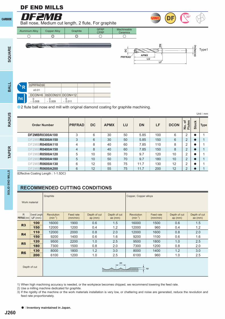
J260
a
u e e u u
DF2MB
PRFRAD DC APMX LU DN LF DCON
DF2MBR0300A100 3 6 30 50 5.85 100 6 2 a 1DF2MBR0300A150 3 6 30 50 5.85 150 6 2 a 1DF2MBR0400A110 4 8 40 60 7.85 110 8 2 a 1DF2MBR0400A150 4 8 40 60 7.85 150 8 2 a 1DF2MBR0500A120 5 10 50 70 9.7 120 10 2 a 1DF2MBR0500A180 5 10 50 70 9.7 180 10 2 a 1DF2MBR0600A130 6 12 55 75 11.7 130 12 2 a 1DF2MBR0600A200 6 12 55 75 11.7 200 12 2 a 1
±0.01
DCON=6 DCON=12 0- 0.008
0- 0.009
0- 0.011
R3100 16000 1900 0.6 1.5 16000 1500 0.6 1.5150 12000 1200 0.4 1.2 12000 960 0.4 1.2
R4110 12000 2000 0.8 2.0 12000 1600 0.8 2.0150 9200 1400 0.6 1.6 9200 1100 0.6 1.6
R5120 9500 2200 1.0 2.5 9500 1800 1.0 2.5180 7300 1500 0.8 2.0 7300 1200 0.8 2.0
R6 130 8000 1800 1.2 3.0 8000 1400 1.2 3.0200 6100 1200 1.0 2.5 6100 960 1.0 2.5
UWC DF 30°
R
h6
APMX
DC
DC
ON
(h6)
LF
PRFRADLU
DN
ap
ae
CARBIDE
SQU
AR
EB
ALL
RA
DIU
STA
PER
SOLI
D E
ND
MIL
LS
Unit : mm
Aluminium Alloy Copper Alloy Graphite GFRPCFRP
MachineableCeramics
Ball nose, Medium cut length, 2 fl ute, For graphite
2 fl ute ball nose end mill with original diamond coating for graphite machining.
(Effective Coating Length : 1-1.5DC)
Order Number
No.
of
Flut
es
Stoc
k
Type
8<DCON<10
3<PRFRAD<6
Type1
DF END MILLS
a : Inventory maintained in Japan.
RECOMMENDED CUTTING CONDITIONS
1) When high machining accuracy is needed, or the workpiece becomes chipped, we recommend lowering the feed rate.2) Use a milling machine dedicated for graphite.3) If the rigidity of the machine or the work materials installation is very low, or chattering and noise are generated, reduce the revolution and
feed rate proportionately.
Work material
Graphite Copper, Copper alloys
RPRFRAD (mm)
Overall LengthLF (mm)
Revolution(min-1)
Feed rate(mm/min)
Depth of cutap (mm)
Depth of cutae (mm)
Revolution(min-1)
Feed rate(mm/min)
Depth of cutap (mm)
Depth of cutae (mm)
Depth of cut
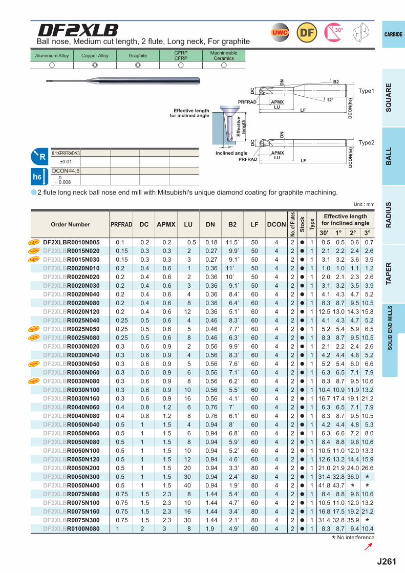
J261
a
DF2XLB
u e e u u
PRFRAD DC APMX LU DN B2 LF DCON30' 1° 2° 3°
DF2XLBR0010N005 0.1 0.2 0.2 0.5 0.18 11.5˚ 50 4 2 a 1 0.5 0.5 0.6 0.7DF2XLBR0015N020 0.15 0.3 0.3 2 0.27 9.9˚ 50 4 2 a 1 2.1 2.2 2.4 2.6DF2XLBR0015N030 0.15 0.3 0.3 3 0.27 9.1˚ 50 4 2 a 1 3.1 3.2 3.6 3.9DF2XLBR0020N010 0.2 0.4 0.6 1 0.36 11˚ 50 4 2 a 1 1.0 1.0 1.1 1.2DF2XLBR0020N020 0.2 0.4 0.6 2 0.36 10˚ 50 4 2 a 1 2.0 2.1 2.3 2.6DF2XLBR0020N030 0.2 0.4 0.6 3 0.36 9.1˚ 50 4 2 a 1 3.1 3.2 3.5 3.9DF2XLBR0020N040 0.2 0.4 0.6 4 0.36 8.4˚ 60 4 2 a 1 4.1 4.3 4.7 5.2DF2XLBR0020N080 0.2 0.4 0.6 8 0.36 6.4˚ 60 4 2 a 1 8.3 8.7 9.5 10.5DF2XLBR0020N120 0.2 0.4 0.6 12 0.36 5.1˚ 60 4 2 a 1 12.5 13.0 14.3 15.8DF2XLBR0025N040 0.25 0.5 0.6 4 0.46 8.3˚ 60 4 2 a 1 4.1 4.3 4.7 5.2DF2XLBR0025N050 0.25 0.5 0.6 5 0.46 7.7˚ 60 4 2 a 1 5.2 5.4 5.9 6.5DF2XLBR0025N080 0.25 0.5 0.6 8 0.46 6.3˚ 60 4 2 a 1 8.3 8.7 9.5 10.5DF2XLBR0030N020 0.3 0.6 0.9 2 0.56 9.9˚ 60 4 2 a 1 2.1 2.2 2.4 2.6DF2XLBR0030N040 0.3 0.6 0.9 4 0.56 8.3˚ 60 4 2 a 1 4.2 4.4 4.8 5.2DF2XLBR0030N050 0.3 0.6 0.9 5 0.56 7.6˚ 60 4 2 a 1 5.2 5.4 6.0 6.6DF2XLBR0030N060 0.3 0.6 0.9 6 0.56 7.1˚ 60 4 2 a 1 6.3 6.5 7.1 7.9DF2XLBR0030N080 0.3 0.6 0.9 8 0.56 6.2˚ 60 4 2 a 1 8.3 8.7 9.5 10.6DF2XLBR0030N100 0.3 0.6 0.9 10 0.56 5.5˚ 60 4 2 a 1 10.4 10.9 11.9 13.2DF2XLBR0030N160 0.3 0.6 0.9 16 0.56 4.1˚ 60 4 2 a 1 16.7 17.4 19.1 21.2DF2XLBR0040N060 0.4 0.8 1.2 6 0.76 7˚ 60 4 2 a 1 6.3 6.5 7.1 7.9DF2XLBR0040N080 0.4 0.8 1.2 8 0.76 6.1˚ 60 4 2 a 1 8.3 8.7 9.5 10.5DF2XLBR0050N040 0.5 1 1.5 4 0.94 8˚ 60 4 2 a 1 4.2 4.4 4.8 5.3DF2XLBR0050N060 0.5 1 1.5 6 0.94 6.8˚ 60 4 2 a 1 6.3 6.6 7.2 8.0DF2XLBR0050N080 0.5 1 1.5 8 0.94 5.9˚ 60 4 2 a 1 8.4 8.8 9.6 10.6DF2XLBR0050N100 0.5 1 1.5 10 0.94 5.2˚ 60 4 2 a 1 10.5 11.0 12.0 13.3DF2XLBR0050N120 0.5 1 1.5 12 0.94 4.6˚ 60 4 2 a 1 12.6 13.2 14.4 15.9DF2XLBR0050N200 0.5 1 1.5 20 0.94 3.3˚ 80 4 2 a 1 21.0 21.9 24.0 26.6DF2XLBR0050N300 0.5 1 1.5 30 0.94 2.4˚ 80 4 2 a 1 31.4 32.8 36.0DF2XLBR0050N400 0.5 1 1.5 40 0.94 1.9˚ 80 4 2 a 1 41.8 43.7DF2XLBR0075N080 0.75 1.5 2.3 8 1.44 5.4˚ 60 4 2 a 1 8.4 8.8 9.6 10.6DF2XLBR0075N100 0.75 1.5 2.3 10 1.44 4.7˚ 60 4 2 a 1 10.5 11.0 12.0 13.2DF2XLBR0075N160 0.75 1.5 2.3 16 1.44 3.4˚ 80 4 2 a 1 16.8 17.5 19.2 21.2DF2XLBR0075N300 0.75 1.5 2.3 30 1.44 2.1˚ 80 4 2 a 1 31.4 32.8 35.9DF2XLBR0100N080 1 2 3 8 1.9 4.9˚ 60 4 2 a 1 8.3 8.7 9.4 10.4
±0.01
DCON=4,6 0- 0.008
UWC DF 30°
R
h6
APMX
DC
DC
ON
(h6)
LF
PRFRADLU
DN
12°
APMX
DC
DC
ON
(h6)
LFPRFRAD LU
DN
B2
SOLI
D E
ND
MIL
LS
CARBIDE
SQU
AR
EB
ALL
RA
DIU
STA
PER
Unit : mm
Aluminium Alloy Copper Alloy Graphite GFRPCFRP
MachineableCeramics
Ball nose, Medium cut length, 2 fl ute, Long neck, For graphite
2 fl ute long neck ball nose end mill with Mitsubishi's unique diamond coating for graphite machining.
* No interference
Effective lengthfor inclined angle
Inclined angle
Effe
ctiv
ele
ngth
Order Number
No. o
f Flut
esSt
ock
Type
Effective lengthfor inclined angle
***
*
0.1<PRFRAD<3
Type1
Type2
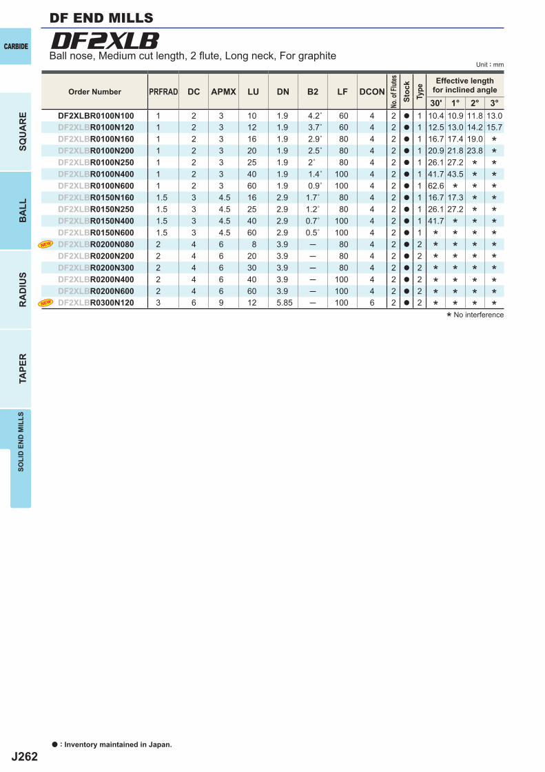
J262
PRFRAD DC APMX LU DN B2 LF DCON30' 1° 2° 3°
DF2XLBR0100N100 1 2 3 10 1.9 4.2˚ 60 4 2 a 1 10.4 10.9 11.8 13.0DF2XLBR0100N120 1 2 3 12 1.9 3.7˚ 60 4 2 a 1 12.5 13.0 14.2 15.7DF2XLBR0100N160 1 2 3 16 1.9 2.9˚ 80 4 2 a 1 16.7 17.4 19.0DF2XLBR0100N200 1 2 3 20 1.9 2.5˚ 80 4 2 a 1 20.9 21.8 23.8DF2XLBR0100N250 1 2 3 25 1.9 2˚ 80 4 2 a 1 26.1 27.2DF2XLBR0100N400 1 2 3 40 1.9 1.4˚ 100 4 2 a 1 41.7 43.5DF2XLBR0100N600 1 2 3 60 1.9 0.9˚ 100 4 2 a 1 62.6DF2XLBR0150N160 1.5 3 4.5 16 2.9 1.7˚ 80 4 2 a 1 16.7 17.3DF2XLBR0150N250 1.5 3 4.5 25 2.9 1.2˚ 80 4 2 a 1 26.1 27.2DF2XLBR0150N400 1.5 3 4.5 40 2.9 0.7˚ 100 4 2 a 1 41.7DF2XLBR0150N600 1.5 3 4.5 60 2.9 0.5˚ 100 4 2 a 1DF2XLBR0200N080 2 4 6 8 3.9 ─ 80 4 2 a 2DF2XLBR0200N200 2 4 6 20 3.9 ─ 80 4 2 a 2DF2XLBR0200N300 2 4 6 30 3.9 ─ 80 4 2 a 2DF2XLBR0200N400 2 4 6 40 3.9 ─ 100 4 2 a 2DF2XLBR0200N600 2 4 6 60 3.9 ─ 100 4 2 a 2DF2XLBR0300N120 3 6 9 12 5.85 ─ 100 6 2 a 2
DF2XLBCARBIDE
SQU
AR
EB
ALL
RA
DIU
STA
PER
SOLI
D E
ND
MIL
LS
Unit : mm
Order Number
No. o
f Flut
esSt
ock
Type
Effective lengthfor inclined angle
* No interference
Ball nose, Medium cut length, 2 fl ute, Long neck, For graphite
DF END MILLS
a : Inventory maintained in Japan.
************
*****
*
***
*
*
*
****
*
*************
*
*
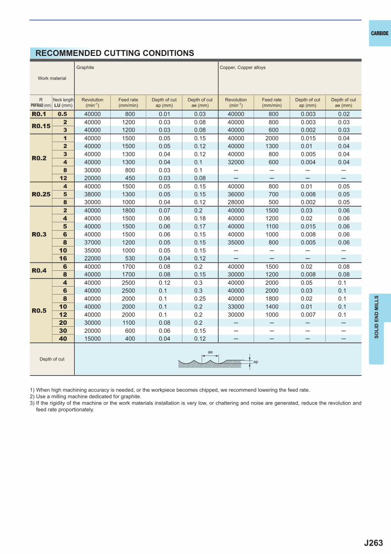
J263
R0.1 0.5 40000 800 0.01 0.03 40000 800 0.003 0.02
R0.15 2 40000 1200 0.03 0.08 40000 800 0.003 0.033 40000 1200 0.03 0.08 40000 600 0.002 0.03
R0.2
1 40000 1500 0.05 0.15 40000 2000 0.015 0.042 40000 1500 0.05 0.12 40000 1300 0.01 0.043 40000 1300 0.04 0.12 40000 800 0.005 0.044 40000 1300 0.04 0.1 32000 600 0.004 0.048 30000 800 0.03 0.1 ─ ─ ─ ─
12 20000 450 0.03 0.08 ─ ─ ─ ─
R0.254 40000 1500 0.05 0.15 40000 800 0.01 0.055 38000 1300 0.05 0.15 36000 700 0.008 0.058 30000 1000 0.04 0.12 28000 500 0.002 0.05
R0.3
2 40000 1800 0.07 0.2 40000 1500 0.03 0.064 40000 1500 0.06 0.18 40000 1200 0.02 0.065 40000 1500 0.06 0.17 40000 1100 0.015 0.066 40000 1500 0.06 0.15 40000 1000 0.008 0.068 37000 1200 0.05 0.15 35000 800 0.005 0.06
10 35000 1000 0.05 0.15 ─ ─ ─ ─16 22000 530 0.04 0.12 ─ ─ ─ ─
R0.4 6 40000 1700 0.08 0.2 40000 1500 0.02 0.088 40000 1700 0.08 0.15 30000 1200 0.008 0.08
R0.5
4 40000 2500 0.12 0.3 40000 2000 0.05 0.16 40000 2500 0.1 0.3 40000 2000 0.03 0.18 40000 2000 0.1 0.25 40000 1800 0.02 0.1
10 40000 2000 0.1 0.2 33000 1400 0.01 0.112 40000 2000 0.1 0.2 30000 1000 0.007 0.120 30000 1100 0.08 0.2 ─ ─ ─ ─30 20000 600 0.06 0.15 ─ ─ ─ ─40 15000 400 0.04 0.12 ─ ─ ─ ─
ap
ae
CARBIDE
SOLI
D E
ND
MIL
LS
RECOMMENDED CUTTING CONDITIONS
1) When high machining accuracy is needed, or the workpiece becomes chipped, we recommend lowering the feed rate.2) Use a milling machine dedicated for graphite.3) If the rigidity of the machine or the work materials installation is very low, or chattering and noise are generated, reduce the revolution and
feed rate proportionately.
Work material
Graphite Copper, Copper alloys
RPRFRAD (mm)
Neck lengthLU (mm)
Revolution(min-1)
Feed rate(mm/min)
Depth of cutap (mm)
Depth of cutae (mm)
Revolution(min-1)
Feed rate(mm/min)
Depth of cutap (mm)
Depth of cutae (mm)
Depth of cut
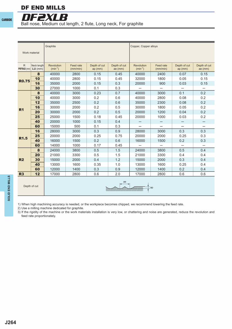
J264
R0.75
8 40000 2800 0.15 0.45 40000 2400 0.07 0.1510 40000 2800 0.15 0.45 32000 1800 0.05 0.1516 35000 2000 0.15 0.3 20000 900 0.03 0.1530 27000 1000 0.1 0.3 ─ ─ ─ ─
R1
8 40000 3000 0.23 0.7 40000 3000 0.1 0.210 40000 3000 0.2 0.6 40000 2800 0.08 0.212 35000 2500 0.2 0.6 35000 2300 0.08 0.216 30000 2000 0.2 0.5 30000 1800 0.05 0.220 30000 2000 0.2 0.5 20000 1200 0.04 0.225 25000 1500 0.18 0.45 20000 1000 0.03 0.240 20000 1000 0.15 0.4 ─ ─ ─ ─60 15000 500 0.1 0.3 ─ ─ ─ ─
R1.5
16 28000 3000 0.3 0.9 28000 3000 0.3 0.325 20000 2000 0.25 0.75 20000 2000 0.25 0.340 16000 1500 0.2 0.6 16000 1500 0.2 0.360 14000 1000 0.17 0.45 ─ ─ ─ ─
R2
8 24000 3800 0.5 1.5 24000 3800 0.5 0.420 21000 3300 0.5 1.5 21000 3300 0.4 0.430 15000 2000 0.4 1.2 15000 2000 0.3 0.440 13000 1600 0.35 1.0 13000 1600 0.25 0.460 12000 1400 0.3 0.9 12000 1400 0.2 0.4
R3 12 17000 2800 0.6 2.0 17000 2800 0.6 0.6
DF2XLB
ap
ae
CARBIDE
SOLI
D E
ND
MIL
LS
Work material
Graphite Copper, Copper alloys
RPRFRAD (mm)
Neck lengthLU (mm)
Revolution(min-1)
Feed rate(mm/min)
Depth of cutap (mm)
Depth of cutae (mm)
Revolution(min-1)
Feed rate(mm/min)
Depth of cutap (mm)
Depth of cutae (mm)
Depth of cut
Ball nose, Medium cut length, 2 fl ute, Long neck, For graphite
DF END MILLS
1) When high machining accuracy is needed, or the workpiece becomes chipped, we recommend lowering the feed rate.2) Use a milling machine dedicated for graphite.3) If the rigidity of the machine or the work materials installation is very low, or chattering and noise are generated, reduce the revolution and
feed rate proportionately.

J265
a
DLC2MB
PRFRAD DC APMX LF DCON
DLC2MBR0010 0.1 0.2 0.4 40 4 2 a 1DLC2MBR0015 0.15 0.3 0.6 40 4 2 a 1DLC2MBR0020 0.2 0.4 0.8 40 4 2 a 1DLC2MBR0025 0.25 0.5 1 40 4 2 a 1DLC2MBR0030 0.3 0.6 1.2 40 4 2 a 1DLC2MBR0040 0.4 0.8 1.6 40 4 2 a 1DLC2MBR0050 0.5 1 2.5 40 4 2 a 1DLC2MBR0075 0.75 1.5 4 40 4 2 a 1DLC2MBR0100 1 2 6 60 6 2 a 1DLC2MBR0125 1.25 2.5 6 60 6 2 a 1DLC2MBR0150 1.5 3 8 70 6 2 a 1DLC2MBR0200 2 4 8 70 6 2 a 1DLC2MBR0250 2.5 5 12 80 6 2 a 1DLC2MBR0300 3 6 12 80 6 2 a 2DLC2MBR0400 4 8 14 90 8 2 a 2DLC2MBR0500 5 10 18 100 10 2 a 2DLC2MBR0600 6 12 22 110 12 2 a 2DLC2MBR0800 8 16 30 140 16 2 a 2DLC2MBR1000 10 20 38 160 20 2 a 2
u e u u
PRFRAD>6±0.01 ±0.02
DC>12 0- 0.020
0- 0.030
DCON=20 0- 0.008
0- 0.009
0- 0.011
0- 0.013
UWC DLC 30°
R
h6
APMX
DC
DCO
N(h6
)
LF
PRFRAD
15°
APMX
DC
DCO
N(h6
)
LFPRFRAD
SOLI
D E
ND
MIL
LS
CARBIDE
SQU
AR
EB
ALL
RA
DIU
STA
PER
Unit : mm
Copper Alloy Aluminium Alloy Graphite GFRPCFRP
MachineableCeramics
Ball nose, Medium cut length, 2 fl ute
2 fl ute ball nose end mill with new high welding resistance DLC coating, ideal for machining non-ferrous materials.
Type2
Type1
Order Number
No.
of
Flut
es
Stoc
k
Type
4<DCON<6 8<DCON<10 12<DCON<16
PRFRAD<6
DC<12
DLC END MILLS
a : Inventory maintained in Japan.
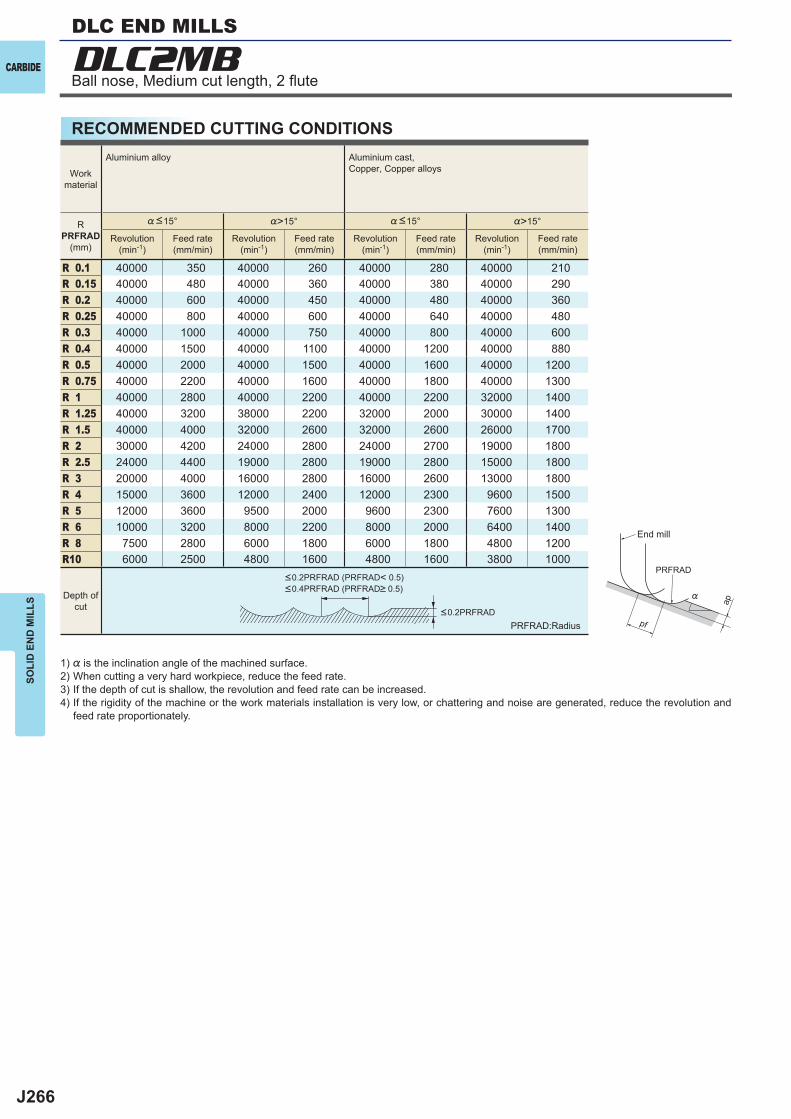
J266
%>15° %>15°
R 0.1 40000 350 40000 260 40000 280 40000 210R 0.15 40000 480 40000 360 40000 380 40000 290R 0.2 40000 600 40000 450 40000 480 40000 360R 0.25 40000 800 40000 600 40000 640 40000 480R 0.3 40000 1000 40000 750 40000 800 40000 600R 0.4 40000 1500 40000 1100 40000 1200 40000 880R 0.5 40000 2000 40000 1500 40000 1600 40000 1200R 0.75 40000 2200 40000 1600 40000 1800 40000 1300R 1 40000 2800 40000 2200 40000 2200 32000 1400R 1.25 40000 3200 38000 2200 32000 2000 30000 1400R 1.5 40000 4000 32000 2600 32000 2600 26000 1700R 2 30000 4200 24000 2800 24000 2700 19000 1800R 2.5 24000 4400 19000 2800 19000 2800 15000 1800R 3 20000 4000 16000 2800 16000 2600 13000 1800R 4 15000 3600 12000 2400 12000 2300 9600 1500R 5 12000 3600 9500 2000 9600 2300 7600 1300R 6 10000 3200 8000 2200 8000 2000 6400 1400R 8 7500 2800 6000 1800 6000 1800 4800 1200R10 6000 2500 4800 1600 4800 1600 3800 1000
DLC2MB
ap
PRFRAD
pf
%
CARBIDE
SOLI
D E
ND
MIL
LS
RECOMMENDED CUTTING CONDITIONS
1) % is the inclination angle of the machined surface. 2) When cutting a very hard workpiece, reduce the feed rate.3) If the depth of cut is shallow, the revolution and feed rate can be increased.4) If the rigidity of the machine or the work materials installation is very low, or chattering and noise are generated, reduce the revolution and
feed rate proportionately.
PRFRAD:Radius<0.2PRFRAD
<0.2PRFRAD (PRFRAD< 0.5)<0.4PRFRAD (PRFRAD> 0.5)
Depth ofcut
Workmaterial
Aluminium alloy Aluminium cast, Copper, Copper alloys
RPRFRAD
(mm)
%<15° %<15°
Revolution(min-1)
Feed rate(mm/min)
Revolution(min-1)
Feed rate(mm/min)
Revolution(min-1)
Feed rate(mm/min)
Revolution(min-1)
Feed rate(mm/min)
End mill
Ball nose, Medium cut length, 2 fl ute
DLC END MILLS
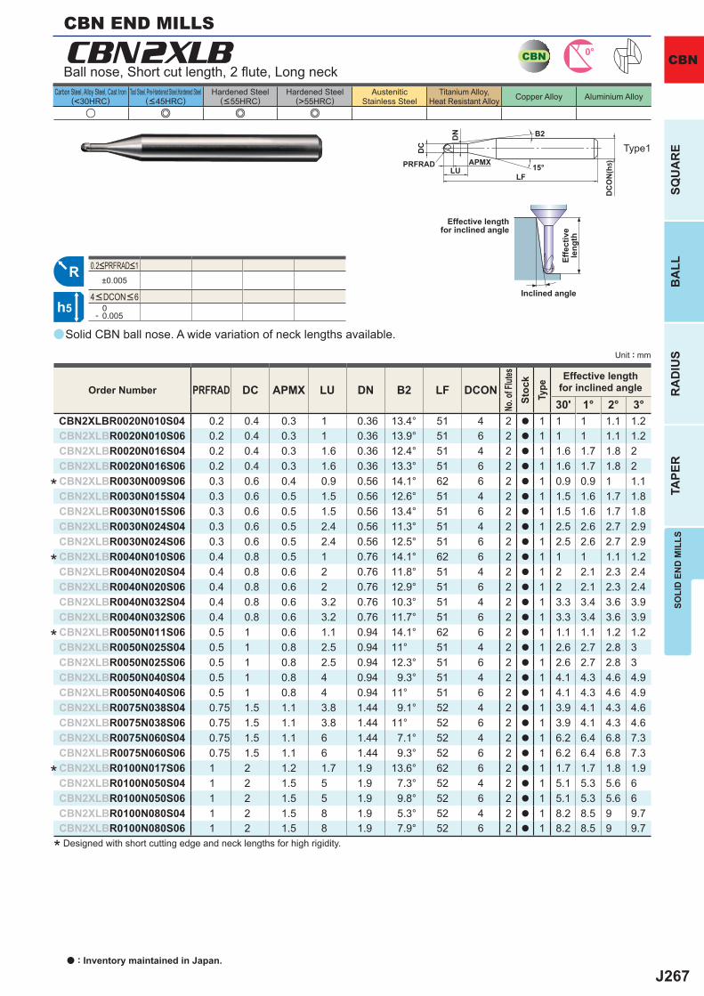
J267
a
u e e e
CBN2XLB
PRFRAD DC APMX LU DN B2 LF DCON30' 1° 2° 3°
CBN2XLBR0020N010S04 0.2 0.4 0.3 1 0.36 13.4° 51 4 2 a 1 1 1 1.1 1.2CBN2XLBR0020N010S06 0.2 0.4 0.3 1 0.36 13.9° 51 6 2 a 1 1 1 1.1 1.2CBN2XLBR0020N016S04 0.2 0.4 0.3 1.6 0.36 12.4° 51 4 2 a 1 1.6 1.7 1.8 2CBN2XLBR0020N016S06 0.2 0.4 0.3 1.6 0.36 13.3° 51 6 2 a 1 1.6 1.7 1.8 2
CBN2XLBR0030N009S06 0.3 0.6 0.4 0.9 0.56 14.1° 62 6 2 a 1 0.9 0.9 1 1.1CBN2XLBR0030N015S04 0.3 0.6 0.5 1.5 0.56 12.6° 51 4 2 a 1 1.5 1.6 1.7 1.8CBN2XLBR0030N015S06 0.3 0.6 0.5 1.5 0.56 13.4° 51 6 2 a 1 1.5 1.6 1.7 1.8CBN2XLBR0030N024S04 0.3 0.6 0.5 2.4 0.56 11.3° 51 4 2 a 1 2.5 2.6 2.7 2.9CBN2XLBR0030N024S06 0.3 0.6 0.5 2.4 0.56 12.5° 51 6 2 a 1 2.5 2.6 2.7 2.9
CBN2XLBR0040N010S06 0.4 0.8 0.5 1 0.76 14.1° 62 6 2 a 1 1 1 1.1 1.2CBN2XLBR0040N020S04 0.4 0.8 0.6 2 0.76 11.8° 51 4 2 a 1 2 2.1 2.3 2.4CBN2XLBR0040N020S06 0.4 0.8 0.6 2 0.76 12.9° 51 6 2 a 1 2 2.1 2.3 2.4CBN2XLBR0040N032S04 0.4 0.8 0.6 3.2 0.76 10.3° 51 4 2 a 1 3.3 3.4 3.6 3.9CBN2XLBR0040N032S06 0.4 0.8 0.6 3.2 0.76 11.7° 51 6 2 a 1 3.3 3.4 3.6 3.9
CBN2XLBR0050N011S06 0.5 1 0.6 1.1 0.94 14.1° 62 6 2 a 1 1.1 1.1 1.2 1.2CBN2XLBR0050N025S04 0.5 1 0.8 2.5 0.94 11° 51 4 2 a 1 2.6 2.7 2.8 3CBN2XLBR0050N025S06 0.5 1 0.8 2.5 0.94 12.3° 51 6 2 a 1 2.6 2.7 2.8 3CBN2XLBR0050N040S04 0.5 1 0.8 4 0.94 9.3° 51 4 2 a 1 4.1 4.3 4.6 4.9CBN2XLBR0050N040S06 0.5 1 0.8 4 0.94 11° 51 6 2 a 1 4.1 4.3 4.6 4.9CBN2XLBR0075N038S04 0.75 1.5 1.1 3.8 1.44 9.1° 52 4 2 a 1 3.9 4.1 4.3 4.6CBN2XLBR0075N038S06 0.75 1.5 1.1 3.8 1.44 11° 52 6 2 a 1 3.9 4.1 4.3 4.6CBN2XLBR0075N060S04 0.75 1.5 1.1 6 1.44 7.1° 52 4 2 a 1 6.2 6.4 6.8 7.3CBN2XLBR0075N060S06 0.75 1.5 1.1 6 1.44 9.3° 52 6 2 a 1 6.2 6.4 6.8 7.3
CBN2XLBR0100N017S06 1 2 1.2 1.7 1.9 13.6° 62 6 2 a 1 1.7 1.7 1.8 1.9CBN2XLBR0100N050S04 1 2 1.5 5 1.9 7.3° 52 4 2 a 1 5.1 5.3 5.6 6CBN2XLBR0100N050S06 1 2 1.5 5 1.9 9.8° 52 6 2 a 1 5.1 5.3 5.6 6CBN2XLBR0100N080S04 1 2 1.5 8 1.9 5.3° 52 4 2 a 1 8.2 8.5 9 9.7CBN2XLBR0100N080S06 1 2 1.5 8 1.9 7.9° 52 6 2 a 1 8.2 8.5 9 9.7
±0.005
0- 0.005
CBN 0°
R
h5
APMX
DC
DC
ON
(h5)
LFPRFRAD
LU
DN
15°
B2
Unit : mm
Carbon Steel, Alloy Steel, Cast Iron(<30HRC)
Tool Steel, Pre-Hardened Steel,Hardened Steel(<45HRC)
Hardened Steel(<55HRC)
Hardened Steel(>55HRC)
AusteniticStainless Steel
Titanium Alloy,Heat Resistant Alloy Copper Alloy Aluminium Alloy
SOLI
D E
ND
MIL
LSSQ
UA
RE
BA
LLR
AD
IUS
TAPE
R
CBN
Solid CBN ball nose. A wide variation of neck lengths available.
Ball nose, Short cut length, 2 fl ute, Long neck
CBN END MILLS
* Designed with short cutting edge and neck lengths for high rigidity.
Type1
Effective lengthfor inclined angle
Inclined angle
Effe
ctiv
ele
ngth
Order Number
No. o
f Flut
esSt
ock
Type
Effective lengthfor inclined angle
4<DCON<6
0.2<PRFRAD<1
*
*
*
*
a : Inventory maintained in Japan.
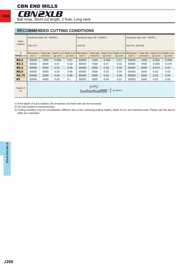
J268
R0.2 50000 1500 0.006 0.01 50000 1200 0.006 0.01 50000 1200 0.004 0.008R0.3 50000 2000 0.01 0.02 50000 1500 0.01 0.02 50000 1500 0.008 0.015R0.4 50000 3000 0.02 0.05 50000 2000 0.02 0.04 50000 2000 0.015 0.03R0.5 50000 3000 0.03 0.06 50000 2000 0.03 0.05 50000 2000 0.02 0.03R0.75 50000 3500 0.04 0.08 50000 2500 0.03 0.06 50000 2500 0.02 0.04R1 50000 4000 0.05 0.1 50000 3000 0.04 0.07 50000 3000 0.03 0.05
CBN2XLBSO
LID
EN
D M
ILLS
CBN
RECOMMENDED CUTTING CONDITIONS
1) If the depth of cut is shallow, the revolution and feed rate can be increased.2) Oil mist coolant is recommended.3) Cutting condition may be considerably different due to the overhang (milling depth), depth of cut, and machine tools. Please see the above
table as a standard.
ae (MAX.)
ap (MAX.)Depth of
cut
Workmaterial
Hardened steel (45─55HRC)
AISI H13
Hardened steel (55─62HRC)
AISI D2
Hardened steel (62─70HRC)
AISI W1, AISI M2
RPRFRAD (mm)
Revolution(min-1)
Feed rate(mm/min)
Depth of cutap (mm)
Depth of cutae (mm)
Revolution(min-1)
Feed rate(mm/min)
Depth of cutap (mm)
Depth of cutae (mm)
Revolution(min-1)
Feed rate(mm/min)
Depth of cutap (mm)
Depth of cutae (mm)
Ball nose, Short cut length, 2 fl ute, Long neck
CBN END MILLS
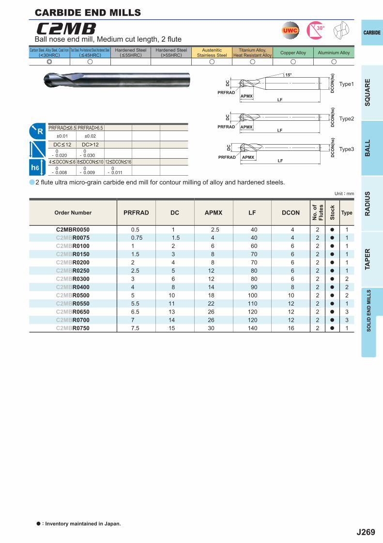
J269
a
e u u u u u
C2MB
PRFRAD DC APMX LF DCON
C2MBR0050 0.5 1 2.5 40 4 2 a 1C2MBR0075 0.75 1.5 4 40 4 2 a 1C2MBR0100 1 2 6 60 6 2 a 1C2MBR0150 1.5 3 8 70 6 2 a 1C2MBR0200 2 4 8 70 6 2 a 1C2MBR0250 2.5 5 12 80 6 2 a 1C2MBR0300 3 6 12 80 6 2 a 2C2MBR0400 4 8 14 90 8 2 a 2C2MBR0500 5 10 18 100 10 2 a 2C2MBR0550 5.5 11 22 110 12 2 a 1C2MBR0650 6.5 13 26 120 12 2 a 3C2MBR0700 7 14 26 120 12 2 a 3C2MBR0750 7.5 15 30 140 16 2 a 1
PRFRAD>6.5±0.01 ±0.02
DC>12 0- 0.020
0- 0.030
0- 0.008
0- 0.009
0- 0.011
UWC 30°
R
h6
APMX
DC
DC
ON
(h6)
LFPRFRAD
15°
APMX
DC
DC
ON
(h6)
LFPRFRAD
APMX
DC
DC
ON
(h6)
LFPRFRAD
SOLI
D E
ND
MIL
LS
CARBIDE
SQU
AR
EB
ALL
RA
DIU
STA
PER
Unit : mm
Carbon Steel, Alloy Steel, Cast Iron(<30HRC)
Tool Steel, Pre-Hardened Steel,Hardened Steel(<45HRC)
Hardened Steel(<55HRC)
Hardened Steel(>55HRC)
AusteniticStainless Steel
Titanium Alloy,Heat Resistant Alloy Copper Alloy Aluminium Alloy
2 fl ute ultra micro-grain carbide end mill for contour milling of alloy and hardened steels.
Ball nose end mill, Medium cut length, 2 fl ute
CARBIDE END MILLS
Type1
Order Number
No.
of
Flut
es
Stoc
k
Type
4<DCON<6 8<DCON<10 12<DCON<16
PRFRAD<6.5
DC<12
Type2
Type3
a : Inventory maintained in Japan.
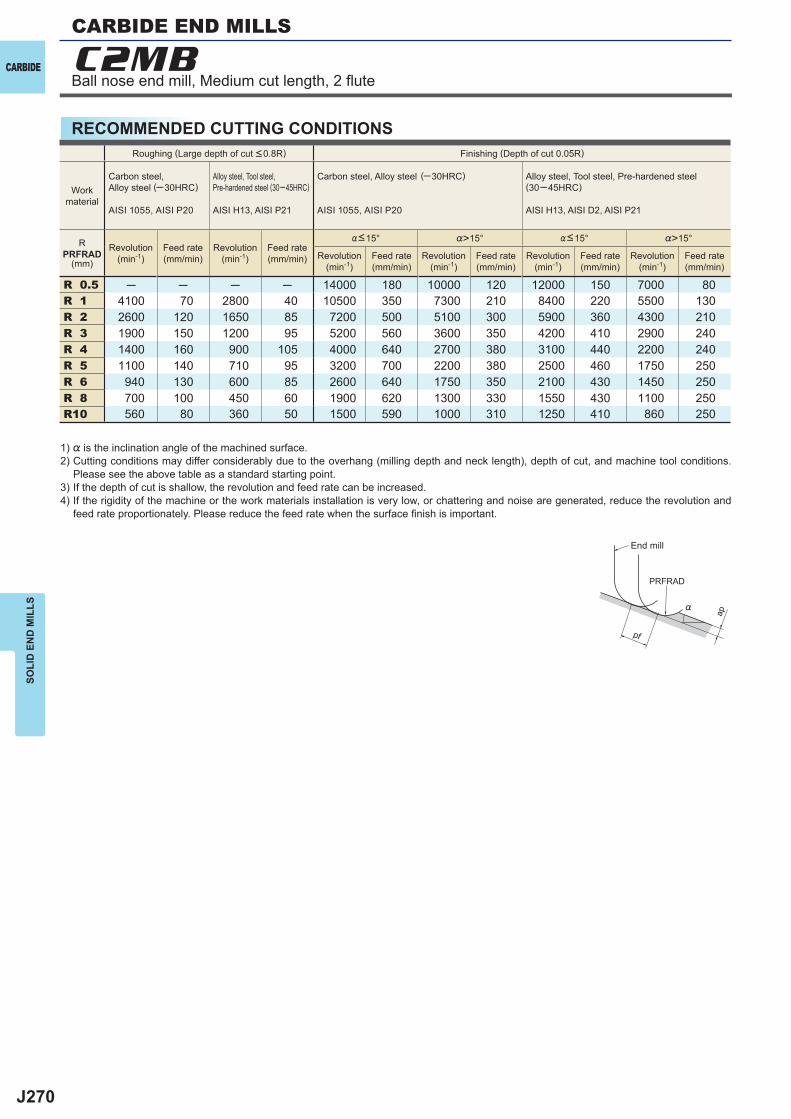
J270
%>15° %>15°
R 0.5 ─ ─ ─ ─ 14000 180 10000 120 12000 150 7000 80R 1 4100 70 2800 40 10500 350 7300 210 8400 220 5500 130R 2 2600 120 1650 85 7200 500 5100 300 5900 360 4300 210R 3 1900 150 1200 95 5200 560 3600 350 4200 410 2900 240R 4 1400 160 900 105 4000 640 2700 380 3100 440 2200 240R 5 1100 140 710 95 3200 700 2200 380 2500 460 1750 250R 6 940 130 600 85 2600 640 1750 350 2100 430 1450 250R 8 700 100 450 60 1900 620 1300 330 1550 430 1100 250R10 560 80 360 50 1500 590 1000 310 1250 410 860 250
C2MB
ap
PRFRAD
pf
%
CARBIDE
SOLI
D E
ND
MIL
LS
RECOMMENDED CUTTING CONDITIONS
1) % is the inclination angle of the machined surface. 2) Cutting conditions may differ considerably due to the overhang (milling depth and neck length), depth of cut, and machine tool conditions.
Please see the above table as a standard starting point.3) If the depth of cut is shallow, the revolution and feed rate can be increased.4) If the rigidity of the machine or the work materials installation is very low, or chattering and noise are generated, reduce the revolution and
feed rate proportionately. Please reduce the feed rate when the surface fi nish is important.
Roughing (Large depth of cut <0.8R) Finishing (Depth of cut 0.05R)
Workmaterial
Carbon steel, Alloy steel (─30HRC)
AISI 1055, AISI P20
Alloy steel, Tool steel,Pre-hardened steel (30─45HRC)
AISI H13, AISI P21
Carbon steel, Alloy steel (─30HRC)
AISI 1055, AISI P20
Alloy steel, Tool steel, Pre-hardened steel(30─45HRC)
AISI H13, AISI D2, AISI P21
RPRFRAD
(mm)
Revolution(min-1)
Feed rate(mm/min)
Revolution(min-1)
Feed rate(mm/min) Revolution
(min-1)Feed rate(mm/min)
Revolution(min-1)
Feed rate(mm/min)
Revolution(min-1)
Feed rate(mm/min)
Revolution(min-1)
Feed rate(mm/min)
%<15° %<15°
End mill
Ball nose end mill, Medium cut length, 2 fl ute
CARBIDE END MILLS
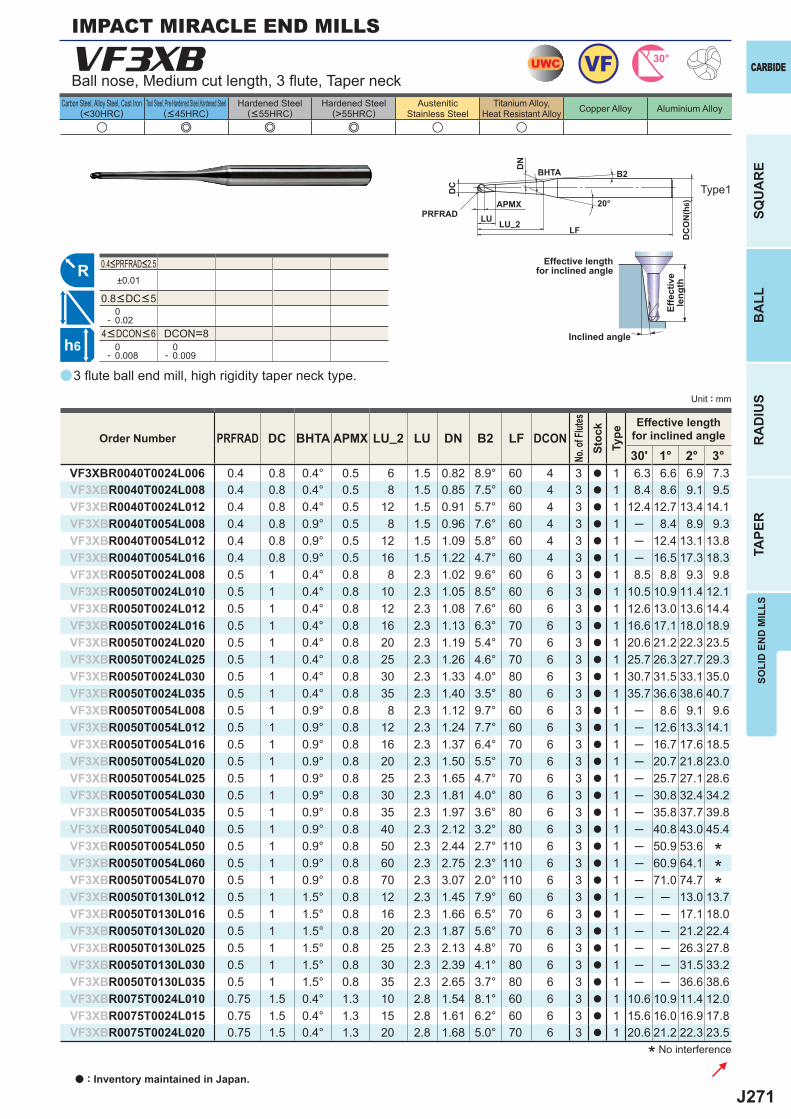
J271
a
VF3XB
PRFRAD DC BHTA APMX LU_2 LU DN B2 LF DCON30' 1° 2° 3°
VF3XBR0040T0024L006 0.4 0.8 0.4° 0.5 6 1.5 0.82 8.9° 60 4 3 a 1 6.3 6.6 6.9 7.3VF3XBR0040T0024L008 0.4 0.8 0.4° 0.5 8 1.5 0.85 7.5° 60 4 3 a 1 8.4 8.6 9.1 9.5VF3XBR0040T0024L012 0.4 0.8 0.4° 0.5 12 1.5 0.91 5.7° 60 4 3 a 1 12.4 12.7 13.4 14.1VF3XBR0040T0054L008 0.4 0.8 0.9° 0.5 8 1.5 0.96 7.6° 60 4 3 a 1 ─ 8.4 8.9 9.3VF3XBR0040T0054L012 0.4 0.8 0.9° 0.5 12 1.5 1.09 5.8° 60 4 3 a 1 ─ 12.4 13.1 13.8VF3XBR0040T0054L016 0.4 0.8 0.9° 0.5 16 1.5 1.22 4.7° 60 4 3 a 1 ─ 16.5 17.3 18.3VF3XBR0050T0024L008 0.5 1 0.4° 0.8 8 2.3 1.02 9.6° 60 6 3 a 1 8.5 8.8 9.3 9.8VF3XBR0050T0024L010 0.5 1 0.4° 0.8 10 2.3 1.05 8.5° 60 6 3 a 1 10.5 10.9 11.4 12.1VF3XBR0050T0024L012 0.5 1 0.4° 0.8 12 2.3 1.08 7.6° 60 6 3 a 1 12.6 13.0 13.6 14.4VF3XBR0050T0024L016 0.5 1 0.4° 0.8 16 2.3 1.13 6.3° 70 6 3 a 1 16.6 17.1 18.0 18.9VF3XBR0050T0024L020 0.5 1 0.4° 0.8 20 2.3 1.19 5.4° 70 6 3 a 1 20.6 21.2 22.3 23.5VF3XBR0050T0024L025 0.5 1 0.4° 0.8 25 2.3 1.26 4.6° 70 6 3 a 1 25.7 26.3 27.7 29.3VF3XBR0050T0024L030 0.5 1 0.4° 0.8 30 2.3 1.33 4.0° 80 6 3 a 1 30.7 31.5 33.1 35.0VF3XBR0050T0024L035 0.5 1 0.4° 0.8 35 2.3 1.40 3.5° 80 6 3 a 1 35.7 36.6 38.6 40.7VF3XBR0050T0054L008 0.5 1 0.9° 0.8 8 2.3 1.12 9.7° 60 6 3 a 1 ─ 8.6 9.1 9.6VF3XBR0050T0054L012 0.5 1 0.9° 0.8 12 2.3 1.24 7.7° 60 6 3 a 1 ─ 12.6 13.3 14.1VF3XBR0050T0054L016 0.5 1 0.9° 0.8 16 2.3 1.37 6.4° 70 6 3 a 1 ─ 16.7 17.6 18.5VF3XBR0050T0054L020 0.5 1 0.9° 0.8 20 2.3 1.50 5.5° 70 6 3 a 1 ─ 20.7 21.8 23.0VF3XBR0050T0054L025 0.5 1 0.9° 0.8 25 2.3 1.65 4.7° 70 6 3 a 1 ─ 25.7 27.1 28.6VF3XBR0050T0054L030 0.5 1 0.9° 0.8 30 2.3 1.81 4.0° 80 6 3 a 1 ─ 30.8 32.4 34.2VF3XBR0050T0054L035 0.5 1 0.9° 0.8 35 2.3 1.97 3.6° 80 6 3 a 1 ─ 35.8 37.7 39.8VF3XBR0050T0054L040 0.5 1 0.9° 0.8 40 2.3 2.12 3.2° 80 6 3 a 1 ─ 40.8 43.0 45.4VF3XBR0050T0054L050 0.5 1 0.9° 0.8 50 2.3 2.44 2.7° 110 6 3 a 1 ─ 50.9 53.6VF3XBR0050T0054L060 0.5 1 0.9° 0.8 60 2.3 2.75 2.3° 110 6 3 a 1 ─ 60.9 64.1VF3XBR0050T0054L070 0.5 1 0.9° 0.8 70 2.3 3.07 2.0° 110 6 3 a 1 ─ 71.0 74.7VF3XBR0050T0130L012 0.5 1 1.5° 0.8 12 2.3 1.45 7.9° 60 6 3 a 1 ─ ─ 13.0 13.7VF3XBR0050T0130L016 0.5 1 1.5° 0.8 16 2.3 1.66 6.5° 70 6 3 a 1 ─ ─ 17.1 18.0VF3XBR0050T0130L020 0.5 1 1.5° 0.8 20 2.3 1.87 5.6° 70 6 3 a 1 ─ ─ 21.2 22.4VF3XBR0050T0130L025 0.5 1 1.5° 0.8 25 2.3 2.13 4.8° 70 6 3 a 1 ─ ─ 26.3 27.8VF3XBR0050T0130L030 0.5 1 1.5° 0.8 30 2.3 2.39 4.1° 80 6 3 a 1 ─ ─ 31.5 33.2VF3XBR0050T0130L035 0.5 1 1.5° 0.8 35 2.3 2.65 3.7° 80 6 3 a 1 ─ ─ 36.6 38.6VF3XBR0075T0024L010 0.75 1.5 0.4° 1.3 10 2.8 1.54 8.1° 60 6 3 a 1 10.6 10.9 11.4 12.0VF3XBR0075T0024L015 0.75 1.5 0.4° 1.3 15 2.8 1.61 6.2° 60 6 3 a 1 15.6 16.0 16.9 17.8VF3XBR0075T0024L020 0.75 1.5 0.4° 1.3 20 2.8 1.68 5.0° 70 6 3 a 1 20.6 21.2 22.3 23.5
u e e e u u
±0.01
0- 0.02
DCON=8 0- 0.008
0- 0.009
UWC VF 30°
R
h6
APMX
DC
DC
ON
(h6)
LF
PRFRAD LU
DN
20°
B2BHTA
LU_2
SOLI
D E
ND
MIL
LS
CARBIDE
SQU
AR
EB
ALL
RA
DIU
STA
PER
Unit : mm
Carbon Steel, Alloy Steel, Cast Iron(<30HRC)
Tool Steel, Pre-Hardened Steel,Hardened Steel(<45HRC)
Hardened Steel(<55HRC)
Hardened Steel(>55HRC)
AusteniticStainless Steel
Titanium Alloy,Heat Resistant Alloy Copper Alloy Aluminium Alloy
3 fl ute ball end mill, high rigidity taper neck type.
Ball nose, Medium cut length, 3 fl ute, Taper neck
Type1
IMPACT MIRACLE END MILLS
* No interference
Effective lengthfor inclined angle
Inclined angle
Effe
ctiv
ele
ngth
Order Number
No. o
f Flut
esSt
ock
Type
Effective lengthfor inclined angle
***
4<DCON<6
0.4<PRFRAD<2.5
0.8<DC<5
a : Inventory maintained in Japan.
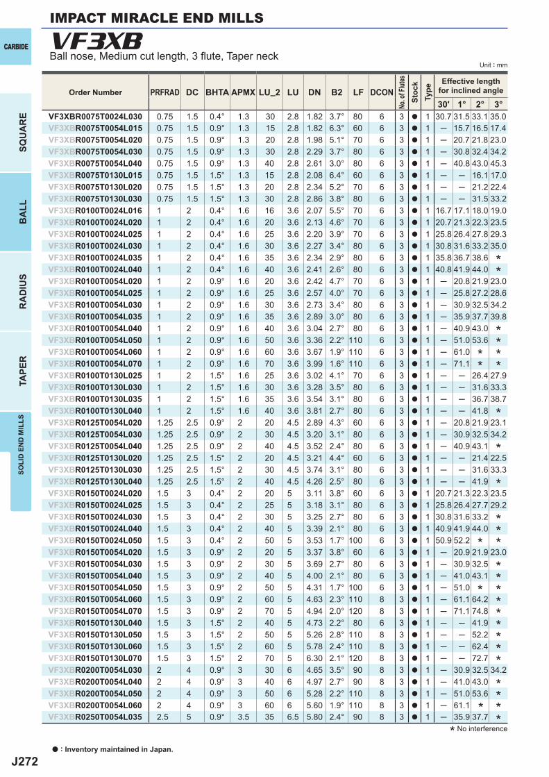
J272
PRFRAD DC BHTA APMX LU_2 LU DN B2 LF DCON30' 1° 2° 3°
VF3XBR0075T0024L030 0.75 1.5 0.4° 1.3 30 2.8 1.82 3.7° 80 6 3 a 1 30.7 31.5 33.1 35.0VF3XBR0075T0054L015 0.75 1.5 0.9° 1.3 15 2.8 1.82 6.3° 60 6 3 a 1 ─ 15.7 16.5 17.4VF3XBR0075T0054L020 0.75 1.5 0.9° 1.3 20 2.8 1.98 5.1° 70 6 3 a 1 ─ 20.7 21.8 23.0VF3XBR0075T0054L030 0.75 1.5 0.9° 1.3 30 2.8 2.29 3.7° 80 6 3 a 1 ─ 30.8 32.4 34.2VF3XBR0075T0054L040 0.75 1.5 0.9° 1.3 40 2.8 2.61 3.0° 80 6 3 a 1 ─ 40.8 43.0 45.3VF3XBR0075T0130L015 0.75 1.5 1.5° 1.3 15 2.8 2.08 6.4° 60 6 3 a 1 ─ ─ 16.1 17.0VF3XBR0075T0130L020 0.75 1.5 1.5° 1.3 20 2.8 2.34 5.2° 70 6 3 a 1 ─ ─ 21.2 22.4VF3XBR0075T0130L030 0.75 1.5 1.5° 1.3 30 2.8 2.86 3.8° 80 6 3 a 1 ─ ─ 31.5 33.2VF3XBR0100T0024L016 1 2 0.4° 1.6 16 3.6 2.07 5.5° 70 6 3 a 1 16.7 17.1 18.0 19.0VF3XBR0100T0024L020 1 2 0.4° 1.6 20 3.6 2.13 4.6° 70 6 3 a 1 20.7 21.3 22.3 23.5VF3XBR0100T0024L025 1 2 0.4° 1.6 25 3.6 2.20 3.9° 70 6 3 a 1 25.8 26.4 27.8 29.3VF3XBR0100T0024L030 1 2 0.4° 1.6 30 3.6 2.27 3.4° 80 6 3 a 1 30.8 31.6 33.2 35.0VF3XBR0100T0024L035 1 2 0.4° 1.6 35 3.6 2.34 2.9° 80 6 3 a 1 35.8 36.7 38.6VF3XBR0100T0024L040 1 2 0.4° 1.6 40 3.6 2.41 2.6° 80 6 3 a 1 40.8 41.9 44.0VF3XBR0100T0054L020 1 2 0.9° 1.6 20 3.6 2.42 4.7° 70 6 3 a 1 ─ 20.8 21.9 23.0VF3XBR0100T0054L025 1 2 0.9° 1.6 25 3.6 2.57 4.0° 70 6 3 a 1 ─ 25.8 27.2 28.6VF3XBR0100T0054L030 1 2 0.9° 1.6 30 3.6 2.73 3.4° 80 6 3 a 1 ─ 30.9 32.5 34.2VF3XBR0100T0054L035 1 2 0.9° 1.6 35 3.6 2.89 3.0° 80 6 3 a 1 ─ 35.9 37.7 39.8VF3XBR0100T0054L040 1 2 0.9° 1.6 40 3.6 3.04 2.7° 80 6 3 a 1 ─ 40.9 43.0VF3XBR0100T0054L050 1 2 0.9° 1.6 50 3.6 3.36 2.2° 110 6 3 a 1 ─ 51.0 53.6VF3XBR0100T0054L060 1 2 0.9° 1.6 60 3.6 3.67 1.9° 110 6 3 a 1 ─ 61.0VF3XBR0100T0054L070 1 2 0.9° 1.6 70 3.6 3.99 1.6° 110 6 3 a 1 ─ 71.1VF3XBR0100T0130L025 1 2 1.5° 1.6 25 3.6 3.02 4.1° 70 6 3 a 1 ─ ─ 26.4 27.9VF3XBR0100T0130L030 1 2 1.5° 1.6 30 3.6 3.28 3.5° 80 6 3 a 1 ─ ─ 31.6 33.3VF3XBR0100T0130L035 1 2 1.5° 1.6 35 3.6 3.54 3.1° 80 6 3 a 1 ─ ─ 36.7 38.7VF3XBR0100T0130L040 1 2 1.5° 1.6 40 3.6 3.81 2.7° 80 6 3 a 1 ─ ─ 41.8VF3XBR0125T0054L020 1.25 2.5 0.9° 2 20 4.5 2.89 4.3° 60 6 3 a 1 ─ 20.8 21.9 23.1VF3XBR0125T0054L030 1.25 2.5 0.9° 2 30 4.5 3.20 3.1° 80 6 3 a 1 ─ 30.9 32.5 34.2VF3XBR0125T0054L040 1.25 2.5 0.9° 2 40 4.5 3.52 2.4° 80 6 3 a 1 ─ 40.9 43.1VF3XBR0125T0130L020 1.25 2.5 1.5° 2 20 4.5 3.21 4.4° 60 6 3 a 1 ─ ─ 21.4 22.5VF3XBR0125T0130L030 1.25 2.5 1.5° 2 30 4.5 3.74 3.1° 80 6 3 a 1 ─ ─ 31.6 33.3VF3XBR0125T0130L040 1.25 2.5 1.5° 2 40 4.5 4.26 2.5° 80 6 3 a 1 ─ ─ 41.9VF3XBR0150T0024L020 1.5 3 0.4° 2 20 5 3.11 3.8° 60 6 3 a 1 20.7 21.3 22.3 23.5VF3XBR0150T0024L025 1.5 3 0.4° 2 25 5 3.18 3.1° 80 6 3 a 1 25.8 26.4 27.7 29.2VF3XBR0150T0024L030 1.5 3 0.4° 2 30 5 3.25 2.7° 80 6 3 a 1 30.8 31.6 33.2VF3XBR0150T0024L040 1.5 3 0.4° 2 40 5 3.39 2.1° 80 6 3 a 1 40.9 41.9 44.0VF3XBR0150T0024L050 1.5 3 0.4° 2 50 5 3.53 1.7° 100 6 3 a 1 50.9 52.2VF3XBR0150T0054L020 1.5 3 0.9° 2 20 5 3.37 3.8° 60 6 3 a 1 ─ 20.9 21.9 23.0VF3XBR0150T0054L030 1.5 3 0.9° 2 30 5 3.69 2.7° 80 6 3 a 1 ─ 30.9 32.5VF3XBR0150T0054L040 1.5 3 0.9° 2 40 5 4.00 2.1° 80 6 3 a 1 ─ 41.0 43.1VF3XBR0150T0054L050 1.5 3 0.9° 2 50 5 4.31 1.7° 100 6 3 a 1 ─ 51.0VF3XBR0150T0054L060 1.5 3 0.9° 2 60 5 4.63 2.3° 110 8 3 a 1 ─ 61.1 64.2VF3XBR0150T0054L070 1.5 3 0.9° 2 70 5 4.94 2.0° 120 8 3 a 1 ─ 71.1 74.8VF3XBR0150T0130L040 1.5 3 1.5° 2 40 5 4.73 2.2° 80 6 3 a 1 ─ ─ 41.9VF3XBR0150T0130L050 1.5 3 1.5° 2 50 5 5.26 2.8° 110 8 3 a 1 ─ ─ 52.2VF3XBR0150T0130L060 1.5 3 1.5° 2 60 5 5.78 2.4° 110 8 3 a 1 ─ ─ 62.4VF3XBR0150T0130L070 1.5 3 1.5° 2 70 5 6.30 2.1° 120 8 3 a 1 ─ ─ 72.7VF3XBR0200T0054L030 2 4 0.9° 3 30 6 4.65 3.5° 90 8 3 a 1 ─ 30.9 32.5 34.2VF3XBR0200T0054L040 2 4 0.9° 3 40 6 4.97 2.7° 90 8 3 a 1 ─ 41.0 43.0VF3XBR0200T0054L050 2 4 0.9° 3 50 6 5.28 2.2° 110 8 3 a 1 ─ 51.0 53.6VF3XBR0200T0054L060 2 4 0.9° 3 60 6 5.60 1.9° 110 8 3 a 1 ─ 61.1VF3XBR0250T0054L035 2.5 5 0.9° 3.5 35 6.5 5.80 2.4° 90 8 3 a 1 ─ 35.9 37.7
VF3XBCARBIDE
SQU
AR
EB
ALL
RA
DIU
STA
PER
SOLI
D E
ND
MIL
LS
Unit : mm
Order Number
No. o
f Flut
esSt
ock
Type
Effective lengthfor inclined angle
* No interference
**
******
*
*
*
****
**********
*****
Ball nose, Medium cut length, 3 fl ute, Taper neck
IMPACT MIRACLE END MILLS
a : Inventory maintained in Japan.
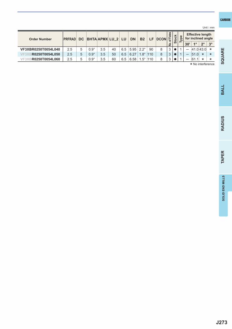
J273
PRFRAD DC BHTA APMX LU_2 LU DN B2 LF DCON30' 1° 2° 3°
VF3XBR0250T0054L040 2.5 5 0.9° 3.5 40 6.5 5.95 2.2° 90 8 3 a 1 ─ 41.0 43.0VF3XBR0250T0054L050 2.5 5 0.9° 3.5 50 6.5 6.27 1.8° 110 8 3 a 1 ─ 51.0VF3XBR0250T0054L060 2.5 5 0.9° 3.5 60 6.5 6.58 1.5° 110 8 3 a 1 ─ 61.1
SOLI
D E
ND
MIL
LS
CARBIDE
SQU
AR
EB
ALL
RA
DIU
STA
PER
Unit : mm
Order Number
No. o
f Flut
esSt
ock
Type
Effective lengthfor inclined angle
*****
* No interference
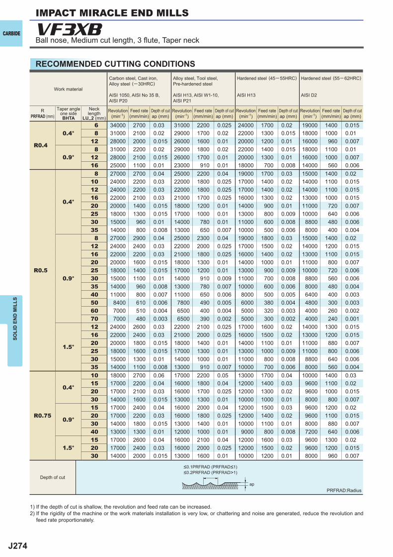
J274
R0.4
0.4°6 34000 2700 0.03 31000 2200 0.025 24000 1700 0.02 19000 1400 0.0158 31000 2100 0.02 29000 1700 0.02 22000 1300 0.015 18000 1000 0.01
12 28000 2000 0.015 26000 1600 0.01 20000 1200 0.01 16000 960 0.007
0.9°8 31000 2200 0.02 29000 1800 0.02 22000 1400 0.015 18000 1100 0.01
12 28000 2100 0.015 26000 1700 0.01 20000 1300 0.01 16000 1000 0.00716 25000 1100 0.01 23000 910 0.01 18000 700 0.008 14000 560 0.006
R0.5
0.4°
8 27000 2700 0.04 25000 2200 0.04 19000 1700 0.03 15000 1400 0.0210 24000 2200 0.03 22000 1800 0.025 17000 1400 0.02 14000 1100 0.01512 24000 2200 0.03 22000 1800 0.025 17000 1400 0.02 14000 1100 0.01516 22000 2100 0.03 21000 1700 0.025 16000 1300 0.02 13000 1000 0.01520 20000 1400 0.015 18000 1200 0.01 14000 900 0.01 11000 720 0.00725 18000 1300 0.015 17000 1000 0.01 13000 800 0.009 10000 640 0.00630 15000 960 0.01 14000 780 0.01 11000 600 0.008 8800 480 0.00635 14000 800 0.008 13000 650 0.007 10000 500 0.006 8000 400 0.004
0.9°
8 27000 2900 0.04 25000 2300 0.04 19000 1800 0.03 15000 1400 0.0212 24000 2400 0.03 22000 2000 0.025 17000 1500 0.02 14000 1200 0.01516 22000 2200 0.03 21000 1800 0.025 16000 1400 0.02 13000 1100 0.01520 20000 1600 0.015 18000 1300 0.01 14000 1000 0.01 11000 800 0.00725 18000 1400 0.015 17000 1200 0.01 13000 900 0.009 10000 720 0.00630 15000 1100 0.01 14000 910 0.009 11000 700 0.008 8800 560 0.00635 14000 960 0.008 13000 780 0.007 10000 600 0.006 8000 480 0.00440 11000 800 0.007 11000 650 0.006 8000 500 0.005 6400 400 0.00350 8400 610 0.006 7800 490 0.005 6000 380 0.004 4800 300 0.00360 7000 510 0.004 6500 400 0.004 5000 320 0.003 4000 260 0.00270 7000 480 0.003 6500 390 0.002 5000 300 0.002 4000 240 0.001
1.5°
12 24000 2600 0.03 22000 2100 0.025 17000 1600 0.02 14000 1300 0.01516 22000 2400 0.03 21000 2000 0.025 16000 1500 0.02 13000 1200 0.01520 20000 1800 0.015 18000 1400 0.01 14000 1100 0.01 11000 880 0.00725 18000 1600 0.015 17000 1300 0.01 13000 1000 0.009 11000 800 0.00630 15000 1300 0.01 14000 1000 0.01 11000 800 0.008 8800 640 0.00635 14000 1100 0.008 13000 910 0.007 10000 700 0.006 8000 560 0.004
R0.75
0.4°
10 18000 2700 0.06 17000 2200 0.05 13000 1700 0.04 10000 1400 0.0315 17000 2200 0.04 16000 1800 0.04 12000 1400 0.03 9600 1100 0.0220 17000 2100 0.03 16000 1700 0.025 12000 1300 0.02 9600 1000 0.01530 14000 1600 0.015 13000 1300 0.01 10000 1000 0.01 8000 800 0.007
0.9°
15 17000 2400 0.04 16000 2000 0.04 12000 1500 0.03 9600 1200 0.0220 17000 2200 0.03 16000 1800 0.025 12000 1400 0.02 9600 1100 0.01530 14000 1800 0.015 13000 1400 0.01 10000 1100 0.01 8000 880 0.00740 13000 1300 0.01 12000 1000 0.01 9000 800 0.008 7200 640 0.006
1.5°15 17000 2600 0.04 16000 2100 0.04 12000 1600 0.03 9600 1300 0.0220 17000 2400 0.03 16000 2000 0.025 12000 1500 0.02 9600 1200 0.01530 14000 2000 0.015 13000 1600 0.01 10000 1200 0.01 8000 960 0.007
VF3XB
ap
CARBIDE
SOLI
D E
ND
MIL
LS
RECOMMENDED CUTTING CONDITIONS
1) If the depth of cut is shallow, the revolution and feed rate can be increased.2) If the rigidity of the machine or the work materials installation is very low, or chattering and noise are generated, reduce the revolution and
feed rate proportionately.
PRFRAD:Radius
Work material
Carbon steel, Cast iron, Alloy steel (─30HRC)
AISI 1050, AISI No 35 B,AISI P20
Alloy steel, Tool steel,Pre-hardened steel
AISI H13, AISI W1-10, AISI P21
Hardened steel (45─ 55HRC)
AISI H13
Hardened steel (55─ 62HRC)
AISI D2
RPRFRAD (mm)
Taper angleone sideBHTA
Necklength
LU_2 (mm)Revolution
(min-1)Revolution
(min-1)Revolution
(min-1)Revolution
(min-1)Feed rate(mm/min)
Feed rate(mm/min)
Feed rate(mm/min)
Feed rate(mm/min)
Depth of cutap (mm)
Depth of cutap (mm)
Depth of cutap (mm)
Depth of cutap (mm)
Depth of cut
<0.1PRFRAD (PRFRAD<1)<0.2PRFRAD (PRFRAD>1)
Ball nose, Medium cut length, 3 fl ute, Taper neck
IMPACT MIRACLE END MILLS
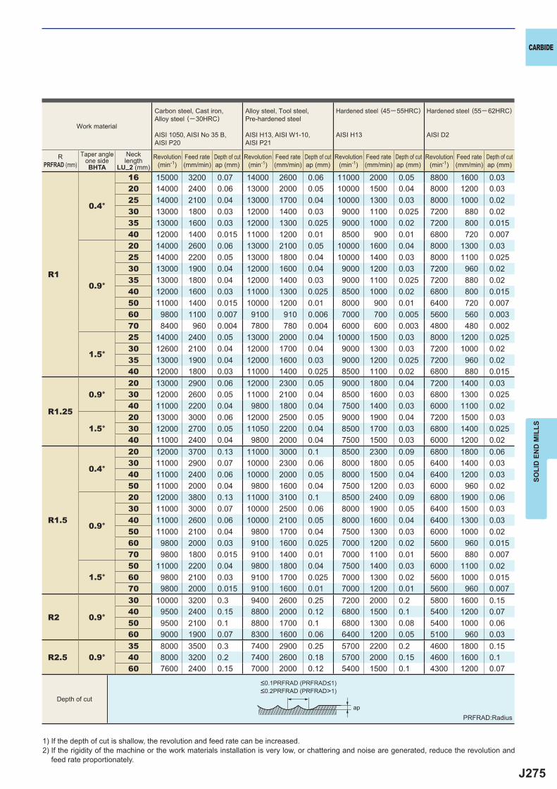
J275
R1
0.4°
16 15000 3200 0.07 14000 2600 0.06 11000 2000 0.05 8800 1600 0.0320 14000 2400 0.06 13000 2000 0.05 10000 1500 0.04 8000 1200 0.0325 14000 2100 0.04 13000 1700 0.04 10000 1300 0.03 8000 1000 0.0230 13000 1800 0.03 12000 1400 0.03 9000 1100 0.025 7200 880 0.0235 13000 1600 0.03 12000 1300 0.025 9000 1000 0.02 7200 800 0.01540 12000 1400 0.015 11000 1200 0.01 8500 900 0.01 6800 720 0.007
0.9°
20 14000 2600 0.06 13000 2100 0.05 10000 1600 0.04 8000 1300 0.0325 14000 2200 0.05 13000 1800 0.04 10000 1400 0.03 8000 1100 0.02530 13000 1900 0.04 12000 1600 0.04 9000 1200 0.03 7200 960 0.0235 13000 1800 0.04 12000 1400 0.03 9000 1100 0.025 7200 880 0.0240 12000 1600 0.03 11000 1300 0.025 8500 1000 0.02 6800 800 0.01550 11000 1400 0.015 10000 1200 0.01 8000 900 0.01 6400 720 0.00760 9800 1100 0.007 9100 910 0.006 7000 700 0.005 5600 560 0.00370 8400 960 0.004 7800 780 0.004 6000 600 0.003 4800 480 0.002
1.5°
25 14000 2400 0.05 13000 2000 0.04 10000 1500 0.03 8000 1200 0.02530 12600 2100 0.04 12000 1700 0.04 9000 1300 0.03 7200 1000 0.0235 13000 1900 0.04 12000 1600 0.03 9000 1200 0.025 7200 960 0.0240 12000 1800 0.03 11000 1400 0.025 8500 1100 0.02 6800 880 0.015
R1.25
0.9°20 13000 2900 0.06 12000 2300 0.05 9000 1800 0.04 7200 1400 0.0330 12000 2600 0.05 11000 2100 0.04 8500 1600 0.03 6800 1300 0.02540 11000 2200 0.04 9800 1800 0.04 7500 1400 0.03 6000 1100 0.02
1.5°20 13000 3000 0.06 12000 2500 0.05 9000 1900 0.04 7200 1500 0.0330 12000 2700 0.05 11050 2200 0.04 8500 1700 0.03 6800 1400 0.02540 11000 2400 0.04 9800 2000 0.04 7500 1500 0.03 6000 1200 0.02
R1.5
0.4°
20 12000 3700 0.13 11000 3000 0.1 8500 2300 0.09 6800 1800 0.0630 11000 2900 0.07 10000 2300 0.06 8000 1800 0.05 6400 1400 0.0340 11000 2400 0.06 10000 2000 0.05 8000 1500 0.04 6400 1200 0.0350 11000 2000 0.04 9800 1600 0.04 7500 1200 0.03 6000 960 0.02
0.9°
20 12000 3800 0.13 11000 3100 0.1 8500 2400 0.09 6800 1900 0.0630 11000 3000 0.07 10000 2500 0.06 8000 1900 0.05 6400 1500 0.0340 11000 2600 0.06 10000 2100 0.05 8000 1600 0.04 6400 1300 0.0350 11000 2100 0.04 9800 1700 0.04 7500 1300 0.03 6000 1000 0.0260 9800 2000 0.03 9100 1600 0.025 7000 1200 0.02 5600 960 0.01570 9800 1800 0.015 9100 1400 0.01 7000 1100 0.01 5600 880 0.007
1.5°50 11000 2200 0.04 9800 1800 0.04 7500 1400 0.03 6000 1100 0.0260 9800 2100 0.03 9100 1700 0.025 7000 1300 0.02 5600 1000 0.01570 9800 2000 0.015 9100 1600 0.01 7000 1200 0.01 5600 960 0.007
R2 0.9°
30 10000 3200 0.3 9400 2600 0.25 7200 2000 0.2 5800 1600 0.1540 9500 2400 0.15 8800 2000 0.12 6800 1500 0.1 5400 1200 0.0750 9500 2100 0.1 8800 1700 0.1 6800 1300 0.08 5400 1000 0.0660 9000 1900 0.07 8300 1600 0.06 6400 1200 0.05 5100 960 0.03
R2.5 0.9°35 8000 3500 0.3 7400 2900 0.25 5700 2200 0.2 4600 1800 0.1540 8000 3200 0.2 7400 2600 0.18 5700 2000 0.15 4600 1600 0.160 7600 2400 0.15 7000 2000 0.12 5400 1500 0.1 4300 1200 0.07
ap
CARBIDE
SOLI
D E
ND
MIL
LS
RPRFRAD (mm)
Taper angleone sideBHTA
Necklength
LU_2 (mm)
1) If the depth of cut is shallow, the revolution and feed rate can be increased.2) If the rigidity of the machine or the work materials installation is very low, or chattering and noise are generated, reduce the revolution and
feed rate proportionately.
PRFRAD:Radius
Work material
Carbon steel, Cast iron, Alloy steel (─30HRC)
AISI 1050, AISI No 35 B,AISI P20
Alloy steel, Tool steel,Pre-hardened steel
AISI H13, AISI W1-10, AISI P21
Hardened steel (45─ 55HRC)
AISI H13
Hardened steel (55─ 62HRC)
AISI D2
Revolution(min-1)
Revolution(min-1)
Revolution(min-1)
Revolution(min-1)
Feed rate(mm/min)
Feed rate(mm/min)
Feed rate(mm/min)
Feed rate(mm/min)
Depth of cutap (mm)
Depth of cutap (mm)
Depth of cutap (mm)
Depth of cutap (mm)
Depth of cut
<0.1PRFRAD (PRFRAD<1)<0.2PRFRAD (PRFRAD>1)
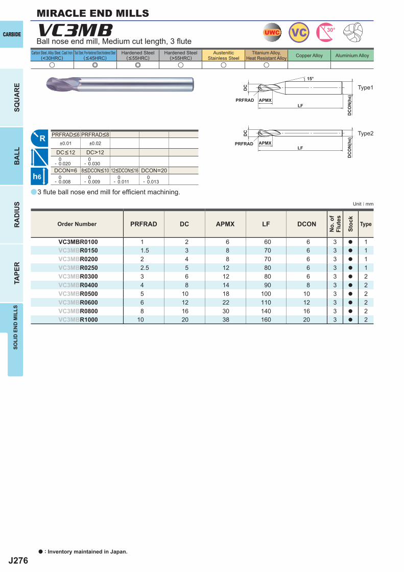
J276
a
u e e u u u
VC3MB
PRFRAD DC APMX LF DCON
VC3MBR0100 1 2 6 60 6 3 a 1VC3MBR0150 1.5 3 8 70 6 3 a 1VC3MBR0200 2 4 8 70 6 3 a 1VC3MBR0250 2.5 5 12 80 6 3 a 1VC3MBR0300 3 6 12 80 6 3 a 2VC3MBR0400 4 8 14 90 8 3 a 2VC3MBR0500 5 10 18 100 10 3 a 2VC3MBR0600 6 12 22 110 12 3 a 2VC3MBR0800 8 16 30 140 16 3 a 2VC3MBR1000 10 20 38 160 20 3 a 2
±0.01 ±0.02
DC>12 0- 0.020
0- 0.030
DCON=6 DCON=20 0- 0.008
0- 0.009
0- 0.011
0- 0.013
UWC VC 30°
R
h6
APMX
DC
DC
ON
(h6)
15°
APMXLF
DC
DC
ON
(h6)
LFPRFRAD
PRFRAD
CARBIDE
SQU
AR
EB
ALL
RA
DIU
STA
PER
SOLI
D E
ND
MIL
LS
Unit : mm
Carbon Steel, Alloy Steel, Cast Iron(<30HRC)
Tool Steel, Pre-Hardened Steel,Hardened Steel(<45HRC)
Hardened Steel(<55HRC)
Hardened Steel(>55HRC)
AusteniticStainless Steel
Titanium Alloy,Heat Resistant Alloy Copper Alloy Aluminium Alloy
MIRACLE END MILLS
3 fl ute ball nose end mill for effi cient machining.
Order Number
No.
of
Flut
es
Stoc
k
Type
8<DCON<10 12<DCON<16
PRFRAD<6 PRFRAD<8
DC<12
Ball nose end mill, Medium cut length, 3 fl ute
Type1
Type2
a : Inventory maintained in Japan.
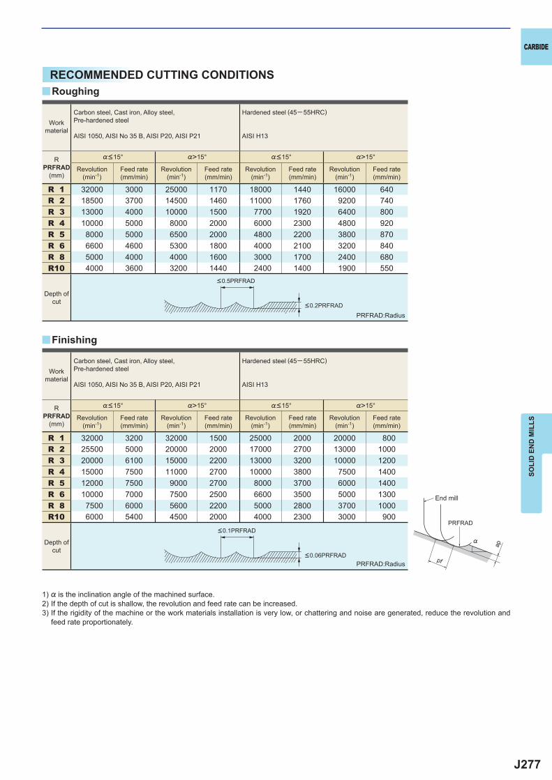
J277
%>15° %>15°
R 1 32000 3000 25000 1170 18000 1440 16000 640R 2 18500 3700 14500 1460 11000 1760 9200 740R 3 13000 4000 10000 1500 7700 1920 6400 800R 4 10000 5000 8000 2000 6000 2300 4800 920R 5 8000 5000 6500 2000 4800 2200 3800 870R 6 6600 4600 5300 1800 4000 2100 3200 840R 8 5000 4000 4000 1600 3000 1700 2400 680R10 4000 3600 3200 1440 2400 1400 1900 550
%>15° %>15°
R 1 32000 3200 32000 1500 25000 2000 20000 800R 2 25500 5000 20000 2000 17000 2700 13000 1000R 3 20000 6100 15000 2200 13000 3200 10000 1200R 4 15000 7500 11000 2700 10000 3800 7500 1400R 5 12000 7500 9000 2700 8000 3700 6000 1400R 6 10000 7000 7500 2500 6600 3500 5000 1300R 8 7500 6000 5600 2200 5000 2800 3700 1000R10 6000 5400 4500 2000 4000 2300 3000 900
y
y
ap
PRFRAD
pf
%
CARBIDE
SOLI
D E
ND
MIL
LS
RECOMMENDED CUTTING CONDITIONSRoughing
Finishing
PRFRAD:Radius
PRFRAD:Radius
1) % is the inclination angle of the machined surface. 2) If the depth of cut is shallow, the revolution and feed rate can be increased.3) If the rigidity of the machine or the work materials installation is very low, or chattering and noise are generated, reduce the revolution and
feed rate proportionately.
Workmaterial
Carbon steel, Cast iron, Alloy steel,Pre-hardened steel
AISI 1050, AISI No 35 B, AISI P20, AISI P21
Hardened steel (45─ 55HRC)
AISI H13
RPRFRAD
(mm)
%<15° %<15°
Revolution(min-1)
Feed rate(mm/min)
Revolution(min-1)
Feed rate(mm/min)
Revolution(min-1)
Feed rate(mm/min)
Revolution(min-1)
Feed rate(mm/min)
Depth ofcut
Workmaterial
Carbon steel, Cast iron, Alloy steel,Pre-hardened steel
AISI 1050, AISI No 35 B, AISI P20, AISI P21
Hardened steel (45─ 55HRC)
AISI H13
RPRFRAD
(mm)
%<15° %<15°
Revolution(min-1)
Feed rate(mm/min)
Revolution(min-1)
Feed rate(mm/min)
Revolution(min-1)
Feed rate(mm/min)
Revolution(min-1)
Feed rate(mm/min)
Depth ofcut
<0.2PRFRAD
<0.5PRFRAD
<0.06PRFRAD
<0.1PRFRAD
End mill
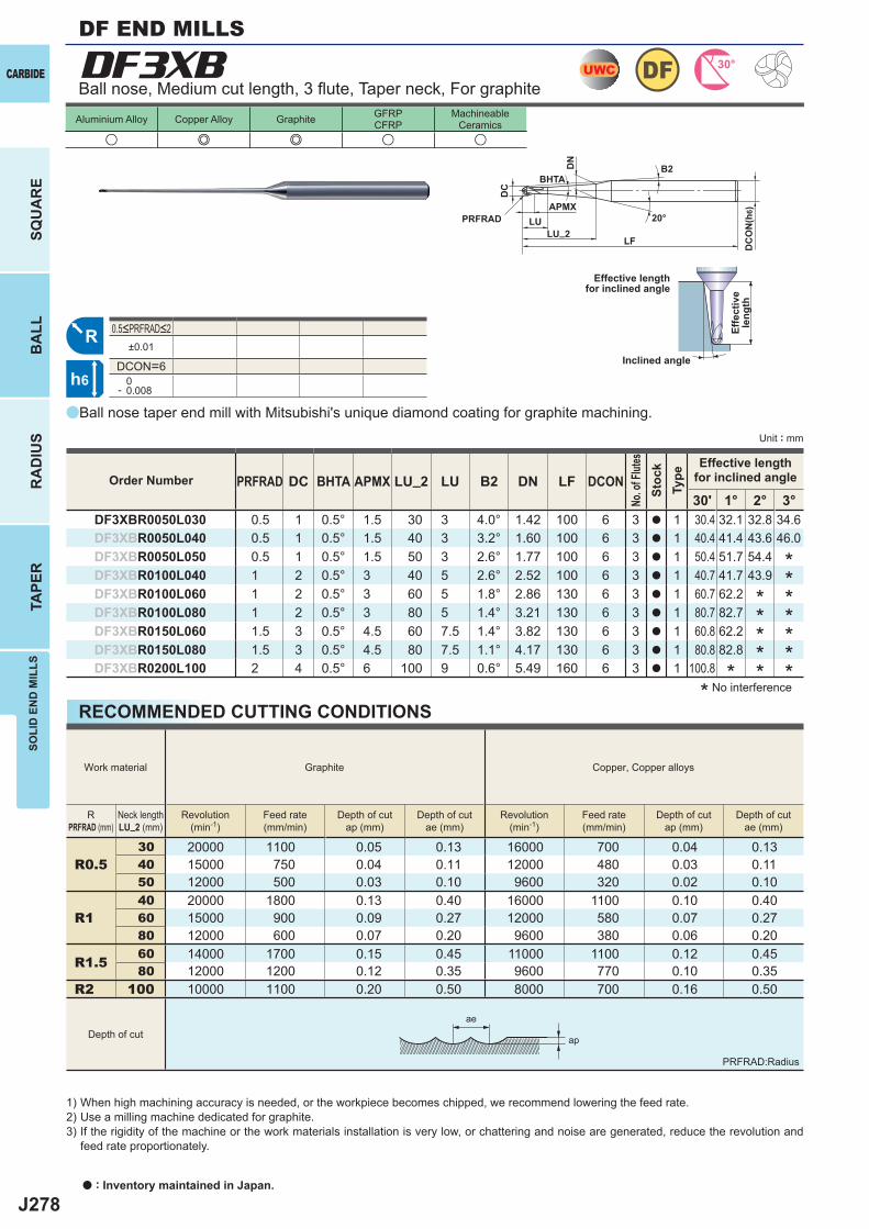
J278
a
DF3XB
u e e u u
PRFRAD DC BHTA APMX LU_2 LU B2 DN LF DCON30' 1° 2° 3°
DF3XBR0050L030 0.5 1 0.5° 1.5 30 3 4.0° 1.42 100 6 3 a 1 30.4 32.1 32.8 34.6DF3XBR0050L040 0.5 1 0.5° 1.5 40 3 3.2° 1.60 100 6 3 a 1 40.4 41.4 43.6 46.0DF3XBR0050L050 0.5 1 0.5° 1.5 50 3 2.6° 1.77 100 6 3 a 1 50.4 51.7 54.4DF3XBR0100L040 1 2 0.5° 3 40 5 2.6° 2.52 100 6 3 a 1 40.7 41.7 43.9DF3XBR0100L060 1 2 0.5° 3 60 5 1.8° 2.86 130 6 3 a 1 60.7 62.2DF3XBR0100L080 1 2 0.5° 3 80 5 1.4° 3.21 130 6 3 a 1 80.7 82.7DF3XBR0150L060 1.5 3 0.5° 4.5 60 7.5 1.4° 3.82 130 6 3 a 1 60.8 62.2DF3XBR0150L080 1.5 3 0.5° 4.5 80 7.5 1.1° 4.17 130 6 3 a 1 80.8 82.8DF3XBR0200L100 2 4 0.5° 6 100 9 0.6° 5.49 160 6 3 a 1 100.8
±0.01
DCON=6 0- 0.008
R0.530 20000 1100 0.05 0.13 16000 700 0.04 0.1340 15000 750 0.04 0.11 12000 480 0.03 0.1150 12000 500 0.03 0.10 9600 320 0.02 0.10
R140 20000 1800 0.13 0.40 16000 1100 0.10 0.4060 15000 900 0.09 0.27 12000 580 0.07 0.2780 12000 600 0.07 0.20 9600 380 0.06 0.20
R1.5 60 14000 1700 0.15 0.45 11000 1100 0.12 0.4580 12000 1200 0.12 0.35 9600 770 0.10 0.35
R2 100 10000 1100 0.20 0.50 8000 700 0.16 0.50
UWC 30°DF
R
h6
APMX
DC
DC
ON
(h6)
20°LU
DN
LF
PRFRADLU_2
BHTAB2
ap
ae
Unit : mm
CARBIDE
SQU
AR
EB
ALL
RA
DIU
STA
PER
SOLI
D E
ND
MIL
LS
Aluminium Alloy Copper Alloy Graphite GFRPCFRP
MachineableCeramics
Ball nose, Medium cut length, 3 fl ute, Taper neck, For graphite
Effective lengthfor inclined angle
Inclined angle
Effe
ctiv
ele
ngth
* No interference
Order Number
No. o
f Flut
esSt
ock
Type
Effective lengthfor inclined angle
Ball nose taper end mill with Mitsubishi's unique diamond coating for graphite machining.
*
**
*
**
**
*****
DF END MILLS
0.5<PRFRAD<2
RECOMMENDED CUTTING CONDITIONS
1) When high machining accuracy is needed, or the workpiece becomes chipped, we recommend lowering the feed rate.2) Use a milling machine dedicated for graphite.3) If the rigidity of the machine or the work materials installation is very low, or chattering and noise are generated, reduce the revolution and
feed rate proportionately.
Work material Graphite Copper, Copper alloys
RPRFRAD (mm)
Neck lengthLU_2 (mm)
Revolution(min-1)
Feed rate(mm/min)
Depth of cutap (mm)
Depth of cutae (mm)
Revolution(min-1)
Feed rate(mm/min)
Depth of cutap (mm)
Depth of cutae (mm)
Depth of cut
a : Inventory maintained in Japan.
PRFRAD:Radius
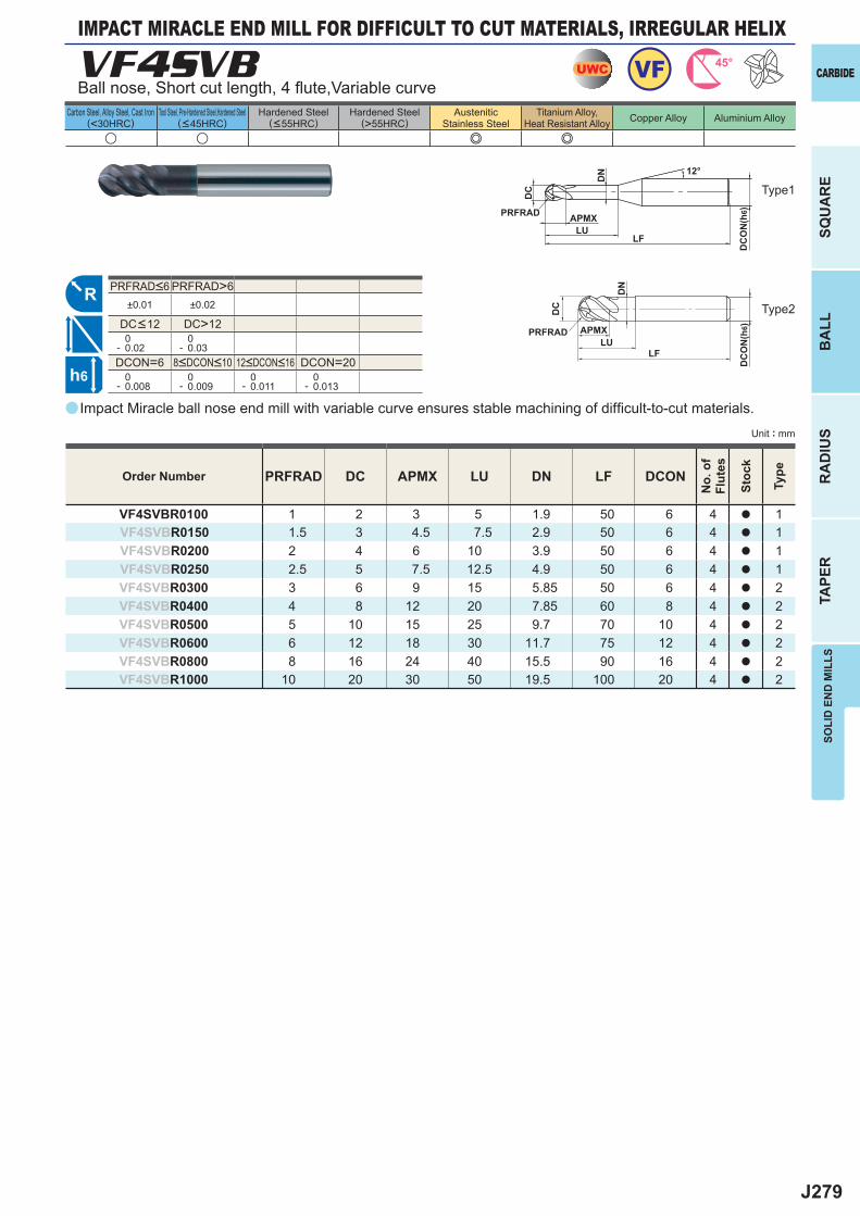
J279
a
VF4SVB
PRFRAD DC APMX LU DN LF DCON
VF4SVBR0100 1 2 3 5 1.9 50 6 4 a 1VF4SVBR0150 1.5 3 4.5 7.5 2.9 50 6 4 a 1VF4SVBR0200 2 4 6 10 3.9 50 6 4 a 1VF4SVBR0250 2.5 5 7.5 12.5 4.9 50 6 4 a 1VF4SVBR0300 3 6 9 15 5.85 50 6 4 a 2VF4SVBR0400 4 8 12 20 7.85 60 8 4 a 2VF4SVBR0500 5 10 15 25 9.7 70 10 4 a 2VF4SVBR0600 6 12 18 30 11.7 75 12 4 a 2VF4SVBR0800 8 16 24 40 15.5 90 16 4 a 2VF4SVBR1000 10 20 30 50 19.5 100 20 4 a 2
u u e e
PRFRAD>6±0.01 ±0.02
DC>12 0- 0.02
0- 0.03
DCON=6 DCON=20 0- 0.008
0- 0.009
0- 0.011
0- 0.013
UWC VF 45°
R
h6
APMX
DC
DC
ON
(h6)
12°
LU
DN
LF
PRFRAD
APMX
DC
DC
ON
(h6)
LU
DN
LF
PRFRAD
SOLI
D E
ND
MIL
LS
CARBIDE
SQU
AR
EB
ALL
RA
DIU
STA
PER
Unit : mm
Carbon Steel, Alloy Steel, Cast Iron(<30HRC)
Tool Steel, Pre-Hardened Steel,Hardened Steel(<45HRC)
Hardened Steel(<55HRC)
Hardened Steel(>55HRC)
AusteniticStainless Steel
Titanium Alloy,Heat Resistant Alloy Copper Alloy Aluminium Alloy
Impact Miracle ball nose end mill with variable curve ensures stable machining of diffi cult-to-cut materials.
Ball nose, Short cut length, 4 fl ute,Variable curve
IMPACT MIRACLE END MILL FOR DIFFICULT TO CUT MATERIALS, IRREGULAR HELIX
Type2
Order Number
No.
of
Flut
es
Stoc
k
Type
Type1
8<DCON<10 12<DCON<16
PRFRAD<6
DC<12
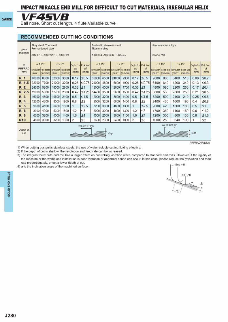
J280
R 1 40000 8000 32000 3800 0.17 36000 6500 24000 2900 0.17 9600 960 6400 510 0.08R 1.5 32000 7700 21000 3200 0.25 24000 4800 16000 1900 0.25 6400 640 4200 340 0.13R 2 24000 5800 16000 2800 0.33 18000 4000 12000 1700 0.33 4800 580 3200 260 0.17R 2.5 19000 5300 12700 2600 0.42 14400 3500 9600 1500 0.42 3800 530 2500 250 0.21R 3 16000 4800 10600 2100 0.5 12000 3200 8000 1400 0.5 3200 500 2100 210 0.25R 4 12000 4300 8000 1900 0.8 9000 3200 6000 1400 0.8 2400 430 1600 190 0.4R 5 9600 4100 6400 1800 1 7200 3000 4800 1300 1 2000 420 1300 180 0.5R 6 8000 4000 5300 1800 1.2 6000 3000 4000 1300 1.2 1700 350 1100 150 0.6R 8 6000 3200 4000 1400 1.6 4500 2500 3000 1100 1.6 1200 300 800 130 0.8R10 4800 3000 3200 1300 2 3600 2300 2400 1000 2 1000 250 640 100 1
VF4SVB
ap
PRFRAD
pf
%
CARBIDE
SOLI
D E
ND
MIL
LS
RECOMMENDED CUTTING CONDITIONS
1) When cutting austenitic stainless steels, the use of water-soluble cutting fl uid is effective.2) If the depth of cut is shallow, the revolution and feed rate can be increased.3) The irregular helix fl ute end mill has a larger effect on controlling vibration when compared to standard end mills. However, if the rigidity of
the machine or the workpiece installation is poor, vibration or abonrmal sound can occur. In this case, please reduce the revolution and feed rate proportionately, or set a lower depth of cut.
4) % is the inclination angle of the machined surface.
PRFRAD:Radius
<0.5PRFRAD <0.2PRFRAD
<ap <ap
Workmaterial
Alloy steel, Tool steel,Pre-hardened steel
AISI H13, AISI W1-10, AISI P21
Austenitic stainless steel,Titanium alloy
AISI 304, AISI 306, Ti-6Al-4V
Heat resistant alloys
Inconel718
RPRFRAD
(mm)
%<15° %>15° Depth of cutap
(mm)
Pick feedpf
(mm)
%<15° %>15° Depth of cutap
(mm)
Pick feedpf
(mm)
%<15° %>15° Depth of cutap
(mm)
Pick feedpf
(mm)Revolution(min-1)
Feed rate(mm/min)
Revolution(min-1)
Feed rate(mm/min)
Revolution(min-1)
Feed rate(mm/min)
Revolution(min-1)
Feed rate(mm/min)
Revolution(min-1)
Feed rate(mm/min)
Revolution(min-1)
Feed rate(mm/min)
<0.5 <0.5 <0.2<0.75 <0.75 <0.3<1 <1 <0.4<1.25 <1.25 <0.5<1.5 <1.5 <0.6<2 <2 <0.8<2.5 <2.5 <1<3 <3 <1.2<4 <4 <1.6<5 <5 <2
Depth ofcut
End mill
Ball nose, Short cut length, 4 fl ute,Variable curve
IMPACT MIRACLE END MILL FOR DIFFICULT TO CUT MATERIALS, IRREGULAR HELIX
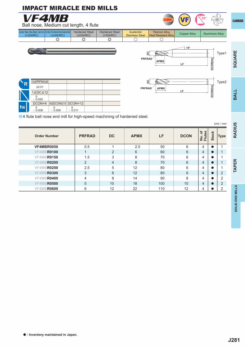
J281
a
VF4MB
PRFRAD DC APMX LF DCON
VF4MBR0050 0.5 1 2.5 50 6 4 a 1VF4MBR0100 1 2 6 60 6 4 a 1VF4MBR0150 1.5 3 8 70 6 4 a 1VF4MBR0200 2 4 8 70 6 4 a 1VF4MBR0250 2.5 5 12 80 6 4 a 1VF4MBR0300 3 6 12 80 6 4 a 2VF4MBR0400 4 8 14 90 8 4 a 2VF4MBR0500 5 10 18 100 10 4 a 2VF4MBR0600 6 12 22 110 12 4 a 2
e e e u u
±0.01
0- 0.020DCON=6 DCON=12 0- 0.008
0- 0.009
0- 0.011
UWC VF 30°
R
h6
APMX
DC
DC
ON
(h6)
15°
APMXLF
DC
DC
ON
(h6)
LF
PRFRAD
PRFRAD
SOLI
D E
ND
MIL
LS
CARBIDE
SQU
AR
EB
ALL
RA
DIU
STA
PER
Unit : mm
Carbon Steel, Alloy Steel, Cast Iron(<30HRC)
Tool Steel, Pre-Hardened Steel,Hardened Steel(<45HRC)
Hardened Steel(<55HRC)
Hardened Steel(>55HRC)
AusteniticStainless Steel
Titanium Alloy,Heat Resistant Alloy Copper Alloy Aluminium Alloy
4 fl ute ball nose end mill for high-speed machining of hardened steel.
Ball nose, Medium cut length, 4 fl ute
Order Number
No.
of
Flut
es
Stoc
k
Type
IMPACT MIRACLE END MILLS
8<DCON<10
1<DC<12
0.5<PRFRAD<6
Type1
Type2
a : Inventory maintained in Japan.
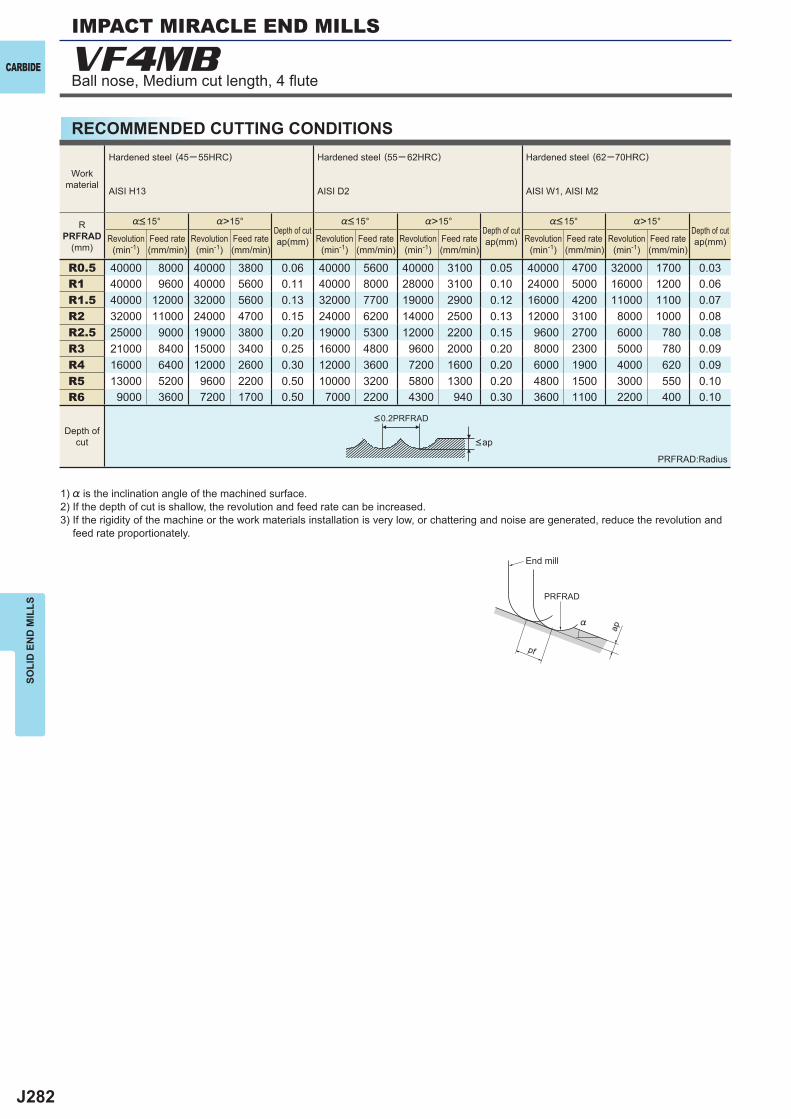
J282
%>15° %>15° %>15°
R0.5 40000 8000 40000 3800 0.06 40000 5600 40000 3100 0.05 40000 4700 32000 1700 0.03R1 40000 9600 40000 5600 0.11 40000 8000 28000 3100 0.10 24000 5000 16000 1200 0.06R1.5 40000 12000 32000 5600 0.13 32000 7700 19000 2900 0.12 16000 4200 11000 1100 0.07R2 32000 11000 24000 4700 0.15 24000 6200 14000 2500 0.13 12000 3100 8000 1000 0.08R2.5 25000 9000 19000 3800 0.20 19000 5300 12000 2200 0.15 9600 2700 6000 780 0.08R3 21000 8400 15000 3400 0.25 16000 4800 9600 2000 0.20 8000 2300 5000 780 0.09R4 16000 6400 12000 2600 0.30 12000 3600 7200 1600 0.20 6000 1900 4000 620 0.09R5 13000 5200 9600 2200 0.50 10000 3200 5800 1300 0.20 4800 1500 3000 550 0.10R6 9000 3600 7200 1700 0.50 7000 2200 4300 940 0.30 3600 1100 2200 400 0.10
VF4MB
ap
PRFRAD
pf
%
CARBIDE
SOLI
D E
ND
MIL
LS
RECOMMENDED CUTTING CONDITIONS
1) % is the inclination angle of the machined surface. 2) If the depth of cut is shallow, the revolution and feed rate can be increased.3) If the rigidity of the machine or the work materials installation is very low, or chattering and noise are generated, reduce the revolution and
feed rate proportionately.
PRFRAD:Radius
<ap
Revolution(min-1)
Revolution(min-1)
Revolution(min-1)
Revolution(min-1)
Revolution(min-1)
Revolution(min-1)
%<15° %<15° %<15°
Feed rate(mm/min)
Feed rate(mm/min)
Feed rate(mm/min)
Feed rate(mm/min)
Feed rate(mm/min)
Feed rate(mm/min)
Depth ofcut
<0.2PRFRAD
Workmaterial
Hardened steel (45─ 55HRC)
AISI H13
Hardened steel (55─ 62HRC)
AISI D2
Hardened steel (62─70HRC)
AISI W1, AISI M2
RPRFRAD
(mm)
Depth of cutap(mm)
Depth of cutap(mm)
Depth of cutap(mm)
End mill
Ball nose, Medium cut length, 4 fl ute
IMPACT MIRACLE END MILLS
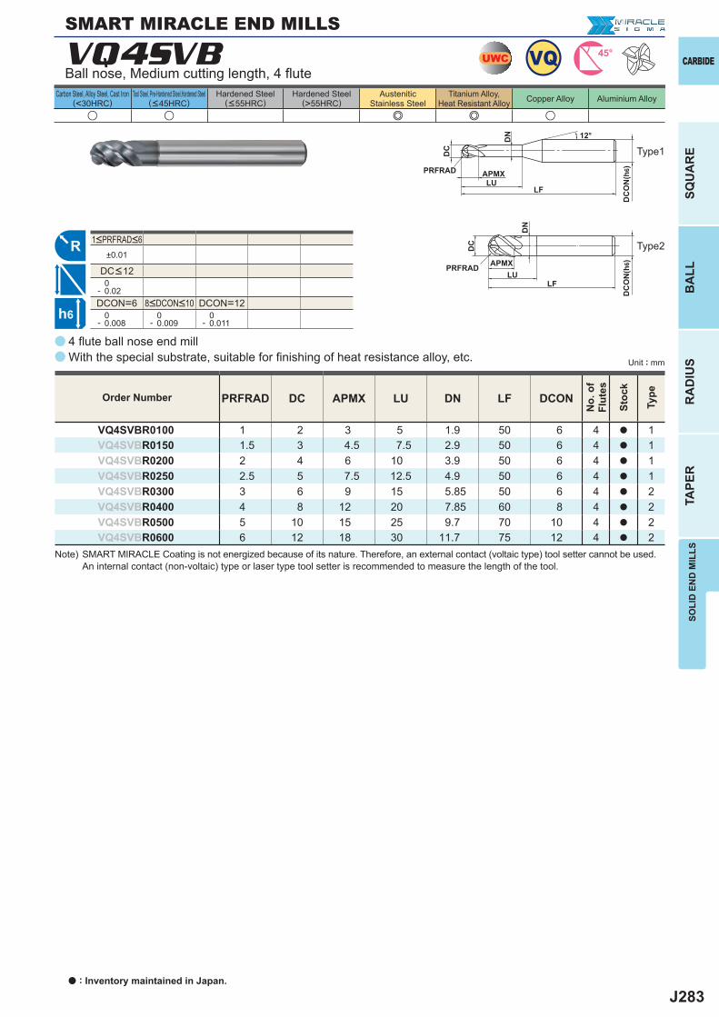
J283
±0.01
0- 0.02DCON=6 DCON=12 0- 0.008
0- 0.009
0- 0.011
u u e e u
PRFRAD DC APMX LU DN LF DCON
VQ4SVBR0100 1 2 3 5 1.9 50 6 4 a 1VQ4SVBR0150 1.5 3 4.5 7.5 2.9 50 6 4 a 1VQ4SVBR0200 2 4 6 10 3.9 50 6 4 a 1VQ4SVBR0250 2.5 5 7.5 12.5 4.9 50 6 4 a 1VQ4SVBR0300 3 6 9 15 5.85 50 6 4 a 2VQ4SVBR0400 4 8 12 20 7.85 60 8 4 a 2VQ4SVBR0500 5 10 15 25 9.7 70 10 4 a 2VQ4SVBR0600 6 12 18 30 11.7 75 12 4 a 2
a
a
VQ4SVB
R
UWC 45°VQ
h6
APMX
DC
DC
ON
(h6)
12°
LU
DN
LF
PRFRAD
APMX
DC
DC
ON
(h6)
LU
DN
LF
PRFRAD
SOLI
D E
ND
MIL
LS
CARBIDE
SQU
AR
EB
ALL
RA
DIU
STA
PER
Unit : mm
Carbon Steel, Alloy Steel, Cast Iron(<30HRC)
Tool Steel, Pre-Hardened Steel,Hardened Steel(<45HRC)
Hardened Steel(<55HRC)
Hardened Steel(>55HRC)
AusteniticStainless Steel
Titanium Alloy,Heat Resistant Alloy Copper Alloy Aluminium Alloy
8<DCON<10
1<PRFRAD<6
DC<12
Type2
Type1
4 fl ute ball nose end millWith the special substrate, suitable for fi nishing of heat resistance alloy, etc.
Order Number
No.
of
Flut
es
Stoc
k
Type
SMART MIRACLE END MILLS
Ball nose, Medium cutting length, 4 fl ute
a : Inventory maintained in Japan.
Note) SMART MIRACLE Coating is not energized because of its nature. Therefore, an external contact (voltaic type) tool setter cannot be used. An internal contact (non-voltaic) type or laser type tool setter is recommended to measure the length of the tool.
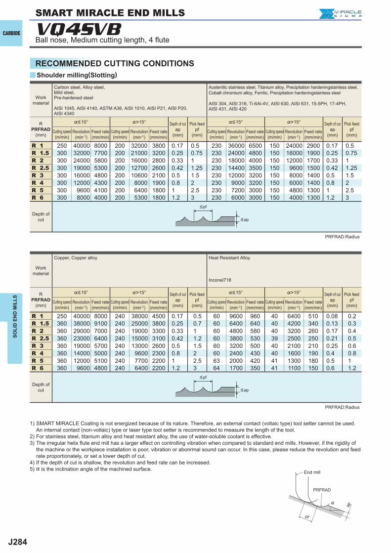
J284
y
VQ4SVB
R 1 250 40000 8000 200 32000 3800 0.17 0.5 230 36000 6500 150 24000 2900 0.17 0.5R 1.5 300 32000 7700 200 21000 3200 0.25 0.75 230 24000 4800 150 16000 1900 0.25 0.75R 2 300 24000 5800 200 16000 2800 0.33 1 230 18000 4000 150 12000 1700 0.33 1R 2.5 300 19000 5300 200 12700 2600 0.42 1.25 230 14400 3500 150 9600 1500 0.42 1.25R 3 300 16000 4800 200 10600 2100 0.5 1.5 230 12000 3200 150 8000 1400 0.5 1.5R 4 300 12000 4300 200 8000 1900 0.8 2 230 9000 3200 150 6000 1400 0.8 2R 5 300 9600 4100 200 6400 1800 1 2.5 230 7200 3000 150 4800 1300 1 2.5R 6 300 8000 4000 200 5300 1800 1.2 3 230 6000 3000 150 4000 1300 1.2 3
R 1 250 40000 8000 240 38000 4500 0.17 0.5 60 9600 960 40 6400 510 0.08 0.2R 1.5 360 38000 9100 240 25000 3800 0.25 0.7 60 6400 640 40 4200 340 0.13 0.3R 2 360 29000 7000 240 19000 3300 0.33 1 60 4800 580 40 3200 260 0.17 0.4R 2.5 360 23000 6400 240 15000 3100 0.42 1.2 60 3800 530 39 2500 250 0.21 0.5R 3 360 19000 5700 240 13000 2600 0.5 1.5 60 3200 500 40 2100 210 0.25 0.6R 4 360 14000 5000 240 9600 2300 0.8 2 60 2400 430 40 1600 190 0.4 0.8R 5 360 12000 5100 240 7700 2200 1 2.5 63 2000 420 41 1300 180 0.5 1R 6 360 9600 4800 240 6400 2200 1.2 3 64 1700 350 41 1100 150 0.6 1.2
ap
PRFRAD
pf
%
CARBIDE
SOLI
D E
ND
MIL
LS
RECOMMENDED CUTTING CONDITIONS
End mill
Shoulder milling(Slotting)
SMART MIRACLE END MILLS
Ball nose, Medium cutting length, 4 fl ute
PRFRAD:Radius
PRFRAD:Radius
<ap
<ap
<pf
<pf
Work material
Carbon steel, Alloy steel, Mild steel, Pre-hardened steel
AISI 1045, AISI 4140, ASTM A36, AISI 1010, AISI P21, AISI P20, AISI 4340
Austenitic stainless steel, Titanium alloy, Precipitation hardeningstainless steel, Cobalt chromium alloy, Ferritic, Precipitation hardeningstainless steel
AISI 304, AISI 316, Ti-6Al-4V, AISI 630, AISI 631, 15-5PH, 17-4PH, AISI 431, AISI 420
R PRFRAD
(mm)
%<15° %>15° Depth of cut ap
(mm)
Pick feed pf
(mm)
%<15° %>15° Depth of cut ap
(mm)
Pick feed pf
(mm)Cutting speed (m/min)
Revolution (min-1)
Feed rate (mm/min)
Cutting speed (m/min)
Revolution (min-1)
Feed rate (mm/min)
Cutting speed (m/min)
Revolution (min-1)
Feed rate (mm/min)
Cutting speed (m/min)
Revolution (min-1)
Feed rate (mm/min)
Depth of cut
Work material
Copper, Copper alloy Heat Resistant Alloy
Inconel718
R PRFRAD
(mm)
%<15° %>15° Depth of cut ap
(mm)
Pick feed pf
(mm)
%<15° %>15° Depth of cut ap
(mm)
Pick feed pf
(mm)Cutting speed (m/min)
Revolution (min-1)
Feed rate (mm/min)
Cutting speed (m/min)
Revolution (min-1)
Feed rate (mm/min)
Cutting speed (m/min)
Revolution (min-1)
Feed rate (mm/min)
Cutting speed (m/min)
Revolution (min-1)
Feed rate (mm/min)
Depth of cut
1) SMART MIRACLE Coating is not energized because of its nature. Therefore, an external contact (voltaic type) tool setter cannot be used. An internal contact (non-voltaic) type or laser type tool setter is recommended to measure the length of the tool.
2) For stainless steel, titanium alloy and heat resistant alloy, the use of water-soluble coolant is effective.3) The irregular helix fl ute end mill has a larger effect on controlling vibration when compared to standard end mills. However, if the rigidity of
the machine or the workpiece installation is poor, vibration or abonrmal sound can occur. In this case, please reduce the revolution and feed rate proportionately, or set a lower depth of cut.
4) If the depth of cut is shallow, the revolution and feed rate can be increased.5) % is the inclination angle of the machined surface.
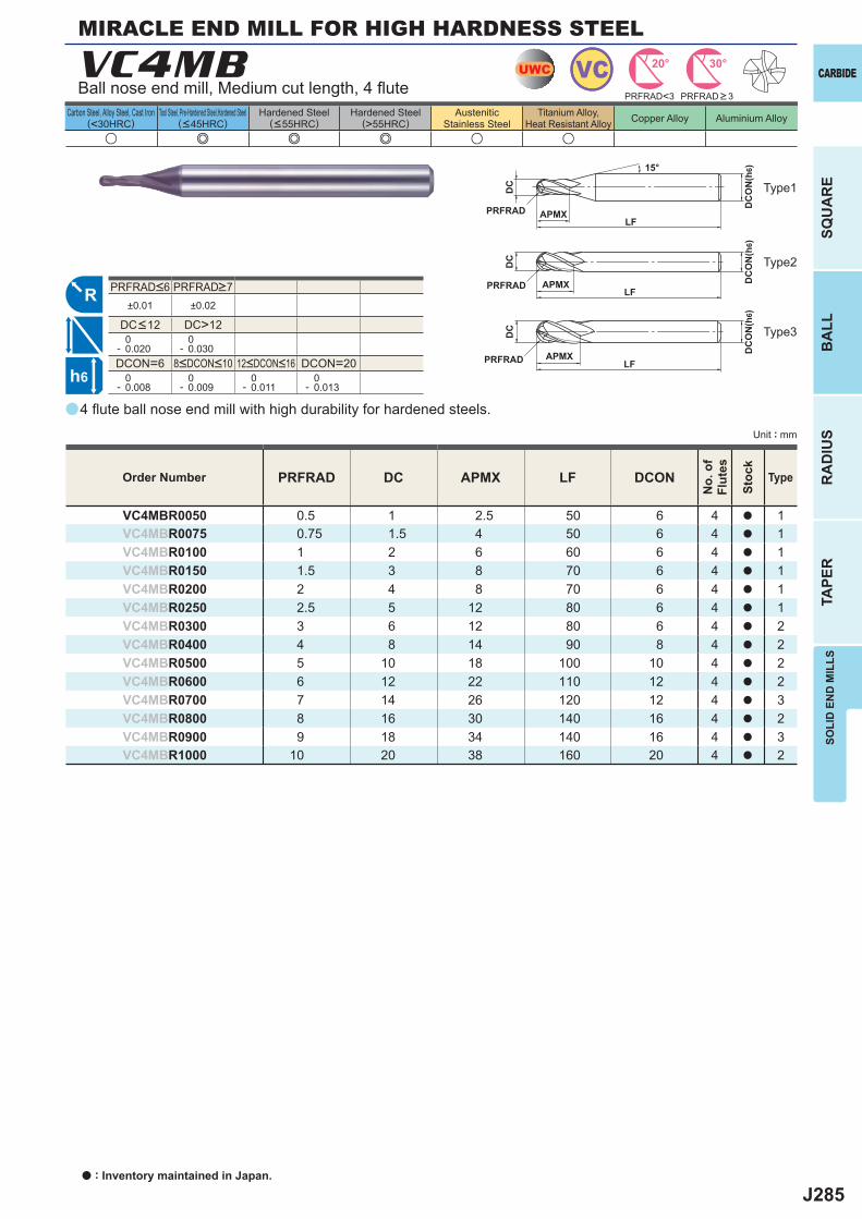
J285
u e e e u u
a
VC4MB
PRFRAD DC APMX LF DCON
VC4MBR0050 0.5 1 2.5 50 6 4 a 1VC4MBR0075 0.75 1.5 4 50 6 4 a 1VC4MBR0100 1 2 6 60 6 4 a 1VC4MBR0150 1.5 3 8 70 6 4 a 1VC4MBR0200 2 4 8 70 6 4 a 1VC4MBR0250 2.5 5 12 80 6 4 a 1VC4MBR0300 3 6 12 80 6 4 a 2VC4MBR0400 4 8 14 90 8 4 a 2VC4MBR0500 5 10 18 100 10 4 a 2VC4MBR0600 6 12 22 110 12 4 a 2VC4MBR0700 7 14 26 120 12 4 a 3VC4MBR0800 8 16 30 140 16 4 a 2VC4MBR0900 9 18 34 140 16 4 a 3VC4MBR1000 10 20 38 160 20 4 a 2
±0.01 ±0.02
DC>12 0- 0.020
0- 0.030
DCON=6 DCON=20 0- 0.008
0- 0.009
0- 0.011
0- 0.013
UWC VC 30°20°
R
h6
APMX
DC
DC
ON
(h6)15°
LFPRFRAD
APMX
DC
DC
ON
(h6)
LFPRFRAD
APMX
DC
DC
ON
(h6)
LFPRFRAD
PRFRAD<3
SOLI
D E
ND
MIL
LS
CARBIDE
SQU
AR
EB
ALL
RA
DIU
STA
PER
Unit : mm
Carbon Steel, Alloy Steel, Cast Iron(<30HRC)
Tool Steel, Pre-Hardened Steel,Hardened Steel(<45HRC)
Hardened Steel(<55HRC)
Hardened Steel(>55HRC)
AusteniticStainless Steel
Titanium Alloy,Heat Resistant Alloy Copper Alloy Aluminium Alloy
MIRACLE END MILL FOR HIGH HARDNESS STEEL
4 fl ute ball nose end mill with high durability for hardened steels.
Ball nose end mill, Medium cut length, 4 fl ute
Type2
Type3
Type1
Order Number
No.
of
Flut
es
Stoc
k
Type
PRFRAD > 3
8<DCON<10 12<DCON<16
PRFRAD<6 PRFRAD>7
DC<12
a : Inventory maintained in Japan.
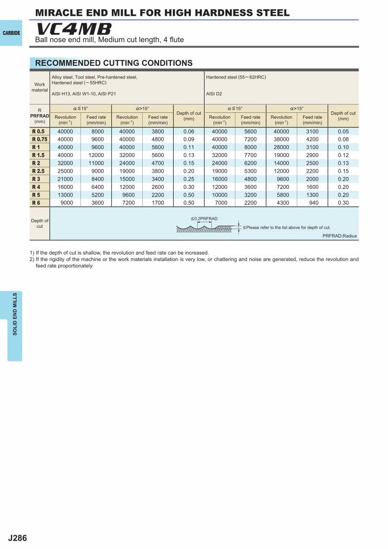
J286
%>15° %>15°
R 0.5 40000 8000 40000 3800 0.06 40000 5600 40000 3100 0.05R 0.75 40000 9600 40000 4800 0.09 40000 7200 38000 4200 0.08R 1 40000 9600 40000 5600 0.11 40000 8000 28000 3100 0.10R 1.5 40000 12000 32000 5600 0.13 32000 7700 19000 2900 0.12R 2 32000 11000 24000 4700 0.15 24000 6200 14000 2500 0.13R 2.5 25000 9000 19000 3800 0.20 19000 5300 12000 2200 0.15R 3 21000 8400 15000 3400 0.25 16000 4800 9600 2000 0.20R 4 16000 6400 12000 2600 0.30 12000 3600 7200 1600 0.20R 5 13000 5200 9600 2200 0.50 10000 3200 5800 1300 0.20R 6 9000 3600 7200 1700 0.50 7000 2200 4300 940 0.30
VC4MBCARBIDE
SOLI
D E
ND
MIL
LS
RECOMMENDED CUTTING CONDITIONS
PRFRAD:Radius
<Please refer to the list above for depth of cut.
1) If the depth of cut is shallow, the revolution and feed rate can be increased.2) If the rigidity of the machine or the work materials installation is very low, or chattering and noise are generated, reduce the revolution and
feed rate proportionately.
Workmaterial
Alloy steel, Tool steel, Pre-hardened steel,Hardened steel (─ 55HRC)
AISI H13, AISI W1-10, AISI P21
Hardened steel (55─ 62HRC)
AISI D2
RPRFRAD
(mm)
%<15°Depth of cut
(mm)
%<15°Depth of cut
(mm)Revolution(min-1)
Feed rate(mm/min)
Revolution(min-1)
Feed rate(mm/min)
Revolution(min-1)
Feed rate(mm/min)
Revolution(min-1)
Feed rate(mm/min)
Depth ofcut
<0.2PRFRAD
MIRACLE END MILL FOR HIGH HARDNESS STEEL
Ball nose end mill, Medium cut length, 4 fl ute
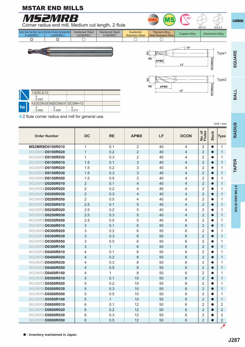
J287
a
MS2MRB
e e u u u
DC RE APMX LF DCON
MS2MRBD0100R010 1 0.1 2 40 4 2 a 1MS2MRBD0100R020 1 0.2 2 40 4 2 a 1MS2MRBD0100R030 1 0.3 2 40 4 2 a 1MS2MRBD0150R010 1.5 0.1 3 40 4 2 a 1MS2MRBD0150R020 1.5 0.2 3 40 4 2 a 1MS2MRBD0150R030 1.5 0.3 3 40 4 2 a 1MS2MRBD0150R050 1.5 0.5 3 40 4 2 a 1MS2MRBD0200R010 2 0.1 4 40 4 2 a 1MS2MRBD0200R020 2 0.2 4 40 4 2 a 1MS2MRBD0200R030 2 0.3 4 40 4 2 a 1MS2MRBD0200R050 2 0.5 4 40 4 2 a 1MS2MRBD0250R010 2.5 0.1 5 40 4 2 a 1MS2MRBD0250R020 2.5 0.2 5 40 4 2 a 1MS2MRBD0250R030 2.5 0.3 5 40 4 2 a 1MS2MRBD0250R050 2.5 0.5 5 40 4 2 a 1MS2MRBD0300R010 3 0.1 6 50 6 2 a 1MS2MRBD0300R020 3 0.2 6 50 6 2 a 1MS2MRBD0300R030 3 0.3 6 50 6 2 a 1MS2MRBD0300R050 3 0.5 6 50 6 2 a 1MS2MRBD0300R100 3 1 6 50 6 2 a 1MS2MRBD0400R010 4 0.1 8 50 6 2 a 1MS2MRBD0400R020 4 0.2 8 50 6 2 a 1MS2MRBD0400R030 4 0.3 8 50 6 2 a 1MS2MRBD0400R050 4 0.5 8 50 6 2 a 1MS2MRBD0400R100 4 1 8 50 6 2 a 1MS2MRBD0500R010 5 0.1 10 50 6 2 a 1MS2MRBD0500R020 5 0.2 10 50 6 2 a 1MS2MRBD0500R030 5 0.3 10 50 6 2 a 1MS2MRBD0500R050 5 0.5 10 50 6 2 a 1MS2MRBD0500R100 5 1 10 50 6 2 a 1MS2MRBD0600R010 6 0.1 12 50 6 2 a 2MS2MRBD0600R020 6 0.2 12 50 6 2 a 2MS2MRBD0600R030 6 0.3 12 50 6 2 a 2MS2MRBD0600R050 6 0.5 12 50 6 2 a 2
DC<3
0- 0.020
DCON=12 0- 0.008
0- 0.009
0- 0.011
UWC MS 30°
h6
APMX
DC
DC
ON
(h6)
15°
APMXLF
DC
DC
ON
(h6)
LF
RE
RE
CARBIDE
SQU
AR
EB
ALL
RA
DIU
STA
PER
SOLI
D E
ND
MIL
LS
Unit : mm
Carbon Steel, Alloy Steel, Cast Iron(<30HRC)
Tool Steel, Pre-Hardened Steel,Hardened Steel(<45HRC)
Hardened Steel(<55HRC)
Hardened Steel(>55HRC)
AusteniticStainless Steel
Titanium Alloy,Heat Resistant Alloy Copper Alloy Aluminium Alloy
2 fl ute corner radius end mill for general use.
Corner radius end mill, Medium cut length, 2 fl ute
MSTAR END MILLS
Order Number
No.
of
Flut
es
Stoc
k
Type
DC>3
4<DCON<6 8<DCON<10
1<DC<12
Type1
Type2
a : Inventory maintained in Japan.
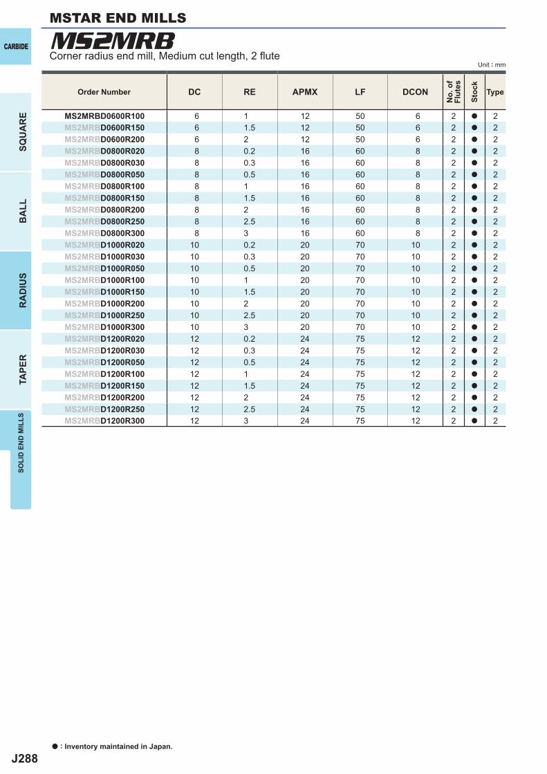
J288
MS2MRB
DC RE APMX LF DCON
MS2MRBD0600R100 6 1 12 50 6 2 a 2MS2MRBD0600R150 6 1.5 12 50 6 2 a 2MS2MRBD0600R200 6 2 12 50 6 2 a 2MS2MRBD0800R020 8 0.2 16 60 8 2 a 2MS2MRBD0800R030 8 0.3 16 60 8 2 a 2MS2MRBD0800R050 8 0.5 16 60 8 2 a 2MS2MRBD0800R100 8 1 16 60 8 2 a 2MS2MRBD0800R150 8 1.5 16 60 8 2 a 2MS2MRBD0800R200 8 2 16 60 8 2 a 2MS2MRBD0800R250 8 2.5 16 60 8 2 a 2MS2MRBD0800R300 8 3 16 60 8 2 a 2MS2MRBD1000R020 10 0.2 20 70 10 2 a 2MS2MRBD1000R030 10 0.3 20 70 10 2 a 2MS2MRBD1000R050 10 0.5 20 70 10 2 a 2MS2MRBD1000R100 10 1 20 70 10 2 a 2MS2MRBD1000R150 10 1.5 20 70 10 2 a 2MS2MRBD1000R200 10 2 20 70 10 2 a 2MS2MRBD1000R250 10 2.5 20 70 10 2 a 2MS2MRBD1000R300 10 3 20 70 10 2 a 2MS2MRBD1200R020 12 0.2 24 75 12 2 a 2MS2MRBD1200R030 12 0.3 24 75 12 2 a 2MS2MRBD1200R050 12 0.5 24 75 12 2 a 2MS2MRBD1200R100 12 1 24 75 12 2 a 2MS2MRBD1200R150 12 1.5 24 75 12 2 a 2MS2MRBD1200R200 12 2 24 75 12 2 a 2MS2MRBD1200R250 12 2.5 24 75 12 2 a 2MS2MRBD1200R300 12 3 24 75 12 2 a 2
a : Inventory maintained in Japan.
CARBIDE
SQU
AR
EB
ALL
RA
DIU
STA
PER
SOLI
D E
ND
MIL
LS
Unit : mmCorner radius end mill, Medium cut length, 2 fl ute
MSTAR END MILLS
Order Number
No.
of
Flut
es
Stoc
k
Type
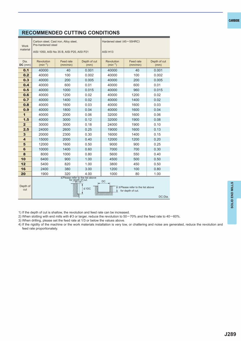
J289
0.1 40000 40 0.001 40000 40 0.0010.2 40000 100 0.002 40000 100 0.0020.3 40000 200 0.005 40000 200 0.0050.4 40000 600 0.01 40000 600 0.010.5 40000 1000 0.015 40000 960 0.0150.6 40000 1200 0.02 40000 1200 0.020.7 40000 1400 0.02 40000 1400 0.020.8 40000 1600 0.03 40000 1600 0.030.9 40000 1800 0.04 40000 1600 0.041 40000 2000 0.06 32000 1600 0.061.5 40000 3000 0.12 32000 1900 0.082 30000 3000 0.18 24000 1900 0.102.5 24000 2600 0.25 19000 1600 0.133 20000 2300 0.30 16000 1400 0.154 15000 2000 0.40 12000 1200 0.205 12000 1600 0.50 9000 900 0.256 10000 1400 0.60 7000 700 0.308 8000 1000 0.80 5600 550 0.40
10 6400 900 1.00 4500 500 0.5012 5400 820 1.00 3800 450 0.5016 2400 380 3.00 1200 100 0.8020 1900 320 4.00 1000 80 1.00
DC
CARBIDE
SOLI
D E
ND
MIL
LS
RECOMMENDED CUTTING CONDITIONS
1) If the depth of cut is shallow, the revolution and feed rate can be increased.2) When slotting with end mills with &3 or larger, reduce the revolution to 50─70% and the feed rate to 40─60%.3) When drilling, please set the feed rate at 1/3 or below the values above.4) If the rigidity of the machine or the work materials installation is very low, or chattering and noise are generated, reduce the revolution and
feed rate proportionately.
DC:Dia.
<Please refer to the list above for depth of cut.
<Please refer to the list above for depth of cut.
Workmaterial
Carbon steel, Cast iron, Alloy steel,Pre-hardened steel
AISI 1050, AISI No 35 B, AISI P20, AISI P21
Hardened steel (45─ 55HRC)
AISI H13
Dia.DC (mm)
Revolution(min-1)
Feed rate(mm/min)
Depth of cut(mm)
Revolution(min-1)
Feed rate(mm/min)
Depth of cut(mm)
Depth ofcut <1DC
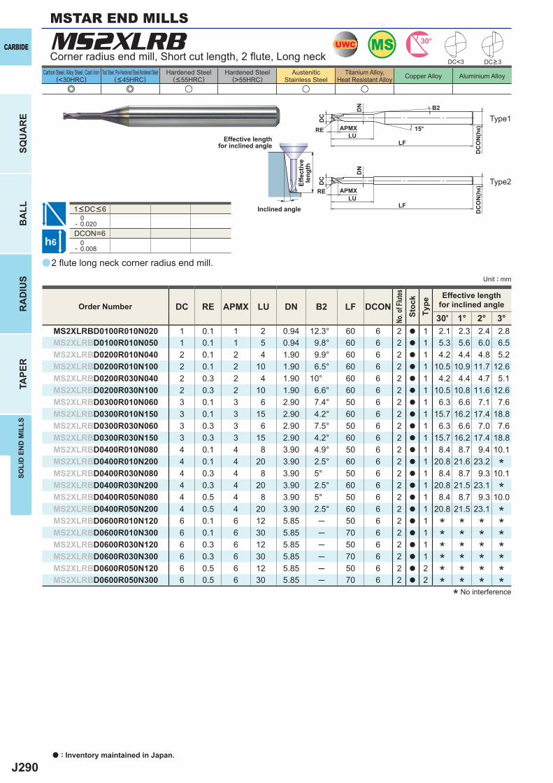
J290
a
e e u u u
MS2XLRB
DC RE APMX LU DN B2 LF DCON30' 1° 2° 3°
MS2XLRBD0100R010N020 1 0.1 1 2 0.94 12.3° 60 6 2 a 1 2.1 2.3 2.4 2.8MS2XLRBD0100R010N050 1 0.1 1 5 0.94 9.8° 60 6 2 a 1 5.3 5.6 6.0 6.5MS2XLRBD0200R010N040 2 0.1 2 4 1.90 9.9° 60 6 2 a 1 4.2 4.4 4.8 5.2MS2XLRBD0200R010N100 2 0.1 2 10 1.90 6.5° 60 6 2 a 1 10.5 10.9 11.7 12.6MS2XLRBD0200R030N040 2 0.3 2 4 1.90 10° 60 6 2 a 1 4.2 4.4 4.7 5.1MS2XLRBD0200R030N100 2 0.3 2 10 1.90 6.6° 60 6 2 a 1 10.5 10.8 11.6 12.6MS2XLRBD0300R010N060 3 0.1 3 6 2.90 7.4° 50 6 2 a 1 6.3 6.6 7.1 7.6MS2XLRBD0300R010N150 3 0.1 3 15 2.90 4.2° 60 6 2 a 1 15.7 16.2 17.4 18.8MS2XLRBD0300R030N060 3 0.3 3 6 2.90 7.5° 50 6 2 a 1 6.3 6.6 7.0 7.6MS2XLRBD0300R030N150 3 0.3 3 15 2.90 4.2° 60 6 2 a 1 15.7 16.2 17.4 18.8MS2XLRBD0400R010N080 4 0.1 4 8 3.90 4.9° 50 6 2 a 1 8.4 8.7 9.4 10.1MS2XLRBD0400R010N200 4 0.1 4 20 3.90 2.5° 60 6 2 a 1 20.8 21.6 23.2MS2XLRBD0400R030N080 4 0.3 4 8 3.90 5° 50 6 2 a 1 8.4 8.7 9.3 10.1MS2XLRBD0400R030N200 4 0.3 4 20 3.90 2.5° 60 6 2 a 1 20.8 21.5 23.1MS2XLRBD0400R050N080 4 0.5 4 8 3.90 5° 50 6 2 a 1 8.4 8.7 9.3 10.0MS2XLRBD0400R050N200 4 0.5 4 20 3.90 2.5° 60 6 2 a 1 20.8 21.5 23.1MS2XLRBD0600R010N120 6 0.1 6 12 5.85 ─ 50 6 2 a 1MS2XLRBD0600R010N300 6 0.1 6 30 5.85 ─ 70 6 2 a 1MS2XLRBD0600R030N120 6 0.3 6 12 5.85 ─ 50 6 2 a 1MS2XLRBD0600R030N300 6 0.3 6 30 5.85 ─ 70 6 2 a 1MS2XLRBD0600R050N120 6 0.5 6 12 5.85 ─ 50 6 2 a 2MS2XLRBD0600R050N300 6 0.5 6 30 5.85 ─ 70 6 2 a 2
DC<3
0- 0.020DCON=6 0- 0.008
UWC MS 30°
h6
APMX
DC
DC
ON
(h6)15°
B2
APMX
LF
DC
DC
ON
(h6)
LF
RE
RELU
LU
DN
DN
a : Inventory maintained in Japan.
CARBIDE
SQU
AR
EB
ALL
RA
DIU
STA
PER
SOLI
D E
ND
MIL
LS
Unit : mm
Carbon Steel, Alloy Steel, Cast Iron(<30HRC)
Tool Steel, Pre-Hardened Steel,Hardened Steel(<45HRC)
Hardened Steel(<55HRC)
Hardened Steel(>55HRC)
AusteniticStainless Steel
Titanium Alloy,Heat Resistant Alloy Copper Alloy Aluminium Alloy
MSTAR END MILLS
2 fl ute long neck corner radius end mill.
Corner radius end mill, Short cut length, 2 fl ute, Long neck
Effective lengthfor inclined angle
Inclined angle
Effe
ctiv
ele
ngth
DC>3
* No interference
Order Number
No. o
f Flut
esSt
ock
Type
Effective lengthfor inclined angle
*******
*
*
******
******
******
1<DC<6
Type1
Type2
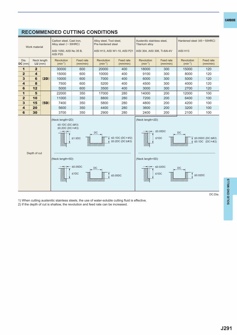
J291
1 2
(2D)
30000 600 20000 400 18000 300 15000 1202 4 15000 600 10000 400 9100 300 8000 1203 6 10000 600 7000 400 6000 300 5000 1204 8 7500 600 5200 400 4500 300 4000 1206 12 5000 600 3500 400 3000 300 2700 1201 5
(5D)
22000 350 17000 280 14000 200 12000 1002 10 11000 350 8800 280 7200 200 6400 1003 15 7400 350 5800 280 4800 200 4200 1004 20 5600 350 4400 280 3600 200 3200 1006 30 3700 350 2900 280 2400 200 2100 100
DC DC
DC DC
CARBIDE
SOLI
D E
ND
MIL
LS
RECOMMENDED CUTTING CONDITIONS
1) When cutting austenitic stainless steels, the use of water-soluble cutting fl uid is effective.2) If the depth of cut is shallow, the revolution and feed rate can be increased.
DC:Dia.
(Neck length=2D) (Neck length=2D)
(Neck length=5D) (Neck length=5D)
Work material
Carbon steel, Cast iron, Alloy steel (─30HRC)
AISI 1050, AISI No 35 B,AISI P20
Alloy steel, Tool steel,Pre-hardened steel
AISI H13, AISI W1-10, AISI P21
Austenitic stainless steel,Titanium alloy
AISI 304, AISI 306, Ti-6Al-4V
Hardened steel (45─ 55HRC)
AISI H13
Dia.DC (mm)
Neck lengthLU (mm)
Revolution(min-1)
Feed rate(mm/min)
Revolution(min-1)
Feed rate(mm/min)
Revolution(min-1)
Feed rate(mm/min)
Revolution(min-1)
Feed rate(mm/min)
<0.1DC (DC <&3)<0.2DC (DC>&3)
<0.1DC (DC<&2)<0.2DC (DC >&2)
<1.5DC
<0.05DC
<0.05DC<1DC
<0.05DC (DC <&2)<0.1DC (DC>&2)
<0.05DC
<0.02DC
<0.02DC
<1DC
<1DC
Depth of cut
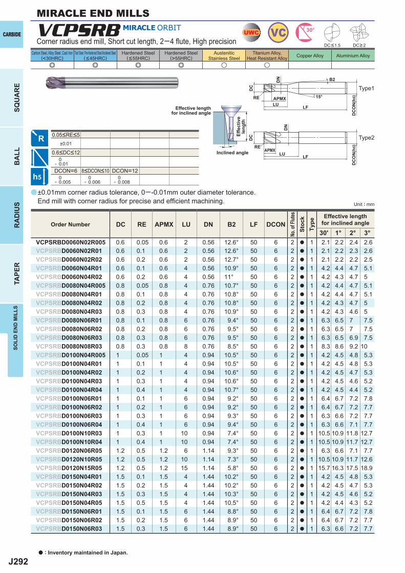
J292
a
e e e e u u
VCPSRB
DC RE APMX LU DN B2 LF DCON30' 1° 2° 3°
VCPSRBD0060N02R005 0.6 0.05 0.6 2 0.56 12.6° 50 6 2 a 1 2.1 2.2 2.4 2.6VCPSRBD0060N02R01 0.6 0.1 0.6 2 0.56 12.6° 50 6 2 a 1 2.1 2.2 2.3 2.6VCPSRBD0060N02R02 0.6 0.2 0.6 2 0.56 12.7° 50 6 2 a 1 2.1 2.2 2.2 2.5VCPSRBD0060N04R01 0.6 0.1 0.6 4 0.56 10.9° 50 6 2 a 1 4.2 4.4 4.7 5.1VCPSRBD0060N04R02 0.6 0.2 0.6 4 0.56 11° 50 6 2 a 1 4.2 4.3 4.7 5VCPSRBD0080N04R005 0.8 0.05 0.8 4 0.76 10.7° 50 6 2 a 1 4.2 4.4 4.7 5.1VCPSRBD0080N04R01 0.8 0.1 0.8 4 0.76 10.8° 50 6 2 a 1 4.2 4.4 4.7 5.1VCPSRBD0080N04R02 0.8 0.2 0.8 4 0.76 10.8° 50 6 2 a 1 4.2 4.3 4.7 5VCPSRBD0080N04R03 0.8 0.3 0.8 4 0.76 10.9° 50 6 2 a 1 4.2 4.3 4.6 5VCPSRBD0080N06R01 0.8 0.1 0.8 6 0.76 9.4° 50 6 2 a 1 6.3 6.5 7 7.5VCPSRBD0080N06R02 0.8 0.2 0.8 6 0.76 9.5° 50 6 2 a 1 6.3 6.5 7 7.5VCPSRBD0080N06R03 0.8 0.3 0.8 6 0.76 9.5° 50 6 2 a 1 6.3 6.5 6.9 7.5VCPSRBD0080N08R03 0.8 0.3 0.8 8 0.76 8.5° 50 6 2 a 1 8.3 8.6 9.2 10VCPSRBD0100N04R005 1 0.05 1 4 0.94 10.5° 50 6 2 a 1 4.2 4.5 4.8 5.3VCPSRBD0100N04R01 1 0.1 1 4 0.94 10.5° 50 6 2 a 1 4.2 4.5 4.8 5.3VCPSRBD0100N04R02 1 0.2 1 4 0.94 10.6° 50 6 2 a 1 4.2 4.5 4.7 5.3VCPSRBD0100N04R03 1 0.3 1 4 0.94 10.6° 50 6 2 a 1 4.2 4.5 4.6 5.2VCPSRBD0100N04R04 1 0.4 1 4 0.94 10.7° 50 6 2 a 1 4.2 4.5 4.4 5.2VCPSRBD0100N06R01 1 0.1 1 6 0.94 9.2° 50 6 2 a 1 6.4 6.7 7.2 7.8VCPSRBD0100N06R02 1 0.2 1 6 0.94 9.2° 50 6 2 a 1 6.4 6.7 7.2 7.7VCPSRBD0100N06R03 1 0.3 1 6 0.94 9.3° 50 6 2 a 1 6.3 6.6 7.2 7.7VCPSRBD0100N06R04 1 0.4 1 6 0.94 9.4° 50 6 2 a 1 6.3 6.6 7.1 7.7VCPSRBD0100N10R03 1 0.3 1 10 0.94 7.4° 50 6 2 a 1 10.5 10.9 11.8 12.7VCPSRBD0100N10R04 1 0.4 1 10 0.94 7.4° 50 6 2 a 1 10.5 10.9 11.7 12.7VCPSRBD0120N06R05 1.2 0.5 1.2 6 1.14 9.3° 50 6 2 a 1 6.3 6.6 7.1 7.7VCPSRBD0120N10R05 1.2 0.5 1.2 10 1.14 7.3° 50 6 2 a 1 10.5 10.9 11.7 12.6VCPSRBD0120N15R05 1.2 0.5 1.2 15 1.14 5.8° 50 6 2 a 1 15.7 16.3 17.5 18.9VCPSRBD0150N04R01 1.5 0.1 1.5 4 1.44 10.2° 50 6 2 a 1 4.2 4.5 4.8 5.3VCPSRBD0150N04R02 1.5 0.2 1.5 4 1.44 10.2° 50 6 2 a 1 4.2 4.5 4.7 5.3VCPSRBD0150N04R03 1.5 0.3 1.5 4 1.44 10.3° 50 6 2 a 1 4.2 4.5 4.6 5.2VCPSRBD0150N04R05 1.5 0.5 1.5 4 1.44 10.5° 50 6 2 a 1 4.2 4.4 4.3 5.2VCPSRBD0150N06R01 1.5 0.1 1.5 6 1.44 8.8° 50 6 2 a 1 6.4 6.7 7.2 7.8VCPSRBD0150N06R02 1.5 0.2 1.5 6 1.44 8.9° 50 6 2 a 1 6.4 6.7 7.2 7.7VCPSRBD0150N06R03 1.5 0.3 1.5 6 1.44 8.9° 50 6 2 a 1 6.3 6.6 7.2 7.7
±0.01
0- 0.01DCON=6 DCON=12 0- 0.005
0- 0.006
0- 0.008
UWC VC 30°
h5
APMX
DC
DC
ON
(h5)15°
APMXLF
DC
DC
ON
(h5)
LF
RE
RELU
LU
DN
DN
B2
a : Inventory maintained in Japan.
CARBIDE
SQU
AR
EB
ALL
RA
DIU
STA
PER
SOLI
D E
ND
MIL
LS
Unit : mm
Carbon Steel, Alloy Steel, Cast Iron(<30HRC)
Tool Steel, Pre-Hardened Steel,Hardened Steel(<45HRC)
Hardened Steel(<55HRC)
Hardened Steel(>55HRC)
AusteniticStainless Steel
Titanium Alloy,Heat Resistant Alloy Copper Alloy Aluminium Alloy
MIRACLE END MILLS
±0.01mm corner radius tolerance, 0─ -0.01mm outer diameter tolerance. End mill with corner radius for precise and effi cient machining.
Corner radius end mill, Short cut length, 2─4 fl ute, High precision
Effective lengthfor inclined angle
Inclined angle
Effe
ctiv
ele
ngth
DC<1.5 DC>2
Order Number
No. o
f Flut
esSt
ock
Type
Effective lengthfor inclined angle
8<DCON<10
0.6<DC<12
0.05<RE<5
Type1
Type2
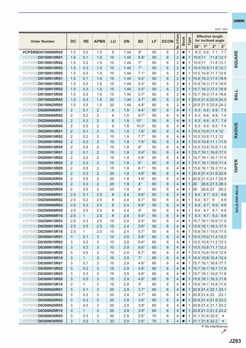
J293
DC RE APMX LU DN B2 LF DCON30' 1° 2° 3°
VCPSRBD0150N06R05 1.5 0.5 1.5 6 1.44 9° 50 6 2 a 1 6.3 6.6 7.1 7.7VCPSRBD0150N10R01 1.5 0.1 1.5 10 1.44 6.9° 50 6 2 a 1 10.6 11 11.8 12.7VCPSRBD0150N10R02 1.5 0.2 1.5 10 1.44 7° 50 6 2 a 1 10.5 11 11.8 12.7VCPSRBD0150N10R03 1.5 0.3 1.5 10 1.44 7° 50 6 2 a 1 10.5 10.9 11.8 12.7VCPSRBD0150N10R05 1.5 0.5 1.5 10 1.44 7.1° 50 6 2 a 1 10.5 10.9 11.7 12.6VCPSRBD0150N15R01 1.5 0.1 1.5 15 1.44 5.5° 50 6 2 a 1 15.8 16.3 17.5 18.9VCPSRBD0150N15R02 1.5 0.2 1.5 15 1.44 5.5° 50 6 2 a 1 15.8 16.3 17.5 18.9VCPSRBD0150N15R03 1.5 0.3 1.5 15 1.44 5.5° 50 6 2 a 1 15.7 16.3 17.5 18.9VCPSRBD0150N15R05 1.5 0.5 1.5 15 1.44 5.7° 50 6 2 a 1 15.7 16.3 17.4 18.6VCPSRBD0150N20R03 1.5 0.3 1.5 20 1.44 4.7° 60 6 2 a 1 20.9 21.6 22.9 24.5VCPSRBD0150N20R05 1.5 0.5 1.5 20 1.44 4.8° 60 6 2 a 1 20.9 21.5 22.8 24.2VCPSRBD0200N06R01 2 0.1 2 6 1.9 9.4° 50 6 4 a 1 6.3 6.6 6.9 7.5VCPSRBD0200N06R02 2 0.2 2 6 1.9 9.7° 50 6 4 a 1 6.3 6.6 6.8 7.4VCPSRBD0200N06R03 2 0.3 2 6 1.9 10° 50 6 4 a 1 6.3 6.6 6.7 7.4VCPSRBD0200N06R05 2 0.5 2 6 1.9 10.3° 50 6 4 a 1 6.3 6.5 6.5 7.4VCPSRBD0200N10R01 2 0.1 2 10 1.9 7.6° 50 6 4 a 1 10.5 10.9 11.4 12VCPSRBD0200N10R02 2 0.2 2 10 1.9 7.7° 50 6 4 a 1 10.5 10.8 11.2 12VCPSRBD0200N10R03 2 0.3 2 10 1.9 7.8° 50 6 4 a 1 10.5 10.8 11.1 11.9VCPSRBD0200N10R05 2 0.5 2 10 1.9 8° 50 6 4 a 1 10.5 10.8 10.9 11.9VCPSRBD0200N15R01 2 0.1 2 15 1.9 5.9° 50 6 4 a 1 15.7 16.1 16.8 17.5VCPSRBD0200N15R02 2 0.2 2 15 1.9 5.9° 50 6 4 a 1 15.7 16.1 16.7 17.5VCPSRBD0200N15R03 2 0.3 2 15 1.9 6° 50 6 4 a 1 15.7 16.1 16.6 17.4VCPSRBD0200N15R05 2 0.5 2 15 1.9 6.1° 50 6 4 a 1 15.6 16.1 16.3 17.4VCPSRBD0200N20R03 2 0.3 2 20 1.9 4.8° 60 6 4 a 1 20.8 21.4 21.9 22.9VCPSRBD0200N20R05 2 0.5 2 20 1.9 4.9° 60 6 4 a 1 20.8 21.4 21.7 22.9VCPSRBD0200N25R03 2 0.3 2 25 1.9 4° 60 6 4 a 1 26 26.6 27.5 28.3VCPSRBD0200N25R05 2 0.5 2 25 1.9 4° 60 6 4 a 1 26 26.6 27 28.2VCPSRBD0250N08R01 2.5 0.1 2.5 8 2.4 8.6° 50 6 4 a 1 8.4 8.7 9.2 9.9VCPSRBD0250N08R02 2.5 0.2 2.5 8 2.4 8.7° 50 6 4 a 1 8.4 8.7 9 9.9VCPSRBD0250N08R03 2.5 0.3 2.5 8 2.4 8.8° 50 6 4 a 1 8.4 8.7 8.9 9.9VCPSRBD0250N08R05 2.5 0.5 2.5 8 2.4 9° 50 6 4 a 1 8.4 8.7 8.7 9.9VCPSRBD0250N08R10 2.5 1 2.5 8 2.4 9.4° 50 6 4 a 1 8.3 8.7 8.2 9.9VCPSRBD0250N15R03 2.5 0.3 2.5 15 2.4 5.5° 50 6 4 a 1 15.7 16.1 16.6 17.5VCPSRBD0250N15R05 2.5 0.5 2.5 15 2.4 5.6° 50 6 4 a 1 15.6 16.1 16.3 17.5VCPSRBD0250N15R10 2.5 1 2.5 15 2.4 5.7° 50 6 4 a 1 15.6 16.1 15.8 17.5VCPSRBD0300N10R01 3 0.1 3 10 2.9 6.6° 60 6 4 a 1 10.5 10.9 11.4 12.3VCPSRBD0300N10R02 3 0.2 3 10 2.9 6.6° 60 6 4 a 1 10.5 10.8 11.2 12.3VCPSRBD0300N10R03 3 0.3 3 10 2.9 6.6° 60 6 4 a 1 10.5 10.8 11.1 12.3VCPSRBD0300N10R05 3 0.5 3 10 2.9 6.7° 60 6 4 a 1 10.5 10.8 10.9 12.4VCPSRBD0300N10R10 3 1 3 10 2.9 7° 60 6 4 a 1 10.4 10.8 10.4 12.4VCPSRBD0300N15R01 3 0.1 3 15 2.9 4.8° 60 6 4 a 1 15.7 16.1 16.8 17.7VCPSRBD0300N15R02 3 0.2 3 15 2.9 4.8° 60 6 4 a 1 15.7 16.1 16.7 17.8VCPSRBD0300N15R03 3 0.3 3 15 2.9 4.8° 60 6 4 a 1 15.7 16.1 16.6 17.8VCPSRBD0300N15R05 3 0.5 3 15 2.9 4.8° 60 6 4 a 1 15.6 16.1 16.3 17.8VCPSRBD0300N15R10 3 1 3 15 2.9 5° 60 6 4 a 1 15.6 16.1 15.8 17.8VCPSRBD0300N20R01 3 0.1 3 20 2.9 3.7° 60 6 4 a 1 20.8 21.4 22.1 23.1VCPSRBD0300N20R02 3 0.2 3 20 2.9 3.7° 60 6 4 a 1 20.8 21.4 22 23.1VCPSRBD0300N20R03 3 0.3 3 20 2.9 3.8° 60 6 4 a 1 20.8 21.4 21.9 23.2VCPSRBD0300N20R05 3 0.5 3 20 2.9 3.8° 60 6 4 a 1 20.8 21.4 21.7 23.2VCPSRBD0300N20R10 3 1 3 20 2.9 3.9° 60 6 4 a 1 20.8 21.3 21.2 23.2VCPSRBD0300N30R03 3 0.3 3 30 2.9 2.6° 70 6 4 a 1 31.1 31.8 32.5VCPSRBD0300N30R05 3 0.5 3 30 2.9 2.6° 70 6 4 a 1 31.1 31.8 32.2
CARBIDE
SQU
AR
EB
ALL
RA
DIU
STA
PER
SOLI
D E
ND
MIL
LS
Unit : mm
* No interference
Order Number
No. o
f Flut
esSt
ock
Type
Effective lengthfor inclined angle
**
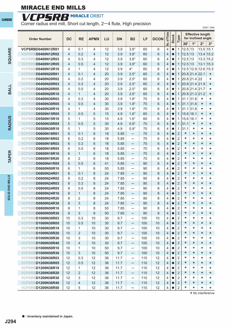
J294
VCPSRB
DC RE APMX LU DN B2 LF DCON30' 1° 2° 3°
VCPSRBD0400N12R01 4 0.1 4 12 3.9 3.8° 60 6 4 a 1 12.5 13 13.5 15.1VCPSRBD0400N12R02 4 0.2 4 12 3.9 3.8° 60 6 4 a 1 12.5 13 13.4 15.2VCPSRBD0400N12R03 4 0.3 4 12 3.9 3.8° 60 6 4 a 1 12.5 13 13.3 15.2VCPSRBD0400N12R05 4 0.5 4 12 3.9 3.9° 60 6 4 a 1 12.5 13 13.1 15.3VCPSRBD0400N12R10 4 1 4 12 3.9 4° 60 6 4 a 1 12.5 12.9 12.6 15.3VCPSRBD0400N20R01 4 0.1 4 20 3.9 2.5° 60 6 4 a 1 20.8 21.4 22.1VCPSRBD0400N20R02 4 0.2 4 20 3.9 2.5° 60 6 4 a 1 20.8 21.4 22VCPSRBD0400N20R03 4 0.3 4 20 3.9 2.5° 60 6 4 a 1 20.8 21.4 21.9VCPSRBD0400N20R05 4 0.5 4 20 3.9 2.5° 60 6 4 a 1 20.8 21.4 21.7VCPSRBD0400N20R10 4 1 4 20 3.9 2.6° 60 6 4 a 1 20.8 21.3 21.2VCPSRBD0400N30R03 4 0.3 4 30 3.9 1.8° 70 6 4 a 1 31.1 31.8VCPSRBD0400N30R05 4 0.5 4 30 3.9 1.8° 70 6 4 a 1 31.1 31.8VCPSRBD0400N30R10 4 1 4 30 3.9 1.8° 70 6 4 a 1 31.1 31.8VCPSRBD0500N15R05 5 0.5 5 15 4.9 1.6° 60 6 4 a 1 15.6 16.1VCPSRBD0500N15R10 5 1 5 15 4.9 1.6° 60 6 4 a 1 15.6 16.1VCPSRBD0500N30R05 5 0.5 5 30 4.9 0.9° 70 6 4 a 1 31.1VCPSRBD0500N30R10 5 1 5 30 4.9 0.9° 70 6 4 a 1 31.1VCPSRBD0600N18R01 6 0.1 6 18 5.85 ─ 70 6 4 a 2VCPSRBD0600N18R02 6 0.2 6 18 5.85 ─ 70 6 4 a 2VCPSRBD0600N18R03 6 0.3 6 18 5.85 ─ 70 6 4 a 2VCPSRBD0600N18R05 6 0.5 6 18 5.85 ─ 70 6 4 a 2VCPSRBD0600N18R10 6 1 6 18 5.85 ─ 70 6 4 a 2VCPSRBD0600N18R20 6 2 6 18 5.85 ─ 70 6 4 a 2VCPSRBD0600N41R05 6 0.5 6 41 5.85 ─ 90 6 4 a 2VCPSRBD0600N50R10 6 1 6 50 5.85 ─ 90 6 4 a 2VCPSRBD0800N24R01 8 0.1 8 24 7.85 ─ 90 8 4 a 2VCPSRBD0800N24R02 8 0.2 8 24 7.85 ─ 90 8 4 a 2VCPSRBD0800N24R03 8 0.3 8 24 7.85 ─ 90 8 4 a 2VCPSRBD0800N24R05 8 0.5 8 24 7.85 ─ 90 8 4 a 2VCPSRBD0800N24R10 8 1 8 24 7.85 ─ 90 8 4 a 2VCPSRBD0800N24R20 8 2 8 24 7.85 ─ 90 8 4 a 2VCPSRBD0800N24R30 8 3 8 24 7.85 ─ 90 8 4 a 2VCPSRBD0800N50R10 8 1 8 50 7.85 ─ 90 8 4 a 2VCPSRBD0800N50R30 8 3 8 50 7.85 ─ 90 8 4 a 2VCPSRBD1000N30R03 10 0.3 10 30 9.7 ─ 100 10 4 a 2VCPSRBD1000N30R05 10 0.5 10 30 9.7 ─ 100 10 4 a 2VCPSRBD1000N30R10 10 1 10 30 9.7 ─ 100 10 4 a 2VCPSRBD1000N30R20 10 2 10 30 9.7 ─ 100 10 4 a 2VCPSRBD1000N30R30 10 3 10 30 9.7 ─ 100 10 4 a 2VCPSRBD1000N30R40 10 4 10 30 9.7 ─ 100 10 4 a 2VCPSRBD1000N50R10 10 1 10 50 9.7 ─ 100 10 4 a 2VCPSRBD1000N50R30 10 3 10 50 9.7 ─ 100 10 4 a 2VCPSRBD1200N36R03 12 0.3 12 36 11.7 ─ 110 12 4 a 2VCPSRBD1200N36R05 12 0.5 12 36 11.7 ─ 110 12 4 a 2VCPSRBD1200N36R10 12 1 12 36 11.7 ─ 110 12 4 a 2VCPSRBD1200N36R20 12 2 12 36 11.7 ─ 110 12 4 a 2VCPSRBD1200N36R30 12 3 12 36 11.7 ─ 110 12 4 a 2VCPSRBD1200N36R40 12 4 12 36 11.7 ─ 110 12 4 a 2VCPSRBD1200N36R50 12 5 12 36 11.7 ─ 110 12 4 a 2
a : Inventory maintained in Japan.
CARBIDE
SQU
AR
EB
ALL
RA
DIU
STA
PER
SOLI
D E
ND
MIL
LS
Unit : mm
MIRACLE END MILLS
Corner radius end mill, Short cut length, 2─4 fl ute, High precision
* No interference
Order Number
No. o
f Flut
esSt
ock
Type
Effective lengthfor inclined angle
********************************************
***************************************
**********************************
********************************
J295
0.62 48000 200─ 600 40000 160─ 500 22000 80─ 2504 48000 160─ 500 40000 100─ 300 22000 50─ 150
0.84 48000 240─ 750 32000 160─ 500 19000 80─ 2506 38000 190─ 600 26000 130─ 400 16000 70─ 2008 29000 150─ 450 19000 100─ 300 12000 50─ 150
14 48000 270─ 900 32000 180─ 600 19000 90─ 3006 38000 220─ 720 26000 150─ 480 16000 70─ 240
10 29000 160─ 540 19000 110─ 360 12000 60─ 180
1.26 48000 300─ 900 32000 200─ 600 19000 100─ 300
10 38000 240─ 720 26000 160─ 480 15000 80─ 24015 29000 180─ 540 19000 120─ 360 12000 60─ 180
1.54 41000 300─ 900 27000 200─ 600 16000 100─ 3006 32000 240─ 720 22000 160─ 480 13000 80─ 240
10 24000 180─ 540 16000 120─ 360 10000 60─ 180
26 36000 600─2000 24000 400─1300 14000 200─ 650
10 29000 480─1600 19000 320─1000 12000 160─ 52015 22000 360─1200 14000 240─ 780 9000 120─ 390
2.58 33000 750─2400 22000 500─1600 13000 250─ 800
15 20000 450─1400 13000 300─ 960 8000 150─ 480
310 30000 900─3000 20000 600─2000 12000 300─100015 24000 720─2400 16000 480─1600 10000 240─ 80020 18000 540─1800 12000 360─1200 7000 180─ 600
412 26000 1200─4500 17000 800─3000 10000 400─150020 20000 960─2000 14000 640─2000 8000 320─200030 15000 720─1000 10000 480─1000 6000 240─1000
515 20000 1200─4800 13000 780─3120 10000 520─200030 12000 720─1900 8000 480─1600 7000 360─1120
618 20000 1600─7500 13000 1100─5000 8000 550─250041 15000 900─2400 12000 720─1600 10000 600─120050 10000 600─1200 8000 480─ 800 6000 360─ 530
824 15000 1900─7500 10000 1300─5000 6000 650─250050 10000 1300─2400 8000 1000─2200 3000 320─ 600
1030 12000 1600─7500 8000 1100─5000 5000 550─250050 10000 1300─3200 7000 950─2200 2500 280─ 600
12 36 10000 1500─7500 7000 1000─5000 4000 500─2500
CARBIDE
SOLI
D E
ND
MIL
LS
RECOMMENDED CUTTING CONDITIONS
DC:Dia.
1) The cutting conditions above are a guide only to machining with cutting edges with a corner radius. When machining with peripheral cutting edges, use the minimum feed rate as a guide.
2) If the depth of cut is shallow, the revolution and feed rate can be increased.3) For profi le machining such as moulds, machining conditions may differ considerably depending on the workpiece geometry, machining
methods and depth of cut. Reduce the feed rate especially when machining the corner sections of a workpiece.4) If the rigidity of the machine or the work materials installation is very low, or chattering and noise are generated, reduce the revolution and
feed rate proportionately.
Work material
Alloy steel, Tool steel,Pre-hardened steel
AISI H13, AISI W1-10, AISI P21
Hardened steel (45─ 55HRC)
AISI H13
Hardened steel (55─ 62HRC)
AISI D2
Dia.DC (mm)
Neck lengthLU (mm)
Revolution(min-1)
Feed rate(mm/min)
Revolution(min-1)
Feed rate(mm/min)
Revolution(min-1)
Feed rate(mm/min)
Depth of cut
<0.2RE (DC < &2)<0.4RE (DC> &2)
<0.1RE (DC< &2)<0.2RE (DC>&2)
<0.1mm (DC< &1.5)<0.2mm (DC< &4)<0.5mm (DC< &6)
<0.05mm (DC< &1.5)<0.1mm (DC< &4)<0.3mm (DC< &6)
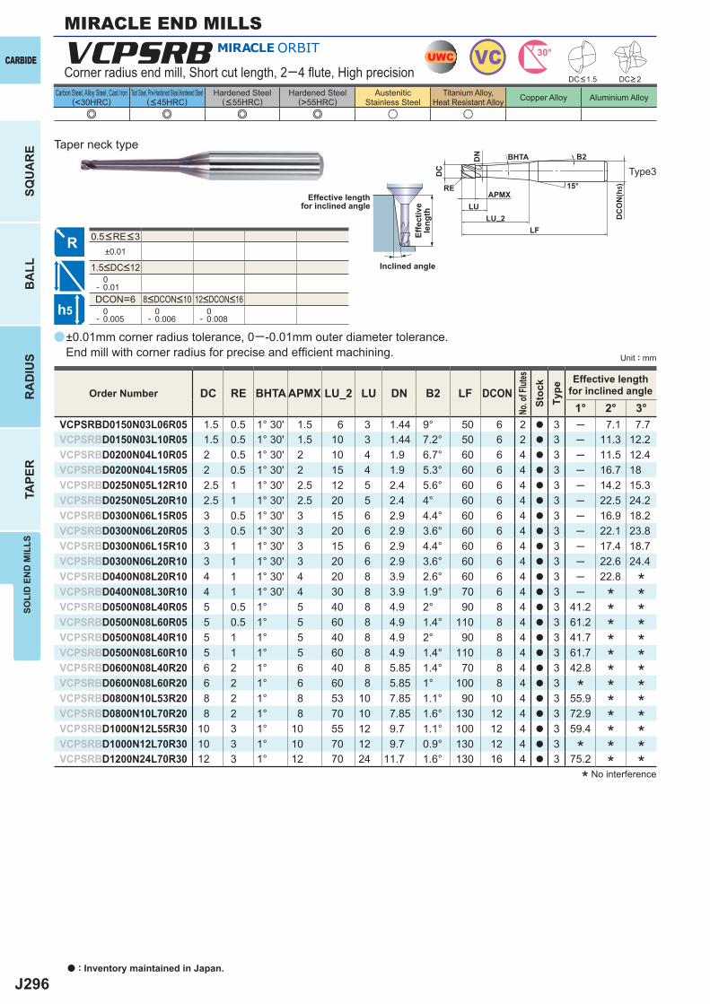
J296
a
e e e e u u
VCPSRB
DC RE BHTA APMX LU_2 LU DN B2 LF DCON1° 2° 3°
VCPSRBD0150N03L06R05 1.5 0.5 1° 30' 1.5 6 3 1.44 9° 50 6 2 a 3 ─ 7.1 7.7VCPSRBD0150N03L10R05 1.5 0.5 1° 30' 1.5 10 3 1.44 7.2° 50 6 2 a 3 ─ 11.3 12.2VCPSRBD0200N04L10R05 2 0.5 1° 30' 2 10 4 1.9 6.7° 60 6 4 a 3 ─ 11.5 12.4VCPSRBD0200N04L15R05 2 0.5 1° 30' 2 15 4 1.9 5.3° 60 6 4 a 3 ─ 16.7 18VCPSRBD0250N05L12R10 2.5 1 1° 30' 2.5 12 5 2.4 5.6° 60 6 4 a 3 ─ 14.2 15.3VCPSRBD0250N05L20R10 2.5 1 1° 30' 2.5 20 5 2.4 4° 60 6 4 a 3 ─ 22.5 24.2VCPSRBD0300N06L15R05 3 0.5 1° 30' 3 15 6 2.9 4.4° 60 6 4 a 3 ─ 16.9 18.2VCPSRBD0300N06L20R05 3 0.5 1° 30' 3 20 6 2.9 3.6° 60 6 4 a 3 ─ 22.1 23.8VCPSRBD0300N06L15R10 3 1 1° 30' 3 15 6 2.9 4.4° 60 6 4 a 3 ─ 17.4 18.7VCPSRBD0300N06L20R10 3 1 1° 30' 3 20 6 2.9 3.6° 60 6 4 a 3 ─ 22.6 24.4VCPSRBD0400N08L20R10 4 1 1° 30' 4 20 8 3.9 2.6° 60 6 4 a 3 ─ 22.8VCPSRBD0400N08L30R10 4 1 1° 30' 4 30 8 3.9 1.9° 70 6 4 a 3 ─VCPSRBD0500N08L40R05 5 0.5 1° 5 40 8 4.9 2° 90 8 4 a 3 41.2VCPSRBD0500N08L60R05 5 0.5 1° 5 60 8 4.9 1.4° 110 8 4 a 3 61.2VCPSRBD0500N08L40R10 5 1 1° 5 40 8 4.9 2° 90 8 4 a 3 41.7VCPSRBD0500N08L60R10 5 1 1° 5 60 8 4.9 1.4° 110 8 4 a 3 61.7VCPSRBD0600N08L40R20 6 2 1° 6 40 8 5.85 1.4° 70 8 4 a 3 42.8VCPSRBD0600N08L60R20 6 2 1° 6 60 8 5.85 1° 100 8 4 a 3VCPSRBD0800N10L53R20 8 2 1° 8 53 10 7.85 1.1° 90 10 4 a 3 55.9VCPSRBD0800N10L70R20 8 2 1° 8 70 10 7.85 1.6° 130 12 4 a 3 72.9VCPSRBD1000N12L55R30 10 3 1° 10 55 12 9.7 1.1° 100 12 4 a 3 59.4VCPSRBD1000N12L70R30 10 3 1° 10 70 12 9.7 0.9° 130 12 4 a 3VCPSRBD1200N24L70R30 12 3 1° 12 70 24 11.7 1.6° 130 16 4 a 3 75.2
±0.01
0- 0.01DCON=6 0- 0.005
0- 0.006
0- 0.008
UWC VC 30°
h5
APMX
DC
DC
ON
(h5)15°
BHTA
LF
RE
LU_2LU
DN B2
a : Inventory maintained in Japan.
CARBIDE
SQU
AR
EB
ALL
RA
DIU
STA
PER
SOLI
D E
ND
MIL
LS
Unit : mm
Carbon Steel, Alloy Steel, Cast Iron(<30HRC)
Tool Steel, Pre-Hardened Steel,Hardened Steel(<45HRC)
Hardened Steel(<55HRC)
Hardened Steel(>55HRC)
AusteniticStainless Steel
Titanium Alloy,Heat Resistant Alloy Copper Alloy Aluminium Alloy
MIRACLE END MILLS
±0.01mm corner radius tolerance, 0─ -0.01mm outer diameter tolerance. End mill with corner radius for precise and effi cient machining.
Corner radius end mill, Short cut length, 2─4 fl ute, High precision
Type3
Taper neck type
Effective lengthfor inclined angle
Inclined angle
Effe
ctiv
ele
ngth
* No interference
Order Number
No. o
f Flut
esSt
ock
Type
Effective lengthfor inclined angle
*************
************
*
*
8<DCON<10 12<DCON<16
DC<1.5 DC>2
0.5<RE<3
1.5<DC<12
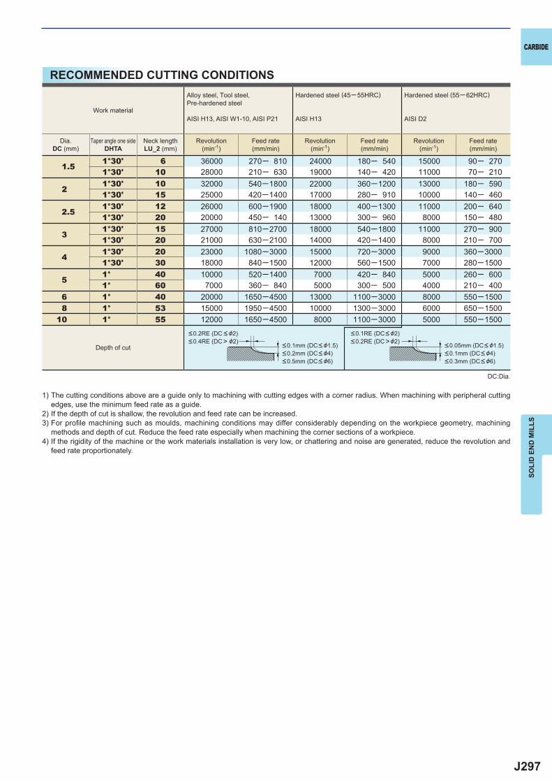
J297
1.51°30' 6 36000 270─ 810 24000 180─ 540 15000 90─ 2701°30' 10 28000 210─ 630 19000 140─ 420 11000 70─ 210
21°30' 10 32000 540─1800 22000 360─1200 13000 180─ 5901°30' 15 25000 420─1400 17000 280─ 910 10000 140─ 460
2.51°30' 12 26000 600─1900 18000 400─1300 11000 200─ 6401°30' 20 20000 450─ 140 13000 300─ 960 8000 150─ 480
31°30' 15 27000 810─2700 18000 540─1800 11000 270─ 9001°30' 20 21000 630─2100 14000 420─1400 8000 210─ 700
41°30' 20 23000 1080─3000 15000 720─3000 9000 360─30001°30' 30 18000 840─1500 12000 560─1500 7000 280─1500
51° 40 10000 520─1400 7000 420─ 840 5000 260─ 6001° 60 7000 360─ 840 5000 300─ 500 4000 210─ 400
6 1° 40 20000 1650─4500 13000 1100─3000 8000 550─1500 8 1° 53 15000 1950─4500 10000 1300─3000 6000 650─150010 1° 55 12000 1650─4500 8000 1100─3000 5000 550─1500
CARBIDE
SOLI
D E
ND
MIL
LS
RECOMMENDED CUTTING CONDITIONS
1) The cutting conditions above are a guide only to machining with cutting edges with a corner radius. When machining with peripheral cutting edges, use the minimum feed rate as a guide.
2) If the depth of cut is shallow, the revolution and feed rate can be increased.3) For profi le machining such as moulds, machining conditions may differ considerably depending on the workpiece geometry, machining
methods and depth of cut. Reduce the feed rate especially when machining the corner sections of a workpiece.4) If the rigidity of the machine or the work materials installation is very low, or chattering and noise are generated, reduce the revolution and
feed rate proportionately.
DC:Dia.
Work material
Alloy steel, Tool steel,Pre-hardened steel
AISI H13, AISI W1-10, AISI P21
Hardened steel (45─ 55HRC)
AISI H13
Hardened steel (55─ 62HRC)
AISI D2
Dia.DC (mm)
Taper angle one sideDHTA
Neck lengthLU_2 (mm)
Revolution(min-1)
Feed rate(mm/min)
Revolution(min-1)
Feed rate(mm/min)
Revolution(min-1)
Feed rate(mm/min)
Depth of cut
<0.2RE (DC < &2)<0.4RE (DC> &2)
<0.1mm (DC< &1.5)<0.2mm (DC< &4)<0.5mm (DC< &6)
<0.1RE (DC< &2)<0.2RE (DC>&2)
<0.05mm (DC< &1.5)<0.1mm (DC< &4)<0.3mm (DC< &6)
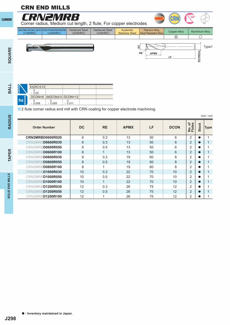
J298
a
e u
CRN2MRB
DC RE APMX LF DCON
CRN2MRBD0600R020 6 0.2 13 50 6 2 a 1CRN2MRBD0600R030 6 0.3 13 50 6 2 a 1CRN2MRBD0600R050 6 0.5 13 50 6 2 a 1CRN2MRBD0600R100 6 1 13 50 6 2 a 1CRN2MRBD0800R030 8 0.3 19 60 8 2 a 1CRN2MRBD0800R050 8 0.5 19 60 8 2 a 1CRN2MRBD0800R100 8 1 19 60 8 2 a 1CRN2MRBD1000R030 10 0.3 22 70 10 2 a 1CRN2MRBD1000R050 10 0.5 22 70 10 2 a 1CRN2MRBD1000R100 10 1 22 70 10 2 a 1CRN2MRBD1200R030 12 0.3 26 75 12 2 a 1CRN2MRBD1200R050 12 0.5 26 75 12 2 a 1CRN2MRBD1200R100 12 1 26 75 12 2 a 1
0- 0.02DCON=6 DCON=12 0- 0.008
0- 0.009
0- 0.011
UWC CRN 30°
h6
APMX
DC
DC
ON
(h6)
LFRE
a : Inventory maintained in Japan.
CARBIDE
SQU
AR
EB
ALL
RA
DIU
STA
PER
SOLI
D E
ND
MIL
LS
Unit : mm
Carbon Steel, Alloy Steel, Cast Iron(<30HRC)
Tool Steel, Pre-Hardened Steel,Hardened Steel(<45HRC)
Hardened Steel(<55HRC)
Hardened Steel(>55HRC)
AusteniticStainless Steel
Titanium Alloy,Heat Resistant Alloy Copper Alloy Aluminium Alloy
2 fl ute corner radius end mill with CRN coating for copper electrode machining.
Corner radius, Medium cut length, 2 fl ute, For copper electrodes
Type1
Order Number
No.
of
Flut
es
Stoc
k
Type
8<DCON<10
6<DC<12
CRN END MILLS
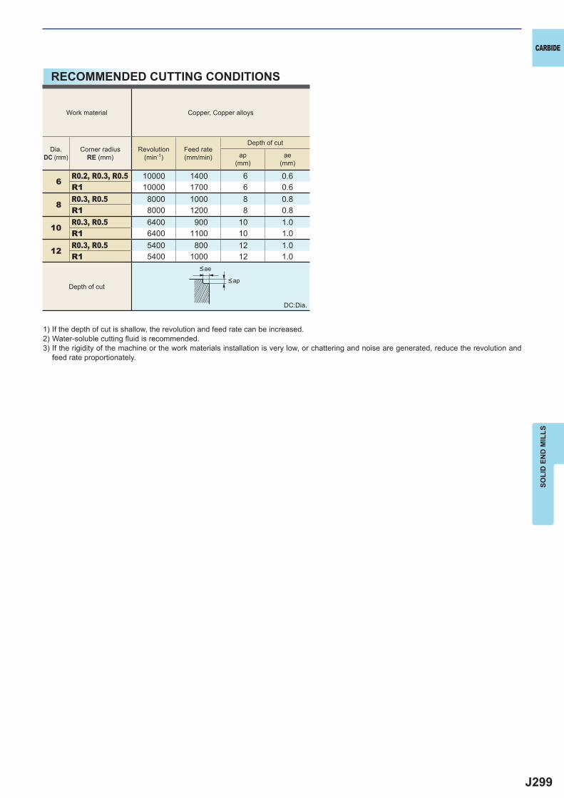
J299
6R0.2, R0.3, R0.5 10000 1400 6 0.6R1 10000 1700 6 0.6
8R0.3, R0.5 8000 1000 8 0.8R1 8000 1200 8 0.8
10R0.3, R0.5 6400 900 10 1.0R1 6400 1100 10 1.0
12R0.3, R0.5 5400 800 12 1.0R1 5400 1000 12 1.0
CARBIDE
SOLI
D E
ND
MIL
LS
RECOMMENDED CUTTING CONDITIONS
1) If the depth of cut is shallow, the revolution and feed rate can be increased.2) Water-soluble cutting fl uid is recommended.3) If the rigidity of the machine or the work materials installation is very low, or chattering and noise are generated, reduce the revolution and
feed rate proportionately.
<ap
<ae
Depth of cut
Work material Copper, Copper alloys
Dia.DC (mm)
Corner radiusRE (mm)
Revolution(min-1)
Feed rate(mm/min)
Depth of cut
ap(mm)
ae(mm)
DC:Dia.
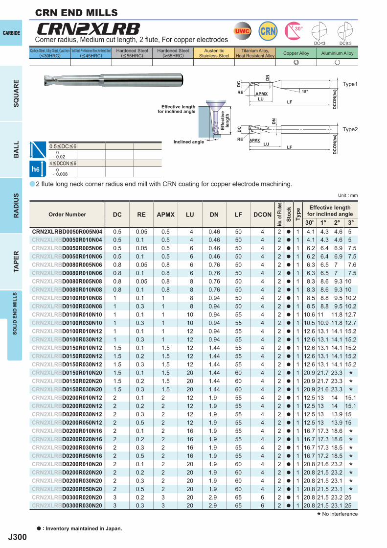
J300
a
e u
CRN2XLRB
DC RE APMX LU DN LF DCON30' 1° 2° 3°
CRN2XLRBD0050R005N04 0.5 0.05 0.5 4 0.46 50 4 2 a 1 4.1 4.3 4.6 5CRN2XLRBD0050R010N04 0.5 0.1 0.5 4 0.46 50 4 2 a 1 4.1 4.3 4.6 5CRN2XLRBD0050R005N06 0.5 0.05 0.5 6 0.46 50 4 2 a 1 6.2 6.4 6.9 7.5CRN2XLRBD0050R010N06 0.5 0.1 0.5 6 0.46 50 4 2 a 1 6.2 6.4 6.9 7.5CRN2XLRBD0080R005N06 0.8 0.05 0.8 6 0.76 50 4 2 a 1 6.3 6.5 7 7.6CRN2XLRBD0080R010N06 0.8 0.1 0.8 6 0.76 50 4 2 a 1 6.3 6.5 7 7.5CRN2XLRBD0080R005N08 0.8 0.05 0.8 8 0.76 50 4 2 a 1 8.3 8.6 9.3 10CRN2XLRBD0080R010N08 0.8 0.1 0.8 8 0.76 50 4 2 a 1 8.3 8.6 9.3 10CRN2XLRBD0100R010N08 1 0.1 1 8 0.94 50 4 2 a 1 8.5 8.8 9.5 10.2CRN2XLRBD0100R030N08 1 0.3 1 8 0.94 50 4 2 a 1 8.5 8.8 9.5 10.2CRN2XLRBD0100R010N10 1 0.1 1 10 0.94 55 4 2 a 1 10.6 11 11.8 12.7CRN2XLRBD0100R030N10 1 0.3 1 10 0.94 55 4 2 a 1 10.5 10.9 11.8 12.7CRN2XLRBD0100R010N12 1 0.1 1 12 0.94 55 4 2 a 1 12.6 13.1 14.1 15.2CRN2XLRBD0100R030N12 1 0.3 1 12 0.94 55 4 2 a 1 12.6 13.1 14.1 15.2CRN2XLRBD0150R010N12 1.5 0.1 1.5 12 1.44 55 4 2 a 1 12.6 13.1 14.1 15.2CRN2XLRBD0150R020N12 1.5 0.2 1.5 12 1.44 55 4 2 a 1 12.6 13.1 14.1 15.2CRN2XLRBD0150R030N12 1.5 0.3 1.5 12 1.44 55 4 2 a 1 12.6 13.1 14.1 15.2CRN2XLRBD0150R010N20 1.5 0.1 1.5 20 1.44 60 4 2 a 1 20.9 21.7 23.3CRN2XLRBD0150R020N20 1.5 0.2 1.5 20 1.44 60 4 2 a 1 20.9 21.7 23.3CRN2XLRBD0150R030N20 1.5 0.3 1.5 20 1.44 60 4 2 a 1 20.9 21.6 23.3CRN2XLRBD0200R010N12 2 0.1 2 12 1.9 55 4 2 a 1 12.5 13 14 15.1CRN2XLRBD0200R020N12 2 0.2 2 12 1.9 55 4 2 a 1 12.5 13 14 15.1CRN2XLRBD0200R030N12 2 0.3 2 12 1.9 55 4 2 a 1 12.5 13 13.9 15CRN2XLRBD0200R050N12 2 0.5 2 12 1.9 55 4 2 a 1 12.5 13 13.9 15CRN2XLRBD0200R010N16 2 0.1 2 16 1.9 55 4 2 a 1 16.7 17.3 18.6CRN2XLRBD0200R020N16 2 0.2 2 16 1.9 55 4 2 a 1 16.7 17.3 18.6CRN2XLRBD0200R030N16 2 0.3 2 16 1.9 55 4 2 a 1 16.7 17.3 18.5CRN2XLRBD0200R050N16 2 0.5 2 16 1.9 55 4 2 a 1 16.7 17.2 18.5CRN2XLRBD0200R010N20 2 0.1 2 20 1.9 60 4 2 a 1 20.8 21.6 23.2CRN2XLRBD0200R020N20 2 0.2 2 20 1.9 60 4 2 a 1 20.8 21.5 23.2CRN2XLRBD0200R030N20 2 0.3 2 20 1.9 60 4 2 a 1 20.8 21.5 23.1CRN2XLRBD0200R050N20 2 0.5 2 20 1.9 60 4 2 a 1 20.8 21.5 23.1CRN2XLRBD0300R020N20 3 0.2 3 20 2.9 65 6 2 a 1 20.8 21.5 23.2 25CRN2XLRBD0300R030N20 3 0.3 3 20 2.9 65 6 2 a 1 20.8 21.5 23.1 25
0- 0.02
0- 0.008
UWC CRN 30°
h6
APMX
DC
DC
ON
(h6)15°
APMXLF
DC
DC
ON
(h6)
LF
RE
RELU
LU
DN
DN
DC<3
a : Inventory maintained in Japan.
CARBIDE
SQU
AR
EB
ALL
RA
DIU
STA
PER
SOLI
D E
ND
MIL
LS
Unit : mm
Carbon Steel, Alloy Steel, Cast Iron(<30HRC)
Tool Steel, Pre-Hardened Steel,Hardened Steel(<45HRC)
Hardened Steel(<55HRC)
Hardened Steel(>55HRC)
AusteniticStainless Steel
Titanium Alloy,Heat Resistant Alloy Copper Alloy Aluminium Alloy
CRN END MILLS
2 fl ute long neck corner radius end mill with CRN coating for copper electrode machining.
Corner radius, Medium cut length, 2 fl ute, For copper electrodes
Type1
Type2
* No interference
Effective lengthfor inclined angle
Inclined angle
Effe
ctiv
ele
ngth
DC>3
Order Number
No. o
f Flut
esSt
ock
Type
Effective lengthfor inclined angle
********
***
4<DCON<6
0.5<DC<6
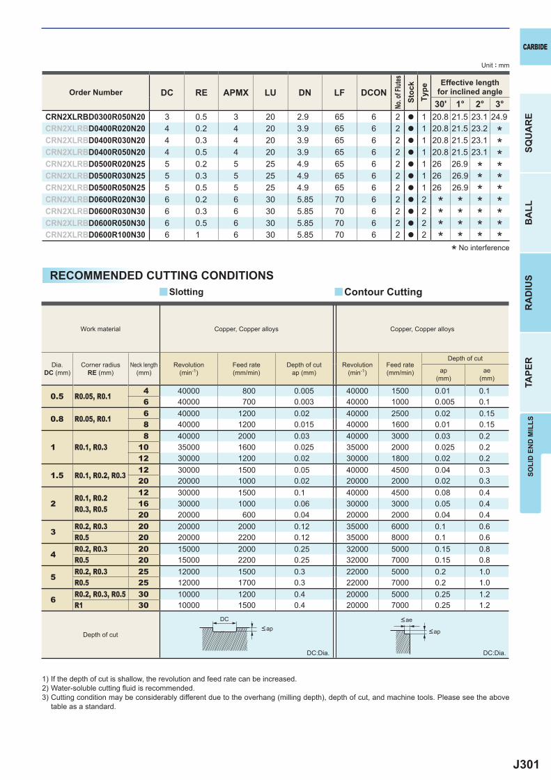
J301
DC RE APMX LU DN LF DCON30' 1° 2° 3°
CRN2XLRBD0300R050N20 3 0.5 3 20 2.9 65 6 2 a 1 20.8 21.5 23.1 24.9CRN2XLRBD0400R020N20 4 0.2 4 20 3.9 65 6 2 a 1 20.8 21.5 23.2CRN2XLRBD0400R030N20 4 0.3 4 20 3.9 65 6 2 a 1 20.8 21.5 23.1CRN2XLRBD0400R050N20 4 0.5 4 20 3.9 65 6 2 a 1 20.8 21.5 23.1CRN2XLRBD0500R020N25 5 0.2 5 25 4.9 65 6 2 a 1 26 26.9CRN2XLRBD0500R030N25 5 0.3 5 25 4.9 65 6 2 a 1 26 26.9CRN2XLRBD0500R050N25 5 0.5 5 25 4.9 65 6 2 a 1 26 26.9CRN2XLRBD0600R020N30 6 0.2 6 30 5.85 70 6 2 a 2CRN2XLRBD0600R030N30 6 0.3 6 30 5.85 70 6 2 a 2CRN2XLRBD0600R050N30 6 0.5 6 30 5.85 70 6 2 a 2CRN2XLRBD0600R100N30 6 1 6 30 5.85 70 6 2 a 2
0.5 R0.05, R0.14 40000 800 0.005 40000 1500 0.01 0.16 40000 700 0.003 40000 1000 0.005 0.1
0.8 R0.05, R0.16 40000 1200 0.02 40000 2500 0.02 0.158 40000 1200 0.015 40000 1600 0.01 0.15
1 R0.1, R0.38 40000 2000 0.03 40000 3000 0.03 0.2
10 35000 1600 0.025 35000 2000 0.025 0.212 30000 1200 0.02 30000 1800 0.02 0.2
1.5 R0.1, R0.2, R0.312 30000 1500 0.05 40000 4500 0.04 0.320 20000 1000 0.02 20000 2000 0.02 0.3
2R0.1, R0.2R0.3, R0.5
12 30000 1500 0.1 40000 4500 0.08 0.416 30000 1000 0.06 30000 3000 0.05 0.420 20000 600 0.04 20000 2000 0.04 0.4
3R0.2, R0.3 20 20000 2000 0.12 35000 6000 0.1 0.6R0.5 20 20000 2200 0.12 35000 8000 0.1 0.6
4R0.2, R0.3 20 15000 2000 0.25 32000 5000 0.15 0.8R0.5 20 15000 2200 0.25 32000 7000 0.15 0.8
5R0.2, R0.3 25 12000 1500 0.3 22000 5000 0.2 1.0R0.5 25 12000 1700 0.3 22000 7000 0.2 1.0
6R0.2, R0.3, R0.5 30 10000 1200 0.4 20000 5000 0.25 1.2R1 30 10000 1500 0.4 20000 7000 0.25 1.2
y y
DC
CARBIDE
SQU
AR
EB
ALL
RA
DIU
STA
PER
SOLI
D E
ND
MIL
LS
Unit : mm
*****
* No interference
Order Number
No. o
f Flut
esSt
ock
Type
Effective lengthfor inclined angle
******
******
****
****
RECOMMENDED CUTTING CONDITIONS
1) If the depth of cut is shallow, the revolution and feed rate can be increased.2) Water-soluble cutting fl uid is recommended.3) Cutting condition may be considerably different due to the overhang (milling depth), depth of cut, and machine tools. Please see the above
table as a standard.
DC:Dia. DC:Dia.
Slotting Contour Cutting
<ap<ap
<ae
Work material Copper, Copper alloys Copper, Copper alloys
Dia.DC (mm)
Corner radiusRE (mm)
Neck length(mm)
Revolution(min-1)
Feed rate(mm/min)
Depth of cutap (mm)
Revolution(min-1)
Feed rate(mm/min)
Depth of cut
ap(mm)
ae(mm)
Depth of cut
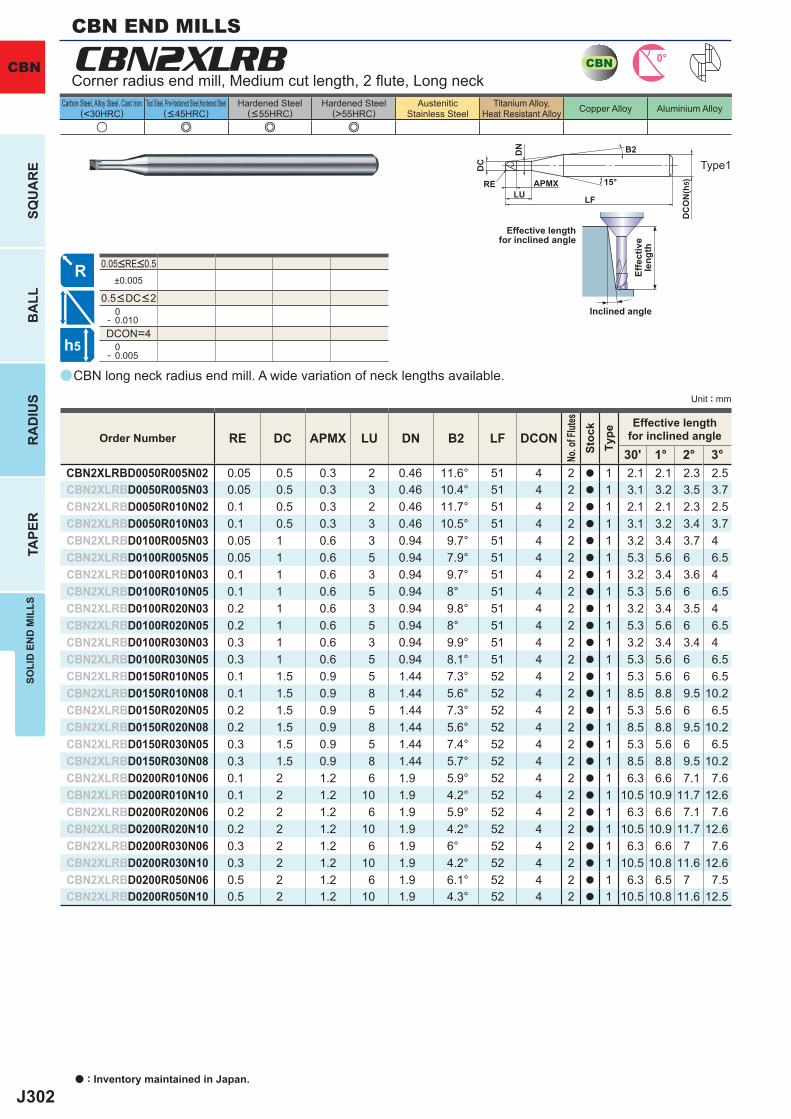
J302
a
u e e e
CBN2XLRB
RE DC APMX LU DN B2 LF DCON30' 1° 2° 3°
CBN2XLRBD0050R005N02 0.05 0.5 0.3 2 0.46 11.6° 51 4 2 a 1 2.1 2.1 2.3 2.5CBN2XLRBD0050R005N03 0.05 0.5 0.3 3 0.46 10.4° 51 4 2 a 1 3.1 3.2 3.5 3.7CBN2XLRBD0050R010N02 0.1 0.5 0.3 2 0.46 11.7° 51 4 2 a 1 2.1 2.1 2.3 2.5CBN2XLRBD0050R010N03 0.1 0.5 0.3 3 0.46 10.5° 51 4 2 a 1 3.1 3.2 3.4 3.7CBN2XLRBD0100R005N03 0.05 1 0.6 3 0.94 9.7° 51 4 2 a 1 3.2 3.4 3.7 4CBN2XLRBD0100R005N05 0.05 1 0.6 5 0.94 7.9° 51 4 2 a 1 5.3 5.6 6 6.5CBN2XLRBD0100R010N03 0.1 1 0.6 3 0.94 9.7° 51 4 2 a 1 3.2 3.4 3.6 4CBN2XLRBD0100R010N05 0.1 1 0.6 5 0.94 8° 51 4 2 a 1 5.3 5.6 6 6.5CBN2XLRBD0100R020N03 0.2 1 0.6 3 0.94 9.8° 51 4 2 a 1 3.2 3.4 3.5 4CBN2XLRBD0100R020N05 0.2 1 0.6 5 0.94 8° 51 4 2 a 1 5.3 5.6 6 6.5CBN2XLRBD0100R030N03 0.3 1 0.6 3 0.94 9.9° 51 4 2 a 1 3.2 3.4 3.4 4CBN2XLRBD0100R030N05 0.3 1 0.6 5 0.94 8.1° 51 4 2 a 1 5.3 5.6 6 6.5CBN2XLRBD0150R010N05 0.1 1.5 0.9 5 1.44 7.3° 52 4 2 a 1 5.3 5.6 6 6.5CBN2XLRBD0150R010N08 0.1 1.5 0.9 8 1.44 5.6° 52 4 2 a 1 8.5 8.8 9.5 10.2CBN2XLRBD0150R020N05 0.2 1.5 0.9 5 1.44 7.3° 52 4 2 a 1 5.3 5.6 6 6.5CBN2XLRBD0150R020N08 0.2 1.5 0.9 8 1.44 5.6° 52 4 2 a 1 8.5 8.8 9.5 10.2CBN2XLRBD0150R030N05 0.3 1.5 0.9 5 1.44 7.4° 52 4 2 a 1 5.3 5.6 6 6.5CBN2XLRBD0150R030N08 0.3 1.5 0.9 8 1.44 5.7° 52 4 2 a 1 8.5 8.8 9.5 10.2CBN2XLRBD0200R010N06 0.1 2 1.2 6 1.9 5.9° 52 4 2 a 1 6.3 6.6 7.1 7.6CBN2XLRBD0200R010N10 0.1 2 1.2 10 1.9 4.2° 52 4 2 a 1 10.5 10.9 11.7 12.6CBN2XLRBD0200R020N06 0.2 2 1.2 6 1.9 5.9° 52 4 2 a 1 6.3 6.6 7.1 7.6CBN2XLRBD0200R020N10 0.2 2 1.2 10 1.9 4.2° 52 4 2 a 1 10.5 10.9 11.7 12.6CBN2XLRBD0200R030N06 0.3 2 1.2 6 1.9 6° 52 4 2 a 1 6.3 6.6 7 7.6CBN2XLRBD0200R030N10 0.3 2 1.2 10 1.9 4.2° 52 4 2 a 1 10.5 10.8 11.6 12.6CBN2XLRBD0200R050N06 0.5 2 1.2 6 1.9 6.1° 52 4 2 a 1 6.3 6.5 7 7.5CBN2XLRBD0200R050N10 0.5 2 1.2 10 1.9 4.3° 52 4 2 a 1 10.5 10.8 11.6 12.5
±0.005
0- 0.010DCON=4 0- 0.005
CBN 0°
h5
APMX
DC
DC
ON
(h5)15°
LF
RELU
DN B2
CBN
Unit : mm
Carbon Steel, Alloy Steel, Cast Iron(<30HRC)
Tool Steel, Pre-Hardened Steel,Hardened Steel(<45HRC)
Hardened Steel(<55HRC)
Hardened Steel(>55HRC)
AusteniticStainless Steel
Titanium Alloy,Heat Resistant Alloy Copper Alloy Aluminium Alloy
a : Inventory maintained in Japan.
SQU
AR
EB
ALL
RA
DIU
STA
PER
SOLI
D E
ND
MIL
LS
CBN long neck radius end mill. A wide variation of neck lengths available.
Corner radius end mill, Medium cut length, 2 fl ute, Long neck
Type1
CBN END MILLS
Effective lengthfor inclined angle
Inclined angle
Effe
ctiv
ele
ngth
Order Number
No. o
f Flut
esSt
ock
Type
Effective lengthfor inclined angle
0.05<RE<0.5
0.5<DC<2
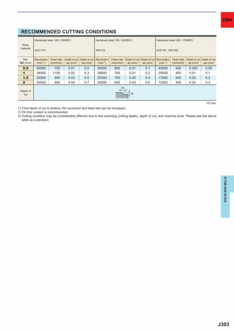
J303
0.5 50000 750 0.01 0.2 50000 600 0.01 0.1 40000 400 0.005 0.061 38000 1100 0.02 0.3 38000 760 0.01 0.2 25000 400 0.01 0.11.5 25000 900 0.03 0.5 25000 700 0.02 0.4 17000 340 0.02 0.22 20000 800 0.04 0.7 20000 600 0.03 0.6 12000 300 0.02 0.3
ae
ap
SOLI
D E
ND
MIL
LS
CBN
RECOMMENDED CUTTING CONDITIONS
1) If the depth of cut is shallow, the revolution and feed rate can be increased.2) Oil mist coolant is recommended.3) Cutting condition may be considerably different due to the overhang (milling depth), depth of cut, and machine tools. Please see the above
table as a standard.
Depth ofcut
Workmaterial
Hardened steel (45─55HRC)
AISI H13
Hardened steel (55─62HRC)
AISI D2
Hardened steel (62─70HRC)
AISI W1, AISI M2
Dia.DC (mm)
Revolution(min-1)
Feed rate(mm/min)
Depth of cutap (mm)
Depth of cutae (mm)
Revolution(min-1)
Feed rate(mm/min)
Depth of cutap (mm)
Depth of cutae (mm)
Revolution(min-1)
Feed rate(mm/min)
Depth of cutap (mm)
Depth of cutae (mm)
DC:Dia.
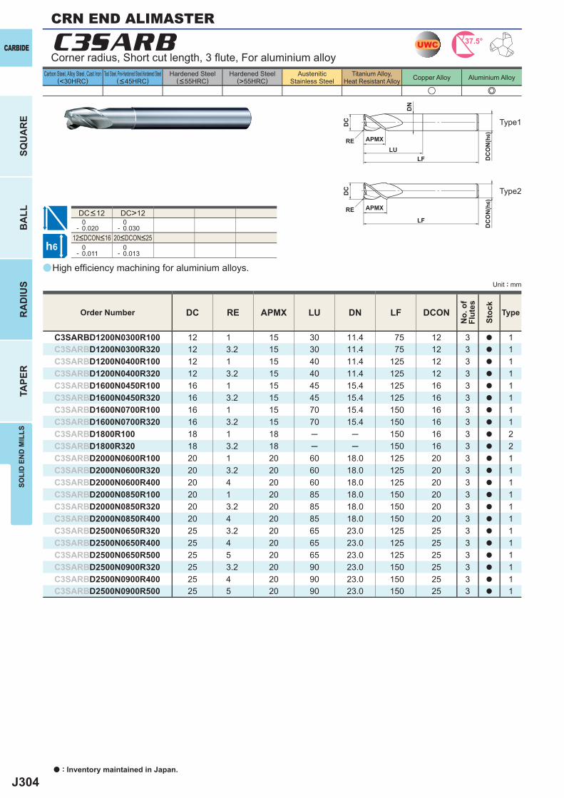
J304
a
u e
C3SARB
DC RE APMX LU DN LF DCON
C3SARBD1200N0300R100 12 1 15 30 11.4 75 12 3 a 1C3SARBD1200N0300R320 12 3.2 15 30 11.4 75 12 3 a 1C3SARBD1200N0400R100 12 1 15 40 11.4 125 12 3 a 1C3SARBD1200N0400R320 12 3.2 15 40 11.4 125 12 3 a 1C3SARBD1600N0450R100 16 1 15 45 15.4 125 16 3 a 1C3SARBD1600N0450R320 16 3.2 15 45 15.4 125 16 3 a 1C3SARBD1600N0700R100 16 1 15 70 15.4 150 16 3 a 1C3SARBD1600N0700R320 16 3.2 15 70 15.4 150 16 3 a 1C3SARBD1800R100 18 1 18 ─ ─ 150 16 3 a 2C3SARBD1800R320 18 3.2 18 ─ ─ 150 16 3 a 2C3SARBD2000N0600R100 20 1 20 60 18.0 125 20 3 a 1C3SARBD2000N0600R320 20 3.2 20 60 18.0 125 20 3 a 1C3SARBD2000N0600R400 20 4 20 60 18.0 125 20 3 a 1C3SARBD2000N0850R100 20 1 20 85 18.0 150 20 3 a 1C3SARBD2000N0850R320 20 3.2 20 85 18.0 150 20 3 a 1C3SARBD2000N0850R400 20 4 20 85 18.0 150 20 3 a 1C3SARBD2500N0650R320 25 3.2 20 65 23.0 125 25 3 a 1C3SARBD2500N0650R400 25 4 20 65 23.0 125 25 3 a 1C3SARBD2500N0650R500 25 5 20 65 23.0 125 25 3 a 1C3SARBD2500N0900R320 25 3.2 20 90 23.0 150 25 3 a 1C3SARBD2500N0900R400 25 4 20 90 23.0 150 25 3 a 1C3SARBD2500N0900R500 25 5 20 90 23.0 150 25 3 a 1
DC>12 0- 0.020
0- 0.030
0- 0.011
0- 0.013
UWC 37.5°
h6
APMX
DC
DC
ON
(h6)
LF
RELU
DN
APMX
DC
DC
ON
(h6)
LFRE
a : Inventory maintained in Japan.
CARBIDE
SQU
AR
EB
ALL
RA
DIU
STA
PER
SOLI
D E
ND
MIL
LS
Unit : mm
Carbon Steel, Alloy Steel, Cast Iron(<30HRC)
Tool Steel, Pre-Hardened Steel,Hardened Steel(<45HRC)
Hardened Steel(<55HRC)
Hardened Steel(>55HRC)
AusteniticStainless Steel
Titanium Alloy,Heat Resistant Alloy Copper Alloy Aluminium Alloy
High effi ciency machining for aluminium alloys.
Corner radius, Short cut length, 3 fl ute, For aluminium alloy
Type2
Type1
Order Number
No.
of
Flut
es
Stoc
k
Type
12<DCON<16 20<DCON<25
DC<12
CRN END ALIMASTER

J305
12 13000 540016 10000 540018 9000 500020 8000 500025 6000 4500
12 13000 320016 10000 320018 9000 300020 8000 300025 6000 2800
y y
DC
CARBIDE
SOLI
D E
ND
MIL
LS
RECOMMENDED CUTTING CONDITIONS
1) Water-soluble cutting fl uid is recommended.2) Climb cutting is recommended for side milling.3) This table shows the cutting condition with less than 4D overhang length. If more than 4D, spindle speed, feed rate and depth of cut should
be reduced.4) These end mills do not have a centre cutting edge, therefore when entering a workpiece use a ramping process rather than vertical feed.5) If the rigidity of the machine or the work materials installation is very low, or chattering and noise are generated, reduce the revolution and
feed rate proportionately, or set the depth of cut smaller.
DC:Dia. DC:Dia.
Side milling Slotting
Depth ofcut
Depth ofcut
<0.3DC
<0.8DC <0.5DC
Workmaterial Aluminium alloy
Workmaterial Aluminium alloy
Dia.DC (mm)
Revolution(min-1)
Feed rate(mm/min)
Dia.DC (mm)
Revolution(min-1)
Feed rate(mm/min)
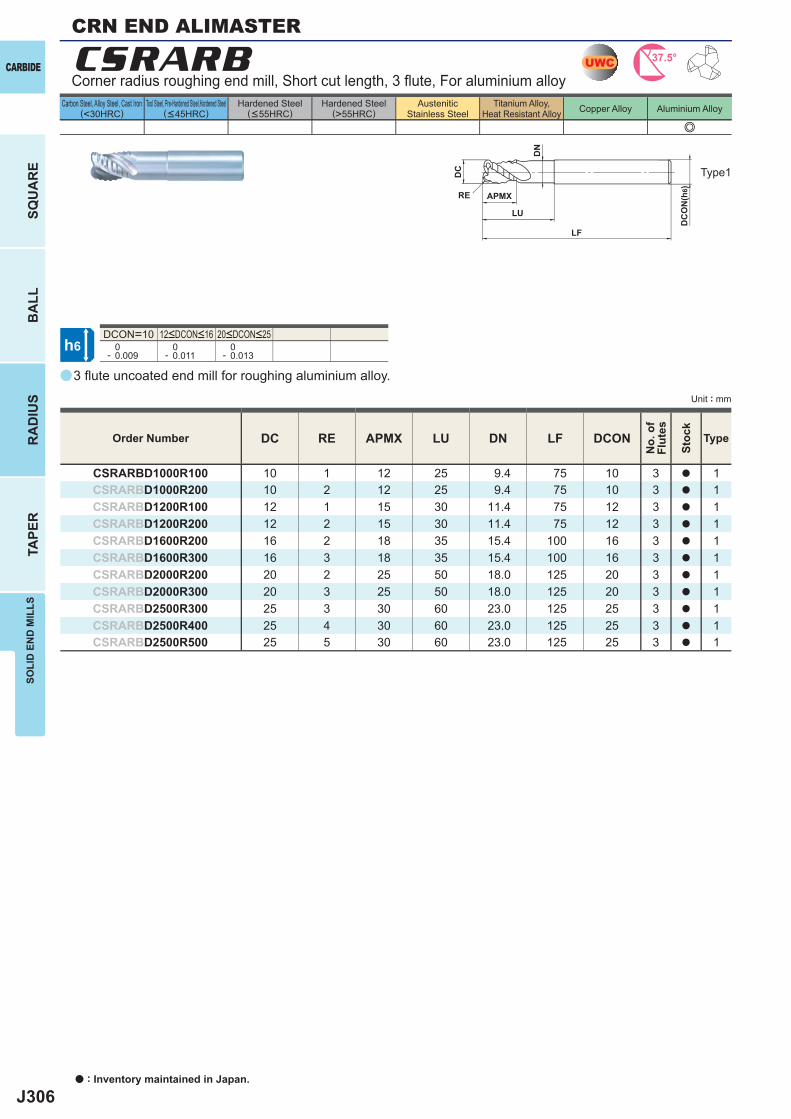
J306
a
e
CSRARB
DC RE APMX LU DN LF DCON
CSRARBD1000R100 10 1 12 25 9.4 75 10 3 a 1CSRARBD1000R200 10 2 12 25 9.4 75 10 3 a 1CSRARBD1200R100 12 1 15 30 11.4 75 12 3 a 1CSRARBD1200R200 12 2 15 30 11.4 75 12 3 a 1CSRARBD1600R200 16 2 18 35 15.4 100 16 3 a 1CSRARBD1600R300 16 3 18 35 15.4 100 16 3 a 1CSRARBD2000R200 20 2 25 50 18.0 125 20 3 a 1CSRARBD2000R300 20 3 25 50 18.0 125 20 3 a 1CSRARBD2500R300 25 3 30 60 23.0 125 25 3 a 1CSRARBD2500R400 25 4 30 60 23.0 125 25 3 a 1CSRARBD2500R500 25 5 30 60 23.0 125 25 3 a 1
DCON=10 0- 0.009
0- 0.011
0- 0.013
UWC 37.5°
h6
APMX
DC
DC
ON
(h6)
LF
RE
LU
DN
a : Inventory maintained in Japan.
CARBIDE
SQU
AR
EB
ALL
RA
DIU
STA
PER
SOLI
D E
ND
MIL
LS
Unit : mm
Carbon Steel, Alloy Steel, Cast Iron(<30HRC)
Tool Steel, Pre-Hardened Steel,Hardened Steel(<45HRC)
Hardened Steel(<55HRC)
Hardened Steel(>55HRC)
AusteniticStainless Steel
Titanium Alloy,Heat Resistant Alloy Copper Alloy Aluminium Alloy
CRN END ALIMASTER
3 fl ute uncoated end mill for roughing aluminium alloy.
Corner radius roughing end mill, Short cut length, 3 fl ute, For aluminium alloy
Type1
Order Number
No.
of
Flut
es
Stoc
k
Type
12<DCON<16 20<DCON<25
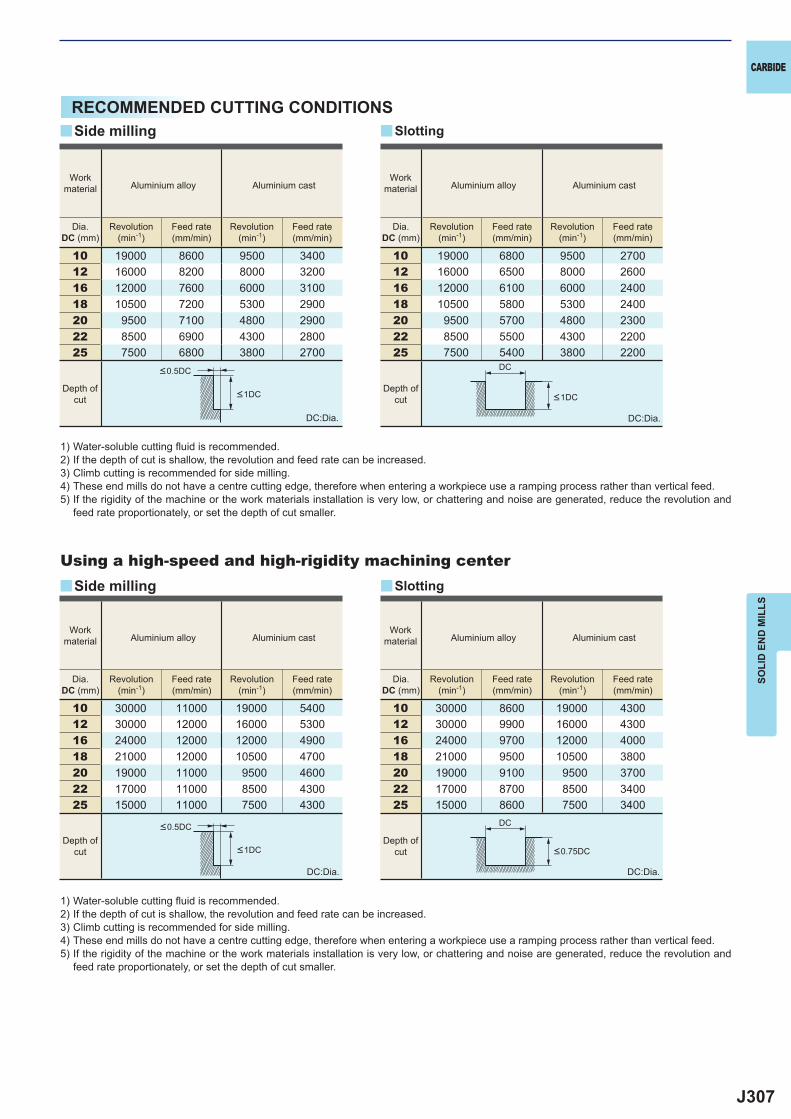
J307
10 19000 8600 9500 340012 16000 8200 8000 320016 12000 7600 6000 310018 10500 7200 5300 290020 9500 7100 4800 290022 8500 6900 4300 280025 7500 6800 3800 2700
10 30000 11000 19000 540012 30000 12000 16000 530016 24000 12000 12000 490018 21000 12000 10500 470020 19000 11000 9500 460022 17000 11000 8500 430025 15000 11000 7500 4300
10 19000 6800 9500 270012 16000 6500 8000 260016 12000 6100 6000 240018 10500 5800 5300 240020 9500 5700 4800 230022 8500 5500 4300 220025 7500 5400 3800 2200
10 30000 8600 19000 430012 30000 9900 16000 430016 24000 9700 12000 400018 21000 9500 10500 380020 19000 9100 9500 370022 17000 8700 8500 340025 15000 8600 7500 3400
y
y
y
y
DC
DC
CARBIDE
SOLI
D E
ND
MIL
LS
RECOMMENDED CUTTING CONDITIONS
1) Water-soluble cutting fl uid is recommended.2) If the depth of cut is shallow, the revolution and feed rate can be increased.3) Climb cutting is recommended for side milling.4) These end mills do not have a centre cutting edge, therefore when entering a workpiece use a ramping process rather than vertical feed.5) If the rigidity of the machine or the work materials installation is very low, or chattering and noise are generated, reduce the revolution and
feed rate proportionately, or set the depth of cut smaller.
DC:Dia.
DC:Dia.
DC:Dia.
DC:Dia.
Using a high-speed and high-rigidity machining center
Side milling
Side milling
Slotting
Slotting
Workmaterial Aluminium alloy Aluminium cast
Workmaterial Aluminium alloy Aluminium cast
Workmaterial Aluminium alloy Aluminium cast
Workmaterial Aluminium alloy Aluminium cast
Dia.DC (mm)
Revolution(min-1)
Feed rate(mm/min)
Revolution(min-1)
Feed rate(mm/min)
Dia.DC (mm)
Revolution(min-1)
Feed rate(mm/min)
Revolution(min-1)
Feed rate(mm/min)
Dia.DC (mm)
Revolution(min-1)
Feed rate(mm/min)
Revolution(min-1)
Feed rate(mm/min)
Dia.DC (mm)
Revolution(min-1)
Feed rate(mm/min)
Revolution(min-1)
Feed rate(mm/min)
Depth ofcut
Depth ofcut
Depth ofcut
Depth ofcut
<0.5DC
<0.5DC
<0.75DC<1DC
<1DC <1DC
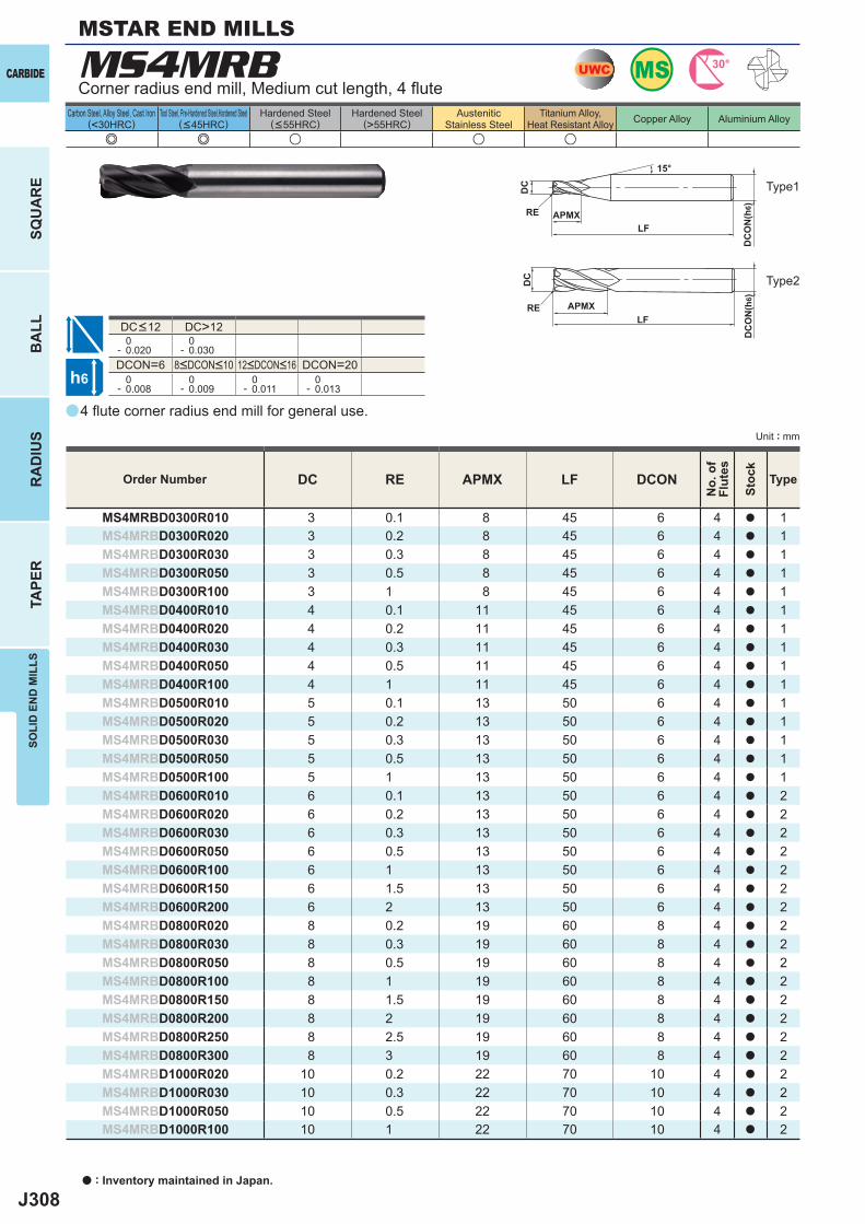
J308
a
MS4MRB
e e u u u
DC RE APMX LF DCON
MS4MRBD0300R010 3 0.1 8 45 6 4 a 1MS4MRBD0300R020 3 0.2 8 45 6 4 a 1MS4MRBD0300R030 3 0.3 8 45 6 4 a 1MS4MRBD0300R050 3 0.5 8 45 6 4 a 1MS4MRBD0300R100 3 1 8 45 6 4 a 1MS4MRBD0400R010 4 0.1 11 45 6 4 a 1MS4MRBD0400R020 4 0.2 11 45 6 4 a 1MS4MRBD0400R030 4 0.3 11 45 6 4 a 1MS4MRBD0400R050 4 0.5 11 45 6 4 a 1MS4MRBD0400R100 4 1 11 45 6 4 a 1MS4MRBD0500R010 5 0.1 13 50 6 4 a 1MS4MRBD0500R020 5 0.2 13 50 6 4 a 1MS4MRBD0500R030 5 0.3 13 50 6 4 a 1MS4MRBD0500R050 5 0.5 13 50 6 4 a 1MS4MRBD0500R100 5 1 13 50 6 4 a 1MS4MRBD0600R010 6 0.1 13 50 6 4 a 2MS4MRBD0600R020 6 0.2 13 50 6 4 a 2MS4MRBD0600R030 6 0.3 13 50 6 4 a 2MS4MRBD0600R050 6 0.5 13 50 6 4 a 2MS4MRBD0600R100 6 1 13 50 6 4 a 2MS4MRBD0600R150 6 1.5 13 50 6 4 a 2MS4MRBD0600R200 6 2 13 50 6 4 a 2MS4MRBD0800R020 8 0.2 19 60 8 4 a 2MS4MRBD0800R030 8 0.3 19 60 8 4 a 2MS4MRBD0800R050 8 0.5 19 60 8 4 a 2MS4MRBD0800R100 8 1 19 60 8 4 a 2MS4MRBD0800R150 8 1.5 19 60 8 4 a 2MS4MRBD0800R200 8 2 19 60 8 4 a 2MS4MRBD0800R250 8 2.5 19 60 8 4 a 2MS4MRBD0800R300 8 3 19 60 8 4 a 2MS4MRBD1000R020 10 0.2 22 70 10 4 a 2MS4MRBD1000R030 10 0.3 22 70 10 4 a 2MS4MRBD1000R050 10 0.5 22 70 10 4 a 2MS4MRBD1000R100 10 1 22 70 10 4 a 2
DC>12 0- 0.020
0- 0.030
DCON=6 DCON=20 0- 0.008
0- 0.009
0- 0.011
0- 0.013
UWC MS 30°
h6
APMX
DC
DC
ON
(h6)
LFRE
15°
APMX
DC
ON
(h6)
LFRE
DC
a : Inventory maintained in Japan.
CARBIDE
SQU
AR
EB
ALL
RA
DIU
STA
PER
SOLI
D E
ND
MIL
LS
Unit : mm
Carbon Steel, Alloy Steel, Cast Iron(<30HRC)
Tool Steel, Pre-Hardened Steel,Hardened Steel(<45HRC)
Hardened Steel(<55HRC)
Hardened Steel(>55HRC)
AusteniticStainless Steel
Titanium Alloy,Heat Resistant Alloy Copper Alloy Aluminium Alloy
4 fl ute corner radius end mill for general use.
Corner radius end mill, Medium cut length, 4 fl ute
Type2
Type1
MSTAR END MILLS
Order Number
No.
of
Flut
es
Stoc
k
Type
8<DCON<10 12<DCON<16
DC<12
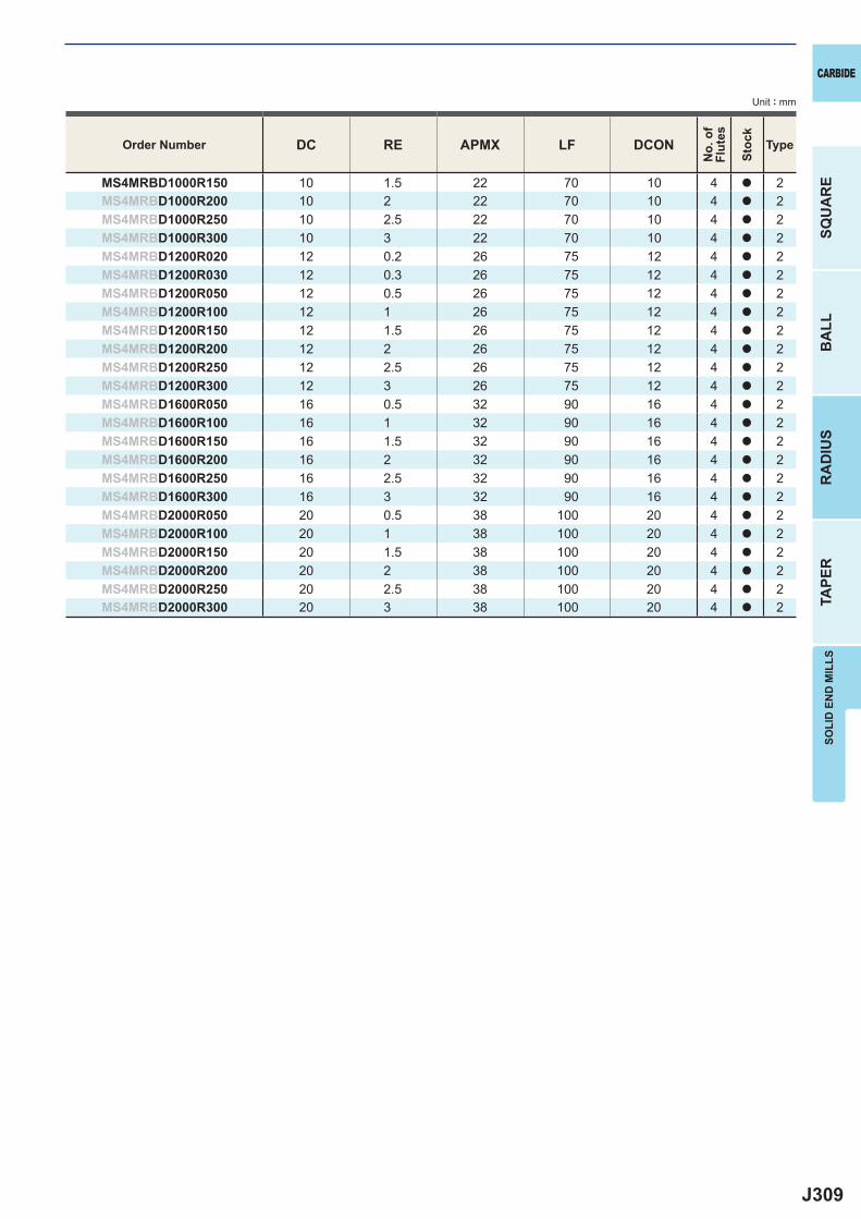
J309
DC RE APMX LF DCON
MS4MRBD1000R150 10 1.5 22 70 10 4 a 2MS4MRBD1000R200 10 2 22 70 10 4 a 2MS4MRBD1000R250 10 2.5 22 70 10 4 a 2MS4MRBD1000R300 10 3 22 70 10 4 a 2MS4MRBD1200R020 12 0.2 26 75 12 4 a 2MS4MRBD1200R030 12 0.3 26 75 12 4 a 2MS4MRBD1200R050 12 0.5 26 75 12 4 a 2MS4MRBD1200R100 12 1 26 75 12 4 a 2MS4MRBD1200R150 12 1.5 26 75 12 4 a 2MS4MRBD1200R200 12 2 26 75 12 4 a 2MS4MRBD1200R250 12 2.5 26 75 12 4 a 2MS4MRBD1200R300 12 3 26 75 12 4 a 2MS4MRBD1600R050 16 0.5 32 90 16 4 a 2MS4MRBD1600R100 16 1 32 90 16 4 a 2MS4MRBD1600R150 16 1.5 32 90 16 4 a 2MS4MRBD1600R200 16 2 32 90 16 4 a 2MS4MRBD1600R250 16 2.5 32 90 16 4 a 2MS4MRBD1600R300 16 3 32 90 16 4 a 2MS4MRBD2000R050 20 0.5 38 100 20 4 a 2MS4MRBD2000R100 20 1 38 100 20 4 a 2MS4MRBD2000R150 20 1.5 38 100 20 4 a 2MS4MRBD2000R200 20 2 38 100 20 4 a 2MS4MRBD2000R250 20 2.5 38 100 20 4 a 2MS4MRBD2000R300 20 3 38 100 20 4 a 2
CARBIDE
SQU
AR
EB
ALL
RA
DIU
STA
PER
SOLI
D E
ND
MIL
LS
Unit : mm
Order Number
No.
of
Flut
es
Stoc
k
Type
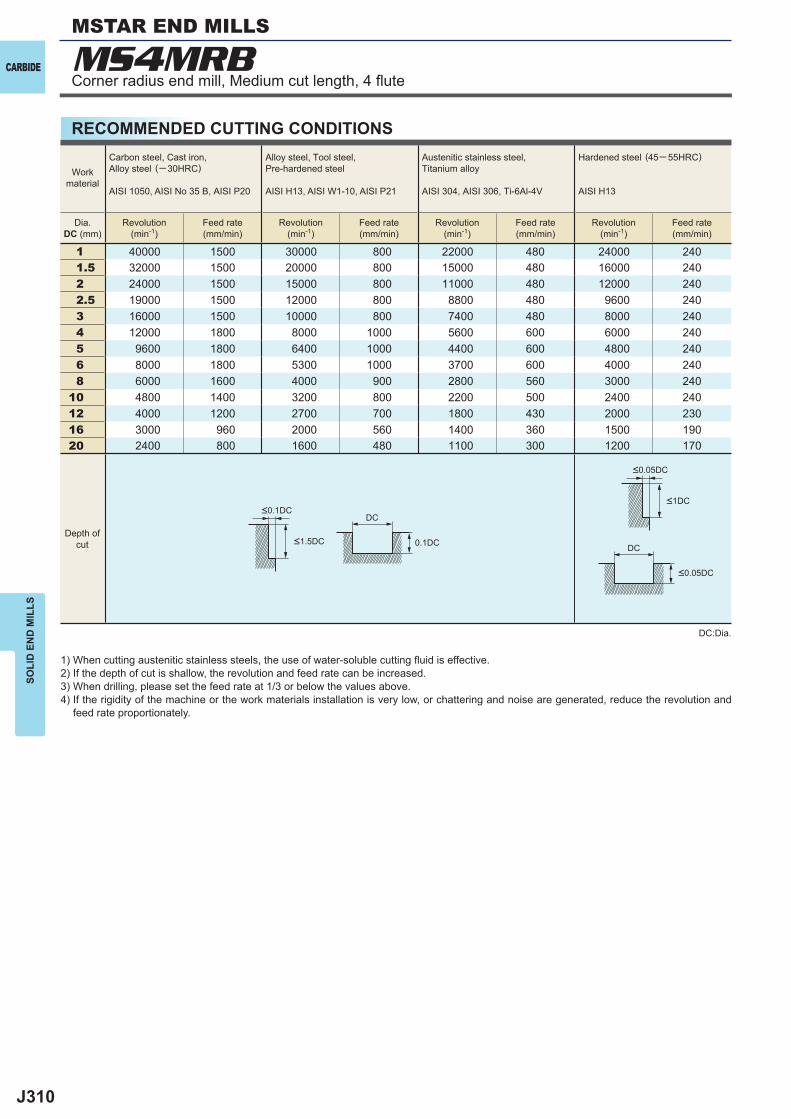
J310
1 40000 1500 30000 800 22000 480 24000 2401.5 32000 1500 20000 800 15000 480 16000 2402 24000 1500 15000 800 11000 480 12000 2402.5 19000 1500 12000 800 8800 480 9600 2403 16000 1500 10000 800 7400 480 8000 2404 12000 1800 8000 1000 5600 600 6000 2405 9600 1800 6400 1000 4400 600 4800 2406 8000 1800 5300 1000 3700 600 4000 2408 6000 1600 4000 900 2800 560 3000 240
10 4800 1400 3200 800 2200 500 2400 24012 4000 1200 2700 700 1800 430 2000 23016 3000 960 2000 560 1400 360 1500 19020 2400 800 1600 480 1100 300 1200 170
DC
DC0.1DC
MS4MRBCARBIDE
SOLI
D E
ND
MIL
LS
RECOMMENDED CUTTING CONDITIONS
1) When cutting austenitic stainless steels, the use of water-soluble cutting fl uid is effective.2) If the depth of cut is shallow, the revolution and feed rate can be increased.3) When drilling, please set the feed rate at 1/3 or below the values above.4) If the rigidity of the machine or the work materials installation is very low, or chattering and noise are generated, reduce the revolution and
feed rate proportionately.
DC:Dia.
Workmaterial
Carbon steel, Cast iron, Alloy steel (─30HRC)
AISI 1050, AISI No 35 B, AISI P20
Alloy steel, Tool steel,Pre-hardened steel
AISI H13, AISI W1-10, AISI P21
Austenitic stainless steel,Titanium alloy
AISI 304, AISI 306, Ti-6Al-4V
Hardened steel (45─ 55HRC)
AISI H13
Dia.DC (mm)
Revolution(min-1)
Feed rate(mm/min)
Revolution(min-1)
Feed rate(mm/min)
Revolution(min-1)
Feed rate(mm/min)
Revolution(min-1)
Feed rate(mm/min)
Depth ofcut
<0.1DC
<1.5DC
<0.05DC
<0.05DC
<1DC
Corner radius end mill, Medium cut length, 4 fl ute
MSTAR END MILLS
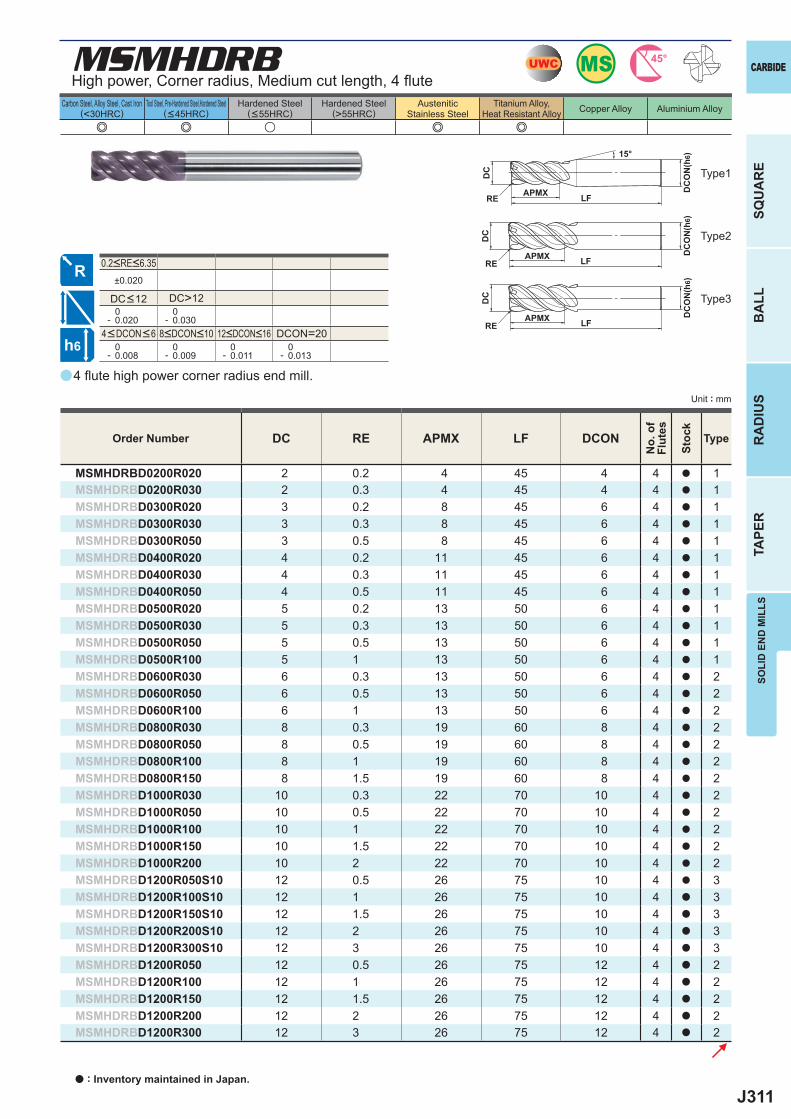
J311
a
e e u e e
MSMHDRB
DC RE APMX LF DCON
MSMHDRBD0200R020 2 0.2 4 45 4 4 a 1MSMHDRBD0200R030 2 0.3 4 45 4 4 a 1MSMHDRBD0300R020 3 0.2 8 45 6 4 a 1MSMHDRBD0300R030 3 0.3 8 45 6 4 a 1MSMHDRBD0300R050 3 0.5 8 45 6 4 a 1MSMHDRBD0400R020 4 0.2 11 45 6 4 a 1MSMHDRBD0400R030 4 0.3 11 45 6 4 a 1MSMHDRBD0400R050 4 0.5 11 45 6 4 a 1MSMHDRBD0500R020 5 0.2 13 50 6 4 a 1MSMHDRBD0500R030 5 0.3 13 50 6 4 a 1MSMHDRBD0500R050 5 0.5 13 50 6 4 a 1MSMHDRBD0500R100 5 1 13 50 6 4 a 1MSMHDRBD0600R030 6 0.3 13 50 6 4 a 2MSMHDRBD0600R050 6 0.5 13 50 6 4 a 2MSMHDRBD0600R100 6 1 13 50 6 4 a 2MSMHDRBD0800R030 8 0.3 19 60 8 4 a 2MSMHDRBD0800R050 8 0.5 19 60 8 4 a 2MSMHDRBD0800R100 8 1 19 60 8 4 a 2MSMHDRBD0800R150 8 1.5 19 60 8 4 a 2MSMHDRBD1000R030 10 0.3 22 70 10 4 a 2MSMHDRBD1000R050 10 0.5 22 70 10 4 a 2MSMHDRBD1000R100 10 1 22 70 10 4 a 2MSMHDRBD1000R150 10 1.5 22 70 10 4 a 2MSMHDRBD1000R200 10 2 22 70 10 4 a 2MSMHDRBD1200R050S10 12 0.5 26 75 10 4 a 3MSMHDRBD1200R100S10 12 1 26 75 10 4 a 3MSMHDRBD1200R150S10 12 1.5 26 75 10 4 a 3MSMHDRBD1200R200S10 12 2 26 75 10 4 a 3MSMHDRBD1200R300S10 12 3 26 75 10 4 a 3MSMHDRBD1200R050 12 0.5 26 75 12 4 a 2MSMHDRBD1200R100 12 1 26 75 12 4 a 2MSMHDRBD1200R150 12 1.5 26 75 12 4 a 2MSMHDRBD1200R200 12 2 26 75 12 4 a 2MSMHDRBD1200R300 12 3 26 75 12 4 a 2
±0.020
DC>12 0- 0.020
0- 0.030
DCON=20 0- 0.008
0- 0.009
0- 0.011
0- 0.013
MSUWC 45°
h6
APMX
DC
DC
ON
(h6)
LFRE
15°
APMX DC
ON
(h6)
LFRE
DC
APMX DC
ON
(h6)
LFRE
DC
CARBIDE
SQU
AR
EB
ALL
RA
DIU
STA
PER
SOLI
D E
ND
MIL
LS
Unit : mm
Carbon Steel, Alloy Steel, Cast Iron(<30HRC)
Tool Steel, Pre-Hardened Steel,Hardened Steel(<45HRC)
Hardened Steel(<55HRC)
Hardened Steel(>55HRC)
AusteniticStainless Steel
Titanium Alloy,Heat Resistant Alloy Copper Alloy Aluminium Alloy
4 fl ute high power corner radius end mill.
High power, Corner radius, Medium cut length, 4 fl ute
Type2
Type1
Type3
Order Number
No.
of
Flut
es
Stoc
k
Type
4<DCON<6 8<DCON<10 12<DCON<16
0.2<RE<6.35
DC<12
a : Inventory maintained in Japan.
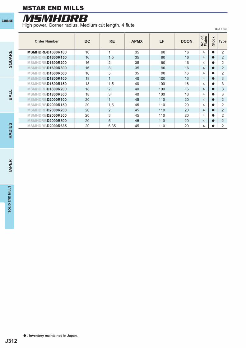
J312
MSMHDRB
DC RE APMX LF DCON
MSMHDRBD1600R100 16 1 35 90 16 4 a 2MSMHDRBD1600R150 16 1.5 35 90 16 4 a 2MSMHDRBD1600R200 16 2 35 90 16 4 a 2MSMHDRBD1600R300 16 3 35 90 16 4 a 2MSMHDRBD1600R500 16 5 35 90 16 4 a 2MSMHDRBD1800R100 18 1 40 100 16 4 a 3MSMHDRBD1800R150 18 1.5 40 100 16 4 a 3MSMHDRBD1800R200 18 2 40 100 16 4 a 3MSMHDRBD1800R300 18 3 40 100 16 4 a 3MSMHDRBD2000R100 20 1 45 110 20 4 a 2MSMHDRBD2000R150 20 1.5 45 110 20 4 a 2MSMHDRBD2000R200 20 2 45 110 20 4 a 2MSMHDRBD2000R300 20 3 45 110 20 4 a 2MSMHDRBD2000R500 20 5 45 110 20 4 a 2MSMHDRBD2000R635 20 6.35 45 110 20 4 a 2
a : Inventory maintained in Japan.
CARBIDE
SQU
AR
EB
ALL
RA
DIU
STA
PER
SOLI
D E
ND
MIL
LS
Unit : mmHigh power, Corner radius, Medium cut length, 4 fl ute
MSTAR END MILLS
Order Number
No.
of
Flut
es
Stoc
k
Type
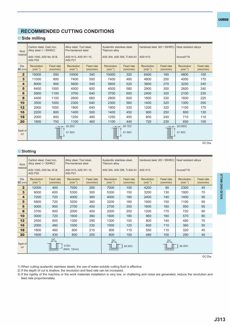
J313
2 15000 550 10000 340 10000 320 6400 160 4800 1003 11000 800 7400 500 7400 480 4800 250 4000 1704 8000 900 5600 540 5600 520 3600 270 3200 2405 6400 1000 4500 600 4500 580 2900 300 2600 2406 5900 1100 3700 640 3700 600 2400 320 2100 2308 4400 1100 2800 660 2800 600 1800 330 1600 220
10 3500 1000 2300 640 2300 560 1400 320 1300 20012 2900 1000 1900 640 1900 530 1200 320 1100 17016 2200 800 1400 500 1400 450 900 250 800 13018 2000 800 1250 480 1250 450 800 240 710 11020 1800 750 1100 460 1100 440 720 230 650 100
2 12000 400 7000 200 7000 100 4200 80 2300 403 9000 600 5300 300 5300 150 3200 130 1900 704 7200 720 4000 360 4000 180 2400 140 1400 955 5800 720 3200 360 3200 180 1900 150 1100 956 5000 800 2700 400 2700 200 1600 160 950 958 3700 800 2000 400 2000 200 1200 170 720 90
10 3000 720 1600 360 1600 180 960 160 570 8012 2500 600 1300 290 1300 150 800 140 480 7016 2000 480 1000 230 1000 120 600 110 360 5018 1800 460 900 210 900 110 550 110 320 4520 1600 430 800 200 800 100 480 100 290 40
DC DC DC
y
y
CARBIDE
SOLI
D E
ND
MIL
LS
RECOMMENDED CUTTING CONDITIONS
1) When cutting austenitic stainless steels, the use of water-soluble cutting fl uid is effective.2) If the depth of cut is shallow, the revolution and feed rate can be increased.3) If the rigidity of the machine or the work materials installation is very low, or chattering and noise are generated, reduce the revolution and
feed rate proportionately.
DC:Dia.
DC:Dia.
Slotting
Side milling
Workmaterial
Carbon steel, Cast iron, Alloy steel (─30HRC)
AISI 1050, AISI No 35 B,AISI P20
Alloy steel, Tool steel,Pre-hardened steel
AISI H13, AISI W1-10, AISI P21
Austenitic stainless steel,Titanium alloy
AISI 304, AISI 306, Ti-6Al-4V
Hardened steel (45─ 55HRC)
AISI H13
Heat resistant alloys
Inconel718
Dia.DC (mm)
Revolution(min-1)
Feed rate(mm/min)
Revolution(min-1)
Feed rate(mm/min)
Revolution(min-1)
Feed rate(mm/min)
Revolution(min-1)
Feed rate(mm/min)
Revolution(min-1)
Feed rate(mm/min)
Depth ofcut
<0.2DC <0.1DC <0.05DC
<1.5DC <1.5DC <1.5DC
Workmaterial
Carbon steel, Cast iron, Alloy steel (─30HRC)
AISI 1050, AISI No 35 B,AISI P20
Alloy steel, Tool steel,Pre-hardened steel
AISI H13, AISI W1-10, AISI P21
Austenitic stainless steel,Titanium alloy
AISI 304, AISI 306, Ti-6Al-4V
Hardened steel (45─ 55HRC)
AISI H13
Heat resistant alloys
Inconel718
Dia.DC (mm)
Revolution(min-1)
Feed rate(mm/min)
Revolution(min-1)
Feed rate(mm/min)
Revolution(min-1)
Feed rate(mm/min)
Revolution(min-1)
Feed rate(mm/min)
Revolution(min-1)
Feed rate(mm/min)
Depth ofcut <1DC <0.5DC <0.2DC
(MAX. 12mm)
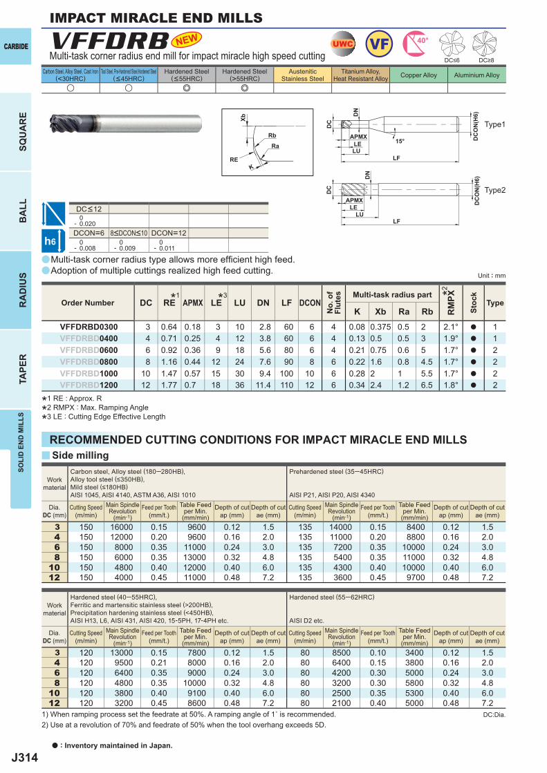
J314
a
u u e e
a
y
DC RE APMX LE LU DN LF DCON
RM
PX
K Xb Ra RbVFFDRBD0300 3 0.64 0.18 3 10 2.8 60 6 4 0.08 0.375 0.5 2 2.1° a 1VFFDRBD0400 4 0.71 0.25 4 12 3.8 60 6 4 0.13 0.5 0.5 3 1.9° a 1VFFDRBD0600 6 0.92 0.36 9 18 5.6 80 6 4 0.21 0.75 0.6 5 1.7° a 2VFFDRBD0800 8 1.16 0.44 12 24 7.6 90 8 6 0.22 1.6 0.8 4.5 1.7° a 2VFFDRBD1000 10 1.47 0.57 15 30 9.4 100 10 6 0.28 2 1 5.5 1.7° a 2VFFDRBD1200 12 1.77 0.7 18 36 11.4 110 12 6 0.34 2.4 1.2 6.5 1.8° a 2
0- 0.020DCON=6 DCON=12 0- 0.008
0- 0.009
0- 0.011
3 150 16000 0.15 9600 0.12 1.5 135 14000 0.15 8400 0.12 1.54 150 12000 0.20 9600 0.16 2.0 135 11000 0.20 8800 0.16 2.06 150 8000 0.35 11000 0.24 3.0 135 7200 0.35 10000 0.24 3.08 150 6000 0.35 13000 0.32 4.8 135 5400 0.35 11000 0.32 4.8
10 150 4800 0.40 12000 0.40 6.0 135 4300 0.40 10000 0.40 6.012 150 4000 0.45 11000 0.48 7.2 135 3600 0.45 9700 0.48 7.2
3 120 13000 0.15 7800 0.12 1.5 80 8500 0.10 3400 0.12 1.5 4 120 9500 0.21 8000 0.16 2.0 80 6400 0.15 3800 0.16 2.06 120 6400 0.35 9000 0.24 3.0 80 4200 0.30 5000 0.24 3.08 120 4800 0.35 10000 0.32 4.8 80 3200 0.30 5800 0.32 4.8
10 120 3800 0.40 9100 0.40 6.0 80 2500 0.35 5300 0.40 6.012 120 3200 0.45 8600 0.48 7.2 80 2100 0.40 5000 0.48 7.2
VFFDRB NEW
h6
UWC VF 40°
LU
LU
LE
LE
DC
REK
Xb
Rb
Ra
DC
DC
ON
(H6)
DC
ON
(H6)
15°APMX
APMX
LF
LF
DN
DN
a : Inventory maintained in Japan.
CARBIDE
SQU
AR
EB
ALL
RA
DIU
STA
PER
SOLI
D E
ND
MIL
LS
Unit : mm
Carbon Steel, Alloy Steel, Cast Iron(<30HRC)
Tool Steel, Pre-Hardened Steel,Hardened Steel(<45HRC)
Hardened Steel(<55HRC)
Hardened Steel(>55HRC)
AusteniticStainless Steel
Titanium Alloy,Heat Resistant Alloy Copper Alloy Aluminium Alloy
IMPACT MIRACLE END MILLS
Order Number
No.
of
Flut
es Multi-task radius part
Stoc
k
Type
Type2
Type1
Multi-task corner radius type allows more effi cient high feed.Adoption of multiple cuttings realized high feed cutting.
DC<12
8<DCON<10
Multi-task corner radius end mill for impact miracle high speed cutting
Work material
Carbon steel, Alloy steel (180─280HB), Alloy tool steel (≤350HB),Mild steel (≤180HB)AISI 1045, AISI 4140, ASTM A36, AISI 1010
Prehardened steel (35─45HRC)
AISI P21, AISI P20, AISI 4340
Dia.DC (mm)
Cutting Speed(m/min)
Main Spindle Revolution
(min-1)Feed per Tooth
(mm/t.)Table Feed
per Min.(mm/min)
Depth of cut ap (mm)
Depth of cut ae (mm)
Cutting Speed(m/min)
Main Spindle Revolution
(min-1)Feed per Tooth
(mm/t.)Table Feed
per Min.(mm/min)
Depth of cut ap (mm)
Depth of cut ae (mm)
Work material
Hardened steel (40─55HRC), Ferritic and martensitic stainless steel (>200HB),Precipitation hardening stainless steel (<450HB),AISI H13, L6, AISI 431, AISI 420, 15-5PH, 17-4PH etc.
Hardened steel (55─62HRC)
AISI D2 etc.
Dia.DC (mm)
Cutting Speed(m/min)
Main Spindle Revolution
(min-1)Feed per Tooth
(mm/t.)Table Feed
per Min.(mm/min)
Depth of cut ap (mm)
Depth of cut ae (mm)
Cutting Speed(m/min)
Main Spindle Revolution
(min-1)Feed per Tooth
(mm/t.)Table Feed
per Min.(mm/min)
Depth of cut ap (mm)
Depth of cut ae (mm)
Side milling
1) When ramping process set the feedrate at 50%. A ramping angle of 1˚ is recommended.2) Use at a revolution of 70% and feedrate of 50% when the tool overhang exceeds 5D.
DC≤6 DC≥8
RECOMMENDED CUTTING CONDITIONS FOR IMPACT MIRACLE END MILLS
*1 RE : Approx. R
*2 RMPX : Max. Ramping Angle
*3 LE : Cutting Edge Effective Length
*1 *2
DC:Dia.
*3
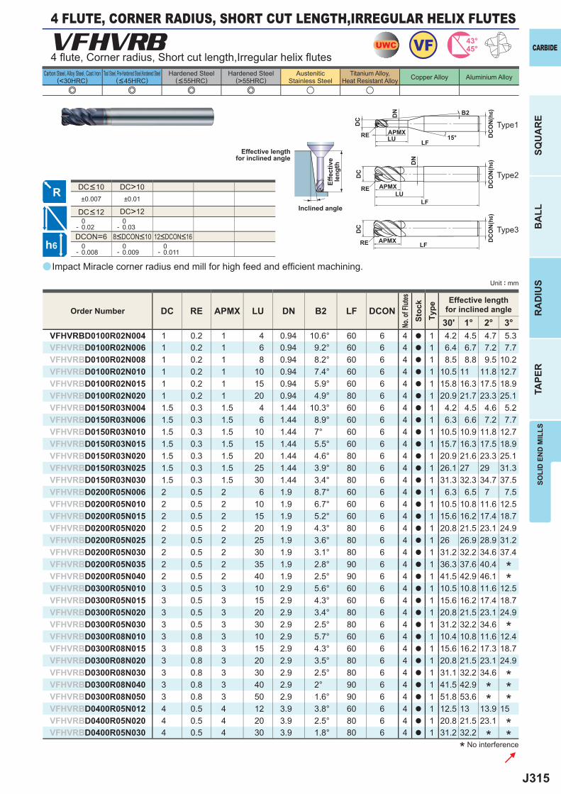
J315
a
e e e e u u
VFHVRB
DC RE APMX LU DN B2 LF DCON30' 1° 2° 3°
VFHVRBD0100R02N004 1 0.2 1 4 0.94 10.6° 60 6 4 a 1 4.2 4.5 4.7 5.3VFHVRBD0100R02N006 1 0.2 1 6 0.94 9.2° 60 6 4 a 1 6.4 6.7 7.2 7.7VFHVRBD0100R02N008 1 0.2 1 8 0.94 8.2° 60 6 4 a 1 8.5 8.8 9.5 10.2VFHVRBD0100R02N010 1 0.2 1 10 0.94 7.4° 60 6 4 a 1 10.5 11 11.8 12.7VFHVRBD0100R02N015 1 0.2 1 15 0.94 5.9° 60 6 4 a 1 15.8 16.3 17.5 18.9VFHVRBD0100R02N020 1 0.2 1 20 0.94 4.9° 80 6 4 a 1 20.9 21.7 23.3 25.1VFHVRBD0150R03N004 1.5 0.3 1.5 4 1.44 10.3° 60 6 4 a 1 4.2 4.5 4.6 5.2VFHVRBD0150R03N006 1.5 0.3 1.5 6 1.44 8.9° 60 6 4 a 1 6.3 6.6 7.2 7.7VFHVRBD0150R03N010 1.5 0.3 1.5 10 1.44 7° 60 6 4 a 1 10.5 10.9 11.8 12.7VFHVRBD0150R03N015 1.5 0.3 1.5 15 1.44 5.5° 60 6 4 a 1 15.7 16.3 17.5 18.9VFHVRBD0150R03N020 1.5 0.3 1.5 20 1.44 4.6° 80 6 4 a 1 20.9 21.6 23.3 25.1VFHVRBD0150R03N025 1.5 0.3 1.5 25 1.44 3.9° 80 6 4 a 1 26.1 27 29 31.3VFHVRBD0150R03N030 1.5 0.3 1.5 30 1.44 3.4° 80 6 4 a 1 31.3 32.3 34.7 37.5VFHVRBD0200R05N006 2 0.5 2 6 1.9 8.7° 60 6 4 a 1 6.3 6.5 7 7.5VFHVRBD0200R05N010 2 0.5 2 10 1.9 6.7° 60 6 4 a 1 10.5 10.8 11.6 12.5VFHVRBD0200R05N015 2 0.5 2 15 1.9 5.2° 60 6 4 a 1 15.6 16.2 17.4 18.7VFHVRBD0200R05N020 2 0.5 2 20 1.9 4.3° 80 6 4 a 1 20.8 21.5 23.1 24.9VFHVRBD0200R05N025 2 0.5 2 25 1.9 3.6° 80 6 4 a 1 26 26.9 28.9 31.2VFHVRBD0200R05N030 2 0.5 2 30 1.9 3.1° 80 6 4 a 1 31.2 32.2 34.6 37.4VFHVRBD0200R05N035 2 0.5 2 35 1.9 2.8° 90 6 4 a 1 36.3 37.6 40.4VFHVRBD0200R05N040 2 0.5 2 40 1.9 2.5° 90 6 4 a 1 41.5 42.9 46.1VFHVRBD0300R05N010 3 0.5 3 10 2.9 5.6° 60 6 4 a 1 10.5 10.8 11.6 12.5VFHVRBD0300R05N015 3 0.5 3 15 2.9 4.3° 60 6 4 a 1 15.6 16.2 17.4 18.7VFHVRBD0300R05N020 3 0.5 3 20 2.9 3.4° 80 6 4 a 1 20.8 21.5 23.1 24.9VFHVRBD0300R05N030 3 0.5 3 30 2.9 2.5° 80 6 4 a 1 31.2 32.2 34.6VFHVRBD0300R08N010 3 0.8 3 10 2.9 5.7° 60 6 4 a 1 10.4 10.8 11.6 12.4VFHVRBD0300R08N015 3 0.8 3 15 2.9 4.3° 60 6 4 a 1 15.6 16.2 17.3 18.7VFHVRBD0300R08N020 3 0.8 3 20 2.9 3.5° 80 6 4 a 1 20.8 21.5 23.1 24.9VFHVRBD0300R08N030 3 0.8 3 30 2.9 2.5° 80 6 4 a 1 31.1 32.2 34.6VFHVRBD0300R08N040 3 0.8 3 40 2.9 2° 90 6 4 a 1 41.5 42.9VFHVRBD0300R08N050 3 0.8 3 50 2.9 1.6° 90 6 4 a 1 51.8 53.6VFHVRBD0400R05N012 4 0.5 4 12 3.9 3.8° 60 6 4 a 1 12.5 13 13.9 15 VFHVRBD0400R05N020 4 0.5 4 20 3.9 2.5° 80 6 4 a 1 20.8 21.5 23.1VFHVRBD0400R05N030 4 0.5 4 30 3.9 1.8° 80 6 4 a 1 31.2 32.2
DC>10±0.007 ±0.01
DC>12 0- 0.02
0- 0.03
DCON=6 0- 0.008
0- 0.009
0- 0.011
UWC 43°45°VF
h6
APMX
DC
DC
ON
(h6)
LFRE 15°
APMX DC
ON
(h6)
LF
RE
DC
APMX DC
ON
(h6)
LFRE
DC
LU
LU
DN
DN B2
CARBIDE
SQU
AR
EB
ALL
RA
DIU
STA
PER
SOLI
D E
ND
MIL
LS
Unit : mm
Carbon Steel, Alloy Steel, Cast Iron(<30HRC)
Tool Steel, Pre-Hardened Steel,Hardened Steel(<45HRC)
Hardened Steel(<55HRC)
Hardened Steel(>55HRC)
AusteniticStainless Steel
Titanium Alloy,Heat Resistant Alloy Copper Alloy Aluminium Alloy
4 fl ute, Corner radius, Short cut length,Irregular helix fl utes
4 FLUTE, CORNER RADIUS, SHORT CUT LENGTH,IRREGULAR HELIX FLUTES
Type2
Type1
Type3
Impact Miracle corner radius end mill for high feed and effi cient machining.
* No interference
Effective lengthfor inclined angle
Inclined angle
Effe
ctiv
ele
ngth
Order Number
No. o
f Flut
esSt
ock
Type
Effective lengthfor inclined angle
***
** *
**
**
*
8<DCON<10 12<DCON<16
DC<12
DC<10
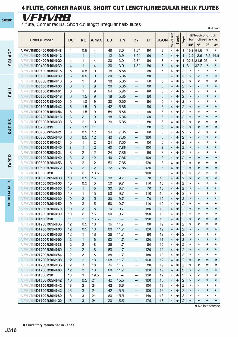
J316
DC RE APMX LU DN B2 LF DCON30' 1° 2° 3°
VFHVRBD0400R05N048 4 0.5 4 48 3.9 1.2° 90 6 4 a 1 49.8 51.5VFHVRBD0400R10N012 4 1 4 12 3.9 3.9° 60 6 4 a 1 12.5 12.9 13.8 14.9VFHVRBD0400R10N020 4 1 4 20 3.9 2.5° 80 6 4 a 1 20.8 21.5 23VFHVRBD0400R10N030 4 1 4 30 3.9 1.8° 80 6 4 a 1 31.1 32.2VFHVRBD0600R05N018 6 0.5 9 18 5.85 ─ 60 6 4 a 2VFHVRBD0600R05N030 6 0.5 9 30 5.85 ─ 80 6 4 a 2VFHVRBD0600R10N018 6 1 9 18 5.85 ─ 60 6 4 a 2VFHVRBD0600R10N030 6 1 9 30 5.85 ─ 80 6 4 a 2VFHVRBD0600R10N054 6 1 9 54 5.85 ─ 90 6 4 a 2VFHVRBD0600R15N018 6 1.5 9 18 5.85 ─ 60 6 4 a 2VFHVRBD0600R15N030 6 1.5 9 30 5.85 ─ 80 6 4 a 2VFHVRBD0600R15N042 6 1.5 9 42 5.85 ─ 90 6 4 a 2VFHVRBD0600R15N054 6 1.5 9 54 5.85 ─ 90 6 4 a 2VFHVRBD0600R20N018 6 2 9 18 5.85 ─ 60 6 4 a 2VFHVRBD0600R20N030 6 2 9 30 5.85 ─ 80 6 4 a 2VFHVRBD0700R15 7 1.5 11 ─ ─ ─ 80 6 4 a 3VFHVRBD0800R05N024 8 0.5 12 24 7.85 ─ 60 8 4 a 2VFHVRBD0800R05N040 8 0.5 12 40 7.85 ─ 100 8 4 a 2VFHVRBD0800R10N024 8 1 12 24 7.85 ─ 60 8 4 a 2VFHVRBD0800R10N040 8 1 12 40 7.85 ─ 100 8 4 a 2VFHVRBD0800R20N024 8 2 12 24 7.85 ─ 60 8 4 a 2VFHVRBD0800R20N040 8 2 12 40 7.85 ─ 100 8 4 a 2VFHVRBD0800R20N056 8 2 12 56 7.85 ─ 120 8 4 a 2VFHVRBD0800R20N072 8 2 12 72 7.85 ─ 120 8 4 a 2VFHVRBD0900R20 9 2 13.5 ─ ─ ─ 100 8 4 a 3VFHVRBD1000R05N030 10 0.5 15 30 9.7 ─ 70 10 4 a 2VFHVRBD1000R05N050 10 0.5 15 50 9.7 ─ 110 10 4 a 2VFHVRBD1000R10N030 10 1 15 30 9.7 ─ 70 10 4 a 2VFHVRBD1000R10N050 10 1 15 50 9.7 ─ 110 10 4 a 2VFHVRBD1000R20N030 10 2 15 30 9.7 ─ 70 10 4 a 2VFHVRBD1000R20N050 10 2 15 50 9.7 ─ 110 10 4 a 2VFHVRBD1000R20N070 10 2 15 70 9.7 ─ 150 10 4 a 2VFHVRBD1000R20N090 10 2 15 90 9.7 ─ 150 10 4 a 2VFHVRBD1100R20 11 2 16.5 ─ ─ ─ 110 10 4 a 3VFHVRBD1200R05N036 12 0.5 18 36 11.7 ─ 80 12 4 a 2VFHVRBD1200R05N060 12 0.5 18 60 11.7 ─ 120 12 4 a 2VFHVRBD1200R10N036 12 1 18 36 11.7 ─ 80 12 4 a 2VFHVRBD1200R10N060 12 1 18 60 11.7 ─ 120 12 4 a 2VFHVRBD1200R20N036 12 2 18 36 11.7 ─ 80 12 4 a 2VFHVRBD1200R20N060 12 2 18 60 11.7 ─ 120 12 4 a 2VFHVRBD1200R20N084 12 2 18 84 11.7 ─ 160 12 4 a 2VFHVRBD1200R20N108 12 2 18 108 11.7 ─ 160 12 4 a 2VFHVRBD1200R30N036 12 3 18 36 11.7 ─ 80 12 4 a 2VFHVRBD1200R30N060 12 3 18 60 11.7 ─ 120 12 4 a 2VFHVRBD1300R30 13 3 19.5 ─ ─ ─ 120 12 4 a 3VFHVRBD1600R05N042 16 0.5 24 42 15.5 ─ 100 16 4 a 2VFHVRBD1600R20N042 16 2 24 42 15.5 ─ 100 16 4 a 2VFHVRBD1600R30N042 16 3 24 42 15.5 ─ 100 16 4 a 2VFHVRBD1600R30N080 16 3 24 80 15.5 ─ 140 16 4 a 2VFHVRBD1600R30N120 16 3 24 120 15.5 ─ 175 16 4 a 2
VFHVRB
a : Inventory maintained in Japan.
CARBIDE
SQU
AR
EB
ALL
RA
DIU
STA
PER
SOLI
D E
ND
MIL
LS
Unit : mm
* No interference
Order Number
No. o
f Flut
esSt
ock
Type
Effective lengthfor inclined angle
* * * ** * * ** * * ** * * ** * * ** * * ** * * ** * * ** * * ** * * ** * * ** * * ** * * ** * * ** * * ** * * ** * * ** * * ** * * ** * * ** * * ** * * ** * * ** * * ** * * ** * * ** * * ** * * ** * * ** * * ** * * ** * * ** * * ** * * ** * * ** * * ** * * ** * * ** * * ** * * ** * * ** * * ** * * ** * * ** * * *
*
***
*
****
4 FLUTE, CORNER RADIUS, SHORT CUT LENGTH,IRREGULAR HELIX FLUTES
4 fl ute, Corner radius, Short cut length,Irregular helix fl utes
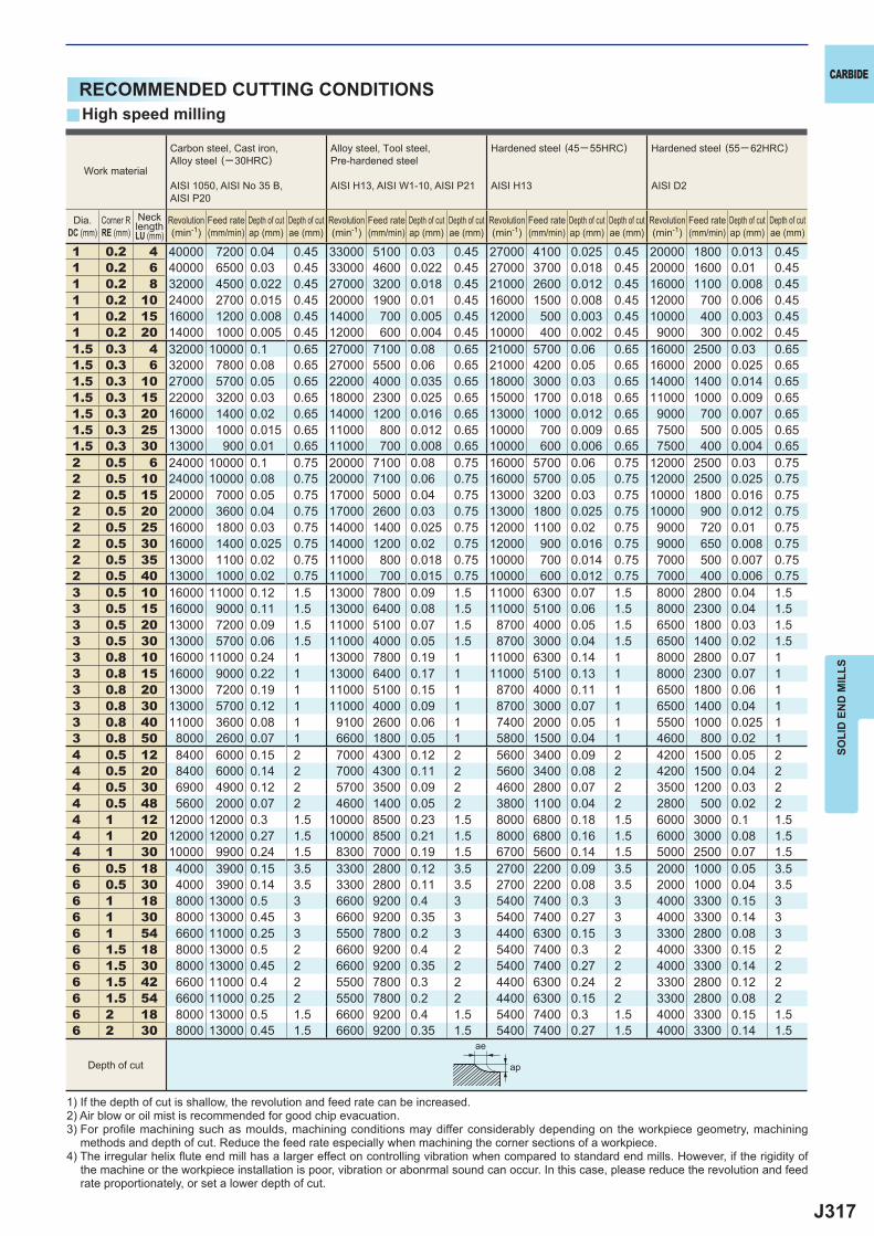
J317
y
1 0.2 4 40000 7200 0.04 0.45 33000 5100 0.03 0.45 27000 4100 0.025 0.45 20000 1800 0.013 0.451 0.2 6 40000 6500 0.03 0.45 33000 4600 0.022 0.45 27000 3700 0.018 0.45 20000 1600 0.01 0.451 0.2 8 32000 4500 0.022 0.45 27000 3200 0.018 0.45 21000 2600 0.012 0.45 16000 1100 0.008 0.451 0.2 10 24000 2700 0.015 0.45 20000 1900 0.01 0.45 16000 1500 0.008 0.45 12000 700 0.006 0.451 0.2 15 16000 1200 0.008 0.45 14000 700 0.005 0.45 12000 500 0.003 0.45 10000 400 0.003 0.451 0.2 20 14000 1000 0.005 0.45 12000 600 0.004 0.45 10000 400 0.002 0.45 9000 300 0.002 0.451.5 0.3 4 32000 10000 0.1 0.65 27000 7100 0.08 0.65 21000 5700 0.06 0.65 16000 2500 0.03 0.651.5 0.3 6 32000 7800 0.08 0.65 27000 5500 0.06 0.65 21000 4200 0.05 0.65 16000 2000 0.025 0.651.5 0.3 10 27000 5700 0.05 0.65 22000 4000 0.035 0.65 18000 3000 0.03 0.65 14000 1400 0.014 0.651.5 0.3 15 22000 3200 0.03 0.65 18000 2300 0.025 0.65 15000 1700 0.018 0.65 11000 1000 0.009 0.651.5 0.3 20 16000 1400 0.02 0.65 14000 1200 0.016 0.65 13000 1000 0.012 0.65 9000 700 0.007 0.651.5 0.3 25 13000 1000 0.015 0.65 11000 800 0.012 0.65 10000 700 0.009 0.65 7500 500 0.005 0.651.5 0.3 30 13000 900 0.01 0.65 11000 700 0.008 0.65 10000 600 0.006 0.65 7500 400 0.004 0.652 0.5 6 24000 10000 0.1 0.75 20000 7100 0.08 0.75 16000 5700 0.06 0.75 12000 2500 0.03 0.752 0.5 10 24000 10000 0.08 0.75 20000 7100 0.06 0.75 16000 5700 0.05 0.75 12000 2500 0.025 0.752 0.5 15 20000 7000 0.05 0.75 17000 5000 0.04 0.75 13000 3200 0.03 0.75 10000 1800 0.016 0.752 0.5 20 20000 3600 0.04 0.75 17000 2600 0.03 0.75 13000 1800 0.025 0.75 10000 900 0.012 0.752 0.5 25 16000 1800 0.03 0.75 14000 1400 0.025 0.75 12000 1100 0.02 0.75 9000 720 0.01 0.752 0.5 30 16000 1400 0.025 0.75 14000 1200 0.02 0.75 12000 900 0.016 0.75 9000 650 0.008 0.752 0.5 35 13000 1100 0.02 0.75 11000 800 0.018 0.75 10000 700 0.014 0.75 7000 500 0.007 0.752 0.5 40 13000 1000 0.02 0.75 11000 700 0.015 0.75 10000 600 0.012 0.75 7000 400 0.006 0.753 0.5 10 16000 11000 0.12 1.5 13000 7800 0.09 1.5 11000 6300 0.07 1.5 8000 2800 0.04 1.53 0.5 15 16000 9000 0.11 1.5 13000 6400 0.08 1.5 11000 5100 0.06 1.5 8000 2300 0.04 1.53 0.5 20 13000 7200 0.09 1.5 11000 5100 0.07 1.5 8700 4000 0.05 1.5 6500 1800 0.03 1.53 0.5 30 13000 5700 0.06 1.5 11000 4000 0.05 1.5 8700 3000 0.04 1.5 6500 1400 0.02 1.53 0.8 10 16000 11000 0.24 1 13000 7800 0.19 1 11000 6300 0.14 1 8000 2800 0.07 13 0.8 15 16000 9000 0.22 1 13000 6400 0.17 1 11000 5100 0.13 1 8000 2300 0.07 13 0.8 20 13000 7200 0.19 1 11000 5100 0.15 1 8700 4000 0.11 1 6500 1800 0.06 13 0.8 30 13000 5700 0.12 1 11000 4000 0.09 1 8700 3000 0.07 1 6500 1400 0.04 13 0.8 40 11000 3600 0.08 1 9100 2600 0.06 1 7400 2000 0.05 1 5500 1000 0.025 13 0.8 50 8000 2600 0.07 1 6600 1800 0.05 1 5800 1500 0.04 1 4600 800 0.02 14 0.5 12 8400 6000 0.15 2 7000 4300 0.12 2 5600 3400 0.09 2 4200 1500 0.05 24 0.5 20 8400 6000 0.14 2 7000 4300 0.11 2 5600 3400 0.08 2 4200 1500 0.04 24 0.5 30 6900 4900 0.12 2 5700 3500 0.09 2 4600 2800 0.07 2 3500 1200 0.03 24 0.5 48 5600 2000 0.07 2 4600 1400 0.05 2 3800 1100 0.04 2 2800 500 0.02 24 1 12 12000 12000 0.3 1.5 10000 8500 0.23 1.5 8000 6800 0.18 1.5 6000 3000 0.1 1.54 1 20 12000 12000 0.27 1.5 10000 8500 0.21 1.5 8000 6800 0.16 1.5 6000 3000 0.08 1.54 1 30 10000 9900 0.24 1.5 8300 7000 0.19 1.5 6700 5600 0.14 1.5 5000 2500 0.07 1.56 0.5 18 4000 3900 0.15 3.5 3300 2800 0.12 3.5 2700 2200 0.09 3.5 2000 1000 0.05 3.56 0.5 30 4000 3900 0.14 3.5 3300 2800 0.11 3.5 2700 2200 0.08 3.5 2000 1000 0.04 3.56 1 18 8000 13000 0.5 3 6600 9200 0.4 3 5400 7400 0.3 3 4000 3300 0.15 36 1 30 8000 13000 0.45 3 6600 9200 0.35 3 5400 7400 0.27 3 4000 3300 0.14 36 1 54 6600 11000 0.25 3 5500 7800 0.2 3 4400 6300 0.15 3 3300 2800 0.08 36 1.5 18 8000 13000 0.5 2 6600 9200 0.4 2 5400 7400 0.3 2 4000 3300 0.15 26 1.5 30 8000 13000 0.45 2 6600 9200 0.35 2 5400 7400 0.27 2 4000 3300 0.14 26 1.5 42 6600 11000 0.4 2 5500 7800 0.3 2 4400 6300 0.24 2 3300 2800 0.12 26 1.5 54 6600 11000 0.25 2 5500 7800 0.2 2 4400 6300 0.15 2 3300 2800 0.08 26 2 18 8000 13000 0.5 1.5 6600 9200 0.4 1.5 5400 7400 0.3 1.5 4000 3300 0.15 1.56 2 30 8000 13000 0.45 1.5 6600 9200 0.35 1.5 5400 7400 0.27 1.5 4000 3300 0.14 1.5
ae
ap
CARBIDE
SOLI
D E
ND
MIL
LS
RECOMMENDED CUTTING CONDITIONSHigh speed milling
1) If the depth of cut is shallow, the revolution and feed rate can be increased.2) Air blow or oil mist is recommended for good chip evacuation.3) For profi le machining such as moulds, machining conditions may differ considerably depending on the workpiece geometry, machining
methods and depth of cut. Reduce the feed rate especially when machining the corner sections of a workpiece.4) The irregular helix fl ute end mill has a larger effect on controlling vibration when compared to standard end mills. However, if the rigidity of
the machine or the workpiece installation is poor, vibration or abonrmal sound can occur. In this case, please reduce the revolution and feed rate proportionately, or set a lower depth of cut.
Work material
Carbon steel, Cast iron, Alloy steel (─30HRC)
AISI 1050, AISI No 35 B,AISI P20
Alloy steel, Tool steel,Pre-hardened steel
AISI H13, AISI W1-10, AISI P21
Hardened steel (45─ 55HRC)
AISI H13
Hardened steel (55─ 62HRC)
AISI D2
Revolution(min-1)
Revolution(min-1)
Revolution(min-1)
Revolution(min-1)
Feed rate(mm/min)
Feed rate(mm/min)
Feed rate(mm/min)
Feed rate(mm/min)
Depth of cutap (mm)
Depth of cutap (mm)
Depth of cutap (mm)
Depth of cutap (mm)
Depth of cutae (mm)
Depth of cutae (mm)
Depth of cutae (mm)
Depth of cutae (mm)
Depth of cut
Dia.DC (mm)
Corner RRE (mm)
NecklengthLU (mm)
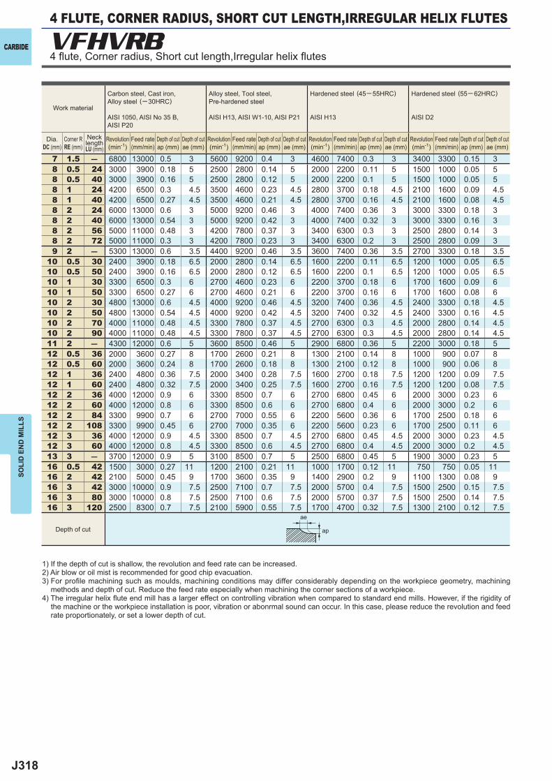
J318
7 1.5 ― 6800 13000 0.5 3 5600 9200 0.4 3 4600 7400 0.3 3 3400 3300 0.15 38 0.5 24 3000 3900 0.18 5 2500 2800 0.14 5 2000 2200 0.11 5 1500 1000 0.05 58 0.5 40 3000 3900 0.16 5 2500 2800 0.12 5 2000 2200 0.1 5 1500 1000 0.05 58 1 24 4200 6500 0.3 4.5 3500 4600 0.23 4.5 2800 3700 0.18 4.5 2100 1600 0.09 4.58 1 40 4200 6500 0.27 4.5 3500 4600 0.21 4.5 2800 3700 0.16 4.5 2100 1600 0.08 4.58 2 24 6000 13000 0.6 3 5000 9200 0.46 3 4000 7400 0.36 3 3000 3300 0.18 38 2 40 6000 13000 0.54 3 5000 9200 0.42 3 4000 7400 0.32 3 3000 3300 0.16 38 2 56 5000 11000 0.48 3 4200 7800 0.37 3 3400 6300 0.3 3 2500 2800 0.14 38 2 72 5000 11000 0.3 3 4200 7800 0.23 3 3400 6300 0.2 3 2500 2800 0.09 39 2 ― 5300 13000 0.6 3.5 4400 9200 0.46 3.5 3600 7400 0.36 3.5 2700 3300 0.18 3.5
10 0.5 30 2400 3900 0.18 6.5 2000 2800 0.14 6.5 1600 2200 0.11 6.5 1200 1000 0.05 6.510 0.5 50 2400 3900 0.16 6.5 2000 2800 0.12 6.5 1600 2200 0.1 6.5 1200 1000 0.05 6.510 1 30 3300 6500 0.3 6 2700 4600 0.23 6 2200 3700 0.18 6 1700 1600 0.09 610 1 50 3300 6500 0.27 6 2700 4600 0.21 6 2200 3700 0.16 6 1700 1600 0.08 610 2 30 4800 13000 0.6 4.5 4000 9200 0.46 4.5 3200 7400 0.36 4.5 2400 3300 0.18 4.510 2 50 4800 13000 0.54 4.5 4000 9200 0.42 4.5 3200 7400 0.32 4.5 2400 3300 0.16 4.510 2 70 4000 11000 0.48 4.5 3300 7800 0.37 4.5 2700 6300 0.3 4.5 2000 2800 0.14 4.510 2 90 4000 11000 0.48 4.5 3300 7800 0.37 4.5 2700 6300 0.3 4.5 2000 2800 0.14 4.511 2 ― 4300 12000 0.6 5 3600 8500 0.46 5 2900 6800 0.36 5 2200 3000 0.18 512 0.5 36 2000 3600 0.27 8 1700 2600 0.21 8 1300 2100 0.14 8 1000 900 0.07 812 0.5 60 2000 3600 0.24 8 1700 2600 0.18 8 1300 2100 0.12 8 1000 900 0.06 812 1 36 2400 4800 0.36 7.5 2000 3400 0.28 7.5 1600 2700 0.18 7.5 1200 1200 0.09 7.512 1 60 2400 4800 0.32 7.5 2000 3400 0.25 7.5 1600 2700 0.16 7.5 1200 1200 0.08 7.512 2 36 4000 12000 0.9 6 3300 8500 0.7 6 2700 6800 0.45 6 2000 3000 0.23 612 2 60 4000 12000 0.8 6 3300 8500 0.6 6 2700 6800 0.4 6 2000 3000 0.2 612 2 84 3300 9900 0.7 6 2700 7000 0.55 6 2200 5600 0.36 6 1700 2500 0.18 612 2 108 3300 9900 0.45 6 2700 7000 0.35 6 2200 5600 0.23 6 1700 2500 0.11 612 3 36 4000 12000 0.9 4.5 3300 8500 0.7 4.5 2700 6800 0.45 4.5 2000 3000 0.23 4.512 3 60 4000 12000 0.8 4.5 3300 8500 0.6 4.5 2700 6800 0.4 4.5 2000 3000 0.2 4.513 3 ― 3700 12000 0.9 5 3100 8500 0.7 5 2500 6800 0.45 5 1900 3000 0.23 516 0.5 42 1500 3000 0.27 11 1200 2100 0.21 11 1000 1700 0.12 11 750 750 0.05 1116 2 42 2100 5000 0.45 9 1700 3600 0.35 9 1400 2900 0.2 9 1100 1300 0.08 916 3 42 3000 10000 0.9 7.5 2500 7100 0.7 7.5 2000 5700 0.4 7.5 1500 2500 0.15 7.516 3 80 3000 10000 0.8 7.5 2500 7100 0.6 7.5 2000 5700 0.37 7.5 1500 2500 0.14 7.516 3 120 2500 8300 0.7 7.5 2100 5900 0.55 7.5 1700 4700 0.32 7.5 1300 2100 0.12 7.5
VFHVRB
ap
ae
CARBIDE
SOLI
D E
ND
MIL
LS
1) If the depth of cut is shallow, the revolution and feed rate can be increased.2) Air blow or oil mist is recommended for good chip evacuation.3) For profi le machining such as moulds, machining conditions may differ considerably depending on the workpiece geometry, machining
methods and depth of cut. Reduce the feed rate especially when machining the corner sections of a workpiece.4) The irregular helix fl ute end mill has a larger effect on controlling vibration when compared to standard end mills. However, if the rigidity of
the machine or the workpiece installation is poor, vibration or abonrmal sound can occur. In this case, please reduce the revolution and feed rate proportionately, or set a lower depth of cut.
Work material
Carbon steel, Cast iron, Alloy steel (─30HRC)
AISI 1050, AISI No 35 B,AISI P20
Alloy steel, Tool steel,Pre-hardened steel
AISI H13, AISI W1-10, AISI P21
Hardened steel (45─ 55HRC)
AISI H13
Hardened steel (55─ 62HRC)
AISI D2
Depth of cut
Dia.DC (mm)
Corner RRE (mm)
Revolution(min-1)
Revolution(min-1)
Revolution(min-1)
Revolution(min-1)
Feed rate(mm/min)
Feed rate(mm/min)
Feed rate(mm/min)
Feed rate(mm/min)
Depth of cutap (mm)
Depth of cutap (mm)
Depth of cutap (mm)
Depth of cutap (mm)
Depth of cutae (mm)
Depth of cutae (mm)
Depth of cutae (mm)
Depth of cutae (mm)
NecklengthLU (mm)
4 FLUTE, CORNER RADIUS, SHORT CUT LENGTH,IRREGULAR HELIX FLUTES
4 fl ute, Corner radius, Short cut length,Irregular helix fl utes
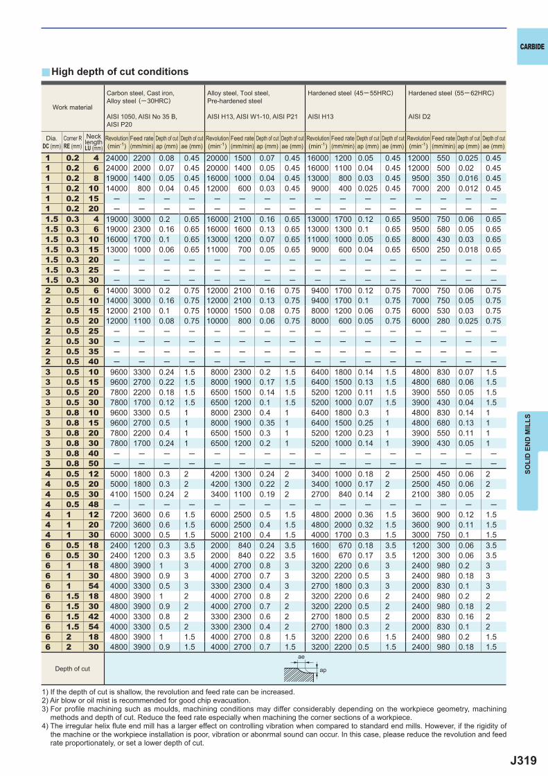
J319
y
1 0.2 4 24000 2200 0.08 0.45 20000 1500 0.07 0.45 16000 1200 0.05 0.45 12000 550 0.025 0.451 0.2 6 24000 2000 0.07 0.45 20000 1400 0.05 0.45 16000 1100 0.04 0.45 12000 500 0.02 0.451 0.2 8 19000 1400 0.05 0.45 16000 1000 0.04 0.45 13000 800 0.03 0.45 9500 350 0.016 0.451 0.2 10 14000 800 0.04 0.45 12000 600 0.03 0.45 9000 400 0.025 0.45 7000 200 0.012 0.451 0.2 15 ─ ─ ─ ─ ─ ─ ─ ─ ─ ─ ─ ─ ─ ─ ─ ─1 0.2 20 ─ ─ ─ ─ ─ ─ ─ ─ ─ ─ ─ ─ ─ ─ ─ ─1.5 0.3 4 19000 3000 0.2 0.65 16000 2100 0.16 0.65 13000 1700 0.12 0.65 9500 750 0.06 0.651.5 0.3 6 19000 2300 0.16 0.65 16000 1600 0.13 0.65 13000 1300 0.1 0.65 9500 580 0.05 0.651.5 0.3 10 16000 1700 0.1 0.65 13000 1200 0.07 0.65 11000 1000 0.05 0.65 8000 430 0.03 0.651.5 0.3 15 13000 1000 0.06 0.65 11000 700 0.05 0.65 9000 600 0.04 0.65 6500 250 0.018 0.651.5 0.3 20 ─ ─ ─ ─ ─ ─ ─ ─ ─ ─ ─ ─ ─ ─ ─ ─1.5 0.3 25 ─ ─ ─ ─ ─ ─ ─ ─ ─ ─ ─ ─ ─ ─ ─ ─1.5 0.3 30 ─ ─ ─ ─ ─ ─ ─ ─ ─ ─ ─ ─ ─ ─ ─ ─2 0.5 6 14000 3000 0.2 0.75 12000 2100 0.16 0.75 9400 1700 0.12 0.75 7000 750 0.06 0.752 0.5 10 14000 3000 0.16 0.75 12000 2100 0.13 0.75 9400 1700 0.1 0.75 7000 750 0.05 0.752 0.5 15 12000 2100 0.1 0.75 10000 1500 0.08 0.75 8000 1200 0.06 0.75 6000 530 0.03 0.752 0.5 20 12000 1100 0.08 0.75 10000 800 0.06 0.75 8000 600 0.05 0.75 6000 280 0.025 0.752 0.5 25 ─ ─ ─ ─ ─ ─ ─ ─ ─ ─ ─ ─ ─ ─ ─ ─2 0.5 30 ─ ─ ─ ─ ─ ─ ─ ─ ─ ─ ─ ─ ─ ─ ─ ─2 0.5 35 ─ ─ ─ ─ ─ ─ ─ ─ ─ ─ ─ ─ ─ ─ ─ ─2 0.5 40 ─ ─ ─ ─ ─ ─ ─ ─ ─ ─ ─ ─ ─ ─ ─ ─3 0.5 10 9600 3300 0.24 1.5 8000 2300 0.2 1.5 6400 1800 0.14 1.5 4800 830 0.07 1.53 0.5 15 9600 2700 0.22 1.5 8000 1900 0.17 1.5 6400 1500 0.13 1.5 4800 680 0.06 1.53 0.5 20 7800 2200 0.18 1.5 6500 1500 0.14 1.5 5200 1200 0.11 1.5 3900 550 0.05 1.53 0.5 30 7800 1700 0.12 1.5 6500 1200 0.1 1.5 5200 1000 0.07 1.5 3900 430 0.04 1.53 0.8 10 9600 3300 0.5 1 8000 2300 0.4 1 6400 1800 0.3 1 4800 830 0.14 13 0.8 15 9600 2700 0.5 1 8000 1900 0.35 1 6400 1500 0.25 1 4800 680 0.13 13 0.8 20 7800 2200 0.4 1 6500 1500 0.3 1 5200 1200 0.23 1 3900 550 0.11 13 0.8 30 7800 1700 0.24 1 6500 1200 0.2 1 5200 1000 0.14 1 3900 430 0.05 13 0.8 40 ─ ─ ─ ─ ─ ─ ─ ─ ─ ─ ─ ─ ─ ─ ─ ─3 0.8 50 ─ ─ ─ ─ ─ ─ ─ ─ ─ ─ ─ ─ ─ ─ ─ ─4 0.5 12 5000 1800 0.3 2 4200 1300 0.24 2 3400 1000 0.18 2 2500 450 0.06 24 0.5 20 5000 1800 0.3 2 4200 1300 0.22 2 3400 1000 0.17 2 2500 450 0.06 24 0.5 30 4100 1500 0.24 2 3400 1100 0.19 2 2700 840 0.14 2 2100 380 0.05 24 0.5 48 ─ ─ ─ ─ ─ ─ ─ ─ ─ ─ ─ ─ ─ ─ ─ ─4 1 12 7200 3600 0.6 1.5 6000 2500 0.5 1.5 4800 2000 0.36 1.5 3600 900 0.12 1.54 1 20 7200 3600 0.6 1.5 6000 2500 0.4 1.5 4800 2000 0.32 1.5 3600 900 0.11 1.54 1 30 6000 3000 0.5 1.5 5000 2100 0.4 1.5 4000 1700 0.3 1.5 3000 750 0.1 1.56 0.5 18 2400 1200 0.3 3.5 2000 840 0.24 3.5 1600 670 0.18 3.5 1200 300 0.06 3.56 0.5 30 2400 1200 0.3 3.5 2000 840 0.22 3.5 1600 670 0.17 3.5 1200 300 0.06 3.56 1 18 4800 3900 1 3 4000 2700 0.8 3 3200 2200 0.6 3 2400 980 0.2 36 1 30 4800 3900 0.9 3 4000 2700 0.7 3 3200 2200 0.5 3 2400 980 0.18 36 1 54 4000 3300 0.5 3 3300 2300 0.4 3 2700 1800 0.3 3 2000 830 0.1 36 1.5 18 4800 3900 1 2 4000 2700 0.8 2 3200 2200 0.6 2 2400 980 0.2 26 1.5 30 4800 3900 0.9 2 4000 2700 0.7 2 3200 2200 0.5 2 2400 980 0.18 26 1.5 42 4000 3300 0.8 2 3300 2300 0.6 2 2700 1800 0.5 2 2000 830 0.16 26 1.5 54 4000 3300 0.5 2 3300 2300 0.4 2 2700 1800 0.3 2 2000 830 0.1 26 2 18 4800 3900 1 1.5 4000 2700 0.8 1.5 3200 2200 0.6 1.5 2400 980 0.2 1.56 2 30 4800 3900 0.9 1.5 4000 2700 0.7 1.5 3200 2200 0.5 1.5 2400 980 0.18 1.5
ae
ap
CARBIDE
SOLI
D E
ND
MIL
LS
High depth of cut conditions
1) If the depth of cut is shallow, the revolution and feed rate can be increased.2) Air blow or oil mist is recommended for good chip evacuation.3) For profi le machining such as moulds, machining conditions may differ considerably depending on the workpiece geometry, machining
methods and depth of cut. Reduce the feed rate especially when machining the corner sections of a workpiece.4) The irregular helix fl ute end mill has a larger effect on controlling vibration when compared to standard end mills. However, if the rigidity of
the machine or the workpiece installation is poor, vibration or abonrmal sound can occur. In this case, please reduce the revolution and feed rate proportionately, or set a lower depth of cut.
Work material
Carbon steel, Cast iron, Alloy steel (─30HRC)
AISI 1050, AISI No 35 B,AISI P20
Alloy steel, Tool steel,Pre-hardened steel
AISI H13, AISI W1-10, AISI P21
Hardened steel (45─ 55HRC)
AISI H13
Hardened steel (55─ 62HRC)
AISI D2
Depth of cut
Revolution(min-1)
Revolution(min-1)
Revolution(min-1)
Revolution(min-1)
Feed rate(mm/min)
Feed rate(mm/min)
Feed rate(mm/min)
Feed rate(mm/min)
Depth of cutap (mm)
Depth of cutap (mm)
Depth of cutap (mm)
Depth of cutap (mm)
Depth of cutae (mm)
Depth of cutae (mm)
Depth of cutae (mm)
Depth of cutae (mm)
Dia.DC (mm)
Corner RRE (mm)
NecklengthLU (mm)
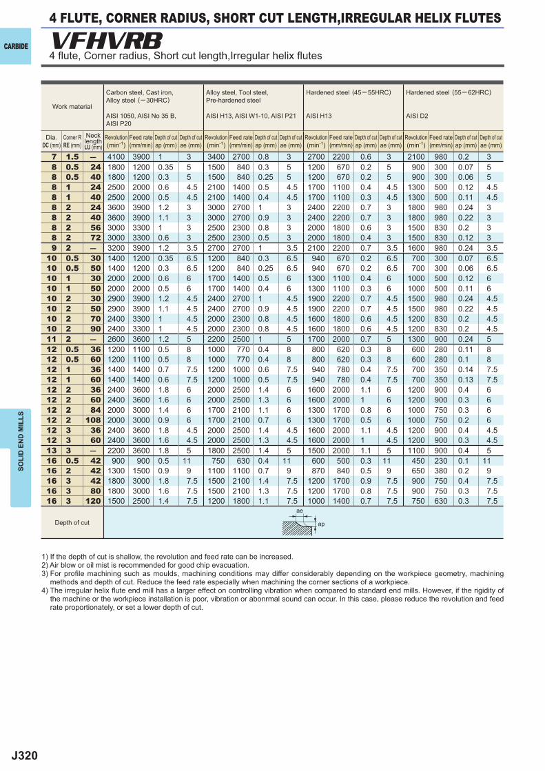
J320
7 1.5 ― 4100 3900 1 3 3400 2700 0.8 3 2700 2200 0.6 3 2100 980 0.2 38 0.5 24 1800 1200 0.35 5 1500 840 0.3 5 1200 670 0.2 5 900 300 0.07 58 0.5 40 1800 1200 0.3 5 1500 840 0.25 5 1200 670 0.2 5 900 300 0.06 58 1 24 2500 2000 0.6 4.5 2100 1400 0.5 4.5 1700 1100 0.4 4.5 1300 500 0.12 4.58 1 40 2500 2000 0.5 4.5 2100 1400 0.4 4.5 1700 1100 0.3 4.5 1300 500 0.11 4.58 2 24 3600 3900 1.2 3 3000 2700 1 3 2400 2200 0.7 3 1800 980 0.24 38 2 40 3600 3900 1.1 3 3000 2700 0.9 3 2400 2200 0.7 3 1800 980 0.22 38 2 56 3000 3300 1 3 2500 2300 0.8 3 2000 1800 0.6 3 1500 830 0.2 38 2 72 3000 3300 0.6 3 2500 2300 0.5 3 2000 1800 0.4 3 1500 830 0.12 39 2 ― 3200 3900 1.2 3.5 2700 2700 1 3.5 2100 2200 0.7 3.5 1600 980 0.24 3.5
10 0.5 30 1400 1200 0.35 6.5 1200 840 0.3 6.5 940 670 0.2 6.5 700 300 0.07 6.510 0.5 50 1400 1200 0.3 6.5 1200 840 0.25 6.5 940 670 0.2 6.5 700 300 0.06 6.510 1 30 2000 2000 0.6 6 1700 1400 0.5 6 1300 1100 0.4 6 1000 500 0.12 610 1 50 2000 2000 0.5 6 1700 1400 0.4 6 1300 1100 0.3 6 1000 500 0.11 610 2 30 2900 3900 1.2 4.5 2400 2700 1 4.5 1900 2200 0.7 4.5 1500 980 0.24 4.510 2 50 2900 3900 1.1 4.5 2400 2700 0.9 4.5 1900 2200 0.7 4.5 1500 980 0.22 4.510 2 70 2400 3300 1 4.5 2000 2300 0.8 4.5 1600 1800 0.6 4.5 1200 830 0.2 4.510 2 90 2400 3300 1 4.5 2000 2300 0.8 4.5 1600 1800 0.6 4.5 1200 830 0.2 4.511 2 ― 2600 3600 1.2 5 2200 2500 1 5 1700 2000 0.7 5 1300 900 0.24 512 0.5 36 1200 1100 0.5 8 1000 770 0.4 8 800 620 0.3 8 600 280 0.11 812 0.5 60 1200 1100 0.5 8 1000 770 0.4 8 800 620 0.3 8 600 280 0.1 812 1 36 1400 1400 0.7 7.5 1200 1000 0.6 7.5 940 780 0.4 7.5 700 350 0.14 7.512 1 60 1400 1400 0.6 7.5 1200 1000 0.5 7.5 940 780 0.4 7.5 700 350 0.13 7.512 2 36 2400 3600 1.8 6 2000 2500 1.4 6 1600 2000 1.1 6 1200 900 0.4 612 2 60 2400 3600 1.6 6 2000 2500 1.3 6 1600 2000 1 6 1200 900 0.3 612 2 84 2000 3000 1.4 6 1700 2100 1.1 6 1300 1700 0.8 6 1000 750 0.3 612 2 108 2000 3000 0.9 6 1700 2100 0.7 6 1300 1700 0.5 6 1000 750 0.2 612 3 36 2400 3600 1.8 4.5 2000 2500 1.4 4.5 1600 2000 1.1 4.5 1200 900 0.4 4.512 3 60 2400 3600 1.6 4.5 2000 2500 1.3 4.5 1600 2000 1 4.5 1200 900 0.3 4.513 3 ― 2200 3600 1.8 5 1800 2500 1.4 5 1500 2000 1.1 5 1100 900 0.4 516 0.5 42 900 900 0.5 11 750 630 0.4 11 600 500 0.3 11 450 230 0.1 1116 2 42 1300 1500 0.9 9 1100 1100 0.7 9 870 840 0.5 9 650 380 0.2 916 3 42 1800 3000 1.8 7.5 1500 2100 1.4 7.5 1200 1700 0.9 7.5 900 750 0.4 7.516 3 80 1800 3000 1.6 7.5 1500 2100 1.3 7.5 1200 1700 0.8 7.5 900 750 0.3 7.516 3 120 1500 2500 1.4 7.5 1200 1800 1.1 7.5 1000 1400 0.7 7.5 750 630 0.3 7.5
VFHVRB
ae
ap
CARBIDE
SOLI
D E
ND
MIL
LS
1) If the depth of cut is shallow, the revolution and feed rate can be increased.2) Air blow or oil mist is recommended for good chip evacuation.3) For profi le machining such as moulds, machining conditions may differ considerably depending on the workpiece geometry, machining
methods and depth of cut. Reduce the feed rate especially when machining the corner sections of a workpiece.4) The irregular helix fl ute end mill has a larger effect on controlling vibration when compared to standard end mills. However, if the rigidity of
the machine or the workpiece installation is poor, vibration or abonrmal sound can occur. In this case, please reduce the revolution and feed rate proportionately, or set a lower depth of cut.
Work material
Carbon steel, Cast iron, Alloy steel (─30HRC)
AISI 1050, AISI No 35 B,AISI P20
Alloy steel, Tool steel,Pre-hardened steel
AISI H13, AISI W1-10, AISI P21
Hardened steel (45─ 55HRC)
AISI H13
Hardened steel (55─ 62HRC)
AISI D2
Depth of cut
Dia.DC (mm)
Corner RRE (mm)
Revolution(min-1)
Revolution(min-1)
Revolution(min-1)
Revolution(min-1)
Feed rate(mm/min)
Feed rate(mm/min)
Feed rate(mm/min)
Feed rate(mm/min)
Depth of cutap (mm)
Depth of cutap (mm)
Depth of cutap (mm)
Depth of cutap (mm)
Depth of cutae (mm)
Depth of cutae (mm)
Depth of cutae (mm)
Depth of cutae (mm)
NecklengthLU (mm)
4 FLUTE, CORNER RADIUS, SHORT CUT LENGTH,IRREGULAR HELIX FLUTES
4 fl ute, Corner radius, Short cut length,Irregular helix fl utes
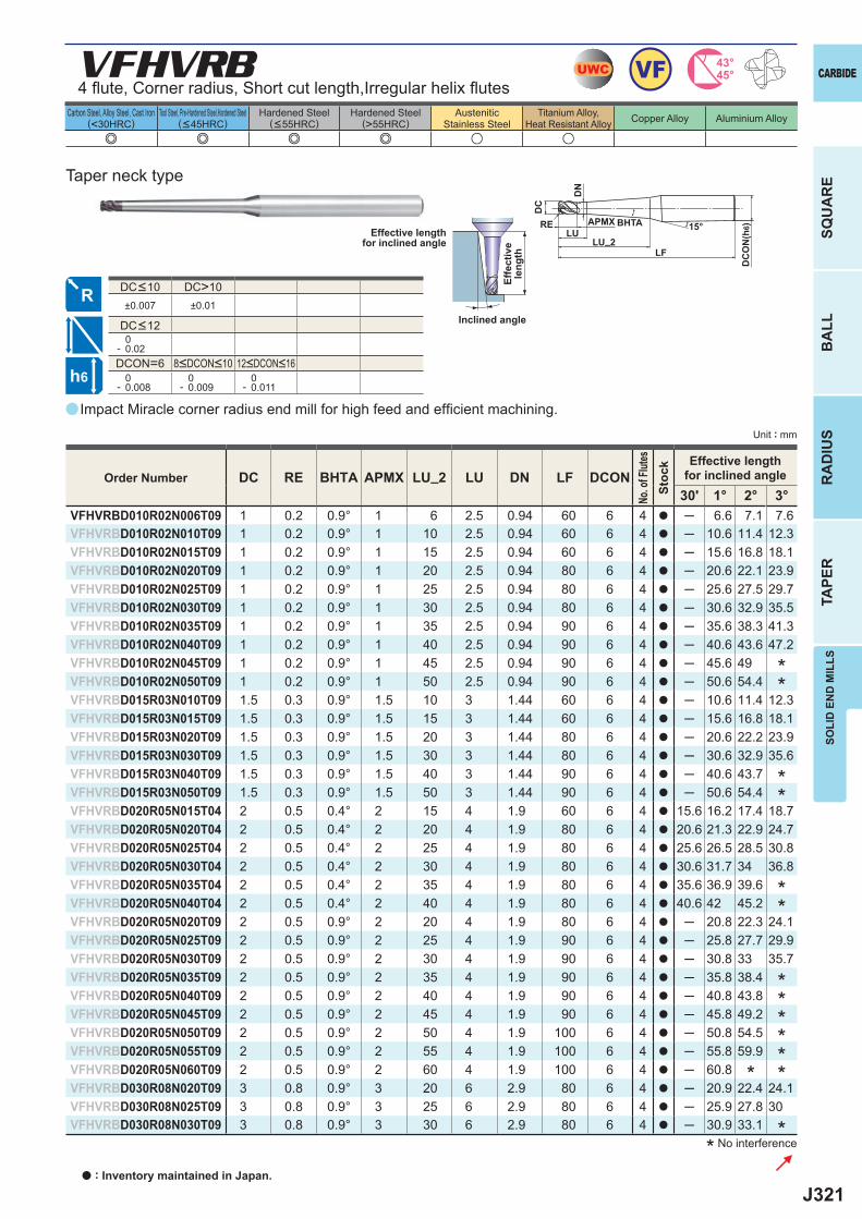
J321
a
e e e e u u
DC RE BHTA APMX LU_2 LU DN LF DCON30' 1° 2° 3°
VFHVRBD010R02N006T09 1 0.2 0.9° 1 6 2.5 0.94 60 6 4 a ─ 6.6 7.1 7.6VFHVRBD010R02N010T09 1 0.2 0.9° 1 10 2.5 0.94 60 6 4 a ─ 10.6 11.4 12.3VFHVRBD010R02N015T09 1 0.2 0.9° 1 15 2.5 0.94 60 6 4 a ─ 15.6 16.8 18.1VFHVRBD010R02N020T09 1 0.2 0.9° 1 20 2.5 0.94 80 6 4 a ─ 20.6 22.1 23.9VFHVRBD010R02N025T09 1 0.2 0.9° 1 25 2.5 0.94 80 6 4 a ─ 25.6 27.5 29.7VFHVRBD010R02N030T09 1 0.2 0.9° 1 30 2.5 0.94 80 6 4 a ─ 30.6 32.9 35.5VFHVRBD010R02N035T09 1 0.2 0.9° 1 35 2.5 0.94 90 6 4 a ─ 35.6 38.3 41.3VFHVRBD010R02N040T09 1 0.2 0.9° 1 40 2.5 0.94 90 6 4 a ─ 40.6 43.6 47.2VFHVRBD010R02N045T09 1 0.2 0.9° 1 45 2.5 0.94 90 6 4 a ─ 45.6 49VFHVRBD010R02N050T09 1 0.2 0.9° 1 50 2.5 0.94 90 6 4 a ─ 50.6 54.4VFHVRBD015R03N010T09 1.5 0.3 0.9° 1.5 10 3 1.44 60 6 4 a ─ 10.6 11.4 12.3VFHVRBD015R03N015T09 1.5 0.3 0.9° 1.5 15 3 1.44 60 6 4 a ─ 15.6 16.8 18.1VFHVRBD015R03N020T09 1.5 0.3 0.9° 1.5 20 3 1.44 80 6 4 a ─ 20.6 22.2 23.9VFHVRBD015R03N030T09 1.5 0.3 0.9° 1.5 30 3 1.44 80 6 4 a ─ 30.6 32.9 35.6VFHVRBD015R03N040T09 1.5 0.3 0.9° 1.5 40 3 1.44 90 6 4 a ─ 40.6 43.7VFHVRBD015R03N050T09 1.5 0.3 0.9° 1.5 50 3 1.44 90 6 4 a ─ 50.6 54.4VFHVRBD020R05N015T04 2 0.5 0.4° 2 15 4 1.9 60 6 4 a 15.6 16.2 17.4 18.7VFHVRBD020R05N020T04 2 0.5 0.4° 2 20 4 1.9 80 6 4 a 20.6 21.3 22.9 24.7VFHVRBD020R05N025T04 2 0.5 0.4° 2 25 4 1.9 80 6 4 a 25.6 26.5 28.5 30.8VFHVRBD020R05N030T04 2 0.5 0.4° 2 30 4 1.9 80 6 4 a 30.6 31.7 34 36.8VFHVRBD020R05N035T04 2 0.5 0.4° 2 35 4 1.9 80 6 4 a 35.6 36.9 39.6VFHVRBD020R05N040T04 2 0.5 0.4° 2 40 4 1.9 80 6 4 a 40.6 42 45.2VFHVRBD020R05N020T09 2 0.5 0.9° 2 20 4 1.9 80 6 4 a ─ 20.8 22.3 24.1VFHVRBD020R05N025T09 2 0.5 0.9° 2 25 4 1.9 90 6 4 a ─ 25.8 27.7 29.9VFHVRBD020R05N030T09 2 0.5 0.9° 2 30 4 1.9 90 6 4 a ─ 30.8 33 35.7VFHVRBD020R05N035T09 2 0.5 0.9° 2 35 4 1.9 90 6 4 a ─ 35.8 38.4VFHVRBD020R05N040T09 2 0.5 0.9° 2 40 4 1.9 90 6 4 a ─ 40.8 43.8VFHVRBD020R05N045T09 2 0.5 0.9° 2 45 4 1.9 90 6 4 a ─ 45.8 49.2VFHVRBD020R05N050T09 2 0.5 0.9° 2 50 4 1.9 100 6 4 a ─ 50.8 54.5VFHVRBD020R05N055T09 2 0.5 0.9° 2 55 4 1.9 100 6 4 a ─ 55.8 59.9VFHVRBD020R05N060T09 2 0.5 0.9° 2 60 4 1.9 100 6 4 a ─ 60.8VFHVRBD030R08N020T09 3 0.8 0.9° 3 20 6 2.9 80 6 4 a ─ 20.9 22.4 24.1VFHVRBD030R08N025T09 3 0.8 0.9° 3 25 6 2.9 80 6 4 a ─ 25.9 27.8 30VFHVRBD030R08N030T09 3 0.8 0.9° 3 30 6 2.9 80 6 4 a ─ 30.9 33.1
DC>10±0.007 ±0.01
0- 0.02DCON=6 0- 0.008
0- 0.009
0- 0.011
VFHVRB UWC 43°45°VF
h6
APMX
DC
DC
ON
(h6)15°BHTA
LF
RE
LU_2LU
DN
CARBIDE
SQU
AR
EB
ALL
RA
DIU
STA
PER
SOLI
D E
ND
MIL
LS
Unit : mm
Carbon Steel, Alloy Steel, Cast Iron(<30HRC)
Tool Steel, Pre-Hardened Steel,Hardened Steel(<45HRC)
Hardened Steel(<55HRC)
Hardened Steel(>55HRC)
AusteniticStainless Steel
Titanium Alloy,Heat Resistant Alloy Copper Alloy Aluminium Alloy
Impact Miracle corner radius end mill for high feed and effi cient machining.
* No interference
Effective lengthfor inclined angle
Inclined angle
Effe
ctiv
ele
ngth
Taper neck type
******
*
**
**
**
*
Order Number
No. o
f Flut
esSt
ock Effective length
for inclined angle
8<DCON<10 12<DCON<16
DC<12
DC<10
4 fl ute, Corner radius, Short cut length,Irregular helix fl utes
a : Inventory maintained in Japan.
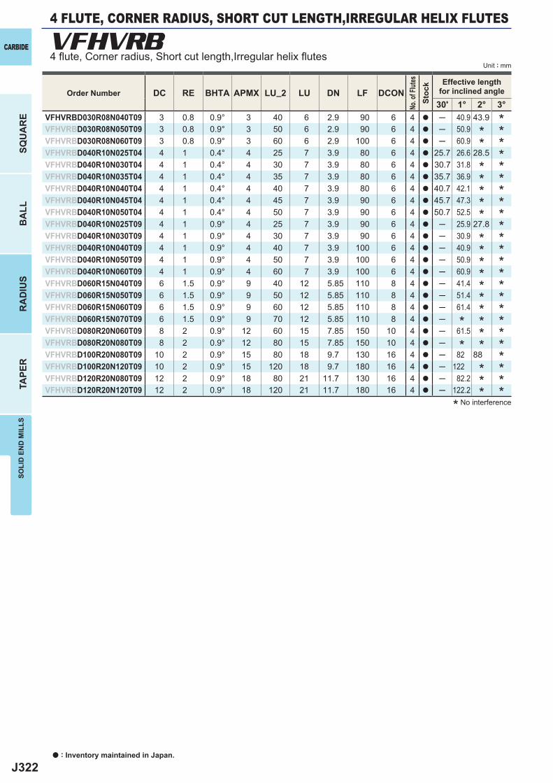
J322
DC RE BHTA APMX LU_2 LU DN LF DCON30' 1° 2° 3°
VFHVRBD030R08N040T09 3 0.8 0.9° 3 40 6 2.9 90 6 4 a ─ 40.9 43.9VFHVRBD030R08N050T09 3 0.8 0.9° 3 50 6 2.9 90 6 4 a ─ 50.9VFHVRBD030R08N060T09 3 0.8 0.9° 3 60 6 2.9 100 6 4 a ─ 60.9VFHVRBD040R10N025T04 4 1 0.4° 4 25 7 3.9 80 6 4 a 25.7 26.6 28.5VFHVRBD040R10N030T04 4 1 0.4° 4 30 7 3.9 80 6 4 a 30.7 31.8VFHVRBD040R10N035T04 4 1 0.4° 4 35 7 3.9 80 6 4 a 35.7 36.9VFHVRBD040R10N040T04 4 1 0.4° 4 40 7 3.9 80 6 4 a 40.7 42.1VFHVRBD040R10N045T04 4 1 0.4° 4 45 7 3.9 90 6 4 a 45.7 47.3VFHVRBD040R10N050T04 4 1 0.4° 4 50 7 3.9 90 6 4 a 50.7 52.5VFHVRBD040R10N025T09 4 1 0.9° 4 25 7 3.9 90 6 4 a ─ 25.9 27.8VFHVRBD040R10N030T09 4 1 0.9° 4 30 7 3.9 90 6 4 a ─ 30.9VFHVRBD040R10N040T09 4 1 0.9° 4 40 7 3.9 100 6 4 a ─ 40.9VFHVRBD040R10N050T09 4 1 0.9° 4 50 7 3.9 100 6 4 a ─ 50.9VFHVRBD040R10N060T09 4 1 0.9° 4 60 7 3.9 100 6 4 a ─ 60.9VFHVRBD060R15N040T09 6 1.5 0.9° 9 40 12 5.85 110 8 4 a ─ 41.4VFHVRBD060R15N050T09 6 1.5 0.9° 9 50 12 5.85 110 8 4 a ─ 51.4VFHVRBD060R15N060T09 6 1.5 0.9° 9 60 12 5.85 110 8 4 a ─ 61.4VFHVRBD060R15N070T09 6 1.5 0.9° 9 70 12 5.85 110 8 4 a ─VFHVRBD080R20N060T09 8 2 0.9° 12 60 15 7.85 150 10 4 a ─ 61.5VFHVRBD080R20N080T09 8 2 0.9° 12 80 15 7.85 150 10 4 a ─VFHVRBD100R20N080T09 10 2 0.9° 15 80 18 9.7 130 16 4 a ─ 82 88VFHVRBD100R20N120T09 10 2 0.9° 15 120 18 9.7 180 16 4 a ─ 122VFHVRBD120R20N080T09 12 2 0.9° 18 80 21 11.7 130 16 4 a ─ 82.2VFHVRBD120R20N120T09 12 2 0.9° 18 120 21 11.7 180 16 4 a ─ 122.2
VFHVRB
a : Inventory maintained in Japan.
CARBIDE
SQU
AR
EB
ALL
RA
DIU
STA
PER
SOLI
D E
ND
MIL
LS
Unit : mm
* No interference
Order Number
No. o
f Flut
esSt
ock Effective length
for inclined angle
*******************
**********
***
****
*
*
*****
**
*
4 FLUTE, CORNER RADIUS, SHORT CUT LENGTH,IRREGULAR HELIX FLUTES
4 fl ute, Corner radius, Short cut length,Irregular helix fl utes
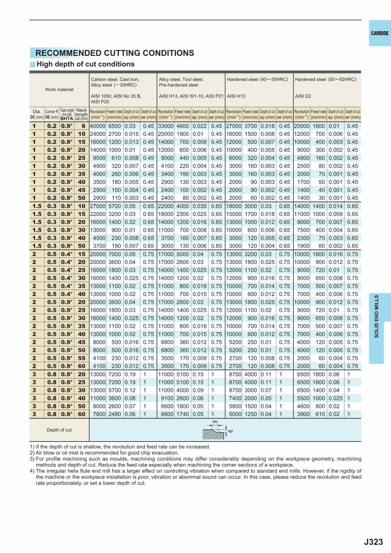
J323
y
1 0.2 0.9° 6 40000 6500 0.03 0.45 33000 4600 0.022 0.45 27000 3700 0.018 0.45 20000 1600 0.01 0.451 0.2 0.9° 10 24000 2700 0.015 0.45 20000 1900 0.01 0.45 16000 1500 0.008 0.45 12000 700 0.006 0.451 0.2 0.9° 15 16000 1200 0.013 0.45 14000 700 0.008 0.45 12000 500 0.007 0.45 10000 400 0.003 0.451 0.2 0.9° 20 14000 1000 0.01 0.45 12000 600 0.006 0.45 10000 400 0.005 0.45 9000 300 0.002 0.451 0.2 0.9° 25 9500 610 0.008 0.45 8000 440 0.005 0.45 6000 320 0.004 0.45 4800 160 0.002 0.451 0.2 0.9° 30 4900 320 0.007 0.45 4100 220 0.004 0.45 3000 160 0.003 0.45 2500 80 0.002 0.451 0.2 0.9° 35 4000 260 0.006 0.45 3400 190 0.003 0.45 3000 160 0.003 0.45 2000 70 0.001 0.451 0.2 0.9° 40 3500 180 0.005 0.45 2900 130 0.003 0.45 2000 90 0.003 0.45 1700 50 0.001 0.451 0.2 0.9° 45 2900 150 0.004 0.45 2400 100 0.002 0.45 2000 90 0.002 0.45 1400 40 0.001 0.451 0.2 0.9° 50 2900 110 0.003 0.45 2400 80 0.002 0.45 2000 60 0.002 0.45 1400 30 0.001 0.451.5 0.3 0.9° 10 27000 5700 0.05 0.65 22000 4000 0.035 0.65 18000 3000 0.03 0.65 14000 1400 0.014 0.651.5 0.3 0.9° 15 22000 3200 0.03 0.65 18000 2300 0.025 0.65 15000 1700 0.018 0.65 11000 1000 0.009 0.651.5 0.3 0.9° 20 16000 1400 0.02 0.65 14000 1200 0.016 0.65 13000 1000 0.012 0.65 9000 700 0.007 0.651.5 0.3 0.9° 30 13000 900 0.01 0.65 11000 700 0.008 0.65 10000 600 0.006 0.65 7500 400 0.004 0.651.5 0.3 0.9° 40 4500 230 0.008 0.65 3700 160 0.007 0.65 3000 120 0.005 0.65 2300 70 0.003 0.651.5 0.3 0.9° 50 3700 190 0.007 0.65 3000 130 0.006 0.65 3000 120 0.004 0.65 1900 60 0.002 0.652 0.5 0.4° 15 20000 7000 0.05 0.75 17000 5000 0.04 0.75 13000 3200 0.03 0.75 10000 1800 0.016 0.752 0.5 0.4° 20 20000 3600 0.04 0.75 17000 2600 0.03 0.75 13000 1800 0.025 0.75 10000 900 0.012 0.752 0.5 0.4° 25 16000 1800 0.03 0.75 14000 1400 0.025 0.75 12000 1100 0.02 0.75 9000 720 0.01 0.752 0.5 0.4° 30 16000 1400 0.025 0.75 14000 1200 0.02 0.75 12000 900 0.016 0.75 9000 650 0.008 0.752 0.5 0.4° 35 13000 1100 0.02 0.75 11000 800 0.018 0.75 10000 700 0.014 0.75 7000 500 0.007 0.752 0.5 0.4° 40 13000 1000 0.02 0.75 11000 700 0.015 0.75 10000 600 0.012 0.75 7000 400 0.006 0.752 0.5 0.9° 20 20000 3600 0.04 0.75 17000 2600 0.03 0.75 13000 1800 0.025 0.75 10000 900 0.012 0.752 0.5 0.9° 25 16000 1800 0.03 0.75 14000 1400 0.025 0.75 12000 1100 0.02 0.75 9000 720 0.01 0.752 0.5 0.9° 30 16000 1400 0.025 0.75 14000 1200 0.02 0.75 12000 900 0.016 0.75 9000 650 0.008 0.752 0.5 0.9° 35 13000 1100 0.02 0.75 11000 800 0.018 0.75 10000 700 0.014 0.75 7000 500 0.007 0.752 0.5 0.9° 40 13000 1000 0.02 0.75 11000 700 0.015 0.75 10000 600 0.012 0.75 7000 400 0.006 0.752 0.5 0.9° 45 8000 500 0.016 0.75 6800 360 0.012 0.75 5200 250 0.01 0.75 4000 120 0.005 0.752 0.5 0.9° 50 8000 500 0.016 0.75 6800 360 0.012 0.75 5200 250 0.01 0.75 4000 120 0.005 0.752 0.5 0.9° 55 4100 230 0.012 0.75 3500 170 0.009 0.75 2700 120 0.008 0.75 2000 60 0.004 0.752 0.5 0.9° 60 4100 230 0.012 0.75 3500 170 0.009 0.75 2700 120 0.008 0.75 2000 60 0.004 0.753 0.8 0.9° 20 13000 7200 0.19 1 11000 5100 0.15 1 8700 4000 0.11 1 6500 1800 0.06 13 0.8 0.9° 25 13000 7200 0.19 1 11000 5100 0.15 1 8700 4000 0.11 1 6500 1800 0.06 13 0.8 0.9° 30 13000 5700 0.12 1 11000 4000 0.09 1 8700 3000 0.07 1 6500 1400 0.04 13 0.8 0.9° 40 11000 3600 0.08 1 9100 2600 0.06 1 7400 2000 0.05 1 5500 1000 0.025 13 0.8 0.9° 50 8000 2600 0.07 1 6600 1800 0.05 1 5800 1500 0.04 1 4600 800 0.02 13 0.8 0.9° 60 7800 2480 0.06 1 6600 1740 0.05 1 5000 1250 0.04 1 3900 610 0.02 1
ae
ap
CARBIDE
SOLI
D E
ND
MIL
LS
RECOMMENDED CUTTING CONDITIONSHigh depth of cut conditions
1) If the depth of cut is shallow, the revolution and feed rate can be increased.2) Air blow or oil mist is recommended for good chip evacuation.3) For profi le machining such as moulds, machining conditions may differ considerably depending on the workpiece geometry, machining
methods and depth of cut. Reduce the feed rate especially when machining the corner sections of a workpiece.4) The irregular helix fl ute end mill has a larger effect on controlling vibration when compared to standard end mills. However, if the rigidity of
the machine or the workpiece installation is poor, vibration or abonrmal sound can occur. In this case, please reduce the revolution and feed rate proportionately, or set a lower depth of cut.
Work material
Carbon steel, Cast iron, Alloy steel (─30HRC)
AISI 1050, AISI No 35 B,AISI P20
Alloy steel, Tool steel,Pre-hardened steel
AISI H13, AISI W1-10, AISI P21
Hardened steel (45─ 55HRC)
AISI H13
Hardened steel (55─ 62HRC)
AISI D2
Taper angleone side
BHTARevolution(min-1)
Revolution(min-1)
Revolution(min-1)
Revolution(min-1)
Feed rate(mm/min)
Feed rate(mm/min)
Feed rate(mm/min)
Feed rate(mm/min)
Depth of cutap (mm)
Depth of cutap (mm)
Depth of cutap (mm)
Depth of cutap (mm)
Depth of cutae (mm)
Depth of cutae (mm)
Depth of cutae (mm)
Depth of cutae (mm)
Depth of cut
Dia.DC (mm)
Corner RRE (mm)
NecklengthLU (mm)
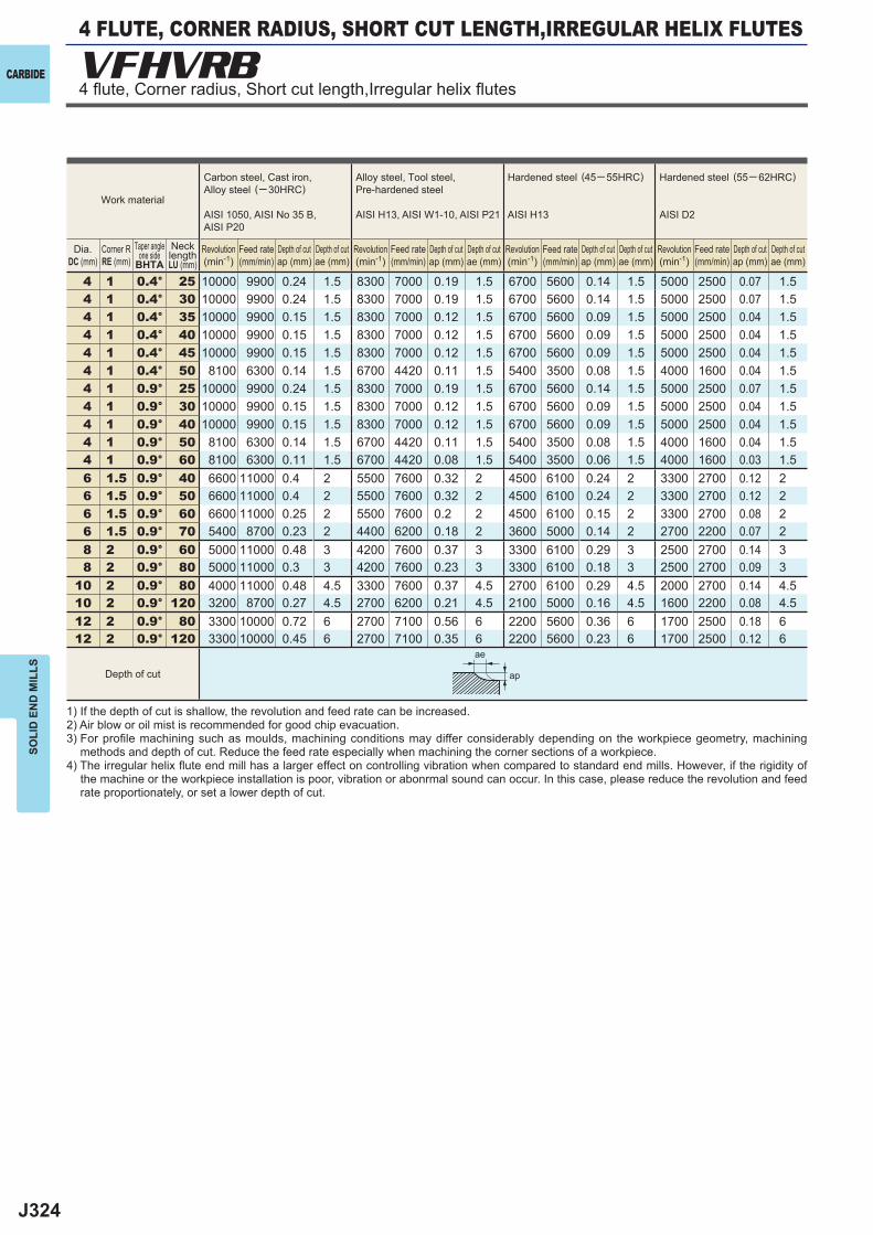
J324
4 1 0.4° 25 10000 9900 0.24 1.5 8300 7000 0.19 1.5 6700 5600 0.14 1.5 5000 2500 0.07 1.54 1 0.4° 30 10000 9900 0.24 1.5 8300 7000 0.19 1.5 6700 5600 0.14 1.5 5000 2500 0.07 1.54 1 0.4° 35 10000 9900 0.15 1.5 8300 7000 0.12 1.5 6700 5600 0.09 1.5 5000 2500 0.04 1.54 1 0.4° 40 10000 9900 0.15 1.5 8300 7000 0.12 1.5 6700 5600 0.09 1.5 5000 2500 0.04 1.54 1 0.4° 45 10000 9900 0.15 1.5 8300 7000 0.12 1.5 6700 5600 0.09 1.5 5000 2500 0.04 1.54 1 0.4° 50 8100 6300 0.14 1.5 6700 4420 0.11 1.5 5400 3500 0.08 1.5 4000 1600 0.04 1.54 1 0.9° 25 10000 9900 0.24 1.5 8300 7000 0.19 1.5 6700 5600 0.14 1.5 5000 2500 0.07 1.54 1 0.9° 30 10000 9900 0.15 1.5 8300 7000 0.12 1.5 6700 5600 0.09 1.5 5000 2500 0.04 1.54 1 0.9° 40 10000 9900 0.15 1.5 8300 7000 0.12 1.5 6700 5600 0.09 1.5 5000 2500 0.04 1.54 1 0.9° 50 8100 6300 0.14 1.5 6700 4420 0.11 1.5 5400 3500 0.08 1.5 4000 1600 0.04 1.54 1 0.9° 60 8100 6300 0.11 1.5 6700 4420 0.08 1.5 5400 3500 0.06 1.5 4000 1600 0.03 1.56 1.5 0.9° 40 6600 11000 0.4 2 5500 7600 0.32 2 4500 6100 0.24 2 3300 2700 0.12 26 1.5 0.9° 50 6600 11000 0.4 2 5500 7600 0.32 2 4500 6100 0.24 2 3300 2700 0.12 26 1.5 0.9° 60 6600 11000 0.25 2 5500 7600 0.2 2 4500 6100 0.15 2 3300 2700 0.08 26 1.5 0.9° 70 5400 8700 0.23 2 4400 6200 0.18 2 3600 5000 0.14 2 2700 2200 0.07 28 2 0.9° 60 5000 11000 0.48 3 4200 7600 0.37 3 3300 6100 0.29 3 2500 2700 0.14 38 2 0.9° 80 5000 11000 0.3 3 4200 7600 0.23 3 3300 6100 0.18 3 2500 2700 0.09 3
10 2 0.9° 80 4000 11000 0.48 4.5 3300 7600 0.37 4.5 2700 6100 0.29 4.5 2000 2700 0.14 4.510 2 0.9° 120 3200 8700 0.27 4.5 2700 6200 0.21 4.5 2100 5000 0.16 4.5 1600 2200 0.08 4.512 2 0.9° 80 3300 10000 0.72 6 2700 7100 0.56 6 2200 5600 0.36 6 1700 2500 0.18 612 2 0.9° 120 3300 10000 0.45 6 2700 7100 0.35 6 2200 5600 0.23 6 1700 2500 0.12 6
VFHVRB
ae
ap
CARBIDE
SOLI
D E
ND
MIL
LS
1) If the depth of cut is shallow, the revolution and feed rate can be increased.2) Air blow or oil mist is recommended for good chip evacuation.3) For profi le machining such as moulds, machining conditions may differ considerably depending on the workpiece geometry, machining
methods and depth of cut. Reduce the feed rate especially when machining the corner sections of a workpiece.4) The irregular helix fl ute end mill has a larger effect on controlling vibration when compared to standard end mills. However, if the rigidity of
the machine or the workpiece installation is poor, vibration or abonrmal sound can occur. In this case, please reduce the revolution and feed rate proportionately, or set a lower depth of cut.
Work material
Carbon steel, Cast iron, Alloy steel (─30HRC)
AISI 1050, AISI No 35 B,AISI P20
Alloy steel, Tool steel,Pre-hardened steel
AISI H13, AISI W1-10, AISI P21
Hardened steel (45─ 55HRC)
AISI H13
Hardened steel (55─ 62HRC)
AISI D2
Depth of cut
Taper angleone side
BHTARevolution(min-1)
Revolution(min-1)
Revolution(min-1)
Revolution(min-1)
Feed rate(mm/min)
Feed rate(mm/min)
Feed rate(mm/min)
Feed rate(mm/min)
Depth of cutap (mm)
Depth of cutap (mm)
Depth of cutap (mm)
Depth of cutap (mm)
Depth of cutae (mm)
Depth of cutae (mm)
Depth of cutae (mm)
Depth of cutae (mm)
Dia.DC (mm)
Corner RRE (mm)
NecklengthLU (mm)
4 FLUTE, CORNER RADIUS, SHORT CUT LENGTH,IRREGULAR HELIX FLUTES
4 fl ute, Corner radius, Short cut length,Irregular helix fl utes
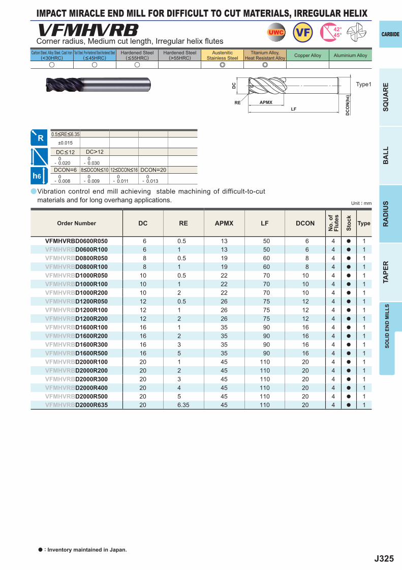
J325
a
VFMHVRB
u u u e e
DC RE APMX LF DCON
VFMHVRBD0600R050 6 0.5 13 50 6 4 a 1VFMHVRBD0600R100 6 1 13 50 6 4 a 1VFMHVRBD0800R050 8 0.5 19 60 8 4 a 1VFMHVRBD0800R100 8 1 19 60 8 4 a 1VFMHVRBD1000R050 10 0.5 22 70 10 4 a 1VFMHVRBD1000R100 10 1 22 70 10 4 a 1VFMHVRBD1000R200 10 2 22 70 10 4 a 1VFMHVRBD1200R050 12 0.5 26 75 12 4 a 1VFMHVRBD1200R100 12 1 26 75 12 4 a 1VFMHVRBD1200R200 12 2 26 75 12 4 a 1VFMHVRBD1600R100 16 1 35 90 16 4 a 1VFMHVRBD1600R200 16 2 35 90 16 4 a 1VFMHVRBD1600R300 16 3 35 90 16 4 a 1VFMHVRBD1600R500 16 5 35 90 16 4 a 1VFMHVRBD2000R100 20 1 45 110 20 4 a 1VFMHVRBD2000R200 20 2 45 110 20 4 a 1VFMHVRBD2000R300 20 3 45 110 20 4 a 1VFMHVRBD2000R400 20 4 45 110 20 4 a 1VFMHVRBD2000R500 20 5 45 110 20 4 a 1VFMHVRBD2000R635 20 6.35 45 110 20 4 a 1
±0.015
DC>12 0- 0.020
0- 0.030
DCON=6 DCON=20 0- 0.008
0- 0.009
0- 0.011
0- 0.013
UWC VF 42°45°
h6
APMX
DC
DC
ON
(h6)
LFRE
CARBIDE
SQU
AR
EB
ALL
RA
DIU
STA
PER
SOLI
D E
ND
MIL
LS
Unit : mm
Carbon Steel, Alloy Steel, Cast Iron(<30HRC)
Tool Steel, Pre-Hardened Steel,Hardened Steel(<45HRC)
Hardened Steel(<55HRC)
Hardened Steel(>55HRC)
AusteniticStainless Steel
Titanium Alloy,Heat Resistant Alloy Copper Alloy Aluminium Alloy
Vibration control end mill achieving stable machining of difficult-to-cut materials and for long overhang applications.
Corner radius, Medium cut length, Irregular helix fl utes
Type1
Order Number
No.
of
Flut
es
Stoc
k
Type
8<DCON<10 12<DCON<16
0.5<RE<6.35
DC<12
IMPACT MIRACLE END MILL FOR DIFFICULT TO CUT MATERIALS, IRREGULAR HELIX
a : Inventory maintained in Japan.
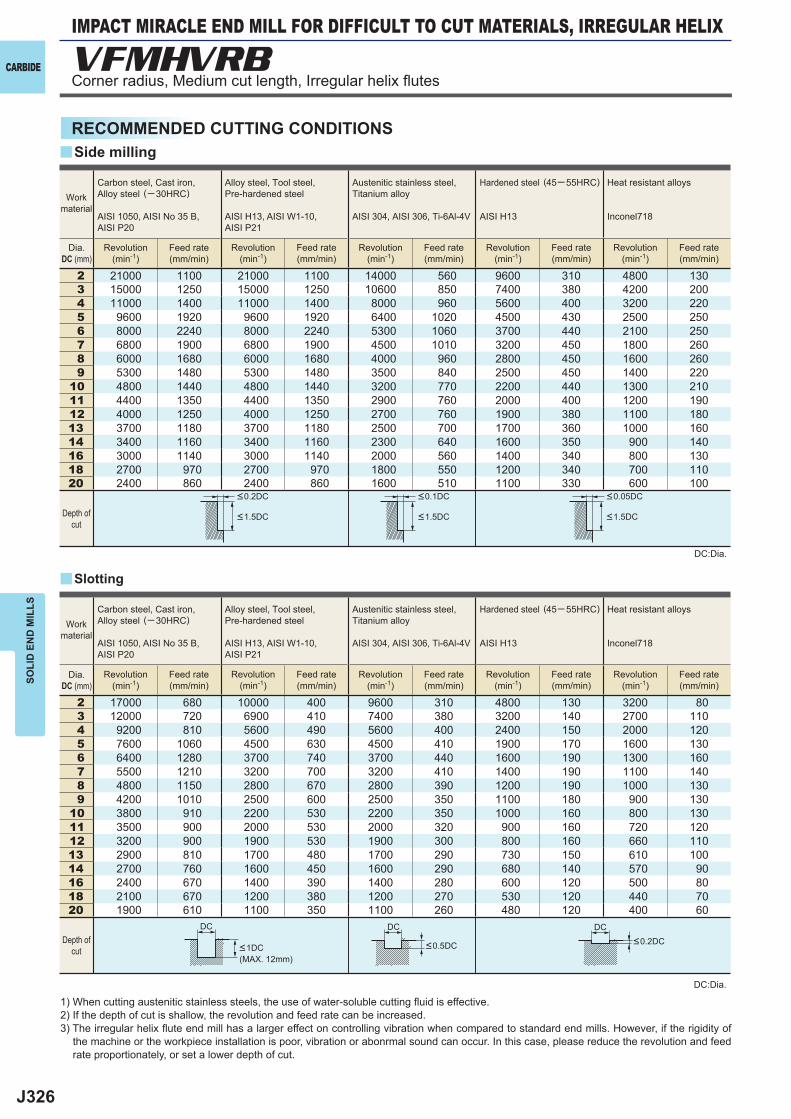
J326
2 21000 1100 21000 1100 14000 560 9600 310 4800 1303 15000 1250 15000 1250 10600 850 7400 380 4200 2004 11000 1400 11000 1400 8000 960 5600 400 3200 2205 9600 1920 9600 1920 6400 1020 4500 430 2500 2506 8000 2240 8000 2240 5300 1060 3700 440 2100 2507 6800 1900 6800 1900 4500 1010 3200 450 1800 2608 6000 1680 6000 1680 4000 960 2800 450 1600 2609 5300 1480 5300 1480 3500 840 2500 450 1400 220
10 4800 1440 4800 1440 3200 770 2200 440 1300 21011 4400 1350 4400 1350 2900 760 2000 400 1200 19012 4000 1250 4000 1250 2700 760 1900 380 1100 18013 3700 1180 3700 1180 2500 700 1700 360 1000 16014 3400 1160 3400 1160 2300 640 1600 350 900 14016 3000 1140 3000 1140 2000 560 1400 340 800 13018 2700 970 2700 970 1800 550 1200 340 700 11020 2400 860 2400 860 1600 510 1100 330 600 100
2 17000 680 10000 400 9600 310 4800 130 3200 803 12000 720 6900 410 7400 380 3200 140 2700 1104 9200 810 5600 490 5600 400 2400 150 2000 1205 7600 1060 4500 630 4500 410 1900 170 1600 1306 6400 1280 3700 740 3700 440 1600 190 1300 1607 5500 1210 3200 700 3200 410 1400 190 1100 1408 4800 1150 2800 670 2800 390 1200 190 1000 1309 4200 1010 2500 600 2500 350 1100 180 900 130
10 3800 910 2200 530 2200 350 1000 160 800 13011 3500 900 2000 530 2000 320 900 160 720 12012 3200 900 1900 530 1900 300 800 160 660 11013 2900 810 1700 480 1700 290 730 150 610 10014 2700 760 1600 450 1600 290 680 140 570 9016 2400 670 1400 390 1400 280 600 120 500 8018 2100 670 1200 380 1200 270 530 120 440 7020 1900 610 1100 350 1100 260 480 120 400 60
y
y
VFMHVRB
DC DC DC
CARBIDE
SOLI
D E
ND
MIL
LS
RECOMMENDED CUTTING CONDITIONS
1) When cutting austenitic stainless steels, the use of water-soluble cutting fl uid is effective.2) If the depth of cut is shallow, the revolution and feed rate can be increased.3) The irregular helix fl ute end mill has a larger effect on controlling vibration when compared to standard end mills. However, if the rigidity of
the machine or the workpiece installation is poor, vibration or abonrmal sound can occur. In this case, please reduce the revolution and feed rate proportionately, or set a lower depth of cut.
DC:Dia.
DC:Dia.
Slotting
Side milling
Workmaterial
Workmaterial
Depth ofcut
Depth ofcut
<0.2DC <0.1DC <0.05DC
<1.5DC <1.5DC <1.5DC
Carbon steel, Cast iron, Alloy steel (─30HRC)
AISI 1050, AISI No 35 B,AISI P20
Alloy steel, Tool steel,Pre-hardened steel
AISI H13, AISI W1-10, AISI P21
Austenitic stainless steel,Titanium alloy
AISI 304, AISI 306, Ti-6Al-4V
Hardened steel (45─ 55HRC)
AISI H13
Heat resistant alloys
Inconel718
Carbon steel, Cast iron, Alloy steel (─30HRC)
AISI 1050, AISI No 35 B,AISI P20
Alloy steel, Tool steel,Pre-hardened steel
AISI H13, AISI W1-10, AISI P21
Austenitic stainless steel,Titanium alloy
AISI 304, AISI 306, Ti-6Al-4V
Hardened steel (45─ 55HRC)
AISI H13
Heat resistant alloys
Inconel718
Revolution(min-1)
Revolution(min-1)
Revolution(min-1)
Revolution(min-1)
Revolution(min-1)
Revolution(min-1)
Revolution(min-1)
Revolution(min-1)
Revolution(min-1)
Revolution(min-1)
Feed rate(mm/min)
Feed rate(mm/min)
Feed rate(mm/min)
Feed rate(mm/min)
Feed rate(mm/min)
Feed rate(mm/min)
Feed rate(mm/min)
Feed rate(mm/min)
Feed rate(mm/min)
Feed rate(mm/min)
<1DC <0.5DC <0.2DC
(MAX. 12mm)
Dia.DC (mm)
Dia.DC (mm)
Corner radius, Medium cut length, Irregular helix fl utes
IMPACT MIRACLE END MILL FOR DIFFICULT TO CUT MATERIALS, IRREGULAR HELIX
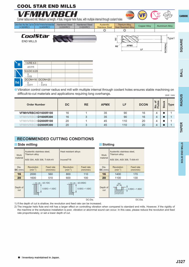
J327
a
e e
VFMHVRBCH
DC RE APMX LF DCON
VFMHVRBCHD1600R100 16 1 35 90 16 4 a 1VFMHVRBCHD1600R300 16 3 35 90 16 4 a 1VFMHVRBCHD2000R100 20 1 45 110 20 4 a 1VFMHVRBCHD2000R300 20 3 45 110 20 4 a 1
±0.015
0- 0.03
DCON=16 DCON=20 0- 0.011
0- 0.013
16 2000 560 800 11020 1600 510 600 100
16 1400 17020 1100 130
0.5DC─1.5DC 0.5DC─1.5DC 0.5DC─1.5DC
yy
UWC VF 42°45°
h6
APMX
DC
DC
ON
(h6)
LFRE
DC
CARBIDE
SQU
AR
EB
ALL
RA
DIU
STA
PER
SOLI
D E
ND
MIL
LS
Unit : mm
Carbon Steel, Alloy Steel, Cast Iron(<30HRC)
Tool Steel, Pre-Hardened Steel,Hardened Steel(<45HRC)
Hardened Steel(<55HRC)
Hardened Steel(>55HRC)
AusteniticStainless Steel
Titanium Alloy,Heat Resistant Alloy Copper Alloy Aluminium Alloy
Vibration control corner radius end mill with multiple internal through coolant holes ensures stable machining on diffi cult-to-cut materials and applications requiring long overhangs.
Corner radius end mill, Medium cut length, 4 fl ute, Irregular helix fl utes, with multiple internal through coolant holes
Type1CoolStarEND MILLS
COOL STAR END MILLS
Order Number
No.
of
Flut
es
Stoc
k
Type
1<RE<3
16<DC<20
RECOMMENDED CUTTING CONDITIONS
DC:Dia. DC:Dia.
1) If the depth of cut is shallow, the revolution and feed rate can be increased.2) The irregular helix fl ute end mill has a larger effect on controlling vibration when compared to standard end mills. However, if the rigidity of
the machine or the workpiece installation is poor, vibration or abonrmal sound can occur. In this case, please reduce the revolution and feed rate proportionately, or set a lower depth of cut.
SlottingSide milling
Workmaterial
Austenitic stainless steel,Titanium alloy
AISI 304, AISI 306, Ti-6Al-4V
Heat resistant alloys
Inconel718
Dia.DC (mm)
Revolution(min-1)
Revolution(min-1)
Feed rate(mm/min)
Feed rate(mm/min)
Workmaterial
Austenitic stainless steel,Titanium alloy
AISI 304, AISI 306, Ti-6Al-4V
Dia.DC (mm)
Revolution(min-1)
Feed rate(mm/min)
Depth ofcut
Depth ofcut
<0.1DC <0.05DC
a : Inventory maintained in Japan.
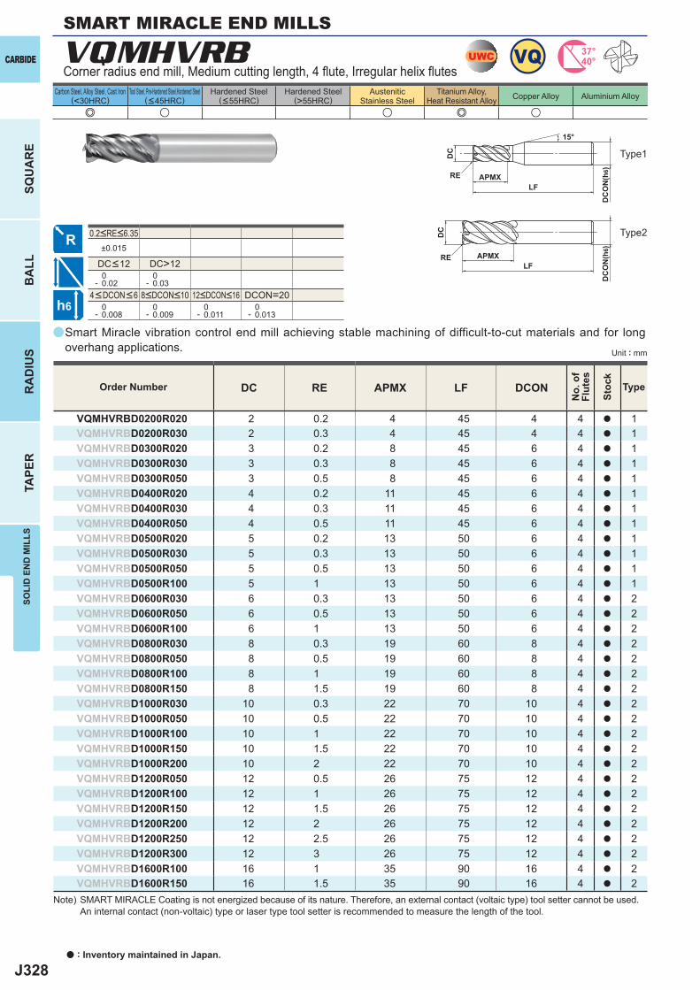
J328
a
e u u e u
VQMHVRB
DC RE APMX LF DCON
VQMHVRBD0200R020 2 0.2 4 45 4 4 a 1VQMHVRBD0200R030 2 0.3 4 45 4 4 a 1VQMHVRBD0300R020 3 0.2 8 45 6 4 a 1VQMHVRBD0300R030 3 0.3 8 45 6 4 a 1VQMHVRBD0300R050 3 0.5 8 45 6 4 a 1VQMHVRBD0400R020 4 0.2 11 45 6 4 a 1VQMHVRBD0400R030 4 0.3 11 45 6 4 a 1VQMHVRBD0400R050 4 0.5 11 45 6 4 a 1VQMHVRBD0500R020 5 0.2 13 50 6 4 a 1VQMHVRBD0500R030 5 0.3 13 50 6 4 a 1VQMHVRBD0500R050 5 0.5 13 50 6 4 a 1VQMHVRBD0500R100 5 1 13 50 6 4 a 1VQMHVRBD0600R030 6 0.3 13 50 6 4 a 2VQMHVRBD0600R050 6 0.5 13 50 6 4 a 2VQMHVRBD0600R100 6 1 13 50 6 4 a 2VQMHVRBD0800R030 8 0.3 19 60 8 4 a 2VQMHVRBD0800R050 8 0.5 19 60 8 4 a 2VQMHVRBD0800R100 8 1 19 60 8 4 a 2VQMHVRBD0800R150 8 1.5 19 60 8 4 a 2VQMHVRBD1000R030 10 0.3 22 70 10 4 a 2VQMHVRBD1000R050 10 0.5 22 70 10 4 a 2VQMHVRBD1000R100 10 1 22 70 10 4 a 2VQMHVRBD1000R150 10 1.5 22 70 10 4 a 2VQMHVRBD1000R200 10 2 22 70 10 4 a 2VQMHVRBD1200R050 12 0.5 26 75 12 4 a 2VQMHVRBD1200R100 12 1 26 75 12 4 a 2VQMHVRBD1200R150 12 1.5 26 75 12 4 a 2VQMHVRBD1200R200 12 2 26 75 12 4 a 2VQMHVRBD1200R250 12 2.5 26 75 12 4 a 2VQMHVRBD1200R300 12 3 26 75 12 4 a 2VQMHVRBD1600R100 16 1 35 90 16 4 a 2VQMHVRBD1600R150 16 1.5 35 90 16 4 a 2
a
±0.015
DC>12 0- 0.02
0- 0.03
DCON=20 0- 0.008
0- 0.009
0- 0.011
0- 0.013
UWC VQ 37°40°
h6
APMX
DC
DC
ON
(h6)
LFRE
15°
APMX
DC
ON
(h6)
LFRE
DC
a : Inventory maintained in Japan.
CARBIDE
SQU
AR
EB
ALL
RA
DIU
STA
PER
SOLI
D E
ND
MIL
LS
Unit : mm
Carbon Steel, Alloy Steel, Cast Iron(<30HRC)
Tool Steel, Pre-Hardened Steel,Hardened Steel(<45HRC)
Hardened Steel(<55HRC)
Hardened Steel(>55HRC)
AusteniticStainless Steel
Titanium Alloy,Heat Resistant Alloy Copper Alloy Aluminium Alloy
SMART MIRACLE END MILLS
Corner radius end mill, Medium cutting length, 4 fl ute, Irregular helix fl utes
Smart Miracle vibration control end mill achieving stable machining of difficult-to-cut materials and for long overhang applications.
Type1
Type2
Order Number
No.
of
Flut
es
Stoc
k
Type
4<DCON<6 8<DCON<10 12<DCON<16
DC<12
0.2<RE<6.35
Note) SMART MIRACLE Coating is not energized because of its nature. Therefore, an external contact (voltaic type) tool setter cannot be used. An internal contact (non-voltaic) type or laser type tool setter is recommended to measure the length of the tool.
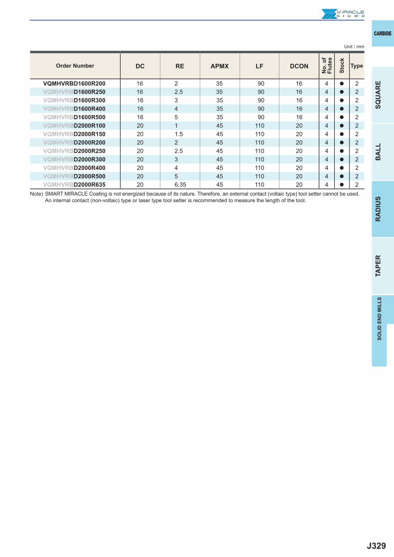
J329
DC RE APMX LF DCON
VQMHVRBD1600R200 16 2 35 90 16 4 a 2VQMHVRBD1600R250 16 2.5 35 90 16 4 a 2VQMHVRBD1600R300 16 3 35 90 16 4 a 2VQMHVRBD1600R400 16 4 35 90 16 4 a 2VQMHVRBD1600R500 16 5 35 90 16 4 a 2VQMHVRBD2000R100 20 1 45 110 20 4 a 2VQMHVRBD2000R150 20 1.5 45 110 20 4 a 2VQMHVRBD2000R200 20 2 45 110 20 4 a 2VQMHVRBD2000R250 20 2.5 45 110 20 4 a 2VQMHVRBD2000R300 20 3 45 110 20 4 a 2VQMHVRBD2000R400 20 4 45 110 20 4 a 2VQMHVRBD2000R500 20 5 45 110 20 4 a 2VQMHVRBD2000R635 20 6.35 45 110 20 4 a 2
CARBIDE
SQU
AR
EB
ALL
RA
DIU
STA
PER
SOLI
D E
ND
MIL
LS
Unit : mm
Order Number
No.
of
Flut
es
Stoc
k
Type
Note) SMART MIRACLE Coating is not energized because of its nature. Therefore, an external contact (voltaic type) tool setter cannot be used. An internal contact (non-voltaic) type or laser type tool setter is recommended to measure the length of the tool.
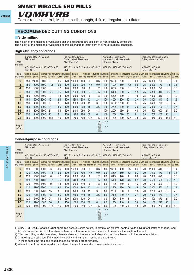
J330
y
2 150 24000 2400 3 0.6 120 19000 1100 3 0.6 100 16000 830 3 0.6 75 12000 720 3 0.43 150 16000 2600 4.5 0.9 120 13000 1200 4.5 0.9 100 11000 880 4.5 0.9 75 8000 770 4.5 0.64 150 12000 2600 6 1.2 120 9500 1300 6 1.2 100 8000 900 6 1.2 75 6000 790 6 0.85 150 9500 2600 7.5 1.5 120 7600 1300 7.5 1.5 100 6400 900 7.5 1.5 75 4800 810 7.5 16 150 8000 2600 9 1.8 120 6400 1300 9 1.8 100 5300 1100 9 1.8 75 4000 810 9 1.28 150 6000 2500 12 2.4 120 4800 1300 12 2.4 100 4000 1200 12 2.4 75 3000 840 12 1.6
10 150 4800 2300 15 3 120 3800 1200 15 3 100 3200 1300 15 3 75 2400 770 15 212 150 4000 1900 18 3.6 120 3200 1200 18 3.6 100 2700 1200 18 3.6 75 2000 720 18 2.416 150 3000 1600 24 4.8 120 2400 960 24 4.8 100 2000 960 24 4.8 75 1500 600 24 3.220 150 2400 1300 30 6 120 1900 760 30 6 100 1600 770 30 6 75 1200 480 30 425 150 1900 1100 37.5 7.5 120 1500 600 37.5 7.5 100 1300 620 37.5 7.5 75 950 380 37.5 5
2 120 19000 1300 3 0.6 100 16000 630 3 0.6 80 13000 450 1.5 0.2 70 11000 440 3 0.43 120 13000 1400 4.5 0.9 100 11000 700 4.5 0.9 80 8500 450 2.2 0.3 70 7400 470 4.5 0.64 120 9500 1400 6 1.2 100 8000 700 6 1.2 80 6400 470 3 0.6 70 5600 490 6 0.85 120 7600 1400 7.5 1.5 100 6400 710 7.5 1.5 80 5100 470 4.5 0.9 70 4500 500 7.5 16 120 6400 1400 9 1.8 100 5300 710 9 1.8 80 4200 580 6 1.2 70 3700 500 9 1.28 120 4800 1300 12 2.4 100 4000 740 12 2.4 80 3200 630 7.5 1.5 70 2800 520 12 1.6
10 120 3800 1200 15 3 100 3200 680 15 3 80 2500 660 9 1.8 70 2200 460 15 212 120 3200 1000 18 3.6 100 2700 640 18 3.6 80 2100 610 12 2.4 70 1900 450 18 2.416 120 2400 860 24 4.8 100 2000 530 24 4.8 80 1600 510 15 3 70 1400 370 24 3.220 120 1900 680 30 6 100 1600 420 30 6 80 1300 410 18 3.6 70 1100 290 30 425 120 1500 390 37.5 7.5 100 1300 340 37.5 7.5 80 1000 210 24 4.8 70 890 230 37.5 5
VQMHVRB
ae
ap
ae
ap
CARBIDE
SOLI
D E
ND
MIL
LS
RECOMMENDED CUTTING CONDITIONSSide milling
High effi ciency conditions
General-purpose conditions
The rigidity of the machine or workpiece and chip discharge are suffi cient at high effi ciency conditions. The rigidity of the machine or workpiece or chip discharge is insuffi cient at general-purpose conditions.
Work material
Carbon steel, Alloy steel,Mild steel
AISI 1045, AISI 4140, ASTM A36, AISI 1010
Pre-hardened steel,Carbon steel, Alloy steel,Alloy tool steel
AISI P21, AISI P20, AISI 4340, SKD, SKT
Austenitic, Ferritic and Martensitic stainless steels, Titanium alloys
AISI 304, AISI 316, Ti-6Al-4V
Hardened stainless steels,Cobaly chromium alloy
AISI 630, AISI 63115-5PH,17-4PH
Dia.DC (mm)
Cutting speed (m/min)
Revolution (min-1)
Feed rate (mm/min)
Depth of cut ap (mm)
Depth of cut ae (mm)
Cutting speed (m/min)
Revolution (min-1)
Feed rate (mm/min)
Depth of cut ap (mm)
Depth of cut ae (mm)
Cutting speed (m/min)
Revolution (min-1)
Feed rate (mm/min)
Depth of cut ap (mm)
Depth of cut ae (mm)
Cutting speed (m/min)
Revolution (min-1)
Feed rate (mm/min)
Depth of cut ap (mm)
Depth of cut ae (mm)
Depth of cut
1) SMART MIRACLE Coating is not energized because of its nature. Therefore, an external contact (voltaic type) tool setter cannot be used. An internal contact (non-voltaic) type or laser type tool setter is recommended to measure the length of the tool.
2) Effective cutting of stainless steel, titanium alloys and heat-resistant alloys etc. can be achieved with the use of emulsion.3) Chattering can still occur if the machine rigidity and clamping method are insuffi cient.
In these cases the feed and speed should be reduced proportionately.4) When the depth of cut is smaller than shown the revolution and feed rate can be increased.
SMART MIRACLE END MILLS
Corner radius end mill, Medium cutting length, 4 fl ute, Irregular helix fl utes
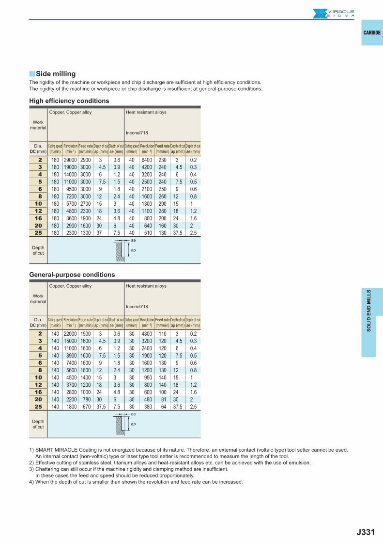
J331
2 180 29000 2900 3 0.6 40 6400 230 3 0.23 180 19000 3000 4.5 0.9 40 4200 240 4.5 0.34 180 14000 3000 6 1.2 40 3200 240 6 0.45 180 11000 3000 7.5 1.5 40 2500 240 7.5 0.56 180 9500 3000 9 1.8 40 2100 250 9 0.68 180 7200 3000 12 2.4 40 1600 260 12 0.8
10 180 5700 2700 15 3 40 1300 290 15 112 180 4800 2300 18 3.6 40 1100 280 18 1.216 180 3600 1900 24 4.8 40 800 200 24 1.620 180 2900 1600 30 6 40 640 160 30 225 180 2300 1300 37 7.5 40 510 130 37.5 2.5
2 140 22000 1500 3 0.6 30 4800 110 3 0.23 140 15000 1600 4.5 0.9 30 3200 120 4.5 0.34 140 11000 1600 6 1.2 30 2400 120 6 0.45 140 8900 1600 7.5 1.5 30 1900 120 7.5 0.56 140 7400 1600 9 1.8 30 1600 130 9 0.68 140 5600 1600 12 2.4 30 1200 130 12 0.8
10 140 4500 1400 15 3 30 950 140 15 112 140 3700 1200 18 3.6 30 800 140 18 1.216 140 2800 1000 24 4.8 30 600 100 24 1.620 140 2200 780 30 6 30 480 81 30 225 140 1800 670 37.5 7.5 30 380 64 37.5 2.5
y
ae
ap
ae
ap
CARBIDE
SOLI
D E
ND
MIL
LS
High effi ciency conditions
General-purpose conditions
The rigidity of the machine or workpiece and chip discharge are suffi cient at high effi ciency conditions. The rigidity of the machine or workpiece or chip discharge is insuffi cient at general-purpose conditions.
Work material
Copper, Copper alloy Heat resistant alloys
Inconel718
Dia.DC (mm)
Cutting speed (m/min)
Revolution (min-1)
Feed rate (mm/min)
Depth of cut ap (mm)
Depth of cut ae (mm)
Cutting speed (m/min)
Revolution (min-1)
Feed rate (mm/min)
Depth of cut ap (mm)
Depth of cut ae (mm)
Depth of cut
Work material
Copper, Copper alloy Heat resistant alloys
Inconel718
Dia.DC (mm)
Cutting speed (m/min)
Revolution (min-1)
Feed rate (mm/min)
Depth of cut ap (mm)
Depth of cut ae (mm)
Cutting speed (m/min)
Revolution (min-1)
Feed rate (mm/min)
Depth of cut ap (mm)
Depth of cut ae (mm)
Depth of cut
1) SMART MIRACLE Coating is not energized because of its nature. Therefore, an external contact (voltaic type) tool setter cannot be used. An internal contact (non-voltaic) type or laser type tool setter is recommended to measure the length of the tool.
2) Effective cutting of stainless steel, titanium alloys and heat-resistant alloys etc. can be achieved with the use of emulsion.3) Chattering can still occur if the machine rigidity and clamping method are insuffi cient.
In these cases the feed and speed should be reduced proportionately.4) When the depth of cut is smaller than shown the revolution and feed rate can be increased.
Side milling
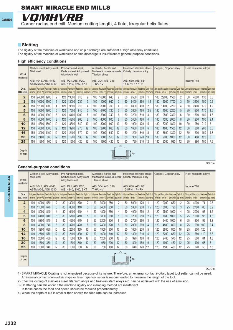
J332
2 150 24000 1200 2 120 19000 610 2 100 16000 640 2 60 9500 300 1 180 29000 1500 2 30 4800 130 0.63 150 16000 1500 3 120 13000 730 3 100 11000 660 3 60 6400 360 1.5 180 19000 1700 3 30 3200 150 0.94 150 12000 1900 4 120 9500 910 4 100 8000 700 4 60 4800 460 2 180 14000 2200 4 30 2400 170 1.25 150 9500 1900 5 120 7600 910 5 100 6400 720 5 60 3800 460 2.5 180 11000 2200 5 30 1900 170 1.56 150 8000 1900 6 120 6400 1000 6 100 5300 740 6 60 3200 510 3 180 9500 2300 6 30 1600 180 1.88 150 6000 1700 8 120 4800 960 8 100 4000 800 8 60 2400 480 4 180 7200 2000 8 30 1200 190 2.4
10 150 4800 1500 10 120 3800 840 10 100 3200 900 10 60 1900 420 5 180 5700 1800 10 30 950 210 312 150 4000 1300 12 120 3200 770 12 100 2700 860 12 60 1600 380 6 180 4800 1500 12 30 800 200 3.616 150 3000 1100 12 120 2400 670 12 100 2000 640 12 60 1200 340 8 180 3600 1300 12 30 600 150 4.820 150 2400 860 12 120 1900 530 12 100 1600 510 12 60 950 270 10 180 2900 1000 12 30 480 120 625 150 1900 760 12 120 1500 420 12 100 1300 420 12 60 760 210 12 180 2300 920 12 30 380 100 7.5
2 100 16000 550 2 80 13000 270 2 60 9500 250 2 50 8000 170 1 120 19000 650 2 25 4000 74 0.63 100 11000 670 3 80 8500 310 3 60 6400 250 3 50 5300 200 1.5 120 13000 790 3 25 2700 86 0.94 100 8000 840 4 80 6400 410 4 60 4800 280 4 50 4000 250 2 120 9500 1000 4 25 2000 93 1.25 100 6400 840 5 80 5100 410 5 60 3800 280 5 50 3200 250 2.5 120 7600 1000 5 25 1600 95 1.56 100 5300 840 6 80 4200 440 6 60 3200 300 6 50 2700 290 3 120 6400 1000 6 25 1300 96 1.88 100 4000 740 8 80 3200 420 8 60 2400 320 8 50 2000 260 4 120 4800 890 8 25 990 100 2.4
10 100 3200 680 10 80 2500 360 10 60 1900 350 10 50 1600 230 5 120 3800 800 10 25 800 120 312 100 2700 570 12 80 2100 330 12 60 1600 340 12 50 1300 210 6 120 3200 680 12 25 660 110 3.616 100 2000 480 12 80 1600 300 12 60 1200 250 12 50 990 180 8 120 2400 570 12 25 500 84 4.820 100 1600 380 12 80 1300 240 12 60 950 200 12 50 800 150 10 120 1900 450 12 25 400 68 625 100 1300 340 12 80 1000 180 12 60 760 160 12 50 640 120 12 120 1500 400 12 25 320 50 7.5
y
VQMHVRB
ap
ap
DC
DC
CARBIDE
SOLI
D E
ND
MIL
LS
High effi ciency conditions
General-purpose conditions
The rigidity of the machine or workpiece and chip discharge are suffi cient at high effi ciency conditions. The rigidity of the machine or workpiece or chip discharge is insuffi cient at general-purpose conditions.
1) SMART MIRACLE Coating is not energized because of its nature. Therefore, an external contact (voltaic type) tool setter cannot be used. An internal contact (non-voltaic) type or laser type tool setter is recommended to measure the length of the tool.
2) Effective cutting of stainless steel, titanium alloys and heat-resistant alloys etc. can be achieved with the use of emulsion.3) Chattering can still occur if the machine rigidity and clamping method are insuffi cient.
In these cases the feed and speed should be reduced proportionately.4) When the depth of cut is smaller than shown the feed rate can be increased.
Work material
Carbon steel, Alloy steel,Mild steel
AISI 1045, AISI 4140, ASTM A36, AISI 1010
Pre-hardened steel,Carbon steel, Alloy steel,Alloy tool steel
AISI P21, AISI P20, AISI 4340, SKD, SKT
Austenitic, Ferritic and Martensitic stainless steels, Titanium alloys
AISI 304, AISI 316, Ti-6Al-4V
Hardened stainless steels,Cobaly chromium alloy
AISI 630, AISI 63115-5PH, 17-4PH
Copper, Copper alloy Heat resistant alloys
Inconel718
Dia.DC (mm)
Cutting speed (m/min)
Revolution (min-1)
Feed rate (mm/min)
Depth of cut ap (mm)
Cutting speed (m/min)
Revolution (min-1)
Feed rate (mm/min)
Depth of cut ap (mm)
Cutting speed (m/min)
Revolution (min-1)
Feed rate (mm/min)
Depth of cut ap (mm)
Cutting speed (m/min)
Revolution (min-1)
Feed rate (mm/min)
Depth of cut ap (mm)
Cutting speed (m/min)
Revolution (min-1)
Feed rate (mm/min)
Depth of cut ap (mm)
Cutting speed (m/min)
Revolution (min-1)
Feed rate (mm/min)
Depth of cut ap (mm)
Depth of cut
Work material
Carbon steel, Alloy steel,Mild steel
AISI 1045, AISI 4140, ASTM A36, AISI 1010
Pre-hardened steel,Carbon steel, Alloy steel,Alloy tool steel
AISI P21, AISI P20, AISI 4340, SKD, SKT
Austenitic, Ferritic and Martensitic stainless steels, Titanium alloys
AISI 304, AISI 316, Ti-6Al-4V
Hardened stainless steels,Cobaly chromium alloy
AISI 630, AISI 63115-5PH, 17-4PH
Copper, Copper alloy Heat resistant alloys
Inconel718
Dia.DC (mm)
Cutting speed (m/min)
Revolution (min-1)
Feed rate (mm/min)
Depth of cut ap (mm)
Cutting speed (m/min)
Revolution (min-1)
Feed rate (mm/min)
Depth of cut ap (mm)
Cutting speed (m/min)
Revolution (min-1)
Feed rate (mm/min)
Depth of cut ap (mm)
Cutting speed (m/min)
Revolution (min-1)
Feed rate (mm/min)
Depth of cut ap (mm)
Cutting speed (m/min)
Revolution (min-1)
Feed rate (mm/min)
Depth of cut ap (mm)
Cutting speed (m/min)
Revolution (min-1)
Feed rate (mm/min)
Depth of cut ap (mm)
Depth of cut
Slotting
SMART MIRACLE END MILLS
Corner radius end mill, Medium cutting length, 4 fl ute, Irregular helix fl utes
DC:Dia.
DC:Dia.
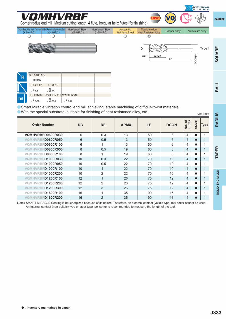
J333
a
VQMHVRBF
±0.015
DC>12 0- 0.02
0- 0.03
DCON=6 0- 0.008
0- 0.009
0- 0.011
u u u e
VQMHVRBF
DC RE APMX LF DCON
VQMHVRBFD0600R030 6 0.3 13 50 6 4 a 1VQMHVRBFD0600R050 6 0.5 13 50 6 4 a 1VQMHVRBFD0600R100 6 1 13 50 6 4 a 1VQMHVRBFD0800R050 8 0.5 19 60 8 4 a 1VQMHVRBFD0800R100 8 1 19 60 8 4 a 1VQMHVRBFD1000R030 10 0.3 22 70 10 4 a 1VQMHVRBFD1000R050 10 0.5 22 70 10 4 a 1VQMHVRBFD1000R100 10 1 22 70 10 4 a 1VQMHVRBFD1000R200 10 2 22 70 10 4 a 1VQMHVRBFD1200R100 12 1 26 75 12 4 a 1VQMHVRBFD1200R200 12 2 26 75 12 4 a 1VQMHVRBFD1200R300 12 3 26 75 12 4 a 1VQMHVRBFD1600R100 16 1 35 90 16 4 a 1VQMHVRBFD1600R200 16 2 35 90 16 4 a 1
a
a
UWC VQ 37°40°
h6
APMX
DC
DC
ON
(h6)
LFRE
CARBIDE
SQU
AR
EB
ALL
RA
DIU
STA
PER
SOLI
D E
ND
MIL
LS
Unit : mm
Carbon Steel, Alloy Steel, Cast Iron(<30HRC)
Tool Steel, Pre-Hardened Steel,Hardened Steel(<45HRC)
Hardened Steel(<55HRC)
Hardened Steel(>55HRC)
AusteniticStainless Steel
Titanium Alloy,Heat Resistant Alloy Copper Alloy Aluminium Alloy
8<DCON<10 12<DCON<16
DC<12
Smart Miracle vibration control end mill achieving stable machining of diffi cult-to-cut materials.With the special substrate, suitable for fi nishing of heat resistance alloy, etc.
Type1
Order Number
No.
of
Flut
es
Stoc
k
Type
0.3<RE<3
Corner radius end mill, Medium cutting length, 4 fl ute, Irregular helix fl utes (for fi nishing)
Note) SMART MIRACLE Coating is not energized because of its nature. Therefore, an external contact (voltaic type) tool setter cannot be used. An internal contact (non-voltaic) type or laser type tool setter is recommended to measure the length of the tool.
a : Inventory maintained in Japan.
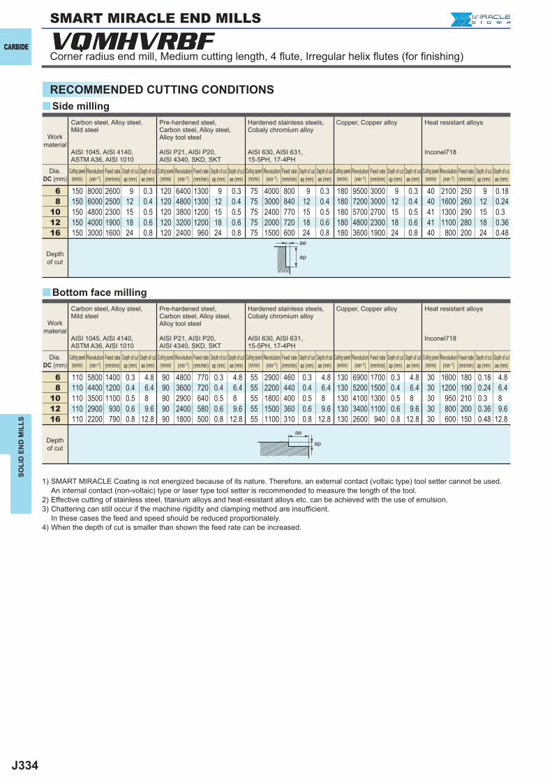
J334
y
y
6 150 8000 2600 9 0.3 120 6400 1300 9 0.3 75 4000 800 9 0.3 180 9500 3000 9 0.3 40 2100 250 9 0.188 150 6000 2500 12 0.4 120 4800 1300 12 0.4 75 3000 840 12 0.4 180 7200 3000 12 0.4 40 1600 260 12 0.24
10 150 4800 2300 15 0.5 120 3800 1200 15 0.5 75 2400 770 15 0.5 180 5700 2700 15 0.5 41 1300 290 15 0.312 150 4000 1900 18 0.6 120 3200 1200 18 0.6 75 2000 720 18 0.6 180 4800 2300 18 0.6 41 1100 280 18 0.3616 150 3000 1600 24 0.8 120 2400 960 24 0.8 75 1500 600 24 0.8 180 3600 1900 24 0.8 40 800 200 24 0.48
6 110 5800 1400 0.3 4.8 90 4800 770 0.3 4.8 55 2900 460 0.3 4.8 130 6900 1700 0.3 4.8 30 1600 180 0.18 4.88 110 4400 1200 0.4 6.4 90 3600 720 0.4 6.4 55 2200 440 0.4 6.4 130 5200 1500 0.4 6.4 30 1200 190 0.24 6.4
10 110 3500 1100 0.5 8 90 2900 640 0.5 8 55 1800 400 0.5 8 130 4100 1300 0.5 8 30 950 210 0.3 812 110 2900 930 0.6 9.6 90 2400 580 0.6 9.6 55 1500 360 0.6 9.6 130 3400 1100 0.6 9.6 30 800 200 0.36 9.616 110 2200 790 0.8 12.8 90 1800 500 0.8 12.8 55 1100 310 0.8 12.8 130 2600 940 0.8 12.8 30 600 150 0.48 12.8
VQMHVRBFVQMHVRBF
ae
ap
ae
ap
CARBIDE
SOLI
D E
ND
MIL
LS
RECOMMENDED CUTTING CONDITIONSSide milling
Bottom face milling
Work material
Carbon steel, Alloy steel,Mild steel
AISI 1045, AISI 4140, ASTM A36, AISI 1010
Pre-hardened steel,Carbon steel, Alloy steel,Alloy tool steel
AISI P21, AISI P20, AISI 4340, SKD, SKT
Hardened stainless steels,Cobaly chromium alloy
AISI 630, AISI 631, 15-5PH, 17-4PH
Copper, Copper alloy Heat resistant alloys
Inconel718
Dia.DC (mm)
Cutting speed (mm/min)
Revolution (min-1)
Feed rate (mm/min)
Depth of cut ap (mm)
Depth of cut ae (mm)
Cutting speed (mm/min)
Revolution (min-1)
Feed rate (mm/min)
Depth of cut ap (mm)
Depth of cut ae (mm)
Cutting speed (mm/min)
Revolution (min-1)
Feed rate (mm/min)
Depth of cut ap (mm)
Depth of cut ae (mm)
Cutting speed (mm/min)
Revolution (min-1)
Feed rate (mm/min)
Depth of cut ap (mm)
Depth of cut ae (mm)
Cutting speed (mm/min)
Revolution (min-1)
Feed rate (mm/min)
Depth of cut ap (mm)
Depth of cut ae (mm)
Depth of cut
1) SMART MIRACLE Coating is not energized because of its nature. Therefore, an external contact (voltaic type) tool setter cannot be used. An internal contact (non-voltaic) type or laser type tool setter is recommended to measure the length of the tool.
2) Effective cutting of stainless steel, titanium alloys and heat-resistant alloys etc. can be achieved with the use of emulsion.3) Chattering can still occur if the machine rigidity and clamping method are insuffi cient.
In these cases the feed and speed should be reduced proportionately.4) When the depth of cut is smaller than shown the feed rate can be increased.
Corner radius end mill, Medium cutting length, 4 fl ute, Irregular helix fl utes (for fi nishing)
SMART MIRACLE END MILLS
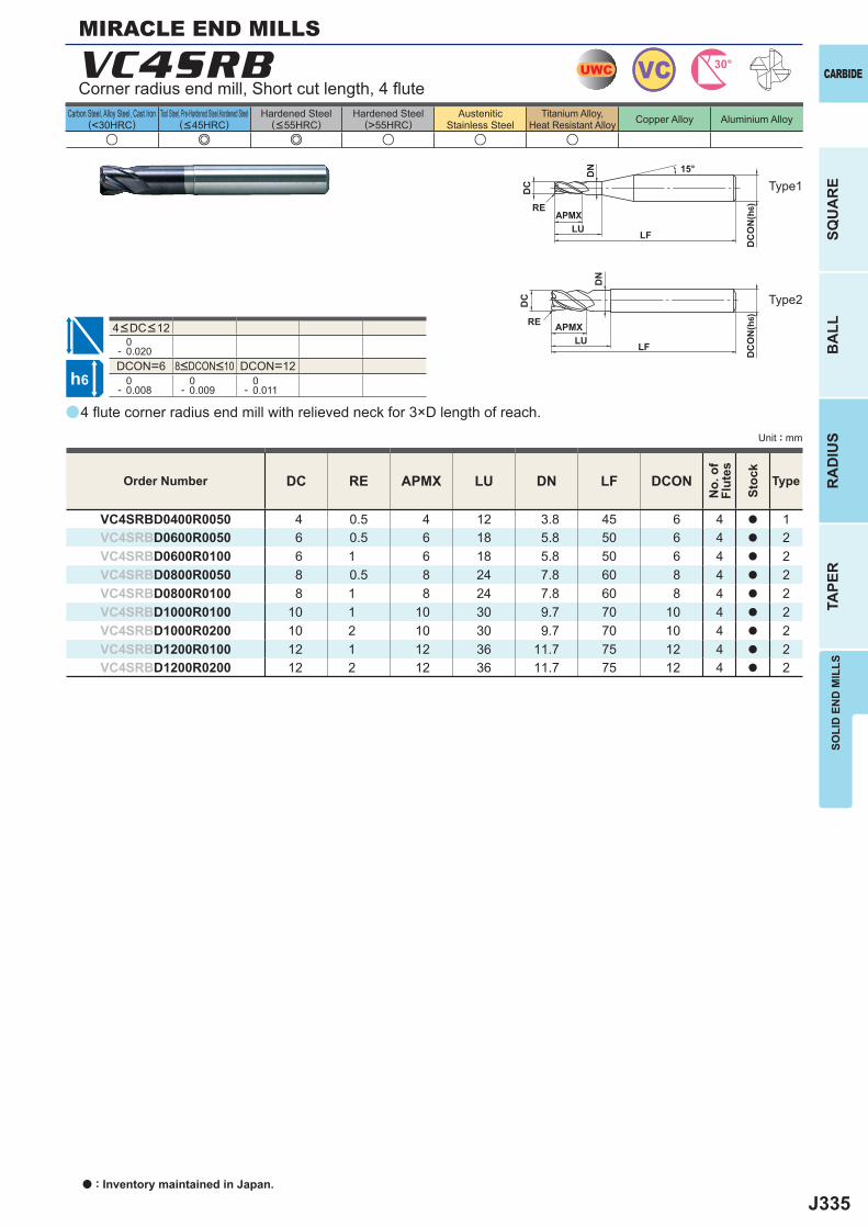
J335
a
u e e u u u
VC4SRB
DC RE APMX LU DN LF DCON
VC4SRBD0400R0050 4 0.5 4 12 3.8 45 6 4 a 1VC4SRBD0600R0050 6 0.5 6 18 5.8 50 6 4 a 2VC4SRBD0600R0100 6 1 6 18 5.8 50 6 4 a 2VC4SRBD0800R0050 8 0.5 8 24 7.8 60 8 4 a 2VC4SRBD0800R0100 8 1 8 24 7.8 60 8 4 a 2VC4SRBD1000R0100 10 1 10 30 9.7 70 10 4 a 2VC4SRBD1000R0200 10 2 10 30 9.7 70 10 4 a 2VC4SRBD1200R0100 12 1 12 36 11.7 75 12 4 a 2VC4SRBD1200R0200 12 2 12 36 11.7 75 12 4 a 2
0- 0.020DCON=6 DCON=12 0- 0.008
0- 0.009
0- 0.011
UWC VC 30°
h6
APMX
DC
DC
ON
(h6)
LF
RE
15°
APMX
DC
ON
(h6)
LF
RE
DC
DN
DN
LU
LU
CARBIDE
SQU
AR
EB
ALL
RA
DIU
STA
PER
SOLI
D E
ND
MIL
LS
Unit : mm
Carbon Steel, Alloy Steel, Cast Iron(<30HRC)
Tool Steel, Pre-Hardened Steel,Hardened Steel(<45HRC)
Hardened Steel(<55HRC)
Hardened Steel(>55HRC)
AusteniticStainless Steel
Titanium Alloy,Heat Resistant Alloy Copper Alloy Aluminium Alloy
4 fl ute corner radius end mill with relieved neck for 3×D length of reach.
Corner radius end mill, Short cut length, 4 fl ute
Type2
Type1
MIRACLE END MILLS
Order Number
No.
of
Flut
es
Stoc
k
Type
8<DCON<10
4<DC<12
a : Inventory maintained in Japan.
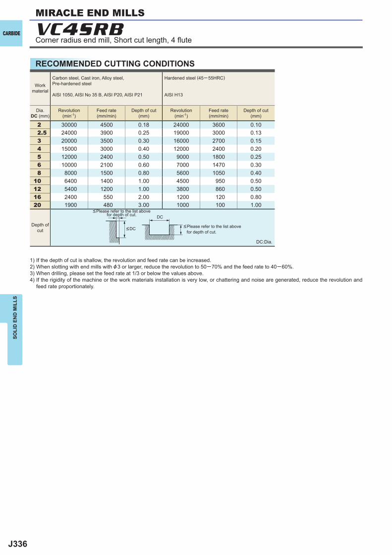
J336
2 30000 4500 0.18 24000 3600 0.10 2.5 24000 3900 0.25 19000 3000 0.13 3 20000 3500 0.30 16000 2700 0.15 4 15000 3000 0.40 12000 2400 0.20 5 12000 2400 0.50 9000 1800 0.25 6 10000 2100 0.60 7000 1470 0.30 8 8000 1500 0.80 5600 1050 0.4010 6400 1400 1.00 4500 950 0.5012 5400 1200 1.00 3800 860 0.5016 2400 550 2.00 1200 120 0.8020 1900 480 3.00 1000 100 1.00
VC4SRB
DC
CARBIDE
SOLI
D E
ND
MIL
LS
RECOMMENDED CUTTING CONDITIONS
1) If the depth of cut is shallow, the revolution and feed rate can be increased.2) When slotting with end mills with &3 or larger, reduce the revolution to 50─70% and the feed rate to 40─60%.3) When drilling, please set the feed rate at 1/3 or below the values above.4) If the rigidity of the machine or the work materials installation is very low, or chattering and noise are generated, reduce the revolution and
feed rate proportionately.
DC:Dia.
<Please refer to the list above for depth of cut.
<Please refer to the list above for depth of cut.
Workmaterial
Carbon steel, Cast iron, Alloy steel,Pre-hardened steel
AISI 1050, AISI No 35 B, AISI P20, AISI P21
Hardened steel (45─ 55HRC)
AISI H13
Dia.DC (mm)
Revolution(min-1)
Feed rate(mm/min)
Depth of cut(mm)
Revolution(min-1)
Feed rate(mm/min)
Depth of cut(mm)
Depth ofcut <DC
Corner radius end mill, Short cut length, 4 fl ute
MIRACLE END MILLS
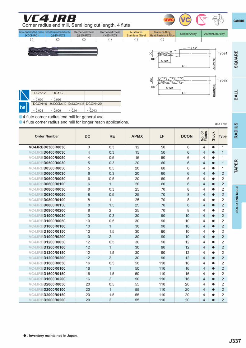
J337
a
u e e u u u
VC4JRB
DC RE APMX LF DCON
VC4JRBD0300R0030 3 0.3 12 50 6 4 a 1VC4JRBD0400R0030 4 0.3 15 50 6 4 a 1VC4JRBD0400R0050 4 0.5 15 50 6 4 a 1VC4JRBD0500R0030 5 0.3 20 60 6 4 a 1VC4JRBD0500R0050 5 0.5 20 60 6 4 a 1VC4JRBD0600R0030 6 0.3 20 60 6 4 a 2VC4JRBD0600R0050 6 0.5 20 60 6 4 a 2VC4JRBD0600R0100 6 1 20 60 6 4 a 2VC4JRBD0800R0030 8 0.3 25 70 8 4 a 2VC4JRBD0800R0050 8 0.5 25 70 8 4 a 2VC4JRBD0800R0100 8 1 25 70 8 4 a 2VC4JRBD0800R0150 8 1.5 25 70 8 4 a 2VC4JRBD0800R0200 8 2 25 70 8 4 a 2VC4JRBD1000R0030 10 0.3 30 90 10 4 a 2VC4JRBD1000R0050 10 0.5 30 90 10 4 a 2VC4JRBD1000R0100 10 1 30 90 10 4 a 2VC4JRBD1000R0150 10 1.5 30 90 10 4 a 2VC4JRBD1000R0200 10 2 30 90 10 4 a 2VC4JRBD1200R0050 12 0.5 30 90 12 4 a 2VC4JRBD1200R0100 12 1 30 90 12 4 a 2VC4JRBD1200R0150 12 1.5 30 90 12 4 a 2VC4JRBD1200R0200 12 2 30 90 12 4 a 2VC4JRBD1600R0050 16 0.5 50 110 16 4 a 2VC4JRBD1600R0100 16 1 50 110 16 4 a 2VC4JRBD1600R0150 16 1.5 50 110 16 4 a 2VC4JRBD1600R0200 16 2 50 110 16 4 a 2VC4JRBD2000R0050 20 0.5 55 110 20 4 a 2VC4JRBD2000R0100 20 1 55 110 20 4 a 2VC4JRBD2000R0150 20 1.5 55 110 20 4 a 2VC4JRBD2000R0200 20 2 55 110 20 4 a 2
a
a
DC>12 0- 0.020
0- 0.030
DCON=6 DCON=20 0- 0.008
0- 0.009
0- 0.011
0- 0.013
UWC VC 30°
h6
APMX
DC
DC
ON
(h6)
LF
RE
15°
APMX
DC
ON
(h6)
LF
RE
DC
CARBIDE
SQU
AR
EB
ALL
RA
DIU
STA
PER
SOLI
D E
ND
MIL
LS
Unit : mm
Carbon Steel, Alloy Steel, Cast Iron(<30HRC)
Tool Steel, Pre-Hardened Steel,Hardened Steel(<45HRC)
Hardened Steel(<55HRC)
Hardened Steel(>55HRC)
AusteniticStainless Steel
Titanium Alloy,Heat Resistant Alloy Copper Alloy Aluminium Alloy
4 fl ute corner radius end mill for general use. 4 fl ute corner radius end mill for longer reach applications.
Corner radius end mill, Semi long cut length, 4 fl ute
Type2
Type1
Order Number
No.
of
Flut
es
Stoc
k
Type
8<DCON<10 12<DCON<16
DC<12
a : Inventory maintained in Japan.
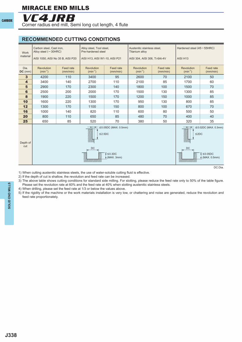
J338
3 4200 110 3400 95 2600 70 2100 504 3400 140 2700 110 2100 85 1700 605 2900 170 2300 140 1800 100 1500 706 2500 200 2000 170 1500 130 1300 858 1900 220 1500 170 1200 150 1000 85
10 1600 220 1300 170 950 130 800 8512 1300 170 1100 150 800 100 670 7016 1000 140 820 110 600 80 500 5020 800 110 650 85 480 70 400 4025 650 85 520 70 380 50 320 35
VC4JRB
DC DC
CARBIDE
SOLI
D E
ND
MIL
LS
RECOMMENDED CUTTING CONDITIONS
1) When cutting austenitic stainless steels, the use of water-soluble cutting fl uid is effective.2) If the depth of cut is shallow, the revolution and feed rate can be increased.3) The above table shows cutting conditions for standard side milling. For slotting, please reduce the feed rate only to 50% of the table fi gure.
Please set the revolution rate at 60% and the feed rate at 40% when slotting austenitic stainless steels.4) When drilling, please set the feed rate at 1/3 or below the values above.5) If the rigidity of the machine or the work materials installation is very low, or chattering and noise are generated, reduce the revolution and
feed rate proportionately.
DC:Dia.
Workmaterial
Carbon steel, Cast iron, Alloy steel (─30HRC)
AISI 1050, AISI No 35 B, AISI P20
Alloy steel, Tool steel,Pre-hardened steel
AISI H13, AISI W1-10, AISI P21
Austenitic stainless steel,Titanium alloy
AISI 304, AISI 306, Ti-6Al-4V
Hardened steel (45─ 55HRC)
AISI H13
Dia.DC (mm)
Revolution(min-1)
Feed rate(mm/min)
Revolution(min-1)
Feed rate(mm/min)
Revolution(min-1)
Feed rate(mm/min)
Revolution(min-1)
Feed rate(mm/min)
Depth ofcut
<0.05DC (MAX. 0.5mm) <0.02DC (MAX. 0.3mm)
<0.3DC (MAX. 3mm)
<0.05DC (MAX. 0.5mm)
<2.5DC <2DC
Corner radius end mill, Semi long cut length, 4 fl ute
MIRACLE END MILLS
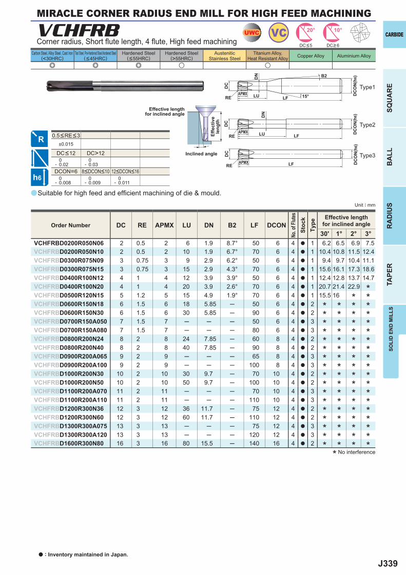
J339
a
e e e u u
VCHFRB
DC RE APMX LU DN B2 LF DCON30' 1° 2° 3°
VCHFRBD0200R050N06 2 0.5 2 6 1.9 8.7° 50 6 4 a 1 6.2 6.5 6.9 7.5VCHFRBD0200R050N10 2 0.5 2 10 1.9 6.7° 70 6 4 a 1 10.4 10.8 11.5 12.4VCHFRBD0300R075N09 3 0.75 3 9 2.9 6.2° 50 6 4 a 1 9.4 9.7 10.4 11.1VCHFRBD0300R075N15 3 0.75 3 15 2.9 4.3° 70 6 4 a 1 15.6 16.1 17.3 18.6VCHFRBD0400R100N12 4 1 4 12 3.9 3.9° 50 6 4 a 1 12.4 12.8 13.7 14.7VCHFRBD0400R100N20 4 1 4 20 3.9 2.6° 70 6 4 a 1 20.7 21.4 22.9VCHFRBD0500R120N15 5 1.2 5 15 4.9 1.9° 70 6 4 a 1 15.5 16VCHFRBD0600R150N18 6 1.5 6 18 5.85 ─ 50 6 4 a 2VCHFRBD0600R150N30 6 1.5 6 30 5.85 ─ 90 6 4 a 2VCHFRBD0700R150A050 7 1.5 7 ─ ─ ─ 50 6 4 a 3VCHFRBD0700R150A080 7 1.5 7 ─ ─ ─ 80 6 4 a 3VCHFRBD0800R200N24 8 2 8 24 7.85 ─ 60 8 4 a 2VCHFRBD0800R200N40 8 2 8 40 7.85 ─ 90 8 4 a 2VCHFRBD0900R200A065 9 2 9 ─ ─ ─ 65 8 4 a 3VCHFRBD0900R200A100 9 2 9 ─ ─ ─ 100 8 4 a 3VCHFRBD1000R200N30 10 2 10 30 9.7 ─ 70 10 4 a 2VCHFRBD1000R200N50 10 2 10 50 9.7 ─ 100 10 4 a 2VCHFRBD1100R200A070 11 2 11 ─ ─ ─ 70 10 4 a 3VCHFRBD1100R200A110 11 2 11 ─ ─ ─ 110 10 4 a 3VCHFRBD1200R300N36 12 3 12 36 11.7 ─ 75 12 4 a 2VCHFRBD1200R300N60 12 3 12 60 11.7 ─ 110 12 4 a 2VCHFRBD1300R300A075 13 3 13 ─ ─ ─ 75 12 4 a 3VCHFRBD1300R300A120 13 3 13 ─ ─ ─ 120 12 4 a 3VCHFRBD1600R300N80 16 3 16 80 15.5 ─ 140 16 4 a 2
±0.015
DC>12 0- 0.02
0- 0.03
DCON=6 0- 0.008
0- 0.009
0- 0.011
UWC VC 10°20°
h6
APMX
DC
DC
ON
(h6)
15°LFRE LU
DN
APMX
DC
DC
ON
(h6)
LFRE LU
DN
APMX
DC
DC
ON
(h6)
LFRE
B2
CARBIDE
SQU
AR
EB
ALL
RA
DIU
STA
PER
SOLI
D E
ND
MIL
LS
Unit : mm
Carbon Steel, Alloy Steel, Cast Iron(<30HRC)
Tool Steel, Pre-Hardened Steel,Hardened Steel(<45HRC)
Hardened Steel(<55HRC)
Hardened Steel(>55HRC)
AusteniticStainless Steel
Titanium Alloy,Heat Resistant Alloy Copper Alloy Aluminium Alloy
Suitable for high feed and effi cient machining of die & mould.
Corner radius, Short fl ute length, 4 fl ute, High feed machining
Type2
Type3
Type1
Effective lengthfor inclined angle
Inclined angle
Effe
ctiv
ele
ngth
DC<5 DC>6
* No interference
Order Number
No. o
f Flut
esSt
ock
Type
Effective lengthfor inclined angle
** *
* * * ** * * ** * * ** * * ** * * ** * * ** * * ** * * ** * * ** * * ** * * ** * * ** * * ** * * ** * * ** * * ** * * *
8<DCON<10 12<DCON<16
0.5<RE<3
DC<12
MIRACLE CORNER RADIUS END MILL FOR HIGH FEED MACHINING
a : Inventory maintained in Japan.
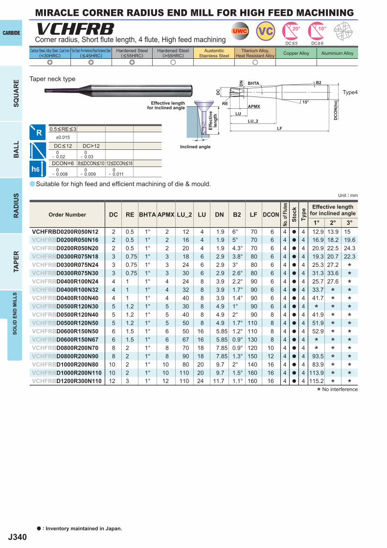
J340
a
e e e u u
VCHFRB
DC RE BHTA APMX LU_2 LU DN B2 LF DCON1° 2° 3°
VCHFRBD0200R050N12 2 0.5 1° 2 12 4 1.9 6° 70 6 4 a 4 12.9 13.9 15VCHFRBD0200R050N16 2 0.5 1° 2 16 4 1.9 5° 70 6 4 a 4 16.9 18.2 19.6VCHFRBD0200R050N20 2 0.5 1° 2 20 4 1.9 4.3° 70 6 4 a 4 20.9 22.5 24.3VCHFRBD0300R075N18 3 0.75 1° 3 18 6 2.9 3.8° 80 6 4 a 4 19.3 20.7 22.3VCHFRBD0300R075N24 3 0.75 1° 3 24 6 2.9 3° 80 6 4 a 4 25.3 27.2VCHFRBD0300R075N30 3 0.75 1° 3 30 6 2.9 2.6° 80 6 4 a 4 31.3 33.6VCHFRBD0400R100N24 4 1 1° 4 24 8 3.9 2.2° 90 6 4 a 4 25.7 27.6VCHFRBD0400R100N32 4 1 1° 4 32 8 3.9 1.7° 90 6 4 a 4 33.7VCHFRBD0400R100N40 4 1 1° 4 40 8 3.9 1.4° 90 6 4 a 4 41.7VCHFRBD0500R120N30 5 1.2 1° 5 30 8 4.9 1° 90 6 4 a 4VCHFRBD0500R120N40 5 1.2 1° 5 40 8 4.9 2° 90 8 4 a 4 41.9VCHFRBD0500R120N50 5 1.2 1° 5 50 8 4.9 1.7° 110 8 4 a 4 51.9VCHFRBD0600R150N50 6 1.5 1° 6 50 16 5.85 1.2° 110 8 4 a 4 52.9VCHFRBD0600R150N67 6 1.5 1° 6 67 16 5.85 0.9° 130 8 4 a 4VCHFRBD0800R200N70 8 2 1° 8 70 18 7.85 0.9° 120 10 4 a 4VCHFRBD0800R200N90 8 2 1° 8 90 18 7.85 1.3° 150 12 4 a 4 93.5VCHFRBD1000R200N80 10 2 1° 10 80 20 9.7 2° 140 16 4 a 4 83.9VCHFRBD1000R200N110 10 2 1° 10 110 20 9.7 1.5° 160 16 4 a 4 113.9VCHFRBD1200R300N110 12 3 1° 12 110 24 11.7 1.1° 160 16 4 a 4 115.2
±0.015
DC>12 0- 0.02
0- 0.03
DCON=6 0- 0.008
0- 0.009
0- 0.011
UWC VC 10°20°
h6
APMX
DC
DC
ON
(h6)15°
BHTA
LF
RE
LU_2
LU
DN B2
a : Inventory maintained in Japan.
CARBIDE
SQU
AR
EB
ALL
RA
DIU
STA
PER
SOLI
D E
ND
MIL
LS
Unit : mm
Carbon Steel, Alloy Steel, Cast Iron(<30HRC)
Tool Steel, Pre-Hardened Steel,Hardened Steel(<45HRC)
Hardened Steel(<55HRC)
Hardened Steel(>55HRC)
AusteniticStainless Steel
Titanium Alloy,Heat Resistant Alloy Copper Alloy Aluminium Alloy
0.5<RE<3
Suitable for high feed and effi cient machining of die & mould.
Corner radius, Short fl ute length, 4 fl ute, High feed machining
Type4
Effective lengthfor inclined angle
Inclined angle
Effe
ctiv
ele
ngth
Taper neck type
DC<5 DC>6
* No interference
***************
************
*
**
Order Number
No. o
f Flut
esSt
ock
Type
Effective lengthfor inclined angle
8<DCON<10 12<DCON<16
DC<12
MIRACLE CORNER RADIUS END MILL FOR HIGH FEED MACHINING
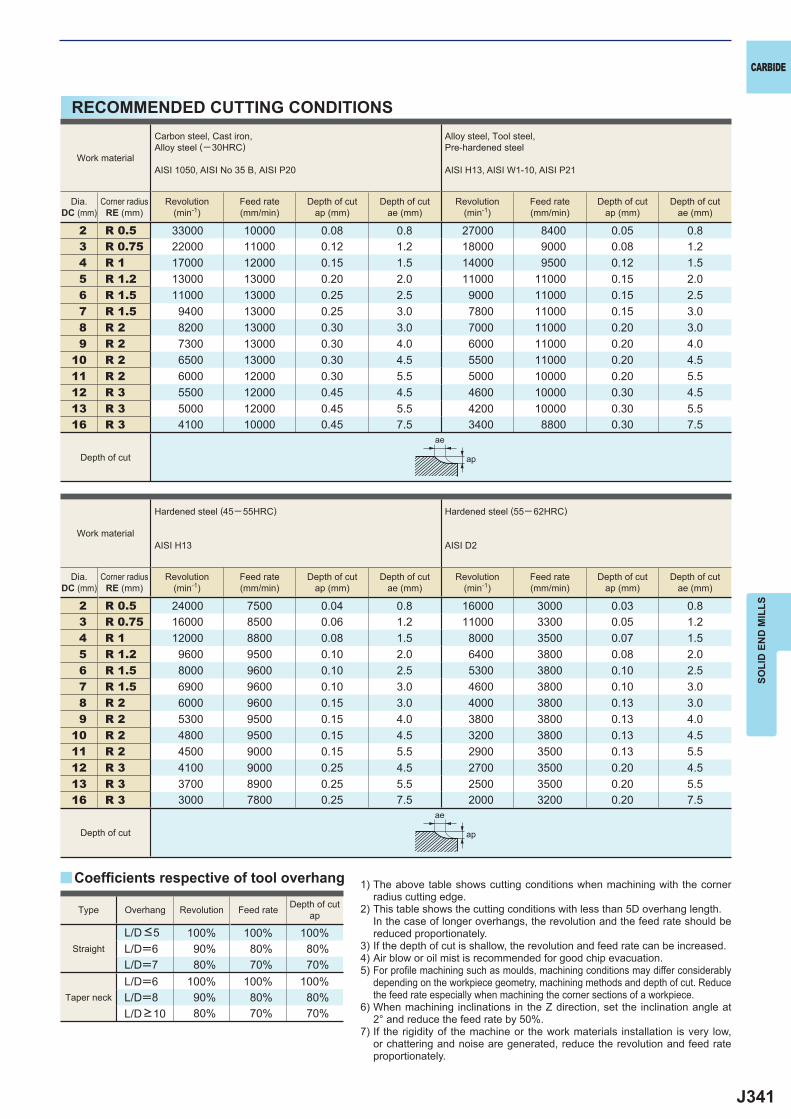
J341
2 R 0.5 33000 10000 0.08 0.8 27000 8400 0.05 0.83 R 0.75 22000 11000 0.12 1.2 18000 9000 0.08 1.24 R 1 17000 12000 0.15 1.5 14000 9500 0.12 1.55 R 1.2 13000 13000 0.20 2.0 11000 11000 0.15 2.06 R 1.5 11000 13000 0.25 2.5 9000 11000 0.15 2.57 R 1.5 9400 13000 0.25 3.0 7800 11000 0.15 3.08 R 2 8200 13000 0.30 3.0 7000 11000 0.20 3.09 R 2 7300 13000 0.30 4.0 6000 11000 0.20 4.0
10 R 2 6500 13000 0.30 4.5 5500 11000 0.20 4.511 R 2 6000 12000 0.30 5.5 5000 10000 0.20 5.512 R 3 5500 12000 0.45 4.5 4600 10000 0.30 4.513 R 3 5000 12000 0.45 5.5 4200 10000 0.30 5.516 R 3 4100 10000 0.45 7.5 3400 8800 0.30 7.5
2 R 0.5 24000 7500 0.04 0.8 16000 3000 0.03 0.83 R 0.75 16000 8500 0.06 1.2 11000 3300 0.05 1.24 R 1 12000 8800 0.08 1.5 8000 3500 0.07 1.55 R 1.2 9600 9500 0.10 2.0 6400 3800 0.08 2.06 R 1.5 8000 9600 0.10 2.5 5300 3800 0.10 2.57 R 1.5 6900 9600 0.10 3.0 4600 3800 0.10 3.08 R 2 6000 9600 0.15 3.0 4000 3800 0.13 3.09 R 2 5300 9500 0.15 4.0 3800 3800 0.13 4.0
10 R 2 4800 9500 0.15 4.5 3200 3800 0.13 4.511 R 2 4500 9000 0.15 5.5 2900 3500 0.13 5.512 R 3 4100 9000 0.25 4.5 2700 3500 0.20 4.513 R 3 3700 8900 0.25 5.5 2500 3500 0.20 5.516 R 3 3000 7800 0.25 7.5 2000 3200 0.20 7.5
100% 100% 100%L/D=6 90% 80% 80%L/D=7 80% 70% 70%L/D=6 100% 100% 100%L/D=8 90% 80% 80%
80% 70% 70%
y
ae
ap
ae
ap
CARBIDE
SOLI
D E
ND
MIL
LS
RECOMMENDED CUTTING CONDITIONS
1) The above table shows cutting conditions when machining with the corner radius cutting edge.
2) This table shows the cutting conditions with less than 5D overhang length. In the case of longer overhangs, the revolution and the feed rate should be
reduced proportionately.3) If the depth of cut is shallow, the revolution and feed rate can be increased.4) Air blow or oil mist is recommended for good chip evacuation.5) For profi le machining such as moulds, machining conditions may differ considerably
depending on the workpiece geometry, machining methods and depth of cut. Reduce the feed rate especially when machining the corner sections of a workpiece.
6) When machining inclinations in the Z direction, set the inclination angle at 2° and reduce the feed rate by 50%.
7) If the rigidity of the machine or the work materials installation is very low, or chattering and noise are generated, reduce the revolution and feed rate proportionately.
Coeffi cients respective of tool overhang
Type Overhang Revolution Feed rate Depth of cutap
Straight
L/D <5
Taper neck
L/D >10
Work material
Carbon steel, Cast iron, Alloy steel (─30HRC)
AISI 1050, AISI No 35 B, AISI P20
Alloy steel, Tool steel,Pre-hardened steel
AISI H13, AISI W1-10, AISI P21
Dia.DC (mm)
Corner radiusRE (mm)
Revolution(min-1)
Feed rate(mm/min)
Depth of cutap (mm)
Depth of cutae (mm)
Revolution(min-1)
Feed rate(mm/min)
Depth of cutap (mm)
Depth of cutae (mm)
Depth of cut
Work material
Hardened steel (45─ 55HRC)
AISI H13
Hardened steel (55─ 62HRC)
AISI D2
Dia.DC (mm)
Corner radiusRE (mm)
Revolution(min-1)
Feed rate(mm/min)
Depth of cutap (mm)
Depth of cutae (mm)
Revolution(min-1)
Feed rate(mm/min)
Depth of cutap (mm)
Depth of cutae (mm)
Depth of cut
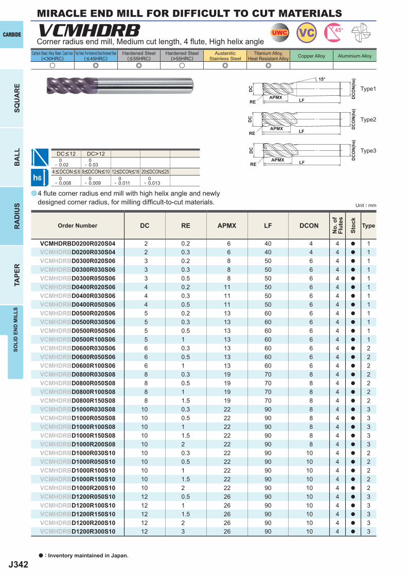
J342
a
u e e u e e
VCMHDRB
DC RE APMX LF DCON
VCMHDRBD0200R020S04 2 0.2 6 40 4 4 a 1VCMHDRBD0200R030S04 2 0.3 6 40 4 4 a 1VCMHDRBD0300R020S06 3 0.2 8 50 6 4 a 1VCMHDRBD0300R030S06 3 0.3 8 50 6 4 a 1VCMHDRBD0300R050S06 3 0.5 8 50 6 4 a 1VCMHDRBD0400R020S06 4 0.2 11 50 6 4 a 1VCMHDRBD0400R030S06 4 0.3 11 50 6 4 a 1VCMHDRBD0400R050S06 4 0.5 11 50 6 4 a 1VCMHDRBD0500R020S06 5 0.2 13 60 6 4 a 1VCMHDRBD0500R030S06 5 0.3 13 60 6 4 a 1VCMHDRBD0500R050S06 5 0.5 13 60 6 4 a 1VCMHDRBD0500R100S06 5 1 13 60 6 4 a 1VCMHDRBD0600R030S06 6 0.3 13 60 6 4 a 2VCMHDRBD0600R050S06 6 0.5 13 60 6 4 a 2VCMHDRBD0600R100S06 6 1 13 60 6 4 a 2VCMHDRBD0800R030S08 8 0.3 19 70 8 4 a 2VCMHDRBD0800R050S08 8 0.5 19 70 8 4 a 2VCMHDRBD0800R100S08 8 1 19 70 8 4 a 2VCMHDRBD0800R150S08 8 1.5 19 70 8 4 a 2VCMHDRBD1000R030S08 10 0.3 22 90 8 4 a 3VCMHDRBD1000R050S08 10 0.5 22 90 8 4 a 3VCMHDRBD1000R100S08 10 1 22 90 8 4 a 3VCMHDRBD1000R150S08 10 1.5 22 90 8 4 a 3VCMHDRBD1000R200S08 10 2 22 90 8 4 a 3VCMHDRBD1000R030S10 10 0.3 22 90 10 4 a 2VCMHDRBD1000R050S10 10 0.5 22 90 10 4 a 2VCMHDRBD1000R100S10 10 1 22 90 10 4 a 2VCMHDRBD1000R150S10 10 1.5 22 90 10 4 a 2VCMHDRBD1000R200S10 10 2 22 90 10 4 a 2VCMHDRBD1200R050S10 12 0.5 26 90 10 4 a 3VCMHDRBD1200R100S10 12 1 26 90 10 4 a 3VCMHDRBD1200R150S10 12 1.5 26 90 10 4 a 3VCMHDRBD1200R200S10 12 2 26 90 10 4 a 3VCMHDRBD1200R300S10 12 3 26 90 10 4 a 3
DC>12 0- 0.02
0- 0.03
0- 0.008
0- 0.009
0- 0.011
0- 0.013
UWC VC 45°
h6
APMX
DC
DC
ON
(h6)15°
LFRE
APMX
DC
DC
ON
(h6)
LFRE
APMX
DC
DC
ON
(h6)
LFRE
a : Inventory maintained in Japan.
CARBIDE
SQU
AR
EB
ALL
RA
DIU
STA
PER
SOLI
D E
ND
MIL
LS
Unit : mm
Carbon Steel, Alloy Steel, Cast Iron(<30HRC)
Tool Steel, Pre-Hardened Steel,Hardened Steel(<45HRC)
Hardened Steel(<55HRC)
Hardened Steel(>55HRC)
AusteniticStainless Steel
Titanium Alloy,Heat Resistant Alloy Copper Alloy Aluminium Alloy
4 fl ute corner radius end mill with high helix angle and newly designed corner radius, for milling diffi cult-to-cut materials.
Corner radius end mill, Medium cut length, 4 fl ute, High helix angle
Type2
Type3
Type1
Order Number
No.
of
Flut
es
Stoc
k
Type
4<DCON<6 8<DCON<10 12<DCON<16 20<DCON<25
DC<12
MIRACLE END MILL FOR DIFFICULT TO CUT MATERIALS
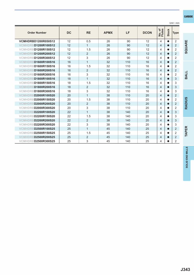
J343
DC RE APMX LF DCON
VCMHDRBD1200R050S12 12 0.5 26 90 12 4 a 2VCMHDRBD1200R100S12 12 1 26 90 12 4 a 2VCMHDRBD1200R150S12 12 1.5 26 90 12 4 a 2VCMHDRBD1200R200S12 12 2 26 90 12 4 a 2VCMHDRBD1200R300S12 12 3 26 90 12 4 a 2VCMHDRBD1600R100S16 16 1 32 110 16 4 a 2VCMHDRBD1600R150S16 16 1.5 32 110 16 4 a 2VCMHDRBD1600R200S16 16 2 32 110 16 4 a 2VCMHDRBD1600R300S16 16 3 32 110 16 4 a 2VCMHDRBD1800R100S16 18 1 32 110 16 4 a 3VCMHDRBD1800R150S16 18 1.5 32 110 16 4 a 3VCMHDRBD1800R200S16 18 2 32 110 16 4 a 3VCMHDRBD1800R300S16 18 3 32 110 16 4 a 3VCMHDRBD2000R100S20 20 1 38 110 20 4 a 2VCMHDRBD2000R150S20 20 1.5 38 110 20 4 a 2VCMHDRBD2000R200S20 20 2 38 110 20 4 a 2VCMHDRBD2000R300S20 20 3 38 110 20 4 a 2VCMHDRBD2200R100S20 22 1 38 140 20 4 a 3VCMHDRBD2200R150S20 22 1.5 38 140 20 4 a 3VCMHDRBD2200R200S20 22 2 38 140 20 4 a 3VCMHDRBD2200R300S20 22 3 38 140 20 4 a 3VCMHDRBD2500R100S25 25 1 45 140 25 4 a 2VCMHDRBD2500R150S25 25 1.5 45 140 25 4 a 2VCMHDRBD2500R200S25 25 2 45 140 25 4 a 2VCMHDRBD2500R300S25 25 3 45 140 25 4 a 2
CARBIDE
SQU
AR
EB
ALL
RA
DIU
STA
PER
SOLI
D E
ND
MIL
LS
Unit : mm
Order Number
No.
of
Flut
es
Stoc
k
Type
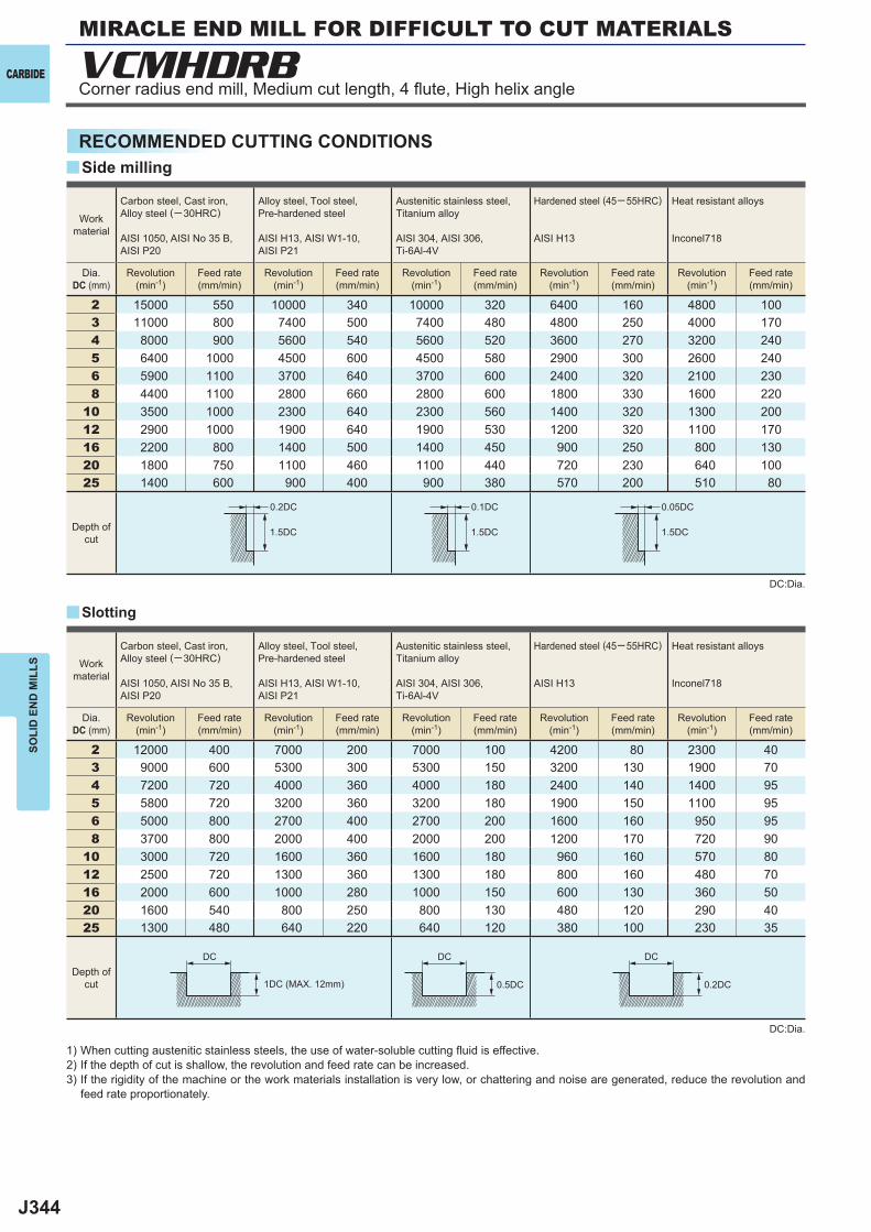
J344
2 15000 550 10000 340 10000 320 6400 160 4800 1003 11000 800 7400 500 7400 480 4800 250 4000 1704 8000 900 5600 540 5600 520 3600 270 3200 2405 6400 1000 4500 600 4500 580 2900 300 2600 2406 5900 1100 3700 640 3700 600 2400 320 2100 2308 4400 1100 2800 660 2800 600 1800 330 1600 220
10 3500 1000 2300 640 2300 560 1400 320 1300 20012 2900 1000 1900 640 1900 530 1200 320 1100 17016 2200 800 1400 500 1400 450 900 250 800 13020 1800 750 1100 460 1100 440 720 230 640 10025 1400 600 900 400 900 380 570 200 510 80
2 12000 400 7000 200 7000 100 4200 80 2300 403 9000 600 5300 300 5300 150 3200 130 1900 704 7200 720 4000 360 4000 180 2400 140 1400 955 5800 720 3200 360 3200 180 1900 150 1100 956 5000 800 2700 400 2700 200 1600 160 950 958 3700 800 2000 400 2000 200 1200 170 720 90
10 3000 720 1600 360 1600 180 960 160 570 8012 2500 720 1300 360 1300 180 800 160 480 7016 2000 600 1000 280 1000 150 600 130 360 5020 1600 540 800 250 800 130 480 120 290 4025 1300 480 640 220 640 120 380 100 230 35
y
y
VCMHDRB
0.2DC 0.1DC
1.5DC1.5DC 1.5DC
0.05DC
DC DC DC
0.5DC 0.2DC
CARBIDE
SOLI
D E
ND
MIL
LS
RECOMMENDED CUTTING CONDITIONS
1) When cutting austenitic stainless steels, the use of water-soluble cutting fl uid is effective.2) If the depth of cut is shallow, the revolution and feed rate can be increased.3) If the rigidity of the machine or the work materials installation is very low, or chattering and noise are generated, reduce the revolution and
feed rate proportionately.
DC:Dia.
DC:Dia.
Slotting
Side milling
Workmaterial
Carbon steel, Cast iron, Alloy steel (─30HRC)
AISI 1050, AISI No 35 B,AISI P20
Alloy steel, Tool steel,Pre-hardened steel
AISI H13, AISI W1-10, AISI P21
Austenitic stainless steel,Titanium alloy
AISI 304, AISI 306, Ti-6Al-4V
Hardened steel (45─ 55HRC)
AISI H13
Heat resistant alloys
Inconel718
Dia.DC (mm)
Revolution(min-1)
Feed rate(mm/min)
Revolution(min-1)
Feed rate(mm/min)
Revolution(min-1)
Feed rate(mm/min)
Revolution(min-1)
Feed rate(mm/min)
Revolution(min-1)
Feed rate(mm/min)
Depth ofcut
Workmaterial
Carbon steel, Cast iron, Alloy steel (─30HRC)
AISI 1050, AISI No 35 B,AISI P20
Alloy steel, Tool steel,Pre-hardened steel
AISI H13, AISI W1-10, AISI P21
Austenitic stainless steel,Titanium alloy
AISI 304, AISI 306, Ti-6Al-4V
Hardened steel (45─ 55HRC)
AISI H13
Heat resistant alloys
Inconel718
Dia.DC (mm)
Revolution(min-1)
Feed rate(mm/min)
Revolution(min-1)
Feed rate(mm/min)
Revolution(min-1)
Feed rate(mm/min)
Revolution(min-1)
Feed rate(mm/min)
Revolution(min-1)
Feed rate(mm/min)
Depth ofcut 1DC (MAX. 12mm)
Corner radius end mill, Medium cut length, 4 fl ute, High helix angle
MIRACLE END MILL FOR DIFFICULT TO CUT MATERIALS
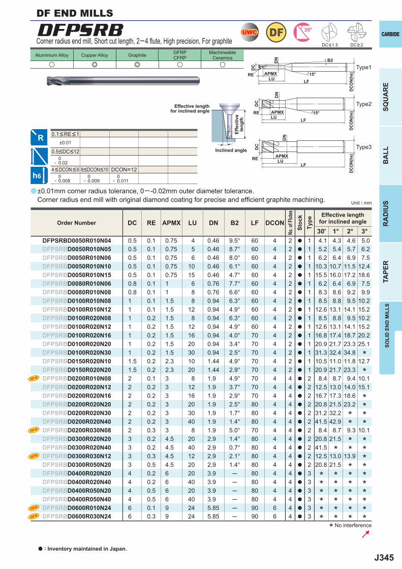
J345
a
DFPSRB
u e e u u
DC RE APMX LU DN B2 LF DCON30' 1° 2° 3°
DFPSRBD0050R010N04 0.5 0.1 0.75 4 0.46 9.5° 60 4 2 a 1 4.1 4.3 4.6 5.0DFPSRBD0050R010N05 0.5 0.1 0.75 5 0.46 8.7° 60 4 2 a 1 5.2 5.4 5.7 6.2DFPSRBD0050R010N06 0.5 0.1 0.75 6 0.46 8.0° 60 4 2 a 1 6.2 6.4 6.9 7.5DFPSRBD0050R010N10 0.5 0.1 0.75 10 0.46 6.1° 60 4 2 a 1 10.3 10.7 11.5 12.4DFPSRBD0050R010N15 0.5 0.1 0.75 15 0.46 4.7° 60 4 2 a 1 15.5 16.0 17.2 18.6DFPSRBD0080R010N06 0.8 0.1 1 6 0.76 7.7° 60 4 2 a 1 6.2 6.4 6.9 7.5DFPSRBD0080R010N08 0.8 0.1 1 8 0.76 6.6° 60 4 2 a 1 8.3 8.6 9.2 9.9DFPSRBD0100R010N08 1 0.1 1.5 8 0.94 6.3° 60 4 2 a 1 8.5 8.8 9.5 10.2DFPSRBD0100R010N12 1 0.1 1.5 12 0.94 4.9° 60 4 2 a 1 12.6 13.1 14.1 15.2DFPSRBD0100R020N08 1 0.2 1.5 8 0.94 6.3° 60 4 2 a 1 8.5 8.8 9.5 10.2DFPSRBD0100R020N12 1 0.2 1.5 12 0.94 4.9° 60 4 2 a 1 12.6 13.1 14.1 15.2DFPSRBD0100R020N16 1 0.2 1.5 16 0.94 4.0° 70 4 2 a 1 16.8 17.4 18.7 20.2DFPSRBD0100R020N20 1 0.2 1.5 20 0.94 3.4° 70 4 2 a 1 20.9 21.7 23.3 25.1DFPSRBD0100R020N30 1 0.2 1.5 30 0.94 2.5° 70 4 2 a 1 31.3 32.4 34.8DFPSRBD0150R020N10 1.5 0.2 2.3 10 1.44 4.9° 70 4 2 a 1 10.5 11.0 11.8 12.7DFPSRBD0150R020N20 1.5 0.2 2.3 20 1.44 2.9° 70 4 2 a 1 20.9 21.7 23.3DFPSRBD0200R010N08 2 0.1 3 8 1.9 4.9° 70 4 4 a 2 8.4 8.7 9.4 10.1DFPSRBD0200R020N12 2 0.2 3 12 1.9 3.7° 70 4 4 a 2 12.5 13.0 14.0 15.1DFPSRBD0200R020N16 2 0.2 3 16 1.9 2.9° 70 4 4 a 2 16.7 17.3 18.6DFPSRBD0200R020N20 2 0.2 3 20 1.9 2.5° 80 4 4 a 2 20.8 21.5 23.2DFPSRBD0200R020N30 2 0.2 3 30 1.9 1.7° 80 4 4 a 2 31.2 32.2DFPSRBD0200R020N40 2 0.2 3 40 1.9 1.4° 80 4 4 a 2 41.5 42.9DFPSRBD0200R030N08 2 0.3 3 8 1.9 5.0° 70 4 4 a 2 8.4 8.7 9.3 10.1DFPSRBD0300R020N20 3 0.2 4.5 20 2.9 1.4° 80 4 4 a 2 20.8 21.5DFPSRBD0300R020N40 3 0.2 4.5 40 2.9 0.7° 80 4 4 a 2 41.5DFPSRBD0300R030N12 3 0.3 4.5 12 2.9 2.1° 80 4 4 a 2 12.5 13.0 13.9DFPSRBD0300R050N20 3 0.5 4.5 20 2.9 1.4° 80 4 4 a 2 20.8 21.5DFPSRBD0400R020N20 4 0.2 6 20 3.9 ─ 80 4 4 a 3DFPSRBD0400R020N40 4 0.2 6 40 3.9 ─ 80 4 4 a 3DFPSRBD0400R050N20 4 0.5 6 20 3.9 ─ 80 4 4 a 3DFPSRBD0400R050N40 4 0.5 6 40 3.9 ─ 80 4 4 a 3DFPSRBD0600R010N24 6 0.1 9 24 5.85 ─ 90 6 4 a 3DFPSRBD0600R030N24 6 0.3 9 24 5.85 ─ 90 6 4 a 3
±0.01
0- 0.02
DCON=12 0- 0.008
0- 0.009
0- 0.011
UWC 30°DF
h6
APMX
DC
DCO
N(h6
)15°LF
RELU
DN
APMX
DC
DCO
N(h6
)
LFRE
LU
DN
15°
APMX
DC
DCO
N(h6
)
LFRE LU
DN
B2Aluminium Alloy Copper Alloy Graphite GFRP
CFRPMachineable
Ceramics
CARBIDE
SQU
AR
EB
ALL
RA
DIU
STA
PER
SOLI
D E
ND
MIL
LS
Unit : mm
±0.01mm corner radius tolerance, 0─ -0.02mm outer diameter tolerance. Corner radius end mill with original diamond coating for precise and effi cient graphite machining.
Corner radius end mill, Short cut length, 2─4 fl ute, High precision, For graphite
Type2
Type3
Type1
Effective lengthfor inclined angle
Inclined angle
Effe
ctiv
ele
ngth
DC<1.5 DC>2
Order Number
No. o
f Flut
esSt
ock
Type
Effective lengthfor inclined angle
4<DCON<6 8<DCON<10
0.1<RE<1
0.5<DC<12
* No interference
DF END MILLS
* * **
* ** * * ** * * ** * * ** * * ** * * ** * * *
****
*
*
*
**
*
a : Inventory maintained in Japan.
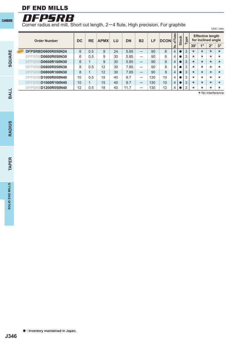
J346
DC RE APMX LU DN B2 LF DCON30' 1° 2° 3°
DFPSRBD0600R050N24 6 0.5 9 24 5.85 ─ 90 6 4 a 3DFPSRBD0600R050N30 6 0.5 9 30 5.85 ─ 90 6 4 a 3DFPSRBD0600R100N30 6 1 9 30 5.85 ─ 90 6 4 a 3DFPSRBD0800R050N30 8 0.5 12 30 7.85 ─ 90 8 4 a 3DFPSRBD0800R100N30 8 1 12 30 7.85 ─ 90 8 4 a 3DFPSRBD1000R050N40 10 0.5 15 40 9.7 ─ 130 10 4 a 3DFPSRBD1000R100N40 10 1 15 40 9.7 ─ 130 10 4 a 3DFPSRBD1200R050N40 12 0.5 18 40 11.7 ─ 130 12 4 a 3
DFPSRB
a : Inventory maintained in Japan.
CARBIDE
SQU
AR
EB
ALL
RA
DIU
STA
PER
SOLI
D E
ND
MIL
LS
Unit : mm
Order Number
No. o
f Flut
esSt
ock
Type
Effective lengthfor inclined angle
* No interference
* * * ** * * ** * * ** * * ** * * ** * * ** * * ** * * *
Corner radius end mill, Short cut length, 2─4 fl ute, High precision, For graphite
DF END MILLS
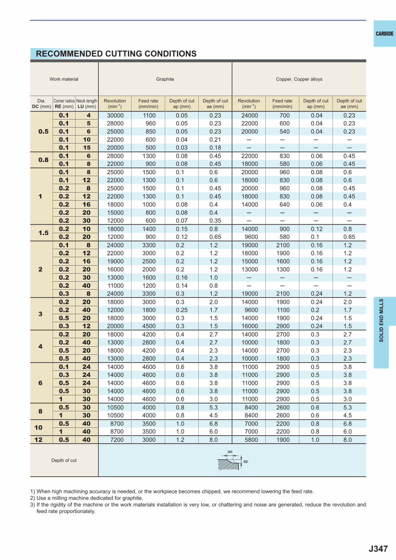
J347
0.5
0.1 4 30000 1100 0.05 0.23 24000 700 0.04 0.230.1 5 28000 960 0.05 0.23 22000 600 0.04 0.230.1 6 25000 850 0.05 0.23 20000 540 0.04 0.230.1 10 22000 600 0.04 0.21 ─ ─ ─ ─0.1 15 20000 500 0.03 0.18 ─ ─ ─ ─
0.8 0.1 6 28000 1300 0.08 0.45 22000 830 0.06 0.450.1 8 22000 900 0.08 0.45 18000 580 0.06 0.45
1
0.1 8 25000 1500 0.1 0.6 20000 960 0.08 0.60.1 12 22000 1300 0.1 0.6 18000 830 0.08 0.60.2 8 25000 1500 0.1 0.45 20000 960 0.08 0.450.2 12 22000 1300 0.1 0.45 18000 830 0.08 0.450.2 16 18000 1000 0.08 0.4 14000 640 0.06 0.40.2 20 15000 800 0.08 0.4 ─ ─ ─ ─0.2 30 12000 600 0.07 0.35 ─ ─ ─ ─
1.5 0.2 10 18000 1400 0.15 0.8 14000 900 0.12 0.80.2 20 12000 900 0.12 0.65 9600 580 0.1 0.65
2
0.1 8 24000 3300 0.2 1.2 19000 2100 0.16 1.20.2 12 22000 3000 0.2 1.2 18000 1900 0.16 1.20.2 16 19000 2500 0.2 1.2 15000 1600 0.16 1.20.2 20 16000 2000 0.2 1.2 13000 1300 0.16 1.20.2 30 13000 1600 0.16 1.0 ─ ─ ─ ─0.2 40 11000 1200 0.14 0.8 ─ ─ ─ ─0.3 8 24000 3300 0.3 1.2 19000 2100 0.24 1.2
3
0.2 20 18000 3000 0.3 2.0 14000 1900 0.24 2.00.2 40 12000 1800 0.25 1.7 9600 1100 0.2 1.70.5 20 18000 3000 0.3 1.5 14000 1900 0.24 1.50.3 12 20000 4500 0.3 1.5 16000 2900 0.24 1.5
4
0.2 20 18000 4200 0.4 2.7 14000 2700 0.3 2.70.2 40 13000 2800 0.4 2.7 10000 1800 0.3 2.70.5 20 18000 4200 0.4 2.3 14000 2700 0.3 2.30.5 40 13000 2800 0.4 2.3 10000 1800 0.3 2.3
6
0.1 24 14000 4600 0.6 3.8 11000 2900 0.5 3.80.3 24 14000 4600 0.6 3.8 11000 2900 0.5 3.80.5 24 14000 4600 0.6 3.8 11000 2900 0.5 3.80.5 30 14000 4600 0.6 3.8 11000 2900 0.5 3.81 30 14000 4600 0.6 3.0 11000 2900 0.5 3.0
8 0.5 30 10500 4000 0.8 5.3 8400 2600 0.6 5.31 30 10500 4000 0.8 4.5 8400 2600 0.6 4.5
10 0.5 40 8700 3500 1.0 6.8 7000 2200 0.8 6.81 40 8700 3500 1.0 6.0 7000 2200 0.8 6.0
12 0.5 40 7200 3000 1.2 8.0 5800 1900 1.0 8.0
ap
ae
CARBIDE
SOLI
D E
ND
MIL
LS
1) When high machining accuracy is needed, or the workpiece becomes chipped, we recommend lowering the feed rate.2) Use a milling machine dedicated for graphite.3) If the rigidity of the machine or the work materials installation is very low, or chattering and noise are generated, reduce the revolution and
feed rate proportionately.
RECOMMENDED CUTTING CONDITIONS
Work material Graphite Copper, Copper alloys
Dia.DC (mm)
Corner radiusRE (mm)
Neck lengthLU (mm)
Revolution(min-1)
Feed rate(mm/min)
Depth of cutap (mm)
Depth of cutae (mm)
Revolution(min-1)
Feed rate(mm/min)
Depth of cutap (mm)
Depth of cutae (mm)
Depth of cut
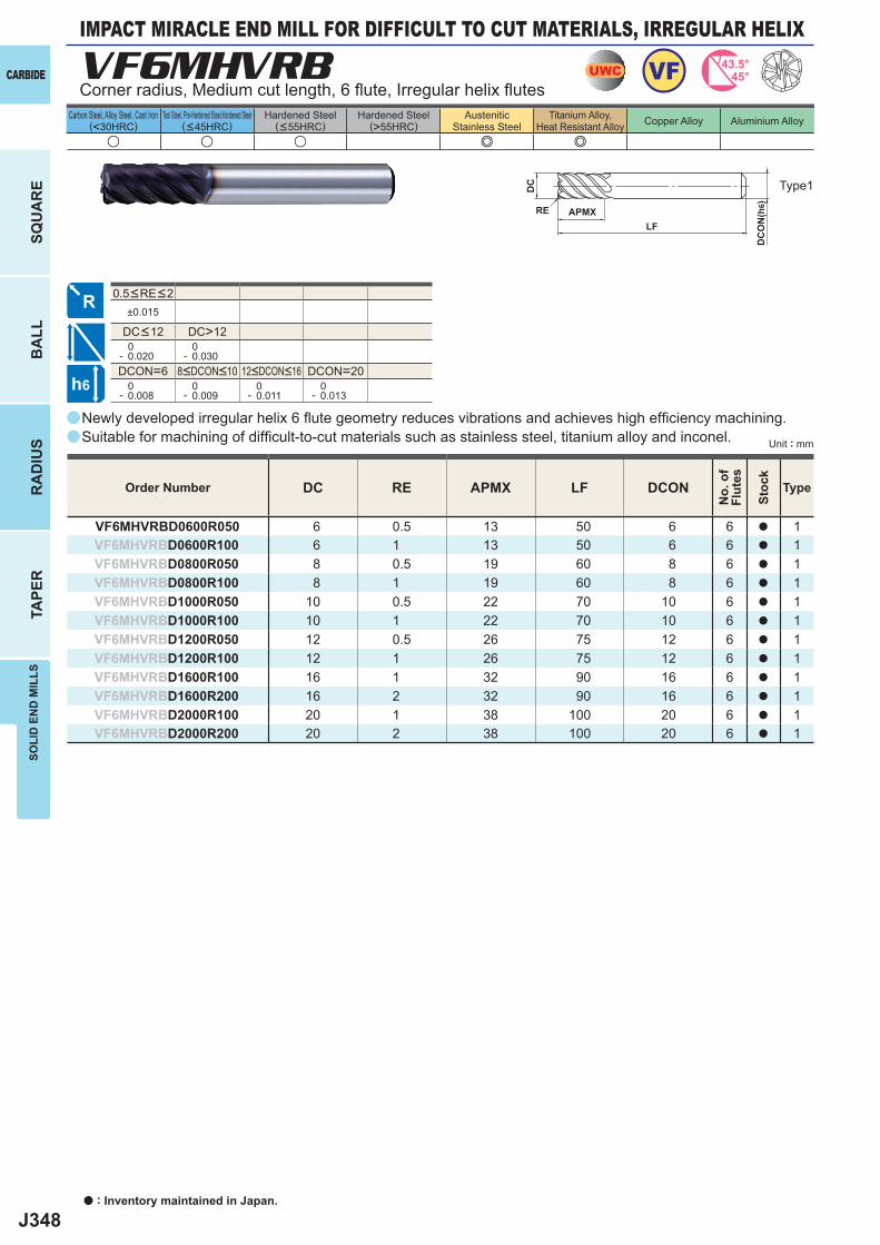
J348
a
VF6MHVRB
u u u e e
DC RE APMX LF DCON
VF6MHVRBD0600R050 6 0.5 13 50 6 6 a 1VF6MHVRBD0600R100 6 1 13 50 6 6 a 1VF6MHVRBD0800R050 8 0.5 19 60 8 6 a 1VF6MHVRBD0800R100 8 1 19 60 8 6 a 1VF6MHVRBD1000R050 10 0.5 22 70 10 6 a 1VF6MHVRBD1000R100 10 1 22 70 10 6 a 1VF6MHVRBD1200R050 12 0.5 26 75 12 6 a 1VF6MHVRBD1200R100 12 1 26 75 12 6 a 1VF6MHVRBD1600R100 16 1 32 90 16 6 a 1VF6MHVRBD1600R200 16 2 32 90 16 6 a 1VF6MHVRBD2000R100 20 1 38 100 20 6 a 1VF6MHVRBD2000R200 20 2 38 100 20 6 a 1
±0.015
DC>12 0- 0.020
0- 0.030
DCON=6 DCON=20 0- 0.008
0- 0.009
0- 0.011
0- 0.013
a
a
UWC VF 43.5°45°
h6
APMX
DC
DC
ON
(h6)
LFRE
a : Inventory maintained in Japan.
CARBIDE
SQU
AR
EB
ALL
RA
DIU
STA
PER
SOLI
D E
ND
MIL
LS
Unit : mm
Carbon Steel, Alloy Steel, Cast Iron(<30HRC)
Tool Steel, Pre-Hardened Steel,Hardened Steel(<45HRC)
Hardened Steel(<55HRC)
Hardened Steel(>55HRC)
AusteniticStainless Steel
Titanium Alloy,Heat Resistant Alloy Copper Alloy Aluminium Alloy
Newly developed irregular helix 6 fl ute geometry reduces vibrations and achieves high effi ciency machining. Suitable for machining of diffi cult-to-cut materials such as stainless steel, titanium alloy and inconel.
Corner radius, Medium cut length, 6 fl ute, Irregular helix fl utes
IMPACT MIRACLE END MILL FOR DIFFICULT TO CUT MATERIALS, IRREGULAR HELIX
Type1
Order Number
No.
of
Flut
es
Stoc
k
Type
8<DCON<10 12<DCON<16
0.5<RE<2
DC<12
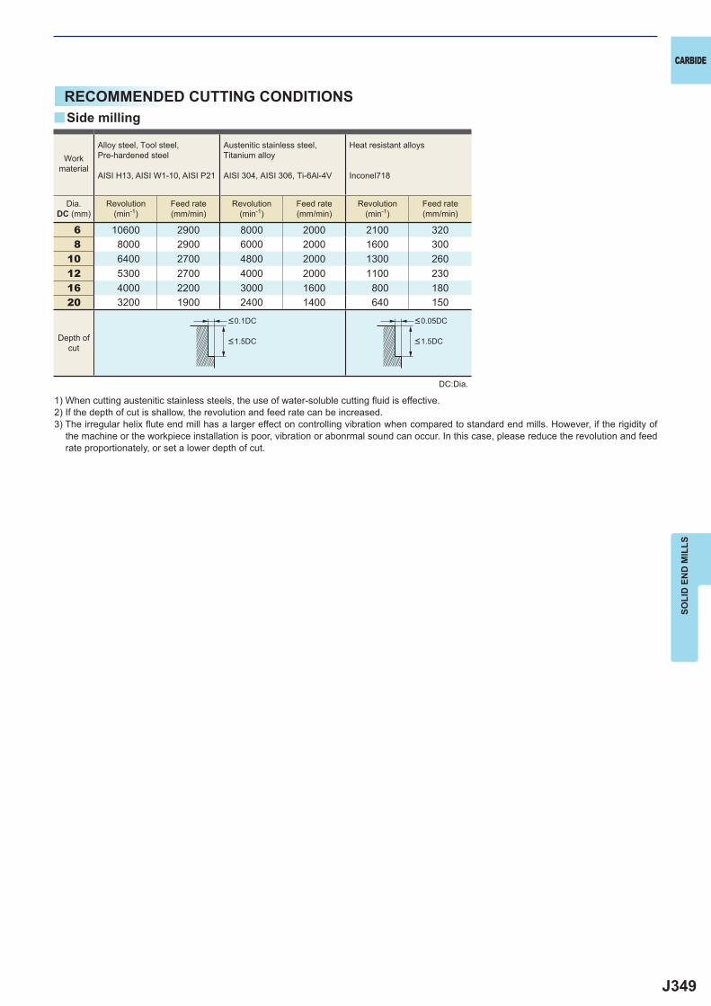
J349
6 10600 2900 8000 2000 2100 3208 8000 2900 6000 2000 1600 300
10 6400 2700 4800 2000 1300 26012 5300 2700 4000 2000 1100 23016 4000 2200 3000 1600 800 18020 3200 1900 2400 1400 640 150
y
CARBIDE
SOLI
D E
ND
MIL
LS
RECOMMENDED CUTTING CONDITIONS
1) When cutting austenitic stainless steels, the use of water-soluble cutting fl uid is effective.2) If the depth of cut is shallow, the revolution and feed rate can be increased.3) The irregular helix fl ute end mill has a larger effect on controlling vibration when compared to standard end mills. However, if the rigidity of
the machine or the workpiece installation is poor, vibration or abonrmal sound can occur. In this case, please reduce the revolution and feed rate proportionately, or set a lower depth of cut.
DC:Dia.
Side milling
Workmaterial
Alloy steel, Tool steel,Pre-hardened steel
AISI H13, AISI W1-10, AISI P21
Austenitic stainless steel,Titanium alloy
AISI 304, AISI 306, Ti-6Al-4V
Heat resistant alloys
Inconel718
Dia.DC (mm)
Revolution(min-1)
Revolution(min-1)
Revolution(min-1)
Feed rate(mm/min)
Feed rate(mm/min)
Feed rate(mm/min)
Depth ofcut
<0.1DC <0.05DC
<1.5DC <1.5DC
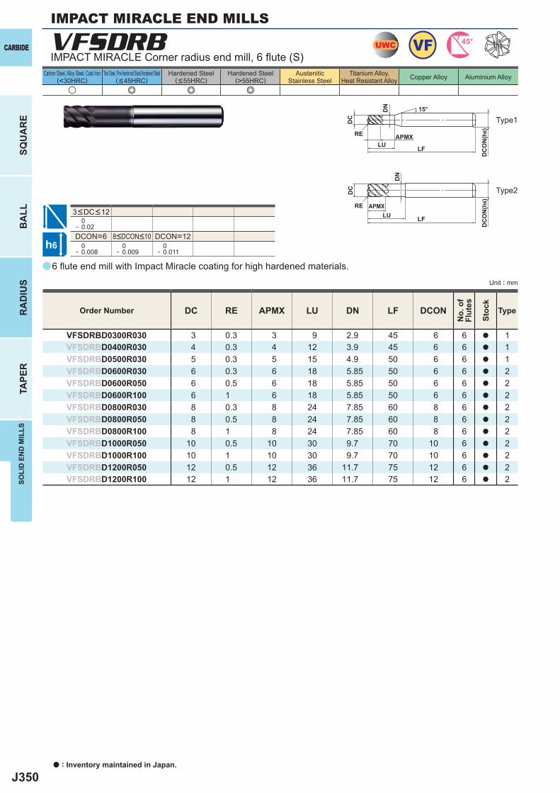
J350
a
VFSDRB
u e e e
DC RE APMX LU DN LF DCON
VFSDRBD0300R030 3 0.3 3 9 2.9 45 6 6 a 1VFSDRBD0400R030 4 0.3 4 12 3.9 45 6 6 a 1VFSDRBD0500R030 5 0.3 5 15 4.9 50 6 6 a 1VFSDRBD0600R030 6 0.3 6 18 5.85 50 6 6 a 2VFSDRBD0600R050 6 0.5 6 18 5.85 50 6 6 a 2VFSDRBD0600R100 6 1 6 18 5.85 50 6 6 a 2VFSDRBD0800R030 8 0.3 8 24 7.85 60 8 6 a 2VFSDRBD0800R050 8 0.5 8 24 7.85 60 8 6 a 2VFSDRBD0800R100 8 1 8 24 7.85 60 8 6 a 2VFSDRBD1000R050 10 0.5 10 30 9.7 70 10 6 a 2VFSDRBD1000R100 10 1 10 30 9.7 70 10 6 a 2VFSDRBD1200R050 12 0.5 12 36 11.7 75 12 6 a 2VFSDRBD1200R100 12 1 12 36 11.7 75 12 6 a 2
0- 0.02DCON=6 DCON=12 0- 0.008
0- 0.009
0- 0.011
UWC VF 45°
h6
APMX
DC
DC
ON
(h6)
15°
LF
RE
APMX
DC
LF
RELU
DN
DC
ON
(h6)
LU
DN
a : Inventory maintained in Japan.
CARBIDE
SQU
AR
EB
ALL
RA
DIU
STA
PER
SOLI
D E
ND
MIL
LS
Unit : mm
Carbon Steel, Alloy Steel, Cast Iron(<30HRC)
Tool Steel, Pre-Hardened Steel,Hardened Steel(<45HRC)
Hardened Steel(<55HRC)
Hardened Steel(>55HRC)
AusteniticStainless Steel
Titanium Alloy,Heat Resistant Alloy Copper Alloy Aluminium Alloy
3<DC<12
6 fl ute end mill with Impact Miracle coating for high hardened materials.
IMPACT MIRACLE Corner radius end mill, 6 fl ute (S)
Type2
Type1
Order Number
No.
of
Flut
es
Stoc
k
Type
8<DCON<10
IMPACT MIRACLE END MILLS

J351
a
VFMDRB
u e e e
DC RE APMX LF DCON
VFMDRBD0300R030 3 0.3 10 60 6 6 a 1VFMDRBD0400R030 4 0.3 12 60 6 6 a 1VFMDRBD0500R030 5 0.3 15 60 6 6 a 1VFMDRBD0600R030 6 0.3 15 60 6 6 a 2VFMDRBD0600R050 6 0.5 15 60 6 6 a 2VFMDRBD0600R100 6 1 15 60 6 6 a 2VFMDRBD0800R030 8 0.3 20 75 8 6 a 2VFMDRBD0800R050 8 0.5 20 75 8 6 a 2VFMDRBD0800R100 8 1 20 75 8 6 a 2VFMDRBD1000R030 10 0.3 25 80 10 6 a 2VFMDRBD1000R050 10 0.5 25 80 10 6 a 2VFMDRBD1000R100 10 1 25 80 10 6 a 2VFMDRBD1200R050 12 0.5 30 100 12 6 a 2VFMDRBD1200R100 12 1 30 100 12 6 a 2VFMDRBD1600R100 16 1 40 110 16 6 a 2VFMDRBD1600R150 16 1.5 40 110 16 6 a 2VFMDRBD1800R100 18 1 40 120 16 6 a 3VFMDRBD1800R150 18 1.5 40 120 16 6 a 3VFMDRBD2000R100 20 1 45 125 20 6 a 2VFMDRBD2000R150 20 1.5 45 125 20 6 a 2VFMDRBD2000R200 20 2 45 125 20 6 a 2
DC>12 0- 0.02
0- 0.03
DCON=6 DCON=20 0- 0.008
0- 0.009
0- 0.011
0- 0.013
UWC VF 45°
h6
APMX
DC
DC
ON
(h6)15°
LFRE
APMX
DC
DC
ON
(h6)
LFRE
APMX
DC
DC
ON
(h6)
LFRE
CARBIDE
SQU
AR
EB
ALL
RA
DIU
STA
PER
SOLI
D E
ND
MIL
LS
Unit : mm
Carbon Steel, Alloy Steel, Cast Iron(<30HRC)
Tool Steel, Pre-Hardened Steel,Hardened Steel(<45HRC)
Hardened Steel(<55HRC)
Hardened Steel(>55HRC)
AusteniticStainless Steel
Titanium Alloy,Heat Resistant Alloy Copper Alloy Aluminium Alloy
6 fl ute corner radius end mill with Impact Miracle coating for high hardened materials.
Corner radius, Medium cut length, 6 fl ute, For hardened materials
Type2
Type3
Type1
Order Number
No.
of
Flut
es
Stoc
k
Type
8<DCON<10 12<DCON<16
DC<12
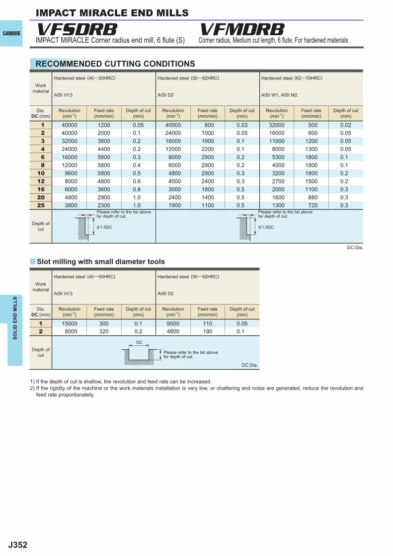
J352
VFSDRB VFMDRB
1 40000 1200 0.05 40000 800 0.03 32000 500 0.022 40000 2000 0.1 24000 1000 0.05 16000 600 0.053 32000 3800 0.2 16000 1900 0.1 11000 1200 0.054 24000 4400 0.2 12000 2200 0.1 8000 1300 0.056 16000 5800 0.3 8000 2900 0.2 5300 1800 0.1 8 12000 5800 0.4 6000 2900 0.2 4000 1800 0.1
10 9600 5800 0.5 4800 2900 0.3 3200 1800 0.2 12 8000 4800 0.6 4000 2400 0.3 2700 1500 0.2 16 6000 3600 0.8 3000 1800 0.5 2000 1100 0.3 20 4800 2900 1.0 2400 1400 0.5 1600 880 0.3 25 3800 2300 1.0 1900 1100 0.5 1300 720 0.3
1 15000 300 0.1 9500 110 0.052 8000 320 0.2 4800 190 0.1
y
DC
CARBIDE
SOLI
D E
ND
MIL
LS
IMPACT MIRACLE Corner radius end mill, 6 fl ute (S) Corner radius, Medium cut length, 6 fl ute, For hardened materials
RECOMMENDED CUTTING CONDITIONS
1) If the depth of cut is shallow, the revolution and feed rate can be increased.2) If the rigidity of the machine or the work materials installation is very low, or chattering and noise are generated, reduce the revolution and
feed rate proportionately.
DC:Dia.
DC:Dia.
Please refer to the list abovefor depth of cut.
Please refer to the list abovefor depth of cut.
Please refer to the list abovefor depth of cut.
Slot milling with small diameter tools
Workmaterial
Hardened steel (45─ 55HRC)
AISI H13
Hardened steel (55─ 62HRC)
AISI D2
Hardened steel (62─70HRC)
AISI W1, AISI M2
Dia.DC (mm)
Dia.DC (mm)
Revolution(min-1)
Revolution(min-1)
Revolution(min-1)
Revolution(min-1)
Revolution(min-1)
Feed rate(mm/min)
Feed rate(mm/min)
Feed rate(mm/min)
Feed rate(mm/min)
Feed rate(mm/min)
Depth of cut(mm)
Depth of cut(mm)
Depth of cut(mm)
Depth of cut(mm)
Depth of cut(mm)
Depth ofcut
Depth ofcut
<1.5DC <1.0DC
Workmaterial
Hardened steel (45─ 55HRC)
AISI H13
Hardened steel (55─ 62HRC)
AISI D2
IMPACT MIRACLE END MILLS
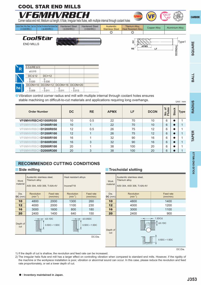
J353
a
e e
VF6MHVRBCH
DC RE APMX LF DCON
VF6MHVRBCHD1000R050 10 0.5 22 70 10 6 a 1VF6MHVRBCHD1000R100 10 1 22 70 10 6 a 1VF6MHVRBCHD1200R050 12 0.5 26 75 12 6 a 1VF6MHVRBCHD1200R100 12 1 26 75 12 6 a 1VF6MHVRBCHD1600R100 16 1 32 90 16 6 a 1VF6MHVRBCHD1600R300 16 3 32 90 16 6 a 1VF6MHVRBCHD2000R100 20 1 38 100 20 6 a 1VF6MHVRBCHD2000R300 20 3 38 100 20 6 a 1
±0.015
DC>12 0- 0.020
0- 0.030
DCON=10 DCON=12 DCON=16 DCON=20 0- 0.009
0- 0.011
0- 0.011
0- 0.013
10 4800 2000 1300 26012 4000 2000 1100 23016 3000 1600 800 18020 2400 1400 640 150
0.5DC─1.5DC 0.5DC─1.5DC
y y
10 4800 140012 4000 120016 3000 110020 2400 900
0.5DC─1.5DC
UWC VF 43.5°45°
h6
APMX
DC
DC
ON
(h6)
LFRE
CARBIDE
SQU
AR
EB
ALL
RA
DIU
STA
PER
SOLI
D E
ND
MIL
LS
Unit : mm
Carbon Steel, Alloy Steel, Cast Iron(<30HRC)
Tool Steel, Pre-Hardened Steel,Hardened Steel(<45HRC)
Hardened Steel(<55HRC)
Hardened Steel(>55HRC)
AusteniticStainless Steel
Titanium Alloy,Heat Resistant Alloy Copper Alloy Aluminium Alloy
0.5<RE<3
CoolStarEND MILLS
Vibration control corner radius end mill with multiple internal through coolant holes ensures stable machining on diffi cult-to-cut materials and applications requiring long overhangs.
Type1
Corner radius end mill, Medium cut length, 6 fl ute, Irregular helix fl utes, with multiple internal through coolant holes
Order Number
No.
of
Flut
es
Stoc
k
Type
DC<12
COOL STAR END MILLS
RECOMMENDED CUTTING CONDITIONS
DC:Dia.
1) If the depth of cut is shallow, the revolution and feed rate can be increased.2) The irregular helix fl ute end mill has a larger effect on controlling vibration when compared to standard end mills. However, if the rigidity of
the machine or the workpiece installation is poor, vibration or abonrmal sound can occur. In this case, please reduce the revolution and feed rate proportionately, or set a lower depth of cut.
Side milling
Workmaterial
Austenitic stainless steel,Titanium alloy
AISI 304, AISI 306, Ti-6Al-4V
Heat resistant alloys
Inconel718
Dia.DC (mm)
Revolution(min-1)
Revolution(min-1)
Feed rate(mm/min)
Feed rate(mm/min)
Depth ofcut
<0.1DC <0.05DC
Trochoidal slotting
<0.1DC
1.5DC<
Workmaterial
Austenitic stainless steel,Titanium alloy
AISI 304, AISI 306, Ti-6Al-4V
Dia.DC (mm)
Revolution(min-1)
Feed rate(mm/min)
Depth ofcut
DC:Dia.
a : Inventory maintained in Japan.
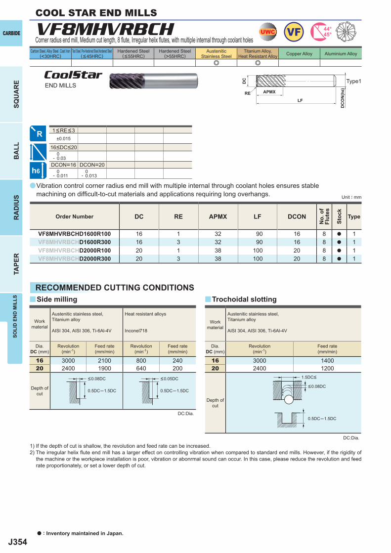
J354
a
e e
VF8MHVRBCH
DC RE APMX LF DCON
VF8MHVRBCHD1600R100 16 1 32 90 16 8 a 1VF8MHVRBCHD1600R300 16 3 32 90 16 8 a 1VF8MHVRBCHD2000R100 20 1 38 100 20 8 a 1VF8MHVRBCHD2000R300 20 3 38 100 20 8 a 1
±0.015
0- 0.03
DCON=16 DCON=20 0- 0.011
0- 0.013
16 3000 2100 800 24020 2400 1900 640 200
0.5DC─1.5DC 0.5DC─1.5DC
y y
16 3000 140020 2400 1200
0.5DC─1.5DC
UWC VF 44°45°
h6
APMX
DC
DC
ON
(h6)
LFRE
a : Inventory maintained in Japan.
CARBIDE
SQU
AR
EB
ALL
RA
DIU
STA
PER
SOLI
D E
ND
MIL
LS
Unit : mm
Carbon Steel, Alloy Steel, Cast Iron(<30HRC)
Tool Steel, Pre-Hardened Steel,Hardened Steel(<45HRC)
Hardened Steel(<55HRC)
Hardened Steel(>55HRC)
AusteniticStainless Steel
Titanium Alloy,Heat Resistant Alloy Copper Alloy Aluminium Alloy
CoolStarEND MILLS
Vibration control corner radius end mill with multiple internal through coolant holes ensures stable machining on diffi cult-to-cut materials and applications requiring long overhangs.
Type1
Corner radius end mill, Medium cut length, 8 fl ute, Irregular helix fl utes, with multiple internal through coolant holes
Order Number
No.
of
Flut
es
Stoc
k
Type
1<RE<3
RECOMMENDED CUTTING CONDITIONS
DC:Dia.
1) If the depth of cut is shallow, the revolution and feed rate can be increased.2) The irregular helix fl ute end mill has a larger effect on controlling vibration when compared to standard end mills. However, if the rigidity of
the machine or the workpiece installation is poor, vibration or abonrmal sound can occur. In this case, please reduce the revolution and feed rate proportionately, or set a lower depth of cut.
Side milling
Workmaterial
Austenitic stainless steel,Titanium alloy
AISI 304, AISI 306, Ti-6Al-4V
Heat resistant alloys
Inconel718
Dia.DC (mm)
Revolution(min-1)
Revolution(min-1)
Feed rate(mm/min)
Feed rate(mm/min)
Depth ofcut
<0.08DC <0.05DC
Trochoidal slotting
DC:Dia.
Workmaterial
Austenitic stainless steel,Titanium alloy
AISI 304, AISI 306, Ti-6Al-4V
Dia.DC (mm)
Revolution(min-1)
Feed rate(mm/min)
Depth ofcut
<0.08DC
1.5DC<
16<DC<20
COOL STAR END MILLS
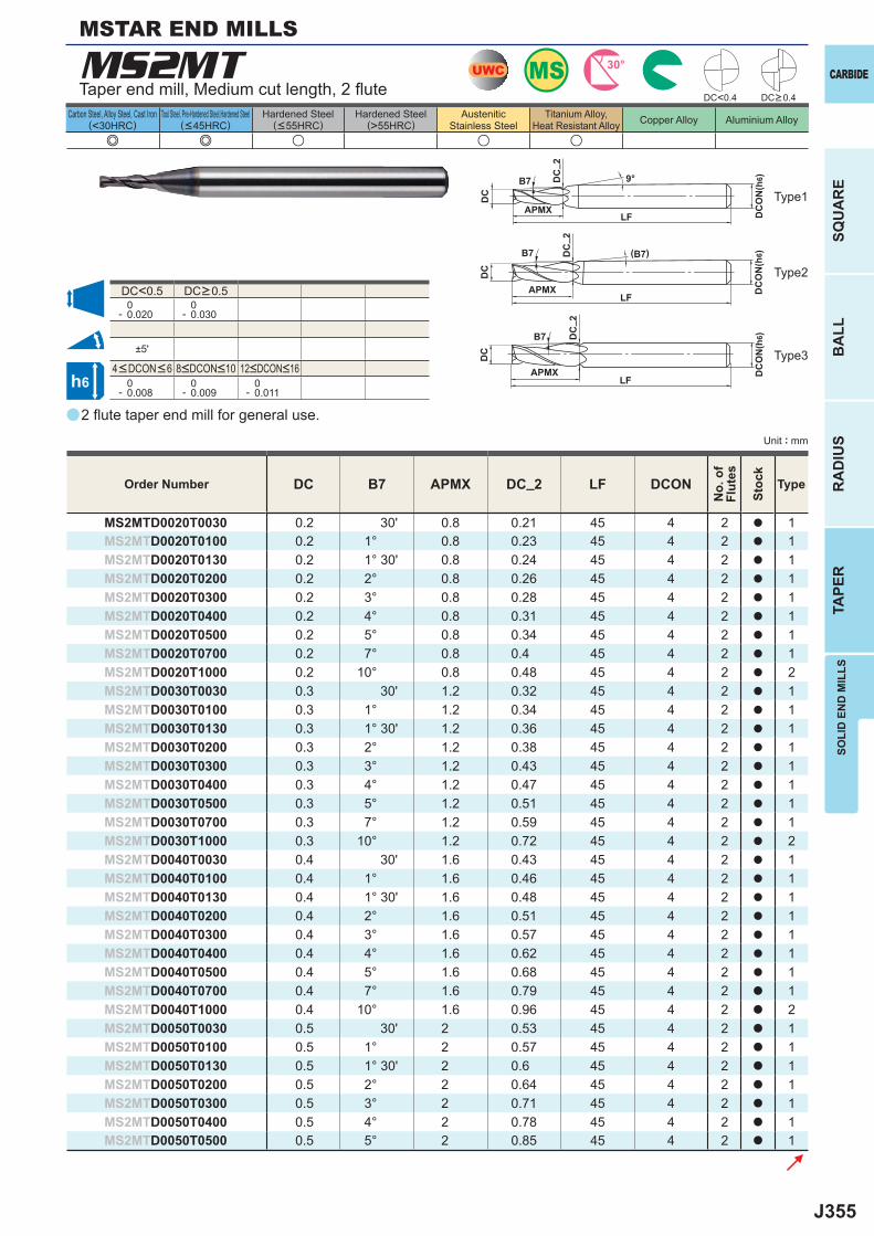
J355
a
(<30HRC) (>55HRC)
MS2MT
e e u u u
DC B7 APMX DC_2 LF DCON
MS2MTD0020T0030 0.2 30' 0.8 0.21 45 4 2 a 1MS2MTD0020T0100 0.2 1° 0.8 0.23 45 4 2 a 1MS2MTD0020T0130 0.2 1° 30' 0.8 0.24 45 4 2 a 1MS2MTD0020T0200 0.2 2° 0.8 0.26 45 4 2 a 1MS2MTD0020T0300 0.2 3° 0.8 0.28 45 4 2 a 1MS2MTD0020T0400 0.2 4° 0.8 0.31 45 4 2 a 1MS2MTD0020T0500 0.2 5° 0.8 0.34 45 4 2 a 1MS2MTD0020T0700 0.2 7° 0.8 0.4 45 4 2 a 1MS2MTD0020T1000 0.2 10° 0.8 0.48 45 4 2 a 2MS2MTD0030T0030 0.3 30' 1.2 0.32 45 4 2 a 1MS2MTD0030T0100 0.3 1° 1.2 0.34 45 4 2 a 1MS2MTD0030T0130 0.3 1° 30' 1.2 0.36 45 4 2 a 1MS2MTD0030T0200 0.3 2° 1.2 0.38 45 4 2 a 1MS2MTD0030T0300 0.3 3° 1.2 0.43 45 4 2 a 1MS2MTD0030T0400 0.3 4° 1.2 0.47 45 4 2 a 1MS2MTD0030T0500 0.3 5° 1.2 0.51 45 4 2 a 1MS2MTD0030T0700 0.3 7° 1.2 0.59 45 4 2 a 1MS2MTD0030T1000 0.3 10° 1.2 0.72 45 4 2 a 2MS2MTD0040T0030 0.4 30' 1.6 0.43 45 4 2 a 1MS2MTD0040T0100 0.4 1° 1.6 0.46 45 4 2 a 1MS2MTD0040T0130 0.4 1° 30' 1.6 0.48 45 4 2 a 1MS2MTD0040T0200 0.4 2° 1.6 0.51 45 4 2 a 1MS2MTD0040T0300 0.4 3° 1.6 0.57 45 4 2 a 1MS2MTD0040T0400 0.4 4° 1.6 0.62 45 4 2 a 1MS2MTD0040T0500 0.4 5° 1.6 0.68 45 4 2 a 1MS2MTD0040T0700 0.4 7° 1.6 0.79 45 4 2 a 1MS2MTD0040T1000 0.4 10° 1.6 0.96 45 4 2 a 2MS2MTD0050T0030 0.5 30' 2 0.53 45 4 2 a 1MS2MTD0050T0100 0.5 1° 2 0.57 45 4 2 a 1MS2MTD0050T0130 0.5 1° 30' 2 0.6 45 4 2 a 1MS2MTD0050T0200 0.5 2° 2 0.64 45 4 2 a 1MS2MTD0050T0300 0.5 3° 2 0.71 45 4 2 a 1MS2MTD0050T0400 0.5 4° 2 0.78 45 4 2 a 1MS2MTD0050T0500 0.5 5° 2 0.85 45 4 2 a 1
DC<0.5 0- 0.020
0- 0.030
±5'
0- 0.008
0- 0.009
0- 0.011
DC<0.4
UWC MS 30°
h6
APMX
DC
DC
ON
(h6)9°
APMXLF
DC
DC
ON
(h6)
LF
(B7)
DC
_ 2D
C_ 2
B7
B7
APMXLF
DC
DC
ON
(h6)D
C_ 2
B7
SOLI
D E
ND
MIL
LS
CARBIDE
SQU
AR
EB
ALL
RA
DIU
STA
PER
Unit : mm
Carbon Steel, Alloy Steel, Cast Iron Tool Steel, Pre-Hardened Steel,Hardened Steel(<45HRC)
Hardened Steel(<55HRC)
Hardened Steel AusteniticStainless Steel
Titanium Alloy,Heat Resistant Alloy Copper Alloy Aluminium Alloy
2 fl ute taper end mill for general use.
Taper end mill, Medium cut length, 2 fl ute
Type2
Type1
Type3
MSTAR END MILLS
DC>0.4
Order Number
No.
of
Flut
es
Stoc
k
Type
4<DCON<6 8<DCON<10 12<DCON<16
DC>0.5
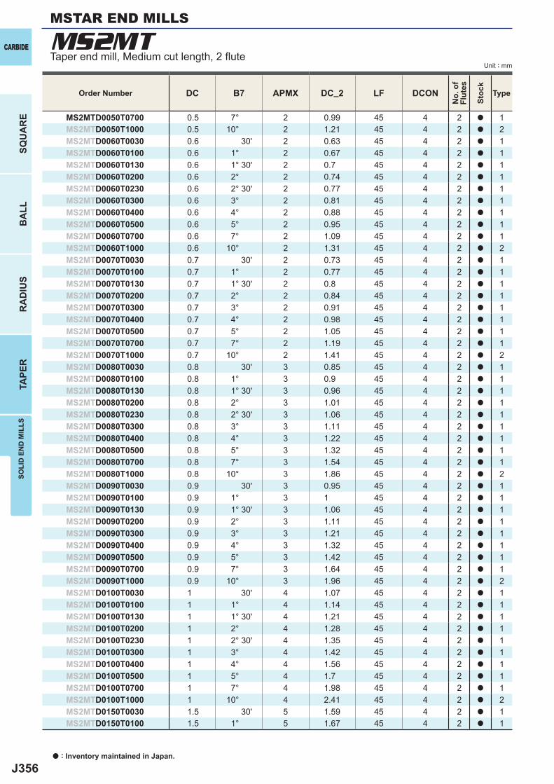
J356
DC B7 APMX DC_2 LF DCON
MS2MTD0050T0700 0.5 7° 2 0.99 45 4 2 a 1MS2MTD0050T1000 0.5 10° 2 1.21 45 4 2 a 2MS2MTD0060T0030 0.6 30' 2 0.63 45 4 2 a 1MS2MTD0060T0100 0.6 1° 2 0.67 45 4 2 a 1MS2MTD0060T0130 0.6 1° 30' 2 0.7 45 4 2 a 1MS2MTD0060T0200 0.6 2° 2 0.74 45 4 2 a 1MS2MTD0060T0230 0.6 2° 30' 2 0.77 45 4 2 a 1MS2MTD0060T0300 0.6 3° 2 0.81 45 4 2 a 1MS2MTD0060T0400 0.6 4° 2 0.88 45 4 2 a 1MS2MTD0060T0500 0.6 5° 2 0.95 45 4 2 a 1MS2MTD0060T0700 0.6 7° 2 1.09 45 4 2 a 1MS2MTD0060T1000 0.6 10° 2 1.31 45 4 2 a 2MS2MTD0070T0030 0.7 30' 2 0.73 45 4 2 a 1MS2MTD0070T0100 0.7 1° 2 0.77 45 4 2 a 1MS2MTD0070T0130 0.7 1° 30' 2 0.8 45 4 2 a 1MS2MTD0070T0200 0.7 2° 2 0.84 45 4 2 a 1MS2MTD0070T0300 0.7 3° 2 0.91 45 4 2 a 1MS2MTD0070T0400 0.7 4° 2 0.98 45 4 2 a 1MS2MTD0070T0500 0.7 5° 2 1.05 45 4 2 a 1MS2MTD0070T0700 0.7 7° 2 1.19 45 4 2 a 1MS2MTD0070T1000 0.7 10° 2 1.41 45 4 2 a 2MS2MTD0080T0030 0.8 30' 3 0.85 45 4 2 a 1MS2MTD0080T0100 0.8 1° 3 0.9 45 4 2 a 1MS2MTD0080T0130 0.8 1° 30' 3 0.96 45 4 2 a 1MS2MTD0080T0200 0.8 2° 3 1.01 45 4 2 a 1MS2MTD0080T0230 0.8 2° 30' 3 1.06 45 4 2 a 1MS2MTD0080T0300 0.8 3° 3 1.11 45 4 2 a 1MS2MTD0080T0400 0.8 4° 3 1.22 45 4 2 a 1MS2MTD0080T0500 0.8 5° 3 1.32 45 4 2 a 1MS2MTD0080T0700 0.8 7° 3 1.54 45 4 2 a 1MS2MTD0080T1000 0.8 10° 3 1.86 45 4 2 a 2MS2MTD0090T0030 0.9 30' 3 0.95 45 4 2 a 1MS2MTD0090T0100 0.9 1° 3 1 45 4 2 a 1MS2MTD0090T0130 0.9 1° 30' 3 1.06 45 4 2 a 1MS2MTD0090T0200 0.9 2° 3 1.11 45 4 2 a 1MS2MTD0090T0300 0.9 3° 3 1.21 45 4 2 a 1MS2MTD0090T0400 0.9 4° 3 1.32 45 4 2 a 1MS2MTD0090T0500 0.9 5° 3 1.42 45 4 2 a 1MS2MTD0090T0700 0.9 7° 3 1.64 45 4 2 a 1MS2MTD0090T1000 0.9 10° 3 1.96 45 4 2 a 2MS2MTD0100T0030 1 30' 4 1.07 45 4 2 a 1MS2MTD0100T0100 1 1° 4 1.14 45 4 2 a 1MS2MTD0100T0130 1 1° 30' 4 1.21 45 4 2 a 1MS2MTD0100T0200 1 2° 4 1.28 45 4 2 a 1MS2MTD0100T0230 1 2° 30' 4 1.35 45 4 2 a 1MS2MTD0100T0300 1 3° 4 1.42 45 4 2 a 1MS2MTD0100T0400 1 4° 4 1.56 45 4 2 a 1MS2MTD0100T0500 1 5° 4 1.7 45 4 2 a 1MS2MTD0100T0700 1 7° 4 1.98 45 4 2 a 1MS2MTD0100T1000 1 10° 4 2.41 45 4 2 a 2MS2MTD0150T0030 1.5 30' 5 1.59 45 4 2 a 1MS2MTD0150T0100 1.5 1° 5 1.67 45 4 2 a 1
MS2MTCARBIDE
SQU
AR
EB
ALL
RA
DIU
STA
PER
SOLI
D E
ND
MIL
LS
Unit : mm
MSTAR END MILLS
Taper end mill, Medium cut length, 2 fl ute
a : Inventory maintained in Japan.
Order Number
No.
of
Flut
es
Stoc
k
Type
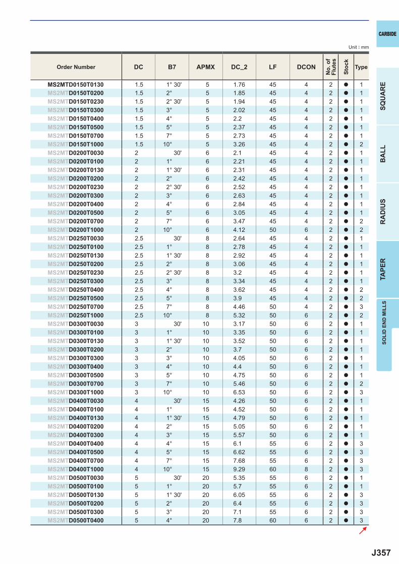
J357
DC B7 APMX DC_2 LF DCON
MS2MTD0150T0130 1.5 1° 30' 5 1.76 45 4 2 a 1MS2MTD0150T0200 1.5 2° 5 1.85 45 4 2 a 1MS2MTD0150T0230 1.5 2° 30' 5 1.94 45 4 2 a 1MS2MTD0150T0300 1.5 3° 5 2.02 45 4 2 a 1MS2MTD0150T0400 1.5 4° 5 2.2 45 4 2 a 1MS2MTD0150T0500 1.5 5° 5 2.37 45 4 2 a 1MS2MTD0150T0700 1.5 7° 5 2.73 45 4 2 a 1MS2MTD0150T1000 1.5 10° 5 3.26 45 4 2 a 2MS2MTD0200T0030 2 30' 6 2.1 45 4 2 a 1MS2MTD0200T0100 2 1° 6 2.21 45 4 2 a 1MS2MTD0200T0130 2 1° 30' 6 2.31 45 4 2 a 1MS2MTD0200T0200 2 2° 6 2.42 45 4 2 a 1MS2MTD0200T0230 2 2° 30' 6 2.52 45 4 2 a 1MS2MTD0200T0300 2 3° 6 2.63 45 4 2 a 1MS2MTD0200T0400 2 4° 6 2.84 45 4 2 a 1MS2MTD0200T0500 2 5° 6 3.05 45 4 2 a 1MS2MTD0200T0700 2 7° 6 3.47 45 4 2 a 2MS2MTD0200T1000 2 10° 6 4.12 50 6 2 a 2MS2MTD0250T0030 2.5 30' 8 2.64 45 4 2 a 1MS2MTD0250T0100 2.5 1° 8 2.78 45 4 2 a 1MS2MTD0250T0130 2.5 1° 30' 8 2.92 45 4 2 a 1MS2MTD0250T0200 2.5 2° 8 3.06 45 4 2 a 1MS2MTD0250T0230 2.5 2° 30' 8 3.2 45 4 2 a 1MS2MTD0250T0300 2.5 3° 8 3.34 45 4 2 a 1MS2MTD0250T0400 2.5 4° 8 3.62 45 4 2 a 2MS2MTD0250T0500 2.5 5° 8 3.9 45 4 2 a 2MS2MTD0250T0700 2.5 7° 8 4.46 50 4 2 a 3MS2MTD0250T1000 2.5 10° 8 5.32 50 6 2 a 2MS2MTD0300T0030 3 30' 10 3.17 50 6 2 a 1MS2MTD0300T0100 3 1° 10 3.35 50 6 2 a 1MS2MTD0300T0130 3 1° 30' 10 3.52 50 6 2 a 1MS2MTD0300T0200 3 2° 10 3.7 50 6 2 a 1MS2MTD0300T0300 3 3° 10 4.05 50 6 2 a 1MS2MTD0300T0400 3 4° 10 4.4 50 6 2 a 1MS2MTD0300T0500 3 5° 10 4.75 50 6 2 a 1MS2MTD0300T0700 3 7° 10 5.46 50 6 2 a 2MS2MTD0300T1000 3 10° 10 6.53 50 6 2 a 3MS2MTD0400T0030 4 30' 15 4.26 50 6 2 a 1MS2MTD0400T0100 4 1° 15 4.52 50 6 2 a 1MS2MTD0400T0130 4 1° 30' 15 4.79 50 6 2 a 1MS2MTD0400T0200 4 2° 15 5.05 50 6 2 a 1MS2MTD0400T0300 4 3° 15 5.57 50 6 2 a 1MS2MTD0400T0400 4 4° 15 6.1 55 6 2 a 3MS2MTD0400T0500 4 5° 15 6.62 55 6 2 a 3MS2MTD0400T0700 4 7° 15 7.68 55 6 2 a 3MS2MTD0400T1000 4 10° 15 9.29 60 8 2 a 3MS2MTD0500T0030 5 30' 20 5.35 55 6 2 a 1MS2MTD0500T0100 5 1° 20 5.7 55 6 2 a 1MS2MTD0500T0130 5 1° 30' 20 6.05 55 6 2 a 3MS2MTD0500T0200 5 2° 20 6.4 55 6 2 a 3MS2MTD0500T0300 5 3° 20 7.1 55 6 2 a 3MS2MTD0500T0400 5 4° 20 7.8 60 6 2 a 3
SOLI
D E
ND
MIL
LS
CARBIDE
SQU
AR
EB
ALL
RA
DIU
STA
PER
Unit : mm
Order Number
No.
of
Flut
es
Stoc
k
Type
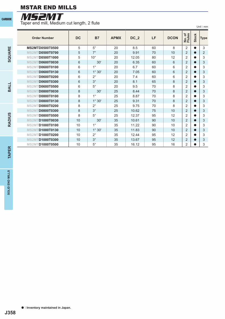
J358
DC B7 APMX DC_2 LF DCON
MS2MTD0500T0500 5 5° 20 8.5 60 8 2 a 3MS2MTD0500T0700 5 7° 20 9.91 70 10 2 a 2MS2MTD0500T1000 5 10° 20 12.05 80 12 2 a 3MS2MTD0600T0030 6 30' 20 6.35 60 6 2 a 3MS2MTD0600T0100 6 1° 20 6.7 60 6 2 a 3MS2MTD0600T0130 6 1° 30' 20 7.05 60 6 2 a 3MS2MTD0600T0200 6 2° 20 7.4 60 6 2 a 3MS2MTD0600T0300 6 3° 20 8.1 65 8 2 a 3MS2MTD0600T0500 6 5° 20 9.5 70 8 2 a 3MS2MTD0800T0030 8 30' 25 8.44 70 8 2 a 3MS2MTD0800T0100 8 1° 25 8.87 70 8 2 a 3MS2MTD0800T0130 8 1° 30' 25 9.31 70 8 2 a 3MS2MTD0800T0200 8 2° 25 9.75 70 8 2 a 3MS2MTD0800T0300 8 3° 25 10.62 75 10 2 a 3MS2MTD0800T0500 8 5° 25 12.37 95 12 2 a 3MS2MTD1000T0030 10 30' 35 10.61 90 10 2 a 3MS2MTD1000T0100 10 1° 35 11.22 90 10 2 a 3MS2MTD1000T0130 10 1° 30' 35 11.83 90 10 2 a 3MS2MTD1000T0200 10 2° 35 12.44 95 12 2 a 3MS2MTD1000T0300 10 3° 35 13.67 95 12 2 a 3MS2MTD1000T0500 10 5° 35 16.12 95 16 2 a 3
MS2MTCARBIDE
SQU
AR
EB
ALL
RA
DIU
STA
PER
SOLI
D E
ND
MIL
LS
Unit : mm
MSTAR END MILLS
Taper end mill, Medium cut length, 2 fl ute
Order Number
No.
of
Flut
es
Stoc
k
Type
a : Inventory maintained in Japan.
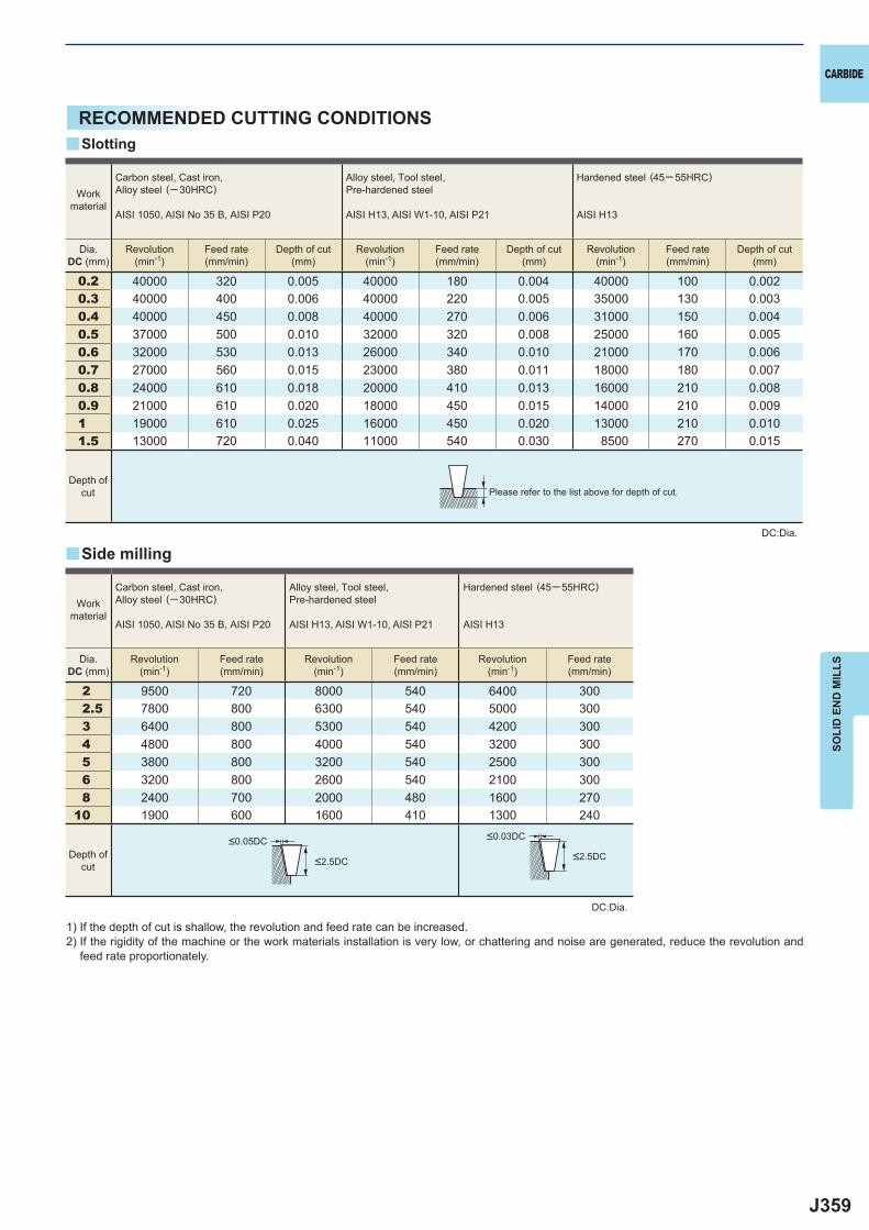
J359
0.2 40000 320 0.005 40000 180 0.004 40000 100 0.0020.3 40000 400 0.006 40000 220 0.005 35000 130 0.0030.4 40000 450 0.008 40000 270 0.006 31000 150 0.0040.5 37000 500 0.010 32000 320 0.008 25000 160 0.0050.6 32000 530 0.013 26000 340 0.010 21000 170 0.0060.7 27000 560 0.015 23000 380 0.011 18000 180 0.0070.8 24000 610 0.018 20000 410 0.013 16000 210 0.0080.9 21000 610 0.020 18000 450 0.015 14000 210 0.0091 19000 610 0.025 16000 450 0.020 13000 210 0.0101.5 13000 720 0.040 11000 540 0.030 8500 270 0.015
2 9500 720 8000 540 6400 3002.5 7800 800 6300 540 5000 3003 6400 800 5300 540 4200 3004 4800 800 4000 540 3200 3005 3800 800 3200 540 2500 3006 3200 800 2600 540 2100 3008 2400 700 2000 480 1600 270
10 1900 600 1600 410 1300 240
y
y
SOLI
D E
ND
MIL
LS
CARBIDE
RECOMMENDED CUTTING CONDITIONS
1) If the depth of cut is shallow, the revolution and feed rate can be increased.2) If the rigidity of the machine or the work materials installation is very low, or chattering and noise are generated, reduce the revolution and
feed rate proportionately.
DC:Dia.
Please refer to the list above for depth of cut.
Slotting
Side milling
Workmaterial
Carbon steel, Cast iron, Alloy steel (─30HRC)
AISI 1050, AISI No 35 B, AISI P20
Alloy steel, Tool steel,Pre-hardened steel
AISI H13, AISI W1-10, AISI P21
Hardened steel (45─ 55HRC)
AISI H13
Dia.DC (mm)
Revolution(min-1)
Feed rate(mm/min)
Depth of cut(mm)
Revolution(min-1)
Feed rate(mm/min)
Depth of cut(mm)
Revolution(min-1)
Feed rate(mm/min)
Depth of cut(mm)
Workmaterial
Carbon steel, Cast iron, Alloy steel (─30HRC)
AISI 1050, AISI No 35 B, AISI P20
Alloy steel, Tool steel,Pre-hardened steel
AISI H13, AISI W1-10, AISI P21
Hardened steel (45─ 55HRC)
AISI H13
Dia.DC (mm)
Revolution(min-1)
Feed rate(mm/min)
Revolution(min-1)
Feed rate(mm/min)
Revolution(min-1)
Feed rate(mm/min)
Depth ofcut
<0.05DC
<2.5DC
<0.03DC
<2.5DC
Depth ofcut
DC:Dia.
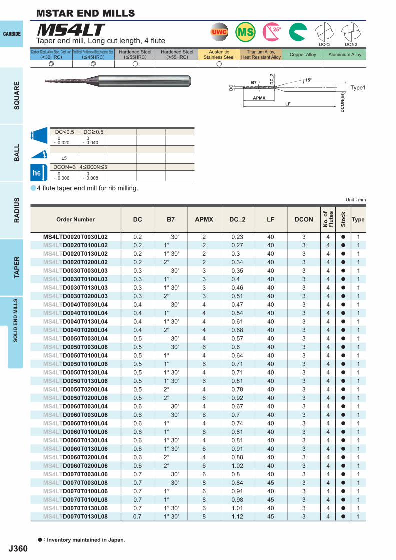
J360
a
(<30HRC) (>55HRC)
MS4LT
e e u u
DC B7 APMX DC_2 LF DCON
MS4LTD0020T0030L02 0.2 30' 2 0.23 40 3 4 a 1MS4LTD0020T0100L02 0.2 1° 2 0.27 40 3 4 a 1MS4LTD0020T0130L02 0.2 1° 30' 2 0.3 40 3 4 a 1MS4LTD0020T0200L02 0.2 2° 2 0.34 40 3 4 a 1MS4LTD0030T0030L03 0.3 30' 3 0.35 40 3 4 a 1MS4LTD0030T0100L03 0.3 1° 3 0.4 40 3 4 a 1MS4LTD0030T0130L03 0.3 1° 30' 3 0.46 40 3 4 a 1MS4LTD0030T0200L03 0.3 2° 3 0.51 40 3 4 a 1MS4LTD0040T0030L04 0.4 30' 4 0.47 40 3 4 a 1MS4LTD0040T0100L04 0.4 1° 4 0.54 40 3 4 a 1MS4LTD0040T0130L04 0.4 1° 30' 4 0.61 40 3 4 a 1MS4LTD0040T0200L04 0.4 2° 4 0.68 40 3 4 a 1MS4LTD0050T0030L04 0.5 30' 4 0.57 40 3 4 a 1MS4LTD0050T0030L06 0.5 30' 6 0.6 40 3 4 a 1MS4LTD0050T0100L04 0.5 1° 4 0.64 40 3 4 a 1MS4LTD0050T0100L06 0.5 1° 6 0.71 40 3 4 a 1MS4LTD0050T0130L04 0.5 1° 30' 4 0.71 40 3 4 a 1MS4LTD0050T0130L06 0.5 1° 30' 6 0.81 40 3 4 a 1MS4LTD0050T0200L04 0.5 2° 4 0.78 40 3 4 a 1MS4LTD0050T0200L06 0.5 2° 6 0.92 40 3 4 a 1MS4LTD0060T0030L04 0.6 30' 4 0.67 40 3 4 a 1MS4LTD0060T0030L06 0.6 30' 6 0.7 40 3 4 a 1MS4LTD0060T0100L04 0.6 1° 4 0.74 40 3 4 a 1MS4LTD0060T0100L06 0.6 1° 6 0.81 40 3 4 a 1MS4LTD0060T0130L04 0.6 1° 30' 4 0.81 40 3 4 a 1MS4LTD0060T0130L06 0.6 1° 30' 6 0.91 40 3 4 a 1MS4LTD0060T0200L04 0.6 2° 4 0.88 40 3 4 a 1MS4LTD0060T0200L06 0.6 2° 6 1.02 40 3 4 a 1MS4LTD0070T0030L06 0.7 30' 6 0.8 40 3 4 a 1MS4LTD0070T0030L08 0.7 30' 8 0.84 45 3 4 a 1MS4LTD0070T0100L06 0.7 1° 6 0.91 40 3 4 a 1MS4LTD0070T0100L08 0.7 1° 8 0.98 45 3 4 a 1MS4LTD0070T0130L06 0.7 1° 30' 6 1.01 40 3 4 a 1MS4LTD0070T0130L08 0.7 1° 30' 8 1.12 45 3 4 a 1
DC<0.5 0- 0.020
0- 0.040
±5'
DCON=3 0- 0.006
0- 0.008
DC<3
UWCUWC MSMS 25°25°
h6
APMX
DC
DC
ON
(h6)
15°
LF
DC
_ 2
B7
CARBIDE
SQU
AR
EB
ALL
RA
DIU
STA
PER
SOLI
D E
ND
MIL
LS
Unit : mm
Carbon Steel, Alloy Steel, Cast Iron Tool Steel, Pre-Hardened Steel,Hardened Steel(<45HRC)
Hardened Steel(<55HRC)
Hardened Steel AusteniticStainless Steel
Titanium Alloy,Heat Resistant Alloy Copper Alloy Aluminium Alloy
4 fl ute taper end mill for rib milling.
Taper end mill, Long cut length, 4 fl ute
Type1
Order Number
No.
of
Flut
es
Stoc
k
Type
4<DCON<6
DC>0.5
DC>3
a : Inventory maintained in Japan.
MSTAR END MILLS
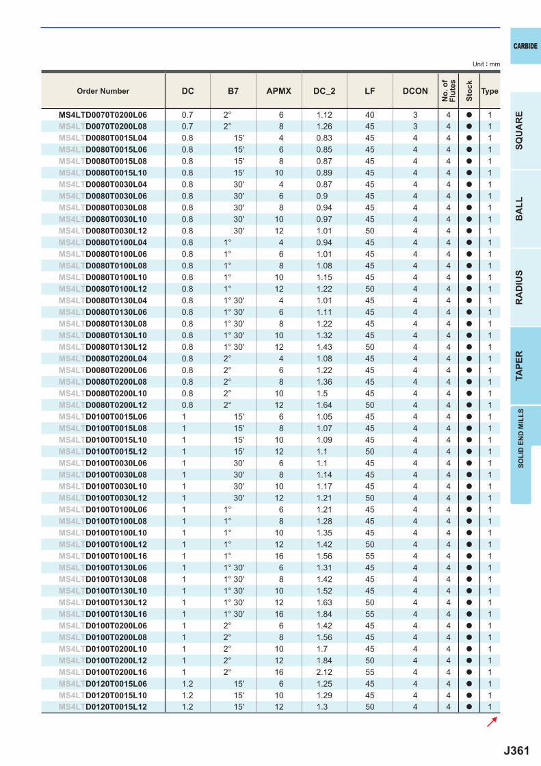
J361
DC B7 APMX DC_2 LF DCON
MS4LTD0070T0200L06 0.7 2° 6 1.12 40 3 4 a 1MS4LTD0070T0200L08 0.7 2° 8 1.26 45 3 4 a 1MS4LTD0080T0015L04 0.8 15' 4 0.83 45 4 4 a 1MS4LTD0080T0015L06 0.8 15' 6 0.85 45 4 4 a 1MS4LTD0080T0015L08 0.8 15' 8 0.87 45 4 4 a 1MS4LTD0080T0015L10 0.8 15' 10 0.89 45 4 4 a 1MS4LTD0080T0030L04 0.8 30' 4 0.87 45 4 4 a 1MS4LTD0080T0030L06 0.8 30' 6 0.9 45 4 4 a 1MS4LTD0080T0030L08 0.8 30' 8 0.94 45 4 4 a 1MS4LTD0080T0030L10 0.8 30' 10 0.97 45 4 4 a 1MS4LTD0080T0030L12 0.8 30' 12 1.01 50 4 4 a 1MS4LTD0080T0100L04 0.8 1° 4 0.94 45 4 4 a 1MS4LTD0080T0100L06 0.8 1° 6 1.01 45 4 4 a 1MS4LTD0080T0100L08 0.8 1° 8 1.08 45 4 4 a 1MS4LTD0080T0100L10 0.8 1° 10 1.15 45 4 4 a 1MS4LTD0080T0100L12 0.8 1° 12 1.22 50 4 4 a 1MS4LTD0080T0130L04 0.8 1° 30' 4 1.01 45 4 4 a 1MS4LTD0080T0130L06 0.8 1° 30' 6 1.11 45 4 4 a 1MS4LTD0080T0130L08 0.8 1° 30' 8 1.22 45 4 4 a 1MS4LTD0080T0130L10 0.8 1° 30' 10 1.32 45 4 4 a 1MS4LTD0080T0130L12 0.8 1° 30' 12 1.43 50 4 4 a 1MS4LTD0080T0200L04 0.8 2° 4 1.08 45 4 4 a 1MS4LTD0080T0200L06 0.8 2° 6 1.22 45 4 4 a 1MS4LTD0080T0200L08 0.8 2° 8 1.36 45 4 4 a 1MS4LTD0080T0200L10 0.8 2° 10 1.5 45 4 4 a 1MS4LTD0080T0200L12 0.8 2° 12 1.64 50 4 4 a 1MS4LTD0100T0015L06 1 15' 6 1.05 45 4 4 a 1MS4LTD0100T0015L08 1 15' 8 1.07 45 4 4 a 1MS4LTD0100T0015L10 1 15' 10 1.09 45 4 4 a 1MS4LTD0100T0015L12 1 15' 12 1.1 50 4 4 a 1MS4LTD0100T0030L06 1 30' 6 1.1 45 4 4 a 1MS4LTD0100T0030L08 1 30' 8 1.14 45 4 4 a 1MS4LTD0100T0030L10 1 30' 10 1.17 45 4 4 a 1MS4LTD0100T0030L12 1 30' 12 1.21 50 4 4 a 1MS4LTD0100T0100L06 1 1° 6 1.21 45 4 4 a 1MS4LTD0100T0100L08 1 1° 8 1.28 45 4 4 a 1MS4LTD0100T0100L10 1 1° 10 1.35 45 4 4 a 1MS4LTD0100T0100L12 1 1° 12 1.42 50 4 4 a 1MS4LTD0100T0100L16 1 1° 16 1.56 55 4 4 a 1MS4LTD0100T0130L06 1 1° 30' 6 1.31 45 4 4 a 1MS4LTD0100T0130L08 1 1° 30' 8 1.42 45 4 4 a 1MS4LTD0100T0130L10 1 1° 30' 10 1.52 45 4 4 a 1MS4LTD0100T0130L12 1 1° 30' 12 1.63 50 4 4 a 1MS4LTD0100T0130L16 1 1° 30' 16 1.84 55 4 4 a 1MS4LTD0100T0200L06 1 2° 6 1.42 45 4 4 a 1MS4LTD0100T0200L08 1 2° 8 1.56 45 4 4 a 1MS4LTD0100T0200L10 1 2° 10 1.7 45 4 4 a 1MS4LTD0100T0200L12 1 2° 12 1.84 50 4 4 a 1MS4LTD0100T0200L16 1 2° 16 2.12 55 4 4 a 1MS4LTD0120T0015L06 1.2 15' 6 1.25 45 4 4 a 1MS4LTD0120T0015L10 1.2 15' 10 1.29 45 4 4 a 1MS4LTD0120T0015L12 1.2 15' 12 1.3 50 4 4 a 1
SOLI
D E
ND
MIL
LS
CARBIDE
SQU
AR
EB
ALL
RA
DIU
STA
PER
Unit : mm
Order Number
No.
of
Flut
es
Stoc
k
Type
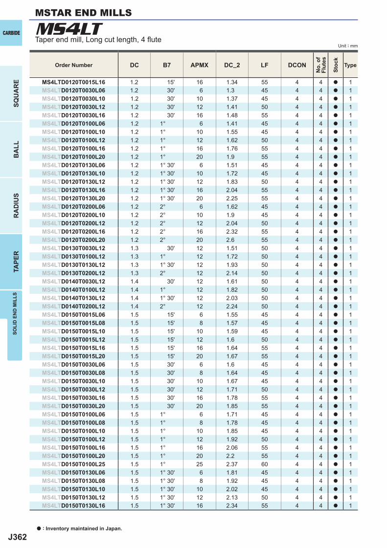
J362
DC B7 APMX DC_2 LF DCON
MS4LTD0120T0015L16 1.2 15' 16 1.34 55 4 4 a 1MS4LTD0120T0030L06 1.2 30' 6 1.3 45 4 4 a 1MS4LTD0120T0030L10 1.2 30' 10 1.37 45 4 4 a 1MS4LTD0120T0030L12 1.2 30' 12 1.41 50 4 4 a 1MS4LTD0120T0030L16 1.2 30' 16 1.48 55 4 4 a 1MS4LTD0120T0100L06 1.2 1° 6 1.41 45 4 4 a 1MS4LTD0120T0100L10 1.2 1° 10 1.55 45 4 4 a 1MS4LTD0120T0100L12 1.2 1° 12 1.62 50 4 4 a 1MS4LTD0120T0100L16 1.2 1° 16 1.76 55 4 4 a 1MS4LTD0120T0100L20 1.2 1° 20 1.9 55 4 4 a 1MS4LTD0120T0130L06 1.2 1° 30' 6 1.51 45 4 4 a 1MS4LTD0120T0130L10 1.2 1° 30' 10 1.72 45 4 4 a 1MS4LTD0120T0130L12 1.2 1° 30' 12 1.83 50 4 4 a 1MS4LTD0120T0130L16 1.2 1° 30' 16 2.04 55 4 4 a 1MS4LTD0120T0130L20 1.2 1° 30' 20 2.25 55 4 4 a 1MS4LTD0120T0200L06 1.2 2° 6 1.62 45 4 4 a 1MS4LTD0120T0200L10 1.2 2° 10 1.9 45 4 4 a 1MS4LTD0120T0200L12 1.2 2° 12 2.04 50 4 4 a 1MS4LTD0120T0200L16 1.2 2° 16 2.32 55 4 4 a 1MS4LTD0120T0200L20 1.2 2° 20 2.6 55 4 4 a 1MS4LTD0130T0030L12 1.3 30' 12 1.51 50 4 4 a 1MS4LTD0130T0100L12 1.3 1° 12 1.72 50 4 4 a 1MS4LTD0130T0130L12 1.3 1° 30' 12 1.93 50 4 4 a 1MS4LTD0130T0200L12 1.3 2° 12 2.14 50 4 4 a 1MS4LTD0140T0030L12 1.4 30' 12 1.61 50 4 4 a 1MS4LTD0140T0100L12 1.4 1° 12 1.82 50 4 4 a 1MS4LTD0140T0130L12 1.4 1° 30' 12 2.03 50 4 4 a 1MS4LTD0140T0200L12 1.4 2° 12 2.24 50 4 4 a 1MS4LTD0150T0015L06 1.5 15' 6 1.55 45 4 4 a 1MS4LTD0150T0015L08 1.5 15' 8 1.57 45 4 4 a 1MS4LTD0150T0015L10 1.5 15' 10 1.59 45 4 4 a 1MS4LTD0150T0015L12 1.5 15' 12 1.6 50 4 4 a 1MS4LTD0150T0015L16 1.5 15' 16 1.64 55 4 4 a 1MS4LTD0150T0015L20 1.5 15' 20 1.67 55 4 4 a 1MS4LTD0150T0030L06 1.5 30' 6 1.6 45 4 4 a 1MS4LTD0150T0030L08 1.5 30' 8 1.64 45 4 4 a 1MS4LTD0150T0030L10 1.5 30' 10 1.67 45 4 4 a 1MS4LTD0150T0030L12 1.5 30' 12 1.71 50 4 4 a 1MS4LTD0150T0030L16 1.5 30' 16 1.78 55 4 4 a 1MS4LTD0150T0030L20 1.5 30' 20 1.85 55 4 4 a 1MS4LTD0150T0100L06 1.5 1° 6 1.71 45 4 4 a 1MS4LTD0150T0100L08 1.5 1° 8 1.78 45 4 4 a 1MS4LTD0150T0100L10 1.5 1° 10 1.85 45 4 4 a 1MS4LTD0150T0100L12 1.5 1° 12 1.92 50 4 4 a 1MS4LTD0150T0100L16 1.5 1° 16 2.06 55 4 4 a 1MS4LTD0150T0100L20 1.5 1° 20 2.2 55 4 4 a 1MS4LTD0150T0100L25 1.5 1° 25 2.37 60 4 4 a 1MS4LTD0150T0130L06 1.5 1° 30' 6 1.81 45 4 4 a 1MS4LTD0150T0130L08 1.5 1° 30' 8 1.92 45 4 4 a 1MS4LTD0150T0130L10 1.5 1° 30' 10 2.02 45 4 4 a 1MS4LTD0150T0130L12 1.5 1° 30' 12 2.13 50 4 4 a 1MS4LTD0150T0130L16 1.5 1° 30' 16 2.34 55 4 4 a 1
MS4LTCARBIDE
SQU
AR
EB
ALL
RA
DIU
STA
PER
SOLI
D E
ND
MIL
LS
Unit : mm
a : Inventory maintained in Japan.
MSTAR END MILLS
Taper end mill, Long cut length, 4 fl ute
Order Number
No.
of
Flut
es
Stoc
k
Type
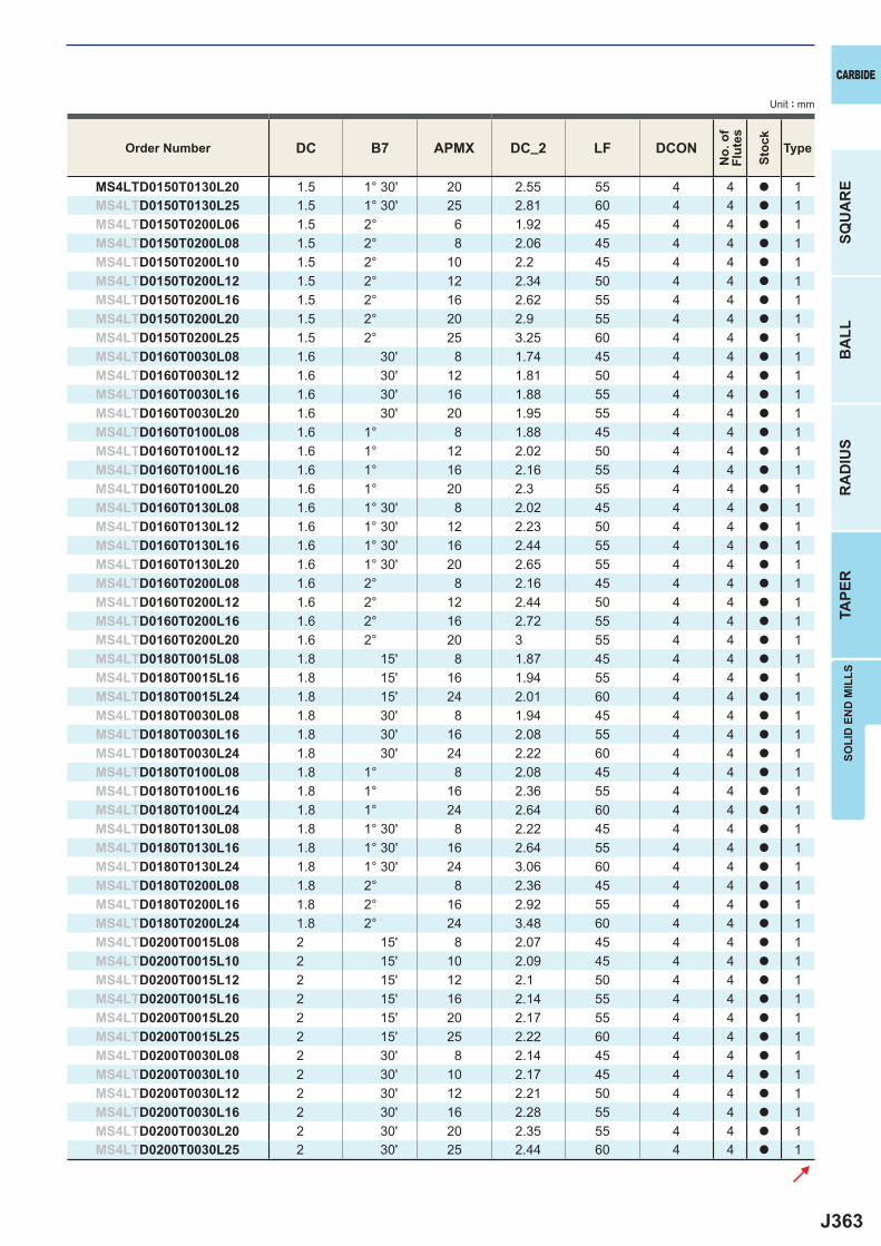
J363
DC B7 APMX DC_2 LF DCON
MS4LTD0150T0130L20 1.5 1° 30' 20 2.55 55 4 4 a 1MS4LTD0150T0130L25 1.5 1° 30' 25 2.81 60 4 4 a 1MS4LTD0150T0200L06 1.5 2° 6 1.92 45 4 4 a 1MS4LTD0150T0200L08 1.5 2° 8 2.06 45 4 4 a 1MS4LTD0150T0200L10 1.5 2° 10 2.2 45 4 4 a 1MS4LTD0150T0200L12 1.5 2° 12 2.34 50 4 4 a 1MS4LTD0150T0200L16 1.5 2° 16 2.62 55 4 4 a 1MS4LTD0150T0200L20 1.5 2° 20 2.9 55 4 4 a 1MS4LTD0150T0200L25 1.5 2° 25 3.25 60 4 4 a 1MS4LTD0160T0030L08 1.6 30' 8 1.74 45 4 4 a 1MS4LTD0160T0030L12 1.6 30' 12 1.81 50 4 4 a 1MS4LTD0160T0030L16 1.6 30' 16 1.88 55 4 4 a 1MS4LTD0160T0030L20 1.6 30' 20 1.95 55 4 4 a 1MS4LTD0160T0100L08 1.6 1° 8 1.88 45 4 4 a 1MS4LTD0160T0100L12 1.6 1° 12 2.02 50 4 4 a 1MS4LTD0160T0100L16 1.6 1° 16 2.16 55 4 4 a 1MS4LTD0160T0100L20 1.6 1° 20 2.3 55 4 4 a 1MS4LTD0160T0130L08 1.6 1° 30' 8 2.02 45 4 4 a 1MS4LTD0160T0130L12 1.6 1° 30' 12 2.23 50 4 4 a 1MS4LTD0160T0130L16 1.6 1° 30' 16 2.44 55 4 4 a 1MS4LTD0160T0130L20 1.6 1° 30' 20 2.65 55 4 4 a 1MS4LTD0160T0200L08 1.6 2° 8 2.16 45 4 4 a 1MS4LTD0160T0200L12 1.6 2° 12 2.44 50 4 4 a 1MS4LTD0160T0200L16 1.6 2° 16 2.72 55 4 4 a 1MS4LTD0160T0200L20 1.6 2° 20 3 55 4 4 a 1MS4LTD0180T0015L08 1.8 15' 8 1.87 45 4 4 a 1MS4LTD0180T0015L16 1.8 15' 16 1.94 55 4 4 a 1MS4LTD0180T0015L24 1.8 15' 24 2.01 60 4 4 a 1MS4LTD0180T0030L08 1.8 30' 8 1.94 45 4 4 a 1MS4LTD0180T0030L16 1.8 30' 16 2.08 55 4 4 a 1MS4LTD0180T0030L24 1.8 30' 24 2.22 60 4 4 a 1MS4LTD0180T0100L08 1.8 1° 8 2.08 45 4 4 a 1MS4LTD0180T0100L16 1.8 1° 16 2.36 55 4 4 a 1MS4LTD0180T0100L24 1.8 1° 24 2.64 60 4 4 a 1MS4LTD0180T0130L08 1.8 1° 30' 8 2.22 45 4 4 a 1MS4LTD0180T0130L16 1.8 1° 30' 16 2.64 55 4 4 a 1MS4LTD0180T0130L24 1.8 1° 30' 24 3.06 60 4 4 a 1MS4LTD0180T0200L08 1.8 2° 8 2.36 45 4 4 a 1MS4LTD0180T0200L16 1.8 2° 16 2.92 55 4 4 a 1MS4LTD0180T0200L24 1.8 2° 24 3.48 60 4 4 a 1MS4LTD0200T0015L08 2 15' 8 2.07 45 4 4 a 1MS4LTD0200T0015L10 2 15' 10 2.09 45 4 4 a 1MS4LTD0200T0015L12 2 15' 12 2.1 50 4 4 a 1MS4LTD0200T0015L16 2 15' 16 2.14 55 4 4 a 1MS4LTD0200T0015L20 2 15' 20 2.17 55 4 4 a 1MS4LTD0200T0015L25 2 15' 25 2.22 60 4 4 a 1MS4LTD0200T0030L08 2 30' 8 2.14 45 4 4 a 1MS4LTD0200T0030L10 2 30' 10 2.17 45 4 4 a 1MS4LTD0200T0030L12 2 30' 12 2.21 50 4 4 a 1MS4LTD0200T0030L16 2 30' 16 2.28 55 4 4 a 1MS4LTD0200T0030L20 2 30' 20 2.35 55 4 4 a 1MS4LTD0200T0030L25 2 30' 25 2.44 60 4 4 a 1
SOLI
D E
ND
MIL
LS
CARBIDE
SQU
AR
EB
ALL
RA
DIU
STA
PER
Unit : mm
Order Number
No.
of
Flut
es
Stoc
k
Type

J364
DC B7 APMX DC_2 LF DCON
MS4LTD0200T0030L30 2 30' 30 2.52 65 4 4 a 1MS4LTD0200T0100L08 2 1° 8 2.28 45 4 4 a 1MS4LTD0200T0100L10 2 1° 10 2.35 45 4 4 a 1MS4LTD0200T0100L12 2 1° 12 2.42 50 4 4 a 1MS4LTD0200T0100L16 2 1° 16 2.56 55 4 4 a 1MS4LTD0200T0100L20 2 1° 20 2.7 55 4 4 a 1MS4LTD0200T0100L25 2 1° 25 2.87 60 4 4 a 1MS4LTD0200T0100L30 2 1° 30 3.05 65 4 4 a 1MS4LTD0200T0130L08 2 1° 30' 8 2.42 45 4 4 a 1MS4LTD0200T0130L10 2 1° 30' 10 2.52 45 4 4 a 1MS4LTD0200T0130L12 2 1° 30' 12 2.63 50 4 4 a 1MS4LTD0200T0130L16 2 1° 30' 16 2.84 55 4 4 a 1MS4LTD0200T0130L20 2 1° 30' 20 3.05 55 4 4 a 1MS4LTD0200T0130L25 2 1° 30' 25 3.31 60 4 4 a 1MS4LTD0200T0130L30 2 1° 30' 30 3.57 65 4 4 a 1MS4LTD0200T0200L08 2 2° 8 2.56 45 4 4 a 1MS4LTD0200T0200L10 2 2° 10 2.7 45 4 4 a 1MS4LTD0200T0200L12 2 2° 12 2.84 50 4 4 a 1MS4LTD0200T0200L16 2 2° 16 3.12 55 4 4 a 1MS4LTD0200T0200L20 2 2° 20 3.4 55 4 4 a 1MS4LTD0200T0200L25 2 2° 25 3.75 60 4 4 a 1MS4LTD0200T0200L30 2 2° 30 4.1 65 6 4 a 1MS4LTD0200T0300L12 2 3° 12 3.26 50 4 4 a 1MS4LTD0200T0300L16 2 3° 16 3.68 55 4 4 a 1MS4LTD0200T0300L20 2 3° 20 4.1 55 6 4 a 1MS4LTD0200T0300L25 2 3° 25 4.62 60 6 4 a 1MS4LTD0200T0300L30 2 3° 30 5.14 65 6 4 a 1MS4LTD0250T0030L10 2.5 30' 10 2.67 45 4 4 a 1MS4LTD0250T0030L16 2.5 30' 16 2.78 50 4 4 a 1MS4LTD0250T0030L20 2.5 30' 20 2.85 55 4 4 a 1MS4LTD0250T0030L25 2.5 30' 25 2.94 60 4 4 a 1MS4LTD0250T0030L30 2.5 30' 30 3.02 65 4 4 a 1MS4LTD0250T0100L10 2.5 1° 10 2.85 45 4 4 a 1MS4LTD0250T0100L16 2.5 1° 16 3.06 50 4 4 a 1MS4LTD0250T0100L20 2.5 1° 20 3.2 55 4 4 a 1MS4LTD0250T0100L25 2.5 1° 25 3.37 60 4 4 a 1MS4LTD0250T0100L30 2.5 1° 30 3.55 65 4 4 a 1MS4LTD0250T0130L10 2.5 1° 30' 10 3.02 45 4 4 a 1MS4LTD0250T0130L16 2.5 1° 30' 16 3.34 50 4 4 a 1MS4LTD0250T0130L20 2.5 1° 30' 20 3.55 55 4 4 a 1MS4LTD0250T0130L25 2.5 1° 30' 25 3.81 60 4 4 a 1MS4LTD0250T0130L30 2.5 1° 30' 30 4.07 65 6 4 a 1MS4LTD0250T0200L10 2.5 2° 10 3.2 45 4 4 a 1MS4LTD0250T0200L16 2.5 2° 16 3.62 50 4 4 a 1MS4LTD0250T0200L20 2.5 2° 20 3.9 55 4 4 a 1MS4LTD0250T0200L25 2.5 2° 25 4.25 60 6 4 a 1MS4LTD0250T0200L30 2.5 2° 30 4.6 65 6 4 a 1MS4LTD0300T0030L25 3 30' 25 3.44 65 6 4 a 1MS4LTD0300T0030L40 3 30' 40 3.7 80 6 4 a 1MS4LTD0300T0100L25 3 1° 25 3.87 65 6 4 a 1MS4LTD0300T0100L40 3 1° 40 4.4 80 6 4 a 1MS4LTD0300T0130L25 3 1° 30' 25 4.31 65 6 4 a 1
MS4LTCARBIDE
SQU
AR
EB
ALL
RA
DIU
STA
PER
SOLI
D E
ND
MIL
LS
Unit : mm
MSTAR END MILLS
Taper end mill, Long cut length, 4 fl ute
a : Inventory maintained in Japan.
Order Number
No.
of
Flut
es
Stoc
k
Type
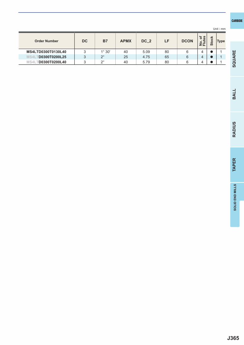
J365
DC B7 APMX DC_2 LF DCON
MS4LTD0300T0130L40 3 1° 30' 40 5.09 80 6 4 a 1MS4LTD0300T0200L25 3 2° 25 4.75 65 6 4 a 1MS4LTD0300T0200L40 3 2° 40 5.79 80 6 4 a 1
SOLI
D E
ND
MIL
LS
CARBIDE
SQU
AR
EB
ALL
RA
DIU
STA
PER
Unit : mm
Order Number
No.
of
Flut
es
Stoc
k
Type
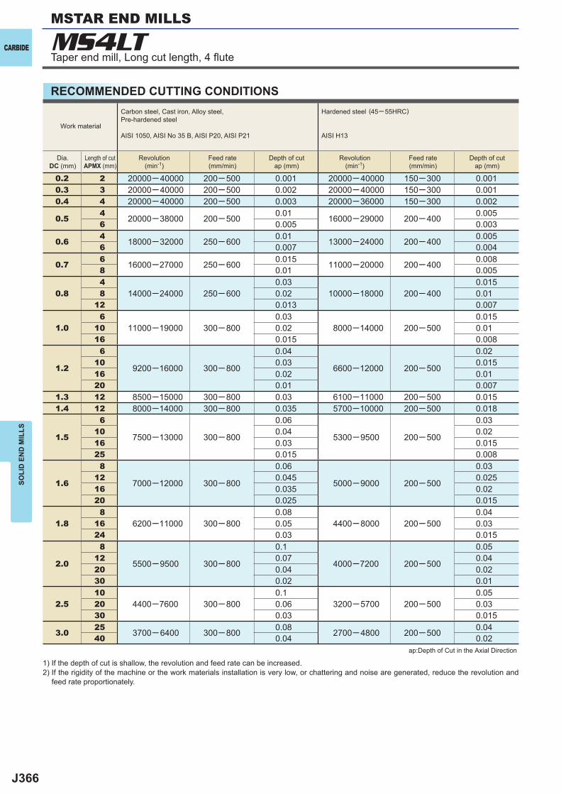
J366
0.2 2 20000─ 40000 200─ 500 0.001 20000─ 40000 150─300 0.0010.3 3 20000─ 40000 200─ 500 0.002 20000─ 40000 150─300 0.0010.4 4 20000─ 40000 200─ 500 0.003 20000─36000 150─300 0.002
0.54
20000─38000 200─ 500 0.01 16000─29000 200─ 400 0.0056 0.005 0.003
0.64
18000─32000 250─ 600 0.01 13000─24000 200─ 400 0.0056 0.007 0.004
0.76
16000─27000 250─ 600 0.015 11000─20000 200─ 400 0.0088 0.01 0.005
0.84
14000─24000 250─ 6000.03
10000─180000.015
8 0.02 200─ 400 0.0112 0.013 0.007
1.06
11000─19000 300─ 8000.03
8000─140000.015
10 0.02 200─ 500 0.0116 0.015 0.008
1.2
6
9200─16000 300─ 800
0.04
6600─12000 200─ 500
0.0210 0.03 0.01516 0.02 0.0120 0.01 0.007
1.3 12 8500─15000 300─ 800 0.03 6100─11000 200─ 500 0.0151.4 12 8000─14000 300─ 800 0.035 5700─10000 200─ 500 0.018
1.5
6
7500─13000 300─ 800
0.06
5300─9500 200─ 500
0.0310 0.04 0.0216 0.03 0.01525 0.015 0.008
1.6
8
7000─12000 300─ 800
0.06
5000─9000 200─ 500
0.0312 0.045 0.02516 0.035 0.0220 0.025 0.015
1.88
6200─11000 300─ 8000.08
4400─ 8000 200─ 5000.04
16 0.05 0.0324 0.03 0.015
2.0
8
5500─9500 300─ 800
0.1
4000─7200 200─ 500
0.0512 0.07 0.0420 0.04 0.0230 0.02 0.01
2.510
4400─7600 300─ 8000.1
3200─ 57000.05
20 0.06 200─ 500 0.0330 0.03 0.015
3.025
3700─ 6400 300─ 800 0.08 2700─ 4800 200─ 500 0.0440 0.04 0.02
MS4LTCARBIDE
SOLI
D E
ND
MIL
LS
RECOMMENDED CUTTING CONDITIONS
1) If the depth of cut is shallow, the revolution and feed rate can be increased.2) If the rigidity of the machine or the work materials installation is very low, or chattering and noise are generated, reduce the revolution and
feed rate proportionately.
ap:Depth of Cut in the Axial Direction
Work material
Carbon steel, Cast iron, Alloy steel,Pre-hardened steel
AISI 1050, AISI No 35 B, AISI P20, AISI P21
Hardened steel (45─ 55HRC)
AISI H13
Dia.DC (mm)
Length of cutAPMX (mm)
Revolution(min-1)
Feed rate(mm/min)
Depth of cutap (mm)
Revolution(min-1)
Feed rate(mm/min)
Depth of cutap (mm)
MSTAR END MILLS
Taper end mill, Long cut length, 4 fl ute
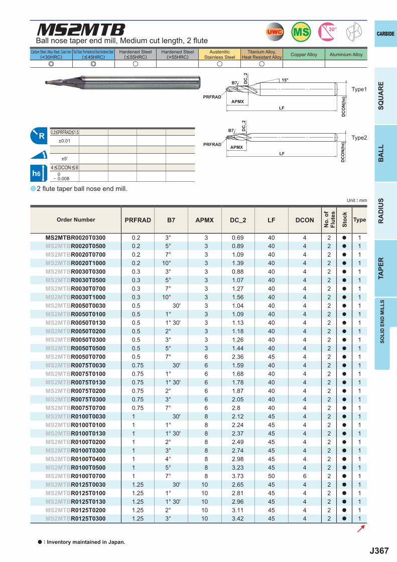
J367
a
MS2MTB
e e u u u
PRFRAD B7 APMX DC_2 LF DCON
MS2MTBR0020T0300 0.2 3° 3 0.69 40 4 2 a 1MS2MTBR0020T0500 0.2 5° 3 0.89 40 4 2 a 1MS2MTBR0020T0700 0.2 7° 3 1.09 40 4 2 a 1MS2MTBR0020T1000 0.2 10° 3 1.39 40 4 2 a 1MS2MTBR0030T0300 0.3 3° 3 0.88 40 4 2 a 1MS2MTBR0030T0500 0.3 5° 3 1.07 40 4 2 a 1MS2MTBR0030T0700 0.3 7° 3 1.27 40 4 2 a 1MS2MTBR0030T1000 0.3 10° 3 1.56 40 4 2 a 1MS2MTBR0050T0030 0.5 30' 3 1.04 40 4 2 a 1MS2MTBR0050T0100 0.5 1° 3 1.09 40 4 2 a 1MS2MTBR0050T0130 0.5 1° 30' 3 1.13 40 4 2 a 1MS2MTBR0050T0200 0.5 2° 3 1.18 40 4 2 a 1MS2MTBR0050T0300 0.5 3° 3 1.26 40 4 2 a 1MS2MTBR0050T0500 0.5 5° 3 1.44 40 4 2 a 1MS2MTBR0050T0700 0.5 7° 6 2.36 45 4 2 a 1MS2MTBR0075T0030 0.75 30' 6 1.59 40 4 2 a 1MS2MTBR0075T0100 0.75 1° 6 1.68 40 4 2 a 1MS2MTBR0075T0130 0.75 1° 30' 6 1.78 40 4 2 a 1MS2MTBR0075T0200 0.75 2° 6 1.87 40 4 2 a 1MS2MTBR0075T0300 0.75 3° 6 2.05 40 4 2 a 1MS2MTBR0075T0700 0.75 7° 6 2.8 40 4 2 a 1MS2MTBR0100T0030 1 30' 8 2.12 45 4 2 a 1MS2MTBR0100T0100 1 1° 8 2.24 45 4 2 a 1MS2MTBR0100T0130 1 1° 30' 8 2.37 45 4 2 a 1MS2MTBR0100T0200 1 2° 8 2.49 45 4 2 a 1MS2MTBR0100T0300 1 3° 8 2.74 45 4 2 a 1MS2MTBR0100T0400 1 4° 8 2.98 45 4 2 a 1MS2MTBR0100T0500 1 5° 8 3.23 45 4 2 a 1MS2MTBR0100T0700 1 7° 8 3.73 50 6 2 a 1MS2MTBR0125T0030 1.25 30' 10 2.65 45 4 2 a 1MS2MTBR0125T0100 1.25 1° 10 2.81 45 4 2 a 1MS2MTBR0125T0130 1.25 1° 30' 10 2.96 45 4 2 a 1MS2MTBR0125T0200 1.25 2° 10 3.11 45 4 2 a 1MS2MTBR0125T0300 1.25 3° 10 3.42 45 4 2 a 1
±0.01
±5'
0- 0.008
UWC MS 30°
R
h6
APMX
DC
ON
(h6)
15°
APMXLF
DC
ON
(h6)
LF
DC
_ 2D
C_ 2
B7
B7
PRFRAD
PRFRAD
SOLI
D E
ND
MIL
LS
CARBIDE
SQU
AR
EB
ALL
RA
DIU
STA
PER
Unit : mm
Carbon Steel, Alloy Steel, Cast Iron(<30HRC)
Tool Steel, Pre-Hardened Steel,Hardened Steel(<45HRC)
Hardened Steel(<55HRC)
Hardened Steel(>55HRC)
AusteniticStainless Steel
Titanium Alloy,Heat Resistant Alloy Copper Alloy Aluminium Alloy
2 fl ute taper ball nose end mill.
Type1
Type2
4<DCON<6
0.2<PRFRAD<1.5
Order Number
No.
of
Flut
es
Stoc
k
Type
Ball nose taper end mill, Medium cut length, 2 fl ute
a : Inventory maintained in Japan.
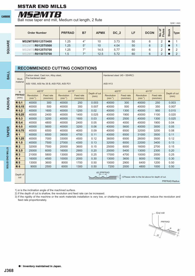
J368
PRFRAD B7 APMX DC_2 LF DCON
MS2MTBR0125T0400 1.25 4° 10 3.73 50 6 2 a 1MS2MTBR0125T0500 1.25 5° 10 4.04 50 6 2 a 1MS2MTBR0125T0700 1.25 7° 14.5 5.77 60 6 2 a 2MS2MTBR0150T0700 1.5 7° 12.5 5.72 60 6 2 a 2
%>15° %>15°
R 0.1 40000 300 40000 250 0.003 40000 300 40000 250 0.003R 0.15 40000 500 40000 350 0.007 40000 500 40000 350 0.007R 0.2 40000 1600 40000 1200 0.02 40000 1300 40000 950 0.015R 0.25 40000 2400 40000 1400 0.025 40000 1900 40000 1100 0.020R 0.3 40000 3200 40000 1600 0.03 40000 2500 40000 1300 0.025R 0.4 40000 4800 40000 2400 0.05 40000 4000 40000 1900 0.04R 0.5 40000 5600 40000 3200 0.06 40000 5600 40000 3000 0.05R 0.75 40000 6500 40000 4000 0.09 40000 6500 32000 3200 0.08R 1 40000 6500 39000 4700 0.11 40000 6500 31000 3500 0.11R 1.25 40000 7000 33000 4500 0.12 36000 6500 26000 3500 0.12R 1.5 40000 7500 27000 4300 0.13 32000 6000 22000 3400 0.13R 2 32000 7500 20000 3600 0.15 25000 6000 16000 2700 0.15R 2.5 25000 6000 16000 2900 0.20 20000 5400 13000 2300 0.20R 3 21000 5800 13000 2600 0.25 17000 4700 10000 2000 0.25R 4 16000 4500 10000 2000 0.30 13000 3600 8000 1500 0.30R 5 13000 3600 8000 1700 0.50 10000 2900 6400 1200 0.50R 6 9000 2500 6000 1300 0.50 7200 2000 4800 1000 0.50
MS2MTB
ap
PRFRAD
pf
%
a : Inventory maintained in Japan.
CARBIDE
SQU
AR
EB
ALL
RA
DIU
STA
PER
SOLI
D E
ND
MIL
LS
Unit : mm
RECOMMENDED CUTTING CONDITIONS
Order Number
No.
of
Flut
es
Stoc
k
Type
1) % is the inclination angle of the machined surface. 2) If the depth of cut is shallow, the revolution and feed rate can be increased.3) If the rigidity of the machine or the work materials installation is very low, or chattering and noise are generated, reduce the revolution and
feed rate proportionately.
PRFRAD:Radius
<Please refer to the list above for depth of cut.
Workmaterial
Carbon steel, Cast iron, Alloy steel,Pre-hardened steel
AISI 1050, AISI No 35 B, AISI P20, AISI P21
Hardened steel (45─ 55HRC)
AISI H13
RPRFRAD
(mm)
%<15°Depth of cut
(mm)
%<15°Depth of cut
(mm)Revolution(min-1)
Feed rate(mm/min)
Revolution(min-1)
Feed rate(mm/min)
Revolution(min-1)
Feed rate(mm/min)
Revolution(min-1)
Feed rate(mm/min)
Depth ofcut
<0.2PRFRAD
End mill
Ball nose taper end mill, Medium cut length, 2 fl ute
MSTAR END MILLS
a : Inventory maintained in Japan.
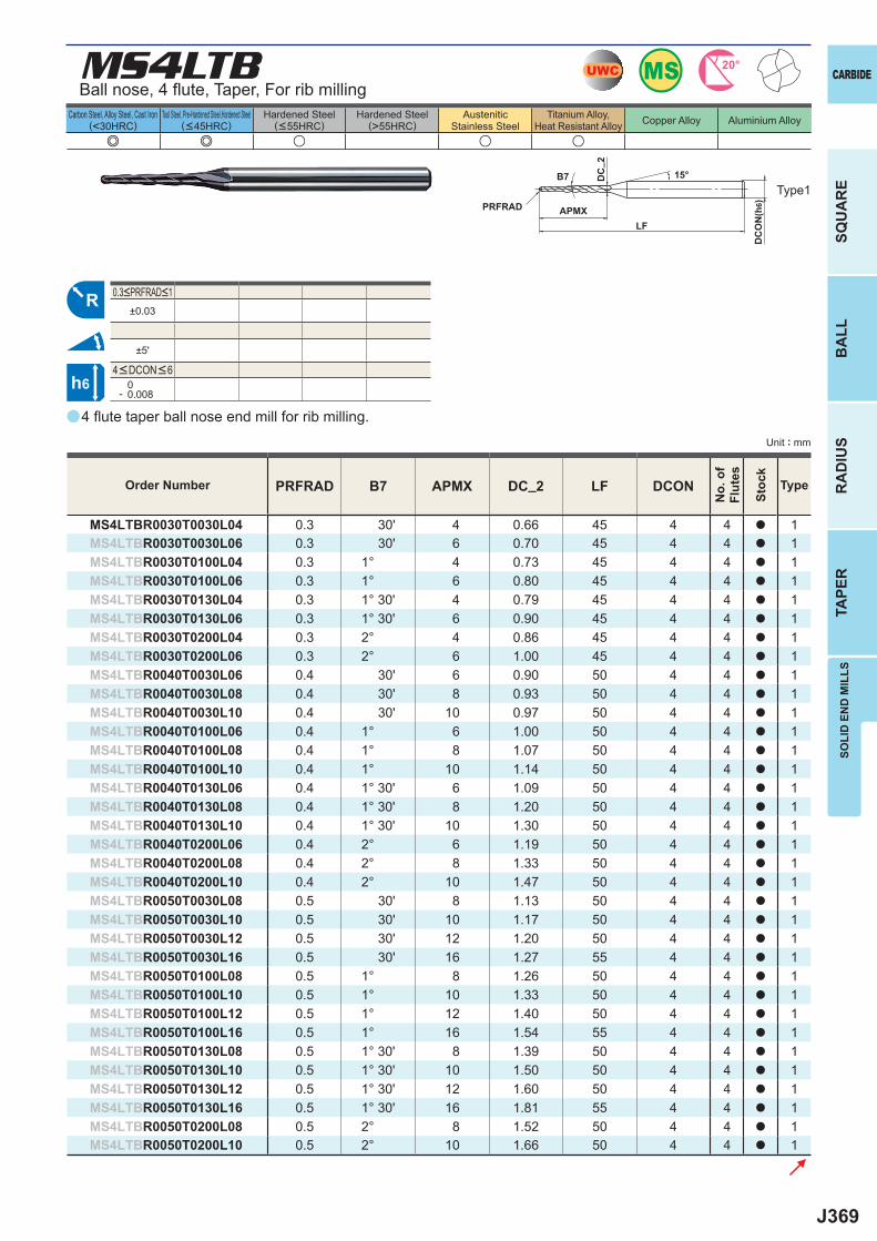
J369
a
MS4LTB
e e u u u
PRFRAD B7 APMX DC_2 LF DCON
MS4LTBR0030T0030L04 0.3 30' 4 0.66 45 4 4 a 1MS4LTBR0030T0030L06 0.3 30' 6 0.70 45 4 4 a 1MS4LTBR0030T0100L04 0.3 1° 4 0.73 45 4 4 a 1MS4LTBR0030T0100L06 0.3 1° 6 0.80 45 4 4 a 1MS4LTBR0030T0130L04 0.3 1° 30' 4 0.79 45 4 4 a 1MS4LTBR0030T0130L06 0.3 1° 30' 6 0.90 45 4 4 a 1MS4LTBR0030T0200L04 0.3 2° 4 0.86 45 4 4 a 1MS4LTBR0030T0200L06 0.3 2° 6 1.00 45 4 4 a 1MS4LTBR0040T0030L06 0.4 30' 6 0.90 50 4 4 a 1MS4LTBR0040T0030L08 0.4 30' 8 0.93 50 4 4 a 1MS4LTBR0040T0030L10 0.4 30' 10 0.97 50 4 4 a 1MS4LTBR0040T0100L06 0.4 1° 6 1.00 50 4 4 a 1MS4LTBR0040T0100L08 0.4 1° 8 1.07 50 4 4 a 1MS4LTBR0040T0100L10 0.4 1° 10 1.14 50 4 4 a 1MS4LTBR0040T0130L06 0.4 1° 30' 6 1.09 50 4 4 a 1MS4LTBR0040T0130L08 0.4 1° 30' 8 1.20 50 4 4 a 1MS4LTBR0040T0130L10 0.4 1° 30' 10 1.30 50 4 4 a 1MS4LTBR0040T0200L06 0.4 2° 6 1.19 50 4 4 a 1MS4LTBR0040T0200L08 0.4 2° 8 1.33 50 4 4 a 1MS4LTBR0040T0200L10 0.4 2° 10 1.47 50 4 4 a 1MS4LTBR0050T0030L08 0.5 30' 8 1.13 50 4 4 a 1MS4LTBR0050T0030L10 0.5 30' 10 1.17 50 4 4 a 1MS4LTBR0050T0030L12 0.5 30' 12 1.20 50 4 4 a 1MS4LTBR0050T0030L16 0.5 30' 16 1.27 55 4 4 a 1MS4LTBR0050T0100L08 0.5 1° 8 1.26 50 4 4 a 1MS4LTBR0050T0100L10 0.5 1° 10 1.33 50 4 4 a 1MS4LTBR0050T0100L12 0.5 1° 12 1.40 50 4 4 a 1MS4LTBR0050T0100L16 0.5 1° 16 1.54 55 4 4 a 1MS4LTBR0050T0130L08 0.5 1° 30' 8 1.39 50 4 4 a 1MS4LTBR0050T0130L10 0.5 1° 30' 10 1.50 50 4 4 a 1MS4LTBR0050T0130L12 0.5 1° 30' 12 1.60 50 4 4 a 1MS4LTBR0050T0130L16 0.5 1° 30' 16 1.81 55 4 4 a 1MS4LTBR0050T0200L08 0.5 2° 8 1.52 50 4 4 a 1MS4LTBR0050T0200L10 0.5 2° 10 1.66 50 4 4 a 1
±0.03
±5'
0- 0.008
MSUWC 20°
R
h6
APMX
DC
ON
(h6)
15°
LF
DC
_ 2
B7
PRFRAD
SOLI
D E
ND
MIL
LS
CARBIDE
SQU
AR
EB
ALL
RA
DIU
STA
PER
Unit : mm
Carbon Steel, Alloy Steel, Cast Iron(<30HRC)
Tool Steel, Pre-Hardened Steel,Hardened Steel(<45HRC)
Hardened Steel(<55HRC)
Hardened Steel(>55HRC)
AusteniticStainless Steel
Titanium Alloy,Heat Resistant Alloy Copper Alloy Aluminium Alloy
4 fl ute taper ball nose end mill for rib milling.
Ball nose, 4 fl ute, Taper, For rib milling
Type1
Order Number
No.
of
Flut
es
Stoc
k
Type
4<DCON<6
0.3<PRFRAD<1
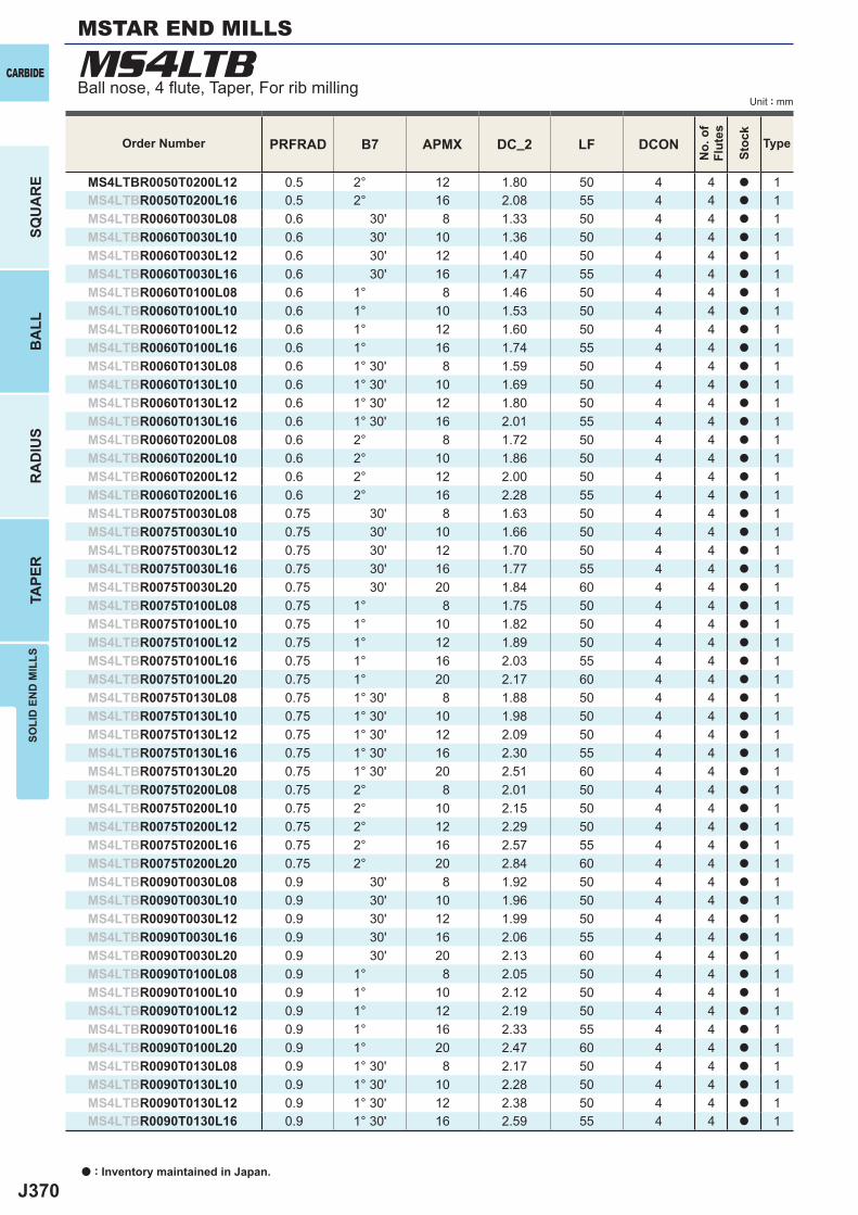
J370
PRFRAD B7 APMX DC_2 LF DCON
MS4LTBR0050T0200L12 0.5 2° 12 1.80 50 4 4 a 1MS4LTBR0050T0200L16 0.5 2° 16 2.08 55 4 4 a 1MS4LTBR0060T0030L08 0.6 30' 8 1.33 50 4 4 a 1MS4LTBR0060T0030L10 0.6 30' 10 1.36 50 4 4 a 1MS4LTBR0060T0030L12 0.6 30' 12 1.40 50 4 4 a 1MS4LTBR0060T0030L16 0.6 30' 16 1.47 55 4 4 a 1MS4LTBR0060T0100L08 0.6 1° 8 1.46 50 4 4 a 1MS4LTBR0060T0100L10 0.6 1° 10 1.53 50 4 4 a 1MS4LTBR0060T0100L12 0.6 1° 12 1.60 50 4 4 a 1MS4LTBR0060T0100L16 0.6 1° 16 1.74 55 4 4 a 1MS4LTBR0060T0130L08 0.6 1° 30' 8 1.59 50 4 4 a 1MS4LTBR0060T0130L10 0.6 1° 30' 10 1.69 50 4 4 a 1MS4LTBR0060T0130L12 0.6 1° 30' 12 1.80 50 4 4 a 1MS4LTBR0060T0130L16 0.6 1° 30' 16 2.01 55 4 4 a 1MS4LTBR0060T0200L08 0.6 2° 8 1.72 50 4 4 a 1MS4LTBR0060T0200L10 0.6 2° 10 1.86 50 4 4 a 1MS4LTBR0060T0200L12 0.6 2° 12 2.00 50 4 4 a 1MS4LTBR0060T0200L16 0.6 2° 16 2.28 55 4 4 a 1MS4LTBR0075T0030L08 0.75 30' 8 1.63 50 4 4 a 1MS4LTBR0075T0030L10 0.75 30' 10 1.66 50 4 4 a 1MS4LTBR0075T0030L12 0.75 30' 12 1.70 50 4 4 a 1MS4LTBR0075T0030L16 0.75 30' 16 1.77 55 4 4 a 1MS4LTBR0075T0030L20 0.75 30' 20 1.84 60 4 4 a 1MS4LTBR0075T0100L08 0.75 1° 8 1.75 50 4 4 a 1MS4LTBR0075T0100L10 0.75 1° 10 1.82 50 4 4 a 1MS4LTBR0075T0100L12 0.75 1° 12 1.89 50 4 4 a 1MS4LTBR0075T0100L16 0.75 1° 16 2.03 55 4 4 a 1MS4LTBR0075T0100L20 0.75 1° 20 2.17 60 4 4 a 1MS4LTBR0075T0130L08 0.75 1° 30' 8 1.88 50 4 4 a 1MS4LTBR0075T0130L10 0.75 1° 30' 10 1.98 50 4 4 a 1MS4LTBR0075T0130L12 0.75 1° 30' 12 2.09 50 4 4 a 1MS4LTBR0075T0130L16 0.75 1° 30' 16 2.30 55 4 4 a 1MS4LTBR0075T0130L20 0.75 1° 30' 20 2.51 60 4 4 a 1MS4LTBR0075T0200L08 0.75 2° 8 2.01 50 4 4 a 1MS4LTBR0075T0200L10 0.75 2° 10 2.15 50 4 4 a 1MS4LTBR0075T0200L12 0.75 2° 12 2.29 50 4 4 a 1MS4LTBR0075T0200L16 0.75 2° 16 2.57 55 4 4 a 1MS4LTBR0075T0200L20 0.75 2° 20 2.84 60 4 4 a 1MS4LTBR0090T0030L08 0.9 30' 8 1.92 50 4 4 a 1MS4LTBR0090T0030L10 0.9 30' 10 1.96 50 4 4 a 1MS4LTBR0090T0030L12 0.9 30' 12 1.99 50 4 4 a 1MS4LTBR0090T0030L16 0.9 30' 16 2.06 55 4 4 a 1MS4LTBR0090T0030L20 0.9 30' 20 2.13 60 4 4 a 1MS4LTBR0090T0100L08 0.9 1° 8 2.05 50 4 4 a 1MS4LTBR0090T0100L10 0.9 1° 10 2.12 50 4 4 a 1MS4LTBR0090T0100L12 0.9 1° 12 2.19 50 4 4 a 1MS4LTBR0090T0100L16 0.9 1° 16 2.33 55 4 4 a 1MS4LTBR0090T0100L20 0.9 1° 20 2.47 60 4 4 a 1MS4LTBR0090T0130L08 0.9 1° 30' 8 2.17 50 4 4 a 1MS4LTBR0090T0130L10 0.9 1° 30' 10 2.28 50 4 4 a 1MS4LTBR0090T0130L12 0.9 1° 30' 12 2.38 50 4 4 a 1MS4LTBR0090T0130L16 0.9 1° 30' 16 2.59 55 4 4 a 1
MS4LTB
a : Inventory maintained in Japan.
CARBIDE
SQU
AR
EB
ALL
RA
DIU
STA
PER
SOLI
D E
ND
MIL
LS
Unit : mm
Order Number
No.
of
Flut
es
Stoc
k
Type
Ball nose, 4 fl ute, Taper, For rib milling
MSTAR END MILLS
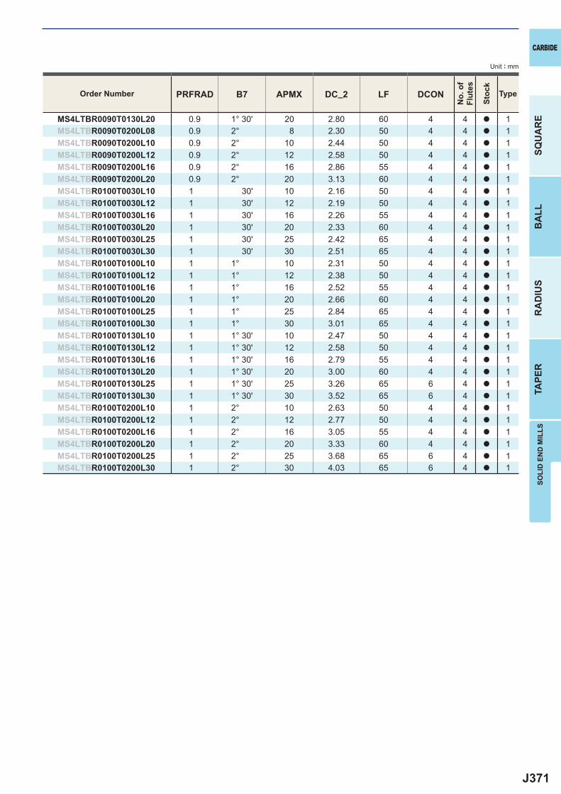
J371
PRFRAD B7 APMX DC_2 LF DCON
MS4LTBR0090T0130L20 0.9 1° 30' 20 2.80 60 4 4 a 1MS4LTBR0090T0200L08 0.9 2° 8 2.30 50 4 4 a 1MS4LTBR0090T0200L10 0.9 2° 10 2.44 50 4 4 a 1MS4LTBR0090T0200L12 0.9 2° 12 2.58 50 4 4 a 1MS4LTBR0090T0200L16 0.9 2° 16 2.86 55 4 4 a 1MS4LTBR0090T0200L20 0.9 2° 20 3.13 60 4 4 a 1MS4LTBR0100T0030L10 1 30' 10 2.16 50 4 4 a 1MS4LTBR0100T0030L12 1 30' 12 2.19 50 4 4 a 1MS4LTBR0100T0030L16 1 30' 16 2.26 55 4 4 a 1MS4LTBR0100T0030L20 1 30' 20 2.33 60 4 4 a 1MS4LTBR0100T0030L25 1 30' 25 2.42 65 4 4 a 1MS4LTBR0100T0030L30 1 30' 30 2.51 65 4 4 a 1MS4LTBR0100T0100L10 1 1° 10 2.31 50 4 4 a 1MS4LTBR0100T0100L12 1 1° 12 2.38 50 4 4 a 1MS4LTBR0100T0100L16 1 1° 16 2.52 55 4 4 a 1MS4LTBR0100T0100L20 1 1° 20 2.66 60 4 4 a 1MS4LTBR0100T0100L25 1 1° 25 2.84 65 4 4 a 1MS4LTBR0100T0100L30 1 1° 30 3.01 65 4 4 a 1MS4LTBR0100T0130L10 1 1° 30' 10 2.47 50 4 4 a 1MS4LTBR0100T0130L12 1 1° 30' 12 2.58 50 4 4 a 1MS4LTBR0100T0130L16 1 1° 30' 16 2.79 55 4 4 a 1MS4LTBR0100T0130L20 1 1° 30' 20 3.00 60 4 4 a 1MS4LTBR0100T0130L25 1 1° 30' 25 3.26 65 6 4 a 1MS4LTBR0100T0130L30 1 1° 30' 30 3.52 65 6 4 a 1MS4LTBR0100T0200L10 1 2° 10 2.63 50 4 4 a 1MS4LTBR0100T0200L12 1 2° 12 2.77 50 4 4 a 1MS4LTBR0100T0200L16 1 2° 16 3.05 55 4 4 a 1MS4LTBR0100T0200L20 1 2° 20 3.33 60 4 4 a 1MS4LTBR0100T0200L25 1 2° 25 3.68 65 6 4 a 1MS4LTBR0100T0200L30 1 2° 30 4.03 65 6 4 a 1
SOLI
D E
ND
MIL
LS
CARBIDE
SQU
AR
EB
ALL
RA
DIU
STA
PER
Unit : mm
Order Number
No.
of
Flut
es
Stoc
k
Type
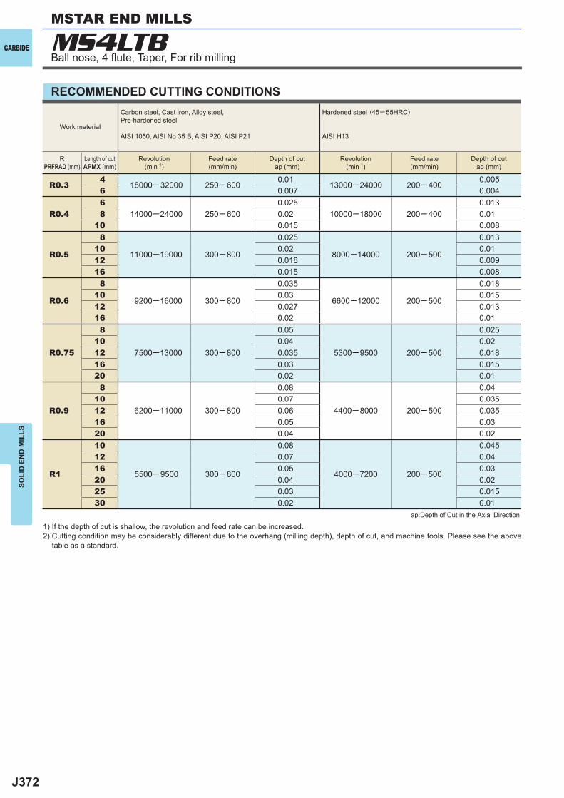
J372
R0.34
18000─32000 250─ 6000.01
13000─24000 200─ 4000.005
6 0.007 0.004
R0.46
14000─24000 250─ 6000.025
10000─18000 200─ 4000.013
8 0.02 0.0110 0.015 0.008
R0.5
8
11000─19000 300─ 800
0.025
8000─14000 200─ 500
0.01310 0.02 0.0112 0.018 0.00916 0.015 0.008
R0.6
8
9200─16000 300─ 800
0.035
6600─12000 200─ 500
0.01810 0.03 0.01512 0.027 0.01316 0.02 0.01
R0.75
8
7500─13000 300─ 800
0.05
5300─9500 200─ 500
0.02510 0.04 0.0212 0.035 0.01816 0.03 0.01520 0.02 0.01
R0.9
8
6200─11000 300─ 800
0.08
4400─ 8000 200─ 500
0.0410 0.07 0.03512 0.06 0.03516 0.05 0.0320 0.04 0.02
R1
10
5500─9500 300─ 800
0.08
4000─7200 200─ 500
0.04512 0.07 0.0416 0.05 0.0320 0.04 0.0225 0.03 0.01530 0.02 0.01
MS4LTBCARBIDE
SOLI
D E
ND
MIL
LS
RECOMMENDED CUTTING CONDITIONS
1) If the depth of cut is shallow, the revolution and feed rate can be increased.2) Cutting condition may be considerably different due to the overhang (milling depth), depth of cut, and machine tools. Please see the above
table as a standard.
ap:Depth of Cut in the Axial Direction
Work material
Carbon steel, Cast iron, Alloy steel,Pre-hardened steel
AISI 1050, AISI No 35 B, AISI P20, AISI P21
Hardened steel (45─ 55HRC)
AISI H13
RPRFRAD (mm)
Length of cutAPMX (mm)
Revolution(min-1)
Feed rate(mm/min)
Depth of cutap (mm)
Revolution(min-1)
Feed rate(mm/min)
Depth of cutap (mm)
Ball nose, 4 fl ute, Taper, For rib milling
MSTAR END MILLS
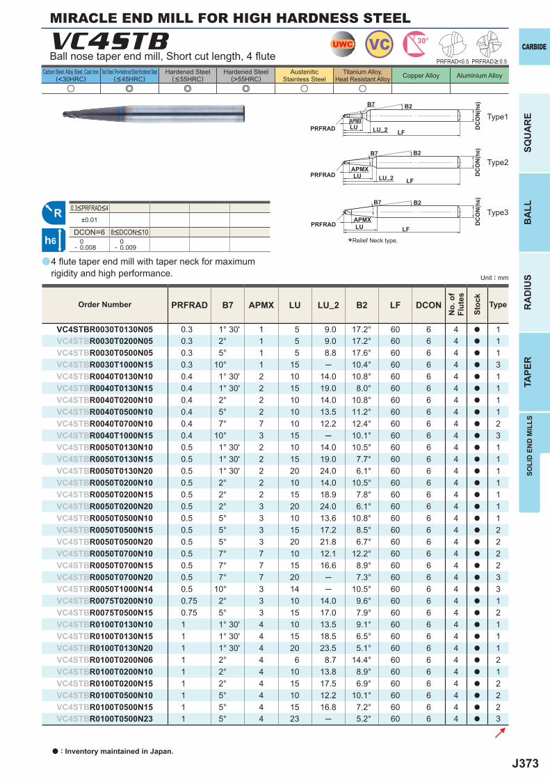
J373
a
u e e e u u
VC4STB
PRFRAD B7 APMX LU LU_2 B2 LF DCON
VC4STBR0030T0130N05 0.3 1° 30' 1 5 9.0 17.2° 60 6 4 a 1VC4STBR0030T0200N05 0.3 2° 1 5 9.0 17.2° 60 6 4 a 1VC4STBR0030T0500N05 0.3 5° 1 5 8.8 17.6° 60 6 4 a 1VC4STBR0030T1000N15 0.3 10° 1 15 ─ 10.4° 60 6 4 a 3VC4STBR0040T0130N10 0.4 1° 30' 2 10 14.0 10.8° 60 6 4 a 1VC4STBR0040T0130N15 0.4 1° 30' 2 15 19.0 8.0° 60 6 4 a 1VC4STBR0040T0200N10 0.4 2° 2 10 14.0 10.8° 60 6 4 a 1VC4STBR0040T0500N10 0.4 5° 2 10 13.5 11.2° 60 6 4 a 1VC4STBR0040T0700N10 0.4 7° 7 10 12.2 12.4° 60 6 4 a 2VC4STBR0040T1000N15 0.4 10° 3 15 ─ 10.1° 60 6 4 a 3VC4STBR0050T0130N10 0.5 1° 30' 2 10 14.0 10.5° 60 6 4 a 1VC4STBR0050T0130N15 0.5 1° 30' 2 15 19.0 7.7° 60 6 4 a 1VC4STBR0050T0130N20 0.5 1° 30' 2 20 24.0 6.1° 60 6 4 a 1VC4STBR0050T0200N10 0.5 2° 2 10 14.0 10.5° 60 6 4 a 1VC4STBR0050T0200N15 0.5 2° 2 15 18.9 7.8° 60 6 4 a 1VC4STBR0050T0200N20 0.5 2° 3 20 24.0 6.1° 60 6 4 a 1VC4STBR0050T0500N10 0.5 5° 3 10 13.6 10.8° 60 6 4 a 1VC4STBR0050T0500N15 0.5 5° 3 15 17.2 8.5° 60 6 4 a 2VC4STBR0050T0500N20 0.5 5° 3 20 21.8 6.7° 60 6 4 a 2VC4STBR0050T0700N10 0.5 7° 7 10 12.1 12.2° 60 6 4 a 2VC4STBR0050T0700N15 0.5 7° 7 15 16.6 8.9° 60 6 4 a 2VC4STBR0050T0700N20 0.5 7° 7 20 ─ 7.3° 60 6 4 a 3VC4STBR0050T1000N14 0.5 10° 3 14 ─ 10.5° 60 6 4 a 3VC4STBR0075T0200N10 0.75 2° 3 10 14.0 9.6° 60 6 4 a 1VC4STBR0075T0500N15 0.75 5° 3 15 17.0 7.9° 60 6 4 a 2VC4STBR0100T0130N10 1 1° 30' 4 10 13.5 9.1° 60 6 4 a 1VC4STBR0100T0130N15 1 1° 30' 4 15 18.5 6.5° 60 6 4 a 1VC4STBR0100T0130N20 1 1° 30' 4 20 23.5 5.1° 60 6 4 a 1VC4STBR0100T0200N06 1 2° 4 6 8.7 14.4° 60 6 4 a 2VC4STBR0100T0200N10 1 2° 4 10 13.8 8.9° 60 6 4 a 1VC4STBR0100T0200N15 1 2° 4 15 17.5 6.9° 60 6 4 a 2VC4STBR0100T0500N10 1 5° 4 10 12.2 10.1° 60 6 4 a 2VC4STBR0100T0500N15 1 5° 4 15 16.8 7.2° 60 6 4 a 2VC4STBR0100T0500N23 1 5° 4 23 ─ 5.2° 60 6 4 a 3
PRFRAD<0.5
±0.01
DCON=6 0- 0.008
0- 0.009
UWC VC 30°
R
h6
APMX
DC
ON
(h6)
LF
B7 B2
PRFRAD LU_2LU
APMX
DC
ON
(h6)
LF
B7 B2
PRFRAD LU_2LU
APMX DC
ON
(h6)
LF
B7 B2
PRFRAD LU
SOLI
D E
ND
MIL
LS
CARBIDE
SQU
AR
EB
ALL
RA
DIU
STA
PER
Unit : mm
Carbon Steel, Alloy Steel, Cast Iron(<30HRC)
Tool Steel, Pre-Hardened Steel,Hardened Steel(<45HRC)
Hardened Steel(<55HRC)
Hardened Steel(>55HRC)
AusteniticStainless Steel
Titanium Alloy,Heat Resistant Alloy Copper Alloy Aluminium Alloy
MIRACLE END MILL FOR HIGH HARDNESS STEEL
4 fl ute taper end mill with taper neck for maximumrigidity and high performance.
Ball nose taper end mill, Short cut length, 4 fl ute
Type2
Type3
Type1
*Relief Neck type.
PRFRAD>0.5
Order Number
No.
of
Flut
es
Stoc
k
Type
8<DCON<10
0.3<PRFRAD<4
a : Inventory maintained in Japan.
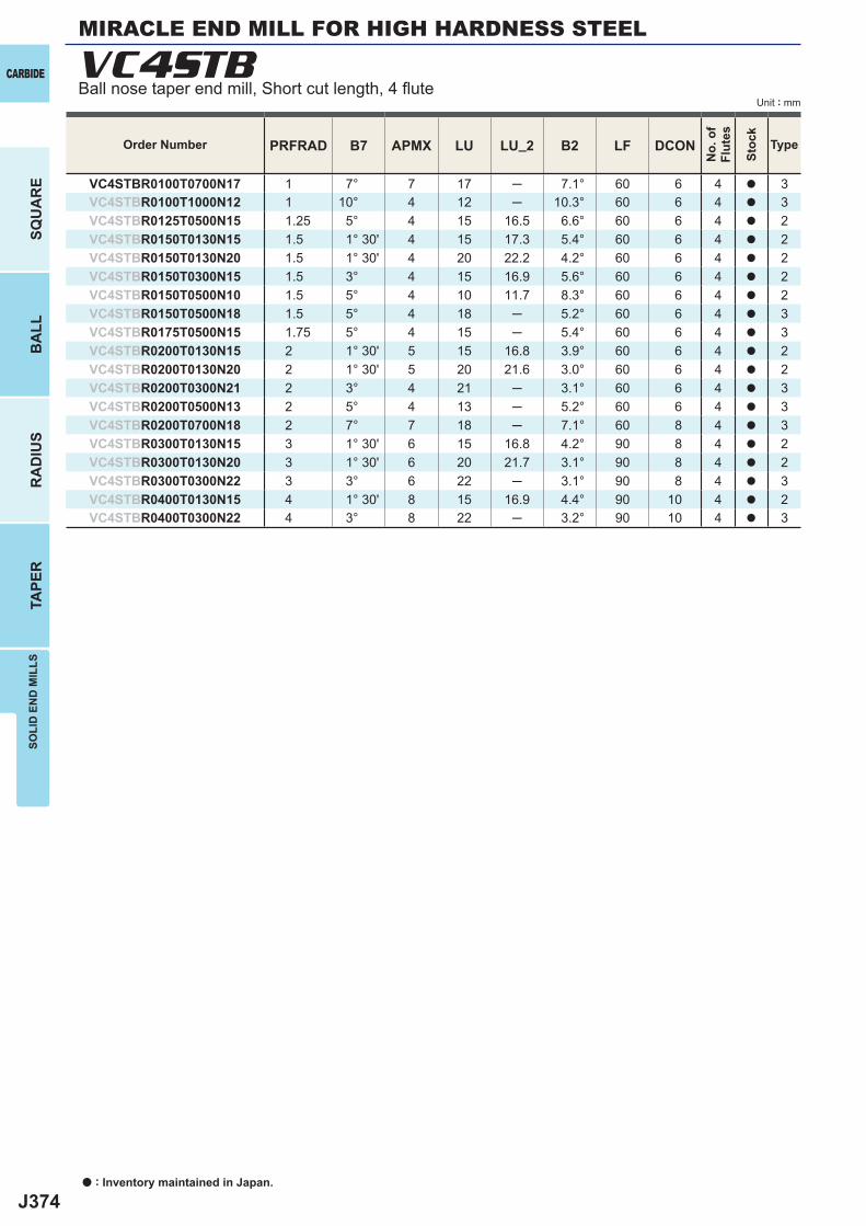
J374
PRFRAD B7 APMX LU LU_2 B2 LF DCON
VC4STBR0100T0700N17 1 7° 7 17 ─ 7.1° 60 6 4 a 3VC4STBR0100T1000N12 1 10° 4 12 ─ 10.3° 60 6 4 a 3VC4STBR0125T0500N15 1.25 5° 4 15 16.5 6.6° 60 6 4 a 2VC4STBR0150T0130N15 1.5 1° 30' 4 15 17.3 5.4° 60 6 4 a 2VC4STBR0150T0130N20 1.5 1° 30' 4 20 22.2 4.2° 60 6 4 a 2VC4STBR0150T0300N15 1.5 3° 4 15 16.9 5.6° 60 6 4 a 2VC4STBR0150T0500N10 1.5 5° 4 10 11.7 8.3° 60 6 4 a 2VC4STBR0150T0500N18 1.5 5° 4 18 ─ 5.2° 60 6 4 a 3VC4STBR0175T0500N15 1.75 5° 4 15 ─ 5.4° 60 6 4 a 3VC4STBR0200T0130N15 2 1° 30' 5 15 16.8 3.9° 60 6 4 a 2VC4STBR0200T0130N20 2 1° 30' 5 20 21.6 3.0° 60 6 4 a 2VC4STBR0200T0300N21 2 3° 4 21 ─ 3.1° 60 6 4 a 3VC4STBR0200T0500N13 2 5° 4 13 ─ 5.2° 60 6 4 a 3VC4STBR0200T0700N18 2 7° 7 18 ─ 7.1° 60 8 4 a 3VC4STBR0300T0130N15 3 1° 30' 6 15 16.8 4.2° 90 8 4 a 2VC4STBR0300T0130N20 3 1° 30' 6 20 21.7 3.1° 90 8 4 a 2VC4STBR0300T0300N22 3 3° 6 22 ─ 3.1° 90 8 4 a 3VC4STBR0400T0130N15 4 1° 30' 8 15 16.9 4.4° 90 10 4 a 2VC4STBR0400T0300N22 4 3° 8 22 ─ 3.2° 90 10 4 a 3
VC4STB
a : Inventory maintained in Japan.
CARBIDE
SQU
AR
EB
ALL
RA
DIU
STA
PER
SOLI
D E
ND
MIL
LS
Unit : mm
Order Number
No.
of
Flut
es
Stoc
k
Type
MIRACLE END MILL FOR HIGH HARDNESS STEEL
Ball nose taper end mill, Short cut length, 4 fl ute
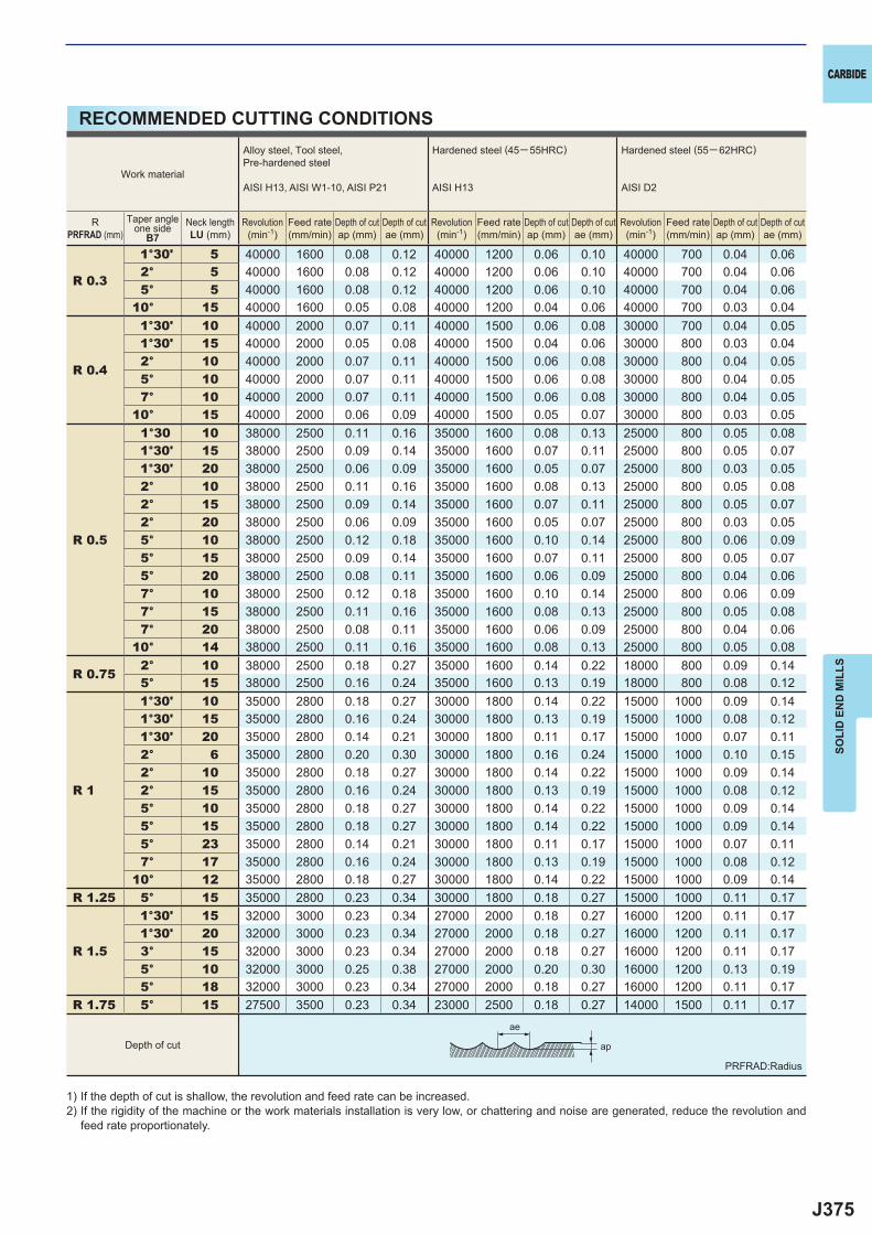
J375
R 0.3
1°30' 5 40000 1600 0.08 0.12 40000 1200 0.06 0.10 40000 700 0.04 0.06 2° 5 40000 1600 0.08 0.12 40000 1200 0.06 0.10 40000 700 0.04 0.06 5° 5 40000 1600 0.08 0.12 40000 1200 0.06 0.10 40000 700 0.04 0.0610° 15 40000 1600 0.05 0.08 40000 1200 0.04 0.06 40000 700 0.03 0.04
R 0.4
1°30' 10 40000 2000 0.07 0.11 40000 1500 0.06 0.08 30000 700 0.04 0.05 1°30' 15 40000 2000 0.05 0.08 40000 1500 0.04 0.06 30000 800 0.03 0.04 2° 10 40000 2000 0.07 0.11 40000 1500 0.06 0.08 30000 800 0.04 0.05 5° 10 40000 2000 0.07 0.11 40000 1500 0.06 0.08 30000 800 0.04 0.05 7° 10 40000 2000 0.07 0.11 40000 1500 0.06 0.08 30000 800 0.04 0.0510° 15 40000 2000 0.06 0.09 40000 1500 0.05 0.07 30000 800 0.03 0.05
R 0.5
1°30 10 38000 2500 0.11 0.16 35000 1600 0.08 0.13 25000 800 0.05 0.08 1°30' 15 38000 2500 0.09 0.14 35000 1600 0.07 0.11 25000 800 0.05 0.07 1°30' 20 38000 2500 0.06 0.09 35000 1600 0.05 0.07 25000 800 0.03 0.05 2° 10 38000 2500 0.11 0.16 35000 1600 0.08 0.13 25000 800 0.05 0.08 2° 15 38000 2500 0.09 0.14 35000 1600 0.07 0.11 25000 800 0.05 0.07 2° 20 38000 2500 0.06 0.09 35000 1600 0.05 0.07 25000 800 0.03 0.05 5° 10 38000 2500 0.12 0.18 35000 1600 0.10 0.14 25000 800 0.06 0.09 5° 15 38000 2500 0.09 0.14 35000 1600 0.07 0.11 25000 800 0.05 0.07 5° 20 38000 2500 0.08 0.11 35000 1600 0.06 0.09 25000 800 0.04 0.06 7° 10 38000 2500 0.12 0.18 35000 1600 0.10 0.14 25000 800 0.06 0.09 7° 15 38000 2500 0.11 0.16 35000 1600 0.08 0.13 25000 800 0.05 0.08 7° 20 38000 2500 0.08 0.11 35000 1600 0.06 0.09 25000 800 0.04 0.0610° 14 38000 2500 0.11 0.16 35000 1600 0.08 0.13 25000 800 0.05 0.08
R 0.75 2° 10 38000 2500 0.18 0.27 35000 1600 0.14 0.22 18000 800 0.09 0.14 5° 15 38000 2500 0.16 0.24 35000 1600 0.13 0.19 18000 800 0.08 0.12
R 1
1°30' 10 35000 2800 0.18 0.27 30000 1800 0.14 0.22 15000 1000 0.09 0.14 1°30' 15 35000 2800 0.16 0.24 30000 1800 0.13 0.19 15000 1000 0.08 0.12 1°30' 20 35000 2800 0.14 0.21 30000 1800 0.11 0.17 15000 1000 0.07 0.11 2° 6 35000 2800 0.20 0.30 30000 1800 0.16 0.24 15000 1000 0.10 0.15 2° 10 35000 2800 0.18 0.27 30000 1800 0.14 0.22 15000 1000 0.09 0.14 2° 15 35000 2800 0.16 0.24 30000 1800 0.13 0.19 15000 1000 0.08 0.12 5° 10 35000 2800 0.18 0.27 30000 1800 0.14 0.22 15000 1000 0.09 0.14 5° 15 35000 2800 0.18 0.27 30000 1800 0.14 0.22 15000 1000 0.09 0.14 5° 23 35000 2800 0.14 0.21 30000 1800 0.11 0.17 15000 1000 0.07 0.11 7° 17 35000 2800 0.16 0.24 30000 1800 0.13 0.19 15000 1000 0.08 0.1210° 12 35000 2800 0.18 0.27 30000 1800 0.14 0.22 15000 1000 0.09 0.14
R 1.25 5° 15 35000 2800 0.23 0.34 30000 1800 0.18 0.27 15000 1000 0.11 0.17
R 1.5
1°30' 15 32000 3000 0.23 0.34 27000 2000 0.18 0.27 16000 1200 0.11 0.17 1°30' 20 32000 3000 0.23 0.34 27000 2000 0.18 0.27 16000 1200 0.11 0.17 3° 15 32000 3000 0.23 0.34 27000 2000 0.18 0.27 16000 1200 0.11 0.17 5° 10 32000 3000 0.25 0.38 27000 2000 0.20 0.30 16000 1200 0.13 0.19 5° 18 32000 3000 0.23 0.34 27000 2000 0.18 0.27 16000 1200 0.11 0.17
R 1.75 5° 15 27500 3500 0.23 0.34 23000 2500 0.18 0.27 14000 1500 0.11 0.17
ap
ae
CARBIDE
SOLI
D E
ND
MIL
LS
RECOMMENDED CUTTING CONDITIONS
1) If the depth of cut is shallow, the revolution and feed rate can be increased.2) If the rigidity of the machine or the work materials installation is very low, or chattering and noise are generated, reduce the revolution and
feed rate proportionately.
Work material
Alloy steel, Tool steel,Pre-hardened steel
AISI H13, AISI W1-10, AISI P21
Hardened steel (45─ 55HRC)
AISI H13
Hardened steel (55─ 62HRC)
AISI D2
RPRFRAD (mm)
Taper angleone side
B7Neck lengthLU (mm)
Revolution(min-1)
Feed rate(mm/min)
Depth of cutap (mm)
Depth of cutae (mm)
Revolution(min-1)
Feed rate(mm/min)
Depth of cutap (mm)
Depth of cutae (mm)
Revolution(min-1)
Feed rate(mm/min)
Depth of cutap (mm)
Depth of cutae (mm)
Depth of cut
PRFRAD:Radius
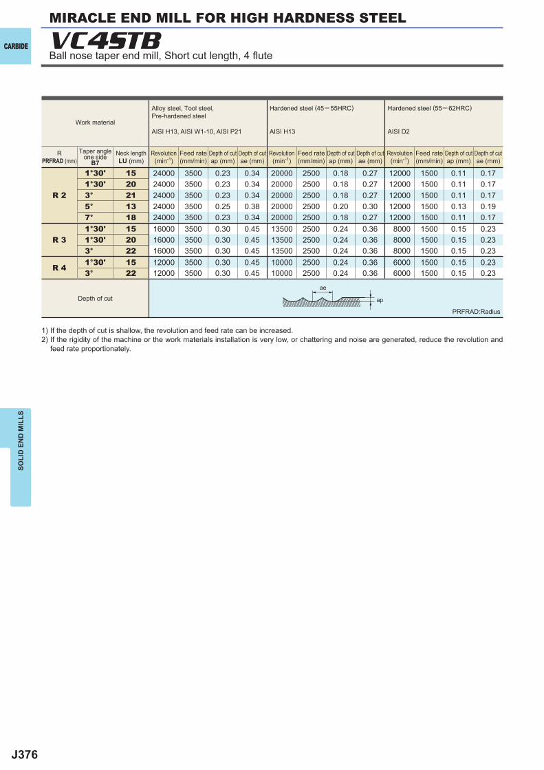
J376
R 2
1°30' 15 24000 3500 0.23 0.34 20000 2500 0.18 0.27 12000 1500 0.11 0.171°30' 20 24000 3500 0.23 0.34 20000 2500 0.18 0.27 12000 1500 0.11 0.173° 21 24000 3500 0.23 0.34 20000 2500 0.18 0.27 12000 1500 0.11 0.175° 13 24000 3500 0.25 0.38 20000 2500 0.20 0.30 12000 1500 0.13 0.197° 18 24000 3500 0.23 0.34 20000 2500 0.18 0.27 12000 1500 0.11 0.17
R 31°30' 15 16000 3500 0.30 0.45 13500 2500 0.24 0.36 8000 1500 0.15 0.231°30' 20 16000 3500 0.30 0.45 13500 2500 0.24 0.36 8000 1500 0.15 0.233° 22 16000 3500 0.30 0.45 13500 2500 0.24 0.36 8000 1500 0.15 0.23
R 41°30' 15 12000 3500 0.30 0.45 10000 2500 0.24 0.36 6000 1500 0.15 0.233° 22 12000 3500 0.30 0.45 10000 2500 0.24 0.36 6000 1500 0.15 0.23
VC4STB
ap
ae
CARBIDE
SOLI
D E
ND
MIL
LS
1) If the depth of cut is shallow, the revolution and feed rate can be increased.2) If the rigidity of the machine or the work materials installation is very low, or chattering and noise are generated, reduce the revolution and
feed rate proportionately.
Work material
Alloy steel, Tool steel,Pre-hardened steel
AISI H13, AISI W1-10, AISI P21
Hardened steel (45─ 55HRC)
AISI H13
Hardened steel (55─ 62HRC)
AISI D2
RPRFRAD (mm)
Taper angleone side
B7Neck lengthLU (mm)
Revolution(min-1)
Feed rate(mm/min)
Depth of cutap (mm)
Depth of cutae (mm)
Revolution(min-1)
Feed rate(mm/min)
Depth of cutap (mm)
Depth of cutae (mm)
Revolution(min-1)
Feed rate(mm/min)
Depth of cutap (mm)
Depth of cutae (mm)
Depth of cut
MIRACLE END MILL FOR HIGH HARDNESS STEEL
Ball nose taper end mill, Short cut length, 4 fl ute
PRFRAD:Radius
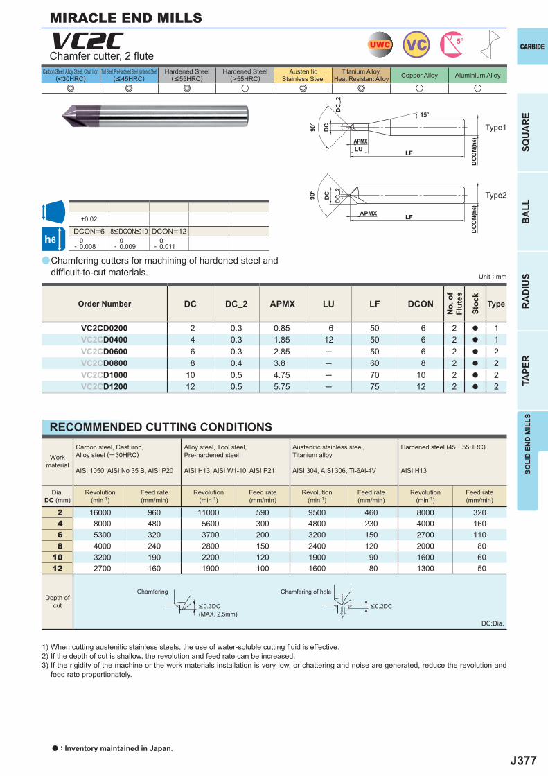
J377
a
e e e u e e u u
VC2C
DC DC_2 APMX LU LF DCON
VC2CD0200 2 0.3 0.85 6 50 6 2 a 1VC2CD0400 4 0.3 1.85 12 50 6 2 a 1VC2CD0600 6 0.3 2.85 ─ 50 6 2 a 2VC2CD0800 8 0.4 3.8 ─ 60 8 2 a 2VC2CD1000 10 0.5 4.75 ─ 70 10 2 a 2VC2CD1200 12 0.5 5.75 ─ 75 12 2 a 2
±0.02
DCON=6 DCON=12 0- 0.008
0- 0.009
0- 0.011
2 16000 960 11000 590 9500 460 8000 3204 8000 480 5600 300 4800 230 4000 1606 5300 320 3700 200 3200 150 2700 1108 4000 240 2800 150 2400 120 2000 80
10 3200 190 2200 120 1900 90 1600 6012 2700 160 1900 100 1600 80 1300 50
UWC VC 5°
h6
APMX
DC
ON
(h6)
LF
DC
LU
15°
DC
_ 2
90°
APMX
DC
ON
(h6)
LF
DC90°
DC
_ 2
SOLI
D E
ND
MIL
LS
CARBIDE
SQU
AR
EB
ALL
RA
DIU
STA
PER
Unit : mm
Carbon Steel, Alloy Steel, Cast Iron(<30HRC)
Tool Steel, Pre-Hardened Steel,Hardened Steel(<45HRC)
Hardened Steel(<55HRC)
Hardened Steel(>55HRC)
AusteniticStainless Steel
Titanium Alloy,Heat Resistant Alloy Copper Alloy Aluminium Alloy
MIRACLE END MILLS
Chamfering cutters for machining of hardened steel and diffi cult-to-cut materials.
Chamfer cutter, 2 fl ute
Type2
Type1
Order Number
No.
of
Flut
es
Stoc
k
Type
8<DCON<10
RECOMMENDED CUTTING CONDITIONS
1) When cutting austenitic stainless steels, the use of water-soluble cutting fl uid is effective.2) If the depth of cut is shallow, the revolution and feed rate can be increased.3) If the rigidity of the machine or the work materials installation is very low, or chattering and noise are generated, reduce the revolution and
feed rate proportionately.
Chamfering Chamfering of hole
DC:Dia.
Workmaterial
Carbon steel, Cast iron, Alloy steel (─30HRC)
AISI 1050, AISI No 35 B, AISI P20
Alloy steel, Tool steel,Pre-hardened steel
AISI H13, AISI W1-10, AISI P21
Austenitic stainless steel,Titanium alloy
AISI 304, AISI 306, Ti-6Al-4V
Hardened steel (45─ 55HRC)
AISI H13
Dia.DC (mm)
Revolution(min-1)
Feed rate(mm/min)
Revolution(min-1)
Feed rate(mm/min)
Revolution(min-1)
Feed rate(mm/min)
Revolution(min-1)
Feed rate(mm/min)
Depth ofcut <0.3DC
(MAX. 2.5mm)<0.2DC
a : Inventory maintained in Japan.
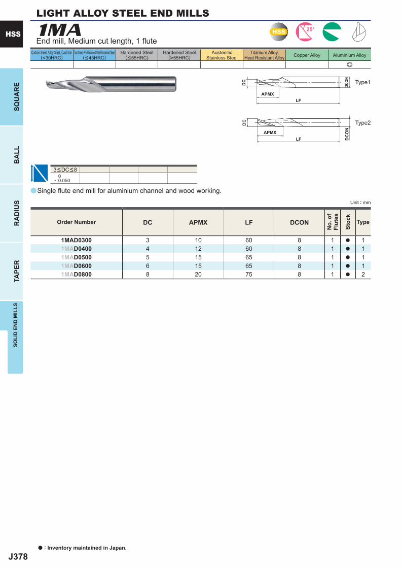
J378
a
e
1MA
0- 0.050
DC APMX LF DCON
1MAD0300 3 10 60 8 1 a 11MAD0400 4 12 60 8 1 a 11MAD0500 5 15 65 8 1 a 11MAD0600 6 15 65 8 1 a 11MAD0800 8 20 75 8 1 a 2
HSS 25°
DC
APMXLF
DCON
DC
APMXLF D
CO
N
a : Inventory maintained in Japan.
HSS
SQU
AR
EB
ALL
RA
DIU
STA
PER
SOLI
D E
ND
MIL
LS
Unit : mm
Carbon Steel, Alloy Steel, Cast Iron(<30HRC)
Tool Steel, Pre-Hardened Steel,Hardened Steel(<45HRC)
Hardened Steel(<55HRC)
Hardened Steel(>55HRC)
AusteniticStainless Steel
Titanium Alloy,Heat Resistant Alloy Copper Alloy Aluminium Alloy
LIGHT ALLOY STEEL END MILLS
End mill, Medium cut length, 1 fl ute
Type2
Type1
3<DC<8
Single fl ute end mill for aluminium channel and wood working.
Order Number
No.
of
Flut
es
Stoc
k
Type
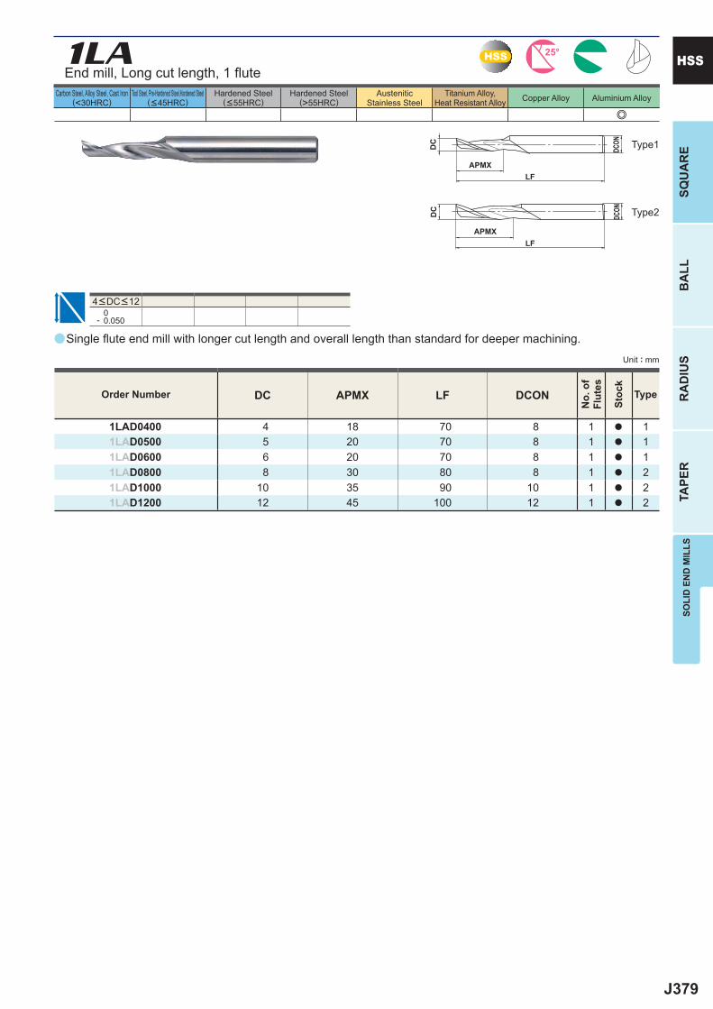
J379
a
e
1LA
0- 0.050
DC APMX LF DCON
1LAD0400 4 18 70 8 1 a 11LAD0500 5 20 70 8 1 a 11LAD0600 6 20 70 8 1 a 11LAD0800 8 30 80 8 1 a 21LAD1000 10 35 90 10 1 a 21LAD1200 12 45 100 12 1 a 2
HSS 25°
DC
APMXLF
DCON
DC
APMXLF
DCON
SOLI
D E
ND
MIL
LSSQ
UA
RE
BA
LLR
AD
IUS
TAPE
R
HSS
Unit : mm
Carbon Steel, Alloy Steel, Cast Iron(<30HRC)
Tool Steel, Pre-Hardened Steel,Hardened Steel(<45HRC)
Hardened Steel(<55HRC)
Hardened Steel(>55HRC)
AusteniticStainless Steel
Titanium Alloy,Heat Resistant Alloy Copper Alloy Aluminium Alloy
Type2
Type1
Order Number
No.
of
Flut
es
Stoc
k
Type
End mill, Long cut length, 1 fl ute
4<DC<12
Single fl ute end mill with longer cut length and overall length than standard for deeper machining.
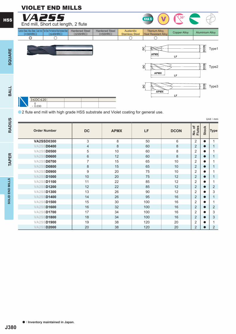
J380
a
e u u u
VA2SS
DC APMX LF DCON
VA2SSD0300 3 8 50 6 2 a 1VA2SSD0400 4 8 60 8 2 a 1VA2SSD0500 5 10 60 8 2 a 1VA2SSD0600 6 12 60 8 2 a 1VA2SSD0700 7 15 65 10 2 a 1VA2SSD0800 8 15 65 10 2 a 1VA2SSD0900 9 20 75 10 2 a 1VA2SSD1000 10 20 75 12 2 a 1VA2SSD1100 11 22 85 12 2 a 1VA2SSD1200 12 22 85 12 2 a 2VA2SSD1300 13 26 90 12 2 a 3VA2SSD1400 14 26 95 16 2 a 1VA2SSD1500 15 30 100 16 2 a 1VA2SSD1600 16 32 100 16 2 a 2VA2SSD1700 17 34 100 16 2 a 3VA2SSD1800 18 34 100 16 2 a 3VA2SSD1900 19 38 120 20 2 a 1VA2SSD2000 20 38 120 20 2 a 2
0- 0.030
KHA S V 30°
DC
APMXLF
DCON
DC
APMXLF
DCON
APMXLF
DC
DCO
N
a : Inventory maintained in Japan.
HSS
SQU
AR
EB
ALL
RA
DIU
STA
PER
SOLI
D E
ND
MIL
LS
Unit : mm
Carbon Steel, Alloy Steel, Cast Iron(<30HRC)
Tool Steel, Pre-Hardened Steel,Hardened Steel(<45HRC)
Hardened Steel(<55HRC)
Hardened Steel(>55HRC)
AusteniticStainless Steel
Titanium Alloy,Heat Resistant Alloy Copper Alloy Aluminium Alloy
VIOLET END MILLS
Type2
Type3
Type1
3<DC<20
End mill, Short cut length, 2 fl ute
2 fl ute end mill with high grade HSS substrate and Violet coating for general use.
Order Number
No.
of
Flut
es
Stoc
k
Type
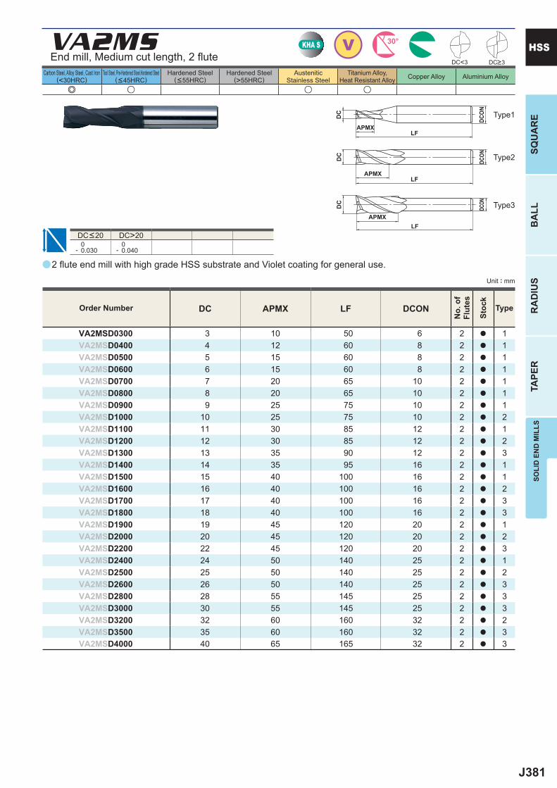
J381
a
e u u u
VA2MS
DC APMX LF DCON
VA2MSD0300 3 10 50 6 2 a 1VA2MSD0400 4 12 60 8 2 a 1VA2MSD0500 5 15 60 8 2 a 1VA2MSD0600 6 15 60 8 2 a 1VA2MSD0700 7 20 65 10 2 a 1VA2MSD0800 8 20 65 10 2 a 1VA2MSD0900 9 25 75 10 2 a 1VA2MSD1000 10 25 75 10 2 a 2VA2MSD1100 11 30 85 12 2 a 1VA2MSD1200 12 30 85 12 2 a 2VA2MSD1300 13 35 90 12 2 a 3VA2MSD1400 14 35 95 16 2 a 1VA2MSD1500 15 40 100 16 2 a 1VA2MSD1600 16 40 100 16 2 a 2VA2MSD1700 17 40 100 16 2 a 3VA2MSD1800 18 40 100 16 2 a 3VA2MSD1900 19 45 120 20 2 a 1VA2MSD2000 20 45 120 20 2 a 2VA2MSD2200 22 45 120 20 2 a 3VA2MSD2400 24 50 140 25 2 a 1VA2MSD2500 25 50 140 25 2 a 2VA2MSD2600 26 50 140 25 2 a 3VA2MSD2800 28 55 145 25 2 a 3VA2MSD3000 30 55 145 25 2 a 3VA2MSD3200 32 60 160 32 2 a 2VA2MSD3500 35 60 160 32 2 a 3VA2MSD4000 40 65 165 32 2 a 3
DC>20 0- 0.030
0- 0.040
DC<3
VKHA S 30°
DC
APMXLF
DCON
DC
APMXLF
DCON
APMXLF
DC
DCO
N
SOLI
D E
ND
MIL
LSSQ
UA
RE
BA
LLR
AD
IUS
TAPE
R
HSS
Unit : mm
Carbon Steel, Alloy Steel, Cast Iron(<30HRC)
Tool Steel, Pre-Hardened Steel,Hardened Steel(<45HRC)
Hardened Steel(<55HRC)
Hardened Steel(>55HRC)
AusteniticStainless Steel
Titanium Alloy,Heat Resistant Alloy Copper Alloy Aluminium Alloy
Type2
Type3
Type1
2 fl ute end mill with high grade HSS substrate and Violet coating for general use.
Order Number
No.
of
Flut
es
Stoc
k
Type
DC<20
End mill, Medium cut length, 2 fl ute DC>3
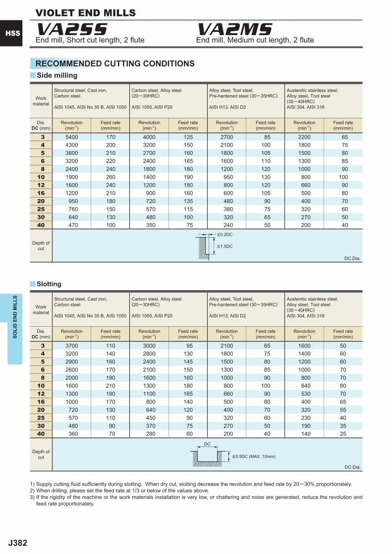
J382
VA2SS VA2MS
3 5400 170 4000 125 2700 85 2200 65 4 4300 200 3200 150 2100 100 1800 75 5 3600 210 2700 160 1800 105 1500 80 6 3200 220 2400 165 1600 110 1300 85 8 2400 240 1800 180 1200 120 1000 9010 1900 260 1400 190 950 130 800 10012 1600 240 1200 180 800 120 660 9016 1200 210 900 160 600 105 500 8020 950 180 720 135 480 90 400 7025 760 150 570 115 380 75 320 6030 640 130 480 100 320 65 270 5040 470 100 350 75 240 50 200 40
3 3700 110 3000 95 2100 65 1600 50 4 3200 140 2800 130 1800 75 1400 60 5 2900 160 2400 145 1500 80 1200 60 6 2600 170 2100 150 1300 85 1000 70 8 2000 190 1600 160 1000 90 800 7010 1600 210 1300 180 800 100 640 8012 1300 190 1100 165 660 90 530 7016 1000 170 800 140 500 80 400 6520 720 130 640 120 400 70 320 5525 570 110 450 90 320 60 230 4030 480 90 370 75 270 50 190 3540 360 70 280 60 200 40 140 25
y
y
DC
HSS
SOLI
D E
ND
MIL
LS
End mill, Short cut length, 2 fl ute End mill, Medium cut length, 2 fl ute
RECOMMENDED CUTTING CONDITIONS
1) Supply cutting fl uid suffi ciently during slotting. When dry cut, slotting decrease the revolution and feed rate by 20─30% proportionately.2) When drilling, please set the feed rate at 1/3 or below of the values above.3) If the rigidity of the machine or the work materials installation is very low, or chattering and noise are generated, reduce the revolution and
feed rate proportionately.
DC:Dia.
DC:Dia.
Side milling
Slotting
Workmaterial
Structural steel, Cast iron, Carbon steel
AISI 1045, AISI No 35 B, AISI 1050
Carbon steel, Alloy steel (20─30HRC)
AISI 1055, AISI P20
Alloy steel, Tool steel,Pre-hardened steel (30─35HRC)
AISI H13, AISI D2
Austenitic stainless steel,Alloy steel, Tool steel(35─40HRC)AISI 304, AISI 316
Dia.DC (mm)
Revolution(min-1)
Feed rate(mm/min)
Revolution(min-1)
Feed rate(mm/min)
Revolution(min-1)
Feed rate(mm/min)
Revolution(min-1)
Feed rate(mm/min)
Depth ofcut
Depth ofcut <0.5DC (MAX. 10mm)
<0.2DC
<1.5DC
VIOLET END MILLS
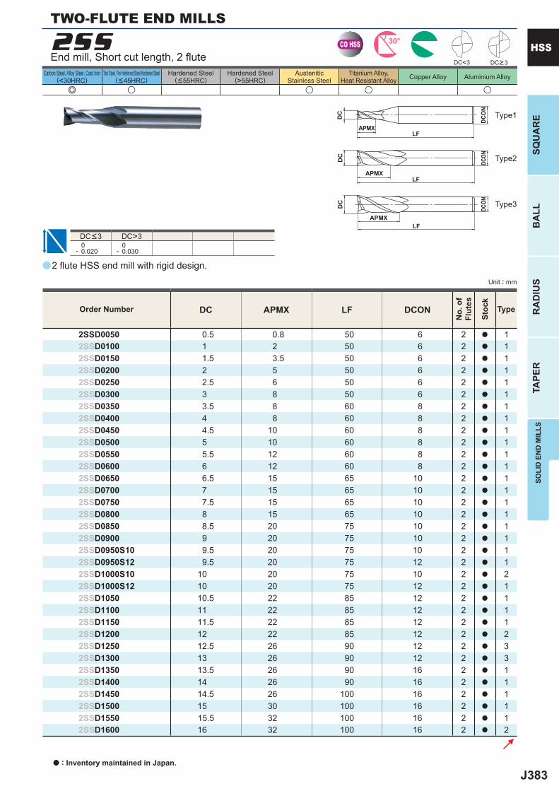
J383
a
e u u u u
2SS
DC APMX LF DCON
2SSD0050 0.5 0.8 50 6 2 a 12SSD0100 1 2 50 6 2 a 12SSD0150 1.5 3.5 50 6 2 a 12SSD0200 2 5 50 6 2 a 12SSD0250 2.5 6 50 6 2 a 12SSD0300 3 8 50 6 2 a 12SSD0350 3.5 8 60 8 2 a 12SSD0400 4 8 60 8 2 a 12SSD0450 4.5 10 60 8 2 a 12SSD0500 5 10 60 8 2 a 12SSD0550 5.5 12 60 8 2 a 12SSD0600 6 12 60 8 2 a 12SSD0650 6.5 15 65 10 2 a 12SSD0700 7 15 65 10 2 a 12SSD0750 7.5 15 65 10 2 a 12SSD0800 8 15 65 10 2 a 12SSD0850 8.5 20 75 10 2 a 12SSD0900 9 20 75 10 2 a 12SSD0950S10 9.5 20 75 10 2 a 12SSD0950S12 9.5 20 75 12 2 a 12SSD1000S10 10 20 75 10 2 a 22SSD1000S12 10 20 75 12 2 a 12SSD1050 10.5 22 85 12 2 a 12SSD1100 11 22 85 12 2 a 12SSD1150 11.5 22 85 12 2 a 12SSD1200 12 22 85 12 2 a 22SSD1250 12.5 26 90 12 2 a 32SSD1300 13 26 90 12 2 a 32SSD1350 13.5 26 90 16 2 a 12SSD1400 14 26 90 16 2 a 12SSD1450 14.5 26 100 16 2 a 12SSD1500 15 30 100 16 2 a 12SSD1550 15.5 32 100 16 2 a 12SSD1600 16 32 100 16 2 a 2
DC<3
DC>3 0- 0.020
0- 0.030
CO HSS 30°
DC
APMXLF
DCON
DC
APMXLF
DCON
APMXLF
DC
DCO
N
SOLI
D E
ND
MIL
LSSQ
UA
RE
BA
LLR
AD
IUS
TAPE
R
HSS
Unit : mm
Carbon Steel, Alloy Steel, Cast Iron(<30HRC)
Tool Steel, Pre-Hardened Steel,Hardened Steel(<45HRC)
Hardened Steel(<55HRC)
Hardened Steel(>55HRC)
AusteniticStainless Steel
Titanium Alloy,Heat Resistant Alloy Copper Alloy Aluminium Alloy
End mill, Short cut length, 2 fl ute
TWO-FLUTE END MILLS
DC>3
Type2
Type3
Type1
DC<3
2 fl ute HSS end mill with rigid design.
Order Number
No.
of
Flut
es
Stoc
k
Type
a : Inventory maintained in Japan.
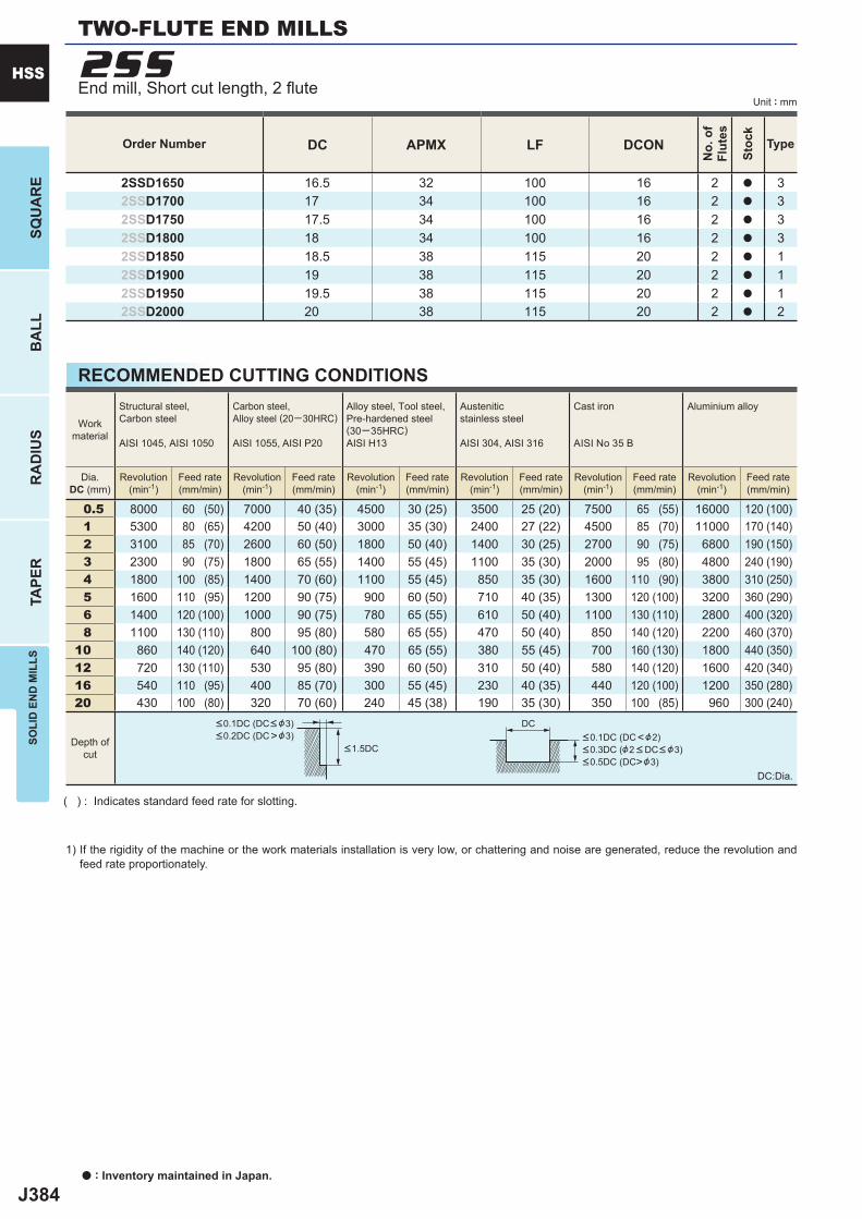
J384
DC APMX LF DCON
2SSD1650 16.5 32 100 16 2 a 32SSD1700 17 34 100 16 2 a 32SSD1750 17.5 34 100 16 2 a 32SSD1800 18 34 100 16 2 a 32SSD1850 18.5 38 115 20 2 a 12SSD1900 19 38 115 20 2 a 12SSD1950 19.5 38 115 20 2 a 12SSD2000 20 38 115 20 2 a 2
0.5 8000 60 (50) 7000 40 (35) 4500 30 (25) 3500 25 (20) 7500 65 (55) 16000 120 (100) 1 5300 80 (65) 4200 50 (40) 3000 35 (30) 2400 27 (22) 4500 85 (70) 11000 170 (140) 2 3100 85 (70) 2600 60 (50) 1800 50 (40) 1400 30 (25) 2700 90 (75) 6800 190 (150) 3 2300 90 (75) 1800 65 (55) 1400 55 (45) 1100 35 (30) 2000 95 (80) 4800 240 (190) 4 1800 100 (85) 1400 70 (60) 1100 55 (45) 850 35 (30) 1600 110 (90) 3800 310 (250) 5 1600 110 (95) 1200 90 (75) 900 60 (50) 710 40 (35) 1300 120 (100) 3200 360 (290) 6 1400 120 (100) 1000 90 (75) 780 65 (55) 610 50 (40) 1100 130 (110) 2800 400 (320) 8 1100 130 (110) 800 95 (80) 580 65 (55) 470 50 (40) 850 140 (120) 2200 460 (370)10 860 140 (120) 640 100 (80) 470 65 (55) 380 55 (45) 700 160 (130) 1800 440 (350)12 720 130 (110) 530 95 (80) 390 60 (50) 310 50 (40) 580 140 (120) 1600 420 (340)16 540 110 (95) 400 85 (70) 300 55 (45) 230 40 (35) 440 120 (100) 1200 350 (280)20 430 100 (80) 320 70 (60) 240 45 (38) 190 35 (30) 350 100 (85) 960 300 (240)
2SS
DC
a : Inventory maintained in Japan.
HSS
SQU
AR
EB
ALL
RA
DIU
STA
PER
SOLI
D E
ND
MIL
LS
Unit : mm
Order Number
No.
of
Flut
es
Stoc
k
Type
RECOMMENDED CUTTING CONDITIONS
( ) : Indicates standard feed rate for slotting.
1) If the rigidity of the machine or the work materials installation is very low, or chattering and noise are generated, reduce the revolution and feed rate proportionately.
DC:Dia.
Workmaterial
Structural steel, Carbon steel
AISI 1045, AISI 1050
Carbon steel,Alloy steel (20─30HRC)
AISI 1055, AISI P20
Alloy steel, Tool steel,Pre-hardened steel(30─35HRC)AISI H13
Austenitic stainless steel
AISI 304, AISI 316
Cast iron
AISI No 35 B
Aluminium alloy
Dia.DC (mm)
Revolution(min-1)
Feed rate(mm/min)
Revolution(min-1)
Feed rate(mm/min)
Revolution(min-1)
Feed rate(mm/min)
Revolution(min-1)
Feed rate(mm/min)
Revolution(min-1)
Feed rate(mm/min)
Revolution(min-1)
Feed rate(mm/min)
Depth ofcut
<0.1DC (DC< &3)<0.2DC (DC>&3)
<1.5DC<0.1DC (DC<&2)<0.3DC (&2 < DC< &3)<0.5DC (DC>&3)
TWO-FLUTE END MILLS
End mill, Short cut length, 2 fl ute
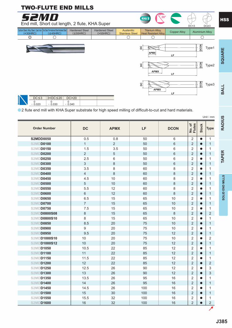
J385
a
e u u u u
S2MD
DC APMX LF DCON
S2MDD0050 0.5 0.8 50 6 2 a 1S2MDD0100 1 2 50 6 2 a 1S2MDD0150 1.5 3.5 50 6 2 a 1S2MDD0200 2 5 50 6 2 a 1S2MDD0250 2.5 6 50 6 2 a 1S2MDD0300 3 8 50 6 2 a 1S2MDD0350 3.5 8 60 8 2 a 1S2MDD0400 4 8 60 8 2 a 1S2MDD0450 4.5 10 60 8 2 a 1S2MDD0500 5 10 60 8 2 a 1S2MDD0550 5.5 12 60 8 2 a 1S2MDD0600 6 12 60 8 2 a 1S2MDD0650 6.5 15 65 10 2 a 1S2MDD0700 7 15 65 10 2 a 1S2MDD0750 7.5 15 65 10 2 a 1S2MDD0800S08 8 15 65 8 2 a 2S2MDD0800S10 8 15 65 10 2 a 1S2MDD0850 8.5 20 75 10 2 a 1S2MDD0900 9 20 75 10 2 a 1S2MDD0950 9.5 20 75 12 2 a 1S2MDD1000S10 10 20 75 10 2 a 2S2MDD1000S12 10 20 75 12 2 a 1S2MDD1050 10.5 22 85 12 2 a 1S2MDD1100 11 22 85 12 2 a 1S2MDD1150 11.5 22 85 12 2 a 1S2MDD1200 12 22 85 12 2 a 2S2MDD1250 12.5 26 90 12 2 a 3S2MDD1300 13 26 90 12 2 a 3S2MDD1350 13.5 26 95 16 2 a 1S2MDD1400 14 26 95 16 2 a 1S2MDD1450 14.5 26 100 16 2 a 1S2MDD1500 15 30 100 16 2 a 1S2MDD1550 15.5 32 100 16 2 a 1S2MDD1600 16 32 100 16 2 a 2
DC<3
DC>20 0- 0.020
0- 0.030
0- 0.040
KHA S 30°
DC
APMXLF
DCON
DC
APMXLF
DCON
APMXLF
DC
DCO
N
SOLI
D E
ND
MIL
LSSQ
UA
RE
BA
LLR
AD
IUS
TAPE
R
HSS
Unit : mm
Carbon Steel, Alloy Steel, Cast Iron(<30HRC)
Tool Steel, Pre-Hardened Steel,Hardened Steel(<45HRC)
Hardened Steel(<55HRC)
Hardened Steel(>55HRC)
AusteniticStainless Steel
Titanium Alloy,Heat Resistant Alloy Copper Alloy Aluminium Alloy
TWO-FLUTE END MILLS
Type2
Type3
Type1
End mill, Short cut length, 2 fl ute, KHA Super DC>3
DC<3 3<DC<20
2 fl ute end mill with KHA Super substrate for high speed milling of diffi cult-to-cut and hard materials.
Order Number
No.
of
Flut
es
Stoc
k
Type
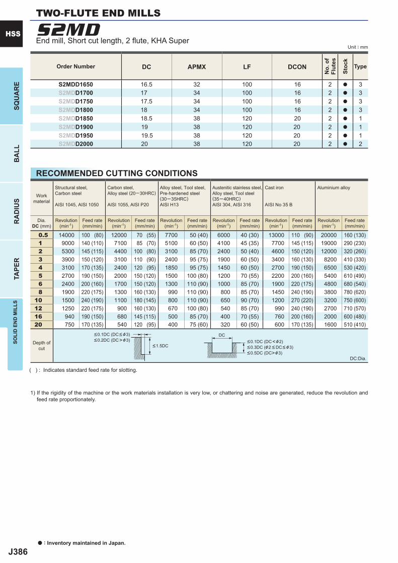
J386
DC APMX LF DCON
S2MDD1650 16.5 32 100 16 2 a 3S2MDD1700 17 34 100 16 2 a 3S2MDD1750 17.5 34 100 16 2 a 3S2MDD1800 18 34 100 16 2 a 3S2MDD1850 18.5 38 120 20 2 a 1S2MDD1900 19 38 120 20 2 a 1S2MDD1950 19.5 38 120 20 2 a 1S2MDD2000 20 38 120 20 2 a 2
0.5 14000 100 (80) 12000 70 (55) 7700 50 (40) 6000 40 (30) 13000 110 (90) 20000 160 (130) 1 9000 140 (110) 7100 85 (70) 5100 60 (50) 4100 45 (35) 7700 145 (115) 19000 290 (230) 2 5300 145 (115) 4400 100 (80) 3100 85 (70) 2400 50 (40) 4600 150 (120) 12000 320 (260) 3 3900 150 (120) 3100 110 (90) 2400 95 (75) 1900 60 (50) 3400 160 (130) 8200 410 (330) 4 3100 170 (135) 2400 120 (95) 1850 95 (75) 1450 60 (50) 2700 190 (150) 6500 530 (420) 5 2700 190 (150) 2000 150 (120) 1500 100 (80) 1200 70 (55) 2200 200 (160) 5400 610 (490) 6 2400 200 (160) 1700 150 (120) 1300 110 (90) 1000 85 (70) 1900 220 (175) 4800 680 (540) 8 1900 220 (175) 1300 160 (130) 990 110 (90) 800 85 (70) 1450 240 (190) 3800 780 (620)10 1500 240 (190) 1100 180 (145) 800 110 (90) 650 90 (70) 1200 270 (220) 3200 750 (600)12 1250 220 (175) 900 160 (130) 670 100 (80) 540 85 (70) 990 240 (190) 2700 710 (570)16 940 190 (150) 680 145 (115) 500 85 (70) 400 70 (55) 760 200 (160) 2000 600 (480)20 750 170 (135) 540 120 (95) 400 75 (60) 320 60 (50) 600 170 (135) 1600 510 (410)
S2MD
DC
a : Inventory maintained in Japan.
HSS
SQU
AR
EB
ALL
RA
DIU
STA
PER
SOLI
D E
ND
MIL
LS
Unit : mm
Order Number
No.
of
Flut
es
Stoc
k
Type
RECOMMENDED CUTTING CONDITIONS
( ) : Indicates standard feed rate for slotting.
1) If the rigidity of the machine or the work materials installation is very low, or chattering and noise are generated, reduce the revolution and feed rate proportionately.
DC:Dia.
Workmaterial
Structural steel, Carbon steel
AISI 1045, AISI 1050
Carbon steel,Alloy steel (20─30HRC)
AISI 1055, AISI P20
Alloy steel, Tool steel,Pre-hardened steel(30─35HRC)AISI H13
Austenitic stainless steel,Alloy steel, Tool steel(35─40HRC)AISI 304, AISI 316
Cast iron
AISI No 35 B
Aluminium alloy
Dia.DC (mm)
Revolution(min-1)
Feed rate(mm/min)
Revolution(min-1)
Feed rate(mm/min)
Revolution(min-1)
Feed rate(mm/min)
Revolution(min-1)
Feed rate(mm/min)
Revolution(min-1)
Feed rate(mm/min)
Revolution(min-1)
Feed rate(mm/min)
Depth ofcut
<0.1DC (DC< &3)<0.2DC (DC>&3)
<1.5DC<0.1DC (DC<&2)<0.3DC (&2 < DC< &3)<0.5DC (DC>&3)
TWO-FLUTE END MILLS
End mill, Short cut length, 2 fl ute, KHA Super
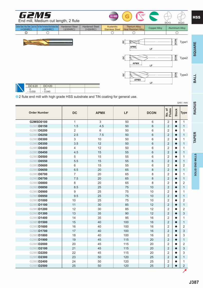
J387
a
e u u u u
G2MS
DC APMX LF DCON
G2MSD0100 1 3 50 6 2 a 1G2MSD0150 1.5 4.5 50 6 2 a 1G2MSD0200 2 6 50 6 2 a 1G2MSD0250 2.5 7.5 50 6 2 a 1G2MSD0300 3 10 50 6 2 a 1G2MSD0350 3.5 12 50 6 2 a 1G2MSD0400 4 12 50 6 2 a 1G2MSD0450 4.5 15 55 6 2 a 1G2MSD0500 5 15 55 6 2 a 1G2MSD0550 5.5 15 55 6 2 a 1G2MSD0600 6 15 55 6 2 a 2G2MSD0650 6.5 20 65 8 2 a 1G2MSD0700 7 20 65 8 2 a 1G2MSD0750 7.5 20 65 8 2 a 1G2MSD0800 8 20 65 8 2 a 2G2MSD0850 8.5 25 75 10 2 a 1G2MSD0900 9 25 75 10 2 a 1G2MSD0950 9.5 25 75 10 2 a 1G2MSD1000 10 25 75 10 2 a 2G2MSD1100 11 30 85 12 2 a 1G2MSD1200 12 30 85 12 2 a 2G2MSD1300 13 35 90 12 2 a 3G2MSD1400 14 35 95 16 2 a 1G2MSD1500 15 40 100 16 2 a 1G2MSD1600 16 40 100 16 2 a 2G2MSD1700 17 40 100 16 2 a 3G2MSD1800 18 40 100 16 2 a 3G2MSD1900 19 45 115 20 2 a 1G2MSD2000 20 45 115 20 2 a 2G2MSD2100 21 45 115 20 2 a 3G2MSD2200 22 45 115 20 2 a 3G2MSD2300 23 50 120 25 2 a 1G2MSD2400 24 50 120 25 2 a 1G2MSD2500 25 50 120 25 2 a 2
DC>20 0- 0.030
0- 0.040
DC<3
CO HSS G 30°
DC
APMXLF
DCON
DC
APMXLF
DCON
APMXLF
DC
DCON
SOLI
D E
ND
MIL
LSSQ
UA
RE
BA
LLR
AD
IUS
TAPE
R
HSS
Unit : mm
Carbon Steel, Alloy Steel, Cast Iron(<30HRC)
Tool Steel, Pre-Hardened Steel,Hardened Steel(<45HRC)
Hardened Steel(<55HRC)
Hardened Steel(>55HRC)
AusteniticStainless Steel
Titanium Alloy,Heat Resistant Alloy Copper Alloy Aluminium Alloy
End mill, Medium cut length, 2 fl ute
Type2
Type3
Type1
DC<20
2 fl ute end mill with high grade HSS substrate and TiN coating for general use.
Order Number
No.
of
Flut
es
Stoc
k
Type
DC>3
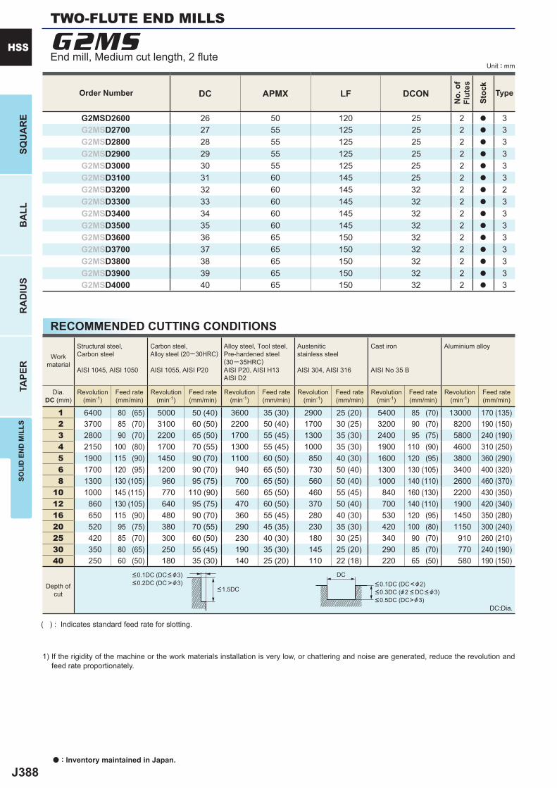
J388
DC APMX LF DCON
G2MSD2600 26 50 120 25 2 a 3G2MSD2700 27 55 125 25 2 a 3G2MSD2800 28 55 125 25 2 a 3G2MSD2900 29 55 125 25 2 a 3G2MSD3000 30 55 125 25 2 a 3G2MSD3100 31 60 145 25 2 a 3G2MSD3200 32 60 145 32 2 a 2G2MSD3300 33 60 145 32 2 a 3G2MSD3400 34 60 145 32 2 a 3G2MSD3500 35 60 145 32 2 a 3G2MSD3600 36 65 150 32 2 a 3G2MSD3700 37 65 150 32 2 a 3G2MSD3800 38 65 150 32 2 a 3G2MSD3900 39 65 150 32 2 a 3G2MSD4000 40 65 150 32 2 a 3
1 6400 80 (65) 5000 50 (40) 3600 35 (30) 2900 25 (20) 5400 85 (70) 13000 170 (135) 2 3700 85 (70) 3100 60 (50) 2200 50 (40) 1700 30 (25) 3200 90 (70) 8200 190 (150) 3 2800 90 (70) 2200 65 (50) 1700 55 (45) 1300 35 (30) 2400 95 (75) 5800 240 (190) 4 2150 100 (80) 1700 70 (55) 1300 55 (45) 1000 35 (30) 1900 110 (90) 4600 310 (250) 5 1900 115 (90) 1450 90 (70) 1100 60 (50) 850 40 (30) 1600 120 (95) 3800 360 (290) 6 1700 120 (95) 1200 90 (70) 940 65 (50) 730 50 (40) 1300 130 (105) 3400 400 (320) 8 1300 130 (105) 960 95 (75) 700 65 (50) 560 50 (40) 1000 140 (110) 2600 460 (370)10 1000 145 (115) 770 110 (90) 560 65 (50) 460 55 (45) 840 160 (130) 2200 430 (350)12 860 130 (105) 640 95 (75) 470 60 (50) 370 50 (40) 700 140 (110) 1900 420 (340)16 650 115 (90) 480 90 (70) 360 55 (45) 280 40 (30) 530 120 (95) 1450 350 (280)20 520 95 (75) 380 70 (55) 290 45 (35) 230 35 (30) 420 100 (80) 1150 300 (240)25 420 85 (70) 300 60 (50) 230 40 (30) 180 30 (25) 340 90 (70) 910 260 (210)30 350 80 (65) 250 55 (45) 190 35 (30) 145 25 (20) 290 85 (70) 770 240 (190)40 250 60 (50) 180 35 (30) 140 25 (20) 110 22 (18) 220 65 (50) 580 190 (150)
G2MS
DC
a : Inventory maintained in Japan.
HSS
SQU
AR
EB
ALL
RA
DIU
STA
PER
SOLI
D E
ND
MIL
LS
Unit : mm
Order Number
No.
of
Flut
es
Stoc
k
Type
RECOMMENDED CUTTING CONDITIONS
( ) : Indicates standard feed rate for slotting.
1) If the rigidity of the machine or the work materials installation is very low, or chattering and noise are generated, reduce the revolution and feed rate proportionately.
DC:Dia.
Workmaterial
Structural steel, Carbon steel
AISI 1045, AISI 1050
Carbon steel,Alloy steel (20─30HRC)
AISI 1055, AISI P20
Alloy steel, Tool steel,Pre-hardened steel(30─35HRC)AISI P20, AISI H13AISI D2
Austenitic stainless steel
AISI 304, AISI 316
Cast iron
AISI No 35 B
Aluminium alloy
Dia.DC (mm)
Revolution(min-1)
Feed rate(mm/min)
Revolution(min-1)
Feed rate(mm/min)
Revolution(min-1)
Feed rate(mm/min)
Revolution(min-1)
Feed rate(mm/min)
Revolution(min-1)
Feed rate(mm/min)
Revolution(min-1)
Feed rate(mm/min)
Depth ofcut
<0.1DC (DC< &3)<0.2DC (DC>&3)
<1.5DC<0.1DC (DC<&2)<0.3DC (&2 < DC< &3)<0.5DC (DC>&3)
TWO-FLUTE END MILLS
End mill, Medium cut length, 2 fl ute
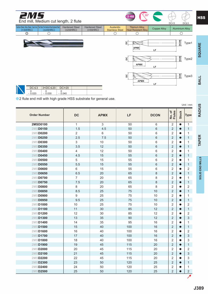
J389
a
e u u u u
2MS
DC APMX LF DCON
2MSD0100 1 3 50 6 2 a 12MSD0150 1.5 4.5 50 6 2 a 12MSD0200 2 6 50 6 2 a 12MSD0250 2.5 7.5 50 6 2 a 12MSD0300 3 10 50 6 2 a 12MSD0350 3.5 12 50 6 2 a 12MSD0400 4 12 50 6 2 a 12MSD0450 4.5 15 55 6 2 a 12MSD0500 5 15 55 6 2 a 12MSD0550 5.5 15 55 6 2 a 12MSD0600 6 15 55 6 2 a 22MSD0650 6.5 20 65 8 2 a 12MSD0700 7 20 65 8 2 a 12MSD0750 7.5 20 65 8 2 a 12MSD0800 8 20 65 8 2 a 22MSD0850 8.5 25 75 10 2 a 12MSD0900 9 25 75 10 2 a 12MSD0950 9.5 25 75 10 2 a 12MSD1000 10 25 75 10 2 a 22MSD1100 11 30 85 12 2 a 12MSD1200 12 30 85 12 2 a 22MSD1300 13 35 90 12 2 a 32MSD1400 14 35 95 16 2 a 12MSD1500 15 40 100 16 2 a 12MSD1600 16 40 100 16 2 a 22MSD1700 17 40 100 16 2 a 32MSD1800 18 40 100 16 2 a 32MSD1900 19 45 115 20 2 a 12MSD2000 20 45 115 20 2 a 22MSD2100 21 45 115 20 2 a 32MSD2200 22 45 115 20 2 a 32MSD2300 23 50 120 25 2 a 12MSD2400 24 50 120 25 2 a 12MSD2500 25 50 120 25 2 a 2
DC<3
DC>20 0- 0.020
0- 0.030
0- 0.040
CO HSS 30°
DC
APMXLF
DCON
DC
APMXLF
DCON
APMXLF
DC
DCON
SOLI
D E
ND
MIL
LSSQ
UA
RE
BA
LLR
AD
IUS
TAPE
R
HSS
Unit : mm
Carbon Steel, Alloy Steel, Cast Iron(<30HRC)
Tool Steel, Pre-Hardened Steel,Hardened Steel(<45HRC)
Hardened Steel(<55HRC)
Hardened Steel(>55HRC)
AusteniticStainless Steel
Titanium Alloy,Heat Resistant Alloy Copper Alloy Aluminium Alloy
End mill, Medium cut length, 2 fl ute
Type2
Type3
Type1
2 fl ute end mill with high grade HSS substrate for general use.
DC<3 3<DC<20
Order Number
No.
of
Flut
es
Stoc
k
Type
DC>3
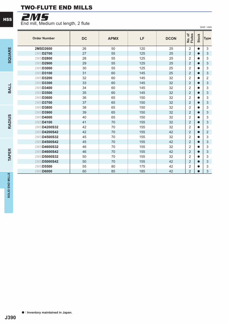
J390
DC APMX LF DCON
2MSD2600 26 50 120 25 2 a 32MSD2700 27 55 125 25 2 a 32MSD2800 28 55 125 25 2 a 32MSD2900 29 55 125 25 2 a 32MSD3000 30 55 125 25 2 a 32MSD3100 31 60 145 25 2 a 32MSD3200 32 60 145 32 2 a 22MSD3300 33 60 145 32 2 a 32MSD3400 34 60 145 32 2 a 32MSD3500 35 60 145 32 2 a 32MSD3600 36 65 150 32 2 a 32MSD3700 37 65 150 32 2 a 32MSD3800 38 65 150 32 2 a 32MSD3900 39 65 150 32 2 a 32MSD4000 40 65 150 32 2 a 32MSD4100 41 70 155 32 2 a 32MSD4200S32 42 70 155 32 2 a 32MSD4200S42 42 70 155 42 2 a 22MSD4500S32 45 70 155 32 2 a 32MSD4500S42 45 70 155 42 2 a 32MSD4600S32 46 70 155 32 2 a 32MSD4600S42 46 70 155 42 2 a 32MSD5000S32 50 70 155 32 2 a 32MSD5000S42 50 70 155 42 2 a 32MSD5500 55 80 175 42 2 a 32MSD6000 60 85 185 42 2 a 3
2MS
a : Inventory maintained in Japan.
HSS
SQU
AR
EB
ALL
RA
DIU
STA
PER
SOLI
D E
ND
MIL
LS
Unit : mm
Order Number
No.
of
Flut
es
Stoc
k
Type
TWO-FLUTE END MILLS
End mill, Medium cut length, 2 fl ute
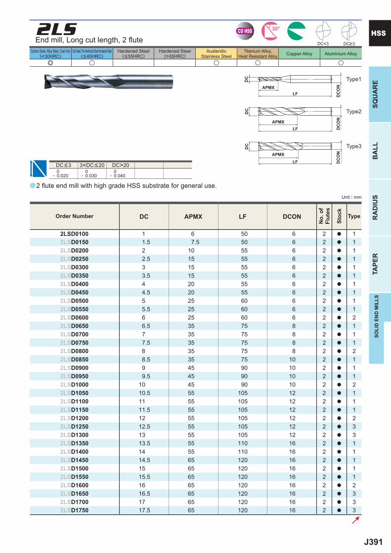
J391
a
e u u u u
2LS
DC APMX LF DCON
2LSD0100 1 6 50 6 2 a 12LSD0150 1.5 7.5 50 6 2 a 12LSD0200 2 10 55 6 2 a 12LSD0250 2.5 15 55 6 2 a 12LSD0300 3 15 55 6 2 a 12LSD0350 3.5 15 55 6 2 a 12LSD0400 4 20 55 6 2 a 12LSD0450 4.5 20 55 6 2 a 12LSD0500 5 25 60 6 2 a 12LSD0550 5.5 25 60 6 2 a 12LSD0600 6 25 60 6 2 a 22LSD0650 6.5 35 75 8 2 a 12LSD0700 7 35 75 8 2 a 12LSD0750 7.5 35 75 8 2 a 12LSD0800 8 35 75 8 2 a 22LSD0850 8.5 35 75 10 2 a 12LSD0900 9 45 90 10 2 a 12LSD0950 9.5 45 90 10 2 a 12LSD1000 10 45 90 10 2 a 22LSD1050 10.5 55 105 12 2 a 12LSD1100 11 55 105 12 2 a 12LSD1150 11.5 55 105 12 2 a 12LSD1200 12 55 105 12 2 a 22LSD1250 12.5 55 105 12 2 a 32LSD1300 13 55 105 12 2 a 32LSD1350 13.5 55 110 16 2 a 12LSD1400 14 55 110 16 2 a 12LSD1450 14.5 65 120 16 2 a 12LSD1500 15 65 120 16 2 a 12LSD1550 15.5 65 120 16 2 a 12LSD1600 16 65 120 16 2 a 22LSD1650 16.5 65 120 16 2 a 32LSD1700 17 65 120 16 2 a 32LSD1750 17.5 65 120 16 2 a 3
DC<3
DC>20 0- 0.020
0- 0.030
0- 0.040
CO HSS 30°
DC
APMXLF
DC
ON
DC
APMXLF
DC
ON
APMXLF
DC
DC
ON
SOLI
D E
ND
MIL
LSSQ
UA
RE
BA
LLR
AD
IUS
TAPE
R
HSS
Unit : mm
Carbon Steel, Alloy Steel, Cast Iron(<30HRC)
Tool Steel, Pre-Hardened Steel,Hardened Steel(<45HRC)
Hardened Steel(<55HRC)
Hardened Steel(>55HRC)
AusteniticStainless Steel
Titanium Alloy,Heat Resistant Alloy Copper Alloy Aluminium Alloy
Type2
Type3
Type1
2 fl ute end mill with high grade HSS substrate for general use.
End mill, Long cut length, 2 fl ute
DC<3 3<DC<20
Order Number
No.
of
Flut
es
Stoc
k
Type
DC>3
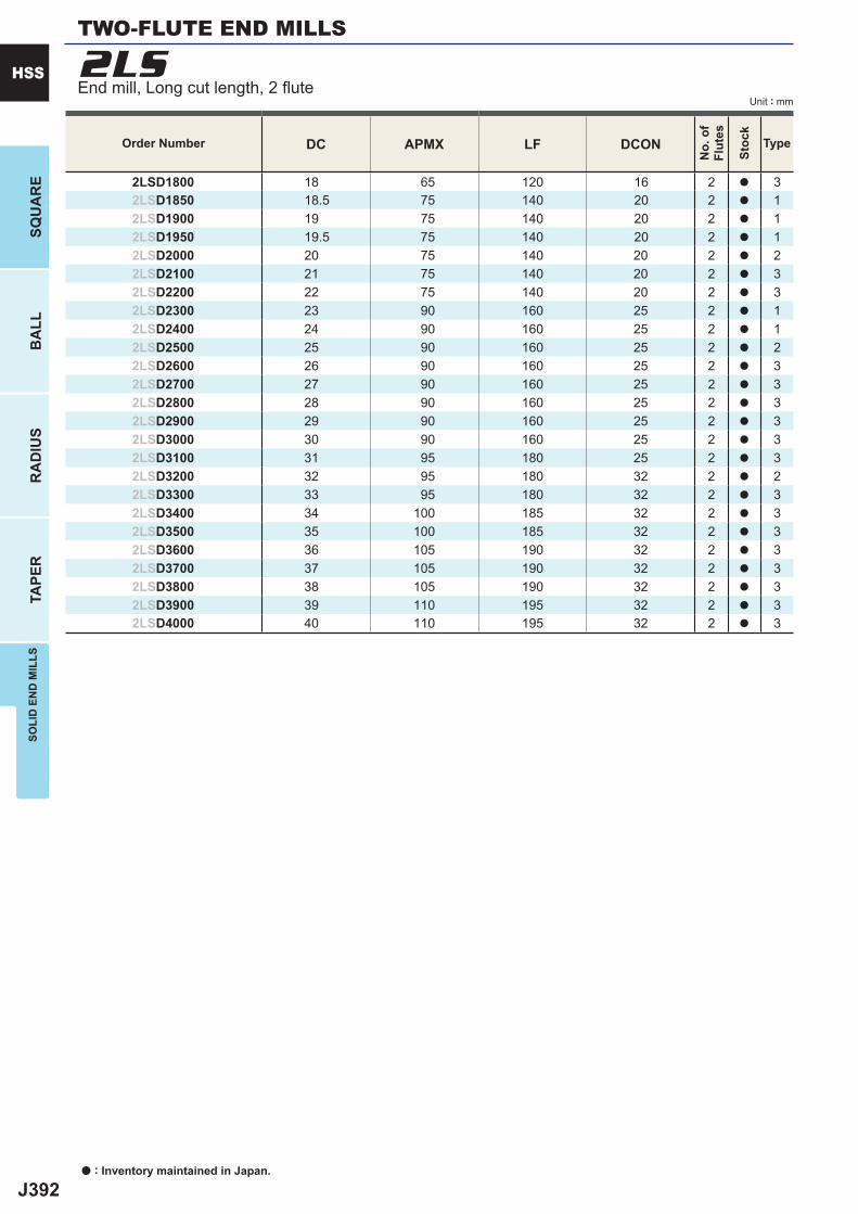
J392
DC APMX LF DCON
2LSD1800 18 65 120 16 2 a 32LSD1850 18.5 75 140 20 2 a 12LSD1900 19 75 140 20 2 a 12LSD1950 19.5 75 140 20 2 a 12LSD2000 20 75 140 20 2 a 22LSD2100 21 75 140 20 2 a 32LSD2200 22 75 140 20 2 a 32LSD2300 23 90 160 25 2 a 12LSD2400 24 90 160 25 2 a 12LSD2500 25 90 160 25 2 a 22LSD2600 26 90 160 25 2 a 32LSD2700 27 90 160 25 2 a 32LSD2800 28 90 160 25 2 a 32LSD2900 29 90 160 25 2 a 32LSD3000 30 90 160 25 2 a 32LSD3100 31 95 180 25 2 a 32LSD3200 32 95 180 32 2 a 22LSD3300 33 95 180 32 2 a 32LSD3400 34 100 185 32 2 a 32LSD3500 35 100 185 32 2 a 32LSD3600 36 105 190 32 2 a 32LSD3700 37 105 190 32 2 a 32LSD3800 38 105 190 32 2 a 32LSD3900 39 110 195 32 2 a 32LSD4000 40 110 195 32 2 a 3
2LS
a : Inventory maintained in Japan.
HSS
SQU
AR
EB
ALL
RA
DIU
STA
PER
SOLI
D E
ND
MIL
LS
Unit : mm
Order Number
No.
of
Flut
es
Stoc
k
Type
TWO-FLUTE END MILLS
End mill, Long cut length, 2 fl ute
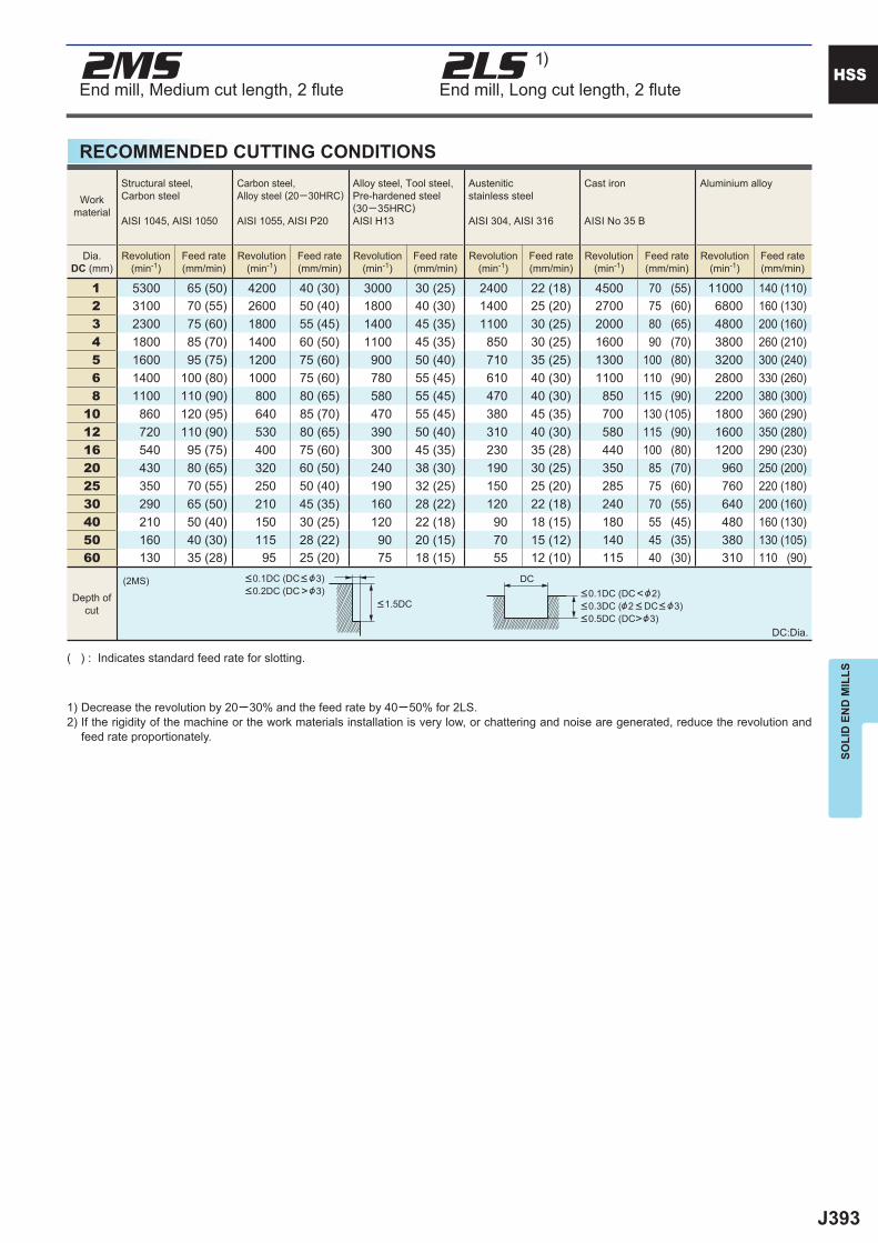
J393
1 5300 65 (50) 4200 40 (30) 3000 30 (25) 2400 22 (18) 4500 70 (55) 11000 140 (110) 2 3100 70 (55) 2600 50 (40) 1800 40 (30) 1400 25 (20) 2700 75 (60) 6800 160 (130) 3 2300 75 (60) 1800 55 (45) 1400 45 (35) 1100 30 (25) 2000 80 (65) 4800 200 (160) 4 1800 85 (70) 1400 60 (50) 1100 45 (35) 850 30 (25) 1600 90 (70) 3800 260 (210) 5 1600 95 (75) 1200 75 (60) 900 50 (40) 710 35 (25) 1300 100 (80) 3200 300 (240) 6 1400 100 (80) 1000 75 (60) 780 55 (45) 610 40 (30) 1100 110 (90) 2800 330 (260) 8 1100 110 (90) 800 80 (65) 580 55 (45) 470 40 (30) 850 115 (90) 2200 380 (300)10 860 120 (95) 640 85 (70) 470 55 (45) 380 45 (35) 700 130 (105) 1800 360 (290)12 720 110 (90) 530 80 (65) 390 50 (40) 310 40 (30) 580 115 (90) 1600 350 (280)16 540 95 (75) 400 75 (60) 300 45 (35) 230 35 (28) 440 100 (80) 1200 290 (230)20 430 80 (65) 320 60 (50) 240 38 (30) 190 30 (25) 350 85 (70) 960 250 (200)25 350 70 (55) 250 50 (40) 190 32 (25) 150 25 (20) 285 75 (60) 760 220 (180)30 290 65 (50) 210 45 (35) 160 28 (22) 120 22 (18) 240 70 (55) 640 200 (160)40 210 50 (40) 150 30 (25) 120 22 (18) 90 18 (15) 180 55 (45) 480 160 (130)50 160 40 (30) 115 28 (22) 90 20 (15) 70 15 (12) 140 45 (35) 380 130 (105)60 130 35 (28) 95 25 (20) 75 18 (15) 55 12 (10) 115 40 (30) 310 110 (90)
(2MS)
2MS 2LS 1)
DC
HSS
SOLI
D E
ND
MIL
LS
RECOMMENDED CUTTING CONDITIONS
( ) : Indicates standard feed rate for slotting.
1) Decrease the revolution by 20─30% and the feed rate by 40─50% for 2LS.2) If the rigidity of the machine or the work materials installation is very low, or chattering and noise are generated, reduce the revolution and
feed rate proportionately.
DC:Dia.
Workmaterial
Structural steel, Carbon steel
AISI 1045, AISI 1050
Carbon steel,Alloy steel (20─30HRC)
AISI 1055, AISI P20
Alloy steel, Tool steel,Pre-hardened steel(30─35HRC)AISI H13
Austenitic stainless steel
AISI 304, AISI 316
Cast iron
AISI No 35 B
Aluminium alloy
Dia.DC (mm)
Revolution(min-1)
Feed rate(mm/min)
Revolution(min-1)
Feed rate(mm/min)
Revolution(min-1)
Feed rate(mm/min)
Revolution(min-1)
Feed rate(mm/min)
Revolution(min-1)
Feed rate(mm/min)
Revolution(min-1)
Feed rate(mm/min)
Depth ofcut
<0.1DC (DC< &3)<0.2DC (DC>&3)
<1.5DC<0.1DC (DC<&2)<0.3DC (&2 < DC< &3)<0.5DC (DC>&3)
End mill, Medium cut length, 2 fl ute End mill, Long cut length, 2 fl ute
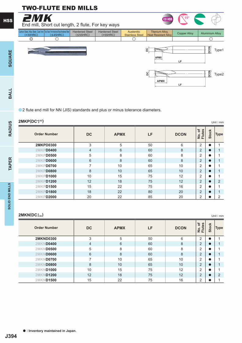
J394
a
e u u u
2MK
DC APMX LF DCON
2MKPD0300 3 5 50 6 2 a 12MKPD0400 4 6 60 8 2 a 12MKPD0500 5 8 60 8 2 a 12MKPD0600 6 8 60 8 2 a 12MKPD0700 7 10 65 10 2 a 12MKPD0800 8 10 65 10 2 a 12MKPD1000 10 15 75 12 2 a 12MKPD1200 12 18 75 12 2 a 22MKPD1500 15 22 75 16 2 a 12MKPD1800 18 22 80 20 2 a 12MKPD2000 20 22 85 20 2 a 2
DC APMX LF DCON
2MKND0300 3 5 50 6 2 a 12MKND0400 4 6 60 8 2 a 12MKND0500 5 8 60 8 2 a 12MKND0600 6 8 60 8 2 a 12MKND0700 7 10 65 10 2 a 12MKND0800 8 10 65 10 2 a 12MKND1000 10 15 75 12 2 a 12MKND1200 12 18 75 12 2 a 22MKND1500 15 22 75 16 2 a 1
2MKP(DC+0.02 0 )
2MKN(DC 0 -0.02)
CO HSS 15°
APMXLF
DC
DCON
APMXLF
DC
DCON
a : Inventory maintained in Japan.
HSS
SQU
AR
EB
ALL
RA
DIU
STA
PER
SOLI
D E
ND
MIL
LS
Carbon Steel, Alloy Steel, Cast Iron(<30HRC)
Tool Steel, Pre-Hardened Steel,Hardened Steel(<45HRC)
Hardened Steel(<55HRC)
Hardened Steel(>55HRC)
AusteniticStainless Steel
Titanium Alloy,Heat Resistant Alloy Copper Alloy Aluminium Alloy
End mill, Short cut length, 2 fl ute, For key ways
Type2
Type1
2 fl ute end mill for NN (JIS) standards and plus or minus tolerance diameters.
Unit : mm
Unit : mm
Order Number
No.
of
Flut
es
Stoc
k
Type
Order Number
No.
of
Flut
es
Stoc
k
Type
TWO-FLUTE END MILLS
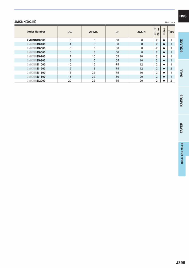
J395
DC APMX LF DCON
2MKNND0300 3 5 50 6 2 a 12MKNND0400 4 6 60 8 2 a 12MKNND0500 5 8 60 8 2 a 12MKNND0600 6 8 60 8 2 a 12MKNND0700 7 10 65 10 2 a 12MKNND0800 8 10 65 10 2 a 12MKNND1000 10 15 75 12 2 a 12MKNND1200 12 18 75 12 2 a 22MKNND1500 15 22 75 16 2 a 12MKNND1800 18 22 80 20 2 a 12MKNND2000 20 22 85 20 2 a 2
2MKNN(DC-0.02-0.04)
SOLI
D E
ND
MIL
LSSQ
UA
RE
BA
LLR
AD
IUS
TAPE
R
HSSUnit : mm
Order Number
No.
of
Flut
es
Stoc
k
Type
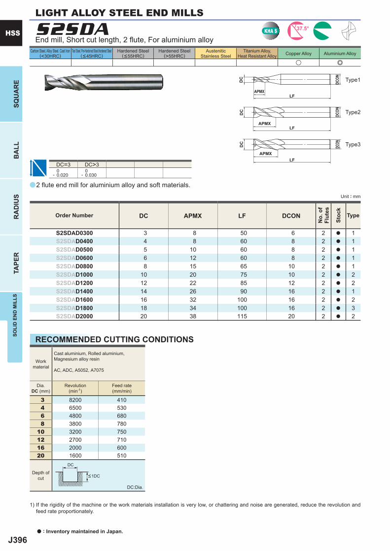
J396
a
u e
S2SDA
DC APMX LF DCON
S2SDAD0300 3 8 50 6 2 a 1S2SDAD0400 4 8 60 8 2 a 1S2SDAD0500 5 10 60 8 2 a 1S2SDAD0600 6 12 60 8 2 a 1S2SDAD0800 8 15 65 10 2 a 1S2SDAD1000 10 20 75 10 2 a 2S2SDAD1200 12 22 85 12 2 a 2S2SDAD1400 14 26 90 16 2 a 1S2SDAD1600 16 32 100 16 2 a 2S2SDAD1800 18 34 100 16 2 a 3S2SDAD2000 20 38 115 20 2 a 2
DC=3 DC>3 0- 0.020
0- 0.030
3 8200 410 4 6500 530 6 4800 680 8 3800 78010 3200 75012 2700 71016 2000 60020 1600 510
KHA S 37.5°
DC
APMXLF
DCON
DC
APMXLF
DCON
APMXLF
DC
DCON
DC
a : Inventory maintained in Japan.
HSS
SQU
AR
EB
ALL
RA
DIU
STA
PER
SOLI
D E
ND
MIL
LS
Unit : mm
Carbon Steel, Alloy Steel, Cast Iron(<30HRC)
Tool Steel, Pre-Hardened Steel,Hardened Steel(<45HRC)
Hardened Steel(<55HRC)
Hardened Steel(>55HRC)
AusteniticStainless Steel
Titanium Alloy,Heat Resistant Alloy Copper Alloy Aluminium Alloy
2 fl ute end mill for aluminium alloy and soft materials.
End mill, Short cut length, 2 fl ute, For aluminium alloy
LIGHT ALLOY STEEL END MILLS
Type2
Type3
Type1
Order Number
No.
of
Flut
es
Stoc
k
Type
RECOMMENDED CUTTING CONDITIONS
Workmaterial
Cast aluminium, Rolled aluminium, Magnesium alloy resin
AC, ADC, A5052, A7075
Dia.DC (mm)
Revolution(min-1)
Feed rate(mm/min)
DC:Dia.
1) If the rigidity of the machine or the work materials installation is very low, or chattering and noise are generated, reduce the revolution and feed rate proportionately.
Depth ofcut <1DC
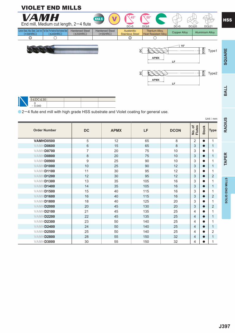
J397
a
e u e u
VAMH
DC APMX LF DCON
VAMHD0500 5 12 65 8 2 a 1VAMHD0600 6 15 65 8 3 a 1VAMHD0700 7 20 75 10 3 a 1VAMHD0800 8 20 75 10 3 a 1VAMHD0900 9 25 90 10 3 a 1VAMHD1000 10 25 90 12 3 a 1VAMHD1100 11 30 95 12 3 a 1VAMHD1200 12 30 95 12 3 a 2VAMHD1300 13 35 105 16 3 a 1VAMHD1400 14 35 105 16 3 a 1VAMHD1500 15 40 115 16 3 a 1VAMHD1600 16 40 115 16 3 a 2VAMHD1800 18 40 125 20 3 a 1VAMHD2000 20 45 130 20 3 a 2VAMHD2100 21 45 135 25 4 a 1VAMHD2200 22 45 135 25 4 a 1VAMHD2300 23 50 140 25 4 a 1VAMHD2400 24 50 140 25 4 a 1VAMHD2500 25 50 140 25 4 a 2VAMHD2800 28 55 150 32 4 a 1VAMHD3000 30 55 150 32 4 a 1
0- 0.040
DC=5 DC=5
VKHA S 45° 50°
APMXLF
DC
DCON
APMXLF
DC
DCON
15°
SOLI
D E
ND
MIL
LSSQ
UA
RE
BA
LLR
AD
IUS
TAPE
R
HSS
Unit : mm
Carbon Steel, Alloy Steel, Cast Iron(<30HRC)
Tool Steel, Pre-Hardened Steel,Hardened Steel(<45HRC)
Hardened Steel(<55HRC)
Hardened Steel(>55HRC)
AusteniticStainless Steel
Titanium Alloy,Heat Resistant Alloy Copper Alloy Aluminium Alloy
Type2
Type1
Order Number
No.
of
Flut
es
Stoc
k
Type
DC>6 DC>21DC<20
2─4 fl ute end mill with high grade HSS substrate and Violet coating for general use.
End mill, Medium cut length, 2─4 fl ute
VIOLET END MILLS
5<DC<30
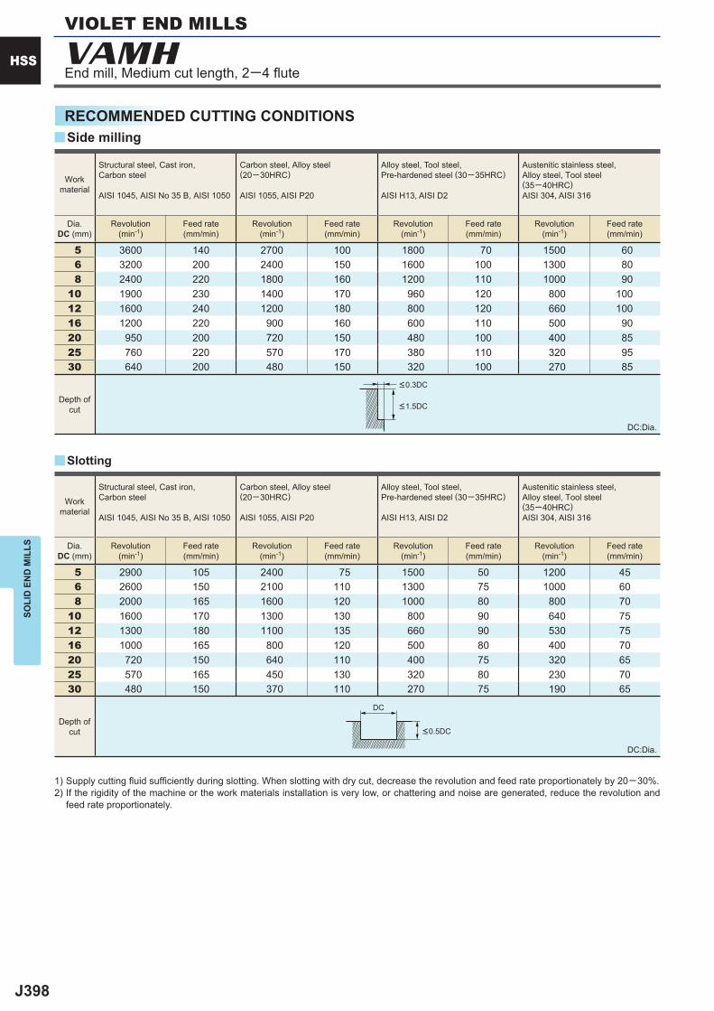
J398
5 3600 140 2700 100 1800 70 1500 60 6 3200 200 2400 150 1600 100 1300 80 8 2400 220 1800 160 1200 110 1000 9010 1900 230 1400 170 960 120 800 10012 1600 240 1200 180 800 120 660 10016 1200 220 900 160 600 110 500 9020 950 200 720 150 480 100 400 8525 760 220 570 170 380 110 320 9530 640 200 480 150 320 100 270 85
5 2900 105 2400 75 1500 50 1200 45 6 2600 150 2100 110 1300 75 1000 60 8 2000 165 1600 120 1000 80 800 7010 1600 170 1300 130 800 90 640 7512 1300 180 1100 135 660 90 530 7516 1000 165 800 120 500 80 400 7020 720 150 640 110 400 75 320 6525 570 165 450 130 320 80 230 7030 480 150 370 110 270 75 190 65
y
y
VAMH
DC
HSS
SOLI
D E
ND
MIL
LS
RECOMMENDED CUTTING CONDITIONS
1) Supply cutting fl uid suffi ciently during slotting. When slotting with dry cut, decrease the revolution and feed rate proportionately by 20─30%.2) If the rigidity of the machine or the work materials installation is very low, or chattering and noise are generated, reduce the revolution and
feed rate proportionately.
DC:Dia.
DC:Dia.
Slotting
Side milling
Workmaterial
Structural steel, Cast iron, Carbon steel
AISI 1045, AISI No 35 B, AISI 1050
Carbon steel, Alloy steel (20─30HRC)
AISI 1055, AISI P20
Alloy steel, Tool steel,Pre-hardened steel (30─35HRC)
AISI H13, AISI D2
Austenitic stainless steel,Alloy steel, Tool steel(35─40HRC)AISI 304, AISI 316
Dia.DC (mm)
Revolution(min-1)
Feed rate(mm/min)
Revolution(min-1)
Feed rate(mm/min)
Revolution(min-1)
Feed rate(mm/min)
Revolution(min-1)
Feed rate(mm/min)
Depth ofcut
Depth ofcut
<0.3DC
<1.5DC
<0.5DC
End mill, Medium cut length, 2─4 fl ute
VIOLET END MILLS
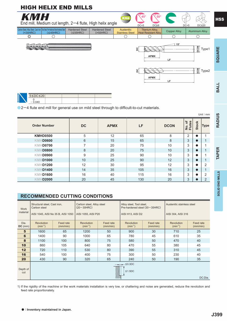
J399
a
e u u u u u
KMH
DC APMX LF DCON
KMHD0500 5 12 65 8 2 a 1KMHD0600 6 15 65 8 3 a 1KMHD0700 7 20 75 10 3 a 1KMHD0800 8 20 75 10 3 a 1KMHD0900 9 25 90 10 3 a 1KMHD1000 10 25 90 12 3 a 1KMHD1200 12 30 95 12 3 a 2KMHD1400 14 35 105 16 3 a 1KMHD1600 16 40 115 16 3 a 2KMHD2000 20 45 130 20 3 a 2
DC=5 DC=5
0- 0.040
5 1600 65 1200 50 900 30 710 25 6 1400 90 1000 65 780 45 610 35 8 1100 100 800 75 580 50 470 4010 860 105 640 80 470 55 380 4512 720 110 530 80 390 55 310 4516 540 100 400 75 300 50 230 4020 430 90 320 65 240 50 190 35
KHA 45° 50°
APMXLF
DC
DCON
APMXLF
DC
DCON
15°
SOLI
D E
ND
MIL
LSSQ
UA
RE
BA
LLR
AD
IUS
TAPE
R
HSS
Unit : mm
Carbon Steel, Alloy Steel, Cast Iron(<30HRC)
Tool Steel, Pre-Hardened Steel,Hardened Steel(<45HRC)
Hardened Steel(<55HRC)
Hardened Steel(>55HRC)
AusteniticStainless Steel
Titanium Alloy,Heat Resistant Alloy Copper Alloy Aluminium Alloy
2─4 fl ute end mill for general use on mild steel through to diffi cult-to-cut materials.
End mill, Medium cut length, 2─4 fl ute, High helix angle
HIGH HELIX END MILLS
5<DC<20
DC>6 DC<20
Type2
Type1
Order Number
No.
of
Flut
es
Stoc
k
Type
RECOMMENDED CUTTING CONDITIONS
DC:Dia.
1) If the rigidity of the machine or the work materials installation is very low, or chattering and noise are generated, reduce the revolution and feed rate proportionately.
Depth ofcut
<0.3DC
<1.5DC
Workmaterial
Structural steel, Cast iron, Carbon steel
AISI 1045, AISI No 35 B, AISI 1050
Carbon steel, Alloy steel (20─30HRC)
AISI 1055, AISI P20
Alloy steel, Tool steel,Pre-hardened steel (30─35HRC)
AISI H13, AISI D2
Austenitic stainless steel
AISI 304, AISI 316
Dia.DC (mm)
Revolution(min-1)
Feed rate(mm/min)
Revolution(min-1)
Feed rate(mm/min)
Revolution(min-1)
Feed rate(mm/min)
Revolution(min-1)
Feed rate(mm/min)
a : Inventory maintained in Japan.
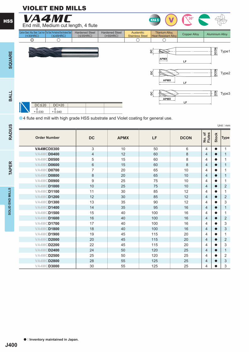
J400
a
e u u u
VA4MC
DC APMX LF DCON
VA4MCD0300 3 10 50 6 4 a 1VA4MCD0400 4 12 60 8 4 a 1VA4MCD0500 5 15 60 8 4 a 1VA4MCD0600 6 15 60 8 4 a 1VA4MCD0700 7 20 65 10 4 a 1VA4MCD0800 8 20 65 10 4 a 1VA4MCD0900 9 25 75 10 4 a 1VA4MCD1000 10 25 75 10 4 a 2VA4MCD1100 11 30 85 12 4 a 1VA4MCD1200 12 30 85 12 4 a 2VA4MCD1300 13 35 90 12 4 a 3VA4MCD1400 14 35 95 16 4 a 1VA4MCD1500 15 40 100 16 4 a 1VA4MCD1600 16 40 100 16 4 a 2VA4MCD1700 17 40 100 16 4 a 3VA4MCD1800 18 40 100 16 4 a 3VA4MCD1900 19 45 115 20 4 a 1VA4MCD2000 20 45 115 20 4 a 2VA4MCD2200 22 45 115 20 4 a 3VA4MCD2400 24 50 120 25 4 a 1VA4MCD2500 25 50 120 25 4 a 2VA4MCD2800 28 55 125 25 4 a 3VA4MCD3000 30 55 125 25 4 a 3
DC>20 0+ 0.030
0+ 0.040
VKHA S 30°
APMXLF
DC
DCON
APMXLF
DC
DCO
N
APMXLF
DC
DCON
a : Inventory maintained in Japan.
HSS
SQU
AR
EB
ALL
RA
DIU
STA
PER
SOLI
D E
ND
MIL
LS
Unit : mm
Carbon Steel, Alloy Steel, Cast Iron(<30HRC)
Tool Steel, Pre-Hardened Steel,Hardened Steel(<45HRC)
Hardened Steel(<55HRC)
Hardened Steel(>55HRC)
AusteniticStainless Steel
Titanium Alloy,Heat Resistant Alloy Copper Alloy Aluminium Alloy
Order Number
No.
of
Flut
es
Stoc
k
Type
4 fl ute end mill with high grade HSS substrate and Violet coating for general use.
End mill, Medium cut length, 4 fl ute
VIOLET END MILLS
DC<20
Type2
Type3
Type1
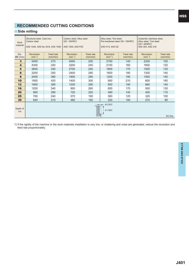
J401
3 5400 270 4000 200 2700 140 2200 100 4 4300 320 3200 240 2100 160 1800 120 5 3600 340 2700 250 1800 170 1500 130 6 3200 350 2400 260 1600 180 1300 140 8 2400 380 1800 290 1200 190 1000 14510 1900 420 1400 300 950 210 800 16012 1600 380 1200 290 800 190 660 14516 1200 340 900 260 600 170 500 13020 950 290 720 220 480 140 400 11025 760 240 570 180 380 120 320 10030 640 210 480 160 320 100 270 80
y
HSS
SOLI
D E
ND
MIL
LS
RECOMMENDED CUTTING CONDITIONS
1) If the rigidity of the machine or the work materials installation is very low, or chattering and noise are generated, reduce the revolution and feed rate proportionately.
DC:Dia.
Side milling
Workmaterial
Structural steel, Cast iron, Carbon steel
AISI 1045, AISI No 35 B, AISI 1050
Carbon steel, Alloy steel (20─30HRC)
AISI 1055, AISI P20
Alloy steel, Tool steel,Pre-hardened steel (30─35HRC)
AISI H13, AISI D2
Austenitic stainless steel,Alloy steel, Tool steel(35─40HRC)AISI 304, AISI 316
Dia.DC (mm)
Revolution(min-1)
Feed rate(mm/min)
Revolution(min-1)
Feed rate(mm/min)
Revolution(min-1)
Feed rate(mm/min)
Revolution(min-1)
Feed rate(mm/min)
Depth ofcut
<0.2DC
<1.5DC
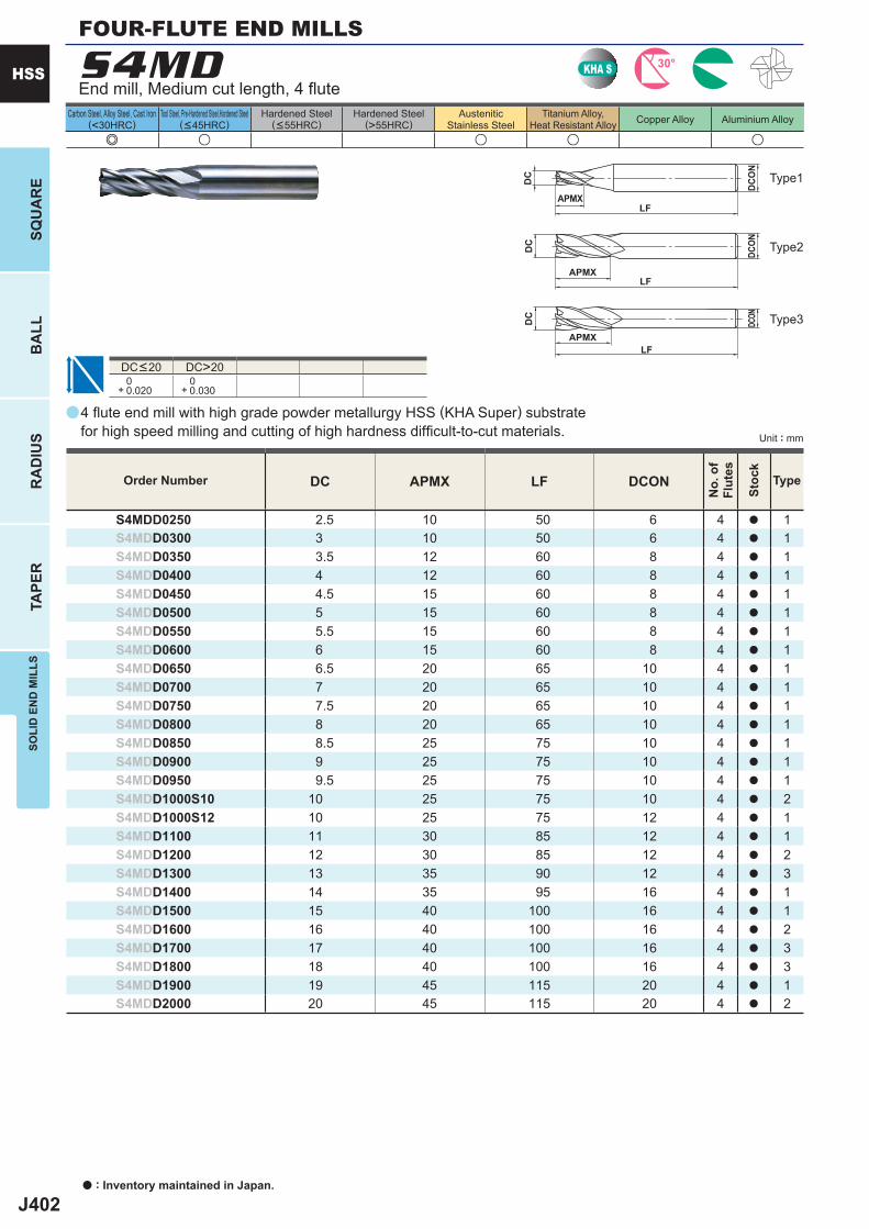
J402
a
S4MD
e u u u u
DC APMX LF DCON
S4MDD0250 2.5 10 50 6 4 a 1S4MDD0300 3 10 50 6 4 a 1S4MDD0350 3.5 12 60 8 4 a 1S4MDD0400 4 12 60 8 4 a 1S4MDD0450 4.5 15 60 8 4 a 1S4MDD0500 5 15 60 8 4 a 1S4MDD0550 5.5 15 60 8 4 a 1S4MDD0600 6 15 60 8 4 a 1S4MDD0650 6.5 20 65 10 4 a 1S4MDD0700 7 20 65 10 4 a 1S4MDD0750 7.5 20 65 10 4 a 1S4MDD0800 8 20 65 10 4 a 1S4MDD0850 8.5 25 75 10 4 a 1S4MDD0900 9 25 75 10 4 a 1S4MDD0950 9.5 25 75 10 4 a 1S4MDD1000S10 10 25 75 10 4 a 2S4MDD1000S12 10 25 75 12 4 a 1S4MDD1100 11 30 85 12 4 a 1S4MDD1200 12 30 85 12 4 a 2S4MDD1300 13 35 90 12 4 a 3S4MDD1400 14 35 95 16 4 a 1S4MDD1500 15 40 100 16 4 a 1S4MDD1600 16 40 100 16 4 a 2S4MDD1700 17 40 100 16 4 a 3S4MDD1800 18 40 100 16 4 a 3S4MDD1900 19 45 115 20 4 a 1S4MDD2000 20 45 115 20 4 a 2
DC>20 0+ 0.020
0+ 0.030
KHA S 30°
APMXLF
DC
DCON
APMXLF
DC
DCO
N
APMXLF
DC
DCON
a : Inventory maintained in Japan.
HSS
SQU
AR
EB
ALL
RA
DIU
STA
PER
SOLI
D E
ND
MIL
LS
Unit : mm
Carbon Steel, Alloy Steel, Cast Iron(<30HRC)
Tool Steel, Pre-Hardened Steel,Hardened Steel(<45HRC)
Hardened Steel(<55HRC)
Hardened Steel(>55HRC)
AusteniticStainless Steel
Titanium Alloy,Heat Resistant Alloy Copper Alloy Aluminium Alloy
4 fl ute end mill with high grade powder metallurgy HSS (KHA Super) substrate for high speed milling and cutting of high hardness diffi cult-to-cut materials.
End mill, Medium cut length, 4 fl ute
FOUR-FLUTE END MILLS
DC<20
Type2
Type3
Type1
Order Number
No.
of
Flut
es
Stoc
k
Type

J403
3 3900 240 3100 175 2400 150 1900 95 3400 260 8200 660 4 3100 270 2400 190 1850 150 1450 95 2700 300 6500 850 5 2700 300 2000 240 1500 160 1200 110 2200 320 5400 980 6 2400 320 1700 240 1300 175 1000 135 1900 350 4800 1100 8 1900 350 1300 260 990 175 800 135 1450 380 3800 125010 1500 380 1100 290 800 175 650 145 1200 430 3200 120012 1250 350 900 260 670 160 540 135 990 380 2700 110016 940 300 680 230 500 135 400 110 760 320 2000 960
(S4MD)
y
HSS
SOLI
D E
ND
MIL
LS
RECOMMENDED CUTTING CONDITIONS
Workmaterial
Structural steel, Carbon steel
AISI 1045, AISI 1050
Carbon steel,Alloy steel (20─30HRC)
AISI 1055, AISI P20
Alloy steel, Tool steel,Pre-hardened steel(30─35HRC)AISI H13
Austenitic stainless steel,Alloy steel, Tool steel(35─40HRC)AISI 304, AISI 316
Cast iron
AISI No 35 B
Aluminium alloy
Dia.DC (mm)
Revolution(min-1)
Feed rate(mm/min)
Revolution(min-1)
Feed rate(mm/min)
Revolution(min-1)
Feed rate(mm/min)
Revolution(min-1)
Feed rate(mm/min)
Revolution(min-1)
Feed rate(mm/min)
Revolution(min-1)
Feed rate(mm/min)
<0.2DC
<1.5DC
Side milling
Depth ofcut
DC:Dia.
1) If the rigidity of the machine or the work materials installation is very low, or chattering and noise are generated, reduce the revolution and feed rate proportionately.
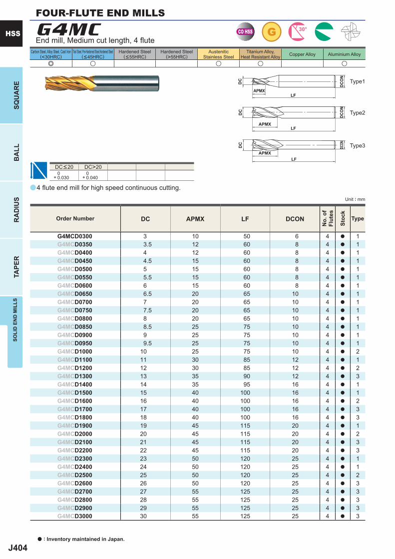
J404
a
e u u u u
G4MC
DC APMX LF DCON
G4MCD0300 3 10 50 6 4 a 1G4MCD0350 3.5 12 60 8 4 a 1G4MCD0400 4 12 60 8 4 a 1G4MCD0450 4.5 15 60 8 4 a 1G4MCD0500 5 15 60 8 4 a 1G4MCD0550 5.5 15 60 8 4 a 1G4MCD0600 6 15 60 8 4 a 1G4MCD0650 6.5 20 65 10 4 a 1G4MCD0700 7 20 65 10 4 a 1G4MCD0750 7.5 20 65 10 4 a 1G4MCD0800 8 20 65 10 4 a 1G4MCD0850 8.5 25 75 10 4 a 1G4MCD0900 9 25 75 10 4 a 1G4MCD0950 9.5 25 75 10 4 a 1G4MCD1000 10 25 75 10 4 a 2G4MCD1100 11 30 85 12 4 a 1G4MCD1200 12 30 85 12 4 a 2G4MCD1300 13 35 90 12 4 a 3G4MCD1400 14 35 95 16 4 a 1G4MCD1500 15 40 100 16 4 a 1G4MCD1600 16 40 100 16 4 a 2G4MCD1700 17 40 100 16 4 a 3G4MCD1800 18 40 100 16 4 a 3G4MCD1900 19 45 115 20 4 a 1G4MCD2000 20 45 115 20 4 a 2G4MCD2100 21 45 115 20 4 a 3G4MCD2200 22 45 115 20 4 a 3G4MCD2300 23 50 120 25 4 a 1G4MCD2400 24 50 120 25 4 a 1G4MCD2500 25 50 120 25 4 a 2G4MCD2600 26 50 120 25 4 a 3G4MCD2700 27 55 125 25 4 a 3G4MCD2800 28 55 125 25 4 a 3G4MCD2900 29 55 125 25 4 a 3G4MCD3000 30 55 125 25 4 a 3
DC>20 0+ 0.030
0+ 0.040
CO HSS G 30°
APMXLF
DC
DCO
N
APMXLF
DC
DCO
N
APMXLF
DC
DCON
a : Inventory maintained in Japan.
HSS
SQU
AR
EB
ALL
RA
DIU
STA
PER
SOLI
D E
ND
MIL
LS
Unit : mm
Carbon Steel, Alloy Steel, Cast Iron(<30HRC)
Tool Steel, Pre-Hardened Steel,Hardened Steel(<45HRC)
Hardened Steel(<55HRC)
Hardened Steel(>55HRC)
AusteniticStainless Steel
Titanium Alloy,Heat Resistant Alloy Copper Alloy Aluminium Alloy
Type2
Type3
Type1
Order Number
No.
of
Flut
es
Stoc
k
Type
4 fl ute end mill for high speed continuous cutting.
End mill, Medium cut length, 4 fl ute
DC<20
FOUR-FLUTE END MILLS
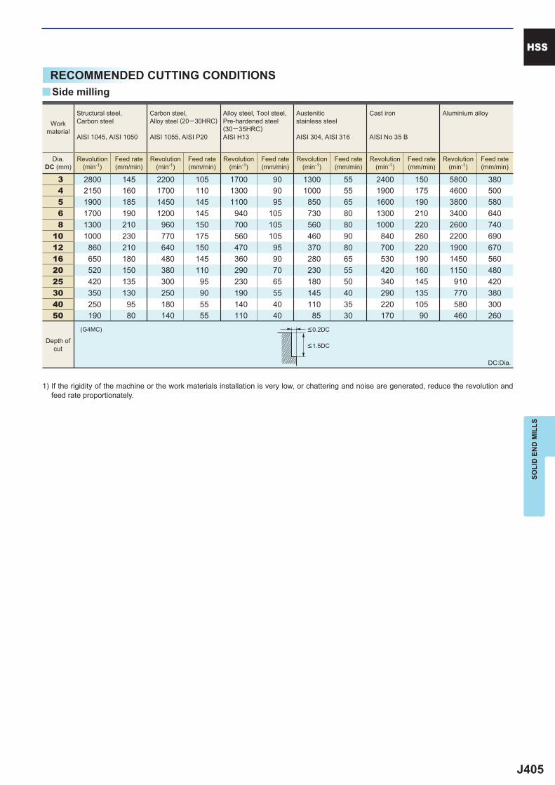
J405
3 2800 145 2200 105 1700 90 1300 55 2400 150 5800 380 4 2150 160 1700 110 1300 90 1000 55 1900 175 4600 500 5 1900 185 1450 145 1100 95 850 65 1600 190 3800 580 6 1700 190 1200 145 940 105 730 80 1300 210 3400 640 8 1300 210 960 150 700 105 560 80 1000 220 2600 74010 1000 230 770 175 560 105 460 90 840 260 2200 69012 860 210 640 150 470 95 370 80 700 220 1900 67016 650 180 480 145 360 90 280 65 530 190 1450 56020 520 150 380 110 290 70 230 55 420 160 1150 48025 420 135 300 95 230 65 180 50 340 145 910 42030 350 130 250 90 190 55 145 40 290 135 770 38040 250 95 180 55 140 40 110 35 220 105 580 30050 190 80 140 55 110 40 85 30 170 90 460 260
(G4MC)
y
HSS
SOLI
D E
ND
MIL
LS
RECOMMENDED CUTTING CONDITIONS
<0.2DC
<1.5DC
Workmaterial
Structural steel, Carbon steel
AISI 1045, AISI 1050
Carbon steel,Alloy steel (20─30HRC)
AISI 1055, AISI P20
Alloy steel, Tool steel,Pre-hardened steel(30─35HRC)AISI H13
Austenitic stainless steel
AISI 304, AISI 316
Cast iron
AISI No 35 B
Aluminium alloy
Dia.DC (mm)
Revolution(min-1)
Feed rate(mm/min)
Revolution(min-1)
Feed rate(mm/min)
Revolution(min-1)
Feed rate(mm/min)
Revolution(min-1)
Feed rate(mm/min)
Revolution(min-1)
Feed rate(mm/min)
Revolution(min-1)
Feed rate(mm/min)
Side milling
Depth ofcut
DC:Dia.
1) If the rigidity of the machine or the work materials installation is very low, or chattering and noise are generated, reduce the revolution and feed rate proportionately.
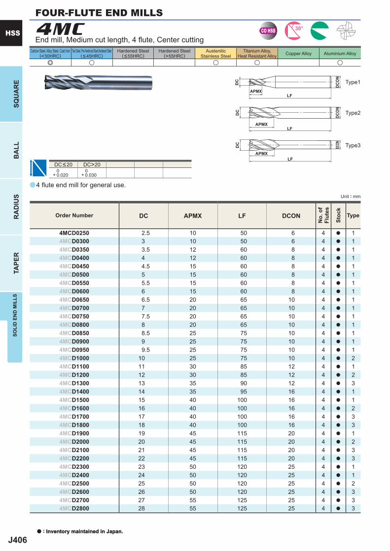
J406
a
e u u u u
4MC
DC APMX LF DCON
4MCD0250 2.5 10 50 6 4 a 14MCD0300 3 10 50 6 4 a 14MCD0350 3.5 12 60 8 4 a 14MCD0400 4 12 60 8 4 a 14MCD0450 4.5 15 60 8 4 a 14MCD0500 5 15 60 8 4 a 14MCD0550 5.5 15 60 8 4 a 14MCD0600 6 15 60 8 4 a 14MCD0650 6.5 20 65 10 4 a 14MCD0700 7 20 65 10 4 a 14MCD0750 7.5 20 65 10 4 a 14MCD0800 8 20 65 10 4 a 14MCD0850 8.5 25 75 10 4 a 14MCD0900 9 25 75 10 4 a 14MCD0950 9.5 25 75 10 4 a 14MCD1000 10 25 75 10 4 a 24MCD1100 11 30 85 12 4 a 14MCD1200 12 30 85 12 4 a 24MCD1300 13 35 90 12 4 a 34MCD1400 14 35 95 16 4 a 14MCD1500 15 40 100 16 4 a 14MCD1600 16 40 100 16 4 a 24MCD1700 17 40 100 16 4 a 34MCD1800 18 40 100 16 4 a 34MCD1900 19 45 115 20 4 a 14MCD2000 20 45 115 20 4 a 24MCD2100 21 45 115 20 4 a 34MCD2200 22 45 115 20 4 a 34MCD2300 23 50 120 25 4 a 14MCD2400 24 50 120 25 4 a 14MCD2500 25 50 120 25 4 a 24MCD2600 26 50 120 25 4 a 34MCD2700 27 55 125 25 4 a 34MCD2800 28 55 125 25 4 a 3
DC>20 0+ 0.020
0+ 0.030
CO HSS 30°
APMXLF
DC
DCON
APMXLF
DC
DCO
N
APMXLF
DC
DCON
a : Inventory maintained in Japan.
HSS
SQU
AR
EB
ALL
RA
DIU
STA
PER
SOLI
D E
ND
MIL
LS
Unit : mm
Carbon Steel, Alloy Steel, Cast Iron(<30HRC)
Tool Steel, Pre-Hardened Steel,Hardened Steel(<45HRC)
Hardened Steel(<55HRC)
Hardened Steel(>55HRC)
AusteniticStainless Steel
Titanium Alloy,Heat Resistant Alloy Copper Alloy Aluminium Alloy
4 fl ute end mill for general use.
End mill, Medium cut length, 4 fl ute, Center cutting
DC<20
Type2
Type3
Type1
Order Number
No.
of
Flut
es
Stoc
k
Type
a : Inventory maintained in Japan.
FOUR-FLUTE END MILLS
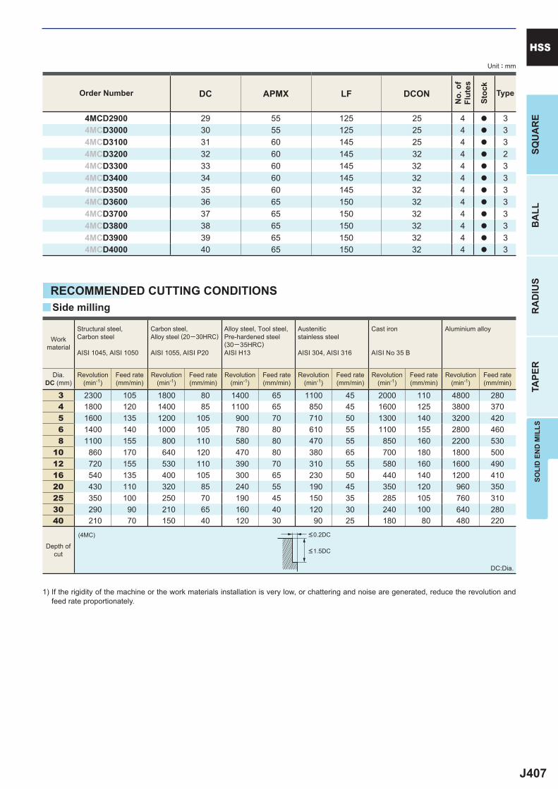
J407
DC APMX LF DCON
4MCD2900 29 55 125 25 4 a 34MCD3000 30 55 125 25 4 a 34MCD3100 31 60 145 25 4 a 34MCD3200 32 60 145 32 4 a 24MCD3300 33 60 145 32 4 a 34MCD3400 34 60 145 32 4 a 34MCD3500 35 60 145 32 4 a 34MCD3600 36 65 150 32 4 a 34MCD3700 37 65 150 32 4 a 34MCD3800 38 65 150 32 4 a 34MCD3900 39 65 150 32 4 a 34MCD4000 40 65 150 32 4 a 3
3 2300 105 1800 80 1400 65 1100 45 2000 110 4800 280 4 1800 120 1400 85 1100 65 850 45 1600 125 3800 370 5 1600 135 1200 105 900 70 710 50 1300 140 3200 420 6 1400 140 1000 105 780 80 610 55 1100 155 2800 460 8 1100 155 800 110 580 80 470 55 850 160 2200 53010 860 170 640 120 470 80 380 65 700 180 1800 50012 720 155 530 110 390 70 310 55 580 160 1600 49016 540 135 400 105 300 65 230 50 440 140 1200 41020 430 110 320 85 240 55 190 45 350 120 960 35025 350 100 250 70 190 45 150 35 285 105 760 31030 290 90 210 65 160 40 120 30 240 100 640 28040 210 70 150 40 120 30 90 25 180 80 480 220
(4MC)
y
SOLI
D E
ND
MIL
LSSQ
UA
RE
BA
LLR
AD
IUS
TAPE
R
HSSUnit : mm
Order Number
No.
of
Flut
es
Stoc
k
Type
RECOMMENDED CUTTING CONDITIONS
<0.2DC
<1.5DC
Workmaterial
Structural steel, Carbon steel
AISI 1045, AISI 1050
Carbon steel,Alloy steel (20─30HRC)
AISI 1055, AISI P20
Alloy steel, Tool steel,Pre-hardened steel(30─35HRC)AISI H13
Austenitic stainless steel
AISI 304, AISI 316
Cast iron
AISI No 35 B
Aluminium alloy
Dia.DC (mm)
Revolution(min-1)
Feed rate(mm/min)
Revolution(min-1)
Feed rate(mm/min)
Revolution(min-1)
Feed rate(mm/min)
Revolution(min-1)
Feed rate(mm/min)
Revolution(min-1)
Feed rate(mm/min)
Revolution(min-1)
Feed rate(mm/min)
Side milling
Depth ofcut
DC:Dia.
1) If the rigidity of the machine or the work materials installation is very low, or chattering and noise are generated, reduce the revolution and feed rate proportionately.
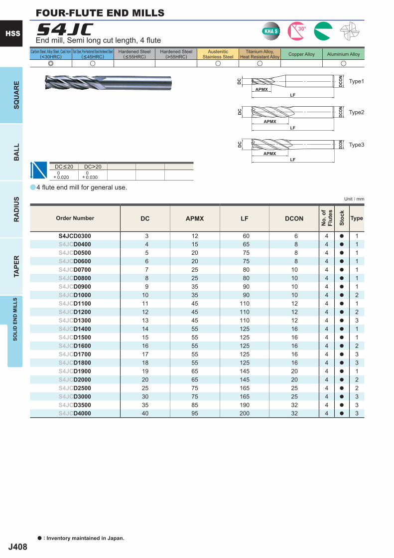
J408
a
e u u u u
S4JC
DC APMX LF DCON
S4JCD0300 3 12 60 6 4 a 1S4JCD0400 4 15 65 8 4 a 1S4JCD0500 5 20 75 8 4 a 1S4JCD0600 6 20 75 8 4 a 1S4JCD0700 7 25 80 10 4 a 1S4JCD0800 8 25 80 10 4 a 1S4JCD0900 9 35 90 10 4 a 1S4JCD1000 10 35 90 10 4 a 2S4JCD1100 11 45 110 12 4 a 1S4JCD1200 12 45 110 12 4 a 2S4JCD1300 13 45 110 12 4 a 3S4JCD1400 14 55 125 16 4 a 1S4JCD1500 15 55 125 16 4 a 1S4JCD1600 16 55 125 16 4 a 2S4JCD1700 17 55 125 16 4 a 3S4JCD1800 18 55 125 16 4 a 3S4JCD1900 19 65 145 20 4 a 1S4JCD2000 20 65 145 20 4 a 2S4JCD2500 25 75 165 25 4 a 2S4JCD3000 30 75 165 25 4 a 3S4JCD3500 35 85 190 32 4 a 3S4JCD4000 40 95 200 32 4 a 3
DC>20 0+ 0.020
0+ 0.030
KHA S 30°
APMXLF
DC
DCON
APMXLF
DC
DCO
N
APMXLF
DC
DCON
a : Inventory maintained in Japan.
HSS
SQU
AR
EB
ALL
RA
DIU
STA
PER
SOLI
D E
ND
MIL
LS
Unit : mm
Carbon Steel, Alloy Steel, Cast Iron(<30HRC)
Tool Steel, Pre-Hardened Steel,Hardened Steel(<45HRC)
Hardened Steel(<55HRC)
Hardened Steel(>55HRC)
AusteniticStainless Steel
Titanium Alloy,Heat Resistant Alloy Copper Alloy Aluminium Alloy
4 fl ute end mill for general use.
End mill, Semi long cut length, 4 fl ute
DC<20
Type2
Type3
Type1
Order Number
No.
of
Flut
es
Stoc
k
Type
FOUR-FLUTE END MILLS
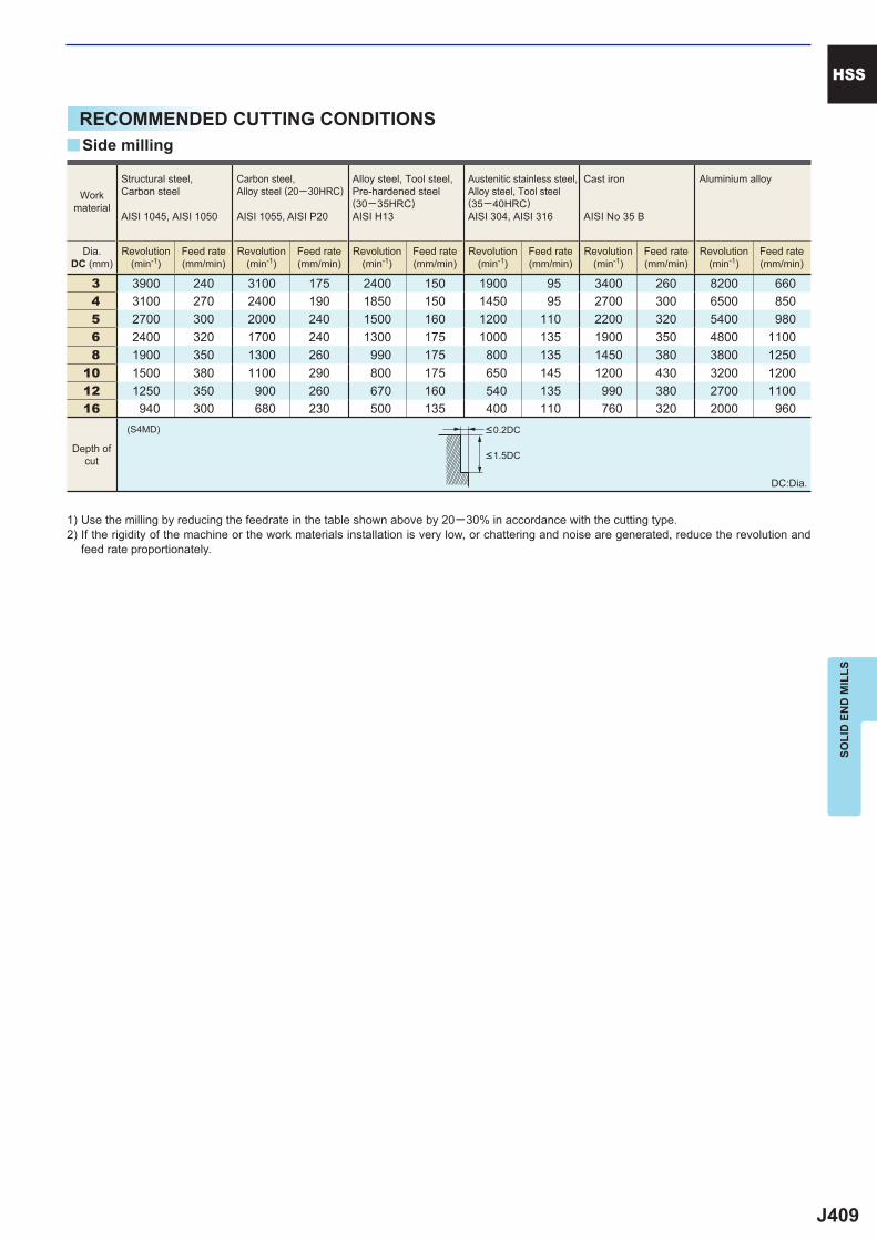
J409
3 3900 240 3100 175 2400 150 1900 95 3400 260 8200 660 4 3100 270 2400 190 1850 150 1450 95 2700 300 6500 850 5 2700 300 2000 240 1500 160 1200 110 2200 320 5400 980 6 2400 320 1700 240 1300 175 1000 135 1900 350 4800 1100 8 1900 350 1300 260 990 175 800 135 1450 380 3800 125010 1500 380 1100 290 800 175 650 145 1200 430 3200 120012 1250 350 900 260 670 160 540 135 990 380 2700 110016 940 300 680 230 500 135 400 110 760 320 2000 960
(S4MD)
y
HSS
SOLI
D E
ND
MIL
LS
RECOMMENDED CUTTING CONDITIONS
Workmaterial
Structural steel, Carbon steel
AISI 1045, AISI 1050
Carbon steel,Alloy steel (20─30HRC)
AISI 1055, AISI P20
Alloy steel, Tool steel,Pre-hardened steel(30─35HRC)AISI H13
Austenitic stainless steel,Alloy steel, Tool steel(35─40HRC)AISI 304, AISI 316
Cast iron
AISI No 35 B
Aluminium alloy
Dia.DC (mm)
Revolution(min-1)
Feed rate(mm/min)
Revolution(min-1)
Feed rate(mm/min)
Revolution(min-1)
Feed rate(mm/min)
Revolution(min-1)
Feed rate(mm/min)
Revolution(min-1)
Feed rate(mm/min)
Revolution(min-1)
Feed rate(mm/min)
<0.2DC
<1.5DC
Side milling
Depth ofcut
DC:Dia.
1) Use the milling by reducing the feedrate in the table shown above by 20─30% in accordance with the cutting type.2) If the rigidity of the machine or the work materials installation is very low, or chattering and noise are generated, reduce the revolution and
feed rate proportionately.
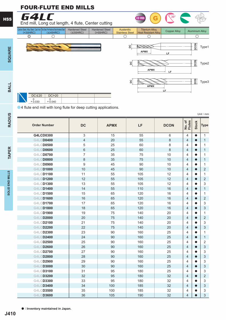
J410
a
e u u u u
G4LC
DC APMX LF DCON
G4LCD0300 3 15 55 6 4 a 1G4LCD0400 4 20 55 8 4 a 1G4LCD0500 5 25 60 8 4 a 1G4LCD0600 6 25 60 8 4 a 1G4LCD0700 7 35 75 10 4 a 1G4LCD0800 8 35 75 10 4 a 1G4LCD0900 9 45 90 10 4 a 1G4LCD1000 10 45 90 10 4 a 2G4LCD1100 11 55 105 12 4 a 1G4LCD1200 12 55 105 12 4 a 2G4LCD1300 13 55 105 12 4 a 3G4LCD1400 14 55 110 16 4 a 1G4LCD1500 15 65 120 16 4 a 1G4LCD1600 16 65 120 16 4 a 2G4LCD1700 17 65 120 16 4 a 3G4LCD1800 18 65 120 16 4 a 3G4LCD1900 19 75 140 20 4 a 1G4LCD2000 20 75 140 20 4 a 2G4LCD2100 21 75 140 20 4 a 3G4LCD2200 22 75 140 20 4 a 3G4LCD2300 23 90 160 25 4 a 1G4LCD2400 24 90 160 25 4 a 1G4LCD2500 25 90 160 25 4 a 2G4LCD2600 26 90 160 25 4 a 3G4LCD2700 27 90 160 25 4 a 3G4LCD2800 28 90 160 25 4 a 3G4LCD2900 29 90 160 25 4 a 3G4LCD3000 30 90 160 25 4 a 3G4LCD3100 31 95 180 25 4 a 3G4LCD3200 32 95 180 32 4 a 2G4LCD3300 33 95 180 32 4 a 3G4LCD3400 34 100 185 32 4 a 3G4LCD3500 35 100 185 32 4 a 3G4LCD3600 36 105 190 32 4 a 3
DC>20 0+ 0.030
0+ 0.040
CO HSS G 30°
APMXLF
DC
DCON
APMXLF
DC
DCO
N
APMX
LF
DC
DCON
a : Inventory maintained in Japan.
HSS
SQU
AR
EB
ALL
RA
DIU
STA
PER
SOLI
D E
ND
MIL
LS
Unit : mm
Carbon Steel, Alloy Steel, Cast Iron(<30HRC)
Tool Steel, Pre-Hardened Steel,Hardened Steel(<45HRC)
Hardened Steel(<55HRC)
Hardened Steel(>55HRC)
AusteniticStainless Steel
Titanium Alloy,Heat Resistant Alloy Copper Alloy Aluminium Alloy
Type2
Type3
Type1
Order Number
No.
of
Flut
es
Stoc
k
Type
4 fl ute end mill with long fl ute for deep cutting applications.
End mill, Long cut length, 4 fl ute, Center cutting
DC<20
FOUR-FLUTE END MILLS
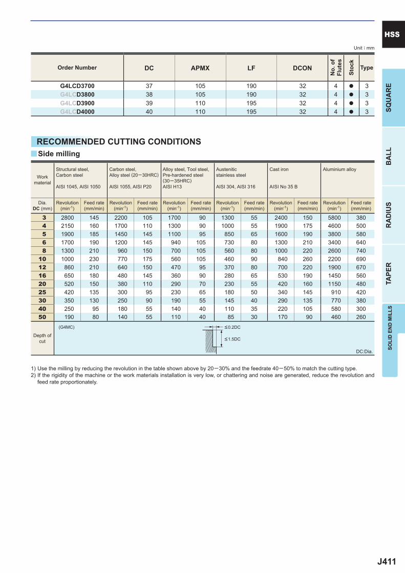
J411
DC APMX LF DCON
G4LCD3700 37 105 190 32 4 a 3G4LCD3800 38 105 190 32 4 a 3G4LCD3900 39 110 195 32 4 a 3G4LCD4000 40 110 195 32 4 a 3
3 2800 145 2200 105 1700 90 1300 55 2400 150 5800 380 4 2150 160 1700 110 1300 90 1000 55 1900 175 4600 500 5 1900 185 1450 145 1100 95 850 65 1600 190 3800 580 6 1700 190 1200 145 940 105 730 80 1300 210 3400 640 8 1300 210 960 150 700 105 560 80 1000 220 2600 74010 1000 230 770 175 560 105 460 90 840 260 2200 69012 860 210 640 150 470 95 370 80 700 220 1900 67016 650 180 480 145 360 90 280 65 530 190 1450 56020 520 150 380 110 290 70 230 55 420 160 1150 48025 420 135 300 95 230 65 180 50 340 145 910 42030 350 130 250 90 190 55 145 40 290 135 770 38040 250 95 180 55 140 40 110 35 220 105 580 30050 190 80 140 55 110 40 85 30 170 90 460 260
(G4MC)
y
SOLI
D E
ND
MIL
LSSQ
UA
RE
BA
LLR
AD
IUS
TAPE
R
HSSUnit : mm
Order Number
No.
of
Flut
es
Stoc
k
Type
RECOMMENDED CUTTING CONDITIONS
<0.2DC
<1.5DC
Workmaterial
Structural steel, Carbon steel
AISI 1045, AISI 1050
Carbon steel,Alloy steel (20─30HRC)
AISI 1055, AISI P20
Alloy steel, Tool steel,Pre-hardened steel(30─35HRC)AISI H13
Austenitic stainless steel
AISI 304, AISI 316
Cast iron
AISI No 35 B
Aluminium alloy
Dia.DC (mm)
Revolution(min-1)
Feed rate(mm/min)
Revolution(min-1)
Feed rate(mm/min)
Revolution(min-1)
Feed rate(mm/min)
Revolution(min-1)
Feed rate(mm/min)
Revolution(min-1)
Feed rate(mm/min)
Revolution(min-1)
Feed rate(mm/min)
Side milling
Depth ofcut
DC:Dia.
1) Use the milling by reducing the revolution in the table shown above by 20─30% and the feedrate 40─50% to match the cutting type.2) If the rigidity of the machine or the work materials installation is very low, or chattering and noise are generated, reduce the revolution and
feed rate proportionately.
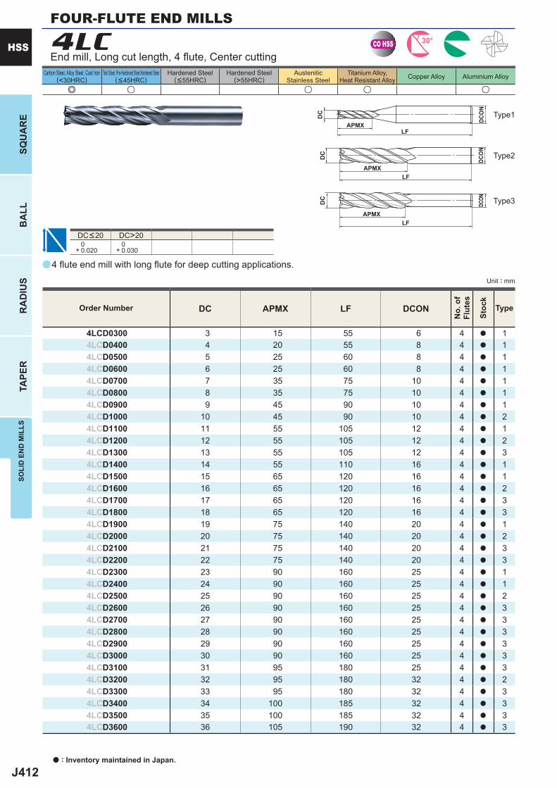
J412
a
e u u u u
4LC
DC APMX LF DCON
4LCD0300 3 15 55 6 4 a 14LCD0400 4 20 55 8 4 a 14LCD0500 5 25 60 8 4 a 14LCD0600 6 25 60 8 4 a 14LCD0700 7 35 75 10 4 a 14LCD0800 8 35 75 10 4 a 14LCD0900 9 45 90 10 4 a 14LCD1000 10 45 90 10 4 a 24LCD1100 11 55 105 12 4 a 14LCD1200 12 55 105 12 4 a 24LCD1300 13 55 105 12 4 a 34LCD1400 14 55 110 16 4 a 14LCD1500 15 65 120 16 4 a 14LCD1600 16 65 120 16 4 a 24LCD1700 17 65 120 16 4 a 34LCD1800 18 65 120 16 4 a 34LCD1900 19 75 140 20 4 a 14LCD2000 20 75 140 20 4 a 24LCD2100 21 75 140 20 4 a 34LCD2200 22 75 140 20 4 a 34LCD2300 23 90 160 25 4 a 14LCD2400 24 90 160 25 4 a 14LCD2500 25 90 160 25 4 a 24LCD2600 26 90 160 25 4 a 34LCD2700 27 90 160 25 4 a 34LCD2800 28 90 160 25 4 a 34LCD2900 29 90 160 25 4 a 34LCD3000 30 90 160 25 4 a 34LCD3100 31 95 180 25 4 a 34LCD3200 32 95 180 32 4 a 24LCD3300 33 95 180 32 4 a 34LCD3400 34 100 185 32 4 a 34LCD3500 35 100 185 32 4 a 34LCD3600 36 105 190 32 4 a 3
DC>20 0+ 0.020
0+ 0.030
CO HSS 30°
APMXLF
DC
DCON
APMXLF
DC
DCO
N
APMXLF
DC
DCON
a : Inventory maintained in Japan.
HSS
SQU
AR
EB
ALL
RA
DIU
STA
PER
SOLI
D E
ND
MIL
LS
Unit : mm
Carbon Steel, Alloy Steel, Cast Iron(<30HRC)
Tool Steel, Pre-Hardened Steel,Hardened Steel(<45HRC)
Hardened Steel(<55HRC)
Hardened Steel(>55HRC)
AusteniticStainless Steel
Titanium Alloy,Heat Resistant Alloy Copper Alloy Aluminium Alloy
Order Number
No.
of
Flut
es
Stoc
k
Type
4 fl ute end mill with long fl ute for deep cutting applications.
End mill, Long cut length, 4 fl ute, Center cutting
DC<20
Type2
Type3
Type1
FOUR-FLUTE END MILLS
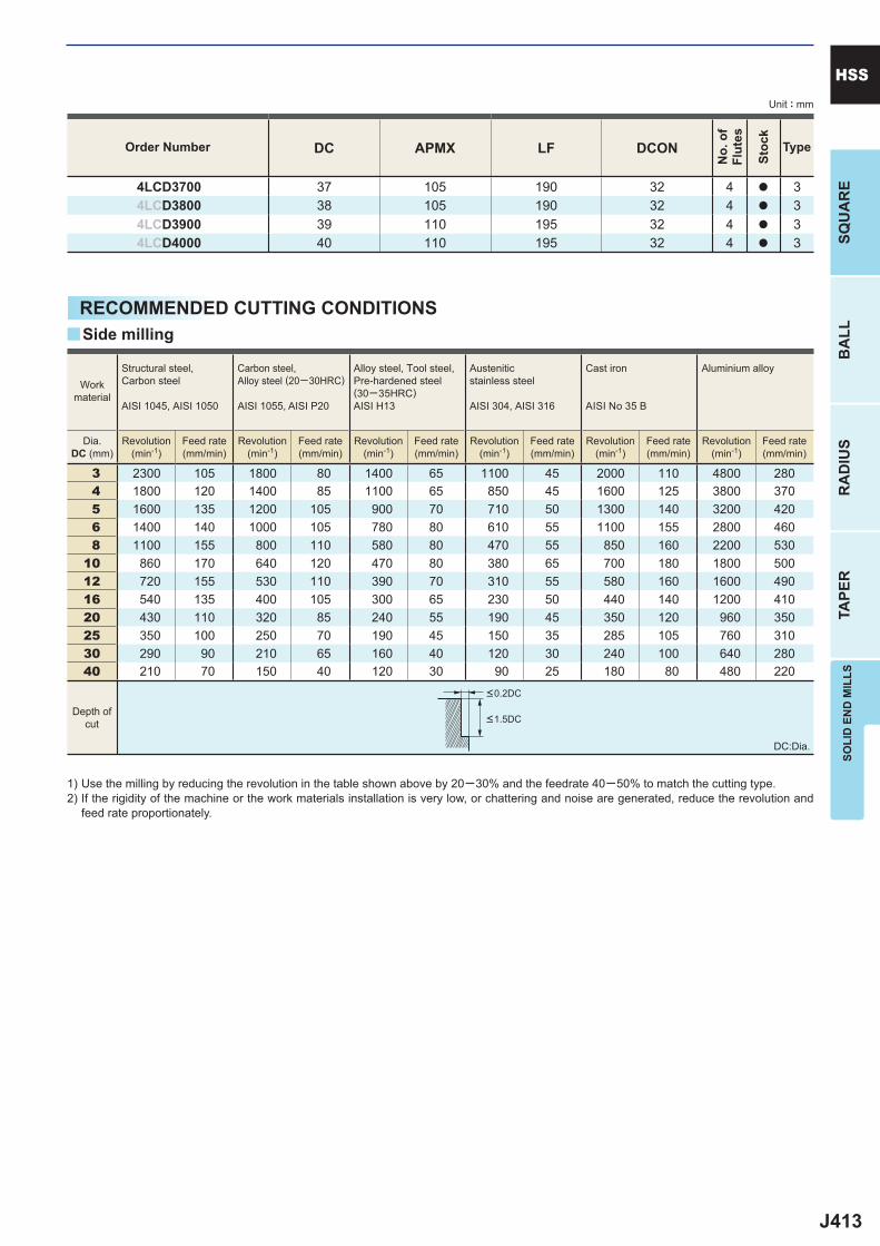
J413
DC APMX LF DCON
4LCD3700 37 105 190 32 4 a 34LCD3800 38 105 190 32 4 a 34LCD3900 39 110 195 32 4 a 34LCD4000 40 110 195 32 4 a 3
3 2300 105 1800 80 1400 65 1100 45 2000 110 4800 280 4 1800 120 1400 85 1100 65 850 45 1600 125 3800 370 5 1600 135 1200 105 900 70 710 50 1300 140 3200 420 6 1400 140 1000 105 780 80 610 55 1100 155 2800 460 8 1100 155 800 110 580 80 470 55 850 160 2200 53010 860 170 640 120 470 80 380 65 700 180 1800 50012 720 155 530 110 390 70 310 55 580 160 1600 49016 540 135 400 105 300 65 230 50 440 140 1200 41020 430 110 320 85 240 55 190 45 350 120 960 35025 350 100 250 70 190 45 150 35 285 105 760 31030 290 90 210 65 160 40 120 30 240 100 640 28040 210 70 150 40 120 30 90 25 180 80 480 220
y
SOLI
D E
ND
MIL
LSSQ
UA
RE
BA
LLR
AD
IUS
TAPE
R
HSSUnit : mm
Order Number
No.
of
Flut
es
Stoc
k
Type
RECOMMENDED CUTTING CONDITIONS
<0.2DC
<1.5DC
Workmaterial
Structural steel, Carbon steel
AISI 1045, AISI 1050
Carbon steel,Alloy steel (20─30HRC)
AISI 1055, AISI P20
Alloy steel, Tool steel,Pre-hardened steel(30─35HRC)AISI H13
Austenitic stainless steel
AISI 304, AISI 316
Cast iron
AISI No 35 B
Aluminium alloy
Dia.DC (mm)
Revolution(min-1)
Feed rate(mm/min)
Revolution(min-1)
Feed rate(mm/min)
Revolution(min-1)
Feed rate(mm/min)
Revolution(min-1)
Feed rate(mm/min)
Revolution(min-1)
Feed rate(mm/min)
Revolution(min-1)
Feed rate(mm/min)
Side milling
Depth ofcut
DC:Dia.
1) Use the milling by reducing the revolution in the table shown above by 20─30% and the feedrate 40─50% to match the cutting type.2) If the rigidity of the machine or the work materials installation is very low, or chattering and noise are generated, reduce the revolution and
feed rate proportionately.
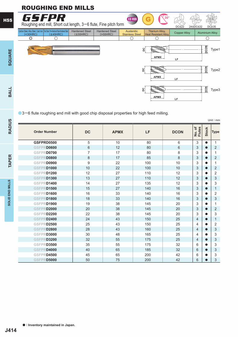
J414
a
e u u u u
GSFPR
DC APMX LF DCON
GSFPRD0500 5 10 80 6 3 a 1GSFPRD0600 6 12 80 6 3 a 2GSFPRD0700 7 17 80 8 3 a 1GSFPRD0800 8 17 85 8 3 a 2GSFPRD0900 9 22 100 10 3 a 1GSFPRD1000 10 22 100 10 3 a 2GSFPRD1200 12 27 110 12 3 a 2GSFPRD1300 13 27 110 12 3 a 3GSFPRD1400 14 27 135 12 3 a 3GSFPRD1500 15 27 140 16 3 a 1GSFPRD1600 16 33 140 16 3 a 2GSFPRD1800 18 33 140 16 3 a 3GSFPRD1900 19 38 145 20 3 a 1GSFPRD2000 20 38 145 20 3 a 2GSFPRD2200 22 38 145 20 3 a 3GSFPRD2400 24 43 150 25 4 a 1GSFPRD2500 25 43 150 25 4 a 2GSFPRD2800 28 43 160 25 4 a 3GSFPRD3000 30 48 165 25 4 a 3GSFPRD3200 32 55 175 25 4 a 3GSFPRD3500 35 55 175 32 6 a 3GSFPRD4000 40 65 185 32 6 a 3GSFPRD4500 45 65 200 42 6 a 3GSFPRD5000 50 75 200 42 6 a 3
CO HSS G 30°
APMXLF
DC
DCON
APMXLF
DC
DC
ON
APMXLF
DC
DCON
a : Inventory maintained in Japan.
HSS
SQU
AR
EB
ALL
RA
DIU
STA
PER
SOLI
D E
ND
MIL
LS
Unit : mm
Carbon Steel, Alloy Steel, Cast Iron(<30HRC)
Tool Steel, Pre-Hardened Steel,Hardened Steel(<45HRC)
Hardened Steel(<55HRC)
Hardened Steel(>55HRC)
AusteniticStainless Steel
Titanium Alloy,Heat Resistant Alloy Copper Alloy Aluminium Alloy
Order Number
No.
of
Flut
es
Stoc
k
Type
3─6 fl ute roughing end mill with good chip disposal properties for high feed milling.
Roughing end mill, Short cut length, 3─6 fl ute, Fine pitch form
ROUGHING END MILLS
Type2
Type3
Type1
DC<22 DC>3524<DC<32

J415
5 1200 (900) 50 (40) 900 (680) 35 (25) 730 (550) 30 (23) 610 (460) 25 (20) 6 1150 (860) 60 (45) 860 (650) 50 (40) 680 (510) 35 (26) 580 (440) 30 (23) 8 960 (720) 80 (60) 720 (540) 60 (45) 600 (450) 50 (40) 480 (360) 35 (26)10 770 (580) 110 (85) 580 (440) 85 (65) 460 (350) 60 (45) 380 (290) 50 (40)12 640 (480) 110 (85) 480 (360) 85 (65) 380 (290) 65 (50) 320 (240) 55 (40)16 480 (360) 110 (85) 360 (270) 85 (65) 290 (220) 65 (50) 240 (180) 55 (40)20 380 (290) 115 (85) 290 (220) 85 (65) 230 (170) 65 (50) 190 (145) 55 (40)25 300 (230) 110 (85) 230 (170) 80 (60) 180 (135) 60 (45) 160 (120) 55 (40)30 250 (190) 100 (75) 190 (145) 80 (60) 160 (120) 60 (45) 130 (100) 55 (40)40 160 (120) 70 (55) 120 (90) 55 (40) 95 (70) 40 (30) 85 (65) 35 (26)50 120 (90) 60 (45) 90 (70) 50 (40) 70 (55) 35 (25) 60 (45) 30 (23)
DC
HSS
SOLI
D E
ND
MIL
LS
RECOMMENDED CUTTING CONDITIONS
Workmaterial
Structural steel, Cast iron, Carbon steel
AISI 1045, AISI No 35 B, AISI 1050
Carbon steel, Alloy steel (20─30HRC)
AISI 1055, AISI P20
Alloy steel, Tool steel,Pre-hardened steel (30─35HRC)
AISI H13, AISI D2
Austenitic stainless steel
AISI 304, AISI 316
Dia.DC (mm)
Revolution(min-1)
Feed rate(mm/min)
Revolution(min-1)
Feed rate(mm/min)
Revolution(min-1)
Feed rate(mm/min)
Revolution(min-1)
Feed rate(mm/min)
Depth ofcut
DC:Dia.
( ) : Indicates standard revolution and feedrates for slotting
1) Supply cutting fl uid suffi ciently during cutting.2) When the diameter exceeds 30 and the metal removal is less than the quantity shown in the table, the revolution and feed rate may be
increased by 10─40%.3) If the rigidity of the machine or the work materials installation is very low, or chattering and noise are generated, reduce the revolution and
feed rate proportionately.
<0.5DC
<1.5DC <1DC (MAX. 30mm)
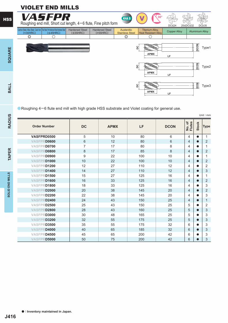
J416
a
VASFPR
e u e u
DC APMX LF DCON
VASFPRD0500 5 10 80 6 4 a 1VASFPRD0600 6 12 80 6 4 a 2VASFPRD0700 7 17 80 8 4 a 1VASFPRD0800 8 17 85 8 4 a 2VASFPRD0900 9 22 100 10 4 a 1VASFPRD1000 10 22 100 10 4 a 2VASFPRD1200 12 27 110 12 4 a 2VASFPRD1400 14 27 110 12 4 a 3VASFPRD1500 15 27 125 16 4 a 1VASFPRD1600 16 33 125 16 4 a 2VASFPRD1800 18 33 125 16 4 a 3VASFPRD2000 20 38 145 20 4 a 2VASFPRD2200 22 38 145 20 4 a 3VASFPRD2400 24 43 150 25 4 a 1VASFPRD2500 25 43 150 25 5 a 2VASFPRD2800 28 43 160 25 5 a 3VASFPRD3000 30 48 165 25 5 a 3VASFPRD3200 32 55 175 25 5 a 3VASFPRD3500 35 55 175 32 6 a 3VASFPRD4000 40 65 185 32 6 a 3VASFPRD4500 45 65 200 42 6 a 3VASFPRD5000 50 75 200 42 6 a 3
VKHA S 30°
APMXLF
DC
DCON
APMXLF
DC
DC
ON
APMXLF
DC
DCON
a : Inventory maintained in Japan.
HSS
SQU
AR
EB
ALL
RA
DIU
STA
PER
SOLI
D E
ND
MIL
LS
Unit : mm
Carbon Steel, Alloy Steel, Cast Iron(<30HRC)
Tool Steel, Pre-Hardened Steel,Hardened Steel(<45HRC)
Hardened Steel(<55HRC)
Hardened Steel(>55HRC)
AusteniticStainless Steel
Titanium Alloy,Heat Resistant Alloy Copper Alloy Aluminium Alloy
Roughing 4─6 fl ute end mill with high grade HSS substrate and Violet coating for general use.
VIOLET END MILLS
Roughing end mill, Short cut length, 4─6 fl ute, Fine pitch form DC>3525<DC<32DC<24
Order Number
No.
of
Flut
es
Stoc
k
Type
Type2
Type3
Type1
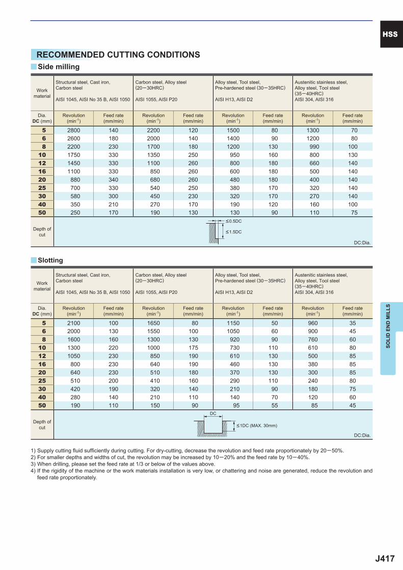
J417
5 2800 140 2200 120 1500 80 1300 70 6 2600 180 2000 140 1400 90 1200 80 8 2200 230 1700 180 1200 130 990 10010 1750 330 1350 250 950 160 800 13012 1450 330 1100 260 800 180 660 14016 1100 330 850 260 600 180 500 14020 880 340 680 260 480 180 400 14025 700 330 540 250 380 170 320 14030 580 300 450 230 320 170 270 14040 350 210 270 170 190 120 160 10050 250 170 190 130 130 90 110 75
5 2100 100 1650 80 1150 50 960 35 6 2000 130 1550 100 1050 60 900 45 8 1600 160 1300 130 920 90 760 6010 1300 220 1000 175 730 110 610 8012 1050 230 850 190 610 130 500 8516 800 230 640 190 460 130 380 8520 640 230 510 180 370 130 300 8525 510 200 410 160 290 110 240 8030 420 190 320 140 210 90 180 7540 280 140 210 110 140 70 120 6050 190 110 150 90 95 55 85 45
y
y
DC
HSS
SOLI
D E
ND
MIL
LS
RECOMMENDED CUTTING CONDITIONS
1) Supply cutting fl uid suffi ciently during cutting. For dry-cutting, decrease the revolution and feed rate proportionately by 20─50%.2) For smaller depths and widths of cut, the revolution may be increased by 10─20% and the feed rate by 10─40%.3) When drilling, please set the feed rate at 1/3 or below of the values above. 4) If the rigidity of the machine or the work materials installation is very low, or chattering and noise are generated, reduce the revolution and
feed rate proportionately.
DC:Dia.
DC:Dia.
Side milling
Slotting
Workmaterial
Structural steel, Cast iron, Carbon steel
AISI 1045, AISI No 35 B, AISI 1050
Carbon steel, Alloy steel (20─30HRC)
AISI 1055, AISI P20
Alloy steel, Tool steel,Pre-hardened steel (30─35HRC)
AISI H13, AISI D2
Austenitic stainless steel,Alloy steel, Tool steel(35─40HRC)AISI 304, AISI 316
Dia.DC (mm)
Revolution(min-1)
Feed rate(mm/min)
Revolution(min-1)
Feed rate(mm/min)
Revolution(min-1)
Feed rate(mm/min)
Revolution(min-1)
Feed rate(mm/min)
Depth ofcut
Depth ofcut <1DC (MAX. 30mm)
<0.5DC
<1.5DC
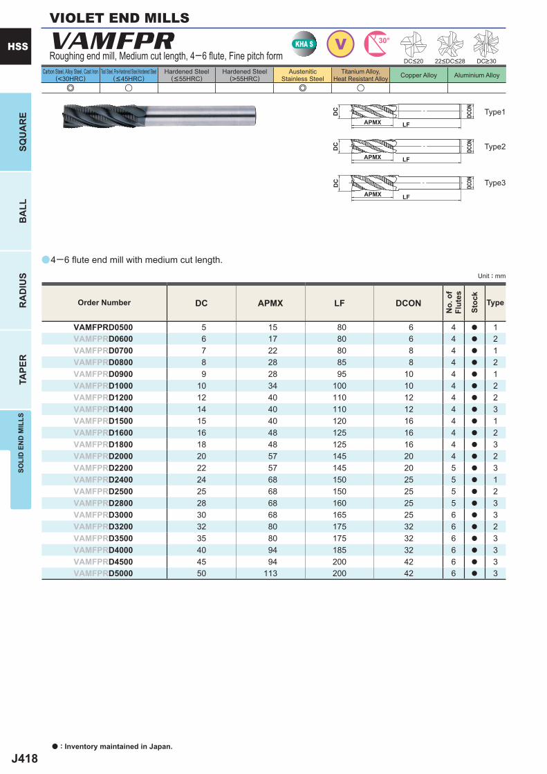
J418
a
e u e u
VAMFPR
DC APMX LF DCON
VAMFPRD0500 5 15 80 6 4 a 1VAMFPRD0600 6 17 80 6 4 a 2VAMFPRD0700 7 22 80 8 4 a 1VAMFPRD0800 8 28 85 8 4 a 2VAMFPRD0900 9 28 95 10 4 a 1VAMFPRD1000 10 34 100 10 4 a 2VAMFPRD1200 12 40 110 12 4 a 2VAMFPRD1400 14 40 110 12 4 a 3VAMFPRD1500 15 40 120 16 4 a 1VAMFPRD1600 16 48 125 16 4 a 2VAMFPRD1800 18 48 125 16 4 a 3VAMFPRD2000 20 57 145 20 4 a 2VAMFPRD2200 22 57 145 20 5 a 3VAMFPRD2400 24 68 150 25 5 a 1VAMFPRD2500 25 68 150 25 5 a 2VAMFPRD2800 28 68 160 25 5 a 3VAMFPRD3000 30 68 165 25 6 a 3VAMFPRD3200 32 80 175 32 6 a 2VAMFPRD3500 35 80 175 32 6 a 3VAMFPRD4000 40 94 185 32 6 a 3VAMFPRD4500 45 94 200 42 6 a 3VAMFPRD5000 50 113 200 42 6 a 3
VKHA S 30°
LF
DC
DCON
APMX LF
DC
DCON
APMX LF
DC
DCON
APMX
a : Inventory maintained in Japan.
HSS
SQU
AR
EB
ALL
RA
DIU
STA
PER
SOLI
D E
ND
MIL
LS
Unit : mm
Carbon Steel, Alloy Steel, Cast Iron(<30HRC)
Tool Steel, Pre-Hardened Steel,Hardened Steel(<45HRC)
Hardened Steel(<55HRC)
Hardened Steel(>55HRC)
AusteniticStainless Steel
Titanium Alloy,Heat Resistant Alloy Copper Alloy Aluminium Alloy
Order Number
No.
of
Flut
es
Stoc
k
Type
Type2
Type3
Type1
Roughing end mill, Medium cut length, 4─6 fl ute, Fine pitch form
4─6 fl ute end mill with medium cut length.
VIOLET END MILLS
DC>3022<DC<28DC<20
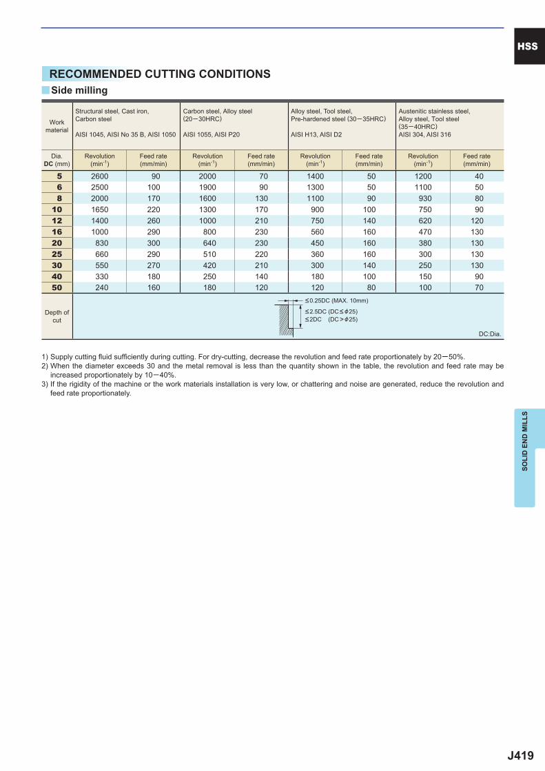
J419
5 2600 90 2000 70 1400 50 1200 40 6 2500 100 1900 90 1300 50 1100 50 8 2000 170 1600 130 1100 90 930 8010 1650 220 1300 170 900 100 750 9012 1400 260 1000 210 750 140 620 12016 1000 290 800 230 560 160 470 13020 830 300 640 230 450 160 380 13025 660 290 510 220 360 160 300 13030 550 270 420 210 300 140 250 13040 330 180 250 140 180 100 150 9050 240 160 180 120 120 80 100 70
y
HSS
SOLI
D E
ND
MIL
LS
RECOMMENDED CUTTING CONDITIONS
1) Supply cutting fl uid suffi ciently during cutting. For dry-cutting, decrease the revolution and feed rate proportionately by 20─50%.2) When the diameter exceeds 30 and the metal removal is less than the quantity shown in the table, the revolution and feed rate may be
increased proportionately by 10─40%.3) If the rigidity of the machine or the work materials installation is very low, or chattering and noise are generated, reduce the revolution and
feed rate proportionately.
DC:Dia.
Side milling
Workmaterial
Structural steel, Cast iron, Carbon steel
AISI 1045, AISI No 35 B, AISI 1050
Carbon steel, Alloy steel (20─30HRC)
AISI 1055, AISI P20
Alloy steel, Tool steel,Pre-hardened steel (30─35HRC)
AISI H13, AISI D2
Austenitic stainless steel,Alloy steel, Tool steel(35─40HRC)AISI 304, AISI 316
Dia.DC (mm)
Revolution(min-1)
Feed rate(mm/min)
Revolution(min-1)
Feed rate(mm/min)
Revolution(min-1)
Feed rate(mm/min)
Revolution(min-1)
Feed rate(mm/min)
Depth ofcut
<0.25DC (MAX. 10mm)
<2.5DC (DC< &25)<2DC (DC>&25)
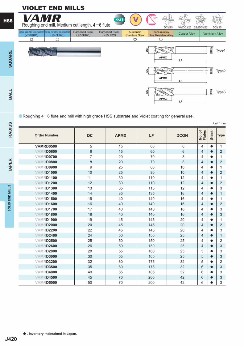
J420
a
e u e u
VAMR
DC APMX LF DCON
VAMRD0500 5 15 60 6 4 a 1VAMRD0600 6 15 60 6 4 a 2VAMRD0700 7 20 70 8 4 a 1VAMRD0800 8 20 70 8 4 a 2VAMRD0900 9 25 80 10 4 a 1VAMRD1000 10 25 80 10 4 a 2VAMRD1100 11 30 110 12 4 a 1VAMRD1200 12 30 110 12 4 a 2VAMRD1300 13 35 115 12 4 a 3VAMRD1400 14 35 135 16 4 a 1VAMRD1500 15 40 140 16 4 a 1VAMRD1600 16 40 140 16 4 a 2VAMRD1700 17 40 140 16 4 a 3VAMRD1800 18 40 140 16 4 a 3VAMRD1900 19 45 145 20 4 a 1VAMRD2000 20 45 145 20 4 a 2VAMRD2200 22 45 145 20 4 a 3VAMRD2400 24 50 150 25 4 a 1VAMRD2500 25 50 150 25 4 a 2VAMRD2600 26 50 150 25 4 a 3VAMRD2800 28 55 160 25 5 a 3VAMRD3000 30 55 165 25 5 a 3VAMRD3200 32 60 175 32 5 a 2VAMRD3500 35 60 175 32 6 a 3VAMRD4000 40 65 185 32 6 a 3VAMRD4500 45 70 200 42 6 a 3VAMRD5000 50 70 200 42 6 a 3
VKHA S 30°
APMXLF
DC
DCON
APMXLF
DC
DCON
APMXLF
DC
DCON
a : Inventory maintained in Japan.
HSS
SQU
AR
EB
ALL
RA
DIU
STA
PER
SOLI
D E
ND
MIL
LS
Unit : mm
Carbon Steel, Alloy Steel, Cast Iron(<30HRC)
Tool Steel, Pre-Hardened Steel,Hardened Steel(<45HRC)
Hardened Steel(<55HRC)
Hardened Steel(>55HRC)
AusteniticStainless Steel
Titanium Alloy,Heat Resistant Alloy Copper Alloy Aluminium Alloy
Roughing 4─6 fl ute end mill with high grade HSS substrate and Violet coating for general use.
Roughing end mill, Medium cut length, 4─6 fl ute
Type2
Type3
Type1
DC<15 16<DC<26 28<DC<32 DC>35
Order Number
No.
of
Flut
es
Stoc
k
Type
VIOLET END MILLS
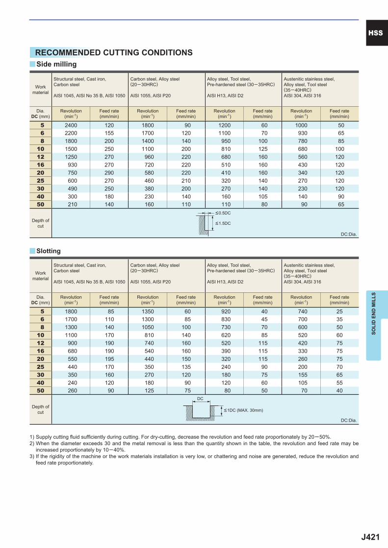
J421
5 2400 120 1800 90 1200 60 1000 50 6 2200 155 1700 120 1100 70 930 65 8 1800 200 1400 140 950 100 780 8510 1500 250 1100 200 810 125 680 10012 1250 270 960 220 680 160 560 12016 930 270 720 220 510 160 430 12020 750 290 580 220 410 160 340 12025 600 270 460 210 320 140 270 12030 490 250 380 200 270 140 230 12040 300 180 230 140 160 105 140 9050 210 140 160 110 110 80 90 65
5 1800 85 1350 60 920 40 740 25 6 1700 110 1300 85 830 45 700 35 8 1300 140 1050 100 730 70 600 5010 1100 170 810 140 620 85 520 6012 900 190 740 160 520 115 420 7516 680 190 540 160 390 115 330 7520 550 195 440 150 320 115 260 7525 440 170 350 135 240 90 200 7030 350 160 270 120 180 75 155 6540 240 120 180 90 120 60 105 5550 260 90 125 75 80 50 70 40
y
y
DC
HSS
SOLI
D E
ND
MIL
LS
RECOMMENDED CUTTING CONDITIONS
DC:Dia.
1) Supply cutting fl uid suffi ciently during cutting. For dry-cutting, decrease the revolution and feed rate proportionately by 20─50%.2) When the diameter exceeds 30 and the metal removal is less than the quantity shown in the table, the revolution and feed rate may be
increased proportionately by 10─40%.3) If the rigidity of the machine or the work materials installation is very low, or chattering and noise are generated, reduce the revolution and
feed rate proportionately.
DC:Dia.
Side milling
Slotting
Workmaterial
Structural steel, Cast iron, Carbon steel
AISI 1045, AISI No 35 B, AISI 1050
Carbon steel, Alloy steel (20─30HRC)
AISI 1055, AISI P20
Alloy steel, Tool steel,Pre-hardened steel (30─35HRC)
AISI H13, AISI D2
Austenitic stainless steel,Alloy steel, Tool steel(35─40HRC)AISI 304, AISI 316
Dia.DC (mm)
Revolution(min-1)
Feed rate(mm/min)
Revolution(min-1)
Feed rate(mm/min)
Revolution(min-1)
Feed rate(mm/min)
Revolution(min-1)
Feed rate(mm/min)
Workmaterial
Structural steel, Cast iron, Carbon steel
AISI 1045, AISI No 35 B, AISI 1050
Carbon steel, Alloy steel (20─30HRC)
AISI 1055, AISI P20
Alloy steel, Tool steel,Pre-hardened steel (30─35HRC)
AISI H13, AISI D2
Austenitic stainless steel,Alloy steel, Tool steel(35─40HRC)AISI 304, AISI 316
Dia.DC (mm)
Revolution(min-1)
Feed rate(mm/min)
Revolution(min-1)
Feed rate(mm/min)
Revolution(min-1)
Feed rate(mm/min)
Revolution(min-1)
Feed rate(mm/min)
Depth ofcut
Depth ofcut <1DC (MAX. 30mm)
<0.5DC
<1.5DC
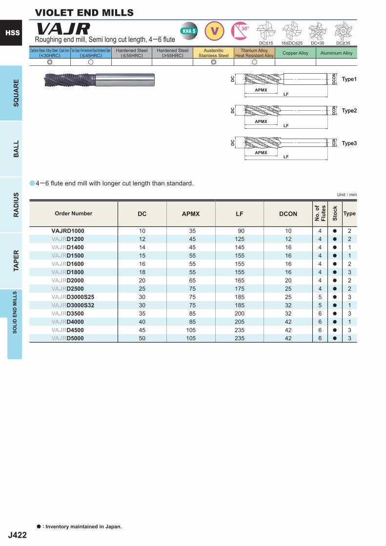
J422
a
e u e u
VAJR
DC APMX LF DCON
VAJRD1000 10 35 90 10 4 a 2VAJRD1200 12 45 125 12 4 a 2VAJRD1400 14 45 145 16 4 a 1VAJRD1500 15 55 155 16 4 a 1VAJRD1600 16 55 155 16 4 a 2VAJRD1800 18 55 155 16 4 a 3VAJRD2000 20 65 165 20 4 a 2VAJRD2500 25 75 175 25 4 a 2VAJRD3000S25 30 75 185 25 5 a 3VAJRD3000S32 30 75 185 32 5 a 1VAJRD3500 35 85 200 32 6 a 3VAJRD4000 40 85 205 42 6 a 1VAJRD4500 45 105 235 42 6 a 3VAJRD5000 50 105 235 42 6 a 3
DC=30
VKHA S 30°
APMXLF
DC
DCON
APMXLF
DC
DCON
APMXLF
DC
DCON
a : Inventory maintained in Japan.
HSS
SQU
AR
EB
ALL
RA
DIU
STA
PER
SOLI
D E
ND
MIL
LS
Unit : mm
Carbon Steel, Alloy Steel, Cast Iron(<30HRC)
Tool Steel, Pre-Hardened Steel,Hardened Steel(<45HRC)
Hardened Steel(<55HRC)
Hardened Steel(>55HRC)
AusteniticStainless Steel
Titanium Alloy,Heat Resistant Alloy Copper Alloy Aluminium Alloy
Type2Type2
Type3Type3
Type1Type1
Order Number
No.
of
Flut
es
Stoc
k
Type
4─6 fl ute end mill with longer cut length than standard.
Roughing end mill, Semi long cut length, 4─6 fl ute DC<15 16<DC<25 DC>35
VIOLET END MILLS
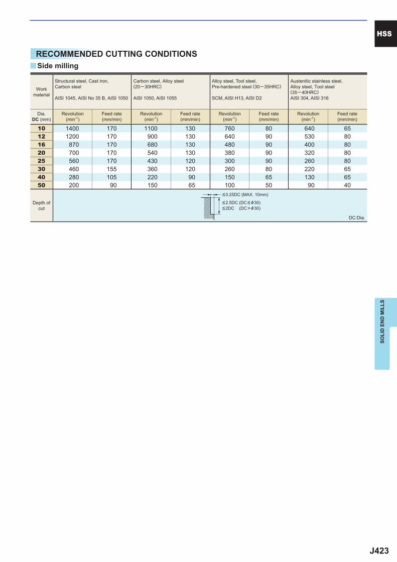
J423
10 1400 170 1100 130 760 80 640 6512 1200 170 900 130 640 90 530 8016 870 170 680 130 480 90 400 8020 700 170 540 130 380 90 320 8025 560 170 430 120 300 90 260 8030 460 155 360 120 260 80 220 6540 280 105 220 90 150 65 130 6550 200 90 150 65 100 50 90 40
y
HSS
SOLI
D E
ND
MIL
LS
RECOMMENDED CUTTING CONDITIONS
DC:Dia.
Side milling
Workmaterial
Structural steel, Cast iron, Carbon steel
AISI 1045, AISI No 35 B, AISI 1050
Carbon steel, Alloy steel (20─30HRC)
AISI 1050, AISI 1055
Alloy steel, Tool steel,Pre-hardened steel (30─35HRC)
SCM, AISI H13, AISI D2
Austenitic stainless steel,Alloy steel, Tool steel(35─40HRC)AISI 304, AISI 316
Dia.DC (mm)
Revolution(min-1)
Feed rate(mm/min)
Revolution(min-1)
Feed rate(mm/min)
Revolution(min-1)
Feed rate(mm/min)
Revolution(min-1)
Feed rate(mm/min)
Depth ofcut
<0.25DC (MAX. 10mm)
<2.5DC (DC< &30)<2DC (DC>&30)
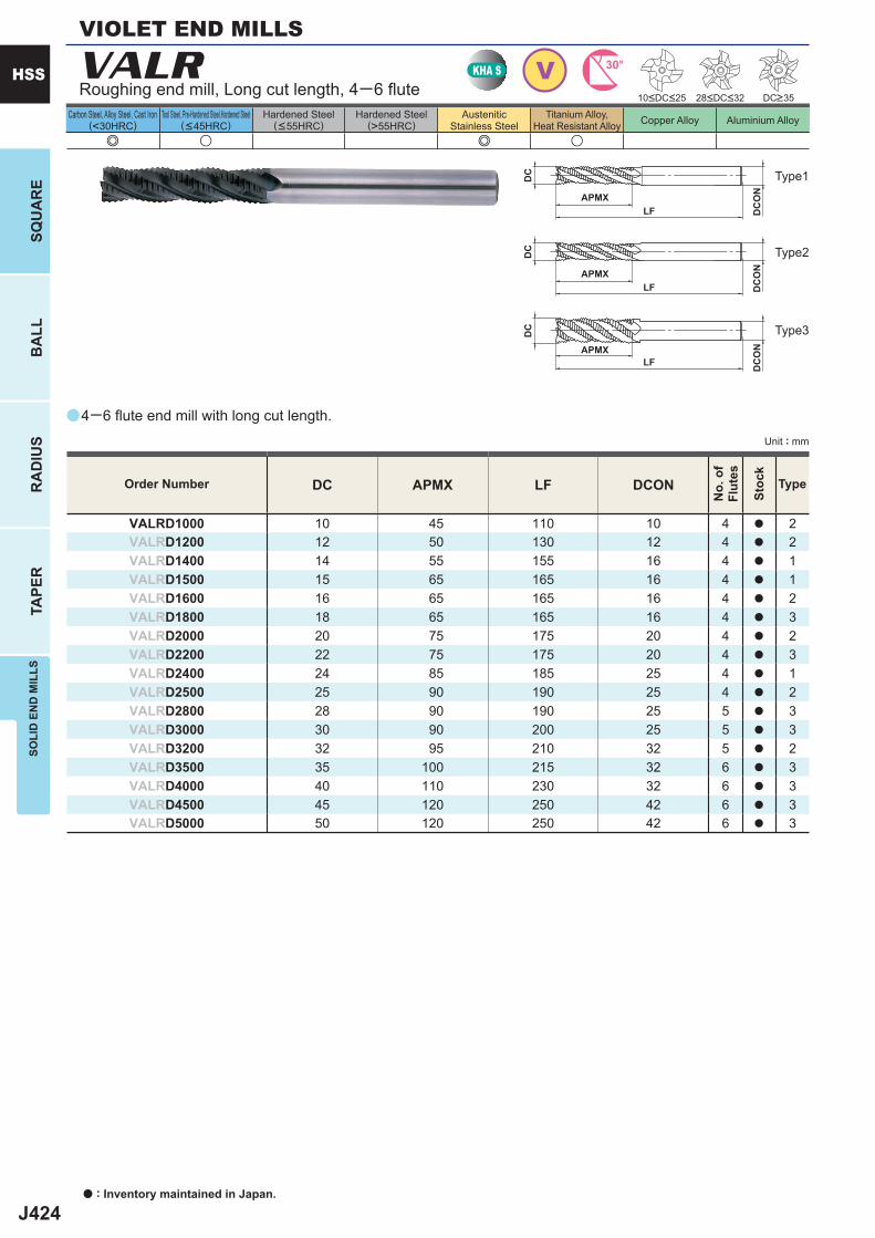
J424
a
e u e u
VALR
DC APMX LF DCON
VALRD1000 10 45 110 10 4 a 2VALRD1200 12 50 130 12 4 a 2VALRD1400 14 55 155 16 4 a 1VALRD1500 15 65 165 16 4 a 1VALRD1600 16 65 165 16 4 a 2VALRD1800 18 65 165 16 4 a 3VALRD2000 20 75 175 20 4 a 2VALRD2200 22 75 175 20 4 a 3VALRD2400 24 85 185 25 4 a 1VALRD2500 25 90 190 25 4 a 2VALRD2800 28 90 190 25 5 a 3VALRD3000 30 90 200 25 5 a 3VALRD3200 32 95 210 32 5 a 2VALRD3500 35 100 215 32 6 a 3VALRD4000 40 110 230 32 6 a 3VALRD4500 45 120 250 42 6 a 3VALRD5000 50 120 250 42 6 a 3
VKHA S 30°
APMXLF
DC
DC
ON
APMXLF
DC
DC
ON
APMXLF
DC
DC
ON
a : Inventory maintained in Japan.
HSS
SQU
AR
EB
ALL
RA
DIU
STA
PER
SOLI
D E
ND
MIL
LS
Unit : mm
Carbon Steel, Alloy Steel, Cast Iron(<30HRC)
Tool Steel, Pre-Hardened Steel,Hardened Steel(<45HRC)
Hardened Steel(<55HRC)
Hardened Steel(>55HRC)
AusteniticStainless Steel
Titanium Alloy,Heat Resistant Alloy Copper Alloy Aluminium Alloy
4─6 fl ute end mill with long cut length.
Roughing end mill, Long cut length, 4─6 fl ute
Type2
Type3
Type1
DC>3528<DC<3210<DC<25
Order Number
No.
of
Flut
es
Stoc
k
Type
VIOLET END MILLS
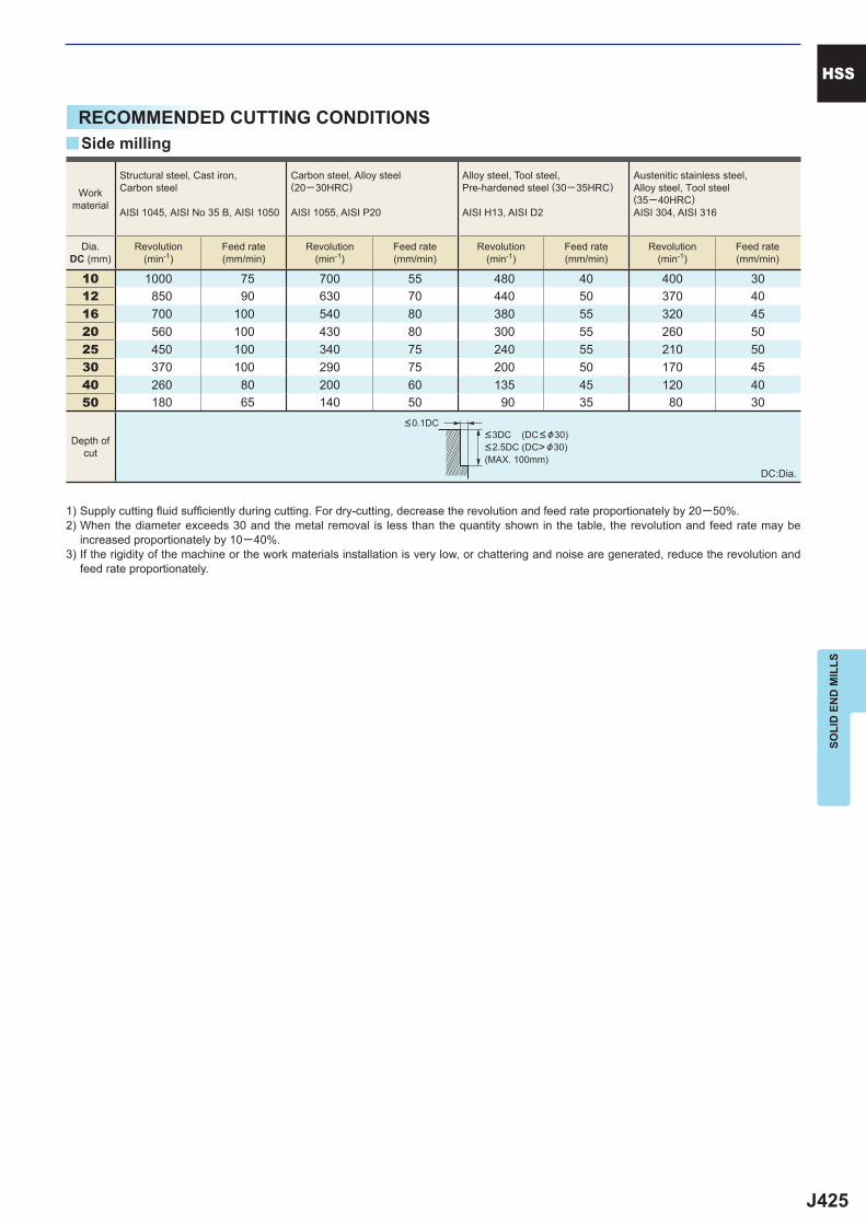
J425
10 1000 75 700 55 480 40 400 3012 850 90 630 70 440 50 370 4016 700 100 540 80 380 55 320 4520 560 100 430 80 300 55 260 5025 450 100 340 75 240 55 210 5030 370 100 290 75 200 50 170 4540 260 80 200 60 135 45 120 4050 180 65 140 50 90 35 80 30
y
HSS
SOLI
D E
ND
MIL
LS
RECOMMENDED CUTTING CONDITIONS
1) Supply cutting fl uid suffi ciently during cutting. For dry-cutting, decrease the revolution and feed rate proportionately by 20─50%.2) When the diameter exceeds 30 and the metal removal is less than the quantity shown in the table, the revolution and feed rate may be
increased proportionately by 10─40%.3) If the rigidity of the machine or the work materials installation is very low, or chattering and noise are generated, reduce the revolution and
feed rate proportionately.
DC:Dia.
Side milling
Workmaterial
Structural steel, Cast iron, Carbon steel
AISI 1045, AISI No 35 B, AISI 1050
Carbon steel, Alloy steel (20─30HRC)
AISI 1055, AISI P20
Alloy steel, Tool steel,Pre-hardened steel (30─35HRC)
AISI H13, AISI D2
Austenitic stainless steel,Alloy steel, Tool steel(35─40HRC)AISI 304, AISI 316
Dia.DC (mm)
Revolution(min-1)
Feed rate(mm/min)
Revolution(min-1)
Feed rate(mm/min)
Revolution(min-1)
Feed rate(mm/min)
Revolution(min-1)
Feed rate(mm/min)
Depth ofcut
<0.1DC<3DC (DC< &30)<2.5DC (DC> &30)(MAX. 100mm)
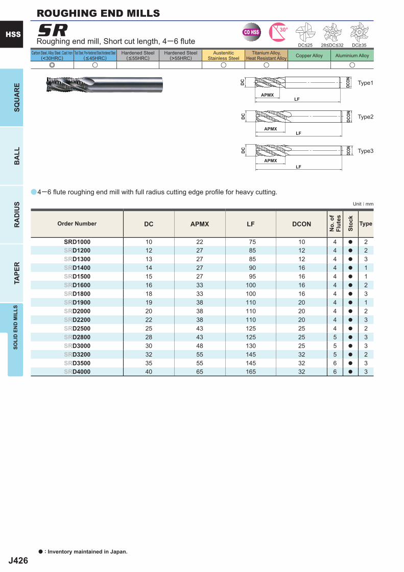
J426
a
e u u u u
SR
DC APMX LF DCON
SRD1000 10 22 75 10 4 a 2SRD1200 12 27 85 12 4 a 2SRD1300 13 27 85 12 4 a 3SRD1400 14 27 90 16 4 a 1SRD1500 15 27 95 16 4 a 1SRD1600 16 33 100 16 4 a 2SRD1800 18 33 100 16 4 a 3SRD1900 19 38 110 20 4 a 1SRD2000 20 38 110 20 4 a 2SRD2200 22 38 110 20 4 a 3SRD2500 25 43 125 25 4 a 2SRD2800 28 43 125 25 5 a 3SRD3000 30 48 130 25 5 a 3SRD3200 32 55 145 32 5 a 2SRD3500 35 55 145 32 6 a 3SRD4000 40 65 165 32 6 a 3
CO HSS 30°
APMXLF
DC
DCON
APMXLF
DC
DCON
APMXLF
DC
DCON
a : Inventory maintained in Japan.
HSS
SQU
AR
EB
ALL
RA
DIU
STA
PER
SOLI
D E
ND
MIL
LS
Unit : mm
Carbon Steel, Alloy Steel, Cast Iron(<30HRC)
Tool Steel, Pre-Hardened Steel,Hardened Steel(<45HRC)
Hardened Steel(<55HRC)
Hardened Steel(>55HRC)
AusteniticStainless Steel
Titanium Alloy,Heat Resistant Alloy Copper Alloy Aluminium Alloy
Type2
Type3
Type1
Order Number
No.
of
Flut
es
Stoc
k
Type
4─6 fl ute roughing end mill with full radius cutting edge profi le for heavy cutting.
Roughing end mill, Short cut length, 4─6 fl ute
ROUGHING END MILLS
DC>35DC<25 28<DC<32

J427
5 1000 (750) 40 (30) 760 (570) 30 (25) 610 (460) 25 (20) 510 (380) 20 (15) 6 960 (720) 50 (40) 720 (540) 40 (30) 570 (430) 30 (25) 480 (360) 25 (20) 8 800 (600) 65 (50) 600 (450) 50 (40) 500 (380) 40 (30) 400 (300) 30 (25)10 640 (480) 90 (70) 480 (360) 70 (55) 380 (290) 50 (40) 320 (240) 40 (30)12 530 (400) 90 (70) 400 (300) 70 (55) 320 (240) 55 (40) 270 (200) 45 (35)16 400 (300) 90 (70) 300 (230) 70 (55) 240 (180) 55 (40) 200 (150) 45 (35)20 320 (240) 95 (70) 240 (180) 70 (55) 190 (140) 55 (40) 160 (120) 45 (35)25 250 (190) 90 (70) 190 (140) 65 (50) 150 (110) 50 (40) 130 (100) 45 (35)30 210 (160) 85 (65) 160 (120) 65 (50) 130 (100) 50 (40) 110 (85) 45 (35)40 135 (100) 60 (45) 100 (75) 45 (40) 80 (60) 35 (26) 70 (55) 30 (25)50 100 (75) 50 (40) 75 (55) 40 (30) 60 (45) 30 (23) 50 (40) 25 (20)
DC
HSS
SOLI
D E
ND
MIL
LS
RECOMMENDED CUTTING CONDITIONS
Workmaterial
Structural steel, Cast iron, Carbon steel
AISI 1045, AISI No 35 B, AISI 1050
Carbon steel, Alloy steel (20─30HRC)
AISI 1055, AISI P20
Alloy steel, Tool steel,Pre-hardened steel (30─35HRC)
AISI H13, AISI D2
Austenitic stainless steel
AISI 304, AISI 316
Dia.DC (mm)
Revolution(min-1)
Feed rate(mm/min)
Revolution(min-1)
Feed rate(mm/min)
Revolution(min-1)
Feed rate(mm/min)
Revolution(min-1)
Feed rate(mm/min)
Depth ofcut
DC:Dia.
( ) : Indicates standard revolution and feedrates for slotting
1) Supply cutting fl uid suffi ciently during cutting.2) When the diameter exceeds 30 and the metal removal is less than the quantity shown in the table, the revolution and feed rate may be
increased by 10─40%.3) If the rigidity of the machine or the work materials installation is very low, or chattering and noise are generated, reduce the revolution and
feed rate proportionately.
<0.5DC
<1.5DC <1DC (MAX. 30mm)
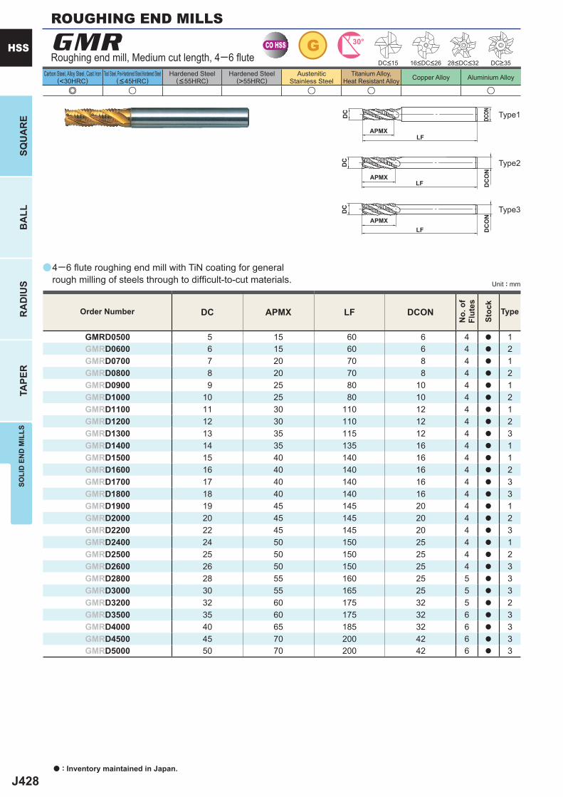
J428
a
e u u u u
GMR
DC APMX LF DCON
GMRD0500 5 15 60 6 4 a 1GMRD0600 6 15 60 6 4 a 2GMRD0700 7 20 70 8 4 a 1GMRD0800 8 20 70 8 4 a 2GMRD0900 9 25 80 10 4 a 1GMRD1000 10 25 80 10 4 a 2GMRD1100 11 30 110 12 4 a 1GMRD1200 12 30 110 12 4 a 2GMRD1300 13 35 115 12 4 a 3GMRD1400 14 35 135 16 4 a 1GMRD1500 15 40 140 16 4 a 1GMRD1600 16 40 140 16 4 a 2GMRD1700 17 40 140 16 4 a 3GMRD1800 18 40 140 16 4 a 3GMRD1900 19 45 145 20 4 a 1GMRD2000 20 45 145 20 4 a 2GMRD2200 22 45 145 20 4 a 3GMRD2400 24 50 150 25 4 a 1GMRD2500 25 50 150 25 4 a 2GMRD2600 26 50 150 25 4 a 3GMRD2800 28 55 160 25 5 a 3GMRD3000 30 55 165 25 5 a 3GMRD3200 32 60 175 32 5 a 2GMRD3500 35 60 175 32 6 a 3GMRD4000 40 65 185 32 6 a 3GMRD4500 45 70 200 42 6 a 3GMRD5000 50 70 200 42 6 a 3
CO HSS G 30°
APMXLF
DC
DC
ON
APMXLF
DC
DCON
APMXLF
DC
DC
ON
a : Inventory maintained in Japan.
HSS
SQU
AR
EB
ALL
RA
DIU
STA
PER
SOLI
D E
ND
MIL
LS
Unit : mm
Carbon Steel, Alloy Steel, Cast Iron(<30HRC)
Tool Steel, Pre-Hardened Steel,Hardened Steel(<45HRC)
Hardened Steel(<55HRC)
Hardened Steel(>55HRC)
AusteniticStainless Steel
Titanium Alloy,Heat Resistant Alloy Copper Alloy Aluminium Alloy
4─6 fl ute roughing end mill with TiN coating for general rough milling of steels through to diffi cult-to-cut materials.
Roughing end mill, Medium cut length, 4─6 fl ute
Order Number
No.
of
Flut
es
Stoc
k
Type
Type2
Type3
Type1
ROUGHING END MILLS
DC>35DC<15 16<DC<26 28<DC<32
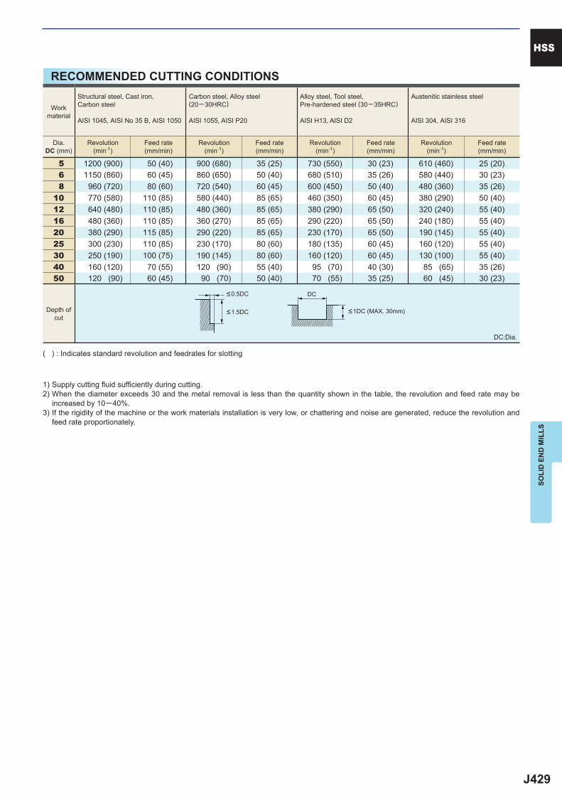
J429
5 1200 (900) 50 (40) 900 (680) 35 (25) 730 (550) 30 (23) 610 (460) 25 (20) 6 1150 (860) 60 (45) 860 (650) 50 (40) 680 (510) 35 (26) 580 (440) 30 (23) 8 960 (720) 80 (60) 720 (540) 60 (45) 600 (450) 50 (40) 480 (360) 35 (26)10 770 (580) 110 (85) 580 (440) 85 (65) 460 (350) 60 (45) 380 (290) 50 (40)12 640 (480) 110 (85) 480 (360) 85 (65) 380 (290) 65 (50) 320 (240) 55 (40)16 480 (360) 110 (85) 360 (270) 85 (65) 290 (220) 65 (50) 240 (180) 55 (40)20 380 (290) 115 (85) 290 (220) 85 (65) 230 (170) 65 (50) 190 (145) 55 (40)25 300 (230) 110 (85) 230 (170) 80 (60) 180 (135) 60 (45) 160 (120) 55 (40)30 250 (190) 100 (75) 190 (145) 80 (60) 160 (120) 60 (45) 130 (100) 55 (40)40 160 (120) 70 (55) 120 (90) 55 (40) 95 (70) 40 (30) 85 (65) 35 (26)50 120 (90) 60 (45) 90 (70) 50 (40) 70 (55) 35 (25) 60 (45) 30 (23)
DC
HSS
SOLI
D E
ND
MIL
LS
RECOMMENDED CUTTING CONDITIONS
Workmaterial
Structural steel, Cast iron, Carbon steel
AISI 1045, AISI No 35 B, AISI 1050
Carbon steel, Alloy steel (20─30HRC)
AISI 1055, AISI P20
Alloy steel, Tool steel,Pre-hardened steel (30─35HRC)
AISI H13, AISI D2
Austenitic stainless steel
AISI 304, AISI 316
Dia.DC (mm)
Revolution(min-1)
Feed rate(mm/min)
Revolution(min-1)
Feed rate(mm/min)
Revolution(min-1)
Feed rate(mm/min)
Revolution(min-1)
Feed rate(mm/min)
Depth ofcut
DC:Dia.
( ) : Indicates standard revolution and feedrates for slotting
1) Supply cutting fl uid suffi ciently during cutting.2) When the diameter exceeds 30 and the metal removal is less than the quantity shown in the table, the revolution and feed rate may be
increased by 10─40%.3) If the rigidity of the machine or the work materials installation is very low, or chattering and noise are generated, reduce the revolution and
feed rate proportionately.
<0.5DC
<1.5DC <1DC (MAX. 30mm)
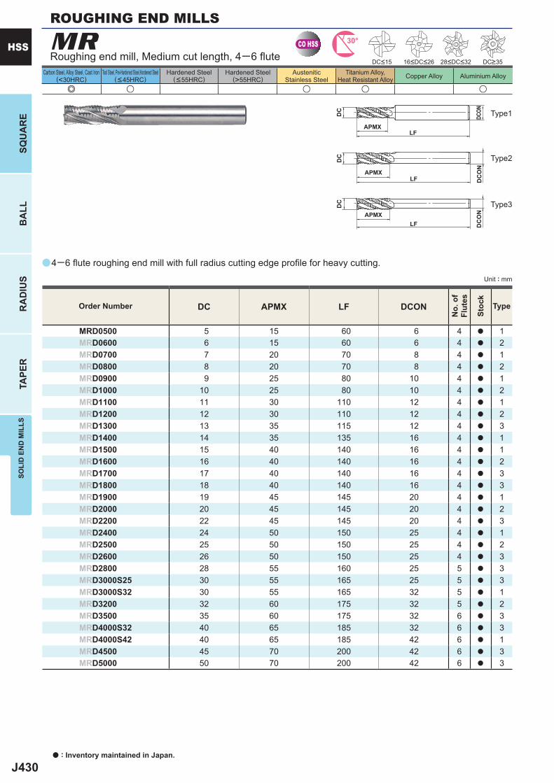
J430
a
e u u u u
MR
DC APMX LF DCON
MRD0500 5 15 60 6 4 a 1MRD0600 6 15 60 6 4 a 2MRD0700 7 20 70 8 4 a 1MRD0800 8 20 70 8 4 a 2MRD0900 9 25 80 10 4 a 1MRD1000 10 25 80 10 4 a 2MRD1100 11 30 110 12 4 a 1MRD1200 12 30 110 12 4 a 2MRD1300 13 35 115 12 4 a 3MRD1400 14 35 135 16 4 a 1MRD1500 15 40 140 16 4 a 1MRD1600 16 40 140 16 4 a 2MRD1700 17 40 140 16 4 a 3MRD1800 18 40 140 16 4 a 3MRD1900 19 45 145 20 4 a 1MRD2000 20 45 145 20 4 a 2MRD2200 22 45 145 20 4 a 3MRD2400 24 50 150 25 4 a 1MRD2500 25 50 150 25 4 a 2MRD2600 26 50 150 25 4 a 3MRD2800 28 55 160 25 5 a 3MRD3000S25 30 55 165 25 5 a 3MRD3000S32 30 55 165 32 5 a 1MRD3200 32 60 175 32 5 a 2MRD3500 35 60 175 32 6 a 3MRD4000S32 40 65 185 32 6 a 3MRD4000S42 40 65 185 42 6 a 1MRD4500 45 70 200 42 6 a 3MRD5000 50 70 200 42 6 a 3
CO HSS 30°
APMXLF
DC
DC
ON
APMXLF
DC
DCON
APMXLF
DC
DC
ON
a : Inventory maintained in Japan.
HSS
SQU
AR
EB
ALL
RA
DIU
STA
PER
SOLI
D E
ND
MIL
LS
Unit : mm
Carbon Steel, Alloy Steel, Cast Iron(<30HRC)
Tool Steel, Pre-Hardened Steel,Hardened Steel(<45HRC)
Hardened Steel(<55HRC)
Hardened Steel(>55HRC)
AusteniticStainless Steel
Titanium Alloy,Heat Resistant Alloy Copper Alloy Aluminium Alloy
Order Number
No.
of
Flut
es
Stoc
k
Type
Type2
Type3
Type1
Roughing end mill, Medium cut length, 4─6 fl ute
4─6 fl ute roughing end mill with full radius cutting edge profi le for heavy cutting.
ROUGHING END MILLS
DC<15 DC>3528<DC<3216<DC<26
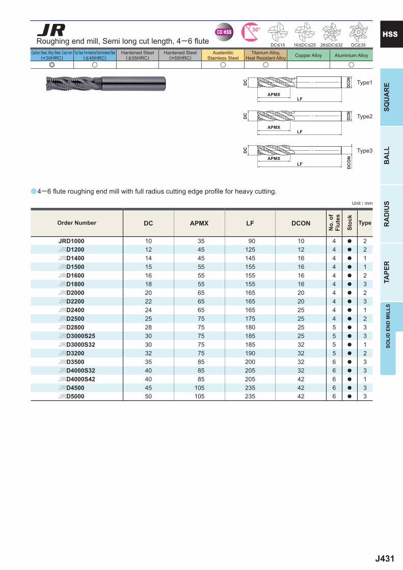
J431
a
e u u u u
JR
DC APMX LF DCON
JRD1000 10 35 90 10 4 a 2JRD1200 12 45 125 12 4 a 2JRD1400 14 45 145 16 4 a 1JRD1500 15 55 155 16 4 a 1JRD1600 16 55 155 16 4 a 2JRD1800 18 55 155 16 4 a 3JRD2000 20 65 165 20 4 a 2JRD2200 22 65 165 20 4 a 3JRD2400 24 65 165 25 4 a 1JRD2500 25 75 175 25 4 a 2JRD2800 28 75 180 25 5 a 3JRD3000S25 30 75 185 25 5 a 3JRD3000S32 30 75 185 32 5 a 1JRD3200 32 75 190 32 5 a 2JRD3500 35 85 200 32 6 a 3JRD4000S32 40 85 205 32 6 a 3JRD4000S42 40 85 205 42 6 a 1JRD4500 45 105 235 42 6 a 3JRD5000 50 105 235 42 6 a 3
CO HSS 30°
APMXLF
DC
DCON
APMXLF
DC
DCON
APMXLF
DC
DC
ON
SOLI
D E
ND
MIL
LSSQ
UA
RE
BA
LLR
AD
IUS
TAPE
R
HSS
Unit : mm
Carbon Steel, Alloy Steel, Cast Iron(<30HRC)
Tool Steel, Pre-Hardened Steel,Hardened Steel(<45HRC)
Hardened Steel(<55HRC)
Hardened Steel(>55HRC)
AusteniticStainless Steel
Titanium Alloy,Heat Resistant Alloy Copper Alloy Aluminium Alloy
4─6 fl ute roughing end mill with full radius cutting edge profi le for heavy cutting.
Roughing end mill, Semi long cut length, 4─6 fl ute DC>35DC<15 16<DC<25 28<DC<32
Type2
Type3
Type1
Order Number
No.
of
Flut
es
Stoc
k
Type
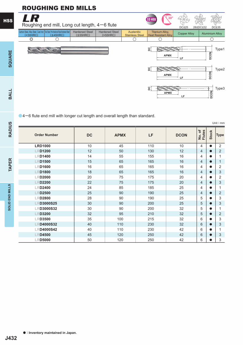
J432
a
e u u u u
LR
DC APMX LF DCON
LRD1000 10 45 110 10 4 a 2LRD1200 12 50 130 12 4 a 2LRD1400 14 55 155 16 4 a 1LRD1500 15 65 165 16 4 a 1LRD1600 16 65 165 16 4 a 2LRD1800 18 65 165 16 4 a 3LRD2000 20 75 175 20 4 a 2LRD2200 22 75 175 20 4 a 3LRD2400 24 85 185 25 4 a 1LRD2500 25 90 190 25 4 a 2LRD2800 28 90 190 25 5 a 3LRD3000S25 30 90 200 25 5 a 3LRD3000S32 30 90 200 32 5 a 1LRD3200 32 95 210 32 5 a 2LRD3500 35 100 215 32 6 a 3LRD4000S32 40 110 230 32 6 a 3LRD4000S42 40 110 230 42 6 a 1LRD4500 45 120 250 42 6 a 3LRD5000 50 120 250 42 6 a 3
CO HSS 30°
APMXLF
DC
DC
ON
APMXLF
DC
DC
ON
APMXLF
DC
DC
ON
a : Inventory maintained in Japan.
HSS
SQU
AR
EB
ALL
RA
DIU
STA
PER
SOLI
D E
ND
MIL
LS
Unit : mm
Carbon Steel, Alloy Steel, Cast Iron(<30HRC)
Tool Steel, Pre-Hardened Steel,Hardened Steel(<45HRC)
Hardened Steel(<55HRC)
Hardened Steel(>55HRC)
AusteniticStainless Steel
Titanium Alloy,Heat Resistant Alloy Copper Alloy Aluminium Alloy
Type2
Type3
Type1
Order Number
No.
of
Flut
es
Stoc
k
Type
Roughing end mill, Long cut length, 4─6 fl ute
4─6 fl ute end mill with longer cut length and overall length than standard.
ROUGHING END MILLS
DC<25 DC>3528<DC<32
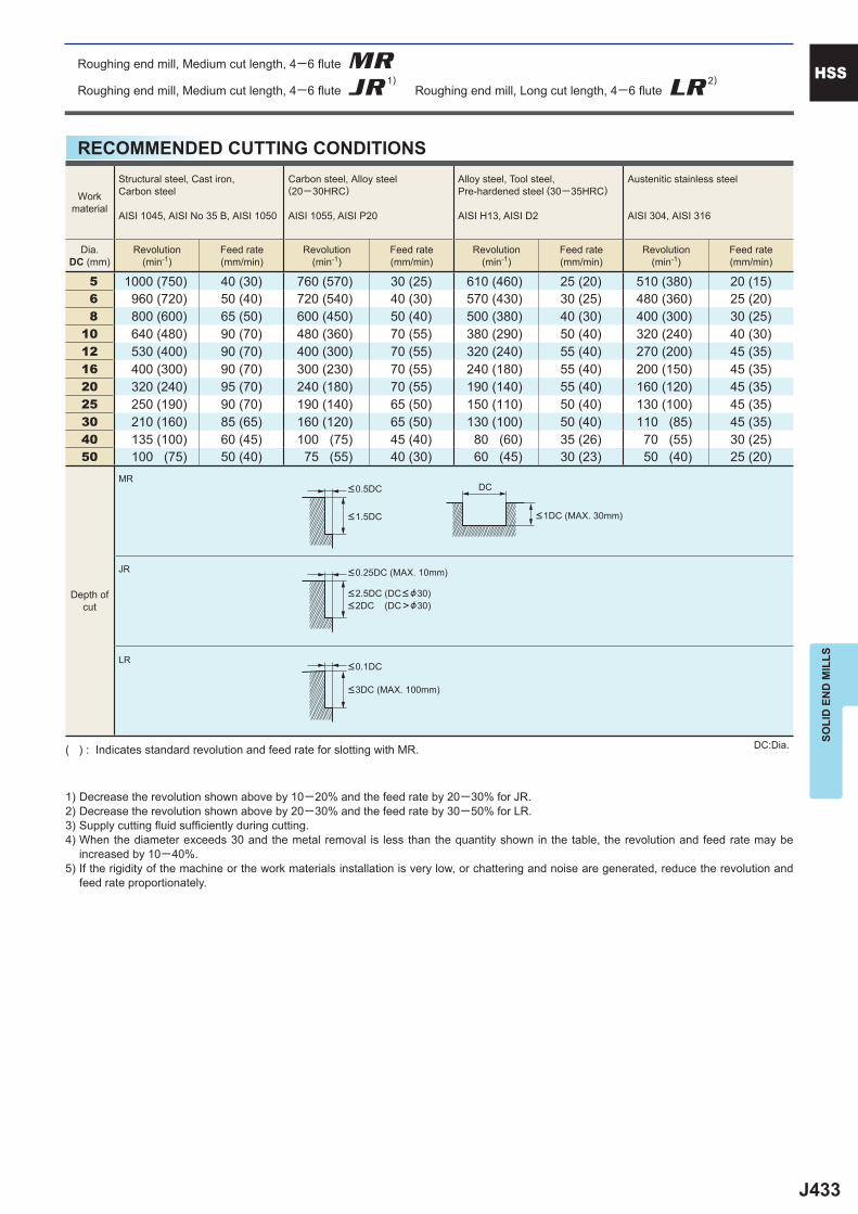
J433
5 1000 (750) 40 (30) 760 (570) 30 (25) 610 (460) 25 (20) 510 (380) 20 (15) 6 960 (720) 50 (40) 720 (540) 40 (30) 570 (430) 30 (25) 480 (360) 25 (20) 8 800 (600) 65 (50) 600 (450) 50 (40) 500 (380) 40 (30) 400 (300) 30 (25)10 640 (480) 90 (70) 480 (360) 70 (55) 380 (290) 50 (40) 320 (240) 40 (30)12 530 (400) 90 (70) 400 (300) 70 (55) 320 (240) 55 (40) 270 (200) 45 (35)16 400 (300) 90 (70) 300 (230) 70 (55) 240 (180) 55 (40) 200 (150) 45 (35)20 320 (240) 95 (70) 240 (180) 70 (55) 190 (140) 55 (40) 160 (120) 45 (35)25 250 (190) 90 (70) 190 (140) 65 (50) 150 (110) 50 (40) 130 (100) 45 (35)30 210 (160) 85 (65) 160 (120) 65 (50) 130 (100) 50 (40) 110 (85) 45 (35)40 135 (100) 60 (45) 100 (75) 45 (40) 80 (60) 35 (26) 70 (55) 30 (25)50 100 (75) 50 (40) 75 (55) 40 (30) 60 (45) 30 (23) 50 (40) 25 (20)
MR
JR
LR
DC
HSS
SOLI
D E
ND
MIL
LS
RECOMMENDED CUTTING CONDITIONS
Workmaterial
Structural steel, Cast iron, Carbon steel
AISI 1045, AISI No 35 B, AISI 1050
Carbon steel, Alloy steel (20─30HRC)
AISI 1055, AISI P20
Alloy steel, Tool steel,Pre-hardened steel (30─35HRC)
AISI H13, AISI D2
Austenitic stainless steel
AISI 304, AISI 316
Dia.DC (mm)
Revolution(min-1)
Feed rate(mm/min)
Revolution(min-1)
Feed rate(mm/min)
Revolution(min-1)
Feed rate(mm/min)
Revolution(min-1)
Feed rate(mm/min)
Depth ofcut
DC:Dia.( ) : Indicates standard revolution and feed rate for slotting with MR.
1) Decrease the revolution shown above by 10─20% and the feed rate by 20─30% for JR.2) Decrease the revolution shown above by 20─30% and the feed rate by 30─50% for LR.3) Supply cutting fl uid suffi ciently during cutting.4) When the diameter exceeds 30 and the metal removal is less than the quantity shown in the table, the revolution and feed rate may be
increased by 10─40%.5) If the rigidity of the machine or the work materials installation is very low, or chattering and noise are generated, reduce the revolution and
feed rate proportionately.
<0.5DC
<1.5DC
<0.25DC (MAX. 10mm)
<2.5DC (DC< &30)<2DC (DC>&30)
<0.1DC
<3DC (MAX. 100mm)
<1DC (MAX. 30mm)
Roughing end mill, Medium cut length, 4─6 fl ute MRRoughing end mill, Medium cut length, 4─6 fl ute JR
1) Roughing end mill, Long cut length, 4─6 fl ute LR2)

J434
Memo

J435
Memo
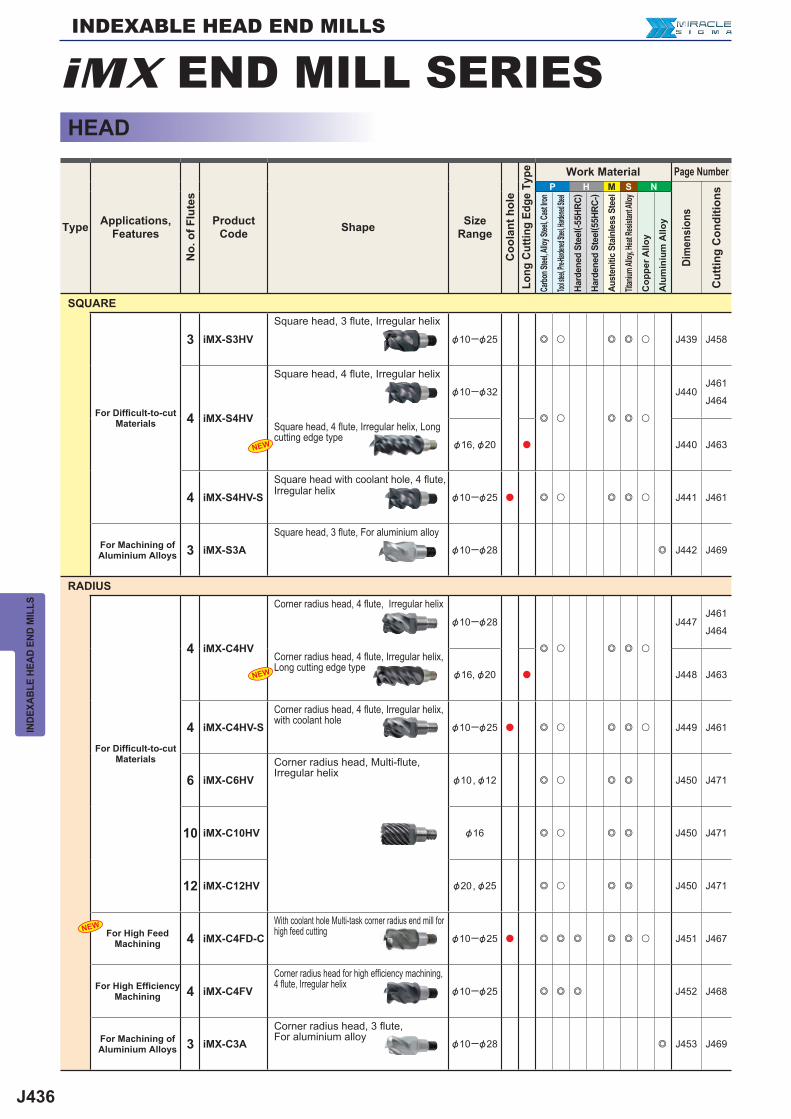
J436
P H M S N
3 iMX-S3HV &10─&25 e u e e u J439 J458
4 iMX-S4HV
&10─&32
e u e e u
J440J461
J464
&16, &20 a J440 J463
4 iMX-S4HV-S &10─&25 a e u e e u J441 J461
3 iMX-S3A &10─&28 e J442 J469
4 iMX-C4HV
&10─&28
e u e e u
J447J461
J464
&16, &20 a J448 J463
4 iMX-C4HV-S &10─&25 a e u e e u J449 J461
6 iMX-C6HV &10, &12 e u e e J450 J471
10 iMX-C10HV &16 e u e e J450 J471
12 iMX-C12HV &20, &25 e u e e J450 J471
4 iMX-C4FD-C &10─&25 a e e e e e u J451 J467
4 iMX-C4FV &10─&25 e e e J452 J468
3 iMX-C3A &10─&28 e J453 J469
NEW
NEW
NEW
INDE
XABL
E HE
AD E
ND M
ILLS
HEAD
Type Applications,Features
No.
of F
lute
s
ProductCode Shape Size
Range
Coo
lant
hol
eLo
ng C
uttin
g Ed
ge T
ype Work Material Page Number
Dim
ensi
ons
Cut
ting
Con
ditio
ns
Carbo
n Stee
l, Allo
y Stee
l, Cas
t Iron
Tool ste
el, Pre-H
ardene
d Steel
, Harde
ned Ste
el
Hard
ened
Ste
el( -5
5HRC
)
Hard
ened
Ste
el( 5
5HRC
-)
Aust
eniti
c St
ainl
ess
Stee
l
Titan
ium Al
loy, H
eat Re
sistan
t Allo
y
Cop
per A
lloy
Alu
min
ium
Allo
y
SQUARE
For Diffi cult-to-cut Materials
Square head, 3 flute, Irregular helix
Square head, 4 flute, Irregular helix
Square head, 4 flute, Irregular helix, Long cutting edge type
Square head with coolant hole, 4 fl ute, Irregular helix
For Machining of Aluminium Alloys
Square head, 3 flute, For aluminium alloy
RADIUS
For Diffi cult-to-cut Materials
Corner radius head, 4 flute, Irregular helix
Corner radius head, 4 flute, Irregular helix, Long cutting edge type
Corner radius head, 4 flute, Irregular helix, with coolant hole
Corner radius head, Multi-flute, Irregular helix
For High Feed Machining
With coolant hole Multi-task corner radius end mill for high feed cutting
For High Effi ciency Machining
Corner radius head for high efficiency machining, 4 flute, Irregular helix
For Machining of Aluminium Alloys
Corner radius head, 3 flute, For aluminium alloy
iMX END MILL SERIESINDEXABLE HEAD END MILLS
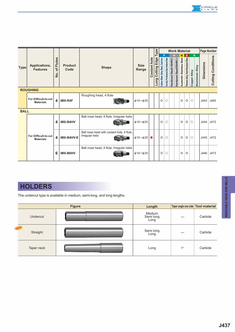
J437
—
—
1°
P H M S N
4 iMX-R4F &10─&25 e u e e u J443 J465
4 iMX-B4HV &10─&25 e u e e u J444 J472
4 iMX-B4HV-E &10─&25 a e u e e u J445 J472
6 iMX-B6HV &10─&25 e u e e J446 J473
NEWIN
DEXA
BLE
HEAD
END
MIL
LS
HOLDERSThe undercut type is available in medium, semi-long, and long lengths.
Figure Length Taper angle one side Tool material
UndercutMedium
Semi longLong
Carbide
Straight Semi longLong Carbide
Taper neck Long Carbide
Type Applications,Features
No.
of F
lute
s
ProductCode Shape Size
Range
Coo
lant
hol
eLo
ng C
uttin
g Ed
ge T
ype Work Material Page Number
Dim
ensi
ons
Cut
ting
Con
ditio
ns
Carbo
n Stee
l, Allo
y Stee
l, Cas
t Iron
Tool ste
el, Pre-H
ardene
d Steel
, Harde
ned Ste
el
Hard
ened
Ste
el( -5
5HRC
)
Hard
ened
Ste
el( 5
5HRC
-)
Aust
eniti
c St
ainl
ess
Stee
l
Titan
ium Al
loy, H
eat Re
sistan
t Allo
y
Cop
per A
lloy
Alu
min
ium
Allo
y
ROUGHING
For Diffi cult-to-cut Materials
Roughing head, 4 flute
BALL
For Diffi cult-to-cut Materials
Ball nose head, 4 flute, Irregular helix
Ball nose head with coolant hole, 4 fl ute, Irregular helix
Ball nose head, 4 flute, Irregular helix
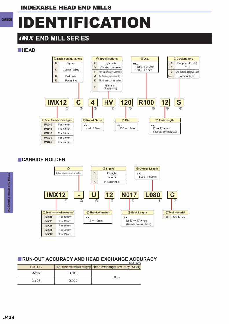
J438
IMX12 - U
S
C
HV R100
N017 L080
120 12
12
HVFAD
F
SUA
SEC
C
y
y
y
z
v
x
b
c
n
v
,
m
m
nb
S
C
BR
IMX12z
Cx
4c
<ø25 0.015±0.02
0.020
IMX10IMX12IMX16IMX20IMX25
IMX10IMX12IMX16IMX20IMX25
INDEXABLE HEAD END MILLS
CARBIDE
INDE
XABL
E HE
AD E
ND M
ILLS
HEAD
CARBIDE HOLDER
v Shank diameter
ex. 12 | 12mm
n Overall Length
ex. L080 | 80mm
m Flute length
ex. 12 | 12.*mm (Truncate decimal places)
n Dia.
ex. R050 | 0.5mm R100 | 1mm
b Neck Length
ex. N017 | 17.*mm (Truncate decimal places)
c FigureStraight
Undercut1° Taper neck
x
Hyphen Indicates these are holders.
, Coolant holePeripheral(Side)
EndEnd cutting edge(Center)
None without hole
m Tool materialCARBIDE
IDENTIFICATION
c No. of Flutes
ex. 4 | 4 flute
b Dia.
ex. 120 | 12mm
v Specifi cationsHigh helix
Vibration controleFor High Effi ciency MachiningFor Machining of Aluminium AlloysMulti-task corner radius
Fine pitch(Roughing)
x Basic confi gurationsSquare
Corner radius
Ball noseRoughing
Dia. DC Run-out accuracy for the peripheral cutting edge Head exchange accuracy (Axial)
>ø25
iMX END MILL SERIES
Unit : mmRUN-OUT ACCURACY AND HEAD EXCHANGE ACCURACY
z Series Description•Fastening sizeFor 10mmFor 12mmFor 16mmFor 20mmFor 25mm
z Series Description•Fastening sizeFor 10mmFor 12mmFor 16mmFor 20mmFor 25mm
J439
DC APMX LH BD
EP70
20
IMX10S3HV10008 10 8.5 16 9.7 3 a 1IMX12S3HV12010 12 10.1 19 11.7 3 a 1IMX16S3HV16013 16 13.3 24 15.5 3 a 1IMX20S3HV20017 20 17 30 19.5 3 a 1IMX25S3HV25021 25 21 37.5 24.5 3 a 1
iMX-S3HV
e u e e u
DC>12 0- 0.020
0- 0.030
a
a
UWC45°43.5°42°
DC
APMX
LH
BD
CARBIDE
INDE
XABL
E HE
AD E
ND M
ILLS
Carbon Steel, Alloy Steel, Cast Iron(<30HRC)
Tool Steel, Pre-Hardened Steel,Hardened Steel(<45HRC)
Hardened Steel(<55HRC)
Hardened Steel(>55HRC)
AusteniticStainless Steel
Titanium Alloy,Heat Resistant Alloy Copper Alloy Aluminium Alloy
SQU
AR
EB
ALL
RA
DIU
S
Type1
Square head, 3 fl ute, Irregular helix
3-fl ute end mills that cover side milling, slotting and plunging.Irregular lead controls vibration and achieves stable machining.
DC<12
* The fastening size of the holder and head should be the same. (refer to J438)
Order Number
No.
of
Flut
es
GradeType
CUTTING CONDITIONS J458a : Inventory maintained in Japan.
Unit : mm
J440
e u e e u
iMX-S4HV
DC>12 0- 0.020
0- 0.030
a
DC APMX LH BD
EP70
20
IMX10S4HV10010 10 10.5 16 9.7 4 a 1IMX10S4HV12012 12 12.5 19 9.7 4 a 2IMX12S4HV12012 12 12.5 19 11.7 4 a 1IMX12S4HV14014 14 14.5 22.5 11.7 4 a 2IMX16S4HV16016 16 16.5 24 15.5 4 a 1IMX16S4HV18018 18 18.5 27 15.5 4 a 2IMX20S4HV20021 20 21 30 19.5 4 a 1IMX20S4HV22023 22 23 33 19.5 4 a 2IMX25S4HV25026 25 26 37.5 24.5 4 a 1IMX25S4HV28029 28 29 41.5 24.5 4 a 2IMX25S4HV30031 30 31 43.5 24.5 4 a 2IMX25S4HV32033 32 33 45.5 24.5 4 a 2
DC APMX LH BD
EP70
20
IMX16S4HV16032 16 32 40 15.5 4 a 3IMX20S4HV20040 20 40 50 19.5 4 a 3
NEW
NEW
NEW
NEW
NEW
NEW
NEW
NEW
NEW
y
42°45°UWC
DC
APMXLH
BD
BD
DC
APMXLH APMX
BD
DC
APMXLH APMX
INDEXABLE HEAD END MILLS
CARBIDE
INDE
XABL
E HE
AD E
ND M
ILLS
Carbon Steel, Alloy Steel, Cast Iron(<30HRC)
Tool Steel, Pre-Hardened Steel,Hardened Steel(<45HRC)
Hardened Steel(<55HRC)
Hardened Steel(>55HRC)
AusteniticStainless Steel
Titanium Alloy,Heat Resistant Alloy Copper Alloy Aluminium Alloy
BA
LLR
AD
IUS
SQU
AR
E
Square head, 4 fl ute, Irregular helix
CUTTING CONDITIONS J461a : Inventory maintained in Japan.
DC<12
Unit : mm
Unit : mm
Type1
Type2
Type3
Order Number
No.
of
Flut
es
GradeType
Order Number
No.
of
Flut
es
GradeType
Irregular lead controls vibration and achieves stable machining even when machining of diffi cult-to-cut materials and long overhang.
* The fastening size of the holder and head should be the same. (refer to J438)
Long cutting edge type
Offset Type
CurvedEdge
CurvedEdge
CUTTING CONDITIONS J461
J441
e u e e u
DC APMX LH BD
EP70
20
IMX10S4HV10010S 10 10.5 16 9.7 4 a 1IMX12S4HV12012S 12 12.5 19 11.7 4 a 1IMX16S4HV16016S 16 16.5 24 15.5 4 a 1IMX20S4HV20021S 20 21 30 19.5 4 a 1IMX25S4HV25026S 25 26 37.5 24.5 4 a 1
iMX-S4HV-S
DC>12 0- 0.020
0- 0.030
a
a
42°45°UWC
DC
APMX
LH
BD
CARBIDE
INDE
XABL
E HE
AD E
ND M
ILLS
Carbon Steel, Alloy Steel, Cast Iron(<30HRC)
Tool Steel, Pre-Hardened Steel,Hardened Steel(<45HRC)
Hardened Steel(<55HRC)
Hardened Steel(>55HRC)
AusteniticStainless Steel
Titanium Alloy,Heat Resistant Alloy Copper Alloy Aluminium Alloy
SQU
AR
EB
ALL
RA
DIU
S
Type1
DC<12
Coolant holes for each cutting edge enable stable coolant supply.Irregular lead controls vibration and achieves stable machining.
Order Number
No.
of
Flut
es
GradeType
CUTTING CONDITIONS J461
Square head with coolant hole, 4 fl ute, Irregular helix
* The fastening size of the holder and head should be the same. (refer to J438)
Peripheral cutting edge with coolant hole
Unit : mm
Peripheral cutting edge with coolant hole
J442
DC>12 0- 0.020
0- 0.030
e
DC APMX LH BD
ET20
20
IMX10S3A10008 10 8.5 16 9.7 3 a 1IMX10S3A12010 12 10.1 19 9.7 3 a 2IMX12S3A12010 12 10.1 19 11.7 3 a 1IMX12S3A14011 14 11.7 22.5 11.7 3 a 2IMX16S3A16013 16 13.3 24 15.5 3 a 1IMX16S3A18014 18 14.9 27 15.5 3 a 2IMX20S3A20017 20 17 30 19.5 3 a 1IMX20S3A22018 22 18.6 33 19.5 3 a 2IMX25S3A25021 25 21 37.5 24.5 3 a 1IMX25S3A28023 28 23.4 41.5 24.5 3 a 2
iMX-S3A
NEW
NEW
NEW
NEW
NEW
a
UWC 37.5°
DC
APMX
LH
BD
DC
APMX
LH
BD
APMX
INDEXABLE HEAD END MILLS
CARBIDE
INDE
XABL
E HE
AD E
ND M
ILLS
Carbon Steel, Alloy Steel, Cast Iron(<30HRC)
Tool Steel, Pre-Hardened Steel,Hardened Steel(<45HRC)
Hardened Steel(<55HRC)
Hardened Steel(>55HRC)
AusteniticStainless Steel
Titanium Alloy,Heat Resistant Alloy Copper Alloy Aluminium Alloy
BA
LLR
AD
IUS
SQU
AR
E
Type1
DC<12
High effi ciency machining due to the sharp cutting edge suitable for aluminium alloy machining and polished rake face.
Order Number
No.
of
Flut
es
GradeType
CUTTING CONDITIONS J469
Square head, 3 fl ute, For aluminium alloy
* The fastening size of the holder and head should be the same. (refer to J438)
a : Inventory maintained in Japan.
Unit : mm
Type2
Offset Type
CurvedEdge
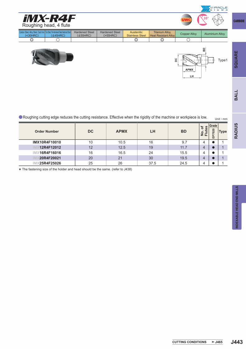
J443
e u e e u
DC APMX LH BD
EP70
20
IMX10R4F10010 10 10.5 16 9.7 4 a 1IMX12R4F12012 12 12.5 19 11.7 4 a 1IMX16R4F16016 16 16.5 24 15.5 4 a 1IMX20R4F20021 20 21 30 19.5 4 a 1IMX25R4F25026 25 26 37.5 24.5 4 a 1
iMX-R4F
a
UWC 35°
DC
APMX
LH
BD
CARBIDE
INDE
XABL
E HE
AD E
ND M
ILLS
Carbon Steel, Alloy Steel, Cast Iron(<30HRC)
Tool Steel, Pre-Hardened Steel,Hardened Steel(<45HRC)
Hardened Steel(<55HRC)
Hardened Steel(>55HRC)
AusteniticStainless Steel
Titanium Alloy,Heat Resistant Alloy Copper Alloy Aluminium Alloy
SQU
AR
EB
ALL
RA
DIU
S
Type1
Roughing head, 4 fl ute
Roughing cutting edge reduces the cutting resistance. Effective when the rigidity of the machine or workpiece is low.
Order Number
No.
of
Flut
es
GradeType
CUTTING CONDITIONS J465
* The fastening size of the holder and head should be the same. (refer to J438)
Unit : mm
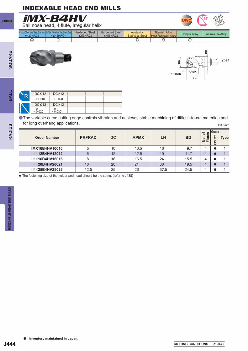
J444
e u e e u
iMX-B4HV
PRFRAD DC APMX LH BD
EP70
20
IMX10B4HV10010 5 10 10.5 16 9.7 4 a 1IMX12B4HV12012 6 12 12.5 19 11.7 4 a 1IMX16B4HV16016 8 16 16.5 24 15.5 4 a 1IMX20B4HV20021 10 20 21 30 19.5 4 a 1IMX25B4HV25026 12.5 25 26 37.5 24.5 4 a 1
DC>12±0.010 ±0.020
DC>12 0- 0.020
0- 0.030
a
UWC 45°
R
DC
APMX
LH
BD
PRFRAD
INDEXABLE HEAD END MILLS
CARBIDE
INDE
XABL
E HE
AD E
ND M
ILLS
Carbon Steel, Alloy Steel, Cast Iron(<30HRC)
Tool Steel, Pre-Hardened Steel,Hardened Steel(<45HRC)
Hardened Steel(<55HRC)
Hardened Steel(>55HRC)
AusteniticStainless Steel
Titanium Alloy,Heat Resistant Alloy Copper Alloy Aluminium Alloy
BA
LLR
AD
IUS
SQU
AR
E
Ball nose head, 4 fl ute, Irregular helix
Type1
DC<12
DC<12
Order Number
No.
of
Flut
es
GradeType
CUTTING CONDITIONS J472
The variable curve cutting edge controls vibraion and achieves stable machining of diffi cult-to-cut materilas and for long overhang applications.
* The fastening size of the holder and head should be the same. (refer to J438)
a : Inventory maintained in Japan.
Unit : mm
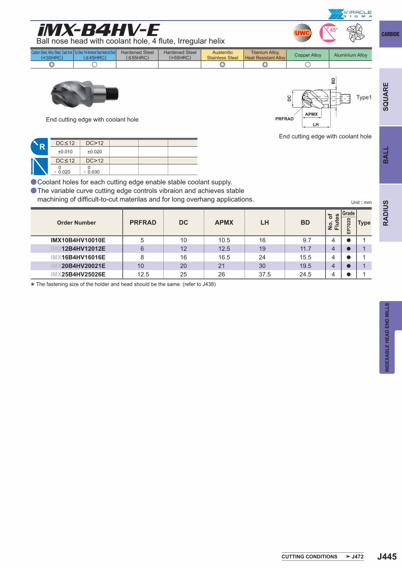
J445
e u e e u
iMX-B4HV-E
PRFRAD DC APMX LH BD
EP70
20
IMX10B4HV10010E 5 10 10.5 16 9.7 4 a 1IMX12B4HV12012E 6 12 12.5 19 11.7 4 a 1IMX16B4HV16016E 8 16 16.5 24 15.5 4 a 1IMX20B4HV20021E 10 20 21 30 19.5 4 a 1IMX25B4HV25026E 12.5 25 26 37.5 24.5 4 a 1
DC>12±0.010 ±0.020
DC>12 0- 0.020
0- 0.030
a
a
UWC 45°
R
DC
APMX
LH
BD
PRFRAD
CARBIDE
INDE
XABL
E HE
AD E
ND M
ILLS
Carbon Steel, Alloy Steel, Cast Iron(<30HRC)
Tool Steel, Pre-Hardened Steel,Hardened Steel(<45HRC)
Hardened Steel(<55HRC)
Hardened Steel(>55HRC)
AusteniticStainless Steel
Titanium Alloy,Heat Resistant Alloy Copper Alloy Aluminium Alloy
SQU
AR
EB
ALL
RA
DIU
S
Type1
DC<12
DC<12
Order Number
No.
of
Flut
es
GradeType
CUTTING CONDITIONS J472
Ball nose head with coolant hole, 4 fl ute, Irregular helix
Coolant holes for each cutting edge enable stable coolant supply.The variable curve cutting edge controls vibraion and achieves stable machining of diffi cult-to-cut materilas and for long overhang applications.
* The fastening size of the holder and head should be the same. (refer to J438)
End cutting edge with coolant hole
Unit : mm
End cutting edge with coolant hole
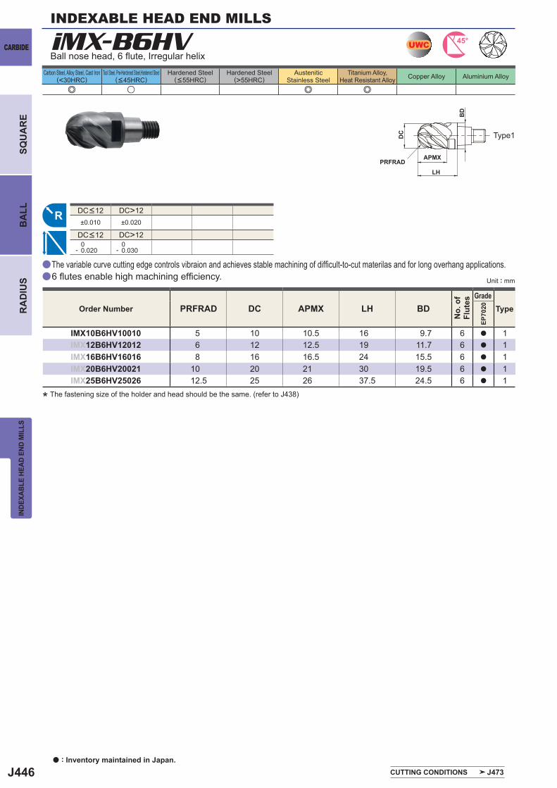
J446
a
a
e u e e
iMX-B6HV
PRFRAD DC APMX LH BD
EP70
20
IMX10B6HV10010 5 10 10.5 16 9.7 6 a 1IMX12B6HV12012 6 12 12.5 19 11.7 6 a 1IMX16B6HV16016 8 16 16.5 24 15.5 6 a 1IMX20B6HV20021 10 20 21 30 19.5 6 a 1IMX25B6HV25026 12.5 25 26 37.5 24.5 6 a 1
DC>12±0.010 ±0.020
DC>12 0- 0.020
0- 0.030
UWC 45°
R
DC
APMX
LH
BD
PRFRAD
INDEXABLE HEAD END MILLS
CARBIDE
INDE
XABL
E HE
AD E
ND M
ILLS
Carbon Steel, Alloy Steel, Cast Iron(<30HRC)
Tool Steel, Pre-Hardened Steel,Hardened Steel(<45HRC)
Hardened Steel(<55HRC)
Hardened Steel(>55HRC)
AusteniticStainless Steel
Titanium Alloy,Heat Resistant Alloy Copper Alloy Aluminium Alloy
BA
LLR
AD
IUS
SQU
AR
E
The variable curve cutting edge controls vibraion and achieves stable machining of diffi cult-to-cut materilas and for long overhang applications.6 fl utes enable high machining effi ciency.
Ball nose head, 6 fl ute, Irregular helix
Type1
DC<12
DC<12
Order Number
No.
of
Flut
es
GradeType
CUTTING CONDITIONS J473
* The fastening size of the holder and head should be the same. (refer to J438)
a : Inventory maintained in Japan.
Unit : mm
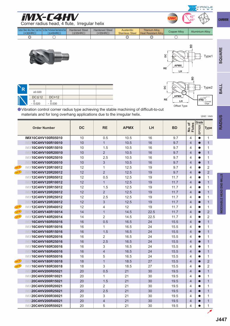
J447
e u e e u
DC RE APMX LH BD
EP70
20
IMX10C4HV100R05010 10 0.5 10.5 16 9.7 4 a 1IMX10C4HV100R10010 10 1 10.5 16 9.7 4 a 1IMX10C4HV100R15010 10 1.5 10.5 16 9.7 4 a 1IMX 10C4HV100R20010 10 2 10.5 16 9.7 4 a 1IMX10C4HV100R25010 10 2.5 10.5 16 9.7 4 a 1IMX10C4HV100R30010 10 3 10.5 16 9.7 4 a 1IMX10C4HV120R10012 12 1 12.5 19 9.7 4 a 2IMX10C4HV120R20012 12 2 12.5 19 9.7 4 a 2IMX12C4HV120R05012 12 0.5 12.5 19 11.7 4 a 1IMX12C4HV120R10012 12 1 12.5 19 11.7 4 a 1IMX12C4HV120R15012 12 1.5 12.5 19 11.7 4 a 1IMX12C4HV120R20012 12 2 12.5 19 11.7 4 a 1IMX12C4HV120R25012 12 2.5 12.5 19 11.7 4 a 1IMX12C4HV120R30012 12 3 12.5 19 11.7 4 a 1IMX12C4HV120R40012 12 4 12 19 11.7 4 a 1IMX12C4HV140R10014 14 1 14.5 22.5 11.7 4 a 2IMX12C4HV140R20014 14 2 14.5 22.5 11.7 4 a 2IMX16C4HV160R05016 16 0.5 16.5 24 15.5 4 a 1IMX16C4HV160R10016 16 1 16.5 24 15.5 4 a 1IMX16C4HV160R15016 16 1.5 16.5 24 15.5 4 a 1IMX16C4HV160R20016 16 2 16.5 24 15.5 4 a 1IMX16C4HV160R25016 16 2.5 16.5 24 15.5 4 a 1IMX16C4HV160R30016 16 3 16.5 24 15.5 4 a 1IMX16C4HV160R40016 16 4 16.5 24 15.5 4 a 1IMX16C4HV160R50016 16 5 16.5 24 15.5 4 a 1IMX16C4HV180R10018 18 1 18.5 27 15.5 4 a 2IMX16C4HV180R30018 18 3 18.5 27 15.5 4 a 2IMX20C4HV200R05021 20 0.5 21 30 19.5 4 a 1IMX20C4HV200R10021 20 1 21 30 19.5 4 a 1IMX20C4HV200R15021 20 1.5 21 30 19.5 4 a 1IMX20C4HV200R20021 20 2 21 30 19.5 4 a 1IMX20C4HV200R25021 20 2.5 21 30 19.5 4 a 1IMX20C4HV200R30021 20 3 21 30 19.5 4 a 1IMX20C4HV200R40021 20 4 21 30 19.5 4 a 1IMX20C4HV200R50021 20 5 21 30 19.5 4 a 1
iMX-C4HV
±0.020
DC>12 0- 0.020
0- 0.030
a
NEW
NEW
NEW
NEW
NEW
NEW
NEW
42°45°UWC
DC
DC
APMX
APMXAPMX
LH
LH
BD
BD
RE
RE
CARBIDE
INDE
XABL
E HE
AD E
ND M
ILLS
Carbon Steel, Alloy Steel, Cast Iron(<30HRC)
Tool Steel, Pre-Hardened Steel,Hardened Steel(<45HRC)
Hardened Steel(<55HRC)
Hardened Steel(>55HRC)
AusteniticStainless Steel
Titanium Alloy,Heat Resistant Alloy Copper Alloy Aluminium Alloy
SQU
AR
EB
ALL
RA
DIU
S
Corner radius head, 4 fl ute, Irregular helix
DC<12
Vibration control corner radius type achieving the stable machining of diffi cult-to-cut materials and for long overhang applications due to the irregular helix.
Order Number
No.
of
Flut
es
GradeType
Unit : mm
Type1
Type2
Offset Type
CurvedEdge
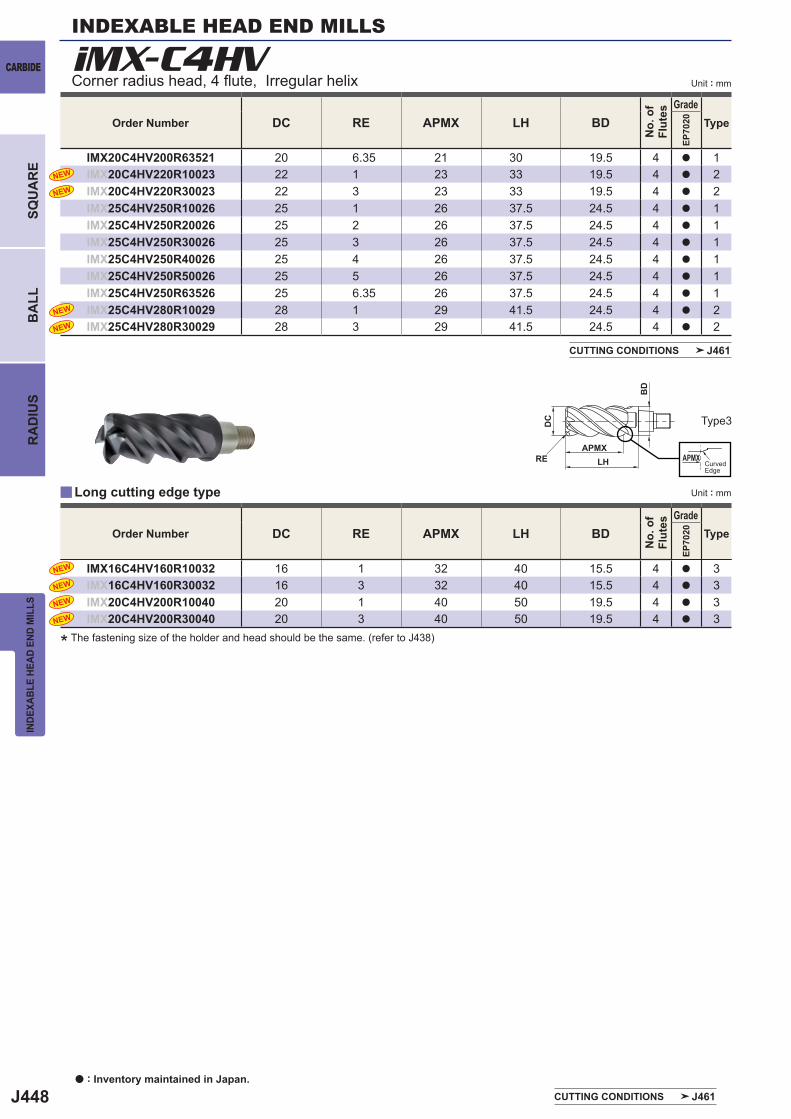
J448
iMX-C4HV
DC RE APMX LH BD
EP70
20
IMX20C4HV200R63521 20 6.35 21 30 19.5 4 a 1IMX20C4HV220R10023 22 1 23 33 19.5 4 a 2IMX20C4HV220R30023 22 3 23 33 19.5 4 a 2IMX25C4HV250R10026 25 1 26 37.5 24.5 4 a 1IMX25C4HV250R20026 25 2 26 37.5 24.5 4 a 1IMX25C4HV250R30026 25 3 26 37.5 24.5 4 a 1IMX25C4HV250R40026 25 4 26 37.5 24.5 4 a 1IMX25C4HV250R50026 25 5 26 37.5 24.5 4 a 1IMX25C4HV250R63526 25 6.35 26 37.5 24.5 4 a 1IMX25C4HV280R10029 28 1 29 41.5 24.5 4 a 2IMX25C4HV280R30029 28 3 29 41.5 24.5 4 a 2
NEW
NEW
NEW
NEW
DC RE APMX LH BD
EP70
20
IMX16C4HV160R10032 16 1 32 40 15.5 4 a 3IMX16C4HV160R30032 16 3 32 40 15.5 4 a 3IMX20C4HV200R10040 20 1 40 50 19.5 4 a 3IMX20C4HV200R30040 20 3 40 50 19.5 4 a 3
NEW
NEW
NEW
NEW
y
DC
APMXAPMXLH
BD
RE
INDEXABLE HEAD END MILLS
CARBIDE
INDE
XABL
E HE
AD E
ND M
ILLS
BA
LLR
AD
IUS
SQU
AR
E
Unit : mm
a : Inventory maintained in Japan.
Corner radius head, 4 fl ute, Irregular helix
Order Number
No.
of
Flut
es
GradeType
CUTTING CONDITIONS J461
Order Number
No.
of
Flut
es
GradeType
* The fastening size of the holder and head should be the same. (refer to J438)
Type3
Long cutting edge type
CUTTING CONDITIONS J461
CurvedEdge
Unit : mm
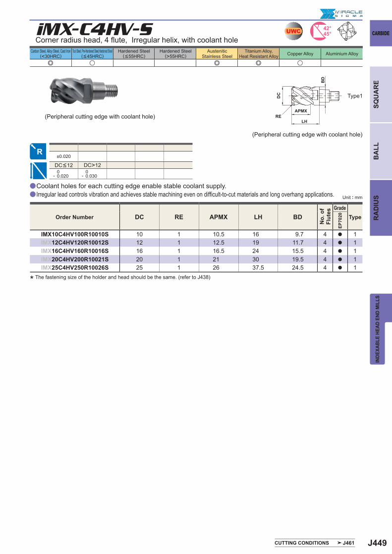
J449
a
a
e u e e u
iMX-C4HV-S
DC RE APMX LH BD
EP70
20
IMX10C4HV100R10010S 10 1 10.5 16 9.7 4 a 1IMX12C4HV120R10012S 12 1 12.5 19 11.7 4 a 1IMX16C4HV160R10016S 16 1 16.5 24 15.5 4 a 1IMX20C4HV200R10021S 20 1 21 30 19.5 4 a 1IMX25C4HV250R10026S 25 1 26 37.5 24.5 4 a 1
±0.020
DC>12 0- 0.020
0- 0.030
42°45°UWC
DC
APMX
LH
BD
RE
CARBIDE
INDE
XABL
E HE
AD E
ND M
ILLS
Carbon Steel, Alloy Steel, Cast Iron(<30HRC)
Tool Steel, Pre-Hardened Steel,Hardened Steel(<45HRC)
Hardened Steel(<55HRC)
Hardened Steel(>55HRC)
AusteniticStainless Steel
Titanium Alloy,Heat Resistant Alloy Copper Alloy Aluminium Alloy
SQU
AR
EB
ALL
RA
DIU
S
Corner radius head, 4 fl ute, Irregular helix, with coolant hole
Type1
DC<12
Order Number
No.
of
Flut
es
GradeType
CUTTING CONDITIONS J461
Coolant holes for each cutting edge enable stable coolant supply.Irregular lead controls vibration and achieves stable machining even on diffi cult-to-cut materials and long overhang applications.
* The fastening size of the holder and head should be the same. (refer to J438)
(Peripheral cutting edge with coolant hole)
Unit : mm
(Peripheral cutting edge with coolant hole)
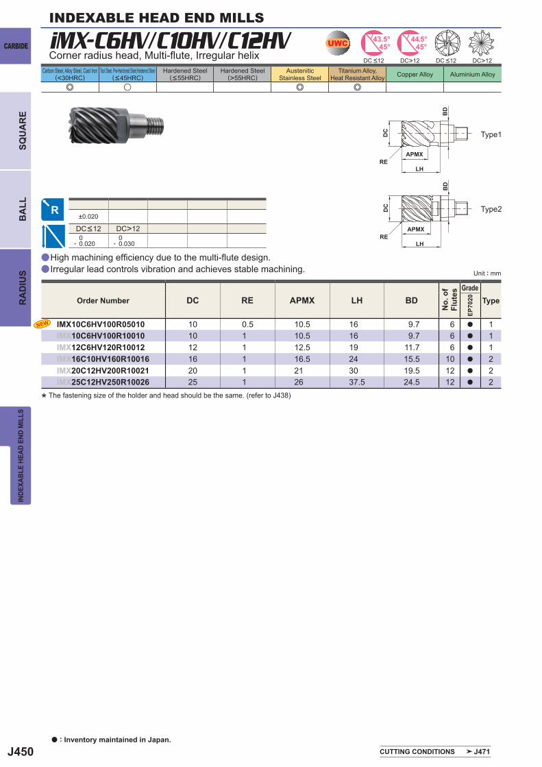
J450
a
a
e u e e
iMX-C6HV/C10HV/C12HV
DC RE APMX LH BD
EP70
20
IMX10C6HV100R05010 10 0.5 10.5 16 9.7 6 a 1IMX10C6HV100R10010 10 1 10.5 16 9.7 6 a 1IMX12C6HV120R10012 12 1 12.5 19 11.7 6 a 1IMX16C10HV160R10016 16 1 16.5 24 15.5 10 a 2IMX20C12HV200R10021 20 1 21 30 19.5 12 a 2IMX25C12HV250R10026 25 1 26 37.5 24.5 12 a 2
±0.020
DC>12 0- 0.020
0- 0.030
DC>12 DC>12
NEW
UWC 43.5°45° 45°
44.5°
DC
APMX
LH
BD
RE
DC
APMX
LH
BD
RE
INDEXABLE HEAD END MILLS
CARBIDE
INDE
XABL
E HE
AD E
ND M
ILLS
Carbon Steel, Alloy Steel, Cast Iron(<30HRC)
Tool Steel, Pre-Hardened Steel,Hardened Steel(<45HRC)
Hardened Steel(<55HRC)
Hardened Steel(>55HRC)
AusteniticStainless Steel
Titanium Alloy,Heat Resistant Alloy Copper Alloy Aluminium Alloy
BA
LLR
AD
IUS
SQU
AR
E
High machining effi ciency due to the multi-fl ute design.Irregular lead controls vibration and achieves stable machining.
Corner radius head, Multi-fl ute, Irregular helix
Type1
Type2
DC <12 DC <12
DC<12
Order Number
No.
of
Flut
es
GradeType
CUTTING CONDITIONS J471
* The fastening size of the holder and head should be the same. (refer to J438)
Unit : mm
a : Inventory maintained in Japan.
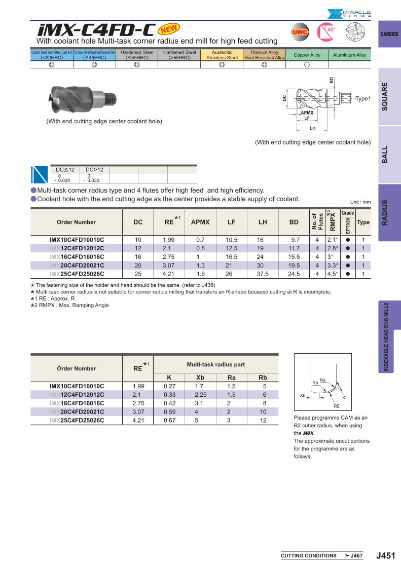
J451
e e e e e u
UWCiMX-C4FD-C
a
a
DC RE APMX LF LH BD
RM
PX
EP70
20
IMX10C4FD10010C 10 1.99 0.7 10.5 16 9.7 4 2.1° a 1IMX12C4FD12012C 12 2.1 0.8 12.5 19 11.7 4 2.8° a 1IMX16C4FD16016C 16 2.75 1 16.5 24 15.5 4 3° a 1IMX20C4FD20021C 20 3.07 1.3 21 30 19.5 4 3.3° a 1IMX25C4FD25026C 25 4.21 1.6 26 37.5 24.5 4 4.5° a 1
DC>12 0- 0.020
0- 0.030
NEW
REK Xb Ra Rb
IMX10C4FD10010C 1.99 0.27 1.7 1.5 5IMX12C4FD12012C 2.1 0.33 2.25 1.5 6IMX16C4FD16016C 2.75 0.42 3.1 2 8IMX20C4FD20021C 3.07 0.59 4 2 10IMX25C4FD25026C 4.21 0.67 5 3 12
45°
DC
APMX
LH
LF
BD
RaRb
Xb K
RE
CARBIDE
INDE
XABL
E HE
AD E
ND M
ILLS
Carbon Steel, Alloy Steel, Cast Iron(<30HRC)
Tool Steel, Pre-Hardened Steel,Hardened Steel(<45HRC)
Hardened Steel(<55HRC)
Hardened Steel(>55HRC)
AusteniticStainless Steel
Titanium Alloy,Heat Resistant Alloy Copper Alloy Aluminium Alloy
SQU
AR
EB
ALL
RA
DIU
SUnit : mm
With coolant hole Multi-task corner radius end mill for high feed cutting
Type1
DC<12
Multi-task corner radius type and 4 fl utes offer high feed and high effi ciency.Coolant hole with the end cutting edge as the center provides a stable supply of coolant.
* The fastening size of the holder and head should be the same. (refer to J438)
* Multi-task corner radius is not suitable for corner radius milling that transfers an R-shape because cutting at R is incomplete.
*1 RE : Approx. R
*2 RMPX : Max. Ramping Angle
(With end cutting edge center coolant hole)
(With end cutting edge center coolant hole)
Order Number *1
No.
of
Flut
es *2 GradeType
CUTTING CONDITIONS J467
Order Number *1 Multi-task radius part
Please programme CAM as an R2 cutter radius, when using the iMX .The approximate uncut portions for the programme are as follows.
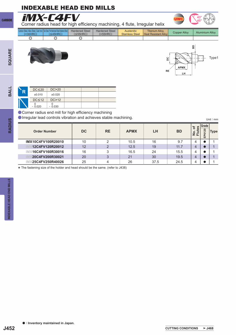
J452
a
a
e e e
DC RE APMX LH BD
EP61
20
IMX10C4FV100R20010 10 2 10.5 16 9.7 4 a 1IMX12C4FV120R20012 12 2 12.5 19 11.7 4 a 1IMX16C4FV160R30016 16 3 16.5 24 15.5 4 a 1IMX20C4FV200R30021 20 3 21 30 19.5 4 a 1IMX25C4FV250R40026 25 4 26 37.5 24.5 4 a 1
iMX-C4FV
DC>20±0.010 ±0.020
DC>12 0- 0.020
0- 0.030
UWC 43°45°
DC
APMX
LH
BD
RE
INDEXABLE HEAD END MILLS
CARBIDE
INDE
XABL
E HE
AD E
ND M
ILLS
Carbon Steel, Alloy Steel, Cast Iron(<30HRC)
Tool Steel, Pre-Hardened Steel,Hardened Steel(<45HRC)
Hardened Steel(<55HRC)
Hardened Steel(>55HRC)
AusteniticStainless Steel
Titanium Alloy,Heat Resistant Alloy Copper Alloy Aluminium Alloy
BA
LLR
AD
IUS
SQU
AR
E
Type1
Corner radius head for high effi ciency machining, 4 fl ute, Irregular helix
DC<12
Order Number
No.
of
Flut
es
GradeType
Corner radius end mill for high effi ciency machiningIrregular lead controls vibration and achieves stable machining.
CUTTING CONDITIONS J468
* The fastening size of the holder and head should be the same. (refer to J438)
a : Inventory maintained in Japan.
Unit : mm
DC<20
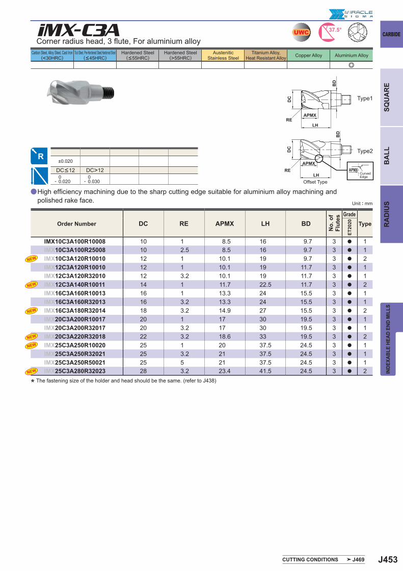
J453
e
DC RE APMX LH BD
ET20
20
IMX10C3A100R10008 10 1 8.5 16 9.7 3 a 1IMX10C3A100R25008 10 2.5 8.5 16 9.7 3 a 1IMX10C3A120R10010 12 1 10.1 19 9.7 3 a 2IMX12C3A120R10010 12 1 10.1 19 11.7 3 a 1IMX12C3A120R32010 12 3.2 10.1 19 11.7 3 a 1IMX12C3A140R10011 14 1 11.7 22.5 11.7 3 a 2IMX16C3A160R10013 16 1 13.3 24 15.5 3 a 1IMX16C3A160R32013 16 3.2 13.3 24 15.5 3 a 1IMX16C3A180R32014 18 3.2 14.9 27 15.5 3 a 2IMX20C3A200R10017 20 1 17 30 19.5 3 a 1IMX20C3A200R32017 20 3.2 17 30 19.5 3 a 1IMX20C3A220R32018 22 3.2 18.6 33 19.5 3 a 2IMX25C3A250R10020 25 1 20 37.5 24.5 3 a 1IMX25C3A250R32021 25 3.2 21 37.5 24.5 3 a 1IMX25C3A250R50021 25 5 21 37.5 24.5 3 a 1IMX25C3A280R32023 28 3.2 23.4 41.5 24.5 3 a 2
iMX-C3A
±0.020
DC>12 0- 0.020
0- 0.030
UWC
a
NEW
NEW
NEW
NEW
NEW
NEW
37.5°
DC
DC
APMX
APMXAPMX
LH
LH
BD
BD
RE
RE
CARBIDE
INDE
XABL
E HE
AD E
ND M
ILLS
Carbon Steel, Alloy Steel, Cast Iron(<30HRC)
Tool Steel, Pre-Hardened Steel,Hardened Steel(<45HRC)
Hardened Steel(<55HRC)
Hardened Steel(>55HRC)
AusteniticStainless Steel
Titanium Alloy,Heat Resistant Alloy Copper Alloy Aluminium Alloy
SQU
AR
EB
ALL
RA
DIU
S
Type1
Corner radius head, 3 fl ute, For aluminium alloy
DC<12
High effi ciency machining due to the sharp cutting edge suitable for aluminium alloy machining and polished rake face.
Order Number
No.
of
Flut
es
GradeType
CUTTING CONDITIONS J469
* The fastening size of the holder and head should be the same. (refer to J438)
Unit : mm
Type2
Offset Type
CurvedEdge
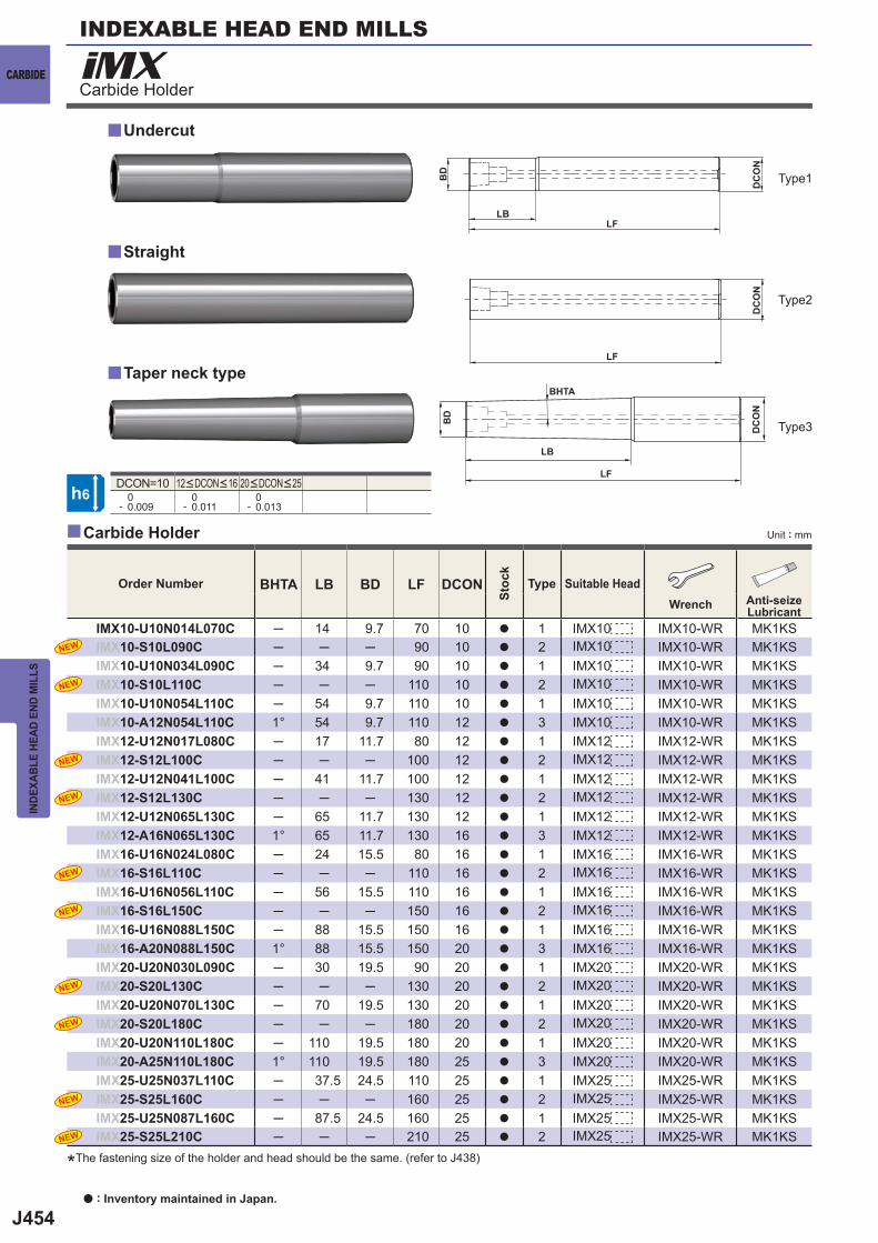
J454
iMX
y
y
y
DCON=10 0- 0.009
0- 0.011
0- 0.013
BHTA LB BD LF DCON
IMX10-U10N014L070C ─ 14 9.7 70 10 a 1 IMX10 IMX10-WR MK1KSIMX10-S10L090C ─ ─ ─ 90 10 a 2 IMX10 IMX10-WR MK1KSIMX10-U10N034L090C ─ 34 9.7 90 10 a 1 IMX10 IMX10-WR MK1KSIMX10-S10L110C ─ ─ ─ 110 10 a 2 IMX10 IMX10-WR MK1KSIMX10-U10N054L110C ─ 54 9.7 110 10 a 1 IMX10 IMX10-WR MK1KSIMX10-A12N054L110C 1° 54 9.7 110 12 a 3 IMX10 IMX10-WR MK1KSIMX12-U12N017L080C ─ 17 11.7 80 12 a 1 IMX12 IMX12-WR MK1KSIMX12-S12L100C ─ ─ ─ 100 12 a 2 IMX12 IMX12-WR MK1KSIMX12-U12N041L100C ─ 41 11.7 100 12 a 1 IMX12 IMX12-WR MK1KSIMX12-S12L130C ─ ─ ─ 130 12 a 2 IMX12 IMX12-WR MK1KSIMX12-U12N065L130C ─ 65 11.7 130 12 a 1 IMX12 IMX12-WR MK1KSIMX12-A16N065L130C 1° 65 11.7 130 16 a 3 IMX12 IMX12-WR MK1KSIMX16-U16N024L080C ─ 24 15.5 80 16 a 1 IMX16 IMX16-WR MK1KSIMX16-S16L110C ─ ─ ─ 110 16 a 2 IMX16 IMX16-WR MK1KSIMX16-U16N056L110C ─ 56 15.5 110 16 a 1 IMX16 IMX16-WR MK1KSIMX16-S16L150C ─ ─ ─ 150 16 a 2 IMX16 IMX16-WR MK1KSIMX16-U16N088L150C ─ 88 15.5 150 16 a 1 IMX16 IMX16-WR MK1KSIMX16-A20N088L150C 1° 88 15.5 150 20 a 3 IMX16 IMX16-WR MK1KSIMX20-U20N030L090C ─ 30 19.5 90 20 a 1 IMX20 IMX20-WR MK1KSIMX20-S20L130C ─ ─ ─ 130 20 a 2 IMX20 IMX20-WR MK1KSIMX20-U20N070L130C ─ 70 19.5 130 20 a 1 IMX20 IMX20-WR MK1KSIMX20-S20L180C ─ ─ ─ 180 20 a 2 IMX20 IMX20-WR MK1KSIMX20-U20N110L180C ─ 110 19.5 180 20 a 1 IMX20 IMX20-WR MK1KSIMX20-A25N110L180C 1° 110 19.5 180 25 a 3 IMX20 IMX20-WR MK1KSIMX25-U25N037L110C ─ 37.5 24.5 110 25 a 1 IMX25 IMX25-WR MK1KSIMX25-S25L160C ─ ─ ─ 160 25 a 2 IMX25 IMX25-WR MK1KSIMX25-U25N087L160C ─ 87.5 24.5 160 25 a 1 IMX25 IMX25-WR MK1KSIMX25-S25L210C ─ ─ ─ 210 25 a 2 IMX25 IMX25-WR MK1KS
NEW
NEW
NEW
NEW
NEW
NEW
NEW
NEW
NEW
NEW
y
h6
DC
ON
DC
ON
LBLF
LF
BD
DC
ON
LB
BHTA
LF
BD
INDEXABLE HEAD END MILLS
CARBIDE
INDE
XABL
E HE
AD E
ND M
ILLS
Unit : mmCarbide Holder
Carbide Holder
a : Inventory maintained in Japan.
12<DCON<16 20<DCON<25
*The fastening size of the holder and head should be the same. (refer to J438)
Order Number
Stoc
k
Type Suitable HeadWrench Anti-seize
Lubricant
Undercut
Taper neck type
Straight
Type1
Type2
Type3
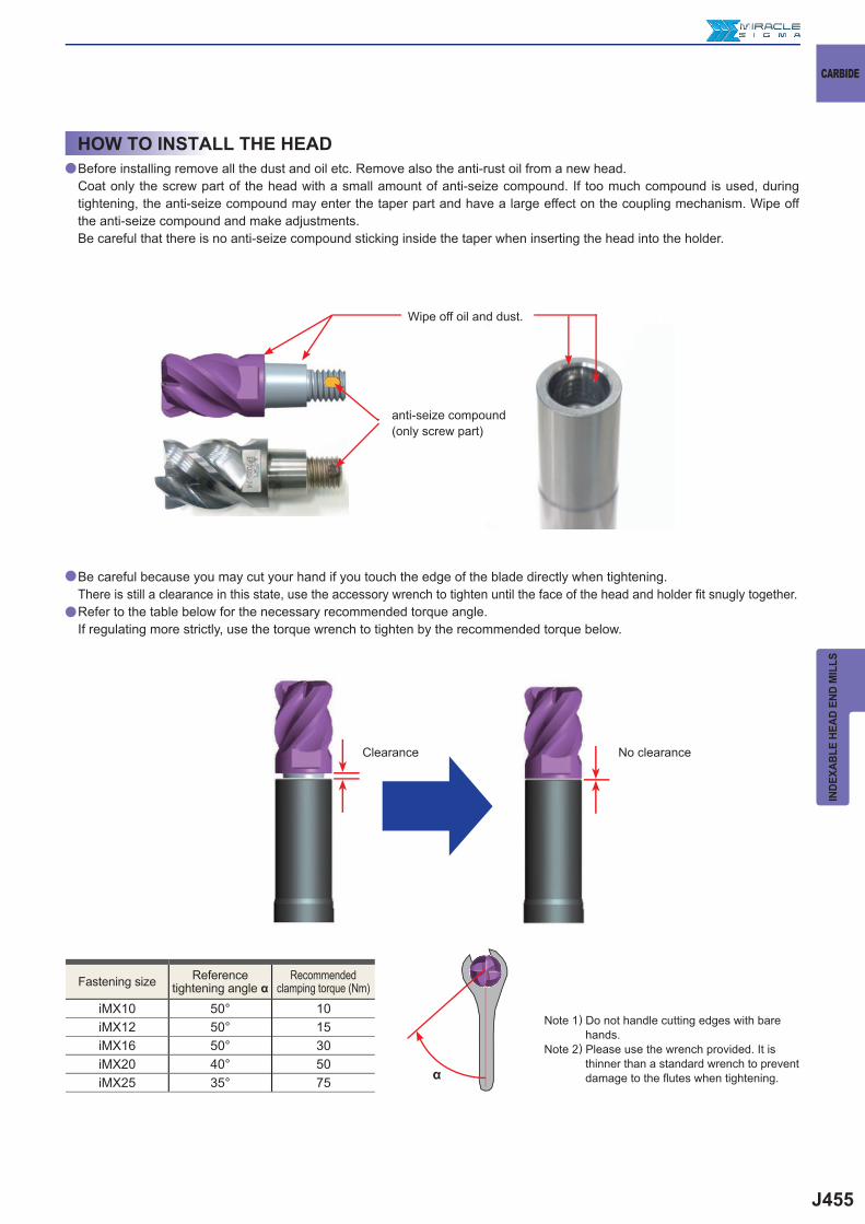
J455
iMX10 50° 10iMX12 50° 15iMX16 50° 30iMX20 40° 50iMX25 35° 75
a
a
a
α
CARBIDE
INDE
XABL
E HE
AD E
ND M
ILLS
Note 1) Do not handle cutting edges with bare hands.
Note 2) Please use the wrench provided. It is thinner than a standard wrench to prevent damage to the fl utes when tightening.
Fastening size Reference tightening angle α
Recommended clamping torque (Nm)
Clearance No clearance
HOW TO INSTALL THE HEADBefore installing remove all the dust and oil etc. Remove also the anti-rust oil from a new head. Coat only the screw part of the head with a small amount of anti-seize compound. If too much compound is used, during tightening, the anti-seize compound may enter the taper part and have a large effect on the coupling mechanism. Wipe off the anti-seize compound and make adjustments. Be careful that there is no anti-seize compound sticking inside the taper when inserting the head into the holder.
Be careful because you may cut your hand if you touch the edge of the blade directly when tightening.There is still a clearance in this state, use the accessory wrench to tighten until the face of the head and holder fi t snugly together.Refer to the table below for the necessary recommended torque angle.If regulating more strictly, use the torque wrench to tighten by the recommended torque below.
Wipe off oil and dust.
anti-seize compound(only screw part)
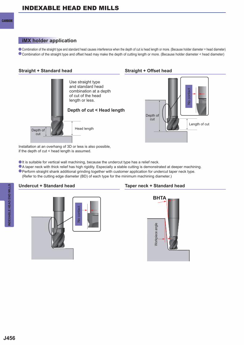
J456
a
a
a
a
a
BHTA
INDEXABLE HEAD END MILLS
CARBIDE
INDE
XABL
E HE
AD E
ND M
ILLS
Combination of the straight type and standard head causes interference when the depth of cut is head length or more. (Because holder diameter = head diameter)Combination of the straight type and offset head may make the depth of cutting length or more. (Because holder diameter < head diameter)
It is suitable for vertical wall machining, because the undercut type has a relief neck.A taper neck with thick relief has high rigidity. Especially a stable cutting is demonstrated at deeper machining.Perform straight shank additional grinding together with customer application for undercut taper neck type.(Refer to the cutting edge diameter (BD) of each type for the minimum machining diameter.)
iMX holder application
Use straight type and standard head combination at a depth of cut of the head length or less.
Depth of cut < Head length
Head lengthLength of cut
Depth of cut
Depth of cut
No
cont
act
Wor
kpie
ce a
ngle
Straight + Offset head
Taper neck + Standard head
Straight + Standard head
Undercut + Standard head
Installation at an overhang of 3D or less is also possible, if the depth of cut < head length is assumed.
No
cont
act
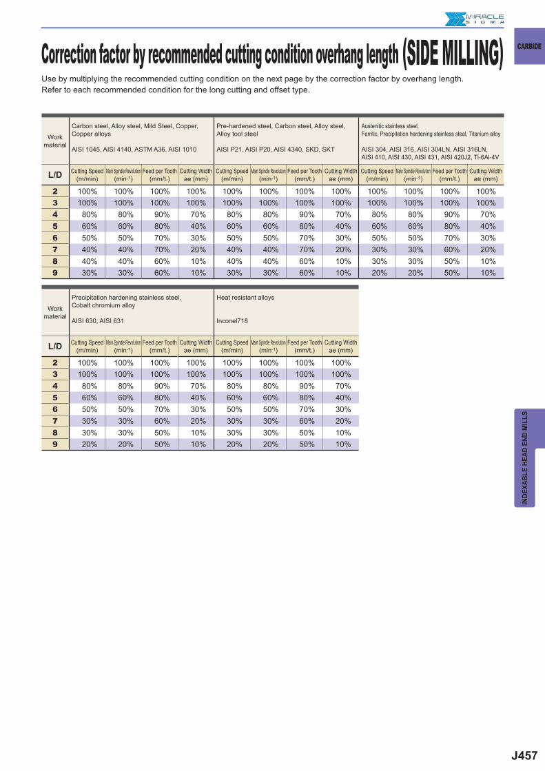
J457
L/D
2 100% 100% 100% 100% 100% 100% 100% 100% 100% 100% 100% 100%3 100% 100% 100% 100% 100% 100% 100% 100% 100% 100% 100% 100%4 80% 80% 90% 70% 80% 80% 90% 70% 80% 80% 90% 70%5 60% 60% 80% 40% 60% 60% 80% 40% 60% 60% 80% 40%6 50% 50% 70% 30% 50% 50% 70% 30% 50% 50% 70% 30%7 40% 40% 70% 20% 40% 40% 70% 20% 30% 30% 60% 20%8 40% 40% 60% 10% 40% 40% 60% 10% 30% 30% 50% 10%9 30% 30% 60% 10% 30% 30% 60% 10% 20% 20% 50% 10%
L/D
2 100% 100% 100% 100% 100% 100% 100% 100%3 100% 100% 100% 100% 100% 100% 100% 100%4 80% 80% 90% 70% 80% 80% 90% 70%5 60% 60% 80% 40% 60% 60% 80% 40%6 50% 50% 70% 30% 50% 50% 70% 30%7 30% 30% 60% 20% 30% 30% 60% 20%8 30% 30% 50% 10% 30% 30% 50% 10%9 20% 20% 50% 10% 20% 20% 50% 10%
CARBIDE
INDE
XABL
E HE
AD E
ND M
ILLS
Work material
Carbon steel, Alloy steel, Mild Steel, Copper, Copper alloys
AISI 1045, AISI 4140, ASTM A36, AISI 1010
Pre-hardened steel, Carbon steel, Alloy steel, Alloy tool steel
AISI P21, AISI P20, AISI 4340, SKD, SKT
Austenitic stainless steel, Ferritic, Precipitation hardening stainless steel, Titanium alloy
AISI 304, AISI 316, AISI 304LN, AISI 316LN, AISI 410, AISI 430, AISI 431, AISI 420J2, Ti-6Al-4V
Cutting Speed(m/min)
Main Spindle Revolution(min-1)
Feed per Tooth(mm/t.)
Cutting Widthae (mm)
Cutting Speed(m/min)
Main Spindle Revolution(min-1)
Feed per Tooth(mm/t.)
Cutting Widthae (mm)
Cutting Speed(m/min)
Main Spindle Revolution(min-1)
Feed per Tooth(mm/t.)
Cutting Widthae (mm)
Work material
Precipitation hardening stainless steel, Cobalt chromium alloy
AISI 630, AISI 631
Heat resistant alloys
Inconel718
Cutting Speed(m/min)
Main Spindle Revolution(min-1)
Feed per Tooth(mm/t.)
Cutting Widthae (mm)
Cutting Speed(m/min)
Main Spindle Revolution(min-1)
Feed per Tooth(mm/t.)
Cutting Widthae (mm)
Use by multiplying the recommended cutting condition on the next page by the correction factor by overhang length. Refer to each recommended condition for the long cutting and offset type.
Correction factor by recommended cutting condition overhang length (SIDE MILLING)
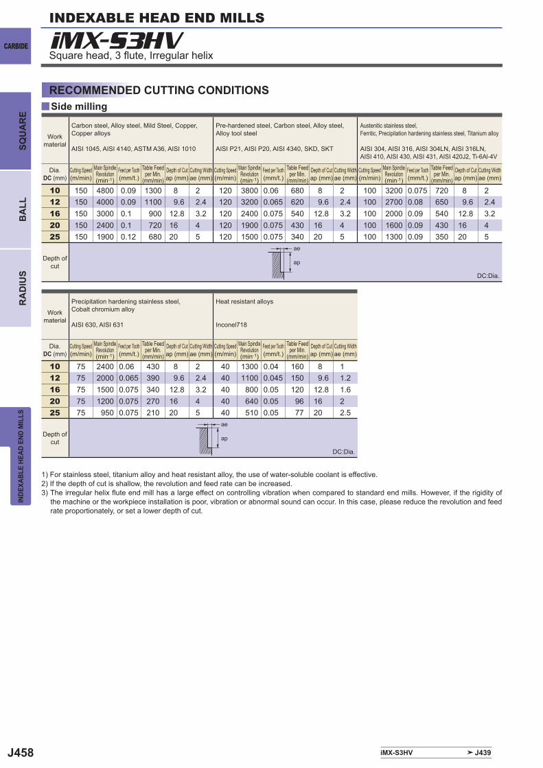
J458
y
iMX-S3HV
iMX-S3HV J439
10 150 4800 0.09 1300 8 2 120 3800 0.06 680 8 2 100 3200 0.075 720 8 212 150 4000 0.09 1100 9.6 2.4 120 3200 0.065 620 9.6 2.4 100 2700 0.08 650 9.6 2.416 150 3000 0.1 900 12.8 3.2 120 2400 0.075 540 12.8 3.2 100 2000 0.09 540 12.8 3.220 150 2400 0.1 720 16 4 120 1900 0.075 430 16 4 100 1600 0.09 430 16 425 150 1900 0.12 680 20 5 120 1500 0.075 340 20 5 100 1300 0.09 350 20 5
10 75 2400 0.06 430 8 2 40 1300 0.04 160 8 112 75 2000 0.065 390 9.6 2.4 40 1100 0.045 150 9.6 1.216 75 1500 0.075 340 12.8 3.2 40 800 0.05 120 12.8 1.620 75 1200 0.075 270 16 4 40 640 0.05 96 16 225 75 950 0.075 210 20 5 40 510 0.05 77 20 2.5
ae
ap
ae
ap
INDEXABLE HEAD END MILLS
CARBIDE
INDE
XABL
E HE
AD E
ND M
ILLS
BA
LLR
AD
IUS
SQU
AR
E
Square head, 3 fl ute, Irregular helix
RECOMMENDED CUTTING CONDITIONSSide milling
1) For stainless steel, titanium alloy and heat resistant alloy, the use of water-soluble coolant is effective. 2) If the depth of cut is shallow, the revolution and feed rate can be increased.3) The irregular helix fl ute end mill has a large effect on controlling vibration when compared to standard end mills. However, if the rigidity of
the machine or the workpiece installation is poor, vibration or abnormal sound can occur. In this case, please reduce the revolution and feed rate proportionately, or set a lower depth of cut.
Work material
Carbon steel, Alloy steel, Mild Steel, Copper, Copper alloys
AISI 1045, AISI 4140, ASTM A36, AISI 1010
Pre-hardened steel, Carbon steel, Alloy steel, Alloy tool steel
AISI P21, AISI P20, AISI 4340, SKD, SKT
Austenitic stainless steel, Ferritic, Precipitation hardening stainless steel, Titanium alloy
AISI 304, AISI 316, AISI 304LN, AISI 316LN, AISI 410, AISI 430, AISI 431, AISI 420J2, Ti-6Al-4V
Dia.DC (mm)
Cutting Speed(m/min)
Main Spindle Revolution(min-1)
Feed per Tooth(mm/t.)
Table Feed per Min.
(mm/min)Depth of Cutap (mm)
Cutting Widthae (mm)
Cutting Speed(m/min)
Main Spindle Revolution(min-1)
Feed per Tooth(mm/t.)
Table Feed per Min.
(mm/min)Depth of Cutap (mm)
Cutting Widthae (mm)
Cutting Speed(m/min)
Main Spindle Revolution(min-1)
Feed per Tooth(mm/t.)
Table Feed per Min.
(mm/min)Depth of Cutap (mm)
Cutting Widthae (mm)
Depth of cut
Work material
Precipitation hardening stainless steel, Cobalt chromium alloy
AISI 630, AISI 631
Heat resistant alloys
Inconel718
Dia.DC (mm)
Cutting Speed(m/min)
Main Spindle Revolution(min-1)
Feed per Tooth(mm/t.)
Table Feed per Min.
(mm/min)Depth of Cutap (mm)
Cutting Widthae (mm)
Cutting Speed(m/min)
Main Spindle Revolution(min-1)
Feed per Tooth(mm/t.)
Table Feed per Min.
(mm/min)Depth of Cutap (mm)
Cutting Widthae (mm)
Depth of cut
DC:Dia.
DC:Dia.
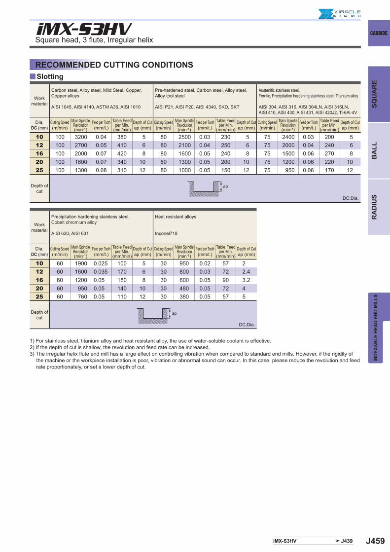
J459
iMX-S3HV
y
iMX-S3HV J439
10 100 3200 0.04 380 5 80 2500 0.03 230 5 75 2400 0.03 200 512 100 2700 0.05 410 6 80 2100 0.04 250 6 75 2000 0.04 240 616 100 2000 0.07 420 8 80 1600 0.05 240 8 75 1500 0.06 270 820 100 1600 0.07 340 10 80 1300 0.05 200 10 75 1200 0.06 220 1025 100 1300 0.08 310 12 80 1000 0.05 150 12 75 950 0.06 170 12
10 60 1900 0.025 100 5 30 950 0.02 57 212 60 1600 0.035 170 6 30 800 0.03 72 2.416 60 1200 0.05 180 8 30 600 0.05 90 3.220 60 950 0.05 140 10 30 480 0.05 72 425 60 760 0.05 110 12 30 380 0.05 57 5
ap
ap
CARBIDE
INDE
XABL
E HE
AD E
ND M
ILLS
SQU
AR
EB
ALL
RA
DIU
S
Square head, 3 fl ute, Irregular helix
SlottingRECOMMENDED CUTTING CONDITIONS
1) For stainless steel, titanium alloy and heat resistant alloy, the use of water-soluble coolant is effective. 2) If the depth of cut is shallow, the revolution and feed rate can be increased.3) The irregular helix fl ute end mill has a large effect on controlling vibration when compared to standard end mills. However, if the rigidity of
the machine or the workpiece installation is poor, vibration or abnormal sound can occur. In this case, please reduce the revolution and feed rate proportionately, or set a lower depth of cut.
Work material
Carbon steel, Alloy steel, Mild Steel, Copper, Copper alloys
AISI 1045, AISI 4140, ASTM A36, AISI 1010
Pre-hardened steel, Carbon steel, Alloy steel, Alloy tool steel
AISI P21, AISI P20, AISI 4340, SKD, SKT
Austenitic stainless steel, Ferritic, Precipitation hardening stainless steel, Titanium alloy
AISI 304, AISI 316, AISI 304LN, AISI 316LN, AISI 410, AISI 430, AISI 431, AISI 420J2, Ti-6Al-4V
Dia.DC (mm)
Cutting Speed(m/min)
Main Spindle Revolution(min-1)
Feed per Tooth(mm/t.)
Table Feed per Min.
(mm/min)Depth of Cutap (mm)
Cutting Speed(m/min)
Main Spindle Revolution(min-1)
Feed per Tooth(mm/t.)
Table Feed per Min.
(mm/min)Depth of Cutap (mm)
Cutting Speed(m/min)
Main Spindle Revolution(min-1)
Feed per Tooth(mm/t.)
Table Feed per Min.
(mm/min)Depth of Cutap (mm)
Depth of cut
Workmaterial
Precipitation hardening stainless steel, Cobalt chromium alloy
AISI 630, AISI 631
Heat resistant alloys
Inconel718
Dia.DC (mm)
Cutting Speed(m/min)
Main Spindle Revolution(min-1)
Feed per Tooth(mm/t.)
Table Feed per Min.
(mm/min)Depth of Cutap (mm)
Cutting Speed(m/min)
Main Spindle Revolution(min-1)
Feed per Tooth(mm/t.)
Table Feed per Min.
(mm/min)Depth of Cutap (mm)
Depth of cut
DC:Dia.
DC:Dia.
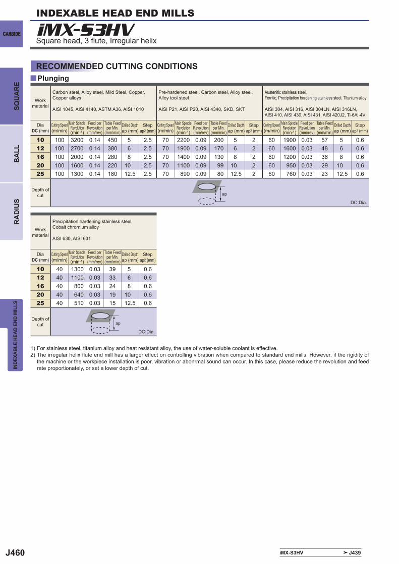
J460
y
iMX-S3HV
iMX-S3HV J439
10 100 3200 0.14 450 5 2.5 70 2200 0.09 200 5 2 60 1900 0.03 57 5 0.612 100 2700 0.14 380 6 2.5 70 1900 0.09 170 6 2 60 1600 0.03 48 6 0.616 100 2000 0.14 280 8 2.5 70 1400 0.09 130 8 2 60 1200 0.03 36 8 0.620 100 1600 0.14 220 10 2.5 70 1100 0.09 99 10 2 60 950 0.03 29 10 0.625 100 1300 0.14 180 12.5 2.5 70 890 0.09 80 12.5 2 60 760 0.03 23 12.5 0.6
10 40 1300 0.03 39 5 0.612 40 1100 0.03 33 6 0.616 40 800 0.03 24 8 0.620 40 640 0.03 19 10 0.625 40 510 0.03 15 12.5 0.6
ap
ap
INDEXABLE HEAD END MILLS
CARBIDE
INDE
XABL
E HE
AD E
ND M
ILLS
BA
LLR
AD
IUS
SQU
AR
E
Square head, 3 fl ute, Irregular helix
RECOMMENDED CUTTING CONDITIONSPlunging
1) For stainless steel, titanium alloy and heat resistant alloy, the use of water-soluble coolant is effective. 2) The irregular helix fl ute end mill has a larger effect on controlling vibration when compared to standard end mills. However, if the rigidity of
the machine or the workpiece installation is poor, vibration or abonrmal sound can occur. In this case, please reduce the revolution and feed rate proportionately, or set a lower depth of cut.
Work material
Carbon steel, Alloy steel, Mild Steel, Copper, Copper alloys
AISI 1045, AISI 4140, ASTM A36, AISI 1010
Pre-hardened steel, Carbon steel, Alloy steel, Alloy tool steel
AISI P21, AISI P20, AISI 4340, SKD, SKT
Austenitic stainless steel,Ferritic, Precipitation hardening stainless steel, Titanium alloy
AISI 304, AISI 316, AISI 304LN, AISI 316LN, AISI 410, AISI 430, AISI 431, AISI 420J2, Ti-6Al-4V
DiaDC (mm)
Cutting Speed(m/min)
Main Spindle Revolution(min-1)
Feed per Revolution(mm/rev)
Table Feed per Min.
(mm/min)Drilled Depthap (mm)
Stepap2 (mm)
Cutting Speed(m/min)
Main Spindle Revolution(min-1)
Feed per Revolution(mm/rev)
Table Feed per Min.
(mm/min)Drilled Depthap (mm)
Stepap2 (mm)
Cutting Speed(m/min)
Main Spindle Revolution(min-1)
Feed per Revolution(mm/rev)
Table Feed per Min.
(mm/min)Drilled Depthap (mm)
Stepap2 (mm)
Depth of cut
Work material
Precipitation hardening stainless steel, Cobalt chromium alloy
AISI 630, AISI 631
DiaDC (mm)
Cutting Speed(m/min)
Main Spindle Revolution(min-1)
Feed per Revolution(mm/rev)
Table Feed per Min.
(mm/min)Drilled Depthap (mm)
Stepap2 (mm)
Depth of cut
DC:Dia.
DC:Dia.
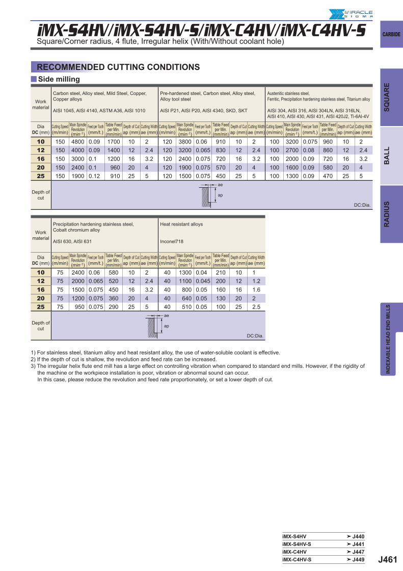
J461
y
iMX-S4HV/iMX-S4HV-S/iMX-C4HV/iMX-C4HV-S
iMX-S4HV J440iMX-S4HV-S J441iMX-C4HV J447iMX-C4HV-S J449
10 150 4800 0.09 1700 10 2 120 3800 0.06 910 10 2 100 3200 0.075 960 10 212 150 4000 0.09 1400 12 2.4 120 3200 0.065 830 12 2.4 100 2700 0.08 860 12 2.416 150 3000 0.1 1200 16 3.2 120 2400 0.075 720 16 3.2 100 2000 0.09 720 16 3.220 150 2400 0.1 960 20 4 120 1900 0.075 570 20 4 100 1600 0.09 580 20 425 150 1900 0.12 910 25 5 120 1500 0.075 450 25 5 100 1300 0.09 470 25 5
10 75 2400 0.06 580 10 2 40 1300 0.04 210 10 112 75 2000 0.065 520 12 2.4 40 1100 0.045 200 12 1.216 75 1500 0.075 450 16 3.2 40 800 0.05 160 16 1.620 75 1200 0.075 360 20 4 40 640 0.05 130 20 225 75 950 0.075 290 25 5 40 510 0.05 100 25 2.5
ae
ap
ae
ap
CARBIDE
INDE
XABL
E HE
AD E
ND M
ILLS
SQU
AR
EB
ALL
RA
DIU
S
Side millingRECOMMENDED CUTTING CONDITIONS
Square/Corner radius, 4 fl ute, Irregular helix (With/Without coolant hole)
1) For stainless steel, titanium alloy and heat resistant alloy, the use of water-soluble coolant is effective. 2) If the depth of cut is shallow, the revolution and feed rate can be increased.3) The irregular helix fl ute end mill has a large effect on controlling vibration when compared to standard end mills. However, if the rigidity of
the machine or the workpiece installation is poor, vibration or abnormal sound can occur. In this case, please reduce the revolution and feed rate proportionately, or set a lower depth of cut.
Work material
Carbon steel, Alloy steel, Mild Steel, Copper, Copper alloys
AISI 1045, AISI 4140, ASTM A36, AISI 1010
Pre-hardened steel, Carbon steel, Alloy steel, Alloy tool steel
AISI P21, AISI P20, AISI 4340, SKD, SKT
Austenitic stainless steel,Ferritic, Precipitation hardening stainless steel, Titanium alloy
AISI 304, AISI 316, AISI 304LN, AISI 316LN, AISI 410, AISI 430, AISI 431, AISI 420J2, Ti-6Al-4V
DiaDC (mm)
Cutting Speed(m/min)
Main Spindle Revolution(min-1)
Feed per Tooth(mm/t.)
Table Feed per Min.
(mm/min)Depth of Cutap (mm)
Cutting Widthae (mm)
Cutting Speed(m/min)
Main Spindle Revolution(min-1)
Feed per Tooth(mm/t.)
Table Feed per Min.
(mm/min)Depth of Cutap (mm)
Cutting Widthae (mm)
Cutting Speed(m/min)
Main Spindle Revolution(min-1)
Feed per Tooth(mm/t.)
Table Feed per Min.
(mm/min)Depth of Cutap (mm)
Cutting Widthae (mm)
Depth of cut
Work material
Precipitation hardening stainless steel, Cobalt chromium alloy
AISI 630, AISI 631
Heat resistant alloys
Inconel718
DiaDC (mm)
Cutting Speed(m/min)
Main Spindle Revolution(min-1)
Feed per Tooth(mm/t.)
Table Feed per Min.
(mm/min)Depth of Cutap (mm)
Cutting Widthae (mm)
Cutting Speed(m/min)
Main Spindle Revolution(min-1)
Feed per Tooth(mm/t.)
Table Feed per Min.
(mm/min)Depth of Cutap (mm)
Cutting Widthae (mm)
Depth of cut
DC:Dia.
DC:Dia.
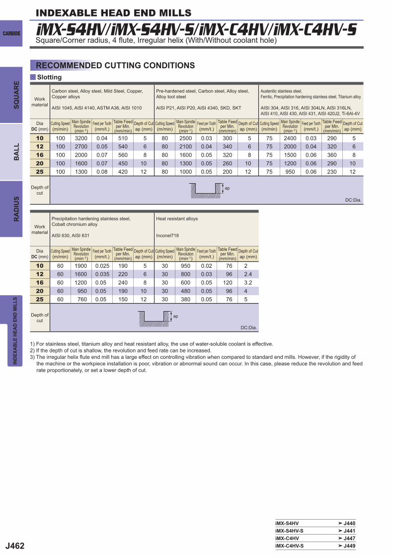
J462
y
iMX-S4HV/iMX-S4HV-S/iMX-C4HV/iMX-C4HV-S
iMX-S4HV J440iMX-S4HV-S J441iMX-C4HV J447iMX-C4HV-S J449
10 100 3200 0.04 510 5 80 2500 0.03 300 5 75 2400 0.03 290 512 100 2700 0.05 540 6 80 2100 0.04 340 6 75 2000 0.04 320 616 100 2000 0.07 560 8 80 1600 0.05 320 8 75 1500 0.06 360 820 100 1600 0.07 450 10 80 1300 0.05 260 10 75 1200 0.06 290 1025 100 1300 0.08 420 12 80 1000 0.05 200 12 75 950 0.06 230 12
10 60 1900 0.025 190 5 30 950 0.02 76 212 60 1600 0.035 220 6 30 800 0.03 96 2.416 60 1200 0.05 240 8 30 600 0.05 120 3.220 60 950 0.05 190 10 30 480 0.05 96 425 60 760 0.05 150 12 30 380 0.05 76 5
ap
ap
INDEXABLE HEAD END MILLS
CARBIDE
INDE
XABL
E HE
AD E
ND M
ILLS
BA
LLR
AD
IUS
SQU
AR
E
Square/Corner radius, 4 fl ute, Irregular helix (With/Without coolant hole)
SlottingRECOMMENDED CUTTING CONDITIONS
1) For stainless steel, titanium alloy and heat resistant alloy, the use of water-soluble coolant is effective. 2) If the depth of cut is shallow, the revolution and feed rate can be increased.3) The irregular helix fl ute end mill has a large effect on controlling vibration when compared to standard end mills. However, if the rigidity of
the machine or the workpiece installation is poor, vibration or abnormal sound can occur. In this case, please reduce the revolution and feed rate proportionately, or set a lower depth of cut.
Workmaterial
Carbon steel, Alloy steel, Mild Steel, Copper, Copper alloys
AISI 1045, AISI 4140, ASTM A36, AISI 1010
Pre-hardened steel, Carbon steel, Alloy steel, Alloy tool steel
AISI P21, AISI P20, AISI 4340, SKD, SKT
Austenitic stainless steel,Ferritic, Precipitation hardening stainless steel, Titanium alloy
AISI 304, AISI 316, AISI 304LN, AISI 316LN, AISI 410, AISI 430, AISI 431, AISI 420J2, Ti-6Al-4V
DiaDC (mm)
Cutting Speed(m/min)
Main Spindle Revolution(min-1)
Feed per Tooth(mm/t.)
Table Feed per Min.
(mm/min)Depth of Cutap (mm)
Cutting Speed(m/min)
Main Spindle Revolution(min-1)
Feed per Tooth(mm/t.)
Table Feed per Min.
(mm/min)Depth of Cutap (mm)
Cutting Speed(m/min)
Main Spindle Revolution(min-1)
Feed per Tooth(mm/t.)
Table Feed per Min.
(mm/min)Depth of Cutap (mm)
Depth ofcut
Workmaterial
Precipitation hardening stainless steel, Cobalt chromium alloy
AISI 630, AISI 631
Heat resistant alloys
Inconel718
DiaDC (mm)
Cutting Speed(m/min)
Main Spindle Revolution(min-1)
Feed per Tooth(mm/t.)
Table Feed per Min.
(mm/min)Depth of Cutap (mm)
Cutting Speed(m/min)
Main Spindle Revolution(min-1)
Feed per Tooth(mm/t.)
Table Feed per Min.
(mm/min)Depth of Cutap (mm)
Depth ofcut
DC:Dia.
DC:Dia.
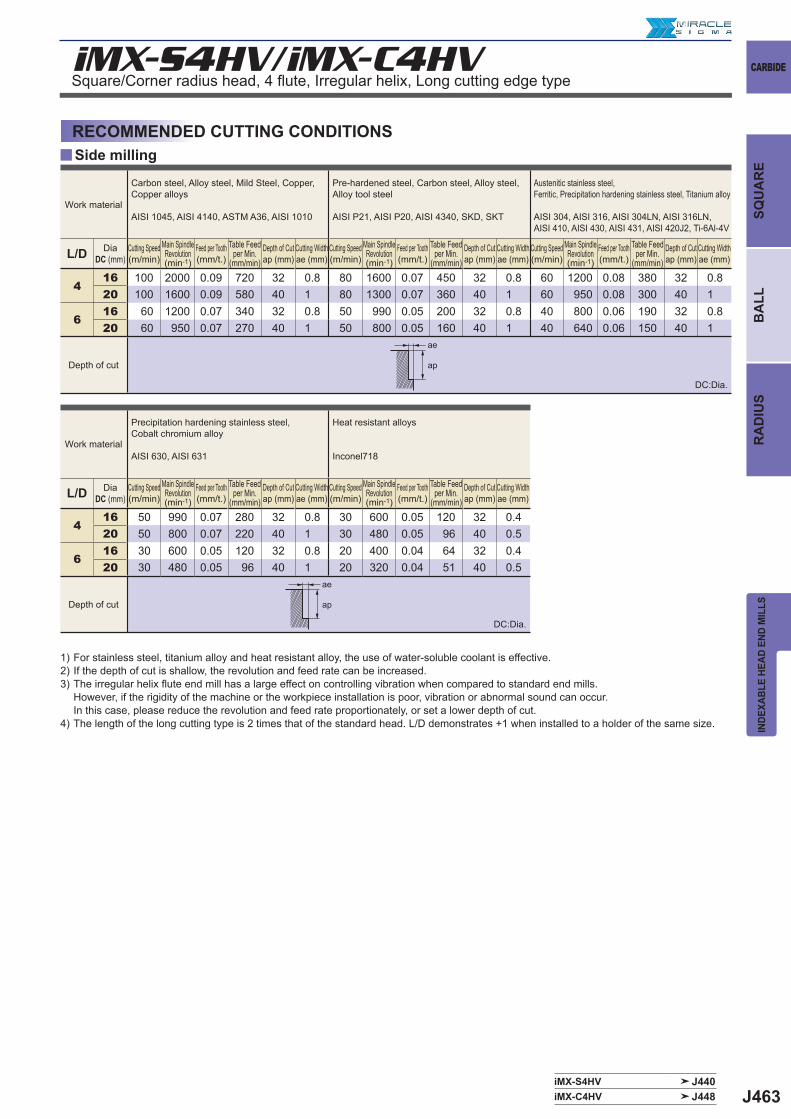
J463iMX-S4HV J440iMX-C4HV J448
y
iMX-S4HV/iMX-C4HV
L/D
416 100 2000 0.09 720 32 0.8 80 1600 0.07 450 32 0.8 60 1200 0.08 380 32 0.820 100 1600 0.09 580 40 1 80 1300 0.07 360 40 1 60 950 0.08 300 40 1
616 60 1200 0.07 340 32 0.8 50 990 0.05 200 32 0.8 40 800 0.06 190 32 0.820 60 950 0.07 270 40 1 50 800 0.05 160 40 1 40 640 0.06 150 40 1
L/D
416 50 990 0.07 280 32 0.8 30 600 0.05 120 32 0.420 50 800 0.07 220 40 1 30 480 0.05 96 40 0.5
616 30 600 0.05 120 32 0.8 20 400 0.04 64 32 0.420 30 480 0.05 96 40 1 20 320 0.04 51 40 0.5
ap
ae
ap
ae
CARBIDE
INDE
XABL
E HE
AD E
ND M
ILLS
SQU
AR
EB
ALL
RA
DIU
S
Side millingRECOMMENDED CUTTING CONDITIONS
Square/Corner radius head, 4 fl ute, Irregular helix, Long cutting edge type
Work material
Carbon steel, Alloy steel, Mild Steel, Copper, Copper alloys
AISI 1045, AISI 4140, ASTM A36, AISI 1010
Pre-hardened steel, Carbon steel, Alloy steel, Alloy tool steel
AISI P21, AISI P20, AISI 4340, SKD, SKT
Austenitic stainless steel,Ferritic, Precipitation hardening stainless steel, Titanium alloy
AISI 304, AISI 316, AISI 304LN, AISI 316LN, AISI 410, AISI 430, AISI 431, AISI 420J2, Ti-6Al-4V
DiaDC (mm)
Cutting Speed(m/min)
Main Spindle Revolution(min-1)
Feed per Tooth(mm/t.)
Table Feed per Min.
(mm/min)Depth of Cutap (mm)
Cutting Widthae (mm)
Cutting Speed(m/min)
Main Spindle Revolution(min-1)
Feed per Tooth(mm/t.)
Table Feed per Min.
(mm/min)Depth of Cutap (mm)
Cutting Widthae (mm)
Cutting Speed(m/min)
Main Spindle Revolution(min-1)
Feed per Tooth(mm/t.)
Table Feed per Min.
(mm/min)Depth of Cutap (mm)
Cutting Widthae (mm)
Depth of cut
Work material
Precipitation hardening stainless steel, Cobalt chromium alloy
AISI 630, AISI 631
Heat resistant alloys
Inconel718
DiaDC (mm)
Cutting Speed(m/min)
Main Spindle Revolution(min-1)
Feed per Tooth(mm/t.)
Table Feed per Min.
(mm/min)Depth of Cutap (mm)
Cutting Widthae (mm)
Cutting Speed(m/min)
Main Spindle Revolution(min-1)
Feed per Tooth(mm/t.)
Table Feed per Min.
(mm/min)Depth of Cutap (mm)
Cutting Widthae (mm)
Depth of cut
1) For stainless steel, titanium alloy and heat resistant alloy, the use of water-soluble coolant is effective.2) If the depth of cut is shallow, the revolution and feed rate can be increased.3) The irregular helix fl ute end mill has a large effect on controlling vibration when compared to standard end mills.
However, if the rigidity of the machine or the workpiece installation is poor, vibration or abnormal sound can occur.In this case, please reduce the revolution and feed rate proportionately, or set a lower depth of cut.
4) The length of the long cutting type is 2 times that of the standard head. L/D demonstrates +1 when installed to a holder of the same size.
DC:Dia.
DC:Dia.
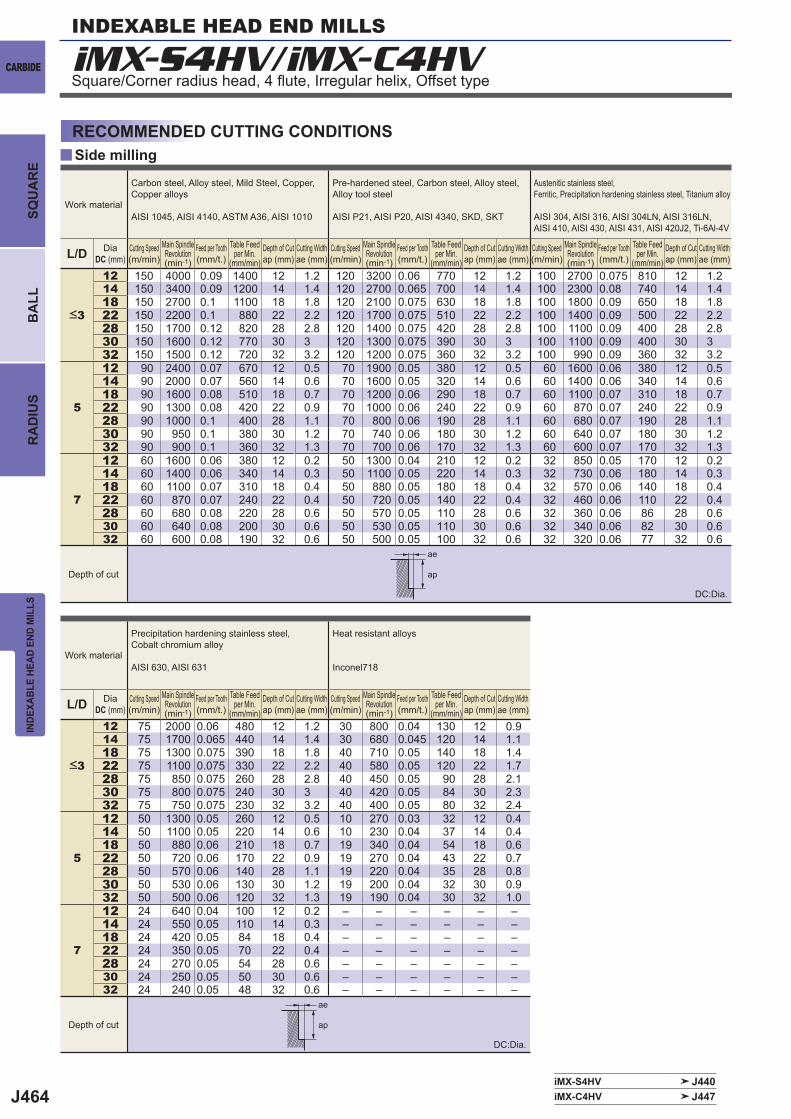
J464
y
iMX-S4HV/iMX-C4HV
L/D12 150 4000 0.09 1400 12 1.2 120 3200 0.06 770 12 1.2 100 2700 0.075 810 12 1.214 150 3400 0.09 1200 14 1.4 120 2700 0.065 700 14 1.4 100 2300 0.08 740 14 1.418 150 2700 0.1 1100 18 1.8 120 2100 0.075 630 18 1.8 100 1800 0.09 650 18 1.822 150 2200 0.1 880 22 2.2 120 1700 0.075 510 22 2.2 100 1400 0.09 500 22 2.228 150 1700 0.12 820 28 2.8 120 1400 0.075 420 28 2.8 100 1100 0.09 400 28 2.830 150 1600 0.12 770 30 3 120 1300 0.075 390 30 3 100 1100 0.09 400 30 332 150 1500 0.12 720 32 3.2 120 1200 0.075 360 32 3.2 100 990 0.09 360 32 3.2
5
12 90 2400 0.07 670 12 0.5 70 1900 0.05 380 12 0.5 60 1600 0.06 380 12 0.514 90 2000 0.07 560 14 0.6 70 1600 0.05 320 14 0.6 60 1400 0.06 340 14 0.618 90 1600 0.08 510 18 0.7 70 1200 0.06 290 18 0.7 60 1100 0.07 310 18 0.722 90 1300 0.08 420 22 0.9 70 1000 0.06 240 22 0.9 60 870 0.07 240 22 0.928 90 1000 0.1 400 28 1.1 70 800 0.06 190 28 1.1 60 680 0.07 190 28 1.130 90 950 0.1 380 30 1.2 70 740 0.06 180 30 1.2 60 640 0.07 180 30 1.232 90 900 0.1 360 32 1.3 70 700 0.06 170 32 1.3 60 600 0.07 170 32 1.3
7
12 60 1600 0.06 380 12 0.2 50 1300 0.04 210 12 0.2 32 850 0.05 170 12 0.214 60 1400 0.06 340 14 0.3 50 1100 0.05 220 14 0.3 32 730 0.06 180 14 0.318 60 1100 0.07 310 18 0.4 50 880 0.05 180 18 0.4 32 570 0.06 140 18 0.422 60 870 0.07 240 22 0.4 50 720 0.05 140 22 0.4 32 460 0.06 110 22 0.428 60 680 0.08 220 28 0.6 50 570 0.05 110 28 0.6 32 360 0.06 86 28 0.630 60 640 0.08 200 30 0.6 50 530 0.05 110 30 0.6 32 340 0.06 82 30 0.632 60 600 0.08 190 32 0.6 50 500 0.05 100 32 0.6 32 320 0.06 77 32 0.6
L/D12 75 2000 0.06 480 12 1.2 30 800 0.04 130 12 0.914 75 1700 0.065 440 14 1.4 30 680 0.045 120 14 1.118 75 1300 0.075 390 18 1.8 40 710 0.05 140 18 1.422 75 1100 0.075 330 22 2.2 40 580 0.05 120 22 1.728 75 850 0.075 260 28 2.8 40 450 0.05 90 28 2.130 75 800 0.075 240 30 3 40 420 0.05 84 30 2.332 75 750 0.075 230 32 3.2 40 400 0.05 80 32 2.4
5
12 50 1300 0.05 260 12 0.5 10 270 0.03 32 12 0.414 50 1100 0.05 220 14 0.6 10 230 0.04 37 14 0.418 50 880 0.06 210 18 0.7 19 340 0.04 54 18 0.622 50 720 0.06 170 22 0.9 19 270 0.04 43 22 0.728 50 570 0.06 140 28 1.1 19 220 0.04 35 28 0.830 50 530 0.06 130 30 1.2 19 200 0.04 32 30 0.932 50 500 0.06 120 32 1.3 19 190 0.04 30 32 1.0
7
12 24 640 0.04 100 12 0.2 ‒ ‒ ‒ ‒ ‒ ‒14 24 550 0.05 110 14 0.3 ‒ ‒ ‒ ‒ ‒ ‒18 24 420 0.05 84 18 0.4 ‒ ‒ ‒ ‒ ‒ ‒22 24 350 0.05 70 22 0.4 ‒ ‒ ‒ ‒ ‒ ‒28 24 270 0.05 54 28 0.6 ‒ ‒ ‒ ‒ ‒ ‒30 24 250 0.05 50 30 0.6 ‒ ‒ ‒ ‒ ‒ ‒32 24 240 0.05 48 32 0.6 ‒ ‒ ‒ ‒ ‒ ‒
iMX-S4HV J440iMX-C4HV J447
ap
ae
ap
ae
INDEXABLE HEAD END MILLS
CARBIDE
INDE
XABL
E HE
AD E
ND M
ILLS
BA
LLR
AD
IUS
SQU
AR
E
Side millingRECOMMENDED CUTTING CONDITIONS
Square/Corner radius head, 4 fl ute, Irregular helix, Offset type
Work material
Carbon steel, Alloy steel, Mild Steel, Copper, Copper alloys
AISI 1045, AISI 4140, ASTM A36, AISI 1010
Pre-hardened steel, Carbon steel, Alloy steel, Alloy tool steel
AISI P21, AISI P20, AISI 4340, SKD, SKT
Austenitic stainless steel, Ferritic, Precipitation hardening stainless steel, Titanium alloy
AISI 304, AISI 316, AISI 304LN, AISI 316LN, AISI 410, AISI 430, AISI 431, AISI 420J2, Ti-6Al-4V
DiaDC (mm)
Cutting Speed(m/min)
Main Spindle Revolution(min-1)
Feed per Tooth(mm/t.)
Table Feed per Min.
(mm/min)Depth of Cutap (mm)
Cutting Widthae (mm)
Cutting Speed(m/min)
Main Spindle Revolution(min-1)
Feed per Tooth(mm/t.)
Table Feed per Min.
(mm/min)Depth of Cutap (mm)
Cutting Widthae (mm)
Cutting Speed(m/min)
Main Spindle Revolution(min-1)
Feed per Tooth(mm/t.)
Table Feed per Min.
(mm/min)Depth of Cutap (mm)
Cutting Widthae (mm)
<3
Depth of cut
Work material
Precipitation hardening stainless steel, Cobalt chromium alloy
AISI 630, AISI 631
Heat resistant alloys
Inconel718
DiaDC (mm)
Cutting Speed(m/min)
Main Spindle Revolution(min-1)
Feed per Tooth(mm/t.)
Table Feed per Min.
(mm/min)Depth of Cutap (mm)
Cutting Widthae (mm)
Cutting Speed(m/min)
Main Spindle Revolution(min-1)
Feed per Tooth(mm/t.)
Table Feed per Min.
(mm/min)Depth of Cutap (mm)
Cutting Widthae (mm)
<3
Depth of cut
DC:Dia.
DC:Dia.
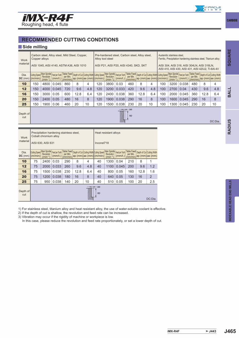
J465
y
iMX-R4F
iMX-R4F J443
10 150 4800 0.045 860 8 4 120 3800 0.03 460 8 4 100 3200 0.038 480 8 412 150 4000 0.045 720 9.6 4.8 120 3200 0.033 420 9.6 4.8 100 2700 0.04 430 9.6 4.816 150 3000 0.05 600 12.8 6.4 120 2400 0.038 360 12.8 6.4 100 2000 0.045 360 12.8 6.420 150 2400 0.05 480 16 8 120 1900 0.038 290 16 8 100 1600 0.045 290 16 825 150 1900 0.06 460 20 10 120 1500 0.038 230 20 10 100 1300 0.045 230 20 10
10 75 2400 0.03 290 8 4 40 1300 0.04 210 8 112 75 2000 0.033 260 9.6 4.8 40 1100 0.045 200 9.6 1.216 75 1500 0.038 230 12.8 6.4 40 800 0.05 160 12.8 1.620 75 1200 0.038 180 16 8 40 640 0.05 130 16 225 75 950 0.038 140 20 10 40 510 0.05 100 20 2.5
ae
ap
ae
ap
CARBIDE
INDE
XABL
E HE
AD E
ND M
ILLS
SQU
AR
EB
ALL
RA
DIU
S
Roughing head, 4 fl ute
Side millingRECOMMENDED CUTTING CONDITIONS
1) For stainless steel, titanium alloy and heat resistant alloy, the use of water-soluble coolant is effective. 2) If the depth of cut is shallow, the revolution and feed rate can be increased.3) Vibration may occur if the rigidity of machine or workpiece is low. In this case, please reduce the revolution and feed rate proportionately, or set a lower depth of cut.
Work material
Carbon steel, Alloy steel, Mild Steel, Copper, Copper alloys
AISI 1045, AISI 4140, ASTM A36, AISI 1010
Pre-hardened steel, Carbon steel, Alloy steel, Alloy tool steel
AISI P21, AISI P20, AISI 4340, SKD, SKT
Austenitic stainless steel,Ferritic, Precipitation hardening stainless steel, Titanium alloy
AISI 304, AISI 316, AISI 304LN, AISI 316LN, AISI 410, AISI 430, AISI 431, AISI 420J2, Ti-6Al-4V
Dia.DC (mm)
Cutting Speed(m/min)
Main Spindle Revolution(min-1)
Feed per Tooth(mm/t.)
Table Feed per Min.
(mm/min)Depth of Cutap (mm)
Cutting Widthae (mm)
Cutting Speed(m/min)
Main Spindle Revolution(min-1)
Feed per Tooth(mm/t.)
Table Feed per Min.
(mm/min)Depth of Cutap (mm)
Cutting Widthae (mm)
Cutting Speed(m/min)
Main Spindle Revolution(min-1)
Feed per Tooth(mm/t.)
Table Feed per Min.
(mm/min)Depth of Cutap (mm)
Cutting Widthae (mm)
Depth of cut
Work material
Precipitation hardening stainless steel, Cobalt chromium alloy
AISI 630, AISI 631
Heat resistant alloys
Inconel718
Dia.DC (mm)
Cutting Speed(m/min)
Main Spindle Revolution(min-1)
Feed per Tooth(mm/t.)
Table Feed per Min.
(mm/min)Depth of Cutap (mm)
Cutting Widthae (mm)
Cutting Speed(m/min)
Main Spindle Revolution(min-1)
Feed per Tooth(mm/t.)
Table Feed per Min.
(mm/min)Depth of Cutap (mm)
Cutting Widthae (mm)
Depth of cut
DC:Dia.
DC:Dia.
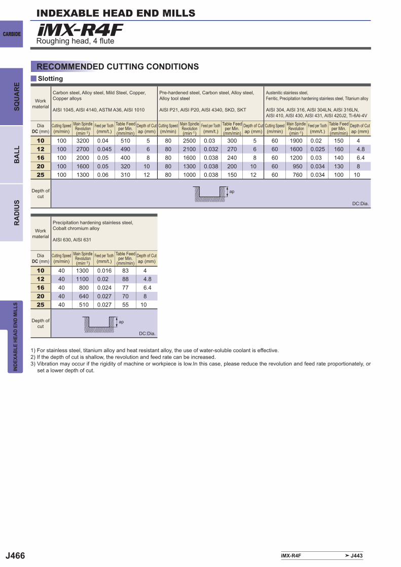
J466
y
iMX-R4F
iMX-R4F J443
10 100 3200 0.04 510 5 80 2500 0.03 300 5 60 1900 0.02 150 412 100 2700 0.045 490 6 80 2100 0.032 270 6 60 1600 0.025 160 4.816 100 2000 0.05 400 8 80 1600 0.038 240 8 60 1200 0.03 140 6.420 100 1600 0.05 320 10 80 1300 0.038 200 10 60 950 0.034 130 825 100 1300 0.06 310 12 80 1000 0.038 150 12 60 760 0.034 100 10
10 40 1300 0.016 83 412 40 1100 0.02 88 4.816 40 800 0.024 77 6.420 40 640 0.027 70 825 40 510 0.027 55 10
ap
ap
INDEXABLE HEAD END MILLS
CARBIDE
INDE
XABL
E HE
AD E
ND M
ILLS
BA
LLR
AD
IUS
SQU
AR
E
Roughing head, 4 fl ute
SlottingRECOMMENDED CUTTING CONDITIONS
1) For stainless steel, titanium alloy and heat resistant alloy, the use of water-soluble coolant is effective. 2) If the depth of cut is shallow, the revolution and feed rate can be increased.3) Vibration may occur if the rigidity of machine or workpiece is low.In this case, please reduce the revolution and feed rate proportionately, or
set a lower depth of cut.
Work material
Carbon steel, Alloy steel, Mild Steel, Copper, Copper alloys
AISI 1045, AISI 4140, ASTM A36, AISI 1010
Pre-hardened steel, Carbon steel, Alloy steel, Alloy tool steel
AISI P21, AISI P20, AISI 4340, SKD, SKT
Austenitic stainless steel,Ferritic, Precipitation hardening stainless steel, Titanium alloy
AISI 304, AISI 316, AISI 304LN, AISI 316LN, AISI 410, AISI 430, AISI 431, AISI 420J2, Ti-6Al-4V
DiaDC (mm)
Cutting Speed(m/min)
Main Spindle Revolution(min-1)
Feed per Tooth(mm/t.)
Table Feed per Min.
(mm/min)Depth of Cutap (mm)
Cutting Speed(m/min)
Main Spindle Revolution(min-1)
Feed per Tooth(mm/t.)
Table Feed per Min.
(mm/min)Depth of Cutap (mm)
Cutting Speed(m/min)
Main Spindle Revolution(min-1)
Feed per Tooth(mm/t.)
Table Feed per Min.
(mm/min)Depth of Cutap (mm)
Depth of cut
Work material
Precipitation hardening stainless steel, Cobalt chromium alloy
AISI 630, AISI 631
DiaDC (mm)
Cutting Speed(m/min)
Main Spindle Revolution(min-1)
Feed per Tooth(mm/t.)
Table Feed per Min.
(mm/min)Depth of Cutap (mm)
Depth of cut
DC:Dia.
DC:Dia.
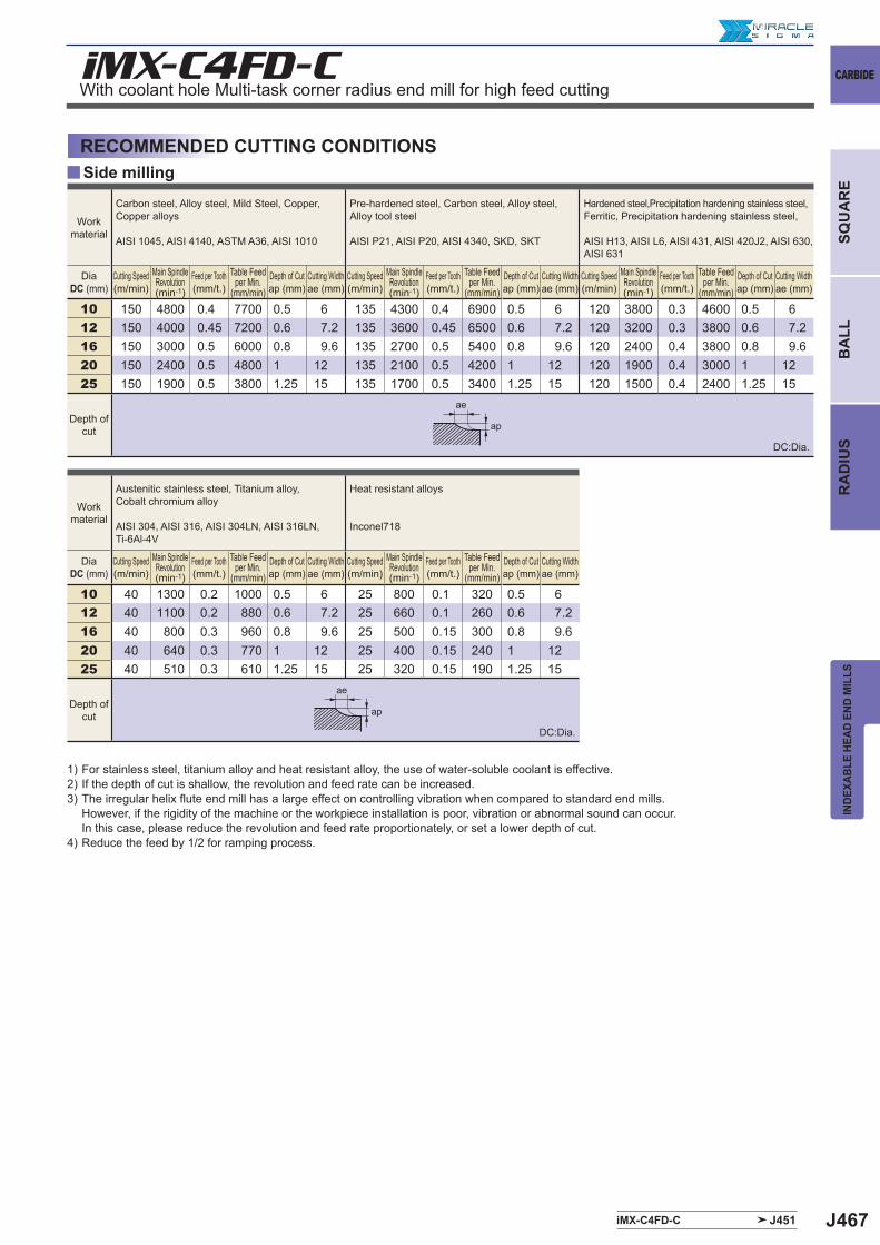
J467iMX-C4FD-C J451
iMX-C4FD-C
y
10 150 4800 0.4 7700 0.5 6 135 4300 0.4 6900 0.5 6 120 3800 0.3 4600 0.5 612 150 4000 0.45 7200 0.6 7.2 135 3600 0.45 6500 0.6 7.2 120 3200 0.3 3800 0.6 7.216 150 3000 0.5 6000 0.8 9.6 135 2700 0.5 5400 0.8 9.6 120 2400 0.4 3800 0.8 9.620 150 2400 0.5 4800 1 12 135 2100 0.5 4200 1 12 120 1900 0.4 3000 1 1225 150 1900 0.5 3800 1.25 15 135 1700 0.5 3400 1.25 15 120 1500 0.4 2400 1.25 15
10 40 1300 0.2 1000 0.5 6 25 800 0.1 320 0.5 612 40 1100 0.2 880 0.6 7.2 25 660 0.1 260 0.6 7.216 40 800 0.3 960 0.8 9.6 25 500 0.15 300 0.8 9.620 40 640 0.3 770 1 12 25 400 0.15 240 1 1225 40 510 0.3 610 1.25 15 25 320 0.15 190 1.25 15
ae
ap
ae
ap
CARBIDE
INDE
XABL
E HE
AD E
ND M
ILLS
SQU
AR
EB
ALL
RA
DIU
S
With coolant hole Multi-task corner radius end mill for high feed cutting
Side millingRECOMMENDED CUTTING CONDITIONS
Work material
Carbon steel, Alloy steel, Mild Steel, Copper, Copper alloys
AISI 1045, AISI 4140, ASTM A36, AISI 1010
Pre-hardened steel, Carbon steel, Alloy steel, Alloy tool steel
AISI P21, AISI P20, AISI 4340, SKD, SKT
Hardened steel,Precipitation hardening stainless steel, Ferritic, Precipitation hardening stainless steel,
AISI H13, AISI L6, AISI 431, AISI 420J2, AISI 630, AISI 631
DiaDC (mm)
Cutting Speed(m/min)
Main Spindle Revolution(min-1)
Feed per Tooth(mm/t.)
Table Feed per Min.
(mm/min)Depth of Cutap (mm)
Cutting Widthae (mm)
Cutting Speed(m/min)
Main Spindle Revolution(min-1)
Feed per Tooth(mm/t.)
Table Feed per Min.
(mm/min)Depth of Cutap (mm)
Cutting Widthae (mm)
Cutting Speed(m/min)
Main Spindle Revolution(min-1)
Feed per Tooth(mm/t.)
Table Feed per Min.
(mm/min)Depth of Cutap (mm)
Cutting Widthae (mm)
Depth of cut
Work material
Austenitic stainless steel, Titanium alloy,Cobalt chromium alloy
AISI 304, AISI 316, AISI 304LN, AISI 316LN, Ti-6Al-4V
Heat resistant alloys
Inconel718
DiaDC (mm)
Cutting Speed(m/min)
Main Spindle Revolution(min-1)
Feed per Tooth(mm/t.)
Table Feed per Min.
(mm/min)Depth of Cutap (mm)
Cutting Widthae (mm)
Cutting Speed(m/min)
Main Spindle Revolution(min-1)
Feed per Tooth(mm/t.)
Table Feed per Min.
(mm/min)Depth of Cutap (mm)
Cutting Widthae (mm)
Depth of cut
1) For stainless steel, titanium alloy and heat resistant alloy, the use of water-soluble coolant is effective.2) If the depth of cut is shallow, the revolution and feed rate can be increased.3) The irregular helix fl ute end mill has a large effect on controlling vibration when compared to standard end mills.
However, if the rigidity of the machine or the workpiece installation is poor, vibration or abnormal sound can occur.In this case, please reduce the revolution and feed rate proportionately, or set a lower depth of cut.
4) Reduce the feed by 1/2 for ramping process.
DC:Dia.
DC:Dia.
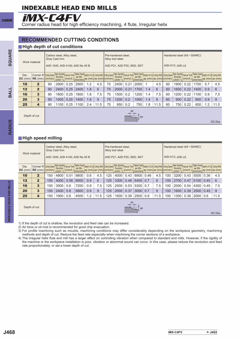
J468
y
y
iMX-C4FV
iMX-C4FV J452
10 2 90 2900 0.25 2900 1.2 4.5 75 2400 0.21 2000 1 4.5 60 1900 0.22 1700 0.7 4.512 2 90 2400 0.25 2400 1.8 6 75 2000 0.21 1700 1.4 6 60 1600 0.22 1400 0.9 616 3 90 1800 0.25 1800 1.8 7.5 75 1500 0.2 1200 1.4 7.5 60 1200 0.22 1100 0.9 7.520 3 90 1400 0.25 1400 1.8 9 75 1200 0.2 1000 1.4 9 60 950 0.22 850 0.9 925 4 90 1100 0.25 1100 2.4 11.5 75 950 0.2 750 1.8 11.5 60 750 0.22 650 1.2 11.5
10 2 150 4800 0.51 9800 0.6 4.5 125 4000 0.43 6900 0.46 4.5 100 3200 0.43 5500 0.36 4.512 2 150 4000 0.56 9000 0.9 6 125 3300 0.48 6400 0.7 6 100 2700 0.47 5100 0.45 616 3 150 3000 0.6 7200 0.9 7.5 125 2500 0.53 5300 0.7 7.5 100 2000 0.54 4300 0.45 7.520 3 150 2400 0.6 5800 0.9 9 125 2000 0.37 3000 0.7 9 100 1600 0.39 2500 0.45 925 4 150 1900 0.6 4500 1.2 11.5 125 1600 0.39 2500 0.9 11.5 100 1300 0.39 2000 0.6 11.5
ae
ae
ap
ap
INDEXABLE HEAD END MILLS
CARBIDE
INDE
XABL
E HE
AD E
ND M
ILLS
BA
LLR
AD
IUS
SQU
AR
E
Corner radius head for high effi ciency machining, 4 fl ute, Irregular helix
RECOMMENDED CUTTING CONDITIONS
1) If the depth of cut is shallow, the revolution and feed rate can be increased.2) Air blow or oil mist is recommended for good chip evacuation.3) For profi le machining such as moulds, machining conditions may differ considerably depending on the workpiece geometry, machining
methods and depth of cut. Reduce the feed rate especially when machining the corner sections of a workpiece.4) The irregular helix fl ute end mill has a larger effect on controlling vibration when compared to standard end mills. However, if the rigidity of
the machine or the workpiece installation is poor, vibration or abonrmal sound can occur. In this case, please reduce the revolution and feed rate proportionately, or set a lower depth of cut.
High depth of cut conditions
High speed milling
Work material
Carbon steel, Alloy steel, Gray Cast Iron
AISI 1045, AISI 4140, AISI No 45 B
Pre-hardened steel, Alloy tool steel
AISI P21, AISI P20, SKD, SKT
Hardened steel (45─ 55HRC)
AISI H13, AISI L6
Dia.DC (mm)
Corner RRE (mm)
Cutting Speed(m/min)
Main Spindle Revolution(min-1)
Feed per Tooth(mm/t.)
Table Feed per Min.
(mm/min)Depth of Cutap (mm)
Cutting Widthae (mm)
Cutting Speed(m/min)
Main Spindle Revolution(min-1)
Feed per Tooth(mm/t.)
Table Feed per Min.
(mm/min)Depth of Cutap (mm)
Cutting Widthae (mm)
Cutting Speed(m/min)
Main Spindle Revolution(min-1)
Feed per Tooth(mm/t.)
Table Feed per Min.
(mm/min)Depth of Cutap (mm)
Cutting Widthae (mm)
Depth of cut
DC:Dia.
DC:Dia.
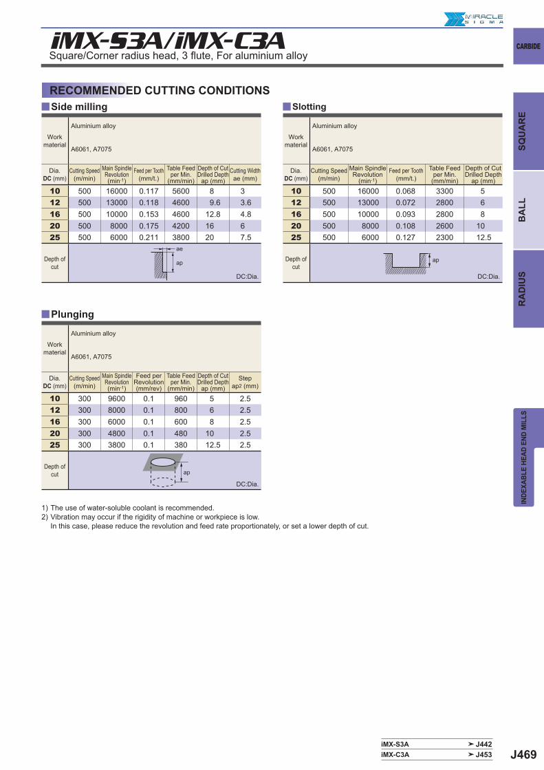
J469
iMX-S3A/iMX-C3A
y y
iMX-S3A J442iMX-C3A J453
y
10 500 16000 0.117 5600 8 312 500 13000 0.118 4600 9.6 3.616 500 10000 0.153 4600 12.8 4.820 500 8000 0.175 4200 16 625 500 6000 0.211 3800 20 7.5
10 300 9600 0.1 960 5 2.512 300 8000 0.1 800 6 2.516 300 6000 0.1 600 8 2.520 300 4800 0.1 480 10 2.525 300 3800 0.1 380 12.5 2.5
10 500 16000 0.068 3300 512 500 13000 0.072 2800 616 500 10000 0.093 2800 820 500 8000 0.108 2600 1025 500 6000 0.127 2300 12.5
ap
ae
ap ap
CARBIDE
INDE
XABL
E HE
AD E
ND M
ILLS
SQU
AR
EB
ALL
RA
DIU
S
RECOMMENDED CUTTING CONDITIONSSide milling Slotting
Square/Corner radius head, 3 fl ute, For aluminium alloy
Workmaterial
Aluminium alloy
A6061, A7075
Dia.DC (mm)
Cutting Speed(m/min)
Main Spindle Revolution(min-1)
Feed per Tooth(mm/t.)
Table Feed per Min.
(mm/min)
Depth of CutDrilled Depth
ap (mm)Cutting Widthae (mm)
Depth of cut
Workmaterial
Aluminium alloy
A6061, A7075
Dia.DC (mm)
Cutting Speed(m/min)
Main Spindle Revolution(min-1)
Feed per Revolution(mm/rev)
Table Feed per Min.
(mm/min)
Depth of CutDrilled Depth
ap (mm)Step
ap2 (mm)
Depth of cut
Workmaterial
Aluminium alloy
A6061, A7075
Dia.DC (mm)
Cutting Speed(m/min)
Main Spindle Revolution
(min-1)Feed per Tooth
(mm/t.)Table Feed
per Min.(mm/min)
Depth of CutDrilled Depth
ap (mm)
Depth of cut
Plunging
1) The use of water-soluble coolant is recommended.2) Vibration may occur if the rigidity of machine or workpiece is low.
In this case, please reduce the revolution and feed rate proportionately, or set a lower depth of cut.
DC:Dia. DC:Dia.
DC:Dia.
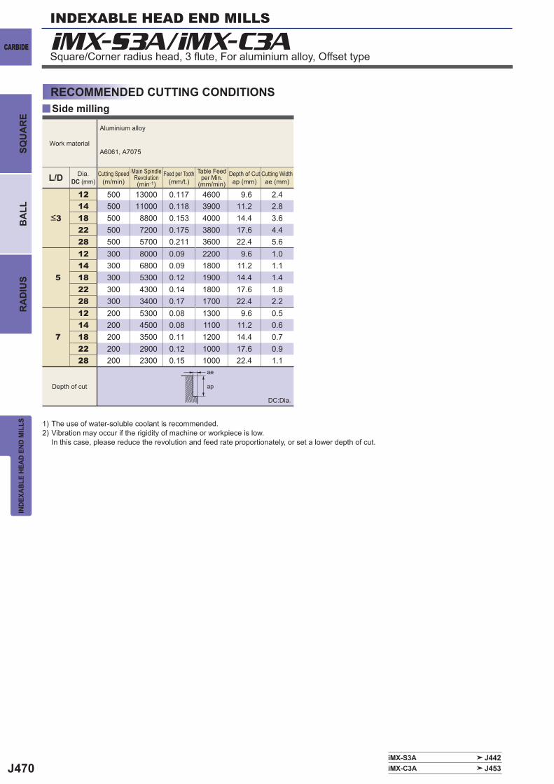
J470
iMX-S3A/iMX-C3A
y
L/D
12 500 13000 0.117 4600 9.6 2.414 500 11000 0.118 3900 11.2 2.818 500 8800 0.153 4000 14.4 3.622 500 7200 0.175 3800 17.6 4.428 500 5700 0.211 3600 22.4 5.6
5
12 300 8000 0.09 2200 9.6 1.014 300 6800 0.09 1800 11.2 1.118 300 5300 0.12 1900 14.4 1.422 300 4300 0.14 1800 17.6 1.828 300 3400 0.17 1700 22.4 2.2
7
12 200 5300 0.08 1300 9.6 0.514 200 4500 0.08 1100 11.2 0.618 200 3500 0.11 1200 14.4 0.722 200 2900 0.12 1000 17.6 0.928 200 2300 0.15 1000 22.4 1.1
iMX-S3A J442iMX-C3A J453
ae
ap
INDEXABLE HEAD END MILLS
CARBIDE
INDE
XABL
E HE
AD E
ND M
ILLS
BA
LLR
AD
IUS
SQU
AR
E
Square/Corner radius head, 3 fl ute, For aluminium alloy, Offset type
RECOMMENDED CUTTING CONDITIONSSide milling
Work material
Aluminium alloy
A6061, A7075
Dia.DC (mm)
Cutting Speed(m/min)
Main Spindle Revolution(min-1)
Feed per Tooth(mm/t.)
Table Feed per Min.
(mm/min)Depth of Cutap (mm)
Cutting Widthae (mm)
<3
Depth of cut
1) The use of water-soluble coolant is recommended.2) Vibration may occur if the rigidity of machine or workpiece is low.
In this case, please reduce the revolution and feed rate proportionately, or set a lower depth of cut.
DC:Dia.
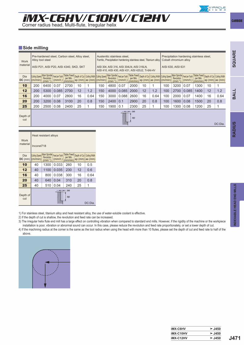
J471
y
iMX-C6HV/C10HV/C12HV
iMX-C6HV J450iMX-C10HV J450iMX-C12HV J450
10 200 6400 0.07 2700 10 1 150 4800 0.07 2000 10 1 100 3200 0.07 1300 10 112 200 5300 0.085 2700 12 1.2 150 4000 0.085 2000 12 1.2 100 2700 0.085 1400 12 1.216 200 4000 0.07 2800 16 0.64 150 3000 0.088 2600 16 0.64 100 2000 0.07 1400 16 0.6420 200 3200 0.08 3100 20 0.8 150 2400 0.1 2900 20 0.8 100 1600 0.08 1500 20 0.825 200 2500 0.08 2400 25 1 150 1900 0.1 2300 25 1 100 1300 0.08 1200 25 1
10 40 1300 0.033 260 10 0.512 40 1100 0.035 230 12 0.616 40 800 0.038 300 16 0.6420 40 640 0.04 310 20 0.825 40 510 0.04 240 25 1
ae
ap
ae
ap
CARBIDE
INDE
XABL
E HE
AD E
ND M
ILLS
SQU
AR
EB
ALL
RA
DIU
S
Side milling
1) For stainless steel, titanium alloy and heat resistant alloy, the use of water-soluble coolant is effective. 2) If the depth of cut is shallow, the revolution and feed rate can be increased.3) The irregular helix fl ute end mill has a large effect on controlling vibration when compared to standard end mills. However, if the rigidity of the machine or the workpiece
installation is poor, vibration or abnormal sound can occur. In this case, please reduce the revolution and feed rate proportionately, or set a lower depth of cut.4) If the machining radius at the corner is the same as the tool radius when using the head with more than 10 fl utes, please set the depth of cut and feed rate to half of the
above.
Corner radius head, Multi-fl ute, Irregular helix
Workmaterial
Pre-hardened steel, Carbon steel, Alloy steel, Alloy tool steel
AISI P21, AISI P20, AISI 4340, SKD, SKT
Austenitic stainless steel, Ferritic, Precipitation hardening stainless steel, Titanium alloy
AISI 304, AISI 316, AISI 304LN, AISI 316LN, AISI 410, AISI 430, AISI 431, AISI 420J2, Ti-6Al-4V
Precipitation hardening stainless steel, Cobalt chromium alloy
AISI 630, AISI 631
DiaDC (mm)
Cutting Speed(m/min)
Main Spindle Revolution(min-1)
Feed per Tooth(mm/t.)
Table Feed per Min.
(mm/min)Depth of Cutap (mm)
Cutting Widthae (mm)
Cutting Speed(m/min)
Main Spindle Revolution(min-1)
Feed per Tooth(mm/t.)
Table Feed per Min.
(mm/min)Depth of Cutap (mm)
Cutting Widthae (mm)
Cutting Speed(m/min)
Main Spindle Revolution(min-1)
Feed per Tooth(mm/t.)
Table Feed per Min.
(mm/min)Depth of Cutap (mm)
Cutting Widthae (mm)
Depth ofcut
Workmaterial
Heat resistant alloys
Inconel718
DiaDC (mm)
Cutting Speed(m/min)
Main Spindle Revolution(min-1)
Feed per Tooth(mm/t.)
Table Feed per Min.
(mm/min)Depth of Cutap (mm)
Cutting Widthae (mm)
Depth ofcut
DC:Dia.
DC:Dia.
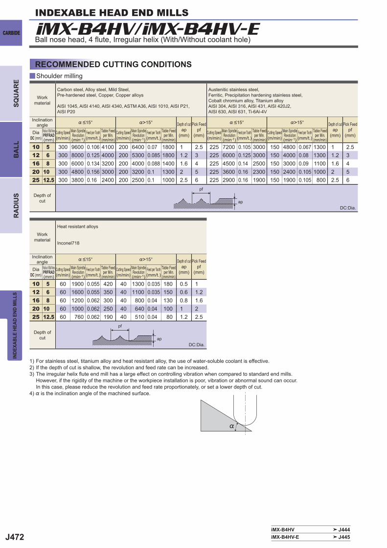
J472
iMX-B4HV/iMX-B4HV-E
y
iMX-B4HV J444iMX-B4HV-E J445
%>15° %>15°
10 5 300 9600 0.106 4100 200 6400 0.07 1800 1 2.5 225 7200 0.105 3000 150 4800 0.067 1300 1 2.512 6 300 8000 0.125 4000 200 5300 0.085 1800 1.2 3 225 6000 0.125 3000 150 4000 0.08 1300 1.2 316 8 300 6000 0.134 3200 200 4000 0.088 1400 1.6 4 225 4500 0.14 2500 150 3000 0.09 1100 1.6 420 10 300 4800 0.156 3000 200 3200 0.1 1300 2 5 225 3600 0.16 2300 150 2400 0.105 1000 2 525 12.5 300 3800 0.16 2400 200 2500 0.1 1000 2.5 6 225 2900 0.16 1900 150 1900 0.105 800 2.5 6
%>15°
10 5 60 1900 0.055 420 40 1300 0.035 180 0.5 112 6 60 1600 0.055 350 40 1100 0.035 150 0.6 1.216 8 60 1200 0.062 300 40 800 0.04 130 0.8 1.620 10 60 1000 0.062 250 40 640 0.04 100 1 225 12.5 60 760 0.062 190 40 510 0.04 80 1.2 2.5
pf
ap
pf
ap
%
INDEXABLE HEAD END MILLS
CARBIDE
INDE
XABL
E HE
AD E
ND M
ILLS
BA
LLR
AD
IUS
SQU
AR
E
Shoulder milling
RECOMMENDED CUTTING CONDITIONS
Ball nose head, 4 fl ute, Irregular helix (With/Without coolant hole)
Work material
Carbon steel, Alloy steel, Mild Steel, Pre-hardened steel, Copper, Copper alloys
AISI 1045, AISI 4140, AISI 4340, ASTM A36, AISI 1010, AISI P21, AISI P20
Austenitic stainless steel, Ferritic, Precipitation hardening stainless steel, Cobalt chromium alloy, Titanium alloyAISI 304, AISI 316, AISI 431, AISI 420J2, AISI 630, AISI 631, Ti-6Al-4V
Inclination angle %<15° Depth of cut
ap (mm)
Pick Feedpf
(mm)
%<15° Depth of cutap
(mm)
Pick Feedpf
(mm)DiaDC (mm)
Radius of Ball NosePRFRAD(mm)
Cutting Speed(m/min)
Main Spindle Revolution(min-1)
Feed per Tooth(mm/t.)
Table Feed per Min.
(mm/min)Cutting Speed(m/min)
Main Spindle Revolution(min-1)
Feed per Tooth(mm/t.)
Table Feed per Min.
(mm/min)Cutting Speed(m/min)
Main Spindle Revolution(min-1)
Feed per Tooth(mm/t.)
Table Feed per Min.
(mm/min)Cutting Speed(m/min)
Main Spindle Revolution(min-1)
Feed per Tooth(mm/t.)
Table Feed per Min.
(mm/min)
Depth of cut
Work material
Heat resistant alloys
Inconel718
Inclination angle %<15° Depth of cut
ap (mm)
Pick Feedpf
(mm)DiaDC (mm)
Radius of Ball NosePRFRAD(mm)
Cutting Speed(m/min)
Main Spindle Revolution(min-1)
Feed per Tooth(mm/t.)
Table Feed per Min.
(mm/min)Cutting Speed(m/min)
Main Spindle Revolution(min-1)
Feed per Tooth(mm/t.)
Table Feed per Min.
(mm/min)
Depth of cut
1) For stainless steel, titanium alloy and heat resistant alloy, the use of water-soluble coolant is effective. 2) If the depth of cut is shallow, the revolution and feed rate can be increased.3) The irregular helix fl ute end mill has a large effect on controlling vibration when compared to standard end mills.
However, if the rigidity of the machine or the workpiece installation is poor, vibration or abnormal sound can occur.In this case, please reduce the revolution and feed rate proportionately, or set a lower depth of cut.
4) % is the inclination angle of the machined surface.
DC:Dia.
DC:Dia.
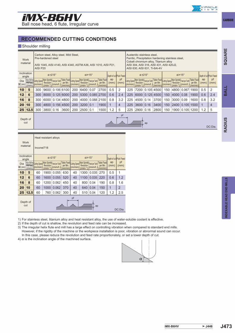
J473
y
iMX-B6HV
%>15° %>15°
10 5 300 9600 0.106 6100 200 6400 0.07 2700 0.5 2 225 7200 0.105 4500 150 4800 0.067 1900 0.5 212 6 300 8000 0.125 6000 200 5300 0.085 2700 0.6 2.4 225 6000 0.125 4500 150 4000 0.08 1900 0.6 2.416 8 300 6000 0.134 4800 200 4000 0.088 2100 0.8 3.2 225 4500 0.14 3700 150 3000 0.09 1600 0.8 3.220 10 300 4800 0.156 4500 200 3200 0.1 1900 1 4 225 3600 0.16 3400 150 2400 0.105 1500 1 425 12.5 300 3800 0.16 3600 200 2500 0.1 1500 1.2 5 225 2900 0.16 2800 150 1900 0.105 1200 1.2 5
%>15°
10 5 60 1900 0.055 630 40 1300 0.035 270 0.5 112 6 60 1600 0.055 520 40 1100 0.035 220 0.6 1.216 8 60 1200 0.062 450 40 800 0.04 190 0.8 1.620 10 60 1000 0.062 370 40 640 0.04 150 1 225 12.5 60 760 0.062 300 40 510 0.04 120 1.2 2.5
iMX-B6HV J446
%
pf
ap
pf
ap
CARBIDE
INDE
XABL
E HE
AD E
ND M
ILLS
SQU
AR
EB
ALL
RA
DIU
S
Shoulder milling
RECOMMENDED CUTTING CONDITIONS
Ball nose head, 6 fl ute, Irregular curve
Work material
Carbon steel, Alloy steel, Mild Steel, Pre-hardened steel
AISI 1045, AISI 4140, AISI 4340, ASTM A36, AISI 1010, AISI P21, AISI P20
Austenitic stainless steel, Ferritic, Precipitation hardening stainless steel, Cobalt chromium alloy, Titanium alloyAISI 304, AISI 316, AISI 431, AISI 420J2, AISI 630, AISI 631, Ti-6Al-4V
Inclination angle %<15° Depth of cut
ap (mm)
Pick Feedpf
(mm)
%<15° Depth of cutap
(mm)
Pick Feedpf
(mm)DiaDC (mm)
Radius of Ball NosePRFRAD(mm)
Cutting Speed(m/min)
Main Spindle Revolution(min-1)
Feed per Tooth(mm/t.)
Table Feed per Min.
(mm/min)Cutting Speed(m/min)
Main Spindle Revolution(min-1)
Feed per Tooth(mm/t.)
Table Feed per Min.
(mm/min)Cutting Speed(m/min)
Main Spindle Revolution(min-1)
Feed per Tooth(mm/t.)
Table Feed per Min.
(mm/min)Cutting Speed(m/min)
Main Spindle Revolution(min-1)
Feed per Tooth(mm/t.)
Table Feed per Min.
(mm/min)
Depth of cut
Work material
Heat resistant alloys
Inconel718
Inclination angle %<15° Depth of cut
ap (mm)
Pick Feedpf
(mm)DiaDC (mm)
Radius of Ball NosePRFRAD(mm)
Cutting Speed(m/min)
Main Spindle Revolution(min-1)
Feed per Tooth(mm/t.)
Table Feed per Min.
(mm/min)Cutting Speed(m/min)
Main Spindle Revolution(min-1)
Feed per Tooth(mm/t.)
Table Feed per Min.
(mm/min)
Depth of cut
1) For stainless steel, titanium alloy and heat resistant alloy, the use of water-soluble coolant is effective. 2) If the depth of cut is shallow, the revolution and feed rate can be increased.3) The irregular helix fl ute end mill has a large effect on controlling vibration when compared to standard end mills.
However, if the rigidity of the machine or the workpiece installation is poor, vibration or abnormal sound can occur.In this case, please reduce the revolution and feed rate proportionately, or set a lower depth of cut.
4) % is the inclination angle of the machined surface.
DC:Dia.
DC:Dia.