Embed Size (px)
Citation preview
3d CAD model of spiral bevel gear in NX8.5 CAD using Nominal tooth data file generated by CAGE Gleason or similar nominal or CMM
inspection data/txt files. With help of gear data processor from Spiral Bevel Corporation.
2016.
Spiralbevel.com
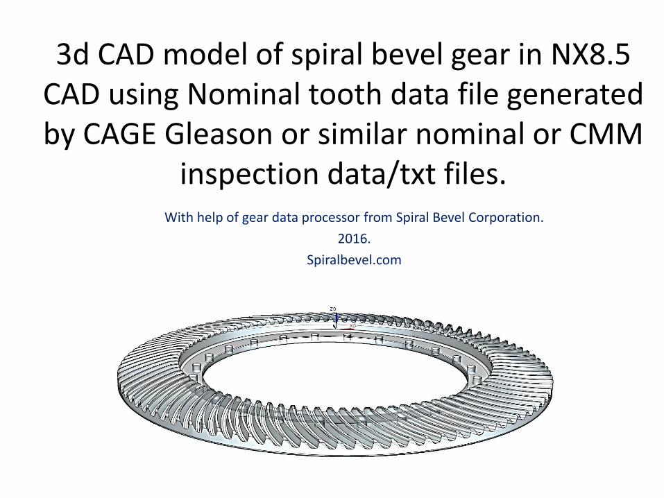
Get you gear blank in 3d
Locate the blank: Axis Z is axis of the gear blank. Pitch cone apex is CAD model origin
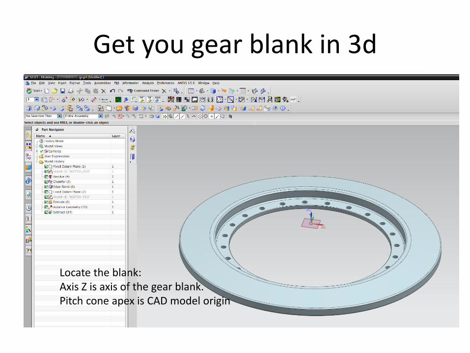
Get nominal data file.
This kind of file is very common in spiral bevel CMM inspection. Gleason CAGE software generates this file. It shows nominal tooth coordinates (digital gear master) that are used for CMM tooth surface inspection. You can view this file in Notepad.
Translate nominal data file to 3d CAD tooth with help of Excel program from
Spiral Bevel Corp.
Spiral Bevel Corporation provides simple solutions for 3d CAD gear modeling often based on commonly used software like MS Excel. Excel allows VBA macros that read nominal gear data files used by Gleason, Klingelnberg, Zeiss, and others for gear inspection. As the result spiralbevel Excel program generated exact 3d copy of the nominal gear tooth geometry that can be used in 5-axis CNC machining of spiral bevel gears. The 3d CAD models can be used for 5-axis CNC rough cutting before finished grinding. Just need to offset the surfaces in CAD for amount of removed material and heat treatment deformations.
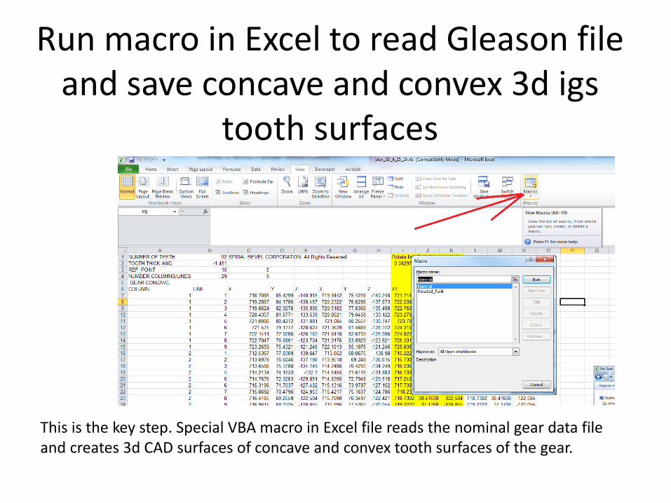
Run macro in Excel to read Gleason file and save concave and convex 3d igs
tooth surfaces
This is the key step. Special VBA macro in Excel file reads the nominal gear data file and creates 3d CAD surfaces of concave and convex tooth surfaces of the gear.
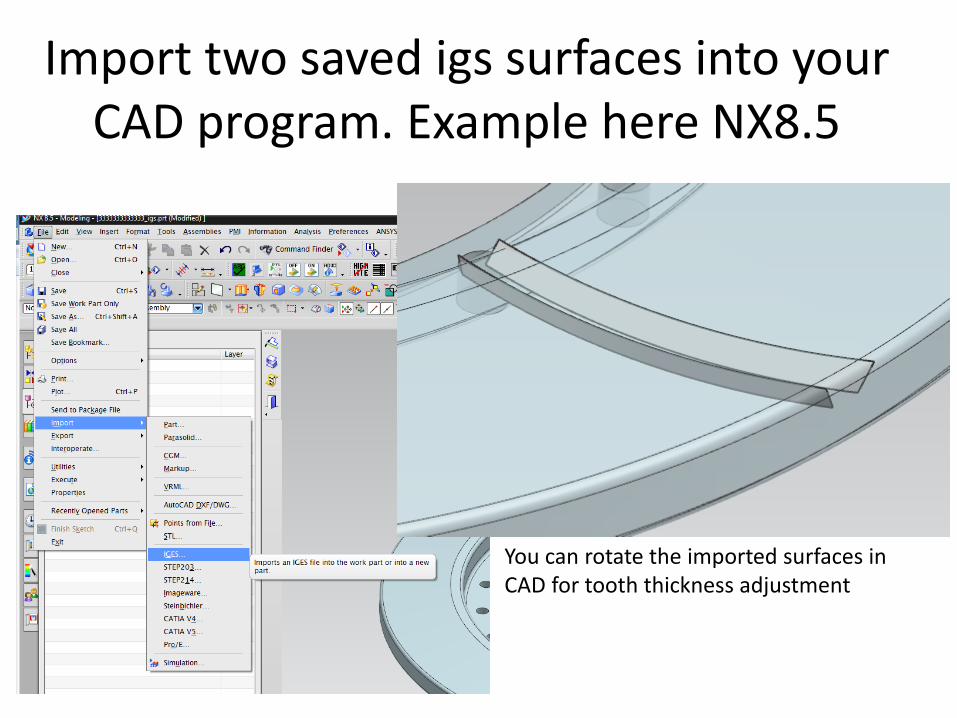
Import two saved igs surfaces into your CAD program. Example here NX8.5
You can rotate the imported surfaces in CAD for tooth thickness adjustment
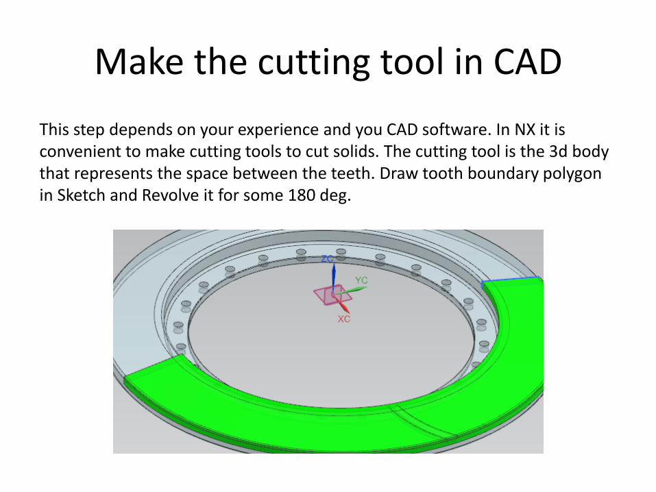
Make the cutting tool in CAD
This step depends on your experience and you CAD software. In NX it is convenient to make cutting tools to cut solids. The cutting tool is the 3d body that represents the space between the teeth. Draw tooth boundary polygon in Sketch and Revolve it for some 180 deg.
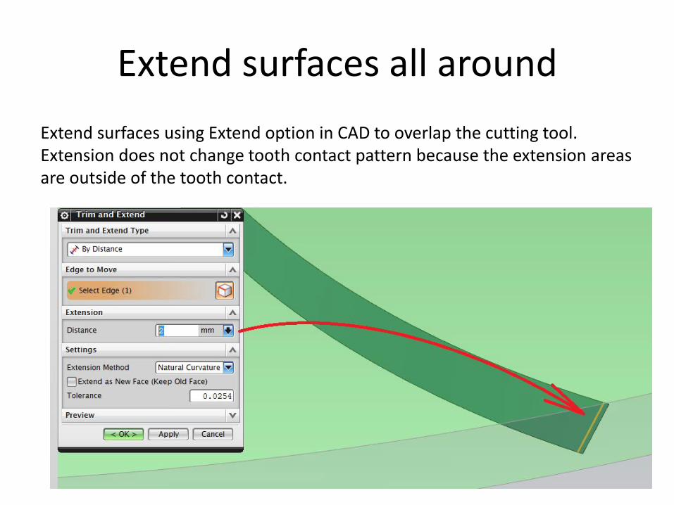
Extend surfaces all around
Extend surfaces using Extend option in CAD to overlap the cutting tool. Extension does not change tooth contact pattern because the extension areas are outside of the tooth contact.
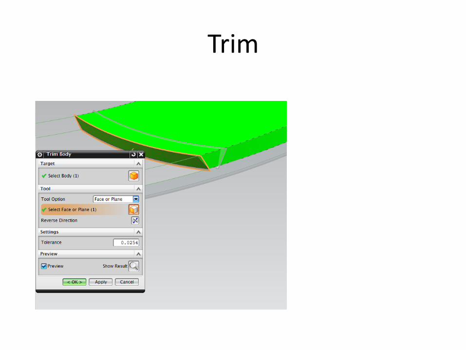
Trim
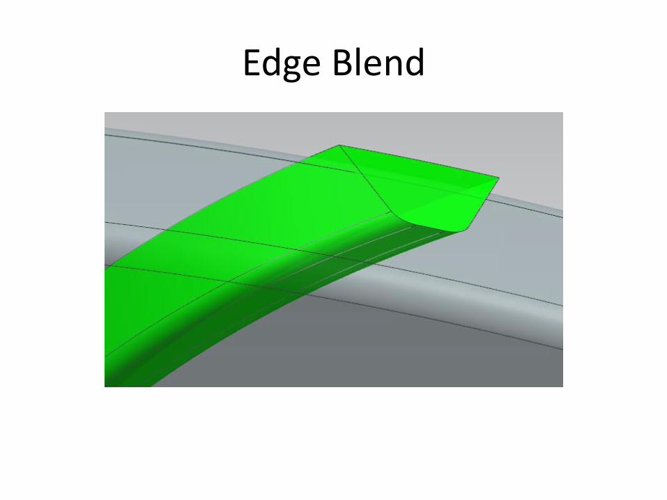
Edge Blend
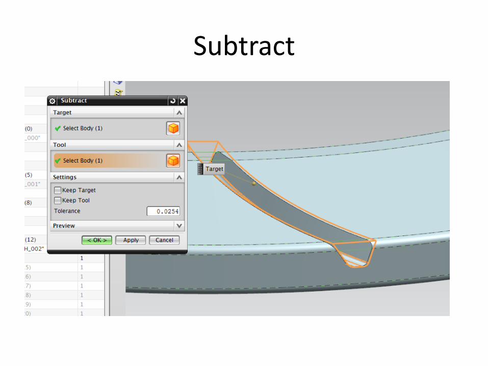
Subtract
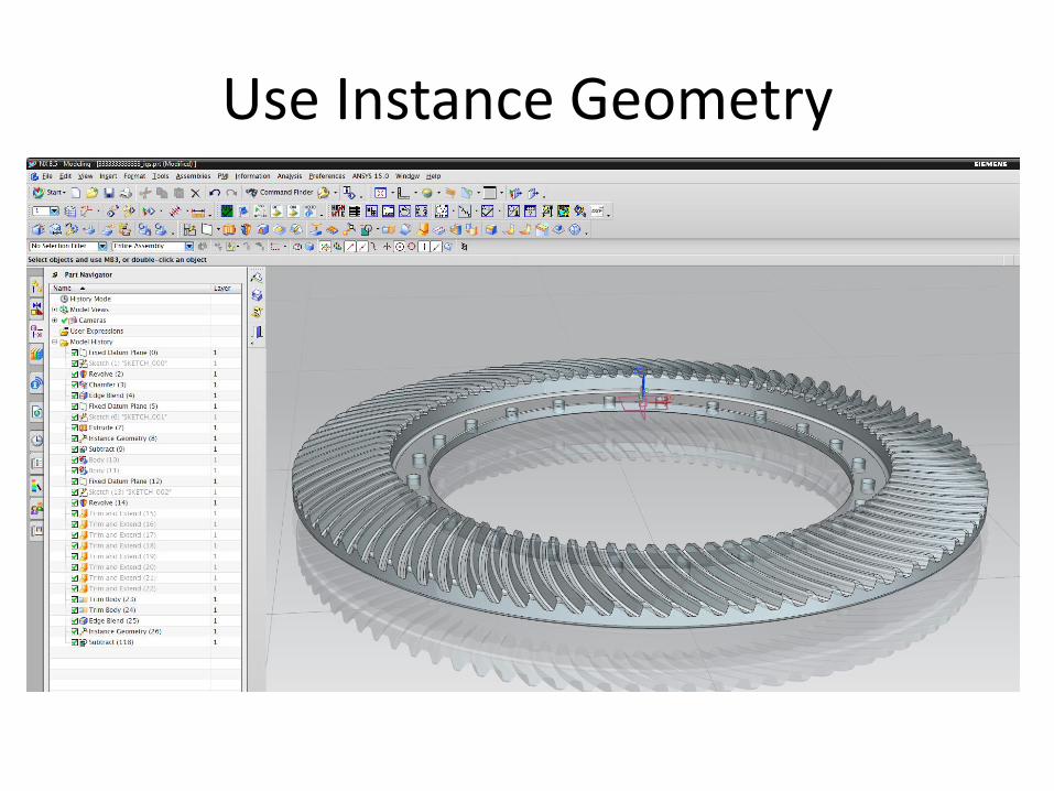
Use Instance Geometry
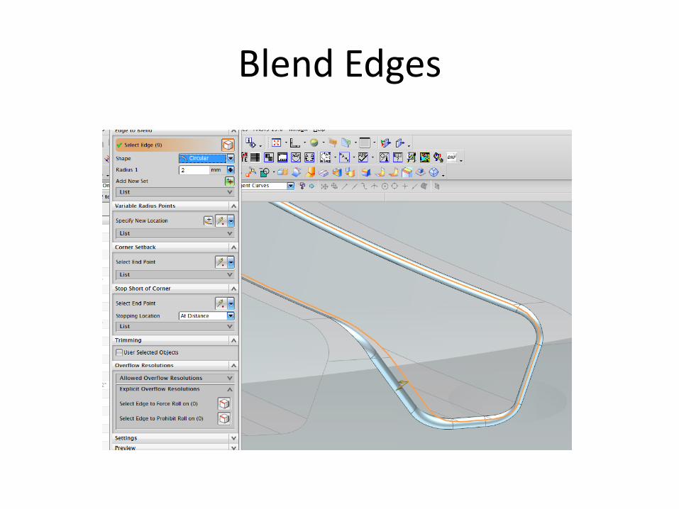
Blend Edges
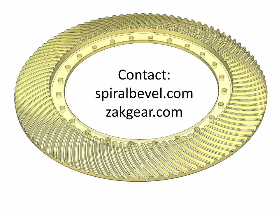
Contact: spiralbevel.com
zakgear.com