Embed Size (px)
Citation preview

How to Hide Circuits in MPC
An Efficient Framework for Private Function Evaluation
Payman Mohassel∗ and Saeed Sadeghian†
University of Calgary
Abstract
We revisit the problem of general-purpose private function evaluation (PFE) wherein a single partyP1 holds a circuit C, while each Pi for 1 ≤ i ≤ n holds a private input xi, and the goal is for a subset (orall) of the parties to learn C(x1, . . . , xn) but nothing else. We put forth a general framework for designingPFE where the task of hiding the circuit and securely evaluating its gates are addressed independently:First, we reduce the task of hiding the circuit topology to oblivious evaluation of a mapping that encodesthe topology of the circuit, which we refer to as oblivious extended permutation (OEP) since the mappingis a generalization of the permutation mapping. Second, we design a subprotocol for private evaluationof a single gate (PFE for one gate), which we refer to as private gate evaluation (PGE). Finally, we showhow to naturally combine the two components to obtain efficient and secure PFE.
We apply our framework to several well-known general-purpose MPC constructions, in each case,obtaining the most efficient PFE construction to date, for the considered setting. Similar to the previouswork we only consider semi-honest adversaries in this paper.
• In the multiparty case with dishonest majority, we apply our techniques to the seminal GMWprotocol [GMW87] and obtain the first general-purpose PFE with linear complexity in the circuitsize.
• In the two-party case, we transform Yao’s garbled circuit protocol [Yao86] into a constant-roundtwo-party PFE. Depending on the instantiation of the underlying subprotocol, we either obtain atwo-party PFE with linear complexity that improves on the only other work with similar asymptoticefficiency (Katz and Malka, ASIACRYPT 2011 [KM11]), or a two-party PFE that provides thebest concrete efficiency to date despite not being linear.
• The above two constructions are for boolean circuits. In case of arithmetic circuits, we obtain thefirst PFE with linear complexity based on any additively homomorphic encryption scheme.
Though each construction uses different techniques, a common feature in all three is that the overheadof hiding the circuit C is essentially equal to the cost of running the OEP protocol on a vector of size |C|.As a result, to improve efficiency, one can focus on lowering the cost of the underlying OEP protocol.OEP can be instantiated using a singly homomorphic encryption or any general-purpose MPC butwe introduce a new construction that we show is significantly more efficient than these alternatives, inpractice. The main building block in our OEP construction is an efficient protocol for oblivious switchingnetwork evaluation (OSN), a generalization of the previously studied oblivious shuffling problem whichis of independent interest. Our results noticeably improve efficiency of the previous solutions to obliviousshuffling, yielding a factor of 25 or more gain in computation and communication.
∗email address: [email protected]†email address: [email protected]

1 Introduction
In a private function evaluation (PFE) protocol, a party P1 holds a function f , and its corresponding circuitCf , while every party Pi holds a private input xi; their goal is for a subset (or all) of the parties to learnf(x1, . . . , xn) without learning any information beyond this.1 In particular, besides the size of the circuit,and the length of P1’s inputs and outputs, Pi (i ≥ 2) should not learn anything else about the circuit. Thisis in contrast to the standard setting for secure multi-party computation where the function f and thecorresponding circuit Cf are publicly known to all the participants. PFE is particularly useful in scenarioswhere learning the function compromises privacy, reveals security vulnerabilities, or when service providersneed to hide the function or a specific implementation of it to protect their Intellectual Property. A numberof papers in the literature have considered the design of efficient special and general-purpose private functionevaluation protocols [AF90, KM11, GHS10, SS09, PSS09, BFK+09, KS08a, IP07, BPSW07].
Solutions Based on Universal Circuits. Most general-purpose PFE solutions reduce the problem tosecure computation of a universal circuit Ug that takes as input the circuit Cf (with at most g gates),and the parties’ private inputs x1, . . . , xn, and outputs f(x1, . . . , xn). The main objective of this line ofwork is to design smaller size universal circuits, and to optimize their implementation using existing MPCconstructions such as Yao’s garbled circuit protocol [KS08a, Sch08, SS09].
The Universal circuit approach works with any secure MPC protocol for evaluating boolean circuitsand is applicable to both the two-party and the multi-party settings. Its main disadvantage, and themain motivation for other alternatives is the additional overhead in efficiency due to the size of universalcircuits and the complexity of designing and implementing such circuits. Valiant [Val76] showed a con-struction of a boolean universal circuit achieving an optimal circuit size of |Ug| ≈ 19g log g. Kolesnikov andSchneider [KS08a] gave an alternative construction of universal circuits. They obtain a worse asymptoticbound of |Ug| ≈ 1.5g log2 g, but their techniques lead to smaller constant factors and seem to yield smalleruniversal circuits than Valiant’s construction for circuit sizes less than 5000. Furthermore, the universalcircuit approach does not provide a satisfactory solution in case of arithmetic circuits. While universalarithmetic circuits exist (e.g. see [SY10] and [Raz08]), their sizes are too large for any practical purpose(e.g. as high as O(g5)).
Solutions Based on Homomorphic Encryption. It is relatively easy to design a PFE based on afully homomorphic encryption scheme [Gen09]. While asymptotically optimal, this solution is not practicaldue to its high computational cost. Recently, Katz and Malka [KM11] designed a novel two-party PFEprotocol based on a singly homomorphic encryption. Complexity of the resulting protocol is linear in thesize of the circuit but the number of public-key operations is also linear in the size of the circuit. Standardtechniques for reducing public-key operations (e.g. OT extension) do not seem applicable either. Given thesignificant gap between the efficiency of public- vs. symmetric-key operations, this new approach improvesover the universal circuit only when dealing with large circuits. Finally, this solution only works in thetwo-party setting.
1.1 Our Contribution
Practical design and implementation of MPC has been the subject of active research in the last few years.These efforts have, in part, lead to the introduction of several software implementations and MPC frame-works [MNPS04, PSSW09, HEKM11, KSS12]. As discussed above, however, when it comes to PFE the
1The traditional definition of PFE assumes that only Pi (i ≥ 2) holds an input to the function, but this can naturally begeneralized to the case where P1 also holds a private input.
1

Circuit C
G2
G1
ow1 = x1 ow6
ow7
y1
ow1ow2ow3ow4
ow6
ow7
iw1
iw2
iw3
iw4
iw5
iw6
n = 5
g − o = 2
CTH
2g = 8
y2
ow5
iw7
iw8
G3
G4
ow2 = x2
ow3 = x3
ow4 = x4
ow5 = x5
iw5
iw6
iw3
iw4
iw1
iw2
iw7
iw8
2j − 1
2j
1
2g
1
n+ j − o
n+ g − o
CTH
Reveal(2j − 1)
Reveal(2j)
[a]i
[b]iIf P1 then Gj
PGE
OMAP([c]i, n + j − o)[c]i
PGE(Gj, [a], [b])
1
2
3
Figure 1: (a) An example circuit and the corresponding mapping (b) Steps of framework for party i andthe jth gate in a topological order.
situations is not the same. The existing solutions are considerably less scalable and more expensive com-pared to their MPC counterparts, and no good solution exists for the multiparty case, or when consideringarithmetic circuits.
We revisit private function evaluation with the intention of designing more practical two-party andmulti-party constructions. In particular, we put forth a general framework for designing PFE and showhow it enables us to construct more efficient PFE variants of the well-known MPC protocols.
Our Framework for Designing PFE. In order to fully hide a circuit C, one needs to hide two typesof information about it: (i) the topology of the circuit, and (ii) the function of the gates in the circuit(AND, OR, XOR). Note that these are in addition to what is already hidden in a MPC setting. Followingthis observation we divide the task of private function evaluation into two different functionalities: (1) theCircuit Topology Hiding (CTH) functionality, and (2) the Private Gate Evaluation (PGE) functionality.Next, we describe these two functionalities in more detail:
• CTH Functionality. We observe that the topology of a circuit C can be fully described using amapping πC : {1 . . . |OW|} → {1 . . . |IW|} where OW (outgoing wires) is the union of the set ofinput wires {ow1 = x1, . . . , own = xn}, and the output wires for each non-output gate in the circuit{own+1, . . . , own+g−o} (g is the circuit size and o is the number of output gates), and IW (incomingwires) is the set of input wires to all the gates in the circuit {iw1, . . . , iw2g}. πC maps i to j (πC(i) = j)if and only if wire owi ∈ OW is connected to iwj ∈ IW, in the circuit C. Note that since the fan-outfor each gate can be more than one, πC is not always a function, but it is easy to check that itsinverse π−1
C is. Note that the party who knows the function f and the corresponding circuit C canefficiently compute πC . Figure 1(a) demonstrates an example circuit and its corresponding mapping.Intuitively the FCT H functionality provides a mechanism for obliviously applying the mapping πCto the n input values and the (g − o) values for intermediate outgoing wires (i.e. mapping them toincoming wires) in an on-demand fashion, and as the MPC protocol proceeds.
• PGE Functionality. The PGE functionality can be seen as a PFE protocol where the function is asingle gate. P1 provides the gate’s functionality, while all parties including P1 provide their shares ofthe two inputs to the gate. The functionality returns to each party, his share of the gate’s output.
These two functionalities can be naturally composed to obtain a complete PFE protocol as describedin Figure 4. A visual demonstration of the steps appears in Figure 1(b).
2

Oblivious Shuffling Protocols Asymptotic Complexity Concrete Efficiency Gain
HE-Based O(N) Asym. 175
Garbled Circuit-Based [HEK12] ( 4`(N logN−N+1)3
+ 2N`) Sym. + O(k) Asym. 25
OSN-Based (our paper) (2N logN − 2N + 2) Sym. + O(k) Asym. 1
Table 1: Comparison of our OSN-based oblivious shuffling vs. HE-based and garbled circuit-based constructions. Let Ndenote the number of elements being permuted, ` be the length of each element and k is the security paremeter. The lastcolumn shows some concrete efficiency gain of our OSN construction over the corresponding construction for 128 ≤ N ≤ 8192,` = 32. These numbers are based on experiments in [HEK12]. We expect similar gains for larger values of N too.
Efficient Realizations of FCT H. We refer to the mapping πC : {1 . . . |OW|} → {1 . . . |IW|} discussedabove as an extended permutation (EP) since it not only permutes the elements in {1 . . . |OW|}, but alsocan replicate them as many times as needed. A main component of our FCT H realization is a protocol foroblivious evaluation of this extended permutation (OEP) on a vector of inputs: the first party holds πC anda blinding2 vector ~t of size |IW|, while the second party holds an input vector ~x of size |OW|. Their goal is tolet the second party learn the output of πC applied to ~x, blinded by ~t. Neither party should learn anythingelse. OEP can be instantiated using a singly homomorphic encryption, or any general-purpose 2PC. Asdiscussed in Section 4, however, neither solution is efficient enough for use in practice. We introduce a newand efficient construction for OEP based on generalized switching networks and oblivious transfer.OEP via Generalized Switching Networks. First, we show how to efficiently implement an extendedpermutation using a generalized switching network SN. Such a network is a set of interconnected switcheswhere each switch maps two inputs to two outputs, using at most two selection bits. This is a generalizationof the well-known permutation networks since the network uses four different switch types (as opposed totwo), as specified by its two selection bits. Once the EP is represented using a SN, we solve the OEPproblem by designing a new OT-based protocol for Oblivious Switching Network evaluation (OSN) whereone party P1 holds the selection bits to SN, and a blinding vector ~t, while the other party P2 holds theinput vector ~x to the SN. The goal is for P2 to learn the output of SN applied to the input vector ~x, blindedby ~t. Our OSN protocol runs in a constant number of rounds and requires O(g) oblivious transfers whereg is the number of switches in the network.
The resulting OEP is more efficient than the homomorphic-based solutions since the number of expo-nentiations can be made independent of the size of the network (using OT extension), and is more efficientthan the Yao-based one since the complexity of our construction does not grow with the number of bitsneeded to represent each input element. We also need a multiparty variant of our OEP protocol where themapping is known to a single party while the input vector ~x and the blinding vector ~t are shared amongthe players. We show how to construct such an m-party OEP protocol via m invocations of the two-partyversion.Improved Oblivious Shuffling. Digressing from the main topic of this paper, we note that OSN is ageneralization of the previously studied problems such as oblivious shuffling [HEK12] (a subprotocol usedfor private set intersection), or secure two-party permutation [WLG+10, Du01]. Our new constructionyields more efficient solutions to these problems as well, improving on the previous proposals based ongarbled circuit implementation of sorting networks, permutation networks, or randomize shell sort [HEK12,WLG+10, Du01]. See Table 1 for concrete (a factor of 25 or more improvement over best previous solutions)and asymptotic efficiency comparisons with previous work.
Applying our Framework to Existing MPC. We apply the above framework to the GMW proto-col [GMW87], Yao’s garbled circuit protocol [Yao86], and secure computation of arithmetic circuits via
2The nature of blinding is intentionally left unspecified as different protocols may use different blinding functions. Ourconstructions use XOR or addition in a finite Ring for this purpose.
3

Multi-Party PFE Complexity
[KS08a] Universal Circuits O(m2g log2 g) Sym. + O(k) Asym.
[Val76] Universal Circuits O(m2g log g) Sym. + O(k) Asym.
GMW-PFE (SN-OEP) O(m2g + mg log g) Sym. + O(k) Asym.
GMW-PFE (HE-OEP) O(m2g) Sym. + O(mg) HE. + O(k) Asym.
Table 2: Comparing our m-party PFE with the generic solution of applying GMW to the universal circuit constructions of[KS08a] and [Val76]. g denotes the number of gates, k denotes the security parameter.
homomorphic encryption [CDN01]. In each case we obtain the most efficient PFE construction to date,for the considered setting.Linear Multi-party PFE. We apply our framework to the seminal GMW protocol [GMW87] to obtaina multiparty PFE against a dishonest majority. The CTH component can be instantiated using eitherthe HE-based or the SN-based OEP discussed above. We also design a simple and efficient multipartyPGE functionality given a multiparty OT as in [FGM07]. To the best of our knowledge, this is the firstmultiparty PFE besides the generic solutions of applying MPC to universal circuits. When instantiatedusing a HE-based OEP, it yields the first multiparty PFE with linear complexity (in the circuit size) andwhen instantiated using our new SN-based OEP, it yields a black-box construction based solely on OT.What makes the second instantiation desirable from a practical point of view, as demonstrated in somerecent GMW implementations [CHK+12, NNOB21], is that it only uses oblivious transfers. As a result, onecan use OT extension [IKNP03] and pre-processing techniques [Bea95] to significantly reduce the numberof public-key operations, and to shift the bulk of the computation to an offline phase. Table 2 comparesthe efficiency of these two constructions with the only other alternative, i.e. using GMW with universalcircuits.More Efficient Two-party PFE. We also design a constant round two-party PFE based on Yao’s garbledcircuit protocol [Yao86]. Once again, the FCT H functionality is realized using our OEP constructions andfor the FPGE functionality we use Yao’s garbling/ungarbling algorithms. To ensure that functions of thegates are hidden, we build the circuit entirely out of NAND gates. As we will see in Section 5.3, multiplesubtleties need to be addressed for this work and in particular to guarantee that the circuit evaluatorcan unblind garbled keys during the evaluation of the garbled circuit without learning the values for theintermediate wires.
We note that the construction of [KM11] also fits in the general framework described above (though notpresented in this way). However, our new abstraction helps us gain more efficiency improvements. Whenusing our HE-OEP, we obtain a two-party PFE with linear complexity that is simpler and more efficientthan that of [KM11] (see Section 5.4 for details on the efficiency gain), and when implemented using ourSN-OEP, the resulting protocol is concretely more efficient for most circuit sizes, since the number ofpublic-key operations can be made independent of the circuit size (via OT extension). Our constructionis both asymptotically and concretely more efficient than the previous work of [KS08a] based on universalcircuits. It is concretely more efficient than Valiant’s construction [Val76]. Table 3 summarizes concreteefficiency comparison of our two-party PFE with all previous constructions. In appendix J.1 we show thatour construction concretely improves over all previous construction for benchmark circuits such as AES,RSA and Edit-distance.Linear 2PC for Arithmetic Circuits. We also apply our framework to the construction for securecomputation of arithmetic circuits based on a homomorphic encryption [CDN01], and obtain the firsttwo-party PFE for arithmetic circuits with linear complexity. Besides utilizing our FCT H realizations, weinstantiate the FPGE functionality by designing a secure gate evaluation protocol wherein only one partyknows/learns the functionality (multiplication or addition) but both parties learn their share of the output(product or sum).
4

2-Party PFE Complexity Concrete Efficiency Gain
[KS08a] 1.5g log2 g sym. + O(k) Asym. 3-6
[Val76] 19g log g sym. + O(k) Asym. 2
[KM11] O(g) Sym. + O(g) (HE+HM+HA) + O(k) Asym. -
Yao-PFE (HE-OEP) O(g) Sym. + O(g) (HE+HA) + O(k) Asym. -
Yao-PFE (SN-OEP) O(g log g) Sym. + O(k) Asym. 1
Table 3: Comparison of our 2-party PFE protocols with previous works. (HM: Homomorphic Multiplication, HA: Ho-momorphic Addition, HE: Homomorphic Encryption). Last column shows concrete gain of our 2-PFE over universal circuitapproaches for benchmark circuits, AES, RSA and Edit-distance (refer to section J.1 for more detailed discussion). g denotesthe number of gates, and k is the security parameter.
2 Preliminaries
Notations. For a set D, we denote its size by |D|. We use the same notation to show the size (numberof gates) of a circuit C. We denote a vector by ~v. We use [a] to denote secret sharing of a value a amongmultiple parties. We intentionally do not specify the sharing scheme used. In our constructions we use anumber of different schemes such as XOR sharing, and additive sharing over a finite ring. We denote theith party’s shared by [a]i. We use {1...n} to denote the set of positive integers less than equal to n.
Homomorphic Encryption. We use a semantically-secure public-key encryption scheme E = (Gen,Enc,Dec)with public key pk that allows for simple computations on encrypted data. We require the schemeto be additively homomorphic and denote the addition operation by +h such that Encpk(m1 + m2) =Encpk(m1)+h Encpk(m2). Furthermore, given Encpk(m) and a plaintext c,there exist an efficient operationsdenoted by ×h such that Encpk(cm) = c×h Encpk(m).
Generalized Switching Networks. A switching network SN is a set of interconnected switches thattakes N inputs and a set of selection bits, and outputs N values. Each switch in the network accepts two`-bits strings as input and outputs two `-bit strings. In our generalized notion of a switch, each of thetwo output strings can take the value of each of the two input strings. Therefore, assuming input values(x0, x1), and output values (y0, y1), four different switch types are possible. The two selection bits s0 ands1 determine the switch type. In particular, the output of the switch will be y1 = xs1 ,and y0 = xs0 . In therest of the paper, we drop the term generalized and simply refer to these networks as switching networks.
Definition 2.1 (Mapping for a Switching Network). The mapping π : {1...N} → {1...N} correspondingto a switching network SN is defined such that π(i) = j if and only if after evaluation of SN on the Ninputs, the value of the input wire i is assigned to the output wire j (assuming a standard numbering ofthe input/output wires).
Note that the mapping π need not be a function since the value for each input wire maybe mapped tomultiple output wires in the network. On the other hand, π−1 is always a function.
Permutation Networks. A permutation network PN is a switching network for which the mapping isa permutation. In constructing a permutation network, one only needs to use two of the four switch typesdescribed above. Particularly, for each switch (also called a permutation cell) with inputs I0 and I1, oneselection bit is sufficient to select between the two possible outputs (I0, I1) and (I1, I0).
An optimal construction for a permutation network was proposed by Waksman [Wak68]. The maintheorem of [Wak68] states that for any N power of 2, there exists a permutation network with N logN −N + 1 switches, and depth of 2 logN −1. We refer the reader to [Wak68] for the details of the constructionwhich can be efficiently implemented with O(N logN) complexity.
5

In the remainder of the paper, if a switch takes two selection bits, we refer to it as a 2-switch, andotherwise we use the term 1-switch.
Security Definitions. Security definitions are given in Appendix A.
3 Our Framework for Designing PFE Protocols
Similar to the previous work on private function evaluation, we assume that the following informationabout the circuit is publicly known: the number of gates in the circuit, the number of each party’s inputwires, and the number of output wires. Everything else about the circuit is considered private information.We aim to hide the circuit through the CTH and PGE functionalities discussed earlier. In this section weformally describe these functionalities and explain how they can be combined to obtain a PFE.
Our interpretation of sharing (denote using []) in the following discussion is very general. In the GMW-based PFE we use XOR sharing, for arithmetic circuits we use additive shares over a finite ring, and inYao’s garbled circuit, one party holds one random key (in a key pair) while the other party holds themapping of each key to its actual bit value.
CTH Functionality. As described in the introduction, the interconnection of wires in the circuit can berepresented by a mapping πC . The CTH functionality is responsible for obliviously applying this mappingto the values of the input wires and the intermediate wires in the circuit, in an on-demand fashion. Ourdefinition of the CTH functionality captures this useful property refered to as on-demand mapping via useof the OMAP/Reveal queries. The OMAP queries allow the participants in the CTH to feed their shares ofthe values for each outgoing wire to the mapping (individually) and obtain the mapped/blinded outcomesfor each incoming wire through the Reveal queries. Our new realization of the CTH functionality as wellas the existing constructions all possess the on-demand property as discussed in Appendix G. Figure 2describes the CTH functionality more formally.
The role of vectors ~k is to prevent P1 from learning the other parties’ shares and the role of vectors~t is to hide P1’s mapping πC from the other parties. The operator ⊗ is used to denote a blinding oper-ation. Depending on the CTH realization, the blinding operation can be XORing, modular addition, orhomomorphic addition using an additively homomorphic encryption.
The PGE Functionality. The PGE functionality can be seen as a PFE protocol where the function is asingle gate. A formal description is given in Figure 3.
Our PFE Framework. These two functionalities can be naturally composed to obtain a complete PFEprotocol as described in Figure 4. Our framework can be seen as a way to extend a PFE protocol forone gate (PGE) to a PFE protocol for the complete circuit (by employing the CTH functionality). Wegive an overview next. In the initialization phase, P1, knowing the circuit C, sorts the gates topologicallyand computes the mapping πC corresponding to it. Next, each party distributes shares of its input to allparties. The idea is for the parties to send the value of each outgoing wire to the CTH functionality assoon as it is ready. Hence, at the start of the protocol they send shares of their input values to FCT H(the input wires are the first set of outgoing wires in the circuit). The FCT H maps these values to thecorresponding incoming wires (through OMAP queries). This ends the initialization phase. Parties thenindividually evaluate the gates. For the current gate being evaluated, parties obtain their shares for thetwo input values using two Reveal queries to the FCT H. Next, parties invoke the PGE functionality toreceive fresh random shares for the output of the current gate. Parties send these newly learnt shares to
6

The FCT H functionality with circuit parameters n (number of input wires), g (number of gates), o (number ofoutput wires), and internal variables Out[i, j] for 1 ≤ i ≤ m and 1 ≤ j ≤ 2g where m is the number of parties,and Out[i, j] denote Pi’s share for the value of the j-th incoming wire in the circuit.
Parties Setup: P1 computes the mapping πC corresponding to circuit C. He also generates m randomvectors ~ti, 1 ≤ i ≤ m, where ~ti =< ti[1], . . . , ti[2g] >. Pi for 2 ≤ i ≤ m generates a random key vector~ki =< ki[1], . . . , ki[2g] >.
On Queries:OMAP([x], j):
• P1’s Input: πC , ~t1, . . . ,~tm.• Pi’s (1 ≤ i ≤ m) Input: [x]i, ~ki, index j for outgoing wire owj .
It sends to P1, Out[i, l] = [x]i ⊗ ki[l]⊗ ti[l] for all l where πC(j) = l. Other parties do not receive any output.
Reveal(j):
• Pi’s (1 ≤ i ≤ m) Input: index j for the incoming wire iwj .
It reveals Out[i, j] to Pi for i ≥ 2. (Note that Pi can unblinds Out[i, j] using ki[j] and recover his fresh randomshare of [x]i ⊗ ti[j].)
Figure 2: The Circuit-Topology Hiding Functionality (FCT H)
Inputs: P1’s input is G, [a]1, [b]1. Pi’s input (i ≥ 2) is [a]i, [b]i.
Output: Pi’s output is fresh random shares of G(a, b), i.e. [c]i = [G(a, b)]i
Figure 3: The Private Gate Evaluation Functionality (FPGE)
7

P1’s Inputs: The circuit C with g gates, n input wires, and o output gates. Denote the corresponding mappingby πC .Pi’s Input (1 ≤ i ≤ m): xj for all input wires j in the circuit belonging to Pi.Outputs: For 1 ≤ i ≤ m, Pi learns his share of the values for the output wires.
Initialization:
1. P1 sort the gates in the circuit, topologically. Denote the ordered gates by G1, . . . , Gg.2. For 1 ≤ i ≤ m, Pi distributes shares of his inputs among all parties.3. For 1 ≤ j ≤ n, parties make the query OMAP([xj ], j) to the FCT H.
Private Function Evaluation:For 1 ≤ j ≤ g:
1. Parties make the queries Reveal(2j − 1) , and Reveal(2j) to the FCT H. Denote the output Pi receives by[a]i and [b]i, respectively.
2. Parties invoke the FPGE where Pi’s input is ([a]i, [b]i), while P1’s input also includes the gate functionality(Gj). Each party Pi receives its share of the gate’s output, i.e. [Gj(a, b)]i.
3. If j < g − o, parties send the query OMAP([Gj(a, b)], n+ j) to FCT H.
For g − o < j ≤ g, parties reveal their shares of [Gj(a, b)], and everyone reconstructs the value of the o outputwires.
Figure 4: A General Framework For m-Party PFE of Circuits.
the CTH functionality and repeat the process until all gates are evaluated.A visual demonstration of thesteps appears in Figure 1(b). Proof of the following theorem is given in Appendix B.
Theorem 3.1. Given secure realizations of FCT H and FPGE against semi-honest adversaries, the abovePFE framework is secure against semi-honest adversaries.
4 Realizing the CTH Functionality via OEP
What is an Extended Permutation? Before describing our construction in more detail, we needto explain the notion of an extended permutation. Recall that a mapping π : {1...N} → {1...N} is apermutation if it is a bijection (i.e. one-to-one and onto). An extended permutation generalizes this notionas follows:
Definition 4.1 (Extended Permutation). For positive integers M and N , we call a mapping π : {1...M} →{1...N} an extended permutation (EP) if for every y ∈ {1...N} there is exactly one x ∈ {1...M} such thatπ(x) = y. We often denote x by π−1(y).
Note that in an extended permutation, unlike a standard permutation mapping, the mapping can alsoreplicate/omit elements (as many times as needed) hence allowing the range to be larger or smaller thanthe domain.
CTH and The OEP Problem. To realize the CTH functionality we have to implement n+g−o OMAPqueries, one for each outgoing wire, and 2g Reveal queries, one for each incoming wire. When combined,these OMAP/Reveal queries naturally form a problem we refer to as oblivious evaluation of the extendedpermutation (OEP). We define the two-party OEP problem here. In Appendix F, we describe a natural
8
generalization of the problem to the m-party case and show how to efficiently realize it using m invocationsof the two-party variant (wee need the multiparty variant for our GMW-based PFE).
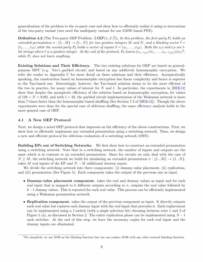
Definition 4.2 (The Two-party OEP Problem: 2-OEP(π, ~x,~t)). In this problem, the first party P1 holds anextended permutation π : {1...M} → {1...N} for two positive integers M and N , and a blinding vector ~t =(t1, . . . , tN ) while the second party P2 holds a vector of inputs ~x = (x1, . . . , xM ). Both the xis and tis are `-bit strings where ` is a positive integer. At the end of the protocol, P2 learns (xπ−1(1)⊕t1, . . . , xπ−1(N)⊕tN )3,while P1 does not learn anything.
Existing Solutions and Their Efficiency. The two existing solutions for OEP are based on general-purpose MPC (e.g. Yao’s garbled circuit) and based on any additively homomorphic encryption. Werefer the reader to Appendix C for more detail on these solutions and their efficiency. Asymptoticallyspeaking, the construction based on homomorphic encryption has linear complexity and hence is superiorto the Yao-based one. Interestingly, however, the Yao-based solution seems to be the more efficient ofthe two in practice, for many values of interest for N and `. In particular, the experiments in [HEK12]show that despite the asymptotic efficiency of the solution based on homomorphic encryption, for valuesof 128 < N < 8192, and with ` = 32, the garbled circuit implementation of the Waksman network is morethan 7 times faster than the homomorphic-based shuffling (See Section 7.2 of [HEK12]). Though the aboveexperiments were done for the special case of oblivious shuffling, the same efficiency analysis holds in themore general case of OEP.
4.1 A New OEP Protocol
Next, we design a novel OEP protocol that improves on the efficiency of the above constructions. First, weshow how to efficiently implement any extended permutation using a switching network. Then, we designa new and efficient protocol for oblivious evaluation of a switching network (OSN).
Building EPs out of Switching Networks. We first show how to construct an extended permutationusing a switching network. Note that in a switching network, the number of inputs and outputs are thesame which is in contrast to an extended permutation. Since for circuits we only deal with the case ofN ≥ M , the switching network we build for simulating an extended permutation π : {1...M} → {1...N},takes M real inputs of the EP and N −M additional dummy inputs.
We divide the switching network into three components: (i) dummy-value placement, (ii) replication,and (iii) permutation (See Figure 5). Each component takes the output of the previous one as input.
• Dummy-value placement component. takes the real and dummy values as input and for eachreal input that is mapped to k different outputs according to π, outputs the real value followed byk−1 dummy values. This is repeated for each real value. This process can be efficiently implementedusing a Waksman permutation network.
• Replication component. takes the output of the previous component as input. It directly outputseach real value but replaces each dummy input with the real input that precedes it. Each replacementcan be implemented using a 1-switch (with a single selection bit) choosing between rows 1 and 3 ofFigure 5 (a), as discussed in Section 2. The entire replication phase can be implemented using N − 1such switches. At the end of this step, we have the necessary copies for each real input and thedummy inputs are eliminated.
3For simplicity we use XOR as the blinding function but one can replace XOR with any other natural blinding function.
9

• Permutation component. takes the output of the replication component as input and permuteseach element to its final location as prescribed by π. Once again, this can be efficiently implementedusing a Waksman permutation network.
Size of the Switching Network for an EP. Adding up the three components, the total of number of1-switches needed to implement the extended permutation described above is 2(N logN−N+1)+N−1 =2N logN −N + 1.
Oblivious Evaluation of Switching Networks (OSN). Next, we design a new and efficient protocolfor oblivious evaluation of a generalized switching network. In this problem, P2 holds the input vector ~xwhile P1 holds the selection bits into the switching network, and a blinding vector ~t. P2 learns the outputof the network on his vector ~x blinded using vector ~t. We start with a high level overview. A completedescription appears in Figure 8 of Appendix D.
2-SW
ri
xj ⊕ rj
xi ⊕ ri
rj
rk
rl
(s1, s0)
y1
y2
xi ⊕ rk xi ⊕ rl
(s1, s0) y1
(0, 0)
y2
xi ⊕ rk xj ⊕ rl(0, 1)
xj ⊕ rk xi ⊕ rl(1, 0)
xj ⊕ rk xj ⊕ rl(1, 1) Dummy Placement
1-SW
1-SW
1-SW
Permutation
Permutation
Network
ReplicationPhase Phase Phase
Permutation
Network
Figure 5: (a) A 2-Switch (Left), (b) A Switching Network for an EP (Right)
Secure evaluation of a single 2-switch. The idea can be best explained by describing the procedurefor secure evaluation of a single 2-switch u in the network. Consider a 2-switch with input wires wi andwj and output wires wk and wl. P2 assigns four uniformly random values ri, rj , rk, rl to the four wires.P1 holds the blinded values xi ⊕ ri and xj ⊕ rj for the two input wires. The goal is to let P1 learn theblinded values for the output wires (see Figure 5). Particularly, depending on the value of his two selectionbits s0(u) and s1(u), P1 learns one of the four possible output pairs: (xi ⊕ rk, xj ⊕ rl), (xi ⊕ rk, xi ⊕ rl),(xj ⊕ rk, xi ⊕ rl), or (xj ⊕ rk, xj ⊕ rl).
To implement this step, P2 creates a table with four rows: (ri⊕rk, rj⊕rl), (ri⊕rk, ri⊕rl), (rj⊕rk, ri⊕rl),and (rj ⊕ rk, rj ⊕ rl) as shown in step 4 of Figure 8. Then, P1 and P2 engage in a 1-out-of-4 oblivioustransfer in which P2’s input is the four rows of the table he just created, and P1’s input is his two selectionbits for the switch u. Without loss of generality suppose that P1’s selection bits are 0, and 0. Hence, P1
retrieves the first row in the table, i.e. (ri⊕ rk, rj⊕ rl). He then XORs xi⊕ ri and ri⊕ rk to recover xi⊕ rkand XORs xj ⊕ rj and rj ⊕ rl to recover xj ⊕ rl, i.e. the blinded values for the output wires.
Evaluating the entire switching network. The above protocol can be extended to securely evaluatethe entire switching network in constant round. In an offline stage, P2 generates a set of random valuesfor every wire in the network, and computes a table for each as described above. Then, P1 and P2 engagein a series of parallel 1-out-of-4 oblivious transfers, one for each switch, where P1 learns a single row ofeach table according to his selection bits.
In the online stage, P2 blinds his input vector using the randomness for the input wires, and sends themto P1. P1 now has all the information necessary to evaluate the switches in the network in a topologicalorder, and recover the blinded values for the output wires (at this stage, P1 locally performs a sequenceof XORs discussed above). He then applies an additional layer of blinding using his random vector ~t, and
10

returns the result to P2. P2 can remove his own blinding (i.e. the randomness he generated for the outputwires in the network) to learn the output of the switching network blinded only with P1’s vector ~t.
The above OSN protocol runs in a constant number of rounds and requires one invocation of an oblivioustransfer per switch in the network. See Appendix D for a more detailed discussion of its efficiency. Wealso prove the following theorem in Appendix E.
Theorem 4.3. In the OT-hybrid model, the OSN protocol of Figure 8 (and the resulting OEP) is secureagainst semi-honest adversaries.
Efficiency of the new OEP. We can now evaluate the efficiency of the OEP protocol that results fromapplying our OSN construction to the switching network corresponding to an EP. As discussed earlier,the total number of switches needed to implement an extended permutation π : {1...M} → {1...N} is2N logN −N + 1. Furthermore, we only need to use 1-switches to implement an EP which means we onlyneed 1-out-of-2 OT as opposed 1-out-of-4 OT. This yields an OEP protocol with O(k) public-key operationsand 4N logN − 2N + 2 symmetric-key operations. The communication of the protocol is dominated byO(N logN) hash values.
Both our protocol and the Yao-based solution are constant round, and when OT extension is used,require the same number of public-key operations O(k).4 However, the number of symmetric-key operationsin our construction for a single Waksman network is 2N logN − 2N + 2 compared to the garbled circuitapproach of [HEK12] which requires 4`(N logN − N + 1)/3 + 2N` symmetric-key operations (assumingeach non-free gate requires four symmetric-key operations)5. This is a significant improvement speciallyas one considers larger values of `. For example for ` = 32 (which is used for comparison in [HEK12])our OSN protocol implementing the Waksman network, is approximately 25 times faster. Consideringthat the Yao-based solution is 7 times faster than HE-based shuffling, we obtain a factor of 175 efficiencygain over the HE-based approach. The bandwidth usage of our construction is also better by the samefactors. An additional advantage of our construction is a very cheap online phase that does not requireany cryptographic operations and only consists of XOR operations. For the same parameters, our SN-OEPconstruction is 161 times faster than HE-based OEP. For a detailed discussion refer to Appendix D.
How OSN Realizes FCT H Queries. It remains to show how our OSN implementation of OEP realizesthe queries in FCT H. While it is obvious that our OSN protocol securely performs all the OMAP/Revealqueries combined, for it to fully satisfy the CTH, we need the ability to make these queries on-demand.The On-demand property of the OSN protocol is discussed in Appendix G.
5 Efficient PFEs From MPC
5.1 Multi-Party Private Function Evaluation
In this section we apply our framework to the seminal GMW protocol to obtain a multi-party PFE variant.In particular, we need to describe how the CTH and the PGE functionalities are designed and then plugthem into the framework to obtain the desired multiparty PFE.
We implement the PGE functionality by means of a multi-party private gate evaluation (m-XOR-PGE(G, a, b)) protocol. In such a protocol, only P1 knows the functionality of the gate G while each partyholds his XOR share of the input bits a and b and obtains his XOR share of the output bit G(a, b). In Ap-pendix H we show a simple construction for this problem based on any multiparty OT (e.g. see [FGM07]).
4The Yao-based solution requires O(N`) OTs. Hence, as long as N` > k, the number of public-key operations in theYao-based solutions and our protocol are the same.
5The numbers are derived from the size of optimized circuits for Waksman networks given in [HEK12]
11

The protocol requires the same number of OTs as a single gate evaluation in the standard GMW. Hence,making the gate functionality private comes for free in terms of computation or communication.
For the CTH functionality, we can use the multiparty variant of either the HE-OEP or the SN-OEPconstructions discussed earlier, where each party uses his XOR shares of the outgoing wires as input tothe OEP and obtains his share of the value for the incoming wires.
The following theorem is implied by the security of our framework (Theorem 3.1), secure instantiationsof the OEP and the PGE functionalities and a standard sequential composition theorem [Can00].
Theorem 5.1. Given that the OEP and m-XOR-PGE protocols are secure against semi-honest adversaries,the Multi-Party PFE protocol based on our framework is also secure against semi-honest adversaries.
Efficiency. The resulting protocol requires a single invocation of the m-OEP protocol (even though theprotocol is executed in an on-demand fashion), and one invocation of the m-XOR-PGE per gate. Using theHE-OPE instantiation, we obtain a protocol with linear complexity (linear number of exponentiations),and using the SN-OPE, we obtain a protocol that uses O(m2g +mg log g) invocations of OT (O(m2g) forthe PGE and O(mg log g) for the OEP). The number of rounds is equal to the number of gates since theyare evaluated sequentially.
5.2 Private Function evaluation for Arithmetic Circuits
In this section we apply the same framework to secure 2PC for arithmetic circuits.
PGE for Arithmetic Circuits. Let E = (Gen,Enc,Dec) be a semantically secure and additively homo-morphic encryption scheme. Suppose a = [a]1 + [a]2 and b = [b]1 + [b]2 are the inputs to the gate, andc = [c]1 + [c]2 is the output of the gate (where the addition occurs over the domain of plaintexts for theencryption scheme). [a]i, [b]i, [c]i are the shares of Pi. In order to hide the functionality of the gate, wedesign a PGE protocol in which P2’s actions are independent of the functionality of the gate (i.e. additionor multiplication). To achieve this, P2 sends to P1 encryption of [a]2, [b]2, and [a]2[b]2. Given these threeciphertexts, P1 can compute an encryption of both the sum and the product of a and b using homomorphicproperties of the scheme. He then sends an encrypted random shares of the outcome to P1 to decrypt.A detailed description of the protocol appears in Appendix I. It is easy to see that the protocol is secureagain semi-honest adversaries if the encryption scheme is semantically secure. We omit the proof of thefollowing theorem.
Theorem 5.2. Given E = (Gen,Enc,Dec) a semantically secure encryption scheme, 2-Arith-PGE protocolis secure against semi-honest adversaries.
We plug in the above PGE and our HE-OEP protocols in our general framework to obtain an efficientand secure 2PC for arithmetic circuits with linear complexity. The following theorem is implied by thesecurity of our framework (Theorem 3.1), secure instantiations of the OEP and the PGE functionalitiesand a standard sequential composition theorem [Can00].
Theorem 5.3. Given that the OEP and 2-Arith-PGE protocols are secure against semi-honest adversaries,the 2-Party Arithmetic PFE protocol based on our framework is secure against semi-honest adversaries.
Efficiency. Each PGE invocation requires a constant number of public-key operations adding up to atotal of O(g) public-key operations. The HE-OEP has a linear complexity leading to a PFE protocolwith similar complexity. The number of rounds is equal to the number of gates since they are evaluatedsequentially.
12

5.3 A Constant-round Two-party PFE
In this section we apply the PFE framework to Yao’s garbled circuit protocol. We only describe the highlevel ideas here. A full description of the protocol (2-PFE) appears in Figure 10. At first sight, it may notbe obvious how to interpret the sharing mechanism in Yao’s protocol. But a closer look at the garblingand evaluation steps reveals that the bit value a for a wire in the circuit is shared by having P2 (garbler)hold the mapping of a pair of random keys to their bit value (k0 → [a]2,k1 → [a]2), and P1 (the evaluator)holding one of the two keys (k[a]1). Note that one may wonder why we do not simplify the sharing schemeby always letting [a]2 = 0. But such a sharing would indeed be insecure in our PFE framework, and morespecifically would allow the evaluator to learn values for the intermediate wires as he evaluates the circuit(since he creates and knows the mapping of keys). Making the CTH component work with this sharingscheme turns out to be the main technical difficulty in designing an efficient Yao-base PFE.
General Idea. Recall Yao’s garbled circuit protocol in the semi-honest case. In our construction, theevaluator is the party who holding the circuit, while we intend to hide the circuit from the garbler. Weneed to hide the topology of the circuit from him using the CTH functionality: first, the Garbler generateshis own random shares for the output wires of all the gates in the circuit (i.e. the permuted garbled keypairs for all those wires). Next, he sends all his shares to the CTH functionality, and receives his outputwhich are his shares for the input wires to all the gates in the circuit (i.e. garbled key pairs for all thosewires). The garbler now has all garbled keys he needs to garbled circuit. If we assume that all the gatesare NAND, there would be no need to hide the gates functionalities. Therefore, our FPGE functionalityrealization consists of the normal garbling of the gate by the garbler and the standard evaluation of thegates by the evaluator. Next, we go into the details of each component and address some of the subtletiesthat arise.
PGE realization. Realization of the FPGE functionality is simple. Lets assume that the inputs are sharedusing the above sharing scheme. P2 first randomly generates his own share of the output wire for the currentgate, which is basically generating two random keys and assigning them to bits zero and one. He thensends his share to CTH functionality. Upon receiving his shares for input wires to the gates, from CTHfunctionality, P2 garbles each gate using his shares for the input and output wires of the gate. He thensends the garbled gates to P1 who can use his own share of the input wires to ungarble a single row andlearn his own share of the output wire.
We now need to integrate our CTH realization with the above PGE construction. For this to work, weneed to modify our standard CTH realization, particularly to make sure that its outputs are fresh sharesbased on the sharing scheme above (i.e. [a]1 and [a]2, and the key pair are fresh and random).
Achieving constant round protocol. Given a correct CTH realization, it is possible to design aconstant-round version of the protocol. Note that P2’s shares for all the outgoing wires can be generatedby him at random and in the beginning of the protocol (without interaction with P1). At this stage, partiescan indeed execute the CTH functionality in its entirety for P2 to learn his fresh random shares for the 2gincoming wires to the circuit. The only difference comparing to our framework is that P1 does not learn hisshares for the intermediate wires until later (in the evaluation). Also, note that P2’s portion of PGE is onlybased on his own randomly generated shares and thus can be done at once and without interaction with P1
for each gate. In particular, he garbles all the gates using the keys he obtained from the CTH functionalityand sends the garbled gates to P1. P1 then performs his portion of the gate evaluation, evaluating the gatesin topological order to obtain his share of each incoming wire and eventually the output wires. During theevaluation (ungarbling) phase, when P1 retrieves a garbled key for an output of a gate in the circuit, heneeds to XOR it with its corresponding blinding value(s) to obtain his correct input share for evaluating
13

G2
G1
ow6
ow7
y1
y2
G3
G4
iw5
iw6
iw3
iw4
iw1
iw2
iw7
iw8
ow1ow2ow3ow4ow5
kv11 , kv11
kv22 , kv22
kv33 , kv33
kv44 , kv44
kv55 , kv55
kv66 , kv66
kv77 , kv77
kv88 , kv88
kv99 , kv99
2. P2 sends
1. P2 generates the keys and v
k03 ⊕ t1|k13 ⊕ t2|v′′1 = 0
v′ = {0, 0, 0, 0, 1, 1, 1, 1}v = {0, 1, 0, 1, 0, 1, 0, 1}
k14 ⊕ t3|k04 ⊕ t4|v′′2 = 1
k03 ⊕ t1|k13 ⊕ t2
k04 ⊕ t4|k14 ⊕ t3
k01 ⊕ t5|k11 ⊕ t6|v′′3 = 0
k12 ⊕ t7|k02 ⊕ t8|v′′4 = 1
k01 ⊕ t5|k11 ⊕ t6
k02 ⊕ t8|k12 ⊕ t7
k16 ⊕ t9|k06 ⊕ t10|v′′5 = 1
k07 ⊕ t11|k17 ⊕ t12|v′′6 = 0
k06 ⊕ t10|k16 ⊕ t9
k07 ⊕ t11|k17 ⊕ t12
k17 ⊕ t13|k07 ⊕ t14|v′′7 = 1
k05 ⊕ t15|k15 ⊕ t16|v′′8 = 0
k07 ⊕ t14|k17 ⊕ t13
k05 ⊕ t15|k15 ⊕ t16
3. P2 receives 4. P2 swaps them
the CTH results based on v′′.
5. P2 starts the Yao’s garbled circuits using these values as key
to CTHv′′ = v ⊕ v′
Figure 6: CTH realization of our 2-PFE protocol, applied to the example of figure 1.
the next garbled gate. Since P1 knows πC and all the blinding values, he has the necessary informationto perform this step. He then asks P2 for his share of the output wires of the circuit (i.e. the translationtable in standard Yao) to determine his actual output. P1’s shares of his inputs wires are delivered to himusing one OT per wire (as done in standard Yao).
CTH realization. During the evaluation, P1 needs to XOR his share with its corresponding blindingvalue(s) to obtain his correct input share for evaluating the next garbled gate. But observing which blindingvalue enables correct decryption of the next garbled gate (potentially) reveals the value of that intermediatewire. To avoid this issue, we need to ensure that the shares generated by the CTH are truly random. Inparticular, we need to ensure that P1 cannot the first blinding to the key 0 and the second blinding withkey 1. As a first solution, P2 randomly swaps the key pairs to prevent such association by P1.
• P2 swaps each key pair randomly. We solve this problem by having P2 swap each key pairrandomly and independently (using a random bit-vector ~v) before using them in the OMAP queries(for the CTH). Steps 1 and 2 of figure 6 demonstrate this fix. Each pair should be swapped usinga different bit since using the same bit would reveal whether the bit values for certain intermediatewires are the same or not. If the first(second) blinding is used for two or more wires we learn thattheir value is the same, though we don’t know if it zero or one. This solves the issue above, butundermines correctness of the protocol. When P2 sends the swapped key pairs to P1, he gets back anextended permuted (and blinded) set of key pairs. As a result, P2 does not know the correct orderfor each pair, and will not be able to perform the garbling of the gates without knowing which keyis for 0 and which is for 1.
14

• P1 and P2 jointly swap each key pair into its original form. A naive fix would be to attacheach “swapping bit” to its corresponding key pair as it goes through the CTH, and reveal the bitto P2 as part of the output of the CTH, who then uses it to swap the key pair back to its originalorder. But this would allow P2 to learn some information about πC (and the topology of the circuit)by comparing the swapping bits in the input and output key pairs for the CTH.
To address this issue, P1 and P2 perform this step together, each holding an XOR share of swappingbits. In particular, the random bit vector ~v will be fed to the CTH (see step 4a of the protocol),but P2 only learns a blinded version, i.e. v′′i = vπ−1(i) ⊕ v′i for 1 ≤ i ≤ 2g, where the blinding vector~v′ = (v′1, . . . , v
′2g) is only known to P1. To swap each key pair back to its original order, P1 first swaps
the pair using v′i (step 3 of figure 6), and sends it to P2. P2 then swaps it one more time using v′′iwhich puts the key pair back in its original order (step 4 of figure 6). Of course, at this point, thekey shares are fresh and random.
If we use a homomorphic-based OEP, this solution is sufficient (see section 5.4), but when using theCTH functionality in a black-box way, and particularly when using our SN-OEP construction, thereis one more issue to address. The described solution does not use the OEP in a black-box fashion,since P1 needs to swap the outcome using ~v′, before sending it to P2. But if the pair is swapped usinga random bit vector not known to P2, he cannot use the appropriate random values to unblind theresult (recall the final step of the OEP where P2 removes his blinding from the output).
• P1 does his swapping using an OSN protocol. To handle this problem, we require that P1’sswapping procedure based on the bit-vector ~v′ takes place as part of an oblivious switching networkevaluation where the v′is are P1’s selection bits to the network. This requires the use of an addi-tional layer of switches attached to the original switching network for the OEPs (see Figure 11 ofAppendix J). This also has the advantage of making the usage of the OEP and the OSN protocolsblack-box.
We prove the following theorem in Appendix J.2.
Theorem 5.4. Given that the OSN and the OEP protocols are secure against semi-honest adversaries,and that Yao’s protocol uses a symmetric-key encryption with related-key security, the 2-PFE protocol issecure against semi-honest adversaries.
5.4 Further Optimizations and Efficiency
Combining the switching networks into one. For ease of composition, and to make the constructionsconceptually easier to understand, in Figure 10 we describe four separate switching networks, one for theOEP , and three for SN0,SN1, and SN2. But since SN0 and SN1 implement πc, we can use a singleswitching network that concatenates their inputs. As a result, the computation (number of oblivioustransfers) reduces by a factor of two. The switching network SN2 still needs to be evaluated separately.
A simpler protocol based on homomorphic encryption. As mentioned earlier, the switching net-work SN2 is not needed when we implement the OSN using a homomorphic encryption scheme. Theintuition is that P2 can still decrypt the outcome of the OSN protocol without knowing the correct swap-ping bit used by P1
6. The resulting 2-PFE is more efficient than the protocol of Katz and Malka [KM11].The main reason is that we blind each key by homomorphically adding a random value to it, while theyneed to apply a universal hashing procedure that requires both a homomorphic addition and a multiplica-tion to blind each key. This is a noticeable improvement since homomorphic multiplication is often more
6Since the final unblinding step in the homomorphic-based OEP is simply to decrypt the obtained ciphertexts.
15

expensive as it requires exponentiation. The reason for the universal hashing is to allow P1 to evaluatethe garbled circuit without learning the values for the intermediate wires (the same hashing is applied toboth keys in the pair). But, we solve this problem via use of swapping bit vectors (~v, ~v′), which can beconcatenated to the end of each key pair as it is being encrypted, hence avoiding any additional cost.
Efficiency of the SN-OEP instantiation. When using our SN-OEP in the above construction, thetotal number of symmetric operations required for the protocol is 8g log 2g+5g+2. We discuss the efficiencyin detail in Appendix J.1 and show that our protocol is a factor of 142 more efficient than the PFE protocolof [KM11], , for wide range of circuit sizes. We also show that it is 2 times more efficient than applyingYao’s garbled circuits to Valiant’s universal circuit construction, and 3-6 times faster than applying Yao’sgarbled circuits to universal circuit construction of [KS08a], for the benchmark circuits such as AES, RSAand Edit-distance. For the latter two constructions, we assume that they take full advantage of free XORgates and in particular that 3/4 of the gates in the Universal circuit are XOR gates that computed for free.
Acknowledgements. We would like to thank an Anonymous EUROCRYPT reviewer for very helpfuldiscussions on efficiency of our two-party PFE and the comparison of its efficiency with the Valiant-baseduniversal circuit approach.
References
[AF90] Martin Abadi and Joan Feigenbaum. Secure circuit evaluation. Journal of Cryptology, 2:1–12,1990.
[AHI10] Benny Applebaum, Danny Harnik, and Yuval Ishai. Semantic security under related-key attacksand applications. 2nd Symp. on Innovations in Computer Science (ICS), 2010. Available athttp://eprint.iacr.org/.
[Bea95] Donald Beaver. Precomputing oblivious transfer. In Don Coppersmith, editor, Advances inCryptology CRYPT0 95, volume 963 of Lecture Notes in Computer Science, pages 97–109.Springer Berlin / Heidelberg, 1995.
[BFK+09] Mauro Barni, Pierluigi Failla, Vladimir Kolesnikov, Riccardo Lazzeretti, Ahmad-Reza Sadeghi,and Thomas Schneider. Secure evaluation of private linear branching programs with medicalapplications. In Proceedings of the 14th European conference on Research in computer security,ESORICS’09, pages 424–439, Berlin, Heidelberg, 2009. Springer-Verlag.
[BPSW07] J. Brickell, D.E. Porter, V. Shmatikov, and E. Witchel. Privacy-preserving remote diagnostics.In Proceedings of the 14th ACM conference on Computer and communications security, pages498–507. ACM, 2007.
[Can00] R. Canetti. Security and composition of multiparty cryptographic protocols. Journal of Cryp-tology, 13(1):143–202, 2000.
[CDN01] Ronald Cramer, Ivan Damgard, and Jesper Buus Nielsen. Multiparty computation from thresh-old homomorphic encryption. In Proceedings of the International Conference on the Theory andApplication of Cryptographic Techniques: Advances in Cryptology, EUROCRYPT ’01, pages280–299, London, UK, UK, 2001. Springer-Verlag.
16

[CHK+12] Seung Geol Choi, Kyung-Wook Hwang, Jonathan Katz, Tal Malkin, and Dan Rubenstein.Secure multi-party computation of boolean circuits with applications to privacy in on-linemarketplaces. In Proceedings of RSA 2012, Cryptographers’ Track (CT-RSA), 2012.
[Du01] Wenliang Du. A Study of Several Specific Secure Two-party Computation Problems. PhDthesis, Department of Computer Sciences, Purdue University, 2001.
[FGM07] M. Franklin, M. Gondree, and P. Mohassel. Multi-party indirect indexing and applications.Advances in Cryptology–ASIACRYPT 2007, pages 283–297, 2007.
[Gen09] Craig Gentry. Fully homomorphic encryption using ideal lattices. In Proceedings of the 41stannual ACM symposium on Theory of computing, STOC ’09, pages 169–178, New York, NY,USA, 2009. ACM.
[GHS10] R. Gennaro, C. Hazay, and J. Sorensen. Text search protocols with simulation based security.Public Key Cryptography–PKC 2010, pages 332–350, 2010.
[GMW87] O. Goldreich, S. Micali, and A. Wigderson. How to play any mental game. In Proceedings ofthe nineteenth annual ACM symposium on Theory of computing, STOC ’87, pages 218–229,New York, NY, USA, 1987. ACM.
[Gol04] O. Goldreich. Foundations of cryptography: Basic applications. Cambridge Univ Pr, 2004.
[HEK12] Yan Huang, David Evans, and Jonathan Katz. Private set intersection: Are garbled circuitsbetter than custom protocols? In Proceedings of 19th Network and Distributed Security Sym-posium (NDSS), 2012.
[HEKM11] Yan Huang, David Evans, Jonathan Katz, and Lior Malka. Faster secure two-party computationusing garbled circuits. In Proceedings of the 20th USENIX conference on Security, SEC’11,pages 35–35, Berkeley, CA, USA, 2011. USENIX Association.
[IKNP03] Y. Ishai, J. Kilian, K. Nissim, and E. Petrank. Extending oblivious transfers efficiently. Ad-vances in Cryptology-CRYPTO 2003, pages 145–161, 2003.
[IP07] Yuval Ishai and Anat Paskin. Evaluating branching programs on encrypted data. In Proceedingsof the 4th conference on Theory of cryptography, TCC’07, pages 575–594, Berlin, Heidelberg,2007. Springer-Verlag.
[KM11] Jonathan Katz and Lior Malka. Constant-round private function evaluation with linear com-plexity. In Dong Lee and Xiaoyun Wang, editors, Advances in Cryptology ASIACRYPT 2011,volume 7073 of Lecture Notes in Computer Science, pages 556–571. Springer Berlin / Heidel-berg, 2011.
[KS08a] Vladimir Kolesnikov and Thomas Schneider. Financial cryptography and data security. chapterA Practical Universal Circuit Construction and Secure Evaluation of Private Functions, pages83–97. Springer-Verlag, Berlin, Heidelberg, 2008.
[KS08b] Vladimir Kolesnikov and Thomas Schneider. Improved garbled circuit: Free xor gates andapplications. In Automata, Languages and Programming, volume 5126 of Lecture Notes inComputer Science, pages 486–498. Springer Berlin / Heidelberg, 2008.
[KSS12] Benjamin Kreuter, Abhi Shelat, and Chih-Hao Shen. Billion-gate secure computation withmalicious adversaries. In Proceedings of the 21st USENIX conference on Security symposium,Security’12, pages 14–14, Berkeley, CA, USA, 2012. USENIX Association.
17

[Lip05] H. Lipmaa. An oblivious transfer protocol with log-squared communication. In Proceedingsof the 8th Information Security Conference (ISC’ 05), volume 3650, pages 314–328. Springer,2005.
[LP07] Y. Lindell and B. Pinkas. An efficient protocol for secure two-party computation in the presenceof malicious adversaries. pages 52–78. Springer, 2007.
[LP09] Yehuda Lindell and Benny Pinkas. A proof of security of yao’s protocol for two-party compu-tation. Journal of Cryptology, 22:161–188, 2009.
[MNPS04] Dahlia Malkhi, Noam Nisan, Benny Pinkas, and Yaron Sella. Fairplay - a secure two-partycomputation system. In Proceedings of the 13th conference on USENIX Security Symposium -Volume 13, SSYM’04, pages 20–20, Berkeley, CA, USA, 2004. USENIX Association.
[NNOB21] Jesper Buus Nielsen, Peter Sebastian Nordholt, Claudio Orlandi, and Sai Sheshank Burra.A new approach to practical active-secure two-party computation. Advances in Cryptology–CRYPTO 2012, 2021.
[NP01] Moni Naor and Benny Pinkas. Efficient oblivious transfer protocols. In Proceedings of the twelfthannual ACM-SIAM symposium on Discrete algorithms, SODA ’01, pages 448–457, 2001.
[PSS09] Annika Paus, Ahmad-Reza Sadeghi, and Thomas Schneider. Practical secure evaluation ofsemi-private functions. In Proceedings of the 7th International Conference on Applied Cryp-tography and Network Security, ACNS ’09, pages 89–106, Berlin, Heidelberg, 2009. Springer-Verlag.
[PSSW09] Benny Pinkas, Thomas Schneider, Nigel Smart, and Stephen Williams. Secure two-party com-putation is practical. In Mitsuru Matsui, editor, Advances in Cryptology ASIACRYPT 2009,volume 5912 of Lecture Notes in Computer Science, pages 250–267. Springer Berlin / Heidel-berg, 2009.
[PVW08] C. Peikert, V. Vaikuntanathan, and B. Waters. A framework for efficient and composableoblivious transfer. Advances in Cryptology–CRYPTO 2008, pages 554–571, 2008.
[Raz08] R. Raz. Elusive functions and lower bounds for arithmetic circuits. In Proceedings of the 40thannual ACM symposium on Theory of computing. ACM, 2008.
[Sch08] Thomas Schneider. Practical secure function evaluation, 2008.
[SS09] Ahmad-Reza Sadeghi and Thomas Schneider. Information security and cryptology — icisc2008. chapter Generalized Universal Circuits for Secure Evaluation of Private Functions withApplication to Data Classification, pages 336–353. Springer-Verlag, Berlin, Heidelberg, 2009.
[SY10] A. Shpilka and A. Yehudayoff. Arithmetic circuits: A survey of recent results and open ques-tions. 2010.
[Val76] L.G. Valiant. Universal circuits (preliminary report). In Proceedings of the eighth annual ACMsymposium on Theory of computing, pages 196–203. ACM, 1976.
[Wak68] Abraham Waksman. A permutation network. J. ACM, 15:159–163, January 1968.
18

[WLG+10] Guan Wang, Tongbo Luo, Michael T. Goodrich, Wenliang Du, and Zutao Zhu. Bureaucraticprotocols for secure two-party sorting, selection, and permuting. In Proceedings of the 5thACM Symposium on Information, Computer and Communications Security, ASIACCS ’10,pages 226–237, New York, NY, USA, 2010. ACM.
[Yao86] Andrew Chi-Chih Yao. How to generate and exchange secrets. In Foundations of ComputerScience, 1986., 27th Annual Symposium on, pages 162 –167, oct. 1986.
A Security Definitions
A.1 Oblivious Transfer
Our protocols use Oblivious Transfer (OT) as a building block. Since we focus on protocols that run inconstant rounds, we describe an abstraction for a one-round OT protocol here. A One-round OT involvesa server holding a list of t secrets (s1, s2, . . . , st), and a client holding a selection index i. The client sendsa query q to the server who responds with an answer a. Using a and its local secret, the client is able torecover si.
More formally, a one-round 1-out-of-t oblivious transfer (OT t1) protocol is defined by a tuple of PPTalgorithms OT t1 = (GOT,QOT,AOT,DOT). The protocol involves two parties, a client and a server wherethe server’s input is a t-tuple of strings (s1, . . . , st) of length τ each, and the client’s input is an indexi ∈ [t]. The parameters t and τ are given as inputs to both parties. The protocol proceeds as follows:
1. The client generates (pk, sk)← GOT(1k), computes a query q ← QOT(pk, 1t, 1τ , i), and sends (pk, q)to the server.
2. The server computes a← AOT(pk, q, s1, . . . , st) and sends a to the client.
3. The client computes and outputs DOT(sk, a).
In case of semi-honest adversaries, many of the OT protocols in the literature are one-round, and secureagainst parallel compositions (e.g. see [NP01, Lip05, PVW08]).
A.2 Secure Two-party Computation
Let f = (f1, f2) of the form f : {0, 1}∗ × {0, 1}∗ → {0, 1}∗ × {0, 1}∗ be a two party computation and Π bea two-party protocol for computing f between the parties p1 and p2. The input of p1 is x and the input ofp2 is y. We briefly review the simulation-based notion of security for secure two-party computation here,focusing on the case where the adversary is semi-honest.
A.2.1 Security Against Semi-Honest Adversaries
Readers can refer to [Gol04] for a detailed discussion. Security for a two-party computation is defined byrequiring indistinguishability (either perfect, statistical or computational) between a real execution of theprotocol and an ideal execution in which there is a TTP (trusted third party) who receives the partiesinput, evaluates the function and outputs the results to them. Consider a semi-honest and admissibleadversary A. An admissible adversary is one that corrupts exactly one of the two party. A also knows anauxiliary input z. Without loss of generality we assume the A corrupts the first party.
In the real world, the honest party follows the description of protocol Π as instructed and responds tomessages sent by A on behalf of the other party. Let viewΠ,A(x, y) denote A’s view through this interaction,and let outΠ(x, y) denote the output of the honest party. The execution of Π in the real model on inputpair (x, y) is defined as follows:
19

REALΠ,A(z)(x, y)def= (viewΠ,A(x, y), outΠ(x, y))
In the ideal model, in which there is a TTP, both parties send their inputs to TTP. The trusted partyreplies with f1(x, y) to the first party and with f2(x, y) to the second party. The honest party outputswhatever is sent by the trusted party, and A outputs an arbitrary function of its view. Let outf,A(x, y)and outf (x, y) denote the output of A and the honest party respectively in the ideal model. The executionof Π in the ideal model on input pair (x, y) is defined as follow:
IDEALf,A(z)(x, y)def= (outf,A(x, y), outf(x, y))
Definition A.1. We say that Π securely computes f in the presence of static malicious adversaries if forevery pair of admissible non-uniform probabilistic polynomial-time machines A = (A1, A2) in the real model,there exists a pair of admissible nonuniform probabilistic expected polynomial-time machines B = (B1, B2)in the ideal model, such that {
IDEALf,B(x, y)}≡{
REALΠ,A(x, y)}
Namely the two distributions are indistinguishable.
A.2.2 The OT hybrid model
We use the OT hybrid model to prove the security of our proposed protocols. In the OT hybrid model(e.g. see [Can00, LP07]), it suffices to analyze the security of a protocol in a hybrid model in which theparties interact with each other and have access to a trusted party (ideal functionality) that computes theoblivious transfer protocol for them. This model is a hybrid of the real and ideal models: on the one hand,the parties send regular messages to each other, similar to the real model; on the other hand, the partieshave access to a trusted party, similar to the ideal model.
B Proof of Security for the PFE Framework
We note that to make our PFE Framework conceptually simpler, we described it as a black-box constructionbased on the FCT H, and the FPGE functionalities. However, for the purpose of the security proof, it isuseful to break down the FCT H functionality into a sequence of calls to the OMAP functionality, and replacecalls to the Reveal queries with a message from P1 to other parties with their blinded shares (which theycan unblind). With this new interpretation, the whole framework can be seen as a series of sequential callsto the OMAP functionality and the PGE functionality. As a result, given the security of the frameworkwith access to these ideal functionalities, and secure instantiation of each functionality, we can invoke theexisting sequential composition theorems [Can00] to obtain security for the resulting PFE constructions.In light of this discussion, we prove security of our framework given access to the ideal OMAP and PGEfunctionalities.
Proof. Case 1: P1, . . . , Pm−1 are corrupted.Simulation. For any PPT adversary A1, controlling P1, . . . , Pm−1 in the real world, we describe a
simulator S1 who simulates A1’s view in the ideal world. S1 runs A1 on input shares of P1, . . . , Pm−1 andcircuit C (with mapping πC).
1. S1 sends the inputs of P1, . . . , Pm−1 and the circuit C (part of P1’s input to the TTP. It receives theo output values out1, . . . , outo, as the outcome of evaluating the circuit C on all the parties’ input(including honest Pm).
20
2. A1 distributes shares of inputs for P1, . . . , Pm−1 to S1. S1 then generates a fake input on behalf ofPm and distributes the shares of all parties by sending their shares to A1.
3. S1 and A1 send shares of the inputs they just distributed to the OMAP functionality. S1 also sendsa blinding vector ~km on behalf of Pm while A1 sends a vector of blinding vectors ~t1, . . . ,~tm. As aresult, A1 receives blinded shares of a subset of the incoming wires in the circuit.
4. For 1 ≤ j ≤ g:
• A1 sends the blinded shares he holds for the two incoming wires of gate Gj to S1, which S1
unblinds using ~km to retrieve [a′]jm and [b′]jm.
• S1 sends [a′]jm and [b′]jm to FPGE ideal functionality while A1 sends [a′]ji , [b′]ji for 1 ≤ i < m and
Gj to the PGE. As a result, S1 gets back [c′]jm.
• S1 sends [c′]jm to the OMAP functionality while A1 sends all other parties shares. Once againA1 receives blinded shares of a subset of the incoming wires in the circuit (those connected tooutputs of Gj).
5. For g − o < j ≤ g: A1 reveals the shares [c′]j1, . . . , [c′]jm−1 of the output of Gj . S1 who has obtained
the output outg−j corresponding to this gate earlier in the simulations, computes an appropriate
shares [c′′]jm, such that a reconstruction of the shares returns outg−i and sends [c′′]jm to A1.
This ends the description of the simulator S1.Indistinguishability of the views. It is easy to see that the ideal and real distributions defined in
Definitions of Appendix A.2.1 are indistinguishable. In particular, in both the real and the ideal worlds,all messages seen by A1 are uniformly random shares except in the final step where shares of the outputof the circuit are revealed. In the latter case, however, A1’s view in both worlds consist of random sharesof the correct outputs values i.e. out1, . . . , outo. This completes the security argument for this corruptioncase.
All other corruption scenarios where P1 is one of the corrupted parties, can be simulated in an identicalfashion. It remains to show that efficient simulation is possible in the case where P2, . . . , Pm are corruptedby the adversary.
Case 2: P2, . . . , Pm are corrupted. the simulation in this case is essentially the same as the previouscase. Note that in this case the simulator needs to play the role of honest P1, and consequently not onlychoose a fake input for P1 but also create and use a fake circuit with n inputs, g gates and o outputs. Butthis does not effect the adversaries view as one again, he only sees random shares for all the intermediatewires, and the o outputs of the circuit. We omit the details of the proof for this case.
C Existing OEP Solutions and Their Complexity
We briefly review the existing methods for designing an OEP and compare their efficiency.
Using General-Purpose 2PC. Obviously, the OEP problem can be solved using any general 2PCprotocol. For instance, one can first implement the functionality of an extended permutation using aswitching network (we show how to do so in Section 4.1). Then, P1 and P2 can engage in a Yao’s garbledcircuit protocol where P1’s inputs are the selection bits to the network and his blinding vector ~t, and P2’s
21

input is the input vector ~x. The boolean circuit being computed consists of the circuit for the switchingnetwork, and some additional gates to blind the network’s output using ~t.
For an EP from M inputs to N outputs, the number of switches required in the switching network willbe in the order of O(N logN) which leads to a circuit with O(N logN`) gates; P1 has O(N logN + N`)input bits in the circuit (O(N logN) for the selection bits and O(N`) for the blinding vector), and P2 hasO(M`) input bits in the circuit.
Kolesnikov and Schneider [KS08a], describe a construction for a similar circuit (called expanded per-mutation) as part of designing an efficient universal circuit. They also show how one can take advantageof the free-XOR optimization techniques [KS08b] in Yao’s garbled circuit to reduce the number of non-freegates for each switch by 75%.
Katz et al. [HEK12] proposed a similar protocol for the special case of oblivious permutation networkevaluation (referred to as a shuffling network in their paper). They use the Waksman [Wak68] switchingnetwork which consists of O(N logN) switches, and employ oblivious swappers to implement each switch.Several optimization techniques are used to improve the implementation of these swappers in a garbledcircuit construction. According to their estimates, the total number of non-free gates (i.e. total numberof gates minus the number of XOR gates) for the whole circuit is `(N logN − N + 1)/3 (See Table 1of [HEK12]).
Using Homomorphic Encryption (HE-OEP). It is also possible to use a semantically secure singlyhomomorphic encryption scheme to design an OEP protocol. In this protocol P2, the party holding theinput vector ~x generates and sends a public key pk for the scheme E = (Gen,Enc,Dec) to P1. P2 thenencrypts his inputs (x1, . . . , xM ) and sends them to P1:
P2 sends Encpk(x1), . . . ,Encpk(x|M |) to P1
P1 in return applies the EP by replicating and permuting the received ciphertexts as prescribed by πC .He then uses the homomorphic properties of encryption scheme to add/multiply his blinding values andsends the result to P2.
P1 sends Encpk(xπ−1C (1) + t1), . . . ,Encpk(xπ−1
C (N) + tN ) to P2
P2 decrypts the ciphertexts and recovers the final result. This approach requiresO(N) encryption/decryptionand O(N) homomorphic operations on the ciphertexts. Note that in the above construction, the blindingfunction is not necessarily an XOR operation. The exact operation depends on the particular homomorphicencryption scheme being used.
Efficiency Discussion. Asymptotically speaking, the construction based on homomorphic encryptionhas linear complexity and hence is superior to the Yao-based one. Interestingly, however, the Yao-basedsolution seems to be the more efficient of the two in practice, for many values of interest for N and `.The latter conclusion is based on the recent experimental results provided in [HEK12]. In this paper, theauthors implement an oblivious shuffling protocol using both approaches, and compare their efficiency. Inparticular, the authors show that despite the asymptotic efficiency of the solution based on homomorphicencryption, for values of 128 < N < 8192, and with ` = 32, the garbled circuit implementation of theWaksman network is more than 7 times faster than the homomorphic-based shuffling (See Section 7.2of [HEK12]). The homomorphic-based solution does not lead to any savings in the bandwidth either.Though the above analysis is done for permutation mappings, we note that the same efficiency analysisholds in the more general case of extended permutations.
22

D Complete Description of OSN Protocol
Efficiency of the OSN Protocol. We analyze, round, computation and communication complexity ofthe above protocol.Round complexity. Given that we can run the oblivious transfers in parallel, our protocol runs in one anda half rounds (three messages). P1 sends his OT queries to P2. P2 replies with the OT responses and hisblinded inputs to P1. P1 then evaluates the switching network and sends the blinded outputs back.Computation. The only cryptographic operation in the above OSN protocol is oblivious transfer. Thenumber of 1-out-of-4 OTs is equal to the number of switches in the network, i.e. q. By employing theOT extension techniques [IKNP03], this only requires O(k) public-key operations where k is a statisticalsecurity parameter, and O(q) symmetric-key operations (4q hash evaluations to be precise). Using the OTpreprocessing techniques of [Bea95], the above computation can be performed in an offline stage, and theonline stage will only consist of O(q) XOR operations.
Efficiency of SN-OEP. The number of symmetric operations in our SN-OEP protocol is 4N logN −2N + 2. To get a number of symmetric operations in Yao-OEP we use the number of gates required for aWN from [HEK12] and extend it to the full OEP, which would be `(2N logN −N + 1)/3. This translatesto 4`(N logN − N + 1)/3 + 2N` symmetric operations. By plugging in the parameters from [HEK12]` = 32, N = 128 and ` = 32, N = 8192, and comparing the number of symmetric operations we get anaverage of 23 time improvement over Yao-OEP. Considering that Yao-OEP is 7 times faster than HE-OEP,we get factor of 161 efficiency gain over HE-OEP.
E Security Proof for the OSN and the OEP Protocols
We show that as long the oblivious transfer protocol used is secure, so is our protocol. Particularly, if theOT is secure against semi-honest adversaries when executed in parallel, the OSN protocol described aboveis also secure against semi-honest adversaries.
The proof also implies the security of our OEP protocol since our OEP construction simply runs theOSN protocol on the switching network for the EP. The following Theorem formalizes this statement.
Theorem E.1. In the OT-hybrid model, the OSN protocol is secure against semi-honest adversaries.
Proof. Our proof follows the ideal/real world simulation paradigm.Case 1: P2 is corrupted.Simulation. For any PPT adversary A2, controlling P2 in the real world, we describe a simulator S2
who simulates A2’s view in the ideal world. S2 runs A2 on ~x.
1. A2 builds a table T (u), for each switch u according to the protocol.
2. A2 sends the tables as his input to the OT ideal functionality.
3. S2 randomly generates the selection bits (corresponding to a random mapping π′) and a uniformlyrandom vector ~t′.
4. A2 sends his blinded inputs to S2.
5. S2, having the tables and the blinded inputs, evaluates the switching network on them, using theselection bits he generated earlier.
6. S2 sends back the blinded outputs O′i = xπ′−1(i) ⊕ t′i for 1 ≤ i ≤ N to A2.
23

7. A2 outputs ~O′ = (O1, . . . , ON ). S2 outputs the same and halts.
This ends the description of the simulator S2.Indistinguishability of the views. We now show that the ideal and real distributions defined in Definitions
of Appendix A.2.1 are indistinguishable. Since P1 (the honest party) has no outputs in the OSN protocol,for the ideal distribution we have that,
IDEALf,S2(z)(x, y)def= (viewπ,A(x, y), outπ(x, y)) = ((xπ′−1(1) ⊕ t′1), . . . , (xπ′−1(N) ⊕ t′N))
In the real protocol, on the other hand, the actual selection bits of P1 corresponding to the mappingπ, and his actual blinding vector ~t is used, hence, the output A2 receives is of the form xπ−1(i) ⊕ ti for1 ≤ i ≤ N :
REALΠ,A2(z)(x, y) =((xπ−1(1) ⊕ t1), . . . , (xπ−1(N) ⊕ tN))
Since both the ideal and the real distribution consist of the blinded outputs (one blinded using P1’srandom blinding vector ~t and the other using S2’s randomly generated blinding vector ~t′), the distributionsare uniformly random, and identical.
Case 2: P1 is corrupted.Simulation. For any PPT adversary A1, controlling P1 in the real world, we describe a simulator S1
who simulates A1’s view in the ideal world. S1 runs A1 on π and the blinding vector ~t.
1. S1 sends π and ~t to the TTP as his input. Honest P2 will receive (xπ−1(1) ⊕ t1), . . . , (xπ−1(N) ⊕ tN )as his output from the TTP.
2. S1 generates random values for every wire in the switching network as an honest P2 would.
3. S1 uses them to build a table T (u), for each switch u in the network.
4. A1 sends his selection bits as input to the OT ideal functionality. S1 uses these selection bits tochoose one of the four rows in each table.
5. S1 randomly generates his inputs to the switching network (x′1, . . . , x′N ). He then blinds them using
the random values he generated earlier for the input wires. Let’s assume that the switching networkis of depth d. We denote the list of the blinded inputs to the switching network by Tr′0, and theselected rows for each switch at layer i of the network by Tri for 1 ≤ i ≤ d. We also denote theentries in Tr′i by (Tr′i(1), . . . , T r′i(hi)), where hi denotes the number of switches at depth i. S1 sends(Tr′0, . . . , T r
′d) to A1.
6. A1 evaluates the switching network, and recovers x′π′−1(i)⊕r′i for 1 ≤ i ≤ N where ris are the random
values S1 generated for the output wires of the network. A1 blinds the output using his blindingvector ~t and sends O′i = x′π′−1(i) ⊕ r
′i ⊕ ti for 1 ≤ i ≤ N back to S1.
7. A1 outputs his view, namely (π,~t, (Tr′0, . . . , T r′d)). S1 does the same and halts.
This ends the description of the simulator S1.Indistinguishability of the views. We now show that the ideal and real distributions defined in Definitions
of Appendix A.2.1 are indistinguishable. For the ideal execution of protocol we have:
IDEALf,S1(z)(x, y) = ((π,~t, (Tr′0, . . . , T r′d)), (xπ−1(1) ⊕ t1), . . . , (xπ−1(N) ⊕ tN ))
The second part is P2’s output in the OSN protocol which is the same in the real and ideal execution.
24

The real distribution is as follows
REALΠ,A1(z)(x, y) =(π,~t, (Tr0, . . . , T rd), (xπ−1(1) ⊕ t1), . . . , (xπ−1(N) ⊕ tN ))
where the Tris are created using the actual input of P2 as opposed to fake inputs.We denote the IDEAL distribution by D′, and the REAL distribution by D. We sequentially modify
the REAL distribution until it is identical to the IDEAL one. We let Dd be the distribution of the REALexecution, with the exception that Trd (the randomly encoded rows for the last layer) is substituted bya random set of values Tr′d. Since the values in Trd are one-time pad encryptions of the values from theprevious layer, Tr′d and Trd will both have a uniform distribution, and hence Dd = D. We can use a similarargument to prove that Di−1 = Di for 1 ≤ i ≤ d. Finally, it is easy to see that D0 where all the Tris arereplaced with uniformly random Tr′is is identically distributed to IDEAL in which uniformly random inputvector ~x was used. This completes the argument that the IDEAL and REAL distributions are identical.
F A Multiparty OEP Protocol
Definition F.1. The n-Party OEP Problem (m-OEP(π, ~x)). In this problem, the first party P1 holdsan extended permutation π : {1...M} → {1...N}; and all the parties (including P1) hold their XOR shareof the vector of inputs ~x = (x1, . . . , xM ) where xis are `-bit strings. At the end of the protocol, each Pilearns his XOR share of the output vector (xπ−1(1), . . . , xπ−1(N)) but nothing else.
Next, we describe a protocol for multi-party OEP. The protocol consists of n − 1 two-party OEPs,between P1 and Pi(1 ≤ i ≤ n). Details follow:
Multi-Party Oblivious Extended Permutation (m-OEP(π, ~x))
P1’s Inputs: An extended permutation π : {1...M} → {1...N}.Shared Inputs: For 1 ≤ i ≤ n, Pi holds ~xi, his XOR share of the input vector ~x = (x1, . . . , xM ).
Shared Output: For 1 ≤ i ≤ n, Pi holds his XOR share of the output vector ~O = (xπ−1(1), . . . , xπ−1(N)).
1. P1 applies π to his share of the input vector ~x1, to retrieve a vector ~y1 of N elements.
2. For 2 ≤ j ≤ n
(a) P1 generates a uniformly random blinding vector ~ti = (ti1, . . . , tiN ).
(b) P1 and Pi engage in a 2-OEP(π, ~xi, ~ti), as a result of which Pi learns the vector ~yi = (xiπ−1(1) ⊕tiπ−1(1), . . . , x
iπ−1(N) ⊕ t
iπ−1(N)).
3. P1 computes his share of the output vector: ~y1 ⊕⊕
2≤j≤n~tj .
4. For 2 ≤ j ≤ n, Pj already holds his share of the output vector, i.e. ~yj .
For correctness, it is easy to verify that XORing the shares of everyone’s output yields the desired output~O. The complexity of the protocol is exactly a factor of n−1 more than the two-party variant. This yieldsa protocol with exactly (n − 1)(4N logN − 2N + 4) oblivious transfers. Furthermore, using standardsequential composition theorems for MPC, the security of the m-OEP protocol follows in a straightforwardmanner from the security of our 2-OEP protocol (discussed in Appendix E). We only state the theorem.
Theorem F.2. The m-OEP protocol is secure against a semi-honest adversary who may corrupt upto n−1parties, if the 2-OEP is secure against semi-honest adversaries.
25

G On-Demand Property of CTH Realizations
It is easy to see that our OSN protocol provides this feature. Once the offline phase of the protocolis completed, we can consider an alternative way of evaluating the switching network by P1. For eachinput/output pair of the network, when P1 receives the blinded value for the input, he can evaluate asingle path in the switching network to compute the blinded output value. In order to do so, P1 needs tofollow the path that the input takes as it goes through the switches in the network (P1 knows the selectionbit vector and hence knows the path).
SN-OEP:
• OMAP([x], j) query: Receive the jth input from ith party and for each j such that πC(j) = l, doesthe on-demand evaluation between j and l and sets Out[i, l] = [x]⊕ ki(l)⊕ ti(l).
• Reveal(j) query: Sends Out[i, j] to Pi.
An OEP protocol based on homomorphic encryption also has the on-demand evaluation property.
Security of SN-OEP Realization of OMAP Query. As mentioned each OMAP query is equivalent toan on-demand evaluation of one input. In other words, we are able to realize each OMAP query individuallyusing on-demand evaluation property of SN-OEP construction.
The security of each OMAP query follows from our proof of OSN protocol (See Appendix E). Partic-ularly, for the case where P2 is corrupted, since he only observes the final values which are blinded byP1, it is the same as the case where we are doing all OMAP queries together and both Ideal and Realdistributions are uniformly random and therefore indistinguishable. For the case where P1 is corrupted,we can follow the same indistinguishability argument in the proof. In fact, if we only follow the path fromoutputs (all l such that πC(j) = l) to input (j) in the network, we can make the same argument with thedifference that in each layer, only the values which belong to these paths are in the views. Therefore, wecan see our SN-OEP protocol as a combination of independent OMAP queries implemented together, whilemaintaining their security individually.
HE-OEP:
• OMAP([x], j) query: Receive the jth input from ith party and for each j such that πC(j) = l, setsOut[i, l] = Encpk([x] + ti(l)).
• Reveal(j) query: Sends Out[i, j] to Pi.
The more efficient Yao-based solution does not provide this capability since all the inputs to the garbledcircuit need to be available to the circuit evaluator to be able to compute even a single output.
H Multiparty Private Gate Evaluation
We now describe a multiparty protocol for secure evaluation of a single gate G, where only P1 knows thefunctionality of G, and everyone holds their share of the two inputs bits a and b to the gate. The goal isto have everyone learn their share of G(a, b). To design such a protocol, we take advantage of a naturalgeneralization of oblivious transfer to the multiparty case, where both the inputs and the outputs areshared. Such a generalization has already been considered, e.g. in [FGM07] where a simple and black-boxconstruction based on any two-party OT is also presented. Roughly speaking, their protocol requires theexecution of a two-party OT between P1 and each party Pi(i > 1). We only define multiparty OT here,and use it in a black-box manner. We refer the readers to [FGM07] for the details of the construction andits security.
26

Definition H.1 (multiparty oblivious transfer: m-OTm(σ,∆)). A multiparty oblivious transfer (m-OT) isa protocol involving n parties where: at the beginning of the protocol, each party holds a share of a secretindex σ and one distinguished party (P1) holds a table of m bits, the database ∆ = (δ0, . . . , δm−1); at theend of the protocol, each party holds a share of the database element δσ. In the terminology of oblivioustransfer, every party is a receiver and one party is also the sender.
Our private gate evaluation protocol easily follows from such multiparty OT.
Multi-Party Private Gate Evaluation (m-XOR-PGE(G, a, b))
P1’s Inputs: A gate G.Shared Inputs: For 1 ≤ i ≤ n, Pi holds ai, and bi, his XOR shares of the two input bits a and b.Shared Output: For 1 ≤ i ≤ n, Pi holds his XOR share of the output bit G(a, b).
1. P1 creates the truth table ∆ for the gate G:
a b0 0 G(0, 0)0 1 G(0, 1)1 0 G(1, 0)1 1 G(1, 1)
2. Parties engage in a multiparty OT m-OT4(2a+ b,∆) to learn their XOR share of the output bit.
Our m-XOR-PGE protocol requires a single invocation of a multiparty OT. Each multiparty OT itselfrequires the invocation of n − 1 OTs. This is equal to the number of OTs needed to evaluate a singlegate in the standard GMW. Hence, making the gates private does not require additional computation orcommunication.
The correctness and security of the m-XOR-PGE protocol directly follows from that of the multipartyOT.
Theorem H.2. The m-XOR-PGE protocol is secure against a semi-honest adversary who may corrupt upton− 1 parties.
I 2-Arith-PGE
J Description and Efficiency of 2-PFE Protocol and Proof of Security
J.1 Efficiency of the Yao-based PFE
Overall efficiency. In addition to the cost of Yao’s garbled circuit protocol which requiresO(g) symmetric-key operations and O(`) oblivious transfers, our protocol needs to execute a single OEP protocol, and asingle OSN protocol. Using the optimizations mentioned above (for combining three switching networks),the total number of switches are 4g log 2g − 2g + 1 + 2g = 4g log 2g + 1, which leads to the same numberof oblivious transfers. With the use of OT extension, this requires 8g log 2g + 2 symmetric-key operations(two for each OT), and yields a two-party PFE with 8g log 2g+5g+2 symmetric-key operations (assumingthat each gate in Yao’s protocol requires four encryptions).
Comparison to construction of [KM11]. We now show a concrete (but rough) comparison of ourtwo-party PFE with the protocol of [KM11]. Note that for input sizes ranging form 128 to 8192, their
27

# of gates [KSS12] Our 2-PFE [Val76] UC Ratio 1 [KS08a] UC Ratio 2
AES 49912 6830798.24 14864610.03 2.17 21336628.72 3.12
RSA-256 266150119 62785164329 1.4153E+11 2.25 3.37727E+11 5.37
4095 Edit-Distance 5901194475 1.60316E+12 3.63932E+12 2.27 9.9792E+12 6.22
Table 4: Comparison of number of symmetric operations for our 2-PFE protocol vs. applying Yao’s garbled circuits toValiant’s universal circuit [Val76] (Ratio 1) and [KS08a] (Ratio 2) while employing Free-XOR technique.
homomorphic-based OEP requires at least a factor of 7 more work than the Yao-based solutions (asdiscussed in Appendix C, and in [HEK12]), and as discussed in Appendix our solution improves on theYao-based solutions by a factor of 23. This yields a factor of 161 improvement for the OEP component.The garbled circuit evaluation in both our protocol and theirs has the same cost and requires at most 5g(4g for garbling, g for evaluation using point and permute) symmetric-key operations. Note that sincethe cost both our solution and HE-based solution does not grow with size of input to 80-bits which is theminimum security required for Yao, we still use 161 in our analysis here. To compute the efficiency gainwe have to compute the following equation: (averaged for g = 128 and g = 8192)
HE-OEP + Yao
SN-OEP + 4g + Yao=
161(SN-OEP) + Yao
SN-OEP + 4g + Yao=
161(8g log 2g − 4g + 2) + 5g
8g log 2g − 4g + 2 + 4g + 5g≈ 142
This shows a factor of 142 or more improvement in the total work of our two-party PFE compared to[KM11]. Note that the OT extension can be used to evaluate both the OTs needed in Yao’s protocol andour OEPs, and hence no additional public-key operations are needed.
Comparison to universal circuit constructions. We analyze the approach of applying Yao’s garbledcircuits to the universal circuit construction of Valiant [Val76] and [KS08a]. According to [KS08a], thenumber of gates for the Valiant’s universal circuit that can handle circuits with g gates is, (19g + 9.5n +9.5v log(g + n) (Circuits from n inputs to v outputs). The number of gates for the universal circuit of[KS08a] is: 1.5g log2 g + (u + 2g) log n + (g + 3v) log v. It is possible to use free xor technique on 3/4 ofthe overhead gates [KS08b]. For a more meaningful comparison we use the parameters for benchmarkcircuits [KSS12], such as AES, RSA and Edit-Distance to give concrete numbers on the improvement ratioof our scheme (see Table 4).
J.2 Proof of Security for the 2-PFE Protocol
Theorem J.1. Given that the OSN and the OEP protocols are secure against semi-honest adversaries,and that the Yao’s protocol uses a symmetric-key encryption with related-key security, the 2-PFE protocolis secure against semi-honest adversaries.
Proof Sketch. What follows is a proof sketch. A complete proof will appear in the full version of the paper.Our 2-PFE protocol can be divided into two stages: (i) generating the random wire keys necessary to createa garbled circuit, and (ii) executing the Yao’s garbled circuit protocol using those keys, where P2 is thecircuit garbler and P1 is the circuit evaluator.
In the 2-PFE protocol, the OEP and the OSN are utilized in the first stage, in a black-box manner. Thesecond stage, simply uses Yao’s garbled circuit protocol. In [KM11] it is shown that if the symmetric-keyencryption scheme used is semantically secure against linear related-key attacks [AHI10], and the followingtwo conditions are met, the Yao’s garbled circuit protocol is secure against semi-honest adversaries:
1. P2 cannot distinguish the distribution of the 6g k-bit keys used in garbling (4g for input wires, and2g for output wires) from a uniformly random distribution U6gk.
28

2. P1 only knows a specific set of linear constraints between a subset of the keys but nothings else,where the set of constraints cannot be used to solve for any key values. More formally, there exista simulator S1 that takes P1’s inputs, and generates P1’s view in the key generation phase (S1 neednot take the keys as input). In our case, the linear constraints are all of the form
⊕i∈T ki = c, for
values of c known to P1, and for specific subsets T of the keys where |T | ≥ 2.
As a result, our proof will only focus on showing that the first stage of the construction guarantees theabove two properties for the set of keys generated. The security of the overall protocol then follows basedon the existing proof of security for Yao’s garbled circuit protocol implemented with a related-key secureencryption, as provided in [KM11].
Lets consider the steps of the 2-PFE that constitute the first stage, i.e. steps 1 to 7. We assume thesecurity of the OEP protocol and the OSN protocol and hence consider the real 2-PFE protocol executedin a OPE- and OSN-hybrid model:• OEP Ideal functionality: P1 and P2 use the OEP as the ideal functionality. P1 sends ~v′ (his
uniformly random blinding vector) and π as his inputs, and P2 sends v as his input to the OEP idealfunctionality. As a result, P2 will learn v′′i = vπ−1(i) ⊕ v′i for 1 ≤ i ≤ 2g and P1 learns nothing.• OSN Ideal functionality: P1 produces the mapping π′ by combining π and v′i for 1 ≤ i ≤ 2g. P1
sends π′ and ti for 1 ≤ i ≤ 2g as his input to OSN ideal functionality. P2 also sends X0(i), X1(i) for1 ≤ i ≤ 2g, to the OSN ideal functionality. OSN ideal functionality returns (Xv′i
(i)⊕t2i−1, Xv′i(i)⊕t2i)
for 1 ≤ i ≤ 2g to P2, while P1 does not learn anything.• The list of key pairs (Xv′i
(i) ⊕ t2i−1, Xv′i(i) ⊕ t2i) for 1 ≤ i ≤ 2g returned to P2 by the OSN ideal
functionality and the additional g key pairs for the output wire generated by P2 at random, constitutethe list of keys P2 needs to use in Yao’s garbled circuit.
The first property we need to prove is that P2 can not distinguish the keys retrieved from the OSNprotocol from keys sampled uniformly at random. Consider P2’s view in the above OSN-, OEP-hybrid realexecution. In the OEP ideal execution, P2 gets to see v′′i = vπ−1(i) ⊕ v′i for 1 ≤ i ≤ 2g, where ~v′ is chosenuniformly at random by P1, and in the OSN ideal execution he gets to see (Xv′i
(i) ⊕ t2i−1, Xv′i(i) ⊕ t2i)
for 1 ≤ i ≤ 2g, where ~t is chosen uniformly at random by P1. Based on the security of one-time padencryption, his whole view in the above execution can be replace by a uniformly random string. Thisessentially provides us with our first requirement.
Now lets consider P1’s view in the above execution. P1 does not receive any outputs from either idealfunctionalities (OEP, OSN) and hence his view in the (hybrid) real protocol is simply his inputs, i.e.π, π′, ~v′, and ~t. A simulator S1 can trivially generate this view since he has the same inputs. This providesus with our second requirement.
According to the above discussion, this completes our proof sketch of security for the 2-PFE protocolagainst semi-honest adversaries.
29

Oblivious Switching Network Evaluation (OSN)
Common Inputs: A switching network SN with q switches, and N inputs/outputs.P1’s Inputs: The selection bit vector ~s = ((s0(0), s1(0)), . . . , (s0(q), s1(q))) for the switching network SN anda random blinding vector ~t = (t1, . . . , tN ), where ti ∈ {0, 1}`. We denote the mapping associated with SN by π.P2’s Inputs: The vector ~x = (x1, . . . , xN ), where xi ∈ {0, 1}`.Outputs: P2 learns the output zi = xπ−1(i) ⊕ ti for 1 ≤ i ≤ N . P1 does not learn anything.
P1 learns a random encoding of the SN with the selection bit vector ~s.
1. We denote the 2q + n wires of the SN with w1, . . . , w2q+n. For every 1 ≤ i ≤ 2q + n:
2. P2 generates a uniformly random bitstring ri ∈ {0, 1}`
3. For each switch u with input wires wi and wj , and output wires wk and wl:
4. P2 computes the following table:
s1(u) s0(u)0 0 T0 : T 0
0 = (ri ⊕ rk) , T 10 = (ri ⊕ rl)
0 1 T1 : T 01 = (ri ⊕ rk) , T 1
1 = (rj ⊕ rl)1 0 T2 : T 0
2 = (rj ⊕ rk) , T 12 = (ri ⊕ rl)
1 1 T3 : T 03 = (rj ⊕ rk) , T 1
3 = (rj ⊕ rl)
Figure 7: Table for each switch
5. P1 and P2 engage in a 1-out-of-4 oblivious transfer where P1’s (the receiver) input is s(u) = 2s1(u)+s0(u)and P2’s (the sender) input is (T0, T1, T2, T3). P1 obtains (T 0
s(u), T1s(u)), a random encoding of the switch
u with selection bits s0(u) and s1(u).
P2 blinds his inputs.
1. For each input wire wi P2 sends his blinded input yi = xi ⊕ ri to P1.
P1 evaluates the random encoding of SN on P2’s blinded inputs.
1. In topological order, for each switch u with input wires i, j and output wires k, l, P1 does the following:
If s0(u) = 0 then yk = yi ⊕ T 0s(u) else yk = yj ⊕ T 0
s(u)
If s1(u) = 0 then yl = yi ⊕ T 1s(u) else yl = yj ⊕ T 1
s(u)
2. P1 eventually obtains blinded values for all the output wires of SN. He will further blind these valuesusing his random values and send to P2. In particular, for each output switch h (1 ≤ h ≤ N/2) withoutput wires wk, wl, P2 computes:
z′k = yk ⊕ t2(h−1)+1, z′l = yl ⊕ t2h
P1 unblinds and retrieves his output.
1. For each output switch with output wires wk, wl, P1 unblinds its outputs using the random strings forthose wires:
zk = z′k ⊕ rk, zl = z′l ⊕ rl
Figure 8: Oblivious Switching Network Evaluation.
30

2-Party PGE Protocol for Arithmetic Gate
Let E = (Gen,Enc,Dec) be an additively homomorphic encryption scheme. Arithmetic gate G with inputsa = [a]1 + [a]2 and b = [b]1 + [b]2 and output G(a, b) = c = [c]1 + [c]2 and G can be one of these two functionsonly known to P1: G(a, b) = a.b or G(a, b) = a+ b.P1’s Inputs: [a]1, [b]1 and G.P2’s Inputs: [a]2, [b]2.Output: P1 learns [G(a, b)]1 and P2 learns [G(a, b)]2 such that G(a, b) = [G(a, b)]1 + [G(a, b)]2.P2 generates a key pair Gen(1k)→ (pk, sk), and sends pk to P1 (this step is performed once for all gates.
1. P2 computes the encryptions Encpk(a2),Encpk(b2),Encpk(a2b2) and sends them to P1.
2. P1 computes his output share and encrypted output share of P2 as follows:
• If G(a, b) = a + b: P1 generates a random value r and locally computes c1 = a1 + b1 − r as hisshare of output and computes the Encpk(c2) = Encpk(a2) +h Encpk(b2) +h Encpk(r) as the encryptedoutput share of P2 and sends it back to P2.
• If G(a, b) = a.b: P1 randomly generates c1 as his output share. He then computes Encpk(c2) =Encpk(a1b1 − c1) +h Encpk(a2b2) +h (a1 ×h Encpk(b2)) +h (b1 ×h Encpk(a2)), and sends it to P2.
3. P2 decrypts Decsk(Encpk(c2)) and recovers his share of gate’s output c2.
Figure 9: 2-Party PGE Protocol for Arithmetic Gate (2-Arith-PGE)
31

Two-Party Private Function Evaluation (2-PFE(C, x, y))
P1’s Inputs: x ∈ {0, 1}n, a boolean circuit C with g gates, and o output gates.P2’s Inputs: y ∈ {0, 1}n.Output: C(x, y).
1. P1 sorts the gates topologically and computes the extended permutation πC corresponding to circuit Cas described in Section 3.
2. P2 randomly generates a key pair for each of his input bits, and for the output bit of each non-outputgate in the circuit. This yields a total of M = n+ g − o key pairs. We denote these key pairs by k0
i , k1i
for 1 ≤ i ≤M . Each key is k bits long, where k is the security parameter.
3. P2 generates a uniformly random vector ~v = (v1, . . . , vM ) and swaps the ith key pair according to thebit vi: (X0(i) = kvii , X1(i) = kvii ).
4. CTH
(a) P1 and P2 engage in an OEP protocol where P1’s input is the extended permutation πC and a
random blinding bit-vector ~v′ with 2g elements, while P2’s input is his vector ~v. As a result, P2
learns v′′i = vπ−1(i) ⊕ v′i for 1 ≤ i ≤ 2g (Figure 11 shows the input/output of this OEP protocol).
(b) Consider two switching networks SN0 and SN1 where P1’s selection bits for both are chosen based
on πC , and P2’s input vector to each is ~X0 = (X0(i))1≤i≤M , and ~X1 = (X1(i))1≤i≤M , respectively.The outcome of the EP would be X0(π−1(i)), X1(π−1(i)) for 1 ≤ i ≤ 2g. We attach a thirdswitching network SN2 to the end of SN0, SN1. SN2 contains 2g parallel switches where the ithswitch (1 ≤ i ≤ 2g) takes the ith output of SN0 and SN1 as its input and takes v′i as its selectionbit. This extra layer is used to let P1 swap the final key pairs according to the bit vector v′ whilestill enabling P2 to unblind the results. The collection of these three switching networks form alarger switching network SN with 2M inputs and 4g outputs (Figure 11 shows the structure of thisswitching network).
(c) P1 and P2 engage in an OSN protocol to evaluate SN , where P1’s selection bits and P2’s inputvector are already described above. P1 also uses a fresh blinding vector ~t with 4g k-bit elements.As a result, P2 obtains 2g key pairs (Xv′i
(i)⊕ t2i−1, Xv′i(i)⊕ t2i) for 1 ≤ i ≤ 2g.
(d) P2 swaps each blinded key pair one more time according to the bit v′′i for 1 ≤ i ≤ 2g. Note that thisessentially cancels out the previous two swappings (one by P1 using ~v and the other by P2 using~v′), and returns each key to its original location (but blinded). We denote these 2g key pairs with(k′0i , k
′1i ) for 1 ≤ i ≤ 2g.
5. P1 and P2 are now ready to engage in a Yao’s garbled circuit protocol. We do not go into all the detailsof the protocol and refer the reader to [LP09], for a complete description. However, we point out a fewpoint regarding the garbling and the evaluation process.
• Garbling. For the ith gate in the circuit, P2 creates the garbled truth table following Yao’s garbledcircuit protocol, where the key pairs used for the two input wires are (k′02i−1, k
′12i−1) and (k′02i, k
′12i)
and the key pair used for the output wire is (k0i , k
1i ). P2 also generates o additional key pairs for the
output wire of the output-gates, and uses them in the garbling process.• Evaluation. P1 evaluates the gates in the topological order he sorted them, using the Yao’s garbled
circuit protocol with a minor modification: Suppose P1 is evaluating the ith gate, and he has alreadyrecovered the output keys for the two gates that feed the two inputs. P1 first blinds these keys usingappropriate components of the blinding vector ~t and uses these blinded values to decrypt one of thefour ciphertexts in the garbled truth table.
Figure 10: Two-Party Private Function Evaluation
32

���
��
��
��
��(�)⊕���
��(�)⊕���
��(��)⊕����
���
��(1)
��(2)
��(�)
�� ��� 1
�� ��� 2
�� ��� 2�
���
��(1)
��(2)
��(�)
�� ��� 1
�� ��� 2
�� ��� 2�
��
��
��
���
���
���
����
��� ��� 1
��� �
�� 1
���� ��� 2
���� �
�� 2
����� ��� 2�
����� ��� 2�
Figure 11: The OEP for ~v (Left), The Switching Networks SN0, SN1, SN2 (Right)
33