Embed Size (px)
Citation preview
How to Design a National 12 Using Google SketchUp
1 Introduction Google SketchUp is a free 3D drawing package that is used by thousands of amateur and
professional designers across a multitude of different disciplines. It takes time and practice to
become proficient with the software but there are many tutorials and articles on the web (e.g.
YouTube) which help with the learning process. There are many extensions available which help and
some are more or less essential when working with curved surfaces. In particular the following
extensions are required to design a curved hull, Bezier Spline, Fred6 LibFredo6, Fredo6 Curviloft and
Fredo6 Joint Push Pull.
The National 12 design detailed in this document could be built in wood or composites but the
writers experience is mainly with wood and the design is biased towards that form of construction.
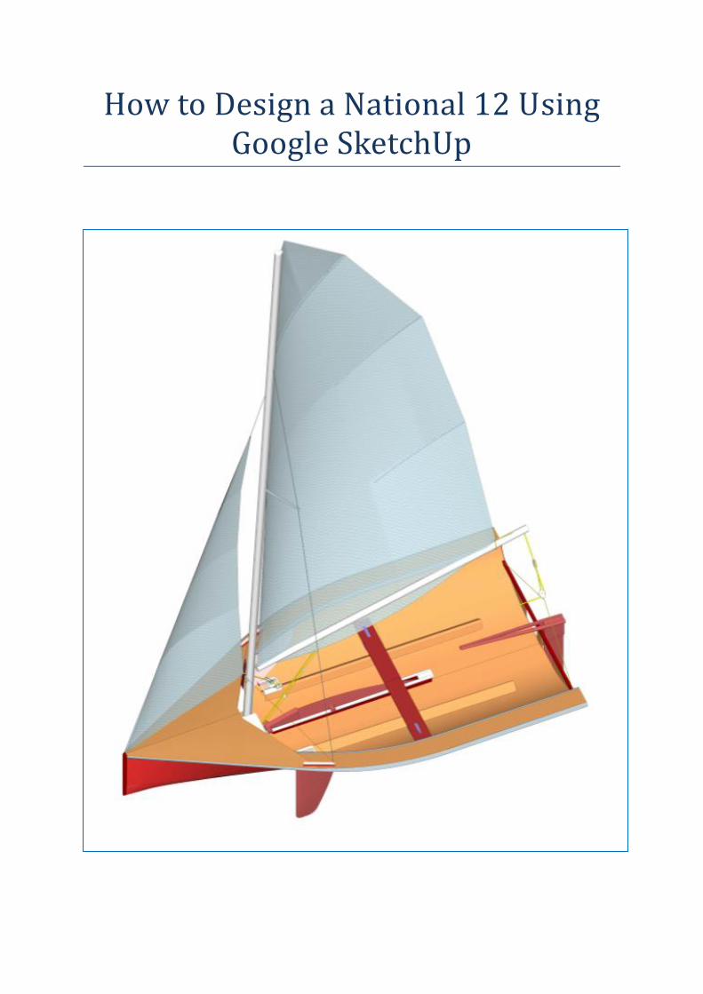
The build technique envisaged could be described as 'inside out': -
The build mould simply supports the floor.
The centre board case combined with the central spine is mounted on the floor.
The forward bulkheads, stem and inner keel are added to the case/spine.
The remaining bulkheads and transom are assembled on the floor
The fore deck, side decks and thwart are added.
The stringers are added (only at ply junctions if strip planking).
And finally a skin developed. The skin is mainly 4mm marine ply with 2 layers of 2mm ply (or
veneer) using 'epoxy
saturated cold moulding' for
the curved surfaces. Finally
the skin is reinforced with
an epoxy glass cloth outer
surface. Alternatively the
curved part of the skin
could be strip planked with
cedar.
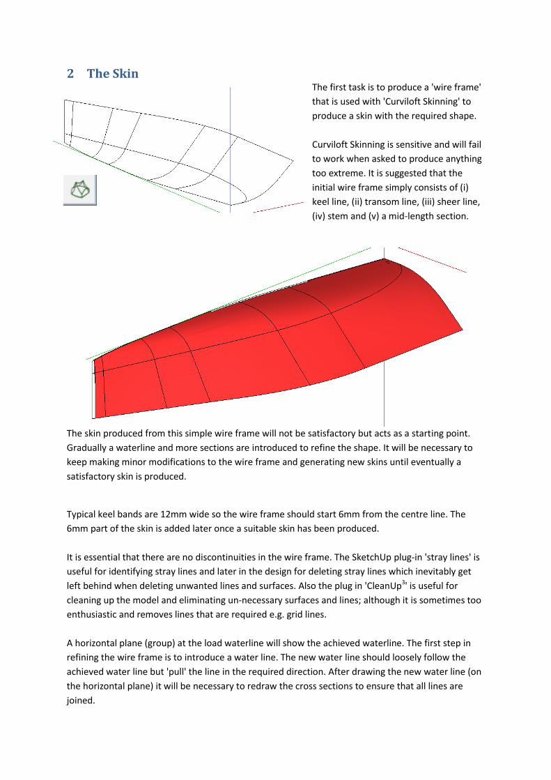
2 The Skin The first task is to produce a 'wire frame'
that is used with 'Curviloft Skinning' to
produce a skin with the required shape.
Curviloft Skinning is sensitive and will fail
to work when asked to produce anything
too extreme. It is suggested that the
initial wire frame simply consists of (i)
keel line, (ii) transom line, (iii) sheer line,
(iv) stem and (v) a mid-length section.
The skin produced from this simple wire frame will not be satisfactory but acts as a starting point.
Gradually a waterline and more sections are introduced to refine the shape. It will be necessary to
keep making minor modifications to the wire frame and generating new skins until eventually a
satisfactory skin is produced.
Typical keel bands are 12mm wide so the wire frame should start 6mm from the centre line. The
6mm part of the skin is added later once a suitable skin has been produced.
It is essential that there are no discontinuities in the wire frame. The SketchUp plug-in 'stray lines' is
useful for identifying stray lines and later in the design for deleting stray lines which inevitably get
left behind when deleting unwanted lines and surfaces. Also the plug in 'CleanUp3' is useful for
cleaning up the model and eliminating un-necessary surfaces and lines; although it is sometimes too
enthusiastic and removes lines that are required e.g. grid lines.
A horizontal plane (group) at the load waterline will show the achieved waterline. The first step in
refining the wire frame is to introduce a water line. The new water line should loosely follow the
achieved water line but 'pull' the line in the required direction. After drawing the new water line (on
the horizontal plane) it will be necessary to redraw the cross sections to ensure that all lines are
joined.
The smoothness of the skin can then be assessed by moving a vertical plane (group) through the skin
and looking closely at the intersection line. Points that are distorted can then be corrected by
changing existing sections or adding new sections to the wire frame.
Keep iterating until completely satisfied with the skin. Time spent at this stage will save time later
on. However it is almost inevitable that the design process will be repeated a number of times as
deficiencies are identified and one realises that 'if I changed xxx it would improve everything'. The
design presented in this document is 'mark 9' and there are still aspects that could be improved.
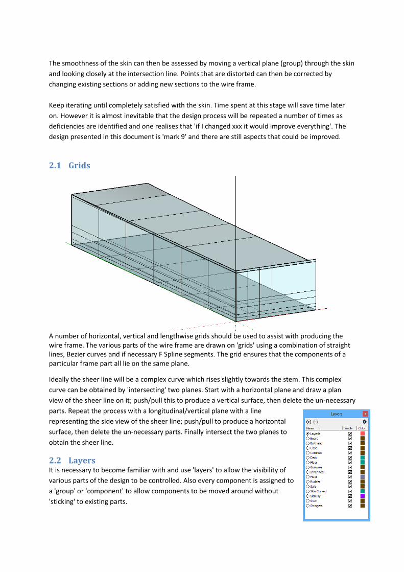
2.1 Grids
A number of horizontal, vertical and lengthwise grids should be used to assist with producing the wire frame. The various parts of the wire frame are drawn on 'grids' using a combination of straight lines, Bezier curves and if necessary F Spline segments. The grid ensures that the components of a particular frame part all lie on the same plane.
Ideally the sheer line will be a complex curve which rises slightly towards the stem. This complex
curve can be obtained by 'intersecting' two planes. Start with a horizontal plane and draw a plan
view of the sheer line on it; push/pull this to produce a vertical surface, then delete the un-necessary
parts. Repeat the process with a longitudinal/vertical plane with a line
representing the side view of the sheer line; push/pull to produce a horizontal
surface, then delete the un-necessary parts. Finally intersect the two planes to
obtain the sheer line.
2.2 Layers It is necessary to become familiar with and use 'layers' to allow the visibility of
various parts of the design to be controlled. Also every component is assigned to
a 'group' or 'component' to allow components to be moved around without
'sticking' to existing parts.
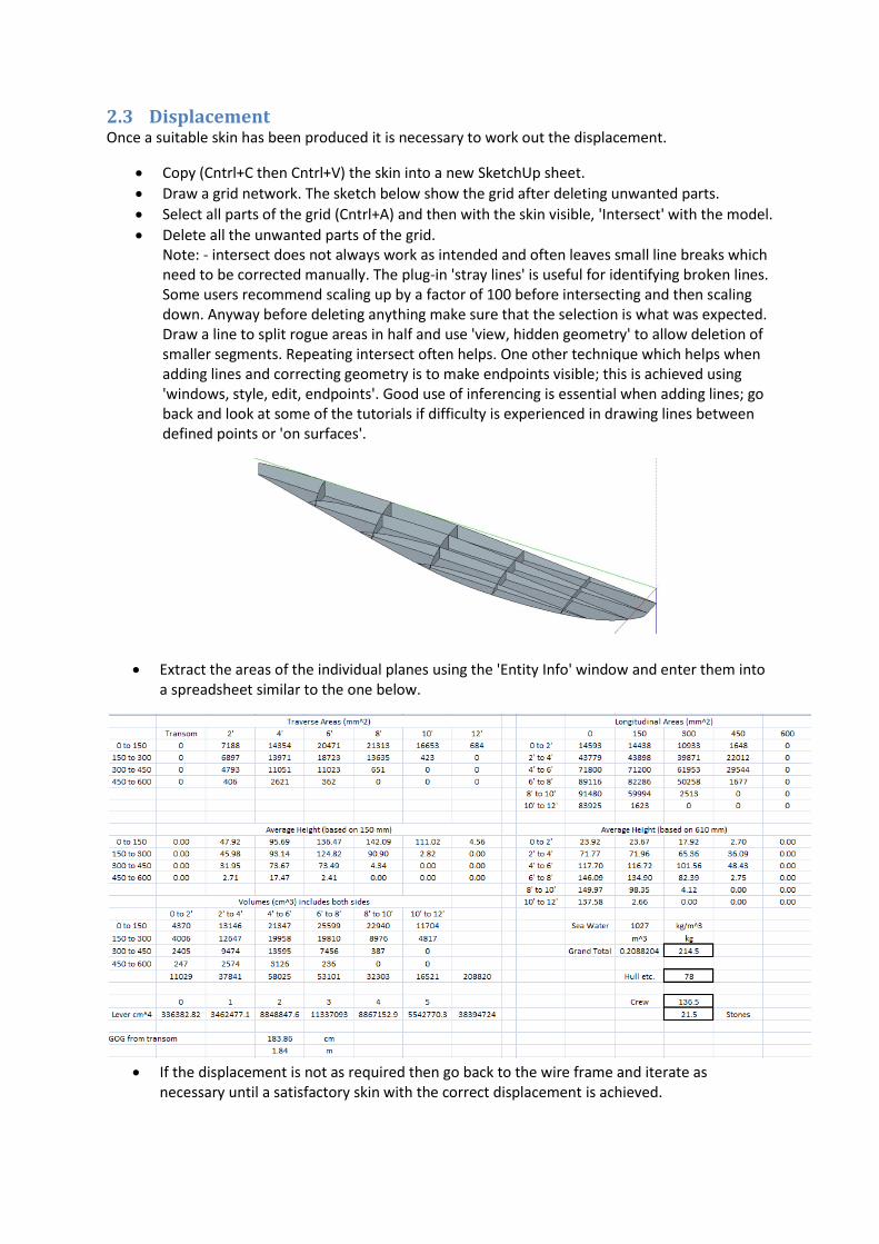
2.3 Displacement Once a suitable skin has been produced it is necessary to work out the displacement.
Copy (Cntrl+C then Cntrl+V) the skin into a new SketchUp sheet.
Draw a grid network. The sketch below show the grid after deleting unwanted parts.
Select all parts of the grid (Cntrl+A) and then with the skin visible, 'Intersect' with the model.
Delete all the unwanted parts of the grid. Note: - intersect does not always work as intended and often leaves small line breaks which need to be corrected manually. The plug-in 'stray lines' is useful for identifying broken lines. Some users recommend scaling up by a factor of 100 before intersecting and then scaling down. Anyway before deleting anything make sure that the selection is what was expected. Draw a line to split rogue areas in half and use 'view, hidden geometry' to allow deletion of smaller segments. Repeating intersect often helps. One other technique which helps when adding lines and correcting geometry is to make endpoints visible; this is achieved using 'windows, style, edit, endpoints'. Good use of inferencing is essential when adding lines; go back and look at some of the tutorials if difficulty is experienced in drawing lines between defined points or 'on surfaces'.
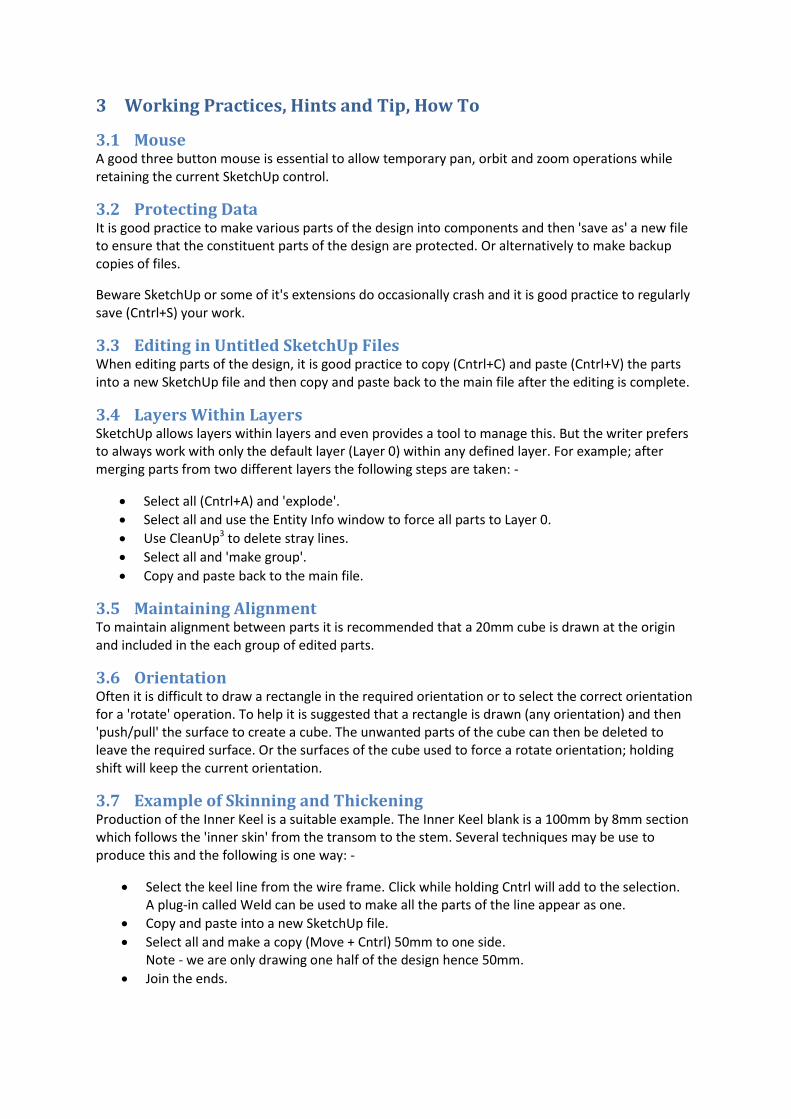
Extract the areas of the individual planes using the 'Entity Info' window and enter them into a spreadsheet similar to the one below.
If the displacement is not as required then go back to the wire frame and iterate as
necessary until a satisfactory skin with the correct displacement is achieved.
3 Working Practices, Hints and Tip, How To
3.1 Mouse A good three button mouse is essential to allow temporary pan, orbit and zoom operations while retaining the current SketchUp control.
3.2 Protecting Data It is good practice to make various parts of the design into components and then 'save as' a new file to ensure that the constituent parts of the design are protected. Or alternatively to make backup copies of files.
Beware SketchUp or some of it's extensions do occasionally crash and it is good practice to regularly save (Cntrl+S) your work.
3.3 Editing in Untitled SketchUp Files When editing parts of the design, it is good practice to copy (Cntrl+C) and paste (Cntrl+V) the parts into a new SketchUp file and then copy and paste back to the main file after the editing is complete.
3.4 Layers Within Layers SketchUp allows layers within layers and even provides a tool to manage this. But the writer prefers to always work with only the default layer (Layer 0) within any defined layer. For example; after merging parts from two different layers the following steps are taken: -
Select all (Cntrl+A) and 'explode'.
Select all and use the Entity Info window to force all parts to Layer 0.
Use CleanUp3 to delete stray lines.
Select all and 'make group'.
Copy and paste back to the main file.
3.5 Maintaining Alignment To maintain alignment between parts it is recommended that a 20mm cube is drawn at the origin and included in the each group of edited parts.
3.6 Orientation Often it is difficult to draw a rectangle in the required orientation or to select the correct orientation for a 'rotate' operation. To help it is suggested that a rectangle is drawn (any orientation) and then 'push/pull' the surface to create a cube. The unwanted parts of the cube can then be deleted to leave the required surface. Or the surfaces of the cube used to force a rotate orientation; holding shift will keep the current orientation.
3.7 Example of Skinning and Thickening Production of the Inner Keel is a suitable example. The Inner Keel blank is a 100mm by 8mm section which follows the 'inner skin' from the transom to the stem. Several techniques may be use to produce this and the following is one way: -
Select the keel line from the wire frame. Click while holding Cntrl will add to the selection. A plug-in called Weld can be used to make all the parts of the line appear as one.
Copy and paste into a new SketchUp file.
Select all and make a copy (Move + Cntrl) 50mm to one side. Note - we are only drawing one half of the design hence 50mm.
Join the ends.
Select all and use Curviloft Skinning to produce a surface. Note this surface is a temporary surface and positioned in line with the outer skin. Note - Curviloft output is always in a new group.
Select the surface just produced and use Curviloft Joint Push Pull 'J' to create a new surface 6mm from the original i.e. in line with the inner skin. Some options need selecting e.g. Erase original face and No Borders. The new surface will be in a new group. Note - 'J' usually works but occasionally fails and then the 'X' option will work.
Select the surface just produced and repeat Curviloft Joint Push Pull 'J' to create a new surface 8mm from the surface just created. In this case select options THICKEN and CONTOUR (borders). The required Inner Keel blank is produced in a new group.
Use CleanUp3 to delete any stray lines.
Draw a 20mm cube at the origin.
Select the cube and the Inner Keel blank, group and copy back to the original file.
3.8 Merging Parts Example From the stem backwards the inner keel is shaped to match the inner skin. This is best accomplished by copying and pasting the inner skin (component 'A') and the inner keel blank (group 'B') to a new file, and then merging the required parts as follows: -
Edit 'A', select all and intersect with model.
Edit 'B', select all and intersect with model.
Use Layers to make only 'A' visible
Edit 'A' and carefully delete all the parts that are not required. Don't worry about leaving parts around the borders that will be deleted later.
Use Layers to make only 'B' visible.
Edit 'B' and carefully delete all the parts that are not required. Don't worry about leaving parts around the borders that will be deleted later.
Use Layers to make 'A' and 'B' visible, select all, Explode and then force all parts to Layer 0.
Now carefully delete the unwanted parts around the borders. Intersect is not perfect, read the notes under 2.3 Displacement. Keep checking that only the required parts are deleted. Alt+backspace can be used to 'undo' if an error is made.
Use CleanUp3 to delete any stray lines.
Draw a 20mm cube at the origin.
Select all and group.
Copy and paste back to the main file.
3.9 Curviloft Follow a Path This extension is useful for creating stringers and gunwales. For example the gunwale can be produced as follows: -
Start by drawing the required gunwales cross section in a plane at the transom/sheer line intersection. Make this a group.
Repeat this at a number of points along the sheer line. Rotating the group if necessary to be approximately perpendicular to the sheer line.
Select the sheer line and all the groups just created.
Select Curviloft Follow a Path.
4 From Outer Skin to Complete Design
4.1 Add Keel Band to the Outer Skin Select the keel line from the wire frame.
Copy and paste into a new SketchUp file.
Move/copy the line 6mm to one side.
Join the ends.
Use Curviloft skinning to create a surface.
Import (or copy and paste) the outer skin.
Explode all to join the keel surface to the outer skin.
Use CleanUp3 to delete any stray lines.
Draw a 20mm cube at the origin.
Select all and force Layer 0 then make a component.
'Save as' to a new file to keep/protect the new outer skin.
4.2 Produce the Inner Skin Open a new SketchUp file.
Import the outer skin.
Select the outer skin and use Curviloft Joint Push Pull 'J' to create a new surface 6mm from the original. Some options need selecting e.g. Thicken and No Borders. It is convenient to select No Borders as this allows the new inner skin to be saved independently. Note - 'J' usually works but occasionally fails and then the 'X' option will work.
Delete the outer skin.
Select all Explode and force Layer 0.
Use CleanUp3 to delete any stray lines.
Draw a 20mm cube at the origin.
Select all, make a component and 'Save as' to a new file to keep/protect the new inner skin.
4.3 Trim the Skins Firstly along the keel line: -
Open a new SketchUp file.
Import the outer skin and inner skin.
Create a vertical longitudinal plane as a group.
Edit the group, select the plane and intersect with model.
Edit the outer skin, select all and intersect with model.
Edit the inner skin, select all and intersect with model.
Select all, explode and force Layer 0
Carefully delete the unwanted parts. The vertical plane becomes the join/edge between the two skins. It helps if the vertical plane is made a vivid colour.
Unfortunately the inner skin towards the bow is near vertical and will not reach the edge. It is possible to accept this and carry on regardless. Alternatively the inner skin can be extended to the keel surface. This is best accomplished by selecting 'hidden geometry' and extending the surface lines (one at a time) to a point on the outer skin/keel surface.
Secondly at the sheer line: -
Import (or copy and paste) the sheer plane group (one of the Grids).
Edit the sheer plane group, select all and intersect with model.
Carefully delete the unwanted parts. The sheer plane becomes the join/edge between the two skins. It helps if the sheer plane is made a vivid colour.
Thirdly at the Stem: -
Draw a construction line (tape measure tool) 28mm behind the stem.
Create a vertical cross sectional plane (approx 50mm wide * height of the sheer) on this construction line.
Select all and intersect with model.
Carefully delete the unwanted parts. The vertical plane becomes the join/edge between the two skins. It helps if the vertical plane is made a vivid colour.
Use CleanUp3 to delete any stray lines.
Draw a 20mm cube at the origin, select all, make a component and save the 'skin' to a new file.
4.4 Outer and Inner Stem These are made from 25mm thick hardwood. An allowance of 3mm is made for the thickness of the keel band. Consequently the join between the outer and inner stem is 28mm behind the stem.
Inner Stem: -
Work in new SketchUp file.
Draw a construction line (tape measure tool) 28mm behind the stem.
Draw a horizontal rectangle 50mm * 25mm representing the inner stem.
Make the rectangle a group.
Edit the group and push/pull the surface to a point just past the sheer line.
Import the inner skin.
Edit the inner stem, select all and intersect with model.
Edit the inner skin, select all and intersect with model.
Select all, explode and force Layer 0.
Use CleanUp3 to delete any stray lines.
Carefully delete the unwanted parts. In effect a very small strip of the inner skin will be left as the outer surface of the inner stem.
Outer Stem: -
Draw a horizontal rectangle 50mm * 25mm on the construction line representing the outer stem.
Make the rectangle a group.
Edit the group and push/pull the surface to a point just past the sheer line.
Import the outer skin.
Edit the outer stem, select all and intersect with model.
Edit the outer skin, select all and intersect with model.
Select all, explode and force Layer 0.
Use CleanUp3 to delete any stray lines.
Carefully delete the unwanted parts. In effect a very small strip of the outer skin will be left as the outer surface of the outer stem.
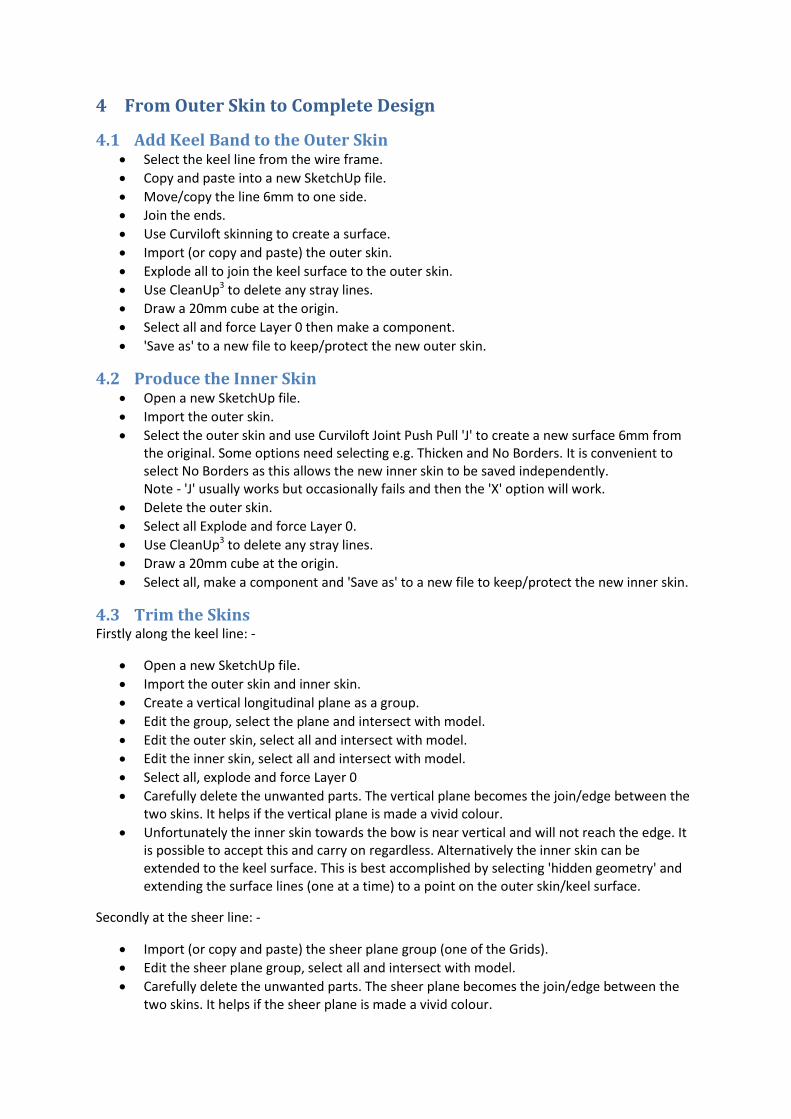
4.5 Stringers
4.5.1 Joint Between the Ply Skin and the Laminated Skin The join between the 4mm ply skin surface and the laminated curved parts of the skin is bridged with a 50mm wide strip of ply. This strip is supported with a perpendicular web of 4mm ply. The resulting stringer/bridge piece is of 'T' section. The web extends to the floor.
Exactly how this is accomplished is left to the readers ingenuity. However a plane needs to be produced which intersects the skin at a line where the ply skin meets the laminated skin. This plane can then be copied 25mm to each side of the original. Two lines at the intersection of these planes with the skin are joined at the ends and then 'skinned' and 'joint push/pull' used to create the bridging piece. The original plane is then used to create the web.
4.5.2 Stringers Supporting the Laminated Skin This can wait until the bulkheads are complete or can be done now using a temporary set of psudo bulkheads. A set of psudo bulkheads, perhaps every 500mm are constructed and intersected with the skin. On each bulkhead an arc is drawn beteen the 'T' stringers. The arc is forced to 3 or 4 segments. The stringers are 10mm * 20mm. A rectange 10mm * 20mm is created as a group and the group copied to each arc junction. Each rectangle is then rotated to be perpendicular to the skin. The model is orbited and the position of the rectangles visually trimmed to form a fair curve. An 'F Spline' line is drawn though each set of rectangles. The line and each of the rectangles are selected and Cuviloft 'Follow a Path' used to create the required stringer.
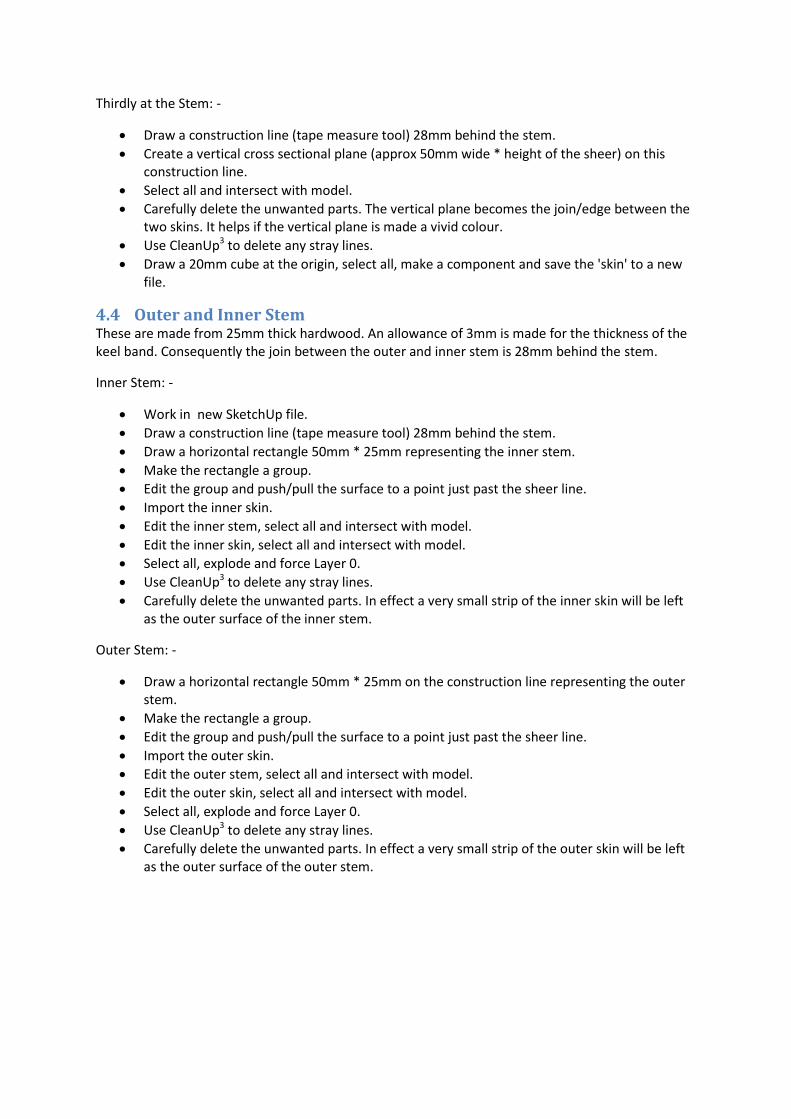
4.6 Critical Design Dimensions Published information can be used to derive the critical dimensions relating to the mast position and the position of the centre board.
With any new design the correct position of the centre board and the final balance (lee/weather helm) of the boat is impossible to predict. In recognition of this the centre board pin in this design is supported between two sheets of aluminium which fold over the top of the centre board case. The case is dimensioned to allow +/- 25mm adjustment of the board from nominal. This idea was once used by International 14's to allow the boats to be correctly trimmed without moving the mast. An additional benefit is that the pin does not penetrate the case and potential leaks are avoided.
4.7 Bulkhead in Front of the Mast This is a convenient point in the design process to draw the bulkhead in front of the mast. The top edge of this bulkhead is an arc that defines the foredeck curvature.
Initially all bulkheads are straightforward planes with no thickness.
4.8 Floor The floor cross section is developed using the transom line as a guide. Once the shape is defined push/pull is used to extend the floor in a horizontal plane to well past the bulkhead in front of the mast. Finally the floor is rotated to create the desired slope. Then the floor is intersected with the skin and the bulkhead and unwanted parts deleted.
4.9 Centre Board Case and Thwart The centre board case/spine is integrated with the inner keel. The sides of the case extend forward to a point midway between the mast bulkhead and the stem. This strengthens the area under the mast. Longitudinal bulkheads/spines stretch forward and aft from the transom to stem. After creating the case/spine it is necessary to edit adjacent parts that are effected e.g. inner keel, floor and mast bulkhead. Note the longitudinal bulkhead is drawn as 2mm thick i.e. one half of the eventual 4mm thickness.
The thwart is supported on extensions to the sides of the case. The thwart is formed from two laminations of 4mm ply with 20mm square hardwood edges. The 20mm edges protrude through the floor and are bonded to the skin. One of the 20mm edge pieces coincides with a bulkhead and provides addition strength and support.
4.10 Bulkheads The ideal position for most of the bulkheads is obvious: -
at the rear of the centre board case
mid way between the rear centre board bulkhead and the transom
either side of the centre board (when it is in the down position) to support the case
mid way between the stem and the mast bulkhead
mid way between any large unsupported areas
The bulkheads are produced as follows: -
draw a rectangle (group) at each point.
edit the rectangle and intersect with the model.
delete where it meets the skin, the floor, the inner keel, the centre board case and the stringers.
push/pull to 4mm thickness
add 10mm square edges where the bulkhead meets the 4mm ply skin. These will be 'faired' to accept the skin during construction.
The transom is a bulkhead but is more complex. It is primarily formed of 25mm thick hardwood skinned with 4mm ply. A 25mm square section is used to cross brace the skin and support the upper rudder pintle. The hardwood is rebated to accept the transom skin and floor, and extensively shaped at its junction with the skin.
One diagonal bulkhead is required from the mast bulkhead to the skin at the approximate position of the shrouds. Approximately 300mm aft of the mast. Initially this bulkhead is drawn with too much height and the final size is determined when drawing the fore deck.
4.11 Gunwales Described in section 3.9
4.12 Side Deck The side deck is supported by the skin, gunwale, bulkheads and top edge of the floor. From the transom forward the floor provides 'edge' support to the side deck but this 'runs out' towards the mast diagonal bulkhead. It is necessary to add a curved deck support in this area. A lamination of two 4mm ply pieced needs incorporating to provide edge support in this area.
Once lines defining the extremities of the side deck are obtained use Curviloft Joint Push Pull to obtain 4mm thickness.
4.13 Fore Deck The top edge of the mast bulkhead defines the curvature of the foredeck. Draw a number of lines radiating from the stem to the top edge of the mast bulkhead. Extend these lines until they meet the over sized diagonal bulkhead. The intersection points define the top edge of the diagonal bulkhead. Draw an F Spline curve between these points and then trim the diagonal bulkhead to its final size.
Lines defining the extremities of the foredeck are now available. Use Curviloft Skinning and Joint Push Pull with a 4mm dimension to create the foredeck.
5 Conclusion There will be many more activities required to tidy up and complete the design but nothing too difficult.
The design exercise requires some ingenuity and skill with the use of SketchUp but a great deal of satisfaction will be obtained.
The writer has not pursued this, but believes it would be possible to take the SketchUp design and produce sufficient information to allow CNC cutting of all of the ply parts - see PS.
The next step is to take your own design and actually build a boat - good luck.
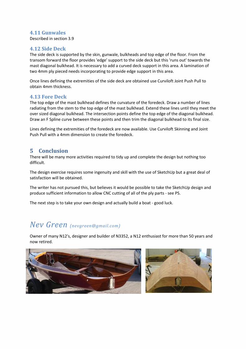
Nev Green ([email protected]) Owner of many N12's, designer and builder of N3352, a N12 enthusiast for more than 50 years and now retired.
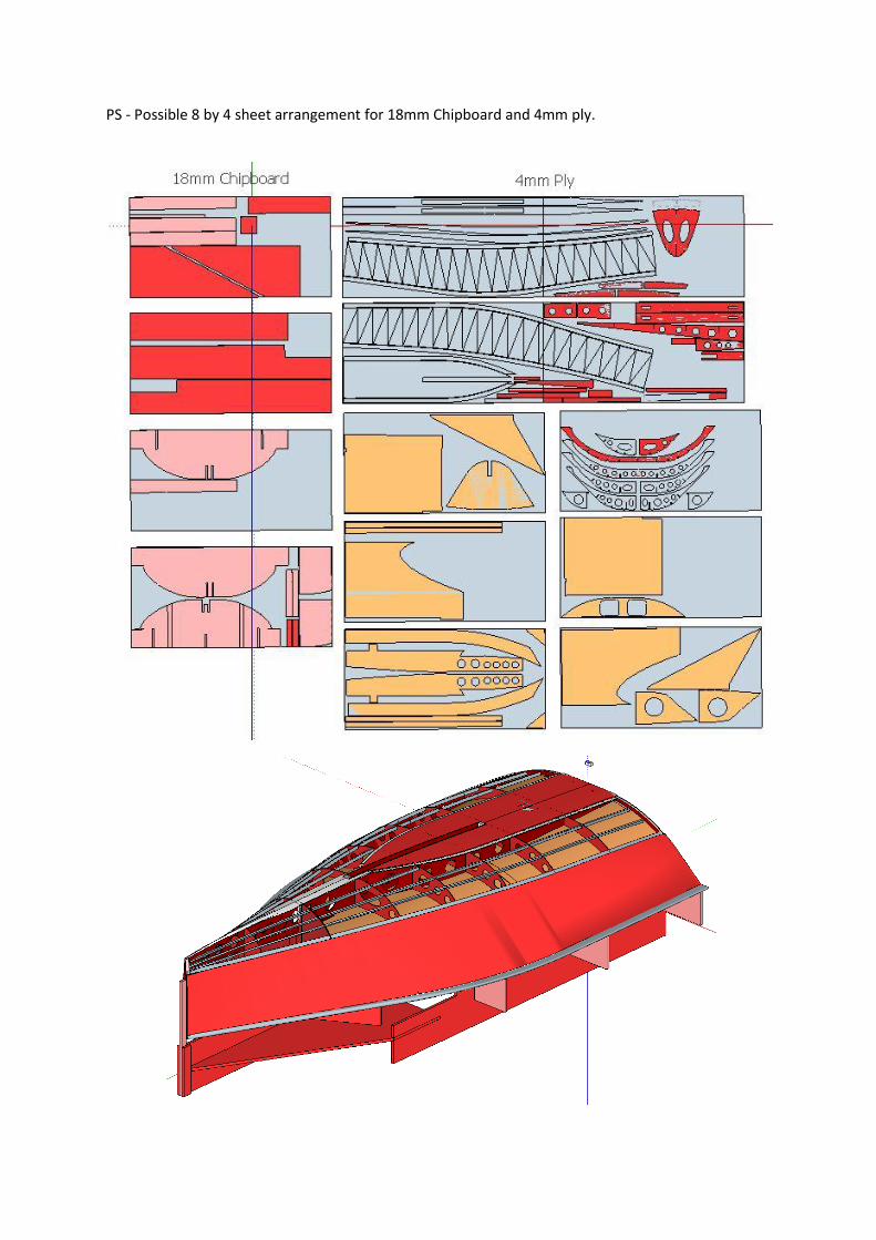
PS - Possible 8 by 4 sheet arrangement for 18mm Chipboard and 4mm ply.