Embed Size (px)
Citation preview
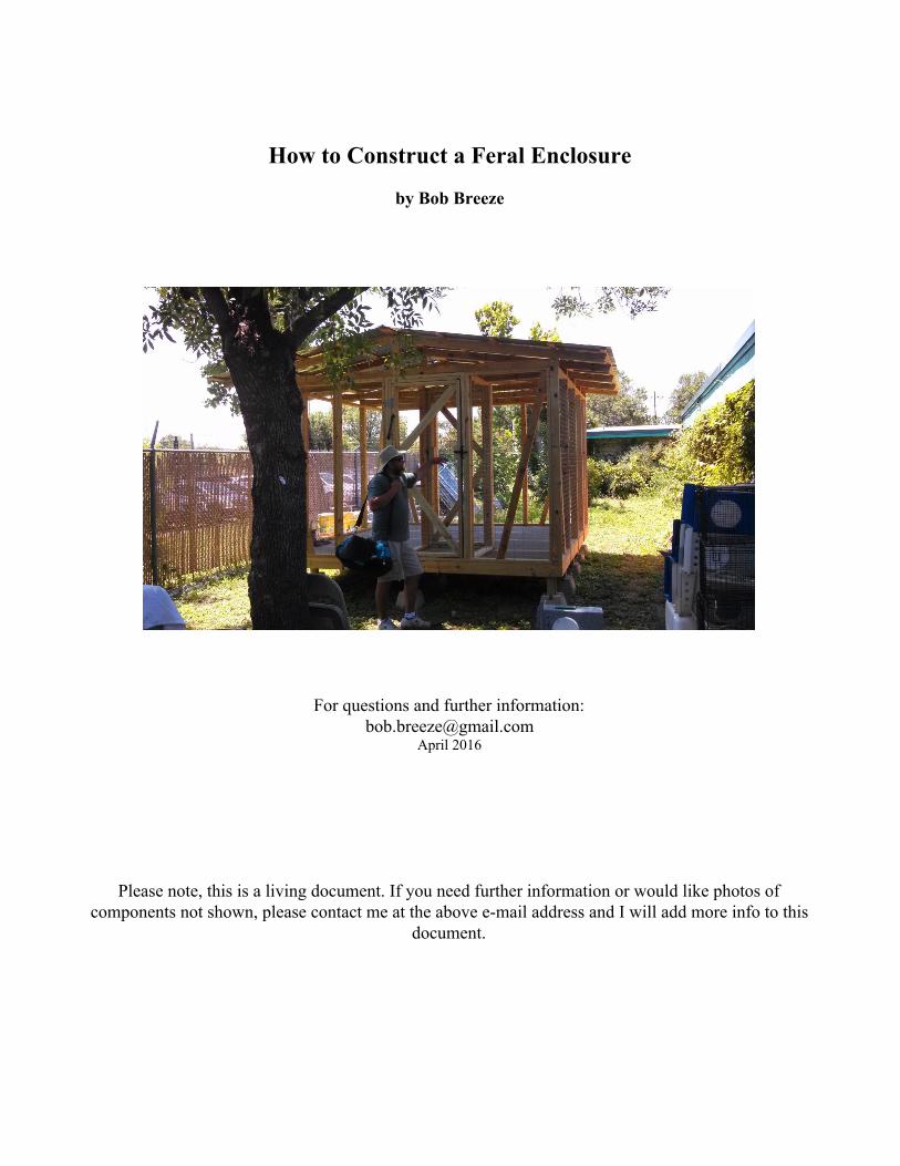
How to Construct a Feral Enclosure
by Bob Breeze
For questions and further information: [email protected]
April 2016
Please note, this is a living document. If you need further information or would like photos of components not shown, please contact me at the above email address and I will add more info to this
document.
Introduction
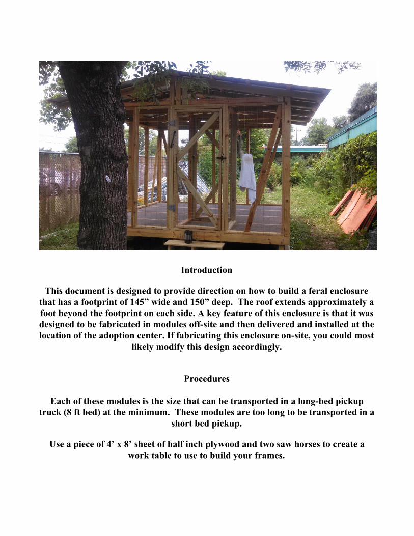
This document is designed to provide direction on how to build a feral enclosure that has a footprint of 145” wide and 150” deep. The roof extends approximately a foot beyond the footprint on each side. A key feature of this enclosure is that it was designed to be fabricated in modules offsite and then delivered and installed at the location of the adoption center. If fabricating this enclosure onsite, you could most
likely modify this design accordingly.
Procedures
Each of these modules is the size that can be transported in a longbed pickup truck (8 ft bed) at the minimum. These modules are too long to be transported in a
short bed pickup.
Use a piece of 4’ x 8’ sheet of half inch plywood and two saw horses to create a work table to use to build your frames.
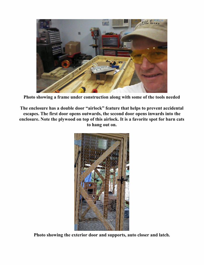
Photo showing a frame under construction along with some of the tools needed
The enclosure has a double door “airlock” feature that helps to prevent accidental escapes. The first door opens outwards, the second door opens inwards into the
enclosure. Note the plywood on top of this airlock. It is a favorite spot for barn cats to hang out on.
Photo showing the exterior door and supports, auto closer and latch.
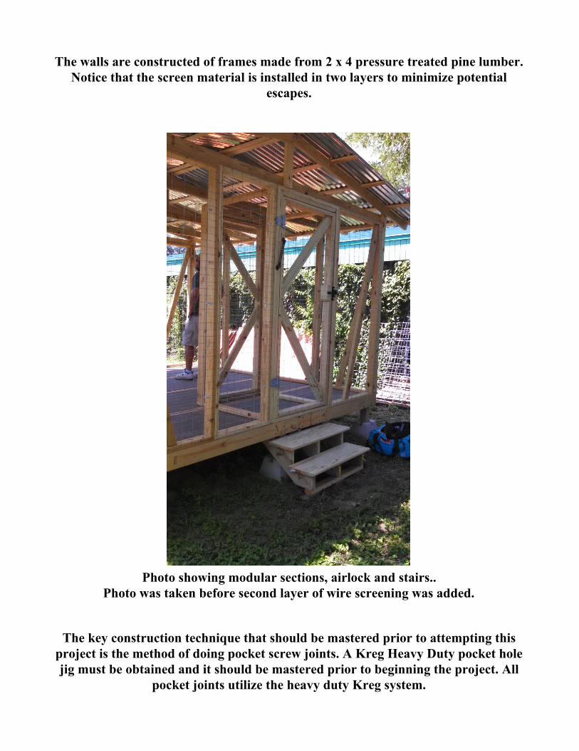
The walls are constructed of frames made from 2 x 4 pressure treated pine lumber. Notice that the screen material is installed in two layers to minimize potential
escapes.
Photo showing modular sections, airlock and stairs..
Photo was taken before second layer of wire screening was added.
The key construction technique that should be mastered prior to attempting this project is the method of doing pocket screw joints. A Kreg Heavy Duty pocket hole jig must be obtained and it should be mastered prior to beginning the project. All
pocket joints utilize the heavy duty Kreg system.
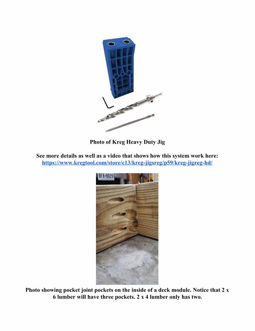
Photo of Kreg Heavy Duty Jig
See more details as well as a video that shows how this system work here: https://www.kregtool.com/store/c13/kregjigsreg/p59/kregjigreghd/
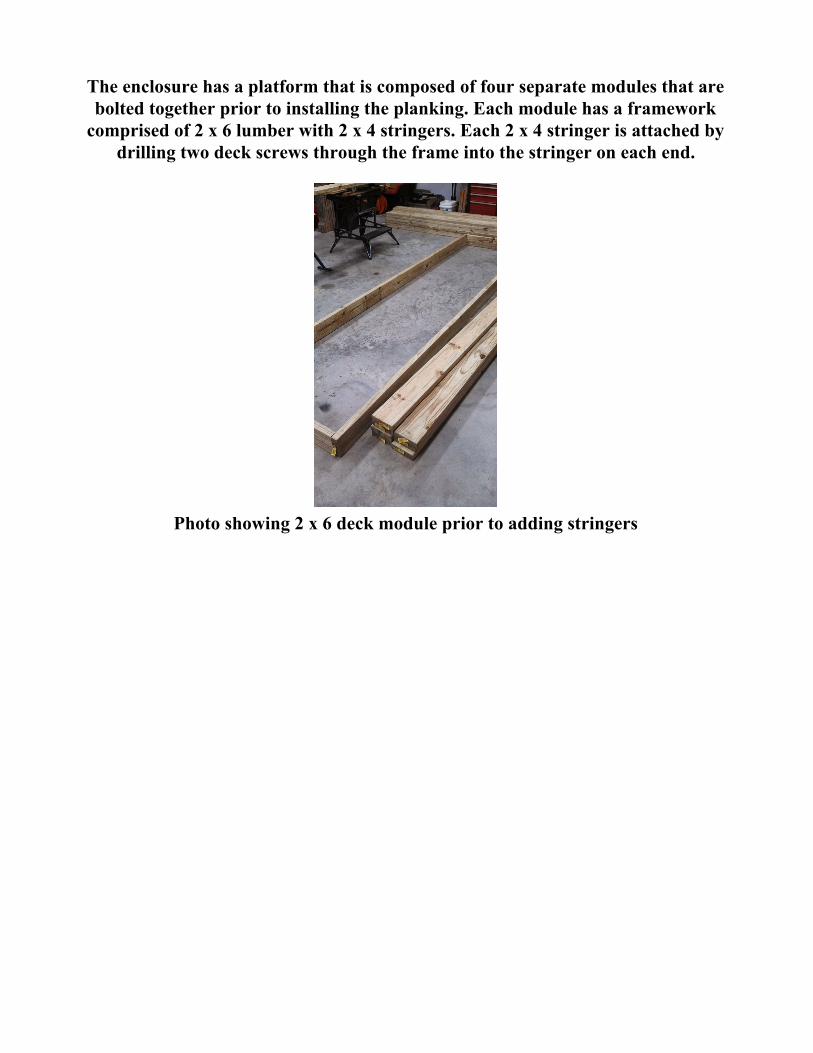
Photo showing pocket joint pockets on the inside of a deck module. Notice that 2 x
6 lumber will have three pockets. 2 x 4 lumber only has two.
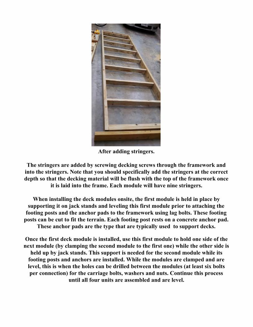
The enclosure has a platform that is composed of four separate modules that are bolted together prior to installing the planking. Each module has a framework comprised of 2 x 6 lumber with 2 x 4 stringers. Each 2 x 4 stringer is attached by
drilling two deck screws through the frame into the stringer on each end.
Photo showing 2 x 6 deck module prior to adding stringers
After adding stringers.
The stringers are added by screwing decking screws through the framework and into the stringers. Note that you should specifically add the stringers at the correct depth so that the decking material will be flush with the top of the framework once
it is laid into the frame. Each module will have nine stringers.
When installing the deck modules onsite, the first module is held in place by supporting it on jack stands and leveling this first module prior to attaching the footing posts and the anchor pads to the framework using lag bolts. These footing posts can be cut to fit the terrain. Each footing post rests on a concrete anchor pad.
These anchor pads are the type that are typically used to support decks.
Once the first deck module is installed, use this first module to hold one side of the next module (by clamping the second module to the first one) while the other side is
held up by jack stands. This support is needed for the second module while its footing posts and anchors are installed. While the modules are clamped and are level, this is when the holes can be drilled between the modules (at least six bolts per connection) for the carriage bolts, washers and nuts. Continue this process
until all four units are assembled and are level.
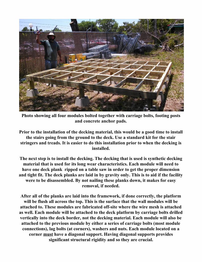
Photo showing all four modules bolted together with carriage bolts, footing posts
and concrete anchor pads.
Prior to the installation of the decking material, this would be a good time to install the stairs going from the ground to the deck. Use a standard kit for the stair
stringers and treads. It is easier to do this installation prior to when the decking is installed.
The next step is to install the decking. The decking that is used is synthetic decking material that is used for its long wear characteristics. Each module will need to have one deck plank ripped on a table saw in order to get the proper dimension
and tight fit. The deck planks are laid in by gravity only. This is to aid if the facility were to be disassembled. By not nailing these planks down, it makes for easy
removal, if needed.
After all of the planks are laid into the framework, if done correctly, the platform will be flush all across the top. This is the surface that the wall modules will be
attached to. These modules are fabricated offsite where the wire mesh is attached as well. Each module will be attached to the deck platform by carriage bolts drilled vertically into the deck border, not the decking material. Each module will also be attached to the previous module by either a series of carriage bolts (most module connections), lag bolts (at corners), washers and nuts. Each module located on a
corner must have a diagonal support. Having diagonal supports provides significant structural rigidity and so they are crucial.
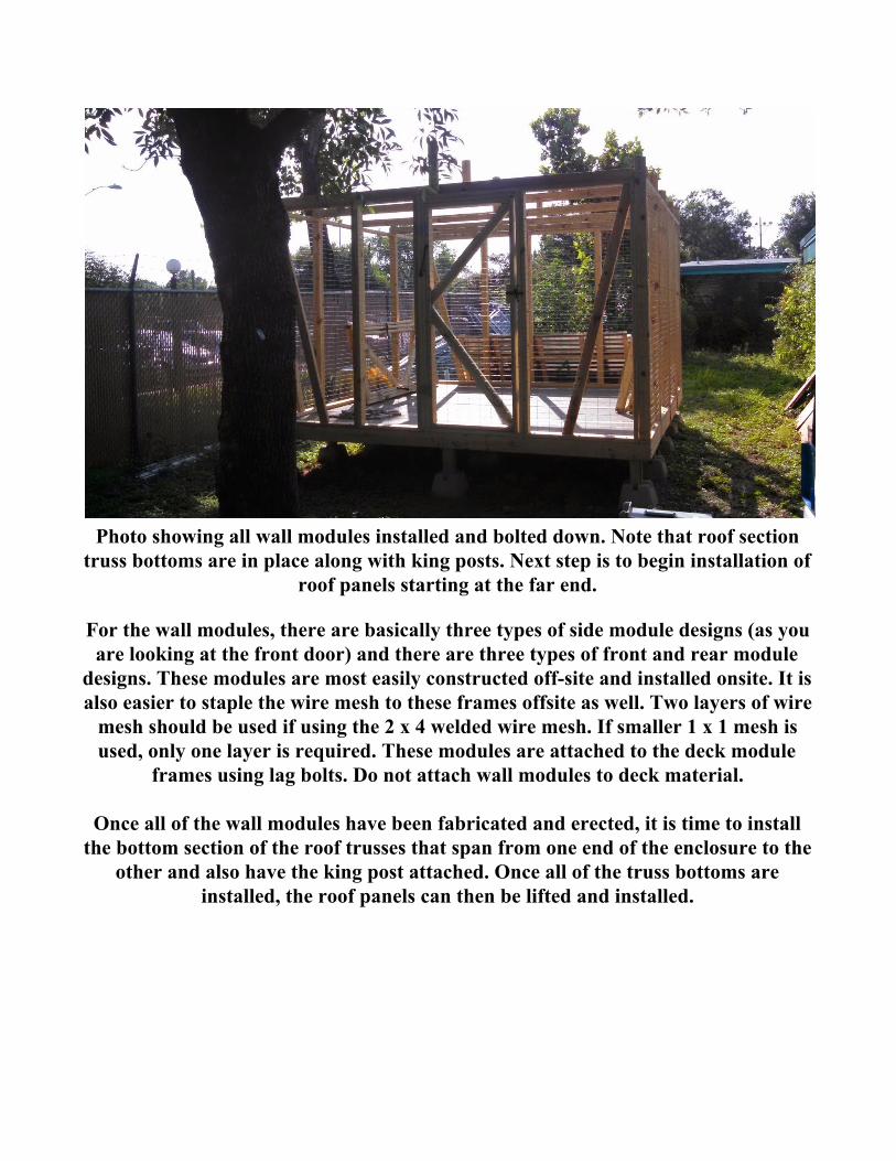
Photo showing all wall modules installed and bolted down. Note that roof section
truss bottoms are in place along with king posts. Next step is to begin installation of roof panels starting at the far end.
For the wall modules, there are basically three types of side module designs (as you are looking at the front door) and there are three types of front and rear module
designs. These modules are most easily constructed offsite and installed onsite. It is also easier to staple the wire mesh to these frames offsite as well. Two layers of wire mesh should be used if using the 2 x 4 welded wire mesh. If smaller 1 x 1 mesh is used, only one layer is required. These modules are attached to the deck module
frames using lag bolts. Do not attach wall modules to deck material.
Once all of the wall modules have been fabricated and erected, it is time to install the bottom section of the roof trusses that span from one end of the enclosure to the
other and also have the king post attached. Once all of the truss bottoms are installed, the roof panels can then be lifted and installed.
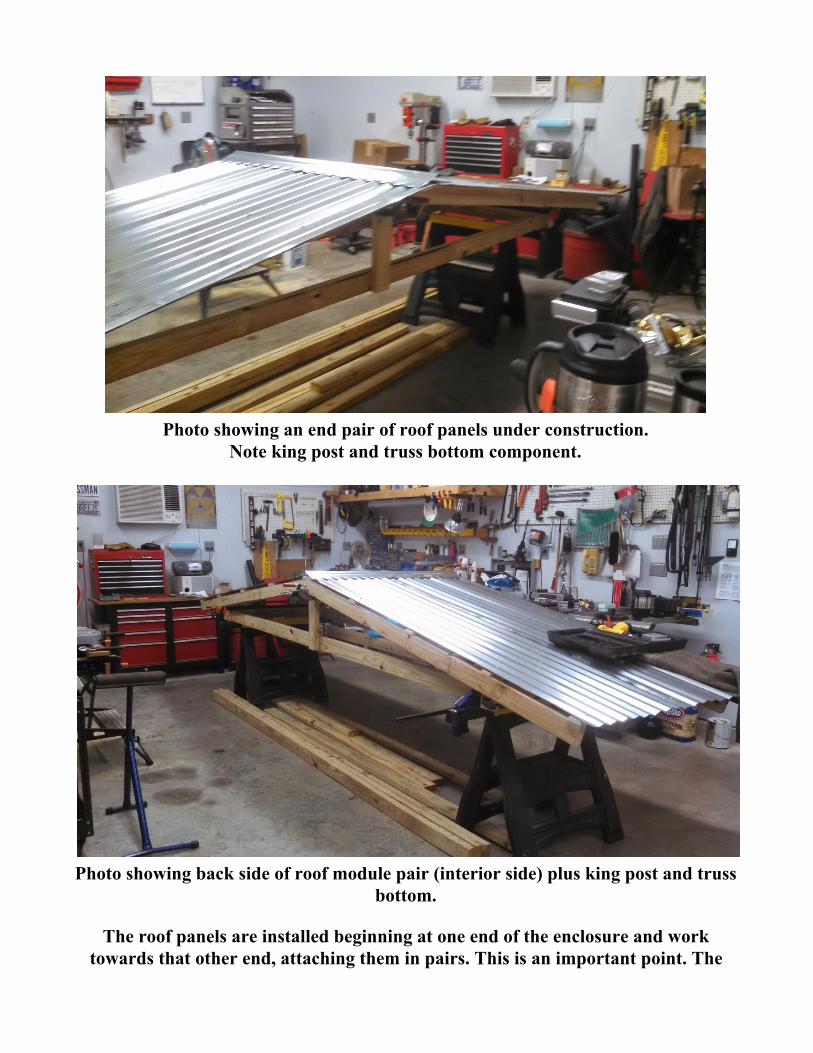
Photo showing an end pair of roof panels under construction.
Note king post and truss bottom component.
Photo showing back side of roof module pair (interior side) plus king post and truss
bottom.
The roof panels are installed beginning at one end of the enclosure and work towards that other end, attaching them in pairs. This is an important point. The
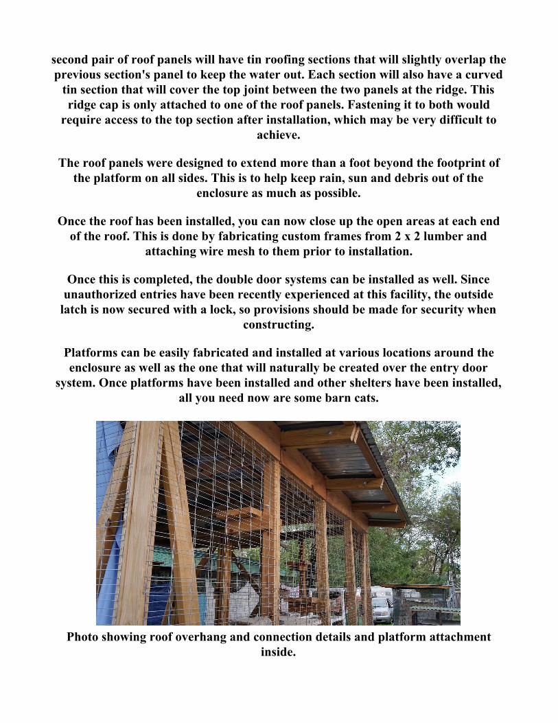
second pair of roof panels will have tin roofing sections that will slightly overlap the previous section's panel to keep the water out. Each section will also have a curved tin section that will cover the top joint between the two panels at the ridge. This ridge cap is only attached to one of the roof panels. Fastening it to both would require access to the top section after installation, which may be very difficult to
achieve.
The roof panels were designed to extend more than a foot beyond the footprint of the platform on all sides. This is to help keep rain, sun and debris out of the
enclosure as much as possible.
Once the roof has been installed, you can now close up the open areas at each end of the roof. This is done by fabricating custom frames from 2 x 2 lumber and
attaching wire mesh to them prior to installation.
Once this is completed, the double door systems can be installed as well. Since unauthorized entries have been recently experienced at this facility, the outside latch is now secured with a lock, so provisions should be made for security when
constructing.
Platforms can be easily fabricated and installed at various locations around the enclosure as well as the one that will naturally be created over the entry door
system. Once platforms have been installed and other shelters have been installed, all you need now are some barn cats.
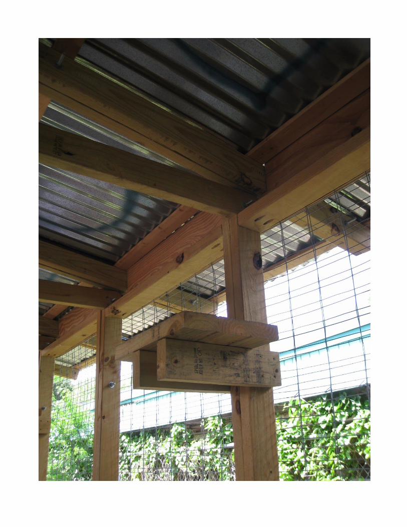
Photo showing roof overhang and connection details and platform attachment
inside.
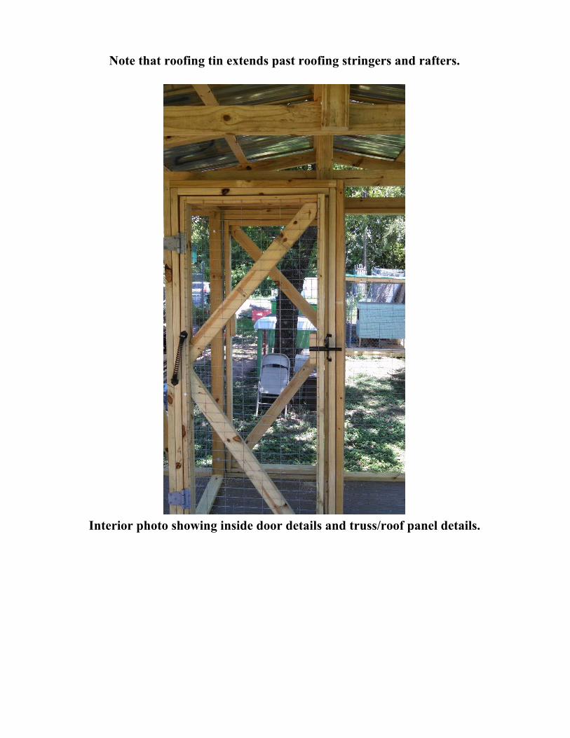
Note that roofing tin extends past roofing stringers and rafters.
Interior photo showing inside door details and truss/roof panel details.
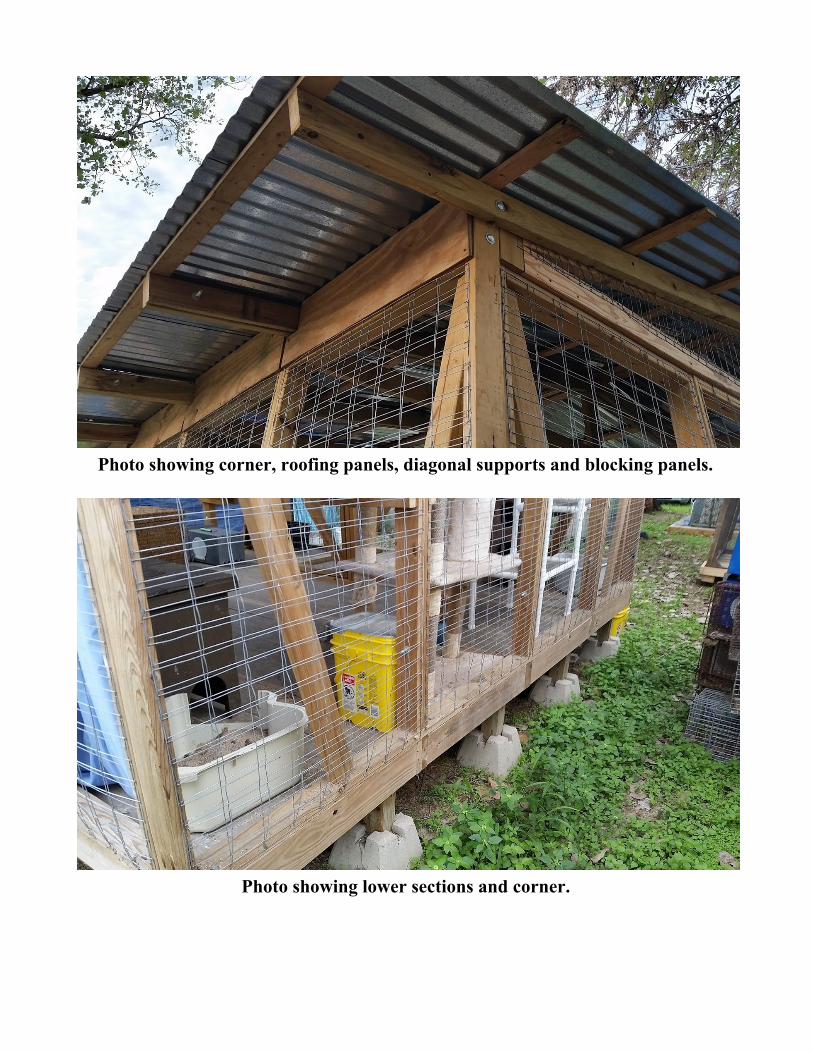
Photo showing corner, roofing panels, diagonal supports and blocking panels.
Photo showing lower sections and corner.
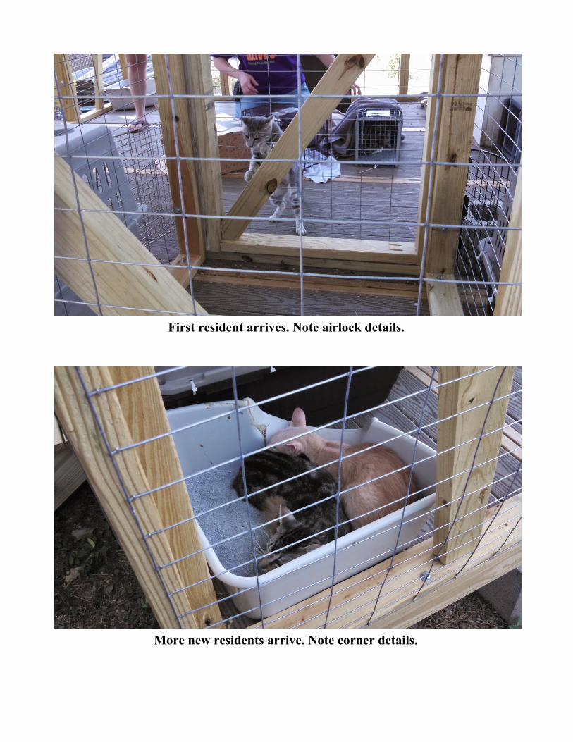
First resident arrives. Note airlock details.
More new residents arrive. Note corner details.
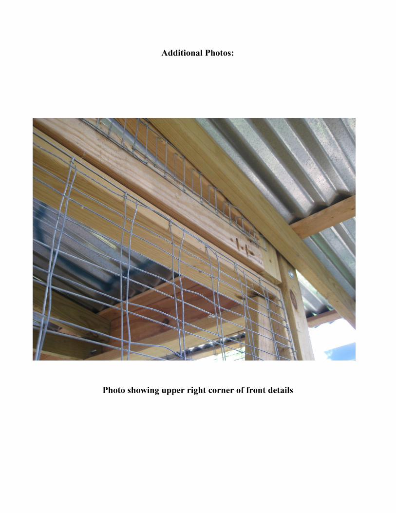
Additional Photos:
Photo showing upper right corner of front details
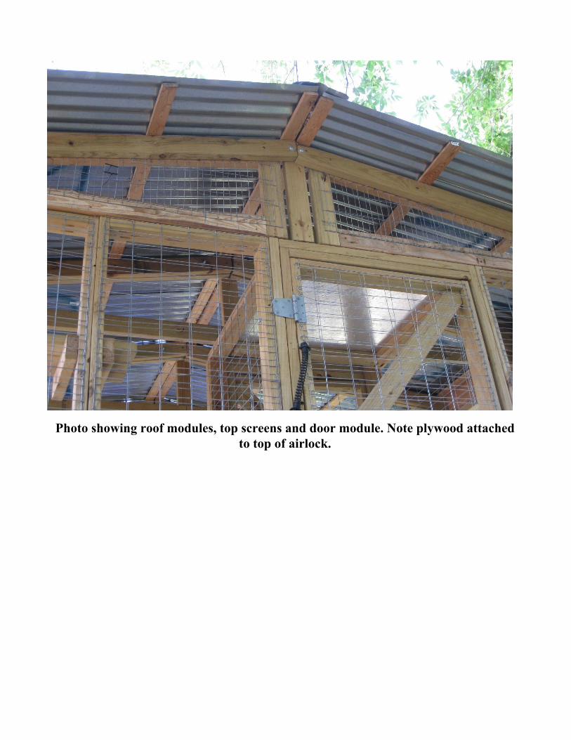
Photo showing roof modules, top screens and door module. Note plywood attached to top of airlock.
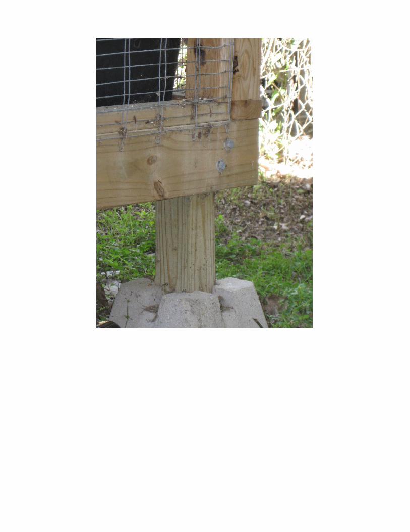
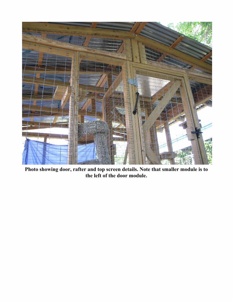
Photo showing door, rafter and top screen details. Note that smaller module is to the left of the door module.
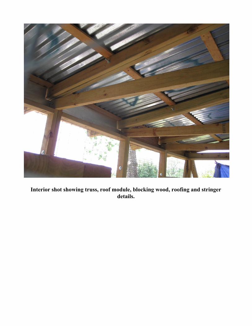
Interior shot showing truss, roof module, blocking wood, roofing and stringer details.
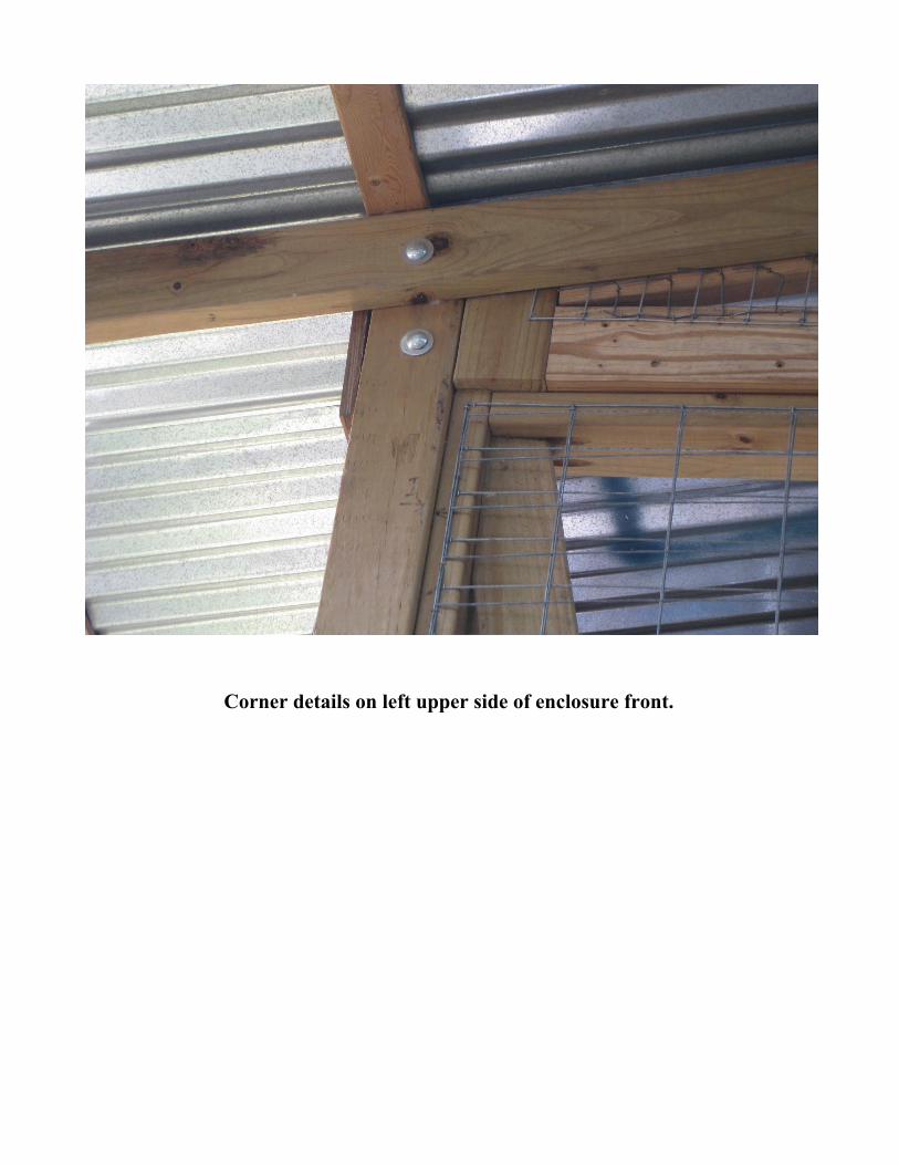
Corner details on left upper side of enclosure front.
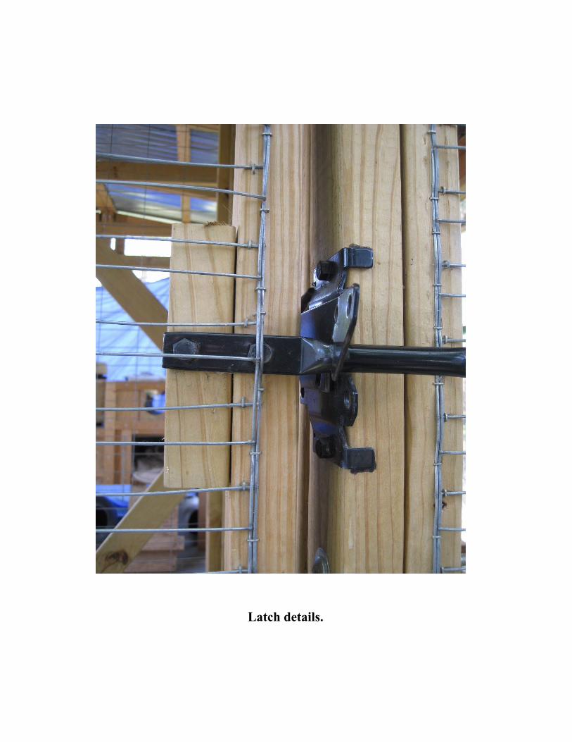
Latch details.

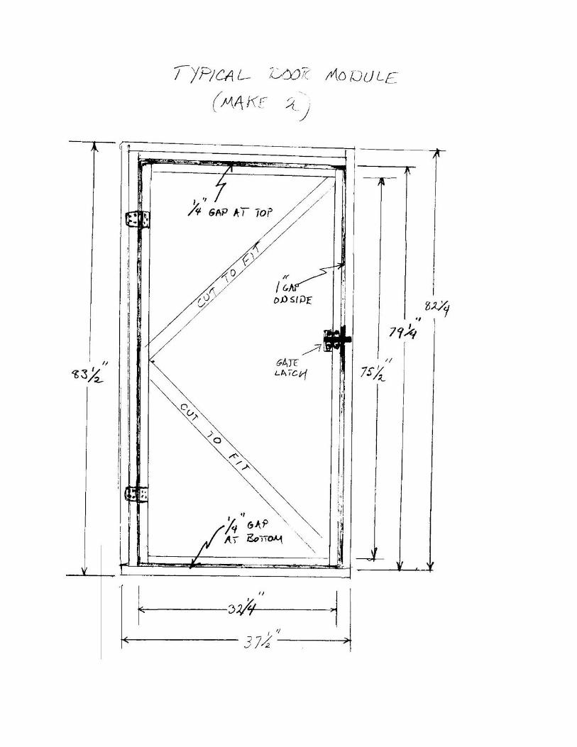
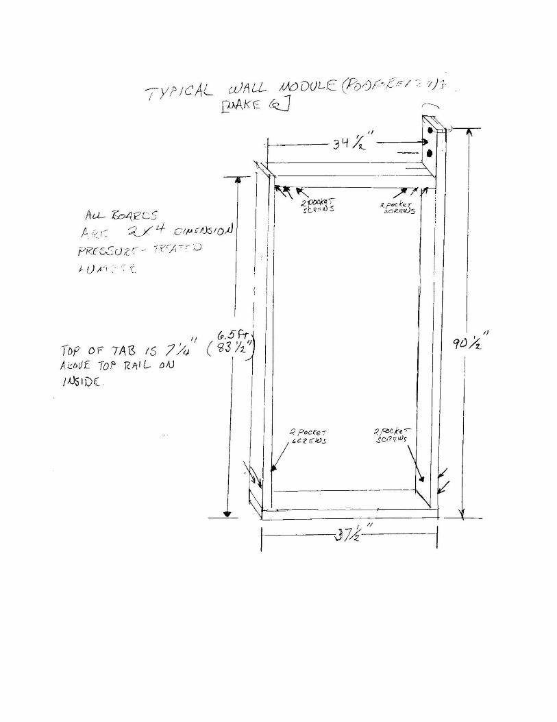
Design Drawings
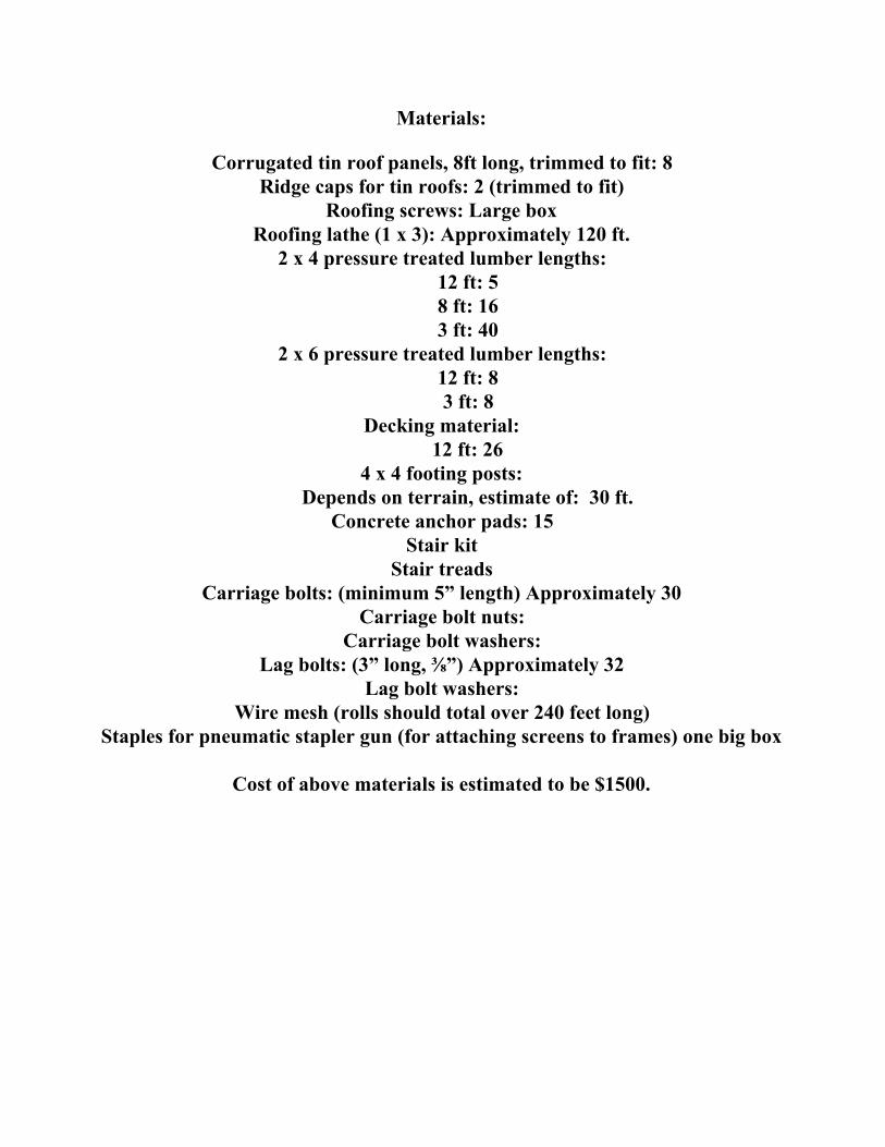
Materials:
Corrugated tin roof panels, 8ft long, trimmed to fit: 8
Ridge caps for tin roofs: 2 (trimmed to fit) Roofing screws: Large box
Roofing lathe (1 x 3): Approximately 120 ft. 2 x 4 pressure treated lumber lengths:
12 ft: 5 8 ft: 16 3 ft: 40
2 x 6 pressure treated lumber lengths: 12 ft: 8 3 ft: 8
Decking material: 12 ft: 26
4 x 4 footing posts: Depends on terrain, estimate of: 30 ft.
Concrete anchor pads: 15 Stair kit
Stair treads Carriage bolts: (minimum 5” length) Approximately 30
Carriage bolt nuts: Carriage bolt washers:
Lag bolts: (3” long, ⅜”) Approximately 32 Lag bolt washers:
Wire mesh (rolls should total over 240 feet long) Staples for pneumatic stapler gun (for attaching screens to frames) one big box
Cost of above materials is estimated to be $1500.